causality' in in-service information and design actions
TRANSCRIPT

Proceedings of TMCE 2008 Symposium, April 21–25, 2008, Izmir, Turkey, edited by I. Horvath and Z. Rusakc© Organizing Committee of TMCE 2008, ISBN 978-90-5155-044-3
‘CAUSALITY’ IN IN-SERVICE INFORMATION AND DESIGN ACTIONS
Santosh JagtapEngineering Design Centre
University of CambridgeUnited Kingdom
Aylmer JohnsonMarco Aurisicchio
Ken WallaceEngineering Design Centre
University of CambridgeUnited Kingdom
{alj3, ma248, kmw}@cam.ac.uk
ABSTRACT
In the global market of air transport, integration ofproducts and services is now seen as being neces-sary for the long-term success of engine manufac-turers. This paper describes research stimulated bya fundamental shift that is occurring in the manu-facture and marketing of aero engines for commer-cial and defence purposes, away from the selling ofproducts to the provision of services. Our collabo-rating aerospace company now offers TotalCareTM
contracts, under which it leases engines to airlineswhile remaining responsible for their maintenance.The aims of our ongoing research are to: (1) un-derstand the current flows of in-service informationto designers; (2) understand the in-service informa-tion requirements of designers; (3) develop, based onthis understanding, the most appropriate theories andmethods to support designers in their new task. Thework presented in this paper aims at understandingthe use of in-service information in a design task byexamining the executed design changes, and the ra-tionale behind these changes. In an attempt to ad-dress this aim, a case study involving the redesignof the ‘burner seal’ of an aero engine, is used. Theredesign is based on the in-service experience of theexisting burner seal.
KEYWORDS
In-service information, knowledge management, de-sign for service, aerospace engineering, causality
1. INTRODUCTION
Integration of products and services is now seen asbeing necessary for the long-term success of enginemanufacturers, in the global market of air transport.A fundamental shift is occurring in our collaborat-ing company, away from the selling of products tothe provision of services. The company now of-fers TotalCareTM contracts, under which it leasesengines to airlines while remaining responsible fortheir maintenance. Different services such as repairand overhaul, technical publications, inventory man-agement, predictive support through engine healthmonitoring, etc. are designed for those contracts.These services transfer the technical and financialburden of engine maintenance and management tothe collaborating company. This affects the design ofnew engines, which now need to have low and pre-dictable maintenance costs, in addition to the previ-ous requirements of reliability and low specific fuelconsumption. By incorporating knowledge aboutthe performance of existing products into the designphase of new products, it is hoped to tackle someof the in-service problems at the design stage. Inthe aerospace sector, it is standard design practice toutilise the experience gained from past projects, butthat from routine in-service operation has not beengiven sufficient attention.
In-service information related to the service issuesof similar aero engines is utilised to avoid the sameproblems in future designs. A flow of informationfrom the service domain to designers is thus crucialfor minimising in-service issues, and can also reduce
913

the cost of both planned and unplanned maintenance.In order to develop a method or tool which can enabledesigners to retrieve the in-service experience of ex-isting engines in an effective and efficient way, it isnecessary to understand the present flow of in-serviceinformation to the designers as well as the designers’requirements regarding this information. Our initialwork identified how in-service experience of existingengines informs design modifications (Jagtap, et al.,2006); how in-service information flows to the de-signers, and designers’ requirements regarding thisinformation (Jagtap, et al., 2007a and 2007b). In thatwork, we used methods such as questionnaires andinterviews, which lacked the context of a design ac-tivity. Therefore, it did not allow us to understandhow designers use in-service information when theydeal with it in a design task. The work presented inthis paper aims at understanding the use of in-serviceinformation in a design task.
In an attempt to address this aims, a case studyinvolving the redesign of the ‘burner seal’ of anaero engine is used. The redesign is based onthe in-service experience of version-1 of the burnerseal. The output of the redesign activity is calledversion-2.
The outline of the paper is as follows. Section 2presents the relevant literature. Section 3 describesthe data collection method. Section 4 explains thecomponent examined in the case study. In addition,the in-service experience and the design changesto the component are presented. The data analy-sis method is presented in Section 5. Section 6 de-scribes the findings and the insights gained in thedata analysis. Finally, the conclusions are presentedin Section 7.
2. LITERATURE REVIEW
2.1. TotalCare TM contracts and aeroengine design
Engines designed for a TotalCareTM contract requirelong service intervals, ease of maintenance and highreliability (Kirkland, Cave, 1999). Alonso-Rasgado,et al. (2004) identified the importance of in-servicedata collection and storage when a manufacturer isresponsible for the maintenance and repair of a prod-uct throughout its life. Harrison (2006) has discussedthe elements of the process, describing problems andsuccesses in the deployment of ‘Design for Service’for the Trent 1000 aero engine, used in the Boeing787 aircraft. He has listed some of the significant op-erator cost drivers such as: range and payload, safety,
schedule reliability, life cycle fuel burn and engineoverhaul. He identified the following issues, whichcan address all of the above drivers positively:• understanding the engine’s deterioration mecha-
nisms;• controlling their rate of occurrence and impact;• ensuring effective and low-cost restoration of ca-
pability at overhaul.
2.2. Importance, applications ofin-service information in design
The literature confirms the importance of in-serviceexperience, in improving the design of the next gen-eration of products. Alonso-Rasgado et al. (2004),with reference to the design of functional that is to-tal care products, highlight the importance of servicedata collection and storage. They define total careproducts as “integrated systems comprising hardwareand support services”. The support systems main-tain the hardware in working condition. Thompson(1999) describes the importance of information re-lated to maintenance for design actions.
Operating records are a vital source of informationfor designers. The interviews with maintenance per-sonnel, and the records kept by them, also provideuseful information for designers. Sander and Brom-bacher (2000), in connection with high volume con-sumer products, state that in order to improve futureproducts, the entire relevant service experience fromthe previous products should be evaluated, stored andused. A clear understanding of the causes behindthe failures of existing products is important in thedesign of the next generation of products. Petkova(2003) describes the consumer electronics products’field feedback that companies require to make deci-sions regarding product quality.
2.3. In-service informationmanagement system and its users’needs
Lannoy and Procaccia (1996) state that, for creatinga database from operation feedback, it is necessary toidentify the needs of its potential users. The data re-garding reliability, maintenance, operations, service,market, management focus, etc. help to improve theproduct. The data has to be stored in systems thatmake it easy to retrieve, analyze, and draw conclu-sions (Markeset, Kumar, 2003). Some of the aspectsbehind the design of the information managementsystem are to identify the users and their require-ments.
914 Santosh Jagtap, Aylmer Johnson, Marco Aurisicchio, Ken Wallace
2.4. Case studies
Gagg and Lewis (2007) have described 7 case studiesregarding wear of components in service; and in 3 ofthese case studies, design changes to avoid failure ofthe concerned components have been described. Thecauses behind the failures have clearly played an im-portant role behind the design changes. Sivaprasadet al. (2006) have described a case study of the fail-ure of a high pressure ammonia line to identify thecauses behind the failure. Smith et al. (2007) de-scribe the redesign of a shear pin to tackle the prob-lem of premature failure due to the unforeseen bend-ing stresses. These bending stresses were due to thewear between two components causing the compo-nents to wobble and in turn subjecting the shear pinto the bending stresses. In addition, in the redesignactivity they have considered the operating environ-ment which caused corrosion of the pin. Their re-design involved changes in the material and geome-try of the shear pin. MacGregor (2003) examined thedistortion and cracking of a laboratory-scale Pressur-ized Circulating Fluidized Bed. The cause behind thefailure was thermal expansion. He describes the re-design of the system, which involved removing thecauses of the failure.
These case studies aim at identifying the causes offailure of the components and the redesign of thecomponents. However, these case studies are notfocused on the in-service information considered bythe designers in the redesign activity. The reviewedliterature does not report case studies that aim atidentifying the in-service information usage in thedesign changes, or at understanding the executed de-sign changes with particular emphasis on the appli-cation of in-service information. Sander and Brom-bacher (2000), Brombacher et al. (1998), Petkova(2003), and the aforementioned case studies high-light the importance of the root causes in the designchanges. However, they do not examine the design-ers’ activities or pattern in these activities when theyuse the root causes or causal chains present in the in-service experience.
2.5. Functionality, causality and sideeffects in a technical system
A given function of a technical system is achievedby a physical process, which is realised by physicaleffects and the geometric and material characteris-tics of the system (Pahl, Beitz, 1996). Hubka (1982)uses the termsprocess structure and function struc-ture to explain and solve design problems. The pro-
cess structure is a transformation between the inputand output situations demanded by the problem. Thefunction structure can be explained in terms of verbsallowing these processes to happen. Sembugamoor-thy and Chandrasekaran (1986) explain function asthe intended response of a device to external or inter-nal stimuli. Behaviour is an explanation of how sucha response is produced, and is described by a causalchain of states. A state establishes state of some ob-jects in the world. Chakrabarti (1993) proposes func-tion as “a relation (or relations) between at least twosituations, describing the measurable responses of adevice to measurable external stimuli”. He proposesform as “one or several structural descriptions of asolution, and could be described by one or a set ofsituations”. Bell (2004) defines the termstructure as“the physical composition of the device; its compo-nents and connections”;behaviour as “how a deviceworks, what it does in terms of its internal proper-ties”; function as “a device’s behaviour expressed interms of its purpose”; andpurpose as “the need thatthe device is intended to fulfil”. He states that theabove concepts provide abstract description of theprevious concept; for instance, function is abstrac-tion of behaviour.
Pahl and Beitz (1996) defineside effect as “func-tionally undesired and unintended effect of a tech-nical system on a human or on the environment”.Chakrabarti et al. (1999) discuss the issue for iden-tifying side-effects in conceptual solutions. They de-fine side effects as “effects whose outputs affect theintended operations of a system”. In order to activatephysical effects, the right ‘inputs’ and right ‘contex-tual parameters’ are necessary. The authors have pro-vided an example – “activation of a piezoelectric ef-fect requires stressing (input) of certain crystals (con-text)”. Side-effects can be identified by noticing theinputs and contexts that are available in the situationin which a system works. From these inputs and con-texts the possible physical effects that might get ac-tivated can be identified. These side effects can beconsidered as secondary effects of Hubka’s (1982)model of the structure of technical processes.
There are multiple meanings and representationsof function, form, design problems and solutions(Chakrabarti, 1993). Chandrasekaran and Josephson(1997) state, “there is also quite a bit of confusionbetween function and behavior in the literature”. TheSAPPhIRE model provides a rich causal explanationof a physical phenomenon and attempts “to reach anon-arbitrary degree of detail of behavioural expla-
‘CAUSALITY’ IN IN-SERVICE INFORMATION AND DESIGN ACTIONS 915

nation” (Chakrabarti, et al., 2005). This model canbe useful in tackling the confusion created by themultiple meanings and representations of the variousconcepts such as function, behaviour, structure, etc.
2.6. Summary of literature review
There is minimal literature on in-service informationin general, and about aero engines in particular. Thepaucity of the literature on field feedback has beenhighlighted by Petkova (2003). The reviewed litera-ture suggests the importance of identification of thepotential users’ needs in developing an in-service in-formation system, but it does not explain in detailthe requirements of these potential users, includingdesigners. Nor does the reviewed literature examinethe designers’ activities or pattern in these activitieswhen they use the in-service experience.
Concepts such as function, structure, behaviour, etc.can be useful in representing the root causes or causalchains occurring in the in-service information andthe design changes. The reviewed literature men-tions that there is not common agreement on theseconcepts. The SAPPhIRE model (Chakrabarti, et al.,2005) provides a rich causal explanation of a physicalphenomenon. Therefore, this model may be useful intackling the confusion created by the multiple mean-ings and representations of the various concepts suchas function, behaviour, structure, etc.
3. DATA COLLECTION METHOD
Semi-structured interviews were conducted with ser-vice engineers and designers. The explanations pro-vided by them allowed us to understand:• the in-service experience of version-1 of the
burner seal;• the design changes carried out on version-1 to ob-
tain version-2.
In addition, the documents containing in-service ex-perience of version-1, and the design changes werecollected. The design changes are documented in adesign definition report (DDR). The DDR providesthe retrospective documentation of the redesign taskby the designers themselves. The diary-notes takenthrough the design process facilitate the designers inthe creation of this DDR.
The findings are mainly based on the analysis of theDDR. The explanations provided by the designersand service engineers, and the documents containingin-service experience of the version-1 facilitated theanalysis of the DDR.
The DDR is structured in three main sections: (1)specification requirements; (2) alternative solutions;(3) solution description. The first section describesthe in-service experience of version-1 and the re-quirements for the design of version-2. The secondsection describes the different alternative solutions.Finally, the third section describes the various deci-sions made in the actual design changes, and the ra-tionale behind those decisions.
4. CASE STUDY SYSTEM - BURNERSEAL
4.1. Burner seal description
In an attempt to address the research questions posedin this paper, a case study involving the redesign ofthe ‘burner seal’ of an aero engine is used. The re-design is based on the in-service experience of theexisting burner seal.
Due to the confidentiality agreements with the col-laborating company, the details of the burner seal’sconstruction, the in-service experience of version-1,and the design changes, are not presented. Theburner seal has three main parts, and these parts arereferred to as A, B, and C in this paper.
4.2. Summary of in-service experienceof the burner seal - version-1
All three parts experience wear in service. This leadsto leakage of air into a zone that houses the controlsystem’s wiring. There is potential risk of customerdisruption when the temperature of this zone reachesa particular value.
In addition, the following issues have been noted.• Due to thermal effects, the shape of part A
changes when the engine is at cruise. Althoughthis shape change is very small, it increases theair leakage.
• Part B experienced a deterioration mechanism,namely corrosion.
4.3. Design changes
Table 1 shows the actual design changes to the threeparts of the burner seal. Part A is not changed.
Table 1 Actual design changes
Part Material change Geometry changeA No NoB Yes YesC Yes No
916 Santosh Jagtap, Aylmer Johnson, Marco Aurisicchio, Ken Wallace
5. DATA ANALYSIS METHOD
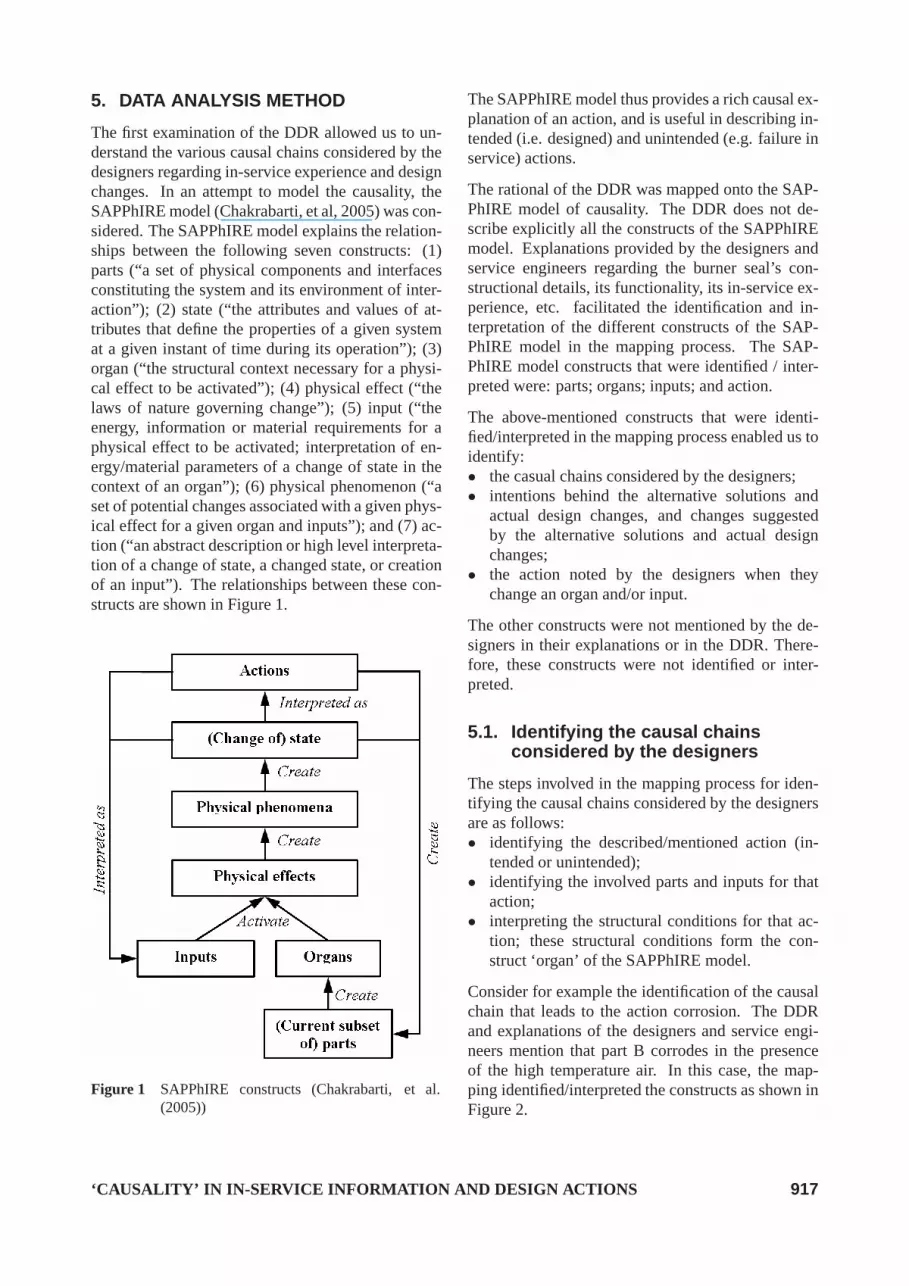
The first examination of the DDR allowed us to un-derstand the various causal chains considered by thedesigners regarding in-service experience and designchanges. In an attempt to model the causality, theSAPPhIRE model (Chakrabarti, et al, 2005) was con-sidered. The SAPPhIRE model explains the relation-ships between the following seven constructs: (1)parts (“a set of physical components and interfacesconstituting the system and its environment of inter-action”); (2) state (“the attributes and values of at-tributes that define the properties of a given systemat a given instant of time during its operation”); (3)organ (“the structural context necessary for a physi-cal effect to be activated”); (4) physical effect (“thelaws of nature governing change”); (5) input (“theenergy, information or material requirements for aphysical effect to be activated; interpretation of en-ergy/material parameters of a change of state in thecontext of an organ”); (6) physical phenomenon (“aset of potential changes associated with a given phys-ical effect for a given organ and inputs”); and (7) ac-tion (“an abstract description or high level interpreta-tion of a change of state, a changed state, or creationof an input”). The relationships between these con-structs are shown in Figure 1.
Figure 1 SAPPhIRE constructs (Chakrabarti, et al.(2005))
The SAPPhIRE model thus provides a rich causal ex-planation of an action, and is useful in describing in-tended (i.e. designed) and unintended (e.g. failure inservice) actions.
The rational of the DDR was mapped onto the SAP-PhIRE model of causality. The DDR does not de-scribe explicitly all the constructs of the SAPPhIREmodel. Explanations provided by the designers andservice engineers regarding the burner seal’s con-structional details, its functionality, its in-service ex-perience, etc. facilitated the identification and in-terpretation of the different constructs of the SAP-PhIRE model in the mapping process. The SAP-PhIRE model constructs that were identified / inter-preted were: parts; organs; inputs; and action.
The above-mentioned constructs that were identi-fied/interpreted in the mapping process enabled us toidentify:• the casual chains considered by the designers;• intentions behind the alternative solutions and
actual design changes, and changes suggestedby the alternative solutions and actual designchanges;
• the action noted by the designers when theychange an organ and/or input.
The other constructs were not mentioned by the de-signers in their explanations or in the DDR. There-fore, these constructs were not identified or inter-preted.
5.1. Identifying the causal chainsconsidered by the designers
The steps involved in the mapping process for iden-tifying the causal chains considered by the designersare as follows:• identifying the described/mentioned action (in-
tended or unintended);• identifying the involved parts and inputs for that
action;• interpreting the structural conditions for that ac-
tion; these structural conditions form the con-struct ‘organ’ of the SAPPhIRE model.
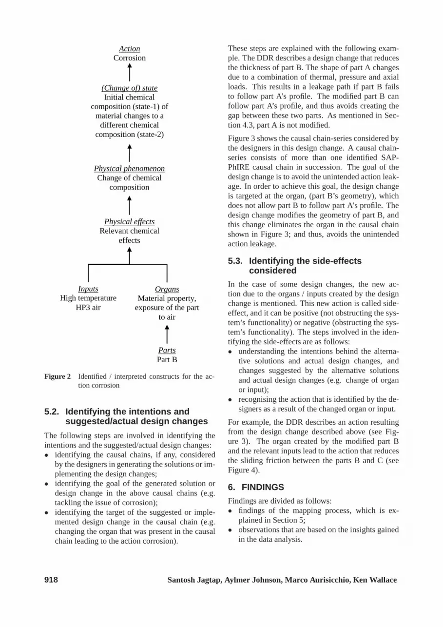
Consider for example the identification of the causalchain that leads to the action corrosion. The DDRand explanations of the designers and service engi-neers mention that part B corrodes in the presenceof the high temperature air. In this case, the map-ping identified/interpreted the constructs as shown inFigure 2.
‘CAUSALITY’ IN IN-SERVICE INFORMATION AND DESIGN ACTIONS 917
Parts Part B
Inputs High temperature
HP3 air
Organs Material property,
exposure of the part to air
Physical effects Relevant chemical
effects
Action Corrosion
Physical phenomenon Change of chemical
composition
(Change of) state Initial chemical
composition (state-1) of material changes to a
different chemical composition (state-2)
Figure 2 Identified / interpreted constructs for the ac-tion corrosion
5.2. Identifying the intentions andsuggested/actual design changes
The following steps are involved in identifying theintentions and the suggested/actual design changes:• identifying the causal chains, if any, considered
by the designers in generating the solutions or im-plementing the design changes;
• identifying the goal of the generated solution ordesign change in the above causal chains (e.g.tackling the issue of corrosion);
• identifying the target of the suggested or imple-mented design change in the causal chain (e.g.changing the organ that was present in the causalchain leading to the action corrosion).
These steps are explained with the following exam-ple. The DDR describes a design change that reducesthe thickness of part B. The shape of part A changesdue to a combination of thermal, pressure and axialloads. This results in a leakage path if part B failsto follow part A’s profile. The modified part B canfollow part A’s profile, and thus avoids creating thegap between these two parts. As mentioned in Sec-tion 4.3, part A is not modified.
Figure 3 shows the causal chain-series considered bythe designers in this design change. A causal chain-series consists of more than one identified SAP-PhIRE causal chain in succession. The goal of thedesign change is to avoid the unintended action leak-age. In order to achieve this goal, the design changeis targeted at the organ, (part B’s geometry), whichdoes not allow part B to follow part A’s profile. Thedesign change modifies the geometry of part B, andthis change eliminates the organ in the causal chainshown in Figure 3; and thus, avoids the unintendedaction leakage.
5.3. Identifying the side-effectsconsidered
In the case of some design changes, the new ac-tion due to the organs / inputs created by the designchange is mentioned. This new action is called side-effect, and it can be positive (not obstructing the sys-tem’s functionality) or negative (obstructing the sys-tem’s functionality). The steps involved in the iden-tifying the side-effects are as follows:• understanding the intentions behind the alterna-
tive solutions and actual design changes, andchanges suggested by the alternative solutionsand actual design changes (e.g. change of organor input);
• recognising the action that is identified by the de-signers as a result of the changed organ or input.
For example, the DDR describes an action resultingfrom the design change described above (see Fig-ure 3). The organ created by the modified part Band the relevant inputs lead to the action that reducesthe sliding friction between the parts B and C (seeFigure 4).
6. FINDINGS
Findings are divided as follows:• findings of the mapping process, which is ex-
plained in Section 5;• observations that are based on the insights gained
in the data analysis.
918 Santosh Jagtap, Aylmer Johnson, Marco Aurisicchio, Ken Wallace

Parts Part A with its shape
changed and part B
Inputs Air
Organs Gap between parts A and B
Action Leakage
Intention behind the design change is to avoid the unintended action leakage.
The design change is targeted at eliminating the organ that is created by part B’s failure to follow part A’s profile, and lead to the unintended action leakage.
Physical effects
Relevant laws of fluid mechanics
Physical phenomenon
Air flows through the
gap geometry
(Change of) state No air flow (state-
1), air flows through the gap
(state-2)
Parts Part A
Inputs Thermal, pressure,
and axial loads Physical effects
Stress-strain laws
Physical phenomenon Change of part A’s geometry
(Change of) state Initial shape
(state-1) of part A changes to a
different shape (state-2)
Organs Part A’s material and geometry, its
interface with other components
Action Shape
change of part A
Figure 3 Causal chain-series considered by the designers in generating a solution
Parts Part C and modified part B
Inputs Force exerted due to the relative motion between
the COC and CSC
Organs Interface between the
modified parts B and C
Physical effects Newtonian laws of motion, friction effect
Action Reduction in sliding friction between parts B and C
Physical phenomenon Relative motion between the parts B and C
(Change of) state Parts B and C at rest (state 1), parts B and C in relative
motion (state 2)
Figure 4 Identification of creation of an action due tothe organs / inputs created by a design change
6.1. Findings of the mapping process
The causal chains and causal chain-series have beenidentified in the ‘specification requirements’ sectionof the DDR. From the description of the ‘alternativesolutions’ section, the intention behind the alterna-tive solutions has been identified (e.g. reduce wear).In addition, design change suggested by the descrip-tion of the alternative solutions is noted. Similarly,in the case of ‘solution description’ section, the in-tention of the design changes and the actual designchanges were identified.
Specification requirements section
Two causal chains of unintended actions are notedin this section of the DDR. Five causal chain-seriesare noticed after mapping the DDR’s description overthe SAPPhIRE model of causality, for example, ox-ide particles created by the corrosion of the part Bexacerbate the wear of the part C’s features.
Alternative solutions section
This section provides the description of the vari-ous alternatives solutions generated by the designers.
‘CAUSALITY’ IN IN-SERVICE INFORMATION AND DESIGN ACTIONS 919
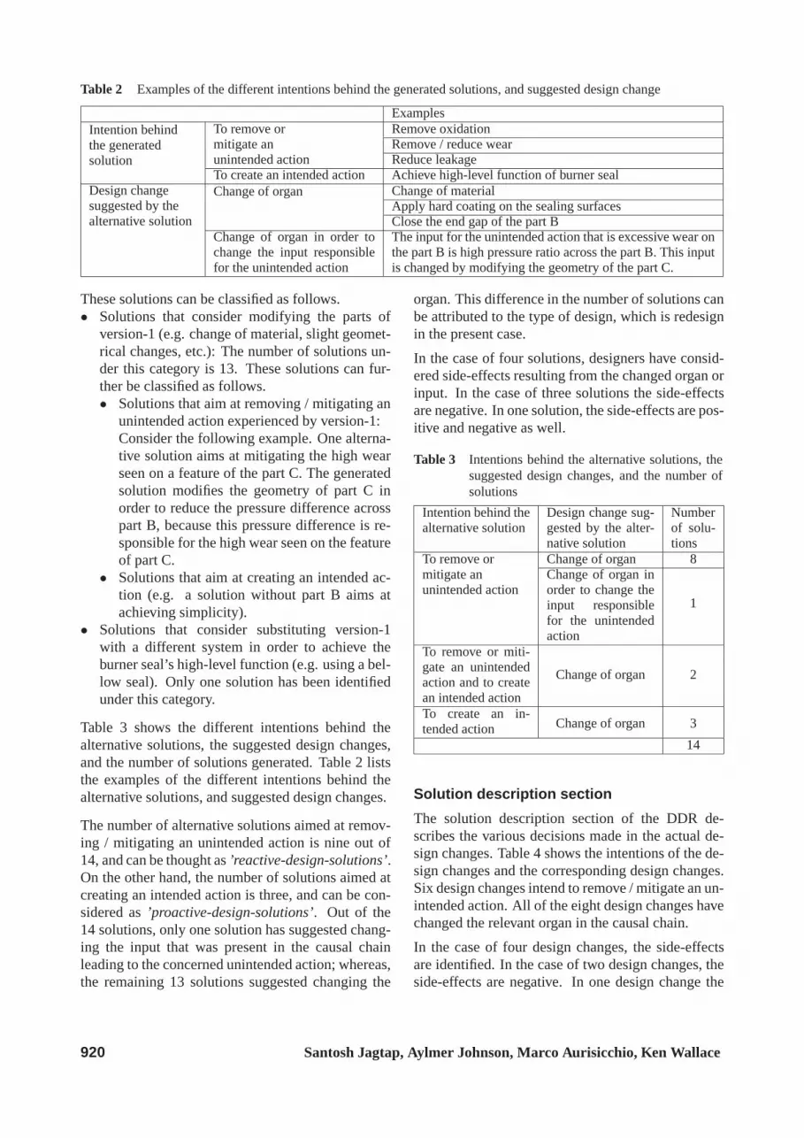
Table 2 Examples of the different intentions behind the generated solutions, and suggested design change
ExamplesIntention behindthe generatedsolution
To remove ormitigate anunintended action
Remove oxidationRemove / reduce wearReduce leakage
To create an intended action Achieve high-level function of burner sealDesign changesuggested by thealternative solution
Change of organ Change of materialApply hard coating on the sealing surfacesClose the end gap of the part B
Change of organ in order tochange the input responsiblefor the unintended action
The input for the unintended action that is excessive wear onthe part B is high pressure ratio across the part B. This inputis changed by modifying the geometry of the part C.
These solutions can be classified as follows.• Solutions that consider modifying the parts of
version-1 (e.g. change of material, slight geomet-rical changes, etc.): The number of solutions un-der this category is 13. These solutions can fur-ther be classified as follows.• Solutions that aim at removing / mitigating an
unintended action experienced by version-1:Consider the following example. One alterna-tive solution aims at mitigating the high wearseen on a feature of the part C. The generatedsolution modifies the geometry of part C inorder to reduce the pressure difference acrosspart B, because this pressure difference is re-sponsible for the high wear seen on the featureof part C.
• Solutions that aim at creating an intended ac-tion (e.g. a solution without part B aims atachieving simplicity).
• Solutions that consider substituting version-1with a different system in order to achieve theburner seal’s high-level function (e.g. using a bel-low seal). Only one solution has been identifiedunder this category.
Table 3 shows the different intentions behind thealternative solutions, the suggested design changes,and the number of solutions generated. Table 2 liststhe examples of the different intentions behind thealternative solutions, and suggested design changes.
The number of alternative solutions aimed at remov-ing / mitigating an unintended action is nine out of14, and can be thought as’reactive-design-solutions’.On the other hand, the number of solutions aimed atcreating an intended action is three, and can be con-sidered as’proactive-design-solutions’. Out of the14 solutions, only one solution has suggested chang-ing the input that was present in the causal chainleading to the concerned unintended action; whereas,the remaining 13 solutions suggested changing the
organ. This difference in the number of solutions canbe attributed to the type of design, which is redesignin the present case.
In the case of four solutions, designers have consid-ered side-effects resulting from the changed organ orinput. In the case of three solutions the side-effectsare negative. In one solution, the side-effects are pos-itive and negative as well.
Table 3 Intentions behind the alternative solutions, thesuggested design changes, and the number ofsolutions
Intention behind thealternative solution
Design change sug-gested by the alter-native solution
Numberof solu-tions
To remove ormitigate anunintended action
Change of organ 8Change of organ inorder to change theinput responsiblefor the unintendedaction
1
To remove or miti-gate an unintendedaction and to createan intended action
Change of organ 2
To create an in-tended action Change of organ 3
14
Solution description section
The solution description section of the DDR de-scribes the various decisions made in the actual de-sign changes. Table 4 shows the intentions of the de-sign changes and the corresponding design changes.Six design changes intend to remove / mitigate an un-intended action. All of the eight design changes havechanged the relevant organ in the causal chain.
In the case of four design changes, the side-effectsare identified. In the case of two design changes, theside-effects are negative. In one design change the
920 Santosh Jagtap, Aylmer Johnson, Marco Aurisicchio, Ken Wallace
Wear, corrosion of the different parts of the burner seal
Increase in the leakage path
Air leakage
Increase in control system’s wiring temperature
Increase in specific fuel consumption (SFC)
Operation of the long-haul flights is less cost-effective
Risk of customer disruption
Target of the formulated requirements
Figure 5 Target of the formulated requirements in the broader causalchain
Table 4 Intentions behind the design changes and theimplemented design change
Intention of the designchange
Actual designchange
Numberof designchanges
To remove / mitigatean unintended action
Change oforgan 6
To create an intendedaction
Change oforgan 2
side-effect is positive, and remaining design changehas positive and negative side-effects.
6.2. Observations
In addition to the mapping of the DDR’s descrip-tion and designers’ and service engineers’ explana-tions over the SAPPhIRE model, the insights gainedthrough the data analysis allowed us to make severalobservations. These observations can be divided asfollows:• in-service information and requirements formula-
tion;• designers’ actions regarding causal chains;• development of the SAPPhIRE model.
In-service information and requirementsformulation
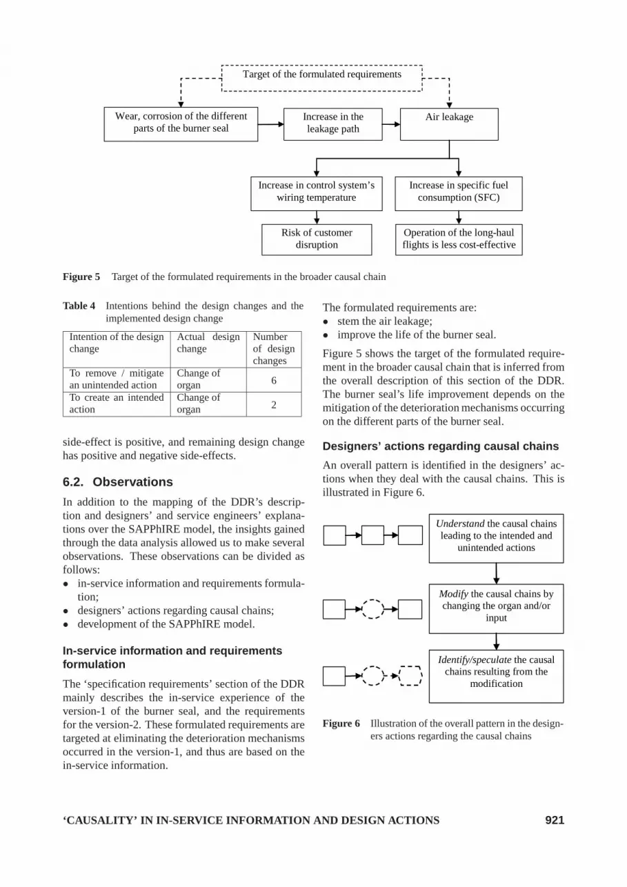
The ‘specification requirements’ section of the DDRmainly describes the in-service experience of theversion-1 of the burner seal, and the requirementsfor the version-2. These formulated requirements aretargeted at eliminating the deterioration mechanismsoccurred in the version-1, and thus are based on thein-service information.
The formulated requirements are:• stem the air leakage;• improve the life of the burner seal.
Figure 5 shows the target of the formulated require-ment in the broader causal chain that is inferred fromthe overall description of this section of the DDR.The burner seal’s life improvement depends on themitigation of the deterioration mechanisms occurringon the different parts of the burner seal.
Designers’ actions regarding causal chains
An overall pattern is identified in the designers’ ac-tions when they deal with the causal chains. This isillustrated in Figure 6.
Understand the causal chains leading to the intended and
unintended actions
Modify the causal chains by changing the organ and/or
input
Identify/speculate the causal chains resulting from the
modification
Figure 6 Illustration of the overall pattern in the design-ers actions regarding the causal chains
‘CAUSALITY’ IN IN-SERVICE INFORMATION AND DESIGN ACTIONS 921

Understanding the causal chains:
The in-service information that is considered consistsof several causal chains and causal chain-series. Therequirements are formulated based on these causalchains and causal-chain series. Figure 2 in Sec-tion 5.1 shows an example of a causal chain leadingto the action corrosion. These causal chains consistof the relevant parts, structural conditions and inputsthat are necessary to lead to the relevant deteriora-tion mechanisms. It means that the designers haveprimarily considered the physical phenomena.
In addition to these physical phenomena, they havetaken into account business aspects. For example, in-formation regarding the impact of the causal chainson the customer’s operation has been taken into ac-count (e.g. the increase in SFC over several monthshas been attributed to the air leakage, and long-haulflights have become less cost-effective due to this in-crease).
Modifying the causal chains:
The designers have generated several solutions thatutilise the causal chains. Those causal chains thatlead to deterioration mechanisms provide the un-derstanding of the necessary inputs and the struc-tural conditions necessary for the deterioration mech-anism to occur. The designers have generated severalsolutions that attempt to eliminate these conditions,whilst maintaining those conditions that are essentialfor the actions required to achieve the desired func-tionality of the system. In order to identify the failuremechanisms, it is necessary to understand the func-tionality of the system. The failure mechanisms arethose actions that obstruct the system’s functionality.The designers utilise the causal chains that lead to theunintended actions and also those chains that achievethe functionality of the system. Figure 3 in Sec-tion 5.2 shows an example of a causal chain-seriesconsidered by the designers in generating a solution.In this example, the designers changed the organ thatis created by part B’s failure to follow part A’s profile,and so leads to the unintended action ‘leakage’.
Identifying/speculating the emerging causalchains:
In the case of some solutions, the designers havemodified the causal chains leading to the deterio-ration mechanisms either by changing the organ orthe input. These changes can activate other actionsthat can be either desirable or undesirable. The de-signers have identified or anticipated these causalchains emerging from the proposed solutions or de-
sign changes. Figure 4 in Section 5.3, shows an ex-ample of the identification of a causal chain leadingto an action due to the organs / inputs created by adesign change.
Development of the SAPPhIRE model:
We suggest the following developments in theChakrabarti et al’s (2005) SAPPhIRE model ofcausality:• partscreate/embody organs;• inputscreate stimuli;• actionscreate/affect parts.
Parts create/embody organs:
We believe that parts create organs when the struc-tural context is formed by the relation between thedifferent parts or different aspects of a part when theyare not embodied in the part. For example, in thecausal chain that leads to the wear (action) of partB, the organ is created by the relation between partsB and C. We use the relationship ‘embody’ when theorgan is embodied in the parts. Consider for examplethe corrosion (action) of part B. In this example, oneof the structural contexts is part B’s material propertyto corrode under the relevant inputs. This materialproperty is embodied in the rings.
Inputs create stimuli:
Chakrabarti et al. (2005) define the construct ‘organ’which is “the structural context necessary for a phys-ical effect to be activated”. This organ is createdby parts. Here, we asked a question: if there is astructural condition created by the parts, why cannotwe consider a condition that is created by the inputsfor the activation of the relevant physical effect? Inthe case study, reported in this paper, we identifiedevidence that supports the necessity of a constructregarding the condition on the ‘inputs’ for the acti-vation of the physical effect. We call this construct‘stimuli’. We define ‘stimuli’ as “input context nec-essary for a physical effect to be activated in the pres-ence of the relevant organs”. Different aspects of aninput (e.g. measure of input’s attribute) and/or rela-tionships between inputs create stimuli. Consider thefollowing example. As mentioned in Section 4.2, in-creased air leakage from the burner seal can increasethe temperature of the control system’s wiring. Thereis a potential risk of customer disruption when thetemperature in the control system’s wiring reaches aparticular value. This indicates that in the presenceof the appropriate organs, a relevant physical effectwill get activated when the attribute ‘temperature’ of
922 Santosh Jagtap, Aylmer Johnson, Marco Aurisicchio, Ken Wallace

the input ‘thermal energy’ attains a particular valueor measure.
Actions create/affect parts:
When an action creates parts, we use the relation-ship ‘create’; whereas, when an action has effectson parts, we employ the relationship ‘affect’. Forexample, the corrosion (action)creates oxide parti-cles, which can be considered as ‘parts’ at an abstractlevel, andaffects the rings (parts) by damaging rings’surfaces.
Thus, in addition to the constructs devised byChakrabarti et al. (2005), we conceived the construct– ‘stimuli’. We devised the additional relationships:embody andaffect. The developed SAPPhIRE modelis shown in Figure 7. The developed model is called‘Sym-SAPPhIRE’ model of causality as it appearssymmetrical about the vertical axis (‘Sym’ stands for‘symmetrical’).
Figure 7 Sym-SAPPhIRE model of causality
7. CONCLUSIONSThis paper explores an aspect of design for servicewhich is closely connected to the design of a product:in this case, an aero engine. In particular, the useof in-service information in improving a product hasbeen investigated.
The application of the SAPPhIRE model was use-ful in understanding the causal chains considered bythe designers who re-designed the burner seal. Thein-service experience of version-1 is employed to in-
fer requirements for version-2. This in-service expe-rience mainly contains the unintended actions seenon version-1 and the causal chains of these unin-tended actions. A pattern has been identified in thedesigners’ actions regarding the causal chains. Thecausal chains responsible for the unintended actionswere used by the designers in generating solutions.It would be useful to present the relevant in-serviceinformation to the designers in the form of rich anddetailed causal chains of intended and unintendedactions, and broader causal chains as well. Thesebroader causal chains might allow the designers togain a more holistic view, and prevent them from be-ing overwhelmed by the detailed causal chains.
The designers have noted new actions due to the or-gans/inputs created by the design changes. When adesigner changes an organ or input to create an in-tended action or to remove/ mitigate an unintendedaction, a method or tool that can prompt the designerof all the possible actions (intended and unintended)that the change might lead to, would be useful. Sucha method or tool can highlight pros (when an in-tended action is created) and cons (when an unin-tended action is created) of the design change.
Furthermore, the insights gained through the studyallowed us to contribute towards the development ofthe SAPPhIRE model.
The above findings are based on the analysis of onlyone case study, so may not be fully representative.Furthermore, it is worth noting that the findings aremainly based on the analysis of the description of theDDR, which is created retrospectively after complet-ing the design task. In order to confirm these find-ings, further case studies may need to be conducted,covering a greater variety of designed components.
ACKNOWLEDGMENT
The authors acknowledge the support of DTI, Rolls-Royce plc through the UTP for Design, and wouldparticularly like to thank Colin Cadas, David Knott,and the participating designers and service engineers.
REFERENCES
Alonso-Rasgado, T., Thompson, G., Elfstrom, B.,2004, “The Design of Functional (Total Care)Products”, Journal of Engineering Design, 15(4),pp. 515–540.
Bell, J., 2004, “Representation of Function”, Univer-sity of Wales, Aberystwyth, UK.
Brombacher, A. C., Steinz, H. C., Volman, H. P.
‘CAUSALITY’ IN IN-SERVICE INFORMATION AND DESIGN ACTIONS 923

J., 1998, “Safety and Reliability Assessment onProducts and Organizations”, The InternationalConference and Exposition for Advancing Mea-surement and Control Technologies, Products andServices, Williamsburg, Pennsylvania.
Chakrabarti, A., 1993, “Towards A Theory for Func-tional Reasoning in Design”, International Con-ference on Engineering Design, ICED’93, TheHague.
Chakrabarti, A., Johnson, A., 1993, “Detecting SideEffects in Solution Principles”, International Con-ference on Engineering Design, ICED’99, Mu-nich.
Chakrabarti, A., Sarkar, P., Leelavathamma, B., andNataraju, B. S., 2005, “A Functional Representa-tion for Aiding Biomimetic and Artificial Inspira-tion of New Ideas”, Artificial Intelligence in En-gineering Design and Manufacturing, AI EDAM,19(2), pp. 113–132.
Chandrasekaran, B., Josephson, J. R., 1997, “Repre-senting Function as Effect”, Proceedings of Func-tional Modeling Workshop, Electricite de France,Paris, France.
Gagg, C. R., Lewis, P. R., 2007, “Wear as a ProductFailure Mechanism - Overview and Case Stud-ies”, Engineering Failure Analysis, 14(8), pp.1618–1640.
Harrison, A., 2006, “Design for Service - Harmon-ising product design with a Services Strategy”,ASME Turbo Expo 2006: Power for Land, Seaand Air, Barcelona, Spain.
Hubka, V., 1982, “Principles of Engineering De-sign”, Butterworth Scientific.
Jagtap, S., Johnson, A., Aurisicchio, M., Wallace, K.,2006, “How In-Service Experience Informs De-sign Modifications: A Case Study in Aero En-gines”, International Conference On Trends inProduct Life Cycle, Modeling, Simulation andSynthesis, PLMSS-2006, Bangalore, India.
Jagtap, S., Johnson, A., Aurisicchio, M., Wallace,K., 2007a, “In-Service Information Flows to De-signers”, International Conference on Engineer-ing Design, ICED’07, Paris, France.
Jagtap, S., Johnson, A., Aurisicchio, M., Wallace, K.,2007b, “In-Service Information Required By En-gineering Designers”, International Conferenceon Engineering Design, ICED’07, Paris, France.
Kirkland, F., Cave, R., 1999, “Design Issues forAeroengines”, Life Assessment of Hot Section
Gas Turbine Components: Proceedings of a Con-ference Held at Heriot Watt University, Edin-burgh, UK, 1–10.
Lannoy, A., Procaccia, H., 1996, “The EDF Fail-ure Reporting System Process, Presentation andProspects”, Reliability Engineering and SystemSafety, 51(2), pp. 147–158.
MacGregor, W., 2003, “Failure and Redesign of aPressurised Circulating Fluidized Bed and Cy-clone”, Engineering Failure Analysis, 10(4), pp.503–509.
Markeset, T., Kumar, U., 2003, “Integration ofRAMS and Risk Analysis in Product Design andDevelopment Work Processes: A Case Study”,Journal of Quality in Maintenance Engineering,9(4), pp. 393–410.
Pahl, G., Beitz, W., 1996, “Engineering Design, K.M. Wallace, translator”, Springer-Verlag, Lon-don.
Petkova, V. T., 2003, “An Analysis of Field Feedbackin Consumer Electronics Industry”, Ph.D., Eind-hoven University of Technology.
Sander, P. C., Brombacher, A. C., 2000, “Analysisof Quality Information Flows in the Product Cre-ation Process of High-Volume Consumer Prod-ucts”, Int. J. Production Economics, 67(1), pp.37–52.
Sembugamoorthy, Chandrasekaran, B., 1986, “Func-tional Representation of Devices and Compilationof Diagnostic Problem-Solving Systems”, Expe-rience, Memory and Reasoning, Lawrence Erl-baum Associates, Hillsdale, NJ.
Sivaprasad, S., Narang, S. K., Singh, R., 2006, “Fail-ure of High Pressure Ammonia Line in a Fertil-izer Plant - A Case Study”, Engineering FailureAnalysis, 13(6), pp. 867–875.
Smith, M., Fisher, F., Romios, M., Es-Said, O.S., 2007, “On the Redesign of a Shear Pin un-der Cyclic Bending Loads.” Engineering FailureAnalysis, 14(1), pp. 138–146.
Thompson, G., 1999, “Improving Maintainabilityand Reliability through Design”, Professional En-gineering Publishing, UK.
924 Santosh Jagtap, Aylmer Johnson, Marco Aurisicchio, Ken Wallace