catalogue 5 stauff quick release couplings
TRANSCRIPT
Catalogue 5STAUFF Quick Release Couplings
Push-to-Connect Couplings
Screw-to-Connect Couplings
Multi Couplings
Please note: Unless otherwise stated, all data and figures in this product catalogue are approximate values and are only valid as references, which are not binding (also in respect to any third parties’ rights of protection) and thus do not release the customer / user from checking and testing the suitability of the products for the foreseen purposes. Therefore, data and figures can only be used in a limited sense for construction purposes.
The application of the products is beyond the control possibilities of the manufacturer and, therefore, is exclusively subject to the responsibility of the customer / user.
In the event that a liability is nevertheless considered, any compensation will be limited to the value of the goods supplied by the manufacturer and used by the customer / user. As a matter of course, the manufacturer guarantees the perfect quality of all products in accordance with the General Terms and Conditions of Business and Sale.
Subject to modifications due to the ongoing development and improvement of the products.
With the publication of this product catalogue, previous editions are no longer valid.
Germany Walter Stauffenberg GmbH & Co. KGIm Ehrenfeld 458791 Werdohl Tel.: +49 2392 91 60Fax: +49 2392 91 61 03E-Mail: [email protected]
STAUFF products and services are globally available through wholly-owned subsidiaries and a tight network of authorised distributors and representatives in all major industrial regions of the world. You can find detailed contact information on the last two pages of this product catalogue or at www.stauff.com.
MK
FF/FU
FH
UX
FO
HP/HU
IA
IB
HC
HD
HS
RH/RK
FT
HR
HI
HT
HM
HV
PS
BP
ID
www.stauff.com/5/en/#3 3Catalogue 5 § Edition 08/2019
Introduction
4 - 11Introduction
21 - 32
29 - 31
33 - 36
37 - 40
41 - 52
53 - 56
57 - 62
63 - 68
69 - 74
75 - 80
81 - 86
87 - 90
91 - 94
95 - 98
99 - 102
Push-to-Connect Couplings
107 - 111MK Series § Multicoupling System, Flat Face Coupling
113 - 124
125 - 130
131 - 134
135 - 140
141 - 146
147 - 152
153 - 158
159 - 164
165 - 168
169 - 172
173 - 176
177 - 181
183 - 185Special Applications
187 - 191Spare Parts / Accessories
193 - 195Technical Appendix
197 - 203Appendix (Product-Specific Abbreviations / Global Contact Directory)
Screw-to-Connect Couplings
Multi Couplings
FF/FH Series § Flat Face Coupling acc. to ISO 16028
FH Series § Flat Face Coupling acc. to ISO 16028, Stainless Steel
FU Series § Flat Face Coupling acc. to ISO 16028, Connect Under Pressure
UX Series § ISO 7241-1, Series A, Push-Pull, Connect Under Pressure
FO Series § Flat Face Coupling, Stainless Steel
HP Series § ISO 7241-1, Series A, Push-Pull
IA Series § ISO 7241-1, Series A
IA Series § ISO 7241-1, Series A, Stainless Steel
IB Series § ISO 7241-1, Series B
IB Series § ISO 7241-1, Series B, Brass
IB Series § ISO 7241-1, Series B, Stainless Steel
ID Series
BP Series § ISO 5676
HC Series § Flat Face Coupling
HD Series § Flat Face Coupling
12 - 19Overview (Product Overview / Structure of the Part Numbers)
HS Series § ISO 14541
HS Series § ISO 14541, Stainless Steel
PS Series § For Hammer Application
RH/RK Series § Flat Face Coupling, Pipeline Coupling
FT Series § Flat Face Coupling, Connect Under Pressure
HH Series
HH Series § Stainless Steel
HI (HIB) Series § ISO 14540
HT Series § Wing Style
HM Series § Wing Style
HV Series § Wing Style
HR Series
HH
103 - 105 HUSHUS Series
HU Series § ISO 7241-1, Series A, Push-Pull, Connect Under Pressure 49
4 www.stauff.com/5/en/#4Catalogue 5 § Edition 08/2019
Introduction
Catalogue 1 STAUFF Clamps
Catalogue 2 STAUFF Connect
Catalogue 3 STAUFF Flanges
Catalogue 4 STAUFF Hose Connectors
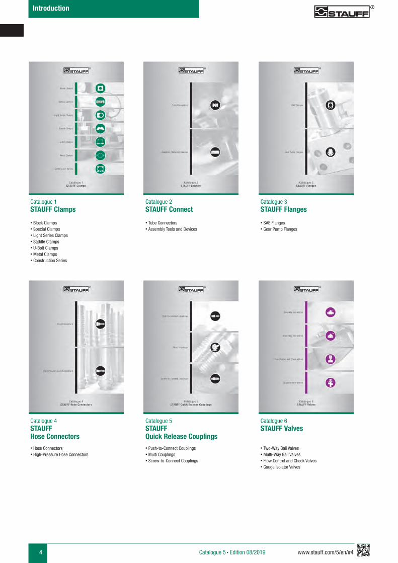
Catalogue 5 STAUFF Quick Release Couplings
Catalogue 6 STAUFF Valves
§ Block Clamps§ Special Clamps§ Light Series Clamps§ Saddle Clamps§ U-Bolt Clamps§ Metal Clamps§ Construction Series
§ Tube Connectors§ Assembly Tools and Devices
§ SAE Flanges§ Gear Pump Flanges
§ Hose Connectors§ High-Pressure Hose Connectors
§ Push-to-Connect Couplings§ Multi Couplings § Screw-to-Connect Couplings
§ Two-Way Ball Valves§ Multi-Way Ball Valves§ Flow Control and Check Valves§ Gauge Isolator Valves
www.stauff.com/5/en/#5 5Catalogue 5 § Edition 08/2019
Introduction
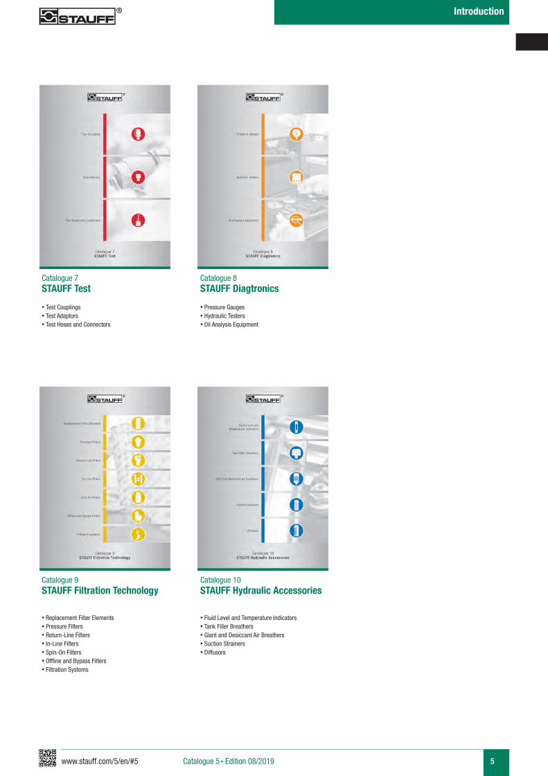
Catalogue 7 STAUFF Test
Catalogue 8 STAUFF Diagtronics
Catalogue 9 STAUFF Filtration Technology
Catalogue 10 STAUFF Hydraulic Accessories
§ Test Couplings § Test Adaptors§ Test Hoses and Connectors
§ Pressure Gauges§ Hydraulic Testers§ Oil Analysis Equipment
§ Replacement Filter Elements§ Pressure Filters§ Return-Line Filters§ In-Line Filters§ Spin-On Filters§ Offline and Bypass Filters§ Filtration Systems
§ Fluid Level and Temperature Indicators§ Tank Filler Breathers§ Giant and Desiccant Air Breathers§ Suction Strainers§ Diffusors
6 www.stauff.com/5/en/#6
Introduction
Catalogue 5 § Edition 08/2019
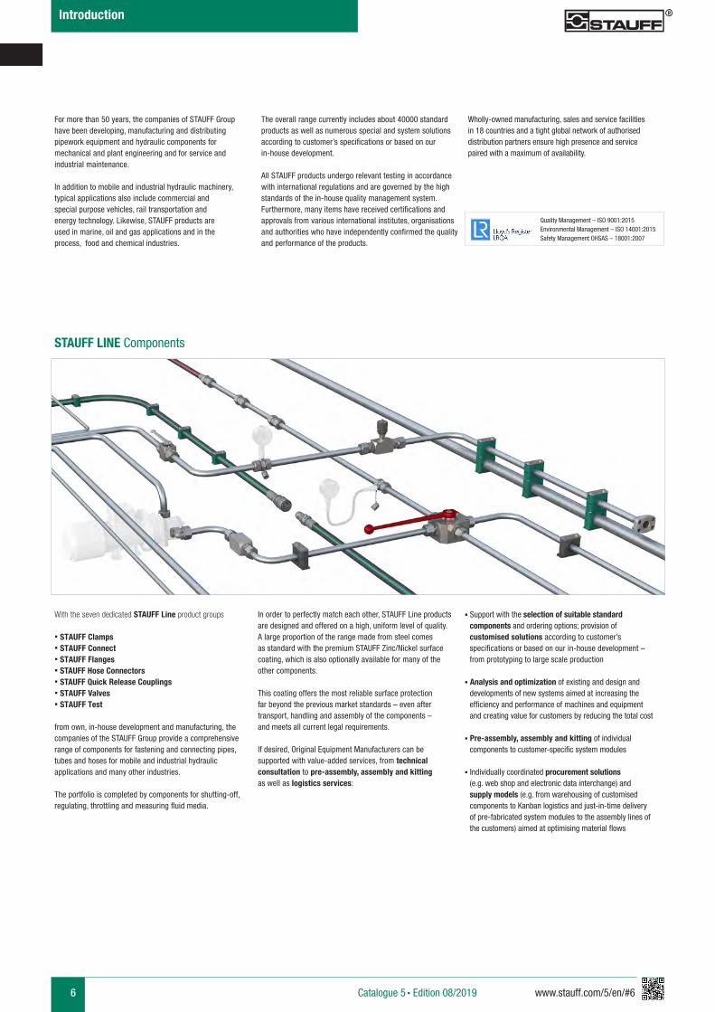
STAUFF LINE Components
With the seven dedicated STAUFF Line product groups
§ STAUFF Clamps§ STAUFF Connect§ STAUFF Flanges§ STAUFF Hose Connectors§ STAUFF Quick Release Couplings § STAUFF Valves § STAUFF Test
from own, in-house development and manufacturing, the companies of the STAUFF Group provide a comprehensive range of components for fastening and connecting pipes, tubes and hoses for mobile and industrial hydraulic applications and many other industries.
The portfolio is completed by components for shutting-off, regulating, throttling and measuring fluid media.
For more than 50 years, the companies of STAUFF Group have been developing, manufacturing and distributing pipework equipment and hydraulic components for mechanical and plant engineering and for service and industrial maintenance.
In addition to mobile and industrial hydraulic machinery, typical applications also include commercial and special purpose vehicles, rail transportation and energy technology. Likewise, STAUFF products are used in marine, oil and gas applications and in the process, food and chemical industries.
The overall range currently includes about 40000 standard products as well as numerous special and system solutions according to customer’s specifications or based on our in-house development.
All STAUFF products undergo relevant testing in accordance with international regulations and are governed by the high standards of the in-house quality management system. Furthermore, many items have received certifications and approvals from various international institutes, organisations and authorities who have independently confirmed the quality and performance of the products.
Wholly-owned manufacturing, sales and service facilities in 18 countries and a tight global network of authorised distribution partners ensure high presence and service paired with a maximum of availability.
In order to perfectly match each other, STAUFF Line products are designed and offered on a high, uniform level of quality. A large proportion of the range made from steel comes as standard with the premium STAUFF Zinc/Nickel surface coating, which is also optionally available for many of the other components.
This coating offers the most reliable surface protection far beyond the previous market standards – even after transport, handling and assembly of the components – and meets all current legal requirements.
If desired, Original Equipment Manufacturers can be supported with value-added services, from technical consultation to pre-assembly, assembly and kitting as well as logistics services:
§ Support with the selection of suitable standard components and ordering options; provision of
customised solutions according to customer’s specifications or based on our in-house development – from prototyping to large scale production
§ Analysis and optimization of existing and design and developments of new systems aimed at increasing the efficiency and performance of machines and equipment
and creating value for customers by reducing the total cost
§ Pre-assembly, assembly and kitting of individual components to customer-specific system modules
§ Individually coordinated procurement solutions (e.g. web shop and electronic data interchange) and supply models (e.g. from warehousing of customised
components to Kanban logistics and just-in-time delivery of pre-fabricated system modules to the assembly lines of the customers) aimed at optimising material flows
Quality Management – ISO 9001:2015 Environmental Management – ISO 14001:2015 Safety Management OHSAS – 18001:2007
www.stauff.com/5/en/#7 7
Introduction
Catalogue 5 § Edition 08/2019
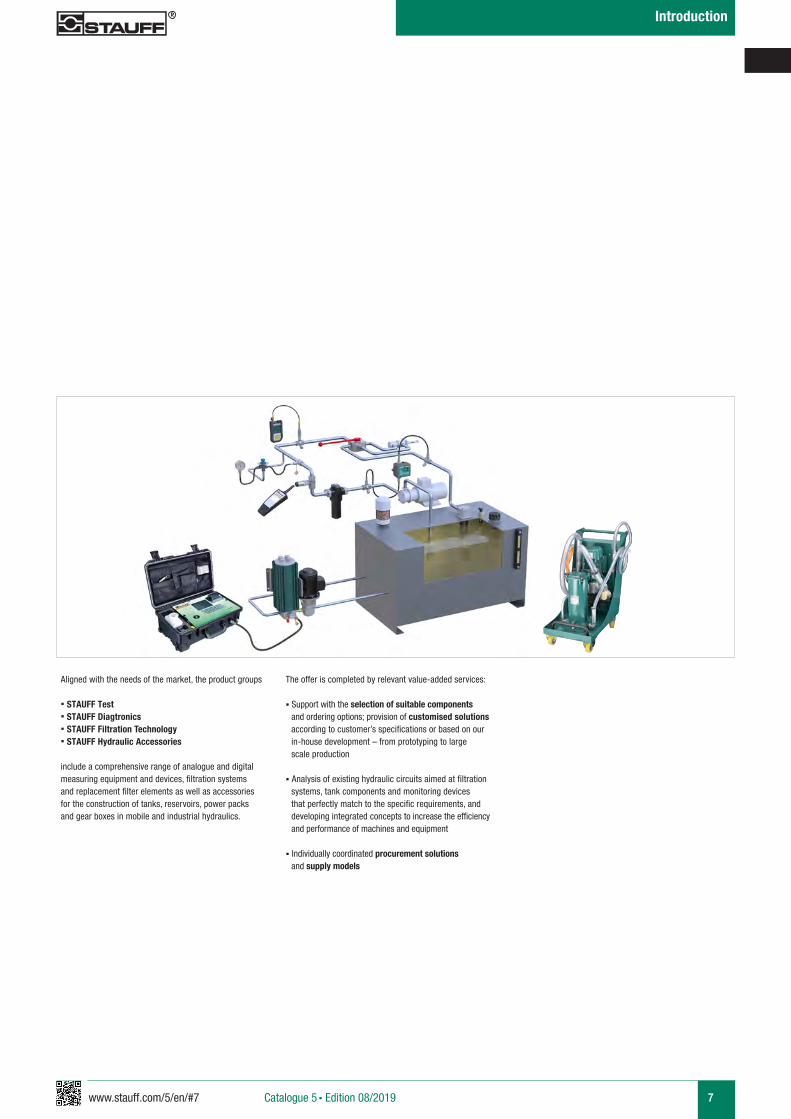
Aligned with the needs of the market, the product groups
§ STAUFF Test§ STAUFF Diagtronics§ STAUFF Filtration Technology§ STAUFF Hydraulic Accessories
include a comprehensive range of analogue and digital measuring equipment and devices, filtration systems and replacement filter elements as well as accessories for the construction of tanks, reservoirs, power packs and gear boxes in mobile and industrial hydraulics.
The offer is completed by relevant value-added services:
§ Support with the selection of suitable components and ordering options; provision of customised solutions according to customer’s specifications or based on our in-house development – from prototyping to large scale production
§ Analysis of existing hydraulic circuits aimed at filtration systems, tank components and monitoring devices that perfectly match to the specific requirements, and developing integrated concepts to increase the efficiency and performance of machines and equipment
§ Individually coordinated procurement solutions and supply models
8 www.stauff.com/5/en/#8
Introduction
Catalogue 5 § Edition 08/2019
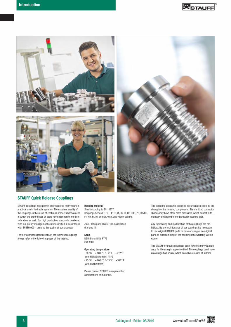
STAUFF Quick Release Couplings
STAUFF couplings have proven their value for many years in practical use in hydraulic systems. The excellent quality of the couplings is the result of continual product improvement in which the experiences of users have been taken into con-sideration, as well. Our high production standards, combined with our quality management system certified in accordance with EN ISO 9001, assures the quality of our products.
For the technical specifications of the individual couplings please refer to the following pages of the catalog.
Housing materialSteel according to EN 10277: Couplings Series FF, FU, HP-10, IA, IB, ID, BP, HUS, PS, RK/RH, FT, HH, HI, HT and MK with Zinc-Nickel coating,
Zinc-Plating and Thick-Film-Passivation (Chrome III)
SealsNBR (Buna-N®), PTFEISO 3601
Operating temperature- 20 °C ... + 100 °C / -4° F ... +212° F with NBR (Buna-N®), PTFE- 25 °C ... + 200 °C / -13° F ... +392° F with FKM (Viton®)
Please contact STAUFF to require othercombinations of materials.
The operating pressures specified in our catalog relate to the strength of the housing components. Standardized connector shapes may have other rated pressures, which cannot auto-matically be applied to the particular coupling type.
Any remodeling and modification of the couplings are pro-hibited. By any maintenance of our couplings it’s necessary to use original STAUFF parts. In case of using of no original parts or disassembling of the couplings the warranty will be expire.
The STAUFF hydraulic couplings don’t have the 94/7/EG guid-ance for the using in explosive field. The couplings don’t have an own ignition source which could be a reason of inflame.
www.stauff.com/5/en/#9 9
Introduction
Catalogue 5 § Edition 08/2019
Normative references
EN ISO 8330:2000, ISO 5675, ISO 5676, ISO 7241, ISO 16028, AMD 1
§ Free of hexavalent chrome Cr(VI)
§ ELV compliant according to 2000/53/EC (End of Life Vehicles Directive)
§ REACH compliant according to 1907/2006/EC (Registration, Evaluation, Authorisation and Restriction of Chemicals)
§ RoHS compliant according to 2002/95/EC (Restrictions of the Use of Hazardous Substances)
ELV REACH RoHS
10 www.stauff.com/5/en/#10
Introduction
10 www.stauff.com/5/en/#10Catalogue 5 § Edition 08/2019
Catalogue 5 § Edition 08/2019
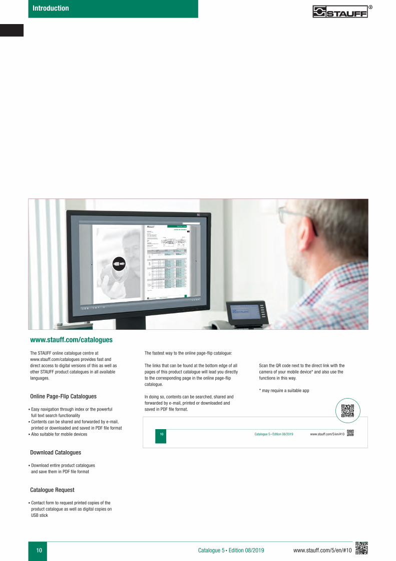
The STAUFF online catalogue centre at www.stauff.com/catalogues provides fast and direct access to digital versions of this as well as other STAUFF product catalogues in all available languages.
www.stauff.com/catalogues
Online Page-Flip Catalogues
§ Easy navigation through index or the powerful full text search functionality§ Contents can be shared and forwarded by e-mail,
printed or downloaded and saved in PDF file format§ Also suitable for mobile devices
Download Catalogues
§ Download entire product catalogues and save them in PDF file format
Catalogue Request
§ Contact form to request printed copies of the product catalogue as well as digital copies on USB stick
The fastest way to the online page-flip catalogue:
The links that can be found at the bottom edge of all pages of this product catalogue will lead you directly to the corresponding page in the online page-flip catalogue.
In doing so, contents can be searched, shared and forwarded by e-mail, printed or downloaded and saved in PDF file format.
Scan the QR code next to the direct link with the camera of your mobile device* and also use the functions in this way.
* may require a suitable app
www.stauff.com/5/en/#11 11
Introduction
Catalogue 5 § Edition 08/2019
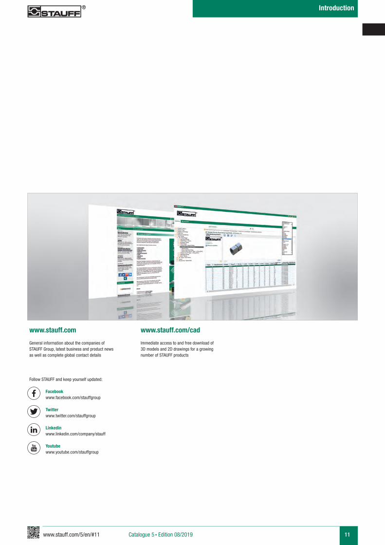
General information about the companies of STAUFF Group, latest business and product news as well as complete global contact details
Immediate access to and free download of 3D models and 2D drawings for a growing number of STAUFF products
www.stauff.com www.stauff.com/cad
Follow STAUFF and keep yourself updated:
Facebook www.facebook.com/stauffgroup Twitter www.twitter.com/stauffgroup
Linkedin www.linkedin.com/company/stauff
Youtube www.youtube.com/stauffgroup
12 www.stauff.com/5/en/#12
Overview
1250 / 18130
1000 / 14504
900 / 13054
800 / 11603Working Pressurebar / PSI 700 / 10153
600 / 8702
500 / 7252
400 / 5802
300 / 4351
200 / 2901
100 / 1450
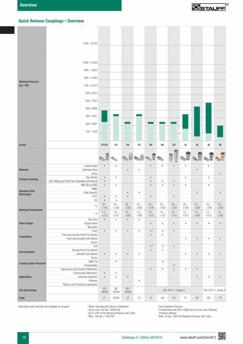
Series FF/FH FU FH FO HP HU UX IA IA IB IB
MaterialCarbon Steel • • • • • • •
Stainless Steel • • •Brass •
Surface Finishing Zinc-Nickel • • • • •
Zinc-Plating and Thick-Film-Passivation (Chrome III) • • • •
Standard Seal Material(s) 1
NBR (Buna-N®) • • • • • • •HNBR
FKM (Viton®) • • • •PTFE • • • • •
PU • •
Working Temperature°C -25 ...
+100-25 ...+100
-25 ...+200
-25 ...+200
-25 ...+100
-25 ...+100
-30 ...+100
-25 ...+100
-25 ...+200
-25 ...+100
-25 ...+200
°F -13 ...+212
-13 ...+212
-13 ...+392
-13 ...+392
-13 ...+212
-13 ...+212
-22 ...+212
-13 ...+212
-13 ...+392
-13 ...+212
-13 ...+392
Valve DesignFlat Face • • • •
Poppet Valve • • • • • • •Ball Valve
Connection
Push • • • • • 2 • 2 •Push and actuate Push-Pull Sleeve • •
Push and actuate Push Sleeve • • • •Screw
Disconnection
Pull • 2 • 2 •Actuate Push-Pull Sleeve • •
Actuate Push Sleeve • • • • • • • •Screw
Connect Under Pressure6 Male Tip • 3 • 3
Female Body • 7
Application
Agricultural and Forestry Machinery • • • • •Construction Machinery • •
Industrial Hydraulic • • • • • •Offshore •
Rescue and Tensioning Hydraulics
ISO Interchange ISO 16028
ISO 16028
ISO 16028 ISO 7241-1, Series A ISO 7241-1, Series B
Page 21 29/30 33 37 41 49 53 57 63 69 75
1 Alternative seal materials are available on request.
Quick Release Couplings § Overview
Catalogue 5 § Edition 08/2019
6 Only Residual Pressure7 Female Body with ISO-A Male Tip up to the max. Working Pressure allowed8 Max. 20 bar / 290 PSI Residual Pressure with Tools
2 When mounting the Sleeve in Bulkhead3 Up to max. 250 bar / 3626 PSI4 Up to 33% of the Working Pressure with Tools5 Max. 100 bar / 1450 PSI
www.stauff.com/5/en/#13 13
Overview
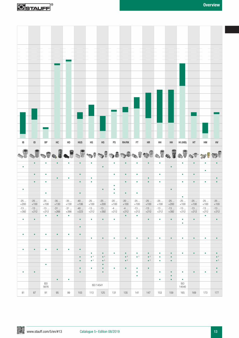
IB ID BP HC HD HUS HS HS PS RH/RK FT HR HH HH HI (HIB) HT HM HV
• • • • • • • • • • • • • • •• • •
•• • • • • • • • •
• • • • •• • • • • • • • • • • •
•• • • •
• • • • ••
-25 ...+200
-25 ...+100
-25 ...+100
-35 ...+130
-35 ...+130
-40 ...+106
-25 ...+100
-25 ...+200
-20 ...+100
-20 ...+100
-25 ...+100
-25 ...+100
-25 ...+100
-25 ...+200
-25 ...+100
-25 ...+100
-25 ...+100
-25 ...+100
-13 ...+392
-13 ...+212
-13 ...+212
-31 ...+266
-31 ...+266
-40 ...+223
-13 ...+212
-13 ...+392
-4 ...+212
-4 ...+212
-13 ...+212
-13 ...+212
-13 ...+212
-13 ...+392
-13 ...+212
-13 ...+212
-13 ...+212
-13 ...+212
• • • • • •• • • • • • • • • • • •
• •
• • • • • •• • • • • • • • • • • •
• • • • • •• • • • • • • • • • • •
• • 4 • 4 • 8 • 3 • 5 • • • 5
• • 4 • 4 • 8 • 5 • • • 5
• •• • • • • • • •
• • • • • • • • • • •• •
• • • • •
ISO5676 ISO 14541 ISO
14540
81 87 91 95 99 103 113 125 131 135 141 147 153 159 165 169 173 177
Catalogue 5 § Edition 08/2019
14 www.stauff.com/5/en/#14
Overview
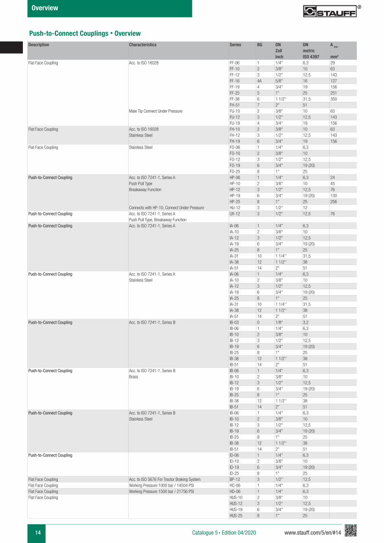
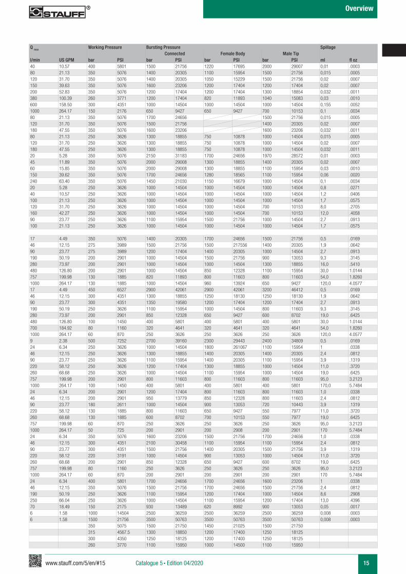
Description Characteristics Series BG DN DN A min Q max Working Pressure Bursting Pressure SpillageZoll metric Connected Female Body Male TipInch ISO 4397 mm2 l/min US GPM bar PSI bar PSI bar PSI bar PSI ml fl oz
Flat Face Coupling Acc. to ISO 16028 FF-06 1 1/4" 6,3 29 40 10.57 400 5801 1500 21756 1220 17695 2000 29007 0,01 .0003FF-10 2 3/8" 10 63 80 21.13 350 5076 1400 20305 1100 15954 1500 21756 0,015 .0005FF-12 3 1/2" 12,5 143 120 31.70 350 5076 1400 20305 1050 15229 1500 21756 0,02 .0007FF-16 4A 5/8" 16 127 150 39.63 350 5076 1600 23206 1200 17404 1200 17404 0,02 .0007FF-19 4 3/4" 19 156 200 52.83 350 5076 1200 17404 1200 17404 1300 18854 0,032 .0011FF-25 5 1" 25 251 380 100.39 260 3771 1200 17404 820 11893 1040 15083 0,03 .0010FF-38 6 1 1/2" 31,5 350 600 158.50 300 4351 1000 14504 1000 14504 1000 14504 0,155 .0052FH-51 7 2" 51 1000 264.17 150 2176 650 9427 650 9427 700 10153 0,1 .0034
Male Tip Connect Under Pressure FU-10 2 3/8" 10 63 80 21.13 350 5076 1700 24656 1500 21756 0,015 .0005FU-12 3 1/2" 12,5 143 120 31.70 350 5076 1500 21756 1400 20305 0,02 .0007FU-19 4 3/4“ 19 156 180 47.55 350 5076 1600 23206 1600 23206 0,032 .0011
Flat Face Coupling Acc. to ISO 16028 FH-10 2 3/8" 10 63 80 21.13 250 3626 1300 18855 750 10878 1000 14504 0,015 .0005Stainless Steel FH-12 3 1/2" 12,5 143 120 31.70 250 3626 1300 18855 750 10878 1000 14504 0,02 .0007
FH-19 6 3/4" 19 156 180 47.55 250 3626 1300 18855 750 10878 1000 14504 0,032 .0011Flat Face Coupling Stainless Steel FO-06 1 1/4" 6,3 20 5.28 350 5076 2150 31183 1700 24656 1970 28572 0,01 .0003
FO-10 2 3/8" 10 45 11.89 350 5076 2000 29008 1300 18855 1400 20305 0,02 .0007FO-12 3 1/2" 12,5 60 15.85 350 5076 2000 29008 1300 18855 1100 15954 0,03 .0010FO-19 6 3/4" 19 (20) 150 39.62 350 5076 1700 24656 1280 18565 1100 15954 0,06 .0020FO-25 8 1" 25 240 63.40 350 5076 1450 21030 1150 16679 1000 14504 0,1 .0034
Push-to-Connect Coupling Acc. to ISO 7241-1, Series A HP-06 1 1/4" 6,3 24 20 5.28 250 3626 1000 14504 1000 14504 1000 14504 0,8 .0271Push Pull Type HP-10 2 3/8" 10 45 40 10.57 250 3626 1000 14504 1000 14504 1000 14504 1,2 .0406Breakaway Function HP-12 3 1/2" 12,5 76 100 21.13 250 3626 1000 14504 1000 14504 1000 14504 1,7 .0575
HP-19 6 3/4" 19 (20) 130 120 31.70 250 3626 1000 14504 1000 14504 700 10153 8,0 .2705HP-25 8 1" 25 256 160 42.27 250 3626 1000 14504 1000 14504 700 10153 12,0 .4058
Connects with HP-10, Connect Under Pressure HU-12 3 1/2'' 12 90 23.77 250 3626 1100 15954 1500 21756 1000 14504 2,7 .0913Push-to-Connect Coupling Acc. to ISO 7241-1, Series A UX-12 3 1/2" 12,5 76 100 21.13 250 3626 1000 14504 1000 14504 1000 14504 1,7 .0575
Push Pull Type, Breakaway FunctionPush-to-Connect Coupling Acc. to ISO 7241-1, Series A IA-06 1 1/4" 6,3 17 4.49 350 5076 1400 20305 1700 24656 1500 21756 0,5 .0169
IA-10 2 3/8" 10 46 12.15 275 3989 1500 21756 1500 217556 1400 20305 1,9 .0642IA-12 3 1/2" 12,5 90 23.77 275 3989 1200 17404 1400 20305 1000 14504 2,7 .0913IA-19 6 3/4" 19 (20) 190 50.19 200 2901 1000 14504 1500 21756 900 13053 9,3 .3145IA-25 8 1" 25 280 73.97 200 2901 1000 14504 1000 14504 1300 18855 16,0 .5410IA-31 10 1 1/4'' 31,5 480 126.80 200 2901 1000 14504 850 12328 1100 15954 30,0 1.0144IA-38 12 1 1/2'' 38 757 199.98 130 1885 820 11893 800 11603 800 11603 54,0 1.8260IA-51 14 2" 51 1000 264.17 130 1885 1000 14504 960 13924 650 9427 120,0 4.0577
Push-to-Connect Coupling Acc. to ISO 7241-1, Series A IA-06 1 1/4" 6,3 17 4.49 450 6527 2900 42061 2900 42061 3200 46412 0,5 .0169Stainless Steel IA-10 2 3/8" 10 46 12.15 300 4351 1300 18855 1250 18130 1250 18130 1,9 .0642
IA-12 3 1/2" 12,5 90 23.77 300 4351 1350 19580 1200 17404 1200 17404 2,7 .0913IA-19 6 3/4" 19 (20) 190 50.19 250 3626 1100 15954 1000 14504 800 11603 9,3 .3145IA-25 8 1" 25 280 73.97 200 2901 850 12328 650 9427 600 8702 19,0 .6425IA-31 10 1 1/4'' 31,5 480 126.80 100 1450 400 5801 400 5801 400 5801 30,0 1.0144IA-38 12 1 1/2'' 38 700 184.92 80 1160 320 4641 320 4641 320 4641 54,0 1.8260IA-51 14 2" 51 1000 264.17 60 870 250 3626 250 3626 250 3626 120,0 4.0577
Push-to-Connect Coupling Acc. to ISO 7241-1, Series B IB-03 0 1/8" 3,2 9 2.38 500 7252 2700 39160 2300 29443 2400 34809 0,5 .0169IB-06 1 1/4" 6,3 24 6.34 250 3626 1000 14504 1800 261067 1100 15954 1 .0338IB-10 2 3/8" 10 46 12.15 250 3626 1300 18855 1400 20305 1400 20305 2,4 .0812IB-12 3 1/2" 12,5 90 23.77 250 3626 1100 15954 1400 20305 1100 15954 3,9 .1319IB-19 6 3/4" 19 (20) 220 58.12 250 3626 1200 17404 1300 18855 1000 14504 11,0 .3720IB-25 8 1" 25 260 68.68 250 3626 1000 14504 1100 15954 1000 14504 19,0 .6425IB-38 12 1 1/2'' 38 757 199.98 200 2901 800 11603 800 11603 800 11603 95,0 3.2123IB-51 14 2" 51 1000 264.17 100 1450 400 5801 400 5801 400 5801 170,0 5.7484
Push-to-Connect Coupling Acc. to ISO 7241-1, Series B IB-06 1 1/4" 6,3 24 6.34 200 2901 1200 17404 800 11603 800 11603 1,0 .0338Brass IB-10 2 3/8" 10 46 12.15 200 2901 950 13779 850 12328 800 11603 2,4 .0812
IB-12 3 1/2" 12,5 90 23.77 180 2611 1000 14504 900 13053 720 10443 3,9 .1319IB-19 6 3/4" 19 (20) 220 58.12 130 1885 800 11603 650 9427 550 7977 11,0 .3720IB-25 8 1" 25 260 68.68 130 1885 600 8702 700 10153 550 7977 19,0 .6425IB-38 12 1 1/2'' 38 757 199.98 60 870 250 3626 250 3626 250 3626 95,0 3.2123IB-51 14 2" 51 1000 264.17 50 725 200 2901 200 2908 200 2901 170 5.7484
Push-to-Connect Coupling Acc. to ISO 7241-1, Series B IB-06 1 1/4" 6,3 24 6.34 350 5076 1600 23206 1500 21756 1700 24656 1,0 .0338Stainless Steel IB-10 2 3/8" 10 46 12.15 300 4351 2100 30458 1100 15954 1100 15954 2,4 .0812
IB-12 3 1/2" 12,5 90 23.77 300 4351 1500 21756 1400 20305 1500 21756 3,9 .1319IB-19 6 3/4" 19 (20) 220 58.12 220 3191 1000 14504 900 13053 1000 14504 11,0 .3720IB-25 8 1" 25 260 68.68 200 2901 850 12328 650 9427 600 8702 19,0 .6425IB-38 12 1 1/2'' 38 757 199.98 80 1160 250 3626 250 3626 250 3626 95,0 3.2123IB-51 14 2" 51 1000 264.17 60 870 200 2901 200 2901 200 2901 170 5.7484
Push-to-Connect Coupling ID-06 1 1/4" 6,3 24 6.34 400 5801 1700 24656 1700 24656 1600 23206 1 .0338ID-10 2 3/8" 10 46 12.15 350 5076 1500 21756 1700 24656 1500 21756 2,4 .0812ID-19 6 3/4" 19 (20) 190 50.19 250 3626 1100 15954 1200 17404 1000 14504 8,6 .2908ID-25 8 1" 25 250 66.04 250 3626 1000 14504 1100 15954 1200 17404 13,0 .4396
Flat Face Coupling Acc. to ISO 5676 For Tractor Braking System BP-12 3 1/2'' 12,5 70 18.49 150 2175 930 13489 620 8992 900 13053 0,05 .0017Flat Face Coupling Working Pressure 1000 bar / 14504 PSI HC-06 1 1/4" 6,3 6 1.58 1000 14504 2500 36259 2500 36259 2500 36259 0,008 .0003Flat Face Coupling Working Pressure 1500 bar / 21756 PSI HD-06 1 1/4" 6,3 6 1.58 1500 21756 3500 50763 3500 50763 3500 50763 0,008 .0003Flat Face Coupling HUS-10 2 3/8“ 10 350 5075 1500 21750 1450 21025 1500 21750
HUS-12 3 1/2“ 12,5 315 4567.5 1300 18850 1200 17400 1250 18125HUS-19 6 3/4“ 19 (20) 300 4350 1250 18125 1200 17400 1250 18125HUS-25 8 1“ 25 260 3770 1100 15950 1000 14500 1100 15950
Push-to-Connect Couplings § Overview
Catalogue 5 § Edition 04/2020
www.stauff.com/5/en/#15 15
Overview
Description Characteristics Series BG DN DN A min Q max Working Pressure Bursting Pressure SpillageZoll metric Connected Female Body Male TipInch ISO 4397 mm2 l/min US GPM bar PSI bar PSI bar PSI bar PSI ml fl oz
Flat Face Coupling Acc. to ISO 16028 FF-06 1 1/4" 6,3 29 40 10.57 400 5801 1500 21756 1220 17695 2000 29007 0,01 .0003FF-10 2 3/8" 10 63 80 21.13 350 5076 1400 20305 1100 15954 1500 21756 0,015 .0005FF-12 3 1/2" 12,5 143 120 31.70 350 5076 1400 20305 1050 15229 1500 21756 0,02 .0007FF-16 4A 5/8" 16 127 150 39.63 350 5076 1600 23206 1200 17404 1200 17404 0,02 .0007FF-19 4 3/4" 19 156 200 52.83 350 5076 1200 17404 1200 17404 1300 18854 0,032 .0011FF-25 5 1" 25 251 380 100.39 260 3771 1200 17404 820 11893 1040 15083 0,03 .0010FF-38 6 1 1/2" 31,5 350 600 158.50 300 4351 1000 14504 1000 14504 1000 14504 0,155 .0052FH-51 7 2" 51 1000 264.17 150 2176 650 9427 650 9427 700 10153 0,1 .0034
Male Tip Connect Under Pressure FU-10 2 3/8" 10 63 80 21.13 350 5076 1700 24656 1500 21756 0,015 .0005FU-12 3 1/2" 12,5 143 120 31.70 350 5076 1500 21756 1400 20305 0,02 .0007FU-19 4 3/4“ 19 156 180 47.55 350 5076 1600 23206 1600 23206 0,032 .0011
Flat Face Coupling Acc. to ISO 16028 FH-10 2 3/8" 10 63 80 21.13 250 3626 1300 18855 750 10878 1000 14504 0,015 .0005Stainless Steel FH-12 3 1/2" 12,5 143 120 31.70 250 3626 1300 18855 750 10878 1000 14504 0,02 .0007
FH-19 6 3/4" 19 156 180 47.55 250 3626 1300 18855 750 10878 1000 14504 0,032 .0011Flat Face Coupling Stainless Steel FO-06 1 1/4" 6,3 20 5.28 350 5076 2150 31183 1700 24656 1970 28572 0,01 .0003
FO-10 2 3/8" 10 45 11.89 350 5076 2000 29008 1300 18855 1400 20305 0,02 .0007FO-12 3 1/2" 12,5 60 15.85 350 5076 2000 29008 1300 18855 1100 15954 0,03 .0010FO-19 6 3/4" 19 (20) 150 39.62 350 5076 1700 24656 1280 18565 1100 15954 0,06 .0020FO-25 8 1" 25 240 63.40 350 5076 1450 21030 1150 16679 1000 14504 0,1 .0034
Push-to-Connect Coupling Acc. to ISO 7241-1, Series A HP-06 1 1/4" 6,3 24 20 5.28 250 3626 1000 14504 1000 14504 1000 14504 0,8 .0271Push Pull Type HP-10 2 3/8" 10 45 40 10.57 250 3626 1000 14504 1000 14504 1000 14504 1,2 .0406Breakaway Function HP-12 3 1/2" 12,5 76 100 21.13 250 3626 1000 14504 1000 14504 1000 14504 1,7 .0575
HP-19 6 3/4" 19 (20) 130 120 31.70 250 3626 1000 14504 1000 14504 700 10153 8,0 .2705HP-25 8 1" 25 256 160 42.27 250 3626 1000 14504 1000 14504 700 10153 12,0 .4058
Connects with HP-10, Connect Under Pressure HU-12 3 1/2'' 12 90 23.77 250 3626 1100 15954 1500 21756 1000 14504 2,7 .0913Push-to-Connect Coupling Acc. to ISO 7241-1, Series A UX-12 3 1/2" 12,5 76 100 21.13 250 3626 1000 14504 1000 14504 1000 14504 1,7 .0575
Push Pull Type, Breakaway FunctionPush-to-Connect Coupling Acc. to ISO 7241-1, Series A IA-06 1 1/4" 6,3 17 4.49 350 5076 1400 20305 1700 24656 1500 21756 0,5 .0169
IA-10 2 3/8" 10 46 12.15 275 3989 1500 21756 1500 217556 1400 20305 1,9 .0642IA-12 3 1/2" 12,5 90 23.77 275 3989 1200 17404 1400 20305 1000 14504 2,7 .0913IA-19 6 3/4" 19 (20) 190 50.19 200 2901 1000 14504 1500 21756 900 13053 9,3 .3145IA-25 8 1" 25 280 73.97 200 2901 1000 14504 1000 14504 1300 18855 16,0 .5410IA-31 10 1 1/4'' 31,5 480 126.80 200 2901 1000 14504 850 12328 1100 15954 30,0 1.0144IA-38 12 1 1/2'' 38 757 199.98 130 1885 820 11893 800 11603 800 11603 54,0 1.8260IA-51 14 2" 51 1000 264.17 130 1885 1000 14504 960 13924 650 9427 120,0 4.0577
Push-to-Connect Coupling Acc. to ISO 7241-1, Series A IA-06 1 1/4" 6,3 17 4.49 450 6527 2900 42061 2900 42061 3200 46412 0,5 .0169Stainless Steel IA-10 2 3/8" 10 46 12.15 300 4351 1300 18855 1250 18130 1250 18130 1,9 .0642
IA-12 3 1/2" 12,5 90 23.77 300 4351 1350 19580 1200 17404 1200 17404 2,7 .0913IA-19 6 3/4" 19 (20) 190 50.19 250 3626 1100 15954 1000 14504 800 11603 9,3 .3145IA-25 8 1" 25 280 73.97 200 2901 850 12328 650 9427 600 8702 19,0 .6425IA-31 10 1 1/4'' 31,5 480 126.80 100 1450 400 5801 400 5801 400 5801 30,0 1.0144IA-38 12 1 1/2'' 38 700 184.92 80 1160 320 4641 320 4641 320 4641 54,0 1.8260IA-51 14 2" 51 1000 264.17 60 870 250 3626 250 3626 250 3626 120,0 4.0577
Push-to-Connect Coupling Acc. to ISO 7241-1, Series B IB-03 0 1/8" 3,2 9 2.38 500 7252 2700 39160 2300 29443 2400 34809 0,5 .0169IB-06 1 1/4" 6,3 24 6.34 250 3626 1000 14504 1800 261067 1100 15954 1 .0338IB-10 2 3/8" 10 46 12.15 250 3626 1300 18855 1400 20305 1400 20305 2,4 .0812IB-12 3 1/2" 12,5 90 23.77 250 3626 1100 15954 1400 20305 1100 15954 3,9 .1319IB-19 6 3/4" 19 (20) 220 58.12 250 3626 1200 17404 1300 18855 1000 14504 11,0 .3720IB-25 8 1" 25 260 68.68 250 3626 1000 14504 1100 15954 1000 14504 19,0 .6425IB-38 12 1 1/2'' 38 757 199.98 200 2901 800 11603 800 11603 800 11603 95,0 3.2123IB-51 14 2" 51 1000 264.17 100 1450 400 5801 400 5801 400 5801 170,0 5.7484
Push-to-Connect Coupling Acc. to ISO 7241-1, Series B IB-06 1 1/4" 6,3 24 6.34 200 2901 1200 17404 800 11603 800 11603 1,0 .0338Brass IB-10 2 3/8" 10 46 12.15 200 2901 950 13779 850 12328 800 11603 2,4 .0812
IB-12 3 1/2" 12,5 90 23.77 180 2611 1000 14504 900 13053 720 10443 3,9 .1319IB-19 6 3/4" 19 (20) 220 58.12 130 1885 800 11603 650 9427 550 7977 11,0 .3720IB-25 8 1" 25 260 68.68 130 1885 600 8702 700 10153 550 7977 19,0 .6425IB-38 12 1 1/2'' 38 757 199.98 60 870 250 3626 250 3626 250 3626 95,0 3.2123IB-51 14 2" 51 1000 264.17 50 725 200 2901 200 2908 200 2901 170 5.7484
Push-to-Connect Coupling Acc. to ISO 7241-1, Series B IB-06 1 1/4" 6,3 24 6.34 350 5076 1600 23206 1500 21756 1700 24656 1,0 .0338Stainless Steel IB-10 2 3/8" 10 46 12.15 300 4351 2100 30458 1100 15954 1100 15954 2,4 .0812
IB-12 3 1/2" 12,5 90 23.77 300 4351 1500 21756 1400 20305 1500 21756 3,9 .1319IB-19 6 3/4" 19 (20) 220 58.12 220 3191 1000 14504 900 13053 1000 14504 11,0 .3720IB-25 8 1" 25 260 68.68 200 2901 850 12328 650 9427 600 8702 19,0 .6425IB-38 12 1 1/2'' 38 757 199.98 80 1160 250 3626 250 3626 250 3626 95,0 3.2123IB-51 14 2" 51 1000 264.17 60 870 200 2901 200 2901 200 2901 170 5.7484
Push-to-Connect Coupling ID-06 1 1/4" 6,3 24 6.34 400 5801 1700 24656 1700 24656 1600 23206 1 .0338ID-10 2 3/8" 10 46 12.15 350 5076 1500 21756 1700 24656 1500 21756 2,4 .0812ID-19 6 3/4" 19 (20) 190 50.19 250 3626 1100 15954 1200 17404 1000 14504 8,6 .2908ID-25 8 1" 25 250 66.04 250 3626 1000 14504 1100 15954 1200 17404 13,0 .4396
Flat Face Coupling Acc. to ISO 5676 For Tractor Braking System BP-12 3 1/2'' 12,5 70 18.49 150 2175 930 13489 620 8992 900 13053 0,05 .0017Flat Face Coupling Working Pressure 1000 bar / 14504 PSI HC-06 1 1/4" 6,3 6 1.58 1000 14504 2500 36259 2500 36259 2500 36259 0,008 .0003Flat Face Coupling Working Pressure 1500 bar / 21756 PSI HD-06 1 1/4" 6,3 6 1.58 1500 21756 3500 50763 3500 50763 3500 50763 0,008 .0003Flat Face Coupling HUS-10 2 3/8“ 10 350 5075 1500 21750 1450 21025 1500 21750
HUS-12 3 1/2“ 12,5 315 4567.5 1300 18850 1200 17400 1250 18125HUS-19 6 3/4“ 19 (20) 300 4350 1250 18125 1200 17400 1250 18125HUS-25 8 1“ 25 260 3770 1100 15950 1000 14500 1100 15950
Catalogue 5 § Edition 04/2020
16 www.stauff.com/5/en/#16
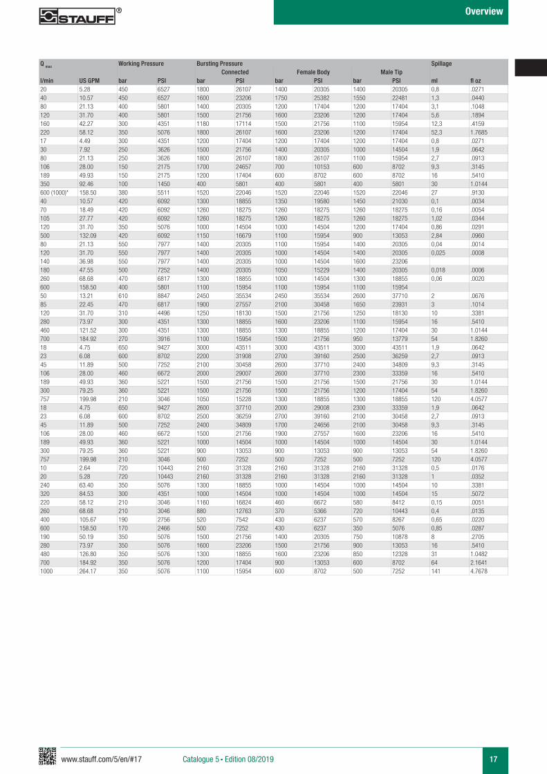
Overview
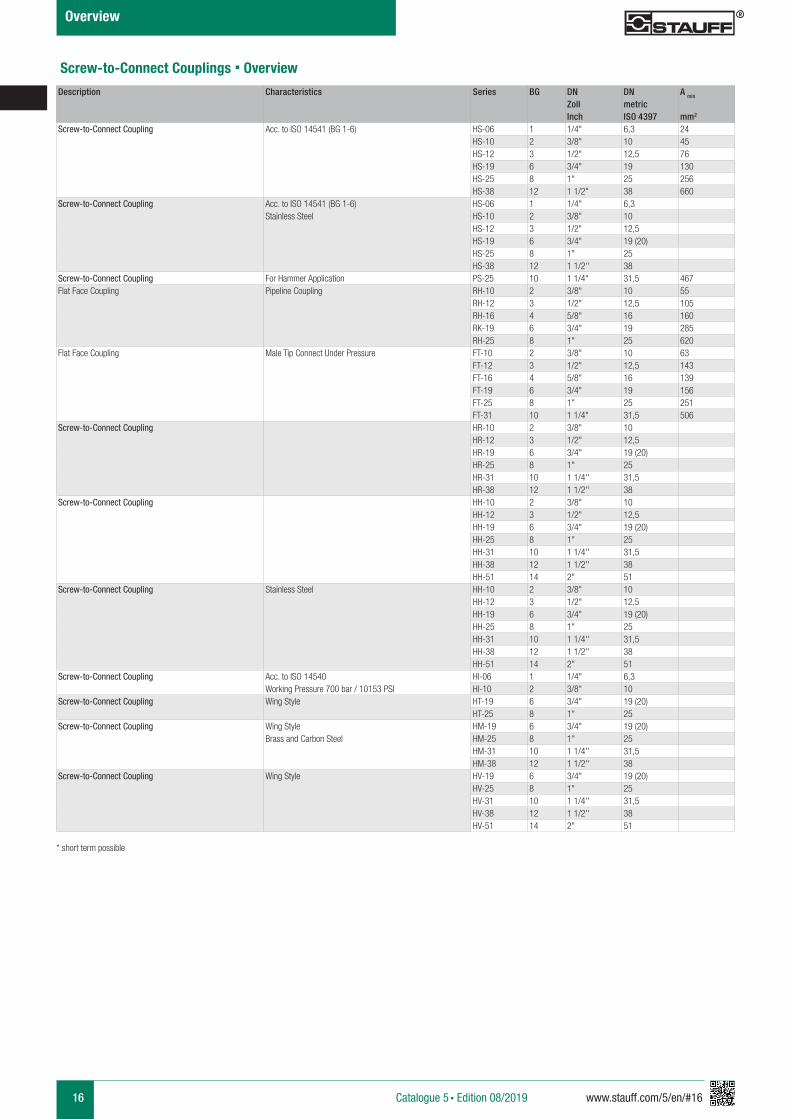
Description Characteristics Series BG DN DN A min Q max Working Pressure Bursting Pressure SpillageZoll metric Connected Female Body Male TipInch ISO 4397 mm2 l/min US GPM bar PSI bar PSI bar PSI bar PSI ml fl oz
Screw-to-Connect Coupling Acc. to ISO 14541 (BG 1-6) HS-06 1 1/4" 6,3 24 20 5.28 450 6527 1800 26107 1400 20305 1400 20305 0,8 .0271HS-10 2 3/8" 10 45 40 10.57 450 6527 1600 23206 1750 25382 1550 22481 1,3 .0440HS-12 3 1/2" 12,5 76 80 21.13 400 5801 1400 20305 1200 17404 1200 17404 3,1 .1048HS-19 6 3/4" 19 130 120 31.70 400 5801 1500 21756 1600 23206 1200 17404 5,6 .1894HS-25 8 1" 25 256 160 42.27 300 4351 1180 17114 1500 21756 1100 15954 12,3 .4159HS-38 12 1 1/2" 38 660 220 58.12 350 5076 1800 26107 1600 23206 1200 17404 52,3 1.7685
Screw-to-Connect Coupling Acc. to ISO 14541 (BG 1-6) HS-06 1 1/4" 6,3 17 4.49 300 4351 1200 17404 1200 17404 1200 17404 0,8 .0271Stainless Steel HS-10 2 3/8" 10 30 7.92 250 3626 1500 21756 1400 20305 1000 14504 1,9 .0642
HS-12 3 1/2" 12,5 80 21.13 250 3626 1800 26107 1800 26107 1100 15954 2,7 .0913HS-19 6 3/4" 19 (20) 106 28.00 150 2175 1700 24657 700 10153 600 8702 9,3 .3145HS-25 8 1" 25 189 49.93 150 2175 1200 17404 600 8702 600 8702 16 .5410HS-38 12 1 1/2'' 38 350 92.46 100 1450 400 5801 400 5801 400 5801 30 1.0144
Screw-to-Connect Coupling For Hammer Application PS-25 10 1 1/4" 31,5 467 600 (1000)* 158.50 380 5511 1520 22046 1520 22046 1520 22046 27 .9130Flat Face Coupling Pipeline Coupling RH-10 2 3/8" 10 55 40 10.57 420 6092 1600 23206 1600 23206 1600 23206 0,1 .0034
RH-12 3 1/2" 12,5 105 70 18.49 420 6092 1260 18275 1260 18275 1260 18275 0,16 .0054RH-16 4 5/8" 16 160 105 27.77 420 6092 1260 18275 1260 18275 1260 18275 1,02 .0344RK-19 6 3/4" 19 285 120 31.70 350 5076 1000 14504 1000 14504 1200 17404 0,86 .0291RH-25 8 1" 25 620 500 132.09 420 6092 1150 16679 1100 15954 900 13053 2,84 .0960
Flat Face Coupling Male Tip Connect Under Pressure FT-10 2 3/8" 10 63 80 21.13 550 7977 1400 20305 1100 15954 1400 20305 0,04 .0014FT-12 3 1/2" 12,5 143 120 31.70 550 7977 1400 20305 1000 14504 1400 20305 0,025 .0008FT-16 4 5/8" 16 139 140 36.98 550 7977 1400 20305 1000 14504 1600 23206FT-19 6 3/4" 19 156 180 47.55 500 7252 1400 20305 1050 15229 1400 20305 0,018 .0006FT-25 8 1" 25 251 260 68.68 470 6817 1300 18855 1000 14504 1300 18855 0,06 .0020FT-31 10 1 1/4" 31,5 506 600 158.50 400 5801 1100 15954 1100 15954 1100 15954
Screw-to-Connect Coupling HR-10 2 3/8" 10 50 13.21 610 8847 2450 35534 2450 35534 2600 37710 2 .0676HR-12 3 1/2" 12,5 85 22.45 470 6817 1900 27557 2100 30458 1650 23931 3 .1014HR-19 6 3/4" 19 (20) 120 31.70 310 4496 1250 18130 1500 21756 1250 18130 10 .3381HR-25 8 1" 25 280 73.97 300 4351 1300 18855 1600 23206 1100 15954 16 .5410HR-31 10 1 1/4'' 31,5 460 121.52 300 4351 1300 18855 1300 18855 1200 17404 30 1.0144HR-38 12 1 1/2'' 38 700 184.92 270 3916 1100 15954 1500 21756 950 13779 54 1.8260
Screw-to-Connect Coupling HH-10 2 3/8" 10 18 4.75 650 9427 3000 43511 3000 43511 3000 43511 1,9 .0642HH-12 3 1/2" 12,5 23 6.08 600 8702 2200 31908 2700 39160 2500 36259 2,7 .0913HH-19 6 3/4" 19 (20) 45 11.89 500 7252 2100 30458 2600 37710 2400 34809 9,3 .3145HH-25 8 1" 25 106 28.00 460 6672 2000 29007 2600 37710 2300 33359 16 .5410HH-31 10 1 1/4'' 31,5 189 49.93 360 5221 1500 21756 1500 21756 1500 21756 30 1.0144HH-38 12 1 1/2'' 38 300 79.25 360 5221 1500 21756 1500 21756 1200 17404 54 1.8260HH-51 14 2" 51 757 199.98 210 3046 1050 15228 1300 18855 1300 18855 120 4.0577
Screw-to-Connect Coupling Stainless Steel HH-10 2 3/8" 10 18 4.75 650 9427 2600 37710 2000 29008 2300 33359 1,9 .0642HH-12 3 1/2" 12,5 23 6.08 600 8702 2500 36259 2700 39160 2100 30458 2,7 .0913HH-19 6 3/4" 19 (20) 45 11.89 500 7252 2400 34809 1700 24656 2100 30458 9,3 .3145HH-25 8 1" 25 106 28.00 460 6672 1500 21756 1900 27557 1600 23206 16 .5410HH-31 10 1 1/4'' 31,5 189 49.93 360 5221 1000 14504 1000 14504 1000 14504 30 1.0144HH-38 12 1 1/2'' 38 300 79.25 360 5221 900 13053 900 13053 900 13053 54 1.8260HH-51 14 2" 51 757 199.98 210 3046 500 7252 500 7252 500 7252 120 4.0577
Screw-to-Connect Coupling Acc. to ISO 14540 HI-06 1 1/4" 6,3 10 2.64 720 10443 2160 31328 2160 31328 2160 31328 0,5 .0176Working Pressure 700 bar / 10153 PSI HI-10 2 3/8" 10 20 5.28 720 10443 2160 31328 2160 31328 2160 31328 1 .0352
Screw-to-Connect Coupling Wing Style HT-19 6 3/4" 19 (20) 240 63.40 350 5076 1300 18855 1000 14504 1000 14504 10 .3381HT-25 8 1" 25 320 84.53 300 4351 1000 14504 1000 14504 1000 14504 15 .5072
Screw-to-Connect Coupling Wing Style HM-19 6 3/4" 19 (20) 220 58.12 210 3046 1160 16824 460 6672 580 8412 0,15 .0051Brass and Carbon Steel HM-25 8 1" 25 260 68.68 210 3046 880 12763 370 5366 720 10443 0,4 .0135
HM-31 10 1 1/4'' 31,5 400 105.67 190 2756 520 7542 430 6237 570 8267 0,65 .0220HM-38 12 1 1/2'' 38 600 158.50 170 2466 500 7252 430 6237 350 5076 0,85 .0287
Screw-to-Connect Coupling Wing Style HV-19 6 3/4" 19 (20) 190 50.19 350 5076 1500 21756 1400 20305 750 10878 8 .2705HV-25 8 1" 25 280 73.97 350 5076 1600 23206 1500 21756 900 13053 16 .5410HV-31 10 1 1/4'' 31,5 480 126.80 350 5076 1300 18855 1600 23206 850 12328 31 1.0482HV-38 12 1 1/2'' 38 700 184.92 350 5076 1200 17404 900 13053 600 8702 64 2.1641HV-51 14 2" 51 1000 264.17 350 5076 1100 15954 600 8702 500 7252 141 4.7678
Screw-to-Connect Couplings § Overview
* short term possible
Catalogue 5 § Edition 08/2019
www.stauff.com/5/en/#17 17
Overview
Description Characteristics Series BG DN DN A min Q max Working Pressure Bursting Pressure SpillageZoll metric Connected Female Body Male TipInch ISO 4397 mm2 l/min US GPM bar PSI bar PSI bar PSI bar PSI ml fl oz
Screw-to-Connect Coupling Acc. to ISO 14541 (BG 1-6) HS-06 1 1/4" 6,3 24 20 5.28 450 6527 1800 26107 1400 20305 1400 20305 0,8 .0271HS-10 2 3/8" 10 45 40 10.57 450 6527 1600 23206 1750 25382 1550 22481 1,3 .0440HS-12 3 1/2" 12,5 76 80 21.13 400 5801 1400 20305 1200 17404 1200 17404 3,1 .1048HS-19 6 3/4" 19 130 120 31.70 400 5801 1500 21756 1600 23206 1200 17404 5,6 .1894HS-25 8 1" 25 256 160 42.27 300 4351 1180 17114 1500 21756 1100 15954 12,3 .4159HS-38 12 1 1/2" 38 660 220 58.12 350 5076 1800 26107 1600 23206 1200 17404 52,3 1.7685
Screw-to-Connect Coupling Acc. to ISO 14541 (BG 1-6) HS-06 1 1/4" 6,3 17 4.49 300 4351 1200 17404 1200 17404 1200 17404 0,8 .0271Stainless Steel HS-10 2 3/8" 10 30 7.92 250 3626 1500 21756 1400 20305 1000 14504 1,9 .0642
HS-12 3 1/2" 12,5 80 21.13 250 3626 1800 26107 1800 26107 1100 15954 2,7 .0913HS-19 6 3/4" 19 (20) 106 28.00 150 2175 1700 24657 700 10153 600 8702 9,3 .3145HS-25 8 1" 25 189 49.93 150 2175 1200 17404 600 8702 600 8702 16 .5410HS-38 12 1 1/2'' 38 350 92.46 100 1450 400 5801 400 5801 400 5801 30 1.0144
Screw-to-Connect Coupling For Hammer Application PS-25 10 1 1/4" 31,5 467 600 (1000)* 158.50 380 5511 1520 22046 1520 22046 1520 22046 27 .9130Flat Face Coupling Pipeline Coupling RH-10 2 3/8" 10 55 40 10.57 420 6092 1300 18855 1350 19580 1450 21030 0,1 .0034
RH-12 3 1/2" 12,5 105 70 18.49 420 6092 1260 18275 1260 18275 1260 18275 0,16 .0054RH-16 4 5/8" 16 160 105 27.77 420 6092 1260 18275 1260 18275 1260 18275 1,02 .0344RK-19 6 3/4" 19 285 120 31.70 350 5076 1000 14504 1000 14504 1200 17404 0,86 .0291RH-25 8 1" 25 620 500 132.09 420 6092 1150 16679 1100 15954 900 13053 2,84 .0960
Flat Face Coupling Male Tip Connect Under Pressure FT-10 2 3/8" 10 63 80 21.13 550 7977 1400 20305 1100 15954 1400 20305 0,04 .0014FT-12 3 1/2" 12,5 143 120 31.70 550 7977 1400 20305 1000 14504 1400 20305 0,025 .0008FT-16 4 5/8" 16 139 140 36.98 550 7977 1400 20305 1000 14504 1600 23206FT-19 6 3/4" 19 156 180 47.55 500 7252 1400 20305 1050 15229 1400 20305 0,018 .0006FT-25 8 1" 25 251 260 68.68 470 6817 1300 18855 1000 14504 1300 18855 0,06 .0020FT-31 10 1 1/4" 31,5 506 600 158.50 400 5801 1100 15954 1100 15954 1100 15954
Screw-to-Connect Coupling HR-10 2 3/8" 10 50 13.21 610 8847 2450 35534 2450 35534 2600 37710 2 .0676HR-12 3 1/2" 12,5 85 22.45 470 6817 1900 27557 2100 30458 1650 23931 3 .1014HR-19 6 3/4" 19 (20) 120 31.70 310 4496 1250 18130 1500 21756 1250 18130 10 .3381HR-25 8 1" 25 280 73.97 300 4351 1300 18855 1600 23206 1100 15954 16 .5410HR-31 10 1 1/4'' 31,5 460 121.52 300 4351 1300 18855 1300 18855 1200 17404 30 1.0144HR-38 12 1 1/2'' 38 700 184.92 270 3916 1100 15954 1500 21756 950 13779 54 1.8260
Screw-to-Connect Coupling HH-10 2 3/8" 10 18 4.75 650 9427 3000 43511 3000 43511 3000 43511 1,9 .0642HH-12 3 1/2" 12,5 23 6.08 600 8702 2200 31908 2700 39160 2500 36259 2,7 .0913HH-19 6 3/4" 19 (20) 45 11.89 500 7252 2100 30458 2600 37710 2400 34809 9,3 .3145HH-25 8 1" 25 106 28.00 460 6672 2000 29007 2600 37710 2300 33359 16 .5410HH-31 10 1 1/4'' 31,5 189 49.93 360 5221 1500 21756 1500 21756 1500 21756 30 1.0144HH-38 12 1 1/2'' 38 300 79.25 360 5221 1500 21756 1500 21756 1200 17404 54 1.8260HH-51 14 2" 51 757 199.98 210 3046 1050 15228 1300 18855 1300 18855 120 4.0577
Screw-to-Connect Coupling Stainless Steel HH-10 2 3/8" 10 18 4.75 650 9427 2600 37710 2000 29008 2300 33359 1,9 .0642HH-12 3 1/2" 12,5 23 6.08 600 8702 2500 36259 2700 39160 2100 30458 2,7 .0913HH-19 6 3/4" 19 (20) 45 11.89 500 7252 2400 34809 1700 24656 2100 30458 9,3 .3145HH-25 8 1" 25 106 28.00 460 6672 1500 21756 1900 27557 1600 23206 16 .5410HH-31 10 1 1/4'' 31,5 189 49.93 360 5221 1000 14504 1000 14504 1000 14504 30 1.0144HH-38 12 1 1/2'' 38 300 79.25 360 5221 900 13053 900 13053 900 13053 54 1.8260HH-51 14 2" 51 757 199.98 210 3046 500 7252 500 7252 500 7252 120 4.0577
Screw-to-Connect Coupling Acc. to ISO 14540 HI-06 1 1/4" 6,3 10 2.64 720 10443 2160 31328 2160 31328 2160 31328 0,5 .0176Working Pressure 700 bar / 10153 PSI HI-10 2 3/8" 10 20 5.28 720 10443 2160 31328 2160 31328 2160 31328 1 .0352
Screw-to-Connect Coupling Wing Style HT-19 6 3/4" 19 (20) 240 63.40 350 5076 1300 18855 1000 14504 1000 14504 10 .3381HT-25 8 1" 25 320 84.53 300 4351 1000 14504 1000 14504 1000 14504 15 .5072
Screw-to-Connect Coupling Wing Style HM-19 6 3/4" 19 (20) 220 58.12 210 3046 1160 16824 460 6672 580 8412 0,15 .0051Brass and Carbon Steel HM-25 8 1" 25 260 68.68 210 3046 880 12763 370 5366 720 10443 0,4 .0135
HM-31 10 1 1/4'' 31,5 400 105.67 190 2756 520 7542 430 6237 570 8267 0,65 .0220HM-38 12 1 1/2'' 38 600 158.50 170 2466 500 7252 430 6237 350 5076 0,85 .0287
Screw-to-Connect Coupling Wing Style HV-19 6 3/4" 19 (20) 190 50.19 350 5076 1500 21756 1400 20305 750 10878 8 .2705HV-25 8 1" 25 280 73.97 350 5076 1600 23206 1500 21756 900 13053 16 .5410HV-31 10 1 1/4'' 31,5 480 126.80 350 5076 1300 18855 1600 23206 850 12328 31 1.0482HV-38 12 1 1/2'' 38 700 184.92 350 5076 1200 17404 900 13053 600 8702 64 2.1641HV-51 14 2" 51 1000 264.17 350 5076 1100 15954 600 8702 500 7252 141 4.7678
Catalogue 5 § Edition 08/2019
18 www.stauff.com/5/en/#18
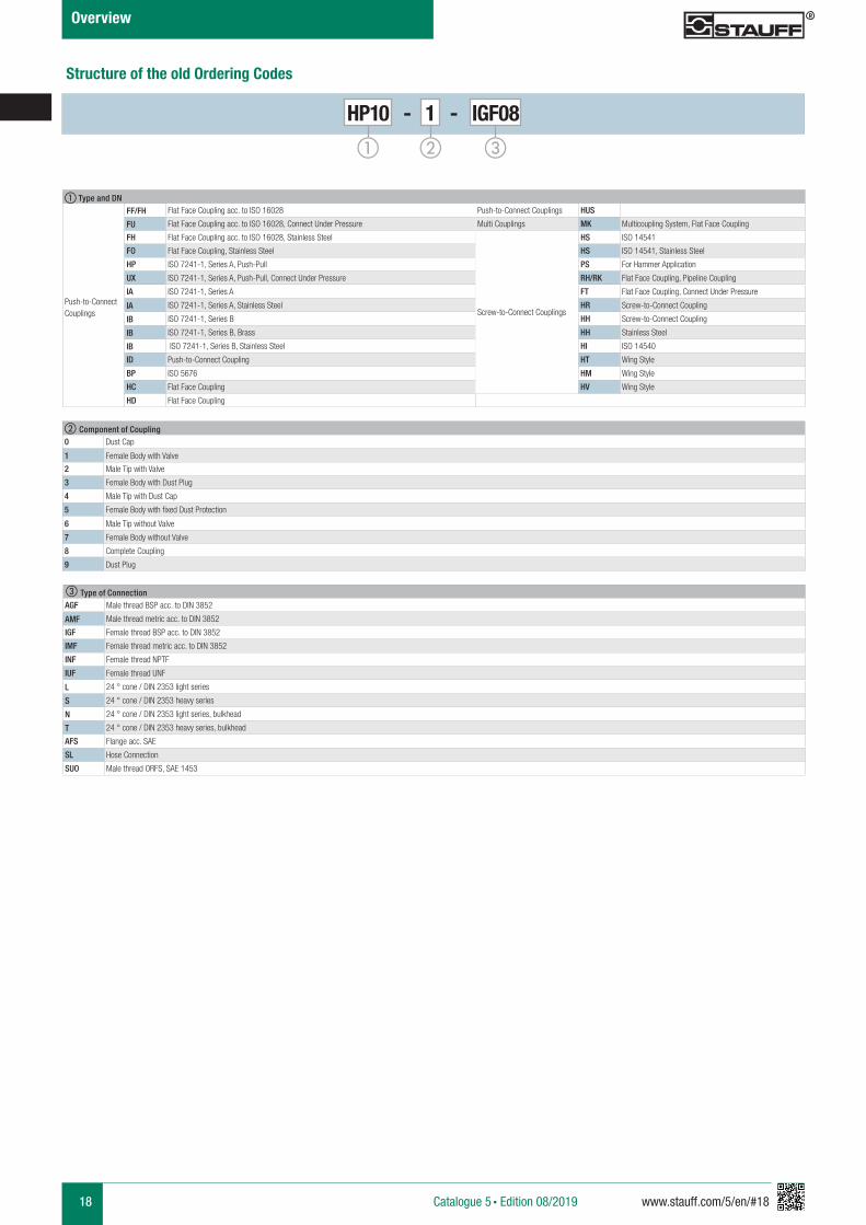
Structure of the old Ordering Codes
HP10 - 1 - IGF08
a b c
b Component of Coupling0 Dust Cap
1 Female Body with Valve
2 Male Tip with Valve
3 Female Body with Dust Plug
4 Male Tip with Dust Cap
5 Female Body with fixed Dust Protection
6 Male Tip without Valve
7 Female Body without Valve
8 Complete Coupling
9 Dust Plug
Overview
Catalogue 5 § Edition 08/2019
a Type and DN
Push-to-Connect Couplings
FF/FH Flat Face Coupling acc. to ISO 16028 Push-to-Connect Couplings HUS
FU Flat Face Coupling acc. to ISO 16028, Connect Under Pressure Multi Couplings MK Multicoupling System, Flat Face Coupling
FH Flat Face Coupling acc. to ISO 16028, Stainless Steel
Screw-to-Connect Couplings
HS ISO 14541
FO Flat Face Coupling, Stainless Steel HS ISO 14541, Stainless Steel
HP ISO 7241-1, Series A, Push-Pull PS For Hammer Application
UX ISO 7241-1, Series A, Push-Pull, Connect Under Pressure RH/RK Flat Face Coupling, Pipeline Coupling
IA ISO 7241-1, Series A FT Flat Face Coupling, Connect Under Pressure
IA ISO 7241-1, Series A, Stainless Steel HR Screw-to-Connect Coupling
IB ISO 7241-1, Series B HH Screw-to-Connect Coupling
IB ISO 7241-1, Series B, Brass HH Stainless Steel
IB ISO 7241-1, Series B, Stainless Steel HI ISO 14540
ID Push-to-Connect Coupling HT Wing Style
BP ISO 5676 HM Wing Style
HC Flat Face Coupling HV Wing Style
HD Flat Face Coupling
c Type of ConnectionAGF Male thread BSP acc. to DIN 3852
AMF Male thread metric acc. to DIN 3852
IGF Female thread BSP acc. to DIN 3852
IMF Female thread metric acc. to DIN 3852
INF Female thread NPTF
IUF Female thread UNF
L 24 ° cone / DIN 2353 light series
S 24 ° cone / DIN 2353 heavy series
N 24 ° cone / DIN 2353 light series, bulkhead
T 24 ° cone / DIN 2353 heavy series, bulkhead
AFS Flange acc. SAE
SL Hose Connection
SUO Male thread ORFS, SAE 1453
www.stauff.com/5/en/#19 19
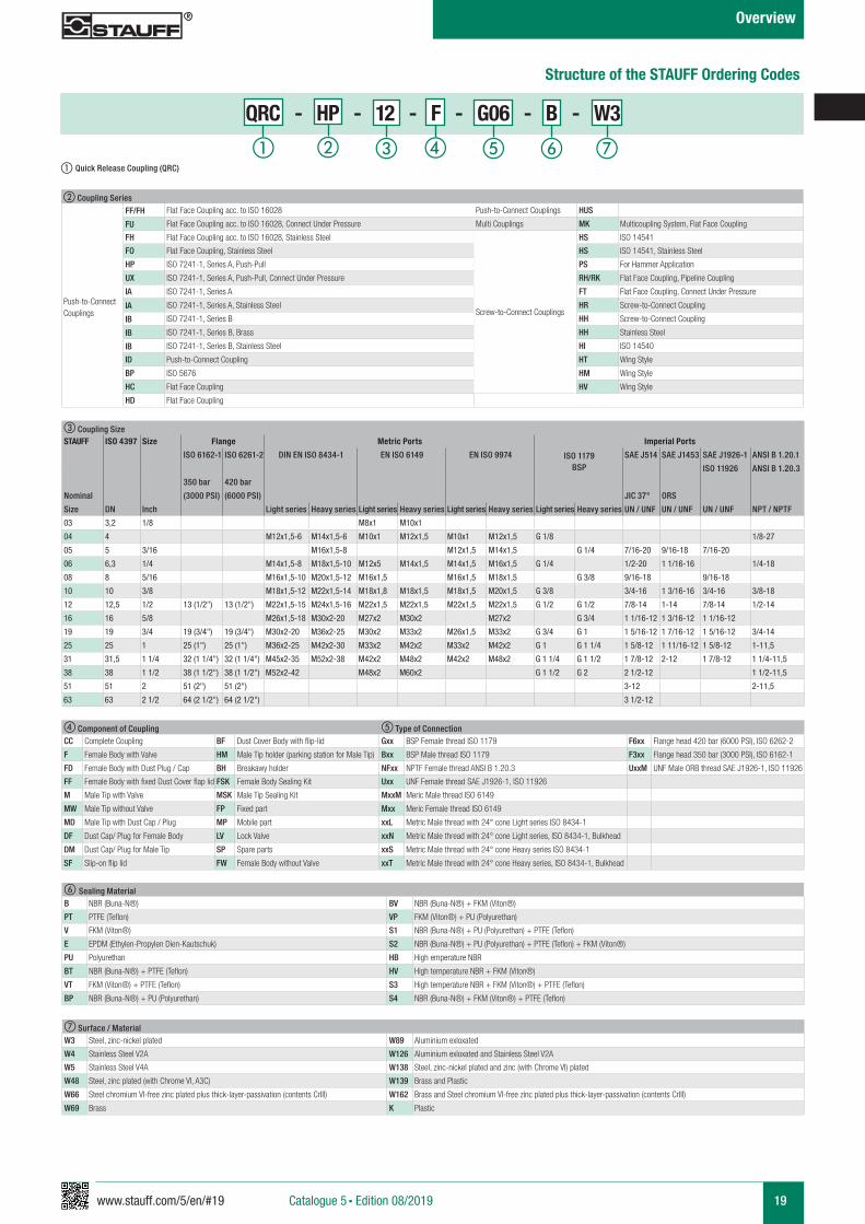
Structure of the STAUFF Ordering Codes
a db c e f g
QRC - HP - 12 - F - G06 - B - W3
b Coupling Series
Push-to-Connect Couplings
FF/FH Flat Face Coupling acc. to ISO 16028 Push-to-Connect Couplings HUS
FU Flat Face Coupling acc. to ISO 16028, Connect Under Pressure Multi Couplings MK Multicoupling System, Flat Face Coupling
FH Flat Face Coupling acc. to ISO 16028, Stainless Steel
Screw-to-Connect Couplings
HS ISO 14541
FO Flat Face Coupling, Stainless Steel HS ISO 14541, Stainless Steel
HP ISO 7241-1, Series A, Push-Pull PS For Hammer Application
UX ISO 7241-1, Series A, Push-Pull, Connect Under Pressure RH/RK Flat Face Coupling, Pipeline Coupling
IA ISO 7241-1, Series A FT Flat Face Coupling, Connect Under Pressure
IA ISO 7241-1, Series A, Stainless Steel HR Screw-to-Connect Coupling
IB ISO 7241-1, Series B HH Screw-to-Connect Coupling
IB ISO 7241-1, Series B, Brass HH Stainless Steel
IB ISO 7241-1, Series B, Stainless Steel HI ISO 14540
ID Push-to-Connect Coupling HT Wing Style
BP ISO 5676 HM Wing Style
HC Flat Face Coupling HV Wing Style
HD Flat Face Coupling
f Sealing MaterialB NBR (Buna-N®) BV NBR (Buna-N®) + FKM (Viton®)
PT PTFE (Teflon) VP FKM (Viton®) + PU (Polyurethan)
V FKM (Viton®) S1 NBR (Buna-N®) + PU (Polyurethan) + PTFE (Teflon)
E EPDM (Ethylen-Propylen Dien-Kautschuk) S2 NBR (Buna-N®) + PU (Polyurethan) + PTFE (Teflon) + FKM (Viton®)
PU Polyurethan HB High emperature NBR
BT NBR (Buna-N®) + PTFE (Teflon) HV High temperature NBR + FKM (Viton®)
VT FKM (Viton®) + PTFE (Teflon) S3 High temperature NBR + FKM (Viton®) + PTFE (Teflon)
BP NBR (Buna-N®) + PU (Polyurethan) S4 NBR (Buna-N®) + FKM (Viton®) + PTFE (Teflon)
c Coupling SizeSTAUFF ISO 4397 Size Flange Metric Ports Imperial Ports
ISO 6162-1 ISO 6261-2 DIN EN ISO 8434-1 EN ISO 6149 EN ISO 9974 ISO 1179BSP
SAE J514 SAE J1453 SAE J1926-1 ANSI B 1.20.1
ISO 11926 ANSI B 1.20.3
350 bar 420 bar
Nominal (3000 PSI) (6000 PSI) JIC 37° ORS
Size DN Inch Light series Heavy series Light series Heavy series Light series Heavy series Light series Heavy series UN / UNF UN / UNF UN / UNF NPT / NPTF
03 3,2 1/8 M8x1 M10x1
04 4 M12x1,5-6 M14x1,5-6 M10x1 M12x1,5 M10x1 M12x1,5 G 1/8 1/8-27
05 5 3/16 M16x1,5-8 M12x1,5 M14x1,5 G 1/4 7/16-20 9/16-18 7/16-20
06 6,3 1/4 M14x1,5-8 M18x1,5-10 M12x5 M14x1,5 M14x1,5 M16x1,5 G 1/4 1/2-20 1 1/16-16 1/4-18
08 8 5/16 M16x1,5-10 M20x1,5-12 M16x1,5 M16x1,5 M18x1,5 G 3/8 9/16-18 9/16-18
10 10 3/8 M18x1,5-12 M22x1,5-14 M18x1,8 M18x1,5 M18x1,5 M20x1,5 G 3/8 3/4-16 1 3/16-16 3/4-16 3/8-18
12 12,5 1/2 13 (1/2") 13 (1/2") M22x1,5-15 M24x1,5-16 M22x1,5 M22x1,5 M22x1,5 M22x1,5 G 1/2 G 1/2 7/8-14 1-14 7/8-14 1/2-14
16 16 5/8 M26x1,5-18 M30x2-20 M27x2 M30x2 M27x2 G 3/4 1 1/16-12 1 3/16-12 1 1/16-12
19 19 3/4 19 (3/4") 19 (3/4") M30x2-20 M36x2-25 M30x2 M33x2 M26x1,5 M33x2 G 3/4 G 1 1 5/16-12 1 7/16-12 1 5/16-12 3/4-14
25 25 1 25 (1") 25 (1") M36x2-25 M42x2-30 M33x2 M42x2 M33x2 M42x2 G 1 G 1 1/4 1 5/8-12 1 11/16-12 1 5/8-12 1-11,5
31 31,5 1 1/4 32 (1 1/4") 32 (1 1/4") M45x2-35 M52x2-38 M42x2 M48x2 M42x2 M48x2 G 1 1/4 G 1 1/2 1 7/8-12 2-12 1 7/8-12 1 1/4-11,5
38 38 1 1/2 38 (1 1/2") 38 (1 1/2") M52x2-42 M48x2 M60x2 G 1 1/2 G 2 2 1/2-12 1 1/2-11,5
51 51 2 51 (2") 51 (2") 3-12 2-11,5
63 63 2 1/2 64 (2 1/2") 64 (2 1/2") 3 1/2-12
d Component of Coupling e Type of ConnectionCC Complete Coupling BF Dust Cover Body with flip-lid Gxx BSP Female thread ISO 1179 F6xx Flange head 420 bar (6000 PSI), ISO 6262-2
F Female Body with Valve HM Male Tip holder (parking station for Male Tip) Bxx BSP Male thread ISO 1179 F3xx Flange head 350 bar (3000 PSI), ISO 6162-1
FD Female Body with Dust Plug / Cap BH Breakawy holder NFxx NPTF Female thread ANSI B 1.20.3 UxxM UNF Male ORB thread SAE J1926-1, ISO 11926
FF Female Body with fixed Dust Cover flap lid FSK Female Body Sealing Kit Uxx UNF Female thread SAE J1926-1, ISO 11926
M Male Tip with Valve MSK Male Tip Sealing Kit MxxM Meric Male thread ISO 6149
MW Male Tip without Valve FP Fixed part Mxx Meric Female thread ISO 6149
MD Male Tip with Dust Cap / Plug MP Mobile part xxL Metric Male thread with 24° cone Light series ISO 8434-1
DF Dust Cap/ Plug for Female Body LV Lock Valve xxN Metric Male thread with 24° cone Light series, ISO 8434-1, Bulkhead
DM Dust Cap/ Plug for Male Tip SP Spare parts xxS Metric Male thread with 24° cone Heavy series ISO 8434-1
SF Slip-on flip lid FW Female Body without Valve xxT Metric Male thread with 24° cone Heavy series, ISO 8434-1, Bulkhead
g Surface / MaterialW3 Steel, zinc-nickel plated W89 Aluminium exloxated
W4 Stainless Steel V2A W126 Aluminium exloxated and Stainless Steel V2A
W5 Stainless Steel V4A W138 Steel, zinc-nickel plated and zinc (with Chrome VI) plated
W48 Steel, zinc plated (with Chrome VI, A3C) W139 Brass and Plastic
W66 Steel chromium VI-free zinc plated plus thick-layer-passivation (contents CrIII) W162 Brass and Steel chromium VI-free zinc plated plus thick-layer-passivation (contents CrIII)
W69 Brass K Plastic
a Quick Release Coupling (QRC)
Overview
Catalogue 5 § Edition 08/2019
www.stauff.com/5/en/#21 21
FF/FU
FH
STAUFF Push-to-Connect Couplings
Catalogue 5 § Edition 04/2020
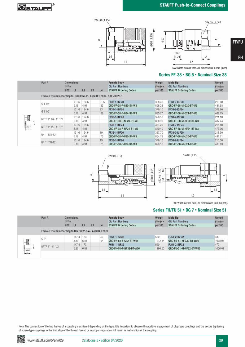
Series FF-19 § BG 4 § Nominal Size 19
Series FU-19 § BG 4 § Nominal Size 19 Connect Under Pressure
30
27
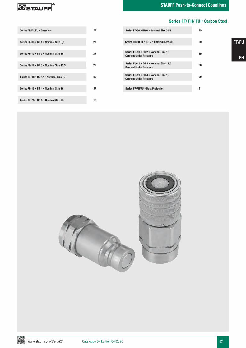
Series FF/FH/FU § Overview
Series FF-06 § BG 1 § Nominal Size 6,3 23
22
Series FF-10 § BG 2 § Nominal Size 10 24
Series FF-12 § BG 3 § Nominal Size 12,5 25Series FU-12 § BG 3 § Nominal Size 12,5 Connect Under Pressure
30
Series FU-10 § BG 2 § Nominal Size 10 Connect Under Pressure
30
Series FF-16 § BG 4A § Nominal Size 16 26
Series FF-25 § BG 5 § Nominal Size 25
Series FF-38 § BG 6 § Nominal Size 31,5 29
28
Series FH/FU 51 § BG 7 § Nominal Size 50
Series FF/FH/FU § Dust Protection 31
29
Series FF/ FH/ FU § Carbon Steel
22 www.stauff.com/5/en/#22
FF/FU
FH
STAUFF Push-to-Connect Couplings
Catalogue 5 § Edition 04/2020
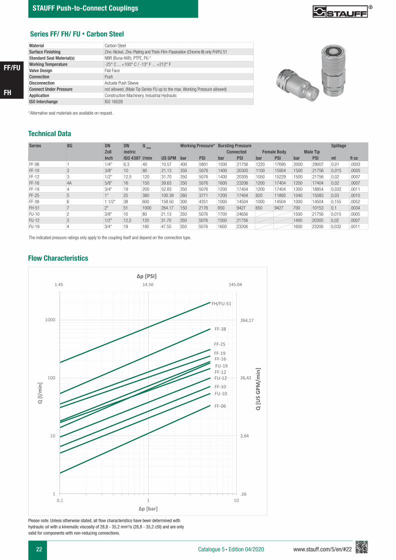
Series FF/ FH/ FU § Carbon Steel
Please note: Unless otherwise stated, all flow characteristics have been determined with hydraulic oil with a kinematic viscosity of 28,8 - 35,2 mm2/s (28,8 - 35,2 cSt) and are only valid for components with non-reducing connections.
2 Alternative seal materials are available on request.
Technical Data
Material Carbon SteelSurface Finishing Zinc-Nickel, Zinc-Plating and Thick-Film-Passivation (Chrome III) only FH/FU 51Standard Seal Material(s) NBR (Buna-N®), PTFE, PU 2
Working Temperature -25° C ... +100° C / -13° F ... +212° F Valve Design Flat FaceConnection PushDisconnection Actuate Push SleeveConnect Under Pressure not allowed, (Male Tip Series FU up to the max. Working Pressure allowed)Application Construction Machinery, Industrial Hydraulic ISO Interchange ISO 16028
Flow Characteristics
Series BG DN DN Q max Working Pressure* Bursting Pressure SpillageZoll metric Connected Female Body Male TipInch ISO 4397 l/min US GPM bar PSI bar PSI bar PSI bar PSI ml fl oz
FF-06 1 1/4" 6,3 40 10.57 400 5801 1500 21756 1220 17695 2000 29007 0,01 .0003FF-10 2 3/8" 10 80 21.13 350 5076 1400 20305 1100 15954 1500 21756 0,015 .0005FF-12 3 1/2" 12,5 120 31.70 350 5076 1400 20305 1050 15229 1500 21756 0,02 .0007FF-16 4A 5/8" 16 150 39.63 350 5076 1600 23206 1200 17404 1200 17404 0,02 .0007FF-19 4 3/4" 19 200 52.83 350 5076 1200 17404 1200 17404 1300 18854 0,032 .0011FF-25 5 1" 25 380 100.39 260 3771 1200 17404 820 11893 1040 15083 0,03 .0010FF-38 6 1 1/2" 38 600 158.50 300 4351 1000 14504 1000 14504 1000 14504 0,155 .0052FH-51 7 2" 51 1000 264.17 150 2176 650 9427 650 9427 700 10153 0,1 .0034FU-10 2 3/8" 10 80 21.13 350 5076 1700 24656 1500 21756 0,015 .0005FU-12 3 1/2" 12,5 120 31.70 350 5076 1500 21756 1400 20305 0,02 .0007FU-19 4 3/4“ 19 180 47.55 350 5076 1600 23206 1600 23206 0,032 .0011
The indicated pressure ratings only apply to the coupling itself and depend on the connection type.
Q [U
S G
PM/m
in]
Δp [PSI]
264,17
26,42
2,64
.26
1.45 14.50 145.04
QRC-FH-51
QRC-FF-38
FF-06
FF-10FU-10
FF-12FU-12
FF-16FF-19
FU-19
FF-25
FF-38
FH/FU-51
1
10
100
1000
0,1 1 10
Q [l/
min
]
Δp [bar]
www.stauff.com/5/en/#23 23
FF/FU
FH
STAUFF Push-to-Connect Couplings
Catalogue 5 § Edition 04/2020
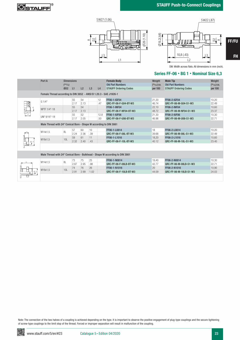
Series FF-06 § BG 1 § Nominal Size 6,3
Port A Dimensions Female Body Weight Male Tip Weight (mm/in) Old Part Numbers (kg/lbs) ca. Old Part Numbers (kg/lbs) ca.
ØD2 L1 L2 L3 L4 STAUFF Ordering Codes per 100 STAUFF Ordering Codes per 100
Female Thread according to DIN 3852 - ANSI B 1.20.3 - SAE J1926-1
G 1/4"55 54 12 FF06-1-IGF04 21,20 FF06-2-IGF04 10,202.17 2.13 .47 QRC-FF-06-F-G04-BT-W3 46.74 QRC-FF-06-M-G04-S1-W3 22.49
NPTF 1/4"-1855 54 FF06-1-INF04 22,10 FF06-2-INF04 10,602.17 2.13 QRC-FF-06-F-NF04-BT-W3 48.72 QRC-FF-06-M-NF04-S1-W3 23.37
UNF 9/16"-1855 52 12,8 FF06-1-IUF06 21,30 FF06-2-IUF06 10,302.17 2.05 .50 QRC-FF-06-F-U06-BT-W3 46.96 QRC-FF-06-M-U06-S1-W3 22.71
Male Thread with 24° Conical Bore - Shape W according to DIN 3861
M14x1,5 8L57 60 10 FF06-1-L0814 18 FF06-2-L0814 10,202.24 2.36 .39 QRC-FF-06-F-08L-BT-W3 39.68 QRC-FF-06-M-08L-S1-W3 22.49
M16x1,5 10L59 61 11 FF06-1-L1016 18,20 FF06-2-L1016 10,602.32 2.40 .43 QRC-FF-06-F-10L-BT-W3 40.12 QRC-FF-06-M-10L-S1-W3 23.40
Male Thread with 24° Conical Bore - Bulkhead - Shape W according to DIN 3861
M14x1,5 8L73 75 25 FF06-1-N0814 19,40 FF06-2-N0814 10,302.87 2.95 .98 QRC-FF-06-F-08LB-BT-W3 42.77 QRC-FF-06-M-08LB-S1-W3 22.71
M16x1,5 10L74 76 26 FF06-1-N1016 20 FF06-2-N1016 10,902.91 2.99 1.02 QRC-FF-06-F-10LB-BT-W3 44.09 QRC-FF-06-M-10LB-S1-W3 24.03
A A
L3 L3
L4
Anschlüsse-Beispiele.pdf 1 10.09.13 15:44A A
L3 L3
L4
Anschlüsse-Beispiele.pdf 1 10.09.13 15:44
SW: Width across flats. All dimensions in mm (inch).
A A
L3 L3
L4
Anschlüsse-Beispiele.pdf 1 10.09.13 15:44
Note: The connection of the two halves of a coupling is achieved depending on the type. It is important to observe the positive engagement of plug-type couplings and the secure tightening of screw-type couplings to the limit stop of the thread. Forced or improper separation will result in malfunction of the coupling.
FF 06
scale 0.74
D2A
L3L1
28 (1
.10)
SW27 (1.06)
D2 A
L3L2
16.2(
.64)
SW22 (.87)
10,8 (.43)
24 www.stauff.com/5/en/#24
FF/FU
FH
STAUFF Push-to-Connect Couplings
Catalogue 5 § Edition 04/2020
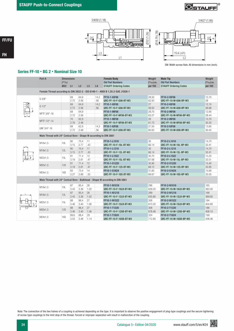
FF10
scale 0.65
D2A
L3L1
SW30 (1.18)
32(1
.26)
19.79
(.78)
15.6 (.61)L2
D2 A
SW27 (1.06)
Series FF-10 § BG 2 § Nominal Size 10Port A Dimensions Female Body Weight Male Tip Weight
(mm/in) Old Part Numbers (kg/lbs) ca. Old Part Numbers (kg/lbs) ca.
ØD2 L1 L2 L3 L4 STAUFF Ordering Codes per 100 STAUFF Ordering Codes per 100
Female Thread according to DIN 3852-2 - ISO 6149-1 - ANSI B 1.20.3-SAE J1926-1
G 3/8" 69 64,9 14,2 FF10-1-IGF06 28,50 FF10-2-IGF06 12,702.72 2.56 .56 QRC-FF-10-F-G06-BT-W3 62.83 QRC-FF-10-M-G06-BP-W3 28
G 1/2" 69 64,9 14,2 FF10-1-IGF08 27 FF10-2-IGF08 12,102.72 2.56 .56 QRC-FF-10-F-G08-BT-W3 59.52 QRC-FF-10-M-G08-BP-W3 26.68
NPTF 3/8"-1869 64,9 FF10-1-INF06 28,70 FF10-2-INF06 12,902.72 2.56 QRC-FF-10-F-NF06-BT-W3 63.27 QRC-FF-10-M-NF06-BP-W3 28.44
NPTF 1/2"-14 70 62,9 FF10-1-INF08 28 FF10-2-INF08 13,702.76 2.48 QRC-FF-10-F-NF08-BT-W3 61.73 QRC-FF-10-M-NF08-BP-W3 30.20
UNF 3/4"-1669 62,9 14,3 FF10-1-IUF08 27,50 FF10-2-IUF08 13,802.72 2.48 .56 QRC-FF-10-F-U08-BT-W3 60.63 QRC-FF-10-M-U08-BP-W3 30.42
Male Thread with 24° Conical Bore - Shape W according to DIN 3861
M16x1,5 10L80 70,4 11 FF10-1-L1016 30 FF10-2-L1016 14,703.15 2.77 .43 QRC-FF-10-F-10L-BT-W3 66.14 QRC-FF-10-M-10L-BP-W3 32.41
M18x1,5 12L80 70,4 11 FF10-1-L1218 30 FF10-2-L1218 14,703.15 2.77 .43 QRC-FF-10-F-12L-BT-W3 66.14 QRC-FF-10-M-12L-BP-W3 32.41
M22x1,5 15L81 71,4 12 FF10-1-L1522 30,70 FF10-2-L1522 15,203.19 2.81 .47 QRC-FF-10-F-15L-BT-W3 67.68 QRC-FF-10-M-15L-BP-W3 33.51
M20x1,5 12S81 71,4 12 FF10-1-S1220 30,90 FF10-2-S1220 15,403.19 2.81 .47 QRC-FF-10-F-12S-BT-W3 68.12 QRC-FF-10-M-12S-BP-W3 33.95
M24x1,5 16S83 73,4 14 FF10-1-S1624 31,60 FF10-2-S1624 15,903.27 2.89 .55 QRC-FF-10-F-16S-BT-W3 69.67 QRC-FF-10-M-16S-BP-W3 35.05
Male Thread with 24° Conical Bore - Bulkhead - Shape W according to DIN 3861
M16x1,5 10L87 85,4 26 FF10-1-N1016 286 FF10-2-N1016 1653.43 3.36 1.02 QRC-FF-10-F-10LB-BT-W3 629.20 QRC-FF-10-M-10LB-BP-W3 363.00
M18x1,5 12L87 85,4 26 FF10-1-N1218 289 FF10-2-N1218 1683.43 3.36 1.02 QRC-FF-10-F-12LB-BT-W3 635.80 QRC-FF-10-M-12LB-BP-W3 369.60
M22x1,5 15L88 86,4 27 FF10-1-N1522 306 FF10-2-N1522 1843.46 3.40 1.06 QRC-FF-10-F-15LB-BT-W3 673.20 QRC-FF-10-M-15LB-BP-W3 404.80
M20x1,5 12S88 86,4 27 FF10-1-T1220 308 FF10-2-T1220 1863.46 3.40 1.06 QRC-FF-10-F-12SB-BT-W3 678.48 QRC-FF-10-M-12SB-BP-W3 408.10
M24x1,5 16S89,6 88,4 29 FF10-1-T1624 324 FF10-2-T1624 1993.53 3.48 1.14 QRC-FF-10-F-16SB-BT-W3 712.80 QRC-FF-10-M-16SB-BP-W3 438.46
A A
L3 L3
L4
Anschlüsse-Beispiele.pdf 1 10.09.13 15:44
A A
L3 L3
L4
Anschlüsse-Beispiele.pdf 1 10.09.13 15:44
SW: Width across flats. All dimensions in mm (inch).
A A
L3 L3
L4
Anschlüsse-Beispiele.pdf 1 10.09.13 15:44
Note: The connection of the two halves of a coupling is achieved depending on the type. It is important to observe the positive engagement of plug-type couplings and the secure tightening of screw-type couplings to the limit stop of the thread. Forced or improper separation will result in malfunction of the coupling.
www.stauff.com/5/en/#25 25
FF/FU
FH
STAUFF Push-to-Connect Couplings
Catalogue 5 § Edition 04/2020
Note: The connection of the two halves of a coupling is achieved depending on the type. It is important to observe the positive engagement of plug-type couplings and the secure tightening of screw-type couplings to the limit stop of the thread. Forced or improper separation will result in malfunction of the coupling.
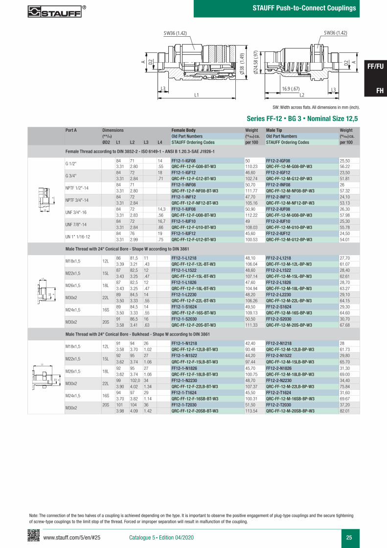
FF12
scale 0.6338
(1.49
)
L1L3
D2A
SW36 (1.42)
D2 A
L3L2
24.58
(.97)
SW36 (1.42)
16.9 (.67)
Series FF-12 § BG 3 § Nominal Size 12,5Port A Dimensions Female Body Weight Male Tip Weight
(mm/in) Old Part Numbers (kg/lbs) ca. Old Part Numbers (kg/lbs) ca.
ØD2 L1 L2 L3 L4 STAUFF Ordering Codes per 100 STAUFF Ordering Codes per 100
Female Thread according to DIN 3852-2 - ISO 6149-1 - ANSI B 1.20.3-SAE J1926-1
G 1/2" 84 71 14 FF12-1-IGF08 50 FF12-2-IGF08 25,503.31 2.80 .55 QRC-FF-12-F-G08-BT-W3 110.23 QRC-FF-12-M-G08-BP-W3 56.22
G 3/4" 84 72 18 FF12-1-IGF12 46,60 FF12-2-IGF12 23,503.31 2.84 .71 QRC-FF-12-F-G12-BT-W3 102.74 QRC-FF-12-M-G12-BP-W3 51.81
NPTF 1/2"-14 84 71 FF12-1-INF08 50,70 FF12-2-INF08 263.31 2.80 QRC-FF-12-F-NF08-BT-W3 111.77 QRC-FF-12-M-NF08-BP-W3 57.32
NPTF 3/4"-14 84 72 FF12-1-INF12 47,70 FF12-2-INF12 24,103.31 2.84 QRC-FF-12-F-NF12-BT-W3 105.16 QRC-FF-12-M-NF12-BP-W3 53.13
UNF 3/4"-1684 72 14,3 FF12-1-IUF08 50,90 FF12-2-IUF08 26,303.31 2.83 .56 QRC-FF-12-F-U08-BT-W3 112.22 QRC-FF-12-M-U08-BP-W3 57.98
UNF 7/8"-1484 72 16,7 FF12-1-IUF10 49 FF12-2-IUF10 25,303.31 2.84 .66 QRC-FF-12-F-U10-BT-W3 108.03 QRC-FF-12-M-U10-BP-W3 55.78
UN 1" 1/16-1284 76 19 FF12-1-IUF12 45,60 FF12-2-IUF12 24,503.31 2.99 .75 QRC-FF-12-F-U12-BT-W3 100.53 QRC-FF-12-M-U12-BP-W3 54.01
Male Thread with 24° Conical Bore - Shape W according to DIN 3861
M18x1,5 12L86 81,5 11 FF12-1-L1218 48,10 FF12-2-L1218 27,703.39 3.21 .43 QRC-FF-12-F-12L-BT-W3 106.04 QRC-FF-12-M-12L-BP-W3 61.07
M22x1,5 15L87 82,5 12 FF12-1-L1522 48,60 FF12-2-L1522 28,403.43 3.25 .47 QRC-FF-12-F-15L-BT-W3 107.14 QRC-FF-12-M-15L-BP-W3 62.61
M26x1,5 18L87 82,5 12 FF12-1-L1826 47,60 FF12-2-L1826 28,703.43 3.25 .47 QRC-FF-12-F-18L-BT-W3 104.94 QRC-FF-12-M-18L-BP-W3 63.27
M30x2 22L89 84,5 14 FF12-1-L2230 48,20 FF12-2-L2230 29,103.50 3.33 .55 QRC-FF-12-F-22L-BT-W3 106.26 QRC-FF-12-M-22L-BP-W3 64.15
M24x1,5 16S89 84,5 14 FF12-1-S1624 49,50 FF12-2-S1624 29,303.50 3.33 .55 QRC-FF-12-F-16S-BT-W3 109.13 QRC-FF-12-M-16S-BP-W3 64.60
M30x2 20S91 86,5 16 FF12-1-S2030 50,50 FF12-2-S2030 30,703.58 3.41 .63 QRC-FF-12-F-20S-BT-W3 111.33 QRC-FF-12-M-20S-BP-W3 67.68
Male Thread with 24° Conical Bore - Bulkhead - Shape W according to DIN 3861
M18x1,5 12L91 94 26 FF12-1-N1218 42,40 FF12-2-N1218 283.58 3.70 1.02 QRC-FF-12-F-12LB-BT-W3 93.48 QRC-FF-12-M-12LB-BP-W3 61.73
M22x1,5 15L92 95 27 FF12-1-N1522 44,20 FF12-2-N1522 29,803.62 3.74 1.06 QRC-FF-12-F-15LB-BT-W3 97.44 QRC-FF-12-M-15LB-BP-W3 65.70
M26x1,5 18L92 95 27 FF12-1-N1826 45,70 FF12-2-N1826 31,303.62 3.74 1.06 QRC-FF-12-F-18LB-BT-W3 100.75 QRC-FF-12-M-18LB-BP-W3 69.00
M30x2 22L99 102,0 34 FF12-1-N2230 48,70 FF12-2-N2230 34,403.90 4.02 1.34 QRC-FF-12-F-22LB-BT-W3 107.37 QRC-FF-12-M-22LB-BP-W3 75.84
M24x1,5 16S94 97 29 FF12-1-T1624 45,50 FF12-2-T1624 31,603.70 3.82 1.14 QRC-FF-12-F-16SB-BT-W3 100.31 QRC-FF-12-M-16SB-BP-W3 69.67
M30x220S 101 104 36 FF12-1-T2030 51,50 FF12-2-T2030 37,20
3.98 4.09 1.42 QRC-FF-12-F-20SB-BT-W3 113.54 QRC-FF-12-M-20SB-BP-W3 82.01
A A
L3 L3
L4
Anschlüsse-Beispiele.pdf 1 10.09.13 15:44
A A
L3 L3
L4
Anschlüsse-Beispiele.pdf 1 10.09.13 15:44
SW: Width across flats. All dimensions in mm (inch).
A A
L3 L3
L4
Anschlüsse-Beispiele.pdf 1 10.09.13 15:44
26 www.stauff.com/5/en/#26
FF/FU
FH
STAUFF Push-to-Connect Couplings
Catalogue 5 § Edition 04/2020
Note: The connection of the two halves of a coupling is achieved depending on the type. It is important to observe the positive engagement of plug-type couplings and the secure tightening of screw-type couplings to the limit stop of the thread. Forced or improper separation will result in malfunction of the coupling.
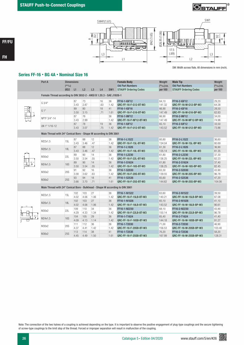
Series FF-16 § BG 4A § Nominal Size 16Port A Dimensions Female Body Weight Male Tip Weight
(mm/in) Old Part Numbers (kg/lbs) ca. Old Part Numbers (kg/lbs) ca.
ØD2 L1 L2 L3 L4 SW1 STAUFF Ordering Codes per 100 STAUFF Ordering Codes per 100
Female Thread according to DIN 3852-2 - ANSI B 1.20.3 - SAE J1926-1
G 3/4"87 73 16 36 FF16-1-IGF12 64,10 FF16-2-IGF12 29,203.43 2.87 .63 1.42 QRC-FF-16-F-G12-BT-W3 141.32 QRC-FF-16-M-G12-BP-W3 64.38
G 1"89 80 18 41 FF16-1-IGF16 66,90 FF16-2-IGF16 28,503.50 3.15 .71 1.61 QRC-FF-16-F-G16-BT-W3 147.49 QRC-FF-16-M-G16-BP-W3 62.83
NPTF 3/4"-1487 76 36 FF16-1-INF12 66,90 FF16-2-INF12 34,003.43 2.99 1.42 QRC-FF-16-F-NF12-BT-W3 147.49 QRC-FF-16-M-NF12-BP-W3 74.96
UN 1" 1/16-1287 78 19 36 FF16-1-IUF12 65,10 FF16-2-IUF12 33,503.43 3.07 .75 1.42 QRC-FF-16-F-U12-BT-W3 143.52 QRC-FF-16-M-U12-BP-W3 73.86
Male Thread with 24° Conical Bore - Shape W according to DIN 3861
M22x1,5 15L87 88 12 36 FF16-1-L1522 60,80 FF16-2-L1522 36,603.43 3.46 .47 1.42 QRC-FF-16-F-15L-BT-W3 134.04 QRC-FF-16-M-15L-BP-W3 80.69
M26x1,5 18L87 88 12 36 FF16-1-L1826 61,30 FF16-2-L1826 36,903.43 3.46 .47 1.42 QRC-FF-16-F-18L-BT-W3 135.14 QRC-FF-16-M-18L-BP-W3 81.35
M30x2 22L89 90 14 36 FF16-1-L2230 61,80 FF16-2-L2230 37,303.50 3.54 .55 1.42 QRC-FF-16-F-22L-BT-W3 136.25 QRC-FF-16-M-22L-BP-W3 82.23
M24x1,5 16S89 90 14 36 FF16-1-S1624 61,80 FF16-2-S1624 37,403.50 3.54 .55 1.42 QRC-FF-16-F-16S-BT-W3 136.25 QRC-FF-16-M-16S-BP-W3 82.45
M30x2 20S91 92 16 36 FF16-1-S2030 63,30 FF16-2-S2030 43.903.58 3.62 .63 1.42 QRC-FF-16-F-20S-BT-W3 139.55 QRC-FF-16-M-20S-BP-W3 96.78
M36x2 25S93 94 18 41 FF16-1-S2536 65,60 FF16-2-S2536 47,203.66 3.70 .71 1.61 QRC-FF-16-F-25S-BT-W3 144.62 QRC-FF-16-M-25S-BP-W3 104.06
Male Thread with 24° Conical Bore - Bulkhead - Shape W according to DIN 3861
M22x1,5 15L102 103 27 36 FF16-1-N1522 63,60 FF16-2-N1522 39,504.02 4.06 1.06 1.42 QRC-FF-16-F-15LB-BT-W3 140.21 QRC-FF-16-M-15LB-BP-W3 87.08
M26x1,5 18L102 103 27 36 FF16-1-N1826 65,10 FF16-2-N1826 41,104.02 4.06 1.06 1.42 QRC-FF-16-F-18LB-BT-W3 143.52 QRC-FF-16-M-18LB-BP-W3 90.61
M30x2 22L109 110 34 36 FF16-1-N2230 68,10 FF16-2-N2230 43,904.29 4.33 1.34 1.42 QRC-FF-16-F-22LB-BT-W3 150.14 QRC-FF-16-M-22LB-BP-W3 96.78
M24x1,5 16S104 105 29 36 FF16-1-T1624 65,40 FF16-2-T1624 41,404.09 4.13 1.14 1.42 QRC-FF-16-F-16SB-BT-W3 144.18 QRC-FF-16-M-16SB-BP-W3 91.27
M30x2 20S111 112 36 36 FF16-1-T2030 71,00 FF16-2-T2030 46,904.37 4.41 1.42 1.42 QRC-FF-16-F-20SB-BT-W3 156.53 QRC-FF-16-M-20SB-BP-W3 103.40
M36x2 25S113 114 38 41 FF16-1-T2536 76,20 FF16-2-T2536 58,204.45 4.49 1.50 1.61 QRC-FF-16-F-25SB-BT-W3 167.99 QRC-FF-16-M-25SB-BP-W3 128.31
A A
L3 L3
L4
Anschlüsse-Beispiele.pdf 1 10.09.13 15:44
A A
L3 L3
L4
Anschlüsse-Beispiele.pdf 1 10.09.13 15:44
A A
L3 L3
L4
Anschlüsse-Beispiele.pdf 1 10.09.13 15:44
SW: Width across flats. All dimensions in mm (inch).
FF16
scale 0.68
A D2
42Ø (1
.65)
26.95
Ø (1
.06)
L1L3
L2L3
SW41(1.61) SW1
AD2
17.5(.69)
www.stauff.com/5/en/#27 27
FF/FU
FH
STAUFF Push-to-Connect Couplings
Catalogue 5 § Edition 04/2020
Note: The connection of the two halves of a coupling is achieved depending on the type. It is important to observe the positive engagement of plug-type couplings and the secure tightening of screw-type couplings to the limit stop of the thread. Forced or improper separation will result in malfunction of the coupling.
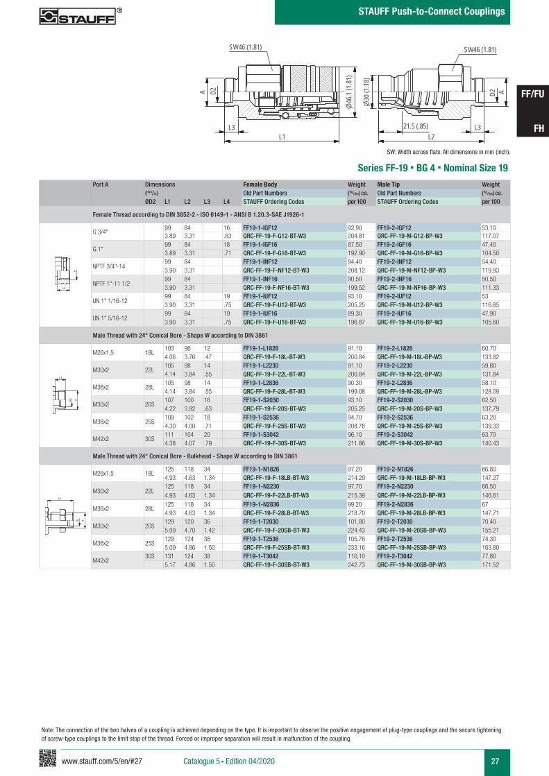
FF19
scale 0.5530
(1.18
)
D2 A
L2L321.5 (.85)
SW46 (1.81)
46.1
(1.81
)
L3L1
D2A
SW46 (1.81)
Series FF-19 § BG 4 § Nominal Size 19Port A Dimensions Female Body Weight Male Tip Weight
(mm/in) Old Part Numbers (kg/lbs) ca. Old Part Numbers (kg/lbs) ca.
ØD2 L1 L2 L3 L4 STAUFF Ordering Codes per 100 STAUFF Ordering Codes per 100
Female Thread according to DIN 3852-2 - ISO 6149-1 - ANSI B 1.20.3-SAE J1926-1
G 3/4" 99 84 16 FF19-1-IGF12 92,90 FF19-2-IGF12 53,103.89 3.31 .63 QRC-FF-19-F-G12-BT-W3 204.81 QRC-FF-19-M-G12-BP-W3 117.07
G 1" 99 84 18 FF19-1-IGF16 87,50 FF19-2-IGF16 47,403.89 3.31 .71 QRC-FF-19-F-G16-BT-W3 192.90 QRC-FF-19-M-G16-BP-W3 104.50
NPTF 3/4"-14 99 84 FF19-1-INF12 94,40 FF19-2-INF12 54,403.90 3.31 QRC-FF-19-F-NF12-BT-W3 208.12 QRC-FF-19-M-NF12-BP-W3 119.93
NPTF 1"-11 1/299 84 FF19-1-INF16 90,50 FF19-2-INF16 50,503.90 3.31 QRC-FF-19-F-NF16-BT-W3 199.52 QRC-FF-19-M-NF16-BP-W3 111.33
UN 1" 1/16-1299 84 19 FF19-1-IUF12 93,10 FF19-2-IUF12 533.90 3.31 .75 QRC-FF-19-F-U12-BT-W3 205.25 QRC-FF-19-M-U12-BP-W3 116.85
UN 1" 5/16-1299 84 19 FF19-1-IUF16 89,30 FF19-2-IUF16 47,903.90 3.31 .75 QRC-FF-19-F-U16-BT-W3 196.87 QRC-FF-19-M-U16-BP-W3 105.60
Male Thread with 24° Conical Bore - Shape W according to DIN 3861
M26x1,5 18L103 96 12 FF19-1-L1826 91,10 FF19-2-L1826 60,704.06 3.76 .47 QRC-FF-19-F-18L-BT-W3 200.84 QRC-FF-19-M-18L-BP-W3 133.82
M30x2 22L105 98 14 FF19-1-L2230 91,10 FF19-2-L2230 59,804.14 3.84 .55 QRC-FF-19-F-22L-BT-W3 200.84 QRC-FF-19-M-22L-BP-W3 131.84
M36x2 28L105 98 14 FF19-1-L2836 90,30 FF19-2-L2836 58,104.14 3.84 .55 QRC-FF-19-F-28L-BT-W3 199.08 QRC-FF-19-M-28L-BP-W3 128.09
M30x2 20S107 100 16 FF19-1-S2030 93,10 FF19-2-S2030 62,504.22 3.92 .63 QRC-FF-19-F-20S-BT-W3 205.25 QRC-FF-19-M-20S-BP-W3 137.79
M36x2 25S109 102 18 FF19-1-S2536 94,70 FF19-2-S2536 63,204.30 4.00 .71 QRC-FF-19-F-25S-BT-W3 208.78 QRC-FF-19-M-25S-BP-W3 139.33
M42x2 30S111 104 20 FF19-1-S3042 96,10 FF19-2-S3042 63,704.38 4.07 .79 QRC-FF-19-F-30S-BT-W3 211.86 QRC-FF-19-M-30S-BP-W3 140.43
Male Thread with 24° Conical Bore - Bulkhead - Shape W according to DIN 3861
M26x1,5 18L125 118 34 FF19-1-N1826 97,20 FF19-2-N1826 66,804.93 4.63 1.34 QRC-FF-19-F-18LB-BT-W3 214.29 QRC-FF-19-M-18LB-BP-W3 147.27
M30x2 22L125 118 34 FF19-1-N2230 97,70 FF19-2-N2230 66,504.93 4.63 1.34 QRC-FF-19-F-22LB-BT-W3 215.39 QRC-FF-19-M-22LB-BP-W3 146.61
M36x2 28L125 118 34 FF19-1-N2836 99,20 FF19-2-N2836 674.93 4.63 1.34 QRC-FF-19-F-28LB-BT-W3 218.70 QRC-FF-19-M-28LB-BP-W3 147.71
M30x2 20S129 120 36 FF19-1-T2030 101,80 FF19-2-T2030 70,405.09 4.70 1.42 QRC-FF-19-F-20SB-BT-W3 224.43 QRC-FF-19-M-20SB-BP-W3 155.21
M36x2 25S129 124 38 FF19-1-T2536 105,76 FF19-2-T2536 74,305.09 4.86 1.50 QRC-FF-19-F-25SB-BT-W3 233.16 QRC-FF-19-M-25SB-BP-W3 163.80
M42x230S 131 124 38 FF19-1-T3042 110,10 FF19-2-T3042 77,80
5.17 4.86 1.50 QRC-FF-19-F-30SB-BT-W3 242.73 QRC-FF-19-M-30SB-BP-W3 171.52
A A
L3 L3
L4
Anschlüsse-Beispiele.pdf 1 10.09.13 15:44
A A
L3 L3
L4
Anschlüsse-Beispiele.pdf 1 10.09.13 15:44
SW: Width across flats. All dimensions in mm (inch).
A A
L3 L3
L4
Anschlüsse-Beispiele.pdf 1 10.09.13 15:44
28 www.stauff.com/5/en/#28
FF/FU
FH
STAUFF Push-to-Connect Couplings
Catalogue 5 § Edition 04/2020
Note: The connection of the two halves of a coupling is achieved depending on the type. It is important to observe the positive engagement of plug-type couplings and the secure tightening of screw-type couplings to the limit stop of the thread. Forced or improper separation will result in malfunction of the coupling.
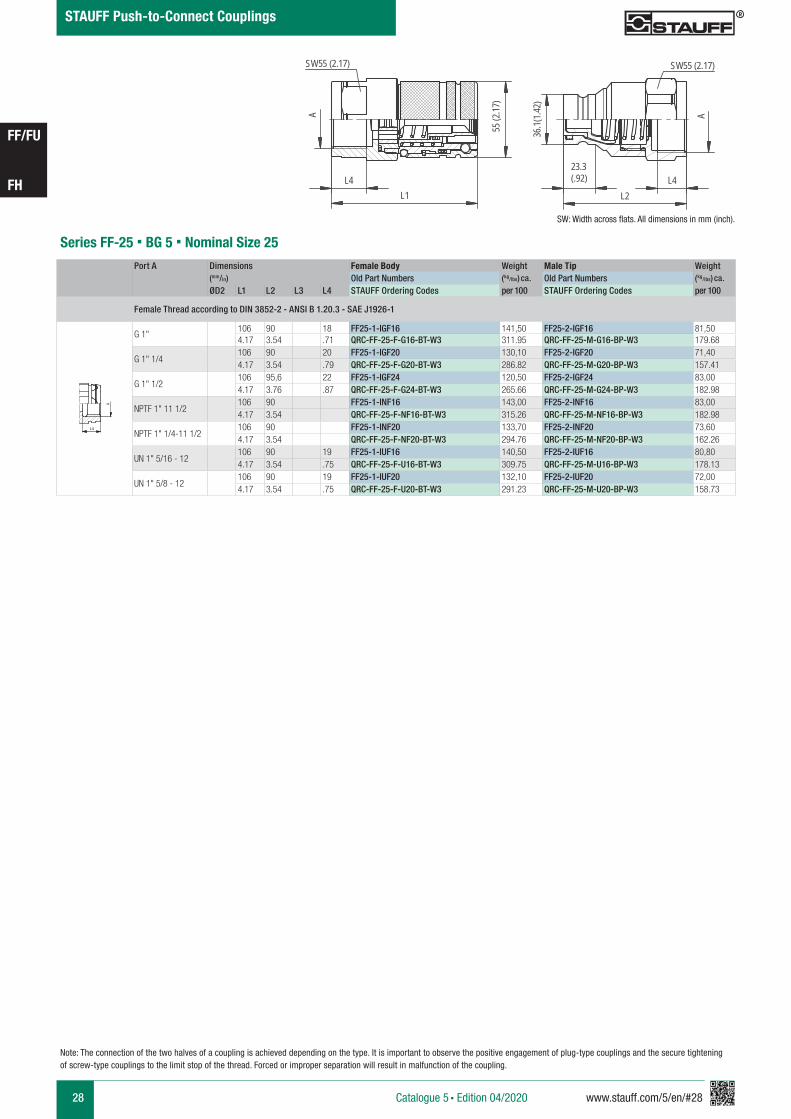
Series FF-25 § BG 5 § Nominal Size 25Port A Dimensions Female Body Weight Male Tip Weight
(mm/in) Old Part Numbers (kg/lbs) ca. Old Part Numbers (kg/lbs) ca.
ØD2 L1 L2 L3 L4 STAUFF Ordering Codes per 100 STAUFF Ordering Codes per 100
Female Thread according to DIN 3852-2 - ANSI B 1.20.3 - SAE J1926-1
G 1"106 90 18 FF25-1-IGF16 141,50 FF25-2-IGF16 81,504.17 3.54 .71 QRC-FF-25-F-G16-BT-W3 311.95 QRC-FF-25-M-G16-BP-W3 179.68
G 1" 1/4106 90 20 FF25-1-IGF20 130,10 FF25-2-IGF20 71,404.17 3.54 .79 QRC-FF-25-F-G20-BT-W3 286.82 QRC-FF-25-M-G20-BP-W3 157.41
G 1" 1/2106 95,6 22 FF25-1-IGF24 120,50 FF25-2-IGF24 83,004.17 3.76 .87 QRC-FF-25-F-G24-BT-W3 265.66 QRC-FF-25-M-G24-BP-W3 182.98
NPTF 1" 11 1/2106 90 FF25-1-INF16 143,00 FF25-2-INF16 83,004.17 3.54 QRC-FF-25-F-NF16-BT-W3 315.26 QRC-FF-25-M-NF16-BP-W3 182.98
NPTF 1" 1/4-11 1/2106 90 FF25-1-INF20 133,70 FF25-2-INF20 73,604.17 3.54 QRC-FF-25-F-NF20-BT-W3 294.76 QRC-FF-25-M-NF20-BP-W3 162.26
UN 1" 5/16 - 12106 90 19 FF25-1-IUF16 140,50 FF25-2-IUF16 80,804.17 3.54 .75 QRC-FF-25-F-U16-BT-W3 309.75 QRC-FF-25-M-U16-BP-W3 178.13
UN 1" 5/8 - 12106 90 19 FF25-1-IUF20 132,10 FF25-2-IUF20 72,004.17 3.54 .75 QRC-FF-25-F-U20-BT-W3 291.23 QRC-FF-25-M-U20-BP-W3 158.73
A A
L3 L3
L4
Anschlüsse-Beispiele.pdf 1 10.09.13 15:44
SW: Width across flats. All dimensions in mm (inch).
FF25
scale 0.5
Schraffuren bitte unter 45° oder 135° anlegen
L1 L2
23.3(.92)
55 (2
.17)
36.1(
1.42)
AA
SW55 (2.17) SW55 (2.17)
L4 L4
www.stauff.com/5/en/#29 29
FF/FU
FH
STAUFF Push-to-Connect Couplings
Catalogue 5 § Edition 04/2020
Note: The connection of the two halves of a coupling is achieved depending on the type. It is important to observe the positive engagement of plug-type couplings and the secure tightening of screw-type couplings to the limit stop of the thread. Forced or improper separation will result in malfunction of the coupling.
FX 32
scale 0.3
A
L4
80Ø
L1
SW 80 SW65
A
L2L430.8
57Ø
SW 80 (3.15)
Ø80
(3.1
5)
Series FF-38 § BG 6 § Nominal Size 38
Port A Dimensions Female Body Weight Male Tip Weight (mm/in) Old Part Numbers (kg/lbs) ca. Old Part Numbers (kg/lbs) ca.
ØD2 L1 L2 L3 L4 STAUFF Ordering Codes per 100 STAUFF Ordering Codes per 100
Female Thread according to ISO 3852-2 - ANSI B 1.20.3 - SAE J1926-1
G 1 1/4“131,6 124,6 21,5 FF38-1-IGF20 388,40 FF38-2-IGF20 218,605.18 4.91 .85 QRC-FF-38-F-G20-S1-W3 856.28 QRC-FF-38-M-G20-BT-W3 481.93
G 1 1/2“131,6 124,6 23 FF38-1-IGF24 379,10 FF38-2-IGF24 209,905.18 4.91 .89 QRC-FF-38-F-G24-S1-W3 835.77 QRC-FF-38-M-G24-BT-W3 462.75
NPTF 1" 1/4- 11 1/2131,6 124,6 FF38-1-INF20 390,50 FF38-2-INF20 221,105.18 4.91 QRC-FF-38-F-NF20-S1-W3 860.91 QRC-FF-38-M-NF20-BT-W3 487.44
NPTF 1" 1/2- 11 1/2131,6 124,6 FF38-1-INF24 381,20 FF38-2-INF24 216,805.18 4.91 QRC-FF-38-F-NF24-S1-W3 840.40 QRC-FF-38-M-NF24-BT-W3 477.96
UN 1" 5/8-12131,6 124,6 19 FF38-1-IUF20 387,70 FF38-2-IUF20 218,505.18 4.91 .75 QRC-FF-38-F-U20-S1-W3 854.73 QRC-FF-38-M-U20-BT-W3 481.71
UN 1" 7/8-12131,6 124,6 19 FF38-1-IUF24 376,10 FF38-2-IUF24 210,305.18 4.91 .75 QRC-FF-38-F-U24-S1-W3 829.16 QRC-FF-38-M-U24-BT-W3 463.63
A A
L3 L3
L4
Anschlüsse-Beispiele.pdf 1 10.09.13 15:44
SW: Width across flats. All dimensions in mm (inch).
30,8(1.21)
SW 65 (2.56)
Series FH/FU 51 § BG 7 § Nominal Size 51
SW: Width across flats. All dimensions in mm (inch).
Port A Dimensions Female Body Weight Male Tip Weight (mm/in) Old Part Numbers (kg/lbs) ca. Old Part Numbers (kg/lbs) ca. ØD2 L1 L2 L3 L4 STAUFF Ordering Codes per 100 STAUFF Ordering Codes per 100
Female Thread according to DIN 3852-2-A - ANSI B 1.20.3
G 2"147,4 173 24 FH51-1-IGF32 550 FU51-2-IGF32 4895.80 6.81 .94 QRC-FH-51-F-G32-BT-W66 1212.54 QRC-FU-51-M-G32-BT-W66 1078.06
NPTF 2" -11 1/2147,4 173 FH51-1-INF32 540 FU51-2-INF32 4795.80 6.81 QRC-FH-51-F-NF32-BT-W66 1190.50 QRC-FU-51-M-NF32-BT-W66 1056.01
FH51-1-2-IGF32 mit FU Stecker
ähnlich wie FH12
scale 0,74
A
L4
L1
103(
4.05)
SW80 (3.15)72
,9(2
.87)
A
L2
L4
SW80 (3.15)
A A
L3 L3
L4
Anschlüsse-Beispiele.pdf 1 10.09.13 15:44
30 www.stauff.com/5/en/#30
FF/FU
FH
Catalogue 5 § Edition 04/2020
STAUFF Push-to-Connect Couplings
Note: The connection of the two halves of a coupling is achieved depending on the type. It is important to observe the positive engagement of plug-type couplings and the secure tightening of screw-type couplings to the limit stop of the thread. Forced or improper separation will result in malfunction of the coupling.
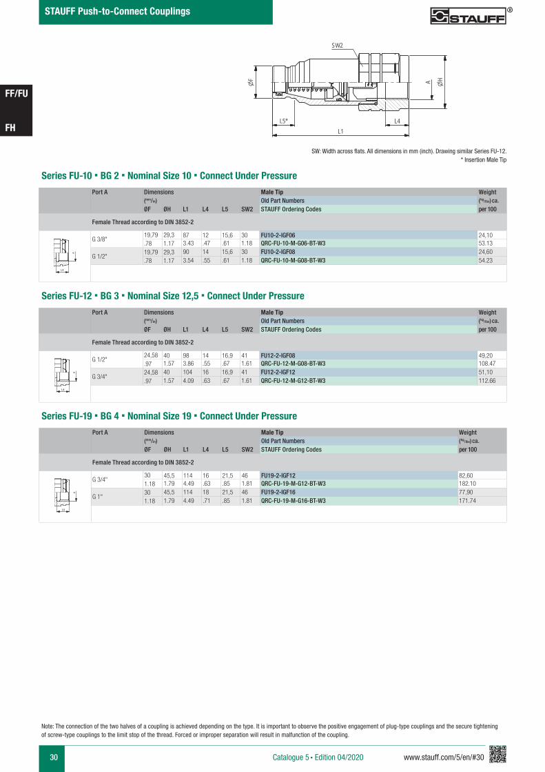
Series FU-10 § BG 2 § Nominal Size 10 § Connect Under PressurePort A Dimensions Male Tip Weight
(mm/in) Old Part Numbers (kg/lbs) ca.
ØF ØH L1 L4 L5 SW2 STAUFF Ordering Codes per 100
Female Thread according to DIN 3852-2
G 3/8"19,79 29,3 87 12 15,6 30 FU10-2-IGF06 24,10.78 1.17 3.43 .47 .61 1.18 QRC-FU-10-M-G06-BT-W3 53.13
G 1/2"19,79 29,3 90 14 15,6 30 FU10-2-IGF08 24,60.78 1.17 3.54 .55 .61 1.18 QRC-FU-10-M-G08-BT-W3 54.23
A A
L3 L3
L4
Anschlüsse-Beispiele.pdf 1 10.09.13 15:44
SW: Width across flats. All dimensions in mm (inch). Drawing similar Series FU-12.* Insertion Male Tip
FU 10-19 Stecker
Stahl
scale 0.74
L1
A H
L5*
F
SW2
zeichnerische Darstellung entspricht Serie FU 12 * Eintauchtiefe Stecker
L4
Series FU-12 § BG 3 § Nominal Size 12,5 § Connect Under Pressure
Port A Dimensions Male Tip Weight (mm/in) Old Part Numbers (kg/lbs) ca.
ØF ØH L1 L4 L5 SW2 STAUFF Ordering Codes per 100
Female Thread according to DIN 3852-2
G 1/2"24,58 40 98 14 16,9 41 FU12-2-IGF08 49,20.97 1.57 3.86 .55 .67 1.61 QRC-FU-12-M-G08-BT-W3 108.47
G 3/4"24,58 40 104 16 16,9 41 FU12-2-IGF12 51,10.97 1.57 4.09 .63 .67 1.61 QRC-FU-12-M-G12-BT-W3 112.66
A A
L3 L3
L4
Anschlüsse-Beispiele.pdf 1 10.09.13 15:44
Series FU-19 § BG 4 § Nominal Size 19 § Connect Under PressurePort A Dimensions Male Tip Weight
(mm/in) Old Part Numbers (kg/lbs) ca.
ØF ØH L1 L4 L5 SW2 STAUFF Ordering Codes per 100
Female Thread according to DIN 3852-2
G 3/4"30 45,5 114 16 21,5 46 FU19-2-IGF12 82,601.18 1.79 4.49 .63 .85 1.81 QRC-FU-19-M-G12-BT-W3 182.10
G 1"30 45,5 114 18 21,5 46 FU19-2-IGF16 77,901.18 1.79 4.49 .71 .85 1.81 QRC-FU-19-M-G16-BT-W3 171.74
A A
L3 L3
L4
Anschlüsse-Beispiele.pdf 1 10.09.13 15:44
www.stauff.com/5/en/#31 31
FF/FU
FH
Catalogue 5 § Edition 04/2020
STAUFF Push-to-Connect Couplings
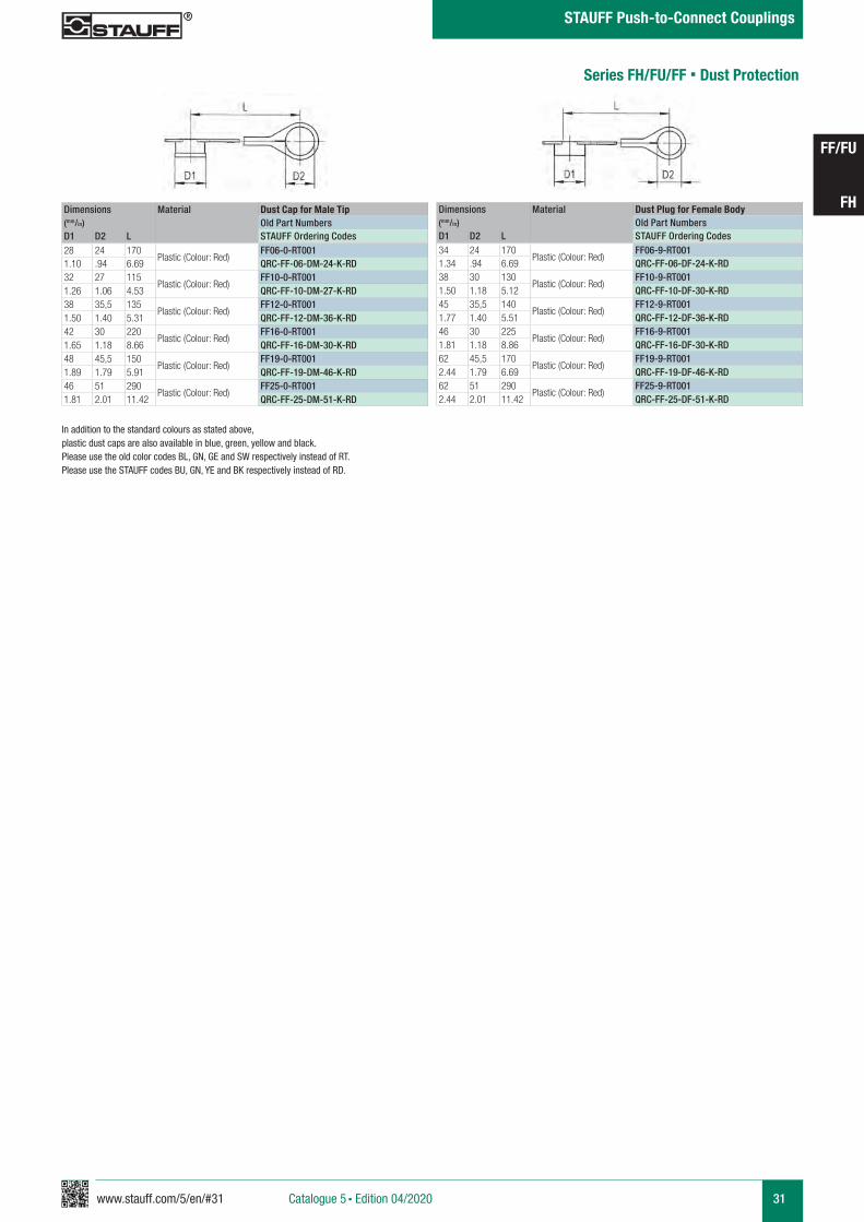
Dimensions Material Dust Cap for Male Tip(mm/in) Old Part NumbersD1 D2 L STAUFF Ordering Codes28 24 170
Plastic (Colour: Red)FF06-0-RT001
1.10 .94 6.69 QRC-FF-06-DM-24-K-RD32 27 115
Plastic (Colour: Red)FF10-0-RT001
1.26 1.06 4.53 QRC-FF-10-DM-27-K-RD38 35,5 135
Plastic (Colour: Red)FF12-0-RT001
1.50 1.40 5.31 QRC-FF-12-DM-36-K-RD42 30 220
Plastic (Colour: Red)FF16-0-RT001
1.65 1.18 8.66 QRC-FF-16-DM-30-K-RD48 45,5 150
Plastic (Colour: Red)FF19-0-RT001
1.89 1.79 5.91 QRC-FF-19-DM-46-K-RD46 51 290
Plastic (Colour: Red)FF25-0-RT001
1.81 2.01 11.42 QRC-FF-25-DM-51-K-RD
Series FH/FU/FF § Dust Protection
Dimensions Material Dust Plug for Female Body(mm/in) Old Part NumbersD1 D2 L STAUFF Ordering Codes34 24 170
Plastic (Colour: Red)FF06-9-RT001
1.34 .94 6.69 QRC-FF-06-DF-24-K-RD38 30 130
Plastic (Colour: Red)FF10-9-RT001
1.50 1.18 5.12 QRC-FF-10-DF-30-K-RD45 35,5 140
Plastic (Colour: Red)FF12-9-RT001
1.77 1.40 5.51 QRC-FF-12-DF-36-K-RD46 30 225
Plastic (Colour: Red)FF16-9-RT001
1.81 1.18 8.86 QRC-FF-16-DF-30-K-RD62 45,5 170
Plastic (Colour: Red)FF19-9-RT001
2.44 1.79 6.69 QRC-FF-19-DF-46-K-RD62 51 290
Plastic (Colour: Red)FF25-9-RT001
2.44 2.01 11.42 QRC-FF-25-DF-51-K-RD
In addition to the standard colours as stated above, plastic dust caps are also available in blue, green, yellow and black. Please use the old color codes BL, GN, GE and SW respectively instead of RT.Please use the STAUFF codes BU, GN, YE and BK respectively instead of RD.
32 www.stauff.com/5/en/#32
FF/FU
FH
Catalogue 5 § Edition 08/2019
STAUFF Push-to-Connect Couplings
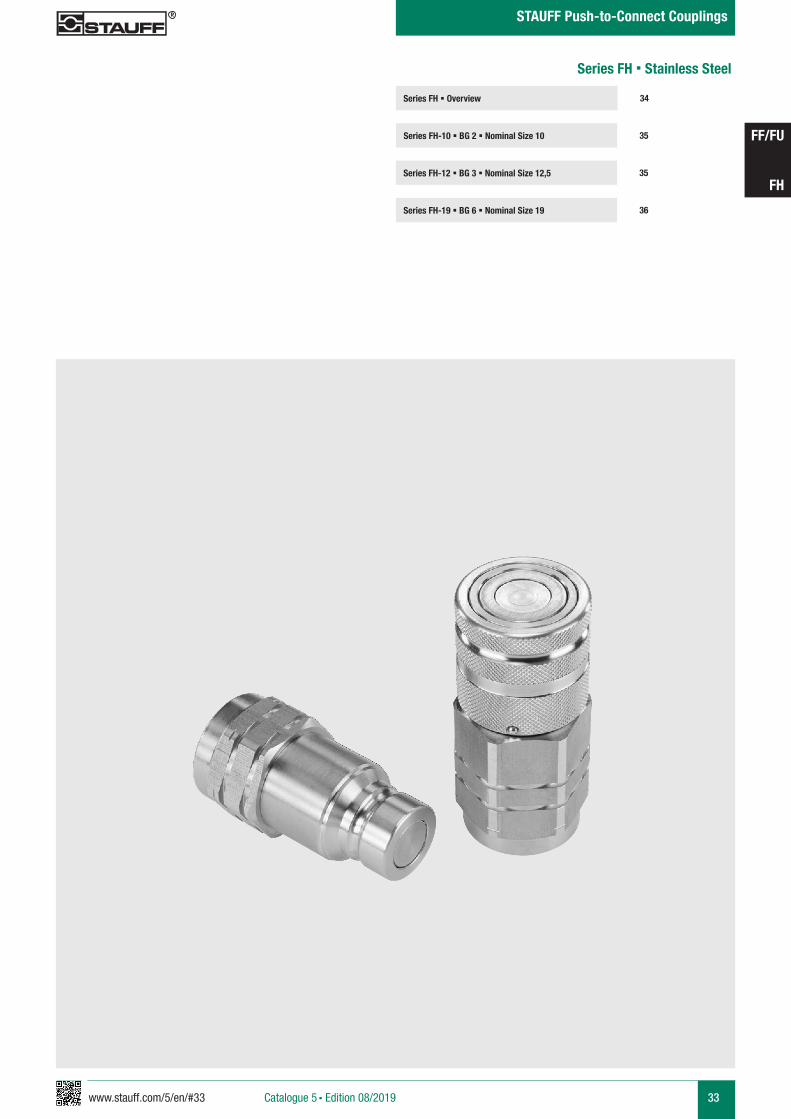
www.stauff.com/5/en/#33 33
FF/FU
FH
Catalogue 5 § Edition 08/2019
STAUFF Push-to-Connect Couplings
Series FH § Overview
Series FH-10 § BG 2 § Nominal Size 10 35
34
Series FH-12 § BG 3 § Nominal Size 12,5 35
Series FH-19 § BG 6 § Nominal Size 19 36
Series FH § Stainless Steel
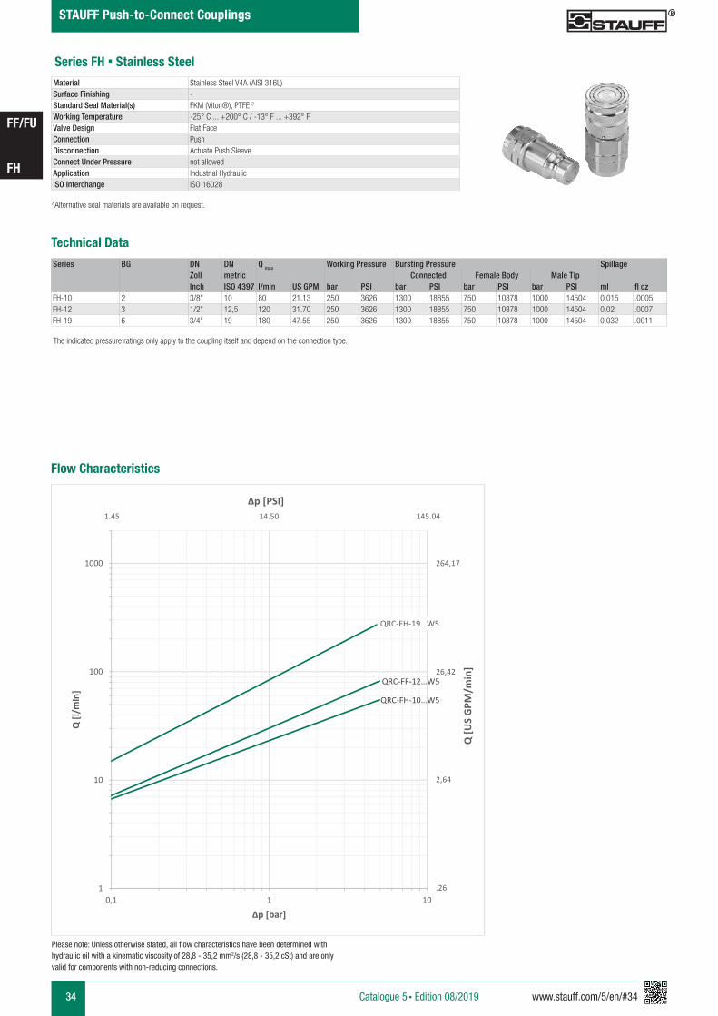
34 www.stauff.com/5/en/#34
FF/FU
FH
Catalogue 5 § Edition 08/2019
STAUFF Push-to-Connect Couplings
Series FH § Stainless Steel
Series BG DN DN Q max Working Pressure Bursting Pressure SpillageZoll metric Connected Female Body Male TipInch ISO 4397 l/min US GPM bar PSI bar PSI bar PSI bar PSI ml fl oz
FH-10 2 3/8" 10 80 21.13 250 3626 1300 18855 750 10878 1000 14504 0,015 .0005FH-12 3 1/2" 12,5 120 31.70 250 3626 1300 18855 750 10878 1000 14504 0,02 .0007FH-19 6 3/4" 19 180 47.55 250 3626 1300 18855 750 10878 1000 14504 0,032 .0011
2 Alternative seal materials are available on request.
Technical Data
Material Stainless Steel V4A (AISI 316L)Surface Finishing -Standard Seal Material(s) FKM (Viton®), PTFE 2
Working Temperature -25° C ... +200° C / -13° F ... +392° FValve Design Flat FaceConnection PushDisconnection Actuate Push SleeveConnect Under Pressure not allowedApplication Industrial HydraulicISO Interchange ISO 16028
The indicated pressure ratings only apply to the coupling itself and depend on the connection type.
Please note: Unless otherwise stated, all flow characteristics have been determined with hydraulic oil with a kinematic viscosity of 28,8 - 35,2 mm2/s (28,8 - 35,2 cSt) and are only valid for components with non-reducing connections.
Flow Characteristics
QRC-FH-10…W5
QRC-FF-12…W5
QRC-FH-19…W5
1
10
100
1000
0,1 1 10
Q [l/
min
]
Δp [bar]
Q [U
S G
PM/m
in]
Δp [PSI]
264,17
26,42
2,64
.26
1.45 14.50 145.04
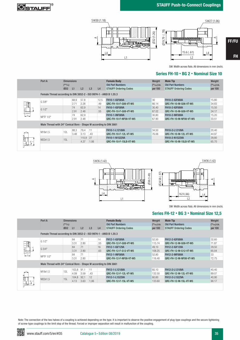
www.stauff.com/5/en/#35 35
FF/FU
FH
Catalogue 5 § Edition 08/2019
STAUFF Push-to-Connect Couplings
Series FH-10 § BG 2 § Nominal Size 10
Port A Dimensions Female Body Weight Male Tip Weight (mm/in) Old Part Numbers (kg/lbs) ca. Old Part Numbers (kg/lbs) ca.
ØD2 L1 L2 L3 L4 STAUFF Ordering Codes per 100 STAUFF Ordering Codes per 100
Female Thread according to DIN 3852-2 - ISO 9974-1 - ANSI B 1.20.3
G 3/8"68,9 57,8 12,5 FH10-1-IGF06VA 30 FH10-2-IGF06VA 15,802.71 2.28 .49 QRC-FH-10-F-G06-VT-W5 66.14 QRC-FH-10-M-G06-VT-W5 34.83
G 1/2"74 62,9 14 FH10-1-IGF08VA 30,40 FH10-2-IGF08VA 15,502.91 2.48 .55 QRC-FH-10-F-G08-VT-W5 67.02 QRC-FH-10-M-G08-VT-W5 34.17
NPTF 1/2" 74 62,9 FH10-1-INF08VA 30,80 FH10-2-INF08VA 15,202.91 2.48 QRC-FH-10-F-NF08-VT-W5 67.90 QRC-FH-10-M-NF08-VT-W5 33.51
Male Thread with 24° Conical Bore - Shape W according to DIN 3861
M18x1,5 12L88,3 79,4 11 FH10-1-L1218VA 34,50 FH10-2-L1218VA 20,403.48 3.13 .43 QRC-FH-10-F-12L-VT-W5 76.06 QRC-FH-10-M-12L-VT-W5 44.97
M22x1,5 15L110,9 27 FH10-1-N1522VA FH10-2-N1522VA 29,804.37 1.06 QRC-FH-10-F-15LB-VT-W5 QRC-FH-10-M-15LB-VT-W5 65.70
A A
L3 L3
L4
Anschlüsse-Beispiele.pdf 1 10.09.13 15:44
SW: Width across flats. All dimensions in mm (inch).
A A
L3 L3
L4
Anschlüsse-Beispiele.pdf 1 10.09.13 15:44
FH10_VA
scale 0.74
A
SW30 (1.18)
L4L1
A
L2L4
SW27 (1.06)
19.79
(.78
)
15.6 ( .61)
32(1
.26)
Note: The connection of the two halves of a coupling is achieved depending on the type. It is important to observe the positive engagement of plug-type couplings and the secure tightening of screw-type couplings to the limit stop of the thread. Forced or improper separation will result in malfunction of the coupling.
Series FH-12 § BG 3 § Nominal Size 12,5Port A Dimensions Female Body Weight Male Tip Weight
(mm/in) Old Part Numbers (kg/lbs) ca. Old Part Numbers (kg/lbs) ca.
ØD2 L1 L2 L3 L4 STAUFF Ordering Codes per 100 STAUFF Ordering Codes per 100
Female Thread according to DIN 3852-2 - ISO 9974-1 - ANSI B 1.20.3
G 1/2" 84 71 14 FH12-1-IGF08VA 52,50 FH12-2-IGF08VA 32,603.31 2.80 .55 QRC-FH-12-F-G08-VT-W5 115.74 QRC-FH-12-M-G08-VT-W5 71.87
G 3/4"84 71 16 FH12-1-IGF12VA 49,10 FH12-2-IGF12VA 29,503.31 2.80 .63 QRC-FH-12-F-G12-VT-W5 108.25 QRC-FH-12-M-G12-VT-W5 65.04
NPTF 1/2" 84 71 FH12-1-INF08VA 52,80 FH12-2-INF08VA 333.31 2.80 QRC-FH-12-F-NF08-VT-W5 116.40 QRC-FH-12-M-NF08-VT-W5 72.75
Male Thread with 24° Conical Bore - Shape W according to DIN 3861
M18x1,5 12L103,8 91,1 11 FH12-1-L1218VA 60,10 FH12-2-L1218VA 40,404.09 3.59 .43 QRC-FH-12-F-12L-VT-W5 132.50 QRC-FH-12-M-12L-VT-W5 89.07
M22x1,5 15L104,8 92,1 12 FH12-1-L1522VA 60,60 FH12-2-L1522VA 40,904.13 3.63 1,06 QRC-FH-12-F-15L-VT-W5 133.60 QRC-FH-12-M-15L-VT-W5 90.17
A A
L3 L3
L4
Anschlüsse-Beispiele.pdf 1 10.09.13 15:44
SW: Width across flats. All dimensions in mm (inch).
A A
L3 L3
L4
Anschlüsse-Beispiele.pdf 1 10.09.13 15:44
FH12_VA
scale 0.65
L4L2
24.58
(.97
)
L4
L1
AA
38(1
.49)
SW36 (1.42) SW36 (1.42)
16.9 (.66)
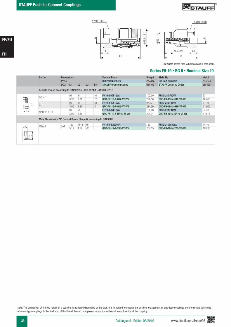
36 www.stauff.com/5/en/#36
FF/FU
FH
Catalogue 5 § Edition 08/2019
STAUFF Push-to-Connect Couplings
Series FH-19 § BG 6 § Nominal Size 19Port A Dimensions Female Body Weight Male Tip Weight
(mm/in) Old Part Numbers (kg/lbs) ca. Old Part Numbers (kg/lbs) ca.
ØD2 L1 L2 L3 L4 STAUFF Ordering Codes per 100 STAUFF Ordering Codes per 100
Female Thread according to DIN 3852-2 - ISO 9974-1 - ANSI B 1.20.3
G 3/4"99 84 16 FH19-1-IGF12VA 102,90 FH19-2-IGF12VA 573.90 3.31 .63 QRC-FH-19-F-G12-VT-W5 226.86 QRC-FH-19-M-G12-VT-W5 125.66
G 1"99 84 18 FH19-1-IGF16VA 97,20 FH19-2-IGF16VA 51,103.90 3.31 .71 QRC-FH-19-F-G16-VT-W5 214.29 QRC-FH-19-M-G16-VT-W5 112.66
NPTF 1"-11 ½ 99 84 FH19-1-INF16VA 100,40 FH19-2-INF16VA 54,303.90 3.31 QRC-FH-19-F-NF16-VT-W5 221.34 QRC-FH-19-M-NF16-VT-W5 119.71
Male Thread with 24° Conical Bore - Shape W according to DIN 3861
M30x2 20S130 114,8 16 FH19-1-S2030VA 120 FH19-2-S2030VA 74,105.12 4.52 .63 QRC-FH-19-F-20S-VT-W5 264.55 QRC-FH-19-M-20S-VT-W5 163.36
A A
L3 L3
L4
Anschlüsse-Beispiele.pdf 1 10.09.13 15:44
SW: Width across flats. All dimensions in mm (inch).
A A
L3 L3
L4
Anschlüsse-Beispiele.pdf 1 10.09.13 15:44
FH19_VA
scale 0.6546
.1(1
.81)
SW46 (1.81)
A
L4
L1
L4
L2
A
30(1
.18)
SW46 (1.81)
21.5 (.85)
Note: The connection of the two halves of a coupling is achieved depending on the type. It is important to observe the positive engagement of plug-type couplings and the secure tightening of screw-type couplings to the limit stop of the thread. Forced or improper separation will result in malfunction of the coupling.
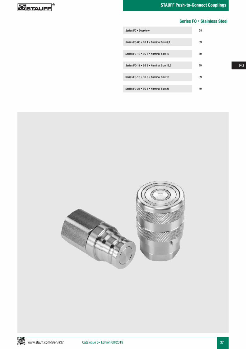
www.stauff.com/5/en/#37 37
FO
Catalogue 5 § Edition 08/2019
STAUFF Push-to-Connect Couplings
Series FO § Overview
Series FO-06 § BG 1 § Nominal Size 6,3 39
38
Series FO-10 § BG 2 § Nominal Size 10 39
Series FO-19 § BG 6 § Nominal Size 19 39
Series FO-25 § BG 8 § Nominal Size 25 40
Series FO-12 § BG 3 § Nominal Size 12,5 39
Series FO § Stainless Steel
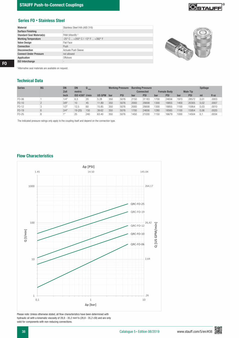
38 www.stauff.com/5/en/#38
FO
Catalogue 5 § Edition 08/2019
STAUFF Push-to-Connect Couplings
Series FO § Stainless Steel
Series BG DN DN Q max Working Pressure Bursting Pressure SpillageZoll metric Connected Female Body Male TipInch ISO 4397 l/min US GPM bar PSI bar PSI bar PSI bar PSI ml fl oz
FO-06 1 1/4" 6,3 20 5.28 350 5076 2150 31183 1700 24656 1970 28572 0,01 .0003FO-10 2 3/8" 10 45 11.89 350 5076 2000 29008 1300 18855 1400 20305 0,02 .0007FO-12 3 1/2" 12,5 60 15.85 350 5076 2000 29008 1300 18855 1100 15954 0,03 .0010FO-19 6 3/4" 19 (20) 150 39.62 350 5076 1700 24656 1280 18565 1100 15954 0,06 .0020FO-25 8 1" 25 240 63.40 350 5076 1450 21030 1150 16679 1000 14504 0,1 .0034
Technical Data
Material Stainless Steel V4A (AISI 316)Surface Finishing -Standard Seal Material(s) FKM (Viton®) 2
Working Temperature -25° C ... +200° C / -13° F ... +392° FValve Design Flat FaceConnection PushDisconnection Actuate Push SleeveConnect Under Pressure not allowedApplication OffshoreISO Interchange -
The indicated pressure ratings only apply to the coupling itself and depend on the connection type.
2 Alternative seal materials are available on request.
Please note: Unless otherwise stated, all flow characteristics have been determined with hydraulic oil with a kinematic viscosity of 28,8 - 35,2 mm2/s (28,8 - 35,2 cSt) and are only valid for components with non-reducing connections.
Flow Characteristics
QRC-FO-06
QRC-FO-10
QRC-FO-12
QRC-FO-19
QRC-FO-25
1
10
100
1000
0,1 1 10
Q [l/
min
]
Δp [bar]
Q [U
S G
PM/m
in]
Δp [PSI]
264,17
26,42
2,64
.26
1.45 14.50 145.04
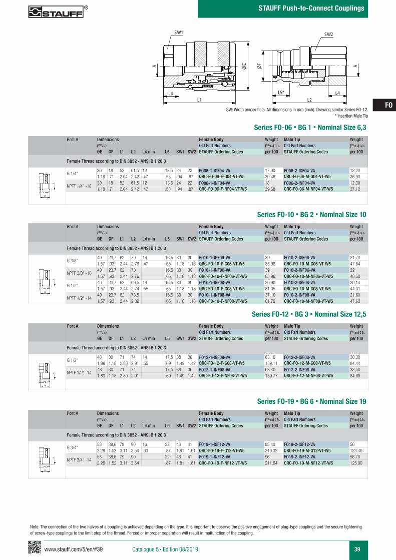
www.stauff.com/5/en/#39 39
FO
Catalogue 5 § Edition 08/2019
STAUFF Push-to-Connect Couplings
Port A Dimensions Female Body Weight Male Tip Weight (mm/in) Old Part Numbers (kg/lbs) ca. Old Part Numbers (kg/lbs) ca. ØE ØF L1 L2 L4 min L5 SW1 SW2 STAUFF Ordering Codes per 100 STAUFF Ordering Codes per 100
Female Thread according to DIN 3852 - ANSI B 1.20.3
G 1/4"30 18 52 61,5 12 13,5 24 22 FO06-1-IGF04-VA 17,90 FO06-2-IGF04-VA 12,201.18 .71 2.04 2.42 .47 .53 .94 .87 QRC-FO-06-F-G04-VT-W5 39.46 QRC-FO-06-M-G04-VT-W5 26.90
NPTF 1/4" -1830 18 52 61,5 12 13,5 24 22 FO06-1-INF04-VA 18 FO06-2-INF04-VA 12,301.18 .71 2.04 2.42 .47 .53 .94 .87 QRC-FO-06-F-NF04-VT-W5 39.68 QRC-FO-06-M-NF04-VT-W5 27.12
Series FO-06 § BG 1 § Nominal Size 6,3
FO06-FO25 - Muffe und Stecker-
Edelstahl
scale 0.74
A
SW2
F
L4L2
L4L1
A
SW1
L5*
zeichnerische Darstellung entspricht Serie FO 12 VA * Eintauchtiefe Stecker
A A
L3 L3
L4
Anschlüsse-Beispiele.pdf 1 10.09.13 15:44
SW: Width across flats. All dimensions in mm (inch). Drawing similar Series FO-12.* Insertion Male Tip
Note: The connection of the two halves of a coupling is achieved depending on the type. It is important to observe the positive engagement of plug-type couplings and the secure tightening of screw-type couplings to the limit stop of the thread. Forced or improper separation will result in malfunction of the coupling.
Series FO-10 § BG 2 § Nominal Size 10Port A Dimensions Female Body Weight Male Tip Weight
(mm/in) Old Part Numbers (kg/lbs) ca. Old Part Numbers (kg/lbs) ca. ØE ØF L1 L2 L4 min L5 SW1 SW2 STAUFF Ordering Codes per 100 STAUFF Ordering Codes per 100
Female Thread according to DIN 3852 - ANSI B 1.20.3
G 3/8"40 23,7 62 70 14 16,5 30 30 FO10-1-IGF06-VA 39 FO10-2-IGF06-VA 21,701.57 .93 2.44 2.76 .47 .65 1.18 1.18 QRC-FO-10-F-G06-VT-W5 85.98 QRC-FO-10-M-G06-VT-W5 47.84
NPTF 3/8" -1840 23,7 62 70 16,5 30 30 FO10-1-INF06-VA 39 FO10-2-INF06-VA 221.57 .93 2.44 2.76 .65 1.18 1.18 QRC-FO-10-F-NF06-VT-W5 85.98 QRC-FO-10-M-NF06-VT-W5 48.50
G 1/2"40 23,7 62 69,5 14 16,5 30 30 FO10-1-IGF08-VA 36,90 FO10-2-IGF08-VA 20,101.57 .93 2.44 2.74 .55 .65 1.18 1.18 QRC-FO-10-F-G08-VT-W5 81.35 QRC-FO-10-M-G08-VT-W5 44.31
NPTF 1/2" -1440 23,7 62 73,5 16,5 30 30 FO10-1-INF08-VA 37,10 FO10-2-INF08-VA 21,601.57 .93 2.44 2.89 .65 1.18 1.18 QRC-FO-10-F-NF08-VT-W5 81.79 QRC-FO-10-M-NF08-VT-W5 47.62
A A
L3 L3
L4
Anschlüsse-Beispiele.pdf 1 10.09.13 15:44
Port A Dimensions Female Body Weight Male Tip Weight (mm/in) Old Part Numbers (kg/lbs) ca. Old Part Numbers (kg/lbs) ca. ØE ØF L1 L2 L4 min L5 SW1 SW2 STAUFF Ordering Codes per 100 STAUFF Ordering Codes per 100
Female Thread according to DIN 3852 - ANSI B 1.20.3
G 1/2"48 30 71 74 14 17,5 38 36 FO12-1-IGF08-VA 63,10 FO12-2-IGF08-VA 38,301.89 1.18 2.80 2.91 .55 .69 1.49 1.42 QRC-FO-12-F-G08-VT-W5 139.11 QRC-FO-12-M-G08-VT-W5 84.44
NPTF 1/2" -1448 30 71 74 17,5 38 36 FO12-1-INF08-VA 63,40 FO12-2-INF08-VA 38,501.89 1.18 2.80 2.91 .69 1.49 1.42 QRC-FO-12-F-NF08-VT-W5 139.77 QRC-FO-12-M-NF08-VT-W5 84.88
Series FO-12 § BG 3 § Nominal Size 12,5
A A
L3 L3
L4
Anschlüsse-Beispiele.pdf 1 10.09.13 15:44
Series FO-19 § BG 6 § Nominal Size 19Port A Dimensions Female Body Weight Male Tip Weight
(mm/in) Old Part Numbers (kg/lbs) ca. Old Part Numbers (kg/lbs) ca. ØE ØF L1 L2 L4 min L5 SW1 SW2 STAUFF Ordering Codes per 100 STAUFF Ordering Codes per 100
Female Thread according to DIN 3852 - ANSI B 1.20.3
G 3/4"58 38,6 79 90 16 22 46 41 FO19-1-IGF12-VA 95,40 FO19-2-IGF12-VA 562.28 1.52 3.11 3.54 .63 .87 1.81 1.61 QRC-FO-19-F-G12-VT-W5 210.32 QRC-FO-19-M-G12-VT-W5 123.46
NPTF 3/4" -1458 38,6 79 90 22 46 41 FO19-1-INF12-VA 96 FO19-2-INF12-VA 56,702.28 1.52 3.11 3.54 .87 1.81 1.61 QRC-FO-19-F-NF12-VT-W5 211.64 QRC-FO-19-M-NF12-VT-W5 125.00
A A
L3 L3
L4
Anschlüsse-Beispiele.pdf 1 10.09.13 15:44
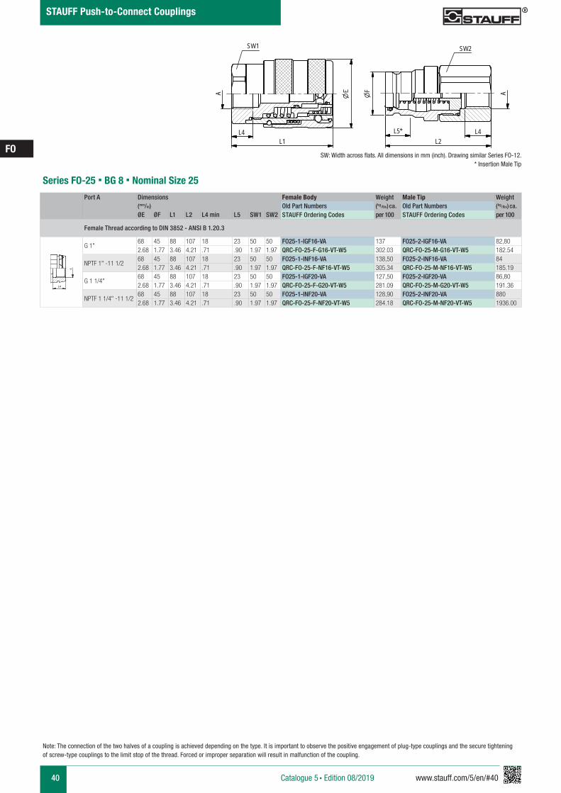
40 www.stauff.com/5/en/#40
FO
Catalogue 5 § Edition 08/2019
STAUFF Push-to-Connect Couplings
Note: The connection of the two halves of a coupling is achieved depending on the type. It is important to observe the positive engagement of plug-type couplings and the secure tightening of screw-type couplings to the limit stop of the thread. Forced or improper separation will result in malfunction of the coupling.
Port A Dimensions Female Body Weight Male Tip Weight (mm/in) Old Part Numbers (kg/lbs) ca. Old Part Numbers (kg/lbs) ca. ØE ØF L1 L2 L4 min L5 SW1 SW2 STAUFF Ordering Codes per 100 STAUFF Ordering Codes per 100
Female Thread according to DIN 3852 - ANSI B 1.20.3
G 1"68 45 88 107 18 23 50 50 FO25-1-IGF16-VA 137 FO25-2-IGF16-VA 82,802.68 1.77 3.46 4.21 .71 .90 1.97 1.97 QRC-FO-25-F-G16-VT-W5 302.03 QRC-FO-25-M-G16-VT-W5 182.54
NPTF 1" -11 1/268 45 88 107 18 23 50 50 FO25-1-INF16-VA 138,50 FO25-2-INF16-VA 842.68 1.77 3.46 4.21 .71 .90 1.97 1.97 QRC-FO-25-F-NF16-VT-W5 305.34 QRC-FO-25-M-NF16-VT-W5 185.19
G 1 1/4"68 45 88 107 18 23 50 50 FO25-1-IGF20-VA 127,50 FO25-2-IGF20-VA 86,802.68 1.77 3.46 4.21 .71 .90 1.97 1.97 QRC-FO-25-F-G20-VT-W5 281.09 QRC-FO-25-M-G20-VT-W5 191.36
NPTF 1 1/4" -11 1/268 45 88 107 18 23 50 50 FO25-1-INF20-VA 128,90 FO25-2-INF20-VA 8802.68 1.77 3.46 4.21 .71 .90 1.97 1.97 QRC-FO-25-F-NF20-VT-W5 284.18 QRC-FO-25-M-NF20-VT-W5 1936.00
Series FO-25 § BG 8 § Nominal Size 25
A A
L3 L3
L4
Anschlüsse-Beispiele.pdf 1 10.09.13 15:44
SW: Width across flats. All dimensions in mm (inch). Drawing similar Series FO-12.* Insertion Male Tip
FO06-FO25 - Muffe und Stecker-
Edelstahl
scale 0.74
A
SW2
F
L4L2
L4L1
A
SW1
L5*
zeichnerische Darstellung entspricht Serie FO 12 VA * Eintauchtiefe Stecker
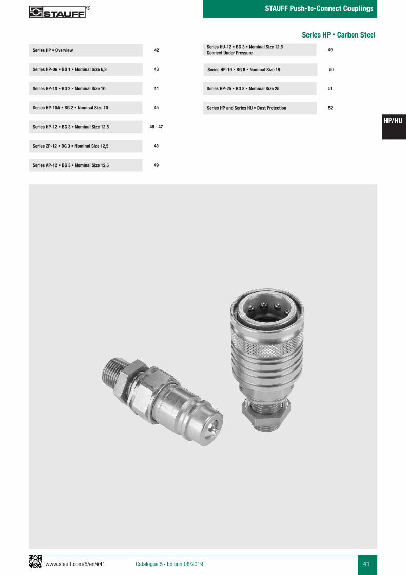
www.stauff.com/5/en/#41 41
HP/HU
Catalogue 5 § Edition 08/2019
STAUFF Push-to-Connect Couplings
Series HP-19 § BG 6 § Nominal Size 19
Series HP-25 § BG 8 § Nominal Size 25 51
50
Series HU-12 § BG 3 § Nominal Size 12,5 Connect Under Pressure
49Series HP § Overview
Series HP-06 § BG 1 § Nominal Size 6,3 43
42
Series HP-10 § BG 2 § Nominal Size 10 44
Series HP-12 § BG 3 § Nominal Size 12,5 46 - 47
Series ZP-12 § BG 3 § Nominal Size 12,5 48
Series HP-10A § BG 2 § Nominal Size 10 45 Series HP and Series HU § Dust Protection 52
Series AP-12 § BG 3 § Nominal Size 12,5 49
Series HP § Carbon Steel
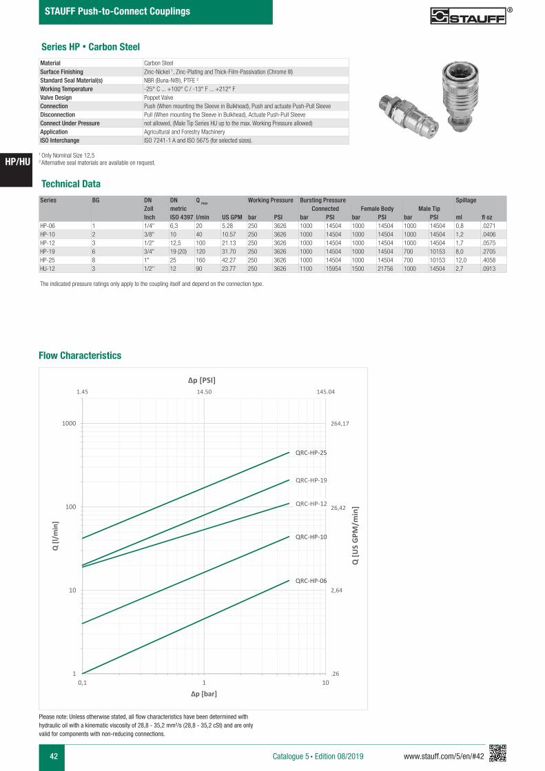
42 www.stauff.com/5/en/#42
HP/HU
Catalogue 5 § Edition 08/2019
STAUFF Push-to-Connect Couplings
Series HP § Carbon Steel
Series BG DN DN Q max Working Pressure Bursting Pressure SpillageZoll metric Connected Female Body Male TipInch ISO 4397 l/min US GPM bar PSI bar PSI bar PSI bar PSI ml fl oz
HP-06 1 1/4" 6,3 20 5.28 250 3626 1000 14504 1000 14504 1000 14504 0,8 .0271HP-10 2 3/8" 10 40 10.57 250 3626 1000 14504 1000 14504 1000 14504 1,2 .0406HP-12 3 1/2" 12,5 100 21.13 250 3626 1000 14504 1000 14504 1000 14504 1,7 .0575HP-19 6 3/4" 19 (20) 120 31.70 250 3626 1000 14504 1000 14504 700 10153 8,0 .2705HP-25 8 1" 25 160 42.27 250 3626 1000 14504 1000 14504 700 10153 12,0 .4058HU-12 3 1/2'' 12 90 23.77 250 3626 1100 15954 1500 21756 1000 14504 2,7 .0913
Technical Data
Material Carbon Steel Surface Finishing Zinc-Nickel 1, Zinc-Plating and Thick-Film-Passivation (Chrome III)Standard Seal Material(s) NBR (Buna-N®), PTFE 2
Working Temperature -25° C ... +100° C / -13° F ... +212° FValve Design Poppet ValveConnection Push (When mounting the Sleeve in Bulkhead), Push and actuate Push-Pull SleeveDisconnection Pull (When mounting the Sleeve in Bulkhead), Actuate Push-Pull SleeveConnect Under Pressure not allowed, (Male Tip Series HU up to the max. Working Pressure allowed)Application Agricultural and Forestry MachineryISO Interchange ISO 7241-1 A and ISO 5675 (for selected sizes).
The indicated pressure ratings only apply to the coupling itself and depend on the connection type.
1 Only Nominal Size 12,52 Alternative seal materials are available on request.
Please note: Unless otherwise stated, all flow characteristics have been determined with hydraulic oil with a kinematic viscosity of 28,8 - 35,2 mm2/s (28,8 - 35,2 cSt) and are only valid for components with non-reducing connections.
Flow Characteristics
QRC-HP-06
QRC-HP-10
QRC-HP-12
QRC-HP-19
QRC-HP-25
1
10
100
1000
0,1 1 10
Q [l/
min
]
Δp [bar]
Q [U
S G
PM/m
in]
Δp [PSI]
264,17
26,42
2,64
.26
1.45 14.50 145.04
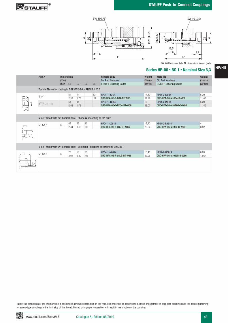
www.stauff.com/5/en/#43 43
HP/HU
Catalogue 5 § Edition 08/2019
STAUFF Push-to-Connect Couplings
Note: The connection of the two halves of a coupling is achieved depending on the type. It is important to observe the positive engagement of plug-type couplings and the secure tightening of screw-type couplings to the limit stop of the thread. Forced or improper separation will result in malfunction of the coupling.
Port A Dimensions Female Body Weight Male Tip Weight (mm/in) Old Part Numbers (kg/lbs) ca. Old Part Numbers (kg/lbs) ca. ØD2 L1 L2 L3 L4 STAUFF Ordering Codes per 100 STAUFF Ordering Codes per 100
Female Thread according to DIN 3852-2-A - ANSI B 1.20.3
G1/4"64 44 13 HP04-1-IGF04 14,60 HP04-2-IGF04 5,202.52 1.73 .51 QRC-HPA-06-F-G04-BT-W66 32.19 QRC-HPA-06-M-G04-B-W66 11.46
NPTF 1/4“ -1864 44 HP04-1-INF04 15 HP04-2-INF04 5,202.52 1.73 QRC-HPA-06-F-NF04-BT-W66 33.07 QRC-HPA-06-M-NF04-B-W66 11.46
Male Thread with 24° Conical Bore - Shape W according to DIN 3861
M14x1,5 8L62 42 10 HP04-1-L0814 13,40 HP04-2-L0814 42.44 1.65 .39 QRC-HPA-06-F-08L-BT-W66 29.54 QRC-HPA-06-M-08L-B-W66 8.82
Male Thread with 24° Conical Bore - Bulkhead - Shape W according to DIN 3861
M14x1,5 8L77 59 25 HP04-1-N0814 15,40 HP04-2-N0814 6,203.01 2.30 .98 QRC-HPA-06-F-08LB-BT-W66 33.95 QRC-HPA-06-M-08LB-B-W66 13.67
Series HP-06 § BG 1 § Nominal Size 6,3
HP 04
s cale 1
A D2
L3L1
26�
SW19
12�
13.5 L3L2
AD2
SW19
ØØ
HP 04.pdf 1 09.02.2017 09:15:16
SW 19 (.75) SW 19 (.75)
Ø26
(1.0
2)
Ø12
(.47
)
13,5(.53)
A A
L3 L3
L4
Anschlüsse-Beispiele.pdf 1 10.09.13 15:44
A A
L3 L3
L4
Anschlüsse-Beispiele.pdf 1 10.09.13 15:44
A A
L3 L3
L4
Anschlüsse-Beispiele.pdf 1 10.09.13 15:44
SW: Width across flats. All dimensions in mm (inch).
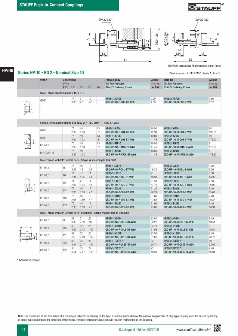
44 www.stauff.com/5/en/#44
HP/HU
Catalogue 5 § Edition 08/2019
STAUFF Push-to-Connect Couplings
HP 08
s cale 0,875
L3
L1
A D2 �
SW22
17.3
�
13.8 L3
L2
AD2
SW22
Ø32
Ø
HP 08.pdf 1 09.02.2017 09:15:45
SW 22 (.87)SW 22 (.87)
Ø32
(1.2
6)
Ø17
,3 (.
68)
13,8 (.54)
Series HP-10 § BG 2 § Nominal Size 10
Port A Dimensions Female Body Weight Male Tip Weight (mm/in) Old Part Numbers (kg/lbs) ca. Old Part Numbers (kg/lbs) ca.
ØD2 L1 L2 L3 L4 STAUFF Ordering Codes per 100 STAUFF Ordering Codes per 100
Male Thread according to ISO 1179-4-B
G3/8"77 51 12 HP08-1-AGF06 2,20 HP08-2-AGF06 7,803.03 2.01 .47 QRC-HP-10-F-B06-BT-W66 4.85 QRC-HP-10-M-B06-B-W66 17.2
Female Thread according to DIN 3852-2-A - ISO 9974-1 - ANSI B 1.20.3
G1/4"76 49 13 HP08-1-IGF04 19,50 HP08-2-IGF04 882.99 1.93 .51 QRC-HP-10-F-G04-BT-W66 42.99 QRC-HP-10-M-G04-B-W66 193.60
G3/8"76 49 13 HP08-1-IGF06 18,80 HP08-2-IGF06 802.99 1.93 .51 QRC-HP-10-F-G06-BT-W66 41.45 QRC-HP-10-M-G06-B-W66 176.00
M16x1,576 49 13 HP08-1-IMF16 18,80 HP08-2-IMF16 812.99 1.93 .51 QRC-HP-10-F-M16-BT-W66 41.45 QRC-HP-10-M-M16-B-W66 178.20
NPTF 3/8"-1876 49 HP08-1-INF06 18,80 HP08-2-INF06 812.99 1.93 QRC-HP-10-F-NF06-BT-W66 41.45 QRC-HP-10-M-NF06-B-W66 178.20
Male Thread with 24° Conical Bore - Shape W according to DIN 3861
M14x1,5 8L73 46 10 HP08-1-L0814 21 HP08-2-L0814 4,202.87 1.81 .39 QRC-HP-10-F-08L-BT-W66 46.30 QRC-HP-10-M-08L-B-W66 9.26
M16x1,5 10L74 47 11 HP08-1-L1016 21 HP08-2-L1016 6,502.91 1.85 .43 QRC-HP-10-F-10L-BT-W66 46.30 QRC-HP-10-M-10L-B-W66 14.33
M18x1,5 12L74 47 11 HP08-1-L1218 21,50 HP08-2-L1218 7,302.91 1.84 .43 QRC-HP-10-F-12L-BT-W66 47.40 QRC-HP-10-M-12L-B-W66 16,09
M16x1,5 8S75 48 12 HP08-1-S0816 21,20 HP08-2-S0816 7,102.95 1.89 .47 QRC-HP-10-F-08S-BT-W66 46.74 QRC-HP-10-M-08S-B-W66 15.65
M18x1,5 10S75 48 12 HP08-1-S1018 21,60 HP08-2-S1018 7,202.95 1.89 .47 QRC-HP-10-F-10S-BT-W66 47.62 QRC-HP-10-M-10S-B-W66 15.87
M20x1,5 12S75 48 12 HP08-1-S1220 21,60 HP08-2-S1220 7,402.95 1.89 .47 QRC-HP-10-F-12S-BT-W66 47.62 QRC-HP-10-M-12S-B-W66 16.31
Male Thread with 24° Conical Bore - Bulkhead - Shape W according to DIN 3861
M14x1,5 8L88 61 25 HP08-1-N0814 22,80 HP08-2-N0814 8,403.46 2.39 .98 QRC-HP-10-F-08LB-BT-W66 50.27 QRC-HP-10-M-08LB-B-W66 18.51
M16x1,5 10L89 62 26 HP08-1-N1016 23,40 HP08-2-N1016 93.50 2.43 1.02 QRC-HP-10-F-10LB-BT-W66 51.59 QRC-HP-10-M-10LB-B-W66 19.84
M18x1,5 12L89 62 26 HP08-1-N1218 23,50 HP08-2-N1218 9,403.50 2.43 1.02 QRC-HP-10-F-12LB-BT-W66 51.81 QRC-HP-10-M-12LB-B-W66 20.72
M16x1,5 08S90 63 27 HP08-1-T0816 * 23 HP08-2-T0816 * 103.54 2.47 1.06 QRC-HP-10-F-08SB-BT-W66 * 50.71 QRC-HP-10-M-08SB-B-W66 * 22.05
M20x1,5 12S90 63 27 HP08-1-T1220 * 22 HP08-2-T1220 * 7,403.54 2.47 1.06 QRC-HP-10-F-12SB-BT-W66 * 48.50 QRC-HP-10-M-12SB-B-W66 * 16.31
* Available on request.
A A
L3 L3
L4
Anschlüsse-Beispiele.pdf 1 10.09.13 15:44
A A
L3 L3
L4
Anschlüsse-Beispiele.pdf 1 10.09.13 15:44
A A
L3 L3
L4
Anschlüsse-Beispiele.pdf 1 10.09.13 15:44
A A
L3 L3
L4
Anschlüsse-Beispiele.pdf 1 10.09.13 15:44
SW: Width across flats. All dimensions in mm (inch).
Note: The connection of the two halves of a coupling is achieved depending on the type. It is important to observe the positive engagement of plug-type couplings and the secure tightening of screw-type couplings to the limit stop of the thread. Forced or improper separation will result in malfunction of the coupling.
Dimensions acc. to ISO 7241-1, Series A, Size 10.
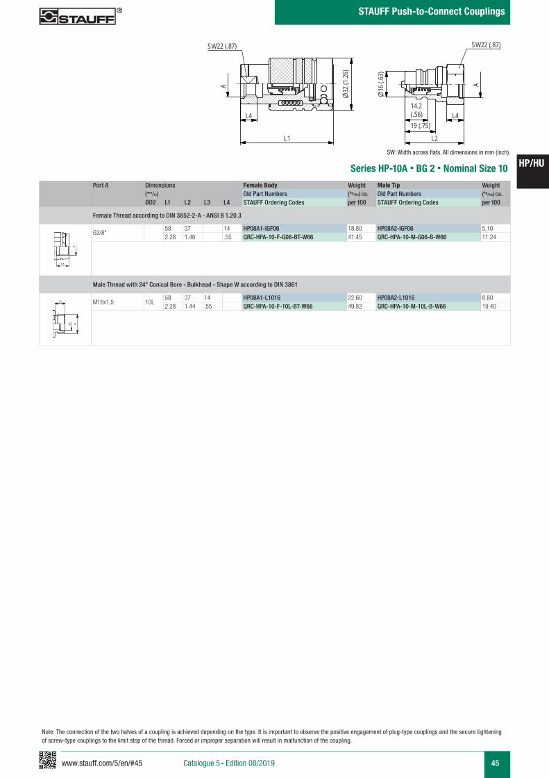
www.stauff.com/5/en/#45 45
HP/HU
Catalogue 5 § Edition 08/2019
STAUFF Push-to-Connect Couplings
Note: The connection of the two halves of a coupling is achieved depending on the type. It is important to observe the positive engagement of plug-type couplings and the secure tightening of screw-type couplings to the limit stop of the thread. Forced or improper separation will result in malfunction of the coupling.
Series HP-10A § BG 2 § Nominal Size 10
Port A Dimensions Female Body Weight Male Tip Weight (mm/in) Old Part Numbers (kg/lbs) ca. Old Part Numbers (kg/lbs) ca. ØD2 L1 L2 L3 L4 STAUFF Ordering Codes per 100 STAUFF Ordering Codes per 100
Female Thread according to DIN 3852-2-A - ANSI B 1.20.3
G3/8"58 37 14 HP08A1-IGF06 18,80 HP08A2-IGF06 5,102.28 1.46 .55 QRC-HPA-10-F-G06-BT-W66 41.45 QRC-HPA-10-M-G06-B-W66 11.24
Male Thread with 24° Conical Bore - Bulkhead - Shape W according to DIN 3861
M16x1,5 10L58 37 14 HP08A1-L1016 22,60 HP08A2-L1016 8,802.28 1.44 .55 QRC-HPA-10-F-10L-BT-W66 49.82 QRC-HPA-10-M-10L-B-W66 19.40
A A
L3 L3
L4
Anschlüsse-Beispiele.pdf 1 10.09.13 15:44
A A
L3 L3
L4
Anschlüsse-Beispiele.pdf 1 10.09.13 15:44
HP08A
scale 0,875
SW22 (.87) SW22 (.87)
A
L1
32(1
.26)
16(.6
3)
14.2(.56)19 (.75)
L2
A
L4 L4
SW: Width across flats. All dimensions in mm (inch).
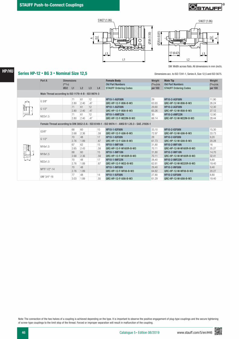
46 www.stauff.com/5/en/#46
HP/HU
Catalogue 5 § Edition 08/2019
STAUFF Push-to-Connect Couplings
Port A Dimensions Female Body Weight Male Tip Weight (mm/in) Old Part Numbers (kg/lbs) ca. Old Part Numbers (kg/lbs) ca. ØD2 L1 L2 L3 L4 STAUFF Ordering Codes per 100 STAUFF Ordering Codes per 100
Male Thread according to ISO 1179-4-B - ISO 9974-3
G 3/8"71 61 12 HP10-1-AGF06N 29 HP10-2-AGF06N 11,902.80 2.40 .47 QRC-HP-12-F-B06-B-W3 63.93 QRC-HP-12-M-B06-B-W3 26.24
G 1/2"71 61 12 HP10-1-AGF08N 29,60 HP10-2-AGF08N 12,302.80 2.40 .47 QRC-HP-12-F-B08-B-W3 65.26 QRC-HP-12-M-B08-B-W3 27.12
M22x1,571 61 12 HP10-1-AMF22N 30 HP10-2-AMF22N 12,902.80 2.40 .47 QRC-HP-12-F-M22M-B-W3 66.14 QRC-HP-12-M-M22M-B-W3 28.44
Female Thread according to DIN 3852-2-A - ISO 6149-1 - ISO 9974-1 - ANSI B 1.20.3 - SAE J1926-1
G3/8"68 60 15 HP10-1-IGF06N 33,10 HP10-2-IGF06N 15,302.68 2.36 .59 QRC-HP-12-F-G06-B-W3 72.97 QRC-HP-12-M-G06-B-W3 33.73
G 1/2"70 48 17 HP10-1-IGF08N 28 HP10-2-IGF08N 9,202.76 1.89 .67 QRC-HP-12-F-G08-B-W3 61.73 QRC-HP-12-M-G08-B-W3 20.28
M16x1,567 62 15 HP10-1-IMF16N 31,80 HP10-2-IMF16N 162.65 2.43 .59 QRC-HP-12-F-M16OR-B-W3 70.11 QRC-HP-12-M-M16OR-B-W3 35.27
M18x1,568 60 15 HP10-1-IMF18N 31,80 HP10-2-IMF18N 14,702.68 2.36 .59 QRC-HP-12-F-M18OR-B-W3 70.11 QRC-HP-12-M-M18OR-B-W3 32.41
M22x1,570 48 17 HP10-1-IMF22N 28,40 HP10-2-IMF22N 8,802.76 1.89 .67 QRC-HP-12-F-M22-B-W3 62.61 QRC-HP-12-M-M22OR-B-W3 19.40
NPTF 1/2"-1470 48 HP10-1-INF08N 29,40 HP10-2-INF08N 9,402.76 1.89 QRC-HP-12-F-NF08-B-W3 64.82 QRC-HP-12-M-NF08-B-W3 20.27
UNF 3/4"-1677 48 14 HP10-1-IUF08N 27,80 HP10-2-IUF08N 8,803.03 1.89 .55 QRC-HP-12-F-U08-B-W3 61.29 QRC-HP-12-M-U08-B-W3 19.40
Series HP-12 § BG 3 § Nominal Size 12,5
A A
L3 L3
L4
Anschlüsse-Beispiele.pdf 1 10.09.13 15:44
A A
L3 L3
L4
Anschlüsse-Beispiele.pdf 1 10.09.13 15:44 HP 10scale 0,825
SW27 (1.06) SW27 (1.06)
L3
L1
A
38 (1
.50)
20.6
(0.81
)
17 (0.67) L3
L2
AD2D2
SW: Width across flats. All dimensions in mm (inch).
Note: The connection of the two halves of a coupling is achieved depending on the type. It is important to observe the positive engagement of plug-type couplings and the secure tightening of screw-type couplings to the limit stop of the thread. Forced or improper separation will result in malfunction of the coupling.
Dimensions acc. to ISO 7241-1, Series A, Size 12,5 and ISO 5675.
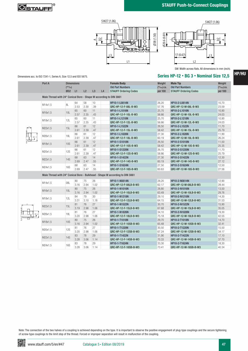
www.stauff.com/5/en/#47 47
HP/HU
Catalogue 5 § Edition 08/2019
STAUFF Push-to-Connect Couplings
Note: The connection of the two halves of a coupling is achieved depending on the type. It is important to observe the positive engagement of plug-type couplings and the secure tightening of screw-type couplings to the limit stop of the thread. Forced or improper separation will result in malfunction of the coupling.
Series HP-12 § BG 3 § Nominal Size 12,5
SW: Width across flats. All dimensions in mm (inch).
HP 10
scale 0,825
SW27 (1.06) SW27 (1.06)
L3
L1
A
38(1
.50)
20.6
(0.81
)
17 (0.67) L3
L2
AD2D2
Port A Dimensions Female Body Weight Male Tip Weight (mm/in) Old Part Numbers (kg/lbs) ca. Old Part Numbers (kg/lbs) ca. ØD2 L1 L2 L3 L4 STAUFF Ordering Codes per 100 STAUFF Ordering Codes per 100
Male Thread with 24° Conical Bore - Shape W according to DIN 3861
M14x1,5 8L64 58 10 HP10-1-L0814N 26,20 HP10-2-L0814N 10,702.53 2.30 .39 QRC-HP-12-F-08L-B-W3 57.76 QRC-HP-12-M-08L-B-W3 23.59
M16x1,5 10L65 60 11 HP10-1-L1016N 25,70 HP10-2-L1016N 10,902.57 2.35 .43 QRC-HP-12-F-10L-B-W3 56.66 QRC-HP-12-M-10L-B-W3 24.03
M18x1,5 12L65 60 11 HP10-1-L1218N 25,70 HP10-2-L1218N 10,902.57 2.35 .43 QRC-HP-12-F-12L-B-W3 56.66 QRC-HP-12-M-12L-B-W3 24.03
M22x1,5 15L66 61 12 HP10-1-L1522N 26,50 HP10-2-L1522N 11,702.61 2.39 .47 QRC-HP-12-F-15L-B-W3 58.42 QRC-HP-12-M-15L-B-W3 25.79
M26x1,5 18L66 61 12 HP10-1-L1826N 27,30 HP10-2-L1826N 11,902.61 2.39 .47 QRC-HP-12-F-18L-B-W3 60.19 QRC-HP-12-M-18L-B-W3 26.24
M18x1,5 10S66 61 12 HP10-1-S1018N 26,50 HP10-2-S1018N 11,502.61 2.39 .47 QRC-HP-12-F-10S-B-W3 58.42 QRC-HP-12-M-10S-B-W3 25.35
M20x1,5 12S66 61 12 HP10-1-S1220N 26,70 HP10-2-S1220N 11,702.61 2.39 .47 QRC-HP-12-F-12S-B-W3 58.86 QRC-HP-12-M-12S-B-W3 25.79
M22x1,5 14S68 63 14 HP10-1-S1422N 27,30 HP10-2-S1422N 12,302.69 2.47 .55 QRC-HP-12-F-14S-B-W3 60.19 QRC-HP-12-M-14S-B-W3 27.12
M24x1,5 16S68 63 14 HP10-1-S1624N 27,50 HP10-2-S1624N 12,502.69 2.47 .55 QRC-HP-12-F-16S-B-W3 60.63 QRC-HP-12-M-16S-B-W3 27.56
Male Thread with 24° Conical Bore - Bulkhead - Shape W according to DIN 3861
M14x1,5 08L80 75 26 HP10-1-N0814N 28,20 HP10-2-N0814N 12,903.16 2.94 1.02 QRC-HP-12-F-08LB-B-W3 62.17 QRC-HP-12-M-08LB-B-W3 28.44
M16x1,5 10L80 75 26 HP10-1-N1016N 28,80 HP10-2-N1016N 13,503.16 2.94 1.02 QRC-HP-12-F-10LB-B-W3 63.49 QRC-HP-12-M-10LB-B-W3 29.76
M18x1,5 12L84 79 30 HP10-1-N1218N 29,10 HP10-2-N1218N 14,303.31 3.10 1.18 QRC-HP-12-F-12LB-B-W3 64.15 QRC-HP-12-M-12LB-B-W3 31.53
M22x1,5 15L81 76 27 HP10-1-N1522N 30,70 HP10-2-N1522N 15,903.19 2.98 1.06 QRC-HP-12-F-15LB-B-W3 67.68 QRC-HP-12-M-15LB-B-W3 35.05
M26x1,5 18L81 76 27 HP10-1-N1826N 34,10 HP10-2-N1826N 19,303.20 2.98 1.06 QRC-HP-12-F-18LB-B-W3 75.18 QRC-HP-12-M-18LB-B-W3 42.55
M18x1,5 10S80 75 26 HP10-1-T1018N 29,70 HP10-2-T1018N 14,703.16 2.94 1.02 QRC-HP-12-F-10SB-B-W3 65.48 QRC-HP-12-M-10SB-B-W3 32.41
M20x1,5 12S81 76 27 HP10-1-T1220N 30,50 HP10-2-T1220N 15,503.20 2.98 1.06 QRC-HP-12-F-12SB-B-W3 67.24 QRC-HP-12-M-12SB-B-W3 34.17
M22x1,5 14S83 78 29 HP10-1-T1422N 31,90 HP10-2-T1422N 17,103.28 3.06 1.14 QRC-HP-12-F-14SB-B-W3 70.33 QRC-HP-12-M-14SB-B-W3 37.70
M24x1,5 16S83 78 29 HP10-1-T1624N 33,30 HP10-2-T1624N 18,303.28 3.06 1.14 QRC-HP-12-F-16SB-B-W3 73.41 QRC-HP-12-M-16SB-B-W3 40.34
A A
L3 L3
L4
Anschlüsse-Beispiele.pdf 1 10.09.13 15:44
A A
L3 L3
L4
Anschlüsse-Beispiele.pdf 1 10.09.13 15:44
Dimensions acc. to ISO 7241-1, Series A, Size 12,5 and ISO 5675.
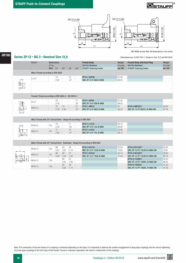
48 www.stauff.com/5/en/#48
HP/HU
Catalogue 5 § Edition 08/2019
STAUFF Push-to-Connect Couplings
ZP 10
s cale 0,825
SW27SW27
A
L1
Ø38
A
LL4
2L4
Ø38
Series ZP-12 § BG 3 § Nominal Size 12,5
SW 27 (1.06)SW 27 (1.06)
Ø38
(1.5
0)
Port A Dimensions Female Body Weight Female Body with Dust Plug Weight (mm/in) Old Part Numbers (kg/lbs) ca. Old Part Numbers (kg/lbs) ca. ØD2 L1 L2 L3 L4 STAUFF Ordering Codes per 100 STAUFF Ordering Codes per 100
Male Thread according to DIN 3852
G 1/2"74 12 ZP10-1-AGF08 31,402.92 .47 QRC-ZP-12-F-B08-B-W66 69.23
Female Thread according to DIN 3852-2 - ISO 9974-1
G1/2"70 17 ZP10-1-IGF08 31,402.76 .67 QRC-ZP-12-F-G08-B-W66 69.23
M22x1,570 75 17 ZP10-1-IMF22 31 ZP10-5-IMF22C1 30,502.76 2.95 .67 QRC-ZP-12-F-M22-B-W66 68.34 QRC-ZP-12-FF-M22/L-B-W66-SW 67.24
Male Thread with 24° Conical Bore - Shape W according to DIN 3861
M18x1,5 12L70 11 ZP10-1-L1218 30,102.76 .43 QRC-ZP-12-F-12L-B-W66 66.36
M22x1,5 15L71 12 ZP10-1-L1522 30,902.80 .47 QRC-ZP-12-F-15L-B-W66 68.12
Male Thread with 24° Conical Bore - Bulkhead - Shape W according to DIN 3861
M18x1,5 12L89 93 30 ZP10-1-N1218 33,50 ZP10-5-N1218C1 36,203.51 3.67 1.18 QRC-ZP-12-F-12LB-B-W66 73.85 QRC-ZP-12-FF-12LB/S-B-W66-SW 79.81
M22x1,5 15L86 90 27 ZP10-1-N1522 35,10 ZP10-5-N1522C1 38,903.39 3.55 1.06 QRC-ZP-12-F-15LB-B-W66 77.38 QRC-ZP-12-FF-15LB/S-B-W66-SW 85.76
M20x1,5 12S90 27 ZP10-5-T1220C1 39,303.55 1.06 QRC-ZP-12-FF-12SB/L-B-W66-SW 86.64
M24x1,5 16S92 29 ZP10-5-T1624C1 41,503.63 1.14 QRC-ZP-12-FF-16SB/L-B-W66-SW 91.49
A A
L3 L3
L4
Anschlüsse-Beispiele.pdf 1 10.09.13 15:44
A A
L3 L3
L4
Anschlüsse-Beispiele.pdf 1 10.09.13 15:44
A A
L3 L3
L4
Anschlüsse-Beispiele.pdf 1 10.09.13 15:44
A A
L3 L3
L4
Anschlüsse-Beispiele.pdf 1 10.09.13 15:44
SW: Width across flats. All dimensions in mm (inch).
Ø 3
8 (1
.50)
Note: The connection of the two halves of a coupling is achieved depending on the type. It is important to observe the positive engagement of plug-type couplings and the secure tightening of screw-type couplings to the limit stop of the thread. Forced or improper separation will result in malfunction of the coupling.
Dimensions acc. to ISO 7241-1, Series A, Size 12,5 and ISO 5675.
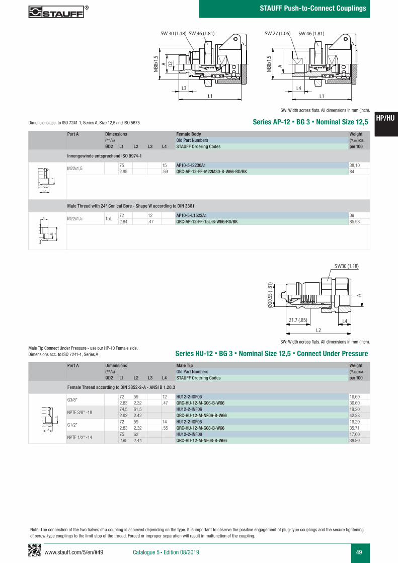
www.stauff.com/5/en/#49 49
HP/HU
Catalogue 5 § Edition 08/2019
STAUFF Push-to-Connect Couplings
Note: The connection of the two halves of a coupling is achieved depending on the type. It is important to observe the positive engagement of plug-type couplings and the secure tightening of screw-type couplings to the limit stop of the thread. Forced or improper separation will result in malfunction of the coupling.
Series AP-12 § BG 3 § Nominal Size 12,5
SW: Width across flats. All dimensions in mm (inch).
Port A Dimensions Female Body Weight (mm/in) Old Part Numbers (kg/lbs) ca. ØD2 L1 L2 L3 L4 STAUFF Ordering Codes per 100
Innengewinde entsprechend ISO 9974-1
M22x1,575 15 AP10-5-I2230A1 38,102.95 .59 QRC-AP-12-FF-M22M30-B-W66-RD/BK 84
Male Thread with 24° Conical Bore - Shape W according to DIN 3861
M22x1,5 15L72 12 AP10-5-L1522A1 392.84 .47 QRC-AP-12-FF-15L-B-W66-RD/BK 85.98
AP 10
s cale 0,625
SW30 SW46 SW27 SW46
D2A38
Mx1
,5
L3 L4
L1 L1
A38M
x1,5
SW 30 (1.18) SW 46 (1.81) SW 46 (1.81)SW 27 (1.06)
A A
L3 L3
L4
Anschlüsse-Beispiele.pdf 1 10.09.13 15:44
A A
L3 L3
L4
Anschlüsse-Beispiele.pdf 1 10.09.13 15:44
Series HU-12 § BG 3 § Nominal Size 12,5 § Connect Under PressurePort A Dimensions Male Tip Weight
(mm/in) Old Part Numbers (kg/lbs) ca. ØD2 L1 L2 L3 L4 STAUFF Ordering Codes per 100
Female Thread according to DIN 3852-2-A - ANSI B 1.20.3
G3/8"72 59 12 HU12-2-IGF06 16,602.83 2.32 .47 QRC-HU-12-M-G06-B-W66 36.60
NPTF 3/8" -1874,5 61,5 HU12-2-INF06 19,202.93 2.42 QRC-HU-12-M-NF06-B-W66 42.33
G1/2"72 59 14 HU12-2-IGF08 16,202.83 2.32 .55 QRC-HU-12-M-G08-B-W66 35.71
NPTF 1/2" -1475 62 HU12-2-INF08 17,602.95 2.44 QRC-HU-12-M-NF08-B-W66 38.80
HU12-1-2-IGF06 "A" entspricht 3/8 Innengewinde
Stahl, Beschichtung Chrom III
scale 0.74
A
L4L2
SW30 (1.18)20
.55(.
81)
SW30 (1.18)
A
L4L1
38(1
.49)
21.7 (.85)
A A
L3 L3
L4
Anschlüsse-Beispiele.pdf 1 10.09.13 15:44
SW: Width across flats. All dimensions in mm (inch).Male Tip Connect Under Pressure - use our HP-10 Female side.Dimensions acc. to ISO 7241-1, Series A
Dimensions acc. to ISO 7241-1, Series A, Size 12,5 and ISO 5675.
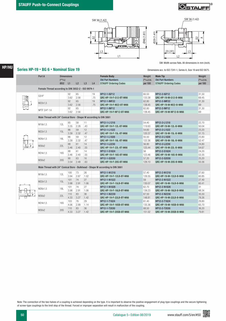
50 www.stauff.com/5/en/#50
HP/HU
Catalogue 5 § Edition 08/2019
STAUFF Push-to-Connect Couplings
Series HP-19 § BG 6 § Nominal Size 19Port A Dimensions Female Body Weight Male Tip Weight
(mm/in) Old Part Numbers (kg/lbs) ca. Old Part Numbers (kg/lbs) ca. ØD2 L1 L2 L3 L4 STAUFF Ordering Codes per 100 STAUFF Ordering Codes per 100
Female Thread according to DIN 3852-2 - ISO 9974-1
G3/4"92 65 19 HP12-1-IGF12 60,50 HP12-2-IGF12 31,503.62 2.56 .75 QRC-HP-19-F-G12-BT-W66 133.38 QRC-HP-19-M-G12-B-W66 69.45
M22x1,592 65 19 HP12-1-IMF22 62,80 HP12-2-IMF22 31,303.62 2.56 .75 QRC-HP-19-F-M22-BT-W66 138.45 QRC-HP-19-M-M22-B-W66 69
NPTF 3/4"-1492 65 HP12-1-INF12 62,80 HP12-2-INF12 31,303.62 2.56 QRC-HP-19-F-NF12-BT-W66 138.45 QRC-HP-19-M-NF12-B-W66 69
Male Thread with 24° Conical Bore - Shape W according to DIN 3861
M18x1,5 12L85 58 11 HP12-1-L1218 54,40 HP12-2-L1218 22,703.35 2.28 .43 QRC-HP-19-F-12L-BT-W66 119.93 QRC-HP-19-M-12L-B-W66 50.04
M22x1,5 15L86 59 12 HP12-1-L1522 54,60 HP12-2-L1522 23,203.39 2.32 .47 QRC-HP-19-F-15L-BT-W66 120.37 QRC-HP-19-M-15L-B-W66 51.15
M26x1,5 18L86 59 12 HP12-1-L1826 55,50 HP12-2-L1826 23,803.39 2.32 .47 QRC-HP-19-F-18L-BT-W66 122.36 QRC-HP-19-M-18L-B-W66 52.47
M30x2 22L88 61 14 HP12-1-L2230 56,90 HP12-2-L2230 24,803.46 2.40 .55 QRC-HP-19-F-22L-BT-W66 125.44 QRC-HP-19-M-22L-B-W66 54.67
M24x1,5 16S88 61 14 HP12-1-S1624 56 HP12-2-S1624 24,203.46 2.40 .55 QRC-HP-19-F-16S-BT-W66 123.46 QRC-HP-19-M-16S-B-W66 53.35
M30x2 20S90 63 16 HP12-1-S2030 57,20 HP12-2-S2030 25,203.54 2.48 .63 QRC-HP-19-F-20S-BT-W66 126.10 QRC-HP-19-M-20S-B-W66 55.56
Male Thread with 24° Conical Bore - Bulkhead - Shape W according to DIN 3861
M18x1,5 12L100 73 26 HP12-1-N1218 57,40 HP12-2-N1218 27,603.94 2.87 1.02 QRC-HP-19-F-12LB-BT-W66 126.55 QRC-HP-19-M-12LB-B-W66 60.85
M22x1,5 15L101 74 27 HP12-1-N1522 59 HP12-2-N1522 27,403.98 2.91 1.06 QRC-HP-19-F-15LB-BT-W66 130.07 QRC-HP-19-M-15LB-B-W66 60.41
M26x1,5 18L101 74 27 HP12-1-N1826 62,70 HP12-2-N1826 313.98 2.91 1.06 QRC-HP-19-F-18LB-BT-W66 138.23 QRC-HP-19-M-18LB-B-W66 68.34
M30x2 22L110 83 36 HP12-1-N2230 67,50 HP12-2-N2230 35,504.33 3.27 1.42 QRC-HP-19-F-22LB-BT-W66 148.81 QRC-HP-19-M-22LB-B-W66 78.26
M24x1,5 16S103 76 29 HP12-1-T1624 61,40 HP12-2-T1624 29,804.06 2.99 1.14 QRC-HP-19-F-16SB-BT-W66 135.36 QRC-HP-19-M-16SB-B-W66 65.70
M30x2 20S110 83 36 HP12-1-T2030 68,50 HP12-2-T2030 36,204.33 3.27 1.42 QRC-HP-19-F-20SB-BT-W66 151.02 QRC-HP-19-M-20SB-B-W66 79.81
A A
L3 L3
L4
Anschlüsse-Beispiele.pdf 1 10.09.13 15:44
A A
L3 L3
L4
Anschlüsse-Beispiele.pdf 1 10.09.13 15:44
A A
L3 L3
L4
Anschlüsse-Beispiele.pdf 1 10.09.13 15:44
HP 12
s cale 0,625
L1L3
�
A D2
SW36
29�
23
AD2
L3L2
SW36
64Ø Ø
HP 12.pdf 1 09.02.2017 09:18:07
SW 36 (1.42) SW 36 (1.42)
Ø46
(1.8
1)
Ø29
(1.4
1)
23 (.91)
SW: Width across flats. All dimensions in mm (inch).
Note: The connection of the two halves of a coupling is achieved depending on the type. It is important to observe the positive engagement of plug-type couplings and the secure tightening of screw-type couplings to the limit stop of the thread. Forced or improper separation will result in malfunction of the coupling.
Dimensions acc. to ISO 7241-1, Series A, Size 19 and ISO 5675.
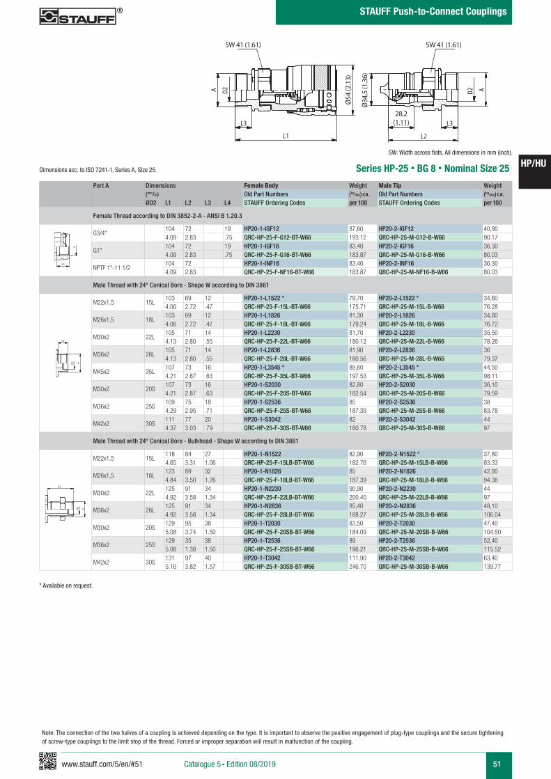
www.stauff.com/5/en/#51 51
HP/HU
Catalogue 5 § Edition 08/2019
STAUFF Push-to-Connect Couplings
Note: The connection of the two halves of a coupling is achieved depending on the type. It is important to observe the positive engagement of plug-type couplings and the secure tightening of screw-type couplings to the limit stop of the thread. Forced or improper separation will result in malfunction of the coupling.
Series HP-25 § BG 8 § Nominal Size 25
SW: Width across flats. All dimensions in mm (inch).
Port A Dimensions Female Body Weight Male Tip Weight (mm/in) Old Part Numbers (kg/lbs) ca. Old Part Numbers (kg/lbs) ca. ØD2 L1 L2 L3 L4 STAUFF Ordering Codes per 100 STAUFF Ordering Codes per 100
Female Thread according to DIN 3852-2-A - ANSI B 1.20.3
G3/4"104 72 19 HP20-1-IGF12 87,60 HP20-2-IGF12 40,904.09 2.83 .75 QRC-HP-25-F-G12-BT-W66 193.12 QRC-HP-25-M-G12-B-W66 90.17
G1"104 72 19 HP20-1-IGF16 83,40 HP20-2-IGF16 36,304.09 2.83 .75 QRC-HP-25-F-G16-BT-W66 183.87 QRC-HP-25-M-G16-B-W66 80.03
NPTF 1"-11 1/2104 72 HP20-1-INF16 83,40 HP20-2-INF16 36,304.09 2.83 QRC-HP-25-F-NF16-BT-W66 183.87 QRC-HP-25-M-NF16-B-W66 80.03
Male Thread with 24° Conical Bore - Shape W according to DIN 3861
M22x1,5 15L103 69 12 HP20-1-L1522 * 79,70 HP20-2-L1522 * 34,604.06 2.72 .47 QRC-HP-25-F-15L-BT-W66 175.71 QRC-HP-25-M-15L-B-W66 76.28
M26x1,5 18L103 69 12 HP20-1-L1826 81,30 HP20-2-L1826 34,804.06 2.72 .47 QRC-HP-25-F-18L-BT-W66 179.24 QRC-HP-25-M-18L-B-W66 76.72
M30x2 22L105 71 14 HP20-1-L2230 81,70 HP20-2-L2230 35,504.13 2.80 .55 QRC-HP-25-F-22L-BT-W66 180.12 QRC-HP-25-M-22L-B-W66 78.26
M36x2 28L105 71 14 HP20-1-L2836 81,90 HP20-2-L2836 364.13 2.80 .55 QRC-HP-25-F-28L-BT-W66 180.56 QRC-HP-25-M-28L-B-W66 79.37
M45x2 35L107 73 16 HP20-1-L3545 * 89,60 HP20-2-L3545 * 44,504.21 2.87 .63 QRC-HP-25-F-35L-BT-W66 197.53 QRC-HP-25-M-35L-B-W66 98.11
M30x2 20S107 73 16 HP20-1-S2030 82,80 HP20-2-S2030 36,104.21 2.87 .63 QRC-HP-25-F-20S-BT-W66 182.54 QRC-HP-25-M-20S-B-W66 79.59
M36x2 25S109 75 18 HP20-1-S2536 85 HP20-2-S2536 384.29 2.95 .71 QRC-HP-25-F-25S-BT-W66 187.39 QRC-HP-25-M-25S-B-W66 83.78
M42x2 30S111 77 20 HP20-1-S3042 82 HP20-2-S3042 444.37 3.03 .79 QRC-HP-25-F-30S-BT-W66 180.78 QRC-HP-25-M-30S-B-W66 97
Male Thread with 24° Conical Bore - Bulkhead - Shape W according to DIN 3861
M22x1,5 15L118 84 27 HP20-1-N1522 82,90 HP20-2-N1522 * 37,804.65 3.31 1.06 QRC-HP-25-F-15LB-BT-W66 182.76 QRC-HP-25-M-15LB-B-W66 83.33
M26x1,5 18L123 89 32 HP20-1-N1826 85 HP20-2-N1826 42,804.84 3.50 1.26 QRC-HP-25-F-18LB-BT-W66 187.39 QRC-HP-25-M-18LB-B-W66 94.36
M30x2 22L125 91 34 HP20-1-N2230 90,90 HP20-2-N2230 444.92 3.58 1.34 QRC-HP-25-F-22LB-BT-W66 200.40 QRC-HP-25-M-22LB-B-W66 97
M36x2 28L125 91 34 HP20-1-N2836 85,40 HP20-2-N2836 48,104.92 3.58 1.34 QRC-HP-25-F-28LB-BT-W66 188.27 QRC-HP-25-M-28LB-B-W66 106.04
M30x2 20S129 95 38 HP20-1-T2030 83,50 HP20-2-T2030 47,405.08 3.74 1.50 QRC-HP-25-F-20SB-BT-W66 184.09 QRC-HP-25-M-20SB-B-W66 104.50
M36x2 25S129 35 38 HP20-1-T2536 89 HP20-2-T2536 52,405.08 1.38 1.50 QRC-HP-25-F-25SB-BT-W66 196.21 QRC-HP-25-M-25SB-B-W66 115.52
M42x2 30S131 97 40 HP20-1-T3042 111,90 HP20-2-T3042 63,405.16 3.82 1.57 QRC-HP-25-F-30SB-BT-W66 246.70 QRC-HP-25-M-30SB-B-W66 139.77
A A
L3 L3
L4
Anschlüsse-Beispiele.pdf 1 10.09.13 15:44
A A
L3 L3
L4
Anschlüsse-Beispiele.pdf 1 10.09.13 15:44
A A
L3 L3
L4
Anschlüsse-Beispiele.pdf 1 10.09.13 15:44
HP 20
s cale 0,5
A D2
L3
L1
54�
SW41
34.5
�
28.2
L2
L3
AD2
SW41
Ø Ø
HP 20.pdf 1 09.02.2017 09:18:37
SW 41 (1.61)SW 41 (1.61)
Ø54
(2.1
3)
Ø34
,5 (1
.36)
28,2 (1.11)
* Available on request.
Dimensions acc. to ISO 7241-1, Series A, Size 25.
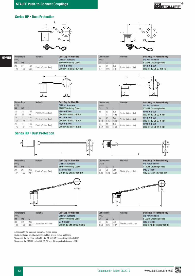
52 www.stauff.com/5/en/#52
HP/HU
Catalogue 5 § Edition 08/2019
STAUFF Push-to-Connect Couplings
Series HU § Dust Protection
Dimensions Material Dust Cap for Male Tip(mm/in) Old Part NumbersD1 D2 L STAUFF Ordering Codes28 27 134
Plastic (Colour: Red)HP10-0-RT004
1.10 1.06 5.28 QRC-HP-12-DM-27-K/1-RD
Dimensions Material Dust Plug for Female Body(mm/in) Old Part NumbersD1 D2 L STAUFF Ordering Codes22 27 135
Plastic (Colour: Red)HP10-9-RT004
.87 1.06 5.31 QRC-HP-12-DF-27-K/1-RD
Dimensions Material Dust Cap for Male Tip(mm/in) Old Part NumbersD1 D2 L STAUFF Ordering Codes22 22 125
Plastic (Colour: Red)HP08-0-RT001
.87 .87 4.92 QRC-HP-10-DM-22-K-RD33 37 190
Plastic (Colour: Red)HP12-0-RT001
1.30 1.46 7.48 QRC-HP-19-DM-37-K-RD36 41 190
Plastic (Colour: Red)HP20-0-RT001
1.42 1.61 7.48 QRC-HP-25-DM-41-K-RD
Dimensions Material Dust Plug for Female Body(mm/in) Old Part NumbersD1 D2 L STAUFF Ordering Codes18 22 125
Plastic (Colour: Red)HP08-9-RT001
.71 .87 4.92 QRC-HP-10-DF-22-K-RD30 37 190
Plastic (Colour: Red)HP12-9-RT001
1.18 1.46 7.48 QRC-HP-19-DF-37-K-RD36 41 190
Plastic (Colour: Red)HP20-9-RT001
1.42 1.61 7.48 QRC-HP-25-DF-41-K-RD
In addition to the standard colours as stated above, plastic dust caps are also available in blue, green, yellow and black. Please use the old color codes BL, GN, GE and SW respectively instead of RT.Please use the STAUFF codes BU, GN, YE and BK respectively instead of RD.
Dimensions Material Dust Cap for Male Tip(mm/in) Old Part NumbersD1 D2 L STAUFF Ordering Codes29 26 250
Plastic (Colour: Red)IA12-0-RT001
1.14 1.02 9.84 QRC-IA-12-DM-26-W66-RD
Dimensions Material Dust Plug for Female Body(mm/in) Old Part NumbersD1 D2 L STAUFF Ordering Codes35 26 250
Plastic (Colour: Red)IA12-9-RT001
1.38 1.02 9.84 QRC-IA-12-DF-26-W66-RD
Series HP § Dust Protection
Dimensions Material Dust Cap for Male Tip(mm/in) Old Part NumbersD1 D2 L STAUFF Ordering Codes38 32 205
Aluminium with chainIA12-0-SI001
1.50 1.26 8.07 QRC-IA-12-DM-32/CN-W89-SI
Dimensions Material Dust Plug for Female Body(mm/in) Old Part NumbersD1 D2 L STAUFF Ordering Codes38 32 205
Aluminium with chainIA12-9-SI001
1.50 1.26 8.07 QRC-IA-12-DF-32/CN-W89-SI
IA12- 0- RT001
Kuns t s tof f r ot
s cale 0,4
D1
LD2
IA12- 9- RT
Kuns t s tof f r ot
s cale 0,4
D1
L
D2
IA..- 0- SI001
Alu mit Ket t e
s cale 0,4
D1L
D2
IA..- 9- SI001
Alu mit Ket t e
s cale 0,4
D1
D2
L
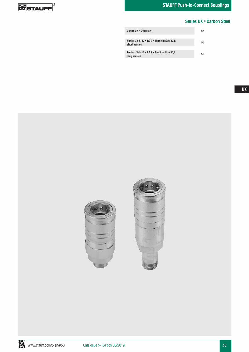
www.stauff.com/5/en/#53 53
UX
Catalogue 5 § Edition 08/2019
STAUFF Push-to-Connect Couplings
Series UX § Overview
Series UX-S-12 § BG 3 § Nominal Size 12,5 short version
55
54
Series UX-L-12 § BG 3 § Nominal Size 12,5 long version
56
Series UX § Carbon Steel
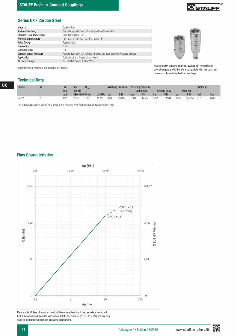
54 www.stauff.com/5/en/#54
UX
Catalogue 5 § Edition 08/2019
STAUFF Push-to-Connect Couplings
Series UX § Carbon Steel
The series UX coupling sleeve is available in two different overall lengths and is therefore compatible with the common commercially available built-in couplings.
Series BG DN DN Q max Working Pressure Bursting Pressure SpillageZoll metric Connected Female Body Male TipInch ISO 4397 l/min US GPM bar PSI bar PSI bar PSI bar PSI ml fl oz
UX-12 3 1/2" 12,5 100 21.13 250 3626 1000 14504 1000 14504 1000 14504 1,7 .0575
Technical Data
Material Carbon Steel Surface Finishing Zinc-Plating and Thick-Film-Passivation (Chrome III)Standard Seal Material(s) NBR (Buna-N®), PTFE 2
Working Temperature -30° C ... +100° C / -22° F ... +212° FValve Design Poppet ValveConnection PushDisconnection PullConnect Under Pressure Female Body with ISO-A Male Tip up to the max. Working Pressure allowedApplication Agricultural and Forestry MachineryISO Interchange ISO 7241-1 Series A, Size 12,5
The indicated pressure ratings only apply to the coupling itself and depend on the connection type.
2 Alternative seal materials are available on request.
Please note: Unless otherwise stated, all flow characteristics have been determined with hydraulic oil with a kinematic viscosity of 28,8 - 35,2 mm2/s (28,8 - 35,2 cSt) and are only valid for components with non-reducing connections.
Flow Characteristics
QRC-UX-12
QRC-UX-12 kurzzeitig
1
10
100
1000
0,1 1 10 100
Q [l/
min
]
Δp [bar]
1450.38
Q [U
S G
PM/m
in]
Δp [PSI]
264,17
26,42
2,64
.26
1.45 14.50 145.04
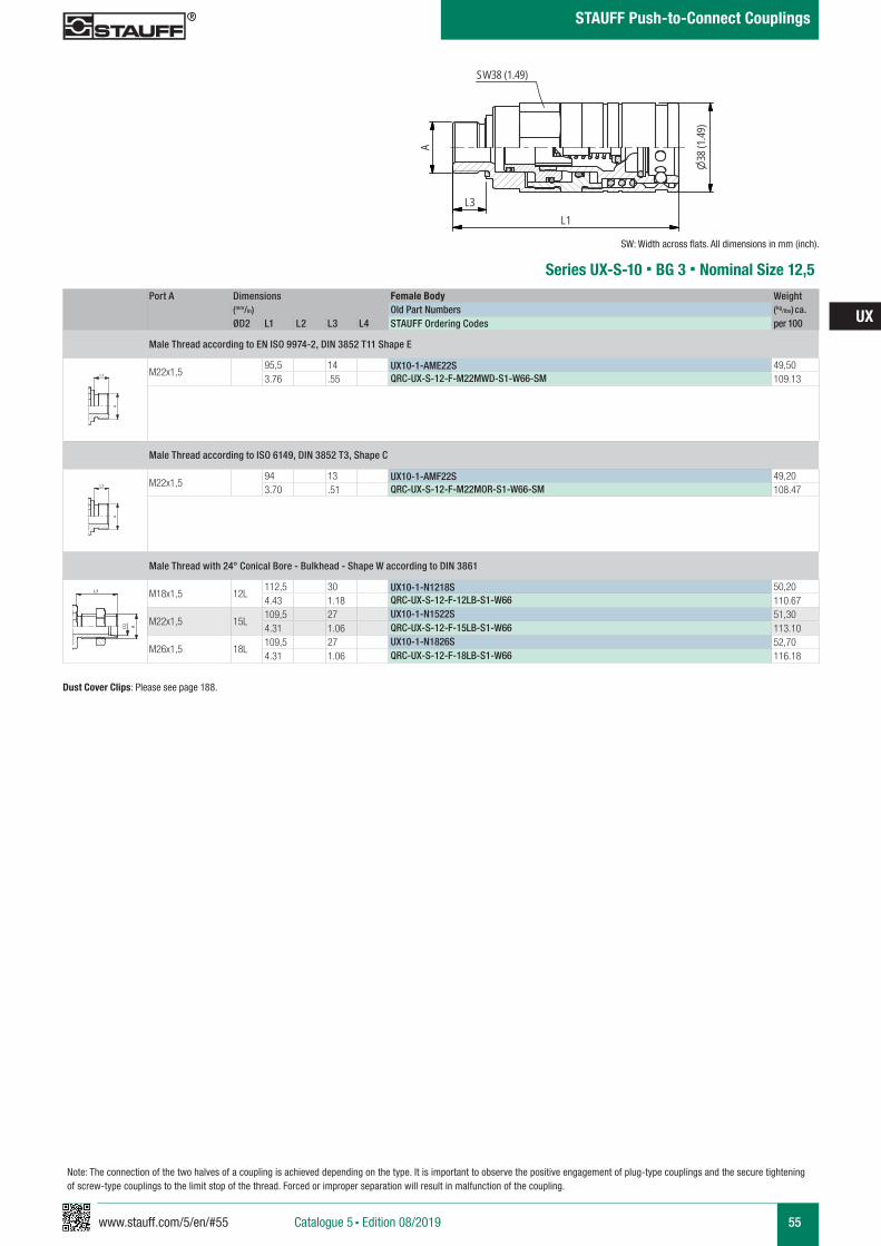
www.stauff.com/5/en/#55 55
UX
Catalogue 5 § Edition 08/2019
STAUFF Push-to-Connect Couplings
UX10-1....S
scale 0.74
A
L1L3
SW38 (1.49)
38(1
.49)
Port A Dimensions Female Body Weight (mm/in) Old Part Numbers (kg/lbs) ca. ØD2 L1 L2 L3 L4 STAUFF Ordering Codes per 100
Male Thread according to EN ISO 9974-2, DIN 3852 T11 Shape E
M22x1,595,5 14 UX10-1-AME22S 49,503.76 .55 QRC-UX-S-12-F-M22MWD-S1-W66-SM 109.13
Male Thread according to ISO 6149, DIN 3852 T3, Shape C
M22x1,594 13 UX10-1-AMF22S 49,203.70 .51 QRC-UX-S-12-F-M22MOR-S1-W66-SM 108.47
Male Thread with 24° Conical Bore - Bulkhead - Shape W according to DIN 3861
M18x1,5 12L112,5 30 UX10-1-N1218S 50,204.43 1.18 QRC-UX-S-12-F-12LB-S1-W66 110.67
M22x1,5 15L109,5 27 UX10-1-N1522S 51,304.31 1.06 QRC-UX-S-12-F-15LB-S1-W66 113.10
M26x1,5 18L109,5 27 UX10-1-N1826S 52,704.31 1.06 QRC-UX-S-12-F-18LB-S1-W66 116.18
Series UX-S-10 § BG 3 § Nominal Size 12,5
A A
L3 L3
L4
Anschlüsse-Beispiele.pdf 1 10.09.13 15:44
SW: Width across flats. All dimensions in mm (inch).
A A
L3 L3
L4
Anschlüsse-Beispiele.pdf 1 10.09.13 15:44
A A
L3 L3
L4
Anschlüsse-Beispiele.pdf 1 10.09.13 15:44
Dust Cover Clips: Please see page 188.
Note: The connection of the two halves of a coupling is achieved depending on the type. It is important to observe the positive engagement of plug-type couplings and the secure tightening of screw-type couplings to the limit stop of the thread. Forced or improper separation will result in malfunction of the coupling.
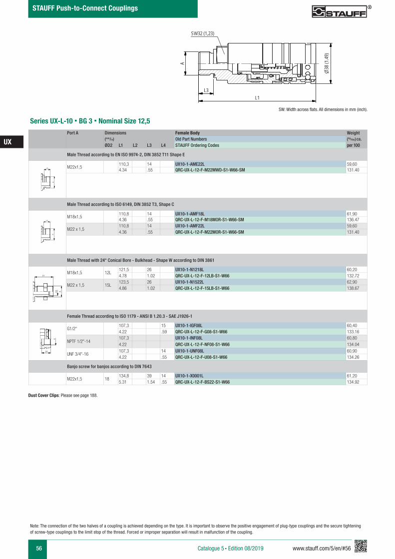
56 www.stauff.com/5/en/#56
UX
Catalogue 5 § Edition 08/2019
STAUFF Push-to-Connect Couplings
Series UX-L-10 § BG 3 § Nominal Size 12,5Port A Dimensions Female Body Weight
(mm/in) Old Part Numbers (kg/lbs) ca.
ØD2 L1 L2 L3 L4 STAUFF Ordering Codes per 100
Male Thread according to EN ISO 9974-2, DIN 3852 T11 Shape E
M22x1,5110,3 14 UX10-1-AME22L 59,604.34 .55 QRC-UX-L-12-F-M22MWD-S1-W66-SM 131.40
Male Thread according to ISO 6149, DIN 3852 T3, Shape C
M18x1,5110,8 14 UX10-1-AMF18L 61,904.36 .55 QRC-UX-L-12-F-M18MOR-S1-W66-SM 136.47
M22 x 1,5110,8 14 UX10-1-AMF22L 59,604.36 .55 QRC-UX-L-12-F-M22MOR-S1-W66-SM 131.40
Male Thread with 24° Conical Bore - Bulkhead - Shape W according to DIN 3861
M18x1,5 12L121,5 26 UX10-1-N1218L 60,204.78 1.02 QRC-UX-L-12-F-12LB-S1-W66 132.72
M22 x 1,5 15L123,5 26 UX10-1-N1522L 62,904.86 1.02 QRC-UX-L-12-F-15LB-S1-W66 138.67
Female Thread according to ISO 1179 - ANSI B 1.20.3 - SAE J1926-1
G1/2"107,3 15 UX10-1-IGF08L 60,404.22 .59 QRC-UX-L-12-F-G08-S1-W66 133.16
NPTF 1/2"-14107,3 UX10-1-INF08L 60,804.22 QRC-UX-L-12-F-NF08-S1-W66 134.04
UNF 3/4"-16107,3 14 UX10-1-UNF08L 60,904.22 .55 QRC-UX-L-12-F-U08-S1-W66 134.26
Banjo screw for banjos according to DIN 7643
M22x1,5 18134,8 39 14 UX10-1-X0001L 61,205.31 1.54 .55 QRC-UX-L-12-F-BS22-S1-W66 134.92
A A
L3 L3
L4
Anschlüsse-Beispiele.pdf 1 10.09.13 15:44
SW: Width across flats. All dimensions in mm (inch).
A A
L3 L3
L4
Anschlüsse-Beispiele.pdf 1 10.09.13 15:44
A A
L3 L3
L4
Anschlüsse-Beispiele.pdf 1 10.09.13 15:44
A A
L3 L3
L4
Anschlüsse-Beispiele.pdf 1 10.09.13 15:44
UX 10...L
scale 0.74
A
L3L1
38(1
.49)
SW32 (1,23)
Dust Cover Clips: Please see page 188.
Note: The connection of the two halves of a coupling is achieved depending on the type. It is important to observe the positive engagement of plug-type couplings and the secure tightening of screw-type couplings to the limit stop of the thread. Forced or improper separation will result in malfunction of the coupling.

www.stauff.com/5/en/#57 57
IA
Catalogue 5 § Edition 08/2019
STAUFF Push-to-Connect Couplings
Series IA-38 § BG 12 § Nominal Size 38
Series IA-51 § BG 14 § Nominal Size 51 61
61
Series IA § Dust Protection 62
Series IA § Overview
Series IA-06 § BG 1 § Nominal Size 6,3 59
58
Series IA-10 § BG 2 § Nominal Size 10 59
Series IA-19 § BG 6 § Nominal Size 19 60
Series IA-25 § BG 8 § Nominal Size 25 61
Series IA-12 § BG 3 § Nominal Size 12,5 60
Series IA-31 § BG 10 § Nominal Size 31,5 61
Series IA § Carbon Steel
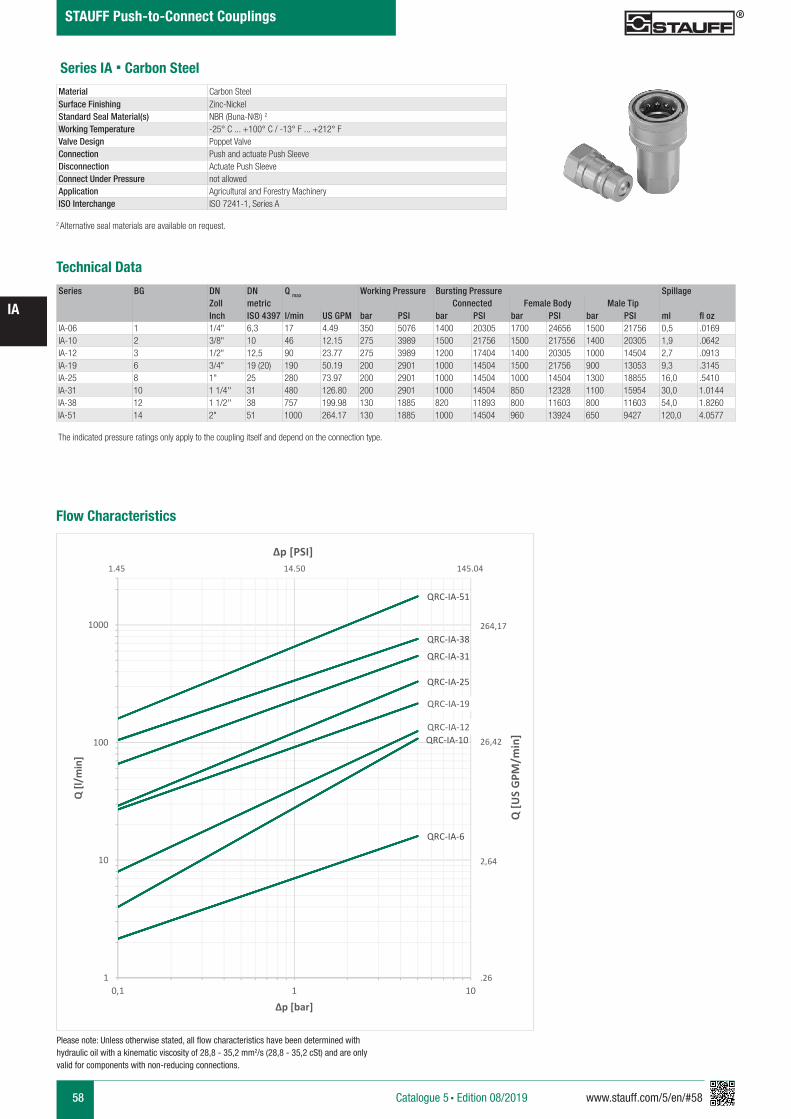
58 www.stauff.com/5/en/#58
IA
Catalogue 5 § Edition 08/2019
STAUFF Push-to-Connect Couplings
Series IA § Carbon Steel
Series BG DN DN Q max Working Pressure Bursting Pressure SpillageZoll metric Connected Female Body Male TipInch ISO 4397 l/min US GPM bar PSI bar PSI bar PSI bar PSI ml fl oz
IA-06 1 1/4" 6,3 17 4.49 350 5076 1400 20305 1700 24656 1500 21756 0,5 .0169IA-10 2 3/8" 10 46 12.15 275 3989 1500 21756 1500 217556 1400 20305 1,9 .0642IA-12 3 1/2" 12,5 90 23.77 275 3989 1200 17404 1400 20305 1000 14504 2,7 .0913IA-19 6 3/4" 19 (20) 190 50.19 200 2901 1000 14504 1500 21756 900 13053 9,3 .3145IA-25 8 1" 25 280 73.97 200 2901 1000 14504 1000 14504 1300 18855 16,0 .5410IA-31 10 1 1/4'' 31 480 126.80 200 2901 1000 14504 850 12328 1100 15954 30,0 1.0144IA-38 12 1 1/2'' 38 757 199.98 130 1885 820 11893 800 11603 800 11603 54,0 1.8260IA-51 14 2" 51 1000 264.17 130 1885 1000 14504 960 13924 650 9427 120,0 4.0577
Technical Data
Material Carbon Steel Surface Finishing Zinc-NickelStandard Seal Material(s) NBR (Buna-N®) 2
Working Temperature -25° C ... +100° C / -13° F ... +212° FValve Design Poppet ValveConnection Push and actuate Push SleeveDisconnection Actuate Push SleeveConnect Under Pressure not allowedApplication Agricultural and Forestry MachineryISO Interchange ISO 7241-1, Series A
The indicated pressure ratings only apply to the coupling itself and depend on the connection type.
2 Alternative seal materials are available on request.
Please note: Unless otherwise stated, all flow characteristics have been determined with hydraulic oil with a kinematic viscosity of 28,8 - 35,2 mm2/s (28,8 - 35,2 cSt) and are only valid for components with non-reducing connections.
Flow Characteristics
QRC-IA-6
QRC-IA-10QRC-IA-12
QRC-IA-19
QRC-IA-25
QRC-IA-31
QRC-IA-38
QRC-IA-51
1
10
100
1000
0,1 1 10
Q [l/
min
]
Δp [bar]
Q [U
S G
PM/m
in]
Δp [PSI]
264,17
26,42
2,64
.26
1.45 14.50 145.04
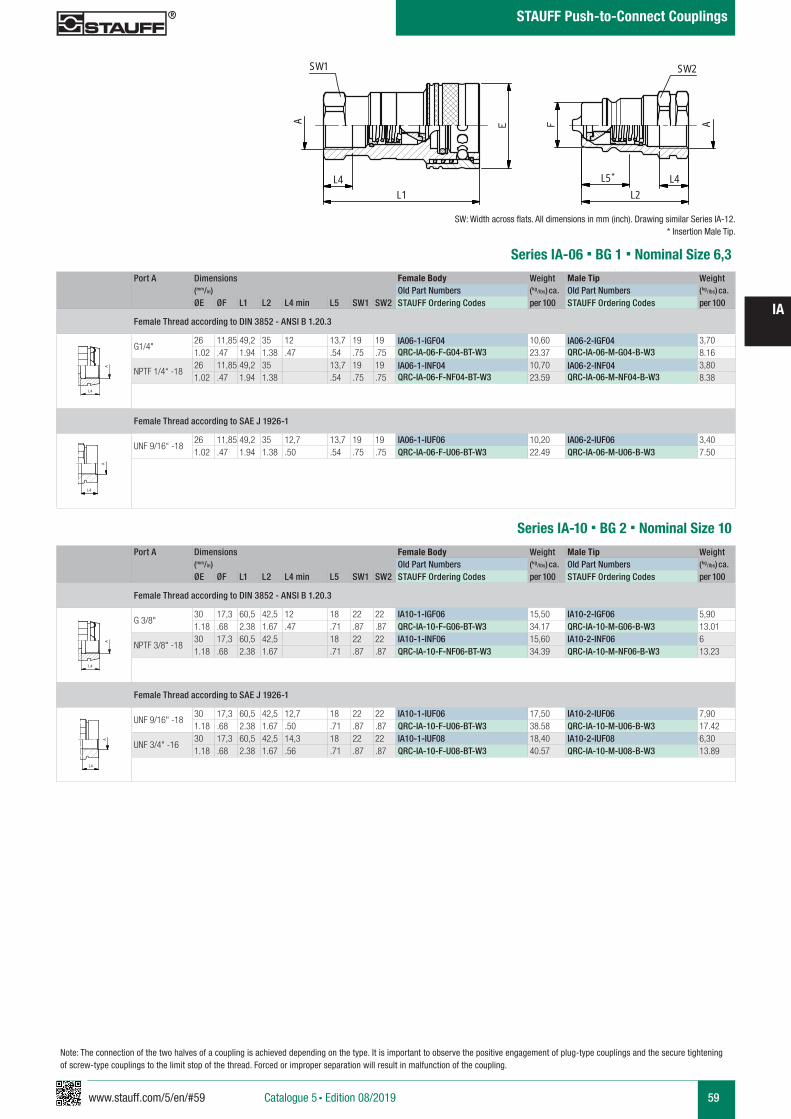
www.stauff.com/5/en/#59 59
IA
Catalogue 5 § Edition 08/2019
STAUFF Push-to-Connect Couplings
Port A Dimensions Female Body Weight Male Tip Weight (mm/in) Old Part Numbers (kg/lbs) ca. Old Part Numbers (kg/lbs) ca. ØE ØF L1 L2 L4 min L5 SW1 SW2 STAUFF Ordering Codes per 100 STAUFF Ordering Codes per 100
Female Thread according to DIN 3852 - ANSI B 1.20.3
G1/4"26 11,85 49,2 35 12 13,7 19 19 IA06-1-IGF04 10,60 IA06-2-IGF04 3,701.02 .47 1.94 1.38 .47 .54 .75 .75 QRC-IA-06-F-G04-BT-W3 23.37 QRC-IA-06-M-G04-B-W3 8.16
NPTF 1/4“ -1826 11,85 49,2 35 13,7 19 19 IA06-1-INF04 10,70 IA06-2-INF04 3,801.02 .47 1.94 1.38 .54 .75 .75 QRC-IA-06-F-NF04-BT-W3 23.59 QRC-IA-06-M-NF04-B-W3 8.38
Female Thread according to SAE J 1926-1
UNF 9/16“ -1826 11,85 49,2 35 12,7 13,7 19 19 IA06-1-IUF06 10,20 IA06-2-IUF06 3,401.02 .47 1.94 1.38 .50 .54 .75 .75 QRC-IA-06-F-U06-BT-W3 22.49 QRC-IA-06-M-U06-B-W3 7.50
Series IA-06 § BG 1 § Nominal Size 6,3
IA06-51-Muffe und Stecker-
(Stahl)
scale 0.74
SW1
A
L4L1
SW2
L4L2
L5
A
zeichnerische Darstellung entspricht Serie IA 12
A A
L3 L3
L4
Anschlüsse-Beispiele.pdf 1 10.09.13 15:44
Series IA-10 § BG 2 § Nominal Size 10Port A Dimensions Female Body Weight Male Tip Weight
(mm/in) Old Part Numbers (kg/lbs) ca. Old Part Numbers (kg/lbs) ca. ØE ØF L1 L2 L4 min L5 SW1 SW2 STAUFF Ordering Codes per 100 STAUFF Ordering Codes per 100
Female Thread according to DIN 3852 - ANSI B 1.20.3
G 3/8"30 17,3 60,5 42,5 12 18 22 22 IA10-1-IGF06 15,50 IA10-2-IGF06 5,901.18 .68 2.38 1.67 .47 .71 .87 .87 QRC-IA-10-F-G06-BT-W3 34.17 QRC-IA-10-M-G06-B-W3 13.01
NPTF 3/8" -1830 17,3 60,5 42,5 18 22 22 IA10-1-INF06 15,60 IA10-2-INF06 61.18 .68 2.38 1.67 .71 .87 .87 QRC-IA-10-F-NF06-BT-W3 34.39 QRC-IA-10-M-NF06-B-W3 13.23
Female Thread according to SAE J 1926-1
UNF 9/16" -18 30 17,3 60,5 42,5 12,7 18 22 22 IA10-1-IUF06 17,50 IA10-2-IUF06 7,901.18 .68 2.38 1.67 .50 .71 .87 .87 QRC-IA-10-F-U06-BT-W3 38.58 QRC-IA-10-M-U06-B-W3 17.42
UNF 3/4" -16 30 17,3 60,5 42,5 14,3 18 22 22 IA10-1-IUF08 18,40 IA10-2-IUF08 6,301.18 .68 2.38 1.67 .56 .71 .87 .87 QRC-IA-10-F-U08-BT-W3 40.57 QRC-IA-10-M-U08-B-W3 13.89
A A
L3 L3
L4
Anschlüsse-Beispiele.pdf 1 10.09.13 15:44
SW: Width across flats. All dimensions in mm (inch). Drawing similar Series IA-12.* Insertion Male Tip.
Anschlüsse
kleine Bilder
scale 0,8
2 A
L3
2 A
L3 L3
A
L4 L4
Flanschanschluss
kleines Bild
scale 0,38
L5
L6
D1
Anschlüsse
kleine Bilder
scale 0,8
2 A
L3
2 A
L3 L3
A
L4 L4
Flanschanschluss
kleines Bild
scale 0,38
L5
L6
D1
*
Note: The connection of the two halves of a coupling is achieved depending on the type. It is important to observe the positive engagement of plug-type couplings and the secure tightening of screw-type couplings to the limit stop of the thread. Forced or improper separation will result in malfunction of the coupling.
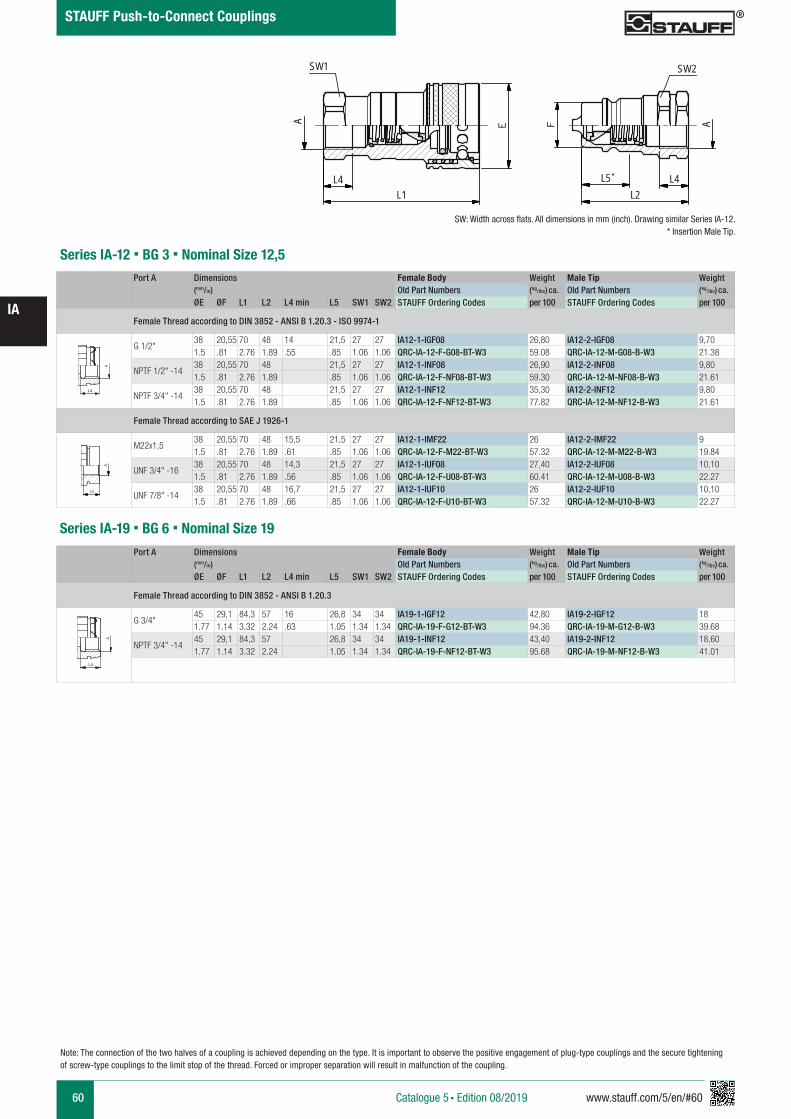
60 www.stauff.com/5/en/#60
IA
Catalogue 5 § Edition 08/2019
STAUFF Push-to-Connect Couplings
Note: The connection of the two halves of a coupling is achieved depending on the type. It is important to observe the positive engagement of plug-type couplings and the secure tightening of screw-type couplings to the limit stop of the thread. Forced or improper separation will result in malfunction of the coupling.
Series IA-12 § BG 3 § Nominal Size 12,5Port A Dimensions Female Body Weight Male Tip Weight
(mm/in) Old Part Numbers (kg/lbs) ca. Old Part Numbers (kg/lbs) ca. ØE ØF L1 L2 L4 min L5 SW1 SW2 STAUFF Ordering Codes per 100 STAUFF Ordering Codes per 100
Female Thread according to DIN 3852 - ANSI B 1.20.3 - ISO 9974-1
G 1/2"38 20,55 70 48 14 21,5 27 27 IA12-1-IGF08 26,80 IA12-2-IGF08 9,701.5 .81 2.76 1.89 .55 .85 1.06 1.06 QRC-IA-12-F-G08-BT-W3 59.08 QRC-IA-12-M-G08-B-W3 21.38
NPTF 1/2" -1438 20,55 70 48 21,5 27 27 IA12-1-INF08 26,90 IA12-2-INF08 9,801.5 .81 2.76 1.89 .85 1.06 1.06 QRC-IA-12-F-NF08-BT-W3 59.30 QRC-IA-12-M-NF08-B-W3 21.61
NPTF 3/4" -1438 20,55 70 48 21,5 27 27 IA12-1-INF12 35,30 IA12-2-INF12 9,801.5 .81 2.76 1.89 .85 1.06 1.06 QRC-IA-12-F-NF12-BT-W3 77.82 QRC-IA-12-M-NF12-B-W3 21.61
Female Thread according to SAE J 1926-1
M22x1,538 20,55 70 48 15,5 21,5 27 27 IA12-1-IMF22 26 IA12-2-IMF22 91.5 .81 2.76 1.89 .61 .85 1.06 1.06 QRC-IA-12-F-M22-BT-W3 57.32 QRC-IA-12-M-M22-B-W3 19.84
UNF 3/4" -16 38 20,55 70 48 14,3 21,5 27 27 IA12-1-IUF08 27,40 IA12-2-IUF08 10,101.5 .81 2.76 1.89 .56 .85 1.06 1.06 QRC-IA-12-F-U08-BT-W3 60.41 QRC-IA-12-M-U08-B-W3 22.27
UNF 7/8" -1438 20,55 70 48 16,7 21,5 27 27 IA12-1-IUF10 26 IA12-2-IUF10 10,101.5 .81 2.76 1.89 .66 .85 1.06 1.06 QRC-IA-12-F-U10-BT-W3 57.32 QRC-IA-12-M-U10-B-W3 22.27
A A
L3 L3
L4
Anschlüsse-Beispiele.pdf 1 10.09.13 15:44
Anschlüsse
kleine Bilder
scale 0,8
2 A
L3
2 A
L3 L3
A
L4 L4
Flanschanschluss
kleines Bild
scale 0,38
L5
L6
D1
Port A Dimensions Female Body Weight Male Tip Weight (mm/in) Old Part Numbers (kg/lbs) ca. Old Part Numbers (kg/lbs) ca. ØE ØF L1 L2 L4 min L5 SW1 SW2 STAUFF Ordering Codes per 100 STAUFF Ordering Codes per 100
Female Thread according to DIN 3852 - ANSI B 1.20.3
G 3/4"45 29,1 84,3 57 16 26,8 34 34 IA19-1-IGF12 42,80 IA19-2-IGF12 181.77 1.14 3.32 2.24 .63 1.05 1.34 1.34 QRC-IA-19-F-G12-BT-W3 94.36 QRC-IA-19-M-G12-B-W3 39.68
NPTF 3/4" -1445 29,1 84,3 57 26,8 34 34 IA19-1-INF12 43,40 IA19-2-INF12 18,601.77 1.14 3.32 2.24 1.05 1.34 1.34 QRC-IA-19-F-NF12-BT-W3 95.68 QRC-IA-19-M-NF12-B-W3 41.01
Series IA-19 § BG 6 § Nominal Size 19
A A
L3 L3
L4
Anschlüsse-Beispiele.pdf 1 10.09.13 15:44
IA06-51-Muffe und Stecker-
(Stahl)
scale 0.74
SW1
A
L4L1
SW2
L4L2
L5
A
zeichnerische Darstellung entspricht Serie IA 12SW: Width across flats. All dimensions in mm (inch). Drawing similar Series IA-12.
* Insertion Male Tip.
*
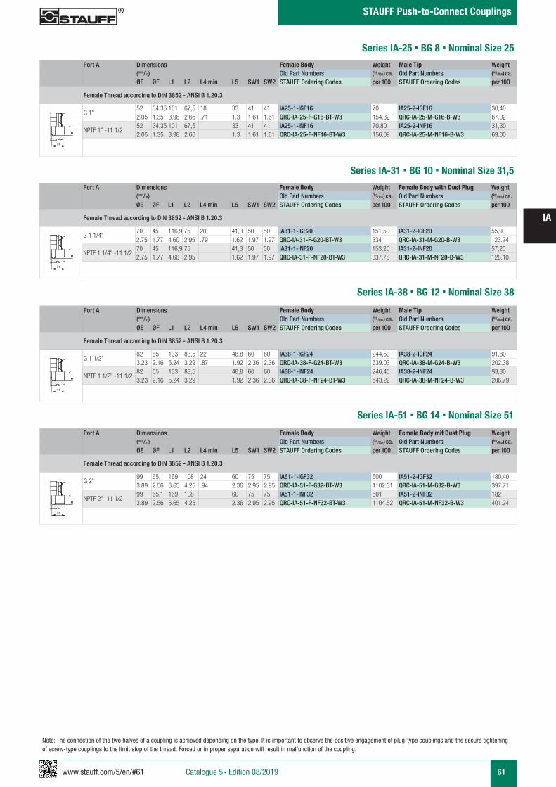
www.stauff.com/5/en/#61 61
IA
Catalogue 5 § Edition 08/2019
STAUFF Push-to-Connect Couplings
Note: The connection of the two halves of a coupling is achieved depending on the type. It is important to observe the positive engagement of plug-type couplings and the secure tightening of screw-type couplings to the limit stop of the thread. Forced or improper separation will result in malfunction of the coupling.
Series IA-25 § BG 8 § Nominal Size 25
Series IA-31 § BG 10 § Nominal Size 31,5
Port A Dimensions Female Body Weight Male Tip Weight (mm/in) Old Part Numbers (kg/lbs) ca. Old Part Numbers (kg/lbs) ca. ØE ØF L1 L2 L4 min L5 SW1 SW2 STAUFF Ordering Codes per 100 STAUFF Ordering Codes per 100
Female Thread according to DIN 3852 - ANSI B 1.20.3
G 1"52 34,35 101 67,5 18 33 41 41 IA25-1-IGF16 70 IA25-2-IGF16 30,402.05 1.35 3.98 2.66 .71 1.3 1.61 1.61 QRC-IA-25-F-G16-BT-W3 154.32 QRC-IA-25-M-G16-B-W3 67.02
NPTF 1" -11 1/252 34,35 101 67,5 33 41 41 IA25-1-INF16 70,80 IA25-2-INF16 31,302.05 1.35 3.98 2.66 1.3 1.61 1.61 QRC-IA-25-F-NF16-BT-W3 156.09 QRC-IA-25-M-NF16-B-W3 69.00
Port A Dimensions Female Body Weight Female Body with Dust Plug Weight (mm/in) Old Part Numbers (kg/lbs) ca. Old Part Numbers (kg/lbs) ca. ØE ØF L1 L2 L4 min L5 SW1 SW2 STAUFF Ordering Codes per 100 STAUFF Ordering Codes per 100
Female Thread according to DIN 3852 - ANSI B 1.20.3
G 1 1/4"70 45 116,9 75 20 41,3 50 50 IA31-1-IGF20 151,50 IA31-2-IGF20 55,902.75 1.77 4.60 2.95 .79 1.62 1.97 1.97 QRC-IA-31-F-G20-BT-W3 334 QRC-IA-31-M-G20-B-W3 123.24
NPTF 1 1/4" -11 1/270 45 116,9 75 41,3 50 50 IA31-1-INF20 153,20 IA31-2-INF20 57,202.75 1.77 4.60 2.95 1.62 1.97 1.97 QRC-IA-31-F-NF20-BT-W3 337.75 QRC-IA-31-M-NF20-B-W3 126.10
A A
L3 L3
L4
Anschlüsse-Beispiele.pdf 1 10.09.13 15:44
A A
L3 L3
L4
Anschlüsse-Beispiele.pdf 1 10.09.13 15:44
Series IA-38 § BG 12 § Nominal Size 38
Series IA-51 § BG 14 § Nominal Size 51
Port A Dimensions Female Body Weight Male Tip Weight (mm/in) Old Part Numbers (kg/lbs) ca. Old Part Numbers (kg/lbs) ca. ØE ØF L1 L2 L4 min L5 SW1 SW2 STAUFF Ordering Codes per 100 STAUFF Ordering Codes per 100
Female Thread according to DIN 3852 - ANSI B 1.20.3
G 1 1/2"82 55 133 83,5 22 48,8 60 60 IA38-1-IGF24 244,50 IA38-2-IGF24 91,803.23 2.16 5.24 3.29 .87 1.92 2.36 2.36 QRC-IA-38-F-G24-BT-W3 539.03 QRC-IA-38-M-G24-B-W3 202.38
NPTF 1 1/2" -11 1/282 55 133 83,5 48,8 60 60 IA38-1-INF24 246,40 IA38-2-INF24 93,803.23 2.16 5.24 3.29 1.92 2.36 2.36 QRC-IA-38-F-NF24-BT-W3 543.22 QRC-IA-38-M-NF24-B-W3 206.79
Port A Dimensions Female Body Weight Female Body mit Dust Plug Weight (mm/in) Old Part Numbers (kg/lbs) ca. Old Part Numbers (kg/lbs) ca. ØE ØF L1 L2 L4 min L5 SW1 SW2 STAUFF Ordering Codes per 100 STAUFF Ordering Codes per 100
Female Thread according to DIN 3852 - ANSI B 1.20.3
G 2"99 65,1 169 108 24 60 75 75 IA51-1-IGF32 500 IA51-2-IGF32 180,403.89 2.56 6.65 4.25 .94 2.36 2.95 2.95 QRC-IA-51-F-G32-BT-W3 1102.31 QRC-IA-51-M-G32-B-W3 397.71
NPTF 2" -11 1/299 65,1 169 108 60 75 75 IA51-1-INF32 501 IA51-2-INF32 1823.89 2.56 6.65 4.25 2.36 2.95 2.95 QRC-IA-51-F-NF32-BT-W3 1104.52 QRC-IA-51-M-NF32-B-W3 401.24
A A
L3 L3
L4
Anschlüsse-Beispiele.pdf 1 10.09.13 15:44
A A
L3 L3
L4
Anschlüsse-Beispiele.pdf 1 10.09.13 15:44
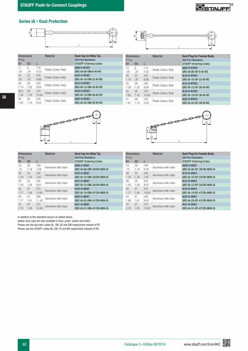
62 www.stauff.com/5/en/#62
IA
Catalogue 5 § Edition 08/2019
STAUFF Push-to-Connect Couplings
Series IA § Dust Protection
In addition to the standard colours as stated above, plastic dust caps are also available in blue, green, yellow and black. Please use the old color codes BL, GN, GE and SW respectively instead of RT.Please use the STAUFF codes BU, GN, YE and BK respectively instead of RD.
Dimensions Material Dust Cap for Male Tip(mm/in) Old Part NumbersD1 D2 L STAUFF Ordering Codes11 6 110
Plastic (Colour: Red)IA06-0-RT001
.43 .24 4.33 QRC-IA-06-DM-6-KI-RD24 22 220
Plastic (Colour: Red)IA10-0-RT001
.93 .87 8.66 QRC-IA-10-DM-22-KI-RD29 26 250
Plastic (Colour: Red)IA12-0-RT001
1.14 1.02 9.84 QRC-IA-12-DM-26-KI-RD36,5 36 270
Plastic (Colour: Red)IA19-0-RT001
1.44 1.42 10.63 QRC-IA-19-DM-36-KI-RD36 28 235
Plastic (Colour: Red)IA25-0-RT001
1.42 1.10 9.25 QRC-IA-25-DM-28-KI-RD
Dimensions Material Dust Plug for Female Body(mm/in) Old Part NumbersD1 D2 L STAUFF Ordering Codes10 6 110
Plastic (Colour: Red)IA06-9-RT001
.39 .24 4.33 QRC-IA-06-DF-6-KI-RD28 22 220
Plastic (Colour: Red)IA10-9-RT001
1.10 .87 8.66 QRC-IA-10-DF-22-KI-RD35 26 250
Plastic (Colour: Red)IA12-9-RT001
1.38 1.02 9.84 QRC-IA-12-DF-26-KI-RD42 36 270
Plastic (Colour: Red)IA19-9-RT001
1.65 1.42 10.63 QRC-IA-19-DF-36-KI-RD41 28 235
Plastic (Colour: Red)IA25-9-RT001
1.61 1.10 9.25 QRC-IA-25-DF-28-KI-RD
Dimensions Material Dust Cap for Male Tip(mm/in) Old Part NumbersD1 D2 L STAUFF Ordering Codes19 30 180
Aluminium with chainIA06-0-SI001
.75 1.18 7.09 QRC-IA-06-DM-30/CN-W89-SI30 33 200
Aluminium with chainIA10-0-SI001
1.18 1.30 7.87 QRC-IA-10-DM-33/CN-W89-SI38 32 205
Aluminium with chainIA12-0-SI001
1.50 1.26 8.07 QRC-IA-12-DM-32/CN-W89-SI45 47 275
Aluminium with chainIA19-0-SI001
1.77 1.85 10.83 QRC-IA-19-DM-47/CN-W89-SI45 41 290
Aluminium with chainIA25-0-SI001
1.77 1.61 11.42 QRC-IA-25-DM-41/CN-W89-SI70 47 275
Aluminium with chainIA31-0-SI001
2.76 1.85 10.83 QRC-IA-31-DM-47/CN-W89-SI
Dimensions Material Dust Plug for Female Body(mm/in) Old Part NumbersD1 D2 L STAUFF Ordering Codes19 30 160
Aluminium with chainIA06-9-SI001
.75 1.18 6.30 QRC-IA-06-DF-30/CN-W89-SI30 33 200
Aluminium with chainIA10-9-SI001
1.18 1.30 7.87 QRC-IA-10-DF-33/CN-W89-SI38 32 205
Aluminium with chainIA12-9-SI001
1.50 1.26 8.07 QRC-IA-12-DF-32/CN-W89-SI45 47 275
Aluminium with chainIA19-9-SI001
1.77 1.85 10.83 QRC-IA-19-DF-47/CN-W89-SI43 41 240
Aluminium with chainIA25-9-SI001
1.69 1.61 9.45 QRC-IA-25-DF-41/CN-W89-SI70 47 275
Aluminium with chainIA31-9-SI001
2.76 1.85 10.83 QRC-IA-31-DF-47/CN-W89-SI
IA12-0-RT001
Kunststoff rot
scale 0,4
D1
LD2
IA12-9-RT
Kunststoff rot
scale 0,4
D1
L
D2
IA..-0-SI001
Alu mit Kette
scale 0,4
D1L
D2
IA..-9-SI001
Alu mit Kette
scale 0,4
D1
D2
L
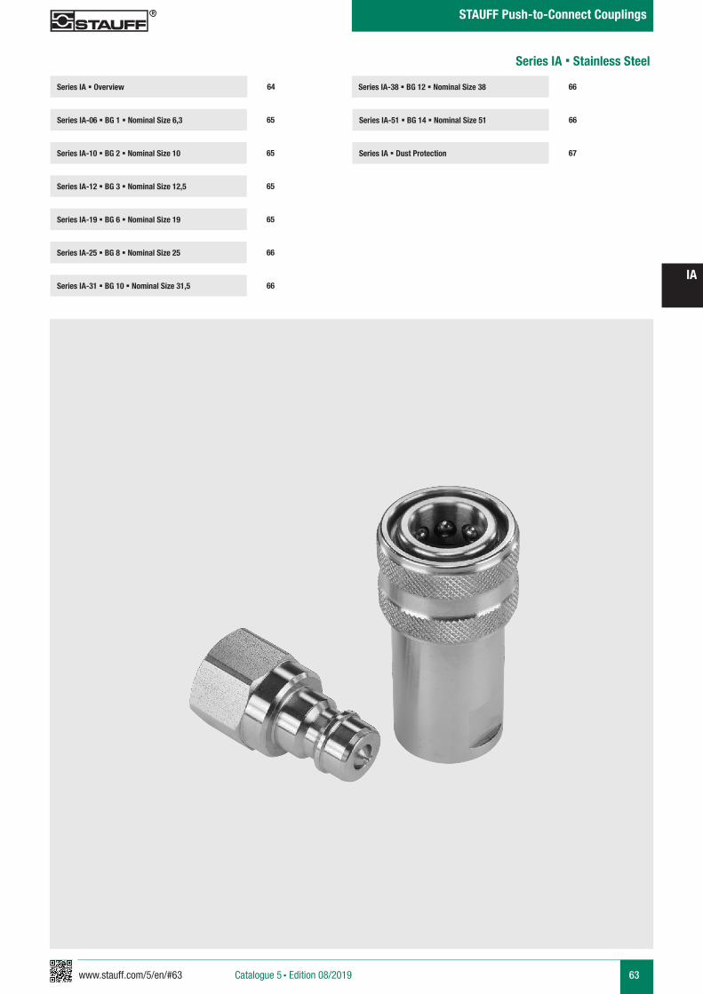
www.stauff.com/5/en/#63 63
IA
Catalogue 5 § Edition 08/2019
STAUFF Push-to-Connect Couplings
Series IA-38 § BG 12 § Nominal Size 38
Series IA-51 § BG 14 § Nominal Size 51 66
66
Series IA § Dust Protection 67
Series IA § Overview
Series IA-06 § BG 1 § Nominal Size 6,3 65
64
Series IA-10 § BG 2 § Nominal Size 10 65
Series IA-19 § BG 6 § Nominal Size 19 65
Series IA-25 § BG 8 § Nominal Size 25 66
Series IA-12 § BG 3 § Nominal Size 12,5 65
Series IA-31 § BG 10 § Nominal Size 31,5 66
Series IA § Stainless Steel
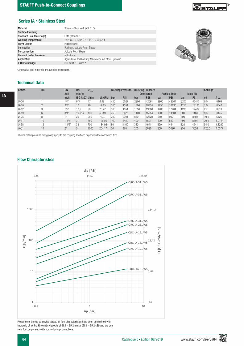
64 www.stauff.com/5/en/#64
IA
Catalogue 5 § Edition 08/2019
STAUFF Push-to-Connect Couplings
Series IA § Stainless Steel
Series BG DN DN Q max Working Pressure Bursting Pressure SpillageZoll metric Connected Female Body Male TipInch ISO 4397 l/min US GPM bar PSI bar PSI bar PSI bar PSI ml fl oz
IA-06 1 1/4" 6,3 17 4.49 450 6527 2900 42061 2900 42061 3200 46412 0,5 .0169IA-10 2 3/8" 10 46 12.15 300 4351 1300 18855 1250 18130 1250 18130 1,9 .0642IA-12 3 1/2" 12,5 90 23.77 300 4351 1350 19580 1200 17404 1200 17404 2,7 .0913IA-19 6 3/4" 19 (20) 190 50.19 250 3626 1100 15954 1000 14504 800 11603 9,3 .3145IA-25 8 1" 25 280 73.97 200 2901 850 12328 650 9427 600 8702 19,0 .6425IA-31 10 1 1/4'' 31 480 126.80 100 1450 400 5801 400 5801 400 5801 30,0 1.0144IA-38 12 1 1/2'' 38 700 184.92 80 1160 320 4641 320 4641 320 4641 54,0 1.8260IA-51 14 2" 51 1000 264.17 60 870 250 3626 250 3626 250 3626 120,0 4.0577
Technical Data
Material Stainless Steel V4A (AISI 316) Surface Finishing -Standard Seal Material(s) FKM (Viton®) 2
Working Temperature -25° C ... +200° C / -13° F ... +392° FValve Design Poppet ValveConnection Push and actuate Push SleeveDisconnection Actuate Push SleeveConnect Under Pressure not allowedApplication Agricultural and Forestry Machinery, Industrial Hydraulic ISO Interchange ISO 7241-1, Series A
The indicated pressure ratings only apply to the coupling itself and depend on the connection type.
2 Alternative seal materials are available on request.
Please note: Unless otherwise stated, all flow characteristics have been determined with hydraulic oil with a kinematic viscosity of 28,8 - 35,2 mm2/s (28,8 - 35,2 cSt) and are only valid for components with non-reducing connections.
Flow Characteristics
QRC-IA-6…W5
QRC-IA-10…W5
QRC-IA-12…W5
QRC-IA-19…W5
QRC-IA-25…W5QRC-IA-31…W5
QRC-IA-38…W5
QRC-IA-51…W5
1
10
100
1000
0,1 1 10
Q [l/
min
]
Δp [bar]
Q [U
S G
PM/m
in]
Δp [PSI]
264,17
26,42
2,64
.26
1.45 14.50 145.04
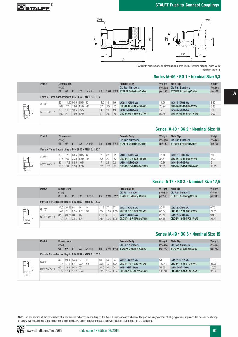
www.stauff.com/5/en/#65 65
IA
Catalogue 5 § Edition 08/2019
STAUFF Push-to-Connect Couplings
Port A Dimensions Female Body Weight Male Tip Weight (mm/in) Old Part Numbers (kg/lbs) ca. Old Part Numbers (kg/lbs) ca. ØE ØF L1 L2 L4 min L5 SW1 SW2 STAUFF Ordering Codes per 100 STAUFF Ordering Codes per 100
Female Thread according to DIN 3852 - ANSI B. 1.20.3
G 1/4"26 11,85 50,5 35,5 12 14,5 19 19 IA06-1-IGF04-VA 11,90 IA06-2-IGF04-VA 3,801.02 .47 1.99 1.40 .47 .57 .75 .75 QRC-IA-06-F-G04-VT-W5 26.24 QRC-IA-06-M-G04-V-W5 8.38
NPTF 1/4" -1826 11,85 50,5 35,5 14,5 19 19 IA06-1-INF04-VA 12 IA06-2-INF04-VA 3,901.02 .47 1.99 1.40 .57 .75 .75 QRC-IA-06-F-NF04-VT-W5 26.46 QRC-IA-06-M-NF04-V-W5 8.60
Series IA-06 § BG 1 § Nominal Size 6,3
IA06-IA51 VA Muffe & Stecker
Edelstahl
scale 0.74
SW1
L4L1
A
L4L2
A
SW2
L5*
zeichnerische Darstellung entspricht Serie IA 12VA * Eintauchtiefe Stecker
A A
L3 L3
L4
Anschlüsse-Beispiele.pdf 1 10.09.13 15:44
Series IA-10 § BG 2 § Nominal Size 10Port A Dimensions Female Body Weight Male Tip Weight
(mm/in) Old Part Numbers (kg/lbs) ca. Old Part Numbers (kg/lbs) ca. ØE ØF L1 L2 L4 min L5 SW1 SW2 STAUFF Ordering Codes per 100 STAUFF Ordering Codes per 100
Female Thread according to DIN 3852 - ANSI B. 1.20.3
G 3/8"30 17,3 58,5 40,5 12 17 22 22 IA10-1-IGF06-VA 15,70 IA10-2-IGF06-VA 5,901.18 .68 2.30 1.59 .47 .62 .87 .87 QRC-IA-10-F-G06-VT-W5 34.61 QRC-IA-10-M-G06-V-W5 13.01
NPTF 3/8" -1830 17,3 58,5 40,5 17 22 22 IA10-1-INF06-VA 15,80 IA10-2-INF06-VA 61.18 .68 2.30 1.59 .62 .87 .87 QRC-IA-10-F-NF06-VT-W5 34.83 QRC-IA-10-M-NF06-V-W5 13.23
A A
L3 L3
L4
Anschlüsse-Beispiele.pdf 1 10.09.13 15:44
SW: Width across flats. All dimensions in mm (inch). Drawing similar Series IA-12.* Insertion Male Tip.
Port A Dimensions Female Body Weight Male Tip Weight (mm/in) Old Part Numbers (kg/lbs) ca. Old Part Numbers (kg/lbs) ca. ØE ØF L1 L2 L4 min L5 SW1 SW2 STAUFF Ordering Codes per 100 STAUFF Ordering Codes per 100
Female Thread according to DIN 3852 - ANSI B. 1.20.3
G 1/2"37,9 20,55 68 46 14 21,5 27 27 IA12-1-IGF08-VA 29,50 IA12-2-IGF08-VA 9,701.49 .81 2.68 1.81 .55 .85 1.06 1.06 QRC-IA-12-F-G08-VT-W5 65.04 QRC-IA-12-M-G08-V-W5 21.38
NPTF 1/2" -1437,9 20,55 68 46 21,5 27 27 IA12-1-INF08-VA 29,70 IA12-2-INF08-VA 9,901.49 .81 2.68 1.81 .85 1.06 1.06 QRC-IA-12-F-NF08-VT-W5 65.48 QRC-IA-12-M-NF08-V-W5 21.83
Series IA-12 § BG 3 § Nominal Size 12,5
A A
L3 L3
L4
Anschlüsse-Beispiele.pdf 1 10.09.13 15:44
Series IA-19 § BG 6 § Nominal Size 19Port A Dimensions Female Body Weight Male Tip Weight
(mm/in) Old Part Numbers (kg/lbs) ca. Old Part Numbers (kg/lbs) ca. ØE ØF L1 L2 L4 min L5 SW1 SW2 STAUFF Ordering Codes per 100 STAUFF Ordering Codes per 100
Female Thread according to DIN 3852 - ANSI B. 1.20.3
G 3/4"45 29,1 84,3 57 16 20,8 34 34 IA19-1-IGF12-VA 51 IA19-2-IGF12-VA 16,501.77 1.14 84 2.24 .63 .82 1.34 1.34 QRC-IA-19-F-G12-VT-W5 112.44 QRC-IA-19-M-G12-V-W5 36.38
NPTF 3/4" -1445 29,1 84,3 57 20,8 34 34 IA19-1-INF12-VA 51,30 IA19-2-INF12-VA 16,801.77 1.14 3.32 2.24 .82 1.34 1.34 QRC-IA-19-F-NF12-VT-W5 113.10 QRC-IA-19-M-NF12-V-W5 37.04
A A
L3 L3
L4
Anschlüsse-Beispiele.pdf 1 10.09.13 15:44
Note: The connection of the two halves of a coupling is achieved depending on the type. It is important to observe the positive engagement of plug-type couplings and the secure tightening of screw-type couplings to the limit stop of the thread. Forced or improper separation will result in malfunction of the coupling.
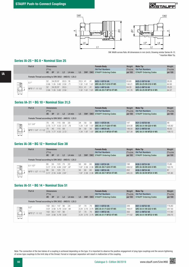
66 www.stauff.com/5/en/#66
IA
Catalogue 5 § Edition 08/2019
STAUFF Push-to-Connect Couplings
Note: The connection of the two halves of a coupling is achieved depending on the type. It is important to observe the positive engagement of plug-type couplings and the secure tightening of screw-type couplings to the limit stop of the thread. Forced or improper separation will result in malfunction of the coupling.
Port A Dimensions Female Body Weight Male Tip Weight (mm/in) Old Part Numbers (kg/lbs) ca. Old Part Numbers (kg/lbs) ca. ØE ØF L1 L2 L4 min L5 SW1 SW2 STAUFF Ordering Codes per 100 STAUFF Ordering Codes per 100
Female Thread according to DIN 3852 - ANSI B. 1.20.3
G 1"52 34,35 97 63,5 18 33,5 41 41 IA25-1-IGF16-VA 63,60 IA25-2-IGF16-VA 28,502.06 1.35 3.82 2.50 .71 1.32 1.61 1.61 QRC-IA-25-F-G16-VT-W5 140.21 QRC-IA-25-M-G16-V-W5 62.83
NPTF 1" -11 1/252 34,35 97 63,5 33,5 41 41 IA25-1-INF16-VA 64,30 IA25-2-INF16-VA 29,202.06 1.35 3.82 2.50 1.32 1.61 1.61 QRC-IA-25-F-NF16-VT-W5 141.76 QRC-IA-25-M-NF16-V-W5 64.37
Series IA-25 § BG 8 § Nominal Size 25
A A
L3 L3
L4
Anschlüsse-Beispiele.pdf 1 10.09.13 15:44
Series IA-31 § BG 10 § Nominal Size 31,5Port A Dimensions Female Body Weight Male Tip Weight
(mm/in) Old Part Numbers (kg/lbs) ca. Old Part Numbers (kg/lbs) ca. ØE ØF L1 L2 L4 min L5 SW1 SW2 STAUFF Ordering Codes per 100 STAUFF Ordering Codes per 100
Female Thread according to DIN 3852 - ANSI B. 1.20.3
G 1 1/4"70 45 115 69 20 34 50 50 IA31-1-IGF20-VA 147 IA31-2-IGF20-VA 482.75 1.77 4.53 2.72 .79 1.34 1.97 1.97 QRC-IA-31-F-G20-VT-W5 324.08 QRC-IA-31-M-G20-V-W5 105.82
NPTF 1 1/4" -11 1/270 45 115 69 34 50 50 IA31-1-INF20-VA 148,50 IA31-2-INF20-VA 49,502.75 1.77 4.53 2.72 1.34 1.97 1.97 QRC-IA-31-F-NF20-VT-W5 327.39 QRC-IA-31-M-NF20-V-W5 109.13
A A
L3 L3
L4
Anschlüsse-Beispiele.pdf 1 10.09.13 15:44
Port A Dimensions Female Body Weight Male Tip Weight (mm/in) Old Part Numbers (kg/lbs) ca. Old Part Numbers (kg/lbs) ca. ØE ØF L1 L2 L4 min L5 SW1 SW2 STAUFF Ordering Codes per 100 STAUFF Ordering Codes per 100
Female Thread according to DIN 3852 - ANSI B. 1.20.3
G 1 1/2"80 55 123 73 22 50 60 60 IA38-1-IGF24-VA 198 IA38-2-IGF24-VA 73,803.17 2.16 4.84 2.87 .87 1.97 2.36 2.36 QRC-IA-38-F-G24-VT-W5 436.52 QRC-IA-38-M-G24-V-W5 162.70
NPTF 1 1/2" -11 1/280 55 123 73 50 60 60 IA38-1-INF24-VA 202 IA38-2-INF24-VA 873.17 2.16 4.84 2.87 1.97 2.36 2.36 QRC-IA-38-F-NF24-VT-W5 445.33 QRC-IA-38-M-NF24-V-W5 191.80
Series IA-38 § BG 12 § Nominal Size 38
A A
L3 L3
L4
Anschlüsse-Beispiele.pdf 1 10.09.13 15:44
Series IA-51 § BG 14 § Nominal Size 51Port A Dimensions Female Body Weight Male Tip Weight
(mm/in) Old Part Numbers (kg/lbs) ca. Old Part Numbers (kg/lbs) ca. ØE ØF L1 L2 L4 min L5 SW1 SW2 STAUFF Ordering Codes per 100 STAUFF Ordering Codes per 100
Female Thread according to DIN 3852 - ANSI B. 1.20.3
G 2"102 65,1 147 90 24 57 70 70 IA51-1-IGF32-VA 349 IA51-2-IGF32-VA 116,804.01 2.56 5.79 3.54 .94 2.24 2.75 2.75 QRC-IA-51-F-G32-VT-W5 769.41 QRC-IA-51-M-G32-V-W5 257.50
NPTF 2" -11 1/2102 65,1 147 90 57 70 70 IA51-1-INF32-VA 350 IA51-2-INF32-VA 117,804.01 2.56 5.79 3.54 2.24 2.75 2.75 QRC-IA-51-F-NF32-VT-W5 771.62 QRC-IA-51-M-NF32-V-W5 259.70
A A
L3 L3
L4
Anschlüsse-Beispiele.pdf 1 10.09.13 15:44
IA06-IA51 VA Muffe & Stecker
Edelstahl
scale 0.74
SW1
L4L1
A
L4L2
A
SW2
L5*
zeichnerische Darstellung entspricht Serie IA 12VA * Eintauchtiefe Stecker
SW: Width across flats. All dimensions in mm (inch). Drawing similar Series IA-12.* Insertion Male Tip.
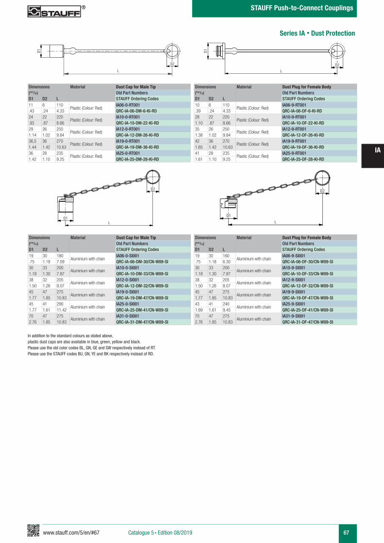
www.stauff.com/5/en/#67 67
IA
Catalogue 5 § Edition 08/2019
STAUFF Push-to-Connect Couplings
Series IA § Dust Protection
In addition to the standard colours as stated above, plastic dust caps are also available in blue, green, yellow and black. Please use the old color codes BL, GN, GE and SW respectively instead of RT.Please use the STAUFF codes BU, GN, YE and BK respectively instead of RD.
Dimensions Material Dust Cap for Male Tip(mm/in) Old Part NumbersD1 D2 L STAUFF Ordering Codes11 6 110
Plastic (Colour: Red)IA06-0-RT001
.43 .24 4.33 QRC-IA-06-DM-6-KI-RD24 22 220
Plastic (Colour: Red)IA10-0-RT001
.93 .87 8.66 QRC-IA-10-DM-22-KI-RD29 26 250
Plastic (Colour: Red)IA12-0-RT001
1.14 1.02 9.84 QRC-IA-12-DM-26-KI-RD36,5 36 270
Plastic (Colour: Red)IA19-0-RT001
1.44 1.42 10.63 QRC-IA-19-DM-36-KI-RD36 28 235
Plastic (Colour: Red)IA25-0-RT001
1.42 1.10 9.25 QRC-IA-25-DM-28-KI-RD
Dimensions Material Dust Plug for Female Body(mm/in) Old Part NumbersD1 D2 L STAUFF Ordering Codes10 6 110
Plastic (Colour: Red)IA06-9-RT001
.39 .24 4.33 QRC-IA-06-DF-6-KI-RD28 22 220
Plastic (Colour: Red)IA10-9-RT001
1.10 .87 8.66 QRC-IA-10-DF-22-KI-RD35 26 250
Plastic (Colour: Red)IA12-9-RT001
1.38 1.02 9.84 QRC-IA-12-DF-26-KI-RD42 36 270
Plastic (Colour: Red)IA19-9-RT001
1.65 1.42 10.63 QRC-IA-19-DF-36-KI-RD41 28 235
Plastic (Colour: Red)IA25-9-RT001
1.61 1.10 9.25 QRC-IA-25-DF-28-KI-RD
Dimensions Material Dust Cap for Male Tip(mm/in) Old Part NumbersD1 D2 L STAUFF Ordering Codes19 30 180
Aluminium with chainIA06-0-SI001
.75 1.18 7.09 QRC-IA-06-DM-30/CN-W89-SI30 33 200
Aluminium with chainIA10-0-SI001
1.18 1.30 7.87 QRC-IA-10-DM-33/CN-W89-SI38 32 205
Aluminium with chainIA12-0-SI001
1.50 1.26 8.07 QRC-IA-12-DM-32/CN-W89-SI45 47 275
Aluminium with chainIA19-0-SI001
1.77 1.85 10.83 QRC-IA-19-DM-47/CN-W89-SI45 41 290
Aluminium with chainIA25-0-SI001
1.77 1.61 11.42 QRC-IA-25-DM-41/CN-W89-SI70 47 275
Aluminium with chainIA31-0-SI001
2.76 1.85 10.83 QRC-IA-31-DM-47/CN-W89-SI
Dimensions Material Dust Plug for Female Body(mm/in) Old Part NumbersD1 D2 L STAUFF Ordering Codes19 30 160
Aluminium with chainIA06-9-SI001
.75 1.18 6.30 QRC-IA-06-DF-30/CN-W89-SI30 33 200
Aluminium with chainIA10-9-SI001
1.18 1.30 7.87 QRC-IA-10-DF-33/CN-W89-SI38 32 205
Aluminium with chainIA12-9-SI001
1.50 1.26 8.07 QRC-IA-12-DF-32/CN-W89-SI45 47 275
Aluminium with chainIA19-9-SI001
1.77 1.85 10.83 QRC-IA-19-DF-47/CN-W89-SI43 41 240
Aluminium with chainIA25-9-SI001
1.69 1.61 9.45 QRC-IA-25-DF-41/CN-W89-SI70 47 275
Aluminium with chainIA31-9-SI001
2.76 1.85 10.83 QRC-IA-31-DF-47/CN-W89-SI
IA12-0-RT001
Kunststoff rot
scale 0,4
D1
LD2
IA12-9-RT
Kunststoff rot
scale 0,4
D1
L
D2
IA..-0-SI001
Alu mit Kette
scale 0,4
D1L
D2
IA..-9-SI001
Alu mit Kette
scale 0,4
D1
D2
L
68 www.stauff.com/5/en/#68
IA
Catalogue 5 § Edition 08/2019
STAUFF Push-to-Connect Couplings
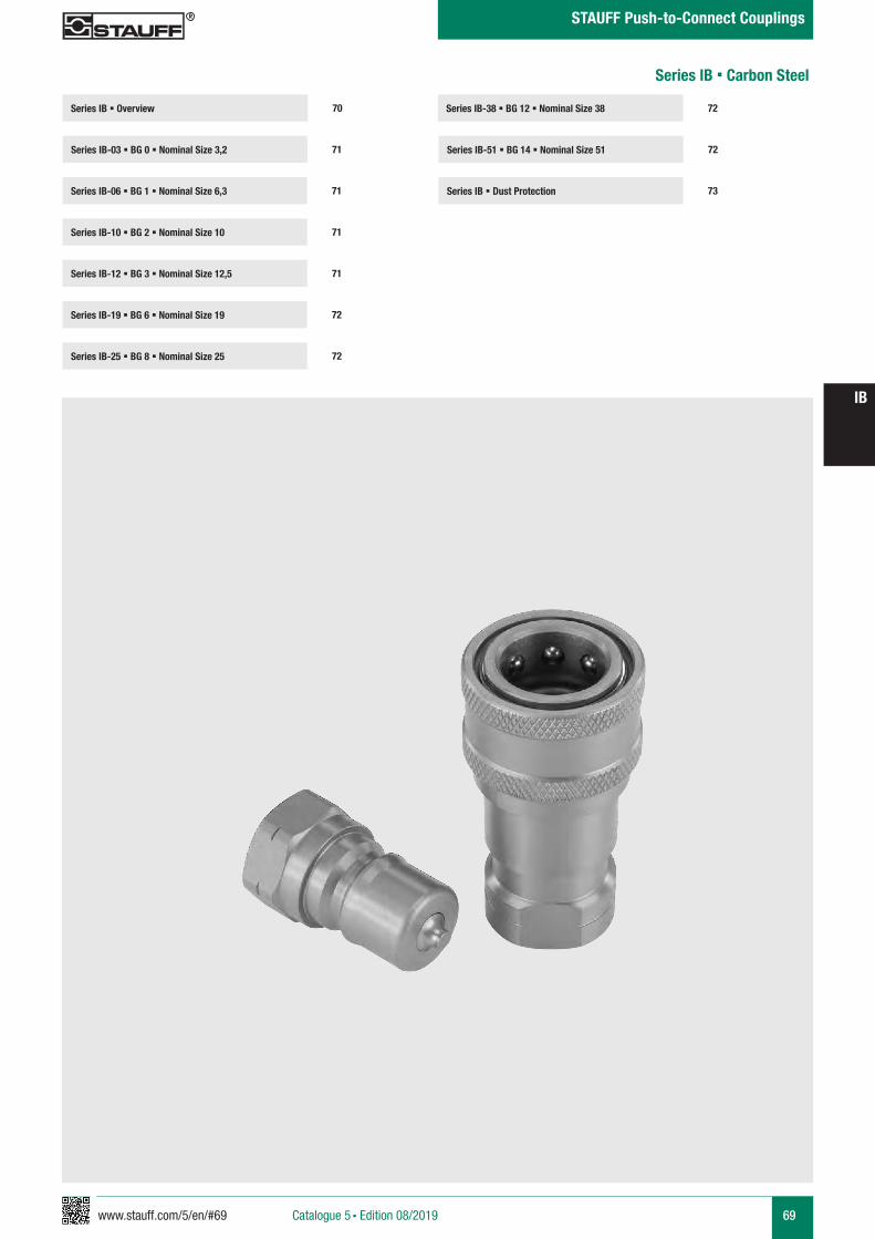
www.stauff.com/5/en/#69 69
IB
Catalogue 5 § Edition 08/2019
STAUFF Push-to-Connect Couplings
Series IB-38 § BG 12 § Nominal Size 38
Series IB-51 § BG 14 § Nominal Size 51 72
72
Series IB § Dust Protection 73
Series IB § Overview
Series IB-03 § BG 0 § Nominal Size 3,2 71
70
Series IB-06 § BG 1 § Nominal Size 6,3 71
Series IB-12 § BG 3 § Nominal Size 12,5 71
Series IB-19 § BG 6 § Nominal Size 19 72
Series IB-10 § BG 2 § Nominal Size 10 71
Series IB-25 § BG 8 § Nominal Size 25 72
Series IB § Carbon Steel
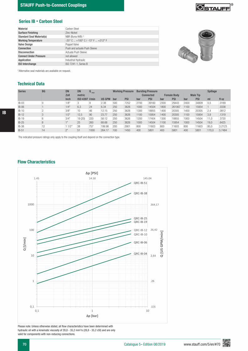
70 www.stauff.com/5/en/#70
IB
Catalogue 5 § Edition 08/2019
STAUFF Push-to-Connect Couplings
Series IB § Carbon Steel
Series BG DN DN Q max Working Pressure Bursting Pressure SpillageZoll metric Connected Female Body Male TipInch ISO 4397 l/min US GPM bar PSI bar PSI bar PSI bar PSI ml fl oz
IB-03 0 1/8" 3 9 2.38 500 7252 2700 39160 2300 29443 2400 34809 0,5 .0169IB-06 1 1/4" 6,3 24 6.34 250 3626 1000 14504 1800 261067 1100 15954 1 .0338IB-10 2 3/8" 10 46 12.15 250 3626 1300 18855 1400 20305 1400 20305 2,4 .0812IB-12 3 1/2" 12,5 90 23.77 250 3626 1100 15954 1400 20305 1100 15954 3,9 .1319IB-19 6 3/4" 19 (20) 220 58.12 250 3626 1200 17404 1300 18855 1000 14504 11,0 .3720IB-25 8 1" 25 260 68.68 250 3626 1000 14504 1100 15954 1000 14504 19,0 .6425IB-38 12 1 1/2'' 38 757 199.98 200 2901 800 11603 800 11603 800 11603 95,0 3.2123IB-51 14 2" 51 1000 264.17 100 1450 400 5801 400 5801 400 5801 170,0 5.7484
Technical Data
Material Carbon SteelSurface Finishing Zinc-NickelStandard Seal Material(s) NBR (Buna-N®) 2
Working Temperature -25° C ... +100° C / -13° F ... +212° FValve Design Poppet ValveConnection Push and actuate Push SleeveDisconnection Actuate Push SleeveConnect Under Pressure not allowedApplication Industrial HydraulicISO Interchange ISO 7241-1, Series B
The indicated pressure ratings only apply to the coupling itself and depend on the connection type.
2 Alternative seal materials are available on request.
Please note: Unless otherwise stated, all flow characteristics have been determined with hydraulic oil with a kinematic viscosity of 28,8 - 35,2 mm2/s (28,8 - 35,2 cSt) and are only valid for components with non-reducing connections.
Flow Characteristics
QRC-IB-04
QRC-IB-06
QRC-IB-10QRC-IB-12
QRC-IB-19QRC-IB-25
QRC-IB-38
QRC-IB-51
0,1
1
10
100
1000
0,1 1 10
Q [l/
min
]
Δp [bar]
.026
Q [U
S G
PM/m
in]
Δp [PSI]
264,17
26,42
2,64
.26
1.45 14.50 145.04
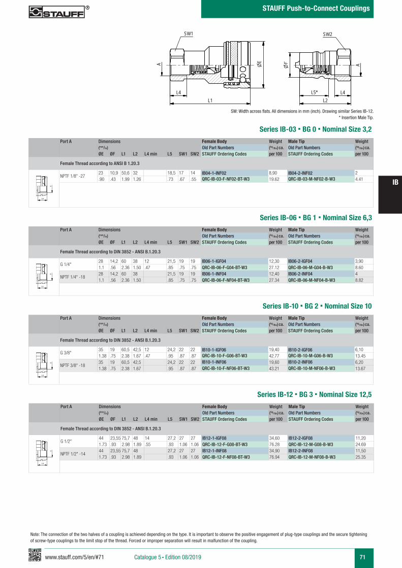
www.stauff.com/5/en/#71 71
IB
Catalogue 5 § Edition 08/2019
STAUFF Push-to-Connect Couplings
Port A Dimensions Female Body Weight Male Tip Weight (mm/in) Old Part Numbers (kg/lbs) ca. Old Part Numbers (kg/lbs) ca. ØE ØF L1 L2 L4 min L5 SW1 SW2 STAUFF Ordering Codes per 100 STAUFF Ordering Codes per 100
Female Thread according to ANSI B 1.20.3
NPTF 1/8" -2723 10,9 50,6 32 18,5 17 14 IB04-1-INF02 8,90 IB04-2-INF02 2.90 .43 1.99 1.26 .73 .67 .55 QRC-IB-03-F-NF02-BT-W3 19.62 QRC-IB-03-M-NF02-B-W3 4.41
Series IB-03 § BG 0 § Nominal Size 3,2
IB 04-51 Muffe und Stecker
Stahl (Chrom III), Edelstahl, Messing
scale 0.74
L4L1
EA
SW1
A
L4L2
SW2
L5*
zeichnerische Darstellung entspricht Serie IB 12 * Eintauchtiefe Stecker
A A
L3 L3
L4
Anschlüsse-Beispiele.pdf 1 10.09.13 15:44
Series IB-06 § BG 1 § Nominal Size 6,3
SW: Width across flats. All dimensions in mm (inch). Drawing similar Series IB-12.* Insertion Male Tip.
Port A Dimensions Female Body Weight Male Tip Weight (mm/in) Old Part Numbers (kg/lbs) ca. Old Part Numbers (kg/lbs) ca. ØE ØF L1 L2 L4 min L5 SW1 SW2 STAUFF Ordering Codes per 100 STAUFF Ordering Codes per 100
Female Thread according to DIN 3852 - ANSI B.1.20.3
G 1/4"28 14,2 60 38 12 21,5 19 19 IB06-1-IGF04 12,30 IB06-2-IGF04 3,901.1 .56 2.36 1.50 .47 .85 .75 .75 QRC-IB-06-F-G04-BT-W3 27.12 QRC-IB-06-M-G04-B-W3 8.60
NPTF 1/4" -1828 14,2 60 38 21,5 19 19 IB06-1-INF04 12,40 IB06-2-INF04 41.1 .56 2.36 1.50 .85 .75 .75 QRC-IB-06-F-NF04-BT-W3 27.34 QRC-IB-06-M-NF04-B-W3 8.82
A A
L3 L3
L4
Anschlüsse-Beispiele.pdf 1 10.09.13 15:44
Port A Dimensions Female Body Weight Male Tip Weight (mm/in) Old Part Numbers (kg/lbs) ca. Old Part Numbers (kg/lbs) ca. ØE ØF L1 L2 L4 min L5 SW1 SW2 STAUFF Ordering Codes per 100 STAUFF Ordering Codes per 100
Female Thread according to DIN 3852 - ANSI B.1.20.3
G 3/8"35 19 60,5 42,5 12 24,2 22 22 IB10-1-IGF06 19,40 IB10-2-IGF06 6,101.38 .75 2.38 1.67 .47 .95 .87 .87 QRC-IB-10-F-G06-BT-W3 42.77 QRC-IB-10-M-G06-B-W3 13.45
NPTF 3/8" -1835 19 60,5 42,5 24,2 22 22 IB10-1-INF06 19,60 IB10-2-INF06 6,201.38 .75 2.38 1.67 .95 .87 .87 QRC-IB-10-F-NF06-BT-W3 43.21 QRC-IB-10-M-NF06-B-W3 13.67
Series IB-10 § BG 2 § Nominal Size 10
A A
L3 L3
L4
Anschlüsse-Beispiele.pdf 1 10.09.13 15:44
Series IB-12 § BG 3 § Nominal Size 12,5Port A Dimensions Female Body Weight Male Tip Weight
(mm/in) Old Part Numbers (kg/lbs) ca. Old Part Numbers (kg/lbs) ca. ØE ØF L1 L2 L4 min L5 SW1 SW2 STAUFF Ordering Codes per 100 STAUFF Ordering Codes per 100
Female Thread according to DIN 3852 - ANSI B.1.20.3
G 1/2"44 23,55 75,7 48 14 27,2 27 27 IB12-1-IGF08 34,60 IB12-2-IGF08 11,201.73 .93 2.98 1.89 .55 .93 1.06 1.06 QRC-IB-12-F-G08-BT-W3 76.28 QRC-IB-12-M-G08-B-W3 24.69
NPTF 1/2" -1444 23,55 75,7 48 27,2 27 27 IB12-1-INF08 34,90 IB12-2-INF08 11,501.73 .93 2.98 1.89 .93 1.06 1.06 QRC-IB-12-F-NF08-BT-W3 76.94 QRC-IB-12-M-NF08-B-W3 25.35
A A
L3 L3
L4
Anschlüsse-Beispiele.pdf 1 10.09.13 15:44
Note: The connection of the two halves of a coupling is achieved depending on the type. It is important to observe the positive engagement of plug-type couplings and the secure tightening of screw-type couplings to the limit stop of the thread. Forced or improper separation will result in malfunction of the coupling.
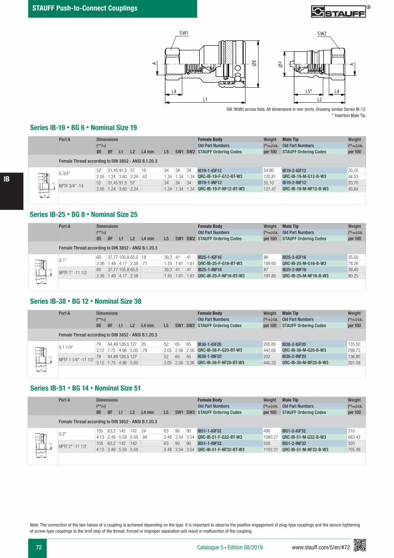
72 www.stauff.com/5/en/#72
IB
Catalogue 5 § Edition 08/2019
STAUFF Push-to-Connect Couplings
Note: The connection of the two halves of a coupling is achieved depending on the type. It is important to observe the positive engagement of plug-type couplings and the secure tightening of screw-type couplings to the limit stop of the thread. Forced or improper separation will result in malfunction of the coupling.
Port A Dimensions Female Body Weight Male Tip Weight (mm/in) Old Part Numbers (kg/lbs) ca. Old Part Numbers (kg/lbs) ca. ØE ØF L1 L2 L4 min L5 SW1 SW2 STAUFF Ordering Codes per 100 STAUFF Ordering Codes per 100
Female Thread according to DIN 3852 - ANSI B.1.20.3
G 3/4"52 31,45 91,5 57 16 34 34 34 IB19-1-IGF12 54,80 IB19-2-IGF12 20,202.05 1.24 3.60 2.24 .63 1.34 1.34 1.34 QRC-IB-19-F-G12-BT-W3 120.81 QRC-IB-19-M-G12-B-W3 44.53
NPTF 3/4" -1452 31,45 91,5 57 34 34 34 IB19-1-INF12 55,10 IB19-2-INF12 20,702.05 1.24 3.60 2.24 1.34 1.34 1.34 QRC-IB-19-F-NF12-BT-W3 121.47 QRC-IB-19-M-NF12-B-W3 45.64
Series IB-19 § BG 6 § Nominal Size 19
A A
L3 L3
L4
Anschlüsse-Beispiele.pdf 1 10.09.13 15:44
Series IB-25 § BG 8 § Nominal Size 25Port A Dimensions Female Body Weight Male Tip Weight
(mm/in) Old Part Numbers (kg/lbs) ca. Old Part Numbers (kg/lbs) ca. ØE ØF L1 L2 L4 min L5 SW1 SW2 STAUFF Ordering Codes per 100 STAUFF Ordering Codes per 100
Female Thread according to DIN 3852 - ANSI B.1.20.3
G 1"60 37,77 105,8 65,5 18 39,3 41 41 IB25-1-IGF16 86 IB25-2-IGF16 35,502.36 1.49 4.17 2.58 .71 1.55 1.61 1.61 QRC-IB-25-F-G16-BT-W3 189.60 QRC-IB-25-M-G16-B-W3 78.26
NPTF 1" -11 1/260 37,77 105,8 65,5 39,3 41 41 IB25-1-INF16 87 IB25-2-INF16 36,402.36 1.49 4.17 2.58 1.55 1.61 1.61 QRC-IB-25-F-NF16-BT-W3 191.80 QRC-IB-25-M-NF16-B-W3 80.25
A A
L3 L3
L4
Anschlüsse-Beispiele.pdf 1 10.09.13 15:44
Port A Dimensions Female Body Weight Male Tip Weight (mm/in) Old Part Numbers (kg/lbs) ca. Old Part Numbers (kg/lbs) ca. ØE ØF L1 L2 L4 min L5 SW1 SW2 STAUFF Ordering Codes per 100 STAUFF Ordering Codes per 100
Female Thread according to DIN 3852 - ANSI B.1.20.3
G 1 1/4"79 44,49 126,5 127 20 52 65 65 IB38-1-IGF20 200,80 IB38-2-IGF20 135,503.12 1.75 4.98 5.00 .79 2.05 2.56 2.56 QRC-IB-38-F-G20-BT-W3 442.69 QRC-IB-38-M-G20-B-W3 298.73
NPTF 1 1/4" -11 1/279 44,49 126,5 127 52 65 65 IB38-1-INF20 202 IB38-2-INF20 136,803.12 1.75 4.98 5.00 2.05 2.56 2.56 QRC-IB-38-F-NF20-BT-W3 445.33 QRC-IB-38-M-NF20-B-W3 301.59
Series IB-38 § BG 12 § Nominal Size 38
A A
L3 L3
L4
Anschlüsse-Beispiele.pdf 1 10.09.13 15:44
Series IB-51 § BG 14 § Nominal Size 51Port A Dimensions Female Body Weight Male Tip Weight
(mm/in) Old Part Numbers (kg/lbs) ca. Old Part Numbers (kg/lbs) ca. ØE ØF L1 L2 L4 min L5 SW1 SW2 STAUFF Ordering Codes per 100 STAUFF Ordering Codes per 100
Female Thread according to DIN 3852 - ANSI B.1.20.3
G 2"105 63,2 142 142 24 63 90 90 IB51-1-IGF32 490 IB51-2-IGF32 3104.13 2.49 5.59 5.59 .94 2.48 3.54 3.54 QRC-IB-51-F-G32-BT-W3 1080.27 QRC-IB-51-M-G32-B-W3 683.43
NPTF 2" -11 1/2105 63,2 142 142 63 90 90 IB51-1-INF32 500 IB51-2-INF32 3204.13 2.49 5.59 5.59 2.48 3.54 3.54 QRC-IB-51-F-NF32-BT-W3 1102.31 QRC-IB-51-M-NF32-B-W3 705.48
A A
L3 L3
L4
Anschlüsse-Beispiele.pdf 1 10.09.13 15:44
IB 04-51 Muffe und Stecker
Stahl (Chrom III), Edelstahl, Messing
scale 0.74
L4L1
EA
SW1
A
L4L2
SW2
L5*
zeichnerische Darstellung entspricht Serie IB 12 * Eintauchtiefe Stecker
SW: Width across flats. All dimensions in mm (inch). Drawing similar Series IB-12.* Insertion Male Tip.
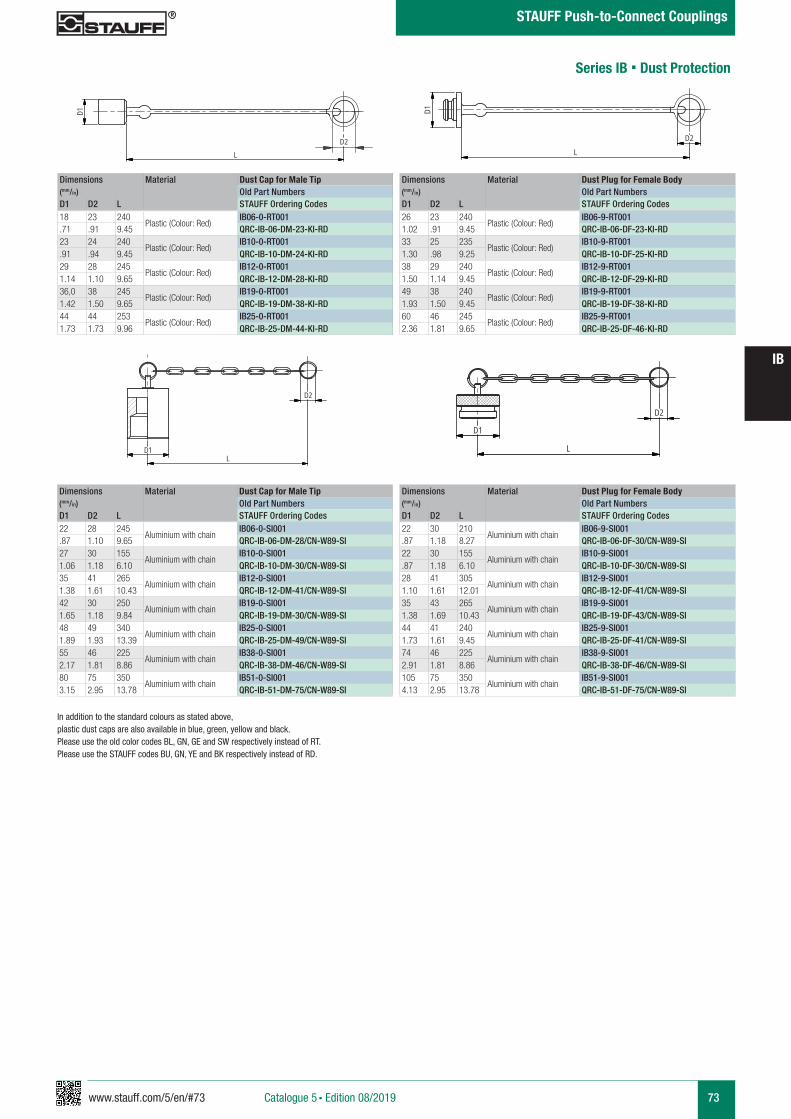
www.stauff.com/5/en/#73 73
IB
Catalogue 5 § Edition 08/2019
STAUFF Push-to-Connect Couplings
Series IB § Dust Protection
In addition to the standard colours as stated above, plastic dust caps are also available in blue, green, yellow and black. Please use the old color codes BL, GN, GE and SW respectively instead of RT.Please use the STAUFF codes BU, GN, YE and BK respectively instead of RD.
Dimensions Material Dust Cap for Male Tip(mm/in) Old Part NumbersD1 D2 L STAUFF Ordering Codes18 23 240
Plastic (Colour: Red)IB06-0-RT001
.71 .91 9.45 QRC-IB-06-DM-23-KI-RD23 24 240
Plastic (Colour: Red)IB10-0-RT001
.91 .94 9.45 QRC-IB-10-DM-24-KI-RD29 28 245
Plastic (Colour: Red)IB12-0-RT001
1.14 1.10 9.65 QRC-IB-12-DM-28-KI-RD36,0 38 245
Plastic (Colour: Red)IB19-0-RT001
1.42 1.50 9.65 QRC-IB-19-DM-38-KI-RD44 44 253
Plastic (Colour: Red)IB25-0-RT001
1.73 1.73 9.96 QRC-IB-25-DM-44-KI-RD
Dimensions Material Dust Plug for Female Body(mm/in) Old Part NumbersD1 D2 L STAUFF Ordering Codes26 23 240
Plastic (Colour: Red)IB06-9-RT001
1.02 .91 9.45 QRC-IB-06-DF-23-KI-RD33 25 235
Plastic (Colour: Red)IB10-9-RT001
1.30 .98 9.25 QRC-IB-10-DF-25-KI-RD38 29 240
Plastic (Colour: Red)IB12-9-RT001
1.50 1.14 9.45 QRC-IB-12-DF-29-KI-RD49 38 240
Plastic (Colour: Red)IB19-9-RT001
1.93 1.50 9.45 QRC-IB-19-DF-38-KI-RD60 46 245
Plastic (Colour: Red)IB25-9-RT001
2.36 1.81 9.65 QRC-IB-25-DF-46-KI-RD
Dimensions Material Dust Cap for Male Tip(mm/in) Old Part NumbersD1 D2 L STAUFF Ordering Codes22 28 245
Aluminium with chainIB06-0-SI001
.87 1.10 9.65 QRC-IB-06-DM-28/CN-W89-SI27 30 155
Aluminium with chainIB10-0-SI001
1.06 1.18 6.10 QRC-IB-10-DM-30/CN-W89-SI35 41 265
Aluminium with chainIB12-0-SI001
1.38 1.61 10.43 QRC-IB-12-DM-41/CN-W89-SI42 30 250
Aluminium with chainIB19-0-SI001
1.65 1.18 9.84 QRC-IB-19-DM-30/CN-W89-SI48 49 340
Aluminium with chainIB25-0-SI001
1.89 1.93 13.39 QRC-IB-25-DM-49/CN-W89-SI55 46 225
Aluminium with chainIB38-0-SI001
2.17 1.81 8.86 QRC-IB-38-DM-46/CN-W89-SI80 75 350
Aluminium with chainIB51-0-SI001
3.15 2.95 13.78 QRC-IB-51-DM-75/CN-W89-SI
Dimensions Material Dust Plug for Female Body(mm/in) Old Part NumbersD1 D2 L STAUFF Ordering Codes22 30 210
Aluminium with chainIB06-9-SI001
.87 1.18 8.27 QRC-IB-06-DF-30/CN-W89-SI22 30 155
Aluminium with chainIB10-9-SI001
.87 1.18 6.10 QRC-IB-10-DF-30/CN-W89-SI28 41 305
Aluminium with chainIB12-9-SI001
1.10 1.61 12.01 QRC-IB-12-DF-41/CN-W89-SI35 43 265
Aluminium with chainIB19-9-SI001
1.38 1.69 10.43 QRC-IB-19-DF-43/CN-W89-SI44 41 240
Aluminium with chainIB25-9-SI001
1.73 1.61 9.45 QRC-IB-25-DF-41/CN-W89-SI74 46 225
Aluminium with chainIB38-9-SI001
2.91 1.81 8.86 QRC-IB-38-DF-46/CN-W89-SI105 75 350
Aluminium with chainIB51-9-SI001
4.13 2.95 13.78 QRC-IB-51-DF-75/CN-W89-SI
IB12-0-RT001
Kunststoff rot
scale 0,4
D2L
D1
IB12-9-RT001
Kunststoff rot
scale 0,4D1
L
D2
IB..-0-SI001
Alu mit Kette
scale 0,5
D1
D2
L
IB..-9-SI001
Alu mit Kette
scale 0,5
D1
L
D2

74 www.stauff.com/5/en/#74
IB
Catalogue 5 § Edition 08/2019
STAUFF Push-to-Connect Couplings
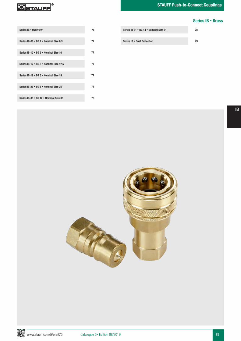
www.stauff.com/5/en/#75 75
IB
Catalogue 5 § Edition 08/2019
STAUFF Push-to-Connect Couplings
Series IB-51 § BG 14 § Nominal Size 51
Series IB § Dust Protection 79
78Series IB § Overview
Series IB-06 § BG 1 § Nominal Size 6,3 77
76
Series IB-10 § BG 2 § Nominal Size 10 77
Series IB-19 § BG 6 § Nominal Size 19 77
Series IB-25 § BG 8 § Nominal Size 25 78
Series IB-12 § BG 3 § Nominal Size 12,5 77
Series IB-38 § BG 12 § Nominal Size 38 78
Series IB § Brass
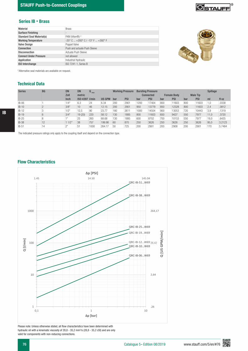
76 www.stauff.com/5/en/#76
IB
Catalogue 5 § Edition 08/2019
STAUFF Push-to-Connect Couplings
Series IB § Brass
Series BG DN DN Q max Working Pressure Bursting Pressure SpillageZoll metric Connected Female Body Male TipInch ISO 4397 l/min US GPM bar PSI bar PSI bar PSI bar PSI ml fl oz
IB-06 1 1/4" 6,3 24 6.34 200 2901 1200 17404 800 11603 800 11603 1,0 .0338IB-10 2 3/8" 10 46 12.15 200 2901 950 13779 850 12328 800 11603 2,4 .0812IB-12 3 1/2" 12,5 90 23.77 180 2611 1000 14504 900 13053 720 10443 3,9 .1319IB-19 6 3/4" 19 (20) 220 58.12 130 1885 800 11603 650 9427 550 7977 11,0 .3720IB-25 8 1" 25 260 68.68 130 1885 600 8702 700 10153 550 7977 19,0 .6425IB-38 12 1 1/2'' 38 757 199.98 60 870 250 3626 250 3626 250 3626 95,0 3.2123IB-51 14 2" 51 1000 264.17 50 725 200 2901 200 2908 200 2901 170 5.7484
Technical Data
Material BrassSurface Finishing -Standard Seal Material(s) FKM (Viton®) 2
Working Temperature -25° C ... +200° C / -13° F ... +392° FValve Design Poppet ValveConnection Push and actuate Push SleeveDisconnection Actuate Push SleeveConnect Under Pressure not allowedApplication Industrial HydraulicISO Interchange ISO 7241-1, Series B
The indicated pressure ratings only apply to the coupling itself and depend on the connection type.
2 Alternative seal materials are available on request.
Flow Characteristics
QRC-IB-06…W69
QRC-IB-10…W69QRC-IB-12…W69
QRC-IB-19…W69
QRC-IB-25…W69
QRC-IB-38…W69
QRC-IB-51…W69
1
10
100
1000
0,1 1 10
Q [l/
min
]
Δp [bar]
26,42
Q [U
S G
PM/m
in]
Δp [PSI]
264,17
2,64
.26
1.45 14.50 145.04
Please note: Unless otherwise stated, all flow characteristics have been determined with hydraulic oil with a kinematic viscosity of 28,8 - 35,2 mm2/s (28,8 - 35,2 cSt) and are only valid for components with non-reducing connections.

www.stauff.com/5/en/#77 77
IB
Catalogue 5 § Edition 08/2019
STAUFF Push-to-Connect Couplings
Port A Dimensions Female Body Weight Male Tip Weight (mm/in) Old Part Numbers (kg/lbs) ca. Old Part Numbers (kg/lbs) ca. ØE ØF L1 L2 L4 L5 SW1 SW2 STAUFF Ordering Codes per 100 STAUFF Ordering Codes per 100
Female Thread according to DIN 3852 - ANSI B 1.20.3
G 1/4"28 14,2 60 38 12 21,5 19 19 IB06-1-IGF04-MS 13,30 IB06-2-IGF04-MS 4,301.1 .56 2.36 1.50 .47 .85 .75 .75 QRC-IB-06-F-G04-VT-W69 29.32 QRC-IB-06-M-G04-V-W69 9.48
NPTF 1/4" -1828 14,2 60 38 21,5 19 19 IB06-1-INF04-MS 13,40 IB06-2-INF04-MS 4,401.1 .56 2.36 1.50 .85 .75 .75 QRC-IB-06-F-NF04-VT-W69 29.54 QRC-IB-06-M-NF04-V-W69 9.70
Series IB-06 § BG 1 § Nominal Size 6,3
IB 04-51 Muffe und Stecker
Stahl (Chrom III), Edelstahl, Messing
scale 0.74
L4L1
EA
SW1
A
L4L2
SW2
L5*
zeichnerische Darstellung entspricht Serie IB 12 * Eintauchtiefe Stecker
A A
L3 L3
L4
Anschlüsse-Beispiele.pdf 1 10.09.13 15:44
Series IB-10 § BG 2 § Nominal Size 10
SW: Width across flats. All dimensions in mm (inch). Drawing similar Series IB-12.* Insertion Male Tip.
Port A Dimensions Female Body Weight Male Tip Weight (mm/in) Old Part Numbers (kg/lbs) ca. Old Part Numbers (kg/lbs) ca. ØE ØF L1 L2 L4 L5 SW1 SW2 STAUFF Ordering Codes per 100 STAUFF Ordering Codes per 100
Female Thread according to DIN 3852 - ANSI B 1.20.3
G 3/8"35 19 67,2 42,5 12 28,2 22 22 IB10-1-IGF06-MS 21,30 IB10-2-IGF06-MS 6,901.38 .75 2.65 1.67 .47 1.11 .87 .87 QRC-IB-10-F-G06-VT-W69 46.96 QRC-IB-10-M-G06-V-W69 15.21
NPTF 3/8" -1835 19 67,2 42,5 28,2 22 22 IB10-1-INF06-MS 21,50 IB10-2-INF06-MS 7,101.38 .75 2.65 1.67 1.11 .87 .87 QRC-IB-10-F-NF06-VT-W69 47.40 QRC-IB-10-M-NF06-V-W69 15.65
A A
L3 L3
L4
Anschlüsse-Beispiele.pdf 1 10.09.13 15:44
Port A Dimensions Female Body Weight Male Tip Weight (mm/in) Old Part Numbers (kg/lbs) ca. Old Part Numbers (kg/lbs) ca. ØE ØF L1 L2 L4 L5 SW1 SW2 STAUFF Ordering Codes per 100 STAUFF Ordering Codes per 100
Female Thread according to DIN 3852 - ANSI B 1.20.3
G 1/2"44 23,55 75,7 48 14 27,2 27 27 IB12-1-IGF08-MS 39,60 IB12-2-IGF08-MS 12,401.73 .93 2.98 1.89 .55 1.07 1.06 1.06 QRC-IB-12-F-G08-VT-W69 87.30 QRC-IB-12-M-G08-V-W69 27.34
NPTF 1/2" -1444 23,55 75,7 48 27,2 27 27 IB12-1-INF08-MS 40 IB12-2-INF08-MS 12,801.73 .93 2.98 1.89 1.07 1.06 1.06 QRC-IB-12-F-NF08-VT-W69 88.18 QRC-IB-12-M-NF08-V-W69 28.22
Series IB-12 § BG 3 § Nominal Size 12,5
A A
L3 L3
L4
Anschlüsse-Beispiele.pdf 1 10.09.13 15:44
Series IB-19 § BG 6 § Nominal Size 19Port A Dimensions Female Body Weight Male Tip Weight
(mm/in) Old Part Numbers (kg/lbs) ca. Old Part Numbers (kg/lbs) ca. ØE ØF L1 L2 L4 L5 SW1 SW2 STAUFF Ordering Codes per 100 STAUFF Ordering Codes per 100
Female Thread according to DIN 3852 - ANSI B 1.20.3
G 3/4"52 31,45 91,5 57 14 34 34 34 IB19-1-IGF12-MS 59,70 IB19-2-IGF12-MS 22,602.05 1.24 3.60 2.24 .55 1.34 1.34 1.34 QRC-IB-19-F-G12-VT-W69 131.62 QRC-IB-19-M-G12-V-W69 49.82
NPTF 3/4" -1452 31,45 91,5 57 34 34 34 IB19-1-INF12-MS 60,10 IB19-2-INF12-MS 232.05 1.24 3.60 2.24 1.34 1.34 1.34 QRC-IB-19-F-NF12-VT-W69 132.50 QRC-IB-19-M-NF12-V-W69 50.71
A A
L3 L3
L4
Anschlüsse-Beispiele.pdf 1 10.09.13 15:44
Note: The connection of the two halves of a coupling is achieved depending on the type. It is important to observe the positive engagement of plug-type couplings and the secure tightening of screw-type couplings to the limit stop of the thread. Forced or improper separation will result in malfunction of the coupling.
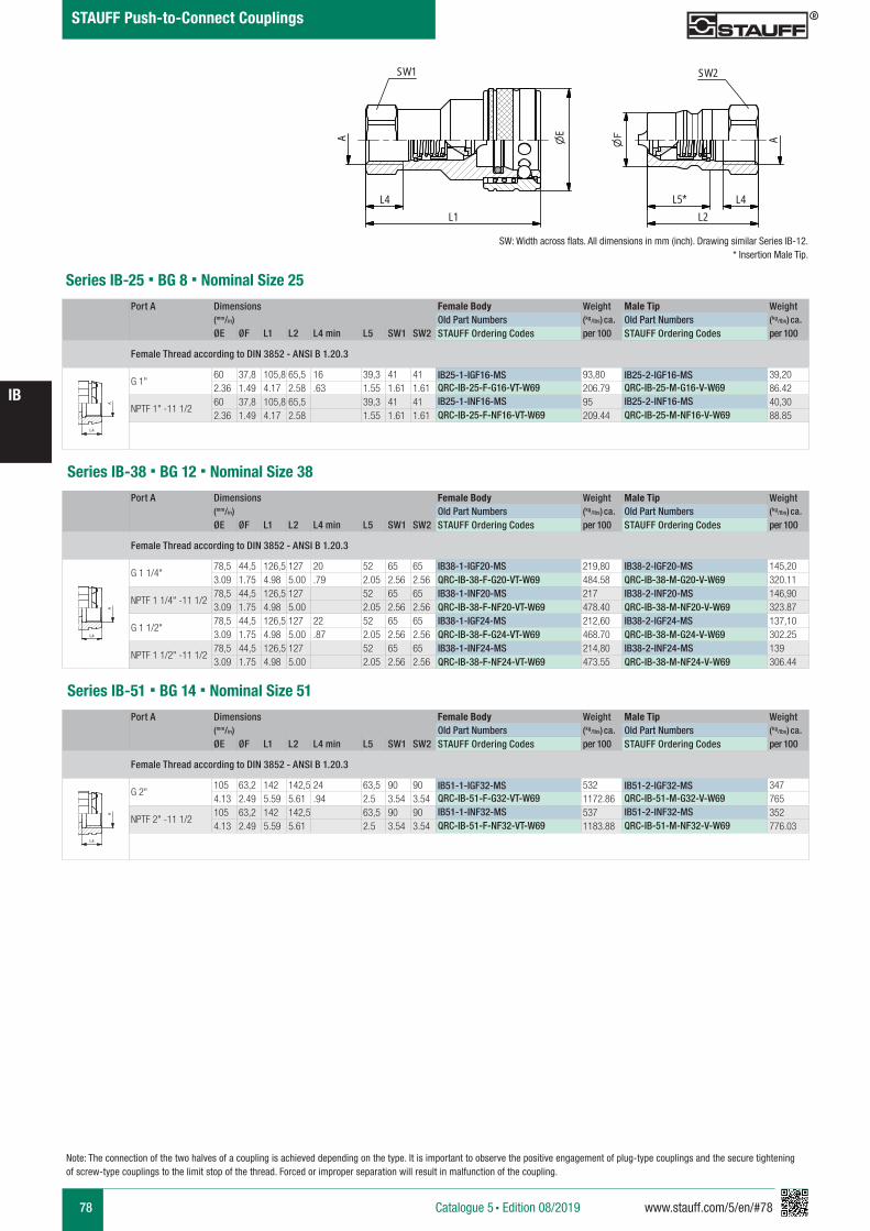
78 www.stauff.com/5/en/#78
IB
Catalogue 5 § Edition 08/2019
STAUFF Push-to-Connect Couplings
SW: Width across flats. All dimensions in mm (inch). Drawing similar Series IB-12.* Insertion Male Tip.
Note: The connection of the two halves of a coupling is achieved depending on the type. It is important to observe the positive engagement of plug-type couplings and the secure tightening of screw-type couplings to the limit stop of the thread. Forced or improper separation will result in malfunction of the coupling.
Port A Dimensions Female Body Weight Male Tip Weight (mm/in) Old Part Numbers (kg/lbs) ca. Old Part Numbers (kg/lbs) ca. ØE ØF L1 L2 L4 min L5 SW1 SW2 STAUFF Ordering Codes per 100 STAUFF Ordering Codes per 100
Female Thread according to DIN 3852 - ANSI B 1.20.3
G 1"60 37,8 105,8 65,5 16 39,3 41 41 IB25-1-IGF16-MS 93,80 IB25-2-IGF16-MS 39,202.36 1.49 4.17 2.58 .63 1.55 1.61 1.61 QRC-IB-25-F-G16-VT-W69 206.79 QRC-IB-25-M-G16-V-W69 86.42
NPTF 1" -11 1/260 37,8 105,8 65,5 39,3 41 41 IB25-1-INF16-MS 95 IB25-2-INF16-MS 40,302.36 1.49 4.17 2.58 1.55 1.61 1.61 QRC-IB-25-F-NF16-VT-W69 209.44 QRC-IB-25-M-NF16-V-W69 88.85
Series IB-25 § BG 8 § Nominal Size 25
A A
L3 L3
L4
Anschlüsse-Beispiele.pdf 1 10.09.13 15:44
Series IB-38 § BG 12 § Nominal Size 38Port A Dimensions Female Body Weight Male Tip Weight
(mm/in) Old Part Numbers (kg/lbs) ca. Old Part Numbers (kg/lbs) ca. ØE ØF L1 L2 L4 min L5 SW1 SW2 STAUFF Ordering Codes per 100 STAUFF Ordering Codes per 100
Female Thread according to DIN 3852 - ANSI B 1.20.3
G 1 1/4"78,5 44,5 126,5 127 20 52 65 65 IB38-1-IGF20-MS 219,80 IB38-2-IGF20-MS 145,203.09 1.75 4.98 5.00 .79 2.05 2.56 2.56 QRC-IB-38-F-G20-VT-W69 484.58 QRC-IB-38-M-G20-V-W69 320.11
NPTF 1 1/4" -11 1/278,5 44,5 126,5 127 52 65 65 IB38-1-INF20-MS 217 IB38-2-INF20-MS 146,903.09 1.75 4.98 5.00 2.05 2.56 2.56 QRC-IB-38-F-NF20-VT-W69 478.40 QRC-IB-38-M-NF20-V-W69 323.87
G 1 1/2"78,5 44,5 126,5 127 22 52 65 65 IB38-1-IGF24-MS 212,60 IB38-2-IGF24-MS 137,103.09 1.75 4.98 5.00 .87 2.05 2.56 2.56 QRC-IB-38-F-G24-VT-W69 468.70 QRC-IB-38-M-G24-V-W69 302.25
NPTF 1 1/2" -11 1/278,5 44,5 126,5 127 52 65 65 IB38-1-INF24-MS 214,80 IB38-2-INF24-MS 1393.09 1.75 4.98 5.00 2.05 2.56 2.56 QRC-IB-38-F-NF24-VT-W69 473.55 QRC-IB-38-M-NF24-V-W69 306.44
A A
L3 L3
L4
Anschlüsse-Beispiele.pdf 1 10.09.13 15:44
Port A Dimensions Female Body Weight Male Tip Weight (mm/in) Old Part Numbers (kg/lbs) ca. Old Part Numbers (kg/lbs) ca. ØE ØF L1 L2 L4 min L5 SW1 SW2 STAUFF Ordering Codes per 100 STAUFF Ordering Codes per 100
Female Thread according to DIN 3852 - ANSI B 1.20.3
G 2"105 63,2 142 142,5 24 63,5 90 90 IB51-1-IGF32-MS 532 IB51-2-IGF32-MS 3474.13 2.49 5.59 5.61 .94 2.5 3.54 3.54 QRC-IB-51-F-G32-VT-W69 1172.86 QRC-IB-51-M-G32-V-W69 765
NPTF 2" -11 1/2105 63,2 142 142,5 63,5 90 90 IB51-1-INF32-MS 537 IB51-2-INF32-MS 3524.13 2.49 5.59 5.61 2.5 3.54 3.54 QRC-IB-51-F-NF32-VT-W69 1183.88 QRC-IB-51-M-NF32-V-W69 776.03
Series IB-51 § BG 14 § Nominal Size 51
A A
L3 L3
L4
Anschlüsse-Beispiele.pdf 1 10.09.13 15:44
IB 04-51 Muffe und Stecker
Stahl (Chrom III), Edelstahl, Messing
scale 0.74
L4L1
EA
SW1
A
L4L2
SW2
L5*
zeichnerische Darstellung entspricht Serie IB 12 * Eintauchtiefe Stecker
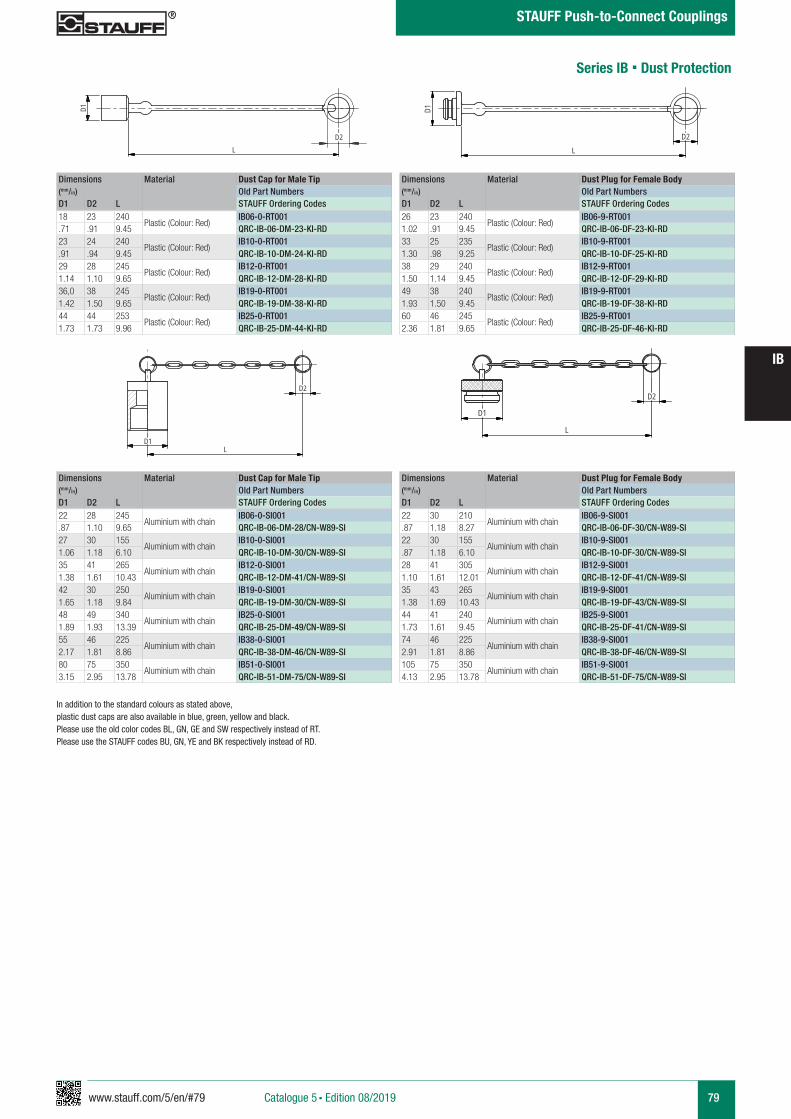
www.stauff.com/5/en/#79 79
IB
Catalogue 5 § Edition 08/2019
STAUFF Push-to-Connect Couplings
Series IB § Dust Protection
In addition to the standard colours as stated above, plastic dust caps are also available in blue, green, yellow and black. Please use the old color codes BL, GN, GE and SW respectively instead of RT.Please use the STAUFF codes BU, GN, YE and BK respectively instead of RD.
Dimensions Material Dust Cap for Male Tip(mm/in) Old Part NumbersD1 D2 L STAUFF Ordering Codes18 23 240
Plastic (Colour: Red)IB06-0-RT001
.71 .91 9.45 QRC-IB-06-DM-23-KI-RD23 24 240
Plastic (Colour: Red)IB10-0-RT001
.91 .94 9.45 QRC-IB-10-DM-24-KI-RD29 28 245
Plastic (Colour: Red)IB12-0-RT001
1.14 1.10 9.65 QRC-IB-12-DM-28-KI-RD36,0 38 245
Plastic (Colour: Red)IB19-0-RT001
1.42 1.50 9.65 QRC-IB-19-DM-38-KI-RD44 44 253
Plastic (Colour: Red)IB25-0-RT001
1.73 1.73 9.96 QRC-IB-25-DM-44-KI-RD
Dimensions Material Dust Plug for Female Body(mm/in) Old Part NumbersD1 D2 L STAUFF Ordering Codes26 23 240
Plastic (Colour: Red)IB06-9-RT001
1.02 .91 9.45 QRC-IB-06-DF-23-KI-RD33 25 235
Plastic (Colour: Red)IB10-9-RT001
1.30 .98 9.25 QRC-IB-10-DF-25-KI-RD38 29 240
Plastic (Colour: Red)IB12-9-RT001
1.50 1.14 9.45 QRC-IB-12-DF-29-KI-RD49 38 240
Plastic (Colour: Red)IB19-9-RT001
1.93 1.50 9.45 QRC-IB-19-DF-38-KI-RD60 46 245
Plastic (Colour: Red)IB25-9-RT001
2.36 1.81 9.65 QRC-IB-25-DF-46-KI-RD
Dimensions Material Dust Cap for Male Tip(mm/in) Old Part NumbersD1 D2 L STAUFF Ordering Codes22 28 245
Aluminium with chainIB06-0-SI001
.87 1.10 9.65 QRC-IB-06-DM-28/CN-W89-SI27 30 155
Aluminium with chainIB10-0-SI001
1.06 1.18 6.10 QRC-IB-10-DM-30/CN-W89-SI35 41 265
Aluminium with chainIB12-0-SI001
1.38 1.61 10.43 QRC-IB-12-DM-41/CN-W89-SI42 30 250
Aluminium with chainIB19-0-SI001
1.65 1.18 9.84 QRC-IB-19-DM-30/CN-W89-SI48 49 340
Aluminium with chainIB25-0-SI001
1.89 1.93 13.39 QRC-IB-25-DM-49/CN-W89-SI55 46 225
Aluminium with chainIB38-0-SI001
2.17 1.81 8.86 QRC-IB-38-DM-46/CN-W89-SI80 75 350
Aluminium with chainIB51-0-SI001
3.15 2.95 13.78 QRC-IB-51-DM-75/CN-W89-SI
Dimensions Material Dust Plug for Female Body(mm/in) Old Part NumbersD1 D2 L STAUFF Ordering Codes22 30 210
Aluminium with chainIB06-9-SI001
.87 1.18 8.27 QRC-IB-06-DF-30/CN-W89-SI22 30 155
Aluminium with chainIB10-9-SI001
.87 1.18 6.10 QRC-IB-10-DF-30/CN-W89-SI28 41 305
Aluminium with chainIB12-9-SI001
1.10 1.61 12.01 QRC-IB-12-DF-41/CN-W89-SI35 43 265
Aluminium with chainIB19-9-SI001
1.38 1.69 10.43 QRC-IB-19-DF-43/CN-W89-SI44 41 240
Aluminium with chainIB25-9-SI001
1.73 1.61 9.45 QRC-IB-25-DF-41/CN-W89-SI74 46 225
Aluminium with chainIB38-9-SI001
2.91 1.81 8.86 QRC-IB-38-DF-46/CN-W89-SI105 75 350
Aluminium with chainIB51-9-SI001
4.13 2.95 13.78 QRC-IB-51-DF-75/CN-W89-SI
IB12-0-RT001
Kunststoff rot
scale 0,4
D2L
D1
IB12-9-RT001
Kunststoff rot
scale 0,4D1
L
D2
IB..-0-SI001
Alu mit Kette
scale 0,5
D1
D2
L
IB..-9-SI001
Alu mit Kette
scale 0,5
D1
L
D2

80 www.stauff.com/5/en/#80
IB
Catalogue 5 § Edition 08/2019
STAUFF Push-to-Connect Couplings
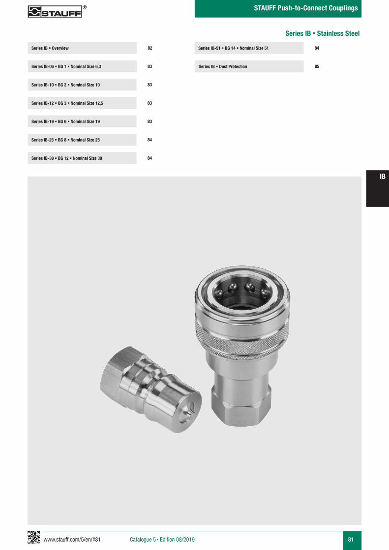
www.stauff.com/5/en/#81 81
IB
Catalogue 5 § Edition 08/2019
STAUFF Push-to-Connect Couplings
Series IB-51 § BG 14 § Nominal Size 51
Series IB § Dust Protection 85
84Series IB § Overview
Series IB-06 § BG 1 § Nominal Size 6,3 83
82
Series IB-10 § BG 2 § Nominal Size 10 83
Series IB-19 § BG 6 § Nominal Size 19 83
Series IB-25 § BG 8 § Nominal Size 25 84
Series IB-12 § BG 3 § Nominal Size 12,5 83
Series IB-38 § BG 12 § Nominal Size 38 84
Series IB § Stainless Steel
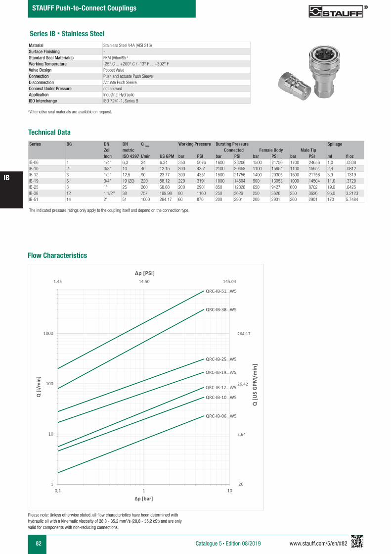
82 www.stauff.com/5/en/#82
IB
Catalogue 5 § Edition 08/2019
STAUFF Push-to-Connect Couplings
Series IB § Stainless Steel
Series BG DN DN Q max Working Pressure Bursting Pressure SpillageZoll metric Connected Female Body Male TipInch ISO 4397 l/min US GPM bar PSI bar PSI bar PSI bar PSI ml fl oz
IB-06 1 1/4" 6,3 24 6.34 350 5076 1600 23206 1500 21756 1700 24656 1,0 .0338IB-10 2 3/8" 10 46 12.15 300 4351 2100 30458 1100 15954 1100 15954 2,4 .0812IB-12 3 1/2" 12,5 90 23.77 300 4351 1500 21756 1400 20305 1500 21756 3,9 .1319IB-19 6 3/4" 19 (20) 220 58.12 220 3191 1000 14504 900 13053 1000 14504 11,0 .3720IB-25 8 1" 25 260 68.68 200 2901 850 12328 650 9427 600 8702 19,0 .6425IB-38 12 1 1/2'' 38 757 199.98 80 1160 250 3626 250 3626 250 3626 95,0 3.2123IB-51 14 2" 51 1000 264.17 60 870 200 2901 200 2901 200 2901 170 5.7484
Technical Data
Material Stainless Steel V4A (AISI 316)Surface Finishing -Standard Seal Material(s) FKM (Viton®) 2
Working Temperature -25° C ... +200° C / -13° F ... +392° FValve Design Poppet ValveConnection Push and actuate Push SleeveDisconnection Actuate Push SleeveConnect Under Pressure not allowedApplication Industrial HydraulicISO Interchange ISO 7241-1, Series B
The indicated pressure ratings only apply to the coupling itself and depend on the connection type.
2 Alternative seal materials are available on request.
Flow Characteristics
QRC-IB-06…W5
QRC-IB-10…W5
QRC-IB-12…W5
QRC-IB-19…W5
QRC-IB-25…W5
QRC-IB-38…W5
QRC-IB-51…W5
1
10
100
1000
0,1 1 10
Q [l/
min
]
Δp [bar]
Q [U
S G
PM/m
in]
Δp [PSI]
264,17
26,42
2,64
.26
1.45 14.50 145.04
Please note: Unless otherwise stated, all flow characteristics have been determined with hydraulic oil with a kinematic viscosity of 28,8 - 35,2 mm2/s (28,8 - 35,2 cSt) and are only valid for components with non-reducing connections.
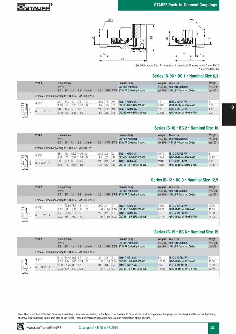
www.stauff.com/5/en/#83 83
IB
Catalogue 5 § Edition 08/2019
STAUFF Push-to-Connect Couplings
Port A Dimensions Female Body Weight Male Tip Weight (mm/in) Old Part Numbers (kg/lbs) ca. Old Part Numbers (kg/lbs) ca. ØE ØF L1 L2 L4 min L5 SW1 SW2 STAUFF Ordering Codes per 100 STAUFF Ordering Codes per 100
Female Thread according to DIN 3852 - ANSI B 1.20.3
G 1/4"28 14,2 60 38 12 21,5 19 19 IB06-1-IGF04-VA 13 IB06-2-IGF04-VA 41.10 .56 2.36 1.50 .47 .85 .75 .75 QRC-IB-06-F-G04-VT-W5 28.66 QRC-IB-06-M-G04-V-W5 8.82
NPTF 1/4" -1828 14,2 60 38 21,5 19 19 IB06-1-INF04-VA 13,10 IB06-2-INF04-VA 4,101.10 .56 2.36 1.50 .85 .75 .75 QRC-IB-06-F-NF04-VT-W5 28.88 QRC-IB-06-M-NF04-V-W5 9.04
Series IB-06 § BG 1 § Nominal Size 6,3
IB 04-51 Muffe und Stecker
Stahl (Chrom III), Edelstahl, Messing
scale 0.74
L4L1
EA
SW1
A
L4L2
SW2
L5*
zeichnerische Darstellung entspricht Serie IB 12 * Eintauchtiefe Stecker
A A
L3 L3
L4
Anschlüsse-Beispiele.pdf 1 10.09.13 15:44
Series IB-10 § BG 2 § Nominal Size 10
SW: Width across flats. All dimensions in mm (inch). Drawing similar Series IB-12.* Insertion Male Tip.
Port A Dimensions Female Body Weight Male Tip Weight (mm/in) Old Part Numbers (kg/lbs) ca. Old Part Numbers (kg/lbs) ca. ØE ØF L1 L2 L4 min L5 SW1 SW2 STAUFF Ordering Codes per 100 STAUFF Ordering Codes per 100
Female Thread according to DIN 3852 - ANSI B 1.20.3
G 3/8"35 19,1 65,2 40,5 12 24,2 22 22 IB10-1-IGF06-VA 19,70 IB10-2-IGF06-VA 61.38 .75 2.57 1.59 .47 .95 .87 .87 QRC-IB-10-F-G06-VT-W5 43.43 QRC-IB-10-M-G06-V-W5 13.23
NPTF 3/8" -1835 19,1 65,2 40,5 24,2 22 22 IB10-1-INF06-VA 19,80 IB10-2-INF06-VA 6,101.38 .75 2.57 1.59 .95 .87 .87 QRC-IB-10-F-NF06-VT-W5 43.65 QRC-IB-10-M-NF06-V-W5 13.45
A A
L3 L3
L4
Anschlüsse-Beispiele.pdf 1 10.09.13 15:44
Port A Dimensions Female Body Weight Male Tip Weight (mm/in) Old Part Numbers (kg/lbs) ca. Old Part Numbers (kg/lbs) ca. ØE ØF L1 L2 L4 min L5 SW1 SW2 STAUFF Ordering Codes per 100 STAUFF Ordering Codes per 100
Female Thread according to DIN 3852 - ANSI B 1.20.3
G 1/2"44 23,55 73,7 46 14 27,2 27 27 IB12-1-IGF08-VA 34,60 IB12-2-IGF08-VA 10,701.73 .93 2.90 1.81 .55 1.07 1.06 1.06 QRC-IB-12-F-G08-VT-W5 76.28 QRC-IB-12-M-G08-V-W5 23.59
NPTF 1/2" -1444 23,55 73,7 46 27,2 27 27 IB12-1-INF08-VA 35 IB12-2-INF08-VA 10,901.73 .93 2.90 1.81 1.07 1.06 1.06 QRC-IB-12-F-NF08-VT-W5 77.16 QRC-IB-12-M-NF08-V-W5 24.03
Series IB-12 § BG 3 § Nominal Size 12,5
A A
L3 L3
L4
Anschlüsse-Beispiele.pdf 1 10.09.13 15:44
Series IB-19 § BG 6 § Nominal Size 19Port A Dimensions Female Body Weight Male Tip Weight
(mm/in) Old Part Numbers (kg/lbs) ca. Old Part Numbers (kg/lbs) ca. ØE ØF L1 L2 L4 min L5 SW1 SW2 STAUFF Ordering Codes per 100 STAUFF Ordering Codes per 100
Female Thread according to DIN 3852 - ANSI B 1.20.3
G 3/4"51,8 31,45 91,5 57 16 34 34 34 IB19-1-IGF12-VA 56 IB19-2-IGF12-VA 212.03 1.24 3.60 2.24 .63 1.34 1.34 1.34 QRC-IB-19-F-G12-VT-W5 123.46 QRC-IB-19-M-G12-V-W5 46.30
NPTF 3/4" -1451,8 31,45 91,5 57 34 34 34 IB19-1-INF12-VA 56,50 IB19-2-INF12-VA 21,502.03 1.24 3.60 2.24 1.34 1.34 1.34 QRC-IB-19-F-NF12-VT-W5 124.56 QRC-IB-19-M-NF12-V-W5 47.40
A A
L3 L3
L4
Anschlüsse-Beispiele.pdf 1 10.09.13 15:44
Note: The connection of the two halves of a coupling is achieved depending on the type. It is important to observe the positive engagement of plug-type couplings and the secure tightening of screw-type couplings to the limit stop of the thread. Forced or improper separation will result in malfunction of the coupling.

84 www.stauff.com/5/en/#84
IB
Catalogue 5 § Edition 08/2019
STAUFF Push-to-Connect Couplings
SW: Width across flats. All dimensions in mm (inch). Drawing similar Series IB-12.* Insertion Male Tip.
Note: The connection of the two halves of a coupling is achieved depending on the type. It is important to observe the positive engagement of plug-type couplings and the secure tightening of screw-type couplings to the limit stop of the thread. Forced or improper separation will result in malfunction of the coupling.
Port A Dimensions Female Body Weight Male Tip Weight (mm/in) Old Part Numbers (kg/lbs) ca. Old Part Numbers (kg/lbs) ca. ØE ØF L1 L2 L4 min L5 SW1 SW2 STAUFF Ordering Codes per 100 STAUFF Ordering Codes per 100
Female Thread according to DIN 3852 - ANSI B 1.20.3
G 1"60 37,8 103,8 63,5 18 39,3 41 41 IB25-1-IGF16-VA 90,80 IB25-2-IGF16-VA 34,202.36 1.49 4.09 2.50 .71 1.55 1.61 1.61 QRC-IB-25-F-G16-VT-W5 200.18 QRC-IB-25-M-G16-V-W5 75.40
NPTF 1" -11 1/260 37,8 103,8 63,5 39,3 41 41 IB25-1-INF16-VA 91,80 IB25-2-INF16-VA 35,202.36 1.49 4.09 2.50 1.55 1.61 1.61 QRC-IB-25-F-NF16-VT-W5 202.38 QRC-IB-25-M-NF16-V-W5 77.60
Series IB-25 § BG 8 § Nominal Size 25
A A
L3 L3
L4
Anschlüsse-Beispiele.pdf 1 10.09.13 15:44
Series IB-38 § BG 12 § Nominal Size 38Port A Dimensions Female Body Weight Male Tip Weight
(mm/in) Old Part Numbers (kg/lbs) ca. Old Part Numbers (kg/lbs) ca. ØE ØF L1 L2 L4 min L5 SW1 SW2 STAUFF Ordering Codes per 100 STAUFF Ordering Codes per 100
Female Thread according to DIN 3852 - ANSI B 1.20.3
G 1 1/4"78,5 44,45 126,5 127 20 52 65 65 IB38-1-IGF20-VA 216,60 IB38-2-IGF20-VA 138,203.09 1.75 4.98 5.00 .79 2.05 2.56 2.56 QRC-IB-38-F-G20-VT-W5 477.52 QRC-IB-38-M-G20-V-W5 304.68
NPTF 1 1/4" -11 1/278,5 44,45 126,5 127 52 65 65 IB38-1-INF20-VA 217,80 IB38-2-INF20-VA 139,403.09 1.75 4.98 5.00 2.05 2.56 2.56 QRC-IB-38-F-NF20-VT-W5 480.17 QRC-IB-38-M-NF20-V-W5 307.32
G 1 1/2"78,5 44,45 126,5 127 22 52 65 65 IB38-1-IGF24-VA 208 IB38-2-IGF24-VA 130,403.09 1.75 4.98 5.00 .87 2.05 2.56 2.56 QRC-IB-38-F-G24-VT-W5 458.56 QRC-IB-38-M-G24-V-W5 287.48
NPTF 1 1/2" -11 1/278,5 44,45 126,5 127 52 65 65 IB38-1-INF24-VA 209,50 IB38-2-INF24-VA 1323.09 1.75 4.98 5.00 2.05 2.56 2.56 QRC-IB-38-F-NF24-VT-W5 461.87 QRC-IB-38-M-NF24-V-W5 291.01
A A
L3 L3
L4
Anschlüsse-Beispiele.pdf 1 10.09.13 15:44
Port A Dimensions Female Body Weight Male Tip Weight (mm/in) Old Part Numbers (kg/lbs) ca. Old Part Numbers (kg/lbs) ca. ØE ØF L1 L2 L4 min L5 SW1 SW2 STAUFF Ordering Codes per 100 STAUFF Ordering Codes per 100
Female Thread according to DIN 3852 - ANSI B 1.20.3
G 2"105 63,2 142 142,5 24 63,5 90 90 IB51-1-IGF32-VA 497 IB51-2-IGF32-VA 3294.13 2.49 5.59 5.61 .94 2.50 3.54 3.54 QRC-IB-51-F-G32-VT-W5 1095.70 QRC-IB-51-M-G32-V-W5 725.32
NPTF 2" -11 1/2105 63,2 142 142,5 63,5 90 90 IB51-1-INF32-VA 505 IB51-2-INF32-VA 3304.13 2.49 5.59 5.61 2.50 3.54 3.54 QRC-IB-51-F-NF32-VT-W5 1113.33 QRC-IB-51-M-NF32-V-W5 727.53
Series IB-51 § BG 14 § Nominal Size 51
A A
L3 L3
L4
Anschlüsse-Beispiele.pdf 1 10.09.13 15:44
IB 04-51 Muffe und Stecker
Stahl (Chrom III), Edelstahl, Messing
scale 0.74
L4L1
EA
SW1
A
L4L2
SW2
L5*
zeichnerische Darstellung entspricht Serie IB 12 * Eintauchtiefe Stecker

www.stauff.com/5/en/#85 85
IB
Catalogue 5 § Edition 08/2019
STAUFF Push-to-Connect Couplings
Series IB § Dust Protection
In addition to the standard colours as stated above, plastic dust caps are also available in blue, green, yellow and black. Please use the old color codes BL, GN, GE and SW respectively instead of RT.Please use the STAUFF codes BU, GN, YE and BK respectively instead of RD.
Dimensions Material Dust Cap for Male Tip(mm/in) Old Part NumbersD1 D2 L STAUFF Ordering Codes18 23 240
Plastic (Colour: Red)IB06-0-RT001
.71 .91 9.45 QRC-IB-06-DM-23-KI-RD23 24 240
Plastic (Colour: Red)IB10-0-RT001
.91 .94 9.45 QRC-IB-10-DM-24-KI-RD29 28 245
Plastic (Colour: Red)IB12-0-RT001
1.14 1.10 9.65 QRC-IB-12-DM-28-KI-RD36,0 38 245
Plastic (Colour: Red)IB19-0-RT001
1.42 1.50 9.65 QRC-IB-19-DM-38-KI-RD44 44 253
Plastic (Colour: Red)IB25-0-RT001
1.73 1.73 9.96 QRC-IB-25-DM-44-KI-RD
Dimensions Material Dust Plug for Female Body(mm/in) Old Part NumbersD1 D2 L STAUFF Ordering Codes26 23 240
Plastic (Colour: Red)IB06-9-RT001
1.02 .91 9.45 QRC-IB-06-DF-23-KI-RD33 25 235
Plastic (Colour: Red)IB10-9-RT001
1.30 .98 9.25 QRC-IB-10-DF-25-KI-RD38 29 240
Plastic (Colour: Red)IB12-9-RT001
1.50 1.14 9.45 QRC-IB-12-DF-29-KI-RD49 38 240
Plastic (Colour: Red)IB19-9-RT001
1.93 1.50 9.45 QRC-IB-19-DF-38-KI-RD60 46 245
Plastic (Colour: Red)IB25-9-RT001
2.36 1.81 9.65 QRC-IB-25-DF-46-KI-RD
Dimensions Material Dust Cap for Male Tip(mm/in) Old Part NumbersD1 D2 L STAUFF Ordering Codes22 28 245
Aluminium with chainIB06-0-SI001
.87 1.10 9.65 QRC-IB-06-DM-28/CN-W89-SI27 30 155
Aluminium with chainIB10-0-SI001
1.06 1.18 6.10 QRC-IB-10-DM-30/CN-W89-SI35 41 265
Aluminium with chainIB12-0-SI001
1.38 1.61 10.43 QRC-IB-12-DM-41/CN-W89-SI42 30 250
Aluminium with chainIB19-0-SI001
1.65 1.18 9.84 QRC-IB-19-DM-30/CN-W89-SI48 49 340
Aluminium with chainIB25-0-SI001
1.89 1.93 13.39 QRC-IB-25-DM-49/CN-W89-SI55 46 225
Aluminium with chainIB38-0-SI001
2.17 1.81 8.86 QRC-IB-38-DM-46/CN-W89-SI80 75 350
Aluminium with chainIB51-0-SI001
3.15 2.95 13.78 QRC-IB-51-DM-75/CN-W89-SI
Dimensions Material Dust Plug for Female Body(mm/in) Old Part NumbersD1 D2 L STAUFF Ordering Codes22 30 210
Aluminium with chainIB06-9-SI001
.87 1.18 8.27 QRC-IB-06-DF-30/CN-W89-SI22 30 155
Aluminium with chainIB10-9-SI001
.87 1.18 6.10 QRC-IB-10-DF-30/CN-W89-SI28 41 305
Aluminium with chainIB12-9-SI001
1.10 1.61 12.01 QRC-IB-12-DF-41/CN-W89-SI35 43 265
Aluminium with chainIB19-9-SI001
1.38 1.69 10.43 QRC-IB-19-DF-43/CN-W89-SI44 41 240
Aluminium with chainIB25-9-SI001
1.73 1.61 9.45 QRC-IB-25-DF-41/CN-W89-SI74 46 225
Aluminium with chainIB38-9-SI001
2.91 1.81 8.86 QRC-IB-38-DF-46/CN-W89-SI105 75 350
Aluminium with chainIB51-9-SI001
4.13 2.95 13.78 QRC-IB-51-DF-75/CN-W89-SI
IB12-0-RT001
Kunststoff rot
scale 0,4
D2L
D1
IB12-9-RT001
Kunststoff rot
scale 0,4D1
L
D2
IB..-0-SI001
Alu mit Kette
scale 0,5
D1
D2
L
IB..-9-SI001
Alu mit Kette
scale 0,5
D1
L
D2
86 www.stauff.com/5/en/#86
IB
Catalogue 5 § Edition 08/2019
STAUFF Push-to-Connect Couplings
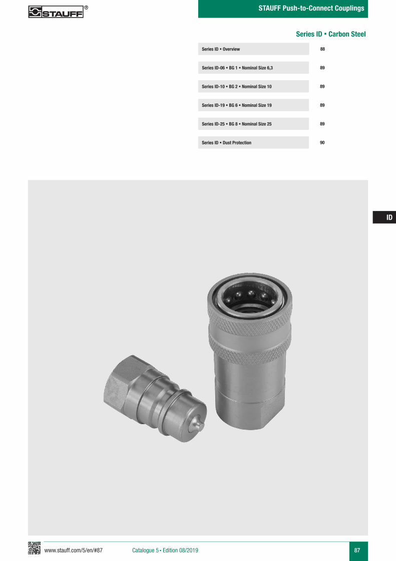
www.stauff.com/5/en/#87 87
ID
Catalogue 5 § Edition 08/2019
STAUFF Push-to-Connect Couplings
Series ID § Overview
Series ID-06 § BG 1 § Nominal Size 6,3 89
88
Series ID-10 § BG 2 § Nominal Size 10 89
Series ID-25 § BG 8 § Nominal Size 25 89
Series ID § Dust Protection 90
Series ID-19 § BG 6 § Nominal Size 19 89
Series ID § Carbon Steel
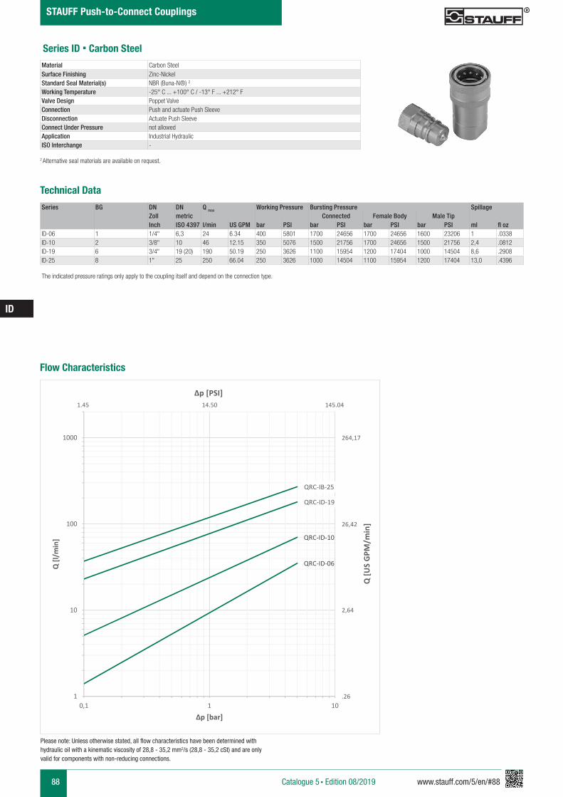
88 www.stauff.com/5/en/#88
ID
Catalogue 5 § Edition 08/2019
STAUFF Push-to-Connect Couplings
Series ID § Carbon Steel
Series BG DN DN Q max Working Pressure Bursting Pressure SpillageZoll metric Connected Female Body Male TipInch ISO 4397 l/min US GPM bar PSI bar PSI bar PSI bar PSI ml fl oz
ID-06 1 1/4" 6,3 24 6.34 400 5801 1700 24656 1700 24656 1600 23206 1 .0338ID-10 2 3/8" 10 46 12.15 350 5076 1500 21756 1700 24656 1500 21756 2,4 .0812ID-19 6 3/4" 19 (20) 190 50.19 250 3626 1100 15954 1200 17404 1000 14504 8,6 .2908ID-25 8 1" 25 250 66.04 250 3626 1000 14504 1100 15954 1200 17404 13,0 .4396
Material Carbon SteelSurface Finishing Zinc-NickelStandard Seal Material(s) NBR (Buna-N®) 2
Working Temperature -25° C ... +100° C / -13° F ... +212° FValve Design Poppet ValveConnection Push and actuate Push SleeveDisconnection Actuate Push SleeveConnect Under Pressure not allowedApplication Industrial HydraulicISO Interchange -
The indicated pressure ratings only apply to the coupling itself and depend on the connection type.
2 Alternative seal materials are available on request.
Technical Data
Flow Characteristics
QRC-ID-06
QRC-ID-10
QRC-ID-19
QRC-IB-25
1
10
100
1000
0,1 1 10
Q [l/
min
]
Δp [bar]
Q [U
S G
PM/m
in]
Δp [PSI]
264,17
26,42
2,64
.26
1.45 14.50 145.04
Please note: Unless otherwise stated, all flow characteristics have been determined with hydraulic oil with a kinematic viscosity of 28,8 - 35,2 mm2/s (28,8 - 35,2 cSt) and are only valid for components with non-reducing connections.
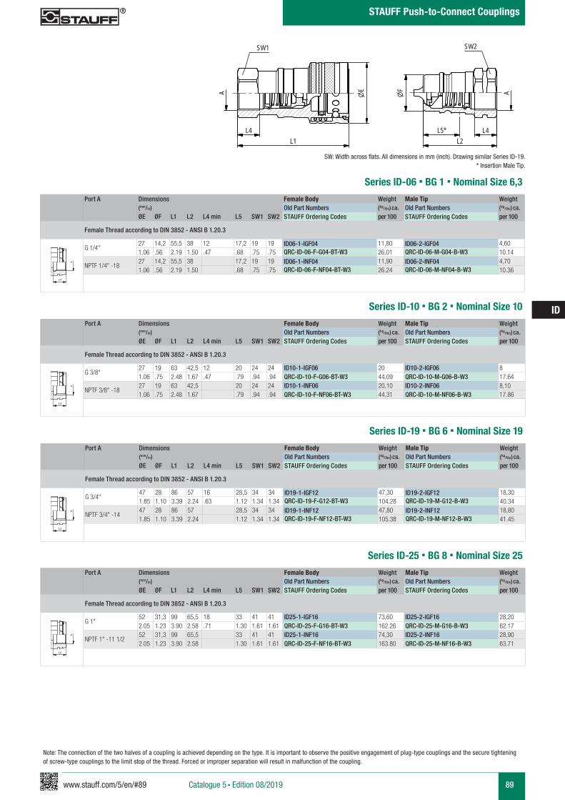
www.stauff.com/5/en/#89 89
ID
Catalogue 5 § Edition 08/2019
STAUFF Push-to-Connect Couplings
Port A Dimensions Female Body Weight Male Tip Weight (mm/in) Old Part Numbers (kg/lbs) ca. Old Part Numbers (kg/lbs) ca. ØE ØF L1 L2 L4 min L5 SW1 SW2 STAUFF Ordering Codes per 100 STAUFF Ordering Codes per 100
Female Thread according to DIN 3852 - ANSI B 1.20.3
G 1/4"27 14,2 55,5 38 12 17,2 19 19 ID06-1-IGF04 11,80 ID06-2-IGF04 4,601.06 .56 2.19 1.50 .47 .68 .75 .75 QRC-ID-06-F-G04-BT-W3 26.01 QRC-ID-06-M-G04-B-W3 10.14
NPTF 1/4" -1827 14,2 55,5 38 17,2 19 19 ID06-1-INF04 11,90 ID06-2-INF04 4,701.06 .56 2.19 1.50 .68 .75 .75 QRC-ID-06-F-NF04-BT-W3 26.24 QRC-ID-06-M-NF04-B-W3 10.36
Series ID-06 § BG 1 § Nominal Size 6,3
ID06-ID25-Muffe und Stecker
Stahl
scale 0,65
A
L4L1
SW1
E AF
L5*L2
L4
SW2
zeichnerische Darstellung entspricht Serie ID 19 * Eintauchtiefe Stecker
A A
L3 L3
L4
Anschlüsse-Beispiele.pdf 1 10.09.13 15:44
Series ID-10 § BG 2 § Nominal Size 10Port A Dimensions Female Body Weight Male Tip Weight
(mm/in) Old Part Numbers (kg/lbs) ca. Old Part Numbers (kg/lbs) ca. ØE ØF L1 L2 L4 min L5 SW1 SW2 STAUFF Ordering Codes per 100 STAUFF Ordering Codes per 100
Female Thread according to DIN 3852 - ANSI B 1.20.3
G 3/8"27 19 63 42,5 12 20 24 24 ID10-1-IGF06 20 ID10-2-IGF06 81.06 .75 2.48 1.67 .47 .79 .94 .94 QRC-ID-10-F-G06-BT-W3 44.09 QRC-ID-10-M-G06-B-W3 17.64
NPTF 3/8" -1827 19 63 42,5 20 24 24 ID10-1-INF06 20,10 ID10-2-INF06 8,101.06 .75 2.48 1.67 .79 .94 .94 QRC-ID-10-F-NF06-BT-W3 44.31 QRC-ID-10-M-NF06-B-W3 17.86
A A
L3 L3
L4
Anschlüsse-Beispiele.pdf 1 10.09.13 15:44
SW: Width across flats. All dimensions in mm (inch). Drawing similar Series ID-19.* Insertion Male Tip.
Port A Dimensions Female Body Weight Male Tip Weight (mm/in) Old Part Numbers (kg/lbs) ca. Old Part Numbers (kg/lbs) ca. ØE ØF L1 L2 L4 min L5 SW1 SW2 STAUFF Ordering Codes per 100 STAUFF Ordering Codes per 100
Female Thread according to DIN 3852 - ANSI B 1.20.3
G 3/4"47 28 86 57 16 28,5 34 34 ID19-1-IGF12 47,30 ID19-2-IGF12 18,301.85 1.10 3.39 2.24 .63 1.12 1.34 1.34 QRC-ID-19-F-G12-BT-W3 104.28 QRC-ID-19-M-G12-B-W3 40.34
NPTF 3/4" -1447 28 86 57 28,5 34 34 ID19-1-INF12 47,80 ID19-2-INF12 18,801.85 1.10 3.39 2.24 1.12 1.34 1.34 QRC-ID-19-F-NF12-BT-W3 105.38 QRC-ID-19-M-NF12-B-W3 41.45
Series ID-19 § BG 6 § Nominal Size 19
A A
L3 L3
L4
Anschlüsse-Beispiele.pdf 1 10.09.13 15:44
Series ID-25 § BG 8 § Nominal Size 25Port A Dimensions Female Body Weight Male Tip Weight
(mm/in) Old Part Numbers (kg/lbs) ca. Old Part Numbers (kg/lbs) ca. ØE ØF L1 L2 L4 min L5 SW1 SW2 STAUFF Ordering Codes per 100 STAUFF Ordering Codes per 100
Female Thread according to DIN 3852 - ANSI B 1.20.3
G 1"52 31,3 99 65,5 18 33 41 41 ID25-1-IGF16 73,60 ID25-2-IGF16 28,202.05 1.23 3.90 2.58 .71 1.30 1.61 1.61 QRC-ID-25-F-G16-BT-W3 162.26 QRC-ID-25-M-G16-B-W3 62.17
NPTF 1" -11 1/252 31,3 99 65,5 33 41 41 ID25-1-INF16 74,30 ID25-2-INF16 28,902.05 1.23 3.90 2.58 1.30 1.61 1.61 QRC-ID-25-F-NF16-BT-W3 163.80 QRC-ID-25-M-NF16-B-W3 63.71
A A
L3 L3
L4
Anschlüsse-Beispiele.pdf 1 10.09.13 15:44
Note: The connection of the two halves of a coupling is achieved depending on the type. It is important to observe the positive engagement of plug-type couplings and the secure tightening of screw-type couplings to the limit stop of the thread. Forced or improper separation will result in malfunction of the coupling.
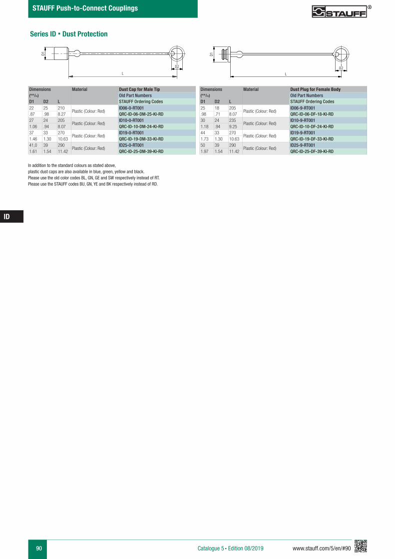
90 www.stauff.com/5/en/#90
ID
Catalogue 5 § Edition 08/2019
STAUFF Push-to-Connect Couplings
Series ID § Dust Protection
In addition to the standard colours as stated above, plastic dust caps are also available in blue, green, yellow and black. Please use the old color codes BL, GN, GE and SW respectively instead of RT.Please use the STAUFF codes BU, GN, YE and BK respectively instead of RD.
Dimensions Material Dust Cap for Male Tip(mm/in) Old Part NumbersD1 D2 L STAUFF Ordering Codes22 25 210
Plastic (Colour: Red)ID06-0-RT001
.87 .98 8.27 QRC-ID-06-DM-25-KI-RD27 24 205
Plastic (Colour: Red)ID10-0-RT001
1.06 .94 8.07 QRC-ID-10-DM-24-KI-RD37 33 270
Plastic (Colour: Red)ID19-0-RT001
1.46 1.30 10.63 QRC-ID-19-DM-33-KI-RD41,0 39 290
Plastic (Colour: Red)ID25-0-RT001
1.61 1.54 11.42 QRC-ID-25-DM-39-KI-RD
Dimensions Material Dust Plug for Female Body(mm/in) Old Part NumbersD1 D2 L STAUFF Ordering Codes25 18 205
Plastic (Colour: Red)ID06-9-RT001
.98 .71 8.07 QRC-ID-06-DF-18-KI-RD30 24 235
Plastic (Colour: Red)ID10-9-RT001
1.18 .94 9.25 QRC-ID-10-DF-24-KI-RD44 33 270
Plastic (Colour: Red)ID19-9-RT001
1.73 1.30 10.63 QRC-ID-19-DF-33-KI-RD50 39 290
Plastic (Colour: Red)ID25-9-RT001
1.97 1.54 11.42 QRC-ID-25-DF-39-KI-RD
ID..-0-RT001
Kunststoff rot
scale 0,4
D1
LD2
ID..-9-RT
Kunststoff rot
scale 0,4
D1
L
D2
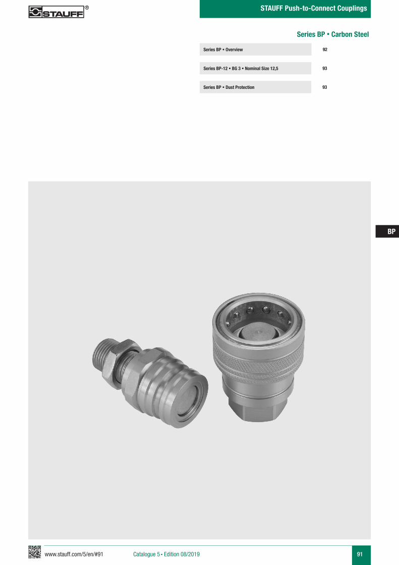
www.stauff.com/5/en/#91 91
BP
Catalogue 5 § Edition 08/2019
STAUFF Push-to-Connect Couplings
Series BP § Overview
Series BP-12 § BG 3 § Nominal Size 12,5 93
92
Series BP § Dust Protection 93
Series BP § Carbon Steel
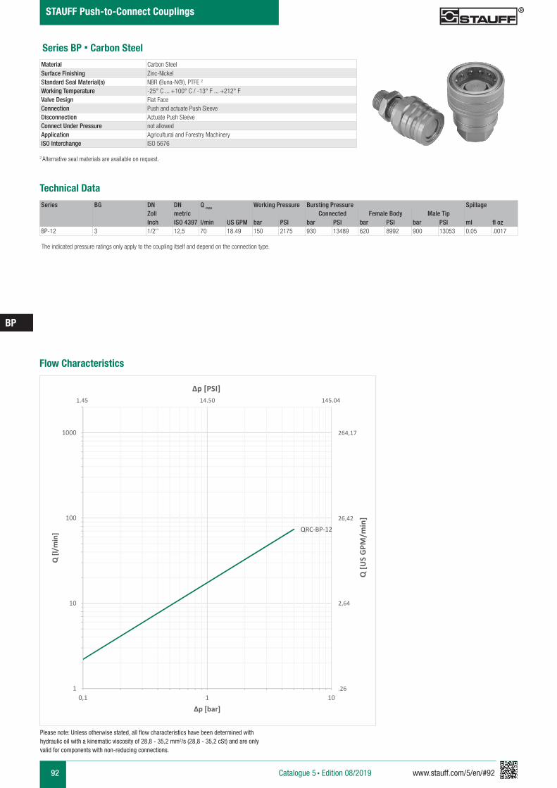
92 www.stauff.com/5/en/#92
BP
Catalogue 5 § Edition 08/2019
STAUFF Push-to-Connect Couplings
Series BP § Carbon Steel
Series BG DN DN Q max Working Pressure Bursting Pressure SpillageZoll metric Connected Female Body Male TipInch ISO 4397 l/min US GPM bar PSI bar PSI bar PSI bar PSI ml fl oz
BP-12 3 1/2'' 12,5 70 18.49 150 2175 930 13489 620 8992 900 13053 0,05 .0017
Material Carbon SteelSurface Finishing Zinc-NickelStandard Seal Material(s) NBR (Buna-N®), PTFE 2
Working Temperature -25° C ... +100° C / -13° F ... +212° FValve Design Flat FaceConnection Push and actuate Push SleeveDisconnection Actuate Push SleeveConnect Under Pressure not allowedApplication Agricultural and Forestry MachineryISO Interchange ISO 5676
The indicated pressure ratings only apply to the coupling itself and depend on the connection type.
2 Alternative seal materials are available on request.
Technical Data
Flow Characteristics
QRC-BP-12
1
10
100
1000
0,1 1 10
Q [l/
min
]
Δp [bar]
Q [U
S G
PM/m
in]
Δp [PSI]
264,17
26,42
2,64
.26
1.45 14.50 145.04
Please note: Unless otherwise stated, all flow characteristics have been determined with hydraulic oil with a kinematic viscosity of 28,8 - 35,2 mm2/s (28,8 - 35,2 cSt) and are only valid for components with non-reducing connections.
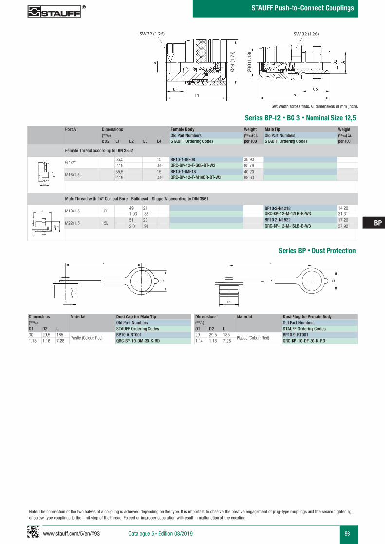
www.stauff.com/5/en/#93 93
BP
Catalogue 5 § Edition 08/2019
STAUFF Push-to-Connect Couplings
Port A Dimensions Female Body Weight Male Tip Weight (mm/in) Old Part Numbers (kg/lbs) ca. Old Part Numbers (kg/lbs) ca. ØD2 L1 L2 L3 L4 STAUFF Ordering Codes per 100 STAUFF Ordering Codes per 100
Female Thread according to DIN 3852
G 1/2''55,5 15 BP10-1-IGF08 38,902.19 .59 QRC-BP-12-F-G08-BT-W3 85.76
M18x1,555,5 15 BP10-1-IMF18 40,202.19 .59 QRC-BP-12-F-M18OR-BT-W3 88.63
Male Thread with 24° Conical Bore - Bulkhead - Shape W according to DIN 3861
M18x1,5 12L49 21 BP10-2-N1218 14,201.93 .83 QRC-BP-12-M-12LB-B-W3 31.31
M22x1,5 15L51 23 BP10-2-N1522 17,202.01 .91 QRC-BP-12-M-15LB-B-W3 37.92
Series BP-12 § BG 3 § Nominal Size 12,5
SW 32 (1.26)
Ø44
(1.7
3)
A A
L3 L3
L4
Anschlüsse-Beispiele.pdf 1 10.09.13 15:44
SW: Width across flats. All dimensions in mm (inch).
A A
L3 L3
L4
Anschlüsse-Beispiele.pdf 1 10.09.13 15:44
Ø30
(1.1
8)
SW 32 (1.26)
Note: The connection of the two halves of a coupling is achieved depending on the type. It is important to observe the positive engagement of plug-type couplings and the secure tightening of screw-type couplings to the limit stop of the thread. Forced or improper separation will result in malfunction of the coupling.
Series BP § Dust Protection
Dimensions Material Dust Cap for Male Tip(mm/in) Old Part NumbersD1 D2 L STAUFF Ordering Codes30 29,5 185
Plastic (Colour: Red)BP10-0-RT001
1.18 1.16 7.28 QRC-BP-10-DM-30-K-RD
Dimensions Material Dust Plug for Female Body(mm/in) Old Part NumbersD1 D2 L STAUFF Ordering Codes29 29,5 185
Plastic (Colour: Red)BP10-9-RT001
1.14 1.16 7.28 QRC-BP-10-DF-30-K-RD
Staubschutz BP
scale 0.77
Schraffuren bitte unter 45° oder 135° anlegen
D1
D2
L
Staubschutz BP
scale 0.77
Schraffuren bitte unter 45° oder 135° anlegen
D2
L
D1
94 www.stauff.com/5/en/#94
BP
Catalogue 5 § Edition 08/2019
STAUFF Push-to-Connect Couplings
www.stauff.com/5/en/#95 95
HC
Catalogue 5 § Edition 08/2019
STAUFF Push-to-Connect Couplings
Series HC § Overview
Series HC-06 § BG 1 § Nominal Size 6,3 97
96
Series HC § Dust Protection 97
Series HC § Carbon Steel
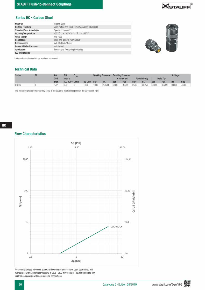
96 www.stauff.com/5/en/#96
HC
Catalogue 5 § Edition 08/2019
STAUFF Push-to-Connect Couplings
Series HC § Carbon Steel
Series BG DN DN Q max Working Pressure Bursting Pressure SpillageZoll metric Connected Female Body Male TipInch ISO 4397 l/min US GPM bar PSI bar PSI bar PSI bar PSI ml fl oz
HC-06 1 1/4" 6,3 6 1.58 1000 14504 2500 36259 2500 36259 2500 36259 0,008 .0003
Material Carbon SteelSurface Finishing Zinc-Plating and Thick-Film-Passivation (Chrome III)Standard Seal Material(s) Special compound 2
Working Temperature -35° C ... +130° C / -31° F ... +266° FValve Design Flat FaceConnection Push and actuate Push SleeveDisconnection Actuate Push SleeveConnect Under Pressure not allowedApplication Rescue and Tensioning HydraulicsISO Interchange -
The indicated pressure ratings only apply to the coupling itself and depend on the connection type.
2 Alternative seal materials are available on request.
Technical Data
Flow Characteristics
QRC-HC-06
1
10
100
1000
0,1 1 10
Q [l/
min
]
Δp [bar]
Q [U
S G
PM/m
in]
Δp [PSI]
264,17
26,42
2,64
.26
1.45 14.50 145.04
Please note: Unless otherwise stated, all flow characteristics have been determined with hydraulic oil with a kinematic viscosity of 28,8 - 35,2 mm2/s (28,8 - 35,2 cSt) and are only valid for components with non-reducing connections.
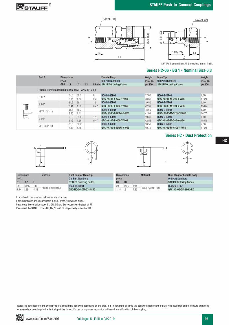
www.stauff.com/5/en/#97 97
HC
Catalogue 5 § Edition 08/2019
STAUFF Push-to-Connect Couplings
Port A Dimensions Female Body Weight Male Tip Weight (mm/in) Old Part Numbers (kg/lbs) ca. Old Part Numbers (kg/lbs) ca. ØD2 L1 L2 L3 L4 min STAUFF Ordering Codes per 100 STAUFF Ordering Codes per 100
Female Thread according to DIN 3852 - ANSI B 1.20.3
G 1/8"54,3 38,1 8 HC06-1-IGF02 17,60 HC06-2-IGF02 7,802.14 1.50 0.31 QRC-HC-06-F-G02-Y-W66 38.80 QRC-HC-06-M-G02-Y-W66 17.20
G 1/4"61,3 38,1 12 HC06-1-IGF04 19,50 HC06-2-IGF04 7,102.41 1.50 0.47 QRC-HC-06-F-G04-Y-W66 42.99 QRC-HC-06-M-G04-Y-W66 15.65
NPTF 1/4" -1858,3 35,7 HC06-1-INF04 18,60 HC06-2-INF04 6,702.30 1.41 QRC-HC-06-F-NF04-Y-W66 41.01 QRC-HC-06-M-NF04-Y-W66 14.77
G 3/8"63,3 39,6 12 HC06-1-IGF06 19,30 HC06-2-IGF06 8,402.49 1.56 0.47 QRC-HC-06-F-G06-Y-W66 42.55 QRC-HC-06-M-G06-Y-W66 18.52
NPTF 3/8" -1860,3 39,6 HC06-1-INF06 18,50 HC06-2-INF06 7,802.37 1.56 QRC-HC-06-F-NF06-Y-W66 40.79 QRC-HC-06-M-NF06-Y-W66 17.20
Series HC-06 § BG 1 § Nominal Size 6,3
SW: Width across flats. All dimensions in mm (inch).
A A
L3 L3
L4
Anschlüsse-Beispiele.pdf 1 10.09.13 15:44
HC 06-1-2-IGF04
Steckerstößel gelb, wie im Modell
"A" entspricht G 1/4"
scale 1
A
L4L1
SW24 ( .94)
28(1
.1)
L4L2
A
14.9
(.59
)
SW22 ( .87)
18.8 ( .74)
Note: The connection of the two halves of a coupling is achieved depending on the type. It is important to observe the positive engagement of plug-type couplings and the secure tightening of screw-type couplings to the limit stop of the thread. Forced or improper separation will result in malfunction of the coupling.
Series HC § Dust Protection
Dimensions Material Dust Cap for Male Tip(mm/in) Old Part NumbersD1 D2 L STAUFF Ordering Codes29 22,5 110
Plastic (Colour: Red)HC06-0-RT001
1.14 .89 4.33 QRC-HC-06-DM-23-KI-RD
Dimensions Material Dust Plug for Female Body(mm/in) Old Part NumbersD1 D2 L STAUFF Ordering Codes29 20,5 110
Plastic (Colour: Red)HC06-9-RT001
1.14 .81 4.33 QRC-HC-06-DF-21-KI-RD
HC-0-RT001
PVC rot
scale 0.74
D1
L
D2
HC-9-RT001
PVC rot
scale 0.74
D1
L
D2
In addition to the standard colours as stated above, plastic dust caps are also available in blue, green, yellow and black. Please use the old color codes BL, GN, GE and SW respectively instead of RT.Please use the STAUFF codes BU, GN, YE and BK respectively instead of RD.
98 www.stauff.com/5/en/#98
HC
Catalogue 5 § Edition 08/2019
STAUFF Push-to-Connect Couplings
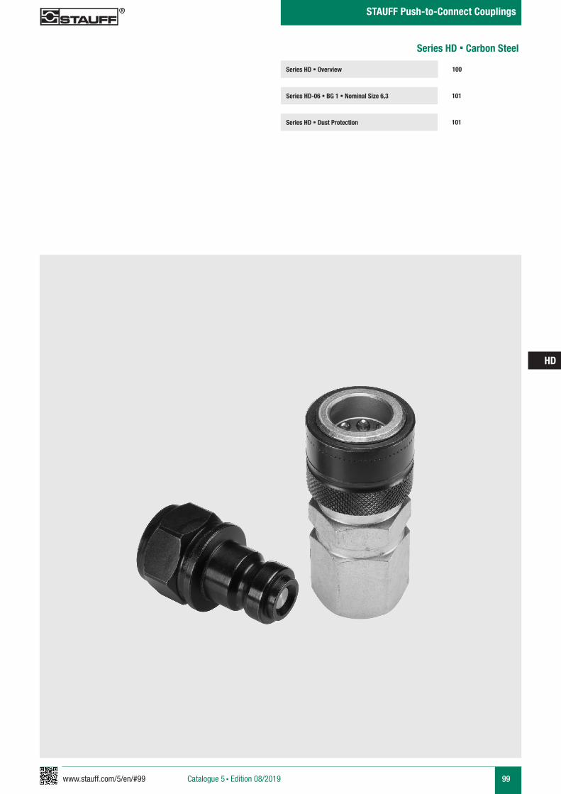
www.stauff.com/5/en/#99 99
HD
Catalogue 5 § Edition 08/2019
STAUFF Push-to-Connect Couplings
Series HD § Overview
Series HD-06 § BG 1 § Nominal Size 6,3 101
100
Series HD § Dust Protection 101
Series HD § Carbon Steel
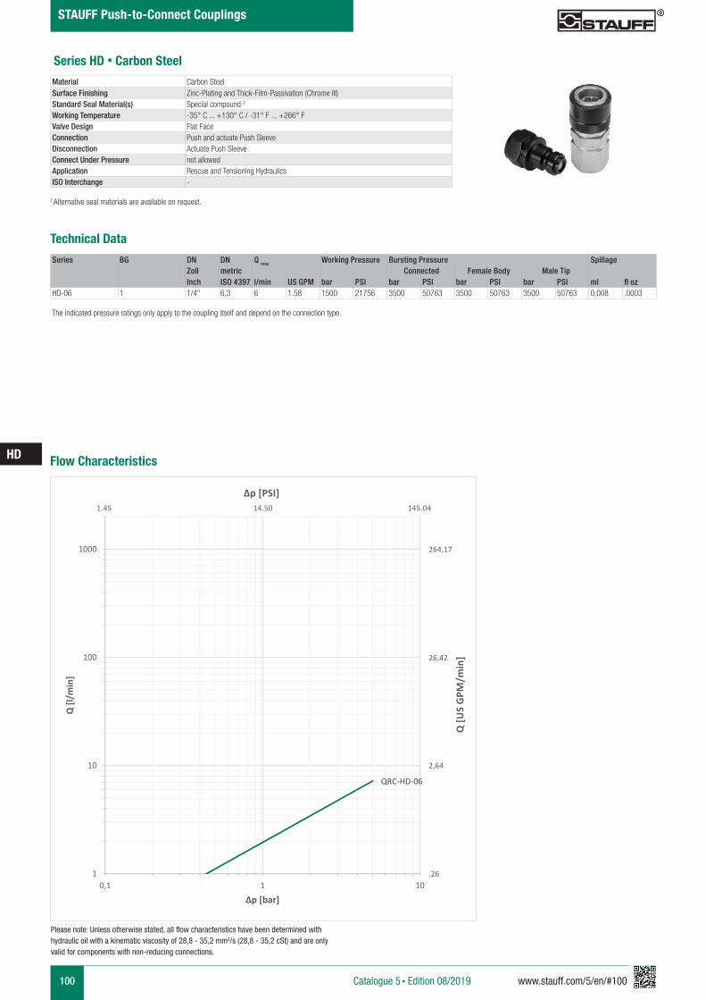
100 www.stauff.com/5/en/#100
HD
Catalogue 5 § Edition 08/2019
STAUFF Push-to-Connect Couplings
Series HD § Carbon Steel
Series BG DN DN Q max Working Pressure Bursting Pressure SpillageZoll metric Connected Female Body Male TipInch ISO 4397 l/min US GPM bar PSI bar PSI bar PSI bar PSI ml fl oz
HD-06 1 1/4" 6,3 6 1.58 1500 21756 3500 50763 3500 50763 3500 50763 0,008 .0003
Material Carbon SteelSurface Finishing Zinc-Plating and Thick-Film-Passivation (Chrome III)Standard Seal Material(s) Special compound 2
Working Temperature -35° C ... +130° C / -31° F ... +266° FValve Design Flat FaceConnection Push and actuate Push SleeveDisconnection Actuate Push SleeveConnect Under Pressure not allowedApplication Rescue and Tensioning HydraulicsISO Interchange -
The indicated pressure ratings only apply to the coupling itself and depend on the connection type.
2 Alternative seal materials are available on request.
Technical Data
Flow Characteristics
QRC-HD-06
1
10
100
1000
0,1 1 10
Q [l/
min
]
Δp [bar]
Q [U
S G
PM/m
in]
Δp [PSI]
264,17
26,42
2,64
.26
1.45 14.50 145.04
Please note: Unless otherwise stated, all flow characteristics have been determined with hydraulic oil with a kinematic viscosity of 28,8 - 35,2 mm2/s (28,8 - 35,2 cSt) and are only valid for components with non-reducing connections.
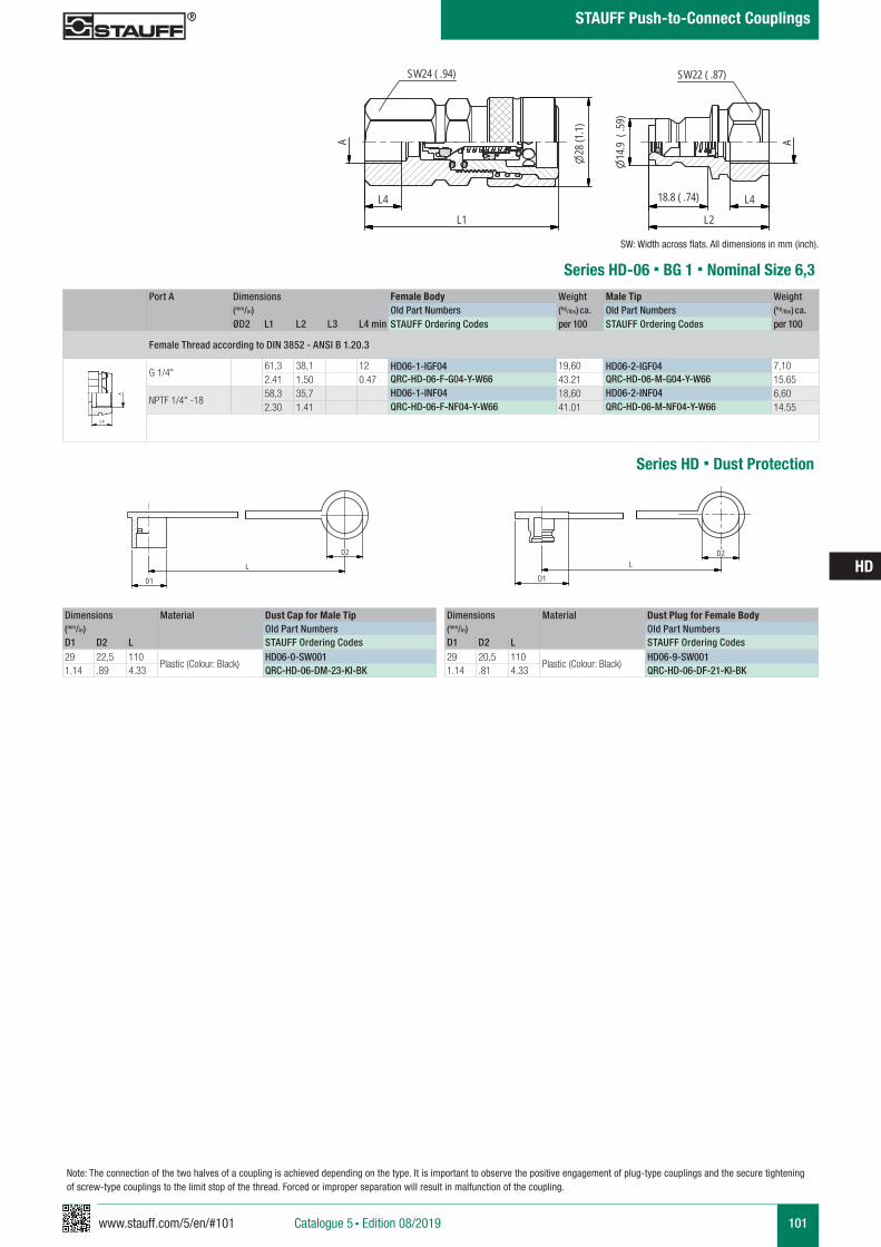
www.stauff.com/5/en/#101 101
HD
Catalogue 5 § Edition 08/2019
STAUFF Push-to-Connect Couplings
Port A Dimensions Female Body Weight Male Tip Weight (mm/in) Old Part Numbers (kg/lbs) ca. Old Part Numbers (kg/lbs) ca. ØD2 L1 L2 L3 L4 min STAUFF Ordering Codes per 100 STAUFF Ordering Codes per 100
Female Thread according to DIN 3852 - ANSI B 1.20.3
G 1/4"61,3 38,1 12 HD06-1-IGF04 19,60 HD06-2-IGF04 7,102.41 1.50 0.47 QRC-HD-06-F-G04-Y-W66 43.21 QRC-HD-06-M-G04-Y-W66 15.65
NPTF 1/4" -1858,3 35,7 HD06-1-INF04 18,60 HD06-2-INF04 6,602.30 1.41 QRC-HD-06-F-NF04-Y-W66 41.01 QRC-HD-06-M-NF04-Y-W66 14.55
Series HD-06 § BG 1 § Nominal Size 6,3
SW: Width across flats. All dimensions in mm (inch).
A A
L3 L3
L4
Anschlüsse-Beispiele.pdf 1 10.09.13 15:44
HD06-1-2
Schwarz eloxiert Schraubhülse + Stecker
Steckerstößel gelb (Kunststoff)
"A" entspricht G1/4"
scale 1:1
A
L4
L2
L4
L1
A
SW24 ( .94)
28(1
.1)
14.9
(.59
)
SW22 ( .87)
18.8 ( .74)
Note: The connection of the two halves of a coupling is achieved depending on the type. It is important to observe the positive engagement of plug-type couplings and the secure tightening of screw-type couplings to the limit stop of the thread. Forced or improper separation will result in malfunction of the coupling.
Series HD § Dust Protection
Dimensions Material Dust Cap for Male Tip(mm/in) Old Part NumbersD1 D2 L STAUFF Ordering Codes29 22,5 110
Plastic (Colour: Black)HD06-0-SW001
1.14 .89 4.33 QRC-HD-06-DM-23-KI-BK
Dimensions Material Dust Plug for Female Body(mm/in) Old Part NumbersD1 D2 L STAUFF Ordering Codes29 20,5 110
Plastic (Colour: Black)HD06-9-SW001
1.14 .81 4.33 QRC-HD-06-DF-21-KI-BKHD-0-SW001
PVC schwarz
scale 0.74
D1
L
D2
HD-9-SW001
PVC schwarz
scale 0.74
D1L
D2
102 www.stauff.com/5/en/#102
HD
Catalogue 5 § Edition 08/2019
STAUFF Push-to-Connect Couplings
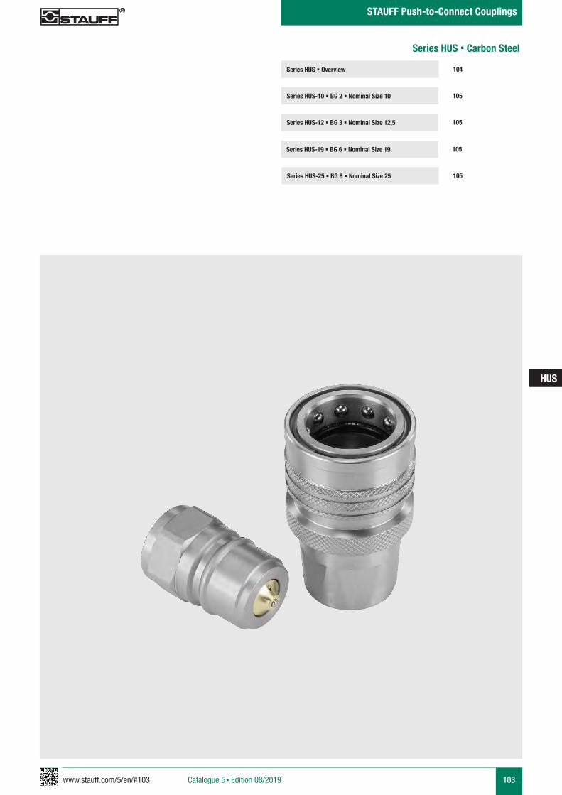
www.stauff.com/5/en/#103 103
HUS
Series HUS § Overview
Series HUS-10 § BG 2 § Nominal Size 10 105
104
Series HUS-12 § BG 3 § Nominal Size 12,5 105
Series HUS § Carbon Steel
Series HUS-19 § BG 6 § Nominal Size 19 105
Series HUS-25 § BG 8 § Nominal Size 25 105
Catalogue 5 § Edition 08/2019
STAUFF Push-to-Connect Couplings
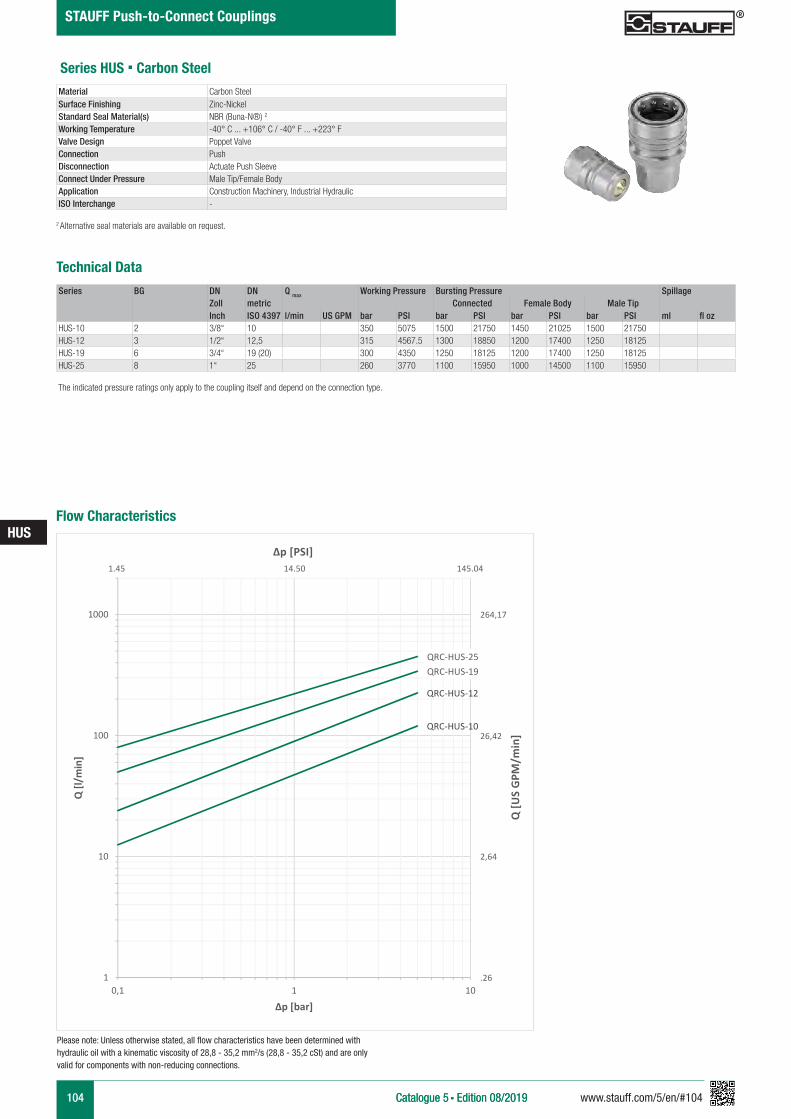
104 www.stauff.com/5/en/#104
HUS
Catalogue 5 § Edition 08/2019Catalogue 5 § Edition 08/2019
STAUFF Push-to-Connect Couplings
Series BG DN DN Q max Working Pressure Bursting Pressure SpillageZoll metric Connected Female Body Male TipInch ISO 4397 l/min US GPM bar PSI bar PSI bar PSI bar PSI ml fl oz
HUS-10 2 3/8“ 10 350 5075 1500 21750 1450 21025 1500 21750HUS-12 3 1/2“ 12,5 315 4567.5 1300 18850 1200 17400 1250 18125HUS-19 6 3/4“ 19 (20) 300 4350 1250 18125 1200 17400 1250 18125HUS-25 8 1“ 25 260 3770 1100 15950 1000 14500 1100 15950
Material Carbon SteelSurface Finishing Zinc-NickelStandard Seal Material(s) NBR (Buna-N®) 2
Working Temperature -40° C ... +106° C / -40° F ... +223° FValve Design Poppet ValveConnection PushDisconnection Actuate Push SleeveConnect Under Pressure Male Tip/Female BodyApplication Construction Machinery, Industrial Hydraulic ISO Interchange -
The indicated pressure ratings only apply to the coupling itself and depend on the connection type.
2 Alternative seal materials are available on request.
Technical Data
Series HUS § Carbon Steel
Flow Characteristics
QRC-HUS-10
QRC-HUS-12
QRC-HUS-19QRC-HUS-25
1
10
100
1000
0,1 1 10
Q [l/
min
]
Δp [bar]
Q [U
S G
PM/m
in]
Δp [PSI]
264,17
26,42
2,64
.26
1.45 14.50 145.04
Please note: Unless otherwise stated, all flow characteristics have been determined with hydraulic oil with a kinematic viscosity of 28,8 - 35,2 mm2/s (28,8 - 35,2 cSt) and are only valid for components with non-reducing connections.
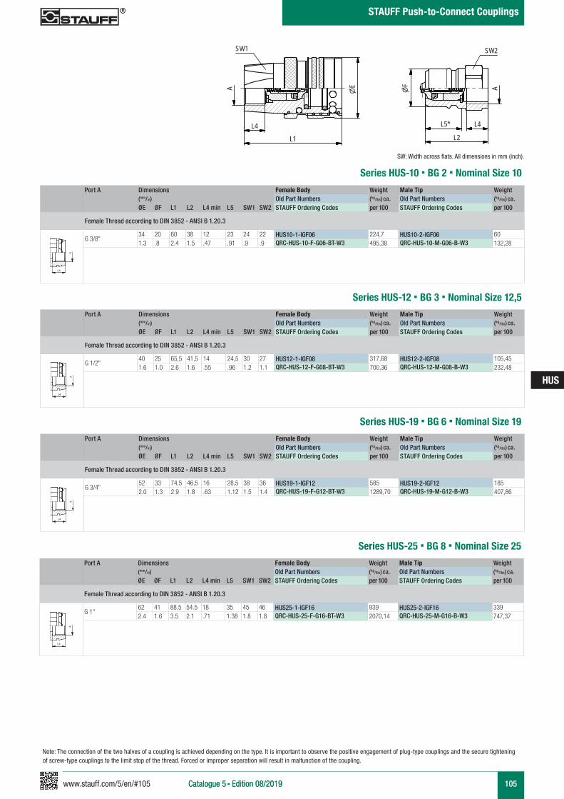
www.stauff.com/5/en/#105 105
HUS
Catalogue 5 § Edition 08/2019Catalogue 5 § Edition 08/2019
STAUFF Push-to-Connect Couplings
Port A Dimensions Female Body Weight Male Tip Weight (mm/in) Old Part Numbers (kg/lbs) ca. Old Part Numbers (kg/lbs) ca. ØE ØF L1 L2 L4 min L5 SW1 SW2 STAUFF Ordering Codes per 100 STAUFF Ordering Codes per 100
Female Thread according to DIN 3852 - ANSI B 1.20.3
G 3/8"34 20 60 38 12 23 24 22 HUS10-1-IGF06 224,7 HUS10-2-IGF06 601.3 .8 2.4 1.5 .47 .91 .9 .9 QRC-HUS-10-F-G06-BT-W3 495,38 QRC-HUS-10-M-G06-B-W3 132,28
Series HUS-10 § BG 2 § Nominal Size 10
SW: Width across flats. All dimensions in mm (inch).
A A
L3 L3
L4
Anschlüsse-Beispiele.pdf 1 10.09.13 15:44
HUS12-Muffe &Stecker
Stahl, Beschichtung Chrom III
scale 0.74
* Eintauchtiefe Stecker
SW2
F
L4
L2
A
L5*
SW1
A
L4
L1
E
Series HUS-12 § BG 3 § Nominal Size 12,5
A A
L3 L3
L4
Anschlüsse-Beispiele.pdf 1 10.09.13 15:44
Series HUS-19 § BG 6 § Nominal Size 19
A A
L3 L3
L4
Anschlüsse-Beispiele.pdf 1 10.09.13 15:44
Series HUS-25 § BG 8 § Nominal Size 25
A A
L3 L3
L4
Anschlüsse-Beispiele.pdf 1 10.09.13 15:44
Port A Dimensions Female Body Weight Male Tip Weight (mm/in) Old Part Numbers (kg/lbs) ca. Old Part Numbers (kg/lbs) ca. ØE ØF L1 L2 L4 min L5 SW1 SW2 STAUFF Ordering Codes per 100 STAUFF Ordering Codes per 100
Female Thread according to DIN 3852 - ANSI B 1.20.3
G 1/2"40 25 65,5 41,5 14 24,5 30 27 HUS12-1-IGF08 317,68 HUS12-2-IGF08 105,451.6 1.0 2.6 1.6 .55 .96 1.2 1.1 QRC-HUS-12-F-G08-BT-W3 700,36 QRC-HUS-12-M-G08-B-W3 232,48
Port A Dimensions Female Body Weight Male Tip Weight (mm/in) Old Part Numbers (kg/lbs) ca. Old Part Numbers (kg/lbs) ca. ØE ØF L1 L2 L4 min L5 SW1 SW2 STAUFF Ordering Codes per 100 STAUFF Ordering Codes per 100
Female Thread according to DIN 3852 - ANSI B 1.20.3
G 3/4"52 33 74,5 46,5 16 28,5 38 36 HUS19-1-IGF12 585 HUS19-2-IGF12 1852.0 1.3 2.9 1.8 .63 1.12 1.5 1.4 QRC-HUS-19-F-G12-BT-W3 1289,70 QRC-HUS-19-M-G12-B-W3 407,86
Port A Dimensions Female Body Weight Male Tip Weight (mm/in) Old Part Numbers (kg/lbs) ca. Old Part Numbers (kg/lbs) ca. ØE ØF L1 L2 L4 min L5 SW1 SW2 STAUFF Ordering Codes per 100 STAUFF Ordering Codes per 100
Female Thread according to DIN 3852 - ANSI B 1.20.3
G 1"62 41 88,5 54.5 18 35 45 46 HUS25-1-IGF16 939 HUS25-2-IGF16 3392.4 1.6 3.5 2.1 .71 1.38 1.8 1.8 QRC-HUS-25-F-G16-BT-W3 2070,14 QRC-HUS-25-M-G16-B-W3 747,37
Note: The connection of the two halves of a coupling is achieved depending on the type. It is important to observe the positive engagement of plug-type couplings and the secure tightening of screw-type couplings to the limit stop of the thread. Forced or improper separation will result in malfunction of the coupling.

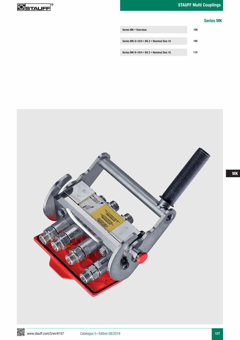
www.stauff.com/5/en/#107 107
MK
Catalogue 5 § Edition 08/2019
STAUFF Multi Couplings
Series MK § Overview
Series MK-Q-10/4 § BG 2 § Nominal Size 10 109
108
Series MK-R-10/4 § BG 2 § Nominal Size 10 110
Series MK
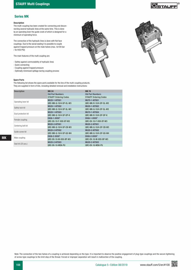
108 www.stauff.com/5/en/#108
MK
Catalogue 5 § Edition 08/2019
STAUFF Multi Couplings
Spare Parts The following list shows the spare parts available for the line of the multi-coupling products. They are supplied in form of kits, including detailed removal and installation instructions:
Description MK 24 MK 74Old Part Numbers Old Part NumbersSTAUFF Ordering Codes STAUFF Ordering Codes
Operating lever kitMU20-1-KIT001 MU70-1-KIT001QRC-MK-Q-10/4-SP-OL-W3 QRC-MK-R-10/4-SP-OL-W3
Safety lock kitMU20-1-KIT002 MU20-1-KIT002QRC-MK-Q-10/4-SP-SL-W3 QRC-MK-Q-10/4-SP-SL-W3
Dust protection kitMU20-1-KIT003 MU70-1-KIT004QRC-MK-Q-10/4-SP-DP-K QRC-MK-R-10/4-SP-DP-K
Female couplingEK08-1-XXXX* EK08-1-XXXX*QRC-EK-10-F-XXX-BT-W3 QRC-EK-10-F-XXX-BT-W3
Centering bolt kitMU20-2-KIT001 MU20-2-KIT001QRC-MK-Q-10/4-SP-CB-W3 QRC-MK-Q-10/4-SP-CB-W3
Guide screw kitMU20-2-KIT002 MU20-2-KIT002QRC-MK-Q-10/4-SP-GS-W4 QRC-MK-Q-10/4-SP-GS-W4
Male couplingEK08-2-XXXX* EK08-2-XXXX*QRC-EK-10-M-XXX-BP-W3 QRC-EK-10-M-XXX-BP-W3
Seal kit (20 pcs.)MU20-2-KIT003 MU20-2-KIT003QRC-EK-10-MSK-PU QRC-EK-10-MSK-PU
Series MK
DescriptionThe multi-coupling has been created for connecting and discon-necting several hydraulic lines at the same time. This is done by an operating lever the guide crank of which is designed for a minimum of operating force.
The connection of the hydraulic lines is done with flat face couplings. Due to the secial sealing it is possible to couple against trapped pressure on the male halves (max. 4x100 bar / 4x1450 PSI)
The main features of the multi coupling are:
- Safety against commutability of hydraulic lines- Quick connecting- Coupling against trapped pressure - Optimally minimized spillage during coupling process
Note: The connection of the two halves of a coupling is achieved depending on the type. It is important to observe the positive engagement of plug-type couplings and the secure tightening of screw-type couplings to the limit stop of the thread. Forced or improper separation will result in malfunction of the coupling.
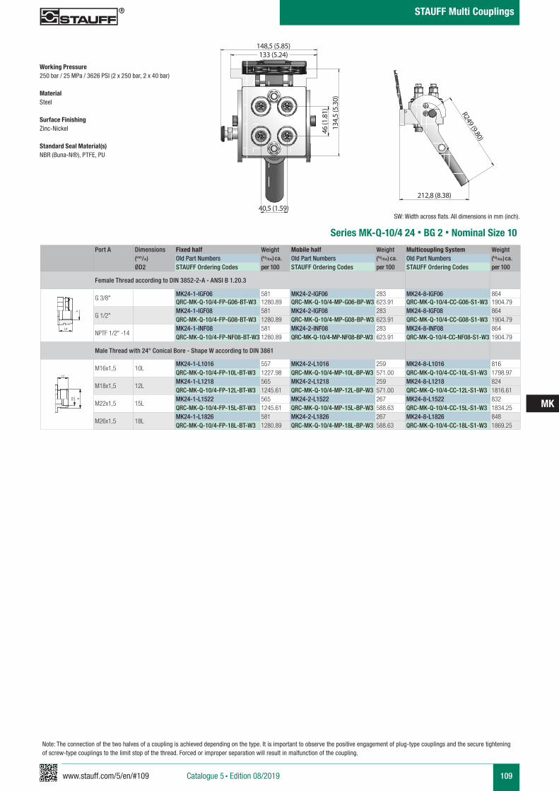
www.stauff.com/5/en/#109 109
MK
Catalogue 5 § Edition 08/2019
STAUFF Multi Couplings
212,8 (8.38)
Series MK-Q-10/4 24 § BG 2 § Nominal Size 10Port A Dimensions Fixed half Weight Mobile half Weight Multicoupling System Weight
(mm/in) Old Part Numbers (kg/lbs) ca. Old Part Numbers (kg/lbs) ca. Old Part Numbers (kg/lbs) ca.
ØD2 STAUFF Ordering Codes per 100 STAUFF Ordering Codes per 100 STAUFF Ordering Codes per 100
Female Thread according to DIN 3852-2-A - ANSI B 1.20.3
G 3/8"MK24-1-IGF06 581 MK24-2-IGF06 283 MK24-8-IGF06 864QRC-MK-Q-10/4-FP-G06-BT-W3 1280.89 QRC-MK-Q-10/4-MP-G06-BP-W3 623.91 QRC-MK-Q-10/4-CC-G06-S1-W3 1904.79
G 1/2"MK24-1-IGF08 581 MK24-2-IGF08 283 MK24-8-IGF08 864QRC-MK-Q-10/4-FP-G08-BT-W3 1280.89 QRC-MK-Q-10/4-MP-G08-BP-W3 623.91 QRC-MK-Q-10/4-CC-G08-S1-W3 1904.79
NPTF 1/2" -14MK24-1-INF08 581 MK24-2-INF08 283 MK24-8-INF08 864QRC-MK-Q-10/4-FP-NF08-BT-W3 1280.89 QRC-MK-Q-10/4-MP-NF08-BP-W3 623.91 QRC-MK-Q-10/4-CC-NF08-S1-W3 1904.79
Male Thread with 24° Conical Bore - Shape W according to DIN 3861
M16x1,5 10LMK24-1-L1016 557 MK24-2-L1016 259 MK24-8-L1016 816QRC-MK-Q-10/4-FP-10L-BT-W3 1227.98 QRC-MK-Q-10/4-MP-10L-BP-W3 571.00 QRC-MK-Q-10/4-CC-10L-S1-W3 1798.97
M18x1,5 12LMK24-1-L1218 565 MK24-2-L1218 259 MK24-8-L1218 824QRC-MK-Q-10/4-FP-12L-BT-W3 1245.61 QRC-MK-Q-10/4-MP-12L-BP-W3 571.00 QRC-MK-Q-10/4-CC-12L-S1-W3 1816.61
M22x1,5 15LMK24-1-L1522 565 MK24-2-L1522 267 MK24-8-L1522 832QRC-MK-Q-10/4-FP-15L-BT-W3 1245.61 QRC-MK-Q-10/4-MP-15L-BP-W3 588.63 QRC-MK-Q-10/4-CC-15L-S1-W3 1834.25
M26x1,5 18LMK24-1-L1826 581 MK24-2-L1826 267 MK24-8-L1826 848QRC-MK-Q-10/4-FP-18L-BT-W3 1280.89 QRC-MK-Q-10/4-MP-18L-BP-W3 588.63 QRC-MK-Q-10/4-CC-18L-S1-W3 1869.25
A A
L3 L3
L4
Anschlüsse-Beispiele.pdf 1 10.09.13 15:44
SW: Width across flats. All dimensions in mm (inch).
A A
L3 L3
L4
Anschlüsse-Beispiele.pdf 1 10.09.13 15:44
R249 (9.80)
40,5 (1.59)
148,5 (5.85)133 (5.24)
46 (1
.81)
134,
5 (5
.30)
Note: The connection of the two halves of a coupling is achieved depending on the type. It is important to observe the positive engagement of plug-type couplings and the secure tightening of screw-type couplings to the limit stop of the thread. Forced or improper separation will result in malfunction of the coupling.
Working Pressure 250 bar / 25 MPa / 3626 PSI (2 x 250 bar, 2 x 40 bar)
Material Steel
Surface FinishingZinc-Nickel
Standard Seal Material(s) NBR (Buna-N®), PTFE, PU
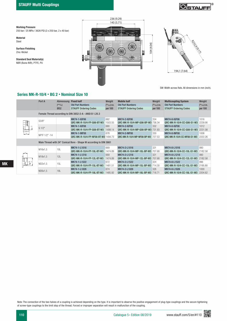
110 www.stauff.com/5/en/#110
MK
Catalogue 5 § Edition 08/2019
STAUFF Multi Couplings
Series MK-R-10/4 § BG 2 § Nominal Size 10Port A Abmessung Fixed half Weight Mobile half Weight Multicoupling System Weight
(mm/in) Old Part Numbers (kg/lbs) ca. Old Part Numbers (kg/lbs) ca. Old Part Numbers (kg/lbs) ca.
ØD2 STAUFF Ordering Codes per 100 STAUFF Ordering Codes per 100 STAUFF Ordering Codes per 100
Female Thread according to DIN 3852-2-A - ANSI B 1.20.3
G3/8"MK74-1-IGF06 682 MK74-2-IGF06 334 MK74-8-IGF06 1016QRC-MK-R-10/4-FP-G06-BT-W3 1503.55 QRC-MK-R-10/4-MP-G06-BP-W3 736.34 QRC-MK-R-10/4-CC-G06-S1-W3 2239.90
G 1/2"MK74-1-IGF08 680 MK74-2-IGF08 332 MK74-8-IGF08 1012QRC-MK-R-10/4-FP-G08-BT-W3 1499.14 QRC-MK-R-10/4-MP-G08-BP-W3 731.93 QRC-MK-R-10/4-CC-G08-S1-W3 2231.08
NPTF 1/2" -14MK74-1-INF08 678 MK74-2-INF08 330 MK74-8-INF08 1008QRC-MK-R-10/4-FP-NF08-BT-W3 1494.73 QRC-MK-R-10/4-MP-NF08-BP-W3 727.53 QRC-MK-R-10/4-CC-NF08-S1-W3 2222.26
Male Thread with 24° Conical Bore - Shape W according to DIN 3861
M16x1,5 10LMK74-1-L1016 669 MK74-2-L1016 321 MK74-8-L1016 990QRC-MK-R-10/4-FP-10L-BT-W3 1474.89 QRC-MK-R-10/4-MP-10L-BP-W3 707.68 QRC-MK-R-10/4-CC-10L-S1-W3 2182.58
M18x1,5 12LMK74-1-L1218 669 MK74-2-L1218 321 MK74-8-L1218 990QRC-MK-R-10/4-FP-12L-BT-W3 1474.89 QRC-MK-R-10/4-MP-12L-BP-W3 707.68 QRC-MK-R-10/4-CC-12L-S1-W3 2182.58
M22x1,5 15LMK74-1-L1522 672 MK74-2-L1522 324 MK74-8-L1522 996QRC-MK-R-10/4-FP-15L-BT-W3 1481.51 QRC-MK-R-10/4-MP-15L-BP-W3 714.30 QRC-MK-R-10/4-CC-15L-S1-W3 2195.80
M26x1,5 18LMK74-1-L1826 674 MK74-2-L1826 326 MK74-8-L1826 1000QRC-MK-R-10/4-FP-18L-BT-W3 1485.92 QRC-MK-R-10/4-MP-18L-BP-W3 718.71 QRC-MK-R-10/4-CC-18L-S1-W3 2204.62
A A
L3 L3
L4
Anschlüsse-Beispiele.pdf 1 10.09.13 15:44
SW: Width across flats. All dimensions in mm (inch).
A A
L3 L3
L4
Anschlüsse-Beispiele.pdf 1 10.09.13 15:44
194,1 (7.64)
R232,9 (9.17)
236 (9.29)145 (5.71)
104
(4.0
4)
Note: The connection of the two halves of a coupling is achieved depending on the type. It is important to observe the positive engagement of plug-type couplings and the secure tightening of screw-type couplings to the limit stop of the thread. Forced or improper separation will result in malfunction of the coupling.
Working Pressure 250 bar / 25 MPa / 3626 PSI (2 x 250 bar, 2 x 40 bar)
Material Steel
Surface FinishingZinc-Nickel
Standard Seal Material(s) NBR (Buna-N®), PTFE, PU
www.stauff.com/5/en/#111 111
MK
Catalogue 5 § Edition 08/2019
STAUFF Multi Couplings
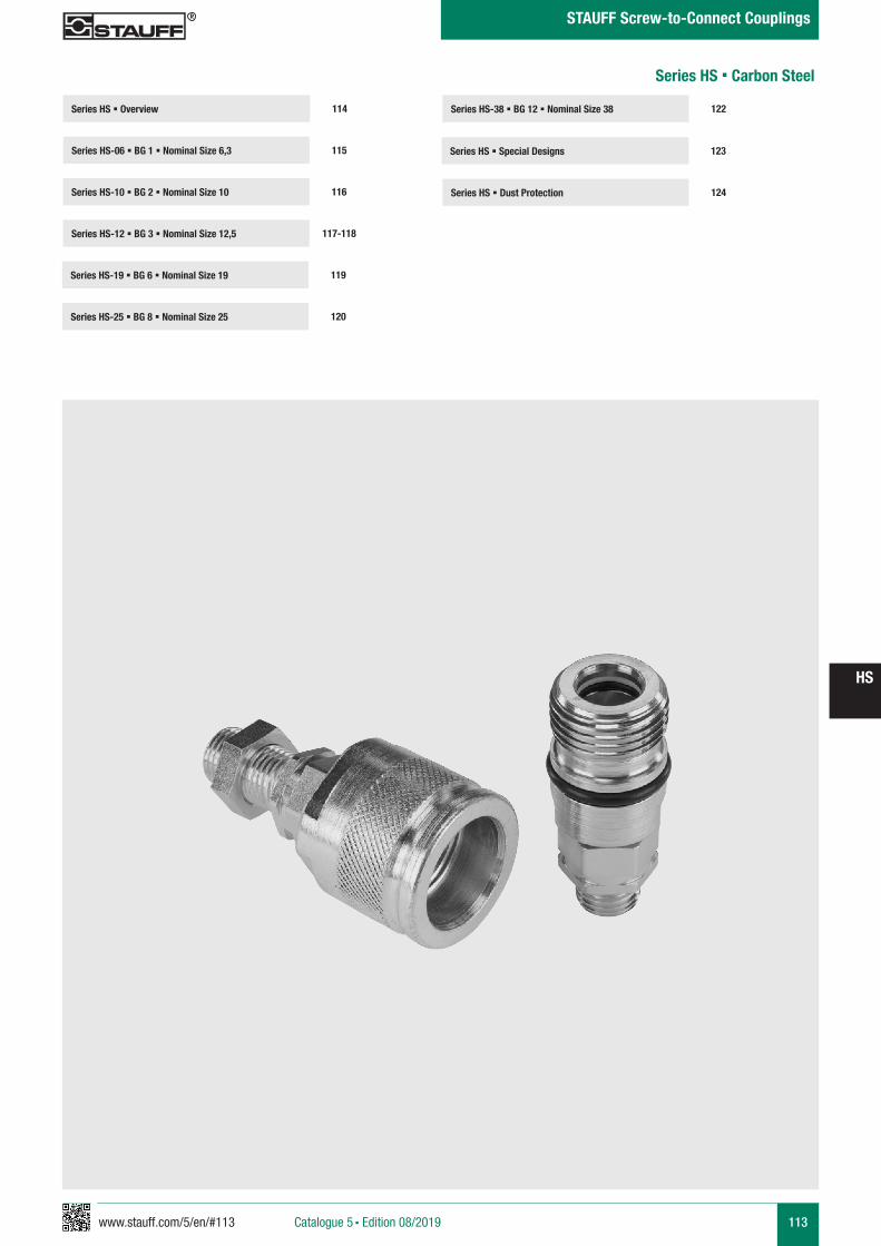
www.stauff.com/5/en/#113 113
HS
Catalogue 5 § Edition 08/2019
STAUFF Screw-to-Connect Couplings
Series HS-38 § BG 12 § Nominal Size 38 122Series HS § Overview
Series HS-06 § BG 1 § Nominal Size 6,3 115
114
Series HS-10 § BG 2 § Nominal Size 10 116
Series HS-19 § BG 6 § Nominal Size 19 119
Series HS-12 § BG 3 § Nominal Size 12,5 117-118
Series HS-25 § BG 8 § Nominal Size 25 120
Series HS § Special Designs
Series HS § Dust Protection 124
123
Series HS § Carbon Steel
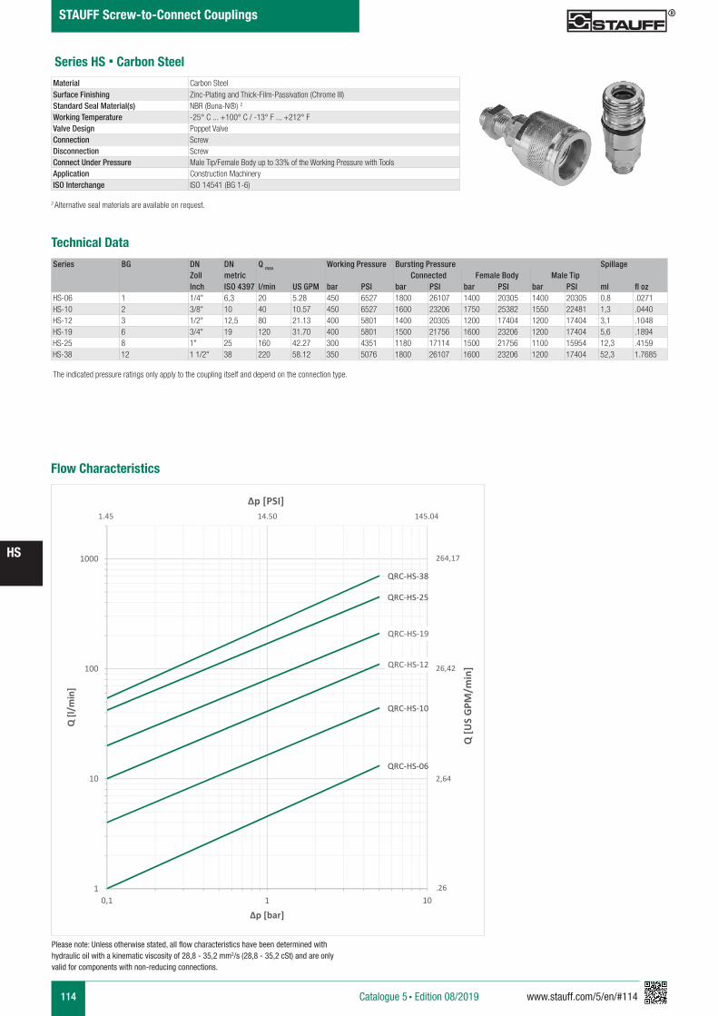
114 www.stauff.com/5/en/#114
HS
Catalogue 5 § Edition 08/2019
STAUFF Screw-to-Connect Couplings
Series HS § Carbon Steel
Series BG DN DN Q max Working Pressure Bursting Pressure SpillageZoll metric Connected Female Body Male TipInch ISO 4397 l/min US GPM bar PSI bar PSI bar PSI bar PSI ml fl oz
HS-06 1 1/4" 6,3 20 5.28 450 6527 1800 26107 1400 20305 1400 20305 0,8 .0271HS-10 2 3/8" 10 40 10.57 450 6527 1600 23206 1750 25382 1550 22481 1,3 .0440HS-12 3 1/2" 12,5 80 21.13 400 5801 1400 20305 1200 17404 1200 17404 3,1 .1048HS-19 6 3/4" 19 120 31.70 400 5801 1500 21756 1600 23206 1200 17404 5,6 .1894HS-25 8 1" 25 160 42.27 300 4351 1180 17114 1500 21756 1100 15954 12,3 .4159HS-38 12 1 1/2" 38 220 58.12 350 5076 1800 26107 1600 23206 1200 17404 52,3 1.7685
Material Carbon SteelSurface Finishing Zinc-Plating and Thick-Film-Passivation (Chrome III)Standard Seal Material(s) NBR (Buna-N®) 2
Working Temperature -25° C ... +100° C / -13° F ... +212° FValve Design Poppet ValveConnection ScrewDisconnection ScrewConnect Under Pressure Male Tip/Female Body up to 33% of the Working Pressure with ToolsApplication Construction MachineryISO Interchange ISO 14541 (BG 1-6)
The indicated pressure ratings only apply to the coupling itself and depend on the connection type.
2 Alternative seal materials are available on request.
Technical Data
Flow Characteristics
QRC-HS-06
QRC-HS-10
QRC-HS-12
QRC-HS-19
QRC-HS-25
QRC-HS-38
1
10
100
1000
0,1 1 10
Q [l/
min
]
Δp [bar]
Q [U
S G
PM/m
in]
Δp [PSI]
264,17
26,42
2,64
.26
1.45 14.50 145.04
Please note: Unless otherwise stated, all flow characteristics have been determined with hydraulic oil with a kinematic viscosity of 28,8 - 35,2 mm2/s (28,8 - 35,2 cSt) and are only valid for components with non-reducing connections.
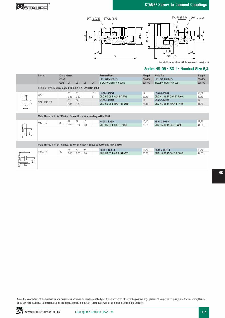
www.stauff.com/5/en/#115 115
HS
Catalogue 5 § Edition 08/2019
STAUFF Screw-to-Connect Couplings
A C
HS 04
scale 0,91
L3
L1
D2
A 24Mx2
SW19 SW22
14.8
L2
35Ø
L3
AD2
SW30 SW19
Port A Dimensions Female Body Weight Male Tip Weight (mm/in) Old Part Numbers (kg/lbs) ca. Old Part Numbers (kg/lbs) ca. ØD2 L1 L2 L3 L4 STAUFF Ordering Codes per 100 STAUFF Ordering Codes per 100
Female Thread according to DIN 3852-2-A - ANSI B 1.20.3
G 1/4"60 59 13 HS04-1-IGF04 12 HS04-2-IGF04 18,202.36 2.32 .51 QRC-HS-06-F-G04-BT-W66 26.46 QRC-HS-06-M-G04-BT-W66 40.12
NPTF 1/4" -1860 59 HS04-1-INF04 12 HS04-2-INF04 192.36 2.32 QRC-HS-06-F-NF04-BT-W66 26.46 QRC-HS-06-M-NF04-B-W66 41.89
Male Thread with 24° Conical Bore - Shape W according to DIN 3861
M14x1,5 8L58 57 10 HS04-1-L0814 12,10 HS04-2-L0814 18,702.28 2.24 .39 QRC-HS-06-F-08L-BT-W66 26.68 QRC-HS-06-M-08L-B-W66 41.23
Male Thread with 24° Conical Bore - Bulkhead - Shape W according to DIN 3861
M14x1,5 8L73 72 25 HS04-1-N0814 13,70 HS04-2-N0814 20,302.87 2.83 .98 QRC-HS-06-F-08LB-BT-W66 30.20 QRC-HS-06-M-08LB-B-W66 44.75
Series HS-06 § BG 1 § Nominal Size 6,3
SW 19 (.75)
Ø35
(1.3
8)
14,8
A A
L3 L3
L4
Anschlüsse-Beispiele.pdf 1 10.09.13 15:44
A A
L3 L3
L4
Anschlüsse-Beispiele.pdf 1 10.09.13 15:44
A A
L3 L3
L4
Anschlüsse-Beispiele.pdf 1 10.09.13 15:44
SW: Width across flats. All dimensions in mm (inch).
SW 22 (.87)
(.58)
SW 30 (1.18) SW 19 (.75)
Note: The connection of the two halves of a coupling is achieved depending on the type. It is important to observe the positive engagement of plug-type couplings and the secure tightening of screw-type couplings to the limit stop of the thread. Forced or improper separation will result in malfunction of the coupling.
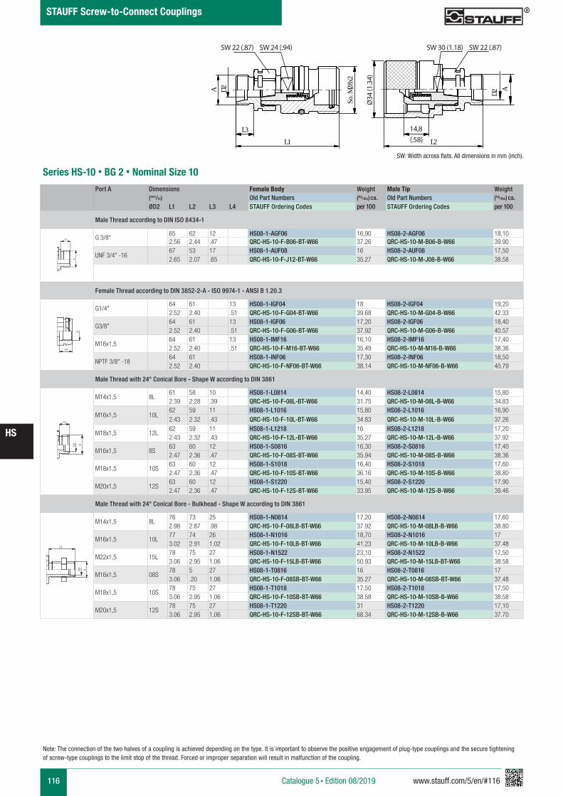
116 www.stauff.com/5/en/#116
HS
Catalogue 5 § Edition 08/2019
STAUFF Screw-to-Connect Couplings
A B
HS 08
scale 0,83
D2A
L3L1
28So
. Mx2
SW22 SW24
34Ø
14.8L2
D2 A
SW30 SW22SW 30 (1.18)
Ø34
(1.3
4)
Series HS-10 § BG 2 § Nominal Size 10Port A Dimensions Female Body Weight Male Tip Weight
(mm/in) Old Part Numbers (kg/lbs) ca. Old Part Numbers (kg/lbs) ca.
ØD2 L1 L2 L3 L4 STAUFF Ordering Codes per 100 STAUFF Ordering Codes per 100
Male Thread according to DIN ISO 8434-1
G 3/8"65 62 12 HS08-1-AGF06 16,90 HS08-2-AGF06 18,102.56 2.44 .47 QRC-HS-10-F-B06-BT-W66 37.26 QRC-HS-10-M-B06-B-W66 39.90
UNF 3/4" -1667 53 17 HS08-1-AUF08 16 HS08-2-AUF08 17,502.65 2.07 .65 QRC-HS-10-F-J12-BT-W66 35.27 QRC-HS-10-M-J08-B-W66 38.58
Female Thread according to DIN 3852-2-A - ISO 9974-1 - ANSI B 1.20.3
G1/4"64 61 13 HS08-1-IGF04 18 HS08-2-IGF04 19,202.52 2.40 .51 QRC-HS-10-F-G04-BT-W66 39.68 QRC-HS-10-M-G04-B-W66 42.33
G3/8"64 61 13 HS08-1-IGF06 17,20 HS08-2-IGF06 18,402.52 2.40 .51 QRC-HS-10-F-G06-BT-W66 37.92 QRC-HS-10-M-G06-B-W66 40.57
M16x1,564 61 13 HS08-1-IMF16 16,10 HS08-2-IMF16 17,402.52 2.40 .51 QRC-HS-10-F-M16-BT-W66 35.49 QRC-HS-10-M-M16-B-W66 38.36
NPTF 3/8" -1864 61 HS08-1-INF06 17,30 HS08-2-INF06 18,502.52 2.40 QRC-HS-10-F-NF06-BT-W66 38.14 QRC-HS-10-M-NF06-B-W66 40.79
Male Thread with 24° Conical Bore - Shape W according to DIN 3861
M14x1,5 8L61 58 10 HS08-1-L0814 14,40 HS08-2-L0814 15,802.39 2.28 .39 QRC-HS-10-F-08L-BT-W66 31.75 QRC-HS-10-M-08L-B-W66 34.83
M16x1,5 10L62 59 11 HS08-1-L1016 15,80 HS08-2-L1016 16,902.43 2.32 .43 QRC-HS-10-F-10L-BT-W66 34.83 QRC-HS-10-M-10L-B-W66 37.26
M18x1,5 12L62 59 11 HS08-1-L1218 16 HS08-2-L1218 17,202.43 2.32 .43 QRC-HS-10-F-12L-BT-W66 35.27 QRC-HS-10-M-12L-B-W66 37.92
M16x1,5 8S63 60 12 HS08-1-S0816 16,30 HS08-2-S0816 17,402.47 2.36 .47 QRC-HS-10-F-08S-BT-W66 35.94 QRC-HS-10-M-08S-B-W66 38.36
M18x1,5 10S63 60 12 HS08-1-S1018 16,40 HS08-2-S1018 17,602.47 2.36 .47 QRC-HS-10-F-10S-BT-W66 36.16 QRC-HS-10-M-10S-B-W66 38.80
M20x1,5 12S63 60 12 HS08-1-S1220 15,40 HS08-2-S1220 17,902.47 2.36 .47 QRC-HS-10-F-12S-BT-W66 33.95 QRC-HS-10-M-12S-B-W66 39.46
Male Thread with 24° Conical Bore - Bulkhead - Shape W according to DIN 3861
M14x1,5 8L76 73 25 HS08-1-N0814 17,20 HS08-2-N0814 17,602.98 2.87 .98 QRC-HS-10-F-08LB-BT-W66 37.92 QRC-HS-10-M-08LB-B-W66 38.80
M16x1,5 10L77 74 26 HS08-1-N1016 18,70 HS08-2-N1016 173.02 2.91 1.02 QRC-HS-10-F-10LB-BT-W66 41.23 QRC-HS-10-M-10LB-B-W66 37.48
M22x1,5 15L78 75 27 HS08-1-N1522 23,10 HS08-2-N1522 17,503.06 2.95 1.06 QRC-HS-10-F-15LB-BT-W66 50.93 QRC-HS-10-M-15LB-BT-W66 38.58
M16x1,5 08S78 5 27 HS08-1-T0816 16 HS08-2-T0816 173.06 .20 1.06 QRC-HS-10-F-08SB-BT-W66 35.27 QRC-HS-10-M-08SB-BT-W66 37.48
M18x1,5 10S78 75 27 HS08-1-T1018 17,50 HS08-2-T1018 17,503.06 2.95 1.06 QRC-HS-10-F-10SB-BT-W66 38.58 QRC-HS-10-M-10SB-B-W66 38.58
M20x1,5 12S78 75 27 HS08-1-T1220 31 HS08-2-T1220 17,103.06 2.95 1.06 QRC-HS-10-F-12SB-BT-W66 68.34 QRC-HS-10-M-12SB-B-W66 37.70
A A
L3 L3
L4
Anschlüsse-Beispiele.pdf 1 10.09.13 15:44
A A
L3 L3
L4
Anschlüsse-Beispiele.pdf 1 10.09.13 15:44
A A
L3 L3
L4
Anschlüsse-Beispiele.pdf 1 10.09.13 15:44
A A
L3 L3
L4
Anschlüsse-Beispiele.pdf 1 10.09.13 15:44
SW: Width across flats. All dimensions in mm (inch).
14,8(.58)
SW 22 (.87)SW 22 (.87) SW 24 (.94)
Note: The connection of the two halves of a coupling is achieved depending on the type. It is important to observe the positive engagement of plug-type couplings and the secure tightening of screw-type couplings to the limit stop of the thread. Forced or improper separation will result in malfunction of the coupling.
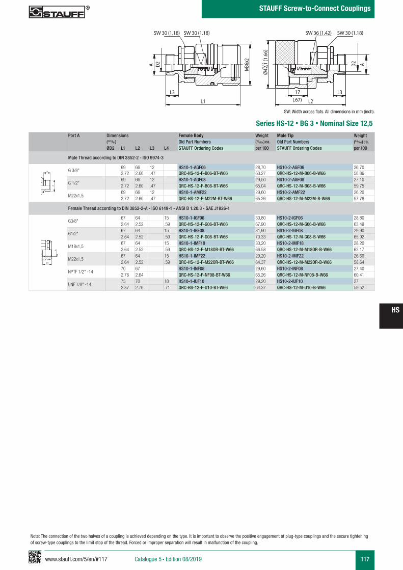
www.stauff.com/5/en/#117 117
HS
Catalogue 5 § Edition 08/2019
STAUFF Screw-to-Connect Couplings
Note: The connection of the two halves of a coupling is achieved depending on the type. It is important to observe the positive engagement of plug-type couplings and the secure tightening of screw-type couplings to the limit stop of the thread. Forced or improper separation will result in malfunction of the coupling.
HS 10
s cale 0,77
L3L1
D2A 36Mx2
42.1
Ø
17L2
L3
D2 A
SW30SW30 SW36 SW30
Ø42
,1 (1
.66)
Series HS-12 § BG 3 § Nominal Size 12,5Port A Dimensions Female Body Weight Male Tip Weight
(mm/in) Old Part Numbers (kg/lbs) ca. Old Part Numbers (kg/lbs) ca.
ØD2 L1 L2 L3 L4 STAUFF Ordering Codes per 100 STAUFF Ordering Codes per 100
Male Thread according to DIN 3852-2 - ISO 9974-3
G 3/8"69 66 12 HS10-1-AGF06 28,70 HS10-2-AGF06 26,702.72 2.60 .47 QRC-HS-12-F-B06-BT-W66 63.27 QRC-HS-12-M-B06-B-W66 58.86
G 1/2"69 66 12 HS10-1-AGF08 29,50 HS10-2-AGF08 27,102.72 2.60 .47 QRC-HS-12-F-B08-BT-W66 65.04 QRC-HS-12-M-B08-B-W66 59.75
M22x1,569 66 12 HS10-1-AMF22 29,60 HS10-2-AMF22 26,202.72 2.60 .47 QRC-HS-12-F-M22M-BT-W66 65.26 QRC-HS-12-M-M22M-B-W66 57.76
Female Thread according to DIN 3852-2-A - ISO 6149-1 - ANSI B 1.20.3 - SAE J1926-1
G3/8"67 64 15 HS10-1-IGF06 30,80 HS10-2-IGF06 28,802.64 2.52 .59 QRC-HS-12-F-G06-BT-W66 67.90 QRC-HS-12-M-G06-B-W66 63.49
G1/2"67 64 15 HS10-1-IGF08 31,90 HS10-2-IGF08 29,902.64 2.52 .59 QRC-HS-12-F-G08-BT-W66 70.33 QRC-HS-12-M-G08-B-W66 65,92
M18x1,567 64 15 HS10-1-IMF18 30,20 HS10-2-IMF18 28,202.64 2.52 .59 QRC-HS-12-F-M18OR-BT-W66 66.58 QRC-HS-12-M-M18OR-B-W66 62.17
M22x1,567 64 15 HS10-1-IMF22 29,20 HS10-2-IMF22 26,602.64 2.52 .59 QRC-HS-12-F-M22OR-BT-W66 64.37 QRC-HS-12-M-M22OR-B-W66 58.64
NPTF 1/2" -1470 67 HS10-1-INF08 29,60 HS10-2-INF08 27,402.76 2.64 QRC-HS-12-F-NF08-BT-W66 65.26 QRC-HS-12-M-NF08-B-W66 60.41
UNF 7/8" -1473 70 18 HS10-1-IUF10 29,20 HS10-2-IUF10 272.87 2.76 .71 QRC-HS-12-F-U10-BT-W66 64.37 QRC-HS-12-M-U10-B-W66 59.52
A A
L3 L3
L4
Anschlüsse-Beispiele.pdf 1 10.09.13 15:44
A A
L3 L3
L4
Anschlüsse-Beispiele.pdf 1 10.09.13 15:44
SW: Width across flats. All dimensions in mm (inch).
17(.67)
SW 30 (1.18) SW 30 (1.18) SW 30 (1.18)SW 36 (1.42)
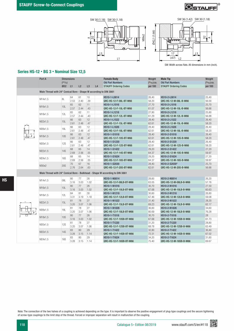
118 www.stauff.com/5/en/#118
HS
Catalogue 5 § Edition 08/2019
STAUFF Screw-to-Connect Couplings
HS 10
s cale 0,77
L3L1
D2A 36Mx2
42.1
Ø
17L2
L3
D2 A
SW30SW30 SW36 SW30
Ø42
,1 (1
.66)
Series HS-12 § BG 3 § Nominal Size 12,5
Port A Dimensions Female Body Weight Male Tip Weight (mm/in) Old Part Numbers (kg/lbs) ca. Old Part Numbers (kg/lbs) ca.
ØD2 L1 L2 L3 L4 STAUFF Ordering Codes per 100 STAUFF Ordering Codes per 100
Male Thread with 24° Conical Bore - Shape W according to DIN 3861
M14x1,5 8L64 61 10 HS10-1-L0814 26,40 HS10-2-L0814 25,402.53 2.40 .39 QRC-HS-12-F-08L-BT-W66 58.20 QRC-HS-12-M-08L-B-W66 56.00
M16x1,5 10L65 62 11 HS10-1-L1016 27,70 HS10-2-L1016 25,702.57 2.44 .43 QRC-HS-12-F-10L-BT-W66 61.07 QRC-HS-12-M-10L-B-W66 56.66
M18x1,5 12L65 62 11 HS10-1-L1218 27,80 HS10-2-L1218 25,802.57 2.44 .43 QRC-HS-12-F-12L-BT-W66 61.29 QRC-HS-12-M-12L-B-W66 56.88
M22x1,5 15L66 63 12 HS10-1-L1522 28,40 HS10-2-L1522 26,402.61 2.48 .47 QRC-HS-12-F-15L-BT-W66 62.61 QRC-HS-12-M-15L-B-W66 58.20
M26x1,5 18L66 63 12 HS10-1-L1826 28,40 HS10-2-L1826 26,402.61 2.48 .47 QRC-HS-12-F-18L-BT-W66 62.61 QRC-HS-12-M-18L-B-W66 58.20
M18x1,5 10S66 63 12 HS10-1-S1018 28,40 HS10-2-S1018 26,402.61 2.48 .47 QRC-HS-12-F-10S-BT-W66 62.61 QRC-HS-12-M-10S-B-W66 58.20
M20x1,5 12S66 63 12 HS10-1-S1220 28,40 HS10-2-S1220 26,402.61 2.48 .47 QRC-HS-12-F-12S-BT-W66 62.61 QRC-HS-12-M-12S-B-W66 58.20
M22x1,5 14S68 65 14 HS10-1-S1422 29,20 HS10-2-S1422 27,202.69 2.56 .55 QRC-HS-12-F-14S-BT-W66 64.37 QRC-HS-12-M-10S-B-W66 59.97
M24x1,5 16S68 65 14 HS10-1-S1624 29,20 HS10-2-S1624 27,202.69 2.56 .55 QRC-HS-12-F-16S-BT-W66 64.37 QRC-HS-12-M-16S-B-W66 59.97
M30x2 20S70 67 16 HS10-1-S2030 28,40 HS10-2-S2030* 25,702.76 2.64 .63 QRC-HS-12-F-20S-BT-W66 62.61 QRC-HS-12-M-20S-B-W66 56.66
Male Thread with 24° Conical Bore - Bulkhead - Shape W according to DIN 3861
M14x1,5 08L80 77 26 HS10-1-N0814 28,60 HS10-2-N0814 26,203.16 3.03 1.02 QRC-HS-12-F-08LB-BT-W66 63.05 QRC-HS-12-M-08LB-B-W66 57.76
M16x1,5 10L80 77 26 HS10-1-N1016 30,70 HS10-2-N1016 27,503.16 3.03 1.02 QRC-HS-12-F-10LB-BT-W66 67.68 QRC-HS-12-M-10LB-B-W66 60.63
M18x1,5 12L84 81 30 HS10-1-N1218 30,60 HS10-2-N1218 26,803.31 3.19 1.18 QRC-HS-12-F-12LB-BT-W66 67.46 QRC-HS-12-M-12LB-B-W66 59.08
M22x1,5 15L81 78 27 HS10-1-N1522 31,40 HS10-2-N1522 28,203.20 3.07 1.06 QRC-HS-12-F-15LB-BT-W66 69.23 QRC-HS-12-M-15LB-B-W66 62.17
M26x1,5 18L81 78 27 HS10-1-N1826 36,60 HS10-2-N1826 34,603.20 3.07 1.06 QRC-HS-12-F-18LB-BT-W66 80.69 QRC-HS-12-M-18LB-B-W66 76.28
M18x1,5 10S80 77 26 HS10-1-T1018 30,70 HS10-2-T1018 283.16 3.03 1.02 QRC-HS-12-F-10SB-BT-W66 67.68 QRC-HS-12-M-10SB-B-W66 61.73
M20x1,5 12S81 78 27 HS10-1-T1220 31,20 HS10-2-T1220 28,803.20 3.07 1.06 QRC-HS-12-F-12SB-BT-W66 68.78 QRC-HS-12-M-12SB-B-W66 63.49
M22x1,5 14S83 80 29 HS10-1-T1422 32,80 HS10-2-T1422 30,403.28 3.15 1.14 QRC-HS-12-F-14SB-BT-W66 72.31 QRC-HS-12-M-14SB-B-W66 67.02
M24x1,5 16S83 80 29 HS10-1-T1624 34,20 HS10-2-T1624 31,603.28 3.15 1.14 QRC-HS-12-F-16SB-BT-W66 75.40 QRC-HS-12-M-16SB-B-W66 69.67
A A
L3 L3
L4
Anschlüsse-Beispiele.pdf 1 10.09.13 15:44
A A
L3 L3
L4
Anschlüsse-Beispiele.pdf 1 10.09.13 15:44
SW: Width across flats. All dimensions in mm (inch).
17(.67)
SW 30 (1.18) SW 30 (1.18) SW 30 (1.18)SW 36 (1.42)
Note: The connection of the two halves of a coupling is achieved depending on the type. It is important to observe the positive engagement of plug-type couplings and the secure tightening of screw-type couplings to the limit stop of the thread. Forced or improper separation will result in malfunction of the coupling.
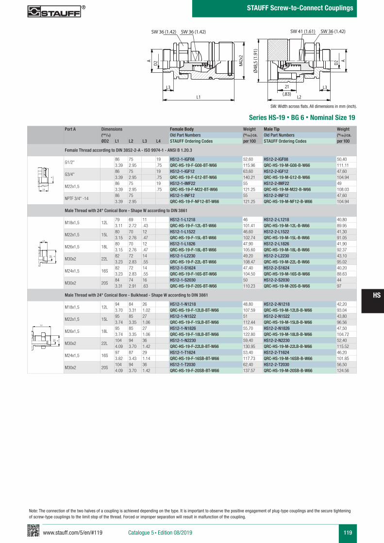
www.stauff.com/5/en/#119 119
HS
Catalogue 5 § Edition 08/2019
STAUFF Screw-to-Connect Couplings
Note: The connection of the two halves of a coupling is achieved depending on the type. It is important to observe the positive engagement of plug-type couplings and the secure tightening of screw-type couplings to the limit stop of the thread. Forced or improper separation will result in malfunction of the coupling.
HS 12
s cale 0,69
L3
L1
SW36 SW36
D2A 42M
x2
L3
L2
48.5
Ø D2A
21
SW41 SW36
Series HS-19 § BG 6 § Nominal Size 19
SW: Width across flats. All dimensions in mm (inch).
SW 36 (1.42)
(.83)
Ø48
,5 (1
.91)
SW 36 (1.42) SW 36 (1.42)SW 41 (1.61)
Port A Dimensions Female Body Weight Male Tip Weight (mm/in) Old Part Numbers (kg/lbs) ca. Old Part Numbers (kg/lbs) ca. ØD2 L1 L2 L3 L4 STAUFF Ordering Codes per 100 STAUFF Ordering Codes per 100
Female Thread according to DIN 3852-2-A - ISO 9974-1 - ANSI B 1.20.3
G1/2"86 75 19 HS12-1-IGF08 52,60 HS12-2-IGF08 50,403.39 2.95 .75 QRC-HS-19-F-G08-BT-W66 115.96 QRC-HS-19-M-G08-B-W66 111.11
G3/4"86 75 19 HS12-1-IGF12 63,60 HS12-2-IGF12 47,603.39 2.95 .75 QRC-HS-19-F-G12-BT-W66 140.21 QRC-HS-19-M-G12-B-W66 104.94
M22x1,586 75 19 HS12-1-IMF22 55 HS12-2-IMF22 493.39 2.95 .75 QRC-HS-19-F-M22-BT-W66 121.25 QRC-HS-19-M-M22-B-W66 108.03
NPTF 3/4" -1486 75 HS12-1-INF12 55 HS12-2-INF12 47,603.39 2.95 QRC-HS-19-F-NF12-BT-W66 121.25 QRC-HS-19-M-NF12-B-W66 104.94
Male Thread with 24° Conical Bore - Shape W according to DIN 3861
M18x1,5 12L79 69 11 HS12-1-L1218 46 HS12-2-L1218 40,803.11 2.72 .43 QRC-HS-19-F-12L-BT-W66 101.41 QRC-HS-19-M-12L-B-W66 89.95
M22x1,5 15L80 70 12 HS12-1-L1522 46,60 HS12-2-L1522 41,303.15 2.76 .47 QRC-HS-19-F-15L-BT-W66 102.74 QRC-HS-19-M-15L-B-W66 91.05
M26x1,5 18L80 70 12 HS12-1-L1826 47,90 HS12-2-L1826 41,903.15 2.76 .47 QRC-HS-19-F-18L-BT-W66 105.60 QRC-HS-19-M-18L-B-W66 92.37
M30x2 22L82 72 14 HS12-1-L2230 49,20 HS12-2-L2230 43,103.23 2.83 .55 QRC-HS-19-F-22L-BT-W66 108.47 QRC-HS-19-M-22L-B-W66 95.02
M24x1,5 16S82 72 14 HS12-1-S1624 47,40 HS12-2-S1624 40,203.23 2.83 .55 QRC-HS-19-F-16S-BT-W66 104.50 QRC-HS-19-M-16S-B-W66 88.63
M30x2 20S84 74 16 HS12-1-S2030 50 HS12-2-S2030 443.31 2.91 .63 QRC-HS-19-F-20S-BT-W66 110.23 QRC-HS-19-M-20S-B-W66 97
Male Thread with 24° Conical Bore - Bulkhead - Shape W according to DIN 3861
M18x1,5 12L94 84 26 HS12-1-N1218 48,80 HS12-2-N1218 42,203.70 3.31 1.02 QRC-HS-19-F-12LB-BT-W66 107.59 QRC-HS-19-M-12LB-B-W66 93.04
M22x1,5 15L95 85 27 HS12-1-N1522 51 HS12-2-N1522 43,803.74 3.35 1.06 QRC-HS-19-F-15LB-BT-W66 112.44 QRC-HS-19-M-15LB-B-W66 96.56
M26x1,5 18L95 85 27 HS12-1-N1826 55,70 HS12-2-N1826 47,503.74 3.35 1.06 QRC-HS-19-F-18LB-BT-W66 122.80 QRC-HS-19-M-18LB-B-W66 104.72
M30x2 22L104 94 36 HS12-1-N2230 59,40 HS12-2-N2230 52,404.09 3.70 1.42 QRC-HS-19-F-22LB-BT-W66 130.95 QRC-HS-19-M-22LB-B-W66 115.52
M24x1,5 16S97 87 29 HS12-1-T1624 53,40 HS12-2-T1624 46,203.82 3.43 1.14 QRC-HS-19-F-16SB-BT-W66 117.73 QRC-HS-19-M-16SB-B-W66 101.85
M30x2 20S104 94 36 HS12-1-T2030 62,40 HS12-2-T2030 56,504.09 3.70 1.42 QRC-HS-19-F-20SB-BT-W66 137.57 QRC-HS-19-M-20SB-B-W66 124.56
A A
L3 L3
L4
Anschlüsse-Beispiele.pdf 1 10.09.13 15:44
A A
L3 L3
L4
Anschlüsse-Beispiele.pdf 1 10.09.13 15:44
A A
L3 L3
L4
Anschlüsse-Beispiele.pdf 1 10.09.13 15:44
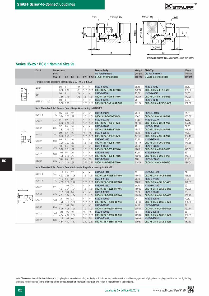
120 www.stauff.com/5/en/#120
HS
Catalogue 5 § Edition 08/2019
STAUFF Screw-to-Connect Couplings
HS 20scale 0.59 Stahl
L1
AD2 48M
x3
SW1 SW41 (1.61)
L3 L326 (1.03)
L2
SW50(1.97) SW2
55(2
.17)
AD2
Series HS-25 § BG 8 § Nominal Size 25
SW: Width across flats. All dimensions in mm (inch).
Port A Dimensions Female Body Weight Male Tip Weight (mm/in) Old Part Numbers (kg/lbs) ca. Old Part Numbers (kg/lbs) ca. ØD2 L1 L2 L3 L4 SW1 SW2 STAUFF Ordering Codes per 100 STAUFF Ordering Codes per 100
Female Thread according to DIN 3852-2-A - ANSI B 1.20.3
G3/4"98 81 19 41 41 HS20-1-IGF12 78,10 HS20-2-IGF12 68,803.86 3.19 .75 1.61 1.61 QRC-HS-25-F-G12-BT-W66 172.18 QRC-HS-25-M-G12-B-W66 151.68
G1"98 81 19 41 41 HS20-1-IGF16 73,80 HS20-2-IGF16 64,503.86 3.19 .75 1.61 1.61 QRC-HS-25-F-G16-BT-W66 162.70 QRC-HS-25-M-G16-B-W66 142.20
NPTF 1" -11 1/298 81 41 41 HS20-1-INF16 78 HS20-2-INF16 60,103.86 3.19 1.61 1.61 QRC-HS-25-F-NF16-BT-W66 171.96 QRC-HS-25-M-NF16-B-W66 132.50
Male Thread with 24° Conical Bore - Shape W according to DIN 3861
M26x1,5 18L95 78 12 41 41 HS20-1-L1826 70,90 HS20-2-L1826 61,603.74 3.07 .47 1.61 1.61 QRC-HS-25-F-18L-BT-W66 156.31 QRC-HS-25-M-18L-B-W66 135.80
M30x2 22L97 80 14 41 41 HS20-1-L2230 71,50 HS20-2-L2230 62,203.82 3.15 .55 1.61 1.61 QRC-HS-25-F-22L-BT-W66 157.63 QRC-HS-25-M-22L-B-W66 137.13
M36x2 28L97 80 14 41 41 HS20-1-L2836 72 HS20-2-L2836 67,203.82 3.15 .55 1.61 1.61 QRC-HS-25-F-28L-BT-W66 158.73 QRC-HS-25-M-28L-B-W66 148.15
M45x2 35L99 82 16 46 46 HS20-1-L3545 80,50 HS20-2-L3545 71,303.90 3.23 .63 1.81 1.81 QRC-HS-25-F-35L-BT-W66 177.47 QRC-HS-25-M-35L-B-W66 157.19
M30x2 20S99 82 16 41 41 HS20-1-S2030 73,10 HS20-2-S2030 63,903.90 3.23 .63 1.61 1.61 QRC-HS-25-F-20S-BT-W66 161.16 QRC-HS-25-M-20S-B-W66 140.88
M36x2 25S101 84 18 41 41 HS20-1-S2536 75,30 HS20-2-S2536 663.98 3.31 .71 1.61 1.61 QRC-HS-25-F-25S-BT-W66 166.01 QRC-HS-25-M-25S-B-W66 145.51
M42x2 30S103 86 20 41 41 HS20-1-S3042 87,10 HS20-2-S3042 654.06 3.39 .79 1.61 1.61 QRC-HS-25-F-30S-BT-W66 192.02 QRC-HS-25-M-30S-B-W66 143.30
M52x2 38S105 88 22 55 55 HS20-1-S3852 108 HS20-2-S3852 90,104.13 3.46 .87 2.17 2.17 QRC-HS-25-F-38S-BT-W66 238.10 QRC-HS-25-M-38S-B-W66 198.64
Male Thread with 24° Conical Bore - Bulkhead - Shape W according to DIN 3861
M22x1,5 15L110 93 27 41 41 HS20-1-N1522 82 HS20-2-N1522 624.33 3.66 1.06 1.61 1.61 QRC-HS-25-F-15LB-BT-W66 180.78 QRC-HS-25-M-15LB-B-W66 136.69
M26x1,5 18L115 98 32 41 41 HS20-1-N1826 76,60 HS20-2-N1826 63,804.53 3.86 1.26 1.61 1.61 QRC-HS-25-F-18LB-BT-W66 168.87 QRC-HS-25-M-18LB-B-W66 140.65
M30x2 22L117 100 34 41 41 HS20-1-N2230 86,10 HS20-2-N2230 654.61 3.94 1.34 1.61 1.61 QRC-HS-25-F-22LB-BT-W66 189.82 QRC-HS-25-M-22LB-B-W66 143.30
M36x2 28L117 100 34 41 41 HS20-1-N2836 89,90 HS20-2-N2836 694.61 3.94 1.34 1.61 1.61 QRC-HS-25-F-28LB-BT-W66 198.20 QRC-HS-25-M-28LB-B-W66 152.12
M30x2 20S121 104 38 41 41 HS20-1-T2030 94 HS20-2-T2030 70,604.76 4.09 1.50 1.61 1.61 QRC-HS-25-F-20SB-BT-W66 207.23 QRC-HS-25-M-20SB-B-W66 155.65
M36x2 25S121 104 38 41 41 HS20-1-T2536 94,70 HS20-2-T2536 744.76 4.09 1.50 1.61 1.61 QRC-HS-25-F-25SB-BT-W66 208.78 QRC-HS-25-M-25SB-B-W66 163.14
M42x2 30S123 106 40 46 46 HS20-1-T3042 104 HS20-2-T3042 854.84 4.17 1.57 1.81 1.81 QRC-HS-25-F-30SB-BT-W66 229.28 QRC-HS-25-M-30SB-B-W66 187.39
M52x2 38S123 106 40 55 55 HS20-1-T3852 140,40 HS20-2-T3852 854.84 4.17 1.57 2.17 2.17 QRC-HS-25-F-38SB-BT-W66 309.53 QRC-HS-25-M-38SB-B-W66 187.39
A A
L3 L3
L4
Anschlüsse-Beispiele.pdf 1 10.09.13 15:44
A A
L3 L3
L4
Anschlüsse-Beispiele.pdf 1 10.09.13 15:44
A A
L3 L3
L4
Anschlüsse-Beispiele.pdf 1 10.09.13 15:44
Note: The connection of the two halves of a coupling is achieved depending on the type. It is important to observe the positive engagement of plug-type couplings and the secure tightening of screw-type couplings to the limit stop of the thread. Forced or improper separation will result in malfunction of the coupling.
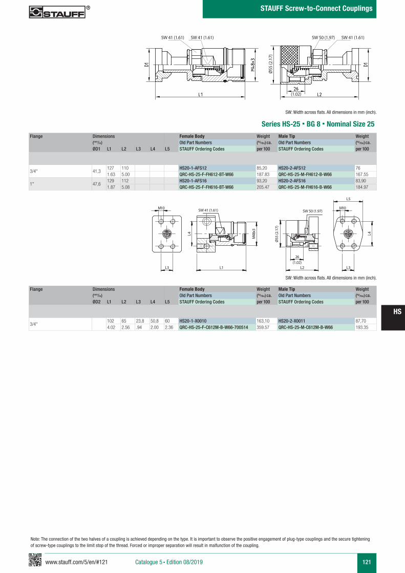
www.stauff.com/5/en/#121 121
HS
Catalogue 5 § Edition 08/2019
STAUFF Screw-to-Connect Couplings
Note: The connection of the two halves of a coupling is achieved depending on the type. It is important to observe the positive engagement of plug-type couplings and the secure tightening of screw-type couplings to the limit stop of the thread. Forced or improper separation will result in malfunction of the coupling.
HS 20
s cale 0.5
L3
10M
L4
L1
48M
x3 55Ø
26
L2 L3
L5
10M
L4
SW41 SW50
Series HS-25 § BG 8 § Nominal Size 25
SW 41 (1.61)
Ø55
(2.1
7)
SW: Width across flats. All dimensions in mm (inch).
Flange Dimensions Female Body Weight Male Tip Weight (mm/in) Old Part Numbers (kg/lbs) ca. Old Part Numbers (kg/lbs) ca. ØD1 L1 L2 L3 L4 L5 STAUFF Ordering Codes per 100 STAUFF Ordering Codes per 100
3/4" 41,3127 110 HS20-1-AFS12 85,20 HS20-2-AFS12 761.63 5.00 QRC-HS-25-F-FH612-BT-W66 187.83 QRC-HS-25-M-FH612-B-W66 167.55
1" 47,6129 112 HS20-1-AFS16 93,20 HS20-2-AFS16 83,901.87 5.08 QRC-HS-25-F-FH616-BT-W66 205.47 QRC-HS-25-M-FH616-B-W66 184.97
(1.02)
SW 50 (1.97)
Flange Dimensions Female Body Weight Male Tip Weight (mm/in) Old Part Numbers (kg/lbs) ca. Old Part Numbers (kg/lbs) ca. ØD2 L1 L2 L3 L4 L5 STAUFF Ordering Codes per 100 STAUFF Ordering Codes per 100
3/4"102 65 23,8 50,8 60 HS20-1-X0010 163,10 HS20-2-X0011 87,704.02 2.56 .94 2.00 2.36 QRC-HS-25-F-C612M-B-W66-700514 359.57 QRC-HS-25-M-C612M-B-W66 193.35
SW: Width across flats. All dimensions in mm (inch).
SW 41 (1.61)
Ø55
(2.1
7)
SW 41 (1.61)
(1.02)
SW 50 (1.97) SW 41 (1.61)
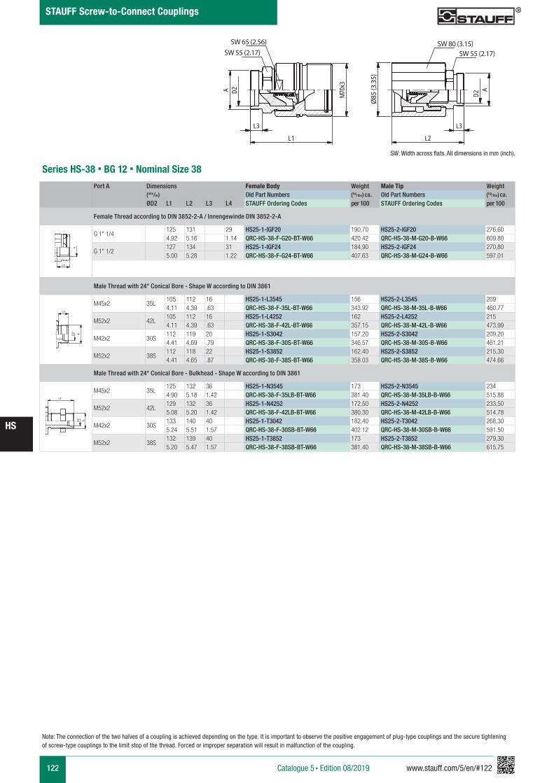
122 www.stauff.com/5/en/#122
HS
Catalogue 5 § Edition 08/2019
STAUFF Screw-to-Connect Couplings
HS 25
s cale 0.4
D2A
L3
L1
70Mx3 85Ø
L3
L2
AD2
SW55SW65 SW80
SW55
Series HS-38 § BG 12 § Nominal Size 38
Port A Dimensions Female Body Weight Male Tip Weight (mm/in) Old Part Numbers (kg/lbs) ca. Old Part Numbers (kg/lbs) ca. ØD2 L1 L2 L3 L4 STAUFF Ordering Codes per 100 STAUFF Ordering Codes per 100
Female Thread according to DIN 3852-2-A / Innengewinde DIN 3852-2-A
G 1" 1/4125 131 29 HS25-1-IGF20 190,70 HS25-2-IGF20 276,604.92 5.16 1.14 QRC-HS-38-F-G20-BT-W66 420.42 QRC-HS-38-M-G20-B-W66 609.80
G 1" 1/2127 134 31 HS25-1-IGF24 184,90 HS25-2-IGF24 270,805.00 5.28 1.22 QRC-HS-38-F-G24-BT-W66 407.63 QRC-HS-38-M-G24-B-W66 597.01
Male Thread with 24° Conical Bore - Shape W according to DIN 3861
M45x2 35L105 112 16 HS25-1-L3545 156 HS25-2-L3545 2094.11 4.39 .63 QRC-HS-38-F-35L-BT-W66 343.92 QRC-HS-38-M-35L-B-W66 460.77
M52x2 42L105 112 16 HS25-1-L4252 162 HS25-2-L4252 2154.11 4.39 .63 QRC-HS-38-F-42L-BT-W66 357.15 QRC-HS-38-M-42L-B-W66 473.99
M42x2 30S112 119 20 HS25-1-S3042 157,20 HS25-2-S3042 209,204.41 4.69 .79 QRC-HS-38-F-30S-BT-W66 346.57 QRC-HS-38-M-30S-B-W66 461.21
M52x2 38S112 118 22 HS25-1-S3852 162,40 HS25-2-S3852 215,304.41 4.65 .87 QRC-HS-38-F-38S-BT-W66 358.03 QRC-HS-38-M-38S-B-W66 474.66
Male Thread with 24° Conical Bore - Bulkhead - Shape W according to DIN 3861
M45x2 35L125 132 36 HS25-1-N3545 173 HS25-2-N3545 2344.90 5.18 1.42 QRC-HS-38-F-35LB-BT-W66 381.40 QRC-HS-38-M-35LB-B-W66 515.88
M52x2 42L129 132 36 HS25-1-N4252 172,50 HS25-2-N4252 233,505.08 5.20 1.42 QRC-HS-38-F-42LB-BT-W66 380.30 QRC-HS-38-M-42LB-B-W66 514.78
M42x2 30S133 140 40 HS25-1-T3042 182,40 HS25-2-T3042 268,305.24 5.51 1.57 QRC-HS-38-F-30SB-BT-W66 402.12 QRC-HS-38-M-30SB-B-W66 591.50
M52x2 38S132 139 40 HS25-1-T3852 173 HS25-2-T3852 279,305.20 5.47 1.57 QRC-HS-38-F-38SB-BT-W66 381.40 QRC-HS-38-M-38SB-B-W66 615.75
A A
L3 L3
L4
Anschlüsse-Beispiele.pdf 1 10.09.13 15:44
A A
L3 L3
L4
Anschlüsse-Beispiele.pdf 1 10.09.13 15:44
A A
L3 L3
L4
Anschlüsse-Beispiele.pdf 1 10.09.13 15:44
SW 65 (2.56)
Ø85
(3.3
5)
SW: Width across flats. All dimensions in mm (inch).
SW 55 (2.17)SW 80 (3.15)
SW 55 (2.17)
Note: The connection of the two halves of a coupling is achieved depending on the type. It is important to observe the positive engagement of plug-type couplings and the secure tightening of screw-type couplings to the limit stop of the thread. Forced or improper separation will result in malfunction of the coupling.
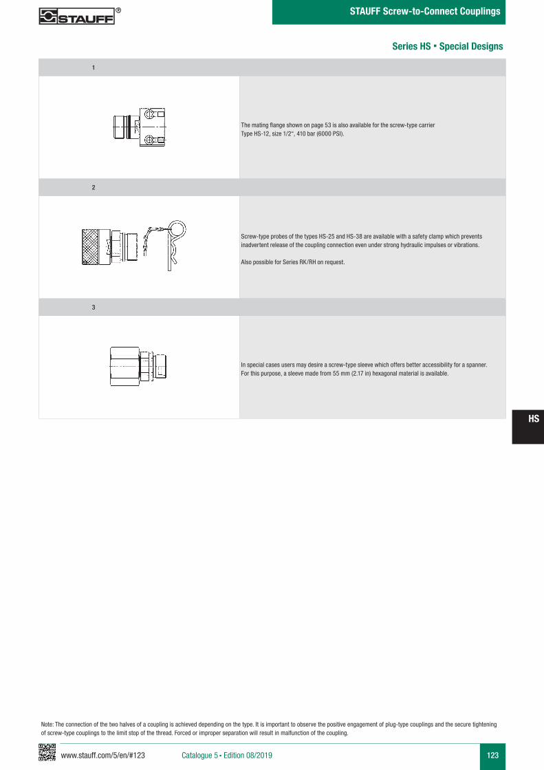
www.stauff.com/5/en/#123 123
HS
Catalogue 5 § Edition 08/2019
STAUFF Screw-to-Connect Couplings
Note: The connection of the two halves of a coupling is achieved depending on the type. It is important to observe the positive engagement of plug-type couplings and the secure tightening of screw-type couplings to the limit stop of the thread. Forced or improper separation will result in malfunction of the coupling.
Series HS § Special Designs
1
The mating flange shown on page 53 is also available for the screw-type carrier Type HS-12, size 1/2“, 410 bar (6000 PSI).
2
Screw-type probes of the types HS-25 and HS-38 are available with a safety clamp which prevents inadvertent release of the coupling connection even under strong hydraulic impulses or vibrations.
Also possible for Series RK/RH on request.
3
In special cases users may desire a screw-type sleeve which offers better accessibility for a spanner. For this purpose, a sleeve made from 55 mm (2.17 in) hexagonal material is available.
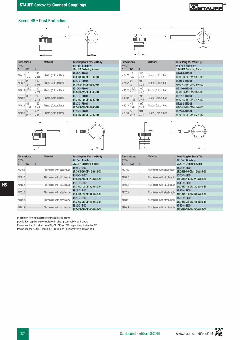
124 www.stauff.com/5/en/#124
HS
Catalogue 5 § Edition 08/2019
STAUFF Screw-to-Connect Couplings
Dimensions Material Dust Cap for Female Body(mm/in) Old Part NumbersD1 D2 L STAUFF Ordering Codes
M24x219 180
Plastic (Colour: Red)HS04-0-RT001
.75 7.09 QRC-HS-06-DF-19-K-RD
M28x223 180
Plastic (Colour: Red)HS08-0-RT001
.91 7.09 QRC-HS-10-DF-23-K-RD
M36x229,5 185
Plastic (Colour: Red)HS10-0-RT001
1.16 7.28 QRC-HS-12-DF-30-K-RD
M42x236,5 190
Plastic (Colour: Red)HS12-0-RT001
1.44 7.48 QRC-HS-19-DF-37-K-RD
M48x341 190
Plastic (Colour: Red)HS20-0-RT001
1.61 7.48 QRC-HS-25-DF-41-K-RD
M70x355 201
Plastic (Colour: Red)HS25-0-RT001
2.17 7.91 QRC-HS-38-DF-55-K-RD
Dimensions Material Dust Plug for Male Tip(mm/in) Old Part NumbersD1 D2 L STAUFF Ordering Codes
M24x219 180
Plastic (Colour: Red)HS04-9-RT001
.75 7.09 QRC-HS-06-DM-19-K-RD
M28x223 180
Plastic (Colour: Red)HS08-9-RT001
.91 7.09 QRC-HS-10-DM-23-K-RD
M36x229,5 185
Plastic (Colour: Red)HS10-9-RT001
1.16 7.28 QRC-HS-12-DM-30-K-RD
M42x236,5 190
Plastic (Colour: Red)HS12-9-RT001
1.44 7.48 QRC-HS-19-DM-37-K-RD
M48x341 190
Plastic (Colour: Red)HS20-9-RT001
1.61 7.48 QRC-HS-25-DM-41-K-RD
M70x355 201
Plastic (Colour: Red)HS25-9-RT001
2.17 7.91 QRC-HS-38-DM-55-K-RD
Series HS § Dust Protection
Staubs chutz HS
s cale 0.77
Schraffuren bitte unter 45° oder 135° anlegen
L
D1 D2
Staubs chutz HS
s cale 0.77
Schraffuren bitte unter 45° oder 135° anlegen
D1
D2
L
Dimensions Material Dust Cap for Female Body(mm/in) Old Part NumbersD1 D2 L STAUFF Ordering Codes
M24x2 Aluminium with steel cableHS04-0-SI001QRC-HS-06-DF-19-W89-SI
M28x2 Aluminium with steel cableHS08-0-SI001QRC-HS-10-DF-23-W89-SI
M36x2 Aluminium with steel cableHS10-0-SI001QRC-HS-12-DF-30-W89-SI
M42x2 Aluminium with steel cableHS12-0-SI001QRC-HS-19-DF-37-W89-SI
M48x3 Aluminium with steel cableHS20-0-SI001QRC-HS-25-DF-41-W89-SI
M70x3 Aluminium with steel cableHS25-0-SI001QRC-HS-38-DF-55-W89-SI
Dimensions Material Dust Plug for Male Tip(mm/in) Old Part NumbersD1 D2 L STAUFF Ordering Codes
M24x2 Aluminium with steel cableHS04-9-SI001QRC-HS-06-DM-19-W89-SI
M28x2 Aluminium with steel cableHS08-9-SI001QRC-HS-10-DM-23-W89-SI
M36x2 Aluminium with steel cableHS10-9-SI001QRC-HS-12-DM-30-W89-SI
M42x2 Aluminium with steel cableHS12-9-SI001QRC-HS-19-DM-37-W89-SI
M48x3 Aluminium with steel cableHS20-9-SI001QRC-HS-25-DM-41-W89-SI
M70x3 Aluminium with steel cableHS25-9-SI001QRC-HS-38-DM-55-W89-SI
Staubs chutz HS
s cale 0.77
Schraffuren bitte unter 45° oder 135° anlegen
L
D1 D2
Staubs chutz HS
s cale 0.77
Schraffuren bitte unter 45° oder 135° anlegen
D1
L
D2
In addition to the standard colours as stated above, plastic dust caps are also available in blue, green, yellow and black. Please use the old color codes BL, GN, GE and SW respectively instead of RT.Please use the STAUFF codes BU, GN, YE and BK respectively instead of RD.
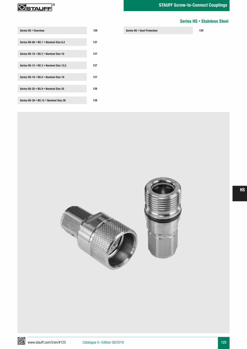
www.stauff.com/5/en/#125 125
HS
Catalogue 5 § Edition 08/2019
STAUFF Screw-to-Connect Couplings
Series HS § Dust Protection 129Series HS § Overview
Series HS-06 § BG 1 § Nominal Size 6,3 127
126
Series HS-10 § BG 2 § Nominal Size 10 127
Series HS-19 § BG 6 § Nominal Size 19 127
Series HS-25 § BG 8 § Nominal Size 25 128
Series HS-12 § BG 3 § Nominal Size 12,5 127
Series HS-38 § BG 12 § Nominal Size 38 128
Series HS § Stainless Steel
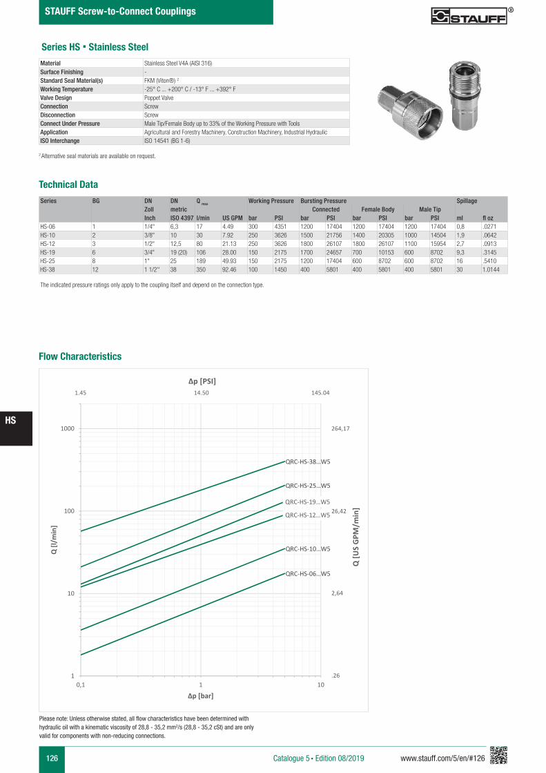
126 www.stauff.com/5/en/#126
HS
Catalogue 5 § Edition 08/2019
STAUFF Screw-to-Connect Couplings
Series HS § Stainless Steel
Series BG DN DN Q max Working Pressure Bursting Pressure SpillageZoll metric Connected Female Body Male TipInch ISO 4397 l/min US GPM bar PSI bar PSI bar PSI bar PSI ml fl oz
HS-06 1 1/4" 6,3 17 4.49 300 4351 1200 17404 1200 17404 1200 17404 0,8 .0271HS-10 2 3/8" 10 30 7.92 250 3626 1500 21756 1400 20305 1000 14504 1,9 .0642HS-12 3 1/2" 12,5 80 21.13 250 3626 1800 26107 1800 26107 1100 15954 2,7 .0913HS-19 6 3/4" 19 (20) 106 28.00 150 2175 1700 24657 700 10153 600 8702 9,3 .3145HS-25 8 1" 25 189 49.93 150 2175 1200 17404 600 8702 600 8702 16 .5410HS-38 12 1 1/2'' 38 350 92.46 100 1450 400 5801 400 5801 400 5801 30 1.0144
Material Stainless Steel V4A (AISI 316)Surface Finishing -Standard Seal Material(s) FKM (Viton®) 2
Working Temperature -25° C ... +200° C / -13° F ... +392° FValve Design Poppet ValveConnection ScrewDisconnection ScrewConnect Under Pressure Male Tip/Female Body up to 33% of the Working Pressure with ToolsApplication Agricultural and Forestry Machinery, Construction Machinery, Industrial Hydraulic ISO Interchange ISO 14541 (BG 1-6)
The indicated pressure ratings only apply to the coupling itself and depend on the connection type.
2 Alternative seal materials are available on request.
Technical Data
Flow Characteristics
QRC-HS-06…W5
QRC-HS-10…W5
QRC-HS-12…W5
QRC-HS-19…W5
QRC-HS-25…W5
QRC-HS-38…W5
1
10
100
1000
0,1 1 10
Q [l/
min
]
Δp [bar]
Q [U
S G
PM/m
in]
Δp [PSI]
264,17
26,42
2,64
.26
1.45 14.50 145.04
Please note: Unless otherwise stated, all flow characteristics have been determined with hydraulic oil with a kinematic viscosity of 28,8 - 35,2 mm2/s (28,8 - 35,2 cSt) and are only valid for components with non-reducing connections.
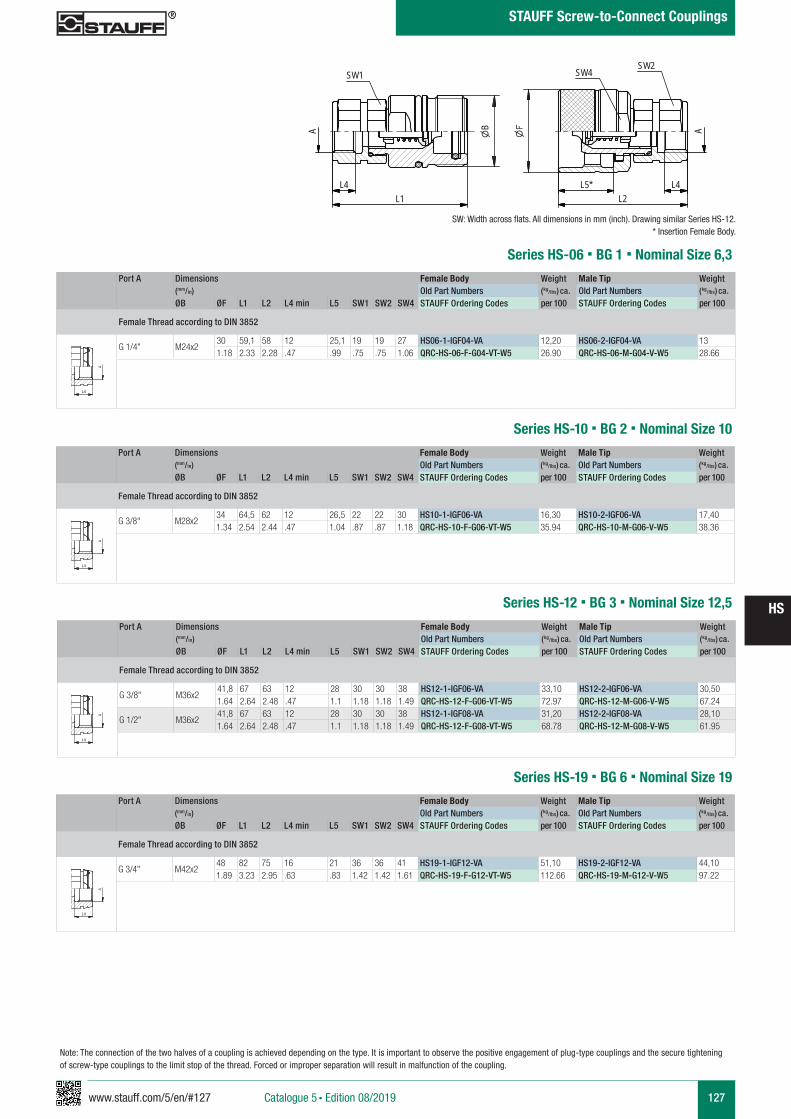
www.stauff.com/5/en/#127 127
HS
Catalogue 5 § Edition 08/2019
STAUFF Screw-to-Connect Couplings
Series HS-06 § BG 1 § Nominal Size 6,3Port A Dimensions Female Body Weight Male Tip Weight
(mm/in) Old Part Numbers (kg/lbs) ca. Old Part Numbers (kg/lbs) ca. ØB ØF L1 L2 L4 min L5 SW1 SW2 SW4 STAUFF Ordering Codes per 100 STAUFF Ordering Codes per 100
Female Thread according to DIN 3852
G 1/4" M24x230 59,1 58 12 25,1 19 19 27 HS06-1-IGF04-VA 12,20 HS06-2-IGF04-VA 131.18 2.33 2.28 .47 .99 .75 .75 1.06 QRC-HS-06-F-G04-VT-W5 26.90 QRC-HS-06-M-G04-V-W5 28.66
A A
L3 L3
L4
Anschlüsse-Beispiele.pdf 1 10.09.13 15:44
SW: Width across flats. All dimensions in mm (inch). Drawing similar Series HS-12.* Insertion Female Body.
HS06-HS38 Muffe und Stecker
Edelstahl
scale 0.74
A
SW1
L4L1
B
SW2SW4
A
L2L4L5*
zeichnerische Darstellung entspricht Serie HS 12 VA * Eintauchtiefe Muffe
Series HS-10 § BG 2 § Nominal Size 10Port A Dimensions Female Body Weight Male Tip Weight
(mm/in) Old Part Numbers (kg/lbs) ca. Old Part Numbers (kg/lbs) ca. ØB ØF L1 L2 L4 min L5 SW1 SW2 SW4 STAUFF Ordering Codes per 100 STAUFF Ordering Codes per 100
Female Thread according to DIN 3852
G 3/8" M28x234 64,5 62 12 26,5 22 22 30 HS10-1-IGF06-VA 16,30 HS10-2-IGF06-VA 17,401.34 2.54 2.44 .47 1.04 .87 .87 1.18 QRC-HS-10-F-G06-VT-W5 35.94 QRC-HS-10-M-G06-V-W5 38.36
A A
L3 L3
L4
Anschlüsse-Beispiele.pdf 1 10.09.13 15:44
Series HS-12 § BG 3 § Nominal Size 12,5
Port A Dimensions Female Body Weight Male Tip Weight (mm/in) Old Part Numbers (kg/lbs) ca. Old Part Numbers (kg/lbs) ca. ØB ØF L1 L2 L4 min L5 SW1 SW2 SW4 STAUFF Ordering Codes per 100 STAUFF Ordering Codes per 100
Female Thread according to DIN 3852
G 3/8" M36x241,8 67 63 12 28 30 30 38 HS12-1-IGF06-VA 33,10 HS12-2-IGF06-VA 30,501.64 2.64 2.48 .47 1.1 1.18 1.18 1.49 QRC-HS-12-F-G06-VT-W5 72.97 QRC-HS-12-M-G06-V-W5 67.24
G 1/2" M36x241,8 67 63 12 28 30 30 38 HS12-1-IGF08-VA 31,20 HS12-2-IGF08-VA 28,101.64 2.64 2.48 .47 1.1 1.18 1.18 1.49 QRC-HS-12-F-G08-VT-W5 68.78 QRC-HS-12-M-G08-V-W5 61.95
A A
L3 L3
L4
Anschlüsse-Beispiele.pdf 1 10.09.13 15:44
Series HS-19 § BG 6 § Nominal Size 19Port A Dimensions Female Body Weight Male Tip Weight
(mm/in) Old Part Numbers (kg/lbs) ca. Old Part Numbers (kg/lbs) ca. ØB ØF L1 L2 L4 min L5 SW1 SW2 SW4 STAUFF Ordering Codes per 100 STAUFF Ordering Codes per 100
Female Thread according to DIN 3852
G 3/4" M42x248 82 75 16 21 36 36 41 HS19-1-IGF12-VA 51,10 HS19-2-IGF12-VA 44,101.89 3.23 2.95 .63 .83 1.42 1.42 1.61 QRC-HS-19-F-G12-VT-W5 112.66 QRC-HS-19-M-G12-V-W5 97.22
A A
L3 L3
L4
Anschlüsse-Beispiele.pdf 1 10.09.13 15:44
Note: The connection of the two halves of a coupling is achieved depending on the type. It is important to observe the positive engagement of plug-type couplings and the secure tightening of screw-type couplings to the limit stop of the thread. Forced or improper separation will result in malfunction of the coupling.
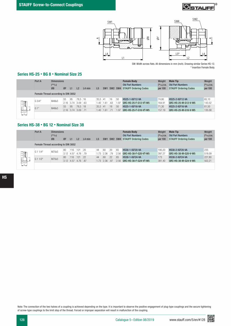
128 www.stauff.com/5/en/#128
HS
Catalogue 5 § Edition 08/2019
STAUFF Screw-to-Connect Couplings
Series HS-25 § BG 8 § Nominal Size 25Port A Dimensions Female Body Weight Male Tip Weight
(mm/in) Old Part Numbers (kg/lbs) ca. Old Part Numbers (kg/lbs) ca. ØB ØF L1 L2 L4 min L5 SW1 SW2 SW4 STAUFF Ordering Codes per 100 STAUFF Ordering Codes per 100
Female Thread according to DIN 3852
G 3/4" M48x355 95 78,5 16 35,5 41 16 50 HS25-1-IGF12-VA 74,80 HS25-2-IGF12-VA 65,102.16 3.74 3.09 .63 1.40 1.61 .63 1.97 QRC-HS-25-F-G12-VT-W5 164.91 QRC-HS-25-M-G12-V-W5 143.52
G 1" M48x355 95 78,5 18 35,5 41 18 50 HS25-1-IGF16-VA 71,30 HS25-2-IGF16-VA 61,502.16 3.74 3.09 .71 1.40 1.61 .71 1.97 QRC-HS-25-F-G16-VT-W5 157.19 QRC-HS-25-M-G16-V-W5 135.58
Series HS-38 § BG 12 § Nominal Size 38
A A
L3 L3
L4
Anschlüsse-Beispiele.pdf 1 10.09.13 15:44
Port A Dimensions Female Body Weight Male Tip Weight (mm/in) Old Part Numbers (kg/lbs) ca. Old Part Numbers (kg/lbs) ca. ØB ØF L1 L2 L4 min L5 SW1 SW2 SW4 STAUFF Ordering Codes per 100 STAUFF Ordering Codes per 100
Female Thread according to DIN 3852
G 1 1/4" M70x380 116 121 20 44 60 20 65 HS38-1-IGF20-VA 180,20 HS38-2-IGF20-VA 2353.12 4.57 4.76 .79 1.73 2.36 .79 2.56 QRC-HS-38-F-G20-VT-W5 397.27 QRC-HS-38-M-G20-V-W5 518.09
G 1 1/2" M70x380 116 121 22 44 60 22 65 HS38-1-IGF24-VA 173 HS38-2-IGF24-VA 227,803.12 4.57 4.76 .87 1.73 2.36 .87 2.56 QRC-HS-38-F-G24-VT-W5 381.40 QRC-HS-38-M-G24-V-W5 502,21
A A
L3 L3
L4
Anschlüsse-Beispiele.pdf 1 10.09.13 15:44
Note: The connection of the two halves of a coupling is achieved depending on the type. It is important to observe the positive engagement of plug-type couplings and the secure tightening of screw-type couplings to the limit stop of the thread. Forced or improper separation will result in malfunction of the coupling.
SW: Width across flats. All dimensions in mm (inch). Drawing similar Series HS-12.* Insertion Female Body.
HS06-HS38 Muffe und Stecker
Edelstahl
scale 0.74
A
SW1
L4L1
B
SW2SW4
A
L2L4L5*
zeichnerische Darstellung entspricht Serie HS 12 VA * Eintauchtiefe Muffe
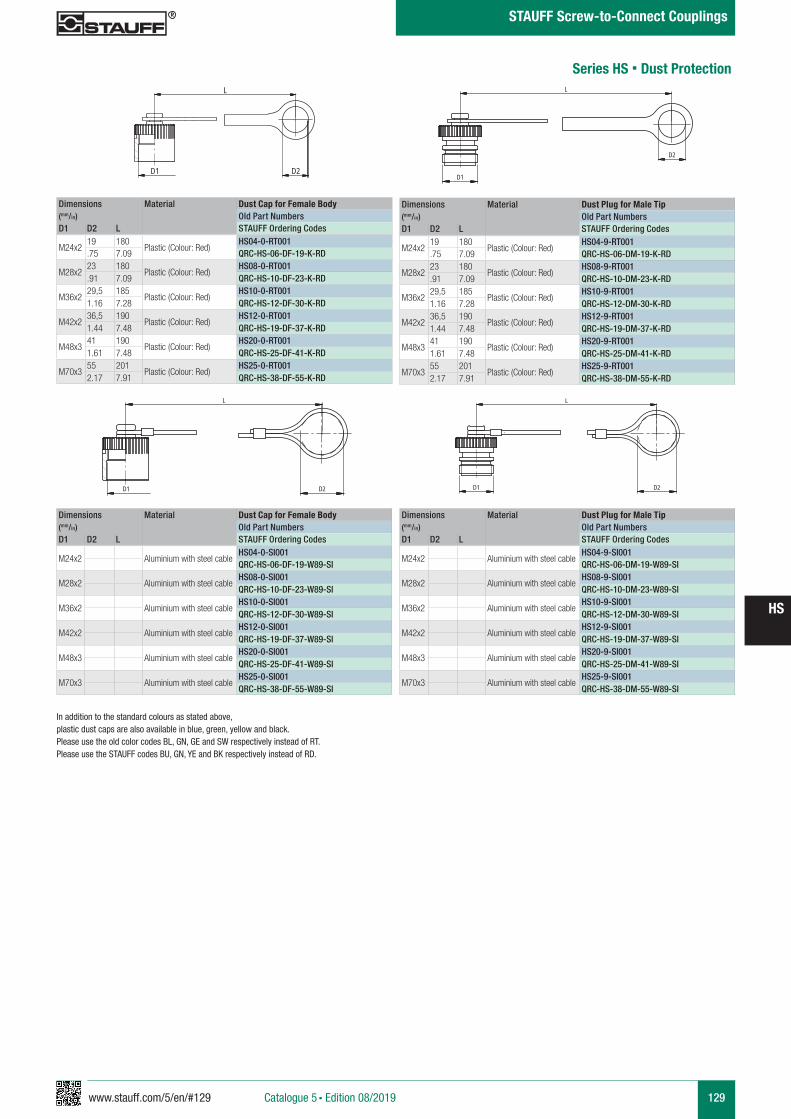
www.stauff.com/5/en/#129 129
HS
Catalogue 5 § Edition 08/2019
STAUFF Screw-to-Connect Couplings
Dimensions Material Dust Cap for Female Body(mm/in) Old Part NumbersD1 D2 L STAUFF Ordering Codes
M24x219 180
Plastic (Colour: Red)HS04-0-RT001
.75 7.09 QRC-HS-06-DF-19-K-RD
M28x223 180
Plastic (Colour: Red)HS08-0-RT001
.91 7.09 QRC-HS-10-DF-23-K-RD
M36x229,5 185
Plastic (Colour: Red)HS10-0-RT001
1.16 7.28 QRC-HS-12-DF-30-K-RD
M42x236,5 190
Plastic (Colour: Red)HS12-0-RT001
1.44 7.48 QRC-HS-19-DF-37-K-RD
M48x341 190
Plastic (Colour: Red)HS20-0-RT001
1.61 7.48 QRC-HS-25-DF-41-K-RD
M70x355 201
Plastic (Colour: Red)HS25-0-RT001
2.17 7.91 QRC-HS-38-DF-55-K-RD
Dimensions Material Dust Plug for Male Tip(mm/in) Old Part NumbersD1 D2 L STAUFF Ordering Codes
M24x219 180
Plastic (Colour: Red)HS04-9-RT001
.75 7.09 QRC-HS-06-DM-19-K-RD
M28x223 180
Plastic (Colour: Red)HS08-9-RT001
.91 7.09 QRC-HS-10-DM-23-K-RD
M36x229,5 185
Plastic (Colour: Red)HS10-9-RT001
1.16 7.28 QRC-HS-12-DM-30-K-RD
M42x236,5 190
Plastic (Colour: Red)HS12-9-RT001
1.44 7.48 QRC-HS-19-DM-37-K-RD
M48x341 190
Plastic (Colour: Red)HS20-9-RT001
1.61 7.48 QRC-HS-25-DM-41-K-RD
M70x355 201
Plastic (Colour: Red)HS25-9-RT001
2.17 7.91 QRC-HS-38-DM-55-K-RD
Series HS § Dust Protection
Staubs chutz HS
s cale 0.77
Schraffuren bitte unter 45° oder 135° anlegen
L
D1 D2
Staubs chutz HS
s cale 0.77
Schraffuren bitte unter 45° oder 135° anlegen
D1
D2
L
Dimensions Material Dust Cap for Female Body(mm/in) Old Part NumbersD1 D2 L STAUFF Ordering Codes
M24x2 Aluminium with steel cableHS04-0-SI001QRC-HS-06-DF-19-W89-SI
M28x2 Aluminium with steel cableHS08-0-SI001QRC-HS-10-DF-23-W89-SI
M36x2 Aluminium with steel cableHS10-0-SI001QRC-HS-12-DF-30-W89-SI
M42x2 Aluminium with steel cableHS12-0-SI001QRC-HS-19-DF-37-W89-SI
M48x3 Aluminium with steel cableHS20-0-SI001QRC-HS-25-DF-41-W89-SI
M70x3 Aluminium with steel cableHS25-0-SI001QRC-HS-38-DF-55-W89-SI
Dimensions Material Dust Plug for Male Tip(mm/in) Old Part NumbersD1 D2 L STAUFF Ordering Codes
M24x2 Aluminium with steel cableHS04-9-SI001QRC-HS-06-DM-19-W89-SI
M28x2 Aluminium with steel cableHS08-9-SI001QRC-HS-10-DM-23-W89-SI
M36x2 Aluminium with steel cableHS10-9-SI001QRC-HS-12-DM-30-W89-SI
M42x2 Aluminium with steel cableHS12-9-SI001QRC-HS-19-DM-37-W89-SI
M48x3 Aluminium with steel cableHS20-9-SI001QRC-HS-25-DM-41-W89-SI
M70x3 Aluminium with steel cableHS25-9-SI001QRC-HS-38-DM-55-W89-SI
Staubs chutz HS
s cale 0.77
Schraffuren bitte unter 45° oder 135° anlegen
L
D1 D2
Staubs chutz HS
s cale 0.77
Schraffuren bitte unter 45° oder 135° anlegen
D1
L
D2
In addition to the standard colours as stated above, plastic dust caps are also available in blue, green, yellow and black. Please use the old color codes BL, GN, GE and SW respectively instead of RT.Please use the STAUFF codes BU, GN, YE and BK respectively instead of RD.
130 www.stauff.com/5/en/#130
HS
Catalogue 5 § Edition 08/2019
STAUFF Screw-to-Connect Couplings
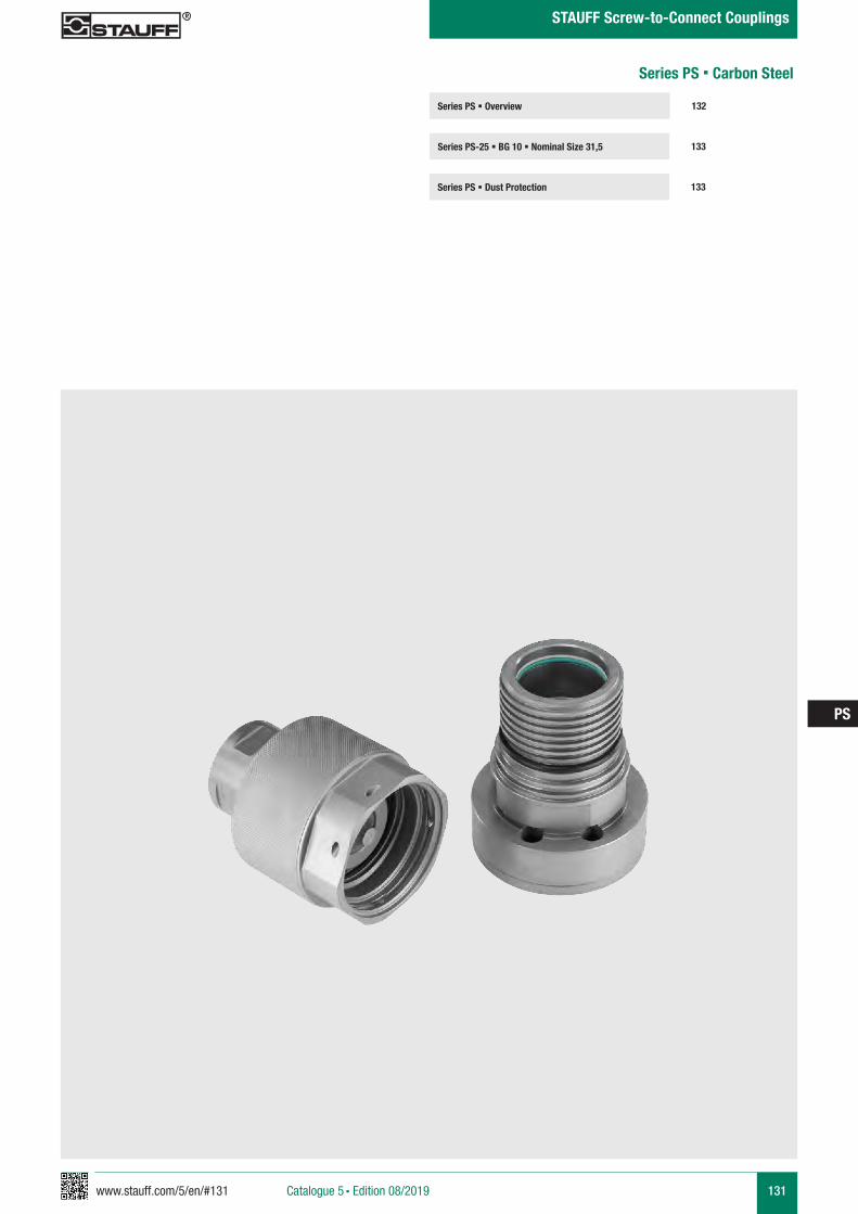
www.stauff.com/5/en/#131 131
PS
Catalogue 5 § Edition 08/2019
STAUFF Screw-to-Connect Couplings
Series PS § Overview
Series PS-25 § BG 10 § Nominal Size 31,5 133
132
Series PS § Dust Protection 133
Series PS § Carbon Steel
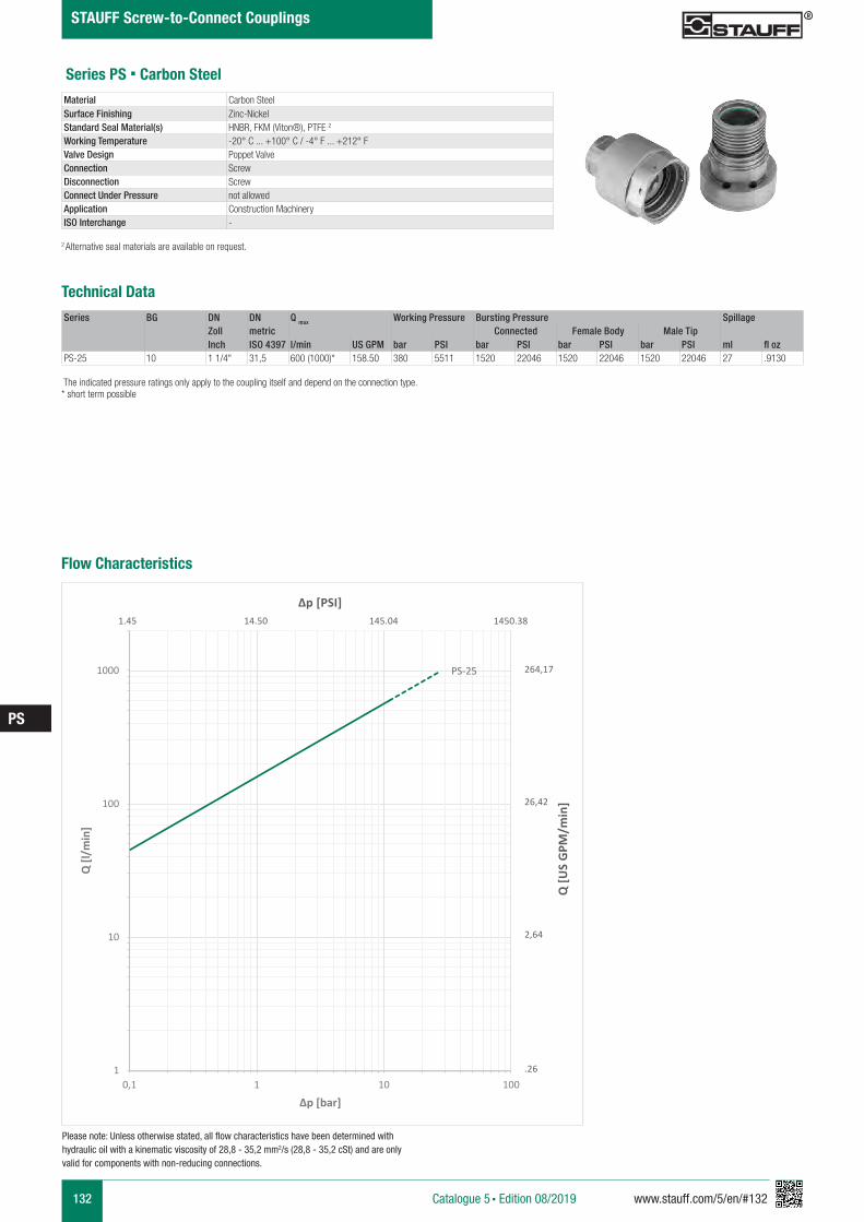
132 www.stauff.com/5/en/#132
PS
Catalogue 5 § Edition 08/2019
STAUFF Screw-to-Connect Couplings
Series PS § Carbon Steel
Series BG DN DN Q max Working Pressure Bursting Pressure SpillageZoll metric Connected Female Body Male TipInch ISO 4397 l/min US GPM bar PSI bar PSI bar PSI bar PSI ml fl oz
PS-25 10 1 1/4" 31,5 600 (1000)* 158.50 380 5511 1520 22046 1520 22046 1520 22046 27 .9130
Material Carbon SteelSurface Finishing Zinc-Nickel Standard Seal Material(s) HNBR, FKM (Viton®), PTFE 2
Working Temperature -20° C ... +100° C / -4° F ... +212° FValve Design Poppet ValveConnection ScrewDisconnection ScrewConnect Under Pressure not allowedApplication Construction MachineryISO Interchange -
The indicated pressure ratings only apply to the coupling itself and depend on the connection type.* short term possible
2 Alternative seal materials are available on request.
Technical Data
Flow Characteristics
PS-25
1
10
100
1000
0,1 1 10 100
Q [l
/min
]
Δp [bar]
Q [U
S G
PM/m
in]
Δp [PSI]
264,17
26,42
2,64
.26
1.45 14.50 145.04 1450.38
Please note: Unless otherwise stated, all flow characteristics have been determined with hydraulic oil with a kinematic viscosity of 28,8 - 35,2 mm2/s (28,8 - 35,2 cSt) and are only valid for components with non-reducing connections.
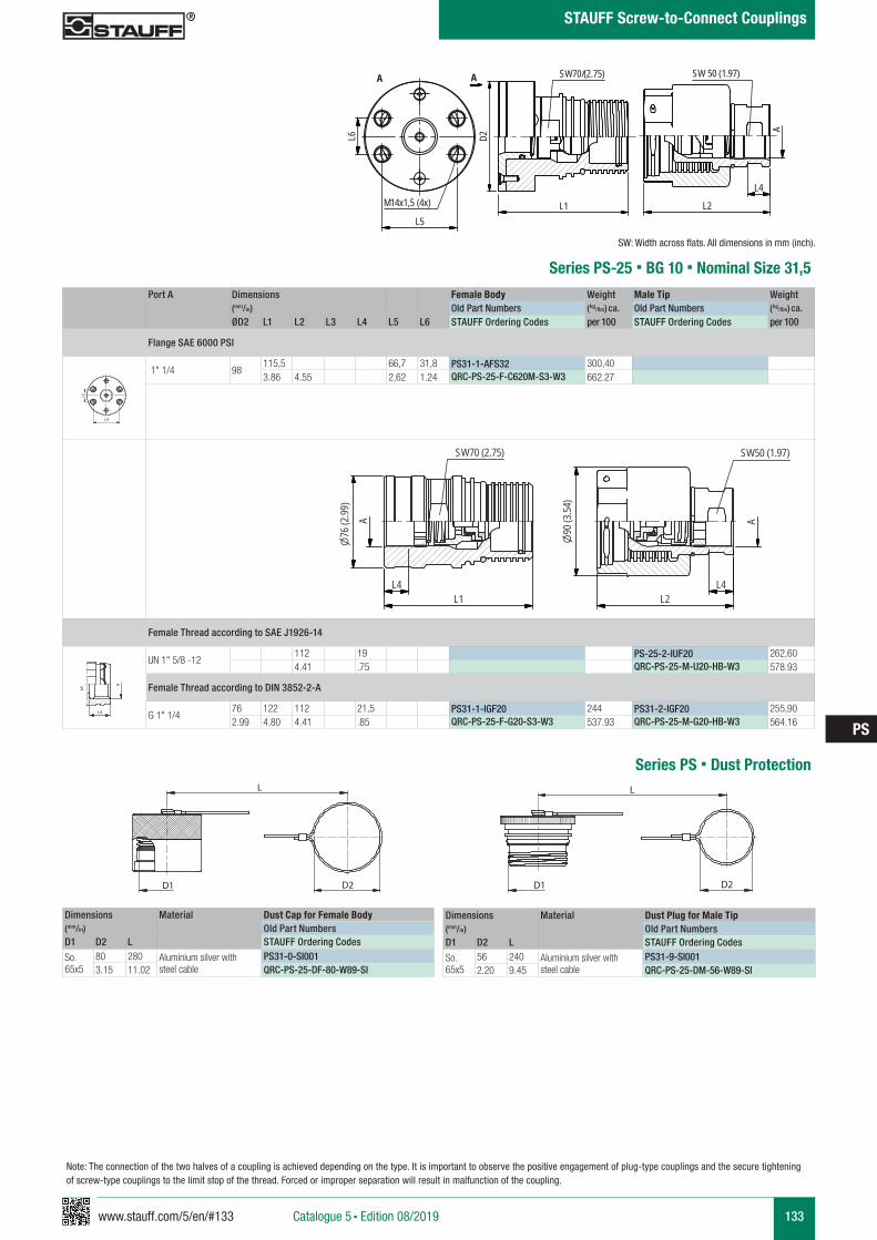
www.stauff.com/5/en/#133 133
PS
Catalogue 5 § Edition 08/2019
STAUFF Screw-to-Connect Couplings
PS 32
scale 0.4
L4L2
SW50 (1.97)
AA
L4L1
SW70 (2.75)
90(3
.54)
76(2
.99)
Port A Dimensions Female Body Weight Male Tip Weight (mm/in) Old Part Numbers (kg/lbs) ca. Old Part Numbers (kg/lbs) ca. ØD2 L1 L2 L3 L4 L5 L6 STAUFF Ordering Codes per 100 STAUFF Ordering Codes per 100
Flange SAE 6000 PSI
1" 1/4 98115,5 66,7 31,8 PS31-1-AFS32 300,403.86 4.55 2,62 1.24 QRC-PS-25-F-C620M-S3-W3 662.27
Female Thread according to SAE J1926-14
UN 1" 5/8 -12112 19 PS-25-2-IUF20 262,604.41 .75 QRC-PS-25-M-U20-HB-W3 578.93
Female Thread according to DIN 3852-2-A
G 1" 1/476 122 112 21,5 PS31-1-IGF20 244 PS31-2-IGF20 255,902.99 4.80 4.41 .85 QRC-PS-25-F-G20-S3-W3 537.93 QRC-PS-25-M-G20-HB-W3 564.16
Series PS-25 § BG 10 § Nominal Size 31,5
A A
L3 L3
L4
Anschlüsse-Beispiele.pdf 1 10.09.13 15:44
SW: Width across flats. All dimensions in mm (inch).
��������������������
������������������������������������
L2L1
A
SW70 SW50
L6
L5�
D1
L5
L6
Note: The connection of the two halves of a coupling is achieved depending on the type. It is important to observe the positive engagement of plug-type couplings and the secure tightening of screw-type couplings to the limit stop of the thread. Forced or improper separation will result in malfunction of the coupling.
Series PS § Dust Protection
Dimensions Material Dust Cap for Female Body(mm/in) Old Part NumbersD1 D2 L STAUFF Ordering Codes
So. 65x5
80 280 Aluminium silver with steel cable
PS31-0-SI0013.15 11.02 QRC-PS-25-DF-80-W89-SI
Dimensions Material Dust Plug for Male Tip(mm/in) Old Part NumbersD1 D2 L STAUFF Ordering Codes
So. 65x5
56 240 Aluminium silver with steel cable
PS31-9-SI0012.20 9.45 QRC-PS-25-DM-56-W89-SI
������������������������
����������������������������������������
L�
D2D1
������������������������
����������������������������������������
�L
D2D1
PS 32
scale 0.4
L2L1
A
SW70/(2.75) SW 50 (1.97)
L6
L5
D2
L4
AA
M14x1,5 (4x)
134 www.stauff.com/5/en/#134
PS
Catalogue 5 § Edition 08/2019
STAUFF Screw-to-Connect Couplings
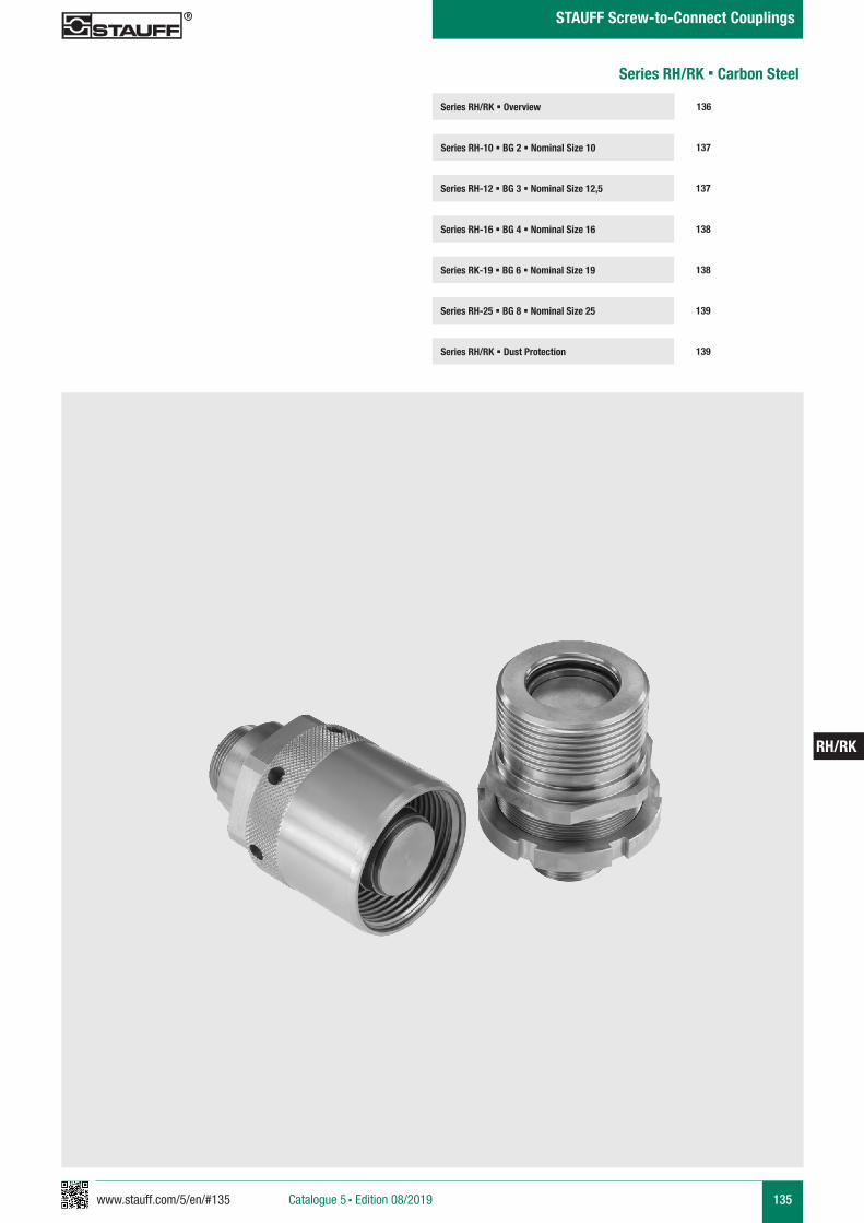
www.stauff.com/5/en/#135 135
RH/RK
Catalogue 5 § Edition 08/2019
STAUFF Screw-to-Connect Couplings
Series RH/RK § Overview
Series RH-10 § BG 2 § Nominal Size 10 137
136
Series RH-12 § BG 3 § Nominal Size 12,5 137
Series RK-19 § BG 6 § Nominal Size 19 138
Series RH-25 § BG 8 § Nominal Size 25 139
Series RH-16 § BG 4 § Nominal Size 16 138
Series RH/RK § Dust Protection 139
Series RH/RK § Carbon Steel
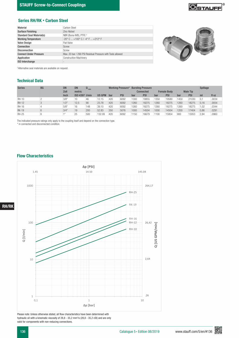
136 www.stauff.com/5/en/#136
RH/RK
Catalogue 5 § Edition 08/2019
STAUFF Screw-to-Connect Couplings
Series RH/RK § Carbon Steel
Series BG DN DN Q max Working Pressure* Bursting Pressure SpillageZoll metric Connected Female Body Male TipInch ISO 4397 l/min US GPM bar PSI bar PSI bar PSI bar PSI ml fl oz
RH-10 2 3/8" 10 46 12.15 420 6092 1300 18855 1350 19580 1450 21030 0,1 .0034RH-12 3 1/2" 12,5 90 23.78 420 6092 1260 18275 1260 18275 1260 18275 0,16 .0054RH-16 4 5/8" 16 148 39.10 420 6092 1260 18275 1260 18275 1260 18275 1,02 .0344RK-19 6 3/4" 19 200 52.83 350 5076 1000 14504 1000 14504 1200 17404 0,86 .0291RH-25 8 1" 25 500 132.09 420 6092 1150 16679 1100 15954 900 13053 2,84 .0960
Material Carbon SteelSurface Finishing Zinc-Nickel Standard Seal Material(s) NBR (Buna-N®), PTFE 2
Working Temperature -20° C ... +100° C / -4° F ... +212° FValve Design Flat ValveConnection ScrewDisconnection ScrewConnect Under Pressure Max. 20 bar / 290 PSI Residual Pressure with Tools allowedApplication Construction MachineryISO Interchange -
The indicated pressure ratings only apply to the coupling itself and depend on the connection type.* in connected and disconnected condition.
2 Alternative seal materials are available on request.
Technical Data
Flow Characteristics
RH-10
RH-12RH-16
RK-19
RH-25
1
10
100
1000
0,1 1 10
Q [l
/min
]
Δp [bar]
Q [U
S G
PM/m
in]
Δp [PSI]
264,17
26,42
2,64
.26
1.45 14.50 145.04
Please note: Unless otherwise stated, all flow characteristics have been determined with hydraulic oil with a kinematic viscosity of 28,8 - 35,2 mm2/s (28,8 - 35,2 cSt) and are only valid for components with non-reducing connections.
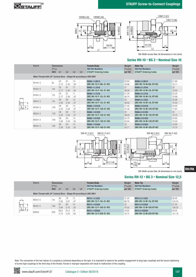
www.stauff.com/5/en/#137 137
RH/RK
Catalogue 5 § Edition 08/2019
STAUFF Screw-to-Connect Couplings
��������������������
����������������������������������������
SW41
M36
x1�
L3
L1
A D2
SW41
So.M
36x3
L2
19.2 L3
Ø45
So.M
36x3
SW46 SW36
D2
A
��29
RH 08
scale 0.74
L214 (.55) L3
AD2
39Ø (1
.54)
So.M
32x3
L3L1
A D2
SW36(1,42)SW36(1,42) SW41 (1.61)SW27 (1.06)
M30x
1
So M
32x3
24(.95)
Port A Dimensions Female Body Weight Male Tip Weight (mm/in) Old Part Numbers (kg/lbs) ca. Old Part Numbers (kg/lbs) ca. ØD2 L1 L2 L3 L4 STAUFF Ordering Codes per 100 STAUFF Ordering Codes per 100
Male Thread with 24° Conical Bore - Shape W according to DIN 3861
M14x1.5 8L54 61 10 RH08-1-L0814 20,80 RH08-2-L0814 31,802.13 2.40 .39 QRC-RH-10-F-08L-S1-W3 45.86 QRC-RH-10-M-08L-BT-W3 70.11
M16x1.5 10L55 61 11 RH08-1-L1016 21 RH08-2-L1016 322.17 2.40 .43 QRC-RH-10-F-10L-S1-W3 46.30 QRC-RH-10-M-10L-BT-W3 70.55
M18x1.5 12L55 61 11 RH08-1-L1218 21,20 RH08-2-L1218 32,202.17 2.40 .43 QRC-RH-10-F-12L-S1-W3 46.74 QRC-RH-10-M-12L-BT-W3 70.99
M22x1.5 15L56 62 12 RH08-1-L1522 22 RH08-2-L1522 32,902.20 2.44 .47 QRC-RH-10-F-15L-S1-W3 48.50 QRC-RH-10-M-15L-BT-W3 72.53
M18x1.5 10S56 62 12 RH08-1-S1018 21,50 RH08-2-S1018 32,602.20 2.44 .47 QRC-RH-10-F-10S-S1-W3 47.40 QRC-RH-10-M-10S-BT-W3 71.87
M20x1.5 12S56 62 12 RH08-1-S1220 22 RH08-2-S1220 332.20 2.44 .47 QRC-RH-10-F-12S-S1-W3 48.50 QRC-RH-10-M-12S-BT-W3 72.75
M22x1.5 14S58 64 14 RH08-1-S1422 22,70 RH08-2-S1422 33,802.28 2.52 .55 QRC-RH-10-F-14S-S1-W3 50.04 QRC-RH-10-M-14S-BT-W3 74.52
M24x1.5 16S58 64 14 RH08-1-S1624 23 RH08-2-S1624 33,902.28 2.52 .55 QRC-RH-10-F-16S-S1-W3 50.71 QRC-RH-10-M-16S-BT-W3 74.74
Series RH-10 § BG 2 § Nominal Size 10
A A
L3 L3
L4
Anschlüsse-Beispiele.pdf 1 10.09.13 15:44
SW: Width across flats. All dimensions in mm (inch).
Port A Dimensions Female Body Weight Male Tip Weight (mm/in) Old Part Numbers (kg/lbs) ca. Old Part Numbers (kg/lbs) ca. ØD2 L1 L2 L3 L4 STAUFF Ordering Codes per 100 STAUFF Ordering Codes per 100
Male Thread with 24° Conical Bore - Shape W according to DIN 3861
M22x1.5 15L65 78 12 RH12-1-L1522 31,20 RH12-2-L1522 56,402.56 3.07 .47 QRC-RH-12-F-15L-S1-W3 68.78 QRC-RH-12-M-15L-BT-W3 124.34
M24x1.5 16S67 80 14 RH12-1-S1624 32 RH12-2-S1624 57,302.64 3.15 .55 QRC-RH-12-F-16S-S1-W3 70.55 QRC-RH-12-M-16S-BT-W3 126.32
M30x2 20S69,5 81,2 16 RH12-1-S2030 34,80 RH12-2-S2030 59,502.74 3.20 .63 QRC-RH-12-F-20S-S1-W3 76.72 QRC-RH-12-M-20S-BT-W3 131.18
Series RH-12 § BG 3 § Nominal Size 12,5
Ø45
(1.7
7)
A A
L3 L3
L4
Anschlüsse-Beispiele.pdf 1 10.09.13 15:44
SW: Width across flats. All dimensions in mm (inch).
29 (1.14)
SW 41 (1.61) SW 41 (1.61) SW 46 (1.81) SW 36 (1.42)
(.76)
Note: The connection of the two halves of a coupling is achieved depending on the type. It is important to observe the positive engagement of plug-type couplings and the secure tightening of screw-type couplings to the limit stop of the thread. Forced or improper separation will result in malfunction of the coupling.
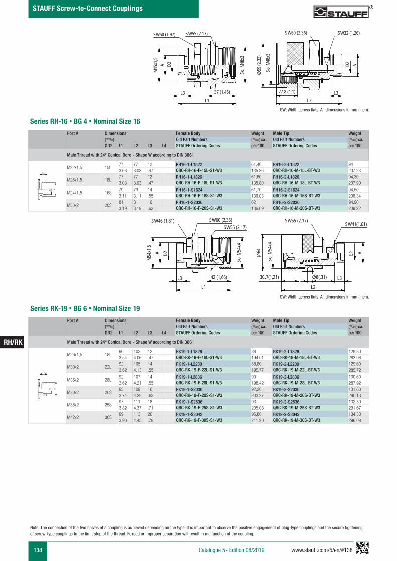
138 www.stauff.com/5/en/#138
RH/RK
Catalogue 5 § Edition 08/2019
STAUFF Screw-to-Connect Couplings
RK 20
scale 0,375
SW46 (1,81) SW60 (2,36)SW55 (2,17)
SW55 (2.17) SW41(1.61)
D2A54Mx1
,5
L3
L1
6454So
. Mx4
So. M
54x4
30.7(1,21) 8(.31) L3
L2
D2 A
42 (1,66)
RH16scale 0,55
Schraffuren bitte unter 45° oder 135° anlegen
D2AM4
5x1,5
SW50 (1.97) SW55 (2.17)
So. M
48x3
L3L1
37 (1.46)
So. M
48x3
59 (2
.32)
D2 A
SW60 (2.36) SW32 (1.26)
27.8 (1.1)
L2L3
Port A Dimensions Female Body Weight Male Tip Weight (mm/in) Old Part Numbers (kg/lbs) ca. Old Part Numbers (kg/lbs) ca. ØD2 L1 L2 L3 L4 STAUFF Ordering Codes per 100 STAUFF Ordering Codes per 100
Male Thread with 24° Conical Bore - Shape W according to DIN 3861
M22x1,5 15L77 77 12 RH16-1-L1522 61,40 RH16-2-L1522 943.03 3.03 .47 QRC-RH-16-F-15L-S1-W3 135.36 QRC-RH-16-M-15L-BT-W3 207.23
M26x1,5 18L77 77 12 RH16-1-L1826 61,60 RH16-2-L1826 94,303.03 3.03 .47 QRC-RH-16-F-18L-S1-W3 135.80 QRC-RH-16-M-18L-BT-W3 207.90
M24x1,5 16S79 79 14 RH16-1-S1624 61,70 RH16-2-S1624 94,503.11 3.11 .55 QRC-RH-16-F-16S-S1-W3 136.03 QRC-RH-16-M-16S-BT-W3 208.34
M30x2 20S81 81 16 RH16-1-S2030 62 RH16-2-S2030 94,903.19 3.19 .63 QRC-RH-16-F-20S-S1-W3 136.69 QRC-RH-16-M-20S-BT-W3 209.22
Series RH-16 § BG 4 § Nominal Size 16
A A
L3 L3
L4
Anschlüsse-Beispiele.pdf 1 10.09.13 15:44
SW: Width across flats. All dimensions in mm (inch).
Port A Dimensions Female Body Weight Male Tip Weight (mm/in) Old Part Numbers (kg/lbs) ca. Old Part Numbers (kg/lbs) ca. ØD2 L1 L2 L3 L4 STAUFF Ordering Codes per 100 STAUFF Ordering Codes per 100
Male Thread with 24° Conical Bore - Shape W according to DIN 3861
M26x1,5 18L90 103 12 RK19-1-L1826 88 RK19-2-L1826 128,803.54 4.06 .47 QRC-RK-19-F-18L-S1-W3 194.01 QRC-RK-19-M-18L-BT-W3 283.96
M30x2 22L92 105 14 RK19-1-L2230 88,80 RK19-2-L2230 129,603.62 4.13 .55 QRC-RK-19-F-22L-S1-W3 195.77 QRC-RK-19-M-22L-BT-W3 285.72
M36x2 28L92 107 14 RK19-1-L2836 90 RK19-2-L2836 130,603.62 4.21 .55 QRC-RK-19-F-28L-S1-W3 198.42 QRC-RK-19-M-28L-BT-W3 287.92
M30x2 20S95 109 16 RK19-1-S2030 92,20 RK19-2-S2030 131,603.74 4.29 .63 QRC-RK-19-F-20S-S1-W3 203.27 QRC-RK-19-M-20S-BT-W3 290.13
M36x2 25S97 111 18 RK19-1-S2536 93 RK19-2-S2536 132,303.82 4.37 .71 QRC-RK-19-F-25S-S1-W3 205.03 QRC-RK-19-M-25S-BT-W3 291.67
M42x2 30S99 113 20 RK19-1-S3042 95,80 RK19-2-S3042 134,303.90 4.45 .79 QRC-RK-19-F-30S-S1-W3 211.20 QRC-RK-19-M-30S-BT-W3 296.08
Series RK-19 § BG 6 § Nominal Size 19
A A
L3 L3
L4
Anschlüsse-Beispiele.pdf 1 10.09.13 15:44
SW: Width across flats. All dimensions in mm (inch).
Note: The connection of the two halves of a coupling is achieved depending on the type. It is important to observe the positive engagement of plug-type couplings and the secure tightening of screw-type couplings to the limit stop of the thread. Forced or improper separation will result in malfunction of the coupling.
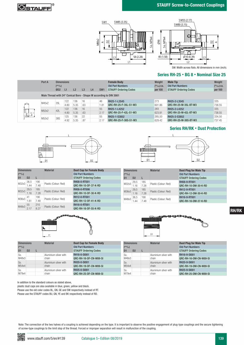
www.stauff.com/5/en/#139 139
RH/RK
Catalogue 5 § Edition 08/2019
STAUFF Screw-to-Connect Couplings
Note: The connection of the two halves of a coupling is achieved depending on the type. It is important to observe the positive engagement of plug-type couplings and the secure tightening of screw-type couplings to the limit stop of the thread. Forced or improper separation will result in malfunction of the coupling.
RH 25
scale 0,25
SW85 (3.35)
80Mx2 A
L3L1
79So
. Mx4
90
So. M
79x4
10 (0.39)40 (1.58) L3L2
A
SW80 (3.15)SW55 (2.17)
58 (2.28)
D2
SW1
D2
Port A Dimensions Female Body Weight Male Tip Weight (mm/in) Old Part Numbers (kg/lbs) ca. Old Part Numbers (kg/lbs) ca. ØD2 L1 L2 L3 L4 SW1 STAUFF Ordering Codes per 100 STAUFF Ordering Codes per 100
Male Thread with 24° Conical Bore - Shape W according to DIN 3861
M45x2 35L122 136 16 46 RH25-1-L3545 273 RH25-2-L3545 3354.80 5.35 .63 1.81 QRC-RH-25-F-35L-S1-W3 601.86 QRC-RH-25-M-35L-BT-W3 738.55
M52x2 42L122 136 16 55 RH25-1-L4252 283 RH25-2-L4252 3354.80 5.35 .63 2.17 QRC-RH-25-F-42L-S1-W3 623.91 QRC-RH-25-M-42L-BT-W3 738.55
M52x2 38S125 136 22 55 RH25-1-S3852 285,50 RH25-2-S3852 334,504.92 5.35 .87 2.17 QRC-RH-25-F-38S-S1-W3 629.42 QRC-RH-25-M-38S-BT-W3 737.45
Series RH-25 § BG 8 § Nominal Size 25
A A
L3 L3
L4
Anschlüsse-Beispiele.pdf 1 10.09.13 15:44
SW: Width across flats. All dimensions in mm (inch).
Dimensions Material Dust Cap for Female Body(mm/in) Old Part NumbersD1 D2 L STAUFF Ordering Codes
M32x336,5 190
Plastic (Colour: Red)RH08-0-RT001
1.44 7.48 QRC-RH-10-DF-37-K-RD
M32x329,5 185
Plastic (Colour: Red)RH08-0-RT006
1.16 7.28 QRC-RH-10-DF-30-K-RD
M36x341 190
Plastic (Colour: Red)RH12-0-RT001
1.61 7.48 QRC-RH-12-DF-41-K-RD
M48x355 210
Plastic (Colour: Red)RH16-0-RT001
2.17 8.27 QRC-RH-16-DF-55-K-RD
Dimensions Material Dust Plug for Male Tip(mm/in) Old Part NumbersD1 D2 L STAUFF Ordering Codes
M32x329,5 185
Plastic (Colour: Red)RH08-9-RT001
1.16 7.28 QRC-RH-10-DM-30-K-RD
M36x329,5 185
Plastic (Colour: Red)RH12-9-RT001
1.16 7.28 QRC-RH-12-DM-30-K-RD
M48x336,5 190
Plastic (Colour: Red)RH16-9-RT001
1.44 7.48 QRC-RH-16-DM-37-K-RD
Series RH/RK § Dust Protection
RH08/ 12- 0
s cale 0,77
L
D2D1
RH08/ 12- 9
s cale 0,77
L
D2D1
Dimensions Material Dust Cap for Female Body(mm/in) Old Part NumbersD1 D2 L STAUFF Ordering Codes
So. M48x3
Aluminium silver withchain
RH16-0-SI001QRC-RH-16-DF-CN-W89-SI
So. M54x4
Aluminium silver withchain
RH20-0-SI001QRC-RH-19-DF-CN-W89-SI
So. M79x4
Aluminium silver withchain
RH25-0-SI001QRC-RH-25-DF-CN-W89-SI
Dimensions Material Dust Plug for Male Tip(mm/in) Old Part NumbersD1 D2 L STAUFF Ordering Codes
So. M48x3
Aluminium silver withchain
RH16-9-SI001QRC-RH-16-DM-CN-W89-SI
So. M54x4
Aluminium silver withchain
RH20-9-SI001QRC-RH-19-DM-CN-W89-SI
So. M79x4
Aluminium silver withchain
RH25-9-SI001QRC-RH-25-DM-CN-W89-SI
In addition to the standard colours as stated above, plastic dust caps are also available in blue, green, yellow and black. Please use the old color codes BL, GN, GE and SW respectively instead of RT.Please use the STAUFF codes BU, GN, YE and BK respectively instead of RD.
RH16-0
scale 0.5
Schraffuren bitte unter 45° oder 135° anlegen
D1
RH16-9
scale 0.5
Schraffuren bitte unter 45° oder 135° anlegen
D1
140 www.stauff.com/5/en/#140
RH/RK
Catalogue 5 § Edition 08/2019
STAUFF Screw-to-Connect Couplings
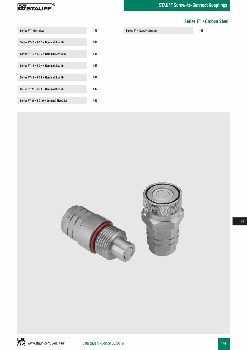
www.stauff.com/5/en/#141 141
FT
Catalogue 5 § Edition 08/2019
STAUFF Screw-to-Connect Couplings
Series FT § Dust Protection 146Series FT § Overview
Series FT-10 § BG 2 § Nominal Size 10 143
142
Series FT-12 § BG 3 § Nominal Size 12,5 143
Series FT-19 § BG 6 § Nominal Size 19 144
Series FT-25 § BG 8 § Nominal Size 25 145
Series FT-16 § BG 4 § Nominal Size 16 144
Series FT-31 § BG 10 § Nominal Size 31,5 145
Series FT § Carbon Steel
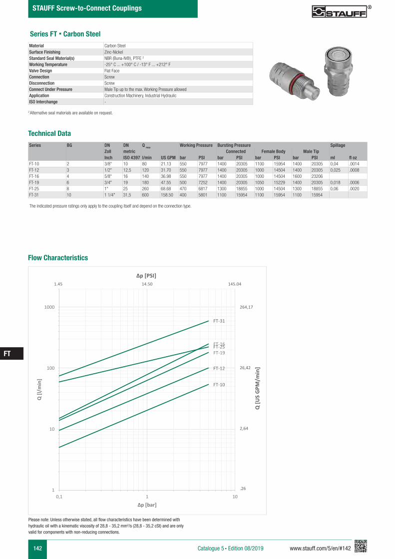
142 www.stauff.com/5/en/#142
FT
Catalogue 5 § Edition 08/2019
STAUFF Screw-to-Connect Couplings
Series BG DN DN Q max Working Pressure Bursting Pressure SpillageZoll metric Connected Female Body Male TipInch ISO 4397 l/min US GPM bar PSI bar PSI bar PSI bar PSI ml fl oz
FT-10 2 3/8" 10 80 21.13 550 7977 1400 20305 1100 15954 1400 20305 0,04 .0014FT-12 3 1/2" 12,5 120 31.70 550 7977 1400 20305 1000 14504 1400 20305 0,025 .0008FT-16 4 5/8" 16 140 36.98 550 7977 1400 20305 1000 14504 1600 23206FT-19 6 3/4" 19 180 47.55 500 7252 1400 20305 1050 15229 1400 20305 0,018 .0006FT-25 8 1" 25 260 68.68 470 6817 1300 18855 1000 14504 1300 18855 0,06 .0020FT-31 10 1 1/4" 31,5 600 158.50 400 5801 1100 15954 1100 15954 1100 15954
Series FT § Carbon SteelMaterial Carbon SteelSurface Finishing Zinc-Nickel Standard Seal Material(s) NBR (Buna-N®), PTFE 2
Working Temperature -25° C ... +100° C / -13° F ... +212° FValve Design Flat FaceConnection ScrewDisconnection ScrewConnect Under Pressure Male Tip up to the max. Working Pressure allowedApplication Construction Machinery, Industrial HydraulicISO Interchange -
The indicated pressure ratings only apply to the coupling itself and depend on the connection type.
2 Alternative seal materials are available on request.
Technical Data
Flow Characteristics
FT-10
FT-12
FT-16
FT-19FT-25
FT-31
1
10
100
1000
0,1 1 10
Q [l
/min
]
Δp [bar]
Q [U
S G
PM/m
in]
Δp [PSI]
264,17
26,42
2,64
.26
1.45 14.50 145.04
Please note: Unless otherwise stated, all flow characteristics have been determined with hydraulic oil with a kinematic viscosity of 28,8 - 35,2 mm2/s (28,8 - 35,2 cSt) and are only valid for components with non-reducing connections.
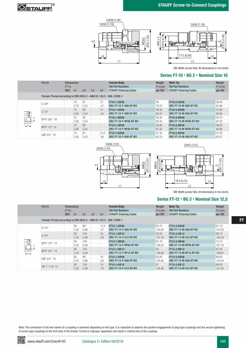
www.stauff.com/5/en/#143 143
FT
Catalogue 5 § Edition 08/2019
STAUFF Screw-to-Connect Couplings
FT 10
scale 0,61
SW30 (1.18)SW38 (1.49)
A
L1
M33x
242
(1.65
)
19.8
(0.78
)M3
3x2
37.8
(1.49
)
17.5 (0.69)
L2
A
SW30 (1.18)
L4 L4
Port A Dimensions Female Body Weight Male Tip Weight (mm/in) Old Part Numbers (kg/lbs) ca. Old Part Numbers (kg/lbs) ca. ØD2 L1 L2 L3 L4 STAUFF Ordering Codes per 100 STAUFF Ordering Codes per 100
Female Thread according to DIN 3852-2 - ANSI B 1.20.3 - SAE J1926-1
G 3/8"70 87 12 FT10-1-IGF06 36 FT10-2-IGF06 38,402.76 3.43 .47 QRC-FT-10-F-G06-BT-W3 79.37 QRC-FT-10-M-G06-BT-W3 84.66
G 1/2"75 90 14 FT10-1-IGF08 36,50 FT10-2-IGF08 37,902.95 3.54 .55 QRC-FT-10-F-G08-BT-W3 80.47 QRC-FT-10-M-G08-BT-W3 83.56
NPTF 3/8" -1875 90 FT10-1-INF06 38,30 FT10-2-INF06 39,702.95 3.54 QRC-FT-10-F-NF06-BT-W3 84.44 QRC-FT-10-M-NF06-BT-W3 87.52
NPTF 1/2"-1475 90 FT10-1-INF08 36,90 FT10-2-INF08 38,502.95 3.54 QRC-FT-10-F-NF08-BT-W3 81.35 QRC-FT-10-M-NF08-BT-W3 84.89
UNF 3/4" -1675 87 14,3 FT10-1-IUF08 37,30 FT10-2-IUF08 37,502.95 3.43 .56 QRC-FT-10-F-U08-BT-W3 82.23 QRC-FT-10-M-U08-BT-W3 82.67
Series FT-10 § BG 2 § Nominal Size 10
A A
L3 L3
L4
Anschlüsse-Beispiele.pdf 1 10.09.13 15:44
SW: Width across flats. All dimensions in mm (inch).
Port A Dimensions Female Body Weight Male Tip Weight (mm/in) Old Part Numbers (kg/lbs) ca. Old Part Numbers (kg/lbs) ca. ØD2 L1 L2 L3 L4 STAUFF Ordering Codes per 100 STAUFF Ordering Codes per 100
Female Thread according to DIN 3852-2 - ANSI B 1.20.3 - SAE J1926-1
G 1/2"85 98 14,5 FT12-1-IGF08 65,70 FT12-2-IGF08 67,103.35 3.86 .57 QRC-FT-12-F-G08-BT-W3 144.84 QRC-FT-12-M-G08-BT-W3 147.93
G 3/4"85 104 16 FT12-1-IGF12 62,50 FT12-2-IGF12 69,103.35 4.09 .63 QRC-FT-12-F-G12-BT-W3 137.79 QRC-FT-12-M-G12-BT-W3 152.34
NPTF 1/2" -1485 104 FT12-1-INF08 61,70 FT12-2-INF08 73,103.35 4.09 QRC-FT-12-F-NF08-BT-W3 136.03 QRC-FT-12-M-NF08-BT-W3 161.16
NPTF 3/4" -1485 104 FT12-1-INF12 63 FT12-2-INF12 67,503.35 4.09 QRC-FT-12-F-NF12-BT-W3 138.89 QRC-FT-12-M-NF12-BT-W3 148.81
UNF 3/4" -1685 98 16 FT12-1-IUF08 65,80 FT12-2-IUF08 69,603.35 3.86 .63 QRC-FT-12-F-U08-BT-W3 145.06 QRC-FT-12-M-U08-BT-W3 153.44
UN 1" 1/16 -1285 104 19 FT12-1-IUF12 61 FT12-2-IUF12 68,503.35 4.09 .75 QRC-FT-12-F-U12-BT-W3 134.48 QRC-FT-12-M-U12-BT-W3 151.02
Series FT-12 § BG 3 § Nominal Size 12,5
A A
L3 L3
L4
Anschlüsse-Beispiele.pdf 1 10.09.13 15:44
SW: Width across flats. All dimensions in mm (inch).
FT 12
scale 0,54
24.6
(0.97
)M4
0x3
46.1
(1.81
)
18.9 (0.74)L2
SW41 (1.61)
L1
M40x
351
.2(2
.01)
SW46 (1.81)SW36 (1.42)
AA
L4 L4
Note: The connection of the two halves of a coupling is achieved depending on the type. It is important to observe the positive engagement of plug-type couplings and the secure tightening of screw-type couplings to the limit stop of the thread. Forced or improper separation will result in malfunction of the coupling.
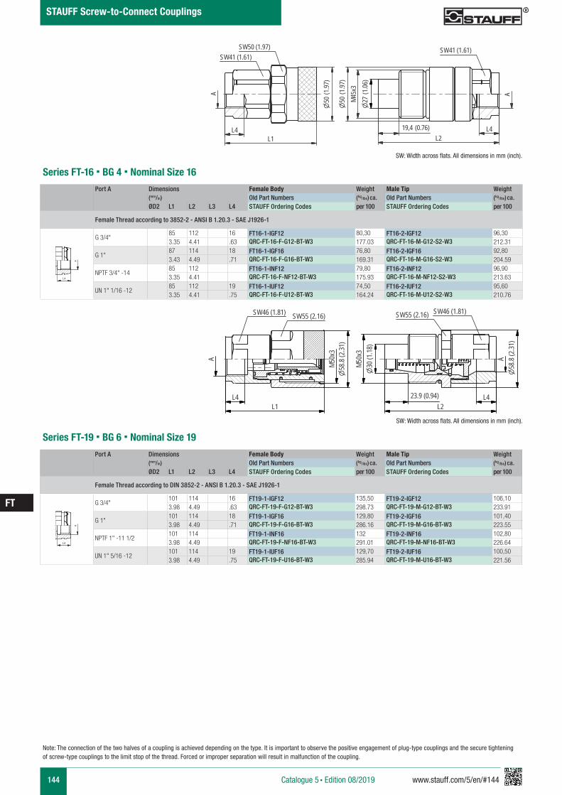
144 www.stauff.com/5/en/#144
FT
Catalogue 5 § Edition 08/2019
STAUFF Screw-to-Connect Couplings
Port A Dimensions Female Body Weight Male Tip Weight (mm/in) Old Part Numbers (kg/lbs) ca. Old Part Numbers (kg/lbs) ca. ØD2 L1 L2 L3 L4 STAUFF Ordering Codes per 100 STAUFF Ordering Codes per 100
Female Thread according to 3852-2 - ANSI B 1.20.3 - SAE J1926-1
G 3/4"85 112 16 FT16-1-IGF12 80,30 FT16-2-IGF12 96,303.35 4.41 .63 QRC-FT-16-F-G12-BT-W3 177.03 QRC-FT-16-M-G12-S2-W3 212.31
G 1"87 114 18 FT16-1-IGF16 76,80 FT16-2-IGF16 92,803.43 4.49 .71 QRC-FT-16-F-G16-BT-W3 169.31 QRC-FT-16-M-G16-S2-W3 204.59
NPTF 3/4" -1485 112 FT16-1-INF12 79,80 FT16-2-INF12 96,903.35 4.41 QRC-FT-16-F-NF12-BT-W3 175.93 QRC-FT-16-M-NF12-S2-W3 213.63
UN 1" 1/16 -1285 112 19 FT16-1-IUF12 74,50 FT16-2-IUF12 95,603.35 4.41 .75 QRC-FT-16-F-U12-BT-W3 164.24 QRC-FT-16-M-U12-S2-W3 210.76
Series FT-16 § BG 4 § Nominal Size 16
A A
L3 L3
L4
Anschlüsse-Beispiele.pdf 1 10.09.13 15:44
SW: Width across flats. All dimensions in mm (inch).
Port A Dimensions Female Body Weight Male Tip Weight (mm/in) Old Part Numbers (kg/lbs) ca. Old Part Numbers (kg/lbs) ca. ØD2 L1 L2 L3 L4 STAUFF Ordering Codes per 100 STAUFF Ordering Codes per 100
Female Thread according to DIN 3852-2 - ANSI B 1.20.3 - SAE J1926-1
G 3/4"101 114 16 FT19-1-IGF12 135,50 FT19-2-IGF12 106,103.98 4.49 .63 QRC-FT-19-F-G12-BT-W3 298.73 QRC-FT-19-M-G12-BT-W3 233.91
G 1"101 114 18 FT19-1-IGF16 129,80 FT19-2-IGF16 101,403.98 4.49 .71 QRC-FT-19-F-G16-BT-W3 286.16 QRC-FT-19-M-G16-BT-W3 223.55
NPTF 1" -11 1/2101 114 FT19-1-INF16 132 FT19-2-INF16 102,803.98 4.49 QRC-FT-19-F-NF16-BT-W3 291.01 QRC-FT-19-M-NF16-BT-W3 226.64
UN 1" 5/16 -12101 114 19 FT19-1-IUF16 129,70 FT19-2-IUF16 100,503.98 4.49 .75 QRC-FT-19-F-U16-BT-W3 285.94 QRC-FT-19-M-U16-BT-W3 221.56
Series FT-19 § BG 6 § Nominal Size 19
A A
L3 L3
L4
Anschlüsse-Beispiele.pdf 1 10.09.13 15:44
SW: Width across flats. All dimensions in mm (inch).
FT16
scale 0.55
L4L1
SW41 (1.61)SW50 (1.97)
A
50(1
.97)
L4L2
A
27(1
.06)
M45x
3
19,4 (0.76)
SW41 (1.61)
50(1
.97)
FT19
scale 0,48
A
L1
M50x
358
.8(2
.31)
SW46 (1.81) SW55 (2.16) SW46 (1.81)
A
30(1
.18)
M50x
3
23.9 (0.94)L2
SW55 (2.16)
58.8
(2.31
)
L4 L4
Note: The connection of the two halves of a coupling is achieved depending on the type. It is important to observe the positive engagement of plug-type couplings and the secure tightening of screw-type couplings to the limit stop of the thread. Forced or improper separation will result in malfunction of the coupling.

www.stauff.com/5/en/#145 145
FT
Catalogue 5 § Edition 08/2019
STAUFF Screw-to-Connect Couplings
Note: The connection of the two halves of a coupling is achieved depending on the type. It is important to observe the positive engagement of plug-type couplings and the secure tightening of screw-type couplings to the limit stop of the thread. Forced or improper separation will result in malfunction of the coupling.
Port A Dimensions Female Body Weight Male Tip Weight (mm/in) Old Part Numbers (kg/lbs) ca. Old Part Numbers (kg/lbs) ca. ØD2 L1 L2 L3 L4 STAUFF Ordering Codes per 100 STAUFF Ordering Codes per 100
Female Thread according to DIN 3852-2 - ANSI B 1.20.3 - SAE J1926-1
G 1" 1/4108 130 20 FT25-1-IGF20 150,20 FT25-2-IGF20 189,704.25 5.12 .79 QRC-FT-25-F-G20-BT-W3 331.13 QRC-FT-25-M-G20-BT-W3 418.22
NPTF 1"¼ -11½108 130 FT25-1-INF20 153,90 FT25-2-INF20 191,904.25 5.12 QRC-FT-25-F-NF20-BT-W3 339.29 QRC-FT-25-M-NF20-BT-W3 423.07
UN 1" 5/8 - 12108 130 19 FT25-1-IUF20 152,30 FT25-2-IUF20 190,404.25 5.12 .75 QRC-FT-25-F-U20-BT-W3 335.76 QRC-FT-25-M-U20-BT-W3 419.76
Series FT-25 § BG 8 § Nominal Size 25
A A
L3 L3
L4
Anschlüsse-Beispiele.pdf 1 10.09.13 15:44
SW: Width across flats. All dimensions in mm (inch).
Port A Dimensions Female Body Weight Male Tip Weight (mm/in) Old Part Numbers (kg/lbs) ca. Old Part Numbers (kg/lbs) ca. ØD2 L1 L2 L3 L4 STAUFF Ordering Codes per 100 STAUFF Ordering Codes per 100
Female Thread according to DIN 3852-2 - ANSI B 1.20.3 - SAE J1926-1
G 1" 1/2134 169 22 FT32-1-IGF24 442,20 FT32-2-IGF24 4025.28 6.65 .87 QRC-FT-31-F-G24-S1-W3 974.88 QRC-FT-31-M-G24-S2-W3 886.26
NPTF 1"½ -11134 169 FT32-1-INF24 444,20 FT32-2-INF24 404,105.28 6.65 QRC-FT-31-F-NF24-S1-W3 979.29 QRC-FT-31-M-NF24-S2-W3 890.89
UN 1" 7/8 -12134 169 19 FT32-1-IUF24 439,20 FT32-2-IUF24 400,505.28 6.65 .75 QRC-FT-31-F-U24-S1-W3 968.27 QRC-FT-31-M-U24-S2-W3 882.95
Series FT-31 § BG 10 § Nominal Size 31,5
A A
L3 L3
L4
Anschlüsse-Beispiele.pdf 1 10.09.13 15:44
SW: Width across flats. All dimensions in mm (inch).
FT 25
scale 0,44
SW55 (2.16)SW65 (2.56)
A
24.9 (0.98)L2L1
36.05
(1.42
)M5
8x3
69.8
(2.75
)A
SW65 (2.56)
M58x
369
.8(2
.75)
SW55 (2.16)
L4 L4
FT 32
scale 0,33
SW80 (3.15)SW85 (3.34)
Tr80
x489
.8(3
.53)
L1
A
57(2
.24)
Tr80
x4
31.5 (1.24)L2
A89
.8(3
.53)
SW65 (2.56)
L4 L4
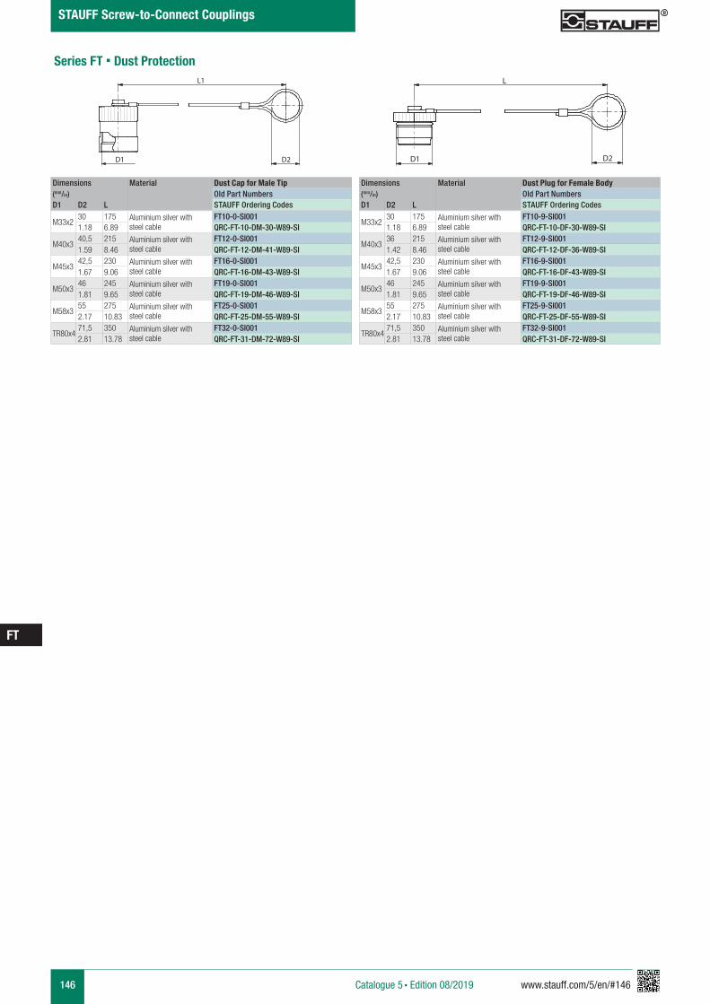
146 www.stauff.com/5/en/#146
FT
Catalogue 5 § Edition 08/2019
STAUFF Screw-to-Connect Couplings
Series FT § Dust Protection
Dimensions Material Dust Cap for Male Tip(mm/in) Old Part NumbersD1 D2 L STAUFF Ordering Codes
M33x230 175 Aluminium silver with
steel cableFT10-0-SI001
1.18 6.89 QRC-FT-10-DM-30-W89-SI
M40x340,5 215 Aluminium silver with
steel cableFT12-0-SI001
1.59 8.46 QRC-FT-12-DM-41-W89-SI
M45x342,5 230 Aluminium silver with
steel cableFT16-0-SI001
1.67 9.06 QRC-FT-16-DM-43-W89-SI
M50x346 245 Aluminium silver with
steel cableFT19-0-SI001
1.81 9.65 QRC-FT-19-DM-46-W89-SI
M58x355 275 Aluminium silver with
steel cableFT25-0-SI001
2.17 10.83 QRC-FT-25-DM-55-W89-SI
TR80x471,5 350 Aluminium silver with
steel cableFT32-0-SI001
2.81 13.78 QRC-FT-31-DM-72-W89-SI
Dimensions Material Dust Plug for Female Body(mm/in) Old Part NumbersD1 D2 L STAUFF Ordering Codes
M33x230 175 Aluminium silver with
steel cableFT10-9-SI001
1.18 6.89 QRC-FT-10-DF-30-W89-SI
M40x336 215 Aluminium silver with
steel cableFT12-9-SI001
1.42 8.46 QRC-FT-12-DF-36-W89-SI
M45x342,5 230 Aluminium silver with
steel cableFT16-9-SI001
1.67 9.06 QRC-FT-16-DF-43-W89-SI
M50x346 245 Aluminium silver with
steel cableFT19-9-SI001
1.81 9.65 QRC-FT-19-DF-46-W89-SI
M58x355 275 Aluminium silver with
steel cableFT25-9-SI001
2.17 10.83 QRC-FT-25-DF-55-W89-SI
TR80x471,5 350 Aluminium silver with
steel cableFT32-9-SI001
2.81 13.78 QRC-FT-31-DF-72-W89-SI
������������������������������������������������������������
����������������������������������������
D1 D2
L1�
������������������������������������������������������������
����������������������������������������
D1 D2
L�
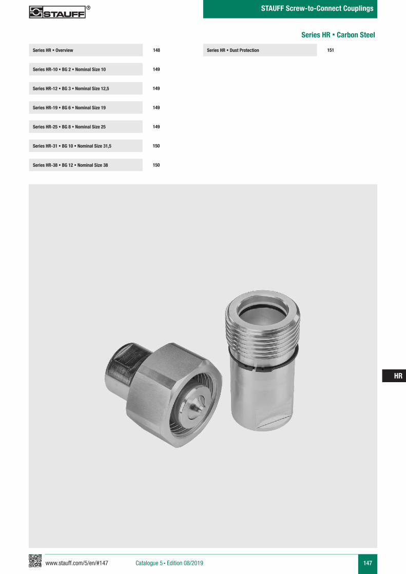
www.stauff.com/5/en/#147 147
HR
Catalogue 5 § Edition 08/2019
STAUFF Screw-to-Connect Couplings
Series HR § Dust Protection 151Series HR § Overview
Series HR-10 § BG 2 § Nominal Size 10 149
148
Series HR-12 § BG 3 § Nominal Size 12,5 149
Series HR-25 § BG 8 § Nominal Size 25 149
Series HR-31 § BG 10 § Nominal Size 31,5 150
Series HR-19 § BG 6 § Nominal Size 19 149
Series HR-38 § BG 12 § Nominal Size 38 150
Series HR § Carbon Steel
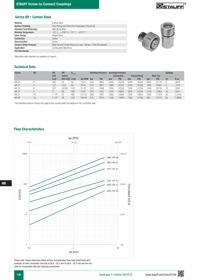
148 www.stauff.com/5/en/#148
HR
Catalogue 5 § Edition 08/2019
STAUFF Screw-to-Connect Couplings
Series HR § Carbon Steel
Series BG DN DN Q max Working Pressure Bursting Pressure SpillageZoll metric Connected Female Body Male TipInch ISO 4397 l/min US GPM bar PSI bar PSI bar PSI bar PSI ml fl oz
HR-10 2 3/8" 10 50 13.21 610 8847 2450 35534 2450 35534 2600 37710 2 .0676HR-12 3 1/2" 12,5 85 22.45 470 6817 1900 27557 2100 30458 1650 23931 3 .1014HR-19 6 3/4" 19 (20) 120 31.70 310 4496 1250 18130 1500 21756 1250 18130 10 .3381HR-25 8 1" 25 280 73.97 300 4351 1300 18855 1600 23206 1100 15954 16 .5410HR-31 10 1 1/4'' 31 460 121.52 300 4351 1300 18855 1300 18855 1200 17404 30 1.0144HR-38 12 1 1/2'' 38 700 184.92 270 3916 1100 15954 1500 21756 950 13779 54 1.8260
Material Carbon SteelSurface Finishing Zinc-Plating and Thick-Film-Passivation (Chrome III)Standard Seal Material(s) NBR (Buna-N®) 2
Working Temperature -25° C ... +100° C / -13° F ... +212° F Valve Design Poppet ValveConnection ScrewDisconnection ScrewConnect Under Pressure Male Tip and Female Body up to max. 100 bar / 1450 PSI allowedApplication Construction MachineryISO Interchange -
The indicated pressure ratings only apply to the coupling itself and depend on the connection type.
2 Alternative seal materials are available on request.
Technical Data
Flow Characteristics
QRC-HR-10
QRC-HR-12
QRC-HR-19
QRC-HR-25
QRC-HR-31
QRC-HR-38
1
10
100
1000
0,1 1 10
Q [l/
min
]
Δp [bar]
Q [U
S G
PM/m
in]
Δp [PSI]
264,17
26,42
2,64
.26
1.45 14.50 145.04
Please note: Unless otherwise stated, all flow characteristics have been determined with hydraulic oil with a kinematic viscosity of 28,8 - 35,2 mm2/s (28,8 - 35,2 cSt) and are only valid for components with non-reducing connections.
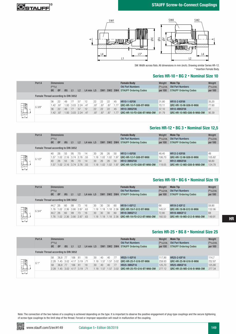
www.stauff.com/5/en/#149 149
HR
Catalogue 5 § Edition 08/2019
STAUFF Screw-to-Connect Couplings
Note: The connection of the two halves of a coupling is achieved depending on the type. It is important to observe the positive engagement of plug-type couplings and the secure tightening of screw-type couplings to the limit stop of the thread. Forced or improper separation will result in malfunction of the coupling.
Series HR-10 § BG 2 § Nominal Size 10Port A Dimensions Female Body Weight Male Tip Weight
(mm/in) Old Part Numbers (kg/lbs) ca. Old Part Numbers (kg/lbs) ca. ØE ØF ØG L1 L2 L4 min L5 SW1 SW2 SW4 STAUFF Ordering Codes per 100 STAUFF Ordering Codes per 100
Female Thread according to DIN 3852
G 3/8"
36 22 49 77 57 12 22 22 22 45 HR10-1-IGF06 31,80 HR10-2-IGF06 35,201.42 .87 1.93 3.03 2.24 .47 .87 .87 .87 1.77 QRC-HR-10-F-G06-BT-W66 70.11 QRC-HR-10-M-G06-B-W66 77.6036 22 49 77 57 12 22 22 22 45 HR10-3MIGF06 37,10 HR10-4MIGF06 411.42 .87 1.93 3.03 2.24 .47 .87 .87 .87 1.77 QRC-HR-10-FD-G06-BT-W66-DM 81.79 QRC-HR-10-MD-G06-B-W66-DM 90.39
A A
L3 L3
L4
Anschlüsse-Beispiele.pdf 1 10.09.13 15:44
SW: Width across flats. All dimensions in mm (inch). Drawing similar Series HR-12.* Insertion Female Body.
HR10-HR38 Muffe und Stecker
scale 0.65
SW1
A
L1
A
SW4
L2
SW2
L4 L4L5*
* Eintauchtiefe Muffe
Series HR-12 § BG 3 § Nominal Size 12,5Port A Dimensions Female Body Weight Male Tip Weight
(mm/in) Old Part Numbers (kg/lbs) ca. Old Part Numbers (kg/lbs) ca. ØE ØF ØG L1 L2 L4 min L5 SW1 SW2 SW4 STAUFF Ordering Codes per 100 STAUFF Ordering Codes per 100
Female Thread according to DIN 3852
G 1/2"
40 26 55 95 70 14 30 26 26 50 HR12-1-IGF08 48,40 HR12-2-IGF08 481.57 1.02 2.16 3.74 2.76 .55 1.18 1.02 1.02 1.97 QRC-HR-12-F-G08-BT-W66 106.70 QRC-HR-12-M-G08-B-W66 105.8240 26 55 95 70 14 30 26 26 50 HR12-3MIGF08 54 HR12-4MIGF08 56,601.57 1.02 2.16 3.74 2.76 .55 1.18 1.02 1.02 1.97 QRC-HR-12-FD-G08-BT-W66-DM 119.05 QRC-HR-12-MD-G08-B-W66-DM 124.78
A A
L3 L3
L4
Anschlüsse-Beispiele.pdf 1 10.09.13 15:44
Series HR-19 § BG 6 § Nominal Size 19Port A Dimensions Female Body Weight Male Tip Weight
(mm/in) Old Part Numbers (kg/lbs) ca. Old Part Numbers (kg/lbs) ca. ØE ØF ØG L1 L2 L4 min L5 SW1 SW2 SW4 STAUFF Ordering Codes per 100 STAUFF Ordering Codes per 100
Female Thread according to DIN 3852
G 3/4"
44,7 26 60 99 73 16 30 30 30 60 HR19-1-IGF12 66 HR19-2-IGF12 59,901.76 1.02 2.36 3.90 2.87 .63 1.18 1.18 1.18 2.36 QRC-HR-19-F-G12-BT-W66 145.51 QRC-HR-19-M-G12-B-W66 132.0644,7 26 60 99 73 16 30 30 30 60 HR19-3MIGF12 72,80 HR19-4MIGF12 681.76 1.02 2.36 3.90 2.87 .63 1.18 1.18 1.18 2.36 QRC-HR-19-FD-G12-BT-W66-DM 160.50 QRC-HR-19-MD-G12-B-W66-DM 149.91
A A
L3 L3
L4
Anschlüsse-Beispiele.pdf 1 10.09.13 15:44
Series HR-25 § BG 8 § Nominal Size 25
Port A Dimensions Female Body Weight Male Tip Weight (mm/in) Old Part Numbers (kg/lbs) ca. Old Part Numbers (kg/lbs) ca. ØE ØF ØG L1 L2 L4 min L5 SW1 SW2 SW4 STAUFF Ordering Codes per 100 STAUFF Ordering Codes per 100
Female Thread according to DIN 3852
G 1"
58 36,8 77 106 81 18 30 40 40 77 HR25-1-IGF16 117,90 HR25-2-IGF16 114,72.28 1.45 3.02 4.17 3.19 .71 1.18 1.57 1.57 3.02 QRC-HR-25-F-G16-BT-W66 259.93 QRC-HR-25-M-G16-B-W66 252.8758 36,8 77 106 81 18 30 40 40 77 HR25-3MIGF16 125,70 HR25-4MIGF16 125,802.28 1.45 3.02 4.17 3.19 .71 1.18 1.57 1.57 3.02 QRC-HR-25-FD-G16-BT-W66-DM 277.12 QRC-HR-25-MD-G16-B-W66-DM 277.34
A A
L3 L3
L4
Anschlüsse-Beispiele.pdf 1 10.09.13 15:44
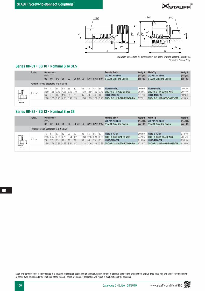
150 www.stauff.com/5/en/#150
HR
Catalogue 5 § Edition 08/2019
STAUFF Screw-to-Connect Couplings
Series HR-31 § BG 10 § Nominal Size 31,5Port A Dimensions Female Body Weight Male Tip Weight
(mm/in) Old Part Numbers (kg/lbs) ca. Old Part Numbers (kg/lbs) ca. ØE ØF ØG L1 L2 L4 min L5 SW1 SW2 SW4 STAUFF Ordering Codes per 100 STAUFF Ordering Codes per 100
Female Thread according to DIN 3852
G 1 1/4"
66 47 88 118 88 20 35 48 48 88 HR31-1-IGF20 160,60 HR31-2-IGF20 180,302.60 1.85 3.46 4.65 3.46 .79 1.38 1.89 1.89 3.46 QRC-HR-31-F-G20-BT-W66 354.06 QRC-HR-31-M-G20-B-W66 397.4966 47 88 118 88 20 35 48 48 88 HR31-3MIGF20 171,10 HR31-4MIGF20 192,802.60 1.85 3.46 4.65 3.46 .79 1.38 1.89 1.89 3.46 QRC-HR-31-FD-G20-BT-W66-DM 377.21 QRC-HR-31-MD-G20-B-W66-DM 425.05
A A
L3 L3
L4
Anschlüsse-Beispiele.pdf 1 10.09.13 15:44
Series HR-38 § BG 12 § Nominal Size 38Port A Dimensions Female Body Weight Male Tip Weight
(mm/in) Old Part Numbers (kg/lbs) ca. Old Part Numbers (kg/lbs) ca. ØE ØF ØG L1 L2 L4 min L5 SW1 SW2 SW4 STAUFF Ordering Codes per 100 STAUFF Ordering Codes per 100
Female Thread according to DIN 3852
G 1 1/2"
75 57 93 121 90 22 35 55 55 93 HR38-1-IGF24 200,60 HR38-2-IGF24 218,402.95 2.24 3.66 4.76 3.54 .87 1.38 2.16 2.16 3.66 QRC-HR-38-F-G24-BT-W66 442.25 QRC-HR-38-M-G24-B-W66 481.4975 57 93 121 90 22 35 55 55 93 HR38-3MIGF24 213,90 HR38-4MIGF24 233,102.95 2.24 3.66 4.76 3.54 .87 1.38 2.16 2.16 3.66 QRC-HR-38-FD-G24-BT-W66-DM 471.57 QRC-HR-38-MD-G24-B-W66-DM 513.90
A A
L3 L3
L4
Anschlüsse-Beispiele.pdf 1 10.09.13 15:44
Note: The connection of the two halves of a coupling is achieved depending on the type. It is important to observe the positive engagement of plug-type couplings and the secure tightening of screw-type couplings to the limit stop of the thread. Forced or improper separation will result in malfunction of the coupling.
SW: Width across flats. All dimensions in mm (inch). Drawing similar Series HR-12.* Insertion Female Body.
HR10-HR38 Muffe und Stecker
scale 0.65
SW1
A
L1
A
SW4
L2
SW2
L4 L4L5*
* Eintauchtiefe Muffe
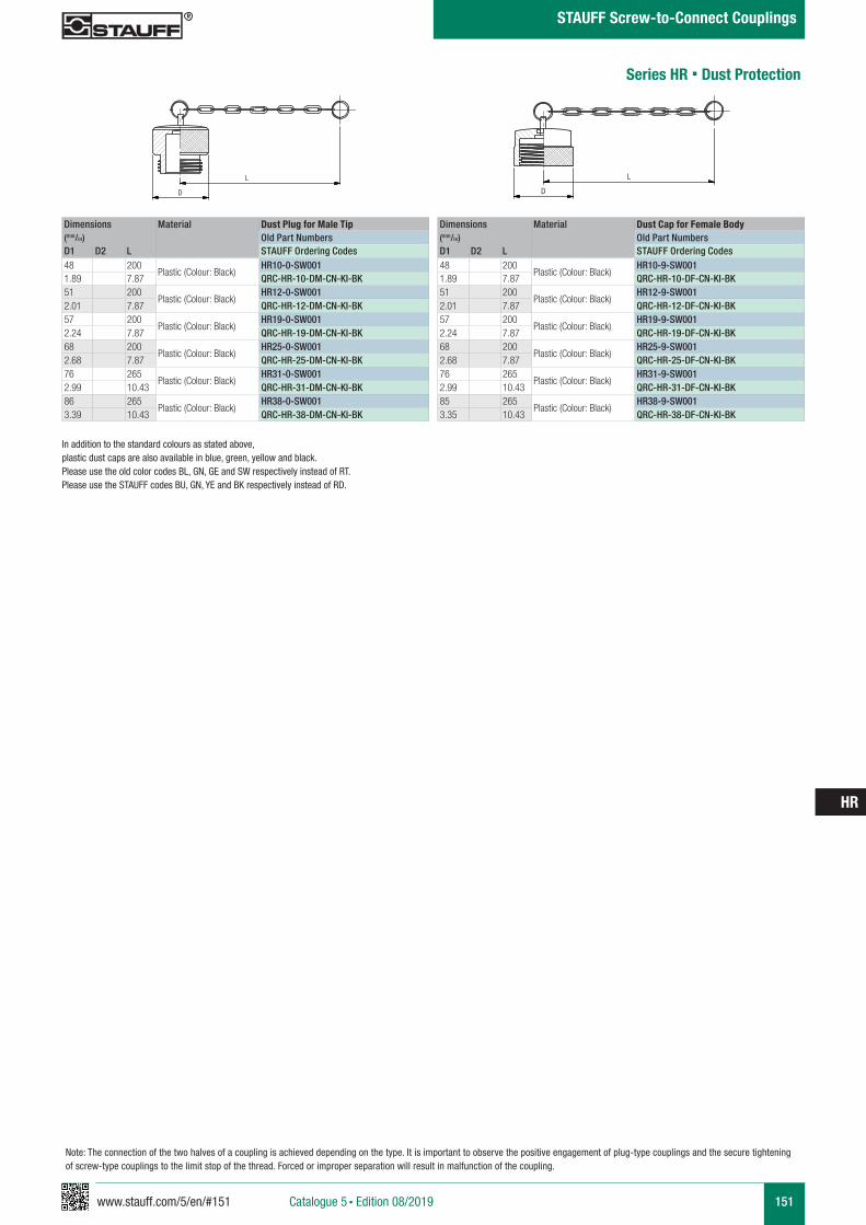
www.stauff.com/5/en/#151 151
HR
Catalogue 5 § Edition 08/2019
STAUFF Screw-to-Connect Couplings
Note: The connection of the two halves of a coupling is achieved depending on the type. It is important to observe the positive engagement of plug-type couplings and the secure tightening of screw-type couplings to the limit stop of the thread. Forced or improper separation will result in malfunction of the coupling.
Series HR § Dust Protection
Dimensions Material Dust Plug for Male Tip(mm/in) Old Part NumbersD1 D2 L STAUFF Ordering Codes48 200
Plastic (Colour: Black)HR10-0-SW001
1.89 7.87 QRC-HR-10-DM-CN-KI-BK51 200
Plastic (Colour: Black)HR12-0-SW001
2.01 7.87 QRC-HR-12-DM-CN-KI-BK57 200
Plastic (Colour: Black)HR19-0-SW001
2.24 7.87 QRC-HR-19-DM-CN-KI-BK68 200
Plastic (Colour: Black)HR25-0-SW001
2.68 7.87 QRC-HR-25-DM-CN-KI-BK76 265
Plastic (Colour: Black)HR31-0-SW001
2.99 10.43 QRC-HR-31-DM-CN-KI-BK86 265
Plastic (Colour: Black)HR38-0-SW001
3.39 10.43 QRC-HR-38-DM-CN-KI-BK
Dimensions Material Dust Cap for Female Body(mm/in) Old Part NumbersD1 D2 L STAUFF Ordering Codes48 200
Plastic (Colour: Black)HR10-9-SW001
1.89 7.87 QRC-HR-10-DF-CN-KI-BK51 200
Plastic (Colour: Black)HR12-9-SW001
2.01 7.87 QRC-HR-12-DF-CN-KI-BK57 200
Plastic (Colour: Black)HR19-9-SW001
2.24 7.87 QRC-HR-19-DF-CN-KI-BK68 200
Plastic (Colour: Black)HR25-9-SW001
2.68 7.87 QRC-HR-25-DF-CN-KI-BK76 265
Plastic (Colour: Black)HR31-9-SW001
2.99 10.43 QRC-HR-31-DF-CN-KI-BK85 265
Plastic (Colour: Black)HR38-9-SW001
3.35 10.43 QRC-HR-38-DF-CN-KI-BK
HR12-0-SW001
PVC schwarz
scale 0,5
D
L
HR12-9-SW001
PVC schwarz
D
L
In addition to the standard colours as stated above, plastic dust caps are also available in blue, green, yellow and black. Please use the old color codes BL, GN, GE and SW respectively instead of RT.Please use the STAUFF codes BU, GN, YE and BK respectively instead of RD.
152 www.stauff.com/5/en/#152
HR
Catalogue 5 § Edition 08/2019
STAUFF Screw-to-Connect Couplings
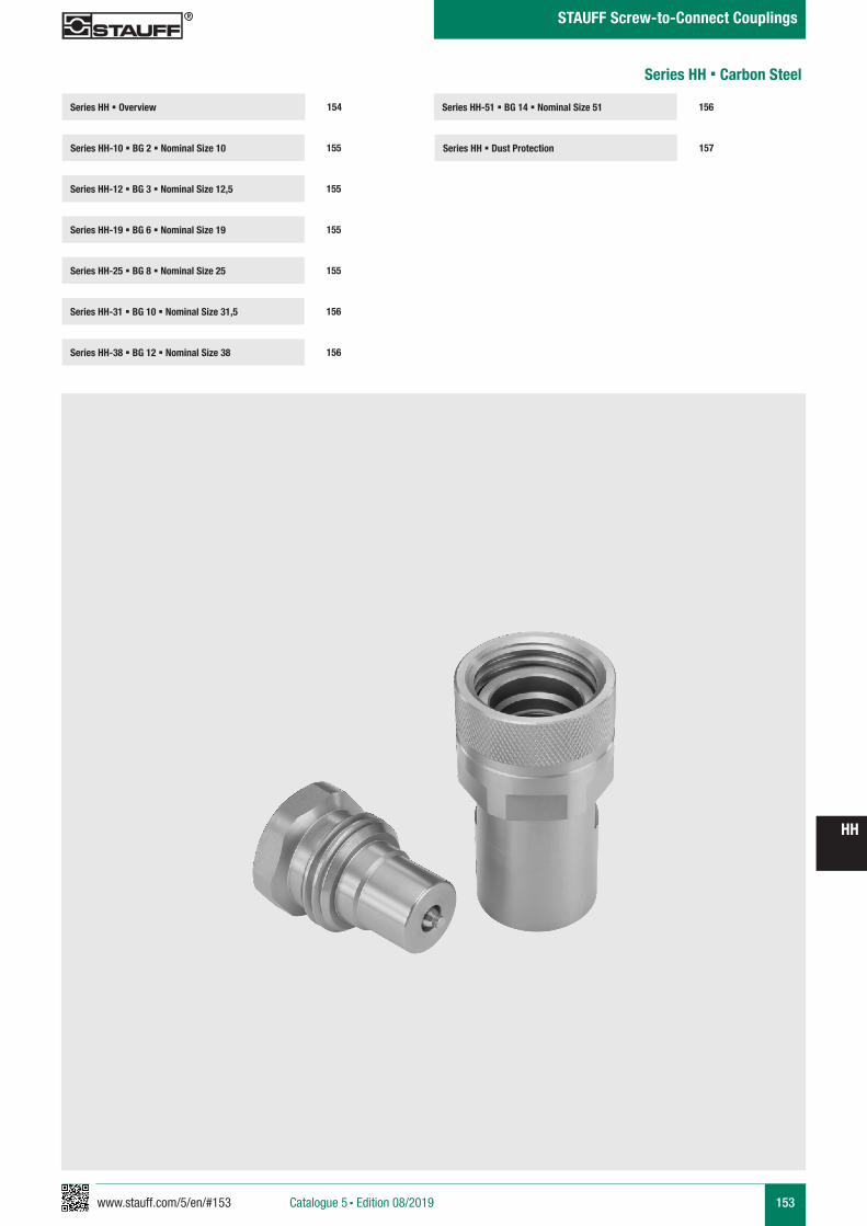
www.stauff.com/5/en/#153 153
HH
Catalogue 5 § Edition 08/2019
STAUFF Screw-to-Connect Couplings
Series HH-51 § BG 14 § Nominal Size 51
Series HH § Dust Protection 157
156Series HH § Overview
Series HH-10 § BG 2 § Nominal Size 10 155
154
Series HH-12 § BG 3 § Nominal Size 12,5 155
Series HH-25 § BG 8 § Nominal Size 25 155
Series HH-31 § BG 10 § Nominal Size 31,5 156
Series HH-19 § BG 6 § Nominal Size 19 155
Series HH-38 § BG 12 § Nominal Size 38 156
Series HH § Carbon Steel
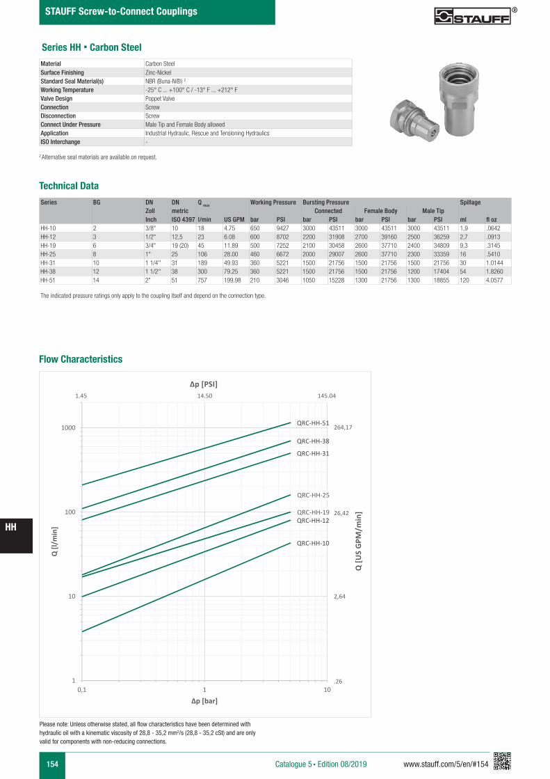
154 www.stauff.com/5/en/#154
HH
Catalogue 5 § Edition 08/2019
STAUFF Screw-to-Connect Couplings
Series HH § Carbon Steel
Series BG DN DN Q max Working Pressure Bursting Pressure SpillageZoll metric Connected Female Body Male TipInch ISO 4397 l/min US GPM bar PSI bar PSI bar PSI bar PSI ml fl oz
HH-10 2 3/8" 10 18 4.75 650 9427 3000 43511 3000 43511 3000 43511 1,9 .0642HH-12 3 1/2" 12,5 23 6.08 600 8702 2200 31908 2700 39160 2500 36259 2,7 .0913HH-19 6 3/4" 19 (20) 45 11.89 500 7252 2100 30458 2600 37710 2400 34809 9,3 .3145HH-25 8 1" 25 106 28.00 460 6672 2000 29007 2600 37710 2300 33359 16 .5410HH-31 10 1 1/4'' 31 189 49.93 360 5221 1500 21756 1500 21756 1500 21756 30 1.0144HH-38 12 1 1/2'' 38 300 79.25 360 5221 1500 21756 1500 21756 1200 17404 54 1.8260HH-51 14 2" 51 757 199.98 210 3046 1050 15228 1300 21756 1300 18855 120 4.0577
Material Carbon SteelSurface Finishing Zinc-NickelStandard Seal Material(s) NBR (Buna-N®) 2
Working Temperature -25° C ... +100° C / -13° F ... +212° F Valve Design Poppet ValveConnection ScrewDisconnection ScrewConnect Under Pressure Male Tip and Female Body allowedApplication Industrial Hydraulic, Rescue and Tensioning HydraulicsISO Interchange -
The indicated pressure ratings only apply to the coupling itself and depend on the connection type.
2 Alternative seal materials are available on request.
Technical Data
Flow Characteristics
QRC-HH-10
QRC-HH-12QRC-HH-19
QRC-HH-25
QRC-HH-31
QRC-HH-38
QRC-HH-51
1
10
100
1000
0,1 1 10
Q [l/
min
]
Δp [bar]
Q [U
S G
PM/m
in]
Δp [PSI]
264,17
26,42
2,64
.26
1.45 14.50 145.04
Please note: Unless otherwise stated, all flow characteristics have been determined with hydraulic oil with a kinematic viscosity of 28,8 - 35,2 mm2/s (28,8 - 35,2 cSt) and are only valid for components with non-reducing connections.
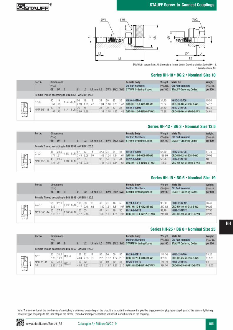
www.stauff.com/5/en/#155 155
HH
Catalogue 5 § Edition 08/2019
STAUFF Screw-to-Connect Couplings
Series HH-10 § BG 2 § Nominal Size 10
Port A Dimensions Female Body Weight Male Tip Weight (mm/in) Old Part Numbers (kg/lbs) ca. Old Part Numbers (kg/lbs) ca. ØE ØF B L1 L2 L4 min L5 SW1 SW2 SW3 STAUFF Ordering Codes per 100 STAUFF Ordering Codes per 100
Female Thread according to DIN 3852 - ANSI B 1.20.3
G 3/8"40 19
1 1/4“ - 8 UN76 48 12 34 30 32 36 HH10-1-IGF06 34,40 HH10-2-IGF06 15,50
1.57 .75 2.99 1.89 .47 1.34 1.18 1.26 1.42 QRC-HH-10-F-G06-BT-W3 75.84 QRC-HH-10-M-G06-B-W3 34.17
NPTF 3/8" -1840 19
1 1/4“ - 8 UN76 48 34 30 32 36 HH10-1-INF06 34,60 HH10-2-INF06 15,70
1.57 .75 2.99 1.89 1.34 1.18 1.26 1.42 QRC-HH-10-F-NF06-BT-W3 76.28 QRC-HH-10-M-NF06-B-W3 34.61
A A
L3 L3
L4
Anschlüsse-Beispiele.pdf 1 10.09.13 15:44
SW: Width across flats. All dimensions in mm (inch). Drawing similar Series HH-12.* Insertion Male Tip.
HH10-HH51 Muffe und Stecker
Stahl und Edelstahl
scale 0.65
A
SW1
B
SW3
L4L1
L4L2
A
SW2
L5
zeichnerische Darstellung entspricht Serie HH 12
Series HH-12 § BG 3 § Nominal Size 12,5Port A Dimensions Female Body Weight Male Tip Weight
(mm/in) Old Part Numbers (kg/lbs) ca. Old Part Numbers (kg/lbs) ca. ØE ØF B L1 L2 L4 min L5 SW1 SW2 SW3 STAUFF Ordering Codes per 100 STAUFF Ordering Codes per 100
Female Thread according to DIN 3852 - ANSI B 1.20.3
G 1/2"45 20,5
1 3/8“ - 8 UN87 53 14 37,5 34 34 41 HH12-1-IGF08 57,60 HH12-2-IGF08 17,70
1.77 .81 3.43 2.09 .55 1.48 1.34 1.34 1.61 QRC-HH-12-F-G08-BT-W3 126.99 QRC-HH-12-M-G08-B-W3 39.02
NPTF 1/2" -1445 20,5
1 3/8“ - 8 UN87 53 37,5 34 34 41 HH12-1-INF08 58,20 HH12-2-INF08 18
1.77 .81 3.43 2.09 1.48 1.34 1.34 1.61 QRC-HH-12-F-NF08-BT-W3 128.31 QRC-HH-12-M-NF08-B-W3 39.68
A A
L3 L3
L4
Anschlüsse-Beispiele.pdf 1 10.09.13 15:44
Series HH-19 § BG 6 § Nominal Size 19Port A Dimensions Female Body Weight Male Tip Weight
(mm/in) Old Part Numbers (kg/lbs) ca. Old Part Numbers (kg/lbs) ca. ØE ØF B L1 L2 L4 min L5 SW1 SW2 SW3 STAUFF Ordering Codes per 100 STAUFF Ordering Codes per 100
Female Thread according to DIN 3852 - ANSI B 1.20.3
G 3/4"55 27,9
1 3/4“ - 6 UN106 63 16 48 41 46 50 HH19-1-IGF12 98,80 HH19-2-IGF12 36,40
2.16 1.1 4.17 2.48 .63 1.89 1.61 1.81 1.97 QRC-HH-19-F-G12-BT-W3 217.82 QRC-HH-19-M-G12-B-W3 80.25
NPFT 3/4" -1455 27,9
1 3/4“ - 6 UN106 63 47 41 46 50 HH19-1-INF12 99,70 HH19-2-INF12 37,30
2.16 1.1 4.17 2.48 1.89 1.61 1.81 1.97 QRC-HH-19-F-NF12-BT-W3 219.80 QRC-HH-19-M-NF12-B-W3 82.23
A A
L3 L3
L4
Anschlüsse-Beispiele.pdf 1 10.09.13 15:44
Series HH-25 § BG 8 § Nominal Size 25Port A Dimensions Female Body Weight Male Tip Weight
(mm/in) Old Part Numbers (kg/lbs) ca. Old Part Numbers (kg/lbs) ca. ØE ØF B L1 L2 L4 min L5 SW1 SW2 SW3 STAUFF Ordering Codes per 100 STAUFF Ordering Codes per 100
Female Thread according to DIN 3852 - ANSI B 1.20.3
G 1"60 31,2
M52x4123 72 18 56 50 50 55 HH25-1-IGF16 140,30 HH25-2-IGF16 53,20
2.36 1.23 4.84 2.83 .71 2.2 1.97 1.97 2.16 QRC-HH-25-F-G16-BT-W3 309.31 QRC-HH-25-M-G16-B-W3 117.29
NPTF 1" -11 1/2
60 31,2M52x4
123 72 56 50 50 55 HH25-1-INF16 148,10 HH25-2-INF16 542.36 1.23 4.84 2.83 2.2 1.97 1.97 2.16 QRC-HH-25-F-NF16-BT-W3 326.50 QRC-HH-25-M-NF16-B-W3 119.05
A A
L3 L3
L4
Anschlüsse-Beispiele.pdf 1 10.09.13 15:44
Note: The connection of the two halves of a coupling is achieved depending on the type. It is important to observe the positive engagement of plug-type couplings and the secure tightening of screw-type couplings to the limit stop of the thread. Forced or improper separation will result in malfunction of the coupling.
*
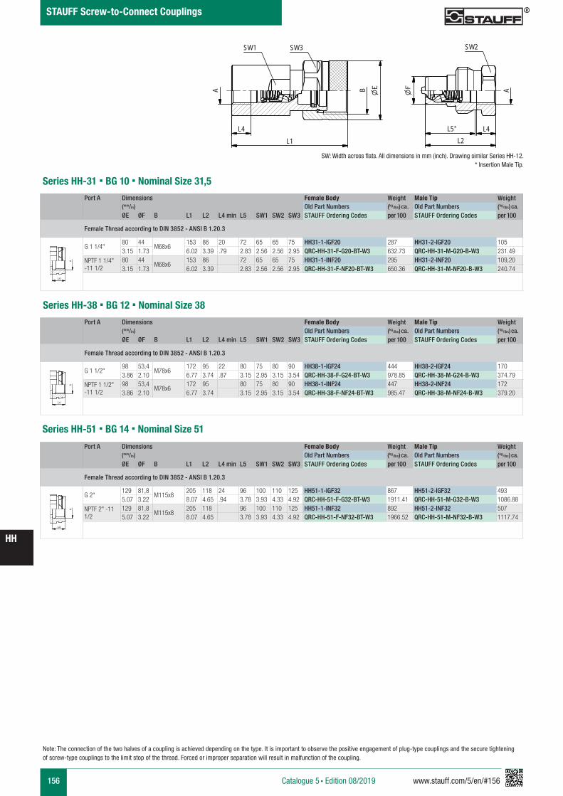
156 www.stauff.com/5/en/#156
HH
Catalogue 5 § Edition 08/2019
STAUFF Screw-to-Connect Couplings
Series HH-31 § BG 10 § Nominal Size 31,5Port A Dimensions Female Body Weight Male Tip Weight
(mm/in) Old Part Numbers (kg/lbs) ca. Old Part Numbers (kg/lbs) ca. ØE ØF B L1 L2 L4 min L5 SW1 SW2 SW3 STAUFF Ordering Codes per 100 STAUFF Ordering Codes per 100
Female Thread according to DIN 3852 - ANSI B 1.20.3
G 1 1/4"80 44
M68x6153 86 20 72 65 65 75 HH31-1-IGF20 287 HH31-2-IGF20 105
3.15 1.73 6.02 3.39 .79 2.83 2.56 2.56 2.95 QRC-HH-31-F-G20-BT-W3 632.73 QRC-HH-31-M-G20-B-W3 231.49
NPTF 1 1/4" -11 1/2
80 44M68x6
153 86 72 65 65 75 HH31-1-INF20 295 HH31-2-INF20 109,203.15 1.73 6.02 3.39 2.83 2.56 2.56 2.95 QRC-HH-31-F-NF20-BT-W3 650.36 QRC-HH-31-M-NF20-B-W3 240.74
A A
L3 L3
L4
Anschlüsse-Beispiele.pdf 1 10.09.13 15:44
Series HH-38 § BG 12 § Nominal Size 38Port A Dimensions Female Body Weight Male Tip Weight
(mm/in) Old Part Numbers (kg/lbs) ca. Old Part Numbers (kg/lbs) ca. ØE ØF B L1 L2 L4 min L5 SW1 SW2 SW3 STAUFF Ordering Codes per 100 STAUFF Ordering Codes per 100
Female Thread according to DIN 3852 - ANSI B 1.20.3
G 1 1/2"98 53,4
M78x6172 95 22 80 75 80 90 HH38-1-IGF24 444 HH38-2-IGF24 170
3.86 2.10 6.77 3.74 .87 3.15 2.95 3.15 3.54 QRC-HH-38-F-G24-BT-W3 978.85 QRC-HH-38-M-G24-B-W3 374.79
NPTF 1 1/2" -11 1/2
98 53,4M78x6
172 95 80 75 80 90 HH38-1-INF24 447 HH38-2-INF24 1723.86 2.10 6.77 3.74 3.15 2.95 3.15 3.54 QRC-HH-38-F-NF24-BT-W3 985.47 QRC-HH-38-M-NF24-B-W3 379.20
A A
L3 L3
L4
Anschlüsse-Beispiele.pdf 1 10.09.13 15:44
Note: The connection of the two halves of a coupling is achieved depending on the type. It is important to observe the positive engagement of plug-type couplings and the secure tightening of screw-type couplings to the limit stop of the thread. Forced or improper separation will result in malfunction of the coupling.
Series HH-51 § BG 14 § Nominal Size 51
Port A Dimensions Female Body Weight Male Tip Weight (mm/in) Old Part Numbers (kg/lbs) ca. Old Part Numbers (kg/lbs) ca. ØE ØF B L1 L2 L4 min L5 SW1 SW2 SW3 STAUFF Ordering Codes per 100 STAUFF Ordering Codes per 100
Female Thread according to DIN 3852 - ANSI B 1.20.3
G 2"129 81,8
M115x8205 118 24 96 100 110 125 HH51-1-IGF32 867 HH51-2-IGF32 493
5.07 3.22 8.07 4.65 .94 3.78 3.93 4.33 4.92 QRC-HH-51-F-G32-BT-W3 1911.41 QRC-HH-51-M-G32-B-W3 1086.88
NPTF 2" -11 1/2
129 81,8M115x8
205 118 96 100 110 125 HH51-1-INF32 892 HH51-2-INF32 5075.07 3.22 8.07 4.65 3.78 3.93 4.33 4.92 QRC-HH-51-F-NF32-BT-W3 1966.52 QRC-HH-51-M-NF32-B-W3 1117.74
A A
L3 L3
L4
Anschlüsse-Beispiele.pdf 1 10.09.13 15:44
SW: Width across flats. All dimensions in mm (inch). Drawing similar Series HH-12.* Insertion Male Tip.
HH10-HH51 Muffe und Stecker
Stahl und Edelstahl
scale 0.65
A
SW1
B
SW3
L4L1
L4L2
A
SW2
L5
zeichnerische Darstellung entspricht Serie HH 12
*
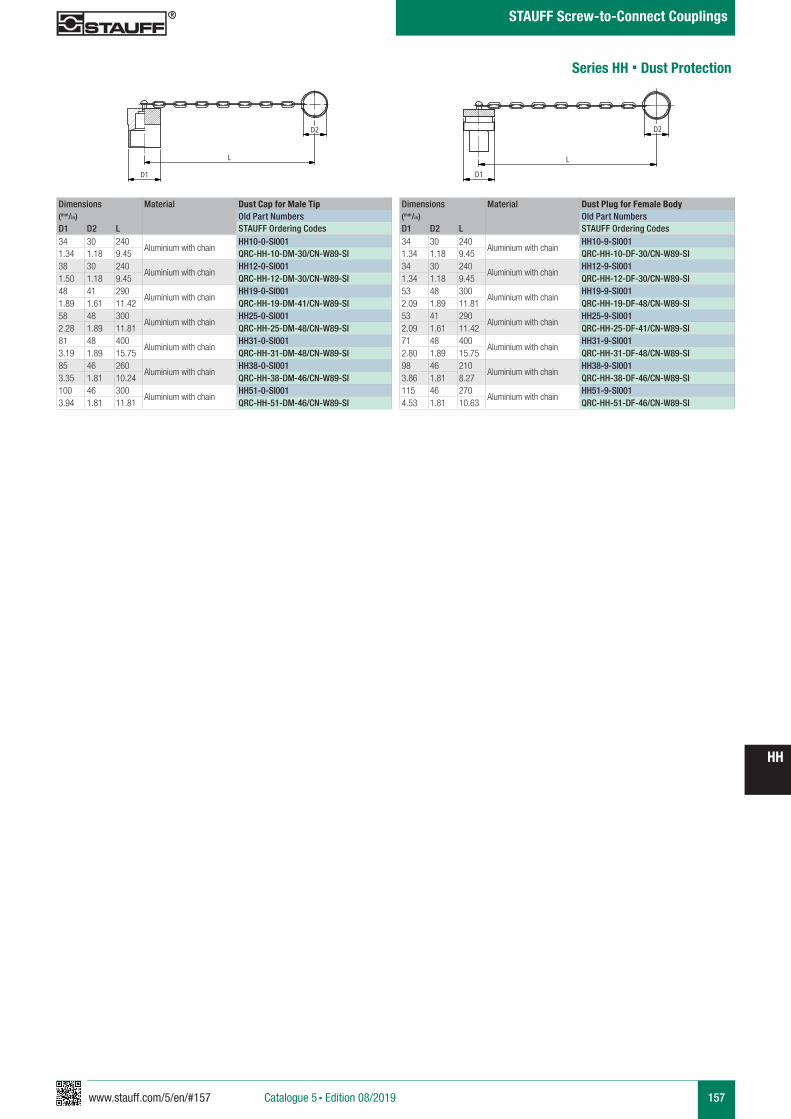
www.stauff.com/5/en/#157 157
HH
Catalogue 5 § Edition 08/2019
STAUFF Screw-to-Connect Couplings
Series HH § Dust Protection
Dimensions Material Dust Cap for Male Tip(mm/in) Old Part NumbersD1 D2 L STAUFF Ordering Codes34 30 240
Aluminium with chainHH10-0-SI001
1.34 1.18 9.45 QRC-HH-10-DM-30/CN-W89-SI38 30 240
Aluminium with chainHH12-0-SI001
1.50 1.18 9.45 QRC-HH-12-DM-30/CN-W89-SI48 41 290
Aluminium with chainHH19-0-SI001
1.89 1.61 11.42 QRC-HH-19-DM-41/CN-W89-SI58 48 300
Aluminium with chainHH25-0-SI001
2.28 1.89 11.81 QRC-HH-25-DM-48/CN-W89-SI81 48 400
Aluminium with chainHH31-0-SI001
3.19 1.89 15.75 QRC-HH-31-DM-48/CN-W89-SI85 46 260
Aluminium with chainHH38-0-SI001
3.35 1.81 10.24 QRC-HH-38-DM-46/CN-W89-SI100 46 300
Aluminium with chainHH51-0-SI001
3.94 1.81 11.81 QRC-HH-51-DM-46/CN-W89-SI
Dimensions Material Dust Plug for Female Body(mm/in) Old Part NumbersD1 D2 L STAUFF Ordering Codes34 30 240
Aluminium with chainHH10-9-SI001
1.34 1.18 9.45 QRC-HH-10-DF-30/CN-W89-SI34 30 240
Aluminium with chainHH12-9-SI001
1.34 1.18 9.45 QRC-HH-12-DF-30/CN-W89-SI53 48 300
Aluminium with chainHH19-9-SI001
2.09 1.89 11.81 QRC-HH-19-DF-48/CN-W89-SI53 41 290
Aluminium with chainHH25-9-SI001
2.09 1.61 11.42 QRC-HH-25-DF-41/CN-W89-SI71 48 400
Aluminium with chainHH31-9-SI001
2.80 1.89 15.75 QRC-HH-31-DF-48/CN-W89-SI98 46 210
Aluminium with chainHH38-9-SI001
3.86 1.81 8.27 QRC-HH-38-DF-46/CN-W89-SI115 46 270
Aluminium with chainHH51-9-SI001
4.53 1.81 10.63 QRC-HH-51-DF-46/CN-W89-SI
HH-0-SI001
Alu mit Kette
scale 0.4
D2
L
D1
HH-9-SI001
Alu mit Kette
scale 0.4
D2
L
D1

158 www.stauff.com/5/en/#158
HH
Catalogue 5 § Edition 08/2019
STAUFF Screw-to-Connect Couplings
www.stauff.com/5/en/#159 159
HH
Catalogue 5 § Edition 08/2019
STAUFF Screw-to-Connect Couplings
Series HH-51 § BG 14 § Nominal Size 51
Series HH § Dust Protection 163
162Series HH § Overview
Series HH-10 § BG 2 § Nominal Size 10 161
160
Series HH-12 § BG 3 § Nominal Size 12,5 161
Series HH-25 § BG 8 § Nominal Size 25 161
Series HH-31 § BG 10 § Nominal Size 31,5 162
Series HH-19 § BG 6 § Nominal Size 19 161
Series HH-38 § BG 12 § Nominal Size 38 162
Series HH § Stainless Steel
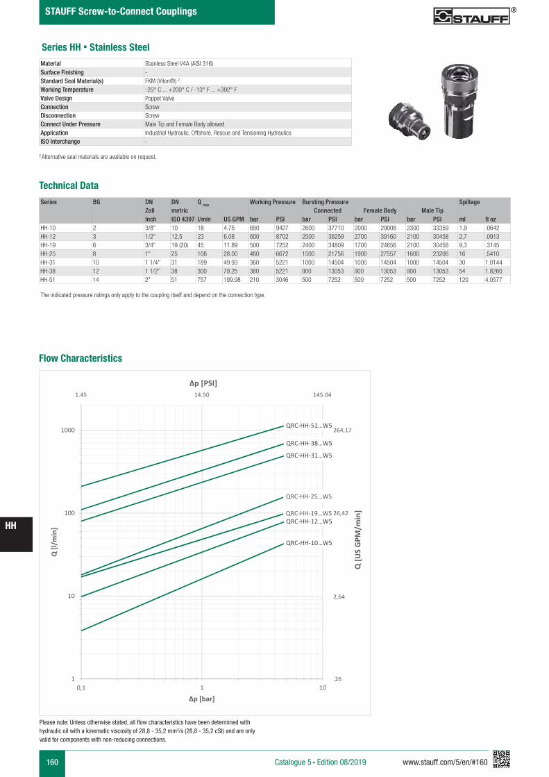
160 www.stauff.com/5/en/#160
HH
Catalogue 5 § Edition 08/2019
STAUFF Screw-to-Connect Couplings
Series HH § Stainless Steel
Series BG DN DN Q max Working Pressure Bursting Pressure SpillageZoll metric Connected Female Body Male TipInch ISO 4397 l/min US GPM bar PSI bar PSI bar PSI bar PSI ml fl oz
HH-10 2 3/8" 10 18 4.75 650 9427 2600 37710 2000 29008 2300 33359 1,9 .0642HH-12 3 1/2" 12,5 23 6.08 600 8702 2500 36259 2700 39160 2100 30458 2,7 .0913HH-19 6 3/4" 19 (20) 45 11.89 500 7252 2400 34809 1700 24656 2100 30458 9,3 .3145HH-25 8 1" 25 106 28.00 460 6672 1500 21756 1900 27557 1600 23206 16 .5410HH-31 10 1 1/4'' 31 189 49.93 360 5221 1000 14504 1000 14504 1000 14504 30 1.0144HH-38 12 1 1/2'' 38 300 79.25 360 5221 900 13053 900 13053 900 13053 54 1.8260HH-51 14 2" 51 757 199.98 210 3046 500 7252 500 7252 500 7252 120 4.0577
Material Stainless Steel V4A (AISI 316)Surface Finishing -Standard Seal Material(s) FKM (Viton®) 2
Working Temperature -25° C ... +200° C / -13° F ... +392° FValve Design Poppet ValveConnection ScrewDisconnection ScrewConnect Under Pressure Male Tip and Female Body allowedApplication Industrial Hydraulic, Offshore, Rescue and Tensioning Hydraulics ISO Interchange -
The indicated pressure ratings only apply to the coupling itself and depend on the connection type.
2 Alternative seal materials are available on request.
Technical Data
Flow Characteristics
QRC-HH-10…W5
QRC-HH-12…W5QRC-HH-19…W5
QRC-HH-25…W5
QRC-HH-31…W5
QRC-HH-38…W5
QRC-HH-51…W5
1
10
100
1000
0,1 1 10
Q [l/
min
]
Δp [bar]
Q [U
S G
PM/m
in]
Δp [PSI]
264,17
26,42
2,64
.26
1.45 14.50 145.04
Please note: Unless otherwise stated, all flow characteristics have been determined with hydraulic oil with a kinematic viscosity of 28,8 - 35,2 mm2/s (28,8 - 35,2 cSt) and are only valid for components with non-reducing connections.

www.stauff.com/5/en/#161 161
HH
Catalogue 5 § Edition 08/2019
STAUFF Screw-to-Connect Couplings
Series HH-10 § BG 2 § Nominal Size 10Port A Dimensions Female Body Weight Male Tip Weight
(mm/in) Old Part Numbers (kg/lbs) ca. Old Part Numbers (kg/lbs) ca. ØE ØF B L1 L2 L4 min L5 SW1 SW2 SW3 STAUFF Ordering Codes per 100 STAUFF Ordering Codes per 100
Female Thread according to DIN 3852 - ANSI B 1.20.3
G 3/8"40 19
1 1/4“ - 8 UN76 48 12 34 27 32 36 HH10-1-IGF06-VA 34,40 HH10-2-IGF06-VA 15,50
1.57 .75 2.99 1.89 .47 1.34 1.06 1.26 1.42 QRC-HH-10-F-G06-VT-W5 75.84 QRC-HH-10-M-G06-V-W5 34.17
NPTF 3/8" -1840 19
1 1/4“ - 8 UN76 48 34 27 32 36 HH10-1-INF06-VA 34,60 HH10-2-INF06-VA 15,70
1.57 .75 2.99 1.89 1.34 1.06 1.26 1.42 QRC-HH-10-F-NF06-VT-W5 76.28 QRC-HH-10-M-NF06-V-W5 34.61
SW: Width across flats. All dimensions in mm (inch). Drawing similar Series HH-12.* Insertion Male Tip.
HH10-HH51 Muffe und Stecker
Stahl und Edelstahl
scale 0.65
A
SW1
B
SW3
L4L1
L4L2
A
SW2
L5
zeichnerische Darstellung entspricht Serie HH 12
Series HH-12 § BG 3 § Nominal Size 12,5Port A Dimensions Female Body Weight Male Tip Weight
(mm/in) Old Part Numbers (kg/lbs) ca. Old Part Numbers (kg/lbs) ca. ØE ØF B L1 L2 L4 min L5 SW1 SW2 SW3 STAUFF Ordering Codes per 100 STAUFF Ordering Codes per 100
Female Thread according to DIN 3852 - ANSI B 1.20.3
G 1/2"45 20,5
1 3/8“ - 8 UN87 53 14 37,5 34 34 41 HH12-1-IGF08-VA 57,60 HH12-2-IGF08-VA 17,70
1.77 .81 3.43 2.09 .55 1.48 1.34 1.34 1.61 QRC-HH-12-F-G08-VT-W5 126.99 QRC-HH-12-M-G08-V-W5 39.02
NPTF 1/2" -1445 20,5
1 3/8“ - 8 UN87 53 37,5 34 34 41 HH12-1-INF08-VA 58,20 HH12-2-INF08-VA 18
1.77 .81 3.43 2.09 1.48 1.34 1.34 1.61 QRC-HH-12-F-NF08-VT-W5 128.31 QRC-HH-12-M-NF08-V-W5 39.68
A A
L3 L3
L4
Anschlüsse-Beispiele.pdf 1 10.09.13 15:44
A A
L3 L3
L4
Anschlüsse-Beispiele.pdf 1 10.09.13 15:44
Series HH-19 § BG 6 § Nominal Size 19Port A Dimensions Female Body Weight Male Tip Weight
(mm/in) Old Part Numbers (kg/lbs) ca. Old Part Numbers (kg/lbs) ca. ØE ØF B L1 L2 L4 min L5 SW1 SW2 SW3 STAUFF Ordering Codes per 100 STAUFF Ordering Codes per 100
Female Thread according to DIN 3852 - ANSI B 1.20.3
G 3/4"55 27,9
1 3/4“ - 6 UN106 63 16 48 41 46 50 HH19-1-IGF12-VA 98,80 HH19-2-IGF12-VA 36,40
2.16 1.10 4.17 2.48 .63 1.89 1.61 1.81 1.97 QRC-HH-19-F-G12-VT-W5 217.82 QRC-HH-19-M-G12-V-W5 80.25
NPFT 3/4" -1455 27,9
1 3/4“ - 6 UN106 63 48 41 46 50 HH19-1-INF12-VA 99,70 HH19-2-INF12-VA 37,30
2.16 1.10 4.17 2.48 1.89 1.61 1.81 1.97 QRC-HH-19-F-NF12-VT-W5 219.80 QRC-HH-19-M-NF12-V-W5 82.23
A A
L3 L3
L4
Anschlüsse-Beispiele.pdf 1 10.09.13 15:44
Series HH-25 § BG 8 § Nominal Size 25Port A Dimensions Female Body Weight Male Tip Weight
(mm/in) Old Part Numbers (kg/lbs) ca. Old Part Numbers (kg/lbs) ca. ØE ØF B L1 L2 L4 min L5 SW1 SW2 SW3 STAUFF Ordering Codes per 100 STAUFF Ordering Codes per 100
Female Thread according to DIN 3852 - ANSI B 1.20.3
G 1"60 31,2
M52x4123 72 18 56 50 50 55 HH25-1-IGF16-VA 146,50 HH25-2-IGF16-VA 52,40
2.36 1.23 4.84 2.83 .71 2.20 1.97 1.97 2.16 QRC-HH-25-F-G16-VT-W5 322.98 QRC-HH-25-M-G16-V-W5 115.52
NPTF 1" -11 1/2
60 31,2M52x4
123 72 56 50 50 55 HH25-1-INF16-VA 148,10 HH25-2-INF16-VA 542.36 1.23 4.84 2.83 2.20 1.97 1.97 2.16 QRC-HH-25-F-NF16-VT-W5 326.50 QRC-HH-25-M-NF16-V-W5 119.05
A A
L3 L3
L4
Anschlüsse-Beispiele.pdf 1 10.09.13 15:44
Note: The connection of the two halves of a coupling is achieved depending on the type. It is important to observe the positive engagement of plug-type couplings and the secure tightening of screw-type couplings to the limit stop of the thread. Forced or improper separation will result in malfunction of the coupling.
*
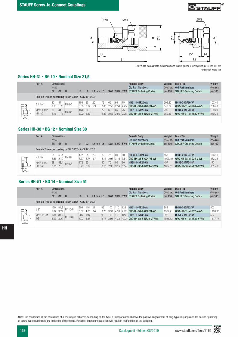
162 www.stauff.com/5/en/#162
HH
Catalogue 5 § Edition 08/2019
STAUFF Screw-to-Connect Couplings
Series HH-31 § BG 10 § Nominal Size 31,5Port A Dimensions Female Body Weight Male Tip Weight
(mm/in) Old Part Numbers (kg/lbs) ca. Old Part Numbers (kg/lbs) ca. ØE ØF B L1 L2 L4 min L5 SW1 SW2 SW3 STAUFF Ordering Codes per 100 STAUFF Ordering Codes per 100
Female Thread according to DIN 3852 - ANSI B 1.20.3
G 1 1/4"80 44
M68x6153 86 20 72 65 65 75 HH31-1-IGF20-VA 293,30 HH31-2-IGF20-VA 107,40
3.15 1.73 6.02 3.39 .79 2.83 2.56 2.56 2.95 QRC-HH-31-F-G20-VT-W5 646.62 QRC-HH-31-M-G20-V-W5 236.78
NPTF 1 1/4" -11 1/2
80 44M68x6
153 86 72 65 65 75 HH31-1-INF20-VA 295 HH31-2-INF20-VA 109,203.15 1.73 6.02 3.39 2.83 2,56 2.56 2.95 QRC-HH-31-F-NF20-VT-W5 650.36 QRC-HH-31-M-NF20-V-W5 240.74
A A
L3 L3
L4
Anschlüsse-Beispiele.pdf 1 10.09.13 15:44
Series HH-38 § BG 12 § Nominal Size 38Port A Dimensions Female Body Weight Male Tip Weight
(mm/in) Old Part Numbers (kg/lbs) ca. Old Part Numbers (kg/lbs) ca. ØE ØF B L1 L2 L4 min L5 SW1 SW2 SW3 STAUFF Ordering Codes per 100 STAUFF Ordering Codes per 100
Female Thread according to DIN 3852 - ANSI B 1.20.3
G 1 1/2"98 53,4
M78x6172 95 22 80 75 80 90 HH38-1-IGF24-VA 455 HH38-2-IGF24-VA 173,40
3.86 2.10 6.77 3.74 .87 3.15 2.95 3.15 3.54 QRC-HH-38-F-G24-VT-W5 1003.10 QRC-HH-38-M-G24-V-W5 382.28
NPTF 1 1/2" -11 1/2
98 53,4M78x6
172 95 80 75 80 90 HH38-1-INF24-VA 457 HH38-2-INF24-VA 1733.86 2.10 6.77 3.74 3.15 2.95 3.15 3.54 QRC-HH-38-F-NF24-VT-W5 1007.51 QRC-HH-38-M-NF24-V-W5 381.40
A A
L3 L3
L4
Anschlüsse-Beispiele.pdf 1 10.09.13 15:44
Note: The connection of the two halves of a coupling is achieved depending on the type. It is important to observe the positive engagement of plug-type couplings and the secure tightening of screw-type couplings to the limit stop of the thread. Forced or improper separation will result in malfunction of the coupling.
Series HH-51 § BG 14 § Nominal Size 51Port A Dimensions Female Body Weight Male Tip Weight
(mm/in) Old Part Numbers (kg/lbs) ca. Old Part Numbers (kg/lbs) ca. ØE ØF B L1 L2 L4 min L5 SW1 SW2 SW3 STAUFF Ordering Codes per 100 STAUFF Ordering Codes per 100
Female Thread according to DIN 3852 - ANSI B 1.20.3
G 2"129 81,8
M115x8205 118 24 96 100 110 125 HH51-1-IGF32-VA 888 HH51-2-IGF32-VA 503
5.07 3.22 8.07 4.65 .94 3.78 3.93 4.33 4.92 QRC-HH-51-F-G32-VT-W5 1957.71 QRC-HH-51-M-G32-V-W5 1108.93
NPTF 2" -11 1/2
129 81,8M115x8
205 118 96 100 110 125 HH51-1-INF32-VA 892 HH51-2-INF32-VA 5075.07 3.22 8.07 4.65 3.78 3.93 4.33 4.92 QRC-HH-51-F-NF32-VT-W5 1966.52 QRC-HH-51-M-NF32-V-W5 1117.74
A A
L3 L3
L4
Anschlüsse-Beispiele.pdf 1 10.09.13 15:44
SW: Width across flats. All dimensions in mm (inch). Drawing similar Series HH-12.* Insertion Male Tip.
HH10-HH51 Muffe und Stecker
Stahl und Edelstahl
scale 0.65
A
SW1
B
SW3
L4L1
L4L2
A
SW2
L5
zeichnerische Darstellung entspricht Serie HH 12
*
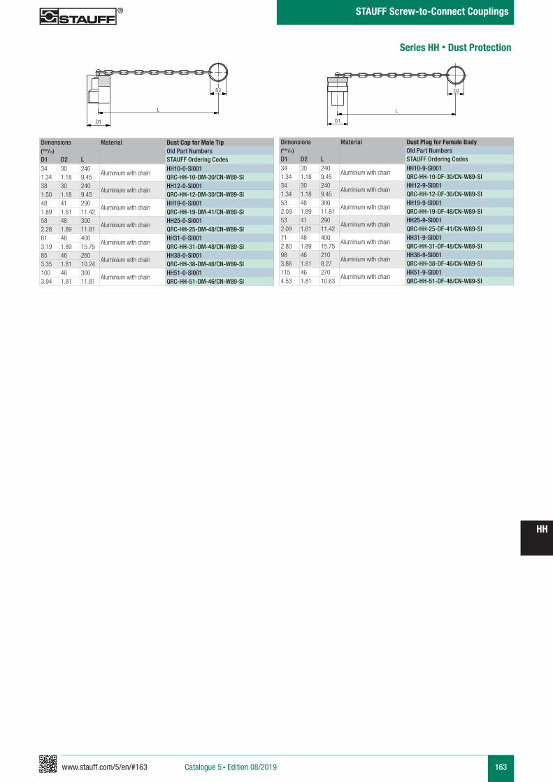
www.stauff.com/5/en/#163 163
HH
Catalogue 5 § Edition 08/2019
STAUFF Screw-to-Connect Couplings
Series HH § Dust Protection
Dimensions Material Dust Cap for Male Tip(mm/in) Old Part NumbersD1 D2 L STAUFF Ordering Codes34 30 240
Aluminium with chainHH10-0-SI001
1.34 1.18 9.45 QRC-HH-10-DM-30/CN-W89-SI38 30 240
Aluminium with chainHH12-0-SI001
1.50 1.18 9.45 QRC-HH-12-DM-30/CN-W89-SI48 41 290
Aluminium with chainHH19-0-SI001
1.89 1.61 11.42 QRC-HH-19-DM-41/CN-W89-SI58 48 300
Aluminium with chainHH25-0-SI001
2.28 1.89 11.81 QRC-HH-25-DM-48/CN-W89-SI81 48 400
Aluminium with chainHH31-0-SI001
3.19 1.89 15.75 QRC-HH-31-DM-48/CN-W89-SI85 46 260
Aluminium with chainHH38-0-SI001
3.35 1.81 10.24 QRC-HH-38-DM-46/CN-W89-SI100 46 300
Aluminium with chainHH51-0-SI001
3.94 1.81 11.81 QRC-HH-51-DM-46/CN-W89-SI
Dimensions Material Dust Plug for Female Body(mm/in) Old Part NumbersD1 D2 L STAUFF Ordering Codes34 30 240
Aluminium with chainHH10-9-SI001
1.34 1.18 9.45 QRC-HH-10-DF-30/CN-W89-SI34 30 240
Aluminium with chainHH12-9-SI001
1.34 1.18 9.45 QRC-HH-12-DF-30/CN-W89-SI53 48 300
Aluminium with chainHH19-9-SI001
2.09 1.89 11.81 QRC-HH-19-DF-48/CN-W89-SI53 41 290
Aluminium with chainHH25-9-SI001
2.09 1.61 11.42 QRC-HH-25-DF-41/CN-W89-SI71 48 400
Aluminium with chainHH31-9-SI001
2.80 1.89 15.75 QRC-HH-31-DF-48/CN-W89-SI98 46 210
Aluminium with chainHH38-9-SI001
3.86 1.81 8.27 QRC-HH-38-DF-46/CN-W89-SI115 46 270
Aluminium with chainHH51-9-SI001
4.53 1.81 10.63 QRC-HH-51-DF-46/CN-W89-SI
HH-0-SI001
Alu mit Kette
scale 0.4
D2
L
D1
HH-9-SI001
Alu mit Kette
scale 0.4
D2
L
D1
164 www.stauff.com/5/en/#164
HH
Catalogue 5 § Edition 08/2019
STAUFF Screw-to-Connect Couplings
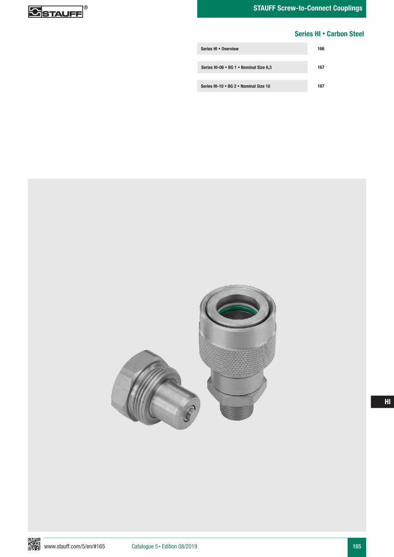
www.stauff.com/5/en/#165 165
HI
Catalogue 5 § Edition 08/2019
STAUFF Screw-to-Connect Couplings
Series HI § Overview
Series HI-06 § BG 1 § Nominal Size 6,3 167
166
Series HI-10 § BG 2 § Nominal Size 10 167
Series HI § Carbon Steel
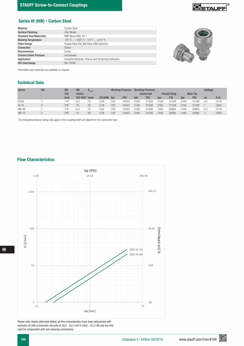
166 www.stauff.com/5/en/#166
HI
Catalogue 5 § Edition 08/2019
STAUFF Screw-to-Connect Couplings
Series HI (HIB) § Carbon Steel
Series BG DN DN Q max Working Pressure Bursting Pressure SpillageZoll metric Connected Female Body Male TipInch ISO 4397 l/min US GPM bar PSI bar PSI bar PSI bar PSI ml fl oz
HI-06 1 1/4" 6,3 10 2.64 720 10443 2160 31328 2160 31328 2160 31328 0,5 .0176HI-10 2 3/8" 10 20 5.28 720 10443 2160 31328 2160 31328 2160 31328 1 .0352HIB-06 1 1/4" 6,3 10 2.64 720 10443 2160 31328 1440 20885 1440 20885 0,5 .0176HIB-10 2 3/8" 10 20 5.28 720 10443 2160 31328 1440 20885 1440 20885 1 .0352
Material Carbon SteelSurface Finishing Zinc-NickelStandard Seal Material(s) NBR (Buna-N®), PU 2
Working Temperature -25° C ... +100° C / -13° F ... +212° FValve Design Poppet Valve (HI), Ball Valve (HIB) (optional)Connection ScrewDisconnection ScrewConnect Under Pressure not allowedApplication Industrial Hydraulic, Rescue and Tensioning HydraulicsISO Interchange ISO 14540
The indicated pressure ratings only apply to the coupling itself and depend on the connection type.
2 Alternative seal materials are available on request.
Technical Data
Flow Characteristics
Please note: Unless otherwise stated, all flow characteristics have been determined with hydraulic oil with a kinematic viscosity of 28,8 - 35,2 mm2/s (28,8 - 35,2 cSt) and are only valid for components with non-reducing connections.
Q [U
S G
PM/m
in]
Δp [PSI]
264,17
26,42
2,64
.26
1.45 14.50 145.04
QRC-HI-06
QRC-HI-10
1
10
100
1000
0,1 1 10
Q [l
/min
]
Δp [bar]
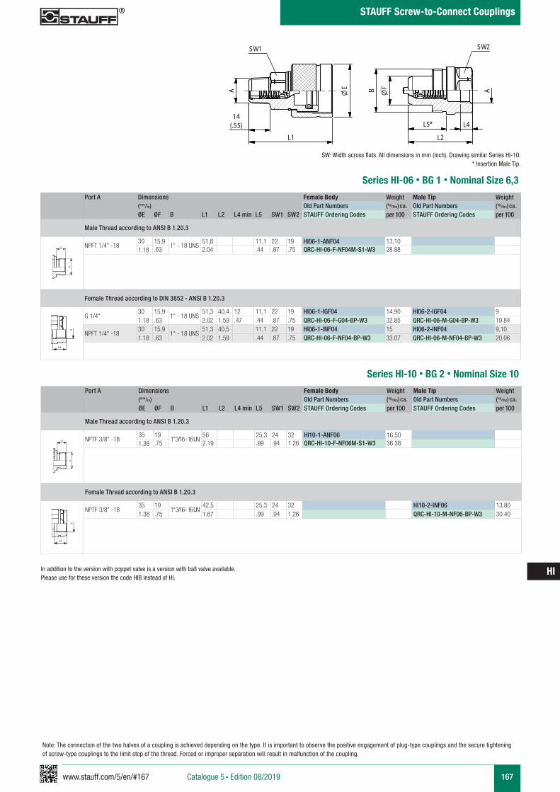
www.stauff.com/5/en/#167 167
HI
Catalogue 5 § Edition 08/2019
STAUFF Screw-to-Connect Couplings
Series HI-06 § BG 1 § Nominal Size 6,3
SW: Width across flats. All dimensions in mm (inch). Drawing similar Series HI-10.* Insertion Male Tip.
HI06-HI10 Muffe und Stecker
scale 0.74
L3L1
A
SW1
A
L4
L2
SW2
B
L5*
zeichnerische Darstellung entspricht Serie HI 10 * Eintauchtiefe Stecker
Port A Dimensions Female Body Weight Male Tip Weight (mm/in) Old Part Numbers (kg/lbs) ca. Old Part Numbers (kg/lbs) ca. ØE ØF B L1 L2 L4 min L5 SW1 SW2 STAUFF Ordering Codes per 100 STAUFF Ordering Codes per 100
Male Thread according to ANSI B 1.20.3
NPFT 1/4" -1830 15,9
1“ - 18 UNS51,8 11,1 22 19 HI06-1-ANF04 13,10
1.18 .63 2.04 .44 .87 .75 QRC-HI-06-F-NF04M-S1-W3 28.88
Female Thread according to DIN 3852 - ANSI B 1.20.3
G 1/4"30 15,9
1“ - 18 UNS51,3 40,4 12 11,1 22 19 HI06-1-IGF04 14,90 HI06-2-IGF04 9
1.18 .63 2.02 1.59 .47 .44 .87 .75 QRC-HI-06-F-G04-BP-W3 32.85 QRC-HI-06-M-G04-BP-W3 19.84
NPFT 1/4" -1830 15,9
1“ - 18 UNS51,3 40,5 11,1 22 19 HI06-1-INF04 15 HI06-2-INF04 9,10
1.18 .63 2.02 1.59 .44 .87 .75 QRC-HI-06-F-NF04-BP-W3 33.07 QRC-HI-06-M-NF04-BP-W3 20.06
A A
L3 L3
L4
Anschlüsse-Beispiele.pdf 1 10.09.13 15:44
A A
L3 L3
L4
Anschlüsse-Beispiele.pdf 1 10.09.13 15:44
Note: The connection of the two halves of a coupling is achieved depending on the type. It is important to observe the positive engagement of plug-type couplings and the secure tightening of screw-type couplings to the limit stop of the thread. Forced or improper separation will result in malfunction of the coupling.
Series HI-10 § BG 2 § Nominal Size 10Port A Dimensions Female Body Weight Male Tip Weight
(mm/in) Old Part Numbers (kg/lbs) ca. Old Part Numbers (kg/lbs) ca. ØE ØF B L1 L2 L4 min L5 SW1 SW2 STAUFF Ordering Codes per 100 STAUFF Ordering Codes per 100
Male Thread according to ANSI B 1.20.3
NPTF 3/8" -1835 19
1“ 3/16 - 16 UN56 25,3 24 32 HI10-1-ANF06 16,50
1.38 .75 2.19 .99 .94 1.26 QRC-HI-10-F-NF06M-S1-W3 36.38
Female Thread according to ANSI B 1.20.3
NPTF 3/8" -1835 19
1“ 3/16 - 16 UN42,5 25,3 24 32 HI10-2-INF06 13.80
1.38 .75 1.67 .99 .94 1.26 QRC-HI-10-M-NF06-BP-W3 30.40
A A
L3 L3
L4
Anschlüsse-Beispiele.pdf 1 10.09.13 15:44
A A
L3 L3
L4
Anschlüsse-Beispiele.pdf 1 10.09.13 15:44
14 (.55)
In addition to the version with poppet valve is a version with ball valve available. Please use for these version the code HIB instead of HI.
168 www.stauff.com/5/en/#168
HI
Catalogue 5 § Edition 08/2019
STAUFF Screw-to-Connect Couplings
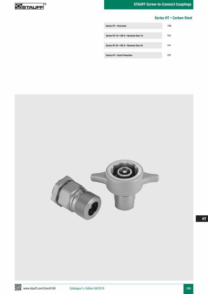
www.stauff.com/5/en/#169 169
HT
Catalogue 5 § Edition 08/2019
STAUFF Screw-to-Connect Couplings
Series HT § Overview
Series HT-19 § BG 6 § Nominal Size 19 171
170
Series HT-25 § BG 8 § Nominal Size 25 171
Series HT § Dust Protection 171
Series HT § Carbon Steel

170 www.stauff.com/5/en/#170
HT
Catalogue 5 § Edition 08/2019
STAUFF Screw-to-Connect Couplings
Series HT § Carbon Steel
Series BG DN DN Q max Working Pressure Bursting Pressure SpillageZoll metric Connected Female Body Male TipInch ISO 4397 l/min US GPM bar PSI bar PSI bar PSI bar PSI ml fl oz
HT-19 6 3/4" 19 (20) 240 63.40 350 5076 1300 18855 1000 14504 1000 14504 10 .3381HT-25 8 1" 25 320 84.53 300 4351 1000 14504 1000 14504 1000 14504 15 .5072
Material Carbon SteelSurface Finishing Zinc-NickelStandard Seal Material(s) NBR (Buna-N®) 2
Working Temperature -25° C ... +100° C / -13° F ... +212° F Valve Design Poppet ValveConnection ScrewDisconnection ScrewConnect Under Pressure not allowedApplication Industrial HydraulicISO Interchange -
The indicated pressure ratings only apply to the coupling itself and depend on the connection type.
2 Alternative seal materials are available on request.
Technical Data
Flow Characteristics
QRC-HT-19
QRC-HT-25
1
10
100
1000
0,1 1 10
Q [l/
min
]
Δp [bar]
Q [U
S G
PM/m
in]
Δp [PSI]
264,17
26,42
2,64
.26
1.45 14.50 145.04
Please note: Unless otherwise stated, all flow characteristics have been determined with hydraulic oil with a kinematic viscosity of 28,8 - 35,2 mm2/s (28,8 - 35,2 cSt) and are only valid for components with non-reducing connections.
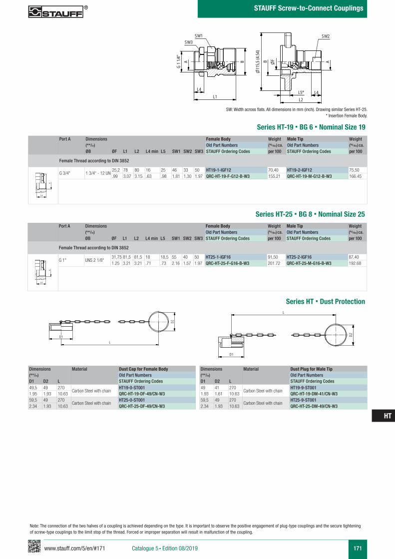
www.stauff.com/5/en/#171 171
HT
Catalogue 5 § Edition 08/2019
STAUFF Screw-to-Connect Couplings
Series HT-19 § BG 6 § Nominal Size 19Port A Dimensions Female Body Weight Male Tip Weight
(mm/in) Old Part Numbers (kg/lbs) ca. Old Part Numbers (kg/lbs) ca. ØB ØF L1 L2 L4 min L5 SW1 SW2 SW3 STAUFF Ordering Codes per 100 STAUFF Ordering Codes per 100
Female Thread according to DIN 3852
G 3/4" 1 3/4“ - 12 UN25,2 78 80 16 25 46 33 50 HT19-1-IGF12 70,40 HT19-2-IGF12 75,50.99 3.07 3.15 .63 .98 1.81 1.30 1.97 QRC-HT-19-F-G12-B-W3 155.21 QRC-HT-19-M-G12-B-W3 166.45
A A
L3 L3
L4
Anschlüsse-Beispiele.pdf 1 10.09.13 15:44
SW: Width across flats. All dimensions in mm (inch). Drawing similar Series HT-25.* Insertion Female Body.
HT19-HT25 Muffe und Stecker
scale 0.4
L4L1
AG
1 1/4"
SW3SW1
B
115,5
(4.54
)
L4
A
SW2
L2L5*
B F
zeichnerische Darstellung entspricht Serie HT 25 * Eintauchtiefe Muffe
Note: The connection of the two halves of a coupling is achieved depending on the type. It is important to observe the positive engagement of plug-type couplings and the secure tightening of screw-type couplings to the limit stop of the thread. Forced or improper separation will result in malfunction of the coupling.
Series HT-25 § BG 8 § Nominal Size 25Port A Dimensions Female Body Weight Male Tip Weight
(mm/in) Old Part Numbers (kg/lbs) ca. Old Part Numbers (kg/lbs) ca. ØB ØF L1 L2 L4 min L5 SW1 SW2 SW3 STAUFF Ordering Codes per 100 STAUFF Ordering Codes per 100
Female Thread according to DIN 3852
G 1" UNS 2 1/8“31,75 81,5 81,5 18 18,5 55 40 50 HT25-1-IGF16 91,50 HT25-2-IGF16 87,401.25 3.21 3.21 .71 .73 2.16 1.57 1.97 QRC-HT-25-F-G16-B-W3 201.72 QRC-HT-25-M-G16-B-W3 192.68
A A
L3 L3
L4
Anschlüsse-Beispiele.pdf 1 10.09.13 15:44
Series HT § Dust Protection
Dimensions Material Dust Plug for Male Tip(mm/in) Old Part NumbersD1 D2 L STAUFF Ordering Codes49 41 270
Carbon Steel with chainHT19-9-ST001
1.93 1.61 10.63 QRC-HT-19-DM-41/CN-W359,5 49 270
Carbon Steel with chainHT25-9-ST001
2.34 1.93 10.63 QRC-HT-25-DM-49/CN-W3
Dimensions Material Dust Cap for Female Body(mm/in) Old Part NumbersD1 D2 L STAUFF Ordering Codes49,5 49 270
Carbon Steel with chainHT19-0-ST001
1.95 1.93 10.63 QRC-HT-19-DF-49/CN-W359,5 49 270
Carbon Steel with chainHT25-0-ST001
2.34 1.93 10.63 QRC-HT-25-DF-49/CN-W3
Staubschutz HT..-0.. Stecker
scale 0.4
L
D2D1
Staubschutz HT..-9.. Stecker
scale 0.4
D2
D1L
172 www.stauff.com/5/en/#172
HT
Catalogue 5 § Edition 08/2019
STAUFF Screw-to-Connect Couplings
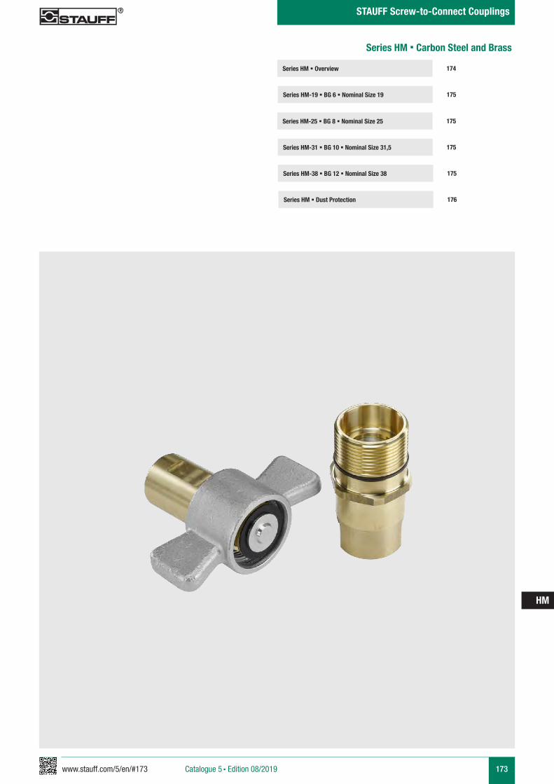
www.stauff.com/5/en/#173 173
HM
Catalogue 5 § Edition 08/2019
STAUFF Screw-to-Connect Couplings
Series HM § Overview
Series HM-19 § BG 6 § Nominal Size 19 175
174
Series HM-25 § BG 8 § Nominal Size 25
Series HM-31 § BG 10 § Nominal Size 31,5 175
175
Series HM-38 § BG 12 § Nominal Size 38
Series HM § Dust Protection 176
175
Series HM § Carbon Steel and Brass
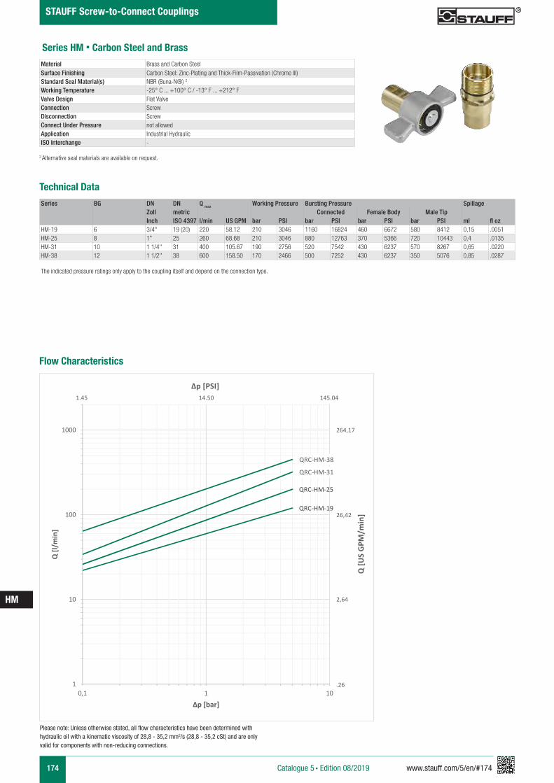
174 www.stauff.com/5/en/#174
HM
Catalogue 5 § Edition 08/2019
STAUFF Screw-to-Connect Couplings
Series HM § Carbon Steel and Brass
Series BG DN DN Q max Working Pressure Bursting Pressure SpillageZoll metric Connected Female Body Male TipInch ISO 4397 l/min US GPM bar PSI bar PSI bar PSI bar PSI ml fl oz
HM-19 6 3/4" 19 (20) 220 58.12 210 3046 1160 16824 460 6672 580 8412 0,15 .0051HM-25 8 1" 25 260 68.68 210 3046 880 12763 370 5366 720 10443 0,4 .0135HM-31 10 1 1/4'' 31 400 105.67 190 2756 520 7542 430 6237 570 8267 0,65 .0220HM-38 12 1 1/2'' 38 600 158.50 170 2466 500 7252 430 6237 350 5076 0,85 .0287
Material Brass and Carbon Steel Surface Finishing Carbon Steel: Zinc-Plating and Thick-Film-Passivation (Chrome III)Standard Seal Material(s) NBR (Buna-N®) 2
Working Temperature -25° C ... +100° C / -13° F ... +212° FValve Design Flat ValveConnection ScrewDisconnection ScrewConnect Under Pressure not allowedApplication Industrial HydraulicISO Interchange -
The indicated pressure ratings only apply to the coupling itself and depend on the connection type.
2 Alternative seal materials are available on request.
Technical Data
Flow Characteristics
QRC-HM-19
QRC-HM-25
QRC-HM-31
QRC-HM-38
1
10
100
1000
0,1 1 10
Q [l/
min
]
Δp [bar]
Q [U
S G
PM/m
in]
Δp [PSI]
264,17
26,42
2,64
.26
1.45 14.50 145.04
Please note: Unless otherwise stated, all flow characteristics have been determined with hydraulic oil with a kinematic viscosity of 28,8 - 35,2 mm2/s (28,8 - 35,2 cSt) and are only valid for components with non-reducing connections.
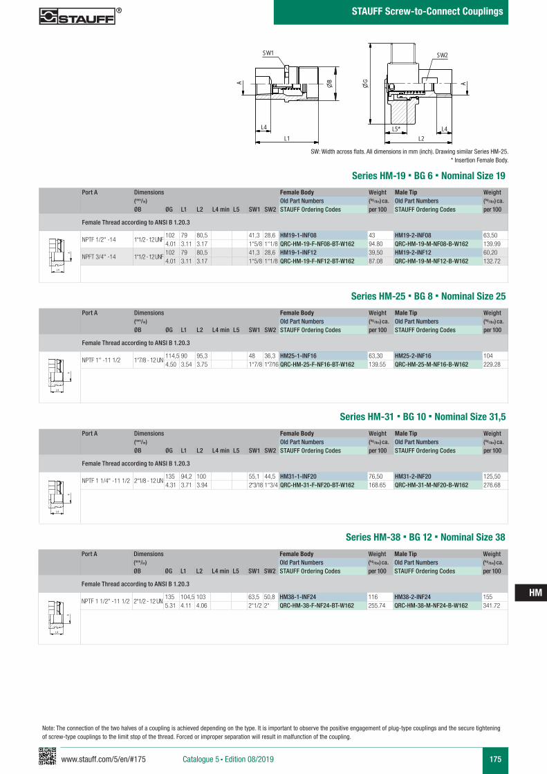
www.stauff.com/5/en/#175 175
HM
Catalogue 5 § Edition 08/2019
STAUFF Screw-to-Connect Couplings
Series HM-25 § BG 8 § Nominal Size 25
Port A Dimensions Female Body Weight Male Tip Weight (mm/in) Old Part Numbers (kg/lbs) ca. Old Part Numbers (kg/lbs) ca. ØB ØG L1 L2 L4 min L5 SW1 SW2 STAUFF Ordering Codes per 100 STAUFF Ordering Codes per 100
Female Thread according to ANSI B 1.20.3
NPTF 1" -11 1/2 1“7/8 - 12 UN114,5 90 95,3 48 36,3 HM25-1-INF16 63,30 HM25-2-INF16 1044.50 3.54 3.75 1“7/8 1“7/16 QRC-HM-25-F-NF16-BT-W162 139.55 QRC-HM-25-M-NF16-B-W162 229.28
A A
L3 L3
L4
Anschlüsse-Beispiele.pdf 1 10.09.13 15:44
Series HM-19 § BG 6 § Nominal Size 19
Port A Dimensions Female Body Weight Male Tip Weight (mm/in) Old Part Numbers (kg/lbs) ca. Old Part Numbers (kg/lbs) ca. ØB ØG L1 L2 L4 min L5 SW1 SW2 STAUFF Ordering Codes per 100 STAUFF Ordering Codes per 100
Female Thread according to ANSI B 1.20.3
NPTF 1/2" -14 1“1/2 - 12 UNF102 79 80,5 41,3 28,6 HM19-1-INF08 43 HM19-2-INF08 63,504.01 3.11 3.17 1“5/8 1“1/8 QRC-HM-19-F-NF08-BT-W162 94.80 QRC-HM-19-M-NF08-B-W162 139.99
NPFT 3/4" -14 1“1/2 - 12 UNF102 79 80,5 41,3 28,6 HM19-1-INF12 39,50 HM19-2-INF12 60,204.01 3.11 3.17 1“5/8 1“1/8 QRC-HM-19-F-NF12-BT-W162 87.08 QRC-HM-19-M-NF12-B-W162 132.72
A A
L3 L3
L4
Anschlüsse-Beispiele.pdf 1 10.09.13 15:44
SW: Width across flats. All dimensions in mm (inch). Drawing similar Series HM-25.* Insertion Female Body.
HM19-HM38 Muffe und Stecker
scale 0,4
SW1
A
L1
B
L2L4
A
SW2
L5*L4
zeichnerische Darstellung entspricht Serie HM 25 * Eintauchtiefe Muffe
Note: The connection of the two halves of a coupling is achieved depending on the type. It is important to observe the positive engagement of plug-type couplings and the secure tightening of screw-type couplings to the limit stop of the thread. Forced or improper separation will result in malfunction of the coupling.
Series HM-31 § BG 10 § Nominal Size 31,5
Port A Dimensions Female Body Weight Male Tip Weight (mm/in) Old Part Numbers (kg/lbs) ca. Old Part Numbers (kg/lbs) ca. ØB ØG L1 L2 L4 min L5 SW1 SW2 STAUFF Ordering Codes per 100 STAUFF Ordering Codes per 100
Female Thread according to ANSI B 1.20.3
NPTF 1 1/4" -11 1/2 2“1/8 - 12 UN135 94,2 100 55,1 44,5 HM31-1-INF20 76,50 HM31-2-INF20 125,504.31 3.71 3.94 2“3/18 1“3/4 QRC-HM-31-F-NF20-BT-W162 168.65 QRC-HM-31-M-NF20-B-W162 276.68
A A
L3 L3
L4
Anschlüsse-Beispiele.pdf 1 10.09.13 15:44
Series HM-38 § BG 12 § Nominal Size 38
Port A Dimensions Female Body Weight Male Tip Weight (mm/in) Old Part Numbers (kg/lbs) ca. Old Part Numbers (kg/lbs) ca. ØB ØG L1 L2 L4 min L5 SW1 SW2 STAUFF Ordering Codes per 100 STAUFF Ordering Codes per 100
Female Thread according to ANSI B 1.20.3
NPTF 1 1/2" -11 1/2 2“1/2 - 12 UN135 104,5 103 63,5 50,8 HM38-1-INF24 116 HM38-2-INF24 1555.31 4.11 4.06 2“1/2 2“ QRC-HM-38-F-NF24-BT-W162 255.74 QRC-HM-38-M-NF24-B-W162 341.72
A A
L3 L3
L4
Anschlüsse-Beispiele.pdf 1 10.09.13 15:44
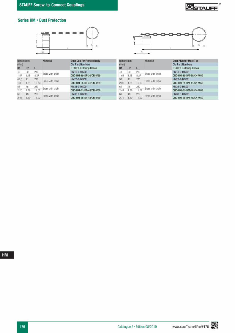
176 www.stauff.com/5/en/#176
HM
Catalogue 5 § Edition 08/2019
STAUFF Screw-to-Connect Couplings
Dimensions Material Dust Cap for Female Body(mm/in) Old Part NumbersD1 D2 L STAUFF Ordering Codes40 30 210
Brass with chainHM19-0-MS001
1.57 1.18 8.27 QRC-HM-19-DF-30/CN-W6948,0 41 270
Brass with chainHM25-0-MS001
1.89 1.61 10.63 QRC-HM-25-DF-41/CN-W6956 48 280
Brass with chainHM31-0-MS001
2.20 1.89 11.02 QRC-HM-31-DF-48/CN-W6963 48 280
Brass with chainHM38-0-MS001
2.48 1.89 11.02 QRC-HM-38-DF-48/CN-W69
Dimensions Material Dust Plug for Male Tip(mm/in) Old Part NumbersD1 D2 L STAUFF Ordering Codes41 30 210
Brass with chainHM19-9-MS001
1.61 1.18 8.27 QRC-HM-19-DM-30/CN-W6953 41 270
Brass with chainHM25-9-MS001
2.09 1.61 10.63 QRC-HM-25-DM-41/CN-W6962 48 280
Brass with chainHM31-9-MS001
2.44 1.89 11.02 QRC-HM-31-DM-48/CN-W6969 48 280
Brass with chainHM38-9-MS001
2.72 1.89 11.02 QRC-HM-38-DM-48/CN-W69
HM25-0-MS001
Messing
scale 0.5
D1
L
D2
HM25-9-MS001
Messing
scale 0.5
D1
LD2
Series HM § Dust Protection
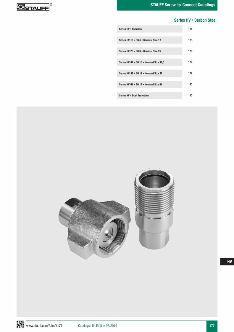
www.stauff.com/5/en/#177 177
HV
Catalogue 5 § Edition 08/2019
STAUFF Screw-to-Connect Couplings
Series HV § Overview
Series HV-19 § BG 6 § Nominal Size 19 179
178
Series HV-25 § BG 8 § Nominal Size 25 179
Series HV-38 § BG 12 § Nominal Size 38 179
Series HV-51 § BG 14 § Nominal Size 51 180
Series HV-31 § BG 10 § Nominal Size 31,5 179
Series HV § Dust Protection 180
Series HV § Carbon Steel
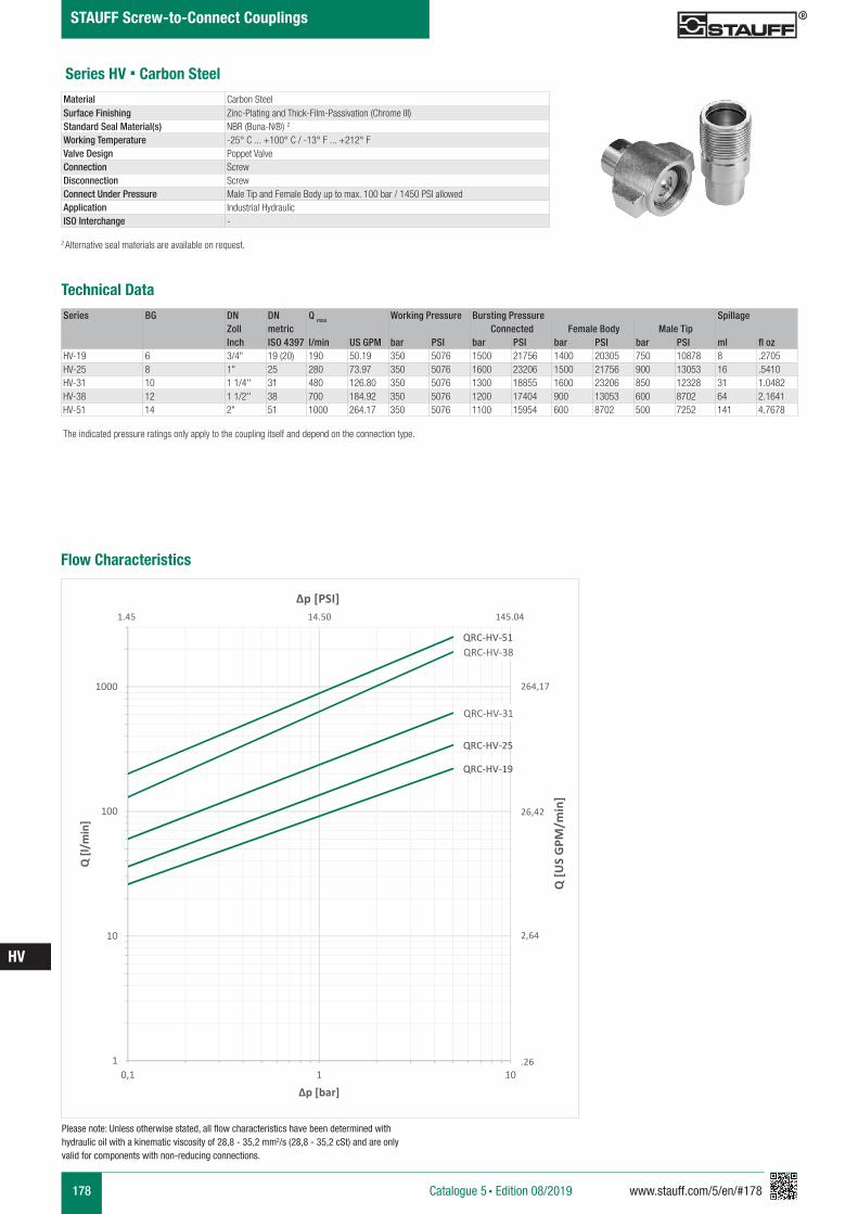
178 www.stauff.com/5/en/#178
HV
Catalogue 5 § Edition 08/2019
STAUFF Screw-to-Connect Couplings
Series HV § Carbon Steel
Series BG DN DN Q max Working Pressure Bursting Pressure SpillageZoll metric Connected Female Body Male TipInch ISO 4397 l/min US GPM bar PSI bar PSI bar PSI bar PSI ml fl oz
HV-19 6 3/4" 19 (20) 190 50.19 350 5076 1500 21756 1400 20305 750 10878 8 .2705HV-25 8 1" 25 280 73.97 350 5076 1600 23206 1500 21756 900 13053 16 .5410HV-31 10 1 1/4'' 31 480 126.80 350 5076 1300 18855 1600 23206 850 12328 31 1.0482HV-38 12 1 1/2'' 38 700 184.92 350 5076 1200 17404 900 13053 600 8702 64 2.1641HV-51 14 2" 51 1000 264.17 350 5076 1100 15954 600 8702 500 7252 141 4.7678
Material Carbon Steel Surface Finishing Zinc-Plating and Thick-Film-Passivation (Chrome III)Standard Seal Material(s) NBR (Buna-N®) 2
Working Temperature -25° C ... +100° C / -13° F ... +212° F Valve Design Poppet ValveConnection ScrewDisconnection ScrewConnect Under Pressure Male Tip and Female Body up to max. 100 bar / 1450 PSI allowedApplication Industrial HydraulicISO Interchange -
The indicated pressure ratings only apply to the coupling itself and depend on the connection type.
2 Alternative seal materials are available on request.
Technical Data
Flow Characteristics
QRC-HV-19
QRC-HV-25
QRC-HV-31
QRC-HV-38QRC-HV-51
1
10
100
1000
0,1 1 10
Q [l/
min
]
Δp [bar]
Q [U
S G
PM/m
in]
Δp [PSI]
264,17
26,42
2,64
.26
1.45 14.50 145.04
Please note: Unless otherwise stated, all flow characteristics have been determined with hydraulic oil with a kinematic viscosity of 28,8 - 35,2 mm2/s (28,8 - 35,2 cSt) and are only valid for components with non-reducing connections.
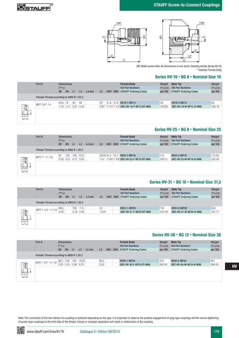
www.stauff.com/5/en/#179 179
HV
Catalogue 5 § Edition 08/2019
STAUFF Screw-to-Connect Couplings
Series HV-25 § BG 8 § Nominal Size 25Port A Dimensions Female Body Weight Male Tip Weight
(mm/in) Old Part Numbers (kg/lbs) ca. Old Part Numbers (kg/lbs) ca. ØE ØG L1 L2 L4 min L5 SW1 SW2 STAUFF Ordering Codes per 100 STAUFF Ordering Codes per 100
Female Thread according to ANSI B 1.20.3
NPTF 1" -11 1/257 102 106 87,6 39,95 41,3 41,3 HV25-1-INF16 110 HV25-2-INF16 114,502.25 4.01 4.17 3.45 1.57 1“5/8 1“5/8 QRC-HV-25-F-NF16-BT-W66 242.51 QRC-HV-25-M-NF16-B-W66 252.43
A A
L3 L3
L4
Anschlüsse-Beispiele.pdf 1 10.09.13 15:44
Series HV-19 § BG 6 § Nominal Size 19Port A Dimensions Female Body Weight Male Tip Weight
(mm/in) Old Part Numbers (kg/lbs) ca. Old Part Numbers (kg/lbs) ca. ØE ØG L1 L2 L4 min L5 SW1 SW2 STAUFF Ordering Codes per 100 STAUFF Ordering Codes per 100
Female Thread according to ANSI B 1.20.3
NPFT 3/4" -1444,5 72 83 62 22 31,8 31,8 HV19-1-INF12 48 HV19-2-INF12 841.75 2.83 3.27 2.44 0.87 1“1/4 1“1/4 QRC-HV-19-F-NF12-BT-W66 105.82 QRC-HV-19-M-NF12-B-W66 185.19
A A
L3 L3
L4
Anschlüsse-Beispiele.pdf 1 10.09.13 15:44
SW: Width across flats. All dimensions in mm (inch). Drawing similar Series HV-25.* Insertion Female Body.
HV19-HV51 Muffe und Stecker
scale 0,4A
L1
SW1
A
L2L5*
L4
L4
SW2
zeichnerische Darstellung entspricht Serie HV 25 * Eintauchtiefe Muffe
Note: The connection of the two halves of a coupling is achieved depending on the type. It is important to observe the positive engagement of plug-type couplings and the secure tightening of screw-type couplings to the limit stop of the thread. Forced or improper separation will result in malfunction of the coupling.
Series HV-31 § BG 10 § Nominal Size 31,5
Port A Dimensions Female Body Weight Male Tip Weight (mm/in) Old Part Numbers (kg/lbs) ca. Old Part Numbers (kg/lbs) ca. ØE ØG L1 L2 L4 min L5 SW1 SW2 STAUFF Ordering Codes per 100 STAUFF Ordering Codes per 100
Female Thread according to ANSI B 1.20.3
NPTF 1 1/4" -11 1/266,5 136 113 51 HV31-1-INF20 187 HV31-2-INF20 2532.62 5.35 4.45 12.01 QRC-HV-31-F-NF20-BT-W66 412.26 QRC-HV-31-M-NF20-B-W66 557.77
A A
L3 L3
L4
Anschlüsse-Beispiele.pdf 1 10.09.13 15:44
Series HV-38 § BG 12 § Nominal Size 38
Port A Dimensions Female Body Weight Male Tip Weight (mm/in) Old Part Numbers (kg/lbs) ca. Old Part Numbers (kg/lbs) ca. ØE ØG L1 L2 L4 min L5 SW1 SW2 STAUFF Ordering Codes per 100 STAUFF Ordering Codes per 100
Female Thread according to ANSI B 1.20.3
NPTF 1 1/2" -11 1/282,5 140 152 133,3 64,3 HV38-1-INF24 310 HV38-2-INF24 4013.25 5.51 5.98 5.25 2.53 QRC-HV-38-F-NF24-BT-W66 683.43 QRC-HV-38-M-NF24-B-W66 884.05
A A
L3 L3
L4
Anschlüsse-Beispiele.pdf 1 10.09.13 15:44
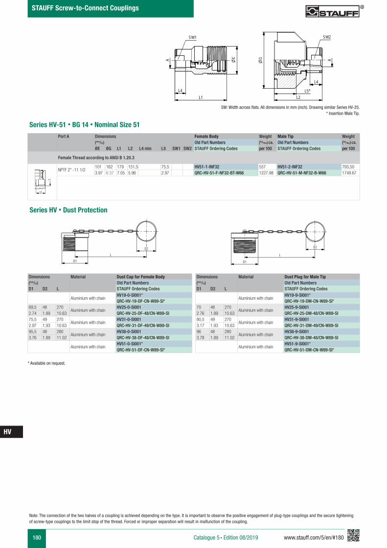
180 www.stauff.com/5/en/#180
HV
Catalogue 5 § Edition 08/2019
STAUFF Screw-to-Connect Couplings
Note: The connection of the two halves of a coupling is achieved depending on the type. It is important to observe the positive engagement of plug-type couplings and the secure tightening of screw-type couplings to the limit stop of the thread. Forced or improper separation will result in malfunction of the coupling.
Series HV-51 § BG 14 § Nominal Size 51Port A Dimensions Female Body Weight Male Tip Weight
(mm/in) Old Part Numbers (kg/lbs) ca. Old Part Numbers (kg/lbs) ca. ØE ØG L1 L2 L4 min L5 SW1 SW2 STAUFF Ordering Codes per 100 STAUFF Ordering Codes per 100
Female Thread according to ANSI B 1.20.3
NPTF 2" -11 1/2101 162 179 151,5 75,5 HV51-1-INF32 557 HV51-2-INF32 793,503.97 6.37 7.05 5.96 2.97 QRC-HV-51-F-NF32-BT-W66 1227.98 QRC-HV-51-M-NF32-B-W66 1749.67
A A
L3 L3
L4
Anschlüsse-Beispiele.pdf 1 10.09.13 15:44
Series HV § Dust Protection
Dimensions Material Dust Cap for Female Body(mm/in) Old Part NumbersD1 D2 L STAUFF Ordering Codes
Aluminium with chainHV19-0-SI001*QRC-HV-19-DF-CN-W89-SI*
69,5 48 270Aluminium with chain
HV25-0-SI0012.74 1.89 10.63 QRC-HV-25-DF-48/CN-W89-SI75,5 49 270
Aluminium with chainHV31-0-SI001
2.97 1.93 10.63 QRC-HV-31-DF-49/CN-W89-SI95,5 48 280
Aluminium with chainHV38-0-SI001
3.76 1.89 11.02 QRC-HV-38-DF-48/CN-W89-SI
Aluminium with chainHV51-0-SI001*QRC-HV-51-DF-CN-W89-SI*
Dimensions Material Dust Plug for Male Tip(mm/in) Old Part NumbersD1 D2 L STAUFF Ordering Codes
Aluminium with chainHV19-9-SI001*QRC-HV-19-DM-CN-W89-SI*
70 48 270Aluminium with chain
HV25-9-SI0012.76 1.89 10.63 QRC-HV-25-DM-48/CN-W89-SI80,5 49 270
Aluminium with chainHV31-9-SI001
3.17 1.93 10.63 QRC-HV-31-DM-49/CN-W89-SI96 48 280
Aluminium with chainHV38-9-SI001
3.78 1.89 11.02 QRC-HV-38-DM-48/CN-W89-SI
Aluminium with chainHV51-9-SI001*QRC-HV-51-DM-CN-W89-SI*
HV25-0-SI001
scale 0.4
D2
L
D1
HV25-9-SI001
scale 0.4
D1
LD2
* Available on request.
SW: Width across flats. All dimensions in mm (inch). Drawing similar Series HV-25.* Insertion Male Tip.
HV19-HV51 Muffe und Stecker
scale 0,4A
L1
SW1
A
L2L5*
L4
L4
SW2
zeichnerische Darstellung entspricht Serie HV 25 * Eintauchtiefe Muffe
www.stauff.com/5/en/#181 181
HV
Catalogue 5 § Edition 08/2019
STAUFF Screw-to-Connect Couplings
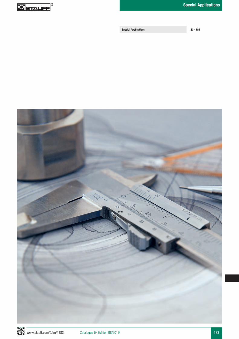
www.stauff.com/5/en/#183 183Catalogue 5 § Edition 08/2019
Special Applications
Special Applications 183 - 185
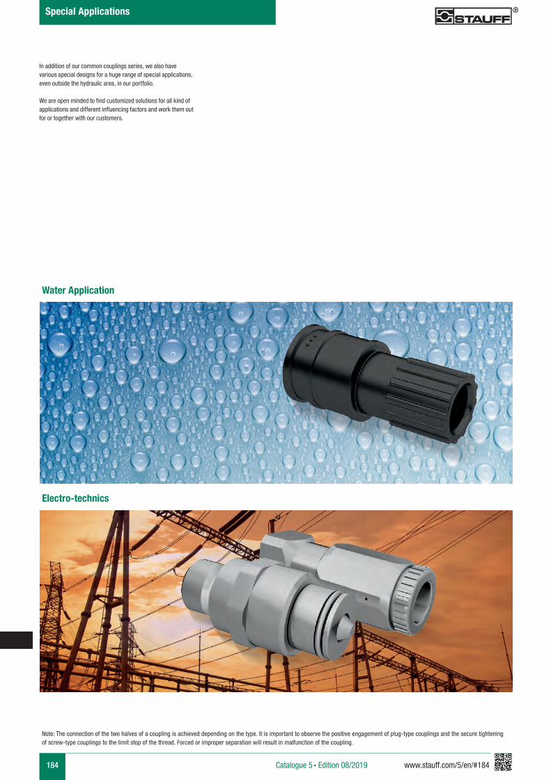
184 www.stauff.com/5/en/#184Catalogue 5 § Edition 08/2019
Special Applications
In addition of our common couplings series, we also have various special designs for a huge range of special applications, even outside the hydraulic area, in our portfolio.
We are open minded to find customized solutions for all kind of applications and different influencing factors and work them out for or together with our customers.
Note: The connection of the two halves of a coupling is achieved depending on the type. It is important to observe the positive engagement of plug-type couplings and the secure tightening of screw-type couplings to the limit stop of the thread. Forced or improper separation will result in malfunction of the coupling.
Water Application
Electro-technics
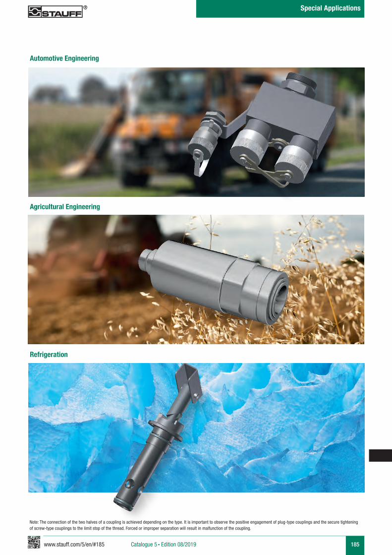
www.stauff.com/5/en/#185 185Catalogue 5 § Edition 08/2019
Special Applications
Note: The connection of the two halves of a coupling is achieved depending on the type. It is important to observe the positive engagement of plug-type couplings and the secure tightening of screw-type couplings to the limit stop of the thread. Forced or improper separation will result in malfunction of the coupling.
Automotive Engineering
Agricultural Engineering
Refrigeration
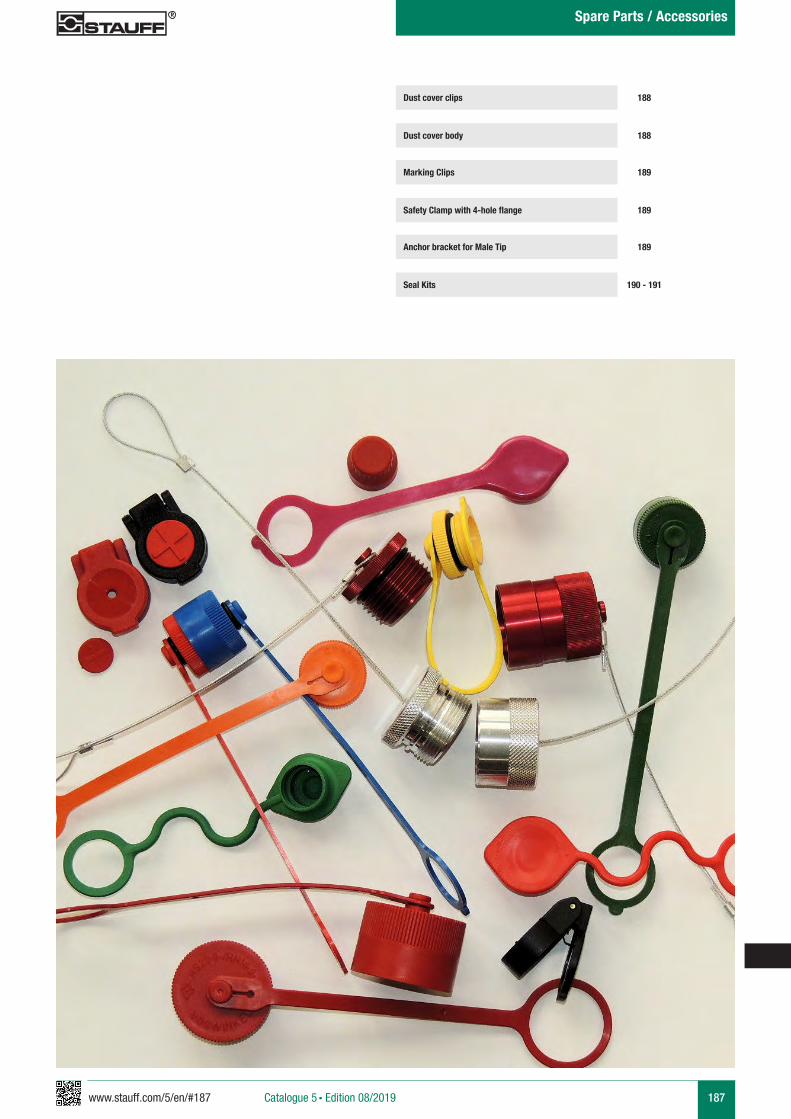
www.stauff.com/5/en/#187 187Catalogue 5 § Edition 08/2019
Spare Parts / Accessories
188
188
189
189
189
190 - 191
Dust cover clips
Dust cover body
Marking Clips
Safety Clamp with 4-hole flange
Anchor bracket for Male Tip
Seal Kits
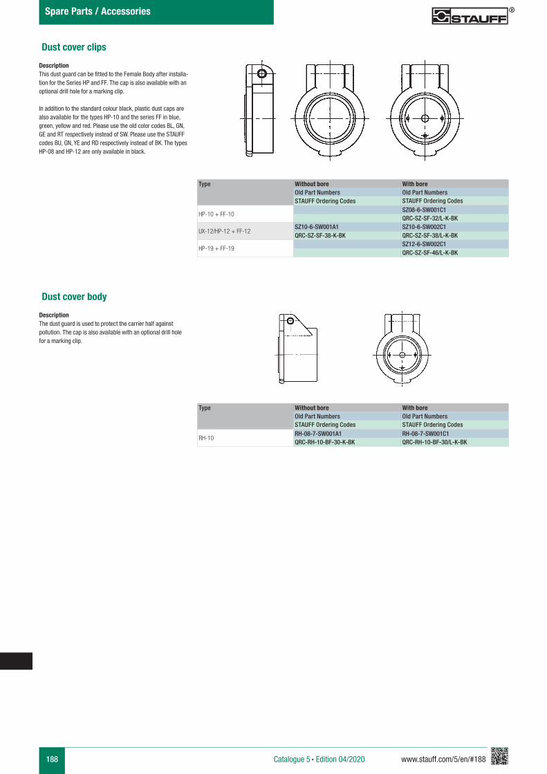
188 www.stauff.com/5/en/#188Catalogue 5 § Edition 04/2020
Spare Parts / Accessories
Dust cover clips
DescriptionThis dust guard can be fitted to the Female Body after installa-tion for the Series HP and FF. The cap is also available with an optional drill hole for a marking clip.
In addition to the standard colour black, plastic dust caps are also available for the types HP-10 and the series FF in blue, green, yellow and red. Please use the old color codes BL, GN, GE and RT respectively instead of SW. Please use the STAUFF codes BU, GN, YE and RD respectively instead of BK. The types HP-08 and HP-12 are only available in black.
Type Without bore With boreOld Part Numbers Old Part NumbersSTAUFF Ordering Codes STAUFF Ordering Codes
HP-10 + FF-10SZ08-6-SW001C1QRC-SZ-SF-32/L-K-BK
UX-12/HP-12 + FF-12SZ10-6-SW001A1 SZ10-6-SW002C1QRC-SZ-SF-38-K-BK QRC-SZ-SF-38/L-K-BK
HP-19 + FF-19SZ12-6-SW002C1QRC-SZ-SF-46/L-K-BK
Dust cover body
DescriptionThe dust guard is used to protect the carrier half against pollution. The cap is also available with an optional drill hole for a marking clip.
Type Without bore With boreOld Part Numbers Old Part NumbersSTAUFF Ordering Codes STAUFF Ordering Codes
RH-10RH-08-7-SW001A1 RH-08-7-SW001C1QRC-RH-10-BF-30-K-BK QRC-RH-10-BF-30/L-K-BK
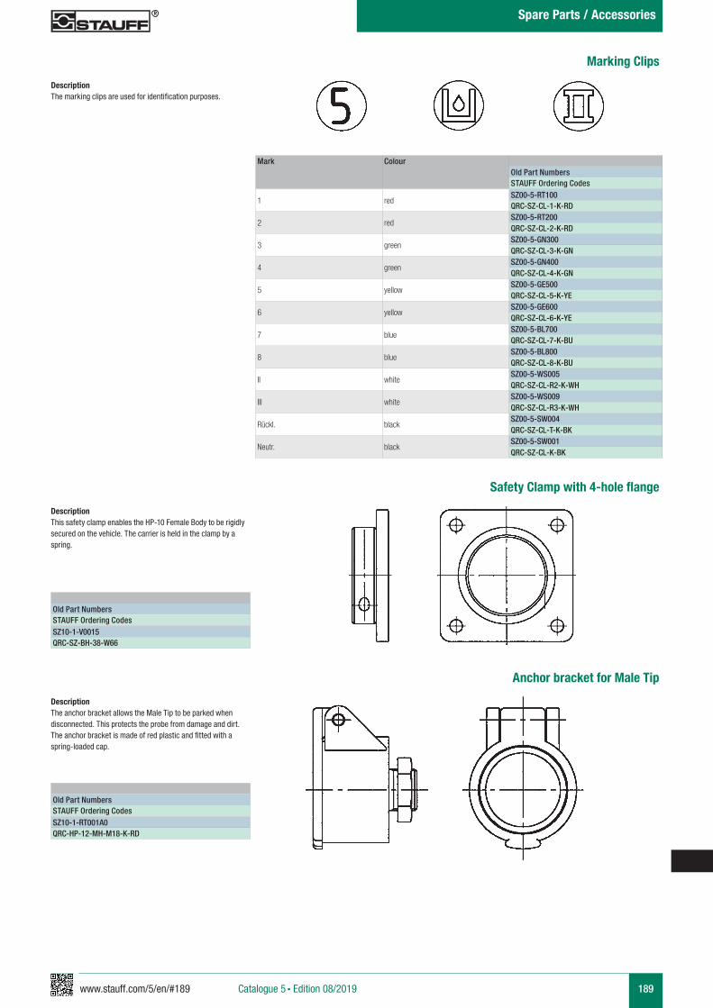
www.stauff.com/5/en/#189 189Catalogue 5 § Edition 08/2019
Spare Parts / Accessories
Marking Clips
DescriptionThe marking clips are used for identification purposes.
Mark ColourOld Part NumbersSTAUFF Ordering Codes
1 redSZ00-5-RT100QRC-SZ-CL-1-K-RD
2 redSZ00-5-RT200QRC-SZ-CL-2-K-RD
3 greenSZ00-5-GN300QRC-SZ-CL-3-K-GN
4 greenSZ00-5-GN400QRC-SZ-CL-4-K-GN
5 yellowSZ00-5-GE500QRC-SZ-CL-5-K-YE
6 yellowSZ00-5-GE600QRC-SZ-CL-6-K-YE
7 blueSZ00-5-BL700QRC-SZ-CL-7-K-BU
8 blueSZ00-5-BL800QRC-SZ-CL-8-K-BU
II whiteSZ00-5-WS005QRC-SZ-CL-R2-K-WH
III whiteSZ00-5-WS009QRC-SZ-CL-R3-K-WH
Rückl. blackSZ00-5-SW004QRC-SZ-CL-T-K-BK
Neutr. blackSZ00-5-SW001QRC-SZ-CL-K-BK
Safety Clamp with 4-hole flange
DescriptionThis safety clamp enables the HP-10 Female Body to be rigidly secured on the vehicle. The carrier is held in the clamp by a spring.
Old Part NumbersSTAUFF Ordering CodesSZ10-1-V0015QRC-SZ-BH-38-W66
Anchor bracket for Male Tip
DescriptionThe anchor bracket allows the Male Tip to be parked when disconnected. This protects the probe from damage and dirt. The anchor bracket is made of red plastic and fitted with a spring-loaded cap.
Old Part NumbersSTAUFF Ordering CodesSZ10-1-RT001A0QRC-HP-12-MH-M18-K-RD
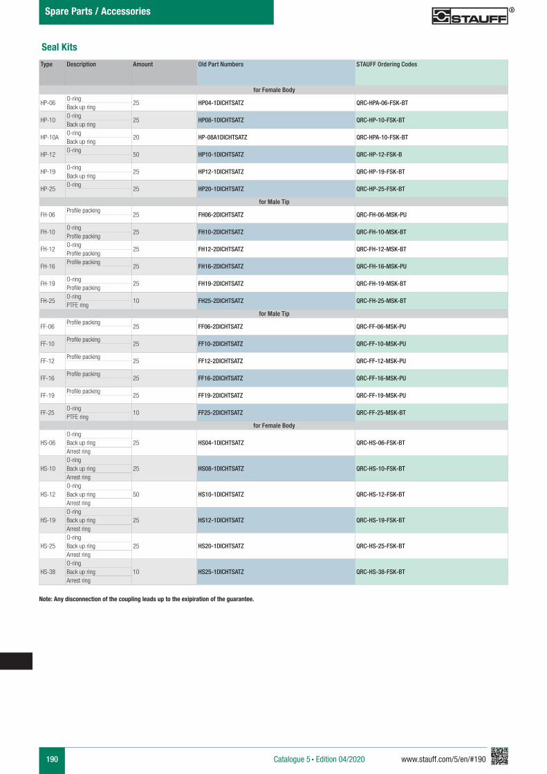
190 www.stauff.com/5/en/#190Catalogue 5 § Edition 04/2020
Spare Parts / Accessories
Seal Kits
Note: Any disconnection of the coupling leads up to the exipiration of the guarantee.
Type Description Amount Old Part Numbers STAUFF Ordering Codes
for Female Body
HP-06O-ring
25 HP04-1DICHTSATZ QRC-HPA-06-FSK-BTBack up ring
HP-10O-ring
25 HP08-1DICHTSATZ QRC-HP-10-FSK-BTBack up ring
HP-10AO-ring
20 HP-08A1DICHTSATZ QRC-HPA-10-FSK-BTBack up ring
HP-12O-ring
50 HP10-1DICHTSATZ QRC-HP-12-FSK-B
HP-19O-ring
25 HP12-1DICHTSATZ QRC-HP-19-FSK-BTBack up ring
HP-25O-ring
25 HP20-1DICHTSATZ QRC-HP-25-FSK-BT
for Male Tip
FH-06Profile packing
25 FH06-2DICHTSATZ QRC-FH-06-MSK-PU
FH-10O-ring
25 FH10-2DICHTSATZ QRC-FH-10-MSK-BTProfile packing
FH-12O-ring
25 FH12-2DICHTSATZ QRC-FH-12-MSK-BTProfile packing
FH-16Profile packing
25 FH16-2DICHTSATZ QRC-FH-16-MSK-PU
FH-19O-ring
25 FH19-2DICHTSATZ QRC-FH-19-MSK-BTProfile packing
FH-25O-ring
10 FH25-2DICHTSATZ QRC-FH-25-MSK-BTPTFE ring
for Male Tip
FF-06Profile packing
25 FF06-2DICHTSATZ QRC-FF-06-MSK-PU
FF-10Profile packing
25 FF10-2DICHTSATZ QRC-FF-10-MSK-PU
FF-12Profile packing
25 FF12-2DICHTSATZ QRC-FF-12-MSK-PU
FF-16Profile packing
25 FF16-2DICHTSATZ QRC-FF-16-MSK-PU
FF-19Profile packing
25 FF19-2DICHTSATZ QRC-FF-19-MSK-PU
FF-25O-ring
10 FF25-2DICHTSATZ QRC-FF-25-MSK-BTPTFE ring
for Female Body
HS-06O-ring
25 HS04-1DICHTSATZ QRC-HS-06-FSK-BTBack up ringArrest ring
HS-10O-ring
25 HS08-1DICHTSATZ QRC-HS-10-FSK-BTBack up ringArrest ring
HS-12O-ring
50 HS10-1DICHTSATZ QRC-HS-12-FSK-BTBack up ringArrest ring
HS-19O-ring
25 HS12-1DICHTSATZ QRC-HS-19-FSK-BTBack up ringArrest ring
HS-25O-ring
25 HS20-1DICHTSATZ QRC-HS-25-FSK-BTBack up ringArrest ring
HS-38O-ring
10 HS25-1DICHTSATZ QRC-HS-38-FSK-BTBack up ringArrest ring
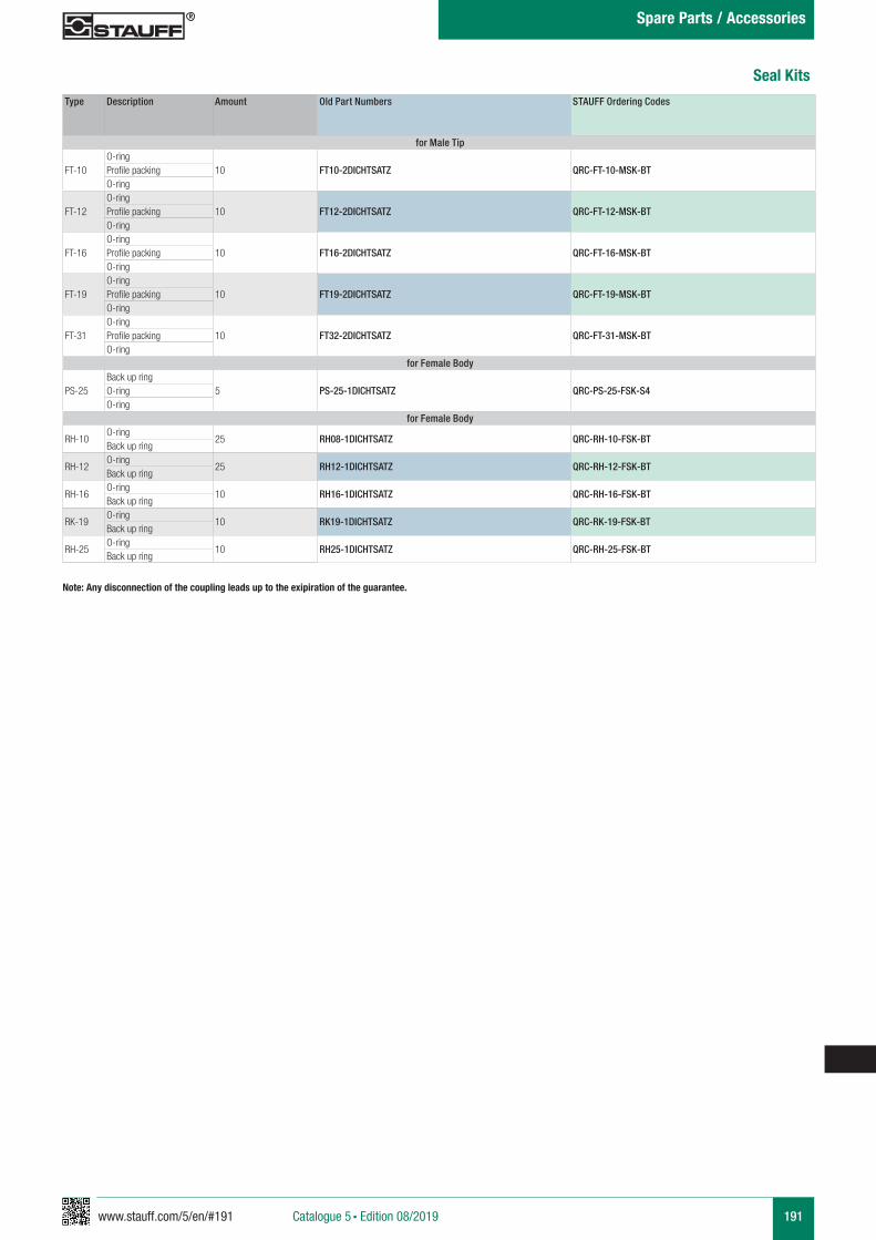
www.stauff.com/5/en/#191 191Catalogue 5 § Edition 08/2019
Spare Parts / Accessories
Type Description Amount Old Part Numbers STAUFF Ordering Codes
for Male Tip
FT-10O-ring
10 FT10-2DICHTSATZ QRC-FT-10-MSK-BTProfile packingO-ring
FT-12O-ring
10 FT12-2DICHTSATZ QRC-FT-12-MSK-BTProfile packingO-ring
FT-16O-ring
10 FT16-2DICHTSATZ QRC-FT-16-MSK-BTProfile packingO-ring
FT-19O-ring
10 FT19-2DICHTSATZ QRC-FT-19-MSK-BTProfile packingO-ring
FT-31O-ring
10 FT32-2DICHTSATZ QRC-FT-31-MSK-BTProfile packingO-ring
for Female Body
PS-25Back up ring
5 PS-25-1DICHTSATZ QRC-PS-25-FSK-S4O-ringO-ring
for Female Body
RH-10O-ring
25 RH08-1DICHTSATZ QRC-RH-10-FSK-BTBack up ring
RH-12O-ring
25 RH12-1DICHTSATZ QRC-RH-12-FSK-BTBack up ring
RH-16O-ring
10 RH16-1DICHTSATZ QRC-RH-16-FSK-BTBack up ring
RK-19O-ring
10 RK19-1DICHTSATZ QRC-RK-19-FSK-BTBack up ring
RH-25O-ring
10 RH25-1DICHTSATZ QRC-RH-25-FSK-BTBack up ring
Seal Kits
Note: Any disconnection of the coupling leads up to the exipiration of the guarantee.
www.stauff.com/5/en/#193 193Catalogue 5 § Edition 08/2019
Technical Appendix
Safety Regulations 194
194 www.stauff.com/5/en/#194Catalogue 5 § Edition 08/2019
Technical Appendix
Important !Incorrect selection or incorrect and inexpert handling of couplings and accessories may result in property damage or personal injury.
§ High velocity fluid discharge§ Explosion or combustion of the conveyed fluid§ Collision with moving or dropping components, caused by failure of a hydraulic circuit§Dangerous whipping of hydraulic hoses§ Risk of injury through contacting hot, cold or otherwise dangerous fluids
Read and observe the following instructions prior to selecting and using a snap-in coupling or associated accessories.
1 General Notes
1.1GeneralThis section contains instructions on selection and handling (installation, coupling and uncoupling and maintenance). This is to be understood as additional safety notes and must be taken into consideration in the use and application of the products.
1.2 Safety MeasuresCouplings may possibly fail without prior warning. Take this into consideration when planning the safety devices of your system or plant.
1.3 Information for the UserForward these safety notes to the persons responsible for the selection and handling of couplings. Use only couplings for which you have received and understood product-specific information.
1.4 Responsibility of the UserDue to the versatile range of applications of couplings, not every application case and every technical detail can be dealt with in this document.
The user is responsible for: § final selection of the product§ fulfilment or requirements by the operator § safety of operating personnel and plant § safety measures necessary in the use of couplings
Should you have any further questions, please contact our sales department.
2 Correct Selection of Couplings
2.1 Pressure RangeThe coupling to be used must be selected so that the maxi-mum permissible operating pressure is equal to or higher than the system pressure. Pressure peaks in the system in excess of the operating pressure reduce the service life of the couplings and therefore should be taken into considera-tion when making the selection.
2.2 Resistance to MediaThe Sealing Materials in the couplings are suitable for a large variety of pressure media. Information on the compatibility of a particular type of fluid are available upon request from product manager.
2.3 Operating TemperatureThe indication of operating temperatures in the technical specifications represents maximum values. These values may not be exceeded in standing or flowing circuits. For actuation the natural warming of the coupling must also be taken into consideration.
2.4 SizeThe selection of the size and type of connection depends on the required transmission of forces. For this purpose, refer to the corresponding diagrams. Flow volume, pressure loss and flow speed should be taken into consideration when select-ing the correct size of a coupling. Should these values be exceeded, malfunctions within the coupling may occur.
2.5 Mechanical ConnectionThe connection of the two halves of a coupling is achieved depending on the type. It is important to observe the positive engagement of plug-type couplings and the secure tighten-ing of screw-type couplings to the limit stop of the thread. Forced or improper separation will result in malfunction of the coupling.
2.6 Thermal StressExcessive warming of the coupling above the recommended operating temperature, for instance due to welding or soldering, can cause the formation of dangerous gases. In addition, the protective surface finish (galvanization) will be damaged and the function of the coupling may be impaired.
2.7 GuidelinesApplicable specifications, standards and regulations as well as technical rules must be taken into consideration in the selection of couplings.
Safety Regulations for Handling of Quick Release Couplings and Accessories
www.stauff.com/5/en/#195 195Catalogue 5 § Edition 08/2019
Technical Appendix
www.stauff.com/5/en/#197 197Catalogue 5 § Edition 08/2019
Appendix
Product-Specific Abbreviations 198 - 201
Global Contact Directory 202 - 203
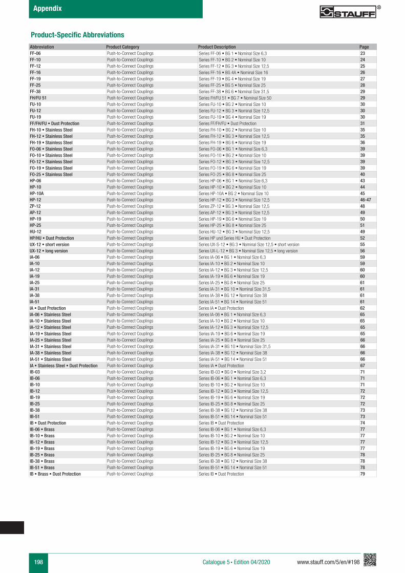
198 www.stauff.com/5/en/#198Catalogue 5 § Edition 04/2020
Appendix
Product-Specific AbbreviationsAbbreviation Product Category Product Description PageFF-06 Push-to-Connect Couplings Series FF-06 § BG 1 § Nominal Size 6,3 23FF-10 Push-to-Connect Couplings Series FF-10 § BG 2 § Nominal Size 10 24FF-12 Push-to-Connect Couplings Series FF-12 § BG 3 § Nominal Size 12,5 25FF-16 Push-to-Connect Couplings Series FF-16 § BG 4A § Nominal Size 16 26FF-19 Push-to-Connect Couplings Series FF-19 § BG 4 § Nominal Size 19 27FF-25 Push-to-Connect Couplings Series FF-25 § BG 5 § Nominal Size 25 28FF-38 Push-to-Connect Couplings Series FF-38 § BG 6 § Nominal Size 31,5 29FH/FU 51 Push-to-Connect Couplings Series FH/FU 51 § BG 7 § Nominal Size 50 29FU-10 Push-to-Connect Couplings Series FU-10 § BG 2 § Nominal Size 10 30FU-12 Push-to-Connect Couplings Series FU-12 § BG 3 § Nominal Size 12,5 30FU-19 Push-to-Connect Couplings Series FU-19 § BG 4 § Nominal Size 19 30FF/FH/FU § Dust Protection Push-to-Connect Couplings Series FF/FH/FU § Dust Protection 31FH-10 § Stainless Steel Push-to-Connect Couplings Series FH-10 § BG 2 § Nominal Size 10 35FH-12 § Stainless Steel Push-to-Connect Couplings Series FH-12 § BG 3 § Nominal Size 12,5 35FH-19 § Stainless Steel Push-to-Connect Couplings Series FH-19 § BG 6 § Nominal Size 19 36FO-06 § Stainless Steel Push-to-Connect Couplings Series FO-06 § BG 1 § Nominal Size 6,3 39FO-10 § Stainless Steel Push-to-Connect Couplings Series FO-10 § BG 2 § Nominal Size 10 39FO-12 § Stainless Steel Push-to-Connect Couplings Series FO-12 § BG 3 § Nominal Size 12,5 39FO-19 § Stainless Steel Push-to-Connect Couplings Series FO-19 § BG 6 § Nominal Size 19 39FO-25 § Stainless Steel Push-to-Connect Couplings Series FO-25 § BG 8 § Nominal Size 25 40HP-06 Push-to-Connect Couplings Series HP-06 § BG 1 § Nominal Size 6,3 43HP-10 Push-to-Connect Couplings Series HP-10 § BG 2 § Nominal Size 10 44HP-10A Push-to-Connect Couplings Series HP-10A § BG 2 § Nominal Size 10 45HP-12 Push-to-Connect Couplings Series HP-12 § BG 3 § Nominal Size 12,5 46-47ZP-12 Push-to-Connect Couplings Series ZP-12 § BG 3 § Nominal Size 12,5 48AP-12 Push-to-Connect Couplings Series AP-12 § BG 3 § Nominal Size 12,5 49HP-19 Push-to-Connect Couplings Series HP-19 § BG 6 § Nominal Size 19 50HP-25 Push-to-Connect Couplings Series HP-25 § BG 8 § Nominal Size 25 51HU-12 Push-to-Connect Couplings Series HU-12 § BG 3 § Nominal Size 12,5 49HP/HU § Dust Protection Push-to-Connect Couplings Series HP und Series HU § Dust Protection 52UX-12 § short version Push-to-Connect Couplings Series UX-S-12 § BG 3 § Nominal Size 12,5 § short version 55UX-12 § long version Push-to-Connect Couplings Series UX-L-12 § BG 3 § Nominal Size 12,5 § long version 56IA-06 Push-to-Connect Couplings Series IA-06 § BG 1 § Nominal Size 6,3 59IA-10 Push-to-Connect Couplings Series IA-10 § BG 2 § Nominal Size 10 59IA-12 Push-to-Connect Couplings Series IA-12 § BG 3 § Nominal Size 12,5 60IA-19 Push-to-Connect Couplings Series IA-19 § BG 6 § Nominal Size 19 60IA-25 Push-to-Connect Couplings Series IA-25 § BG 8 § Nominal Size 25 61IA-31 Push-to-Connect Couplings Series IA-31 § BG 10 § Nominal Size 31,5 61IA-38 Push-to-Connect Couplings Series IA-38 § BG 12 § Nominal Size 38 61IA-51 Push-to-Connect Couplings Series IA-51 § BG 14 § Nominal Size 51 61IA § Dust Protection Push-to-Connect Couplings Series IA § Dust Protection 62IA-06 § Stainless Steel Push-to-Connect Couplings Series IA-06 § BG 1 § Nominal Size 6,3 65IA-10 § Stainless Steel Push-to-Connect Couplings Series IA-10 § BG 2 § Nominal Size 10 65IA-12 § Stainless Steel Push-to-Connect Couplings Series IA-12 § BG 3 § Nominal Size 12,5 65IA-19 § Stainless Steel Push-to-Connect Couplings Series IA-19 § BG 6 § Nominal Size 19 65IA-25 § Stainless Steel Push-to-Connect Couplings Series IA-25 § BG 8 § Nominal Size 25 66IA-31 § Stainless Steel Push-to-Connect Couplings Series IA-31 § BG 10 § Nominal Size 31,5 66IA-38 § Stainless Steel Push-to-Connect Couplings Series IA-38 § BG 12 § Nominal Size 38 66IA-51 § Stainless Steel Push-to-Connect Couplings Series IA-51 § BG 14 § Nominal Size 51 66IA § Stainless Steel § Dust Protection Push-to-Connect Couplings Series IA § Dust Protection 67IB-03 Push-to-Connect Couplings Series IB-03 § BG 0 § Nominal Size 3,2 71IB-06 Push-to-Connect Couplings Series IB-06 § BG 1 § Nominal Size 6,3 71IB-10 Push-to-Connect Couplings Series IB-10 § BG 2 § Nominal Size 10 71IB-12 Push-to-Connect Couplings Series IB-12 § BG 3 § Nominal Size 12,5 72IB-19 Push-to-Connect Couplings Series IB-19 § BG 6 § Nominal Size 19 72IB-25 Push-to-Connect Couplings Series IB-25 § BG 8 § Nominal Size 25 72IB-38 Push-to-Connect Couplings Series IB-38 § BG 12 § Nominal Size 38 73IB-51 Push-to-Connect Couplings Series IB-51 § BG 14 § Nominal Size 51 73IB § Dust Protection Push-to-Connect Couplings Series IB § Dust Protection 74IB-06 § Brass Push-to-Connect Couplings Series IB-06 § BG 1 § Nominal Size 6,3 77IB-10 § Brass Push-to-Connect Couplings Series IB-10 § BG 2 § Nominal Size 10 77IB-12 § Brass Push-to-Connect Couplings Series IB-12 § BG 3 § Nominal Size 12,5 77IB-19 § Brass Push-to-Connect Couplings Series IB-19 § BG 6 § Nominal Size 19 77IB-25 § Brass Push-to-Connect Couplings Series IB-25 § BG 8 § Nominal Size 25 78IB-38 § Brass Push-to-Connect Couplings Series IB-38 § BG 12 § Nominal Size 38 78IB-51 § Brass Push-to-Connect Couplings Series IB-51 § BG 14 § Nominal Size 51 78IB § Brass § Dust Protection Push-to-Connect Couplings Series IB § Dust Protection 79
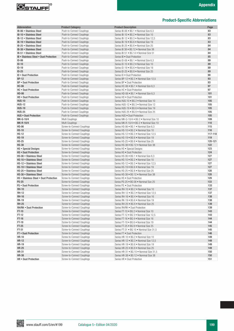
www.stauff.com/5/en/#199 199Catalogue 5 § Edition 04/2020
Appendix
Abbreviation Product Category Product Description PageIB-06 § Stainless Steel Push-to-Connect Couplings Series IB-06 § BG 1 § Nominal Size 6,3 83IB-10 § Stainless Steel Push-to-Connect Couplings Series IB-10 § BG 2 § Nominal Size 10 83IB-12 § Stainless Steel Push-to-Connect Couplings Series IB-12 § BG 3 § Nominal Size 12,5 83IB-19 § Stainless Steel Push-to-Connect Couplings Series IB-19 § BG 6 § Nominal Size 19 83IB-25 § Stainless Steel Push-to-Connect Couplings Series IB-25 § BG 8 § Nominal Size 25 84IB-38 § Stainless Steel Push-to-Connect Couplings Series IB 38 § BG 12 § Nominal Size 38 84IB-51 § Stainless Steel Push-to-Connect Couplings Series IB-51 § BG 14 § Nominal Size 51 84IB § Stainless Steel § Dust Protection Push-to-Connect Couplings Series IB § Dust Protection 85ID-06 Push-to-Connect Couplings Series ID-06 § BG 1 § Nominal Size 6,3 89ID-10 Push-to-Connect Couplings Series ID-10 § BG 2 § Nominal Size 10 89ID-19 Push-to-Connect Couplings Series ID-19 § BG 6 § Nominal Size 19 89ID-25 Push-to-Connect Couplings Series ID-25 § BG 8 § Nominal Size 25 89ID § Dust Protection Push-to-Connect Couplings Series ID § Dust Protection 90BP-12 Push-to-Connect Couplings Series BP-12 § BG 3 § Nominal Size 12,5 93BP § Dust Protection Push-to-Connect Couplings Series BP § Dust Protection 93HC-06 Push-to-Connect Couplings Series HC-06 § BG 1 § Nominal Size 6,3 97HC § Dust Protection Push-to-Connect Couplings Series HC § Dust Protection 97HD-06 Push-to-Connect Couplings Series HD-06 § BG 1 § Nominal Size 6,3 101HD § Dust Protection Push-to-Connect Couplings Series HD § Dust Protection 101HUS-10 Push-to-Connect Couplings Series HUS-10 § BG 2 § Nominal Size 10 105HUS-12 Push-to-Connect Couplings Series HUS-12 § BG 3 § Nominal Size 12 105HUS-19 Push-to-Connect Couplings Series HUS-19 § BG 6 § Nominal Size 19 105HUS-25 Push-to-Connect Couplings Series HUS-25 § BG 8 § Nominal Size 25 105HUS § Dust Protection Push-to-Connect Couplings Series HUS § Dust Protection 105MK-Q-10/4 Multi Couplings Series MK-Q-10/4 § BG 2 § Nominal Size 10 109MK-R-10/4 Multi Couplings Series MK-R-10/4 § BG 2 § Nominal Size 10 110HS-06 Screw-to-Connect Couplings Series HS-06 § BG 1 § Nominal Size 6,3 115HS-10 Screw-to-Connect Couplings Series HS-10 § BG 2 § Nominal Size 10 116HS-12 Screw-to-Connect Couplings Series HS-12 § BG 3 § Nominal Size 12,5 117-118HS-19 Screw-to-Connect Couplings Series HS-19 § BG 6 § Nominal Size 19 119HS-25 Screw-to-Connect Couplings Series HS-25 § BG 8 § Nominal Size 25 120-121HS-38 Screw-to-Connect Couplings Series HS-38 § BG 12 § Nominal Size 38 122HS § Special Designs Screw-to-Connect Couplings Series HS § Special Designs 123HS § Dust Protection Screw-to-Connect Couplings Series HS § Dust Protection 124HS-06 § Stainless Steel Screw-to-Connect Couplings Series HS-06 § BG 1 § Nominal Size 6,3 127HS-10 § Stainless Steel Screw-to-Connect Couplings Series HS-10 § BG 2 § Nominal Size 10 127HS-12 § Stainless Steel Screw-to-Connect Couplings Series HS-12 § BG 3 § Nominal Size 12,5 127HS-19 § Stainless Steel Screw-to-Connect Couplings Series HS-19 § BG 6 § Nominal Size 19 127HS-25 § Stainless Steel Screw-to-Connect Couplings Series HS-25 § BG 8 § Nominal Size 25 128HS-38 § Stainless Steel Screw-to-Connect Couplings Series HS-38 § BG 12 § Nominal Size 38 128HS § Stainless Steel § Dust Protection Screw-to-Connect Couplings Series HS § Dust Protection 129PS-25 Screw-to-Connect Couplings Series PS-25 § BG 08 § Nominal Size 25 133PS § Dust Protection Screw-to-Connect Couplings Series PS § Dust Protection 133RH-10 Screw-to-Connect Couplings Series RH-10 § BG 2 § Nominal Size 10 137RH-12 Screw-to-Connect Couplings Series RH-12 § BG 3 § Nominal Size 12,5 137RH-16 Screw-to-Connect Couplings Series RH-16 § BG 4 § Nominal Size 16 138RK-19 Screw-to-Connect Couplings Series RK-19 § BG 6 § Nominal Size 19 138RH-25 Screw-to-Connect Couplings Series RH-25 § BG 8 § Nominal Size 25 139RH/RK § Dust Protection Screw-to-Connect Couplings Series RH/RK § Dust Protection 139FT-10 Screw-to-Connect Couplings Series FT-10 § BG 2 § Nominal Size 10 143FT-12 Screw-to-Connect Couplings Series FT-12 § BG 3 § Nominal Size 12,5 143FT-16 Screw-to-Connect Couplings Series FT-16 § BG 4 § Nominal Size 16 144FT-19 Screw-to-Connect Couplings Series FT-19 § BG 6 § Nominal Size 19 144FT-25 Screw-to-Connect Couplings Series FT-25 § BG 8 § Nominal Size 25 145FT-31 Screw-to-Connect Couplings Series FT-31 § BG 10 § Nominal Size 31,5 145FT § Dust Protection Screw-to-Connect Couplings Series FT § Dust Protection 146HR-10 Screw-to-Connect Couplings Series HR-10 § BG 2 § Nominal Size 10 149HR-12 Screw-to-Connect Couplings Series HR-12 § BG 3 § Nominal Size 12,5 149HR-19 Screw-to-Connect Couplings Series HR-19 § BG 6 § Nominal Size 19 149HR-25 Screw-to-Connect Couplings Series HR-25 § BG 8 § Nominal Size 25 149HR-31 Screw-to-Connect Couplings Series HR-31 § BG 10 § Nominal Size 31,5 150HR-38 Screw-to-Connect Couplings Series HR-38 § BG 12 § Nominal Size 38 150HR § Dust Protection Screw-to-Connect Couplings Series HR § Dust Protection 151
Product-Specific Abbreviations
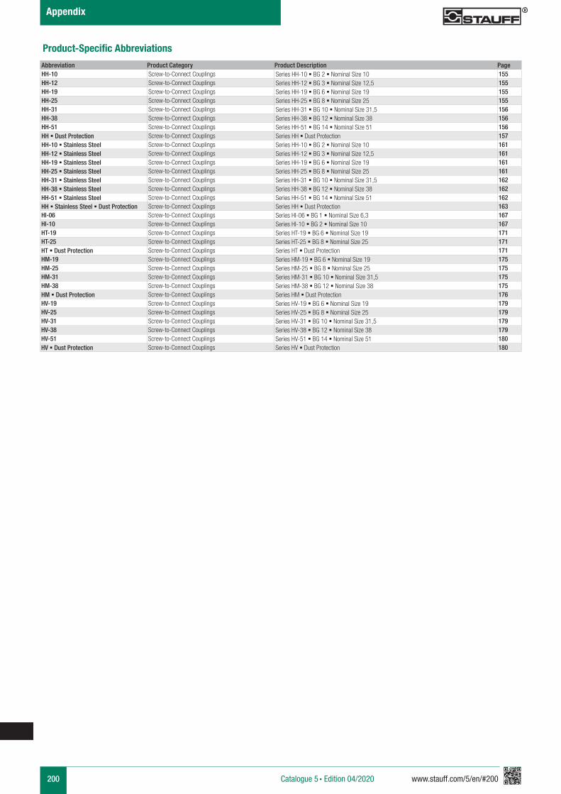
200 www.stauff.com/5/en/#200Catalogue 5 § Edition 04/2020
Appendix
Product-Specific Abbreviations
Abbreviation Product Category Product Description PageHH-10 Screw-to-Connect Couplings Series HH-10 § BG 2 § Nominal Size 10 155HH-12 Screw-to-Connect Couplings Series HH-12 § BG 3 § Nominal Size 12,5 155HH-19 Screw-to-Connect Couplings Series HH-19 § BG 6 § Nominal Size 19 155HH-25 Screw-to-Connect Couplings Series HH-25 § BG 8 § Nominal Size 25 155HH-31 Screw-to-Connect Couplings Series HH-31 § BG 10 § Nominal Size 31,5 156HH-38 Screw-to-Connect Couplings Series HH-38 § BG 12 § Nominal Size 38 156HH-51 Screw-to-Connect Couplings Series HH-51 § BG 14 § Nominal Size 51 156HH § Dust Protection Screw-to-Connect Couplings Series HH § Dust Protection 157HH-10 § Stainless Steel Screw-to-Connect Couplings Series HH-10 § BG 2 § Nominal Size 10 161HH-12 § Stainless Steel Screw-to-Connect Couplings Series HH-12 § BG 3 § Nominal Size 12,5 161HH-19 § Stainless Steel Screw-to-Connect Couplings Series HH-19 § BG 6 § Nominal Size 19 161HH-25 § Stainless Steel Screw-to-Connect Couplings Series HH-25 § BG 8 § Nominal Size 25 161HH-31 § Stainless Steel Screw-to-Connect Couplings Series HH-31 § BG 10 § Nominal Size 31,5 162HH-38 § Stainless Steel Screw-to-Connect Couplings Series HH-38 § BG 12 § Nominal Size 38 162HH-51 § Stainless Steel Screw-to-Connect Couplings Series HH-51 § BG 14 § Nominal Size 51 162HH § Stainless Steel § Dust Protection Screw-to-Connect Couplings Series HH § Dust Protection 163HI-06 Screw-to-Connect Couplings Series HI-06 § BG 1 § Nominal Size 6,3 167HI-10 Screw-to-Connect Couplings Series HI-10 § BG 2 § Nominal Size 10 167HT-19 Screw-to-Connect Couplings Series HT-19 § BG 6 § Nominal Size 19 171HT-25 Screw-to-Connect Couplings Series HT-25 § BG 8 § Nominal Size 25 171HT § Dust Protection Screw-to-Connect Couplings Series HT § Dust Protection 171HM-19 Screw-to-Connect Couplings Series HM-19 § BG 6 § Nominal Size 19 175HM-25 Screw-to-Connect Couplings Series HM-25 § BG 8 § Nominal Size 25 175HM-31 Screw-to-Connect Couplings Series HM-31 § BG 10 § Nominal Size 31,5 175HM-38 Screw-to-Connect Couplings Series HM-38 § BG 12 § Nominal Size 38 175HM § Dust Protection Screw-to-Connect Couplings Series HM § Dust Protection 176HV-19 Screw-to-Connect Couplings Series HV-19 § BG 6 § Nominal Size 19 179HV-25 Screw-to-Connect Couplings Series HV-25 § BG 8 § Nominal Size 25 179HV-31 Screw-to-Connect Couplings Series HV-31 § BG 10 § Nominal Size 31,5 179HV-38 Screw-to-Connect Couplings Series HV-38 § BG 12 § Nominal Size 38 179HV-51 Screw-to-Connect Couplings Series HV-51 § BG 14 § Nominal Size 51 180HV § Dust Protection Screw-to-Connect Couplings Series HV § Dust Protection 180
www.stauff.com/5/en/#201 201Catalogue 5 § Edition 08/2019
Appendix
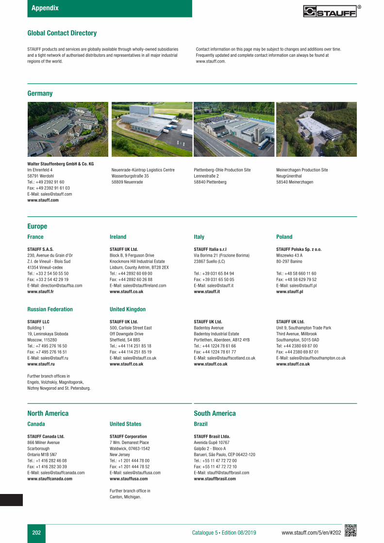
202 www.stauff.com/5/en/#202Catalogue 5 § Edition 08/2019
Appendix
Global Contact Directory
STAUFF products and services are globally available through wholly-owned subsidiaries and a tight network of authorised distributors and representatives in all major industrial regions of the world.
Contact information on this page may be subject to changes and additions over time.Frequently updated and complete contact information can always be found at www.stauff.com.
Germany
Walter Stauffenberg GmbH & Co. KGIm Ehrenfeld 458791 WerdohlTel.: +49 2392 91 60Fax: +49 2392 91 61 03E-Mail: [email protected]
Neuenrade-Küntrop Logistics CentreWasserburgstraße 3558809 Neuenrade
Plettenberg-Ohle Production Site Lennestraße 258840 Plettenberg
EuropeFrance
STAUFF S.A.S.230, Avenue du Grain d’OrZ.I. de Vineuil - Blois Sud41354 Vineuil-cedexTel.: +33 2 54 50 55 50Fax: +33 2 54 42 29 19E-Mail: [email protected]
Ireland
STAUFF UK Ltd.Block B, 9 Ferguson DriveKnockmore Hill Industrial EstateLisburn, County Antrim, BT28 2EXTel.: +44 2892 60 69 00Fax: +44 2892 60 26 88E-Mail: [email protected]
Italy
STAUFF Italia s.r.lVia Borima 21 (Frazione Borima)23867 Suello (LC)
Tel.: +39 031 65 84 94Fax: +39 031 65 50 05E-Mail: [email protected]
Poland
STAUFF Polska Sp. z o.o.Miszewko 43 A80-297 Banino
Tel.: +48 58 660 11 60Fax: +48 58 629 79 52E-Mail: [email protected]
Russian Federation
STAUFF LLC Building 119, Leninskaya SlobodaMoscow, 115280Tel.: +7 495 276 16 50Fax: +7 495 276 16 51E-Mail: [email protected] Further branch offices in Engels, Volzhskiy, Magnitogorsk, Nizhny Novgorod and St. Petersburg.
United Kingdon
STAUFF UK Ltd.500, Carlisle Street EastOff Downgate DriveSheffield, S4 8BSTel.: +44 114 251 85 18Fax: +44 114 251 85 19E-Mail: [email protected]
STAUFF UK Ltd.Badentoy AvenueBadentoy Industrial EstatePortlethen, Aberdeen, AB12 4YBTel.: +44 1224 78 61 66Fax: +44 1224 78 61 77E-Mail: [email protected]
STAUFF UK Ltd.Unit 9, Southampton Trade ParkThird Avenue, MillbrookSouthampton, SO15 0ADTel: +44 2380 69 87 00Fax: +44 2380 69 87 01E-Mail: [email protected]
North AmericaCanada
STAUFF Canada Ltd.866 Milner AvenueScarboroughOntario M1B 5N7Tel.: +1 416 282 46 08Fax: +1 416 282 30 39E-Mail: [email protected]
United States
STAUFF Corporation7 Wm. Demarest PlaceWaldwick, 07463-1542New JerseyTel.: +1 201 444 78 00Fax: +1 201 444 78 52E-Mail: [email protected]
Further branch office in Canton, Michigan.
Brazil
STAUFF Brasil Ltda.Avenida Gupê 10767Galpão 2 - Bloco ABarueri, São Paulo, CEP 06422-120Tel.: +55 11 47 72 72 00Fax: +55 11 47 72 72 10E-Mail: [email protected]
South America
Meinerzhagen Production SiteNeugrünenthal58540 Meinerzhagen
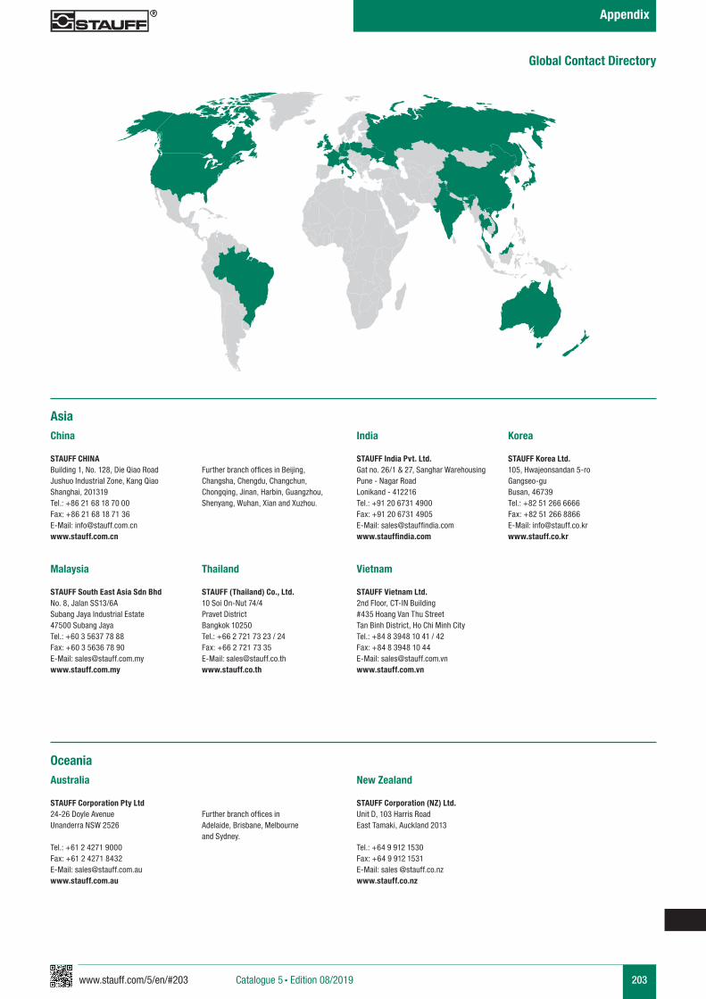
www.stauff.com/5/en/#203 203Catalogue 5 § Edition 08/2019
Appendix
AsiaChina
STAUFF CHINABuilding 1, No. 128, Die Qiao RoadJushuo Industrial Zone, Kang QiaoShanghai, 201319Tel.: +86 21 68 18 70 00Fax: +86 21 68 18 71 36E-Mail: [email protected]
Further branch offices in Beijing, Changsha, Chengdu, Changchun, Chongqing, Jinan, Harbin, Guangzhou, Shenyang, Wuhan, Xian and Xuzhou.
India
STAUFF India Pvt. Ltd.Gat no. 26/1 & 27, Sanghar WarehousingPune - Nagar RoadLonikand - 412216Tel.: +91 20 6731 4900Fax: +91 20 6731 4905E-Mail: [email protected]
Korea
STAUFF Korea Ltd.105, Hwajeonsandan 5-roGangseo-guBusan, 46739Tel.: +82 51 266 6666Fax: +82 51 266 8866E-Mail: [email protected]
Malaysia
STAUFF South East Asia Sdn BhdNo. 8, Jalan SS13/6ASubang Jaya Industrial Estate47500 Subang JayaTel.: +60 3 5637 78 88Fax: +60 3 5636 78 90E-Mail: [email protected]
Thailand
STAUFF (Thailand) Co., Ltd.10 Soi On-Nut 74/4Pravet DistrictBangkok 10250Tel.: +66 2 721 73 23 / 24Fax: +66 2 721 73 35E-Mail: [email protected]
Vietnam
STAUFF Vietnam Ltd.2nd Floor, CT-IN Building#435 Hoang Van Thu StreetTan Binh District, Ho Chi Minh CityTel.: +84 8 3948 10 41 / 42Fax: +84 8 3948 10 44E-Mail: [email protected]
OceaniaAustralia
STAUFF Corporation Pty Ltd24-26 Doyle AvenueUnanderra NSW 2526
Tel.: +61 2 4271 9000Fax: +61 2 4271 8432E-Mail: [email protected]
Further branch offices in Adelaide, Brisbane, Melbourne and Sydney.
New Zealand
STAUFF Corporation (NZ) Ltd.Unit D, 103 Harris RoadEast Tamaki, Auckland 2013
Tel.: +64 9 912 1530Fax: +64 9 912 1531E-Mail: sales @stauff.co.nzwww.stauff.co.nz
Global Contact Directory
Germany Walter Stauffenberg GmbH & Co. KG Im Ehrenfeld 458791 Werdohl Tel.: +49 2392 91 60Fax: +49 2392 91 61 03E-Mail: [email protected]
Catalogue 5 STAUFF Quick Release Couplings § English § 9910000425 § 08/2019
STAUFF products and services are globally available through wholly-owned subsidiaries and a tight network of authorised distributors and representatives in all major industrial regions of the world. You can find detailed contact information on the last two pages of this product catalogue or at
www.stauff.com
Catalogue 5
STAUFF Quick Release Couplings
Introduction
Push-to-Connect Couplings § HP/HU Series
Push-to-Connect Couplings § UX Series
Push-to-Connect Couplings § IA Series
Push-to-Connect Couplings § ID Series
Push-to-Connect Couplings § FH Series
Push-to-Connect Couplings § IB Series
Push-to-Connect Couplings § FF/FU Series
Push-to-Connect Couplings § BP Series
Push-to-Connect Couplings § HC Series
Push-to-Connect Couplings § HD Series
Multi Couplings § MK Series
Screw-to-Connect Couplings § HS Series
Screw-to-Connect Couplings § PS Series
Screw-to-Connect Couplings § RH/RK Series
Screw-to-Connect Couplings § HR Series
Screw-to-Connect Couplings § HH Series
Screw-to-Connect Couplings § FT Series
Screw-to-Connect Couplings § HI Series
Screw-to-Connect Couplings § HT Series
Screw-to-Connect Couplings § HM Series
Special Applications
Spare Parts / Accessories
Technical Appendix
Appendix
Screw-to-Connect Couplings § HV Series
Push-to-Connect Couplings § HUS Series
Push-to-Connect Couplings § FO Series
Overview