cambada soccer team: from robot architecture to multiagent coordination
TRANSCRIPT
������������ ����������� ����� � ���� ���� ����� ������ �� ��
0
CAMBADA soccer team: from robotarchitecture to multiagent coordination∗
António J. R. Neves, José Luís Azevedo, Bernardo Cunha, Nuno Lau,João Silva, Frederico Santos, Gustavo Corrente, Daniel A. Martins,Nuno Figueiredo, Artur Pereira, Luís Almeida, Luís Seabra Lopes,
Armando J. Pinho, João Rodrigues and Paulo PedreirasTransverse Activity on Intelligent Robotics, IEETA / DETI
University of Aveiro, Portugal
1. Introduction
Robotic soccer is nowadays a popular research domain in the area of multi-robot systems.RoboCup is an international joint project to promote research in artificial intelligence, roboticsand related fields. RoboCup chose soccer as the main problem aiming at innovations to beapplied for socially relevant problems. It includes several competition leagues, each one witha specific emphasis, some only at software level, others at both hardware and software, withsingle or multiple agents, cooperative and competitive.In the context of RoboCup, the Middle Size League (MSL) is one of the most challenging. Inthis league, each team is composed of up to 5 robots with a maximum size of 50cm × 50cm,80cm height and a maximum weight of 40Kg, playing in a field of 18m × 12m. The rules of thegame are similar to the official FIFA rules, with minor changes required to adapt them for theplaying robotsCAMBADA, Cooperative Autonomous Mobile roBots with Advanced Distributed Architecture, is theMSL Soccer team from the University of Aveiro. The project started in 2003, coordinated bythe Transverse Activity on Intelligent Robotics group of the Institute of Electronic and Telem-atic Engineering of Aveiro (IEETA). This project involves people working on several areasfor building the mechanical structure of the robot, its hardware architecture and controllers(Almeida et al., 2002; Azevedo et al., 2007) and the software development in areas such as im-age analysis and processing (Caleiro et al., 2007; Cunha et al., 2007; Martins et al., 2008; Neveset al., 2007; 2008), sensor and information fusion (Silva et al., 2008; 2009), reasoning and con-trol (Lau et al., 2008), cooperative sensing approach based on a Real-Time Database (Almeidaet al., 2004), communications among robots (Santos et al., 2009; 2007) and the development ofan efficient basestation.The main contribution of this chapter is to present the new advances in the areas describedabove involving the development of an MSL team of soccer robots, taking the example ofthe CAMBADA team that won the RoboCup 2008 and attained the third place in the lastedition of the MSL tournament at RoboCup 2009. CAMBADA also won the last three editions
∗This work was partially supported by project ACORD, Adaptive Coordination of Robotic Teams,FCT/PTDC/EIA/70695/2006.
�

�� �(��-.
of the Portuguese Robotics Open 2007-2009, which confirms the efficiency of the proposedarchitecture.This chapter is organized as follows. In Section 2 it is presented the layered and modular ar-chitecture of the robot’s hardware. Section 3 describes the vision system of the robots, startingin the calibration of the several parameters and presenting efficient algorithms for the detec-tion of the colored objects and algorithms for the detection of arbitrary FIFA balls, a currentchallenge in the MSL. In Section 4 it is presented the process of building the representationof the environment and the algorithms for the integration of the several sources of informa-tion received by the robot. Section 5 presents the architecture used in CAMBADA robots toshare information between them using a real-time database. Section 6 presents the methodol-ogy developed for the communication between robots, using an adaptive TDMA transmissioncontrol. In Section 7 it is presented the robots coordination model based on notions like strate-gic positioning, role and formation. Section 8 presents the Base Station application, responsiblefor the control of the agents, interpreting and sending high level instructions and monitoringinformation of the robots. Finally, in Section 9 we draw some conclusions.
2. Hardware architecture
The CAMBADA robots (Fig. 1) were designed and completely built in-house. The baseline forrobot construction is a cylindrical envelope, with 485 mm in diameter. The mechanical struc-ture of the players is layered and modular. Each layer can easily be replaced by an equivalentone. The components in the lower layer, namely motors, wheels, batteries and an electromag-netic kicker, are attached to an aluminum plate placed 8 cm above the floor. The second layercontains the control electronics. The third layer contains a laptop computer, at 22.5 cm fromthe floor, an omni-directional vision system, a frontal camera and an electronic compass, allclose to the maximum height of 80 cm. The players are capable of holonomic motion, basedon three omni-directional roller wheels.
Fig. 1. Robots used by the CAMBADA MSL robotic soccer team.
The general architecture of the CAMBADA robots has been described in (Almeida et al., 2004;Silva et al., 2005). Basically, the robots follow a biomorphic paradigm, each being centeredon a main processing unit (a laptop), the brain, which is responsible for the higher-level be-havior coordination, i.e. the coordination layer. This main processing unit handles externalcommunication with the other robots and has high bandwidth sensors, typically vision, di-rectly attached to it. Finally, this unit receives low bandwidth sensing information and sends

������������ ����������� ����� � ���� ���� ����� ������ �� -�
actuating commands to control the robot attitude by means of a distributed low-level sens-ing/actuating system (Fig. 2), the nervous system.
Fig. 2. Hardware architecture with functional mapping.
The low-level sensing/actuating system follows the fine-grain distributed model where mostof the elementary functions, e.g. basic reactive behaviors and closed-loop control of complexactuators, are encapsulated in small microcontroller-based nodes interconnected by means ofa network. For this purpose, Controller Area Network (CAN), a real-time fieldbus typicalin distributed embedded systems, has been chosen. This network is complemented with ahigher-level transmission control protocol to enhance its real-time performance, composabil-ity and fault-tolerance, namely the FTT-CAN protocol (Flexible Time-Triggered communica-tion over CAN) (Almeida et al., 2002). This protocol keeps all the information of periodicflows within a master node, implemented on another basic module, which works like a mae-stro triggering tasks and message transmissions.The low-level sensing/actuation system executes four main functions as described in Fig. 3,namely Motion, Odometry, Kick and System monitoring. The former provides holonomicmotion using 3 DC motors. The Odometry function combines the encoder readings fromthe 3 motors and provides a coherent robot displacement information that is then sent to thecoordination layer. The Kick function includes the control of an electromagnetic kicker and ofa ball handler to dribble the ball.
Fig. 3. Layered software architecture of CAMBADA players.
The system monitor function monitors the robot batteries as well as the state of all nodes in thelow-level layer. Finally, the low-level control layer connects to the coordination layer through
�� �(��--
a gateway, which filters interactions within both layers, passing through the information thatis relevant across the layers, only. Such filtering reduces the overhead of handling unnecessaryreceptions at each layer as well as the network bandwidth usage at the low-level side, thusfurther reducing mutual interference across the layers.A detailed description regarding the implementation of this architecture, namely the map-ping between the functional architecture onto hardware and the information flows and theirsynchronization are presented in (Azevedo et al., 2007).
3. Vision system
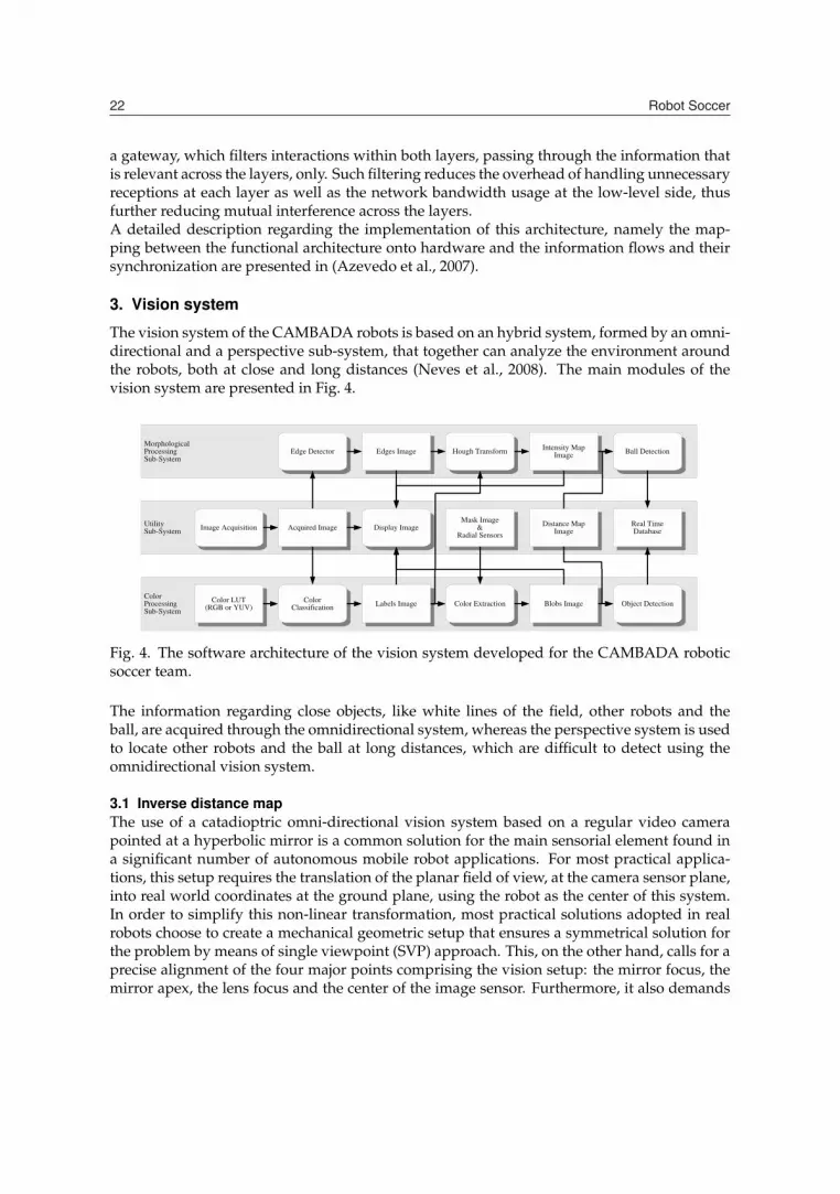
The vision system of the CAMBADA robots is based on an hybrid system, formed by an omni-directional and a perspective sub-system, that together can analyze the environment aroundthe robots, both at close and long distances (Neves et al., 2008). The main modules of thevision system are presented in Fig. 4.
Fig. 4. The software architecture of the vision system developed for the CAMBADA roboticsoccer team.
The information regarding close objects, like white lines of the field, other robots and theball, are acquired through the omnidirectional system, whereas the perspective system is usedto locate other robots and the ball at long distances, which are difficult to detect using theomnidirectional vision system.
3.1 Inverse distance mapThe use of a catadioptric omni-directional vision system based on a regular video camerapointed at a hyperbolic mirror is a common solution for the main sensorial element found ina significant number of autonomous mobile robot applications. For most practical applica-tions, this setup requires the translation of the planar field of view, at the camera sensor plane,into real world coordinates at the ground plane, using the robot as the center of this system.In order to simplify this non-linear transformation, most practical solutions adopted in realrobots choose to create a mechanical geometric setup that ensures a symmetrical solution forthe problem by means of single viewpoint (SVP) approach. This, on the other hand, calls for aprecise alignment of the four major points comprising the vision setup: the mirror focus, themirror apex, the lens focus and the center of the image sensor. Furthermore, it also demands
������������ ����������� ����� � ���� ���� ����� ������ �� -/
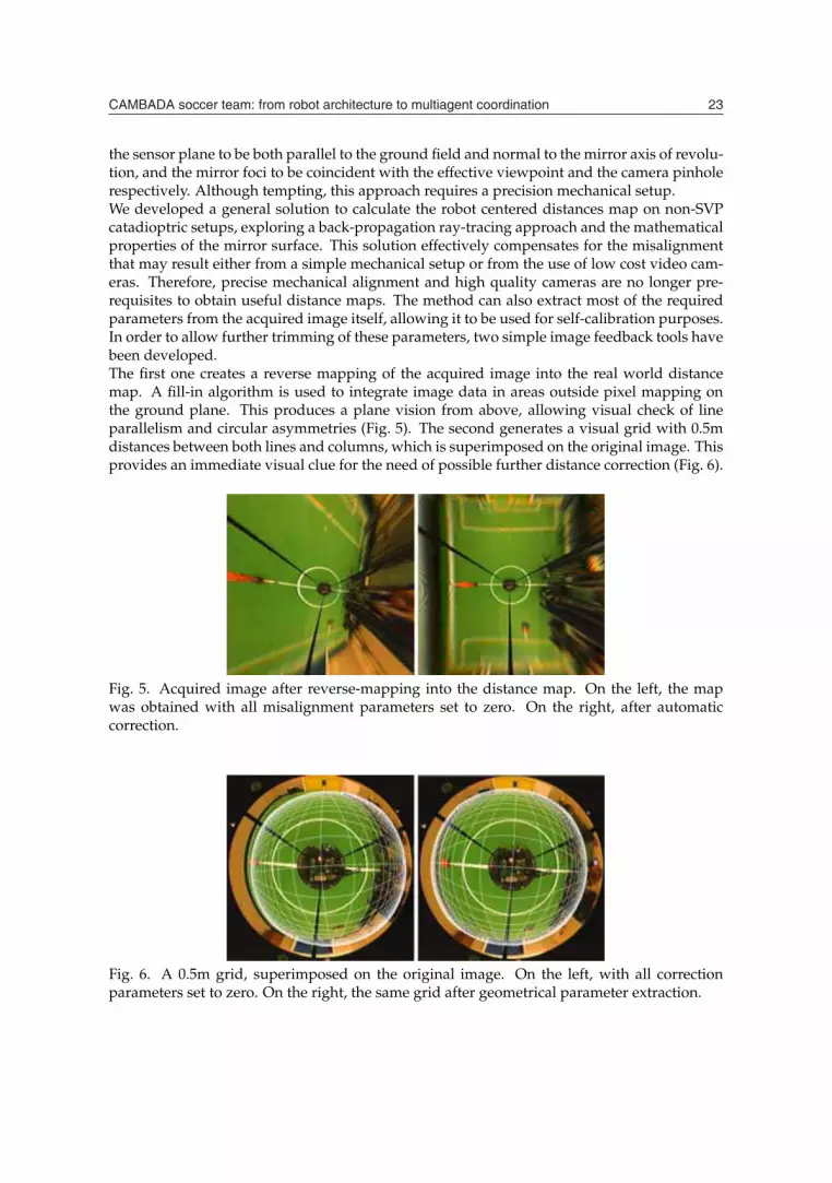
the sensor plane to be both parallel to the ground field and normal to the mirror axis of revolu-tion, and the mirror foci to be coincident with the effective viewpoint and the camera pinholerespectively. Although tempting, this approach requires a precision mechanical setup.We developed a general solution to calculate the robot centered distances map on non-SVPcatadioptric setups, exploring a back-propagation ray-tracing approach and the mathematicalproperties of the mirror surface. This solution effectively compensates for the misalignmentthat may result either from a simple mechanical setup or from the use of low cost video cam-eras. Therefore, precise mechanical alignment and high quality cameras are no longer pre-requisites to obtain useful distance maps. The method can also extract most of the requiredparameters from the acquired image itself, allowing it to be used for self-calibration purposes.In order to allow further trimming of these parameters, two simple image feedback tools havebeen developed.The first one creates a reverse mapping of the acquired image into the real world distancemap. A fill-in algorithm is used to integrate image data in areas outside pixel mapping onthe ground plane. This produces a plane vision from above, allowing visual check of lineparallelism and circular asymmetries (Fig. 5). The second generates a visual grid with 0.5mdistances between both lines and columns, which is superimposed on the original image. Thisprovides an immediate visual clue for the need of possible further distance correction (Fig. 6).
Fig. 5. Acquired image after reverse-mapping into the distance map. On the left, the mapwas obtained with all misalignment parameters set to zero. On the right, after automaticcorrection.
Fig. 6. A 0.5m grid, superimposed on the original image. On the left, with all correctionparameters set to zero. On the right, the same grid after geometrical parameter extraction.
�� �(��-0
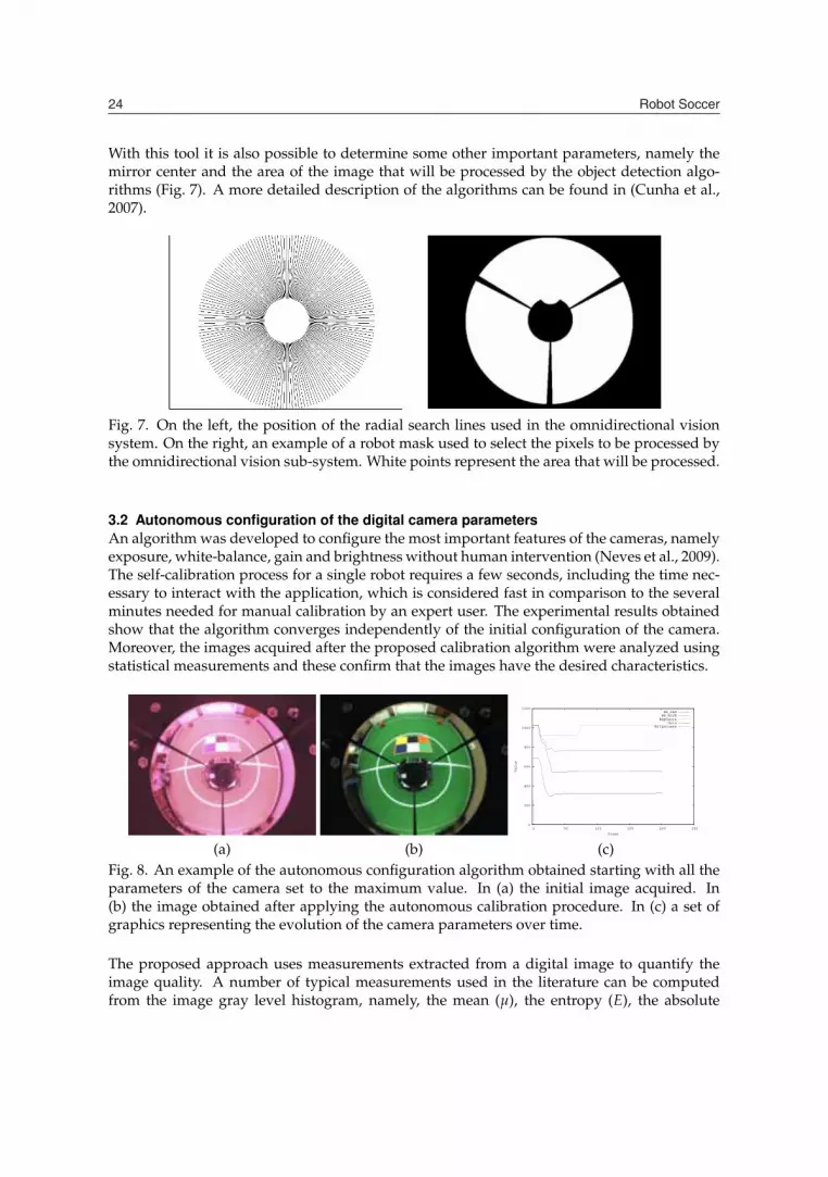
With this tool it is also possible to determine some other important parameters, namely themirror center and the area of the image that will be processed by the object detection algo-rithms (Fig. 7). A more detailed description of the algorithms can be found in (Cunha et al.,2007).
Fig. 7. On the left, the position of the radial search lines used in the omnidirectional visionsystem. On the right, an example of a robot mask used to select the pixels to be processed bythe omnidirectional vision sub-system. White points represent the area that will be processed.
3.2 Autonomous configuration of the digital camera parametersAn algorithm was developed to configure the most important features of the cameras, namelyexposure, white-balance, gain and brightness without human intervention (Neves et al., 2009).The self-calibration process for a single robot requires a few seconds, including the time nec-essary to interact with the application, which is considered fast in comparison to the severalminutes needed for manual calibration by an expert user. The experimental results obtainedshow that the algorithm converges independently of the initial configuration of the camera.Moreover, the images acquired after the proposed calibration algorithm were analyzed usingstatistical measurements and these confirm that the images have the desired characteristics.
0
200
400
600
800
1000
1200
0 50 100 150 200 250
Value
Frame
WB_REDWB_BLUE
ExposureGain
Brightness
(a) (b) (c)Fig. 8. An example of the autonomous configuration algorithm obtained starting with all theparameters of the camera set to the maximum value. In (a) the initial image acquired. In(b) the image obtained after applying the autonomous calibration procedure. In (c) a set ofgraphics representing the evolution of the camera parameters over time.
The proposed approach uses measurements extracted from a digital image to quantify theimage quality. A number of typical measurements used in the literature can be computedfrom the image gray level histogram, namely, the mean (μ), the entropy (E), the absolute

������������ ����������� ����� � ���� ���� ����� ������ �� -1
central moment (ACM) and the mean sample value (MSV). These measurements are used tocalibrate the exposure and gain. Moreover, the proposed algorithm analyzes a white area inthe image to calibrate the white-balance and a black area to calibrate the brightness.
3.3 Object detectionThe vision software architecture is based on a distributed paradigm, grouping main tasks indifferent modules. The software can be split in three main modules, namely the Utility Sub-System, the Color Processing Sub-System and the Morphological Processing Sub-System, as can beseen in Fig. 4. Each one of these sub-systems labels a domain area where their processes fit, asthe case of Acquire Image and Display Image in the Utility Sub-System. As can be seen in the ColorProcessing Sub-System, proper color classification and extraction processes were developed,along with an object detection process to extract information, through color analysis, from theacquired image.Image analysis in the RoboCup domain is simplified, since objects are color coded. This factis exploited by defining color classes, using a look-up-table (LUT) for fast color classification.The table consists of 16777216 entries (24 bits: 8 bits for red, 8 bits for green and 8 bits forblue), each 8 bits wide, occupying 16 MB in total. The pixel classification is carried out usingits color as an index into the table. The color calibration is done in HSV (Hue, Saturation andValue) color space. In the current setup the image is acquired in RGB or YUV format and isthen converted to an image of labels using the appropriate LUT.The image processing software uses radial search lines to analyze the color information. Aradial search line is a line that starts in the center of the robot with some angle and ends in thelimit of the image. The center of the robot in the omnidirectional subsystem is approximatelyin the center of the image (an example is presented in Fig. 7), while in the perspective sub-system the center of the robot is in the bottom of the image. The regions of the image that haveto be excluded from analysis (such as the robot itself, the sticks that hold the mirror and theareas outside the mirror) are ignored through the use of a previously generated image mask,as described in Section 3.1. The objects of interest (a ball, obstacles and the white lines) aredetected through algorithms that, using the color information collected by the radial searchlines, calculate the object position and/or their limits in an angular representation (distanceand angle). The white lines are detected using an algorithm that, for each search line, findsthe transition between green and white pixels. A more detailed description of the algorithmscan be found in (Neves et al., 2007; 2008).
Fig. 9. On the left, the images acquired by the omnidirectional vision system. In the center, thecorresponding image of labels. On the right, the color blobs detected in the images. A marksover a ball points to its center of mass. The several marks near the white lines (magenta) arethe position of the white lines. Finally, the cyan marks denote the position of the obstacles.

�� �(��-2
The Morphological Processing Sub-System consists of a color independent ball detection algo-rithm, that will be described in the next section. Martins et al. (2008) presents preliminaryresults using this approach.In the final of the image processing pipeline, the position of the detected objects are sent tothe real-time database, described later in Section 5, after converting its position in the imageinto the real position in the environment, using the inverse distance map obtained with thealgorithms and tools proposed in (Cunha et al., 2007) and briefly described before.
3.4 Arbitrary ball detectionThe arbitrary FIFA ball recognition algorithm is based on the use of edge detection and thecircular Hough transform. The search for potential ball candidates is conducted taking ad-vantage of morphological characteristics of the ball (round shape), using a feature extractiontechnique known as the Hough transform. First used to identify lines in images, the Houghtransform has been generalized through the years to identify positions of arbitrary shapes,most commonly circles or ellipses, by a voting procedure (Grimson and Huttenlocher, 1990;Ser and Siu, 1993; Zhang and Liu, 2000).To feed the Hough transform process, it is necessary a binary image with the edge informationof the objects. This image, Edges Image, is obtained using an edge detector operator. In thefollowing, we present an explanation of this process and its implementation.To be possible to use this image processing system in real-time, we implemented efficient datastructures to process the image data (Neves et al., 2007; 2008). We used a two-thread approachto perform the most time consuming operations in parallel, namely image segmentation, edgedetection and Hough transform, taking advantage of the dual core processor used by thelaptop computers of our robots.The first image processing step in the morphological detection is the edge detection. It mustbe as efficient and accurate as possible in order not to compromise the efficiency of the wholesystem. Besides being fast to calculate, the intended resulting image must be absent of noiseas much as possible, with well defined contours and be tolerant to the motion blur introducedby the movement of the ball and the robots.Some popular edge detectors were tested, namely Sobel (Zin et al., 2007; Zou et al., 2006;Zou and Dunsmuir, 1997), Laplace (Blaffert et al., 2000; Zou and Dunsmuir, 1997) and Canny(Canny, 1986). According to our experiments, the Canny edge detector was the most de-manding in terms of processing time. Even so, it was fast enough for real-time operation and,because it provided the most effective contours, it was chosen.The next step in the proposed approach is the use of the Hough transform to find points ofinterest containing possible circular objects. After finding these points, a validation procedureis used for choosing points containing a ball, according to our characterization. The votingprocedure of the Hough transform is carried out in a parameter space. Object candidates areobtained as local maxima of a denoted Intensity Image (Fig. 10c)), that is constructed by theHough Transform block (Fig. 4).Due to the special features of the Hough circular transform, a circular object in the Edges Imagewould produce an intense peak in Intensity Image corresponding to the center of the object (ascan be seen in Fig. 10c)). On the contrary, a non-circular object would produce areas of lowintensity in the Intensity Image. However, as the ball moves away, its edge circle size decreases.To solve this problem, information about the distance between the robot center and the ball isused to adjust the Hough transform. We use the inverse mapping of our vision system (Cunhaet al., 2007) to estimate the radius of the ball as a function of distance.

������������ ����������� ����� � ���� ���� ����� ������ �� -3
In some situations, particularly when the ball is not present in the field, false positives mightbe produced. To solve this problem and improve the ball information reliability, we proposea validation algorithm that discards false positives based on information from the IntensityImage and the Acquired Image. This validation algorithm is based on two tests against whicheach ball candidate is put through.In the first test performed by the validation algorithm, the points with local maximum valuesin the Intensity Image are considered if they are above a distance-dependent threshold. Thisthreshold depends on the distance of the ball candidate to the robot center, decreasing as thisdistance increases. This first test removes some false ball candidates, leaving a reduced groupof points of interest.Then, a test is made in the Acquired Image over each point of interest selected by the previoustest. This test is used to eliminate false balls that usually appear in the intersection of the linesof the field and other robots (regions with several contours). To remove these false balls, weanalyze a square region of the image centered in the point of interest. We discard this pointof interest if the sum of all green pixels is over a certain percentage of the square area. Notethat the area of this square depends on the distance of the point of interest to the robot center,decreasing as this distance increases. Choosing a square where the ball fits tightly makes thistest very effective, considering that the ball fills over 90% of the square. In both tests, we usethreshold values that were obtained experimentally.Besides the color validation, it is also performed a validation of the morphology of the candi-date, more precisely a circularity validation. Here, from the candidate point to the center ofthe ball, it is performed a search of pixels at a distance r from the center. For each edge foundbetween the expected radius, the number of edges at that distance are determined. By the sizeof the square which covers the possible ball and the number of edge pixels, it is calculatedthe edges percentage. If the edges percentage is greater than 70, then the circularity of thecandidate is verified.Figure 10 presents an example of the of the Morphological Processing Sub-System. As can beobserved, the balls in the Edges Image (Fig. 10 b)) have almost circular contours. Figure 10 c)shows the resulting image after applying the circular Hough transform. Notice that the cen-ter of the balls present a very high peak when compared to the rest of the image. The ballconsidered was the closest to the robot due to the fact that it has the high peak in the image.
(a) (b) (c)Fig. 10. Example of a captured image using the proposed approach. The cross over the ballpoints out the detected position. In b) the image a), with the Canny edge detector applied. Inc), the image b) after applying the circular Hough transform.

�� �(��-4
4. Sensor Fusion
Having the raw information, the Integrator module is responsible for building the represen-tation of the environment. The integration has several sources of information input, beingthe main input the raw information obtained by the cameras. Besides this information, theintegration also uses information given by other sensors, namely an electronic compass (forlocalization purposes), an infra-red barrier sensor for ball engaged validation, odometry infor-mation given by the motors encoders, robot battery status, past cycles worldstate data, sharedinformation obtained from team mate robots and coach information, both concerning gamestates and team formation, obtained from an external agent acting as a coach.The first task executed by the integration is the update of the low level internal status, byupdating the data structure values concerning battery and infra red ball barrier sensor. This isinformation that goes directly into the structure, because no treatment or filtering is needed.Afterwards, robot self-localization is made, followed by robot velocity estimation. The ballinformation is then treated, followed by obstacle treatment. Finally, the game state and anyrelated issue are treated, for example, reset and update of timers, concerning setpieces.
4.1 LocalizationSelf-localization of the agent is an important issue for a soccer team, as strategic moves andpositioning must be defined by positions on the field. In the MSL, the environment is com-pletely known, as every agent knows exactly the layout of the game field. Given the knownmapping, the agent has then to locate itself on it.The CAMBADA team localization algorithm is based on the detected field lines, with fusioninformation from the odometry sensors and an electronic compass. It is based on the approachdescribed in (Lauer et al., 2006), with some adaptations. It can be seen as an error minimizationtask, with a derived measure of reliability of the calculated position so that a stochastic sensorfusion process can be applied to increase the estimate accuracy (Lauer et al., 2006).The idea is to analyze the detected line points, estimating a position, and through an errorfunction describe the fitness of the estimate. This is done by reducing the error of the matchingbetween the detected lines and the known field lines (Fig. 9). The error function must bedefined considering the substantial amount of noise that affect the detected line points whichwould distort the representation estimate (Lauer et al., 2006).Although the odometry measurement quality is much affected with time, within the reducedcycle times achieved in the application, consecutive readings produce acceptable results andthus, having the visual estimation, it is fused with the odometry values to refine the estimate.This fusion is done based on a Kalman filter for the robot position estimated by odometryand the robot position estimated by visual information. This approach allows the agent toestimate its position even if no visual information is available. However, it is not reliable touse only odometry values to estimate the position for more than a very few cycles, as slidingsand frictions on the wheels produce large errors on the estimations in short time.The visually estimated orientation can be ambiguous, i.e. each point on the soccer field has asymmetric position, relatively to the field center, and the robot detects exactly the same fieldlines. To disambiguate, an electronic compass is used. The orientation estimated by the robotis compared to the orientation given by the compass and if the error between them is largerthan a predefined threshold, actions are taken. If the error is really large, the robot assumesa mirror position. If it is larger than the acceptance threshold, a counter is incremented. Thiscounter forces relocation if it reaches a given threshold.
������������ ����������� ����� � ���� ���� ����� ������ �� -�
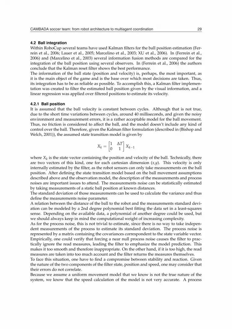
4.2 Ball integrationWithin RoboCup several teams have used Kalman filters for the ball position estimation (Fer-rein et al., 2006; Lauer et al., 2005; Marcelino et al., 2003; XU et al., 2006). In (Ferrein et al.,2006) and (Marcelino et al., 2003) several information fusion methods are compared for theintegration of the ball position using several observers. In (Ferrein et al., 2006) the authorsconclude that the Kalman reset filter shows the best performance.The information of the ball state (position and velocity) is, perhaps, the most important, asit is the main object of the game and is the base over which most decisions are taken. Thus,its integration has to be as reliable as possible. To accomplish this, a Kalman filter implemen-tation was created to filter the estimated ball position given by the visual information, and alinear regression was applied over filtered positions to estimate its velocity.
4.2.1 Ball positionIt is assumed that the ball velocity is constant between cycles. Although that is not true,due to the short time variations between cycles, around 40 milliseconds, and given the noisyenvironment and measurement errors, it is a rather acceptable model for the ball movement.Thus, no friction is considered to affect the ball, and the model doesn’t include any kind ofcontrol over the ball. Therefore, given the Kalman filter formulation (described in (Bishop andWelch, 2001)), the assumed state transition model is given by
Xk =[
1 ΔT0 1
]Xk−1
where Xk is the state vector containing the position and velocity of the ball. Technically, thereare two vectors of this kind, one for each cartesian dimension (x,y). This velocity is onlyinternally estimated by the filter, as the robot sensors can only take measurements on the ballposition. After defining the state transition model based on the ball movement assumptionsdescribed above and the observation model, the description of the measurements and processnoises are important issues to attend. The measurements noise can be statistically estimatedby taking measurements of a static ball position at known distances.The standard deviation of those measurements can be used to calculate the variance and thusdefine the measurements noise parameter.A relation between the distance of the ball to the robot and the measurements standard devi-ation can be modeled by a 2nd degree polynomial best fitting the data set in a least-squaressense. Depending on the available data, a polynomial of another degree could be used, butwe should always keep in mind the computational weight of increasing complexity.As for the process noise, this is not trivial to estimate, since there is no way to take indepen-dent measurements of the process to estimate its standard deviation. The process noise isrepresented by a matrix containing the covariances correspondent to the state variable vector.Empirically, one could verify that forcing a near null process noise causes the filter to prac-tically ignore the read measures, leading the filter to emphasize the model prediction. Thismakes it too smooth and therefore inappropriate. On the other hand, if it is too high, the readmeasures are taken into too much account and the filter returns the measures themselves.To face this situation, one have to find a compromise between stability and reaction. Giventhe nature of the two components of the filter state, position and speed, one may consider thattheir errors do not correlate.Because we assume a uniform movement model that we know is not the true nature of thesystem, we know that the speed calculation of the model is not very accurate. A process
�� �(��/.
noise covariance matrix was empirically estimated, based on several tests, so that a goodsmoothness/reactivity relationship was kept.Using the filter a-priori estimation, a system to detect great differences between the expectedand read positions was implemented, allowing to detect hard deviations on the ball path.
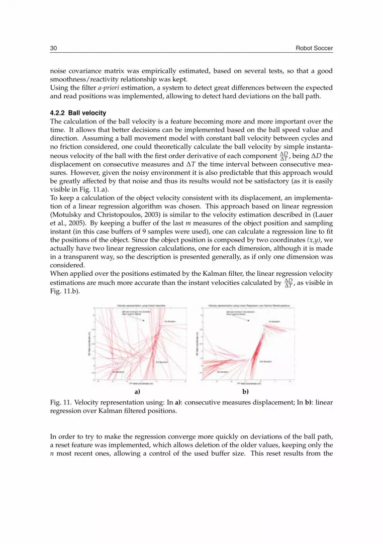
4.2.2 Ball velocityThe calculation of the ball velocity is a feature becoming more and more important over thetime. It allows that better decisions can be implemented based on the ball speed value anddirection. Assuming a ball movement model with constant ball velocity between cycles andno friction considered, one could theoretically calculate the ball velocity by simple instanta-neous velocity of the ball with the first order derivative of each component ΔD
ΔT , being ΔD thedisplacement on consecutive measures and ΔT the time interval between consecutive mea-sures. However, given the noisy environment it is also predictable that this approach wouldbe greatly affected by that noise and thus its results would not be satisfactory (as it is easilyvisible in Fig. 11.a).To keep a calculation of the object velocity consistent with its displacement, an implementa-tion of a linear regression algorithm was chosen. This approach based on linear regression(Motulsky and Christopoulos, 2003) is similar to the velocity estimation described in (Laueret al., 2005). By keeping a buffer of the last m measures of the object position and samplinginstant (in this case buffers of 9 samples were used), one can calculate a regression line to fitthe positions of the object. Since the object position is composed by two coordinates (x,y), weactually have two linear regression calculations, one for each dimension, although it is madein a transparent way, so the description is presented generally, as if only one dimension wasconsidered.When applied over the positions estimated by the Kalman filter, the linear regression velocityestimations are much more accurate than the instant velocities calculated by ΔD
ΔT , as visible inFig. 11.b).
a) b)
Fig. 11. Velocity representation using: In a): consecutive measures displacement; In b): linearregression over Kalman filtered positions.
In order to try to make the regression converge more quickly on deviations of the ball path,a reset feature was implemented, which allows deletion of the older values, keeping only then most recent ones, allowing a control of the used buffer size. This reset results from the

������������ ����������� ����� � ���� ���� ����� ������ �� /�
interaction with the Kalman filter described earlier, which triggers the velocity reset when itdetects a hard deviation on the ball path.Although in this case the Kalman filter internal functioning estimates a velocity, the obtainedvalues were tested to confirm if the linear regression of the ball positions was still needed.Tests showed that the velocity estimated by the Kalman filter has a slower response than thelinear regression estimation when deviations occur. Given this, the linear regression was usedto estimate the velocity because quickness of convergence was preferred over the slightlysmoother approximation of the Kalman filter in the steady state. That is because in the gameenvironment, the ball is very dynamic, it constantly changes its direction and thus a conver-gence in less than half the cycles is much preferred.
4.2.3 Team ball position sharingDue to the highly important role that the ball has in a soccer game, when a robot cannot detectit by its own visual sensors (omni or frontal camera), it may still know the position of the ball,through sharing of that knowledge by the other team mates.The ball data structure include a field with the number of cycles it was not visible by the robot,meaning that the ball position given by the vision sensors can be the “last seen” position.When the ball is not visible for more than a given number of cycles, the robot assumes thatit cannot detect the ball on its own. When that is the case, it uses the information of the ballcommunicated by the other running team mates to know where the ball is. This can be donethrough a function to get the statistics on a set of positions, mean and standard deviation, toget the mean value of the position of the ball seen by the team mates.Another approach is to simply use the ball position of the team mate that have more confi-dence in the detection. Whatever the case, the robot assumes that ball position as its own.When detecting the ball on its own, there is also the need to validate that information. Cur-rently the seen ball is only considered if it is within a given margin inside the field of play asthere would be no point in trying to play with a ball outside the field. Fig. 12 illustrates thegeneral ball integration activity diagram.
Fig. 12. Ball integration activity diagram.

�� �(��/-
4.3 Obstacle selection and identificationWith the objective of refining the information of the obstacles, and have more meaningful andhuman readable information, the obstacles are selected and a matching is attempted, in orderto try to identify them as team mates or opponents.Due to the weak precision at long distances, a first selection of the obstacles is made by se-lecting only the obstacles closer than a given distance as available for identification (currently5 meters). Also, obstacles that are smaller than 10 centimeters wide or outside the field ofplay margin are ignored. This is done because the MSL robots are rather big, and in gamesituations small obstacles are not present inside the field. Also, it would be pointless to payattention to obstacles that are outside the field of play, since the surrounding environment iscompletely ignorable for the game development.To be able to distinguish obstacles, to identify which of them are team mates and which areopponent robots, a fusion between the own visual information of the obstacles and the sharedteam mates positions is made. By creating a circle around the team mate positions, a matchingof the estimated center of visible obstacle is made (Fig. 13), and the obstacle is identified as thecorresponding team mate in case of a positive matching (Figs. 14c)). This matching consistson the existence of interception points between the team mate circle and the obstacle circle orif the obstacle center is inside the team mate circle (the obstacle circle can be smaller, and thusno interception points would exist).
Fig. 13. When a CAMBADA robot is on, the estimated centers of the detected obstacles arecompared with the known position of the team mates and tested; the left obstacle is withinthe CAMBADA acceptance radius, the right one is not.
Since the obstacles detected can be large blobs, the above described identification algorithmcannot be applied directly to the visually detected obstacles. If the detected obstacle fulfillsthe minimum size requisites already described, it is selected as candidate for being a robotobstacle. Its size is evaluated and classified as robot if it does not exceed the maximum sizeallowed for MSL robots (MSL Technical Committee 1997-2009, 2008) (Fig. 14a) and 14b)).If the obstacle exceeds the maximum size of an MSL robot, a division of the obstacle is made,by analyzing its total size and verifying how many robots are in that obstacle. This is a com-mon situation, robots clashing together and thus creating a compact black blob, originating abig obstacle. After completing the division, each obstacle is processed as described before.

������������ ����������� ����� � ���� ���� ����� ������ �� //
a) b) c)
Fig. 14. Illustration of single obstacles identification. In a): image acquired from the robotcamera (obstacles for identification are marked); In b): the same image after processing; In c):image of the control station. Each robot represents itself and robot 6 (the lighter gray) drawsall the 5 obstacles evaluated (squares with the same gray scale as itself). All team mates werecorrectly identified (marked by its corresponding number over the obstacle square) and theopponent is also represented with no number.
5. Real-time database
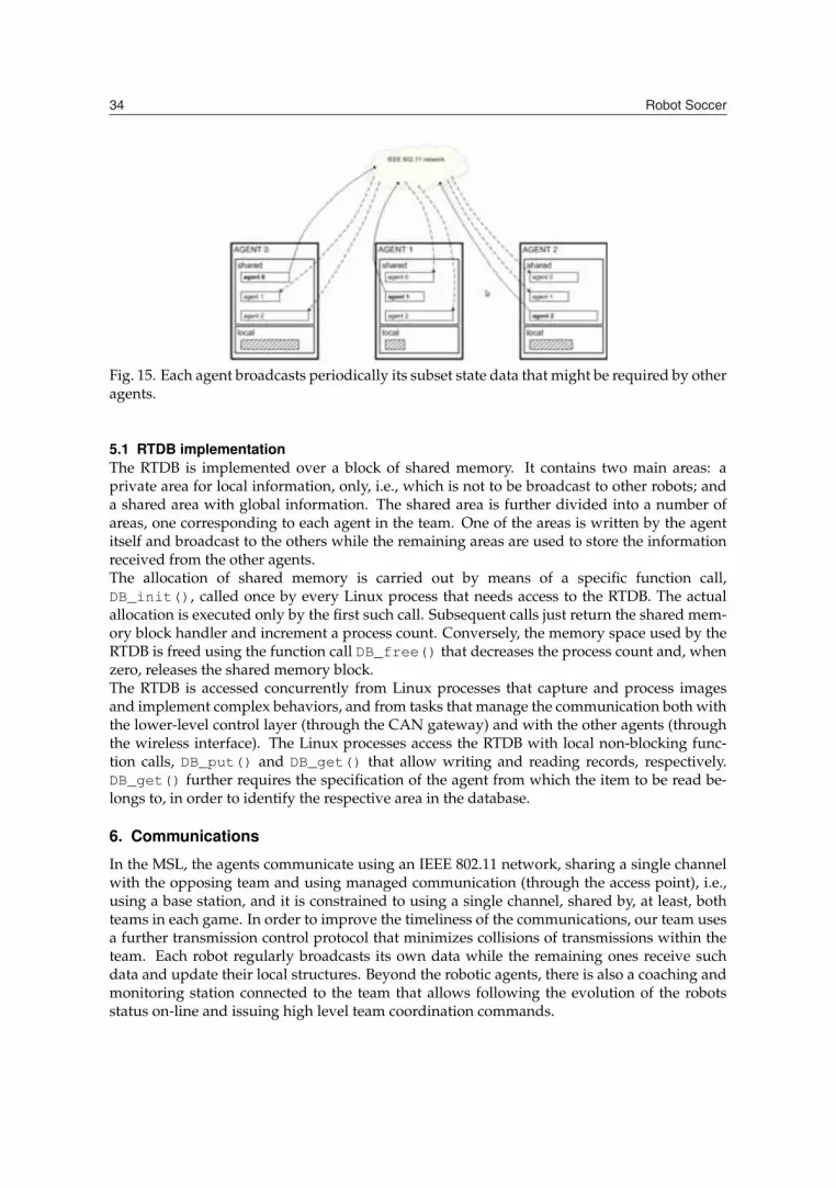
Similarly to other teams, our team software architecture emphasizes cooperative sensing as akey capability to support the behavioral and decision-making processes in the robotic play-ers. A common technique to achieve cooperative sensing is by means of a blackboard, whichis a database where each agent publishes the information that is generated internally andthat maybe requested by others. However, typical implementations of this technique seldomaccount for the temporal validity (coherence) of the contained information with adequate ac-curacy, since the timing information delivered by general-purpose operating systems such asLinux is rather coarse. This is a problem when robots move fast (e.g. above 1m/s) becausetheir state information degrades faster, too, and temporal validity of state data becomes of thesame order of magnitude, or lower, than the operating system timing accuracy.Another problem of typical implementations is that they are based on the client-server modeland thus, when a robot needs a datum, it has to communicate with the server holding theblackboard, introducing an undesirable delay. To avoid this delay, we use two features: firstly,the dissemination of the local state data is carried out using broadcasts, according to theproducer-consumer cooperation model, secondly, we replicate the blackboard according tothe distributed shared memory model. In this model, each node has local access to all theprocess state variables that it requires. Those variables that are remote have a local image thatis updated automatically by an autonomous communication system (Fig. 15).We call this replicated blackboard the Real-time Data Base (RTDB), (Almeida et al., 2004)which holds the state data of each agent together with local images of the relevant state dataof the other team members. A specialized communication system triggers the required trans-actions at an adequate rate to guarantee the freshness of the data.Generally, the information within the RTDB holds the absolute positions and postures of allplayers, as well as the position of the ball, goal areas and corners in global coordinates. Thisapproach allows a robot to easily use the other robots sensing capabilities to complement itsown. For example, if a robot temporarily loses track of the ball, it might use the position ofthe ball as detected by another robot.
�� �(��/0
Fig. 15. Each agent broadcasts periodically its subset state data that might be required by otheragents.
5.1 RTDB implementationThe RTDB is implemented over a block of shared memory. It contains two main areas: aprivate area for local information, only, i.e., which is not to be broadcast to other robots; anda shared area with global information. The shared area is further divided into a number ofareas, one corresponding to each agent in the team. One of the areas is written by the agentitself and broadcast to the others while the remaining areas are used to store the informationreceived from the other agents.The allocation of shared memory is carried out by means of a specific function call,DB_init(), called once by every Linux process that needs access to the RTDB. The actualallocation is executed only by the first such call. Subsequent calls just return the shared mem-ory block handler and increment a process count. Conversely, the memory space used by theRTDB is freed using the function call DB_free() that decreases the process count and, whenzero, releases the shared memory block.The RTDB is accessed concurrently from Linux processes that capture and process imagesand implement complex behaviors, and from tasks that manage the communication both withthe lower-level control layer (through the CAN gateway) and with the other agents (throughthe wireless interface). The Linux processes access the RTDB with local non-blocking func-tion calls, DB_put() and DB_get() that allow writing and reading records, respectively.DB_get() further requires the specification of the agent from which the item to be read be-longs to, in order to identify the respective area in the database.
6. Communications
In the MSL, the agents communicate using an IEEE 802.11 network, sharing a single channelwith the opposing team and using managed communication (through the access point), i.e.,using a base station, and it is constrained to using a single channel, shared by, at least, bothteams in each game. In order to improve the timeliness of the communications, our team usesa further transmission control protocol that minimizes collisions of transmissions within theteam. Each robot regularly broadcasts its own data while the remaining ones receive suchdata and update their local structures. Beyond the robotic agents, there is also a coaching andmonitoring station connected to the team that allows following the evolution of the robotsstatus on-line and issuing high level team coordination commands.

������������ ����������� ����� � ���� ���� ����� ������ �� /1
As referred above, agents communicate using an IEEE 802.11 network, sharing a single chan-nel with the opposing team and using managed communication (through the access point).This raises several difficulties because the access to the channel cannot be controlled and theavailable bandwidth is roughly divided by 2.Therefore, the only alternative left for each team is to adapt to the current channel conditionsand reduce access collisions among team members. This is achieved using an adaptive TDMAtransmission control, with a predefined round period called team update period (Ttup) thatsets the responsiveness of the global communication. Within such round, there is one singleslot allocated to each team member so that all slots in the round are separated as much aspossible (Fig. 16). This allows calculating the target inter-slot period Txwin as Ttup
N , where N isthe number of running agents.
Fig. 16. TDMA round indicating the slots allocated to each robot.
The transmissions generated by each running agent are scheduled within the communicationprocess, according to the production periods specified in the RTDB records. Currently a rate-monotonic scheduler is used. When the respective TDMA slot comes, all currently scheduledtransmissions are piggybacked on one single 802.11 frame and sent to the channel. The re-quired synchronization is based on the reception of the frames sent by the other agents duringTtup. With the reception instants of those frames and the target inter-slot period Txwin it ispossible to generate the next transmission instant. If these delays affect all TDMA frames ina round, then the whole round is delayed from then on, thus its adaptive nature. Figure 17shows a TDMA round indicating the slots allocated to each agent and the adaptation of theround duration.
Fig. 17. An adaptive TDMA round.
When a robot transmits at time tnow it sets its own transmission instant tnext = tnow + Ttup, i.e.one round after. However, it continues monitoring the arrival of the frames from the otherrobots. When the frame from robot k arrives, the delay δk of the effective reception instantwith respect to the expected instant is calculated. If this delay is within a validity window[0, Δ], with Δ being a global configuration parameter, the next transmission instant is delayedaccording to the longest such delay among the frames received in one round (Fig. 17), i.e.,
tnext = tnow + Ttup + maxk(δk)
On the other hand, if the reception instant is outside that validity window, or the frame is notreceived, then (δk) is set to 0 and does not contribute to update tnext.
�� �(��/2
The practical effect of the protocol is that the transmission instant of a frame in each roundmay be delayed up to Δ with respect to the predefined round period Ttup. Therefore, theeffective round period will vary between Ttup and Ttup + Δ. When a robot does not receiveany frame in a round within the respective validity windows, it updates tnext using a robotspecific configuration parameter βk in the following way
tnext = tnow + Ttup + βk
with 0 ≤ βk ≤ Δ.This is used to prevent a possible situation in which the robots could all remain transmittingbut unsynchronized, i.e. outside the validity windows of each other, and with the same periodTtup. By imposing different periods in this situation we force the robots to resynchronizewithin a limited number of rounds because the transmissions will eventually fall within thevalidity windows of each other.One of the limitations of the adaptive TDMA protocol as proposed is that the number of teammembers was fixed, even if the agents were not active, causing the use of Txwin values smallerthan needed. Notice that a smaller Txwin increases the probability of collisions in the team.Therefore, a self-configuration capability was added to the protocol, to cope with variablenumber of team members. This is the specific mechanism described in this section, whichsupports the dynamic insertion / removal of agents in the protocol. Currently, the Ttup periodis still constant but it is divided by the number of running agents at each instant, maximizingthe inter-slot separation between agents Txwin at each moment.However, the number of active team members is a global variable that must be consistent sothat the TDMA round is divided in the same number of slots in all agents. To support thesynchronous adaptation of the current number of active team members a membership vectorwas added to the frame transmitted by each agent in each round, containing its perception ofthe team status.When a new agent arrives it starts to transmit its periodic information in an unsynchronizedmode. In this mode all the agents, including the new one, continue updating its membershipvector with the received frames and continue refreshing the RTDB shared areas, too. The Txwinvalue, however, is not yet adapted and thus the new agent has no slot in the round. When allthe team members reach the same membership vector, the number of active team membersis updated, so as the inter-slot period Txwin. The protocol enters then in the scan mode inwhich the agents, using their slightly different values of Ttup, rotate their relative phases inthe round until they find their slots. From then on, all team members are again synchronized.The removal of an absent agent uses a similar process. After a predefined number of roundswithout receiving frames from a given agent, each remaining member removes it from themembership vector. The change in the vector leads to a new agreement process similar todescribed above.More details about the communication process in the CAMBADA team, as well as in the MSL,can be found in (Almeida et al., 2004; Santos et al., 2009; 2007).
7. Coordination and strategy
In CAMBADA each robot is an independent agent and coordinates its actions with its team-mates through communication and information exchange. The resulting behavior of the indi-vidual robot should be integrated into the global team strategy, thus resulting in cooperativeactions by all the robots. This is done by the use of roles and behaviors that define each robotattitude in the field and resulting individual actions. Behaviors are the basic sensorimotor

������������ ����������� ����� � ���� ���� ����� ������ �� /3
skills of the robot, like moving to a specific position or kicking the ball, while roles select theactive behavior at each time step, according to the attitude in cause.For open play, CAMBADA uses an implicit coordination model based on notions like strategicpositioning, role and formation. These notions and related algorithms have been introducedand/or extensively explored in the RoboCup Soccer Simulation League (Reis et al., 2001; Stoneand Veloso, 1999). In order to apply such algorithms in the MSL, several changes had to beintroduced.A formation defines a movement model for the robotic players. Formations are sets of strate-gic positioning, where each positioning is a movement model for a specific player. The as-signment of players to specific positioning is dynamic, and it is done according to some rulesconcerning ball and team mates positions. Each positioning is specified by three elements:Home position, which is the target position of the player when the ball is at the centre of thefield, Region of the field where the player can move, and Ball attraction parameters, used tocompute the target position of the player in each moment based on the current ball positionAll these items of information are given in a strategy configuration file. Using different homepositions and attraction parameters for the positioning allows a simple definition of defen-sive, wing, midfielder and attack strategic movement models. Figure 18 shows an example offormation of the team for several ball positions.
Fig. 18. CAMBADA Robots in some different game situations.
During open play, the CAMBADA agents use only three roles: RoleGoalie,RoleMidfielder and RoleStriker. The RoleGoalie is activated for the goalkeeper.RoleMidfielder moves according to its strategic positioning, defined as stated earlier.RoleStriker is an active player role, which substitutes the highest priority position of theformation, the one closer to the ball. It tries to catch the ball and score goals.

�� �(��/4
The striker activates several behaviors that try to engage the ball (bMove, bMoveToAbs), getinto the opponent’s side avoiding obstacles (bDribble) and shoot to the goal (bKick). ThebKick behavior can perform 180◦ turns while keeping possession of the ball.In a consistent role assignment, only one player at a time takes on the role of striker. The otherteammates take on RoleMidfielder (Lau et al., 2008). Midfielders maintain their target po-sitions as determined by their current positioning assignments and the current ball position.As a result, they accompany the striker as it plays along the field, without interfering. In casethe ball is captured by the opponent, some of the midfielders hopefully will be in a good posi-tion to become the new striker. Occasionally, midfielders can take a more active behavior. Thishappens when the striker can’t progress with the ball towards the opponent goal accordingto defined parameters. In this case, the closest midfielder to the ball also approaches the ball,acting as backup striker.The role and position assignment in open play is based on considering different priorities forthe different roles and positionings, so that the most important ones are always covered. Thepositioning is dynamically defined (not considering the goal keeper, which has a fixed role) byevaluating the distances of each of the robots to each of the target positions. Then the strikerrole is assigned to the robot that is closest to the highest priority strategic positioning, whichis in turn the closest to the ball. The second position to be assigned is the defense position,then the two side positions. This algorithm results in the striker role having top priority,followed by the defensive positioning, followed by the wingers. The assignment algorithmmay be performed by the coach agent in the base station, ensuring a coordinated assignmentresult, or locally by each robot, in which case the inconsistencies of world models may lead tounsynchronized assignments.More explicit coordination is present on passes and setplays. Passing is a coordinated behav-ior involving two players, in which one kicks the ball towards the other, so that the other cancontinue with the ball. In the general case, the player running RoleStriker may decide totake on RolePasser, choosing the player to receive the ball. After being notified, the secondplayer takes on the RoleReceiver. These roles have not been used yet for open play in in-ternational competition games, but they have been demonstrated in RoboCup 2008 MSL FreeTechnical Challenge and are used in a similar way in ball stoppage situations.Another methodology implemented in CAMBADA is the use of coordinated procedures forsetplays, i.e. situations when the ball is introduced in open play after a stoppage, such askick-off, throw-in, corner kick, free kick and goal kick. Setplay procedures define a sequenceof behaviors for several robots in a coordinated way. RoleReplacer and RoleReceiverare two exclusive roles used to overcome the MSL indirect rule in the case of indirect setplaysagainst the opponent. The replacer passes the ball to the receiver which tries to score a goal,while the replacer assumes a position to defend the team mate shooting line. They positionthemselves as close to the shoot alignment as possible, so that a shot can be taken soon afterthe pass. If desired, a second receiver RoleReceiver2 can be assigned to provide a secondpass option for the replacer.Finally, in the case of setplays against CAMBADA, RoleBarrier is used to protect the goalfrom a direct shoot. The line connecting the ball to the own goal defines the barrier positions.One player places itself on this line, as close to the ball as it is allowed. Two players placethemselves near the penalty area. One player is placed near the ball (as much as allowed), 45◦degrees from the mentioned line, so that it can observe the ball coming into play and reportthat to team mates.

������������ ����������� ����� � ���� ���� ����� ������ �� /�
8. The Base Station Application
In robotic soccer, the game is refereed by a human and his orders are communicated to theteams using an application called “Referee Box”. No human interference is allowed duringthe games except for removing malfunctioning robots and re-entering robots in the game. Thebase station, a software application as described in this section, has a determinant role duringthe development of a robotic soccer team and also during a game. This application mustcontrol the agents interpreting and sending high level instructions, like Start or Stop, andmonitor information of the robots, for example the position and velocity, allowing easily toattest the feasibility of the robots behavior.The base station application must provide a set of tools to perform the activities mentionedabove. Regarding the control activity, this application must allow high level control of therobots sending basic commands/information in particular the run and stop commands, playmode, role assignment, etc.This application must also provide a high level monitoring of the robots internal states,namely the position in the field, velocity, battery charge, among other relevant informationrelated with the robots and the game.Furthermore, this application should provide an easy mechanism that can be used to easilyshow a specific behavior of the robot, allowing debugging.Besides that, the base station has a fundamental role during a game, while receiving the com-mands from the referee box, translating them to internal game states and broadcasting theresults to the robots. During a game, no human interference is allowed except for removingmalfunctioning robots and re-entering robots in the game.The role of the base station during these phases, development and games, demands the ful-fillment of some requirements, being the most important the following:
Reliability / Stability: during the game, the base station is not accessible for human interactionof any kind and thus, it has to be a very robust application, all team depends on that.
Usability: the information displayed in the base station should be easy to interpret, allowing,for instance, a fast detection of a problem in a robot. It should be possible to choosedifferent levels of details in the displayed information. Moreover, the base station hasto be easy to use, allowing an intuitive management of the robots.
Adaptability: a robotic soccer team is in a permanent development stage, which may lead tosignificant changes within a short period of time.
Specifically to each phase the base station should provide the following features:
• Development phase
Manual role assignment: acting as a cooperative team, each robot has a specific rolewhich is, during a real game, dynamically assigned. In the development phase, itshould be possible to manually assign a role to a specific robot.
Local referee box: the base station should provide an interface widget to emulate a realreferee box in order to simulate events of a real game.
Visualization Tool: the application should provide a representation of the field and therobots in that context. Moreover, some visual information should be attached inorder to improve the visual perception of the internal states of each robot.
�� �(��0.
Multi-windows solution: the application should be a multi-window environment, al-lowing the user to choose between different levels of information. At least, threedifferent levels of information should be provided: a work level that presents thecontrols of the robots and basic status information; a visual level that presentsvisual information of the position of the robots and, finally a detailed level thatshows all the information related to the robots.
Adaptable windows geometry: the multi-windows system should adapt to monitors withdifferent resolutions. According to the new MSL rules, the base stations of eachteam must use an external monitor provided by the organizing committee.
• Game situation
Robust communication skills: the correct operation of the team during the game is fullydependent on the communication between the robots, the base station and thereferee box. Hence, the base station should provide a robust communication layer.
Automatic processing of the game states: the base station should process the commandsreceived from the referee box allowing the robots to change their internal gamestates accordingly. One specific action should be the changing of the field side athalf time.
8.1 The CAMBADA base station approachRegarding the challenges and requirements mentioned before, we will detail the used ap-proaches in the conception of the base station application. We have divided, once again, thedescription in the mentioned activities in order to more precisely describe the features imple-mented for each one.
8.1.1 Performing controlMerging the available methods provided by the communication protocol of the team we wereable to implement a widget that allows an high level control of the robots. All the actionswere grouped to each robot and are accessible in a delimited space in order to improve theusability. These actions represents the enable/disable of each robot, the team color and goalcolor (in spite of the current rules don’t specify goal colors, we decide keep it in order tofacilitate the monitoring process), the role of the player, the re-location button, the start andstop that controls remotely the software in each robot and the bottom to launch remotely theagent.Additionally, were created two other widgets, one to control all the team and one that imple-ments a local referee box.
8.1.2 MonitoringRegarding the monitoring activity, we developed a visualization widget that makes a rep-resentation of the field and the robots. This visualization widget shows the robots number,position and orientation and the ball that each robot view. Additionally was implementeda mechanism that allows to change the orientation of the field, in order to turn possible tomonitor the robots in any position of the field, increasing the usability.The base station has three separated windows representing three different levels of informa-tion. The main level shows the controls and relevant information about the robots state, otherwindow only shows the visualization widget (this is the window to monitor the game, ac-cording with the new rules) and finally we implemented a window with full information of

������������ ����������� ����� � ���� ���� ����� ������ �� 0�
the robots, all the information available in the RTDB is shown in this window. In Fig. 19 isshown the main window.
Fig. 19. The base station Main Window.
In order to perform debugging in the development phase, it was implemented, in the visual-ization widget, a debug mechanism. Is possible to enable this mechanism writing in a specificfield of the RTDB. This field is a vector with two dimensions representing a position on thegame field. There are one point of debug per robot and if enabled in the base station this pointcan be shown in the game field together with the representation of the robots. This point isfree to use and can represent whatever the developer wants.Additionally, the third window, considered as the full information window, allows to performdebug to the robot state, more precisely in the transition between the roles and behaviorsstates.All the project were developed using the Qt library using a modular architecture. This in-creased the reliability and stability allowing to test each module before the integration in theproject.
9. Conclusions
This chapter presented the new advances in several areas that involves the development of anMSL team of soccer robots, namely the mechanical structure of the robot, its hardware archi-tecture and controllers, the software development in areas such as image processing, sensorand information fusion, reasoning and control, cooperative sensing approach, communica-tions among robots and some other auxiliary software.The CAMBADA soccer robots have a hierarchical distributed hardware architecture with acentral computer to carry out vision sensing, global coordination and deliberative functionsand a low-level distributed sensing and actuation system based on a set of simple micro-controller nodes interconnected with a Controller Area Network (CAN). The advantages of
�� �(��0-
distributed architectures extend from improved composability, allowing a system to be builtby putting together different subsystems, to higher scalability, allowing to add functionality tothe system by adding more nodes, more flexibility, allowing to reconfigure the system easily,better maintainability, due to the architecture modularity and easiness of node replacement,and higher reduction of mutual interference, thus offering a strong potential to support reac-tive behaviors more efficiently. Moreover, distributed architectures may also provide benefitsin terms of dependability by creating error-containment regions at the nodes and opening theway for inexpensive spatial replication and fault tolerance.The vision system of the CAMBADA robots is based on an hybrid system, formed by an om-nidirectional and a perspective sub-system, that together can analyze the environment aroundthe robots, both at close and long distances. We presented in this chapter several algorithmsfor the calibration of the most important parameters of the vision system and we proposeefficient color-based algorithms for object detection. Moreover, we proposed a promising so-lution for the detection of arbitrary FIFA balls, as demonstrated by the first place obtained inthe mandatory technical challenge in the Robocup 2009, where the robots had to play with anarbitrary standard FIFA ball.Sensor and information fusion is important to maintain a more reliable description of the stateof the world. The techniques proposed for information and sensor fusion proved to be effec-tive in accomplishing their objectives. The Kalman filter allows to filter the noise on the ballposition and provides an important prediction feature which allows fast detection of devia-tions of the ball path. The linear regression used to estimate the velocity is also effective, andcombined with the deviation detection based on the Kalman filter prediction error, providesa faster way to recalculate the velocity in the new trajectory. The increasing reliability of theball position and velocity lead to a better ball trajectory evaluation. This allowed the devel-opment of a more effective goalie action, as well as other behaviors, such as ball interceptionbehaviors and pass reception. The results regarding obstacle identification, provide tools foran improvement of the overall team coordination and strategic play.The robots coordination is based on a replicated database, the Real-Time Data Base (RTDB)that includes local state variables together with images of remote ones. These images are up-dated transparently to the application software by means of an adequate real-time manage-ment system. Moreover, the RTDB is accessible to the application using a set of non-blockingprimitives, thus yielding a fast data access.Regarding the communication between robots, is was developed a wireless communicationprotocol that reduces the probability of collisions among the team members. The protocolcalled adaptive TDMA, adapts to the current channel conditions, particularly accommodatingperiodic interference patterns. It was also developed an extended version of the protocol withon-line self-configuration capabilities that allow reconfiguring the slots structure of the TDMAround to the actual number of active team members, further reducing the collision probability.In the CAMBADA MSL team, each robot is an independent agent and coordinates its actionswith its teammates through communication and information exchange. The resulting behav-ior of the individual robot should be integrated into the global team strategy, thus resulting incooperative actions by all the robots. This is done by the use of roles and behaviors that defineeach robot attitude in the field and resulting individual actions. This resulted in a coordinatedbehavior of the team that largely contributed to its recent successes.The base station application has a important role during the development of a robotic soccerteam and also during a game. This chapter presented the approach that was used by theCAMBADA team in the design of this important application.
������������ ����������� ����� � ���� ���� ����� ������ �� 0/
The CAMBADA MSL team attained the first place in the MSL at RoboCup 2008 and attainedthe third place in the last edition of the MSL at RoboCup 2009. CAMBADA also won the lastthree editions of the Portuguese Robotics Open 2007-2009. These results confirm the effective-ness of the proposed architecture.
10. References
Almeida, L., P. Pedreiras, and J. A. Fonseca (2002). The FTT-CAN protocol: Why and how.IEEE Transactions on Industrial Electronics 49(6), 1189–1201.
Almeida, L., F. Santos, T. Facchinetti, P. Pedreira, V. Silva, and L. S. Lopes (2004). Coordinatingdistributed autonomous agents with a real-time database: The CAMBADA project.In Proc. of the 19th International Symposium on Computer and Information Sciences, ISCIS2004, Volume 3280 of Lecture Notes in Computer Science, pp. 878–886. Springer.
Azevedo, J. L., B. Cunha, and L. Almeida (2007). Hierarchical distributed architectures for au-tonomous mobile robots: a case study. In Proc. of the 12th IEEE Conference on EmergingTechnologies and Factory Automation, ETFA2007, Greece, pp. 973–980.
Bishop, G. and G. Welch (2001). An introduction to the kalman filter. In Proc of SIGGRAPH,Course 8, Number NC 27599-3175, Chapel Hill, NC, USA.
Blaffert, T., S. Dippel, M. Stahl, and R. Wiemker (2000). The laplace integral for a watershedsegmentation. In Proc. of the International Conference on Image Processing, 2000, Vol-ume 3, pp. 444–447.
Caleiro, P. M. R., A. J. R. Neves, and A. J. Pinho (2007, June). Color-spaces and color segmen-tation for real-time object recognition in robotic applications. Revista do DETUA 4(8),940–945.
Canny, J. F. (1986, November). A computational approach to edge detection. IEEE Transactionson Pattern Analysis and Machine Intelligence 8(6).
Cunha, B., J. L. Azevedo, N. Lau, and L. Almeida (2007). Obtaining the inverse distance mapfrom a non-SVP hyperbolic catadioptric robotic vision system. In Proc. of the RoboCup2007, Atlanta, USA.
Ferrein, A., L. Hermanns, and G. Lakemeyer (2006). Comparing sensor fusion techniques forball position estimation. In RoboCup 2005: Robot Soccer World Cup IX, Volume 4020 ofLNCS, pp. 154–165. Springer.
Grimson, W. E. L. and D. P. Huttenlocher (1990). On the sensitivity of the hough transform forobject recognition. IEEE Trans. on Pattern Analysis and Machine Intelligence 12, 1255–1274.
Lau, N., L. S. Lopes, and G. Corrente (2008, April). CAMBADA: information sharing andteam coordination. In Proc. of the 8th Conference on Autonomous Robot Systems andCompetitions, Portuguese Robotics Open - ROBOTICA’2008, Aveiro, Portugal, pp. 27–32.
Lauer, M., S. Lange, and M. Riedmiller (2005). Modeling moving objects in a dynamicallychanging robot application. In KI 2005: Advances in Artificial Intelligence, Volume 3698of LNCS, pp. 291–303. Springer.
Lauer, M., S. Lange, and M. Riedmiller (2006). Calculating the perfect match: an efficient andaccurate approach for robot self-localization. In RoboCup 2005: Robot Soccer WorldCup IX, Lecture Notes in Computer Science, pp. 142–153. Springer.
Marcelino, P., P. Nunes, P. Lima, and M. I. Ribeiro (2003). Improving object localizationthrough sensor fusion applied to soccer robots. In Proc. Scientific Meeting of the Por-tuguese Robotics Open - ROBOTICA 2003.

�� �(��00
Martins, D. A., A. J. R. Neves, and A. J. Pinho (2008, october). Real-time generic ball recogni-tion in RoboCup domain. In Proc. of the 11th edition of the Ibero-American Conference onArtificial Intelligence, IBERAMIA 2008, Lisbon, Portugal.
Motulsky, H. and A. Christopoulos (2003). Fitting models to biological data using linear andnonlinear regression. GraphPad Software Inc.
MSL Technical Committee 1997-2009 (2008). Middle size robot league rules and regulationsfor 2009.
Neves, A. J. R., A. J. P. B. Cunha, and I. Pinheiro (2009, June). Autonomous configuration ofparameters in robotic digital cameras. In Proc. of the 4th Iberian Conference on PatternRecognition and Image Analysis, ibPRIA 2009, Póvoa de Varzim, Portugal.
Neves, A. J. R., G. Corrente, and A. J. Pinho (2007). An omnidirectional vision system forsoccer robots. In Progress in Artificial Intelligence, Volume 4874 of Lecture Notes inArtificial Inteligence, pp. 499–507. Springer.
Neves, A. J. R., D. A. Martins, and A. J. Pinho (2008, April). A hybrid vision system forsoccer robots using radial search lines. In Proc. of the 8th Conference on AutonomousRobot Systems and Competitions, Portuguese Robotics Open - ROBOTICA’2008, Aveiro,Portugal, pp. 51–55.
Reis, L., N. Lau, and E. Oliveira (2001). Situation based strategic positioning for coordinat-ing a team of homogeneous agents. In Balancing Reactivity and Social Deliberation inMulti-Agent Systems, Volume 2103 of Lecture Notes in Computer Science, pp. 175–197.Springer.
Santos, F., L. Almeida, L. S. Lopes, J. L. Azevedo, and M. B. Cunha (2009). Communicatingamong robots in the robocup middle-size league. In RoboCup 2009: Robot Soccer WorldCup XIII, Lecture Notes in Artificial Intelligence. Springer (In Press).
Santos, F., G. Corrente, L. Almeida, N. Lau, and L. S. Lopes (2007, December). Self-configuration of an adaptive TDMA wireless communication protocol for teams ofmobile robots. In Proc. of the 13th Portuguese Conference on Artificial Intelligence, EPIA2007, Guimarães, Portugal.
Ser, P.-K. and W.-C. Siu (1993). Invariant hough transform with matching technique for therecognition of non-analytic objects. In IEEE International Conference on Acoustics,Speech, and Signal Processing, ICASSP 1993., Volume 5, pp. 9–12.
Silva, J., N. Lau, J. Rodrigues, and J. L. Azevedo (2008, october). Ball sensor fusion and ballinterception behaviours for a robotic soccer team. In Proc. of the 11th edition of theIbero-American Conference on Artificial Intelligence, IBERAMIA 2008, Lisbon, Portugal.
Silva, J., N. Lau, J. Rodrigues, J. L. Azevedo, and A. J. R. Neves (2009). Sensor and informationfusion applied to a robotic soccer team. In RoboCup 2009: Robot Soccer World Cup XIII,Lecture Notes in Artificial Intelligence. Springer (In Press).
Silva, V., R. Marau, L. Almeida, J. Ferreira, M. Calha, P. Pedreiras, and J. Fonseca (2005). Im-plementing a distributed sensing and actuation system: The CAMBADA robots casestudy. In Proc. of the 10th IEEE Conference on Emerging Technologies and Factory Automa-tion, ETFA2005, Italy, pp. 781–788.
Stone, P. and M. Veloso (1999). Task decomposition, dynamic role assignment, and low-bandwidth communication for real-time strategic teamwork. Volume 110, pp. 241–273.
XU, Y., C. JIANG, and Y. TAN (2006). SEU-3D 2006 Soccer simulation team description. In CDProc. of RoboCup Symposium 2006.

������������ ����������� ����� � ���� ���� ����� ������ �� 01
Zhang, Y.-J. and Z.-Q. Liu (2000). Curve detection using a new clustering approach in thehough space. In IEEE International Conference on Systems, Man, and Cybernetics, 2000,Volume 4, pp. 2746–2751.
Zin, T. T., H. Takahashi, and H. Hama (2007). Robust person detection using far infraredcamera for image fusion. In Second International Conference on Innovative Computing,Information and Control, ICICIC 2007, pp. 310–310.
Zou, J., H. Li, B. Liu, and R. Zhang (2006). Color edge detection based on morphology. In FirstInternational Conference on Communications and Electronics, ICCE 2006, pp. 291–293.
Zou, Y. and W. Dunsmuir (1997). Edge detection using generalized root signals of 2-d medianfiltering. In Proc. of the International Conference on Image Processing, 1997, Volume 1,pp. 417–419.

�� �(��02