calvert cliffs, units 1 & 2 - asme section xi relief request to
TRANSCRIPT
Kevin J. NietmannPlant General Manager
1650 Calvert Cliffs ParkwayLusby, Maryland 20657
410.495.4101410.495.4787 Fax
Constellation EnergyCalvert Cliffs Nuclear Power Plant
February 18, 2005
U. S. Nuclear Regulatory CommissionWashington, DC 20555
ATTENTION:
SUBJECT:
Document Control Desk
Calvert Cliffs Nuclear Power PlantUnit Nos. I & 2; Docket Nos. 50-317 & 50-318ASME Section XI Relief Request to Use Weld Overlay and AssociatedAlternative Techniques
REFERENCE: (a) Letter from Ms. M. Gamberoni (NRC) to Mr. C. H. Cruse (BGE), datedApril 5, 2000, Safety Evaluation of Proposed Alternate American Societyof Mechanical Engineers Boiler and Pressure Vessel Code (ASME Code)Section XI, 1998 Edition for the Third 10-Year Inspection Interval -Calvert Cliffs Nuclear Power Plant, Unit Nos. I and 2 (TAC Nos.MA4647 and MA4648)
Pursuant to 10 CFR 50.55a(a)(3)(i), Calvert Cliffs Nuclear Power Plant, Inc. (CCNPP) hereby proposesalternatives to the American Society of Mechanical Engineers (ASME) Boiler and Pressure Vessel Code(Code) requirements concerning repair/replacement activities for pressure retaining welds subject toArticle IWA-4000 in Section XI for the Third Ten-Year Inservice Inspection interval.Paragraph 50.55a(a)(3)(i) allows the use of alternatives to the requirements of Paragraph 50.55a(g), thatprovide an acceptable level of quality and safety, when authorized by the Director of the Office ofNuclear Reactor Regulation.
The Third Ten-Year Inservice Inspection Program Plan for Calvert Cliffs Units I and 2 meets therequirements of the 1998 Edition, no Addenda of Section XI of the ASME Code (except forSubsections IWE and IWL), as approved by Nuclear Regulatory Commission (NRC) letter (Reference a).
RELIEF REQUEST
Article IWA-4000 of ASME Code, Section Xl, and NRC approved Code Cases N-504-2 and N-638contain the requirements for structural weld overlay repair activities for unacceptable indications inwelded nozzles. Appendix VIII, Supplement 11 of Section XI contains ultrasonic examinationrequirements for the completed structural weld overlay repair. In lieu of these ASME Coderequirements, CCNPP proposes to use alternative techniques for full structural weld overlay repair, andthe examination of dissimilar metal weld with unacceptable indications in existing Alloy 82/182 welds.
AXOLV7
Document Control DeskFebruary 18, 2005Page 2
Similar relief requests have been previously approved for other licensees including AmerGen EnergyCompany for its Three Mile Island Nuclear Station, Unit I on July 21, 2004. The detailed relief requestand the justification are provided in Attachment (I).
SCHEDULE
The structural weld overlay is intended as a contingency repair for any flaws identified duringexamination of dissimilar metal welds in the upcoming Calvert Cliffs Unit 2 Spring 2005 refuelingoutage (scheduled to begin in late February 2005) and the remainder of the third ten year inserviceinspection interval for Units I and 2. We request that the Nuclear Regulatory Commission review andapprove our proposed alternative for use during this outage.
Should you have questions regarding this matter, we will be pleased to discuss them with you.
Very truly yours,
KJN/GT/bjd
Attachment: (1) Relief Request To Use Alternative Techniques for Repair and Examination ofUnacceptable Indications in Welded NozzlesEnclosure: Minimum Chromium Content in Nickel-Alloy Weld Overlays to
Mitigate PWSCC
cc: C. W. Fleming, EsquireJ. E. Silberg, EsquireR. V. Guzman, NRC
S. J. Collins, NRCResident Inspector, NRCR. I. McLean, DNR
ATTACHMENT (1)
RELIEF REQUEST TO USE ALTERNATIVE TECHNIQUES FOR
REPAIR AND EXAMINATION OF UNACCEPTABLE INDICATIONS IN
WELDED NOZZLES
Calvert Cliffs Nuclear Power Plant, Inc.February 18, 2005
ATTACHMENT (1)
RELIEF REQUEST TO USE ALTERNATIVE TECHNIQUES FOR REPAIR ANDEXAMINATION OF UNACCEPTABLE INDICATIONS IN WELDED NOZZLES
COMPONENT FOR WHICH RELIEF IS REOUESTED:
Class I dissimilar metal welds, with unacceptable indications attributed to primary water stress corrosioncracking (PWSCC) in existing Alloy 82/182 welds.
CODE REQUIREMENTS FOR WHICH RELIEF IS REOUESTED:
The 1998 Edition no Addenda of American Society of Mechanical Engineers (ASME) Section XI,Article IWA-4000 and Appendix V11I, Supplement 11 and Nuclear Regulatory Commission (NRC)approved Code Cases N-504-2 and N-638. Tables 1-4 provide the specific requirements that are includedin this relief request.
PROPOSED ALTERNATIVE AND SUPPORTING INFORMATION:
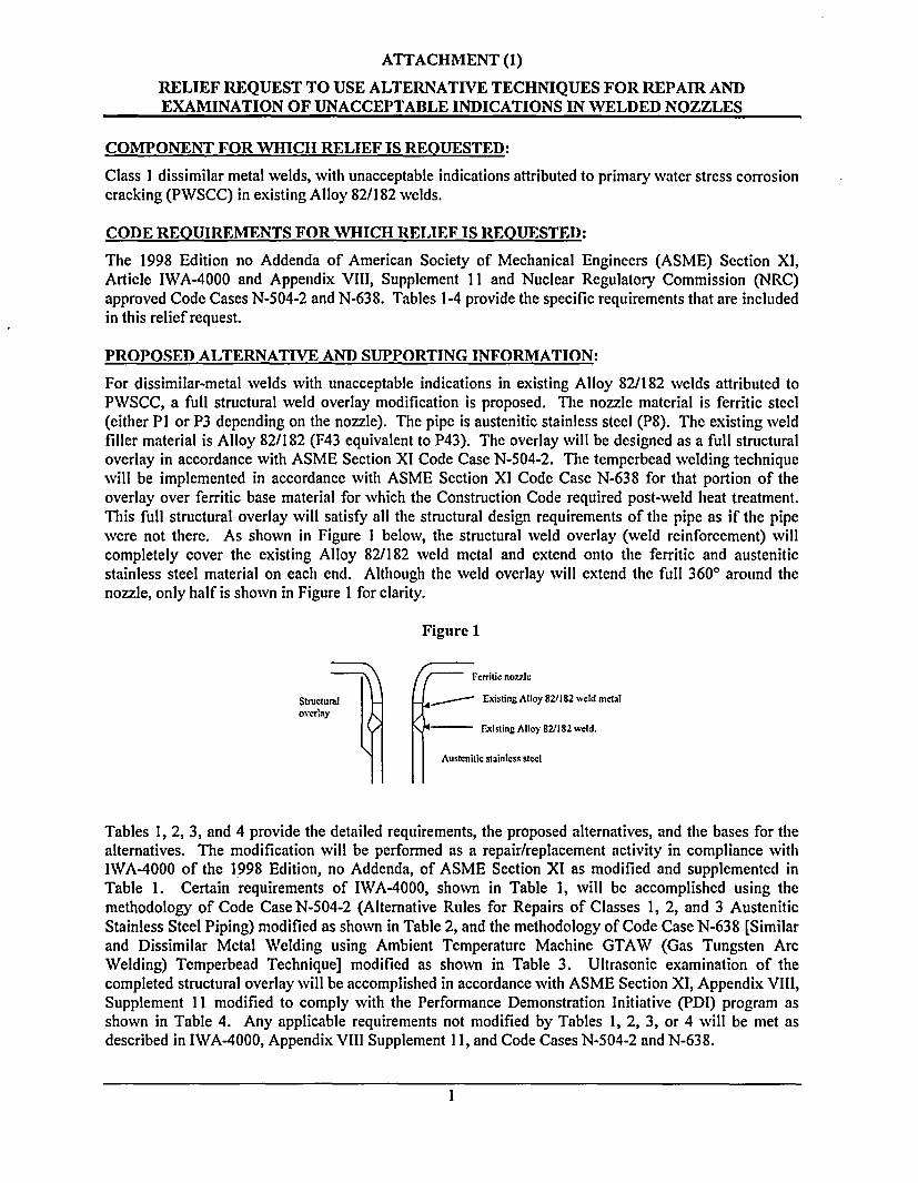
For dissimilar-metal welds with unacceptable indications in existing Alloy 82/182 welds attributed toPWSCC, a full structural weld overlay modification is proposed. The nozzle material is ferritic steel(either PI or P3 depending on the nozzle). The pipe is austenitic stainless steel (P8). The existing weldfiller material is Alloy 82/182 (F43 equivalent to P43). The overlay will be designed as a full structuraloverlay in accordance with ASME Section XI Code Case N-504-2. The temperbead welding techniquewill be implemented in accordance with ASME Section XI Code Case N-638 for that portion of theoverlay over ferritic base material for which the Construction Code required post-weld heat treatment.This full structural overlay will satisfy all the structural design requirements of the pipe as if the pipewere not there. As shown in Figure I below, the structural weld overlay (weld reinforcement) willcompletely cover the existing Alloy 82/182 weld metal and extend onto the ferritic and austeniticstainless steel material on each end. Although the weld overlay will extend the full 3600 around thenozzle, only half is shown in Figure I for clarity.
Figure 1
/- rritic no77ic
Structur a l il Existing Alloy 82/182 weld metaloverl3y
I1Fisting Alloy 821182 weld.
Austcnitic stainless stcel
Tables 1, 2, 3, and 4 provide the detailed requirements, the proposed alternatives, and the bases for thealternatives. The modification will be performed as a repair/replacement activity in compliance withIWA-4000 of the 1998 Edition, no Addenda, of ASME Section XI as modified and supplemented inTable 1. Certain requirements of IWA-4000, shown in Table 1, will be accomplished using themethodology of Code CaseN-504-2 (Alternative Rules for Repairs of Classes 1, 2, and 3 AusteniticStainless Steel Piping) modified as shown in Table 2, and the methodology of Code Case N-638 [Similarand Dissimilar Metal Welding using Ambient Temperature Machine GTAW (Gas Tungsten ArcWelding) Temperbead Technique] modified as shown in Table 3. Ultrasonic examination of thecompleted structural overlay will be accomplished in accordance with ASME Section XI, Appendix VIII,Supplement II modified to comply with the Performance Demonstration Initiative (PDI) program asshown in Table 4. Any applicable requirements not modified by Tables 1, 2, 3, or 4 will be met asdescribed in IWA-4000, Appendix VIll Supplement I1, and Code Cases N-504-2 and N-638.
1

ATTACHMENT (1)
RELIEF REQUEST TO USE ALTERNATIVE TECHNIQUES FOR REPAIR ANDEXAMINATION OF UNACCEPTABLE INDICATIONS IN WELDED NOZZLES
Code Case N-504-2 was approved for generic use in Regulatory Guide 1.147, Revision 13, and wasdeveloped for austenitic stainless steel material. An alternate application for nickel based and ferriticmaterials is proposed due to the specific configuration of the subject weldments. Therefore, CalvertCliffs intends to follow the methodology of Code Case N-504-2, except for the differences identified inTable 2.
Code Case N-638 was approved for generic use in Regulatory Guide 1.147, Revision 13, and wasdeveloped for similar and dissimilar metal welding using ambient temperature machine GTAWtemperbead technique. Calvert Cliffs intends to follow the methodology of Code Case N-638 for anywelding on ferritic or ferritic/austenitic interfaces where the Construction Code required post-weld heattreatment, except for the differences identified in Table 3.
CONCLUSION:
Calvert Cliffs believes the proposed alternatives to Article IWA-4000, Appendix VIII, Supplement 11,and NRC approved Code Cases N-504-2 and N-638, as described in this request, provide an acceptablelevel of quality and safety.
2
ATTACHMENT (1)
RELIEF REQUEST TO USE ALTERNATIVE TECHNIQUES FOR REPAIR ANDEXAMINATION OF UNACCEPTABLE INDICATIONS IN WELDED NOZZLES
Table 1
Modifications to IWA-4000
IWAA4000 Differences/Basis for Relief
IWA-4226 Reconciliation of Design Requirements Clarification. The structural weld overlay will be
IWA-4311 Material, Design, or Configuration Changes designed to the requirements of ASME Section Xl, CodeCase N-504-2 (Alternative Rules for Repair of Classes 1,2, and 3 Austenitic Stainless Steel Piping). While thereis no change to the design requirements of Code CaseN-504-2, we are proposing alternatives to some of therequirements as shown in Table 2.
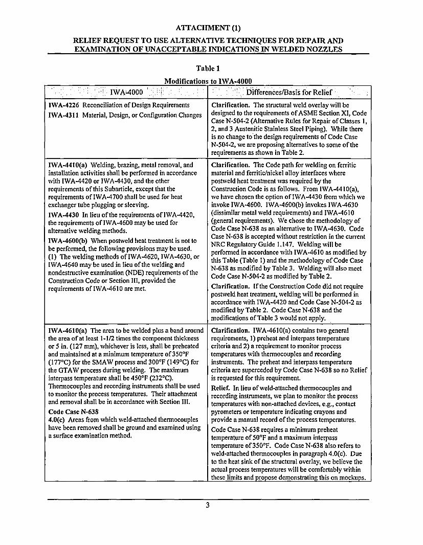
IWA-4410(a) Welding, brazing, metal removal, and Clarification. The Code path for welding on ferriticinstallation activities shall be performed in accordance material and ferritic/nickel alloy interfaces wherewith IWA-4420 or IWA-4430, and the other postweld heat treatment was required by therequirements of this Subarticle, except that the Construction Code is as follows. From IWA-4410(a),requirements of IWA-4700 shall be used for heat we have chosen the option of IWA-4430 from which weexchanger tube plugging or sleeving. invoke IWA-4600. IWA-4600(b) invokes IWA-4630
IWA-4430 In lieu of the requirements of IWA-4420, (dissimilar metal weld requirements) and IWA-4610the requirements of IWA-4600 may be used for (general requirements). We chose the methodology ofalternative welding methods. Code Case N-638 as an alternative to IWA-4630. Code
Case N-638 is accepted without restriction in the currentIWA-4600(b) When postwveld heat treatment is not to NRC Regulatory Guide 1.147. WVelding wvill bebe performed, the following provisions may be used. pRfoRedunacordance with WA-ding as m e(I) The welding methods of IWA-4620, IWA-4630, or performed (T accordance meth IWAo46dO as modified byIWA-4640 may be used in lieu of the welding and N-638 as modified by Table 3. Welding will also meetnondestructive examination (NDE) requirements of the Code Case N-N04-2 as modified by Table 2.Construction Code or Section 111, provided therequirements of IWA-4610 are met. Clarification. If the Construction Code did not require
postweld heat treatment, welding will be performed inaccordance with IWA-4420 and Code Case N-504-2 asmodified by Table 2. Code Case N-638 and themodifications of Table 3 would not apply.
IWA-4610(a) The area to be welded plus a band around Clarification. IWA-4610(a) contains two generalthe area of at least 1-1/2 times the component thickness requirements, 1) preheat and interpass temperatureor 5 in. (127 mm), whichever is less, shall be preheated criteria and 2) a requirement to monitor processand maintained at a minimum temperature of 350'F temperatures with thermocouples and recording(1771C) for the SMAW process and 300'F (1491C) for instruments. The preheat and interpass temperaturethe GTAW process during welding. The maximum criteria are superceded by Code Case N-638 so no Reliefinterpass temperature shall be 450'F (2320C). is requested for this requirement.Thermocouples and recording instruments shall be used Relief. In lieu of weld-attached thermocouples andto monitor the process temperatures. Their attachment recording instruments, we plan to monitor the processand removal shall be in accordance with Section Ill. temperatures with non-attached devices, e.g., contact
Code Case N-638 pyrometers or temperature indicating crayons and4.0(c) Areas from which weld-attached thermocouples provide a manual record of the process temperatures.have been removed shall be ground and examined using Code Case N-638 requires a minimum preheata surface examination method. temperature of 50'F and a maximum interpass
temperature of 3501F. Code Case N-638 also refers toweld-attached thermocouples in paragraph 4.0(c). Dueto the heat sink of the structural overlay, we believe theactual process temperatures will be comfortably withinthese limits and propose demonstrating this on mockups.
3
ATTACHMENT (1)
RELIEF REQUEST TO USE ALTERNATIVE TECHNIQUES FOR REPAIR ANDEXAMINATION OF UNACCEPTABLE INDICATIONS IN WELDED NOZZLES
Table 1
Modifications to IWA-4000
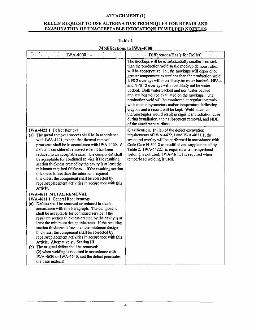
:. . ~ ; - , -;- . IWA4000- ;- -- -: re-. .i- .Differences/Basis forRelief -- -IWA.40i RlefThe mockups will be of substantially smaller heat sinkthan the production weld so the mockup demonstrationwill be conservative, i.e., the mockups will experiencegreater temperature excursions than the production weld.NPS 2 overlays will most likely be water backed. NPS 4and NPS 12 overlays will most likely not be waterbacked. Both water backed and non water backedapplications will be evaluated on the mockups. Theproduction weld will be monitored at regular intervalswith contact pyrometers and/or temperature indicatingcrayons and a record will be kept. Weld-attachedthermocouples would result in significant radiation doseduring installation, their subsequent removal, and NDEof the attachment surfaces.
IWA-4422.1 Defect Removal(a) The metal removal process shall be in accordance
with IWA-4421, except that thermal removalprocesses shall be in accordance with IWA-4460. Adefect is considered removed when it has beenreduced to an acceptable size. The component shallbe acceptable for continued service if the resultingsection thickness created by the cavity is at least theminimum required thickness. If the resulting sectionthickness is less than the minimum requiredthickness, the component shall be corrected byrepair/replacement activities in accordance with thisArticle.
IWA-4611 METAL REMOVALIWA-4611.1 General Requirements(a) Defects shall be removed or reduced in size in
accordance with this Paragraph. The componentshall be acceptable for continued service if theresultant section thickness created by the cavity is atleast the minimum design thickness. If the resultingsection thickness is less than the minimum designthickness, the component shall be corrected byrepair/replacement activities in accordance with thisArticle. Alternatively... Section III.
(b) The original defect shall be removed:(2) when welding is required in accordance withIWVA-4630 or IWA-4640, and the defect penetratesthe base material.
Clarification. In lieu of the defect excavationrequirements of IWA-4422.1 and IWA-461 1.1, thestructural overlay will be performed in accordance withCode Case N-504-2 as modified and supplemented byTable 2. IWA-4422.1 is required when temperbeadwelding is not used. IWA-461 1.1 is required whentemperbead welding is used.
4
ATTACHMENT (1)
RELIEF REQUEST TO USE ALTERNATIVE TECHNIQUES FOR REPAIR ANDEXAMINATION OF UNACCEPTABLE INDICATIONS IN WELDED NOZZLES
Table 1
Modifications to IWA-4000
IWA4000 Differences/Basis for Relief
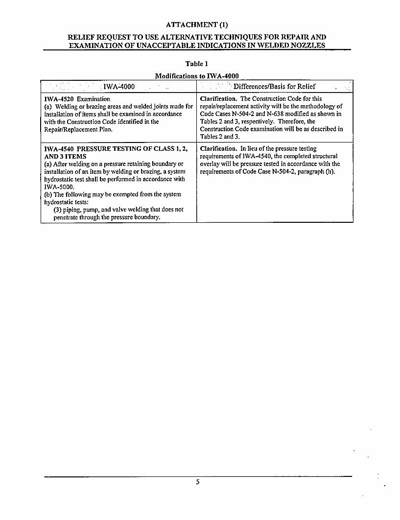
IWA-4520 Examination Clarification. The Construction Code for this(a) Welding or brazing areas and welded joints made for repair/replacement activity will be the methodology ofinstallation of items shall be examined in accordance Code Cases N-504-2 and N-638 modified as shown inwith the Construction Code identified in the Tables 2 and 3, respectively. Therefore, theRepair/Replacement Plan. Construction Code examination will be as described in
Tables 2 and 3.
IWA-4540 PRESSURE TESTING OF CLASS 1, 2, Clarification. In lieu of the pressure testingAND 3 ITEMS requirements of IWA-4540, the completed structural(a) After welding on a pressure retaining boundary or overlay will be pressure tested in accordance with theinstallation of an item by welding or brazing, a system requirements of Code Case N-504-2, paragraph (h).hydrostatic test shall be performed in accordance withIWA-5000.(b) The following may be exempted from the systemhydrostatic tests:
(3) piping, pump, and valve welding that does notpenetrate through the pressure boundary.
5
ATTACHMENT (1)
RELIEF REQUEST TO USE ALTERNATIVE TECHNIQUES FOR REPAIR ANDEXAMINATION OF UNACCEPTABLE INDICATIONS IN WELDED NOZZLES
Table 2
Modifications to Code Case N-504-2
Code Case N-504-2 Differences/Basis for-Relief
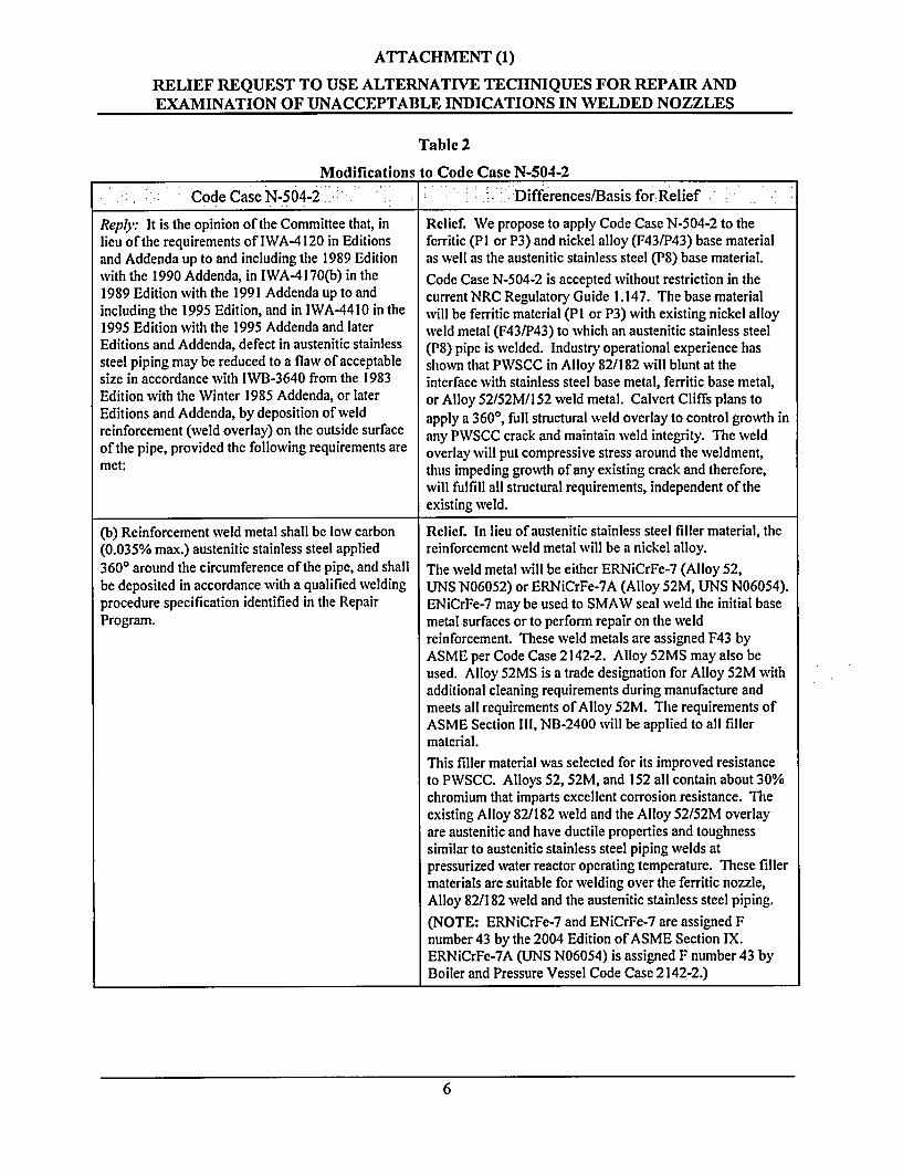
Reply: It is the opinion of the Committee that, in Relief. We propose to apply Code Case N-504-2 to thelieu of the requirements of IWA-4120 in Editions ferritic (PI or P3) and nickel alloy (F43/P43) base materialand Addenda up to and including the 1989 Edition as well as the austenitic stainless steel (P8) base material.with the 1990 Addenda, in IWA-4170(b) in the Code Case N-504-2 is accepted without restriction in the1989 Edition with the 1991 Addenda up to and current NRC Regulatory Guide 1.147. The base materialincluding the 1995 Edition, and in IWA-4410 in the will be ferritic material (PI or P3) with existing nickel alloy1995 Edition with the 1995 Addenda and later weld metal (F43/P43) to which an austenitic stainless steelEditions and Addenda, defect in austenitic stainless (P8) pipe is welded. Industry operational experience hassteel piping may be reduced to a flaw of acceptable shown that PWSCC in Alloy 82/182 will blunt at thesize in accordance with IWB-3640 from the 1983 interface with stainless steel base metal, ferritic base metal,Edition with the Winter 1985 Addenda, or later or Alloy 52/52M/I 52 weld metal. Calvert Cliffs plans toEditions and Addenda, by deposition of weld apply a 3600, full structural weld overlay to control growth inreinforcement (weld overlay) on the outside surface any PWSCC crack and maintain weld integrity. The weldof the pipe, provided the following requirements are overlay will put compressive stress around the weldment,met: thus impeding growth of any existing crack and therefore,
will fulfill all structural requirements, independent of theexisting weld.
(b) Reinforcement weld metal shall be low carbon Relief. In lieu of austenitic stainless steel filler material, the(0.035% max.) austenitic stainless steel applied reinforcement weld metal will be a nickel alloy.360° around the circumference of the pipe, and shall The weld metal will be either ERNiCrFe-7 (Alloy 52,be deposited in accordance with a qualified welding UNS N06052) or ERNiCrFe-7A (Alloy 52M, UNS N06054).procedure specification identified in the Repair ENiCrFe-7 may be used to SMAW seal weld the initial baseProgram. metal surfaces or to perform repair on the weld
reinforcement. These weld metals are assigned F43 byASME per Code Case 2142-2. Alloy 52MS may also beused. Alloy 52MS is a trade designation for Alloy 52M withadditional cleaning requirements during manufacture andmeets all requirements of Alloy 52M. The requirements ofASME Section III, NB-2400 will be applied to all fillermaterial.This filler material was selected for its improved resistanceto PWSCC. Alloys 52, 52M, and 152 all contain about 30%chromium that imparts excellent corrosion resistance. Theexisting Alloy 82/182 weld and the Alloy 52/52M overlayare austenitic and have ductile properties and toughnesssimilar to austenitic stainless steel piping welds atpressurized water reactor operating temperature. These fillermaterials are suitable for welding over the ferritic nozzle,Alloy 82/182 weld and the austenitic stainless steel piping.(NOTE: ERNiCrFe-7 and ENiCrFe-7 are assigned Fnumber 43 by the 2004 Edition of ASME Section IX.ERNiCrFe-7A (UNS N06054) is assigned F number 43 byBoiler and Pressure Vessel Code Case 2142-2.)
6
ATTACHMENT (1)
RELIEF REQUEST TO USE ALTERNATIVE TECHNIQUES FOR REPAIR ANDEXAMINATION OF UNACCEPTABLE INDICATIONS IN WELDED NOZZLES
Table 2
Modifications to Code Case N-504-2
Code Case N-504-2 -Differences/Basis for Relief
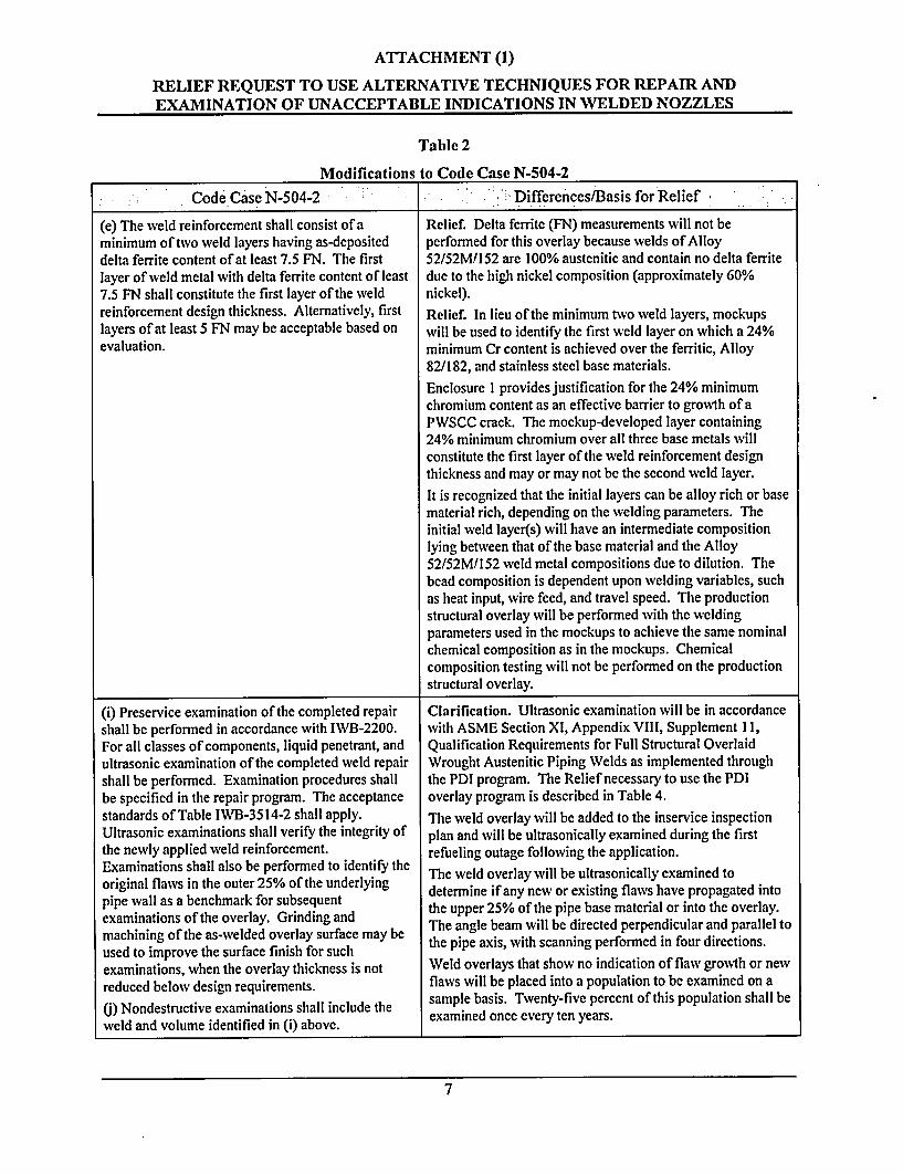
(e) The weld reinforcement shall consist of a Relief. Delta ferrite (FN) measurements will not beminimum of two weld layers having as-deposited performed for this overlay because welds of Alloydelta ferrite content of at least 7.5 FN. The first 52/52M/1 52 are 100% austenitic and contain no delta ferritelayer of weld metal with delta ferrite content of least due to the high nickel composition (approximately 60%7.5 FN shall constitute the first layer of the weld nickel).reinforcement design thickness. Alternatively, first Relief. In lieu of the minimum two weld layers, mockupslayers of at least 5 FN may be acceptable based on will be used to identify the first weld layer on which a 24%evaluation. minimum Cr content is achieved over the ferritic, Alloy
82/182, and stainless steel base materials.Enclosure I provides justification for the 24% minimumchromium content as an effective barrier to growth of aPWSCC crack. The mockup-developed layer containing24% minimum chromium over all three base metals willconstitute the first layer of the weld reinforcement designthickness and may or may not be the second weld layer.It is recognized that the initial layers can be alloy rich or basematerial rich, depending on the welding parameters. Theinitial weld layer(s) will have an intermediate compositionlying between that of the base material and the Alloy52/52M/152 weld metal compositions due to dilution. Thebead composition is dependent upon welding variables, suchas heat input, wire feed, and travel speed. The productionstructural overlay will be performed with the weldingparameters used in the mockups to achieve the same nominalchemical composition as in the mockups. Chemicalcomposition testing will not be performed on the productionstructural overlay.
(i) Preservice examination of the completed repair Clarification. Ultrasonic examination will be in accordanceshall be performed in accordance with IWB-2200. with ASME Section Xl, Appendix VITT, Supplement 11,For all classes of components, liquid penetrant, and Qualification Requirements for Full Structural Overlaidultrasonic examination of the completed weld repair Wrought Austenitic Piping Welds as implemented throughshall be performed. Examination procedures shall the PDI program. The Relief necessary to use the PDIbe specified in the repair program. The acceptance overlay program is described in Table 4.standards of Table IWB-3514-2 shall apply. The weld overlay will be added to the inservice inspectionUltrasonic examinations shall verify the integrity of plan and will be ultrasonically examined during the firstthe newly applied weld reinforcement. refueling outage following the application.Examinations shall also be performed to identify the refuel outag foll te appicatin.
orgialflwsin the outer 25% of the underlying The wveld overlay will be ultrasonically examined tooriginal flaws determine if any new or existing flaws have propagated intopipe wall as a benchmark for subsequent the upper 25% of the pipe base material or into the overlay.examinations of the overlay. Grinding and The angle beam will be directed perpendicular and parallel tomachining of the as-welded overlay surface may be the pipe axis, with scanning performed in four directions.used to improve the surface finish for suchexaminations, when the overlay thickness is not Weld overlays that show no indication of flaw growth or newreduced below design requirements. flaws will be placed into a population to be examined on a
(I) Nondestructive examinations shall include the sample basis. Twenty-five percent of this population shall beweld and volume identified in (i) above. examined once every ten years.
7
ATTACHMENT (1)
RELIEF REQUEST TO USE ALTERNATIVE TECHNIQUES FOR REPAIR ANDEXAMINATION OF UNACCEPTABLE INDICATIONS IN WELDED NOZZLES
Table 2
Modifications to Code Case N-504-2
Code Case N-504-2; - Differences/Basis for Relief
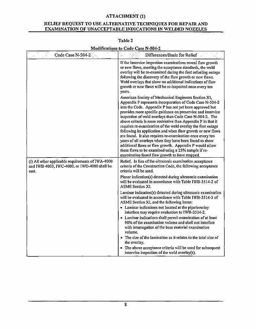
If the inservice inspection examinations reveal flaw growthor new flaws, meeting the acceptance standards, the weldoverlay will be re-examined during the first refueling outagefollowing the discovery of the flaw growth or new flaws.Weld overlays that show no additional indications of flawgrowth or new flaws will be re-inspected once every tenyears.American Society of Mechanical Engineers Section XI,Appendix P represents incorporation of Code Case N-504-2into the Code. Appendix P has not yet been approved butprovides more specific guidance on preservice and inserviceinspection of weld overlays than Code Case N-504-2. Theabove criteria is more restrictive than Appendix P in that itrequires re-examination of the weld overlay the first outagefollowing its application and when flaw growth or new flawsare found. It also requires re-examination once every tenyears of all overlays when they have been found to showadditional flaws or flaw growth. Appendix P would allowthese flaws to be examined using a 25% sample if re-examination found flaw growth to have stopped.
(I) All other applicable requirements of IWA-4000and IWB-4000, IWC-4000, or IWD-4000 shall bemet.
Relief. In lieu of the ultrasonic examination acceptancecriteria of the Construction Code, the following acceptancecriteria will be used.Planar indication(s) detected during ultrasonic examinationwill be evaluated in accordance with Table IWB-3514-2 ofASME Section Xl.Laminar indication(s) detected during ultrasonic examinationwill be evaluated in accordance with Table IWB-3514-3 ofASME Section XI, and the following items:. Laminar indications not located at the pipe/overlay
interface may require evaluation to IWB-3514-2.* Laminar indications shall permit examination of at least
90% of the examination volume and shall not interferewith interrogation of the base material examinationvolume.
* The size of the lamination as it relates to the total size ofthe overlay.
* The above acceptance criteria will be used for subsequentinservice inspection of the weld overlay(s).
8
ATTACHMENT (1)
RELIEF REQUEST TO USE ALTERNATIVE TECHNIQUES FOR REPAIR ANDEXAMINATION OF UNACCEPTABLE INDICATIONS IN WELDED NOZZLES
Table 3
Modifications to Code Case N-638
Code Case N-638 Differences/Basis for Relief
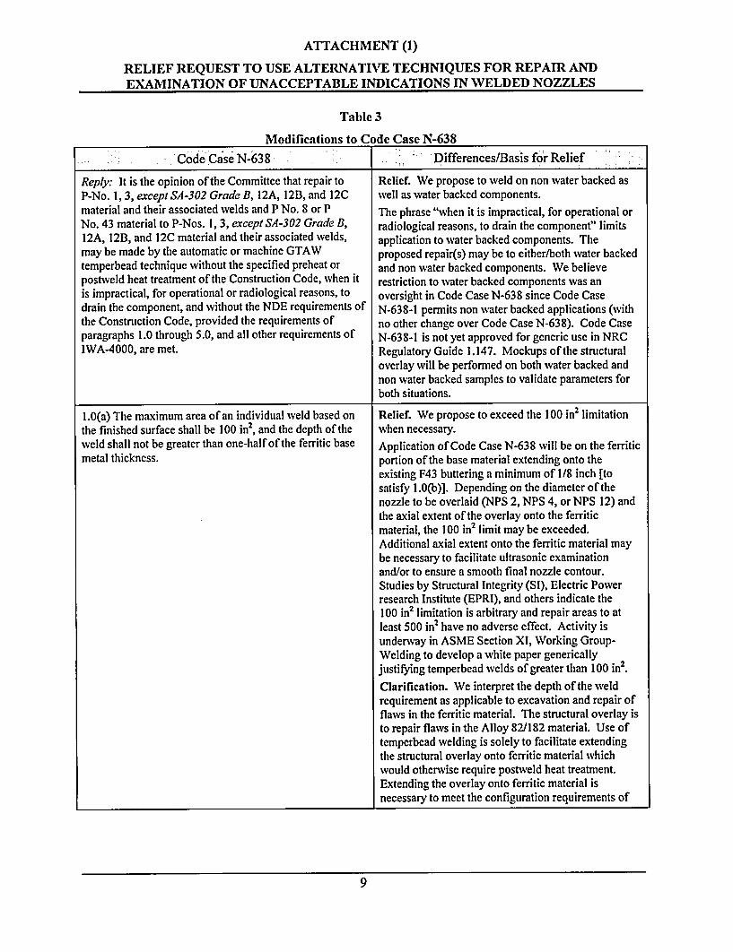
Reply: It is the opinion of the Committee that repair to Relief. We propose to weld on non water backed asP-No. 1, 3, except SA-302 Grade B, 12A, 12B, and 12C well as water backed components.material and their associated welds and P No. 8 or P The phrase "when it is impractical, for operational orNo. 43 material to P-Nos. 1, 3, except SA-302 Grade B, radiological reasons, to drain the component" limits12A, 12B, and 12C material and their associated welds, application to water backed components. Themay be made by the automatic or machine GTAW proposed repair(s) may be to either/both water backedtemperbead technique without the specified preheat or and non water backed components. We believepostweld heat treatment of the Construction Code, when it restriction to water backed components was anis impractical, for operational or radiological reasons, to oversight in Code Case N-638 since Code Casedrain the component, and without the NDE requirements of N-638-1 permits non water backed applications (withthe Construction Code, provided the requirements of no other change over Code Case N-638). Code Caseparagraphs 1.0 through 5.0, and all other requirements of N-638-1 is not yet approved for generic use in NRCIWA-4000, are met. Regulatory Guide 1.147. Mockups of the structural
overlay will be performed on both water backed andnon water backed samples to validate parameters forboth situations.
1.0(a) The maximum area of an individual weld based on Relief. We propose to exceed the 100 in2 limitationthe finished surface shall be 100 in2, and the depth of the when necessary.weld shall not be greater than one-half of the ferritic base Application of Code Case N-638 will be on the ferriticmetal thickness. portion of the base material extending onto the
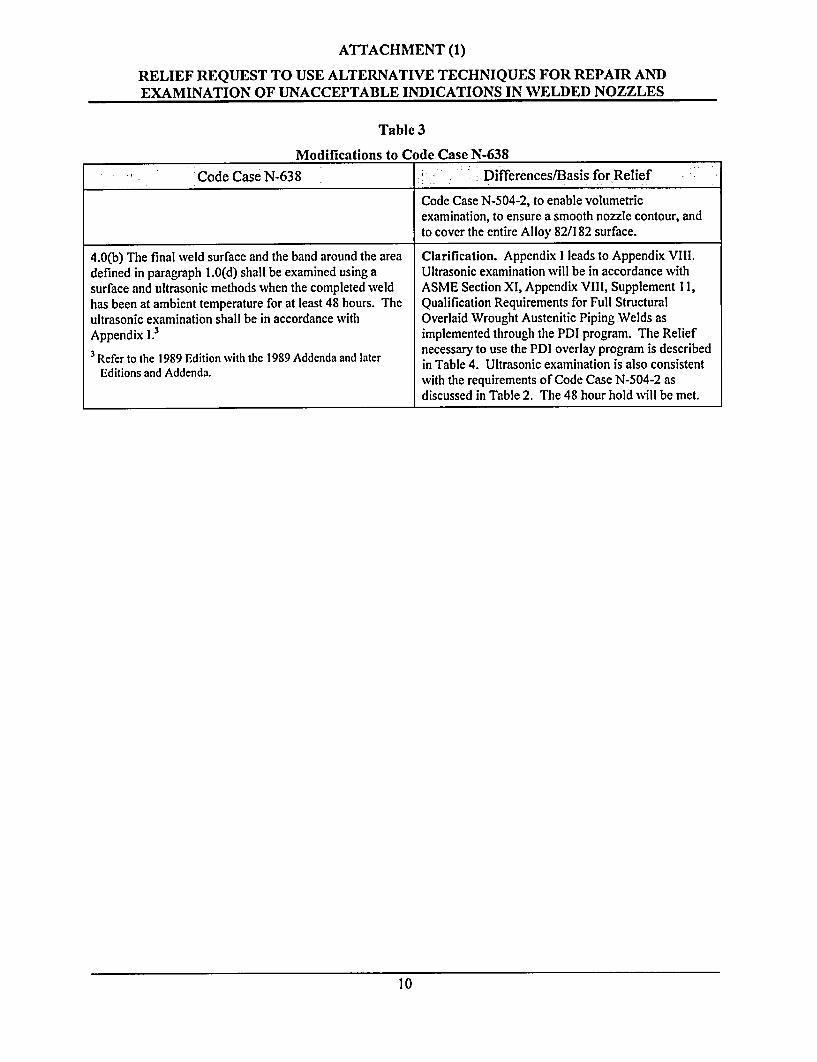
existing F43 buttering a minimum of 1/8 inch [tosatisfy 1.0(b)]. Depending on the diameter of thenozzle to be overlaid (NPS 2, NPS 4, or NPS 12) andthe axial extent of the overlay onto the ferriticmaterial, the 100 in2 limit may be exceeded.Additional axial extent onto the ferritic material maybe necessary to facilitate ultrasonic examinationand/or to ensure a smooth final nozzle contour.Studies by Structural Integrity (SI), Electric Powerresearch Institute (EPRI), and others indicate the100 in2 limitation is arbitrary and repair areas to atleast 500 in2 have no adverse effect. Activity isunderway in ASME Section XI, Working Group-Welding to develop a white paper genericallyjustifying temperbead welds of greater than 100 in2.Clarification. We interpret the depth of the weldrequirement as applicable to excavation and repair offlaws in the ferritic material. The structural overlay isto repair flaws in the Alloy 82/182 material. Use oftemperbead welding is solely to facilitate extendingthe structural overlay onto ferritic material whichwould otherwise require postweld heat treatment.Extending the overlay onto ferritic material isnecessary to meet the configuration requirements of
9
ATTACHMENT (1)
RELIEF REQUEST TO USE ALTERNATIVE TECHNIQUES FOR REPAIR ANDEXAMINATION OF UNACCEPTABLE INDICATIONS IN WELDED NOZZLES
Table 3
Modifications to Code Case N-638
Code Case N-638 Differences/Basis for Relief
Code Case N-504-2, to enable volumetricexamination, to ensure a smooth nozzle contour, andto cover the entire Alloy 82/182 surface.
4.0(b) The final weld surface and the band around the area Clarification. Appendix I leads to Appendix Vill.defined in paragraph 1.0(d) shall be examined using a Ultrasonic examination will be in accordance withsurface and ultrasonic methods when the completed weld ASME Section XI, Appendix VIll, Supplement 11,has been at ambient temperature for at least 48 hours. The Qualification Requirements for Full Structuralultrasonic examination shall be in accordance with Overlaid Wrought Austenitic Piping Welds asAppendix 1.3 implemented through the PDI program. The Relief
3 Refer to the 1989 Edition with the 1989 Addenda and later necessary to use the PDI overlay program is describedR Edition wite Addendaa in Table 4. Ultrasonic examination is also consistentEditions and Addenda. with the requirements of Code Case N-504-2 as
discussed in Table 2. The 48 hour hold will be met.
10
ATTACHMENT (1)
RELIEF REQUEST TO USE ALTERNATIVE TECHNIQUES FOR REPAIR ANDEXAMINATION OF UNACCEPTABLE INDICATIONS IN WELDED NOZZLES
Appendix VIII of Section XI cannot be used for the structural weld overlay required NDE. Relief isrequested to use the PDI program implementation of Appendix VIII. A detailed comparison of AppendixVIII and PDI requirements is summarized belowv.
At this time, the Performance Demonstration Initiative has not qualified procedures for weld overlaysless than 4 inch diameter. We propose to use the existing PDI procedures (for greater than or equal to4 inch diameter) on weld overlays less than 4 inch diameter down to 2 inch diameter. The proposedmethods of examination of weld overlays less than NPS 4 will ensure that we find any flaws ofsignificance in the weld overlay. The basis for this conclusion is that the techniques have beendemonstrated on samples of greater than and equal to 4 inch diameter weld overlays. Personnel qualifiedon 4 inch diameter weld overlays will be used to examine weld overlays less than 4 inch diameter. Oncequalified procedures are developed for weld overlays less than 4 inch diameter, the qualified procedureswill be used, along with personnel qualified on such procedures.
Relief is requested to allow closer spacing of flaws provided they don't interfere with detection ordiscrimination. The specimens used to date for qualification to the Tri-party (NRC/BWROG/EPRI)agreement have a flaw population density greater than allowed by current Code requirements. Thesesamples have been used successfully for all previous qualifications under the Tri-party agreementprogram. To facilitate their use and provide continuity from the Tri-party agreement program toSupplement I 1, the PDI program has merged the Tri-party test specimens into their weld overlayprogram.
Table 4
Modifications to Appendix VIII, Supplement 11
SUPPLEMENT II -QUALIFICATION PDI PROGRAM:REQUIREMENTS FOR FULL STRUCTURAL The Proposed Alternative to
OVERLAID WROUGHT AUSTENITIC PIPING Supplement 11 RequirementsWELDS
1.0 SPECIMEN REQUIREMENTS
1.1 General. The specimen set shall conform to thefollowing requirements.
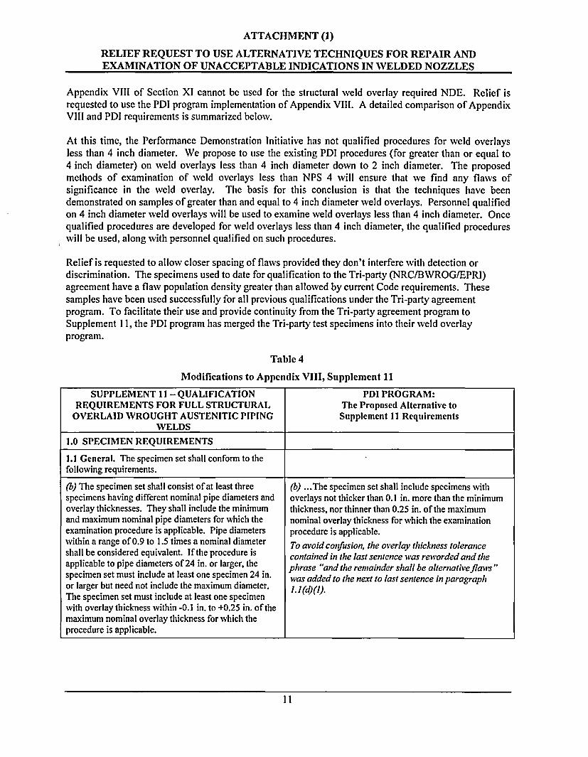
(b) The specimen set shall consist of at least three (b) .. The specimen set shall include specimens withspecimens having different nominal pipe diameters and overlays not thicker than 0.1 in. more than the minimumoverlay thicknesses. They shall include the minimum thickness, nor thinner than 0.25 in. of the maximumand maximum nominal pipe diameters for which the nominal overlay thickness for which the examinationexamination procedure is applicable. Pipe diameters procedure is applicable.within a range of 0.9 to 1.5 times a nominal diameter To avoid confusion, the overlay thickness toleranceshall be considered equivalent. If the procedure is contained in the last sentence was reworded and theapplicable to pipe diameters of 24 in. or larger, the phrase "and the remainder shall be alternativefla'vs"specimen set must include at least one specimen 24 in. was added to the next to last sentence in paragraphor larger but need not include the maximum diameter. .I (d) ().The specimen set must include at least one specimenwith overlay thickness within -0.1 in. to +0.25 in. of themaximum nominal overlay thickness for which theprocedure is applicable.
11
ATTACHMENT (1)
RELIEF REQUEST TO USE ALTERNATIVE TECHNIQUES FOR REPAIR ANDEXAMINATION OF UNACCEPTABLE INDICATIONS IN WELDED NOZZLES
Table 4
Modifications to Appendix VIII, Supplement 11
SUPPLEMENT 11 -QUALIFICATION PDI PROGRAM:REQUIREMENTS FOR FULL STRUCTURAL The Proposed Alternative to
OVERLAID WROUGHT AUSTENITIC PIPING Supplement 11 RequirementsWELDS
(d) Flaiv Conditions
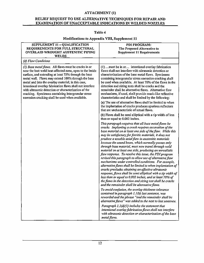
(1) Base metalflanvs. All flaws must be cracks in ornear the butt weld heat-affected zone, open to the insidesurface, and extending at least 75% through the basemetal wall. Flaws may extend 100% through the basemetal and into the overlay material; in this case,intentional overlay fabrication flaws shall not interferewith ultrasonic detection or characterization of thecracking. Specimens containing intergranular stresscorrosion cracking shall be used when available.
(I) ...must be in or... intentional overlay fabricationflaws shall not interfere with ultrasonic detection orcharacterization of the base metal flaws. Specimenscontaining intergranular stress corrosion cracking shallbe used when available. At least 70% of the flaws in thedetection and sizing tests shall be cracks and theremainder shall be alternative flaws. Alternative flawmechanisms, if used, shall provide crack-like reflectivecharacteristics and shall be limited by the following:(a) The use of alternative flaws shall be limited to whenthe implantation of cracks produces spurious reflectorsthat are uncharacteristic of actual flaws.(b) Flaws shall be semi elliptical with a tip width of lessthan or equal to 0.002 inches.This paragraph requires that all base metalflaws becracks. Implanting a crack requires excavation of thebase material on at least one side of the flaw While thismay be satisfactoryforferritic materials, it does notproduce a useable axialflaw in austenitic materialsbecause the sound beam, which normally passes onlythrough base material, must now travel through w eldmaterial on at least one side, producing an unrealisticflaw response. To resolve this issue, the PD! programrevised this paragraph to allow use of alternativeflawvmechanisms under controlled conditions. For example,alternativeflaws shall be limited to when implantation ofcracks precludes obtaining an effective ultrasonicresponse, flaws shall be semi elliptical with a tip width ofless than or equal to 0. 002 inches, and at least 70% ofthe flaws in the detection and sizing test shall be cracksand the remainder shall be alternativeflaws.To avoid confusion, the overlay thickness tolerancecontained in paragraph 1I (b) last sentence, wasreworded and the phrase "and the remainder shall bealternativeflcnvs" wvas added to the next to last sentence.
Paragraph 1. I (d)(l) includes the statement thatintentional overlayfabricationflaws shall not interferewith ultrasonic detection or characterization of the basemetalflavs.
12
ATTACHMENT (1)
RELIEF REQUEST TO USE ALTERNATIVE TECHNIQUES FOR REPAIR ANDEXAMINATION OF UNACCEPTABLE INDICATIONS IN WELDED NOZZLES
Table 4
Modifications to Appendix VIII, Supplement 11
SUPPLEMENT II-QUALIFICATION PDI PROGRAM:REQUIREMENTS FOR FULL STRUCTURAL The Proposed Alternative to
OVERLAID WROUGHT AUSTENITIC PIPING Supplement 11 RequirementsWELDS
(e) Detection Specimens
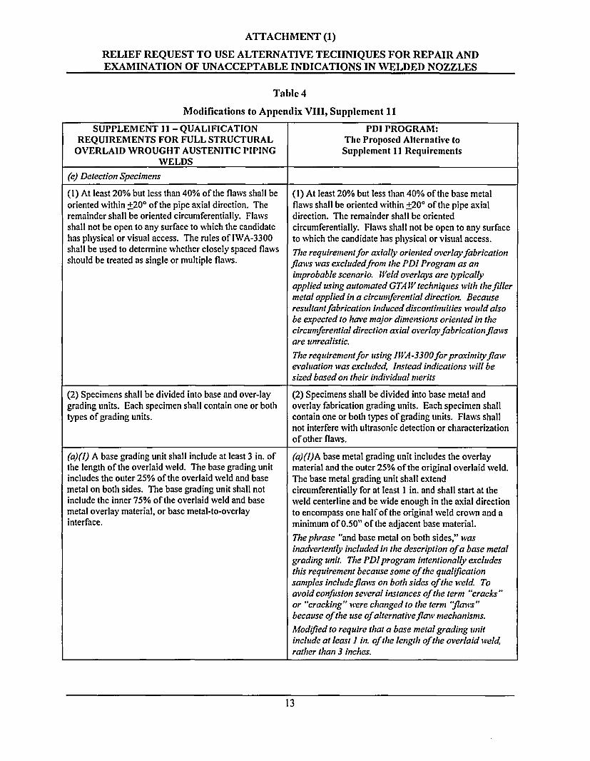
(1) At least 20% but less than 40% of the flaws shall be (1) At least 20% but less than 40% of the base metaloriented within +200 of the pipe axial direction. The flaws shall be oriented within +20° of the pipe axialremainder shall be oriented circumferentially. Flaws direction. The remainder shall be orientedshall not be open to any surface to which the candidate circumferentially. Flaws shall not be open to any surfacehas physical or visual access. The rules of IWA-3300 to which the candidate has physical or visual access.shall be used to determine whether closely spaced flaws The requirementfor axially oriented overlayfabricationshould be treated as single or multiple flaws. flawvs lvas excludedfrom the PDI Program as an
improbable scenario. Meld overlays are typicallyapplied using automated GTA IV techniques with the fillermetal applied in a circumferential direction. Becauseresultantfabrication induced discontinuities would alsobe expected to have major dimensions oriented in thecircumferential direction axial overlay fabrication flawsare unrealistic.The requirement for using lIWA-3300for proximityflawevaluation was excluded, Instead indications till besized based on their individual merits
(2) Specimens shall be divided into base and over-lay (2) Specimens shall be divided into base metal andgrading units. Each specimen shall contain one or both overlay fabrication grading units. Each specimen shalltypes of grading units. contain one or both types of grading units. Flaws shall
not interfere with ultrasonic detection or characterizationof other flaws.
(a)fl) A base grading unit shall include at least 3 in. of (a)(I)A base metal grading unit includes the overlaythe length of the overlaid weld. The base grading unit material and the outer 25% of the original overlaid weld.includes the outer 25% of the overlaid weld and base The base metal grading unit shall extendmetal on both sides. The base grading unit shall not circumferentially for at least I in. and shall start at theinclude the inner 75% of the overlaid weld and base weld centerline and be wide enough in the axial directionmetal overlay material, or base metal-to-overlay to encompass one half of the original weld crown and ainterface. minimum of 0.50" of the adjacent base material.
Thephrase "and base metal on both sides," wasinadvertently included in the description of a base metalgrading unit. The PD! program intentionally excludesthis requirement because some of the qualificationsamples includeflawvs on both sides of the weld Toavoid confusion several instances of the term "cracks"or "cracking" wvere changed to the term 'flaws "because of the use of alternative flaw mechanisms.
Modified to require that a base metal grading unitinclude at least I in. of the length of the overlaid weld,rather than 3 inches.
13
ATTACHMENT (1)
RELIEF REQUEST TO USE ALTERNATIVE TECHNIQUES FOR REPAIR ANDEXAMINATION OF UNACCEPTABLE INDICATIONS IN WELDED NOZZLES
Table 4
Modifications to Appendix VIII, Supplement 11
SUPPLEMENT 11-QUALIFICATION PDI PROGRAM:REQUIREMENTS FOR FULL STRUCTURAL The Proposed Alternative to
OVERLAID WROUGHT AUSTENITIC PIPING Supplement 11 RequirementsWELDS
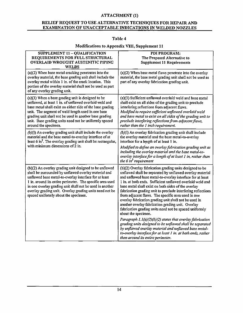
(a)(2) When base metal cracking penetrates into the (a)(2) When base metal flaws penetrate into the overlayoverlay material, the base grading unit shall include the material, the base metal grading unit shall not be used asoverlay metal within 1 in. of the crack location. This part of any overlay fabrication grading unit.portion of the overlay material shall not be used as partof any overlay grading unit.
(a)(3) When a base grading unit is designed to be (a)(3) Sufficient unflawed overlaid weld and base metalunflawed, at least I in. of unflawed overlaid weld and shall exist on all sides of the grading unit to precludebase metal shall exist on either side of the base grading interfering reflections from adjacent flaws.unit. The segment of weld length used in one base Modified to require sufficient unflawed overlaid weldgrading unit shall not be used in another base grading and base metal to exist on all sides of the grading unit tounit. Base grading units need not be uniformly spaced preclude interfering reflections from adjacentflaws,around the specimen. rather than the I inch requirement.
(b)(1) An overlay grading unit shall include the overlay (b)(l) An overlay fabrication grading unit shall includematerial and the base metal-to-overlay interface of at the overlay material and the base metal-to-overlayleast 6 in2. The overlay grading unit shall be rectangular, interface for a length of at least I in.with minimum dimensions of 2 in. Modified to define an overlay fabrication grading unit as
including the overlay material and the base metal-to-overlay interface for a length of at least I in, rather thanthe 6 in2 requirement
(b)(2) An overlay grading unit designed to be unflawed (b)(2) Overlay fabrication grading units designed to beshall be surrounded by unflawed overlay material and unflawed shall be separated by unflawed overlay materialunflawed base metal-to-overlay interface for at least and unflawed base metal-to-overlay interface for at leastI in. around its entire perimeter. The specific area used I in. at both ends. Sufficient unflawed overlaid weld andin one overlay grading unit shall not be used in another base metal shall exist on both sides of the overlayoverlay grading unit. Overlay grading units need not be fabrication grading unit to preclude interfering reflectionsspaced uniformly about the specimen. from adjacent flaws. The specific area used in one
overlay fabrication grading unit shall not be used inanother overlay fabrication grading unit. Overlayfabrication grading units need not be spaced uniformlyabout the specimen.Paragraph 1.I(e) (2) (b) (2) states that overlay fabricationgrading units designed to be unflawed shall be separatedby unflawed overlay material and unflawved base metal-to-overlay interfacefor at least I in. at both ends, ratherthan around its entire perimeter.
14
ATTACHMENT (1)
RELIEF REQUEST TO USE ALTERNATIVE TECHNIQUES FOR REPAIR ANDEXAMINATION OF UNACCEPTABLE INDICATIONS IN WELDED NOZZLES
Table 4
Modifications to Appendix VIII, Supplement 11
SUPPLEMENT II-QUALIFICATIONREQUIREMENTS FOR FULL STRUCTURAL
OVERLAID WROUGHT AUSTENITIC PIPINGWELDS
PDI PROGRAM:The Proposed Alternative toSupplement 11 Requirements
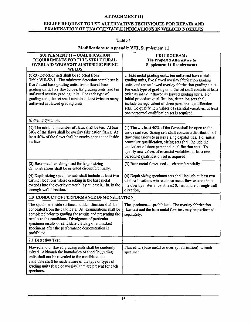
(b)(3) Detection sets shall be selected from ... base metal grading units, ten unflawed base metalTable VIII-S2-1. The minimum detection sample set is grading units, five flawed overlay fabrication gradingfive flawed base grading units, ten unflawed base units, and ten unflawed overlay fabrication grading units.grading units, five flawed overlay grading units, and ten For each type of grading unit, the set shall contain at leastunflawed overlay grading units. For each type of twice as many unflawed as flawed grading units. Forgrading unit, the set shall contain at least twice as many initial procedure qualification, detection sets shallunflawed as flawed grading units. include the equivalent of three personnel qualification
sets. To qualify new values of essential variables, at leastone personnel qualification set is required.
69 Sizing Specimen
(I) The minimum number of flaws shall be ten. At least (I) The .... least 40% of the flaws shall be open to the30% of the flaws shall be overlay fabrication flaws. At inside surface. Sizing sets shall contain a distribution ofleast 40% of the flaws shall be cracks open to the inside flawv dimensions to assess sizing capabilities. For initialsurface. procedure qualification, sizing sets shall include the
equivalent of three personnel qualification sets. Toqualify new values of essential variables, at least onepersonnel qualification set is required.
(3) Base metal cracking used for length sizing (3) Base metal flaws used ... circumferentially.demonstrations shall be oriented circumferentially.
(4) Depth sizing specimen sets shall include at least two (4) Depth sizing specimen sets shall include at least twodistinct locations where cracking in the base metal distinct locations where a base metal flaw extends intoextends into the overlay material by at least 0.1 in. in the the overlay material by at least 0.1 in. in the through-wallthrough-wall direction. direction.
2.0 CONDUCT OF PERFORMANCE DEMONSTRATION
The specimen inside surface and identification shall be The specimen.....prohibited. The overlay fabricationconcealed from the candidate. All examinations shall be flaw test and the base metal flaw test may be performedcompleted prior to grading the results and presenting the separately.results to the candidate. Divulgence of particularspecimen results or candidate viewing of unmaskedspecimens after the performance demonstration isprohibited.
2.1 Detection Test.
Flawed and unflawed grading units shall be randomly Flawed.... (base metal or overlay fabrication) ... eachmixed. Although the boundaries of specific grading specimen.units shall not be revealed to the candidate, thecandidate shall be made aware of the type or types ofgrading units (base or overlay) that are present for eachspecimen.
15
ATTACHMENT (1)
RELIEF REQUEST TO USE ALTERNATIVE TECHNIQUES FOR REPAIR ANDEXAMINATION OF UNACCEPTABLE INDICATIONS IN WELDED NOZZLES
Table 4
Modifications to Appendix VIII, Supplement 11
SUPPLEMENT II-QUALIFICATION PDI PROGRAM:REQUIREMENTS FOR FULL STRUCTURAL The Proposed Alternative to
OVERLAID WROUGHT AUSTENITIC PIPING Supplement 11 RequirementsWELDS
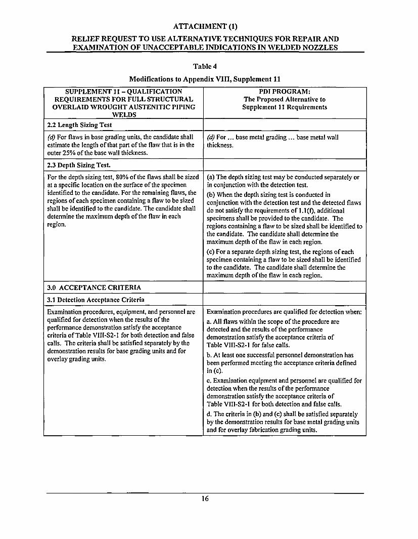
2.2 Length Sizing Test
(d) For flaws in base grading units, the candidate shall (d) For ... base metal grading ... base metal wallestimate the length of that part of the flaw that is in the thickness.outer 25% of the base wall thickness.
2.3 Depth Sizing Test.
For the depth sizing test, 80% of the flaws shall be sized (a) The depth sizing test may be conducted separately orat a specific location on the surface of the specimen in conjunction with the detection test.identified to the candidate. For the remaining flaws, the (b) When the depth sizing test is conducted inregions of each specimen containing a flaw to be sized conjunction with the detection test and the detected flawsshall be identified to the candidate. The candidate shall do not satisfy the requirements of 1.1(f), additionaldetermine the maximum depth of the flaw in each specimens shall be provided to the candidate. Theregion. regions containing a flaw to be sized shall be identified to
the candidate. The candidate shall determine themaximum depth of the flaw in each region.(c) For a separate depth sizing test, the regions of eachspecimen containing a flaw to be sized shall be identifiedto the candidate. The candidate shall determine themaximum depth of the flaw in each region.
3.0 ACCEPTANCE CRITERIA
3.1 Detection Acceptance Criteria
Examination procedures, equipment, and personnel are Examination procedures are qualified for detection when:qualified for detection when the results of the a. All flaws within the scope of the procedure areperformance demonstration satisfy the acceptance detected and the results of the performancecriteria of Table Vill-S2-1 for both detection and false demonstration satisfy the acceptance criteria ofcalls. The criteria shall be satisfied separately by the Table Vlll-S2-1 for false calls.
demonstration results for base grading units and for b. At least one successful personnel demonstration hasoverlay grading units. been performed meeting the acceptance criteria defined
in (c).c. Examination equipment and personnel are qualified fordetection when the results of the performancedemonstration satisfy the acceptance criteria ofTable VIll-S2-I for both detection and false calls.
d. The criteria in (b) and (c) shall be satisfied separatelyby the demonstration results for base metal grading unitsand for overlay fabrication grading units.
16
ATTACHMENT (1)
RELIEF REQUEST TO USE ALTERNATIVE TECHNIQUES FOR REPAIR ANDEXAMINATION OF UNACCEPTABLE INDICATIONS IN WELDED NOZZLES
Table 4
Modifications to Appendix VIII, Supplement 11
SUPPLEMENT 11 - QUALIFICATION PDI PROGRAM:REQUIREMENTS FOR FULL STRUCTURAL The Proposed Alternative toOVERLAID WROUGHT AUSTENITIC PIPING Supplement 11 Requirements
WELDS
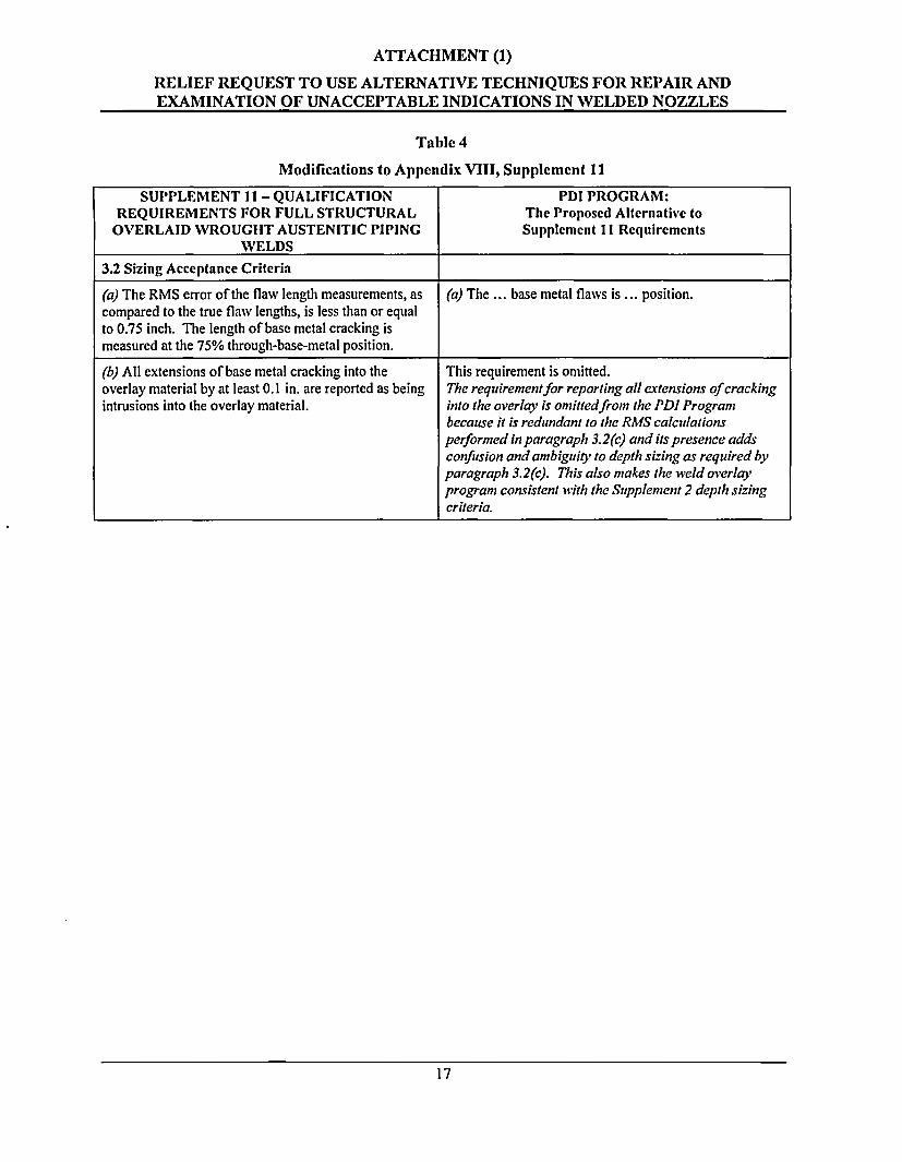
3.2 Sizing Acceptance Criteria
(a) The RMS error of the flaw length measurements, as (a) The ... base metal flaws is ... position.compared to the true flaw lengths, is less than or equalto 0.75 inch. The length of base metal cracking ismeasured at the 75% through-base-metal position.
(b) All extensions of base metal cracking into the This requirement is omitted.overlay material by at least 0.1 in. are reported as being The requirement for reporting all extensions of crackingintrusions into the overlay material. into the overlay is omittedfront the PDI Program
because it is redundant to the RMS calculationsperformed in paragraph 3.2(c) and its presence addsconfusion and ambiguity to depth sizing as required byparagraph 3.2(c). This also makes the wield overlayprogram consistent with the Supplement 2 depth sizingcriteria.
17
ENCLOSURE 1
MINIMUM CHROMIUM CONTENT IN NICKEL-ALLOY WELD
OVERLAYS TO MITIGATE PWSCC
Calvert Cliffs Nuclear Power Plant, Inc.February 18, 2005