building the internet of things with ipv6 and mipv6
TRANSCRIPT

BUILDING THE INTERNETOF THINGS WITH IPv6AND MIPv6

BUILDING THE INTERNETOF THINGS WITH IPv6AND MIPv6The Evolving World ofM2M Communications
DANIEL MINOLI

Copyright C© 2013 by John Wiley & Sons, Inc. All rights reserved.
Published by John Wiley & Sons, Inc., Hoboken, New Jersey.Published simultaneously in Canada.
No part of this publication may be reproduced, stored in a retrieval system, or transmitted in any form orby any means, electronic, mechanical, photocopying, recording, scanning, or otherwise, except aspermitted under Section 107 or 108 of the 1976 United States Copyright Act, without either the priorwritten permission of the Publisher, or authorization through payment of the appropriate per-copy fee tothe Copyright Clearance Center, Inc., 222 Rosewood Drive, Danvers, MA 01923, (978) 750-8400,fax (978) 750-4470, or on the web at www.copyright.com. Requests to the Publisher for permissionshould be addressed to the Permissions Department, John Wiley & Sons, Inc., 111 River Street, Hoboken,NJ 07030, (201) 748-6011, fax (201) 748-6008, or online at http://www.wiley.com/go/permission.
Limit of Liability/Disclaimer of Warranty: While the publisher and author have used their best efforts inpreparing this book, they make no representations or warranties with respect to the accuracy orcompleteness of the contents of this book and specifically disclaim any implied warranties ofmerchantability or fitness for a particular purpose. No warranty may be created or extended by salesrepresentatives or written sales materials. The advice and strategies contained herein may not be suitablefor your situation. You should consult with a professional where appropriate. Neither the publisher norauthor shall be liable for any loss of profit or any other commercial damages, including but not limited tospecial, incidental, consequential, or other damages.
For general information on our other products and services or for technical support, please contact ourCustomer Care Department within the United States at (800) 762-2974, outside the United States at(317) 572-3993 or fax (317) 572-4002.
Wiley also publishes its books in a variety of electronic formats. Some content that appears in print maynot be available in electronic formats. For more information about Wiley products, visit our web site atwww.wiley.com.
Library of Congress Cataloging-in-Publication Data:
Minoli, Daniel, 1952–Building the internet of things (IoT) with IPv6 and MIPv6 / Daniel Minoli.
pages cmISBN 978-1-118-47347-4 (hardback)
1. Embedded Internet devices. 2. Internet of things. 3. TCP/IP (Computer network protocol)4. Mobile computing. I. Title.
TK7895.E43M56 2013004.6′2–dc23
2012049072
Printed in the United States of America
10 9 8 7 6 5 4 3 2 1

For Anna

CONTENTS
PREFACE xiii
ABOUT THE AUTHOR xvii
1 WHAT IS THE INTERNET OF THINGS? 1
1.1 Overview and Motivations / 11.2 Examples of Applications / 121.3 IPv6 Role / 171.4 Areas of Development and Standardization / 201.5 Scope of the Present Investigation / 23Appendix 1.A: Some Related Literature / 25References / 26
2 INTERNET OF THINGS DEFINITIONS AND FRAMEWORKS 28
2.1 IoT Definitions / 282.1.1 General Observations / 282.1.2 ITU-T Views / 312.1.3 Working Definition / 33
2.2 IoT Frameworks / 382.3 Basic Nodal Capabilities / 44References / 46
vii

viii CONTENTS
3 INTERNET OF THINGS APPLICATION EXAMPLES 48
3.1 Overview / 493.2 Smart Metering/Advanced Metering Infrastructure / 523.3 e-Health/Body Area Networks / 553.4 City Automation / 623.5 Automotive Applications / 643.6 Home Automation / 673.7 Smart Cards / 703.8 Tracking (Following and Monitoring Mobile Objects) / 773.9 Over-The-Air-Passive Surveillance/Ring of Steel / 793.10 Control Application Examples / 863.11 Myriad Other Applications / 93References / 94
4 FUNDAMENTAL IoT MECHANISMS AND KEYTECHNOLOGIES 97
4.1 Identification of IoT Objects and Services / 974.2 Structural Aspects of the IoT / 101
4.2.1 Environment Characteristics / 1014.2.2 Traffic Characteristics / 1024.2.3 Scalability / 1024.2.4 Interoperability / 1034.2.5 Security and Privacy / 1034.2.6 Open Architecture / 103
4.3 Key IoT Technologies / 1034.3.1 Device Intelligence / 1034.3.2 Communication Capabilities / 1044.3.3 Mobility Support / 1044.3.4 Device Power / 1054.3.5 Sensor Technology / 1074.3.6 RFID Technology / 1114.3.7 Satellite Technology / 118
References / 119
5 EVOLVING IoT STANDARDS 120
5.1 Overview and Approaches / 120

CONTENTS ix
5.2 IETF IPv6 Routing Protocol for RPL Roll / 1235.3 Constrained Application Protocol (CoAP) / 126
5.3.1 Background / 1265.3.2 Messaging Model / 1295.3.3 Request/Response Model / 1295.3.4 Intermediaries and Caching / 129
5.4 Representational State Transfer (REST) / 1305.5 ETSI M2M / 1305.6 Third-Generation Partnership Project Service Requirements for
Machine-Type Communications / 1315.6.1 Approach / 1315.6.2 Architectural Reference Model for MTC / 134
5.7 CENELEC / 1355.8 IETF IPv6 Over Lowpower WPAN (6LoWPAN) / 1375.9 ZigBee IP (ZIP) / 1375.10 IP in Smart Objects (IPSO) / 138Appendix 5.A: Legacy Supervisory Control and Data Acquisition(SCADA) Systems / 138References / 142
6 LAYER 1/2 CONNECTIVITY: WIRELESS TECHNOLOGIESFOR THE IoT 144
6.1 WPAN Technologies for IoT/M2M / 1456.1.1 Zigbee/IEEE 802.15.4 / 1556.1.2 Radio Frequency for Consumer Electronics (RF4CE) / 1706.1.3 Bluetooth and its Low-Energy Profile / 1706.1.4 IEEE 802.15.6 WBANs / 1806.1.5 IEEE 802.15 WPAN TG4j MBANs / 1816.1.6 ETSI TR 101 557 / 1846.1.7 NFC / 1876.1.8 Dedicated Short-Range Communications (DSRC)
and Related Protocols / 1896.1.9 Comparison of WPAN Technologies / 192
6.2 Cellular and Mobile Network Technologies for IoT/M2M / 1956.2.1 Overview and Motivations / 1956.2.2 Universal Mobile Telecommunications System / 1966.2.3 LTE / 197

x CONTENTS
Appendix 6.A: Non-Wireless Technologies for IoT: PowerlineCommunications / 209
References / 216
7 LAYER 3 CONNECTIVITY: IPv6 TECHNOLOGIES FOR THE IoT 220
7.1 Overview and Motivations / 2207.2 Address Capabilities / 224
7.2.1 IPv4 Addressing and Issues / 2247.2.2 IPv6 Address Space / 225
7.3 IPv6 Protocol Overview / 2317.4 IPv6 Tunneling / 2397.5 IPsec in IPv6 / 2427.6 Header Compression Schemes / 2427.7 Quality of Service in IPv6 / 2457.8 Migration Strategies to IPv6 / 246
7.8.1 Technical Approaches / 2467.8.2 Residential Broadband Services in an IPv6 Environment / 2507.8.3 Deployment Opportunities / 252
References / 254
8 LAYER 3 CONNECTIVITY: MOBILE IPv6 TECHNOLOGIES FORTHE IoT 257
8.1 Overview / 2578.2 Protocol Details / 266
8.2.1 Generic Mechanisms / 2678.2.2 New IPv6 Protocol, Message Types, and Destination
Option / 2718.2.3 Modifications to IPv6 Neighbor Discovery / 2778.2.4 Requirements for Various IPv6 Nodes / 2788.2.5 Correspondent Node Operation / 2788.2.6 HA Node Operation / 2858.2.7 Mobile Node Operation / 2868.2.8 Relationship to IPV4 Mobile IPv4 (MIP) / 291
References / 292
9 IPv6 OVER LOW-POWER WPAN (6LoWPAN) 293
9.1 Background/Introduction / 294

CONTENTS xi
9.2 6LoWPANs Goals / 2969.3 Transmission of IPv6 Packets Over IEEE 802.15.4 / 297References / 301
GLOSSARY 302
INDEX 356
PREFACE
The proliferation of an enlarged gamut of devices able to be directly connectedto the Internet is leading to a new ubiquitous-computing paradigm: the Internetof Things (IoT). The IoT is a new type of Internet application that endeavors tomake the thing’s information (whatever that may be) available on a global scale.It has two attributes: (i) being an Internet application, and (ii) dealing with thing’sinformation. The IoT is predicated on the expansion of the scope, network reach, andpossibly even architecture of Internet through the inclusion of physical, instrumentedobjects. IoT aims at providing smarter services to the environment or the end-useras more in situ, transferable data becomes available. Thus, the IoT is seen as a new-generation information network that realizes machine-to-machine communication.The IoT eliminates time and space isolation between geographical space and virtualspace, forming what proponents label as “smart geographical space,” and creatingnew human–environment relationships. The latter implies that the IoT can advancethe goal of integration of human beings and their surroundings. Applications rangefrom energy efficiency to logistics, and many more.
At the “low end” of the spectrum, the thing’s information is typically coded by theUnique Identification (UID) and/or Electronic Product Code (EPC); the informationis (typically) stored in a Radio Frequency Identification (RFID) electronic tag; and,the information is uploaded by noncontact reading using an RFID reader. Moregenerally, smart cards (SCs) will also play an important role in IoT; SCs typicallyincorporate a microprocessor and storage. At the mid-range of the spectrum one findsdevices with embedded intelligence (microprocessors) and embedded active wirelesscapabilities to perform a variety of data gathering and possibly control functions. On-body biomedical sensors (supporting body area networks), home appliance and powermanagement, and industrial control are some examples of these applications. At the
xiii

xiv PREFACE
other end of the spectrum, more sophisticated sensors can be employed in the IoT:some of these sensor approaches use distributed wireless sensor networks (WSNs)systems that can collect, process, and forward a wide variety of environmental datasuch as temperature, atmospheric and environmental chemical content, or even lowor high resolution ambient video images from geographic dispersed locations; theseobjects may span a city, region, or large distribution grid.
The IoT is receiving a large amount of interest on the part of researchers, withthousands of papers published on this topic in the recent past. While specific applica-tions have existed for several years, perhaps supported on private enterprise networks,Internet-based systems along with system supporting a broader application scope arenow beginning to be deployed. The capabilities offered by IP Version 6 (IPv6) arecritical to the wide-spread deployment of the technology.
This text aims at exploring these evolving trends and offering practical suggestionsof how these technologies can be implemented in the service provider networks tosupport cost-effective applications, and how new revenue-generating services couldbe brought to the market. All the latest physical layer, MAC layer, and upper layerIoT and Machine to Machine (M2M) protocols are discussed.
Planners are asking questions such as: What is the Internet of Things? How doesM2M apply? How can it help my specific operation? What is the cost of deploy-ing such a system? Will standardization help? What are the security implications?This text addresses the following IoT aspects: evolving wireless standards, espe-cially low energy and medical applications; IPv6 technologies; Mobile IPv6 (MIPv6)technologies; applications; key underlying technologies for IoT applications; imple-mentation approaches; implementation challenges; and mid-range and long-rangeopportunities.
More specifically, the text reviews the latest technologies, the emerging com-mercial applications (especially health care), and the recently evolving standards,including all layers of the protocol stack applicable to IoT/M2M. The text focuseson extensively IPv6, MIPv6, and 6LowPAN/RPL and argues that the IoT/M2M maybe the killer app for IPv6. It covers the latest standards supporting the IoT and theM2M applications, including home area networking (HAN), AMI, IEEE 802.15.4,6LowPAN/RPL, Smart Energy 2.0, ETSI M2M, ZigBee IP (ZIP); ZigBee PersonalHome and Hospital Care (PHHC) Profile; IP in Smart Objects (IPSO); BLE; IEEE802.15.6 wireless body area networks (WBAN); IEEE 802.15 WPAN Task Group 4j(TG4j) medical body area networks; ETSI TR 101 557; near field communication(NFC); dedicated short-range communications (DSRC)/WAVE and related protocols;the Internet Engineering Task Force (IETF) IPv6 Routing Protocol for Low power andlossy networks (RPL)/Routing Over Low power and Lossy networks (ROLL); IETFConstrained Application Protocol (CoAP); IETF Constrained RESTful environments(CoRE); 3rd Generation Partnership Project (3GPP) Machine-Type Communications(MTC); long term evolution (LTE) cellular systems; and IEEE 1901.
This text covers the latest standards supporting IoT/M2M from the perspectiveof Body Area Network/E-health/Assistive Technologies; it also covers over-the-airsurveillance, object tracking, smart grid, smart cards, and home automation.

PREFACE xv
This is believed to be the first book on MIPv6 with applications to the IoT, espe-cially in a mobile context. This work will be of interest to technology investors;planners with carriers and service providers; CTOs; logistics professionals; engi-neers at equipment developers; technology integrators; Internet and Internet ServiceProviders (ISP); and telcos, and wireless providers, both domestically and in the restof the world.

ABOUT THE AUTHOR
Among other activities, Mr. Minoli has done extensive work in Internet engineering,design, and implementation over the years. The results presented in this book arebased on the foundation work done while at Telcordia, NYU, Stevens Institute ofTechnology, Rutgers University, AT&T, and other engineering firms, starting in theearly 1990s and continuing to the present. Some of his Internet- and wireless-relatedwork that plays a role in the deployment of the Internet of Things has been documentedin books he has authored, including:
� Internet and Intranet Engineering (McGraw-Hill, 1997)� Internet Architectures (co-authored) (Wiley, 1999)� Hotspot Networks: Wi-Fi for Public Access Locations (McGraw-Hill, 2002)� Wireless Sensor Networks (co-authored) (Wiley 2007)� Handbook of IPv4 to IPv6 Transition Methodologies For Institutional & Cor-
porate Networks (co-authored) (Auerbach, 2008)� Satellite Systems Engineering in an IPv6 Environment (Francis and Taylor 2009)� Mobile Video with Mobile IPv6 (Wiley 2012)
Mr. Minoli has many years of technical hands-on and managerial experience inplanning, designing, deploying, and operating IP/IPv6, telecom, wireless, satellite,and video networks, and Data Center systems and subsystems for global Best-In-Classcarriers and financial companies. He has worked on advanced network deployments atfinancial firms such as AIG, Prudential Securities, Capital One Financial, and serviceprovider firms such as Network Analysis Corporation, Bell Telephone Laboratories,
xvii

xviii ABOUT THE AUTHOR
ITT DTS/Worldcom, Bell Communications Research (now Telcordia), AT&T, Lead-ing Edge Networks Inc., SES, and other institutions. In the recent past, Mr. Minolihas been responsible for (i) the development and deployment of IPTV systems, (ii)the development and deployment of terrestrial and mobile IP-based networking ser-vices; (iii) deployments of large aperture antenna at teleports in the United States andabroad; (iv) deployment of satellite monitoring services worldwide using IP/MPLSservices; and (v) IPv6 services. He also played a founding role in the launching oftwo companies through the high tech incubator Leading Edge Networks Inc., whichhe ran in the early 2000s: Global Wireless Services, a provider of secure broadbandhotspot mobile Internet and hotspot VoIP services; and, InfoPort CommunicationsGroup, an optical and Gigabit Ethernet metropolitan carrier supporting Data Cen-ter/SAN/channel extension and cloud network access services. For several years, hehas been Session, Tutorial, and more recently overall Technical Program Chair for theIEEE ENTNET (Enterprise Networking) conference; ENTNET focuses on enterprisenetworking and security requirements for large financial firms and other corporateinstitutions.
Mr. Minoli has also written columns for ComputerWorld, NetworkWorld, andNetwork Computing (1985–2006). He has taught at New York University (InformationTechnology Institute), Rutgers University, and Stevens Institute of Technology (1984–2006). Also, he was a Technology Analyst At-Large, for Gartner/DataPro (1985–2001); based on extensive hand-on work at financial firms and carriers, he trackedtechnologies and wrote CTO/CIO-level technical scans in the area of telephony anddata systems, including topics on security, disaster recovery, network management,LANs, WANs (ATM and MPLS), wireless (LAN and public hotspot), VoIP, networkdesign/economics, carrier networks (such as metro Ethernet and CWDM/DWDM),and e-commerce. Over the years, he has advised Venture Capitals for investments of$150M in a dozen high tech companies.
Mr. Minoli has also acted as Expert Witness in a (won) $11B lawsuit regard-ing a VoIP-based wireless Air-to-Ground radio communication system for airplanein-cabin services, as well as for a large lawsuit related to digital scanning and trans-mission of bank documents/instruments (such as checks). He has also been engagedas a technical expert in a number of patent infringement proceedings in the digitalimaging and VoIP space supporting law firms such as Schiff Hardin LLP, Fulbright& Jaworski LLP, Dimock Stratton LLP/Smart & Biggar LLP, and Baker & McKenzieLLP, among others.

CHAPTER 1
WHAT IS THE INTERNET OF THINGS?
1.1 OVERVIEW AND MOTIVATIONS
The proliferation of an ever-growing set of devices able to be directly connected to theInternet is leading to a new ubiquitous-computing paradigm. Indeed, the Internet—itsdeployment and its use—has experienced significant growth in the past four decades,evolving from a network of a few hundred hosts (in its ARPAnet form) to a platformcapable of linking billions of entities globally. Initially, the Internet connected insti-tutional hosts and accredited terminals via specially developed gateways (routers).More recently, the Internet has connected servers of all kinds to users of all kindsseeking access to information and applications of all kinds. Now, with social media,it intuitively and effectively connects all sorts of people to people, and to virtualcommunities. The growth of the Internet shows no signs of slowing down, and itis steadily becoming the infrastructure fabric of choice for a new paradigm for all-inclusive pervasive computing and communications. The next evolution is to connectall “things” and objects that have (or will soon have) embedded wireless (or wireline)connectivity to control systems that support data collection, data analysis, decision-making, and (remote) actuation. “Things” include, but are not limited to, machinery,home appliances, vehicles, individual persons, pets, cattle, animals, habitats, habitatoccupants, as well as enterprises. Interactions are achieved utilizing a plethora ofpossibly different networks; computerized devices of various functions, form factors,
Building the Internet of Things with IPv6 and MIPv6: The Evolving World of M2M Communications,First Edition. Daniel Minoli.© 2013 John Wiley & Sons, Inc. Published 2013 by John Wiley & Sons, Inc.
1

2 WHAT IS THE INTERNET OF THINGS?
sizes, and capabilities such as iPads, smartphones, monitoring nodes, sensors, andtags; and a gamut of host application servers.This new paradigm seeks to enhance the traditional Internet into a smart Inter-
net of Things (IoT) created around intelligent interconnections of diverse objectsin the physical world. In the IoT, commonly deployed devices and objects containan embedded device or microprocessor that can be accessed by some communica-tion mechanism, typically utilizing wireless links. The IoT aims at closing the gapbetween objects in the material world, the “things,” and their logical representationin information systems. It is perceived by proponents as the “next-generation net-work (NGN) of the Internet.” Thus, the IoT is a new type of Internet applicationthat endeavors to make the thing’s information (whatever that may be) available ona global scale using the Internet as the underlying connecting fabric (although otherinterconnection data networks, besides the Internet, can also be used such as privatelocal area networks and/or wide area networks). The IoT has two attributes: (i) beingan Internet application and (ii) dealing with the thing’s information. The term Internetof Things was coined and first used by Kevin Ashton over a decade ago1 (1). The“things” are also variously known as “objects,” “devices,” “end nodes,” “remotes,”or “remote sensors,” to list just a few commonly used terms.The IoT generally utilizes low cost information gathering and dissemination
devices—such as sensors and tags—that facilitate fast-paced interactions in anyplace and at any time, among the objects themselves, as well as among objects andpeople. Actuators are also part of the IoT. Hence, the IoT can be described as anew-generation information network that enables seamless and continuous machine-to-machine (M2M)2 and/or human-to-machine (H2M) communication. One of theinitial goals of the IoT is to enable connectivity for the various “things”; a nextgoal is to be able to have the “thing” provide back appropriate, application-specifictelemetry; an intermediary next step is to provide a web-based interface to the “thing”(especially when human access is needed); the final step is to permit actuation bythe “thing” (i.e., to cause a function or functions to take place). Certain “things” arestationary, such as an appliance in a home; other “things” may be in motion, such asa car or a carton (or even an item within the carton) in a supply chain environment(either end-to-end, or while in an intermediary warehouse).At the “low end” of the spectrum, the thing’s information is typically coded by the
unique identification (UID) and/or electronic product code (EPC); the information is(typically) stored in a radio frequency identification (RFID) electronic tag; and, theinformation is uploaded by noncontact reading using an RFID reader. In fact, UIDand RFID have been mandated by the Department of Defense (DoD) for all theirsuppliers to modernize their global supply chain; RFID and EPC were also mandated
1Synonym keywords are: “Ubiquitous computing (Ubi-comp), pervasive computing, ambient intelligence,sentient computing, and internet of objects.” Multiple terminology terms should not confuse the reader,because, as a side note, often industry players redefine terms just to give the concept some cachet.For example, what some in the late 1960s called “time-sharing,” others in the 1980s called it “utilitycomputing.” Then in the 1990s, people called it “grid computing.” And now in the 2000s–2010s all therage is “cloud.” Same concepts, just new names.2Some (e.g., 3GPP) also use the term machine-type communications (MTC) to describe M2M systems.

OVERVIEW AND MOTIVATIONS 3
by Wal-Mart to all their suppliers as of January 1, 2006, and many other commercialestablishments have followed suit since then. More generally, smart cards (SCs) willalso play an important role in IoT; SCs typically incorporate a microprocessor andstorage.At the “mid range” of the spectrum, one finds devices with embedded intelligence
(microprocessors) and embedded active wireless capabilities to perform a variety ofdata gathering and possibly control functions. On-body biomedical sensors, homeappliance and power management, and industrial control are some examples of theseapplications.At the other end of the spectrum, more sophisticated sensors can also be employed
in the IoT: some of these sensor approaches use distributed wireless sensor network(WSN) systems that (i) can collect a wide variety of environmental data such astemperature, atmospheric and environmental chemical content, or even low- or highresolution ambient video images from geographically dispersed locations; (ii) canoptionally pre-process some or all of the data; and (iii) can forward all these informa-tion to a centralized (or distributed/virtualized) site for advanced processing. Theseobjects may span a city, region, or large distribution grid.Other “things” may be associated with personal area networks (PANs), vehicular
networks (VNs), or delay tolerant networks (DTNs).The IoT is seen by many as a comprehensive extension of the Internet and/or Inter-
net services that can establish and support pervasive connections between objects(things) (and their underlying intrinsic information) and data collection and manage-ment centers located in the network’s “core” (possibly even in a distributed “cloud”)(2,3). The IoT operates in conjunction with real-time processing and ubiquitous com-puting. The IoT is also perceived as a global network that connects physical objectswith virtual objects through the combination of data capture techniques and com-munication networks. As such, the IoT is predicated on the expansion of the scope,network reach, and possibly even the architecture of the Internet through the inclusionof physical instrumented objects, such expansion fused with the ability to providesmarter services to the environment or to the end user, as more in situ transferable databecome available. Some see the IoT in the context of ambient intelligence; namely, avision where environment becomes smart, friendly, context aware, and responsive tomany types of human needs. In such a world, computing and networking technologycoexist with people in a ubiquitous, friendly, and pervasive way: numerous miniatureand interconnected smart devices create a new intelligence and interact with eachother seamlessly (4).The IoT effectively eliminates time and space isolation between geographical
space and virtual space, forming what proponents label as “smart geographicalspace” and creating new human-to-environment (and/or H2M) relationships. Thelatter implies that the IoT can advance the goal of integration of human beings withtheir surroundings. A smart environment can be defined as consisting of networks offederated sensors and actuators and can be designed to encompass homes, offices,buildings, and civil infrastructure; from this granular foundation, large-scale end-to-end services supporting smart cities, smart transportation, and smart grids (SGs),among others, can be contemplated. Recently, the IEEE Computer Society stated that

4 WHAT IS THE INTERNET OF THINGS?
“. . .The Internet of Things (IoT) promises to be the most disruptive technology sincethe advent of the World Wide Web. Projections indicate that up to 100 billion uniquelyidentifiable objects will be connected to the Internet by 2020, but human understandingof the underlying technologies has not kept pace. This creates a fundamental chal-lenge to researchers, with enormous technical, socioeconomic, political, and evenspiritual, consequences. IoT is just one of the most significant emerging trends intechnology . . . ” (5).
Figure 1.1 depicts the high level logical partitioning of the interaction space,showing where the IoT applies for the purpose of this text; the figure illustrateshuman-to-human (H2H) communication, M2M communication, H2M communica-tions, and machine in (or on) humans (MiH) communications (MiH devices mayinclude human embedded chips, medical monitoring probes, global positioning sys-tem (GPS) bracelets, and so on). The focus of the IoT is on M2M, H2M, and MiHapplications; this range of applicability is the theme captured in this text.
Top left: Interaction space partitioning showing humans and machinesTop right: The target machine is shown explicitly to be embedded in the “thing”
Bottom left: Interaction space showing icons Bottom right: Embedded machine, icon view
H2H: Human to HumanH2M: Human to Machine = H2TM: Human to Thing with Microprocessor/MachineM2M: Machine to Machine = M2TM: Machine to Thing with Microprocessor/MachineMiH: Machine in Humans (e.g., medical sensors) (also includes chips in animals/pets)
(*) People have been communicating withcomputers for over half-a-century, but in thiscontext “machine” means a microprocessorembedded in some objects (other than atraditional computer)
Traditional electroniccommunications
H2M(*)
H2M(*)
M2M
M2M
M2TM
Things
Things
H2TM(*)
M2TM
H2TM(*)
H2H
H2H H2H
H2H
IoTTraditional electroniccommunications IoT
MiH
MiH MiH
MiH
FIGURE 1.1 H2H, H2M, and M2M environment.

OVERVIEW AND MOTIVATIONS 5
Recently, the IoT has been seen as an emerging “paradigm of building smart com-munities” through the networking of various devices enabled by M2M technologies(but not excluding H2M), for which standards are now emerging (e.g., from EuropeanTelecommunications Standards Institute [ETSI]). M2M services aim at automat-ing decision and communication processes and support consistent, cost-effectiveinteraction for ubiquitous applications (e.g., fleet management, smart metering,home automation, and e-health).M2M communications per se is the communicationbetween two or more entities that do not necessarily need direct human intervention:it is the communication between remotely deployed devices with specific roles andrequiring little or no human intervention. M2M communication modules are usuallyintegrated directly into target devices, such as automated meter readers (AMRs),vending machines, alarm systems, surveillance cameras, and automotive equipment,to list a few. These devices span an array of domains including (among others) indus-trial, trucking/transportation, financial, retail point of sales (POS), energy/utilities,smart appliances, and healthcare. The emerging standards allow both wireless andwired systems to communicate with other devices of similar capabilities; M2Mdevices, however, are typically connected to an application server via a mobile datacommunication network.IoT applications range widely from energy efficiency to logistics, from appliance
control to “smart” electric grids. Indeed, there is increasing interest in connecting andcontrolling in real time all sorts of devices for personal healthcare (patient monitor-ing and fitness monitoring), building automation (also known as building automationand control (BA&C)—for example, security devices/cameras; heating, ventilation,and air-conditioning (HVAC); AMRs), residential/commercial control (e.g., secu-rity HVAC, lighting control, access control, lawn and garden irrigation), consumerelectronics (e.g., TV, DVRs); PC and peripherals (e.g., mouse, keyboard, joystick,wearable computers), industrial control (e.g., asset management, process control,environmental, energy management), and supermarket/supply chain management(this being just a partial list). Figures 1.2–1.5 provide some pictorial views of actualIoT applications; these figures only depict illustrative cases and are not exhaustive ornormative. As it can be inferred, however, in an IoT environment there are a multi-tude of applications and players that need to be managed across multiple platforms(6). Some see IoT in the context of the “Web 3.0” (a name/concept advanced byJohn Markoff of The New York Times in 2006), although this term has not yet gainedindustry-wide, consistent support (7). The proposed essence of the term implies“an intelligent Web,” such as supporting natural language search, artificial intelli-gence/machine learning, and machine-facilitated understanding of information, withthe goal of providing a more intuitive user experience. IoT might fit such paradigm,but does not depend on it.The initial vision of the IoT in the mid-2000s was of a world where physical
objects are tagged and uniquely identified by RFID transponders; however, the con-cept has recently grown in multiple dimensions, encompassing dispersed sensorsthat are able to provide real-world intelligence and goal-oriented collaboration ofdistributed smart objects via local interconnections (such as through wireless LANs,WSNs, and so on), or global interconnections (such as through the Internet). The

6 WHAT IS THE INTERNET OF THINGS?
WeatherServer
TrafficServer
EEG
ECG
BLOODPRESSURE
TOXINSPROTEIN
GLUCOSE
MOTIONSENSORS
BodyArea
NetworkMedicalServer
Internet orOtherInterconnectionWAN
PoliceVideoServer
PollutionData
aggregation
Caregiver/Physician
Power Co.Network
LAN/WLAN
Wireline Network
WiFi Network
ZigBee Network
Wireless SensorNetwork
Cellular Network
WiMax Network
FIGURE 1.2 Illustrative example of the IoT.
seamless integration of communication capabilities between RFID tags, sensors, andactuators is seen as an important area of development. WSNs are likely the “outertier” communication apparatus of the IoT. Thus, the IoT is not just an extensionof today’s Internet: it represents an aggregate of intelligent end-to-end systems thatenable smart solutions, and, as such, it covers a diverse range of technologies, includ-ing sensing, communications, networking, computing, information processing, andintelligent control technologies, some of which are covered in this text.As stated above, we take the IoT to encompass the M2M, H2M, and MiH space.
It has been estimated that in 2011, there were 7 billion people on earth and 60 billionmachines worldwide. Market research firm Frost & Sullivan recently forecasted that

OVERVIEW AND MOTIVATIONS 7
IPv6 adr
IPv6 adrIPv6 adr
IPv6 adr
IPv6 adr
IPv6 adr
IPv6 adr
IPv6 adr
IPv6 adr
IPv6 adr
Water heater& Heating system
Basement
Fireplace
Livingroom
Roof & Attic Bathroom
Kitchen
IPv6 adr
FIGURE 1.3 Another illustrative example of the IoT.
mobile computing devices, such as connected laptops, netbooks, tablets, and MiFinodes, will increase to 50 million units by 2017 in the United States, while totalcellular M2M connections are expected to increase from around 24 million in 2010to more than 75 million over the same period; worldwide, the expectation is that thenumber of M2M device connections will grow from around 60 million in 2010 toover 2 billion in 2020 (8). Other market research puts the worldwide M2M revenuesat over $38 billion in 2012 (9). Yet other market research companies project 15 billionconnected devices moving 35 trillion gigabytes of data at a cost of $3 trillion annuallyby 2015 (10). These market data point to major development and deployment of theIoT technology in the next few years. Note that personal communication devices(smartphones, pads, and so on) can be viewed as machines or just simply as endnodes; when personal communication devices are used for H2M devices where thehuman employs the smartphone to communicate with amachine (such as a thermostator a home appliance), then we consider the personal communication devices part ofthe IoT (otherwise we do not).The definition of “IoT” has still some variability and can encompass different
aspects depending on the researcher and/or the field in question. The European

8 WHAT IS THE INTERNET OF THINGS?
Wireless
Wireless
Wireless
WirelessCentral communication device
WAN, Extranet,Internet, Celluar
Emergency(Police,
ambulance)
SurveiIlanceService
(Security firm)
HomelandSecurity(HLS)
Personmapping
Assettracking,
Fraud
AAA/access
management StroageRemotecontrol
Otherprovider
HAN (Home Area Network) (logical view)
Fire alarms Door locks Alarmsystem
Cameras
Appliances
Sensors(e.g., gas)
ConsumptionMeter
Other “thing”
Wireline
Wireline
FIGURE 1.4 Yet another illustrative example of the IoT showing service providers.
Commission recently made these observations, which we can employ in our discus-sion of the IoT (11):
“ . . . Considering the functionality and identity as central it is reasonable to define theIoT as “Things having identities and virtual personalities operating in smart spacesusing intelligent interfaces to connect and communicate within social, environmental,and user contexts.”A different definition, that puts the focus on the seamless integration,could be formulated as “Interconnected objects having an active role in what might becalled the Future Internet.” The semantic origin of the expression is composed by twowords and concepts: “Internet” and “Thing,” where “Internet” can be defined as “Theworld-wide network of interconnected computer networks, based on a standard commu-nication protocol, the Internet suite (TCP/IP),”while “Thing” is “an object not preciselyidentifiable.” Therefore, semantically, “Internet of Things” means “a world-wide net-work of interconnected objects uniquely addressable, based on standard communicationprotocols . . . ”
Some see IoT as an environment where “things talk” and/or “things talk back” (7);effectively this simplymeans that devices have communication capabilities. The set of

OVERVIEW AND MOTIVATIONS 9
MedicalServer
MedicalServer
MBAN with portable patient monitor
MBAN with stationary/bedside patient monitoring
MedicalServer
MedicalServer
ArtificialJointController
ToxinsMonitor
Blood PressureMonitor
EKG Monitor
EEG Monitor
GlucoseMonitor
Home Network
Home or InstitutionNetwork
Caregiver/Physician
Caregiver/Physician
Internet
Internet
ArtificialJointController
ToxinsMonitor
Blood PressureMonitor
EKG Monitor
EEG Monitor
GlucoseMonitor
WirelessController
IPv6
IPv6
IPv6
IPv6
IPv6
IPv6
IPv6IPv6
IPv6IPv6
IPv6
FIGURE 1.5 Yet another illustrative example of the IoT (body area network (BAN) appli-cation).
data and environmental awareness that objects should have depends on the applicationin question. Researchers are suggesting that objects should have the capability to beaware of such data as, but not limited to, its creation, transformation, ownershipchange, and physical-world parameters. Also, in some applications, objects shouldbe able to interact actively with the environment, operating as actuators.At a macro level, an IoT comprises a remote set of assets (a sensing domain), a
network domain, and an applications domain. We define the data processing thing,also known as data integration point or person (DIPP), as the point (entity, person)where the administrative decisioning and/or the data accumulation takes place. We

10 WHAT IS THE INTERNET OF THINGS?
define the “remote things,” also known as data end points (DEPs), as the deviceswhere events are sensed, data are collected, and/or an actuation takes place. Table 1.1provides a working taxonomy of “things” in the IoT universe, as perceived in this text.There are interactions of interest between a DIPP being a human (H) and a “remotething” being a machine/device (e.g., a thermostat) (such as a person changing thesetting of the thermostat while away from home) or between two machines (M)(such as a server handling the usage reading from a residential electric meter). Aperson/human may use a PC or laptop, but increasingly a person may be using aniPad/tablet or a smartphone. The DIPP could be accessing the IoT system from astationary location (e.g., a PC or server), from a wireless local environment (e.g., afixed home hotspot), or from a completely mobile venue (e.g., using a smartphone).The “remote thing” could be stationary (e.g., a thermostat), on a wireless LAN orsensor network (but be relatively stationary), or be completely mobile (e.g., on amobile ad hoc Network (MANET)—a self-configuring infrastructureless network ofmobile devices connected by wireless links—or on a 3G/4G cellular network).IoT is not seen by advocates as a future thing, but a set of capabilities that are
already available at this time. Proponents and developers are endeavoring to reusewhat is already available by way of the Internet suite of protocols, although there maybe a need for some more research and/or standards, especially for large-scale, lowpower, broadly dispersed (where sensors are broadly dispersed in the environment)applications. An overriding goal is not to redesign the Internet (12); many researchesposition the IoT and work in support of the IoT simply as the (normal) “Evolutionof the Internet” (what might be called by analogy with cellular networks, the long-term evolution of the Internet (LTEI)). A key observation is that if each of the largemultitude of things in the IoT is to be addressed directly and individually, then a largeaddress space is needed.Cost as well as energy requirements of embedded devices require the use of
efficient protocols and efficient communication architectures for the IoT. Standard-ization of IoT elements also becomes critical: the benefits of standardization includereduced complexity of IoT deployments, reduced deployment time for new services,lower capital requirements (CAPEX), and lower operating expense (OPEX). The IoTrequires robust “last-yard,” “last-mile,” and “core” network technologies to make ita commercial reality.Various technologies have indeed emerged in the past two decades that can be
utilized for implementations, including PANs, such as IEEE 802.15.4; wireless localarea networks (WLANs);WSNs; 3G/4G cellular networks; metro-Ethernet networks;multiprotocol label switching (MPLS); and virtual private network (VPN) systems.Wireless access and/or wireless ad hoc mesh systems reduce the “last-mile” costof IoT applications, such as for distributed monitoring and control applications.However, we believe that the fundamental technical advancement that will fosterthe deployment of the IoT is IP Version 6 (IPv6). In fact, IoT may well become the“killer-app” for IPv6. IoT is deployable using IP Version 4 (IPv4) as has been thecase in the recent past, but only IPv6 provides the proper scalability and functionalityto make it economical, ubiquitous, and pervasive. There are many advantages inusing IP for IoT, but we have to ascertain that the infrastructure and the supporting

TA
BL
E1.
1Ta
xono
my
of“T
hing
s”in
IoT
H2M
DIPP“thing”
HStationaryaccess/connectivity
Localmobilityaccess/connectivity
Fullmobilityaccess/connectivity
Remote
“thing”
(DEP)
MTargetdevice
isstationary
Targetdevice
haslocal
mobility
Targetdevice
hasfull
mobility
Targetdevice
isstationary
Targetdevice
haslocal
mobility
Targetdevice
hasfull
mobility
Targetdevice
isstationary
Targetdevice
haslocal
mobility
Targetdevice
hasfull
mobility
Example
Accessahome
thermostat
from
anofficePC
Accessa
monitoron
ahome-
boundpet
from
anofficePC
AccessaGPS
deviceona
teenager’s
carfrom
anofficePC
Accessahome
thermostat
from
ahome,
office,or
hotspot
wirelessPC
Accessa
monitoron
ahome-
boundpet
from
ahome,
office,or
hotspot
wirelessPC
AccessaGPS
deviceona
teenager’s
carfrom
ahome,
office,or
hotspot
wirelessPC
Accessahome
thermostat
from
asmartphone
Accessa
monitoron
ahome-
boundpet
from
asmartphone
AccessaGPS
deviceona
teenager’s
carfrom
asmartphone
M2M
DIPP“thing”
M1
Stationaryaccess/connectivity
Localmobilityaccess/connectivity
Fullmobilityaccess/connectivity
Remote
“thing”
(DEP)
M2
Targetdevice
isstationary
Targetdevice
haslocal
mobility
Targetdevice
hasfull
mobility
Targetdevice
isstationary
Targetdevice
haslocal
mobility
Targetdevice
hasfull
mobility
Targetdevice
isstationary
Targetdevice
haslocal
mobility
Targetdevice
hasfull
mobility
Example
Accessahome
electrical
meterfrom
anoffice/
provider
server
Accessa
monitoron
ahome-
boundpet
from
anoffice/
provider
server
AccessaGPS
deviceona
person’scar
from
anoffice/
provider
server
Accessahome
electrical
meterfrom
aWLAN-
based
office/
provider
server
Accessa
monitoron
ahome-
boundpet
from
aWLAN-
based
office/
provider
server
AccessaGPS
deviceona
person’scar
from
aWLAN-
based
office/
provider
server
Accessahome
electrical
meterfrom
roaming-
3G/4G
based
provider
server
Accessa
monitoron
ahome-
boundpet
from
aroaming-
3G/
4G-based
provider
server
AccessaGPS
deviceona
person’scar
from
aroaming-
3G/
4G-based
provider
server
11

12 WHAT IS THE INTERNET OF THINGS?
Deployssolution
Has directrelation toServiceproviderOrReseller
Offersadditionalservice(e.g., energy)
Resellsservices
Solutionpackaging
Provision ofservices
Operation ofsolution
Interfaces Middleware
Applications
Tariffs
Vendingmachines
PMDs
RadiosOMUs
RoboticsComputer
NetworksAvailabilityConnectivity
SIM cards
SensorsAggregatorsCamerasSender
Enablingcapabilities(e.g., QoS)
Solutionbuild-up
HardwareintegrationLegacy/SWintegration
Serviceprovider
Systemintegrator
Serviceenabler
Networkoperator
Machinesupply
Module/Modems
CustomerConsumer
Reseller(Bus. Cust.)
FIGURE 1.6 Stakeholder universe in the IoT/M2M world (representative, not completeview).
technology scale to meet the challenges. This is why there is a broad agreement thatIPv6 is critical for the deployment of the IoT.IoT stakeholders include technology investors, technology developers, planners
with carriers and service providers, chief technical officers (CTOs), logistics pro-fessionals, engineers at equipment developers, technology integrators, Internet-backbone and ISP providers, cloud service providers, and telcos and wirelessproviders, both domestically and in the rest of the world. See Figure 1.6.
1.2 EXAMPLES OF APPLICATIONS
Vertical industries in arenas such as automotive and fleetmanagement, telehealth (alsocalled telecare by some) and Mobile Health (m-Health—when mobile communica-tions are used), energy and utilities, public infrastructure, telecommunications, secu-rity and defense, consumer telematics, automated tellermachines (ATMs)/kiosk/POS,

EXAMPLES OF APPLICATIONS 13
and digital signage are in the process of deploying IoT services and capabilities. Pro-ponents make the claim that IoT will usher in a wide range of smart applications andservices to cope with many of the challenges individuals and organizations face intheir everyday lives. For example, remote healthcare monitoring systems could aidin managing costs and alleviating the shortage of healthcare personnel; intelligenttransportation systems could aid in reducing traffic congestion and the issues causedby congestion such as air pollution; smart distribution systems from utility gridsto supply chains could aid in improving the quality and reducing the cost of theirrespective goods and services; and, tagged objects could result in more systematicrecycling and effective waste disposal (13). These applications may change the waysocieties function and, thus, have a major impact on many aspects of people’s livesin the years to come. Many of today’s home entertainment and monitoring systemsoften offer a web interface to the end user; the IoT aims at greatly extending thosecapabilities to many other devices and many other applications.A short list of (early) applications includes the following (also see Table 1.2):
� Things on the move
Retail
Logistics
Pharmaceutical
Food� Ubiquitous intelligent devices� Ambient and assisted living
Health
Intelligent Home
Transportation� Education and Information� Environmental aspects/Resource Efficiency
Pollution and disaster avoidance
A longer, but far from complete, list of applications includes the following:
� Smart appliances� Efficient appliances via the use of eco-aware/ambient-aware things� Interaction of physical and virtual worlds; executable tags, intelligent tags,autonomous tags, collaborative tags
� Intelligent devices cooperation� Ubiquitous readers� Smart transportation� Smart living� In vivo health

14 WHAT IS THE INTERNET OF THINGS?
TABLE 1.2 The Scope of IoT
Application Devices (“Things”) ofService Sector Group Location (Partial List) Interest (Partial List)
Real estate(industrial)
Commercial/institutional
Office complex, school,retail space, hospitalityspace, hospital, medicalsite, airport, stadium
UPS, generator, HVAC,fire and safety (EHS),lighting, securitymonitoring, securitycontrol/accessIndustrial Factory, processing site,
inventory room, cleanroom, campus
Energy Supplyproviders/consumers
Power generation, powertransmission, powerdistribution, energymanagement, AMI
Turbine, windmills, UPS,batteries, generators,fuel cells
Alternativeenergysystems
Solar systems, windsystem, cogenerationsystems
Oil/gasoperations
Rigs, well heads, pumps,pipelines, refineries
Consumer andhome
Infrastructure Home wiring/routers, homenetwork access, homeenergy management
Power systems,HVAC/thermostats,sprinklers, MID,dishwashers,refrigerators, ovens,eReaders,washer/dryers,computers, digitalvideocameras, meters,lights, computers, gameconsoles, TVs, PDRs
Safety Home fire safety system,home environmentalsafety system (e.g.,CO2), homesecurity/intrusiondetection system, homepower protection system,remote telemetry/videointo home, oversight ofhome children, oversightof home basedbabysitters, oversight ofhome-bound elderly
Environmentals Home HVAC, homelighting, homesprinklers, homeappliance control, homepools and jacuzzis
Entertainment TVs, PDRs

EXAMPLES OF APPLICATIONS 15
TABLE 1.2 (Continued)
Application Devices (“Things”) ofService Sector Group Location (Partial List) Interest (Partial List)
Healthcare Care Hospitals, ERs, mobilePOC, clinic,laboratories, doctor’soffice
MRIs, PDAs, implants,surgical equipment,BAN devices, powersystems
In vivo/home Implants, homemonitoring systems,body area networks(BANs)
Research Diagnostic laboratory,pharmaceuticalresearch site
Industrial Resourceautomation
Mining sites, irrigationsites, agricultural sites,monitoredenvironments(wetlands, woodlands,etc.)
Pumps, valves, vets,conveyors, pipelines,tanks, motors, drives,converters, packagingsystems, power systems
Fluidsmanagement
Petrochemical sites,chemical sites, foodpreparation site,bottling sites, wineries,breweries
Convertingoperations
Metal processing sites,paper processing sites,rubber/plasticprocessing sites,metalworking site,electronics assemblysite
Distribution Pipelines, conveyor beltsTransportation Nonvehicular Airplanes, trains, busses,
ships/boats, ferriesVehicles, ships, planes,traffic lights, dynamicsignage, toll gates, tags
Vehicles Consumer andcommercial vehicle(car, motorcycle, etc.),construction vehicle(e.g., crane)
Transportationsubsystems
Toll booths, traffic lightsand traffic management,navigation signs,bridge/tunnel statussensors
(continued )

16 WHAT IS THE INTERNET OF THINGS?
TABLE 1.2 (Continued)
Application Devices (“Things”) ofService Sector Group Location (Partial List) Interest (Partial List)
Retail Stores Supermarkets, shoppingcenters, small stores,distribution centers
POS terminals, cashregisters, vendingmachines, ATMs,parking meters
Hospitality Hotel, restaurants, cafe’,banquet halls, shoppingmalls
Specialty Banks, gas stations,bowling, movie theaters
Public safetyand security
Surveillance Radars, military security,speed monitoringsystems, securitymonitoring systems
Vehicles, ferries, subwaytrains, helicopters,airplanes, videocameras, ambulances,police cars, fire trucks,chemical/radiologicalmonitors, triangulationsystems, UAVs
Equipment Vehicles, ferries, subwaytrains, helicopters,airplanes
Tracking Commercial trucks, postaltrucks, ambulances,police cars
Publicinfrastructure
Water treatment sites,sewer systems, bridges,tunnels
Emergencyservices
First responders
IT systems andnetworks
Public networks Network facilities, centraloffices, data centers,submarine cable, cableTV headends, telcohotels, cellular towers,poles, teleports, ISPcenters, lights-off sites,NOCs
Network elements,switches, core routers,antenna towers, poles,servers, power systems,backup generators
Enterprisenetworks
Data centers, networkequipment (e.g.,routers)
� Security-based living� Energy and resource conservation� Advanced metering infrastructure (AMI)� Energy harvesting (biology, chemistry, induction)� Power generation in hash environments� Energy recycling� Ambient intelligence� Authentication, trust, and verification

IPv6 ROLE 17
� Search the physical world (“Google of things”)� Virtual worlds� Web of things (WoT) which aims for direct web connectivity by pushing itstechnology down to devices
Regarding retail, the first large-scale application of the IoT technologies will beto replace the bar code in retail environments. The challenge so far has been the (i)higher cost of the tag over the bar code, (ii) some needed technology improvementfor transportation of metals and liquid items, and (iii) privacy concerns. Nonetheless,the replacement has already started in some pilot projects. Although one may expectto see the coexistence of the two identification mechanisms for many years into thefuture, advances in the electronics industry will make the RFID tag more affordableand, thus, more attractive and accessible to the retailers. Logistics aims at improvingefficiency of processes or enables new value-added features. The warehouses of thefuture will likely become completely automated, with items being checked in and outand orders automatically passed to the suppliers. For example, with IoT techniquesfoodsmay be transportedwithout human intervention fromproducer to consumer, andthe manufacturers will have a direct feedback on the market’s needs.Health logisticsis one of the near-term applications of IoT, noting, for example, that reportedly morethan 7000 people lose their lives in US hospitals every year because of the errors inmedication delivery to the patient. Health logistics, the flow of drugs and patients,requires one to design systems that can be supported by the healthcare workersand that can be integrated from the supply chain to the bedside, and even before thepatient is admitted to a hospital (11). The cost of healthcare is rising every year, havingreached 16% to 17% of the US gross domestic product (GDP), with the trend to addat least 1% each year. Wide utilization of wireless communications in conjunctionwith mobile monitoring devices can reduce healthcare costs by billions of dollarson an annual basis, with much of that savings derived by reducing hospitalizationsand extending independent living for seniors (14). These observations are but a smallsample of the applications and scope of IoT. The evolution to a connected worldspans the arena of measurement, data collection, state inference, and reaction. Someresearchers also see a convergence of utility computing (cloud computing) with theIoT (15). These and other practical applications will be discussed in the chaptersthat follow, particularly in Chapter 3.
1.3 IPv6 ROLE
We retain the position that IoT may well become the “killer-app” for IPv6. UsingIPv6 with its abundant address spaces, globally unique object (thing) identificationand connectivity can be provided in a standardized manner without additional statusor address (re)processing—hence, its intrinsic advantage over IPv4 or other schemes.It is both desirable as well as feasible for all physical (and even virtual or logical)
objects to have a permanent unique identifier, an object ID (OID). It is also desirableas well as feasible for all end-point network locations and/or intermediary-point

18 WHAT IS THE INTERNET OF THINGS?
network locations to have a durable unique network address (NAdr); the IPv6 addressspace enables the concrete realization of these goals. When objects that have enoughintelligence to (run a communication protocol stack so that they can) communicateare placed on a network, these objects can be tagged with an NAdr. Every object thenhas a tuple (OID, NAdr) that is always unique, although the second entry of the tuplemay change with time, location, or situation. In a stationary, nonvariable, or mostlystatic environment, one could opt, if one so chose, to assign the OID to be identicalto the NAdr where the object is expected to attach to the network; that is, the objectinherits the tuple (NAdr, NAdr). In the rare case where the object moved, the OIDcould then be refreshed to the address of the new location; that is, the object theninherits the tuple (NAdr’, NAdr’). However, there is a general trend toward objectmobility, giving rise to a dynamic environment (e.g., for mobile or variable case);hence, to retain maximal flexibility it is best to separate, in principle, the OID fromthe NAdr and thus assign a general (OID, NAdr) tuple where the OID is completelyinvariant; however, the OID can still be drawn from the NAdr space, that is from theIPv6 address space.What was described above is not feasible in an IPv4 world, because in the 32-bit
address space, only 232∼1010 NAdr location can be identified uniquely. IPv6 offersa much larger 2128 space; hence, the number of available unique node addressees is2128∼1039. IPv6 has more than 340 undecillion (340,282,366,920,938,463,463,374,607,431,768,211,456) addresses, grouped into blocks of 18 quintillion addresses.Already today many tags operate with a 128-bit OID field that allows 2128∼1039(≈3.4 × 1038) unique identifiers, but the tuple (OID, NAdr = OID) could not bedefined uniquely in the IPv4 world.IPv6 was originally defined in 1995 in request for comments (RFC) 1883 and then
further refined by RFC 2460, “Internet Protocol, Version 6 (IPv6) Specification,”authored by S. Deering and R. Hinden (December 1998). A large body of additionalRFCs has emerged in recent years to add capabilities and refine the IPv6 concept. IPv6embodies IPv4 best practices but removes unused or obsolete IPv4 characteristics;this results in a better-optimized Internet protocol. Some of the advantages of IPv6include the following:
� Scalability and expanded addressing capabilities: as noted, IPv6 has 128-bitaddresses versus 32-bit IPv4 addresses. With IPv4, the theoretical number ofavailable IP addresses is 232∼1010. IPv6 offers a much larger 2128 space. Hence,the number of available unique node addressees is 2128∼1039.
� “Plug-and-play”: IPv6 includes a “plug-and-play” mechanism that facilitatesthe connection of equipment to the network. The requisite configuration isautomatic; it is a serverless mechanism.
� Security: IPv6 includes and requires security in its specifications such as payloadencryption and authentication of the source of the communication. End-to-endsecurity, with built-in strong IP-layer encryption and authentication (embed-ded security support with mandatory IP security (IPsec) implementation), issupported.

IPv6 ROLE 19
� Mobility: IPv6 includes an efficient and robust mobility mechanism namely anenhanced support for mobile IP, specifically, the set of mobile IPv6 (MIPv6)protocols, including the base protocol defined in RFC 3775.
For the IoT as well as for other applications for smartphones and similar devices,there is a desire to support direct communication between mobile nodes (MNs)and far-end destinations, whether such far-ends are themselves a stationary node oranother MN. Such far-end destination could be, for example, a roving sensor collect-ing environmental or other data. In order to efficiently maintain reacheability, thussupporting flexible mobility, the goal is to retain the same explicit IP address regard-less of the real-time location or specific network elements and/or networks used to sup-port connectivity. This is not easily achievablewith IPv4 for a number of reasons; how-ever, MIPv6 described in RFC 3775, “Mobility Support in IPv6” (June 2004), amongothers, facilitates this task. RFC 3775 is known as the “MIPv6 base specification.”RFCs are specifications and related materials published by the Internet EngineeringTask Force (IETF). IPv6 mobility, specifically MIPv6, relies on IPv6 capabilities.RFC 3775 notes that without specific support formobility in IPv6, packets destined
to an MN would not be able to reach it while the MN is away from its home network.In order to continue communication in spite of its movement, an MN could changeits IP address each time it moves to a new link, but the MN would then not be able tomaintain transport and higher-layer connections when it changes location. Mobilitysupport in IPv6 is particularly important, as mobile users are likely to account for amajority, or at least a substantial fraction, of the population of the Internet during thelifetime of IPv6, including instrumented objects, which is the topic of this text.MIPv6allows nodes to remain reachable while moving around in the IPv6 Internet: it enablesa device (an MN) to change its attachment point to the Internet without losing higher-layer functionality through the use of tunneling between it and a designated homeagent (HA). Stated another way, MIPv6 enables anMN tomaintain its connectivity tothe Internet when moving from one AR to another, a process referred to as handover.See Figure 1.7.Two fundamental questions are: (1) how to deliver and/or receive information
from an instrumented object and (2) how to do so in the presence of mobility. It is tobe understood that mobility management (items 1 and 2 just listed) can be handled,to some (considerable) degree, by acquiring new physical links at the physical layer,namely, via a new channel acquisition at the PHY layer as supported by a cellular-level cell handoff (or a WiFi, WiMAX, or ZigBee handoff), in a transparent mannerto the upper layers (which include IP and higher layers supporting the video stream).However, there are situations where an IP-level handoff is desirable;MIPv6 addressesthe latter case. Figure 1.8 depicts the protocol stacks at a generic level supportingthese two modes.These (IPv6) mechanisms, which give objects the ability of addressing each other
and of verifying their respective identities, enable all the objects to exchange infor-mation, if they so choose and/or if it is necessary. This enables one to create a highlywoven fabric of processing hosts, communication nodes and relays, sensors, andactuators.

20 WHAT IS THE INTERNET OF THINGS?
Weatherserver
CNMN
Foreignnetwork
Homeagent
Internet H A
Home network
Foreignnetwork
Correspondentnode(s)
Data
Data
BU
Trafficserver
Medicalserver
Caregiver/physician
Policevideoserver
Pollutiondataaggregation
BU = Binding updatesMN = Mobile nodeCN = Correspondent note
FIGURE 1.7 Communication supported in MIPv6 through the HA.
1.4 AREAS OF DEVELOPMENT AND STANDARDIZATION
Despite significant technological advances in many subtending disciplines, difficul-ties associated with the evaluation of IoT solutions under realistic conditions in real-world experimental deployments still hamper their maturation and significant rollout.Obviously, with limited standardization, there are capability mismatches betweendifferent devices; also, there are mismatches between communication and processingbandwidth. While IoT systems can utilize existing Internet protocols, as mentionedearlier, in a number of cases the power-, processing-, and capabilities-constrainedIoT environments can benefit from additional protocols that help optimize the com-munications and lower the computational requirements. The M2M environment

AREAS OF DEVELOPMENT AND STANDARDIZATION 21
Previous Link A
Previous Route A
L3 A L3 B1L3 B2
L3 B3
Next Link B3
Next Link B2Next Link B1
Next Route B3
Next Route B2Next Route B1
PHY APHY B1
PHY B2
PHY B3
FIGURE 1.8 Handoff at the physical (e.g., cellular) or IP (e.g., routing) layer.
has been a fragmented space, but recent standardization efforts are beginning toshow results.Some see the four “pillars” supporting or defining the IoT: (i) M2M/MTC as the
“Internet of devices”; (ii) RFID as the “Internet of objects”; (iii) WSN as the “Internetof transducers”; and (iv) supervisory control and data acquisition (SCADA) as the“Internet of controllers” (7). Certainly, these are the constituent elements of the IoTecosystems, but they do not uniquely define the space, especially since WSNs arenot uniquely well defined, and SCADA and RFIDs are legacy technologies. We seethe IoT mostly, but not exclusively, as a new generation of collaborative, ubiquitous-computing entities that have significant embedded computing/communication capa-bilities, by and large using wireless links at the physical/media access layer and

22 WHAT IS THE INTERNET OF THINGS?
migrating (or natively using) IPv6 at the networking layer; while not aiming atexcluding any subsegment of the space, a forward-looking environment is assumedand predicated in our discussion.Standards covering many of the underlying technologies are critical because pro-
prietary solutions fragment the industry. Standards are particularly important whenthere is a requirement to physically or logically connect entities across an interface.Device-, network-, and application standards can enable global solutions for seam-less operations at reduced costs. The focus of this text is to make the case that IPv6is the fundamental optimal network communication technology to deploy IoT in arobust, commercial manner rather than just a preliminary desktop “science experi-ment” in some academic researcher’s laboratory. (Layer 2 wireless technologies arealso critical to IoT’s end-to-end connectivity.)IoT standardization spans several domains, including physical interfaces, access
connectivity (e.g., low power IEEE802.15.4-based wireless standards such asIEC62591, 6LoWPAN, and ZigBee Smart Energy (SE) 2.0, DASH7, ETSI M2M),networking (such as IPv6), and applications. Some studies have shown that for thehome twowireless physical layer communication technologies that bestmeet the over-all performance and cost requirements are Wi-Fi (802.11/n) and ZigBee (802.15.4)(16). Examples of standardization efforts targeted for these environments includethe initiatives known as “constrained RESTful environments (CoRE),” “IPv6 overlow power WPAN (6LoWPAN),” and “routing over low power and lossy networks(ROLL),” which have been (and are being) studied by appropriate working groups ofthe IETF (12).Some specific considerations need to be taken when designing protocols and
architectures for interconnecting smart objects to the Internet, including scalability,power efficiency, interworking between different technologies and network domains,usability andmanageability, and security and privacy (12). Tomake the IoT a practicalpervasive reality, significant research needs to be conducted within and across thesetechnological aspects of IoT. This has recently motivated a voluminous amount ofresearch activities in the field. Some areas of active research include but are notlimited to the following (13–15):
� Standardization at all layers/domains� Architectures and middlewares for IoT integration� Protocols for smart things: end-to-end/M2M protocols and standardization� Mobility management� Cloud computing and things internetworking� Lightweight implementations of cryptographic stacks� End-to-end security capabilities for the things� Bootstrapping techniques� Routing protocols for the IoT� Global connectivity

SCOPE OF THE PRESENT INVESTIGATION 23
1.5 SCOPE OF THE PRESENT INVESTIGATION
Given potential benefit of the technology, corporate and technical planners maybe asking questions such as, but not limited to, “What is the IoT?”, “How can ithelp my specific operation?”, “What is the cost of deploying such a system?”, and“What are the security implications?”. This text addresses the following IoT aspects:IPv6 technologies, MIPv6 technologies, applications, key technologies for the IoTapplications, implementation approaches, implementation challenges, and mid-rangeand long-range opportunities.Observations such as these give impetus to the investigation in this text (11):
“ . . . RFID and related identification technologies will be the cornerstone of the upcom-ing Internet of Things . . . While RFID was initially developed with retail and logisticsapplications inmind in order to replace the bar code, developments of active componentswill make this technology much more than a simple identification scheme. In the nottoo distant future, it can be expected that a single numbering scheme, such as IPv6, willmake every single object identifiable and addressable. Smart components will be ableto execute different set of actions, according to their surroundings and the tasks they aredesigned for. There will be no limit to the actions and operations these smart “things”will be able to perform: for instance, devices will be able to direct their transport, adaptto their respective environments, self-configure, self-maintain, self-repair, and eventu-ally even play an active role in their own disposal. To reach such a level of ambientintelligence, however, major technological innovations and developments will need totake place. Governance, standardization and interoperability are absolute necessities onthe path towards the vision of things able to communicate with each other . . . ”
and (8):
“The M2M Evolution: In a “Perfect Storm” of technology adoption, M2M is leveragingmodern Internet technologies and infrastructures with mature IT middleware and solu-tions to address the Enterprise’s desire for better utilizing operational assets and theirassociated information.”
and (9):
“M2M is poised to become an integral part of the telecoms landscape with a potentiallytransformative impact on a vast number of industries—with an equally vast number ofservices and applications to monetize. As operators struggle to gain market share ina time of subscriber saturation, M2M represents an opportunity to transform revenuestreams,ARPUand churn rates . . . M2M is already being successfully utilized in severalindustries, with impressive results . . . With other industries as diverse as automotiveand e-health . . . smart services, smart metering and the connected home promise afuture of eco-friendly energy use, technologically advanced living spaces and machineto machine connectivity. M2M seeks to improve the lives of subscribers, the success ofenterprises and the operations of service providers . . . ”
and (17):

24 WHAT IS THE INTERNET OF THINGS?
“After years of anticipation, the M2M era has finally arrived. A new Yankee Groupforecast predicts enterprise cellular M2M connections worldwide will surge from 81.8million in 2011 to nearly 217.5 million in 2015. In the same time frame, connectivityrevenue will more than double from U.S. $3.1 billion to U.S. $6.7 billion, makingthe M2M market one of the highest growth areas in the wireless arena during thenext decade . . . Falling hardware prices and the increased availability of end-to-endsolutions have established a more accessible M2M market for enterprises around theworld.”
and (18):
“The IoT makes possible for virtually any object around us to exchange information andwork in synergy to increase quality of our life. There are smart clotheswhichwill interactintelligently with climate control of car and home to select the most suitable temperatureand humidity for the person. Smart book interacts with entertainment devices such asTV in order to elaborate the topic we are reading . . . ”
and (19):
“ . . . the possibilities and opportunities are endless . . . ”
and (20):
The IoT is a key enabler for the realization of M2M, as it allows for the pervasive inter-action with/between smart things leading to a effective integration of information intothe digital world. These smart (mobile) things – which are instrumented with sensing,actuation, and interaction capabilities – have the means to exchange information andinfluence the real world entities and other actors of a smart city eco-system in real time,forming a smart pervasive computing environment. The objective is to reach a globalaccess to the services and information through the so-calledWeb of Things and efficientsupport for global communications, in order to embrance the M2M communications inthe future IoT composed of IPv6 network and various smart things . . . issues such asthe adaptation of legacy technologies and RFID to IPv6 and the Future IoT, security andprivacy requirements in Smart Cities and the design of a secure and privacy-aware IoT,as well as the definition of new advanced architectures and models for the Internet andits application to smart livable Cities, [are important].
After the introductory chapter, Chapter 2 provides a formal framework for the IoT.Chapter 3 identifies a number of practical IoT applications, including BANs and over-the-air-passive surveillance (such as the Ring of Steel in London and now in manyUS cities). Chapter 4 looks at fundamental IoTmechanisms, for example, addressing,followed by a survey of key technologies to support the IoT applications. Emergingand applicable standards are discussed in Chapter 5. Chapter 6 discusses wirelessconnectivity at Layer 1 and Layer 2. Chapter 7 discusses connectivity at Layer 3,specifically IPv6 mechanisms, which are critical to the large-scale deployment ofthe IoT. Chapter 8 reviews MIPv6 technologies for possible mobile applications

APPENDIX 1.A: SOME RELATED LITERATURE 25
while Chapter 9 provides an overview of 6LoWPAN which is ideally suited to IoTenvironments.Interested readers include technology investors, researchers and academics, tech-
nology developers, planners with carriers and service providers, technology integra-tors, Internet-backbone and ISP providers, cloud service providers, and telcos andwireless providers.This text is one in a series of texts by the author on the topic of IPv6. We are
not implying in this text that IPv6 and/or MIPv6 is strictly and uniquely required tosupport IoT developments—early deployments are, in fact, using IPv4. We are advo-cating, however, that platforms based on these protocols provide an ideal, future-proof, scalable, and ubiquitous environment for such evolving services and capa-bilities. Appendix 1.A identifies some related books, a number of which are editedmonographs; our treatise endeavors to put emphasis on the use of IPv6.
APPENDIX 1.A: SOME RELATED LITERATURE
This appendix contains some related literature. As it can be seen, most of this IoTliterature is fairly recent and, therefore, does not uniquely cover the focus of this text,which is related to IPv6 being the fundamental optimal communication technologyto deploy IoT in a robust commercial manner rather than just a desktop “scienceexperiment” in some academic researcher’s laboratory.Here are some related books, a number of which are edited monographs:
� (Edited text) Giusto D, Iera A, Morabito G, Atzori L, editors, The Internet ofThings: 20th Tyrrhenian Workshop on Digital Communications.1st ed. Springer;2010.
� (Edited text) Uckelmann D, Harrison M, Michahelles F, editors, Architectingthe Internet of Things, Springer; 2011.
� (Edited text) Chaouchi H, editor, The Internet of Things: Connecting Objects,Wiley; 2012.
� (Edited text) Chabanne H, Urien P, Susini J-F, editors, RFID and the Internetof Things, Wiley-ISTE; 2011.
� Lu Yan, Yan Zhang, Laurence T. Yang, The Internet of Things: from RFIDto the Next-generation Pervasive Networked Systems, Wireless Networksand Mobile Communications Series, CRC Press, Taylor and Francis Group;2008.
� Evdokimov S, Fabian B, Gunther O, Ivantysynova L, Ziekow H, RFID and theInternet of Things: Technology, Applications, and Security Challenges, Hanover,Mass.: Now Publishers Inc.; 2011.
� Hazenberg W, Huisman M, Meta Products: Building the Internet ofThings,Amsterdam, NL: BIS Publishers; 2011.

26 WHAT IS THE INTERNET OF THINGS?
� Hersent O, Boswarthick D, Elloumi O, The Internet of Things: Key Applicationsand Protocols. New York: Wiley; 2012.
� Zhou H, The Internet of Things in the Cloud: A Middleware Perspective, NewYork, NY: CRC Press; 2013.
REFERENCES
1. Ashton K. That ‘Internet of things’ thing. RFID Journal, 2009.
2. Ping L, Quan L, Zude Z, Wang H. Agile supply chain management over the Internet ofThings. 2011 International Conference on Management and Service Science (MASS),2011 Aug, 1–4; Wuhan, China.
3. Zheng J, Simplot-Ryl D, et al. The Internet of Things. IEEE Communications Magazine,November 2011;49(11):30–31.
4. Practel, Inc., Role of Wireless ICT in Health Care andWellness – Standards, Technologiesand Markets, May, 2012. CT: Published by Global Information, Inc. (GII).
5. IEEE Computer. The Internet of Things: The Next Technological Revolution. SpecialIssue, February 2013.
6. Schlautmann A. Embedded Networking Systems in the Smart Home & Office.M2M ZoneConference at the International CTIA Wireless 2011; 2011 Mar 22–24;Orange CountyConvention Center, Orlando Florida.
7. Zhou H. The Internet of Things in the Cloud: A Middleware Perspective. New York: CRCPress; 2013.
8. Duke-Woolley R. Wireless Enterprise, Industry & Consumer Apps for the AutomationAge. M2M Zone Conference at the International CTIA Wireless 2011; 2011 Mar 22–24;Orange County Convention Center, Orlando Florida.
9. Peerun S. Machine to Machine (M2M) Revenues Will Reach $38.1bn in 2012. VisiongainReport, United Kingdom; 2012.
10. Kreisher K. Intel: M2M data tsunami begs for analytics, security. Online Magazine, (Oct8), 2012. Available at http://www.telecomengine.com.
11. Internet of Things in 2020 – Roadmap For The Future, INFSO D.4 Networked Enterprise& RFID, INFSO G.2 Micro & Nanosystems in co-operation with the Working GroupRFID Of The ETP EPOSS. (European Commission – Information Society and Media.)Version 1.1–27, May, 2008.
12. Internet Architecture Board, Interconnecting Smart Objects with the Internet Workshop2011, 25th March 2011, Prague.
13. Gluhak A, Krco S, et al. A Survey on Facilities for Experimental Internet of Thingsresearch. Communications Magazine, IEEE, 2011;49(11):58–67.
14. Staff. Smart networked objects and Internet of Things. White paper, January 2011, Asso-ciation Instituts Carnot, 120 avenue du General Leclerc, 75014 Paris, France.
15. Ladid L. Keynote Speech, InternationalWorkshop on Extending Seamlessly to the Internetof Things (esloT-2012), in conjunction with IMIS-2012 International Conference; 2012July 4–6; Palermo, Italy.
16. Drake J, Najewicz D, Watts W. Energy Efficiency Comparisons of Wireless Communica-tion Technology Options for Smart Grid Enabled Devices. White Paper, General ElectricCompany, GE Appliances & Lighting, December 9, 2010.

REFERENCES 27
17. Yankee Group. Global Enterprise Cellular M2M Forecast, April 2011, Boston, MA.Available at www.yankeegroup.com.
18. Lee GM, Park J, Kong N, Crespi N. The Internet of Things – Concept and ProblemStatement. July 2011. Internet Research Task Force, July 11, 2011, draft-lee-iot-problem-statement-02.txt.
19. Principi B. CTIA: Global M2M deployments becoming a reality. Telecom Engine OnlineMagazine, (May 9) 2012. Available at www.telecomengine.com.
20. Ladid L, Skarmeta A, Ziegler S. Symposium On Selected Areas In Communications:Internet Of Things Track, IEEE 2013 Globecom, December 9–13, Atlanta, GA, U.S.A.

CHAPTER 2
INTERNET OF THINGS DEFINITIONSAND FRAMEWORKS
This chapter elaborates on the concept, definition, and a usable framework of theInternet of Things (IoT).
2.1 IoT DEFINITIONS
We noted in Chapter 1 that the IoT is an evolving type of Internet application thatendeavors to make a thing’s information (whatever that may be) securely availableon a global scale if/when such information is needed by an aggregation point orpoints. Since the definition of the IoT is still evolving, the material that follows pro-vides illustrative concept definitions rather than a tightly worded definition; nonethe-less, a provisional “working definition” is in fact provided in order to baseline ourdiscussion.
2.1.1 General Observations
Some applicable observations related to the definition of the IoT include the following:
“Internet of Things is a twenty-first century phenomenon in which physical consumerproducts (meta products) connect to the web and start communicating with each otherby means of sensors and actuators . . . ” (1).
Building the Internet of Things with IPv6 and MIPv6: The Evolving World of M2M Communications,First Edition. Daniel Minoli.© 2013 John Wiley & Sons, Inc. Published 2013 by John Wiley & Sons, Inc.
28

IoT DEFINITIONS 29
“Today’s Internet is experienced by users as a set of applications, such as email, instantmessaging, and social networks. While these applications do not require users to bepresent at the time of service execution, in many cases they are. There are also sub-stantial differences in performance between the various end devices, but in general enddevices participating in the Internet are considered to have high performance. As wemove forward with the interconnection of all kinds of devices via the Internet, thesecharacteristics will change. The term “Internet of Things” denotes a trend where a largenumber of devices benefit from communication services that use Internet protocols.Many of these devices are not directly operated by humans, but exist as components inbuildings, vehicles, and the environment. There will be a lot of variation in the comput-ing power, available memory, and communications bandwidth between different typesof devices. Many of these devices provide new services or provide more value for previ-ously unconnected devices. Some devices have been connected in various legacy waysin the past but are now migrating to the use of the Internet Protocol, sharing the samecommunications medium between all applications and enabling rich communicationsservices . . . ” (2).
“The M2M . . . term is used to refer to machine-to-machine communication, i.e.,automated data exchange between machines. (“Machine” may also refer to virtualmachines such as software applications.) Viewed from the perspective of its func-tions and potential uses, M2M is causing an entire “Internet of Things”, or internetof intelligent objects, to emerge . . . On closer inspection, however, M2M has merelybecome a new buzzword for demanding applications involving telemetry (automaticremote transmission of any measured data) and SCADA (Supervisory, Control andData Acquisition). In contrast to telemetry and SCADA-based projects, the majorityof M2M applications are broadly based on established standards, particularly wherecommunication protocols and transmission methods currently in use are concerned.Telemetry applications involve completely proprietary solutions that, in some cases,have even been developed with a specific customer or application in mind. M2Mconcepts, meanwhile, use open protocols such as TCP/IP, which are also found onInternet and local company networks. The data formats in each case are similar inappearance . . . ” (3).
“IoT spans a great range of applications. People bring varied assumptions about whatdevices are ‘things’. Most IoT devices have constraints but the nature of constraintsvaries. IoT needs to be divided into manageable topic areas . . . ” (4).
“Information Communications Technology (ITC) evolution has led to wireless personaldevices such as smart phones, personal computers and PDAs. These devices have incommon that they are designed to operate over IP networks. Hence, the number ofdevices that are connected to the Internet is growing exponentially. This has led todefine a new concept of Internet, the commonly called Future Internet and Internet ofThings (IoT). The objective of IoT is the integration and unification of all communicationsystems located surrounds us. Thereby, the systems can get control and total access ofthe other systems for leading to provide ubiquitous communication and computing withthe purpose of defining a new generation of services . . . ” (5).
“The vision of the internet of things is to attach tiny devices to every single object tomake it identifiable by its own unique IP address. These devices can then autonomouslycommunicatewith one another. The success of the internet of things relies on overcoming

30 INTERNET OF THINGS DEFINITIONS AND FRAMEWORKS
the following technical challenges: (1) The current manner of using IP addresses mustchange to a system that provides an IP address to every possible object that may needone in the future. (2) The power behind the embedded chips on such devices will need tobe smaller andmore efficient. And, (3) The software applications must be developed thatcan communicate with and manage the stream of data from hundreds of interconnectednon-computing devices that comprise a ‘smart’ system which can adapt and respond tochanges . . . ” (6).
“ . . . Order(s) of magnitude bigger than the Internet, no computers or humans at end-point, inherently mobile, disconnected, unattended . . . IoT is going to be an advancednetwork including normal physical objects together with computers and other advancedelectronic appliances. Instead of forming ad hoc network, normal objects will be apart of whole network so that they can collaborate, understand real time environmen-tal data and react accordingly in need . . . The basic idea is that IoT will connectobjects around us (electronic, electrical, non electrical) to provide seamless commu-nication and contextual services provided by them. Development of RFID (radio-frequency identification) tags, sensors, actuators, mobile phones make it possible tomaterialize IoT which interact and co-operate each other to make the service bet-ter and accessible anytime, from anywhere . . . The ‘Internet of Things (IoT)’ refersto the networked interconnection of everyday objects. An ‘IoT’ means ‘a world-wide network of interconnected objects uniquely addressable, based on standardcommunication protocols’ . . . In the IoT, ‘things’ are very various such as comput-ers, sensors, people, actuators, refrigerators, TVs, vehicles, mobile phones, clothes,food, medicines, books, etc. These things are classified as three scopes: people,machine (for example, sensor, actuator, etc) and information (for example clothes,food, medicine, books and so on). These ‘things’ should be identified at least by oneunique way of identification for the capability of addressing and communicating witheach other and verifying their identities . . . if the ‘thing’ is identified, we call it the‘object’ . . .” (7, 8).
“ . . . Commonly we focus on the deployment of a new generation of networked objectswith communication, sensory and action capabilities for numerous applications with avision ‘from simple connected objects as sensor networks to more complex and smartercommunicated objects as in the envisioned IoT’ . . . In the IETF/IRTF perspective,one of our visions is to provide global interoperability via IP for making heteroge-neous/constraint objects very smart . . . ” (8, 9).
“ . . . M2M describes devices that are connected to the Internet, using a variety of fixedand wireless networks and communicate with each other and the wider world. Theyare active communication devices. The term embedded wireless has been coined, fora variety of applications where wireless cellular communication is used to connectany device that is not a phone. This term is widely used by the GSM Association(GSMA) . . . ” (10).
Originally the term “Internet of Things” was invented by the MIT Auto-IDCenter in 2001 and referred to an architecture that comprises four elements, asfollows (11):

IoT DEFINITIONS 31
– Passive radio frequency identification (RFIDs), such as Class-1 Generation-2UHFRFIDs, introduced by the electronic product code (EPC)GlobalConsortiumand operating in the 860–960 MHz range1
– Readers plugged to a local (computing) system, which read the EPC– A local system offering IP connectivity that collects information pointed by theEPC, thanks to a protocol called object naming service (ONS)
– EPCIS (EPC Information Services) servers that process incoming ONS requestsand returns physicalmarkup language (PML)files, for example,XMLdocumentscarrying meaningful information linked to RFIDs
However, as noted in the discussion so far, the term is now much more encom-passing. A short, incomplete bibliography of articles describing the IoT includes thereferences at the end of this chapter in general and the following in particular: (7–9,12–19).
2.1.2 ITU-T Views
The ITU-T is in the process of identifying a common way to define/describe the IoT.So far, the ITU-T has not found “a good definition to cover all aspects of IoT as theIoT has quite big scope not only the technological viewpoints but also other views. . . We recognized whatever we define, everyone cannot be happy” (20).One can view the Internet as an infrastructure providing a number of technolog-
ical capabilities or as a concept to provide an array of data exchange and linkageservices. The infrastructure perspective describes the Internet as a global system ofinterconnected computer networks (of many conceivable technologies) that use theTCP/IP Internet Protocol Suite to communicate; the networks comprise millions ofprivate, public, business, academic, and governmental servers, computers, and nodes.The concept perspective sees the Internet as a worldwide logical interconnectionof computers and networks that support the exchange of information among users,including but not limited to interlinked hypertext documents of the World Wide Web(WWW). Similarly, at the current time different experts can define the IoT differently,the conceptual way or the infrastructural way as follows (20):
View A: IoT is just a concept (conceptual aspects of definition): the IoT does notrefer to a network infrastructure; the IoT is not a technical term but a concept(or a phenomenon).
View B: IoT is an infrastructure: The IoT refers to an infrastructure.
As shown in Figure 2.1, if defined as an infrastructure, IoT should be identified forall aspects of infrastructure such as service and functional requirements, architectures,
1(also known as the “Gen 2” standard) this standard defines the physical and logical requirements for apassive-backscatter, interrogator-talks-first (ITF), RFID system operating in the 860–960 MHz frequencyrange; the system comprises interrogators (also known as readers), and tags (also known as labels).

32 INTERNET OF THINGS DEFINITIONS AND FRAMEWORKS
Existing infrastructure
IoT = Concept
IoT = Infrastructure
Enhancement ofexisting
Infrastructure
Harmonizing withExisting Infrastructure
Conflicting withExisting Infrastructure
NewInfrastructure
ServiceInfrastructure
Identifying newcap abilities and
functions to supportIoT from existing
infrastructure
Newly developing allaspects includingrequirements and
architecture of newinfrastructure
On-going work Future work
NetworkInfrastructure
FIGURE 2.1 Direction for standardization according to IoT definition.
and so on. If defined as a concept, all relevant capabilities and specific functions tosupport (or realize) that concept of IoT will need to be identified for each technicalarea.When ITU-T SG13 had developed Y.2002 (“Overview of ubiquitous networking
and of its support in NGN”), the study group (SG) noted that ubiquitous networkingis not a new network; the IoT is a conceptual design goal, which one has to considerfor developing standards. Based on this conceptual goal (a simple definition), eachSG can define detailed concepts with its own view. From SG13’s perspective, next-generation network (NGN), smart ubiquitous network (SUN), and the future network(FN) should support key characteristics for realizing IoT. The main role of SG13 is tofocus on the enhancement of networking technologies based on the NGN, the SUN,and the FN, rather than creating a new network.The ITU-T is suggesting to define the IoT as a short definition with more general
concept rather than as a technical definition; this should be done, in their view, inorder for the IoT to be easily incorporated into various areas from technology, as wellas accepted to all other interested SGs. After that, one can concentrate on definingthe scope for IoT (e.g., service, network, control, security, quality, billing/chargingaspects, and others) and finding related technological issues for further standard-ization work. ITU-T “strongly insists on a short definition as concept instead of atechnical definition (long or detailed description of technology)” (20). Tables 2.1 and2.2 from TD27 (IoT-GSI) show a representative set of working definitions.Some see machine-to-machine (M2M) deployments into four domains: sensors
and controllers; “the edge,” where data from these devices are gathered; the cloud,where the data are stored and managed; and the client, where that data are ultimatelyevaluated (21).

IoT DEFINITIONS 33
TABLE 2.1 Examples of Definitions for Case A (IoT is Just a Concept)
Candidate Definition Reference
A technological revolution that represents the futureof computing and communications, and itsdevelopment depends on dynamic technicalinnovation in a number of important fields, fromwireless sensors to nanotechnology
Source: ITU Internet Reports 2005:The Internet of Things, ExecutiveSummary
The networked interconnection of objects—from thesophisticated to the mundane—through identifierssuch as sensors, RFID tags, and IP addresses
Margery Conner, Technical Editorof EDN Magazine, “Sensorsempower the ‘Internet ofThings’ ”, May 2010
The Internet of things links the objects of the realworld with the virtual world, thus enablinganytime, anyplace connectivity for anything andnot only for anyone. It refers to a world wherephysical objects and beings, as well as virtual dataand environments, all interact with each other inthe same space and time
Cluster of European ResearchProjects on the Internet of Things,“Vision and Challenges forRealizing the Internet of Things”,March 2010
The IoT refers to as ubiquitous networking orpervasive computing environments, is a visionwhere all manufactured things can be networkenabled, that is connected to each other viawireless or wired communication networks
European Network and InformationSecurity Agency (ENISA)
The IoT is a world where physical objects areseamlessly integrated into the informationnetwork, and where the physical objects canbecome active participants in business processes.Services are available to interact with these “smartobjects” over the Internet, query and change theirstate and any information associated with them,taking into account security and privacy issues.RFID, sensor networks, and so on are just enablingtechnologies
SAS
IoT is a [high-level service concept based on]existing and evolving global ICT (Information andCommunication Technology) infrastructures thatprovide information services by interconnectingthings
2.1.3 Working Definition
Generalizing from the published literature and the observations made thus far in thistext, we characterize the IoT with a “working definition” as follows:
Definition: A broadly-deployed aggregate computing/communication applicationand/or application-consumption system, that is deployed over a local (L-IoT),

34 INTERNET OF THINGS DEFINITIONS AND FRAMEWORKS
TABLE 2.2 Examples of Definitions for Case B (Infrastructural Aspects of Definition)
Candidate Definition Reference
A global network infrastructure, linking physical andvirtual objects through the exploitation of data captureand communication capabilities. This infrastructureincludes existing and evolving Internet and networkdevelopments. It will offer specific objectidentification, sensor and connection capability as thebasis for the development of independent federatedservices and applications. These will be characterizedby a high degree of autonomous data capture, eventtransfer, network connectivity, and interoperability
Coordination and Support Action(CSA) for GlobalRFID-related Activities andStandardization(CASAGRAS)
A global information and communication infrastructureenabling automated chains of actions (not requiringexplicit human intervention) facilitating informationassembly and knowledge production and contributingto enrichment of human life by interconnectingphysical and logical objects based on standard andinteroperable communication protocols and throughthe exploitation of data capture and communicationcapabilities supported by existing and evolvinginformation and communication technologiesNOTE: Physical objects may include sensors, devices,machines, and so on. Logical objects may includecontents and so on
Originally produced by thediscussion amongChina-Japan-Korea. ITUQ3/13 has made somemodifications
A global ICT infrastructure linking physical objects andvirtual objects (as the informational counterparts ofphysical objects) through the exploitation of sensorand actuator data capture, processing andtransmission capabilities. As such, the IoT is anoverlay above the “generic” Internet, offeringfederated physical-object-related services (including,if relevant, identification, monitoring, and control ofthese objects) to all kinds of applications.
Proposed by France Telecom onthe IoT definition mailing list.
IoT is (a global ICT infrastructure) which providesinformation services by interconnecting thingsNOTE: Infrastructure should not be interpreted onlyas a network
A more prescriptive definition follows:
The Internet of Things consists of networks of sensorsattached to objects and communication devices,providing data that can be analyzed and used toinitiate automated actions. The data also generate vitalintelligence for planning, management, policy, anddecision-making
Proposed by Cisco

IoT DEFINITIONS 35
metropolitan (M-IoT), regional (R-IoT), national (N-IoT), or global (G-IoT) geogra-phy, consisting of (i) dispersed instrumented objects (“things”) with embedded one-or two-way communications and some (or, at times, no) computing capabilities, (ii)where objects are reachable over a variety of wireless or wired local area and/orwide area networks, and, (iii) whose inbound data and/or outbound commands arepipelined to or issued by a(n application) system with a (high) degree of (human orcomputer-based) intelligence.
In this definition, things are generally objects, tags, sensors, or actuators in the envi-ronment, but not typically business/personal PCs, laptops, smartphones, or tablets.We posit that this definition looks at the IoT as both a concept and an infrastruc-ture, from a hybrid perspective. Unless there is a specific need to clarify the natureof the geographic scope, we use the generic term IoT to cover all instances of thetechnology.Note that a variety of definitions could be formulated; the above formulation is not
offered to be exclusive of other definitions offered by other researchers, but simplyto be a useful reference baseline for the present discussion.Two other related “working definitions” are as follows:
Definition: Sensors are active devices that measure some variable of the natural orman-made environment (e.g., a building, an assembly line, an industrial assemblagesupporting a process).
The technology for sensing and control includes electric and magnetic field sen-sors; radiowave frequency sensors; optical-, electro-optic-, and infrared sensors;radars; lasers; location/navigation sensors; seismic and pressure-wave sensors; envi-ronmental parameter sensors (e.g., wind, humidity, heat, and so on); and, biochemicalHomeland Security-oriented sensors.Sensor networks usually consider remote devices as belonging to two classes,
based on device capabilities: Full-function devices (FFDs) and reduced functiondevices (RFDs). Sensors and actuators are part of a larger universe of objects. Objectsin the IoT context can also be classified from a functionality perspective.
Definition: An actuator is a mechanized device of various sizes (from ultra-small tovery large) that accomplishes a specified physical action, for example, controlling amechanism or system, opening or closing a valve, starting some kind or rotary orlinear motion, or initiating physical locomotion. An actuator is the mechanism bywhich an entity acts upon an environment.
The actuator embodies a source of energy, such as an electric current (battery,solar, motion), and a source of physical interaction such as a hydraulic fluid pressureor a pneumatic pressure; the device converts that energy into some kind of action ormotion upon receipt of an external command or stimulus.An object is a model of an entity. An object is distinct from any other object and
is characterized by its behavior. An object is informally said to perform functionsand offer services (an object that performs a function available to other entitiesand/or objects is said to offer a service). For modeling purposes, these functions

36 INTERNET OF THINGS DEFINITIONS AND FRAMEWORKS
and services are specified in terms of the behavior of the object and of its interfaces(18, 22). An object can, as needed, perform more than one function and a functioncan be performed by the cooperation of several objects. Objects are also called“smart/connected objects” by some. In the definition of the ITU (18), objects includeterminal devices (e.g., used by a person to access the network such as mobile phones,personal computers, and so on), remote monitoring devices (e.g., cameras, sensors,and so on), information devices (e.g., content delivery server), products, contents, andresources. We stated in Chapter 1, however, that for the purpose of our discussion,personal communication devices (smartphones, pads, and so on) can be viewed asmachines or just simply as end nodes: when personal communication devices are usedfor H2M devices where the human employs the smartphone to communicate witha machine (e.g., a thermostat or a home appliance), then we consider the personalcommunication devices as part of the IoT; otherwise, we do not. Smart/connectedobjects are heterogeneous with different sizes, mobility capabilities, power sources,connectivity mechanisms, and protocols. A physical object interacts with severalentities, performs various functionalities, and generates data that might be used byother entities. Usually, the resources of these objects are limited. Furthermore, thereare various types of networking interfaces that have different coverage and data rates.These environments have the characteristics of low power and lossy networks such asBluetooth, IEEE 802.15.4 (6LoWPAN, ZigBee), near field communication (NFC),and so on (8). Things (objects) can be classified as shown in Figure 2.2. Objects havethe following characteristics, among others, (8):
� have the ability to sense and/or actuate� are generally small (but not always)� have limited computing capabilities (but not always)� are energy/power limited� are connected to the physical world� sometimes have intermittent connectivity� are mobile (but not always)� of interest to people� managed by devices, not people (but not always)
While the IoT can in principle be seen as a more encompassing concept than whatis captured under the ETSI M2M standards and definitions, nonetheless the M2Mdefinitions can serve the purpose adding some structure to the discussion. We notedin Figure 1.1 a high level logical partitioning of the entity-to-entity interaction spacethat included human to human (H2H) communication, M2M communication, humanto machine (H2M) communications, and machine in (or on) human (MiH) commu-nications. (MiH devices may include medical monitoring probes, global positioningsystem (GPS) bracelets, and so on.) For the present discussion, the focus of the IoTis on M2M, H2M, and MiH applications; this range of applicability is the themecaptured in this text, also as depicted in Figure 2.3. Figure 2.4 illustrates classes ofgeneric IoT arrangements that are included in our discussion.

IoT DEFINITIONS 37
FIGURE 2.2 Object classification.
Intuitively, an M2M/H2M environment comprises three basic elements: (i) thedata integration point (DIP)2; (ii) the communication network; and; (iii) the dataend point (DEP) (again, a machine M). See Figure 2.5, where the process (X) andapplication (Y) form the actual functional end points. Typically, a DEP refers to amicrocomputer system, one end of which is connected to a process or to a higherlevel subsystem via special interfaces; the other end is connected to a communicationnetwork. However, the DEP can also be a machine M in a human H, as is the casein the MiH environment. Many applications have a large base of dispersed DEPs (3).A DIP can be an Internet server, a software application running on a firm-residenthost, or an application implemented as a cloud service. As previously mentioned,
2In Chapter 1, we also called the DIP a “data integration point or person (DIPP)” because the DIPcorresponds with a point (P, that is a machine M) or with a person (P).

38 INTERNET OF THINGS DEFINITIONS AND FRAMEWORKS
H2H H2M
Caregiver/Physician
MedicalServer
IoT Scope (Illustrative, not complete)
TrafficServer
SecurityMonitoringServer
PoliceVideoServer
WeatherServer WMax Network
WiFi Network
WirelineNetwork
LAN/WLAN
Power Co.Network
Wireless SensorNetwork
Cellular Network
ZigBee Network
PollutionDataaggregation
M2M
MiH
EEG
ECG
BLOODPRESSURE
TOXINSPROTEIN
GLUCOSE
MOTIONSENSORS
BodyArea
Network
FIGURE 2.3 Scope of IoT by way of illustration.
basic applications include, but are not limited to, smart meters, e-health, track-and-trace, monitoring, transaction, control, home automation, city automation, connectedconsumers, and automotive.As noted in Chapter 1, at a macro level, an IoT comprises a remote set of sensing
assets (sensing domain, also known as M2M domain in an M2M environment), anetwork domain, and an applications domain. Figures 2.6 and 2.7 provide illustrativepictorial view of the domains.
2.2 IoT FRAMEWORKS
A high levelM2M system architecture (HLSA) (see Figure 2.8) is defined in the ETSITS 102 690 V1.1.1 (2011–10) specification that is useful to the present discussion.We describe the HLSA next, summarized from Reference 23. The HLSA comprisesthe device and gateway domain, the network domain, and the applications domain.

IoT FRAMEWORKS 39
M
M
M
MiH
M
M
MH
Interface
Things
Things
EmbeddedWeb Server
MH
Browser
H2M
H2M
M2M
M2M
FIGURE 2.4 Classes of generic IoT arrangements.
The device and gateway domain is composed of the following elements:
1. M2M device:A device that runsM2M application(s) usingM2M service capa-bilities. M2M devices connect to network domain in the following manners:
– Case 1 “Direct Connectivity”:M2Mdevices connect to the network domainvia the access network. The M2M device performs the procedures such as
Y
XData
Endpoint(DEP)
XData
Endpoint(DEP)
DataIntegration
Point(DIP)
XData
Endpoint(DEP)
CommunicationNetwork
FIGURE 2.5 Basic elements of an M2M application.

40 INTERNET OF THINGS DEFINITIONS AND FRAMEWORKS
Caregiver/Physician
MedicalServer
Internet orOtherInterconnectionWAN
EEG
ECG
BLOODPRESSURE
TOXINSPROTEIN
BodyArea
Network
Person
Person
Person
Machine
Machine
Machine
Machine
Machine
Machine
Machine
Machine
Machine
Machine
Machine
Machine
Machine
Machine
Sensing DeviceDomain
NetworkDomin
ApplicationDomin
MOTIONSENSORS
GLUCOSETrafficServer
PoliceVideoServer
WeatherServer
WiFi Network
Wireline Network
LAN/WLAN
Power Co.Network
Wireless SensorNetwork
Cellular Network
ZigBee Network
PollutionDataaggregation
WMax Network
FIGURE 2.6 M2M domains.
registration, authentication, authorization, management, and provisioningwith the network domain. The M2M device may provide service to otherdevices (e.g., legacy devices) connected to it that are hidden from the networkdomain.
– Case 2 “Gateway as a Network Proxy”: The M2M device connects to thenetwork domain via an M2M gateway. M2M devices connect to the M2Mgateway using the M2M area network. The M2M gateway acts as a proxyfor the network domain toward the M2M devices that are connected to it.

IoT FRAMEWORKS 41
Network Domain
SensingDevice Domain
Applications Domain
MonitoringSystems
ControlSystems
EnterpriseApplications
Cellular – WAN -LAN
Cellular NetworkCellular Network
FIGURE 2.7 Other example of M2M domains.
User interface to applicatione.g., Web portal interface(usage monitoring,user preferences, ...)
PC dedicatedappliance
M2M Applications
M2M Service Capabilities
M2M Core
Core Network (CN)
Access Network
MAS
Net
wor
kM
anag
emen
tF
unct
ions
M2M
Man
agem
ent
Fun
ctio
ns
MSBF
Application domainBased on existing standards 3GP P, TISPAN, IETF, ...
Network domainBased on existing standards 3GP P, TISPAN, IETF, ...
M2M Device DomainBased on existing standards andtechnologies, e.g.,: DLMS, CEN, CENELEC,PLT, Zigbee, M-BUS, KNX, etc.
M2M Device and Gateway Domain
M2M Gateway
M2M Device
M2MDevice
M2MApplications
M2MApplications
M2M ServiceCapabilities
M2M ServiceCapabilities
M2M AreaNetwork
TransportNetwork
M2M ServiceProvider’sDomain
FIGURE 2.8 M2M HLSA.

42 INTERNET OF THINGS DEFINITIONS AND FRAMEWORKS
Examples of procedures that are proxied include authentication, authoriza-tion, management, and provisioning.(M2M devices may be connected to the network domain via multiple M2Mgateways.)
2. M2M area network: It provides connectivity betweenM2Mdevices andM2Mgateways. Examples of M2M area networks include personal area network(PAN) technologies such as IEEE 802.15.1, Zigbee, Bluetooth, IETF ROLL,ISA100.11a, among others, or local networks such as power line communica-tion (PLC), M-BUS, Wireless M-BUS, and KNX.3
3. M2M gateway: A gateway that runs M2M application(s) using M2M servicecapabilities. The gateway acts as a proxy betweenM2Mdevices and the networkdomain. The M2M gateway may provide service to other devices (e.g., legacydevices) connected to it that are hidden from the network domain. As anexample, an M2M gateway may run an application that collects and treatsvarious information (e.g., from sensors and contextual parameters).
The network domain is composed of the following elements:
1. Access network: A network that allows the M2M device and gateway domainto communicate with the core network. Access networks include (but are notlimited to) digital subscriber line (xDSL), hybrid fiber coax (HFC), satel-lite, GSM/EDGE radio access network (GERAN), UMTS terrestrial radioaccess network (UTRAN), evolved UMTS terrestrial radio access network(eUTRAN), W-LAN, and worldwide interoperability for microwave access(WiMAX).
2. Core network: A network that provides the following capabilities (differentcore networks offer different features sets):
– IP connectivity at a minimum, and possibly other connectivity means– Service and network control functions– Interconnection (with other networks)– Roaming
3KNX (administered by the KNX Association) is an OSI-based network communications protocol forintelligent buildings defined in standards CEN EN 50090 and ISO/IEC 14543. KNX is the follow-onstandard built on the European Home Systems (EHS) Protocol, BatiBUS, and the European InstallationBus (EIB or Instabus). Effectively, KNX uses the communication stack of EIB but augmented with thephysical layers and configuration modes BatiBUS and EHS; thus, KNX includes the following PHYs:� Twisted pair wiring (inherited from the BatiBUS and EIB Instabus standards). This approach usesdifferential signaling with a signaling speed of 9.6 Kbps. Media access control is controlled with theCSMA/CA method
� Powerline networking (inherited from EIB and EHS)� Radio (KNX-RF)� Infrared� Ethernet (also known as EIBnet/IP or KNXnet/IP)

IoT FRAMEWORKS 43
– Core networks (CoNs) include (but are not limited to) 3GPP CoNs, ETSITISPAN CoN, and 3GPP2 CoN
3. M2M service capabilities:– Provide M2M functions that are to be shared by different applications– Expose functions through a set of open interfaces– Use CoN functionalities– Simplify and optimize application development and deployment throughhiding of network specificities
The “M2M service capabilities” along with the “core network” is known collec-tively as the “M2M core.”The applications domain is composed of the following elements:
1. M2M applications: Applications that run the service logic and use M2Mservice capabilities accessible via an open interface.
There are also management functions within an overall M2M service providerdomain, as follows:
1. Network management functions: Consists of all the functions required tomanage the access and core networks; these functions include provisioning,supervision, fault management.
2. M2M management functions:Consists of all the functions required tomanageM2M service capabilities in the network domain. Themanagement of theM2Mdevices and gateways uses a specific M2M service capability.
– The set of M2M management functions include a function for M2M servicebootstrap. This function is called M2M service bootstrap function (MSBF)and is realized within an appropriate server. The role of MSBF is to facilitatethe bootstrapping of permanent M2M service layer security credentials inthe M2M device (or M2M gateway) and the M2M service capabilities in thenetwork domain.
– Permanent security credentials that are bootstrapped using MSBF are storedin a safe location, which is called M2M authentication server (MAS). Sucha server can be an AAA server. MSBF can be included within MAS, ormay communicate the bootstrapped security credentials to MAS, through anappropriate interface (e.g., the DIAMETER protocol defined in IETF RFC3588) for the case where MAS is an AAA server.
The H2M portion of the IoT could theoretically make use of these same mech-anisms and capabilities, but the information flow would likely need to be front-ended by an access layer (which can also be seen as an application in the sensedescribed above) that allows the human user to interact with the machine usingan intuitive interface. One such mechanism can be an HTML/HTTP-based browser

44 INTERNET OF THINGS DEFINITIONS AND FRAMEWORKS
that interacts with a suitable software peer in the machine (naturally this requiressome higher level capabilities to be supported by the DEP/machine in order to beable to run an embedded web server software module). (When used in embeddeddevices or applications, web servers must assume they are secondary to the essen-tial functions the device or application must perform; as such, the web server mustminimize its resource demands and should be deterministic in the load it places ona system.4)
2.3 BASIC NODAL CAPABILITIES
Consistent with the HLSA, a remote device generally needs to have a basic protocolstack that supports as a minimum local connectivity and networking connectivity(we include the transport layer in our terminology here, whether this is TCP, UDP, orsome other protocol); in addition, some higher layer application support protocols aregenerally needed, with varying degrees of computational/functional sophistication.See Figure 2.9. IoT devices may have capability differences, such as but not limitedto the following (25): maximum transmission unit (MTU) differences, simplifiedversus full-blown web protocol stack (COAP/UDP versus HTTP/TCP), single stackversus dual stack, sleep schedule, security protocols, processing and communicationbandwidth. The networking technologies listed above, including 3GPP, 3GPP2, ETSITISPAN, eUTRAN, GERAN, HFC, IETF ROLL, ISA100.11a, KNX, M-BUS, PLC,Satellite, SCADA (Supervisory Control And Data Acquisition), UTRAN, WiMAX,Wireless M-BUS, W-LAN, and xDSL, are discussed in more detail in the chaptersthat follow.Distributed control/M2M typically entails continuously changing variables to con-
trol the behavior of an application. Typical requirements include the following capa-bilities (26):
� Retransmission
– Network recovers from packet loss or informs application– Recovery is immediate: on the order of RTTs, not seconds
4As an illustrative example of an embedded web server, Oracle’s GoAhead WebServer is a simple,portable, and compact web server for embedded devices and applications; it runs on dozens of operatingenvironments and can be easily ported and adapted. The GoAhead WebServer is a simple, compact webserver that has been widely ported to many embedded operating systems. Appweb is faster and morepowerful—but requires more memory. If a device requires a simple, low end web server and has littlememory available, the GoAhead WebServer is ideal; if the device needs higher performance and extendedsecurity, then Appweb is the right choice. As one of the most widely deployed embedded web servers,Appweb is being used in networking equipment, telephony,mobile devices, consumer and office equipmentas well as hosting for enterprise web applications and frameworks. It is embedded in hundreds of millionsof devices. The server runs equally well stand-alone or in a web farm behind a reverse proxy such asApache (24).

BASIC NODAL CAPABILITIES 45
M2M Applications
DEP
GUI(opt.)
Middleware A
ApplicationSupport Protocols
NetworkConnectivity
LocalConnectivity A
LocalConnectivity B
DeviceHardware A
Application
Middleware B
Application Support Protocols
NetworkConnectivity
DeviceHardware B
DIP
Other
IP Smart Objects
Middleware Capabilities
Application Support Protocols
Networking Connectivity (IP-based)
smart buildings
Industrial machinery/equipment
factories/power plants
meters other
Local Connectivity (IEEE 802, WSN, PLC, etc)
AssetManagement
FacilityManagement
SecurityMonitoring Energy
Management
FIGURE 2.9 Protocol stack, general view.
� Network independent of MAC/PHY� Scale
– Thousands of nodes– Multiple link speeds
� Multicast
– Throughout network– Reliable (positive Ack)
� Duplicate suppression� Emergency messages
– Routed and/or queued around other traffic– Other traffic slushed as delivered
� Routine traffic delivered in sequence� Separate timers by peer/message� Polling of nodes
– Sequential– Independent of responses
� Paradigm supports peer-to-peer
– Not everything is client/server� Capabilities
– Discover nodes– Discover node capabilities– Deliver multisegment records (files)

46 INTERNET OF THINGS DEFINITIONS AND FRAMEWORKS
� Exchange of multisegment records� Network and application versioning� Simple publish/subscribe parsers� Security
– Strong encryption– Mutual authentication– Protection against record/playback attacks– Suite B ciphers
Related to the last item, Suite B security is a National Security Agency (NSA)directive that requires that key establishment and authentication algorithms be basedon elliptic curve cryptography, and that the encryption algorithm be AES. SuiteB defines two security levels, of 128 and 192 bits (see Glossary for additionalinformation).
REFERENCES
1. Hazenberg W, Huisman M. Meta Products: Building the Internet of Things. Amsterdam,NL: BIS Publishers; 2011.
2. Internet Architecture Board. Interconnecting Smart Objects with the Internet Workshop2011, 25th March 2011, Prague.
3. Walter K-D. Implementing M2M applications via GPRS, EDGE and UMTS. OnlineArticle, August 2007, http://m2m.com. M2M Alliance e.V., Aachen, Germany.
4. Nordman B. Building Networks. Interconnecting Smart Objects with the Internet Work-shop 2011, 25th March 2011, Prague.
5. Ladid L. Keynote Speech, InternationalWorkshop on Extending Seamlessly to the Internetof Things (esloT-2012), in conjunction with IMIS-2012 International Conference; 2012Jul 4–6; 2012, Palermo, Italy.
6. Financial Times Lexicon, London, U.K. Available at http://lexicon.ft.com.
7. BottermanM. Internet of Things: an early reality of the Future Internet. Workshop Report,European Commission Information Society and Media, May 2009.
8. Lee GM, Park J, Kong N, Crespi N. The Internet of Things – Concept and ProblemStatement, July 2011. Internet Research Task Force, July 11, 2011, draft-lee-iot-problem-statement-02.txt.
9. Staff. Smart networked objects and Internet of Things. White paper, January 2011, Asso-ciation Instituts Carnot, 120 avenue du General Leclerc, 75014 Paris, France.
10. OECD. Machine-to-Machine Communications: Connecting Billions of Devices. OECDDigital Economy Papers, No. 192, 2012, OECD Publishing. doi:10.1787/5k9gsh2gp043-en
11. Urien P, Lee GM, Pujolle G. HIP support for RFIDs. HIP Research Group, Internet Draft,draft-irtf-hiprg-rfid-03, July 2011.
12. Atzori L, Iera A, Morabito G. The internet of things: a survey. Computer Networks,October 2010;54 (15):2787–2805.

REFERENCES 47
13. Guinard D, Trifa V, Karnouskos S, Spiess P, Savio D. Interacting with the SOA-basedInternet of things: discovery, query, selection, and on-demand provisioning ofweb services.IEEE Services Computing, IEEE Transactions, July–September 2010;3 (3).
14. ITU-T Internet Reports. Internet of Things. November 2005.
15. Malatras A, Asgari A, Bauge T. Web enabled wireless sensor networks for facilitiesmanagement. IEEE Systems Journal, 2008;2 (4).
16. Sarma A, Girao Joao. Identities in the Future Internet of Things. Wireless Pers Comm.,2009.
17. Sundmaeker H, Guilemin P, Friess P, Woelffle S, editors. Vision and Challenges forRealizing the Internet of Things. European Commission, Information Society and Media,March 2010.
18. ITU-T Y. 2002. Overview of ubiquitous networking and of its support in NGN. November2009.
19. Zouganeli E, Svinnset IE. Connected objects and the Internet of things-a paradigm shift.Photonics in Switching 2009, September 2009.
20. International Telecommunications Union, Telecommunication Standardization SectorStudy Period 2009–2012. IoT-GSI – C 44 – E. August 2011.
21. Kreisher K. Intel: M2M data tsunami begs for analytics, security. Online Magazine,October 8, 2012. Available at http://www.telecomengine.com.
22. Lee GM, Choi JK, et al. Naming architecture for object to object communications. HIPWorking Group, Internet Draft, March 8, 2010, draft-lee-object-naming-02.txt
23. Machine-to-Machine Communications (M2M); Functional Architecture Technical Spec-ification, ETSI TS 102 690 V1.1.1 (2011-10), ETSI, 650 Route des Lucioles F-06921Sophia Antipolis Cedex – France.
24. Embedthis Inc. Promotional Materials, Embedthis Software, LLC, 4616 25th Ave NE,Seattle, WA 98105. Available at http://embedthis.com.
25. Arkko J. Interoperability Challenges in the Internet of Things. Interconnecting SmartObjects with the Internet Workshop 2011, 25th March 2011, Prague.
26. Dolan B, Baker F. Distributed Control: Echelon’s view of the Internet of Things. Inter-connecting Smart Objects with the Internet Workshop 2011, 25th March 2011, Prague.

CHAPTER 3
INTERNET OF THINGSAPPLICATION EXAMPLES
This chapter provides a sample of applications than can be provided with/by theInternet of Things (IoT), although any such survey is invariably incomplete and islimited in the temporal domain (with new applications being added on an ongoingbasis). We look at applications that are already emerging and/or have a lot of cur-rent industry interest. Related to IoT applications, proponents make the observationthat (1)
“ . . . there are so many applications that are possible because of IoT. For individualusers, IoT brings useful applications like home automation, security, automated devicesmonitoring, and management of daily tasks. For professionals, automated applicationsprovide useful contextual information all the time to help on their works and deci-sion making. Industries, with sensors and actuators operations can be rapid, efficientand more economic. Managers who need to keep eye on many things can automatetasks connection digital and physical objects together. Every sectors energy, computing,management, security, transportation are going to be benefitted with this new paradigm.Development of several technologies made it possible to achieve the vision of Internet ofthings. Identification technology such as RFID allows each object to represent uniquelyby having unique identifier. Identity reader can read any time the object allows real timeidentification and tracking. Wireless sensor technology allows objects to provide realtime environmental condition and context. Smart technologies allow objects to becomemore intelligent which can think and communicate. Nanotechnologies are helping toreduce the size of the chip incorporating more processing power and communicationcapabilities in a very small chip.
Building the Internet of Things with IPv6 and MIPv6: The Evolving World of M2M Communications,First Edition. Daniel Minoli.© 2013 John Wiley & Sons, Inc. Published 2013 by John Wiley & Sons, Inc.
48

OVERVIEW 49
Healthcare
M2M
AutomationQualitycontrol
Production linemanagement,Quality control
Smart Meters,Smart Grid
/Green Energy
Home/Hospital
Mobile
e-Health/
Assisted Living
Home
Home / OfficeAutomation
Office
Tansport Retail
ElectronicMonitoring/Military Use
Stores Tourism
Goods Tracking/Supply chainAutomation
VehiclesSupplyChain
IntelligentTransport Systems/
E-Vehicles/Goods Tracking
Energy
Generation Distribution
Production
Security
Crime /Terrorism
Desaster /Emergency
Buildings
FIGURE 3.1 Grouping of applications in the M2M context.
3.1 OVERVIEW
Table 1.2 offered a taxonomy of applications, although no claim is made here thatthis taxonomy is complete or fully normative; in the same vein, Figure 3.1, par-tially inspired by Reference 2, depicts a grouping of applications, particularly in themachine-to-machine (M2M) context. As should be clear by now, some of the possibleshort-term applications include the following: building automation and remote con-trol (facilitating efficient commercial spaces); smart energy (supporting office build-ing/home energy management); healthcare (providing health and fitness monitoring);home automation (giving rise to smart homes); and retail services (enabling smartshopping). A longer list of applications includes, but is not limited to, the following:
� Public services and smart cities:◦ Telemetry: for example, smart metering, parking metering, and vendingmachines
◦ Intelligent transportation systems (ITSs) and traffic management◦ Connecting consumer and citizens to public infrastructure (such as publictransportation)
◦ In-building automation, municipal, and regional infrastructure◦ Metropolitan operations (traffic, automatic tolls, fire, and so on)◦ Electrical grid management at a global level; smart grids (SGs)◦ Electrical demand response (DR) at a global level
� Automotive, fleet management, asset tracking:◦ e-Vehicle: for example, navigation, road safety, and traffic control

50 INTERNET OF THINGS APPLICATION EXAMPLES
◦ Driver safety and emergency services◦ Fleet management systems: hired-car monitoring, goods vehicle management◦ Back-seat infotainment device integration◦ Next-generation global positioning system (GPS) services◦ Tracking: asset tracking, cargo tracking, and order tracking
� Commercial markets:◦ Industrial monitoring and control, for example, industrial machines, and ele-vator monitoring
◦ Commercial building and control◦ Process control◦ Maintenance automation◦ Home automation◦ Wireless automated meter reading (AMR)/load management (LM)◦ Homeland security applications: chemical, biological, radiological, andnuclear wireless sensors
◦ Military sensors◦ Environmental (land, air, sea) and agricultural wireless sensors◦ Finance: Point-of-sale (POS) terminals, ticketing◦ Security: Public surveillance, personal security
� Embedded networking systems in the smart home and smart office:◦ Smart appliances: for example, AC-power control, lighting control, heatingcontrol, and low power management
◦ Automated home: remote media control◦ Smart meters and energy efficiency: efficiencies obtained by exploiting thepotential of the SG
◦ Telehealth (e-health): Assisted Living and in-homem-health services (includ-ing remote monitoring, remote diagnostic)
◦ Security and emergency services: integrated remote services
Table 3.1 provides some examples by category as defined in 3GPP machine-typecommunication (MTC) documentation (3). MTC is the term used in 3GPP to describeM2M systems.In recent years, ETSI has published a number of use cases for IoT (specifically
for M2M) applications in the following documents:
� ETSI TR 102 691: “Machine-to-Machine Communications (M2M); SmartMetering Use Cases.”
� ETSI TR 102 732: “Machine-to-Machine Communications (M2M); Use Casesof M2M Applications for eHealth.”

OVERVIEW 51
TABLE 3.1 Examples of MTC Applications as Defined in 3GPP TS 22.368 Release 10
Category Specific Example
Consumer devices Digital cameraDigital photo frameeBook
Health monitoring vital signs Remote diagnosticsSupporting the aged or handicappedWeb access telemedicine points
Metering GasGrid controlHeatingIndustrial meteringPowerWater
Payment Gaming machinesPOSVending machines
Remote maintenance/control sensors Elevator controlLightingPumpsValvesVehicle diagnosticsVending machine control
Service area MTC applications Backup for landlineCar/driver securityControl of physical access (e.g., to buildings)Security surveillance systems
Tracking and tracing fleet management Asset trackingNavigationOrder managementPay as you driveRoad tollingRoad traffic optimization/steeringTraffic information
� ETSI TR 102 897: “Machine-to-Machine Communications (M2M); Use Casesof M2M Applications for City Automation.”
� ETSI TR102 875: “Access, Terminals, Transmission, and Multiplexing (ATTM);Study of European Requirements for Virtual Noise for ADSL2, ADSL2plus, andVDSL2.”
� ETSI TR 102 898: “Machine-to-Machine Communications (M2M); Use Casesof Automotive Applications in M2M Capable Networks.”
� ETSI TS 102 412: “Smart Cards; Smart Card Platform Requirements Stage 1(Release 8).”

52 INTERNET OF THINGS APPLICATION EXAMPLES
The International Organization for Standardization (ISO) has published thefollowing relevant document, among others:
� ISO 16750: “Road Vehicles—Environmental Conditions and Testing for Elec-trical and Electronic Equipment.”
Some of these (ETSI-covered) applications are discussed in the sections thatfollow.
3.2 SMART METERING/ADVANCED METERING INFRASTRUCTURE
The European Technology Platform for Electricity Networks for the Future defines anSG as: “an electricity network that can intelligently integrate the actions of all usersconnected to it—the consumers, the power generators, and those that do both—inorder to efficiently deliver sustainable, economic, and secure electricity supplies.” Akey element of an SG is a smart metering network that enables automated meter-ing capabilities on the customer side (downstream). On the upstream, the utilityacquires the capability for real-time grid monitoring and for information processingof significant network events; this includes fault detection, isolation, and resolution.Specifically, a smart metering network enables a utility company to (i) remotelyconnect or disconnect power to individual customers, (ii) remotely or automaticallyupdate the grid configuration, (iii) collect power consumption data in variable timeintervals, and (iv) modulate customer loads automatically during critical demandperiods. The SG is also able to automatically detect theft and is able to notify the util-ity if a meter is tampered with. Smart appliances and SG devices are often referred tobeing as “DR-enabled.” Some of the consumer benefits of smart metering include theelimination of domicile/site access issues, improved billing accuracy, and cost savingsderived from DR/demand management in conjunction with incentivized tariffs (4).The general goal is to monitor and control the consumption of utilities-supplied
consumable assets, such as electricity, gas, and water. Utility companies deployintelligent metering services by incorporating M2M communication modules intometering devices (“the thing”); these intelligent meters are able to send informationautomatically (or on demand) to a server application that can directly bill or con-trol the metered resource. The ultimate objective is to improve energy distributionperformance and efficiency by utilizing accurate real-time information on endpointconsumption. A variation of this application for metering of gas, electricity, and wateris a pre-payment arrangement: here a consumer can purchase a specific volume ofgas, electricity, water, and so on by pre-payment; the information about the purchasedvolume is securely transmitted to the metering device and then securely stored onthe M2Mmodules. During use, the actual information about the consumed volume istransmitted to theM2Mmodule, and when the purchased volume has been consumed,the supply can be stopped (via a secure actuation capability) (5, 37). See Figure 3.2for an example of a smart flowmeter for a water utility application; similar conceptsapply to natural gas or electric power.

SMART METERING/ADVANCED METERING INFRASTRUCTURE 53
FIGURE 3.2 Example of an instrumented flowmeter.
The advanced metering infrastructure (AMI) is the electric information serviceinfrastructure that is put in place between the end-user (or end device) and the powerutility. AMI is a system for implementing the SG, and it is the principal means forrealizing DR. According to press time market forecasts, shipments of smart meterunits were expected to continue to grow at a 15% annual rate, with a total of abouthalf-a-billion meters shipped by 2015.Proponents expect that the use of smart appliances and energy management sys-
tems will allow consumers to manage and reduce their energy bills and overallconsumption. The combination of the AMI meter and an appropriate home area net-work (HAN) enables consumers to become aware of electricity consumption costs ona near real-time basis; to be able to monitor their energy usage; and to manage theirusage based on their financial metrics. To assist consumers in managing their energyuse, manufacturers are designing products that contain built-in communication sys-tems that communicate with the HAN (and the AMI meter). Having knowledge ofthe cost of electricity and of the consumer preferences, these smart devices are ableto manage appliances to either defer operation or adjust the operating condition toreduce peak energy demand. Thus, this intelligent management has the potential toreduce the consumer’s energy bills and also reduce the peak demand for the utility.Peak reduction can save utilities money by helping them avoid the construction ofnew peaking power plants1 that exist only to handle peak loads; peak load may occuronly a few hours per day, or, in some cases, for only a few hours per year. Utilities can
1Peaking power plants are power plants that operate only when there is a high peak demand for electricpower.

54 INTERNET OF THINGS APPLICATION EXAMPLES
also avoid (or defer) the cost of upgrading their infrastructure to meet these infrequentpeak loads (6).The AMI environment is fairly complex. The underlying technology that enables
these benefits to the consumer and the utility company is the availability of an AMIand HAN communication system. To be effective and easily deployed, the HANcommunication network should preferably be based on a network technology that(i) utilizes open standards, (ii) is low cost, (iii) consumes a minimum amount ofenergy, and (iv) does not require extensive new infrastructure. Metering devices aretypically monitored and controlled by a centralized entity outside or inside the net-work operator system. Due to the need for centralized control, the centralized entitywill inform or poll the metering device when it needs measurement informationrather than the metering device autonomously sending measurements. Depending onthe nature of the metering application, low latency responses are sometimes required(metering for high pressure pipelines, for example). To accomplish this, the central-ized entity will need to inform the metering device when it needs a measurement.Typically, due to the limitation of IPv4 address space, the metering terminal is behinda network address translator (NAT) where it is not assigned a routable IPv4 address(3). This predicament is one of the reasons why it is desirable to utilize IPv6 for IoTdevices/things.AMI can utilize a number of methods and communication standards to connect
the end device to the applications of the utility company. To communicate betweenphysical service layers, some combinations and/or refinements of existing commu-nication protocols are required. See Figure 3.3, loosely modeled after reference (37).While a number of power line carrier (PLC)-based communication approaches aretechnically feasible, at the current time none of these technologies and protocolshave reached the level of technical maturity and cost competitiveness to enable one
Meter DataProcessing
Server(MDMS)
AutomatedData
Collection Server (ADCS)
Data Collection
Unit (DCU)
PLC
PLC
SmartMeter
ZigbeeEnergy Service Interface
AMI Enterprise ServiceBilling Usage System
FIGURE 3.3 Advanced Metering Infrastructure.

e-HEALTH/BODY AREA NETWORKS 55
to institutionalize a viable solution. However, there is work underway by severalindustry and/or standards organizations to develop standards for devices supportingthese applications; for example, the European Commission (EC) has given supportto the following initiatives:
� EC’s M/411 Smart Metering Mandate: EC mandate issued in March 2009 bythe Directorate-General for Transport and Energy (DG TREN) and sent tothe three ESOs (European Standards Organizations)—CEN, CENELEC, andETSI. The objective is to build standards for European smart meters, allowinginteroperability and consumer actual consumption awareness.
� EC’s M/490 SGMandate: EC mandate issued in March 2011 by DG TREN andsent to the three ESOs—CEN, CENELEC, and ETSI. The objective is to buildstandards for European SGs.
3.3 e-HEALTH/BODY AREA NETWORKS
e-Health applications include health and fitness. Advocates envisage an environmentwhere mobile health monitoring systems interoperate seamlessly and cohesively toreduce the lag time between the onset of medical symptoms in an individual and thediagnosis of the underlying condition. These applications make use of one or morebiosensors placed on, or in, the human body, enabling the collection of a specified setof body’s parameters to be transmitted and then monitored remotely. These sensorsfree patients from the set of wires that would otherwise tie the patients to a specificsite at home or to a hospital bed; the on-body sensors are generally light and thelinks are wireless in nature, allowing the patient to enjoy a high degree of mobility(7). Sensors may consist of several wearable body sensor units, each containing abiosensor, a radio, an antenna, and some on-board control and computation. Whenmultiple sensors are used by a patient, they are typically homed to a central unit alsoon the body. These on-body sensor systems—the sensors and the connectivity—arecalled wireless body area networks (WBANs), or alternatively, medical body areanetworks (MBANs), or alternatively medical body area network system (MBANS),although in the latter case the term does not necessarily mean a wireless system (8).Figure 3.4 provides a pictorial view of a WBAN.MBAN technology consists of small, low powered sensors on the body that capture
clinical information, such as temperature and respiratory function. Sensors are usedfor monitoring and trending for disease detection, progression, remission, and fitness.As patients recover, MBANs allow them to move about the healthcare facility, whilestill being monitored for any health issues that might develop. MBANs consist oftwo paired devices—one that is worn on the body (sensor) and another that is locatedeither on the body or in close proximity to it (hub) (9). Some of these devices aredisposable and are similar to a band-aid in size and shape; the disposable sensorsinclude a low power radio transmitter. Sensors typically register patient’s temperature,pulse, blood glucose level, blood pressure (BP), and respiratory health; the benefits

56 INTERNET OF THINGS APPLICATION EXAMPLES
FIGURE 3.4 Wireless body area network/Medical body area network.
include increased mobility, better care, and lower costs. Examples of healthcare-related sensors include, but are not limited to:
� Glucose meter: A device that measures the approximate concentration of glu-cose in the blood; it is used by chronic disease (e.g., diabetes) managementapplications.
� Pulse oximeter: A device that indirectly measures the amount of oxygen in apatient’s blood (oxygen saturation (SpO2)).
� Electrocardiograph (ECG): A device that records and measures the electricalactivity of the heart over time.
� Social alarm devices: Devices that allow individuals to raise an alarm and com-municate with a caretaker when an emergency situation occurs; the caretakermay be a monitoring center, a medical care team, or a family member; theseinclude devices fall detector and panic pendant/wrist transmitters.
The development activities related to WBANs/MBANs/MBANSs pertain to theformalization and standardization of wireless on-body monitoring technology entail-ing low power radio system used for the transmission of non-voice data to and frommedical devices, especially in terms of frequency bands and communications at thehigher layers (PHY, MAC, IP). A WBANs/MBANs consists of one or more on-body wireless sensors to simultaneously collect multiple vital sign parameters and/ormedical actuator devices that can communicate with a monitoring device placedon/around (up to 10 m from) the human body. Today, existing technologies allowfor wired solutions for monitoring patient vital signs as well as controlling actuators

e-HEALTH/BODY AREA NETWORKS 57
such as ventilators and infusion pumps. On-body sensors—measuring vital signs ofa patient—and actuators are typically wired up to a bedside patient monitor. Thisbundle-of-wires situation limits the mobility of patients and reduces their comfort,adversely affecting their recovery times. Workflow delays are also introduced due tocaregivers moving tethered patients. In Europe, the first wireless patient monitoringsolutions operating in the generic short-range device (SRD) band from 2400 MHzto 2483.5 MHz have recently been introduced by vendors to overcome the disad-vantages of wired solutions. However, the increasingly intensive use of this band byother applications (such asWiFi R©, Bluetooth R©, and ISM equipment) will tend to pre-vent such systems from offering the required reliability as their use increases withinhealthcare facilities (8). Hence the need for a standardized dedicated approach forMBANs, preferably with a worldwide and/or multiregion standard. There is move-ment to that effect in the United States (see below) and in Europe (with ETSI TR 101557 as discussed in Chapter 6).WBANs/MBANs are considered to be an assistive technology (AT). AT can be
defined as “any device or system that allows an individual to perform a task thatthey would otherwise be unable to do, or increases the ease and safety with whichthe task can be performed” (according to the United Kingdom Royal Commis-sion on Long-term Care). Another definition is “any product or service designedto enable independence for disabled or older people” (according to the EuropeanUnion SOPRANO Review State-of-the-Art and Market Analysis Deliverable D1.1.2published in 2007) (10). Table 3.2 depicts some of the benefits of (and/or motivationsfor) MBAN technology (9).Standards drive economy-of-scale benefits for components; standards also sim-
plify the control and monitoring of patients in hospitals, in care facilities, and inhomes. e-Health and m-health rely on groups of connected devices, including devicescommunicating with classic smartphones using near field communication (NFC)technology, or with other nodes using low power, short-range radio communicationtechnology such as Bluetooth low energy (BLE), or ZigBee (10), Kingsley (39).
� ZigBee aims at enabling the deployment of reliable, cost-effective, low power,wireless monitoring and control products based on an open IEEE standard;it was designed with simplicity in mind and is efficient in the use of power,allowing monitoring devices to operate on commonly available batteries foryears.
� BLE is a low power version of Bluetooth capable of reporting data from asensor for up to a year from a small button battery; although the BLE data rateand radio range is lower than that of classic Bluetooth, also an IEEE standard,the low power and long battery life make it suitable for short-range monitoringapplications in medicine.
� NFC is a form of contactless communication between devices such as smart-phones or tablets and readers. Contactless communication allows a user to wavethe smartphone over an NFC-compatible device to send information withoutrequiring the devices to touch or to use a cable.

58 INTERNET OF THINGS APPLICATION EXAMPLES
TABLE 3.2 Benefits of (and/or Motivations for) MBAN Technology
Benefit Description
TransformingPatient Care,Saving Lives
� Almost 50% of all patients in US hospitals are not monitored.MBANs provide a cost-effective way to monitor patients in ahealthcare institution, so clinicians can provide real-time andaccurate data, allowing them to intervene and save lives
� MBANs allow for ubiquitous and reliable monitoring and givehealthcare providers the chance to identify life-threatening problemsor events before they occur. According to a study by the Institute forHealthcare Improvement, a monitored hospital patient has a 48%chance of surviving a cardiac arrest—this number plummets as lowas 6% without monitoring
� Portions of MBAN spectrum can also be used outside the hospitaland in patients’ homes. Monitoring a patient at home saves money byreducing readmission rates
� MBAN-equipped devices allow patients greater independence andmobility, both in the hospital and in the home, implying a higher levelof comfort and care
Driving DownCosts
� With MBAN technology, physicians can intervene before a patient’scondition seriously deteriorates—resulting in less time spent in theintensive care unit—and can reduce costly follow-up visits. Onehealthcare company estimates it could save $1.5 million per month ifunplanned (emergency) transfers could be prevented by earlydetection and treatment
� Disposable wireless sensors can also help decrease hospital-acquiredinfections. The industry estimates that disposable sensors could helpto save an estimated $2000 to $12,000 per patient—more than$11 billion nationwide
� As one example, remote monitoring of patients with congestive heartfailure would create an annual savings of over $10 billion a year
SpurringInnovation inMobile Health
� The m-health industry consists of mobile applications, cloud-baseddata management, wireless medical devices, and other solutions toincrease patient engagement and improve the delivery of healthcareservices
� Almost 17 million people are accessing health data on their mobilephones in the United States, a 125% increase since 2010
� m-health is expected to be a $2 to 6 billion industry by 2015� About 88% of doctors support patients monitoring their health athome, especially weight, blood sugar, and vital signs
� Early detection allows earlier treatment and better outcomes. Forexample, after an initial hospitalization for heart failure, 60% ofpatients are readmitted at least once within 6–9 months. Industryestimates indicate that remote monitoring could generate net savingsof $197 billion over 25 years from just four chronic conditions

e-HEALTH/BODY AREA NETWORKS 59
These wireless technologies are discussed in more detail in Chapter 6.In mid-2012, the US Federal Communications Commission (FCC) announced it
was planning to allocate spectrum bandwidth in the United States for use of bodysensors to monitor wirelessly a variety of patient’s vital signs using MBANSs. TheFCC was planning to adopt new rules to permit more intensive use of spectrum forwireless medical devices, making the United States the first country in the world todedicate spectrum forMBANs in hospitals, clinics, and doctors’ offices (9). Using thenewly allocated spectrum bandwidth, the sensors on a patient’s bodywirelessly form anetwork to a designated control node that aggregates the results and transmits that datato centralized computer systems. TheFCC’sMBANproposal is amulti-industry effortto foster innovation in this spectrum band (2360–2400 MHz) by allowing distinct butcompatible users to share. This proposed use of spectrum provides wireless healthmanufacturers with increased spectrum capacity and reliability, giving them thecertainty they need to streamline their product development, which for many yearsoperated on a variety of frequencies. The proposed new spectrum allocation can:
� Provide more reliable service and increased capacity for the use of MBANsin hospital waiting rooms, elevator lobbies, preparatory areas, and other highdensity settings.
� Greatly improve the quality of patient care with more effective monitoring,catching patients before critical stages, improving patient outcomes, and ulti-mately saving lives.
� Decrease expenses while increasing competition and innovation, easing entryfor companies that are developing new wireless medical devices.
Healthcare monitoring applications include chronic disease monitoring, personalwellness monitoring, and personal fitness. Chronic diseases include diabetes, asthma,heart diseases, and sleep disorders. Chronic diseases typically require some kind ofhealth monitoring, especially in advanced stages of the disease progression. Chronicdisease monitoring encompasses the following, as described in Reference 10 (onwhich the next few paragraphs are based):
� Episodic patient monitoring; this is utilized in noncritical patients to trackspecific indicators and identify the progress of the disease or recovery. In this usecase, the patient’s vital signs (e.g., heart rate, temperature) and disease-specificindicators (e.g., BP, blood glucose level, EKG) are monitored to determineanomalies and identify trends. The monitoring is done periodically, and allthe information collected by the medical sensors is time-stamped and thensecurely forwarded to a gateway that functions as a patient monitoring system.Additionally, the gateway forwards the aggregated information in a secure wayto a database server. Medical personnel and family caregivers can access theinformation stored in the database server to monitor the progress of the disease.
� Continuous patient monitoring; this is associated with acute conditions thatrequire constant or frequent measurement of health status. In this case, the

60 INTERNET OF THINGS APPLICATION EXAMPLES
vital signs (e.g., heart rate, temperature, pulse oximeter) are monitored on aconstant basis to allow continuous measurement of patients’ health status atrest or during mild exercise for purpose of treatment adjustment, recovery, ordiagnosis. The vital signs measurements waveforms (e.g., pulse pleth wave orheart rate) are securely streamed to an on-body data collection unit for datafusion and/or sequential storage. The data is securely forwarded from the datacollection unit to an off-body gateway (e.g., PC/laptop, PDA or mobile phone)for storage and data analysis; alternatively, the data can be sent directly to amobile terminal. The patient or the care provider remotely activates the on-bodysensors via the off-body unit; the measurement data from the body sensors issecurely transmitted continuously to the on-body unit, where it is temporarilystored. Subsequently, the recorded measurement data is securely sent to the off-body unit via batch transmission for persistent storage and further analysis bythe healthcare provider. Optionally, an off-body unit can also be used for securewaveform viewing during the measurement. The healthcare professional usesthe captured data to provide the appropriate diagnosis or to adjust the treatmentlevel.
� Patient alarm monitoring: this entails the triggering of alarms based on presetconditions that are specific to the patient and the disease. In this use case, thepatient’s vital signs (e.g., heart rate, temperature) and disease-specific indicators(e.g., BP, EKG, EEG) are monitored on a continuous basis. The data collectedby the sensors is time-stamped and securely forwarded to a gateway that actsas a patient monitoring system. The gateway securely forwards the aggregatedinformation to a database server. Additionally, at predetermined settings, alarmsare issued and responses/actions could be triggered automatically. For example,if during the monitoring of a diabetic patient the blood glucose level falls belowa certain threshold, an alert can be sent to the patient, physician(s), and/ormedical personnel. Increasing the sampling rate of a given monitor can also betriggered once an alarm has been asserted. The alarm can be issued either bythe medical device or by the gateway.
Personal wellness monitoring concerns a person’s activity and safety (especiallyfor the elderly). Applications include but are not limited to smoke alarms, panicbuttons, motion sensors, home sensors (e.g., bed, door, window, shower), and othermonitors for assisted living facilities. The information collected by these devices issecurely transmitted to a central location for decision-making, analysis, trending, andstorage. Personal wellness monitoring includes the following:
� Senior activity monitoring scenario focuses on monitoring an elderly person’sdaily activity. Besides a wearable medical sensors/devices that monitor the vitalsigns (e.g., heartbeat, body temperature), this application involves monitoringother nonmedical sensors such as environmental sensors. If an elderly personhas to follow a certain daily schedule, for example, taking aweightmeasurementin the morning, obtaining glucose level readings at 11 AM and at 5 PM, and so

e-HEALTH/BODY AREA NETWORKS 61
on, the caregiver can monitor the daily activity status of the person. If certainroutine activities are not completed, the person can be sent a reminder.
� Safety monitoring scenario deals with monitoring the safety of the home envi-ronment. The home environment is monitored for safety hazards including toxicgases, water, and fire. Additionally, the vital signs (e.g., heartbeat, temperature)of the persons in the home are also monitored.
Personal fitness monitoring includes (i) monitoring and tracking fitness level and(ii) personalized fitness schedule scenario:
� The monitoring and tracking fitness level use case focuses on tracking thefitness level or progress made by an individual. A number of parameters that theindividual wishes to monitor are recorded as that individual performs his/herworkout routine (e.g., while running on a treadmill, the individual monitorshis/her heart rate, temperature, and blood oxygen level). This information,obtained from medical sensors that are worn by the individual, is securelystreamed to a gateway or a collection data unit and displayed on the treadmill’sconsole in real time, along with other performance information provided by thetreadmill. Additionally, the gateway sends the information to a database serverfor recordkeeping.
� The personalized fitness schedule use case focuses on personalization of thefitness schedule of an individual. The schedule to be followed by that individualcan be entered by a trainer or the individual. For example, training for amarathoncould include running on a treadmill according to a schedule designed by his/hertrainer. For each training day, the trainer schedules the distance, the pace, andthe maximum heart rate at which the individual is to train. The trainer wouldalso like to monitor the individual’s respiration pattern. While the distance andthe pace are provided by the treadmill, the heart rate and the respiration aremonitored by wireless medical devices worn by the individual.
Some press time demonstrations of MBAN technology included the following:
� Fetal telemetry: A small, lightweight, and noninvasive way to continuouslymonitor a baby’s health, while allowing the mother to move freely.
� LifeLine home care pendants: A device that collects health information for theelderly or those with chronic diseases—allowing them to live independentlywith the security and peace of mind that they are being monitored.
� Predictive and early warning systems: Provides continuous monitoring to helpprevent sudden and acute deterioration of a patient’s condition.
� A greatly abbreviated press time list of specific illustrative examples in thisarena includes the following.2
2Companies named in this text are simply illustrative examples of entities that may offer technologies andservices under discussion at point in the text; named companies are generally not the only suppliers that

62 INTERNET OF THINGS APPLICATION EXAMPLES
Sierra Wireless has developed Positive ID secure modules to provide support fordiabetics through monitoring levels of glucose in the blood. Cinterion/Gemalto hasdeveloped Aerotel, a system capable of modulating in real time the flow of air sent topeople suffering from sleep apnea; the company has also developedM2Mmodules toremotely monitor problems of cardiac arrhythmia in real time. The first applicationsof NFC technology appeared recently in the United States with the launch by thecompany iMPack of a system “tracking” the quality of sleep, allowing a clock totransmit data collected during the night to the Nokia C7 NFC smartphone. It uses anembedded application to generate an initial result, which can then be transmitted toa physician (11).Press time research issues forWBANs include but are not limited to the following:
� Antenna design for in- and on-body networks� Channel modeling radio propagation issues for WBAN� Electromagnetic radiation and human tissues� Interference management and mitigation� Coexistence of WBAN with other wireless technologies� Protocols and algorithms for the PHY, MAC, and network layer� End-to-end quality of service (QoS) provision for WBAN� Energy-efficient and low power consumption protocols� Power management for WBAN� Integration of WBAN with heterogeneous networks� (Lightweight) security, authentication, and cryptography solutions for WBAN� Standardization activities
3.4 CITY AUTOMATION
Some applications in this domain include but are not limited to the following:
� Traffic flow management system in combination with dynamic traffic lightcontrol
� Street light control� Passenger information system for public transportation� Passive surveillance (see Section 3.9)
Generic city sensors include environmental sensors and activity sensors. Environ-mental sensors include:
– thermal– hygrometric
may provide such services, and mention of a company and/or service does not imply that such entities orcapabilities are recommended herewith, or considered in any way better than others.

CITY AUTOMATION 63
– anemometric– sound– gas– particles– light, other EM spectrum– seismic
Activity sensors include:
– pavement/roadway pressure– vehicle and pedestrian detection– parking space occupancy
ETSI TR 102 897: “Machine-to-Machine Communications (M2M); Use Cases ofM2M Applications for City Automation” provides the following description of theseapplications (12):
Use Case 1: Traffic Flow Management System in Combination with DynamicTraffic Light Control. The flow of road traffic within cities depends on a number offactors such as the number of vehicles on the road, the time and the day, the currentor expected weather, current traffic issues and accidents, as well as road constructionwork. Traffic flow sensors provide key traffic flow information to a central trafficflow management system; the traffic flow management system can develop a real-time traffic optimization strategy and, thus, endeavor to control the traffic flow. Thetraffic control can be achieved by dynamic information displays informing the driverabout traffic jams and congested roads; traffic signs can direct the traffic to utilize lessused roads. The traffic flow management system can also interact with controllabletraffic lights to extend or to reduce the green light period to increase the vehiclethroughput on heavy used roads; dynamically changeable traffic signs can lead to anenvironment where the vehicular traffic is managed more efficiently, thus enablingcities to reduce fuel consumption, air pollution, congestions, and the time spent onthe road.
Use Case 2: Street Light Control. Street lights are not required to shine at thesame intensity to accomplish the intended safety goal. The intensity may depend onconditions such as moonlight or weather. Adjusting the intensity helps to reduce theenergy consumption and the expenditures incurred by a municipality. The street lightcontroller of each street light segment is connected (often wirelessly) with the centralstreet light managing and control system. Based on local information measured bylocal sensors, the control system can dim the corresponding street lights of a segmentremotely or is able to switch street lights on and off.
Use Case 3: Passenger Information System for Public Transportation. Publictransportation vehicles, such as busses, subways, and commuter trains, operate ona schedule that may be impacted by external variables and, thus, have a degree ofvariability compared with a baseline formal schedule. Passengers need to know whentheir next connection is available; this information also allows passengers to selectalternative connections in the case of longer delays. In this application, the current

64 INTERNET OF THINGS APPLICATION EXAMPLES
locations of the various public transport vehicles are provided to the central systemthat is able to match the current location with the forecasted location at each time orat specific checkpoints. Based on the time difference, the system is able to calculatethe current delay and the expected arrival time at the upcoming stops. The vehiclelocation can be captured via checkpoints on the regular track or via GPS/generalpacket radio service (GPRS) tracking devices that provide the position informationin regular intervals. Two approaches are possible:
� With a checkpoint-based approach, the line number (of the bus or the streetcar) is captured at each station where the vehicle stops regularly, or at definedcheckpoint in between. Because of the fact that the sensor at a specific stationis able to provide the data to the central system, the expected delay can becalculated by comparing the information of the scheduled arrival time and theactual arrival time. This change can be added to the arrival time displayedat each following station. Each vehicle must be equipped with a transponder(variously based on infrared, radio frequency identification (RFID), short-rangecommunication, or optical recognition). In addition, each station has to beequipped with one or more checkpoint systems that are able to readout or toreceive the line number information of the vehicle. In case of larger stationswith several platforms, multiple systems are needed.
� With a GPS/GPRS-based approach, each vehicle has to be equipped with aGPS/GPRS tracking device that provide, besides the current position, the infor-mation that can be directly or indirectly matched to the serviced line number.Based on the “regular” position/time pattern, the system is able to calculate theactual time difference and provide the expected time on the passenger display.
A combination of checkpoint- and GPS/GPRS-based solution can be used tointegrate railed vehicles (such as subways and street cars) and road vehicles (such asbusses).
3.5 AUTOMOTIVE APPLICATIONS
IoT/M2M automotive and transportation applications focus on safety, security, con-nected navigation, and other vehicle services such as, but not limited to, insuranceor road pricing, emergency assistance, fleet management, electric car charging man-agement, and traffic optimization. These applications typically entail IoT/M2M com-munication modules that are embedded into the car or the transportation equipment.Some of the technical challenges relate to mobility management and environmentalhardware considerations. A brief description of applications follows from Reference13 (on which the next few paragraphs are based).
� bCall (breakdown call):A bCall sends the current vehicle position to a roadsideassistance organization and initiates a voice call. The bCall trigger is usually a

AUTOMOTIVE APPLICATIONS 65
switch that is manually pushed by the user in order to activate the service. An“enhanced” bCall service allows current vehicle diagnostic information to betransmitted in addition to the vehicle position.
� Stolen vehicle tracking (SVT): A basic application for automotive M2M com-munications is tracking of mobile assets—either for purposes of managing afleet of vehicles or to determine the location of stolen property. The goal ofa SVT system is to facilitate the recovery of a vehicle in case of theft. TheSVT service provider periodically requests location data from the TelematicsControl Unit (TCU) in the vehicle and interacts with the police. The TCU mayalso be capable of sending out automatic theft alerts based on vehicle intrusionor illegal movement. The TCU may also be linked to the Engine Manage-ment System (EMS) to enable immobilization or speed degradation by remotecommand. Vehicles contain embedded M2M devices that can interface withlocation-determination technology and can communicate via a mobile cellularnetwork to an entity (server) in the M2M core. The M2M devices will com-municate directly with the telecommunication network; the M2M devices willinterface with location-determination technology such as standalone GPS, ornetwork-based mechanisms such as assisted GPS, Cell-ID, and so on. For theft-tracking applications, the M2M device is typically embedded in an inaccessibleor inconspicuous place so that it may not be easily disabled by a thief. Thetracking server is an entity located in the M2M core and owned or operatedby the asset owner or service provider to receive, process, and render locationand velocity information provided by the deployed assets. The tracking servermay trigger a particular M2M device to provide a location/velocity update, orthe M2M devices may be configured to autonomously provide updates on aschedule or upon an event-based trigger.
� Remote diagnostics: Remote diagnostic services can broadly be grouped intothe following categories:� Maintenance minder—when the vehicle reaches a certain mileage (e.g., 90%of the manufacturer’s recommended service interval since the previous ser-vice), the TCU sends a message to the owner or the owner’s named deal-ership, advising the owner (or the dealership) that the vehicle is due forservice.
� Health check—Either on a periodic basis or triggered by a request from theowner, the TCU compiles the vehicle’s general status using inbuilt diagnosticreporting functions and transmits a diagnostic report to the owner, the owner’spreferred dealership, or to the vehicle manufacturer.
� Fault triggered—When a fault (a diagnostic trouble code [DTC]) is detectedwith one of the vehicle systems, this triggers the TCU to send the DTC codeand any related information to the owner’s preferred dealer, or to the vehiclemanufacturer.
� Enhanced bCall—When a manual breakdown call is initiated by the owner,the TCU sends both position data and DTC status information to the roadsideassistance service or to the vehicle manufacturer.

66 INTERNET OF THINGS APPLICATION EXAMPLES
� Fleet management: The fleet owner wishes to track the vehicles—that is, toknow, over time, the location and velocity of each vehicle—in order to planand optimize business operations. A fleet management application assumes thata fleet of vehicles have been deployed with M2M devices installed that areable to:� Interface with sensors on the vehicle that measure velocity� Interface with devices that can detect position� Establish a link with a mobile telecommunication network using appropriatenetwork access credentials, such as a USIM (universal subscriber identitymodule)
A server in the fleet owner’s employ receives, aggregates, and processes the trackingdata from the fleet and provides this information to the fleet owner. Devices could beconfigured to autonomously establish communication with the server via a cellularnetwork either at regular intervals, at prescheduled times, or based on some eventsuch as crossing a geographic threshold. Alternatively, the M2M devices could becommanded by the M2M server to report their location/velocity data. See Figure 3.5for an illustrative example.
� Vehicle-to-infrastructure communications. A European Intelligent TransportSystemsDirective3 seeks the implementation of eSafety applications in vehicles.Some vehicle manufacturers have begun to deploy vehicle-to-vehicle communi-cation, for example, in the context of wireless access in vehicular environments(WAVE). On the other hand, vehicle to roadside applications are less well-developed; in this case, vehicles have embedded M2M devices that can inter-face with location-determination technology and can communicate via a mobiletelecommunication network to an entity (server). This application assumes thatvehicles have been deployed with M2M devices installed that are able to:� Interface with sensors on the vehicle that measure velocity, external impacts� Interface with devices that can detect position� Establish a link with a mobile telecommunication network using appropriatenetwork access credentials, such as a USIM
� Upload or download traffic and safety information to a traffic informationserver
Devices could be configured to establish communication with the server via thecellular network based on some event triggered by a vehicle sensor such as externalimpact, motor failure, and so on. For example, the traffic information server pushesroadside or emergency information out to vehicles based on location (cell location oractual location). Or, vehicle information is pushed to the traffic information server
3A directive is a legislative act of the European Union requiring member states to achieve a stated resultbut without mandating the means of achieving that result.

HOME AUTOMATION 67
GPS GPSGPS
GPS GPS
GPS
AssetOwner &TrackingServer
TelecomNetwork
TelecomNetwork Telecom
Core
FIGURE 3.5 Vehicular asset tracking.
based on external sensor information, internal sensor information, or subscriptionbasis. See Figure 3.6.
� Insurance services: Pay-as-you-drive (PAYD) schemes offer insurers the oppor-tunity to reduce costs based on actual risk and providemore competitive productsto the end-user based on getting feedback from the vehicle as to when, where,how, or how far the vehicle is being driven (or a combination of these factors).
3.6 HOME AUTOMATION
Home automation has received a lot of attention of late in the IoT/M2M context. Basicapplications of the automated home include remote media control, heating control,lighting control (including low power landscape lighting control), and appliancecontrol. Sensed homes, as examples of smart space, are seen as “next-step/next-generation” applications. Smart meters and energy efficiency (making use of thepotential of SG), discussed above, also fit this category. Telehealth (e.g., assisted livingand in-home m-health services) also can be captured under this set of applications;security and emergency services also can be included here.

68 INTERNET OF THINGS APPLICATION EXAMPLES
Traffic InformationServer
Mobile Network
Vehicle-to-Vehicle comms
FIGURE 3.6 Vehicle-to-infrastructure communications.
M2M communications is expected to play a major role in residences, whereinstrumentation of elements supporting daily living (e.g., appliances), comfort, health,security, and energy efficiency can improve the quality of life and the quality ofexperience. Home control applications include but are not limited to:
� Lighting control� Thermostat/HVAC� White goods/� Appliance control� In-home displays
Home security applications include but are not limited to:
� Door access phone� Window locks� Motion detector� Smoke/fire alert� Baby monitors� Medical pendant
See Figure 3.7 for an illustrative example.Energy efficiency at home is a key application of interest because of the possibility
of monetary saving for the consumer. Occupancy sensors can be used to establishwhether there is somebody in a room or not and when the room becomes unoccupiedthe lights are automatically switched off; other types of sensors can be used to control

Ene
rgy
Har
vest
ing
Mic
ro s
ite (
sola
r/ w
ind
etc.
)
LIN
EN
BA
TH
Wat
er M
eter
Ele
ctric
ity M
eter
Wat
er M
eter
Gas
Met
erLi
ght D
imm
er/
Con
trolB
ED
RO
OM
WA
LK-I
NC
LOS
ET
WA
LK-I
NC
LOS
ET
Hom
eG
atew
ay
Zig
bee/
ULE
/ w-M
bus
etc.
Hea
t/ Li
ght
Con
trol
LIV
ING
RO
OM
EN
TR
YH
eatin
g C
ontr
ol
DIN
ING
RO
OM
BA
TH
Boi
ler
UT
ILIT
YK
ITC
HE
N
NO
OK
FAM
ILY
RO
OMH
eat M
eter
Med
ia T
able
t/ La
ptop
xxxx
xxx
xxx
xxxx
x
xxxxx
RT
X D
ata
Con
cent
rato
rs
RT
X S
mar
t Met
ers
Ele
ctric
Veh
icle
s/ H
EV
s(C
harg
ing
Sta
tion)
Por
chxx
xxxx
xxx
FIG
UR
E3.
7Homeautomationexample.
69

70 INTERNET OF THINGS APPLICATION EXAMPLES
the energy consumption from different equipments (e.g., temperature, TVs, and soon). The sensors and actuators can be autonomous (as in the case of light sensors), orcan be connected to anM2Mgateway control node (wirelessly or usingwires, e.g., viaPLC). By integrating the data from a plethora of sensors (e.g., outside temperature,multizone heating status), the gateway can dispatch the appropriate commands to therelevant actuators (e.g., to switch off the heater in a room or zone, or in the entirehouse). The M2M system allows reducing energy consumption by automaticallyadapting the use of the house equipment to various short-term situations (peoplemoving in and out of rooms, people going to work and retuning later) or long-termsituations (people taking vacations or long weekends or managing a second/vacationhome) (5).
3.7 SMART CARDS
Smart cards (SCs) in general, and M2M-based systems in particular, enable wiredand wireless communication for a large set of commercial and industrial applications.SCs are now routinely accepted as credentials for controlling secure physical access.The purpose of an SC is to safeguard user identities and secret keys and to performrequisite cryptographic computations (an SC is a tamper-resistant device). SC tech-nology includes contact and contactless systems. A terminal is the entity with whichthe SC can establish a secure channel. Examples include generic card acceptancedevices (CADs), a CAD on a mobile handset, a Set-top box, a laptop/PC/tablet. SeeFigure 3.8.Applications include utility monitoring, vending machines, security systems,
industrial machines, automotive, traffic management, speed cameras, and medicalequipment. A more inclusive list of SC applications is as follows:
� Biometrics� Cybersecurity� Enterprise ID� Government ID
ePassport
FIPS 201
Real ID
Passport Card/WHTI� Healthcare� Identity� Logical access� Market research� Mobile telecommunications� Network security

SMART CARDS 71
User Interface
UICC, withapplications
UICC
CardAcceptanceDevice
Secure TerminalEnvironment (including
KeyPad and Display)
Firewell application
USIM
FIGURE 3.8 UICC environment, including user interfaces.
� Payments
POS
Contactless payments
EMV payments
Mobile payments/NFC
Transportation payments� Physical access� Privacy� RF/RFID tags� Security
ePassport security
Contactless payments security
Transit fare payment system security� Transportation (toll tags, speed-of-vehicle readers)
These applications require advanced, durable USIM cards. SCs are resource-limiteddevices because they are designed to be economic and portable (small and light).

72 INTERNET OF THINGS APPLICATION EXAMPLES
In recent years, memory size on SCs has increased from KBs up to MBs; thistrend is expected to continue in the future allowing operators to offer enhanced newservices.Applications such as electronic payment, electronic ticketing, and transit can be
combined with physical access to provide a multiapplication and multitechnology IDcredential; the issuer can also record and update appropriate privileges from a singlecentral location. Contactless SCs can authenticate a person’s identity, determine theappropriate level of access, and admit the cardholder to a facility, all from datastored on the card; SCs can also include additional authentication factors (such asbiometric templates) and other card technologies (such as an SC chip) (14). Anotherapplication example is POS use. Currently, most POS terminals are connected usinga wired connection; as a consequence, the terminals are placed at a fixed positionwithin the establishment in question, and the person needing to perform a transactionis required to go to the location of the POS terminal—this may be inconvenienceor restrict commerce (in some fashion). In some cases (e.g., remotely located POSterminals, parking meters, garage checkout booths, and so on), a wired connection isdifficult and costly to be installed. An option, therefore, is to connect POS terminalsvia a secure wireless connection. As M2M communication modules are installedinto wireless POS terminals, street parking, and ticketing machines, and so on toprovide communication for credit or debit card online transactions, new commercialapplications become a reality (5).Contactless cards use NFC to communicate and receive power over short dis-
tances; since these devices do not need physical contact with a reader, they simplifyoperation and increases transaction speeds. For transponders to work they requirepower, although the levels are very small. Passive devices operate without an inter-nal battery source, deriving the power to operate from the field generated by thereader; this implies that passive devices offer an unlimited operational lifetime buthave shorter read ranges and require a higher-powered reader (15). There are threebasic contactless technologies considered for physical access control applications:125 kHz, ISO/IEC 14443, and ISO/IEC 15693 technologies.
� 125 kHz read-only technology is used by many of today’s RFID access controlsystems and is based on de facto industry standards rather than internationalstandards. 125 kHz technology allows for a secure, uniquely coded number tobe transmitted and processed by a back-end system. The back-end system thendetermines the rights and privileges associated with that card.
� Contactless SC technology based on ISO/IEC 14443 and ISO/IEC 15693 stan-dards are intelligent, read/write devices capable of storing different kinds of dataand operating at different ranges. Contactless SCs operate at 13.56MHz and arefurther divided into proximity (ISO 14443) and vicinity (ISO 15693) deviceswith nominal operating ranges of up to 10 cm and 1 m, respectively. ISO 14443specifies A and B operation modes that use different communication and cardselection procedures. The ISO 14443A standard is used with most contactlesscards and is compatible with the lower layers of popular commercial products.The standard specifies the operating frequency, modulation and coding schemes

SMART CARDS 73
(ISO 14443-2), anti-collision routines (ISO 14443-3), and communication pro-tocols (ISO 14443-4). It uses amplitude shift keying (ASK) modulation withmodified miller coding (106 Kbps) in reader to card communication (15).
NFC setups allow a device (known as a reader, interrogator, or active device)to create a radio frequency current that enables communication with another NFC-compatible device or a small NFC tag holding the information the reader wants.Passive devices, such as the NFC tag in smart posters, store information and com-municate with the reader, but do not actively read other devices. Peer-to-peer com-munication through two active devices is also a possibility with NFC, allowing bothdevices to send and receive information. NFCmaintains interoperability between dif-ferent wireless communication methods such as Bluetooth and other NFC standardsincluding FeliCa—popular in Japan—through the NFC Forum. Founded in 2004 bySony, Nokia, and Philips, the NFC Forum enforces standards that manufacturers mustmeet when designing NFC-compatible devices. This ensures that NFC is secure andremains easy to use with different versions of the technology. Compatibility is thekey to the growth of NFC as a popular payment and data communication method. Itmust be able to communicate with other wireless technologies and be able to inter-act with different types of NFC transmissions. For example, by integrating creditcards, subway tickets, and paper coupons all into one device, a customer can board atrain, pay for groceries, redeem coupons or store loyalty points, and even exchangecontact information all with the wave of a smartphone. NFC technology is popularin parts of Europe and Asia and is also being deployed in the United States. As anillustrative example, Google launched Google Wallet that supports MasterCard Pay-Pass, PayPal offers money transfers between smartphones, and other companies areexpected to follow suit. The expectation is that as the technology is deployed, moreNFC-compatible smartphones will be available, and more stores will offer NFC cardreaders for customer convenience (16). This topic is revisited later in the text.SC use depends on the environment in which they are deployed. For example,
in banking, user information includes identity, account information, and possiblyinformation on recent transactions made and secret keys used in security functions;the operations allowed encompass card holder authentication, automatic transactionregistration, and transaction nonrepudiation. In mobile communications, user infor-mation includes identity, personal information such as address book, operator-relatedinformation, and again secret keys used in security functions. Functions executedinclude user authentication, voice encryption, as well as data access to user’s privateinformation. There are no peripherals that allow user direct access, such as a keyboardor a screen: SC access must go through a terminal, and, unless the communication issecure end-to-end, this may constitute a security weakness. System security is deter-mined at the weakest link and, unless strengthened, attackers may target the terminalor the data exchange with the terminal, to get round the robustness of the tamper-resistant device (17). For example, a UICC (Universal Integrated Circuit Card) isthe SC used in mobile terminals in GSM and UMTS networks. A UICC typicallycontains several applications, and the same SC provides access to both GSM andUMTS networks. The UICC also provides storage (e.g., for a directory). In a GSMnetwork, the UICC contains a subscriber identification module (SIM) application; in

74 INTERNET OF THINGS APPLICATION EXAMPLES
a UMTS network it is the USIM application. It is a new-generation SIM included incell phones or laptops using high speed 3G cellular networks. The UICC SC typicallyhas a CPU, ROM, RAM, EEPROM, and I/O circuits.Occupational use of health cards still lags behind that of credit cards and mobile
phone SIM/USIM cards, but they are finding applications in countries where thehealth system is subject to extensive major fraud and where the costs of conventionaltreatment of medical data are becoming difficult to manage. The Health Informa-tion Technology for Economic and Clinical Health (HITECH) Act, signed in theUnited States in February 2009, encourages stakeholders in the health ecosystem towork toward the creation of a network (protected health infrastructure) for the col-lection and exchange of standardized medical data (electronic health record) using“certified technology” capable of simultaneously ensuring the availability, sharing,security, accuracy, and confidentiality of such data. Although not explicitly named,smart security technologies are at the forefront of this trend: any candidate technol-ogy must be able to handle the rights of all stakeholders (patients, doctors, nurses,specialists, pharmacists, and so on), keys and certificates, means of encryption, andstrong authentication (in some cases, biometric). The American Medical Association(AMA) has stressed the benefits offered by the use of an SC that stores personal med-ical information (allergies, blood type, current treatment, and so on), especially inemergency situations. The Secure ID Coalition, which also campaigns in the UnitedStates for the generalization of personal health cards, observed recently that SCs couldbe employed to reduce fraud in health spending of around $370 billion over a periodof just 10 years. Several health SCs have already emerged in the United States as ofpress time. For example, LifeNexus4 launched a health card that also serves as a per-sonal credit card. A bracelet containing a contactless chip (MasterCard PayPass) hasalso been issued; the bracelet contains a unique number (VITAnumber5), providingaccess in emergencies to the bearer’s personal medical data. Germany was prepar-ing to launch a new generation of health cards (eGK Generation 1plus) designedin conjunction with insurance companies for online use. In France, the new CPS3card for health professionals entered circulation earlier this year; this contactless cardis now in line with the European IAS ECC standard (signature, identification, andauthentication) (11).Other examples of SC/UICC applications include the following as described in
Reference 17 (some of these applications require a high speed dedicated channelbetween UICC and terminal):
� The UICC is a control point for device management (DM). DM aims to providethe protocols and mechanisms to achieve remote management of devices. DMincludes: (a) setting initial configuration information in devices; (b) subsequentinstallation and updates of persistent information in devices (firmware update);
4See previous footnote.5VITA Products Incorporated’s VITAnumber is a unique numerical identifier printed on a VITAband that isindividually assigned to each user. The VITAnumber links the user to his/her Emergency Response Profile(ERP). Unlike other ID bracelets, which print all the personal information on the band, the VITAnumberanonymizes the personal information until it is needed.

SMART CARDS 75
(c) retrieval of management information from devices; and (d) processing eventsand alarms generated by devices. In this application, the SC inserted in the deviceis expected to: (i) support dynamic provisioning of the device with up-to-dateinformation and (ii) handle a part of the security during the update of devicefirmware (service access controlled by the operator, authentication of the origin,and so on). To achieve this, the SC must store DM objects accessible by thedevice through the SC to device interface and also manageable by a remoteserver (through the device).
� Digital rights management (DRM) and distributed applications. DRM is used tosecure media content owned by a service provider; the end-user has a limited setof rights to use the content. Usually, media content is supposed to be renderedon any type of compatible terminal (e.g., CD audio on any CD player) so thatthe user can transport his/her content wherever he/she wants. Adding securityshould not change this user experience. When the user is a mobile networkoperator (MNO) subscriber, the rights are bound to a device, not to a user. Thisimplies that when the user needs to change the player (i.e., the handset), therights have to be downloaded onto the new device and the certificates are tobe recalculated with the new terminal ID. This scheme works well as long asa network connection is available and/or the terminal belongs to the same userdomain.
� Multimedia file management. As the UICC will be able to store andencrypt/decrypt multimedia files (such as multimedia message service [MMS],pictures, MP3 files, video clips), customer’s usability and quality user experi-ence cannot be compromised by a too long wait for the data download/upload.For example, it could be of interest to associate an image, a sound, and even-tually a short video with the information relative to each contact in order todisplay all the images and video when accessing the phonebook.
� Man–machine interface (MMI) on UICC. Large-sized SCs offer the possibilityto store card issuer’s MMI in the UICC. During initialization process, theterminal can detect the type of UICC (which operator, which service providers,which features) and upload the whole MMI that the card issuer has defined forits purposes and its services.
� Real-time multimedia data encryption/decryption. UICC can be used to directlyencrypt/decrypt data stream (such as protected voice communications orstreamed video and music). For example, the user should be able to receivemultimedia files encrypted using rights stored inside the UICC. Both the con-tent and its decryption key should be stored in the UICC and also the decryptionprocess could be executed inside the card. The decrypted content could beoffered via a streaming protocol in order to increase the level of security. Inaddition, the user could also store personal contents in the UICC and send themafter having protected them through encryption features of the UICC.
� Storage of terminal applications on the UICC. UICC could be used to storeand distribute applications that could be uploaded by the terminal during theinitialization phase or later. The uploading from the UICC to the terminal(or vice versa) of the applications should happen dynamically according to

76 INTERNET OF THINGS APPLICATION EXAMPLES
user rights purchased from the operator. This enables efficient management ofoperator-related applications on the terminal and easy deployment of innovativeservices on the field.
� Direct and indirect UICC connection to a PC. As it is now possible for somedevices, it should be possible either to insert a UICC directly into a PC laptop orto connect the handset to PC laptop in order to download/retrieve some personaldata (MMS, pictures, movies, applications, and so on) to/from the card in a veryquick time but also to easily execute cryptographic operations for accessing asecure environment (e.g., PKI for e-commerce). The user should consider theUICC as his/her trusted storage device, ensuring acceptable performances forthe targeted use.
� Web server on SC. UICC can be considered similar to a web server, to whichan Internet connection can be established with a usual Internet browser. Sucha solution removes the needs of deployment of middleware to interface thefunctionality of the UICC as standard browsers and protocols would be usedto access UICC contents and applications. Contents will be both stored anddynamically generated on the SC and then transferred to the terminal: the aim isto reuse standard graphic features of handsets to allow mobile operators to offerattractive and secure services. An effective communication interface betweenthe terminal and the UICC will enhance the web server performances; TCP/IP-based communication allows internal pages (in the UICC) to be served locallyand remotely using standard protocols and methods.
� Antivirus on UICC. The usage of the UICC as a storage device or the download-ing on it of new applications and services leads to the need of antivirus runningon the UICC itself, as is the case in a PC environment. The UICC could be ableto perform auto-scan, to update virus signature or manage user rights.
� High priced ticketing scenario. Tickets can be purchased and stored securely onthe UICC. In view of the (medium to) high value of the tickets, the UICC-basedimplementation must provide adequate protection mechanisms (e.g., to makeit useless to steal someone’s phone to enter an event). The UICC-based ticketmay need the system to authenticate itself before each ticket can be viewed,used, or deleted. The ability to view and legitimately and securely transfertickets is potentially an added benefit for tickets stored in a UICC (as comparedwith a “classical” contactless card). For this type of application, UICC-basedticketing offers the issuers of these tickets a cheaper way of implementing acontactless ticketing system. For the user, UICC-based ticketing should offera more convenient and secure way to carry ticket and more flexible purchaseexperience.
� Payment application. Here the UICC contains the application and data requiredfor contactless payment application. The terminal containing the UICC in thisscenario has two possibilities: (i) it can act like a contactless payment applicationto pay at a contactless-enabled POS; (ii) it can act as a proxy for a paymentaccount in which a third party performs a debit transaction, passing the paymentto the merchant.

TRACKING (FOLLOWING AND MONITORING MOBILE OBJECTS) 77
� Loyalty application. Here the UICC contains the application and data requiredfor loyalty application. The terminal containing the UICC can act like a con-tactless loyalty application at a contactless-enabled POS.
� Healthcare application. Here the UICC contains the application and datarequired for a healthcare application. The terminal containing this UICC isused to store medical and health insurance data. These essential data would beavailable whatever the powering mode of the UICC. The use of the contactlessinterface may occur in places where strict security or safety rules apply (e.g.,regulations requiring a terminal to be switched off in a hospital).
The SCAlliance is an advocate for a multitude of applications of SC technology; itis a not-for-profit, multi-industry association of member firms working to acceleratethe widespread acceptance of multiple applications for SC technology—the Alliancemembership includes leading companies in banking, financial services, computer,telecommunications, technology, healthcare, retail and entertainment industries, aswell as a number of government agencies.
3.8 TRACKING (FOLLOWING AND MONITORING MOBILE OBJECTS)
Track and trace applications are typical of automotive environments as well as ofgoods movement in production environments, distribution, and retail; in the lattercase RFID tags are often utilized. Automotive applications are focused on (i) phys-ical security for people such as emergency situations, (ii) asset tracking for theft orlaw enforcement applications, and (iii) fleet management to achieve increased opera-tional efficiency. Other facets of these services include remote diagnostics, navigationsystems, PAYD (insurance, in-car services), and so on. See Table 3.3, loosely basedon references (5, 13). In these applications, the M2M modules will have to functionin an extended temperature and humidity range; in addition, the connection with theM2M communication module will have to withstand the vibration produced by theengine of a car, truck, or construction machinery, as well as by the movement ofthe vehicle on the road. Tracking devices are often placed in harsh environments;this means that may experience strong vibrations or shocks. The space is often verylimited, implying that the size of the M2M communication module needs to be keptto a minimum.Tracking (such as vehicles of any kind, containers, people, pets, and so on) is a com-
mon application implemented in conjunction with GPS; it can also be implementedusing cellular technology. GPS is based on a cluster of satellites that continuallysend out signals. The satellites orbit the earth approximately every 12 h; the heightof the orbits is about 20,183 km in the MEO (medium earth orbit). See Figure 3.9.GPS receivers can determine their position based on the time delay between trans-mission and reception of the signals transmitted by the satellites. The satellites arearranged on six planes, each of them containing at least four slots where satellitescan be arranged equidistantly. Typically more than 24 GPS satellites orbit the earth(Russia and Europe are also planning to deploy their own GPS systems). In theory,

78 INTERNET OF THINGS APPLICATION EXAMPLES
TABLE 3.3 Track and Trace Application Examples
Example Description
Emergency call The in-vehicle emergency call system can automatically or manuallysend location and driver information to an emergency center. Thein-vehicle M2M communication module supports the transfer ofemergency call data between the vehicle and the emergency servicecenter. The on-board M2M communication module is connected tosensors that can identify an accident event and in such case set up aconnection to an emergency center forwarding information about thelocation, an indication about the level of the accident, and possiblyother additional information. A key requirement for this applicationis that the M2M module and its sensors/interfaces are able to surviveand operate after a shock caused by an accident
Fleet management For this application, a vehicle has a built-in M2M communicationmodule (typically owned by the service provider not the driver) thatcollects information, such as location, timings, traffic jams,maintenance data, and travel location environmental conditions at anypoint along the way. This information is transmitted by the modulevia a mobile network to a server application where it is used to trackthe vehicle and deliveries. Using real-time information (such as trafficconditions), a logistics application can optimize the delivery plan androute; the updated delivery plan is then sent to the vehicle’s driver.Using maintenance-related information, maintenance can be plannedor remote emergency maintenance can be performed. In addition,environmental sensors can be used to retrieve information on thestorage environment and condition of product being transported
Theft tracking In this application, the use of M2M capabilities allows the recovery of astolen vehicle. The M2M module supports secure communicationover the network to a third-party entity. The M2M module needs tobe protected against theft and misuse; another factor in thisenvironment is the often limited space available to conceal or securethe system from theft and misuse, implying that the size of M2Mmodules should be kept small
Person/animalprotection/tracking
In this application, humans (e.g., workers, healthcare, elderly, orchildren) and/or animals are equipped with portable and/or wearabledevices incorporating an M2M communication module that transmitsinformation (automatically or on demand) to a server applicationused to monitor the status and positioning of the subject. Cellularand/or GPS-based triangularization functions are used. Theseservices may be implemented via applications residing inside theM2M module/ UICC
Object protection/tracking
The purpose of this application is to track and trace. In this application,objects (e.g., containers, construction equipment, and so on) areequipped with portable devices containing an M2M communicationmodule, and optionally a GPS function, which forward location/statusinformation either automatically or on demand to a server application;the server can monitor the status and location of those objects

OVER-THE-AIR-PASSIVE SURVEILLANCE/RING OF STEEL 79
FIGURE 3.9 GPS satellites.
three satellites emitting signals are sufficient to determine the precise position andheight; in practice additional satellites are utilized. GPS allows one to establish thereceiver’s position as well as the receiver’s speed and direction (this is done by mea-suring the Doppler effect or the numerical differentiation of a location accordingto time). Figure 3.10 shows a basic service arrangement: the DEP is comprised ofa GPS sensor and a cellular modem; the GPS sensor transfers the position data tothe cell modem and the modem transmits the position data to the DIP via a cellularnetwork. The positioning data is then manipulated, displayed (e.g., using a map orGIS—geographic information system), and/or stored as needed.
3.9 OVER-THE-AIR-PASSIVE SURVEILLANCE/RING OF STEEL
Integrated open-air surveillance (IOS) technologies such as high resolution digitalvideo surveillance (DVS), license plate recognition technology, facial recognitionsystems, traffic light cameras, gunshot detection systems (GDSs), aerial surveillancewith drones (UAVs—unmanned aerial vehicles), and other related technologies areincreasingly being put to use to support public safety mandates at a reduced surveil-lance/interdiction costs for those jurisdictions that deploy the infrastructure, whileat the same time generating revenues for service providers and system integrators.Open air refers to the fact that the surveillance is done in the public domain; thistype of surveillance can be done, for example, with (i) high resolution (even lowlight level) digital video cameras (which can be wired and/or wireless); (ii) licenseplate/face recognition technology; (iii) GDSs; and (iv) other related technologies orsensors. Integrated refers to the internetworking of multiple geographically dispersed

80 INTERNET OF THINGS APPLICATION EXAMPLES
GeolocationApplication
GSM/G3/G4Network
GSM/G3/G4Modem
GPS-Sensor
Data Endpoint(DEP)
DataIntegration
Point(DIP)
FIGURE 3.10 Geolocation/tracking application.
systems and multiple technologies with database systems that may archive a varietyof pertinent background data or metadata. IOS technologies make use of both of thesecapabilities. Many of these applications can be seen as IoT applications, where the“things” are the sensors, the cameras, and other related instrumentation.IOS enables the collection, aggregation, and analysis of factors in physical public
view. This is not identical to the term mass surveillance.Mass surveillance is used todescribe the pervasive surveillance of an entire (or large fraction of the) population.6 ,7
6Mass surveillance could be done, say, with wiretapping of voice and data communications, metadatacollection, or with other means. We are not covering this topic because different technologies are in playcompared with those used for integrated open-air surveillance: We only make passing mention of this bynoting that recent surveys in about 50 countries suggest that there has been an increase in recent yearsin surveillance. For example, there are already mass surveillance (and open-air surveillance) in Taiwan,Thailand, the United States, Singapore, the United Kingdom, China, Malaysia and Russia, and others.In 2006, the European Union passed and adopted the Data Retention Directive (Directive 2006/24/EC),which requires telecommunication companies to retain metadata on telecommunications (e.g., who calledwhom, when, how often, etc.) and to keep the collected data at the disposal of governmental agencies forup to two years. Under this directive, access to the information is not required to be limited to investigationof serious crimes nor is a warrant required for access.7The directive requires member states to ensure that communication providers must retain necessary dataas specified in the directive
� to trace and identify the source of a communication;� to trace and identify the destination of a communication;� to identify the date, time, and duration of a communication;� to identify the type of communication;

OVER-THE-AIR-PASSIVE SURVEILLANCE/RING OF STEEL 81
We focus in this section only on open-air surveillance and not other areas (e.g.,wiretapping of voice and data communications). Open-air surveillance may be doneeither with or without the consent of those under surveillance; it may or may not servetheir interests. The focus of this section, however, is on legitimate law enforcementapplications. There are legitimate legal law enforcement uses of the technology,but also there are other uses of the technology. Considerations and issues related topossible surveillance abuse and privacy concerns are not addressed herewith, althoughthese should not be ignored outright.8
As a backdrop, note that during the 1990s, the City of London, England, deployedfor a security and surveillance an electronic cordon surrounding the city. The popularname of the system was and remains Ring of Steel. In 2005, the Ring of Steel waswidened to include more businesses in the City. In 2007, New York City announcedplans to install an array of cameras and roadblocks designed to detect, track, anddeter terrorists; this effort is known as the Lower Manhattan Security Initiative,which is similar to the “Ring of Steel.” The Lower Manhattan Security Initiativeaims at hardening a number of physical “high value target” areas. The New YorkPolice Department also deployed a system to track every car, truck, or other vehi-cle entering Manhattan and screen it for radiation or other terror threats; this pro-posal is called Operation Sentinel and is being developed alongside the SecurityInitiative to tighten security throughout lower Manhattan. As of early 2013 LowerManhattan reportedly had 3,000 publicly deployed monitoring video cameras. Thesecameras are integrated via a system known as Domain Awareness System, that pro-vides data mining using artificial intelligence techniques. In the recent past, manyother cities in the United States have made similar announcements. In recent years,the federal budget sought to increase the amount of money spent on surveillancetechnology and programs; the money is being used by state and local govern-ments to create networks of surveillance cameras to watch over the public in thestreets, shopping centers, at airports, and elsewhere (18–20). At the private level,many universities are now using camera surveillance systems, including the Uni-versity of Nevada at Reno, the University of Texas at Austin, and the University ofPennsylvania (18).Figure 3.11 depicts a generalized scenario of dispersed equipment such as video
cameras, triangularization devices, and wireless sensors connected over a (multitech-nology) network to a control/operations center. Connectivity services may includetraditional telephone company facilities, including T1 lines, fiberoptic links, metro
� to identify the communication device;� to identify the location of mobile communication equipment.
The data is required to be available to competent national authorities in specific cases, “for the purposeof the investigation, detection and prosecution of serious crime, as defined by each Member State in itsnational law.”8There are advocates that are (strongly) opposed to the idea of surveillance. The reader may wish to consultthe Electronic Privacy Information Center, Spotlight on Surveillance, http://epic.org/, and/or PrivacyInternational, http://www.privacyinternational.org, for such advocacy.

82 INTERNET OF THINGS APPLICATION EXAMPLES
Connectivity Network(telco, MPLS, IP,Cellular 3G/4G)
ControlCenter
NOC
Database
Database
FIGURE 3.11 Generalized scenario of dispersed IOS equipment.
Ethernet services,MultiProtocol label switching, Internet services, andwireless links,including cellular 3G/4G, WiMax, WiFi links, point-to-point microwave, and otherwireless technologies.IOS’ baseline objective is to create and maintain (through a combination of tech-
nologies and analysis tools) a “crime-free zone” within an urban or suburban envi-ronment by securing a perimeter both physically and electronically. At this time,cameras are found in stores, streets, parks, and intersections where police seek toticket drivers for running red lights; cameras installed at intersections monitor everyvehicle coming into the city—the cameras capture all license plate numbers.The recent Law Enforcement success in using video imaging to identify suspects
the Boston Marathon bombing will give further impetus to sustained additionaldeployment of IOS-based technologies in general, and video monitoring in particular,in major U.S. cities and abroad. While the data fusion and data mining will requirelarge computational (and human) capabilities, the utility of having these data isself-evident. Face recognition technology will become widespread in the future.

OVER-THE-AIR-PASSIVE SURVEILLANCE/RING OF STEEL 83
Deployments of IOS-like services have seen quantifiable success in high crimeareas. IOS proponents and law enforcement personnel often feel that the benefits“outweigh concern over privacy.” Basic open-air surveillance is increasingly beingundertaken bymetropolitan (law enforcement) jurisdictions and by homeland securityagencies: IOS systems are now being deployed in various forms in the United Statesand abroad. Cities such as Baltimore, Chicago, and New Orleans have installedcamera surveillance networks with financing from the federal government; duringthe 2010s, many additional agencies and municipalities have deployed these IOScapabilities.IOS functionality, however, can go beyond routine law enforcement and can
provide sensor-based capabilities for toxic chemicals, explosives, and biologicalagents; applications include anti-terrorist detection, for example, with a chemicalsensing overlay. Furthermore, with every telephone call, swipe of a card, and click ofa mouse that an individual may make, information is being recorded, compiled, andstored, and this data is generally available for mining by authorities; while the latteris not exactly “open air,” it is still affords a somewhat “passive” form of monitoring.IOS approaches can be taxonomized as follows:
� Public space open-air surveillance: Methods of collecting (any type of) infor-mation about individuals when they are in any public environment (whetherindoors or outdoors). Examples are people in a crowd, people in the street, carswith toll tags, and so on.
� Private space open-air surveillance: Methods of collecting (any type of) infor-mation about individuals when they are in a private environment, typicallyindoors. Examples are people in a doctor’s office, people at work, and so on.
� Hybrid public/private space open-air surveillance: Methods of collecting (anytype of) information about individuals that crosses both boundaries. Examplesinclude using cell phones to track movements.
At the macro level, three drivers have been offered for IOS services:
� Detection/prevention of crimes� Anti-terrorism� Increased municipal revenue collection via remote monitoring of infractions
Recent events in Boston, Massachusetts, will further fuel sales growth in the $3.2billion video U.S. surveillance industry, as assessed in 2013; the U.S. market wasprojected to grow to $4.1 billion by 2016.Looking at the first driver, for example, some US cities have a high rate of violent
crime, with 2332.6 violent crimes per 100,000 population, compared with a nationalaverage of 454.5 (2008 statistics) (21). Some claim that studies have found thatsurveillance systems have limited effect on crime, and that it is more effective toplace more officers on the streets and improve lighting in high crime areas (18); lawenforcement entities tend to take the view that services such as the IOS services

84 INTERNET OF THINGS APPLICATION EXAMPLES
described here can be very helpful. San Francisco has given license plate readers topolice as well as to parking control officers, allowing them to track cars parked fortoo long in one spot; some cities use the cameras to assess anti-congestion tolls onmotorists, while casino bosses get an alert when a high roller—or a cheater—arrivesat the establishment (22).At this juncture, the apparent goal of metropolitan (law enforcement) jurisdic-
tions and homeland security agencies is to have a capability to support quick turnkeyinstallations for IOS services. The deployment can be motivated and “sold” to theappropriate governmental funding agency on the idea that recurring revenue streamgenerated by IOS enablement (parking tickets (38), expired registration, suspendedlicense, bail jumpers) will pay for itself in a matter of months. Most importantly,criminal activity detection coupled with rapid interdiction can result in the reduction,migration, and cessation of the same. IOS systems are being positioned by advo-cates for Homeland Security grant money similar to the approach used for PublicSafety Interoperable Communications (PSIC) grants for state, municipal, and localjurisdictions.As noted, the basic model for IOS is based on the concept of Ring of Steel. During
the 1990s, the City of London, England, deployed for a security and surveillance cor-don surrounding the city to deter identifiable threats; the popular name of the systemwas and remains Ring of Steel. Under this arrangement, roads entering the city arenarrowed and have small chicanes to force drivers to slow down and be recorded byinterconnected video cameras. A chicane is an obstacle on a racecourse or a seriesof tight serpentine curves in a roadway (opposite directions in an otherwise straightstretch—usually an S-shape curve), used on city streets to slow down traffic. Theseroads typically have a concrete median with a sentry boxwhere police can stand guardand monitor traffic.9 Since February 2003, the London congestion charging zone con-tains the Ring of Steel and also records all traffic on closed-circuit TV (CCTV). Thesemeasures were introduced following an IRA bombing campaign in the city; duringthe 1990s, the sentry posts were guarded by armed police continuously. Followingthe September 11, 2001, terrorist attacks, and other terrorist threats, security has beenstepped up again. In 2005, the Ring of Steel was widened to include more businessesin the City. London had 200,000 cameras in 2005, and more than 4.3 million camerashave been deployed throughout the country. (Britain now has a fifth of the camerasin use around the world—and around 8000 speed cameras.) It is estimated that thereis one camera for every 14 citizens and the typical Briton is seen by 300 cameras perday—some say the average Briton is being recorded 3,254 times a week inclusivelyusing a variety of means (the average person living in Britain has that many pieces ofpersonal information stored about him or her—details about shopping habits, mobilephone use, emails, locations during the day, journeys and Internet searches—most ofwhich is kept in databases for years and in some cases indefinitely) (23).Video surveillance is only one of several technologies and techniques used for
IOS. Much of the technology needed to implement IOS is off-the-shelf; however
9Notwithstanding the term “Ring of Steel,” the roadblocks and chicanes are actually created with concreteblocks that are wedged together.

OVER-THE-AIR-PASSIVE SURVEILLANCE/RING OF STEEL 85
the integration is novel. Sensor technologies can be upgraded as new and/or afford-able developments emerge (e.g., EM detection of IEDs, microwave bombardmentusing ultra wide band (UWB) methods at stationary and moving structures, etc.). Thepotential enhancements to visual detection are numerous (including night vision/IRsensors, gait analysis, etc.). Constituent technologies that can be deployed in inte-grated open-air surveillance consist of:
� High resolution (low light level) DVS (wired & wireless). Cameras can beindoor/outdoor, PTZ (pan, tilt, zoom) and configured in covert or exposedmodes depending upon deterrent philosophy, field conditions, and field of viewconsiderations.� Outdoor cameras will be physically hardened, vandal–proof and pole, walland surface mountable.
� Transport media (copper, fiber, wireless) and camera power (wired, solar, bat-tery) will depend upon physical constraints. Dozens to hundreds of cameraswill be deployed in a scalable architecture.
� Recording can be selective or under all conditions at all times for a givenview.
� These cameras can be remotely controlled by police to PTZ and rotate; haveday and night vision capabilities, and wireless technologies. The cost can beas high as $60,000 per unit for some complex systems.
� Image processing systems (at the command center) to analyze the videostreams in real time, alert law-enforcement personnel, and detect aberrant behav-ior (individualswalking erratically, lying prone), imagery of interest (e.g., crowdgathering, individuals running, etc.) as well as simple motion detection and ifpossible facial recognition of “persons of interest.”
� License plate recognition of both parked and moving vehicles (within the fieldof view) at speeds up to 60 MPH moving past certain checkpoints. This canbe augmented with UPC handheld scanners of registration stickers by rovingpatrols.
� GDSs using acoustic triangulation technology (pioneered with great success inIraq to ferret out night snipers). GDS will be integrated with DVS so that afterdetecting gunfire, DVS will “train” on specific areas viewing in zoom for lowlight conditions and initiating event recording.
� Moveable barrier technology to inhibit selectively the movement of peopleand vehicle and/or people at designated checkpoints.
� Real-time position reporting system for vehicles, personnel, assets (VPA)using a combination of GPS, radio triangulation, and other automated vehi-cle locator (AVL) technologies (sign post transponders/checkpoints); per-sonnel can be equipped with either or both active transponders/vehiclesalso. The tracking can start with inexpensive techniques (available from cellphone or other portable radio systems) and evolve to military-style resolution(+/−1 m).

86 INTERNET OF THINGS APPLICATION EXAMPLES
� Computer-aided dispatch will direct VPA to events, targets based on prede-fined and/or user-defined threat categories/priorities. This can be augmented ofcourse with AI techniques working off a predefined knowledge base.
� GIS will be overlaid and integrated with photogrammetry and remote sensing(PRS), as appropriate to identify building structures, natural resources, andknown hazardous materials.
� Interoperability may be needed between different systems to extend coverageand surveillance area as well as among types of personnel (local police, stateauthorities, law enforcement, Office of Domestic Preparedness (ODP), andintelligence types) as well as in some cases the Feds (FEMA, FBI, DEA, ATF,etc.).
� Traditional covert alarms alerting personnel to events of interest.� Wireless sensors for detection of toxic chemicals, explosives, and biologicalagents, along with sensor networking systems to support a city-wide distributedenvironment.
The surveillance ring provided by IOS can be tightened or loosened dynamically byenabling different regional cameras and/or “illuminating” areas of interest. Table 3.4(based partially on Reference 23) provides a perspective on data collection, including“over-the-air” information.Table 3.5 lists a number of recent examples to illustrate some of the approaches,
issues, and perspectives; this appendix is only illustrative of some announcements inthe past few years; of late, there has been an acceleration in the deployment of IOSsystems across the United States, also including the use of domestic drones.
3.10 CONTROL APPLICATION EXAMPLES
Some other possible examples are discussed below, as described in Reference 5.Controlling vending machines. Vending machines can be found in a variety of
locations, for example inside office or public buildings, outdoors in public places, andgas stations. The re-stocking and maintenance of vending machines is typically donemanually by staffers that visit the vending machines at regular intervals to checkthe re-stock levels, re-stock the machines, and perform any requisite maintenancefunctions. The introduction of M2M technology automates vending machine man-agement: by having access to a (mobile) telecommunication network, the built-inM2M communication module provides information to the operator about the currentstatus of the vending machine (e.g., current fill-levels, maintenance status, possibledamages, malfunctions, and so on); as a consequence, the vending machines needonly to be visited when absolutely required.
Controlling production machines. Various industrial processes make use ofdispersed production devices (including but not limited to construction machines,manufacturingmachines, food productionmachines, and so on). Thesemachinesmaybe exposed to harsh environments driving repair and maintenance requirements. This

CONTROL APPLICATION EXAMPLES 87
TABLE 3.4 A Perspective on Data Collection
Mobile phones Every day the average person makes three mobile phone calls and sendsat least two text messages. Each time the network provider logsinformation about who was called as well as the caller’s location anddirection of travel, worked out by triangulation from phone towers.Customers can also have their locations tracked even when they arenot using their phones, as the devices send out unique identifyingsignals at regular intervals. All of this information can be accessed bypolice and other public authorities investigating crimes
The Internet Internet service providers (ISPs) compile information about theircustomers when they go online, including name, address, the uniqueidentification number for the connection, known as an IP address, anybrowser used, and location. They also keep details of emails, such aswhom they were sent to, together with the date and time they weresent. In 2008, an average of 50 websites are visited and 32 emails sentper person in Britain every day; very likely these numbers are highertoday (23). Privacy campaigners have expressed concern that thecountry’s three biggest ISPs—BT, Virgin Media, and TalkTalk—nowprovide this data to a digital advertising company called Phorm sothat it can analyze web surfing habits. ISPs are already voluntarilyproviding information they hold about their customers if requested bylaw-enforcement agencies and public authorities. A total of 520,000requests were made in the United Kingdom by public officials fortelephone and Internet details last year, an increase from around350,000 the previous year. Internet search engines also compile dataabout their users, including the IP address and what was searched for.Google receives around 68 searches from the average person eachday and stores this data for 18 months. Companies such as Googleand ISPs are building up huge databases of data about Internet users.These companies may be compelled, through a legal action, to handover this information to third parties or the Government, or thecompanies may lose the data and it can then be misused
Loyalty cards Store “loyalty” cards also retain large amounts of information aboutindividuals who have signed up to use them. They link a person’spersonal details to the outlets used, the transaction times, and howmuch is spent. In the case of Nectar cards, which are used by morethan 10 million people in Britain once a week, information fromdozens of shops is compiled, giving a detailed picture of acardholder’s shopping habits
Banks Banks can also be required to hand over personal account informationto the authorities if requested as part of an investigation. They alsoprovide personal data to credit reference agencies, debt collectors,and fraud prevention organizations. Debit and credit card transactionscan give information about where and on what people are spendingtheir money
(continued )

88 INTERNET OF THINGS APPLICATION EXAMPLES
TABLE 3.4 (Continued)
CCTV The biggest source of surveillance in Britain is through the network ofCCTV (closed-circuit television) cameras. On average, an individualwill appear on 300 CCTV cameras during a day and those tapes arekept by many organizations for indefinite lengths of time. On theLondon Underground network, Transport for London (TfL) keepsfootage for a minimum of 14 days. TfL operates more than 8500CCTV cameras in its underground stations, 1550 cameras on tubetrains, and up to 60,000 cameras on buses. Britain now has moreCCTV cameras in public spaces than any other country in the world.A study in 2002 estimated that there were around 4.2 millioncameras, but that number is likely to now be far higher
Number platerecognition
The latest development in CCTV is the increased use of automaticnumber plate recognition systems, which read number plates andsearch databases for signs that a vehicle has been used in crime. Anational automatic number plate recognition system is maintained bythe Association of Chief Police Officers along motorways and mainroads. Every number plate picked up by the system is stored in adatabase with date, time, and location for two years
Public transportand car tollcards
Travel passes such as the Oyster Card used in London and the Key card,in Oxford, can also reveal remarkable amounts of information aboutan individual. When they are registered to a person’s name, theyrecord journey history, dates, times, and fares. The same can be saidabout EasyPass (toll) cards for cars
The workplace Employers are increasingly using radio-tagged security passes foremployees, providing them with information about when staff enterand leave the office
On the street Car-mounted video-camera passby to record pictures of the street forGoogle’s StreetView website
Airports Miami International Airport is one of a dozen airports in the UnitedStates that have begun pilot-testing whole-body imaging machines,which reveal weapons and explosives concealed under layers ofclothing. It allows authorities to detect threat objects that are notmetallic and that cannot be detected by metal detectors, and itemsthat are sometimes missed even in a physical pat-down, in anonintrusive manner using millimeter wave technology to create animage. This technology is being discontinued in some locations dueto privacy concerns (24).
maintenance is typically done by dedicated personnel who have to visit the productionmachines at regular intervals to repair, perform maintenance, and identify damagesor malfunction. M2M technologies improve the efficiency and optimization of theoperation by allowing access to a mobile telecommunication network to forwardinformation about the current status of the production machine (e.g., the currentmaintenance status, possible damages which may lead to malfunctions, and so on;additionally it is possible to transmit updates of updated software or perform remotemaintenance).

CONTROL APPLICATION EXAMPLES 89
TABLE 3.5 Recent Examples of IOS Systems; for Illustrative Purposes
New York City,New York
The New York Police Department is working on a plan to track everycar, truck, or other vehicle entering Manhattan and screen it forradiation or other terror threats; the proposal, called OperationSentinel, is being developed alongside a separate $90 million securityinitiative to tighten security throughout lower Manhattan in NewYork City. Police officials say Operation Sentinel would rely onlicense plate readers, radiation detectors, and closed-circuit camerasinstalled at the 16 bridges and four tunnels serving Manhattan,including the Brooklyn and George Washington bridges and theLincoln Tunnel. About a million vehicles drive into Manhattan everyday. The vehicle data—license plate numbers, radiological readings,and photos—would be automatically analyzed by computersprogrammed with information about suspicious vehicles. Vehicledata deemed innocent would be purged from police records after 30days. The plan calls for 116 fixed and mobile license plate readersand 3000 closed-circuit cameras monitored by officers assigned to acommand center on Broadway (this goal was reportedly achieved asof early 2013). The plan was modeled in part after the Ring of Steelsurveillance measures in London’s financial district. There is noestimate yet for the cost of Operation Sentinel since it was only in theplanning phase at press time. The proposal has raised red flags forcivil rights advocates, as one might expect (25)
Washington D.C. For public health and safety reasons D.C. officials were planning in2008 to give police access to more than 5260 CCTV camerascitywide that monitor traffic, schools, and public housing; this makesD.C. one of the largest surveillance networks in the country. TheVideo Interoperability for Public Safety (VIPS) program aims atconsolidating more than 5200 cameras operated by D.C.agencies—including D.C. Public Schools and the D.C. HousingAuthority—into one network managed by the city’s HomelandSecurity and Emergency Management Agency. The program willallow agencies to share camera video feeds and provide the city witha network that is actively monitored and that will operate 24 × 365days a year. The initiative was expected to enhance the District’scounter-surveillance and public safety capabilities by increasing thenumber of cameras available for authorities to monitor. For example,225 surveillance cameras in high crime neighborhoods will becomeavailable to police, and other agencies also will have access to 1388outside cameras and 3874 cameras inside buildings throughout thecity. Nearly 3500 of the cameras are operated by D.C. PublicSchools. The city’s transportation department operates 131 of thedevices, which are normally trained on streets but can swivel (26).The Police Chief testified in 2008 that the department’s cameras haveresulted in a 19% reduction in violent crime within 250 feet of thedevices, and a 4% violent crime reduction within 1000 feet. TheDistrict expected to spend an estimated $900,000 in recent years tooperate and staff the consolidated monitoring network
(continued )

90 INTERNET OF THINGS APPLICATION EXAMPLES
TABLE 3.5 (Continued)
In the recent past, D.C. officials have placed cameras on light poles,police cars, and government buildings. But now, they are planning toput them on street-sweepers in the latest example of increasingsurveillance of city residents. Officials will equip the District’sstreet-sweeping machines with cameras that can scan license platesand photograph vehicles illegally parked in a street-sweeping zone.The cameras will cost approximately $40,000 each and will be placedinitially on two street-sweepers. The city also operates 74surveillance cameras affixed to light poles and buildings inneighborhoods as part of an effort to deter crime. Officials say that if20% of motorists violate regulations against parking in blocksmarked for street sweeping in a given month, the city will collect over$200,000 in additional monthly revenue
Boston As of mid-2013 the Boston Financial District had about 250 public andprivate cameras and dvs to terrorist events that number is expected toincrease over time.
Medina,Washington
In Medina, a new sign bears this warning: “You Are Entering a 24 HourVideo Surveillance Area.” Cameras have recently been installed atintersections to monitor every vehicle coming into the city. Under the“automatic license plate recognition” project, once a car entersMedina, a camera captures its license plate number. Within seconds,the number is run through a database. If a hit comes up for afelony—say, the vehicle was reported stolen or is being driven by ahomicide suspect—the information is transmitted instantaneously topolice, who can “leap into action.” All captured information is storedfor 60 days—even if nothing negative turns up, he said. That allowspolice to mine data if a crime occurs later. The Police Chief has statedthat “These cameras provide us with intelligence; they gets us in frontof criminals.” Medina had discussed the idea for years as a way todiscourage crime (in 2008 there were 11 burglaries). Spokesmen forthe American Civil Liberties Union of Washington argue that such asystem raises the issue of privacy violations but Medina City Councilmembers state that crime prevention “outweighs concern overprivacy” (27)
Hunts Point,Washington
Hunts Point has been using a video-camera setup to record a continuousloop of car traffic in and out of town since 2006. There are eightcameras in all; pairs of cameras point in four directions. No residentshave ever complained about it. The town has used it for evidence in acouple of traffic accident cases (27)
Michigan and NewYork Borders
The US Border Patrol is erecting 16 more video surveillance towers inMichigan and New York as part of its plans to use technology to helpsecure parts of the United States’ 4000-mile northern border withCanada. The government awarded the $20 million project to BoeingCo., the same company responsible for the so-called virtual fencealong the United States–Mexico border that has come under criticismfor faulty technology. Eleven of the towers are being installed inDetroit and five in Buffalo, N.Y., to help monitor water trafficbetween Canada and the United States along Lake St. Clair and theNiagara River. At present, Border Patrol agents are posted along theriver to keep an eye on water traffic (28)

CONTROL APPLICATION EXAMPLES 91
TABLE 3.5 (Continued)
Also in Michigan, the City of Flint was looking for sponsors forsurveillance cameras that will be mounted around the city to keep awatch out for criminals. In exchange for cash, the city will show thebusiness names next to police logos on the pole-mounted cameraboxes that sport a blue police light that flashes 24 h a day. Thesesystems are known as PODDS (portable overt digital surveillancesystem). The 14 cameras being planned cost around half-a-milliondollars (29)
Illinois, Arizona,Maryland
Chicago is the US city that has made the most aggressive use ofsurveillance technology, has installed more than 2250 cameras in its“Homeland Security Grid,” which DHS helped finance, and beganlinking the devices into a single network over a 900-mile fiber-opticgrid (26). The cameras are linked to an operations center constantlymonitored by police officers. Additionally, the State of Illinois hasreportedly considered installing speed cameras in each direction ofevery interstate in the 20 State Police districts across the state to raise$50 million a year in revenue. Currently, camera-equipped vans nabspeeders in construction zones, but state law does not allow speedcameras on interstates. As of 2013 Chicago authorities had access toour 10,000 public and private video surveillance cameras. Also,Cicero, Ill., was planning to install several surveillance cameras witha grant from Homeland SecurityIn Arizona, 100 speed cameras were planned to be deployed on
highways at a cost of about $20 million. The state was planning toraise $90 million a year by imposing $165 fines on vehicles going 10mph over the speed limitBaltimore has used federal grants to finance its camera system and
a “Watch Center.” The cameras are connected to the state’s existinghighway monitoring cameras, and the plan is for five counties inMaryland—Anne Arundel, Baltimore, Carroll, Hartford, andHoward—to connect with the city’s surveillance system
Florida A surveillance video program is being implemented in Orlando calledInnovative Response to Improve Safety (IRIS) aimed at detectingcrimes or other incidents and send alerts to law enforcement.High-tech cameras similar to those used in London will be installedin busy sections of Orlando to help curb crime. The IRIS cams arealso known as “intelligent cameras.” The first 18 of 60 motion-detecting cameras installed around Orlando will cost about $1.3million. Orlando is one of the first US cities in the nation to get thehigh-tech cameras that provide real-time data enabling the police tosend officers as soon as they see some activity and we send officers tothat activity in a “hot zone”—the legacy technology that is in storesemploys offline recording (typically for evidence for future use, forfuture follow-up, and future investigative purposes); these systems doall that, but also allow real-time video collection (30)As of 2013 Orlando police had 138 cameras scattered throughout
the city with more on the way. Police stated that in 2012 the cameraswere used in nearly 800 criminal investigations, leading to more than100 arrests.
(continued )

92 INTERNET OF THINGS APPLICATION EXAMPLES
TABLE 3.5 (Continued)
The Miami Police Department could soon be the first in the UnitedStates to use cutting-edge, spy-in-the-sky technology to beef up theirfight against crime. A small pilotless drone manufactured byHoneywell International, capable of hovering and “staring” usingelectro-optic or infrared sensors, is expected to make its debut soon inthe skies over the Florida Everglades. If use of the drone wins FederalAviation Administration approval after tests, the Miami-Dade PoliceDepartment will start flying the 14-pound (6.3 kg) drone over urbanareas with an eye toward full-fledged employment in crime fighting.It is intended to be used in tactical situations as an extra set of eyes.The wingless Honeywell aircraft fits into a backpack and is capableof vertical takeoff and landing. Government agencies acknowledgethe development of a dragonfly-sized unmanned aerial vehicle (UAV)known as the “Insectohopter” for laser-guided spy operations as longago as the 1970s. There is reportedly strong interest from law-enforcement agencies in getting UAVs up and running and smalleraircrafts are possibly having a “huge economic impact” over the next10 years (31). (Reportedly there are around 100 different designs offlying drones currently in use by the US Government.)
Other localities Tiburon, a town that juts into San Francisco Bay, is planning to usecameras to record the license plate number of every vehicle thatcrosses city limits. Some residents describe the plan as acommonsense way to thwart thieves, most of whom come from out oftown. The readers, which use character recognition software, cancompare plates to databases of cars that have been stolen or linked tocrimes, then immediately notify police of matches. The project has anexpected price tag of $100,000. Once the street cameras are installed,hunting a burglary suspect could be easier: officials will look for aplate that came and went and detectives could then check to see if anyof the cars has been linked with crimes in the past. Information onwhich cars enter and leave town will be erased within 60 days andpolice officers will be granted access to the information only duringan investigation. License plate readers have exploded in popularity inrecent years, but Tiburon would be one of the first to mount them atfixed locations—and perhaps the very first to record exhaustivelyevery car coming or going. California Highway Patrol (CHP) officialshave put the readers on 18 cruisers and at four fixed locations. CHPofficers have seen an increase in recoveries of stolen cars since thedevices were installed, starting in August 2005. Through December2008, CHP had used the devices to recover 1739 cars and arrest 675people (22)In New Orleans, digital camera images are sent to a main server
archive for monitoring, and the Internet-based archive can beaccessed from any location, including police vehicles. Paramus, N.J.,is launching a pilot camera surveillance system at shopping malls thatwill be partially financed by federal grants. A federal grant wasexpected to help Newport, R.I. pay for the installation of surveillancecameras. St. Bernard Parish, La., has used federal funds forsurveillance cameras

MYRIAD OTHER APPLICATIONS 93
TABLE 3.5 (Continued)
England Local newspapers read: “Now snooping on the public has reached newheights with local authorities putting spy planes in the air to snoop onhomeowners who are wasting too much energy” (32). Thermalimaging cameras are being used to create color-coded maps that willenable council officers to identify offenders. The aircraft takesimages of homes and businesses, with those losing the most heatshowing up as red, while better insulated properties appear blue. TheCity Council has spent £30,000 using a plane carrying a thermalcamera to determine which homes are wasting energy. A scheme isalready underway in Broadland District Council in Norfolk, whichhas spent £30,000 hiring a plane with a thermal imaging camera. Theexercise has been so successful that other local authorities areplanning to follow suit.In England, police could soon use unmanned spyplanes like those
used to track enemy troops in Iraq and Afghanistan for surveillanceoperations on British homes. Plans to introduce the UAVs areoutlined in the Home Office’s Science and Innovation Strategy. TheHome Office has suggested that the remote-controlled drones couldbe used to help police gather evidence and track criminals withoutputting officers at risk. The miniature aircraft could be fitted withcameras and heat-seeking equipment, allowing police to carry outaerial reconnaissance from a control room. They also have the benefitof being quieter than conventional helicopters or spotter planes andare much cheaper to run due to their fuel economy. Home Office’sScience and Innovation Strategy states that “UAVs are likely tobecome an increasingly useful tool for police in the future, potentiallyreducing the number of dangerous situations the police may have toenter and also providing evidence for prosecutions and support policeoperations in real time” (33)In one week, the average person living in Britain has 3254 pieces
of personal information stored about him or her, most of which iskept in databases for years and in some cases indefinitely. The datainclude details about shopping habits, mobile phone use, emails,locations during the day, journeys, and Internet searches. In manycases, this information is kept by companies such as banks and shops,but in certain circumstances they can be asked to hand it over to arange of legal authorities. The U.K. Government has published plansto grant local authorities and other public bodies access to the emailand Internet records of millions. Phone companies already retain dataabout their customers and (in the United Kingdom, for example) giveit to 650 public bodies on request
3.11 MYRIAD OTHER APPLICATIONS
Many other examples of IoT applications can be cited and many more will evolvein the future. For example, M2M and SCADA applications are now also being

94 INTERNET OF THINGS APPLICATION EXAMPLES
extended to support over satellite links. Satellite service providers perceive M2Mcommunications as an approach the global demand for uninterrupted and seamlessdata connectivity across a mixture of urban, suburban, exurban, rural, and oceanicenvironments: satellite-based M2M can facilitate the delivery of small quantitiesof information to and from anywhere in the world. Applications include civil gov-ernment, environmental monitoring and climate analysis, police and coast guard,off-shore oil drilling, and mining. Observers are noticing an increased demand forsatellite services from several companies associated with finance, energy, and mar-itime industries. Although at press time, satellite-based services were only a smallshare of the M2Mmarket which is largely dominated by cellular systems (around 2%in terms of volume and 6% of revenue in 2011), M2M is a growing segment for thesatellite industry: forecasts say the global satellite M2Mmarket will reach 2.3 billionEUR by 2016. The region with the highest rate of progress will be the Asia-Pacificwith developments in countries such as China, Indonesia, Vietnam, and India (34).Proponents make the case that “M2Mmarket represents an interesting and potentiallyhuge revenue stream for the satellite industry with opportunities in many markets,particularly vertical ones.” (35).As another application, Bank of America Corp has been testing a technology that
allows a customer to pay at a store register by simply scanning an image with asmartphone, such as Apple Inc’s iPhone or Google Inc’s Android devices. This issimilar but not identical to the SC concept described earlier in the chapter. Com-panies such as, but not limited to, Google and eBay Inc’s PayPal are investigatingways to turn phones into digital wallets that house credit and debit cards, couponsand store loyalty program details. The market for global mobile payments was over$170 billion at press time. Initially Bank of America experimented with NFC tech-nology, in which a chip installed in a phone transmits a radio signal when it iswaved or tapped at a device at the cash register; newer approaches entail the use ofiPhones and phones that implement the Android operating system (iPhone 5 doesnot embed NFC chips). In the bank’s NFC trials, customers stored their paymentinformation digitally in a secure area on their phone and then paid at a merchantwho kept a device to read the signal from the phone (36). In the latest test, cus-tomers store their payment cards on a computer server and when they pay, they usean application on their phone that scans a Quick Response code displayed at theregister.
REFERENCES
1. Lee GM, Park J, Kong N, Crespi N. The Internet of Things – Concept and ProblemStatement. July 2011. Internet Research Task Force, July 11, 2011, draft-lee-iot-problem-statement-02.txt.
2. Scarrone E, Boswarthick D. Overview of ETSI TC M2M Activities, March 2012, ETSI,650 Route des Lucioles F-06921 Sophia Antipolis Cedex – France.
3. 3rd Generation Partnership Project, Technical Specification Group Services and Sys-tem Aspects; Service Requirements for Machine Type Communications (MTC); Stage 1(Release 10); Technical Specification 3GPP TS 22.368 V10.1.0 (2010–06).

REFERENCES 95
4. African Utility Week Conference: 22–23 May 2012, Nasrec Expo Centre, Johannesburg.Available at www.african-utility-week.com.
5. Machine-to-Machine communications (M2M);M2MService Requirements. ETSI TS 102689 V1.1.1 (2010–08). ETSI, 650 Route des Lucioles F-06921 Sophia Antipolis Cedex –France.
6. Drake J, Najewicz D, Watts W. Energy Efficiency Comparisons of Wireless Communica-tion Technology Options for Smart Grid Enabled Devices. White Paper, General ElectricCompany, GE Appliances & Lighting, December 9, 2010.
7. ETSI TR 102 732: Machine to Machine Communications (M2M); Use Cases of M2MApplications for eHealth. (2011–03). ETSI, 650 Route des Lucioles F-06921 SophiaAntipolis Cedex – France.
8. ETSI TR 101 557 V1.1.1 (2012–02), Electromagnetic Compatibility and Radio SpectrumMatters (ERM); System Reference document (SRdoc); Medical Body Area NetworkSystems (MBANSs) in the 1785 MHz to 2500 MHz range.
9. Staff. FCC Chairman Unveils Proposal to Spur Innovation in Medical Body Area Net-works, to Transform Patient Care, and Lower Health Care Costs. May 17, 2012, FederalCommunications Commission, 445 12th Street SW, Washington, DC 20554.
10. ZigBee Wireless Sensor Applications for Health, Wellness and Fitness, March 2009,ZigBee Alliance. Available at www.zigbee.org.
11. Staff. Smart Cards,Mobile Telephony andM2Mat theHeart of e-health Services. CARTES& IDentificationConference, Parc des Expositions Paris-NordVillepinte,November, 2011.
12. ETSI TR 102 897: Machine to Machine Communications (M2M); Use Cases of M2MApplications for City Automation. (2010-01). ETSI, 650 Route des Lucioles F-06921Sophia Antipolis Cedex – France.
13. ETSI TR 102 898: Machine to Machine Communications (M2M); Use Cases of Automo-tive Applications in M2M Capable Networks. (2010-09). ETSI, 650 Route des LuciolesF-06921 Sophia Antipolis Cedex – France.
14. Smart Card Alliance. Contactless Technology for Secure Physical Access: Technologyand Standards Choices. Smart Card Alliance Report, October 2002, Publication Number:ID-02002, Princeton Junction, New Jersey.
15. Hancke G. A Practical Relay Attack on ISO 14443 Proximity Cards. White Paper, July2008, University of Cambridge, Computer Laboratory JJ Thomson Avenue, Cambridge,CB3 0FD, UK.
16. Promotional Material of NearFieldCommunication.org. Available at www.nearfieldcommunication.org.
17. ETSI TS 102 412: Smart Cards; Smart Card Platform Requirements Stage 1 (Release 8).(2007-07). ETSI, 650 Route des Lucioles F-06921 Sophia Antipolis Cedex – France.
18. Electronic Privacy Information Center, Spotlight on Surveillance, More Cities DeployCamera Surveillance Systems with Federal Grant Money, May 2005, Washington, D.C.Available at http://epic.org/.
19. Department of Homeland Security, Budget-in-Brief Fiscal Year 2006, at 81-82 (Feb. 7,2005).Available at http://www.epic.org/privacy/surveillance/spotlight/0505/dhsb06.pdf.
20. Rotenberg M, Laurant C. Privacy and Human Rights: An International Survey of PrivacyLaws and Developments, EPIC and Privacy International 2004 (EPIC 2004).
21. O’Leary-Morgan K, Morgan S, Boba R, editors, City Crime Rankings 2009—2010. Wash-ington, DC: CQ Press, A Division of SAGE; November 23, 2009.

96 INTERNET OF THINGS APPLICATION EXAMPLES
22. Bulwa D. Tiburon May Install License Plate Cameras. San Francisco Chronicle; July 10,2009.
23. Gray R. How big brother watches your every move. The Sunday Telegraph, 16 Aug 2008.
24. Cordle IP. Miami Airport Security Cameras see Through Clothing. Miami Herald, July22, 2008.
25. AP/Crain’s New York, NYPD Planning to Track Every Vehicle in Manhattan. August 18,2008.
26. Washington Times. D.C. Police Set to Monitor 5,000 Cameras. April 9, 2008.
27. Krishnan S. Cameras Keep Track of all Cars Entering Medina. Seattle Times, September16, 2009.
28. Sullivan E. Surveillance Towers Planned for Detroit, Buffalo, AP, March 31, 2009.
29. Foren J. Flint seeks sponsors for police surveillance cameras. Flint Journal, July 30, 2008.
30. Local6.com. Orlando Surveillance Cams Will Detect Motion, Alert In Real-Time. June23, 2008.
31. Brown T. Spy-in-the-sky Drone Sets Sights on Miami. Reuters, March 26, 2008.
32. Levy A. Council Uses Spy Plane with Thermal Imaging Camera to Snoop on HomesWasting Energy. Daily Mail, 24th March 2009.
33. Wardrop M. Remote-controlled Planes Could Spy on British Homes. The Sunday Tele-graph, 24 Feb 2009.
34. IDATE. The Satellite M2M Market 2012–2016. Report, IDATE Consulting & Research,April 23, 2012, London, UK.
35. Staff. Satellite M2M: An Emerging Revenue Stream, September/October 2010. Availableat www.satellite-evolution.com.
36. Rothacker R. Bank of America Tests Technology to Pay with Phones. Reuters, October 1,2012.
37. Jung N-J, Yang I-K, Park S-W, Lee S-Y. “A design of AMI protocols for two way commu-nication in K-AMI”, Control, Automation and Systems (ICCAS), Conference Proceedings2011 11th international Conference on, Date of Conference: 26-29 Oct. 2011, S/WCenter,KEPCO Res. Inst., Daejeon, South Korea, Page(s): 1011–1016.
38. Washington Times. Street-sweeper Cameras Eye Illegal Parking. April 2, 2008.
39. Kingsley S, “Personal body networks go wireless at 2.4GHZ”, ElectronicsWeekly OnlineMagazine, 16 May 2012, http://www.electronicsweekly.com.

CHAPTER 4
FUNDAMENTAL IoT MECHANISMSAND KEY TECHNOLOGIES
This chapter looks briefly at some fundamental issues and technologies that have tobe considered in the context of Internet of things (IoT) design and deployment. Infact, there are indeed many issues that have to be considered; only a small set ofsuch issues are covered here as a way to highlight some of the underlying logicaland technological infrastructure needed. A hybrid view of the IoT both as a service(application) concept and as an infrastructure is utilized in this discussion.
4.1 IDENTIFICATION OF IoT OBJECTS AND SERVICES
There are a number of key underpinning issues that come into play in the (architec-tural) design and field deployment of IoT applications. The discussion that followsis synthesized from a number of published documents including References 1–3among others.An important first issue is the identification of objects and services. There are
various types of identifiers with different purposes and practicality. Globally uniqueidentifiers are highly desirable. Identification codes can be classified as (i) objectIDs (OIDs) and (ii) communication IDs. Examples of the former include but arenot limited to radio frequency identification (RFID)/electronic product code (EPC),
Building the Internet of Things with IPv6 and MIPv6: The Evolving World of M2M Communications,First Edition. Daniel Minoli.© 2013 John Wiley & Sons, Inc. Published 2013 by John Wiley & Sons, Inc.
97

98 FUNDAMENTAL IoT MECHANISMS AND KEY TECHNOLOGIES
content ID,1 telephone number, and uniform resource identifier (URI)/uniformresource locator (URL); examples of the latter include media access control (MAC)address, network layer/IP address, and session/protocol ID. A number of researchersadvocate defining an identity layer for objects that is logically independent of thenetworking addresses; according to these proponents, the IoT should be identityoriented. One such practical, but not necessarily elegant, approach might be to useRFIDs physically attached to the objects in question that would act as electronic IDfor objects to which they are linked.Among other identification approaches, one can use the general approach briefly
described in Chapter 1. There we noted that it is both desirable and feasible for allobjects to have a permanent unique identifier, an OID. It is also desirable as wellas feasible for all end-point network locations and/or intermediary-point networklocations to have a durable, unique network address (NAdr); the IPv6 address spaceenables the concrete realization of these location identification goals. When objectsthat have enough intelligence to run a communications protocol stack (so that theycan communicate), are placed on a network, these objects can be tagged with a NAdr.Every object then has a tuple (OID, NAdr) that is always unique, although the
second entry of the tuple may change with time, location, or situation. In a stationary,non-variable, or mostly static environment, one could opt, if one so chose, to assignthe OID to be identical to the NAdr where the object is expected to attach to thenetwork; that is, the object inherits the tuple (NAdr, NAdr). In the rare case wherethe object moved, the OID could then be refreshed to the address of the new location;that is, the object then inherits the tuple (NAdr’, NAdr’). However, there is a generaltrend toward object mobility, giving rise to a dynamic environment; hence, to retainmaximal flexibility, it is best to separate, in principle, the OID from the NAdr and thusassign a general (OID, NAdr) tuple where the OID is completely invariant; however,the OID can still be drawn from the NAdr space, that is, from the IPv6 address space.The basic requirement for an identification scheme is that it affords global unique-
ness. Additionally, it is useful to have mechanisms for hierarchical grouping to dealwith large populations. The aggregation feature of IPv6 address provides such hier-archical grouping. For a number of applications, there is a need to map/bind IPaddresses (communications IDs) with other relevant OIDs. Additionally, modernlayered communication architectures also require addressing and processing capa-bilities at several layers, for example, at the Data Link Layer, at the Network Layer,at the Transport (Protocol ID), and at the session/application layer. Naturally, thereis also a desire for simplicity. Some argue that different identification schemes arerequired for different applications. For example, the information related to thingssuch as books, medicine, and clothes may not require global identification becauserevocation lists are required (e.g., some objects may eventually be consumed and/ordestroyed).
1The content ID, defined by the Content ID Forum, is an identifier that is typically attached to a content-based object. It can specify and distinguish digital content, being a complete set of attribute informationabout a content object stored as metadata including, among other aspects, the nature of the contents,rights-related information, and information about distribution.

IDENTIFICATION OF IoT OBJECTS AND SERVICES 99
An example of IDs for objects is the above-mentioned EPC used in theRFID/sensor context. An EPC is a number assigned to an RFID tag representa-tive of an actual EPC. Their value is that they have been carefully characterizedand categorized to embed certain meanings within their structure. Each number isencoded with a header, identifying the particular EPC version used for coding theentire EPC number. An EPC manager number is defined, allowing individual com-panies or organizations to be uniquely identified; an object class number is present,identifying objects used within this organization, such as product types. Finally, aserial number is characterized, allowing the unique identification of each individualobject tagged by the organization (4). An EPC is a unique identification code thatis generally thought of as the next generation of the traditional bar code. Like thebar code, EPC uses a numerical system for product identification, but its capabilitiesare much greater. An EPC is actually a number that can be associated with specificproduct information, such as date of manufacture and origin and destination of ship-ment. This provides significant advantages for businesses and consumers. The EPC isstored on an RFID tag, which transmits data when prompted by a signal emitted by aspecial reader. Note that EPC and RFID are not interchangeable—there are numerousRFID applications that have nothing to do with the EPC, such as E-Z Pass use attollbooths (5).In addition to OID, there may be a need for object naming. Domain name system
(DNS) is one example of a mechanism for Internet-based naming; however, currentlyone only identifies the specific server in which the contents are stored; the data itselfis not named. In the IoT context, some proponents have argued for the advantagesof identifying information by name, not by node address. DNS is used to mapthe “human-friendly” host names of computers to their corresponding “machine-friendly” IP addresses. Hence, one is able, for example, to access the server (or largefarm of servers) of CNN, Google, and so on, simply by the term www.cnn.com andso on. To some large degree, object name service (ONS) will also be important in theIoT to map the “thing-friendly” names of object which may belong to heterogeneousname spaces (e.g., EPC, uCode, and any other self-defined code) on different networks(e.g., TCP/IP network) into their corresponding “machine-friendly” addresses or otherrelated information of another TCP/IP network (1). However, a “thing” or an objectin an IoT world may be a lot more mundane and modest in scope/function (say, thanCNN, Citibank, United Airlines, Ford), such that it does not need to have its ownname, since very few people may be interested in that specific thing. For example,a large villa may have, for argument’s safe, a dozen security sensors. While it istrue that they could be named “Smith-villa-front-door sensor,” “Smith-villa-front-gate sensor,” “Smith-villa-back-door sensor,” “Smith-villa-garage-door sensor,” veryfew people besides Mr. Smith or Mr. Smith’s security company will ever want tospecifically identify these objects by name. Nonetheless, object naming service forIoT applications needs to be developed, at least for a set of applications.For some applications, especially where there is a need for simple end-user visibil-
ity of a small set of objects (i.e., where the objects are few and discretely identifiable –a home’s thermostat, a home’s refrigerator, a home’s lighting system, a pet of theowner), the object may be identified through Web Services (WSs). WSs provide

100 FUNDAMENTAL IoT MECHANISMS AND KEY TECHNOLOGIES
standard infrastructure for data exchange between two different distributed applica-tions. Lightweight WS protocols are of interest; for example, the representationalstate transfer (REST) interface may be useful in this context. REST is a softwarearchitecture for distributed systems to implement WSs. REST is gaining popularitycomparedwithmore classical protocols such as simple object access protocol (SOAP)and web services description language (WSDL) due to its relative simplicity.Given the potential pervasive nature of IoT objects and IoT applications (e.g.,
grid control, home control, traffic control, and medical monitoring), security andprivacy in communications and services become absolutely critical. Security needsto be intrinsically included in protocol development, and not just be a catch-up after-thought. The plethora of heterogeneous devices now connected to the Internet, fromtraditional PCs and laptops, to smartphones and Bluetooth-enabled devices, to namejust a few, aggravates the risk. Strong authentication, encryption while transmitting,and also encryptions for data at rest is ideal; however, the computational requirementsfor encryption can be significant. Furthermore, at the central/authenticating site, rapidauthentication support is desirable; otherwise objectswould not be able to authenticatein large-population environments.In some IoT applications, as discussed in Chapter 3, there is a need to know the
precise physical location of objects; thus, the challenge is how to cost-effectivelyobtain location information; methods that rely on GPS or cellular services may betoo expensive for some applications. In some cases, objects move independently; inother cases, the objects move as the one group. Different tracking methods may berequired to achieve efficient handling of tracking information. That is, if a group ofobjects is known to move as an ensemble (say, a myriad of sensors on a cruise ship; or,multiple medical monitors on an individual, as part of a medical body area network(MBAN) with one gateway controller), then one needs only to figure out where oneobject is, and the rest of the objects is then in the same relative position. Typically,there is a need to maintain ubiquitous and seamless communication while trackingthe location of objects.Capabilities for scalability are important in order to be able to support an IoT
environment where there is a large population that is highly distributed. Solutionsare necessary in the arena of distributed networking. For example, the IAB’s October2006 Routing and Addressing Workshop (RFC 4984) refocused interest in scalablerouting and addressing architectures for the Internet. Among the many issues driv-ing this renewed interest are concerns about the scalability of the routing system.Proposals have been made recently based on the “locator/identifier separation.” Thebasic idea behind the separation is that the Internet architecture combines two func-tions, routing locators (where one is attached to the network) and identifiers (whereone is located), in one number space: the IP address. Proponents of the separationarchitecture postulate that splitting these functions apart will yield several advan-tages, including improved scalability for the routing system. The separation aimsto decouple locators and identifiers, thus allowing for efficient aggregation of therouting locator space and providing persistent identifiers in the identifier space. Thelocator/ID separation protocol (LISP) IETF Working Group (WG) has completedthe first set of experimental RFCs describing the LISP. LISP requires no changes to

STRUCTURAL ASPECTS OF THE IoT 101
end-systems or to routers that do not directly participate in the LISP deployment.LISP aims for an incrementally deployable protocol. The LISP WG is working ondeliverables for the 2012/2013 time frame that include (i) an architecture description,(ii) deployment models, (iii) a description of the impacts of LISP, (iv) LISP securitythreats and solutions, (v) allocation of end-point identifier (EID) space, (vi) alternatemapping system designs, and (vii) data models for management of LISP. The firstthree items (architecture, deployment models, and impacts) need to be completed firstbefore other items can be submitted as RFCs (2). Shim6 (RFCs 5533 through 5535)is another example of possible interest. This protocol is a layer 3 shim for providinglocator agility with failover capabilities for IPv6 nodes. Hosts that employ Shim6 usemultiple IPv6 address prefixes and setup state with peer hosts. This state can later beused to failover to a different set of locators, should the original locators stop work-ing. The Shim6 approach has a number of advantages, such as enabling small sites tobe multihomed without requiring a provider-independent IPv6 address prefix for thesite. However, the approach has also been criticized, for example, for the operationalimpacts that the use of multiple prefixes causes; at this time, there is no clear viewon how well Shim6 works in practice, and implementation and deployment in selectnetworks is needed to determine its true characteristics (3).
4.2 STRUCTURAL ASPECTS OF THE IoT
Some key structural related desiderata are highlighted in this section; these issuesultimately may determine the extent and/or rapidity of deployment of IoT servicesand technologies. This list is not exhaustive.
4.2.1 Environment Characteristics
Aswe have seen at various points in this text, most (but certainly not all) IoT/machine-to-machine (M2M) nodes have noteworthy design constraints, such as but not limitedto the following (6):
� Low power (with the requirement that they will run potentially for years onbatteries)
� Low cost (total device cost in single-digit dollars)� Significantly more devices than in a LAN environment� Severely limited code and RAM space (e.g., generally desirable to fit therequired code—MAC, IP, and anything else needed to execute the embeddedapplication—in, for example, 32K of flash memory, using 8-bit microproces-sors)
� Unobtrusive but very different user interface for configuration (e.g., using ges-tures or interactions involving the physical world)
� Requirement for simple wireless communication technology. In particular, theIEEE 802.15.4 standard is very promising for the lower (physical and link)layers

102 FUNDAMENTAL IoT MECHANISMS AND KEY TECHNOLOGIES
TABLE 4.1 Properties and Requirements of M2M Applications
ITS e-Health Surveillance Smart Meters
Mobility Vehicular Pedestrian/vehicular
None None
Message size Medium Medium? Large Small (few kB)Traffic pattern Regular/
irregularRegular/irregular
Regular Regular
Device density High Medium Low Very high (up to10,000 per cell)
Latencyrequirements
Very high (fewmilliseconds)
Medium(seconds)
Medium(<200 ms)
Low (up to hours)
Powerefficiencyrequirements
Low High (batterypowerdevices)
Low High (battery-poweredmeters)
Reliability High High Medium HighSecurityrequirements
Very high Very high Medium High
Courtesy: A. Maeder, NEC Laboratories Europe.
4.2.2 Traffic Characteristics
The characteristics of IoT/M2M communication is different from other types of net-works or applications. For example, cellular mobile networks are designed for humancommunication and communication is connection centric; it entails interactive com-munication between humans (voice, video), or data communication involving humans(web browsing, file downloads, and so on). It follows that cellular mobile networksare optimized for traffic characteristics of human-based communication and appli-cations. Specifically, communication takes place with a certain length (sessions) anddata volume; furthermore, communication takes place with a certain interaction fre-quency and patterns (talk-listen, download-reading, and so on) (7). On the other hand,in M2M the expectation is that there are many devices, there will be long idle inter-vals, transmission entails small messages, there may be relaxed delay requirements,and device energy efficiency is paramount. Table 4.1 depicts some key properties andrequirements of M2M applications.
4.2.3 Scalability
While some applications (e.g., smart grid, home automation, and so on) may startout covering a small geographic area or a small community of users, as noted above,there invariably will be a desire over time for the service to expand, in order to makesuch service more cost-effective on a per-unit basis, or to have sufficient critical massfor developers to be motivated to invest resources to add capabilities to the service.When contemplating expansion, one wants to be able to build on previously deployedtechnology (systems, protocols), without having to scrap the system and start fromscratch. Also, the efficiency of a larger system should be better than the efficiency ofa smaller system. This is what is meant by scalability. The goal is to make sure that

KEY IoT TECHNOLOGIES 103
capabilities such as addressing, communication, and service discovery, among others,are delivered efficiently in both small and large scale. There is a need for enoughname space to support increasing populations of devices and new applications. Inparticular, note that IPv6 is an ideal component (but not the only one) to be employedto support scalability, both for a given application as it reaches more users and foruse for a wide class of applications spanning many fields (as described in Chapter 3).
4.2.4 Interoperability
Because of the plethora of applications, technology suppliers, and stakeholders, itis desirable to develop and/or re-use a core set of common standards. To the degreepossible, existing standards may prove advantageous to a rapid and cost-effectivedeployment of the technology. Product and service interoperability is of interest.
4.2.5 Security and Privacy
Unfortunately, security is chronically an after-thought when it comes to protocoldevelopment: almost invariably a protocol spec will have many pages of data formatand operation procedures and only a short paragraph or twoon security considerations.When IoT relates to electric power distribution, goods distribution, transport andtraffic management, e-health, and other key applications, as noted earlier, it is criticalto maintain system-wide confidentiality, identity integrity, and trustworthiness.
4.2.6 Open Architecture
The goal is to support a wide range of applications using a common infrastructure,preferably based on a service-oriented architecture (SOA) over an open service plat-form, and utilizing overly networks (these being logical networks defined on top of aphysical infrastructure). In an SOA environment, objects expose their functionalitiesusing a protocol such as SOAP or REST application programming interface (API).These devices may provide their functionality as a WS that can in turn be used byother entities (other devices or other business applications).
4.3 KEY IoT TECHNOLOGIES
There are a number of key supportive technologies that are needed for wide-scaledeployment of IoT applications. This list is not exhaustive.
4.3.1 Device Intelligence
A key consideration relates to on-board intelligence. In order for the IoT to becomea reality, the objects should be able to intelligently sense and interact with the envi-ronment, possibly store some passive or acquired data, and communicate with theworld around them. Object-to-gateway device communication, or even direct object-to-object communication, is desirable. These intelligent capabilities are necessary tosupport the ubiquitous networking to provide seamlessly interconnection between

104 FUNDAMENTAL IoT MECHANISMS AND KEY TECHNOLOGIES
humans and objects. Some have called this mode of communication Any Services,Any Time, Any Where, Any Devices, and Any Networks (also known as “5-Any”) (1).Pervasive computing (also known as ubiquitous computing) deals with the embeddedability to support logical processing as well with the ability to be in continuous rangeof a wireless gateway peer.
4.3.2 Communication Capabilities
As just noted, it is highly desirable for objects to support ubiquitous end-to-endcommunications; hence, another technological consideration relates to communica-tion mechanisms. To achieve ubiquitous connectivity human-to-object and object-to-object communications, networking capabilities will need to be implemented in theobjects (“things”). In particular, IP is considered to be key capability for IoT objects;furthermore, the entire TCP/IP Internet Suite is generally desirable. Self-configuringcapabilities, especially how an IoT device can establish its connectivity automati-cally without human intervention, are also of interest. IPv6 auto-configuration andmultihoming features are useful in this context, particularly the scope-based IPv6addressing features.While we have discussed objects that have sophisticated capabilities (IP support,
IPv6 support, Web server capabilities, and so on) in the past few paragraphs, someapplications, especially those using simple sensors and/or where is there a very largenumber of dispersed sensors and/or where there is limited remote energizing power,may have a need to support leaner protocols both at the network layer (e.g., routeand/or topology management) and at the transport layer (e.g., using UDP). Thismay entail some extensions of existing networking protocols to achieve a level ofsimplicity andminimize power consumption. For constrained objects that do not havehigh levels of energizing power, memory, and/or computing, lightweight protocolsthat minimize energy consumption is a desiderata; however, one needs to keep inmind that these protocols may not have enough capabilities to support advancedapplications. It should be noted that some existing applications may not even supportthe IP protocol (even IPv4) and the IP addressing scheme. Hence, there is a needto support heterogeneous (IP and non-IP) networking interfaces, at least in the shortterm. There may be a need for proxy gateways; such gateways would support multipleinterfaces that have evolved from different heterogeneous networks. Interoperabilityamong heterogeneous interfaces can facilitate commercial deployment.
4.3.3 Mobility Support
Yet another consideration relates to tracking andmobility support ofmobile object (1).Mobility-enabled architectures and protocols are required. Some objects move inde-pendently, while others will move as one of group. Therefore, according to themovingfeature, different tracking methods are required. It is important to provide ubiquitousand seamless communication among objects while tracking the location of objects.Mobile IPv6 (MIPv6) offers several capabilities that can address this requirement.

KEY IoT TECHNOLOGIES 105
4.3.4 Device Power
A key consideration relates to the powering of the “thing,” especially for mobiledevices or for devices that otherwise would not have intrinsic power. M2M/IoTapplications are almost invariably constrained by the following factors: devices haveultra-low-power capabilities, devices must be of low cost, and devices generallymust have small physical size and be light. Specifically, efficient communicationmechanisms are needed. A number of devices operate with a small battery, whileother devices use a self-energizing energy source, for example a small solar cellarray. Yet other devises are passive (e.g., passive RFID) and, thus, need to deriveenergy indirectly from the environment, such as an intercepting electric/magneticfield. The power requirement is driven by the need to operate for extended periodsof time from small batteries or from energy-scavenger mechanisms. In general,wireless technologies require significant amounts of power; hence, the need for lowenergy (LE) wireless technologies, as discussed in Chapter 6. Batteries are criticalto all sorts of products including laptops, pads, smartphones, and IoT objects. Theso-called “coin batteries,” also known as “button batteries,” are typical in manyIoT applications.In recent years, battery technology has seen a doubling in performance approx-
imately every 10 (some say 15) years. Unfortunately, battery technology does notfollow Moore’s Law which observes empirically that computer chips double in per-formance and drop their price 50% every 18 to 24 months.Batteries convert chemical energy released in particular chemical reactions into
electrical energy. Batteries have a positive and a negative electrode (the cathodeand the anode), separated by an electrolyte. When the electrodes are connected toa closed circuit, a series of chemical reactions occurs such that at one end chargedparticles (ions) from the electrolyte flow to the anode, react, and free up electrons;at the other end, reactions at the cathode attract free electrons. Thus, electrons atthe anode move to the cathode and the flow of electrons through the electric circuitcreates an electric current—the electrolyte also prevents the electrons from taking theshortest direct path, instead forcing them through the attached circuit. In rechargeablebatteries, the reactions are reversible, with the ions and electrons flowing back inthe opposite direction during charging. Batteries can be classified into primary andsecondary systems (8). Primary batteries are disposable batteries, that is, batteriesthat cannot be recharged, and their conversion of chemical energy into electricalenergy is irreversible (the chemicals are consumed while the battery discharges).Secondary batteries can be recharged, and the electrode material is reconstitutedusing an electric charge, so that discharge process can be repeated a number of timesduring the lifecycle of the battery.The most common primary systems are alkaline, lithium, and metal/air batteries.
Among secondary batteries, lead acid, nickel/cadmium (NiCd), nickel/metal hybrid(NiMH), and lithium-ion (Liion)/lithium-polymer (Li-polymer) batteries dominatethe market, but efforts are constantly being made to find new systems that can matchor exceed the performance of existing systems, improve their safety, and reducetheir cost.

106 FUNDAMENTAL IoT MECHANISMS AND KEY TECHNOLOGIES
Rechargeable Liion batteries have an anode comprising carbon (e.g., graphite), ametal oxide cathode, and an electrolyte containing lithium salt. It is relatively easy topeel ions from lithium metal. The widespread deployment of this battery technologyis due to the fact that the resulting batteries are lightweight, have a high energydensity, hold their charge better than other batteries, and they do not suffer from the“memory effect,” where batteries hold less and less charge over time if they are notdrained and then recharged completely. The technology became popular in the early1990s, replacing the nickel cadmium predecessors. In recent years, manufacturershave improved battery performance by applying enhanced engineering, optimizingthe structures, and/or adding new materials inside the battery to make them moreefficient. While battery technology is evolving, Liion batteries will continue to beimportant for the foreseeable future.Materials such as silicon and others are being studied as possible replacement of
the graphite anodes in Liion batteries. Silicon is of interest because it is inexpensive, itis abundant, and, by weight, it can store 10 times more lithium ions than graphite; thisimplies that it could theoretically allow a 10-fold increase in performance. However,to be useful, researchers must overcome a problem: while graphite anodes hold theirshape when they soak up lithium ions, silicon swells, causing silicon particles tobecome separated, quickly reducing the performance of the battery. There is workunderway to address this challenge, for example, by developing rubbery conductivebinders that stick to the silicon particles within the anode, stretching and shrinking asthe battery is charged and discharged. Others are looking to develop Liion batterieswith anodes containing silicon nanowires. We are also starting to see a research ontotally different chemistries. One example is lithium–air batteries with anodes madeof lightweight porous carbon. Oxygen from the air enters the porous carbon andreacts with the lithium ions in the electrolyte and electrons in the external circuit toform solid lithium oxide. Recharging causes the lithium compound to decompose,releasing the lithium ions and releasing the oxygen; calculations of the amount ofenergy involved in the chemical reactions involved suggest it could produce batteriesthat last three to five times as long as existing Liion batteries. Other researchers arealso investigating lightweight lithium–sulfur packs, which have a life span of threetimes that of current Liion batteries. Research work is proceeding on these and othertechnologies (9). However, these advances represent only incremental improvementsin performance. New materials may be needed to make a quantum leap forward.MIT’s Materials Project has already identified four new materials with the potentialto be used in batteries. For example, the use of magnesium metal anode could resultinto a three-fold energy density compared with the best Liion batteries; furthermorethese magnesium-ion batteries hold the majority of their charge over 3000 chargecycles. The technology, however, is not ready for widespread commercialization.Another approach is the fuel cell, which is a proven technology since they were
used to power electronics of the Gemini and Apollo space missions. Fuel cells convertchemical energy into electricity by converting the chemical energy from a fuel (e.g.,alcohol) into electricity through a chemical reaction with oxygen. Fuel cells have ahigh energy density: hydrogen contains nearly 150 times the energy of an equivalentweight of lithium. However, to be practical, they need to be small and have an easily

KEY IoT TECHNOLOGIES 107
rechargeable reservoir for fuel. Microelectromechanical system (MEMS) technologyis being investigated for this purpose. MEMSs are miniaturized mechanical devicesthat are already used in solar cells and flat-screen TVs. Currently, the technologyis expensive because precious metals such as platinum and palladium are used;companies such as, but not limited to, NEC, Toshiba, and Apple are continuingsubstantive research in the field.Some evolving technologies use small solar panels embedded in the screen of a
smartphone or object; other systems may use kinetic devices that translate movementof objects into an electric current. Solar cells are an example of an energy harvester,but they are for low efficiency when converting ambient light into useful electricalenergy. A 3 cm2 solar cell (dimensions similar to the common CR2032 coin cell)yields only 12 μW.There are a number of factors that must be considered in selecting themost suitable
battery for a particular application; key considerations include (8):
� Operating voltage level� Load current and profile� Duty cycle—continuous or intermittent� Service life� Physical requirement
� Size� Shape� Weight
� Environmental conditions� Temperature� Pressure� Humidity� Vibration� Shock� Pressure
� Safety and reliability� Shelf life� Maintenance and replacement� Environmental impact and recycling capability� Cost
4.3.5 Sensor Technology
A sensor network is an infrastructure comprising sensing (measuring), comput-ing, and communication elements that gives the administrator the ability to instru-ment, observe, and react to events and phenomena in a specified environment. Theadministrator typically is some civil, government, commercial, or industrial entity.

108 FUNDAMENTAL IoT MECHANISMS AND KEY TECHNOLOGIES
Network(ed) sensor systems support a plethora of applications, not the least beingHomeland Security. Typical applications include, but are not limited to, data col-lection, monitoring, surveillance, and medical telemetry. Sensors facilitate theinstrumenting and controlling of factories, offices, homes, vehicles, cities, and theambiance, especially as commercial off-the-shelf technology becomes available.Withsensor network technology, specifically,with embedded networked sensing, ships, air-crafts, and buildings can “self-detect” structural faults (e.g., fatigue-induced cracks).Places of public assembly can be instrumented to detect airborne agents such as toxinsand to trace the source of the contamination, should any be present (this also can bedone for ground/underground situations). Earthquake-oriented sensors in buildingscan locate potential survivors and can help assess structural damage; tsunami-alertingsensors can certainly prove useful for nations with extensive coastlines. Sensors alsofind extensive applicability in battlefield for reconnaissance and surveillance. In addi-tion to sensing, one is often also interested in control and activation (13).There are four basic components in a sensor network: (i) an assembly of distributed
or localized sensors; (ii) an interconnecting network (usually, but not always,wireless-based); (iii) a central point of information clustering; and (iv) a set of computingresources at the central point (or beyond) to handle data correlation, event-trending,querying, and datamining. Because the interconnecting network is generallywireless,these systems are known as wireless sensor networks (WSNs).In this context, the sensing and computation nodes are considered part of the
sensor network; in fact, some of the computing may be done in the network itself.Because of the potentially large quantity of data collected, algorithmic methodsfor data management play an important role in sensor networks. The computationand communication infrastructure associated with sensor networks is often specificto this environment and rooted in the device- and application-based nature of thesenetworks. For example, unlike most other settings, in-network processing is desirablein sensor networks; furthermore, node power (and/or battery life) is a key designconsideration.Sensors, the things or objects in this discussion, are active devices that measure
some variable of the natural or man-made environment (e.g., a building, an assem-bly line, an industrial assemblage). Sensors in a WSN have a variety of purposes,functions, and capabilities. The radar networks used in air traffic control, the nationalelectrical power grid, and the nation-wide weather stations deployed over a regulartopographic mesh are all examples of early-deployment sensor networks. All of thesesystems, however, use specialized computers and communication protocols and arevery expensive. Less expensiveWSNs are nowbeing planned for novel applications inphysical security, healthcare, and commerce. The technology for sensing and controlincludes electric and magnetic field sensors; radio-wave frequency sensors; optical,electro-optic, and infrared sensors; radars; lasers; location/navigation sensors; seismicand pressure-wave sensors; environmental parameter sensors (e.g., wind, humidity,heat, and so on); and biochemical Homeland Security-oriented sensors.Sensors can be described as “smart” inexpensive devices equipped with multiple
on-board sensing elements: they are low cost, low power, untethered multifunc-tional nodes that are logically homed to a central sink node. Sensors are typicallyinternetworked via a series of multihop short-distance low power wireless links

KEY IoT TECHNOLOGIES 109
(particularly within a defined “sensor field”); they typically utilize the Internet orsome other network for long-haul delivery of information to a point (or points) of finaldata aggregation and analysis. In general, within the “sensor field,” WSNs employcontention-oriented random access channel sharing/transmission techniques that arenow incorporated in the IEEE 802 family of standards; indeed, these techniques weredeveloped in the late 1960s and 1970s expressly for wireless (not cabled) environ-ments, and for large sets of dispersed nodes with limited channel-management intel-ligence. However, other channel management techniques are also available. Sensorsare typically deployed in a high density manner and in large quantities: a WSN con-sists of densely distributed nodes that support sensing, signal processing, embeddedcomputing, and connectivity; sensors are logically linked by self-organizing means(sensors that are deployed in short-hop point-to-point master-slave pair arrangementsare also of interest). Wireless sensors typically transmit information to collecting(monitoring) stations that aggregate some or all of the information. WSNs haveunique characteristics, such as, but not limited to, power constraints/limited bat-tery life for the wireless sensors, redundant data, low duty cycle, and many-to-oneflows. Consequently, new design methodologies are needed across a set of disci-plines, including, but not limited to, information transport, network and operationalmanagement, confidentiality, integrity, availability, and in-network/local processing.In some cases, it is challenging to collect (extract) data from wireless nodes (WNs)because connectivity to/from the WNs may be intermittent due to a low battery sta-tus (e.g., if these are dependent on sun light to recharge), or other wireless sensormalfunction. Furthermore, a lightweight protocol stack is desired. Often, a very largenumber of client units (say 64K or more) need to be supported by the system and bythe addressing apparatus.Sensors span several orders of magnitude in physical size; they (or, at least some of
their components) range from nanoscopic-scale devices to mesoscopic-scale devicesat one end; and, from microscopic-scale devices to macroscopic-scale devices at theother end. Nanoscopic (also known as nanoscale) refers to objects or devices in theorder of 1–100 nm in diameter; mesoscopic scale refers to objects between 100 and10,000 nm in diameter; the microscopic scale ranges from 10 to 1000 microns; andthe macroscopic scale is at the millimeter-to-meter range. At the low end of thescale, one finds, among others, biological sensors, small passive microsensors (suchas “smart dust”), and “lab-on-a-chip” assemblies. At the other end of the scale, onefinds platforms such as, but not limited to, identity tags, toll collection devices, con-trollable weather data collection sensors, bioterrorism sensors, radars, and underseasubmarine traffic sensors based on sonars.2 Some refer to the latest generation ofsensors, especially the miniaturized ones that are directly embedded in some phys-ical infrastructure, as “microsensors.” Microsensors with on-board processing andwireless interfaces can be utilized to study and monitor a variety of phenomena andenvironments at close proximity.Sensors may be passive and/or be self-powered; further along in the power-
consumption chain, some sensors may require relatively low power from a battery
2While satellites can be used to support sensing, this book does not explicitly include them in the technicaldiscussion.

110 FUNDAMENTAL IoT MECHANISMS AND KEY TECHNOLOGIES
or line feed. At the high end of the power-consumption chain, some sensors mayrequire very high power feeds (e.g., for radars). Chemical-, physical-, acoustic-, andimage-based sensors can be utilized to study ecosystems (e.g., in support of globalparameters such as temperature, microorganism populations, and so on). Near-termcommercial applications include, but are not limited to, industrial/building WSNs,appliance control (lighting and heating, ventilation, and air conditioning (HVAC)),automotive sensors and actuators, home automation and networking, automatic meterreading/load management (LM), consumer electronics/entertainment, and asset man-agement. Commercial market segments include the following:
� Industrial monitoring and control� Commercial building and control� Process control� Home automation� Wireless automated meter reading (AMR)/ LM� Metropolitan operations (traffic, automatic tolls, fire, and so on)� Homeland Security applications: chemical, biological, radiological, and nuclearwireless sensors
� Military sensors� Environmental (land, air, sea)/agricultural wireless sensors
Suppliers and products tend to cluster according to these categories.Implementations of WSNs have to address a set of technical challenges; however,
the move toward standardization will, in due course, minimize a number of thesechallenges by addressing the issues once and then resulting in off-the-shelf chipsetsand components. One of the challenges of WSNs is the need for extended temporaloperation of the sensing node in spite of a (typically) limited power supply (and/orbattery life). In particular, the architecture of the radio, including the use of low powercircuitry, must be properly selected. In practical terms, this implies low power con-sumption for transmission over low bandwidth channels and low power-consumptionlogic to pre-process and/or compress data. Energy-efficient wireless communicationssystems are being sought and are typical of WSNs. Low power consumption is a keyfactor in ensuring long operating horizons for non-power-fed systems (some systemscan indeed be power-fed and/or relay on other power sources). Power efficiency inWSNs is generally accomplished in three ways:
(i) Low duty cycle operation
(ii) Local/in-network processing to reduce data volume (and, hence, transmissiontime)
(iii) Multihop networking (this reduces the requirement for long-range transmissionsince signal path loss is an inverse power with range/distance (e.g., 4)—eachnode in the sensor network can act as a repeater, thereby reducing the linkrange coverage required, and, in turn, the transmission power

KEY IoT TECHNOLOGIES 111
Conventional wireless networks are generally designed with link ranges of theorder of tens, hundreds, or thousands of miles. The reduced link range and thecompressed data payload in WSNs result in characteristic link budgets that differfrom conventional systems.
4.3.6 RFID Technology
RFIDs are electronic devices associated with objects (“things”) that transmit theiridentity (usually a serial number) via radio links. The RFID space is large and welldocumented. Our discussion here is very limited by choice; the reader requiring moredetails is encouraged to seek out the literature on the topic.RFID tags are devices that typically have a read-only chip that stores a unique
number but has no processing capability. RFID tags have broad applications, includingthe rapid collection of data in commercial environments. For example, RFID and barcoding are nearly ubiquitous in the inventory process, providing both accuracy andspeed of data collection. These technologies facilitate the global supply chain andimpact all subsystems within that overall process, including material requirementplanning (MRP), just in time (JIT), electronic data interchange (EDI), and electroniccommerce (EC). RFIDs are also used in industrial environments, such as but notlimited to dirty, wet, or harsh environments. The technology can also be used foridentification of people or assets. Figure 4.1 depicts two illustrative examples ofRFIDs. Figure 4.2 depicts the basic operation of an RFID system.Contactless smart cards (SCs) are more sophisticated than RFID tags, being that
they contain a microprocessor that enables (i) on-board computing, (ii) two-way
FIGURE 4.1 Illustrative examples of RFIDs.

112 FUNDAMENTAL IoT MECHANISMS AND KEY TECHNOLOGIES
Labels Reader
Receiver
Transmitter
Con
trol
ler
FIGURE 4.2 RFID reader operation.
communication including encryption, and (iii) storage of predefined and newlyacquired information. Because of their more restricted capabilities, RFID tags are typ-ically less expensive than SCs. When an RFID tag or contactless SC passes within adefined range, a reader generates electromagnetic waves; the tag’s integrated antennareceives the signal and activates the chip in the tag/SC, and a wireless communica-tions channel is set up between the reader and the tag enabling the transfer of pertinentdata. Figure 4.3 provides a comparison between SCs and RFID tags.RFID examples applicable to IoT include but are not limited to the following:
� Warehouse retailer automotive� Grocery chain transportation� Distribution center asset management� Manufacturing� Inventory management� Warehousing and distribution� Shop floor (production)� Document tracking and asset management� Industrial applications (e.g., time and attendance, shipping document tracking,receiving fixed assets)
� Retail applications
There are a number of standards for RFIDs. Some of the key ones include thefollowing:
� The ISO 14443 standard describes components operating at 13.56 MHz fre-quency that embed a CPU; power consumption is about 10mW; data through-put is about 100 Kbps and the maximum working distance (from the reader) isaround 10 cm.
� The ISO 15693 standard also describes components operating at 13.56 MHzfrequency, but it enablesworking distances as high as 1m,with a data throughputof a few Kbps.

KEY IoT TECHNOLOGIES 113
1 2 3
RFID chips are
much smaller than smart chips
When a contactless smart card or an RFID tag passes within range,a reader sends out radio frequency electromagnetic waves.
The antenna, tuned to receive these waves, wakes up the chip in the smart card or tag.
A wireless commun-ications channel is set up between the reader and the smart card or tag.
The contactless smart card contains a microprocessor, a small but real computer that makes calculations, communicates both ways, remembers new information, and actively uses these capabilities for security and many other applications.
RFID tags are devices that typically have a read-only chip that stores a unique number but has no processing capability. It is more like a radio-based bar code used mostly for identification (hence “radio frequency identification”).
Characteristics of a contactless card
Strong security capacities:mutual authentication before providing access to informationaccess can be further protected via PIN or biometricencryption to protect data on card during exchangehardware and software protection to combat attacks or counterfeiting
Hundreds of security features mean an individual’s personal ID, financial details, payment transactions, transit fares or physical access privileges can be safely stored, managed, and exchanged
Short-distance data exchange, typically two inches
Read and write memory capacity of 512 bytes and up, with very large memory storage possible
Characteristics of an RFID tag
Minimal security:one-way authentication; card cannot protect itselfinsufficient storage for biometricsno on-chip calculations of new informationrelies on static keys
Single function; used to help machines identify objects to increase efficiency. Example: inventory control
Small memory (92 bytes); often read-only
Larger distance data exchange, typically several yards
Because of their more restricted capabilities, RFID tags are generally cheaper.
Overview: what happens in RF (radio frequency) communication
FIGURE 4.3 Comparison between contactless SCs and RFID tags. Source: Gemalto (usedwith Permission).

114 FUNDAMENTAL IoT MECHANISMS AND KEY TECHNOLOGIES
� The ISO 18000 standard defines parameters for air interface communicationsassociated with frequency such as 135 KHz, 13.56 MHz, 2.45 GHz, 5.8 GHz,860–960MHz, and 433MHz.The ISO18000–6 standard uses the 860–960MHzrange and is the basis for the Class-1 Generation-2 UHF RFID, introduced bythe EPCglobal Consortium.
As a side note, EPCglobal Inc. was created as a joint venture between GS1(formerly EAN International) and GS1 US (formerly the Uniform Code Council,Inc.)—the same organizations entrusted to drive adoption of the barcode—to developstandards and to create a “visible” global supply chain. EPCglobal is a neutral,not-for-profit standards organization consisting of manufacturers, technology solu-tion providers, and retailers. Many industries participate in the EPCglobal standardsdevelopment process such as aerospace, apparel, chemical, consumer electronics,consumer goods, healthcare and life sciences, and transportation and logistics.Typically, EPC codes used for active RFIDs or IP addresses are transmitted in clear
form; however, some new protocols are now emerging that can provide strong privacyfor the IoT. The host identity protocol (HIP) is one example; with this protocol, activeRFIDs do not expose their identity in clear text, but protect the identity value (e.g.,an EPC) using cryptographic procedures (10).Table 4.2 based on material from Reference 11 provides a very basic listing of
RFID concepts. An RFID system is logically comprising several layers, as follows:the tag layer, the air interface (also called media interface) layer, and the reader layer;additionally there are network, middleware, and application aspects. Some of the keyaspects of the basic layers are as follows:
� Tag (device) layer: Architecture and EPCglobal Gen2 tag finite state machine� Media interface layer: Frequency bands, antennas, read range, modulation,encoding, data rates
� Reader layer: Architecture, antenna configurations, Gen2 sessions, Gen2
The following is a list of key specifications supporting basic RFID operations:
� EPCglobalTM: EPCTM Tag Data Standards� EPCglobalTM (2004): FMCG RFID Physical Requirements Document� EPCglobalTM (2004): Class-1 Generation-2 UHF RFID Implementation Refer-
ence� EPCglobalTM (2005):Radio-Frequency Identity Protocols, Class-1 Generation-
2 UHF RFID, Protocol for Communications at 860 MHz–960 MHz� European Telecommunications Standards Institute (ETSI), EN 302 208:
Electromagnetic Compatibility and Radio Spectrum Matters (ERM)—Radio-Frequency Identification Equipment Operating in the Band 865 MHz to 868MHz with Power Levels up to 2 W, Part 1 – Technical Characteristics and TestMethods

KEY IoT TECHNOLOGIES 115
TABLE 4.2 Basic RFID Concepts
Concept Definition
Air interface The complete communication link between an interrogator and a tagincluding the physical layer, collision arbitration algorithm, commandand response structure, and data-coding methodology
Continuouswave (CW)
Typically a sinusoid at a given frequency, but more generally anyinterrogator waveform suitable for powering a passive tag withoutamplitude and/or phase modulation of sufficient magnitude to beinterpreted by a tag as transmitted data
Cover-coding A method by which an interrogator obscures information that it istransmitting to a tag. To cover-code data or a password, aninterrogator first requests a random number from the tag. Theinterrogator then performs a bit-wise EXOR of the data or passwordwith this random number and transmits the cover-coded (also calledciphertext) string to the tag. The tag uncovers the data or password byperforming a bit-wise EXOR of the received cover-coded string withthe original random number
EPC A unique identifier for a physical object, unit load, location, or otheridentifiable entity playing a role in business operations. EPCs areassigned following rules designed to ensure uniqueness despitedecentralized administration of code space, and to accommodatelegacy coding schemes in common use. EPCs have multiplerepresentations, including binary forms suitable for use on RFID tags,and text forms suitable for data exchange among enterpriseinformation systems
EPCglobalarchitectureframework
A collection of interrelated standards (“EPCglobal Standards”), togetherwith services operated by EPCglobal, its delegates, and others (“EPCNetwork Services”), all in service of a common goal of enhancingbusiness flows and computer applications through the use of EPCs
Interrogator A device that modulates/transmits and receives/demodulates a sufficientset of the electrical signals defined in the signaling layer tocommunicate with conformant tags, while conforming to all localradio regulations. A typical interrogator is a passive-backscatter,interrogator-talks-first (ITF), RFID system operating in the860–960 MHz frequency range. An interrogator transmits informationto a Tag by modulating an RF signal in the 860 MHz–960 MHzfrequency range. The tag receives both information and operatingenergy from this RF signal. Tags are passive, meaning that theyreceive all of their operating energy from the interrogator’s RFwaveform. An interrogator receives information from a tag bytransmitting a continuous-wave (CW) RF signal to the tag; the Tagresponds by modulating the reflection coefficient of its antenna,thereby backscattering an information signal to the interrogator. Thesystem is ITF, meaning that a tag modulates its antenna reflectioncoefficient with an information signal only after being directed to doso by an interrogator. Interrogators and tags are not required to talksimultaneously; rather, communications are half-duplex, meaningthat interrogators talk and tags listen, or vice versa
(continued)

116 FUNDAMENTAL IoT MECHANISMS AND KEY TECHNOLOGIES
TABLE 4.2 (Continued)
Concept Definition
Operatingenvironment
A region within which an interrogator’s RF transmissions are attenuatedby less than 90dB. In free space, the operating environment is a spherewhose radius is approximately 1000 m, with the interrogator locatedat the center. In a building or other enclosure, the size and shape ofthe operating environment depends on factors such as the materialproperties and shape of the building and may be less than 1000 m incertain directions and greater than 1000 m in other directions
Operatingprocedure
Collectively, the set of functions and commands used by an interrogatorto identify and modify tags (also known as the tag-identificationlayer)
Passive tag (orpassive label)
A tag (or label) whose transceiver is powered by the RF field
Physical layer The data coding and modulation waveforms used in interrogator-to-tagand tag-to-interrogator signaling
Singulation Identifying an individual tag in a multiple-tag environmentSlotted randomanticollision
An anticollision algorithm where tags load a random (orpseudo-random) number into a slot counter, decrement this slotcounter based on interrogator commands, and reply to the interrogatorwhen their slot counter reaches zero
Tag air interface As defined in ISO 19762–3, a conductor-free medium, usually air,between a transponder and a reader/interrogator through which datacommunication is achieved by means of a modulated inductive orpropagated electromagnetic field
Tag-identificationlayer
Collectively, the set of functions and commands used by an interrogatorto identify and modify tags (also known as the operating procedure)
� European Telecommunications Standards Institute (ETSI), EN 302 208:Electromagnetic Compatibility and Radio Spectrum Matters (ERM)—Radio-Frequency Identification Equipment Operating in the Band 865 MHz to 868MHz with Power Levels up to 2 W, Part 2—Harmonized EN under article 3.2 ofthe R&TTE Directive
� ISO/IECDirectives, Part 2:Rules for the Structure and Drafting of InternationalStandards
� ISO/IEC 3309: Information Technology—Telecommunications and Informa-tion Exchange Between Systems—High Level Data Link Control (HDLC)Procedures—Frame Structure
� ISO/IEC 15961: Information Technology, Automatic Identification and DataCapture—Radio Frequency Identification (RFID) for Item Management—DataProtocol: Application Interface
� ISO/IEC 15962: Information Technology, Automatic Identification andData Capture Techniques—Radio Frequency Identification (RFID) for Item

KEY IoT TECHNOLOGIES 117
Management—Data Protocol: Data Encoding Rules and Logical Memory Func-tions
� ISO/IEC 15963: Information Technology—Radiofrequency Identification forItem Management—Unique Identification for RF Tags
� ISO/IEC 18000–1: Information Technology—Radio Frequency Identificationfor Item Management—Part 1: Reference Architecture and Definition of Param-eters to be Standardized
� ISO/IEC 18000–6: Information Technology Automatic Identification and DataCapture Techniques—Radio Frequency Identification for Item Management AirInterface—Part 6: Parameters for Air Interface Communications at 860–960MHz
� ISO/IEC 19762: Information Technology AIDC Techniques—HarmonizedVocabulary—Part 3: Radio-Frequency Identification (RFID)
� U.S. Code of Federal Regulations (CFR), Title 47, Chapter I, Part 15: Radio-Frequency Devices, U.S. Federal Communications Commission
Figure 4.4 depicts the set of relevant standards in the EPCglobal environment.In particular, the EPCglobal organization has defined an EPCglobal ArchitectureFramework in the document The EPCglobal Architecture Framework, EPCglobalFinal Version 1.4, December 2010. The EPCglobal Architecture Framework is a
ArchitectureFramework
Certificate Profile Pedigree
Tag Data Standard (TDS) Tag Data Translation (TDT)
Discovery Services
DataStandards
Exchange
Capture
Identify
InterfaceStandards
Standardsin development
Object Name Service (ONS)
EPC Information Services (EPCIS) Core Business Vocabulary (CBV)
Application Level Events (ALE)
Reader Mangement (RM)
Low Level Reader Protocol (LLRP)
Tag Protocol - EPC UHF Gen 2 Tag Protocol - EPC HF
Discovery Configuration & Information (DCI)
FIGURE 4.4 Standards that comprise the EPCglobal environment.

118 FUNDAMENTAL IoT MECHANISMS AND KEY TECHNOLOGIES
collection of interrelated standards (“EPCglobal Standards”), together with servicesoperated by EPCglobal, its delegates, and others (“EPC Network Services”), all inservice of a common goal of enhancing business flows and computer applicationsthrough the use of EPCs. It describes the collection of interrelated standards forhardware, software, and data interfaces, together with core services that are operatedby EPCglobal and its delegates, all in service of a common goal of enhancing thesupply chain through the use of EPCs. The architecture define core services that areoperated by EPCglobal and its delegates, showing how the different components fittogether to form a cohesive whole. It discusses (12):
� Individual hardware, software, and data interfaces are defined normatively byEPCglobal standards, or by standards produced by other standards bodies.EPCglobal standards are developed by the EPCglobal Community through theEPCglobal Standard Development Process (SDP). EPCglobal standards arenormative, and implementations are subject to conformance and certificationrequirements. An example of an interface is the UHF Class-1 Gen-2 tag airinterface, which specifies a radio-frequency communications protocol by whichan RFID tag and an RFID reader device may interact. This interface is definednormatively by the UHF Class-1 Gen-2 tag air interface standard.
� The design of hardware and software components that implement EPCglobalstandards are proprietary to the solution providers and end users that create suchcomponents. While EPCglobal standards provide normative guidance as to thebehavior of interfaces between components, implementers are free to innovatein the design of components so long as they correctly implement the interfacestandards. An example of a component is an RFID tag that is the product of aspecific tag manufacturer. This tag may comply with the UHF Class-1 Gen-2tag air interface standard.
� A special case of components that implement EPCglobal standards are sharednetwork services that are operated and deployed by EPCglobal itself (or byother organizations to which EPCglobal delegates responsibility), or by otherthird parties. These components are referred to as EPC network services andprovide services to all end users. An example of an EPC Network Service isthe ONS, which provides a logically centralized registry through which an EPCmay be associated with information services. The ONS is logically operated byEPCglobal; from a deployment perspective this responsibility is delegated to acontractor of EPCglobal that operates the ONS “root” service, which in turndelegates responsibility for certain lookup operations to services operated byother organizations.
4.3.7 Satellite Technology
Due to its global reach and the ability to support mobility in all geographical envi-ronments (including Antarctica), satellite communications can play a critical role in

REFERENCES 119
many broadly distributed M2M applications. This topic deserves more attention anddevelopment because it offers interesting commercial possibilities.
REFERENCES
1. Lee GM, Park J, Kong N, Crespi N. The Internet of Things – Concept and ProblemStatement. July 2011. Internet Research Task Force, July 11, 2011, draft-lee-iot-problem-statement-02.txt.
2. Manderson T, Halpern JM. Locator/ID Separation Protocol (lisp). IETF Working Group.
3. Huston G, Lindqvist K. Site Multihoming by IPv6 Intermediation (shim6). IETFWorkingGroup, 2010.
4. Lee GM, Choi JK, et al. Naming Architecture for Object to Object Communications. HIPWorking Group, Internet Draft, March 8, 2010, draft-lee-object-naming-02.txt.
5. EPCglobal R© Organization Web Site, http://www.gs1.org/epcglobal.6. Mulligan G. IPv6 Over Low power WPAN (6lowpan). Description of Working Group,IETF, 2012, http://datatracker.ietf.org/wg/6lowpan/charter/, http://www.ietf.org/mail-archive/web/6lowpan/.
7. Maeder A. How to Deal with a Thousand Nodes: M2M Communication Over CellularNetworks. IEEE WoWMoM 2012 Panel, San Francisco, California, USA June 25–28,2012.
8. Tidblad AA. The Future of Battery Technologies – Part I, IntertekWhite Paper, November2009, [email protected].
9. Fleming N. Smartphone Batteries: When will They Last Longer?. bbc.com online article,February 27, 2012.
10. Urien P, Lee GM, Pujolle G. HIP Support for RFIDs. HIP Research Group, Internet Draft,draft-irtf-hiprg-rfid-03, July 2011.
11. EPCglobal R©, EPCTM Radio-Frequency Identity Protocols, Class-1 Generation-2 UHFRFID, Protocol for Communications at 860 MHz–960 MHz, Version 1.0.9, January 2005.
12. EPCglobal R©, The EPCglobal Architecture Framework, EPCglobal Final Version 1.4,December 2010, Ken Traub Editor.
13. Minoli D, Sohraby K, Zanti T. Wireless Sensor Networks, Wiley 2007, New York, NY.
CHAPTER 5
EVOLVING IoT STANDARDS
For many years, embedded systems have been deployed as specialized vertical appli-cationswith unique functions and attributes.As the need arises for broad-scale deploy-ment, with the ensuing requirement of being able to easily connect these embeddedmachines to control systems and to users that require interaction with them, stan-dards become fundamentally important. This chapter provides a short survey of somekey evolving standards that can be used to support IoT applications. Mainstreamlayer 1/2 communication standards (specifically, Zigbee, Bluetooth, and long-termevolution [LTE]) and layer 3 communication standards (specifically, IPv6, MobileIPv6, and IPv6 technologies directly applied to the IoT) are discussed in Chapters 6through 9; this chapter, therefore, covers the multitude of other support standards thatcome into play in the deployment of IoT and machine-to-machine (M2M) services(also known as machine-type communication [MTC] in third-generation partnershipproject [3GPP] environments).
5.1 OVERVIEW AND APPROACHES
Despite technological advances in many supporting technologies that are advancingIoT concepts, difficulties associated with interworking and multisupplier approachesstill hamper the cost-effective implementation and rollout of the technology. Whenthere is insufficient standardization, capability mismatches between different devices
Building the Internet of Things with IPv6 and MIPv6: The Evolving World of M2M Communications,First Edition. Daniel Minoli.© 2013 John Wiley & Sons, Inc. Published 2013 by John Wiley & Sons, Inc.
120

OVERVIEW AND APPROACHES 121
easily arise. While IoT systems can utilize existing Internet protocols, as mentionedearlier, in a number of cases the power-, processing-, and capabilities-constrainedIoT environment can benefit from additional protocols that help optimize the com-munications and lower the computational requirements. Developers have expressedthe desire for having the IoT utilize existing Internet protocol stack, to a large extentand to the degree possible. However, one should expect some challenges and mod-ifications because of the larger capability variations than in the current Internet,and because of the fact that there is no human in the loop for most applications(M2M), although humans may be in the loop in human-to-machine (H2M) situations.Also, as hinted in Chapter 4, power consideration drive the need for leaner protocolstacks.Standards covering many of the underlying technologies are important because
proprietary solutions fragment the industry. Standards are particularly critical whenthere is a requirement to physically or logically connect entities across an interface.Some areas requiring standardization include, but are not limited to, the following(1–3):
� Developing IP/routing/transport/web protocols subsets that scale down to IOTdevices; specifically, lightweight routing protocols for the IoT;
� Describing architectures that employ gateways and middleware;� Developing mobility management;� Internetworking of IoT things;� Lightweight implementations of cryptographic stacks; and building a suitablesecurity infrastructure: end-to-end security capabilities for the IoT things;
� Developing standards for applications, specifically, data formats; and� Discouraging on domain-specific solutions.
There is a practical desire, motivated by financial consideration, to build opti-mized solutions that can solve the problem in a particular setting, but these solu-tions may not be general enough for all situations. Such “point solutions” invari-ably leads to interoperability problems. Some observers make the case that Internetprotocols were successful because they were good enough, scalable, and useful,not because they were particularly optimized for any hardware back in the earlydays (3).Fortunately, several global organizations are currently working on global M2M
standards. Several standardization efforts are underway addressing layer-specificprotocols, optimized architectures, and policy, including but not limited to thefollowing:
� The Internet Engineering Task Force (IETF) IPv6 routing protocol for lowpower and lossy networks (RPL)/routing over low power and lossy networks(ROLL);
� IETF constrained application protocol (CoAP);

122 EVOLVING IoT STANDARDS
� IETF constrained RESTful environments (CoRE);� IETF IPv6 over low power WPAN (6LoWPAN);� 3GPP MTC; and� ETSIM2M. Recall thatM2M involves communication without (or only limited)human intervention where the human is not the input agent but possibly (butnot always) the output agent. For example, ETSI TS/TR 102 addresses M2Marchitecture and services (e.g., smart metering, e-health, auto, and city).
A number of specific considerations need to be taken when designing protocolsand architectures for interconnecting smart objects to the Internet. Key concernsare scalability, power efficiency, interworking between different technologies andnetwork domains, usability and manageability, and security and privacy (4). IoTstandardization deals with physical interfaces, access connectivity (e.g., low powerIEEE 802.15.4-based wireless standards such as IEC62591, 6LoWPAN, and ZigBeeSmart Energy (SE) 2.0, DASH7/ISO/IEC 18000-7), networking (such as IPv6), andapplications. IETF 6LoWPAN, ROLL, and CoRE aim at making IPv6 work wellon constrained devices. 3GPP MTC seeks to include scalability in LTE. ETSI M2Maims at making devices communicate to service platforms and applications (5). Otheractivities include:
� IEEE 802: addresses LANs, WLANs, and PANs (personal area networks), par-ticularly the IEEE802.15.4 wireless standards such as IEC62591, 6LoWPAN,and ZigBee, ZigBee IP (ZIP), ZigBee SE 2.0—IEEE 802 now includes over 100standards. Specifically, the ZigBee Alliance’s ZIP standard is a first definitionof an open standards-based IPv6 stack for smart objects, the goal being to bringIPv6 network protocols over 802.15.4 wireless mesh networks to reality.
� IEEE P2030/SCC21: addresses smart grid (SG) interoperability.� Emerging IEEE P1901.2 standard for Orthogonal Frequency Division Multi-plexing (OFDM)-based communication over power lines and offers guaranteedinteroperability. This standard is key to fostering SG deployments.
� ETSI TS/TR 102: addresses M2M architecture, services, smart metering,e-health, auto, and city.
� 3GPP SA1-SA3: addresses services, architecture, and security.� JTC1 SC 6 and China NITSC: address sensor networks.� TIA: TR-50: addresses smart device communications.� CENELEC: addresses device addressability.
In summary, three major strands of press time standardization include the follow-ing: (i) ETSI: for end-to-end framework for M2M; (ii) 3GPP: to enable operators tosupport services; and (iii) IEEE: to optimize the radio access/physical layer.

IETF IPv6 ROUTING PROTOCOL FOR RPL ROLL 123
5.2 IETF IPv6 ROUTING PROTOCOL FOR RPL ROLL
Low power and lossy networks (LLNs) are1 a class of networks in which both therouters and their interconnect are constrained. LLN routers typically operate withconstraints on processing power, memory, and energy (battery power); their intercon-nects are characterized by high loss rates, low data rates, and instability. LLNs com-prise a few dozen routers up to thousands of routers. Supported traffic flows includepoint-to-point (between devices inside the LLN), point-to-multipoint (from a centralcontrol point to a subset of devices inside the LLN), and multipoint-to-point (fromdevices inside the LLN toward a central control point). The IPv6 Routing Protocolfor LLNs (RPL) is a mechanism proposed by the IETF to support multipoint-to-pointtraffic from devices inside the LLN toward a central control point, as well as point-to-multipoint traffic from the central control point to the devices inside the LLN (6).LLNs consist largely of constrained nodes (with limited processing power, mem-
ory, and sometimes energy when they are battery operated or energy scavenging).These routers are interconnected by lossy unstable links, resulting in relatively highpacket loss rates and typically supporting only low data rates. Another characteristicof such networks is that the traffic patterns are not simply point-to-point, but in manycases point-to-multipoint or multipoint-to-point. Furthermore, such networks maypotentially comprise up to thousands of nodes. These characteristics offer uniquechallenges to a routing solution. To address these issues, the IETF ROLL Work-ing Group has defined application-specific routing requirements for an LLN routingprotocol; it has also specified the RPL. A set of IETF companion documents to thebasic specification provides further guidance in the form of applicability statementsspecifying a set of operating points appropriate to the building automation, homeautomation, industrial, and urban application scenarios.Existing routing protocols include OSPF/IS-IS (open shortest path first/
intermediate system to intermediate system), OLSRv2 (optimized link state routingprotocol version 2), TBRPF (topology-based reverse path forwarding), RIP (routinginformation protocol), AODV (ad hoc on-demand distance vector), DYMO (dynamicMANET on-demand), and DSR (dynamic source routing). Some of the metrics to beconsidered for IoT applications include the following:
� Routing state memory space—limited memory resources of low power nodes;� Loss response—what happens in response to link failures;� Control cost—constraints on control traffic;� Link and node cost—link and node properties are considered when choosingroutes.
The existing protocols all fail one or more of these goals for IoT applications. Forexample, for protocol state memory size OSPF/IS-IS fails; for loss OSPF/IS-IS fails;
1This discussion is based on and summarized from the IETF document draft-ietf-roll-rpl-19 [6]; it includedto motivate the reader to consult the full document and/or related IETF documents for an inclusive viewof the issue.

124 EVOLVING IoT STANDARDS
for control OSPF/IS-IS fails; for link cost OSPF/IS-IS would pass; and for node costOSPF/IS-IS fails (see Reference 7 for additional information). Hence, the need for anew protocol.In order to be useful in a wide range of LLN application domains, RPL separates
packet processing and forwarding from the routing optimization objective. Examplesof such objectives include minimizing energy, minimizing latency, or satisfying con-straints. An RPL implementation, in support of a particular LLN application, willinclude the necessary objective function(s) as required by the application.Consistent with the layered architecture of IP, RPL does not rely on any particular
features of a specific link layer technology. RPL is designed to be able to operate overa variety of different link layers, including ones that are constrained, potentially lossy,or typically utilized in conjunction with highly constrained host or router devices,such as but not limited to low power wireless or PLC (power line communication)technologies.RPL operations, however, require bidirectional links. In some LLN scenarios,
communication links may exhibit asymmetric properties. Therefore, the reachabilityof a router needs to be verified before the router can be used as a parent. RPL expectsan external mechanism to be triggered during the parent selection phase in order toverify link properties and neighbor reachability. Neighbor unreachability detection(NUD) is such a mechanism, but alternates are possible, including bidirectionalforwarding detection described in RFC 5881 and hints from lower layers via layer2 triggers. In general, a detection mechanism that is reactive to traffic is favored inorder to minimize the cost of monitoring links that are not being used.RPL also expects an external mechanism to access and transport some control
information, referred to as the “RPL Packet Information,” in data packets. The RPLpacket information enables the association of a data packet with an RPL instance andthe validation of RPL routing states. The IPv6 Hop-by-Hop RPL option is an exampleof such a mechanism. The mechanism is required for all packets except when strictsource routing is used which, by nature, prevents endless loops and alleviates theneed for the RPL packet information. Future companion specifications may proposealternate ways to carry the RPL packet information in the IPv6 packets and mayextend the RPL packet information to support additional features.RPL provides a mechanism to disseminate information over the dynamically
formed network topology. The dissemination enables minimal configuration in thenodes, allowing nodes to operate mostly autonomously.In some applications, RPL assembles topologies of routers that own independent
prefixes. Those prefixes may or may not be aggregatable depending on the origin ofthe routers. A prefix that is owned by a router is advertised as “on-link.”RPL also introduces the capability to bind a subnet together with a common prefix
and to route within that subnet. A source can inject information about the subnet to bedisseminated by RPL, and that source is authoritative for that subnet. Because manyLLN links have non-transitive properties, a common prefix that RPL disseminatesover the subnet must not be advertised as on-link.RPL may, in particular, disseminate IPv6 neighbor discovery (ND) informa-
tion prefix information option (PIO) and the route information option (RIO). ND
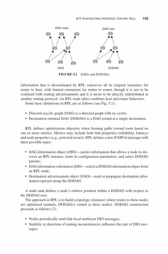
IETF IPv6 ROUTING PROTOCOL FOR RPL ROLL 125
DAG roots
DAG DODAG
DAG root
FIGURE 5.1 DAGs and DODAGs.
information that is disseminated by RPL conserves all its original semantics forrouter to host, with limited extensions for router to router, though it is not to beconfused with routing advertisements and it is never to be directly redistributed inanother routing protocol. An RPL node often combines host and router behaviors.Some basic definitions in RPL are as follows (see Fig. 5.1):
� Directed acyclic graph (DAG) is a directed graph with no cycles.� Destination-oriented DAG (DODAG) is a DAG rooted at a single destination.
RPL defines optimization objective when forming paths toward roots based onone or more metrics. Metrics may include both link properties (reliability, latency)and node properties (e.g., powered on not). RPL defines a new ICMPv6message withthree possible types:
� DAG information object (DIO)—carries information that allows a node to dis-cover an RPL instance, learn its configuration parameters, and select DODAGparents;
� DAG information solicitation (DIS)—solicit a DODAG information object froman RPL node;
� Destination advertisement object (DAO)—used to propagate destination infor-mation upward along the DODAG.
A node rank defines a node’s relative position within a DODAG with respect tothe DODAG root.The approach in RPL is to build a topology (instance) where routes to these nodes
are optimized (namely, DODAG(s) rooted at these nodes). DODAG constructionproceeds as follows (7):
� Nodes periodically send link-local multicast DIO messages;� Stability or detection of routing inconsistencies influence the rate of DIO mes-sages;

126 EVOLVING IoT STANDARDS
� Nodes listen for DIOs and use their information to join a new DODAG, or tomaintain an existing DODAG;
� Nodes may use a DIS message to solicit a DIO;� Based on information in the DIOs, the node chooses parents that minimize pathcost to the DODAG root.
RPL is optimized for many-to-one and one-to-many traffic patterns. Routing stateis minimized: stateless nodes have to store only instance(s) configuration parametersand a list of parent nodes. The protocol takes into account both link and nodeproperties when choosing paths. Additionally, link failures do not trigger globalnetwork re-optimization. The reader is referred to the draft specification discussedin the key reference (6) for an extensive discussion of the capabilities, formats, andprocedures of this protocol.
5.3 CONSTRAINED APPLICATION PROTOCOL (CoAP)
5.3.1 Background
The IETF constrained RESTful environments (CoRE) Working Group has recentlyundertaken standardization work the CoAP. CoAP is a simple application layer pro-tocol targeted to simple electronic devices (e.g., IoT/M2M things) to allow themto communicate interactively over the Internet. CoAP is designed for low powersensors (especially wireless sensor network [WSN] nodes described in Chapters 3and 4) and for actuators that need to be controlled or monitored remotely, usingIP/Internet networks. CoAP can be seen as a specialized web transfer protocol foruse with constrained networks and nodes for M2M applications, such as smart energyand building automation. CoAP operates with HTTP (hypertext transfer protocol) forbasic support with the web, allowing proxies to be built providing access to CoAPresources via HTTP in a uniform way, while also supporting multicast and enjoyinglow overhead CoAP can run on most devices that support user datagram protocol(UDP) or a similar protocol. Some key aspects of the protocol are as follows: (i)minimal complexity for the mapping with HTTP; (ii) low header overhead and lowparsing complexity; (iii) support for the discovery of resources; (iv) simple resourcesubscription process; and (v) simple caching based on max-age.CoAP makes use of two message types, requests and responses, using a simple
binary base header format. The base header may be followed by options in Internetcontrol message protocol (ICMP)-style type-length-value format. CoAP is by defaultbound to UDP and, optionally, to transmission control protocol (TCP). Any bytesafter the headers in the packet are considered the message body if any. The length ofthe message body is implied by the datagram length. When bound to UDP, the entiremessage must fit within a single datagram. When used with 6LoWPAN as defined inRFC 4944, messages fit into a single IEEE 802.15.4 frame.The constrained nodes for which CoAP is targeted often have 8-bit microcon-
trollers with small amounts of ROM and RAM, while networks such as 6LoWPAN

CONSTRAINED APPLICATION PROTOCOL (CoAP) 127
often have high packet error rates and a typical throughput of 10s of Kbps. CoAP pro-vides a method/response interaction model between application end-points, supportsbuilt-in resource discovery, and includes key web concepts such as URIs (uniformresource identifiers) and content-types. CoAP easily translates to HTTP for integra-tion with the web while meeting specialized requirements such as multicast support,very low overhead, and simplicity for constrained environments (8).The use of Web Services (WS) on the Internet has become ubiquitous in most
applications; it depends on the fundamental representational state transfer (REST)architecture of the web (see Section 5.4). The CoREworking group2 aims at realizingthe REST architecture in a suitable form for constrained IoT/M2M nodes (e.g., 8-bitmicrocontrollers with limited RAM and ROM) and IoT/M2M networks (e.g., 6LoW-PAN). Constrained networks such as 6LoWPAN support the expensive fragmentationof IPv6 packets into small link-layer frames. One design goal of CoAP has been tokeep message overhead small, thus limiting the use of fragmentation.One of the main goals of CoAP is to design a generic web protocol for the
special requirements of this constrained environment, especially considering energy,building automation, and other M2M applications. The objective of CoAP is not tostatically compress HTTP, but rather to realize a subset of REST commonwith HTTP,but optimized for M2M applications. Although CoAP can be used for compressingsimple HTTP interfaces, it also offers features for M2M such as built-in discovery,multicast support, and asynchronous message exchanges. CoAP has the followingmain features:
� Constrained web protocol fulfilling M2M requirements;� UDP binding with optional reliability supporting unicast andmulticast requests;� Asynchronous message exchanges;� Low header overhead and parsing complexity;� URI and content-type support;� Simple proxy and caching capabilities;� A stateless HTTP mapping, allowing proxies to be built providing access toCoAP resources via HTTP in a uniform way or for HTTP simple interfaces tobe realized alternatively over CoAP; and
� Security binding to datagram transport layer security (DTLS).
The interaction model of CoAP is similar to the client/server model of HTTP.However, M2M interactions typically result in a CoAP implementation acting inboth client and server roles (called an end-point). A CoAP request is equivalent tothat of HTTP and is sent by a client to request an action (using a method code)on a resource (identified by a URI) on a server. The server then sends a responsewith a response code; this response may include a resource representation. Unlike
2This discussion is based on and summarized from the IETF document draft-ietf-core-coap-09 (8); it isincluded to motivate the reader to consult the full document and/or related IETF documents for an inclusiveview of the issue.

128 EVOLVING IoT STANDARDS
Application
UDP
IP (especially IPv6)
CoAP
Lower layers (e.g., Zigbee, LANs, WLANs, and PANs)
Requests/responses
messages
FIGURE 5.2 Abstract layering of CoAP.
HTTP, CoAP deals with these interchanges asynchronously over a datagram-orientedtransport such as UDP. This is done logically using a layer of messages that supportsoptional reliability (with exponential back-off). CoAP defines four types of messages:confirmable (CON), non-confirmable (NON), acknowledgement, reset; method codesand response codes included in some of these messages make them carry requests orresponses. The basic exchanges of the four types of messages are transparent to therequest/response interactions.One could think of CoAP logically as using a two-layer approach, a CoAP mes-
saging layer used to deal with UDP and the asynchronous nature of the interactions,and the request/response interactions using method and response codes (see Fig. 5.2).CoAP is, however, a single protocol, with messaging and request/response just fea-tures of the CoAP header. Figure 5.3 depicts the overall protocol stack that is beingconsidered in the CoAP context.The reader is referred to the draft specification discussed in the key reference
(8) for an extensive discussion of the capabilities, formats, and procedures of thisprotocol. A short summary follows.
CoAP
TCP
802.15.4 WiFi BT-LE
Adaptation (6LoWPAN)
IPv4/v6 RPL
UDP
FIGURE 5.3 Overall protocol stack in CoAP’s environment.

CONSTRAINED APPLICATION PROTOCOL (CoAP) 129
5.3.2 Messaging Model
TheCoAPmessagingmodel is based on the exchange ofmessages over UDP betweenend-points. It uses a short fixed-length binary header (4 bytes) that may be followedby compact binary options and a payload. This message format is shared by requestsand responses. Each CoAP message contains a message ID used to detect duplicatesand for optional reliability.Reliability is provided by marking a message as CON. A CON message is
retransmitted using a default timeout and exponential back-off between retransmis-sions, until the recipient sends an acknowledgement message (ACK) with the samemessage ID from the corresponding end-point. When a recipient is not able to processa CONmessage, it replies with a reset message (RST) instead of an ACK. A messagethat does not require reliable delivery, for example, each single measurement out ofa stream of sensor data, can be sent as a NONmessage. These are not acknowledged,but still have a message ID for duplicate detection. When a recipient is not able toprocess a NON message, it may reply with an RST.Since CoAP is based on UDP, it also supports the use of multicast IP destination
addresses, enabling multicast CoAP requests.
5.3.3 Request/Response Model
CoAP request and response semantics are carried in CoAP messages, which includeeither a method code or response code, respectively. Optional (or default) requestand response information, such as the URI and payload content-type, are carried asCoAP options. A token option is used to match responses to requests independent ofthe underlying messages.A request is carried in a CON or NON message, and if immediately available,
the response to a request carried in a CON message is carried in the resulting ACKmessage. This is called a piggy-backed response. If the server is not able to respondimmediately to a request carried in a CON message, it simply responds with anempty ACK message so that the client can stop retransmitting the request. When theresponse is ready, the server sends it in a new CON message (which then in turnneeds to be acknowledged by the client). This is called a separate response. Likewise,if a request is sent in a NON message, then the response is usually sent using a newNON message, although the server may send a CON message.CoAP makes use of GET, PUT, POST, and DELETE methods in a similar manner
to HTTP.
5.3.4 Intermediaries and Caching
The protocol supports the caching of responses in order to efficiently fulfill requests.Simple caching is enabled using freshness and validity information carriedwithCoAPresponses. A cache could be located in an end-point or an intermediary.Proxying is useful in constrained networks for several reasons, including (i) net-
work traffic limiting, (ii) to improve performance, (iii) to access resources of sleeping

130 EVOLVING IoT STANDARDS
devices, or (iv) for security reasons. The proxying of requests on behalf of anotherCoAP end-point is supported in the protocol. The URI of the resource to request isincluded in the request, while the destination IP address is set to the proxy.The reader is referred to the draft specification discussed in the key reference
(8) for an extensive discussion of the capabilities, formats, and procedures of thisprotocol.
5.4 REPRESENTATIONAL STATE TRANSFER (REST)
As noted, CoAP uses REST techniques. REST was first described in 2000 by RoyFielding in his University of California dissertation which analyzed a set of web-focused software architecture principles for distributed computing. REST aims atsupporting scalability of component interactions, generality of interfaces, and inde-pendent deployment of components. Hence, it defines a set of architectural prin-ciples by which one can design WS that focus on a system’s resources, includ-ing how resource states are addressed and transferred over HTTP by a plethoraof clients written in different languages (9). Stated differently, REST is an archi-tectural style of large-scale networked software that takes advantage of the tech-nologies and protocols of the World Wide Web; it describes how distributed dataobjects, or resources, can be defined and addressed, stressing the easy exchangeof information and scalability (10). A REST-based WS follows four basic designprinciples:
� Use HTTP methods explicitly.� Be stateless.� Expose directory structure-like URIs.� Transfer XML, JavaScript Object Notation (JSON), or both.
5.5 ETSI M2M
ETSI recently created a dedicated Technical Committee, with the mission to developstandard M2M communications. The group seeks to provide an end-to-end viewof M2M standardization and is expected to co-operate closely with ETSI’s ongo-ing activities on next-generation networks (NGNs), radio communications, fiberoptics and powerline, as well as collaboration with 3GPP standards group onmobile communication technologies. The reference model used in this text is theM2M model developed by this group, as defined in various evolving standards,including the ETSI M2M Release 1 standards described in ETSI TS 102 689(requirements), ETSI TS 102 690 (functional architecture), and ETSI TS 102 921(interface descriptions). ETSI has also published a number of documents defin-ing common use cases. These documents were cited in other chapters and are notre-listed here.

THIRD-GENERATION PARTNERSHIP PROJECT SERVICE REQUIREMENTS 131
Key elements in the M2M environment include the following (11):
� M2M device: A device capable of replying to request for data contained withinthose device or capable of transmitting data contained within those devicesautonomously;
� M2M area network (device domain): A network that provides connectivitybetween M2M devices and M2M gateways, for example, a PAN;
� M2M gateway: A gateway (say a router or higher layer network element) thatusesM2Mcapabilities to ensureM2Mdevices interworking and interconnectionto the communication network;
� M2M communication networks (network domain): A wider-range network thatsupports communications between the M2M gateway(s) and M2M application;examples include but are not limited to xDSL, LTE, WiMAX, and WLAN; and
� M2M applications: Systems that contain the middleware layer where datagoes through various application services and is used by the specific business-processing engines.
The reader is referred to the architecture specification cited above for an extensivediscussion of the M2M environment.
5.6 THIRD-GENERATION PARTNERSHIP PROJECT SERVICEREQUIREMENTS FOR MACHINE-TYPE COMMUNICATIONS
5.6.1 Approach
Current mobile networks are optimized for human-to-human (H2H) traffic and notfor M2M/MTC interactions; hence, optimizations for MTC are advantageous. Forexample, one needs lower costs to reflect lower MTC ARPUs (average revenue peruser); also, there is a need to support triggering. Hence, 3GPP has started work onM2M specification in 2010 for interoperable solutions, particularly in the 3G/4G/LTEcontext. Table 5.1 provides a superset of specifications that are applicable toMTC ser-vices. Figure 5.4 depicts the service model, while Figure 5.5 depicts the architecture.In that architecture, the interfaces are as follows:
� MTCu: provides MTC devices access to the 3GPP network for the transport ofuser traffic;
� MTCi: the reference point for MTC server to connect the 3GPP network via3GPP bearer service; and
� MTCsms: the reference point for MTC server to connect the 3GPP network via3GPP SMS.
The key document 3rd Generation Partnership Project Service Requirements forMachine Type Communications—Release 10 focused on overload and congestioncontrol, extended access barring (EAB), low priority access, APN (access point

132 EVOLVING IoT STANDARDS
TABLE 5.1 3GPP Specifications Related to MTC
3GPPSpecifications Specifications Associated with or Affected by MTC Work
22.011 Service accessibility22.368 Service requirements for MTC; stage 123.008 Organization of subscriber data23.012 Location management procedures23.060 General packet radio service (GPRS); service description; stage 223.122 Non-access-stratum (NAS) functions related to mobile station (MS) in idle
mode23.203 Policy and charging control architecture23.401 GPRS enhancements for evolved universal terrestrial radio access network
(E-UTRAN) access23.402 Architecture enhancements for non-3GPP accesses23.888 System improvements for MTC24.008 Mobile radio interface layer 3 specification; core network protocols; stage 324.301 NAS protocol for evolved packet system (EPS); stage 324.368 NAS configuration management object (MO)25.331 Radio resource control (RRC); protocol specification29.002 Mobile application part (MAP) specification29.018 GPRS; serving GPRS support node (SGSN)—visitors location register
(VLR); Gs interface layer 3 specification29.060 GPRS; GPRS tunneling protocol (GTP) across the Gn and Gp interface29.118 Mobility management entity (MME)—VLR SGs interface specification29.274 3GPP EPS; evolved GTP for control plane (GTPv2-C); stage 329.275 Proxy mobile IPv6 (PMIPv6)-based mobility and tunneling protocols;
stage 329.282 Mobile IPv6 vendor-specific option format and usage within 3GPP31.102 Characteristics of the universal subscriber identity module (USIM)
application33.868 Security aspects of MTC36.331 Evolved universal terrestrial radio access (E-UTRA); RRC; protocol
specification37.868 RAN improvements for MTC43.868 GERAN improvements for MTC44.018 Mobile radio interface layer 3 specification; RRC protocol44.060 GPRS; MS–base station system (BSS) interface; radio link control/medium
access control (RLC/MAC) protocol45.002 Multiplexing and multiple access on the radio path
name)-based congestion control, and downlink throttling (12). For MTC communi-cation, the following communication scenarios are identified and described in theRelease 10 document:
(i) MTC devices communicating with one or more MTC server;
(ii) MTC devices communicating with each other.

THIRD-GENERATION PARTNERSHIP PROJECT SERVICE REQUIREMENTS 133
Direct model
Applications MTCapplication
MTCapplication
MTC server
MTCapplication
Serviceenablement
Connectivity
Devices
Operator’s wirelessnetwork
Operator’s wirelessnetwork
Operator’s wirelessnetwork
Devices Devices
Indirect modelservice providercontrolled
Indirect modeloperator controlled
MTC server
FIGURE 5.4 M2M in 3GPP—service models.
MTCdevice
MTCu
MTCserver
MTCremote app
MTCdevice
UEUm/Uu/
LTE-Uu
SGSN /MME
RAN
MTCserver
MTCi
MTCsms
3GPP bearer services /SMS / IMS
MTCserver
MTCuser
MTCapplication
HLR /HSS
MTCIWF
SMS-SC/IP-SM-GW
IP SMS
Legacy SMS
S6m
T5a/T5b
Gn/Gp/S1-U
3GPP
Gi/SGi
Gi/SGi
MTCsp
API
Operatorcontrolled
service providercontrolled
Involet model
Direct model
Hybrid model +
1
1
1
2
2
2T4Rf/Ga MTCsms
Control planeUser plane
Gr/S6a/S6d
GGSN/S-GW+P-GW
CDF/CGF
FIGURE 5.5 M2M in 3GPP—Architecture.

134 EVOLVING IoT STANDARDS
For MTC devices communicating with one or more MTC servers, the followinguse cases exist:
(a) MTC server controlled by the network operator; namely the MTC server islocated in the operator domain. Here
– The network operator offers API (e.g., Open Systems Architecture [OSA])on its MTC server(s)
– MTC user accesses MTC server(s) of the network operator via API(b) MTC server not controlled by the network operator; namely MTC server is
located outside the operator domain. Here
– The network operator offers the network connectivity to the MTC server(s)located outside of the network operator domain
The communication scenario where the MTC devices communicate directly with-out intermediate MTC server is not considered in this release of the specification.MTC applications do not all have the same characteristics. This implies that
not every system optimization is suitable for every MTC application. Therefore,MTC features are defined in Release 10 to provide structure for the different systemoptimization possibilities that can be invoked. Such MTC features are offered on aper subscription basis. MTC features can be individually activated. The followingMTC features have been defined:
– Low mobility– Time controlled– Time tolerant– Packet switched (PS) only (here the MTC feature PS only is intended for usewith MTC devices that only require packet switched services)
– Small data transmissions– Mobile originated only– Infrequent mobile terminated– MTC monitoring– Priority alarm– Secure connection– Location-specific trigger– Network provided destination for uplink data– Infrequent transmission
5.6.2 Architectural Reference Model for MTC
The latest Release 11 (an extensive document) focuses on numbers and addressing,on improvements of device triggering, and on interfaces between MTC server andmobile network (13, 14). Referring to Figure 5.5, MTCsp is a new control interface

CENELEC 135
for interactions with MTC server; MTC-IWF is a new interworking function between(external) MTC server and operator core network handling security, authorization,authentication, and charging.The end-to-end application, between the user equipment (UE) used for MTC
and the MTC application, uses services provided by the 3GPP system, and option-ally services provided by an MTC server. The 3GPP system provides transport andcommunication services (including 3GPP bearer services, IMS, and SMS) includingvarious optimizations that can facilitate MTC. Figure 5.5 shows UE used for MTCconnecting to the 3GPP network (UTRAN, E-UTRAN, GERAN, I-WLAN, and soon) via the Um/Uu/LTE-Uu interface. The architecture encompasses a number ofmodels as follows:
– Direct model—direct communication provided by the 3GPP operator: TheMTCapplication connects directly to the operator network without the use of anyMTC server;
– Indirect model—MTC service provider controlled communication: The MTCserver is an entity outside of the operator domain. The MTCsp and MTCsms areexternal interfaces (i.e., to a third-party M2M service provider);
– Indirect model—3GPP operator controlled communication: The MTC server isan entity inside the operator domain. The MTCsp and MTCsms are internal tothe public land mobile network (PLMN);
– Hybrid model: The direct and indirect models are used simultaneously in thehybrid model, for example, connecting the user plane using the direct model anddoing control plane signalling using the indirect model.
Some believe that there may be E.164 telephone number issues as related toM2M:in several countries, regulators have indicated that there are not enough (mobile)numbers available for M2M applications. 3GPP postulates that solutions will have tosupport 100× more M2M devices than devices for H2H communications. Proposedsolutions include: (i) mid-term solution: special M2M number ranges with longertelephone numbers (e.g., 14 digits); (ii) long-term solution: no longer provide E.164telephone numbers for M2M applications.Figure 5.6 provides a view to the various protocol stacks defined in Release 11.The reader is referred to the Technical Report by 3GPP (13) for an extensive
discussion of architectural aspects and system requirements for MTC/M2M commu-nication. The second part of Chapter 6 discusses some 3GPP networks that may comeinto play in the MTC/M2M context.
5.7 CENELEC
Recently, the European Committee for Electrotechnical Standardization (CENELEC)has accepted the transport profile of Siemens’ distribution line carrier communicationprotocol, CX1, as a standardization proposal. The standard aims at supporting open

136 EVOLVING IoT STANDARDS
User-plane
Control plane
MTC server-MTC-IWF MTCsp reference point
MTC Server-SMS SC MTCsms reference point
MTC application MTC application
IP
MT/L3
MT/L2 L2
L1
L3
L2
L1
L3
IP IP IP
MTC UPfunction
MT/L1
UE
Urr/Uu/LTE-Uu
CP protocol(s)CP
protocol(s)MTCsp
protocol(s)MTCsp protocol(s)
MTCsms protocol MTCsms protocol
MTCsmsMTC serverSMS_SC
MTCspMTC serverMTC-IWFTBD3GPP PLMN
network elements
IP IP
IPIP IP
3GPP PLMN(RAN+CN nodes)
S5/S8Gn/Gp P-GW/GGSN
MTCi
MTC server
APIApplication
domain
FIGURE 5.6 User and control plane stack for MTC architecture—as described in Release11—Technical Report 3GPP TR 23.888 V1.7.0 (2012–08).
and fault tolerant communication via powerline in intelligent power supply grids.As the basis for the transmission protocol, which uses the low voltage network asa communication channel for data of grid sensors and smart meters, the transportprofile has been designed to ensure interoperability in accordance with EU MandateM/441. CENELEC TC 13 was planning to forward the CX1 transport profile toTC 57 of the International Electrotechnical Commission (IEC) as a proposal forinclusion in the IEC standardization process. CX1 is already used to connect metersand other intelligent terminal devices in Siemens’ SG metering systems, such asin the load switching devices that will replace household ripple control receivers.The systems collect energy consumption data and network information, which arethen relayed to a control center for further processing (15). CX1 utilizes spreadspectrum modulation, in which multiple frequencies within the same frequency bandare used simultaneously to transmit a single signal. This means that interference,which often occurs at certain frequencies, has only a negligible effect on signal

ZigBee IP (ZIP) 137
transmission. In addition, the communication protocol can handle any change in thephysical communication parameters of a lowvoltage power supply grid, such as signalattenuation, noise, network disruption and signal coupling, as well as operationalchanges in network configuration. The protocol can also be integrated into existingIEC protocol-based network automation and energy management infrastructures.
5.8 IETF IPv6 OVER LOWPOWER WPAN (6LoWPAN)
6LoWPAN is an IPv6 adaption layer for low power wireless PAN (LoWPAN).IPv6-over-IEEE802.15.4 described inRFC4944 specifies how IPv6 is carried over
an IEEE 802.15.4 network with the help of an adaptation layer which sits betweenthe MAC layer and the IP network layer. As it should be clear at this juncture, a linkin a LoWPAN is characterized as lossy, low power, low bit-rate, short range, withmany nodes saving energy with long sleep periods.It turns out that multicast as used in IPv6 ND described in RFC 4861 is not
desirable in such a wireless low power and lossy network. Moreover, LoWPAN linksare asymmetric and non-transitive in nature. A LoWPAN is potentially composedof a large number of overlapping radio ranges. Although a given radio range hasbroadcast capabilities, the aggregation of these is a complex non-broadcast multi-access (NBMA) structure with generally no LoWPAN-wide multicast capabilities.Link-local scope is in reality defined by reachability and radio strength. Thus, onecan consider a LoWPAN to be made up of links with undetermined connectivityproperties, along with the corresponding address model assumptions defined therein.Hence, there is work underway to develop optimizations to IPv6 ND (RFC 4861)specifically aimed at low power and lossy networks such as LoWPANs (16).This topic is covered in Chapter 9, after the reader has acquired some background
on IPv6.
5.9 ZigBee IP (ZIP)
ZigBee is a wireless PAN IEEE 802.15.4 standard, which we cover in Chapter 6.Here we simply make some passing reference to the ZigBee Alliance’s ZIP standard,which is a first definition of an open standards-based IPv6 stack for smart objects.The goal is to extend the use of IP networking into resource-constrained devices overa wide range of low power link technologies. The effort related to ZIP developmenthas made significant progress to bring IPv6 network protocols over 802.15.4 wirelessmesh networks to reality. ZIP is a protocol stack based on IETF- and IEEE-definedstandards such as 6LoWPAN and IEEE 802.15.4 to be used for the Smart Energy 2.0(SE 2.0) profile.ZIP enables low power 802.15.4 nodes to participate natively with other IPv6-
enabled WiFi, Homeplug, and Ethernet nodes without the complexity and cost ofapplication layer gateways. To accomplish this, the ZIP stack incorporates a numberof standardized IETF protocols including 6LoWPAN for IP header compressionand ND, and RPL for mesh routing. ZIP further employs other IETF standards to

138 EVOLVING IoT STANDARDS
support network joining procedures, service discovery, and TLS/SSL-based securitymechanisms (17). At press time, the ZIP specification was nearing release of its 0.9draft and had already progressed through numerous certification events. In particular,there has been interest in validating that ZIP will comfortably support SEP2 unicastand multicast messaging over an 802.15.4-based HAN mesh. It was anticipated thatproduction ready, certified stacks would be available mid-2013. Early implementersincluded Cisco, Exegin, and Grid2Home, among others. Proponents expect that ZIP-based product offerings would soon be interoperating within the SG.
5.10 IP IN SMART OBJECTS (IPSO)
The IPSO Alliance is an advocate for IP-networked devices for use in energy, con-sumer, healthcare, and industrial applications. The objective of the Alliance is notto define technologies or standards, but to document the use of IP-based technolo-gies defined at the standard organizations such as IETF with focus on support bythe Alliance of various use cases. The IPSO Alliance is a non-profit associationof more than 60 members at press time from leading technology, communications,and energy companies around the world. The mission is to provide a foundation forindustry growth through building stronger relationships, fostering awareness, pro-viding education, promoting the industry, generating research, and creating a betterunderstanding of IP and its role in connecting smart objects. Goals include (18):
� Promote IP as the premier solution for access and communication for smartobjects.
� Promote the use of IP in smart objects by developing and publishingwhite papersand case studies and providing updates on standards progress from associationslike IETF, among others, and through other supporting marketing activities.
� Understand the industries andmarkets where smart objects can have an effectiverole in growth when connected using the Internet protocol.
� Organize interoperability tests that will allow members and interested partiesto show that products and services using IP for smart objects can work togetherand meet industry standards for communication.
� Support IETF and other standards development organizations in the develop-ment of standards for IP for smart objects.
APPENDIX 5.A: LEGACY SUPERVISORY CONTROL AND DATAACQUISITION (SCADA) SYSTEMS
This appendix provides a short summary of SCADA, a legacy, but widely deployedsystem used to monitor and control a plant or equipment in industries such as butnot limited to energy, oil and gas refining, water and waste control, transporta-tion, and telecommunications. This section is summarized and synthesized from

LEGACY SUPERVISORY CONTROL AND DATA ACQUISITION (SCADA) SYSTEMS 139
reference (19) from the National Communications System (NCS). M2M approachesseek to enhance, modernize, and extend the basic concepts found in SCADA (M2Mis not intended to be directly interoperable with SCADA but can be supported withproxies/gateways.)A SCADA system gathers remote operational information, transfers the informa-
tion to a central site, then alerts a management station that an event has occurred,carrying out necessary analysis and control. These systems can be relatively simple,such as one that monitors environmental conditions of a small office building, or verycomplex, such as a system that monitors all the activity in a nuclear power plant orthe activity of a municipal water system. Traditionally, SCADA systems have madeuse of public switched network (PSN) facilities for monitoring purposes; wirelesstechnologies are now being widely deployed for purposes of monitoring.A SCADA system encompasses the transfer of data between a SCADAcentral host
computer and a number of remote terminal units (RTUs) and/or programmable logiccontrollers (PLCs); the central host typically supports operator terminals. Specifically,a SCADA system consists of:
� One or more field data interface devices, usually RTUs or PLCs, which interfaceto field sensing devices and local control switchboxes and actuators;
� A communications system used to transfer data between field data interfacedevices and control units and the computers in the SCADA central host; thecommunication may use telephone, cable, radio, cellular, satellite, etc. or anycombination of these;
� A central host computer server or servers (sometimes called a SCADA center,master station, or master terminal unit [MTU]);
� A collection of standard and/or custom software systems [sometimes calledhuman machine interface (HMI) software or man machine interface (MMI)software] used to provide the SCADA central host and operator terminal appli-cation, support the communications system, and monitor and control remotelylocated field data interface devices.
There have been three generations of SCADA systems:
� First generation—monolithic approach� Second generation—distributed approach� Third generation—networked approach
In a SCADA system, the RTU accepts commands to operate control points, setsanalog output levels, and responds to requests. The RTU provides status, as well asdiscrete and accumulated data to the SCADAmaster station. The data representationssent are not identified in any fashion other than by unique addressing. The addressingis designed to correlate with the SCADA master station database. The RTU has noknowledge of which unique parameters it is monitoring in the real world; it simplymonitors certain points and stores the information in a local addressing scheme. Each

140 EVOLVING IoT STANDARDS
protocol consists of two message sets or pairs. One set forms the master protocol,containing the valid statements for master station initiation or response, and the otherset is the RTU protocol, containing the valid statements an RTU can initiate andrespond to. In most but not all cases, these pairs can be considered a poll or requestfor information or action and a confirming response. The SCADA protocol betweenmaster and RTU forms a viable model for RTU-to-intelligent electronic device (IED)communications. Currently, there are several different protocols in use; the mostcommon are:
� IEC 60870-5 series, specifically IEC 60870-5-101 (commonly referred to as101) and
� Distributed network protocol version 3 (DNP3).
IEC 60870-5 Series
IEC 60870-5 specifies a number of frame formats and services that may be providedat different layers. IEC 60870-5 is based on a three-layer enhanced performancearchitecture (EPA) reference model (see Fig. 5A.1) for efficient implementationwithin RTUs, meters, relays, and other IEDs. Additionally, IEC 60870-5 definesbasic application functionality for a user layer; such user layer is situated betweenthe open system interconnection (OSI) application layer and the application program.This user layer adds interoperability for such functions as clock synchronization andfile transfers.
IEC 60870-5-101IEC 60870-5-102IEC 60870-5-103
Application
Application layer(OSI layer 7)
Link interface
Physical interface
LLC-like layer
MAC-like layer
Link layer(OSI layer 2)
Physical layer(OSI layer 1)
IEC 60870-5-5IEC 60870-5-4
IEC 60870-5-3IEC 60870-5-2
IEC 60870-5-1
FIGURE 5A.1 SCADA protocols and EPA.

LEGACY SUPERVISORY CONTROL AND DATA ACQUISITION (SCADA) SYSTEMS 141
The following descriptions provide the basic scope of each of the five documentsin the base IEC 60870-5 telecontrol transmission protocol specification set. Standardprofiles are necessary for uniform application of the IEC 60870-5 standards. Aprofile is a set of parameters defining the way a device acts; such profiles have beencreated.
� IEC 60870-5-1 (1990–02) specifies the basic requirements for services to beprovided by the data link and physical layers for telecontrol applications. Inparticular, it specifies standards on coding, formatting, and synchronizing dataframes of variable and fixed lengths that meet specified data integrity require-ments. At the physical layer, the Standard 101 Profile additionally allows theselection of International Telecommunication Union-Telecommunication Stan-dardization Sector (ITU-T) standards that are compatible with Electronic Indus-tries Association (EIA) standards RS-232 and RS-485 and also support fiberoptics interfaces.
� IEC-60870-5-2 (1992–04) provides a selection of link transmission proceduresusing a control field and optional address field; the address field is optionalbecause some point-to-point topologies do not require either source or destina-tion addressing.
� IEC 60870-5-3 (1992–09) specifies rules for structuring application data unitsin transmission frames of telecontrol systems. These rules are presented asgeneric standards that may be used to support a variety of present and futuretelecontrol applications. This section of IEC 60870-5 describes the generalstructure of application data and basic rules to specify application data unitswithout specifying details about information fields and their contents.
� IEC 60870-5-4 (1993–08) provides rules for defining information data elementsand a common set of information elements, particularly digital and analogprocess variables that are frequently used in telecontrol applications.
� IEC 60870-5-5 (1995–06) defines basic application functions that perform stan-dard procedures for telecontrol systems,which are procedures that reside beyondlayer 7 (application layer) of the ISO reference model. These utilize standardservices of the application layer. The specifications in IEC 60870-5-5 (1995–06)serve as basic standards for application profiles that are then created in detailfor specific telecontrol tasks.
DNP3
DNP3 is a protocol for transmission of point-to-point data using serial communica-tions. It has been used primarily by utilities, but can also be used in other areas. TheDNP3 is specifically developed for interdevice communication involving SCADARTUs and provides for both RTU-to-IED and master-to-RTU/IED. It is based on thethree-layer EPAmodel contained in the IEC 60870-5 standards, with some alterations

142 EVOLVING IoT STANDARDS
to meet additional requirements of a variety of users in the electric utility industry.DNP3 was developed with the following goals in mind:
� High data integrity. The DNP3 data link layer uses a variation of the IEC 60870-5-1 (1990–02) frame format FT3. Both data link layer frames and applicationlayer messages may be transmitted using confirmed service.
� Flexible structure. The DNP3 application layer is object based, with a structurethat allows a range of implementations while retaining interoperability.
� Multiple applications. DNP3 can be used in several modes, including: (i) polledonly; (ii) polled report-by-exception; (iii) unsolicited report-by-exception (qui-escent mode); and (iv) a mixture of modes. It can also be used with severalphysical layers, and as a layered protocol it is suitable for operation over localand some wide area networks.
� Minimized overhead. DNP3 was designed for existing wire-pair data links withoperating bit rates as low as 1200 bps and attempts to use a minimum ofoverhead while retaining flexibility. Selection of a data reporting method, suchas report-by-exception, further reduces overhead.
� Open standard. DNP3 is a non-proprietary, evolving standard controlled by ausers group whose members include RTU, IED, and master station vendors,and representatives of the electric utility and system consulting community.
REFERENCES
1. Gluhak A, Krco S, et al. A survey on facilities for experimental internet of things research.Communications Magazine, IEEE, November 2011;49(11):58–67.
2. Ladid L. Keynote Speech, InternationalWorkshop on Extending Seamlessly to the Internetof Things (ESLOT 2012), in conjunction with IMIS-2012 International Conference, July4–6, 2012, Palermo, Italy.
3. Arkko J. Interoperability Challenges in the Internet of Things. Interconnecting SmartObjects with the Internet Workshop 2011, 25th March 2011, Prague.
4. Internet Architecture Board, Interconnecting Smart Objects with the Internet Workshop2011, 25th March 2011, Prague.
5. Kutscher D, Farrell S. Towards an Information-Centric Internet with more Things.Interconnecting Smart Objects with the Internet Workshop 2011, 25th March 2011,Prague.
6. Winter T, editor. ROLL/RPL: IPv6 Routing Protocol for Low Power and Lossy Networks,March 2011, draft-ietf-roll-rpl-19.
7. Kuryla S. RPL: IPv6 Routing Protocol for Low Power and Lossy Networks, Networksand Distributed Systems Seminar, March 1, 2010.
8. Shelby Z, Hartke K, Bormann C, Frank B. Constrained Application Protocol (CoAP).CoRE Working Group, March 12, 2012, Internet-Draft, draft-ietf-core-coap-09.
9. Richardson L, Ruby S. RESTful Web Service, O’Reilly Media, 2007, Sebastopol, CA.
10. Kay R. QuickStudy: Representational State Transfer (REST). ComputerWorld, August 6,2007.

REFERENCES 143
11. Lin T-M. M2M: Machine to Machine Communication (From ETSI/3GPP Aspect). WhitePaper, Industrial Technology Research Institute of Taiwan, R.O.C, 2010.
12. 3rd Generation Partnership Project, Technical Specification Group Services and Sys-tem Aspects; Service Requirements for Machine Type Communications (MTC); Stage 1(Release 10); Technical Specification 3GPP TS 22.368 V10.1.0 (2010–06).
13. 3rd Generation Partnership Project, Technical Specification Group Services and SystemAspects; System Improvements forMachine-Type Communications; Stage 1 (Release 11);Technical Report 3GPP TR 23.888 V1.7.0 (2012–08).
14. Norp T. Mobile Network Improvements for M2M, a 3GPP Perspective. ETSI M2MWorkshop, October 2011. TNO, P.O. Box 342, NL-7300 AH Apeldoorn.
15. Mrosik J. International PLC data communication standard for grid automation and smartmetering proposed by Siemens. On line Magazine, Nov 15, 2012, http://www. metering.com.
16. Shelby Z, editor. Neighbor Discovery Optimization for Low Power and Lossy Networks(6LoWPAN), Updates: 4944 (if approved), August 24, 2012, IETF draft-ietf-6lowpan-nd-21.
17. Duffy P. Zigbee IP: Extending the Smart Grid to Consumers., Cisco Blog – The Platform,June 4, 2012, Cisco Systems, Inc., 170 West Tasman Dr., San Jose, CA 95134 USA.
18. IPSO Alliance, http://www.ipso-alliance.org/.
19. National Communications System, Supervisory Control and Data Acquisition (SCADA)Systems, Technical Information Bulletin 04-1, NCS TIB 04-1, October 2004, P.O. Box4052, Arlington, VA 22204-4052. http://www.ncs.gov.

CHAPTER 6
LAYER 1/2 CONNECTIVITY: WIRELESSTECHNOLOGIES FOR THE IoT
This chapter surveys basic lower-layer wireless technologies to support IoT/machine-to-machine (M2M) applications, as it appears that many such implementations willentail wireless connectivity at the PHY/MAC layer. Available wireless networks1 thatcan be utilized for IoT/M2M applications include the following:
� Personal area networks (PANs): Zigbee R©, Bluetooth R©, especially Bluetoothlow energy (BLE), near field communications (NFC), and proprietary systems(e.g., ANT+,2 NIKE+3); specifically, there is interest in low-power wirelesspersonal area networks (LoWPANs); some of these PANs are also classified aslow-rate wireless personal area networks (LR-WPANs);
1Some refer to the entire “wireless networks” field as wireless information and communication technology(WICT).2ANT/ANT+ is a proprietary wireless sensor network technology targeted at manufacturers of bikecomputers, speed/cadence sensors, foot pods, power meters, heart rate monitors, calorimeters, body massindex-measuring devices, blood pressure monitors, blood glucose meters, and so on, promoted by theANT+ Alliance. It is principally used for compatible Garmin device. For example, an ANT+ heart ratestrap will send heart rate data to a watch, phone, bike computer, tablet, and/or any other device that readsANT+ heart rate.3Nike+ R© is a proprietary wireless technology developed by Nike and Apple to allow users to monitortheir activity levels while exercising.
Building the Internet of Things with IPv6 and MIPv6: The Evolving World of M2M Communications,First Edition. Daniel Minoli.© 2013 John Wiley & Sons, Inc. Published 2013 by John Wiley & Sons, Inc.
144

WPAN TECHNOLOGIES FOR IoT/M2M 145
� Wireless local area networks (WLANs):Wi-Fi R© IEEE Standard 802.11 (includ-ing vendor-specific implementations for low power4);
� Metropolitan area networks (MANs): WiMAX;� Wireless sensor networks (WSN): application-specific technology, in general;� Third generation (3G)/4G cellular: Universal mobile telecommunications sys-tem (UMTS), general packet radio service (GPRS), enhanced data rates (EDRs)for GSM evolution (EDGE), and long-term evolution (LTE); and,
� Global: Satellite networks.
While IoT/M2M connectivity might be achieved by wired means, for examplepower line communication (PLC)-based grid management, some operators have usedwireless technology for meter reading. Furthermore, although energy suppliers rou-tinely utilize supervisory control and data acquisition (SCADA)-based systems toenable remote telemetry functions in the power grid and, and although, traditionally,SCADA systems have used wireline networks to link remote power grid elementswith a central operations center, at this time an increasing number of utilities areturning to public cellular networks to support these functions. Some of the wirelinetechnologies, including PLC, are briefly discussed in the appendix to this chapter.
6.1 WPAN TECHNOLOGIES FOR IoT/M2M
A PAN (also called WPAN) is a network used for communication among intelligentdevices physically close to a person (including smartphones, tablets, body monitors,and so on). PANs can be used to support wireless body area networks (WBANs)(also known as wireless medical body area networks [WMBANs] and/or medicalbody area network systems [MBANSs]), but they can also be used to support otherapplications. As discussed in Chapter 3, Medical applications include, among others,vital sign monitoring, respiration monitoring, electrocardiography (ECG), pH mon-itoring, glucose monitoring, disability assistance, muscle tension monitoring, andartificial limb support. Nonmedical applications of WBANs include, among others,video streaming, data transfer, and entertainment and gaming. The reach of a PANis typically a few meters. The devices in question are sometimes known as short-range devices (SRDs) (1). PANs can be used for communication among the personaldevices themselves (intrapersonal communication), or for connecting to a higher levelnetwork such as the Internet. Table 6.1 (partially based on Reference 2) summarizesa coarse comparison between three wireless technologies, highlighting the featuresof BANs/WBANs. The WBAN technologies can satisfy, in various degrees, majorrequirements that the healthcare industry considers important: (i) very low-power
4In recent years, several improvements have been made to the Wi-Fi LAN standard; some of theseimprovements (including IEEE Standard 802.11v) are aimed at reducing its power consumption. Wi-Fi isoptimized for traditional office automation (OA) large data transfer, where high throughput is needed; itis not generally intended for coin cell operation.

146 LAYER 1/2 CONNECTIVITY: WIRELESS TECHNOLOGIES FOR THE IoT
TABLE 6.1 Comparison of Technologies
WBAN WSNCellular WirelessNetworks
Traffic Application specific, sporadic/cyclic, modestdata rate
Multimedia, highdata rate
Topology Dynamic Random, dynamic Few infrastructurechanges
Configuration/maintenance
Some flexibilitySpecialists areneeded
Self-configurable,unattendedoperation
Managed by largeorganizations/carriers
Battery Multimonth to multiyear battery life Replaced as needed
Network size Dense distributionlimited by body size
Unlimited number(typically 102–106)
Tens of nodes
Node Low/modest complexity High complexity
Overall designgoals
Limitedelectromagneticexposure, energyefficiency
Energy efficiency,self-operabilitycost optimization
Bandwidth efficiency.QoS (throughput/delay)
Standardization Multiple (IEEE)standards especiallyat lower layers
Relatively littlestandardization
Multiple internationalstandards, ITU-T,ETSI, etc.
sensor consumption, (ii) very low transmitted power, and (iii) high reliability andquality of service (QoS).Focusing specifically onWBANs, the keywireless standards include ZigBee/IEEE
802.15.4 along with the Personal, Home and Hospital Care (PHHC) Profile—ZigBeeHealth Care, IEEE 802.15.1 (Bluetooth), and the newer IEEE 802.15.6 and IEEE802.15.4j; other standards include ISO/IEEE 11073 and ETSI TR 101 557 V1.1.1(2012–02). Note that both ZigBee and Bluetooth have been extended and modifiedin recent years to satisfy particular requirements of medical/fitness industries (3).Low-power consumption IEEE 802.11 Wi-Fi is considered generally less attractiveat this time, although some proponents argue in favor.5
In this chapter, we focus predominantly on PANs and 3G/4G technologies. SeeTable 6.2 for a tabulation of some important technologies. It is not the goal of this
5Proponents make the case that no other wireless technology is as IP friendly as Wi-Fi. For example,ZigBee IP that requires the use of a bridge. ZigBee may have lower node costs, but it requires newinfrastructure. Wi-Fi also provides the highest bandwidth of any wireless technologies—some low-powerimplementations provide up to 11Mbps, with a fallback to 1Mbps. ZigBee offers less than 250 Kbps, withno fallback. Wi-Fi also provides well-proven encryption, authentication, and end-to-end network security(WPA2, EAP, TLS/SSL); ZigBee still requires testing, since some security holes have been identified (4).On the other hand, Wi-Fi’s power requirements are high. Work is being conducted in Wi-Fi groups tolower power consumption. Currently, however, proprietary drivers are needed, with the technology onlyapplicable to the personal computer market where receiver power budgets are higher (5).

WPAN TECHNOLOGIES FOR IoT/M2M 147
TABLE 6.2 Key Wireless Technology and Concepts Supporting IoT/M2MApplications
Technology/Concept Description
3GPP 3GPP unites six telecommunications standard bodies, known as“organizational partners” and provides their members with astable environment to produce the reports and specificationsthat define 3GPP technologies. These technologies areconstantly evolving through—what have become knownas—generations of commercial cellular/mobile systems.3GPP was originally the standards partnership evolvingGlobal System for Mobile communication (GSM) systemstoward the 3G. However, since the completion of the firstLTE and the Evolve Packet Core (EPC) specifications, 3GPPhas become the focal point for mobile systems beyond 3G.From 3GPP Release 10 onward, 3GPP is compliant with thelatest ITU-R requirements for IMT-Advanced “Systemsbeyond 3G.” The standard now allows for operation at speedsup to100 Mbps for high-mobility and 1 Gbps forlow-mobility communication. The original scope of 3GPPwas to produce Technical Specifications and TechnicalReports for a 3G Mobile System based on evolved GSM CNsand the radio access technologies that they support (i.e.,Universal Terrestrial Radio Access (UTRA) both frequencydivision duplex [FDD] and time division duplex [TDD]modes). The scope was subsequently amended to include themaintenance and development of the GSM TechnicalSpecifications and Technical Reports including evolved radioaccess technologies (e.g. GPRS and EDGE) (6). The term“3GPP specification” covers all GSM (including GPRS andEDGE), W-CDMA, and LTE (including LTE-Advanced)specifications. The following terms are also used to describenetworks using the 3G specifications: UTRAN, UMTS (inEurope), and FOMA (in Japan)
3GPP2 (Third-GenerationPartnership Project 2)
3GPP2 is a collaborative 3G telecommunicationsspecification-setting project comprising North American andAsian interests developing global specifications forANSI/TIA/EIA-41 Cellular RadiotelecommunicationIntersystem Operations network evolution to 3G and globalspecifications for the radio transmission technologies (RTTs)supported by ANSI/TIA/EIA-41. 3GPP2 was born out of theInternational Telecommunication Union’s (ITU)International Mobile Telecommunications “IMT-2000”initiative, covering HS, broadband, and Internet protocol(IP)-based mobile systems featuring network-to-networkinterconnection, feature/service transparency, globalroaming, and seamless services independent of location (7)
(continued )

148 LAYER 1/2 CONNECTIVITY: WIRELESS TECHNOLOGIES FOR THE IoT
TABLE 6.2 (Continued )
Technology/Concept Description
6LoWPAN: IPv6 overlow-power areanetworks (IEEE802.15.4)
6LoWPAN is now a widely accepted approach to run IP on802.15.4 based on RFC 4944 (September 2007). It issupported in TinyOS, Contiki, and in standards such asISA100, ZigBee SE 2.0. RFC 4944 makes 802.15.4 look likean IPv6 link. It provides basic encapsulation, efficientrepresentation of packets < ∼100 bytes. It addresses topicssuch as (8):
� Fragmentation (how to map 1280-byte MTU topackets 128 bytes or less);
� First approach to stateless header compression;� Datagram tag/datagram offset;� Mesh forwarding;� Identify originator/final destination;� Minimal use of complex MAC layer concepts
ANT/ANT+ ANTTM is a low-power proprietary wireless technologyintroduced in 2004 by the sensor company Dynastream. Thesystem operates in the 2.4 GHz band. ANT devices canoperate for years on a coin cell. ANT’s goal is to allow sportsand fitness sensors to communicate with a display unit.ANT+TM extends the ANT protocol and makes the devicesinteroperable in a managed network. ANT+ recentlyintroduced a new certification process as a prerequisite forusing ANT+ branding (5)
Bluetooth Bluetooth is a PAN technology based on IEEE 802.15.1. It is aspecification for short-range wireless connectivity forportable personal devices initially developed by Ericsson.The Bluetooth SIG made their specifications publiclyavailable in the late 1990s, at which time the IEEE 802.15Group has took the Bluetooth work and developed avendor-independent standard. The sublayers of IEEE802.15:include: (i) RF layer; (ii) baseband layer; (iii) the linkmanager; and (iv) the L2CAP. Bluetooth has evolved throughfour versions; all versions of the Bluetooth standardsmaintain downward compatibility. BLE is a subset toBluetooth v4.0 with an entirely new protocol stack for rapidbuild-up of simple links. BLE is an alternative to the “powermanagement” features that were introduced in Bluetooth v1.0to v3.0 as part of the standard Bluetooth protocols
(Bluetooth is a trademark of the Bluetooth Alliance, acommercial organization that certifies the interoperability ofspecific devices designed to the respective IEEE standard.)

WPAN TECHNOLOGIES FOR IoT/M2M 149
TABLE 6.2 (Continued )
Technology/Concept Description
EDGE (Enhanced DataRates for GlobalEvolution)
An enhancement of the GSMTM radio access technology toprovide faster bit rates for data applications, both circuit andpacket switched. As an enhancement of the existing GSMPHY layer, EDGE is realized via modifications of the existinglayer 1 specifications rather than by separate, standalonespecifications. Other than providing improved data rates,EDGE is transparent to the service offering at the upper layers,but is an enabler for HS circuit switched data (HSCSD) andenhanced GPRS (EGPRS). By way of illustration, the GPRScan offer a data rate of 115 Kbps, whereas EDGE can increasethis to 384 Kbps. This is comparable with the rate for earlyimplementations of Wideband Code Division Multiple Access(W-CDMA), leading some parties to consider EDGE as a 3Gtechnology rather than 2G (a capability of 384 Kbps allowsEDGE systems to meet the ITU’s IMT-2000 requirements).EDGE is generally viewed as a bridge between the twogenerations: a sort of 2.5G (9)
DASH7 A long range low-power wireless networking technology, withthe following features:
� Range: dynamically adjustable from 10 m to 10 km� Power: <1 milliwatt power draw� Data rate: dynamically adjustable from 28 Kbps to 200Kbps
� Frequency: 433.92 MHz (available worldwide)� Signal propagation: penetrates walls, concrete, water� Real-time locating precision: within 4 m� Latency: configurable, but worst case is less than 2 s� P2P cessaging� IPv6 support� Security: 128-bit AES, public key� Standard: ISO/IEC 18000-7; advanced by the DASH7Alliance
GPRS (General PacketRadio Service)
Packet-switched functionality for GSM, which is essentiallycircuit switched. GPRS is the essential enabler for always-ondata connection for applications such as web browsing andpush-to-talk over cellular. GPRS was introduced into the GSMspecifications in Release 97 and usability was further approvedin Releases 98 and 99. It offers faster data rates than plainGSM by aggregating several GSM time slots intoa single bearer, potentially up to eight, giving a theoretical datarate of 171 Kbps. Most operators do not offer such high rates,because obviously if a slot is being used for a GPRS bearer, itis not available for other traffic. Also, not all mobiles are ableto aggregate all combinations of slots.
(continued )

150 LAYER 1/2 CONNECTIVITY: WIRELESS TECHNOLOGIES FOR THE IoT
TABLE 6.2 (Continued )
Technology/Concept Description
The “GPRS class number” indicates the maximum speedcapability of a terminal, which might be typically 14 Kbps inthe uplink direction and 40 Kbps in the downlink,comparable with the rates offered by current wireline dial-upmodems. Mobile terminals are further classified according towhether or not they can handle simultaneous GSM andGPRS connections: class A = both simultaneously, class B =GPRS connection interrupted during a GSM call,automatically resumed at end of call, class C = manualGSM/GPRS mode switching. Further data rate increaseshave been achieved with the introduction of EDGE (9)
GSM EDGE RadioAccess Network(GERAN)
GERAN is an Radio Access Network (RAN) architecture,based on GSM/EDGE radio access technologies. GERAN isthe term given to the second-generation digital cellular GSMradio access technology, including its evolutions in the formof EDGE and, for most purposes, the GPRS. The GERAN isharmonized with the UTRAN through a commonconnectivity to the UMTS CN, making it possible to build acombined network for GSM/GPRS and UMTS. GERAN isalso the name of the 3GPPTM Technical Specification Groupresponsible for its development. The technical specificationswhich together comprise a 3GPP system with a GERAN arelisted in 3GPP TS 41.101
IEEE 802.15.4 IEEE Standard for Local and MANs. Part 15.4: Low-RateWireless Personal Area Networks (LR-WPANs). IEEE802.15.4-conformant devices support a wide range ofindustrial and commercial applications. The amended MACsublayer facilitates industrial applications such as processcontrol and factory automation in addition to the MACbehaviors that support the Chinese wireless personal areanetwork (CWPAN) standard
IEEE 802.15.4j (TG4j)MBANs
The purpose of Task Group 4j (TG4j) is to create an amendmentto 802.15.4, which defines a PHY layer for IEEE 802.15.4 inthe 2360 to 2400 MHz band and complies with FCC MBANrules. The amendment may also define modifications to theMAC needed to support this new PHY layer. Thisamendment allows 802.15.4- and MAC-defined changes tobe used in the MBAN band (10)
Infrared Data Association(IrDA R©)
IrDA is an SIG consisting of about 40 members at press time.The SIG is pursuing a 1 Gbps connectivity link; however, thislink only operates over a distance of less than 10 cm. One ofthe challenges with IR signaling is its requirement for LOSrequirement. Additionally, IrDA is also not very powerefficient (power per bit) when compared with radiotechnologies

WPAN TECHNOLOGIES FOR IoT/M2M 151
TABLE 6.2 (Continued )
Technology/Concept Description
ISA100.11a ISA SP100 standard for wireless industrial networks developedby the International Society of Automation (ISA) to address allaspects of wireless technologies in a plant. The ISA100Committee addresses wireless manufacturing and controlsystems in the areas of the: (i) environment in which thewireless technology is deployed; (ii) technology and life cyclefor wireless equipment and systems; and (iii) application ofwireless technology. The wireless environment includes thedefinition of wireless, radio frequencies (starting point),vibration, temperature, humidity, electromagneticcompatibility (EMC), interoperability, coexistence withexisting systems, and physical equipment location.ISA100.11a Working Group Charter addresses (11):
� Low-energy consumption devices, with the ability toscale to address large installations
� Wireless infrastructure, interfaces to legacyinfrastructure and applications, security, and networkmanagement requirements in a functionally scalablemanner
� Robustness in the presence of interference found inharsh industrial environments and with legacy systems
� Coexistence with other wireless devices anticipated inthe industrial work space
� Interoperability of ISA100 devicesLTE (Long TermEvolution)
LTE is the 3GPP initiative to evolve the UMTS technologytoward a 4G. LTE can be viewed as an architecture frameworkand a set of ancillary mechanisms that aim at providingseamless IP connectivity between UE and the packet (IPv4,IPv6) data network without any disruption to the end-users’applications during mobility. In contrast to the circuit-switchedmodel of previous-generation cellular systems, LTE has beendesigned to support only packet-switched services
NFC (Near FieldCommunication)
A group of standards for devices such as PDAs, smartphones,and tablets that support the establishment of wirelesscommunication when such devices are in immediate proximityof a few inches. These standards encompass communicationsprotocols and data exchange formats; they are based onexisting RFID standards including ISO/IEC 14443 and FeliCa(a contactless RFID smart card system developed by Sony,e.g., utilized in electronic money cards in use in Japan). NFCstandards include ISO/IEC 18092, as well as other standardsdefined by the NFC Forum. NFC standards allow two-waycommunication between endpoints (earlier generation systemswere one-way systems only). Unpowered NFC-based tags canalso be read by NFC devices; therefore, this technology cansubstitute for earlier one-way systems. Applications of NFCinclude contactless transactions
(continued )

152 LAYER 1/2 CONNECTIVITY: WIRELESS TECHNOLOGIES FOR THE IoT
TABLE 6.2 (Continued )
Technology/Concept Description
NIKE+ Nike+ R© is a proprietary wireless technology developed by Nikeand Apple to allow users to monitor their activity levels whileexercising. Its power consumption is relatively high, returningonly 40 days of battery life from a coin cell. It is a proprietaryradio that only works between Nike and Apple devices. Nike+devices are shipped as a single unit: processor, radio, andsensor (5)
RF4CE (Radio Frequencyfor ConsumerElectronics)
RF4CE is based on ZigBee and was standardized in 2009 by fourCE companies: Sony, Philips, Panasonic, and Samsung. Twosilicon vendors support RF4CE: Texas Instruments andFreescale Semiconductor, Inc. RF4CE’s intended use is as adevice RC system, for example for television set-top boxes. Theintention is that it overcomes the common problems associatedwith IR: interoperability, line of sight, and limited enhancedfeatures (5)
Satellite systems Satellite communication plays a key role in commercial,TV/media, government, and military communications becauseof its intrinsic multicast/broadcast capabilities, mobility aspects,global reach, reliability, and ability to quickly supportconnectivity in open-space and/or hostile environments.Satellite communications is a LOS one-way or two-way RFtransmission system that is comprised of a transmitting station(uplink), a satellite system that acts as a signal regenerationnode, and one or more receiving stations (downlink). Satellitescan reside in a number of orbits. A geosynchronous (GEO)satellite circles the earth at the earth’s rotational speed and withthe same direction of rotation, therefore appearing at the sameposition in the sky at a particular time each day. When thesatellite is in the equatorial plane, it appears to be permanentlystationary when observed at the earth’s surface, so that anantenna pointed to it will not require tracking or (major)positional adjustments at periodic intervals of time (this satellitearrangement is also known as “geostationary”). Thegeostationary orbit is at 35,786 km (22,236 mi) of altitude fromthe earth’s surface. Other orbits include the following: low earthorbits (LEOs), medium earth orbits (MEOs) (aka intermediatecircular orbits [ICOs]), polar orbits, and highly elliptical orbits(HEOs). LEOs are either elliptical or (more commonly) circularorbits that are at a height of 2000 km or less above the surface ofthe earth. The advantage of LEOs is that they significantlyreduce the propagation delay of the signal. The orbit period atthese altitudes varies between 90 min and 2 h and the maximumtime during which a satellite in LEO orbit is above the localhorizon for an observer on the earth is up to 20 min.

WPAN TECHNOLOGIES FOR IoT/M2M 153
TABLE 6.2 (Continued )
Technology/Concept Description
With LEOs, there are long periods during which a givensatellite is out of view of a particular ground station; this maybe acceptable for some applications, for example, for earthmonitoring. Coverage can be extended by deploying more thanone satellite and using multiple orbital planes. A completeglobal coverage system using LEO orbits requires a largenumber of satellites (>12+), in multiple orbital planes, and invarious orbits. See Reference 12 for extensive treatment of thistopic
UTRAN (UMTSTerrestrial AccessNetwork)
A collective term for the NodeBs (base stations) and radionetwork controllers (RNCs) that comprise the UMTS RAN.NodeB is the equivalent to the BTS concept used in GSM. TheUTRAN allows connectivity between the UE and the CN
UMTS (Universal MobileTelecommunicationsSystem)
UMTS is a 3G mobile cellular technology for networkssupporting voice and data (IP) based on the GSM standarddeveloped by the 3GPP
Very small apertureterminal (VSAT)
A complete end-user terminal (typically with a small 4–5 ftantenna) that is designed to interact with other terminals in asatellite delivered data IP-based network, commonly in a“star” configuration through a hub. Contention and/or trafficengineering are typical of these services. Hub or networkoperator to control the system and present billing based on adata throughput, or other form of usage basis. VSATs areutilized in a variety of remote applications and are designed aslow-cost units (say $1500–$3000 depending on applicationand data rate)
Wi-Fi WLANs based on the IEEE 802.11 family of standards,including 802.11a, 802.11b, 802.11g, and 802.11n (13).(Wi-Fi is a trademark of the Wi-Fi Alliance, a commercialorganization that certifies the interoperability of specificdevices designed to the respective IEEE standard.)
WiMAX WiMAX is defined as Worldwide Interoperability for MicrowaveAccess by the WiMAX Forum, formed in June 2001 topromote conformance and interoperability of the IEEE 802.16standard. The WiMAX Forum describes WiMAX as “astandards-based technology enabling the delivery of last milewireless broadband access as an alternative to cable and DSL.”(53)
Wireless Meter-Bus(M-Bus)
The Wireless M-Bus standard (EN 13757–4:2005) specifiescommunications between water, gas, heat, and electric metersand is becoming widely accepted in Europe for smart meteringor AMI applications. Wireless M-Bus is targeted to operate inthe 868 MHz band (from 868 MHz to 870 MHz); this bandenjoys good trade-offs between RF range and antenna size.Typically chip manufacturers, for example Texas Instruments,have both single-chip (SoC) and two-chip solutions forWireless M-Bus
(continued )

154 LAYER 1/2 CONNECTIVITY: WIRELESS TECHNOLOGIES FOR THE IoT
TABLE 6.2 (Continued )
Technology/Concept Description
WSN (Wireless SensorNetwork)
A sensor network is an infrastructure comprised of sensing(measuring), computing, and communication elements that givesthe administrator the ability to instrument, observe, and react toevents and phenomena in a specified environment. Typically, theconnectivity is by wireless means, hence the term WSN. Seereference (14) for an extensive treatment of this topic
WirelessHART(aka IEC 62591)
WirelessHART is a wireless sensor networking technology based onthe highway addressable remote transducer protocol (HART). In2010, WirelessHart was approved by the InternationalElectrotechnical Commission (IEC) as IEC 62591 as a wirelessinternational standard. IEC 62591 entails operation in the 2.4GHz ISM band using IEEE 802.15.4 standard radios and makesuse of a time-synchronized, self-organizing, and self-healingmesh architecture. WirelessHART/IEC 62591 was defined for therequirements of process field device networks. It is a globalIEC-approved standard that specifies an interoperableself-organizing mesh technology in which field devices formwireless networks that dynamically mitigate obstacles in theprocess environment. This architecture creates a cost-effectiveautomation alternative that does not require wiring and othersupporting infrastructure (15)
ZigBee RF4CEspecification
The specialty-use driven specification was designed for simple,two-way device-to-device control applications that do not requirethe full-featured mesh networking capabilities offered by ZigBee2007. ZigBee RF4CE offers lower memory size requirements,thereby enabling lower cost implementations. The simpledevice-to-device topology provides easy development and testing,resulting in faster time to market. ZigBee RF4CE provides amultivendor interoperable solution for consumer electronicsfeaturing a simple, robust, and low-cost communication networkfor two-way wireless connectivity. Through the ZigBee Certifiedprogram, the Alliance independently tests platformsimplementing this specification and has a list of ZigBeeCompliant Platforms offering support for ZigBee RF4CE (16)
ZigBee specification The core ZigBee specification defines ZigBee’s smart,cost-effective, and energy-efficient mesh network based on IEEE802.15.4. It is a self-configuring, self-healing system ofredundant, low-cost, very low-power nodes that enable ZigBee’sunique flexibility, mobility, and ease of use. ZigBee is availableas two feature sets, ZigBee PRO and ZigBee. Both feature setsdefine how the ZigBee mesh networks operate. ZigBee PRO, themost widely used specification, is optimized for low-powerconsumption and to support large networks with thousands ofdevices (16). (ZigBee is a trademark of the ZigBee Alliance, acommercial organization that certifies the interoperability ofspecific devices designed to the respective IEEE standard.)
(continued )

WPAN TECHNOLOGIES FOR IoT/M2M 155
TABLE 6.2 (Continued )
Technology/Concept Description
Z-wave Z-wave is a wireless ecosystem that aims at supporting connectivityof home electronics, and the user, via Remote Control (RC). Ituses low-power radio waves that easily travel through walls,floors, and cabinets. Z-wave control can be added to almost anyelectronic device in the home, even devices that one would notordinarily think of as “intelligent,” such as appliances, windowshades, thermostats, smoke alarms, security sensors, and homelighting. Z-wave operates around 900 MHz (the band used bysome cordless telephones but avoids interference with Wi-Fidevices). Z-wave was developed by Zen-Sys, a Danish startuparound 2005; the company was later acquired by Sigma Designs.The Z-wave Alliance was established in 2005; it is comprised ofabout 200 industry leaders dedicated to the development andextension of Z-wave as the key enabling technology for “smart”home and business applications
chapter to provide an in-depth technical review of all these technologies, since eachwould require a text of its own, but the goal is to expose the reader to a plethora ofavailable choices (furthermore, we are not attempting to exhaustively list all possiblyapplicable wireless or wireline standards, but to focus on a handful of key ones).The following network topologies are applicable to personal low-power radio
networks (5) (also see Table 6.3 ):
� Broadcast: environment where a message is sent from a device in the hopethat it is received by a receiver within range. The broadcaster does not receivesignals;
� Mesh: environment where amessage can be relayed from one point in a networkto any other by hopping through multiple nodes;
� Star: environment where a central device can communicate with a number ofconnected devices;
� Scanning: environment where a scanning device is constantly in receive mode,waiting to pick up a signal from anything transmitting within range;
� Point-to-point: in this mode, a one-to-one connection exists, where only twodevices are connected over the communication path.
6.1.1 Zigbee/IEEE 802.15.4
As we have seen, the commercialization of consumer-based IoT services requires theintroduction of wireless, low-power, battery-powered sensors and actuators in peo-ple’s premises. Until recently, this space has been comprised of several PHY/MAC-specific nonstandardized protocol stacks that do not interoperate. ZigBee’s focus hasbeen aimed at the “little devices” (things, objects) often overlooked in an IT-centric

TA
BL
E6.
3To
polo
gies
Supp
orte
dby
PAN
Wir
eles
sTe
chno
logi
es
ZigBee
RF4CE
BLE
Wi-Fi
NFC
ANT/ANT+NIKE+
IrDA
Topology
Broadcast
No
No
Yes
No
No
Yes
No
No
Mesh
Yes
Yes
Yes
No
No
Yes
No
No
Point-to-point
Yes
Yes
Yes
Yes
Yes
Yes
Yes
Yes
Scanning
Yes
Yes
Yes
No
No
Yes
Yes
No
Star
Yes
Yes
Yes
Yes
No
Yes
No
No
Technology
aspects
Range
100m
100m
280m
150m
5cm
30m
10m
10cm
Processorcosts
N/A
N/A
N/A
Highcost
Highcost
Lowcost
Lowcost
N/A
Radiocost
Lowcost
Lowcost
Lowcost
Highcost(∼$3)
Highcost(∼$1)
Verylow
cost
Verylow
cost
Verylow
cost
Throughput
∼100 Kbps
(sameas
ZigBee)
∼305 Kbps
∼6Mbps(lowest
power802.11b
mode)
∼424Kbps
∼20Kbps
∼272bps
∼1Gbps
Latency
∼20ms
(sameas
ZigBee)
∼2.5ms
∼1.5ms
Manufacturer
specific
(typicallypolled
everysecond)
∼Zero
∼1s
∼25ms
Peakcurrentdraw
(manganese
dioxidelithium
coinbatteries
suchasthe
CR2032)
∼40mA
(sameas
ZigBee)
∼12.5mA
>100mA
∼50mA
∼17mA
∼12.3mA
∼10.2mA
Powerperbit
∼185.9
μW/bit
(sameas
ZigBee)0.153
μW/bit0.00525
μW/bitfor
highthroughput
NA
0.71
μW/bit2.48
μW/bit11.7
μW/bit
Not
e1:ANT/ANT+,NIKE+,andIrDAsystemsareonlycitedinpassinginthischapter.
Not
e2:SomeparametersincludedherearebasedondataderivedinReference5.
156

WPAN TECHNOLOGIES FOR IoT/M2M 157
Developer (vendor)&Customer
Applications
Application Profile
Application framework
Network and Security
Logical Link ControlMedium Access Control
Physical Layer2.4 GHz 868/915 MHz
IEEE 802.15.4
Alliance
ZigBee
ZigBee or OEM
Star/ Mash/ Cluster-Tree 32-/64-/128-bit encryption
ZigBee Alliance – “the software” – Network, Security & Application layers – Brand management
IEEE 802.15.4 – “the hardware” – Physical & Media Access Control layers
FIGURE 6.1 ZigBee protocol stack (overview).
world, such as light switches, thermostats, electricity meters, remote controls (RCs),as well as more complex sensor devices found in the healthcare, commercial build-ing, and industrial automation sectors (17). To avoid multiple separate consumernetworks, a PHY/MAC-agnostic solution is needed upon which IP standards andother well-known higher-layer protocols can run with little changes (18). ZigBee isone such open standard, as discussed below. ZigBee IP (ZIP) discussed in Chapter 5is an example where Zigbee systems operate in an IP context. Here we focus moreon the wireless lower-layer aspects of Zigbee and not the IP part per se.ZigBee makes use of the physical radio specified by IEEE 802.15.4; it adds logical
network capabilities, and security and application software. Figure 6.1 depicts theZigBee protocol stack at a general level and Figure 6.2 depicts the stack at a morespecific level. ZigBee utilizes the globally available, license-free 2.4 GHz industrial,scientific, and medical (ISM) frequency band to provide low data rate wireless appli-cations (more generally, under IEEE 802.15.4, wireless links can operate in threeunlicensed frequency bands, namely the 858 MHz band, the 902-to-928 MHz band,and the 2.4 GHz band6).IEEE 802.15.4 defines a robust radio PHY (physical) layer and MAC (medium
access control) layer, while ZigBee defines the network, security, and applicationframework for an IEEE 802.15.4-based system. (Table 6.4 provides an overview ofthe IEEE 802.15 family of PAN standards.) ZigBee networks support star, mesh,and cluster-tree topologies. These capabilities enable a network to have over 65,000devices on a single wireless network. ZigBee offers low-latency communicationbetween devices without the need for the initial network synchronization delays asrequired by Bluetooth. ZigBee can create robust self-forming, self-healing wirelessmesh networks. The ZigBee mesh network connects sensors and controllers withoutbeing restricted by distance or range limitations; ZigBee mesh networks allow all
6858 MHz in Europe; 902-to-928 MHz in the United States and Australia; 2.5 GHz in India; and 2.4 GHzin most countries worldwide

158 LAYER 1/2 CONNECTIVITY: WIRELESS TECHNOLOGIES FOR THE IoT
Application (APL) Layer
Application Framework
Application Support Sublayer (APL)
Network (NWK) Layer
ZD
O M
ang
emen
t P
lan
e
SecurityServiceProvider
Medium Access Control (MAC) Layer
Physical (PHY) Layer
2.4 GHz Radio 868/915 MHz Radio
PLME-SAPPD-SAP
Layerinterface
MLDE-SAP
NLDE-SAP
End Manufacturerdefined
ZigBee Alliancedefined
IEEE 802.15.4defined
MLME-SAP
NL
ME
-SA
PA
SP
ME
-SA
P
NLME-SAP
Endpoint 0APSDE-SAP
Endpoint 1APSDE-SAP
ZD
O P
ub
licIn
terf
aces
Endpoint 240APSDE-SAP
ApplicationObject 240
ApplicationObject 1
ZigBee Device Object(ZDO)
ASP SecurityManagement
ReflectorManagement
ASP MessageBroker
SecurityManagement
MessageBroker
RoutingManagement
NetworkManagement
FIGURE 6.2 ZigBee protocol stack (details).
participating devices to communicate with one another and act as repeaters transfer-ring data between devices.ZigBee is available as two feature sets, ZigBee PROTM and ZigBee. Both feature
sets define how the ZigBee mesh networks operate. ZigBee PRO, the most widelyused specification, is optimized for low-power consumption and to support largenetworks with thousands of devices (16). In October 2007, the ZigBee Allianceannounced an expanded set of features for the ZigBee protocol. This new stackprofile is universally referred to as ZigBee PRO and for the most part defines specificstack settings and makes mandatory many of the features that are optional in theZigBee stack that was ratified in 2006. ZigBee PRO also adds some new applicationprofiles such as automatic meter reading, commercial building automation, and homeautomation. In general, ZigBee PRO features implement support for larger networks,for example stochastic addressing to assign addresses using probability analysis tosimplify network formation. The Alliance likes to position ZigBee PRO as a seamlessextension of 2006 ZigBee (a ZigBee 2006 node can join a 2007 network, and vice-versa, but designers cannot mix 2006 routers with 2007 routers) (19). ZigBee PROimplements a technique known as frequency agility (not hopping): a network nodeis able to scan for clear spectrum (with a choice of 16 available channels) andcommunicate its findings back to the ZigBee coordinator so that a new channel can

WPAN TECHNOLOGIES FOR IoT/M2M 159
TABLE 6.4 The IEEE 802.15TM Family of Wireless PANs
Standard and Date Description
IEEE 802.15.1TM-2005 IEEE Standard for Informationtechnology—Telecommunications and InformationExchange between systems: Local and MAN-specificrequirements. Part 15.1: Wireless Medium Access Control(MAC) and Physical layer (PHY) specifications for WirelessPersonal Area Networks (WPANs)
IEEE 802.15.2TM-2003 IEEE Recommended Practice for Telecommunications andInformation Exchange between systems: Local andMAN-specific requirements. Part 15.2: Coexistence ofWireless Personal Area Networks with Other WirelessDevices Operating in Unlicensed Frequency Band
IEEE 802.15.3TM-2003 IEEE Standard for InformationTechnology—Telecommunications and InformationExchange between systems: Local and MAN-specificrequirements. Part 15.3: Wireless Medium Access Control(MAC) and Physical layer (PHY) specifications for HighRate Wireless Personal Area Networks (WPAN)
IEEE 802.15.3bTM-2005 IEEE Standard for InformationTechnology—Telecommunications and InformationExchange between systems: Local and MAN-specificrequirements. Part 15.3b: Wireless Medium Access Control(MAC) and Physical layer (PHY) specifications for HighRate Wireless Personal Area Networks (WPANs) Amendment1: MAC Sublayer
IEEE 802.15.3cTM-2009 IEEE Standard for InformationTechnology—Telecommunications and InformationExchange between systems: Local and MAN-specificrequirements. Part 15.3: Wireless Medium Access Control(MAC) and Physical layer (PHY) specifications for HighRate Wireless Personal Area Networks (WPANs) Amendment2: Millimeter-wave-based Alternative PHY layer extension
IEEE 802.15.4TM-2011 IEEE Standard for Local and MANs. Part 15.4: Low-RateWireless Personal Area Networks (LR-WPANs)
IEEE 802.15.4eTM-2011 IEEE Standard for Local and MANs. Part 15.4: Low-RateWireless Personal Area Networks (LR-WPANs) Amendment1: MAC sublayer
IEEE 802.15.5TM-2009 IEEE Standard for Recommended Practice for Informationtechnology - Telecommunications and information exchangebetween systems: Local and MANs - Specific requirementsPart 15.5: Mesh Topology Capability in WPANs.
IEEE 802.15.6TM-2012 IEEE Standard for Local and MANs. Part 15.6: Wireless BodyArea Networks
IEEE 802.15.7TM-2011 IEEE Standard for Local and MANs. Part 15.7: Short-RangeWireless Optical Communication Using Visible Light

160 LAYER 1/2 CONNECTIVITY: WIRELESS TECHNOLOGIES FOR THE IoT
be used across the network (5). ZigBee PRO networks have the ability to aggregateroutes through the use of “many-to-one” routing; this allows each device to sharethe same routing path reducing broadcast and network traffic and greatly improvesthe efficiency and stability of the network routing table. The ZigBee 802.15.4 specdefines a maximum packet size of 128 octets; this packet size is optimal for shortcontrol messages, but there may be instances where the network needs to send largermessages; therefore, ZigBee PRO now has the means to automatically fragmentand reassemble a message at a receiving node relieving the host application of thisoverhead.At press time, there were over 600 certified products from 400 companies. The
interoperability process has been fostered by the ZigBee Alliance. The ZigBeeAlliance is a global ecosystem of 400+ companies in the M2M/IoT space devel-oping standards and producing products for use in commercial building automation,consumer electronics, health care and fitness, home automation, energy management,retail management, and wireless telecommunications. The Alliance was establishedin October 2002 to create global standards to connect a wide range of devices intosecure, low-cost, low-power, and easy-to-use wireless sensor and control networks.Nine interoperable standards published by the Alliance enable manufacturers to bringto market a variety of energy management, commercial, and consumer applicationproducts.LR-WPANs applications require a low-cost, small-size, highly reliable technology
which offers long battery life, measured in months or even years, and automatic orsemiautomatic installation. The IEEE 802.15.4 standard supports these requirementsby trading off higher speed and performance for architectures that benefit from low-power consumption and low cost. ZigBee is a low-power wireless specification thatintroduces mesh networking to the low-power wireless space and is targeted towardapplications such as smart meters, home automation, and RC units. ZigBee technol-ogy provides reasonably efficient low-power connectivity and ability to connect alarge number of devices into a single network. Some studies have shown that for thehome, two wireless PHY layer communications technologies that best meet the over-all performance and cost requirements are Wi-Fi (802.11/n) and ZigBee (802.15.4)(20). 6LoWPAN, discussed in Chapter 9, makes use of the IEEE 802.15.4 PAN struc-ture. Other researchers, however, argue that ZigBee’s relative complexity (as seen inthe protocol stack of Fig. 6.2) and the apparent fact that the power consumption ofZigBee devices is higher than the consumption of some alternatives (e.g., BLE) tendtomake ZigBee not always themost ideal solution for unmaintained devices that needto operate for extensive periods of time from a limited power source; hence, whilemany home applications make ideal use of ZigBee, other IoT/M2M applications canalso be supported by other approaches.The PHY layer of the reference model specifies the network interface components,
their parameters, and their operation. To support the operation of the MAC layer, thePHY layer includes a variety of features, such as receiver energy detection (RED), linkquality indicator (LQI), and clear channel assessment (CCA). The PHY layer is alsospecified with a number of operational low-power features, including low-duty cycleoperations, strict power management, and low transmission overhead. IEEE 802.15.4defines several addressing modes: it allows the use of either IEEE 64-bit extended

WPAN TECHNOLOGIES FOR IoT/M2M 161
addresses or (after an association event) 16-bit addresses unique within the PAN. TheMAC layer handles network association and disassociation. It also regulates accessto the medium; this is achieved through two modes of operation, namely beaconingand nonbeaconing. The beaconing mode is specified for environments where con-trol and data forwarding is achieved by an always active device. The nonbeaconingmode specifies the use of unslotted, nonpersistent CSMA-based MAC protocol. Thenetwork layer provides the functionality required to support network routing capa-bilities, configuration and device discovery, association and disassociation, topologymanagement, MAC layer management, and routing and security management. Threenetwork topologies, namely star, mesh, and cluster tree, are supported. The securitylayer leverages the basic security services specified by the IEEE 802.15.4 securitymodel to provide support for infrastructure security and application data security.The application layer consists of the application support sublayer (APS), the ZigBeedevice object (ZDO), and themanufacturer-defined application objects. The responsi-bilities of the APS sublayer include maintaining tables for binding devices together,based on their services and their needs, and forwarding messages between bounddevices. Refer to Table 6.3 for some technical parameters of this technology.ZigBee channels are similar to those for BLE in that they are 2MHzwide; however,
they are separated by 5 MHz, thus wasting spectrum, to some degree. ZigBee isnot a frequency-hopping technology; therefore, it requires careful planning duringdeployment in order to ensure that there are no interfering signals in the vicinity (5).The design of the PHY layer is driven by the need for low-cost, power-effective PHYlayer for cost-sensitive, lowdata ratemonitoring and control applications.Under IEEE802.15.4, wireless links can operate in three unlicensed frequency bands, alreadyidentified above, namely in the 858 MHz band, in the 902-to-928 MHz band, andin the 2.4 GHz band. Based on these frequency bands, the IEEE 802.15.4 standarddefines three physical media (14):
� Direct sequence spread spectrum (DSSS) using binary phase shift keying(BPSK), operating in the 868 MHz at a data rate of 20 Kbps;
� DSSS using BPSK, operating in the 915 MHz at a data rate of 40 Kbps; and� DSSS using offset quadrature phase shift keying (O-QPSK), operating in the2.4 GHz at a data rate of 140 Kbps.
These operating frequency bands are depicted in Figure 6.3. The spreading codeof the 868 MHz and the 915 MHz PHY layers is a 15-chip m-sequence. Bothspecifications use BPSKwith differential encoding datamodulation scheme. The datarate of 868 MHz layer is 20 Kbps, while the data rat of the 915 MHz specificationis 40 Kbps. The resulting chip rate is 300 Kchips/s for the 868 MHz PHY layer and600 Kchips/s for the 915 MHz PHY layer. The data modulation of the 2.4 GHz PHYlayer is a 16-ary orthogonal modulation. Consequently, 16 symbols are orthogonal setof 32-chip Pseudorandom Noise (PN) codes. The resulting data rate is 250 Kbps (4bits/symbol, 62.5 Ksymbols/s). The specification uses O-QPSK with half-sine pulseshaping, which is equivalent to minimum shift keying; the resulting chip rate is 2.0Mchips/s.

162 LAYER 1/2 CONNECTIVITY: WIRELESS TECHNOLOGIES FOR THE IoT
868.3
2
Channel 0
Channels 1-10
Channels 11-26
902 MHz
5 MHz
2.48352.4
Europe
Americas
20 Kbps
40 Kbps 10
Worldwide 250 Kbps 16
1868 MHz COVERAGE DATA RATE CHANNELS
COVERAGE DATA RATE CHANNELS
COVERAGE DATA RATE CHANNELS
928
915 MHz
868 MHz
2.4 GHz
2.4 GHz ISM
915 MHz
FIGURE 6.3 IEEE 802.15.4 PHY layer operating frequency bands.
IEEE 802.15.4 defines four types of frames: beacon frames, MAC commandframes, acknowledgement frames, and data frames (see Fig. 6.4). As noted earlier,IEEE 802.15.4 networks can either be nonbeacon enabled or beacon enabled. Thelatter is an optional mode in which devices are synchronized by a so-called coordi-nator’s beacons. This allows the use of superframes within which a contention-freeguaranteed time service (GTS) is possible. In nonbeacon-enabled networks, dataframes are sent via the contention-based channel access method of unslotted carriersense multiple access/collision detect (CSMA/CD). In nonbeacon-enabled networks,beacons are not used for synchronization; however, they are still useful for link-layerdevice discovery to aid in association and disassociation events (21).The packet structure of the IEEE 802.15.4 PHY layer is depicted in Figure 6.5.
The first field of this structure contains a 32-bit preamble; this field is used for symbolsynchronization. The next field represents the start of packet delimiter; this field of8 bits is used for frame synchronization. The 8-bit PHY header field specifies thelength of the PHY service data unit (PSDU). The PSDU field can carry up to 127bytes of data.In order to accommodate the MAC protocol, the IEEE 802.15.4 standard distin-
guishes devices based on their hardware complexity and capability. Accordingly, thestandard defines two classes of physical devices, namely a full function device (FFD)and a reduced function device (RFD). These device types differ in their use and

WPAN TECHNOLOGIES FOR IoT/M2M 163
Acknowledgement Frame Format
MAC Command Frame Format
Beacon Frame format
Data Frame Format
Octets:
Octets:PHYlayer
PreambleSequence
Start of FrameDelimiter
FrameLength
SHR PHR
MPDU
PSDU
PSDU
MACsublayer
MACsublayer
2Address
Information
AddressInformation
CommandType
CommandPayload
Data Payload FCS
FCS
MFRMSDU
5 + (4 to 20) + n
11 + (4 to 20) + n
12 + (4 to 20) + n
MHR
MPDU
PSDU
PPDU
MFRMSDUMHR
DataScquenceNumber
DataScquenceNumber
4 1 1
Octets:
Octets:
PHYlayer
PreambleSequence
Start ofFrame
DelimiterFrameLength
SHR PHR
FCS
MFRMHR
FrameControl
FrameControl
PSDU
PPDU
MPDU
6 + (4 to 20) + n
4
2 21
5
11
1 1
MACsublayer
Octets:
Octets:
PHYlayer
PreambleSequence
Start ofFrame
Delimiter
FrameLength
SHR PHR
4 1 1
1 4 to 20 n 2
Octets:
Octets:PHYlayer
PreambleSequence
Start of FrameDelimiter
FrameLength
SHR PHR MPDU
PPDU
PSDU
MACsublayer
2 2FrameControl
Src. AddressInformation
SuperframeSpecification
GTSFields
PendingAddressFields
BeaconPayload
FCS
MFRMSDU
7 + (4 to 10) + k + m + n
13 + (4 to 10) + k + m + n
MHR
BeaconSequenceNumber
4 1 1
1 4 to 20 nmk 2
2 1 4 to 20 n 21
FrameControl
DataScquenceNumber
FIGURE 6.4 IEEE 802.15.4 frames.

164 LAYER 1/2 CONNECTIVITY: WIRELESS TECHNOLOGIES FOR THE IoT
Preamble
4 Bytes
6 Bytes ≤ 127 Bytes
(≤ 4.1 ms @ 250 Kbps)(≤ 50.8 ms @ 40 Kbps)
(0.2 ms @ 250 Kbps)(1.2 ms @ 40 Kbps)
1 Byte 1 Byte
Start ofPacket
Delimiter
PHYHeader
PHY ServiceData Unit (PSDU)
FIGURE 6.5 IEEE 802.15.4 PHY layer packet structure.
how much of the standard they implement. An FFD is equipped with the adequateresources and memory capacity to handle all the functionalities and features specifiedby the standard. It can, therefore, assumemultiple network responsibilities; it can alsocommunicate with any other network device. An RFD is a simple device that carriesa reduced set of functionalities, for lower cost and complexity. It typically contains aphysical interface to the wireless modem and executes the specified IEEE 802.15.4MAC layer protocol. Furthermore, it can only associate and communicate with anFFD. Based on these physical device types, ZigBee defines a variety of logical devicetypes. These logical devices are distinguished based on their physical capabilities andthe role they play in the deployed network (14). There are three categories of logicaldevices:
� Network coordinator: An FFD device responsible for network establishmentand control. The coordinator is responsible for choosing key parameters of thenetwork configuration and for starting the network. It also stores informationabout the network and acts as the repository for security keys.
� Router: An FFD device that supports the data routing functionality, includingacting as an intermediate device to link different components of the network andforwarding message between remote devices across multihop paths. A routercan communicate with other routers and end devices.
� End Devices: An RFD device that contains (just) enough functionality to com-municate with its parent node, namely the network coordinator or a router. Anend device does not have the capability to relay data messages to other enddevices.
A PAN coordinator is the designated principal controller of the WPAN. Everynetwork has exactly one PAN coordinator, selected from within all the coordinatorsof the network. A coordinator is a network device configured to support networkfunctionalities and additional responsibilities, including:
� Managing a list of all associated network devices;� Exchanging data frames with network devices and peer coordinator;

WPAN TECHNOLOGIES FOR IoT/M2M 165
� Allocating 16-bit short addresses to network devices. The short addresses,assigned on-demand, are used by the associated devices in lieu of the 64-bitaddresses for subsequent communications with the coordinator;
� Generating, on a periodic basis, beacon frames. These frames are used toannounce the PAN identifier, the list of outstanding frames, and other networkand device parameters.
Based on these logical device types, a ZigBeeWPAN can be organized into one ofthree possible topologies, namely a star, a mesh (peer-to-peer), or a cluster tree. (SeeFig. 6.6.) The star network topology supports a single coordinator, with up to 65,536devices. In this topology configuration, one of the FFD-type devices assumes the roleof network coordinator. All other devices act as end devices. The selected coordinatoris responsible for initiating and maintaining the end devices on the network. Uponinitiation, the end devices can only communicate with the coordinator. The meshconfiguration allows path formation from any source device to any destination device,using tree- and table-driven routing algorithms. Cluster-tree networks enable a peer–peer network to be formed with a minimum of routing overhead, using multihoprouting. The topology is suitable for latency-tolerant applications. A cluster-treenetwork is self-organized and supports network redundancy to achieve a high degreeof fault resistance and self-repair. The cluster can be rather large, comprising up to255 clusters of up to 254 nodes each, for a total of 64,770 nodes. It may also spanlarge physical areas. Any FFD can be a coordinator. Only one coordinator is selectedfor the PAN. The PAN coordinator forms the first cluster and assigns to it a clusteridentity (CID) of value 0. Subsequent clusters are then formed with a designatedcluster head for each cluster.Public application profiles are agreements for messages, message formats, and
processing actions. Profiles enable developers to create interoperable, distributedapplication entities residing on separate devices. These applications (written by thedevice manufacturer) send commands, request data, and process commands and
Mesh TopologyStar Topology Cluster-Tree Topology
PAN Coordinator
Full Function Device (FFD)
Reduced Function Device (RFD)
FIGURE 6.6 Network topologies.

166 LAYER 1/2 CONNECTIVITY: WIRELESS TECHNOLOGIES FOR THE IoT
requests over the ZigBee network. The ZDO represents a predefined base class offunctionality upon which all applications are written. The ZDO creates an abstractionso that the developer can focus onwriting application-specific code rather than dealingwith the low-level details. The ZDO provides an interface between the applicationobjects, the profile (e.g., the ZigBee Health Care), and the APS. The ZDO satisfiesthe common requirements of all applications operating in a ZigBee protocol stack.The ZDO is responsible for initializing the APS, the network layer, and the securityservice provider. Table 6.5 lists specific application standards defined and supportedby ZigBee and the ZigBee Alliance.Note: IEEE 802.15.4 mandates link-layer security based on Advanced Encryption
Standard (AES), but it does not specify capabilities for bootstrapping, key manage-ment, and security at higher layers.The ZigBee Alliance’s focus on health care has resulted in the development of
the ZigBee Health Care public application profile, also known as the PHHC Profileor simply the Medical Profile. ZigBee Health Care was designed for use by assis-tive devices operating in noninvasive health care. ZigBee Health Care provides anindustry-wide standard for exchanging data between a variety of medical and non-medical devices. The PHHC Profile supports secure monitoring and management ofnoncritical, low-acuity healthcare services in support of chronic disease management.This profile also provides support for IEEE11073-conformant devices (e.g., glucome-ters, pulse oximeters, ECGs, blood pressure monitors, respirometers, weight scales,and thermometers). The ZigBee Health Care definitions are comprised of devicespecializations defined by IEEE, including IEEE 11073 device specializations ofstandards point-of-care medical device communication. One of the standards that arepart of this family, the 11073–20601 standard, is a transport-independent, optimizedexchange protocol. This standard forms the basis of the data exchanges between thedevices that will support the PHHC Profile. This protocol provides methods for (i)establishing logical connections between devices, (ii) presenting the capabilities ofdevices, and (iii) servicing communication needs. In summary, the ZigBee HealthCare public application profile fully supports ISO/IEEE 11073 for point-of-care med-ical device communication and provides support for additional devices. The ZigBeeHealth Care also supports all device specializations; device specializations for anumber of medical devices already exist including the pulse oximeter, blood pressuremonitor, pulse monitor, weight scale, and glucose meter (16, 17).Earlier, we mentioned ZIP as an example of an IP-based stack (IPv6 in particular)
that supports Zigbee. A typical ZIP product implementation would have parameterssimilar to these:
� ZigBee: ZigBee Pro compliant and Full ZigBee Smart Energy (SE) Profilesupport
� Radio: IEEE 802.15.4 compliant ZigBee radio� Operating frequency: 2405–2483.5 MHz, supports ZigBee channels 11 to 26,5 MHz spacing
� Receiver sensitivity: −95 dBm

WPAN TECHNOLOGIES FOR IoT/M2M 167
TABLE 6.5 Application Standards Defined and Supported by ZigBee and the ZigBeeAlliance
Standard Application Description
ZigBee BuildingAutomation (usedfor efficientcommercial spaces)
ZigBee Building Automation offers a global standard forinteroperable products enabling the secure and reliablemonitoring and control of commercial building systems. It is theonly BACnet R©-approved wireless mesh network standard forcommercial buildings
ZigBee Health Care(used for health andfitness monitoring)
ZigBee Health Care offers a global standard for interoperableproducts enabling secure and reliable monitoring andmanagement of noncritical, low-acuity healthcare servicestargeted at chronic disease, aging independence and generalhealth, and wellness and fitness. ZigBee Alliance has joinedforces with the Continua Health Alliance, a nonprofit, openindustry coalition of the finest healthcare and technologycompanies collaborating to improve the quality of personalhealth care. Continua has endorsed ZigBee Health Care as itslow-power LAN standard in the Continua 2010 DesignGuidelines
ZigBee HomeAutomation (usedfor smart homes)
ZigBee Home Automation offers a global standard forinteroperable products enabling smart homes that can controlappliances, lighting, environment, energy management andsecurity, as well as the expandability to connect with otherZigBee networks
ZigBee Input Device(easy-to-usetouchpads, mice,keyboards, wands)
ZigBee Input Device is a global standard for greener, innovative,and easy-to-use mice, keyboards, touchpads, wands, and otherinput devices used with computers and CE devices. Thisstandard allows consumers to use their devices from greaterdistances or even from another room because operation is notlimited to LOS. The standard operates with existing ZigBeeRemote Control-equipped HDTVs, set-top boxes, and otherdevices and existing computers. ZigBee Input Device is astandard designed specifically for the ZigBee RF4CEspecification
ZigBee Light Link(LED lightingcontrol)
ZigBee Light Link gives the lighting industry a global standard forinteroperable and very easy-to-use consumer lighting andcontrol products. It allows consumers to gain wireless controlover all their LED fixtures, light bulbs, timers, remotes, andswitches. Products using this standard will let consumerschange lighting remotely to reflect ambiance, task, or season, allwhile managing energy use and making their homes greener.Since ZigBee Light Link is a ZigBee standard, lighting productswill interoperate effortlessly with products using other ZigBeestandards already in consumers’ homes, including ZigBeeHome Automation, ZigBee Input Device, ZigBee RemoteControl, and ZigBee Health Care
(continued )

168 LAYER 1/2 CONNECTIVITY: WIRELESS TECHNOLOGIES FOR THE IoT
TABLE 6.5 (Continued )
Standard Application Description
ZigBee networkdevices (assist andexpand ZigBeenetworks)
ZigBee network device is the category for device specificstandards designed to assist and expand ZigBee PRO-basednetworks. These universal devices can work on just about anyZigBee PRO network; they also work with most ZigBeestandards. ZigBee Gateway is the first standard to join thiscategory, and work is underway to develop standards for bridgeand range extender devices. ZigBee Gateway makes it easy toconnect Internet-based service provider systems with ZigBeeusers everywhere, allowing them both to take advantage of costand energy efficiencies. This standard complements a number ofZigBee standards using the ZigBee PRO specification: (i)ZigBee Building Automation; (ii) ZigBee Health Care; (iii)ZigBee Home Automation; (iv) ZigBee Retail Services; (v)ZigBee SE; and (vi) ZigBee Telecom Services
ZigBee RemoteControl (used foradvanced RCs)
ZigBee Remote Control provides a global standard for advanced,greener, and easy-to-use RF remotes that remove LOSrestrictions while also delivering two-way communication,longer range of use, and extended battery life. It was designedfor a variety of CE devices including HDTV, home theaterequipment, set-top boxes, and other audio equipment
ZigBee Retail Services(used for smartershopping)
ZigBee Retail Services is a global standard of interoperableproducts to monitor, control, and automate the purchase anddelivery of goods. It will also help retailers’ manage theirsupply chain. ZigBee Retail Services will support a fullyintegrated ecosystem of technology suppliers, merchants,distribution centers, and both residential and commercialconsumers in providing a standard way to purchase, fulfill,automate, and monitor the purchase and delivery of goods
ZigBee Smart Energy(SE) (used for homeenergy savings)
ZigBee SE is a leading standard for interoperable products thatmonitor, control, inform, and automate the delivery and use ofenergy and water. It helps create greener homes by givingconsumers the information and automation needed to easilyreduce their consumption and save money, too. ZigBee SEversion 1.1, the newest version for product development, addsseveral important features including dynamic pricingenhancements, tunneling of other protocols, prepaymentfeatures, over-the-air updates, and guaranteed backwardcompatibility with certified ZigBee SE products version 1.0. AllZigBee SE products are ZigBee certified to perform regardlessof manufacturer, allowing utilities and consumers to purchasewith confidence. Every product needed to implement a robustZigBee SE HAN is available. These products make it easy forutilities and governments to deploy smart grid solutions that aresecure, easy to install, and consumer friendly
(continued )

WPAN TECHNOLOGIES FOR IoT/M2M 169
TABLE 6.5 (Continued )
Standard Application Description
SE Profile version 2.0 was under development at press time, incooperation with a number of other standard development groups.SE 2.0 offers IP-based control for AMI and HANs; the IP-basedprotocol is used to monitor, control, and automate the delivery anduse of energy and water. This version will not replace ZigBee SEversion 1, rather it will offer utilities and energy service providersanother choice when creating their AMI and HANs. In addition toall the services and devices found in ZigBee SE version 1, version2.0 will feature control of PEV charging, installation, configurationand firmware download for HAN devices, prepay services, userinformation and messaging, load control, demand response andcommon information, and application profile interfaces for wiredand wireless HANs. Development partners include HomeGrid,HomePlug Powerline Alliance, International Society ofAutomative Engineers SAE International, IPSO Alliance, SunSpecAlliance, and the Wi-Fi Alliance
On August 25, 2012, the Alliance closed the final public commentperiod on the latest draft 0.9 version of the Draft Standard (publicapplication profile) and supporting documents. This was the finalcomment period because SE Profile 2 development is nearlycomplete. Public and member comments will be integrated toproduce a final version 1 of the standard
ZigBee TelecomServices (used forvalue-addedservices)
ZigBee Telecom Services offers a global standard for interoperableproducts enabling a wide variety of value-added services,including information delivery, mobile gaming, location-basedservices, secure mobile payments, mobile advertising, zone billing,mobile office access control, payments, and peer-to-peerdata-sharing services. This single standard offers an affordable andeasy way to introduce innovative new services that touch almosteveryone using mobile phones and other portable electronicdevices. It offers a variety of value-added services for mobilephone network operators, retailers, businesses, and governments
Source: ZigBee Alliance.
� Transmitter power: +18 dBm output power (<100 mW)� Ethernet and TCP/IP specifications:
� Ethernet 10/100 base TX with auto negotiation� Supports standard socket-based communications� Protocols supported: IPv6, UDP, TCP, Telnet, ICMP, ARP, DHCP, BOOTP,Auto IP, HTTP, SMTP, TFTP, HTTPS, SSH, SSL, FTP, PPP, SNMP
� Encryption: end-to-end AES 128-bit encryption, 3DES and RC4 encryptionfor SSH and SSL
� Authentication: SHA-1, MD5

170 LAYER 1/2 CONNECTIVITY: WIRELESS TECHNOLOGIES FOR THE IoT
It should be noted that ZigBee and Bluetooth protocols are substantially differentand are designed for different purposes: ZigBee is designed for low-to-very-low-dutycycle static and dynamic environments with many active nodes; Bluetooth, on theother hand, is designed for high QoS, variety of duty cycles, and moderate data ratesin networks with limited active nodes.
6.1.2 Radio Frequency for Consumer Electronics (RF4CE)
The specialty-use-driven ZigBee RF4CE protocol has been designed for simple,two-way device-to-device control applications that do not require the full-featuredmesh networking capabilities offered by ZigBee 2007. ZigBee RF4CE offers lowermemory size requirements, thereby enabling lower cost implementations.RF4CE is based on ZigBee and was standardized in 2009 by four consumer
electronics (CE) companies: Sony, Philips, Panasonic, and Samsung.The ZigBee RF4CE specification defines an RC network that defines a simple,
robust, and low-cost communication network allowing wireless connectivity in appli-cations for CE devices. The ZigBee RF4CE specification enhances the IEEE 802.15.4standard by providing a simple networking layer and standard application layer thatcan be used to create a multivendor interoperable solution for use within the home.Some of the characteristics of ZigBee RF4CE include the following (16):
� Operation in the 2.4 GHz frequency band according to IEEE 802.15.4;� Frequency agile solution operating over three channels;� Incorporates power-saving mechanisms for all device classes;� Discovery mechanism with full application confirmation;� Pairing mechanism with full application confirmation;� Multiple star topology with inter-PAN communication;� Various transmission options including broadcast;� Security key generation mechanism;� Utilizes the industry standard AES-128 security scheme;� Specifies a simple RC control profile for CE products;� Support alliance-developed standards or manufacturer-specific profiles.
RF4CE’s intended use is as a device RC system, for example for television set-top boxes. The intention is that it overcomes the common problems associated withinfrared (IR): interoperability, line-of-sight (LOS), and limited enhanced features (5).At least wo-chip vendors supported RF4CE as of press time: Texas Instruments andFreescale Semiconductor, Inc.
6.1.3 Bluetooth and its Low-Energy Profile
6.1.3.1 Overview Bluetooth is a WPAN technology based on IEEE 802.15.1. Itis a specification for short-range wireless connectivity for portable personal devices,including computer peripherals. It is now one of the most popular technologies in

WPAN TECHNOLOGIES FOR IoT/M2M 171
consumer electronics. Bluetooth was initially developed by Ericsson; in the late1990s, the Bluetooth Special Interest Group (SIG) made their specifications publiclyavailable. Soon thereafter, the IEEE 802.15 Group took the Bluetooth work anddeveloped a vendor-independent standard. The Bluetooth SIG, in conjunction withthe IEEE, has managed enhancements of the basic standard over the years. Bluetoothhas evolved through four versions (see Table 6.6); all versions of the Bluetoothstandards maintain downward compatibility. The Bluetooth SIG has approximately17,000 member companies in telecommunication, computing, and CE.
TABLE 6.6 Versions of Bluetooth
Version Description
Bluetooth v1.0 and v1.0B Original versions; had limited interoperabilityBluetooth v1.1 This is original IEEE Standard 802.15.1–2002Bluetooth v1.2 Ratified as IEEE Standard 802.15.1–2005. Incorporates a
number of enhancements compared with v1.1 including (i)faster connection and discovery; (ii) use of AFH spreadspectrum; (iii) supports higher transmission speeds up to 721Kbps; and (iv) adds flow control mechanisms
Bluetooth v2.0 + EDR Published in 2004. Incorporates a number of enhancementscompared with v1.1 including faster data transfer of about3 Mbps and lower power consumption through a reducedduty cycle. Note: To be exact, Version 2.0 devices have ahigher power consumption; however, the fact that thetransmission rate is three times faster (thereby reducing thetransmission burst times), effectively reduces consumption tohalf that of 1.x devices
Bluetooth v2.1 + EDR Published in July 2007. This release adds secure simple pairing(SSP), which improves the pairing process for Bluetoothdevices while improving security; it also incorporates asubrating mechanism that reduces the power consumption inlow-power mode
Bluetooth v3.0 + HS Published in April 2009. This release supports a theoretical datatransfer speeds of up to 24 Mbps by using the Bluetooth linkfor negotiation and establishment of a session for high datarate traffic carried over a collocated 802.11 link. It addsalternate MAC/PHY (AMP) for the use of 802.11 as a HStransport. Note: The HS portion of the specification is notmandatory, and only devices with the “+HS” label actuallysupport the Bluetooth over 802.11 HS data transfer. Theenhanced power control feature updates the power controlfeature to remove the open loop power control and also toclarify ambiguities in power control as related to EDR
Bluetooth v4.0 Published in June 2010. This version includes ClassicBluetooth, Bluetooth high speed, and BLE protocols.Bluetooth high speed is based on Wi-Fi and ClassicBluetooth consists of legacy Bluetooth protocols

172 LAYER 1/2 CONNECTIVITY: WIRELESS TECHNOLOGIES FOR THE IoT
Bluetooth is a short-range data exchange communication protocol widely usedin cellular phones, smartphones, tablets, and PDAs (has a range of about 10 m, ora maximum of 100 m with power boost). Bluetooth is designed for a small varietyof tasks, such as synchronization, voice headsets, cell-modem calls, and mouse andkeyboard input. TheBluetooth specification defines a low-power, low-cost technologythat provides a standardized platform for eliminating cables between mobile devicesand facilitating connections between products.Bluetooth operates in the 2.4-GHz ISMband and has a bandwidth of approximately
1–3 Mbps (newer version support higher speeds). Bluetooth uses frequency-hoppingspread spectrum. While the cost of Bluetooth equipment is significantly lower thanthe cost of WLAN, the transmission range of 10 m or less and the data transfer rate12 Mbps or less (in Version 2.0 of the standard) are often considered a drawback. Bycomparison, EEE 802.11a/b/g/n is a collection of related technologies that operatein the 2.4-GHz ISM band, the 5-GHz ISM band, and the 5-GHz U-NII bands; itprovides the highest power and longest range of the common unlicensed wirelesstechnologies. Transmission data rates can reach 54 Mbps (twice as much with thelatest 802.11n protocol). Typically, hardware implementation of some or all of 802.11protocols comes preinstalled on most new laptop computers; the technology is oftenalso available for PDAs and cellular phones. Also by comparison, the IEEE 802.15.4(ZigBee) standard supports a maximum data rate of 250 Kbps, with rates as low as20 Kbps; however, it has the lowest power requirement of the group: ZigBee devicesare designed to run several years on a single set of batteries, making them idealcandidates for unattended or difficult-to-reach locations. See Table 6.7.The sublayers of IEEE 802.15 are as follows: (i) RF layer; (ii) baseband layer;
(iii) the link manager (an MAC-level protocol); and (iv) the logical link control andadaptation protocol (L2CAP) (also an MAC-level protocol). Bluetooth is designedfor high QoS applications, a variety of duty cycles, and moderate data rates innetworks with limited active nodes. Compared with WLANs, Bluetooth is limited asa transmission technology in terms of both bandwidth and distance. The functionalityof the layers is as follows:
– RF layer: The air interface is based on antenna power range starting from 0 dBmup to 20 dBm, 2.4 GHz band, and the link range from 0.1 to 10 m.
– Baseband layer: The baseband layer establishes the Bluetooth piconet. Thepiconet is formed when two Bluetooth devices connect. In a piconet, one deviceacts as the master and the other devices act as slaves.
– Link manager: The link manager establishes the link between Bluetoothdevices. Additional functions include security, negotiation of Baseband packetsizes, power mode and duty cycle control of the Bluetooth device, and the con-nection states of a Bluetooth device in a piconet.
– L2CAP: This sublayer provides the upper-layer protocols with connectionlessand connection-oriented services. The services provided by this layer includeprotocol multiplexing capability, segmentation and reassembly of packets, andgroup abstractions.

WPAN TECHNOLOGIES FOR IoT/M2M 173
TABLE 6.7 Wireless Protocol Comparison
IEEE StandardProperty 802.11 WLANs
802.15.1/Bluetooth
802.15.4/ZigBee
Battery lifemeasured in:
Minutes to hours Hours to days Days toyears
Datathroughput
� 802.11a: up to 54 Mbps� 802.11b: up to 11 Mbps� 802.11g: up to 54 Mbps� 802.11n: up to 150 Mbps (at 40 MHzoperation at 5 GHz)
� 802.11ac: up to 867 Mbps (160 MHzoperation at 5 GHz)
∼1 Mbps(Version 1)to 3 Mbps(Version 2)
∼0.25 Mbps
Powerconsumption
Medium Low Very low
Range ∼250 m (this figure is for 802.11n,otherwise ∼100 m)
Note: IEEE 802.11y-2008 extendedoperation of 802.11a to the licensed3.7 GHz band (co-primary basis in the3650 to 3700 MHz band in the U.S.band); this increased power limitsallow a range up to 5000 m. This bandhas traditionally been used for satellitecommunications and is known as theC-band
∼10 to 100 m ∼10 m
BLE (originally known as WiBree and/or Bluetooth ultra low power [ULP]7) isa low-power subset to Bluetooth v4.0, with an entirely new protocol stack for rapidbuild-up of simple links. BLE is an alternative to the “power management” featuresthat were introduced in Bluetooth v1.0 to v3.0 as part of the standard Bluetoothprotocols. BLE is aimed at very low-power applications running off a coin cell:it is capable of reporting data from a sensor for up to a year from a small buttonbattery without recharging. Although the BLE data rate and radio range are lowerthan the same metrics in classic Bluetooth, the low-power and long battery life makeit suitable for short-range monitoring applications in medicine. BLE sensor devicesare typically required to operate for many years without needing a new battery; theycommonly use a coin cell, for example, the popular CR2032 (22). The aim of the BLEtechnology is to enable power-sensitive devices to be permanently connected to theInternet. BLE per se is primarily aimed at mobile telephones, where it is envisaged
7BLE started as a project in the Nokia Research Centre with the nameWibree. In 2007, the technology wasadopted by the Bluetooth SIG and renamed Bluetooth ultra low power; later, it was renamed Bluetoothlow energy.

174 LAYER 1/2 CONNECTIVITY: WIRELESS TECHNOLOGIES FOR THE IoT
1B 4B 1B
Overhead
Pre
ambl
e
Acc
ess
Add
ress
Adv
ertis
ing
Hea
der
Pay
load
Leng
th
Adv
ertis
erA
ddre
ss
Pay
load
CR
C
Overhead
1B 6B
PDU (Protocol Data Unit [packet or message])
2–39 B
Payload up to 31B 3B
FIGURE 6.7 BLE packet.
that a star network topology, similar to Bluetooth, will often be created between thephone and an ecosystem of other devices.Figure 6.7 depicts the BLE packet, while Figure 6.8 shows the frequency plan.
Current chip designs allow for two types of implementation—dual mode and singlemode. In a single-mode implementation, the BLE protocol stack is implementedsolely. In a dual-mode implementation, BLE functionality is integrated into an exist-ing Classic Bluetooth controller.Most newBluetooth chipsets from leading Bluetoothsilicon manufacturers are expected to support Bluetooth and the new BLE function-ality; a number of companies had announced support of BLE by press time, includingBroadcom and Texas Instruments.As implied in Figure 6.8, there are some coexistence scenarios in a corporate
setting, in a home, or in a small office home office (SOHO) where Wi-Fi is used. TheIEEE 802.11b and 802.11g specifications postulate a partitioning of the spectruminto 14 overlapping, staggered channels whose center frequencies are 5 MHz apart;within this partitioning of the ISM spectrum, channels 1, 6, and 11 (and, if availablein the regulatory domain, channel 14) do not overlap. These channels (or othersets with similar gaps) can be used so that multiple networks can operate in closeproximity without interfering with each other. See Figure 6.9. The spectral maskfor 802.11b requires that the signal be at least 30 dB down from its peak energy at±11 MHz from the center frequency and at least 50 dB down from its peak energyat ±22 MHz from the center frequency. Note that if the transmitter is sufficientlypowerful, the signal can be quite strong even beyond the ±22 MHz point (e.g., apowerful transmitter on channel 6 can easily overwhelm a weaker transmitter onchannel 11); in most situations, however, the signal in a given channel is sufficientlyattenuated to minimally interfere with a transmitter on any other channel. Each BLEchannel is 2 MHz wide, but the spacing and placement of ZigBee channels impliesthat only four channels are likely to be free in the presence of average Wi-Fi networksettings (typically, channels 1, 6, and 11 are defaults). With an on-air signaling datarate of only 250 Kbps and the inability to implement hopping, ZigBee is at riskof nondelivery of its packets; BLE, on the other hand, makes much more efficientuse of the spectrum and employs adaptive frequency hopping (AFH) as proven by

WPAN TECHNOLOGIES FOR IoT/M2M 175
011 12 13 14 15 16 17 18 19 20 21 22 23 24 25 26
37 1 2 3 4 5 6 7 8 9 10 38 11 12 13 14 15 16 17 18 19 20 21 22 23 24 25 26 27 28 29 30 31 32 33 34 35 36 39
Wi-Fi Ch. 1 Wi-Fi Ch. 6 Wi-Fi Ch. 11
Wi-Fi Ch. 1 Wi-Fi Ch. 6
Frequency
Ch
LL
Wi-Fi Ch. 11
2402
MH
z24
04 M
Hz
2406
MH
z24
08 M
Hz
2410
MH
z24
12 M
Hz
2414
MH
z24
16 M
Hz
2418
MH
z24
20 M
Hz
2422
MH
z24
24 M
Hz
2426
MH
z24
28 M
Hz
2430
MH
z24
32 M
Hz
2434
MH
z24
36 M
Hz
2438
MH
z24
40 M
Hz
2442
MH
z24
44 M
Hz
2446
MH
z24
48 M
Hz
2450
MH
z24
52 M
Hz
2454
MH
z24
56 M
Hz
2458
MH
z24
60 M
Hz
2462
MH
z24
64 M
Hz
2466
MH
z24
68 M
Hz
2470
MH
z24
72 M
Hz
2474
MH
z24
76 M
Hz
2478
MH
z24
80 M
Hz
FIGURE 6.8 Frequency spectrum. Top: BLE channel allocations (each channel is 2 MHzwide). Bottom: ZigBee channel allocations (each channel is 2 MHz wide but there is a 5 MHzspacing; in the presence of a multichannel Wi-Fi, only four channels may actually to beavailable).
Bluetooth. As noted earlier, a device that operates Bluetooth v4.0 may not necessarilyimplement other versions of Bluetooth; in such cases, it is known as a single-modedevice (5).In the recent past, Bluetooth was used in health caremostly just for interconnection
of various medical apparatus. The situation is changing with the development ofthe Bluetooth Health Device Profile (HDP). Under Bluetooth, a profile defines thecharacteristics and features including function of a Bluetooth system. The HDP isused for connecting application data source devices such as blood pressure monitors,weight scales, glucose meters, thermometers, and pulse oximeters to applicationdata sink devices such as mobile phones, laptops, desktop computers, and healthappliances without the need for cables. This profile can be combined with BLE tomake sure that medical devices can be in the operational conditions for many monthsand even years (3). The topic is revisited below.

176 LAYER 1/2 CONNECTIVITY: WIRELESS TECHNOLOGIES FOR THE IoT
Access point
Router
Power
BT BT BT BT BT BT BT BT BT BTFrequency
ISM
IEEE 802.11b/g frequency
IEEE 802.11b/g IEEE 802.11b/g IEEE 802.11b/g
Firewall
Internetor WAN
ChannelWiFi
1
2
f1
f6
f11
f1 f6 f11
3
4
5
6
7
8
9
10
11
12
13
14
2412
2417
2422
2427
2432
2437
2442
2447
2452
2457
2462
2467
2472
2484
2434
2239
2444
2449
2454
2459
2464
2469
2474
2479
2484
2489
MHz
1 2 3 4 5 6 7 8 9 10 11 12 13 14
2412
2417
2422
2427
2432
2437
2442
2447
2452
2457
2462
2467
2472
2484
2434
2239
2444
2449
2454
2459
2464
2469
2474
2479
2484
2489
ChannelBluetooth
i
ii
iii
iv
v
2412
2413
2414
2415
2413
2214
2415
MHz
Access point
Access point
Ethernet switch
WiredLAN
f11
f6
f1
FIGURE 6.9 IEEE 802.11b/g frequency bands, typical topology, and Bluetooth interaction.

WPAN TECHNOLOGIES FOR IoT/M2M 177
6.1.3.2 Details As noted, Bluetooth is a specification for short-range RF-basedconnectivity for portable personal devices. The specification originally started out asa de facto industry standard; more recently, the IEEE Project 802.15.1 developed awireless PAN standard based on the Bluetooth v1.1 Foundation Specifications. TheIEEE 802.15.1 standard was published in 2002. Bluetooth is principally directed tothe support of personal communication devices such as telephones, printers, headsets,PC keyboards/mice, etc. The technology has restricted performance characteristicsby design; hence, its applicability to WSN is rather limited in most cases.As part of its effort, the IEEE has reviewed and provided a standard adaptation of
the Bluetooth Specification v1.1 Foundation MAC (L2CAP, LMP, and baseband) andPHY (radio). Also specified is a clause on service access points (SAPs) that includesan LLC/MAC interface for the ISO/IEC 8802-2 LLC. A Protocol ImplementationConformance Statement (PICS) proforma has been developed. Also specified is aninformative high-level behavioral ITU-TZ.100 specification and description language(SDL) model for an integrated Bluetooth MAC sublayer (23).The system uses omnidirectional radio waves that can transmit through walls
and other nonmetal barriers. Unlike other wireless standards, the Bluetooth wirelessspecification includes both link-layer and application layer definitions for productdevelopers. Radios that comply with the Bluetooth wireless specification operate inthe unlicensed, 2.4-GHz ISM radio spectrum ensuring communication compatibilityworldwide.Bluetooth radios use a spread spectrum, frequency-hopping, full-duplex signal.
While point-to-point connections are supported, the specification allows up to sevensimultaneous connections to be established and maintained by a single radio (24).AFH available with newer versions allows for better graceful coexistence with IEEE802.11 WLAN systems. The signal hops among 79 frequencies at 1 MHz intervalsto give an acceptable degree of interference immunity between multiple Bluetoothdevices and between a Bluetooth device and a WLAN device (at least in the casewhere not all the available frequencies are used by theWLAN—this is likely the casein a SOHO environment where only one or two access points are used at a location).Refer again to Figure 6.9. In order to minimize interference with other protocols thatuse the same band, the protocol can change channels up to 1600 times per second. Ifthere is interference from other devices, the transmission does not stop, but its speedis downgraded.Bluetooth version 1.2 allowed a maximum data rate of 1 Mbps; this results in an
effective throughput of about 723 Kbps. In late 2004, a new version of Bluetooth,known as Bluetooth Version 2, was ratified; among other features, it included EDR.With EDR, the maximum data rate is able to reach 3 Mbps (throughput of 2.1 Mbps)within a range of 10 m (up to 100 m with a power boost). Older and newer Bluetoothdevices can work together with no special effort (25). Because a device such as atelephone headset can transmit the same information faster with Bluetooth 2.0+EDR,it will use less energy since the radio is on for shorter periods of time. The data rate isimproved by more efficient coding of the data sent across the air; this also means thatfor the same amount of data, the radio will be active less of the time, thus reducingthe power consumption (24). Newer Bluetooth devices are efficient at using small
178 LAYER 1/2 CONNECTIVITY: WIRELESS TECHNOLOGIES FOR THE IoT
amounts of power when not actively transmitting: for example, the headset is able toburst two to three times more data in a transmission; it is able to sleep longer betweentransmissions. Noteworthy features of Bluetooth Core Specification Version 2.0 +EDR include:
� Three times faster transmission speed compared with pre-existing technology� Lower power consumption through reduced duty cycle� Simplification of multilink applications due to increased available bandwidth� Backward compatibility to earlier versions� Improved BER (bit error rate) performance
In the recent past, hardware developers were shifting from Bluetooth 1.1 to Blue-tooth 1.2 and then Bluetooth 2.0. To be exact, Version 2.0 devices have a higherpower consumption; however, the fact that the transmission rate is three times faster(thereby reducing the transmission burst times) effectively reduces consumption tohalf that of 1.x devices.Devices are able to establish a trusted relationship; a device that wants to commu-
nicate only with a trusted device can cryptographically authenticate the identity ofthe other device. Trusted devices may also encrypt the data that they exchange overthe air.A Bluetooth device playing the role of “master” can communicate with up to seven
devices playing the role of “slave” (these groups of up to eight devices are calledpiconets). At any given instant in time, data can be transferred between the masterand one slave; but the master switches rapidly from slave to slave in a round-robinfashion. (Simultaneous transmission from the master to multiple slaves is possible,but not used much in practice.) The Bluetooth specification also allows connectingtwo or more piconets together to form a scatternet, with some devices acting as abridge by simultaneously playing the master role in one piconet and the slave role inanother piconet.
6.1.3.3 Bluetooth HDP Until recently, Bluetooth systems for medical applica-tion made use of proprietary implementations and data format; typically applicationsare placed on top of the serial port profile (SPP); however, they were not interopera-ble across vendors. To address the interoperability issue, the Bluetooth SIG started aprogram several years ago to define a newmedical application, and in 2008 it releasedthe HDP elluded to earlier.The end result of this work was the HDP specification that included the multi-
channel adaptation protocol (MCAP) and that made use of the device ID (DI) profile.Figure 6.10 describes the architecture of a Bluetooth system with the HDP and appli-cations. Table 6.8 describes the key components (26). HDP provides several criticalfeatures; these include control channel connection/disconnection, data link creation(reliable or streaming), data link deletion, data link abort, data link reconnection, datatransmission (over one or more data links), and clock synchronization.

WPAN TECHNOLOGIES FOR IoT/M2M 179
Medical Device Components
-10404Pulse
Oximeter
-10407Blood
Pressure
-10408Themo-meter
-10415Weighing
Scale
-10417Glucose
-10441Cardio
-10442Strength
-10471ActivityData
11073-00103 Technical Report - Overview
11073-20601 Optimized Exchange Protocol
Medical Application
IEEE 11073-20601 Stack
Health Device Profile (HDP)Dl Profile
SDPGeneric AccessProfile (GAP)
Host Controller Interface HCI
Bluetooth Transport Interface
L2CAP
MCAP
FIGURE 6.10 Bluetooth protocol and a HDP in a medical device application.
TABLE 6.8 Description of the HDP Functional Blocks
Functional Block Description
Medical application Describes the actual device application, including its user interface,application behavior, and integration layer to the IEEE11073-20601 stack implementation
IEEE 11073-20601 Stack performs building, transmission, reception, and parsing ofIEEE PDU packets for the associated agent/manager beingdeveloped. This component will directly link to the HDP
DI profile Bluetooth profile designed to provide device-specific informationthrough the use of the service discovery protocol (SDP). Ifvendor-specific information is required as part of a particularmedical device, this profile provides specific behavior to acquirethis information. A good HDP implementation offers APIs toregister and query for such vendor-specific information. TheseAPIs can then be integrated directly into the medical application
HDP The core Bluetooth profile designed to facilitate transmission andreception of medical device data. The APIs of this layer interactwith the lower-level MCAP layer, but also perform SDP behaviorto connect to remote HDP devices
SDP The discovery protocol used by all Bluetooth profiles to registerand/or discover available services on remote devices so thatconnections over L2CAP can be established
MCAP Used by HDP and facilitates the creation of a communications link(MCL) for exchanging generic commands, and also one or moredata links (MDL) to transfer actual medical device data. MCAP isspecific for the HDP and guarantees reliable transmission of data
Generic accessprofile (GAP)
Describes the required features of all core Bluetooth profilesincluding inquiry, connection, and authentication procedures
L2CAP Supports protocol multiplexing, packet segmentation and reassembly,QoS, retransmission, and flow control for the Bluetooth packetstransmitted through MCAP
Host controllerinterface (HCI)
Describes the commands and events that all Bluetooth hardwareimplementations (controllers) can understand
Bluetooth transportinterface
Describes the UART, USB, SDIO, three-wire, ABCSP, etc. transportinterface to the actual Bluetooth hardware components being used.Typically, UART and USB are the most widely used transports

180 LAYER 1/2 CONNECTIVITY: WIRELESS TECHNOLOGIES FOR THE IoT
HDP devices act as sinks and/or sources. A source is the small device that willact as the transmitter of the medical data (weight scale, glucose meter, thermometer,etc.). The sink is the feature-rich device that will act as the receiver of the medicaldata (mobile phone, desktop computer, health appliances, etc.). HDP devices actingas a source device are weight scales, blood pressure meters, thermometers, or glucosemeters which transmit application data over a reliable data channel to a sink (PC,mobile phone, or PDA). Other source devices such as pulse oximeter, EEG, or ECGtransmit application data over a streaming data channel to a sink (PC,mobile phone, orPDA). Multiple source devices transmit application data over reliable and streamingdata channels to a sink. This data can then be routed on to a physician throughan alternate transport (e.g., the Internet or a mobile phone network) to a medicalserver application at a hospital. A source device may be a combination device (pulseoximeter with thermometer capability) utilizing multiple data channels (26).HDP does not define the data format and data content. The Bluetooth SIG requires
for HDP the usage of the IEEE 11073-20601 Personal Health Device Communica-tion Application Profile as the only allowed protocol for data exchange between HDPdevices and the IEEE 11073-104xx Device Specification. IEEE 11073-20601 definesthe data exchange protocol and IEEE 11073-104xx defines the data format includingsize and coding of all data exchanged between HDP devices. The data exchange pro-tocol includes services for a reliable communication, mechanism for event reporting,object access via GET/SET, and the domain information (object-oriented descrip-tion with attributes for the device configuration). Device description and attributedefinitions are using ASN.1. Refer again to Figure 6.10 for the architecture of a Blue-tooth device with IEEE 11073-20601 and device specifications with IEEE 11073(-104xx). The length of transmitted data is in most cases 896 bytes for transmit and224 bytes for receive. The exception is the oximeter (transmit: 9216 bytes; receive:256 bytes).
6.1.4 IEEE 802.15.6 WBANs
At press time, the IEEE 802.15 Task Group (TG) 6 was in the process of developinga communication standard optimized for low-power devices and operation on, in, oraround the human body (but nonetheless not limited to humans) to serve a varietyof applications including medical, CE/personal entertainment, and others. The tech-nology is intended to support low-power in-body/on-body nodes to serve a variety ofmedical and nonmedical applications. The IEEE TG postulated that for a successfulimplementation of WBAN, a standard model was required, which would be able toaddress both medical and CE applications.The IEEE 802.15 TG6 was formed in November 2007 and begun operations as
TG6 in January 2008. It had received 34 proposals, which were merged into a singlecandidate proposal. A draft of the standard was developed in March 2009. The drafthas undergone significant editing and underwent five Letter Ballots; the last wasLetter Ballot 79. On July 22, 2011, the draft was approved to start Sponsor Ballot.The standard defines an MAC layer supporting several PHY layers.

WPAN TECHNOLOGIES FOR IoT/M2M 181
The selection of the PHYs (frequency bands) was an important issue.8 Gen-erally, the available frequencies for WBANs are regulated by communicationauthorities in different countries. Medical Implant Communication Service (MICS)band is a licensed band used for implant communication and has the same frequencyrange (402–405 MHz) in most of the countries. Wireless Medical Telemetry Ser-vices (WMTS) is a licensed band used for medical telemetry system. Both MICSand WMTS bandwidths do not support high data rate applications. The ISM bandsupports high data rate applications and is available worldwide. However, there arehigh chances of interference as many wireless devices including IEEE 802.1 andIEEE 802.15.4 operate at ISM band. The current IEEE 802.15.6 standard definesthree PHY layers as follows: the narrowband (NB) layer, the ultra wideband (UWB)layer, and the human body communications (HBC) layer. The selection of each PHYdepends on the application requirements. On the top of the PHY layer, the stan-dard defines a sophisticated MAC protocol that controls access to the channel. Fortime-referenced resource allocations, the hub (or the coordinator) divides the timeaxis (or the channel) into a series of superframes. The superframes are bounded bybeacon periods of equal length. To ensure high-level security, the standard definesthree levels: (a) level 0—unsecured communication, (b) level 1—authentication only,(c) level 2—both authentication and encryption (27). Table 6.9, also from Reference27, describes the PHY layers.Regarding the MAC layer in IEEE 802.15.6, the entire channel is divided into
superframe structures. Each superframe is bounded by a beacon period of equallength. The hub selects the boundaries of the beacon period and thereby selects theallocation slots. The hub may also shift the offsets of the beacon period. Generally,the beacons are transmitted in each beacon period except in inactive superframes orunless prohibited by regulations such as in MICS band. The IEEE 802.15.6 networkoperates in one of three modes listed in Table 6.10 and also from Reference 27. Theaccess mechanisms used in each period of the superframe are divided into three cate-gories: (1) random accessmechanism,which uses either CSMA/CAor a slottedAlohaprocedure for resource allocation, (2) improvized and unscheduled access (connec-tionless contention-free access), which uses unscheduled polling/posting for resourceallocation, and (3) scheduled access and variants (connection-oriented contention-free access), which schedules the allocation of slots in one or multiple upcomingsuperframes. These mechanisms are described in detail in the standard.
6.1.5 IEEE 802.15 WPAN TG4j MBANs
The purpose of TG4j is to create an amendment to 802.15.4, which defines a PHYlayer for IEEE 802.15.4 in the 2360 to 2400 MHz band and complies with FederalCommunications Commission (FCC) MBAN rules. The amendment may also definemodifications to the MAC needed to support this new PHY layer. This amendmentallows 802.15.4- andMAC-defined changes to be used in theMBANband. TG4jwork
8This discussion is based on and summarized from reference (7) which the reader should consult foradditional details.

182 LAYER 1/2 CONNECTIVITY: WIRELESS TECHNOLOGIES FOR THE IoT
TABLE 6.9 PHY Layer Specification for the IEEE 802.15.6 Standard
PHY Description
NB PHY The NB PHY is responsible for activation/deactivation of the radiotransceiver, CCA within the current channel, and datatransmission/reception. The Physical Protocol Data Unit (PPDU)frame of NB PHY contains a Physical Layer Convergence Procedure(PLCP) preamble, a PLCP header, and a PSDU. The PLCP preamblehelps the receiver in the timing synchronization and carrier-offsetrecovery; it is the first component transmitted. The PLCP headerconveys information necessary for a successful decoding of a packetto the receiver. The PLCP header is transmitted after PLCP preambleusing the given header data rate in the operating frequency band. Thelast component of PPDU is PSDU which consists of an MAC header,MAC frame body, and frame check sequence (FCS) and istransmitted after PLCP header using any of the available data rates inthe operating frequency band. A WBAN device should be able tosupport transmission and reception in one of the frequency bandsavailable, including the following: 402–405 MHz; 420–450 MHz;863–870 MHz; 902–928 MHz; 950–956 MHz; 2360–2400 MHz; and2400–2483.5 MHz. The table further shows the data rate-dependentmodulation parameters for PLCP header and PSDU. In NB PHY, thestandard uses differential binary phase-shift keying (DBPSK),differential quadrature phase-shift keying (DQPSK), and differential8-phase-shift keying (D8PSK) modulation techniques except420–450 MHz which uses a Gaussian minimum shift keying (GMSK)technique
UWB PHY UWB PHY operates in two frequency bands: low band and high band.Each band is divided into channels, all of them characterized by abandwidth of 499.2 MHz. The low band consists of three channels(1–3) only. The channel 2 has a central frequency of 3993.6 MHz andis considered a mandatory channel. The high band consists of eightchannels (4–11) where channel 7 with a central frequency7987.2 MHz is considered a mandatory channel, while all otherchannels are optional. A typical UWB device should support at leastone of the mandatory channels. The UWB PHY transceivers allowlow implementation complexity and generate signal power levels inthe order of those used in the MICS band. The UWB PPDU thatcontains a synchronization header (SHR), a PHY header (PHR), andPSDU. The SHR is composed of a preamble and a start framedelimiter (SFD). The PHR conveys information about the data rate ofthe PSDU, length of the payload, and scrambler seed. Theinformation in the PHR is used by the receiver in order to decode thePSDU. The SHR is formed of repetitions of Kasami sequences oflength 63. Typical data rates range from 0.5 Mbps up to 10 Mbps,with 0.4882 Mbps as the mandatory one

WPAN TECHNOLOGIES FOR IoT/M2M 183
TABLE 6.9 (Continued )
PHY Description
HBC PHY HBC PHY operates in two frequency bands centered at 16 MHz and27 MHz with the bandwidth of 4 MHz. Both operating bands arevalid for the United States, Japan, and Korea, and the operating bandat 27MHz is valid for Europe. HBC is the electrostatic fieldcommunication (EFC) specification of PHY, which covers the entireprotocol for WBAN such as packet structure, modulation,preamble/SFD, etc. The PPDU structure of EFC that is composed of apreamble, SFD, PHY header, and PSDU. The preamble and SFD arefixed data patterns. They are pre-generated and sent ahead of thepacket header and payload. The preamble sequence is transmittedfour times in order to ensure packet synchronization while the SFD istransmitted only once. When the packet is received by the receiver, itfinds the start of the packet by detecting the preamble sequence, andthen it finds the start of the frame by detecting the SFD
TABLE 6.10 MAC Layer Modes for the IEEE 802.15.6 Standard
Beacon Mode Description
Beacon mode withbeacon periodsuperframeboundaries
In this mode, the beacons are transmitted by the hub in eachbeacon period except in inactive superframes or unlessprohibited by regulations. The superframe structure of IEEE802.15.6 is divided into exclusive access phase 1 (EAP1),random access phase 1 (RAP1), type I/II phase, EAP2,random access phase 2 (RAP2), type I/II phase, and acontention access phase (CAP). In EAP, RAP, and CAPperiods, nodes contend for the resource allocation usingeither CSMA/CA or a slotted Aloha access procedure. TheEAP1 and EAP2 are used for highest priority traffic such asreporting emergency events. The RAP1, RAP2, and CAP areused for regular traffic only. The type I/II phases are used foruplink allocation intervals, downlink allocation intervals,bilink allocation intervals, and delay bilink allocationintervals. In type I/II phases, polling is used for resourceallocation. Depending on the application requirements, thecoordinator can disable any of these periods by setting theduration length to zero
Nonbeacon modewith superframeboundaries
In this mode, the entire superframe duration is covered by eithera type I or a type II access phase but not by both phases
Nonbeacon modewithout superframeboundaries
In this mode, the coordinator provides unscheduled type IIpolled allocation only

184 LAYER 1/2 CONNECTIVITY: WIRELESS TECHNOLOGIES FOR THE IoT
started in 2010 and a standard could emerge in 2013.9 The title of the standard underdevelopment is: IEEE Standard for Information Technology—Telecommunicationsand Information Exchange Between Systems: Local and Metropolitan Area Network-Specific Requirements. Part 15.4: Wireless Medium Access Control (MAC) and Phys-ical Layer (PHY) Specifications for Low-Rate Wireless Personal Area Networks(WPANs) Amendment: Alternative Physical Layer Extension to support MedicalBody Area Network (MBAN) services operating in the 2360–2400 MHz band.IEEE 802.15.4 has always supported operation in appropriate frequency bands,
and an opportunity is now available to extend the operation of 15.4 into a band thatis reserved for MBAN use by the FCC. As noted elsewhere in this text, the FCC hasissued a Notice of Proposed Rule Making (NPRM) (FCC NPRM 09-57) to allocatethe band 2360 to 2400 MHz for MBANSs using body sensor devices. Service andtechnical rules allow such devices to operate in this band either on a licensed-by-rulebasis under theMedical Device Radiocommunication Service (MedRadio Service) inPart 95 or on a licensed and nonexclusive basis under Part 90 along with a frequencycoordination model to minimize interference to incumbent users in the band. Thisproject defines an alternate PHY and the necessary modifications to the MAC thatare needed to support the PHY operation according to the FCC rules in the MBANband (10). The proposed amendment to IEEE 802.15.4 provides a solution for the useof the MBAN spectrum that makes use of existing silicon solutions. The proposedamendment to IEEE 802.15.4 targets both on and off body applications.By way of comparison, and as noted above, the IEEE P802.15.6 group is also
working on BANs with potential medical applications. The two projects address acommon application but provide a different set of capabilities. IEEE 802.15.6 isaddressing communication in the vicinity of, or inside, a human body. The proposedamendment to IEEE 802.15.4 will address low data rate applications. IEEE P802.15.6is targeting significant high data rates and lower power consumption applications.
6.1.6 ETSI TR 101 557
The 2012 ETSI TR 101 557 Technical Report (TR) has been produced by the ETSITechnical Committee, Electromagnetic Compatibility and Radiospectrum Matters(ERM) to address bandwidth allocations forWBANs/MBANSs. Previously (in 2011)ERM developed a system reference document (SRdoc) (TR 102 889-2) for techni-cal characteristics for SRD equipment for wireless industrial applications usingtechnologies different from UWB. ETSI has also identified two of the candidatefrequency bands proposed for MBANSs (2360–2400 MHz and 2483.5–2500 MHz)as candidate bands for these wireless industrial applications. Both applications are
9Final agreement on the features of the amendment were agreed to during the March, 2012 meeting inWaikoloa, Letter Ballot #81 was approved by the Work Group, opened on March 28, 2012 and closed onApril 27, 2012. The Letter Ballot passed with 90.83% Yes votes and generated 575 comments. There were2 recirculations of the letter ballot, Letter Ballot #82 and Letter Ballot #84, both of which also passed.There were no new comments on the final recirculation ballot and no remaining NO votes. The WorkGroup has asked the Executive Committee to approve the amendment for Sponsor Ballot at the September2012 meeting in Palm Springs, USA.

WPAN TECHNOLOGIES FOR IoT/M2M 185
license-exempt SRD applications but can be both considered as critical within theirenvironment and hence why the usual SRD bands are not intended to be used bythese systems. MBANSs are used to provide wireless networking of multiple bodysensors and actuators used for monitoring patient physiological parameters, patientdiagnosis, and patient treatment, primarily in healthcare facilities as well as in otherhealthcare monitoring situations such as ambulances and the patient’s home; the useof MBANSs holds the promise of improved quality and efficiency of patient careby reducing or eliminating a wide array of hardwired, patient-attached cables usedby present monitoring technologies. MBANSs are intended to be used mainly inhospitals or, at a later stage of the treatment, at the patient’s home. In any case, theenvironment for the application is far away from the application of wireless sensorsused for machine automation in a factory environment. This is why these two appli-cations in such clearly defined but totally different environments will not harmfullyinterfere with each other (1).The ISM radio bands are radio bands allocated internationally for the said purpose.
The ISM bands are defined by the ITU-R in 5.138, 5.150, and 5.280 of the radioregulations. Unfortunately, individual countries’ use of the bands designated in thesesectionsmay differ due to variations in national radio regulations. In theUnited States,uses of the ISM bands are governed by Part 15 and Part 18 of the FCC rules. Thereare a number of ISM bands, but the most well known is the one covering the 2400–2500 MHz region (some other bands include allocations of 6.7 MHz, 13.5 MHz,26.9 MHz, 40.6 MHz, 433 MHz, 902 MHz, and 5725 MHz).In Europe, MBANS proponents (e.g., Philips, Zarlink, Texas Instruments, and
Dutch Ministry of Economic Affairs Agriculture and Innovation) have an interestin addressing a growing market for MBANS services in the frequency range 1785–2500 MHz, but are concerned that no specific regulatory guidance from CEPT/ECCexists for administrations wishing to implement theMBANSs. A spectrum of 40MHzbetween 1785 MHz and 2500 MHz is required for MBANS operation. A 40 MHzspectrum designation plays a key role in enabling MBANS devices achieve harmo-nized coexistencewith other services. It enablesMBANSequipment to use low-powerand limited duty cycle while providing sufficient space for MBANSs to avoid inter-ference to/from other services. It is also needed to support MBANS coexistencein high-density deployment scenarios. The proposed 40 MHz designation affordsmeaningful frequency diversity that would allowMBANS devices to use lower trans-mission power and thereforemitigate potential interference to other services. Initially,only the band 2360–2400 MHz has been proposed by the SRdoc to be consideredfor use by MBANS. However, during the SRdoc development process, the 1785–1805 MHz, 2400–2483.5 MHz, and 2483.5–2500 MHz bands were suggested asother candidate bands to be considered for designation for MBANS use. See Fig-ure 6.11 for a view to the ITU-R radio regulations current allocation of the candidatebands (1710–2500 MHz). Also see Reference 1 for an extensive discussion of bandavailability and options, particularly for Europe.In ETSI TR 101 557, it is proposed that the bigger portion (75%) of the required
operational band should be used only inside the healthcare facilities such as hospitals,clinics, emergency rooms, etc. (indoor use), and the smaller portion (25%) should

186 LAYER 1/2 CONNECTIVITY: WIRELESS TECHNOLOGIES FOR THE IoT
Europe, Africa,Middle East westof the Persian Gulf,former Soviet Union,and Mongolia.
FIXEDMOBILEAmateurRadiolocation
FIXEDMOBILERADIOLOCATIONAmateur
FIXEDMOBILERadiolocation
FIXEDMOBILEMOBILE-SATELLITE(space-to-Earth)Radiolocation
FIXEDMOBILEMOBILE-SATELLITE (space-to-Earth)RADIOLOCATIONRADIODETERMINATION-SATELLITE (space-to-Earth)
FIXEDMOBILEMOBILE-SATELLITE (space-to-Earth)RADIOLOCATIONRadiodetermination-satellite (space-to-Earth)
FIXEDMOBILERADIOLOCATION
Americas,Greenland,and some ofthe easternPacific Islands
Asia,and most ofOceania
Region 1
1710 MHz to 1930 MHz
2300 MHz to 2450 MHz 2300 MHz to 2450 MHz
2450 MHz to 2483.5 MHz 2450 MHz to 2483.5 MHz
2483.5 MHz to 2500 MHz 2483.5 MHz to 2500 MHz 2483.5 MHz to 2500 MHz
FIXEDMOBILE
Region 2
Allocation to services
Region 3
FIGURE 6.11 Current allocation of the candidate bands (1710–2500 MHz) in the ITU-Rradio regulations. Note: the ISM (industrial, scientific and medical) radio band in the 2.5 GHzregion covers the region 2400–2500 MHz. Bluetooth, 802.11/Wi-Fi, IEEE 802.15.4, andZigBee may use this band, possibly among other bands.
be used both inside and outside the boundaries of healthcare facilities (indoor andoutdoor). The required emission bandwidth is up to 5MHz for proper operation of theMBANS. The emission bandwidth used would depend on the data-rate requirementof the particular MBANS application. For high data-rate applications (e.g., 250 Kbpsand beyond), the bandwidth would be 3–5 MHz. For low data-rate applications, thebandwidth would be 1–3MHz. For MBANS transmitters operating within the health-care facility sub-band (indoor), the maximum transmitted power over the emissionbandwidth is 1 mWEIRP (effective isotropic radiated power). For MBANS transmit-ters operating within the location-independent sub-band, the maximum transmittedpower over the emission bandwidth is 20 mW EIRP. The proposed MBANSs willoperate at limited duty cycle to reduce power consumption and avoid interference to

WPAN TECHNOLOGIES FOR IoT/M2M 187
other services. It is expected that the duty cycle of a MBANS for in-hospital use willnot be more than 25%. For location-independent MBANS applications, such as inpatient homes, a much lower duty cycle of usually less than 2% is expected (1).
6.1.7 NFC
NFC can be used for IoT/M2M applications; it provides wireless connectivity, but itis not a WBAN technology. NFC10 is a form of contactless communication betweendevices such as smartphones, tablets, and other devices. Contactless communica-tion allows a user to wave the smartphone over an NFC-compatible device to sendinformation without needing to touch the devices together or go through multiplesteps setting up a connection. NFC is an offshoot of radio frequency identification(RFID), with the exception that NFC is designed for use by devices within closeproximity to each other. NFC utilizes electromagnetic radio fields while technolo-gies such as Bluetooth and Wi-Fi rely on radio transmissions. NFC technology ispopular in parts of Europe and Asia and is spreading throughout the United States.As noted elsewhere in this text, Google has launched Google Wallet that supportsMasterCard PayPass; PayPal offers money transfers between smartphones; and othercompanies are expected to offer comparable services. As the technology grows, moreNFC-compatible smartphones will be available and more stores will offer NFC cardreaders for customer use.The technology behind NFC allows a device, known as a reader, interrogator, or
active device, to create an electromagnetic field that interacts with another NFC-compatible device or a small NFC tag holding the information the reader requires.Passive devices, such as the NFC tag in smart posters, store information, and commu-nicate with the reader, but these devices do not actively read other devices. Peer-to-peer communication through two active devices is also possible with NFC, allowingboth devices to send and receive information. Three forms of NFC technology exist—Type A, Type B, and FeliCa; all three types are similar, but communicate in slightlydifferent ways.Compatibility is the key to the growth of NFC as a popular payment and data
communication method; hence, NFC-based device must be able to communicatewith other wireless technologies and be able to interact with different types of NFCtransmissions. NFC maintains interoperability between different wireless communi-cation methods such as Bluetooth and other NFC standards (e.g., FeliCa, popularin Japan) through the NFC Forum. Founded in 2004 by Sony, Nokia, and Philips,the forum enforces standards that manufacturers must meet when designing NFC-compatible devices; this ensures that NFC is secure and remains easy to use withdifferent versions of the technology.Standards exist to ensure all forms of NFC technology can interact with other
NFC-compatible devices and will work with newer devices in the future. Two major
10This discussion is based onmaterials from theNearFieldCommunication.org, an advocacy group forNFCapplications. The organization aims at offering insightful information that keeps stakeholders informed onboth the benefits and possible drawbacks of this evolving technology.

188 LAYER 1/2 CONNECTIVITY: WIRELESS TECHNOLOGIES FOR THE IoT
specifications exist for NFC technology: ISO/IEC 14443 and ISO/IEC 18000-3. Thefirst defines the ID cards used to store information, such as that found inNFC tags. Thelatter specifies the RFID communication used by NFC devices. ISO/IEC 18000-3 isan international standard for all devices communicating wirelessly at the 13.56 MHzfrequency using Type A or Type B cards, as is the case for NFC. The devices must bewithin 4 cm of each other before they can transfer information. The standards definehow a device and the NFC tag it is reading should communicate with one another.The device is known as the interrogating device while the NFC tag is simply referredto as the tag.To operate, the interrogator sends out a signal to the tag. If the devices are close
enough to each other, the tag becomes powered by the interrogator’s signal. Sincethe interrogator’s signal powers the tag, the tag can be small in size and can functionwithout any battery or power source of its own. The two devices create a high-frequency magnetic field between the loosely coupled coils in both the interrogatingdevice and the NFC tag. Once this field is established, a connection is formed andthe information can be passed between the interrogator and the tag. The interrogatorsends the first message to the tag to find out what type of communication the taguses, such as Type A or Type B. When the tag responds, the interrogator sendsits first commands in the appropriate specification. The tag receives the instructionand checks if it is valid. If not, nothing occurs. If it is a valid request, the tag thenresponds with the requested information. For sensitive transactions such as credit cardpayments, a secure communication channel is first established, and all informationsent is encrypted.NFC tags function at half duplex; the interrogator functions at full duplex. Half
duplex refers to a device that can only send or receive, but not both at once; full duplexcan do both simultaneously. An NFC tag can only receive or send a signal, whilethe interrogating device can receive a signal at the same time it sends a command.Commands are transmitted from the interrogator using phase jitter modulation (PJM)to modify the surrounding field and send out a signal. The tag answers using inductivecoupling by sending a charge through the coils in it.Devices usingNFCmay be active or passive. A passive device, such as anNFC tag,
contains information that other devices can read but does not read any informationitself; an example could be a poster or a commercial sign on awall where other devicescan read the information, but the sign itself only transmits the stored information toauthorized devices. Active devices can read information and send it. An active NFCdevice, such as a smartphone, is not only able to collect information from NFC tags,but it is also able to exchange information with other compatible phones or devicesand could even alter the information on the NFC tag if authorized to make suchchanges.To ensure security, NFC often establishes a secure channel and uses encryption
when sending sensitive information such as credit card numbers. Users can furtherprotect their private data by keeping antivirus software on their smartphones andadding a password to the phone.As noted, NFC is limited to a distance of approximately 4 cm; Bluetooth does offer
a longer signal range for connecting during data communication and transfers. NFC

WPAN TECHNOLOGIES FOR IoT/M2M 189
technology consumes little power when compared to standard Bluetooth technology(but not when comparedwith BLEwhich uses less power thanNFC). Only whenNFChas to power a passive, unpowered source such as an NFC tag does it require morepower than a traditional Bluetooth transmission. Another benefit of NFC technologycomes in its ease of use. Bluetooth requires users to manually set up connectionsbetween smartphones and takes several seconds. NFC connects automatically in afraction of a second. Although the users must be close to one another to use NFCtechnology, it is faster and easier to set up than a Bluetooth connection. Also see thetechnical parameters depicted in Table 6.3 for this technology.
6.1.8 Dedicated Short-Range Communications (DSRC)and Related Protocols
DSRC is a two-way short-to-medium-range wireless communications capability thatpermits very high data transmission critical in communications-based active safetyapplications. DSRC-based communications is a major research priority of the JointProgram Office (ITS JPO) at the U.S. Department of Transportation (U.S. DOT)Research and Innovative Technology Administration (RITA). The cross-modal pro-gram is conducting research using DSRC and other wireless communications tech-nologies to ensure safe, interoperable connectivity to help prevent vehicular crashesof all types and to enhance mobility and environmental benefits across all transporta-tion system modes. In Report and Order FCC-03-324, the FCC allocated 75 MHz ofspectrum in the 5.9 GHz band for use by Intelligent Transportation Systems (ITS)vehicle safety and mobility applications. Vehicle-to-vehicle (V2V) and vehicle-to-infrastructure (V2I) applications utilizing DSRC may have the potential to signifi-cantly reduce many of the most deadly types of crashes through real-time advisoriesalerting drivers to imminent hazards—such as veering close to the edge of the road;vehicles suddenly stopped ahead; collision paths during merging; the presence ofnearby communications devices and vehicles; and sharp curves or slippery patches ofroadway ahead. Convenience V2I services such as e-parking and toll payment are alsoable to communicate using DSRC. Anonymous information from electronic sensorsin vehicles and devices can also be transmitted over DSRC to provide better trafficand travel condition information to travelers and transportation managers. DSRCwasdeveloped with a primary goal of enabling technologies that support safety applica-tions and communication between vehicle-based devices and infrastructure to reducecollisions. DSRC is the only short-range wireless alternative today that provides (28):
� Designated licensed bandwidth: For secure, reliable communications to takeplace. It is primarily allocated for vehicle safety applications by FCC Reportand Order FCC 03-324.
� Fast network acquisition: Active safety applications require the immediateestablishment of communication and frequent updates.
� Low latency: Active safety applications must recognize each other and transmitmessages to each other in milliseconds without delay.

190 LAYER 1/2 CONNECTIVITY: WIRELESS TECHNOLOGIES FOR THE IoT
IEEE P1556
Layer 7
Layer 6
Layer 5
Layer 4
Layer 3
Layer 2
Layer 1
IEEE P1609WAVE
IEEE 802.11p,ASTM 2213
DSRC
FIGURE 6.12 Relationship of WAVE, DSRC, and other protocols.
� High reliability when required: Active safety applications require a high levelof link reliability. DSRC works in high vehicle speed mobility conditions anddelivers performance immune to extreme weather conditions (e.g., rain, fog,snow, etc.).
� Priority for safety applications: Safety applications on DSRC are given priorityover nonsafety applications.
� Interoperability: DSRC ensures interoperability, which is the key to successfuldeployment of active safety applications, using widely accepted standards. Itsupports both V2V and V2I communications.
� Security and privacy:DSRCprovides safetymessage authentication and privacy.
The ASTM (American Society for Testing and Materials) Standard E2213-03,11
based on IEEE 802.11a, is planned to be used for IoT applications in ITS environ-ments. It uses a band around 5.9 GHz allocated to DSRC applications in the ITSenvironment—to be exact, the applicable band is now12 5.850–5.925 GHz range,which is divided into seven channels (each 10 MHz—these are licensed channels).Transmission has a range of 300–1000 m and a data rate of 6–27 Mbps. Half-duplexoperation is used: a station can only send or transmit, but not both at the sametime. DSRC devices are IEEE 802.11 systems using the WAVE (wireless access invehicular environments) mode of operation in the DSRC band. The 5.9 GHz DSRCwas originally developed for the U.S. market, and currently it is at the beginning ofcommercialization. Figure 6.12 depicts the relationship of WAVE, DSRC, and othersupport protocols.
11ASTM E2213-03 Standard Specification for Telecommunications and Information Exchange BetweenRoadside and Vehicle Systems—5 GHz Band Dedicated Short-Range Communications (DSRC) MediumAccess Control (MAC) and Physical Layer (PHY) Specifications.12Originally, the band was in the 915 MHz region, with a single unlicensed channel.

WPAN TECHNOLOGIES FOR IoT/M2M 191
IEEE 802.11p (802.11p-2010—IEEE Standard for Information technology: Localand Metropolitan Area Network-Specific Requirements. Part 11: Wireless LANMedium Access Control (MAC) and Physical Layer (PHY) Specifications Amend-ment 6: Wireless Access in Vehicular Environments) is an amendment that specifiesthe extensions to IEEE Standard 802.11 for WLANs providing reliable wirelesscommunications while in a vehicular environment. IEEE 802.11p is based on ASTMStandard E2213-03 and defines the MAC layer for wireless communication in vehic-ular environments. It supports two different stacks:
� IPv6, but only on service channels (not control channel)� WAVE short message protocol (WSMP): can be sent on any channel and allowsapplications to directly control physical characteristics (channel number andtransmitter power)
The IEEE 802.11p standard is positioned as an underlying protocol for car-to-carand car-to-infrastructure applications worldwide. At the PHY layer, it has essentiallythe same structure as 802.11a and 802.11g: the modulation format, based on orthog-onal frequency-division multiplexing (OFDM), the forward-error-correction (FEC),the structure of the preamble sequences, and the pilot-symbol schemes are identical.Furthermore, 802.11p uses the same medium access scheme common to all IEEE802.11 standards, namely CSMA/CA (29).WAVE is amode of operation used by IEEE 802.11 devices to operate in the DSRC
band. WAVE is part of the IEEE 1609 specification, which defines the architecture,the communications model, the management structure, the security, and physicalaccess. The key architecture components are: (i) the on-board unit (OBU), (ii) theroad side unit (RSU), and (iii) the WAVE interface. Figure 6.13, loosely basedon Reference 30, depicts the WAVE protocol stack. Supportive standards are asfollows (31):
� P1609.1 Resource Manager describes key components of WAVE system archi-tecture and defines data flows and resources; it also defines command messageformats and data storage formats. Finally it also specifies the types of devicesthat may by supported by OBU;
� P1609.2 Security Services for Applications and Management Messages definessecure message formats and processing and describes circumstances for usingsecure message exchanges;
� P1609.3 Networking Services defines network and transport layer services,including addressing and routing, in support of secure WAVE data exchange; itdefines WAVE short messages (WSMs), providing an efficient WAVE-specificalternative to IP that can be directly supported by applications. Also it definesthe MIB for WAVE protocol stack;
� P1609.4 Multichannel Operations defines enhancements to 802.11 MAC tosupport WAVE.

192 LAYER 1/2 CONNECTIVITY: WIRELESS TECHNOLOGIES FOR THE IoT
FIGURE 6.13 WAVE elements and protocol stack.
6.1.9 Comparison of WPAN Technologies
This section makes some general comparisons between some of the key PAN tech-nologies discussed in this chapter, following observations and conclusion made inReference 5. A basic comparison was already provided in Table 6.3, while Table 6.11(also synthesized from Reference 5) describes some additional factors to take intoaccount when comparing PAN technologies.ANT/ANT+ is a mass production technology, establishing itself as the “sports
and fitness” space. It is a proprietary technology, and it is unlikely that it will becomepervasive. It had only been integrated into three mobile handsets at press time. ANTendeavors at operating from limited power sources and has built a niche ecosystem.ANT/ANT+ is not perceived to be a major IoT/M2M technology, but it is part of theecosystem. The same can be said about NIKE+.BLE is the closest competitor to ANT/ANT+ from an overall raw performance
perspective. BLE is targeting the same markets as the competitive alternatives,but it offers the mobile handset manufacturers access to a larger product oppor-tunity environment. BLE provides the best power per bit requirements of the PAN

WPAN TECHNOLOGIES FOR IoT/M2M 193
TABLE 6.11 Some Additional Factors to Take into Account when Comparing PANTechnologies
Issue Description
Implementationcomplexity
Implementation complexity is established by assessing the amount ofsoftware that would be required to implement a simple program alongwith hardware requirements
It was noted in the text that BLE chipsets come in two categories: singlemode and Bluetooth + BLE. Single-mode configurations are shippedas an SoC that contains the host processor and radio. The protocolstack is integrated in the silicon and exposes some simple applicationprogramming interfaces (API) for a developer to use. As a result, thereis little effort required by the developer when creating a new product.Single-mode BLE devices are often shipped from silicon vendors asprecertified units. This means that original end manufacturers(OEMs) do not need to spend resources qualifying their newproducts. If the developer decides to deviate significantly from agiven reference design, then it is possible that some features mayneed retesting. The hardware for a single-mode LE device is simple.The main costs associated with a low-power sensor are the processor,radio, antenna, battery, battery connector, sensor, regulator, and theprinted circuit board (PCB). A BLE device is expected to cost about$3 in components (about $2 for the Bluetooth IC and the EEPROM)and $1 for the rest (particularly the battery and the RF crystal); thesecomponent costs will be lower when mass production is activated.
Dual-mode Bluetooth chipsets, as used in a mobile handset, have a hostprocessor present. Silicon vendors normally ship a protocol stack thatexecutes on the host processor and provides a simple API to accessBluetooth and LE. Dual-mode Bluetooth chips may also contain theirown application processor. Such devices have the sensitive protocolstack burnt into read-only memory (ROM) and expose an API as avirtual machine. These types of chips are often found in consumerelectronics, like headsets, where more than just sensing applicationsare necessary
Protocolefficiency
A wireless transmission protocol consists of the payload and overhead.The efficiency of the protocol can be defined as the ratio of payload tototal packet length. If a protocol is inefficient, it will effectively implythat the transmission channel and the radio emanations are used totransferring nonpayload information; this will rapidly discharge thebattery while transferring a limited amount of useful data.Alternatively, a protocol that is very efficient will transfer a largeramount of useful data on a single charge. There is a trade-off betweenreliability and efficiency; for example an ultra-efficient protocol thatdoes not incorporate a checksum or error corrections; given theintrinsic possibility of interference in the 2.4 GHz band, this mayrequire retransmissions (assuming that there are upper-layer protocolsto address this predicament). For example, BLE protocol efficiency isaround 66%
(continued )

194 LAYER 1/2 CONNECTIVITY: WIRELESS TECHNOLOGIES FOR THE IoT
TABLE 6.11 (Continued )
Issue Description
Powerefficiency
Power efficiency is one of the most critical factors in selecting the PANtechnology for a given application. This efficiency is typicallymeasured as the power per bit
An ANT device is configured to transmit 32 bytes/s and consumes61 μA. The power per bit = 0.183 mW/256 bits = 0.71 μW/bit
In BLE, connectable advertising packets (adverts) are broadcast every500 ms. Each packet has 20 bytes of useful payload and consumes49 μA at 3 V. For this particular setup, the power per bit is 0.153μW/bit
For IrDA, the power per bit is 11.7 μW/bitA NIKE+ foot pod lasts 1000 h and transmits its payload every second.The power per bit is 2.48 μW/bit
Wi-Fi consumes approximately 116 mA at 1.8 V when transmitting a40 Mbps user datagram protocol (UDP) payload. Power per bit is0.00525 μW/bit. Unfortunately, current consumption does not reducewhen throughput is reduced in a Wi-Fi chipset. Hence, this measure isnot completely comparable to the other data cited here. Also Wi-FI’speak current consumption exceeds the capabilities of a coin battery
A Zigbee device consumes 0.035706 W when transferring 24 bytes ofdata. Hence, the power per bit is 0.035706/192 = 185.9 μW/bit
Peak powerconsumption
Peak power consumption is an important parameter when designinglong-life devices. The common CR2032 coin cell can only provideabout 15 mA peaks without damage (drawing 30 mA at peaks willreduce realized capacity by about 10% of manufacturers’ statedfigures). Acceptable continuous standard loads are typically 2 mA orless, in order to achieve published capacity figures. The PANtechnologies discussed in this chapter have peak current requirementsin the 10–50 mA, with the exception of Wi-Fi, which has a higherrequirement
Robustness andcoexistence
Packet transfer reliability impacts on battery life and the userexperience: if a data packet is undeliverable due to suboptimaltransmission environments, or interference from nearby radios, atransmitter may keep retransmitting until the packet is successfullydelivered, expanding battery energy. A method to address these issuesis to use channel hopping (which also helps with interference). If awireless system is restricted to a single channel, its reliability maydeteriorate in congested environments. Bluetooth and BLE usechannel hopping: Bluetooth devices use AFH, which allows eachnode to map out frequently congested areas of the spectrum to beavoided in future transactions
Coexistence is typically thought of as the ability of technologies tooperate in the presence of other radios in the same room or building.ZigBee can interplay with a Wi-Fi access point; as can BLEs (refer toearlier figures on this issue). Colocation of PAN technologies withWLANs must be carefully designed, especially as Wi-Fi outputpower increases with advances in technology
(continued )

CELLULAR AND MOBILE NETWORK TECHNOLOGIES FOR IoT/M2M 195
TABLE 6.11 (Continued )
Issue Description
BLE implements passive interference avoidance schemes. For example,AFH can be used to keep clear of channels where interference isdetected. BLE advertising channels are also specifically chosen to bein the least congested regions of the 2.4 GHz ISM band. Wi-Fi hasactive coexistence technology implemented, when integrated with adevice containing Bluetooth, and a mechanism to reduce its datarates, when interferers are detected from neighboring wirelesstechnology. ZigBee does not implement a coexistence scheme, but itdoes have the ability to continuously listen for clear time on itschannel. If the channel is heavily used, ZigBee throughput andlatency are adversely affected, eventually halting. ZigBee PRO has afeature known as frequency agility (not the same as hopping) where itmay be possible to search for a clear channel (of the 16 channelsdefined) and then re-establish the network
Note: Synthesized from Reference 5; consult reference for additional details.
technologies, exceeded only by Wi-Fi. BLE is likely to turn out to be an importantIoT/M2M technology in the healthcare and/or home environment, for example forperipheral and/or smartphone connectivity.Wi-Fi is normally intended for bulk traffic transfer at high speed (HS). It should
come as no surprise that Wi-Fi is the most complicated technology to integrate intoa system. Wi-Fi requires various drivers and a full protocol stack. In addition, suchsystems typically consume significant power at the PC end of the link to minimizelatency.ZigBee and RF4CE are practically the same technology and appear prima facia to
require more power compared with the other PAN radio technologies. These systemsare likely to turn out to be important IoT/M2M technologies in the healthcare and/orhome environment.NFC is not seen as a competitor to most low-power wireless technologies; the
interest in this technology is that it brings new use cases to the mobile space. IRtransmit-only devices are inexpensive and may still remain a viable option in low-end televisions for the near future, but the technology is also relatively power hungry.IR is being replaced in many areas by non-LOS radio technology.
6.2 CELLULAR AND MOBILE NETWORK TECHNOLOGIESFOR IoT/M2M
6.2.1 Overview and Motivations
Developers of IoT/M2M applications that are geographically dispersed over a city,region, or nation may find cellular networks to be the practical connectivity technol-ogy of choice. This section looks at some key capabilities of these networks. In the

196 LAYER 1/2 CONNECTIVITY: WIRELESS TECHNOLOGIES FOR THE IoT
near future, M2M applications are expected to become important sources of traffic(and revenues) for cellular data networks. For example, energy suppliers routinely uti-lize SCADA-based systems to enable remote telemetry functions in the power grid.Traditionally, SCADA systems have used wireline networks to link remote powergrid elements with a central operations center; however, at this time an increasingnumber of utilities are turning to public cellular networks to support these functions.Naturally, reliability and security are key considerations; endpoints typically willsupport virtual private network (VPN) built on IPsec mechanisms in addition to otherembedded firewall capabilities.In starting the discussion about mobile networks, one should keep in mind that
IoT/M2M traffic has specific characteristics, discussed briefly in Chapter 4, whichrelate to the priority of the data being communicated, the size of the data, the real-time streaming needs on one end of the requirements spectrum to the extremelyhigh delay tolerance of the data on the other end of the requirements spectrum, andvarying degrees of mobility; cellular/mobile networks are characterized by varyingcapacity, bandwidth, link conditions, link utilization, and overall network load, whichaffect their ability to reliably transfer such M2M data (32). These details have to bereconciled in order to be able to cost-effectively utilize cellular technologies for abroad set of applications (while some applications may be less sensitive to cost con-sideration, many more applications will indeed require optimized connectivity costmetrics). Initial 3GPP efforts have focused on the ability to differentiate MTC-typedevices, allowing operators to selectively handle such devices in congestion/overloadsituations. Specifically, low priority indicator has been added to the relevant UE(user equipment)-to-network procedures; with this, overload and congestion controlis done on both core network (CN) and radio access network (RAN) based on thisindicator (33).There are different opinions as to which cellular technologies are practical and/or
ideal for M2M. Some proponents claim that many developers are concentrating on4G products. However, the cost of 4G modules is two times more expensive than 3Gmodules and three times more expensive than 2G modules; hence some proponentsonly recommend a 4G device if it is going to be deployed in an urban setting andthe cost of connectivity was unimportant. Others argue that if a service provider ororganization wanted to deploy an inexpensive system with a short lifespan of 1 or2 years, they could go with 2G; but if a service provider or organization wanted tobuild a device to have longevity of around 10 years, then they should consider using3G (34).
6.2.2 Universal Mobile Telecommunications System
UMTS is a 3Gmobile cellular technology for networks supporting voice and data (IP)based on the GSM standard developed by the 3GPP (Third-Generation PartnershipProject). UMTS is a component of the ITU IMT-2000 standard set and is functionallycomparable with the CDMA2000 standard set for networks based on the competingcdmaOne technology. UMTS can carry many traffic types from real-time circuitswitched to IP-based packet switched.

CELLULAR AND MOBILE NETWORK TECHNOLOGIES FOR IoT/M2M 197
FIGURE 6.14 UTRAN.
Universal terrestrial radio access network (UTRAN) is a collective term for theNodeBs (base stations) and radio network controllers (RNC) that comprise the UMTSRAN. NodeB is the equivalent to the base transceiver station (BTS) concept usedin GSM. The UTRAN allows connectivity between the UE and the CN. As seen inFigure 6.14, UTRAN contains the base stations, which are called NodeBs, and theRNC; the RNC provides control functionalities for one or more NodeBs.As noted earlier, video can be supported over the data (IP) capability of a 3G
system; mobility is generally supported at the PHY level, but could also be supportedwith the MIPv6 mechanisms. The challenge of 3G system is related to bandwidthavailability.
6.2.3 LTE
6.2.3.1 Overview LTE is the 3GPP initiative to evolve the UMTS technologytoward a 4G. LTE can be viewed as an architecture framework and a set of ancillarymechanisms that aims at providing seamless IP connectivity between UE and thepacket (IPv4, IPv6) data networkwithout any disruption to the end-users’ applicationsduring mobility. In contrast to the circuit-switched model of previous-generationcellular systems, LTE has been designed to support only packet-switched services.System architecture evolution (SAE) is the corresponding evolution of the
GPRS/3G packet CN evolution. LTE/SAE standards are defined in 3GPP Rel.8specifications. Colloquially, the term LTE is typically used to represent both LTEand SAE.

198 LAYER 1/2 CONNECTIVITY: WIRELESS TECHNOLOGIES FOR THE IoT
NAS security
Inter-cell RRM Mobile anchoringUW IP
address allocation
Packet filtering
EPC Internet
RRC
PDCP
RLC
MAC
PHY
E-UTRAN
RB control
Connection Mobility Control
Radio Admission Control
eNB measurementconfiguration and provision
Dynamic resourceallocation (scheduler)
HSS
MME PCRF
P-GWUE S-GWOperator’s
IP services (for example,IMS, PSS)
eNodeB
S6a
S11 GxRx
Sl-U SGI
S11-MME
LTE-Uu
EPS Bearer Control
Idle state mobilityhandling
FIGURE 6.15 The EPS network elements.
The key element provided by LTE/SAE is the EPS (evolved packet system), that is,together LTE and SAE comprise the EPS. EPS provides the user with IP connectivityto a packet data network for accessing the Internet, as well as for supporting servicessuch as streaming video. Figure 6.15 shows the overall network architecture, includingthe network elements and the standardized interfaces. The EPS consists of the:
� New air interface E-UTRAN (evolved UTRAN) and� The evolved packet core (EPC) network

CELLULAR AND MOBILE NETWORK TECHNOLOGIES FOR IoT/M2M 199
TABLE 6.12 Basic Comparison Between Two Generations of Cellular Technologies
3G Systems 4G/LTE/SAE Systems
Competing standardsLimited set of devicesLack of applicationsMultiple bands and frequencySlow rolloutInteroperability andinterworking
– Complex technology� 130+ 3GPP specifications� 35 specs for devices, 56 specs for eNodeB, 41 specsfor EPC
� New network and functional elements (e.g., MME,SGW, PGW, PCRF, . . .)
� New interfaces (S6a, S8, S9, S13, S13’, . . .)� S6a/S6d in LTE is the equivalent of MAP-based Grand D in Pre-Rel.8
� S13/S13’ in LTE is the equivalent of MAP-based Gfin Pre-Rel.8
� New protocols (PMIP, GTPv2, diameter, SIP, . . .)
– Limited availability of network/user devices
– Voice, video, data, and messaging� Lack of voice support in early LTE networks
– Multiple frequency/spectrum fragmentation
– Expanded ecosystem
– Interoperability and interworking� 15 network types with which to interoperate
� Access networks� Converged core� CS core and PS core
– Billing and settlement capabilities
Hence, while the term “LTE” encompasses the evolution of the UMTS radioaccess through the E-UTRAN, it is accompanied by an evolution of the nonradioaspects under the term SAE, which includes, as just noted, the EPC network.Table 6.12 (based on observations made in Reference 35) provides a short com-
parison between two generations of cellular technologies.In principle, LTE promises the following benefits:
� Simplified network architecture (Flat IP based);� Efficient interworking;� Robust QoS framework;� Common evolution for multiple technologies;� Real-time, interactive, low-latency true broadband;� Multisession data;� End-to-end enhanced QoS management (see below);� Policy control and management;� High level of security.

200 LAYER 1/2 CONNECTIVITY: WIRELESS TECHNOLOGIES FOR THE IoT
S-GW
S-GW PDN-GWAPN # 1
ApplicationServer#1
ApplicationServer#2
APN # 2
APN # 3
PDN-GW
AS
AS #3
AS #4AS #5
Packet Data Network
Single BearerSession
Separate BearerSessions
PDN = Packet Data NetworkFRPS = General packet radio serviceAS = Application Servers
ASASService Data flow - Video
Service Data flow - IM
Service Data flow - VolP
GPRSBIT Pipe
Gen
eral
AP
Nin
tern
et
Flo
w B
ased
Cha
rgin
g
FIGURE 6.16 Bearers in EPS.
The EPS uses the concept of bearers to route IP traffic from a gateway in thepacket data network to the UE. A bearer is an IP packet flow with a defined QoSbetween the gateway and the UE. The E-UTRAN and EPC together set up and releasebearers as required by applications. An EPS bearer is often associated with a QoS.Multiple bearers can be established for an end-user in order to provide different QoSstreams or connectivity to different packet data networks or applications reachablevia that network. For example, a user might be engaged in watching a video clip whileat the same time performing web browsing or FTP download; a video bearer wouldprovide the necessary QoS for the video stream, while a best-effort bearer would besuitable for the web browsing or file transfer session (see Fig. 6.16). This is achievedby means of several EPS network elements that have different roles.
6.2.3.2 Core Network At a high level, the network is comprised of the CN (i.e.,the EPC) and the access network E-UTRAN. While the CN consists of many logicalnodes, the access network is comprised of essentially just one node, the evolvedNodeB (eNodeB), which connects to the UEs. Each of these network elements isinterconnected over interfaces that are standardized in order to allow multivendorinteroperability.The logical CN nodes are shown in Figure 6.15 and briefly discussed in Table 6.13
(36, 37). The CN is responsible for the overall control of the UE and establishmentof the bearers. The main logical nodes of the CN are: (i) PDN gateway (P-GW); (ii)serving gateway (S-GW); and (iii) mobility management entity (MME). In additionto these nodes, the CN also includes other logical nodes and functions such as theHome Subscriber Server (HSS) and the Policy Control and Charging Rules Function

CELLULAR AND MOBILE NETWORK TECHNOLOGIES FOR IoT/M2M 201
TABLE 6.13 CN Nodes
Function Description
Policy Controland ChargingRules Function(PCRF)
The PCRF is responsible for policy control decision-making, as well asfor controlling the flow-based charging functionalities in the PolicyControl Enforcement Function (PCEF), which resides in the P-GW.The PCRF provides the QoS authorization (QCI and bit rates) thatdecides how a certain data flow will be treated in the PCEF and ensuresthat this is in accordance with the user’s subscription profile
Home SubscriberServer (HSS)
The HSS contains users’ Systems Architecture Evolution (SAE)subscription data such as the EPS-subscribed QoS profile and anyaccess restrictions for roaming. It also holds information about thepacket data networks to which the user can connect. This could be inthe form of an access point name (APN) (which is a label according toDNS naming conventions describing the access point to the PDN) or aPDN address (indicating subscribed IP address(es)). In addition, theHSS holds dynamic information such as the identity of the MME towhich the user is currently attached or registered. The HSS may alsointegrate the authentication center (AUC), which generates the vectorsfor authentication and security keys
Packet datanetworkGateway(P-GW)
The P-GW is responsible for IP address allocation for the UE, as well asQoS enforcement and flow-based charging according to rules from thePCRF. It is responsible for the filtering of downlink user IP packetsinto the different QoS-based bearers. This is performed based on trafficflow templates (TFTs). The P-GW performs QoS enforcement for GBRbearers. It also serves as the mobility anchor for interworking withnon-3GPP technologies such as CDMA2000 and WiMAX R© networks
Serving Gateway(S-GW)
All user IP packets are transferred through the S-GW, which serves as thelocal mobility anchor for the data bearers when the UE moves betweeneNodeBs. It also retains the information about the bearers when the UEis in the idle state (known as “EPS Connection Management — IDLE”[ECM-IDLE]) and temporarily buffers downlink data while the MMEinitiates paging of the UE to re-establish the bearers. In addition, theS-GW performs some administrative functions in the visited networksuch as collecting information for charging (e.g., the volume of datasent to or received from the user) and lawful interception. It also servesas the mobility anchor for interworking with other 3GPP technologiessuch as GPRS and UMTS
MobilityManagementEntity (MME)
The MME is the control node that processes the signaling between theUE and the CN. The protocols running between the UE and the CN areknown as the nonaccess stratum (NAS) protocols. The main functionssupported by the MME can be classified as: (i) Functions related tobearer management—This includes the establishment, maintenance,and release of the bearers and is handled by the session managementlayer in the NAS protocol and (ii) Functions related to connectionmanagement—This includes the establishment of the connection andsecurity between the network and UE and is handled by the connectionor mobility management layer in the NAS protocol layer

202 LAYER 1/2 CONNECTIVITY: WIRELESS TECHNOLOGIES FOR THE IoT
MME/S-GW MME/S-GW
E-UTRAN eNodeB#3eNodeB#2
eNodeB#1
X2X2
X2
S1 S1
S1 S1
FIGURE 6.17 E-UTRAN.
(PCRF). Since the EPS only provides a bearer path of a certain QoS, control ofmultimedia applications such as packet video is provided by the IP multimediasubsystem (IMS), which is considered to be outside the EPS itself.
6.2.3.3 Access Network The access network of LTE, E-UTRAN, consists of anetwork of eNodeBs, as illustrated in Figure 6.17. For normal user traffic (as opposedto broadcast), there is no centralized controller in E-UTRAN; hence the E-UTRANarchitecture is said to be flat. The eNodeBs are normally interconnected with eachother by means of an interface known as “X2” and to the EPC by means of the S1interface—more specifically, to the MME by means of the S1–MME interface andto the S-GW by means of the S1–U interface. The protocols that run between theeNodeBs and the UE are known as the “AS protocols.” The E-UTRAN is responsiblefor all radio-related functions, as depicted in Table 6.14 (36, 37). On the networkside, all of these functions reside in the eNodeBs, each of which can be responsiblefor managing multiple cells. Unlike some of the previous second-generation and 3Gtechnologies, LTE integrates the radio controller function into the eNodeB; this allowstight interaction between the different protocol layers of the RAN, thus reducinglatency and improving efficiency. Such distributed control eliminates the need fora high-availability, processing-intensive controller, which in turn has the potentialto reduce costs and avoid “single points of failure.” Furthermore, as LTE does notsupport soft handover, there is no need for a centralized data-combining function inthe network. One consequence of the lack of a centralized controller node is that,as the UE moves, the network must transfer all information related to a UE, that

CELLULAR AND MOBILE NETWORK TECHNOLOGIES FOR IoT/M2M 203
TABLE 6.14 E-UTRAN Functions
Function Description
Radio resourcemanagement (RRM)
This function covers all activities related to the radio bearers,such as radio bearer control, radio admission control, radiomobility control, scheduling, and dynamic allocation ofresources to UEs in both uplink and downlink
Header compression This function is used to ensure efficient use of the radiointerface by compressing the IP packet headers that couldotherwise represent a significant overhead, especially forsmall packets such as Voice Over IP (VoIP) or video
Security All data sent over the radio interface is encryptedConnectivity to the EPC This function consists of the signaling toward MME and the
bearer path toward the S-GW
is, the UE context, together with any buffered data, from one eNodeB to another;mechanisms are, therefore, needed to avoid data loss during handover.
6.2.3.4 Roaming A network run by one operator in a jurisdiction (or servicearea) is known as a “public land mobile network (PLMN).” Roaming is the capabilitywhere users are allowed to connect to PLMNs other than those to which they aredirectly subscribed, as shown in Figure 6.18. A roaming user is connected to theE-UTRAN,MME, and S-GW of the visited LTE network; however, LTE/SAE allowsthe P-GW of either the visited or the home network to be used (36, 37). Using thehome network’s P-GW allows the user to access the home operator’s services evenwhile in a visited network.
6.2.3.5 Interworking Interworking with other networks is also critically impor-tant. The EPS also supports interworking and mobility (handover) with networkssuch as GSM, UMTS, CDMA2000, and WiMAX (worldwide interoperability formicrowave access). The architecture for interworking with 2G and 3G GPRS/UMTSnetworks is depicted in Figure 6.19; in Figure 6.19 the S-GW acts as the mobilityanchor for interworking with other 3GPP technologies such as GSM and UMTS,while the P-GW serves as an anchor allowing seamless mobility to non-3GPP net-works such as CDMA2000 or WiMAX. The P-GWmay also support a Proxy MobileInternet Protocol (PMIPv6)-based interface.
6.2.3.6 Protocol Architecture The protocol architecture spans the user planeand the control plane. The user plane protocols operate as follows: an IP packet for aUE is encapsulated in an EPC-specific protocol and tunneled between the P-GW andthe eNodeB for transmission to the UE. Different tunneling protocols are used acrossdifferent interfaces; A 3GPP-specific tunneling protocol called the GPRS tunnelingprotocol (GTP) is used over the CN interfaces, S1, and S5/S8. The E-UTRAN userplane protocol stack is shown in Figure 6.20 top, consisting of the packet data

204 LAYER 1/2 CONNECTIVITY: WIRELESS TECHNOLOGIES FOR THE IoT
ControlPlaneUser
Plane
UserPlane
UserPlane
UserPlane
UE
UE
S1-MMES1-U
S11
LTE-Uu
ControlPlane
Home Network
HPMN: Home Public Mobile Network
VPMN: Visited Public Mobile Network
Visited Network
ControlPlane
ControlPlane
ControlPlane
ControlPlane
E-UTRA
ControlPlane
ControlPlane
S-6a S8 S9
HSS
MME SGWV-PDN
GW
V-PCRF
H-PCRF
Services
H-PDNGW
FIGURE 6.18 Roaming architecture for 3GPP accesses with P-GW in home network.
3GPP technologies suchas GSM and UMTS
non-3GPP networks suchas CDMA2000 or WiMAX.
UTRAN3G-SGSN
MME
S-GW
S3 S4
S5/S8
S11
S1-U
S1-MME
LTE-UuE-UTRANUE
P-GW
FIGURE 6.19 LTE and pre-LTE interworking mechanisms.
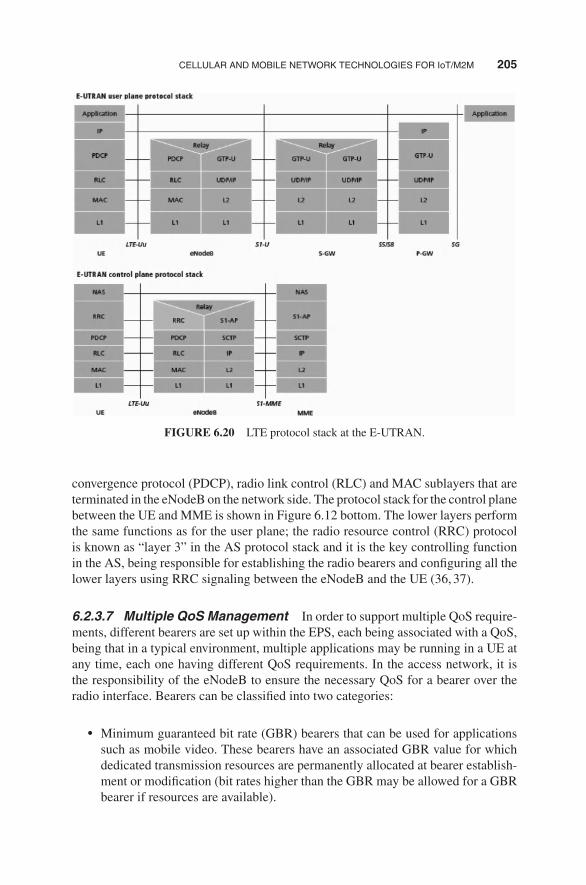
CELLULAR AND MOBILE NETWORK TECHNOLOGIES FOR IoT/M2M 205
FIGURE 6.20 LTE protocol stack at the E-UTRAN.
convergence protocol (PDCP), radio link control (RLC) and MAC sublayers that areterminated in the eNodeB on the network side. The protocol stack for the control planebetween the UE and MME is shown in Figure 6.12 bottom. The lower layers performthe same functions as for the user plane; the radio resource control (RRC) protocolis known as “layer 3” in the AS protocol stack and it is the key controlling functionin the AS, being responsible for establishing the radio bearers and configuring all thelower layers using RRC signaling between the eNodeB and the UE (36,37).
6.2.3.7 Multiple QoS Management In order to support multiple QoS require-ments, different bearers are set up within the EPS, each being associated with a QoS,being that in a typical environment, multiple applications may be running in a UE atany time, each one having different QoS requirements. In the access network, it isthe responsibility of the eNodeB to ensure the necessary QoS for a bearer over theradio interface. Bearers can be classified into two categories:
� Minimum guaranteed bit rate (GBR) bearers that can be used for applicationssuch as mobile video. These bearers have an associated GBR value for whichdedicated transmission resources are permanently allocated at bearer establish-ment or modification (bit rates higher than the GBR may be allowed for a GBRbearer if resources are available).

206 LAYER 1/2 CONNECTIVITY: WIRELESS TECHNOLOGIES FOR THE IoT
� Non-GBR bearers that do not guarantee any particular bit rate. These bearerscan be used for applications such as, but not limited to, web browsing or FTPtransfer. For these bearers, no bandwidth resources are allocated permanentlyto the bearer.
Each bearer has an associated QoS class identifier (QCI), and an allocation andretention priority (ARP). The QCI is a scalar identifying a set of transport charac-teristics and used to infer node-specific parameters that control packet-forwardingtreatment. Each packet flow is mapped to a QCI value based on the level of servicerequired by the application. Transport characteristics include bearer with/withoutGBR, priority, packet loss rate, packet latency budget, and so on. Packet-forwardingtreatment includes scheduling weights, admission thresholds, queue managementthresholds, and link-layer protocol configuration. Nine QCI values were defined andstandardized in the Release 8 version of the specifications, as depicted in Table 6.15;standardization ensures that an LTE operator can expect uniform traffic-handlingbehavior throughout the network regardless of the manufacturers of the eNodeBequipment. The usage of the QCI avoids the transmission of a full set of QoS-relatedparameters over the network interfaces and reduces the complexity of QoS negotia-tion. The QCI, along with ARP and, if where needed, GBR and maximum bit rate(MBR), determines the QoS associated to an EPS bearer. Hence, each QCI is charac-terized by priority, packet delay budget, and acceptable packet loss rate; the QCI labelfor a bearer determines how it is handled in the eNodeB. A mapping between EPSand pre-Release 8 QoS parameters has been defined to allow proper interworkingwith legacy networks.
TABLE 6.15 Standardized QCIs in LTE (Current List)
Resource Type QCI APPPacket DelayBudget (ms)
Packet LossRate Examples
GBR 1 2 100 10−2 VoiceGBR 2 4 150 10−3 Video streaming (live)GBR 3 5 300 10−6 Video streaming
(buffered)GBR 4 3 50 10−3 Interactive gamingNon-GBR 5 1 100 10−6 IMS signalingNon-GBR 6 7 100 10−3 Voice, video (live
streaming),interactive gaming
Non-GBR 7 6 300 10−6 Video streaming(buffered)
Non-GBR 8 8 300 10−6 WWW, e-mail, FTP,progressive video,p2p file sharing,TCP-based apps
Non-GBR 9 9 300 10−6

CELLULAR AND MOBILE NETWORK TECHNOLOGIES FOR IoT/M2M 207
The priority and packet delay budget (and to some extent the acceptable packetloss rate) from the QCI label determine the RLC mode configuration and how thescheduler in theMAChandles packets sent over the bearer (e.g., in terms of schedulingpolicy, queue management policy, and rate-shaping policy). For example, a packetwith higher priority can be expected to be scheduled before a packet with lowerpriority. For bearers with a low acceptable loss rate, an acknowledged mode can beused within the RLC protocol layer to ensure that packets are delivered successfullyacross the radio interface. The ARP of a bearer is used for call admission control—that is, to decide whether or not the requested bearer should be established in caseof radio congestion. It also governs the prioritization of the bearer for pre-emptionwith respect to a new bearer establishment request. Once successfully established,a bearer’s ARP does not have any impact on the bearer-level packet-forwardingtreatment (e.g., for scheduling and rate control). Such packet-forwarding treatmentshould be solely determined by the other bearer-level QoS parameters such as QCI,GBR, and MBR (36,37).
6.2.3.8 Signaling 2G/3G networks use SS7-MAP protocol for the followingfunctions:
� location� subscriber access� handover� authentication� security/identity management� handover services
In LTE/SAE (3GPP Rel.8), Diameter Base Protocol (RFC 3588) has been chosenby 3GPP for many of these procedures and is increasingly used for interoperatorsignaling network and roaming infrastructure. For example, registration messagesreceived will be based on diameter (rather than SS7-MAP). The LTE interfaces basedon diameter include the following (35):
� Packet core-related interfaces toward HSS and EIR� S6a (MME to HSS) and S6d (SGSN to HSS)� S6b, S6c (external AAA functions for non-3GPP accesses)� S13 (MME to EIR) and S13’ (SGSN to EIR)
� Network signaling for policy control and charging
1. S9 (H-PCRF to V-PCRF)
2. S7 (PCRF to P-GW)
3. Gx (PCRF to PCEF)
4. Gxc (PCRF to S-GW)
5. Rx (AF to PCRF)
6. Gy (PCEF to OCS)

208 LAYER 1/2 CONNECTIVITY: WIRELESS TECHNOLOGIES FOR THE IoT
GSM EDGE WCDMA
Non-3GPPtechnologies
HSPA LTE
FIGURE 6.21 Evolution to LTE.
6.2.3.9 Evolution Paths to 4G/LTE Mobile operators are evolving towardLTE/SAE using different evolution paths, as follows (see Fig. 6.21):
� 3GPP environments: GSM, GPRS, EDGE, WCDMA, HSPA� Non-3GPP environments: 1xRTT, EV-DO, 3xRTT, WLAN, WiMAX
Some of the challenges in LTE deployment were hinted in Table 6.12, the keyfactors being the complexity of the technology and the plethora of interfaces thathave to be supported. The evolution from a 2G/3G baseline will also be nontrivial.Network element evolution from 2G/3G to LTE includes the following upgrades inthe provider network:
� GERAN and UTRAN -> E-UTRAN� SGSN/PDSN-FA ->S-GW� GGSN/PDSN-HA ->PDN-GW� HLR/AAA ->HSS� VLR ->MME
In addition, the following signaling evolution from 2G/3G to LTE is needed:
� SS7-MAP/ANSI-41/RADIUS ->Diameter� GTPc-v0 and v1 ->GTPc-v2� MIP ->PMIP

APPENDIX 6.A: NON-WIRELESS TECHNOLOGIES FOR IoT 209
FIGURE 6.22 EPS and support of legacy environments.
After the LTE environment is established in a portion of the provider’s environ-ment, legacy components of the provider’s network can be supported by the LTEinfrastructure as depicted pictorially in Figure 6.22 (35).
APPENDIX 6.A: NON-WIRELESS TECHNOLOGIES FOR IoT:POWERLINE COMMUNICATIONS
This appendix provides a brief description of some non-wireless networking tech-nologies that have been considered for IoT/M2M. See Table 6A.1 for a listing ofsome of the key technologies. SCADA was discussed in the context of standards inthe Appendix to Chapter 5. Here we focus on PLC.PLC refers to any technology that enables data transfer through powerlines by
using advanced modulation technology. Data communication can take place at NB orbroadband speeds. The technology has been around since the 1950s, but initially onlysupported NB applications for relay management, for example for public lighting.Broadband over PLC only began at the end of the 1990s. PLC is thus a term usedto identify technologies, equipments, applications and services aiming at providingusers with communication means over existing “powerlines” (cables transmittingelectricity). The term broadband over powerline (BPL) is used to underline thetechnology capability to address broadband services. As for the term access PLC, it

210 LAYER 1/2 CONNECTIVITY: WIRELESS TECHNOLOGIES FOR THE IoT
TABLE 6A.1 Listing of Some of the Key Non-Wireless Technologies used for IoT-LikeServices Over the Years
Technology/Concept Description
KNX and KNX-RF KNX (administered by the KNX Association) is an OSI-basednetwork communications protocol for intelligent buildingsdefined in standards CEN EN 50090 and ISO/IEC 14543. KNXis the follow-on standard built on the European Home SystemsProtocol (EHS), BatiBUS, and the European Installation Bus(EIB or Instabus). Effectively, KNX uses the communicationstack of EIB but augmented with the PHY layers andconfiguration modes BatiBUS and EHS; thus, KNX includes thefollowing PHYs:
� Twisted pair wiring (inherited from the BatiBUS and EIBInstabus standards). This approach uses differentialsignaling with a signaling speed of 9.6 Kbps. MAC iscontrolled with the CSMA/CA method;
� Powerline networking (inherited from EIB and EHS);� Radio (KNX-RF);� IR; and,� Ethernet (also known as EIBnet/IP or KNXnet/IP).
M-Bus The M-Bus is a European standard for remote reading of gas andelectric meters; it is also usable for all other types ofconsumption meters. It is specified as follows:
� EN 13757-2 (PHY and link layer)� EN 13757-3 (application layer)� Note: the frame layer uses IEC 870 and the network(packet layer) is optional
A radio variant of M-Bus (wireless M-Bus) is also specified in EN13757-4
PLC PLC (also called powerline communication as a singular term;also called powerline telecommunications [or PLT]) refers toany technology that enables data transfer through powerlines.Data communication can take place at NB or broadband speeds.The technology has been around since the 1950s, but initiallyonly supported NB applications for relay management, forexample for public lighting. Broadband over PLC only began atthe end of the 1990s. PLC is thus a term used to identifytechnologies, equipments, applications, and services aiming atproviding users with communication means over existing“powerlines” (cables transmitting electricity). The term BPL isused to underline the technology capability to addressbroadband services. As for the term access PLC, it is used toidentify those PLC solutions aiming at providing consumerswith broadband services through the external electricity grid,while in-home PLC is used to identify PLC solutions aiming atapplications within the home (38)

APPENDIX 6.A: NON-WIRELESS TECHNOLOGIES FOR IoT 211
TABLE 6A.1 (Continued )
Technology/Concept Description
SCADA A long-existing industrial control system (ICS). It is a centralizedsystem used to monitor and control systems deployed over largegeographic areas, such as a power grid. There are three mainelements in a SCADA system, multiple RTUs (remote telemetryunits), a communications apparatus, and a HMI (humanmachine interface) mechanism
xDSL A 1990s technology that exploits unused frequencies on coppertelephone lines to transmit traffic typically at multimegabitspeeds. DSL can allow voice and HS data to be sentsimultaneously over the same line. Because the service is“always available,” end-users do not need to dial in or wait forcall set-up. Asymmetrical variations include ADSL, G.liteADSL (or simply G.lite), VDSL (ITU-T G.993.1), and VDSL2(ITU-T G.993.2). The standard forms of ADSL (ITU G.992.3,G.992.5, and ANSI T1.413—Issue 2) are all built upon the sametechnical foundation, discrete multitone (DMT). The suite ofADSL standards facilitates interoperability between all standardforms of ADSL (39)
is used to identify those PLC solutions aiming at providing consumerswith broadbandservices through the external electricity grid, while in-home PLC is used to identifyPLC solutions aiming at applications within the home (38). A brief history is asfollows (40):
� 1950: at a frequency of 10 Hz, 10 kW of power, one-way: town lighting, relayRC;
� Mid-1980s: beginning of research into the use of the electrical grid to supportdata transmission; on bands between 5 and 500 KHz, always in a one-waydirection;
� 1997: first tests for bidirectional data signal transmission over the electricalsupply network and the beginning of research by Ascom (Switzerland) andNorweb (United Kingdom);
� 2000: first tests carried out in France by EDF R&D and Ascom;� 2011-12: Publication of IEEE 1901 standards.
PLC transmission works by superimposing a high-frequency signal at low-energylevels over the 50 Hz electrical signal. The powerline is transformed into a commu-nication network through the superposition of a low-energy information signal to thepower wave. In order to ensure a suited coexistence and separation between the twosystems, the frequency range used for communication is very far from the one used

212 LAYER 1/2 CONNECTIVITY: WIRELESS TECHNOLOGIES FOR THE IoT
for the power wave (50 Hz in Europe): 3–148.5 kHz for PLC NB applications andfrom 1–30MHz for PLC broadband applications. Themodulated signal is transmittedvia the power infrastructure and can be received and decoded remotely. Thus, thePLC signal is received by any PLC receiver located on the same electrical network.An integrated coupler at the PLC receiver entry points eliminates low frequencycomponents before the signal is treated.There now is standardization work underway in the PLC Forum and in ETSI.
CENELEC has issued regulations for transmission in defined bands. The CENELECA-band is reserved by law in CENELEC regulated countries for the exclusive useof utilities and their licensees. The CENELEC C-band is available for consumer andcommercial use without restriction, but a common access protocol and coexistenceprotocol is mandated (41).A plethora of NB (some Kbps) and broadband (tens or even hundreds of Mbps)
applications can be provided through access and in-home PLC solutions, for thebenefit of end consumers and of utilities (to increase their performances and improvetheir service quality). NB applications include home control, home automation, auto-matic meter reading, remote surveillance, and control of home appliances. Broadbandapplications include (for access PLC) Internet access, telephony, TV and (for in-homePLC) Internet access sharing, computer resource sharing, and AV whole-house dis-tribution. PLC can be used in places where radio frequency (RF) cannot be used or isunreliable; for example, smart meters in the basement of a building are unlikely to beable to use RF to communicate with the neighborhood data concentrator—PLC com-munication can utilize the power wires to reach the data concentrator. It is estimatedtoday that more than 80 PLC initiatives in more than 40 countries have been launched,worldwide, by electric utilities. Pilot sites, technological or commercial trials, anddeployments are numerous in Europe. Among the most important initiatives are theones developed by EDF (France), EDP (Portugal), EEF (Switzerland), ENDESA andIBERDROLA (Spain), PPC (Germany), and SSE (Scotland) (38).IEEE 1901 is a group of PLC standards that enables transmission of data over AC
electrical powerlines. Its goal was to replace a set of different powerline specs nowin existence but maintaining a mandatory coexistence with legacy PLC approaches.There are two basic standards: (i) a BPL standard and (ii) a low-frequency narrowband(LF NB) standard.
� The IEEE 1901TM BPL standard was finalized and published in December2010. The standard was sponsored by the IEEE Communications Society. TheBPL standard is designed for use in a wide range of applications includingSE, transportation, and LANs in both the home and the enterprise. Networkingproducts that fully comply with IEEE 1901 will deliver data rates in excess of500 Mbps in LAN applications. In first-mile/last-mile applications, IEEE 1901-compliant devices will achieve ranges of up to 1500m. The technology specifiedby IEEE 1901 uses sophisticated modulation techniques to transmit data overstandard AC powerlines of any voltage at transmission frequencies of less than100MHz. In the transportation sector, for example, the standard’s data rates andrange make it possible to deliver A/V entertainment to the seats of airplanes,

APPENDIX 6.A: NON-WIRELESS TECHNOLOGIES FOR IoT 213
trains, and other mass transit vehicles. Electric vehicles (EVs) can download anew entertainment playlist to theA/V systemwhile the car is charging overnight.In the home, PLC will complement wireless LANs by providing a link throughwalls and other RF impediments as well as over distances beyond the normalrange of wireless networks. It will complement wireless networks in hotels andother multistory buildings by carryingmultimedia data over the longer distancesand allowing wireless to complete the communication link over the last fewmeters. IEEE 1901 may also benefit utilities, service providers, and consumerelectronics companies—anyone with a stake in smart grid technologies—aswell as smart-meter providers and home appliance manufacturers (42).
� The IEEE has been working on IEEE P1901.2TM, a standard for LF NB (lessthan 500 kHz) PLC for smart grid applications. The specification entered itsfinal approval process in early 2012 and was expected to be ratified soon there-after. LF NB PLC is needed, according to proponents, to accelerate wider-scalerollout of smart grids. IEEE P1901.2 is designed to support smart grid applica-tions such as grid to utility meter, EV to charging station, home area networking,and solar-panel communications. More than 30 semiconductor manufacturers,meter and systems manufacturers, software developers, service providers, andutilities have contributed to the work of the IEEE P1901.2Working Group sinceits inception in fall 2009. The work was sponsored by the Powerline Communi-cations Standards Committee of the IEEE Communications Society (ComSoc).IEEE P1901.2 is designed to specify secure PLC at data rates up to 500 Kbpsand at transmission frequencies of less than 500 kHz for applications such asgrid to utility meter, EV to charging station, home area networking and light-ing, and solar-panel communications. The standard addresses LF NB PLC overlow-voltage lines of less than 1000 V between transformer and meter, throughtransformer low-voltage to medium-voltage (1000 V up to 72 kV) and throughtransformer medium-voltage to low-voltage powerlines in both urban and long-distance (multikilometer) rural communications. IEEE P1901.2 supports thebalanced and efficient use of the PLC channel by all classes of LF NB devicesby defining detailed mechanisms for coexistence among standard technologiesoperating in the same field, data rate, and frequency band. This standard assurescoexistence with broadband powerline (BPL) devices by minimizing out-of-band emissions in frequencies greater than 500 kHz. The standard addresses thenecessary security requirements that assure communication privacy and allowuse for security sensitive services. This standard defines the PHY layer and themedium access sublayer of the data link layer, as defined by the InternationalOrganization for Standardization (ISO) Open Systems Interconnection (OSI)Basic Reference Model (43).
The PLCforum is a leading international association that represents the inter-ests of manufacturers, energy utilities, and other organizations (universities, otherPLC associations, consultants, etc.) active in the field of access and in-home PLCtechnologies.

214 LAYER 1/2 CONNECTIVITY: WIRELESS TECHNOLOGIES FOR THE IoT
Beyond the PLCforum, a number of industry groups and electric utilities, allaround the world, are supporting the development of the PLC technology. Amongindustry groups areUPLC and PLCA (in theUnited States), PLC-J (in Japan), APTEL(in South America), PUA (PLC Utilities Alliance) in Europe, Utilitel in Australia,the Universal Powerline Alliance, and the HomePlug R© Powerline Alliance, amongothers.The HomePlug Alliance’s mission13 is to enable and promote rapid availability,
adoption, and implementation of cost-effective, interoperable, and standards-basedhome powerline networks and products. By working with utility companies andthe Wi-Fi Alliance and ZigBee Alliance, the HomePlug Alliance aims at helpingto build the home area network (HAN) ecosystem that enables intelligent energymanagement and efficiency in the home and small businesses. With the goal ofproviding a complimentary wireless (ZigBee) and wired (HomePlug) infrastructure,the coverage for large homes and multidwelling units can be assured.Basic applications include the use of in-home wires to distribute signals to support
Smart Grid & Smart Energy, HDTV Networking, Whole Home Audio, and Gaming.Technology standards defined by the Alliance include the following:
� HomePlug Green PHYTM (“GP”)� IEEE 1901 Powerline Networking Standard� HomePlug Broadband-Speed Technologies� SE Profile 2
HomePlug Green PHY Specification. This is a new powerline networking spec-ification that targets smart grid/SE applications. HomePlug GP is based on customerrequirements for cost, coverage, and performance and driven by input from utilitycompanies, as well as from companies that manufacture meters, automobiles, andappliances. In addition to low cost and power consumption, IPv6 networking andinteroperability with the installed base of powerline products are critical to the suc-cess of products. As such, HomePlug GP will be interoperable with both HomePlugAV and IEEE 1901, just cited; this means that HomePlug Green PHY is a certificationprofile of IEEE 1901. HomePlug Green PHY has ample bandwidth to support criticalfunctionality such as IP networking, but with power consumption estimated to be75% lower than HomePlug AV, with similar cost savings projected. The specificationis designed to the specific requirements of Smart Grid applications while interoper-ating with HomePlug AV and AV2 products and the IEEE 1901 standard. GP chipsare already available; certified products are expected to ship in early 2013.
� Principal applications: Monitor and control devices via low speed, low-costPLC, including smart energy applications such as demand response, loadcontrol, energy efficiency Home/Building Automation. It targets smart grid
13This section is based on material from The HomePlug R© Powerline Alliance (44).

APPENDIX 6.A: NON-WIRELESS TECHNOLOGIES FOR IoT 215
applications such as HVAC/thermostats, smart meters, home appliances, andplug-in electric vehicles (PEVs).
� Features: (i) interoperable with HomePlug AV; (ii) HomePlug GP is a profile ofIEEE P1901; and (iii) low-power consumption, low cost� Estimated, up to 75% lower cost, 75% less power consumption than Home-Plug AV
� Internet (IP) networking: 802.2, IPv6 support� Minimum 1 Mbps effective data rate (3.8 Mbps peak PHY rate)� Support for firmware updates
IEEE 1901 Powerline Networking Standard. Regarding IEEE 1901.2010—ForHS communication devices (HomePlugAV), theHomePlugAlliance and itsmembersfirst collaborated with IEEE in 2005 with the inception of the P1901 workgroup,tasked to develop a standard for HS communication devices. In December 2008, theIEEE P1901 working group voted to include HomePlug technology in the baselinestandard for PLC. The IEEE 1901.2010 standard was ratified in September 2010,and multiple semiconductor vendors are now shipping integrated circuits (ICs) basedon the standard. In addition, the installed base of tens of millions of HomePlug AVproducts are fully interoperable with the 1901 standard, ensuring a seamless roadmapfor existing users of HomePlug technology. The HomePlug Alliance conducts acomprehensive compliance and interoperabilty (C&I) program for products basedon the HomePlug AV IEEE P1901 standard, ensuring that reliable, interoperableproducts are available from multiple suppliers. Additionally, the HomePlug Allianceplans to launch a new certification program—Netricity PLC—to provide C&I testingof products built on the IEEE P1901.2 LF NB PLC standard.
HomePlug Broadband-Speed Technologies. In June 2011, the HomePlugAlliance put its support behind the IEEE P1905 working group’s efforts to define thefirst standard for hybrid home networks. A P1905 network would include combina-tions of stationary home networking devices such as set-top boxes, home gateways,Blu-Ray players and televisions, and mobile devices such as laptops, tablets, andsmartphones. The IEEE P1905 standard provides an abstraction layer to establishedpowerline, wireless, coaxial cable, and Ethernet home networking technologies. Thestandard enables consumers and service providers to combine the capabilities ofotherwise disparate networks to maximize a home network’s overall performanceand reliability. IEEE P1905’s abstraction layer common interface allows applicationsand upper-layer protocols to be agnostic to the underlying home networking tech-nologies. Packets can arrive and be transmitted over any technology according toQoS priorities. IEEE P1905 also simplified the network set-up by providing commonset-up procedures for adding devices, establishing secure links, implementing QoS,and managing the network.
SE Initiative. In 2008, a number of utility companies (American Electric Power,Consumers Energy, Pacific Gas and Electric Company, Reliant Energy, Sempra, andSouthern California Edison) announced that they are working with the ZigBee and

216 LAYER 1/2 CONNECTIVITY: WIRELESS TECHNOLOGIES FOR THE IoT
HomePlug alliances to develop a common application layer integrated solution foradvanced metering infrastructure (AMI) and HANs. The three groups are expandingthe application layer, enabling it to run on HomePlug technology, and providingutilities with industry standards for both wireless and wired HAN options whenimplementing new AMI programs. Shortly after the formation of the group, theElectric Power Research Institute (EPRI) began to collaborate to develop a commonlanguage for HAN devices to utilize the AMI. This arrangement further expands theSmart Grid by creating a standard communication approach between AMI systemsand HANs, as well as a common set of certification procedures. As noted elsewhere,the term “smart energy” refers generally to actions and technologies that are usedto improve the efficiency of energy consumption. Energy demand and costs areincreasing rapidly, so utility companies are focusing on adopting communicationsand networking technologies to help consumers monitor and reduce their energyconsumption.
REFERENCES
1. ETSI TR 101 557 V1.1.1 (2012-02), Electromagnetic Compatibility and Radio spectrumMatters (ERM); System Reference document (SRdoc); Medical Body Area NetworkSystems (MBANSs) in the 1785 MHz to 2500 MHz range.
2. Coronel P, Schott W, Schwieger K, Zimmermann E, Zasowski T, Chevillat P, editors.Briefing on Wireless Body Area and Sensor Networks, 8th Wireless World ResearchForum (WWRF8bis) Meeting, Beijing, China, February 2004; (ii) 11th Wireless WorldResearch Forum Meeting, Oslo, Norway, June 2004.
3. Practel, Inc., Role ofWireless ICT in Health Care andWellness—Standards, Technologiesand Markets, May 2012, Published by Global Information, Inc. (GII), 195 FarmingtonAvenue, Suite 208 Farmington, CT 06032 USA.
4. Gainspan, Gainspan Low-Power Embedded WI-FI VS ZigBee. GainSpan Corporation,3590 N. First Street, Suite 300, San Jose, CA 95134, Available at http://www.gainspan.com.
5. Smith P. Comparing Low-PowerWireless Technologies. Tech Zone, Digikey OnlineMag-azine, Digi-Key Corporation, 701 Brooks Avenue, South Thief River Falls, MN 56701USA.
6. 3rd Generation Partnership Project (3GPP) Organization, Available at www.3gpp.org.
7. Third Generation Partnership Project 2 Organization, Available at http://www.3gpp2.org.
8. Bormann C. Getting Started with IPv6 in Low-PowerWireless. “Personal Area” Networks(6LoWPAN), Universitat Bremen TZI, IETF 6lowpan WG and CoREWG Co-Chair, IABTutorial on Interconnecting Smart Objects with the Internet, Prague, Saturday, 2011-03-26,Available at http://www.iab.org/about/workshops/smartobjects/tutorial.html.
9. ETSI Documentation, ETSI, 650 Route des Lucioles F-06921 Sophia Antipolis Cedex—FRANCE.
10. Krasinski R, Nikolich P, Heile RF. IEEE 802.15.4j Medical Body Area NetworksTask Group PAR, IEEE P802.15 Working Group for Wireless Personal Area Networks(WPANs), January18, 2011.

REFERENCES 217
11. ISA, 67 Alexander Drive, P.O. Box 12277, Research Triangle Park, NC 27709,[email protected].
12. Minoli D. Satellite Systems Engineering in an IPv6 Environment. Boca Raton, FL: Francisand Taylor; 2009.
13. MinoliD.HotspotNetworks:Wi-Fi for PublicAccess Locations.NewYork,NY:McGraw-Hill; 2002.
14. Minoli D,Wireless Sensor Networks (co-authoredwithK. Sohraby and T. Znati). Hoboken,NJ: Wiley; 2007.
15. Emerson Process Management, IEC 62591 WirelessHART, System Engineering Guide,Revision 2.3, Emerson Process Management, 2011.
16. ZigBee Alliance, Available at http://www.zigbee.org/.
17. ZigBee Wireless Sensor Applications for Health, Wellness and Fitness, March 2009,ZigBee Alliance, Available at www.zigbee.org.
18. Duffy P. Zigbee IP: Extending the Smart Grid to Consumers. Cisco Blog – The Plat-form, June 4, 2012, Cisco Systems, Inc., 170 West Tasman Dr., San Jose, CA 95134USA.
19. Shandle J. What does ZigBee Pro mean for your application?. EETimes Online Magazine,11/27/2007, Available at http://www.eetimes.com.
20. Drake J, Najewicz D, Watts W. Energy efficiency comparisons of wireless communica-tion technology options for smart grid enabled devices. White Paper, General ElectricCompany, GE Appliances & Lighting, December 9, 2010.
21. Montenegro G, Kushalnagar N, Hui J, Culler D. Transmission of IPv6 Packets over IEEE802.15.4 Networks, RFC 4944, Updated by RFC 6282, RFC 6775 (was draft-ietf-6lowpan-format), September 2007.
22. Kingsley S. Personal Body Networks go Wireless at 2.4GHz. ElectronicsWeekly OnlineMagazine, 16 May 2012, Available at http://www.electronicsweekly.com.
23. IEEE 802.15 WPAN Task Group 1 (TG1), WPAN Home Page, Monday, June 20, 2005.
24. Bluetooth SIG Home page, Available at www.bluetooth.com (more info at www.bluetooth.org).
25. Fleishman G. Inside Bluetooth 2.0., Macworld, February 9, 2005.
26. Latuske R. Bluetooth Health Device Profile (HDP). White Paper, September 2009, ARSSoftware GmbH, Stanberger Strasse 22, D-82131, Gauting/Munchen, Germany, Availableat http://www.ars2000.com/.
27. Kwak KS, Ullah S, Ullah N An Overview of IEEE 802.15.6 Standard (Invited Paper),ISABEL 2010 in Rome, Italy. UWB-ITRC Center, Inha University, 253 Yonghyun-dong,Nam-gu, Incheon (402–751), South Korea.
28. U.S. Department of Transportation, Research and Innovative Technology Administration.Intelligent Transportation Systems. December 2012, Available at http://www.its.dot.gov.
29. Fuxjager P, Costantini A, et al. IEEE 802.11p Transmission Using GNURadio.Forschungszentrum Telekommunikation Wien, Donau-City-Strasse 1, A-1220 Vienna,Austria. And, University of Salento, 73100 Lecce, Italy. 2007.
30. TechnoCom. The WAVE Communications Stack: IEEE 802.11p, 1609.4 and, 1609.3.Presentation, September, 2007, TechnoCom, 2030 Corte del Nogal, Suite 200, Carlsbad,CA 92011 Available at http://www.ieeevtc.org/plenaries/vtc2007fall/34.pdf.

218 LAYER 1/2 CONNECTIVITY: WIRELESS TECHNOLOGIES FOR THE IoT
31. WeigleM. Standards:WAVE /DSRC /802.11p in Vehicular Networks, CS 795/895, Spring2008, Old Dominion University.
32. IEEE WoWMoM 2012 Panel, San Francisco, California, USA June 25–28, 2012.
33. Rao YS, Pica F, Krishnaswamy D. 3GPP Enhancements for Machine Type Communi-cations Overview. IEEE WoWMoM 2012 Panel, San Francisco, California, USA June25–28, 2012.
34. Principi B. CTIA: Should M2M skip 3G and go right to 4G?. May 9, 2012, Online Article,Available at http://www.telecomengine.com.
35. Clark M, Neal BJ, Gullstrand C. Preparing for LTE Roaming. Syniverse Technolo-gies, 120 Moorgate London, EC2M 6UR United Kingdom, March 2011, Available atwww.syniverse.com.
36. Alcatel-Lucent. LTE—The UMTS Long Term Evolution: From Theory to Practice. Strate-gic Whitepaper, Available at www.alcatel-lucent.com, Wiley; 2009.
37. Sesia S, Toufik I, Baker M, editors, LTE – The UMTS Long Term Evolution: From Theoryto Practice. Wiley; 2009.
38. PLCforum. Available at http://www.plcforum.org/frame_plc.html.
39. DSL Forum, DSL Forum, 48377 Fremont Blvd, Suite 117, Fremont, CA 94538, Availableat http://www.dslforum.org.
40. Cacciaguerra F. Introduction to Power Line Communications (PLC). November2003, Kioskea.net Online Magazine, Available at http://en.kioskea.net/contents/cpl/cpl-intro.php3.
41. Power Line Communications (PLC), Echelon Corporation, 550 Meridian Ave., San Jose,CA 95126 USA. Available at http://www.echelon.com.
42. Yu S. Final IEEE 1901 Broadband Over Power Line Standard Now Published. IEEE PressRelease, February 1, 2011.
43. Yu S. IEEE P1901.2TM Standard FOR Low-Frequency, Narrowband Power Line Commu-nications Enters Letter Balloting, IEEE Press Release, January 2012.
44. The HomePlug R© Powerline Alliance, Available at http://www.homeplug.org.45. 3GPP2 X.S0011-002-D. cdma2000 Wireless IP Network Standard: Simple IP and Mobile
IP Access Services. Available at http://www.3gpp2.org/Public_html/specs/X.S0011-002-D_v1.0_060301.pdf, February 2006.
46. Alcatel-Lucent. Alcatel-Lucent Researches Opportunities for Delivering Enhanced VideoSharing ServiceswithDOCOMOEuro-Labs. Press Release, Paris andBarcelona, February15, 2011. Available at www.alcatel-lucent.com.
47. California Software Labs. Basic Streaming Technology and RTSP Protocol—A TechnicalReport, 2002. California Software Labs, 6800 Koll Center Parkway, Suite 100 PleasantonCA 94566, USA.
48. Machine-to-Machine Communications (M2M); M2M Service Requirements. ETSI TS102 689 V1.1.1 (2010-08). ETSI, 650 Route des Lucioles F-06921 Sophia AntipolisCedex—FRANCE.
49. Machine-to-Machine Communications (M2M); Functional Architecture Technical Spec-ification, ETSI TS 102 690 V1.1.1 (2011-10), ETSI, 650 Route des Lucioles F-06921Sophia Antipolis Cedex—FRANCE.
50. H.720. Overview of IPTV Terminal Devices and End-Systems. (also known as ex H.IPTV-TDES.0), October 2008. ITU-T Study Group 16. International Telecommunication Union,Telecommunication Standardization Bureau, Place des Nations, CH-1211 Geneva 20.

REFERENCES 219
51. Near Field Communication.org, Advocacy Group, Available at http://www.nearfieldcommunication.or.
52. Patil B, Dommety G. Why the Authentication Data Suboption is Needed for Mobile IPv6(MIPv6). RFC 5419, January 2009.
53. WiMAX Network Architecture—WiMAX End-to-End Network Systems Architecture.May 2008, Available at http://www.wimaxforum.org/documents/documents/WiMAX_Forum_Network_Architecture_Stage_23_Rel_1v1.2.zip.

CHAPTER 7
LAYER 3 CONNECTIVITY:IPv6 TECHNOLOGIES FOR THE IoT
7.1 OVERVIEW AND MOTIVATIONS
Internet Protocol Version 6 (IPv6) is a newer version of the network layer protocol thatis designed to coexist (but not directly interwork) with IPv4. In the long term, IPv6 isexpected to replace IPv4, but that will not happen overnight. IPv6 provides improvedinternetworking capabilities compared to what is presently available with IPv4. Thecurrent IPv4 has been in use for over 30 years, but it exhibits some challenges insupporting emerging demands for address space cardinality, high-density mobility,multimedia, and strong security. IPv6 offers the potential of achieving scalability,reacheability, end-to-end interworking, quality of service (QoS), and commercial-grade robustness that is needed for contemporary and emerging web services, dataservices, mobile video, and Internet of things (IoT) applications.We retain the position stated in Chapter 1 that IoT may well become the “killer-
app” for IPv6. Using IPv6 with its abundant address spaces, globally unique object(thing) identification and connectivity can be provided in a standardized mannerwithout additional status or address (re)processing; hence, its intrinsic advantageover IPv4 or other schemes. We are not implying in this text that IPv6 is strictly anduniquely required to support IoT, just that it provides an ideal, future-proof, scalablemechanism for such services, whether in a terrestrial mode or in a satellite-basedmode (1, 2).
Building the Internet of Things with IPv6 and MIPv6: The Evolving World of M2M Communications,First Edition. Daniel Minoli.© 2013 John Wiley & Sons, Inc. Published 2013 by John Wiley & Sons, Inc.
220

OVERVIEW AND MOTIVATIONS 221
IP was designed as a packet-based technology (protocol) in the late 1970s–early1980s for the purpose of connecting computers that were in separate geographic loca-tions. Starting in the early 1990s, developers realized that the communication needsof the twenty-first century needed a protocol with some new features and capabilities,while at the same time retaining the useful features of the existing protocol. IPv6was initially developed in the early 1990s because of the anticipated need for moreend-system addresses based on anticipated Internet growth, encompassing mobilephone deployment, smart home appliances, and billions of new users in developingcountries (e.g., BRIC: Brazil, Russia, India, China). Technologies and applicationssuch as voice over IP (VoIP), “always-on access” (e.g., cable modems), broadbandand/or ethernet-to-the-home, converged networks, evolving ubiquitous computingapplications, and IoT will be driving this need even more in the next few years (3).IPv6 is now being slowly deployed worldwide: there is documented institutional
and commercial interest and activity in Europe and Asia, and there also is evolvinginterest in the United States. The expectation is that in the next few years deploymentof this new protocol will occur worldwide. For example, the U.S. Department ofDefense (DoD) announced that from October 1, 2003, all new developments andprocurements needed to be IPv6 capable; the DoD’s goal was to complete the tran-sition to IPv6 for all intra- and internetworking across the agency by 2008, whichwas accomplished. The U.S. Government Accountability Office (GAO) has recom-mended that all agencies become proactive in planning a coherent transition to IPv6.The current expectation is that IPv4 will continue to exist for the foreseeable future,while IPv6 will be used for new broad-scale applications. The two protocols are notdirectly interworkable, but tunneling and dual-stack techniques allow coexistenceand co-working.While the basic function of the network layer internetworking protocol is to move
information across networks, IPv6 has more capabilities built into its foundation thanIPv4. Link-level communication does not generally require a node identifier (address)since the device is intrinsically identified with the link-level address; however, com-munication over a group of links (a network) does require unique node identifiers(addresses). The IP address is an identifier that is applied to each device connectedto an IP network. In this setup, different entities taking part in the network (servers,routers, user computers, and so on) communicate among each other using their IPaddress, as an entity identifier. The current IPv4 naming scheme was developed inthe 1970s and had capacity for about 4.3 billion addresses, which were grouped into255 blocks of 16 million addresses each. In IPv4, addresses consist of four octets.With IPv4, the 32-bit address can be represented as AdrClass|netID|hostID. Thenetwork portion can contain either a network ID or a network ID and a subnet. Everynetwork and every host or device has a unique address, by definition. For ease ofhuman conversation, IP addresses are represented as separated by periods, for exam-ple: 166.74.110.83, where the decimal numbers are a shorthand and corresponds tothe binary code described by the byte in question (an 8-bit number takes a valuein the 0–255 range). Since the IPv4 address has 32 bits, there are nominally 232
different IP addresses (as noted, approximately 4.3 billion nodes, if all combinationsare used).

222 LAYER 3 CONNECTIVITY: IPv6 TECHNOLOGIES FOR THE IoT
TABLE 7.1 Projected RIR Unallocated Address Pool Exhaustion (as of April 2011)
RIR Assigned Addresses (/8s) Remaining Addresses (/8s)
AFRINIC 8.3793 4.6168APNIC 53.7907 1.2093ARIN 77.9127 6.0130LACNIC 15.6426 4.3574RIPE NCC 45.0651 3.9349
RIR, regional Internet registry; AFRINIC, AfricanNetwork Information Centre; ARIN,American Registryfor Internet Numbers; APNIC, Asia-Pacific Network Information Centre; LACNIC, Latin America andCaribbean Network Information Centre; RIPE NCC, Reseaux IP Europeens Network Coordination Centre(the RIR for Europe, the Middle East, and parts of Central Asia).
IPv4 has proven, bymeans of its long life, to be a flexible and powerful networkingmechanism. However, IPv4 is starting to exhibit limitations, not only with respect tothe need for an increase of the IP address space, driven, for example, by new popula-tions of users in countries such as China and India; by new technologies with “alwaysconnected devices” (e.g., cable modems, networked PDAs, 3G/4G mobile smart-phones, and so on); and by new services such as global rollout of VoIP, IP Television(IPTV), and social networking. A full deployment of IoT applications will certainlystress the IPv4 environment. A regional Internet registry (RIR) manages the alloca-tion and registration of Internet resources such as IPv4 addresses, IPv6 addresses, andautonomous system (AS) numbers, in a specific region of the world. As of February1, 2011, only 1% of all possible IPv4 addresses were left unassigned. This has ledto a predicament known as IPv4 Run-Out. The entire address space was expectedto be more or less exhausted by September 2011, according to the IPv4 AddressReport (see Table 7.1) (4, 5). The IPv4 address allocation is based on the followinghierarchy:
Internet assigned numbers authority (IANA)→RIRs→ internet service providers(ISPs)→ the public (including businesses).
Thus, a key desirable capability is the increase in address space such that it is able tocover all elements of the universe set under consideration. For example, all computingdevices could have a public IP address, so that they can be uniquely tracked1; todayinventory management of dispersed IT assets cannot be achieved with IP mechanismsalone. With IPv6, one can use the network to verify that such equipment is deployedin place and active; even non-IT equipment in the field can be tracked by having an IPaddress permanently assigned to it. IPv6 creates a new IP address format, such that thenumber of IP addresses will not exhaust for several decades or longer, even though anentire new crop of devices are expected to connect to Internet over the coming years.
1Note that this has some potential negative security issues as attackers could be able to own a machine andthen exactly know how to go back to that same machine again. Therefore, reliable security mechanismsneed to be understood and put in place in IPv6 environments.

OVERVIEW AND MOTIVATIONS 223
IPv6 also adds improvements in areas such as routing and network configuration. IPv6has extensive automatic configuration (autoconfiguration) mechanisms and reducesthe IT burden, making configuration essentially plug-and-play. Specifically, newdevices that connect to intranet or Internet will be “plug-and-play” devices. WithIPv6, one is not required to configure dynamic non-published local IP addresses,the gateway address, the subnetwork mask, or any other parameters. The equipmentautomatically obtains all requisite configuration data when it connects to the network.Autoconfiguration implies that a dynamic host configuration protocol (DHCP) serveris not needed and/or does not have to be configured (2, 6, 7).IPv6 was originally defined in RFC 1883 that was then obsolete by RFC 2460,
“Internet Protocol, Version 6 (IPv6) Specification,” S. Deering, R. Hinden (Decem-ber 1998).2 A large body of additional RFCs has emerged in recent years to addcapabilities and refine the concept.The advantages of IPv6, some of which we already noted in Chapter 1, can be
summarized as follows:
� Scalability and expanded addressing capabilities: IPv6 has 128-bit addressesversus 32-bit IPv4 addresses. With IPv4, the theoretical number of available IPaddresses is 232∼1010. IPv6 offers a 2128 space. Hence, the number of availableunique node addressees is 2128∼1039. IPv6 has more than 340 undecillion(340,282,366,920,938,463,463,374,607,431,768,211,456) addresses, groupedinto blocks of 18 quintillion addresses.
� “Plug-and-play”: IPv6 includes a “plug-and-play” mechanism that facilitatesthe connection of equipment to the network. The requisite configuration isautomatic; it is a serverless mechanism.
� IPv6 makes it easy for nodes to have multiple IPv6 addresses on the same net-work interface. This can create the opportunity for users to establish overlay orcommunities of interest (COI) networks on top of other physical IPv6 networks.Department, groups, or other users and resources can belong to one or moreCOIs, where each can have its own specific security policy (8).
� Security: IPv6 includes security in its specifications such as payload encryptionand authentication of the source of the communication. It calls for end-to-endsecurity, with built-in, strong IP-layer encryption and authentication (embeddedsecurity support with mandatory IP Security [IPsec] implementation). It followsthat IPv6 network architectures can easily adapt to an end-to-end security modelwhere the end hosts have the responsibility of providing the security servicesnecessary to protect any data traffic between them; this results in greater flexibil-ity for creating policy-based trust domains that are based on varying parametersincluding node address and application (9).
� In IPv6, creating a Virtual Private Network (VPN) is easier and more standardthan in IPv4, because of the (authentication header [AH] and encapsulating
2The “version 5” referencewas employed for another use—an experimental real-time streaming protocol—and to avoid any confusion, it was decided not to use this nomenclature.

224 LAYER 3 CONNECTIVITY: IPv6 TECHNOLOGIES FOR THE IoT
security protocol [ESP]) extension headers. The performance penalty is lowerfor the VPN implemented in IPv6 compared to those built in IPv4 (10).
� Optimized protocol: IPv6 embodies IPv4 best practices but removes unused orobsolete IPv4 characteristics. This results in a better-optimized IP.Also,mergingtwo IPv4 networks with overlapping addresses (say, if two organizations merge)is complex; it will be much easier to merge networks with IPv6.
� Real-time applications: To provide better support for real-time traffic (e.g.,VoIP, IPTV), IPv6 includes “labeled flows” in its specifications. By means ofthis mechanism, routers can recognize the end-to-end flow to which transmittedpackets belong. This is similar to the service offered by multiprotocol labelswitching (MPLS), but it is intrinsic with the IP mechanism rather than anadd-on. Also, it preceded this MPLS feature by a number of years.
� Mobility: IPv6 includes more efficient and robust mobility mechanisms(enhanced support for mobile IP, mobile computing devices, and mobile video).Specifically, mobile IPv6 (MIPv6) as defined in RFC 3775 is now starting to bedeployed (11).
� Streamlined header format and flow identification.� Extensibility: IPv6 has been designed to be extensible and offers support fornew options and extensions.
ISPs and carriers have been preparing for IP-address exhaustion for a number ofyears, and there are transition plans in place. The expectation is that IPv6 can makeIP devices less expensive, more powerful, and even consume less power; the powerissue is not only important for environmental reasons, but also improves operability(e.g., longer battery life in portable devices, such as mobile phones).
7.2 ADDRESS CAPABILITIES
7.2.1 IPv4 Addressing and Issues
IPv4 addresses can be from an officially assigned public range or from an internalintranet private (but not globally unique) block. As noted, IPv4 theoretically allows upto 232 addresses, based on a four-octet address space. Hence, there are 4,294,967,296unique values, which can be considered as a sequence of 256 “/8s,” where each “/8”corresponds to 16,777,216 unique address values. Public, globally unique addressesare assigned by IANA. IP addresses are addresses of network nodes at layer 3; eachdevice on a network (whether the Internet or an intranet) must have a unique address.In IPv4, it is a 32-bit (4-byte) binary address used to identify a host’s network ID.It is represented by the nomenclature a.b.c.d (each of a, b, c, and d being from 1 to255) (0 has a special meaning). Examples are 167.168.169.170, 232.233.229.209,and 200.100.200.100.The problem is that during the 1980s, many public, registered addresses were
allocated to firms and organizations without any consistent control. As a result, some

ADDRESS CAPABILITIES 225
organizations have more addresses that they actually might need, giving rise to thepresent dearth of available “registerable” layer 3 addresses. Furthermore, not all IPaddresses can be used due to the fragmentation described above.One approach to the issue would be a renumbering and a reallocation of the
IPv4 addressing space. However, this is not as simple as it appears since it requiresworldwide coordination efforts. Moreover, it would still be limited for the humanpopulation and the quantity of devices that will be connected to Internet in themedium-term future. At this juncture, and as a temporary and pragmatic approachto alleviate the dearth of addresses, network address translation (NAT) mechanismsare employed by organizations and even home users. This mechanism consists ofusing only a small set of public IPv4 addresses for an entire network to access theInternet. The myriad of internal devices are assigned IP addresses from a specificallydesignated range of Class A or Class C address that are locally unique but areduplicatively used and reused within various organizations. In some cases (e.g.,residential Internet access use via Digital Subscriber Line [DSL] or cable), the legalIP address is only provided to a user on a time-lease basis, rather than permanently.Internal intranet addresses may be in the ranges 10.0.0.0/8, 172.16.0.0/12, and
192.168.0.0/16. In the internal intranet private address case, a NAT function isemployed to map the internal addresses to an external public address when theprivate-to-public network boundary is crossed. This, however, imposes a number oflimitations, particularly since the number of registered public addresses available toa company is almost invariably much smaller (as small as 1) than the number ofinternal devices requiring an address. A number of protocols cannot travel through aNAT device, and hence the use of NAT implies that many applications (e.g., VoIP)cannot be used effectively in all instances. As a consequence, these applications canonly be used in intranets. Examples include:
� Multimedia applications such as videoconferencing, VoIP, or video-on-demand/IPTV do not work smoothly throughNAT devices.Multimedia applica-tions make use of real-time transport protocol (RTP) and real-time control pro-tocol (RTCP). These in turn use User Datagram Protocol (UDP) with dynamicallocation of ports and NAT does not directly support this environment.
� IPsec is used extensively for data authentication, integrity, and confidentiality.However, when NAT is used, IPsec operation is impacted, since NAT changesthe address in the IP header.
� Multicast, although possible in theory, requires complex configuration in a NATenvironment and hence, in practice, is not utilized as often as could be the case.
The need for obligatory use of NAT disappears with IPv6.
7.2.2 IPv6 Address Space
The IPv6 addressing architecture is described in RFC 4291 February 2006 (12).One of the major modifications in the addressing scheme in IPv6 is a change to the

226 LAYER 3 CONNECTIVITY: IPv6 TECHNOLOGIES FOR THE IoT
• Unicast
• Brodacast
• Multicast
• Multicast
• Anycast (new)
• Special• Special
• Unicast
- An ID for an interface- Explict assignment
- Limited: 255.255.255.255- Directed: <net>11.1
- An ID For a set of interfaces.- Deliver to all of them class D:
- An ID for a set of interfaces. Deliver to the nearest one.- Undistinguishable from unicast
224.0.0.0 -239.255.255.255
- 0.0.0.0, 127.0.0.1- ::, ::1
IPv4 IPv6
- N per interface- Based on IEEE EUI-64
FIGURE 7.1 Address comparison between IPv4 and IPv6.
basic types of addresses and how they are utilized.Unicast addresses are utilized for amajority of traditional (enterprise) communications, aswas the case in IPv4.However,Broadcast as a specific addressing type has been eliminated; in its place support formulticast addressing has been expanded and made a required part of the protocol. Anew type of addressing called anycast has also been implemented. In addition, thereare a number of special IPv6 addresses. Figure 7.1 compares the two address formats.Figure 7.2 provides a pictorial comparison of these three transmission (and address)modes. Logically, one can interpret the types of transmissions as follows3:
� Unicast transmission: “send to this one specific address”� Multicast transmission: “send to every member of this specific group”� Anycast transmission: “send to any one member of this specific group.” Typi-cally (motivated by efficiency goals), the transmission occurs to the closest (inrouting terms) member of the group. Generally one interprets anycast to mean“send to the closest member of this specific group.”
ETSI standards on the M2M system require support for anycast, unicast, multi-cast and broadcast communication modes; whenever possible, a global broadcast is
3Broadcast, by contrast, means “send this information/content to the entire universe of users in the addressspace.”

ADDRESS CAPABILITIES 227
1
2
3
1
1
1
1
UnicastUnicast
a
a
a
a
b c
c
b
1
1
2
2
3
1
1
1
1
1
1
1
1
MulitcastMulitcast
a
a
a
a
a
3
UnicastUnicast
64˚72˚ 64˚
72˚
64˚72˚
64˚72˚
64˚72˚
64˚72˚
64˚72˚
Note: Device 1 and 2are part of the samegroup
Note: Device 1,2 and3 are part of the sameGroup
FIGURE 7.2 Comparison of transmissions to IPv6 nodes.

228 LAYER 3 CONNECTIVITY: IPv6 TECHNOLOGIES FOR THE IoT
expected to be replaced by a multicast or anycast in order to minimize the load onthe communication network (13).The format of IPv6 addressing is described in RFC 2373. As noted, an IPv6
address consists of 128 bits, rather than 32 bits as with IPv4 addresses; the numberof bits correlates to the address space, as follows:
IP Version Size of Address Space
IPv6 128 bits, which allows for 2128 or340,282,366,920,938,463,463,374,607,431,768,211,456 (3.4 × 1038)possible addresses
IPv4 32 bits, which allows for 232 or 4,294,967,296 possible addresses
The relatively large size of the IPv6 address is designed to be subdivided intohierarchical routing domains that reflect the topology of the modern-day Internet.The use of 128 bits provides multiple levels of hierarchy and flexibility in designinghierarchical addressing and routing. The IPv4-based Internet currently lacks thisflexibility (14).The IPv6 address is represented as eight groups of 16 bits each, separated by the
“:” character. Each 16-bit group is represented by 4 hexadecimal digits, that is, eachdigit has a value between 0 and f (0,1, 2, . . . a, b, c, d, e, f with a = 10, b = 11, andso on, to f = 15). What follows is an IPv6 address example
3223:0ba0:01e0:d001:0000:0000:d0f0:0010
An abbreviated format exists to designate IPv6 addresses when all endings are 0. Forexample
3223:0ba0::
is the abbreviated form of the following address:
3223:0ba0:0000:0000:0000:0000:0000:0000
Similarly, only one 0 is written, removing 0’s in the left side, and four 0’s in themiddle of the address. For example the address
3223:ba0:0:0:0:0::1234
is the abbreviated form of the following address
3223:0ba0:0000:0000:0000:0000:0000:1234

ADDRESS CAPABILITIES 229
There is also a method to designate groups of IP addresses or subnetworks thatis based on specifying the number of bits that designate the subnetwork, beginningfrom left to right, using remaining bits to designate single devices inside the network.For example, the notation
3223:0ba0:01a0::/48
indicates that the part of the IP address used to represent the subnetwork has 48 bits.Since each hexadecimal digit has 4 bits, this points out that the part used to representthe subnetwork is formed by 12 digits, that is: “3223:0ba0:01a0.” The remainingdigits of the IP address would be used to represent nodes inside the network.As noted, anycast addresses are a new type of address defined in IPv6 (as originally
defined in RFC 1546). The purpose of the anycast address functionality is to enablecapabilities that were difficult to implement in IPv4 environments. Datagrams sentto the anycast address are automatically delivered to the device in the network that isthe easiest to reach. Anycast addresses can be used to define a group of devices, anyone of which can support a service request from the user sent to a single specific IPaddress. One example is situations where one needs a service that can be provided bya set of different (dispersed) servers, but where one does not specifically care whichone provides it; a specific example here may be an Internet or video (streaming)cache. Another example of anycast addressing is a router arrangement that allowsdatagrams to be transmitted to whichever router in a group of equivalent routersis closest to the point of transmission; a specific example here may be to allowload sharing between routers. It should be noted that there is no special anycastaddressing format: anycast addresses are the same as unicast addresses from anaddress format perspective. In practicality, an anycast address is defined and createdin a self-declarativemannerwhen a unicast address is assigned tomore than one deviceinterface.Special IPv6 addresses, as follows (see Table 7.2 for additional details) (15):
� Auto-return or loopback virtual address. This address is specified in IPv4 as the127.0.0.1 address. In IPv6, this address is represented as ::1.
� Not specified address (::). This address is not allocated to any node since it isused to indicate absence of address.
� IPv6 over IPv4 dynamic/automatic tunnel addresses. These addresses are des-ignated as IPv4-compatible IPv6 addresses and allow the sending of IPv6 trafficover IPv4 networks in a transparent manner. They are represented as, for exam-ple, ::156.55.23.5.
� IPv4 over IPv6 addresses automatic representation. These addresses allow forIPv4-only nodes to still work in IPv6 networks. They are designated as “mappedfrom IPv4 to IPv6 addresses” and are represented as ::FFFF:, for example::FFFF.156.55.43.3.

230 LAYER 3 CONNECTIVITY: IPv6 TECHNOLOGIES FOR THE IoT
TABLE 7.2 A Set of IPv6 Addresses of Particular Note
Node-scopedunicast
::1/128 is the loopback address (per RFC 4291)::/128 is the unspecified address (per RFC 4291)Addresses within this block should not appear on the public Internet
IPv4-mappedaddresses
::FFFF:0:0/96 are the IPv4-mapped addresses (per RFC 4291).Addresses within this block should not appear on the public Internet
IPv4-compatibleaddresses
::ipv4-address/96 are the IPv4-compatible addresses (per RFC4291).These addresses are deprecated and should not appear on the publicInternet
Link-scopedunicast
FE80::/10 are the link-local unicast (per RFC 4291) addresses.Addresses within this block should not appear on the public Internet
Unique local FC00::/7 are the unique-local addresses (per RFC 4193). Addresseswithin this block should not appear by default on the public Internet
Documentationprefix
The 2001:db8::/32 are the documentation addresses (per RFC 3849).They are used for documentation purposes such as user manuals,RFCs, and so on. Addresses within this block should not appear onthe public Internet
6to4 2002::/16 are the 6to4 addresses (per RFC 3056). The 6to4 addressesmay be advertised when the site is running a 6to4 relay or offeringa 6to4 transit service. However, the provider of this service shouldbe aware of the implications of running such service (per RFC3964), which include some specific filtering rules for 6to4. IPv4addresses disallowed in 6to4 prefixes are listed in (per RFC 3964)
Teredo 2001::/32 are the Teredo addresses (per RFC 4380). The Teredoaddresses may be advertised when the site is running a Teredo relayor offering a Teredo transit service
6bone 5F00::/8 were the addresses of the first instance of the 6boneexperimental network (per RFC 1897)3FFE::/16 were the addressesof the second instance of the 6bone experimental network (per RFC2471)Both 5F00::/8 and 3FFE::/16 were returned to IANA (perRFC 3701). These addresses are subject to future allocation, similarto current unallocated address space. Addresses within this blockshould not appear on the public Internet until they are reallocated
ORCHID 2001:10::/28 are ORCHID addresses (per RFC 4843). Theseaddresses are used as identifiers and are not routable at the IP layer.Addresses within this block should not appear on the public Internet
Default route ::/0 is the default unicast route addressIANA special-purpose IPv6address block
An IANA registry (iana-ipv6-special-registry) is set (per RFC 4773)for special-purpose IPv6 address block assignments used forexperiments and other purposes. Addresses within this registryshould be reviewed for Internet routing considerations
Multicast FF00::/8 are multicast addresses (per RFC 4291). They have a 4-bitscope in the address field where only some values are of globalscope (per RFC 4291). Only addresses with global scope in thisblock may appear on the public Internet
Multicast routes must not appear in unicast routing tables

IPv6 PROTOCOL OVERVIEW 231
7.3 IPv6 PROTOCOL OVERVIEW
Table 7.3 summarizes the core protocols that comprise IPv6. IPv6 basic protocolcapabilities include the following:
� Addressing� Anycast� Flow Labels� ICMPv6� Neighbor discovery (ND)
Like IPv4, IPv6 is a connectionless datagram protocol used primarily for address-ing and routing packets between hosts. Connectionless means that a session is notestablished before exchanging data. “Unreliable” means that delivery is not guaran-teed. IPv6 always makes a best-effort attempt to deliver a packet. An IPv6 packetmight be lost, delivered out of sequence, duplicated, or delayed. IPv6 per se doesnot attempt to recover from these types of errors. The acknowledgment of packetsdelivered and the recovery of lost packets is done by a higher-layer protocol, such asTCP (14). From a packet-forwarding perspective, IPv6 operates in a similar, nearlyidentical manner to IPv4.
TABLE 7.3 Key IPv6 Protocols
Protocol (Current Version) Description
IPv6: RFC 2460Updated by RFC 5095, RFC 5722,RFC 5871
IPv6 is a connectionless datagram protocol usedfor routing packets between hosts
Internet control message protocolfor IPv6 (ICMPv6): RFC 4443
Updated by RFC 4884
A mechanism that enables hosts and routers thatuse IPv6 communication to report errors andsend status messages
Multicast listener discovery (MLD):RFC 2710Updated by RFC 3590, RFC 3810
A mechanism that enables one to manage subnetmulticast membership for IPv6. MLD uses aseries of three ICMPv6 messages. MLDreplaces the Internet group managementprotocol (IGMP) v3 that is employed for IPv4
ND: RFC 4861Updated by RFC 5942
A mechanism that is used to manage node-to-nodecommunication on a link. ND uses a series offive ICMPv6 messages. ND replaces addressresolution protocol (ARP), ICMPv4 routerdiscovery, and the ICMPv4 redirect message
ND is implemented using the neighbor discoveryprotocol (NDP)

232 LAYER 3 CONNECTIVITY: IPv6 TECHNOLOGIES FOR THE IoT
Version
1 16 32
Traffic Class Flow Label
Source Address
Destination Address
Extension headers/Payload
Payload Length Next Header Hop Limit
FIGURE 7.3 IPv6 packet.
An IPv6 packet, also known as an IPv6 datagram, consists of an IPv6 header andan IPv6 payload, as shown Figure 7.3. The IPv6 header consists of two parts, the IPv6base header and optional extension headers. See Figure 7.4. Functionally, the optionalextension headers and upper-layer protocols, for example TCP, are considered partof the IPv6 payload. Table 7.4 shows the fields in the IPv6 base header. IPv4 headersand IPv6 headers are not directly interoperable: hosts and/or routers must use animplementation of both IPv4 and IPv6 in order to recognize and process both headerformats (see Fig. 7.5). This gives rise to a number of complexities in the migrationprocess between the IPv4 and the IPv6 environments. The IP header in IPv6 hasbeen streamlined and defined to be of a fixed length (40 bytes). In IPv6, header fieldsfrom the IPv4 header have been removed, renamed, or moved to the new optionalIPv6 extension headers. The header length field is no longer needed since the IPv6header is now a fixed-length entity. The IPv4 “type of service” is equivalent to theIPv6 “traffic class” field. The “total length” field has been replaced with the “payloadlength” field. Since IPv6 only allows for fragmentation to be performed by the IPv6source and destination nodes, and not individual routers, the IPv4 segment control

IPv6 PROTOCOL OVERVIEW 233
Version Traffic Class Flow LabelPayload Length Next Header
Next Header
Source IPv6 Address (128 Bits)
Extension Header Information
Payload
VariableLength
40Octets
Destination IPv6 Address (128 Bits)
Hop Limit
IPv6 extension headers are optional headers that may follow the basic IPv6 header. An IPv6 PDU may include zero, one, or multiple extension headers. When multiple extension headers are used, they form a chained list of headers identified by the Next Header field of the previous header.
FIGURE 7.4 IPv6 extension headers.
fields (identification, flags, and fragment offset fields) have been moved to similarfields within the fragment extension header. The functionality provided by the “timeto live (TTL4)” field has been replaced with the “hop limit” field. The “protocol”field has been replaced with the “next header type” field. The “header checksum”field was removed, which has the main advantage of not having each relay spendtime processing the checksum. The “options” field is no longer part of the headeras it was in IPv4. Options are specified in the optional IPv6 extension headers.The removal of the options field from the header enables more efficient routing; onlythe information that is needed by a router needs to be processed (16).One area requiring consideration, however, is the length of the IPv6 PDU: the
40-octet header can be a problem for real-time IP applications such as VoIP andIPTV. Header compression (HC) becomes critical for many applications, as notedin Section 7.4. Also, there will be some bandwidth inefficiency in general, whichcould be an issue in limited-bandwidth environments or applications (e.g., wirelessnetworks, sensor networks, IoT networks).Stateless address autoconfiguration (described in RFC 4862) defines how an IPv6
node generates addresses without the use of a DHCP for IPv6 (DHCPv6) server(17). “Autoconfiguration” is a new characteristic of the IPv6 protocol that facili-tates network management and system set-up tasks by users. This characteristic is
4TTL has been used in many attacks and intrusion detection system (IDS) tricks in IPv4.

234 LAYER 3 CONNECTIVITY: IPv6 TECHNOLOGIES FOR THE IoT
TABLE 7.4 IPv6 Base Header
IPv6 Header Field Length (bits) Function
Version 4 Identifies the version of the protocol. For IPv6, theversion is 6
Traffic class 8 Intended for originating nodes and forwarding routers toidentify and distinguish between different classes orpriorities of IPv6 packets
Flow label 20 (sometimes referred to as flow ID) Defines how traffic ishandled and identified. A flow is a sequence of packetssent either to a unicast or to a multicast destination. Thisfield identifies packets that require special handling bythe IPv6 node. The following list shows the ways thefield is handled if a host or router does not support flowlabel field functions:
� If the packet is being sent, the field is set to zero� If the packet is being received, the field isignored
Payload length 16 Identifies the length, in octets, of the payload. This fieldis a 16-bit unsigned integer. The payload includes theoptional extension headers, as well as the upper-layerprotocols, for example, TCP
Next header 8 Identifies the header immediately following the IPv6header. The following shows examples of the nextheader:
� 00 = Hop-by-hop options� 01 = ICMPv4� 04 = IP in IP (encapsulation)� 06 = TCP� 17 = UDP� 43 = Routing� 44 = Fragment� 50 = Encapsulating security payload� 51 = Authentication� 58 = ICMPv6
Hop limit 8 Identifies the number of network segments, also knownas links or subnets, on which the packet is allowed totravel before being discarded by a router. The hoplimit is set by the sending host and is used to preventpackets from endlessly circulating on an IPv6internetwork
When forwarding an IPv6 packet, IPv6 routers mustdecrease the hop limit by 1 and must discard the IPv6packet when the hop limit is 0
Source address 128 Identifies the IPv6 address of the original source of theIPv6 packet
Destination address 128 Identifies the IPv6 address of intermediate or finaldestination of the IPv6 packet

IPv6 PROTOCOL OVERVIEW 235
IPv4 Header IPv6 Header0012
Verslon IHL
FlagsIdentification
Time to Live Protocol Header Checksum
Fragment Offset
Total Length Version Traffic Class Flow Label
Payload Length (16 bits)Next Header
Type Hop Limit
Source Address (128 bits)
Options
Version (4-bit) Version (4-bit) IPv6 header contains a new value
Removed in IPv6, the basic IPv6 headerhas fixed length of 40 octets
New field added to tag a flow for IPv6 packets
Same function for both headers
Removed in IPv6 because fragmentation is nolonger done by intermediate routers in the networks,
but by the source node that originates the packet
Removed in IPv6 because fragmentation is nolonger done by intermediate routers in the networks,
but by the source node that originates the packet
Removed in IPv6 because fragmentation is nolonger done by intermediate routers in the networks,
but by the source node that originates the packet
Same function for both headers
Same function for both headers
Removed in IPv6; upper-layer protocols handlechecksums
Same function, but source address is expanded in IPv6
Same function, but destination address is expanded inIPv6
Removed in IPv6. Options handled differently
Removed in IPv6. Options handled differently
New way in IPv6 to handle Options fields, security
Same function for both headers
Header length (4-bit)
Type of service (8-bit)
Total PDU length (16-bit)
Identification (16-bit)
Flags (3-bit)
Fragment offset (13-bit)
Time to live (8-bit)
Protocol number (8-bit)
Header checksum (16-bit)
Source address (32-bit)
Destination address (32-bit)
Extension headers
Hop limit (8-bit)
Payload length (16-bit)
Flow label (20-bit)
Traffic class (8-bit)
Next header (8-bit)
Source address (128-bit)
Destination address (128-bit)
Padding (variable)
Options (variable)
—
—
—
—
—
—
—
—
—
Padding
Destination Address (128 bits)
Destination Address
Source Address
Type ofService
34567890123456789012345678901 012345678901234567890123456789011 2 3 0 1 2 3
FIGURE 7.5 Comparison of IPv4 and IPv6 headers.
often called “plug-and-play” or “connect-and-work.” Autoconfiguration facilitatesinitialization of user devices: after connecting a device to an IPv6 network, one orseveral IPv6 globally unique addresses are automatically allocated. Note, however,that an IPv6 address must be configured on a router’s interface for the interface toforward IPv6 traffic. Configuring a site-local or global IPv6 address on a router’sinterface automatically configures a link-local address (LLA) and activates IPv6 forthat interface.DHCP allows systems to obtain an IPv4 address and other required informa-
tion (e.g., default router or domain name system [DNS] server); a similar protocol,DHCPv6, has been published for IPv6. DHCP and DHCPv6 are known as statefulprotocols because they maintain tables on (specialized) servers. However, IPv6 alsohas a new stateless autoconfiguration protocol that has no equivalent in IPv4. Thestateless autoconfiguration protocol does not require a server component becausethere is no state to maintain (a DHCP server may typically run in a router or firewall).Every IPv6 system (other than routers) is able to build its own unicast global address

236 LAYER 3 CONNECTIVITY: IPv6 TECHNOLOGIES FOR THE IoT
(18). “Stateless” autoconfiguration is also described as “serverless.” The acronymSLAAC is also used; it expands to stateless address autoconfiguration. SLAAC wasoriginally defined in RFC 2462. With SLAAC, the presence of configuration serversto supply profile information is not required.The host generates its own address using a combination of the information that it
possesses (in its interface or network card) and the information that is supplied by therouter. As noted in RFC 4941, nodes use IPv6 SLAAC to generate addresses using acombination of locally available information and information advertised by routers.Addresses are formed by combining network prefixes with an interface identifier.On an interface that contains an embedded IEEE identifier, the interface identifier istypically derived from it. On other interface types, the interface identifier is generatedthrough other means, for example, via random number generation (19). Some typesof network interfaces come with an embedded IEEE identifier (i.e., a link-layer mediaaccess control [MAC] address), and in those cases, SLAAC uses the IEEE identifierto generate a 64-bit interface identifier (12). By design, the interface identifier is likelyto be globally unique when generated in this fashion. The interface identifier is inturn appended to a prefix to form a 128-bit IPv6 address. Not all nodes and interfacescontain IEEE identifiers. In such cases, an interface identifier is generated throughsome other means (e.g., at random), and the resultant interface identifier may not beglobally unique and may also change over time. Routers determine the prefix thatidentifies networks associated to the link under discussion. The “interface identifier”identifies an interface within a subnetwork and is often, and by default, generatedfrom the MAC address of the network card. The IPv6 address is built combining the64 bits of the interface identifier with the prefixes that routers determine as belongingto the subnetwork. If there is no router, the interface identifier is self-sufficient toallow the PC to generate a “link-local” address. The “link-local” address is sufficientto allow the communication between several nodes connected to the same link (thesame local network).In summary, all nodes combine interface identifiers (whether derived from an
IEEE identifier or generated through some other technique) with the reserved link-local prefix to generate LLAs for their attached interfaces. Additional addresses canthen be created by combining prefixes advertised in router advertisements via ND(defined in RFC 4861) (20) with the interface identifier.Note: As seen addresses generated using SLAAC contain an embedded interface
identifier that remains constant over time. Whenever a fixed identifier is used inmultiple contexts, a security exposure could theoretically result. A correlation canbe performed by an attacker who is in the path between the node in question and thepeer(s) to which it is communicating, and who can view the IPv6 addresses present inthe datagrams. Because the identifier is embedded within the IPv6 address, which isa fundamental requirement of communication, it cannot be easily hidden. Solutionsto this issue have been proposed by generating interface identifiers that vary overtime (19).IPv6 addresses are “leased” to an interface for a fixed established time (including
an infinite time). When this “lifetime” expires, the link between the interface and

IPv6 PROTOCOL OVERVIEW 237
the address is invalidated and the address can be reallocated to other interfaces. Forthe suitable management of addresses expiration time, an address goes through twostates (stages) while is affiliated to an interface (21):
(a) At first, an address is in a “preferred” state, so its use in any communicationis not restricted.
(b) After that, an address becomes “deprecated,” indicating that its affiliation withthe current interface will (soon) be invalidated.
When it is in a “deprecated” state, the use of the address is discouraged, although itis not forbidden. However, when possible, any new communication (e.g., the openingof a new TCP connection) must use a “preferred” address. A “deprecated” addressshould only be used by applications that have already used it before and in caseswhere it is difficult to change this address to another address without causing aservice interruption.To ensure that allocated addresses (granted either by manual mechanisms or by
autoconfiguration) are unique in a specific link, the link duplicated address detectionalgorithm is used. The address to which the duplicated address detection algorithmis being applied to is designated (until the end of this algorithmic session) as an“attempt address.” In this case, it does not matter that such address has been allocatedto an interface and received packets are discarded.Next we describe how an IPv6 address is formed. The lowest 64 bits of the address
identify a specific interface, and these bits are designated as “interface identifier.”The highest 64 bits of the address identify the “path” or the “prefix” of the networkor router in one of the links to which such interface is connected. The IPv6 addressis formed by combining the prefix with the interface identifier.It is possible for a host or device to have IPv6 and IPv4 addresses simultaneously.
Most of the systems that currently support IPv6 allow the simultaneous use of bothprotocols. In this way, it is possible to support communication with IPv4-only net-works as well as with IPv6-only networks and the use of the applications developedfor both protocols (21).Is it possible to transmit IPv6 traffic over IPv4 networks via tunneling methods.
This approach consists of “wrapping” the IPv6 traffic as IPv4 payload data: IPv6traffic is sent “encapsulated” into IPv4 traffic, and at the receiving end this traffic isparsed as IPv6 traffic. Transition mechanisms are methods used for the coexistenceof IPv4 and/or IPv6 devices and networks. For example, an “IPv6-in-IPv4 tunnel”is a transition mechanism that allows IPv6 devices to communicate through an IPv4network. The mechanism consists of creating the IPv6 packets in a normal wayand encapsulating them in an IPv4 packet. The reverse process is undertaken in thedestination machine that de-encapsulates the IPv6 packet.There is a significant difference between the procedures to allocate IPv4 addresses,
which focus on the parsimonious use of addresses (since addresses are a scareresource and should be managed with caution), and the procedures to allocate IPv6

238 LAYER 3 CONNECTIVITY: IPv6 TECHNOLOGIES FOR THE IoT
addresses, which focus on flexibility. ISPs deploying IPv6 systems follow the RIRs’policies relating to how to assign IPv6 addressing space among their clients. RIRs arerecommending ISPs and operators allocate to each IPv6 client a /48 subnetwork; thisallows clients to manage their own subnetworks without using NAT. (The implicationis that the obligatory need for NAT for intranet-based devices disappears in IPv6.)In order to allow its maximum scalability, the IPv6 protocol uses an approach
based on a basic header, with minimum information. This differentiates it from IPv4where different options are included in addition to the basic header. IPv6 uses a header“concatenation” mechanism to support supplementary capabilities. The advantagesof this approach include the following:
� The size of the basic header is always the same and is well known. The basicheader has been simplified compared with IPv4, since only eight fields are usedinstead of 12. The basic IPv6 header has a fixed size; hence, its processing bynodes and routers is more straightforward. Also, the header’s structure aligns to64 bits, so that new and future processors (64 bits minimum) can process it ina more efficient way.
� Routers placed between a source point and a destination point (i.e., the routethat a specific packet has to pass through) do not need to process or understandany “following headers.” In other words, in general, interior (core) points ofthe network (routers) only have to process the basic header, while in IPv4 allheaders must be processed. This flow mechanism is similar to the operation inMPLS, yet precedes it by several years.
� There is no limit to the number of options that the headers can support (the IPv6basic header is 40 octets in length, while IPv4 one varies from 20 to 60 octets,depending on the options used).
In IPv6, interior/core routers do not perform packet fragmentation, but the frag-mentation is performed end-to-end. That is, source and destination nodes perform,by means of the IPv6 stack, the fragmentation of a packet and the reassembly, respec-tively. The fragmentation process consists of dividing the source packet into smallerpackets or fragments (21).The IPv6 specification defines a number of extension headers (16) (also see
Table 7.5) (22):
� Routing header—Similar to the source routing options in IPv4. The header isused to mandate a specific routing.
� AH—A security header that provides authentication and integrity.� Encapsulating security payload (ESP) header—A security header that providesauthentication and encryption.
� Fragmentation header—The Fragmentation Header is similar to the fragmenta-tion options in IPv4.

IPv6 TUNNELING 239
TABLE 7.5 IPv6 Extension Headers
Header(Protocol ID) Description
Hop-by-hop optionsheader (protocol 0)
The hop-by-hop options header is used for Jumbogram packetsand the router alert. An example of applying the hop-by-hopoptions header is resource reservation protocol (RSVP). Thisfield is read and processed by every node and router along thedelivery path
Destination optionsheader (protocol 60)
This header carries optional information that is specificallytargeted to a packet’s destination address. The MIPv6 protocolspecification makes use of the destination options header toexchange registration messages between MNs and the HA.Mobile IP is a protocol allowing MNs to keep permanent IPaddresses even if they change point of attachment
Routing header(protocol 43)
This header can be used by an IPv6 source node to force a packetto pass through specific routers on the way to its destination. Alist of intermediary routers may be specified within the routingheader when the routing type field is set to 0
Fragment header(protocol 44)
In IPv6, the path MTU discovery (PMTUD) mechanism isrecommended to all IPv6 nodes. When an IPv6 node does notsupport PMTUD and it must send a packet larger than thegreatest MTU along the delivery path, the fragment header isused. When this happens, the node fragments the packets andsends each fragment using fragment headers; then thedestination node reassembles the original packet byconcatenating all the fragments
AH (protocol 51) This header is used in IPsec to provide authentication, dataintegrity, and replay protection. It also ensures protection ofsome fields of the basic IPv6 header. This header is identicalin both IPv4 and IPv6
Encapsulating securitypayload (ESP)header (protocol 50)
This header is also used in IPsec to provide authentication, dataintegrity, replay protection, and confidentiality of the IPv6packet. Similar to the AH, this header is identical in both IPv4and IPv6
� Destination options header—Header that contains a set of options to be pro-cessed only by the final destination node. MIPv6 is an example of an environ-ment that uses such a header.
� Hop-by-hop options header—A set of options needed by routers to performcertain management or debugging functions.
7.4 IPv6 TUNNELING
IPv6 tunneling is used in a variety of settings, including in MIPv6. MIPv6 tunnelspayload packets between the mobile node (MN) and the home agent (HA) in bothdirections. This tunneling uses IPv6 encapsulation discussed below.

240 LAYER 3 CONNECTIVITY: IPv6 TECHNOLOGIES FOR THE IoT
IPv6 tunneling as defined in RFC 2473 (23) is a technique for establishing a“virtual link” between two IPv6 nodes for transmitting data packets as payloads ofIPv6 packets. From the perspective of the two nodes, this “virtual link,” called anIPv6 tunnel, appears as a point-to-point link on which IPv6 acts like a link-layerprotocol. The two IPv6 nodes support specific roles. One node encapsulates originalpackets received from other nodes or from itself and forwards the resulting tunnelpackets through the tunnel. The other node decapsulates the received tunnel packetsand forwards the resulting original packets toward their destinations, possibly itself.The encapsulator node is called the tunnel entry-point node, and it is the source ofthe tunnel packets. The decapsulator node is called the tunnel exit point, and it is thedestination of the tunnel packets. An IPv6 tunnel is a unidirectional mechanism—tunnel packet flow takes place in one direction between the IPv6 tunnel entry-point andexit-point nodes (see Fig. 7.6, top). Bidirectional tunneling is achieved by mergingtwo unidirectional mechanisms, that is, configuring two tunnels, each in oppositedirection to the other—the entry-point node of one tunnel is the exit-point node ofthe other tunnel (see Fig. 7.6, bottom).Note: while tunnels between two nodes identified by unicast addresses are typical
(such tunnels look like “virtual point to point links”), one can also define tunnelswhere the exit-point nodes are identified by anycast or multicast addresses.
Tunneling Mechanism
Tunnel from node B to node C
Tunnel from node B to node C
Tunnel from node C to node B
OriginalPacketSourceNode
OriginalPacketSourceNode
OriginalPacketDestinationNode
OriginalPacketDestinationNode
OriginalPacketDestinationNode
OriginalPacketSourceNode
TunnelEntry-PointNode
TunnelEntry-PointNode
TunnelEntry-PointNode
TunnelExit-PointNode
TunnelExit-PointNode
TunnelExit-PointNode
A
A
D
D
B C
C
Tunnel
B Tunnel
FIGURE 7.6 IPv6 tunneling. Top: Unidirectional. Bottom: Bidirectional.

IPv6 TUNNELING 241
Original
Original Packet
Original Packet
Original PacketTunnel IPv6 Headers
Tunnel IPv6 Packet
Original Packet PayloadHeader
IPv6
Header
IPv6ExtensionHeaders
FIGURE 7.7 Encapsulating a packet.
IPv6 encapsulation entails prepending an IPv6 header to the original packet,and, optionally, a set of IPv6 extension headers, as depicted in Figure 7.7 that arecollectively called tunnel IPv6 headers. The encapsulation takes place in an IPv6tunnel entry-point node, as a result of an original packet being forwarded ontothe virtual link represented by the tunnel. The original packet is processed duringforwarding according to the forwarding rules of the protocol of that packet. Atencapsulation, the source field of the tunnel IPv6 header is filled with an IPv6 addressof the tunnel entry-point node and the destination field with an IPv6 address of thetunnel exit point. Subsequently, the tunnel packet resulting from encapsulation is senttoward the tunnel exit-point node.
IPv6 intermediate processing by intermediate nodes in the tunnel processes theIPv6 tunnel packets according to the IPv6 protocol. For example, a tunnel hop-by-hopoptions extension header is processed by each receiving node in the tunnel; a tunnelrouting extension header identifies the intermediate processing nodes and controlsat a finer granularity the forwarding path of the tunnel packet through the tunnel; atunnel destination options extension header is processed at the tunnel exit-point node.
IPv6 decapsulation is the opposite process of encapsulation. Upon receiving anIPv6 packet destined to an IPv6 address of a tunnel exit-point node, its IPv6 protocollayer processes the tunnel headers. The strict left-to-right processing rules for exten-sion headers are applied. When processing is complete, control is handed to the nextprotocol engine, which is identified by the next header field value in the last headerprocessed. If this is set to a tunnel protocol value, the tunnel protocol engine discardsthe tunnel headers and passes the resulting original packet to the Internet or lower-layer protocol identified by that value for further processing. For example, in the casethe next header field has the IPv6 tunnel protocol value, the resulting original packetis passed to the IPv6 protocol layer. (The tunnel exit-point node, which decapsulatesthe tunnel packets, and the destination node, which receives the resulting originalpackets, can be the same node.)

242 LAYER 3 CONNECTIVITY: IPv6 TECHNOLOGIES FOR THE IoT
7.5 IPsec IN IPv6
As noted, IPsec provides network-level security where the application data is encap-sulated within the IPv6 packet. IPsec itself is a set of two protocols: ESP, whichprovides integrity and confidentiality and AH, which provides integrity. IPsec uti-lizes the AH and/or ESP header to provide security (the AH and ESP header may beused separately or in combination). IPsec, with ESP, offers integrity and data originauthentication, confidentiality, and optional (at the discretion of the receiver) anti-replay features (using confidentiality without integrity is discouraged by the RFCs);in addition, ESP provides limited traffic flow confidentiality. Both the AH and ESPheader may be employed as follows (16):
– “Tunnel mode”—The protocol is applied to the entire IP packet. This method isneeded to ensure security over the entire packet, where a new IPv6 header andan AH or ESP header are wrapped around the original IP packet.
– “Transport mode”—The protocol is just applied to the transport layer (i.e., TCP,UDP, ICMP) in the form of an IPv6 header and AH or ESP header, followed bythe transport protocol data (header, data). (see Fig. 7.8).
It should be noted that although the basic IPv6 standards have long been stable,considerable work continues in the IETF, particularly to resolve the issue of highlyscalable multihoming support for IPv6 sites, and to resolve the problem of IP-layerinterworking between IPv6-only and IPv4-only hosts. IPv6/IPv4 interworking at theapplication layers is handledwithin the original dual-stackmodel of IPv6 deployment:either one end of an application session will have dual-stack connectivity or a dual-stack intermediary such as a hypertext transfer protocol (HTTP) proxy or simple mailtransfer protocol (SMTP) server will interface to both IPv4-only and IPv6-only hostsor applications (24).
7.6 HEADER COMPRESSION SCHEMES
Implementation of IPv6 gives rise to concerns related to expanded packet headers,especially for video and wireless (low bandwidth channel) applications. As notedin earlier sections, the packet header size doubled from 20 bytes in IPv4 to at least40 bytes in IPv6. The use of network-layer encryption mechanism nearly doublesIP operational overhead. HC is, therefore, of interest. Currently, the use of HC incommercial networks is generally rare, but wireless and video applications (especiallyin an IPv6 environment) may well drive future deployment of the technology.HC algorithms can reduce the performance and throughput impact of expanded
IPv6 packet headers and protocol-imposed overhead. Consider the illustrative casewhere packets with constant 20 byte payloads are transmitted using a 40-byte IPv6header. Consider a 1 Mbps link. Then during a 1-s period, about 666 kb transmittedover the link is IPv6 overhead, and only about 333 kb transmitted over the link is

HEADER COMPRESSION SCHEMES 243
IPsec
IPsec
IPsecSession/Tunnel
FNForeign Network(e.g., Internet)
IP HDR
IPsec Authenticated sessionAH Protocol (RFC 2402)
IPsec Encrypted sessionESP Transport Mode (RFC 2406)
IPsec TunnelESP Tunnel Mode (RFC 2406)
Data Data
Dataencrypted
Dataencrypted
IP HDR
IP HDR
New IP HDR IP HDR
AH HDR
ESP HDR
ESP HDR
IP HDR Data
IP HDR Data
IP HDR Data
IP HDR Data
IP HDR Data
FIGURE 7.8 IPsec network environment.
actual user data. This implies that 66% of data transmitted is overhead. Now con-sider the case where the same packet of payload is sent with a 2-byte compressedheader. Now over a 1-s period, about 90 kb transmitted is IPv6 overhead, and about910 kb transmitted is actual user data. This implies that only 9% of data transmitted isoverhead. This example shows that HC can theoretically decrease header overhead by95%. Overhead is defined as “IP header bytes” divided by “total bytes transmitted.”Naturally, the overhead for larger packets will be less as a total percentage. Studiesshow that although the average packet length of packets traveling over the Internet isaround 350–400 bytes, a considerable portion of the Internet traffic is short (say,40 bytes or less) (25). Depending on the encapsulation protocol, video packetscan also be small. For example, under the DVB standard (e.g., DVB-T, DVB-C,DVB-S, DVB-S2), basic packets have a length of 204 bytes. This implies a sig-nificant percentage of overhead is incurred without HC. (For illustration, a 40-byteIPv6 header on a DVB packet would result in an overhead of 40/244 = 16.39%;if one assumes that header size is reduced to 2 bytes per packet, the overhead is2/206 = 0.97%.)

244 LAYER 3 CONNECTIVITY: IPv6 TECHNOLOGIES FOR THE IoT
CompressedHeader
2-4B
60 Byte RTP/UDP/IPv6 Header Payload
Payload
FIGURE 7.9 HC for IPv6.
There is additional protocol overhead. Applications carrying data carried withinRTP will, in addition to link-layer framing, have an IPv4 header (20 octets), a UDPheader (8 octets), and an RTP header (12 octets), for a total of 40 octets. With IPv6,the IPv6 header is 40 octets for a total of 60 octets. Applications transferring datausing TCP have 20 octets for the transport header, for a total size of 40 octets forIPv4 and 60 octets for IPv6 (26).Usually HC techniques are applied to a link, on a per-hop basis. Application
of hop-by-hop HC techniques to network backbones is relatively rare because toachieve compression over the network, multiple compression–decompression cyclesare required. This represents a scalability and resource issues on core network nodes.Developments in the IETF in the past few years provide a framework for applyingHC over multiple-hop to backbone networks. For example, work has been done HCtechniques to MPLS backbones and mobile ad hoc networks (MANETs) (wheretrade needs to be made between computational processing, power requirements, andbandwidth savings).Traditionally, compression is applied to layer 3 (IP) and several layer 4 proto-
col headers; for example, RTP/UDP/IPv6 headers can be compressed from 60 bytesto 2–4 bytes. See Figure 7.9. HC algorithms can also reduce the additional over-head introduced by network-layer encryption mechanisms (e.g., IPsec). Compressionalgorithms that address encryption/decryption have the ability to: (i) compress innerheaders before encryption and (ii) compress outer ESP/IP headers after encryption.Two compression protocols emerged from the IETF in recent years:
(i) Internet protocol header compression (IPHC), a scheme designed for low biterror rate (BER) links (compression profiles were originally defined in RFC2507 and RFC 2508, and further discussed in RFC 4995, 4996, and 4497); itprovides compression of TCP/IP, UDP/IP, RTP/UDP/IP, and ESP/IP header;“enhanced” compression of RTP/UDP/IP (ECRTP) headers is defined in RFC3545.

QUALITY OF SERVICE IN IPv6 245
(ii) Robust header compression (ROHC) is a scheme designed for wireless linksthat provides greater compression compared to IPHC at the cost of greaterimplementation complexity (compression profiles were originally defined inRFC 3095 and RFC 3096 with further developments in other RFCs) (26–28);this is more suitable for high BER, long RTT links and supports compressionof ESP/IP, UDP/IP, and RTP/UDP/IP headers.
Compression is applied over a link between a source node (i.e., compressor) anda destination node (i.e., decompressor). HC algorithms make use of protocol inter-packet header field redundancies to improve overall efficiency. Both compressor anddecompressor store header fields of each packet stream and associate each streamwith a context identifier (CID). Upon reception of a packet with an associated context,the compressor removes the IPv6 header fields from packet header and appends aCID. Upon reception of a packet with a CID, the decompressor inserts IPv6 headerfields back into packet header and transmits packet (25). IPHC and ROHC are bothspecified in Release 4 and Release 5 of the Third-Generation Partnership Project(3GPP). Cisco Systems router Internetwork Operating System (IOS) provides IPHCimplementation.Point-to-point protocol (PPP) (defined in RFC 1661) provides (i) a method for
encapsulating datagrams over serial links; (ii) a link control protocol (LCP) forestablishing, configuring, and testing the data-link connection; and (iii) a family ofnetwork control protocols (NCPs) for establishing and configuring different network-layer protocols. In order to establish communications over a point-to-point link, eachend of the PPP link must first send LCP packets to configure and test the data link.After the link has been established and optional facilities have been negotiated asneeded by the LCP, PPP must send NCP packets to choose and configure one ormore network-layer protocols. Once each of the chosen network-layer protocols hasbeen configured, datagrams from each network-layer protocol can be sent over thelink. The link will remain configured for communications until explicit LCP or NCPpackets close the link down, or until some external event occurs (power failure at theother end, carrier drop, and so on) (29).In RFC 5072, the NCP for establishing and configuring IPv6 over PPP, called
IPV6CP, is defined. InRFC5172, the compression parameter for use in IPv6 datagramcompression is defined. The configuration option described in this just-cited RFCprovides a way to negotiate the use of a specific IPv6 packet compression protocol.The IPv6-compression protocol configuration option is used to indicate the abilityto receive compressed packets. IPv6-compression protocol field values have beenassigned in for IPHC (0061) and for ROHC (0003).
7.7 QUALITY OF SERVICE IN IPv6
ETSI standards on the M2M system require that the M2M system should be able tomake use of the QoS supported by underlying networks; M2M applications or servicecapabilities may use QoS capabilities of the underlying networks when implemented

246 LAYER 3 CONNECTIVITY: IPv6 TECHNOLOGIES FOR THE IoT
by the system (13). QoS is supported in IPv6. The IPv6 header has two QoS-relatedfields:
� 20-bit flow label, usable in IntServ-based environments. In IntServ environ-ments, performance guarantees to traffic and resource reservations are providedon per-flow basis. A guaranteed and controlled load service capability is sup-ported. IntServ approaches have scalability issues;
� 8-bit traffic class indicator usable in DiffServ-based environments. DiffServenvironments are more common. The traffic class field may be used to setspecific precedence or differentiated services code point (DSCP) values. Thesevalues are used in the exact same way as in IPv4. Performance guaranteesare provided to traffic aggregates rather than to flows. DiffServ classifies allthe network traffic into classes. Two distinct types (per hop behaviors) aresupported:
� Expedited forwarding (EF): aims at providing QoS for the class by minimizingjitter and is generally focused on providing stricter guarantees;
� Assured forwarding (AF): inserts at most four classes with at most three levelsof packets dropping categories.
There are no signaling protocol for resource allocation (admission control) andQoS mechanisms control. The following priority levels are typical, but variances arepossible:
� Level 0—No specify priority� Level 1—Background traffic (news)� Level 2—Unattended data transfer (email)� Level 3—Reserved� Level 4—Attended bulk transfer (FTP)� Level 5—Reserved� Level 6—Interactive traffic (Telnet, Windowing)� Level 7—Control traffic (routing, network management)
7.8 MIGRATION STRATEGIES TO IPv6
7.8.1 Technical Approaches
While the infrastructure is in place for IPv4 systems and IPv6 systems to run inparallel, widespread adoption of IPv6 has been slow because the two systems arenot directly compatible (IPv6 and IPv4 protocols can coexist, but they cannot inter-communicate directly), and there been so far rather limited economic incentive forproviders and end-user firms to introduce the technology (4). Therefore, migrationto IPv6 environments is expected to be fairly complex. However, with the growth inthe number of users and the IPv4 address exhaustion, large-scale deployment will

MIGRATION STRATEGIES TO IPv6 247
invariably happen in the near future. IoT/M2M applications are expected to providean impetus to the deployment of IPv6. Initially, internetworking between the twoenvironments will be critical (6). Existing IPv4-endpoints and/or nodes will need torun dual-stack nodes or convert to IPv6 systems. Fortunately, the new protocol sup-ports an IPv4-compatible IPv6 address that is an IPv6 address employing embeddedIPv4 addresses. Tunneling, which we already described in passing, will play a majorrole in the beginning. There are a number of requirements that are typically applicableto an organization wishing to introduce an IPv6 service (30):
� The existing IPv4 service should not be adversely disrupted (e.g., as it might beby router loading of encapsulating IPv6 in IPv4 for tunnels);
� The IPv6 service should perform as well as the IPv4 service (e.g., at the IPv4line rate, and with similar network characteristics);
� The service must be manageable and be able to be monitored (thus tools shouldbe available for IPv6 as they are for IPv4);
� The security of the network should not be compromised, due to the additionalprotocol itself or a weakness of any transition mechanism used; and
� An IPv6 address allocation plan must be drawn up.
Well-known interworking mechanisms include the following, as described in RFC2893:
� Dual IP layer (also known as dual stack): A technique for providing completesupport for both IPs—IPv4 and IPv6—in hosts and routers;
� Configured tunneling of IPv6 over IPv4: Point-to-point tunnels made by encap-sulating IPv6 packets within IPv4 headers to carry them over IPv4 routinginfrastructures; and
� Automatic tunneling of IPv6 over IPv4:Amechanism for using IPv4-compatibleaddresses to automatically tunnel IPv6 packets over IPv4 networks.
Tunneling techniques include the following approaches, as described in RFC 2893:
� IPv6-over-IPv4 tunneling: The technique of encapsulating IPv6 packets withinIPv4 so that they can be carried across IPv4 routing infrastructures.
� Configured tunneling: IPv6-over-IPv4 tunneling where the IPv4 tunnel end-point address is determined by configuration information on the encapsulatingnode. The tunnels can be either unidirectional or bidirectional. Bidirectionalconfigured tunnels behave as virtual point-to-point links.
� Automatic tunneling: IPv6-over-IPv4 tunneling where the IPv4 tunnel endpointaddress is determined from the IPv4 address embedded in the IPv4-compatibledestination address of the IPv6 packet being tunneled.
� IPv4 multicast tunneling: IPv6-over-IPv4 tunneling where the IPv4 tunnel end-point address is determined using ND. Unlike configured tunneling, this does

248 LAYER 3 CONNECTIVITY: IPv6 TECHNOLOGIES FOR THE IoT
not require any address configuration, and unlike automatic tunneling it doesnot require the use of IPv4-compatible addresses. However, the mechanismassumes that the IPv4 infrastructure supports IPv4 multicast.
Applications (and the lower-layer protocol stack) need to be properly equipped.Some examples of interoperability techniques include dual stacks and tunneling—IPv6-in-IPv4 (e.g., 6-to-4, 6rd, protocol 41), IPv4-in-IPv6, and IPv6-in-UDP (Teredo,TSP). There are four cases, as described in RFC 4038:
Case 1: IPv4-only applications in a dual-stack node. IPv6 protocol is introduced ina node, but applications are not yet ported to support IPv6. The protocol stackis as follows:
+----------------------+| appv4 | (appv4 - IPv4-only applications)+----------------------+| TCP / UDP / others | (transport protocols - TCP,+----------------------+ UDP, and so on)| IPv4 | IPv6 | (IP protocols supported/enabled+----------------------+ in the OS)
Case 2: IPv4-only applications and IPv6-only applications in a dual-stack node.Applications are ported for IPv6 only. Therefore, there are two similar applica-tions, one for each protocol version (e.g., ping and ping6). The protocol stackis as follows:
+----------------------+ (appv4 - IPv4-only applications)| appv4 | appv6 | (appv6 - IPv6-only applications)+----------------------+| TCP / UDP / others | (transport protocols - TCP,+----------------------+ UDP, and so on)| IPv4 | IPv6 | (IP protocols supported/+----------------------+ enabled in the OS)
Case 3: Applications supporting both IPv4 and IPv6 in a dual-stack node. Appli-cations are ported for both IPv4 and IPv6 support. Therefore, the existing IPv4applications can be removed. The protocol stack is as follows:
+----------------------+| appv4/v6 | (appv4/v6 - applications+----------------------+ supporting both IPv4 and IPv6)| TCP / UDP / others | (transport protocols - TCP,+----------------------+ UDP, and so on)| IPv4 | IPv6 | (IP protocols supported/+----------------------+ enabled in the OS)

MIGRATION STRATEGIES TO IPv6 249
Case 4: Applications supporting both IPv4 and IPv6 in an IPv4-only node. Appli-cations are ported for both IPv4 and IPv6 support, but the same applicationsmay also have to work when IPv6 is not being used (e.g., disabled from theOS). The protocol stack is as follows:
+----------------------+| appv4/v6 | (appv4/v6 - applications+----------------------+ supporting both IPv4 and IPv6)| TCP / UDP / others | (transport protocols - TCP,+----------------------+ UDP, and so on)| IPv4 | (IP protocols supported/+----------------------+ enabled in the OS)
The first two cases are not interesting in the longer term; only a few applicationsare inherently IPv4 or IPv6 specific and should work with both protocols withouthaving to care about which one is being used.It should be noted that the transition from a pure IPv4 network to a network where
IPv4 and IPv6 coexist brings a number of extra security considerations that need tobe taken into account when deploying IPv6 and operating the dual-protocol networkand the associated transition mechanisms (7, 31).Figure 7.10 depicts some basic scenarios of carrier-based IPv6 support. Case (a)
and (b) represent traditional environments where the carrier link supports either aclear channel that is used to connect, say, two IPv4 routers, or is IP aware. (In eachcase, the “cloud” on the left could also be the IPv4 Internet or the IPv6 Internet.)In Case (c), the carrier link is used to connect as a transparent link two IPv6
routers; the carrier link is not (does not need to be) aware that it is transferring IPv6PDUs. In Case (d), the carrier system is IPv4 aware, so the use of that environmentto support IPv6 requires IPv6 to operate in a tunneled mode over the non-IPv6 cloud,which is a capability of IPv6.In Case (e), the carrier infrastructure needs to provide a gateway function between
the IPv4 and the IPv6 world (this could entail re-packing the IP PDUs from the v4format to the v6 format). Case (f) is the ideal long-term scenario where the “worldhas converted to IPv6” and “so did the carrier network.”In Case (g), the carrier IP-aware network provides a conversion function to support
both IPv4 (as a baseline) and IPv6 (as a “new technology”) handoffs. Possibly a dual-stack mechanism is utilized. In Case (h), the carrier IPv6-aware network provides asupport function for IPv6 (as a baseline) and also a conversion function to supportlegacy IPv4 islands.Some user organizations have expressed concerns about security in an IPv6 envi-
ronment, fundamentally because of tunneling and firewall issues. The interestedreader should consult Reference 7 for an extensive discussion of this topic and fortools and techniques to address the issues. Even network/security administrators thatoperate in a pure IPv4 environment need to be aware of IPv6-related security issues.In a standard IPv4 environment where IPv6 is not explicitly supported, any formof IPv6-based tunneling traffic must be considered abnormal, malicious traffic. For

250 LAYER 3 CONNECTIVITY: IPv6 TECHNOLOGIES FOR THE IoT
(a) (IPv4 (IPv4Network(PHY)
(b) (IPv4 (IPv4Network(IPv4-based)
(c) IPv6 IPv6Network(PHY)
(d) IPv6 IPv6Network(IPv4-based)
(e) (IPv4 IPv6NetworkIPv4 to IPv6
(f) IPv6 IPv6Network(IPv6-based)
(g) (IPv4
IPv6
(IPv4
NetworkIPv4 to IPv6
(h) IPv6
IPv6
(IPv4
NetworkIPv6 to IPv4
Carrier (telco) Carrier (telco)
Carrier (telco)Carrier (telco)
Carrier (telco) Carrier (telco)
Carrier (telco)Carrier (telco)
FIGURE 7.10 Support of IPv6 in carrier networks.
example, unconstrained 6to4-based traffic should be blocked (as noted elsewhere6to4 is a transitional mechanism intended for individual independent nodes to con-nect IPv6 over the greater Internet). Most commercial-grade IPv4 firewalls blockthe IP protocol 41, the 6to4, and the tunnel protocol, unless it has been explicitlyenabled (32).
7.8.2 Residential Broadband Services in an IPv6 Environment
One of the challenges related to the deployment of IPv6 is how to continue tosupport IPv4 services in residential broadband environments at the same time asthe users migrate to a mixed IPv4 and IPv6 operational model. This is especiallycritical as IPv6 is technically incompatible with IPv4; this forces the introduction ofsome new concepts that change the present operation of broadband networks and hasramifications on how IPv6 can be offered to residential subscribers. Three approachescan be used, as covered in Reference 33 on which this discussion is based:
1. IPv6 support in telco environments using PPP over Ethernet (PPPoX) and/orasynchronous transfer mode (ATM) as defined in TR-187 of the BroadbandForum.

MIGRATION STRATEGIES TO IPv6 251
2. IPv6 support using PPPoX in conjunction with the bridged residential gateway(RG).
3. IPv6 support using IP over ethernet (IPoE) as defined in the Broadband Forumspecification TR-177.
Approach 1. The introduction of IPv6 using PPPoX/layer 2 tunneling protocol(L2TP) has no implications on the access and aggregation network elements. PPPsession authentication for IPv6 is identical to IPv4, using password authenticationprotocol/challenge handshake authentication protocol (PAP/CHAP) or option 82.IPv4 and IPv6 authentication can be done in a single authentication phase to RADIUS(remote authentication dial-in user service). Since PPPoX IPv6 control protocol(CP) is only defining the LLA, global IPv6 addresses are typically assigned usingDHCP or SLAAC. To support an IPv6 routed RG using the PPP termination andaggregation/L2TP network server (PTA/LNS) model, the following mechanisms arerequired between the RG and the broadband network gateway/broadband remoteaccess server (BNG/BRAS) to ensure IPv6 connectivity:
� PPPoX IPv6 CP is used for LLA assignment� DHCPv6 prefix delegation (IA-PD—identity association for prefix delegation)is used to obtain a prefix for LAN address assignment
� Stateless DHCPv6 is used to obtain additional configuration parameters� When the numbered RG model is deployed, stateful DHCPv6 (identity associa-tion for non-temporary addresses [IA-NA]) is used to obtain an RGmanagementIPv6 address; in case of an unnumbered RG model, this is not required
� Route advertisements are required to assign the default gateway assignment
Approach 2. The utilization of the Bridged RG requires the following:
� PPPoX IPv6CP is used for LLA assignment� SLAAC is used for the host to obtain a global-Unicast IPv6 address� Stateless DHCP is used to obtain additional configuration parameters� Route advertisements are used to assign the default gateway assignment
Therefore, to support IPv6 in a telco environment, PPPoX for IPv6 imposes nodifferent requirements on N:1 virtual local area network (VLAN) or 1:1 VLANarchitectures or on a bridged gateway model, compared to IPv4. However, PPPoXfor IPv6 will always impact the BNG/BRAS, CPE, and home gateway using a routedgateway model.
Approach 3. The implications for introducing IPv6 IPoE mainly depend on theVLAN model used (1:1 or N:1) and the operational model of the home gateway(bridged or routed). The impact of IPv6 support for IPoE in a bridged RG modeldepends on whether DHCP or SLAAC is used to the end device. When deployingDHCP, the key difference from the routed RG IPoE model arises from the fact that

252 LAYER 3 CONNECTIVITY: IPv6 TECHNOLOGIES FOR THE IoT
there is no DHCP PD address required and only an IA address is assigned to thehost. Care must be taken to ensure communication between IPv6 devices in the homeremains local and is not sent through the BNG.
7.8.3 Deployment Opportunities
There was a lack of ubiquitous IPv6 utilization as of early 2013; this is partly dueto the fact that the number of IPv6 nodes is rather low. However, IPv6 rollout hasstarted to get traction. The approaching exhaustion of IPv4 address space will bringabout a situation where ISPs are faced with a choice between one or more of threemajor alternatives (24):
1. Squeeze the use of IPv4 addresses even harder than today, using smaller andsmaller address blocks per enterprise customer, and possibly trading addressblocks with other ISPs.
2. Install multiple layers of NAT or share IPv4 addresses by other methods, suchas address-plus-port mapping.
3. Deploy IPv6 and operate IPv4–IPv6 coexistence and interworkingmechanisms.
RFC 5514 (April 2009) proposed to vastly increase the number of IPv6 hostsby transforming all social networking platforms into IPv6 networks. This wouldimmediately add millions of IPv6 hosts to the existing IPv6 Internet.Hosts (PCs, servers) and network infrastructure (routers, switches) are generally
IPv6 ready at this time, but organizationsmay need to upgrade their overall end-to-endenvironment. Service providers such as Google have already rolled out an IPv6 sitefor customers already on that system. In fact, Google, Facebook, Yahoo!, Akamai, andLimelight Networks are among some of the larger companies that planed a one-daytest run of IPv6 addresses as part of World IPv6 Day, on June 8, 2011, to encouragethe transition to the new namespace. These organizations were planning to offertheir content over IPv6 for a 24-hour “test flight,” with the goal of the Test FlightDay being to motivate organizations across the industry—ISPs, hardware makers,operating system (OS) vendors, and web companies—to prepare their services forIPv6 to ensure a successful transition as IPv4 addresses run out. Internet users didnot need to do anything different on World IPv6 Day. Web services, ISPs, and OSmanufacturers were planning to be updating their systems to ensure Internet usersreceive uninterrupted service. In rare cases, users may still experience connectivityissues when visiting participating websites. Users were able to visit an IPv6 test siteto check if their connectivity was impacted. Organizations that wanted to bring theircompany’s website online using IPv6 during the World IPv6 Day needed to make itIPv6 accessible using dual-stack technology and provide an AAAA record for thesite. Of course, IPv4 websites continued to be accessible over IPv4 during the event.According to the Internet Society (ISOC), the World IPv6 Day saw more than
1000 major website operators switch over to IPv6-compatible main pages in the mostextensive live run of the next-generation addressing protocol so far. The day turned

MIGRATION STRATEGIES TO IPv6 253
out to be a technological success. Approximately two-thirds of the participants werereportedly so pleased with the results they left IPv6 enabled on their equipment goingforward. Nonetheless, just 0.16% of Facebook users were IPv6 natives and 0.04%were using 6to4 tunneling capabilities, delivering around 1 million IPv6 visitors overthe course of the day.In DNS, host names are mapped to IPv6 addresses by AAAA (also known as
Quad A) resource records (RRs). The IETF specifies the use AAAA RR for forwardmapping and pointer RRs (PTRs) for reversemapping. The IPv6AAAARR approachis described in RFC 3596. The forward DNS entry for an IPv6 entry in entered usingAAAA. It can be entered using the full IPv6 address or by using the shorthand ::notation. PTRs are the opposite of AAAA RRs and are used in reverse map zone filesto map an IPv6 address to a host name.Tier 1 telecommunication firms have been upgrading their infrastructure over the
past few years in anticipation of the eventual transition. The same has occurred forcontent providers. For example, Comcast has begun assigning IPv6 addresses toits cable modem customers in a “native dual-stack” configuration as of early 2011;under this configuration, customers have both IPv4 and IPv6 addresses and can accesscontent and services over both systems. Comcast’s first 25 IPv6-enabled customerswent live January 11, 2011, in the Littleton, Colo. TimeWarner Cable has alreadysigned up commercial customers on IPv6 and was planning to begin residential IPv6trials in early 2011. TimeWarner Cable is also expected to adopt a dual-stack approachsimilar to that of Comcast. Domain infrastructure company VeriSign will also providebusiness services to assist companies with the transition in 2011 (4).Having ISPs deploy IPv6 to customers’ sites, in addition to IPv4 and without extra
charge, is a way to break the existing impasse that has delayed IPv6 deployment:ISPs wait for customer demand before deploying IPv6; customers do not demandIPv6 as long as application vendors announce that their products work on existinginfrastructures (that are based on IPv4 with NATs); application vendors focus theirinvestments on NAT traversal compatibility as long as ISPs do not deploy IPv6.However, most ISPs are not willing to add IPv6 to their current offerings at no chargeunless incurred investment and operational costs are small. For this, ISPs that providerouter customer premise equipment (CPE) to their customers have the most favorableconditions: they can upgrade their router CPEs and can operate gateways betweentheir IPv4 infrastructures and the global IPv6 Internet to support IPv6 encapsulationin IPv4. They then need no additional routing plans than those that already exist onthese IPv4 infrastructures. Encapsulation using 6to4 methods, as specified in RFC3056, is nearly sufficient for this: (i) it is simple; (ii) it is supported on many platformsincluding PC-compatible appliances; (iii) open-source portable code is available; and(iv) its stateless nature ensures good scalability. There is, however, a limitation of6to4 that prevents ISPs from using it to offer full IPv6 unicast connectivity to theircustomers. While an ISP that deploys 6to4 can guarantee that IPv6 packets outgoingfrom its customer siteswill reach the IPv6 Internet, and also can guarantee that packetscoming from other 6to4 sites will reach its customer sites, it cannot guarantee thatpackets from native IPv6 sites will reach them. The problem is that a packet comingfrom a native IPv6 address needs to traverse (somewhere on its way) a 6to4 relay

254 LAYER 3 CONNECTIVITY: IPv6 TECHNOLOGIES FOR THE IoT
router to do the required IPv6/IPv4 encapsulation. There is no guarantee that routestoward such a relay exist from everywhere, nor is there a guarantee that all suchrelays do forward packets toward the IPv4 Internet. Also, if an ISP operates one orseveral 6to4 relay routers and opens IPv6 routes toward them in the IPv6 Internet,for the 6to4 prefix 2002::/16, it may receive in these relays packets destined to anunknown number of other 6to4 ISPs. If it does not forward these packets, it createsa “black hole” in which packets may be systematically lost, breaking some of theIPv6 connectivity. If it does forward them, it can no longer dimension its 6to4 relayrouters in proportion to the traffic of its own customers; QoS, at least for customersof other 6to4 ISPs, will then not be guaranteed (34). To address these issues RFC5569, 6rd—IPv6 Rapid Deployment, also known simply as 6rd, proposes to slightlymodify 6to4 so that:
1. Packets coming from the global Internet, entering 6rd gateways of an ISP areonly packets destined to customer sites of this ISP.
2. All IPv6 packets destined to 6rd customer sites of an ISP, and coming fromanywhere else on the IPv6 Internet, traverse a 6rd gateway of this ISP.
The principle of the RFC 5569 proposal is that to build on 6to4 and suppress itslimitation, it is sufficient that:
1. 6to4 functions are modified to replace the standard 6to4 prefix 2002::/16 by anIPv6 prefix that belongs to the ISP-assigned address space, and to replace the6to4 anycast address by another anycast address chosen by the ISP.
2. The ISP operates one or several 6rd gateways (upgraded 6to4 routers) at itsborder between its IPv4 infrastructure and the IPv6 Internet.
3. CPEs support IPv6 on their customer-site side and support 6rd (upgraded 6to4function) on their provider side.
There is no guarantee that this proposal will be broadly accepted, but it representsone press-time approach for IPv6 deployment.
REFERENCES
1. Minoli D. IP Multicast with Applications to IPTV and Mobile DVB-H. New York: Wiley;2008.
2. Minoli D. Satellite Systems Engineering in an IPv6 Environment. Francis and Taylor;2009.
3. Minoli D. Voice Over IPv6 – Architecting the Next-Generation VoIP. New York: Elsevier;2006.
4. Rashid FY. IPv4 Address Exhaustion Not Instant Cause for Concern with IPv6 in Wings,Eweek, 2011-02-01.
5. The IPv4 Address Report, Online resource, http://www.potaroo.net.

REFERENCES 255
6. Minoli D, Amoss J. Handbook of IPv4 to IPv6 Transition Methodologies For Institutional& Corporate Networks. New York: Auerbach/CRC; 2008.
7. Minoli D, Kouns J. Security in an IPv6 Environment. Taylor and Francis; 2009.
8. An IPv6 Security Guide for U.S. Government Agencies—Executive Summary, The IPv6World Report Series, Volume 4 February 2008, Juniper Networks, 1194 North MathildaAvenue, Sunnyvale, CA 94089 USA.
9. KaeoM,GreenD, Bound J, Pouffary, Y. IPv6 Security Technology Paper. North AmericanIPv6 Task Force (NAv6TF) Technology Report, July 22, 2006.
10. Lioy A. Security Features of IPv6Security Features of IPv6, Chapter 8 of Internet-working IPv6 with Cisco Routers by Silvano Gai McGraw-Hill, 1998; also availableat www.ip6.com/us/book/Chap8.pdf.
11. Johnson D, Perkins C, Arkko J. Mobility Support in IPv6. RFC 3775, June 2004.
12. Hinden R, Deering S. IP Version 6 Addressing Architecture. RFC 4291, February 2006.
13. Machine-to-Machine Communications (M2M); M2M Service Requirements. ETSI TS102 689 V1.1.1 (2010-08). 650 Route des Lucioles F-06921 Sophia Antipolis Cedex—FRANCE.
14. Microsoft Corporation, MSDN Library, Internet Protocol, 2004, http://msdn.microsoft.com.
15. Blanchet M. Special-Use IPv6 Addresses. draft-ietf-v6ops-rfc3330-for-ipv6-04.txt, Jan-uary 15, 2008.
16. Hermann-Seton, P. Security Features in IPv6, SANS Institute 2002, As part of the Infor-mation Security Reading Room.
17. Thomson S, Narten T, Jinmei T. IPv6 Stateless Address Autoconfiguration. RFC 4862,September 2007.
18. Donze F. IPv6 Autoconfiguration. The Internet Protocol Journal, June 2004;7 (2). Pub-lished Online, http://www.cisco.com.
19. Narten T, Draves R, Krishnan S. Privacy Extensions for Stateless Address Autoconfigu-ration in IPv6. RFC 4941, September 2007.
20. Narten T, Nordmark E, Simpson W, Soliman H. Neighbor Discovery for IP version 6(IPv6). RFC 4861, September 2007.
21. IPv6 Portal, http://www.ipv6tf.org.
22. Desmeules R. Cisco Self-Study: Implementing Cisco IPv6 Networks (IPv6). Cisco Press;June 6, 2003.
23. ContaA,Deering S.Generic Packet Tunneling in IPv6 Specification. RFC2473,December1998.
24. Carpenter B, Jiang S. Emerging Service Provider Scenarios for IPv6 Deployment. RFC6036, October 2010.
25. Ertekin E, Christou C. IPv6 Header Compression. North American IPv6 Summit, June2004.
26. Jonsson L-E, Pelletier G, Sandlund K. The RObust Header Compression (ROHC) Frame-work. RFC 4995, July 2007.
27. Pelletier G, Sandlund K, Jonsson L-E, West M. RObust Header Compression (ROHC): AProfile for TCP/IP (ROHC-TCP). RFC 4996, July 2007.
28. Finking R, Pelletier G. Formal Notation for RObust Header Compression (ROHC-FN).RFC 4997, July 2007.

256 LAYER 3 CONNECTIVITY: IPv6 TECHNOLOGIES FOR THE IoT
29. Varada S, editor. IPv6 Datagram Compression. RFC 5172, March 2008.
30. 6NET. D2.2.4: Final IPv4 to IPv6 Transition Cookbook for Organizational/ISP (NREN)and Backbone Networks. Version: 1.0 (4th February 2005), Project Number: IST-2001-32603, CEC Deliverable Number: 32603/UOS/DS/2.2.4/A1.
31. Davies E, Krishnan S, Savola P. IPv6 Transition/Co-existence Security Considerations.RFC 4942, September 2007.
32. Warfield MH. Security Implications of IPv6”, 16th Annual FIRST Conference on Com-puter Security Incident Handling, June 13–18, 2004—Budapest, Hungary.
33. HenderickxW.Making theMove to IPv6, alcatel-lucentWhite Paper, September 20, 2011.
34. Despres R. 6rd - IPv6 Rapid Deployment. RFC 5569, January 2010.

CHAPTER 8
LAYER 3 CONNECTIVITY: MOBILE IPv6TECHNOLOGIES FOR THE IoT
This chapter provides an in-depth view of mobile IPv6 (MIPv6). It starts with anoverview of the key concepts (Section 8.1) and then provides amore detailed protocol-level description (Section 8.2). MIPv6 is specified in RFC 3775; this RFC is known asthe “MIPv6 base specification.” For amore complete description ofMIPv6 and severalextensions to the base specification, the reader may wish to refer to Reference 1.MIPv6 is one of several approaches that can be utilized to manage mobility in anIoT/machine-to-machine (M2M) environment.
8.1 OVERVIEW
MIPv6 specifies a protocol that allows nodes to remain reachable while movingaround in the IPv6 Internet. An entity that implements the MIPv6 protocol is aMIPv6 entity. There are three types of entities defined in the MIPv6 protocol:
� Mobile node (MN): A node that can change its point of attachment from onelink to another while still being reachable via its home address.
� Correspondent node (CN): A peer node with which an MN is communicating.The CN may be either mobile or stationary. A CN does not necessarily requireMIPv6 support, but it does require IPv6 support.
Building the Internet of Things with IPv6 and MIPv6: The Evolving World of M2M Communications,First Edition. Daniel Minoli.© 2013 John Wiley & Sons, Inc. Published 2013 by John Wiley & Sons, Inc.
257

258 LAYER 3 CONNECTIVITY: MOBILE IPv6 TECHNOLOGIES FOR THE IoT
� Home agent (HA): A router on an MN’s home link with which the MN hasregistered its current care-of address (CoA) described below. While the MN isaway from home, the HA intercepts packets on the home link destined to theMN’s home address, encapsulates them, and routes them to the MN’s CoA.
If an MN is not currently attached to its home network (also called the homelink1), the MN is said to be “away from home.” Each MN is identified by its homeaddress (which we also call stationary home address), regardless of its current pointof attachment to the remote network (e.g., the Internet); this is a globally unique,explicit IPv6 address. While situated away from its home, on a foreign link (alsoknown as foreign network [FN]2), an MN is also associated with an “in-care-of-address” known, in fact, as care-of address, or CoA, which provides informationabout the MN’s current location. Clearly, the CoA changes depending on the cur-rent location of the MN. The CoA is used for routing (i.e., delivering) IPv6 packetsaddressed to an MN’s home address; packets sent to the MN’s home address aretransparently routed to the MN via its current CoA. The CoA must be a unicastroutable address, typically specified by the source address field in the IPv6 header;the IPv6 source address must be a topologically correct source address. The MNis assumed to be seeking to communicate with a CN, also an IPv6-ready node.The MIPv6 protocol enables IPv6 nodes to cache the binding of an MN’s homeaddress with its CoA; these underlying mechanisms ascertain that communications(e.g., TCP sessions) are maintained while the MN is physically moving, and, thus,connecting via an FNs. MIPv6 operations involve movement detection, IP addressconfiguration, and location update. Table 8.1 provides some basic MIPv6 nomencla-ture used in this chapter as defined in Reference 2. Figure 8.1 depicts the basic MIPv6environment.The binding (association) between the two IP addresses utilized in MIPv6 (the
home address and the CoA) is kept at a well-known location, the HA, which is used tosupport connectivity; the HA is a router in theMN’s home network. The CN performspacket routing toward theMN using the routing header. The CN learns the position ofan MN by processing binding updates (BUs). Whenever the MN connects to an FN,it sends a BU to the HA and CNs; an MN keeps a list of the CNs to which it sent aBU. The recipients of the BUs reply with a binding acknowledgement (BA). Securityis a consideration; therefore, BU information requires protection and authentication;broadly speaking, IP Security (IPsec) can be used for this.3 Figure 8.2 depicts thebasic routing/forwarding operation of the HA (this is the tunnel mode).Note: The MN may have multiple CoAs. The CoA sent to the HA in the BU is
called the primary CoA. For example, in the case of a wireless networks, an MNmight be reachable through multiple links at the same time (e.g., with overlapping
1The home link is defined as the link on which a mobile node’s home subnet prefix is defined.2The FN can be the Internet or a network that is connected to the Internet.3BUs can be protected using IPSec extensions headers (as covered in Chapter 2), or by the use of thebinding authorization data option (this option employs a binding management key [known as Kbm] whichcan be established through the return-routability procedure).

OVERVIEW 259
TABLE 8.1 Basic MIPv6 Terminology
Term Description
Binding The association of the home address of an MN with an in-CoA for thatMN, along with the remaining lifetime of that association
Bindingauthorization
Mechanism where correspondent’s registration is authorized, enablingthe recipient to conclude that the sender has the right to specify a newbinding
Binding cache A cache of bindings for other nodes. This cache is maintained by HAs)and CNs. The cache contains both “correspondent registration”entries and “home registration” entries
Bindingmanagementkey
(also known as Kbm) A key used for authorizing a binding cachemanagement message (e.g., BU or BA). Return-routability provides away to create a binding management key
BU list A list that is maintained by each MN. The list has an item for everybinding that the MN has or is trying to establish with a specific othernode. Both correspondent and home registrations are included in thislist. Entries from the list are deleted as the lifetime of the bindingexpires
Care-of address(CoA)
A unicast routable IPv6 address associated with an MN while visiting aforeign link; the subnet prefix of this IP address is a foreign subnetprefix. Among the multiple CoAs that an MN may have at any giventime (e.g., with different subnet prefixes), the one registered with theMN’s HA for a given home address is called its “primary” CoA
Care-of initcookie
A cookie sent to the CN in the care-of test init message, to be returnedin the care-of test message
Care-of keygentoken
A keygen token sent by the CN in the Care-of test message
Cookie A cookie is a random number used by an MN to prevent spoofing by abogus CN in the return-routability procedure
Correspondentnode (CN)
A peer node with which an MN is communicating. The CN may beeither mobile or stationary
Correspondentregistration
A return-routability procedure followed by a registration, run betweenthe MN and a CN
Destination option Options that are carried by the IPv6 DESTINATION OPTIONSextension header. Destination options include optional informationthat is examined only by the IPv6 node given as the destinationaddress in the IPv6 header, not by routers in between. MIPv6 definesone new destination option, the home address destination option
Foreign link Any link other than the MN’s home link. Also known as FNForeign subnetprefix
Any IP subnet prefix other than the MN’s home subnet prefix
Home address A unicast routable address assigned to an MN, used as the permanentaddress of the MN; this address is within the MN’s home link.Standard IP routing mechanisms will deliver packets destined for anMN’s home address to its home link. MNs can in principle havemultiple home addresses, for instance when there are multiple homeprefixes on the home link
(continued )

260 LAYER 3 CONNECTIVITY: MOBILE IPv6 TECHNOLOGIES FOR THE IoT
TABLE 8.1 (Continued)
Term Description
Home agent (HA) A router on an MN’s home link with which the MN has registered itscurrent CoA. While the MN is away from home, the HA interceptspackets on the home link destined to the MN’s home address,encapsulates them, and tunnels them to the MN’s registered CoA
HA list HAs need to know which other HAs are on the same link. Thisinformation is stored in the HA list; the list is used for informingMNs during dynamic HAAD
Home init cookie A cookie sent to the CN in the home test init (HoTi) message, to bereturned in the home test (HoT) message
Home keygen token A keygen token sent by the CN in the HoT messageHome registration A registration between the MN and its HA, authorized by the use of
IPsecHome subnet prefix The IP subnet prefix corresponding to an MN’s home addressInterface identifier A number used to identify a node’s interface on a link. The interface
identifier is the remaining low-order bits in the node’s IP addressafter the subnet prefix
IP Security (IPsec)securityassociation
A cooperative relationship formed by the sharing of cryptographickeying material and associated context. SAs are simplex; that is,two SAs are needed to protect bidirectional traffic between twonodes, one for each direction
Keygen token A number supplied by a CN in the return-routability procedure toenable the MN to compute the necessary binding management keyfor authorizing a BU
Layer 2 (L2)handover
A process by which the MN changes from one link-layer connectionto another
Layer 3 (L3)handover
Subsequent to an L2 handover, an MN detects a change in an on-linksubnet prefix that would require a change in the primary CoA. Forexample, a change of access router subsequent to a change ofwireless access point typically results in an L3 handover
Link-layer address A link-layer identifier for an interface, such as IEEE 802 addresses onEthernet links
Mobility message A message containing a mobility headerNonce Random numbers used internally by the CN in the creation of keygen
tokens related to the return-routability procedure. The nonces arenot specific to an MN and are kept secret within the CN
Registration The process during which an MN sends a BU to its HA or a CN,causing a binding for the MN to be registered
Return-routabilityprocedure
A procedure that authorizes registrations by the use of a cryptographictoken exchange
Routing header A routing header may be present as an IPv6 header extension andindicates that the payload has to be delivered to a destination IPv6address in some way that is different from what would be carriedout by standard Internet routing
Unicast routableaddress
An identifier for a single interface such that a packet sent to it fromanother IPv6 subnet is delivered to the interface identified by thataddress

OVERVIEW 261
MN
HomeNetwork
Destination IPv6 Host inSession with a MN
Access Router (AR):The MN’s default routerInterconnecting Network
(e.g., Internet)
Foreign NetworkFN
MN
Home AgentAn IPv6-enabled router thatmaintains an association betweenthe MN’s “Home Address” and its“Care-of address” while“away from home”
An IPv6 Host that Maintains networkconnectivity using its “Home Address”,regardless of which link (or network) it isconnected to
HA
Correspondent NodeCN
Mobile NodeMN
FIGURE 8.1 Basic MIPv6 environment.
wireless cells). The MN must ensure that its primary CoA always has a prefix that isadvertised by its current default router.Note: An MN may use various and multiple types of network interfaces to obtain
durable and wide-area network connectivity, for example using protocols such asIEEE 802.2, 802.11, 802.16, cellular radios, etc. Note, however, that while an MNmay have several CoA but only one, called the primary CoA, can be registered withits HA and the CNs. There are cases where it is desirable for the MN to get Internetaccess through multiple accesses simultaneously, in which case the MN would beconfigured with multiple active IPv6 CoAs. In RFC 5648, MIPv6 and NetworkMobility (NEMO) basic support are extended to allow the binding of more than oneCoA to a home address.At least one IPv6-capable router on the home network must be able to act as HA.
The HA supports the following functions:
– Maintains the MN’s binding information;– Intercepts packets that arrive at the MN’s home network and whose destinationaddress is its HA;
– Tunnels (i.e., provides IPv6 encapsulation) these packets to the MN; and– Provides reverse tunneling from the MN to the CN (i.e., provides IPv6 de-encapsulation).
– MIPv6 makes use of IPv6 packet formats and procedures, and, furthermore,

262 LAYER 3 CONNECTIVITY: MOBILE IPv6 TECHNOLOGIES FOR THE IoT
Internet
Internet
TunnelHeader
TunnelHeader
IPsrc = HA address
IPdst = HA address
IPdst = CoA address
IPsrc = CoA address
IPsrc = Stationary H(ome) address
IPdst = CN address
de-encapsulate as follows
Header
IPsrc = CN address
IPdst = Stationary H(ome) address
Header
Data
Header
Header
Data
Data
Data
IPsrc = CN address
IPdst = Stationary H(ome) address
Correspondent Node
Header Data
Home Network
3
3
2
2encapsulate (tunnel)
as follows
1
1
IPsrc = Stationary H(ome) address
IPdst = CN address
Correspondent Node
Header Data3
3
1
2
HA
Data
Data
MNForeignNetwork
1
MNForeignNetwork
HomeAgent
Home Network
2
HA
HomeAgent
FIGURE 8.2 HA tunneling.
1. Establishes new extension header, specifically the mobility header (describedfurther in Section 8.2).
2. Adds a new routing header type (routing header type 2); MIPv6 defines arouting header that allows packets to be routed directly from a CN to MN viathe MN’s CoA. This is achieved by inserting the MN’s CoA into the IPv6destination address field. Once the packet arrives at the location specified bythe CoA, theMN retrieves its home address from the routing header; this is thenused as the final destination of the packet. The newly defined routing headeruses a different type than the type used for “regular” IPv6 routing; this, forexample, allows firewalls to utilize different security rules for MIPv6 packetsthat would be used for source-routed IPv6 packets (see Fig. 8.3). And,

OVERVIEW 263
Next Header = 43Routing Header
IPv6 Basic Header
Routing Header
Next Header
Reserved
Home Address
Hdr Ext Length Routing Type = 2 Segments Left = 1
FIGURE 8.3 New routing header type for MIPv6.
3. Adds a new destination option; The destination option extension header is usedto support home address option. This option is utilized in a packet sent by anMN while it is on an FN to inform the recipient of the MN’s home address (seeFig. 8.4).
HA address discovery (HAAD) is an important mechanism. MIPv6 introducesfour new Internet control message protocol version 6 (ICMPv6) messages to supportits processes. Two of the new ICMPv6 messages are employed in the dynamichome agent address discovery (DHAAD) process; these messages support the (i)HAAD request (using the HA’s anycast address of its own home subnet prefix)and (ii) HAAD reply. The other two ICMPv6 are used for renumbering and mobileconfiguration mechanisms; these messages support (i) mobile prefix solicitation and(ii) mobile prefix advertisement. The utilization of these four ICMPv6 messages plusthe neighbor discovery protocol (NDP) makes MIPv6 independent of the underlying(layer 2) networking technology.The NDP is modified with MIPv6 to support requisite mobility functions, as fol-
lows. The modified router advertisement message format has a single flag indicatingHA service. The modified prefix information option format allows a router to adver-tise its global address. Other modifications include: (i) a new advertisement intervaloption format; (ii) a new HA information option format; and (iii) changes to sendingrouter advertisements.
Next Header = 60Destination Header IPv6 Basic Header
Destination Header
Next Header
Home Address
Hdr Ext Length Option Type Option Length
FIGURE 8.4 Destination option extension header.

264 LAYER 3 CONNECTIVITY: MOBILE IPv6 TECHNOLOGIES FOR THE IoT
Communications with MNs takes place in two ways:
1. Bidirectional tunneling. In this approach, the HA plays a crucial role, althoughthis implies that the network traffic to this node can be high; however, the CNhas no requirements related to mobility support—also, the MNs have no directvisibility related to the CN. This approach was depicted in Figure 8.2.
2. Direct routing (aka route optimization). In this approach, the HA plays a lesserrole, but the overall mechanism is more complex. To support this operation,the MNs have three basic functions to manage communication (in additionto gaining access to the FN): (i) perform IPv6 packet encapsulation and de-encapsulation; (ii) send BUs and receive BAs (this entails processing the mobil-ity header); and (iii) keep track of BUs that are sent. To support this operation,the CNs have three basic functions to manage communication: (i) process themobility header (BUs, BAs); (ii) process/use routing headers type 2; and, (iii)maintain a binding cache. This approach is depicted in Figure 8.5.
If a binding exists, the MN will send the packets directly to the CN; otherwise, ifa binding does not exist, the MN must use tunneling. MIPv6 route optimization asdescribed in RFC 3775 enables MNs and CNs to communicate via a direct routingpath despite changes in IP connectivity on the MN side. Both end nodes use a stable“home address” in identifying theMN at stack layers above IP, while payload packetsare sent or received via a CoA that routes to the MN’s current network attachment.MIPv6 swaps the home address and COA when a payload packet traverses the IPlayer. The association between an MN’s home address and CoA is the “binding” forthe MN. It is the responsibility of the MN to update its binding at the CN througha “correspondent registration” when it changes IP connectivity. A correspondentregistration further involves theMN’s HA, which proxies theMN at the home addressand mainly serves as a relay for payload packets exchanged with CNs that do notsupport route optimization. The MN keeps the HA up to date about its current CoAby means of “home registrations” (3). See Figure 8.6.Higher-layer protocols, for example user datagram protocol (UDP), transmission
control protocol (TCP), real-time streaming protocol (RTSP), real-time transportprotocol (RTP), generally treat the MN’s home address as its IP address for mostpackets. For packets sent that are part of transport-level connections establishedwhile the MN was at home, the MN must use its home address; for packets sent thatare part of transport-level connections that the MN may still be using after movingto a new location, the MN also uses its home address.In summary, the MIPv6 protocol requires the MN to own a home address and
to have an assigned HA to the MN. The MN needs to register with the HA inorder to enable its reachability and mobility, when away from its home link. Theregistration process itself may require an establishment of IPsec security associations(SAs) and cryptographic material between the MN and the HA. Alternatively, theregistration process may be secured using a mobility message authentication option,which enables IPv6 mobility in an MN without having to establish an IPsec SAwith its HA. According to the latest RFCs, the only SA that is preconfigured is

Internet
Direct Routing: MN → CN
Direct Routing: CN → MN
Internet
IPdst = HA address
IPsrc = CoA address
Header Data
Correspondent Node
Correspondent Node
Home Network
StationaryH(ome) address
IPdst = CoA address
IPsrc = CN address
Header DataStationaryH(ome) address
IPdst = CN address
IPsrc = CoA address
Header BUStationaryH(ome) address
Correspondent Node
1
2
1
H A
BABUBU
BU : Binding UpdateBA : Binding Acknowledgment
Data
Data
IPv6 header Dest text(MIP options)
IPv6 Header Op. Dest. MobilityHeader
IPv6 Header Routing Ext. Hdr(type 2)
MNForeignNetwork
1
MNForeignNetwork
HomeAgent
Home Network
H A
HomeAgent
Internet
1
MNForeignNetwork
Home Network
HA
HomeAgent
FIGURE 8.5 Direct communication.

266 LAYER 3 CONNECTIVITY: MOBILE IPv6 TECHNOLOGIES FOR THE IoT
FIGURE 8.6 CoA registration.
a shared secret between the MN and the home authentication, authorization, andaccounting (AAA) server; this is in contrast with an earlier version of the MIPv6model. Automatically providing the collection of home address, HA address, andkeying material is generally referred to as the MIPv6 bootstrapping problem (4).Table 8.2 provides a listing (from reference 5) of MIPv6 implementations as
available in the recent past.The sections that followprovidemore in-depth information aboutMIPv6 processes
and procedures.
8.2 PROTOCOL DETAILS
The sections that follow are summarized from relevant RFCs, including RFC 3775.Only a subset of concepts is described; the interested reader should always consult the

PROTOCOL DETAILS 267
TABLE 8.2 Recent Implementations on MIPv6 Technology (Partial List)
� 6 Wind� Cisco—HA� Elmic systems now Treck Inc.� Ericsson� HP—HP-UX (HA, CN) and Tru64 (HA, CN)� Keio University (wide) —HA, MN, CN, and IPsec� Microsoft Window XP, Vista� NEC-MN, HA, CN, and IPsec� Nokia-MN, HA, CN� Samsung—MN, CN� Siemens� University of Helsinski (Linux) —MN, CN� 6NET MIPv6 implementation survey
primary RFC for complete and detailed information. The key concepts were alreadydiscussed in Section 8.1, but this section provides additional details.
8.2.1 Generic Mechanisms
8.2.1.1 MIPv6 Basic Operation As noted, an MN is always addressable at itshome address, whether it is currently attached to its home link or is away from home.The “home address” is an IP address assigned to theMNwithin its home subnet prefixon its home link. While an MN is at home, packets addressed to its home addressare routed to the MN’s home link using traditional routing mechanisms. While anMN is attached to some foreign link away from home, it is also addressable at oneor more CoAs. A CoA is an IP address associated with an MN that has the subnetprefix of a particular foreign link. The MN acquires its CoA using traditional IPv6mechanisms, such as stateless or stateful autoconfiguration. As long as the MN staysin this location, packets addressed to this CoA will be routed to the MN. The MNmay also accept packets from several CoAs, this being the case, for example, whenit is moving to a new location but still reachable at the previous link. The MIPv6specification requires that home and CoAs must be unicast routable addresses. Theassociation between an MN’s home address and CoA is known as a “binding” forthe MN. While away from home, an MN registers its primary CoA with a routeron its home link, requesting this router to function as the “HA” for the MN. TheMN performs this binding registration by sending a BU message to the HA. The HAreplies to the MN by returning a BA message. The exchange of BUs, BAs, and othercontrol messages is referred to as “signaling.”Note: In addition to the binding cache, each HA also maintains an HA list. This
list has information about routers on the same link that is acting as an HA and isused by the HAAD mechanism—a router is known to be acting as an HA, if it sends

268 LAYER 3 CONNECTIVITY: MOBILE IPv6 TECHNOLOGIES FOR THE IoT
TABLE 8.3 Binding Cache Content
Content Description
Home address The home address of the MN for which this is the binding cache entry.This field is used as the key for searching the binding cache for thedestination address of a packet being sent
CoA The CoA for the MN indicated by the home address field in thisbinding cache entry
Lifetime value The lifetime value indicates the remaining lifetime for this bindingcache entry. The lifetime value is initialized from the lifetime fieldin the BU that created or last modified this binding cache entry
Flag This flag indicates whether or not this binding cache entry is a homeregistration entry (applicable only on nodes that support HAfunctionality)
Maximum value The maximum value of the sequence number field received inprevious BUs for this home address. The sequence number field is16 bits long (it uses modulo 216 math)
Usage information Usage information for this binding cache entry. This is needed toimplement the cache replacement policy in use in the bindingcache. Recent use of a cache entry also serves as an indication that aBRR should be sent when the lifetime of this entry nears expiration
a router advertisement in which the HA (H) bit is set. The HA maintains a separateHA list for each link on which it is serving as an HA.Any node communicating with an MN is referred to as a “correspondent node” of
the MN and may itself be either a stationary device or a mobile device. MNs are alsoable to provide information about their current location to CNs. This happens throughthe correspondent registration. As a part of this procedure, a return-routability test isperformed in order to authorize the establishment of the binding.There are two possible modes for communications between the MN and a CN, as
previously noted, as follows:
� The first mode, “bidirectional tunneling,” does not require MIPv6 support fromthe CN and is available even if theMN has not registered its current binding withthe CN. Packets from the CN are routed to the HA and then tunneled to the MN.Packets to the CN are tunneled from the MN to the HA (“reverse tunneled”)and then routed normally from the home network to the CN. In this mode, theHA uses proxy neighbor discovery to intercept any IPv6 packets addressed tothe MN’s home address on the home link. Each intercepted packet is tunneledto the MN’s primary CoA.
� The second mode, “route optimization4” (also called above, “direct routing”),requires the MN to register its current binding at the CN. Packets from the CNcan be routed directly to the CoA of theMN.When sending a packet to any IPv6destination, the CN checks its cached bindings (see Table 8.3) for an entry for
4The acronym RO is also used by some practitioners.

PROTOCOL DETAILS 269
the packet’s destination address. If a cached binding for this destination addressis found, the node uses a new type of IPv6 routing header to route the packet tothe MN by way of the CoA indicated in this binding. Routing packets directlyto the MN’s CoA allows the shortest communications path to be used. It alsoeliminates congestion at the MN’s HA and home link. In addition, the impact ofany possible failure of the HA or networks on the path to or from it is reduced.
When routing packets directly to the MN, the CN sets the destination address inthe IPv6 header to the CoA of the MN. A new type of IPv6 routing header is alsoadded to the packet to carry the desired home address. Similarly, the MN sets thesource address in the packet’s IPv6 header to its current CoAs. The MN adds a newIPv6 “home address” destination option to carry its home address. The inclusion ofhome addresses in these packets makes the use of the CoA transparent above thenetwork layer (e.g., at the transport layer).Note: MIPv6 requires the MN to know its HA address, its own home address, and
the cryptographic materials (e.g., shared keys or certificates) needed to set up IPsecSAs with the HA in order to protect MIPv6 signaling. The MIPv6 base protocol doesnot specify any method to automatically acquire this information, which means thatnetwork administrators are normally required to manually set configuration data onMNs and HAs. However, in real deployments, manual configuration does not scaleas the MNs increase in number (6). A bootstrapping process can be beneficial. Also,according to the latest RFCs, the only SA that is preconfigured is a shared secretbetween the MN and the home AAA server; this is in contrast with an earlier versionof the MIPv6 model.
8.2.1.2 IPv6 Protocol Extensions MIPv6 defines a new IPv6 protocol, usingthe mobility header. This header is used to carry the messages summarized inTable 8.4.
8.2.1.3 New IPv6 Destination Option MIPv6 defines a new IPv6 destinationoption, the home address destination option. This option is described in more detailin Section 8.2.2.
8.2.1.4 New IPv6 ICMP Messages As alluded to earlier, MIPv6 also intro-duces four new ICMPv6 message types, two for use in the dynamic HAAD mecha-nism and two for renumbering and mobile configuration mechanisms.
� HAAD request. The ICMP HAAD request message is used by an MN to initiatethe dynamic HAAD mechanism. The MN sends the HAAD request message tothe MIPv6 HA anycast address for its own home subnet prefix.
� HAAD reply. The ICMP HAAD reply message is used by an HA to respond toan MN that uses the dynamic HAAD mechanism.
� Mobile prefix solicitation. The ICMP mobile prefix solicitation message is sentby an MN to its HA while it is away from home. The purpose of the message isto solicit a mobile prefix advertisement from the HA, which will allow the MN

270 LAYER 3 CONNECTIVITY: MOBILE IPv6 TECHNOLOGIES FOR THE IoT
TABLE 8.4 Mobility Header Messages
Message Description
HoTiHoT
These messages are used to perform the return-routability procedurefrom the MN to a CN
Care-of test initCare-of testBU Message is used by an MN to notify a CN or the MN’s HA of its current
binding. The BU sent to the MN’s HA to register its primary CoA ismarked as a “home registration”
BA Message is used to acknowledge receipt of a BU, if an acknowledgementwas requested in the BU, the BU was sent to an HA, or an erroroccurred
BRR Message is used by a CN to request an MN to re-establish its bindingwith the CN. This message is typically used when the cached bindingis in active use, but the binding’s lifetime is close to expiration. TheCN may use, for instance, recent traffic and open transport layerconnections as an indication of active use
Binding error Message is used by the CN to signal an error related to mobility, such asan inappropriate attempt to use the home address destination optionwithout an existing binding
to gather prefix information about its home network. This information can beused to configure and update home address(es) according to changes in prefixinformation supplied by the HA.
� Mobile prefix advertisement. An HA will send a mobile prefix advertisementto an MN to distribute prefix information about the home link while the MNis traveling away from the home network. This occurs in response to a mobileprefix solicitation with an advertisement, or by an unsolicited advertisement.
8.2.1.5 Mobile IPv6 Security MIPv6 incorporates a number of security fea-tures. These include the protection of BUs both to HAs and to CNs, the protection ofmobile prefix discovery, and the protection of the mechanisms that MIPv6 uses fortransporting data packets:
� BUs are protected by the use of IPsec extension headers, or by the use of thebinding authorization data option (this option employs a binding managementkey, Kbm, which can be established through the return-routability procedure).
� Mobile prefix discovery is protected through the use of IPsec extension headers.� Mechanisms related to transporting payload packets—such as the home addressdestination option and type 2 routing header—have been specified in a mannerthat restricts their use in attacks.
Although these basic security mechanisms are adequate for some environmentsand applications, there are limitations with these for other environments.

PROTOCOL DETAILS 271
8.2.2 New IPv6 Protocol, Message Types, and Destination Option
8.2.2.1 Mobility Header The mobility header is an extension header used byMNs, CNs, and HAs in all messaging related to the creation and management ofbindings. The subsections within this section describe the message types that maybe sent using the mobility header. The mobility header is identified by a next headervalue of 135 in the immediately preceding header and has the format depicted inFigure 8.7.
PayloadProto
8-bit selector. Identifies the type of header immediately following the mobility header. Uses the same valu es as the IPv6 next header field. This field is intended to be used by a future extension.
Header Len
8-bit unsigned integer, representing the length of the mobility header in units of 8 octets, excluding the first 8 octets.
MH Type 8-bit selector. Identifies the particular mobility message in question.
Reserved 8-bit field reserved for future use. The value must be initialized to zero by the sender and must be ignored by the receiver.
Checksum 16-bit unsigned integer. This field contains the checksum of the mobility header.
Message Data
A variable length field containing the data specific to the indicated mobility header type.
The message types are as follows:
Binding refresh request (BRR) Message
The BRR message requests a mobile node to update its mobility binding. This message is sent by correspondent nodes. The BRR message uses the MH Type value 0.
Home test init (HoTI) message
A mobile node uses the HoTI message to initiate the return-routability procedure and request a home keygen token from a correspondent node. The Home test init message uses the MH type value 1. This message is tunneled through the home agent when the mobile node is away from home. Such tunneling should employ IPsec ESP in tunnel mode between the HA and themobile node. This protection is indicated by the IPsec security policy database.
Care-of test init (CoTI) message
A mobile node uses the CoTI message to initiate the return-routability procedure and request a care-of keygen token from a correspondent node. The Care-of test init message uses the MH type value 2.
Home test (HoT) message
The HoT message is a response to the Home test init message and is sent from the correspondent node to the mobile node. The HoT message uses the MH type value 3.
Care-of test (CoT) message
The CoT message is a response to the CoT Init message and is sent from the correspondent node to the mobile node. The CoT message uses the MH type value 4.
Binding update (BU) message
The BU message is used by a mobile node to notify other nodes of a new CoA for itself. The BU uses the MH type value 5.
Bindingacknowledgement (BA) message
The BA is used to acknowledge receipt of a BU. The BA has the MH type value 6.
Binding error (BE) message
The BE message is used by the correspondent node to signal an error related to mobility, such as an inappropriate attempt to use the home address destination option without an existing binding. The BE message uses the MH type value 7.
FIGURE 8.7 Mobility header (details).
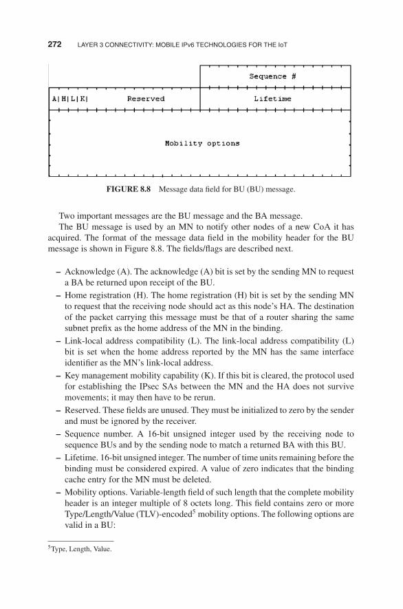
272 LAYER 3 CONNECTIVITY: MOBILE IPv6 TECHNOLOGIES FOR THE IoT
FIGURE 8.8 Message data field for BU (BU) message.
Two important messages are the BU message and the BA message.The BU message is used by an MN to notify other nodes of a new CoA it has
acquired. The format of the message data field in the mobility header for the BUmessage is shown in Figure 8.8. The fields/flags are described next.
– Acknowledge (A). The acknowledge (A) bit is set by the sending MN to requesta BA be returned upon receipt of the BU.
– Home registration (H). The home registration (H) bit is set by the sending MNto request that the receiving node should act as this node’s HA. The destinationof the packet carrying this message must be that of a router sharing the samesubnet prefix as the home address of the MN in the binding.
– Link-local address compatibility (L). The link-local address compatibility (L)bit is set when the home address reported by the MN has the same interfaceidentifier as the MN’s link-local address.
– Key management mobility capability (K). If this bit is cleared, the protocol usedfor establishing the IPsec SAs between the MN and the HA does not survivemovements; it may then have to be rerun.
– Reserved. These fields are unused. They must be initialized to zero by the senderand must be ignored by the receiver.
– Sequence number. A 16-bit unsigned integer used by the receiving node tosequence BUs and by the sending node to match a returned BA with this BU.
– Lifetime. 16-bit unsigned integer. The number of time units remaining before thebinding must be considered expired. A value of zero indicates that the bindingcache entry for the MN must be deleted.
– Mobility options. Variable-length field of such length that the complete mobilityheader is an integer multiple of 8 octets long. This field contains zero or moreType/Length/Value (TLV)-encoded5 mobility options. The following options arevalid in a BU:
5Type, Length, Value.

PROTOCOL DETAILS 273
Sequence
Status Reserved
Lifetime
Mobility options
| K |
number
FIGURE 8.9 Message data field for BA message.
� Binding authorization data option (this option is mandatory in BUs sent toa CN);
� Nonce indices option;� Alternate CoA option
The CoA is specified either by the source address field in the IPv6 header or by thealternate CoA option, if present. IPv6 source address must be a topologically correctsource address. BUs for a CoA that is not a unicast routable address must be silentlydiscarded. Similarly, the BU must be silently discarded if the CoA appears as a homeaddress in an existing binding cache entry, with its current location creating a circularreference back to the home address specified in the BU (possibly through additionalentries).The BA message is used to acknowledge the receipt of a BU. The format of the
message data field in the mobility header for the BA message is shown in Figure 8.9.The fields/flags are described next.
– Key management mobility capability (K). If this bit is cleared, the protocol usedby the HA for establishing the IPsec SAs between the MN and the HA does notsurvive movements (it may then have to be rerun).
– Reserved. These fields are unused. They must be initialized to zero by the senderand must be ignored by the receiver.
– Status. 8-bit unsigned integer indicating the disposition of the BU. Values ofthe status field less than 128 indicate that the BU was accepted by the receivingnode. Values greater than or equal to 128 indicate that the BU was rejected bythe receiving node. The following status values were originally defined:
0 BU accepted1 Accepted but prefix discovery necessary
128 Reason unspecified129 Administratively prohibited130 Insufficient resources

274 LAYER 3 CONNECTIVITY: MOBILE IPv6 TECHNOLOGIES FOR THE IoT
131 Home registration not supported132 Not home subnet133 Not HA for this MN134 Duplicate address detection failed135 Sequence number out of window136 Expired home nonce index137 Expired care-of nonce index138 Expired nonces139 Registration type change disallowed
– Sequence number. The sequence number in the BA is copied from the sequencenumber field in the BU. It is used by the MN in matching this BA with anoutstanding BU.
– Lifetime. The granted lifetime, in time units of 4 s, for which this node shouldretain the entry for this MN in its binding cache.
– Mobility options. Variable-length field of such length that the complete mobilityheader is an integer multiple of 8 octets long. This field contains zero or moreTLV-encoded mobility options. The receiver must ignore and skip any optionswhich it does not understand.
BUs and BAs follow the rules discussed in RFC 37766 (7) and summarized inTable 8.5.A CN registration involves six message transmissions at the MN, totaling about
376 bytes. This signaling overhead may be acceptable if movements are infrequent.For example, an MN that moves once every 30 min generates an average of 1.7 bpsof signaling traffic. Higher mobility causes more substantial overhead, however. Acell size of 100 m and a speed of 120 km/h yields a change in IP connectivity every3 s and about 1000 bps of signaling traffic. This is significant compared to a highlycompressed voice streamwith a typical data rate of 10,000 to 30,000 bps. Furthermore,base MIPv6 requires MNs to renew a correspondent registration at least every 7 min.The signaling overhead amounts to 7.16 bps if theMNcommunicateswith a stationarynode. It doubles if both peers are mobile. This overhead may be negligible when thenodes communicate, but it can be an issue for MNs that are inactive and stay at thesame location for a while because these MNs are typically designed to go to standbymode to conserve battery power. Also, the periodic refreshments consume a fractionof the wireless bandwidth that one could use more efficiently (3).
8.2.2.2 Mobility Options Mobility messages can include zero or more mobilityoptions. This allows optional fields that may not be needed in every use of a particularmobility header, as well as future extensions to the format of the messages. Suchoptions are included in the message data field of the message itself, after the fixedportion of the message data. The presence of such options is be indicated by theheader Len of the mobility header. See Figure 8.10.
6RFC 3776 has been updated in RFC 4877.

PROTOCOL DETAILS 275
TABLE 8.5 BUs and BAs
MN Status Message Description
MN is awayfrom its home
BUs When the MN is away from its home, the BUs sent by it to theHA must support at least the following headers in the followingorder:
IPv6 header (source = CoA, destination = HA)Destination options header
Home address option (home address)
ESP header in transport mode
Mobility header
BU
Alternate CoA option (CoA)
BAs The BA sent back to the MN when it is away from home mustsupport at least the following headers in the following order:
IPv6 header (source = HA, destination = CoA)Routing header (type 2)
Home address
ESP header in transport mode
Mobility header
BA
MN is at home BUs When the MN is at home, the above rules are different since theMN can use its home address as a source address; this typicallyhappens for the de-registration BU when the mobile isreturning home. Here the BUs must support at least thefollowing headers in the following order:
IPv6 header (source = home address, destination = HA)ESP header in transport mode
Mobility header
BU
BAs The BA messages sent to the home address must support atleast the following headers in the following order:
IPv6 header (source = HA, destination = home address)ESP header in transport mode
Mobility header
BA

276 LAYER 3 CONNECTIVITY: MOBILE IPv6 TECHNOLOGIES FOR THE IoT
FIGURE 8.10 Format of mobility options.
8.2.2.3 Home Address Option The home address option is carried by thedestination option extension header (next header value = 60). It is used in a packetsent by an MN while away from home, to inform the recipient of the MN’s homeaddress. See Figure 8.11.
8.2.2.4 Type 2 Routing Header MIPv6 defines a new routing header variant,the type 2 routing header, to allow the packet to be routed directly from a correspon-dent to the MN’s CoA. The MN’s CoA is inserted into the IPv6 destination addressfield. Once the packet arrives at the CoA, the MN retrieves its home address fromthe routing header; this address is used as the final destination address for the packet.The type 2 routing header is shown in Figure 8.12.The new routing header uses a different type than defined for “regular” IPv6
source routing, enabling firewalls to apply different rules to source routed packetsthan to MIPv6. This routing header type (type 2) is restricted to carry only one IPv6address. All IPv6 nodes that process this routing header must verify that the addresscontained within is the node’s own home address in order to prevent packets frombeing forwarded outside the node. The IP address contained in the routing headermustbe a unicast routable address, being that it is the MN’s home address. Furthermore,if the scope of the home address is smaller than the scope of the CoA, the MN mustdiscard the packet.
FIGURE 8.11 Format of home address option.

PROTOCOL DETAILS 277
8-bit selector. Identifies the type of header immediately following the routing header. Next header Uses the same values as the IPv6 next header field.
2 (8-bit unsigned integer); length of the routing header in 8-octet units, not including the Hdr ext Len first 8 octets.
2 (8-bit unsigned integer). Routing type
Segmentsleft
1 (8-bit unsigned integer).
32-bit reserved field. The value must be initialized to zero by the sender and must be Reserved ignored by the receiver.
Homeaddress
The home address of the destination mobile node.
FIGURE 8.12 Type 2 routing header.
8.2.3 Modifications to IPv6 Neighbor Discovery
Modifications to existing protocols are described herewith as described in RFC 3775.
8.2.3.1 Modified Router Advertisement Message MIPv6 modifies the for-mat of the router advertisement message by the addition of a single flag bit to indicatethat the router sending the advertisement message is serving as an HA on this link.
8.2.3.2 Modified Prefix Information Option MIPv6 requires knowledge ofa router’s global address in building an HA list as part of the dynamic HAADmechanism. MIPv6 extends neighbor discovery defined in RFC 2461 (8) to allow arouter to advertise its global address by the addition of a single flag bit in the formatof a prefix information option for use in router advertisement messages.
8.2.3.3 New Advertisement Interval Option MIPv6 defines a new advertise-ment interval option, used in router advertisement messages to advertise the intervalat which the sending router sends unsolicited multicast router advertisements.

278 LAYER 3 CONNECTIVITY: MOBILE IPv6 TECHNOLOGIES FOR THE IoT
8.2.3.4 New HA Information Option MIPv6 defines a new HA informationoption, used in router advertisements sent by an HA to advertise information specificto this router’s functionality as an HA.
8.2.3.5 Changes to Sending Router Advertisements The basic NDPspecification limits routers to a minimum interval of 3s between sending unso-licited multicast router advertisement messages from any given network interface(limited by MinRtrAdvInterval and MaxRtrAdvInterval). This limitation, however,is not suitable to providing timely movement detection for MNs. MNs detect theirown movement by learning the presence of new routers as the MN moves into wire-less transmission range of them (or physically connects to a new wired network),and by learning that previous routers are no longer reachable. MNs must be ableto quickly detect when they move to a link served by a new router, so that theycan acquire a new CoA and send BUs to register this CoA with their HA and tonotify CNs as needed. One method that can provide for faster movement detectionis to increase the rate at which unsolicited router advertisements are sent. MIPv6relaxes this limit such that routers may send unsolicited multicast router advertise-ments more frequently. This method can be applied where the router is expecting toprovide service to visiting MNs (e.g., wireless network interfaces), or on which it isserving as an HA to one or more MNs (who may return home and need to hear itsadvertisements).
8.2.4 Requirements for Various IPv6 Nodes
MIPv6 imposes specific requirements on the functions provided by different types ofIPv6 nodes (except for a generic IPv6 node acting as CN). These are summarized inTable 8.6.
8.2.5 Correspondent Node Operation
IPv6 nodeswith route optimization supportmustmaintain a binding cache of bindingsfor other nodes (as shown in Table 8.3); a separate Binding Cache is typicallymaintained by each IPv6 node for each of its unicast routable addresses. Specifically,CNs are required to support the following functionality:
� Processing mobility headers� Packet processing� Return-routability procedure� Processing bindings� Cache replacement policy
8.2.5.1 Processing Mobility Headers Mobility header processing followsthe process of Figure 8.13. Subsequent checks depend on the particular mobilityheader.

PROTOCOL DETAILS 279
TABLE 8.6 Requirements for Various IPv6 Nodes
Nodes Requirement
IPv6 nodes Any IPv6 node may at any time be a CN of an MN,either sending a packet to an MN or receiving apacket from an MN. There are no MIPv6-specificrequirements for such nodes and basic IPv6capabilities are sufficient. If an MN attempts to setup route optimization with a node with only basicIPv6 support, an ICMP error will signal that thenode does not support such optimizations andcommunications will flow through the HA
IPv6 nodes with support forroute optimization.Nodes that implement routeoptimization are a subset of allIPv6 nodes on the Internet.The ability of a CN toparticipate in routeoptimization is essential forthe efficient operation of theIPv6 environment
The node must be able to validate a home addressoption using an existing binding cache entry
The node must be able to insert a type 2 routing headerinto packets being sent to an MN
Unless the CN is also acting as an MN, it must ignoretype 2 routing headers and silently discard allpackets that it has received with such headers
The node should be able to interpret ICMP messages.The node must be able to send Binding Error messages.The node must be able to process Mobility Headers.The node must be able to participate in areturn-routability procedure.
The node must be able to process BU messages.The node must be able to return a BA.The node must be able to maintain a Binding Cache ofthe bindings received in accepted BUs.
The node should allow route optimization to beadministratively enabled or disabled. The defaultshould be enabled.
IPv6 routers. All IPv6 routers,even those not serving as anHA for MIPv6, have an effecton how well MNs cancommunicate
Every IPv6 router should be able to send anadvertisement interval option in each of its routeradvertisements, to aid movement detection by MNs.The use of this option in router advertisementsshould be configurable
Every IPv6 router should be able to support sendingunsolicited multicast router advertisements at a fastrate (the used rate should then be configurable)
Each router should include at least one prefix with therouter address (R) bit set and with its full IP addressin its router advertisements
Routers supporting filtering packets with routingheaders should support different rules for type 0 andtype 2 routing headers so that filtering of sourcerouted packets (type 0) will not necessarily limitMIPv6 traffic which is delivered via type 2 routingheaders
(continued )

280 LAYER 3 CONNECTIVITY: MOBILE IPv6 TECHNOLOGIES FOR THE IoT
TABLE 8.6 (Continued)
Nodes Requirement
IPv6 routers that serve as anHA.In order for an MN tooperate correctly while awayfrom home, at least one IPv6router on the MN’s homelink must function as an HAfor the MN
Every HA must be able to maintain an entry in its bindingcache for each MN for which it is serving as the HA
Every HA must be able to intercept packets (using proxyneighbor discovery) addressed to an MN for which it iscurrently serving as the HA, on that MN’s home link,while the MN is away from home
Every HA must be able to encapsulate such interceptedpackets in order to tunnel them to the primary CoA forthe MN indicated in its binding in the HA’s bindingcache
Every HA must support decapsulating reverse tunneledpackets sent to it from an MN’s home address. EveryHA must also check that the source address in thetunneled packets corresponds to the currentlyregistered location of the MN
The node must be able to process mobility headers.Every HA must be able to return a BA in response to a BUEvery HA must maintain a separate HA list for each linkon which it is serving as an HA
Every HA must be able to accept packets addressed to theMIPv6 HA anycast address for the subnet on which itis serving as an HA and must be able to participate indynamic HAAD
Every HA should support a configuration mechanism toallow a system administrator to manually set the valueto be sent by this HA in the HA preference field of theHA information option in router advertisements that itsends
Every HA should support sending ICMP mobile prefixadvertisements and should respond to mobile prefixsolicitations. If supported, this behavior must beconfigurable, so that HAs can be configured to avoidsending such prefix advertisements according to theneeds of the network administration in the homedomain
Every HA must support IPsec encapsulating securitypayload (ESP) for protection of packets belonging tothe return-routability procedure
Every HA should support the multicast groupmembership control protocols. If this support isprovided, the HA must be capable of using it todetermine which multicast data packets to forward viathe tunnel to the MN
HAs may support stateful address autoconfiguration forMNs

PROTOCOL DETAILS 281
TABLE 8.6 (Continued)
Nodes Requirement
IPv6 MNs The node must maintain a BU listThe node must support sending packets containing a home address optionand follow the required IPsec interaction
The node must be able to perform IPv6 encapsulation and decapsulationThe node must be able to process type 2 routing headerThe node must support receiving a binding error messageThe node must support receiving ICMP errorsThe node must support movement detection, CoA formation, andreturning home
The node must be able to process mobility headersThe node must support the return-routability procedureThe node must be able to send BUsThe node must be able to receive and process BAsThe node must support receiving a BRR by responding with a BUThe node must support receiving mobile prefix advertisements andreconfiguring its home address based on the prefix informationcontained therein
The node should support use of the dynamic HAAD mechanismThe node must allow route optimization to be administratively enabled ordisabled. The default should be enabled
The node may support the multicast address listener part of a multicastgroup membership protocol. If this support is provided, the MN mustbe able to receive tunneled multicast packets from the HA
The node may support stateful address autoconfiguration mechanismssuch as dynamic host configuration protocol version 6 (DHCPv6) onthe interface represented by the tunnel to the HA
8.2.5.2 Packet Processing Packet processing covers the following subactivi-ties:
� Receiving packets with home address option� Sending packets to an MN� Sending binding error messages� Receiving ICMP error messages
These subactivities are described next.Receiving packets with home address option. The CN must process the option in
a manner consistent with exchanging the home address field from the home addressoption into the IPv6 header and replacing the original value of the source addressfield there. After all IPv6 options have been processed, the upper layers can processthe packet without the knowledge that it came originally from a CoA or that a homeaddress option was used.Packets containing a home address option must be dropped if the given home
address is not a unicast routable address. MNs can include a home address destination

282 LAYER 3 CONNECTIVITY: MOBILE IPv6 TECHNOLOGIES FOR THE IoT
Header Checksum Successful?
MH Type is a known value?
Is the Payload Proto field = 59
(decimal)?
Is Header length correct?
yes
no
yes
yes
no
no
no
Discard Message
Discard Message & Issue Binding Error Message
Discard Message & Issue ICMP Parameter Problem Message
Discard Message & Issue ICMP Parameter Problem Message
Start
End
FIGURE 8.13 Mobility header processing.

PROTOCOL DETAILS 283
option in a packet if they believe theCNhas a binding cache entry for the home addressof an MN. Packets containing a home address option must be dropped if there is nocorresponding binding cache entry. A corresponding binding cache entry must havethe same home address as appears in the home address destination option, and thecurrently registered CoA must be equal to the source address of the packet. Theseactions are not done for packets that contain a home address option and a BU. Ifthe packet is dropped due to these conditions, the CN must send the binding errormessage.
Sending packets to an MN. Before sending any packet (except when sending anIPv6 neighbor discovery packet), the sending node should examine its binding cachefor an entry for the destination address to which the packet is being sent. If the sendingnode has a binding cache entry for this address, the sending node should use a type2 routing header to route the packet to this MN (the destination node) by way of itsCoA. For example, if there are no additional routing headers in this packet beyondthose needed by MIPv6, the CN could set the fields in the packet’s IPv6 header androuting header as follows:
� The destination address in the packet’s IPv6 header is set to the MN’shome address (the original destination address to which the packet was beingsent).
� The routing header is initialized to contain a single route segment, containingthe MN’s CoA copied from the binding cache entry. The segments left field is,however, temporarily set to zero.
If, on the other hand, the sending node has no binding cache entry for the desti-nation address to which the packet is being sent, the sending node simply sends thepacket normally, with no routing header. If the destination node is not anMN (or is anMN that is currently at home), the packet will be delivered directly to this node andprocessed normally by it. If, however, the destination node is an MN that is currentlyaway from home, the packet will be intercepted by the MN’s HA and tunneled to theMN’s current primary CoA.
Sending binding error messages. A binding error message is sent directly tothe address that appeared in the IPv6 source address field of the offending packet(if the source address field does not contain a unicast address, the binding errormessage must not be sent). The home address field in the binding error message iscopied from the home address field in the home address destination option of theoffending packet, or set to the unspecified address if no such option appeared in thepacket.
Receiving ICMP error messages. When the CN has a binding cache entry for anMN, all traffic destined to the MN goes directly to the current CoA of the MN using arouting header. Any ICMP error message caused by packets on their way to the CoAwill be returned in the normal manner to the CN. On the other hand, if the CN has nobinding cache entry for the MN, the packet will be routed through the MN’s homelink. In all cases, any meaningful ICMP error messages caused by packets from a CNto an MN will be returned to the CN.

284 LAYER 3 CONNECTIVITY: MOBILE IPv6 TECHNOLOGIES FOR THE IoT
TABLE 8.7 Return-Routability Actions of the CN
Action Description
Receiving HoTimessages
Upon receiving a HoTi message, the CN verifies that the packet doesnot include a home address destination option. Any packet carryinga HoTi message that fails to satisfy all of these tests must be silentlyignored. Otherwise, in preparation for sending the correspondingHoT message, the CN checks that it has the necessary material toengage in a return-routability procedure. The CN must have asecret Kcn and a nonce; it does not have this material yet, it mustproduce it before continuing with the return-routability procedure
Receiving care-oftest init messages
Upon receiving a HoTi message, the CN verifies that the packet doesnot include a home address destination option. Any packet carryinga care-of test init message that fails to satisfy all of these tests mustbe silently ignored. Otherwise, in preparation for sending thecorresponding care-of test message, the CN checks that it has thenecessary material to engage in a return-routability procedure
Sending HoTmessages
The CN creates a home keygen token and uses the current nonceindex as the home nonce index; it then creates a HoT message andsends it to the MN at the latter’s home address
Sending care-of testmessages
The CN creates a care-of keygen token and uses the current nonceindex as the care-of nonce index; it then creates a care-of testmessage and sends it to the MN at the latter’s CoA
8.2.5.3 Return-Routability Procedure Actions taken by a CN during thereturn-routability procedure are listed in Table 8.7.
8.2.5.4 Processing Bindings Messages related to bindings are as follows:
� Receiving BUs. Before accepting a BU, the receiving node must validate theBU. This validation entails the following: the packet must contain a unicastroutable home address, either in the home address option or in the sourceaddress if the home address option is not present; also, the sequence numberfield in the BU is greater than the sequence number received in the previousvalid BU for this home address, if any (if the receiving node has no BINDINGCACHE entry for the indicated home address, it must accept any sequencenumber value in a received BU from this MN); also, other tests must pass.
� Requests to cache a binding. There is a need to process a valid BU that requestsa node to cache a binding, for which the home registration (H) bit is not set inthe BU. In this case, the receiving node should create a new entry in its bindingcache for this home address, or update its existing binding cache entry for thishome address, if such an entry already exists. The lifetime for the binding cacheentry is initialized from the lifetime field specified in the BU, although thislifetime may be reduced by the node caching the binding; the lifetime for thebinding cache entry cannot be greater than the lifetime value specified in the

PROTOCOL DETAILS 285
BU. Any binding cache entry must be deleted after the expiration of its lifetime.The CN may refuse to accept a new binding cache entry if it does not havesufficient resources.
� Requests to delete a binding. There is a need to process a valid BU that requestsa node to delete a binding when the home registration (H) bit is not set in the BU.Any existing binding for the given home address must be deleted. A bindingcache entry for the home address must not be created in response to receivingthe BU. If the binding cache entry was created by use of return-routabilitynonces, the CN must ensure that the same nonces are not used again with theparticular home and CoA. If both nonces are still valid, the CN has to rememberthe particular combination of nonce indexes, addresses, and sequence numberas illegal until at least one of the nonces has become too old.
� Sending BAs. A BAmay be sent to indicate receipt of a BU. If the node acceptsthe BU and creates or updates an entry for this binding, the status field in theBA must be set to a value less than 128. Otherwise, the status field must be setto a value greater than or equal to 128.
� Sending binding refresh requests (BRRs). If a binding cache entry beingdeleted is still in active use when sending packets to an MN, then the nextpacket sent to the MN will be routed normally to the MN’s home link. Com-munication with the MN continues, but the tunneling from the home networkcreates additional overhead and latency in delivering packets to the MN. If thesender is aware that the binding cache entry is still in active use, it may send aBRRmessage to the MN in an attempt to avoid this overhead and latency due todeleting and recreating the binding cache entry. This message is always sent tothe home address of the MN. The CN may retransmit BRR messages as long asthe rate limitation is applied. The CN must stop retransmitting when it receivesa BU.
8.2.5.5 Cache Replacement Policy A node may maintain a separate timerfor each entry in its binding cache. When creating or updating a binding cache entryin response to a received and accepted BU, the node sets the timer for this entry tothe specified lifetime period; entries in a node’s binding cache are deleted after theexpiration of the lifetime specified in the BU from which the entry was created or lastupdated. A node may also opt to drop any entry already in its binding cache in orderto make space for a new entry. If the node sends a packet to a destination for whichit has dropped the entry from its binding cache, the packet will be routed through theMN’s home link; the MN can detect this and establish a new binding if necessary.
8.2.6 HA Node Operation
HA operations entail the following functions:
� Maintaining the binding cache and the HA list� Processing mobility headers

286 LAYER 3 CONNECTIVITY: MOBILE IPv6 TECHNOLOGIES FOR THE IoT
� Processing bindings◦ Primary CoA registration◦ Primary CoA de-registration
� Packet processing◦ Intercepting packets for an MN◦ Processing intercepted packets◦ Multicast membership control◦ Stateful Address autoconfiguration◦ Handling reverse tunneled packets◦ Protecting return-routability packets
� Dynamic HAAD� Sending prefix information to the MN
We have generally described this (or comparable) functionality earlier in thischapter; hence we will not discuss it further herewith.
8.2.7 Mobile Node Operation
MN operations entail the following functions:
� Maintaining the BU list� Processing bindings
◦ Sending BUs to the HA◦ Correspondent registration◦ Receiving BAs◦ Receiving BRRs
� Processing mobility headers� Packet processing
◦ Sending packets while away from home◦ Interaction with outbound IPsec processing◦ Receiving packets while away from home◦ Routing multicast packets◦ Receiving ICMP error messages◦ Receiving binding error messages
� HA and prefix management◦ Dynamic HAAD◦ Sending mobile prefix solicitations◦ Receiving mobile prefix advertisements
� Movement support◦ Movement detection

PROTOCOL DETAILS 287
◦ Forming new CoA◦ Using multiple CoA◦ Returning home
� Return-routability procedure◦ Sending test init messages◦ Receiving test messages◦ Protecting return-routability packets
� Retransmissions and rate limiting
The BU list records information for each BU sent by thisMN, in which the lifetimeof the binding has not yet expired. The BU list includes all bindings sent by the MNeither to its HA or to remote CNs; it also contains BUs which are waiting for thecompletion of the return-routability procedure before they can be sent. However,for multiple BUs sent to the same destination address, the BU list contains onlythe most recent BU (i.e., with the greatest sequence number value) sent to thatdestination.Other aspects of the MN operations are covered next; however, only some key
highlights are covered here; for additional details, consult RFC 3775 (2).
8.2.7.1 Packet Processing For packets sent by an MN while it is at home, nospecial MIPv6 processing is required.While an MN is away from home, it can continue to use its home address or it
can use one or more CoAs as the source of the packet (thus eliminating the use ofa home address option in the packet.) Using the MN’s CoA as the source generallyhas a lower overhead than using the MN’s home address, given that no extra optionsneed be used. Such packets can be routed normally, that is, directly between theirsource and destination without relying on MIPv6 mechanisms. Summarizing this,if the MN uses an address other than one of its home addresses as the source ofa packet sent while away from home, no special MIPv6 processing is required:packets are simply addressed and transmitted in the same way as any normal IPv6packet.For packets sent by the MN while away from home using the MN’s home address
as the source, MIPv6 processing of the packet is required. As we noted, this can bedone in one of two ways:
� Route optimization: This approach to the delivery of packets does not requiregoing through the home network, and such, typically enables faster and morereliable transmission. The MN needs to ensure that a binding cache entry existsfor its home address so that the CN can process the packet. An MN shouldarrange to supply the home address in a home address option and must set theIPv6 header’s source address field to the CoA which the MN has registered tobe used with this CN. The CN will then use the address supplied in the homeaddress option to serve the function traditionally done by the source IP address

288 LAYER 3 CONNECTIVITY: MOBILE IPv6 TECHNOLOGIES FOR THE IoT
in the IPv6 header. The MN’s home address is then supplied to higher protocollayers and applications.
� Reverse tunneling. This is the mechanism that tunnels the packets via the HA,being needed if there is no binding yet with the CN; as such, it is not as efficientas the route optimization mechanism. This mechanism is used for packets thathave the MN’s home address as the source address in the IPv6 header, or withmulticast control protocol. The process is as follows: (i) the packet is sent tothe HA using IPv6 encapsulation; (ii) the source address in the tunnel packetis the primary CoA as registered with the HA; (iii) the destination address inthe tunnel packet is the HA’s address. Then, the HA will pass the encapsulatedpacket to the CN.
During packet processing, there will be an interaction between outbound MIPv6processing and outbound IPsec processing for packets sent by an MN while awayfrom home. This interaction is shown in Figure 8.14; in Figure 8.14, it is assumed thatIPsec is being used in transport mode and that theMN is using its home address as thesource for the packet. Note that the treatment of destination options (in RFC 2402)is extended as follows: the authentication header (AH) authentication data must becalculated as if the following were true: (i) the IPv6 source address in the IPv6 headercontains the MN’s home address; (ii) the home address field of the home addressdestination option contains the new CoA.While away from home, anMNwill receive packets addressed to its home address,
by one of two methods:
� Packets sent by a CN, which does not have a binding cache entry for the MN,will be sent to the home address, captured by the HA, and tunneled to the MN.Here the MN must check that the IPv6 source address of the tunneled packetis the IP address of its HA. In this method, the MN may also send a BU to theoriginal sender of the packet and subject to rate-limiting processes. TheMNmustalso process the received packet in the manner defined for IPv6 encapsulation,which will result in the encapsulated (inner) packet being processed normallyby upper-layer protocols within the MN as if it had been addressed (only) to theMN’s home address.
� Packets sent by a CN that has a binding cache entry for the MN that containsthe MN’s current CoA will be sent by the CN using a type 2 routing header.The packet will be addressed to the MN’s CoA, with the final hop in the routingheader directing the packet to the MN’s home address; the processing of thislast hop of the routing header is entirely internal to the MN, since the CoA andhome address are both addresses within the MN.
8.2.7.2 Home Agent Address Discovery Sometimes when the MN needs tosend a BU to its HA to register its new primary CoA, the MN may not know theaddress of any router on its home link that can serve as an HA for it. In this case, theMN may attempt to discover the address of a suitable HA on its home link. To do so,

PROTOCOL DETAILS 289
The packet is created by higher- layer protocols and applications as if
the MNs were at home and MIPv6 were not being used
Determine the outgoing interface for the packet
As part of outbound packet processing, the packet is compared
against the IPsec security policy database to determine what
processing is required for the packet
If IPsec processing is required, the packet is either mapped to an
existing Security Association (or SA bundle), or a new SA (or SA bundle) is created for the packet, according to the procedures defined for IPsec
Since the MN is away from home,
it is either using reverse tunnelingor route optimization to
reach the CN
The packet is constructed in the normal manner and then tunneled
through the HA
The MN inserts a home address destination option into the packet,
replacing the source address in the packet's IP header with the CoA
used with this correspondent node
route optimizationreverse tunneling
The destination options header in which the home address destination option is inserted appears in the packet after the routing header, if present, and before the IPsec (AH or ESP)
header, so that the home address destination option is processed by the destination node before the IPsec header
is processed
The packet is fully assembled andthe necessary IPsec authentication
(and encryption, if required) processing is performed on the
packet, initializing the Authentication Data in the IPsec header
FIGURE 8.14 Interaction with outbound IPsec processing.
the MN sends an ICMP HAAD request message to the MIPv6 HA anycast addressfor its home subnet prefix. The HA on its home link that receives this request messagewill return an ICMP HAAD reply message. This message gives the addresses for theHAs operating on the home link. TheMN, upon receiving this HAAD reply message,may then send its home registration BU to any of the unicast IP addresses listed inthe HA addresses field in the reply.

290 LAYER 3 CONNECTIVITY: MOBILE IPv6 TECHNOLOGIES FOR THE IoT
8.2.7.3 Movement Support The goal of movement detection is to detect Layer3 handovers.While full-function roamingmechanismsmight be useful in this context,as a minimum, one needs some generic method of detecting handoffs. Methods thatmake use of the facilities of IPv6 neighbor discovery, including router discoveryand neighbor unreachability detection, may be of interest. Table 8.8 depicts somemechanisms for movement support. Due to the temporary packet flow disruption andsignaling overhead involved in updating mobility bindings, the MN should avoidperforming an L3 handover until it is strictly necessary.
TABLE 8.8 Basic Mechanisms for Movement Support
Activity Description
Movementdetection
Generic movement detection can use neighbor unreachabilitydetection to detect when the default router is no longerbidirectionally reachable, in which case the MN must discover anew default router. However, this detection only occurs whenthe MN has packets to send, and in the absence of frequentrouter advertisements or indications from the link layer, the MNmight become unaware of an L3 handover that occurred. Hence,the MN should supplement this method with other informationwhenever it is available to the MN (e.g., from lower protocollayers)
When the MN detects an L3 handover, it selects a new defaultrouter as a consequence of router discovery and then performsprefix discovery with that new router to form new CoA(es). Itthen registers its new primary CoA with its HA. After updatingits home registration, the MN then updates associated mobilitybindings in CNs that it is performing route optimization
Forming newCoA
After detecting that it has moved an MN is expected to generate anew primary CoA using normal IPv6 mechanisms. This shouldalso be done when the current primary CoA becomes deprecated
After selecting a new primary CoA, the MN must send a BUcontaining that CoA to its HA. The BU must have the homeregistration (H) and acknowledge (A) bits set its HA. In order toform a new CoA, an MN may use either stateless or stateful(e.g., DHCPv6) address autoconfiguration
Using multipleCoAs
An MN may use more than one CoA at a time. To assist withsmooth handovers, an MN should retain its previous primaryCoA as a (non-primary) CoA and should still accept packets atthis address, even after registering its new primary CoA with itsHA
Whenever an MN determines that it is no longer reachable througha given link, it should invalidate all CoAs associated withaddress prefixes that it discovered from routers on theunreachable link which are not in the current set of addressprefixes advertised by the (possibly new) current default router

PROTOCOL DETAILS 291
8.2.8 Relationship to IPV4 Mobile IPv4 (MIP)
A question might be “what is the relationship of MIPv6 to IPV4 MIPv4 defined inRFC 3344 (9)?” RFC 3775 (2) notes that the design of MIPv6 benefits both fromthe experiences gained from the development of MIP and also from the opportunitiesprovided by IPv6. Therefore, MIPv6 shares many features with MIP, but is integratedinto IPv6 and offers other improvements. The notable differences between MIP andMIPv6 are as follows:
– There is no need to deploy special routers as “foreign agents,” as in MIP. MIPv6operates in any location without any special support required from the localrouter.
– Support for route optimization is a fundamental part of the protocol, rather thana nonstandard set of extensions.
– MIPv6 route optimization can operate securely even without prearranged SAs.It is expected that route optimization can be deployed on a global scale betweenall MNs and CNs.
– Support is also integrated into MIPv6 for allowing route optimization to coexistefficiently with routers that perform “ingress filtering.”
– The IPv6 neighbor unreachability detection assures symmetric reachabilitybetween the MN and its default router in the current location.
– Most packets sent to an MN while away from home in MIPv6 are sent usingan IPv6 routing header rather than IP encapsulation, reducing the amount ofresulting overhead compared to MIP.
– MIPv6 is decoupled from any particular link layer, as it uses IPv6 neighbordiscovery instead of Address Resolution Protocol (ARP); this also improves therobustness of the protocol.
– The use of IPv6 encapsulation (and the routing header) removes the need inMIPv6 to manage “tunnel soft state.”
– The dynamic HAAD mechanism in MIPv6 returns a single reply to the MN.The directed broadcast approach used in IPv4 returns separate replies fromeach HA.
MIPv6offers a number of improvements overMIPv4principally due to capabilitiesinherited from IPv6. For example, route optimization and dynamic HA discovery canonly be achieved with MIPv6. One of the advantages of the large address spaceprovided by IPv6 is that it allows MNs to obtain a globally unique CoA whereverthey are; therefore, there is no need for network address translator (NAT) traversaltechniques designed for MIPv4. This allows MIPv6 to be a significantly simpler andmore bandwidth-efficient mobility management protocol. At the same time, duringthe transition toward IPv6, NAT traversal for existing private IPv4 networks needs tobe considered (10).
292 LAYER 3 CONNECTIVITY: MOBILE IPv6 TECHNOLOGIES FOR THE IoT
REFERENCES
1. Minoli D. Mobile Video with Mobile IPv6. New York: Wiley; 2012.
2. Johnson D, Perkins C, Arkko J. Mobility Support in IPv6. RFC 3775, June 2004.
3. Arkko J, Vogt C, Haddad W. Enhanced Route Optimization for Mobile IPv6. RFC 4866,May 2007.
4. Korhonen J, editor. Bournelle J, Giaretta G, NakhjiriM. Diameter Mobile IPv6: Supportfor Home Agent to Diameter Server Interaction. February 2010, RFC 5778.
5. 6deploy.org. IPv6 Workshop – IPv6 Mobility Module. October 2008.
6. Giaretta G, Devarapalli V. Mobile IPv6 Bootstrapping in Split Scenario, RFC 5026,October 2007.
7. Arkko J, Devarapalli V, Dupont F. Using IPsec to Protect Mobile IPv6 Signaling BetweenMobile Nodes and Home Agents. RFC 3776, June 2004.
8. Narten T, Nordmark E, Simpson W. Neighbor Discovery for IP Version 6 (IPv6). RFC2461, December 1998.
9. Perkins C. editor. IP Mobility Support for IPv4. RFC 3344, August 2002.
10. Soliman H, editor. Mobile IPv6 Support for Dual Stack Hosts and Routers. RFC 5555,June 2009.

CHAPTER 9
IPv6 OVER LOW-POWER WPAN(6LoWPAN)
As we have seen at various points in this text, most (but certainly not all) IoT/M2Mnodes have noteworthy design constraints. Developers make the case that the IEEE802.15.4-2003 standard is very promising for the lower (physical and link) layers.As for higher layer functions, the goal is to utilize IP technology, specifically IPv6,considering the v6 capabilities and benefits described in Chapter 7. To that end, anIETFWorkingGroup (WG)was chartered in 2005 to define IPv6 over IEEE 802.15.4,that is to say, IPv6 over low-power WPANs; the outcome is known as 6LoWPAN.Two initial deliverables were generated in 2007: (i) problem statement (“Goals andAssumptions”) and (ii) format specification (“IPv6 over 802.15.4”). 6LoWPAN isnow a widely accepted approach to run IP on 802.15.4 based on the just cited formatspecification. It is already supported in TinyOS, Contiki, and in standards such as ISASP 100, ZigBee Smart Energy (SE) 2.0, and the IEEE 1451.5 standard for wirelesstransducers. The basic RFC makes 802.15.4 look like an IPv6 link; it provides basicencapsulation and efficient representation of packets smaller than 100 octets. Somehighlights of this work are provided in this chapter. The material is abstracted andsynthesized from the basic RFCs. The reader is referred to the original material for amore detailed description of the specifications.
Building the Internet of Things with IPv6 and MIPv6: The Evolving World of M2M Communications,First Edition. Daniel Minoli.© 2013 John Wiley & Sons, Inc. Published 2013 by John Wiley & Sons, Inc.
293
294 IPv6 OVER LOW-POWER WPAN (6LoWPAN)
9.1 BACKGROUND/INTRODUCTION
The requirement for IPv6 connectivity in a LoWPAN is driven by the following (1):
� The many devices in a LoWPAN make network autoconfiguration and state-lessness highly desirable; as we have seen, IPv6 offers ready solutions;
� The large number of devices poses the need for a large address space, well metby IPv6;
� Given the limited packet size of LoWPANs, the IPv6 address format allowssubsuming of IEEE 802.15.4 addresses, if so desired;
� Given the limited packet size, headers for IPv6 and layers above must becompressed whenever possible; and
� Simple interconnectivity of the LoWPANs to other IP networks including theInternet.
The WG has completed two RFCs: (i) “IPv6 over Low-Power Wireless Per-sonal Area Networks (6LoWPANs): Overview, Assumptions, Problem Statement, andGoals” (RFC 4919) that documents and discusses the problem space, and (ii) “Trans-mission of IPv6 Packets over IEEE 802.15.4 Networks” (RFC 4944) that defines theformat for the adaptation between IPv6 and 802.15.4. 6LoWPAN has also workedclosely with the routing over low-power and lossy networks (LLNs) (roll)WG, whichis developing IPv6 routing solutions for LLNs. See Table 9.1 for a detailed listing ofthe 6LoWPAN family of documents and specifications.Recent additional work items of the WG include the following (2):
1. Produce “6LoWPAN Bootstrapping and 6LoWPAN IPv6 ND Optimizations”to define limited extensions to IPv6 neighbor discovery (RFC 4861) for usespecifically in low-power networks. This document defines how to bootstrap a6LoWPAN network and explore ND optimizations such as reusing the structureof the 802.15.4 network (e.g., by using the coordinators) and reduce the needfor multicast by having devices talk to coordinators (without creating a singlepoint of failure or changing the semantics of the IPv6 ND multicasts).
2. Produce “6LoWPAN Improved Header Compression” to describe mechanismsto allow enhancements to the 6LoWPAN headers. Specifically, this documentdescribes the compression of addresses that are not link local. Additionally,the document may include other enhancements or optimizations of the HC1 orHC2 6LoWPAN headers.
3. Produce “6LoWPAN Architecture” to describe the design and implementationof 6LoWPAN networks. This document covers the concepts of “Mesh Under”and “Route Over,” 802.15.4 design issues such as operation with sleepingnodes, network components (both battery and line powered), addressing, andIPv4/IPv6 network connections.

BACKGROUND/INTRODUCTION 295
TABLE 9.1 6LoWPAN Family of Documents and Specifications
Title Date Status
Active Internet Drafts
draft-ietf-6LoWPAN-btle-11
Transmission of IPv6 packetsover Bluetooth low energy
2012-10-12 IESG evaluation:AD follow-up(for 106 days)
Submitted toIESG forpublication
RFCs
RFC 4919 (draft-ietf-6LoWPAN-problem)
IPv6 over Low-Power WirelessPersonal Area Networks(6LoWPANs): Overview,Assumptions, ProblemStatement, and Goals
2007-08 RFC 4919(informational)errata
RFC 4944 (draft-ietf-6LoWPAN-format)
Transmission of IPv6 packetsover IEEE 802.15.4 networks
2007-09 RFC 4944(proposedstandard)updated byRFC 6282, RFC6775
RFC 6282 (draft-ietf-6LoWPAN-hc)
Compression format for IPv6datagrams over IEEE802.15.4-based networks
2011-09 RFC 6282(proposedstandard)
RFC 6568 (draft-ietf-6LoWPAN-usecases)
Design and Application Spacesfor IPv6 over Low-PowerWireless Personal AreaNetworks (6LoWPANs)
2012-04 RFC 6568(informational)
RFC 6606 (draft-ietf-6LoWPAN-routing-requirements)
Problem Statement andRequirements for IPv6 overLow-Power Wireless PersonalArea Network (6LoWPAN)Routing
2012-05 RFC 6606(informational)
RFC 6775 (draft-ietf-6LoWPAN-nd)
Neighbor DiscoveryOptimization for IPv6 overLow-Power Wireless PersonalArea Networks (6LoWPANs)
2012-11 (new) RFC 6775(proposedstandard)
Related Documents/Active Internet Drafts
draft-bormann-6LoWPAN-ghc-05
6LoWPAN Generic Compressionof Headers and Header-likePayloads
2012-09-06 I-D exists
draft-bormann-6LoWPAN-roadmap-03
6LoWPAN Roadmap andImplementation Guide
2012-10-22 I-D exists
draft-schoenw-6LoWPAN-mib-01
Definition of Managed Objectsfor IPv6 over Low-PowerWireless Personal AreaNetworks (6LoWPANs)

296 IPv6 OVER LOW-POWER WPAN (6LoWPAN)
4. As a separate Internet Draft, “6LoWPAN Routing Requirements” is aimedat describing 6LoWPAN-specific requirements on routing protocols used in6LoWPANs, addressing both the “route-over” and “mesh-under” approach.
5. Produce “Use Cases for 6LoWPAN” to define, for a small set of applicationswith sufficiently unique requirements, how6LoWPANs can solve those require-ments, and which protocols and configuration variants can be used for thesescenarios. The use cases will cover protocols for transport, application layer,discovery, configuration, and commissioning.
6. Produce “6LoWPAN Security Analysis” to define the threat model of 6LoW-PANs, to document the suitability of existing key management schemes, andto discuss bootstrapping/installation/commissioning/setup issues.
9.2 6LoWPANS GOALS
LoWPANs1 in general and IEEE 802.15.4-2003-based systems in particular havedesign constraints that need to be taken into consideration when developing a protocolstack. These constraints fall into two categories:
� Communication constraints defined by the underlying personal area network(PAN):◦ Small packet size. Given that themaximum physical layer packet is 127 bytes,the resulting maximum frame size at the media access control layer is 102octets. Link-layer security imposes further overhead, leaving 81 octets for datapackets. Adding all layers for IP connectivity should still allow transmissionin one frame, without incurring excessive fragmentation and reassembly.Furthermore “control/protocol packets” fit within a single 802.15.4 frame;
◦ Support for both 16-bit short or IEEE 64-bit extended media access controladdresses;
◦ Low bandwidth. Data rates of 250 Kbps, 40 Kbps, and 20 Kbps for eachof the currently defined physical layers (2.4 GHz, 915 MHz, and 868 MHz,respectively);
◦ Topologies include star and mesh operation;◦ Other issues to address include limited configuration and management capa-bilities, need for service discovery, and need for security (confidentiality andintegrity protection).
� System constraints driven by the intended application parameters:◦ Characteristic examples include low/battery power, low cost, low processingcapabilities, small memory size, large population of devices, ad-hoc loca-tions/logical topology, mobility, and unreliable nodal behaviors (e.g., due touncertain radio connectivity, interference, sleep state, battery drain, device,etc.)
1This discussion is summarized and synthesized from Reference 1.

TRANSMISSION OF IPv6 PACKETS OVER IEEE 802.15.4 297
While many LoWPAN devices in a network are expected to have limited function-ality (the “reduced function devices” or RFDs discussed in Chapter 6), other, morecapable “full function devices” (FFDs) will also be present in the network. FFDsare expected to “aid” RFDs by providing functions such as network coordination,packet forwarding, interfacing with other types of networks, and so on. LoWPANsmust support various topologies including mesh and star. Mesh topologies implymultihop routing to a desired destination. In this case, intermediate devices act aspacket forwarders at the link layer (akin to routers at the network layer). Typically,these are “FFDs” that have more capabilities in terms of power, computation, etc.The requirements on the routing protocol are:
� Given the minimal packet size of LoWPANs, the routing protocol must imposelow (or no) overhead on data packets.
� The routing protocols should have low routing overhead (low chattiness) bal-anced with topology changes and power conservation.
� The computation and memory requirements in the routing protocol should beminimal to satisfy the low-cost and low-power objectives. Thus, storage andmaintenance of large routing tables is detrimental.
� Support for network topologies in which either FFDs or RFDs may be batteryor mains powered. This implies the appropriate considerations for routing inthe presence of sleeping nodes.
Table 9.2 summarizes IP Protocol considerations for LoWPANs as defined in RFC4919.
9.3 TRANSMISSION OF IPv6 PACKETS OVER IEEE 802.15.4
RFC 49442 describes the frame format for transmission of IPv6 packets and themethod of forming IPv6 link-local addresses and statelessly autoconfigured addresseson IEEE 802.15.4 networks. Additional specifications include a simple header com-pression scheme using shared context and provisions for packet delivery in IEEE802.15.4 meshes.IEEE 802.15.4 defines four types of frames: beacon frames, MAC command
frames, acknowledgement frames, and data frames, as noted in Chapter 6. IPv6packets must be carried on data frames. Data frames may optionally request that theybe acknowledged. IPv6 packetswill be carried in frames forwhich acknowledgementsare requested so as to aid link-layer recovery. IEEE 802.15.4 networks can either benonbeacon enabled or beacon enabled. 6LoWPAN (RFC 4944) does not requirethat IEEE networks run in beacon-enabled mode. In nonbeacon-enabled networks,data frames (including those carrying IPv6 packets) are sent via the contention-based channel access method of unslotted Carrier Sense Multiple Access/CollisionAvoidance (CSMA/CA). In nonbeacon-enabled networks, beacons are not used for
2This discussion is summarized and synthesized from Reference 3.
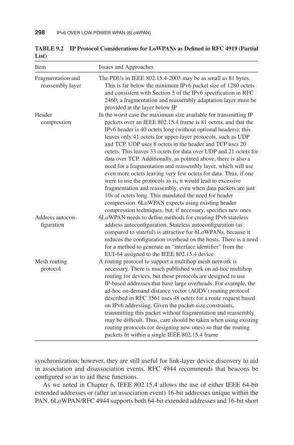
298 IPv6 OVER LOW-POWER WPAN (6LoWPAN)
TABLE 9.2 IP Protocol Considerations for LoWPANs as Defined in RFC 4919 (PartialList)
Item Issues and Approaches
Fragmentation andreassembly layer
The PDUs in IEEE 802.15.4-2003 may be as small as 81 bytes.This is far below the minimum IPv6 packet size of 1280 octetsand consistent with Section 5 of the IPv6 specification in RFC2460; a fragmentation and reassembly adaptation layer must beprovided at the layer below IP
Headercompression
In the worst case the maximum size available for transmitting IPpackets over an IEEE 802.15.4 frame is 81 octets, and that theIPv6 header is 40 octets long (without optional headers); thisleaves only 41 octets for upper-layer protocols, such as UDPand TCP. UDP uses 8 octets in the header and TCP uses 20octets. This leaves 33 octets for data over UDP and 21 octets fordata over TCP. Additionally, as pointed above, there is also aneed for a fragmentation and reassembly layer, which will useeven more octets leaving very few octets for data. Thus, if onewere to use the protocols as is, it would lead to excessivefragmentation and reassembly, even when data packets are just10s of octets long. This mandated the need for headercompression. 6LoWPAN expects using existing headercompression techniques, but, if necessary, specifies new ones
Address autocon-figuration
6LoWPAN needs to define methods for creating IPv6 statelessaddress autoconfiguration. Stateless autoconfiguration (ascompared to stateful) is attractive for 6LoWPANs, because itreduces the configuration overhead on the hosts. There is a needfor a method to generate an “interface identifier” from theEUI-64 assigned to the IEEE 802.15.4 device
Mesh routingprotocol
A routing protocol to support a multihop mesh network isnecessary. There is much published work on ad-hoc multihoprouting for devices, but these protocols are designed to useIP-based addresses that have large overheads. For example, thead-hoc on-demand distance vector (AODV) routing protocoldescribed in RFC 3561 uses 48 octets for a route request basedon IPv6 addressing. Given the packet-size constraints,transmitting this packet without fragmentation and reassemblymay be difficult. Thus, care should be taken when using existingrouting protocols (or designing new ones) so that the routingpackets fit within a single IEEE 802.15.4 frame
synchronization; however, they are still useful for link-layer device discovery to aidin association and disassociation events. RFC 4944 recommends that beacons beconfigured so as to aid these functions.As we noted in Chapter 6, IEEE 802.15.4 allows the use of either IEEE 64-bit
extended addresses or (after an association event) 16-bit addresses unique within thePAN. 6LoWPAN/RFC 4944 supports both 64-bit extended addresses and 16-bit short

TRANSMISSION OF IPv6 PACKETS OVER IEEE 802.15.4 299
addresses; however, the RFC imposes additional constraints (beyond those imposedby IEEE 802.15.4) on the format of the 16-bit short addresses. Short addressesare transient in nature and are assigned by the PAN coordinator function duringan association event; hence their validity and uniqueness is limited by the lifetime ofthat association. It should also be noted that because of the scalability issues posedby such a centralized allocation and single point of failure at the PAN coordina-tor, deployers should carefully weigh the trade-offs (and implement the necessarymechanisms) of growing such networks based on short addresses.RFC 4944 assumes that a PAN maps to a specific IPv6 link. Note that multicast
is not supported natively in IEEE 802.15.4; hence, IPv6 level multicast packets mustbe carried as link-layer broadcast frames in IEEE 802.15.4 networks.The maximum transmission unit (MTU) size for IPv6 packets over IEEE 802.15.4
is 1280 octets. However, a full IPv6 packet does not fit in an IEEE 802.15.4 frame.802.15.4 protocol data units (PDUs) have different sizes depending on how muchoverhead is present. Starting from amaximum physical layer packet size of 127 octets(aMaxPHYPacketSize) and a maximum frame overhead of 25 (aMaxFrameOver-head), the resultant maximum frame size at the media access control layer is 102octets. Link-layer security imposes further overhead, which in the maximum case(21 octets of overhead in the AES-CCM-128 case, versus 9 and 13 for AES-CCM-32and AES-CCM-64, respectively) leaves only 81 octets available. This implies thatfragmentation and reassembly adaptation layermust be provided at the layer below IP.Furthermore, the IPv6 header is 40 octets long and this leaves only 41 octets for
upper-layer protocols, such as UDP. The latter uses 8 octets in the header, whichleaves only 33 octets for application data. Additionally, as just noted, there is a needfor a fragmentation and reassembly layer, which will use even more octets.The encapsulation formats defined in the RFC (also called the “LoWPAN encap-
sulation”) are the payload in the IEEE 802.15.4 MAC PDU. The LoWPAN payload(e.g., an IPv6 packet) follows this encapsulation header.All LoWPAN-encapsulated datagrams transported over IEEE 802.15.4 are pre-
fixed by an encapsulation header stack. Each header in the header stack contains aheader type followed by zero or more header fields. While in an IPv6 header, thestack would contain, in the following order, addressing, hop-by-hop options, routing,fragmentation, destination options, and finally payload; in a LoWPAN header, theanalogous header sequence is mesh (layer 2) addressing, hop-by-hop options (includ-ing layer 2 broadcast/multicast), fragmentation, and finally payload. Figure 9.1 showstypical header stacks that may be used in a LoWPAN network.When more than one LoWPAN header is used in the same packet, they must
appear in the following order:
1. Mesh addressing header
2. Broadcast header
3. Fragmentation header
All protocol datagrams (e.g., IPv6, compressed IPv6 headers, etc.) are precededby one of the valid LoWPAN-encapsulation headers, examples of which are given

300 IPv6 OVER LOW-POWER WPAN (6LoWPAN)
A LoWPAN-encapsulated IPv6 datagram
+---------------+-------------+---------+| IPv6 Dispatch | IPv6 Header | Payload | +---------------+-------------+---------+
A LoWPAN-encapsulated LOWPAN_HC1 compressed IPv6 datagram
+--------------+------------+---------+| HC1 Dispatch | HC1 Header | Payload | +--------------+------------+---------+
A LoWPAN-encapsulated LOWPAN_HC1 compressed IPv6 datagram that requires mesh addressing
+-----------+-------------+--------------+------------+---------+| Mesh Type | Mesh Header | HC1 Dispatch | HC1 Header | Payload | +-----------+-------------+--------------+------------+---------+
A LoWPAN-encapsulated LOWPAN_HC1 compressed IPv6 datagram that requires fragmentation
+-----------+-------------+--------------+------------+---------+| Frag Type | Frag Header | HC1 Dispatch | HC1 Header | Payload | +-----------+-------------+--------------+------------+---------+
A LoWPAN-encapsulated LOWPAN_HC1 compressed IPv6 datagram that requires both mesh addressing and fragmentation
+-------+-------+-------+-------+---------+---------+---------+| M Typ | M Hdr | F Typ | F Hdr | HC1 Dsp | HC1 Hdr | Payload | +-------+-------+-------+-------+---------+---------+---------+
A LoWPAN-encapsulated LOWPAN_HC1 compressed IPv6 datagram that requires both mesh addressing and a broadcast header to support mesh broadcast/multicast:
+-------+-------+-------+-------+---------+---------+---------+| M Typ | M Hdr | B Dsp | B Hdr | HC1 Dsp | HC1 Hdr | Payload | +-------+-------+-------+-------+---------+---------+---------+
FIGURE 9.1 Typical header stacks that may be used in a LoWPAN network.
above. This allows uniform software treatment of datagrams without regard to themode of their transmission.The definition of LoWPAN headers, other than mesh addressing and fragmenta-
tion, consists of the dispatch value, the definition of the header fields that follow,and their ordering constraints relative to all other headers. Although the header stackstructure provides a mechanism to address future demands on the LoWPAN adapta-tion layer, it is not intended to provide general-purpose extensibility.Refer to the RFC 4944 as well as to the other RFCs and drafts identified in Table
9.1 for an extensive discussion of the 6LoWPAN technology.

REFERENCES 301
REFERENCES
1. Kushalnagar N, Montenegro G, Schumacher C. RFC 4919: IPv6 over Low-Power WirelessPersonal Area Networks (6LoWPANs): Overview, Assumptions, Problem Statement, andGoals. IETF, August 2007.
2. Mulligan G. IPv6 over Low power WPAN (6LoWPAN). Description of Working Group,IETF, 2012, http://datatracker.ietf.org/wg/6lowpan/charter/, http://www.ietf.org/mail-archive/web/6lowpan/.
3. Montenegro G, Kushalnagar N, Hui J, Culler, D. Transmission of IPv6 Packets overIEEE 802.15.4 Networks, RFC 4944, Updated by RFC 6282, RFC 6775 (was draft-ietf-6LoWPAN-format), September 2007.

GLOSSARY
3GPP (Third-Generation Partnership Project) The Third-Generation PartnershipProject unites (six) telecommunications standards bodies, known as “organiza-tional partners,” and provides their members with a stable environment to producethe Reports and Specifications that define 3GPP technologies. Wireless technolo-gies are constantly evolving through—what have become known as—generationsof commercial cellular/mobile systems. 3GPPwas originally the standards partner-ship evolving global system formobile (GSM) systems toward the third generation.However, since the completion of the first LTE and the evolved packet core speci-fications, 3GPP has become the focal point for mobile systems beyond 3G. From3GPP Release 10 onward, 3GPP is compliant with the latest ITU-R requirementsfor IMT-advanced “Systems beyond 3G.” The standard now allows for opera-tion at peak speeds of 100 Mbps for high-mobility and 1 Gbps for low-mobilitycommunication.The original scope of 3GPP was to produce Technical Specifications and Tech-
nical Reports for a 3G Mobile System based on evolved GSM core networks andthe radio access technologies that they support (i.e., Universal Terrestrial RadioAccess [UTRA] both frequency division duplex [FDD] and time division duplex[TDD] modes). The scope was subsequently amended to include the mainte-nance and development of the GSM communication Technical Specifications and
Building the Internet of Things with IPv6 and MIPv6: The Evolving World of M2M Communications,First Edition. Daniel Minoli.© 2013 John Wiley & Sons, Inc. Published 2013 by John Wiley & Sons, Inc.
302

GLOSSARY 303
Technical Reports including evolved radio access technologies (e.g., generalpacket radio service [GPRS] and enhanced data rates for GSM evolution [EDGE])(1). The term “3GPP specification” covers all GSM (including GPRS and EDGE),W-CDMA, and LTE (including LTE-advanced) specifications. The followingterms are also used to describe networks using the 3G specifications: UTRAN,universal mobile telecommunications system (UMTS) (in Europe), and FOMA(in Japan).
3GPP2 (Third-Generation Partnership Project 2) The Third-Generation Part-nership Project 2 is a collaborative third-generation (3G) telecommunicationsspecifications-setting project comprising North American and Asian interestsdeveloping global specifications for ANSI/TIA/EIA-41 cellular radiotelecommu-nication intersystem operations network evolution to 3G and global specificationsfor the radio transmission technologies (RTTs) supported by ANSI/TIA/EIA-41.3GPP2 was born out of the International Telecommunication Union’s (ITU) Inter-national Mobile Telecommunications “IMT-2000” initiative, covering high-speed,broadband, and internet protocol (IP)-based mobile systems featuring network-to-network interconnection, feature/service transparency, global roaming, and seam-less services independent of location. IMT-2000 is intended to bring high-qualitymobile multimedia telecommunications to a worldwide mass market by achievingthe goals of increasing the speed and ease of wireless communications, respondingto the problems faced by the increased demand to pass data via telecommunica-tions, and providing “anytime, anywhere” services (2). 3GPP2 provides globallyapplicable Technical Specifications for a 3G mobile system based on the evolvingANSI-41 core network and the relevant radio access technologies to be transposedby standardization bodies (organizational partners) into appropriate deliverables(e.g., standards).
6LoWPAN: IPv6 Over Low-Power Area Networks (IEEE 802.15.4) 6LoWPANis now a widely accepted approach to run IP on 802.15.4 based on RFC 4944(September 2007.) It is supported in TinyOS, Contiki, and in standards such asISA100, ZigBee Smart Energy (SE) 2.0. RFC 4944 makes 802.15.4 look like anIPv6 link. It provides basic encapsulation and efficient representation of packets< ∼100 bytes. It addresses topics such as (3):
� Fragmentation (how to map 1280 byte MTU to packets 128 bytes or less);� First approach to stateless header compression;� Datagram tag/datagram offset;� Mesh forwarding;� Identify originator/final destination;� Minimal use of complex MAC (media access control) layer concepts.
6over4 An IPv6 transition technology that provides IPv6 unicast and multicast con-nectivity through an IPv4 infrastructure with multicast support, using the IPv4network as a logical multicast link.

304 GLOSSARY
6over4 Link-Local Address An IPv6 address of the form FE80::WWXX:YYZZ,where WWXX:YYZZ is the hexadecimal representation of w.x.y.z, a public orprivate IPv4 address assigned to the 6over4 device interface.
6over4 Unicast Address An IPv6 address of the form 64-bit prefix:0:0:WWXX:YYZZ, where WWXX:YYZZ is the hexadecimal representation of w.x.y.z, apublic or private IPv4 address assigned to the 6over4 device interface.
6to4 An IPv6 transition technology that provides unicast connectivity between IPv6networks and devices through an IPv4 infrastructure. 6to4 uses a public IPv4address to build a global IPv6 prefix.
6to4 Address A global IPv6 address of the form 2002:WWXX:YYZZ:SLA_ID:interface ID, where WWXX:YYZZ is the hexadecimal representationof w.x.y.z, a public IPv4 address assigned to a 6to4 router’s IPv4 interface andSLA_ID is the site-level aggregation identifier (SLA ID). The address space2002::/16 is assigned to 6to4 addresses.
6to4 Host An IPv6 device that is configured with at least one 6to4 address (a globaladdress with a 2002::/16 prefix). 6to4 devices do not require manual configu-ration and they create 6to4 addresses by means of standard autoconfigurationmechanisms.
6to4 Relay Router An IPv6/IPv4 router that forwards traffic between 6to4 routersand IPv6 Internet devices.
6to4 Router A router that participates in the 6to4 transition technology, providingunicast connectivity between IPv6 networks and devices through an IPv4 infras-tructure.
Actuator An actuator is a mechanized device of various sizes (from ultra-small tovery large) that accomplishes a specified physical action, for example controllinga mechanism or system, opening or closing a valve, starting some kind or rotaryor linear motion, and initiating physical locomotion. It is the mechanism by whichan entity acts upon an environment. The actuator embodies a source of energy,such as an electric current (battery, solar, motion), a hydraulic fluid pressure, ora pneumatic pressure; the device converts that energy into some kind of action ormotion upon external command.
Address In this context a network-layer identifier assigned to an interface or set ofinterfaces that can be used as source or destination field in IP datagrams. An IPlayer identifier for an interface or a set of interfaces.The IPv6 128-bit address is divided along 16-bit boundaries. Each 16-bit block
is then converted to a 4-digit hexadecimal number, separated by colons. Theresulting representation is called colon-hexadecimal. This is in contrast to the32-bit IPv4 address represented in dotted-decimal format, divided along 8-bitboundaries, and then converted to its decimal equivalent, separated by periods (4).The following example shows a 128-bit IPv6 address in binary form:
0010000111011010000000001101001100000000000000000010111100111011000000101 0101010000000001111111111111110001010001001110001011010

GLOSSARY 305
The following example shows this same address divided along 16-bit boundaries:
0010000111011010 0000000011010011 0000000000000000
0010111100111011 0000001010101010 0000000011111111
1111111000101000 1001110001011010
The following example shows each 16-bit block in the address converted to hex-adecimal and delimited with colons.
21DA:00D3:0000:2F3B:02AA:00FF:FE28:9C5A
IPv6 representation can be further simplified by removing the leading zeros withineach 16-bit block. However, each block must have at least a single digit. Thefollowing example shows the address without the leading zeros:
21DA:D3:0:2F3B:2AA:FF:FE28:9C5A
Address Autoconfiguration The automatic configuration process for IPv6 addresseson an interface; specifically, the process for configuring IP addresses for interfacesin the absence of a stateful address configuration server, such as dynamic hostconfiguration protocol version 6 (DHCPv6).
Address Maximum Valid Time Time period during which a unicast address,obtained by means of stateless autoconfiguration mechanism, is valid.
Address Resolution Procedure used by a node for determining the link-layer addressof other nodes on a link. In an IPv6 context, the process by which a node resolvesa neighboring node’s IPv6 address to its link-layer address. In IPv4, the procedureis accomplished via the ARP protocol. In IPv6, the procedure is accomplished vianeighbor advertisement and neighbor solicitation ICMPv6 messages.
Advanced Encryption Standard (AES) Cryptographic algorithm; National Insti-tute of Standards and Technology (NIST)-approved standard. It was chosen byNIST because it is considered to be both faster and smaller than its competitors(5).
Advanced Meter Infrastructure (AMI) system An infrastructure that containsmeters capable of two-way communicationswith a centralized grid control system.These aremeters that can receive signals, including the cost of electricity and statusof the grid, track electricity usage on a short-term basis, and automatically reportthe meter readings back to the utility (6).
Aggregatable Global Unicast Address Also known as global addresses, theseaddresses are identified by means of the 3-bit format prefix 001 (2000::/3). IPv6global addresses are equivalent to IPv4 public addresses and they are routable inthe IPv6 Internet.
Air Interface In radio-frequency identification (RFID) environments, the completecommunication link between an interrogator and a tag including the physical layer,

306 GLOSSARY
collision arbitration algorithm, command and response structure, and data-codingmethodolog (7).
Ambient Intelligence Ambient intelligence is a vision where environment becomessmart, friendly, context aware, and responsive to any type of human needs. In such aworld, computing and networking technology coexist with people in a ubiquitous,friendly, and pervasiveway.Numerousminiature and interconnected smart devicescreate a new intelligence and interact with each other seamlessly. For health care,this translates into proliferation of remote monitoring and telemedicine (8).
AMI (Advanced Metering Infrastructure) The electric information service infras-tructure between the end-user or end device and the electric company. A system forimplementing smart grid (SG) and a principalmeans of realizing demand response.AMI has several methods to connect from end device to applications of utility,and there are many standards communication protocols. To communicate betweenphysical service layers, some combinations and transformations of the protocolsare required. AMI environment is very complex because it should be consideredthe area of home area network (HAN) and demand respond application (9).
AMR Automated meter reader
ANTTM/ANT+TM ANT is a low-power proprietary wireless technology introducedin 2004 by the sensor company Dynastream. The system operates in the 2.4 GHzband. ANT devices can operate for years on a coin cell. ANT’s goal is to allowsports and fitness sensors to communicate with a display unit. ANT+ extends theANT protocol and makes the devices interoperable in a managed network. ANT+recently introduced a new certification process as a prerequisite for using ANT+branding (10).
Anycast Address A unicast address that is assigned to several interfaces and isused for the delivery of IP datagrams to one of the several interfaces. With anappropriate route, datagrams addressed to an anycast address will be delivered toa single interface—the nearest one.
Asymmetric Encryption Type of encryption in which encryption keys are differentfrom decryption keys, and one key is computationally difficult to determine fromthe other. Uses an asymmetric algorithm (5).
Attempt Address Unicast address where uniqueness is no longer checked.Authentication The process of proving the genuineness of an entity (such as a smartcard) by means of a cryptographic procedure. Authentication entails using a fixedprocedure to determine whether someone is actually the person he or she claimsto be (5).
Authentication, Authorization, and Accounting (AAA) Authentication refers tothe confirmation that a user who is requesting services is a valid user of the networkservices requested. Authorization refers to the granting of specific types of service(including “no service”) to a user, based on their authentication, what servicesthey are requesting, and the current system state. Accounting refers to the trackingof the consumption of network resources by users. This information may be usedfor management, planning, billing, or other purposes (11).

GLOSSARY 307
Authorization An authorization provides access (or legal power) to some protectedservice. In a CA system, the authorization gives access to encrypted services(channels, movies, and so on) (5).
Automatic IPv6 Tunnel Automatic creation of tunnels, generally through the useof various IPv6 address formats that contain the IPv4 tunnel endpoints.
Autonomous System (AS) A network domain that belongs to the same administra-tive authority.
Bandwidth The amount of information that can be sent through a connection. Indigital settings, it is measured in bits-per-second. Full-motion full-screen videorequires 2.5–12 Mbps depending on compression (e.g., MPEG-2, MPEG-4) andformat (SD or HD).
Bluetooth Bluetooth is a personal area network (PAN) technology based on IEEE802.15.1. It is a specification for short-range wireless connectivity for portablepersonal devices, initially developed by Ericsson. The Bluetooth special inter-est group (SIG) made their specifications publicly available in the late 1990s;soon thereafter the IEEE 802.15 group has took the Bluetooth work developeda vendor-independent standard. The sublayers of IEEE 802.15 are: (i) RF layer,(ii) baseband layer, (iii) the link manager, and (iv) the logical link control andadaptation protocol (L2CAP). Bluetooth has evolved through four versions; allversions of the Bluetooth standards maintain downward compatibility. Bluetoothlow energy (BLE) is a subset to Bluetooth v4.0, with an entirely new protocolstack for rapid build-up of simple links. BLE is an alternative to the “power man-agement” features that were introduced in Bluetooth v1.0 to v3.0 as part of thestandard Bluetooth protocols.The functionality is as follows:
� RF layer: The air interface is based on antenna power range starting from0 dBm up to 20 dBm, 2.4 GHz band, and the link range from 0.1 to 10 m.
� Baseband layer: The baseband layer establishes the Bluetooth piconet. Thepiconet is formed when two Bluetooth devices connect. In a piconet, one deviceacts as the master and the other devices act as slaves.
� Linkmanager: The linkmanager establishes the link betweenBluetooth devices.Additional functions include security, negotiation of baseband packet sizes,power mode and duty cycle control of the Bluetooth device, and the connectionstates of a Bluetooth device in a piconet.
� Logical link control and adaptation protocol (L2CAP): This sublayer providesthe upper-layer protocols with connectionless and connection-oriented services.The services provided by this layer include protocol multiplexing capability,segmentation and reassembly of packets, and group abstractions.
(Bluetooth is a trademark of the Bluetooth Alliance, a commercial organization thatcertifies the interoperability of specific devices designed to the respective IEEEstandard.)

308 GLOSSARY
Broadcasting Satellite Service (BSS) A satellite service that (for ITU Region 2segments covering the majority of the Americas) operates at 17.3–17.8 GHz forthe uplink and 12.2 to 12.7 GHz for the downlink. High-power geostationarysatellites are utilized.
Buffering The temporary storing data before playing it back. A buffer is a temporaryholding area in memory for data; buffers can be on the input or output side of adata-carrying link.
Certificate A digital certificate consists of three things, as follows: (1) The public-key portion of the certificate holder’s public and private key pair. (2) Informationthat identifies the holder of the certificate (the owner of the corresponding privatekey). (3) The digital signature of a trusted entity attesting to the validity of thecertificate (i.e., that the key and the certificate information truly go together) (5).
Circular Orbit (Satellite) A satellite orbit where the distance between the center ofmass of the satellite and of the earth is constant.
Clarke Belt (Satellite) The circular orbit (geostationary orbit [GEO]) at approxi-mately 35,786 km above the equator, where the satellites travel at the same speed asthe earth’s rotation and thus appear to be stationary to an observer on earth (namedafter Arthur C. Clarke who was the first to describe the concept of geostationarycommunication satellites).
Client The originating endpoint of a request; the destination endpoint of a response.Cloud Computing The latest term to describe a grid/utility computing service. Suchservice is provided in the network. From the perspective of the user, the service isvirtualized. In turn, the service provider will most likely use virtualization tech-nologies (virtualized computing, virtualized storage, etc.) to provide the serviceto the user.
Codec (COmpressor/DECompressor)—The system (hardware, software, or combi-nation of both) used to compress/decompress an audio and/or video file for storageor transmission. Codecs convert data between uncompressed and compressed for-mats, thereby reducing the bandwidth a clip consumes.
Collocated Satellites Two or more satellites occupying approximately the samegeostationary orbital position such that the angular separation between them iseffectively zero when viewed from the ground. To a small receiving antenna, thesatellites appear to be exactly collocated; in reality, the satellites are kept severalkilometers apart in space to avoid collisions.Different operating frequencies and/orpolarizations are used.
Colon Hexadecimal Notation The notation used to represent IPv6 addresses.The 128-bit address is divided into eight blocks of 16 bits. Each block isrepresented as a hexadecimal number and is separated from the next blockby means of a colon (:). Inside each block, left zeros placed are removed. Anexample of an IPv6 unicast address represented in hexadecimal notation is3FFE:FFFF:2A1D:48C:2AA:3CFF:FE21:81F9.
Compatibility Addresses IPv6 addresses used when IPv6 traffic is sent throughan IPv4 infrastructure. Some examples are IPv4 compatible addresses, 6to4addresses, and ISATAP addresses.

GLOSSARY 309
Compressing Zeros Some IPv6 addresses expressed in colon-hexadecimal containlong sequences of zeros. A contiguous sequence of 16-bit blocks set to 0 in thecolon-hexadecimal format can be compressed to :: (known as double-colon). Thefollowing shows examples of compressing zeros (4):The link-local address of FE80:0:0:0:2AA:FF:FE9A:4CA2 can be compressed
to FE80::2AA:FF:FE9A:4CA2.The multicast address of FF02:0:0:0:0:0:0:2 can be compressed to FF02::2.Zero compression can only be used to compress a single contiguous series of
16-bit blocks expressed in colon-hexadecimal notation.
Confidentiality The property that information is not made available or disclosed tounauthorized individuals, entities, or processes.
Constrained Application Protocol (CoAP) CoAP is a simple application layerprotocol targeted to simple electronics devices (e.g., IoT/M2M things) to allowthem to communicate interactively over the Internet. CoAP is designed for low-power sensors and for actuators that need to be controlled or monitored remotely,using IP/Internet networks.
Continuous Wave In RFID environments, typically a sinusoid at a given frequency,but more generally any interrogator waveform suitable for powering a passivetag without amplitude and/or phase modulation of sufficient magnitude to beinterpreted by a tag as transmitted data (7).
Correspondent Node Refers to a node that is communicating with a node that isusing mobile IP.
Cover-coding In RFID environments, a method by which an interrogator obscuresinformation that it is transmitting to a tag. To cover-code data or a password, aninterrogator first requests a random number from the tag. The interrogator thenperforms a bit-wise EXOR of the data or password with this random numberand transmits the cover-coded (also called ciphertext) string to the tag. The taguncovers the data or password by performing a bit-wise EXOR of the receivedcover-coded string with the original random number (7).
DASH7 A long range low-power wireless networking technology, with the followingfeatures:
� Range: dynamically adjustable from 10 m to 10 km;� Power: <1 milliwatt power draw;� Data rate: dynamically adjustable from 28 Kbps to 200 Kbps;� Frequency: 433.92 MHz (available worldwide);� Signal propagation: penetrates walls, concrete, water;� Real-time locating precision: within 4 m;� Latency: configurable, but worst case is less than 2 s;� P2P messaging;� IPv6 support;� Security:128-bit AES, public key; and� Standard: ISO/IEC 18000-7; advanced by the DASH7 Alliance.

310 GLOSSARY
DASH7 Alliance The DASH7 Alliance was formed to advance the use of DASH7wireless data technology by developing extensions to the ISO 18000-7 standard,ensuring interoperability among devices, and educating the market about DASH7technology. Formed in 2009, the Alliance had more than 20 members at presstime. Manufacturers, systems integrators, developers, regulators, academia, andend-users all work together to promote the use of DASH7 technology in a widearray of industries and applications.
Data Encryption Standard (DES) A 64-bit block cipher, symmetric algorithm alsoknown as data encryption algorithm (DEA) by ANSI and DEA-1 by ISO. Widelyused for over two decades, adopted in 1976 as FIPS 46 (5).
Data Origin Authentication The corroboration that the source of data received isas claimed.
Datagram Another name for an IP-level packet.
Decoding The decompression of an encoded file for playback or use.Decoding Time Stamp (DTS) Time stamps are inserted close to the material towhich they refer (normally in the PES packet header). They indicate the exactmoment where a video frame or an audio frame has to be decoded or presented tothe user respectively. These rely on reference time stamps for operation (12).
Default Route The route with a ::/0 prefix. The default route is the route used toobtain the next destination address when there are no other matching routes.
Default Routers List A list of routers that can be used as a default router. The list ispopulated based on router advertisement messages received that have a non-nullrouter lifetime.
Delay-Tolerant Network (DTN) An architecture being developed by the Delay-Tolerant Networking Research Group (DTNRG), which is a research group char-tered as part of the Internet Research Task Force (IRTF). Members of DTNRGare concerned with how to address the architectural and protocol design prin-ciples arising from the need to provide interoperable communications with andamong extreme and performance-challenged environments where continuous end-to-end connectivity cannot be assumed. Stated another way, one is concerned withinterconnecting highly heterogeneous networks together even if end-to-end con-nectivity may never be available. Examples of such environments include space-craft, military/tactical, some forms of disaster response, underwater, and someforms of ad-hoc sensor/actuator networks. It may also include Internet connec-tivity in places where performance may suffer such as developing parts of theworld (13). This work is also related to DARPA’s disruption tolerant networkingprogram.Delay-tolerant networks make use of store-and-forward techniques within
the network in order to compensate for intermittent link connectivity. In theDTN, the fundamental concept is an architecture based on Internet-independentmiddleware where protocols at all layers are used that best suit the operationwithin each environment, with a new overlay network protocol (bundle proto-col) inserted between the applications and the locally optimized communicationsstacks. Many applications can benefit from the reliable delivery of messages in

GLOSSARY 311
a disconnected network. The Internet, in contrast, is a connected network whereIPs, most notably transmission control protocol/IP (TCP/IP), are dependent upon(low) latencies of approximately milliseconds. This low latency, coupled with lowbit error rates (BERs), allows TCP to reliably transmit and receive acknowledge-ments for messages traversing the terrestrial Internet. One of the best examples ofhigh latency, high BER links, with intermittent connectivity is that of space com-munications. One-way trip times, at the speed of light, from the Earth to the moonincur a delay of 1.7 s, while one-way trip times to Mars incur a minimum delay of8min.Military applications in theDTN arena are substantial, allowing the retrievalof critical information in mobile battlefield scenarios using only intermittentlyconnected network communications (14).
Denial of Service (DoS) The prevention of authorized access to resources or thedelaying of time-critical operations.
Device Lower Layer (DLL) Component of the lower layer in an M2M device.Digital Signature Data appended to, or a cryptographic transformation of a dataunit that allows a recipient of the data unit to prove the source and integrity of thedata unit and protect against forgery for example, by the recipient.
Digital Subscriber Line (DSL) A 1990s technology that exploits unused frequen-cies on copper telephone lines to transmit traffic typically at multi-megabit speeds.DSL can allow voice and high-speed data to be sent simultaneously over the sameline. Because the service is “always available,” end-users do not need to dial in orwait for call setup. Asymmetrical variations include ADSL, G.lite ADSL (or sim-ply G.lite), VDSL (ITU-T G.993.1), and VDSL2 (ITU-T G.993.2). The standardforms of ADSL (ITU G.992.3, G.992.5, and ANSI T1.413—Issue 2) are all builtupon the same technical foundation, discrete multitone (DMT). The suite of ADSLstandards facilitates interoperability between all standard forms of ADSL (15).
Digital Subscriber Line Access Multiplexer (DSLAM) Telephone carrier equip-ment typically residing at the Central Office that terminates multiple DSL lines(usually 96, 192, or 384) and multiplexes the combined output to an ATM, MPLS,or IP uplink. The uplink is typically an OC-3 (155Mbps) or an OC-12 (622Mbps).
Distance Vector Routing Protocol A routing protocol in which a router periodicallyinforms its neighbors of topology changes. This is in contrast to link state routingprotocols, which require a router to inform all the nodes in a network of topologychanges (16).
DNP3 DNP3 is a protocol for transmission of point-to-point data using serial com-munications. It has been used primarily by utilities, but can also be used in otherareas. The DNP3 is specifically developed for interdevice communication involv-ing SCADA RTUs. It is based on the three-layer model contained in the IEC60870-5 standards.
Domain Name System (DNS) A hierarchical storage system and its associatedprotocol to store and retrieve information about names and IP addresses.
Double Colon Notation used in compressing continuous series of 0 blocks in IPv6addresses. For example, the FF02:0:0:0:0:0:0:2 multicast address is expressed asFF02::2.

312 GLOSSARY
Dual Stack Architecture A node architecture in which two complete protocolsstack implementations exist, one for IPv4 and one for IPv6, each with its ownimplementation of the transport layer (TCP and UDP).
Dynamic Host Configuration Protocol (DHCP) A configuration protocol that pro-vides IP addresses and other configuration parameters when connected to an IPnetwork.
Dynamic Host Registration A mechanism that informs the network that a host(receiver) is a member of a particular group (otherwise, the network would haveto flood rather than multicast the transmissions for each group.) For IP networks,the Internet Group Multicast Protocol (IGMP) serves this purpose.
EDGE (Enhanced Data Rates for Global Evolution) An enhancement of theGSMTM radio access technology to provide faster bit rates for data applications,both circuit and packet switched. As an enhancement of the existing GSM phys-ical layer, EDGE is realized via modifications of the existing layer 1 specifi-cations rather than by separate, stand-alone specifications. Other than providingimproved data rates, EDGE is transparent to the service offering at the upper lay-ers, but is an enabler for high-speed circuit switched data (HSCSD) and enhancedGPRS (EGPRS). GPRS can offer a data rate of 115 Kbps, whereas EDGE canincrease this to 384 Kbps. This is comparable with the rate for early implemen-tations of wideband code division multiple access (W-CDMA), leading someparties to consider EDGE as a 3G technology rather than 2G (a capability of384 Kbps allows EDGE systems to meet the ITU’s IMT-2000 requirements).EDGE is generally viewed as a bridge between the two generations: a sort of2.5G (17).
eHealth A term for healthcare practice supported by electronic processes and com-munication.
Electronic Product Code (EPC) A unique identifier for a physical object, unit load,location, or other identifiable entity playing a role in business operations. EPCs areassigned the following rules designed to ensure uniqueness despite decentralizedadministration of code space and to accommodate legacy coding schemes incommon use. EPCs have multiple representations, including binary forms suitablefor use on RFID tags and text forms suitable for data exchange among enterpriseinformation systems.
Encapsulating Security Payload An IPv6 extension header that provides datasource authentication, data integrity, and confidentiality.
Encapsulator A network device that receives PDUs (also known as SNDUs) (Eth-ernet frames or IP datagrams) and formats these for output as a transport streamof TS packets (18).
Encoder A device that converts an audio or video signal to a specific streamingformat, for example, MPEG-4 (or MPEG-2). The conversion typically includescompression and generation on an IP packet.
Encoding Converting a file into a compressed format.

GLOSSARY 313
Encryption The process of making a message unintelligible for all who do not havethe proper key.
Entitlement Access criteria authorizations.EPCglobal Architecture Framework A collection of interrelated standards (“EPC-global Standards”), together with services operated by EPCglobal, its delegates,and others (“EPC Network Services”), all in service of a common goal of enhanc-ing business flows and computer applications through the use of EPCs.
ESN Electronic serial number.
Ethernet Over an MPLS (EoMPLS) Transport of native Ethernet over an MPLSpseudowire.
ETSI Machine-to-Machine (M2M) Machine-to-machine (M2M) communicationsis the communication between two ormore entities that do not necessarily need anydirect human intervention. M2M services intend to automate decision and com-munication processes. Defined in ETSI TS 102 689 V1.1.1 (2010-08) and ETSITS 102 690 V1.1.1 (2011-10) (and elsewhere). Basic applications include, butare not limited to, smart meters, eHealth, track and trace, monitoring, transaction,control, home automation, city automation, connected consumers, and automotive(19, 20).
EUI-64 Address 64-bit link-layer address that is used as the basis to generate inter-face identifiers in IPv6.
eUICC A certified tamper-resistant hardware component, performing the role of atraditional UICC (universal integrated circuit card), which may be soldered intomobile devices, to run the secure network access application (s) and enable thesecure changing of subscription identity and other subscription data.
European Telecommunications Standards Institute (ETSI) An independent, non-profit European-focused organization whose mission is to produce telecommuni-cations standards.
Extended Access Barring (EAB) 3GPP-defined capability that extends legacyaccess control barring (ACB), which can bar all User Equipment (UEs) in acell.
Extended Unique Identifier (EUI) Link-layer address defined by the Institute ofElectrical and Electronic Engineers (IEEE).
Extension Headers Headers placed between the IPv6 header and higher-level pro-tocols headers to provide additional functionalities to IPv6.
Fibre Channel (FC) The dominant storage networking protocol used in the enter-prise data center and for (multimedia) content storage. A high-speed stor-age/networking interface that offers a high performance, large transfer capacity,long cabling distance, system configuration flexibility and scalability, and sim-plified cabling. The current operating speed is 8 Gbps; the expectation is that a16 Gbps rate will be achievable by mid-decade (by comparison, 10 Gbps Ether-net is expected to move up to a 40 Gbps or even 100 Gbps rates over the sameperiod).

314 GLOSSARY
File Formats Container file formats for various platforms. The more common for-mats include:avi (audio video interleave)—Amultimedia container file format developed by
Microsoft to allow synchronous audio-with-video playback..flv—Flash video file format; used to deliver video over the Internet..mov—A video publishing file format developed by Apple for use with their
QuickTime video players..wmv (windows media video)—An audio and video file encoded for use with
Windows media player.
Fixed Satellite Service (FSS) A satellite service that (for ITU Region 2 segmentscovering the majority of the Americas) operates at 14.0–14.5 GHz for the uplinkand 11.7–12.2 GHz the downlink. Geostationary satellites are utilized. The serviceis utilized by television stations/broadcast networks/cable TV systems to distributesignals to affiliates across a wide geographic region, as well as for other traditionaltelecommunications (voice and data communications) applications. Typical videoapplications include content distribution from a content-generation center (e.g.,studios) to local cable headends. FSS satellites have also been used for direct-to-home (DTH) applications, although Direct Broadcast Satellite (DBS) servicesat the ku-BSS frequencies (such as those used by DirecTV and Dish Network)are specifically intended for those applications. The term “fixed” is used to implythat the sending station is fixed and the receiving stations are generally (but notalways) fixed. This is in contrast to the mobile satellite services (MSSs), whichrefer to communications satellites intended for use with mobile and portable wire-less devices/telephones. MSS-supporting services can be delivered using GEO,medium earth orbit (MEO), or low earth orbit (LEO) satellites.
Flow A series of IP datagrams exchanged between a source and a destination.
Format Prefix Variable number of high-order bits of an IPv6 address that definesan IPv6 address type.
Forward Direction The dominant direction of data transfer over a network path.Data transfer in the forward direction is called “forward transfer.” Packets travelingin the forward direction follow the forward path through the IP network (18).
Forward Error Correction (FEC) FEC is a family of well-known simplex errorcorrection techniques that add “coding” bits to the information bits at the transmitend (encoder) that enables the decoder to determine which bits are in error andcorrect them (up to a limit); for example, R 4/5 FEC means 1 coding bit is addedfor every 4 information bits (thereby transmitting 5 bits); the more coding bits, the“stronger” the code (requires less transmit power or link quality to get the same per-formance), but more coding bits mean more bandwidth required. Because satellitetransmission can attenuate the signal by up to 200 db, FEC is critical. High cod-ing: R 1/2; low coding: R 7/8. Typical satellite FEC is either convolutional/viterbiwith Reed–Solomon or Turbo coding. Typical Turbo codes provide about a 2 dBadvantage over conventional codes. ‘Viterbi’ soft-decision decoding has been thenorm (<4.4dB gain). “Turbo coding” has been advanced recently (<6.3dB gain).“Low Density Parity Check” (LDPC) is the newest algorithm (<7.8dB gain).

GLOSSARY 315
Fragment A portion of a message sent by a host in an IPv6 datagram. Fragmentscontain a fragmentation header to allow reassembly at the destination.
Fragmentation Process in which the source device divides a message into somenumber of smaller messages, termed fragments.
Fragmentation Header An IPv6 extension header that contains information thatallows the receiving node to reassemble fragments into the original message.
Frame Rate The rate at which video frames are displayed. The frame rate for movieson film is 24 frames per second (24 fps). Standard NTSC video has a frame rate of30 fps (actually 60 fields per second). The frame rate of a progressive-scan videoformat is twice that of an interlaced-scan format. For example, interlaced formatslike 480i and 1080i deliver 30 complete frames per second; progressive formatslike 480p, 720p and 1080p provide 60 (21).
Full-Rate Asymmetrical DSL (ADSL) Access technology that offers differingupload and download speeds and can be configured to deliver up to six megabitsof data per second (6000 Kbps) from the network to the customer that is up to 120times faster than dialup service and 100 times faster than integrated services digitalnetwork (ISDN). ADSL enables voice and high-speed data to be sent simultane-ously over the existing telephone line. This type of DSL is the most predominantin commercial use for business and residential customers around the world. Goodfor general Internet access and for applications where downstream speed is mostimportant, such as video-on-demand. ITU-T Recommendation G.992.1 and ANSIStandard T1.413-1998 specify full-rate ADSL. ITU Recommendation G.992.3specifies ADSL2 that provides advanced diagnostics, power-saving functions,PSD shaping, and slightly better performance than G.992.1. ITU Recommenda-tion G.992.5 specifies ADSL2Plus that provides the benefits of ADSL2Plus twicethe bandwidth so that bit rates as high as 20 Mbps downstream can be achievedon relatively short lines (15).
Fully Qualified Domain Name (FQDN) FQDN gives the full location of a resourcewithin the whole DNS name space. When interpreting the FQDN, one starts at theroot and then follows the sequence of domain labels from right to left, going topto bottom within the name space tree. An FQDN includes the top-level domain.For example, www.cnn.com is an FQDN. www is the host, cnn is the second-leveldomain, and com is the top-level domain. This is in contrast to a partially qualifieddomain name (PQDN), which does not give the full path to the domain. One canonly use a PQDN within the context of a particular parent domain.
Future Network (FN) The ITU-T FN is a network that will be able to providerevolutionary services, capabilities, and facilities that are hard to support usingexisting network technologies. Also, it is expected that the FN will overcomethe limitations of the current networks. The FN includes core technologies thatare necessary for constructing future networking infrastructure and applicationservice infrastructure. In 2009, ITU-TSG13 established “Focus Group on FutureNetworks (FG-FN)” to share the discussion on FNs and ensure global commonunderstanding about FNs with collaboration and harmonization with relevant enti-ties and activities. The FG successfully completed its work in 2010. The FG, by

316 GLOSSARY
collaborating with worldwide FN communities (e.g., research institutes, forums,academia), aims to
� collect and identify visions of FNs, based on new technologies,� assess the interactions between FNs and new services,� familiarize ITU-T and standardization communities with emerging attributes ofFNs, and
� encourage collaboration between ITU-T and FN communities.
G.lite ADSL (or Simply G.lite A standard that was specifically developed to meetthe plug-and-play requirements of the consumer market segment. G.lite is amedium bandwidth version of ADSL that allows Internet access at up to 30times the speed of the fastest 56K analog modems—up to 1.5 Mbps downstreamand up to 500 Kbps upstream. G.lite is an International TelecommunicationsUnion (ITU) standard, globally standardized interoperable ADSL system per ITUG.992.2. G.lite has seen comparatively little use, but it did introduce the valuableconcept of splitterless installation (15).
Gateway Lower Layer (GLL) Component of the lower layer in an M2M gateway.General Packet Radio Service (GPRS) Packet-switched functionality for GSM,which is essentially circuit switched. GPRS is the essential enabler for always-on data connection for applications such as web browsing and push-to-talk overcellular. GPRS was introduced into the GSM specifications in Release 97, andusability was further approved in Releases 98 and 99. It offers faster data ratesthan plain GSM by aggregating several GSM time slots into a single bearer,potentially up to eight, giving a theoretical data rate of 171 Kbps. Most operatorsdo not offer such high rates, because obviously if a slot is being used for aGPRS bearer, it is not available for other traffic. Also, not all mobiles are ableto aggregate all combinations of slots. The “GPRS class number” indicates themaximum speed capability of a terminal, which might be typically 14 Kbps in theuplink direction and 40 kbit/s in the downlink, comparable with the rates offered bycurrent wireline dial-upmodems.Mobile terminals are further classified accordingto whether or not they can handle simultaneous GSM andGPRS connections: classA = both simultaneously, class B = GPRS connection interrupted during a GSMcall, automatically resumed at end of call, class C = manual GSM/GPRS modeswitching. Further data rate increases have been achieved with the introduction ofEDGE (17).
Geostationary Orbit/Satellite The orbit of a geosynchronous satellite whose orbitlies in the plane of the earth’s equator. A satellite orbiting the earth at such speedthat it permanently appears to remain stationary with respect to the earth’s surface.
Geosynchronous Object An object orbiting the earth at the earth’s rotational speedand with the same direction of rotation. The object appears at the same positionin the sky at a particular time each day, but will not appear stationary if it is notorbiting in the equatorial plane.

GLOSSARY 317
GLOB Addressing RFC 2770 recommended that the 233.0.0.0/8 address range bereserved for statically defined addresses by organizations that already have an ASnumber reserved. The AS number of the domain is embedded into the second andthird octets of the 233.0.0.0/8 range. GLOP is a mechanism that allocates multicastaddresses to ASs. (GLOP is neither an acronym nor an abbreviation.)
Global Address See aggregatable global unicast address.GPRS (General Packet Radio Service) A mobile packet data service available tousers of GSM. It provides data rates of up to 40–170 Kbps, depending upon devicecapabilities, network configurations, and system load.
Group-Based Machine-Type Communications (MTC) Feature A group-basedMTC feature is an MTC feature that applies to an MTC group. This is a 3GPPconcept (22).
Group Identifier Last 112 bits (for predefined multicast addresses) or last 32 bits(for new multicast addresses) of an IPv6 multicast address used to identify amulticast group (RFC2373).
GSM (Global System for Mobile Communications) GSM is a global cellularnetwork standard, but used mostly outside the U.S.
GSM EDGE Radio Access Network (GERAN) GERAN is a radio access net-work architecture, based on GSM/EDGE radio access technologies. GERAN isthe term given to the second-generation digital cellular GSM radio access tech-nology, including its evolutions in the form of EDGE and, for most purposes,the GPRS. The GERAN is harmonized with the UMTS terrestrial radio accessnetwork (UTRAN) through a common connectivity to the UMTS core networkmaking it possible to build a combined network for GSM/GPRS and UMTS.GERAN is also the name of the 3GPPTM Technical Specification Group responsi-ble for its development. The Technical Specifications which together comprise a3GPP system with a GERAN are listed in 3GPP TS 41.101.
HDSL (High Data Rate DSL) A DSL variety created in the late 1980s deliverssymmetric service at speeds up to 2.3 Mbps in both directions. Available at 1.5or 2.3 Mbps, this symmetric fixed rate application does not provide standardtelephone service over the same line and is already standardized through ETSIand ITU. Seen as an economical replacement for T1 or E1, it uses one, two, orthree twisted copper pairs (15).
HDSL2 (Second-Generation HDSL) A variant of DSL that delivers 1.5 Mbps ser-vice each way, supporting voice, data, and video using either ATM (asynchronoustransfer mode), private-line service, or frame relay over a single copper pair.This ATIS standard (T1.418) for this symmetric service gives a fixed 1.5 Mbpsrate both up and downstream. HDSL2 does not provide standard voice telephoneservice on the same wire pair. HSDL2 differs from HDSL in that HDSL2 uses onepair of wires to convey 1.5 Mbps, whereas ANSI HDSL uses two wire pairs (15).
HDSL4 A HDSL that is virtually the same as HDSL2 except it achieves about 30%greater distance than HDSL or HDSL2 by using two pairs of wire (thus, fourconductors), whereas HDSL2 uses one pair of wires (15).

318 GLOSSARY
Hierarchical Storage Management (HSM) A storage system in which new, fre-quently used data is stored on the fastest, most accessible (and generally moreexpensive) media (e.g., RAID) and older, less frequently used data is stored onslower (less expensive) media (e.g., tape) (23).
Higher-Level Checksum A checksum based on the IPv6 pseudo-header, used inICMPv6, TCP, and UDP.
Higher-Level Protocol Protocol that uses IPv6 as transport and is carried as apayload in IPv6, such as ICMPv6, TCP, and UDP.
Home Area Network (HAN) A local area network (LAN) applicable to a residentialhome. Can be wired or wireless.
Home Network (HN) A communication system designed for the residential envi-ronment, in which two or more devices exchange information.
Hop-By-Hop Option Header An IPv6 extension header that contains options thatmust be processed by all intermediate routers as well as final router.
Host Any node that is not a router.Host-To-Host Tunnel An IPv6 over IPv4 tunnel where endpoints are hosts.Host-To-Router Tunnel An IPv6 over IPv4 tunnel in which the tunnel begins at ahost and ends at an IPv6/IPv4 router.
HTTP Streaming The default higher-layer protocol for streaming audio and videoover the Internet. It involves the simultaneous download and viewing/listening ofthe file through HTTP (24).
Hypertext Transfer Protocol (HTTP) An application-level, stateless, object-oriented protocol for distributed, collaborative, hypermedia information systems.
ICC Terminal/integrated circuit card
ICMPv6 See Internet control message protocol for IPv6.IEEE 802.11v 802.11v, wireless network management, is an extension of existing802.11 Wi-Fi devices first proposed in 2004 to add some networking capabilitiesto Wi-Fi systems and to address power management issues. 802.11v automati-cally cutting power to the Wi-Fi chip when it is not being used. Specifically, itprovides further extension to base 802.11 power saving, which allows for longerpower-off times for 802.11 radios; it enables “wake on WLAN.” The access pointresponds to address resolution protocol (ARP) requests to enable stations to powerdown for longer periods (25). As of press time, balloting on P802.11v D15.0 hadclosed; however, an additional recirculation ballot had taken place to addressassigned number issues discovered subsequently in industry interoperabilitytesting.
IEEE 802.15.4 IEEE standard for local and metropolitan area networks—Part15.4: Low-Rate Wireless Personal Area Networks (LR-WPANs). IEEE 802.15.4-conformant devices support a wide range of industrial and commercial appli-cations. The amended MAC sublayer facilitates industrial applications suchas process control and factory automation in addition to the MAC behav-iors that support the Chinese wireless personal area network (CWPAN)standard.

GLOSSARY 319
IEEE 802.15.4j (TG4j) Medical Body Area Networks The purpose of Task Group4j (TG4j) is to create an amendment to 802.15.4, that defines a physical layerfor IEEE 802.15.4 in the 2360 to 2400 MHz band and complies with FederalCommunications Commission (FCC) MBAN rules. The amendment may alsodefine modifications to the MAC needed to support this new physical layer. Thisamendment allows 802.15.4- and MAC-defined changes to be used in the MBANband (26).
IEEE 802.1ad IEEE 802.1ad (provider bridges) is an amendment to IEEE standardIEEE 802.1Q-1998, intended to develop an architecture and bridge protocols toprovide separate instances of the MAC services to multiple independent users ofa bridged LAN in a manner that does not require cooperation among the usersand requires a minimum of cooperation between the users and the provider of theMAC service. This is a standard version of the Q-in-Q protocol used by Cisco forcarrier Ethernet service (11).
IEEE 802.1ah Provider backbone bridges (PBBs) is being formalized by IEEE802.1ah standards. It allows for layering the Ethernet network into customer andprovider domains with complete isolation among their MAC addresses. It definesa B-DA and B-SA to indicate the backbone source and destination address. It alsodefines B-VID (backbone Virtual LAN (VLAN) ID) and I-SID (service instanceVLAN ID).
IEEE 802.1q IEEE 802.1Q was a project in the IEEE 802 standards process todevelop a mechanism to allow multiple bridged networks to transparently sharethe same physical network link without leakage of information between networks(i.e., trunking). IEEE 802.1Q is also the name of the standard issued by thisprocess, and in common usage the name of the encapsulation protocol used toimplement this mechanism over Ethernet networks. IEEE 802.1Q also defines themeaning of a virtual LAN or VLAN with respect to the specific conceptual modelunderpinning bridging at the MAC layer and to the IEEE 802.1D-spanning treeprotocol. This protocol allows for individual VLANs to communicate with oneanother with the use of a layer 3 (network) router (11).
IETF-Constrained RESTful Environments (CoRE) Working Group IETFWorking Group that is working on standardization for constrained networks,such as, but not limited to, low-power and lossy networks (LLNs). LLN is classof networks in which both the routers and their interconnects are constrained.LLN routers typically operate with constraints on processing power, memory, andenergy (battery power).
IMEI International mobile equipment identity.IMEISV International mobile equipment identity and software version.
Inclination (Satellite) The angle between the plane of the orbit of a satellite andthe earth’s equatorial plane. An orbit of a perfectly geostationary satellite has aninclination of 0.
Inclined Orbit An orbit that approximates the GEO but whose plane is tilted slightlywith respect to the equatorial plane. The satellite appears to move about itsnominal position in a daily “figure-of-eight”motionwhen viewed from the ground.

320 GLOSSARY
Spacecrafts (satellites) are often allowed to drift into an inclined orbit near theend of their nominal lifetime in order to conserve on-board fuel, which wouldotherwise be used to correct this natural drift caused by the gravitational pull ofthe sun and moon. North–South maneuvers are not conducted, allowing the orbitto become highly inclined.
Incoming Interface (iif) In protocol-independent multicast-sparsemode (PIM-SM),the iif of a multicast route entry indicates the interface from which multicast datapackets are accepted for forwarding. The iif is initialized when the entry is created(27).
Industrial, Scientific, and Medical (ISM) Radio Bands The ISM radio bands areradio bands allocated internationally for the said purpose. The ISM bands aredefined by the ITU-R in 5.138, 5.150, and 5.280 of the radio regulations. In theUnited States, uses of the ISM bands are governed by Part 15 and Part 18 of theFCC rules. There are a number of ISM bands, but the most well known is the onecovering the 2400–2500 MHz region (some other bands include allocations a 6.7MHz, 13.5 MHz, 26.9 MHz, 40.6 MHz, 433 MHz, 902 MHz, and 5725 MHz.)
Infrared Data Association (IrDA R©) IrDA is an SIG consisting of about 40membersat press time. The SIG is pursuing a 1 Gbps connectivity link; however, this linkonly operates over a distance of less than 10 cm. One of the challenges withinfrared (IR) signaling is its requirement for line-of-sight (LOS) requirement.Additionally, IrDA is also not very power efficient (power per bit) when comparedwith radio technologies.
Integrated Services Digital Network DSL (ISDL) A form of DSL that supportssymmetric data rates of up to 144 Kbps using existing phone lines. It is uniquein that it has the ability to deliver services through a DLC (digital loop carrier: aremote device often placed in newer neighborhoods to simplify the distributionof cable and wiring from the phone company). While DLCs provide a means ofsimplifying the delivery of traditional voice services to newer neighborhoods, theyalso provide a unique challenge in delivering DSL into those same neighborhoods.IDSL addresses this market along with ADSL and G.lite as they are implementeddirectly into those DLCs. IDSL differs from its relative ISDN in that it is an“always-available” service, but capable of using the same terminal adapter, ormodem, used for ISDN (15).
Integrity The property that data has not been altered or destroyed in an unauthorizedmanner.
Interface A node’s attachment to a link. A representation of a physical or logicallink of a node to a link. An example of a physical interface is a network interface.An example of a logical interface is a tunnel interface.
Interface Identifier Last 64 bits of a unicast or anycast IPv6 address.Intermediary (in the CoAP Environment) A CoAP endpoint that acts both as aserver and as a client toward (possibly via further intermediaries) an origin server.There are two common forms of intermediary: proxy and reverse proxy. In somecases, a single endpoint might act as an origin server, proxy, or reverse proxy,switching behavior based on the nature of each request (28).

GLOSSARY 321
Internet-Based TV (IBTV) Video distribution approaches such as Web television,Internet television, and/or user-generated video (UGV).
Internet Control Message Protocol for IPv6 (ICMPv6) Protocol for internet con-trol messages for IPv6. A protocol that provides error messages for the routing anddelivery of IPv6 datagrams and information messages for diagnostics, neighbordiscovery (ND), multicast receiver discovery, and IPv6 mobility.
Interrogator In RFID environments, a device that modulate/transmit andreceive/demodulate a sufficient set of the electrical signals defined in the signalinglayer to communicate with conformant tags while conforming to all local radioregulations. A typical interrogator is a passive-backscatter, interrogator-talks-first(ITF), RFID system operating in the 860 MHz–960 MHz frequency range. Aninterrogator transmits information to a tag by modulating an RF signal in the 860MHz–960 MHz frequency range. The tag receives both information and operatingenergy from this RF signal. Tags are passive, meaning that they receive all of theiroperating energy from the interrogator’s RF waveform. An interrogator receivesinformation from a tag by transmitting a continuous-wave (CW) RF signal tothe tag; the tag responds by modulating the reflection coefficient of its antenna,thereby backscattering an information signal to the interrogator (7).
Interworking Mechanisms for IPv6 and IPv4 Well-known interworking mecha-nisms include (29):
� Dual stack: A technique for providing complete support for both protocols—IPv4 and IPv6—in hosts and routers.
� Configured tunneling of IPv6 over IPv4: Manually configured point-to-pointtunnels for encapsulating IPv6 packets within IPv4 headers to carry them overan IPv4 routing infrastructures.
� Automatic tunneling of IPv6 over IPv4: Mechanisms for automatically tunnel-ing IPv6 packets over IPv4 networks.
� Translation: Refers to the direct conversion of protocols.
Intra-Site Automatic Tunnel Addressing Protocol (ISATAP) An IPv6 transitiontechnology that provides IPv6 unicast connectivity between devices placed in anIPv4 intranetwork. ISATAP obtains an interface identifier from the IPv4 address(public or private) assigned to the device. This identifier is used for the establish-ment of automatic tunnels through the IPv4 infrastructure (16).
Intra-Site Automatic Tunnel Addressing Protocol (ISATAP) Address An IPv6address of the form 64-bit prefix:0:5EFE:w.x.y.z, where w.x.y.z is a public orprivate IPv4 address allocated to an ISATAP device.
Intra-Site Automatic Tunnel Addressing Protocol (ISATAP) Device A device towhich an ISATAP address is assigned to.
Intra-Site Automatic Tunnel Addressing Protocol (ISATAP) Name The name“ISATAP” is resolved by computers with Windows XP or Windows Server 2003operating system to automatically discover the ISATAP router address for initialconfiguration.

322 GLOSSARY
Intra-Site Automatic Tunnel Addressing Protocol (ISATAP) Router AnIPv6/IPv4 router that answers ISATAP node requests and routes traffic to andfrom ISATAP nodes.
IP Multimedia Subsystem (IMS) IMS is a 3GPP/3GPP2 initiative to define an allIP-based wireless network as an evolution from historically distinct voice, data,signaling, and control network elements.
IP Over Ethernet (IPoE) IP over Ethernet is used in DSL and PON access networksin place of PPPoE.
IP Storage Using IP and gigabit Ethernet to build storage area networks (SANs).Traditional SANs were developed using the FC transport, because it providedgigabit speeds compared to 10 and 100 Mbps Ethernet used to build messagingnetworks at that time. FC equipment has been costly, and interoperability betweendifferent vendors’ switches was not completely standardized. Since gigabit Eth-ernet and IP have become commonplace, IP storage enables familiar networkprotocols to be used, and IP allows SANs to be extended throughout the world.Variants include:
� Internet FCP (iFCP)� Metro fiber channel protocol (mFCP)� Internet small computer system interface (iSCSI)� Fiber channel over Internet protocol (FCIP)
IP6.arpa The DNS domain created for the IPv6 reverse resolution (RFC 3596). Thereverse resolution has the purpose of “reverse mapping” of IPv6 addresses to DNSnames.
IPoDWDM Optical Network Carriage of IP packets directly over the optical layerprovided by a dense-wavelength division multiplexing optical system.
IPSO Alliance The IPSO Alliance is an advocate for IP networked devices for usein energy, consumer, healthcare, and industrial applications. The objective of theAlliance is not to define technologies or standards, but to document the use ofIP-based technologies defined at the standard organizations such as IETF withfocus on support by the Alliance of various use cases.
IPv4 Node A node that implements IPv4; it can send and receive IPv4 packets. Itcan be an IPv4-only node or a dual IPv4/IPv6 node.
IPv4-Compatible IPv6 Address A 0:0:0:0:0:0:w.x.y.z or ::w.x.y.z address, wherew.x.y.z is the decimal representation of a public IPv4 address. For example,::131:107:89:42 is an IPv4-compatible address. IPv6 transition mechanisms nolonger use IPv4-compatible address scheme.
IPv4-Mapped IPv6 Address A 0:0:0:0:0:FFFF:w.x.y.z (or ::FFFF:w.x.y.z) address,where w.x.y.z is the IPv4 address of an IPv4-only node. Mapped IPv4 addressesare used to represent an IPv4-only host.
IPv6 in IPv4 See IPv6 over IPv4 tunnel.

GLOSSARY 323
IPv6 Node Node that implements IPv6; it can send and receive IPv6 packets. AnIPv6 node can be an IPv6-only node or a dual IPv6/IPv4 node.
IPv6 Over IPv4 Tunnel Encapsulating IPv6 packets into an IPv4 datagram andtransporting the datagram over an IPv4 infrastructure. In the IPv4 header, theprotocol field value is 41.
IPv6 Prefixes The initial bits of an IP address. The number of bits is representedvia the prefix-length notation. Prefixes for IPv6 routes and subnet identifiers areexpressed in the same way as classless interdomain routing (CIDR) notation forIPv4. For example, 21DA:D3::/48 is a route prefix and 21DA:D3:0:2F3B::/64 isa subnet prefix. IPv4 implementations commonly use a dotted decimal represen-tation of the network prefix known as the subnet mask. A subnet mask is not usedin IPv6. Only the prefix-length notation is used (4).
IPv6 Routing Protocol for LLNs (RPL) A mechanism proposed by the IETF tosupport multipoint-to-point traffic from devices inside LLNs toward a centralcontrol point, as well as point-to-multipoint traffic from the central control pointto the devices inside the LLN (30).
IPv6 Routing Table Set of routes used to determine the next node address andinterface when forwarding IPv6 traffic.
IPv6/IPv4 Node A node that has both IPv4 and IPv6 implementations.ISA100.11a ISA SP100 standard for wireless industrial networks developed by theInternational Society of Automation (ISA) to address all aspects of wireless tech-nologies in a plant. The ISA100 Committee addresses wireless manufacturing andcontrol systems in the areas of the: (i) environment in which the wireless technol-ogy is deployed; (ii) technology and life cycle for wireless equipment and systems;and (iii) application of wireless technology. The wireless environment includes thedefinition of wireless, radio frequencies (starting point), vibration, temperature,humidity, EMC, interoperability, coexistence with existing systems, and physicalequipment location. ISA100.11a Working Group Charter addresses (31):
� Low-energy consumption devices, with the ability to scale to address largeinstallations
� Wireless infrastructure, interfaces to legacy infrastructure and applications,security, and network management requirements in a functionally scalable man-ner
� Robustness in the presence of interference found in harsh industrial environ-ments and with legacy systems
� Coexistence with other wireless devices anticipated in the industrial workspace
� Interoperability of ISA100 devices
Key A digital code used to encrypt, sign, decrypt, and verify messages and files. Asequence of symbols that controls the operations of encipherment and decipher-ment.

324 GLOSSARY
Key Management Generation, distribution, storage, replacement, and destructionof keys.
Key Pair A public key and its complementary private key. In public-key systems,each user has at least one key pair.
KNX and KNX-RF KNX (administered by the KNX Association) is an OSI-basednetwork communications protocol for intelligent buildings defined in standardsCEN EN 50090 and ISO/IEC 14543. KNX is the follow-on standard built on theEuropean Home Systems Protocol (EHS), BatiBUS, and the European InstallationBus (EIB or Instabus). Effectively, KNX uses the communication stack of EIB butaugmented with the physical layers and configuration modes BatiBUS and EHS;thus, KNX includes the following PHYs:
� Twisted pair wiring (inherited from the BatiBUS and EIB Instabus standards).This approach uses differential signaling with a signaling speed of 9.6 Kbps.MAC is controlled with the CSMA/CA method;
� Powerline networking (inherited from EIB and EHS);� Radio (KNX-RF);� IR; and� Ethernet (also known as EIBnet/IP or KNXnet/IP).
Layer 2 Layer 2 of the protocol stack. This typically refers to the set of Ethernetprotocols that operate below the IP layer of the protocol stack.
Layer 2 Tunneling Protocol (L2TP) Layer 2 tunneling protocol (L2TP) is a tun-neling protocol used to support virtual private networks (VPNs).
Layer 3 Layer 3 of the open systems interconnection (OSI) protocol stack. Thisrefers to the IP used for routing in the Internet.
Lifetime in Preferred State Time during which a unicast address, obtained bymeans of stateless autoconfiguration mechanism, stays in the preferred state. Thistime is specified by the preferred lifetime field in Routers Advertisement messageprefix information option.
Limited Scope Addresses (also known as Administratively Scoped Addresses)The range of addresses from239.0.0.0 through 239.255.255.255. RFC2365 definesthese addresses to be limited to a local group or organization (RFC2365). Routersare required to be configured with packet filters to prevent multicast traffic in thisaddress range from flowing outside of an AS.
Link A communication facility or medium over which nodes can communicate atthe link layer, i.e., the layer immediately below IPv6. Examples include Ethernetenvironments (simple or bridged); PPP links; X.25 Packet Switching, FrameRelay,Cell Relay/ATM; or IPv4.
Link-Local Addresses IP multicast addresses that have been reserved for specificfunctions. Addresses in the 224.0.0.0 through 224.0.0.255 are reserved to be usedby network protocols on a local network segment. Network protocols make use

GLOSSARY 325
of these addresses for automatic router discovery and to communicate routinginformation (e.g., OSPF uses 224.0.0.5 and 224.0.0.6 to exchange link state infor-mation). IP packets with these addresses are not forwarded by a router; theyremain local on a particular LAN segment (they have a time-to-live [TTL] param-eter set to 1; even if the TTL is different from 1, they still are not forwarded bythe router).
Link State Routing Protocol A routing protocol in which a router informs allthe nodes in a network of topology changes. Information exchanged consistsof prefixes of networks connected to the router and their associated cost. Thisis in contrast to distance vector routing protocols that exchange routing tableinformation but only with neighboring nodes.
Link-Layer Identifier A link-layer identifier for an interface. Examples includeIEEE 802 addresses for Ethernet or token ring network interfaces and E.164addresses for ISDN links.
Link-Local Address An IPv6 address having a link-only scope, indicated by theprefix (FE80::/10), which can be used to reach neighboring nodes attached to thesame link. Every interface has a link-local address.
Local Address An IPv6 unicast address that is not reachable on IPv6 Internet. Localaddresses include “link-local” and “site-local” addresses.
Local Interface Internal interface that allows a node to send packets to itself.Long-Term Evolution (LTE) (aka 4G) LTE is a project named an “all IP” standardfor mobile traffic that will increase the broadband capabilities beyond current 3Gmobile technologies. LTE is the 3GPP initiative to evolve the UMTS technologytoward a fourth generation (4G.) LTE can be viewed as an architecture frameworkand a set of ancillary mechanisms that aims at providing seamless IP connectivitybetween User Equipment (UE) and the packet (IPv4, IPv6) data network withoutany disruption to the end-users’ applications during mobility. In contrast to thecircuit-switched model of previous-generation cellular systems, LTE has beendesigned to support only packet-switched services.
Loopback Address The IPv6 address—0:0:0:0:0:0:0:1 or ::1—assigned to the localinterface.
Low-Power and Lossy Networks (LLNs) A class of network in which both therouters and their interconnects are constrained. LLN routers typically operatewith constraints on processing power, memory, and energy (battery power). Theirinterconnects are characterized by high loss rates, low data rates, and instability(30).
Lower Layer (LL) Allows DSCL, GSCL, and NSCL components to exchange dataon behalf of applications and perform other appropriate communication.
M2M (Machine-to-Machine) Term used to refer to M2M communication, i.e.,automated data exchange between machines. (“Machine” may also refer to virtualmachines such as software applications.) M2M is an enabler of the Internet ofthings (IoT).

326 GLOSSARY
M2M Area Network Layer Provides the communication between DA/GA compo-nents and DSCL/GSCL components.
M2M Service Provider’s Domain Domain that includes the network applicationdomain and any standardized systems under the control of the M2M serviceprovider which interact with the M2M service capabilities.
M2M System Comprises network application domain, M2M devices domain, andany interfaces or networks required to connect those entities.
MAC Address A link-layer address for LAN technologies such as Ethernet andtoken ring. It is also referred to as a physical address, hardware address, or networkadapter address.
MAC Header The link-layer header of the IEEE 802.3 standard or Ethernet v2. Itconsists of a 6B destination address, 6B source address, and 2B type field (seealso NPA, LLC) (32).
Machine (Host) A node that cannot send datagrams not created by itself. A machine(host) is both the source and destination of IPv6 traffic and will discard traffic thatis not specifically addressed to it.
Machine-to-Machine (M2M) Communication Communication between remotelydeployed (generally low-end) devices with specific responsibilities and requiringlittle or no human intervention, which are all connected to an application servervia the mobile network data communications.
Machine-Type Communications (MTC) M2M system communication asdescribed by the 3GPP.
Machine-Type Communications (MTC) Device AnMTC device is a UE equippedfor MTC, which communicates through a public land mobile network (PLMN)with MTC server(s) and/or other MTC device(s).NOTE: An MTC device might also communicate locally (wirelessly, possibly
through a PAN, or hardwired) with other entities which provide the MTC device“raw data” for processing and communication to the MTC server(s) and/or otherMTC device(s). This is a 3GPP concept (22).
Machine-Type Communications (MTC) Feature MTC features are network func-tions to optimize the network for use byM2M applications. This is a 3GPP concept(22).
Machine-Type Communications (MTC) Group AnMTCgroup is a group ofMTCdevices that share one or more group-based MTC features and that belong to thesame MTC subscriber. This is a 3GPP concept (22).
Machine-Type Communications (MTC) Server AnMTC server is an entity, whichcommunicates to the PLMN itself, and to MTC devices through the PLMN. TheMTC server also has an interface that can be accessed by the MTC user. The MTCserver performs services for the MTC user. This is a 3GPP concept (22).
Machine-Type Communications (MTC) User An MTC user uses the service pro-vided by the MTC server. This is a 3GPP concept (22).
Maximum Transmission Unit (MTU) Maximum transmission unit (MTU) refersto the size (in bytes) of the largest packet that a given layer of a communications

GLOSSARY 327
protocol can pass onward. MTUs are defined at the link layer (frame maximumsize) and at the network or Internet layer (maximum IPv6 packet size).
Maximum-Level Aggregation Identifier (aka top-level aggregation identifier—TLA ID). Thirteen-bit field inside the global unicast address reserved for largeorganizations or ISP by the IANA; hence, it identifies the address range that theyhave delegated. The TLA scheme has been obsolete by RFC 3587.
M-BUS The M-Bus (“Meter-Bus”) is a European standard for remote reading of gasand electric meters; it is also usable for all other types of consumption meters. Itis specified as follows:
� EN 13757-2 (physical and link layer)� EN 13757-3 (application layer)� Note: the frame layer uses IEC 870 and the network (packet layer) is optional.
A radio variant of M-Bus (wireless M-Bus) is also specified in EN 13757-4.
Media Access Control (MAC) Media access and control of the Ethernet IEEE 802standard and protocols (18). Its functionalities include the creation of frames andthe management of medium sharing and access.
Medical Body Area Network System (MBANS) Low-power radio system used forthe transmission of non-voice data to and from medical devices for the purposesof monitoring, diagnosing, and treating patients as prescribed by duly authorizedhealthcare professionals (33).
MEO satellite A satellite with an earth orbit within the range from a few hundredmiles to a few thousand miles above the earth’s surface; this orbit is called mediumearth orbit, henceMEO.MEO satellites orbit higher than LEO satellites, but lowerthan geostationary (GEO) satellites.
MEID Mobile equipment identifier.
mHealth A term for eHealth services using mobile phones or cellular networks.
Mobility The ability for the end-user or other mobile entities to communicate andaccess services irrespective of changes of the location or technical environment.
Motion Picture Expert Group (MPEG) A family of standards used for codingaudio-visual information (e.g., movies, video, music) in a digitally compressedformat. There are threemajorMPEG standards:MPEG-1,MPEG-2, and the newerMPEG-4. Both MPG-2 and MPEG-4 are important for IPTV, but the recent trendis in favor of MPEG-4.
MPEG-2 (Motion Picture Experts Group-2) A set of multiplexing/encoding stan-dards specified by the Motion Picture Experts Group (MPEG) and standardizedby the International Organization for Standardization (ISO/IEC 113818-1) andITU-T (H.220).
MPLS VPN A layer 3 virtual IP network specified by RFC2547bis. It used a combi-nation of border gateway protocol (BGP) routing and MPLS forwarding to create

328 GLOSSARY
a virtual IP network on top of a service provider’s physical IP network. MPLSVPN services are replacing frame relay and ATM services (11).
Multicast A methodology and supporting mechanisms, technologies, and standardsfor distribution of information (including video content) over the Internet. Multi-cast allows a server to inject a single copy of a given content into the Internet andmany receivers (computers, smart phones, Internet-ready TV sets, and so on), butnot the entire universe of receivers as would be the case in broadcast, to receiveand play the same stream simultaneously.
Multicast Address An address that identifies several interfaces and is used to deliverdata from one source to several destinations. That is, an identifier for a set ofinterfaces typically belonging to different nodes. Bymeans of themulticast routingtopology, packets to amulticast address will be delivered to all interfaces identifiedby that address.An identifier for a group of nodes. An IP multicast address or group address, as
defined in “Host Extensions for IPMulticasting,” STD 5, RFC 1112, August 1989,and in “IP Version 6 Addressing Architecture,” RFC2373, July 1998. The InternetAssigned Numbers Authority (IANA) controls the assignment of IP multicastaddresses. IANA has allocated what has been known as the Class D addressspace to be utilized for IP multicast. IP multicast group addresses are in the range224.0.0.0 through 239.255.255.255.
Multicast Address Dynamic Client Allocation Protocol (MADCAP) A protocoldefined in RFC2730 that allows hosts to request multicast addresses frommulticastaddress allocation servers. This protocol is part of the IETF Multicast AddressAllocation Architecture (34).
Multicast Address Set Claim Protocol (MASC) Protocol defined in RFC2909 thatcan be used for interdomain multicast address set allocation. MASC is used by anode (typically a router) to claim and allocate one or more address prefixes to thatnode’s domain. While a domain does not necessarily need to allocate an addressset for hosts in that domain to be able to allocate group addresses, allocating anaddress set to the domain does ensure that interdomain group-specific distributiontrees will be locally rooted, and that traffic will be sent outside the domain onlywhen and where external receivers exist (35).
Multicast Environment Environment where one system communicates to a selectgroup of other systems.
Multicast Group Set of interfaces listening to a specific multicast address.
Multicast IPv4 Tunnel See 6over4.Multicast Listener Discovery Protocol (MLDv2) MLDv2 is anMLD protocol thatis used by an IPv6 router to discover the presence of multicast listeners on directlyattached links, and to discover which multicast addresses are of interest to thoseneighboring nodes. MLDv2 is designed to be interoperable with MLDv1. MLDv2adds the ability for a node to report interest in listening to packets with a particularmulticast address only from specific source addresses or from all sources exceptfor specific source addresses (36).

GLOSSARY 329
The Internet Group Management Protocol (IGMP) (RFC1112, IGMPv2,IGMPv3) allows an IPv4 host to communicate IP multicast group membershipinformation to its neighboring routers; IGMPv3 provides the ability for a hostto selectively request or filter traffic from individual sources within a multicastgroup. MLD defined in RFC2710 (MLDv2) offers similar functionality for IPv6hosts. MLDv2 provides the analogous “source filtering” functionality of IGMPv3for IPv6 (37).
Multicast OSPF (MOSPF) Protocol defined in RFC 1584 that provides enhance-ments to OSPF Version 2 to support IP multicast routing. With MOSPF, an IPmulticast packet is routed based both on the packet’s source and on its multicastdestination (commonly referred to as source/destination routing). As it is routed,the multicast packet follows a shortest path to each multicast destination. Duringpacket forwarding, any commonality of paths is exploited; when multiple hostsbelong to a single multicast group, a multicast packet will be replicated only whenthe paths to the separate hosts diverge.OSPF, a link-state routing protocol, provides a database describing the AS’s
topology. A new OSPF link state advertisement has been added describing thelocation of multicast destinations. A multicast packet’s path is then calculated bybuilding a pruned shortest-path tree (SPT) rooted at the packet’s IP source. Thesetrees are built on demand, and the results of the calculation are cached for use bysubsequent packets (38).
Multicast Payload Forwarding Communication mechanism to forward payload.Almost invariably, this is IP based at the network layer. Typical IP multicastapplications make use of user datagram protocol (UDP) at the transport layer;however, TCP can also be used in same applications.
Multicast Routing Amechanism to build distribution trees that define a unique for-warding path between the subnet of the content source and each subnet containingmembers of the multicast group, specifically, receivers.
Multicast Routing Information Base (MRIB) This is the multicast topologytable, which is typically derived from the unicast routing table, or from rout-ing protocols such as MBGP that carry multicast-specific topology informa-tion. PIM-DM uses the MRIB to make decisions regarding RPF interfaces(39).
Multicast Scope A range of multicast addresses configured so that traffic sent tothese addresses is limited to some subset of the internetwork. Defined in “Admin-istratively Scoped IP Multicast,” BCP 23, RFC2365, July 1998.
Multicast Source Discovery Protocol (MSDP) A protocol that allows multi-ple PIM-SM domains to share information about active sources. The protocolannounces active sources to MSDP peers. It is a BGP-like protocol that allows arendezvous point (RP) to forward source and multicast group information to otherRPs (e.g., to support redundant RPs or multidomain applications where each ISPcan each have its own RP(s)) (40).
Multichannel audio Audio signal with more than two channels.

330 GLOSSARY
Multiprotocol Border Gateway Protocol (MP-BGP) (also referred to by theacronym form MBGP) A protocol that defines multiprotocol extensions to theBGP, the unicast interdomain protocol that supports multicast-specific routinginformation. MP-BGP augments BGP to enable multicast routing policy andconnect multicast topologies within and between BGP ASs. It carries multipleinstances of routes for unicast routing as well as multicast routing. Protocol thatcarries routing information about several protocols, including IP multicast (andalso IPv6 and MPLS VPN information, among others). In IP multicast, MP-BGPcarries a separate copy of unicast routes. MP-BGP helps establish which linksthe PIM join messages use, which in turn allows us to control which links themulticast traffic traverses (40).
Name Resolution Procedure to obtain an IP address from a name.
Named Data Networking (NDN) Aproposed architecture that moves the communi-cation paradigm from today’s focus on “where,” i.e., addresses, servers, and hosts,to “what,” i.e., the content that users and applications care about. By naming datainstead of their location (IP address), NDN transforms data into first-class entities.While the current Internet secures the communication channel or path betweentwo communication points and sometimes the data with encryption, NDN securesthe content and provides essential context for security. This approach allows thedecoupling of trust in data from trust in hosts and servers, enabling trustworthi-ness aswell as several radically scalable communicationmechanisms, for example,automatic caching to optimize bandwidth and the potential to move content alongmultiple paths to the destination (41). This architecture may be applicable to theIoT.
Near-Field Communication (NFC) A group of standards for devices such as PDAs,smartphones, and tablets that support the establishment ofwireless communicationwhen such devices are in immediate proximity of a few inches. These standardsencompass communications protocols and data exchange formats; they are basedon existing RFID standards including ISO/IEC 14443 and FeliCa (a contactlessRFID smart card system developed by Sony, for example utilized in electronicmoney cards in use in Japan). NFC standards include ISO/IEC 18092, as wellas other standards defined by the NFC Forum. NFC standards allow two-waycommunication between endpoints (earlier generation systems were one-way sys-tems only). Unpowered NFC-based tags can also be read by NFC devices; hencethis technology can substitute for earlier one-way systems. Applications of NFCinclude contactless transactions.
Neighbor Discovery (ND) A set of messages and ICMPv6 processes that fixes therelations between neighbor nodes. ND replaces ARP, ICMP routes discovery, andICMP redirection messages used in IPv4. It also provides inaccessible neighbordetection.
Neighbor Discovery Options Options in an ND message that show link-layeraddresses, information about prefixes, MTU, and routes and configuration infor-mation for IPv6 mobility.
Neighbors Nodes connected to the same link.

GLOSSARY 331
Neighbors Cache A cache supported by each IPv6 node that stores the IP address ofits neighbors on the link, its corresponding link-layer address, and an indicationof its accessibility state. Neighbors cache is equivalent to the ARP cache in IPv4.
Network Address Translation-Protocol Translation (NAT-PT) Process per-formed by a network device on the boundary of an IPv4 and IPv6 network.NAT-PT uses a pool of IPv4 addresses for dynamic assignment to the IPv6 nodes.NAT-PT also allows the multiplexing of multiple sessions on a single IPv4 addressvia the “port” field.
Network Addresses Translator (NAT) A device that translates IP addresses andport numbers when forwarding packets between a network with private addressesand the Internet.
Network Point of Attachment (NPA) A 6-byte destination address (resembling anIEEE MAC address) within the MPEG-2 transmission network that is used toidentify individual receivers or groups of receivers (32).
Network-Attached Storage (NAS) A disk array storage system that is attacheddirectly to a network rather than to the network server (i.e., host attached). It func-tions as a server in a client/server relationship; has a processor, an operating system,or micro-kernel; and processes file I/O protocols such as SMB and NFS (23).
Next-Generation Network (NGN) According to ITU-T Recommendation Y.2001(12/2004) “General overview of NGN,” an NGN is a packet-based network ableto provide Telecommunication Services to users and able to make use of multiplebroadband, QoS-enabled transport technologies and in which service-related func-tions are independent of the underlying transport-related technologies. It enablesunfettered access for users to networks and to competing service providers and ser-vices of their choice. It supports generalized mobility, which will allow consistentand ubiquitous provision of services to users.The NGN is characterized by the following fundamental aspects:
� Packet-based transfer� Separation of control functions among bearer capabilities, call/session, andapplication/service
� Decoupling of service provision from transport and provision of open interfaces� Support for a wide range of services, applications, and mechanisms based onservice building blocks (including real-time/streaming/non-real-time servicesand multimedia)
� Broadband capabilities with end-to-end QoS and transparency� Interworking with legacy networks via open interfaces� Generalized mobility� Unfettered access by users to different service providers� A variety of identification schemes which can be resolved to IP addresses forthe purposes of routing in IP networks
� Unified service characteristics for the same service as perceived by the user

332 GLOSSARY
� Converged services between fixed and mobile networks� Independence of service-related functions from underlying transport technolo-gies
� Support of multiple last mile technologies� Compliant with all regulatory requirements, for example concerning emergencycommunications and security/privacy.
Next-Level Aggregation Identifier (NLA ID) 24-bit field inside the global unicastaggregatable address that allows the creation of several hierarchical levels ofaddressing to organize addresses and routing to other ISPs, as well as to identifyorganization sites. The NLA scheme has been obsolete by RFC 3587.
NIKE+ R© A proprietary wireless technology developed by Nike and Apple to allowusers to monitor their activity levels while exercising. Its power consumptionis relatively high, returning only 40 days of battery life from a coin cell. It is aproprietary radio that only works between Nike and Apple devices. Nike+ devicesare shipped as a single unit: processor, radio, and sensor (10).
NIT (Network Information Table) MPEG signaling table that contains details ofthe bearer network used to transmit the MPEG multiplex, including the carrierfrequency (PID=10) (12).
Node A device that implements IP.Node Types Node types in an IPv6 environment include the following (29):
� IPv4-only node: A host or router that implements only IPv4. An IPv4-only nodedoes not understand IPv6. The installed base of IPv4 hosts and routers existingbefore the transition to IPv6 begins are IPv4-only nodes.
� IPv6/IPv4 node: A host or router that implements both IPv4 and IPv6.� IPv6-only node: A host or router that implements IPv6 and does not implementIPv4.
� IPv6 node: Any host or router that implements IPv6. IPv6/IPv4 and IPv6-onlynodes are both IPv6 nodes.
� IPv4 node: Any host or router that implements IPv4. IPv6/IPv4 and IPv4-onlynodes are both IPv4 nodes.
Non-Broadcast Multiple Access (NBMA) A link-layer technology that supportslinks with more than two nodes, but without allowing the sending of a packetto all nodes on the link (broadcast). Example technologies include X.25 packet-switching service, frame relay service, and cell relay service/ ATM.
Non-Broadcast Networks A network supporting the attachment of more than twostations, but not supporting the delivery of a single physical datagram to multipledestinations (i.e., not supporting data-link multicast). OSPF describes these net-works as non-broadcast, multiaccess networks. An example of a non-broadcastnetwork is an X.25 public data network (38).

GLOSSARY 333
Non-Multicast router In the context of MOSPF, a router running OSPF Version 2,but not themulticast extensions. These routers do not forwardmulticast datagrams,but can interoperate with MOSPF routers in the forwarding of unicast packets.Routers running the MOSPF protocol are referred to as either multicast-capablerouters or MOSPF routers (38).
Object An object is a model of an entity. An object is characterized by its behavior,and an object is distinct from any other object. An object interacts with its envi-ronment including other objects at its interaction points. An object is informallysaid to perform functions and offer services (an object that performs a functionavailable to other entities and/or objects is said to offer a service). For modelingpurposes, these functions and services are specified in terms of the behavior of theobject and of its interfaces. An object can perform more than one function and afunction can be performed by the cooperation of several objects (42, 43).
Object Storage An emerging storage approach similar to file-based storage except itmakes greater use of metadata. It trades the efficiency and performance of block-based storage for easier management and more automation. Object metadata willlet content providers and enterprisesmanage the storagemore effectively and applypolicies based on the data content, regulatory requirements, ownership of the data,or based on other principles. The metadata can also be used to dynamically storedata at the most appropriate service levels (44).
Operating Environment In RFID environments, a region within which an inter-rogator’s RF transmissions are attenuated by less than 90 dB. In free space, theoperating environment is a sphere whose radius is approximately 1000 m, withthe interrogator located at the center. In a building or other enclosure, the size andshape of the operating environment depends on factors such as the material prop-erties and shape of the building and may be less than 1000 m in certain directionsand greater than 1000 m in other direction (7).
Operating Procedure In RFID environments, collectively, the set of functions andcommands used by an interrogator to identify and modify tags (also known as thetag-identification layer (7).
Orbit (Satellite) The path described by the center of mass of a satellite in space,subjected to natural forces, principally gravitational attraction, but occasional low-energy corrective forces exerted by a propulsive device in order to achieve andmaintain the desired path.
Orbital Plane (Satellite) The plane containing the center of mass of the earth andthe velocity vector (direction of motion) of a satellite.
Outgoing Interface (oif) List In PIM-SM, each multicast route entry has an oif listcontaining the outgoing interfaces to which multicast packets should be forwarded(27).
Packet Protocol data unit (PDU) at network layer. In IPv6, a packet that consists ofan IPv6 header and an IPv6 payload.
Parameter Discovery Part of theNDprocess that allows nodes to learn configurationparameters, including link MTU, and the default hop limit for outgoing packets.

334 GLOSSARY
Passive Tag (or Passive Label) In RFID environments, a tag (or label) whosetransceiver is powered by the RF field.
Path Determination Procedure to select the route from the routing table for use inforwarding the datagram.
Path MTU Maximum IPv6 packet size that can be sent without using fragmentationbetween a source and a destination over an IPv6 network route. The route MTUequates with the smallest link MTU for all links in such route.
Path MTU Discovery Process relating to the use of ICMPv6 “Too Big” message todiscover the path MTU.
Path Vector A routing protocols approach that involves the exchange of hop infor-mation sequences showing the path to follow in a route. For example, BGP-4exchanges sequences of numbers of ASs.
Peaking Power Plants (also known as peaker plants or peakers) power plants thattypically operate only when there is a high peak demand for electric power.
Peer-Entity Authentication The corroboration that a peer entity in an associationis the one claimed.
Peer-to-Peer (P2P) Network A distributed system in which all nodes have identicalresponsibilities and all communication is symmetric. P2P applications rely bydesign on the interaction between end nodes. The nodes have significant or totalindependence of central servers. Every participating node acts as both a server anda client. The idea behind P2P is to (1) bring communication to the edges of thenetwork to avoid overloading central servers and (2) harness the great number ofunderutilized computers and Internet connections in people’s homes and offices.This is accomplished by turning every user into a rebroadcaster. The content streamis divided into small parts, and each part is distributed to one user’s computer. Theparticipating computers request missing parts from each other and exchange partsto rebuild the whole content. Users can view the content, for example a movie, asif it were sent directly from the content provider (45).
Personal Mobility Mobility for those scenarios where the end-user changes theterminal device used for network access at different locations. The ability of a userto access telecommunication services at any terminal on the basis of a personalidentifier and the capability of the network to provide those services delineated inthe user’s service profile (46).
Phishing Act of acquiring sensitive or personal information such as usernames, dateof birth, passwords or credit card details, by masquerading as a trustworthy entity.
Physical Layer In RFID environments, the data coding and modulation waveformsused in interrogator-to-tag and tag-to-interrogator signaling.
PLC (Powerline Communications) PLC (also called powerline communication asa singular term; also called powerline telecommunications [or PLT]) refers toany technology that enables data transfer through powerlines by using advancedmodulation technology. Data communication can take place at narrowband orbroadband speeds. The technology has been around since the 1950s, but initiallyonly supported narrowband applications for relay management, for example for

GLOSSARY 335
public lighting. Broadband over PLC only began at the end of the 1990s. PLC isthus a term used to identify technologies, equipments, applications, and servicesaiming at providing users with communication means over existing “powerlines”(cables transmitting electricity). The term broadband over powerline (BPL) is usedto underline the technology capability to address broadband services. As for theterm Access PLC, it is used to identify those PLC solutions aiming at providingconsumers with broadband services through the external electricity grid, whilein-home PLC is used to identify PLC solutions aiming at applications within thehome (47).
Point-To-Point Protocol (PPP) Point-to-point network encapsulation method thatprovides frame delimiters, protocol identification, and integrity services at the bitlevel.
Point-to-Point Protocol over Ethernet (PPPoE) PPPoE is a network protocol forencapsulating PPP frames in Ethernet frames. It is used mainly with ADSL ser-vices. It offers standard PPP features such as authentication, encryption, andcompression.
Prefix The initial bits of an IP address. The number of bits is represented via theprefix-length notation.
Prefix length The number of bits in a prefix.
Prefix List A collection of prefixes typically used when creating match conditions,for example, for firewall filters.
Prefix-Length Notation Notation used to represent network prefix length. It usesthe “address/prefix length” form, where prefix length indicates the number of bitsin the prefix.
Presentation Time Stamp (PTS) Time stamps are inserted close to the material towhich they refer (normally in the PES packet header). They indicate the exactmoment where a video frame or an audio frame has to be decoded or presented tothe user respectively (12).
Privacy The right of individuals to control or influence what information related tothem may be collected and stored and by whom and to whom that informationmay be disclosed.
Private Key Decryption key is often called private key in public-key systems. Aprivate key is also used for signing a message.
Private Security Sector Services and solutions such as but not limited to mannedguarding, alarm system integration and monitoring, and cash and valuableshandling.
Product Metadata Metadata related to a media file, including product id, category,protecting services, access modes, usage rights, pricing info, scheduling info,maturity rating, addressing, and so on (5).
Protocol Data Unit (PDU) A unit of information associated with a particular proto-col. During transmission, the PDU of the N-layer in a protocol suite becomes thepayload of the PDU of the N-1 layer.

336 GLOSSARY
Proxy (in the CoAP Environment) A “proxy” is an endpoint selected by a client,usually via local configuration rules, to perform requests on behalf of the client,doing any necessary translations. Some translations are minimal, such as for proxyrequests for “coap” URIs, whereas other requests might require translation to andfrom entirely different application-layer protocols (28).
Pseudo-Header Provisional header that is built to calculate the needed checksumfor higher layer protocols. IPv6 uses a new pseudo-header format to calculateUDP, TCP, and ICMPv6 checksums.
Pseudo-Periodic Event that is repeated at intervals of various lengths. For example,the routes advertisement sent by an IPv6 router is made at intervals that arecalculated between a minimum and a maximum (16).
Pseudowire (PW) Emulation of a native service over a packet-switched network(PSN). The native service may be ATM, frame relay, Ethernet, low-rate TDM, orSONET/SDH, while the PSN may be MPLS, IP (either IPv4 or IPv6), or L2TPv3.The first PW specifications were the Martini draft for ATM PWs, and the TDMoIPdraft for transport of E1/T1 over IP. In 2001, the IETF set up the PWE3 Work-ing Group, which was chartered to develop an architecture for service provideredge-to-edge PWs, and service-specific documents detailing the encapsulationtechniques. Other standardization forums, including the ITU and the MFA Forum,are also active in producing standards and implementation agreements for PWs(11).
Public Key Encryption key is often called public key in public-key systems. A publickey can also be used for verification of signatures (5).
Public-Key Algorithm An algorithm where the key used for encryption is differentfrom the key used for decryption. Furthermore, the private (decryption) key cannotbe calculated from the public (encryption) key (5).
Public-Key Infrastructure (PKI) System that provides public-key encryption anddigital signature services.
Public-Key Cryptography Standards (PKCS) Set of standards for public-keycryptography from RSA Security Inc. See www.rsasecurity.com (5).
Q-in-Q An enhancement of IEEE 802.1q that allows service providers to createcarrier Ethernet VLANs that will preserve the IEEE 802.1q headers used in theinternal enterprise VLAN.
Quadrature Amplitude Modulation (QAM) Modulation technique that has beenused in Cable TV broadcasting (as well as in other applications).
Quaternary Phase Shift Keying (QPSK) Modulation technique for satellite broad-casting.
Radio Frequency for Consumer Electronics (RF4CE) RF4CE is based on ZigBeeand was standardized in 2009 by four consumer electronics companies: Sony,Philips, Panasonic, and Samsung. Two silicon vendors support RF4CE: TexasInstruments andFreescale Semiconductor, Inc. RF4CE’s intended use is as a deviceremote control system, for example for television set-top boxes. The intention is

GLOSSARY 337
that it overcomes the common problems associated with IR: interoperability, LOS,and limited enhanced features (10).
Rate Adaptive DSL (RADSL) Anon-standard version of ADSL. Note that standardADSL also permits the ADSL modem to adapt speeds of data transfer (15).
Real-Time Streaming Protocol (RTSP) An IETF protocol that is used for contin-uous (streaming) of audio and video sessions. It provides the control for playing,stopping, and media position control (e.g., fast forward) via bidirectional com-munication sessions. An application-level protocol for control of the delivery ofdata with real-time properties. It embodies an extensible framework to enablecontrolled, on-demand delivery of real-time audio and video data; it uses TCPor/or the user data protocol (UDP), depending on function.
Real-Time Transport Control Protocol (RTCP) (also known as RTP control pro-tocol) An IETF protocol used for signaling, for example, identify and coordinatethe reporting of streaming flow information (e.g., lost packets). Control protocolthat works in conjunction with RTP to control performance and for diagnosticpurposes. RTCP control packets are periodically transmitted by each participantin an RTP session to all other participants.
Real-Time Transport Protocol (RTP) An IETF protocol (a set of commands andprocesses) that is used to add timing and sequence information to each packet toallow the reassembly of packets to reproduce real-time audio and video informa-tion. A UDP-based packet format and set of conventions that provides end-to-endnetwork connectivity functions suitable for applications transmitting real-timedata, such as audio, video, and etcetera, over multicast or unicast network ser-vices.RTP provides end-to-end delivery services for data with real-time charac-
teristics, such as interactive audio and video. Those services include payloadtype identification, sequence numbering, time stamping, and delivery monitoring.Applications typically run RTP on top of UDP to make use of its multiplexingand checksum services; both protocols contribute parts of the transport protocolfunctionality. However, RTP may be used with other suitable underlying networkor transport protocols. RTP supports data transfer to multiple destinations usingmulticast distribution if provided by the underlying network (48).
Reassembly Procedure to rebuild the original message that had been subject tofragmentation.
Receiver Equipment that processes the signal from a TS multiplex and performsfiltering and forwarding of encapsulated PDUs to the network-layer service (orbridging module when operating at the link layer) (32).
Recipient The destination endpoint of a message.Redirect Procedure included in the ND mechanisms to inform a host about the IPv6address of another neighbor that is more appropriate as a next hop destination.
Redundant Array of Inexpensive Disks (RAIDs) Also known as “redundant arrayof independent disks.” It is a storage approach (system) that provides high reliabil-ity through redundancy. It combines multiple disk drive components into a logical

338 GLOSSARY
unit, allowing the data to be distributed across the drives in one of a number ofways called “RAID levels.”
Reference Time Stamp Time stamp providing the indication of the current time.Reference time stamps are to be found in the PES syntax (ESCR), in the programsyntax (SCR), and in the transport packet adaption program clock reference (PCR)field (12).
Representational State Transfer (REST) REST is an architectural style of large-scale networked software that takes advantage of the technologies and protocolsof the World Wide Web; it describes how distributed data objects, or resources,can be defined and addressed, stressing the easy exchange of information andscalability (49).
Repudiation Denial by one of the entities involved in a communication of havingparticipated in all or part of the communication.
Request Headers Request headers are used in client requests to communicate infor-mation about the client.
Reverse Path Forwarding (RPF) In PIM-SM, RPF is used to select the appropriateincoming interface (iif) for a multicast route entry. RPF is a multicast forwardingmode in which a data packet is accepted for forwarding only if it is received on aninterface used to reach the source in unicast (39). The RPF neighbor for an addressX is the next-hop router used to forward packets toward X. The RPF interface isthe interface to that RPF neighbor. In the common case, this is the next hop usedby the unicast routing protocol for sending unicast packets toward X. For example,in cases where unicast and multicast routes are not congruent, it can be different(27).
Reverse Proxy (in the CoAP Environment) A “reverse proxy” is an endpoint thatacts as a layer above some other server(s) and satisfies requests on behalf of these,doing any necessary translations. Unlike a proxy, a reverse proxy receives requestsas if it was the origin server for the target resource; the requesting client will notbe aware that it is communicating with a reverse proxy (28).
Router Node that can forward datagrams not specifically addressed to it. In an IPv6network, a router is also used to send advertisements related to its presence andnode configuration information.
Router Advertisement NDmessage sent by a router in a pseudo-periodicway or as arouter solicitation message response. The advertisement includes, at a minimum,a prefix that can be used by the host to calculate its own unicast IPv6 addressfollowing the stateless address configuration procedures.
Router Discovery ND process that allows a node to discover routers connected to aparticular link.
Router-Port Group Management Protocol (RGMP) A protocol that constrains IPmulticast on switches that have only routers attached.
Routing Loop Undesirable situation in a network where traffic is relayed over aclosed loop and never reaches its destination. The TTL field is used to detect suchtraffic and delete it.

GLOSSARY 339
Routing Over Low-Power and Lossy Networks (ROLL) IETF Working Groupthat has defined application-specific routing requirements for an LLN routingprotocol; it has also specified the IPv6 routing protocol for low-power and lossynetworks (RPL) (30).
RP-Set In PIM-SM, theRP-Set is a set of RP addresses constructed by theBSRbasedon candidate-RP advertisements received. The RP-Set information is distributedto all PIM routers in the BSR’s PIM domain (27).
Satellite Footprint The geographic area of the earth on which a satellite’s directtransmissions can be received by a ground-based station or home dish.
Satellite Systems Satellite communication plays a key role in commercial,TV/media, government, and military communications because of its intrinsicmulticast/broadcast capabilities, mobility aspects, global reach, reliability, andability to quickly support connectivity in open-space and/or hostile environments.Satellite communications is a LOS one-way or two-way radio frequency (RF)transmission system that is comprised of a transmitting station (uplink), a satellitesystem that acts as a signal regeneration node, and one or more receiving stations(downlink). Satellites can reside in a number of orbits. A geosynchronous (GEO)satellite circles the earth at the earth’s rotational speed and with the same directionof rotation, therefore appearing at the same position in the sky at a particular timeeach day. When the satellite is in the equatorial plane, it appears to be permanentlystationary when observed at the earth’s surface, so that an antenna pointed to itwill not require tracking or (major) positional adjustments at periodic intervals oftime (this satellite arrangement is also known as “geostationary”). The GEO is at35,786 km (22,236 mi) of altitude from the earth’s surface. Other orbits includethe following: LEOs,MEOs (aka intermediate circular orbits [ICOs]), polar orbits,and highly elliptical orbits (HEOs). LEOs are either elliptical or (more commonly)circular orbits that are at a height of 2000 km or less above the surface of the earth.The advantage of LEOs is that they significantly reduce the propagation delay ofthe signal. The orbit period at these altitudes varies between 90 min and 2 h, andthe maximum time during which a satellite in LEO orbit is above the local horizonfor an observer on the earth is up to 20 min. With LEOs, there are long periodsduring which a given satellite is out of view of a particular ground station; this maybe acceptable for some applications, for example, for earth monitoring. Coveragecan be extended by deploying more than one satellite and using multiple orbitalplanes. A complete global coverage system using LEOs requires a large numberof satellites (>12+) in multiple orbital planes and in various orbits (50).
Scope For IPv6 addresses, the scope is the portion of the network to which the trafficwill be propagated.
Scope ID The scope ID is an identifier for a specific area or scope.
Scope Zone One multicast scope may have several instances, which are known asscope zones or zones, for short. For instance, an organization may have multiplesites. Each site might have its own site-local scope zone, each of which wouldbe an instance of the site-local scope. However, a given interface on a given hostwould only ever be in at most one instance of a given scope. Messages sent by

340 GLOSSARY
a host in a site-local scope zones to an address in the site-local scope would belimited to the site-local scope zone containing the host (34).
Scrambling Term used as a word for weaker encryption or controlled distortionof an analog signal. The distortion can be removed by possessing and using thedescrambling equipment and proper keys (5).
Scrambling Algorithm An algorithm used in a scrambling (encryption) or descram-bling (decryption) process.
Second-Generation VDSL (VDSL2) An ITU Recommendation G.993.2 specifieseight profiles that address a range of applications including up to 100 Mbpssymmetric transmission on loops about 100 m long (using a bandwidth of 30MHz), symmetric bit rates in the 10–30 Mbps range on intermediate-length loops(using a bandwidth of 12 MHz), and asymmetric operation with downstream ratesin the range of 10–40 Mbps on loops of lengths ranging from 3 km to 1 km (usinga bandwidth of 8.5 MHz). VDSL2 includes most of the advanced feature fromADSL2. The rate/reach performance of VDSL2 is better than VDSL (15).
Security Label The marking bound to a resource (e.g., a data unit) that names ordesignates the security attributes of that resource.
Security Policy The set of criteria for the provision of security services.Sender The originating endpoint of a message.Sensor Network A sensor network is an infrastructure comprised of sensing (mea-suring), computing, and communication elements that gives the administrator theability to instrument, observe, and react to events and phenomena in a specifiedenvironment. The administrator typically is some civil, government, commercial,or industrial entity. Typically, the connectivity is by wireless means, hence theterm wireless sensor network (WSN). The environment can be the physical world,a biological system, or an information technology (IT) framework. Network(ed)sensors systems are seen by observers as an important technology that will experi-ence major deployment in the next few years for a plethora of applications, not theleast being homeland security. Typical applications include, but are not limited to,data collection, monitoring, surveillance, and medical telemetry. There are fourbasic components in a sensor network: (i) an assembly of distributed or localizedsensors; (ii) an interconnecting network (usually but not always wireless based);(iii) a central point of information clustering; and (iv) a set of computing resourcesat the central point (or beyond) to handle data correlation, event-trending, querying,and data mining. In this context, the sensing and computation nodes are consideredpart of the sensor network; in fact, some of the computing may be done in thenetwork itself. Because of the potentially large quantity of data collected, algorith-mic methods for data management play an important role in sensor networks. Thecomputation and communication infrastructure associated with sensor networks isoften specific to this environment and rooted in the device- and application-basednature of these networks. For example, unlike most other settings, in-network pro-cessing is desirable in sensor networks; furthermore, node power (and/or batterylife) is a key design consideration.

GLOSSARY 341
Sensors Active devices that measure some variable of the natural or man-madeenvironment (e.g., a building, an assembly line). The technology for sensing andcontrol includes electric and magnetic field sensors; radio-wave frequency sen-sors; optical-, electro-optic-, and IR-sensors; radars; lasers; location/navigationsensors; seismic and pressure-wave sensors; environmental parameter sensors(e.g., wind, humidity, heat); and biochemical homeland security-oriented sensors.Sensors can be described as “smart” inexpensive devices equipped with multipleon-board sensing elements: they are low-cost, low-power, untethered multifunc-tional nodes that are logically homed to a central sink node. Sensors are typicallyinternetworked via a series of multihop short-distance low-power wireless links(particularly within a defined “sensor field”); they typically utilize the Internet orsome other network for long-haul delivery of information to a point (or points) offinal data aggregation and analysis. In general, within the “sensor field,” WSNsemploy contention-oriented random access channel sharing/transmission tech-niques that are now incorporated in the IEEE 802 family of standards; indeed,these techniques were developed in the late 1960s and 1970s expressly for wire-less (not cabled) environments, and for large sets of dispersed nodes with limitedchannel-management intelligence. Sensors span several orders of magnitude inphysical size; they (or, at least some of their components) range from nanoscopicscale devices to mesoscopic scale devices at one end and from microscopic scaledevices to macroscopic scale devices at the other end. Nanoscopic (also knownas nanoscale) refers to objects or devices in the order of 1–100 nm in diameter;mesoscopic scale refers to objects between 100 and 10,000 nm in diameter; themicroscopic scale ranges from 10 to 1000 μm; and the macroscopic scale is at themillimeter-to-meter range. At the low end of the scale, one finds, among others,biological sensors, small passive microsensors (such as “smart dust”—The SmartDustmote is an autonomous sensing, computing, and communication system thatuses the optical visible spectrum for transmission; they are tiny and inexpensivesensors developed by UCBerkeley engineers), and “lab-on-a-chip” assemblies. Atthe other end of the scale, one finds platforms such as, but not limited to, identitytags; toll collection devices; controllable weather data collection sensors; bio-terrorism sensors; radars; and undersea submarine traffic sensors based on sonars.Some refer to the latest generation of sensors, especially the miniaturized onesthat are directly embedded in some physical infrastructure, as “microsensors.” Asensor network supports any kind of generic sensor; more narrowly, networkedmicrosensors are a subset of the general family of sensor networks. Microsensorswith on-board processing and wireless interfaces can be utilized to study andmonitor a variety of phenomena and environments at close proximity.
Server The destination endpoint of a request; the originating endpoint of a response.Service Protection Ensuring that an end-user can only acquire a service, and, byextension, the content contained therein, which they are entitled to receive.
Session Description Protocol (SDP) A media description specification used fordescribing multimedia sessions for the purposes of session announcement, sessioninvitation, and session initiation.

342 GLOSSARY
Session Key A key (normally symmetric) used to encrypt each set of data on atransaction basis. A different session key is used for each communication session.The session key is normally transferred to the receiver using a key exchangemechanism or by encrypting the key under the receiver’s public key (5).
Shared Tree A tree that uses a single common root placed at some chosen pointin the network. This shared root is called a RP (also called core or center). Allsources in the multicast group use the common shared tree. The notation (∗, G) isused to represents the tree. In this case “∗” is a wildcard to mean all sources.
Shortest-Path Tree (SPT) In PIM-SM, it is the SPT that is based on the mergedshortest paths from all receivers to the multicast source. This is one of the featuresthat distinguishes PIM-SM from core-based trees (CBT). When appropriate, theuse of the SPT provides an optimal distribution network that helps to keep themulticast traffic closer to the minimum required to deliver the information to allmembers. (51). In PIM-SM, the SPT is the multicast distribution tree created bythe merger of all of the shortest paths that connect receivers to the source (asdetermined by unicast routing) (27).
Singulation Identifying an individual tag in a multiple-tag environment.
Site-Level Aggregation Identifier (SLA ID) 16-bit field in the global unicastaddress that identifies subnetworks. The SLA ID field is used by an individualorganization to create its own local addressing hierarchy and to identify subnets.
Site-Local Address Address identified by the 1111 1110 11 (FEC0::/10) prefix. Thescope of these addresses is a local site (of an organization). Site-local addressesare not accessible from other sites and routers should not direct site-local trafficout of a site.
Slotted Random Anticollision In RFID environments, an anticollision algorithmwhere tags load a random (or pseudo-random) number into a slot counter, decre-ment this slot counter based on interrogator commands, and reply to the interroga-tor when their slot counter reaches zero (7).
Smart Energy The term “smart energy” refers to actions and technologies that areused to improve the efficiency of energy consumption.
Smart Grid (SG) An electricity network that can intelligently integrate the actionsof all users connected to it—consumers, generators, and those that do both—inorder to efficiently deliver sustainable, economic, and secure electricity supplies(as defined by the European Technology Platform for Electricity Networks for theFuture).
Smart Ubiquitous Networks (SUNs) ITU-T SUNs are IP-based packet networksthat can provide transport and delivery to a wide range of existing and emergingservices to people and things. The services provided by the networks can coveraspects such as control, processing, and storage. The networks are smart in thesense that they are knowledgeable, context aware, adaptable, autonomous, andprogrammable and can instigate services effectively and securely. The networksare ubiquitous in the sense that they allow access anytime, anywhere, through

GLOSSARY 343
varied access technologies, access devices including end-user devices and human–machine interfaces. Due to emerging trends in Information and CommunicationsTechnology (ICT) concerning the extension of communication objects (includingnot only humans but also machines and objects) and ways of communication,the ITU-T Study Group 13 has proposed a name—SUNs—as a new vision thatincorporates current activities and emerging trends. In 2011, it was decided thatactivities for SUN in the following areas would commence: content awareness,context awareness, programmability, smart resourcesmanagement, and autonomicnetwork management (52).
Solicited-Node Address IPv6 multicast address used by nodes during the addressresolution process. The solicited-node address facilitates efficient querying ofnetwork nodes during address resolution. IPv6 uses the neighbor solicitation mes-sage to perform address resolution. In IPv4, the ARP request frame is sent to theMAC-level broadcast, disturbing all nodes on the network segment regardless ofwhether a node is running IPv4. For IPv6, instead of disturbing all IPv6 nodeson the local link by using the local-link scope all-node address, the solicited-nodemulticast address is used as the neighbor solicitation message destination. Thesolicited-node multicast address consists of the prefix FF02::1:FF00:0/104 andthe last 24-bits of the IPv6 unicast address that is being resolved (16).
Source Tree A tree that has its root at the multicast source and has branches forminga spanning tree over the network to the receivers. The tree uses the shortest paththrough the network and hence a separate SPT exists for each individual sourcesending to each group. The notation of (S,G) is used to describe an SPT where Sis the IP address of the source and G is the multicast group address.
Source-Specific Multicast (SSM) A formofmulticast inwhich a receiver is requiredto specify both the network-layer address of the source and the multicast destina-tion address in order to receive the multicast transmission. The 232/8 IPv4 addressrange is currently allocated for SSMby IANA. In IPv6, the FF3x::/32 range (where“x” is a valid IPv6 multicast scope value) is reserved for SSM semantics, althoughtoday SSM allocations are restricted to FF3x::/96 (37).
Sparse-Mode (SM) protocols SM is one mode of operation of a multicast protocol.PIM-SM uses explicit join/prune messages and RPs in place of dense-mode PIM’sand DVMRP’s broadcast and prune mechanism (27). Multicast routing protocolsare designed on the assumption that only few routers in the network will need todistribute multicast traffic for each multicast group. SM protocols start out withan empty distribution tree and add drop-off branches only upon explicit requestsfrom receivers to join the distribution. SM protocols are generally used in WANenvironments, where bandwidth considerations are important.
SSM-Aware Host A host that knows the SSM address range and is capable ofapplying SSM semantics to it (37).
Stateless IP/ICMP Translation (SIIT) An IPv6 transition technique that allowsIPv4-only hosts to talk to IPv6-only hosts.

344 GLOSSARY
Static Routing Utilization of routes configured manually into a router’s routingtable.
Static Tunneling Tunneling technique where addresses are manually configured forthe tunnel source and destination endpoints.
Storage Infrastructure (typically in the form of appliances) that is used for thepermanent or semipermanent online retention of structured (e.g., databases) andunstructured (e.g., business/e-mail files) corporate information. Typically includes(i) a controller that manages incoming and outgoing communications as well asthe data steering onto the physical storage medium (e.g., RAIDs, semiconductormemory) and (ii) the physical storage medium itself. The communications mech-anism could be a network interface (such as gigabit Ethernet), a channel interface(such as SCSI), or an SAN interface (i.e., FC).
Storage Appliance A storage platform designed to perform a specific task, such asNAS, routers, and virtualization.
Storage Virtualization Software (sub)systems (typically middleware) that abstractthe physical and logical storage assets from the host systems.
Stream A flow of a single type of data.
Stream Cipher Algorithms that simply produce a keystream to be XORed with theplaintext. The same keystream is reproduced at the receiver side for decryption(5).
Streaming An approach where a large media file (audio, video, and so on) is parti-tioned into smaller pieces so it can be viewed or heard immediately; this forgoeshaving to wait for the whole file to be downloaded first. The process of playing afile while it is still downloading. Streaming technology, also known as streamingmedia, lets a user view and hear digitized content—video, sound and animation—as it is being downloaded. Using a World Wide Web browser plug-in, streamedsounds and images can arrive within seconds of a user’s click (53).
Streaming Media Internet video and/or audio clips that can play directly over theInternet, without needing to be downloaded first onto a computer. Used to viewand hear broadcasts, and to interactively play and seek in stored clips (24).
Streaming Protocols Commands, processes, and procedures that can be used toselect, set up, start the playing, pausing, recording, and tear down of streamingsessions.
STUB Multicast Routing Amechanism that allows IGMPmessages to be forwardedthrough a non-PIM-enabled router toward a PIM-enabled router.
Stub Network A network having only a single OSPF router attached. A networkbelonging to an OSPF system is either a transit or a stub network, but never both(38).
Subnet-Router Anycast Address Anycast address that is allocated to router inter-faces. Packets sent to the subnet-router anycast address will be delivered to onerouter on the subnet.
Subnetwork One or more links that use the same 64-bit prefix in IPv6.

GLOSSARY 345
Subnetwork Data Unit (SNDU) SNDU is an IPv4 or IPv6 datagram (or othersubnetwork packet, e.g., an arp message or bridged Ethernet frame) (18). Anencapsulated PDU sent as an MPEG-2 payload unit.
Subscriber A household or business that legally receives and pays for cable or PayTV services for its own use (not for retransmission).
Suite B security Suite B security is a National Security Agency (NSA) directive thatrequires that key establishment and authentication algorithms be based on ellipticcurve cryptography, and that the encryption algorithm be AES. The United Statesgovernment has posted the Fact Sheet on NSA Suite B Cryptography that states inpart as follows: “To complement the existing policy for the use of the AdvancedEncryption Standard (AES) to protect national security systems and information asspecified in The National Policy on the use of the Advanced Encryption Standard(AES) to Protect National Security Systems and National Security Information(CNSSP-15), the NSA announced Suite B Cryptography at the 2005 RSA Con-ference. In addition to the AES, Suite B includes cryptographic algorithms forhashing, digital signatures, and key exchange. Suite B only specifies the cryp-tographic algorithms to be used . . . ” The Fact Sheet on Suite B Cryptographyrequires that key establishment and authentication algorithms be based on ellipticcurve cryptography, and that the encryption algorithm be AES. Suite B definestwo security levels, of 128 and 192 bits. In particular, Suite B includes (54):
� Encryption: AES—FIPS 197 (with key sizes of 128 and 256 bits)� Digital signature: Elliptic curve digital signature algorithm (ECDSA)—FIPS186-2 (using the curves with 256- and 384-bit prime moduli)
� Key exchange: Elliptic curve Diffie–Hellman (ECDH)—NIST Special Publica-tion 800-56A (using the curves with 256- and 384-bit prime moduli)
The 128-bit security level corresponds to an elliptic curve size of 256 bits and AES-128; it also makes use of SHA-256. The 192-bit security level corresponds to anelliptic curve size of 384 bits and AES-256; it also makes use of SHA-384. Toaccommodate backward compatibility, a Suite B compliant client or server can beconfigured to accept a cipher suite that is not part of Suite B. Note: Some refer tothe two security levels based on the AES key size that is employed instead of theoverall security provided by the combination of Suite B algorithms. At the 128-bitsecurity level, an AES key size of 128 bits is utilized; however, at the 192-bitsecurity level, an AES key size of 256 bits is used.
SUNs Smart ubiquitous networks.Supervisory Control and Data Acquisition (SCADA) A legacy, but widelydeployed system used to monitor and control a plant or equipment in indus-tries such as but not limited to energy, oil and gas refining, water and wastecontrol, transportation, and telecommunications. A SCADA system encompassesthe transfer of data between a SCADA central host computer and a number ofremote terminal units (RTUs) and/or programmable logic controllers (PLCs), andthe central host and the operator terminals.

346 GLOSSARY
Symmetric DSL (SDSL) A vendor-proprietary version of symmetric DSL that mayinclude bit rates to and from the customer ranging of 128Kbps to 2.32Mbps. SDSLis an umbrella term for a number of supplier-specific implementations over a singlecopper pair providing variable rates of symmetric service. SDSL uses 2B1QHDSLrun on a single pair with an Ethernet interface to the customer. The industry isexpected to quickly move toward the higher-performing and standardized G.shdsltechnology developed by the ITU with support from T1E1.4 (USA) and ETSI(European Telecommunications Standards Institute) (15).
Symmetric Encryption Type of encryption inwhich encryption and decryption keysare the same key or can easily be derived from each other. In most cryptographicsystems, the decryption key and the encryption keys are identical (5).
Symmetric Flavors DSL Symmetrical variations of DSL that include SDSL,SHDSL, HDSL, HDSL2, and IDSL. The equal speeds make symmetrical DSLsuseful for LAN access, video-conferencing, and for locations hosting their ownWeb sites (15).
Symmetric High-Speed Digital Subscriber Line (SHDSL) A state-of-the-art,industry standard based on ITU Recommendation G.991.2, also known as G.shdsl(2001). SHDSL achieves 20% better loop-reach than older versions of symmetricDSL, it causes much less crosstalk into other transmission systems in the samecable, and multivendor interoperability is facilitated by the standardization of thistechnology. SHDSL systems may operate at many bit rates, from 192 Kbps to5.7 Mbps, thereby maximizing the bit rate for each customer. G.shdsl specifiesoperation via one pair of wires, or for operation on longer loops, two pairs of wiremay be used. For example, with two pairs of wire, 1.2 Mbps can be sent over20,000 feet of 26 AWG wire. SHDSL is best suited to data-only applications thatneed high upstream bit rates. SHDSL is being deployed primarily for businesscustomers (15).
Tag Air Interface As defined in ISO 19762-3, a conductor-free medium, usually air,between a transponder and a reader/interrogator through which data communica-tion is achieved by means of a modulated inductive or propagated electromagneticfield.
Tag-Identification Layer In RFID environments, collectively, the set of functionsand commands used by an interrogator to identify and modify tags (also knownas the operating procedur) (7).
Telco Traditional telephone company.Teredo IPv6 transition technology for use when IPv6/IPv4 hosts are located behindan IPv4 network address translator.
Teredo Client Software on an IPv6/IPv4 host allowing it to participate in the Teredotransition technology.
Teredo Relay An IPv6 router that can receive traffic from the IPv6 Internet andforward to a Teredo client.
Teredo Server A node that assists in the provision of IPv6 connectivity to Teredoclients.

GLOSSARY 347
Threat A potential violation of security.Tiered Storage A process for the assignment of different categories of data to differ-ent types of storage media. The purpose is to reduce total storage cost and optimizeaccessibility. In practice, the assignment of data to particular media tends to be anevolutionary and complex activity. Storage categories may be based on a variety ofdesign/architectural factors, including levels of protection required for the appli-cation or organization, performance requirements, and frequency of use. Softwareexists for automatically managing the process based on a company-defined pol-icy. Tiered storage generally introduces more vendors into the environment andinteroperability is important.As an example of tiered storage is as follows: Tier 1 data (e.g., mission-critical
files) could be effectively stored on high-quality directly attached storage (DAS)(but relatively expensive) media such as double-parity RAIDs. Tier 2 data (e.g.,quarterly financial records) could be stored on media affiliated with an SAN;this media tends to be less expensive than DAS drives, but there may be networklatencies associated with the access. Tier 3 data (e.g., e-mail backup files) could bestored on recordable compact discs (CD-Rs) or tapes. (Clearly, there could bemorethan three tiers, but the management of the multiple tiers becomes fairly complex.)Another example (in themedical field) is as follows: Real-timemedical imaging
information may be temporarily stored on DAS disks as a Tier 1, say for a coupleof weeks. Recent medical images and patient data may be kept on FC drives (tier2) for about a year. After that, less frequently accessed images and patient recordsare stored on AT attachment (ATA) drives (tier-3) for 18 months or more. Tier 4consists of a tape library for archiving.
Transit Network A network having two or more OSPF routers attached. Thesenetworks can forward data traffic that is neither locally originated nor locallydestined. In OSPF, with the exception of point-to-point networks and virtuallinks, the neighborhood of each transit network is described by a network linksadvertisement (38).
Translation Translation refers to the direct conversion of protocols, for example,between IPv4 and IPv6.
Transport Relay Translator (TRT) TRT partitions the IP layer into two terminatedIP legs, one IPv4 and one IPv6. Translation then occurs at the higher layers (16).
Tree Information Base (TIB) This is the collection of state maintained by a PIMrouter and created by receiving PIM messages and IGMP information from localhosts. The table essentially stores the state of all multicast distribution trees at thatrouter (39).
Tunnel In IPv6 transition context, an IPv6 over IPv4 tunnel.Tunneling Techniques Tunneling techniques include the following (29):
� IPv6-over-IPv4 tunneling: The technique of encapsulating IPv6 packets withinIPv4 so that they can be carried across IPv4 routing infrastructures.
� Configured tunneling: IPv6-over-IPv4 tunneling where the IPv4 tunnel end-point address is determined by configuration information on the encapsulating

348 GLOSSARY
node. The tunnels can be either unidirectional or bidirectional. Bidirectionalconfigured tunnels behave as virtual point-to-point links.
� Automatic tunneling: Tunneling where the IPv4 tunnel endpoint address is auto-matically determined, generally being embedded in the IPv6 address. Examplesinclude IPv6-compatible addresses and IPv6 6to4 addresses.
UICC (Universal Integrated Circuit Card) UICC, the smart card used in mobileterminals in GSM andUMTS networks. AUICC typically contain several applica-tions, and the same smart card provides access to both GSM and UMTS networks.The UICC also provides storage (e.g., for a directory). In a GSM network, theUICC contains a subscriber identification module (SIM) application; in a UMTSnetwork it is the USIM (universal subscriber identity module) application. It isa new-generation SIM included in cell phones or laptops using high-speed 3Gcellular networks. The UICC smart card typically has of a CPU, ROM, RAM,EEPROM, and I/O circuits.
UMTS Terrestrial Radio Access Network (UTRAN) A collective term for theNodeBs (base stations) and radio network controllers (RNC) that comprise theUTRAN. NodeB is the equivalent to the base transceiver station (BTS) conceptused in GSM. The UTRAN allows connectivity between the UE and the corenetwork.
Unicast Address An address that identifies an IPv6 interface and allows network-layer point-to-point communication. It identifies a single interface within thescope of the unicast address type. An identifier for a single interface. A packetsent to a unicast address is delivered to the interface identified by that address.The following list shows the types of IPv6 unicast addresses:
� Aggregatable global unicast addresses� Link-local addresses� Site-local addresses� Special addresses, including unspecified and loopback addresses� Compatibility addresses, including 6to4 addresses
Unicast Environment Environment where one system communicates directly toanother system.
Unidirectional Link (UDL) Aone-way transmission IP overDVB link, for example,a broadcast satellite link.
Universal Mobile Telecommunications System (UMTS) UMTS is a 3G mobilecellular technology for networks supporting voice and data (IP) based on the GSMstandard developed by the 3GPP.
Unspecified Address 0:0:0:0:0:0:0:0 or ::—used to show the absence of any address,equivalent to the IPv4 address 0.0.0.0.
Upstream Interface Interface toward the source of the datagram. Also known asthe RPF interface (39).

GLOSSARY 349
Upstream Interface (or Router) In CBT, an “upstream” interface (or router) is onethat is on the path toward the group’s core router with respect to this interface (orrouter) [BAL199701].
USIM Universal subscriber identity module.
Very High Bit Rate DSL (VDSL) A standard for up to 26 Mbps, over distances upto 50 m on short loops such as from fiber to the curb. In most cases, VDSL lineswill be served from neighborhood cabinets that link to a Central Office via opticalfiber. VDSL has been introduced in some market to deliver video services overexisting phone lines. VDSL can also be configured in symmetric mode (15).
Very Small Aperture Terminal (VSAT) A complete end-user terminal (typicallywith a small 4–5 ft antenna) that is designed to interact with other terminals ina satellite-delivered data IP-based network, commonly in a “star” configurationthrough a hub. Contention and/or traffic engineering are typical of these services.Hub or network operator to control the system and present billing based on a datathroughput, or other form of usage basis. VSATs are utilized in a variety of remoteapplications and are designed as low-cost units (say $1500–$3000 depending onapplication and data rate).
Video Compression The process through which a video file is reduced in size forstoring and streaming either on traditional TV systems, IPTV, or IBTV. Performinga digital compression process on a video signal. Compression techniques are usedto enable efficient transmission of video signals.
Video Format The file type of a video file. Some of the most well-known formatsfor digital video include .avi (Microsoft), .mov (Quicktime), .wmv (Windows),and .flv (Flash).
Virtual Infrastructure An infrastructure where there is a dynamic mapping ofphysical resources to functional service requests, such that the entity requiringservice is oblivious to the specific nature of the actual hardware supporting theunderlying service.
Virtual Private LAN service (VPLS) VPLS is a way to provide Ethernet-basedmultipoint-to-multipoint communication over IP/MPLS networks. VPLS allowsgeographically dispersed sites to share an Ethernet broadcast domain by connect-ing sites through pseudowires. The technologies that can be used as pseudo-wirecan be Ethernet over MPLS, L2TPv3, or even GRE. There are two IETF standardsdescribing VPLS establishment. VPLS requires a full mesh of LSPs which hasthe n2 scaling problem. H-VPLS helps solve this problem by dividing the virtualLAN into separate hierarchies (11).
Virtualization The abstraction of server, storage, and network resources in orderto make them available dynamically for sharing by IT services, both internal toand external to an organization. In combination with other server, storage, andnetworking capabilities, virtualization offers customers the opportunity to buildmore efficient IT infrastructures. Virtualization is seen by some as a step on theroad to utility computing. An approach that allows several operating systems torun simultaneously on one (large) computer (e.g., IBM’s z/VM operating system

350 GLOSSARY
lets multiple instances of Linux coexist on the samemainframe computer). It is thepractice of making resources from diverse devices accessible to a user as if theywere a single, larger, homogenous, appear-to-be-locally available resource. Virtu-alization depends on being able to dynamically shift resources across platforms tomatch computing demands with available resources: the computing environmentcan become dynamic, enabling autonomic shifting applications between serversto match demand.
Web Cache A Web cache fills requests from the Web server, stores the requestedinformation locally, and sends the information to the client. The next time theWeb cache gets a request for the same information, it simply returns the locallycached data instead of searching over the Internet, thus reducing Internet trafficand response time (23).
Web of Things Technology that aims for direct Web connectivity of things in theIoT context by pushing Web capabilities (e.g., web server) down to devices.
Web Services (WSs) WSsprovide standard infrastructure for data exchange betweentwo different distributed applications.
Widget A stand-alone application that can be embedded into a (third party) websiteby a(ny) user on a page where they have rights of authorship (e.g., a profile ona social media site). A widget is a standardized on-screen representation of acontrol that may be manipulated by the user. Scroll bars, buttons, and textboxesare all examples of widgets. For example, a “search widget” could be added on apersonal website by copying and pasting the embed code into the home page (orsome similar action on a Facebook profile). Widgets allow users to turn personalcontent into dynamic web apps. Traditional web widgets provided functions suchas advertising banners and link counters.
Wi-Fi Wi-Fi is a brand originally licensed by the Wi-Fi Alliance to describe theunderlying technology of wireless local area networks (WLANs) based on theIEEE 802.11 family of standards, including 802.11a, 802.11b, 802.11g, 802.11n,and 802.11v (55). It was developed to be used for business mobile computingdevices, such as laptops, in LANs, but is now increasingly used for additionalservices, including Internet and voice over IP (VoIP) phone access, gaming, andbasic connectivity of consumer electronics such as televisions and DVD players,or digital cameras (11). (Wi-Fi is a trademark of the Wi-Fi Alliance, a commercialorganization that certifies the interoperability of specific devices designed to therespective IEEE standard.)
Wildcard (WC) Multicast Route Entry In PIM-SM, wildcard multicast routeentries are those entries that may be used to forward packets for any sourcesending to the specified group. Wildcard bots in the join list of a join/prune mes-sage represent either a (∗,G) or (∗,∗,RP) join; in the prune list they represent a(∗,G) prune (27).
Wireless M-BUS TheWireless M-BUS standard (EN 13757-4:2005) specifies com-munications between water, gas, heat, and electric meters and is becoming widelyaccepted in Europe for smart metering or AMI applications. Wireless M-BUS

GLOSSARY 351
is targeted to operate in the 868 MHz band (from 868 MHz to 870 MHz); thisband enjoys good trade-offs between RF range and antenna size. Typically, chipmanufacturers, for example Texas Instruments, have both single-chip (SoC) andtwo-chip solutions for wireless M-BUS.
Wireless Sensor Network (WSN) A sensor network is an infrastructure comprisedof sensing (measuring), computing, and communication elements that gives theadministrator the ability to instrument, observe, and react to events and phenomenain a specified environment. Typically, the connectivity is by wireless means, hencethe term WSN (56).
WirelessHART (aka IEC 62591) WirelessHART is a wireless sensor networkingtechnology based on the highway addressable remote transducer protocol (HART).In 2010, WirelessHart was approved by the International Electrotechnical Com-mission (IEC) as IEC 62591 as a wireless international standard. IEC 62591entails operation in the 2.4 GHz ISM band using IEEE 802.15.4 standard radiosand makes use of a time-synchronized, self-organizing, and self-healing mesharchitecture. WirelessHART/IEC 62591 was defined for the requirements of pro-cess field device networks. It is a global IEC-approved standard that specifies aninteroperable self-organizing mesh technology in which field devices form wire-less networks that dynamically mitigate obstacles in the process environment. Thisarchitecture creates a cost-effective automation alternative that does not requirewiring and other supporting infrastructure (57).
Worldwide Interoperability for Microwave Access (WiMAX) WiMAX is astandards-based technology enabling the delivery of last mile wireless broad-band access as an alternative to cable and DSLWiMAX is defined by theWiMAXForum, formed in June 2001, to promote conformance and interoperability of theIEEE 802.16 standard.
Worldwide Interoperability for Microwave Access (WiMAX) Forum TheWiMAX Forum was formed in June 2001 to promote conformance and interoper-ability of the IEEE 802.16 standard. The WiMAX Forum describes WiMAX as “astandards-based technology enabling the delivery of last mile wireless broadbandaccess as an alternative to cable and DSL.”
ZigBee IP (ZIP) The goal of this protocol stack is to extend the use of IP networkinginto resource-constrained devices over a wide range of low-power link technolo-gies. The effort related to ZIP development has resulted in significant progress tothe goal of bringing IPv6 network protocols over 802.15.4 wireless mesh networksto reality. ZIP is a protocol stack based on IETF- and IEEE-defined standards suchas 6LoWPAN and IEEE 802.15.4 to be used for the SE 2.0 profile.
ZigBee RF4CE Specification The specialty-use driven ZigBee RF4CE is designedfor simple, two-way device-to-device control applications that do not requirethe full-featured mesh networking capabilities offered by ZigBee 2007. ZigBeeRF4CEoffers lowermemory size requirements, thereby enabling lower cost imple-mentations. The simple device-to-device topology provides easy development andtesting, resulting in faster time to market. ZigBee RF4CE provides a multivendorinteroperable solution for consumer electronics featuring a simple, robust, and

352 GLOSSARY
low-cost communication network for two-way wireless connectivity. Through theZigBee-certified program, the Alliance independently tests platforms implement-ing this specification and has a list of ZigBee-compliant platforms offering supportfor ZigBee RF4CE (58).
ZigBee Smart Energy A leading standard for interoperable products that monitor,control, inform, and automate the delivery and use of energy and water. It helpscreate greener homes by giving consumers the information and automation neededto easily reduce their consumption and save money. ZigBee SE version 1.1, thenewest version for product development, adds several important features includingdynamic pricing enhancements, tunneling of other protocols, prepayment features,over-the-air updates, and guaranteed backward compatibility with certified ZigBeeSE products version 1.0. (58).
ZigBee Specification The core ZigBee specification defines ZigBee’s smart, cost-effective, and energy-efficient mesh network based on IEEE 802.15.4. It is a self-configuring, self-healing system of redundant, low-cost, very low-power nodesthat enable ZigBee’s unique flexibility, mobility, and ease of use. ZigBee is avail-able as two feature sets, ZigBee PRO and ZigBee. Both feature sets define howthe ZigBee mesh networks operate. ZigBee PRO, the most widely used specifi-cation, is optimized for low-power consumption and to support large networkswith thousands of devices (58). (ZigBee is a trademark of the ZigBee Alliance,a commercial organization that certifies the interoperability of specific devicesdesigned to the respective IEEE standard.)
Zone Name A human readable name for a scope zone. An ISO 10646 characterstring with an RFC 1766 language tag. One zone may have several zone names,each in a different language. For instance, a zone for use within IBM’s locationsin Switzerland might have the names “IBM Suisse,” “IBM Switzerland,” “IBMSchweiz,” and “IBM Svizzera” with language tags “fr,” “en,” “de,” and “it” (34).
Z-Wave Z-Wave is a wireless ecosystem that aims at supporting connectivity ofhome electronics, and the user, via remote control. It uses low-power radio wavesthat easily travel through walls, floors, and cabinets. Z-Wave control can be addedto almost any electronic device in the home, even devices that one would not ordi-narily think of as “intelligent,” such as appliances, window shades, thermostats,smoke alarms, security sensors, and home lighting. Z-Wave operates around 900MHz (the band used by some cordless telephones but avoids interference withWi-Fi devices). Z-Wave was developed by Zen-Sys, a Danish startup around 2005;the company was later acquired by Sigma Designs. The Z-Wave Alliance wasestablished in 2005; it is comprised of about 200 industry leaders dedicated to thedevelopment and extension of Z-Wave as the key enabling technology for “smart”home and business applications.
REFERENCES
1. 3rd Generation Partnership Project (3GPP) Organization, www.3gpp.org.
2. Third Generation Partnership Project 2 Organization, http://www.3gpp2.org.

REFERENCES 353
3. Bormann C. Getting Started with IPv6 in Low-Power Wireless “Personal Area” Networks(6LoWPAN), Universitat Bremen TZI, IETF 6lowpan WG and CoREWG Co-Chair, IABTutorial on Interconnecting Smart Objects with the Internet, Prague, Saturday, 2011-03-26,http://www.iab.org/about/workshops/smartobjects/tutorial.html.
4. Microsoft Corporation, MSDN Library, Internet Protocol, 2004, http://MSDn.microsoft.com.
5. Conax AS. Glossary of Terms, Fred Olsensgate 6, NO-0152 Oslo, Norway.
6. Drake J, Najewicz D, Watts W. Energy Efficiency Comparisons of Wireless Communica-tion Technology Options for Smart Grid Enabled Devices. White Paper, General ElectricCompany, GE Appliances & Lighting, December 9, 2010.
7. EPCglobal IncTM, EPCTM Radio-Frequency Identity Protocols, Class-1 Generation-2 UHFRFID, Protocol for Communications at 860 MHz–960 MHz, Version 1.0.9, January 2005.
8. Practel, Inc., Role ofWireless ICT in Health Care andWellness—Standards, Technologiesand Markets, May, 2012, Published by Global Information, Inc. (GII), 195 FarmingtonAvenue, Suite 208 Farmington, CT 06032 USA.
9. Jung N-J, Yang I-K, Park S-W, Lee S-Y. A design of AMI protocols for two way commu-nication in K-AMI. Control, Automation and Systems (ICCAS), Conference Proceedings2011, 11th International Conference on,Date ofConference: 26–29Oct. 2011, S/WCenter,KEPCO Res. Inst., Daejeon, South Korea, Page(s): 1011–1016.
10. Smith P. Comparing Low-PowerWireless Technologies. Tech Zone, Digikey OnlineMag-azine, Digi-Key Corporation, 701 Brooks Avenue, South Thief River Falls, MN 56701USA.
11. Cisco. IP NGN Carrier Ethernet Design: Powering the Connected Life in the ZettabyteEra. Cisco Whitepaper, 2007, Cisco Systems, Inc., 170 West Tasman Dr., San Jose, CA95134, USA.
12. Fairhurst G.MPEG-2Digital Video, Background toDigital Video, University ofAberdeen,King’s College, Dept. of Engineering, Aberdeen, AB24 3FX, UK, January 2001,http://www.erg.abdn.ac.uk/research/future-net/digital-video/mpeg2-trans.html.
13. Delay Tolerant Networking Research Group, http://www.dtnrg.org.
14. Gifford K. Disruption Tolerant Networking for Space Operations (DTN). Uni-versity of Colorado, Boulder, CO, United States, NASA Research, March 2012,http://www.nasa.gov/mission_pages/station/research/experiments/DTN.html.
15. DSL Forum, DSL Forum, 48377 Fremont Blvd, Suite 117, Fremont, CA 94538,http://www.dslforum.org.
16. IPv6 Portal, http://www.ipv6tf.org/meet/faqs.php.
17. ETSI Documentation, ETSI, 650 Route des Lucioles F-06921 Sophia Antipolis Cedex—FRANCE.
18. Clausen Horst D, Collini-Nocker Bernhard, et al. Simple Encapsulation for Transmissionof IP Datagrams over MPEG-2/DVB Networks, Internet Engineering Task Force, draft-unisal-ipdvb-enc-00.txt, May 2003.
19. Machine-to-Machine Communications (M2M); M2M Service Requirements. ETSI TS102 689 V1.1.1 (2010-08). ETSI, 650 Route des Lucioles F-06921 Sophia AntipolisCedex—FRANCE.
20. Machine-to-Machine Communications (M2M); Functional Architecture Technical Spec-ification, ETSI TS 102 690 V1.1.1 (2011-10), ETSI, 650 Route des Lucioles F-06921Sophia Antipolis Cedex—FRANCE.

354 GLOSSARY
21. Kindig S. TV and HDTV Glossary. December 02, 2009, Crutchfield, 1 Crutchfield Park,Charlottesville, VA 22911.
22. 3GPP TS 22.368 V10.1.0 (2010-06), Technical Specification, June 2010, 3rd GenerationPartnership Project; Technical Specification Group Services and System Aspects; Servicerequirements for Machine-Type Communications (MTC); Stage 1 (Release 10).
23. SunStar, Storage Glossary of Terms, 900 West Hyde Park Blvd. Inglewood, CA 90302.
24. ReelSEO.com, Online Video Dictionary—Glossary of Online Video Terms, The OnlineVideo Marketer’s Guide, 2010.
25. Gast M. Introduction to 802.11v, Trapeze Networks, Interop Presentation, 2008.
26. Krasinski R, Nikolich P, Heile RF. IEEE 802.15.4j Medical Body Area NetworksTask Group PAR, IEEE P802.15 Working Group for Wireless Personal Area Networks(WPANs), January18, 2011.
27. Estrin D, Farinacci D, et al. Protocol Independent Multicast-Sparse Mode (PIM-SM):Protocol Specification. RFC2362, June 1998.
28. Shelby Z, Hartke K, Bormann C, Frank B. Constrained Application Protocol (CoAP).CoRE Working Group, March 12, 2012, Internet-Draft, draft-ietf-core-coap-09.
29. Gilligan R, Nordmark E. Transition Mechanisms for IPv6 Hosts and Routers, RFC2893,August 2000.
30. Winter T, editor. ROLL/RPL: IPv6 Routing Protocol for Low power and Lossy Networks,March 2011, draft-ietf-roll-rpl-19.
31. ISA, 67 Alexander Drive, P.O. Box 12277, Research Triangle Park, NC 27709,[email protected].
32. Fairhurst G,MontpetitM-J.AddressResolution for IPDatagrams overMPEG-2Networks,Internet Draft draft-ietf-ipdvb-ar-00.txt, IETF ipdvb, June 2005.
33. ETSI TR 101 557 V1.1.1 (2012-02), Electromagnetic Compatibility and Radio SpectrumMatters (ERM); System Reference Document (SRdoc); Medical Body Area NetworkSystems (MBANSs) in the 1785 MHz to 2500 MHz range.
34. Hanna S, Patel B, ShahM.Multicast Address Dynamic Client Allocation Protocol (MAD-CAP). RFC2730, December 1999.
35. Radoslavov P, Estrin D, et al. The Multicast Address-Set Claim (MASC) Protocol.RFC2909, September 2000.
36. Vida R, Costa L, editors. Multicast Listener Discovery Version 2 (MLDv2) for IPv6, RFC3810, June 2004.
37. Holbrook H, Cain B, Haberman B. Using Internet Group Management Protocol Version3 (IGMPv3) and Multicast Listener Discovery Protocol Version 2 (MLDv2) for Source-Specific Multicast. RFC4604, August 2006.
38. Moy J. Multicast Extensions to OSPF. RFC 1584, March 1994.
39. Adams A, Nicholas J, Siadak W. Protocol Independent Multicast—Dense Mode (PIM-DM): Protocol Specification (Revised). RFC 3973, January 2005.
40. Welcher PJ. The Protocols of IP Multicast, NetCraftsmen White Paper, ChesapeakeNetCraftsmen, LLC., 1290 Bay Dale Drive—Suite #312, Arnold, MD 21012.
41. NSF Future Internet Architecture Project, http://www.nets-fia.net.
42. Lee GM, Choi JK, et al. Naming Architecture for Object to Object Communications. HIPWorking Group, Internet Draft, March 8, 2010, draft-lee-object-naming-02.txt.

REFERENCES 355
43. ITU-TY.2002. Overview of Ubiquitous Networking and of its Support in NGN. November2009.
44. Radding A. SAN of the Future. Essential Guide To Storage Networking, Storage MediaGroup/SearchStorage.com Whitepaper, March 2010.
45. Sjoberg D. Content Delivery Networks: Ensuring Quality of Experience in StreamingMedia Applications. TeliaSonera International Carrier, CDN White Paper, August 14,2008.
46. Johnson M. ITU-T IPTV Focus Group Proceedings, ITU-T, 2008.
47. PLCforum, http://www.plcforum.org/frame_plc.html.
48. Schulzrinne H, Casner S, et al. RTP: A Transport Protocol for Real-Time Applications,IETF Request for Comments, July 2003.
49. Kay R. Quick Study: Representational State Transfer (REST). ComputerWorld, August 6,2007.
50. Minoli D. Satellite Systems Engineering in an IPv6 Environment. Boca Raton, FL: Francisand Taylor; 2009.
51. Rodbell M. Protocol Independent Multicast—Sparse Mode, CMP COMMs Design,an EE Times Community, 3 June 2007, http://www.comMSDesign.com/main/9811/9811standards.htm.
52. Service Architecture Lab (a leading French research group with a focus on ‘Future Ser-vices’), http://servicearchitecture.wp.it-sudparis.eu/.
53. California Software Labs, Basic Streaming Technology and RTSP Protocol—A TechnicalReport, 2002, California Software Labs, 6800 Koll Center Parkway, Suite 100 PleasantonCA 94566, USA.
54. Salter M, Rescorla E, Housley R. Suite B Profile for Transport Layer Security (TLS). RFC5430, March 2009.
55. Minoli D.Hotspot Networks: Wi-Fi for Public Access Locations. NewYork, NY:McGraw-Hill; 2002.
56. Minoli D.Wireless Sensor Networks (co authored with K. Sohraby and T. Znati). Hoboken,NJ: Wiley; 2007.
57. Emerson Process Management, IEC 62591 WirelessHART, System Engineering Guide,Revision 2.3, Emerson Process Management, 2011.
58. ZigBee Alliance, http://www.zigbee.org/.
59. Cisco Systems, Internet Protocol (IP) Multicast Technology Overview, 2007, Cisco Sys-tems, Inc., 170 West Tasman Dr., San Jose, CA 95134, USA.
60. Open IPTV Forum (OIPF), Services and Functions for Release 2 [V1.0]-[2008-10-20],2008, Open IPTV Forum, 650 Route des Lucioles - Sophia Antipolis, Valbonne, France.

INDEX
AAAA (also known as Quad A) resourcerecords (RRs), 253
abbreviated form of IPv6 address, 228abstract layering of CoAP, 128actuators, 6, 30, 35address autoconfiguration, 6LoWPANs, 298address comparison between IPv4 and IPv6,226
address leases, IPv6, 236ad hoc on-demand distance vector (AODV),123
advanced metering infrastructure (AMI),16, 53
aerial surveillance with drones/UAVs, 79air interface, 115air interface for E-UTRAN (evolvedUTRAN), 198
allocation and retention priority (ARP), 206ambient and assisted living, 13ambient intelligence, 16ANT/ANT+, 144, 148, 192anti-terrorism capabilities, 83anycast transmission, 226
AODV (ad hoc on-demand distance vector),123
appliance control, 68applications, asset tracking, 49applications, automotive, 49applications, consumer, 14applications, distribution, 15applications, electrical grid management, 49applications, energy, 14applications, environmental, 50applications, finance/point-of-sale (POS),50
applications, geolocation/tracking, 80applications, healthcare, 15applications, homeland securityapplications, 50
applications, in-building automation, 49applications, industrial, 15applications, industrial monitoring andcontrol, 50
applications, intelligent transportationsystems (ITSs), 49
applications, metropolitan operations, 49
Building the Internet of Things with IPv6 and MIPv6: The Evolving World of M2M Communications,First Edition. Daniel Minoli.© 2013 John Wiley & Sons, Inc. Published 2013 by John Wiley & Sons, Inc.
356

INDEX 357
applications, military sensors, 50applications, parking metering, 49applications, process control, 50applications, public safety, 16applications, public services, 49applications, real estate (industrial), 14applications, residential home, 15applications, resource automation, 16applications, retail, 16, 17applications, RFID examples applicable toIoT, 112
applications, security, 16applications, smart cities, 49applications, smart meters, 49, 50applications, surveillance, 17applications, telehealth (e-health), 50applications, telemetry, 49applications, track and trace, 17, 77applications, transportation, 15applications, wireless automated meterreading (AMR)/load management (LM),50
architectural reference model for MTC, 134asset tracking for theft, 77assistive technology (AT), 57assured forwarding (AF), 246ASTM (American Society for Testing andMaterials), 190
authentication, 238authentication header (AH) (protocol 51),IPv6, 238, 239
automatic meter reading (AMR), 5, 110automatic tunneling of IPv6 over IPv4, 247automotive and transportation applications,64
baby monitors, 68baseband layer, 172basic operation, MIPv6, 267battery considerations, 107battery life, various wireless systems, 173battery technology, 105battery types, 105bCall (breakdown call), 64bearers in EPS, 200benefits of MBAN Technology, 58BER (bit error rate), 178bidirectional tunneling, MIPv6, 264, 268binary phase shift keying (BPSK), 161
binding acknowledgement (BA), MIPv6,258, 270
binding authorization, MIPv6, 259binding cache, MIPv6, 259binding error, MIPv6, 270binding management key, MIPv6, 259binding, MIPv6, 259binding refresh request, MIPv6, 270binding update list, MIPv6, 259binding updates (BUs), MIPv6, 258, 270biometrics, 70bit error rate (BER), 178BLE, 172, 173, 194, 195BLE channel allocations, 174, 175BLE packet, 174BLE protocol stack, 174blood pressure (BP), 55Bluetooth, 36, 42, 144, 148, 170, 187Bluetooth equipment, 57Bluetooth HDP, 178, 179Bluetooth health device profile (HDP), 175,178, 179
Bluetooth low energy (BLE), 57, 144, 171Bluetooth MAC specification v1.1foundation MAC (L2CAP, LMP, andbaseband), 177
Bluetooth PHY (radio) Specification, 177Bluetooth piconet, 172Bluetooth protocol, 179Bluetooth transport interface, 179Bluetooth v1.0 and v1.0b, 171Bluetooth v1.1, 171Bluetooth v1.2, 171Bluetooth v2.0 + enhanced data rate(EDR), 171
Bluetooth v2.1 + Enhanced Data Rate(EDR), 171
Bluetooth v3.0 + High-Speed (HS), 171Bluetooth v4.0, 171Bluetooth versions, 171body area network (BAN), 9, 145broadband over powerline (BPL), 209broadcast environment, 155broadcast header, 6lowpans, 299building automation and control (BA&C), 5
cache replacement policy, MIPv6, 285care-of address (CoA), MIPv6, 258, 259care-of init cookie, MIPv6, 259

358 INDEX
care-of keygen token, MIPv6, 259care-of test init, MIPv6, 270care-of test, MIPv6, 270car-to-car applications, 191car-to-infrastructure applications, 191CCTV (Closed-Circuit TV), 88cellular network technologies forIoT/M2M, 195
cellular wireless networks battery, 146cellular wireless networksconfiguration/maintenance, 146
cellular wireless networks design goals, 146cellular wireless networks node, 146cellular wireless networks standardization,WBAN standardization, 146
cellular wireless networks topology, 146cellular wireless networks traffic, 146CENELEC, 135, 212CENELEC device addressability, 122changes to sending router advertisements,MIPv6, 278
chief technical officers (CTOs), 12cities using camera surveillance systems, 82city sensors, 62clear channel assessment (CCA), 160closed-circuit TV (CCTV), 84cloud computing, 22cluster-tree networks, 165CoAP (Constrained Application Protocol),126
CoAP messaging model, 129CoAP protocol layers, 128CoAP request and response semantics, 129COAP/UDP for IoT, 44CoA registration, MIPv6, 266coexistence scenarios for wirelesstechnologies, 174
coin cell, CR2032, 194communication capabilities, IP support,104
communication capabilities, IPv6 support,104
communication constrains defined by theunderlying personal area network(PAN), 6LoWPANs, 296
communications IDs, 98communities of interest (COI), 223comparison between two generations ofcellular technologies, 199
comparison of IPv4 and IPv6 headers, 235comparison of transmissions to IPv6 nodes,227
comparison of WPAN Technologies, 192compression of addresses, 294computer-aided dispatch, 86configured tunneling of IPv6 over IPv4, 247connectivity to the EPC, 203constrained application protocol (CoAP),121, 126
constrained RESTful environments (CoRE),22, 122, 126
contactless payments, 71contactless SCs and RFID tags comparison,113
contactless smart cards (SCs), 72, 111, 113continuous patient monitoring, 59controlling production machines, 86controlling vending machines, 86control plane stack for MTC architecture,136
cookie, MIPv6, 259CoRE, 22, 122, 126core networks (CoNs), 42, 43, 200, 201correspondent node (CN), MIPv6, 257, 259correspondent registration, MIPv6, 259cover-coding, 115CR2032 coin cell, 194crime-free zones, 82CSMA/CA, 181, 191cybersecurity, 70
DAG information object (DIO), 125DAG information solicitation (DIS), 125DASH7/ISO/IEC 18000-7, 22, 122, 149data end points (DEPs), 10datagram transport layer security (DTLS),127
data integration point (DIP), 37data throughput, various wireless systems,173
dedicated short-range communications(DSRC), 189
demand response (DR), 49, 52DEP, 37destination advertisement object (DAO),125
destination option extension header, 263destination option, MIPv6, 259

INDEX 359
destination options header (protocol 60),IPv6, 238, 239
destination-oriented DAG (DODAG), 125detection of IEDs, 85detection/prevention of crimes, 83device and gateway domain (framework), 39device ID (DI) profile, 179device intelligence, 103device mobility, 36device power, 105DHCPv6, 233, 235diagnostic trouble code (DTC), 65DIAMETER protocol (IETF RFC 3588), 43differentiated services code point (DSCP),246
DiffServ QoS, 246digital rights management (DRM), 75digital subscriber line (xDSL), 42digital video surveillance (DVS), 79DIPP “thing”, 11direct communication, MIPv6, 265direct connectivity, 39directed acyclic graph (DAG), 125direct routing (aka route optimization),MIPv6, 264
direct sequence spread spectrum (DSSS),161
discovery of node capabilities, 45distributed network protocol version 3(DNP3), 140, 141
DNP3, 140, 141domain name system (DNS), 99domain-specific solutions, 121drones/UAVs aerial surveillance with, 79,86
DSRC vehicle-to-infrastructure (V2I), 189DSRC Vehicle-to-vehicle (V2V), 189DSR (dynamic source routing), 123dual IP layer (also known as dual stack),247
durable unique network address (NAdr),18
DVS, 85DYMO (dynamic MANET on-demand),123
dynamic home agent address discovery(DHAAD), 263
dynamic host configuration protocol(DHCP), 223
EDGE, 149e-Health, 55, 102electric vehicles (EVs), 213electrocardiograph (ECG), 56, 145electronic commerce (EC), 111electronic data interchange (EDI), 111electronic product code (EPC), 2, 31, 97,99, 114, 115
embedded chips, 4embedded wireless, 1EN 13757-3 (application layer),210
encapsulating a packet, IPv6, 241encapsulating security payload (ESP)header (protocol 50), IPv6, 238, 239
encryption, 238end nodes, 2end-point identifier (EID), 101energy/power limitations, 36engine management System (EMS), 65enhanced bCall, 65enhanced data rates (EDRs), 145enhanced performance architecture (EPA),140
eNodeBs, 202, 205EN 13757-2 (physical and link layer), 210environment characteristics of IoT nodes,101
e-parking, 189ePassport, 70EPC, 2, 31, 97, 99, 114, 115EPCglobal Architecture Framework, 118EPCglobal environment, 117EPCglobal Inc., 114EPCglobal standards, 114episodic patient monitoring, 59EPS and support of legacy environments,208
EPS Bearers, 200EPS network elements, 198ETSI M2M, 22, 122ETSI TISPAN CoN, 43ETSI TR 101 557 Technical Report (TR),184
ETSI TR 101 557 V1.1.1 (2012–02), 146ETSI TS/TR 102 for M2M architecture,services, 122
European Committee for ElectrotechnicalStandardization (CENELEC), 135

360 INDEX
E-UTRAN (evolved UTRAN), 198, 200,202
evolution paths to 4G/LTE, 208evolution to LTE, 208evolved packet core (EPC) network, 198evolved UMTS terrestrial radio accessnetwork (eUTRAN), 42
example of M2M domains, 41expedited forwarding (EF), 246extensions to IPv6 neighbor discovery forlow-power networks, 294
E-Z pass tags, 99
face recognition, 82face recognition systems, 79FCC’s MBAN spectrum proposal, 59federal communications commission (FCC)MBAN rules, 181
FeliCa, 187fetal telemetry, 61fitness (health), 55fitness level, monitoring and tracking, 61fleet management, 66, 77, 78foreign link, MIPv6, 259foreign subnet prefix, mipv6, 259format of mobility options, MIPv6, 276forming an 128-bit IPv6 address, 236forward-error-correction (FEC), 191fragmentation and reassembly layer,6LoWPANs, 298
fragmentation header, IPv6, 238fragmentation header, 6LoWPANs, 299fragment header (protocol 44), IPv6, 239full function device (FFD), 35, 162full ZigBee smart energy (SE) profile, 166
gateway as a network proxy, 40GBR, 2063G cellular systems, 199GDS, 85general packet radio service (GPRS), 65,145
generic access profile (GAP), 179geographic information system (GIS), 86geosynchronous (GEO) satellite system,152
3G/4G cellular networks, 103G/4G technologies, 146global IoT (G-IoT), 35
globally unique identifiers, 97global network infrastructure, 34global positioning system (GPS), 4GIS, 864G/LTE/SAE cellular systems, 199glucose meter, 56Google Wallet, 733GPP CoN, 433GPP2 CoN, 433GPP (3rd Generation Partnership Project),147, 196
3GPP (3rd Generation Partnership Project)service requirements for machine typecommunications, 131
3GPP MTC, 1223GPP specifications for MTC, 1323GPP2 (Third-Generation PartnershipProject 2), 147
3GPP TS 22.368 Release 10 for MTC, 50GPRS, 132, 149, 197GPRS tunneling protocol (GTP), 203GPS, 65, 77, 79GPS bracelets, 36GPS/general packet radio service (GPRS)tracking devices, 64
grid management, 145GSM, 149, 196GSM EDGE Radio Access Network(GERAN), 42, 150
GSM evolution (EDGE), 145guaranteed time service (GTS), 162gunshot detection systems (GDSs), 79, 85
HA node operation, MIPv6, 285HA tunneling, 262HBC PHY Layer Specification for the IEEE802.15.6 Standard, 183
HDP, Bluetooth, 179header compression (HC), 203, 233header compression (HC), IPv6, 242, 243,244
header compression, 6LoWPANs, 298health cards, 74healthcare facilities, 55health device profile (HDP), 179health IoT opportunities, 13heating, ventilation, and air conditioning(HVAC), 5, 110
higher-layer connections, 19
INDEX 361
high level M2M system architecture(HLSA), 38
high resolution digital video surveillance(DVS), 79, 85
HLSA (High level M2M systemarchitecture), 38
H2M communication, 4H2M devices, 7home address, MIPv6, 258, 259home Address Option, MIPv6, 276home Agent Address Discovery, MIPv6,288
home agent (HA), MIPv6, 258, 260home Agents List, MIPv6, 260home area network (HAN), 53, 214home automation, 67home init cookie, MIPv6, 260home keygen token, MIPv6, 260Homeland Security, 108, 110HomePlug Alliance, 215HomePlug Broadband-Speed Technologies,214, 215
HomePlug Green PHY (“GP”), 214HomePlug Green PHY Specification, 214home registration, MIPv6, 260home subnet prefix, MIPv6, 260home subscriber server (HSS), 200, 201home test (HoT), MIPv6, 270home test init (HoTi), MIPv6, 270hop-by-hop options header (protocol 0),IPv6, 238, 239
host controller interface (HCI), 179host identity protocol (HIP), 114HTTP, 130HTTP/TCP for IoT, 44human body communications PHY (HBC),183
human embedded chips, 4human to human (H2H) communication, 36human-to-machine (H2M), 2human to machine (H2M) communications,36
HVAC, 5, 110hybrid fiber coax (HFC), 42
ICMPv6, 231ICMPv6 messages, 125IEC 60870-5 series, 140, 141IEDs, Detection of, 85
IEEE 11073-104xx Device Specification,180
IEEE 11073-20601 Personal Health DeviceCommunication Application Profile,179, 180
IEEE 1901 BPL standard, 212IEEE 1901 Powerline NetworkingStandard, 214, 215
IEEE 802.11a, 191IEEE 802.11b/g and Bluetooth frequencyinteraction, 176
IEEE 802.11b/g frequency bands, 176IEEE 802.11b/g typical topology, 176IEEE 802.11g, 191IEEE 802.11p-2010, 191IEEE 802.11p PHY layer, 191IEEE 802.15 Family of Wireless PANs, 159IEEE 802.15.1 (Bluetooth), 42, 146IEEE 802.15.4, 10, 36, 101, 122, 150, 170,184
IEEE 802.15.4 frames, 163IEEE 802.15.4 PHY layer, 162, 181IEEE 802.15.4 PHY layer operatingfrequency bands, 162
IEEE 802.15.4 PHY layer packet structure,164
IEEE 802.15.4-2003 standard for lower(physical and link) layers, 293
IEEE 802.15.4-based wireless standards, 22IEEE 802.15.4j (TG4j) MBANs, 146, 150,151
IEEE 802.15.6, 146, 184IEEE 802.15.6 Beacon mode with beaconperiod superframe boundaries, 183
IEEE 802.15.6 Non-beacon mode withsuperframe boundaries, 183
IEEE 802.15.6 Non-beacon mode withoutsuperframe boundaries, 183
IEEE 802.15.6 PHY, human bodycommunications (HBC) layer, 181
IEEE 802.15.6 PHY, narrowband (NB)layer, 181
IEEE 802.15.6 PHY, ultra wideband(UWB) layer, 181
IEEE 802.15.6 WBANs, 180IEEE P1901.2, 213IEEE P1901.2 LF NB PLC standard, 215IEEE P1901.2 standard for OFDM-basedcommunication, 122

362 INDEX
IEEE P2030/SCC21, 122image processing systems, 85industrial, scientific and medical (ISM)equipment, 57
information communications technology(ITC), 29
information prefix information option(PIO), 124
Infrared Data Association (IrDA), 150infrared (IR) systems, 170integrated open-air surveillance (IOS), 79integration point or person (DIPP), 9intelligent home, 13intelligent meters, 52intelligent tags, 13intelligent transportation systems (ITS), 49,189
interface identifier, MIPv6, 260Internet Assigned Numbers Authority(IANA), 222
internet protocol header compression(IPHC), 244
internet service providers (ISPs), 222internetworking of IoT things, 121interoperability, 103interrogator, 115interworking, LTE, 203IntServ QoS, 246IOS Systems Examples, 89IoT, 3IoT applications, 12, 48IoT applications taxonomy, 49IoT definition, Cisco, 34IoT definition, conceptual aspects ofdefinition, 31
IoT definition, examples, 33, 34IoT definition, infrastructure aspects ofdefinition, 31
IoT definition, ITU-T, 31IoT definition, standardization, 32IoT definition, Working Definition this text,33
IoT devices, 2IoT example, 6, 7, 9IoT Framework, 38IoT/M2M nodes design constraints, 293IoT nodes, Environment Characteristics of,101
IoT stakeholders, 12
IoT standardization, 20IP address format, 222IP connectivity, 42IP In Smart Objects (IPSO), 138IP multimedia subsystem (IMS), 202IP Protocol considerations for LoWPAN,6LoWPANs, 298
IPsec, 223, 258IPsec in IPv6, 242IPsec mechanisms, 196IPsec network environment, 243IPsec Processing, MIPv6, 289IP Security (IPsec) security association,MIPv6, 260
IPSO Alliance, 138IP standards for higher layer functions,IPv6, 293
IPTV, 225IPv4 address, 221, 224IPv4 Address comparison with IPv6, 226IPv4 and IPv6 Comparison of headers, 235IP Version 6 (IPv6), 10IPv4 over IPv6 addresses automaticrepresentation, 229
IPv4-compatible addresses in IPv6, 230IPv4 Run-Out, 222IPv6, 17, 101, 122, 169, 191, 197, 220IPv6 adaption layer, 137IPv6 6to4 address, 230IPv6 address, 18, 223, 228, 229, 231, 253IPv6 address, abbreviated form, 228IPv6 address comparison with IPv4, 226IPv6 address deprecated state, 237IPv6 address leases, 236IPv6 address preferred state, 237IPv6 address space, 225IPv6 and IPv4 Comparison of headers, 235IPv6 Anycast, 231IPv6 Anycast transmission, 226IPv6, Authentication Header (AH), 238IPv6 Autoconfiguration, 233IPv6 Base Header, 234IPv6 comparison of transmissions modes,227
IPv6 decapsulation, 241IPv6, Destination Options Header, 238IPv6, Encapsulating Security Payload (ESP)Header, 238
IPv6 encapsulation, 241

INDEX 363
IPv6 extension headers, 233IPv6 flow labels, 231IPv6, Fragmentation Header, 238IPv6 header, 232IPv6, Hop-by-Hop Options Header, 238IPv6 intermediate processing, 241IPv6, IPv4-compatible addresses, 230IPv6, key protocols, 231IPv6 labeled flows, 224IPv6 loopback virtual address, 229IPv6 migration strategies, 246, 248, 249,250
IPv6 multicast address, 230IPv6 multicast transmission, 226IPv6 neighbor discovery (ND), 124IPv6 Not specified address, 229IPv6 over IPv4 dynamic/automatic tunneladdresses, 229
IPv6-over-IPv4 tunneling, 247IPv6 over low power WPAN (6LoWPAN),22, 122, 293
IPv6 packet, 232IPv6 plug-and-play, 18IPv6 Protocol Extensions for MIPv6, 269IPv6, routing header, 238IPv6 Routing Protocol for LLNs (RPL), 123IPv6 technologies, 23IPv6 Teredo address, 230IPv6 Transport mode IPsec, 242IPv6 tunneling, 239, 240IPv6 Tunnel mode IPsec, 242IPv6 unicast transmission, 226IPv6 use of IPsec, 242ISA100.11a, 42, 151ISM band, 172, 181, 185, 195ISO 18000, 114ISO/IEC 11073, 146ISO/IEC 14443, 72, 112, 188ISO/IEC 15693, 72, 112ISO/IEC 18000-3, 188ISO/IEC standards, 115, 116ISP, 12, 237, 253ITS, 49, 102ITU-T Z.100 specification and descriptionlanguage (SDL), 177
JavaScript Object Notation (JSON), 130JTC1 SC 6, 122just in time (JIT), 111
Kevin Ashton, 2Keygen token, MIPv6, 260key IPv6 protocols, 231“killer app” for IPv6, 10, 17, 220KNX, 42, 210
labeled flows, IPv6, 224latency requirements, 102layer 2 (L2) handover, MIPv6, 260layer 3 (L3) handover, MIPv6, 260layering of CoAP, 128licensed band used for medical telemetrysystem, 181
license plate recognition, 79, 85LifeLine home care pendants, 61lighting control, 68Liion batteries, 106limited code and RAM space, 101limited computing capabilities, 36line-of-sight (LOS), 170link control protocol (LCP), 245link-layer address, MIPv6, 260link quality indicator (LQI), 160load management (LM), 110locator/ID separation protocol (LISP), 100logical link control and adaptation protocol(L2CAP), 172, 179
London’s Ring of Steel, 81long-term evolution (LTE), 145long-term evolution of the Internet (LTEI),10
low bandwidth, 6LoWPANs, 296low earth orbits (LEOs) satellite system,152
low energy (LE) wireless technologies, 105lower Manhattan security initiative, 81low-frequency narrowband (LF NB)standard, 212
6LoWPAN, 36, 122, 127, 137, 2936LoWPAN architecture, 2946LoWPAN bootstrapping, 2946LoWPAN improved header compression,294
6LoWPAN IPv6 ND optimizations, 2946LoWPAN, IPv6 overlow-power areanetworks (IEEE 802.15.4), 148
6LoWPANs, Address Autoconfiguration,298
6LoWPANs, broadcast header, 299

364 INDEX
6LoWPANs, communication constrainsdefined by the underlying Personal AreaNetwork (PAN), 296
6LoWPANs, fragmentation and reassemblylayer, 298
6LoWPANs, fragmentation header, 2996LoWPANs, header compression, 2986LoWPANs, IP Protocol considerations forLoWPAN, 297
6LoWPANs, low bandwidth, 2966LoWPANs, mesh addressing header,299
6LoWPANs, mesh routing protocol, 2986LoWPANs, small packet size, 2966LoWPANs, transmission of IPv6 Packetsover IEEE 802.15.4, 297
6LoWPANs, typical header stacks that maybe used in a LoWPAN network, 300
low power, 101low power and lossy networks (LLNs), 123low-power consumption IEEE 802.11Wi-Fi, 146
low-power wireless personal area networks(LoWPANs), 144
low-rate wireless personal area networks(LR-WPANs), 144
loyalty cards, 87LR-WPANs, 160LTE, 151, 197, 199LTE, connectivity to the EPC, 203LTE header compression, 203LTE home subscriber server (HSS), 201LTE interfaces, 207LTE Interworking, 203LTE interworking mechanisms, 204LTE mobility management entity (MME),201
LTE packet data network gateway (P-GW),201
LTE policy control and charging rulesfunction (PCRF), 201
LTE, pre-LTE interworking mechanisms,204
LTE protocol architecture, 203LTE protocol stack at the E-UTRAN, 205LTE QoS management, 205LTE radio resource management (RRM),203
LTE roaming, 203, 204
LTE security, 203LTE serving gateway (S-GW), 201
machine in (or on) humans (MiH), 4machine in (or on) human (MiH)communications, 36
machine-to-machine (M2M), 2machine-type communication (MTC), 2, 50MAC Layer Modes for the IEEE 802.15.6Standard, 183
man–machine interface (MMI), 75mass surveillance, 80material requirement planning (MRP), 111maximum bit rate (MBR), 206maximum transmission unit (MTU), 44MBANS, 185MBANS frequency band coexistence, 185MBANS frequency bands, 185MBAN Technology, Benefits of, 58M-BUS, 42, 210mechanisms for movement support, MIPv6,290
media access control (MAC), 205medical body area network system(MBANS), 55
medical implant communication service(MICS), 181
medical monitoring probes, 4medical pendant, 68medical profile, ZigBee, 166medium earth orbits (MEOs) satellitesystem, 77, 152
MEO (medium earth orbit), 77, 152mesh addressing header, 6LoWPANs, 299mesh environments, 155mesh routing protocol, 6LoWPANs, 298message data field for BU messages,MIPv6, 272
metering for high pressure pipelines, 54metro-ethernet networks, 10metropolitan area networks (MANs), 145metropolitan IoT (M-IoT), 35microwave bombardment using ultra wideband (UWB), 85
migration strategies to IPv6, 246, 248, 249,250
minimum guaranteed bit rate (GBR), 205MIP (Mobile IPv4), 291MIPv6, 238, 239
INDEX 365
MIPv6 base specification, 257MIPv6, BA, 270MIPv6 basic operation, 267MIPv6, bidirectional tunneling, 264, 268MIPv6 binding, 259MIPv6 binding authorization, 259MIPv6 binding cache, 259MIPv6, binding error, 270MIPv6 binding management key, 259MIPv6, binding refresh request, 270MIPv6 binding update list, 259MIPv6, BU, 270MIPv6 cache replacement policy, 285MIPv6, care-of address (CoA), 258, 259MIPv6 care-of init cookie, 259MIPv6 care-of keygen token, 259MIPv6, care-of test, 270MIPv6, care-of test init, 270MIPv6 changes to sending routeradvertisements, 278
MIPv6 CoA registration, 266MIPv6 cookie, 259MIPv6, correspondent node (CN), 257, 259MIPv6 correspondent registration, 259MIPv6 destination option, 259MIPv6 direct communication, 265MIPv6, direct routing (aka routeoptimization), 264
MIPv6 foreign link, 259MIPv6 foreign subnet prefix, 259MIPv6 format of mobility options, 276MIPv6 HA node operation, 285MIPv6, home address, 258, 259MIPv6, home address option, 276MIPv6 home agent address discovery, 288MIPv6, home agent (HA), 258, 260MIPv6 home agents list, 260MIPv6 home init cookie, 260MIPv6 home keygen token, 260MIPv6 home registration, 260MIPv6 home subnet prefix, 260MIPv6, home test (HoT), 270MIPv6, home test init (HoTi), 270MIPv6 interface identifier, 260MIPv6 IPsec Processing, 289MIPv6 IP Security (IPsec) securityassociation, 260
MIPv6, IPv6 protocol extensions for, 269MIPv6 Keygen token, 260
MIPv6 layer 2 (L2) handover, 260MIPv6 layer 3 (L3) handover, 260MIPv6 link-layer address, 260MIPv6 mechanisms for movement support,290
MIPv6, message data field for BUmessages, 272
MIPv6, mobile node (MN), 257MIPv6 mobile node operation, 286MIPv6, mobility header, 271MIPv6, mobility header messages, 270MIPv6 mobility header processing, 278,281, 282
MIPv6 mobility message, 260MIPv6 mobility options, 274MIPv6 modifications to IPv6 neighbordiscovery, 277
MIPv6 modified prefix information option,277
MIPv6 modified router advertisementmessage, 277
MIPv6 movement support, 290MIPv6 new advertisement interval option,277
MIPv6 new HA information option, 278MIPv6, new IPv6 destination option for, 269MIPv6, new IPv6 ICMP messages for, 269MIPv6 nonce, 260MIPv6 packet processing, 287MIPv6 processing bindings, 284MIPv6 receiving BUs, 284MIPv6 registration, 260MIPv6 relationship to mobile IPv4 (MIP),291
MIPv6 requests to cache a binding, 284MIPv6 requests to delete a binding, 285MIPv6, requirements for various nodes,279, 280, 281
MIPv6 return-routability procedure, 260,284
MIPv6 reverse tunneling, 288MIPv6 route optimization, 268, 287MIPv6 routing header, 260MIPv6 routing header type 2, 262MIPv6 security, 270MIPv6 sending BAs, 285MIPv6, type 2 routing header, 276MIPv6 unicast routable address, 260M2M, 23, 29, 43

366 INDEX
M2M area network, 42M2M area network (device domain), 131M2M authentication server (MAS), 43M2M communication, 4, 36M2M communication networks (networkdomain), 131
M2M device, 131M2M device (framework), 39M2M domains, 41M2M gateway, 42, 131M2M gateway control node, 70M2M HLSA, 41M2M in 3GPP, architecture, 133M2M in 3GPP, service models, 133M2M management functions, 43M2M revenues, 7M2M service bootstrap function (MSBF),43
M2M services, 5M2M standardization, 130mobile ad hoc network (MANET), 10mobile health, 58mobile IPv4 (MIP), 291mobile IPv4 (MIP) relationship to MIPv6,291
mobile IPv6 (MIPv6), 19, 104, 224mobile IPv6 (MIPv6) technologies, 24mobile network technologies for IoT/M2M,195
mobile node (MN), MIPv6, 257mobile node operation, MIPv6, 286mobile phones, 30mobility, 19, 102mobility handoff at the IP (e.g., routing)layer, 21
mobility handoff at the physical (e.g.,cellular) layer, 21
mobility header messages, MIPv6, 270,278, 281, 282
mobility header, MIPv6, 271mobility management entity (MME), 200,201
mobility message, MIPv6, 260mobility options, MIPv6, 274mobility support, 104modifications to IPv6 neighbor discovery,MIPv6, 277
modified prefix information option, MIPv6,277
modified router advertisement message,MIPv6, 277
modulation phase jitter, 188monitoring and tracking fitness level, 61moveable barrier technology, 85movement support, MIPv6, 290MTC applications defined by 3GPP, 50MTC architectural reference model, 134,135
MTC features, 134multicast transmission, 45, 226multi-channel adaptation layer (MCAP),178, 179
multimedia applications, 225multimedia file management, 75multiprotocol label switching (MPLS), 10
narrowband PHY (NB), 182NAT, 238, 253national IoT (N-IoT), 35NB PHY layer specification for the IEEE802.15.6 standard, 182
near field communication (NFC), 36, 144neighbor discovery (ND), 231neighbor discovery protocol (NDP), 231,263
neighbor unreachability detection (NUD),124
NEMO (network mobility), 261network address translation (NAT), 54, 225network control protocols (NCPs), 245network coordinator, 164network domain, 42network mobility (NEMO), 261network security, 70new advertisement interval option, MIPv6,277
new HA information option, MIPv6, 278new IPv6 destination option for MIPv6, 269new IPv6 ICMP messages for MIPv6, 269,270
New York city operation sentinel, 81next generation network (NGN), 2, 32NFC, 72, 151, 187NFC active device, 73NFC contactless communication, 57NFC Forum, 73, 187NFC interrogator, 73NFC reader, 73

INDEX 367
NFC tag, 187, 188NFC technology specifications, 188NIKE+, 152, 192NITSC (China), 122node (thing) protocol stack, 44, 45nodeBs (base stations), 197nonce, MIPv6, 260nonpersistent CSMA, 161non-wireless technologies used for IoT, 209number plate recognition, 88
object classification, 37object ID (OID), 17object name service (ONS), 99object protection, 78objects, 2offset quadrature phase shift keying(O-QPSK), 161
OID, 98OLSRv2 (optimized link state routingprotocol version 2), 123
on-board unit (OBU), 191open-air surveillance, 79open architecture, 103open systems interconnection (OSI) basicreference model, 213
operation sentinel, 81orthogonal frequency-division multiplexing(OFDM), 191
OSPF/IS-IS (open shortest pathfirst/intermediate system to intermediatesystem), 123
outdoor cameras, 85
P1609.1, 191P1609.2, 191P1609.3, 191P1609.4, 191packet data convergence protocol (PDCP),205
packet data network gateway (P-GW), 201packet processing, MIPv6, 287PAN, 3, 42, 144, 145PAN wireless technologies, topologiessupported, 156
parking space occupancy, 63passenger information system for publictransportation, 63
passive surveillance, 62
passive tag, 115patient alarm monitoring, 60pavement/roadway pressure, 63PDN gateway (P-GW), 200peaking power plants, 53peak power consumption, 194personal area network (PAN), 3, 42, 144,145
personal, home and hospital care (PHHC)Profile, 146
personalized fitness schedule, 61pervasive computing environments, 33PHHC Profile, 166PHY Layer Specification for the IEEE802.15.6 Standard, 182
PHY service data unit (PSDU), 162physical markup language (PML), 31Piconet, Bluetooth, 172PLCforum, 213PLC (Power Line Communications), 42, 54,145, 210, 211
plug-in electric vehicles (PEVs), 214pointer records (PTRs) RRs, 253point of sale (POS), 72point-to-point environment, 155point-to-point protocol (PPP), 245policy control and charging rules function(PCRF), 200, 201
polling of nodes, 45power and lossy networks (RPL)/routingover low power and lossy networks(ROLL), 121
power consumption, various wirelesssystems, 173
power efficiency, 194power efficiency requirements, 102power line communication (PLC), 42, 54,145, 210, 211
predictive and early warning systems, 61private space open-air surveillance, 83processing bindings, MIPv6, 284production machines, 86programmable logic controllers (PLCs), 139protocol comparison, wireless technologies,173
protocol efficiency, 193protocol ID, 98protocol implementation conformancestatement (PICS) proforma, 177

368 INDEX
protocol stack in CoAP’s environment, 128proxy mobile IPv6 (PMIPv6)-basedmobility, 132
public land mobile network (PLMN), 203public space open-air surveillance, 83pulse oximeter, 56
QCI values, 206QoS, 146, 170, 172, 179, 199, 200, 201,202, 205, 206, 207, 215, 220
QoS class identifier (QCI), 206QoS support in IPv6, 246quality of sevice (QoS), 146, 170, 172, 179,199, 200, 201, 202, 205, 206, 207, 215,220
radio access network (RAN), 196radio frequency for consumer electronics(RF4CE), 170
radio frequency identification (RFID), 2, 5,6, 17, 21, 23, 24, 30, 31, 33, 34, 48, 64,71, 72, 77, 97, 98, 99, 105, 111–118,151, 187, 188
radio link control (RLC), 205radio network controllers (RNC), 197radio resource management (RRM), 203random access mechanisms, 181range, various wireless systems, 173rate of violent crimes, 83real-time control protocol (RTCP), 225real-time position reporting systems, 85real-time streaming protocol (RTSP), 264real-time transport protocol (RTP), 225,264
receiver energy detection (RED), 160receiving BUs, MIPv6, 284reduced function device (RFD), 35, 162regional internet registry (RIR), 222regional IoT (R-IoT), 35registration, MIPv6, 260relationship of WAVE and DSRC, 190relationship to Mobile IPv4 (MIP), 291remote DEP “thing”, 11remote diagnostics, 65remote monitoring of traffic infractions, 83representational state transfer (REST), 100,130
requests to cache a binding, MIPv6, 284requests to delete a binding, MIPv6, 285
requirements for various IPv6 nodes, 279,280, 281
residential broadband services in an IPv6environment, 250
retail point of sale (POS), 5return-routability procedure, MIPv6, 260,284
reverse tunneling, MIPv6, 288RF4CE, 152, 195RFID, 2, 5, 6, 17, 21, 23, 24, 30, 31, 33, 34,48, 64, 71, 72, 77, 97, 98, 99, 105,111–118, 151, 187, 188
RFID tags, 6, 71, 113RF layer, 172Ring of Steel, 81, 84RIP (routing information protocol), 123road side unit (RSU), 191roaming, 42roaming architecture for 3GPP accesseswith P-GW in home network, 204
roaming, LTE, 203robust header compression (ROHC), 245ROLL, 22, 42, 122route information option (RIO), 124route optimization, MIPv6, 268, 287routing header (protocol 43), IPv6, 238, 239routing header type 2, MIPv6, 260, 262routing header type for MIPv6, new header,263
routing over low power and lossy networks(ROLL), 22
routing protocols, 123routing state memory space, 123
safety monitoring, 60satellite systems, 152satellite technology, 42, 118SCADA protocol stack, 140SCADA remote terminal units (RTUs), 139SCADA (Supervisory Control And DataAcquisition), 21, 29, 44, 93, 138–141,145, 196, 209, 211
scalability, 102scanning environment, 155security bindings, 127security, MIPv6, 270sending BAs, MIPv6, 285senior activity monitoring, 60sensor field, 109

INDEX 369
sensor networks, 107sensors, 6, 30, 35, 108, 109SE Profile 2, 214service access points (SAPs), 177service discovery protocol (SDP), 179serving gateway (S-GW), 200, 201Shim6 (RFCs 5533-5535), 101short-range device (SRD), 57, 145signaling, 207simple object access protocol (SOAP), 100SLAAC (stateless addressautoconfiguration), 236
slotted Aloha, 181small packet size, 6LoWPANs, 296smart appliances, 13smart cards (SCs), 3, 70Smart Energy 2.0 (SE 2.0) profile, 137Smart Energy Initiative, 215smart grid (SG), 3, 52smart grid (SG) interoperability, 122smart meters, 102smart transportation, 13smart ubiquitous network (SUN), 32social alarm devices, 56social media, 1specification and description language(SDL), 177
specifications for NFC technology, 188speed-of-vehicle readers, 71SRD (Short-range device), 57, 145, 184SS7-MAP protocol, 207standards for IoT, 121star environment, 155stateless address autoconfiguration(SLAAC), 236
stolen vehicle tracking (SVT), 65street light control, 62, 63suite B ciphers, 46supervisory control and data acquisition(SCADA), 21, 29, 44, 93, 138–141, 145,196, 209, 211
surveilance drones, 79surveillance, 17, 79, 102surveillance examples, 89system architecture evolution (SAE), 197
tag identification layer, 115tags, 30taxonomy of “Things” in IoT, 11
taxonomy of IoT applications, 49TBRPF (topology-based reverse pathforwarding), 123
TCP, 169telehealth (also see e-health), 12telematics control unit (TCU), 65thermostat/HVAC, 68things (in IoT), 1things (objects) characteristics, 36things on the move, 13TIA TR-50 smart device communications,122
TLS/SSL, 146toll payment, 189toll tags, 71topologies supported by PAN wirelesstechnologies, 156
traditional covert alarms, 86traffic characteristics of IoT nodes, 102traffic flow management, 62, 63traffic light cameras, 79transmission control protocol (TCP), 126,264
transmission of IPv6 packets over IEEE802.15.4, 6LoWPANs, 297
Type 2 routing header, MIPv6, 276type of sensors, 35typical header stacks that may be used in aLoWPAN network, 6LoWPANs, 300
UAVs (unmanned aerial vehicles), 79ubiquitous intelligent devices, 13ubiquitous networking, 33UDP (User datagram protocol), 126, 169,225, 264
UE (user equipment), 203UICC (Universal Integrated Circuit Card),73, 74, 75, 76
ultra wideband PHY (UWB), 182UMTS, 153UMTS terrestrial radio access network(UTRAN), 42
unicast routable address, MIPv6, 260unicast transmission, 226uniform resource identifier (URI)/uniformresource locator (URL), 98
U-NII band, 172unique identification (UID), 2universal integrated circuit card (UICC), 73

370 INDEX
universal mobile telecommunicationssystem (UMTS), 145, 196
universal terrestrial radio access network(UTRAN), 197
universities using camera surveillancesystems, 81
unmanned aerial vehicles (UAV), 79unslotted carrier sense multipleaccess/collision detect (CSMA/CA), 162
U.S. Department of Defense (U.S. DoD),221
U.S. Department of Transportation (U.S.DoT), 189
user datagram protocol (UDP), 126, 169,225, 264
user equipment (UE) used for MTC, 135user plane stack for MTC architecture, 136UTRAN, 153UWB PHY layer specification for the IEEE802.15.6 standard, 182
vehicle and pedestrian detection, 63vehicle-to-infrastructure communications,66, 68
vehicle-to-infrastructure (V2I), DSRC, 189vehicle-to-vehicle (V2V), DSRC, 189vehicular asset tracking, 67vending machines, 86versions of Bluetooth, 171very small aperture terminal (VSAT), 153videoconferencing, 225video-ondemand, 225virtual private network (VPN), 10, 196VITAnumber, 74VoIP, 225
WAVE protocol stack, 192WAVE short message protocol (WSMP),191
WAVE (wireless access in vehicularenvironments), 190
WBAN Battery, 146WBAN configuration/maintenance, 146WBAN design goals, 146WBAN node, 146WBAN standardization, 146WBAN topology, 146WBAN traffic, 146web of things (WoT), 17
web services description language (WSDL),100
Wi-Fi, 145, 153, 194, 195WiFi channel allocations, 175WiFi equipment, 57Wi-Fi, low-power consumption IEEE802.11, 146
WiMAX, 145, 153wireless access in vehicular environments(WAVE), 190
wireless body area networks (WBANs), 55WirelessHART (aka IEC 62591), 154wireless local area networks (WLANs), 5,10, 42, 145
wireless M-BUS, 42wireless medical body area networks(WMBANs), 145
wireless medical telemetry services(WMTS), 181
wireless meter-bus (M-Bus), 153wireless PANs, IEEE 802.15 family ofstandards, 159
wireless protocol comparison, 173wireless sensor network (WSN), 3, 10, 108,145, 154
wireless sensors, 86wireless technologies, coexistence, 174wireless technology and conceptssupporting IoT/M2M, 147
World IPv6 Day, 252worldwide interoperability for microwaveaccess (WiMAX), 42
WSN, 3, 10, 108, 145, 154WSN battery, 146WSN configuration/maintenance, 146WSN design goals, 146WSN node, 146WSNs, 110WSN topology, 146WSN traffic, 146
xDSL, 210
ZDO, 166ZigBee, 36, 42, 57, 144, 160, 195, 214ZigBee Alliance, 158, 160ZigBee building automation, 167ZigBee channels, 174, 175ZigBee device object (ZDO), 161, 166

INDEX 371
ZigBee health care, 146, 166, 167ZigBee home automation, 167ZigBee/IEEE 802.15.4, 146, 155ZigBee input device, 167ZigBee IP (ZIP), 122, 137, 157ZigBee light link, 167ZigBee MAC, 157ZigBee network devices, 168ZigBee PHY, 157ZigBee PRO, 158
ZigBee protocol stack, 157, 158ZigBee remote control, 168ZigBee retail services, 168ZigBee RF4CE specification, 154ZigBee Smart Energy (SE) 2.0, 22, 122, 168ZigBee specification, 154ZigBee standards, 167ZigBee telecom services, 169ZigBee WPAN topologies, 165Z-wave, 155