brittle fracture assessments on offshore psvs - citeseerx
TRANSCRIPT
BRITTLE FRACTURE ASSESSMENTS OF OFFSHORE PSVS
Kannan Subramanian Stress Engineering Services Inc.
Metairie, Louisiana, USA [email protected]
Jorge Penso Shell Global Solutions (US) Inc.
Houston, Texas, USA [email protected]
Harbi Pordal
Stress Engineering Services Inc. Cincinnati, Ohio, USA
Greg Garic Stress Engineering Services Inc.
Metairie, Louisiana, USA [email protected]
Graham McVinnie Shell Exploration & Production Company
New Orleans, Louisiana, USA [email protected]
ABSTRACT Pressure safety relief valve needs to be designed and
operated to assure metal temperatures are not lower than the Minimum Allowable Temperature (MAT) to prevent brittle fractures. Design and fitness for service codes include general procedures to prevent brittle fractures. Design procedures in the codes are very conservative whereas fitness for service codes in some cases lack details. In the absence of a detailed brittle fracture assessment procedure for valves subject to significant low temperatures as a result of either Joule-Thompson effect or auto-refrigeration, an approach involving pressure based stress ratio method of ASME/API 579, Part 3 has been adopted and implemented. The initial and very conservative approach involved a worst case combination of the upstream pressure while calculating the stress ratio and a comparison of the newly established MAT with the downstream temperature. This conservative approach resulted in the disqualification of numerous PSVs studied in this work. Valve replacement and associated lost production time leads to high costs. A sophisticated and appropriately conservative brittle fracture assessment approach involving the use of computational fluid dynamics (CFD) followed by finite element method analysis (FEA) based stress analysis was adopted based on the concepts defined in ASME/API 579 and is presented in this paper.
Predictive CFD analysis establishes more realistic temperatures and pressures in relation to the actual operating conditions. The CFD predicted pressure and temperature field is used to determine the stresses in the valve body using FEA methods. The stress analysis is followed by an intermediate brittle fracture assessment based on the procedures described in API 579 Part 3 using the actual PSV body metal temperatures and stresses established using the stress analysis. A discussion on the allowable stresses and stress components to be used in this intermediate assessment is also presented. If the PSVs cannot be qualified with this intermediate brittle fracture assessment, fracture mechanics evaluations are carried out to establish the limiting flaw sizes for the valves. In addition, the flaw tolerances of the valves are also established using reference flaw approach described in API 579, Part 9.
NOMENCLATURE
PSV Pressure Safety/Relief Valve CET Critical Exposure Temperature MMT Minimum Metal Temperature MAT Minimum Allowable Temperature FM Fracture Mechanics CAD Computer Aided Design 3D Three-dimensional
Proceedings of the ASME 2014 Pressure Vessels & Piping Conference PVP2014
July 20-24, 2014, Anaheim, California, USA
PVP2014-28071
1 Copyright © 2014 by ASME and Shell Oil Company
Downloaded From: http://proceedings.asmedigitalcollection.asme.org/ on 11/25/2014 Terms of Use: http://asme.org/terms
CFD Computational Fluid Dynamics FEM Finite Element Method FEA Finite Element Analysis MDMT Minimum Design Metal Temperature MMSCFD Million Standard Cubic Feet per Day
INTRODUCTION Brittle fracture can occur without warning, and the damage
may manifest itself in complete rupture of the equipment. Carbon and other ferritic steel valves that are used in offshore piping systems may become susceptible to brittle fracture with decreasing temperatures. Similar to fire, brittle fracture can occur if the following three elements are present:
1) Susceptible material 2) Stress riser such as a crack or notch 3) Sufficient stresses For carbon steel valves used in offshore service,
susceptibility to brittle fracture increases as the temperature decreases. Cast valves may be found with casting defects. Stresses due to thermal contraction during low-temperature event may increase above a minimum stress level for brittle fracture (~6-8 ksi for carbon steel material). Auto-refrigeration (adiabatic-flash) and depressurization (throttling) can provide the mechanism for low temperature exposure thereby making the carbon steel valves susceptible to brittle fracture. In this paper, the cooling of flow stream is due to depressurization; also known as Joule-Thompson effect.
An evaluation of a number of offshore piping systems (Reference 1) involved an initial analysis on the PSVs which assumed a conservative screening approach based on pressure ratings. In addition, the process analysis also assumed a most severe scenario yet utilized a simplified approach to establish the Minimum Metal Temperature (MMT) on the downstream side of the valve. This evaluation has demonstrated that numerous pressure safety relief valves (PSVs) fail brittle fracture assessments under the worst case combination of their upstream pressure and downstream temperature. The recommendations from such assessments were to replace a large number of those PSVs with either low temperature carbon steel or stainless steel material. These replacements will involve a significant cost. In addition, the time involved in the procurement of such valves is considerably high.
In order toverify the necessity of these changes, a more sophisticated approach involving the use of computational fluid dynamics (CFD) to establish more realistic temperatures and pressures was sought. The CFD analysis was followed by stress analysis to establish stresses in the valve body during the operation of the PSVs. The stress analysis was followed by brittle fracture assessments based on the procedures described in API 579 Part 3 (Reference 2) using the predicted PSV body metal temperatures and stresses established using the stress analysis. If the PSVs could not be qualified with this brittle fracture assessment, fracture mechanics evaluations were carried out using reference flaw approach described in API 579,
Part 9 or by explicitly modeling the reference flaws using FEA methods.
The PSVs analyzed are pilot operated type and the sizes considered are 4″x6″, 3″x4″, and 1″x2″. PSVs that involve only vapor as the operating fluid is considered in this work. The operating fluid is methane for all these analyses.
ANALYSIS METHOD API 579, Part 3 brittle fracture assessment (BFA) requires
the use of actual operating stresses during the low temperature event for the stress ratio calculations followed by the determination of temperature reduction below the minimum design metal temperature (MDMT). In the case of the PSV operation, the drop in pressure downstream of the valve orifice results in low temperatures. The estimated operating stresses can be obtained using a sequentially coupled thermal-mechanical stress analysis once the flow conditions are established from the CFD analysis. In addition to establishing the flow conditions, the CFD analysis also establishes the steady state temperature profile through the wall of the modeled valve geometry and steady state pressure profile on the inside surface of the valve from the valve upstream through downstream during the relieving event.
The determination of the temperature profile alone accounts for the thermal part of the thermo-mechanical stress analysis. The temperature and pressure profile determined from the CFD analysis is at the steady state conditions. In a sequentially coupled thermal-mechanical stress analysis, the loads used are primarily the nodal temperature distribution. Pressure distributions on the inside surface of the valves are also used in addition to the mechanical loads (forces and moments) due to the attached piping. The mechanical loads for each configuration of the valve considered are obtained as the reaction forces at the attached flanges from the piping stress analyses. Since the assessment does not address the joint integrity at the flange joints, bolt pretensions are not included in the assessment.
The stress ratio calculation and temperature reduction are calculated at each node in the finite element model used for the stress analysis and the newly established Minimum Allowable Temperature (MAT) is compared with the MMT determined from CFD analysis at each node, based on which a Level 2 PASS-FAIL plot is developed. If there is any “FAIL” region in the plot, then the assessment is elevated to Level 3 which involves the use of fracture mechanics solutions either using closed form stress intensity factor solutions for known flaw configurations or by explicitly modeling the flaws using finite element method. In addition, the flaw tolerance of the valve body during the relieving event can also be established using the reference flaw approach described in API 579, Part 9 for brittle fracture qualifications.
CFD: Computer-based models of each of the PSV sizes (4″x6″, 3″x4″, and 1″x2″) were created using the valve manufacturer provided CAD files. The geometry was de-featured to retain only the details necessary to simulate flow and temperature
2 Copyright © 2014 by ASME and Shell Oil Company
Downloaded From: http://proceedings.asmedigitalcollection.asme.org/ on 11/25/2014 Terms of Use: http://asme.org/terms

behavior. Since the valve geometry was not symmetric about any plane, a full 3D model was used. A three diameter extension was added to the valve exit to allow flow to develop and minimize the influence of exit conditions. Appropriate material properties were assigned to the various components and steady-state flow of methane was computed using computer-based predictive flow analysis.
At high pressures methane behaves as a real gas and the ideal gas assumption was not entirely valid at specific locations in the flow domain (depending on local pressure and temperature, particularly on the high pressure side). However, for robustness of the computational procedure, ideal gas law behavior was assumed in the entire flow domain. This assumption should not significantly affect the end results, specifically in the downstream section of the valve where pressures are very low and metal temperatures are much lower compared to the high pressure regions in the valve. Expansion of high pressure gas results in supersonic flow. A transient flow analysis is required to develop and evolve the supersonic flow field. The time-scales associated with high-speed/supersonic flow are very small as compared to the timescales for thermal transport in the metal. To account for the varying time-scales, the following approach was adopted. The flow field was computed using transient simulations. Once the flow achieved a near steady-state, the flow was frozen in time and the thermal field in the solid regions of the valve was evolved using a steady-state analysis. At high-speed flow, heat generated within the boundary layer (viscous heating) at the wall plays an important role. Heat generation within the boundary layer is accounted for using viscous heating.
The flow simulations were carried out using commercially available computational fluid dynamics software Fluent V13 from ANSYS, Inc (Reference 3). The flow simulations provided temperature, pressure and velocity distribution within the valve body. See Figure 1 for the Mach number contours for the 4″x6″ PSV. All exterior walls were adiabatic, which allowed no heating or cooling from the surrounding environment to the PSV. The other boundary conditions are known inflow pressure, temperature, and outflow pressure that are maintained constant. The exact opening of the valve was not known. However, the target flow rate was known; the valve open position was adjusted in the flow models to arrive at the target flow rate for each valve.
Figure 1. Mach Number Contours on Mid-Plane
Through 4″x6″ Valve from Flow Simulations.
FEM Based Stress Analysis: For the finite element method (FEM) based stress analyses on all the considered valves, commercial FE package ABAQUS, Version 6.11 (Reference 4) was used. The steady-state through wall temperature computed as part of CFD analysis was prescribed as the temperature field for the thermal stress analyses. The finite element mesh used for the CFD analysis and stress analysis are different. Therefore, temperature field from the CFD mesh needed to be mapped onto the stress analysis mesh. Such mapping is shown in Figure 2 for the 4″x6″ valve. Following load cases were analyzed during the assessment in order to capture the worst case scenarios for further BFA.
1. Pressure-only load case 2. Temperature-only load case 3. Mechanical-only load case 4. A combination of Pressure & Mechanical load case 5. A combination of all the loads, i.e. Pressure,
Temperature, and Mechanical loads.
Figure 2. Temperature Mapping from CFD Analysis to
FEM based Stress Analysis for 4″x6″ Valve.
For the FEM based stress analysis, the mesh was generated primarily by using 3D solid brick or the hexahedron and tetrahedron elements. Shell elements are used on the inside surface of the valve overlaid on the solid elements for non-uniform pressure application from the CFD analysis. Appropriate end conditions were prescribed during the solution
3 Copyright © 2014 by ASME and Shell Oil Company
Downloaded From: http://proceedings.asmedigitalcollection.asme.org/ on 11/25/2014 Terms of Use: http://asme.org/terms
procedure. Since the assessment does not address the joint integrity at the flange joints, bolt pretensions are not included in the assessment. The model for FEM based stress analysis is primarily the same model used for the CFD analysis with the exclusion of the valve internals and the extended control volume used in the downstream side of the valve. No bolts or bolt holes included in the model. To account for the reduced material in the flanged ends due to bolt holes, an equivalent stiffness is defined at the flanges based on the number of bolt holes and the geometries of end flange and bolt holes. Flange mechanical loads are determined from the reaction forces from the piping models used in Reference 1. As stated in Section “Analysis Method,” flange bolt loads are not included in the FEA of the valves. Level 2 Brittle Fracture Assessment (BFA) would be unaffected because it is based on primary stresses, and bolt loading would be considered secondary. In addition, the bolt makeup stresses tend toward compression at the ID of the PSV, specifically, in the downstream flange section and hence, excluding the bolt loads in the analysis adds more conservatism to the whole assessment.
Brittle Fracture Assessment: The steady-state temperature within the PSV and the resulting stresses were computed and provided as inputs for the API 579, Part 3, BFA. Stress and temperature data from the FEA was used to establish an allowable temperature reduction and reduced MAT in accordance with API 579, Part 3, Level 2 assessment. This analysis is identical to that used in the piping assessments of the brittle fracture studies reported in Reference 1 conducted on offshore piping systems, with the exception that the temperatures and stresses are obtained from the CFD/FEA study. Each node in the FE model has a unique temperature/stress value and must be addressed individually. This is accomplished by performing the temperature reduction calculations within the FEA software using the temperature and stress data by developing an automation script. The MMT is the temperature determined from the CFD analysis which was used as the field condition for the FEA. MAT is the temperature below the MDMT after taking the temperature reduction. If the MAT goals are not met by this task at every node, the assessment will be elevated to API 579, Part 3, Level 3 methods and a fracture mechanics approach was adopted. Threshold Stresses for BFA
A threshold stress of approximately 7 ksi is determined using the either of 0.35x20 ksi or 0.3x24 ksi where 0.3 and 0.35 are the threshold stress ratios. 20 ksi is ASME B31.3 (Reference 5) allowable stress for piping components based on the valve body material. For the PSVs whose MDMT is -20°F, the valve body material is SA216 Gr. WCB and 24 ksi is the material allowable stress at the MDMT per ASME BPV Section II, Part D (Reference 6). For the BFA, two MDMTs are used -20°F and -50°F to represent plain carbon steel and low temperature carbon steels respectively based on ASME B31.3, Table A-1 (Reference 5). Figure 3.9 in API 579, Part 3 allows a primary stress up to 8 ksi if the temperature is above or equal to
-155°F. Method C approach in API 579, Part 3 involves the use of Figure 3.9 in which 8 ksi is shown as the threshold stress for piping components. For conservative assessment, this report used 7 ksi as the threshold stress.
PASS-FAIL Establishment
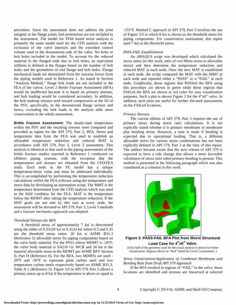
An ABAQUS script was developed which calculated the stress ratios (in this work, ratio of von Mises stress to allowable stress) and then determine the temperature reduction and reduced MAT at each node. Once the new MAT is established at each node, the script compared the MAT with the MMT at each node and reported either a “PASS” or a “FAIL” at each node. Graphically, those regions that PASSed the BFA using this procedure are shown in green while those regions that FAILed the BFA are shown in red color for easy visualization purposes. Such a plot is shown Figure 3 for the 4″x6″ valve. In addition, such plots are useful for further elevated assessments on the FAILed locations.
Primary Stresses
The current edition of API 579, Part 3 requires the use of primary stress during stress ratio calculations. It is not explicitly stated whether it is primary membrane or membrane plus bending stress. However, a note is made if bending is expected due to operational loading. That is, a different allowable stress for various stress combinations has not been explicitly defined in API 579, Part 3 at the time of this report. The authors became aware that the next release of API 579 is expected to have a rule change that allows a more favorable calculation of stress ratio when primary bending is present. This method is presented in the following paragraph which was also considered as a criterion in this work.
Figure 3. PASS-FAIL BFA Plot from Worst Structural
Load Case for 4″x6″ Valve. (Only half of the geometry used for the actual analysis is shown for better
visualization. Regions shown in “Red” failed the Level 2 assessment. )
Stress Linearization/Application of Combined Membrane and Bending Rule from Draft API 579 Approach
If the BFA resulted in regions of “FAIL” in the valve, those locations are identified and stresses are linearized at selected
4 Copyright © 2014 by ASME and Shell Oil Company
Downloaded From: http://proceedings.asmedigitalcollection.asme.org/ on 11/25/2014 Terms of Use: http://asme.org/terms
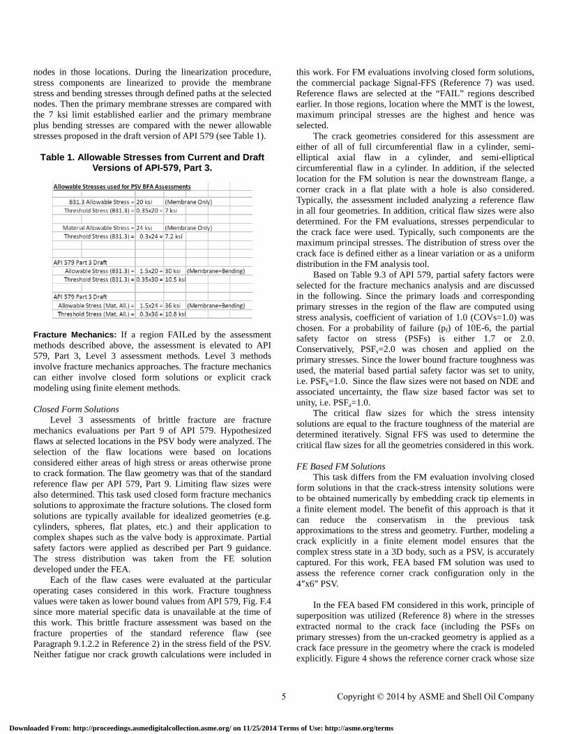
nodes in those locations. During the linearization procedure, stress components are linearized to provide the membrane stress and bending stresses through defined paths at the selected nodes. Then the primary membrane stresses are compared with the 7 ksi limit established earlier and the primary membrane plus bending stresses are compared with the newer allowable stresses proposed in the draft version of API 579 (see Table 1).
Table 1. Allowable Stresses from Current and Draft Versions of API-579, Part 3.
Fracture Mechanics: If a region FAILed by the assessment methods described above, the assessment is elevated to API 579, Part 3, Level 3 assessment methods. Level 3 methods involve fracture mechanics approaches. The fracture mechanics can either involve closed form solutions or explicit crack modeling using finite element methods. Closed Form Solutions
Level 3 assessments of brittle fracture are fracture mechanics evaluations per Part 9 of API 579. Hypothesized flaws at selected locations in the PSV body were analyzed. The selection of the flaw locations were based on locations considered either areas of high stress or areas otherwise prone to crack formation. The flaw geometry was that of the standard reference flaw per API 579, Part 9. Limiting flaw sizes were also determined. This task used closed form fracture mechanics solutions to approximate the fracture solutions. The closed form solutions are typically available for idealized geometries (e.g. cylinders, spheres, flat plates, etc.) and their application to complex shapes such as the valve body is approximate. Partial safety factors were applied as described per Part 9 guidance. The stress distribution was taken from the FE solution developed under the FEA.
Each of the flaw cases were evaluated at the particular operating cases considered in this work. Fracture toughness values were taken as lower bound values from API 579, Fig. F.4 since more material specific data is unavailable at the time of this work. This brittle fracture assessment was based on the fracture properties of the standard reference flaw (see Paragraph 9.1.2.2 in Reference 2) in the stress field of the PSV. Neither fatigue nor crack growth calculations were included in
this work. For FM evaluations involving closed form solutions, the commercial package Signal-FFS (Reference 7) was used. Reference flaws are selected at the “FAIL” regions described earlier. In those regions, location where the MMT is the lowest, maximum principal stresses are the highest and hence was selected.
The crack geometries considered for this assessment are either of all of full circumferential flaw in a cylinder, semi-elliptical axial flaw in a cylinder, and semi-elliptical circumferential flaw in a cylinder. In addition, if the selected location for the FM solution is near the downstream flange, a corner crack in a flat plate with a hole is also considered. Typically, the assessment included analyzing a reference flaw in all four geometries. In addition, critical flaw sizes were also determined. For the FM evaluations, stresses perpendicular to the crack face were used. Typically, such components are the maximum principal stresses. The distribution of stress over the crack face is defined either as a linear variation or as a uniform distribution in the FM analysis tool.
Based on Table 9.3 of API 579, partial safety factors were selected for the fracture mechanics analysis and are discussed in the following. Since the primary loads and corresponding primary stresses in the region of the flaw are computed using stress analysis, coefficient of variation of 1.0 (COVs=1.0) was chosen. For a probability of failure (pf) of 10E-6, the partial safety factor on stress (PSFs) is either 1.7 or 2.0. Conservatively, PSFs=2.0 was chosen and applied on the primary stresses. Since the lower bound fracture toughness was used, the material based partial safety factor was set to unity, i.e. PSFk=1.0. Since the flaw sizes were not based on NDE and associated uncertainty, the flaw size based factor was set to unity, i.e. PSFa=1.0.
The critical flaw sizes for which the stress intensity solutions are equal to the fracture toughness of the material are determined iteratively. Signal FFS was used to determine the critical flaw sizes for all the geometries considered in this work. FE Based FM Solutions
This task differs from the FM evaluation involving closed form solutions in that the crack-stress intensity solutions were to be obtained numerically by embedding crack tip elements in a finite element model. The benefit of this approach is that it can reduce the conservatism in the previous task approximations to the stress and geometry. Further, modeling a crack explicitly in a finite element model ensures that the complex stress state in a 3D body, such as a PSV, is accurately captured. For this work, FEA based FM solution was used to assess the reference corner crack configuration only in the 4″x6″ PSV.
In the FEA based FM considered in this work, principle of
superposition was utilized (Reference 8) where in the stresses extracted normal to the crack face (including the PSFs on primary stresses) from the un-cracked geometry is applied as a crack face pressure in the geometry where the crack is modeled explicitly. Figure 4 shows the reference corner crack whose size
5 Copyright © 2014 by ASME and Shell Oil Company
Downloaded From: http://proceedings.asmedigitalcollection.asme.org/ on 11/25/2014 Terms of Use: http://asme.org/terms
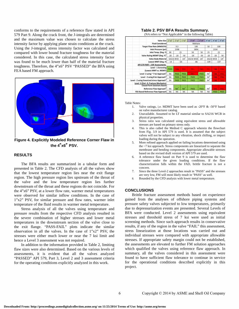
conforms to the requirements of a reference flaw stated in API 579 Part 9. Along the crack front, the J-integrals are determined and the maximum value was chosen to calculate the stress intensity factor by applying plane strain conditions at the crack. Using the J-integral, stress intensity factor was calculated and compared with lower bound fracture toughness for the material considered. In this case, the calculated stress intensity factor was found to be much lower than half of the material fracture toughness. Therefore, the 4″x6″ PSV “PASSED” the BFA using FEA based FM approach.
Figure 4. Explicitly Modeled Reference Corner Flaw in
the 4″x6″ PSV.
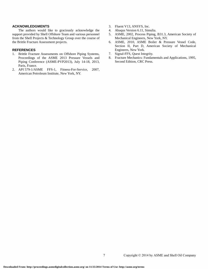
RESULTS The BFA results are summarized in a tabular form and
presented in Table 2. The CFD analysis of all the valves show that the lowest temperature region lies near the exit flange region. The high pressure region lies upstream of the throat of the valve and the low temperature region lies further downstream of the throat and these regions do not coincide. For the 4″x6″ PSV, at a lower flow rate, warmer metal temperatures were observed for similar inflow conditions. In the case of 1″x2″ PSV, for similar pressure and flow rates, warmer inlet temperature of the fluid results in warmer metal temperature.
Stress analysis of all the valves using temperature and pressure results from the respective CFD analysis resulted in the severe combination of higher stresses and lower metal temperatures in the downstream section of the valve close to the exit flange. “PASS-FAIL” plots indicate the similar observation in all the valves. In the case of 1″x2″ PSV, the stresses were either much lower or near the 7 ksi limit and hence a Level 3 assessment was not required.
In addition to the information provided in Table 2, limiting flaw sizes were also determined. Based on the various levels of assessments, it is evident that all the valves analyzed “PASSED” API 579, Part 3, Level 2 and 3 assessment criteria for the operating conditions explicitly analyzed in this work.
Table 2. PSV BFA Results Summary. (NA refers to “Not Applicable” in the following Table)
Table Notes:
1. Valve ratings, i.e. MDMT have been used as -20°F & -50°F based on valve manufacturer catalog.
2. Unavailable. Assumed to be LT material similar to SA216 WCB in physical properties.
3. Stress ratio was calculated using equivalent stress and allowable stresses are based on primary stress only.
4. This is also called the Method C approach wherein the flowchart from Fig. 3.9 in API 579 is used. It is assumed that the subject valves will not be subject to any vibration, shock chilling, or impact loading during the operation.
5. More refined approach applied on failing locations determined using the ~7 ksi approach. Stress components are linearized to separate the membrane and bending components. Appropriate allowable stresses based on the revised draft version of API 579 are used.
6. A reference flaw based on Part 9 is used to determine the flaw tolerance under the given loading conditions. If the flaw characterization falls within the FAD, brittle fracture is not a concern.
7. Since the three Level-2 approaches result in "PASS" and the stresses are very low, FM will most likely result in "PASS" as well.
8. Bounded by the CFD analysis with lower metal temperature.
CONCLUSIONS Brittle fracture assessment methods based on experience
gained from the analyses of offshore piping systems and pressure safety valves subjected to low temperatures, primarily due to depressurization events are presented. Several Levels of BFA were conducted. Level 2 assessments using equivalent stresses and threshold stress of 7 ksi were used as initial screening methods. Since such approach results in conservative results, if any of the region in the valve “FAIL” this assessment, stress linearization at those locations was carried out and individual stresses were compared with appropriate allowable stresses. If appropriate safety margin could not be established, the assessments are elevated to further FM solution approaches which qualified the valves using reference flaw approach. In summary, all the valves considered in this assessment were found to have sufficient flaw tolerance to continue in service for the operational conditions described explicitly in this project.
Valve Size 1"x2" 1"x2" 1"x2" 3"x4" 3"x4" 4"x6" 4"x6" 4"x6"Fluid Considered
Target Flow Rate (MMSCFD) 50Inlet Pressure (psi)
Inlet Temp. (Deg. F) 90 50 50 25Valve Rating MDMT (Deg. F)1 -20 -20 -50 -20 -50 -20 -20 -50
Valve Body Material UA2 SA216 WCB UA2 UA2
Lowest MMT (Deg. F) - 14 -109API 579 PART - 3 BF Assessments
Level - 1 Screening(Lowest MMT vs. MDMT)
Level -2 using ~ 7 ksi Approach3 NA PASS PASS FAIL PASS NA8 FAIL FAILLevel - 2 using 8 ksi Approach4 NA PASS PASS PASS PASS NA8 FAIL FAIL
Level - 2 using linearized stress Approach5 NA PASS PASS PASS PASS NA8 FAIL FAILLevel -3 (Part -9, Fracture Mechanics)
NA NA7 NA7 PASS PASS NA8 FAIL FAILFEA Based Reference Flaw Approach NA NA NA NA NA NA PASS PASS
Closed-Form Solutions Based Reference Flaw Approach6
FAIL FAILPASS FAIL FAIL FAIL FAIL FAIL
Methane1009.3 100
23343894239825
SA216 WCB SA216 WCB
25
- 64 -86 -147
6 Copyright © 2014 by ASME and Shell Oil Company
Downloaded From: http://proceedings.asmedigitalcollection.asme.org/ on 11/25/2014 Terms of Use: http://asme.org/terms
ACKNOWLEDGMENTS The authors would like to graciously acknowledge the
support provided by Shell Offshore Team and various personnel from the Shell Projects & Technology Group over the course of the Brittle Fracture Assessment projects.
REFERENCES 1. Brittle Fracture Assessments on Offshore Piping Systems,
Proceedings of the ASME 2013 Pressure Vessels and Piping Conference (ASME-PVP2013), July 14-18, 2013, Paris, France.
2. API 579-1/ASME FFS-1, Fitness-For-Service, 2007, American Petroleum Institute, New York, NY.
3. Fluent V13, ANSYS, Inc. 4. Abaqus Version 6.11, Simulia. 5. ASME, 2002, Process Piping, B31.3, American Society of
Mechanical Engineers, New York, NY. 6. ASME, 2010, ASME Boiler & Pressure Vessel Code,
Section II, Part D, American Society of Mechanical Engineers, New York.
7. Signal-FFS, Quest Integrity. 8. Fracture Mechanics: Fundamentals and Applications, 1995,
Second Edition, CRC Press.
7 Copyright © 2014 by ASME and Shell Oil Company
Downloaded From: http://proceedings.asmedigitalcollection.asme.org/ on 11/25/2014 Terms of Use: http://asme.org/terms