boss: beacon-less on demand strategy for geographic routing inwireless sensor networks
TRANSCRIPT
1-4244-1455-5/07/$25.00 c©2007 IEEE
BOSS: Beacon-less On Demand Strategy for Geographic Routing in WirelessSensor Networks
Juan A. Sanchez, Rafael Marin-Perez and Pedro M. RuizDept. of Information and Communications Engineering
Fac. Informatica, Univ. of MurciaCampus de Espinardo s/n
E-30100, Espinardo, MurciaEmail: {jlaguna, rafael81, pedrom}@dif.um.es
Abstract
Geographic Routing (GR) algorithms, require nodes toperiodically transmit HELLO messages to allow neighborsknow their positions (beaconing mechanism). To reduce thecontrol overhead due to theses messages, beacon-less rout-ing algorithms have recently been proposed.
However, existing beacon-less algorithms have not con-sidered realistic physical layers. Therefore, those algo-rithms can not work properly in realistic scenarios.
In this paper we present a new beacon-less routing pro-tocol called BOSS. Its design is based on the conclusions ofour open-field experiments using Tmote-sky sensors. BOSSis adapted to error-prone networks and uses a new delayfunction to reduce collisions and duplicate messages pro-duced during the phase of selecting the next forwarder.Through extensive simulations we compare BOSS with BLRand CBF and show that our scheme is able to achieve al-most perfect packet delivery ratio (like BLR) while having alow bandwidth consumption (even lower than CBF).
1 Introduction
In the last few years, Wireless Sensor Networks (WSN)have become a hot topic not only for researchers but also forthe industry. A WSN consists of a big set of lightweight andcheap devices with many integrated sensors and wirelesscommunication interfaces.
Nodes use their wireless radio to communicate the infor-mation acquired with their sensors. When the destination isout of the radio range of source node, other nodes are usedas relay stations.
Geographic Routing is one of the schemes which hasgained most momentum in the recent years. In GR eachnode needs to know the position of its neighbors. To do
that, they send periodic HELLO messages called beaconsincluding the identifier of the sender and its position. Thesepackets are not forwarded, therefore only one hop neighborscan receive them. The packets include the identifier of thesender and its position.
However, although GR in general is highly desirable, thebeaconing mechanism has some issues, such as generatinginterferences with regular data transmission and consumingbandwidth and battery power. In particular in those sensorsnot taking part in any routing process, the energy and band-width consumption represents a total waste of resources. Toovercome such issues several beacon-less routing protocolshave been proposed for WSNs. The most representative ex-amples are: IGF [2], GeRaF [23], CBF [8], and BLR [18].Beacon-less routing protocols do not require the proactivetransmission of control messages which saves network re-sources. In these algorithms, the next forwarder can be re-actively selected using two different approaches: a reactiveand distributed scheme where the neighbors collaborativelydecide which one must be the next forwarder or in a central-ized way at each step. That is, the node currently holdingthe packet determines the next forwarder among its neigh-bors.
Nevertheless most of the beacon-less protocols reportedin the literature assume a perfect wireless channel and donot consider the problems of losses and interferences cre-ated by the transmission of messages during the next for-warder selection process. As it has been shown recently([20, 19]), there are huge differences between a real linkand the well known unit disk model widely used in the liter-ature. Considering a realistic link layer has big implicationson the performance and validity of the proposed algorithms.
In this paper, we propose BOSS, the Beacon-less On De-mand Strategy for Geographic Routing in Wireless SensorNetworks. Its design takes into account the losses and colli-sions typical of radio communications. Concretely, we have
made a practical study to determine the impact of the packetsize on the Packet Reception Ratio (PRR). As our exper-iments confirm, bigger packets are more likely to be lost.Thus, unlike previous schemes, BOSS starts sending out thedata packet itself rather than a control message. By doingthat, only the neighbors able to receive the data packet con-tend for becoming the next forwarder.
BOSS uses also a passive ACK scheme to reduce thecontrol overhead. We also introduce the Discrete DynamicForwarding Delay (DDFD) a new timer-based contentionscheme to achieve a reduction of the collisions of the an-swers during the selection phase.
The remainder of this paper is organized as follows. Insection 2, an overview of existing geographic routing pro-tocols is given. The routing algorithm BOSS is described insection 3. In section 3.1, some variations and optimizationsare discussed. BOSS is evaluated in section 4 through sim-ulations and compared to existing solutions in the literature.Finally, section 5 concludes this paper.
2 Related work
Geographic Routing algorithms have become very pop-ular in the field of WSNs because of their localized oper-ation, reduced computation and storage requirements and,above all, because of their scalability with the number ofnodes [11, 14].
The idea of geographic algorithms is to forward thepacket in the direction of the destination. If the density ofnodes is high enough, at each step the packet can be movedto a node closer to the destination than the previous one.This is called greedy routing, but it is possible to reach anode where no neighbor closer to the destination exist. Inthose cases, a recovery strategy must be used to surroundthe void area reached. This is called perimeter routing andit is based in the application of the right-hand rule [3] over aplanarized vision of the underlying graph. The combinationof a greedy approach and a recovery strategy is widely usedin the literature. The most well-known algorithm doing thatis Greedy Face Greedy Routing [4]
They usually employ a beaconing mechanism to knowneighbors positions. Some of the beacons may be uselessif data packets are not routed through some of the nodes.Moreover, recent studies have shown the limitations of thesealgorithms have when mobility is taken into account [13,17].
To avoid these periodic transmissions, beacon-less pro-tocols have been proposed in the literature. The generalidea of beacon-less is to reactively discover the informationabout neighbors’s positions necessary to select the next for-warder when routing data packets.
The Implicit Geographic Forwarding [2] (IGF) is a state-free routing protocol. IGF is a modification of the 802.11
DCF MAC protocol adding to the RTS/CTS handshakinga DATA/ACK interchange. Authors define the time eachneighbor receiving the RTS from the forwarder node mustwait before answering with a CTS. That time depends onthe increase in distance towards the destination.
A similar scheme is also used in the Geographic Ran-dom Forwarding [23] (GeRAF) protocol. The main dif-ference is that here two different frequencies are used bythe collision avoidance MAC scheme defined. More recen-tely a newer paper from the same authors[22] presented anextension of GeRAF. This variant called GeRaF-1R doescollision resolution with a single radio frequency. Candi-date relays schedule the forwarding of received messagesby means of a probabilistic approach. Doing so they areable to reschedule the operation avoiding the possible colli-sions.
Lately, Heissenbuttel et al. proposed a new algorithmcalled Beacon-Less Routing [12] (BLR) which follows adifferent approach. In BLR, the selection of the next for-warder is totally distributed. That is, the current forwarderjust broadcasts the data packet and the closest neighbor tothe destination will resend the packet because its timer willexpire the first. The rest of neighbors hearing the trans-mission cancel their timers. To avoid duplications due toneighbors not hearing transmissions, the authors determinethat only the nodes located in a specific area, denominatedForwarding Area, can participate in the process. This areais relative to the forwarding node and can be of any shapeprovided that all nodes within the area can overhear eachother. Additionally, a recovery strategy is defined. Whenthe forwarder node does not hear any retransmission dur-ing a predefined time interval it broadcast again the packetand all the nodes answer with their positions. The forward-ing node then, is able to locally build the planar graph andusing the recovery scheme of GFG [4] determine the nextforwarding node in perimeter mode.
The Contention-Based Forwarding algorithm [8] (CBF)mixes the centralized selection of the next forwarder basedin a RTS/CTS/DATA process with a delimited ForwardingArea whose goal is reducing the duplicates in the same wayas in BLR.
The Blind Geographic Routing [16] (BGR) protocol isvery similar to BLR. The novelties introduced are a differ-ent recovery process and a strategy to avoid the problemof simultaneous forwarding. The results achieved are verysimilar to the ones of BLR.
Finally, Chawla et al. [6] proposed a new delay func-tion to reduce the number of neighbors replying in perime-ter mode. This function assigns shorter delays to neighborscloser to the forwarding node. Therefore, farther neighborscan cancel their responses after hearing the perimeter res-ponse of other neighbors, because they determine they arenot part of planar graph of the forwarding node.
0
20
40
60
80
100
120
10 20 30 40
Pac
ket R
ecep
tion
Rat
io (
PR
R)
40 41 42 43 44 45 46 47 48 49 50 51
Distance (meters)
60 80 100 120
10 bytes25 bytes40 bytes55 bytes70 bytes85 bytes
100 bytes115 bytes
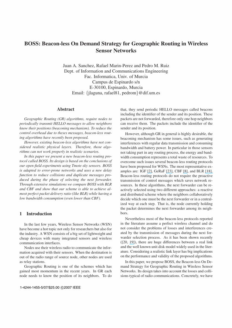
Figure 1. Percentage of messages success-fully transmited at varying the distance fordifferent packet sizes using the CC2420 radiointerface.
3 Beacon-less Routing with BOSS
BOSS uses a three way handshake mechanism to selectand forward messages in a similar way to the RTS/CTSscheme used in IEEE 802.11. Firstly the forwarding nodebroadcasts the data at maximum power to reach all its possi-ble neighbors and waits for the first response of a neighbor.Then it confirms the selection with a final control packet.The key aspect of BOSS is the way of discovering the neigh-borhood. To do that, instead of using a control packet weuse the data packet. Data messages are bigger than controlmessages, so that, they are more likely to be lost. Thus, theidea behind BOSS is to use the data packet being routed todiscover the neighbors. In that way, neighbors not able toreceive a packet of that size due to wireless errors will nottake part in the selection process.
To confirm the importance of the packet size in thepercentage of packets received and, therefore, support thegoodness of our idea, we have made some experimentswhose results are shown in the next section.
3.1 Analysis of the CC2420 Radio
The BOSS protocol is based on the assumption that thesize of the packets has a direct relationship with the prob-ability of error. Concretely, bigger packets have less prob-ability of being received than smaller ones. If that is thecase, discovering the neighborhood using one small con-trol packet may cause to select a neighbor which may notbe able to receive the bigger data packet. Our goal is tovalidate such assumption. Therefore, we run a set of realexperiments in order to obtain the relation between Packet
Size and the Packet Reception Ratio.We use are the new Tmote-sky [1] sensors based on the
CC2420 radio chip from Chipcon [7]. The main elementsintegrated on the Tmote-sky, are the following: a MSP430microcontroller (with 10kB RAM memory and 48kB Flashmemory), a CC2420 radio chip (based in standard IEEE802.15.4), an omnidirectional antenna (that provides a ra-dio range of up to 50 meters indoor and 125 meters outdoor)and optionally, sensors of humidity, temperature, and lightto monitor the environment.
The measurements have been obtained in an outdoor areaof 100x100 meters. We use two sensors (source and re-ceiver) placed at 0,5m above the ground and connected viaUSB to laptops. Each test consist in a 50 sequences of 100packets for each packet size sent at maximum power (0 db)by the source node. The receiver reports to its connectedlaptop the following measured parameters: Radio SignalStrength Indicator (RSSI) which is a 8-bit value given byCC2420 chip that indicates the received signal strength indb. The Link Quality Indicator (LQI) which can be viewedas the chip error rate and it is calculated over 8 bits fol-lowing the start frame delimiter (SFD). The LQI values areusually between 110 and 50, and correspond to maximumand minimum quality frames respectively. And finally, thePacket Size (PS) which is the sum of the payload size andheader size of the received packet. The Packet ReceptionRatio (PRR) is calculated in the laptop and it is defined asthe ratio between the number of packets received and thetotal number of packets sent.
We have performed tests using 8 different payload sizes(10, 25, 40, 55, 70, 85, 100 and 115 bytes) and varying thedistance between source and receiver (from 5m to 120m).As the results in the range between 44 and 51 meters havegreater variability, the resolution in that range is greater.
Fig. 1 summarizes the results of our experiments. Itshows the value of the PRR at varying the distance. Eachcurve represents the data obtained with each packet sizetested. The packet size is the sum of the payload and theheaders of the MAC and link layer.
The first conclusion that we can extract is that, as we an-ticipated, the greater the packet size, the lower the PRR. Thesecond conclusion is that there is no direct relation betweenthe distance and the PRR. As it can be seen, the results atsome distances such as 48m and 45m, are better than atsome other shortest distances, respectively 47 and 45. Thiscoincides with some other empirical results [10][21][5]that show the irregularities of wireless communications inWSNs.
Moreover, as it can be seen, sensors placed farther than51m are not able to communicate directly. Although themaximum theoretical range is 125m, placing the sensorsnear the floor causes too much reflections. In some othertests done with sensors placed at 2m above the floor, the
n1
n3
c
r
5
n4
n2dn
Area Progreso PositivaArea Progreso Negativa
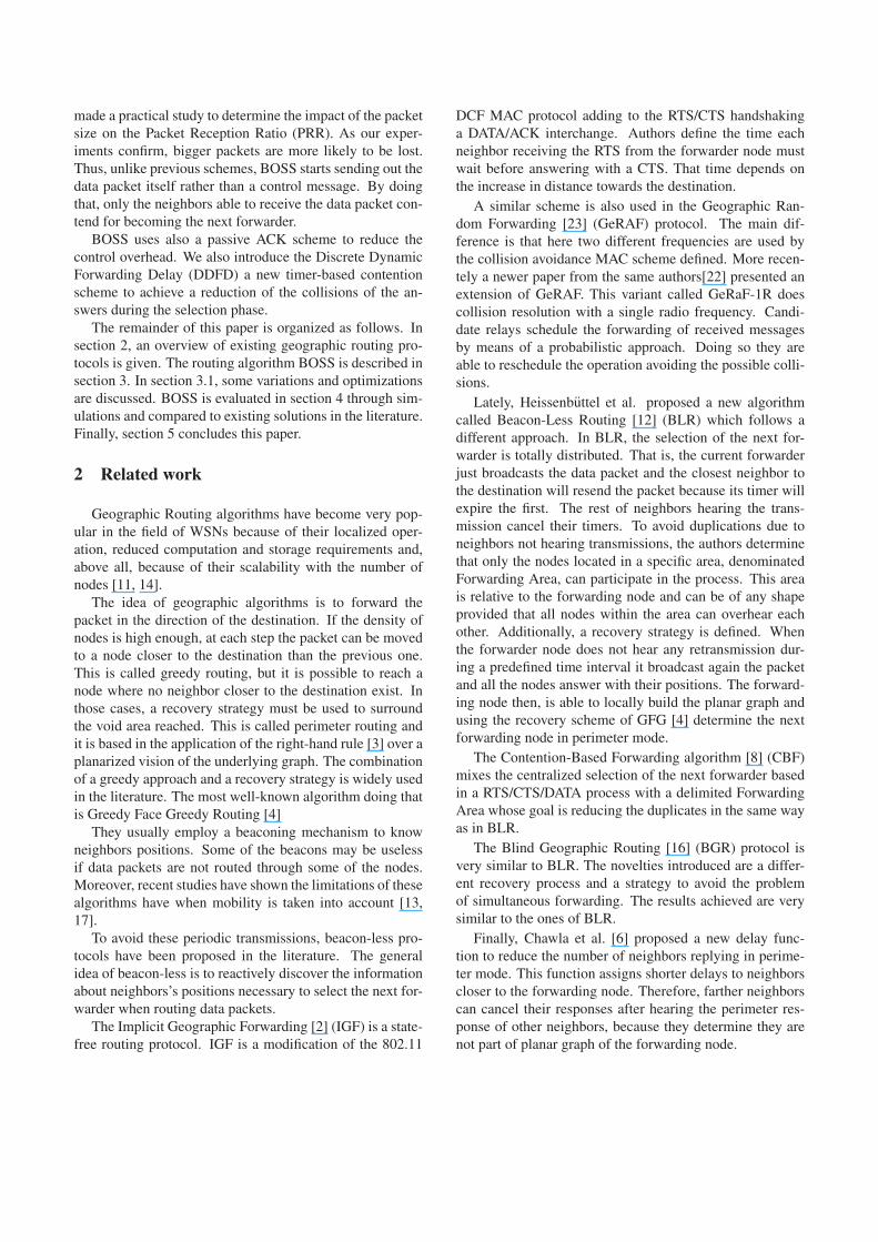
Figure 2. Node c currently holding the mes-sage toward d and its neighbors. Nodes n1,n2 and n3 are in the Positive Progress Area.Nodes n4 and n5 are in the Negative ProgressArea. Nodes n1 and n3 can not hear eachother replies.
range grows up to 150m.
3.2 Forwarding in BOSS
BOSS uses four different types of messages: DATA,RESPONSE, SELECTION and ACK. In addition, given theforwarding node (i.e. the node currently holding the mes-sage) we define two relative areas around it. The Posi-tive Progress Area (PPA) and the Negative Progress Area(NPA). PPA comprises each node whose position is closestto the destination than the forwarding node while the NPAcomprises the rest of neighbors of the forwarding node.That is, those not providing progress towards the destina-tion. Additionally, the DATA, RESPONSE and SELECTIONmessages include a bit in their headers to indicate the rout-ing mode currently being used (Greedy or Perimeter). Thisbit is called the Routing Mode bit (RM). The RM bit is set toG mode by default. We now describe the detailed operationof the protocol, firstly in the greedy and then in perimetermode.
In greedy mode, the forwarding node sends a broadcastwith a DATA message and waits for responses for a prede-fined maximum time of TMax seconds. The DATA messagecontains the original message, the position of the forward-ing node and the final destination’s position. Each neigh-bor receiving the message stores it and determines the rel-ative area in which it is located (PPA or NPA). Finally,
instead of answering immediately, the node starts a timerwhose value depends on its position. When the timer fin-ishes the neighbor broadcast a RESPONSE message. TheRESPONSE message contains the neighbor position.
Each neighbor in the PPA receiving a RESPONSE mes-sage from another neighbor in the same area, cancels itstimer and deletes the stored message. The RESPONSE mes-sages from NPA neighbors do not cancel any timer. Noticethat it is possible that some neighbors do not receive thismessage because of their positions. Fig. 2 shows an exam-ple of this situation, in which, neighbors n1 and n2 can-not hear the RESPONSE messages from each other. Theforwarding node stops its timer if a RESPONSE messagefrom a PPA neighbor is received. It then broadcasts a SE-LECTION message. This message contains the identifier ofthe neighbor selected by the forwarding node to become thenext forwarding node. That neighbor is the one whose RES-PONSE message arrived in the first place to the forwardingnode. More than one RESPONSE message from PPA neigh-bors might arrive to the forwarding node but only the firstone is used. Each neighbor receiving the SELECTION mes-sage will immediately cancel its timer and delete the storedmessage except for the one selected by the forwarding node.The selected node knows it is the new forwarding node byexamining the header of the SELECTION message. Finally,the new forwarding node starts again the protocol by broad-casting a new DATA message.
Some nodes may not have any neighbors providing ad-vance toward the destination. In that case, a so-called voidarea, is found and the routing process can not continue ingreedy mode. In Geographic Routing protocols there existdifferent strategies to surround these void areas but, usually,it is necessary to know the position of the neighbors in orderto locally build a planar graph to determine the next perime-ter forwarder. The most common algorithms to do thatare the Relative Neighbor Graph [15] (RNG) and GabrielGraph [9] (GG). As we have already commented, in BOSS,the RESPONSE messages from neighbors in the NPA do notcancel any timer. Thus, when the forwarding node does nothave any neighbor providing advance towards the destina-tion, all the RESPONSE messages from the other neighbors(those in the NPA area) are received and stored. When thetimer expires, the forwarding node can thus build the planargraph using all the information gathered and then selectsthe next forwarding node using the desired recovery mech-anism, in our case we use the one proposed in GFG [4].
In the case of perimeter routing the SELECTION mes-sage must include some extra information. Concretely theidentifier of the forwarding node, its position, identifier ofthe next hop selected and the current perimeter informationdefined by GFG which consists of: the position of the nodewhere perimeter routing started (Lp), the first edge (E0) tra-versed on current face, and the (Lf ) point, that is the cross

point between the LpD line and the current face, being Dthe position of the destination node. Additionally, the RMbit must be set to P indicating perimeter routing.
When messages are being routed in perimeter routing,the behavior of neighbors is slightly different. To beginwith, the forwarding node must include in the DATA mes-sage the Lp point. A neighbor receiving the DATA messagemust check if it is placed closer to the destination than theLp point. If that is the case, it resumes to greedy mode.Thus, the RM bit of the RESPONSE message is set to G.Only in those cases, the RESPONSE message will be sentbut, after the timer expires as in greedy routing. The for-warding node may stop its timer if it receives a RESPONSEmessage including a RM≡G. In that case, it changes togreedy mode and continues in that mode by sending theappropriate SELECTION message. If there is no neigh-bor closer to the destination than Lp then the forwardingnode will wait up to TMax seconds. Then, it selects thenext forwarder to continue in perimeter mode and selectsit by broadcasting the corresponding SELECTION messageincluding also a RM≡P.
3.3 Design Decisions
The previous section describes the behavior of the BOSSalgorithm but there are some important design decisions toconsider during the implementation phase. As we have al-ready commented, the neighbors receiving a DATA messagestore it and then wait for a timer to answer. The question ishow long must that data packet be stored. Obviously, if thenode receives a RESPONSE message, the data packet canbe deleted. The same occurs after receiving a SELECTIONmessage directed to another neighbor. But, as we are deal-ing with error-prone networks, both messages might be lost.In that case, the node will send its own RESPONSE messagewhen its timer expires. The forwarding node receiving thatlate response must ignore it, but the neighbor is waiting fora SELECTION message to select it as next forwarder. Thismessage will never arrive. Therefore, the data packet mustbe deleted after a maximum time.
Moreover, as messages can be lost, we need a confirma-tion of their reception. At least, the reception of the SELEC-TION message must be confirmed. To do that, we use twodifferent techniques: a passive acknowledgement (PACK)and an active one (ACK). The use of the ACK introduces anew message in the process incrementing the protocol over-head in a 33%. Thus, we use the DATA message of the nextforwarder as PACK to confirm the reception of the previ-ous SELECTION message. The ACK is also needed whenthe message arrives to its destination because there is nomore DATA forwarding. So, when a forwarding node doesnot receive a PACK or an ACK, it resends the SELECTIONmessage up to a maximum number of 3 times. That means
dcr
n
n2
1
Sub area 0
Sub area NSA−1
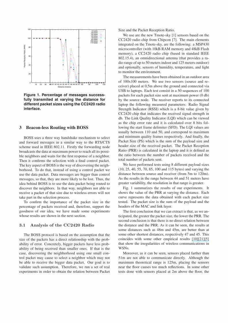
Figure 3. Division in areas for the DDFD.
that, neighbors selected as next forwarders must keep theirdata packets during at least, the 3 possible rounds of re-selections.
Finally, when the third re-selection fails the whole pro-cess is repeated. The forwarder node re-sends the DATApacket and the neighbors start again the contention pro-cess. This retransmission process can be tried up to 10times. After that, the packet is dropped. Our experimentsshow that in BOSS the retransmissions are rarely used. AsBOSS uses the data packet to determine which neighborstake part in the contention process, only those having stronglinks send their responses and can be selected. Therefore,as the RESPONSE and SELECTION messages are signifi-cantly smaller than the DATA packets, their probability ofbeing transmitted successfully is higher. Thus, the proba-bility using retransmissions is lower.
3.4 Discrete Dynamic Forwarding Delay(DDFD)
As we have already commented, all the neighbors waitfor a period of time before answering the forwarding node.Moreover, the time to wait is related to their position. Thisbehavior has two important goals: avoiding collisions anddetermining the forwarding strategy. Letting all the neigh-bors answer immediately increases exponentially the prob-ability of colliding answers because the DATA message ar-rives almost at the same time to all of them. On the otherhand, in BOSS the forwarding node selects as next for-warder the neighbor which replies first. Therefore, the for-warding strategy is clearly controlled by the way the timerswork. Additionally, by forcing some neighbors to wait more

than others we can reduce the number of possible answersand thus, the bandwidth consumption. The key then is todesign a function to determine the timeout value in such away that the most promising neighbors answer in the firstplace.
To determine the forwarding strategy we, as some otherprotocols in the literature, define the progress of a candi-date neighbor as a way to measure its goodness as next for-warder. In our case, we define it as follows:
P (n, d, c) = dist(c, d) − dist(n, d) (1)
where c and d are the forwarding and the destination nodesrespectively and dist(a, b) represents the Euclidean dis-tance between the positions of the nodes a and b. Obvi-ously, the maximum progress possible is equal to r, the ra-dio range, and the minimum one is −r, achieved by theneighbors placed farther from the destination than c.
Our Discrete Dynamic Forwarding Delay (DDFD) func-tion assigns smaller delay times to the neighbors providingthe maximum progress toward the destination. To do that,instead of using directly the value of the progress function ineach neighbor, we divide the neighborhood in sets of neigh-bors providing a similar progress (see Fig. 3). Concretely,we determine the Number of Sub Areas (NSA) in which wewant to uniformly divide the whole coverage area and then,taking into account that the maximum difference in progressbetween two neighbors is 2r, each neighbor determines inwhich Common Sub Area (CSA) it is placed. To do that ituses the following equation:
CSA =⌊NSA × r − P (n, d, c)
2r
⌋(2)
here, the value of CSA falls between 0 and NSA−1 corre-sponding 0 to the area placed closest to the destination andNSA−1 to the farthest one. Given the CSA, each neighborcomputes its delay time according to the next equation:
T =(
CSA × TMax
NSA
)+ random
(TMax
NSA
)(3)
here, TMax is a constant representing the maximum delaytime that a forwarding node will wait for answers of itsneighbors and, random(x) a function obtaining a randomvalue between 0 and x. By its construction, this function as-signs half the total TMax delay to neighbors in the PPA andhalf to the others. That allows the forwarding node to deter-mine whether there are PPA neighbors or not because a PPAneighbor will always answer before TMax
2 seconds. Addi-tionally, the neighbors in the same CSA can wait differentamount of times thanks to the random function. Neighborsfrom consecutive CSAs will never wait the same amount oftime because the base time is determined by the CSA index.
Unlike other solutions proposed in the literature, ourDDFD function combines a uniformly distributed value thatdepends on the progress with a random value generated sothat the total delay does not mixes responses from nodes indifferent sub-areas. Thus, it manages to to reduce the num-ber of responses and the probability of generating simulta-neous responses from nodes which are in the same sub-area.The problem of other functions is that, usually, their valueonly depend on the progress to the destination. In this case,the forwarding node could have several neighbors providinga similar progress and, therefore, replying simultaneouslycauses collisions between the responses.
Finally, as our proposed function works in both routingmodes (greedy and perimeter) it is not necessary to initiatea new process (broadcast, answering) for the cases whengreedy routing fails. In those cases, no PPA neighbors willanswer during the first TMax
2 seconds but, after that, the an-swers from the NPA neighbors will arrive. The same situ-ation occurs when routing in perimeter mode. If there ex-ists a node closer to the destination than the position whereperimeter routing started, that node answers before any ofthe NPA nodes. The SELECTION message issued by theforwarding node will then cancel all the responses fromthose neighbors.
4 Experimental Results
In this section, we provide a comparison between BOSSand two well known beacon-less algorithms: Beacon-LessRouting [18] (BLR) and Contention Based Forwarding [8](CBF). BLR has different variants corresponding to differ-ent forwarding areas. Three possible areas can be used,namely Sector, Reuleaux triangle and Circle. We useReuleaux triangle as forwarding area because, according toauthors, Reuleaux triangle obtains better performance thanSector and Circle in terms of packet duplications and aver-age progress in each hop. By CBF we refer to the version ofthe protocol using the active suppression method since thismethod is the one achieving the best performance.
Finally, in our simulations we consider a realistic MAClayer with collisions and interferences. That is, a messagesent out by a node, might not be received by some nodesin its radio range. To do that, we use the results of ourempirical experiments commented in section 3.1. We usethem to build a function that computes the probability forthat packet to be received given a distance and a packet size.
The simulation scenario is a 500x500m2 area in whicha varying number of nodes (from 150 to 700 nodes) aredeployed. This results in scenarios with different networkdensities (mean number of neighbors/node). We have con-sidered 8 different mean densities to represent a wide spec-trum of scenarios, from the sparse to the very dense ones.On the other hand, the source and destination nodes are al-
ways placed respectively a (0,0) and (500,500) coordinates.Thus, using a radio range of r = 50, the theoretical min-imum number of hops is 500
√2
r � 14. That is useful todetermine the deviation from the better path of each proto-col tested. For each scenario our results are the average overa total number of 200 simulation runs in order to achieve asufficient small 95% confidence interval.
For BOSS we use: TMax = 600ms and NSA = 10.In CBF there are two different timers, one for greedy rout-ing and another for perimeter routing. The two are set to300ms. The same occurs in the case of BLR, it is config-ured to use 300ms per timer. To make a fair comparison thethree protocols are configured to behave in the same waywhen losses occur. The SELECT/ACK process can be re-peated up to 3 times and the maximum number of retrans-missions is set to 10. BLR can only do that in perimetermode because in greedy mode there is no defined mecha-nism to do that. Finally, we have modified the CBF protocolto force the selected neighbor to use an ACK to inform theforwarder. That process is also retried up to 10 times. Oth-erwise, CBF provided a really poor performance in realisticerror-prone WSNs.
4.1 Performance metrics
We considered the following metrics during the evalua-tion of performance of the algorithms:
• Total transmissions. This metric accounts for the to-tal number of packets transmitted during the processof routing a message from the source to the destina-tion. Includes also the messages not received and thetransmissions made by duplicate packets due to errorsin the protocols.
• Hop Count. This metric accounts for the number ofpoint-to-point links in a transmission path. The num-ber of hops is the average number of intermediatenodes between the source node and the destinationnode.
• Duplicates. This metric accounts for the number ofpackets received by the destination node for each onesent by the source in those cases where all the algo-rithms reach the destination.
• Packet Delivery Ratio (PDR). This metric shows theeffectiveness of the protocols. It determines the per-centage of packets that reach the destination node.This is an important performance metric in scenarioswith realistic conditions.
• End-to-end delay. This metric accounts for the totaltime required for the first message sent by the sourceto make it to the destination.
1
10
100
1000
5 10 15 20 25 30 35 40 45 50
Dup
licat
e P
acke
ts
Density
BOSS BLR CBF
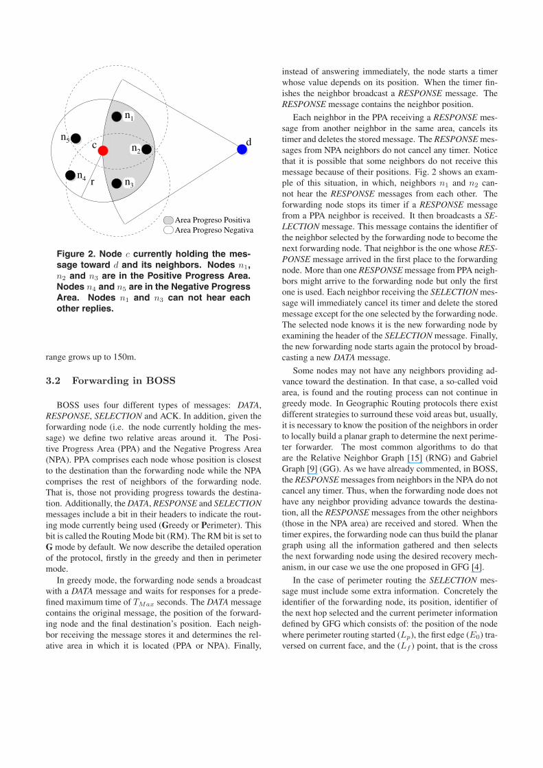
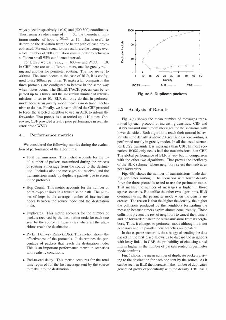
Figure 5. Duplicate packets
4.2 Analysis of Results
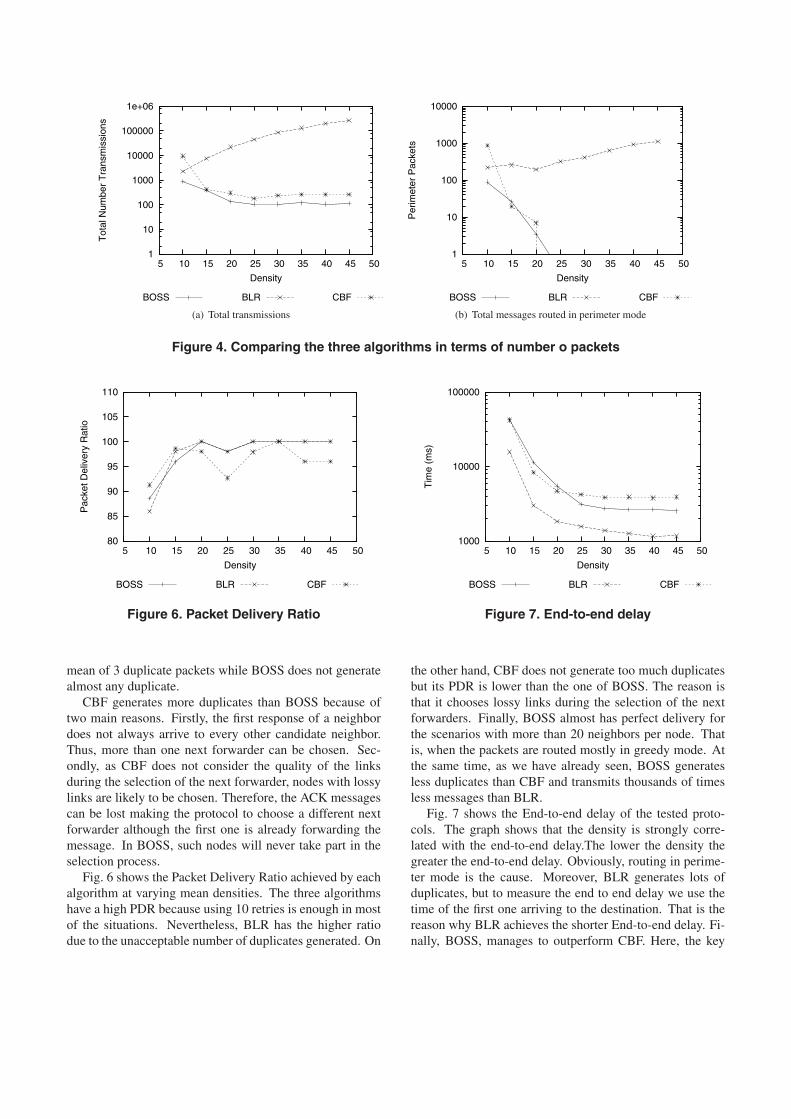
Fig. 4(a) shows the mean number of messages trans-mitted by each protocol at increasing densities. CBF andBOSS transmit much more messages for the scenarios withlower densities. Both algorithms reach their normal behav-ior when the density is above 20 (scenarios where routing isperformed mostly in greedy mode). In all the tested scenar-ios BOSS transmits less messages than CBF. In most sce-narios, BOSS only needs half the transmissions than CBF.The global performance of BLR is very bad in comparisonwith the other two algorithms. That proves the inefficacyof the BLR scheme, where neighbors select themselves asnext forwarders.
Fig. 4(b) shows the number of transmissions made dur-ing perimeter routing. The scenarios with lower densityforce the three protocols tested to use the perimeter mode.That means, the number of messages is higher in thosesparse scenarios. But unlike the other two algorithms, BLRcontinues using the perimeter mode when the density in-creases. The reason is that the higher the density, the higherthe collisions produced by the neighbors forwarding themessage because timers expire almost concurrently. Thosecollisions prevent the rest of neighbors to cancel their timersand the forwarder to hear the retransmissions from its neigh-bors. Thus, it changes to perimeter mode although it is notnecessary and, in parallel, new branches are created.
In those sparse scenarios, the strategy of sending the datapacket in the first place allows us to discard the neighborswith lossy links. In CBF, the probability of choosing a badlink is higher as the number of packets routed in perimetermode confirms.
Fig. 5 shows the mean number of duplicate packets arriv-ing to the destination for each one sent by the source. As itcan be seen, in BLR the increase in the number of duplicatesgenerated grows exponentially with the density. CBF has a
1
10
100
1000
10000
100000
1e+06
5 10 15 20 25 30 35 40 45 50
Tot
al N
umbe
r T
rans
mis
sion
s
Density
BOSS BLR CBF
(a) Total transmissions
1
10
100
1000
10000
5 10 15 20 25 30 35 40 45 50
Per
imet
er P
acke
ts
Density
BOSS BLR CBF
(b) Total messages routed in perimeter mode
Figure 4. Comparing the three algorithms in terms of number o packets
80
85
90
95
100
105
110
5 10 15 20 25 30 35 40 45 50
Pac
ket D
eliv
ery
Rat
io
Density
BOSS BLR CBF
Figure 6. Packet Delivery Ratio
mean of 3 duplicate packets while BOSS does not generatealmost any duplicate.
CBF generates more duplicates than BOSS because oftwo main reasons. Firstly, the first response of a neighbordoes not always arrive to every other candidate neighbor.Thus, more than one next forwarder can be chosen. Sec-ondly, as CBF does not consider the quality of the linksduring the selection of the next forwarder, nodes with lossylinks are likely to be chosen. Therefore, the ACK messagescan be lost making the protocol to choose a different nextforwarder although the first one is already forwarding themessage. In BOSS, such nodes will never take part in theselection process.
Fig. 6 shows the Packet Delivery Ratio achieved by eachalgorithm at varying mean densities. The three algorithmshave a high PDR because using 10 retries is enough in mostof the situations. Nevertheless, BLR has the higher ratiodue to the unacceptable number of duplicates generated. On
1000
10000
100000
5 10 15 20 25 30 35 40 45 50
Tim
e (m
s)
Density
BOSS BLR CBF
Figure 7. End-to-end delay
the other hand, CBF does not generate too much duplicatesbut its PDR is lower than the one of BOSS. The reason isthat it chooses lossy links during the selection of the nextforwarders. Finally, BOSS almost has perfect delivery forthe scenarios with more than 20 neighbors per node. Thatis, when the packets are routed mostly in greedy mode. Atthe same time, as we have already seen, BOSS generatesless duplicates than CBF and transmits thousands of timesless messages than BLR.
Fig. 7 shows the End-to-end delay of the tested proto-cols. The graph shows that the density is strongly corre-lated with the end-to-end delay.The lower the density thegreater the end-to-end delay. Obviously, routing in perime-ter mode is the cause. Moreover, BLR generates lots ofduplicates, but to measure the end to end delay we use thetime of the first one arriving to the destination. That is thereason why BLR achieves the shorter End-to-end delay. Fi-nally, BOSS, manages to outperform CBF. Here, the key
1
10
100
1000
5 10 15 20 25 30 35 40 45 50
Num
ber
of H
ops
Density
BOSS BLR CBF
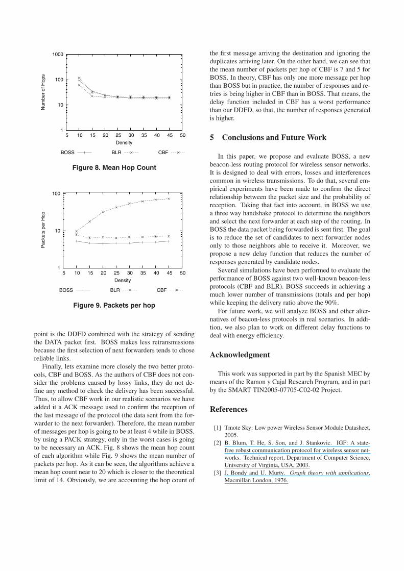
Figure 8. Mean Hop Count
1
10
100
5 10 15 20 25 30 35 40 45 50
Pac
kets
per
Hop
Density
BOSS BLR CBF
Figure 9. Packets per hop
point is the DDFD combined with the strategy of sendingthe DATA packet first. BOSS makes less retransmissionsbecause the first selection of next forwarders tends to chosereliable links.
Finally, lets examine more closely the two better proto-cols, CBF and BOSS. As the authors of CBF does not con-sider the problems caused by lossy links, they do not de-fine any method to check the delivery has been successful.Thus, to allow CBF work in our realistic scenarios we haveadded it a ACK message used to confirm the reception ofthe last message of the protocol (the data sent from the for-warder to the next forwarder). Therefore, the mean numberof messages per hop is going to be at least 4 while in BOSS,by using a PACK strategy, only in the worst cases is goingto be necessary an ACK. Fig. 8 shows the mean hop countof each algorithm while Fig. 9 shows the mean number ofpackets per hop. As it can be seen, the algorithms achieve amean hop count near to 20 which is closer to the theoreticallimit of 14. Obviously, we are accounting the hop count of
the first message arriving the destination and ignoring theduplicates arriving later. On the other hand, we can see thatthe mean number of packets per hop of CBF is 7 and 5 forBOSS. In theory, CBF has only one more message per hopthan BOSS but in practice, the number of responses and re-tries is being higher in CBF than in BOSS. That means, thedelay function included in CBF has a worst performancethan our DDFD, so that, the number of responses generatedis higher.
5 Conclusions and Future Work
In this paper, we propose and evaluate BOSS, a newbeacon-less routing protocol for wireless sensor networks.It is designed to deal with errors, losses and interferencescommon in wireless transmissions. To do that, several em-pirical experiments have been made to confirm the directrelationship between the packet size and the probability ofreception. Taking that fact into account, in BOSS we usea three way handshake protocol to determine the neighborsand select the next forwarder at each step of the routing. InBOSS the data packet being forwarded is sent first. The goalis to reduce the set of candidates to next forwarder nodesonly to those neighbors able to receive it. Moreover, wepropose a new delay function that reduces the number ofresponses generated by candidate nodes.
Several simulations have been performed to evaluate theperformance of BOSS against two well-known beacon-lessprotocols (CBF and BLR). BOSS succeeds in achieving amuch lower number of transmissions (totals and per hop)while keeping the delivery ratio above the 90%.
For future work, we will analyze BOSS and other alter-natives of beacon-less protocols in real scenarios. In addi-tion, we also plan to work on different delay functions todeal with energy efficiency.
Acknowledgment
This work was supported in part by the Spanish MEC bymeans of the Ramon y Cajal Research Program, and in partby the SMART TIN2005-07705-C02-02 Project.
References
[1] Tmote Sky: Low power Wireless Sensor Module Datasheet,2005.
[2] B. Blum, T. He, S. Son, and J. Stankovic. IGF: A state-free robust communication protocol for wireless sensor net-works. Technical report, Department of Computer Science,University of Virginia, USA, 2003.
[3] J. Bondy and U. Murty. Graph theory with applications.Macmillan London, 1976.

[4] P. Bose, P. Morin, I. Stojmenovic, and J. Urrutia. Routingwith Guaranteed Delivery in Ad Hoc Wireless Networks.Wireless Networks, 7(6):609–616, 2001.
[5] A. Cerpa, J. L. Wong, L. Kuang, M. Potkonjak, and D. Es-trin. Statistical model of lossy links in wireless sensor net-works. In Proc. 4th international symposium on Informationprocessing in sensor networks, (IPSN ’05), page 11, Piscat-away, NJ, USA, 2005. IEEE Press.
[6] M. Chawla, N. Goel, K. Kalaichelvan, A. Nayak, and I. Sto-jmenovic. Beaconless Position Based Routing with Guar-anteed Delivery for Wireless Ad-Hoc and Sensor Networks.In Proc. 19th IFIP World Computer Congress, Santiago deChile, Chile, August 2006.
[7] CC2420 2.4 GHz IEEE 802.15.4 / Zigbee RF Transceiver.Chipcon Product data sheet.
[8] H. Fußler, J. Widmer, M. Kasemann, M. Mauve, andH. Hartenstein. Contention-Based Forwarding for MobileAd Hoc Networks. Ad Hoc Networks, 1(4):351 – 369, 2003.
[9] K. Gabriel and R. Sokal. A New Statistical Approachto Geographic Variation Analysis. Systematic Zoology,18:259–278, 1969.
[10] D. Ganesan, B. Krishnamachari, A. Woo, D. Culler, D. Es-trin, and S. Wicker. Complex Behavior at Scale: An Ex-perimental Study of Low-Power Wireless Sensor Networks.Csd-tr 02-0013, UCLA, February 2002.
[11] S. Giordano, I. Stojmenovic, and L. Blazevie. PositionBased Routing Algorithms for Ad Hoc Networks: A Tax-onomy. Ad Hoc Wireless Networking, pages 103–136, 2004.
[12] M. Heissenbuttel, T. Braun, T. Bernoulli, and M. Wachli.BLR: Beacon-Less Routing Algorithm for Mobile Ad-HocNetworks. Elsevier’s Computer Communications Journal(ECC), 27(11):1076–1086, July 2004.
[13] M. Heissenbuttel, T. Braun, M. Walchli, and T. Bernoulli.Evaluating of the limitations and alternatives in beaconing.Ad Hoc Netw., 5(5):558–578, 2007.
[14] J. Li, J. Jannotti, D. S. J. D. Couto, D. R. Karger, and R. Mor-ris. A Scalable Location Service for Geographic Ad HocRouting. In Proc. 6th annual ACM/IEEE International Con-ference on Mobile Computing and Networking (MobiCom’00), pages 120–130, New York, NY, USA, 2000. ACMPress.
[15] G. Toussaint. The Relative Neighborhood Graph of a FinitePlanar Set. Pattern Recognition, 12:261–268, 1980.
[16] M. W. V. Turau. BGR: Blind Geographic Routing for Sen-sor Networks. In Proc. of the Third Workshop on IntelligentSolutions in Embedded Systems (WISES’05), Hamburg, Ger-many, May 2005.
[17] M. W. V. Turau. The Impact of Location Errors on Geogra-phic Routing in Sensor Networks. In Proc. of the SecondInternational Conference on Wireless and Mobile Commu-nications (ICWMC’06), Bucharest, Romania, July 2006.
[18] M. uttel and T. Braun. A novel position-based and beacon-less routing algorithm for mobile ad-hoc networks, 2003.
[19] A. Woo, T. Tong, and D. Culler. Taming the UnderlyingChallenges of Reliable Multihop Routing in Sensor Net-works. In Proc. First International Conference on Embed-ded Networked Sensor Systems (SenSys ’03), pages 14–27.ACM Press New York, NY, USA, 2003.
[20] J. Zhao and R. Govindan. Understanding Packet DeliveryPerformance in Dense Wireless Sensor Networks. In Proc.First International Conference on Embedded NetworkedSensor Systems (SenSys ’03), pages 1–13, New York, NY,USA, 2003. ACM Press.
[21] J. Zhao and R. Govindan. Understanding packet deliveryperformance in dense wireless sensor networks. In Proc. ofthe first international conference on Embedded networkedsensor systems, pages 1–13, 2003.
[22] M. Zorzi. A new contention-based MAC protocol for geo-graphic forwarding in ad hoc and sensor networks. In Proc.of the IEEE International Conference on Communications(ICC ’04), volume 6, pages 3481–3485, 2004.
[23] M. Zorzi and R. Rao. Geographic random forwarding(GeRaF) for ad hoc and sensor networks: energy and la-tency performance. Mobile Computing, IEEE Transactionson, 2(4):349–365, 2003.