bosch motorsport equipment for high performance vehicles
TRANSCRIPT
Bosch MotorsportEquipment for High Performance VehiclesEdition 2009/2
14 May. 09 [email protected] 3
Contents Engine Control Units
Gasoline Engine Control Units ECU MS 3 Sport........................................7 ECU MS 3.1...............................................9 ECU MS 4 Sport/Sport Turbo.................11 ECU MS 4 Sport Package .......................13 ECU MS 4.0.............................................14 ECU MS 4.4 Sport/Sport Turbo..............16 ECU MS 4.4.............................................18 ECU MS 5.1.............................................20 ECU MS 5.5.............................................22 ECU MS 5.2.............................................24
Diesel Engine Control Units ECU MS 15 Sport....................................26 ECU MS 15.1...........................................27 ECU MS 15.2...........................................29 ECU MS 12..............................................31
Injection & Ignition Injection Valves
Injection Valve EV 6 ................................34 Injection Valve EV 12 ..............................36 Injection Valve EV 14 ..............................37
HP Injection Valves HP Injection Valve HDEV 5.1...................39 HP Injection Valve Mini-HDEV 1.2 ...........41 HP Injection Valve Mini-HDEV LV ............42 HP Injection Valve Mini-HDEV LV 8A ....... 43
Power Stage Units HPI 1.1....................................................45 HPI 1.16 LV / LVD ...................................47 HPI 1.16 HV / HVD ..................................48 Ignition Module IM 3.1 / 3.2 ...................49 Ignition Module IM 4...............................52
Fuel Pumps Fuel Pump FP 100 ..................................55 Fuel Pump FP 165 ..................................56 Fuel Pump FP 200 ..................................57 HP Fuel Pump HDP 5..............................58 Diesel Fuel Pump DFP 300 .....................59
Fuel Pressure Regulators Fuel Pressure Regulator 05-40 A ............60 Fuel Pressure Regulator 14-50 ...............61 Fuel Pressure Regulator 15-50 ...............62 Fuel Pressure Regulator 19-50 ...............63 Fuel Pressure Regulator 20x120.............64 Fuel Pressure Regulators Mini/Mini M....65 Fuel Pressure Regulator Mini A ..............66 Fuel Pressure Regulator Mini 38.............67
Fuel Pressure Regulator Mini 50 ............ 68 HP Control Valve DSV............................. 69
Diesel System Components Diesel System Components.................... 70
Ignition CoilsDouble Fire Coil 3x2............................... 73 Double Fire Coil 2x2............................... 76 Double Fire Coil 1x2............................... 79 Single Fire Coil P35 / P35-T ................... 82 Single Fire Coil P50 / P50-M .................. 85 Single Fire Coil P100-T ........................... 88 Single Fire Coil M ................................... 91 Single Fire Coil PS / PS-T ....................... 94 Single Fire Coil S22 / S22-T ................... 98 Single Fire Coil S19 / S19-T ................. 101 Single Fire Coil S16 / S16-T ................. 104
Spark PlugsSpark Plugs........................................... 107
Starters & Alternators Starters
Starter 1.4 kW ...................................... 109 Starter 1.7 kW ...................................... 110 Starter 2.0 kW ...................................... 111
AlternatorsAlternator GCM1 .................................. 112
SensorsAbsolute Position Sensor
Absolute Position Sensor APS-C .......... 117 Acceleration Sensor
Accelerometer AM 600-2, AM 600-3 ..... 119 Gear Shift Sensors
Gear Shift Sensor GSS-2 ...................... 121 Gear Shift Sensor GSS-M ..................... 123
Knock SensorsKnock Sensor KS-P ............................... 125 Knock Sensor KS-R ............................... 127
Lambda SensorsLambda Sensor LSM 11 ....................... 129 Lambda Sensor LSM 11-PM ................. 131 Lambda Sensor LSU 4.2 ....................... 133 Lambda Sensor LSU 4.9 ....................... 135 Lambda Sensor Mini-LSU 4.9 ............... 137
Linear Potentiometers Linear Potentiometer LP 10 ................. 139 Linear Potentiometer LP 25 ................. 141 Linear Potentiometer LP 25 twin ......... 143
Linear Potentiometer LP 50 .................145 Linear Potentiometer LP 50 twin ......... 147 Linear Potentiometer LP 75 .................149 Linear Potentiometer LP 75F ...............151 Linear Potentiometer LP 100 ...............153 Linear Potentiometer LP 100F .............155 Linear Potentiometer LP 125 ...............157 Linear Potentiometer LP 150 ...............159
Pressure Sensors AirPressure Sensor Air PSA-B ...................161 Pressure Sensor Air PSA-C ...................164 Pressure Sensor Air PSB-2 ...................166 Pressure Sensor Air PSB-4 ...................168 Pressure Sensor Air PSP ......................170 Pressure Sensor Air PST.......................172
Pressure Sensors Differential Pressure Sensor Differential DP-A........175 Pressure Sensor Differential DP-C .......177 Pitot Static Tube PT .............................179
Pressure Sensors Fluid Pressure Sensor Fluid PSS-10..............181 Pressure Sensor Fluid PSS-10R............183 Pressure Sensor Fluid PSS-100R..........185 Pressure Sensor Fluid PSS-250R..........187 Pressure Sensor Fluid PSC-10..............189 Pressure Sensor Fluid PSC-10R ...........191 Pressure Sensor Fluid PSC-250R .........193 Pressure Sensor Fluid PSM ..................195 Pressure Sensor Fluid PSM-S...............197
Ride Height Sensor Ride Height Sensor RHS.......................199
Rotary Potentiometers Rotary Potentiometer RP 50-/130-/350-M201 Rotary Potentiometer RP 55.................203 Rotary Potentiometer RP 86.................205 Rotary Potentiometer RP 100/130/308 207 Rotary Potentiometer RP 100 twin.......209 Rotary Potentiometer Mini-RP 100-M...211 Rotary Potentiometer RP 345-M...........213
Speed Sensors Inductive Speed Sensor IA ...................215 Inductive Speed Sensor IA-C ................218 Inductive Speed Sensor IS ...................221 Inductive Speed Sensor IS-C................224 Inductive Speed Sensor IS-T ................227 Hall-Effect Speed Sensor HA-M ............ 229 Hall-Effect Speed Sensor HA-P .............232 Hall-Effect Speed Sensor Mini-HA-P .....234 Hall-Effect Speed Sensor HA-D 90........ 237
Temperature SensorsTemperature Sensor NTC M6 ...............240 Temperature Sensor NTC M6-H............242 Temperature Sensor NTC M8 ...............244
Temperature Sensor NTC M12 ............. 246 Temperature Sensor NTC M12-H.......... 248 Temperature Sensor NTC M12-L .......... 250
Temperature Sensors Infrared Temperature Sensor Infrared TI-16-r / TI-
16-s................................................ 252 Temperature Sensor Infrared TI-100-s / TI-
100-c.............................................. 254 Thermocouple Probes
Thermocouple Probe TCP-K ................. 256 Thermocouple Probe TCP-NF ............... 258 Thermocouple Probe TCP-KA ............... 260
Wire Potentiometers Wire Potentiometer WP 35................... 263 Wire Potentiometer WP 50................... 265 Wire Potentiometer WP 75................... 267 Wire Potentiometer WP 100................. 269 Wire Potentiometer WP 120................. 271 Wire Potentiometer WP 125................. 273
Yaw Rate SensorYaw Rate Sensor YRS 2 ........................ 275 Yaw Rate Sensor YRS 3 ........................ 277
Electronic Throttle Control Electronic Throttle Grip ETG ................ 280
Chassis & Brake Control ABS M4 Kit............................................ 282
DisplaysDisplay DDU Sport................................ 285 Display DDU 4....................................... 287 Display DDU 6....................................... 288
Data Logging Systems Data Loggers
Data Logger C Sport............................. 290 CardMemory C 40 / C 40 Plus.............. 292 Data Logging Accessories..................... 293 Data Logging System DLS .................... 294 CardMemory C 55................................. 295 Modular Sensor Interface MSI 55......... 296
TelemetryOnline Telemetry System Overview...... 297 Telemetry Unit FM 40 ........................... 298 Pit Receiver Box ................................... 299 Telemetry Accessories.......................... 304 Burst Telemetry System Overview........ 306 Burst Telemetry System ....................... 307
Laptrigger Systems Lap Trigger IR-02 .................................. 309 Lap Trigger HF 24 ................................. 310
14 May. 09 [email protected] 5
Software Calibration
RaceCon ...............................................313 Modas...................................................314 Modas Sport .........................................315
Simulation LapSim..................................................316
Analysis WinDarab..............................................318
Accessories Communication Interface
MSA-Box ...............................................321 Handheld Test Devices
RS 2000 ................................................322 Expansion Modules
Lambdatronic LT4 ................................323 AWS LSU 4.9.........................................325
CAN Module EM-A6............................... 327 CAN Module EM-C ................................ 329 CAN Module EM-D1 .............................. 330 CAN Module EM-D8 .............................. 331 CAN Module EM-H4 .............................. 332 CAN Module EM-I4................................ 333 CAN Module EM-L5............................... 334 CAN Module EM-P5 .............................. 335 ThermoCAN Module.............................. 336
RelayRelay 25 A............................................. 337
SwitchesSwitches............................................... 338
AppendixGeneral Information ............................. 340 Vibration Profile 1.................................340 Vibration Profile 2.................................341 Vibration Profile 3.................................341

14 May. 09 [email protected] 7
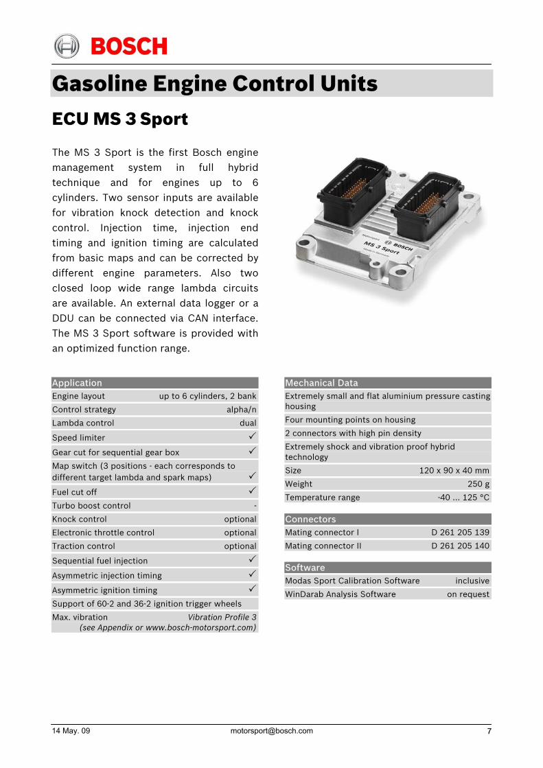
Gasoline Engine Control Units ECU MS 3 Sport
The MS 3 Sport is the first Bosch enginemanagement system in full hybridtechnique and for engines up to 6cylinders. Two sensor inputs are availablefor vibration knock detection and knockcontrol. Injection time, injection endtiming and ignition timing are calculatedfrom basic maps and can be corrected bydifferent engine parameters. Also twoclosed loop wide range lambda circuitsare available. An external data logger or aDDU can be connected via CAN interface.The MS 3 Sport software is provided withan optimized function range.
Application Engine layout up to 6 cylinders, 2 bank
Control strategy alpha/n
Lambda control dual
Speed limiter
Gear cut for sequential gear box
Map switch (3 positions - each corresponds to different target lambda and spark maps)
Fuel cut off
Turbo boost control -
Knock control optional
Electronic throttle control optional
Traction control optional
Sequential fuel injection
Asymmetric injection timing
Asymmetric ignition timing
Support of 60-2 and 36-2 ignition trigger wheels
Max. vibration Vibration Profile 3 (see Appendix or www.bosch-motorsport.com)
Mechanical Data Extremely small and flat aluminium pressure casting housing
Four mounting points on housing
2 connectors with high pin density
Extremely shock and vibration proof hybrid technology
Size 120 x 90 x 40 mm
Weight 250 g
Temperature range -40 … 125 °C
Connectors Mating connector I D 261 205 139
Mating connector II D 261 205 140
Software Modas Sport Calibration Software inclusive
WinDarab Analysis Software on request
Electrical Data Max. power consumption 10 W at 14 V
Inputs
2 inputs for exhaust gas temperature sensors
2 LSU lambda sensor interfaces
4 inputs for Hall-effect wheel speed sensors
1 input for inductive crankshaft sensor
1 input for Hall-effect camshaft sensor
15 universal inputs 0 … 5 V
2 knock sensor inputs
6 digital inputs
Outputs
6 injection power stages
6 ignition power stages
16 power stages (2 A/1 A; low side; PWM)
2 power stages for lambda heater
1 H-bridge (5 A)
2 sensor supply 5 V/100 mA
Communication interfaces
1 K-line serial interface
1 CAN interface for external communication
Optional Accessories MSA-Box B 261 208 015-01
Data logger C Sport F 01T A20 061
Data logger C 40 F 01T A20 403
Data logger C 40 Plus B 261 206 860
Display DDU Sport (incl. logger) F 01T A20 050-01
Display DDU 4 F 01E B01 461
Display DDU 6 F 01E B01 459
Part Number MS 3 Sport F 01T A20 067
14 May. 09 [email protected] 9
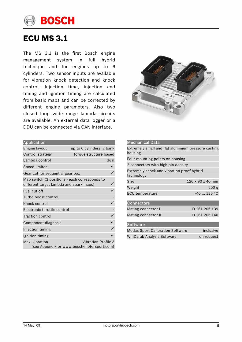
ECU MS 3.1
The MS 3.1 is the first Bosch enginemanagement system in full hybridtechnique and for engines up to 6cylinders. Two sensor inputs are availablefor vibration knock detection and knockcontrol. Injection time, injection endtiming and ignition timing are calculatedfrom basic maps and can be corrected bydifferent engine parameters. Also twoclosed loop wide range lambda circuitsare available. An external data logger or aDDU can be connected via CAN interface.
Application Engine layout up to 6 cylinders, 2 bank
Control strategy torque-structure based
Lambda control dual
Speed limiter
Gear cut for sequential gear box
Map switch (3 positions - each corresponds to different target lambda and spark maps)
Fuel cut off
Turbo boost control -
Knock control
Electronic throttle control -
Traction control
Component diagnosis
Injection timing
Ignition timing
Max. vibration Vibration Profile 3 (see Appendix or www.bosch-motorsport.com)
Mechanical Data Extremely small and flat aluminium pressure casting housing
Four mounting points on housing
2 connectors with high pin density
Extremely shock and vibration proof hybrid technology
Size 120 x 90 x 40 mm
Weight 250 g
ECU temperature -40 … 125 °C
Connectors Mating connector I D 261 205 139
Mating connector II D 261 205 140
Software Modas Sport Calibration Software inclusive
WinDarab Analysis Software on request
Electrical Data Max. power consumption 10 W at 14 V
In general
2 microcontrollers with 16 bit organization calculation capacity 20 MIPS
Inputs
2 lambda LSU 4 interfaces
3 analog inputs 0 … 5 V for water temperature, oil temperature, intake air temperature
3 analog inputs 0 … 5 V for oil pressure, fuel pressure, ambient pressure
1 analog input 0 … 5 V for throttle position sensor
1 digital input for laptrigger
1 digital input for wheel speed sensor
1 input for inductive crankshaft sensor
1 input for Hall-effect camshaft sensor
2 knock sensor inputs
Outputs
6 injection power stages with diagnosis interface
2 high current power stages (8 A) with diagnosis interface for LSU heating
6 ignition power stages
Sensors supply output 5 V/100 mA
Separate supply output for throttle position sensor 5 V/100 mA
2 power stages (1 A) for main relay and fuel pump relay control
Communication interfaces
1 K-line serial interface
1 CAN interface for external communication
Application Hints Depending on your experiences with calibration of ECUs we recommend calibration support from Bosch Motorsport.
Optional Accessories MSA-Box B 261 208 015-01
Data logger C Sport F 01T A20 061
Data logger C 40 F 01T A20 403
Data logger C 40 Plus B 261 206 860
Display DDU Sport (incl. logger) F 01T A20 050-01
Display DDU 4 F 01E B01 461
Display DDU 6 F 01E B01 459
Part Number MS 3.1 B 261 208 245-01
14 May. 09 [email protected] 11
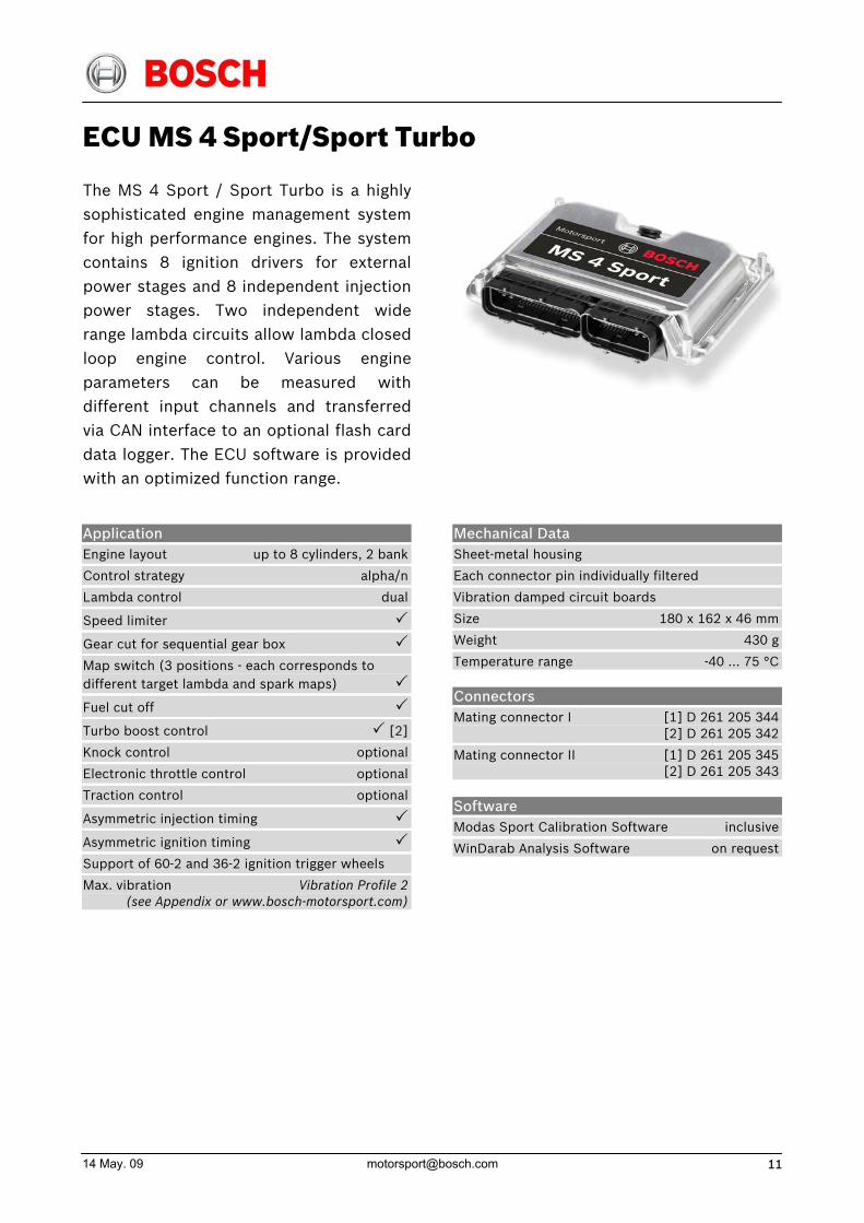
ECU MS 4 Sport/Sport Turbo
The MS 4 Sport / Sport Turbo is a highlysophisticated engine management systemfor high performance engines. The systemcontains 8 ignition drivers for externalpower stages and 8 independent injectionpower stages. Two independent widerange lambda circuits allow lambda closedloop engine control. Various engineparameters can be measured withdifferent input channels and transferred via CAN interface to an optional flash carddata logger. The ECU software is providedwith an optimized function range.
Application Engine layout up to 8 cylinders, 2 bank
Control strategy alpha/n
Lambda control dual
Speed limiter
Gear cut for sequential gear box
Map switch (3 positions - each corresponds to different target lambda and spark maps)
Fuel cut off
Turbo boost control [2]
Knock control optional
Electronic throttle control optional
Traction control optional
Asymmetric injection timing
Asymmetric ignition timing
Support of 60-2 and 36-2 ignition trigger wheels
Max. vibration Vibration Profile 2 (see Appendix or www.bosch-motorsport.com)
Mechanical Data Sheet-metal housing
Each connector pin individually filtered
Vibration damped circuit boards
Size 180 x 162 x 46 mm
Weight 430 g
Temperature range -40 … 75 °C
Connectors Mating connector I [1] D 261 205 344 [2] D 261 205 342
Mating connector II [1] D 261 205 345 [2] D 261 205 343
Software Modas Sport Calibration Software inclusive
WinDarab Analysis Software on request

Electrical Data Max. power consumption 30 W at 14 V
Inputs
2 inputs for exhaust gas temperature sensors
2 lambda interfaces LSU
4 inputs for Hall-effect wheel speed sensors
1 input for inductive crankshaft sensor
1 input for Hall-effect camshaft sensor
16 universal inputs 0 … 5 V
2 knock sensor inputs
7 digital inputs
Outputs
8 injection power stages
8 ignition drivers
20 power stages (2,7 A/0,6 A; low side; PWM)
2 power stages for lambda heater
1 H-bridge (5 A)
2 sensor supply 5 V/100 mA
Communication interfaces
1 K-line serial interface
2 CAN interfaces for external communication
Optional Accessories MSA-Box B 261 208 015-01
Data logger C Sport F 01T A20 061
Data logger C 40 F 01T A20 403
Data logger C40 Plus B 261 206 860
Display DDU Sport (incl. Logger) F 01T A20 050-01
Display DDU 4 F 01E B01 461
Display DDU 6 F 01E B01 459
Part Number MS 4 Sport [1] F 01T A20 049-01
MS 4 Sport Turbo [2] F 01T A20 060-01
14 May. 09 [email protected] 13
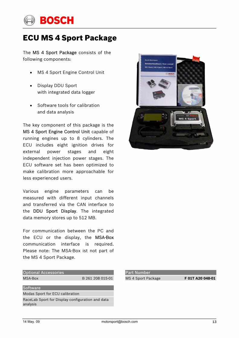
ECU MS 4 Sport Package
The MS 4 Sport Package consists of the following components:
• MS 4 Sport Engine Control Unit
• Display DDU Sport with integrated data logger
• Software tools for calibration and data analysis
The key component of this package is theMS 4 Sport Engine Control Unit capable ofrunning engines up to 8 cylinders. TheECU includes eight ignition drives forexternal power stages and eightindependent injection power stages. TheECU software set has been optimized tomake calibration more approachable forless experienced users.
Various engine parameters can bemeasured with different input channelsand transferred via the CAN interface tothe DDU Sport Display. The integrateddata memory stores up to 512 MB.
For communication between the PC andthe ECU or the display, the MSA-Boxcommunication interface is required. Please note: The MSA-Box ist not part of the MS 4 Sport Package.
Optional Accessories MSA-Box B 261 208 015-01
Software Modas Sport for ECU calibration
RaceLab Sport for Display configuration and data analysis
Part Number MS 4 Sport Package F 01T A20 048-01
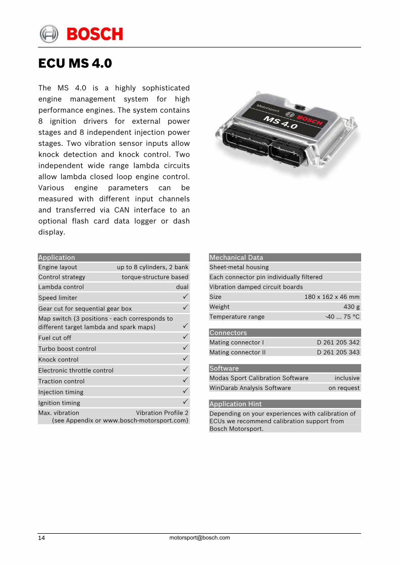
ECU MS 4.0
The MS 4.0 is a highly sophisticatedengine management system for highperformance engines. The system contains8 ignition drivers for external powerstages and 8 independent injection powerstages. Two vibration sensor inputs allowknock detection and knock control. Twoindependent wide range lambda circuitsallow lambda closed loop engine control.Various engine parameters can bemeasured with different input channelsand transferred via CAN interface to anoptional flash card data logger or dashdisplay.
Application Engine layout up to 8 cylinders, 2 bank
Control strategy torque-structure based
Lambda control dual
Speed limiter
Gear cut for sequential gear box
Map switch (3 positions - each corresponds to different target lambda and spark maps)
Fuel cut off
Turbo boost control
Knock control
Electronic throttle control
Traction control
Injection timing
Ignition timing
Max. vibration Vibration Profile 2 (see Appendix or www.bosch-motorsport.com)
Mechanical Data Sheet-metal housing
Each connector pin individually filtered
Vibration damped circuit boards
Size 180 x 162 x 46 mm
Weight 430 g
Temperature range -40 … 75 °C
Connectors Mating connector I D 261 205 342
Mating connector II D 261 205 343
Software Modas Sport Calibration Software inclusive
WinDarab Analysis Software on request
Application Hint Depending on your experiences with calibration of ECUs we recommend calibration support from Bosch Motorsport.
14 May. 09 [email protected] 15
Electrical Data Max. power consumption 30 W at 14 V
Inputs
2 inputs for exhaust gas temperature sensors
2 lambda interfaces LSU
4 inputs for Hall-effect wheel speed sensors
1 input for inductive crankshaft sensor
1 input for Hall-effect camshaft sensor
16 universal inputs 0 … 5 V
2 knock sensor inputs
7 digital inputs
Outputs
8 injection power stages
8 ignition drivers
20 power stages (2,7 A/0,6 A; low side; PWM)
2 power stages for lambda heater
1 H-bridge (5 A)
2 sensor supply 5 V/100 mA
Communication interfaces
1 K-line serial interface
2 CAN interfaces for external communication
Optional Accessories MSA-Box B 261 208 015-01
Data logger C Sport F 01T A20 061
Data logger C 40 F 01T A20 403
Data logger C 40 Plus B 261 206 860
Display DDU Sport (incl. logger) F 01T A20 050-01
Display DDU 4 F 01E B01 461
Display DDU 6 F 01E B01 459
Part Number MS 4.0 B 261 208 300-01
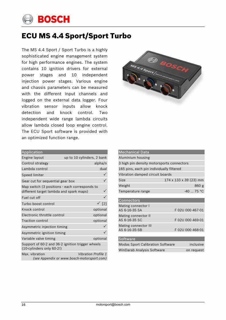
ECU MS 4.4 Sport/Sport Turbo
The MS 4.4 Sport / Sport Turbo is a highlysophisticated engine management systemfor high performance engines. The systemcontains 10 ignition drivers for externalpower stages and 10 independentinjection power stages. Various engineand chassis parameters can be measuredwith the different input channels and logged on the external data logger. Fourvibration sensor inputs allow knockdetection and knock control. Twoindependent wide range lambda circuitsallow lambda closed loop engine control.The ECU Sport software is provided withan optimized function range.
Application Engine layout up to 10 cylinders, 2 bank
Control strategy alpha/n
Lambda control dual
Speed limiter
Gear cut for sequential gear box
Map switch (3 positions - each corresponds to different target lambda and spark maps)
Fuel cut off
Turbo boost control [2]
Knock control optional
Electronic throttle control optional
Traction control optional
Asymmetric injection timing
Asymmetric ignition timing
Variable valve timing optional
Support of 60-2 and 36-2 ignition trigger wheels (10-cylinders only 60-2!)
Max. vibration Vibration Profile 1 (see Appendix or www.bosch-motorsport.com)
Mechanical Data Aluminium housing
3 high pin density motorsports connectors
165 pins, each pin individually filtered
Vibration damped circuit boards
Size 174 x 133 x 39 (23) mm
Weight 860 g
Temperature range -40 … 75 °C
Connectors Mating connector I AS 6-16-35 SA F 02U 000 467-01
Mating connector II AS 6-16-35 SC F 02U 000 469-01
Mating connector III AS 6-16-35-SB F 02U 000 468-01
Software Modas Sport Calibration Software inclusive
WinDarab Analysis Software on request
14 May. 09 [email protected] 17
Electrical Data Max. power consumption 20 W at 14 V
Inputs
1 input for inductive crankshaft sensor
4 inputs for Hall-effect camshaft sensors
4 inputs for Hall-effect wheel speed sensors
2 lambda interfaces LSU 4.9
39 inputs 0 … 5 V (20 with configurable pullups)
4 knock sensor inputs
8 digital inputs
Outputs
10 injection power stages (2.2 A)
10 ignition drivers for external power stages
21 power stages (2.7 A/0.6 A; low side)
2 power stages for lambda heater
1 H-bridge (7 A)
3 sensor supply 5 V/600 mA
Communication interfaces
1 K-line serial interface
2 CAN interfaces for external communication
Optional Accessories MSA-Box B 261 208 015-01
Data logger C Sport F 01T A20 061
Data logger C 40 F 01T A20 403
Data logger C40 Plus B 261 206 860
Display DDU Sport (incl. Logger) F 01T A20 050-01
Display DDU 4 F 01E B01 461
Display DDU 6 F 01E B01 459
Part Number MS 4.4 Sport [1] F 01T A20 068-01
MS 4.4 Sport Turbo [2] F 01T A20 074-01
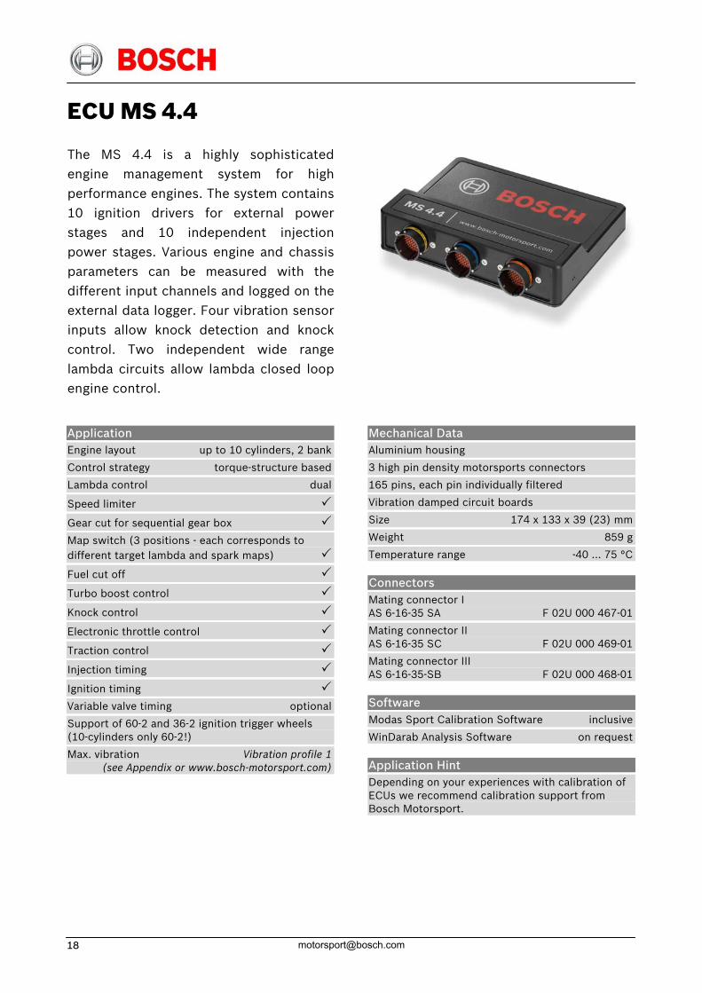
ECU MS 4.4
The MS 4.4 is a highly sophisticatedengine management system for highperformance engines. The system contains10 ignition drivers for external powerstages and 10 independent injectionpower stages. Various engine and chassis parameters can be measured with thedifferent input channels and logged on theexternal data logger. Four vibration sensorinputs allow knock detection and knockcontrol. Two independent wide rangelambda circuits allow lambda closed loopengine control.
Application Engine layout up to 10 cylinders, 2 bank
Control strategy torque-structure based
Lambda control dual
Speed limiter
Gear cut for sequential gear box
Map switch (3 positions - each corresponds to different target lambda and spark maps)
Fuel cut off
Turbo boost control
Knock control
Electronic throttle control
Traction control
Injection timing
Ignition timing
Variable valve timing optional
Support of 60-2 and 36-2 ignition trigger wheels (10-cylinders only 60-2!)
Max. vibration Vibration profile 1 (see Appendix or www.bosch-motorsport.com)
Mechanical Data Aluminium housing
3 high pin density motorsports connectors
165 pins, each pin individually filtered
Vibration damped circuit boards
Size 174 x 133 x 39 (23) mm
Weight 859 g
Temperature range -40 … 75 °C
Connectors Mating connector I AS 6-16-35 SA F 02U 000 467-01
Mating connector II AS 6-16-35 SC F 02U 000 469-01
Mating connector III AS 6-16-35-SB F 02U 000 468-01
Software Modas Sport Calibration Software inclusive
WinDarab Analysis Software on request
Application Hint Depending on your experiences with calibration of ECUs we recommend calibration support from Bosch Motorsport.
14 May. 09 [email protected] 19
Electrical Data Max. power consumption 20 W at 14 V
Inputs
1 input for inductive crankshaft sensor
4 inputs for Hall-effect camshaft sensors
4 inputs for Hall-effect wheel speed sensors
2 lambda interfaces LSU 4.9
39 inputs 0 … 5 V (20 with configurable pullups)
4 inputs for vibration knock sensors
8 digital inputs
Outputs
10 injection power stages (2.2 A)
10 ignition drivers for external power stages
21 power stages (2.7 A/0.6 A; low side)
2 power stages for lambda heater
1 H-bridge (7 A)
3 sensor supply 5 V/600 mA
Communication interfaces
1 K-line serial interface
2 CAN interfaces for external communication
Optional Accessories MSA-Box B 261 208 015-01
Data logger C 40 F 01T A20 403
Data logger C 40 Plus B 261 206 860
Display DDU Sport (incl. logger) F 01T A20 050-01
Display DDU 4 F 01E B01 461
Display DDU 6 F 01E B01 459
Part Number MS 4.4 F 01T A20 040
ECU MS 5.1
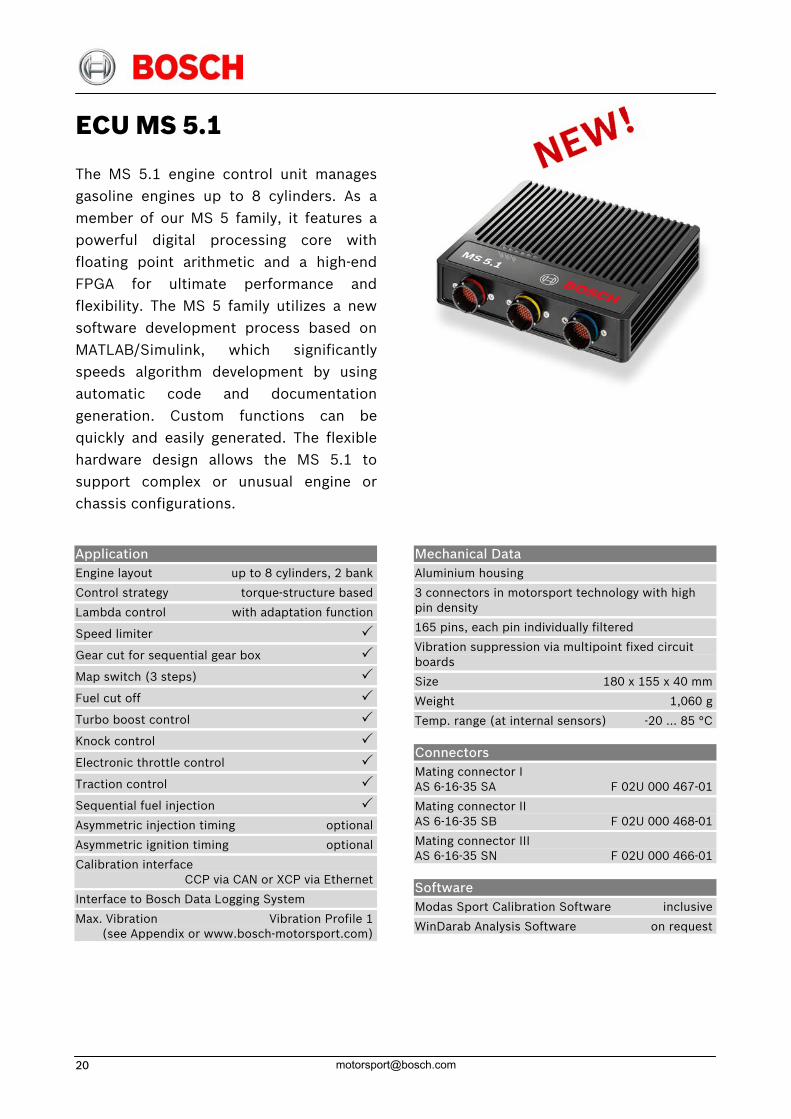
The MS 5.1 engine control unit managesgasoline engines up to 8 cylinders. As amember of our MS 5 family, it features apowerful digital processing core withfloating point arithmetic and a high-end FPGA for ultimate performance andflexibility. The MS 5 family utilizes a newsoftware development process based onMATLAB/Simulink, which significantlyspeeds algorithm development by usingautomatic code and documentationgeneration. Custom functions can bequickly and easily generated. The flexiblehardware design allows the MS 5.1 to support complex or unusual engine orchassis configurations.
Application Engine layout up to 8 cylinders, 2 bank
Control strategy torque-structure based
Lambda control with adaptation function
Speed limiter
Gear cut for sequential gear box
Map switch (3 steps)
Fuel cut off
Turbo boost control
Knock control
Electronic throttle control
Traction control
Sequential fuel injection
Asymmetric injection timing optional
Asymmetric ignition timing optional
Calibration interface CCP via CAN or XCP via Ethernet
Interface to Bosch Data Logging System
Max. Vibration Vibration Profile 1 (see Appendix or www.bosch-motorsport.com)
Mechanical Data Aluminium housing
3 connectors in motorsport technology with high pin density
165 pins, each pin individually filtered
Vibration suppression via multipoint fixed circuit boards
Size 180 x 155 x 40 mm
Weight 1,060 g
Temp. range (at internal sensors) -20 … 85 °C
Connectors Mating connector I AS 6-16-35 SA F 02U 000 467-01
Mating connector II AS 6-16-35 SB F 02U 000 468-01
Mating connector III AS 6-16-35 SN F 02U 000 466-01
Software Modas Sport Calibration Software inclusive
WinDarab Analysis Software on request
14 May. 09 [email protected] 21
Electrical Data Approx. power cons. (w/o loads) 9 W at 14 V
Power Supply
Operating range 6.5 … 18 V
Recommended 11 … 14 V
Absolute maximum 6 … 24 V
Inputs
2 thermocouple exhaust gas temperature sensors
2 lambda interfaces (LSU 4.9)
1 crankshaft sensor (2-wire, inductive or Hall-effect)
1 camshaft sensor (2-wire, inductive or Hall-effect)
2 turbo speed sensors (2-wire, inductive or Hall-effect)
4 wheel speed sensors (inductive or Hall-effect)
38 universal analog inputs 0 … 5 V; 12 Bit
4 analog inputs (angle synchronous or time synchronous triggering up to 250 ksps, 12 Bit)
4 knock sensor inputs
1 laptrigger input
Outputs
8 injection power stages
8 ignition power stages (up to 20 A)
20 power stages (2 A; low side; PWM)
4 power stages (4 A; low side; PWM)
2 H-bridges (5 A)
3 sensor supplies 5 V/400 mA and 1x 10 V/200 mA
1 protected Ubat output 1A
6 diagnostic outputs with selectable internal signals
1 timebase reference synch-in/out
Communication interfaces
2 x 100 Mbps Ethernet interfaces
1 x RS232 serial interface
3 x 1 Mbps CAN interfaces
Application Hints Depending on your experience with ECU calibration, we recommend calibration support from the experienced team at Bosch Motorsport.
Optional Accessories MSA-Box B 261 208 015-01
Data logger C 55 F 01E B01 630
Display DDU 4 F 01E B01 461
Display DDU 6 F 01E B01 459
Part Number MS 5.1 F 01T A20 071-01
ECU MS 5.5
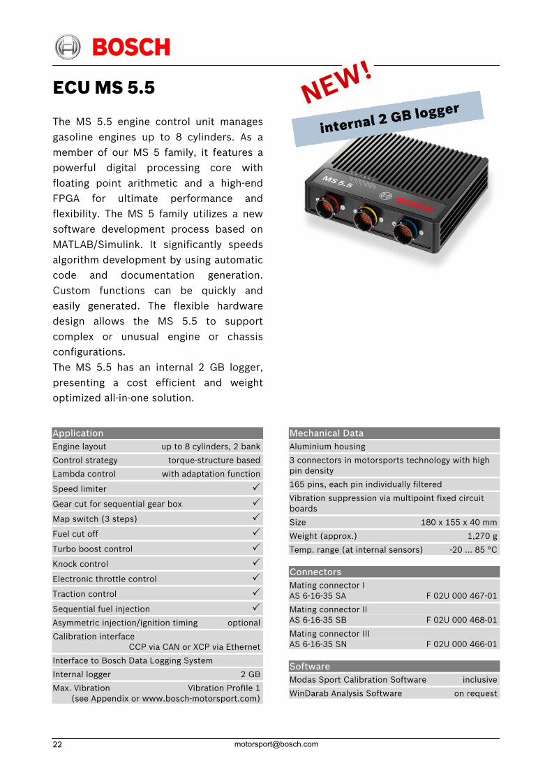
The MS 5.5 engine control unit managesgasoline engines up to 8 cylinders. As amember of our MS 5 family, it features apowerful digital processing core withfloating point arithmetic and a high-end FPGA for ultimate performance andflexibility. The MS 5 family utilizes a newsoftware development process based onMATLAB/Simulink. It significantly speeds algorithm development by using automaticcode and documentation generation.Custom functions can be quickly andeasily generated. The flexible hardwaredesign allows the MS 5.5 to supportcomplex or unusual engine or chassisconfigurations. The MS 5.5 has an internal 2 GB logger,presenting a cost efficient and weightoptimized all-in-one solution.
Application Engine layout up to 8 cylinders, 2 bank
Control strategy torque-structure based
Lambda control with adaptation function
Speed limiter
Gear cut for sequential gear box
Map switch (3 steps)
Fuel cut off
Turbo boost control
Knock control
Electronic throttle control
Traction control
Sequential fuel injection
Asymmetric injection/ignition timing optional
Calibration interface CCP via CAN or XCP via Ethernet
Interface to Bosch Data Logging System
Internal logger 2 GB
Max. Vibration Vibration Profile 1 (see Appendix or www.bosch-motorsport.com)
Mechanical Data Aluminium housing
3 connectors in motorsports technology with high pin density
165 pins, each pin individually filtered
Vibration suppression via multipoint fixed circuit boards
Size 180 x 155 x 40 mm
Weight (approx.) 1,270 g
Temp. range (at internal sensors) -20 … 85 °C
Connectors Mating connector I AS 6-16-35 SA F 02U 000 467-01
Mating connector II AS 6-16-35 SB F 02U 000 468-01
Mating connector III AS 6-16-35 SN F 02U 000 466-01
Software Modas Sport Calibration Software inclusive
WinDarab Analysis Software on request
14 May. 09 [email protected] 23
Electrical Data Approx. power cons. (w/o loads) 13 W at 14 V
Power Supply
Full operation 6.5 … 18 V
Recommended 11 … 14 V
Absolute maximum 6 … 24 V
Inputs
2 thermocouple exhaust gas temperature sensors
2 lambda interfaces (LSU 4.9)
1 crankshaft sensor (2-wire, inductive or Hall-effect)
1 camshaft sensor (2-wire, inductive or Hall-effect)
2 turbo speed sensors (2-wire, inductive or Hall-effect)
4 wheel speed sensors (inductive or Hall-effect)
38 universal analog inputs 0 … 5 V; 12 Bit
4 analog inputs (angle synchronous or time synchronous triggering up to 250 ksps, 12 Bit)
4 inputs for vibration knock sensors
1 laptrigger input
Outputs
8 injection power stages
8 ignition power stages (up to 20 A)
20 power stages (2 A; low side; PWM)
4 power stages (4 A; low side; PWM)
2 H-bridges (5 A)
3 sensor supplies 5 V/400 mA and 1x 10 V/200 mA
1 protected Ubat output 1A
6 diagnostic outputs with selectable internal signals
1 timebase synch-in/out
Communication interfaces
2 x 100 Mbps Ethernet interfaces
1 x RS232 serial interface
3 x 1 Mbps CAN interfaces
Application Hints Depending on your experiences with calibration of ECUs we recommend calibration support from Bosch Motorsport.
Optional Accessories MSA-Box B 261 208 015-01
Display DDU 4 F 01E B01 461
Display DDU 6 F 01E B01 459
Part Number MS 5.5 F 02U V00 285-01
ECU MS 5.2
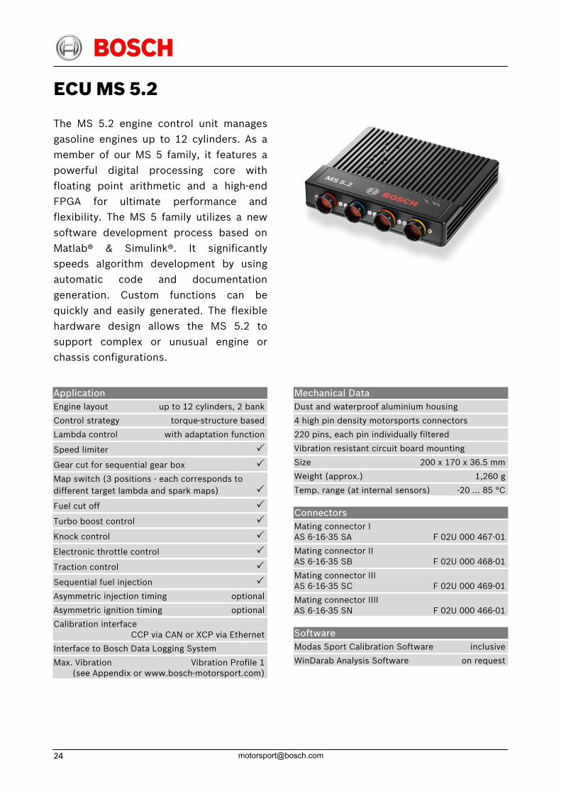
The MS 5.2 engine control unit managesgasoline engines up to 12 cylinders. As amember of our MS 5 family, it features apowerful digital processing core withfloating point arithmetic and a high-end FPGA for ultimate performance andflexibility. The MS 5 family utilizes a newsoftware development process based onMatlab® & Simulink®. It significantlyspeeds algorithm development by usingautomatic code and documentationgeneration. Custom functions can bequickly and easily generated. The flexible hardware design allows the MS 5.2 tosupport complex or unusual engine orchassis configurations.
Application Engine layout up to 12 cylinders, 2 bank
Control strategy torque-structure based
Lambda control with adaptation function
Speed limiter
Gear cut for sequential gear box
Map switch (3 positions - each corresponds to different target lambda and spark maps)
Fuel cut off
Turbo boost control
Knock control
Electronic throttle control
Traction control
Sequential fuel injection
Asymmetric injection timing optional
Asymmetric ignition timing optional
Calibration interface CCP via CAN or XCP via Ethernet
Interface to Bosch Data Logging System
Max. Vibration Vibration Profile 1 (see Appendix or www.bosch-motorsport.com)
Mechanical Data Dust and waterproof aluminium housing
4 high pin density motorsports connectors
220 pins, each pin individually filtered
Vibration resistant circuit board mounting
Size 200 x 170 x 36.5 mm
Weight (approx.) 1,260 g
Temp. range (at internal sensors) -20 … 85 °C
Connectors Mating connector I AS 6-16-35 SA F 02U 000 467-01
Mating connector II AS 6-16-35 SB F 02U 000 468-01
Mating connector III AS 6-16-35 SC F 02U 000 469-01
Mating connector IIII AS 6-16-35 SN F 02U 000 466-01
Software Modas Sport Calibration Software inclusive
WinDarab Analysis Software on request
14 May. 09 [email protected] 25
Electrical Data Power cons. (w/o loads) approx. 10 W at 14 V
Power Supply
Operating range 6.5 … 18 V
Recommended 11 … 14 V
Absolute maximum 6 … 24 V
Inputs
2 thermocouple exhaust gas temperature sensors
2 lambda interfaces (LSU 4.9)
1 crankshaft sensor (2-wire, inductive or Hall-effect)
1 camshaft sensor (2-wire, inductive or Hall-effect)
2 turbo speed sensors (2-wire, inductive or Hall-effect)
4 wheel speed sensors (inductive or Hall-effect)
2 gearbox speed sensors (inductive or Hall-effect)
45 universal analog inputs 0 … 5 V, 12 Bit
14 analog inputs (angle synchronous or time synchronous triggering up to 250 ksps, 12 Bit)
4 inputs for vibration knock sensors
1 laptrigger input
Outputs
12 injection power stages (peak & hold)
12 ignition power stages (up to 20 A)
16 power stages (2 A; low side; PWM)
4 power stages (4 A; low side; PWM)
4 H-bridge valve drivers (± 100 mA)
2 H-bridges (5 A)
3 sensor supplies 5 V/400 mA and 1x 10 V/100 mA
6 diagnostic outputs with selectable internal signals
12 outputs with configurable function (FPGA)
1 timebase reference synch-in/out
Communication interfaces
2 x 100 Mbps Ethernet interfaces
1 x RS232 serial interface
4 x 1 Mbps CAN interfaces
Application Hints Depending on your experiences with calibration of ECUs we recommend calibration support from Bosch Motorsport.
Optional Accessories MSA-Box B 261 208 015-01
Data logger C 55 F 01E B01 630
Display DDU 4 F 01E B01 461
Display DDU 6 F 01E B01 459
Part Number MS 5.2 F 01T A20 069-01
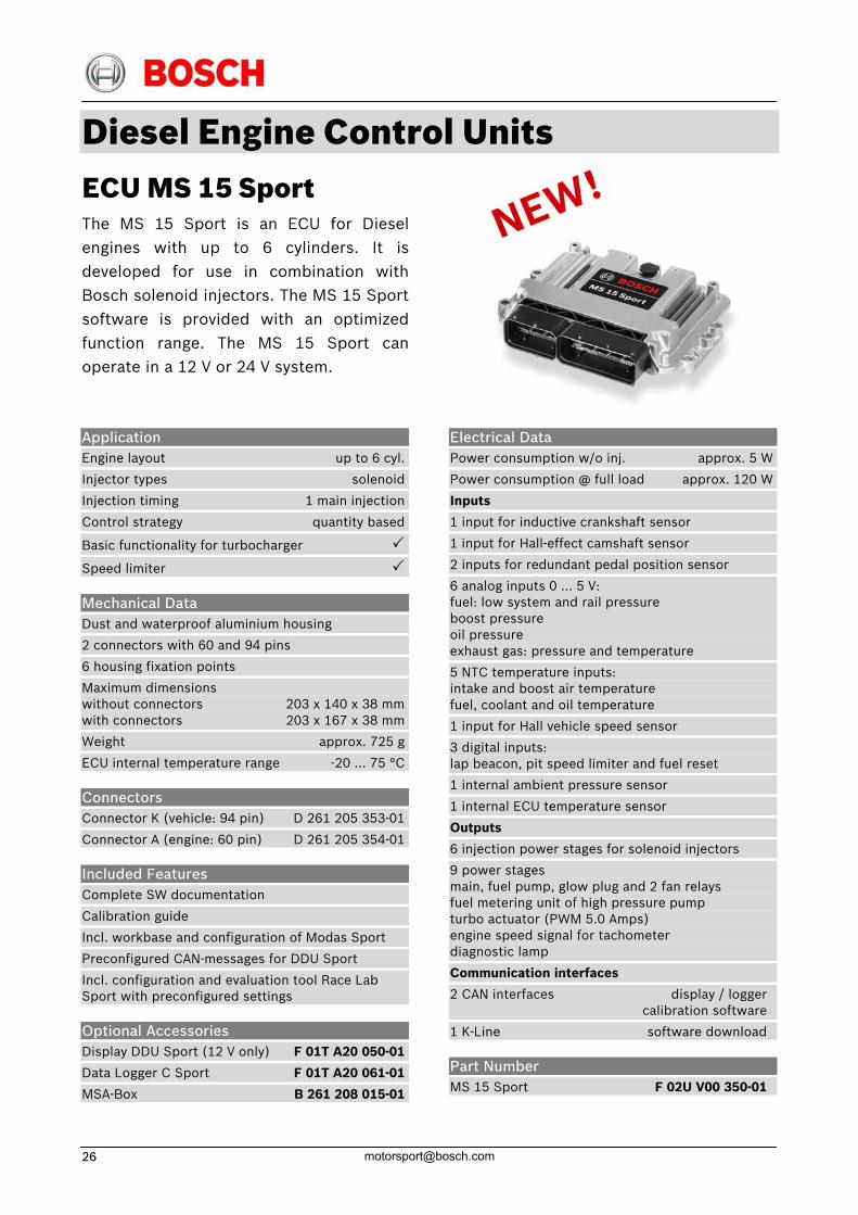
Diesel Engine Control Units ECU MS 15 Sport The MS 15 Sport is an ECU for Dieselengines with up to 6 cylinders. It is developed for use in combination withBosch solenoid injectors. The MS 15 Sport software is provided with an optimizedfunction range. The MS 15 Sport canoperate in a 12 V or 24 V system.
Application Engine layout up to 6 cyl.
Injector types solenoid
Injection timing 1 main injection
Control strategy quantity based
Basic functionality for turbocharger
Speed limiter
Mechanical Data Dust and waterproof aluminium housing
2 connectors with 60 and 94 pins
6 housing fixation points
Maximum dimensions without connectors 203 x 140 x 38 mmwith connectors 203 x 167 x 38 mm
Weight approx. 725 g
ECU internal temperature range -20 … 75 °C
Connectors Connector K (vehicle: 94 pin) D 261 205 353-01
Connector A (engine: 60 pin) D 261 205 354-01
Included Features Complete SW documentation
Calibration guide
Incl. workbase and configuration of Modas Sport
Preconfigured CAN-messages for DDU Sport
Incl. configuration and evaluation tool Race Lab Sport with preconfigured settings
Optional Accessories Display DDU Sport (12 V only) F 01T A20 050-01
Data Logger C Sport F 01T A20 061-01
MSA-Box B 261 208 015-01
Electrical Data Power consumption w/o inj. approx. 5 W
Power consumption @ full load approx. 120 W
Inputs
1 input for inductive crankshaft sensor
1 input for Hall-effect camshaft sensor
2 inputs for redundant pedal position sensor
6 analog inputs 0 … 5 V: fuel: low system and rail pressure boost pressure oil pressure exhaust gas: pressure and temperature
5 NTC temperature inputs: intake and boost air temperature fuel, coolant and oil temperature
1 input for Hall vehicle speed sensor
3 digital inputs: lap beacon, pit speed limiter and fuel reset
1 internal ambient pressure sensor
1 internal ECU temperature sensor
Outputs
6 injection power stages for solenoid injectors
9 power stages main, fuel pump, glow plug and 2 fan relays fuel metering unit of high pressure pump turbo actuator (PWM 5.0 Amps) engine speed signal for tachometer diagnostic lamp
Communication interfaces
2 CAN interfaces display / logger calibration software
1 K-Line software download
Part Number MS 15 Sport F 02U V00 350-01
14 May. 09 [email protected] 27
ECU MS 15.1
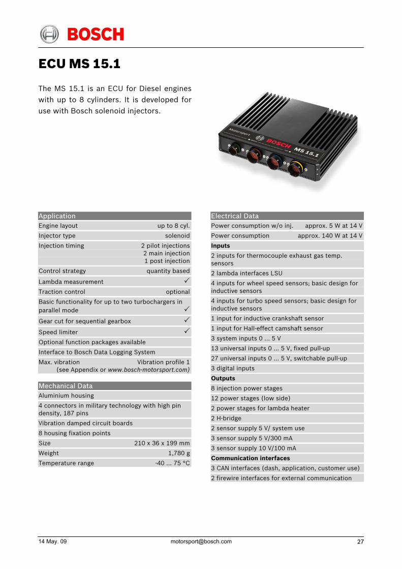
The MS 15.1 is an ECU for Diesel engineswith up to 8 cylinders. It is developed for use with Bosch solenoid injectors.
Application Engine layout up to 8 cyl.
Injector type solenoid
Injection timing 2 pilot injections 2 main injection 1 post injection
Control strategy quantity based
Lambda measurement
Traction control optional
Basic functionality for up to two turbochargers in parallel mode
Gear cut for sequential gearbox
Speed limiter
Optional function packages available
Interface to Bosch Data Logging System
Max. vibration Vibration profile 1 (see Appendix or www.bosch-motorsport.com)
Mechanical Data Aluminium housing
4 connectors in military technology with high pin density, 187 pins
Vibration damped circuit boards
8 housing fixation points
Size 210 x 36 x 199 mm
Weight 1,780 g
Temperature range -40 … 75 °C
Electrical Data Power consumption w/o inj. approx. 5 W at 14 V
Power consumption approx. 140 W at 14 V
Inputs
2 inputs for thermocouple exhaust gas temp. sensors
2 lambda interfaces LSU
4 inputs for wheel speed sensors; basic design for inductive sensors
4 inputs for turbo speed sensors; basic design for inductive sensors
1 input for inductive crankshaft sensor
1 input for Hall-effect camshaft sensor
3 system inputs 0 … 5 V
13 universal inputs 0 … 5 V, fixed pull-up
27 universal inputs 0 … 5 V, switchable pull-up
3 digital inputs
Outputs
8 injection power stages
12 power stages (low side)
2 power stages for lambda heater
2 H-bridge
2 sensor supply 5 V/ system use
3 sensor supply 5 V/300 mA
3 sensor supply 10 V/100 mA
Communication interfaces
3 CAN interfaces (dash, application, customer use)
2 firewire interfaces for external communication
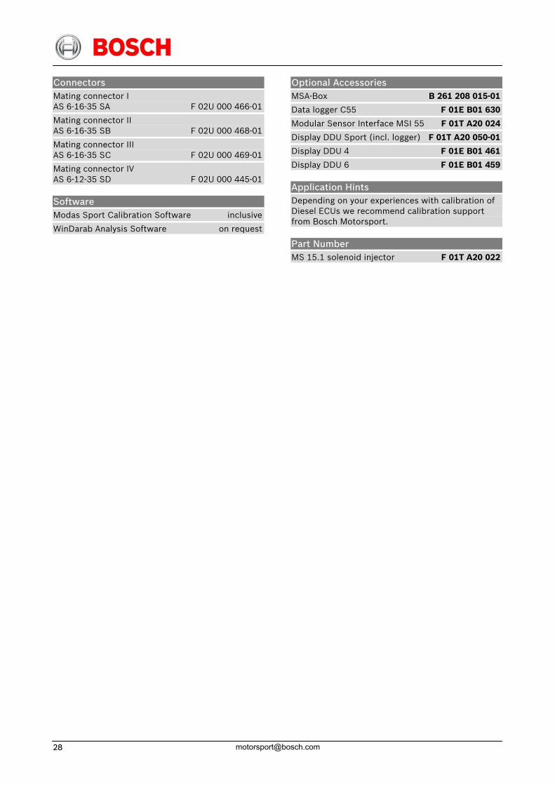
Connectors Mating connector I AS 6-16-35 SA F 02U 000 466-01
Mating connector II AS 6-16-35 SB F 02U 000 468-01
Mating connector III AS 6-16-35 SC F 02U 000 469-01
Mating connector IV AS 6-12-35 SD F 02U 000 445-01
Software Modas Sport Calibration Software inclusive
WinDarab Analysis Software on request
Optional Accessories MSA-Box B 261 208 015-01
Data logger C55 F 01E B01 630
Modular Sensor Interface MSI 55 F 01T A20 024
Display DDU Sport (incl. logger) F 01T A20 050-01
Display DDU 4 F 01E B01 461
Display DDU 6 F 01E B01 459
Application Hints Depending on your experiences with calibration of Diesel ECUs we recommend calibration support from Bosch Motorsport.
Part Number MS 15.1 solenoid injector F 01T A20 022

14 May. 09 [email protected] 29
ECU MS 15.2
The MS 15.2 is an ECU for Diesel engineswith up to 6 cylinders. It is developed for use with Bosch piezo injectors.
Application Engine layout up to 6 cyl.
Injector type piezo
Injection timing 2 pilot injections 1 main injection 1 post injection
Control strategy quantity based
Lambda measurement
Traction control optional
Basic functionality for up to two turbochargers in parallel mode
Gear cut for sequential gearbox
Speed limiter
Optional function packages available
Interface to Bosch Data Logging System
Max. vibration Vibration profile 1 (see Appendix or www.bosch-motorsport.com)
Mechanical Data Aluminium housing
4 connectors in motorsports technology with high pin density, 187 pins
Vibration damped circuit boards
8 housing fixation points
Size 210 x 36 x 199 mm
Weight 1,780 g
Temperature range -40 … 75 °C
Electrical Data Power consumption w/o inj. approx. 5 W at 14 V
Power consumption approx. 140 W at 14 V
Inputs
2 inputs for thermocouple exhaust gas temp. sensors
2 lambda interfaces LSU
4 inputs for wheel speed sensors; basic design for inductive sensors
4 inputs for turbo speed sensors; basic design for inductive sensors
1 input for inductive crankshaft sensor
1 input for Hall-effect camshaft sensor
3 system inputs 0 … 5 V
13 universal inputs 0 … 5 V, fixed pullup
27 universal inputs 0 … 5 V, switchable pullup
3 digital inputs
Outputs
6 injection power stages
12 power stages (low side)
2 power stages for lambda heater
2 H-bridges
2 sensor supply 5 V/ system use
3 sensor supply 5 V/300 mA
3 sensor supply 10 V/100 mA
Communication interfaces
3 CAN interfaces (dash, application, customer use)
2 firewire interfaces for external communication
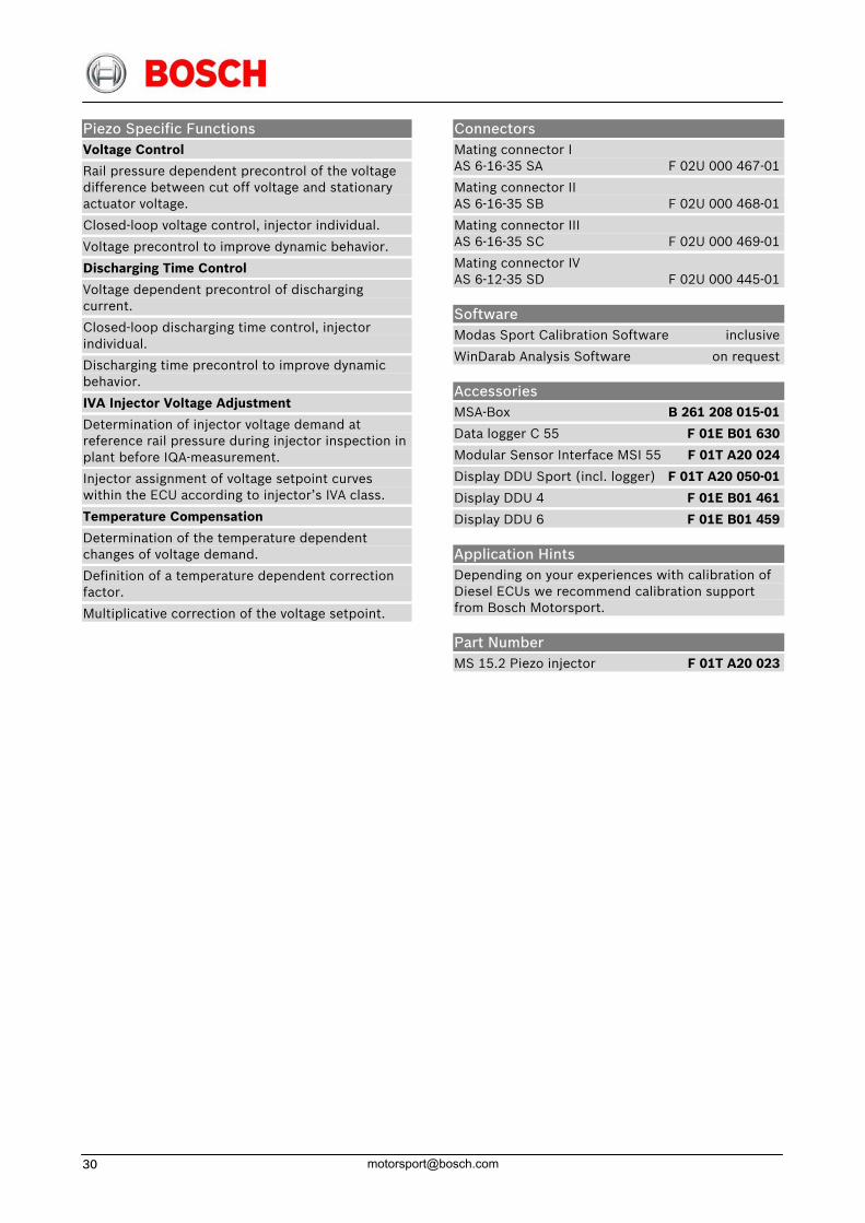
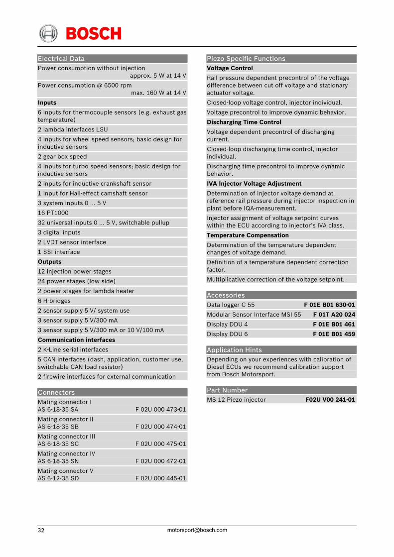
Piezo Specific Functions Voltage Control
Rail pressure dependent precontrol of the voltage difference between cut off voltage and stationary actuator voltage.
Closed-loop voltage control, injector individual.
Voltage precontrol to improve dynamic behavior.
Discharging Time Control
Voltage dependent precontrol of discharging current.
Closed-loop discharging time control, injector individual.
Discharging time precontrol to improve dynamic behavior.
IVA Injector Voltage Adjustment
Determination of injector voltage demand at reference rail pressure during injector inspection in plant before IQA-measurement.
Injector assignment of voltage setpoint curves within the ECU according to injector’s IVA class.
Temperature Compensation
Determination of the temperature dependent changes of voltage demand.
Definition of a temperature dependent correction factor.
Multiplicative correction of the voltage setpoint.
Connectors Mating connector I AS 6-16-35 SA F 02U 000 467-01
Mating connector II AS 6-16-35 SB F 02U 000 468-01
Mating connector III AS 6-16-35 SC F 02U 000 469-01
Mating connector IV AS 6-12-35 SD F 02U 000 445-01
Software Modas Sport Calibration Software inclusive
WinDarab Analysis Software on request
Accessories MSA-Box B 261 208 015-01
Data logger C 55 F 01E B01 630
Modular Sensor Interface MSI 55 F 01T A20 024
Display DDU Sport (incl. logger) F 01T A20 050-01
Display DDU 4 F 01E B01 461
Display DDU 6 F 01E B01 459
Application Hints Depending on your experiences with calibration of Diesel ECUs we recommend calibration support from Bosch Motorsport.
Part Number MS 15.2 Piezo injector F 01T A20 023
14 May. 09 [email protected] 31
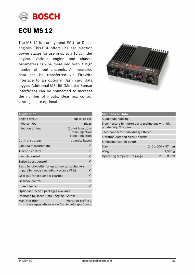
ECU MS 12
The MS 12 is the high-end ECU for Dieselengines. This ECU offers 12 Piezo injectionpower stages for use in up to a 12 cylinderengine. Various engine and chassisparameters can be measured with a high number of input channels. All measureddata can be transferred via FireWireinterface to an optional flash card datalogger. Additional MSI 55 (Modular SensorInterfaces) can be connected to increase the number of inputs. Gear box controlstrategies are optional.
Application Engine layout up to 12 cyl.
Injector type piezo
Injection timing 2 pilot injections 1 main injection 1 post injection
Control strategy quantity based
Lambda measurement
Traction control
Launch control
Turbo boost control
Basic functionality for up to two turbochargers in parallel mode (including variable VTG) Gear cut for sequential gearbox
Gearbox control
Speed limiter
Optional function packages available
Interface to Bosch Data Logging System
Max. vibration Vibration profile 1 (see Appendix or www.bosch-motorsport.com)
Mechanical Data Aluminium housing
5 connectors in motorsports technology with high pin density, 242 pins
Each connector individually filtered
Vibration damped circuit boards
8 housing fixation points
Size 240 x 200 x 57 mm
Weight 2,500 g
Operating temperature range -20 … 85 °C
Electrical Data Power consumption without injection approx. 5 W at 14 V
Power consumption @ 6500 rpm max. 160 W at 14 V
Inputs
6 inputs for thermocouple sensors (e.g. exhaust gas temperature)
2 lambda interfaces LSU
4 inputs for wheel speed sensors; basic design for inductive sensors
2 gear box speed
4 inputs for turbo speed sensors; basic design for inductive sensors
2 inputs for inductive crankshaft sensor
1 input for Hall-effect camshaft sensor
3 system inputs 0 … 5 V
16 PT1000
32 universal inputs 0 … 5 V, switchable pullup
3 digital inputs
2 LVDT sensor interface
1 SSI interface
Outputs
12 injection power stages
24 power stages (low side)
2 power stages for lambda heater
6 H-bridges
2 sensor supply 5 V/ system use
3 sensor supply 5 V/300 mA
3 sensor supply 5 V/300 mA or 10 V/100 mA
Communication interfaces
2 K-Line serial interfaces
5 CAN interfaces (dash, application, customer use, switchable CAN load resistor)
2 firewire interfaces for external communication
Connectors Mating connector I AS 6-18-35 SA F 02U 000 473-01
Mating connector II AS 6-18-35 SB F 02U 000 474-01
Mating connector III AS 6-18-35 SC F 02U 000 475-01
Mating connector IV AS 6-18-35 SN F 02U 000 472-01
Mating connector V AS 6-12-35 SD F 02U 000 445-01
Piezo Specific Functions Voltage Control
Rail pressure dependent precontrol of the voltage difference between cut off voltage and stationary actuator voltage.
Closed-loop voltage control, injector individual.
Voltage precontrol to improve dynamic behavior.
Discharging Time Control
Voltage dependent precontrol of discharging current.
Closed-loop discharging time control, injector individual.
Discharging time precontrol to improve dynamic behavior.
IVA Injector Voltage Adjustment
Determination of injector voltage demand at reference rail pressure during injector inspection in plant before IQA-measurement.
Injector assignment of voltage setpoint curves within the ECU according to injector’s IVA class.
Temperature Compensation
Determination of the temperature dependent changes of voltage demand.
Definition of a temperature dependent correction factor.
Multiplicative correction of the voltage setpoint.
Accessories Data logger C 55 F 01E B01 630-01
Modular Sensor Interface MSI 55 F 01T A20 024
Display DDU 4 F 01E B01 461
Display DDU 6 F 01E B01 459
Application Hints Depending on your experiences with calibration of Diesel ECUs we recommend calibration support from Bosch Motorsport.
Part Number MS 12 Piezo injector F02U V00 241-01
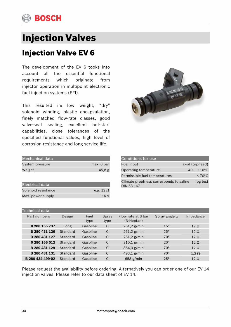
Injection Valves Injection Valve EV 6
The development of the EV 6 tooks intoaccount all the essential functionalrequirements which originate frominjector operation in multipoint electronicfuel injection systems (EFI).
This resulted in: low weight, “dry”solenoid winding, plastic encapsulation,finely matched flow-rate classes, good valve-seat sealing, excellent hot-start capabilities, close tolerances of thespecified functional values, high level ofcorrosion resistance and long service life.
Mechanical data System pressure max. 8 bar
Weight 45,8 g
Electrical data Solenoid resistance e.g. 12 Ω
Max. power supply 16 V
Conditions for use Fuel input axial (top-feed)
Operating temperature -40 ... 110°C
Permissible fuel temperatures ≤ 70°C
Climate proofness corresponds to saline fog test DIN 53 167
Technical data Part numbers
Design
Fuel type
Spray type
Flow rate at 3 bar(N-Heptan)
Spray angle α
Impedance
0 280 155 737 Long Gasoline C 261,2 g/min 15° 12 Ω
B 280 431 126 Standard Gasoline C 261,2 g/min 25° 12 Ω
B 280 431 127 Standard Gasoline C 261,2 g/min 70° 12 Ω
0 280 156 012 Standard Gasoline C 310,1 g/min 20° 12 Ω
B 280 431 129 Standard Gasoline C 364,3 g/min 70° 12 Ω
B 280 431 131 Standard Gasoline C 493,1 g/min 70° 1,2 Ω
B 280 434 499-02 Standard Gasoline C 658 g/min 25° 12 Ω Please request the availability before ordering. Alternatively you can order one of our EV 14 injection valves. Please refer to our data sheet of EV 14.
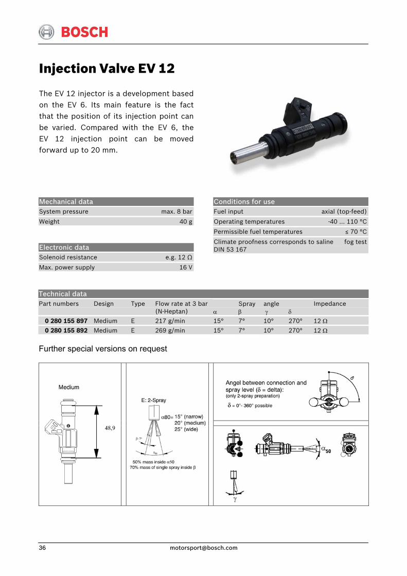
Injection Valve EV 12
The EV 12 injector is a development basedon the EV 6. Its main feature is the factthat the position of its injection point canbe varied. Compared with the EV 6, theEV 12 injection point can be movedforward up to 20 mm.
Mechanical data System pressure max. 8 bar
Weight 40 g
Electronic data Solenoid resistance e.g. 12 Ω
Max. power supply 16 V
Conditions for use Fuel input axial (top-feed)
Operating temperatures -40 ... 110 °C
Permissible fuel temperatures ≤ 70 °C
Climate proofness corresponds to saline fog test DIN 53 167
Technical data Part numbers
Design
Type
Flow rate at 3 bar(N-Heptan)
α
Spray β
angle γ
δ
Impedance
0 280 155 897 Medium E 217 g/min 15° 7° 10° 270° 12 Ω
0 280 155 892 Medium E 269 g/min 15° 7° 10° 270° 12 Ω Further special versions on request
Injection & Ignition
14 May. 09 [email protected] 37
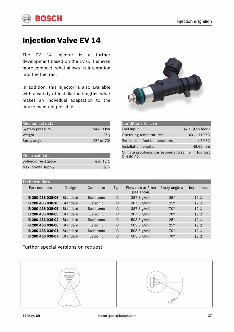
Injection Valve EV 14
The EV 14 injector is a further development based on the EV 6. It is even more compact, what allows its integration into the fuel rail.
In addition, this injector is also available with a variety of installation lengths, what makes an individual adaptation to the intake manifold possible.
Mechanical data System pressure max. 8 bar
Weight 25 g
Spray angle 25° or 70°
Electrical data Solenoid resistance e.g. 12 Ω
Max. power supply 16 V
Conditions for use Fuel input axial (top-feed)
Operating temperatures -40 ... 110 °C
Permissible fuel temperatures ≤ 70 °C
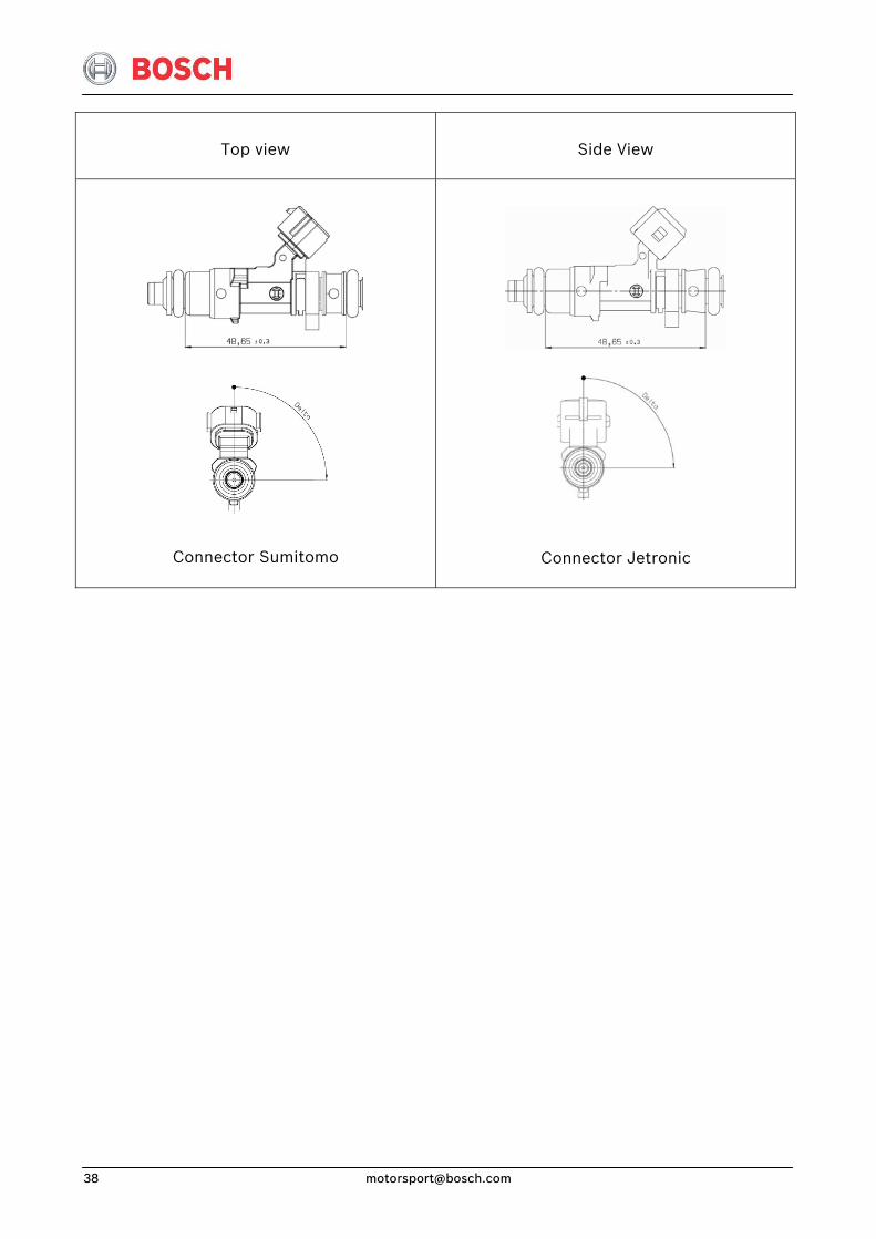
Installation lengths 48,65 mm
Climate proofness corresponds to saline fog test DIN 50 021
Technical data Part numbers
Design
Connector
Type
Flow rate at 3 bar
(N-Heptan) Spray angle α
Impedance
B 280 436 038-06 Standard Sumitomo C 387,3 g/min 25° 12 Ω
B 280 436 038-10 Standard Jetronic C 387,3 g/min 25° 12 Ω
B 280 436 038-05 Standard Sumitomo C 387,3 g/min 70° 12 Ω
B 280 436 038-09 Standard Jetronic C 387,3 g/min 70° 12 Ω
B 280 436 038-02 Standard Sumitomo C 503,5 g/min 25° 12 Ω
B 280 436 038-08 Standard Jetronic C 503,5 g/min 25° 12 Ω
B 280 436 038-01 Standard Sumitomo C 503,5 g/min 70° 12 Ω
B 280 436 038-07 Standard Jetronic C 503,5 g/min 70° 12 Ω Further special versions on request.
Injection & Ignition
14 May. 09 [email protected] 39
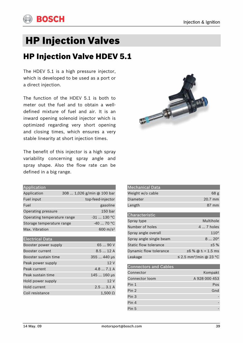
HP Injection Valves HP Injection Valve HDEV 5.1
The HDEV 5.1 is a high pressure injector,which is developed to be used as a port ora direct injection.
The function of the HDEV 5.1 is both tometer out the fuel and to obtain a well-defined mixture of fuel and air. It is aninward opening solenoid injector which isoptimized regarding very short openingand closing times, which ensures a verystable linearity at short injection times.
The benefit of this injector is a high sprayvariability concerning spray angle andspray shape. Also the flow rate can bedefined in a big range.
Application Application 308 … 1,026 g/min @ 100 bar
Fuel input top-feed-injector
Fuel gasoline
Operating pressure 150 bar
Operating temperature range -31 … 130 °C
Storage temperature range -40 … 70 °C
Max. Vibration 600 m/s2
Electrical Data Booster power supply 65 … 90 V
Booster current 8.5 … 12 A
Booster sustain time 355 … 440 μs
Peak power supply 12 V
Peak current 4.8 … 7.1 A
Peak sustain time 145 … 160 μs
Hold power supply 12 V
Hold current 2.5 … 3.1 A
Coil resistance 1,500 Ω
Mechanical Data Weight w/o cable 68 g
Diameter 20.7 mm
Length 87 mm
Characteristic Spray type Multihole
Number of holes 4 … 7 holes
Spray angle overall 110°
Spray angle single beam 8 … 20°
Static flow tolerance ±5 %
Dynamic flow tolerance ±6 % @ ti = 1.5 ms
Leakage ≤ 2.5 mm³/min @ 23 °C
Connectors and Cables Connector Kompakt
Connector loom A 928 000 453
Pin 1 Pos
Pin 2 Gnd
Pin 3 -
Pin 4 -
Pin 5 -
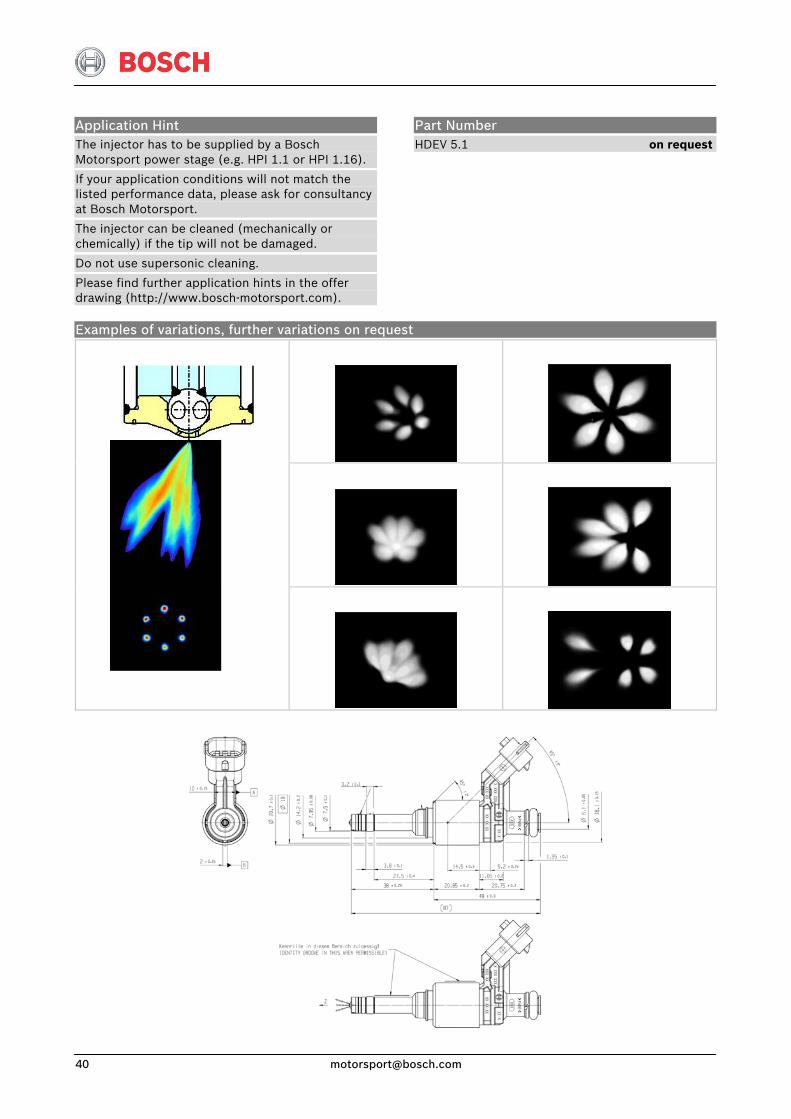
Application Hint The injector has to be supplied by a Bosch Motorsport power stage (e.g. HPI 1.1 or HPI 1.16).
If your application conditions will not match the listed performance data, please ask for consultancy at Bosch Motorsport.
The injector can be cleaned (mechanically or chemically) if the tip will not be damaged.
Do not use supersonic cleaning.
Please find further application hints in the offer drawing (http://www.bosch-motorsport.com).
Part Number HDEV 5.1 on request
Examples of variations, further variations on request
Injection & Ignition
14 May. 09 [email protected] 41
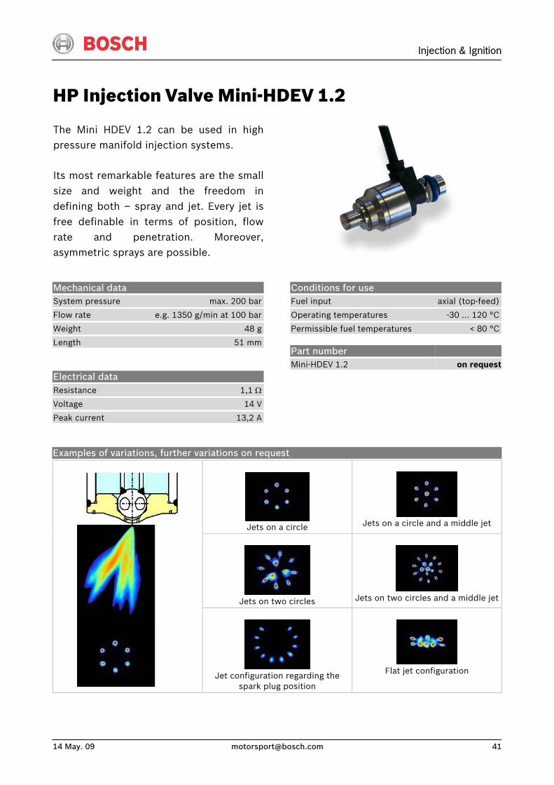
HP Injection Valve Mini-HDEV 1.2
The Mini HDEV 1.2 can be used in highpressure manifold injection systems.
Its most remarkable features are the smallsize and weight and the freedom indefining both – spray and jet. Every jet isfree definable in terms of position, flowrate and penetration. Moreover,asymmetric sprays are possible.
Conditions for use Fuel input axial (top-feed)
Operating temperatures -30 … 120 °C
Permissible fuel temperatures < 80 °C
Mechanical data System pressure max. 200 bar
Flow rate e.g. 1350 g/min at 100 bar
Weight 48 g
Length 51 mm
Electrical data Resistance 1,1 Ω
Voltage 14 V
Peak current 13,2 A
Part number Mini-HDEV 1.2
on request
Examples of variations, further variations on request
Jets on a circle
Jets on a circle and a middle jet
Jets on two circles
Jets on two circles and a middle jet
Jet configuration regarding the
spark plug position
Flat jet configuration
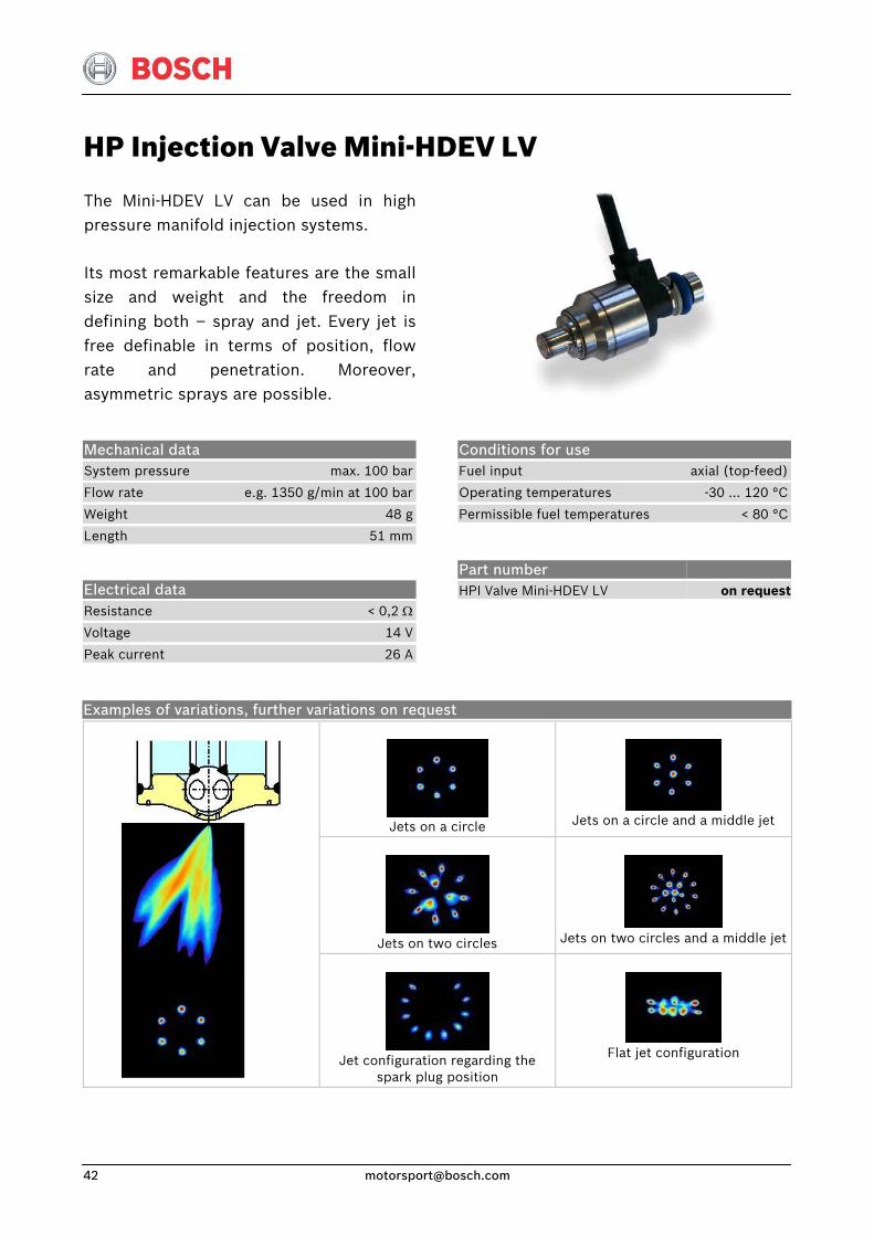
HP Injection Valve Mini-HDEV LV
The Mini-HDEV LV can be used in highpressure manifold injection systems.
Its most remarkable features are the smallsize and weight and the freedom indefining both – spray and jet. Every jet isfree definable in terms of position, flowrate and penetration. Moreover,asymmetric sprays are possible.
Conditions for use Fuel input axial (top-feed)
Operating temperatures -30 … 120 °C
Permissible fuel temperatures < 80 °C
Mechanical data System pressure max. 100 bar
Flow rate e.g. 1350 g/min at 100 bar
Weight 48 g
Length 51 mm
Electrical data Resistance < 0,2 Ω
Voltage 14 V
Peak current 26 A
Part number HPI Valve Mini-HDEV LV
on request
Examples of variations, further variations on request
Jets on a circle
Jets on a circle and a middle jet
Jets on two circles
Jets on two circles and a middle jet
Jet configuration regarding the
spark plug position
Flat jet configuration
Injection & Ignition
14 May. 09 [email protected] 43
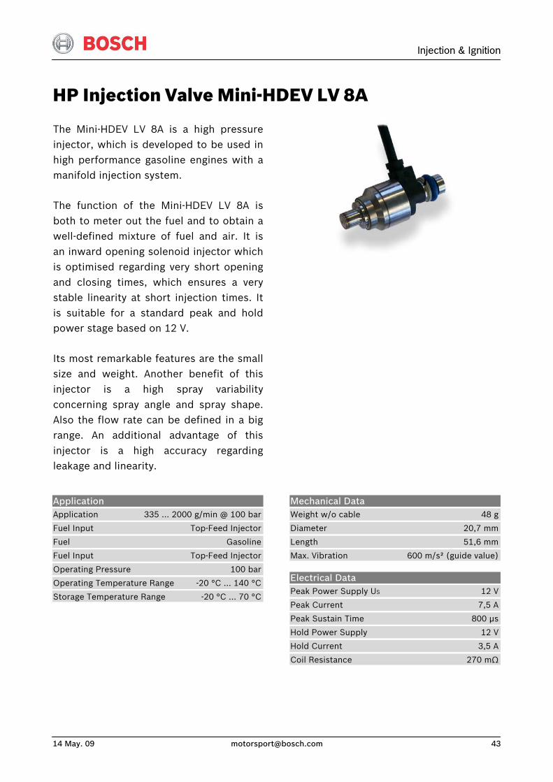
HP Injection Valve Mini-HDEV LV 8A
The Mini-HDEV LV 8A is a high pressureinjector, which is developed to be used inhigh performance gasoline engines with amanifold injection system.
The function of the Mini-HDEV LV 8A is both to meter out the fuel and to obtain awell-defined mixture of fuel and air. It isan inward opening solenoid injector whichis optimised regarding very short openingand closing times, which ensures a verystable linearity at short injection times. Itis suitable for a standard peak and holdpower stage based on 12 V.
Its most remarkable features are the smallsize and weight. Another benefit of this injector is a high spray variabilityconcerning spray angle and spray shape.Also the flow rate can be defined in a bigrange. An additional advantage of thisinjector is a high accuracy regardingleakage and linearity.
Application Application 335 ... 2000 g/min @ 100 bar
Fuel Input Top-Feed Injector
Fuel Gasoline
Fuel Input Top-Feed Injector
Operating Pressure 100 bar
Operating Temperature Range -20 °C … 140 °C
Storage Temperature Range -20 °C … 70 °C
Mechanical Data Weight w/o cable 48 g
Diameter 20,7 mm
Length 51,6 mm
Max. Vibration 600 m/s² (guide value)
Electrical Data Peak Power Supply US 12 V
Peak Current 7,5 A
Peak Sustain Time 800 μs
Hold Power Supply 12 V
Hold Current 3,5 A
Coil Resistance 270 mΩ
Connectors and Cables Cable Size AWG18
Cable Length < 100 cm
Sleeve DR 25
Various military and automotive connectors on request.
Application Hint The injector can be supplied by a peak and hold power stage with maximum 8 A @ 12 V.
If your application conditions will not match the listed performance data, please ask for consultancy at Bosch Motorsport.
The injector can be cleaned (mechanically or chemically) if the tip will not be damaged.
Do not use supersonic cleaning.
Please find further application hints in the offer drawing (http://www.bosch-motorsport.com).
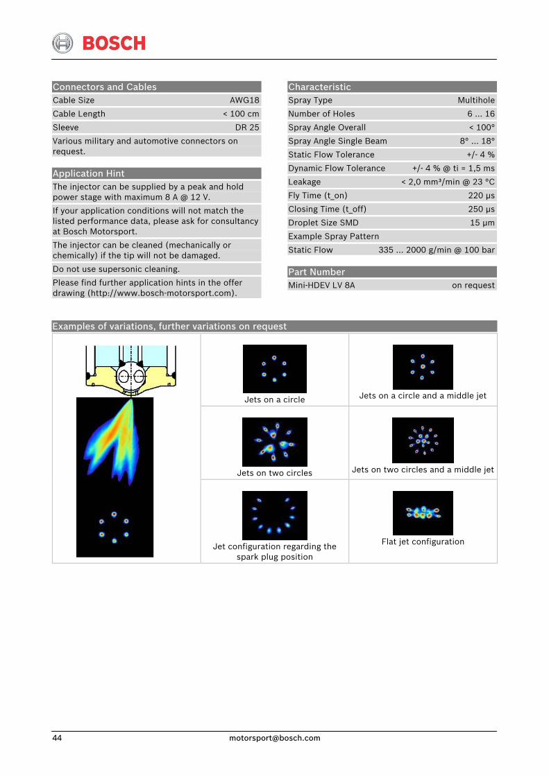
Characteristic Spray Type Multihole
Number of Holes 6 … 16
Spray Angle Overall < 100°
Spray Angle Single Beam 8° … 18°
Static Flow Tolerance +/- 4 %
Dynamic Flow Tolerance +/- 4 % @ ti = 1,5 ms
Leakage < 2,0 mm³/min @ 23 °C
Fly Time (t_on) 220 μs
Closing Time (t_off) 250 μs
Droplet Size SMD 15 μm
Example Spray Pattern
Static Flow 335 ... 2000 g/min @ 100 bar
Part Number Mini-HDEV LV 8A on request
Examples of variations, further variations on request
Jets on a circle
Jets on a circle and a middle jet
Jets on two circles
Jets on two circles and a middle jet
Jet configuration regarding the
spark plug position
Flat jet configuration
Injection & Ignition
14 May. 09 [email protected] 45
Power Stage Units HPI 1.1
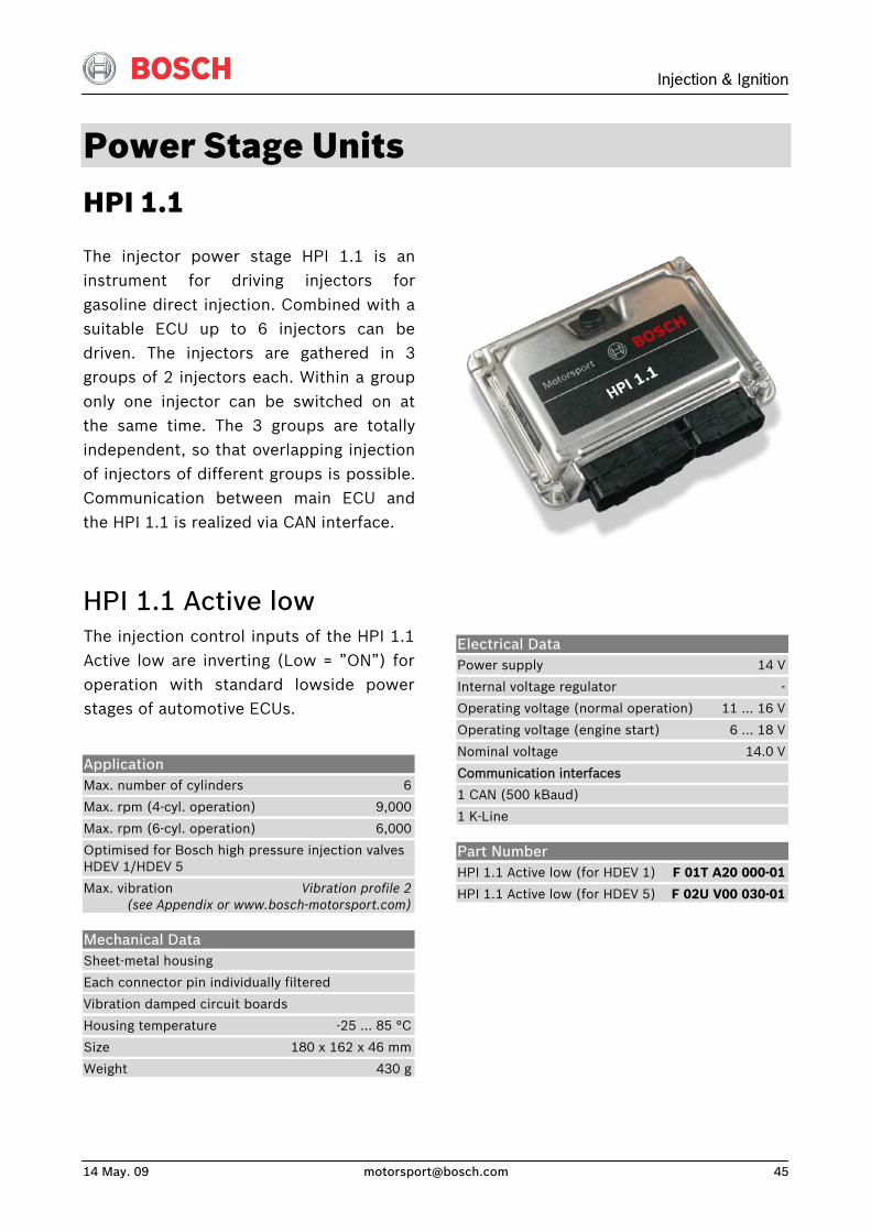
The injector power stage HPI 1.1 is an instrument for driving injectors forgasoline direct injection. Combined with asuitable ECU up to 6 injectors can bedriven. The injectors are gathered in 3groups of 2 injectors each. Within a grouponly one injector can be switched on atthe same time. The 3 groups are totallyindependent, so that overlapping injectionof injectors of different groups is possible. Communication between main ECU andthe HPI 1.1 is realized via CAN interface.
HPI 1.1 Active low
Electrical Data Power supply 14 V
Internal voltage regulator -
Operating voltage (normal operation) 11 … 16 V
Operating voltage (engine start) 6 … 18 V
Nominal voltage 14.0 V
Communication interfaces
1 CAN (500 kBaud)
1 K-Line
The injection control inputs of the HPI 1.1Active low are inverting (Low = ”ON”) foroperation with standard lowside powerstages of automotive ECUs.
Application Max. number of cylinders 6
Max. rpm (4-cyl. operation) 9,000
Max. rpm (6-cyl. operation) 6,000
Optimised for Bosch high pressure injection valves HDEV 1/HDEV 5
Max. vibration Vibration profile 2 (see Appendix or www.bosch-motorsport.com)
Mechanical Data Sheet-metal housing
Each connector pin individually filtered
Vibration damped circuit boards
Housing temperature -25 … 85 °C
Size 180 x 162 x 46 mm
Weight 430 g
Part Number HPI 1.1 Active low (for HDEV 1) F 01T A20 000-01
HPI 1.1 Active low (for HDEV 5) F 02U V00 030-01
HPI 1.1 Active high
Electrical Data Power supply 14 V
Internal voltage regulator -
Operating voltage (normal operation) 11 … 16 V
Operating voltage (engine start) 6 … 18 V
Nominal voltage 14.0 V
Communication interfaces
1 CAN (500kBaud)
1 K-Line
The injection control inputs of the HPI 1.1Active high are non-inverting (High = ”ON”).
Application Max. number of cylinders 6
Max. rpm (4-cyl. operation) 9,000
Max. rpm (6-cyl. operation) 6,000
Optimised for Bosch high pressure injection valves HDEV 1/HDEV 5
Max. vibration Vibration profile 2 (see Appendix or www.bosch-motorsport.com)
Mechanical Data Sheet-metal housing
Each connector pin individually filtered
Vibration damped circuit boards
Housing temperature -25 … 85 °C
Size 180 x 162 x 46 mm
Weight 430 g
Part Number HPI 1.1 Active high (for HDEV 1) F 01E B01 645-01
HPI 1.1 Active high (for HDEV 5) F 02U V00 036-01
Injection & Ignition
14 May. 09 [email protected] 47
HPI 1.16 LV / LVD
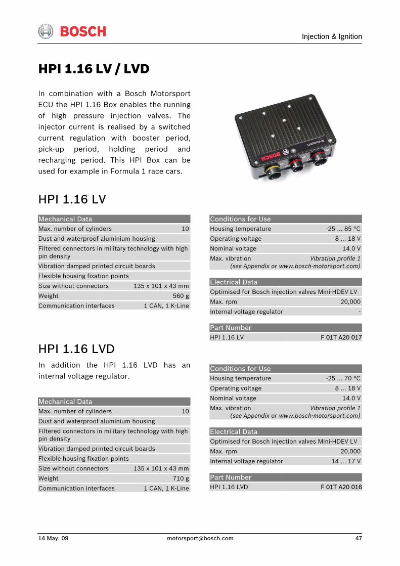
In combination with a Bosch MotorsportECU the HPI 1.16 Box enables the running of high pressure injection valves. Theinjector current is realised by a switchedcurrent regulation with booster period,pick-up period, holding period andrecharging period. This HPI Box can beused for example in Formula 1 race cars.
HPI 1.16 LV
Conditions for Use Housing temperature -25 … 85 °C
Operating voltage 8 … 18 V
Nominal voltage 14.0 V
Max. vibration Vibration profile 1 (see Appendix or www.bosch-motorsport.com)
Electrical Data Optimised for Bosch injection valves Mini-HDEV LV
Max. rpm 20,000
Internal voltage regulator -
Mechanical Data Max. number of cylinders 10
Dust and waterproof aluminium housing
Filtered connectors in military technology with high pin density
Vibration damped printed circuit boards
Flexible housing fixation points
Size without connectors 135 x 101 x 43 mm
Weight 560 g
Communication interfaces 1 CAN, 1 K-Line
Part Number HPI 1.16 LV
F 01T A20 017
HPI 1.16 LVD
Conditions for Use Housing temperature -25 … 70 °C
Operating voltage 8 … 18 V
Nominal voltage 14.0 V
Max. vibration Vibration profile 1 (see Appendix or www.bosch-motorsport.com)
Electrical Data Optimised for Bosch injection valves Mini-HDEV LV
Max. rpm 20,000
Internal voltage regulator 14 … 17 V
In addition the HPI 1.16 LVD has aninternal voltage regulator.
Mechanical Data Max. number of cylinders 10
Dust and waterproof aluminium housing
Filtered connectors in military technology with high pin density
Vibration damped printed circuit boards
Flexible housing fixation points
Size without connectors 135 x 101 x 43 mm
Weight 710 g
Communication interfaces 1 CAN, 1 K-Line
Part Number HPI 1.16 LVD
F 01T A20 016
HPI 1.16 HV / HVD
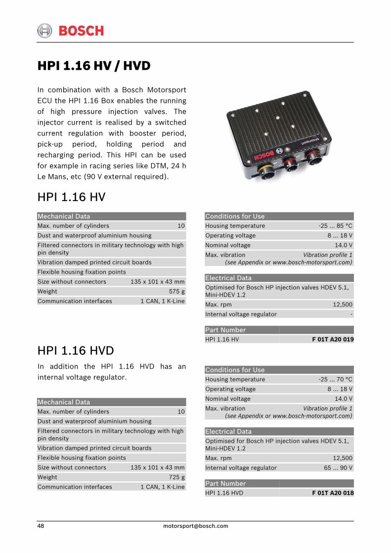
In combination with a Bosch MotorsportECU the HPI 1.16 Box enables the running of high pressure injection valves. Theinjector current is realised by a switchedcurrent regulation with booster period,pick-up period, holding period andrecharging period. This HPI can be usedfor example in racing series like DTM, 24 hLe Mans, etc (90 V external required).
HPI 1.16 HV
Conditions for Use Housing temperature -25 … 85 °C
Operating voltage 8 … 18 V
Nominal voltage 14.0 V
Max. vibration Vibration profile 1 (see Appendix or www.bosch-motorsport.com)
Electrical Data Optimised for Bosch HP injection valves HDEV 5.1, Mini-HDEV 1.2
Max. rpm 12,500
Internal voltage regulator -
Mechanical Data Max. number of cylinders 10
Dust and waterproof aluminium housing
Filtered connectors in military technology with high pin density
Vibration damped printed circuit boards
Flexible housing fixation points
Size without connectors 135 x 101 x 43 mm
Weight 575 g
Communication interfaces 1 CAN, 1 K-Line
Part Number HPI 1.16 HV
F 01T A20 019
HPI 1.16 HVD
Conditions for Use Housing temperature -25 … 70 °C
Operating voltage 8 … 18 V
Nominal voltage 14.0 V
Max. vibration Vibration profile 1 (see Appendix or www.bosch-motorsport.com)
Electrical Data Optimised for Bosch HP injection valves HDEV 5.1, Mini-HDEV 1.2
Max. rpm 12,500
Internal voltage regulator 65 … 90 V
In addition the HPI 1.16 HVD has aninternal voltage regulator.
Mechanical Data Max. number of cylinders 10
Dust and waterproof aluminium housing
Filtered connectors in military technology with high pin density
Vibration damped printed circuit boards
Flexible housing fixation points
Size without connectors 135 x 101 x 43 mm
Weight 725 g
Communication interfaces 1 CAN, 1 K-Line
Part Number HPI 1.16 HVD
F 01T A20 018
Injection & Ignition
14 May. 09 [email protected] 49
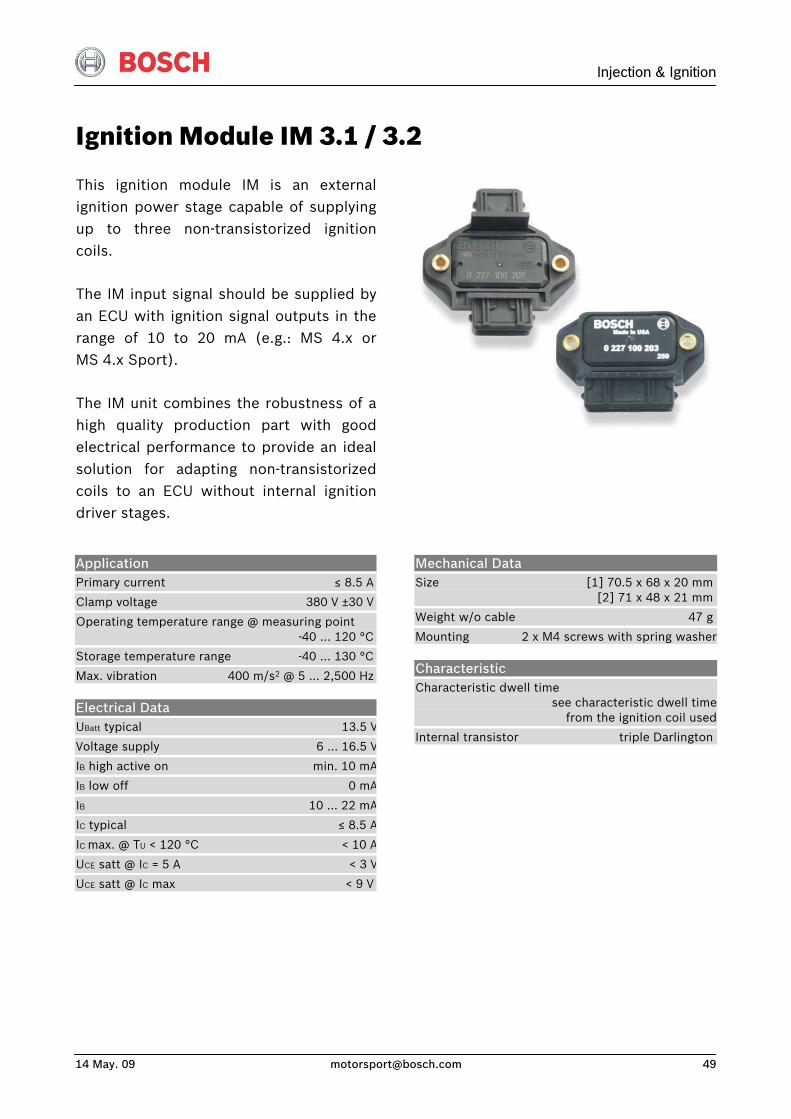
Ignition Module IM 3.1 / 3.2
This ignition module IM is an externalignition power stage capable of supplyingup to three non-transistorized ignitioncoils.
The IM input signal should be supplied byan ECU with ignition signal outputs in therange of 10 to 20 mA (e.g.: MS 4.x orMS 4.x Sport).
The IM unit combines the robustness of ahigh quality production part with goodelectrical performance to provide an idealsolution for adapting non-transistorizedcoils to an ECU without internal ignitiondriver stages.
Application Primary current ≤ 8.5 A
Clamp voltage 380 V ±30 V
Operating temperature range @ measuring point -40 … 120 °C
Storage temperature range -40 … 130 °C
Max. vibration 400 m/s2 @ 5 … 2,500 Hz
Electrical Data UBatt typical 13.5 V
Voltage supply 6 ... 16.5 V
IB high active on min. 10 mA
IB low off 0 mA
IB 10 … 22 mA
IC typical ≤ 8.5 A
IC max. @ TU < 120 °C < 10 A
UCE satt @ IC = 5 A < 3 V
UCE satt @ IC max < 9 V
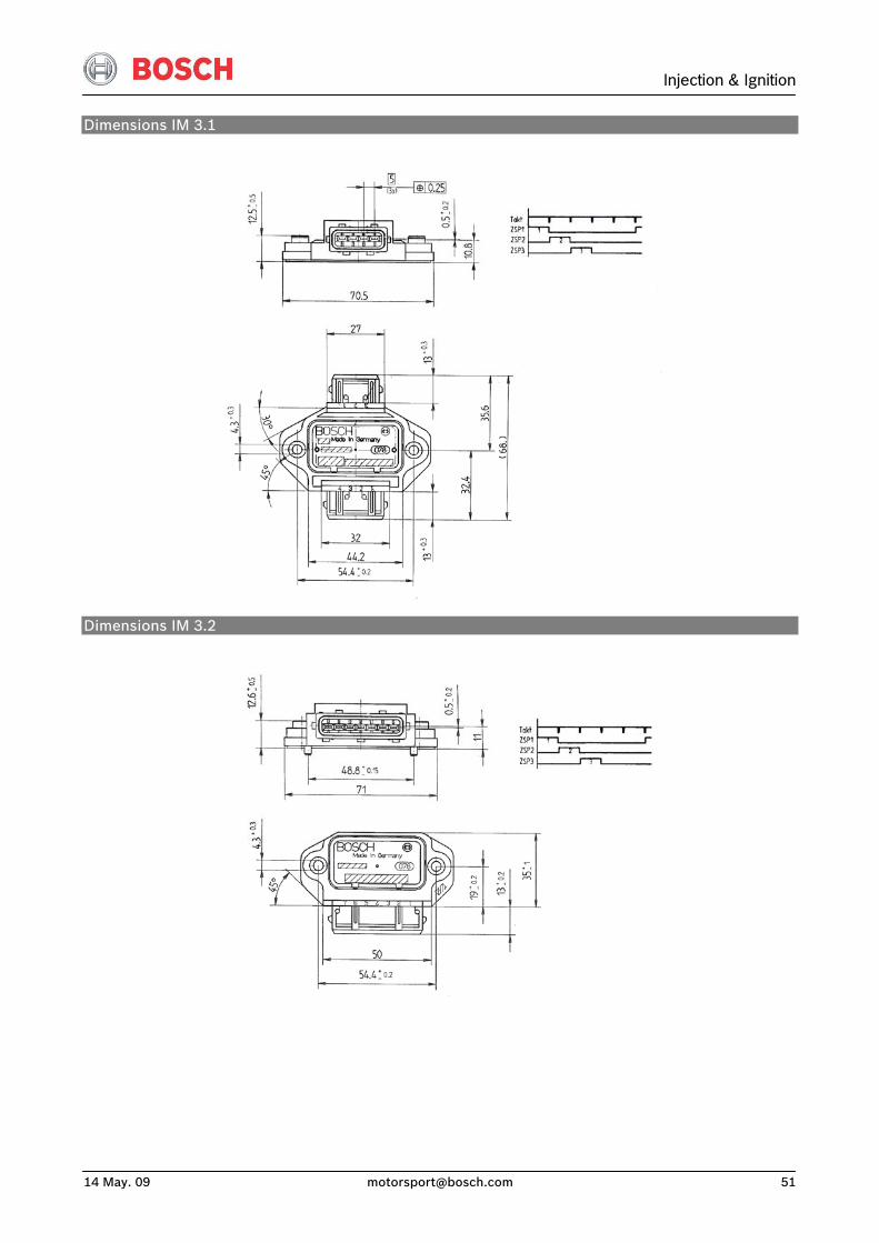
Mechanical Data Size [1] 70.5 x 68 x 20 mm [2] 71 x 48 x 21 mm
Weight w/o cable 47 g
Mounting 2 x M4 screws with spring washer
Characteristic Characteristic dwell time see characteristic dwell time from the ignition coil used
Internal transistor triple Darlington
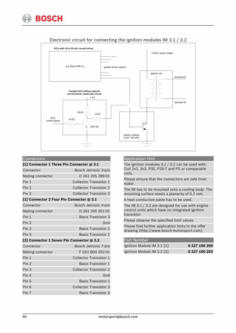
Electronic circuit for connecting the ignition modules IM 3.1 / 3.2
ignition coilterminal 4a
terminal 4b
U batt / power supply
e.g. Bosch MS 4.x
ECU with 10 to 20 mA current driver
Foreign ECU without special current driver needs this circuit
ignition driver outputs
150 Ω
10 kΩ
33 Ω
BCX 58
+ 5 V
ignition module0 227 100 2XX
ECUcontrol signal
Application Hint The ignition modules 3.1 / 3.2 can be used with: Coil 2x2, 3x2, P35, P35-T and PS or comparable coils.
Please ensure that the connectors are safe from water.
The IM has to be mounted onto a cooling body. The mounting surface needs a planarity of 0.2 mm.
A heat conductive paste has to be used.
The IM 3.1 / 3.2 are designed for use with engine control units which have no integrated ignition transistor.
Please observe the specified limit values.
Please find further application hints in the offer drawing (http://www.bosch-motorsport.com).
Connectors [1] Connector 1 Three Pin Connector @ 3.1
Connector Bosch Jetronic 3-pin
Mating connector D 261 205 289-01
Pin 1 Collector Transistor 1
Pin 2 Collector Transistor 2
Pin 3 Collector Transistor 3
[1] Connector 2 Four Pin Connector @ 3.1
Connector Bosch Jetronic 4-pin
Mating connector D 261 205 351-01
Pin 1 Basis Transistor 3
Pin 2 Gnd
Pin 3 Basis Transistor 2
Pin 4 Basis Transistor 1
[2] Connector 1 Seven Pin Connector @ 3.2
Connector Bosch Jetronic 7-pin
Mating connector F 02U B00 252-01
Pin 1 Collector Transistor 1
Pin 2 Basis Transistor 1
Pin 3 Collector Transistor 2
Pin 4 Gnd
Pin 5 Basis Transistor 2
Pin 6 Collector Transistor 3
Pin 7 Basis Transistor 3
Part Number Ignition Module IM 3.1 [1] 0 227 100 209
Ignition Module IM 3.2 [2] 0 227 100 203
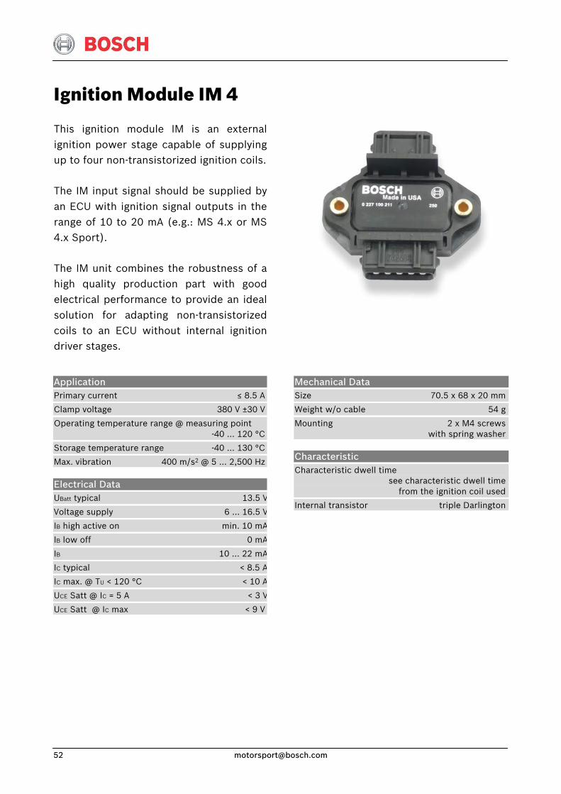
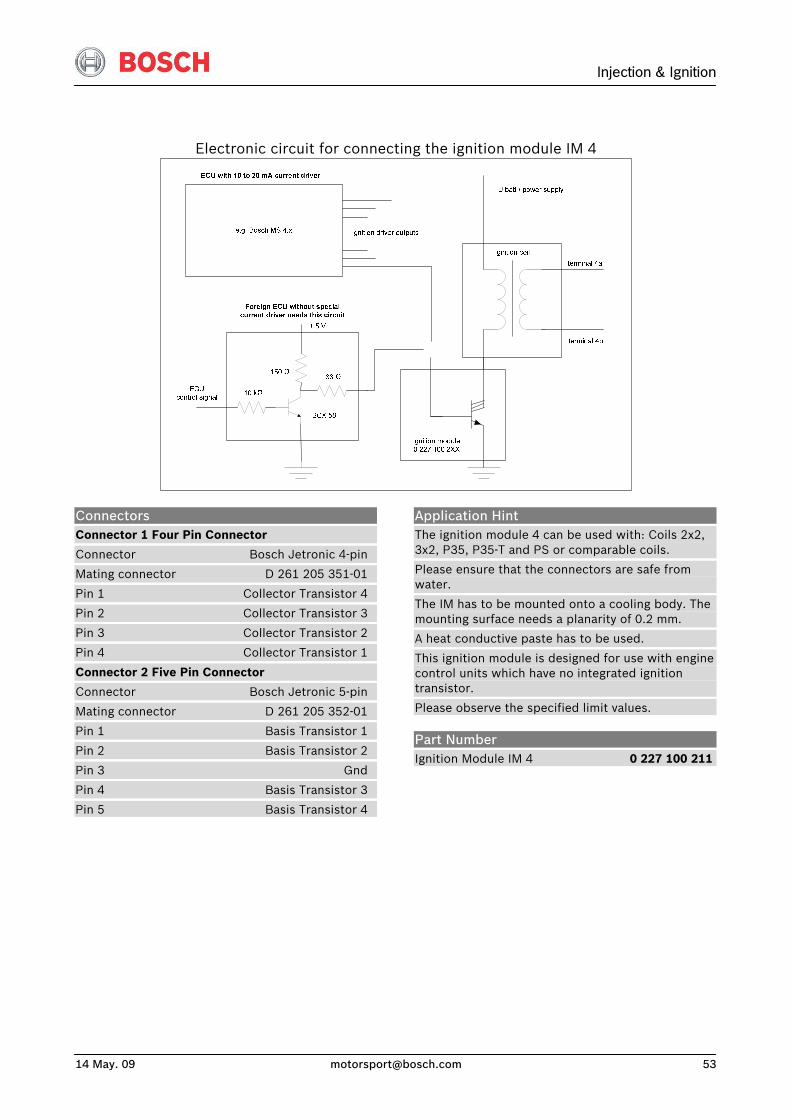
Ignition Module IM 4
This ignition module IM is an externalignition power stage capable of supplyingup to four non-transistorized ignition coils.
The IM input signal should be supplied byan ECU with ignition signal outputs in therange of 10 to 20 mA (e.g.: MS 4.x or MS4.x Sport).
The IM unit combines the robustness of ahigh quality production part with goodelectrical performance to provide an idealsolution for adapting non-transistorizedcoils to an ECU without internal ignitiondriver stages.
Application Primary current ≤ 8.5 A
Clamp voltage 380 V ±30 V
Operating temperature range @ measuring point -40 … 120 °C
Storage temperature range -40 … 130 °C
Max. vibration 400 m/s2 @ 5 … 2,500 Hz
Electrical Data UBatt typical 13.5 V
Voltage supply 6 ... 16.5 V
IB high active on min. 10 mA
IB low off 0 mA
IB 10 … 22 mA
IC typical < 8.5 A
IC max. @ TU < 120 °C < 10 A
UCE Satt @ IC = 5 A < 3 V
UCE Satt @ IC max < 9 V
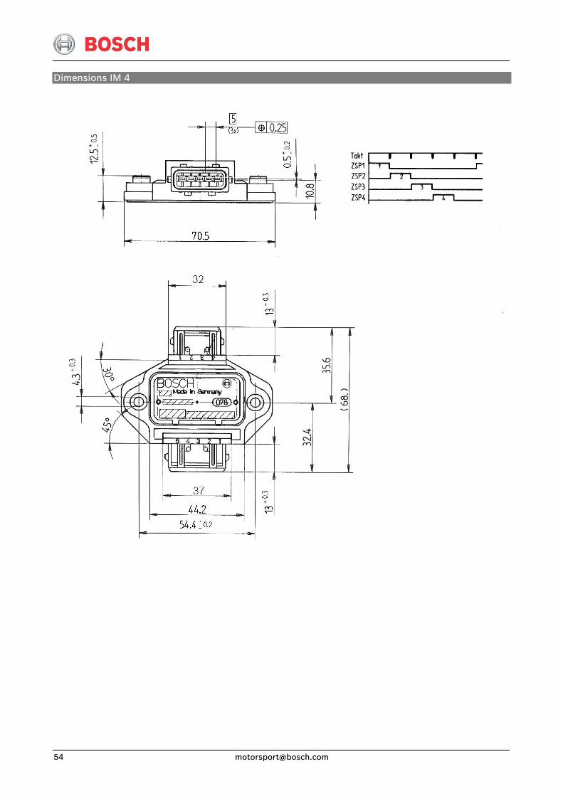
Mechanical Data Size 70.5 x 68 x 20 mm
Weight w/o cable 54 g
Mounting 2 x M4 screws with spring washer
Characteristic Characteristic dwell time see characteristic dwell time from the ignition coil used
Internal transistor triple Darlington
Injection & Ignition
14 May. 09 [email protected] 53
Electronic circuit for connecting the ignition module IM 4
Connectors Connector 1 Four Pin Connector
Connector Bosch Jetronic 4-pin
Mating connector D 261 205 351-01
Pin 1 Collector Transistor 4
Pin 2 Collector Transistor 3
Pin 3 Collector Transistor 2
Pin 4 Collector Transistor 1
Connector 2 Five Pin Connector
Connector Bosch Jetronic 5-pin
Mating connector D 261 205 352-01
Pin 1 Basis Transistor 1
Pin 2 Basis Transistor 2
Pin 3 Gnd
Pin 4 Basis Transistor 3
Pin 5 Basis Transistor 4
Application Hint The ignition module 4 can be used with: Coils 2x2, 3x2, P35, P35-T and PS or comparable coils.
Please ensure that the connectors are safe from water.
The IM has to be mounted onto a cooling body. The mounting surface needs a planarity of 0.2 mm.
A heat conductive paste has to be used.
This ignition module is designed for use with engine control units which have no integrated ignition transistor.
Please observe the specified limit values.
Part Number Ignition Module IM 4 0 227 100 211
Injection & Ignition
14 May. 09 [email protected] 55
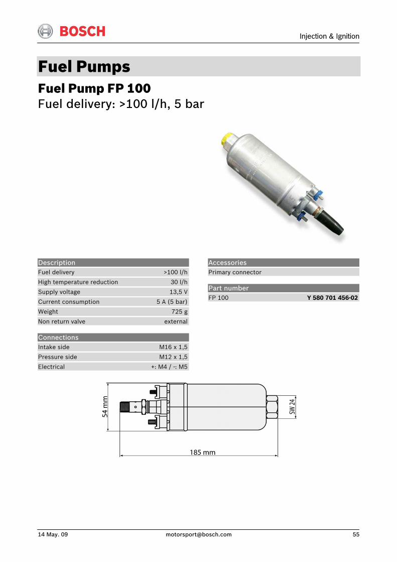
Fuel Pumps Fuel Pump FP 100 Fuel delivery: >100 l/h, 5 bar
Description Fuel delivery >100 l/h
High temperature reduction 30 l/h
Supply voltage 13,5 V
Current consumption 5 A (5 bar)
Weight 725 g
Non return valve external
Connections Intake side M16 x 1,5
Pressure side M12 x 1,5
Electrical +: M4 / -: M5
Accessories Primary connector
Part number FP 100 Y 580 701 456-02
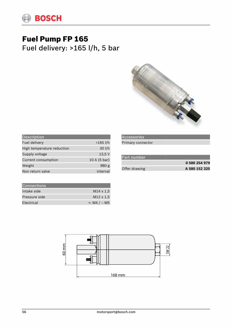
Fuel Pump FP 165 Fuel delivery: >165 l/h, 5 bar
Description Fuel delivery >165 l/h
High temperature reduction 30 l/h
Supply voltage 13,5 V
Current consumption 10 A (5 bar)
Weight 980 g
Non return valve internal
Connections Intake side M14 x 1,5
Pressure side M12 x 1,5
Electrical +: M4 / -: M5
Accessories Primary connector
Part number
Offer drawing
0 580 254 979
A 580 152 325
Injection & Ignition
14 May. 09 [email protected] 57
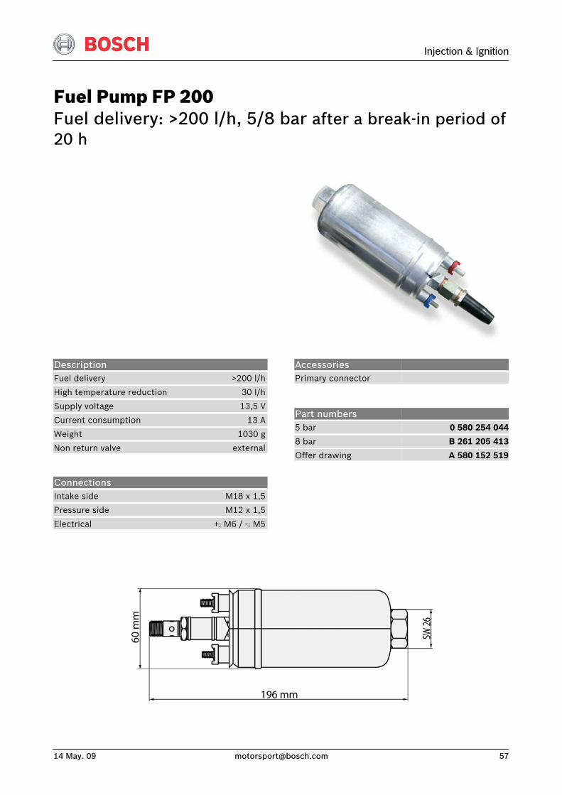
Fuel Pump FP 200 Fuel delivery: >200 l/h, 5/8 bar after a break-in period of 20 h
Description Fuel delivery >200 l/h
High temperature reduction 30 l/h
Supply voltage 13,5 V
Current consumption 13 A
Weight 1030 g
Non return valve external
Connections Intake side M18 x 1,5
Pressure side M12 x 1,5
Electrical +: M6 / -: M5
Accessories Primary connector
Part numbers 5 bar
8 bar
Offer drawing
0 580 254 044
B 261 205 413
A 580 152 519
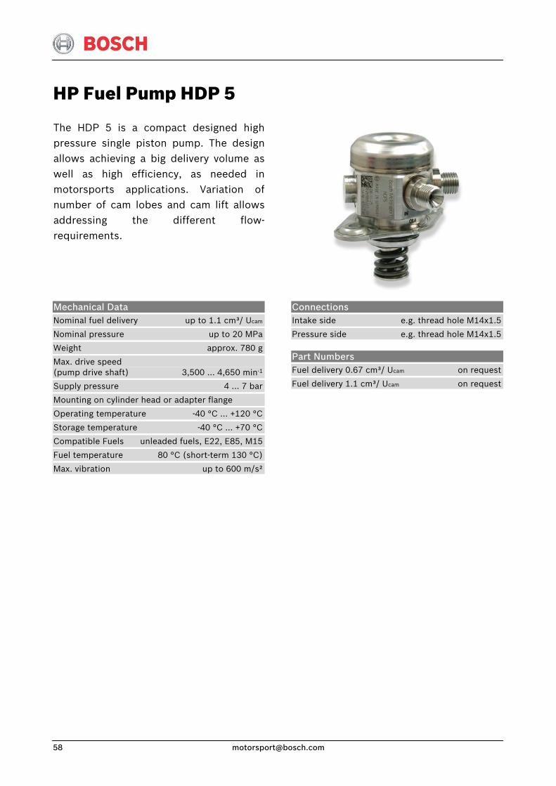
HP Fuel Pump HDP 5
The HDP 5 is a compact designed highpressure single piston pump. The designallows achieving a big delivery volume aswell as high efficiency, as needed inmotorsports applications. Variation ofnumber of cam lobes and cam lift allowsaddressing the different flow-requirements.
Mechanical Data Nominal fuel delivery up to 1.1 cm³/ Ucam
Nominal pressure up to 20 MPa
Weight approx. 780 g
Max. drive speed (pump drive shaft) 3,500 … 4,650 min-1
Supply pressure 4 … 7 bar
Mounting on cylinder head or adapter flange
Operating temperature -40 °C ... +120 °C
Storage temperature -40 °C … +70 °C
Compatible Fuels unleaded fuels, E22, E85, M15
Fuel temperature 80 °C (short-term 130 °C)
Max. vibration up to 600 m/s²
Connections Intake side e.g. thread hole M14x1.5
Pressure side e.g. thread hole M14x1.5
Part Numbers Fuel delivery 0.67 cm³/ Ucam on request
Fuel delivery 1.1 cm³/ Ucam on request

Injection & Ignition
14 May. 09 [email protected] 59
Diesel Fuel Pump DFP 300 Fuel delivery: >300 l/h, 5 bar relative
This electrical diesel fuel pump withoutnon-ferrous metal is especially designedfor diesel applications. A modified rotorprovides higher fuel delivery than the series version. Its tight housing withscrewed connectors fits to any intank orinline fuel circuit. This pump results in anexcellent weight-to-power ratio.
Connections Intake side M18 x 1,5
Pressure side M12 x 1,5
Electrical +: M6 / -: M5
Description Fuel delivery at fuel temp. < 90 °C >300 l/h
Fuel delivery increase after break-in period of 20 h 20 l/h
Supply voltage 13,5 V
Current consumption 17,2 A
Weight 700 g
Non return valve internal
Housing version inline
Allowed diesel spec. EN590
Part numbers DFP 300l/h
B 261 205 366
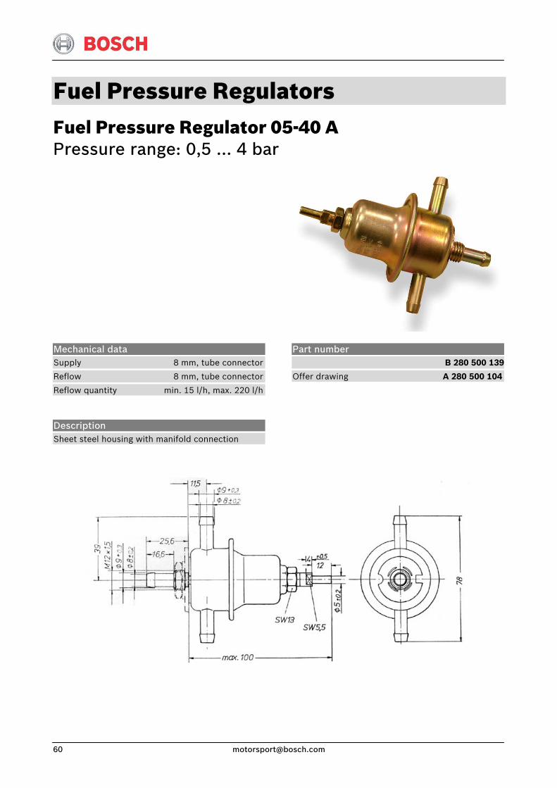
Fuel Pressure Regulators Fuel Pressure Regulator 05-40 A Pressure range: 0,5 … 4 bar
Mechanical data Supply 8 mm, tube connector
Reflow 8 mm, tube connector
Reflow quantity min. 15 l/h, max. 220 l/h
Description Sheet steel housing with manifold connection
Part number B 280 500 139
Offer drawing A 280 500 104
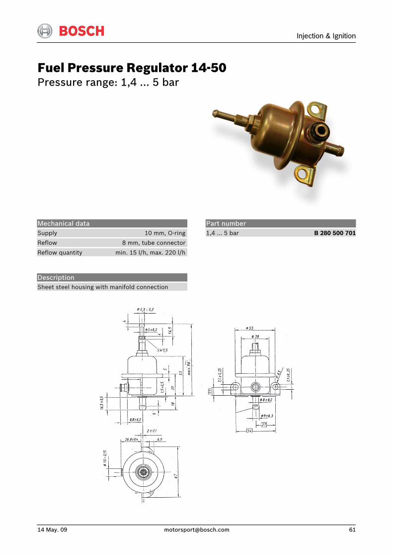
Injection & Ignition
14 May. 09 [email protected] 61
Fuel Pressure Regulator 14-50 Pressure range: 1,4 … 5 bar
Mechanical data Supply 10 mm, O-ring
Reflow 8 mm, tube connector
Reflow quantity min. 15 l/h, max. 220 l/h
Description Sheet steel housing with manifold connection
Part number 1,4 … 5 bar
B 280 500 701
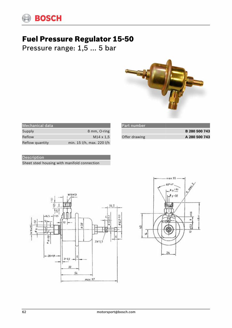
Fuel Pressure Regulator 15-50 Pressure range: 1,5 … 5 bar
Mechanical data Supply 8 mm, O-ring
Reflow M14 x 1,5
Reflow quantity min. 15 l/h, max. 220 l/h
Description Sheet steel housing with manifold connection
Part number
Offer drawing
B 280 500 743
A 280 500 743
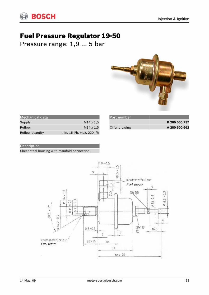
Injection & Ignition
14 May. 09 [email protected] 63
Fuel Pressure Regulator 19-50 Pressure range: 1,9 … 5 bar
Mechanical data Supply M14 x 1,5
Reflow M14 x 1,5
Reflow quantity min. 15 l/h, max. 220 l/h
Description Sheet steel housing with manifold connection
Part number
Offer drawing
B 280 500 737
A 280 500 662
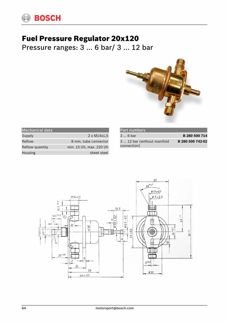
Fuel Pressure Regulator 20x120 Pressure ranges: 3 … 6 bar/ 3 … 12 bar
Mechanical data Supply 2 x M14x1,5
Reflow 8 mm, tube connector
Reflow quantity min. 15 l/h, max. 220 l/h
Housing sheet steel
Part numbers 3 … 6 bar
3 … 12 bar (without manifold connection)
B 280 500 714
B 280 500 742-02
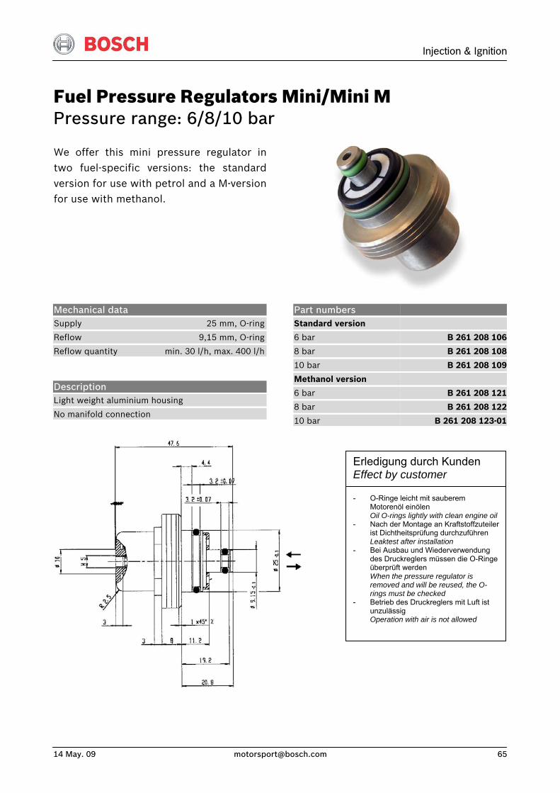
Injection & Ignition
14 May. 09 [email protected] 65
Fuel Pressure Regulators Mini/Mini M Pressure range: 6/8/10 bar
We offer this mini pressure regulator intwo fuel-specific versions: the standardversion for use with petrol and a M-versionfor use with methanol.
Mechanical data Supply 25 mm, O-ring
Reflow 9,15 mm, O-ring
Reflow quantity min. 30 l/h, max. 400 l/h
Description Light weight aluminium housing
No manifold connection
Part numbers Standard version
6 bar
8 bar
10 bar
Methanol version
6 bar
8 bar
10 bar
B 261 208 106
B 261 208 108
B 261 208 109
B 261 208 121
B 261 208 122
B 261 208 123-01
Erledigung durch Kunden Effect by customer - O-Ringe leicht mit sauberem
Motorenöl einölen Oil O-rings lightly with clean engine oil
- Nach der Montage an Kraftstoffzuteiler ist Dichtheitsprüfung durchzuführen Leaktest after installation
- Bei Ausbau und Wiederverwendung des Druckreglers müssen die O-Ringe überprüft werden When the pressure regulator is removed and will be reused, the O-rings must be checked
- Betrieb des Druckreglers mit Luft ist unzulässig Operation with air is not allowed

Fuel Pressure Regulator Mini A Pressure ranges: 2,2 … 3,5 bar/3,5 … 5 bar
Accessories Pre-filter
1 287 431 008
Mechanical data Supply 24,6 mm, O-ring
Reflow 9,15 mm, O-ring
Reflow quantity min. 15 l/h, max. 220 l/h
Weight 58 g
Description Light weight aluminium housing
No manifold connection
Part numbers 2,2 … 3,5 bar
3,5 … 5 bar
Offer drawing
B 280 550 340
B 280 550 341
A 280 550 340
Erledigung durch Kunden Effect by customer - O-Ringe leicht mit sauberem
Motorenöl einölen Oil O-rings lightly with clean engine oil
- Nach der Montage an Kraftstoffzuteiler ist Dichtheitsprüfung durchzuführen Leaktest after installation
- Bei Ausbau und Wiederverwendung des Druckreglers müssen die O-Ringe überprüft werden When the pressure regulator is removed and will be reused, the O-rings must be checked
- Betrieb des Druckreglers mit Luft ist unzulässig Operation with air is not allowed
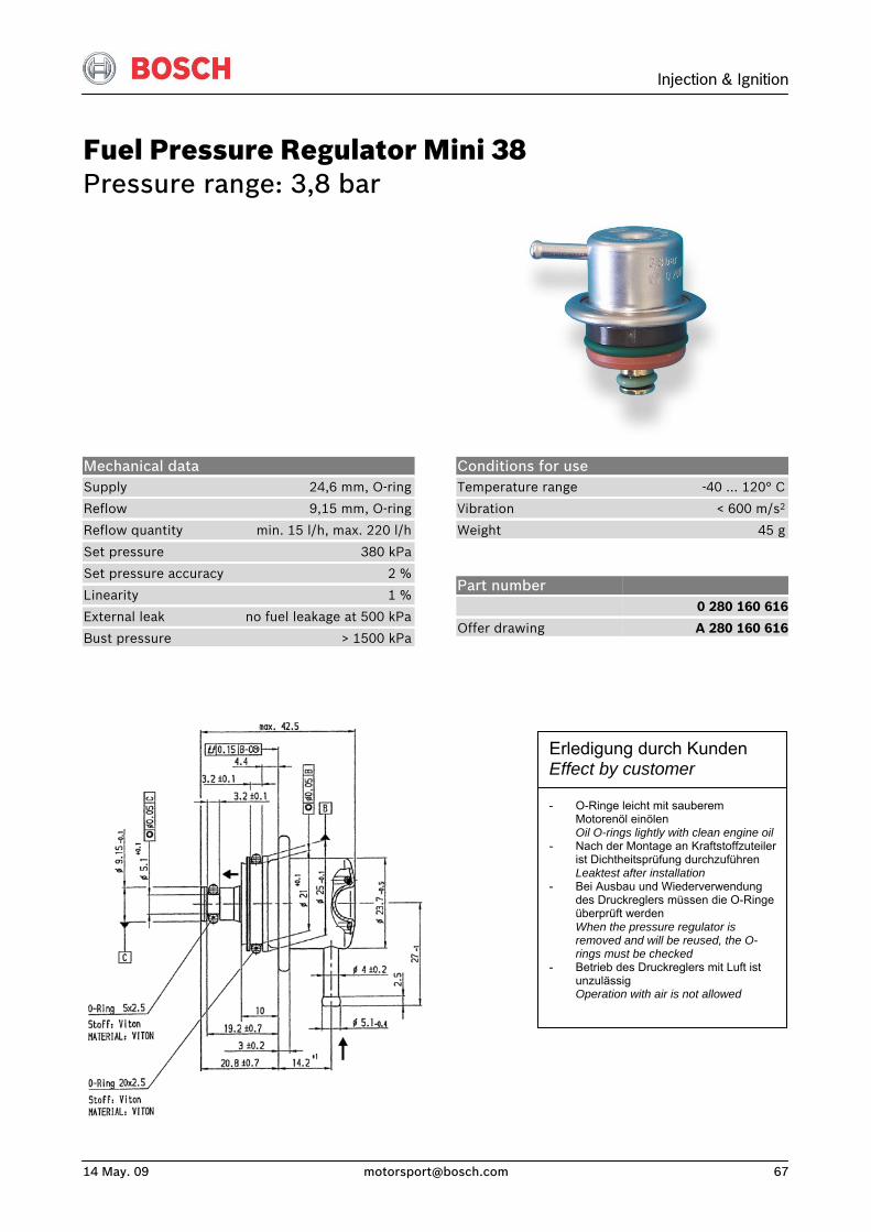
Injection & Ignition
14 May. 09 [email protected] 67
Fuel Pressure Regulator Mini 38 Pressure range: 3,8 bar
Conditions for use Temperature range -40 … 120° C
Vibration < 600 m/s2
Weight 45 g
Mechanical data Supply 24,6 mm, O-ring
Reflow 9,15 mm, O-ring
Reflow quantity min. 15 l/h, max. 220 l/h
Set pressure 380 kPa
Set pressure accuracy 2 %
Linearity 1 %
External leak no fuel leakage at 500 kPa
Bust pressure > 1500 kPa
Part number
Offer drawing
0 280 160 616
A 280 160 616
Erledigung durch Kunden Effect by customer - O-Ringe leicht mit sauberem
Motorenöl einölen Oil O-rings lightly with clean engine oil
- Nach der Montage an Kraftstoffzuteiler ist Dichtheitsprüfung durchzuführen Leaktest after installation
- Bei Ausbau und Wiederverwendung des Druckreglers müssen die O-Ringe überprüft werden When the pressure regulator is removed and will be reused, the O-rings must be checked
- Betrieb des Druckreglers mit Luft ist unzulässig Operation with air is not allowed
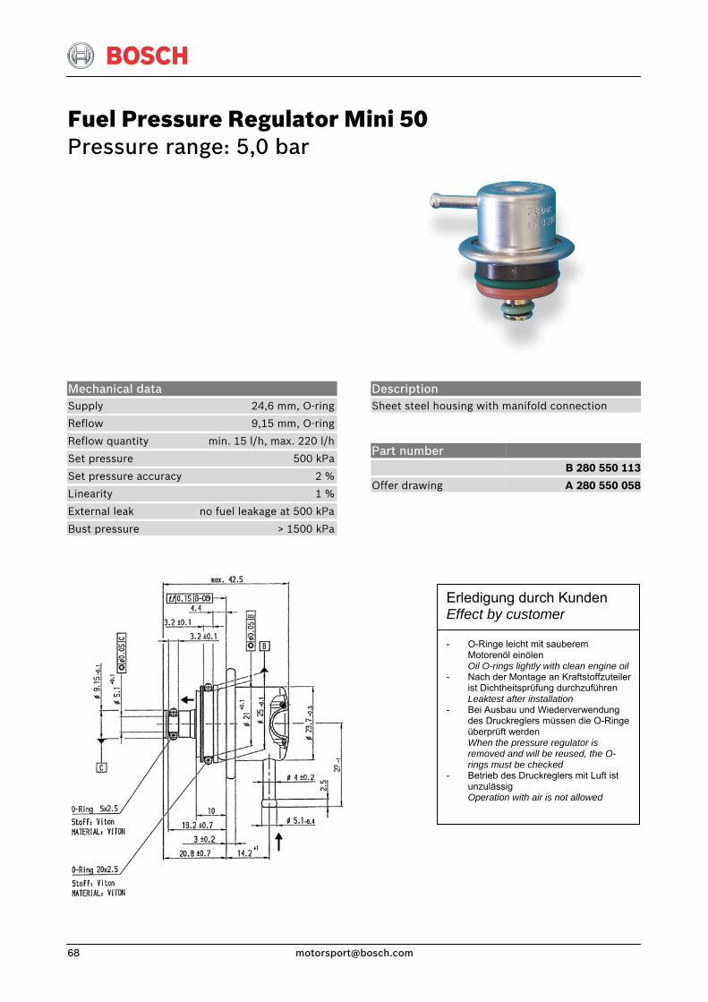
Fuel Pressure Regulator Mini 50 Pressure range: 5,0 bar
Description Sheet steel housing with manifold connection
Mechanical data Supply 24,6 mm, O-ring
Reflow 9,15 mm, O-ring
Reflow quantity min. 15 l/h, max. 220 l/h
Set pressure 500 kPa
Set pressure accuracy 2 %
Linearity 1 %
External leak no fuel leakage at 500 kPa
Bust pressure > 1500 kPa
Part number
Offer drawing
B 280 550 113
A 280 550 058
Erledigung durch Kunden Effect by customer - O-Ringe leicht mit sauberem
Motorenöl einölen Oil O-rings lightly with clean engine oil
- Nach der Montage an Kraftstoffzuteiler ist Dichtheitsprüfung durchzuführen Leaktest after installation
- Bei Ausbau und Wiederverwendung des Druckreglers müssen die O-Ringe überprüft werden When the pressure regulator is removed and will be reused, the O-rings must be checked
- Betrieb des Druckreglers mit Luft ist unzulässig Operation with air is not allowed
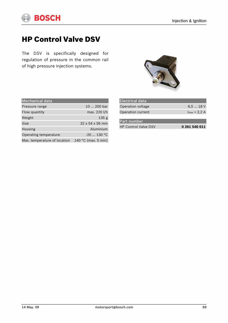
Injection & Ignition
14 May. 09 [email protected] 69
HP Control Valve DSV
The DSV is specifically designed forregulation of pressure in the common railof high pressure injection systems.
Electrical data Operation voltage 6,5 … 18 V
Operation current Imax = 2,2 A
Mechanical data Pressure range 10 … 200 bar
Flow quantity max. 220 l/h
Weight 135 g
Size 32 x 54 x 56 mm
Housing Aluminium
Operating temperature -20 … 130 °C
Max. temperature of location 140 °C (max. 5 min)
Part number HP Control Valve DSV 0 261 540 011
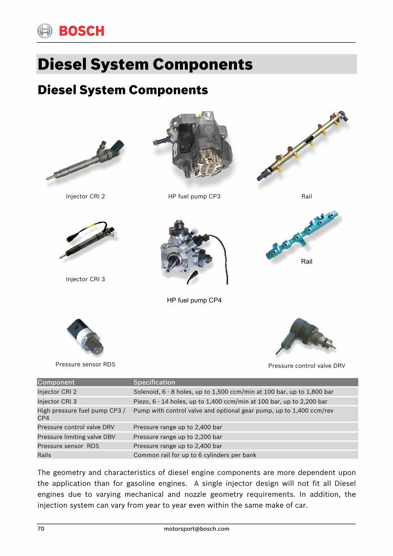
Diesel System Components Diesel System Components
Injector CRI 2
HP fuel pump CP3 Rail
Injector CRI 3
HP fuel pump CP4
Rail
Pressure sensor RDS
Pressure control valve DRV
Component Specification Injector CRI 2
Injector CRI 3
Solenoid, 6 - 8 holes, up to 1,500 ccm/min at 100 bar, up to 1,800 bar
Piezo, 6 - 14 holes, up to 1,400 ccm/min at 100 bar, up to 2,200 bar High pressure fuel pump CP3 / CP4
Pump with control valve and optional gear pump, up to 1,400 ccm/rev
Pressure control valve DRV
Pressure limiting valve DBV
Pressure range up to 2,400 bar
Pressure range up to 2,200 bar Pressure sensor RDS Pressure range up to 2,400 bar Rails Common rail for up to 6 cylinders per bank The geometry and characteristics of diesel engine components are more dependent upon the application than for gasoline engines. A single injector design will not fit all Diesel engines due to varying mechanical and nozzle geometry requirements. In addition, the injection system can vary from year to year even within the same make of car.
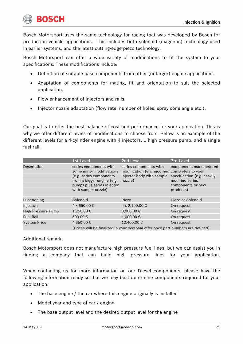
Injection & Ignition
14 May. 09 [email protected] 71
Bosch Motorsport uses the same technology for racing that was developed by Bosch for production vehicle applications. This includes both solenoid (magnetic) technology used in earlier systems, and the latest cutting-edge piezo technology.
Bosch Motorsport can offer a wide variety of modifications to fit the system to your specifications. These modifications include:
• Definition of suitable base components from other (or larger) engine applications.
• Adaptation of components for mating, fit and orientation to suit the selected application.
• Flow enhancement of injectors and rails.
• Injector nozzle adaptation (flow rate, number of holes, spray cone angle etc.).
Our goal is to offer the best balance of cost and performance for your application. This is why we offer different levels of modifications to choose from. Below is an example of the different levels for a 4-cylinder engine with 4 injectors, 1 high pressure pump, and a single fuel rail:
1st Level 2nd Level 3rd Level Description
series components with some minor modifications (e.g. series components from a bigger engine (e.g. pump) plus series injector with sample nozzle)
series components with modification (e.g. modified injector body with sample nozzle)
components manufactured completely to your specification (e.g. heavily modified series components or new products)
Functioning Solenoid Piezo Piezo or Solenoid Injectors 4 x 650.00 € 4 x 2,100.00 € On request
High Pressure Pump 1,250.00 € 3,000.00 € On request Fuel Rail 500.00 € 1,000.00 € On request System Price 4,350.00 € 12,400.00 € On request
(Prices will be finalized in your personal offer once part numbers are defined) Additional remark:
Bosch Motorsport does not manufacture high pressure fuel lines, but we can assist you in finding a company that can build high pressure lines for your application.
When contacting us for more information on our Diesel components, please have the following information ready so that we may best determine components required for your application:
• The base engine / the car where this engine originally is installed
• Model year and type of car / engine
• The base output level and the desired output level for the engine

• If it is a Bosch application, the part numbers of the components • Alternatively the car / engine manufacturer part number of the original injection
system.
Please note: If your engine is originally equipped with Bosch components, modifications will be easier than replacing third party components.
We reserve the right to assess a fee for applications where the component specification requires an extraordinary amount of time.
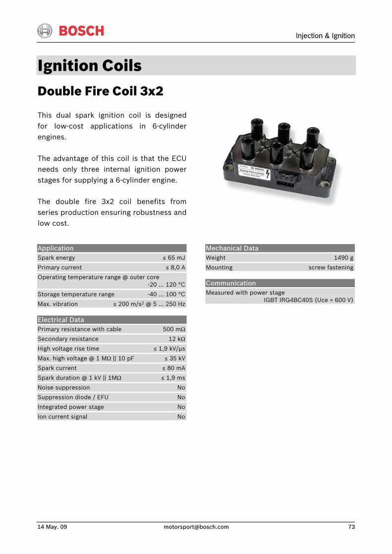
Injection & Ignition
14 May. 09 [email protected] 73
Ignition Coils Double Fire Coil 3x2
This dual spark ignition coil is designedfor low-cost applications in 6-cylinderengines.
The advantage of this coil is that the ECUneeds only three internal ignition powerstages for supplying a 6-cylinder engine.
The double fire 3x2 coil benefits fromseries production ensuring robustness andlow cost.
Application Spark energy ≤ 65 mJ
Primary current ≤ 8,0 A
Operating temperature range @ outer core -20 … 120 °C
Storage temperature range -40 … 100 °C
Max. vibration ≤ 200 m/s2 @ 5 … 250 Hz
Electrical Data Primary resistance with cable 500 mΩ
Secondary resistance 12 kΩ
High voltage rise time ≤ 1,9 kV/μs
Max. high voltage @ 1 MΩ || 10 pF ≤ 35 kV
Spark current ≤ 80 mA
Spark duration @ 1 kV || 1MΩ ≤ 1,9 ms
Noise suppression No
Suppression diode / EFU No
Integrated power stage No
Ion current signal No
Mechanical Data Weight 1490 g
Mounting screw fastening
Communication Measured with power stage IGBT IRG4BC40S (Uce = 600 V)
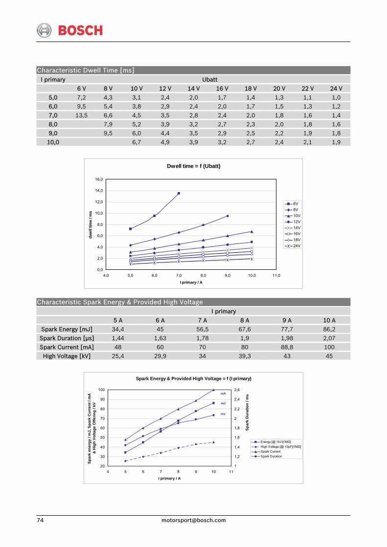
Characteristic Dwell Time [ms] I primary Ubatt
6 V 8 V 10 V 12 V 14 V 16 V 18 V 20 V 22 V 24 V 5,0 7,2 4,3 3,1 2,4 2,0 1,7 1,4 1,3 1,1 1,0 6,0 9,5 5,4 3,8 2,9 2,4 2,0 1,7 1,5 1,3 1,2
7,0 13,5 6,6 4,5 3,5 2,8 2,4 2,0 1,8 1,6 1,4 8,0 7,9 5,2 3,9 3,2 2,7 2,3 2,0 1,8 1,6 9,0 9,5 6,0 4,4 3,5 2,9 2,5 2,2 1,9 1,8
10,0 6,7 4,9 3,9 3,2 2,7 2,4 2,1 1,9
Dwell time = f (Ubatt)
0,0
2,0
4,0
6,0
8,0
10,0
12,0
14,0
16,0
4,0 5,0 6,0 7,0 8,0 9,0 10,0 11,0
I primary / A
dwel
l tim
e / m
s
6V8V10V12V14V16V18V24V
Characteristic Spark Energy & Provided High Voltage I primary
5 A 6 A 7 A 8 A 9 A 10 A Spark Energy [mJ] 34,4 45 56,5 67,6 77,7 86,2 Spark Duration [μs] 1,44 1,63 1,78 1,9 1,98 2,07
Spark Current [mA] 48 60 70 80 88,8 100 High Voltage [kV] 25,4 29,9 34 39,3 43 45
Spark Energy & Provided High Voltage = f (I primary)
20
30
40
50
60
70
80
90
100
4 5 6 7 8 9 10 11
I primary / A
Spar
k en
ergy
/ m
J, S
park
Cur
rent
/ m
A
& H
igh
Volta
ge O
fferin
g / k
V
1
1,2
1,4
1,6
1,8
2
2,2
2,4
2,6
Energy [@ 1kV||1MΩ]High Voltage [@ 10pF||1MΩ]Spark CurrentSpark Duration
Spar
k D
urat
ion
/ ms
ms
mA
mJ
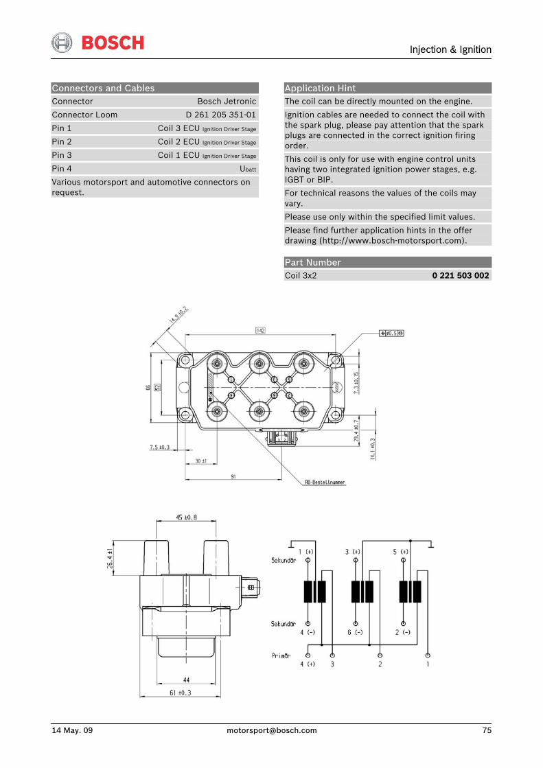
Injection & Ignition
14 May. 09 [email protected] 75
Connectors and Cables Connector Bosch Jetronic
Connector Loom D 261 205 351-01
Pin 1 Coil 3 ECU Ignition Driver Stage
Pin 2 Coil 2 ECU Ignition Driver Stage
Pin 3 Coil 1 ECU Ignition Driver Stage
Pin 4 Ubatt
Various motorsport and automotive connectors on request.
Application Hint The coil can be directly mounted on the engine.
Ignition cables are needed to connect the coil with the spark plug, please pay attention that the spark plugs are connected in the correct ignition firing order.
This coil is only for use with engine control units having two integrated ignition power stages, e.g. IGBT or BIP.
For technical reasons the values of the coils may vary.
Please use only within the specified limit values.
Please find further application hints in the offer drawing (http://www.bosch-motorsport.com).
Part Number Coil 3x2 0 221 503 002
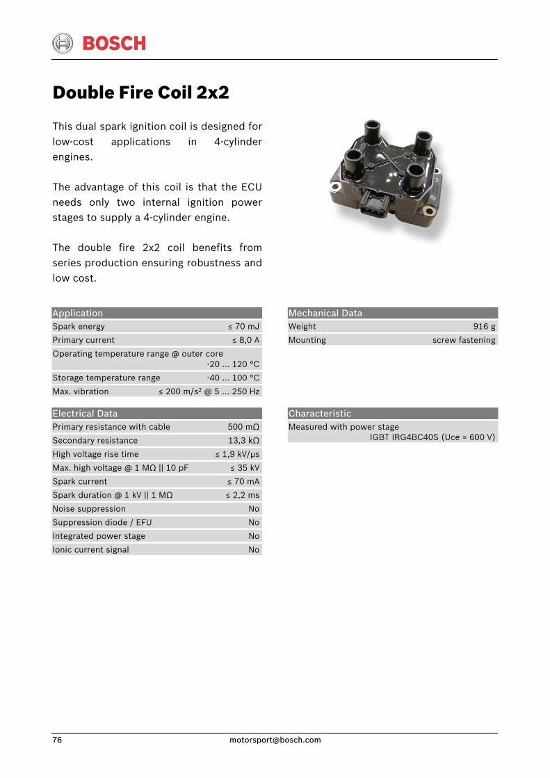
Double Fire Coil 2x2
This dual spark ignition coil is designed forlow-cost applications in 4-cylinder engines.
The advantage of this coil is that the ECUneeds only two internal ignition powerstages to supply a 4-cylinder engine.
The double fire 2x2 coil benefits fromseries production ensuring robustness andlow cost.
Application Spark energy ≤ 70 mJ
Primary current ≤ 8,0 A
Operating temperature range @ outer core -20 … 120 °C
Storage temperature range -40 … 100 °C
Max. vibration ≤ 200 m/s2 @ 5 … 250 Hz
Mechanical Data Weight 916 g
Mounting screw fastening
Electrical Data Primary resistance with cable 500 mΩ
Secondary resistance 13,3 kΩ
High voltage rise time ≤ 1,9 kV/μs
Max. high voltage @ 1 MΩ || 10 pF ≤ 35 kV
Spark current ≤ 70 mA
Spark duration @ 1 kV || 1 MΩ ≤ 2,2 ms
Noise suppression No
Suppression diode / EFU No
Integrated power stage No
Ionic current signal No
Characteristic Measured with power stage IGBT IRG4BC40S (Uce = 600 V)
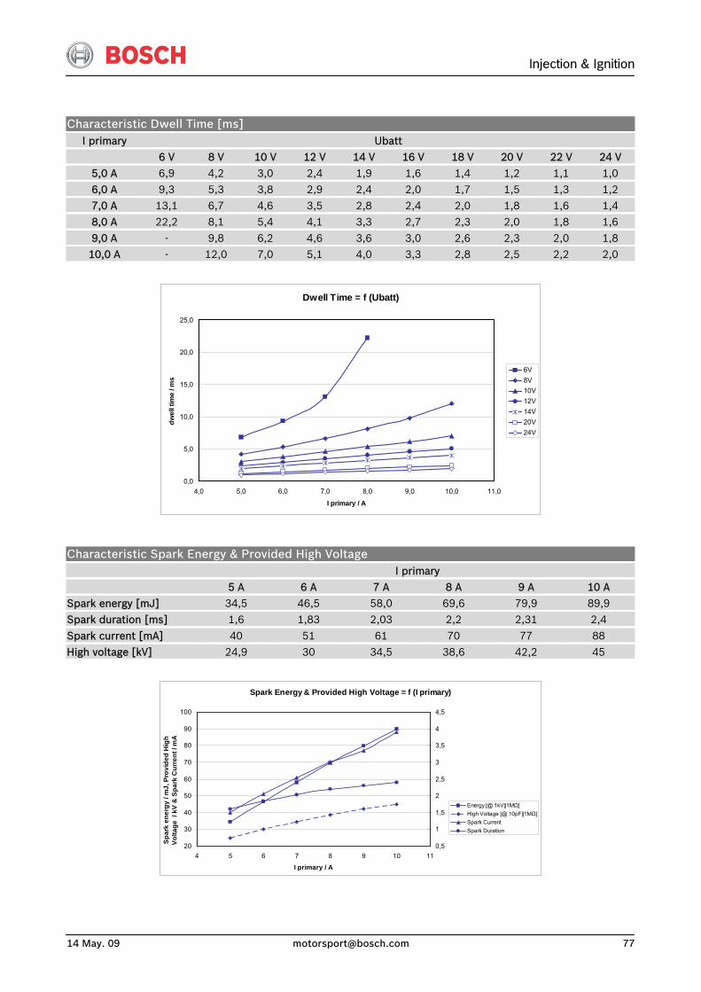
Injection & Ignition
14 May. 09 [email protected] 77
Characteristic Dwell Time [ms] I primary Ubatt
6 V 8 V 10 V 12 V 14 V 16 V 18 V 20 V 22 V 24 V
5,0 A 6,9 4,2 3,0 2,4 1,9 1,6 1,4 1,2 1,1 1,0 6,0 A 9,3 5,3 3,8 2,9 2,4 2,0 1,7 1,5 1,3 1,2 7,0 A 13,1 6,7 4,6 3,5 2,8 2,4 2,0 1,8 1,6 1,4 8,0 A 22,2 8,1 5,4 4,1 3,3 2,7 2,3 2,0 1,8 1,6
9,0 A - 9,8 6,2 4,6 3,6 3,0 2,6 2,3 2,0 1,8 10,0 A - 12,0 7,0 5,1 4,0 3,3 2,8 2,5 2,2 2,0
Dwell Time = f (Ubatt)
0,0
5,0
10,0
15,0
20,0
25,0
4,0 5,0 6,0 7,0 8,0 9,0 10,0 11,0
I primary / A
dwel
l tim
e / m
s
6V8V10V12V14V20V24V
Characteristic Spark Energy & Provided High Voltage I primary
5 A 6 A 7 A 8 A 9 A 10 A Spark energy [mJ] 34,5 46,5 58,0 69,6 79,9 89,9 Spark duration [ms] 1,6 1,83 2,03 2,2 2,31 2,4
Spark current [mA] 40 51 61 70 77 88 High voltage [kV] 24,9 30 34,5 38,6 42,2 45
Spark Energy & Provided High Voltage = f (I primary)
20
30
40
50
60
70
80
90
100
4 5 6 7 8 9 10 11
I primary / A
Spar
k en
ergy
/ m
J, P
rovi
ded
Hig
h Vo
ltage
/ k
V &
Spa
rk C
urre
nt /
mA
0,5
1
1,5
2
2,5
3
3,5
4
4,5
Energy [@ 1kV||1MΩ]High Voltage [@ 10pF||1MΩ]Spark CurrentSpark Duration
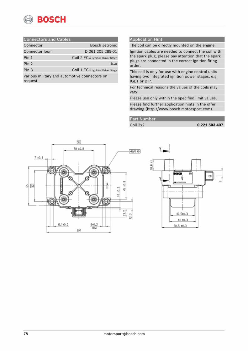
Connectors and Cables Connector Bosch Jetronic
Connector loom D 261 205 289-01
Pin 1 Coil 2 ECU Ignition Driver Stage
Pin 2 Ubatt
Pin 3 Coil 1 ECU Ignition Driver Stage
Various military and automotive connectors on request.
Application Hint The coil can be directly mounted on the engine.
Ignition cables are needed to connect the coil with the spark plug, please pay attention that the spark plugs are connected in the correct ignition firing order.
This coil is only for use with engine control units having two integrated ignition power stages, e.g. IGBT or BIP.
For technical reasons the values of the coils may vary.
Please use only within the specified limit values.
Please find further application hints in the offer drawing (http://www.bosch-motorsport.com).
Part Number Coil 2x2 0 221 503 407
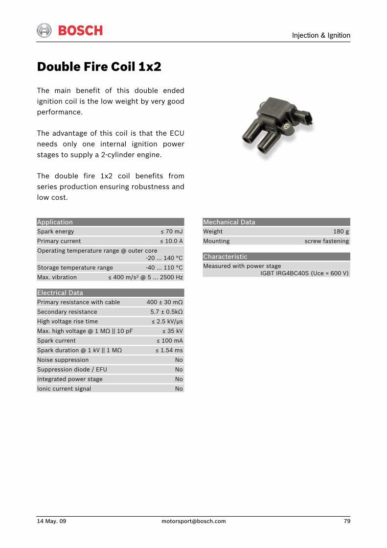
Injection & Ignition
14 May. 09 [email protected] 79
Double Fire Coil 1x2
The main benefit of this double endedignition coil is the low weight by very goodperformance.
The advantage of this coil is that the ECUneeds only one internal ignition powerstages to supply a 2-cylinder engine.
The double fire 1x2 coil benefits fromseries production ensuring robustness andlow cost.
Application Spark energy ≤ 70 mJ
Primary current ≤ 10.0 A
Operating temperature range @ outer core -20 … 140 °C
Storage temperature range -40 … 110 °C
Max. vibration ≤ 400 m/s2 @ 5 … 2500 Hz
Electrical Data Primary resistance with cable 400 ± 30 mΩ
Secondary resistance 5.7 ± 0.5kΩ
High voltage rise time ≤ 2.5 kV/μs
Max. high voltage @ 1 MΩ || 10 pF ≤ 35 kV
Spark current ≤ 100 mA
Spark duration @ 1 kV || 1 MΩ ≤ 1.54 ms
Noise suppression No
Suppression diode / EFU No
Integrated power stage No
Ionic current signal No
Mechanical Data Weight 180 g
Mounting screw fastening
Characteristic Measured with power stage IGBT IRG4BC40S (Uce = 600 V)
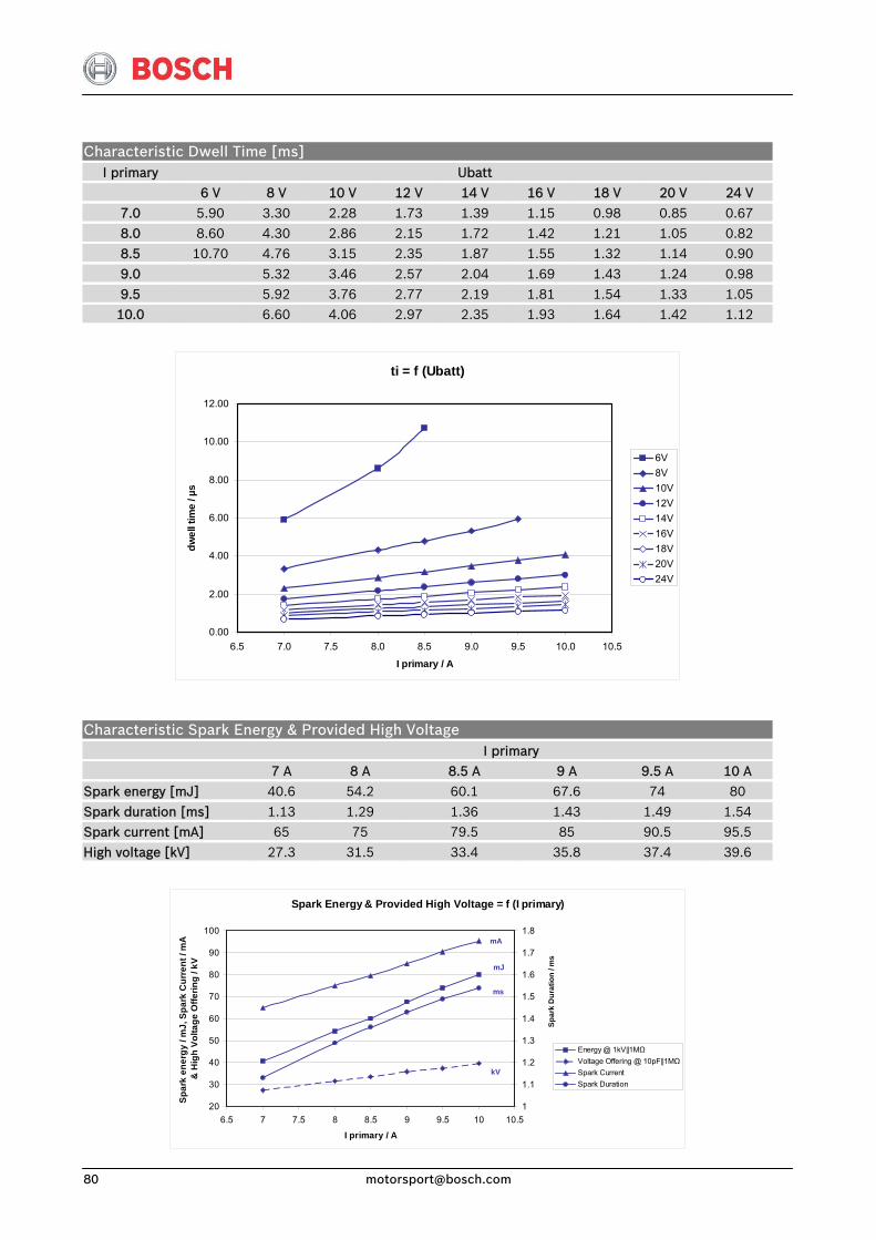
Characteristic Dwell Time [ms] I primary Ubatt
6 V 8 V 10 V 12 V 14 V 16 V 18 V 20 V 24 V
7.0 5.90 3.30 2.28 1.73 1.39 1.15 0.98 0.85 0.67 8.0 8.60 4.30 2.86 2.15 1.72 1.42 1.21 1.05 0.82 8.5 10.70 4.76 3.15 2.35 1.87 1.55 1.32 1.14 0.90
9.0 5.32 3.46 2.57 2.04 1.69 1.43 1.24 0.98 9.5 5.92 3.76 2.77 2.19 1.81 1.54 1.33 1.05 10.0 6.60 4.06 2.97 2.35 1.93 1.64 1.42 1.12
ti = f (Ubatt)
0.00
2.00
4.00
6.00
8.00
10.00
12.00
6.5 7.0 7.5 8.0 8.5 9.0 9.5 10.0 10.5
I primary / A
dwel
l tim
e / µ
s
6V8V10V12V14V16V18V20V24V
Characteristic Spark Energy & Provided High Voltage I primary 7 A 8 A 8.5 A 9 A 9.5 A 10 A
Spark energy [mJ] 40.6 54.2 60.1 67.6 74 80
Spark duration [ms] 1.13 1.29 1.36 1.43 1.49 1.54 Spark current [mA] 65 75 79.5 85 90.5 95.5 High voltage [kV] 27.3 31.5 33.4 35.8 37.4 39.6
Spark Energy & Provided High Voltage = f (I primary)
20
30
40
50
60
70
80
90
100
6.5 7 7.5 8 8.5 9 9.5 10 10.5
I primary / A
Spar
k en
ergy
/ m
J, S
park
Cur
rent
/ m
A
& H
igh
Volta
ge O
fferin
g / k
V
1
1.1
1.2
1.3
1.4
1.5
1.6
1.7
1.8
Energy @ 1kV||1MΩVoltage Offering @ 10pF||1MΩSpark CurrentSpark Duration
Spar
k D
urat
ion
/ ms
ms
kV
mA
mJ
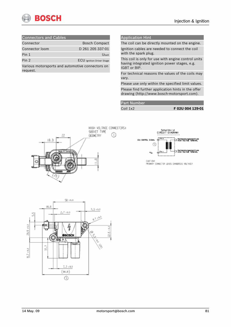
Injection & Ignition
14 May. 09 [email protected] 81
Connectors and Cables Connector Bosch Compact
Connector loom D 261 205 337-01
Pin 1 Ubatt
Pin 2 ECU Ignition Driver Stage
Various motorsports and automotive connectors on request.
Application Hint The coil can be directly mounted on the engine.
Ignition cables are needed to connect the coil with the spark plug.
This coil is only for use with engine control units having integrated ignition power stages, e.g. IGBT or BIP.
For technical reasons the values of the coils may vary.
Please use only within the specified limit values.
Please find further application hints in the offer drawing (http://www.bosch-motorsport.com).
Part Number Coil 1x2 F 02U 004 129-01
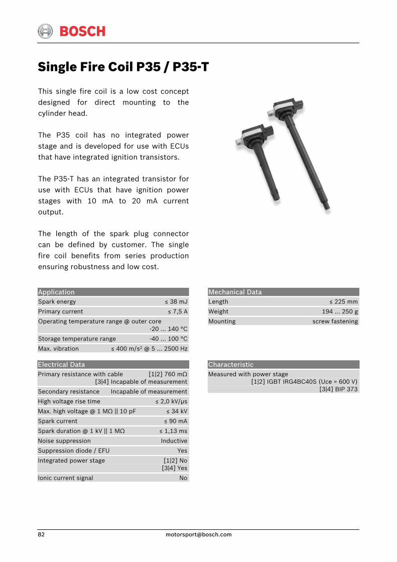
Single Fire Coil P35 / P35-T
This single fire coil is a low cost conceptdesigned for direct mounting to thecylinder head.
The P35 coil has no integrated powerstage and is developed for use with ECUsthat have integrated ignition transistors.
The P35-T has an integrated transistor foruse with ECUs that have ignition powerstages with 10 mA to 20 mA currentoutput.
The length of the spark plug connectorcan be defined by customer. The singlefire coil benefits from series productionensuring robustness and low cost.
Application Spark energy ≤ 38 mJ
Primary current ≤ 7,5 A
Operating temperature range @ outer core -20 … 140 °C
Storage temperature range -40 … 100 °C
Max. vibration ≤ 400 m/s2 @ 5 … 2500 Hz
Mechanical Data Length ≤ 225 mm
Weight 194 … 250 g
Mounting screw fastening
Electrical Data Primary resistance with cable [1|2] 760 mΩ [3|4] Incapable of measurement
Secondary resistance Incapable of measurement
High voltage rise time ≤ 2,0 kV/μs
Max. high voltage @ 1 MΩ || 10 pF ≤ 34 kV
Spark current ≤ 90 mA
Spark duration @ 1 kV || 1 MΩ ≤ 1,13 ms
Noise suppression Inductive
Suppression diode / EFU Yes
Integrated power stage [1|2] No [3|4] Yes
Ionic current signal No
Characteristic Measured with power stage [1|2] IGBT IRG4BC40S (Uce = 600 V) [3|4] BIP 373
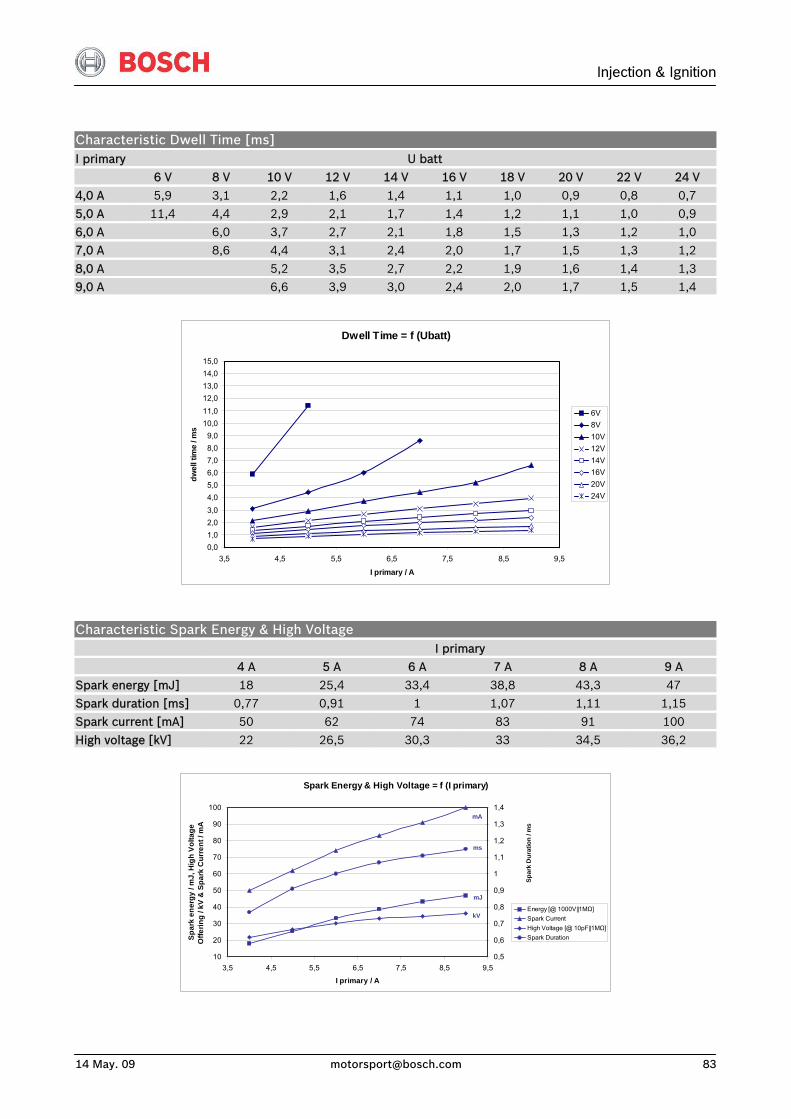
Injection & Ignition
14 May. 09 [email protected] 83
Characteristic Dwell Time [ms] I primary U batt 6 V 8 V 10 V 12 V 14 V 16 V 18 V 20 V 22 V 24 V
4,0 A 5,9 3,1 2,2 1,6 1,4 1,1 1,0 0,9 0,8 0,7 5,0 A 11,4 4,4 2,9 2,1 1,7 1,4 1,2 1,1 1,0 0,9 6,0 A 6,0 3,7 2,7 2,1 1,8 1,5 1,3 1,2 1,0 7,0 A 8,6 4,4 3,1 2,4 2,0 1,7 1,5 1,3 1,2
8,0 A 5,2 3,5 2,7 2,2 1,9 1,6 1,4 1,3 9,0 A 6,6 3,9 3,0 2,4 2,0 1,7 1,5 1,4
Dwell Time = f (Ubatt)
0,01,02,03,04,05,06,07,08,09,0
10,011,012,013,014,015,0
3,5 4,5 5,5 6,5 7,5 8,5 9,5
I primary / A
dwel
l tim
e / m
s
6V8V10V12V14V16V20V24V
Characteristic Spark Energy & High Voltage I primary 4 A 5 A 6 A 7 A 8 A 9 A
Spark energy [mJ] 18 25,4 33,4 38,8 43,3 47 Spark duration [ms] 0,77 0,91 1 1,07 1,11 1,15 Spark current [mA] 50 62 74 83 91 100
High voltage [kV] 22 26,5 30,3 33 34,5 36,2
Spark Energy & High Voltage = f (I primary)
10
20
30
40
50
60
70
80
90
100
3,5 4,5 5,5 6,5 7,5 8,5 9,5
I primary / A
Spar
k en
ergy
/ m
J, H
igh
Volta
ge
Offe
ring
/ kV
& S
park
Cur
rent
/ m
A
0,5
0,6
0,7
0,8
0,9
1
1,1
1,2
1,3
1,4
Energy [@ 1000V||1MΩ]Spark CurrentHigh Voltage [@ 10pF||1MΩ]Spark Duration
Spar
k D
urat
ion
/ ms
ms
kV
mA
mJ
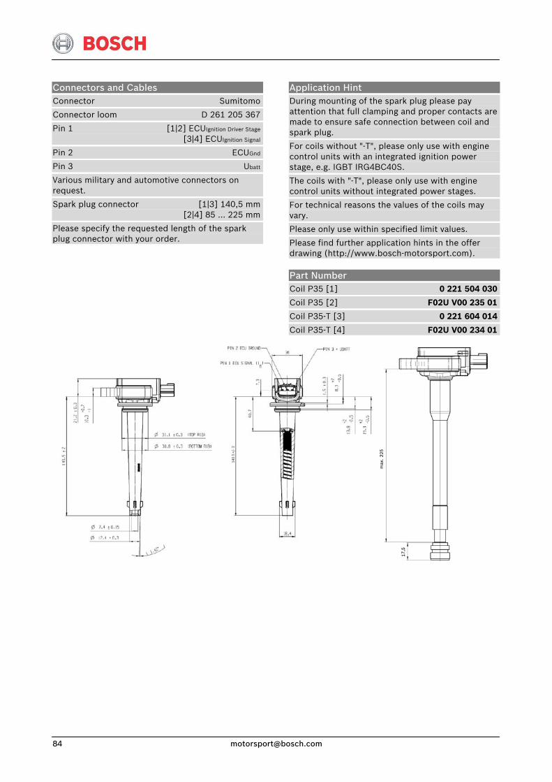
Connectors and Cables Connector Sumitomo
Connector loom D 261 205 367
Pin 1 [1|2] ECUIgnition Driver Stage
[3|4] ECUIgnition Signal
Pin 2 ECUGnd
Pin 3 Ubatt
Various military and automotive connectors on request.
Spark plug connector [1|3] 140,5 mm [2|4] 85 … 225 mm
Please specify the requested length of the spark plug connector with your order.
Application Hint During mounting of the spark plug please pay attention that full clamping and proper contacts are made to ensure safe connection between coil and spark plug.
For coils without "-T", please only use with engine control units with an integrated ignition power stage, e.g. IGBT IRG4BC40S.
The coils with "-T", please only use with engine control units without integrated power stages.
For technical reasons the values of the coils may vary.
Please only use within specified limit values.
Please find further application hints in the offer drawing (http://www.bosch-motorsport.com).
Part Number Coil P35 [1] 0 221 504 030
Coil P35 [2] F02U V00 235 01
Coil P35-T [3] 0 221 604 014
Coil P35-T [4] F02U V00 234 01

Injection & Ignition
14 May. 09 [email protected] 85
Single Fire Coil P50 / P50-M
This single fire coil is a low cost conceptdesigned for direct mounting to thecylinder-head. A high voltage ignition cablecan optionally be connected to thesecondary output terminal.
The mating ECU must have internalignition power stages for each single firecoil.
The coil P50-M is especially formotorsports applications. This coil hasincreased spark energy, increased highvoltage rise time and is operable in highervibration environments.
Application Spark energy ≤ 50 mJ
Primary current ≤ 8,5 A
Operating temperature range @ outer core -20 … 140 °C
Storage temperature range -40 … 100 °C
Max. vibration [1] ≤ 400 m/s2 @ 5 … 2000 Hz [2] ≤ 800 m/s2 @ 5 … 2000 Hz
Mechanical Data Weight [1] 223 g [2] 265 g
Mounting pluggable
Electrical Data Primary resistance with cable 370 mΩ
Secondary resistance incapable of measurement
High voltage rise time ≤ 3,0 kV/μs
Max. high voltage @ 1 MΩ || 10 pF ≤ 35 kV
Spark current ≤ 92 mA
Spark duration @ 1kV || 1MΩ ≤ 1,15 ms
Noise suppression Yes, with spark plug connector
Suppression diode / EFU Yes
Integrated power stage No
Ionic current signal No
Characteristic Measured with power stage IGBT IRG4BC40S (Uce = 600 V)
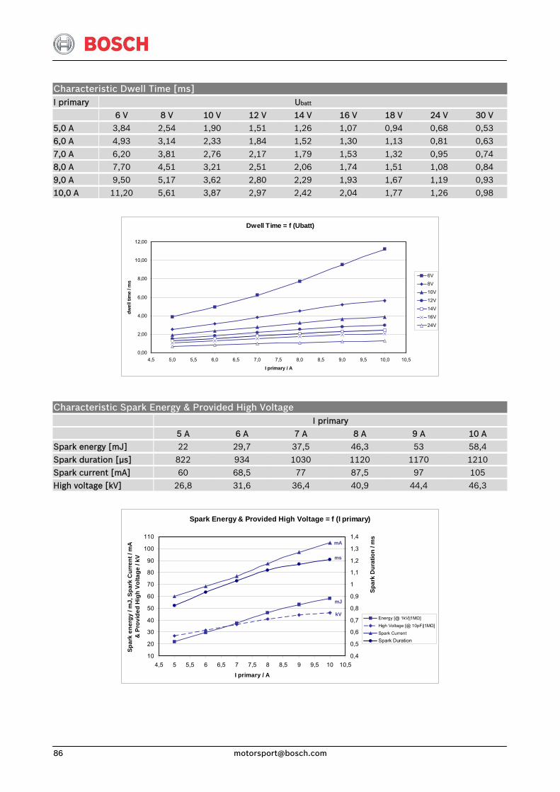
Characteristic Dwell Time [ms] I primary Ubatt
6 V 8 V 10 V 12 V 14 V 16 V 18 V 24 V 30 V 5,0 A 3,84 2,54 1,90 1,51 1,26 1,07 0,94 0,68 0,53 6,0 A 4,93 3,14 2,33 1,84 1,52 1,30 1,13 0,81 0,63
7,0 A 6,20 3,81 2,76 2,17 1,79 1,53 1,32 0,95 0,74 8,0 A 7,70 4,51 3,21 2,51 2,06 1,74 1,51 1,08 0,84 9,0 A 9,50 5,17 3,62 2,80 2,29 1,93 1,67 1,19 0,93
10,0 A 11,20 5,61 3,87 2,97 2,42 2,04 1,77 1,26 0,98
Dwell Time = f (Ubatt)
0,00
2,00
4,00
6,00
8,00
10,00
12,00
4,5 5,0 5,5 6,0 6,5 7,0 7,5 8,0 8,5 9,0 9,5 10,0 10,5
I primary / A
dwel
l tim
e / m
s
6V
8V
10V
12V
14V
16V
24V
Characteristic Spark Energy & Provided High Voltage I primary 5 A 6 A 7 A 8 A 9 A 10 A Spark energy [mJ] 22 29,7 37,5 46,3 53 58,4
Spark duration [μs] 822 934 1030 1120 1170 1210 Spark current [mA] 60 68,5 77 87,5 97 105 High voltage [kV] 26,8 31,6 36,4 40,9 44,4 46,3
Spark Energy & Provided High Voltage = f (I primary)
10
20
30
40
50
60
70
80
90
100
110
4,5 5 5,5 6 6,5 7 7,5 8 8,5 9 9,5 10 10,5
I primary / A
Spar
k en
ergy
/ m
J, S
park
Cur
rent
/ m
A
& P
rovi
ded
Hig
h Vo
ltage
/ kV
0,4
0,5
0,6
0,7
0,8
0,9
1
1,1
1,2
1,3
1,4
Energy [@ 1kV||1MΩ]
High Voltage [@ 10pF||1MΩ]
Spark Current
Spark Duration
Spar
k D
urat
ion
/ ms
kV
mA
mJ
ms
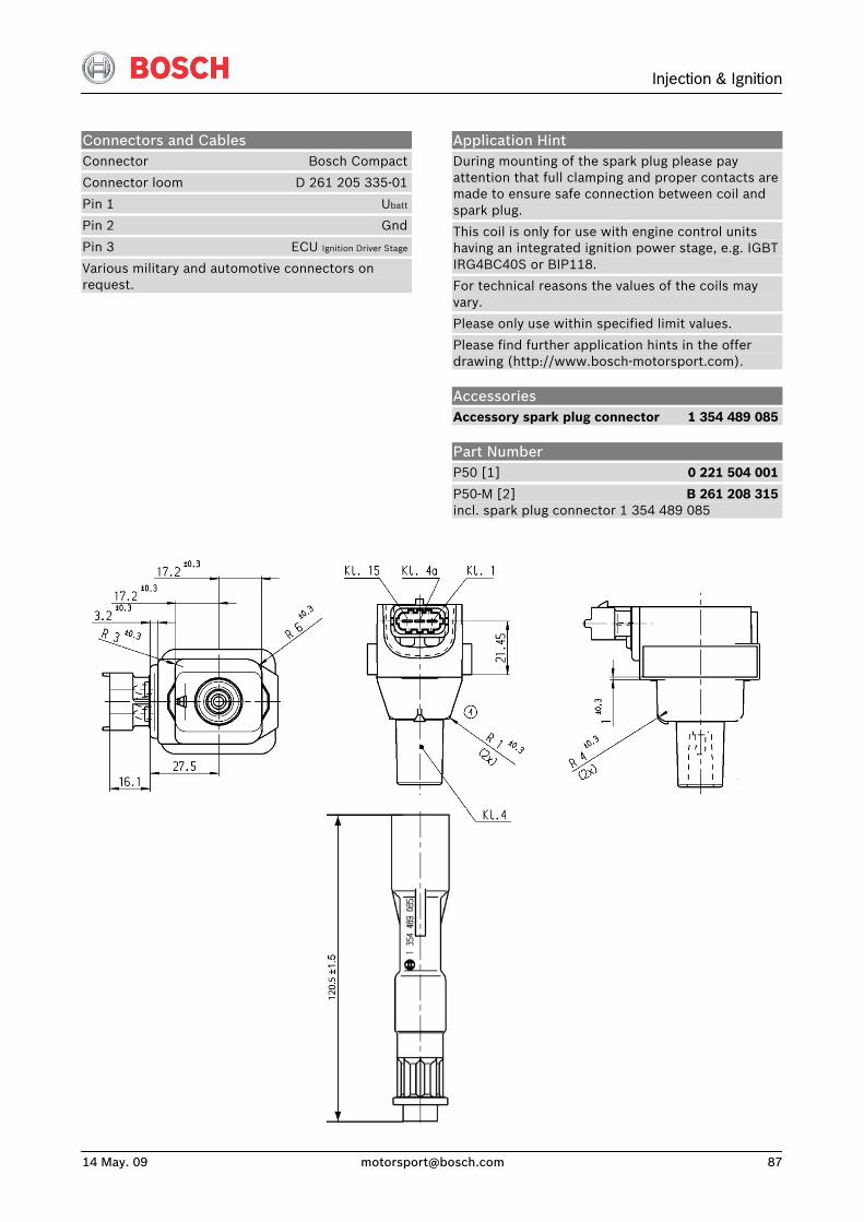
Injection & Ignition
14 May. 09 [email protected] 87
Connectors and Cables Connector Bosch Compact
Connector loom D 261 205 335-01
Pin 1 Ubatt
Pin 2 Gnd
Pin 3 ECU Ignition Driver Stage
Various military and automotive connectors on request.
Application Hint During mounting of the spark plug please pay attention that full clamping and proper contacts are made to ensure safe connection between coil and spark plug.
This coil is only for use with engine control units having an integrated ignition power stage, e.g. IGBT IRG4BC40S or BIP118.
For technical reasons the values of the coils may vary.
Please only use within specified limit values.
Please find further application hints in the offer drawing (http://www.bosch-motorsport.com).
Accessories Accessory spark plug connector 1 354 489 085
Part Number P50 [1] 0 221 504 001
P50-M [2] B 261 208 315incl. spark plug connector 1 354 489 085
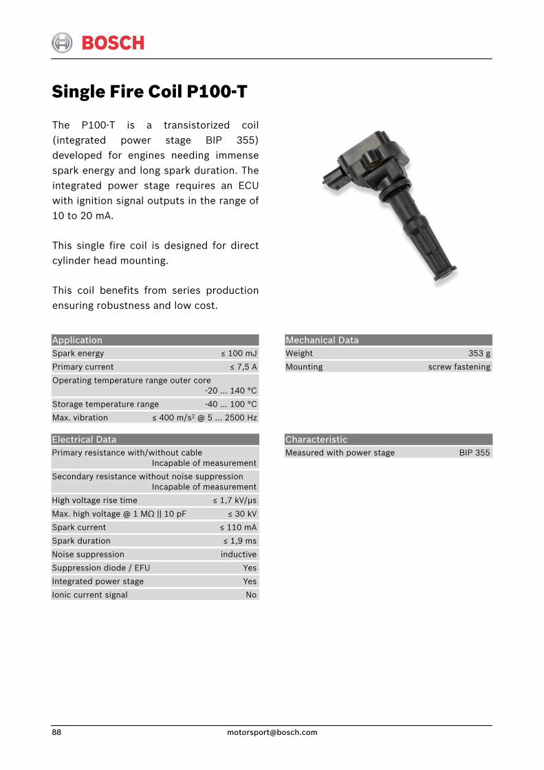
Single Fire Coil P100-T
The P100-T is a transistorized coil(integrated power stage BIP 355)developed for engines needing immensespark energy and long spark duration. Theintegrated power stage requires an ECU with ignition signal outputs in the range of10 to 20 mA.
This single fire coil is designed for directcylinder head mounting.
This coil benefits from series productionensuring robustness and low cost.
Application Spark energy ≤ 100 mJ
Primary current ≤ 7,5 A
Operating temperature range outer core -20 … 140 °C
Storage temperature range -40 … 100 °C
Max. vibration ≤ 400 m/s2 @ 5 … 2500 Hz
Mechanical Data Weight 353 g
Mounting screw fastening
Electrical Data Primary resistance with/without cable Incapable of measurement
Secondary resistance without noise suppression Incapable of measurement
High voltage rise time ≤ 1,7 kV/μs
Max. high voltage @ 1 MΩ || 10 pF ≤ 30 kV
Spark current ≤ 110 mA
Spark duration ≤ 1,9 ms
Noise suppression inductive
Suppression diode / EFU Yes
Integrated power stage Yes
Ionic current signal No
Characteristic Measured with power stage BIP 355
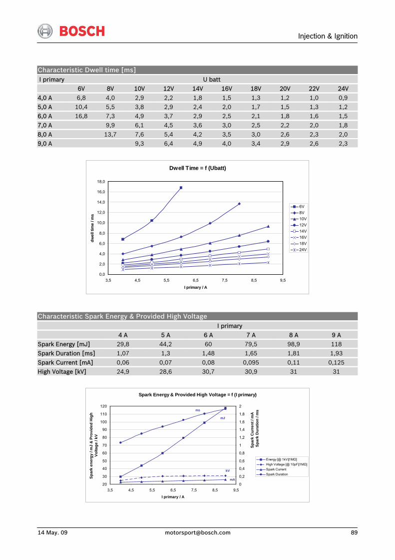
Injection & Ignition
14 May. 09 [email protected] 89
Characteristic Dwell time [ms] I primary U batt
6V 8V 10V 12V 14V 16V 18V 20V 22V 24V
4,0 A 6,8 4,0 2,9 2,2 1,8 1,5 1,3 1,2 1,0 0,9 5,0 A 10,4 5,5 3,8 2,9 2,4 2,0 1,7 1,5 1,3 1,2 6,0 A 16,8 7,3 4,9 3,7 2,9 2,5 2,1 1,8 1,6 1,5 7,0 A 9,9 6,1 4,5 3,6 3,0 2,5 2,2 2,0 1,8
8,0 A 13,7 7,6 5,4 4,2 3,5 3,0 2,6 2,3 2,0 9,0 A 9,3 6,4 4,9 4,0 3,4 2,9 2,6 2,3
Dwell Time = f (Ubatt)
0,0
2,0
4,0
6,0
8,0
10,0
12,0
14,0
16,0
18,0
3,5 4,5 5,5 6,5 7,5 8,5 9,5
I primary / A
dwel
l tim
e / m
s
6V8V10V12V14V16V18V24V
Characteristic Spark Energy & Provided High Voltage I primary
4 A 5 A 6 A 7 A 8 A 9 A Spark Energy [mJ] 29,8 44,2 60 79,5 98,9 118 Spark Duration [ms] 1,07 1,3 1,48 1,65 1,81 1,93
Spark Current [mA] 0,06 0,07 0,08 0,095 0,11 0,125 High Voltage [kV] 24,9 28,6 30,7 30,9 31 31
Spark Energy & Provided High Voltage = f (I primary)
20
30
40
50
60
70
80
90
100
110
120
3,5 4,5 5,5 6,5 7,5 8,5 9,5
I primary / A
Spar
k en
ergy
/ m
J &
Pro
vide
d H
igh
Volta
ge /
kV
0
0,2
0,4
0,6
0,8
1
1,2
1,4
1,6
1,8
2
Energy [@ 1kV||1MΩ]High Voltage [@ 10pF||1MΩ]Spark CurrentSpark Duration
Spar
k C
urre
nt /
mA
S
park
Dur
atio
n / m
sms
kV
mA
mJ
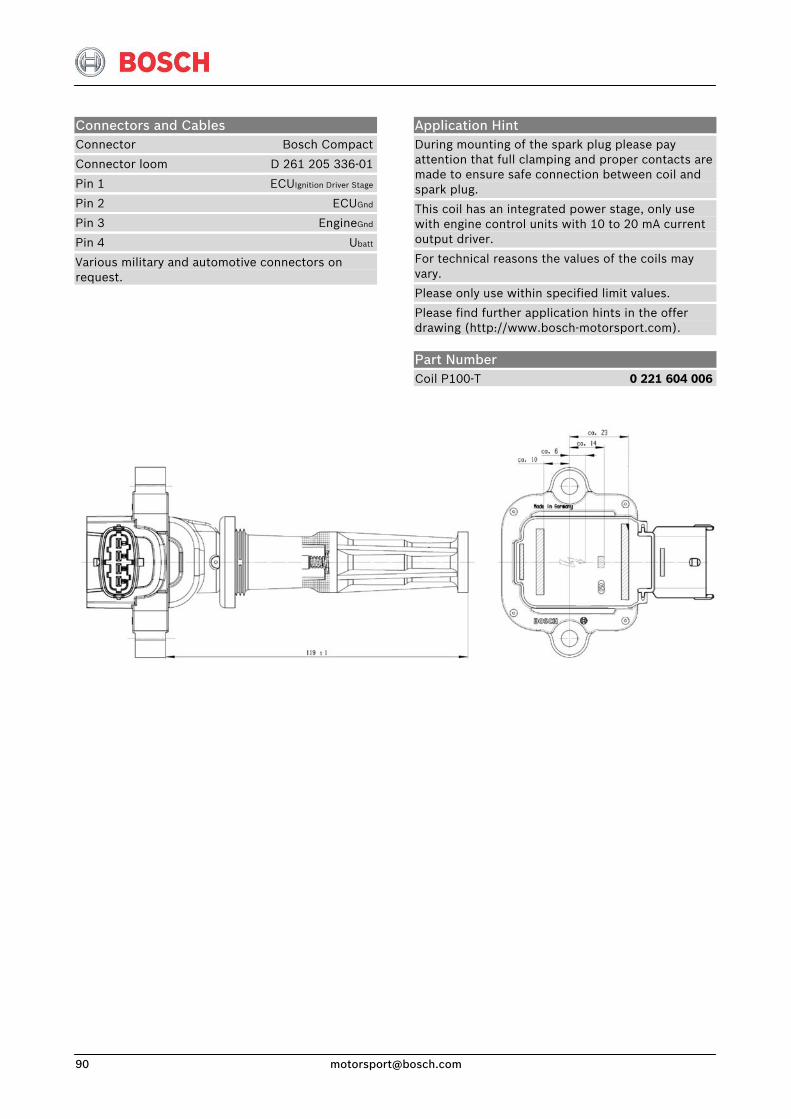
Connectors and Cables Connector Bosch Compact
Connector loom D 261 205 336-01
Pin 1 ECUIgnition Driver Stage
Pin 2 ECUGnd
Pin 3 EngineGnd
Pin 4 Ubatt
Various military and automotive connectors on request.
Application Hint During mounting of the spark plug please pay attention that full clamping and proper contacts are made to ensure safe connection between coil and spark plug.
This coil has an integrated power stage, only use with engine control units with 10 to 20 mA current output driver.
For technical reasons the values of the coils may vary.
Please only use within specified limit values.
Please find further application hints in the offer drawing (http://www.bosch-motorsport.com).
Part Number Coil P100-T 0 221 604 006
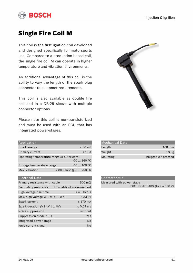
Injection & Ignition
14 May. 09 [email protected] 91
Single Fire Coil M
This coil is the first ignition coil developedand designed specifically for motorsportsuse. Compared to a production based coil, the single fire coil M can operate in highertemperature and vibration environments.
An additional advantage of this coil is theability to vary the length of the spark plugconnector to customer requirements.
This coil is also available as double fire coil and in a DR-25 sleeve with multipleconnector options.
Please note this coil is non-transistorizedand must be used with an ECU that hasintegrated power-stages.
Application Spark energy ≤ 38 mJ
Primary current ≤ 10 A
Operating temperature range @ outer core -20 … 160 °C
Storage temperature range -40 … 100 °C
Max. vibration ≤ 800 m/s2 @ 5 … 250 Hz
Mechanical Data Length 168 mm
Weight 180 g
Mounting pluggable / pressed
Electrical Data Primary resistance with cable 500 mΩ
Secondary resistance Incapable of measurement
High voltage rise time ≤ 4,0 kV/μs
Max. high voltage @ 1 MΩ || 10 pF ≤ 33 kV
Spark current ≤ 170 mA
Spark duration @ 1 kV || 1 MΩ ≤ 0,53 ms
Noise suppression without
Suppression diode / EFU Yes
Integrated power stage No
Ionic current signal No
Characteristic Measured with power stage IGBT IRG4BC40S (Uce = 600 V)
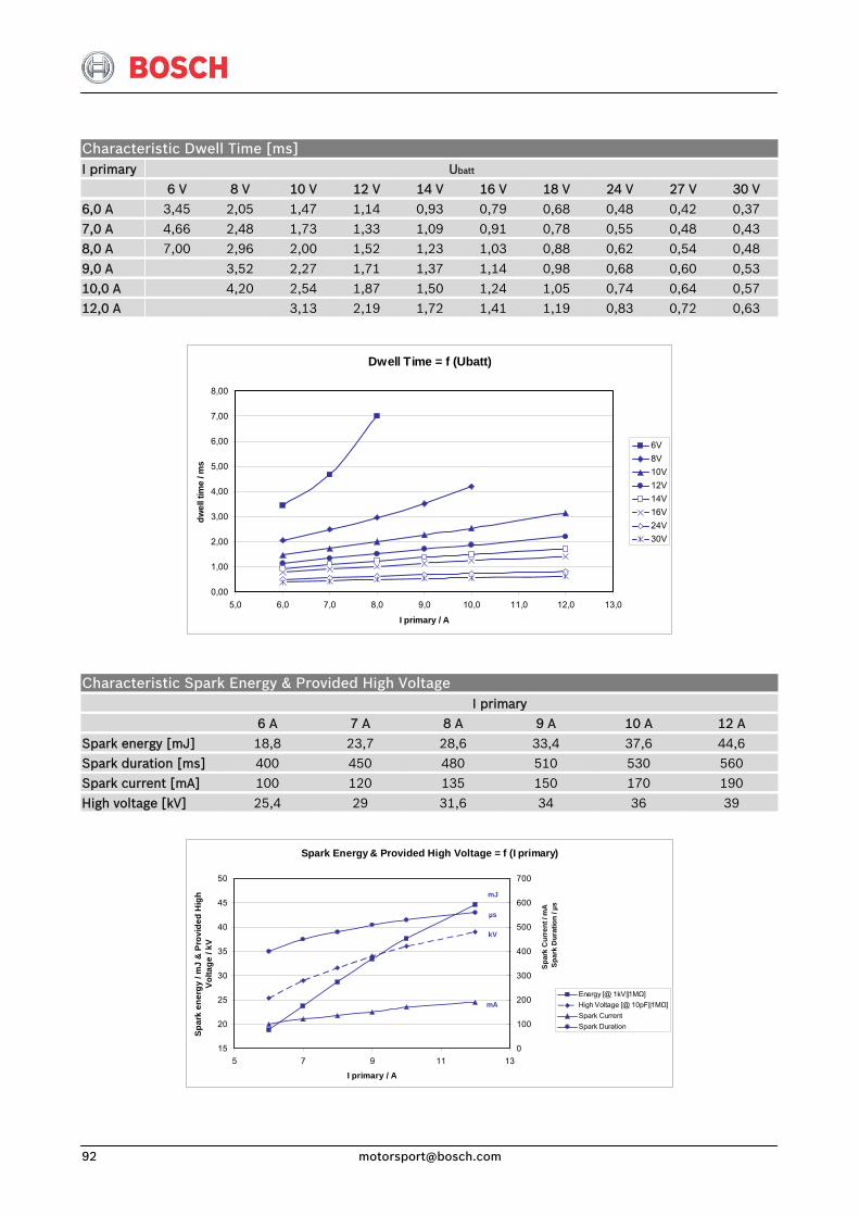
Characteristic Dwell Time [ms] I primary Ubatt 6 V 8 V 10 V 12 V 14 V 16 V 18 V 24 V 27 V 30 V
6,0 A 3,45 2,05 1,47 1,14 0,93 0,79 0,68 0,48 0,42 0,37 7,0 A 4,66 2,48 1,73 1,33 1,09 0,91 0,78 0,55 0,48 0,43 8,0 A 7,00 2,96 2,00 1,52 1,23 1,03 0,88 0,62 0,54 0,48
9,0 A 3,52 2,27 1,71 1,37 1,14 0,98 0,68 0,60 0,53 10,0 A 4,20 2,54 1,87 1,50 1,24 1,05 0,74 0,64 0,57 12,0 A 3,13 2,19 1,72 1,41 1,19 0,83 0,72 0,63
Dwell Time = f (Ubatt)
0,00
1,00
2,00
3,00
4,00
5,00
6,00
7,00
8,00
5,0 6,0 7,0 8,0 9,0 10,0 11,0 12,0 13,0
I primary / A
dwel
l tim
e / m
s
6V8V10V12V14V16V24V30V
Characteristic Spark Energy & Provided High Voltage I primary 6 A 7 A 8 A 9 A 10 A 12 A
Spark energy [mJ] 18,8 23,7 28,6 33,4 37,6 44,6 Spark duration [ms] 400 450 480 510 530 560 Spark current [mA] 100 120 135 150 170 190
High voltage [kV] 25,4 29 31,6 34 36 39
Spark Energy & Provided High Voltage = f (I primary)
15
20
25
30
35
40
45
50
5 7 9 11 13
I primary / A
Spar
k en
ergy
/ m
J &
Pro
vide
d H
igh
Volta
ge /
kV
0
100
200
300
400
500
600
700
Energy [@ 1kV||1MΩ]High Voltage [@ 10pF||1MΩ]Spark CurrentSpark Duration
Spar
k C
urre
nt /
mA
S
park
Dur
atio
n / µ
s
µs
kV
mA
mJ
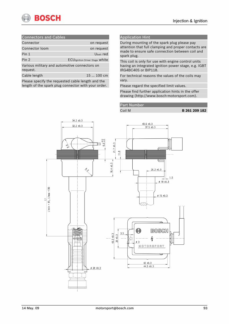
Injection & Ignition
14 May. 09 [email protected] 93
Connectors and Cables Connector on request
Connector loom on request
Pin 1 Ubatt red
Pin 2 ECUIgnition Driver Stage white
Various military and automotive connectors on request.
Cable length 15 … 100 cm
Please specify the requested cable length and the length of the spark plug connector with your order.
Application Hint During mounting of the spark plug please pay attention that full clamping and proper contacts are made to ensure safe connection between coil and spark plug.
This coil is only for use with engine control units having an integrated ignition power stage, e.g. IGBT IRG4BC40S or BIP118.
For technical reasons the values of the coils may vary.
Please regard the specified limit values.
Please find further application hints in the offer drawing (http://www.bosch-motorsport.com).
Part Number Coil M B 261 209 182
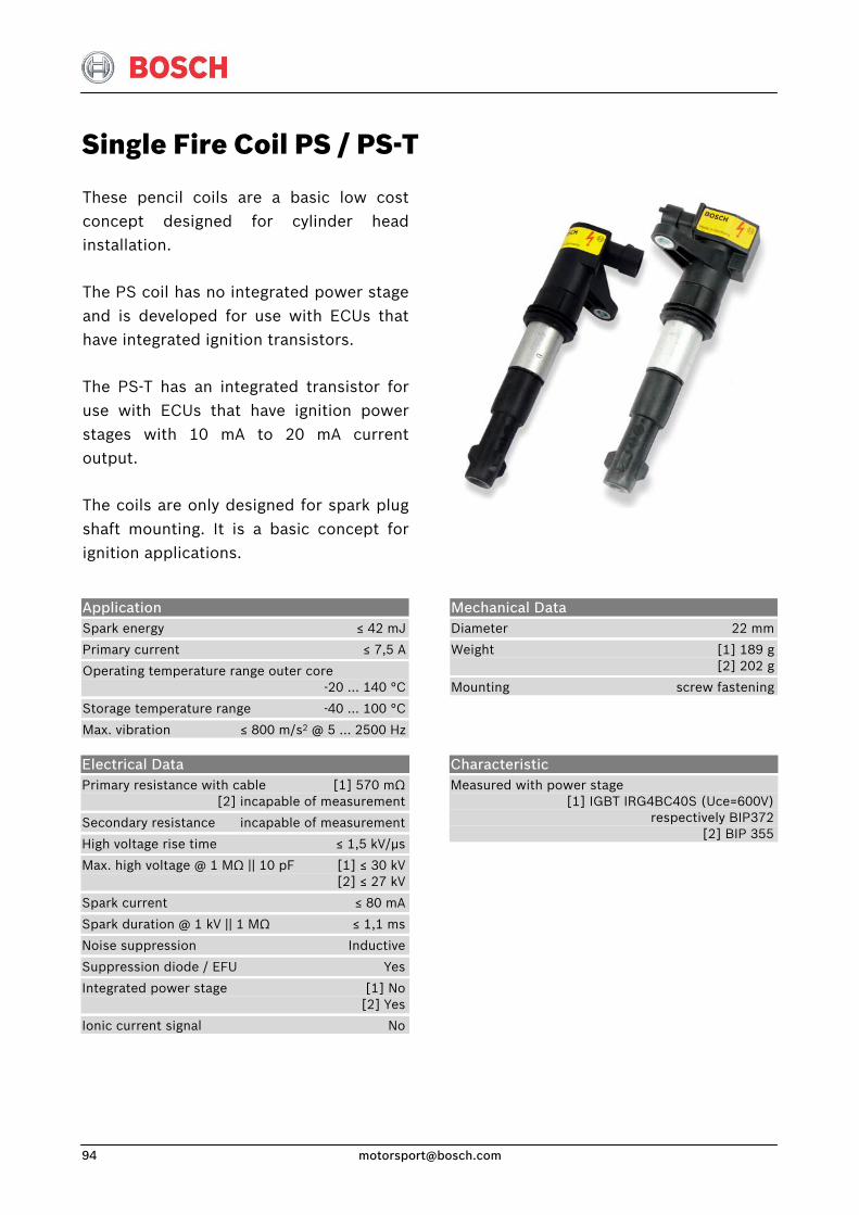
Single Fire Coil PS / PS-T
These pencil coils are a basic low costconcept designed for cylinder headinstallation.
The PS coil has no integrated power stageand is developed for use with ECUs thathave integrated ignition transistors.
The PS-T has an integrated transistor foruse with ECUs that have ignition powerstages with 10 mA to 20 mA currentoutput.
The coils are only designed for spark plugshaft mounting. It is a basic concept forignition applications.
Application Spark energy ≤ 42 mJ
Primary current ≤ 7,5 A
Operating temperature range outer core -20 … 140 °C
Storage temperature range -40 … 100 °C
Max. vibration ≤ 800 m/s2 @ 5 … 2500 Hz
Mechanical Data Diameter 22 mm
Weight [1] 189 g [2] 202 g
Mounting screw fastening
Electrical Data Primary resistance with cable [1] 570 mΩ [2] incapable of measurement
Secondary resistance incapable of measurement
High voltage rise time ≤ 1,5 kV/μs
Max. high voltage @ 1 MΩ || 10 pF [1] ≤ 30 kV [2] ≤ 27 kV
Spark current ≤ 80 mA
Spark duration @ 1 kV || 1 MΩ ≤ 1,1 ms
Noise suppression Inductive
Suppression diode / EFU Yes
Integrated power stage [1] No [2] Yes
Ionic current signal No
Characteristic Measured with power stage [1] IGBT IRG4BC40S (Uce=600V) respectively BIP372 [2] BIP 355
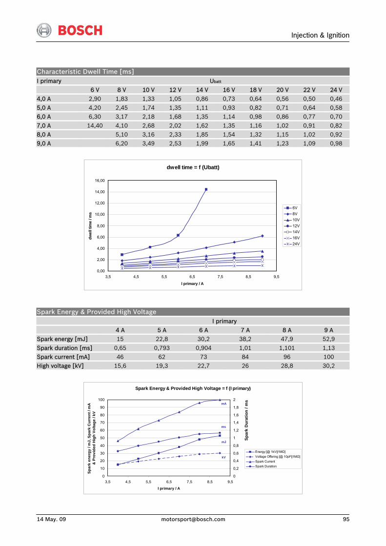
Injection & Ignition
14 May. 09 [email protected] 95
Characteristic Dwell Time [ms] I primary Ubatt
6 V 8 V 10 V 12 V 14 V 16 V 18 V 20 V 22 V 24 V 4,0 A 2,90 1,83 1,33 1,05 0,86 0,73 0,64 0,56 0,50 0,46 5,0 A 4,20 2,45 1,74 1,35 1,11 0,93 0,82 0,71 0,64 0,58 6,0 A 6,30 3,17 2,18 1,68 1,35 1,14 0,98 0,86 0,77 0,70
7,0 A 14,40 4,10 2,68 2,02 1,62 1,35 1,16 1,02 0,91 0,82 8,0 A 5,10 3,16 2,33 1,85 1,54 1,32 1,15 1,02 0,92 9,0 A 6,20 3,49 2,53 1,99 1,65 1,41 1,23 1,09 0,98
dwell time = f (Ubatt)
0,00
2,00
4,00
6,00
8,00
10,00
12,00
14,00
16,00
3,5 4,5 5,5 6,5 7,5 8,5 9,5
I primary / A
dwel
l tim
e / m
s
6V8V10V12V14V16V24V
Spark Energy & Provided High Voltage I primary 4 A 5 A 6 A 7 A 8 A 9 A Spark energy [mJ] 15 22,8 30,2 38,2 47,9 52,9
Spark duration [ms] 0,65 0,793 0,904 1,01 1,101 1,13 Spark current [mA] 46 62 73 84 96 100 High voltage [kV] 15,6 19,3 22,7 26 28,8 30,2
Spark Energy & Provided High Voltage = f (I primary)
0
10
20
30
40
50
60
70
80
90
100
3,5 4,5 5,5 6,5 7,5 8,5 9,5
I primary / A
Spar
k en
ergy
/ m
J, S
park
Cur
rent
/ m
A
& P
rovi
ded
Hig
h Vo
ltage
/ kV
0
0,2
0,4
0,6
0,8
1
1,2
1,4
1,6
1,8
2
Energy [@ 1kV||1MΩ]Voltage Offering [@ 10pF||1MΩ]Spark CurrentSpark Duration
Spar
k D
urat
ion
/ ms
ms
kV
mA
mJ
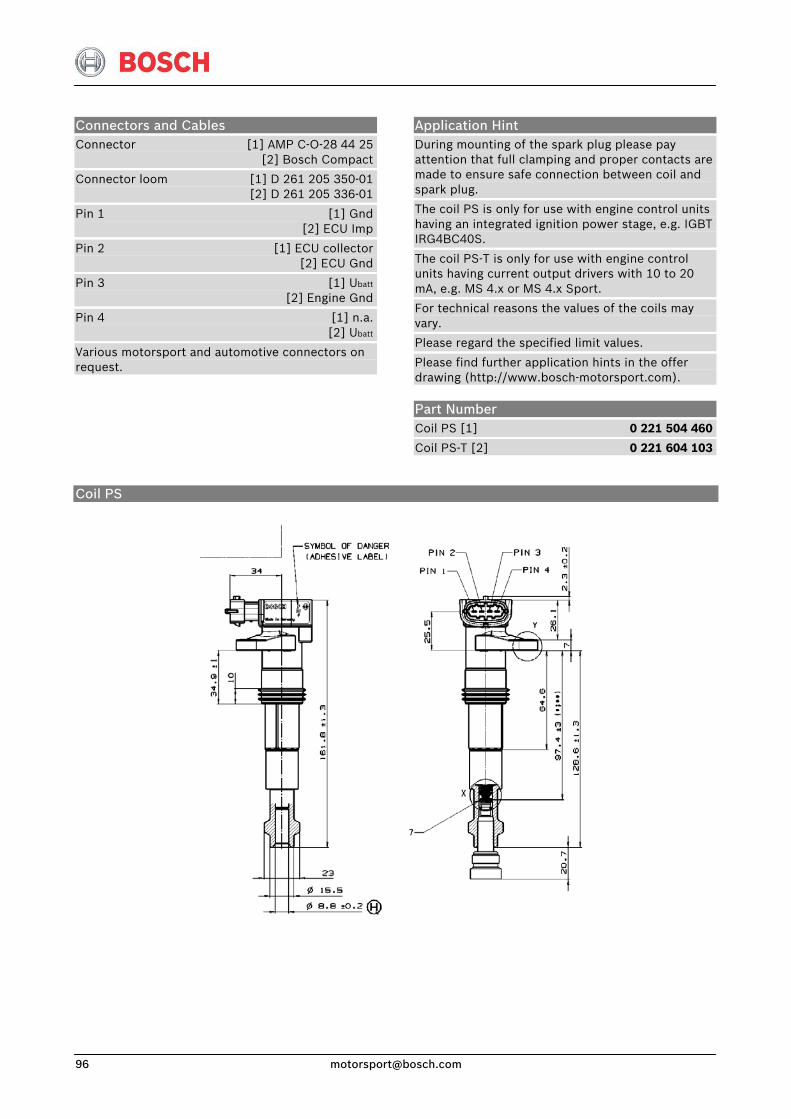
Connectors and Cables Connector [1] AMP C-O-28 44 25 [2] Bosch Compact
Connector loom [1] D 261 205 350-01 [2] D 261 205 336-01
Pin 1 [1] Gnd [2] ECU Imp
Pin 2 [1] ECU collector [2] ECU Gnd
Pin 3 [1] Ubatt
[2] Engine Gnd
Pin 4 [1] n.a. [2] Ubatt
Various motorsport and automotive connectors on request.
Application Hint During mounting of the spark plug please pay attention that full clamping and proper contacts are made to ensure safe connection between coil and spark plug.
The coil PS is only for use with engine control units having an integrated ignition power stage, e.g. IGBT IRG4BC40S.
The coil PS-T is only for use with engine control units having current output drivers with 10 to 20 mA, e.g. MS 4.x or MS 4.x Sport.
For technical reasons the values of the coils may vary.
Please regard the specified limit values.
Please find further application hints in the offer drawing (http://www.bosch-motorsport.com).
Part Number Coil PS [1] 0 221 504 460
Coil PS-T [2] 0 221 604 103
Coil PS
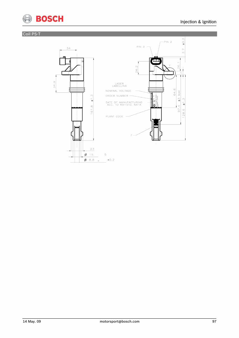
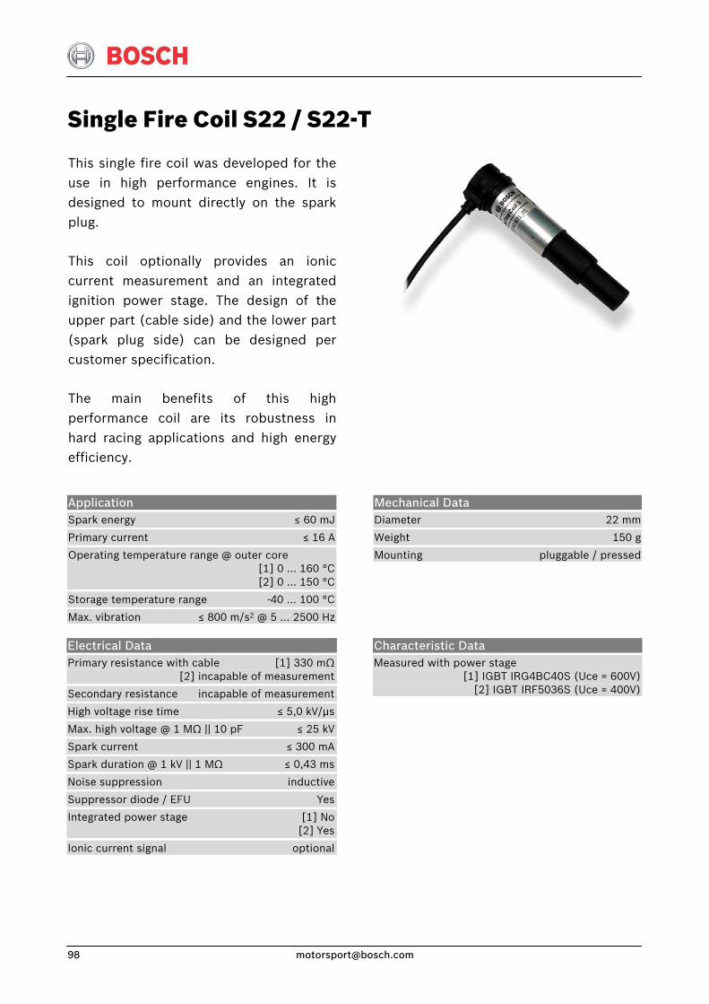
Single Fire Coil S22 / S22-T
This single fire coil was developed for the use in high performance engines. It is designed to mount directly on the spark plug.
This coil optionally provides an ionic current measurement and an integrated ignition power stage. The design of the upper part (cable side) and the lower part (spark plug side) can be designed per customer specification.
The main benefits of this high performance coil are its robustness in hard racing applications and high energy efficiency.
Application Spark energy ≤ 60 mJ
Primary current ≤ 16 A
Operating temperature range @ outer core [1] 0 … 160 °C [2] 0 … 150 °C
Storage temperature range -40 ... 100 °C
Max. vibration ≤ 800 m/s2 @ 5 … 2500 Hz
Mechanical Data Diameter 22 mm
Weight 150 g
Mounting pluggable / pressed
Electrical Data Primary resistance with cable [1] 330 mΩ [2] incapable of measurement
Secondary resistance incapable of measurement
High voltage rise time ≤ 5,0 kV/μs
Max. high voltage @ 1 MΩ || 10 pF ≤ 25 kV
Spark current ≤ 300 mA
Spark duration @ 1 kV || 1 MΩ ≤ 0,43 ms
Noise suppression inductive
Suppressor diode / EFU Yes
Integrated power stage [1] No [2] Yes
Ionic current signal optional
Characteristic Data Measured with power stage [1] IGBT IRG4BC40S (Uce = 600V) [2] IGBT IRF5036S (Uce = 400V)
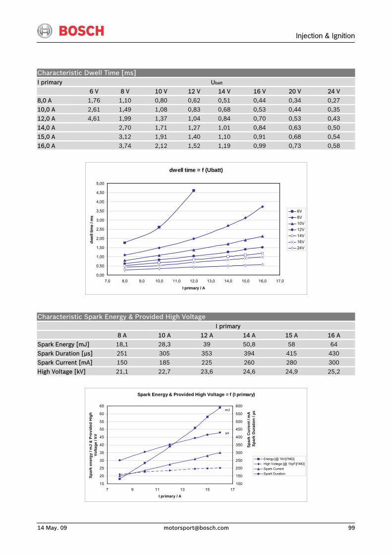
Injection & Ignition
14 May. 09 [email protected] 99
Characteristic Dwell Time [ms] I primary Ubatt
6 V 8 V 10 V 12 V 14 V 16 V 20 V 24 V 8,0 A 1,76 1,10 0,80 0,62 0,51 0,44 0,34 0,27 10,0 A 2,61 1,49 1,08 0,83 0,68 0,53 0,44 0,35 12,0 A 4,61 1,99 1,37 1,04 0,84 0,70 0,53 0,43
14,0 A 2,70 1,71 1,27 1,01 0,84 0,63 0,50 15,0 A 3,12 1,91 1,40 1,10 0,91 0,68 0,54 16,0 A 3,74 2,12 1,52 1,19 0,99 0,73 0,58
dwell time = f (Ubatt)
0,00
0,50
1,00
1,50
2,00
2,50
3,00
3,50
4,00
4,50
5,00
7,0 8,0 9,0 10,0 11,0 12,0 13,0 14,0 15,0 16,0 17,0
I primary / A
dwel
l tim
e / m
s
6V8V10V12V14V16V24V
Characteristic Spark Energy & Provided High Voltage I primary
8 A 10 A 12 A 14 A 15 A 16 A Spark Energy [mJ] 18,1 28,3 39 50,8 58 64 Spark Duration [μs] 251 305 353 394 415 430
Spark Current [mA] 150 185 225 260 280 300 High Voltage [kV] 21,1 22,7 23,6 24,6 24,9 25,2
Spark Energy & Provided High Voltage = f (I primary)
15
20
25
30
35
40
45
50
55
60
65
7 9 11 13 15 17
I primary / A
Spar
k en
ergy
/ m
J &
Pro
vide
d H
igh
Volta
ge /
kV
100
150
200
250
300
350
400
450
500
550
600
Energy [@ 1kV||1MΩ]High Voltage [@ 10pF||1MΩ]Spark CurrentSpark Duration
Spar
k C
urre
nt /
mA
S
park
Dur
atio
n / µ
s
µs
mJ
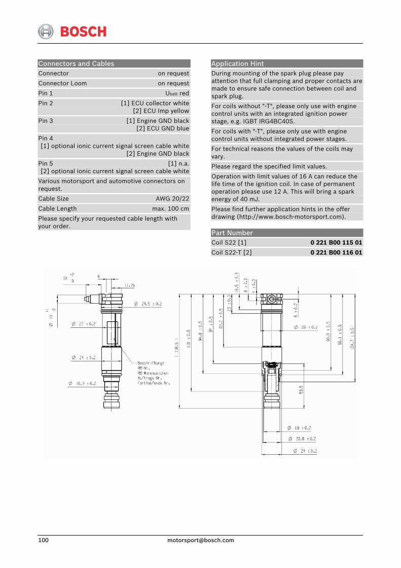
Connectors and Cables Connector on request
Connector Loom on request
Pin 1 Ubatt red
Pin 2 [1] ECU collector white [2] ECU Imp yellow
Pin 3 [1] Engine GND black [2] ECU GND blue
Pin 4 [1] optional ionic current signal screen cable white [2] Engine GND black
Pin 5 [1] n.a. [2] optional ionic current signal screen cable white
Various motorsport and automotive connectors on request.
Cable Size AWG 20/22
Cable Length max. 100 cm
Please specify your requested cable length with your order.
Application Hint During mounting of the spark plug please pay attention that full clamping and proper contacts are made to ensure safe connection between coil and spark plug.
For coils without "-T", please only use with engine control units with an integrated ignition power stage, e.g. IGBT IRG4BC40S.
For coils with "-T", please only use with engine control units without integrated power stages.
For technical reasons the values of the coils may vary.
Please regard the specified limit values.
Operation with limit values of 16 A can reduce the life time of the ignition coil. In case of permanent operation please use 12 A. This will bring a spark energy of 40 mJ.
Please find further application hints in the offer drawing (http://www.bosch-motorsport.com).
Part Number Coil S22 [1] 0 221 B00 115 01
Coil S22-T [2] 0 221 B00 116 01
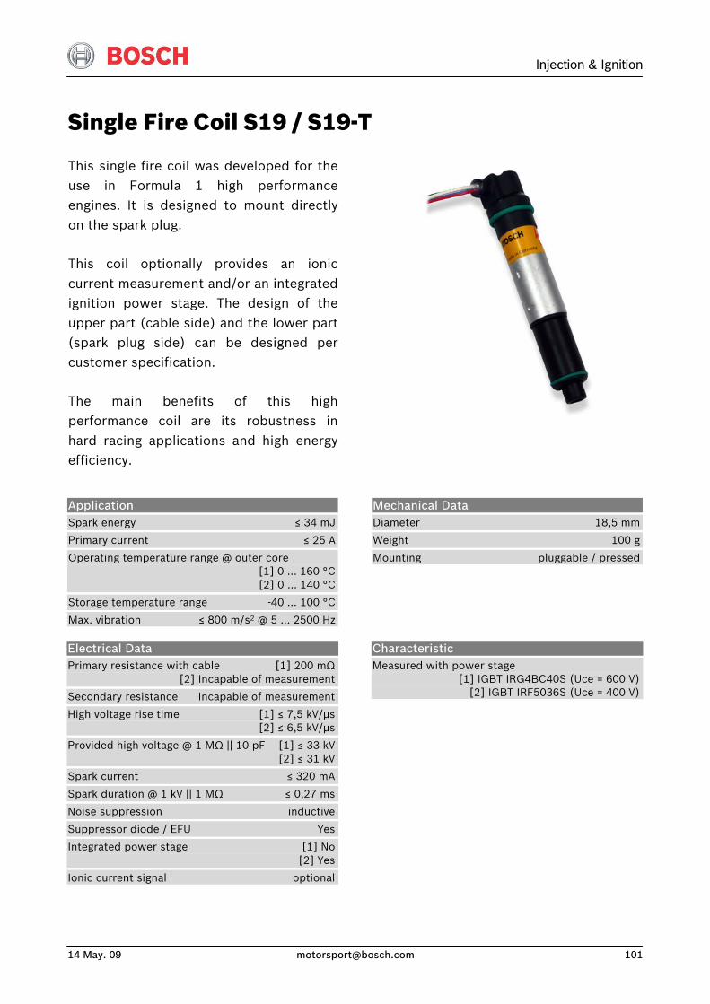
Injection & Ignition
14 May. 09 [email protected] 101
Single Fire Coil S19 / S19-T
This single fire coil was developed for theuse in Formula 1 high performanceengines. It is designed to mount directlyon the spark plug.
This coil optionally provides an ioniccurrent measurement and/or an integratedignition power stage. The design of theupper part (cable side) and the lower part(spark plug side) can be designed percustomer specification.
The main benefits of this highperformance coil are its robustness in hard racing applications and high energyefficiency.
Application Spark energy ≤ 34 mJ
Primary current ≤ 25 A
Operating temperature range @ outer core [1] 0 … 160 °C [2] 0 … 140 °C
Storage temperature range -40 … 100 °C
Max. vibration ≤ 800 m/s2 @ 5 … 2500 Hz
Mechanical Data Diameter 18,5 mm
Weight 100 g
Mounting pluggable / pressed
Electrical Data Primary resistance with cable [1] 200 mΩ [2] Incapable of measurement
Secondary resistance Incapable of measurement
High voltage rise time [1] ≤ 7,5 kV/μs [2] ≤ 6,5 kV/μs
Provided high voltage @ 1 MΩ || 10 pF [1] ≤ 33 kV [2] ≤ 31 kV
Spark current ≤ 320 mA
Spark duration @ 1 kV || 1 MΩ ≤ 0,27 ms
Noise suppression inductive
Suppressor diode / EFU Yes
Integrated power stage [1] No [2] Yes
Ionic current signal optional
Characteristic Measured with power stage [1] IGBT IRG4BC40S (Uce = 600 V) [2] IGBT IRF5036S (Uce = 400 V)
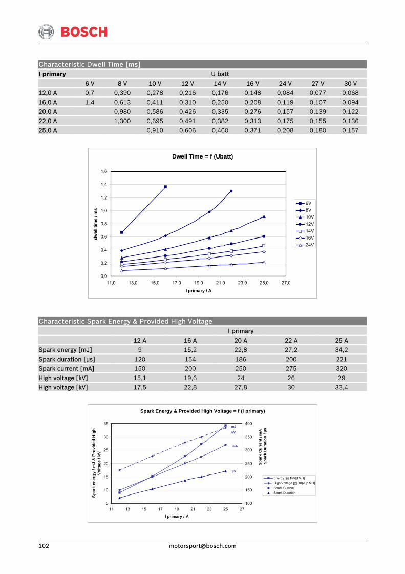
Characteristic Dwell Time [ms] I primary U batt
6 V 8 V 10 V 12 V 14 V 16 V 24 V 27 V 30 V 12,0 A 0,7 0,390 0,278 0,216 0,176 0,148 0,084 0,077 0,068 16,0 A 1,4 0,613 0,411 0,310 0,250 0,208 0,119 0,107 0,094
20,0 A 0,980 0,586 0,426 0,335 0,276 0,157 0,139 0,122 22,0 A 1,300 0,695 0,491 0,382 0,313 0,175 0,155 0,136 25,0 A 0,910 0,606 0,460 0,371 0,208 0,180 0,157
Dwell Time = f (Ubatt)
0,0
0,2
0,4
0,6
0,8
1,0
1,2
1,4
1,6
11,0 13,0 15,0 17,0 19,0 21,0 23,0 25,0 27,0
I primary / A
dwel
l tim
e / m
s
6V8V10V12V14V16V24V
Characteristic Spark Energy & Provided High Voltage I primary 12 A 16 A 20 A 22 A 25 A Spark energy [mJ] 9 15,2 22,8 27,2 34,2
Spark duration [μs] 120 154 186 200 221 Spark current [mA] 150 200 250 275 320 High voltage [kV] 15,1 19,6 24 26 29
High voltage [kV] 17,5 22,8 27,8 30 33,4
Spark Energy & Provided High Voltage = f (I primary)
5
10
15
20
25
30
35
11 13 15 17 19 21 23 25 27
I primary / A
Spar
k en
ergy
/ m
J &
Pro
vide
d H
igh
Volta
ge /
kV
100
150
200
250
300
350
400
Energy [@ 1kV||1MΩ]High Voltage [@ 10pF||1MΩ]Spark CurrentSpark Duration
Spar
k C
urre
nt /
mA
S
park
Dur
atio
n / µ
s
µs
kV
mA
mJ
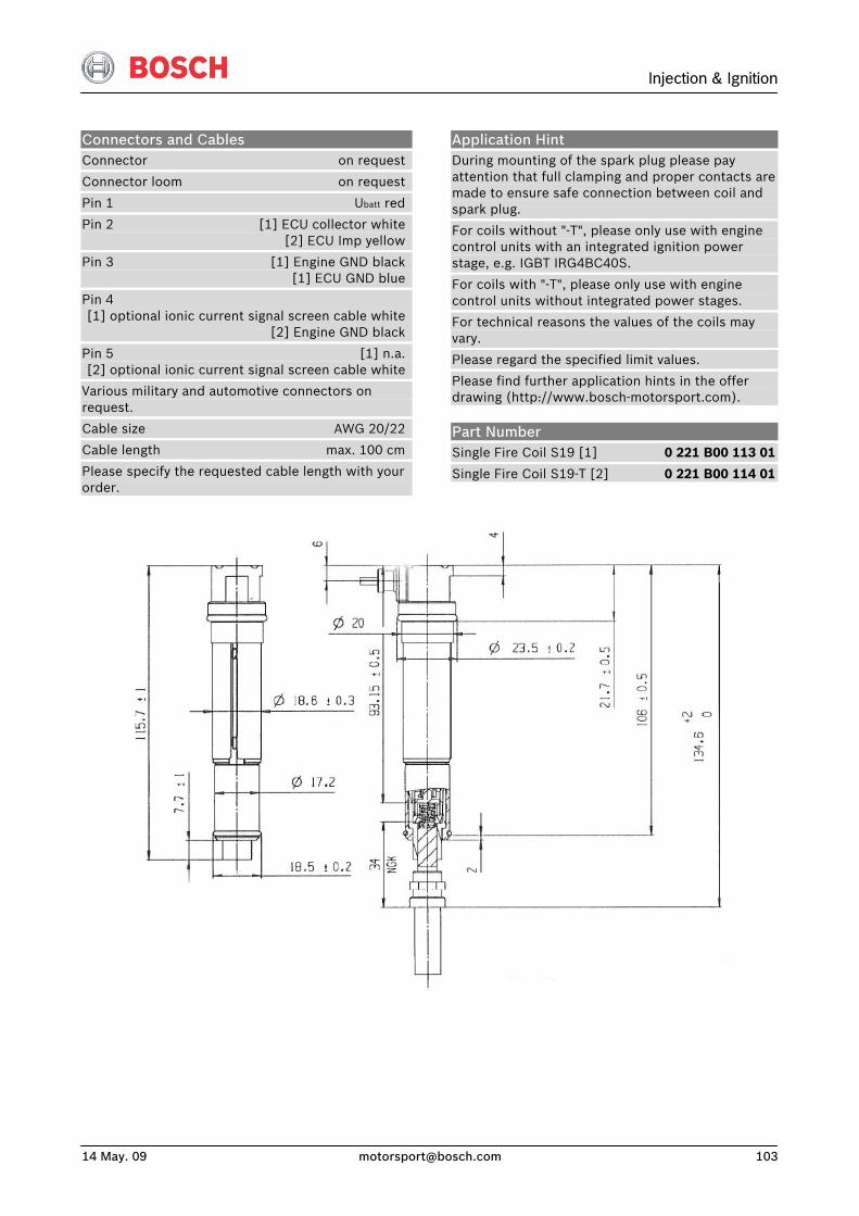
Injection & Ignition
14 May. 09 [email protected] 103
Connectors and Cables Connector on request
Connector loom on request
Pin 1 Ubatt red
Pin 2 [1] ECU collector white [2] ECU Imp yellow
Pin 3 [1] Engine GND black [1] ECU GND blue
Pin 4 [1] optional ionic current signal screen cable white [2] Engine GND black
Pin 5 [1] n.a. [2] optional ionic current signal screen cable white
Various military and automotive connectors on request.
Cable size AWG 20/22
Cable length max. 100 cm
Please specify the requested cable length with your order.
Application Hint During mounting of the spark plug please pay attention that full clamping and proper contacts are made to ensure safe connection between coil and spark plug.
For coils without "-T", please only use with engine control units with an integrated ignition power stage, e.g. IGBT IRG4BC40S.
For coils with "-T", please only use with engine control units without integrated power stages.
For technical reasons the values of the coils may vary.
Please regard the specified limit values.
Please find further application hints in the offer drawing (http://www.bosch-motorsport.com).
Part Number Single Fire Coil S19 [1] 0 221 B00 113 01
Single Fire Coil S19-T [2] 0 221 B00 114 01
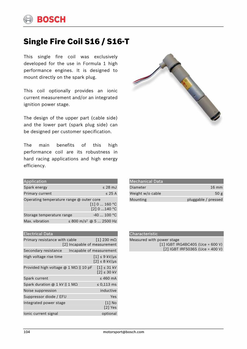
Single Fire Coil S16 / S16-T
This single fire coil was exclusivelydeveloped for the use in Formula 1 highperformance engines. It is designed tomount directly on the spark plug.
This coil optionally provides an ioniccurrent measurement and/or an integratedignition power stage.
The design of the upper part (cable side)and the lower part (spark plug side) canbe designed per customer specification.
The main benefits of this highperformance coil are its robustness inhard racing applications and high energyefficiency.
Application Spark energy ≤ 28 mJ
Primary current ≤ 25 A
Operating temperature range @ outer core [1] 0 … 160 °C [2] 0 …140 °C
Storage temperature range -40 … 100 °C
Max. vibration ≤ 800 m/s2 @ 5 … 2500 Hz
Mechanical Data Diameter 16 mm
Weight w/o cable 50 g
Mounting pluggable / pressed
Electrical Data Primary resistance with cable [1] 230 mΩ [2] Incapable of measurement
Secondary resistance Incapable of measurement
High voltage rise time [1] ≤ 9 kV/μs [2] ≤ 8 kV/μs
Provided high voltage @ 1 MΩ || 10 pF [1] ≤ 31 kV [2] ≤ 30 kV
Spark current ≤ 460 mA
Spark duration @ 1 kV || 1 MΩ ≤ 0,113 ms
Noise suppression inductive
Suppressor diode / EFU Yes
Integrated power stage [1] No [2] Yes
Ionic current signal optional
Characteristic Measured with power stage [1] IGBT IRG4BC40S (Uce = 600 V) [2] IGBT IRF5036S (Uce = 400 V)
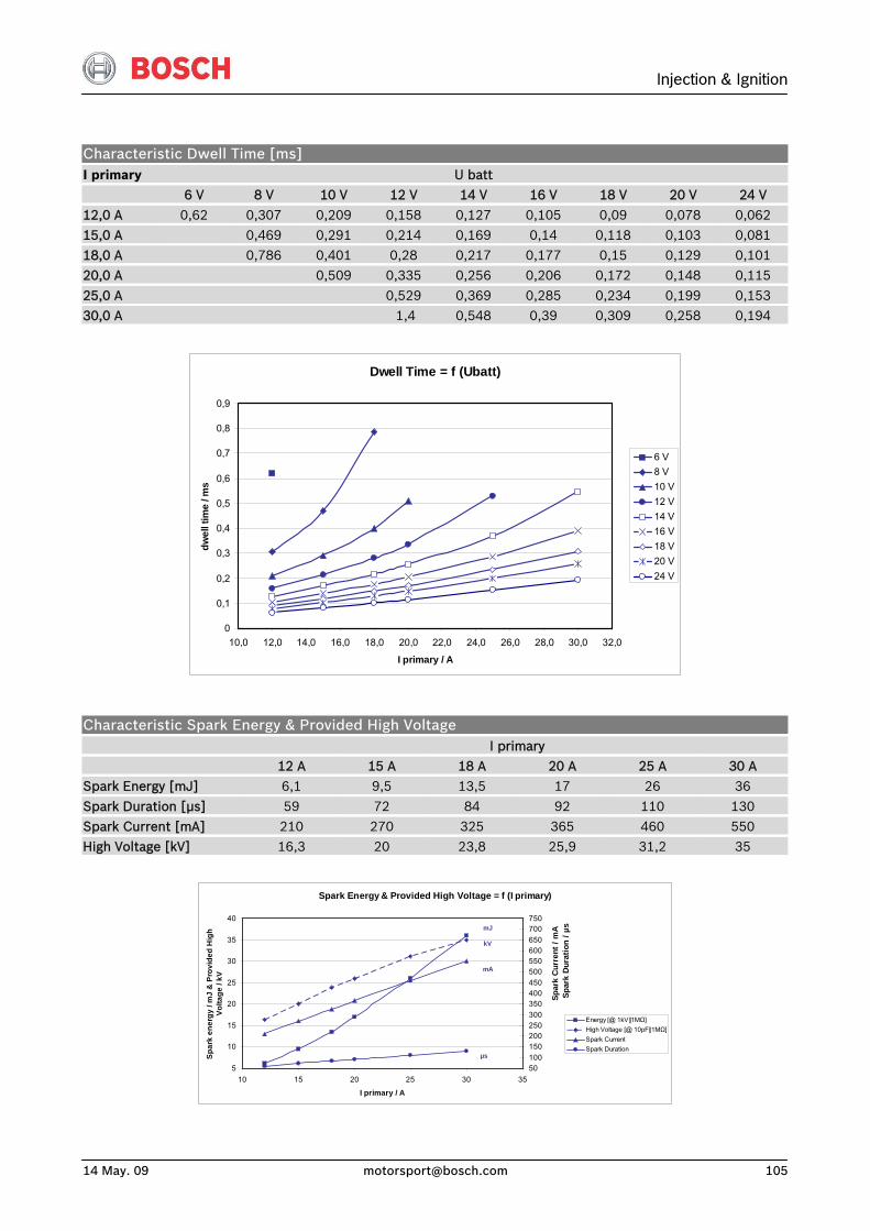
Injection & Ignition
14 May. 09 [email protected] 105
Characteristic Dwell Time [ms] I primary U batt 6 V 8 V 10 V 12 V 14 V 16 V 18 V 20 V 24 V
12,0 A 0,62 0,307 0,209 0,158 0,127 0,105 0,09 0,078 0,062 15,0 A 0,469 0,291 0,214 0,169 0,14 0,118 0,103 0,081 18,0 A 0,786 0,401 0,28 0,217 0,177 0,15 0,129 0,101 20,0 A 0,509 0,335 0,256 0,206 0,172 0,148 0,115
25,0 A 0,529 0,369 0,285 0,234 0,199 0,153 30,0 A 1,4 0,548 0,39 0,309 0,258 0,194
Dwell Time = f (Ubatt)
0
0,1
0,2
0,3
0,4
0,5
0,6
0,7
0,8
0,9
10,0 12,0 14,0 16,0 18,0 20,0 22,0 24,0 26,0 28,0 30,0 32,0
I primary / A
dwel
l tim
e / m
s
6 V8 V10 V12 V14 V16 V18 V20 V24 V
Characteristic Spark Energy & Provided High Voltage I primary 12 A 15 A 18 A 20 A 25 A 30 A Spark Energy [mJ] 6,1 9,5 13,5 17 26 36
Spark Duration [μs] 59 72 84 92 110 130 Spark Current [mA] 210 270 325 365 460 550 High Voltage [kV] 16,3 20 23,8 25,9 31,2 35
Spark Energy & Provided High Voltage = f (I primary)
5
10
15
20
25
30
35
40
10 15 20 25 30 35
I primary / A
Spar
k en
ergy
/ m
J &
Pro
vide
d H
igh
Volta
ge /
kV
50100150200250300350400450500550600650700750
Energy [@ 1kV||1MΩ]High Voltage [@ 10pF||1MΩ]Spark CurrentSpark Duration
Spar
k C
urre
nt /
mA
S
park
Dur
atio
n / µ
s
µs
kV
mA
mJ
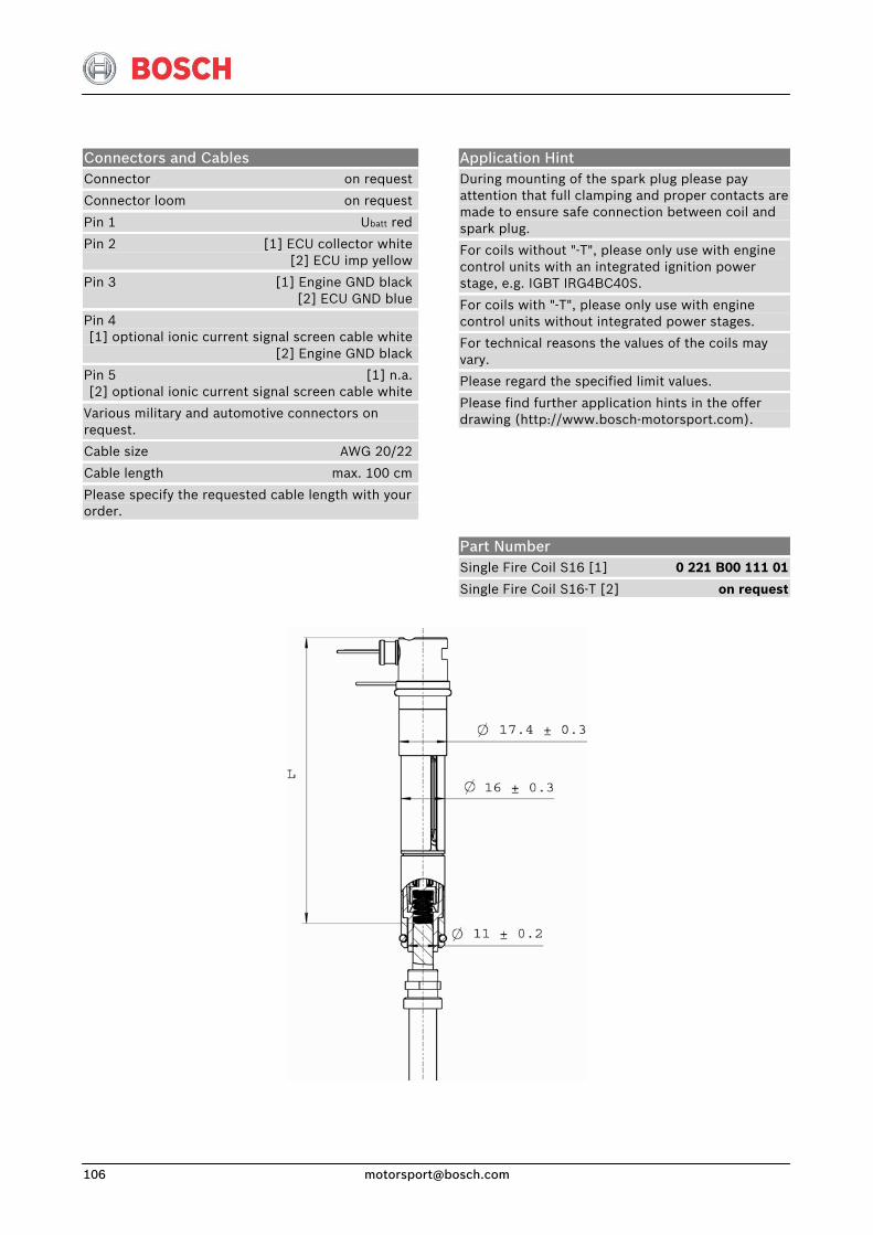
Connectors and Cables Connector on request
Connector loom on request
Pin 1 Ubatt red
Pin 2 [1] ECU collector white [2] ECU imp yellow
Pin 3 [1] Engine GND black [2] ECU GND blue
Pin 4 [1] optional ionic current signal screen cable white [2] Engine GND black
Pin 5 [1] n.a. [2] optional ionic current signal screen cable white
Various military and automotive connectors on request.
Cable size AWG 20/22
Cable length max. 100 cm
Please specify the requested cable length with your order.
Application Hint During mounting of the spark plug please pay attention that full clamping and proper contacts are made to ensure safe connection between coil and spark plug.
For coils without "-T", please only use with engine control units with an integrated ignition power stage, e.g. IGBT IRG4BC40S.
For coils with "-T", please only use with engine control units without integrated power stages.
For technical reasons the values of the coils may vary.
Please regard the specified limit values.
Please find further application hints in the offer drawing (http://www.bosch-motorsport.com).
Part Number Single Fire Coil S16 [1] 0 221 B00 111 01
Single Fire Coil S16-T [2] on request

Injection & Ignition
14 May. 09 [email protected] 107
Spark Plugs Spark Plugs
The engines of competition vehicles are exposed to high thermal stress because of running them at full load most of the time.
Spark plugs for this operating conditions often have precious metal center electrodes (platinum, silver) and a short insulator base. This causes a very small heat absorption and a good heat derivation through the center electrode.
Corresponding to the various field of operations we manufacture over 1400 different types of spark plugs in production. You can get these standard spark plugs from your local Bosch-service and most spare parts dealers. The range of products includes versions with various seats and threads, thread lengths and electrode positions, the design parts air-gap, surface-gap and surface-air-gap types. You can choose between versions with one to four ground electrodes, the center electrode can be made from various materials.
Moreover we offer special versions and small batches which you should not hesitate asking for.

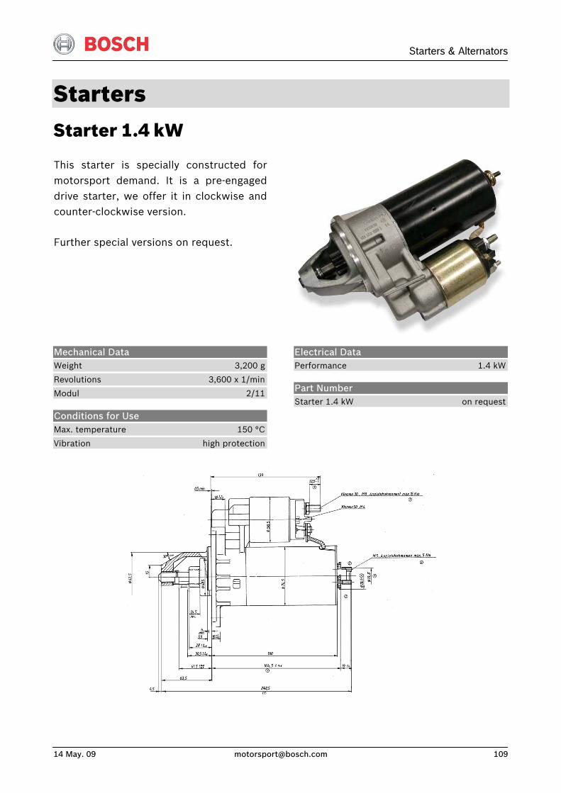
Starters & Alternators
14 May. 09 [email protected] 109
Starters Starter 1.4 kW
This starter is specially constructed formotorsport demand. It is a pre-engageddrive starter, we offer it in clockwise andcounter-clockwise version.
Further special versions on request.
Electrical Data Performance 1.4 kW
Mechanical Data Weight 3,200 g
Revolutions 3,600 x 1/min
Modul 2/11
Conditions for Use Max. temperature 150 °C
Vibration high protection
Part Number Starter 1.4 kW on request
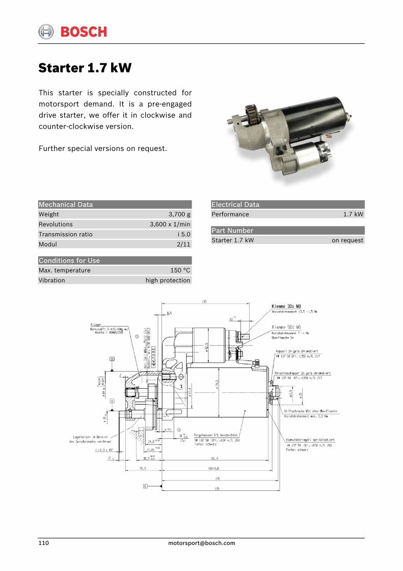
Starter 1.7 kW
This starter is specially constructed formotorsport demand. It is a pre-engageddrive starter, we offer it in clockwise and counter-clockwise version.
Further special versions on request.
Electrical Data Performance 1.7 kW
Mechanical Data Weight 3,700 g
Revolutions 3,600 x 1/min
Transmission ratio i 5.0
Modul 2/11
Conditions for Use Max. temperature 150 °C
Vibration high protection
Part Number Starter 1.7 kW on request
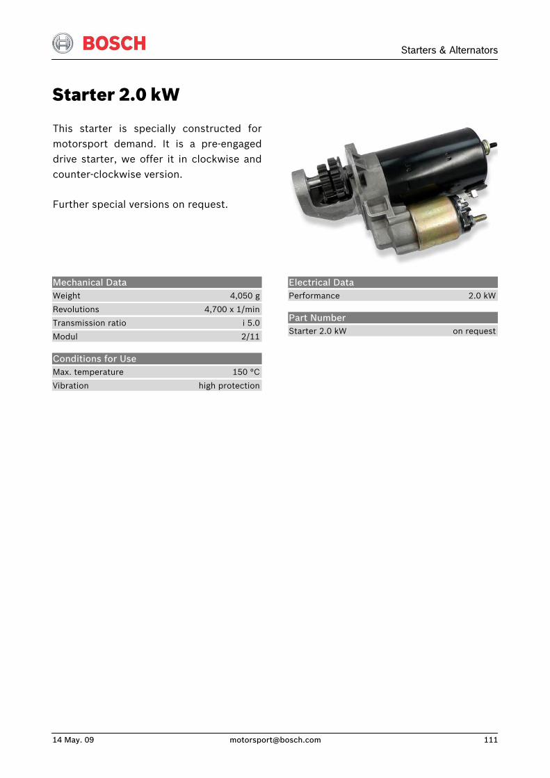
Starters & Alternators
14 May. 09 [email protected] 111
Starter 2.0 kW
This starter is specially constructed formotorsport demand. It is a pre-engageddrive starter, we offer it in clockwise andcounter-clockwise version.
Further special versions on request.
Electrical Data Performance 2.0 kW
Mechanical Data Weight 4,050 g
Revolutions 4,700 x 1/min
Transmission ratio i 5.0
Modul 2/11
Conditions for Use Max. temperature 150 °C
Vibration high protection
Part Number Starter 2.0 kW on request
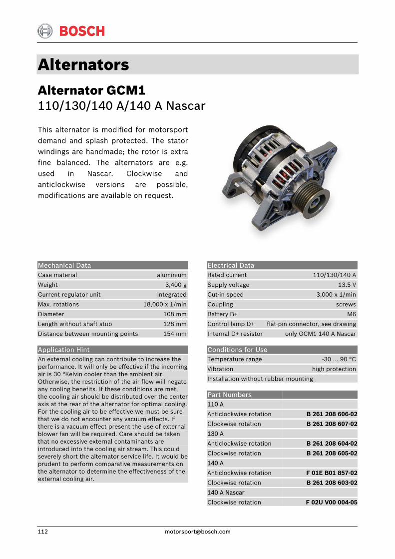
Alternators Alternator GCM1 110/130/140 A/140 A Nascar
This alternator is modified for motorsportdemand and splash protected. The statorwindings are handmade; the rotor is extrafine balanced. The alternators are e.g.used in Nascar. Clockwise andanticlockwise versions are possible, modifications are available on request.
Electrical Data Rated current 110/130/140 A
Supply voltage 13.5 V
Cut-in speed 3,000 x 1/min
Coupling screws
Battery B+ M6
Control lamp D+ flat-pin connector, see drawing
Internal D+ resistor only GCM1 140 A Nascar
Conditions for Use Temperature range -30 … 90 °C
Vibration high protection
Installation without rubber mounting
Mechanical Data Case material aluminium
Weight 3,400 g
Current regulator unit integrated
Max. rotations 18,000 x 1/min
Diameter 108 mm
Length without shaft stub 128 mm
Distance between mounting points 154 mm
Application Hint An external cooling can contribute to increase the performance. It will only be effective if the incoming air is 30 °Kelvin cooler than the ambient air. Otherwise, the restriction of the air flow will negate any cooling benefits. If these conditions are met, the cooling air should be distributed over the center axis at the rear of the alternator for optimal cooling.For the cooling air to be effective we must be sure that we do not encounter any vacuum effects. If there is a vacuum effect present the use of external blower fan will be required. Care should be taken that no excessive external contaminants are introduced into the cooling air stream. This could severely short the alternator service life. It would be prudent to perform comparative measurements on the alternator to determine the effectiveness of the external cooling air.
Part Numbers 110 A
Anticlockwise rotation
Clockwise rotation
130 A
Anticlockwise rotation
Clockwise rotation
140 A
Anticlockwise rotation
Clockwise rotation
140 A Nascar
Clockwise rotation
B 261 208 606-02
B 261 208 607-02
B 261 208 604-02
B 261 208 605-02
F 01E B01 857-02
B 261 208 603-02
F 02U V00 004-05
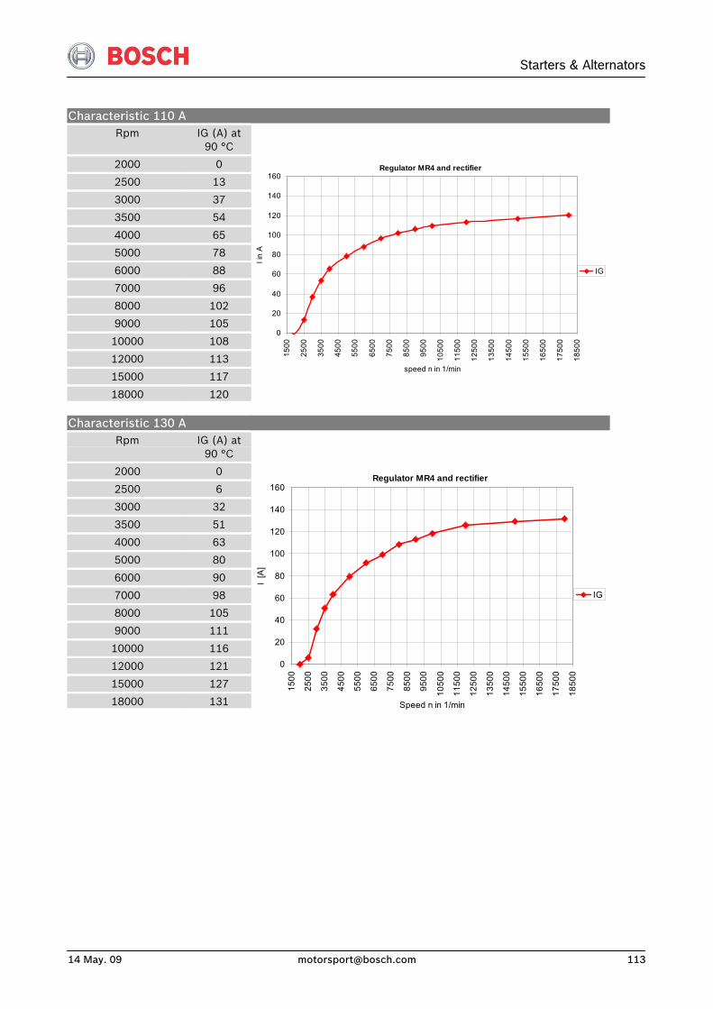
Starters & Alternators
14 May. 09 [email protected] 113
Characteristic 110 A Rpm
2000
2500
3000
3500
4000
5000
6000
7000
8000
9000
10000
12000
15000
18000
IG (A) at
90 °C
0
13
37
54
65
78
88
96
102
105
108
113
117
120
Regulator MR4 and rectifier
0
20
40
60
80
100
120
140
160
1500
2500
3500
4500
5500
6500
7500
8500
9500
1050
0
1150
0
1250
0
1350
0
1450
0
1550
0
1650
0
1750
0
1850
0
speed n in 1/min
I in
AIG
Characteristic 130 A Rpm
2000
2500
3000
3500
4000
5000
6000
7000
8000
9000
10000
12000
15000
18000
IG (A) at
90 °C
0
6
32
51
63
80
90
98
105
111
116
121
127
131
Regulator MR4 and rectifier
0
20
40
60
80
100
120
140
160
1500
2500
3500
4500
5500
6500
7500
8500
9500
1050
0
1150
0
1250
0
1350
0
1450
0
1550
0
1650
0
1750
0
1850
0
Speed n in 1/min
I [A
]
IG
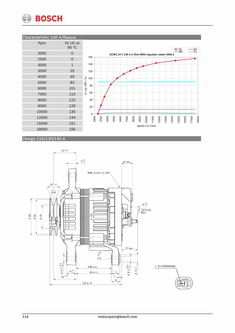
Characteristic 140 A Rpm
2000
2500
3000
3500
4000
5000
6000
7000
8000
9000
10000
12000
15000
18000
/Nascar IG (A) at
90 °C
0
0
1
25
49
83
101
113
122
129
135
144
151
156
GCM1 14 V 140 A 2 Ohm MR4 regulator stator 5406-1
0
20
40
60
80
100
120
140
160
2500
3500
4500
5500
6500
7500
8500
9500
1050
0
1150
0
1250
0
1350
0
1450
0
1550
0
1650
0
1750
0
1850
0
speed n in 1/min
A /
Ug
/ MD
/ Tu
.
IG UGMD TU
Design 110/130/140 A
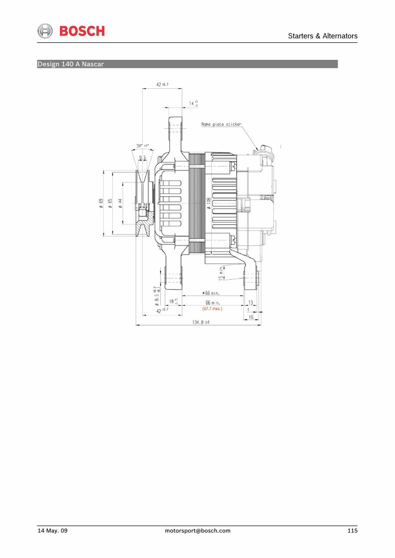

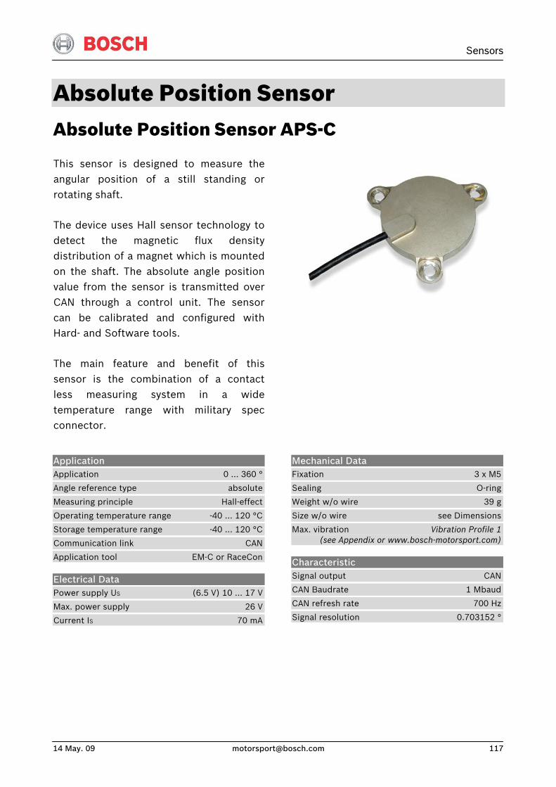
Sensors
14 May. 09 [email protected] 117
Absolute Position Sensor Absolute Position Sensor APS-C
This sensor is designed to measure theangular position of a still standing orrotating shaft.
The device uses Hall sensor technology todetect the magnetic flux densitydistribution of a magnet which is mountedon the shaft. The absolute angle positionvalue from the sensor is transmitted overCAN through a control unit. The sensorcan be calibrated and configured withHard- and Software tools.
The main feature and benefit of thissensor is the combination of a contactless measuring system in a widetemperature range with military specconnector.
Application Application 0 … 360 °
Angle reference type absolute
Measuring principle Hall-effect
Operating temperature range -40 … 120 °C
Storage temperature range -40 … 120 °C
Communication link CAN
Application tool EM-C or RaceCon
Electrical Data Power supply US (6.5 V) 10 … 17 V
Max. power supply 26 V
Current IS 70 mA
Mechanical Data Fixation 3 x M5
Sealing O-ring
Weight w/o wire 39 g
Size w/o wire see Dimensions
Max. vibration Vibration Profile 1 (see Appendix or www.bosch-motorsport.com)
Characteristic Signal output CAN
CAN Baudrate 1 Mbaud
CAN refresh rate 700 Hz
Signal resolution 0.703152 °
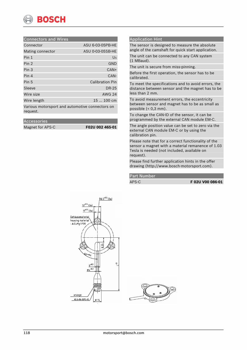
Connectors and Wires Connector ASU 6-03-05PB-HE
Mating connector ASU 0-03-05SB-HE
Pin 1 US
Pin 2 GND
Pin 3 CAN+
Pin 4 CAN-
Pin 5 Calibration Pin
Sleeve DR-25
Wire size AWG 24
Wire length 15 … 100 cm
Various motorsport and automotive connectors on request.
Accessories Magnet for APS-C F02U 002 465-01
Application Hint The sensor is designed to measure the absolute angle of the camshaft for quick start application.
The unit can be connected to any CAN system (1 MBaud).
The unit is secure from miss-pinning.
Before the first operation, the sensor has to be calibrated.
To meet the specifications and to avoid errors, the distance between sensor and the magnet has to be less than 2 mm.
To avoid measurement errors, the eccentricity between sensor and magnet has to be as small as possible (< 0,3 mm).
To change the CAN-ID of the sensor, it can be programmed by the external CAN module EM-C.
The angle position value can be set to zero via the external CAN module EM-C or by using the calibration pin.
Please note that for a correct functionality of the sensor a magnet with a material remanence of 1.03 Tesla is needed (not included, available on request).
Please find further application hints in the offer drawing (http://www.bosch-motorsport.com).
Part Number APS-C F 02U V00 086-01
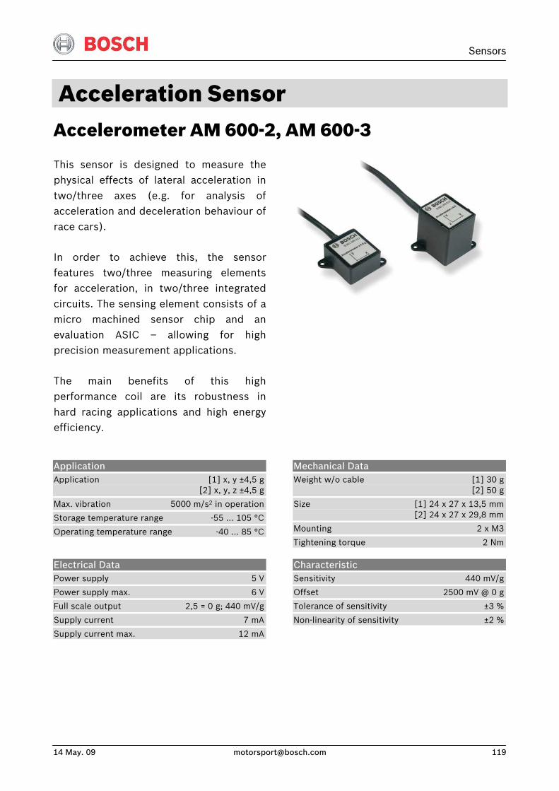
Sensors
14 May. 09 [email protected] 119
Acceleration Sensor Accelerometer AM 600-2, AM 600-3
This sensor is designed to measure thephysical effects of lateral acceleration intwo/three axes (e.g. for analysis ofacceleration and deceleration behaviour ofrace cars).
In order to achieve this, the sensorfeatures two/three measuring elementsfor acceleration, in two/three integratedcircuits. The sensing element consists of amicro machined sensor chip and anevaluation ASIC – allowing for high precision measurement applications.
The main benefits of this highperformance coil are its robustness inhard racing applications and high energyefficiency.
Application Application [1] x, y ±4,5 g [2] x, y, z ±4,5 g
Max. vibration 5000 m/s2 in operation
Storage temperature range -55 … 105 °C
Operating temperature range -40 … 85 °C
Mechanical Data Weight w/o cable [1] 30 g [2] 50 g
Size [1] 24 x 27 x 13,5 mm [2] 24 x 27 x 29,8 mm
Mounting 2 x M3
Tightening torque 2 Nm
Electrical Data Power supply 5 V
Power supply max. 6 V
Full scale output 2,5 = 0 g; 440 mV/g
Supply current 7 mA
Supply current max. 12 mA
Characteristic Sensitivity 440 mV/g
Offset 2500 mV @ 0 g
Tolerance of sensitivity ±3 %
Non-linearity of sensitivity ±2 %
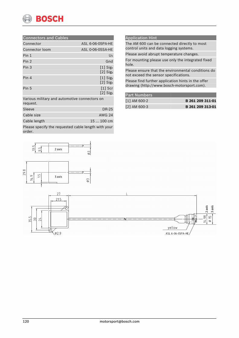
Application Hint The AM 600 can be connected directly to most control units and data logging systems.
Please avoid abrupt temperature changes.
For mounting please use only the integrated fixed hole.
Please ensure that the environmental conditions do not exceed the sensor specifications.
Please find further application hints in the offer drawing (http://www.bosch-motorsport.com).
Connectors and Cables Connector ASL 6-06-05PA-HE
Connector loom ASL 0-06-05SA-HE
Pin 1 US
Pin 2 Gnd
Pin 3 [1] Sigx
[2] Sigy
Pin 4 [1] Sigy
[2] Sigx
Pin 5 [1] Scr [2] Sigz
Various military and automotive connectors on request.
Sleeve DR-25
Cable size AWG 24
Cable length 15 … 100 cm
Please specify the requested cable length with your order.
Part Numbers [1] AM 600-2
[2] AM 600-3
B 261 209 311-01
B 261 209 313-01
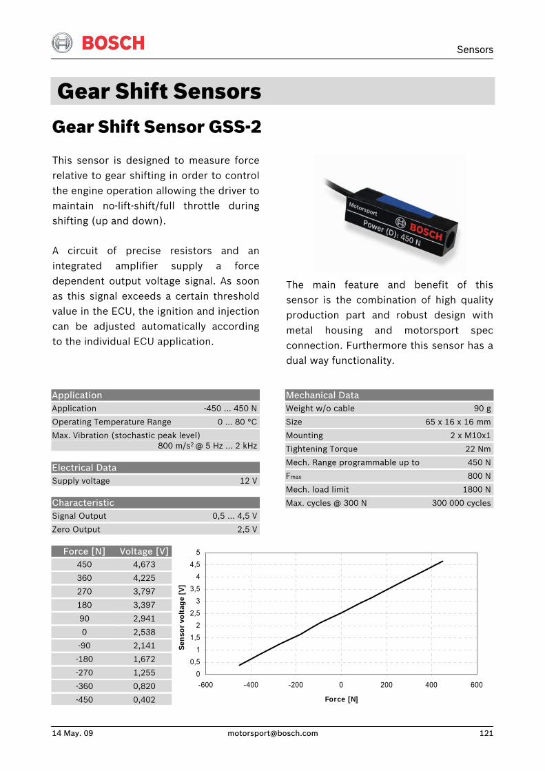
Sensors
14 May. 09 [email protected] 121
Gear Shift Sensors Gear Shift Sensor GSS-2
This sensor is designed to measure forcerelative to gear shifting in order to controlthe engine operation allowing the driver tomaintain no-lift-shift/full throttle duringshifting (up and down).
A circuit of precise resistors and anintegrated amplifier supply a forcedependent output voltage signal. As soonas this signal exceeds a certain thresholdvalue in the ECU, the ignition and injectioncan be adjusted automatically accordingto the individual ECU application.
The main feature and benefit of this sensor is the combination of high quality production part and robust design with metal housing and motorsport spec connection. Furthermore this sensor has a dual way functionality.
Application Application -450 … 450 N
Operating Temperature Range 0 … 80 °C
Max. Vibration (stochastic peak level) 800 m/s2 @ 5 Hz … 2 kHz
Electrical Data Supply voltage 12 V
Characteristic Signal Output 0,5 … 4,5 V
Zero Output 2,5 V
Mechanical Data Weight w/o cable 90 g
Size 65 x 16 x 16 mm
Mounting 2 x M10x1
Tightening Torque 22 Nm
Mech. Range programmable up to 450 N
Fmax 800 N
Mech. load limit 1800 N
Max. cycles @ 300 N 300 000 cycles
Force [N] 450
360
270
180
90
0
-90
-180
-270
-360
-450
Voltage [V] 4,673
4,225
3,797
3,397
2,941
2,538
2,141
1,672
1,255
0,820
0,402
00,5
11,5
22,5
33,5
44,5
5
-600 -400 -200 0 200 400 600
Force [N]
Sens
or v
olta
ge [V
]
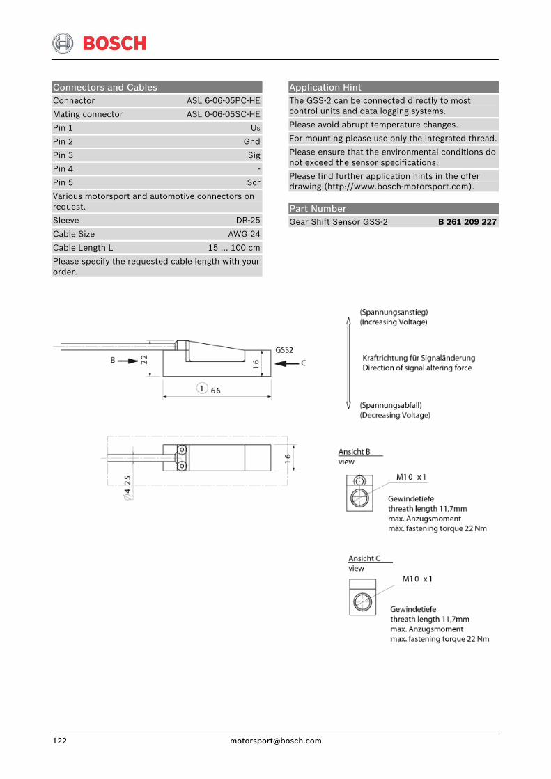
Application Hint The GSS-2 can be connected directly to most control units and data logging systems.
Please avoid abrupt temperature changes.
For mounting please use only the integrated thread.
Please ensure that the environmental conditions do not exceed the sensor specifications.
Please find further application hints in the offer drawing (http://www.bosch-motorsport.com).
Connectors and Cables Connector ASL 6-06-05PC-HE
Mating connector ASL 0-06-05SC-HE
Pin 1 US
Pin 2 Gnd
Pin 3 Sig
Pin 4 -
Pin 5 Scr
Various motorsport and automotive connectors on request.
Sleeve DR-25
Cable Size AWG 24
Cable Length L 15 … 100 cm
Please specify the requested cable length with your order.
Part Number Gear Shift Sensor GSS-2 B 261 209 227
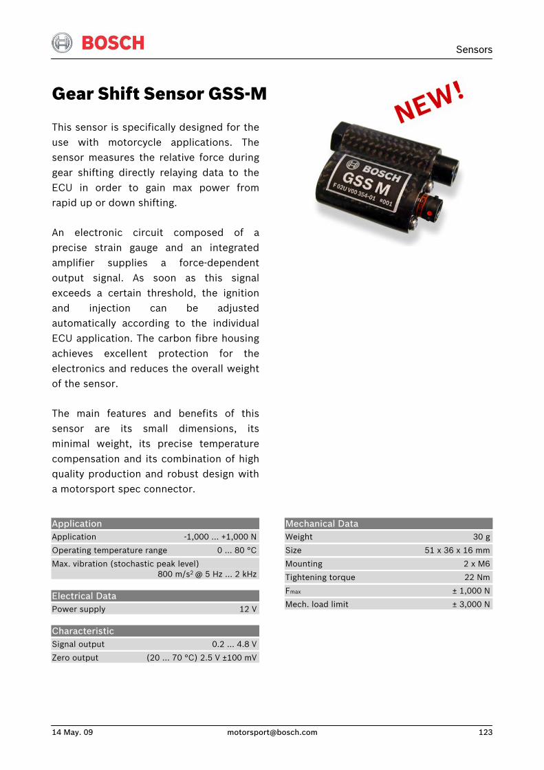
Sensors
14 May. 09 [email protected] 123
Gear Shift Sensor GSS-M
This sensor is specifically designed for theuse with motorcycle applications. Thesensor measures the relative force during gear shifting directly relaying data to theECU in order to gain max power fromrapid up or down shifting.
An electronic circuit composed of aprecise strain gauge and an integratedamplifier supplies a force-dependentoutput signal. As soon as this signal exceeds a certain threshold, the ignitionand injection can be adjustedautomatically according to the individualECU application. The carbon fibre housingachieves excellent protection for theelectronics and reduces the overall weightof the sensor.
The main features and benefits of thissensor are its small dimensions, itsminimal weight, its precise temperaturecompensation and its combination of highquality production and robust design witha motorsport spec connector.
Application Application -1,000 … +1,000 N
Operating temperature range 0 … 80 °C
Max. vibration (stochastic peak level) 800 m/s2 @ 5 Hz … 2 kHz
Electrical Data Power supply 12 V
Characteristic Signal output 0.2 … 4.8 V
Zero output (20 … 70 °C) 2.5 V ±100 mV
Mechanical Data Weight 30 g
Size 51 x 36 x 16 mm
Mounting 2 x M6
Tightening torque 22 Nm
Fmax ± 1,000 N
Mech. load limit ± 3,000 N
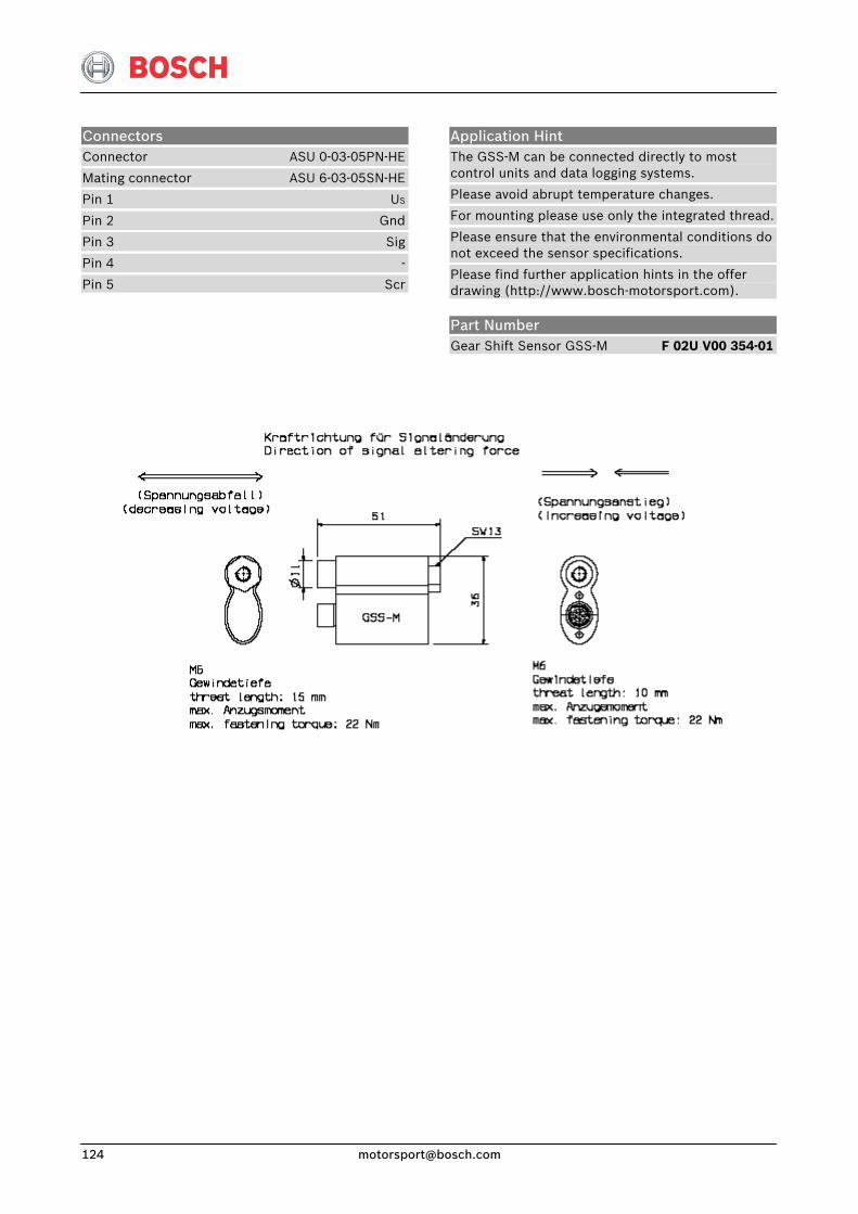
Application Hint The GSS-M can be connected directly to most control units and data logging systems.
Please avoid abrupt temperature changes.
For mounting please use only the integrated thread.
Please ensure that the environmental conditions do not exceed the sensor specifications.
Please find further application hints in the offer drawing (http://www.bosch-motorsport.com).
Connectors Connector ASU 0-03-05PN-HE
Mating connector ASU 6-03-05SN-HE
Pin 1 US
Pin 2 Gnd
Pin 3 Sig
Pin 4 -
Pin 5 Scr
Part Number Gear Shift Sensor GSS-M F 02U V00 354-01
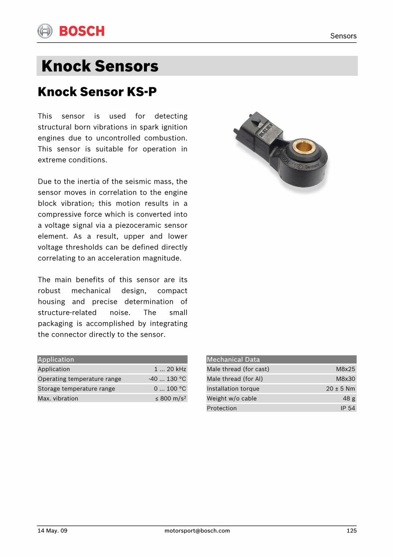
Sensors
14 May. 09 [email protected] 125
Knock Sensors Knock Sensor KS-P
This sensor is used for detectingstructural born vibrations in spark ignitionengines due to uncontrolled combustion.This sensor is suitable for operation inextreme conditions.
Due to the inertia of the seismic mass, thesensor moves in correlation to the engineblock vibration; this motion results in acompressive force which is converted intoa voltage signal via a piezoceramic sensorelement. As a result, upper and lowervoltage thresholds can be defined directlycorrelating to an acceleration magnitude.
The main benefits of this sensor are itsrobust mechanical design, compacthousing and precise determination ofstructure-related noise. The smallpackaging is accomplished by integratingthe connector directly to the sensor.
Application Application 1 … 20 kHz
Operating temperature range -40 … 130 °C
Storage temperature range 0 … 100 °C
Max. vibration ≤ 800 m/s2
Mechanical Data Male thread (for cast) M8x25
Male thread (for Al) M8x30
Installation torque 20 ± 5 Nm
Weight w/o cable 48 g
Protection IP 54
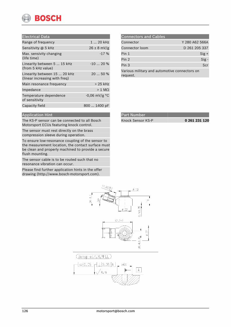
Electrical Data Range of frequency 1 … 20 kHz
Sensitivity @ 5 kHz 26 ± 8 mV/g
Max. sensivity changing -17 %(life time)
Linearity between 5 … 15 kHz -10 … 20 %(from 5 kHz value)
Linearity between 15 … 20 kHz 20 … 50 %(linear increasing with freq)
Main resonance frequency > 25 kHz
Impedance > 1 MΩ
Temperature dependence -0,06 mV/g °Cof sensitivity
Capacity field 800 … 1400 pF
Connectors and Cables Connector Y 280 A62 566A
Connector loom D 261 205 337
Pin 1 Sig +
Pin 2 Sig -
Pin 3 Scr
Various military and automotive connectors on request.
Application Hint The KS-P sensor can be connected to all Bosch Motorsport ECUs featuring knock control.
The sensor must rest directly on the brass compression sleeve during operation.
To ensure low-resonance coupling of the sensor to the measurement location, the contact surface must be clean and properly machined to provide a secure flush mounting.
The sensor cable is to be routed such that no resonance vibration can occur.
Please find further application hints in the offer drawing (http://www.bosch-motorsport.com).
Part Number Knock Sensor KS-P
0 261 231 120
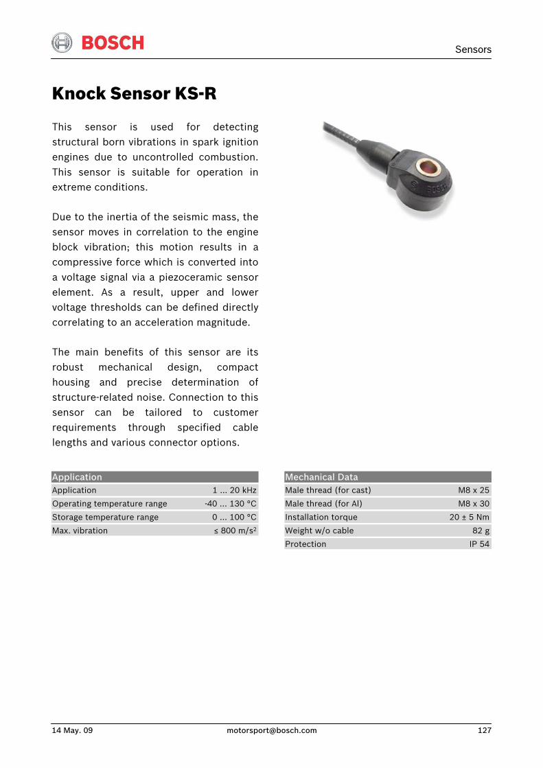
Sensors
14 May. 09 [email protected] 127
Knock Sensor KS-R
This sensor is used for detectingstructural born vibrations in spark ignition engines due to uncontrolled combustion.This sensor is suitable for operation inextreme conditions.
Due to the inertia of the seismic mass, thesensor moves in correlation to the engineblock vibration; this motion results in acompressive force which is converted intoa voltage signal via a piezoceramic sensorelement. As a result, upper and lowervoltage thresholds can be defined directlycorrelating to an acceleration magnitude.
The main benefits of this sensor are itsrobust mechanical design, compacthousing and precise determination ofstructure-related noise. Connection to thissensor can be tailored to customerrequirements through specified cablelengths and various connector options.
Application Application 1 … 20 kHz
Operating temperature range -40 … 130 °C
Storage temperature range 0 … 100 °C
Max. vibration ≤ 800 m/s2
Mechanical Data Male thread (for cast) M8 x 25
Male thread (for Al) M8 x 30
Installation torque 20 ± 5 Nm
Weight w/o cable 82 g
Protection IP 54
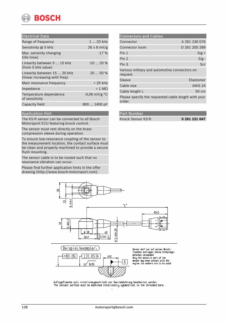
Electrical Data Range of frequency 1 … 20 kHz
Sensitivity @ 5 kHz 26 ± 8 mV/g
Max. sensivity changing -17 %(life time)
Linearity between 5 … 15 kHz -10 … 20 %(from 5 kHz value)
Linearity between 15 … 20 kHz 20 … 50 %(linear increasing with freq)
Main resonance frequency > 25 kHz
Impedance > 1 MΩ
Temperature dependence -0,06 mV/g °Cof sensitivity
Capacity field 800 … 1400 pF
Connectors and Cables Connector A 261 230 076
Connector loom D 261 205 289
Pin 1 Sig +
Pin 2 Sig -
Pin 3 Scr
Various military and automotive connectors on request.
Sleeve Elastomer
Cable size AWG 24
Cable length L 50 cm
Please specify the requested cable length with your order.
Application Hint The KS-R sensor can be connected to all Bosch Motorsport ECU featuring knock control.
The sensor must rest directly on the brass compression sleeve during operation.
To ensure low-resonance coupling of the sensor to the measurement location, the contact surface must be clean and properly machined to provide a secure flush mounting.
The sensor cable is to be routed such that no resonance vibration can occur.
Please find further application hints in the offer drawing (http://www.bosch-motorsport.com).
Part Number Knock Sensor KS-R 0 261 231 047
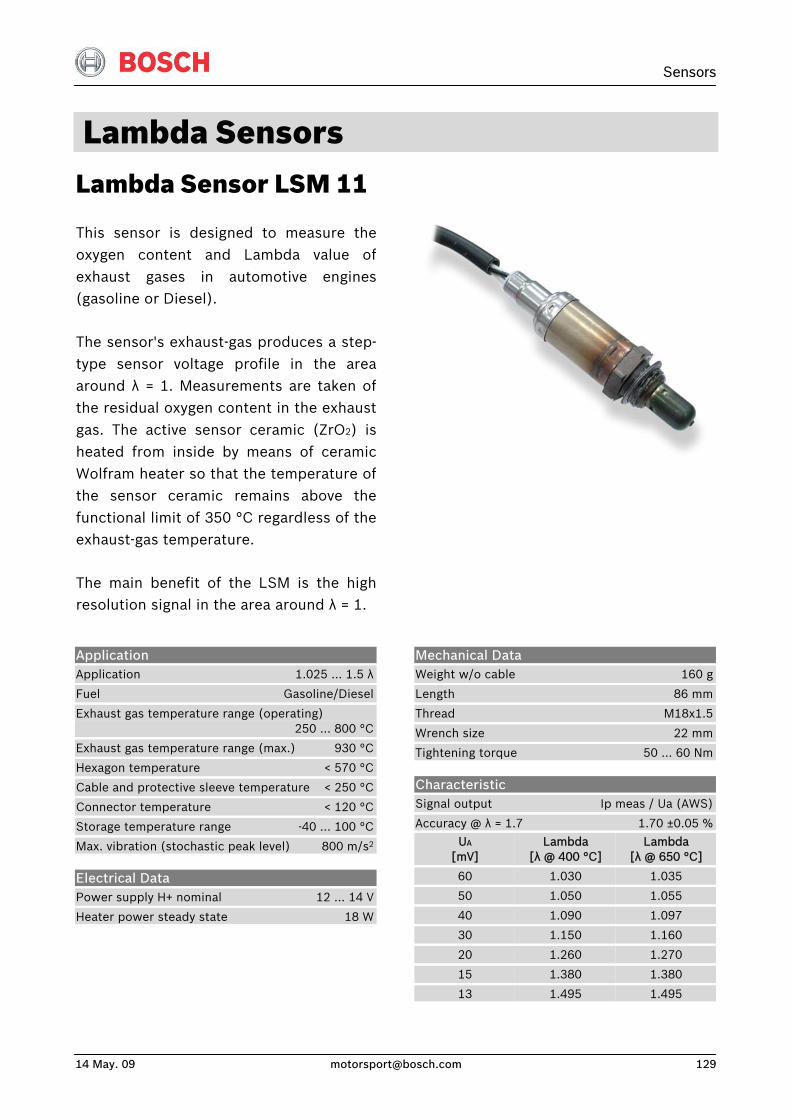
Sensors
14 May. 09 [email protected] 129
Lambda Sensors Lambda Sensor LSM 11
This sensor is designed to measure theoxygen content and Lambda value ofexhaust gases in automotive engines(gasoline or Diesel).
The sensor's exhaust-gas produces a step-type sensor voltage profile in the areaaround λ = 1. Measurements are taken ofthe residual oxygen content in the exhaustgas. The active sensor ceramic (ZrO2) is heated from inside by means of ceramicWolfram heater so that the temperature ofthe sensor ceramic remains above thefunctional limit of 350 °C regardless of theexhaust-gas temperature.
The main benefit of the LSM is the highresolution signal in the area around λ = 1.
Mechanical Data Weight w/o cable 160 g
Length 86 mm
Thread M18x1.5
Wrench size 22 mm
Tightening torque 50 … 60 Nm
Characteristic Signal output Ip meas / Ua (AWS)
Accuracy @ λ = 1.7 1.70 ±0.05 %
Application Application 1.025 … 1.5 λ
Fuel Gasoline/Diesel
Exhaust gas temperature range (operating) 250 … 800 °C
Exhaust gas temperature range (max.) 930 °C
Hexagon temperature < 570 °C
Cable and protective sleeve temperature < 250 °C
Connector temperature < 120 °C
Storage temperature range -40 … 100 °C
Max. vibration (stochastic peak level) 800 m/s2
Electrical Data Power supply H+ nominal 12 … 14 V
Heater power steady state 18 W
UA [mV]
60
50
40
30
20
15
13
Lambda [λ @ 400 °C]
1.030
1.050
1.090
1.150
1.260
1.380
1.495
Lambda [λ @ 650 °C]
1.035
1.055
1.097
1.160
1.270
1.380
1.495
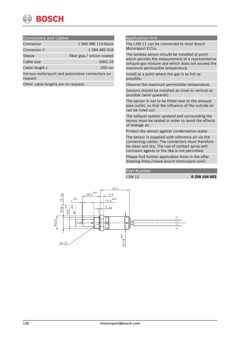
Connectors and Cables Connector 1 284 485 110-black
Connector II 1 284 485 018
Sleeve fiber glas / silicon coated
Cable size AWG 24
Cable length L 250 cm
Various motorsport and automotive connectors on request.
Other cable lengths are on request.
Application Hint The LSM 11 can be connected to most Bosch Motorsport ECUs.
The lambda sensor should be installed at point which permits the measurement of a representative exhaust-gas mixture and which does not exceed the maximum permissible temperature.
Install at a point where the gas is as hot as possible.
Observe the maximum permissible temperature.
Sensors should be installed as close to vertical as possible (wire upwards).
The sensor is not to be fitted near to the exhaust pipe outlet, so that the influence of the outside air can be ruled out.
The exhaust system upstand and surrounding the sensor must be sealed in order to avoid the effects of leakage air.
Protect the sensor against condensation water.
The sensor is supplied with reference air via the connecting cables. The connectors must therefore be clean and dry. The use of contact spray anti-corrosion agents or the like is not permitted.
Please find further application hints in the offer drawing (http://www.bosch-motorsport.com).
Part Number LSM 11 0 258 104 002
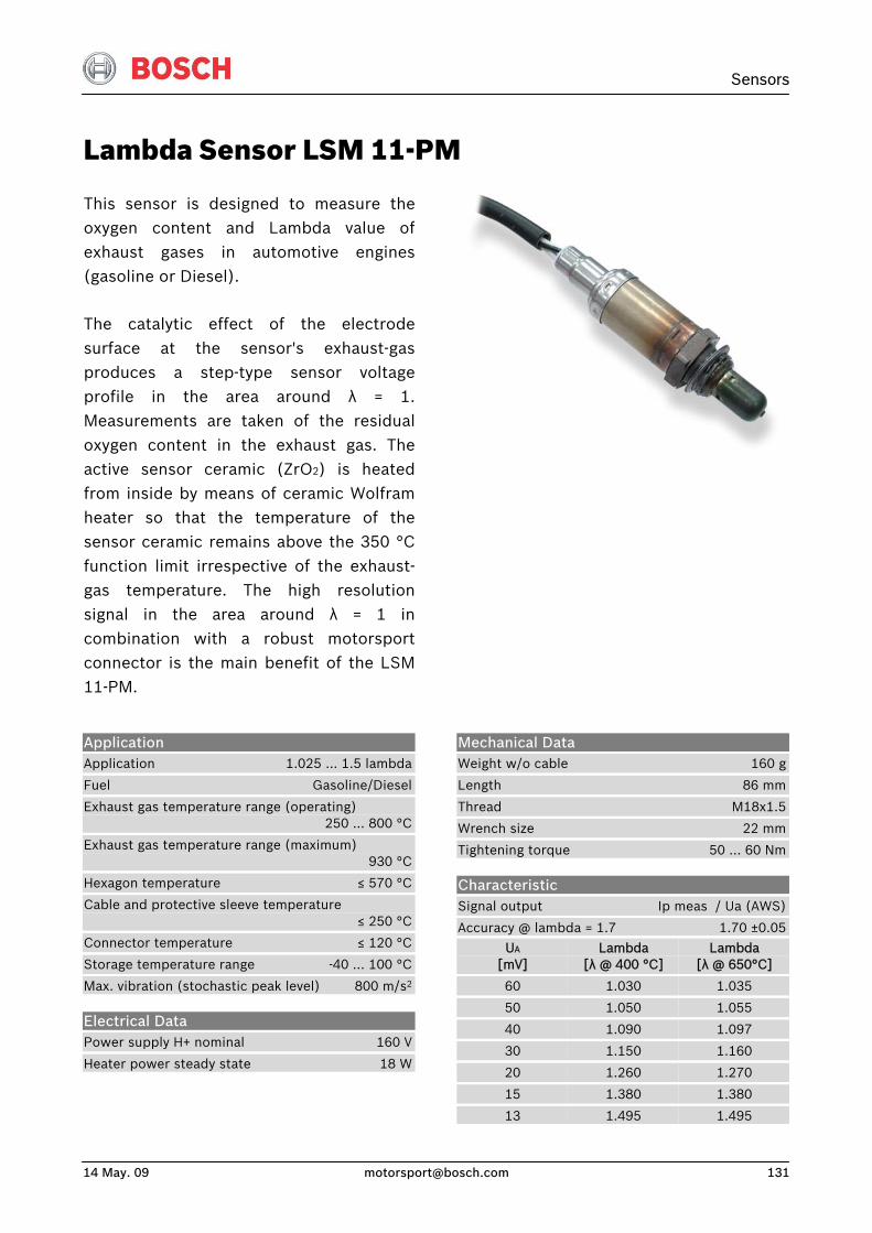
Sensors
14 May. 09 [email protected] 131
Lambda Sensor LSM 11-PM
This sensor is designed to measure theoxygen content and Lambda value ofexhaust gases in automotive engines(gasoline or Diesel).
The catalytic effect of the electrodesurface at the sensor's exhaust-gas produces a step-type sensor voltageprofile in the area around λ = 1.Measurements are taken of the residualoxygen content in the exhaust gas. Theactive sensor ceramic (ZrO2) is heatedfrom inside by means of ceramic Wolframheater so that the temperature of thesensor ceramic remains above the 350 °Cfunction limit irrespective of the exhaust-gas temperature. The high resolutionsignal in the area around λ = 1 incombination with a robust motorsportconnector is the main benefit of the LSM11-PM.
Mechanical Data Weight w/o cable 160 g
Length 86 mm
Thread M18x1.5
Wrench size 22 mm
Tightening torque 50 … 60 Nm
Characteristic Signal output Ip meas / Ua (AWS)
Accuracy @ lambda = 1.7 1.70 ±0.05
Application Application 1.025 … 1.5 lambda
Fuel Gasoline/Diesel
Exhaust gas temperature range (operating) 250 … 800 °C
Exhaust gas temperature range (maximum) 930 °C
Hexagon temperature ≤ 570 °C
Cable and protective sleeve temperature ≤ 250 °C
Connector temperature ≤ 120 °C
Storage temperature range -40 … 100 °C
Max. vibration (stochastic peak level) 800 m/s2
Electrical Data Power supply H+ nominal 160 V
Heater power steady state 18 W
UA [mV]
60
50
40
30
20
15
13
Lambda [λ @ 400 °C]
1.030
1.050
1.090
1.150
1.260
1.380
1.495
Lambda [λ @ 650°C]
1.035
1.055
1.097
1.160
1.270
1.380
1.495
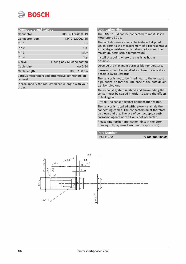
Application Hint The LSM 11-PM can be connected to most Bosch Motorsport ECUs.
The lambda sensor should be installed at point which permits the measurement of a representative exhaust-gas mixture, which does not exceed the maximum permissible temperature.
Install at a point where the gas is as hot as possible.
Observe the maximum permissible temperature.
Sensors should be installed as close to vertical as possible (wire upwards).
The sensor is not to be fitted near to the exhaust pipe outlet, so that the influence of the outside air can be ruled out.
The exhaust system upstand and surrounding the sensor must be sealed in order to avoid the effects of leakage air.
Protect the sensor against condensation water.
The sensor is supplied with reference air via the connecting cables. The connectors must therefore be clean and dry. The use of contact spray anti-corrosion agents or the like is not permitted.
Please find further application hints in the offer drawing (http://www.bosch-motorsport.com).
Connectors and Cables Connector KPTC 6E8-4P-C-DN
Connector loom KPTC 120062-55
Pin 1 Uh+
Pin 2 Uh-
Pin 3 Sig+
Pin 4 Sig-
Sleeve Fiber glas / Silicone coated
Cable size AWG 24
Cable length L 30 … 100 cm
Various motorsport and automotive connectors on request.
Please specify the requested cable length with your order.
Part Number LSM 11-PM B 261 209 105-01
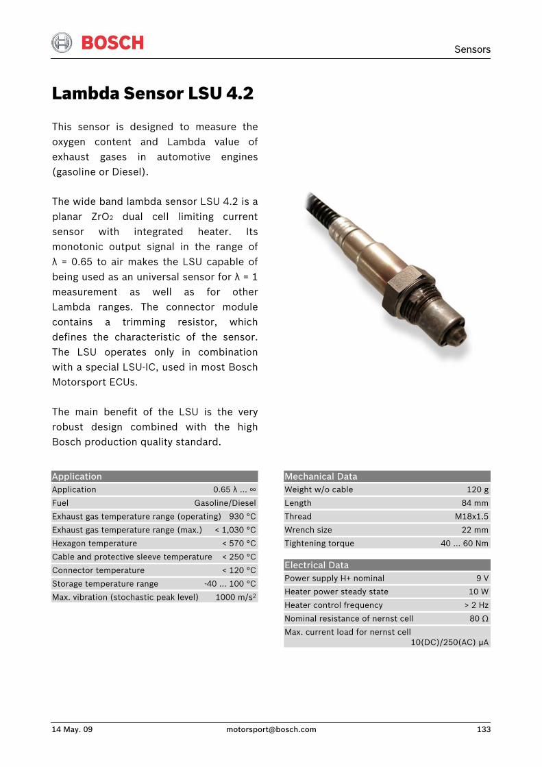
Sensors
14 May. 09 [email protected] 133
Lambda Sensor LSU 4.2
This sensor is designed to measure theoxygen content and Lambda value ofexhaust gases in automotive engines(gasoline or Diesel).
The wide band lambda sensor LSU 4.2 is aplanar ZrO2 dual cell limiting currentsensor with integrated heater. Its monotonic output signal in the range ofλ = 0.65 to air makes the LSU capable ofbeing used as an universal sensor for λ = 1measurement as well as for otherLambda ranges. The connector modulecontains a trimming resistor, whichdefines the characteristic of the sensor.The LSU operates only in combinationwith a special LSU-IC, used in most BoschMotorsport ECUs.
The main benefit of the LSU is the veryrobust design combined with the highBosch production quality standard.
Application Application 0.65 λ … ∞
Fuel Gasoline/Diesel
Exhaust gas temperature range (operating) 930 °C
Exhaust gas temperature range (max.) < 1,030 °C
Hexagon temperature < 570 °C
Cable and protective sleeve temperature < 250 °C
Connector temperature < 120 °C
Storage temperature range -40 … 100 °C
Max. vibration (stochastic peak level) 1000 m/s2
Mechanical Data Weight w/o cable 120 g
Length 84 mm
Thread M18x1.5
Wrench size 22 mm
Tightening torque 40 … 60 Nm
Electrical Data Power supply H+ nominal 9 V
Heater power steady state 10 W
Heater control frequency > 2 Hz
Nominal resistance of nernst cell 80 Ω
Max. current load for nernst cell 10(DC)/250(AC) μA
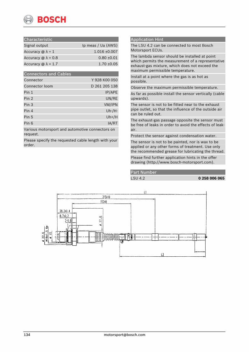
Characteristic Signal output Ip meas / Ua (AWS)
Accuracy @ λ = 1 1.016 ±0.007
Accuracy @ λ = 0.8 0.80 ±0.01
Accuracy @ λ = 1.7 1.70 ±0.05
Connectors and Cables Connector Y 928 K00 050
Connector loom D 261 205 138
Pin 1 IP/APE
Pin 2 UN/RE
Pin 3 VM/IPN
Pin 4 Uh-/H-
Pin 5 Uh+/H
Pin 6 IA/RT
Various motorsport and automotive connectors on request.
Please specify the requested cable length with your order.
Application Hint The LSU 4.2 can be connected to most Bosch Motorsport ECUs.
The lambda sensor should be installed at point which permits the measurement of a representative exhaust-gas mixture, which does not exceed the maximum permissible temperature.
Install at a point where the gas is as hot as possible.
Observe the maximum permissible temperature.
As far as possible install the sensor vertically (cable upwards).
The sensor is not to be fitted near to the exhaust pipe outlet, so that the influence of the outside air can be ruled out.
The exhaust-gas passage opposite the sensor must be free of leaks in order to avoid the effects of leak-air.
Protect the sensor against condensation water.
The sensor is not to be painted, nor is wax to be applied or any other forms of treatment. Use only the recommended grease for lubricating the thread.
Please find further application hints in the offer drawing (http://www.bosch-motorsport.com).
Part Number LSU 4.2 0 258 006 065
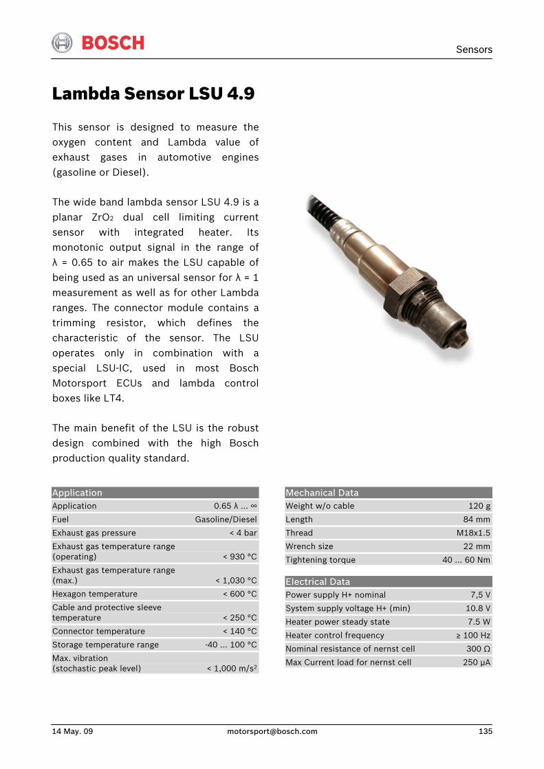
Sensors
14 May. 09 [email protected] 135
Lambda Sensor LSU 4.9
This sensor is designed to measure theoxygen content and Lambda value ofexhaust gases in automotive engines(gasoline or Diesel).
The wide band lambda sensor LSU 4.9 is aplanar ZrO2 dual cell limiting currentsensor with integrated heater. Itsmonotonic output signal in the range ofλ = 0.65 to air makes the LSU capable ofbeing used as an universal sensor for λ = 1measurement as well as for other Lambdaranges. The connector module contains atrimming resistor, which defines thecharacteristic of the sensor. The LSUoperates only in combination with aspecial LSU-IC, used in most BoschMotorsport ECUs and lambda controlboxes like LT4.
The main benefit of the LSU is the robustdesign combined with the high Boschproduction quality standard.
Application Application 0.65 λ … ∞
Fuel Gasoline/Diesel
Exhaust gas pressure < 4 bar
Exhaust gas temperature range (operating) < 930 °C
Exhaust gas temperature range (max.) < 1,030 °C
Hexagon temperature < 600 °C
Cable and protective sleeve temperature < 250 °C
Connector temperature < 140 °C
Storage temperature range -40 … 100 °C
Max. vibration (stochastic peak level) < 1,000 m/s2
Mechanical Data Weight w/o cable 120 g
Length 84 mm
Thread M18x1.5
Wrench size 22 mm
Tightening torque 40 … 60 Nm
Electrical Data Power supply H+ nominal 7,5 V
System supply voltage H+ (min) 10.8 V
Heater power steady state 7.5 W
Heater control frequency ≥ 100 Hz
Nominal resistance of nernst cell 300 Ω
Max Current load for nernst cell 250 μA
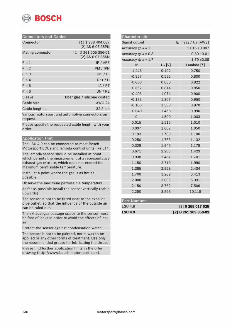
Characteristic Signal output Ip meas / Ua (AWS)
Accuracy @ λ = 1 1.016 ±0.007
Accuracy @ λ = 0.8 0.80 ±0.01
Accuracy @ λ = 1.7 1.70 ±0.05
IP
-1.243
-0.927
-0.800
-0.652
-0.405
-0.183
-0.106
-0.040
0
0.015
0.097
0.193
0.250
0.329
0.671
0.938
1.150
1.385
1.700
2.000
2.150
2.250
UA [V]
0.192
0.525
0.658
0.814
1.074
1.307
1.388
1.458
1.500
1.515
1.602
1.703
1.763
1.846
2.206
2.487
2.710
2.958
3.289
3.605
3.762
3.868
Lambda [λ]
0.750
0.800
0.822
0.850
0.900
0.950
0.970
0.990
1.003
1.010
1.050
1.100
1.132
1.179
1.429
1.701
1.990
2.434
3.413
5.391
7.506
10.119
Connectors and Cables Connector [1] 1 928 404 687 [2] AS 6-07-35PN
Mating connector [1] D 261 205 356-01 [2] AS 0-07-35SN
Pin 1 IP / APE
Pin 2 VM / IPN
Pin 3 Uh- / H-
Pin 4 Uh+ / H
Pin 5 IA / RT
Pin 6 UN / RE
Sleeve fiber glas / silicone coated
Cable size AWG 24
Cable length L 32.5 cm
Various motorsport and automotive connectors on request.
Please specify the requested cable length with your order.
Application Hint The LSU 4.9 can be connected to most Bosch Motorsport ECUs and lambda control units like LT4.
The lambda sensor should be installed at point which permits the measurement of a representative exhaust-gas mixture, which does not exceed the maximum permissible temperature.
Install at a point where the gas is as hot as possible.
Observe the maximum permissible temperature.
As far as possible install the sensor vertically (cable upwards).
The sensor is not to be fitted near to the exhaust pipe outlet, so that the influence of the outside air can be ruled out.
The exhaust-gas passage opposite the sensor must be free of leaks in order to avoid the effects of leak-air.
Protect the sensor against condensation water.
The sensor is not to be painted, nor is wax to be applied or any other forms of treatment. Use only the recommended grease for lubricating the thread.
Please find further application hints in the offer drawing (http://www.bosch-motorsport.com).
Part Number LSU 4.9 [1] 0 258 017 025
LSU 4.9 [2] B 261 209 358-02
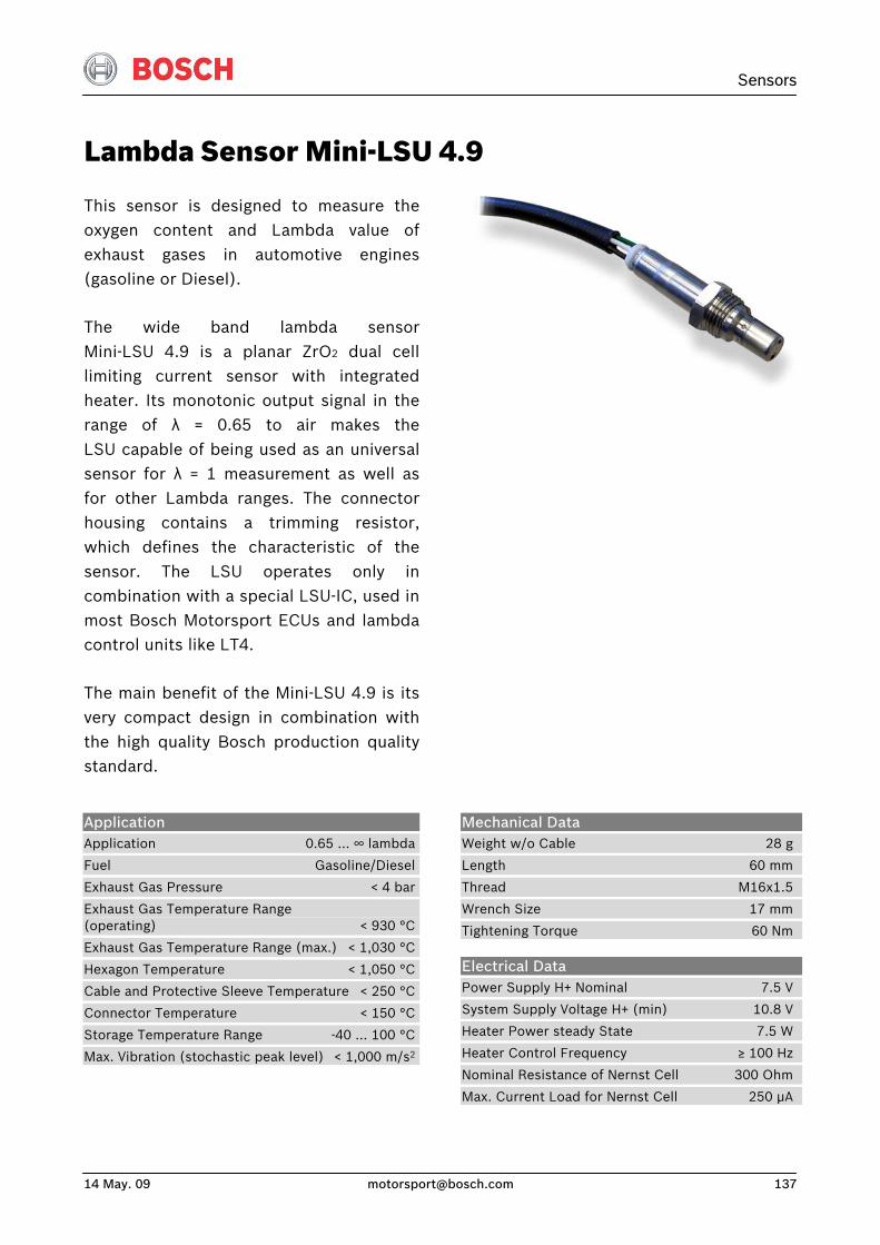
Sensors
14 May. 09 [email protected] 137
Lambda Sensor Mini-LSU 4.9
This sensor is designed to measure theoxygen content and Lambda value ofexhaust gases in automotive engines(gasoline or Diesel).
The wide band lambda sensorMini-LSU 4.9 is a planar ZrO2 dual celllimiting current sensor with integratedheater. Its monotonic output signal in therange of λ = 0.65 to air makes theLSU capable of being used as an universalsensor for λ = 1 measurement as well asfor other Lambda ranges. The connectorhousing contains a trimming resistor,which defines the characteristic of thesensor. The LSU operates only in combination with a special LSU-IC, used inmost Bosch Motorsport ECUs and lambdacontrol units like LT4.
The main benefit of the Mini-LSU 4.9 is itsvery compact design in combination withthe high quality Bosch production qualitystandard.
Application Application 0.65 … ∞ lambda
Fuel Gasoline/Diesel
Exhaust Gas Pressure < 4 bar
Exhaust Gas Temperature Range (operating) < 930 °C
Exhaust Gas Temperature Range (max.) < 1,030 °C
Hexagon Temperature < 1,050 °C
Cable and Protective Sleeve Temperature < 250 °C
Connector Temperature < 150 °C
Storage Temperature Range -40 … 100 °C
Max. Vibration (stochastic peak level) < 1,000 m/s2
Mechanical Data Weight w/o Cable 28 g
Length 60 mm
Thread M16x1.5
Wrench Size 17 mm
Tightening Torque 60 Nm
Electrical Data Power Supply H+ Nominal 7.5 V
System Supply Voltage H+ (min) 10.8 V
Heater Power steady State 7.5 W
Heater Control Frequency ≥ 100 Hz
Nominal Resistance of Nernst Cell 300 Ohm
Max. Current Load for Nernst Cell 250 μA
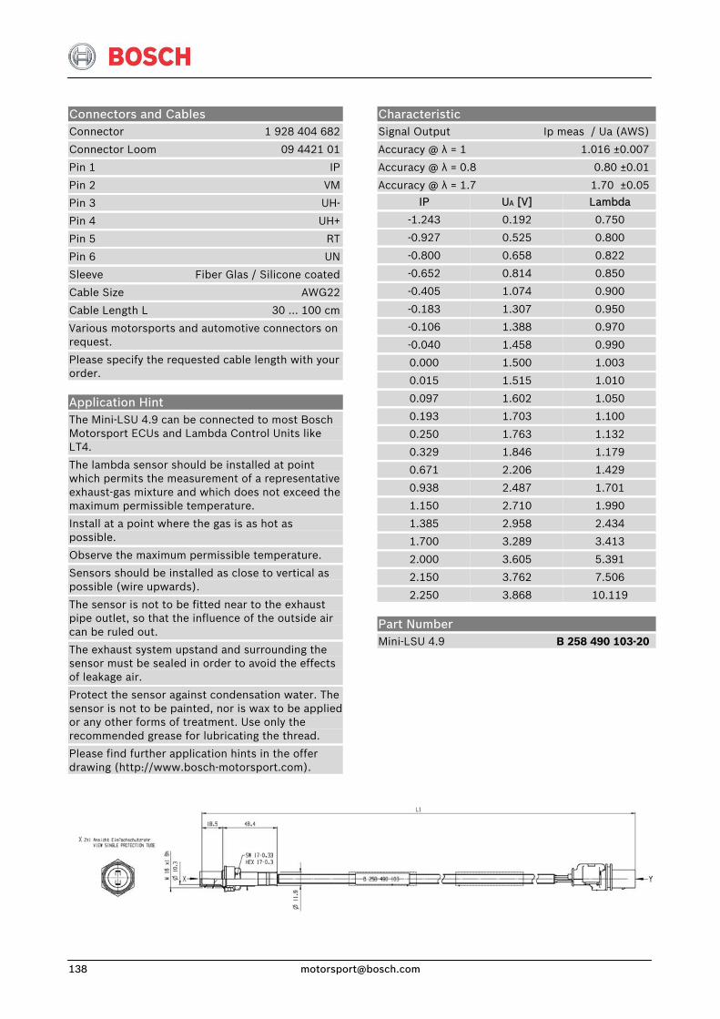
Characteristic Signal Output Ip meas / Ua (AWS)
Accuracy @ λ = 1 1.016 ±0.007
Accuracy @ λ = 0.8 0.80 ±0.01
Accuracy @ λ = 1.7 1.70 ±0.05
IP
-1.243
-0.927
-0.800
-0.652
-0.405
-0.183
-0.106
-0.040
0.000
0.015
0.097
0.193
0.250
0.329
0.671
0.938
1.150
1.385
1.700
2.000
2.150
2.250
UA [V]
0.192
0.525
0.658
0.814
1.074
1.307
1.388
1.458
1.500
1.515
1.602
1.703
1.763
1.846
2.206
2.487
2.710
2.958
3.289
3.605
3.762
3.868
Lambda
0.750
0.800
0.822
0.850
0.900
0.950
0.970
0.990
1.003
1.010
1.050
1.100
1.132
1.179
1.429
1.701
1.990
2.434
3.413
5.391
7.506
10.119
Connectors and Cables Connector 1 928 404 682
Connector Loom 09 4421 01
Pin 1 IP
Pin 2 VM
Pin 3 UH-
Pin 4 UH+
Pin 5 RT
Pin 6 UN
Sleeve Fiber Glas / Silicone coated
Cable Size AWG22
Cable Length L 30 … 100 cm
Various motorsports and automotive connectors on request.
Please specify the requested cable length with your order.
Application Hint The Mini-LSU 4.9 can be connected to most Bosch Motorsport ECUs and Lambda Control Units like LT4.
The lambda sensor should be installed at point which permits the measurement of a representative exhaust-gas mixture and which does not exceed the maximum permissible temperature.
Install at a point where the gas is as hot as possible.
Observe the maximum permissible temperature.
Sensors should be installed as close to vertical as possible (wire upwards).
The sensor is not to be fitted near to the exhaust pipe outlet, so that the influence of the outside air can be ruled out.
The exhaust system upstand and surrounding the sensor must be sealed in order to avoid the effects of leakage air.
Protect the sensor against condensation water. The sensor is not to be painted, nor is wax to be applied or any other forms of treatment. Use only the recommended grease for lubricating the thread.
Please find further application hints in the offer drawing (http://www.bosch-motorsport.com).
Part Number Mini-LSU 4.9 B 258 490 103-20
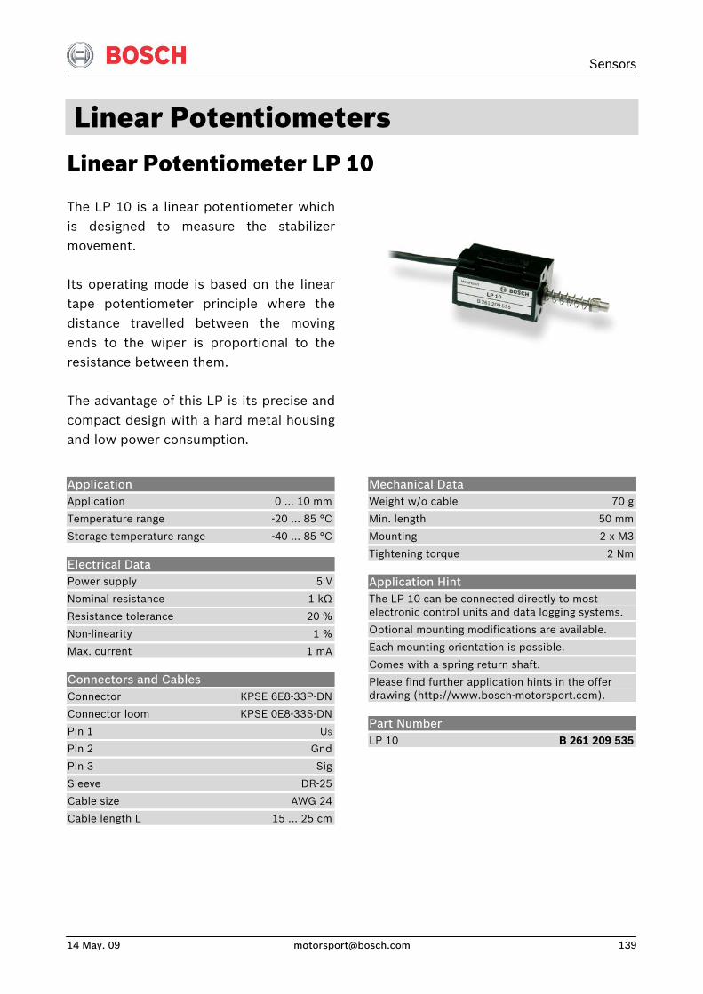
Sensors
14 May. 09 [email protected] 139
Linear Potentiometers Linear Potentiometer LP 10
The LP 10 is a linear potentiometer whichis designed to measure the stabilizermovement.
Its operating mode is based on the lineartape potentiometer principle where thedistance travelled between the movingends to the wiper is proportional to theresistance between them.
The advantage of this LP is its precise andcompact design with a hard metal housingand low power consumption.
Application Application 0 … 10 mm
Temperature range -20 … 85 °C
Storage temperature range -40 … 85 °C
Electrical Data Power supply 5 V
Nominal resistance 1 kΩ
Resistance tolerance 20 %
Non-linearity 1 %
Max. current 1 mA
Connectors and Cables Connector KPSE 6E8-33P-DN
Connector loom KPSE 0E8-33S-DN
Pin 1 US
Pin 2 Gnd
Pin 3 Sig
Sleeve DR-25
Cable size AWG 24
Cable length L 15 … 25 cm
Mechanical Data Weight w/o cable 70 g
Min. length 50 mm
Mounting 2 x M3
Tightening torque 2 Nm
Application Hint The LP 10 can be connected directly to most electronic control units and data logging systems.
Optional mounting modifications are available.
Each mounting orientation is possible.
Comes with a spring return shaft.
Please find further application hints in the offer drawing (http://www.bosch-motorsport.com).
Part Number LP 10 B 261 209 535
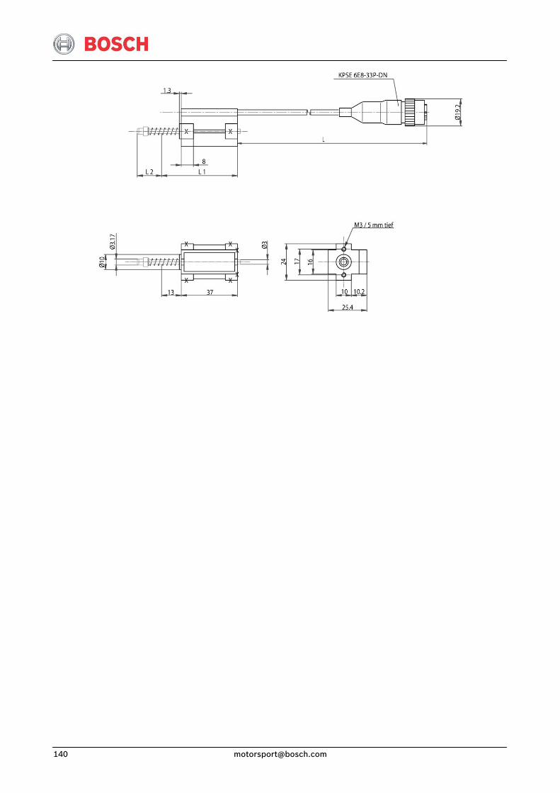
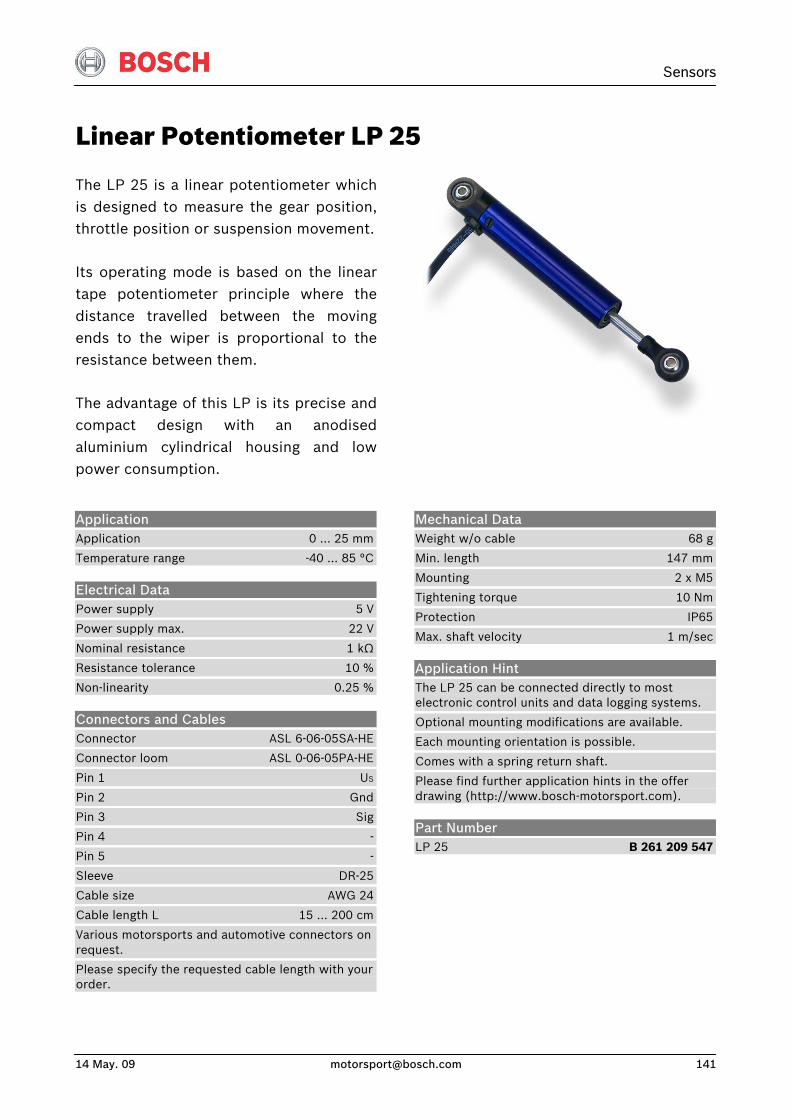
Sensors
14 May. 09 [email protected] 141
Linear Potentiometer LP 25
The LP 25 is a linear potentiometer whichis designed to measure the gear position,throttle position or suspension movement.
Its operating mode is based on the lineartape potentiometer principle where thedistance travelled between the movingends to the wiper is proportional to theresistance between them.
The advantage of this LP is its precise andcompact design with an anodisedaluminium cylindrical housing and lowpower consumption.
Application Application 0 … 25 mm
Temperature range -40 … 85 °C
Electrical Data Power supply 5 V
Power supply max. 22 V
Nominal resistance 1 kΩ
Resistance tolerance 10 %
Non-linearity 0.25 %
Connectors and Cables Connector ASL 6-06-05SA-HE
Connector loom ASL 0-06-05PA-HE
Pin 1 US
Pin 2 Gnd
Pin 3 Sig
Pin 4 -
Pin 5 -
Sleeve DR-25
Cable size AWG 24
Cable length L 15 … 200 cm
Various motorsports and automotive connectors on request.
Please specify the requested cable length with your order.
Mechanical Data Weight w/o cable 68 g
Min. length 147 mm
Mounting 2 x M5
Tightening torque 10 Nm
Protection IP65
Max. shaft velocity 1 m/sec
Application Hint The LP 25 can be connected directly to most electronic control units and data logging systems.
Optional mounting modifications are available.
Each mounting orientation is possible.
Comes with a spring return shaft.
Please find further application hints in the offer drawing (http://www.bosch-motorsport.com).
Part Number LP 25 B 261 209 547

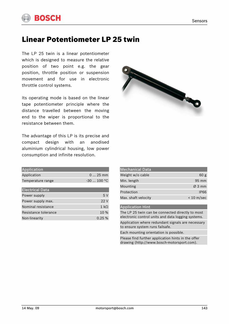
Sensors
14 May. 09 [email protected] 143
Linear Potentiometer LP 25 twin
The LP 25 twin is a linear potentiometerwhich is designed to measure the relativeposition of two point e.g. the gearposition, throttle position or suspension movement and for use in electronicthrottle control systems.
Its operating mode is based on the lineartape potentiometer principle where thedistance travelled between the movingend to the wiper is proportional to theresistance between them.
The advantage of this LP is its precise andcompact design with an anodisedaluminium cylindrical housing, low powerconsumption and infinite resolution.
Application Application 0 … 25 mm
Temperature range -30 … 100 °C
Electrical Data Power supply 5 V
Power supply max. 22 V
Nominal resistance 1 kΩ
Resistance tolerance 10 %
Non-linearity 0.25 %
Mechanical Data Weight w/o cable 60 g
Min. length 95 mm
Mounting Ø 3 mm
Protection IP66
Max. shaft velocity < 10 m/sec
Application Hint The LP 25 twin can be connected directly to most electronic control units and data logging systems.
Application where redundant signals are necessary to ensure system runs failsafe.
Each mounting orientation is possible.
Please find further application hints in the offer drawing (http://www.bosch-motorsport.com).
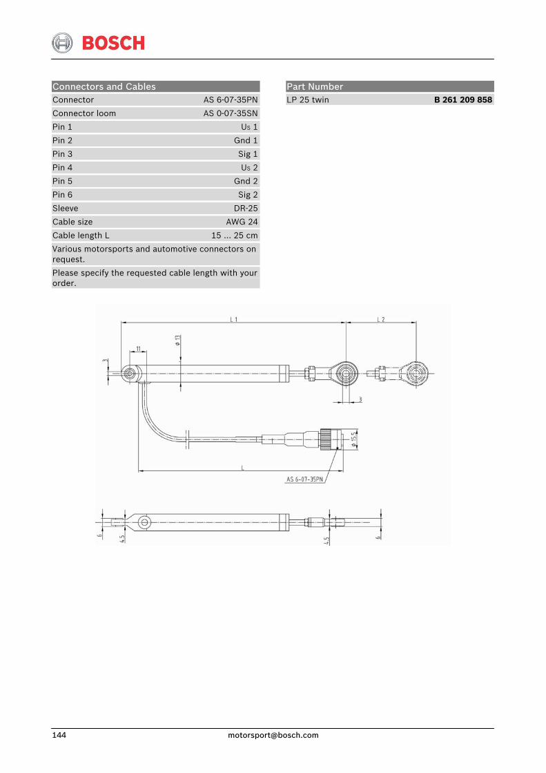
Connectors and Cables Connector AS 6-07-35PN
Connector loom AS 0-07-35SN
Pin 1 US 1
Pin 2 Gnd 1
Pin 3 Sig 1
Pin 4 US 2
Pin 5 Gnd 2
Pin 6 Sig 2
Sleeve DR-25
Cable size AWG 24
Cable length L 15 … 25 cm
Various motorsports and automotive connectors on request.
Please specify the requested cable length with your order.
Part Number LP 25 twin B 261 209 858
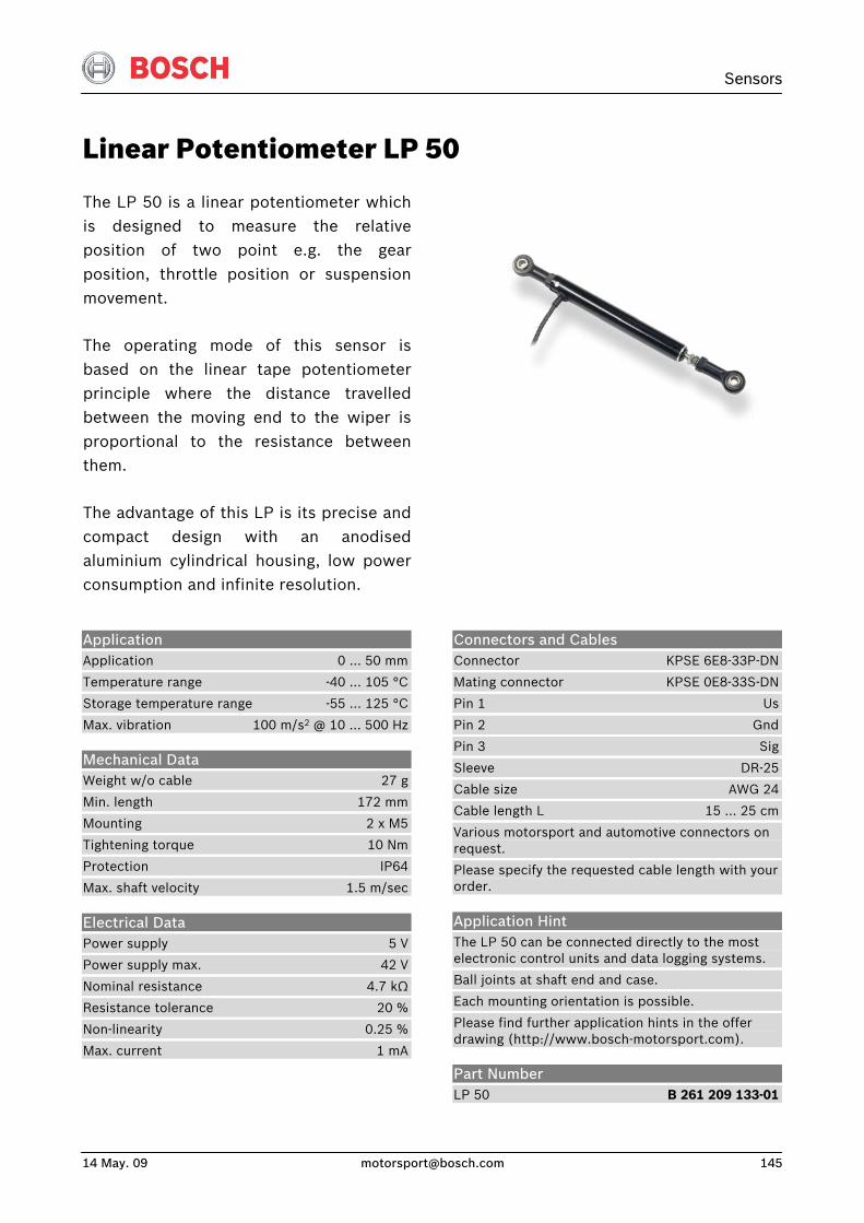
Sensors
14 May. 09 [email protected] 145
Linear Potentiometer LP 50
The LP 50 is a linear potentiometer whichis designed to measure the relativeposition of two point e.g. the gearposition, throttle position or suspensionmovement.
The operating mode of this sensor isbased on the linear tape potentiometerprinciple where the distance travelledbetween the moving end to the wiper isproportional to the resistance betweenthem.
The advantage of this LP is its precise andcompact design with an anodisedaluminium cylindrical housing, low powerconsumption and infinite resolution.
Connectors and Cables Connector KPSE 6E8-33P-DN
Mating connector KPSE 0E8-33S-DN
Pin 1 Us
Pin 2 Gnd
Pin 3 Sig
Sleeve DR-25
Cable size AWG 24
Cable length L 15 … 25 cm
Various motorsport and automotive connectors on request.
Please specify the requested cable length with your order.
Application Hint The LP 50 can be connected directly to the most electronic control units and data logging systems.
Ball joints at shaft end and case.
Each mounting orientation is possible.
Please find further application hints in the offer drawing (http://www.bosch-motorsport.com).
Part Number LP 50 B 261 209 133-01
Application Application 0 … 50 mm
Temperature range -40 … 105 °C
Storage temperature range -55 … 125 °C
Max. vibration 100 m/s2 @ 10 … 500 Hz
Mechanical Data Weight w/o cable 27 g
Min. length 172 mm
Mounting 2 x M5
Tightening torque 10 Nm
Protection IP64
Max. shaft velocity 1.5 m/sec
Electrical Data Power supply 5 V
Power supply max. 42 V
Nominal resistance 4.7 kΩ
Resistance tolerance 20 %
Non-linearity 0.25 %
Max. current 1 mA
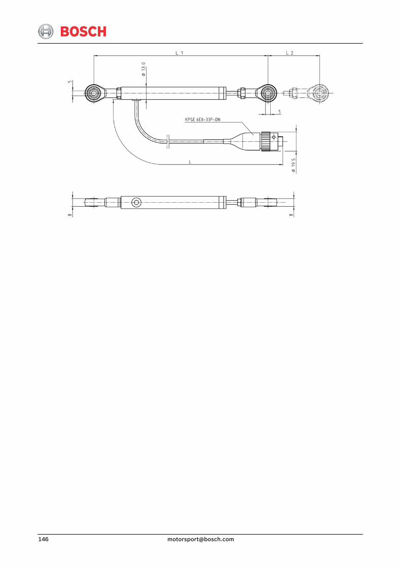
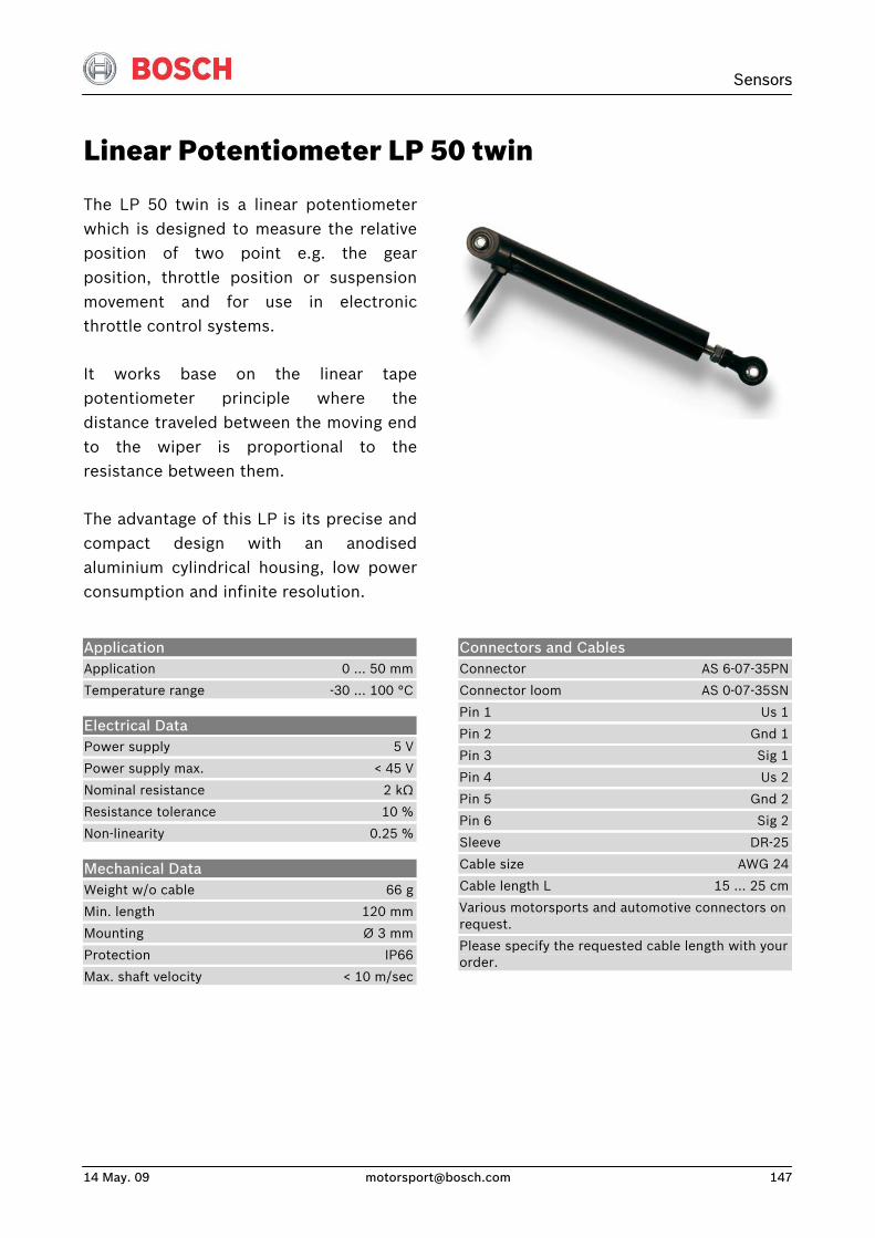
Sensors
14 May. 09 [email protected] 147
Linear Potentiometer LP 50 twin
The LP 50 twin is a linear potentiometer which is designed to measure the relativeposition of two point e.g. the gearposition, throttle position or suspensionmovement and for use in electronicthrottle control systems.
It works base on the linear tapepotentiometer principle where thedistance traveled between the moving endto the wiper is proportional to theresistance between them.
The advantage of this LP is its precise andcompact design with an anodisedaluminium cylindrical housing, low powerconsumption and infinite resolution.
Application Application 0 … 50 mm
Temperature range -30 … 100 °C
Electrical Data Power supply 5 V
Power supply max. < 45 V
Nominal resistance 2 kΩ
Resistance tolerance 10 %
Non-linearity 0.25 %
Mechanical Data Weight w/o cable 66 g
Min. length 120 mm
Mounting Ø 3 mm
Protection IP66
Max. shaft velocity < 10 m/sec
Connectors and Cables Connector AS 6-07-35PN
Connector loom AS 0-07-35SN
Pin 1 Us 1
Pin 2 Gnd 1
Pin 3 Sig 1
Pin 4 Us 2
Pin 5 Gnd 2
Pin 6 Sig 2
Sleeve DR-25
Cable size AWG 24
Cable length L 15 … 25 cm
Various motorsports and automotive connectors on request.
Please specify the requested cable length with your order.
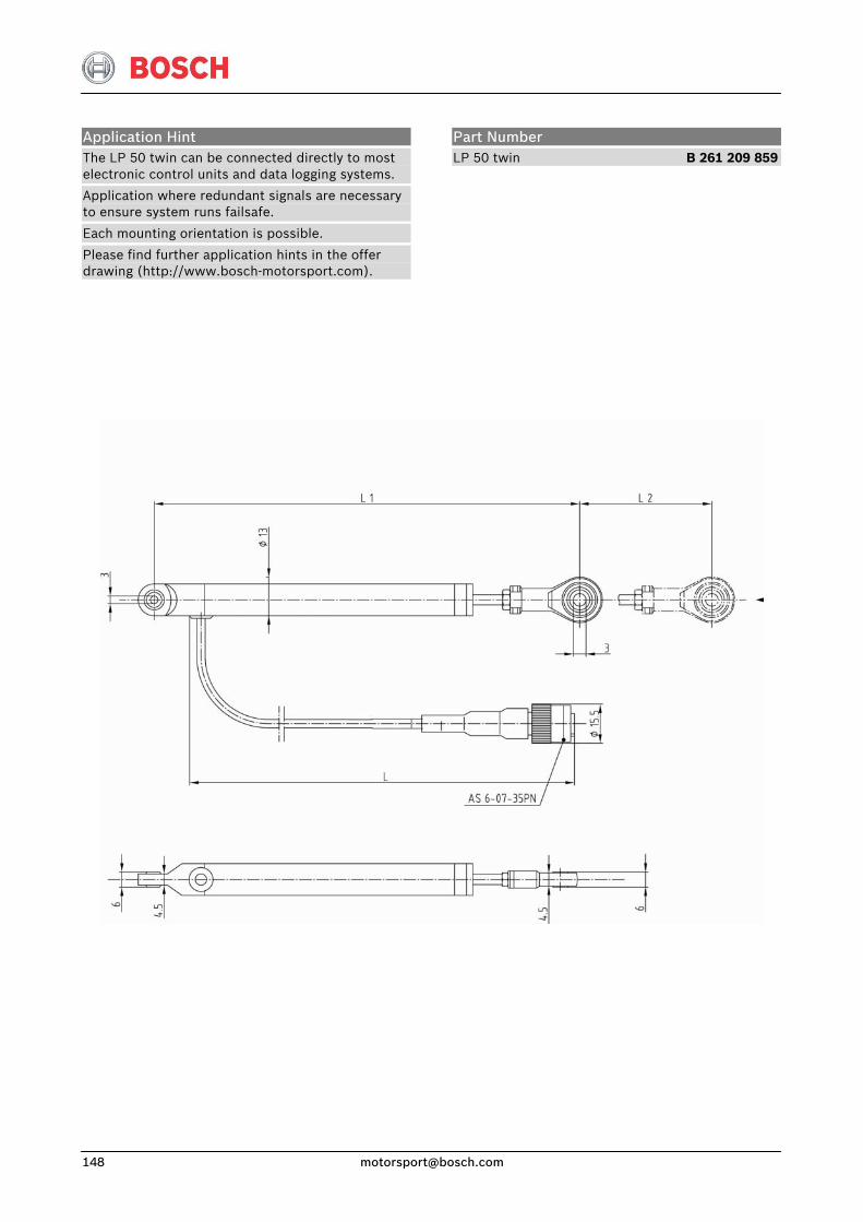
Application Hint The LP 50 twin can be connected directly to most electronic control units and data logging systems.
Application where redundant signals are necessary to ensure system runs failsafe.
Each mounting orientation is possible.
Please find further application hints in the offer drawing (http://www.bosch-motorsport.com).
Part Number LP 50 twin B 261 209 859
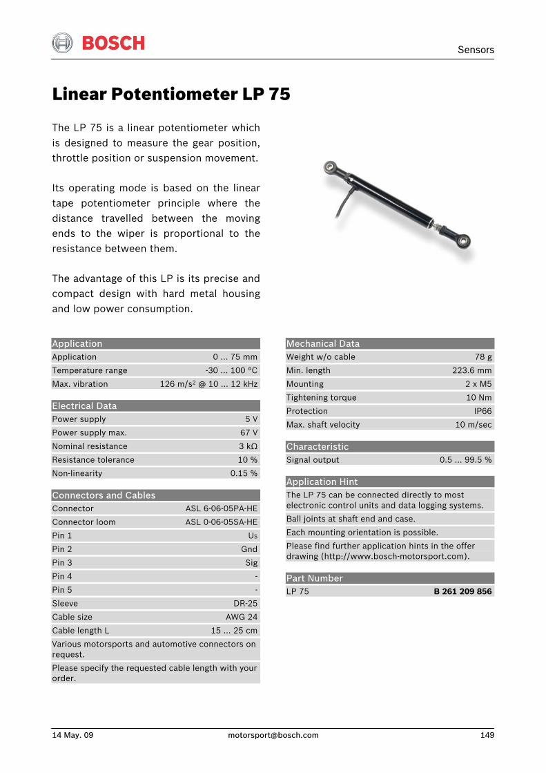
Sensors
14 May. 09 [email protected] 149
Linear Potentiometer LP 75
The LP 75 is a linear potentiometer whichis designed to measure the gear position,throttle position or suspension movement.
Its operating mode is based on the lineartape potentiometer principle where thedistance travelled between the movingends to the wiper is proportional to theresistance between them.
The advantage of this LP is its precise andcompact design with hard metal housingand low power consumption.
Application Application 0 … 75 mm
Temperature range -30 … 100 °C
Max. vibration 126 m/s2 @ 10 … 12 kHz
Electrical Data Power supply 5 V
Power supply max. 67 V
Nominal resistance 3 kΩ
Resistance tolerance 10 %
Non-linearity 0.15 %
Connectors and Cables Connector ASL 6-06-05PA-HE
Connector loom ASL 0-06-05SA-HE
Pin 1 US
Pin 2 Gnd
Pin 3 Sig
Pin 4 -
Pin 5 -
Sleeve DR-25
Cable size AWG 24
Cable length L 15 … 25 cm
Various motorsports and automotive connectors on request.
Please specify the requested cable length with your order.
Mechanical Data Weight w/o cable 78 g
Min. length 223.6 mm
Mounting 2 x M5
Tightening torque 10 Nm
Protection IP66
Max. shaft velocity 10 m/sec
Characteristic Signal output 0.5 … 99.5 %
Application Hint The LP 75 can be connected directly to most electronic control units and data logging systems.
Ball joints at shaft end and case.
Each mounting orientation is possible.
Please find further application hints in the offer drawing (http://www.bosch-motorsport.com).
Part Number LP 75 B 261 209 856


Sensors
14 May. 09 [email protected] 151
Linear Potentiometer LP 75F
The LP 75F is a linear potentiometerwhich is designed to measure the gearposition, throttle position or suspensionmovement.
The operating mode of this sensor isbased on the linear tape potentiometerprinciple where the distance travelledbetween the moving end to the wiper isproportional to the resistance betweenthem.
The advantage of this LP is its compactand lightweight design together with itswider operating temperature range.
Application Application 0 … 75 mm
Temperature range -30 … 100 °C
Max. vibration 126 m/s2 @ 10 … 12 kHz
Electrical Data Power supply 5 V
Power supply max. 67 V
Nominal resistance 3 kΩ
Resistance tolerance 10 %
Non-linearity 0.15 %
Connectors and Cables Connector KPSE 6E8-33P-DN-A34
Connector loom KPSE 0E8-33S-DN
Pin 1 Us
Pin 2 Gnd
Pin 3 Sig
Sleeve DR-25
Cable size AWG 24
Cable length L 15 … 25 cm
Various motorsports and automotive connectors on request.
Please specify the requested cable length with your order.
Mechanical Data Weight w/o cable 78 g
Min. length 223.6 mm
Mounting 2 x M5
Tightening torque 10 Nm
Protection IP66
Max. shaft velocity 10 m/sec
Characteristic Signal output 0.5 … 99.5 %
Application Hint The LP 75F can be connected directly to most electronic control units and data logging systems.
Each mounting orientation is possible.
Please find further application hints in the offer drawing (http://www.bosch-motorsport.com).
Part Number LP 75F B 261 209 852
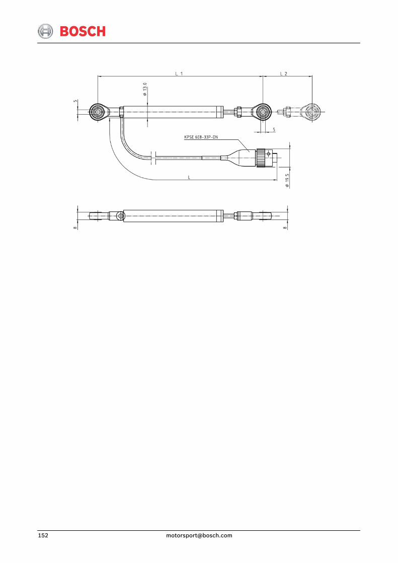
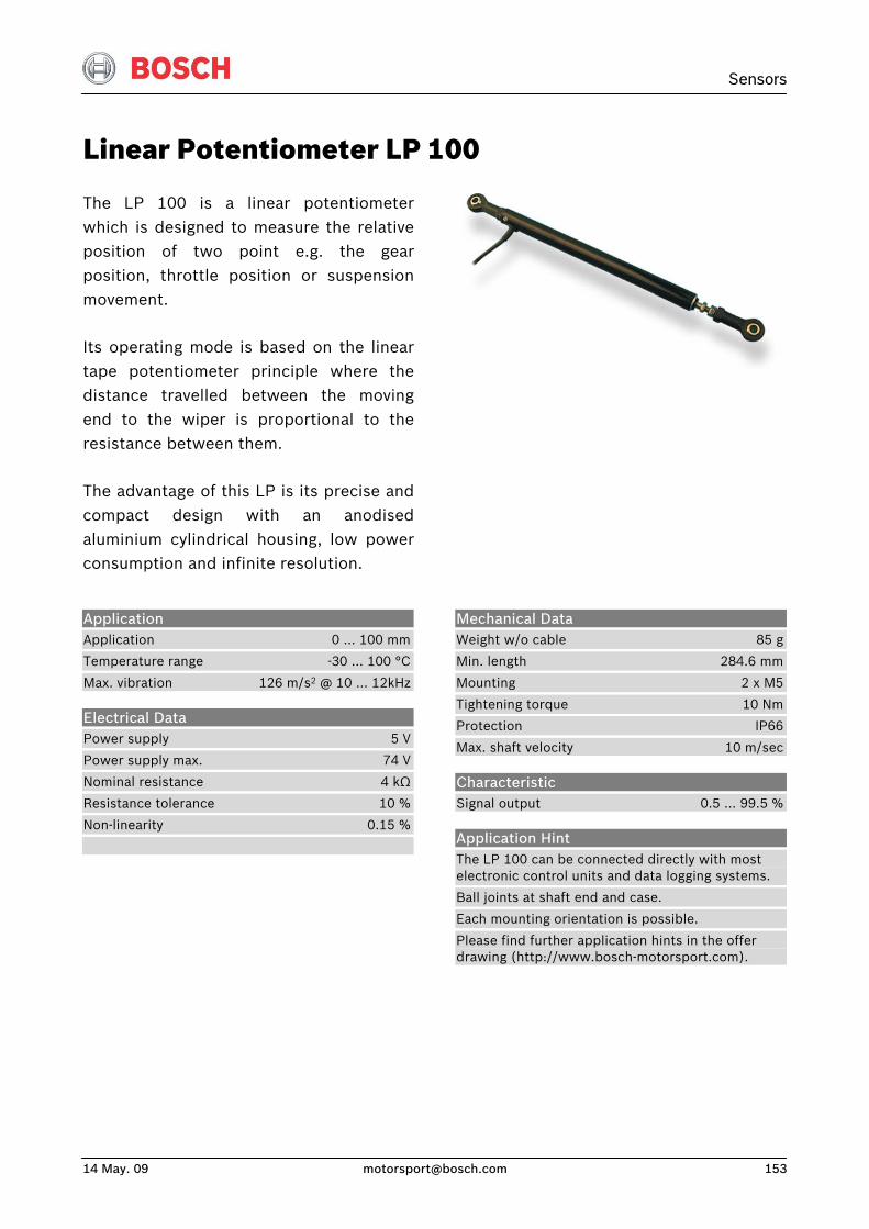
Sensors
14 May. 09 [email protected] 153
Linear Potentiometer LP 100
The LP 100 is a linear potentiometerwhich is designed to measure the relativeposition of two point e.g. the gearposition, throttle position or suspensionmovement.
Its operating mode is based on the lineartape potentiometer principle where thedistance travelled between the movingend to the wiper is proportional to theresistance between them.
The advantage of this LP is its precise andcompact design with an anodisedaluminium cylindrical housing, low powerconsumption and infinite resolution.
Application Application 0 … 100 mm
Temperature range -30 … 100 °C
Max. vibration 126 m/s2 @ 10 … 12kHz
Electrical Data Power supply 5 V
Power supply max. 74 V
Nominal resistance 4 kΩ
Resistance tolerance 10 %
Non-linearity 0.15 %
Mechanical Data Weight w/o cable 85 g
Min. length 284.6 mm
Mounting 2 x M5
Tightening torque 10 Nm
Protection IP66
Max. shaft velocity 10 m/sec
Characteristic Signal output 0.5 … 99.5 %
Application Hint The LP 100 can be connected directly with most electronic control units and data logging systems.
Ball joints at shaft end and case.
Each mounting orientation is possible.
Please find further application hints in the offer drawing (http://www.bosch-motorsport.com).
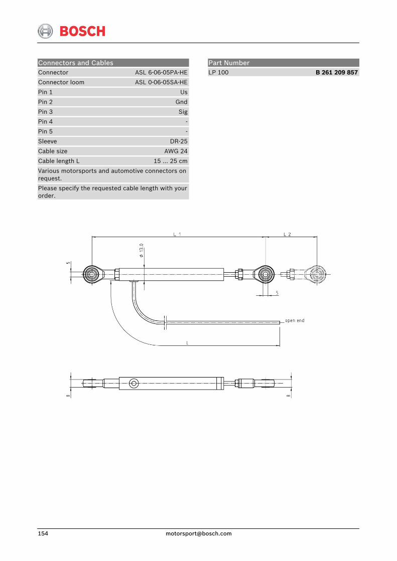
Connectors and Cables Connector ASL 6-06-05PA-HE
Connector loom ASL 0-06-05SA-HE
Pin 1 Us
Pin 2 Gnd
Pin 3 Sig
Pin 4 -
Pin 5 -
Sleeve DR-25
Cable size AWG 24
Cable length L 15 … 25 cm
Various motorsports and automotive connectors on request.
Please specify the requested cable length with your order.
Part Number LP 100 B 261 209 857
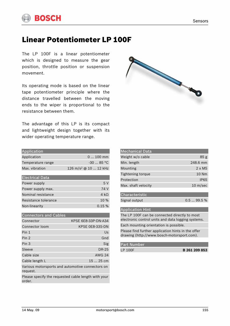
Sensors
14 May. 09 [email protected] 155
Linear Potentiometer LP 100F
The LP 100F is a linear potentiometerwhich is designed to measure the gearposition, throttle position or suspensionmovement.
Its operating mode is based on the lineartape potentiometer principle where thedistance travelled between the movingends to the wiper is proportional to the resistance between them.
The advantage of this LP is its compactand lightweight design together with itswider operating temperature range.
Application Application 0 … 100 mm
Temperature range -30 … 85 °C
Max. vibration 126 m/s2 @ 10 … 12 kHz
Electrical Data Power supply 5 V
Power supply max. 74 V
Nominal resistance 4 kΩ
Resistance tolerance 10 %
Non-linearity 0.15 %
Connectors and Cables Connector KPSE 6E8-33P-DN-A34
Connector loom KPSE 0E8-33S-DN
Pin 1 Us
Pin 2 Gnd
Pin 3 Sig
Sleeve DR-25
Cable size AWG 24
Cable length L 15 … 25 cm
Various motorsports and automotive connectors on request.
Please specify the requested cable length with your order.
Mechanical Data Weight w/o cable 85 g
Min. length 248.6 mm
Mounting 2 x M5
Tightening torque 10 Nm
Protection IP65
Max. shaft velocity 10 m/sec
Characteristic Signal output 0.5 … 99.5 %
Application Hint The LP 100F can be connected directly to most electronic control units and data logging systems.
Each mounting orientation is possible.
Please find further application hints in the offer drawing (http://www.bosch-motorsport.com).
Part Number LP 100F B 261 209 853
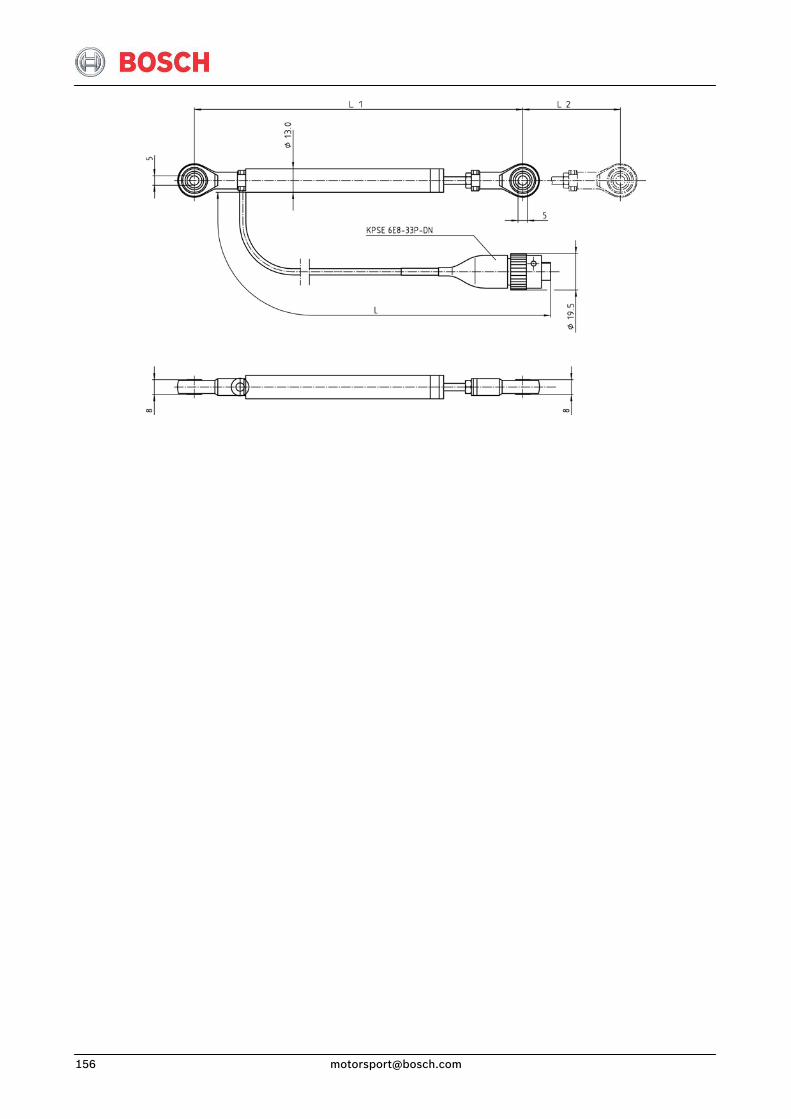
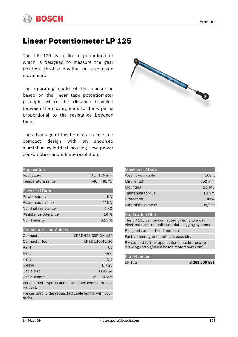
Sensors
14 May. 09 [email protected] 157
Linear Potentiometer LP 125
The LP 125 is a linear potentiometerwhich is designed to measure the gearposition, throttle position or suspensionmovement.
The operating mode of this sensor is based on the linear tape potentiometerprinciple where the distance travelledbetween the moving ends to the wiper isproportional to the resistance betweenthem.
The advantage of this LP is its precise andcompact design with an anodisedaluminium cylindrical housing, low powerconsumption and infinite resolution.
Application Application 0 … 125 mm
Temperature range -40 … 85 °C
Electrical Data Power supply 5 V
Power supply max. 110 V
Nominal resistance 5 kΩ
Resistance tolerance 10 %
Non-linearity 0.15 %
Connectors and Cables Connector KPSE 6E8-33P-DN-A34
Connector loom KPSE 120061-30
Pin 1 Us
Pin 2 Gnd
Pin 3 Sig
Sleeve DR-25
Cable size AWG 24
Cable length L 15 … 90 cm
Various motorsports and automotive connectors on request.
Please specify the requested cable length with your order.
Mechanical Data Weight w/o cable 108 g
Min. length 252 mm
Mounting 2 x M5
Tightening torque 10 Nm
Protection IP64
Max. shaft velocity 1 m/sec
Application Hint The LP 125 can be connected directly to most electronic control units and data logging systems.
Ball joints at shaft end and case.
Each mounting orientation is possible.
Please find further application hints in the offer drawing (http://www.bosch-motorsport.com).
Part Number LP 125 B 261 209 531
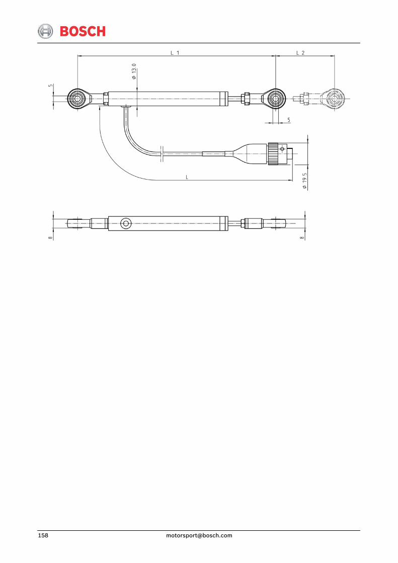
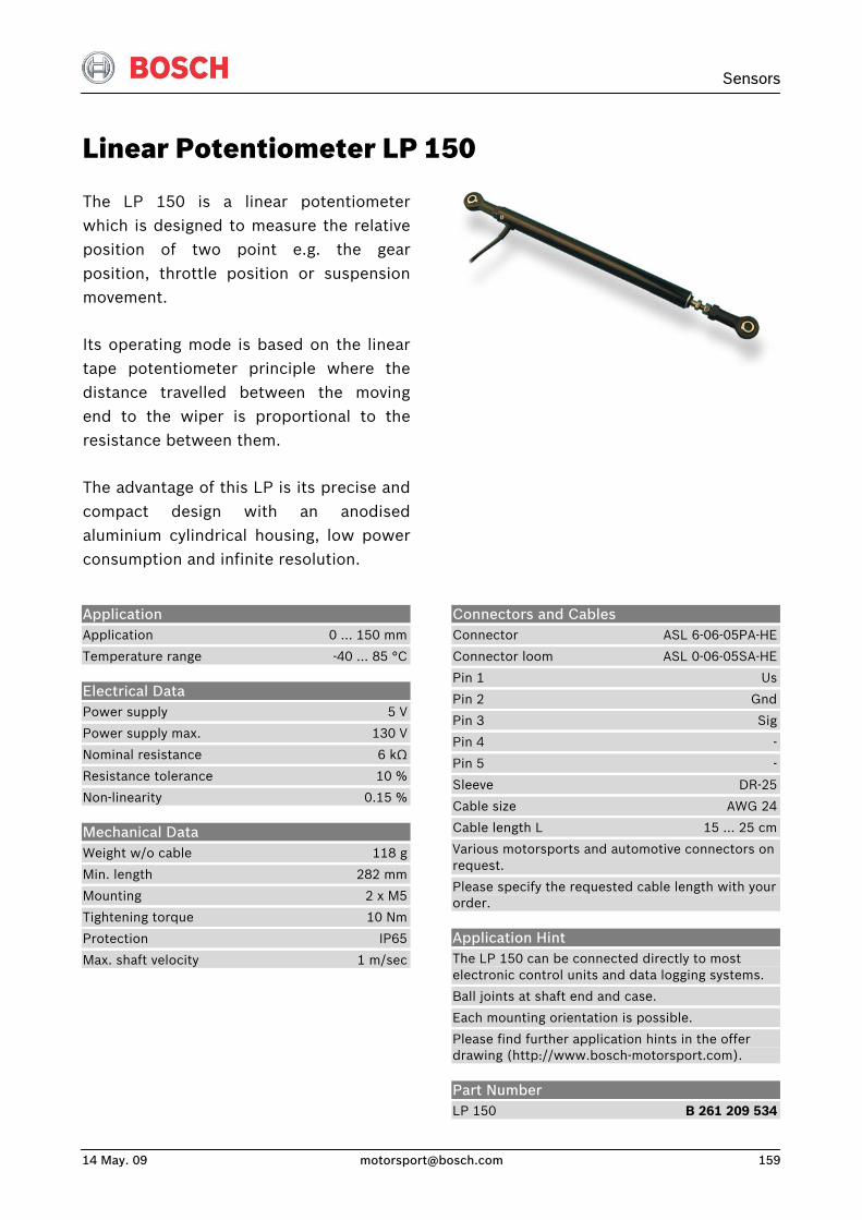
Sensors
14 May. 09 [email protected] 159
Linear Potentiometer LP 150
The LP 150 is a linear potentiometerwhich is designed to measure the relativeposition of two point e.g. the gearposition, throttle position or suspensionmovement.
Its operating mode is based on the lineartape potentiometer principle where thedistance travelled between the movingend to the wiper is proportional to theresistance between them.
The advantage of this LP is its precise andcompact design with an anodisedaluminium cylindrical housing, low powerconsumption and infinite resolution.
Application Application 0 … 150 mm
Temperature range -40 … 85 °C
Electrical Data Power supply 5 V
Power supply max. 130 V
Nominal resistance 6 kΩ
Resistance tolerance 10 %
Non-linearity 0.15 %
Mechanical Data Weight w/o cable 118 g
Min. length 282 mm
Mounting 2 x M5
Tightening torque 10 Nm
Protection IP65
Max. shaft velocity 1 m/sec
Connectors and Cables Connector ASL 6-06-05PA-HE
Connector loom ASL 0-06-05SA-HE
Pin 1 Us
Pin 2 Gnd
Pin 3 Sig
Pin 4 -
Pin 5 -
Sleeve DR-25
Cable size AWG 24
Cable length L 15 … 25 cm
Various motorsports and automotive connectors on request.
Please specify the requested cable length with your order.
Application Hint The LP 150 can be connected directly to most electronic control units and data logging systems.
Ball joints at shaft end and case.
Each mounting orientation is possible.
Please find further application hints in the offer drawing (http://www.bosch-motorsport.com).
Part Number LP 150 B 261 209 534
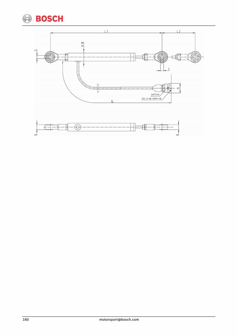

Sensors
14 May. 09 [email protected] 161
Pressure Sensors Air Pressure Sensor Air PSA-B
This sensor is designed to measure theabsolute air pressure, especially the airbox pressure of gasoline or Diesel engines.
A piezo-resistive sensor element andelectronic systems for signal-amplification and temperature-compensation are integrated on a silicon chip. The output ofthe sensor is an analog, ratiometric signal.Two different pressure ranges areavailable (0.1 ... 1.15 bar or 0.2 ... 2.5 bar).
The main feature and benefit of thissensor is the combination of both highquality production part and motorsportspec connection.
Application Application [1] 0.1 … 1.15 bar (a) [2] 0.2 … 2.50 bar (a)
Pressure reference type absolute
Max. pressure 5 bar
Operating temp. range -40 … 130 °C
Media temp. range -40 … 130 °C
Storage temp. range -40 … 130 °C
Max. vibration 2,500 m/s2 @ 200 Hz 1,250 m/s2 @ 440 Hz sine
Electrical Data Power Supply US 4.75 … 5.25 V
Max. Power Supply 16 V
Full Scale Output UA @ 5 V 0.3 … 4.8 V
Current IS 9 mA
Mechanical Data Mounting M6
Fitting 12.05 mm
Weight w/o cable 17 g
Sealing O-ring 7.59 x 2.62 mm
Characteristic Response time T10/90 1 ms
Compensated range 10 … 85 °C
Tolerance (FS) @ US = 5 V [1] ± 0.016 bar [2] ± 0.034 bar
Tolerance (FS) [1] ± 1.39 % [2] ± 1.36 %
Sensitivity [1] 4,040 mV/bar [2] 1,848 mV/bar
Offset [1] -4.8 mV [2] 30.4 mV
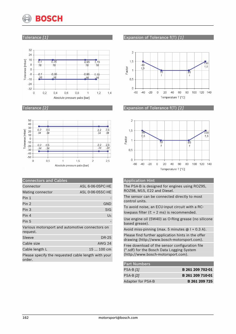
Tolerance [1]
Expansion of Tolerance f(T) [1]
Tolerance [2]
Expansion of Tolerance f(T) [2]
Connectors and Cables Connector ASL 6-06-05PC-HE
Mating connector ASL 0-06-05SC-HE
Pin 1 -
Pin 2 GND
Pin 3 SIG
Pin 4 US
Pin 5 -
Various motorsport and automotive connectors on request.
Sleeve DR-25
Cable size AWG 24
Cable length L 15 … 100 cm
Please specify the requested cable length with your order.
Application Hint The PSA-B is designed for engines using ROZ95, ROZ98, M15, E22 and Diesel.
The sensor can be connected directly to most control units.
To avoid noise, an ECU-input circuit with a RC-
lowpass filter (Շ = 2 ms) is recommended.
Use engine oil (5W40) as O-Ring grease (no silicone based grease).
Avoid miss-pinning (max. 5 minutes @ I = 0.3 A).
Please find further application hints in the offer drawing (http://www.bosch-motorsport.com).
Free download of the sensor configuration file (*.sdf) for the Bosch Data Logging System (http://www.bosch-motorsport.com).
Part Numbers PSA-B [1] B 261 209 702-01
PSA-B [2] B 261 209 710-01
Adapter for PSA-B B 261 209 725
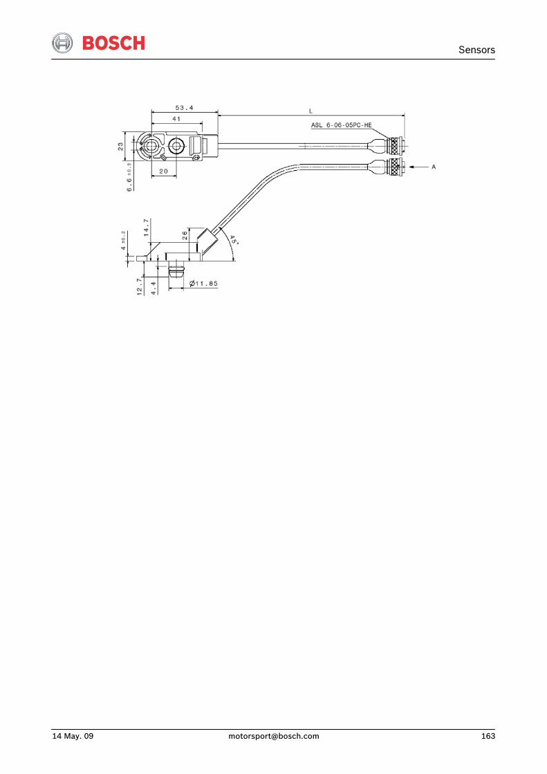
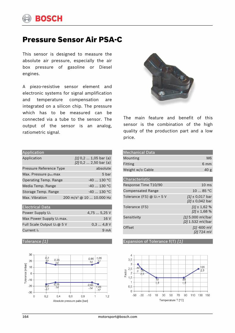
Pressure Sensor Air PSA-C
This sensor is designed to measure theabsolute air pressure, especially the airbox pressure of gasoline or Diesel engines.
A piezo-resistive sensor element and electronic systems for signal amplificationand temperature compensation areintegrated on a silicon chip. The pressurewhich has to be measured can be connected via a tube to the sensor. The output of the sensor is an analog, ratiometric signal.
The main feature and benefit of this sensor is the combination of the high quality of the production part and a low price.
Application Application [1] 0,2 … 1,05 bar (a) [2] 0,2 … 2,50 bar (a)
Pressure Reference Type absolute
Max. Pressure pabs max 5 bar
Operating Temp. Range -40 … 130 °C
Media Temp. Range -40 … 130 °C
Storage Temp. Range -40 … 130 °C
Max. Vibration 200 m/s2 @ 10 … 10.000 Hz
Electrical Data Power Supply US 4,75 … 5,25 V
Max Power Supply US max. 16 V
Full Scale Output UA @ 5 V 0,3 … 4,8 V
Current IS 9 mA
Mechanical Data Mounting M6
Fitting 6 mm
Weight w/o Cable 40 g
Characteristic Response Time T10/90 10 ms
Compensated Range 10 … 85 °C
Tolerance (FS) @ US = 5 V [1] ± 0,017 bar [2] ± 0,042 bar
Tolerance (FS) [1] ± 1,62 % [2] ± 1,68 %
Sensitivity [1] 5.000 mV/bar [2] 1.532 mV/bar
Offset [1] -600 mV [2] 724 mV
Tolerance [1]
Expansion of Tolerance f(T) [1]
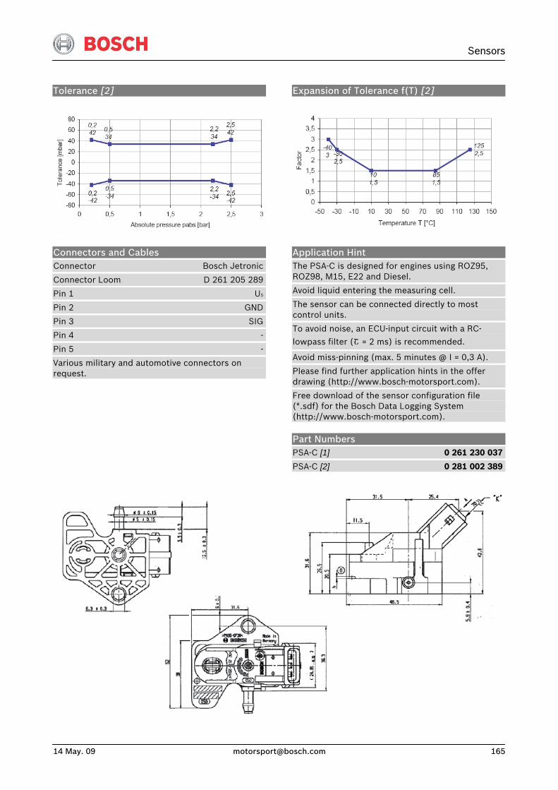
Sensors
14 May. 09 [email protected] 165
Tolerance [2]
Expansion of Tolerance f(T) [2]
Connectors and Cables Connector Bosch Jetronic
Connector Loom D 261 205 289
Pin 1 US
Pin 2 GND
Pin 3 SIG
Pin 4 -
Pin 5 -
Various military and automotive connectors on request.
Application Hint The PSA-C is designed for engines using ROZ95, ROZ98, M15, E22 and Diesel.
Avoid liquid entering the measuring cell.
The sensor can be connected directly to most control units.
To avoid noise, an ECU-input circuit with a RC-
lowpass filter (Շ = 2 ms) is recommended.
Avoid miss-pinning (max. 5 minutes @ I = 0,3 A).
Please find further application hints in the offer drawing (http://www.bosch-motorsport.com).
Free download of the sensor configuration file (*.sdf) for the Bosch Data Logging System (http://www.bosch-motorsport.com).
Part Numbers PSA-C [1] 0 261 230 037
PSA-C [2] 0 281 002 389
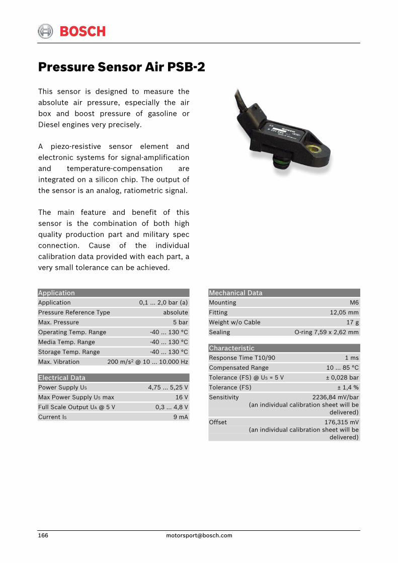
Pressure Sensor Air PSB-2
This sensor is designed to measure theabsolute air pressure, especially the airbox and boost pressure of gasoline or Diesel engines very precisely.
A piezo-resistive sensor element andelectronic systems for signal-amplification and temperature-compensation are integrated on a silicon chip. The output ofthe sensor is an analog, ratiometric signal.
The main feature and benefit of this sensor is the combination of both highquality production part and military specconnection. Cause of the individualcalibration data provided with each part, avery small tolerance can be achieved.
Application Application 0,1 … 2,0 bar (a)
Pressure Reference Type absolute
Max. Pressure 5 bar
Operating Temp. Range -40 … 130 °C
Media Temp. Range -40 … 130 °C
Storage Temp. Range -40 … 130 °C
Max. Vibration 200 m/s2 @ 10 … 10.000 Hz
Electrical Data Power Supply US 4,75 … 5,25 V
Max Power Supply US max 16 V
Full Scale Output UA @ 5 V 0,3 … 4,8 V
Current IS 9 mA
Mechanical Data Mounting M6
Fitting 12,05 mm
Weight w/o Cable 17 g
Sealing O-ring 7,59 x 2,62 mm
Characteristic Response Time T10/90 1 ms
Compensated Range 10 … 85 °C
Tolerance (FS) @ US = 5 V ± 0,028 bar
Tolerance (FS) ± 1,4 %
Sensitivity 2236,84 mV/bar (an individual calibration sheet will be delivered)
Offset 176,315 mV (an individual calibration sheet will be delivered)
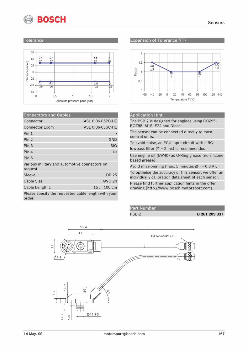
Sensors
14 May. 09 [email protected] 167
Tolerance
Expansion of Tolerance f(T)
Connectors and Cables Connector ASL 6-06-05PC-HE
Connector Loom ASL 0-06-05SC-HE
Pin 1 -
Pin 2 GND
Pin 3 SIG
Pin 4 US
Pin 5 -
Various military and automotive connectors on request.
Sleeve DR-25
Cable Size AWG 24
Cable Length L 15 … 100 cm
Please specify the requested cable length with your order.
Application Hint The PSB-2 is designed for engines using ROZ95, ROZ98, M15, E22 and Diesel.
The sensor can be connected directly to most control units.
To avoid noise, an ECU-input circuit with a RC-
lowpass filter (Շ = 2 ms) is recommended.
Use engine oil (5W40) as O-Ring grease (no silicone based grease).
Avoid miss-pinning (max. 5 minutes @ I = 0,3 A).
To optimise the accuracy of this sensor, we offer an individually calibration data sheet of each sensor.
Please find further application hints in the offer drawing (http://www.bosch-motorsport.com).
Part Number PSB-2 B 261 209 337
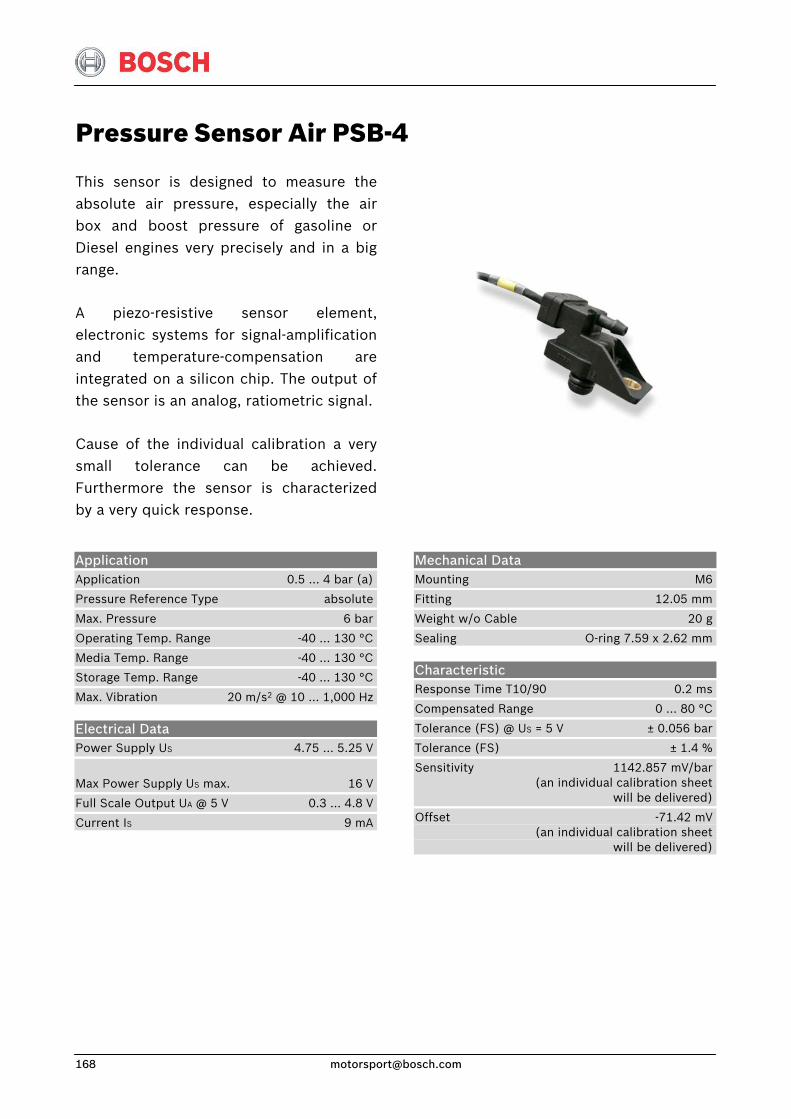
Pressure Sensor Air PSB-4
This sensor is designed to measure theabsolute air pressure, especially the airbox and boost pressure of gasoline orDiesel engines very precisely and in a bigrange.
A piezo-resistive sensor element,electronic systems for signal-amplification and temperature-compensation are integrated on a silicon chip. The output ofthe sensor is an analog, ratiometric signal.
Cause of the individual calibration a verysmall tolerance can be achieved.Furthermore the sensor is characterizedby a very quick response.
Application Application 0.5 … 4 bar (a)
Pressure Reference Type absolute
Max. Pressure 6 bar
Operating Temp. Range -40 … 130 °C
Media Temp. Range -40 … 130 °C
Storage Temp. Range -40 … 130 °C
Max. Vibration 20 m/s2 @ 10 … 1,000 Hz
Electrical Data Power Supply US 4.75 … 5.25 V
Max Power Supply US max. 16 V
Full Scale Output UA @ 5 V 0.3 … 4.8 V
Current IS 9 mA
Mechanical Data Mounting M6
Fitting 12.05 mm
Weight w/o Cable 20 g
Sealing O-ring 7.59 x 2.62 mm
Characteristic Response Time T10/90 0.2 ms
Compensated Range 0 … 80 °C
Tolerance (FS) @ US = 5 V ± 0.056 bar
Tolerance (FS) ± 1.4 %
Sensitivity 1142.857 mV/bar (an individual calibration sheet will be delivered)
Offset -71.42 mV (an individual calibration sheet will be delivered)
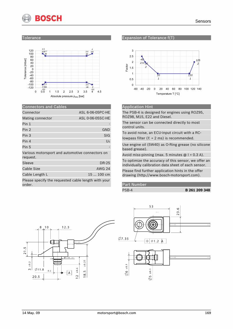
Sensors
14 May. 09 [email protected] 169
Tolerance
4-101
3.6-86
0.7-860.5
-101
41013.6
860.786
0.5101
-120-100
-80-60-40-20
020406080
100120
0 0.5 1 1.5 2 2.5 3 3.5 4 4.5
Absolute pressure pabs [bar]
Tole
ranc
e [m
bar]
Expansion of Tolerance f(T)
1252
1101
101
-302
-402.5
0
0.5
1
1.5
2
2.5
3
-60 -40 -20 0 20 40 60 80 100 120 140
Temperature T [°C]
Fact
or
Connectors and Cables Connector ASL 6-06-05PC-HE
Mating connector ASL 0-06-05SC-HE
Pin 1 -
Pin 2 GND
Pin 3 SIG
Pin 4 US
Pin 5 -
Various motorsport and automotive connectors on request.
Sleeve DR-25
Cable Size AWG 24
Cable Length L 15 … 100 cm
Please specify the requested cable length with your order.
Application Hint The PSB-4 is designed for engines using ROZ95, ROZ98, M15, E22 and Diesel.
The sensor can be connected directly to most control units.
To avoid noise, an ECU-input circuit with a RC-
lowpass filter (Շ = 2 ms) is recommended.
Use engine oil (5W40) as O-Ring grease (no silicone based grease).
Avoid miss-pinning (max. 5 minutes @ I = 0.3 A).
To optimize the accuracy of this sensor, we offer an individually calibration data sheet of each sensor.
Please find further application hints in the offer drawing (http://www.bosch-motorsport.com).
Part Number PSB-4 B 261 209 348
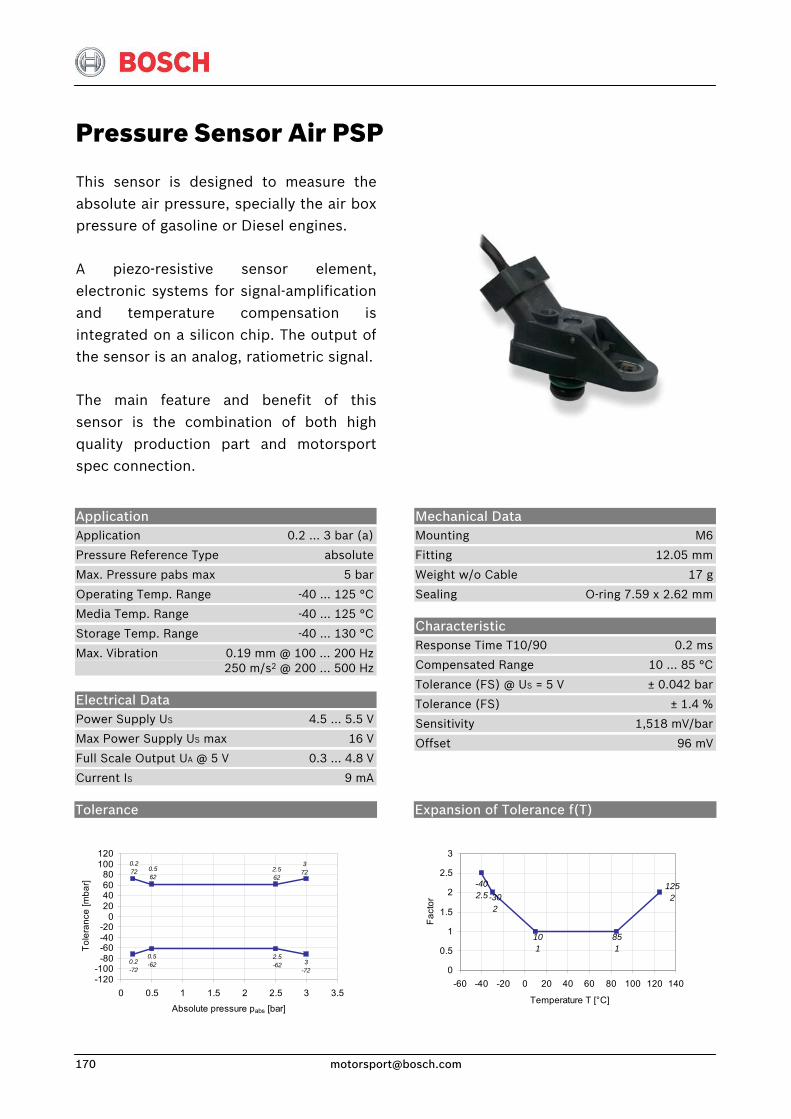
Pressure Sensor Air PSP
This sensor is designed to measure theabsolute air pressure, specially the air box pressure of gasoline or Diesel engines.
A piezo-resistive sensor element,electronic systems for signal-amplification and temperature compensation isintegrated on a silicon chip. The output ofthe sensor is an analog, ratiometric signal.
The main feature and benefit of thissensor is the combination of both highquality production part and motorsportspec connection.
Application Application 0.2 … 3 bar (a)
Pressure Reference Type absolute
Max. Pressure pabs max 5 bar
Operating Temp. Range -40 … 125 °C
Media Temp. Range -40 … 125 °C
Storage Temp. Range -40 … 130 °C
Max. Vibration 0.19 mm @ 100 … 200 Hz 250 m/s2 @ 200 … 500 Hz
Electrical Data Power Supply US 4.5 … 5.5 V
Max Power Supply US max 16 V
Full Scale Output UA @ 5 V 0.3 … 4.8 V
Current IS 9 mA
Mechanical Data Mounting M6
Fitting 12.05 mm
Weight w/o Cable 17 g
Sealing O-ring 7.59 x 2.62 mm
Characteristic Response Time T10/90 0.2 ms
Compensated Range 10 … 85 °C
Tolerance (FS) @ US = 5 V ± 0.042 bar
Tolerance (FS) ± 1.4 %
Sensitivity 1,518 mV/bar
Offset 96 mV
Tolerance
3-72
2.5-62
0.5-620.2
-72
3722.5
620.562
0.272
-120-100
-80-60-40-20
020406080
100120
0 0.5 1 1.5 2 2.5 3 3.5
Absolute pressure pabs [bar]
Tole
ranc
e [m
bar]
Expansion of Tolerance f(T)
1252
851
101
-302
-402.5
0
0.5
1
1.5
2
2.5
3
-60 -40 -20 0 20 40 60 80 100 120 140
Temperature T [°C]
Fact
or
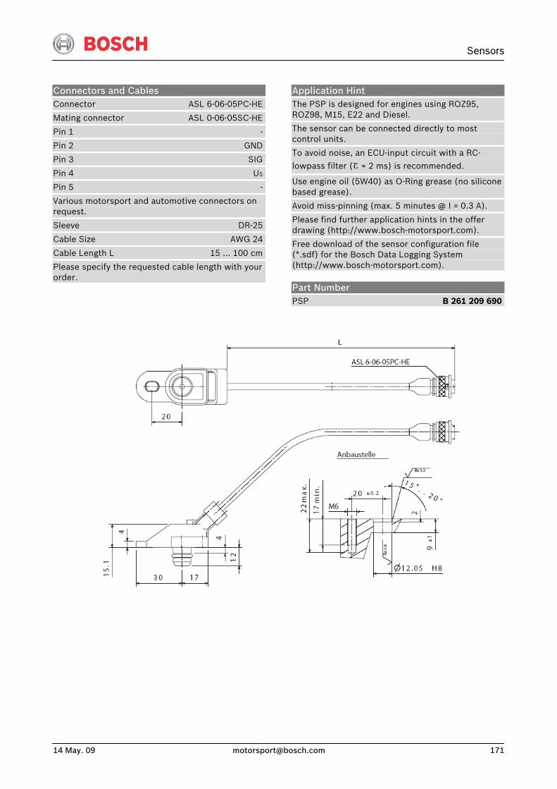
Sensors
14 May. 09 [email protected] 171
Connectors and Cables Connector ASL 6-06-05PC-HE
Mating connector ASL 0-06-05SC-HE
Pin 1 -
Pin 2 GND
Pin 3 SIG
Pin 4 US
Pin 5 -
Various motorsport and automotive connectors on request.
Sleeve DR-25
Cable Size AWG 24
Cable Length L 15 … 100 cm
Please specify the requested cable length with your order.
Application Hint The PSP is designed for engines using ROZ95, ROZ98, M15, E22 and Diesel.
The sensor can be connected directly to most control units.
To avoid noise, an ECU-input circuit with a RC-
lowpass filter (Շ = 2 ms) is recommended.
Use engine oil (5W40) as O-Ring grease (no silicone based grease).
Avoid miss-pinning (max. 5 minutes @ I = 0.3 A).
Please find further application hints in the offer drawing (http://www.bosch-motorsport.com).
Free download of the sensor configuration file (*.sdf) for the Bosch Data Logging System (http://www.bosch-motorsport.com).
Part Number PSP B 261 209 690
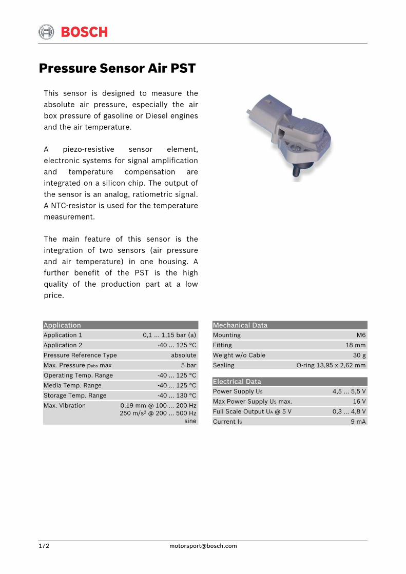
Pressure Sensor Air PST
This sensor is designed to measure theabsolute air pressure, especially the airbox pressure of gasoline or Diesel enginesand the air temperature.
A piezo-resistive sensor element, electronic systems for signal amplificationand temperature compensation areintegrated on a silicon chip. The output ofthe sensor is an analog, ratiometric signal. A NTC-resistor is used for the temperaturemeasurement.
The main feature of this sensor is the integration of two sensors (air pressureand air temperature) in one housing. A further benefit of the PST is the highquality of the production part at a lowprice.
Application Application 1 0,1 … 1,15 bar (a)
Application 2 -40 … 125 °C
Pressure Reference Type absolute
Max. Pressure pabs max 5 bar
Operating Temp. Range -40 … 125 °C
Media Temp. Range -40 … 125 °C
Storage Temp. Range -40 … 130 °C
Max. Vibration 0,19 mm @ 100 … 200 Hz 250 m/s2 @ 200 … 500 Hz sine
Mechanical Data Mounting M6
Fitting 18 mm
Weight w/o Cable 30 g
Sealing O-ring 13,95 x 2,62 mm
Electrical Data Power Supply US 4,5 … 5,5 V
Max Power Supply US max. 16 V
Full Scale Output UA @ 5 V 0,3 … 4,8 V
Current IS 9 mA
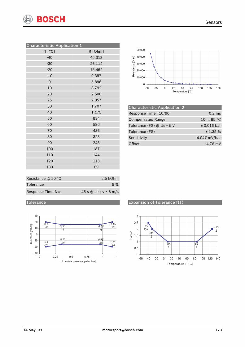
Sensors
14 May. 09 [email protected] 173
Characteristic Application 1 T [°C]
-40
-30
-20
-10
0
10
20
25
30
40
50
60
70
80
90
100
110
120
130
R [Ohm]
45.313
26.114
15.462
9.397
5.896
3.792
2.500
2.057
1.707
1.175
834
596
436
323
243
187
144
113
89 Resistance @ 20 °C 2,5 kOhm
Tolerance 5 %
Response Time Շ 63 45 s @ air ; v = 6 m/s
0
10.000
20.000
30.000
40.000
50.000
-50 -25 0 25 50 75 100 125 150Temperature [°C]
Res
ista
nce
[Ohm
]
Characteristic Application 2 Response Time T10/90 0,2 ms
Compensated Range 10 … 85 °C
Tolerance (FS) @ US = 5 V ± 0,016 bar
Tolerance (FS) ± 1,39 %
Sensitivity 4.047 mV/bar
Offset -4,76 mV
Tolerance
Expansion of Tolerance f(T)
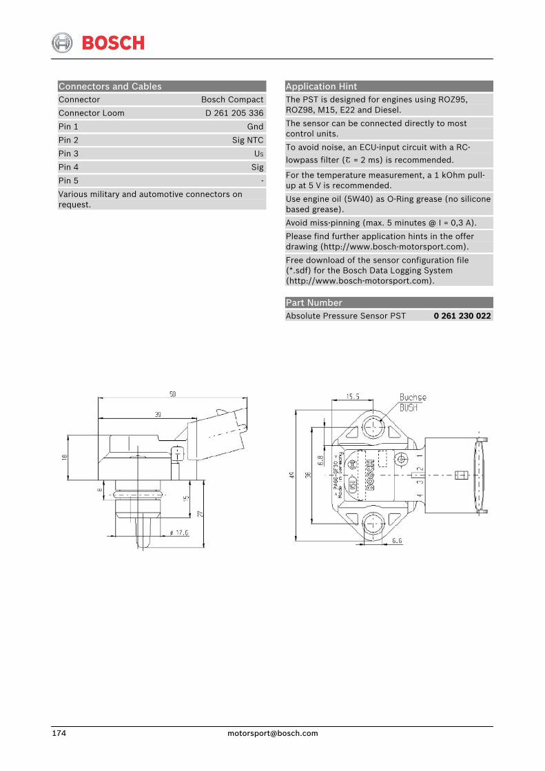
Connectors and Cables Connector Bosch Compact
Connector Loom D 261 205 336
Pin 1 Gnd
Pin 2 Sig NTC
Pin 3 US
Pin 4 Sig
Pin 5 -
Various military and automotive connectors on request.
Application Hint The PST is designed for engines using ROZ95, ROZ98, M15, E22 and Diesel.
The sensor can be connected directly to most control units.
To avoid noise, an ECU-input circuit with a RC-
lowpass filter (Շ = 2 ms) is recommended.
For the temperature measurement, a 1 kOhm pull-up at 5 V is recommended.
Use engine oil (5W40) as O-Ring grease (no silicone based grease).
Avoid miss-pinning (max. 5 minutes @ I = 0,3 A).
Please find further application hints in the offer drawing (http://www.bosch-motorsport.com).
Free download of the sensor configuration file (*.sdf) for the Bosch Data Logging System (http://www.bosch-motorsport.com).
Part Number Absolute Pressure Sensor PST 0 261 230 022
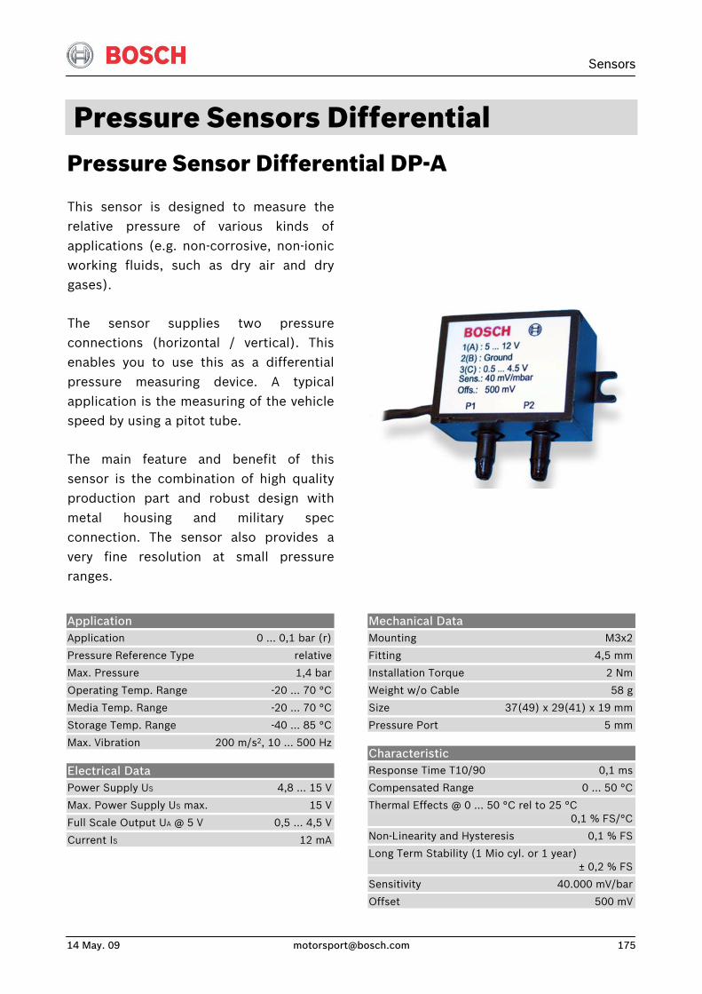
Sensors
14 May. 09 [email protected] 175
Pressure Sensors Differential Pressure Sensor Differential DP-A
This sensor is designed to measure therelative pressure of various kinds ofapplications (e.g. non-corrosive, non-ionic working fluids, such as dry air and drygases).
The sensor supplies two pressureconnections (horizontal / vertical). Thisenables you to use this as a differentialpressure measuring device. A typicalapplication is the measuring of the vehiclespeed by using a pitot tube.
The main feature and benefit of thissensor is the combination of high qualityproduction part and robust design withmetal housing and military specconnection. The sensor also provides avery fine resolution at small pressureranges.
Application Application 0 … 0,1 bar (r)
Pressure Reference Type relative
Max. Pressure 1,4 bar
Operating Temp. Range -20 … 70 °C
Media Temp. Range -20 … 70 °C
Storage Temp. Range -40 ... 85 °C
Max. Vibration 200 m/s2, 10 … 500 Hz
Electrical Data Power Supply US 4,8 ... 15 V
Max. Power Supply US max. 15 V
Full Scale Output UA @ 5 V 0,5 … 4,5 V
Current IS 12 mA
Mechanical Data Mounting M3x2
Fitting 4,5 mm
Installation Torque 2 Nm
Weight w/o Cable 58 g
Size 37(49) x 29(41) x 19 mm
Pressure Port 5 mm
Characteristic Response Time T10/90 0,1 ms
Compensated Range 0 … 50 °C
Thermal Effects @ 0 ... 50 °C rel to 25 °C 0,1 % FS/°C
Non-Linearity and Hysteresis 0,1 % FS
Long Term Stability (1 Mio cyl. or 1 year) ± 0,2 % FS
Sensitivity 40.000 mV/bar
Offset 500 mV
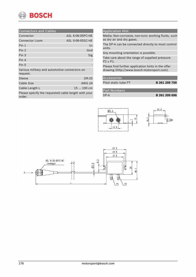
Connectors and Cables Connector ASL 6-06-05PC-HE
Connector Loom ASL 0-06-05SC-HE
Pin 1 US
Pin 2 Gnd
Pin 3 Sig
Pin 4 -
Pin 5 -
Various military and automotive connectors on request.
Sleeve DR-25
Cable Size AWG 24
Cable Length L 15 … 100 cm
Please specify the requested cable length with your order.
Application Hint Media: Non-corrosive, non-ionic working fluids, such as dry air and dry gases.
The DP-A can be connected directly to most control units.
Any mounting orientation is possible.
Take care about the range of supplied pressure: P2 ≥ P1.
Please find further application hints in the offer drawing (http://www.bosch-motorsport.com).
Accessories Pitot static tube PT B 261 209 700
Part Numbers DP-A B 261 209 696

Sensors
14 May. 09 [email protected] 177
Pressure Sensor Differential DP-C
This sensor is designed to measure therelative pressure of various kinds ofapplications (e.g. non-corrosive, non-ionic working fluids, such as dry air and drygases).
The sensor supplies two pressureconnections (horizontal / vertical). Thisenables you to use this as a differentialpressure measuring device. A typicallyapplication is the measuring of the vehiclespeed by using a pitot tube.
The main feature and benefit of thissensor is the combination of high quality,small size, and military spec connection.The sensor provides a very fine resolutionat small pressure ranges.
Application Application 0 … 0,1 bar (r)
Pressure Reference Type relative
Max. Pressure p_absmax 1,4 bar
Operating Temperature Range -20 … 70 °C
Media Temperature Range -20 … 70 °C
Storage Temperature Range -40 … 85 °C
Max. Vibration 200 m/s2, 10 … 500 Hz
Electrical data Power supply US 4,8 … 15 V
Max Power Supply US max. 15 V
Full Scale Output UA 0,5 … 4,5 V
Current IS 12 mA
Mechanical data Mounting 2 x M2,5
Fitting 2,6 mm
Installation Torque 2 Nm
Weight w/o Cable 24 g
Size 35 x 25(40) x 18 mm
Pressure Port 5 mm
Characteristic Response Time T10/90 0,1 ms
Compensated Range 0 … 50 °C
Thermal Effects @ 0 ... 50 °C rel to 25 °C 0,1 % FS/°C
Non-Linearity and Hysteresis 0,1 % FS
Long Term Stability (1 Mio cyl or 1 year) ± 0,2 % FS
Sensitivity 40 mV/mbar
Offset 500 mV
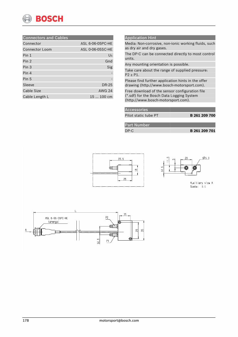
Application Hint Media: Non-corrosive, non-ionic working fluids, such as dry air and dry gases.
The DP-C can be connected directly to most control units.
Any mounting orientation is possible.
Take care about the range of supplied pressure: P2 ≥ P1.
Please find further application hints in the offer drawing (http://www.bosch-motorsport.com).
Free download of the sensor configuration file (*.sdf) for the Bosch Data Logging System (http://www.bosch-motorsport.com).
Connectors and Cables Connector ASL 6-06-05PC-HE
Connector Loom ASL 0-06-05SC-HE
Pin 1 US
Pin 2 Gnd
Pin 3 Sig
Pin 4 -
Pin 5 -
Sleeve DR-25
Cable Size AWG 24
Cable Length L 15 … 100 cm
Accessories Pitot static tube PT
Part Number DP-C
B 261 209 700
B 261 209 701
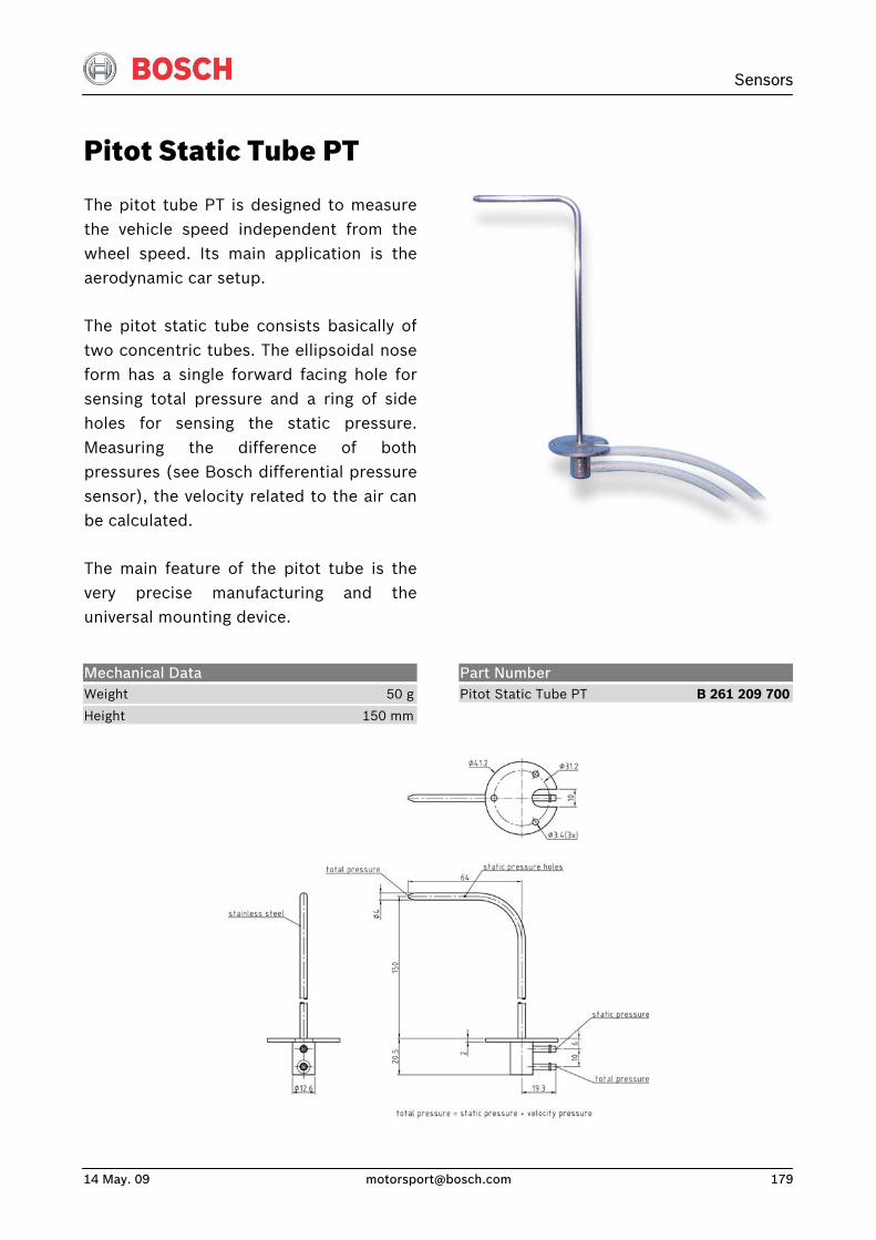
Sensors
14 May. 09 [email protected] 179
Pitot Static Tube PT
The pitot tube PT is designed to measurethe vehicle speed independent from thewheel speed. Its main application is theaerodynamic car setup.
The pitot static tube consists basically oftwo concentric tubes. The ellipsoidal noseform has a single forward facing hole forsensing total pressure and a ring of sideholes for sensing the static pressure.Measuring the difference of bothpressures (see Bosch differential pressuresensor), the velocity related to the air canbe calculated.
The main feature of the pitot tube is thevery precise manufacturing and theuniversal mounting device.
Mechanical Data Weight 50 g
Height 150 mm
Part Number Pitot Static Tube PT B 261 209 700
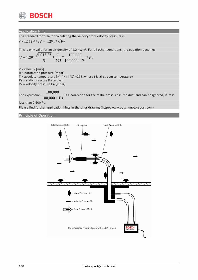
Application Hint The standard formula for calculating the velocity from velocity pressure is:
V = 1.291 √ Pv PvV *291.1= This is only valid for an air density of 1.2 kg/m³. For all other conditions, the equation becomes:
PvPs
TB
V *000,100
000,100*293
*25.013,1
291.1+
=
V = velocity [m/s] B = barometric pressure [mbar] T = absolute temperature [K] ( = t [°C] +273; where t is airstream temperature) Ps = static pressure Pa [mbar] Pv = velocity pressure Pa [mbar]
The expression Ps+000,100
000,100 is a correction for the static pressure in the duct and can be ignored, if Ps is
less than 2,500 Pa.
Please find further application hints in the offer drawing (http://www.bosch-motorsport.com)
Principle of Operation
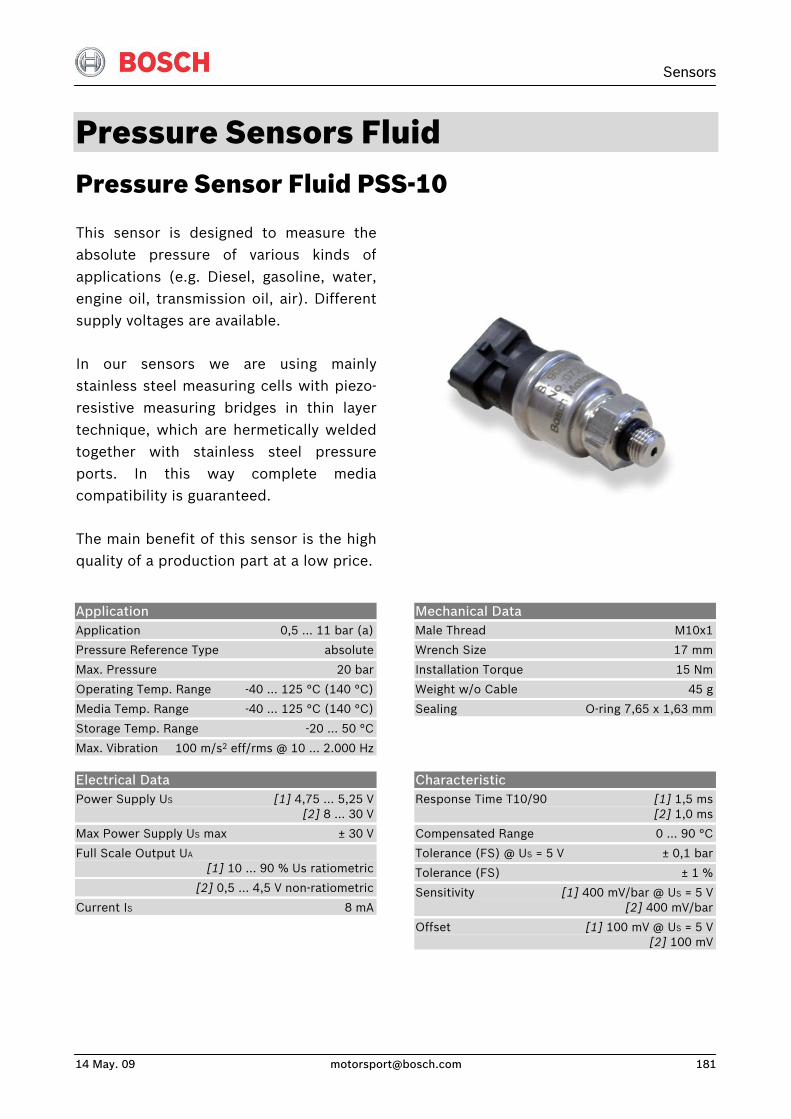
Sensors
14 May. 09 [email protected] 181
Pressure Sensors Fluid Pressure Sensor Fluid PSS-10
This sensor is designed to measure theabsolute pressure of various kinds of applications (e.g. Diesel, gasoline, water,engine oil, transmission oil, air). Differentsupply voltages are available.
In our sensors we are using mainly stainless steel measuring cells with piezo-resistive measuring bridges in thin layer technique, which are hermetically welded together with stainless steel pressureports. In this way complete mediacompatibility is guaranteed.
The main benefit of this sensor is the highquality of a production part at a low price.
Application Application 0,5 … 11 bar (a)
Pressure Reference Type absolute
Max. Pressure 20 bar
Operating Temp. Range -40 … 125 °C (140 °C)
Media Temp. Range -40 … 125 °C (140 °C)
Storage Temp. Range -20 … 50 °C
Max. Vibration 100 m/s2 eff/rms @ 10 … 2.000 Hz
Mechanical Data Male Thread M10x1
Wrench Size 17 mm
Installation Torque 15 Nm
Weight w/o Cable 45 g
Sealing O-ring 7,65 x 1,63 mm
Electrical Data Power Supply US [1] 4,75 … 5,25 V [2] 8 … 30 V
Max Power Supply US max ± 30 V
Full Scale Output UA [1] 10 … 90 % Us ratiometric
[2] 0,5 … 4,5 V non-ratiometric
Current IS 8 mA
Characteristic Response Time T10/90 [1] 1,5 ms [2] 1,0 ms
Compensated Range 0 … 90 °C
Tolerance (FS) @ US = 5 V ± 0,1 bar
Tolerance (FS) ± 1 %
Sensitivity [1] 400 mV/bar @ US = 5 V [2] 400 mV/bar
Offset [1] 100 mV @ US = 5 V [2] 100 mV
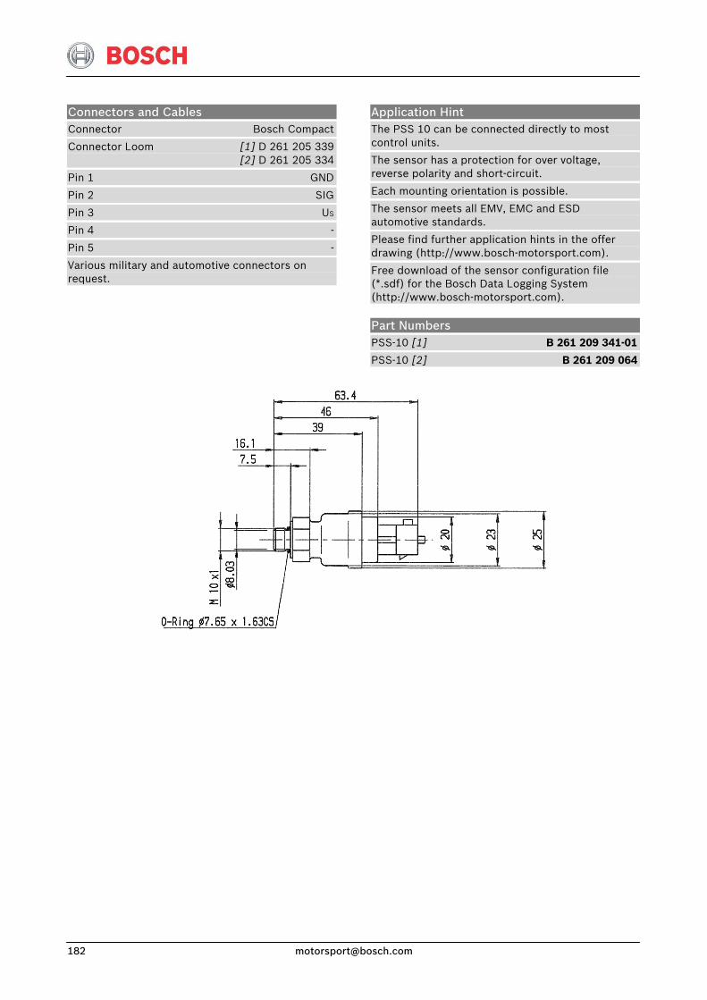
Connectors and Cables Connector Bosch Compact
Connector Loom [1] D 261 205 339 [2] D 261 205 334
Pin 1 GND
Pin 2 SIG
Pin 3 US
Pin 4 -
Pin 5 -
Various military and automotive connectors on request.
Application Hint The PSS 10 can be connected directly to most control units.
The sensor has a protection for over voltage, reverse polarity and short-circuit.
Each mounting orientation is possible.
The sensor meets all EMV, EMC and ESD automotive standards.
Please find further application hints in the offer drawing (http://www.bosch-motorsport.com).
Free download of the sensor configuration file (*.sdf) for the Bosch Data Logging System (http://www.bosch-motorsport.com).
Part Numbers PSS-10 [1] B 261 209 341-01
PSS-10 [2] B 261 209 064
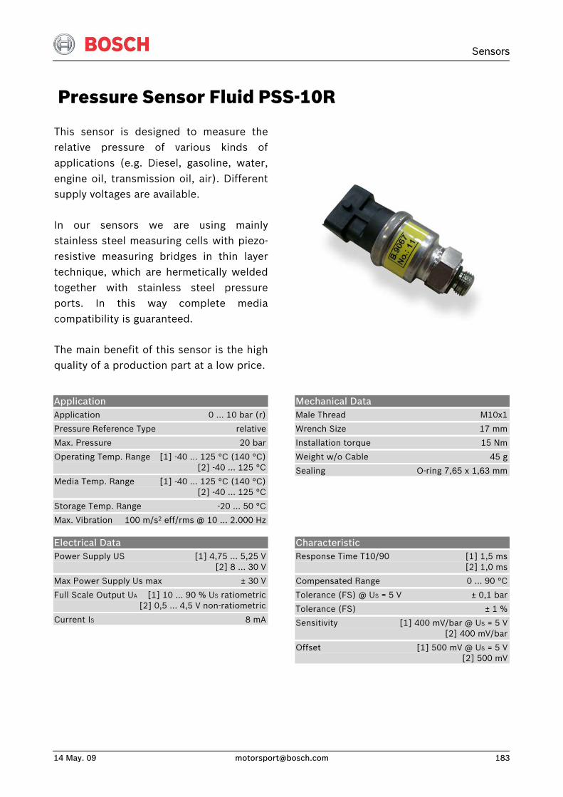
Sensors
14 May. 09 [email protected] 183
Pressure Sensor Fluid PSS-10R
This sensor is designed to measure therelative pressure of various kinds of applications (e.g. Diesel, gasoline, water,engine oil, transmission oil, air). Differentsupply voltages are available.
In our sensors we are using mainly stainless steel measuring cells with piezo-resistive measuring bridges in thin layer technique, which are hermetically welded together with stainless steel pressureports. In this way complete mediacompatibility is guaranteed.
The main benefit of this sensor is the highquality of a production part at a low price.
Application Application 0 … 10 bar (r)
Pressure Reference Type relative
Max. Pressure 20 bar
Operating Temp. Range [1] -40 … 125 °C (140 °C) [2] -40 … 125 °C
Media Temp. Range [1] -40 … 125 °C (140 °C) [2] -40 … 125 °C
Storage Temp. Range -20 … 50 °C
Max. Vibration 100 m/s2 eff/rms @ 10 … 2.000 Hz
Mechanical Data Male Thread M10x1
Wrench Size 17 mm
Installation torque 15 Nm
Weight w/o Cable 45 g
Sealing O-ring 7,65 x 1,63 mm
Electrical Data Power Supply US [1] 4,75 … 5,25 V [2] 8 … 30 V
Max Power Supply Us max ± 30 V
Full Scale Output UA [1] 10 … 90 % US ratiometric [2] 0,5 … 4,5 V non-ratiometric
Current IS 8 mA
Characteristic Response Time T10/90 [1] 1,5 ms [2] 1,0 ms
Compensated Range 0 … 90 °C
Tolerance (FS) @ US = 5 V ± 0,1 bar
Tolerance (FS) ± 1 %
Sensitivity [1] 400 mV/bar @ US = 5 V [2] 400 mV/bar
Offset [1] 500 mV @ US = 5 V [2] 500 mV
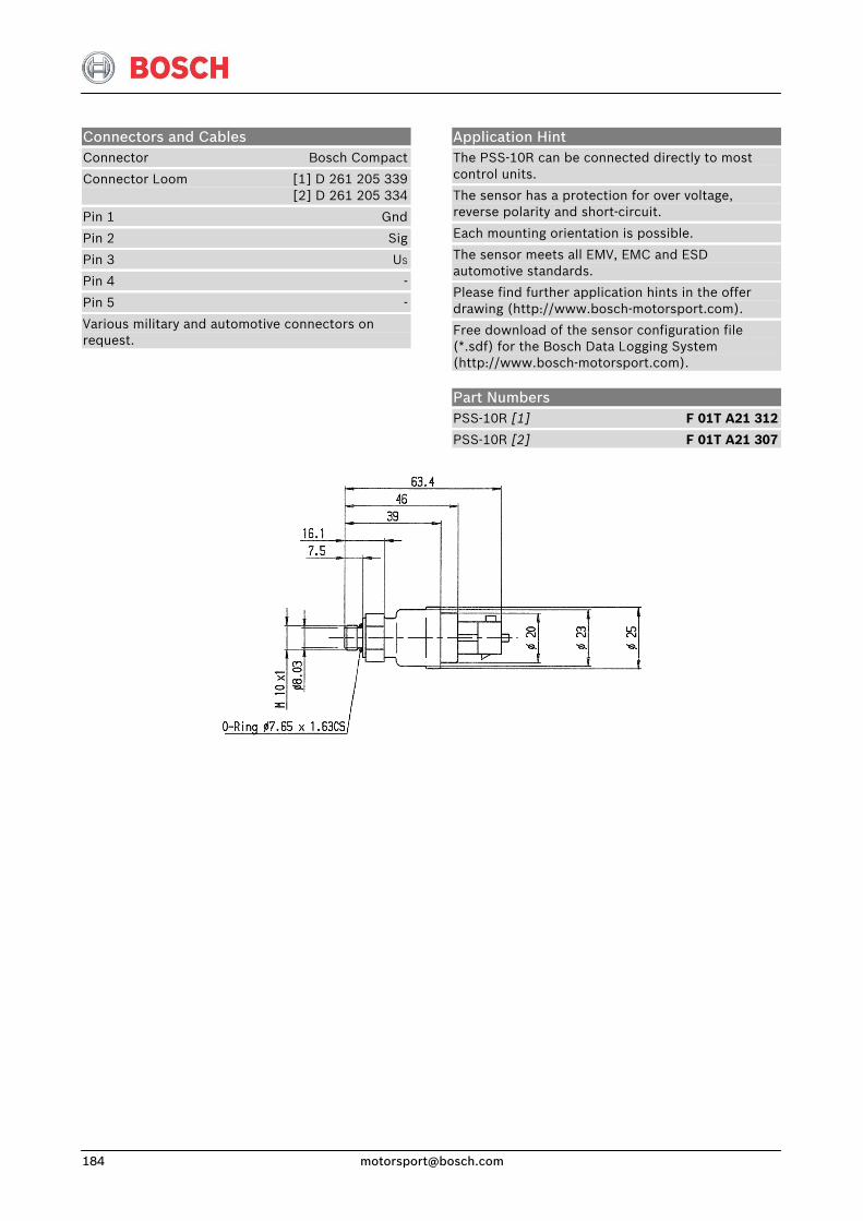
Connectors and Cables Connector Bosch Compact
Connector Loom [1] D 261 205 339 [2] D 261 205 334
Pin 1 Gnd
Pin 2 Sig
Pin 3 US
Pin 4 -
Pin 5 -
Various military and automotive connectors on request.
Application Hint The PSS-10R can be connected directly to most control units.
The sensor has a protection for over voltage, reverse polarity and short-circuit.
Each mounting orientation is possible.
The sensor meets all EMV, EMC and ESD automotive standards.
Please find further application hints in the offer drawing (http://www.bosch-motorsport.com).
Free download of the sensor configuration file (*.sdf) for the Bosch Data Logging System (http://www.bosch-motorsport.com).
Part Numbers PSS-10R [1] F 01T A21 312
PSS-10R [2] F 01T A21 307
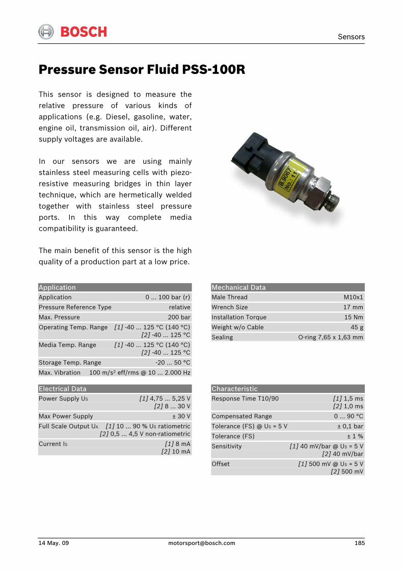
Sensors
14 May. 09 [email protected] 185
Pressure Sensor Fluid PSS-100R
This sensor is designed to measure therelative pressure of various kinds of applications (e.g. Diesel, gasoline, water,engine oil, transmission oil, air). Differentsupply voltages are available.
In our sensors we are using mainly stainless steel measuring cells with piezo-resistive measuring bridges in thin layer technique, which are hermetically welded together with stainless steel pressureports. In this way complete mediacompatibility is guaranteed.
The main benefit of this sensor is the highquality of a production part at a low price.
Application Application 0 … 100 bar (r)
Pressure Reference Type relative
Max. Pressure 200 bar
Operating Temp. Range [1] -40 … 125 °C (140 °C) [2] -40 … 125 °C
Media Temp. Range [1] -40 … 125 °C (140 °C) [2] -40 … 125 °C
Storage Temp. Range -20 … 50 °C
Max. Vibration 100 m/s2 eff/rms @ 10 … 2.000 Hz
Mechanical Data Male Thread M10x1
Wrench Size 17 mm
Installation Torque 15 Nm
Weight w/o Cable 45 g
Sealing O-ring 7,65 x 1,63 mm
Electrical Data Power Supply US [1] 4,75 … 5,25 V [2] 8 … 30 V
Max Power Supply ± 30 V
Full Scale Output UA [1] 10 … 90 % US ratiometric [2] 0,5 … 4,5 V non-ratiometric
Current IS [1] 8 mA [2] 10 mA
Characteristic Response Time T10/90 [1] 1,5 ms [2] 1,0 ms
Compensated Range 0 … 90 °C
Tolerance (FS) @ US = 5 V ± 0,1 bar
Tolerance (FS) ± 1 %
Sensitivity [1] 40 mV/bar @ US = 5 V [2] 40 mV/bar
Offset [1] 500 mV @ US = 5 V [2] 500 mV
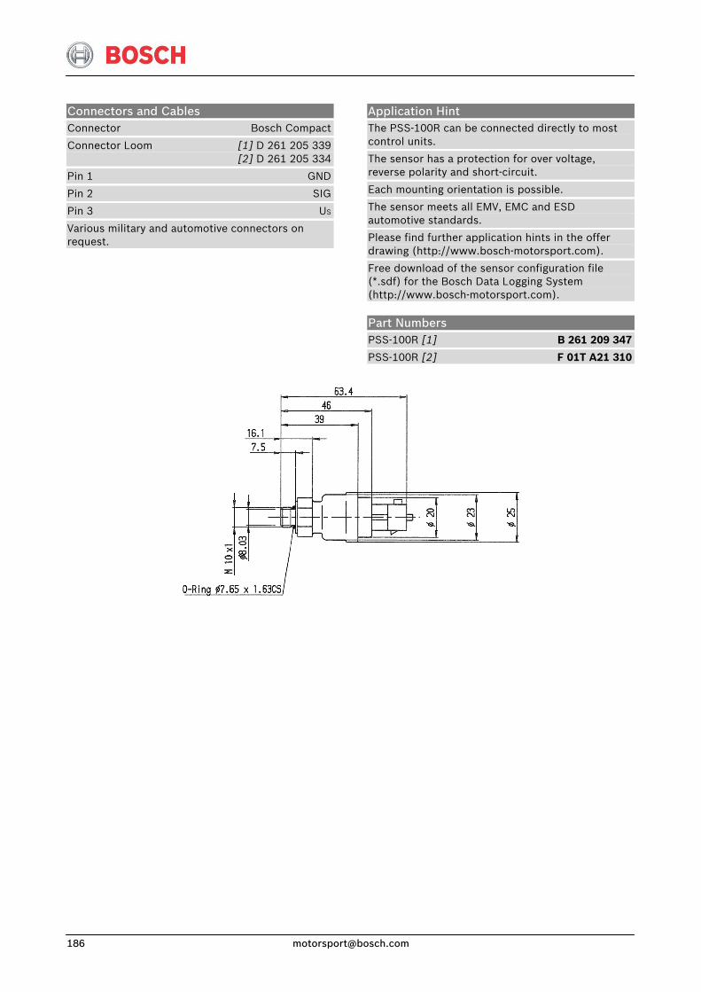
Connectors and Cables Connector Bosch Compact
Connector Loom [1] D 261 205 339 [2] D 261 205 334
Pin 1 GND
Pin 2 SIG
Pin 3 US
Various military and automotive connectors on request.
Application Hint The PSS-100R can be connected directly to most control units.
The sensor has a protection for over voltage, reverse polarity and short-circuit.
Each mounting orientation is possible.
The sensor meets all EMV, EMC and ESD automotive standards.
Please find further application hints in the offer drawing (http://www.bosch-motorsport.com).
Free download of the sensor configuration file (*.sdf) for the Bosch Data Logging System (http://www.bosch-motorsport.com).
Part Numbers PSS-100R [1] B 261 209 347
PSS-100R [2] F 01T A21 310
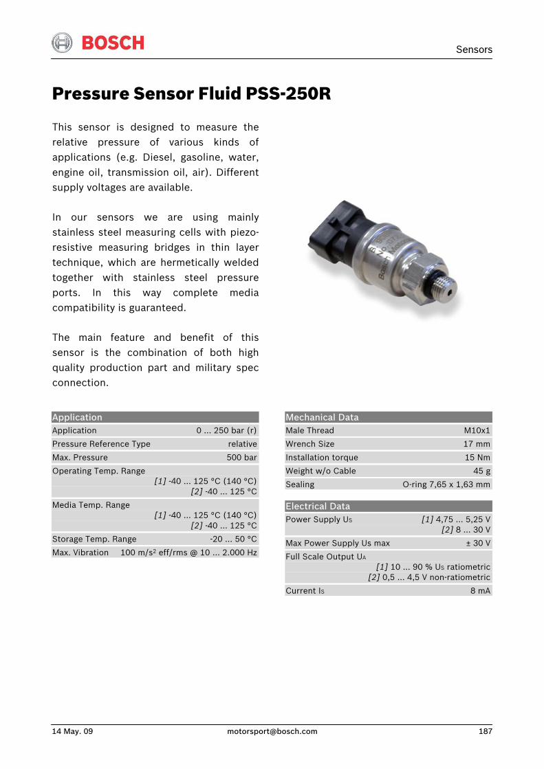
Sensors
14 May. 09 [email protected] 187
Pressure Sensor Fluid PSS-250R
This sensor is designed to measure therelative pressure of various kinds of applications (e.g. Diesel, gasoline, water,engine oil, transmission oil, air). Differentsupply voltages are available.
In our sensors we are using mainly stainless steel measuring cells with piezo-resistive measuring bridges in thin layer technique, which are hermetically welded together with stainless steel pressureports. In this way complete mediacompatibility is guaranteed.
The main feature and benefit of this sensor is the combination of both highquality production part and military specconnection.
Application Application 0 … 250 bar (r)
Pressure Reference Type relative
Max. Pressure 500 bar
Operating Temp. Range [1] -40 … 125 °C (140 °C) [2] -40 … 125 °C
Media Temp. Range [1] -40 … 125 °C (140 °C) [2] -40 … 125 °C
Storage Temp. Range -20 … 50 °C
Max. Vibration 100 m/s2 eff/rms @ 10 … 2.000 Hz
Mechanical Data Male Thread M10x1
Wrench Size 17 mm
Installation torque 15 Nm
Weight w/o Cable 45 g
Sealing O-ring 7,65 x 1,63 mm
Electrical Data Power Supply US [1] 4,75 … 5,25 V [2] 8 ... 30 V
Max Power Supply Us max ± 30 V
Full Scale Output UA [1] 10 … 90 % US ratiometric [2] 0,5 … 4,5 V non-ratiometric
Current IS 8 mA
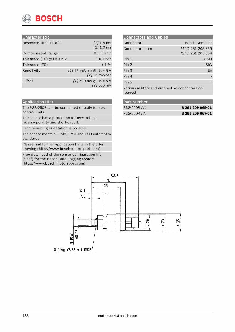
Characteristic Response Time T10/90 [1] 1,5 ms [2] 1,0 ms
Compensated Range 0 … 90 °C
Tolerance (FS) @ US = 5 V ± 0,1 bar
Tolerance (FS) ± 1 %
Sensitivity [1] 16 mV/bar @ US = 5 V [2] 16 mV/bar
Offset [1] 500 mV @ US = 5 V [2] 500 mV
Connectors and Cables Connector Bosch Compact
Connector Loom [1] D 261 205 339 [2] D 261 205 334
Pin 1 GND
Pin 2 SIG
Pin 3 US
Pin 4 -
Pin 5 -
Various military and automotive connectors on request.
Application Hint The PSS-250R can be connected directly to most control units.
The sensor has a protection for over voltage, reverse polarity and short-circuit.
Each mounting orientation is possible.
The sensor meets all EMV, EMC and ESD automotive standards.
Please find further application hints in the offer drawing (http://www.bosch-motorsport.com).
Free download of the sensor configuration file (*.sdf) for the Bosch Data Logging System (http://www.bosch-motorsport.com).
Part Number PSS-250R [1] B 261 209 965-01
PSS-250R [2] B 261 209 067-01
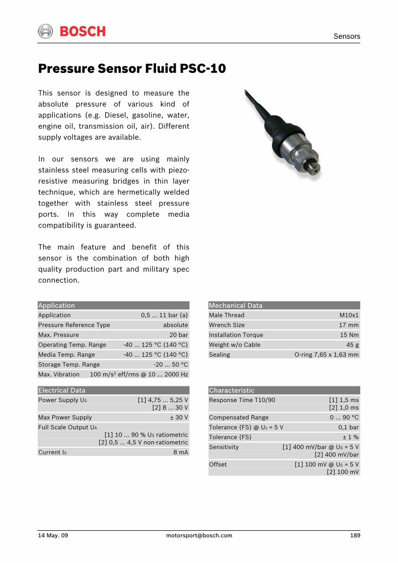
Sensors
14 May. 09 [email protected] 189
Pressure Sensor Fluid PSC-10
This sensor is designed to measure theabsolute pressure of various kind ofapplications (e.g. Diesel, gasoline, water,engine oil, transmission oil, air). Differentsupply voltages are available.
In our sensors we are using mainlystainless steel measuring cells with piezo-resistive measuring bridges in thin layertechnique, which are hermetically weldedtogether with stainless steel pressureports. In this way complete mediacompatibility is guaranteed.
The main feature and benefit of thissensor is the combination of both highquality production part and military specconnection.
Application Application 0,5 … 11 bar (a)
Pressure Reference Type absolute
Max. Pressure 20 bar
Operating Temp. Range -40 … 125 °C (140 °C)
Media Temp. Range -40 … 125 °C (140 °C)
Storage Temp. Range -20 … 50 °C
Max. Vibration 100 m/s2 eff/rms @ 10 … 2000 Hz
Mechanical Data Male Thread M10x1
Wrench Size 17 mm
Installation Torque 15 Nm
Weight w/o Cable 45 g
Sealing O-ring 7,65 x 1,63 mm
Electrical Data Power Supply US [1] 4,75 … 5,25 V [2] 8 … 30 V
Max Power Supply ± 30 V
Full Scale Output UA [1] 10 … 90 % US ratiometric [2] 0,5 … 4,5 V non-ratiometric
Current IS 8 mA
Characteristic Response Time T10/90 [1] 1,5 ms [2] 1,0 ms
Compensated Range 0 … 90 °C
Tolerance (FS) @ US = 5 V 0,1 bar
Tolerance (FS) ± 1 %
Sensitivity [1] 400 mV/bar @ US = 5 V [2] 400 mV/bar
Offset [1] 100 mV @ US = 5 V [2] 100 mV
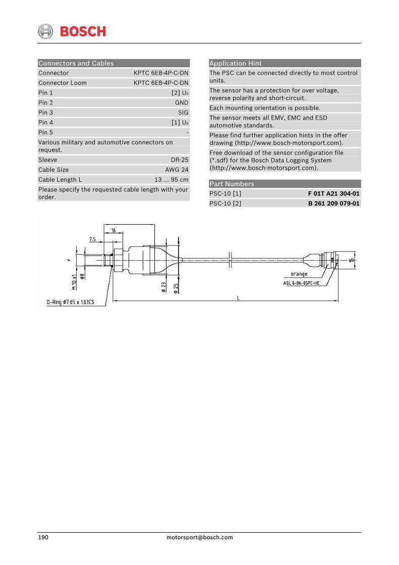
Connectors and Cables Connector KPTC 6E8-4P-C-DN
Connector Loom KPTC 6E8-4P-C-DN
Pin 1 [2] US
Pin 2 GND
Pin 3 SIG
Pin 4 [1] US
Pin 5 -
Various military and automotive connectors on request.
Sleeve DR-25
Cable Size AWG 24
Cable Length L 13 … 95 cm
Please specify the requested cable length with your order.
Application Hint The PSC can be connected directly to most control units.
The sensor has a protection for over voltage, reverse polarity and short-circuit.
Each mounting orientation is possible.
The sensor meets all EMV, EMC and ESD automotive standards.
Please find further application hints in the offer drawing (http://www.bosch-motorsport.com).
Free download of the sensor configuration file (*.sdf) for the Bosch Data Logging System (http://www.bosch-motorsport.com).
Part Numbers PSC-10 [1] F 01T A21 304-01
PSC-10 [2] B 261 209 079-01

Sensors
14 May. 09 [email protected] 191
Pressure Sensor Fluid PSC-10R
This sensor is designed to measure therelative pressure of various kinds of applications (e.g. Diesel, gasoline, water,engine oil, transmission oil, air).
In our sensors we are using mainly stainless steel measuring cells with piezo-resistive measuring bridges in thin layer technique, which are hermetically weldedtogether with stainless steel pressureports. In this way complete mediacompatibility is guaranteed.
The main feature and benefit of this sensor is the combination of both highquality production part and military specconnection.
Application Application 0 … 10 bar (r)
Pressure Reference Type relative
Max. Pressure 20 bar
Operating Temp. Range [1] -40 … 125 °C (140 °C) [2] -40 ... 125 °C
Media Temp. Range [1] -40 … 125 °C (140 °C)
[2] -40 ... 125 °C
Storage Temp. Range -20 … 50 °C
Max. Vibration 100 m/s2 eff/rms @ 10 … 2.000 Hz
Mechanical Data Male Thread M10x1
Wrench Size 17 mm
Installation Torque 15 Nm
Weight w/o Cable 45 g
Sealing O-ring 7,65 x 1,63 mm
Electrical Data Power Supply US [1] 4,75 … 5,25 V [2] 8 … 30 V
Max Power Supply US max. ± 30 V
Full Scale Output UA [1] 10 … 90 % US ratiometric [2] 0,5 … 4,5 V non-ratiometric
Current IS 8 mA
Characteristic Response Time T10/90 [1] 1,5 ms [2] 1,0 ms
Compensated Range 0 … 90 °C
Tolerance (FS) @ US = 5 V ± 0,1 bar
Tolerance (FS) ± 1 %
Sensitivity [1] 400 mV/bar @ US = 5 V [2] 400 mV/bar
Offset [1] 500 mV @ US = 5 V [2] 500 mV
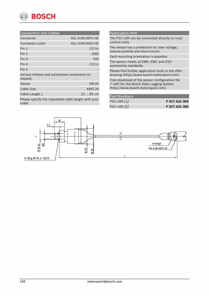
Connectors and Cables Connector ASL 6-06-05PC-HE
Connector Loom ASL 0-06-05SC-HE
Pin 1 [2] US
Pin 2 GND
Pin 3 SIG
Pin 4 [1] US
Pin 5 -
Various military and automotive connectors on request.
Sleeve DR-25
Cable Size AWG 24
Cable Length L 13 … 95 cm
Please specify the requested cable length with your order.
Application Hint The PSC-10R can be connected directly to most control units.
The sensor has a protection for over voltage, reverse polarity and short-circuit.
Each mounting orientation is possible.
The sensor meets all EMV, EMC and ESD automotive standards.
Please find further application hints in the offer drawing (http://www.bosch-motorsport.com).
Free download of the sensor configuration file (*.sdf) for the Bosch Data Logging System (http://www.bosch-motorsport.com).
Part Numbers PSC-10R [1] F 01T A21 303
PSC-10R [2] F 01T A21 305
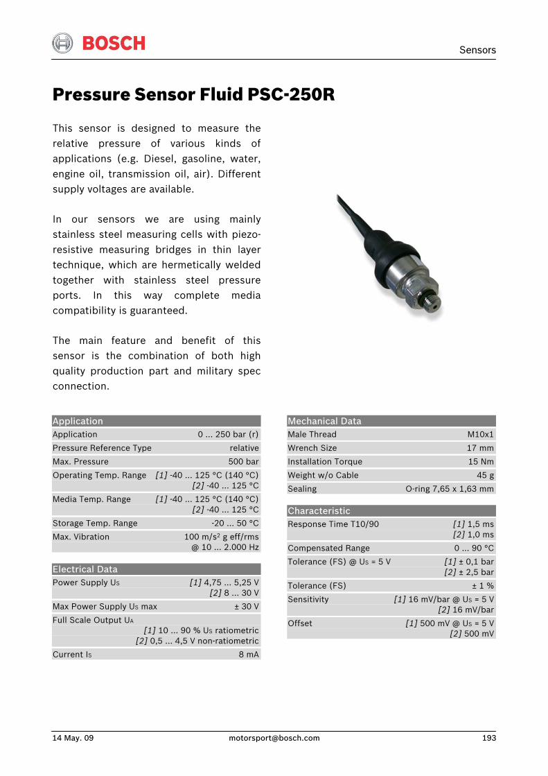
Sensors
14 May. 09 [email protected] 193
Pressure Sensor Fluid PSC-250R
This sensor is designed to measure therelative pressure of various kinds of applications (e.g. Diesel, gasoline, water,engine oil, transmission oil, air). Differentsupply voltages are available.
In our sensors we are using mainly stainless steel measuring cells with piezo-resistive measuring bridges in thin layer technique, which are hermetically weldedtogether with stainless steel pressureports. In this way complete mediacompatibility is guaranteed.
The main feature and benefit of this sensor is the combination of both highquality production part and military specconnection.
Application Application 0 … 250 bar (r)
Pressure Reference Type relative
Max. Pressure 500 bar
Operating Temp. Range [1] -40 … 125 °C (140 °C) [2] -40 … 125 °C
Media Temp. Range [1] -40 ... 125 °C (140 °C) [2] -40 … 125 °C
Storage Temp. Range -20 … 50 °C
Max. Vibration 100 m/s2 g eff/rms @ 10 … 2.000 Hz
Electrical Data Power Supply US [1] 4,75 ... 5,25 V [2] 8 … 30 V
Max Power Supply US max ± 30 V
Full Scale Output UA [1] 10 … 90 % US ratiometric [2] 0,5 … 4,5 V non-ratiometric
Current IS 8 mA
Mechanical Data Male Thread M10x1
Wrench Size 17 mm
Installation Torque 15 Nm
Weight w/o Cable 45 g
Sealing O-ring 7,65 x 1,63 mm
Characteristic Response Time T10/90 [1] 1,5 ms [2] 1,0 ms
Compensated Range 0 … 90 °C
Tolerance (FS) @ US = 5 V [1] ± 0,1 bar [2] ± 2,5 bar
Tolerance (FS) ± 1 %
Sensitivity [1] 16 mV/bar @ US = 5 V [2] 16 mV/bar
Offset [1] 500 mV @ US = 5 V [2] 500 mV
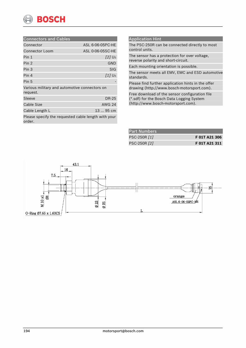
Connectors and Cables Connector ASL 6-06-05PC-HE
Connector Loom ASL 0-06-05SC-HE
Pin 1 [2] US
Pin 2 GND
Pin 3 SIG
Pin 4 [1] US
Pin 5 -
Various military and automotive connectors on request.
Sleeve DR-25
Cable Size AWG 24
Cable Length L 13 … 95 cm
Please specify the requested cable length with your order.
Application Hint The PSC-250R can be connected directly to most control units.
The sensor has a protection for over voltage, reverse polarity and short-circuit.
Each mounting orientation is possible.
The sensor meets all EMV, EMC and ESD automotive standards.
Please find further application hints in the offer drawing (http://www.bosch-motorsport.com).
Free download of the sensor configuration file (*.sdf) for the Bosch Data Logging System (http://www.bosch-motorsport.com).
Part Numbers PSC-250R [1] F 01T A21 306
PSC-250R [2] F 01T A21 311
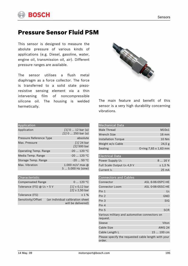
Sensors
14 May. 09 [email protected] 195
Pressure Sensor Fluid PSM
This sensor is designed to measure theabolute pressure of various kinds of applications (e.g. Diesel, gasoline, water,engine oil, transmission oil, air). Differentpressure ranges are available.
The sensor utilises a flush metaldiaphragm as a force collector. The forceis transferred to a solid state piezo-resistive sensing element via a thinintervening film of noncompressiblesilicone oil. The housing is weldedhermetically.
The main feature and benefit of this sensor is a very high durability concerning vibrations.
Application Application [1] 0 … 12 bar (a) [2] 0 … 250 bar (a)
Pressure Reference Type absolute
Max. Pressure [1] 24 bar [2] 500 bar
Operating Temp. Range -20 … 120 °C
Media Temp. Range -20 ... 120 °C
Storage Temp. Range -20 … 50 °C
Max. Vibration 1.000 m/s2 max @ 5 … 5.000 Hz (sine)
Mechanical Data Male Thread M10x1
Wrench Size 16 mm
Installation Torque 10 Nm
Weight w/o Cable 24,5 g
Sealing O-ring 7,65 x 1,63 mm
Electrical Data Power Supply US 8 … 16 V
Full Scale Output UA 4,9 V ± 1,5 %
Current IS 25 mA
Characteristic Compensated Range 0 … 120 °C
Tolerance (FS) @ US = 5 V [1] ± 0,12 bar [2] ± 2,50 bar
Tolerance (FS) ± 1 %
Sensitivity/Offset (an individual calibration sheet will be delivered)
Connectors and Cables Connector ASL 6-06-05PC-HE
Connector Loom ASL 0-06-05SC-HE
Pin 1 US
Pin 2 GND
Pin 3 SIG
Pin 4 -
Pin 5 SCR
Various military and automotive connectors on request.
Sleeve Viton
Cable Size AWG 24
Cable Length L 15 … 100 cm
Please specify the requested cable length with your order.
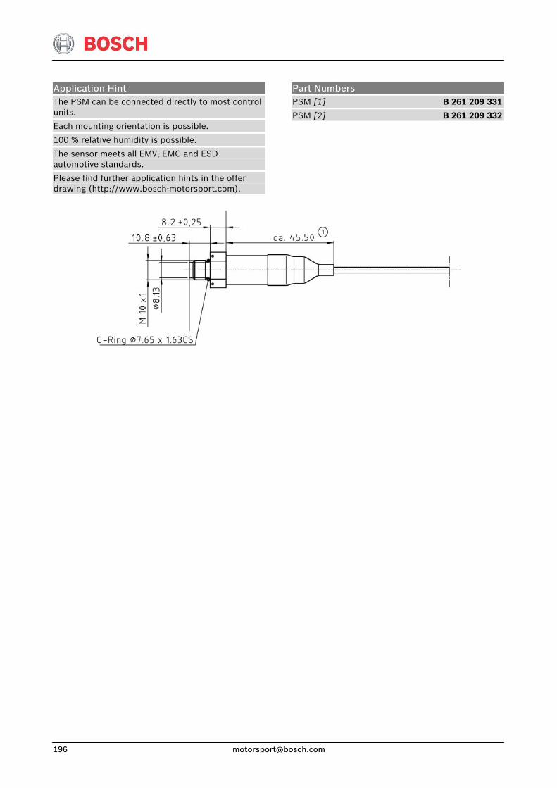
Application Hint The PSM can be connected directly to most control units.
Each mounting orientation is possible.
100 % relative humidity is possible.
The sensor meets all EMV, EMC and ESD automotive standards.
Please find further application hints in the offer drawing (http://www.bosch-motorsport.com).
Part Numbers PSM [1] B 261 209 331
PSM [2] B 261 209 332
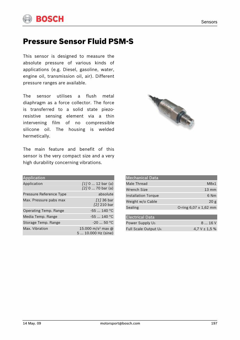
Sensors
14 May. 09 [email protected] 197
Pressure Sensor Fluid PSM-S
This sensor is designed to measure theabsolute pressure of various kinds of applications (e.g. Diesel, gasoline, water,engine oil, transmission oil, air). Differentpressure ranges are available.
The sensor utilises a flush metaldiaphragm as a force collector. The forceis transferred to a solid state piezo-resistive sensing element via a thinintervening film of no compressiblesilicone oil. The housing is weldedhermetically.
The main feature and benefit of this sensor is the very compact size and a veryhigh durability concerning vibrations.
Application Application [1] 0 … 12 bar (a) [2] 0 … 70 bar (a)
Pressure Reference Type absolute
Max. Pressure pabs max [1] 36 bar [2] 210 bar
Operating Temp. Range -55 … 140 °C
Media Temp. Range -55 … 140 °C
Storage Temp. Range -20 … 50 °C
Max. Vibration 15.000 m/s2 max @ 5 … 10.000 Hz (sine)
Mechanical Data Male Thread M8x1
Wrench Size 13 mm
Installation Torque 6 Nm
Weight w/o Cable 20 g
Sealing O-ring 6,07 x 1,62 mm
Electrical Data Power Supply US 8 … 16 V
Full Scale Output UA 4,7 V ± 1,5 %
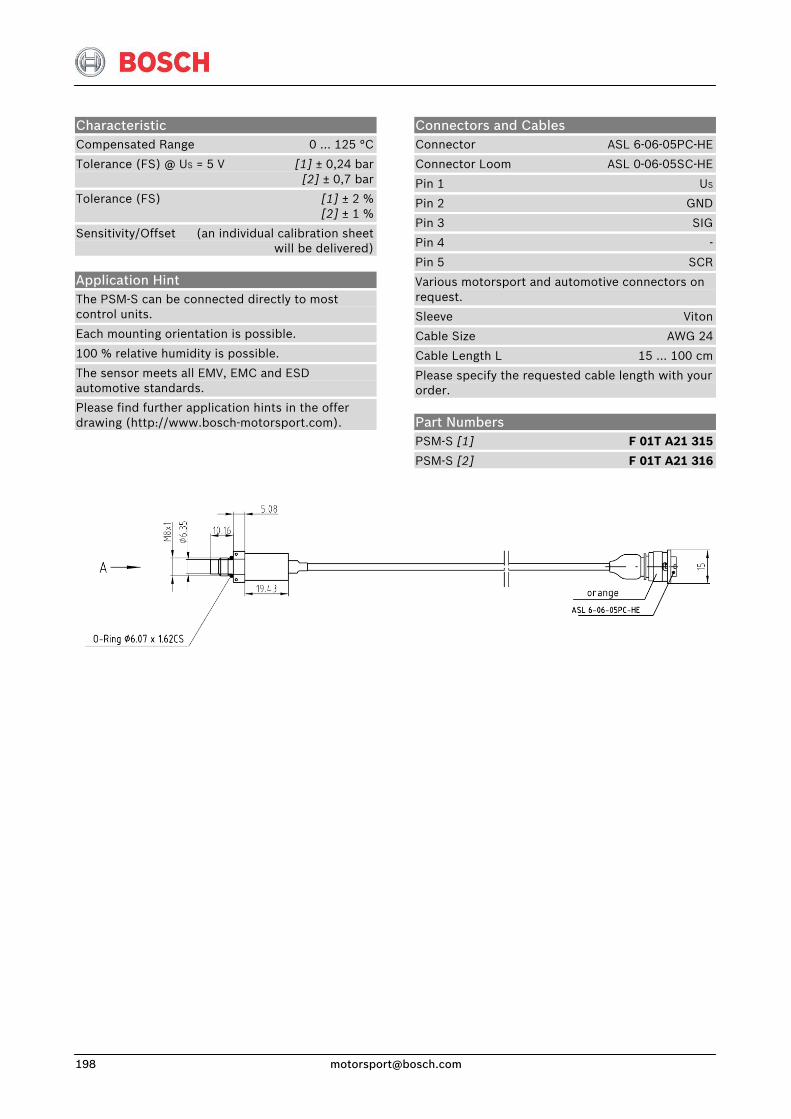
Connectors and Cables Connector ASL 6-06-05PC-HE
Connector Loom ASL 0-06-05SC-HE
Pin 1 US
Pin 2 GND
Pin 3 SIG
Pin 4 -
Pin 5 SCR
Various motorsport and automotive connectors on request.
Sleeve Viton
Cable Size AWG 24
Cable Length L 15 … 100 cm
Please specify the requested cable length with your order.
Characteristic Compensated Range 0 … 125 °C
Tolerance (FS) @ US = 5 V [1] ± 0,24 bar [2] ± 0,7 bar
Tolerance (FS) [1] ± 2 % [2] ± 1 %
Sensitivity/Offset (an individual calibration sheet will be delivered)
Application Hint The PSM-S can be connected directly to most control units.
Each mounting orientation is possible.
100 % relative humidity is possible.
The sensor meets all EMV, EMC and ESD automotive standards.
Please find further application hints in the offer drawing (http://www.bosch-motorsport.com). Part Numbers
PSM-S [1] F 01T A21 315
PSM-S [2] F 01T A21 316
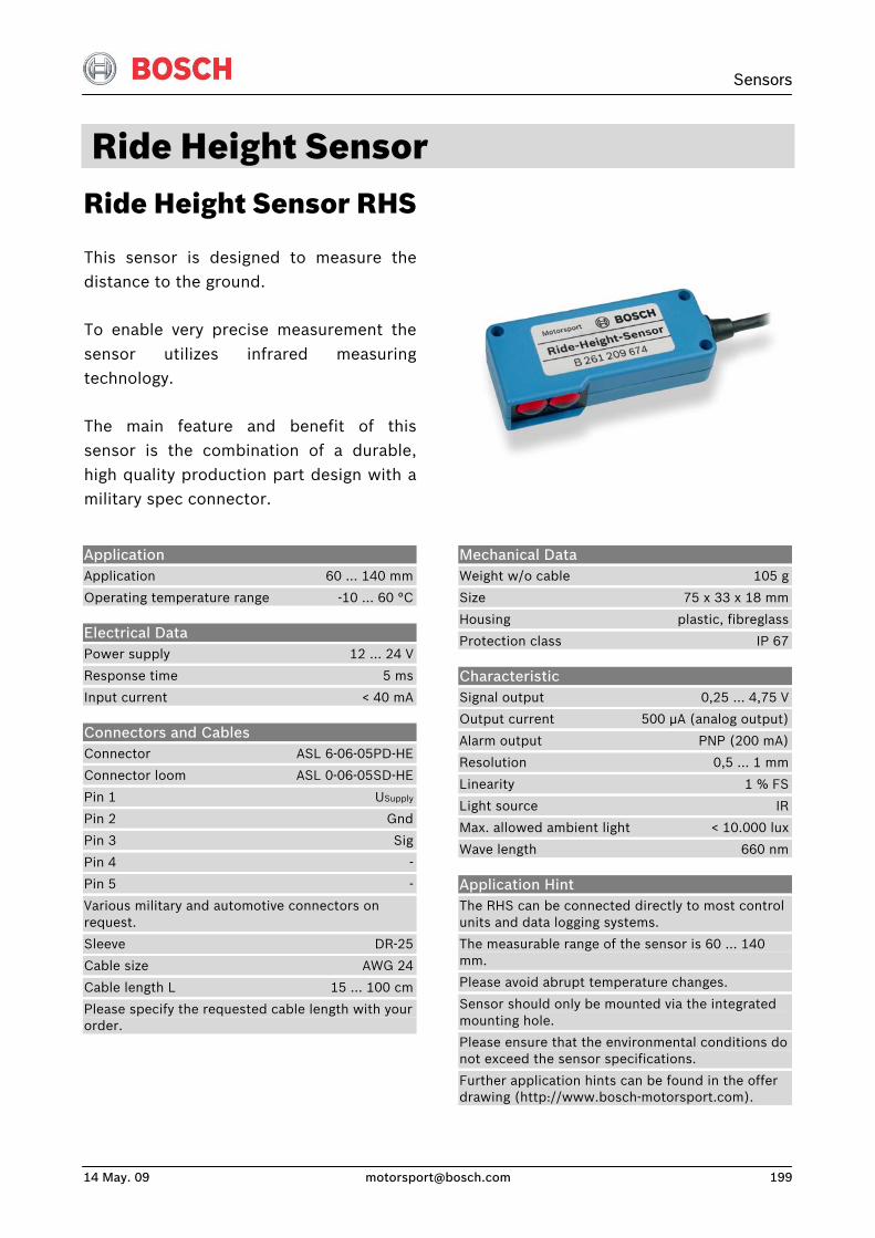
Sensors
14 May. 09 [email protected] 199
Ride Height Sensor Ride Height Sensor RHS
This sensor is designed to measure thedistance to the ground.
To enable very precise measurement thesensor utilizes infrared measuringtechnology.
The main feature and benefit of thissensor is the combination of a durable,high quality production part design with amilitary spec connector.
Application Application 60 … 140 mm
Operating temperature range -10 … 60 °C
Electrical Data Power supply 12 … 24 V
Response time 5 ms
Input current < 40 mA
Connectors and Cables Connector ASL 6-06-05PD-HE
Connector loom ASL 0-06-05SD-HE
Pin 1 USupply
Pin 2 Gnd
Pin 3 Sig
Pin 4 -
Pin 5 -
Various military and automotive connectors on request.
Sleeve DR-25
Cable size AWG 24
Cable length L 15 … 100 cm
Please specify the requested cable length with your order.
Mechanical Data Weight w/o cable 105 g
Size 75 x 33 x 18 mm
Housing plastic, fibreglass
Protection class IP 67
Characteristic Signal output 0,25 … 4,75 V
Output current 500 μA (analog output)
Alarm output PNP (200 mA)
Resolution 0,5 … 1 mm
Linearity 1 % FS
Light source IR
Max. allowed ambient light < 10.000 lux
Wave length 660 nm
Application Hint The RHS can be connected directly to most control units and data logging systems.
The measurable range of the sensor is 60 ... 140 mm.
Please avoid abrupt temperature changes.
Sensor should only be mounted via the integrated mounting hole.
Please ensure that the environmental conditions do not exceed the sensor specifications.
Further application hints can be found in the offer drawing (http://www.bosch-motorsport.com).
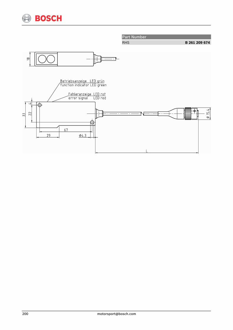
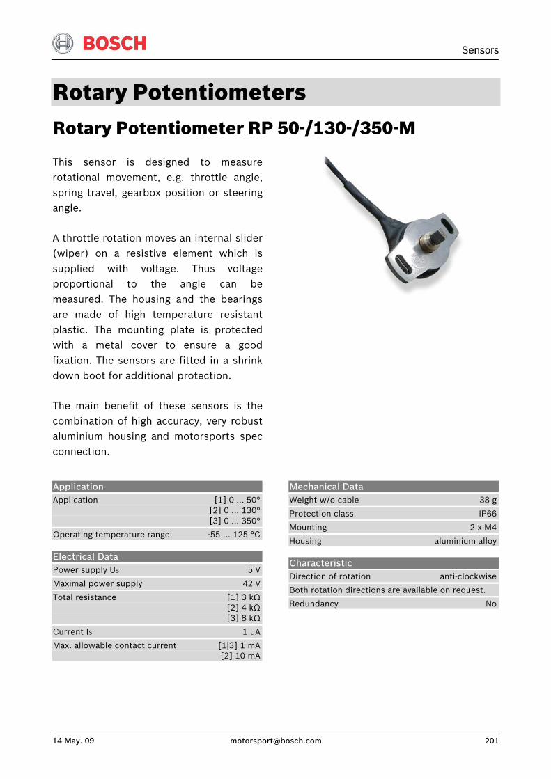
Sensors
14 May. 09 [email protected] 201
Rotary Potentiometers Rotary Potentiometer RP 50-/130-/350-M
This sensor is designed to measurerotational movement, e.g. throttle angle,spring travel, gearbox position or steeringangle.
A throttle rotation moves an internal slider(wiper) on a resistive element which issupplied with voltage. Thus voltageproportional to the angle can bemeasured. The housing and the bearingsare made of high temperature resistantplastic. The mounting plate is protectedwith a metal cover to ensure a goodfixation. The sensors are fitted in a shrinkdown boot for additional protection.
The main benefit of these sensors is thecombination of high accuracy, very robustaluminium housing and motorsports specconnection.
Application Application [1] 0 … 50° [2] 0 … 130° [3] 0 … 350°
Operating temperature range -55 … 125 °C
Electrical Data Power supply US 5 V
Maximal power supply 42 V
Total resistance [1] 3 kΩ [2] 4 kΩ [3] 8 kΩ
Current IS 1 μA
Max. allowable contact current [1|3] 1 mA [2] 10 mA
Mechanical Data Weight w/o cable 38 g
Protection class IP66
Mounting 2 x M4
Housing aluminium alloy
Characteristic Direction of rotation anti-clockwise
Both rotation directions are available on request.
Redundancy No
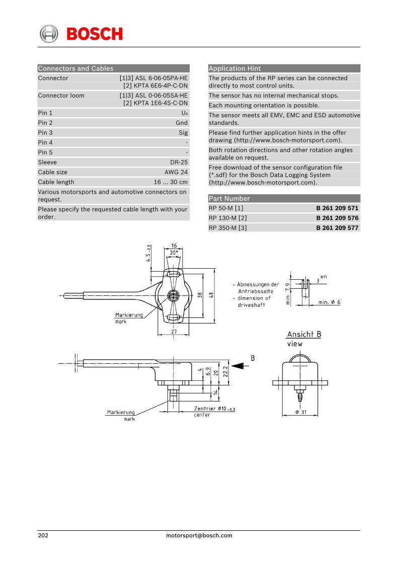
Connectors and Cables Connector [1|3] ASL 6-06-05PA-HE [2] KPTA 6E6-4P-C-DN
Connector loom [1|3] ASL 0-06-05SA-HE [2] KPTA 1E6-4S-C-DN
Pin 1 Us
Pin 2 Gnd
Pin 3 Sig
Pin 4 -
Pin 5 -
Sleeve DR-25
Cable size AWG 24
Cable length 16 … 30 cm
Various motorsports and automotive connectors on request.
Please specify the requested cable length with your order.
Application Hint The products of the RP series can be connected directly to most control units.
The sensor has no internal mechanical stops.
Each mounting orientation is possible.
The sensor meets all EMV, EMC and ESD automotive standards.
Please find further application hints in the offer drawing (http://www.bosch-motorsport.com).
Both rotation directions and other rotation angles available on request.
Free download of the sensor configuration file (*.sdf) for the Bosch Data Logging System (http://www.bosch-motorsport.com).
Part Number RP 50-M [1] B 261 209 571
RP 130-M [2] B 261 209 576
RP 350-M [3] B 261 209 577
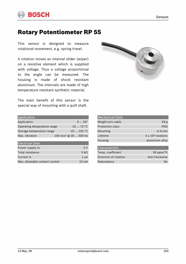
Sensors
14 May. 09 [email protected] 203
Rotary Potentiometer RP 55
This sensor is designed to measurerotational movement, e.g. spring travel.
A rotation moves an internal slider (wiper)on a resistive element which is suppliedwith voltage. Thus a voltage proportionalto the angle can be measured. Thehousing is made of shock resistantaluminium. The internals are made of hightemperature resistant synthetic material.
The main benefit of this sensor is thespecial way of mounting with a quill shaft.
Application Application 0 … 55°
Operating temperature range -25 … 75 °C
Storage temperature range -25 … 105 °C
Max. vibration 100 m/s2 @ 30 … 500 Hz
Electrical Data Power supply US 5 V
Total resistance 5 kΩ
Current Is 1 μA
Max. allowable contact current 10 mA
Mechanical Data Weight w/o cable 59 g
Protection class IP63
Mounting di 6 mm
Lifetime 5 x 10⁶ rotations
Housing aluminium alloy
Characteristic Temp. coefficient 50 ppm/°K
Direction of rotation Anti-Clockwise
Redundancy No
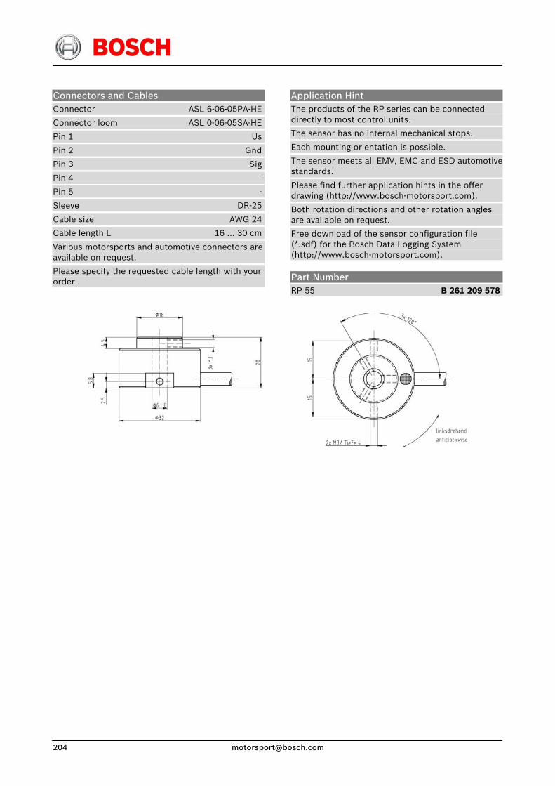
Connectors and Cables Connector ASL 6-06-05PA-HE
Connector loom ASL 0-06-05SA-HE
Pin 1 Us
Pin 2 Gnd
Pin 3 Sig
Pin 4 -
Pin 5 -
Sleeve DR-25
Cable size AWG 24
Cable length L 16 … 30 cm
Various motorsports and automotive connectors areavailable on request.
Please specify the requested cable length with your order.
Application Hint The products of the RP series can be connected directly to most control units.
The sensor has no internal mechanical stops.
Each mounting orientation is possible.
The sensor meets all EMV, EMC and ESD automotive standards.
Please find further application hints in the offer drawing (http://www.bosch-motorsport.com).
Both rotation directions and other rotation angles are available on request.
Free download of the sensor configuration file (*.sdf) for the Bosch Data Logging System (http://www.bosch-motorsport.com).
Part Number RP 55 B 261 209 578
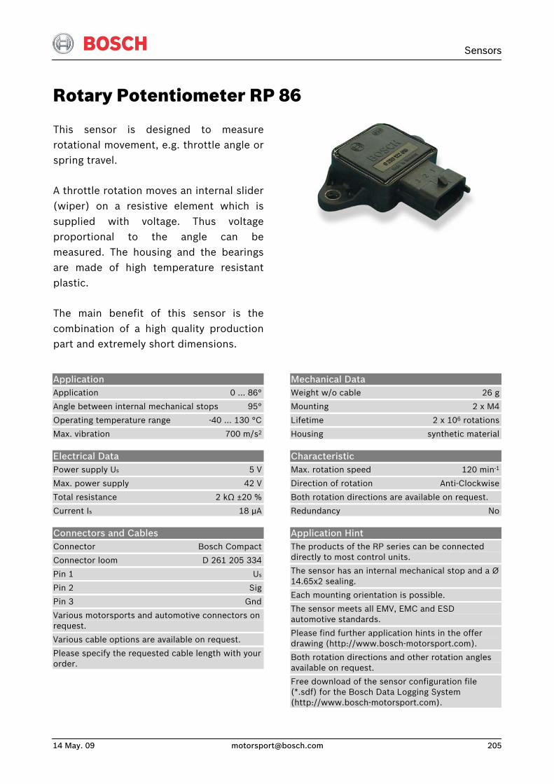
Sensors
14 May. 09 [email protected] 205
Rotary Potentiometer RP 86
This sensor is designed to measurerotational movement, e.g. throttle angle orspring travel.
A throttle rotation moves an internal slider(wiper) on a resistive element which issupplied with voltage. Thus voltageproportional to the angle can bemeasured. The housing and the bearingsare made of high temperature resistantplastic.
The main benefit of this sensor is thecombination of a high quality productionpart and extremely short dimensions.
Application Application 0 … 86°
Angle between internal mechanical stops 95°
Operating temperature range -40 … 130 °C
Max. vibration 700 m/s2
Electrical Data Power supply Us 5 V
Max. power supply 42 V
Total resistance 2 kΩ ±20 %
Current Is 18 μA
Connectors and Cables Connector Bosch Compact
Connector loom D 261 205 334
Pin 1 Us
Pin 2 Sig
Pin 3 Gnd
Various motorsports and automotive connectors on request.
Various cable options are available on request.
Please specify the requested cable length with your order.
Mechanical Data Weight w/o cable 26 g
Mounting 2 x M4
Lifetime 2 x 10⁶ rotations
Housing synthetic material
Characteristic Max. rotation speed 120 min-1
Direction of rotation Anti-Clockwise
Both rotation directions are available on request.
Redundancy No
Application Hint The products of the RP series can be connected directly to most control units.
The sensor has an internal mechanical stop and a Ø 14.65x2 sealing.
Each mounting orientation is possible.
The sensor meets all EMV, EMC and ESD automotive standards.
Please find further application hints in the offer drawing (http://www.bosch-motorsport.com).
Both rotation directions and other rotation angles available on request.
Free download of the sensor configuration file (*.sdf) for the Bosch Data Logging System (http://www.bosch-motorsport.com).
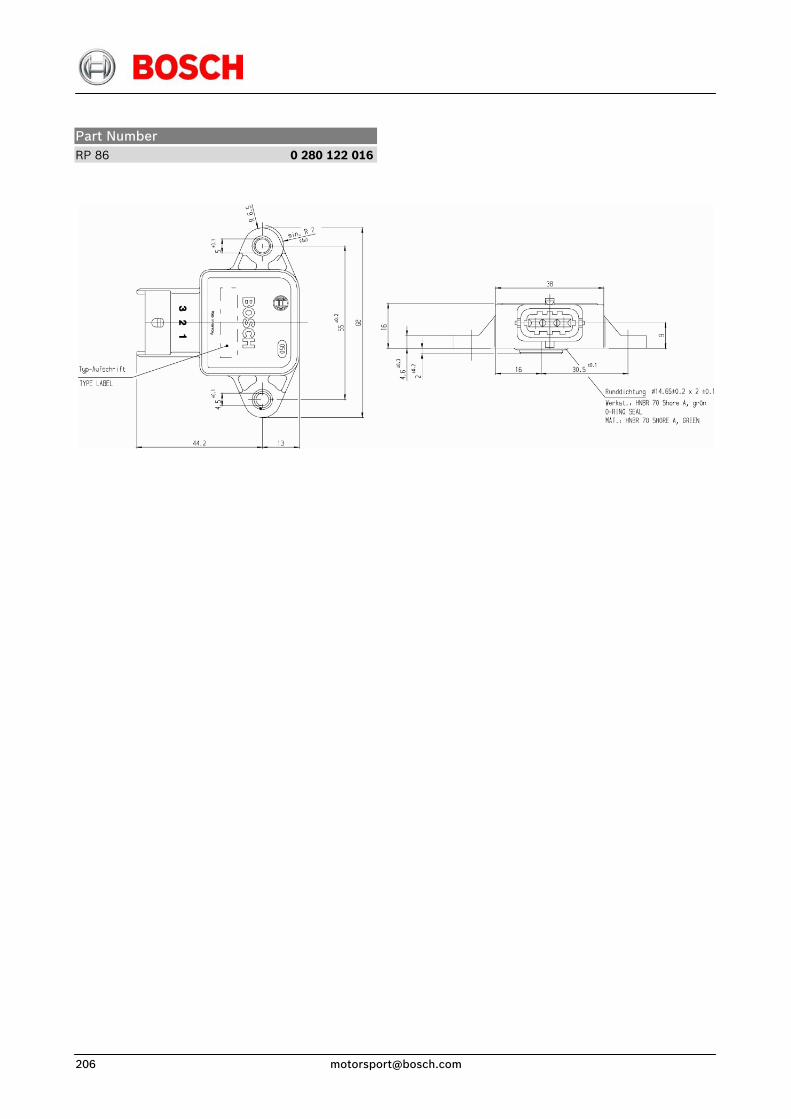
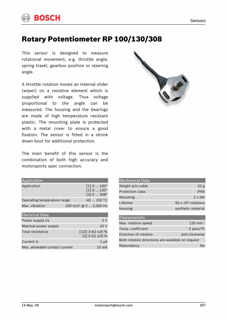
Sensors
14 May. 09 [email protected] 207
Rotary Potentiometer RP 100/130/308
This sensor is designed to measurerotational movement, e.g. throttle angle,spring travel, gearbox position or steeringangle.
A throttle rotation moves an internal slider(wiper) on a resistive element which issupplied with voltage. Thus voltageproportional to the angle can bemeasured. The housing and the bearingsare made of high temperature resistantplastic. The mounting plate is protectedwith a metal cover to ensure a goodfixation. The sensor is fitted in a shrinkdown boot for additional protection.
The main benefit of this sensor is thecombination of both high accuracy andmotorsports spec connection.
Application Application [1] 0 … 100° [2] 0 … 130° [3] 0 … 308°
Operating temperature range -40 … 150 °C
Max. vibration 200 m/s2 @ 5 … 2,000 Hz
Electrical Data Power supply Us 5 V
Maximal power supply 42 V
Total resistance [1|2] 3 kΩ ±20 % [3] 5 kΩ ±20 %
Current Is 1 μA
Max. allowable contact current 10 mA
Mechanical Data Weight w/o cable 32 g
Protection class IP65
Mounting 2 x M4
Lifetime 50 x 106 rotations
Housing synthetic material
Characteristic Max. rotation speed 120 min-1
Temp. coefficient 5 ppm/°K
Direction of rotation anti-clockwise
Both rotation directions are available on request
Redundancy No
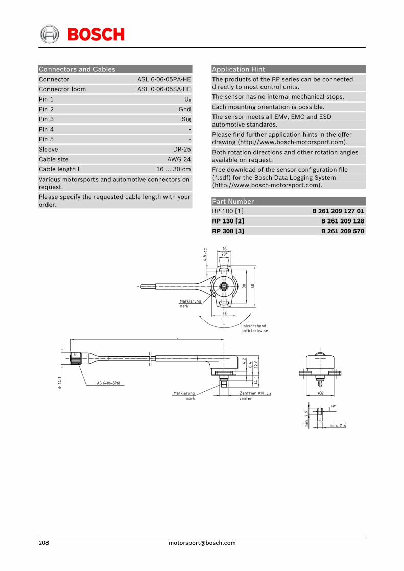
Connectors and Cables Connector ASL 6-06-05PA-HE
Connector loom ASL 0-06-05SA-HE
Pin 1 Us
Pin 2 Gnd
Pin 3 Sig
Pin 4 -
Pin 5 -
Sleeve DR-25
Cable size AWG 24
Cable length L 16 … 30 cm
Various motorsports and automotive connectors on request.
Please specify the requested cable length with your order.
Application Hint The products of the RP series can be connected directly to most control units.
The sensor has no internal mechanical stops.
Each mounting orientation is possible.
The sensor meets all EMV, EMC and ESD automotive standards.
Please find further application hints in the offer drawing (http://www.bosch-motorsport.com).
Both rotation directions and other rotation angles available on request.
Free download of the sensor configuration file (*.sdf) for the Bosch Data Logging System (http://www.bosch-motorsport.com).
Part Number RP 100 [1] B 261 209 127 01
RP 130 [2] B 261 209 128
RP 308 [3] B 261 209 570
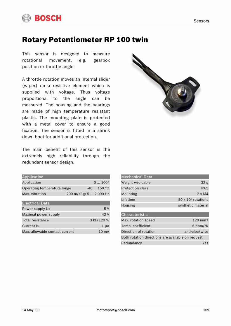
Sensors
14 May. 09 [email protected] 209
Rotary Potentiometer RP 100 twin
This sensor is designed to measurerotational movement, e.g. gearboxposition or throttle angle.
A throttle rotation moves an internal slider(wiper) on a resistive element which issupplied with voltage. Thus voltageproportional to the angle can bemeasured. The housing and the bearingsare made of high temperature resistantplastic. The mounting plate is protectedwith a metal cover to ensure a goodfixation. The sensor is fitted in a shrinkdown boot for additional protection.
The main benefit of this sensor is theextremely high reliability through theredundant sensor design.
Application Application 0 … 100°
Operating temperature range -40 … 150 °C
Max. vibration 200 m/s2 @ 5 … 2,000 Hz
Electrical Data Power supply US 5 V
Maximal power supply 42 V
Total resistance 3 kΩ ±20 %
Current IS 1 μA
Max. allowable contact current 10 mA
Mechanical Data Weight w/o cable 32 g
Protection class IP65
Mounting 2 x M4
Lifetime 50 x 106 rotations
Housing synthetic material
Characteristic Max. rotation speed 120 min-1
Temp. coefficient 5 ppm/°K
Direction of rotation anti-clockwise
Both rotation directions are available on request
Redundancy Yes
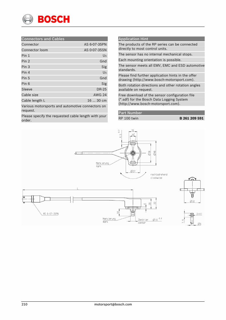
Connectors and Cables Connector AS 6-07-35PN
Connector loom AS 0-07-35SN
Pin 1 US
Pin 2 Gnd
Pin 3 Sig
Pin 4 US
Pin 5 Gnd
Pin 6 Sig
Sleeve DR-25
Cable size AWG 24
Cable length L 16 … 30 cm
Various motorsports and automotive connectors on request.
Please specify the requested cable length with your order.
Application Hint The products of the RP series can be connected directly to most control units.
The sensor has no internal mechanical stops.
Each mounting orientation is possible.
The sensor meets all EMV, EMC and ESD automotive standards.
Please find further application hints in the offer drawing (http://www.bosch-motorsport.com).
Both rotation directions and other rotation angles available on request.
Free download of the sensor configuration file (*.sdf) for the Bosch Data Logging System (http://www.bosch-motorsport.com).
Part Number RP 100 twin B 261 209 591
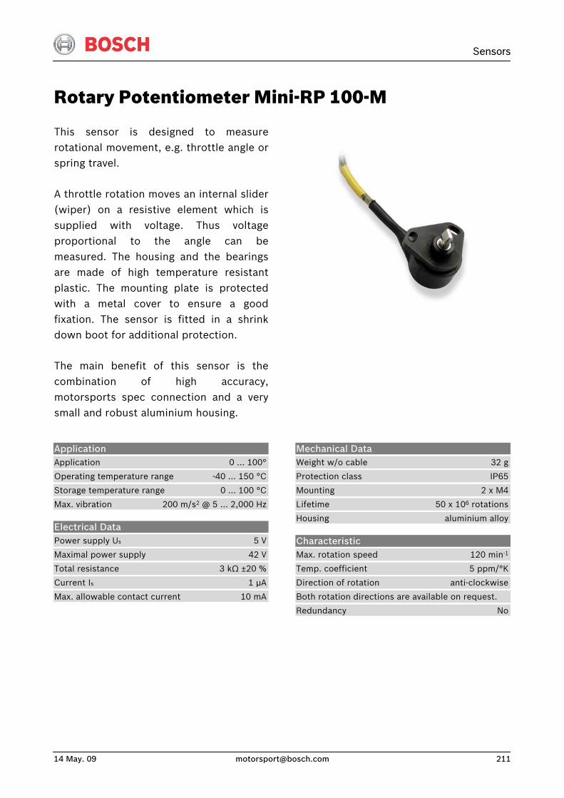
Sensors
14 May. 09 [email protected] 211
Rotary Potentiometer Mini-RP 100-M
This sensor is designed to measurerotational movement, e.g. throttle angle orspring travel.
A throttle rotation moves an internal slider (wiper) on a resistive element which issupplied with voltage. Thus voltageproportional to the angle can bemeasured. The housing and the bearingsare made of high temperature resistantplastic. The mounting plate is protectedwith a metal cover to ensure a goodfixation. The sensor is fitted in a shrinkdown boot for additional protection.
The main benefit of this sensor is thecombination of high accuracy,motorsports spec connection and a verysmall and robust aluminium housing.
Application Application 0 … 100°
Operating temperature range -40 … 150 °C
Storage temperature range 0 … 100 °C
Max. vibration 200 m/s2 @ 5 … 2,000 Hz
Electrical Data Power supply Us 5 V
Maximal power supply 42 V
Total resistance 3 kΩ ±20 %
Current Is 1 μA
Max. allowable contact current 10 mA
Mechanical Data Weight w/o cable 32 g
Protection class IP65
Mounting 2 x M4
Lifetime 50 x 106 rotations
Housing aluminium alloy
Characteristic Max. rotation speed 120 min-1
Temp. coefficient 5 ppm/°K
Direction of rotation anti-clockwise
Both rotation directions are available on request.
Redundancy No
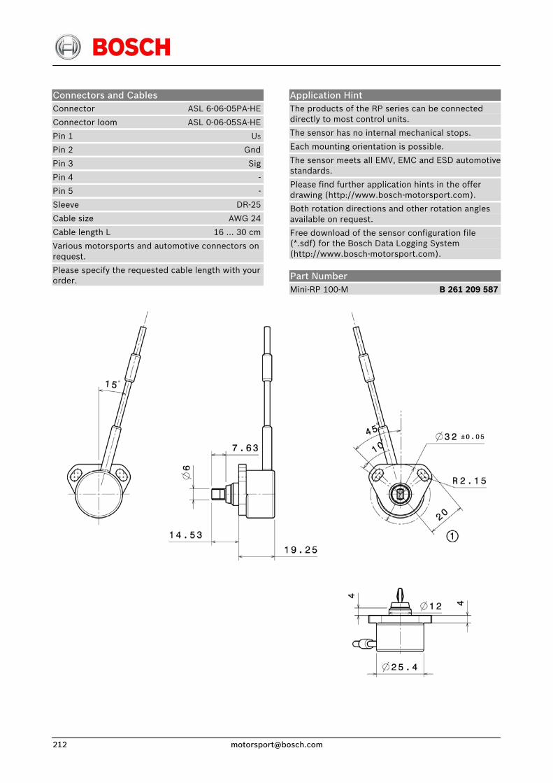
Connectors and Cables Connector ASL 6-06-05PA-HE
Connector loom ASL 0-06-05SA-HE
Pin 1 US
Pin 2 Gnd
Pin 3 Sig
Pin 4 -
Pin 5 -
Sleeve DR-25
Cable size AWG 24
Cable length L 16 … 30 cm
Various motorsports and automotive connectors on request.
Please specify the requested cable length with your order.
Application Hint The products of the RP series can be connected directly to most control units.
The sensor has no internal mechanical stops.
Each mounting orientation is possible.
The sensor meets all EMV, EMC and ESD automotive standards.
Please find further application hints in the offer drawing (http://www.bosch-motorsport.com).
Both rotation directions and other rotation angles available on request.
Free download of the sensor configuration file (*.sdf) for the Bosch Data Logging System (http://www.bosch-motorsport.com).
Part Number Mini-RP 100-M B 261 209 587
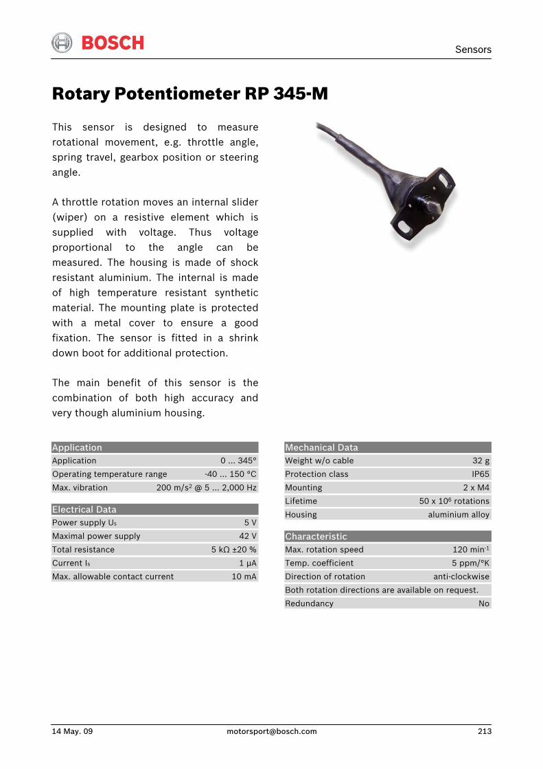
Sensors
14 May. 09 [email protected] 213
Rotary Potentiometer RP 345-M
This sensor is designed to measurerotational movement, e.g. throttle angle,spring travel, gearbox position or steeringangle.
A throttle rotation moves an internal slider (wiper) on a resistive element which issupplied with voltage. Thus voltageproportional to the angle can bemeasured. The housing is made of shockresistant aluminium. The internal is madeof high temperature resistant syntheticmaterial. The mounting plate is protectedwith a metal cover to ensure a goodfixation. The sensor is fitted in a shrinkdown boot for additional protection.
The main benefit of this sensor is thecombination of both high accuracy andvery though aluminium housing.
Application Application 0 … 345°
Operating temperature range -40 … 150 °C
Max. vibration 200 m/s2 @ 5 … 2,000 Hz
Electrical Data Power supply Us 5 V
Maximal power supply 42 V
Total resistance 5 kΩ ±20 %
Current Is 1 μA
Max. allowable contact current 10 mA
Mechanical Data Weight w/o cable 32 g
Protection class IP65
Mounting 2 x M4
Lifetime 50 x 106 rotations
Housing aluminium alloy
Characteristic Max. rotation speed 120 min-1
Temp. coefficient 5 ppm/°K
Direction of rotation anti-clockwise
Both rotation directions are available on request.
Redundancy No
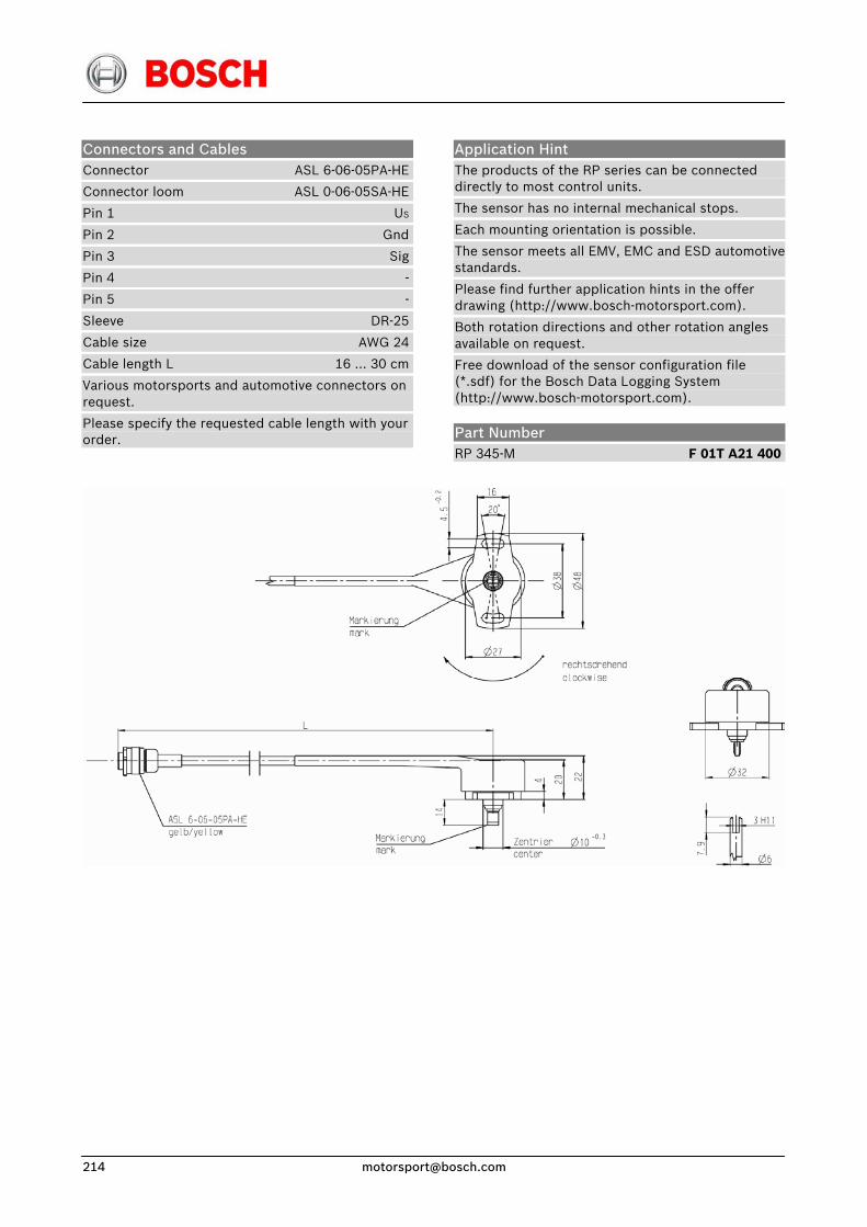
Connectors and Cables Connector ASL 6-06-05PA-HE
Connector loom ASL 0-06-05SA-HE
Pin 1 US
Pin 2 Gnd
Pin 3 Sig
Pin 4 -
Pin 5 -
Sleeve DR-25
Cable size AWG 24
Cable length L 16 … 30 cm
Various motorsports and automotive connectors on request.
Please specify the requested cable length with your order.
Application Hint The products of the RP series can be connected directly to most control units.
The sensor has no internal mechanical stops.
Each mounting orientation is possible.
The sensor meets all EMV, EMC and ESD automotive standards.
Please find further application hints in the offer drawing (http://www.bosch-motorsport.com).
Both rotation directions and other rotation angles available on request.
Free download of the sensor configuration file (*.sdf) for the Bosch Data Logging System (http://www.bosch-motorsport.com).
Part Number RP 345-M F 01T A21 400
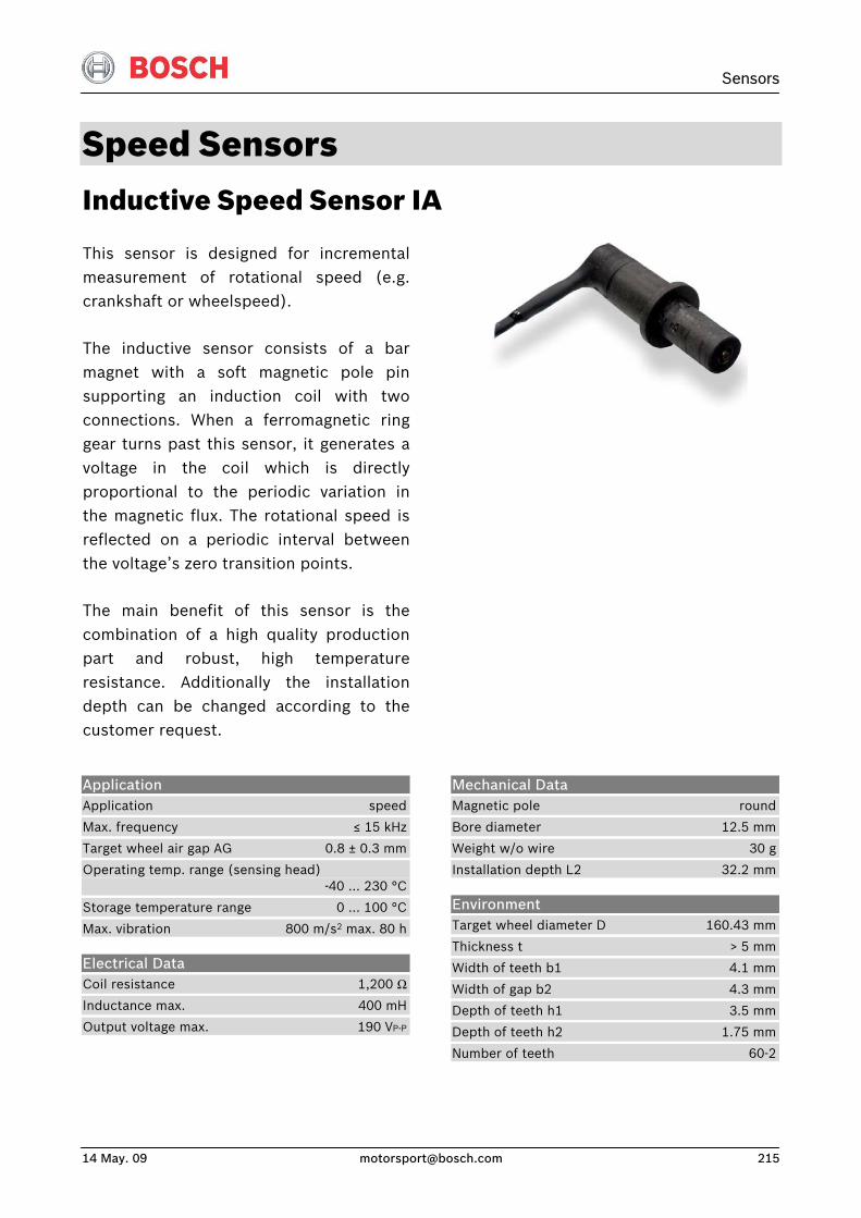
Sensors
14 May. 09 [email protected] 215
Speed Sensors Inductive Speed Sensor IA
This sensor is designed for incrementalmeasurement of rotational speed (e.g.crankshaft or wheelspeed).
The inductive sensor consists of a barmagnet with a soft magnetic pole pinsupporting an induction coil with twoconnections. When a ferromagnetic ringgear turns past this sensor, it generates avoltage in the coil which is directlyproportional to the periodic variation inthe magnetic flux. The rotational speed isreflected on a periodic interval betweenthe voltage’s zero transition points.
The main benefit of this sensor is thecombination of a high quality productionpart and robust, high temperatureresistance. Additionally the installationdepth can be changed according to thecustomer request.
Application Application speed
Max. frequency ≤ 15 kHz
Target wheel air gap AG 0.8 ± 0.3 mm
Operating temp. range (sensing head) -40 … 230 °C
Storage temperature range 0 … 100 °C
Max. vibration 800 m/s2 max. 80 h
Electrical Data Coil resistance 1,200 ΩInductance max. 400 mH
Output voltage max. 190 VP-P
Mechanical Data Magnetic pole round
Bore diameter 12.5 mm
Weight w/o wire 30 g
Installation depth L2 32.2 mm
Environment Target wheel diameter D 160.43 mm
Thickness t > 5 mm
Width of teeth b1 4.1 mm
Width of gap b2 4.3 mm
Depth of teeth h1 3.5 mm
Depth of teeth h2 1.75 mm
Number of teeth 60-2
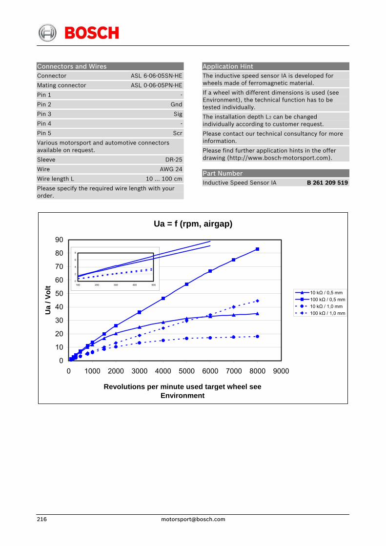
Connectors and Wires Connector ASL 6-06-05SN-HE
Mating connector ASL 0-06-05PN-HE
Pin 1 -
Pin 2 Gnd
Pin 3 Sig
Pin 4 -
Pin 5 Scr
Various motorsport and automotive connectors available on request.
Sleeve DR-25
Wire AWG 24
Wire length L 10 … 100 cm
Please specify the required wire length with your order.
Application Hint The inductive speed sensor IA is developed for wheels made of ferromagnetic material.
If a wheel with different dimensions is used (see Environment), the technical function has to be tested individually.
The installation depth L2 can be changed individually according to customer request.
Please contact our technical consultancy for more information.
Please find further application hints in the offer drawing (http://www.bosch-motorsport.com).
Part Number Inductive Speed Sensor IA B 261 209 519
Ua = f (rpm, airgap)
0
10
20
30
40
50
60
70
80
90
0 1000 2000 3000 4000 5000 6000 7000 8000 9000
Revolutions per minute used target wheel see Environment
Ua
/ Vol
t
10 kΩ / 0,5 mm100 kΩ / 0,5 mm10 kΩ / 1,0 mm100 kΩ / 1,0 mm
0
2
4
6
8
100 200 300 400 500
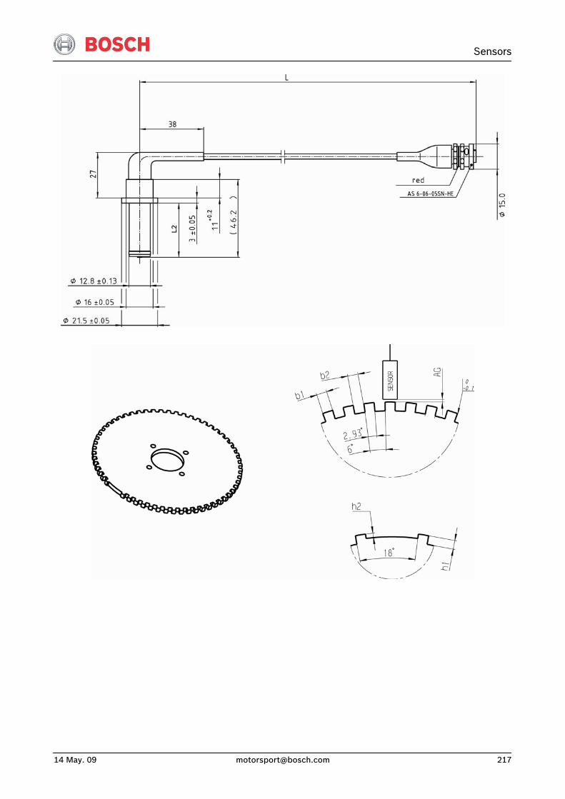
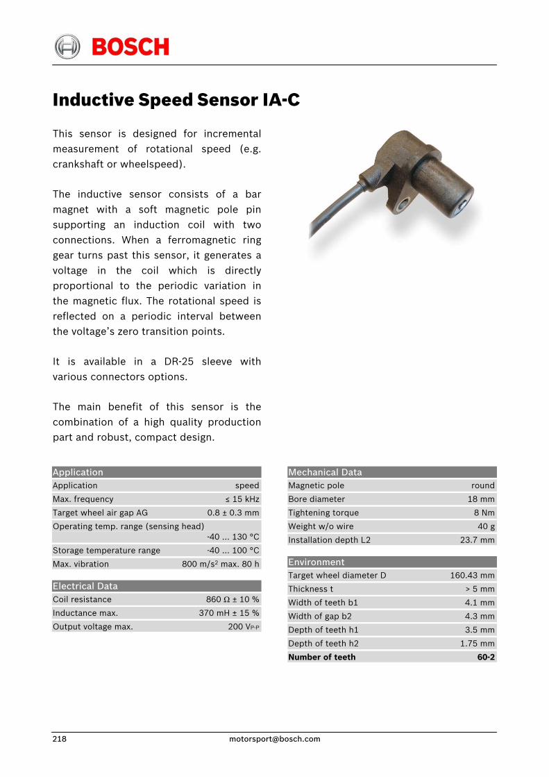
Inductive Speed Sensor IA-C
This sensor is designed for incrementalmeasurement of rotational speed (e.g.crankshaft or wheelspeed).
The inductive sensor consists of a barmagnet with a soft magnetic pole pinsupporting an induction coil with twoconnections. When a ferromagnetic ringgear turns past this sensor, it generates avoltage in the coil which is directlyproportional to the periodic variation inthe magnetic flux. The rotational speed isreflected on a periodic interval betweenthe voltage’s zero transition points.
It is available in a DR-25 sleeve with various connectors options.
The main benefit of this sensor is thecombination of a high quality productionpart and robust, compact design.
Application Application speed
Max. frequency ≤ 15 kHz
Target wheel air gap AG 0.8 ± 0.3 mm
Operating temp. range (sensing head) -40 … 130 °C
Storage temperature range -40 … 100 °C
Max. vibration 800 m/s2 max. 80 h
Electrical Data Coil resistance 860 Ω ± 10 %
Inductance max. 370 mH ± 15 %
Output voltage max. 200 VP-P
Mechanical Data Magnetic pole round
Bore diameter 18 mm
Tightening torque 8 Nm
Weight w/o wire 40 g
Installation depth L2 23.7 mm
Environment Target wheel diameter D 160.43 mm
Thickness t > 5 mm
Width of teeth b1 4.1 mm
Width of gap b2 4.3 mm
Depth of teeth h1 3.5 mm
Depth of teeth h2 1.75 mm
Number of teeth 60-2
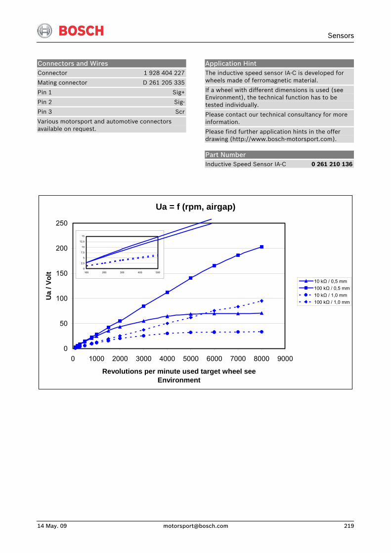
Sensors
14 May. 09 [email protected] 219
Connectors and Wires Connector 1 928 404 227
Mating connector D 261 205 335
Pin 1 Sig+
Pin 2 Sig-
Pin 3 Scr
Various motorsport and automotive connectors available on request.
Application Hint The inductive speed sensor IA-C is developed for wheels made of ferromagnetic material.
If a wheel with different dimensions is used (see Environment), the technical function has to be tested individually.
Please contact our technical consultancy for more information.
Please find further application hints in the offer drawing (http://www.bosch-motorsport.com).
Part Number Inductive Speed Sensor IA-C 0 261 210 136
Ua = f (rpm, airgap)
0
50
100
150
200
250
0 1000 2000 3000 4000 5000 6000 7000 8000 9000
Revolutions per minute used target wheel see Environment
Ua
/ Vol
t
10 kΩ / 0,5 mm100 kΩ / 0,5 mm10 kΩ / 1,0 mm100 kΩ / 1,0 mm
0
2,5
5
7,5
10
12,5
15
100 200 300 400 500
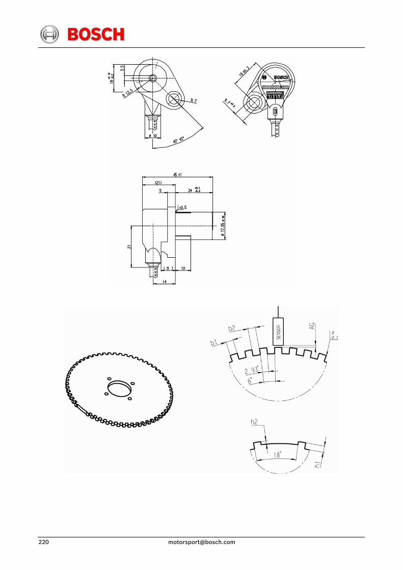
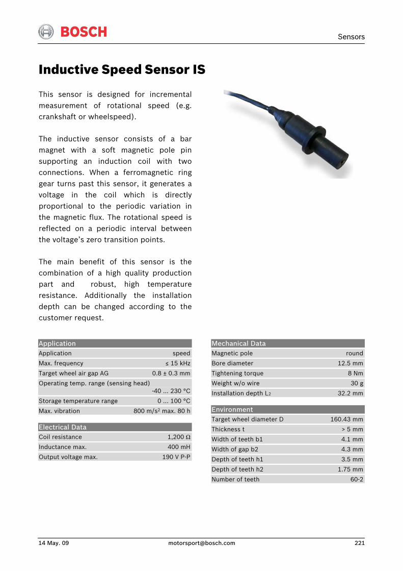
Sensors
14 May. 09 [email protected] 221
Inductive Speed Sensor IS
This sensor is designed for incrementalmeasurement of rotational speed (e.g.crankshaft or wheelspeed).
The inductive sensor consists of a barmagnet with a soft magnetic pole pinsupporting an induction coil with twoconnections. When a ferromagnetic ringgear turns past this sensor, it generates avoltage in the coil which is directlyproportional to the periodic variation inthe magnetic flux. The rotational speed isreflected on a periodic interval between the voltage’s zero transition points.
The main benefit of this sensor is thecombination of a high quality productionpart and robust, high temperatureresistance. Additionally the installationdepth can be changed according to thecustomer request.
Application Application speed
Max. frequency ≤ 15 kHz
Target wheel air gap AG 0.8 ± 0.3 mm
Operating temp. range (sensing head) -40 … 230 °C
Storage temperature range 0 … 100 °C
Max. vibration 800 m/s2 max. 80 h
Electrical Data Coil resistance 1,200 ΩInductance max. 400 mH
Output voltage max. 190 V P-P
Mechanical Data Magnetic pole round
Bore diameter 12.5 mm
Tightening torque 8 Nm
Weight w/o wire 30 g
Installation depth L2 32.2 mm
Environment Target wheel diameter D 160.43 mm
Thickness t > 5 mm
Width of teeth b1 4.1 mm
Width of gap b2 4.3 mm
Depth of teeth h1 3.5 mm
Depth of teeth h2 1.75 mm
Number of teeth 60-2

Connectors and Wires Connector ASL 6-06-05SN-HE
Mating connector ASL 0-06-05PN-HE
Pin 1 -
Pin 2 Sig-
Pin 3 Sig+
Pin 4 -
Pin 5 Scr
Various motorsport and automotive connectors available on request.
Sleeve DR-25
Wire AWG 24
Wire length L 10 … 100 cm
Please specify the required wire length with your order.
Application Hint The inductive speed sensor IS is developed for wheels made of ferromagnetic material.
If a wheel with different dimensions is used (see Environment), the technical function has to be tested individually.
The installation depth L2 can be changed individually according to customer request.
Please contact our technical consultancy for more information.
Please find further application hints in the offer drawing (http://www.bosch-motorsport.com).
Part Number Inductive Speed Sensor IS B 261 209 517
Ua = f (rpm, airgap)
0
10
20
30
40
50
60
70
80
90
0 1000 2000 3000 4000 5000 6000 7000 8000 9000
Revolutions per minute used target wheel see Environment
Ua
/ Vol
t
10 kΩ / 0,5 mm100 kΩ / 0,5 mm10 kΩ / 1,0 mm100 kΩ / 1,0 mm
0
2
4
6
8
100 200 300 400 500
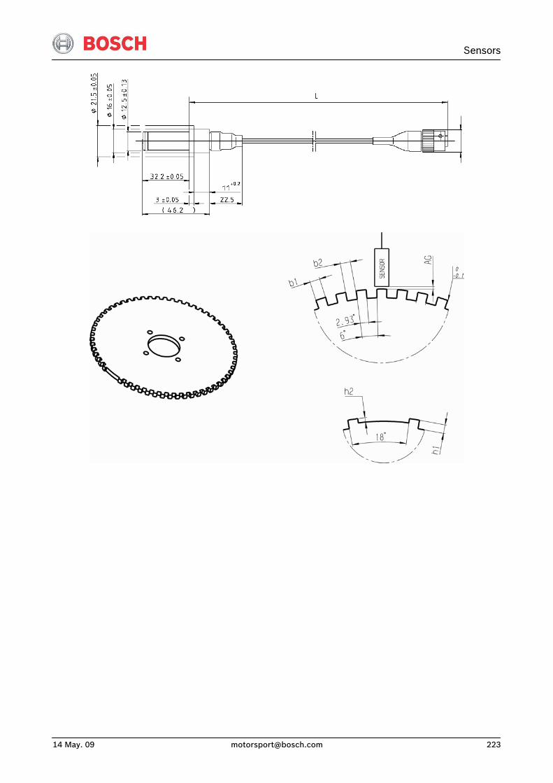
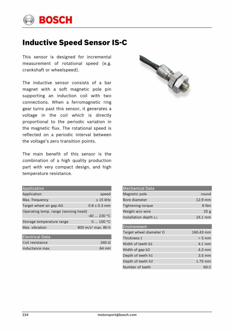
Inductive Speed Sensor IS-C
This sensor is designed for incrementalmeasurement of rotational speed (e.g.crankshaft or wheelspeed).
The inductive sensor consists of a barmagnet with a soft magnetic pole pinsupporting an induction coil with twoconnections. When a ferromagnetic ringgear turns past this sensor, it generates avoltage in the coil which is directlyproportional to the periodic variation inthe magnetic flux. The rotational speed isreflected on a periodic interval betweenthe voltage’s zero transition points.
The main benefit of this sensor is thecombination of a high quality productionpart with very compact design, and hightemperature resistance.
Application Application speed
Max. frequency ≤ 15 kHz
Target wheel air gap AG 0.8 ± 0.3 mm
Operating temp. range (sensing head) -40 … 230 °C
Storage temperature range 0 … 100 °C
Max. vibration 800 m/s2 max. 80 h
Electrical Data Coil resistance 340 Ω
Inductance max. 64 mH
Mechanical Data Magnetic pole round
Bore diameter 12.9 mm
Tightening torque 8 Nm
Weight w/o wire 25 g
Installation depth L2 24.1 mm
Environment Target wheel diameter D 160.43 mm
Thickness t > 5 mm
Width of teeth b1 4.1 mm
Width of gap b2 4.3 mm
Depth of teeth h1 3.5 mm
Depth of teeth h2 1.75 mm
Number of teeth 60-2
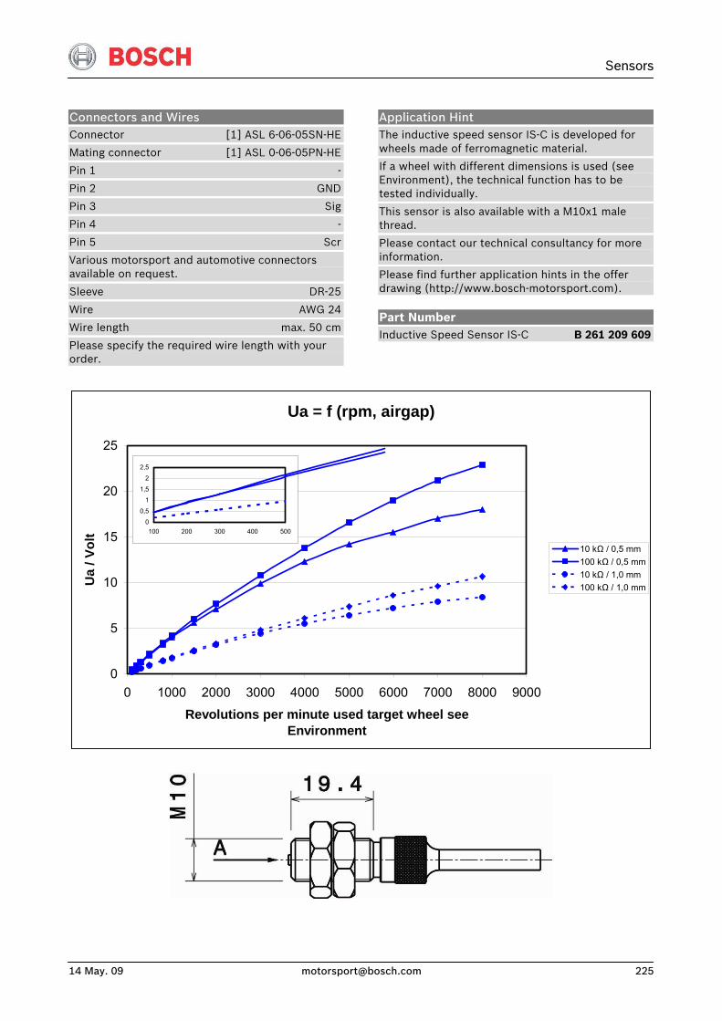
Sensors
14 May. 09 [email protected] 225
Connectors and Wires Connector [1] ASL 6-06-05SN-HE
Mating connector [1] ASL 0-06-05PN-HE
Pin 1 -
Pin 2 GND
Pin 3 Sig
Pin 4 -
Pin 5 Scr
Various motorsport and automotive connectors available on request.
Sleeve DR-25
Wire AWG 24
Wire length max. 50 cm
Please specify the required wire length with your order.
Application Hint The inductive speed sensor IS-C is developed for wheels made of ferromagnetic material.
If a wheel with different dimensions is used (see Environment), the technical function has to be tested individually.
This sensor is also available with a M10x1 male thread.
Please contact our technical consultancy for more information.
Please find further application hints in the offer drawing (http://www.bosch-motorsport.com).
Part Number Inductive Speed Sensor IS-C B 261 209 609
Ua = f (rpm, airgap)
0
5
10
15
20
25
0 1000 2000 3000 4000 5000 6000 7000 8000 9000
Revolutions per minute used target wheel see Environment
Ua
/ Vol
t
10 kΩ / 0,5 mm100 kΩ / 0,5 mm10 kΩ / 1,0 mm100 kΩ / 1,0 mm
0
0,5
1
1,5
2
2,5
100 200 300 400 500
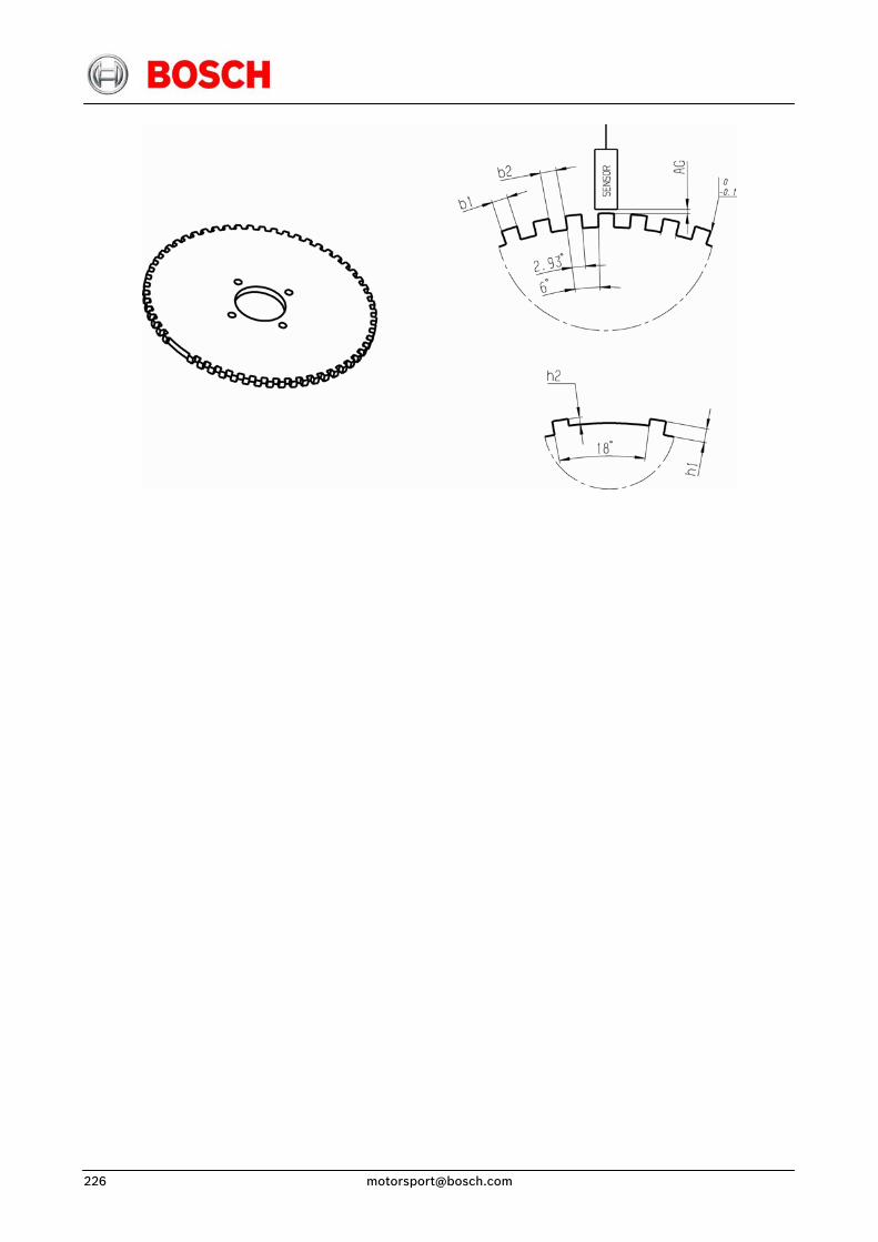
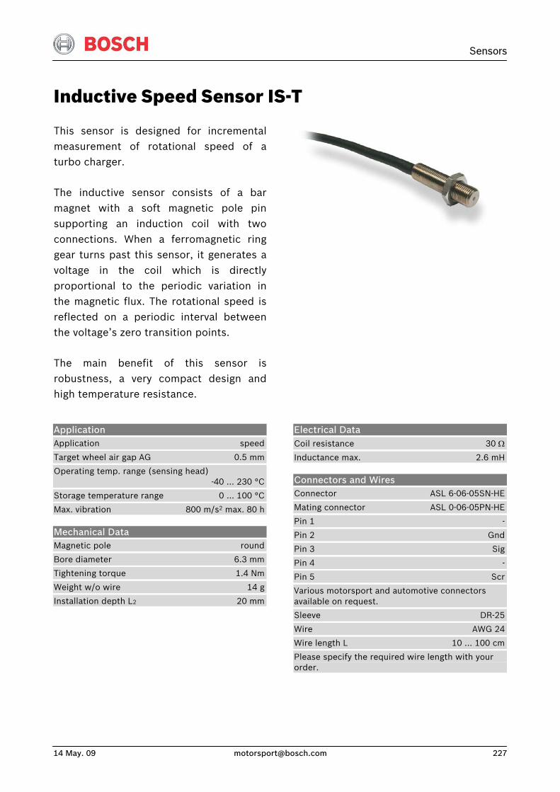
Sensors
14 May. 09 [email protected] 227
Inductive Speed Sensor IS-T
This sensor is designed for incrementalmeasurement of rotational speed of aturbo charger.
The inductive sensor consists of a barmagnet with a soft magnetic pole pinsupporting an induction coil with twoconnections. When a ferromagnetic ringgear turns past this sensor, it generates avoltage in the coil which is directlyproportional to the periodic variation inthe magnetic flux. The rotational speed isreflected on a periodic interval betweenthe voltage’s zero transition points.
The main benefit of this sensor isrobustness, a very compact design andhigh temperature resistance.
Application Application speed
Target wheel air gap AG 0.5 mm
Operating temp. range (sensing head) -40 … 230 °C
Storage temperature range 0 … 100 °C
Max. vibration 800 m/s2 max. 80 h
Mechanical Data Magnetic pole round
Bore diameter 6.3 mm
Tightening torque 1.4 Nm
Weight w/o wire 14 g
Installation depth L2 20 mm
Electrical Data Coil resistance 30 Ω
Inductance max. 2.6 mH
Connectors and Wires Connector ASL 6-06-05SN-HE
Mating connector ASL 0-06-05PN-HE
Pin 1 -
Pin 2 Gnd
Pin 3 Sig
Pin 4 -
Pin 5 Scr
Various motorsport and automotive connectors available on request.
Sleeve DR-25
Wire AWG 24
Wire length L 10 … 100 cm
Please specify the required wire length with your order.
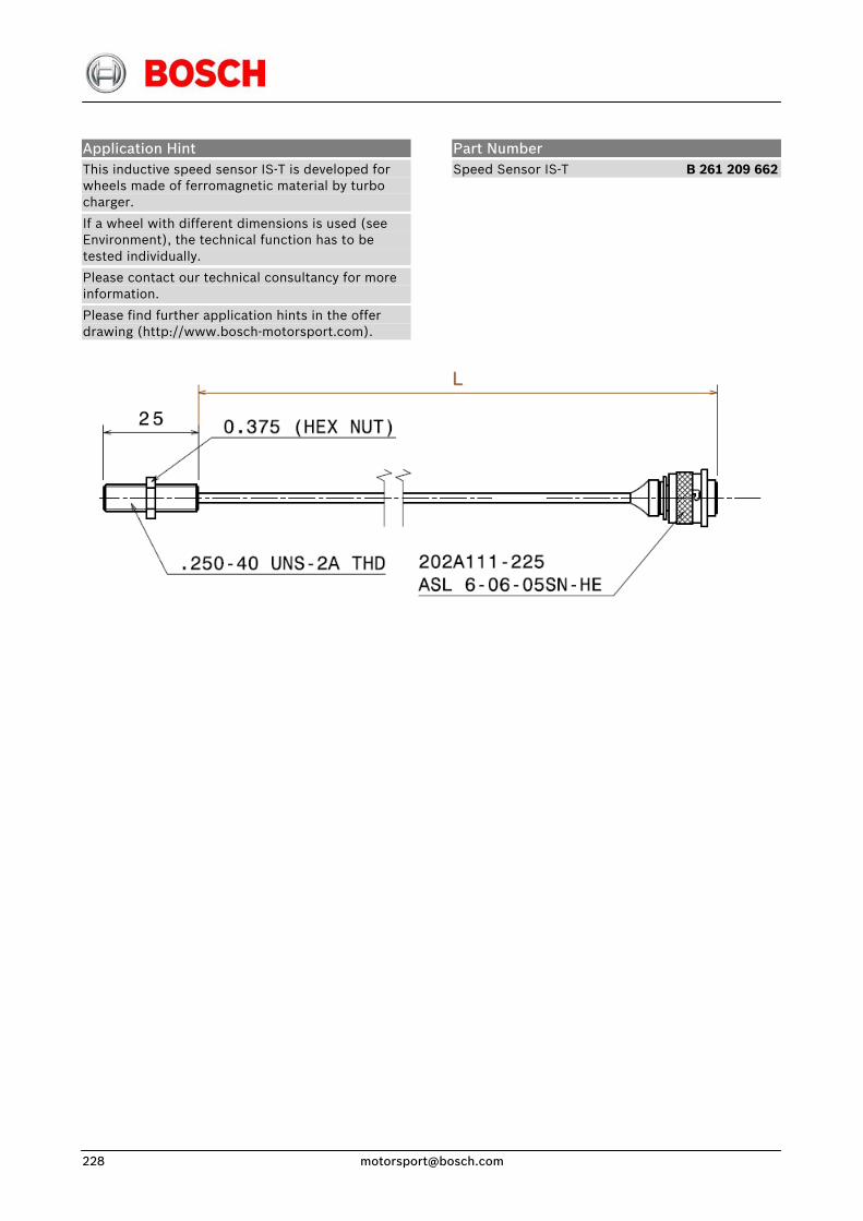
Application Hint This inductive speed sensor IS-T is developed for wheels made of ferromagnetic material by turbo charger.
If a wheel with different dimensions is used (see Environment), the technical function has to be tested individually.
Please contact our technical consultancy for more information.
Please find further application hints in the offer drawing (http://www.bosch-motorsport.com).
Part Number Speed Sensor IS-T B 261 209 662
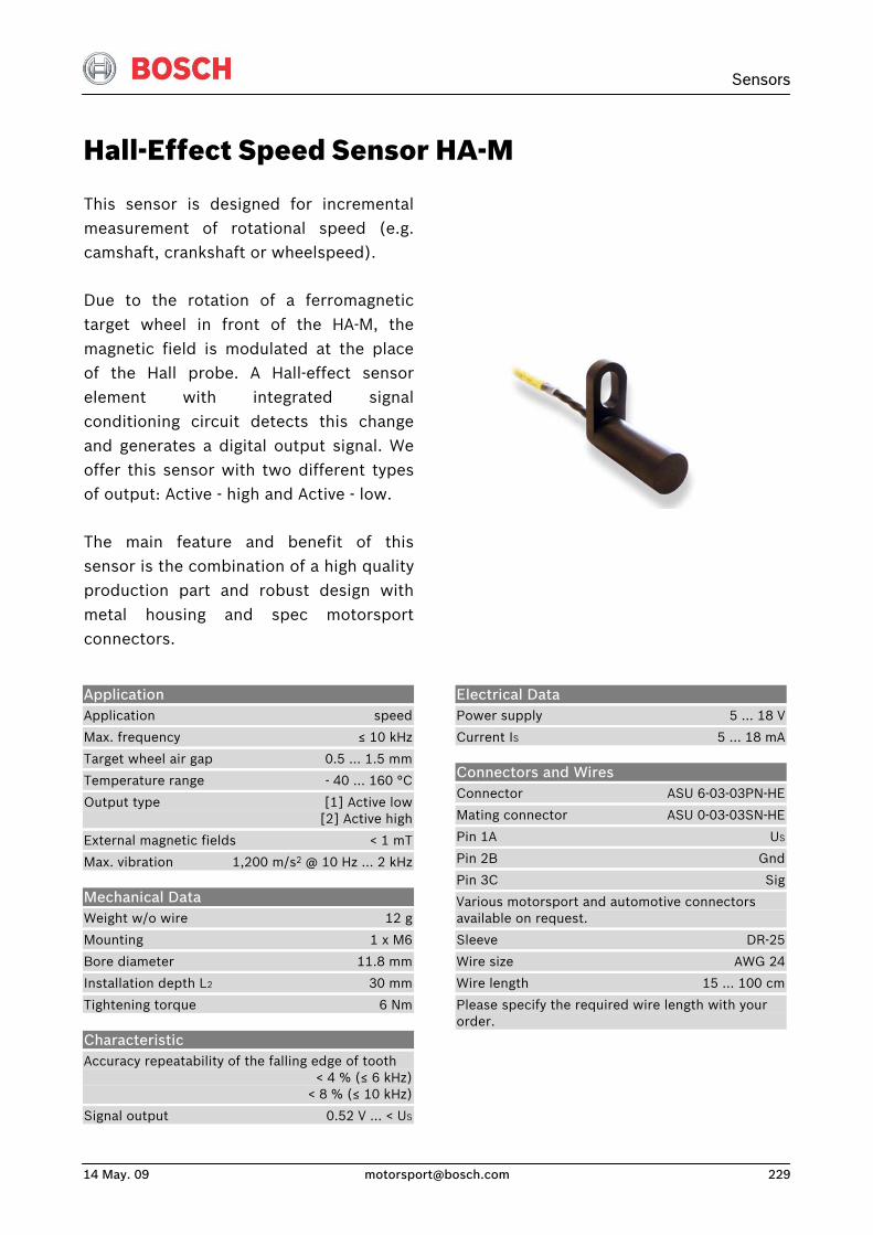
Sensors
14 May. 09 [email protected] 229
Hall-Effect Speed Sensor HA-M
This sensor is designed for incremental measurement of rotational speed (e.g. camshaft, crankshaft or wheelspeed).
Due to the rotation of a ferromagnetic target wheel in front of the HA-M, the magnetic field is modulated at the place of the Hall probe. A Hall-effect sensor element with integrated signal conditioning circuit detects this change and generates a digital output signal. We offer this sensor with two different types of output: Active - high and Active - low.
The main feature and benefit of this sensor is the combination of a high quality production part and robust design with metal housing and spec motorsport connectors.
Application Application speed
Max. frequency ≤ 10 kHz
Target wheel air gap 0.5 … 1.5 mm
Temperature range - 40 … 160 °C
Output type [1] Active low [2] Active high
External magnetic fields < 1 mT
Max. vibration 1,200 m/s2 @ 10 Hz … 2 kHz
Mechanical Data Weight w/o wire 12 g
Mounting 1 x M6
Bore diameter 11.8 mm
Installation depth L2 30 mm
Tightening torque 6 Nm
Characteristic Accuracy repeatability of the falling edge of tooth < 4 % (≤ 6 kHz) < 8 % (≤ 10 kHz)
Signal output 0.52 V … < US
Electrical Data Power supply 5 … 18 V
Current IS 5 … 18 mA
Connectors and Wires Connector ASU 6-03-03PN-HE
Mating connector ASU 0-03-03SN-HE
Pin 1A US
Pin 2B Gnd
Pin 3C Sig
Various motorsport and automotive connectors available on request.
Sleeve DR-25
Wire size AWG 24
Wire length 15 … 100 cm
Please specify the required wire length with your order.
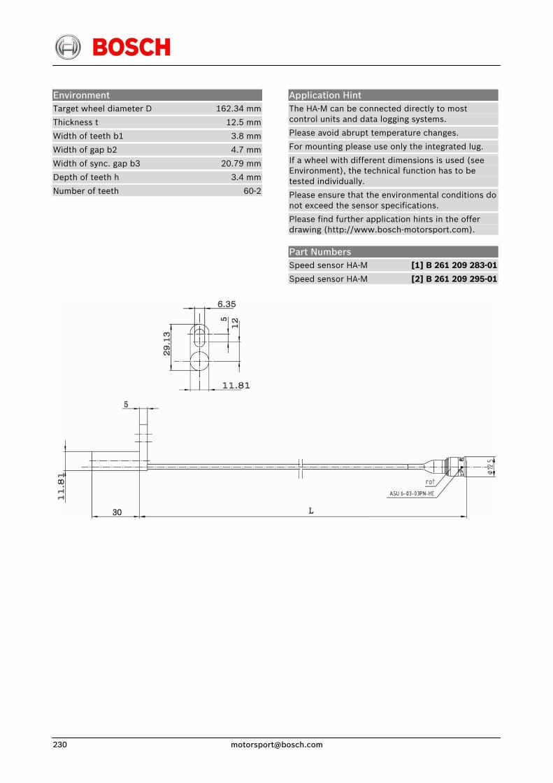
Environment Target wheel diameter D 162.34 mm
Thickness t 12.5 mm
Width of teeth b1 3.8 mm
Width of gap b2 4.7 mm
Width of sync. gap b3 20.79 mm
Depth of teeth h 3.4 mm
Number of teeth 60-2
Application Hint The HA-M can be connected directly to most control units and data logging systems.
Please avoid abrupt temperature changes.
For mounting please use only the integrated lug.
If a wheel with different dimensions is used (see Environment), the technical function has to be tested individually.
Please ensure that the environmental conditions do not exceed the sensor specifications.
Please find further application hints in the offer drawing (http://www.bosch-motorsport.com).
Part Numbers Speed sensor HA-M [1] B 261 209 283-01
Speed sensor HA-M [2] B 261 209 295-01

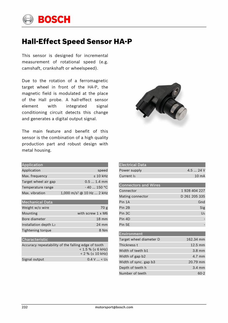
Hall-Effect Speed Sensor HA-P
This sensor is designed for incremental measurement of rotational speed (e.g. camshaft, crankshaft or wheelspeed).
Due to the rotation of a ferromagnetic target wheel in front of the HA-P, the magnetic field is modulated at the place of the Hall probe. A hall-effect sensor element with integrated signal conditioning circuit detects this change and generates a digital output signal.
The main feature and benefit of this sensor is the combination of a high quality production part and robust design with metal housing.
Application Application speed
Max. frequency ≤ 10 kHz
Target wheel air gap 0.5 … 1.4 mm
Temperature range - 40 … 150 °C
Max. vibration 1,000 m/s2 @ 10 Hz … 2 kHz
Mechanical Data Weight w/o wire 70 g
Mounting with screw 1 x M6
Bore diameter 18 mm
Installation depth L2 24 mm
Tightening torque 8 Nm
Characteristic Accuracy repeatability of the falling edge of tooth < 1.5 % (≤ 6 kHz) < 2 % (≤ 10 kHz)
Signal output 0.4 V … < US
Electrical Data Power supply 4.5 … 24 V
Current IS 10 mA
Connectors and Wires Connector 1 928 404 227
Mating connector D 261 205 335
Pin 1A Gnd
Pin 2B Sig
Pin 3C US
Pin 4D -
Pin 5E -
Environment Target wheel diameter D 162.34 mm
Thickness t 12.5 mm
Width of teeth b1 3.8 mm
Width of gap b2 4.7 mm
Width of sync. gap b3 20.79 mm
Depth of teeth h 3.4 mm
Number of teeth 60-2
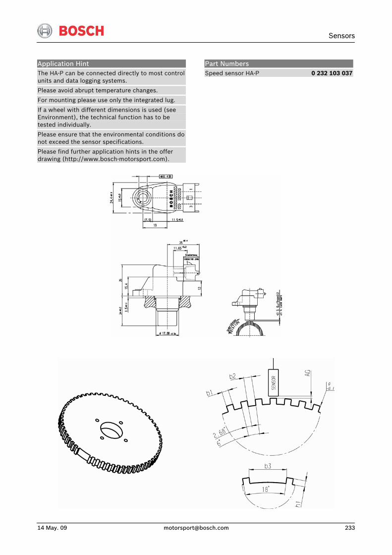
Sensors
14 May. 09 [email protected] 233
Application Hint The HA-P can be connected directly to most control units and data logging systems.
Please avoid abrupt temperature changes.
For mounting please use only the integrated lug.
If a wheel with different dimensions is used (see Environment), the technical function has to be tested individually.
Please ensure that the environmental conditions do not exceed the sensor specifications.
Please find further application hints in the offer drawing (http://www.bosch-motorsport.com).
Part Numbers Speed sensor HA-P 0 232 103 037
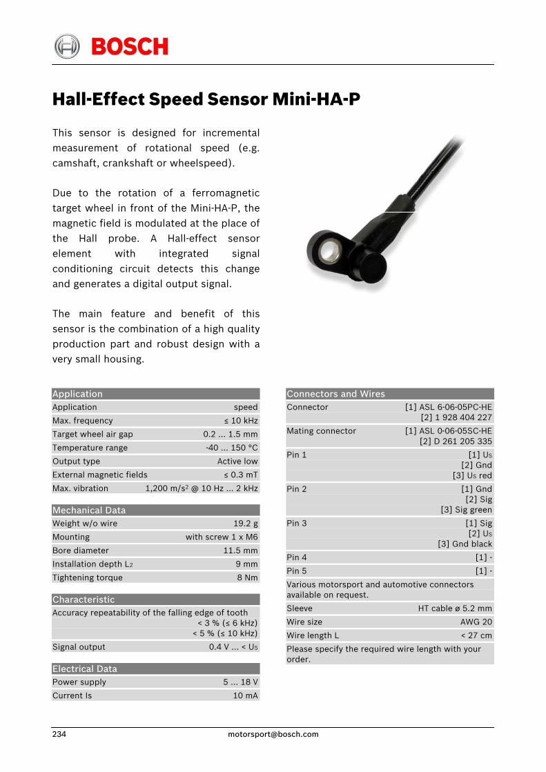
Hall-Effect Speed Sensor Mini-HA-P
This sensor is designed for incrementalmeasurement of rotational speed (e.g.camshaft, crankshaft or wheelspeed).
Due to the rotation of a ferromagnetictarget wheel in front of the Mini-HA-P, the magnetic field is modulated at the place ofthe Hall probe. A Hall-effect sensorelement with integrated signalconditioning circuit detects this changeand generates a digital output signal.
The main feature and benefit of thissensor is the combination of a high qualityproduction part and robust design with avery small housing.
Application Application speed
Max. frequency ≤ 10 kHz
Target wheel air gap 0.2 … 1.5 mm
Temperature range -40 … 150 °C
Output type Active low
External magnetic fields ≤ 0.3 mT
Max. vibration 1,200 m/s2 @ 10 Hz … 2 kHz
Mechanical Data Weight w/o wire 19.2 g
Mounting with screw 1 x M6
Bore diameter 11.5 mm
Installation depth L2 9 mm
Tightening torque 8 Nm
Characteristic Accuracy repeatability of the falling edge of tooth < 3 % (≤ 6 kHz) < 5 % (≤ 10 kHz)
Signal output 0.4 V … < US
Electrical Data Power supply 5 … 18 V
Current Is 10 mA
Connectors and Wires Connector [1] ASL 6-06-05PC-HE [2] 1 928 404 227
Mating connector [1] ASL 0-06-05SC-HE [2] D 261 205 335
Pin 1 [1] US
[2] Gnd [3] US red
Pin 2 [1] Gnd [2] Sig [3] Sig green
Pin 3 [1] Sig [2] US
[3] Gnd black
Pin 4 [1] -
Pin 5 [1] -
Various motorsport and automotive connectors available on request.
Sleeve HT cable ø 5.2 mm
Wire size AWG 20
Wire length L < 27 cm
Please specify the required wire length with your order.
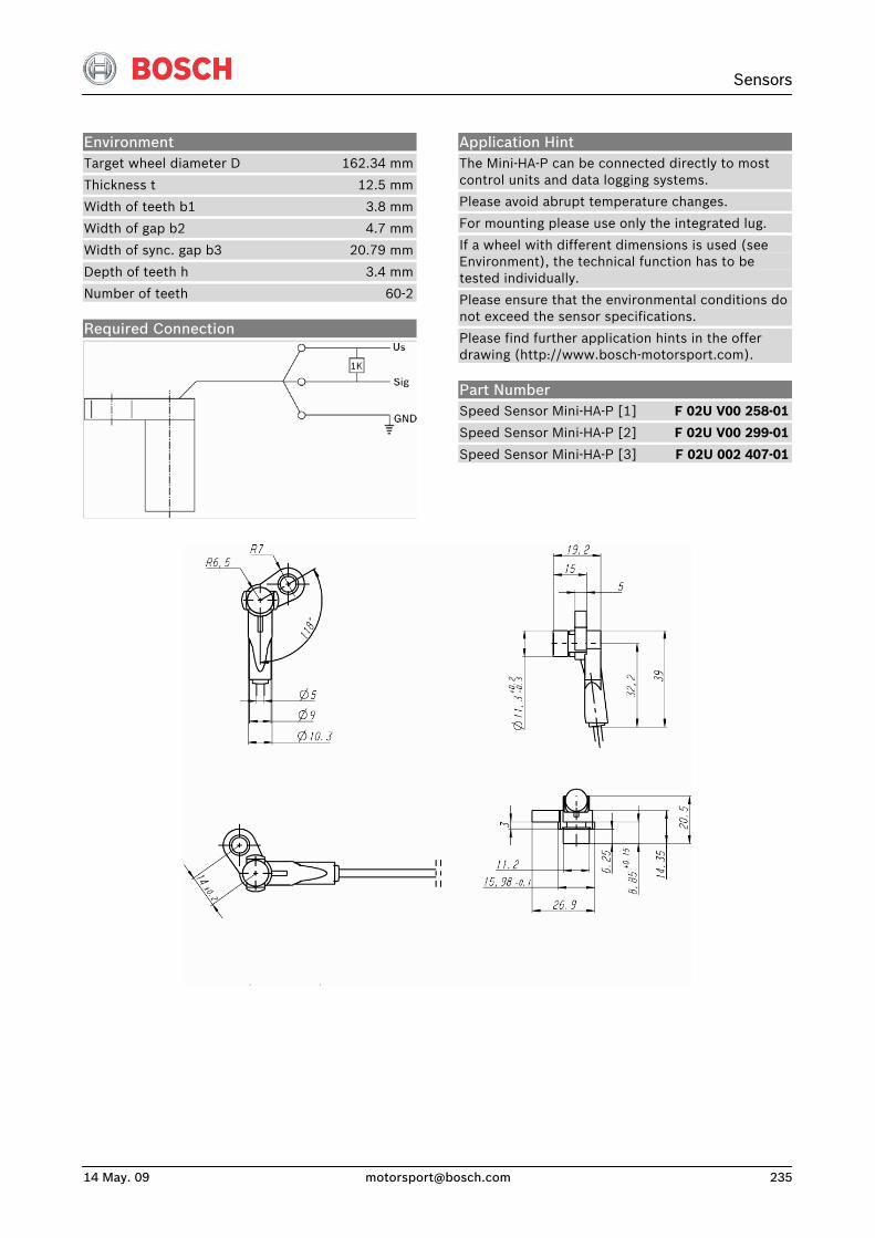
Sensors
14 May. 09 [email protected] 235
Environment Target wheel diameter D 162.34 mm
Thickness t 12.5 mm
Width of teeth b1 3.8 mm
Width of gap b2 4.7 mm
Width of sync. gap b3 20.79 mm
Depth of teeth h 3.4 mm
Number of teeth 60-2
Required Connection
Application Hint The Mini-HA-P can be connected directly to most control units and data logging systems.
Please avoid abrupt temperature changes.
For mounting please use only the integrated lug.
If a wheel with different dimensions is used (see Environment), the technical function has to be tested individually.
Please ensure that the environmental conditions do not exceed the sensor specifications.
Please find further application hints in the offer drawing (http://www.bosch-motorsport.com).
Part Number Speed Sensor Mini-HA-P [1] F 02U V00 258-01
Speed Sensor Mini-HA-P [2] F 02U V00 299-01
Speed Sensor Mini-HA-P [3] F 02U 002 407-01
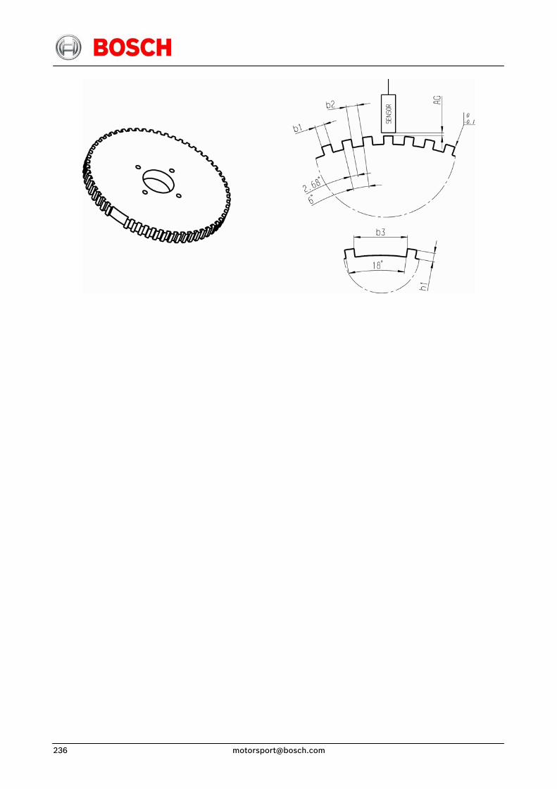
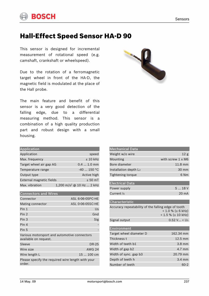
Sensors
14 May. 09 [email protected] 237
Hall-Effect Speed Sensor HA-D 90
This sensor is designed for incrementalmeasurement of rotational speed (e.g.camshaft, crankshaft or wheelspeed).
Due to the rotation of a ferromagnetictarget wheel in front of the HA-D, the magnetic field is modulated at the place ofthe Hall probe.
The main feature and benefit of thissensor is a very good detection of thefalling edge, due to a differentialmeasuring method. This sensor is acombination of a high quality productionpart and robust design with a smallhousing.
Application Application speed
Max. frequency ≤ 10 kHz
Target wheel air gap AG 0.4 … 1.0 mm
Temperature range -40 … 150 °C
Output type Active high
External magnetic fields ≤ 50 mT
Max. vibration 1,200 m/s2 @ 10 Hz … 2 kHz
Connectors and Wires Connector ASL 6-06-05PC-HE
Mating connector ASL 0-06-05SC-HE
Pin 1 Us
Pin 2 Gnd
Pin 3 Sig
Pin 4 -
Pin 5 -
Various motorsport and automotive connectors available on request.
Sleeve DR-25
Wire size AWG 24
Wire length L 15 … 100 cm
Please specify the required wire length with your order.
Mechanical Data Weight w/o wire 12 g
Mounting with screw 1 x M6
Bore diameter 11.8 mm
Installation depth L2 30 mm
Tightening torque 6 Nm
Electrical Data Power supply 5 … 18 V
Current IS 20 mA
Characteristic Accuracy repeatability of the falling edge of tooth < 1.0 % (≤ 6 kHz) < 1.5 % (≤ 10 kHz)
Signal output 0.52 V… < US
Environment Target wheel diameter D 162.34 mm
Thickness t 12.5 mm
Width of teeth b1 3.8 mm
Width of gap b2 4.7 mm
Width of sync. gap b3 20.79 mm
Depth of teeth h 3.4 mm
Number of teeth 60-2
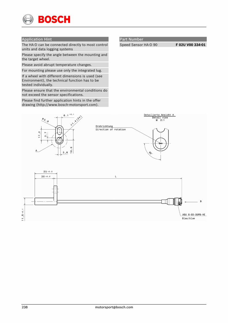
Application Hint The HA-D can be connected directly to most control units and data logging systems
Please specify the angle between the mounting and the target wheel.
Please avoid abrupt temperature changes.
For mounting please use only the integrated lug.
If a wheel with different dimensions is used (see Environment), the technical function has to be tested individually.
Please ensure that the environmental conditions do not exceed the sensor specifications.
Please find further application hints in the offer drawing (http://www.bosch-motorsport.com).
Part Number Speed Sensor HA-D 90 F 02U V00 334-01
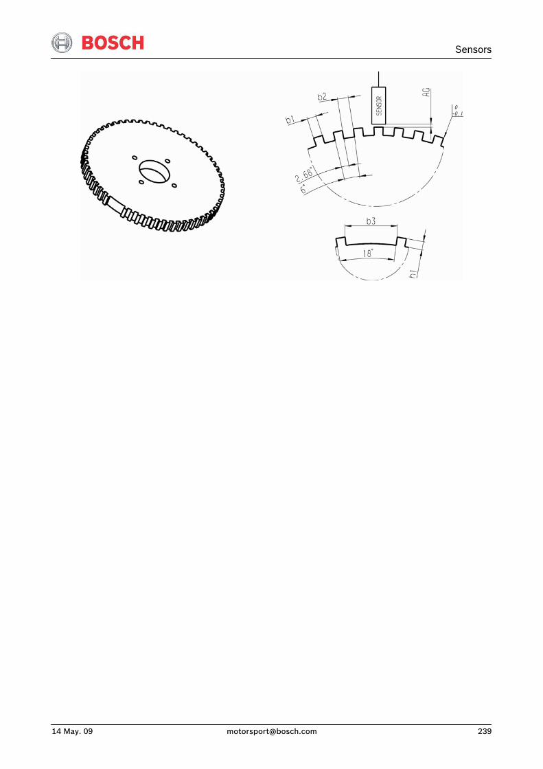
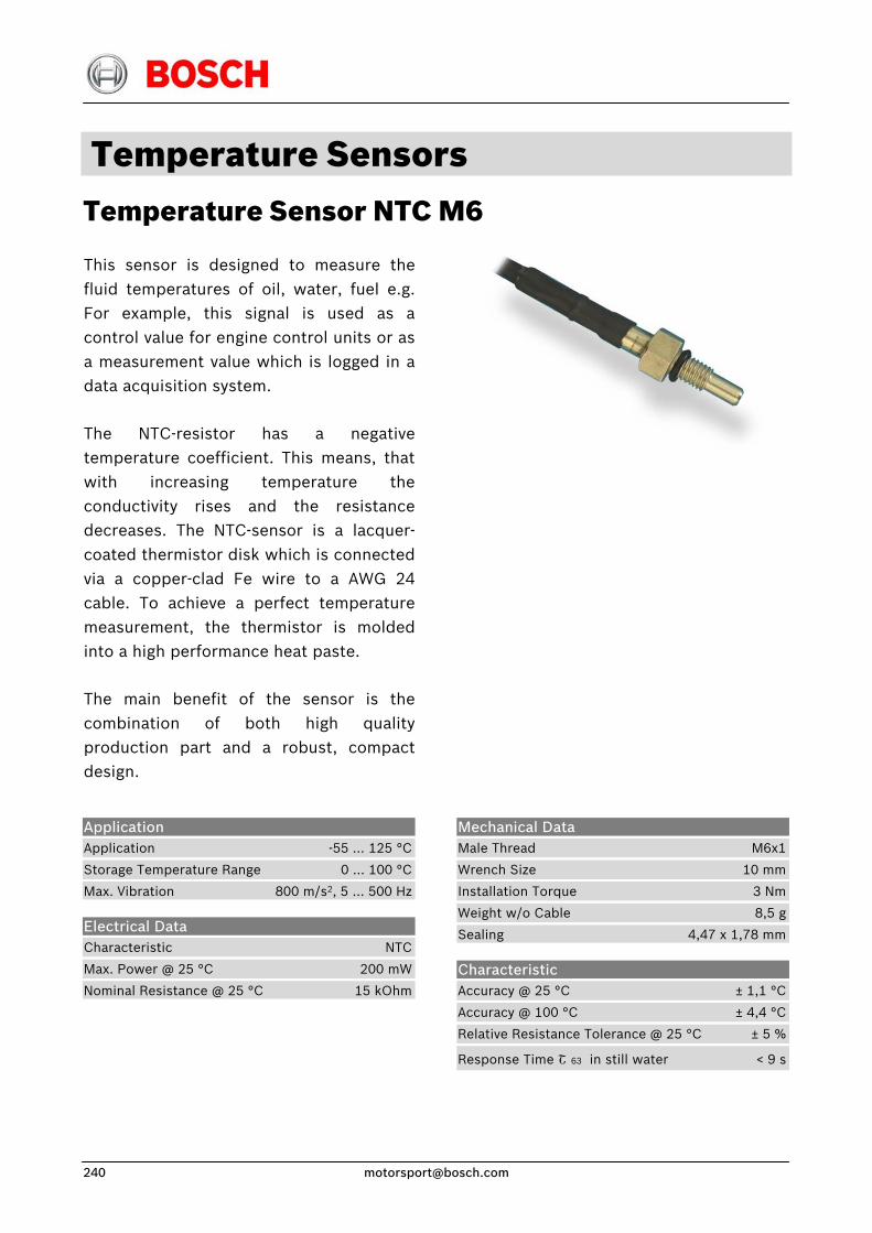
Temperature Sensors Temperature Sensor NTC M6
This sensor is designed to measure thefluid temperatures of oil, water, fuel e.g.For example, this signal is used as acontrol value for engine control units or asa measurement value which is logged in adata acquisition system.
The NTC-resistor has a negative temperature coefficient. This means, thatwith increasing temperature theconductivity rises and the resistancedecreases. The NTC-sensor is a lacquer-coated thermistor disk which is connectedvia a copper-clad Fe wire to a AWG 24cable. To achieve a perfect temperaturemeasurement, the thermistor is moldedinto a high performance heat paste.
The main benefit of the sensor is thecombination of both high qualityproduction part and a robust, compactdesign.
Mechanical Data Male Thread M6x1
Wrench Size 10 mm
Installation Torque 3 Nm
Weight w/o Cable 8,5 g
Sealing 4,47 x 1,78 mm
Application Application -55 … 125 °C
Storage Temperature Range 0 … 100 °C
Max. Vibration 800 m/s2, 5 … 500 Hz
Electrical Data Characteristic NTC
Max. Power @ 25 °C 200 mW
Nominal Resistance @ 25 °C 15 kOhm
Characteristic Accuracy @ 25 °C ± 1,1 °C
Accuracy @ 100 °C ± 4,4 °C
Relative Resistance Tolerance @ 25 °C ± 5 %
Response Time Շ 63 in still water < 9 s
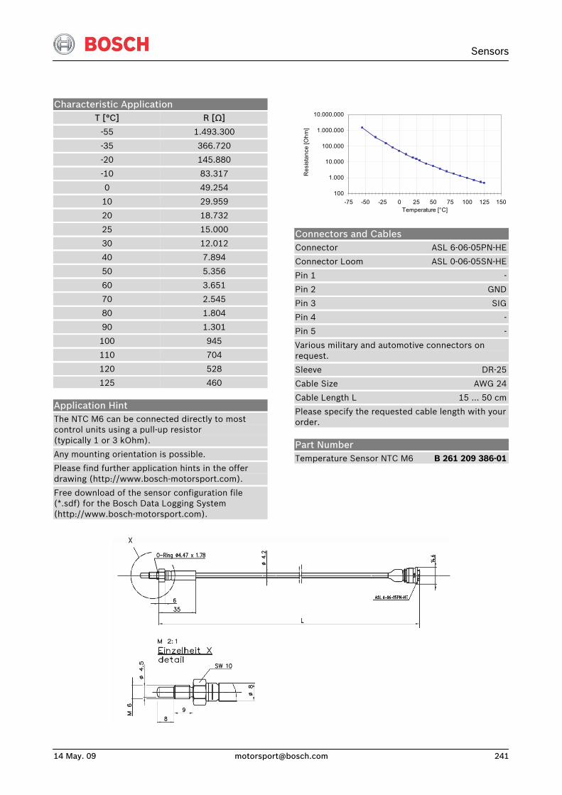
Sensors
14 May. 09 [email protected] 241
Characteristic Application T [°C]
-55
-35
-20
-10
0
10
20
25
30
40
50
60
70
80
90
100
110
120
125
R [Ω]
1.493.300
366.720
145.880
83.317
49.254
29.959
18.732
15.000
12.012
7.894
5.356
3.651
2.545
1.804
1.301
945
704
528
460
Application Hint The NTC M6 can be connected directly to most control units using a pull-up resistor (typically 1 or 3 kOhm).
Any mounting orientation is possible.
Please find further application hints in the offer drawing (http://www.bosch-motorsport.com).
Free download of the sensor configuration file (*.sdf) for the Bosch Data Logging System (http://www.bosch-motorsport.com).
100
1.000
10.000
100.000
1.000.000
10.000.000
-75 -50 -25 0 25 50 75 100 125 150Temperature [°C]
Res
ista
nce
[Ohm
]
Connectors and Cables Connector ASL 6-06-05PN-HE
Connector Loom ASL 0-06-05SN-HE
Pin 1 -
Pin 2 GND
Pin 3 SIG
Pin 4 -
Pin 5 -
Various military and automotive connectors on request.
Sleeve DR-25
Cable Size AWG 24
Cable Length L 15 … 50 cm
Please specify the requested cable length with your order.
Part Number Temperature Sensor NTC M6 B 261 209 386-01
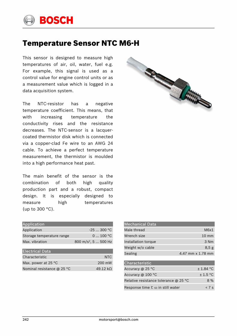
Temperature Sensor NTC M6-H
This sensor is designed to measure hightemperatures of air, oil, water, fuel e.g.For example, this signal is used as acontrol value for engine control units or asa measurement value which is logged in adata acquisition system.
The NTC-resistor has a negativetemperature coefficient. This means, thatwith increasing temperature theconductivity rises and the resistancedecreases. The NTC-sensor is a lacquer-coated thermistor disk which is connectedvia a copper-clad Fe wire to an AWG 24cable. To achieve a perfect temperaturemeasurement, the thermistor is mouldedinto a high performance heat past.
The main benefit of the sensor is thecombination of both high qualityproduction part and a robust, compactdesign. It is especially designed tomeasure high temperatures(up to 300 °C).
Application Application -25 … 300 °C
Storage temperature range 0 … 100 °C
Max. vibration 800 m/s2, 5 … 500 Hz
Electrical Data Characteristic NTC
Max. power at 25 °C 200 mW
Nominal resistance @ 25 °C 49.12 kΩ
Mechanical Data Male thread M6x1
Wrench size 10 mm
Installation torque 3 Nm
Weight w/o cable 8,5 g
Sealing 4.47 mm x 1.78 mm
Characteristic Accuracy @ 25 °C ± 1.84 °C
Accuracy @ 100 °C ± 1.5 °C
Relative resistance tolerance @ 25 °C 8 %
Response time Շ 63 in still water < 7 s
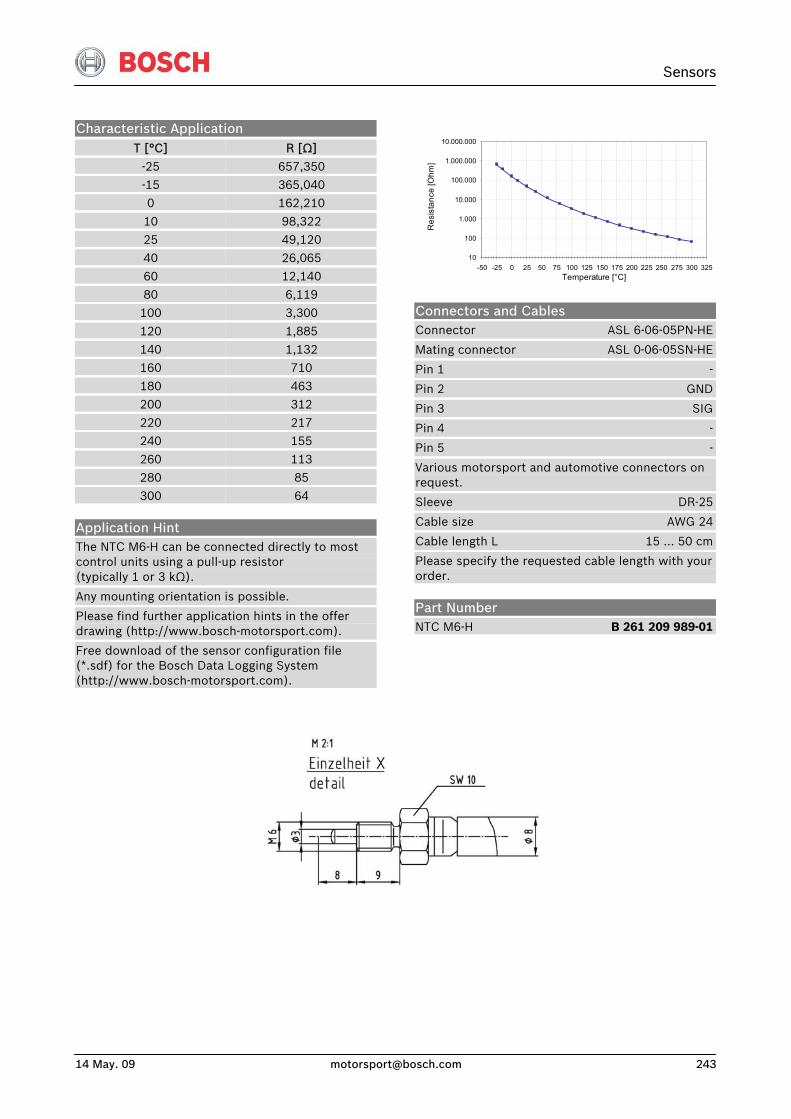
Sensors
14 May. 09 [email protected] 243
Characteristic Application T [°C] R [Ω]
-25 657,350 -15 365,040 0 162,210
10 98,322 25 49,120 40 26,065
60 12,140 80 6,119 100 3,300
120 1,885 140 1,132 160 710
180 463 200 312 220 217 240 155
260 113 280 85 300 64
Application Hint The NTC M6-H can be connected directly to most control units using a pull-up resistor (typically 1 or 3 kΩ).
Any mounting orientation is possible.
Please find further application hints in the offer drawing (http://www.bosch-motorsport.com).
Free download of the sensor configuration file (*.sdf) for the Bosch Data Logging System (http://www.bosch-motorsport.com).
10
100
1.000
10.000
100.000
1.000.000
10.000.000
-50 -25 0 25 50 75 100 125 150 175 200 225 250 275 300 325Temperature [°C]
Res
ista
nce
[Ohm
]
Connectors and Cables Connector ASL 6-06-05PN-HE
Mating connector ASL 0-06-05SN-HE
Pin 1 -
Pin 2 GND
Pin 3 SIG
Pin 4 -
Pin 5 -
Various motorsport and automotive connectors on request.
Sleeve DR-25
Cable size AWG 24
Cable length L 15 … 50 cm
Please specify the requested cable length with your order.
Part Number NTC M6-H B 261 209 989-01
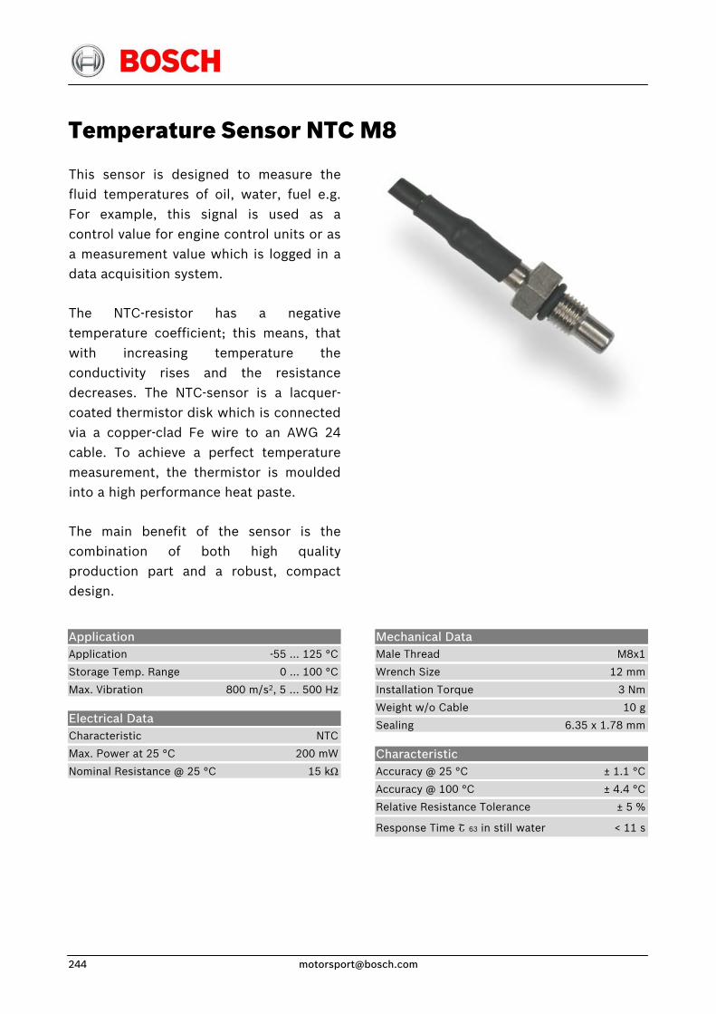
Temperature Sensor NTC M8
This sensor is designed to measure thefluid temperatures of oil, water, fuel e.g.For example, this signal is used as a control value for engine control units or asa measurement value which is logged in adata acquisition system.
The NTC-resistor has a negativetemperature coefficient; this means, thatwith increasing temperature theconductivity rises and the resistancedecreases. The NTC-sensor is a lacquer-coated thermistor disk which is connectedvia a copper-clad Fe wire to an AWG 24 cable. To achieve a perfect temperaturemeasurement, the thermistor is mouldedinto a high performance heat paste.
The main benefit of the sensor is thecombination of both high qualityproduction part and a robust, compactdesign.
Mechanical Data Male Thread M8x1
Wrench Size 12 mm
Installation Torque 3 Nm
Weight w/o Cable 10 g
Sealing 6.35 x 1.78 mm
Application Application -55 … 125 °C
Storage Temp. Range 0 … 100 °C
Max. Vibration 800 m/s2, 5 … 500 Hz
Electrical Data Characteristic NTC
Max. Power at 25 °C 200 mW
Nominal Resistance @ 25 °C 15 kΩ
Characteristic Accuracy @ 25 °C ± 1.1 °C
Accuracy @ 100 °C ± 4.4 °C
Relative Resistance Tolerance ± 5 %
Response Time Շ 63 in still water < 11 s
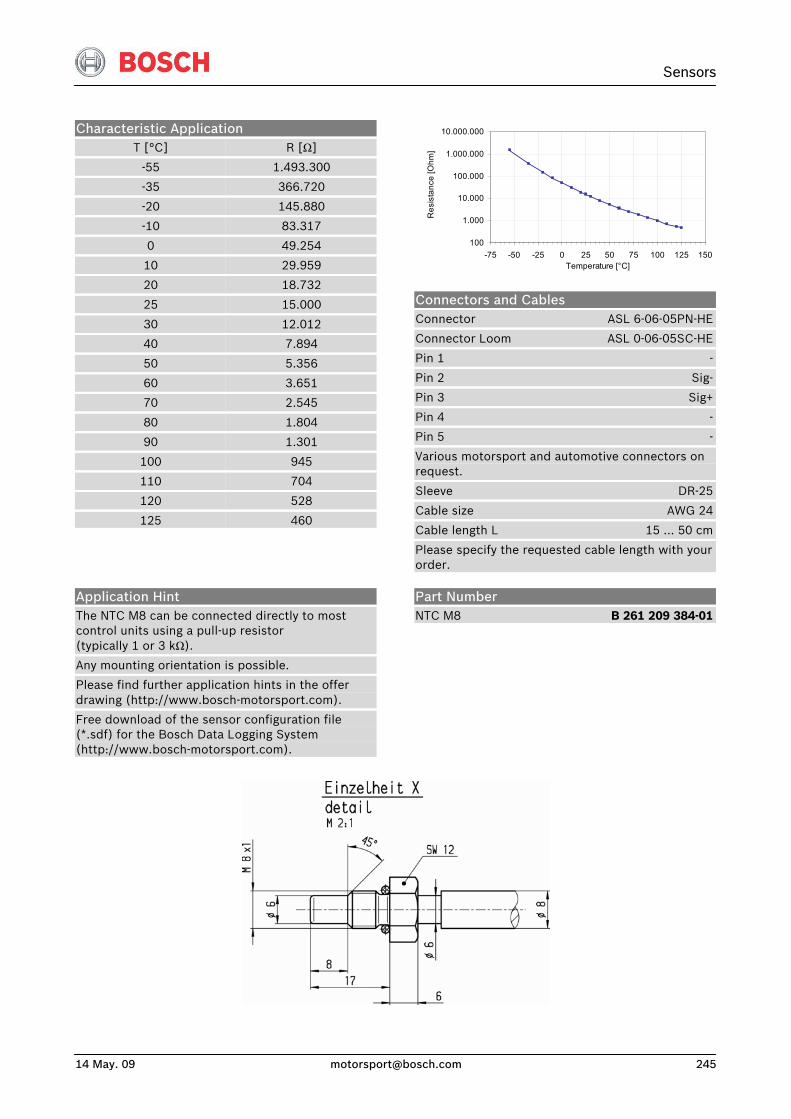
Sensors
14 May. 09 [email protected] 245
Characteristic Application T [°C]
-55
-35
-20
-10
0
10
20
25
30
40
50
60
70
80
90
100
110
120
125
R [Ω]
1.493.300
366.720
145.880
83.317
49.254
29.959
18.732
15.000
12.012
7.894
5.356
3.651
2.545
1.804
1.301
945
704
528
460
100
1.000
10.000
100.000
1.000.000
10.000.000
-75 -50 -25 0 25 50 75 100 125 150Temperature [°C]
Res
ista
nce
[Ohm
]
Connectors and Cables Connector ASL 6-06-05PN-HE
Connector Loom ASL 0-06-05SC-HE
Pin 1 -
Pin 2 Sig-
Pin 3 Sig+
Pin 4 -
Pin 5 -
Various motorsport and automotive connectors on request.
Sleeve DR-25
Cable size AWG 24
Cable length L 15 … 50 cm
Please specify the requested cable length with your order.
Application Hint The NTC M8 can be connected directly to most control units using a pull-up resistor (typically 1 or 3 kΩ).
Any mounting orientation is possible.
Please find further application hints in the offer drawing (http://www.bosch-motorsport.com).
Free download of the sensor configuration file (*.sdf) for the Bosch Data Logging System (http://www.bosch-motorsport.com).
Part Number NTC M8 B 261 209 384-01
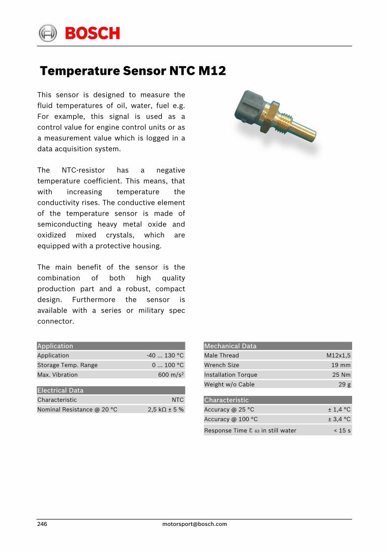
Temperature Sensor NTC M12
This sensor is designed to measure thefluid temperatures of oil, water, fuel e.g.For example, this signal is used as a control value for engine control units or asa measurement value which is logged in adata acquisition system.
The NTC-resistor has a negativetemperature coefficient. This means, thatwith increasing temperature theconductivity rises. The conductive elementof the temperature sensor is made ofsemiconducting heavy metal oxide andoxidized mixed crystals, which areequipped with a protective housing.
The main benefit of the sensor is thecombination of both high qualityproduction part and a robust, compactdesign. Furthermore the sensor isavailable with a series or military specconnector.
Application Application -40 … 130 °C
Storage Temp. Range 0 … 100 °C
Max. Vibration 600 m/s2
Electrical Data Characteristic NTC
Nominal Resistance @ 20 °C 2,5 kΩ ± 5 %
Mechanical Data Male Thread M12x1,5
Wrench Size 19 mm
Installation Torque 25 Nm
Weight w/o Cable 29 g
Characteristic Accuracy @ 25 °C ± 1,4 °C
Accuracy @ 100 °C ± 3,4 °C
Response Time Շ 63 in still water < 15 s
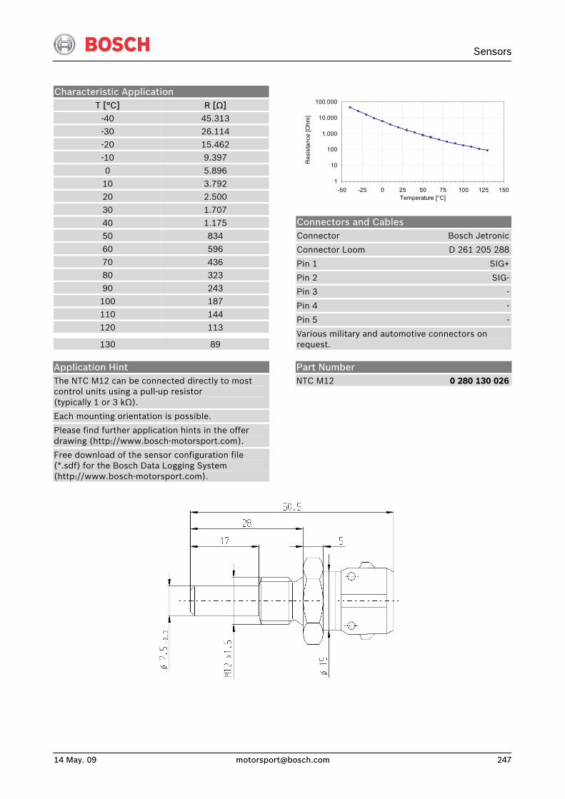
Sensors
14 May. 09 [email protected] 247
Characteristic Application T [°C] R [Ω]
-40 45.313 -30 26.114 -20 15.462 -10 9.397
0 5.896 10 3.792 20 2.500
30 1.707 40 1.175 50 834
60 596 70 436 80 323
90 243 100 187 110 144
120 113
130 89
1
10
100
1.000
10.000
100.000
-50 -25 0 25 50 75 100 125 150Temperature [°C]
Res
ista
nce
[Ohm
]
Connectors and Cables Connector Bosch Jetronic
Connector Loom D 261 205 288
Pin 1 SIG+
Pin 2 SIG-
Pin 3 -
Pin 4 -
Pin 5 -
Various military and automotive connectors on request.
Application Hint The NTC M12 can be connected directly to most control units using a pull-up resistor (typically 1 or 3 kΩ).
Each mounting orientation is possible.
Please find further application hints in the offer drawing (http://www.bosch-motorsport.com).
Free download of the sensor configuration file (*.sdf) for the Bosch Data Logging System (http://www.bosch-motorsport.com).
Part Number NTC M12 0 280 130 026
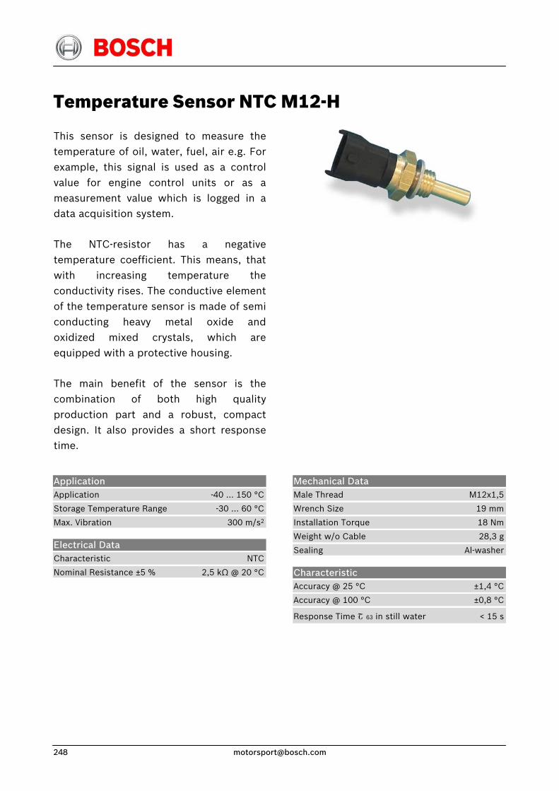
Temperature Sensor NTC M12-H
This sensor is designed to measure thetemperature of oil, water, fuel, air e.g. For example, this signal is used as a controlvalue for engine control units or as ameasurement value which is logged in adata acquisition system.
The NTC-resistor has a negativetemperature coefficient. This means, thatwith increasing temperature the conductivity rises. The conductive elementof the temperature sensor is made of semiconducting heavy metal oxide andoxidized mixed crystals, which areequipped with a protective housing.
The main benefit of the sensor is thecombination of both high quality production part and a robust, compactdesign. It also provides a short responsetime.
Application Application -40 … 150 °C
Storage Temperature Range -30 … 60 °C
Max. Vibration 300 m/s2
Electrical Data Characteristic NTC
Nominal Resistance ±5 % 2,5 kΩ @ 20 °C
Mechanical Data Male Thread M12x1,5
Wrench Size 19 mm
Installation Torque 18 Nm
Weight w/o Cable 28,3 g
Sealing Al-washer
Characteristic Accuracy @ 25 °C ±1,4 °C
Accuracy @ 100 °C ±0,8 °C
Response Time Շ 63 in still water < 15 s
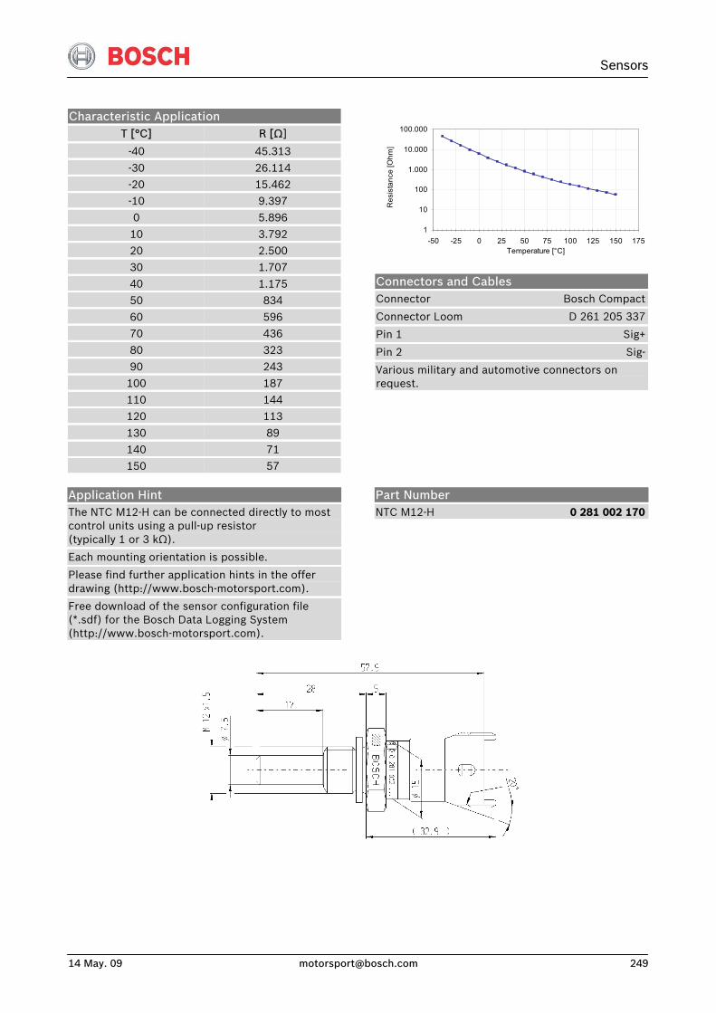
Sensors
14 May. 09 [email protected] 249
Characteristic Application T [°C]
-40
R [Ω]
45.313
-30 26.114 -20 15.462 -10 9.397 0 5.896
10 3.792 20 2.500 30 1.707
40 1.175 50 834 60 596
70 436 80 323 90 243
100 187 110 144 120 113
130 89 140 71 150 57
1
10
100
1.000
10.000
100.000
-50 -25 0 25 50 75 100 125 150 175Temperature [°C]
Res
ista
nce
[Ohm
]
Connectors and Cables Connector Bosch Compact
Connector Loom D 261 205 337
Pin 1 Sig+
Pin 2 Sig-
Various military and automotive connectors on request.
Application Hint The NTC M12-H can be connected directly to most control units using a pull-up resistor (typically 1 or 3 kΩ).
Each mounting orientation is possible.
Please find further application hints in the offer drawing (http://www.bosch-motorsport.com).
Free download of the sensor configuration file (*.sdf) for the Bosch Data Logging System (http://www.bosch-motorsport.com).
Part Number NTC M12-H 0 281 002 170
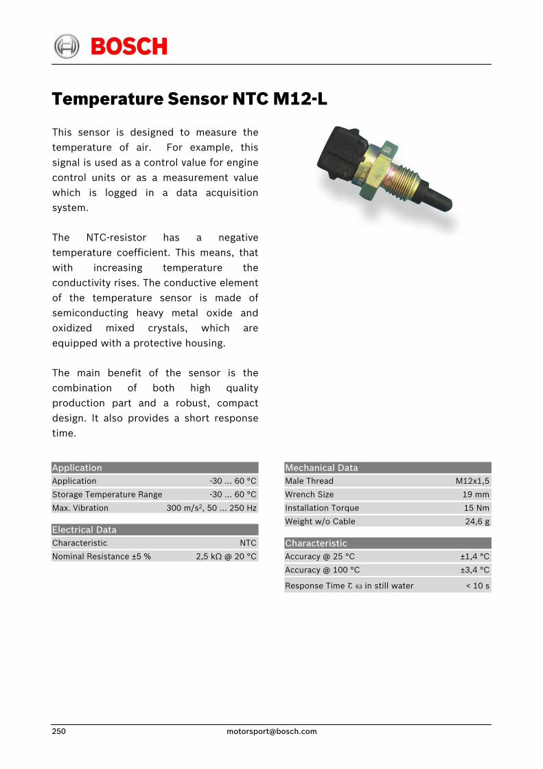
Temperature Sensor NTC M12-L
This sensor is designed to measure thetemperature of air. For example, thissignal is used as a control value for enginecontrol units or as a measurement valuewhich is logged in a data acquisitionsystem.
The NTC-resistor has a negativetemperature coefficient. This means, thatwith increasing temperature theconductivity rises. The conductive elementof the temperature sensor is made ofsemiconducting heavy metal oxide andoxidized mixed crystals, which areequipped with a protective housing.
The main benefit of the sensor is thecombination of both high qualityproduction part and a robust, compactdesign. It also provides a short responsetime.
Application Application -30 … 60 °C
Storage Temperature Range -30 … 60 °C
Max. Vibration 300 m/s2, 50 … 250 Hz
Electrical Data Characteristic NTC
Nominal Resistance ±5 % 2,5 kΩ @ 20 °C
Mechanical Data Male Thread M12x1,5
Wrench Size 19 mm
Installation Torque 15 Nm
Weight w/o Cable 24,6 g
Characteristic Accuracy @ 25 °C ±1,4 °C
Accuracy @ 100 °C ±3,4 °C
Response Time Շ 63 in still water < 10 s
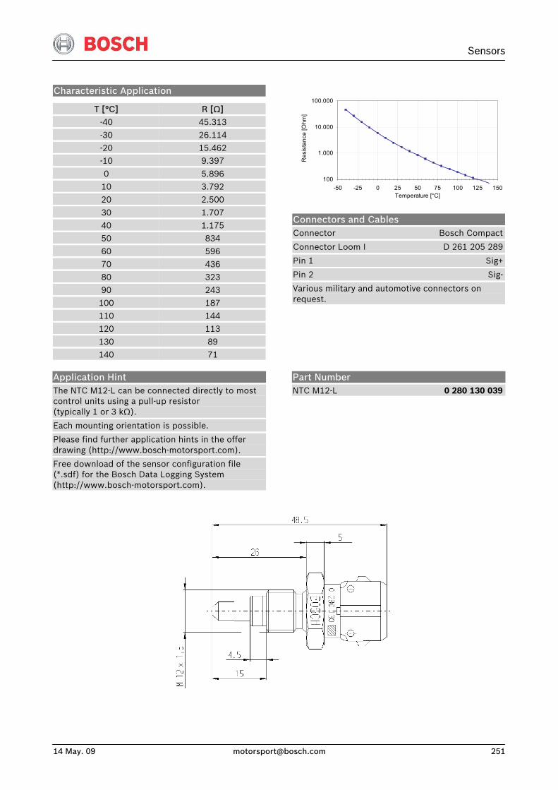
Sensors
14 May. 09 [email protected] 251
Characteristic Application
T [°C] R [Ω]
-40 45.313 -30 26.114 -20 15.462 -10 9.397
0 5.896 10 3.792 20 2.500
30 1.707 40 1.175 50 834
60 596 70 436 80 323
90 243 100 187 110 144
120 113 130 89 140 71
100
1.000
10.000
100.000
-50 -25 0 25 50 75 100 125 150Temperature [°C]
Res
ista
nce
[Ohm
]
Connectors and Cables Connector Bosch Compact
Connector Loom I D 261 205 289
Pin 1 Sig+
Pin 2 Sig-
Various military and automotive connectors on request.
Application Hint The NTC M12-L can be connected directly to most control units using a pull-up resistor (typically 1 or 3 kΩ).
Each mounting orientation is possible.
Please find further application hints in the offer drawing (http://www.bosch-motorsport.com).
Free download of the sensor configuration file (*.sdf) for the Bosch Data Logging System (http://www.bosch-motorsport.com).
Part Number NTC M12-L 0 280 130 039
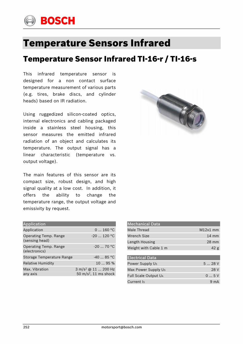
Temperature Sensors Infrared Temperature Sensor Infrared TI-16-r / TI-16-s
This infrared temperature sensor isdesigned for a non contact surfacetemperature measurement of various parts(e.g. tires, brake discs, and cylinderheads) based on IR radiation.
Using ruggedized silicon-coated optics,internal electronics and cabling packagedinside a stainless steel housing, thissensor measures the emitted infraredradiation of an object and calculates itstemperature. The output signal has alinear characteristic (temperature vs.output voltage).
The main features of this sensor are itscompact size, robust design, and highsignal quality at a low cost. In addition, itoffers the ability to change thetemperature range, the output voltage andemissivity by request.
Application Application 0 … 160 °C
Operating Temp. Range -20 … 120 °C(sensing head)
Operating Temp. Range -20 … 70 °C(electronics)
Storage Temperature Range -40 … 85 °C
Relative Humidity 10 … 95 %
Max. Vibration 3 m/s2 @ 11 … 200 Hzany axis 50 m/s2, 11 ms shock
Mechanical Data Male Thread M12x1 mm
Wrench Size 14 mm
Length Housing 28 mm
Weight with Cable 1 m 42 g
Electrical Data Power Supply US 5 … 28 V
Max Power Supply US 28 V
Full Scale Output UA 0 … 5 V
Current IS 9 mA
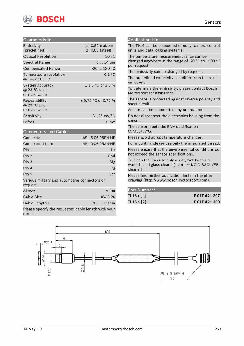
Sensors
14 May. 09 [email protected] 253
Characteristic Emissivity [1] 0,95 (rubber)(predefined) [2] 0,80 (steel)
Optical Resolution 10 : 1
Spectral Range 8 … 14 μm
Compensated Range -20 … 120 °C
Temperature resolution 0,1 °C@ Tobj < 100 °C
System Accuracy ± 1,5 °C or 1,5 %@ 23 °C tamb, or max. value
Repeatability ± 0,75 °C or 0,75 %@ 23 °C tamb, or max. value
Sensitivity 31,25 mV/°C
Offset 0 mV
Connectors and Cables Connector ASL 6-06-05PN-HE
Connector Loom ASL 0-06-05SN-HE
Pin 1 US
Pin 2 Gnd
Pin 3 Sig
Pin 4 Prg
Pin 5 Scr
Various military and automotive connectors on request.
Sleeve Viton
Cable Size AWG 26
Cable Length L 70 … 100 cm
Please specify the requested cable length with your order.
Application Hint The TI-16 can be connected directly to most control units and data logging systems.
The temperature measurement range can be changed anywhere in the range of -20 °C to 1000 °C per request.
The emissivity can be changed by request.
The predefined emissivity can differ from the real emissivity.
To determine the emissivity, please contact Bosch Motorsport for assistance.
The sensor is protected against reverse polarity and short-circuit.
Sensor can be mounted in any orientation.
Do not disconnect the electronics housing from the sensor.
The sensor meets the EMV qualification 89/336/EWG.
Please avoid abrupt temperature changes.
For mounting please use only the integrated thread.
Please ensure that the environmental conditions do not exceed the sensor specifications.
To clean the lens use only a soft, wet (water or water based glass cleaner) cloth -> NO DISSOLVER cleaner!
Please find further application hints in the offer drawing (http://www.bosch-motorsport.com).
Part Numbers TI-16-r [1] F 01T A21 207
TI-16-s [2] F 01T A21 209
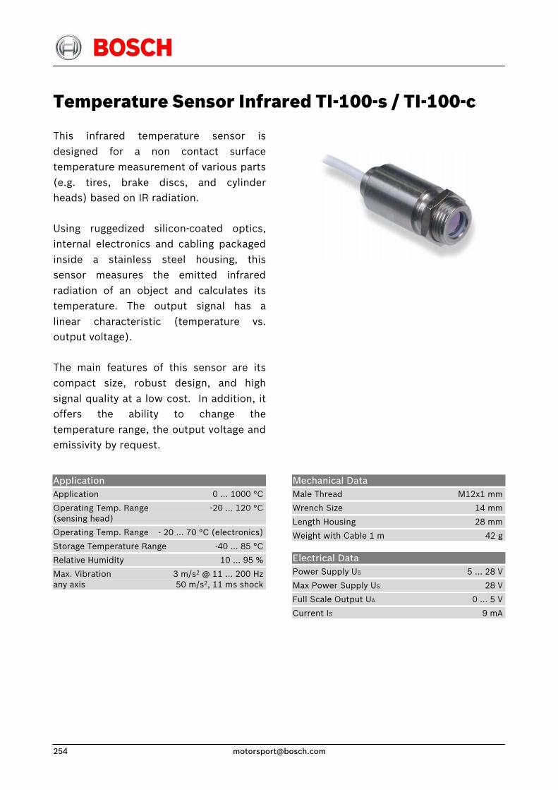
Temperature Sensor Infrared TI-100-s / TI-100-c
This infrared temperature sensor isdesigned for a non contact surfacetemperature measurement of various parts(e.g. tires, brake discs, and cylinderheads) based on IR radiation.
Using ruggedized silicon-coated optics,internal electronics and cabling packagedinside a stainless steel housing, thissensor measures the emitted infraredradiation of an object and calculates itstemperature. The output signal has alinear characteristic (temperature vs.output voltage).
The main features of this sensor are itscompact size, robust design, and highsignal quality at a low cost. In addition, itoffers the ability to change thetemperature range, the output voltage andemissivity by request.
Application Application 0 … 1000 °C
Operating Temp. Range -20 … 120 °C(sensing head)
Operating Temp. Range - 20 … 70 °C (electronics)
Storage Temperature Range -40 … 85 °C
Relative Humidity 10 … 95 %
Max. Vibration 3 m/s2 @ 11 … 200 Hzany axis 50 m/s2, 11 ms shock
Mechanical Data Male Thread M12x1 mm
Wrench Size 14 mm
Length Housing 28 mm
Weight with Cable 1 m 42 g
Electrical Data Power Supply US 5 … 28 V
Max Power Supply US 28 V
Full Scale Output UA 0 … 5 V
Current IS 9 mA
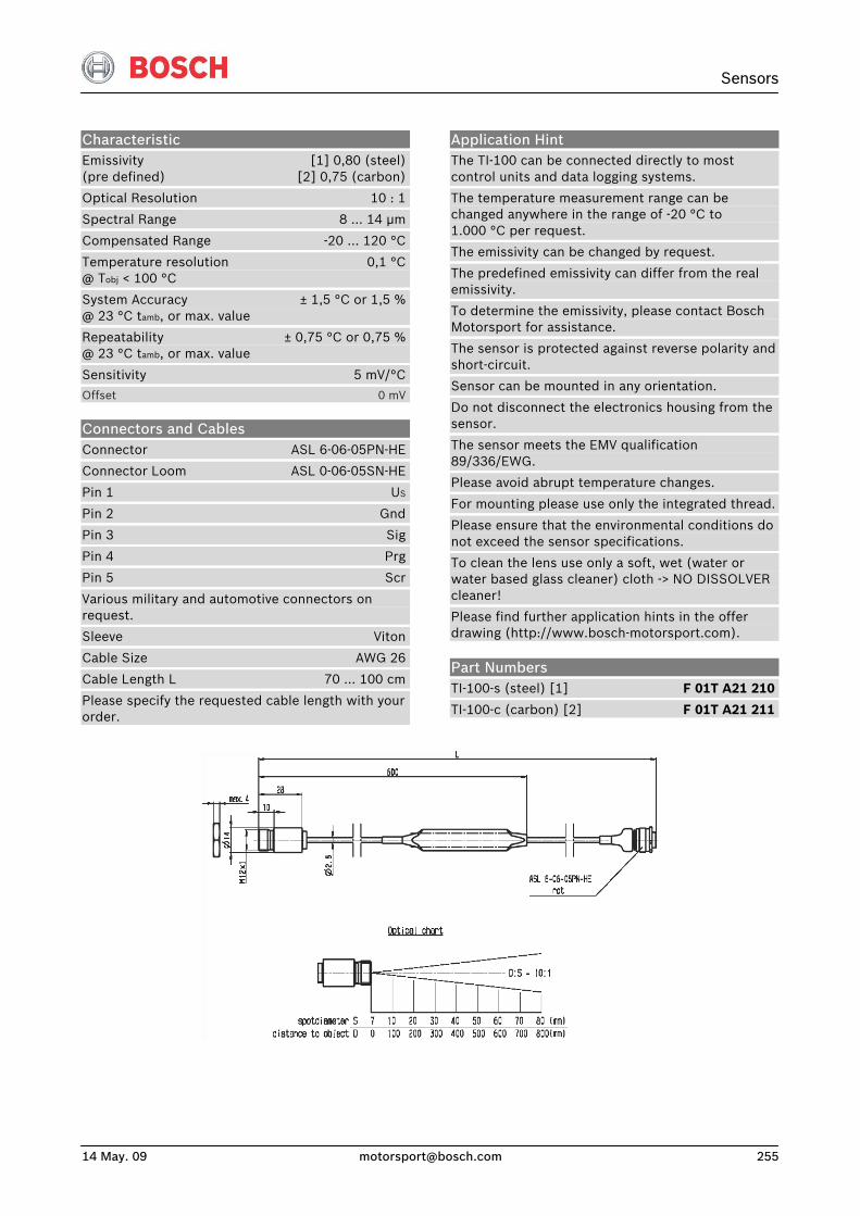
Sensors
14 May. 09 [email protected] 255
Characteristic Emissivity [1] 0,80 (steel) (pre defined) [2] 0,75 (carbon)
Optical Resolution 10 : 1
Spectral Range 8 … 14 μm
Compensated Range -20 … 120 °C
Temperature resolution 0,1 °C@ Tobj < 100 °C
System Accuracy ± 1,5 °C or 1,5 %@ 23 °C tamb, or max. value
Repeatability ± 0,75 °C or 0,75 %@ 23 °C tamb, or max. value
Sensitivity 5 mV/°C
Offset 0 mV
Connectors and Cables Connector ASL 6-06-05PN-HE
Connector Loom ASL 0-06-05SN-HE
Pin 1 US
Pin 2 Gnd
Pin 3 Sig
Pin 4 Prg
Pin 5 Scr
Various military and automotive connectors on request.
Sleeve Viton
Cable Size AWG 26
Cable Length L 70 … 100 cm
Please specify the requested cable length with your order.
Application Hint The TI-100 can be connected directly to most control units and data logging systems.
The temperature measurement range can be changed anywhere in the range of -20 °C to 1.000 °C per request.
The emissivity can be changed by request.
The predefined emissivity can differ from the real emissivity.
To determine the emissivity, please contact Bosch Motorsport for assistance.
The sensor is protected against reverse polarity and short-circuit.
Sensor can be mounted in any orientation.
Do not disconnect the electronics housing from the sensor.
The sensor meets the EMV qualification 89/336/EWG.
Please avoid abrupt temperature changes.
For mounting please use only the integrated thread.
Please ensure that the environmental conditions do not exceed the sensor specifications.
To clean the lens use only a soft, wet (water or water based glass cleaner) cloth -> NO DISSOLVER cleaner!
Please find further application hints in the offer drawing (http://www.bosch-motorsport.com).
Part Numbers TI-100-s (steel) [1] F 01T A21 210
TI-100-c (carbon) [2] F 01T A21 211
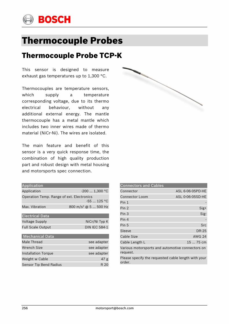
Thermocouple Probes Thermocouple Probe TCP-K
This sensor is designed to measureexhaust gas temperatures up to 1,300 °C.
Thermocouples are temperature sensors,which supply a temperaturecorresponding voltage, due to its thermoelectrical behaviour, without anyadditional external energy. The mantlethermocouple has a metal mantle whichincludes two inner wires made of thermomaterial (NiCr-Ni). The wires are isolated.
The main feature and benefit of thissensor is a very quick response time, thecombination of high quality productionpart and robust design with metal housingand motorsports spec connection.
Application Application -200 … 1,300 °C
Operation Temp. Range of ext. Electronics -55 … 125 °C
Max. Vibration 800 m/s2 @ 5 … 500 Hz
Electrical Data Voltage Supply NiCr/Ni Typ K
Full Scale Output DIN IEC 584-1
Mechanical Data Male Thread see adapter
Wrench Size see adapter
Installation Torque see adapter
Weight w Cable 47 g
Sensor Tip Bend Radius R 20
Connectors and Cables Connector ASL 6-06-05PD-HE
Connector Loom ASL 0-06-05SD-HE
Pin 1 -
Pin 2 Sig+
Pin 3 Sig-
Pin 4 -
Pin 5 Src
Sleeve DR-25
Cable Size AWG 24
Cable Length L 15 … 75 cm
Various motorsports and automotive connectors on request.
Please specify the requested cable length with your order.
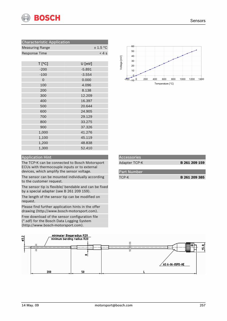
Sensors
14 May. 09 [email protected] 257
Characteristic Application Measuring Range ± 1.5 °C
Response Time < 4 s
T [°C]
-200
U [mV]
-5.891
-100 -3.554 0 0.000
100 4.096
200 8.138 300 12.209 400 16.397
500 20.644 600 24.905 700 29.129
800 33.275 900 37.326
1,000 41.276
1,100 45.119 1,200 48.838 1,300 52.410
-10
0
10
20
30
40
50
60
-200 0 200 400 600 800 1000 1200 1400
Temperature [°C]
Vol
tage
[mV
]
Application Hint The TCP-K can be connected to Bosch Motorsport ECUs with thermocouple inputs or to external devices, which amplify the sensor voltage.
The sensor can be mounted individually according to the customer request.
The sensor tip is flexible/ bendable and can be fixed by a special adapter (see B 261 209 159).
The length of the sensor tip can be modified on request.
Please find further application hints in the offer drawing (http://www.bosch-motorsport.com).
Free download of the sensor configuration file (*.sdf) for the Bosch Data Logging System (http://www.bosch-motorsport.com).
Accessories Adapter TCP-K B 261 209 159
Part Number TCP-K B 261 209 385
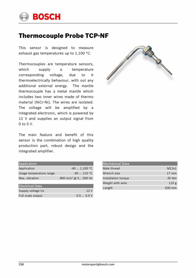
Thermocouple Probe TCP-NF
This sensor is designed to measureexhaust gas temperatures up to 1,100 °C.
Thermocouples are temperature sensors,which supply a temperaturecorresponding voltage, due to itthermoelectrically behaviour, with out anyadditional external energy. The mantlethermocouple has a metal mantle whichincludes two inner wires made of thermomaterial (NiCr-Ni). The wires are isolated.The voltage will be amplified by aintegrated electronic, which is powered by12 V and supplies an output signal from0 to 5 V.
The main feature and benefit of thissensor is the combination of high qualityproduction part, robust design and theintegrated amplifier.
Application Application -40 … 1,100 °C
Usage temperature range -40 … 115 °C
Max. vibration 800 m/s2 @ 5… 500 Hz
Electrical Data Supply voltage Us 12 V
Full scale output 0.5 … 4.5 V
Mechanical Data Male thread M12x1
Wrench size 17 mm
Installation torque 45 Nm
Weight with wire 110 g
Length 630 mm
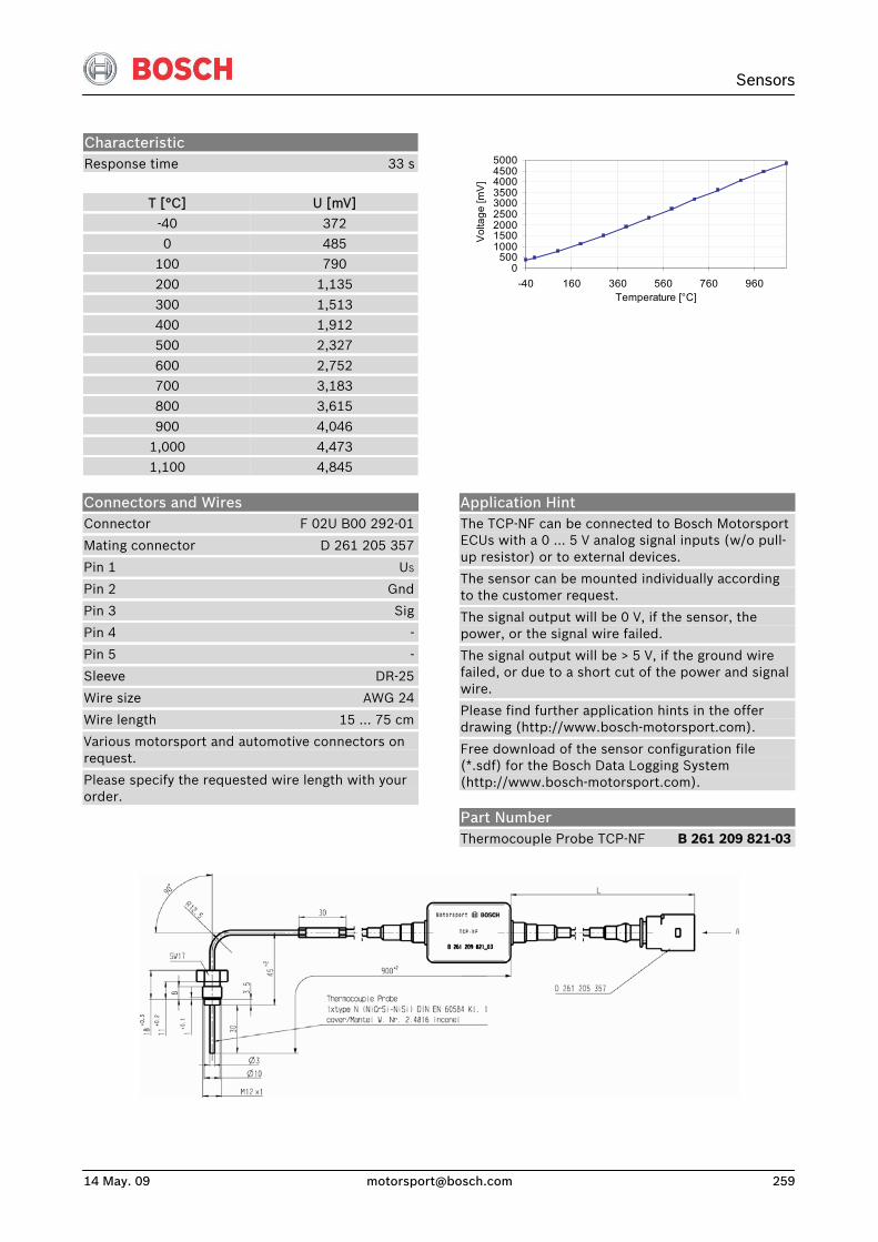
Sensors
14 May. 09 [email protected] 259
Characteristic Response time 33 s
T [°C] U [mV]
-40 372 0 485
100 790 200 1,135
300 1,513 400 1,912 500 2,327
600 2,752 700 3,183 800 3,615
900 4,046 1,000 4,473 1,100 4,845
0500
100015002000250030003500400045005000
-40 160 360 560 760 960Temperature [°C]
Vol
tage
[mV
]
Connectors and Wires Connector F 02U B00 292-01
Mating connector D 261 205 357
Pin 1 US
Pin 2 Gnd
Pin 3 Sig
Pin 4 -
Pin 5 -
Sleeve DR-25
Wire size AWG 24
Wire length 15 … 75 cm
Various motorsport and automotive connectors on request.
Please specify the requested wire length with your order.
Application Hint The TCP-NF can be connected to Bosch Motorsport ECUs with a 0 ... 5 V analog signal inputs (w/o pull-up resistor) or to external devices.
The sensor can be mounted individually according to the customer request.
The signal output will be 0 V, if the sensor, the power, or the signal wire failed.
The signal output will be > 5 V, if the ground wire failed, or due to a short cut of the power and signal wire.
Please find further application hints in the offer drawing (http://www.bosch-motorsport.com).
Free download of the sensor configuration file (*.sdf) for the Bosch Data Logging System (http://www.bosch-motorsport.com).
Part Number Thermocouple Probe TCP-NF B 261 209 821-03
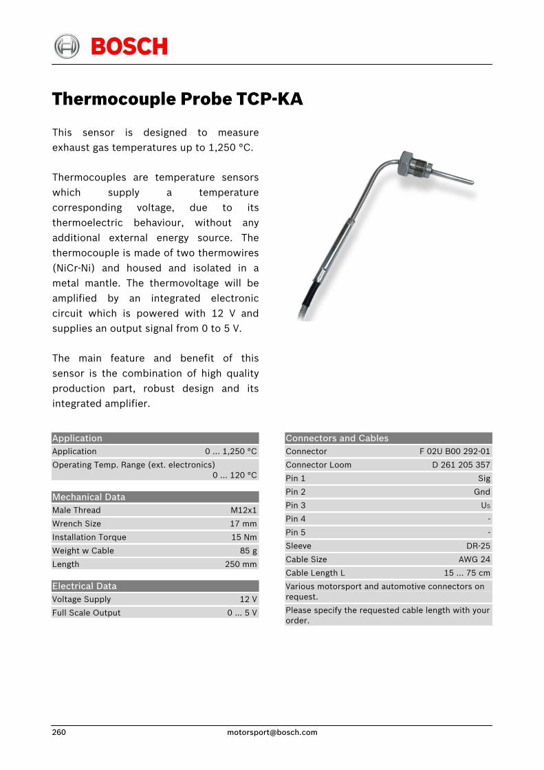
Thermocouple Probe TCP-KA
This sensor is designed to measureexhaust gas temperatures up to 1,250 °C.
Thermocouples are temperature sensorswhich supply a temperaturecorresponding voltage, due to itsthermoelectric behaviour, without anyadditional external energy source. Thethermocouple is made of two thermowires(NiCr-Ni) and housed and isolated in ametal mantle. The thermovoltage will beamplified by an integrated electroniccircuit which is powered with 12 V andsupplies an output signal from 0 to 5 V.
The main feature and benefit of thissensor is the combination of high qualityproduction part, robust design and itsintegrated amplifier.
Application Application 0 … 1,250 °C
Operating Temp. Range (ext. electronics) 0 … 120 °C
Mechanical Data Male Thread M12x1
Wrench Size 17 mm
Installation Torque 15 Nm
Weight w Cable 85 g
Length 250 mm
Electrical Data Voltage Supply 12 V
Full Scale Output 0 … 5 V
Connectors and Cables Connector F 02U B00 292-01
Connector Loom D 261 205 357
Pin 1 Sig
Pin 2 Gnd
Pin 3 US
Pin 4 -
Pin 5 -
Sleeve DR-25
Cable Size AWG 24
Cable Length L 15 … 75 cm
Various motorsport and automotive connectors on request.
Please specify the requested cable length with your order.
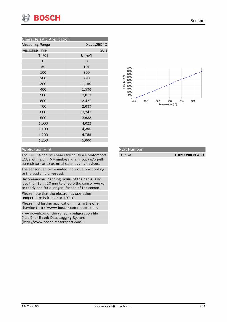
Sensors
14 May. 09 [email protected] 261
Characteristic Application Measuring Range 0 … 1,250 °C
Response Time 20 s
T [°C]
0
50
100
200
300
400
500
600
700
800
900
1,000
1,100
1,200
1,250
U [mV]
0
197
399
793
1,190
1,598
2,012
2,427
2,839
3,243
3,638
4,022
4,396
4,759
5,000
0500
100015002000250030003500400045005000
-40 160 360 560 760 960Temperature [°C]
Vol
tage
[mV
]
Application Hint The TCP-KA can be connected to Bosch Motorsport ECUs with a 0 ... 5 V analog signal input (w/o pull-up resistor) or to external data logging devices.
The sensor can be mounted individually according to the customers request.
Recommended bending radius of the cable is no less than 15 … 20 mm to ensure the sensor works properly and for a longer lifespan of the sensor.
Please note that the electronics operating temperature is from 0 to 120 °C.
Please find further application hints in the offer drawing (http://www.bosch-motorsport.com).
Free download of the sensor configuration file (*.sdf) for Bosch Data Logging System (http://www.bosch-motorsport.com).
Part Number TCP-KA F 02U V00 264-01

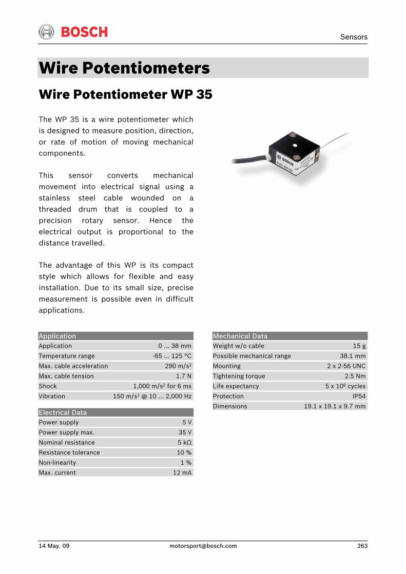
Sensors
14 May. 09 [email protected] 263
Wire Potentiometers Wire Potentiometer WP 35
The WP 35 is a wire potentiometer whichis designed to measure position, direction,or rate of motion of moving mechanicalcomponents.
This sensor converts mechanicalmovement into electrical signal using astainless steel cable wounded on athreaded drum that is coupled to aprecision rotary sensor. Hence theelectrical output is proportional to thedistance travelled.
The advantage of this WP is its compactstyle which allows for flexible and easyinstallation. Due to its small size, precisemeasurement is possible even in difficultapplications.
Application Application 0 … 38 mm
Temperature range -65 … 125 °C
Max. cable acceleration 290 m/s2
Max. cable tension 1.7 N
Shock 1,000 m/s2 for 6 ms
Vibration 150 m/s2 @ 10 … 2,000 Hz
Electrical Data Power supply 5 V
Power supply max. 35 V
Nominal resistance 5 kΩ
Resistance tolerance 10 %
Non-linearity 1 %
Max. current 12 mA
Mechanical Data Weight w/o cable 15 g
Possible mechanical range 38.1 mm
Mounting 2 x 2-56 UNC
Tightening torque 2.5 Nm
Life expectancy 5 x 10⁶ cycles
Protection IP54
Dimensions 19.1 x 19.1 x 9.7 mm
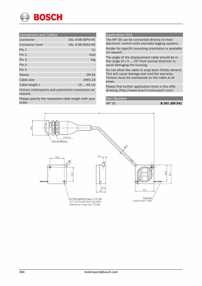
Connectors and Cables Connector ASL 6-06-05PA-HE
Connector loom ASL 0-06-05SA-HE
Pin 1 US
Pin 2 Gnd
Pin 3 Sig
Pin 4 -
Pin 5 -
Sleeve DR-25
Cable size AWG 24
Cable length L 15 … 45 cm
Various motorsports and automotive connectors on request.
Please specify the requested cable length with your order.
Application Hint The WP 35 can be connected directly to most electronic control units and data logging systems.
Holder for specific mounting orientation is available on request.
The angle of the displacement cable should be in the range of ± 5 … 10° from normal direction to avoid damaging the housing.
Do not allow the cable to snap back (freely retract). This will cause damage and void the warranty. Tension must be maintained on the cable at all times.
Please find further application hints in the offer drawing (http://www.bosch-motorsport.com).
Part Number WP 35 B 261 209 541
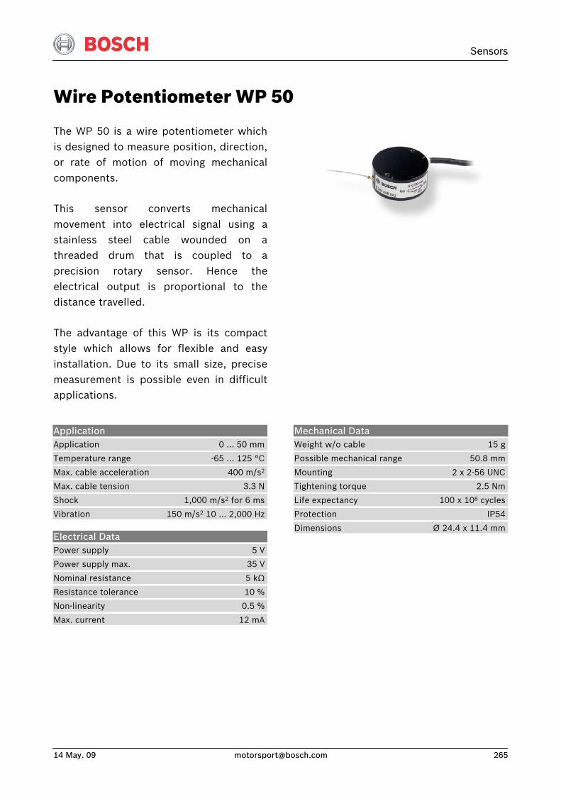
Sensors
14 May. 09 [email protected] 265
Wire Potentiometer WP 50
The WP 50 is a wire potentiometer whichis designed to measure position, direction,or rate of motion of moving mechanicalcomponents.
This sensor converts mechanicalmovement into electrical signal using astainless steel cable wounded on athreaded drum that is coupled to aprecision rotary sensor. Hence the electrical output is proportional to thedistance travelled.
The advantage of this WP is its compactstyle which allows for flexible and easyinstallation. Due to its small size, precisemeasurement is possible even in difficultapplications.
Application Application 0 … 50 mm
Temperature range -65 … 125 °C
Max. cable acceleration 400 m/s2
Max. cable tension 3.3 N
Shock 1,000 m/s2 for 6 ms
Vibration 150 m/s2 10 … 2,000 Hz
Electrical Data Power supply 5 V
Power supply max. 35 V
Nominal resistance 5 kΩ
Resistance tolerance 10 %
Non-linearity 0.5 %
Max. current 12 mA
Mechanical Data Weight w/o cable 15 g
Possible mechanical range 50.8 mm
Mounting 2 x 2-56 UNC
Tightening torque 2.5 Nm
Life expectancy 100 x 106 cycles
Protection IP54
Dimensions Ø 24.4 x 11.4 mm
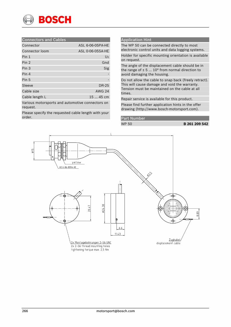
Connectors and Cables Connector ASL 6-06-05PA-HE
Connector loom ASL 0-06-05SA-HE
Pin 1 US
Pin 2 Gnd
Pin 3 Sig
Pin 4 -
Pin 5 -
Sleeve DR-25
Cable size AWG 24
Cable length L 15 … 45 cm
Various motorsports and automotive connectors on request.
Please specify the requested cable length with your order.
Application Hint The WP 50 can be connected directly to most electronic control units and data logging systems.
Holder for specific mounting orientation is available on request.
The angle of the displacement cable should be in the range of ± 5 … 10° from normal direction to avoid damaging the housing.
Do not allow the cable to snap back (freely retract). This will cause damage and void the warranty. Tension must be maintained on the cable at all times.
Repair service is available for this product.
Please find further application hints in the offer drawing (http://www.bosch-motorsport.com).
Part Number WP 50 B 261 209 542
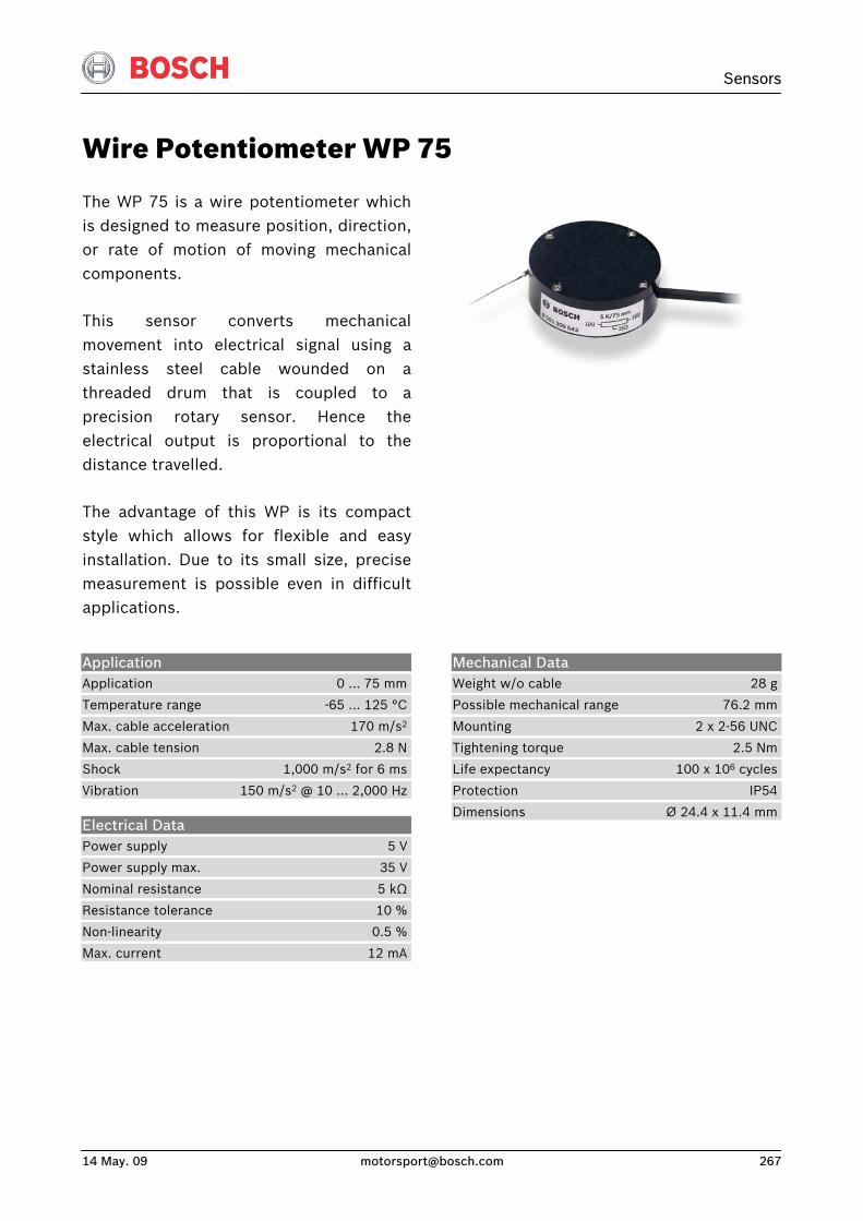
Sensors
14 May. 09 [email protected] 267
Wire Potentiometer WP 75
The WP 75 is a wire potentiometer whichis designed to measure position, direction,or rate of motion of moving mechanicalcomponents.
This sensor converts mechanicalmovement into electrical signal using astainless steel cable wounded on athreaded drum that is coupled to aprecision rotary sensor. Hence theelectrical output is proportional to thedistance travelled.
The advantage of this WP is its compactstyle which allows for flexible and easyinstallation. Due to its small size, precisemeasurement is possible even in difficultapplications.
Application Application 0 … 75 mm
Temperature range -65 … 125 °C
Max. cable acceleration 170 m/s2
Max. cable tension 2.8 N
Shock 1,000 m/s2 for 6 ms
Vibration 150 m/s2 @ 10 … 2,000 Hz
Electrical Data Power supply 5 V
Power supply max. 35 V
Nominal resistance 5 kΩ
Resistance tolerance 10 %
Non-linearity 0.5 %
Max. current 12 mA
Mechanical Data Weight w/o cable 28 g
Possible mechanical range 76.2 mm
Mounting 2 x 2-56 UNC
Tightening torque 2.5 Nm
Life expectancy 100 x 106 cycles
Protection IP54
Dimensions Ø 24.4 x 11.4 mm
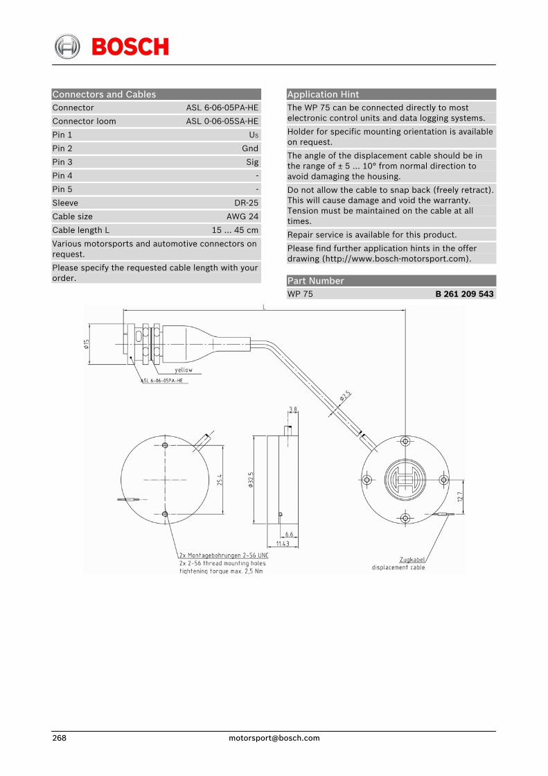
Connectors and Cables Connector ASL 6-06-05PA-HE
Connector loom ASL 0-06-05SA-HE
Pin 1 US
Pin 2 Gnd
Pin 3 Sig
Pin 4 -
Pin 5 -
Sleeve DR-25
Cable size AWG 24
Cable length L 15 … 45 cm
Various motorsports and automotive connectors on request.
Please specify the requested cable length with your order.
Application Hint The WP 75 can be connected directly to most electronic control units and data logging systems.
Holder for specific mounting orientation is available on request.
The angle of the displacement cable should be in the range of ± 5 … 10° from normal direction to avoid damaging the housing.
Do not allow the cable to snap back (freely retract). This will cause damage and void the warranty. Tension must be maintained on the cable at all times.
Repair service is available for this product.
Please find further application hints in the offer drawing (http://www.bosch-motorsport.com).
Part Number WP 75 B 261 209 543
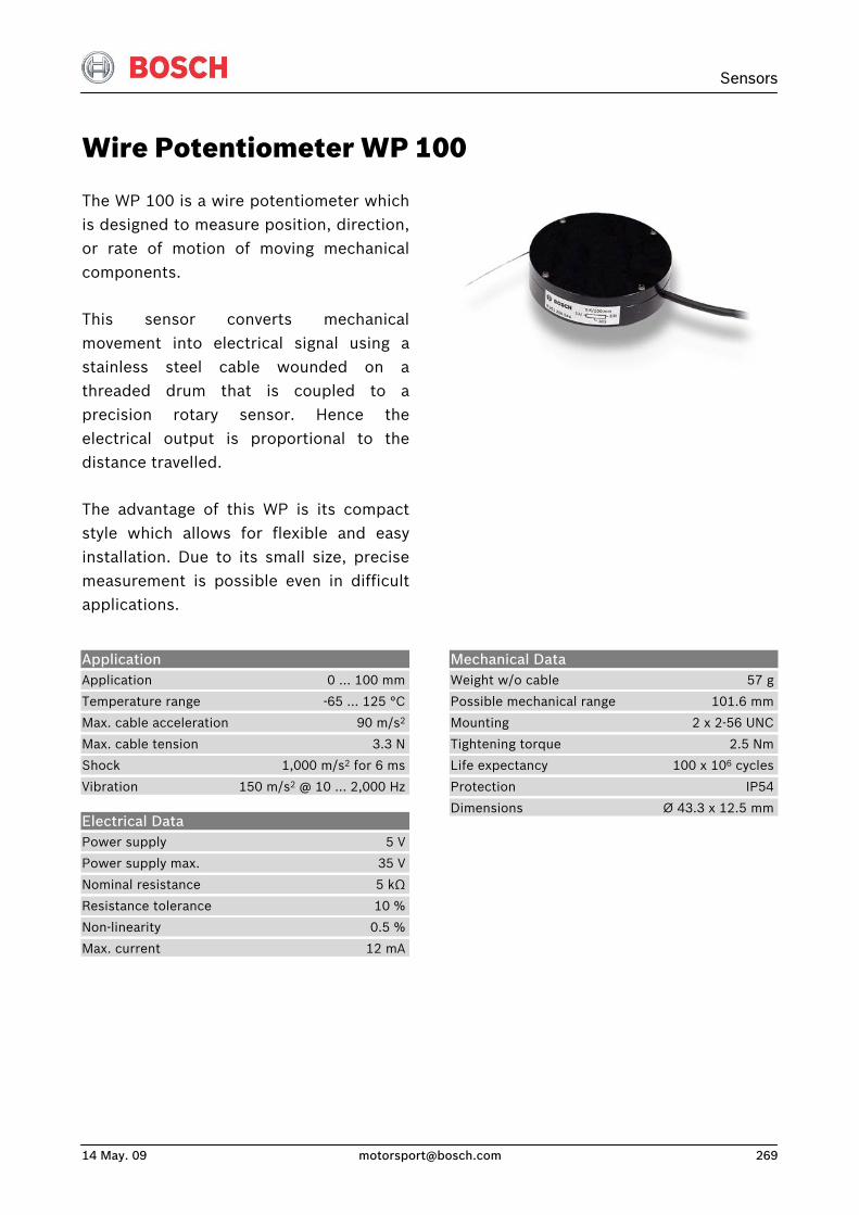
Sensors
14 May. 09 [email protected] 269
Wire Potentiometer WP 100
The WP 100 is a wire potentiometer whichis designed to measure position, direction,or rate of motion of moving mechanicalcomponents.
This sensor converts mechanicalmovement into electrical signal using astainless steel cable wounded on athreaded drum that is coupled to aprecision rotary sensor. Hence theelectrical output is proportional to thedistance travelled.
The advantage of this WP is its compactstyle which allows for flexible and easyinstallation. Due to its small size, precisemeasurement is possible even in difficultapplications.
Application Application 0 … 100 mm
Temperature range -65 … 125 °C
Max. cable acceleration 90 m/s2
Max. cable tension 3.3 N
Shock 1,000 m/s2 for 6 ms
Vibration 150 m/s2 @ 10 … 2,000 Hz
Electrical Data Power supply 5 V
Power supply max. 35 V
Nominal resistance 5 kΩ
Resistance tolerance 10 %
Non-linearity 0.5 %
Max. current 12 mA
Mechanical Data Weight w/o cable 57 g
Possible mechanical range 101.6 mm
Mounting 2 x 2-56 UNC
Tightening torque 2.5 Nm
Life expectancy 100 x 106 cycles
Protection IP54
Dimensions Ø 43.3 x 12.5 mm
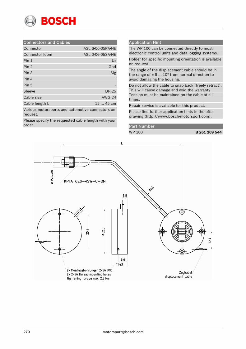
Connectors and Cables Connector ASL 6-06-05PA-HE
Connector loom ASL 0-06-05SA-HE
Pin 1 US
Pin 2 Gnd
Pin 3 Sig
Pin 4 -
Pin 5 -
Sleeve DR-25
Cable size AWG 24
Cable length L 15 … 45 cm
Various motorsports and automotive connectors on request.
Please specify the requested cable length with your order.
Application Hint The WP 100 can be connected directly to most electronic control units and data logging systems.
Holder for specific mounting orientation is available on request.
The angle of the displacement cable should be in the range of ± 5 … 10° from normal direction to avoid damaging the housing.
Do not allow the cable to snap back (freely retract). This will cause damage and void the warranty. Tension must be maintained on the cable at all times.
Repair service is available for this product.
Please find further application hints in the offer drawing (http://www.bosch-motorsport.com).
Part Number WP 100 B 261 209 544
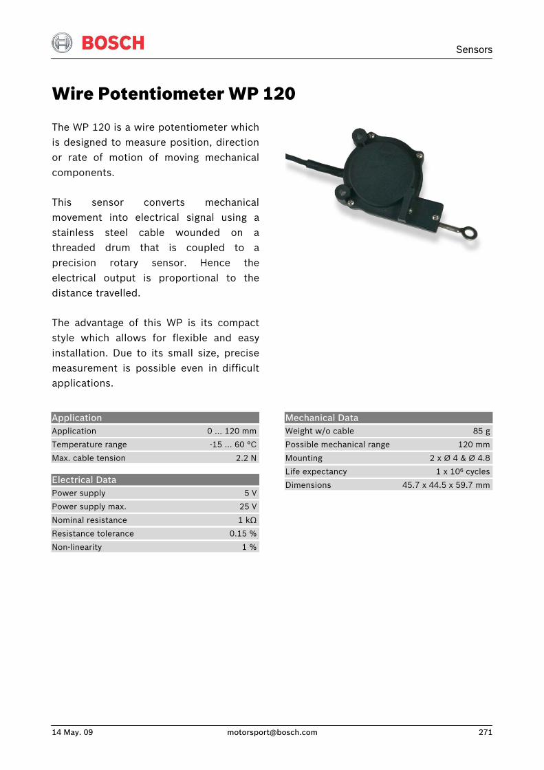
Sensors
14 May. 09 [email protected] 271
Wire Potentiometer WP 120
The WP 120 is a wire potentiometer whichis designed to measure position, directionor rate of motion of moving mechanicalcomponents.
This sensor converts mechanicalmovement into electrical signal using a stainless steel cable wounded on athreaded drum that is coupled to aprecision rotary sensor. Hence theelectrical output is proportional to thedistance travelled.
The advantage of this WP is its compactstyle which allows for flexible and easyinstallation. Due to its small size, precisemeasurement is possible even in difficultapplications.
Application Application 0 … 120 mm
Temperature range -15 … 60 °C
Max. cable tension 2.2 N
Electrical Data Power supply 5 V
Power supply max. 25 V
Nominal resistance 1 kΩ
Resistance tolerance 0.15 %
Non-linearity 1 %
Mechanical Data Weight w/o cable 85 g
Possible mechanical range 120 mm
Mounting 2 x Ø 4 & Ø 4.8
Life expectancy 1 x 10⁶ cycles
Dimensions 45.7 x 44.5 x 59.7 mm
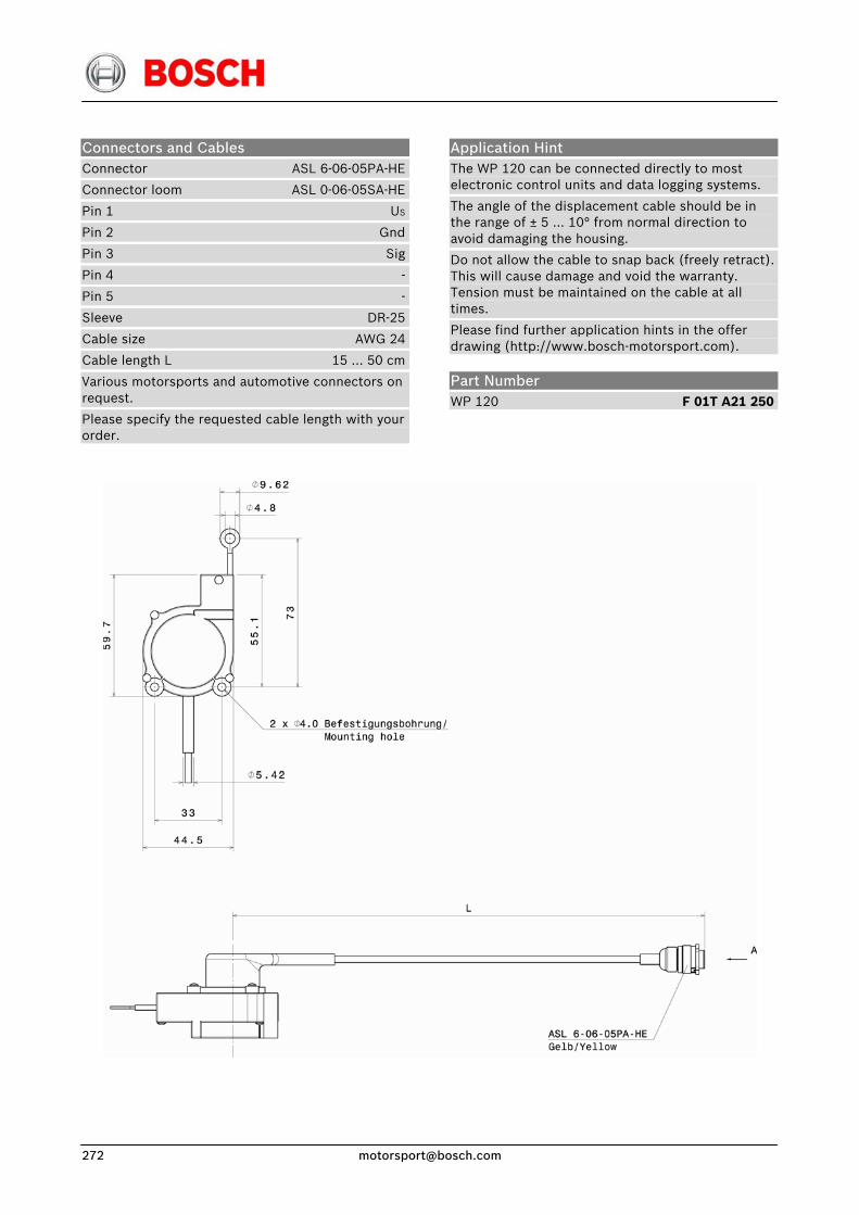
Connectors and Cables Connector ASL 6-06-05PA-HE
Connector loom ASL 0-06-05SA-HE
Pin 1 US
Pin 2 Gnd
Pin 3 Sig
Pin 4 -
Pin 5 -
Sleeve DR-25
Cable size AWG 24
Cable length L 15 … 50 cm
Various motorsports and automotive connectors on request.
Please specify the requested cable length with your order.
Application Hint The WP 120 can be connected directly to most electronic control units and data logging systems.
The angle of the displacement cable should be in the range of ± 5 … 10° from normal direction to avoid damaging the housing.
Do not allow the cable to snap back (freely retract). This will cause damage and void the warranty. Tension must be maintained on the cable at all times.
Please find further application hints in the offer drawing (http://www.bosch-motorsport.com).
Part Number WP 120 F 01T A21 250
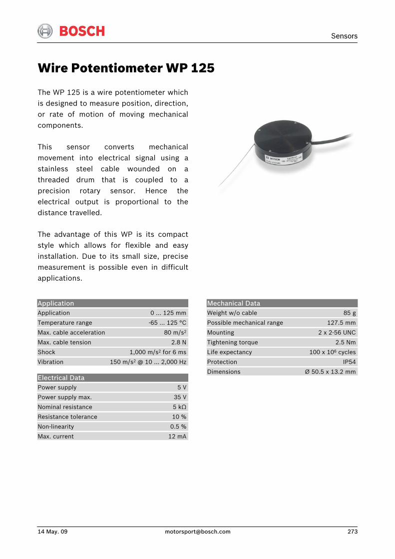
Sensors
14 May. 09 [email protected] 273
Wire Potentiometer WP 125
The WP 125 is a wire potentiometer whichis designed to measure position, direction,or rate of motion of moving mechanicalcomponents.
This sensor converts mechanicalmovement into electrical signal using astainless steel cable wounded on athreaded drum that is coupled to aprecision rotary sensor. Hence theelectrical output is proportional to thedistance travelled.
The advantage of this WP is its compactstyle which allows for flexible and easyinstallation. Due to its small size, precisemeasurement is possible even in difficultapplications.
Application Application 0 … 125 mm
Temperature range -65 … 125 °C
Max. cable acceleration 80 m/s2
Max. cable tension 2.8 N
Shock 1,000 m/s2 for 6 ms
Vibration 150 m/s2 @ 10 … 2,000 Hz
Electrical Data Power supply 5 V
Power supply max. 35 V
Nominal resistance 5 kΩ
Resistance tolerance 10 %
Non-linearity 0.5 %
Max. current 12 mA
Mechanical Data Weight w/o cable 85 g
Possible mechanical range 127.5 mm
Mounting 2 x 2-56 UNC
Tightening torque 2.5 Nm
Life expectancy 100 x 106 cycles
Protection IP54
Dimensions Ø 50.5 x 13.2 mm
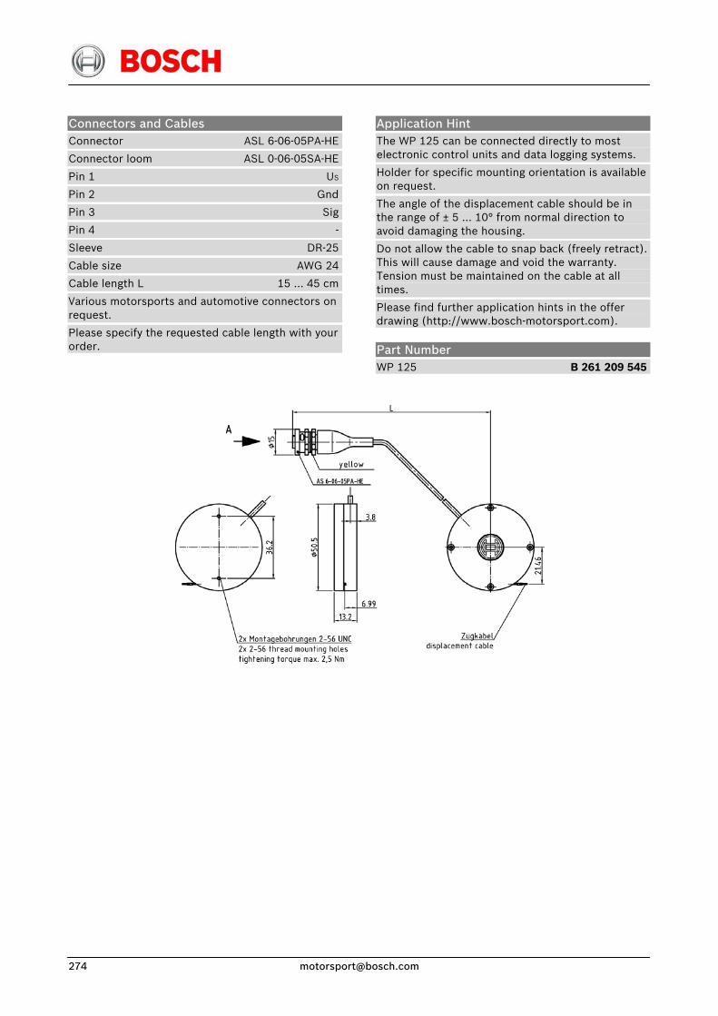
Connectors and Cables Connector ASL 6-06-05PA-HE
Connector loom ASL 0-06-05SA-HE
Pin 1 US
Pin 2 Gnd
Pin 3 Sig
Pin 4 -
Sleeve DR-25
Cable size AWG 24
Cable length L 15 … 45 cm
Various motorsports and automotive connectors on request.
Please specify the requested cable length with your order.
Application Hint The WP 125 can be connected directly to most electronic control units and data logging systems.
Holder for specific mounting orientation is available on request.
The angle of the displacement cable should be in the range of ± 5 … 10° from normal direction to avoid damaging the housing.
Do not allow the cable to snap back (freely retract). This will cause damage and void the warranty. Tension must be maintained on the cable at all times.
Please find further application hints in the offer drawing (http://www.bosch-motorsport.com).
Part Number WP 125 B 261 209 545
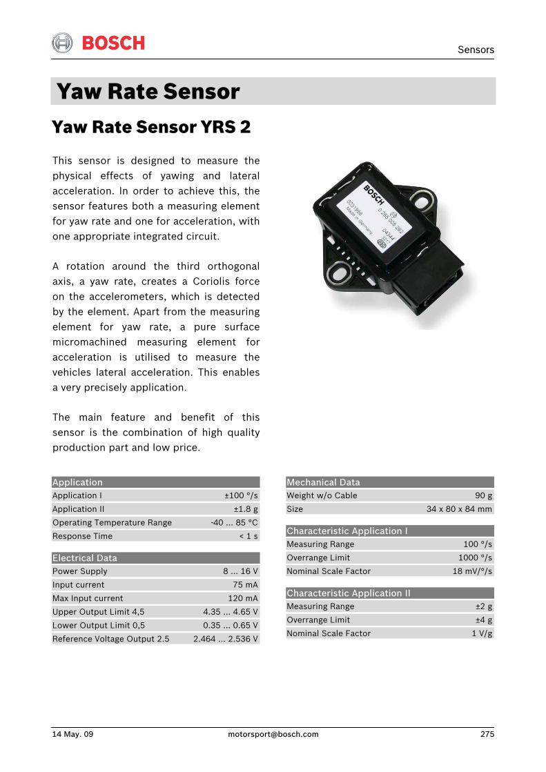
Sensors
14 May. 09 [email protected] 275
Yaw Rate Sensor Yaw Rate Sensor YRS 2
This sensor is designed to measure thephysical effects of yawing and lateralacceleration. In order to achieve this, thesensor features both a measuring elementfor yaw rate and one for acceleration, withone appropriate integrated circuit.
A rotation around the third orthogonalaxis, a yaw rate, creates a Coriolis forceon the accelerometers, which is detectedby the element. Apart from the measuringelement for yaw rate, a pure surfacemicromachined measuring element foracceleration is utilised to measure thevehicles lateral acceleration. This enablesa very precisely application.
The main feature and benefit of thissensor is the combination of high qualityproduction part and low price.
Application Application I ±100 °/s
Application II ±1.8 g
Operating Temperature Range -40 … 85 °C
Response Time < 1 s
Electrical Data Power Supply 8 … 16 V
Input current 75 mA
Max Input current 120 mA
Upper Output Limit 4,5 4.35 … 4.65 V
Lower Output Limit 0,5 0.35 … 0.65 V
Reference Voltage Output 2.5 2.464 … 2.536 V
Mechanical Data Weight w/o Cable 90 g
Size 34 x 80 x 84 mm
Characteristic Application I Measuring Range 100 °/s
Overrange Limit 1000 °/s
Nominal Scale Factor 18 mV/°/s
Characteristic Application II Measuring Range ±2 g
Overrange Limit ±4 g
Nominal Scale Factor 1 V/g
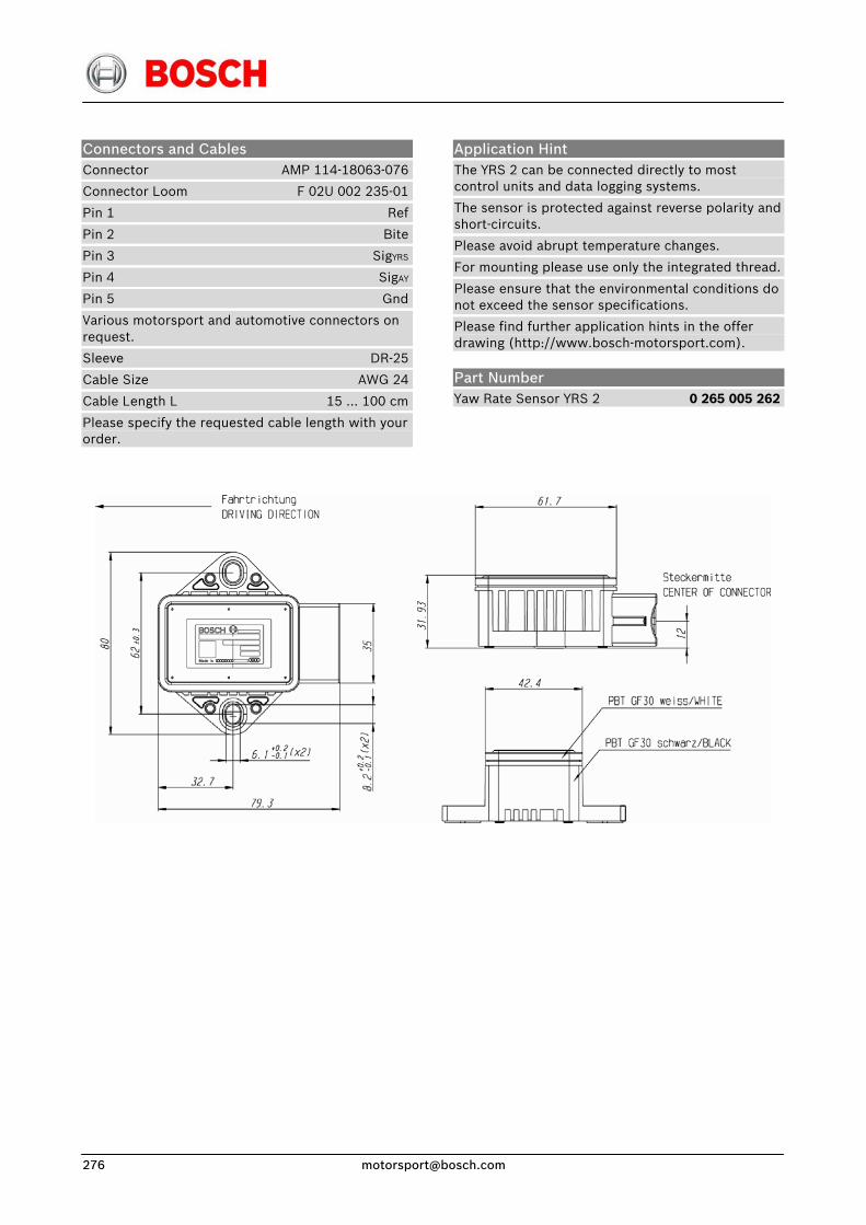
Connectors and Cables Connector AMP 114-18063-076
Connector Loom F 02U 002 235-01
Pin 1 Ref
Pin 2 Bite
Pin 3 SigYRS
Pin 4 SigAY
Pin 5 Gnd
Various motorsport and automotive connectors on request.
Sleeve DR-25
Cable Size AWG 24
Cable Length L 15 … 100 cm
Please specify the requested cable length with your order.
Application Hint The YRS 2 can be connected directly to most control units and data logging systems.
The sensor is protected against reverse polarity and short-circuits.
Please avoid abrupt temperature changes.
For mounting please use only the integrated thread.
Please ensure that the environmental conditions do not exceed the sensor specifications.
Please find further application hints in the offer drawing (http://www.bosch-motorsport.com).
Part Number Yaw Rate Sensor YRS 2 0 265 005 262
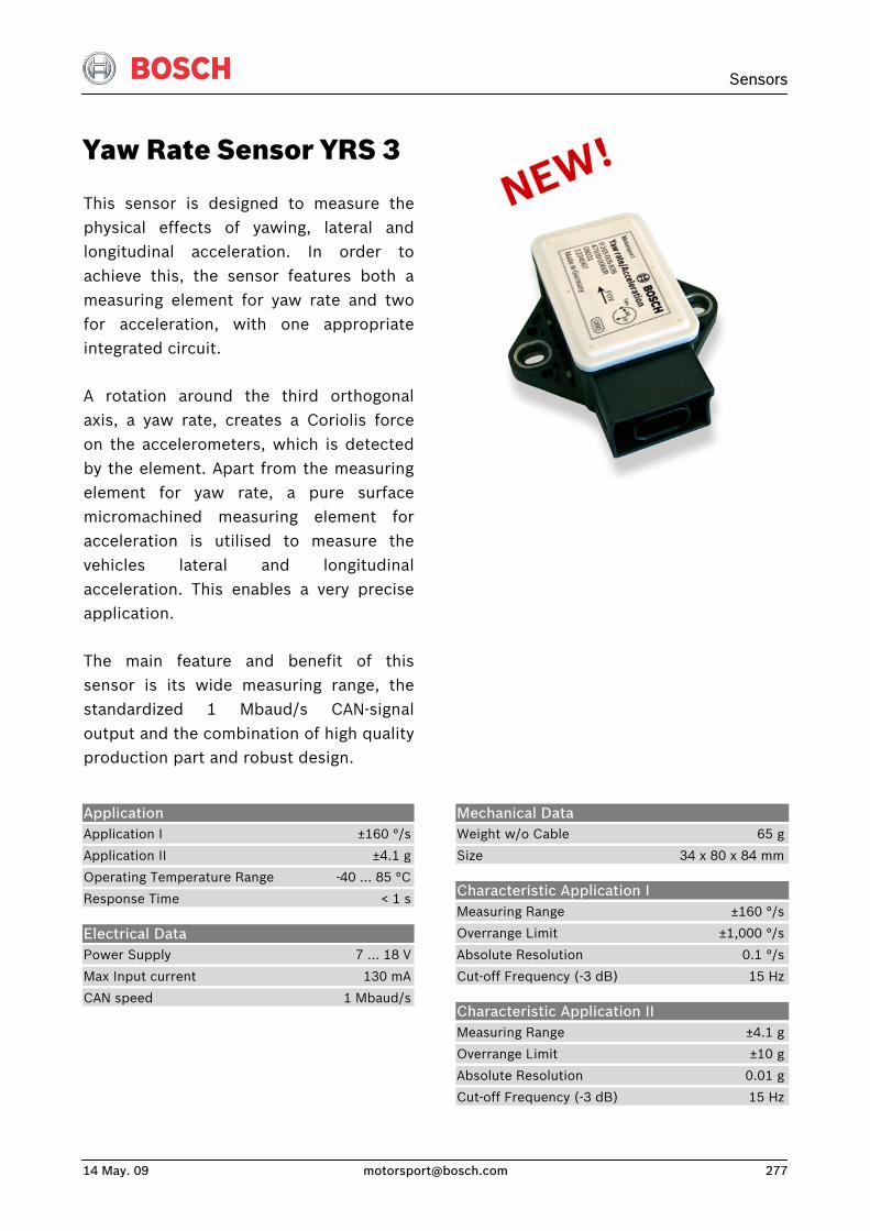
Sensors
14 May. 09 [email protected] 277
Yaw Rate Sensor YRS 3
This sensor is designed to measure thephysical effects of yawing, lateral andlongitudinal acceleration. In order toachieve this, the sensor features both ameasuring element for yaw rate and twofor acceleration, with one appropriateintegrated circuit.
A rotation around the third orthogonalaxis, a yaw rate, creates a Coriolis forceon the accelerometers, which is detected by the element. Apart from the measuringelement for yaw rate, a pure surfacemicromachined measuring element foracceleration is utilised to measure thevehicles lateral and longitudinalacceleration. This enables a very preciseapplication.
The main feature and benefit of thissensor is its wide measuring range, thestandardized 1 Mbaud/s CAN-signal output and the combination of high qualityproduction part and robust design.
Application Application I ±160 °/s
Application II ±4.1 g
Operating Temperature Range -40 … 85 °C
Response Time < 1 s
Electrical Data Power Supply 7 … 18 V
Max Input current 130 mA
CAN speed 1 Mbaud/s
Mechanical Data Weight w/o Cable 65 g
Size 34 x 80 x 84 mm
Characteristic Application I Measuring Range ±160 °/s
Overrange Limit ±1,000 °/s
Absolute Resolution 0.1 °/s
Cut-off Frequency (-3 dB) 15 Hz
Characteristic Application II Measuring Range ±4.1 g
Overrange Limit ±10 g
Absolute Resolution 0.01 g
Cut-off Frequency (-3 dB) 15 Hz
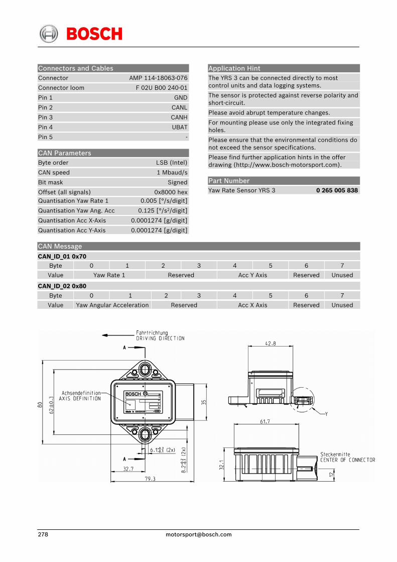
Connectors and Cables Connector AMP 114-18063-076
Connector loom F 02U B00 240-01
Pin 1 GND
Pin 2 CANL
Pin 3 CANH
Pin 4 UBAT
Pin 5 -
CAN Parameters Byte order LSB (Intel)
CAN speed 1 Mbaud/s
Bit mask Signed
Offset (all signals) 0x8000 hexQuantisation Yaw Rate 1 0.005 [°/s/digit]
Quantisation Yaw Ang. Acc 0.125 [°/s2/digit]
Quantisation Acc X-Axis 0.0001274 [g/digit]
Quantisation Acc Y-Axis 0.0001274 [g/digit]
Application Hint The YRS 3 can be connected directly to most control units and data logging systems.
The sensor is protected against reverse polarity and short-circuit.
Please avoid abrupt temperature changes.
For mounting please use only the integrated fixing holes.
Please ensure that the environmental conditions do not exceed the sensor specifications.
Please find further application hints in the offer drawing (http://www.bosch-motorsport.com).
Part Number Yaw Rate Sensor YRS 3 0 265 005 838
CAN Message CAN_ID_01 0x70
Byte 0 1 2 3 4 5 6 7
Value Yaw Rate 1 Reserved Acc Y Axis Reserved Unused
CAN_ID_02 0x80
Byte 0 1 2 3 4 5 6 7
Value Yaw Angular Acceleration Reserved Acc X Axis Reserved Unused


Electronic Throttle Grip ETG Drive by wire system for motorcycles
This new Electronic Throttle Grip (ETG)eliminates the throttle cables connectingthe throttle grip and the throttle body andreplaces them with a single electricalconnection.
The grip is spring loaded to return to theidle position where a damping elementand 10° free play below the idle positionprovide optimal control and feel for therider. The grip includes two redundantsets of magnetic sensors to ensure amaximum safety and reliability.
There is an integrated switch denotingthree power settings for the bike: OFF,IGN ON and START.
Application Hint The ETG can be connected directly to control units with ETC functionality.
Please avoid abrupt temperature changes.
Application Temperature range 0 … 80 °C
Max. vibration 800 m/s² @ 5 Hz … 2 kHz
Mechanical Data Size of housing 80 x 60 x 160 mm
Weight 326 g
Mounting handlebar ø 22.2 mm
Working angle + free play 60° + 10°
Tightening torque 4.5 Nm
Electrical Data Supply voltage 2 x 5 V
Characteristic Output Signal I 0.15 V … 2.325 V (0° … 70°)
Output Signal II 0.3 V … 4.65 V (0° … 70°)
Connector Connector
Mating connector
Pin 1
Pin 2
Pin 3
Pin 4
Pin 5
Pin 6
Pin 8
Pin 9
Pin 12
Pin 13
Part Number El. Throttle Grip ETG
AS 6-10-35PN
AS 1-10-35SN
terminal 30
terminal 15
terminal 50 (Starter)
-
5 V supply (Signal I)
5 V supply (Signal II)
Gnd (Signal I)
Gnd (Signal II)
Signal I (screened)
Signal II (screened)
Cs

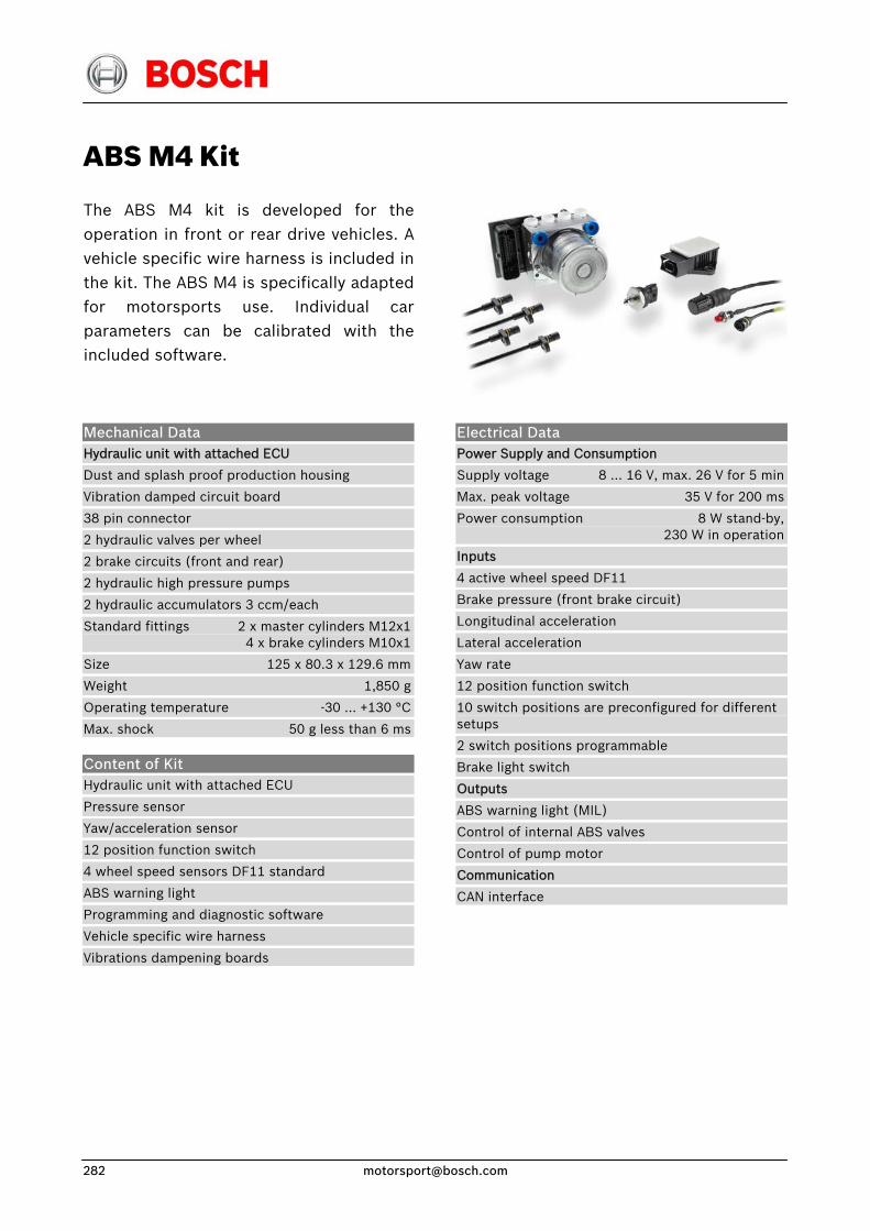
ABS M4 Kit
The ABS M4 kit is developed for theoperation in front or rear drive vehicles. Avehicle specific wire harness is included inthe kit. The ABS M4 is specifically adaptedfor motorsports use. Individual carparameters can be calibrated with theincluded software.
Mechanical Data Hydraulic unit with attached ECU
Dust and splash proof production housing
Vibration damped circuit board
38 pin connector
2 hydraulic valves per wheel
2 brake circuits (front and rear)
2 hydraulic high pressure pumps
2 hydraulic accumulators 3 ccm/each
Standard fittings 2 x master cylinders M12x1 4 x brake cylinders M10x1
Size 125 x 80.3 x 129.6 mm
Weight 1,850 g
Operating temperature -30 … +130 °C
Max. shock 50 g less than 6 ms
Content of Kit Hydraulic unit with attached ECU
Pressure sensor
Yaw/acceleration sensor
12 position function switch
4 wheel speed sensors DF11 standard
ABS warning light
Programming and diagnostic software
Vehicle specific wire harness
Vibrations dampening boards
Electrical Data Power Supply and Consumption
Supply voltage 8 … 16 V, max. 26 V for 5 min
Max. peak voltage 35 V for 200 ms
Power consumption 8 W stand-by, 230 W in operation
Inputs
4 active wheel speed DF11
Brake pressure (front brake circuit)
Longitudinal acceleration
Lateral acceleration
Yaw rate
12 position function switch
10 switch positions are preconfigured for different setups
2 switch positions programmable
Brake light switch
Outputs
ABS warning light (MIL)
Control of internal ABS valves
Control of pump motor
Communication
CAN interface
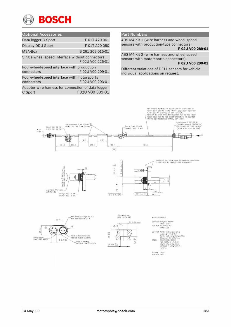
14 May. 09 [email protected] 283
Optional Accessories Data logger C Sport F 01T A20 061
Display DDU Sport F 01T A20 050
MSA-Box B 261 208 015-01
Single-wheel-speed interface without connectors F 02U V00 225-01
Four-wheel-speed interface with production connectors F 02U V00 209-01
Four-wheel-speed interface with motorsports connectors F 02U V00 203-01
Adapter wire harness for connection of data logger C Sport F02U V00 309-01
Part Numbers ABS M4 Kit 1 (wire harness and wheel speed sensors with production-type connectors) F 02U V00 289-01
ABS M4 Kit 2 (wire harness and wheel speed sensors with motorsports connectors) F 02U V00 290-01
Different variations of DF11 sensors for vehicle individual applications on request.

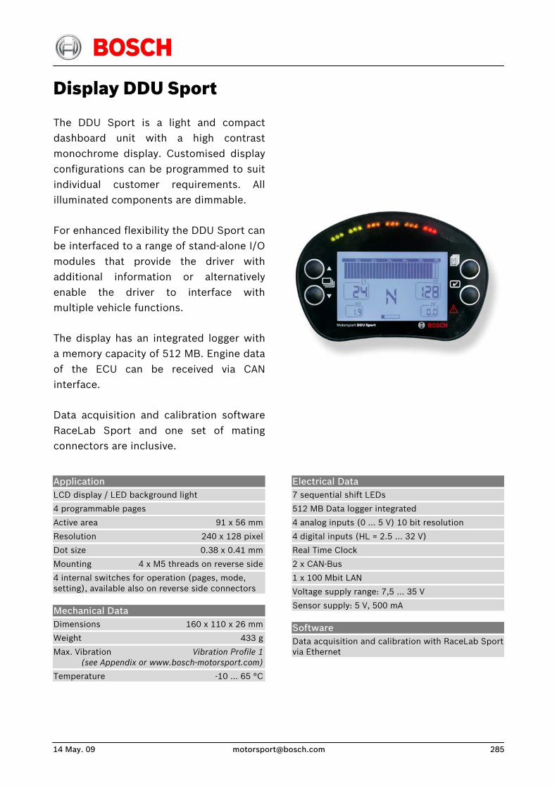
14 May. 09 [email protected] 285
Display DDU Sport
The DDU Sport is a light and compactdashboard unit with a high contrast monochrome display. Customised displayconfigurations can be programmed to suitindividual customer requirements. Allilluminated components are dimmable.
For enhanced flexibility the DDU Sport can be interfaced to a range of stand-alone I/Omodules that provide the driver withadditional information or alternativelyenable the driver to interface withmultiple vehicle functions.
The display has an integrated logger witha memory capacity of 512 MB. Engine dataof the ECU can be received via CANinterface.
Data acquisition and calibration softwareRaceLab Sport and one set of mating connectors are inclusive.
Application LCD display / LED background light
4 programmable pages
Active area 91 x 56 mm
Resolution 240 x 128 pixel
Dot size 0.38 x 0.41 mm
Mounting 4 x M5 threads on reverse side
4 internal switches for operation (pages, mode, setting), available also on reverse side connectors
Mechanical Data Dimensions 160 x 110 x 26 mm
Weight 433 g
Max. Vibration Vibration Profile 1 (see Appendix or www.bosch-motorsport.com)
Temperature -10 … 65 °C
Electrical Data 7 sequential shift LEDs
512 MB Data logger integrated
4 analog inputs (0 … 5 V) 10 bit resolution
4 digital inputs (HL = 2.5 … 32 V)
Real Time Clock
2 x CAN-Bus
1 x 100 Mbit LAN
Voltage supply range: 7,5 … 35 V
Sensor supply: 5 V, 500 mA
Software Data acquisition and calibration with RaceLab Sport via Ethernet
Connectors Mating connector 3 x Binder 712 99 0425 00 08
Connector 1 (red)
Pin 1 Input, digital 1
Pin 2 Input, digital 2
Pin 3 Input, digital 3
Pin 4 Input, digital 4
Pin 5 Input, terminal 30
Pin 6 Input, terminal 15
Pin 7 Input/Output, GND
Pin 8 Output, US
Connector 2 (green)
Pin 1 Input, KEY4
Pin 2 Input, KEY3
Pin 3 Input, KEY2
Pin 4 Input, KEY1
Pin 5 Input, AIN3
Pin 6 Input, AIN2
Pin 7 Input, AIN1
Pin 8 Input, AIN0
Connector 3 (blue)
Pin 1 Input/Output, CANB-LOW
Pin 2 Input/Output, CANB-HIGH
Pin 3 Input/Output, CANA-LOW
Pin 4 Input/Output, CANA-HIGH
Pin 5 Input, RX- LAN
Pin 6 Input, RX+ LAN
Pin 7 Output, TX- LAN
Pin 8 Output, TX+ LAN
Part Number DDU Sport F 01T A20 050
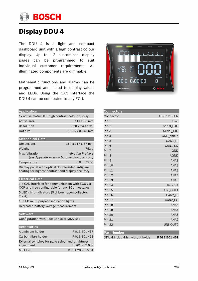
14 May. 09 [email protected] 287
Display DDU 4
The DDU 4 is a light and compactdashboard unit with a high contrast colourdisplay. Up to 12 customized displaypages can be programmed to suitindividual customer requirements. Allilluminated components are dimmable.
Mathematic functions and alarms can beprogrammed and linked to display valuesand LEDs. Using the CAN interface theDDU 4 can be connected to any ECU.
Application 1x active matrix TFT high contrast colour display
Active area 111 x 83 mm
Resolution 320 x 240 pixel
Dot size 0.116 x 0.348 mm
Mechanical Data Dimensions 164 x 117 x 37 mm
Weight 753 g
Max. Vibration Vibration Profile 1 (see Appendix or www.bosch-motorsport.com)
Temperature -10 ... 75 °C
Display panel with optical double-sided antiglare coating for highest contrast and display accuracy.
Electrical Data 1 x CAN interface for communication with ECU via CCP and free configurable for any ECU messages
5 LED shift indicators (5 drivers, open collector, 2.2 A)
10 LED multi purpose indication lights
Dedicated battery voltage measurement
Software Configuration with RaceCon over MSA-Box
Accessories Aluminium holder F 01E B01 457
Carbon fibre holder F 01E B01 458
External switches for page select and brightness adjustment B 261 209 659
MSA-Box B 261 208 015-01
Connectors Connector AS 6-12-35PN
Pin 1 Ubatt
Pin 2 Serial_RXD
Pin 3 Serial_TXD
Pin 4 GND_shield
Pin 5 CAN1_HI
Pin 6 CAN1_LO
Pin 7 GND
Pin 8 AGND
Pin 9 ANA1
Pin 10 ANA2
Pin 11 ANA3
Pin 12 ANA4
Pin 13 ANA5
Pin 14 Ubatt out
Pin 15 UNI_OUT1
Pin 16 CAN2_HI
Pin 17 CAN2_LO
Pin 18 ANA6
Pin 19 ANA7
Pin 20 ANA8
Pin 21 ANA9
Pin 22 UNI_OUT2
Part Number DDU 4 incl. cable, without holder F 01E B01 461
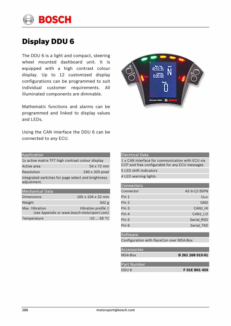
Display DDU 6
The DDU 6 is a light and compact, steering wheel mounted dashboard unit. It isequipped with a high contrast colourdisplay. Up to 12 customized displayconfigurations can be programmed to suitindividual customer requirements. Allilluminated components are dimmable.
Mathematic functions and alarms can beprogrammed and linked to display valuesand LEDs.
Using the CAN interface the DDU 6 can beconnected to any ECU.
Application 1x active matrix TFT high contrast colour display
Active area 54 x 72 mm
Resolution 240 x 320 pixel
Integrated switches for page select and brightness adjustment.
Mechanical Data Dimensions 165 x 104 x 32 mm
Weight 342 g
Max. Vibration Vibration profile 1 (see Appendix or www.bosch-motorsport.com)
Temperature -10 ... 65 °C
Electrical Data 1 x CAN interface for communication with ECU via CCP and free configurable for any ECU messages
5 LED shift indicators
4 LED warning lights
Connectors Connector AS 6-12-35PN
Pin 1 Ubatt
Pin 2 GND
Pin 3 CAN1_HI
Pin 4 CAN1_LO
Pin 5 Serial_RXD
Pin 6 Serial_TXD
Software Configuration with RaceCon over MSA-Box
Accessories MSA-Box B 261 208 015-01
Part Number DDU 6 F 01E B01 459

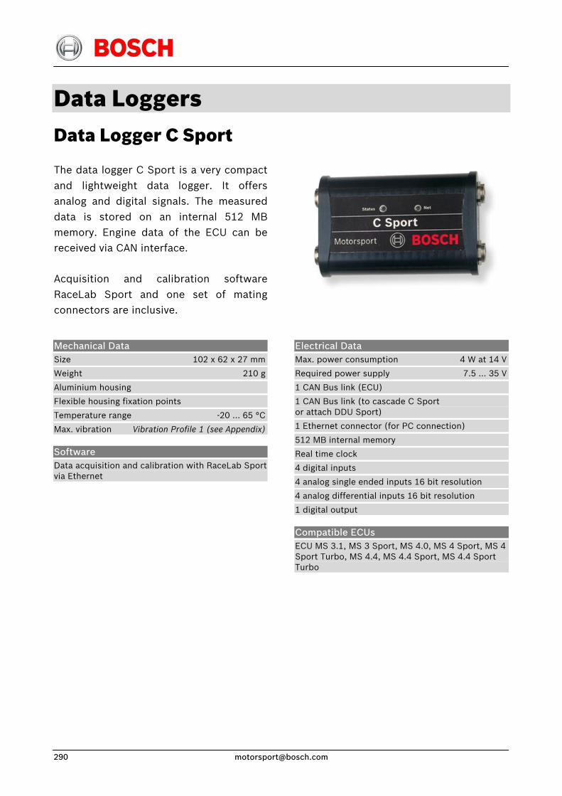
Data Loggers Data Logger C Sport
The data logger C Sport is a very compactand lightweight data logger. It offersanalog and digital signals. The measureddata is stored on an internal 512 MB memory. Engine data of the ECU can bereceived via CAN interface.
Acquisition and calibration softwareRaceLab Sport and one set of matingconnectors are inclusive.
Mechanical Data Size 102 x 62 x 27 mm
Weight 210 g
Aluminium housing
Flexible housing fixation points
Temperature range -20 … 65 °C
Max. vibration Vibration Profile 1 (see Appendix)
Software Data acquisition and calibration with RaceLab Sport via Ethernet
Electrical Data Max. power consumption 4 W at 14 V
Required power supply 7.5 … 35 V
1 CAN Bus link (ECU)
1 CAN Bus link (to cascade C Sport or attach DDU Sport)
1 Ethernet connector (for PC connection)
512 MB internal memory
Real time clock
4 digital inputs
4 analog single ended inputs 16 bit resolution
4 analog differential inputs 16 bit resolution
1 digital output
Compatible ECUs ECU MS 3.1, MS 3 Sport, MS 4.0, MS 4 Sport, MS 4 Sport Turbo, MS 4.4, MS 4.4 Sport, MS 4.4 Sport Turbo
14 May. 09 [email protected] 291
Connectors Mating connector 4 x Binder 712 99 0425 00 08
Connector 1 (bottom right)
Pin 1 Input, terminal 15
Pin 2 Input, terminal 30
Pin 3 Output
Pin 4 Output, TX+ LAN
Pin 5 Output, TX- LAN
Pin 6 Input, RX+ LAN
Pin 7 Input, RX- LAN
Pin 8 Input/Output, GND
Connector 2 (top right)
Pin 1 Input/output, CANB-LOW
Pin 2 Input/output, CANB-HIGH
Pin 3 Input, digital 1
Pin 4 Input, digital 2
Pin 5 Input, digital 3
Pin 6 Input, digital 4
Pin 7 Output, US
Pin 8 Input/output, GND
Connector 3 (top left)
Pin 1 Input, analog 6+
Pin 2 Input, analog GND 5/6
Pin 3 Input, analog 7+
Pin 4 Input, analog 8+
Pin 5 Input, analog GND 7/8
Pin 6 Input, CANA-LOW
Pin 7 Input, CANA-HIGH
Pin 8 Input, analog 5+
Connector 4 (bottom left)
Pin 1 Diff. input, analog 1-
Pin 2 Diff. input, analog 2+
Pin 3 Diff. input, analog 2-
Pin 4 Diff. input, analog 3+
Pin 5 Diff. input, analog 3-
Pin 6 Diff. input, analog 4+
Pin 7 Diff. input, analog 4-
Pin 8 Diff. input, analog 1+
Part Number C Sport F 01T A20 061
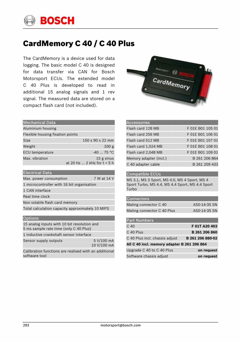
CardMemory C 40 / C 40 Plus
The CardMemory is a device used for datalogging. The basic model C 40 is designed for data transfer via CAN for BoschMotorsport ECUs. The extended modelC 40 Plus is developed to read inadditional 15 analog signals and 1 revsignal. The measured data are stored on acompact flash card (not included).
Accessories Flash card 128 MB
Flash card 256 MB
Flash card 512 MB
Flash card 1,024 MB
Flash card 2,048 MB
Memory adapter (incl.)
C 40 adapter cable
F 01E B01 105 01
F 01E B01 106 01
F 01E B01 107 01
F 01E B01 108 01
F 01E B01 109 01
B 261 206 864
B 261 209 433
Mechanical Data Aluminium housing
Flexible housing fixation points
Size 150 x 90 x 22 mm
Weight 330 g
ECU temperature -40 … 75 °C
Max. vibration 15 g sinus at 20 Hz … 2 kHz for t < 5 h
Electrical Data Max. power consumption 7 W at 14 V
1 microcontroller with 16 bit organisation
1 CAN interface
Real time clock
Non volatile flash card memory
Total calculation capacity approximately 10 MIPS
Options 15 analog inputs with 10 bit resolution and 5 ms sample rate time (only C 40 Plus)
1 inductive crankshaft sensor interface
Sensor supply outputs 5 V/100 mA 10 V/100 mA
Calibration functions are realised with an additional software tool
Compatible ECUs MS 3.1, MS 3 Sport, MS 4.0, MS 4 Sport, MS 4 Sport Turbo, MS 4.4, MS 4.4 Sport, MS 4.4 Sport Turbo
Connectors Mating connector C 40 AS0-14-35 SN
Mating connector C 40 Plus AS0-14-35 SN
Part Numbers C 40 F 01T A20 403
C 40 Plus B 261 206 860
C 40 Plus incl. chassis adjust B 261 206 880-02
All C 40 incl. memory adapter B 261 206 864
Upgrade C 40 to C 40 Plus on request
Software chassis adjust on request
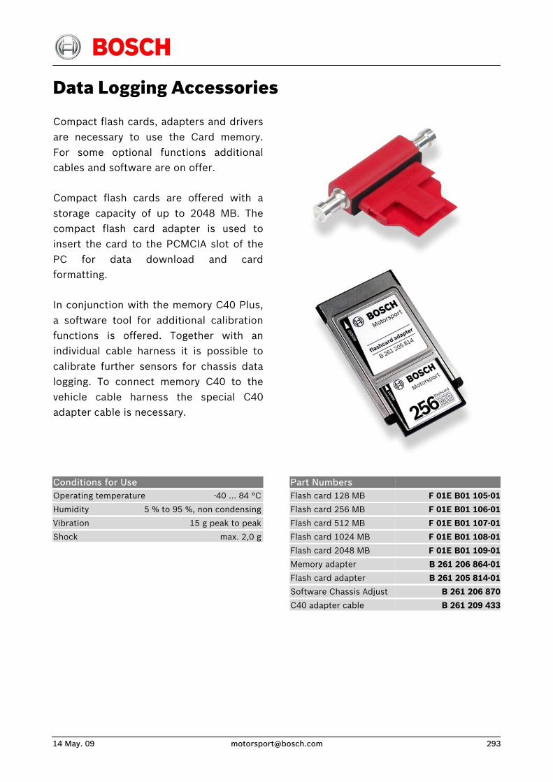
14 May. 09 [email protected] 293
Data Logging Accessories
Compact flash cards, adapters and driversare necessary to use the Card memory.For some optional functions additionalcables and software are on offer.
Compact flash cards are offered with astorage capacity of up to 2048 MB. Thecompact flash card adapter is used toinsert the card to the PCMCIA slot of thePC for data download and cardformatting.
In conjunction with the memory C40 Plus,a software tool for additional calibrationfunctions is offered. Together with anindividual cable harness it is possible tocalibrate further sensors for chassis datalogging. To connect memory C40 to thevehicle cable harness the special C40adapter cable is necessary.
Conditions for Use Operating temperature -40 … 84 °C
Humidity 5 % to 95 %, non condensing
Vibration 15 g peak to peak
Shock max. 2,0 g
Part Numbers Flash card 128 MB
Flash card 256 MB
Flash card 512 MB
Flash card 1024 MB
Flash card 2048 MB
Memory adapter
Flash card adapter
Software Chassis Adjust
C40 adapter cable
F 01E B01 105-01
F 01E B01 106-01
F 01E B01 107-01
F 01E B01 108-01
F 01E B01 109-01
B 261 206 864-01
B 261 205 814-01
B 261 206 870
B 261 209 433
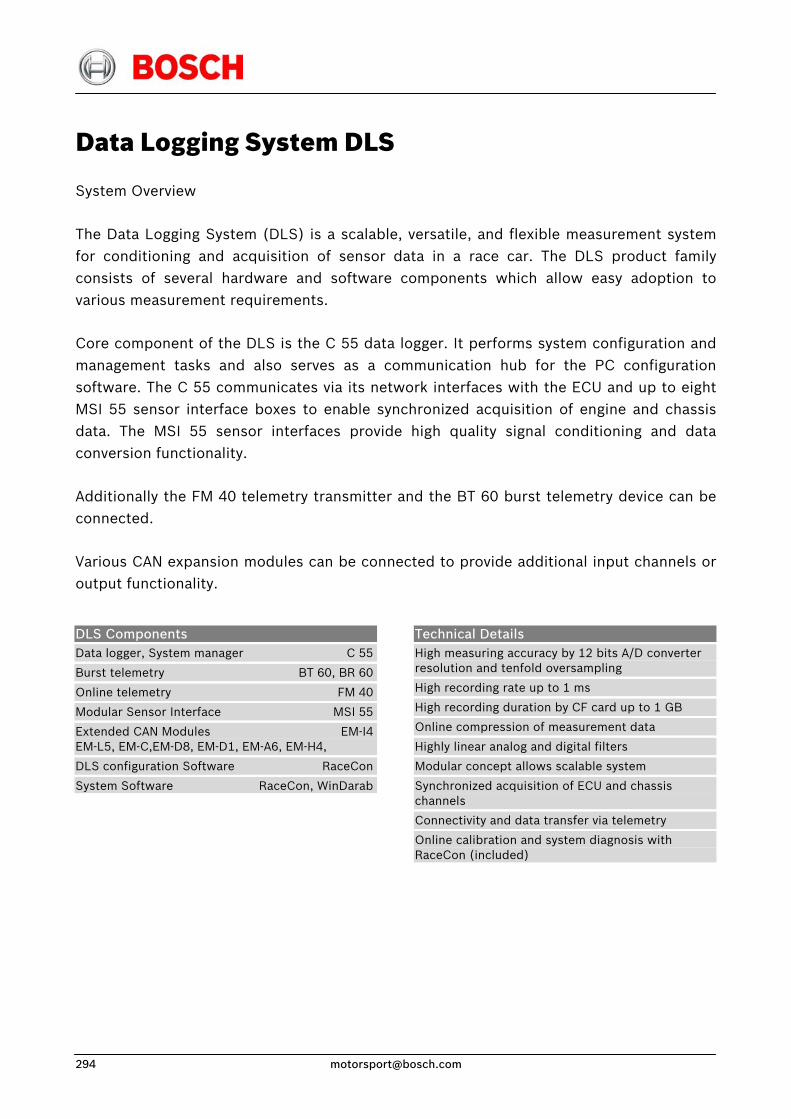
Data Logging System DLS
System Overview
The Data Logging System (DLS) is a scalable, versatile, and flexible measurement system for conditioning and acquisition of sensor data in a race car. The DLS product family consists of several hardware and software components which allow easy adoption to various measurement requirements.
Core component of the DLS is the C 55 data logger. It performs system configuration and management tasks and also serves as a communication hub for the PC configuration software. The C 55 communicates via its network interfaces with the ECU and up to eight MSI 55 sensor interface boxes to enable synchronized acquisition of engine and chassis data. The MSI 55 sensor interfaces provide high quality signal conditioning and data conversion functionality.
Additionally the FM 40 telemetry transmitter and the BT 60 burst telemetry device can be connected.
Various CAN expansion modules can be connected to provide additional input channels or output functionality.
DLS Components Data logger, System manager C 55
Burst telemetry BT 60, BR 60
Online telemetry FM 40
Modular Sensor Interface MSI 55
Extended CAN Modules EM-I4EM-L5, EM-C,EM-D8, EM-D1, EM-A6, EM-H4,
DLS configuration Software RaceCon
System Software RaceCon, WinDarab
Technical Details High measuring accuracy by 12 bits A/D converter resolution and tenfold oversampling
High recording rate up to 1 ms
High recording duration by CF card up to 1 GB
Online compression of measurement data
Highly linear analog and digital filters
Modular concept allows scalable system
Synchronized acquisition of ECU and chassis channels
Connectivity and data transfer via telemetry
Online calibration and system diagnosis with RaceCon (included)
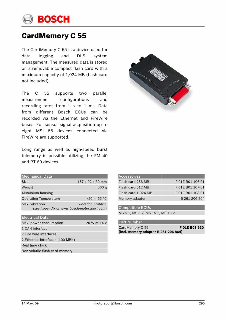
14 May. 09 [email protected] 295
CardMemory C 55
The CardMemory C 55 is a device used fordata logging and DLS systemmanagement. The measured data is storedon a removable compact flash card with amaximum capacity of 1,024 MB (flash cardnot included).
The C 55 supports two parallelmeasurement configurations andrecording rates from 1 s to 1 ms. Datafrom different Bosch ECUs can berecorded via the Ethernet and FireWirebuses. For sensor signal acquisition up toeight MSI 55 devices connected viaFireWire are supported.
Long range as well as high-speed bursttelemetry is possible utilizing the FM 40and BT 60 devices.
Accessories Flash card 256 MB
Flash card 512 MB
Flash card 1,024 MB
Memory adapter
F 01E B01 106-01
F 01E B01 107-01
F 01E B01 108-01
B 261 206 864
Mechanical Data Size 157 x 92 x 30 mm
Weight 500 g
Aluminium housing
Operating Temperature -20 … 65 °C
Max. vibration Vibration profile 1 (see Appendix or www.bosch-motorsport.com)
Electrical Data Max. power consumption 20 W at 14 V
1 CAN interface
2 Fire wire interfaces
2 Ethernet interfaces (100 MBit)
Real time clock
Non volatile flash card memory
Compatible ECUs MS 5.1, MS 5.2, MS 15.1, MS 15.2
Part Number CardMemory C 55 F 01E B01 630(incl. memory adapter B 261 206 864)
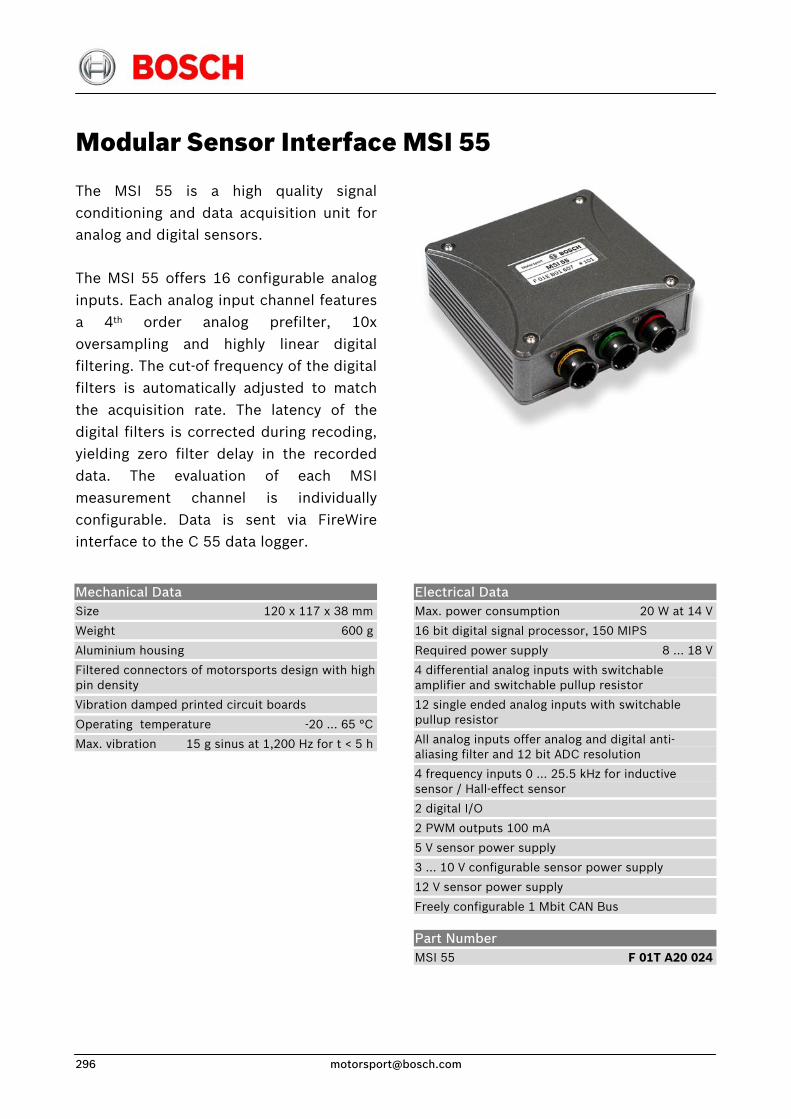
Modular Sensor Interface MSI 55
The MSI 55 is a high quality signalconditioning and data acquisition unit foranalog and digital sensors.
The MSI 55 offers 16 configurable analoginputs. Each analog input channel featuresa 4th order analog prefilter, 10xoversampling and highly linear digitalfiltering. The cut-of frequency of the digitalfilters is automatically adjusted to matchthe acquisition rate. The latency of thedigital filters is corrected during recoding,yielding zero filter delay in the recordeddata. The evaluation of each MSImeasurement channel is individuallyconfigurable. Data is sent via FireWireinterface to the C 55 data logger.
Mechanical Data Size 120 x 117 x 38 mm
Weight 600 g
Aluminium housing
Filtered connectors of motorsports design with high pin density
Vibration damped printed circuit boards
Operating temperature -20 … 65 °C
Max. vibration 15 g sinus at 1,200 Hz for t < 5 h
Electrical Data Max. power consumption 20 W at 14 V
16 bit digital signal processor, 150 MIPS
Required power supply 8 … 18 V
4 differential analog inputs with switchable amplifier and switchable pullup resistor
12 single ended analog inputs with switchable pullup resistor
All analog inputs offer analog and digital anti-aliasing filter and 12 bit ADC resolution
4 frequency inputs 0 … 25.5 kHz for inductive sensor / Hall-effect sensor
2 digital I/O
2 PWM outputs 100 mA
5 V sensor power supply
3 … 10 V configurable sensor power supply
12 V sensor power supply
Freely configurable 1 Mbit CAN Bus
Part Number MSI 55 F 01T A20 024
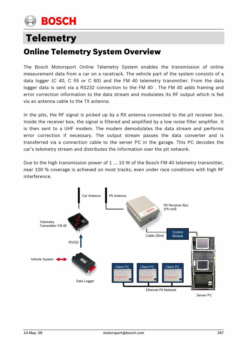
14 May. 09 [email protected] 297
Telemetry Online Telemetry System Overview
The Bosch Motorsport Online Telemetry System enables the transmission of online measurement data from a car on a racetrack. The vehicle part of the system consists of a data logger (C 40, C 55 or C 60) and the FM 40 telemetry transmitter. From the data logger data is sent via a RS232 connection to the FM 40 . The FM 40 adds framing and error correction information to the data stream and modulates its RF output which is fed via an antenna cable to the TX antenna.
In the pits, the RF signal is picked up by a RX antenna connected to the pit receiver box. Inside the receiver box, the signal is filtered and amplified by a low noise filter amplifier. It is then sent to a UHF modem. The modem demodulates the data stream and performs error correction if necessary. The output stream passes the data converter and is transferred via a connection cable to the server PC in the garage. This PC decodes the car’s telemetry stream and distributes the information over the pit network.
Due to the high transmission power of 1 … 10 W of the Bosch FM 40 telemetry transmitter, near 100 % coverage is achieved on most tracks, even under race conditions with high RF interference.
Data Logger
RS232
Vehicle System
Car Antenna
Pit Receiver Box (Pit roof)
Client PC
Ethernet Pit Network
Client PC Client PC
Control Module Cable (30m)
Pit Antenna
Telemetry Transmitter FM 40
Server PC
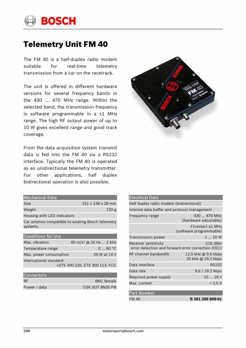
Telemetry Unit FM 40
The FM 40 is a half-duplex radio modemsuitable for real-time telemetrytransmission from a car on the racetrack.
The unit is offered in different hardwareversions for several frequency bands inthe 430 … 470 MHz range. Within theselected band, the transmission frequencyis software programmable in a ±1 MHz range. The high RF output power of up to10 W gives excellent range and good trackcoverage.
From the data acquisition system transmitdata is fed into the FM 40 via a RS232interface. Typically the FM 40 is operatedas an unidirectional telemetry transmitter.For other applications, half duplexbidirectional operation is also possible.
Mechanical Data Size 151 x 138 x 28 mm
Weight 720 g
Housing with LED indicators
Car antenna compatible to existing Bosch telemetry systems.
Conditions for Use Max. vibration 60 m/s2 @ 20 Hz ... 2 kHz
Temperature range 0 ... 60 °C
Max. power consumption 25 W at 14 V
International standard I-ETS 300 220, ETS 300 113, FCC
Connectors RF BNC female
Power / data CGK SOT 8N35 PN
Electrical Data Half duplex radio modem (bidirectional)
Internal data buffer and protocol management
Frequency range 430 ... 470 MHz (hardware adjustable)
F(center) ±1 MHz (software programmable)
Transmission power 1 ... 10 W
Receiver sensitivity -116 dBm error detection and forward error correction (FEC)
RF channel bandwidth 12,5 kHz @ 9.6 kbps 25 kHz @ 19.2 kbps
Data interface RS232
Data rate 9.6 / 19.2 kbps
Required power supply 10 ... 18 V
Max. current < 2,5 A
Part Number FM 40 B 261 208 898-01
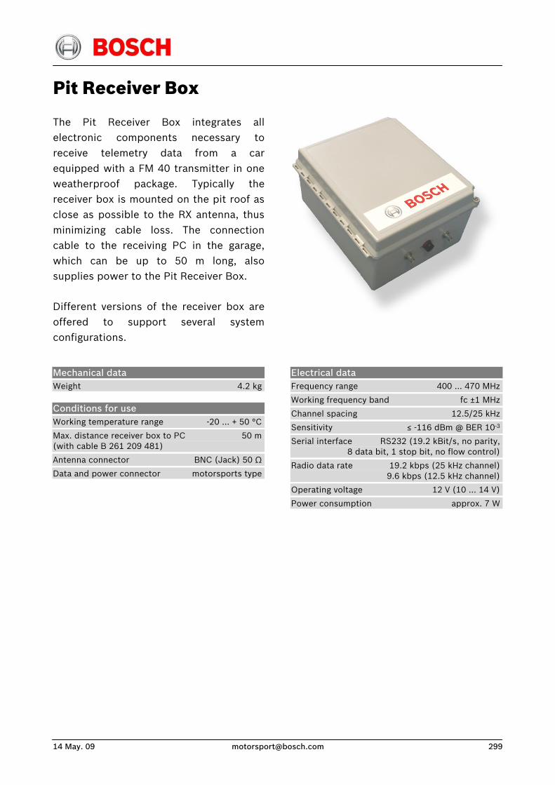
14 May. 09 [email protected] 299
Pit Receiver Box
The Pit Receiver Box integrates allelectronic components necessary toreceive telemetry data from a car equipped with a FM 40 transmitter in oneweatherproof package. Typically thereceiver box is mounted on the pit roof asclose as possible to the RX antenna, thusminimizing cable loss. The connectioncable to the receiving PC in the garage,which can be up to 50 m long, alsosupplies power to the Pit Receiver Box.
Different versions of the receiver box areoffered to support several systemconfigurations.
Mechanical data Weight 4.2 kg
Conditions for use Working temperature range -20 … + 50 °C
Max. distance receiver box to PC 50 m(with cable B 261 209 481)
Antenna connector BNC (Jack) 50 Ω
Data and power connector motorsports type
Electrical data Frequency range 400 … 470 MHz
Working frequency band fc ±1 MHz
Channel spacing 12.5/25 kHz
Sensitivity ≤ -116 dBm @ BER 10-3
Serial interface RS232 (19.2 kBit/s, no parity, 8 data bit, 1 stop bit, no flow control)
Radio data rate 19.2 kbps (25 kHz channel) 9.6 kbps (12.5 kHz channel)
Operating voltage 12 V (10 … 14 V)
Power consumption approx. 7 W
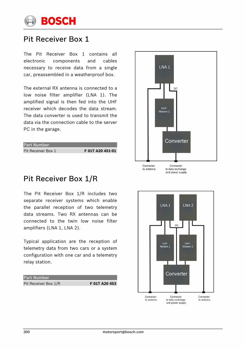
Pit Receiver Box 1
The Pit Receiver Box 1 contains allelectronic components and cablesnecessary to receive data from a singlecar, preassembled in a weatherproof box.
The external RX antenna is connected to alow noise filter amplifier (LNA 1). Theamplified signal is then fed into the UHFreceiver which decodes the data stream.The data converter is used to transmit thedata via the connection cable to the serverPC in the garage.
Part Number Pit Receiver Box 1 F 01T A20 451-01
Pit Receiver Box 1/R
The Pit Receiver Box 1/R includes twoseparate receiver systems which enablethe parallel reception of two telemetrydata streams. Two RX antennas can beconnected to the twin low noise filteramplifiers (LNA 1, LNA 2).
Typical application are the reception of telemetry data from two cars or a systemconfiguration with one car and a telemetryrelay station.
Part Number Pit Receiver Box 1/R F 01T A20 453
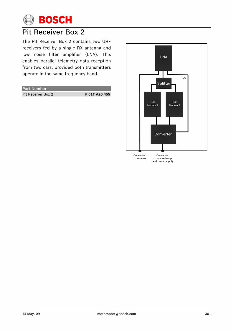
14 May. 09 [email protected] 301
Pit Receiver Box 2 The Pit Receiver Box 2 contains two UHFreceivers fed by a single RX antenna and low noise filter amplifier (LNA). Thisenables parallel telemetry data receptionfrom two cars, provided both transmittersoperate in the same frequency band.
Part Number Pit Receiver Box 2 F 01T A20 455
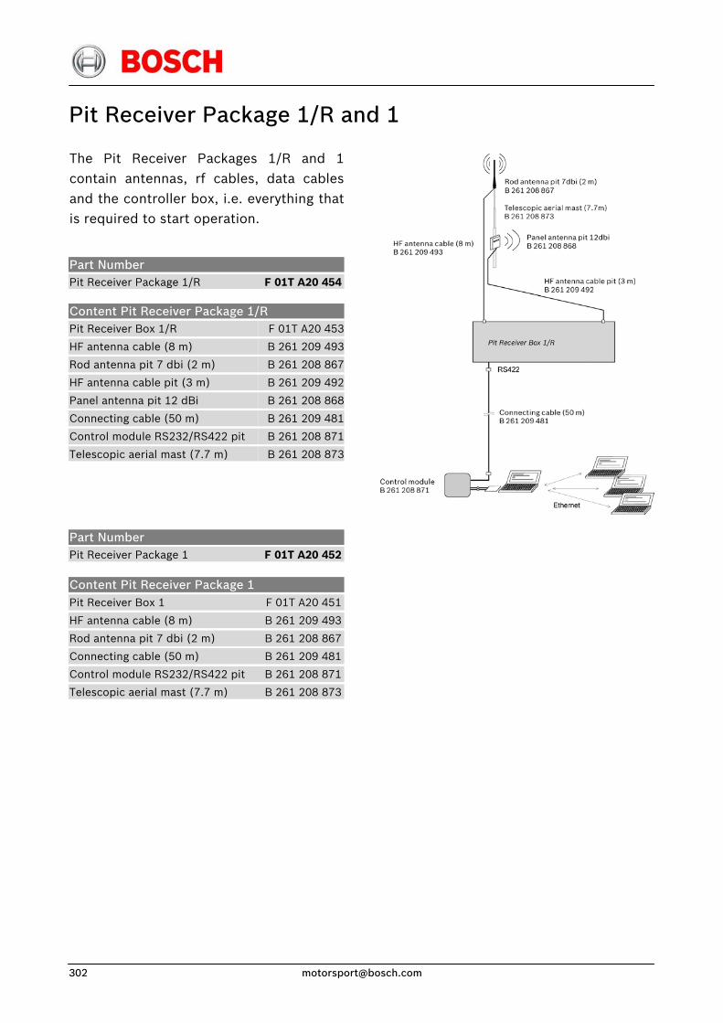
Pit Receiver Package 1/R and 1
The Pit Receiver Packages 1/R and 1contain antennas, rf cables, data cablesand the controller box, i.e. everything thatis required to start operation.
Part Number Pit Receiver Package 1/R F 01T A20 454
Content Pit Receiver Package 1/R Pit Receiver Box 1/R
HF antenna cable (8 m)
Rod antenna pit 7 dbi (2 m)
HF antenna cable pit (3 m)
Panel antenna pit 12 dBi
Connecting cable (50 m)
Control module RS232/RS422 pit
Telescopic aerial mast (7.7 m)
F 01T A20 453
B 261 209 493
B 261 208 867
B 261 209 492
B 261 208 868
B 261 209 481
B 261 208 871
B 261 208 873
Part Number Pit Receiver Package 1 F 01T A20 452
Content Pit Receiver Package 1 Pit Receiver Box 1 F 01T A20 451
HF antenna cable (8 m) B 261 209 493
Rod antenna pit 7 dbi (2 m) B 261 208 867
Connecting cable (50 m) B 261 209 481
Control module RS232/RS422 pit B 261 208 871
Telescopic aerial mast (7.7 m) B 261 208 873
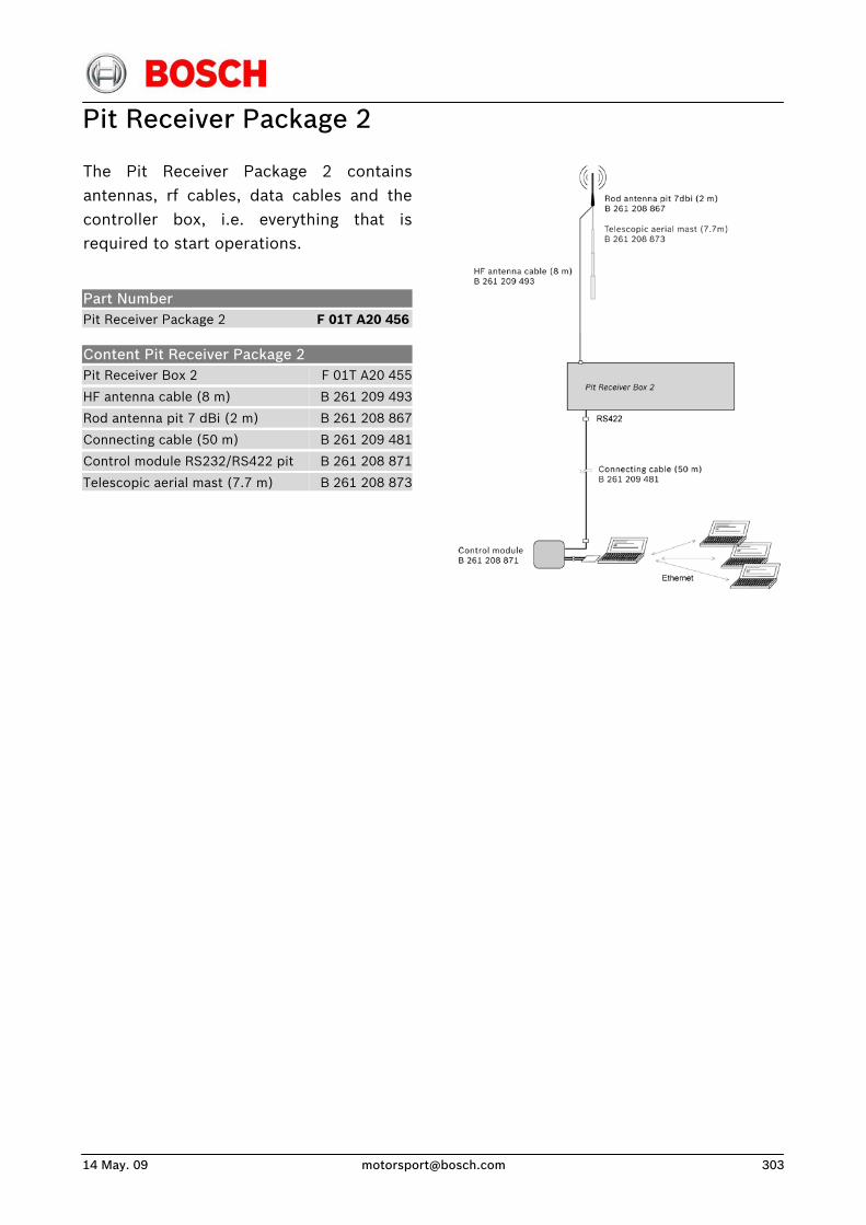
14 May. 09 [email protected] 303
Pit Receiver Package 2
The Pit Receiver Package 2 containsantennas, rf cables, data cables and thecontroller box, i.e. everything that isrequired to start operations.
Part Number Pit Receiver Package 2 F 01T A20 456
Content Pit Receiver Package 2 Pit Receiver Box 2
HF antenna cable (8 m)
Rod antenna pit 7 dBi (2 m)
Connecting cable (50 m)
Control module RS232/RS422 pit
Telescopic aerial mast (7.7 m)
F 01T A20 455
B 261 209 493
B 261 208 867
B 261 209 481
B 261 208 871
B 261 208 873
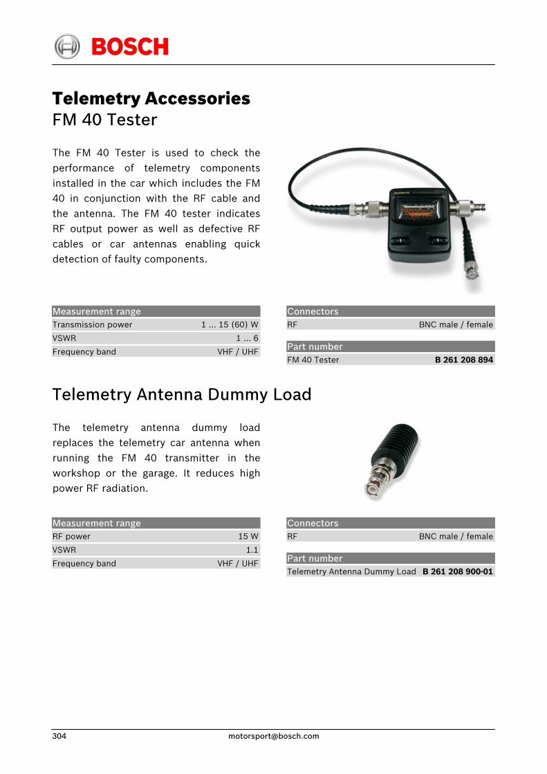
Telemetry Accessories FM 40 Tester
The FM 40 Tester is used to check theperformance of telemetry componentsinstalled in the car which includes the FM40 in conjunction with the RF cable andthe antenna. The FM 40 tester indicatesRF output power as well as defective RFcables or car antennas enabling quickdetection of faulty components.
Measurement range Transmission power 1 … 15 (60) W
VSWR 1 … 6
Frequency band VHF / UHF
Connectors RF BNC male / female
Part number FM 40 Tester B 261 208 894
Telemetry Antenna Dummy Load
The telemetry antenna dummy loadreplaces the telemetry car antenna whenrunning the FM 40 transmitter in theworkshop or the garage. It reduces highpower RF radiation.
Measurement range RF power 15 W
VSWR 1.1
Frequency band VHF / UHF
Connectors RF BNC male / female
Part number Telemetry Antenna Dummy Load B 261 208 900-01

14 May. 09 [email protected] 305
Telemetry Car Antenna
Rugged telemetry antennas for carmounting.
Dual Band Single Band
Connectors RF BNC male
Part number
Parameter Single Band Car Antenna
Frequency band UHF
Type 1/4λPattern (hor.) omni
Length 150 mm
Dual Band Car Antenna
Frequency band VHF / UHF
Gain 1/4λ / 5/8λPattern (hor.) omni
Length 440 mm
Single Band Car Antenna
Dual Band Car Antenna
B 261 208 888
B 261 208 862
Antenna Cable Kit For car mounting RF cable for the installation of telemetryantennas in the car. Intended for singlehole mounting.
Measurement range Length max. 2 m (tbd.)
Drill hole diameter 12,5 mm
Attenuation max. 0.7 dB @ 2 m, 450 MHz
Connectors RF BNC male / female
Part number Antenna Cable Kit B 261 209 490-01
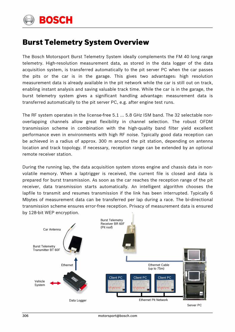
Burst Telemetry System Overview
The Bosch Motorsport Burst Telemetry System ideally complements the FM 40 long range telemetry. High-resolution measurement data, as stored in the data logger of the data acquisition system, is transferred automatically to the pit server PC when the car passes the pits or the car is in the garage. This gives two advantages: high resolution measurement data is already available in the pit network while the car is still out on track, enabling instant analysis and saving valuable track time. While the car is in the garage, the burst telemetry system gives a significant handling advantage: measurement data is transferred automatically to the pit server PC, e.g. after engine test runs.
The RF system operates in the license-free 5.1 … 5.8 GHz ISM band. The 32 selectable non-overlapping channels allow great flexibility in channel selection. The robust OFDM transmission scheme in combination with the high-quality band filter yield excellent performance even in environments with high RF noise. Typically good data reception can be achieved in a radius of approx. 300 m around the pit station, depending on antenna location and track topology. If necessary, reception range can be extended by an optional remote receiver station.
During the running lap, the data acquisition system stores engine and chassis data in non-volatile memory. When a laptrigger is received, the current file is closed and data is prepared for burst transmission. As soon as the car reaches the reception range of the pit receiver, data transmission starts automatically. An intelligent algorithm chooses the lapfile to transmit and resumes transmission if the link has been interrupted. Typically 6 Mbytes of measurement data can be transferred per lap during a race. The bi-directional transmission scheme ensures error-free reception. Privacy of measurement data is ensured by 128-bit WEP encryption.
Burst Telemetry Transmitter BT 60F
Data Logger
Ethernet
Vehicle System
Client PC
Ethernet Pit Network
Client PC Client PC
Ethernet Cable (up to 75m)
Car Antenna
Burst Telemetry Receiver BR 60F (Pit roof)
Server PC
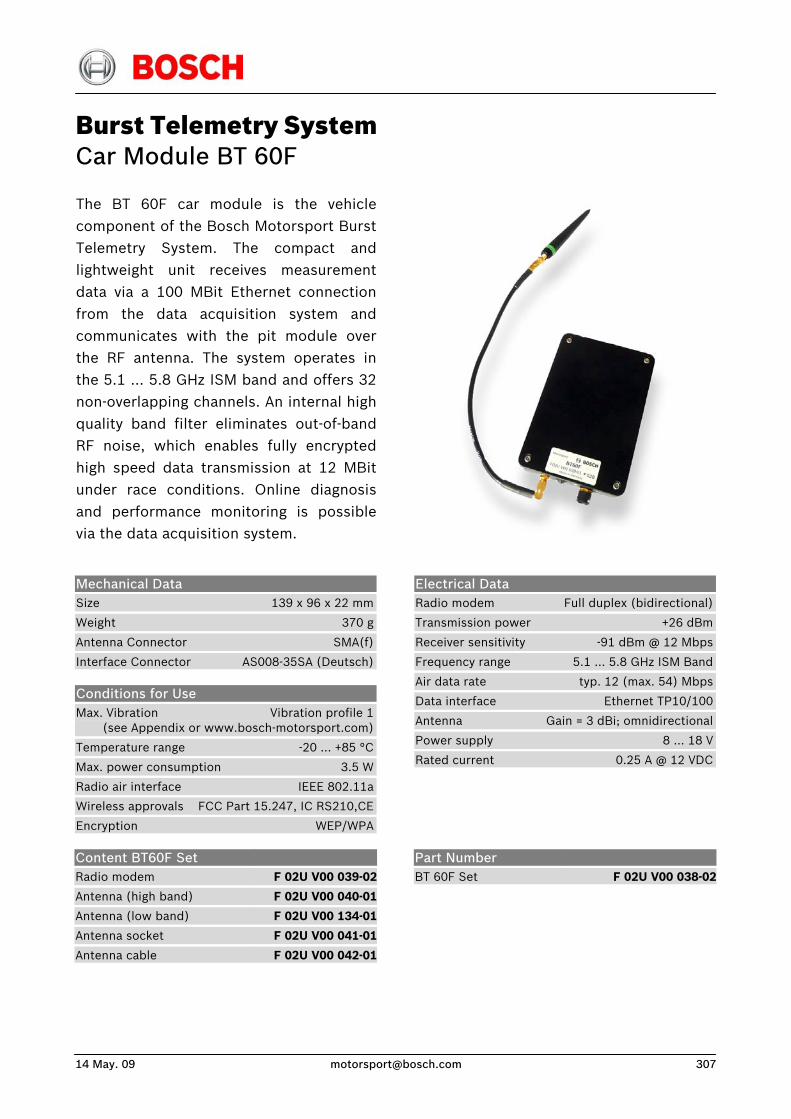
14 May. 09 [email protected] 307
Burst Telemetry System Car Module BT 60F
The BT 60F car module is the vehiclecomponent of the Bosch Motorsport BurstTelemetry System. The compact andlightweight unit receives measurementdata via a 100 MBit Ethernet connectionfrom the data acquisition system andcommunicates with the pit module overthe RF antenna. The system operates inthe 5.1 … 5.8 GHz ISM band and offers 32non-overlapping channels. An internal highquality band filter eliminates out-of-band RF noise, which enables fully encryptedhigh speed data transmission at 12 MBitunder race conditions. Online diagnosisand performance monitoring is possiblevia the data acquisition system.
Mechanical Data Size 139 x 96 x 22 mm
Weight 370 g
Antenna Connector SMA(f)
Interface Connector AS008-35SA (Deutsch)
Conditions for Use Max. Vibration Vibration profile 1 (see Appendix or www.bosch-motorsport.com)
Temperature range -20 ... +85 °C
Max. power consumption 3.5 W
Radio air interface IEEE 802.11a
Wireless approvals FCC Part 15.247, IC RS210,CE
Encryption WEP/WPA
Electrical Data Radio modem Full duplex (bidirectional)
Transmission power +26 dBm
Receiver sensitivity -91 dBm @ 12 Mbps
Frequency range 5.1 … 5.8 GHz ISM Band
Air data rate typ. 12 (max. 54) Mbps
Data interface Ethernet TP10/100
Antenna Gain = 3 dBi; omnidirectional
Power supply 8 ... 18 V
Rated current 0.25 A @ 12 VDC
Content BT60F Set Radio modem
Antenna (high band)
Antenna (low band)
Antenna socket
Antenna cable
F 02U V00 039-02
F 02U V00 040-01
F 02U V00 134-01
F 02U V00 041-01
F 02U V00 042-01
Part Number BT 60F Set
F 02U V00 038-02
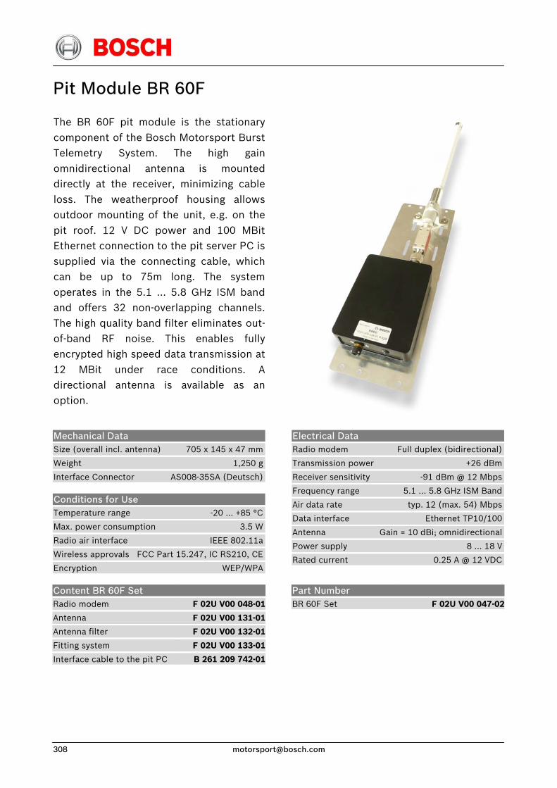
Pit Module BR 60F
The BR 60F pit module is the stationarycomponent of the Bosch Motorsport BurstTelemetry System. The high gain omnidirectional antenna is mounteddirectly at the receiver, minimizing cableloss. The weatherproof housing allowsoutdoor mounting of the unit, e.g. on thepit roof. 12 V DC power and 100 MBitEthernet connection to the pit server PC issupplied via the connecting cable, whichcan be up to 75m long. The systemoperates in the 5.1 … 5.8 GHz ISM bandand offers 32 non-overlapping channels.The high quality band filter eliminates out-of-band RF noise. This enables fullyencrypted high speed data transmission at 12 MBit under race conditions. Adirectional antenna is available as anoption.
Mechanical Data Size (overall incl. antenna) 705 x 145 x 47 mm
Weight 1,250 g
Interface Connector AS008-35SA (Deutsch)
Conditions for Use Temperature range -20 ... +85 °C
Max. power consumption 3.5 W
Radio air interface IEEE 802.11a
Wireless approvals FCC Part 15.247, IC RS210, CE
Encryption WEP/WPA
Electrical Data Radio modem Full duplex (bidirectional)
Transmission power +26 dBm
Receiver sensitivity -91 dBm @ 12 Mbps
Frequency range 5.1 … 5.8 GHz ISM Band
Air data rate typ. 12 (max. 54) Mbps
Data interface Ethernet TP10/100
Antenna Gain = 10 dBi; omnidirectional
Power supply 8 ... 18 V
Rated current 0.25 A @ 12 VDC
Content BR 60F Set Radio modem
Antenna
Antenna filter
Fitting system
Interface cable to the pit PC
F 02U V00 048-01
F 02U V00 131-01
F 02U V00 132-01
F 02U V00 133-01
B 261 209 742-01
Part Number BR 60F Set
F 02U V00 047-02
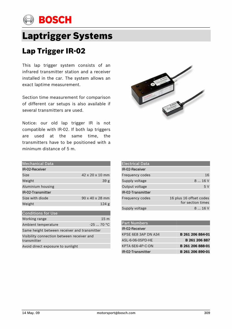
14 May. 09 [email protected] 309
Laptrigger Systems Lap Trigger IR-02
This lap trigger system consists of aninfrared transmitter station and a receiver installed in the car. The system allows anexact laptime measurement.
Section time measurement for comparisonof different car setups is also available ifseveral transmitters are used.
Notice: our old lap trigger IR is notcompatible with IR-02. If both lap triggersare used at the same time, thetransmitters have to be positioned with aminimum distance of 5 m.
Electrical Data IR-02-Receiver
Frequency codes 16
Supply voltage 8 … 16 V
Output voltage 5 V
IR-02-Transmitter
Frequency codes 16 plus 16 offset codes for section times
Supply voltage 8 … 16 V
Mechanical Data IR-02-Receiver
Size 42 x 20 x 10 mm
Weight 39 g
Aluminium housing
IR-02-Transmitter
Size with diode 90 x 40 x 28 mm
Weight 124 g
Conditions for Use Working range 15 m
Ambient temperature -25 … 70 °C
Same height between receiver and transmitter
Visibility connection between receiver and transmitter
Avoid direct exposure to sunlight
Part Numbers IR-02-Receiver
KPSE 6E8 3AP DN A34
ASL-6-06-05PD-HE
KPTA 6E6-4P-C-DN
IR-02-Transmitter
B 261 206 884-01
B 261 206 887
B 261 206 888-01
B 261 206 890-01
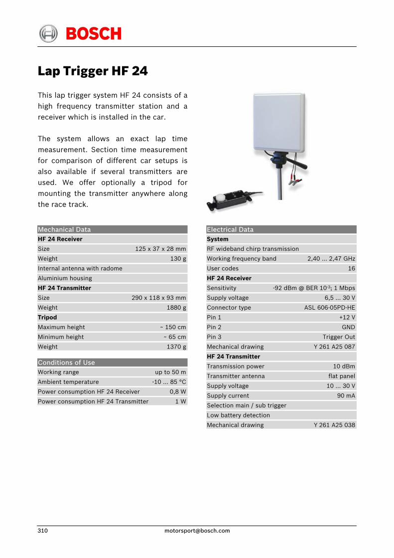
Lap Trigger HF 24
This lap trigger system HF 24 consists of ahigh frequency transmitter station and areceiver which is installed in the car.
The system allows an exact lap timemeasurement. Section time measurementfor comparison of different car setups isalso available if several transmitters areused. We offer optionally a tripod formounting the transmitter anywhere alongthe race track.
Electrical Data System
RF wideband chirp transmission
Working frequency band 2,40 … 2,47 GHz
User codes 16
HF 24 Receiver
Sensitivity -92 dBm @ BER 10-3; 1 Mbps
Supply voltage 6,5 … 30 V
Connector type ASL 606-05PD-HE
Pin 1 +12 V
Pin 2 GND
Pin 3 Trigger Out
Mechanical drawing Y 261 A25 087
HF 24 Transmitter
Transmission power 10 dBm
Transmitter antenna flat panel
Supply voltage 10 … 30 V
Supply current 90 mA
Selection main / sub trigger
Low battery detection
Mechanical drawing Y 261 A25 038
Mechanical Data HF 24 Receiver
Size 125 x 37 x 28 mm
Weight 130 g
Internal antenna with radome
Aluminium housing
HF 24 Transmitter
Size 290 x 118 x 93 mm
Weight 1880 g
Tripod
Maximum height ~ 150 cm
Minimum height ~ 65 cm
Weight 1370 g
Conditions of Use Working range up to 50 m
Ambient temperature -10 … 85 °C
Power consumption HF 24 Receiver 0,8 W
Power consumption HF 24 Transmitter 1 W
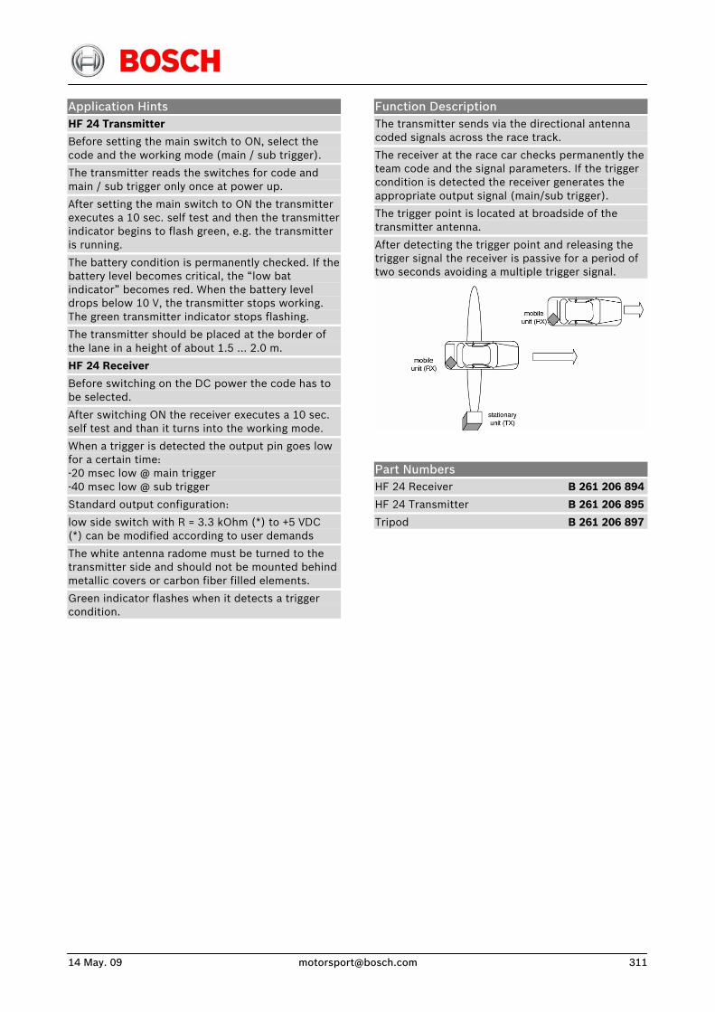
14 May. 09 [email protected] 311
Application Hints HF 24 Transmitter
Before setting the main switch to ON, select the code and the working mode (main / sub trigger).
The transmitter reads the switches for code and main / sub trigger only once at power up.
After setting the main switch to ON the transmitter executes a 10 sec. self test and then the transmitter indicator begins to flash green, e.g. the transmitter is running.
The battery condition is permanently checked. If the battery level becomes critical, the “low bat indicator” becomes red. When the battery level drops below 10 V, the transmitter stops working. The green transmitter indicator stops flashing.
The transmitter should be placed at the border of the lane in a height of about 1.5 … 2.0 m.
HF 24 Receiver
Before switching on the DC power the code has to be selected.
After switching ON the receiver executes a 10 sec. self test and than it turns into the working mode.
When a trigger is detected the output pin goes low for a certain time: -20 msec low @ main trigger -40 msec low @ sub trigger
Standard output configuration:
low side switch with R = 3.3 kOhm (*) to +5 VDC (*) can be modified according to user demands
The white antenna radome must be turned to the transmitter side and should not be mounted behind metallic covers or carbon fiber filled elements.
Green indicator flashes when it detects a trigger condition.
Function Description The transmitter sends via the directional antenna coded signals across the race track.
The receiver at the race car checks permanently the team code and the signal parameters. If the trigger condition is detected the receiver generates the appropriate output signal (main/sub trigger).
The trigger point is located at broadside of the transmitter antenna.
After detecting the trigger point and releasing the trigger signal the receiver is passive for a period of two seconds avoiding a multiple trigger signal.
Part Numbers HF 24 Receiver B 261 206 894
HF 24 Transmitter B 261 206 895
Tripod B 261 206 897

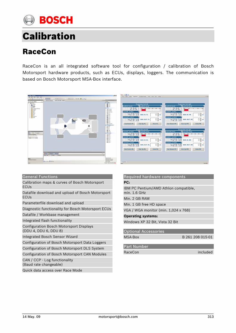
14 May. 09 [email protected] 313
Calibration RaceCon
RaceCon is an all integrated software tool for configuration / calibration of Bosch Motorsport hardware products, such as ECUs, displays, loggers. The communication is based on Bosch Motorsport MSA-Box interface.
General Functions Calibration maps & curves of Bosch Motorsport ECUs
Datafile download and upload of Bosch Motorsport ECUs
Parameterfile download and upload
Diagnostic functionality for Bosch Motorsport ECUs
Datafile / Workbase management
Integrated flash functionality
Configuration Bosch Motorsport Displays (DDU 4, DDU 6, DDU 8)
Integrated Bosch Sensor Wizard
Configuration of Bosch Motorsport Data Loggers
Configuration of Bosch Motorsport DLS System
Configuration of Bosch Motorsport CAN Modules
CAN / CCP - Log functionality (Baud rate changeable)
Quick data access over Race Mode
Required hardware components PC:
IBM PC Pentium/AMD Athlon compatible, min. 1.6 GHz
Min. 2 GB RAM
Min. 1 GB free HD space
VGA / WGA monitor (min. 1,024 x 768)
Operating systems:
Windows XP 32 Bit, Vista 32 Bit
Optional Accessories MSA-Box B 261 208 015-01
Part Number RaceCon included
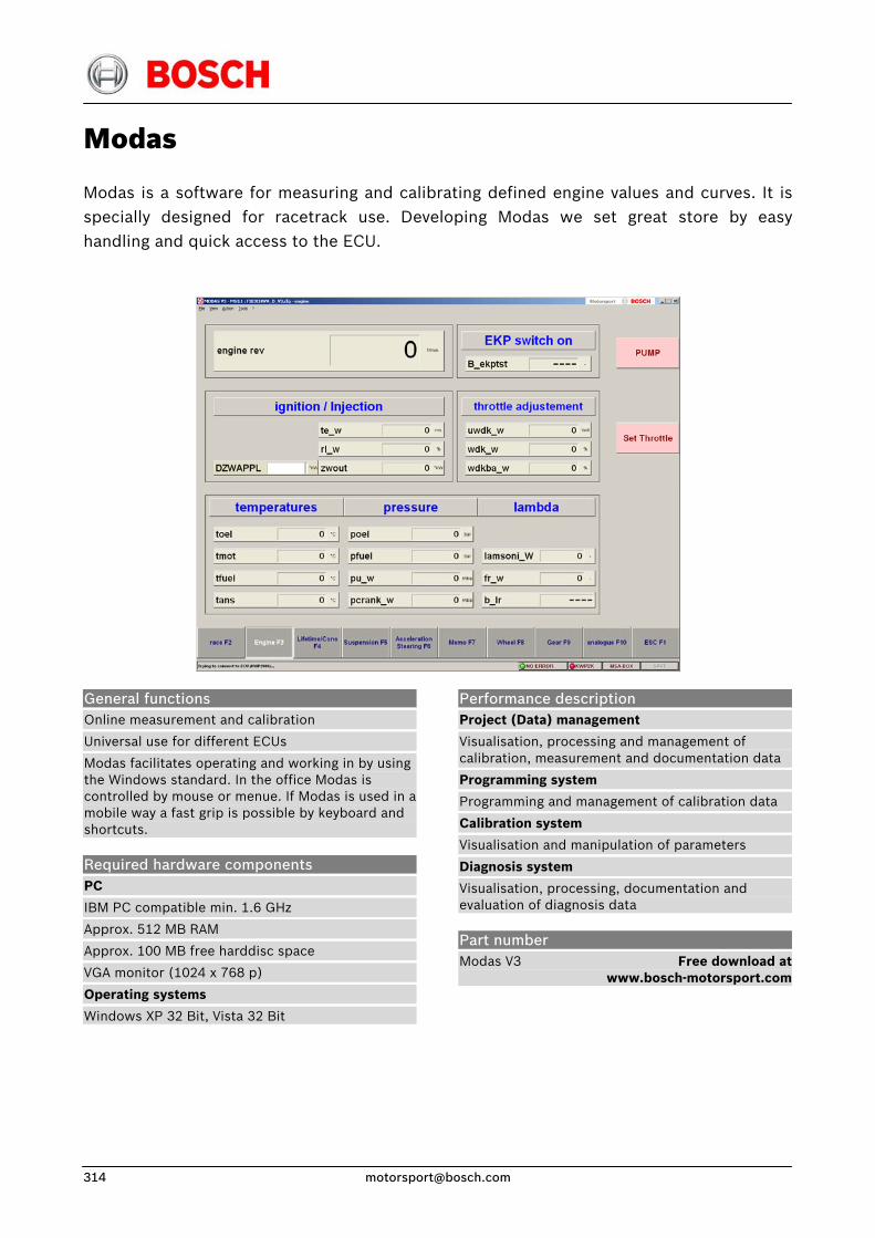
Modas
Modas is a software for measuring and calibrating defined engine values and curves. It is specially designed for racetrack use. Developing Modas we set great store by easy handling and quick access to the ECU.
Performance description Project (Data) management
Visualisation, processing and management of calibration, measurement and documentation data
Programming system
Programming and management of calibration data
Calibration system
Visualisation and manipulation of parameters
Diagnosis system
Visualisation, processing, documentation and evaluation of diagnosis data
Part number
General functions Online measurement and calibration
Universal use for different ECUs
Modas facilitates operating and working in by using the Windows standard. In the office Modas is controlled by mouse or menue. If Modas is used in a mobile way a fast grip is possible by keyboard and shortcuts.
Required hardware components PC
IBM PC compatible min. 1.6 GHz
Approx. 512 MB RAM
Approx. 100 MB free harddisc space
VGA monitor (1024 x 768 p)
Operating systems
Windows XP 32 Bit, Vista 32 Bit
Modas V3
Free download at www.bosch-motorsport.com
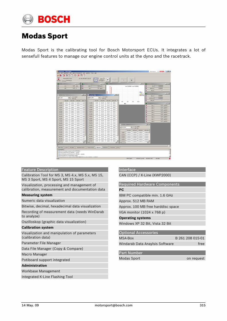
14 May. 09 [email protected] 315
Modas Sport
Modas Sport is the calibrating tool for Bosch Motorsport ECUs. It integrates a lot of sensefull features to manage our engine control units at the dyno and the racetrack.
Feature Description Calibration Tool for MS 3, MS 4.x, MS 5.x, MS 15, MS 3 Sport, MS 4 Sport, MS 15 Sport
Visualization, processing and management of calibration, measurement and documentation data
Measuring system
Numeric data visualization
Bitwise, decimal, hexadecimal data visualization
Recording of measurement data (needs WinDarab to analyze)
Oszilloskop (graphic data visualization)
Calibration system
Visualization and manipulation of parameters (calibration data)
Parameter File Manager
Data File Manager (Copy & Compare)
Macro Manager
Potiboard support integrated
Administration
Workbase Management
Integrated K-Line Flashing Tool
Interface CAN (CCP) / K-Line (KWP2000)
Required Hardware Components PC
IBM PC compatible min. 1.6 GHz
Approx. 512 MB RAM
Approx. 100 MB free harddisc space
VGA monitor (1024 x 768 p)
Operating systems
Windows XP 32 Bit, Vista 32 Bit
Optional Accessories MSA-Box B 261 208 015-01
Windarab Data Anaylsis Software free
Part Number Modas Sport on request
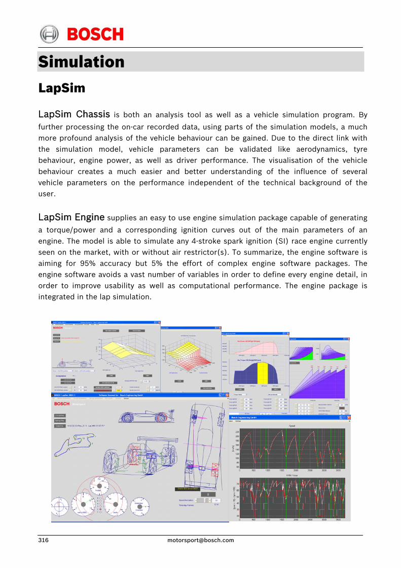
Simulation LapSim
LapSim Chassis is both an analysis tool as well as a vehicle simulation program. By
further processing the on-car recorded data, using parts of the simulation models, a muchmore profound analysis of the vehicle behaviour can be gained. Due to the direct link withthe simulation model, vehicle parameters can be validated like aerodynamics, tyrebehaviour, engine power, as well as driver performance. The visualisation of the vehicle behaviour creates a much easier and better understanding of the influence of several vehicle parameters on the performance independent of the technical background of theuser.
LapSim Engine supplies an easy to use engine simulation package capable of generating
a torque/power and a corresponding ignition curves out of the main parameters of an engine. The model is able to simulate any 4-stroke spark ignition (SI) race engine currentlyseen on the market, with or without air restrictor(s). To summarize, the engine software isaiming for 95% accuracy but 5% the effort of complex engine software packages. Theengine software avoids a vast number of variables in order to define every engine detail, inorder to improve usability as well as computational performance. The engine package isintegrated in the lap simulation.
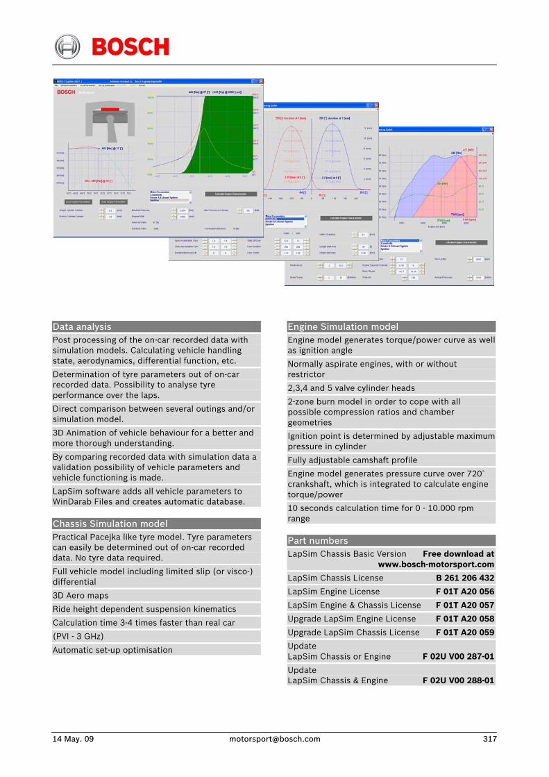
14 May. 09 [email protected] 317
Data analysis Post processing of the on-car recorded data with simulation models. Calculating vehicle handling state, aerodynamics, differential function, etc.
Determination of tyre parameters out of on-car recorded data. Possibility to analyse tyre performance over the laps.
Direct comparison between several outings and/or simulation model.
3D Animation of vehicle behaviour for a better and more thorough understanding.
By comparing recorded data with simulation data a validation possibility of vehicle parameters and vehicle functioning is made.
LapSim software adds all vehicle parameters to WinDarab Files and creates automatic database.
Chassis Simulation model Practical Pacejka like tyre model. Tyre parameters can easily be determined out of on-car recorded data. No tyre data required.
Full vehicle model including limited slip (or visco-) differential
3D Aero maps
Ride height dependent suspension kinematics
Calculation time 3-4 times faster than real car
(PVI - 3 GHz)
Automatic set-up optimisation
Engine Simulation model Engine model generates torque/power curve as well as ignition angle
Normally aspirate engines, with or without restrictor
2,3,4 and 5 valve cylinder heads
2-zone burn model in order to cope with all possible compression ratios and chamber geometries
Ignition point is determined by adjustable maximum pressure in cylinder
Fully adjustable camshaft profile
Engine model generates pressure curve over 720˚ crankshaft, which is integrated to calculate engine torque/power
10 seconds calculation time for 0 - 10.000 rpm range
Part numbers LapSim Chassis Basic Version Free download at www.bosch-motorsport.com
LapSim Chassis License B 261 206 432
LapSim Engine License F 01T A20 056
LapSim Engine & Chassis License F 01T A20 057
Upgrade LapSim Engine License F 01T A20 058
Upgrade LapSim Chassis License F 01T A20 059
Update LapSim Chassis or Engine F 02U V00 287-01
Update LapSim Chassis & Engine F 02U V00 288-01
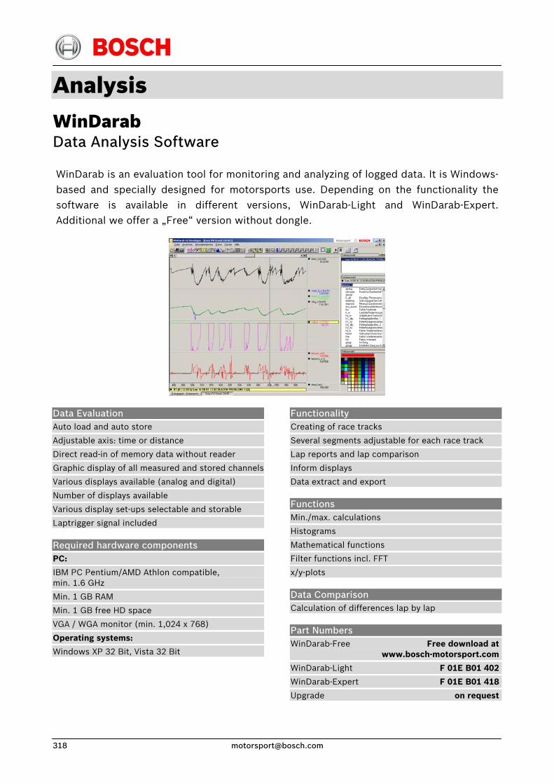
Analysis WinDarab Data Analysis Software WinDarab is an evaluation tool for monitoring and analyzing of logged data. It is Windows-based and specially designed for motorsports use. Depending on the functionality the software is available in different versions, WinDarab-Light and WinDarab-Expert. Additional we offer a „Free“ version without dongle.
Data Evaluation Auto load and auto store
Adjustable axis: time or distance
Direct read-in of memory data without reader
Graphic display of all measured and stored channels
Various displays available (analog and digital)
Number of displays available
Various display set-ups selectable and storable
Laptrigger signal included
Required hardware components PC:
IBM PC Pentium/AMD Athlon compatible, min. 1.6 GHz
Min. 1 GB RAM
Min. 1 GB free HD space
VGA / WGA monitor (min. 1,024 x 768)
Operating systems:
Windows XP 32 Bit, Vista 32 Bit
Functionality Creating of race tracks
Several segments adjustable for each race track
Lap reports and lap comparison
Inform displays
Data extract and export
Functions Min./max. calculations
Histograms
Mathematical functions
Filter functions incl. FFT
x/y-plots
Data Comparison Calculation of differences lap by lap
Part Numbers WinDarab-Free Free download at www.bosch-motorsport.com
WinDarab-Light F 01E B01 402
WinDarab-Expert F 01E B01 418
Upgrade on request

14 May. 09 [email protected] 319
Encryption of data / access rights
The on-board recorded measuring data will be encrypted in the data logger via a so-called project key. Each project key belongs to a specified project or customer.
Reading or viewing data with WinDarab „Light“ or „Expert“, is either possible with
• a dongle with key information on it or
• a project license with corresponding key information on the PC.
The project license can be installed on many PCs, whereas the single-user license needs the stuck dongle for operation. So the data are secured against misuse.
Dongle-free working with WinDarab „Free“
To install WinDarab on many PCs (like the project licenses) we offer WinDarab „Free“ exclusively for free available Bosch Motorsport software and project keys. To ensure our customers data we will not offer a WinDarab „Free“ installation for customers program datasets or project keys.
WinDarab Feature List Free Light Expert Function
Limited number of opened files
Limited number of measuring data windows
Limited number of areas in measuring data windows
Views - Histogram
Views - (x/y)-Plot
Views - Distribution
Views - Min/Max-Tables
Views - Fourier-Transformation
Views - Outing report
Views - Lap analysis
Views - Flowcharts
Views - Instrument Panel (numeric/bargraph/round scale)
User defined Physical Units
Language Support German/English
Racetrack generation via speed/lateral G or GPS
ASCII Export
Matlab Import (seperated tool)
Extras - Functions/Conditions/Differences
Extras - Settings - Comments
Measuring data window - Area channel name - View options
Desktop load/save
Free dongle read-in (single user license)
Free read-in (project license)
Telemetry
Data security (data recording, Darab files)
2
1
2
•
•
–
–
•
•
•
•
•
•
•
–
4
2
4
•
•
•
•
•
–
–
–
•
•
•
•
•
•
–
–
–
•
•
•
•
•
–
–
–
•
•
•
•
•
•
•
•
•
•
•
•
•
•
•
•
•
•
•
•
•
•

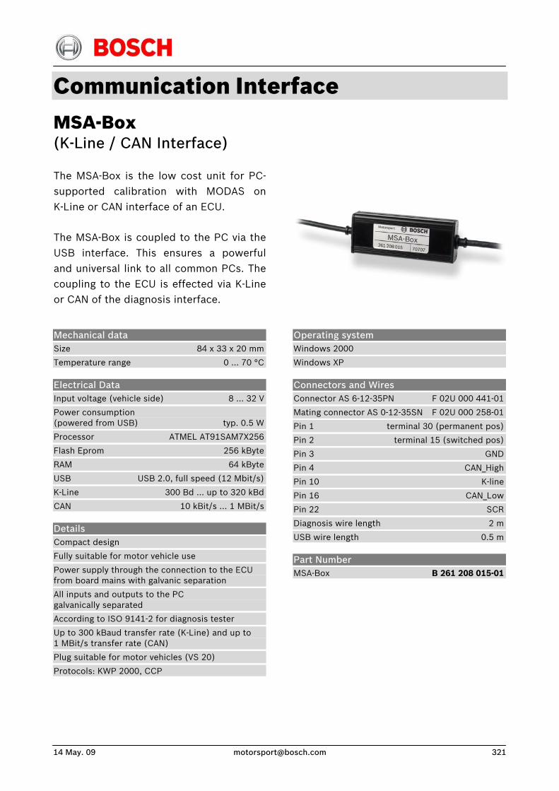
14 May. 09 [email protected] 321
Communication Interface MSA-Box (K-Line / CAN Interface)
The MSA-Box is the low cost unit for PC-supported calibration with MODAS onK-Line or CAN interface of an ECU.
The MSA-Box is coupled to the PC via theUSB interface. This ensures a powerfuland universal link to all common PCs. Thecoupling to the ECU is effected via K-Line or CAN of the diagnosis interface.
Mechanical data Size 84 x 33 x 20 mm
Temperature range 0 ... 70 °C
Electrical Data Input voltage (vehicle side) 8 ... 32 V
Power consumption (powered from USB) typ. 0.5 W
Processor ATMEL AT91SAM7X256
Flash Eprom 256 kByte
RAM 64 kByte
USB USB 2.0, full speed (12 Mbit/s)
K-Line 300 Bd ... up to 320 kBd
CAN 10 kBit/s ... 1 MBit/s
Details Compact design
Fully suitable for motor vehicle use
Power supply through the connection to the ECU from board mains with galvanic separation
All inputs and outputs to the PC galvanically separated
According to ISO 9141-2 for diagnosis tester
Up to 300 kBaud transfer rate (K-Line) and up to 1 MBit/s transfer rate (CAN)
Plug suitable for motor vehicles (VS 20)
Protocols: KWP 2000, CCP
Operating system Windows 2000
Windows XP
Connectors and Wires Connector AS 6-12-35PN F 02U 000 441-01
Mating connector AS 0-12-35SN F 02U 000 258-01
Pin 1 terminal 30 (permanent pos)
Pin 2 terminal 15 (switched pos)
Pin 3 GND
Pin 4 CAN_High
Pin 10 K-line
Pin 16 CAN_Low
Pin 22 SCR
Diagnosis wire length 2 m
USB wire length 0.5 m
Part Number MSA-Box B 261 208 015-01

Handheld Test Devices RS 2000
With the RS 2000 you can simulatecrank shaft-, cam shaft- and wheel-speed-signals quickly and comfortable.
Electrical data Power supply 12 V
Functions Infinitely variable simulation of Hall- and inductive signal.
Compatible with all Bosch Motorsport ECUs from MS 1.9 to MS 4.1
Adjustable on cylinder numbers from 4 to 12.
Usable for increment- and segment-systems.
Part numbers RS 2000
Cable harness connector
B 261 206 862 01
B 261 206 451
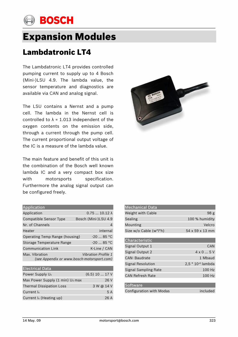
14 May. 09 [email protected] 323
Expansion Modules Lambdatronic LT4
The Lambdatronic LT4 provides controlledpumping current to supply up to 4 Bosch(Mini-)LSU 4.9. The lambda value, thesensor temperature and diagnostics areavailable via CAN and analog signal.
The LSU contains a Nernst and a pumpcell. The lambda in the Nernst cell iscontrolled to λ = 1.013 independent of theoxygen contents on the emission side,through a current through the pump cell.The current proportional output voltage ofthe IC is a measure of the lambda value.
The main feature and benefit of this unit isthe combination of the Bosch well knownlambda IC and a very compact box sizewith motorsports specification.Furthermore the analog signal output canbe configured freely.
Application Application 0.75 … 10.12 λ
Compatible Sensor Type Bosch (Mini-)LSU 4.9
Nr. of Channels 4
Heater internal
Operating Temp Range (housing) -20 … 85 °C
Storage Temperature Range -20 … 85 °C
Communication Link K-Line / CAN
Max. Vibration Vibration Profile 1 (see Appendix or www.bosch-motorsport.com)
Electrical Data Power Supply Us (6.5) 10 … 17 V
Max Power Supply (1 min) US max 26 V
Thermal Dissipation Loss 3 W @ 14 V
Current Is 5 A
Current Is (Heating up) 26 A
Mechanical Data Weight with Cable 98 g
Sealing 100 % humidity
Mounting Velcro
Size w/o Cable (w*l*h) 54 x 59 x 13 mm
Characteristic Signal Output 1 CAN
Signal Output 2 4 x 0 … 5 V
CAN- Baudrate 1 Mbaud
Signal Resolution 2,5 * 10-4 lambda
Signal Sampling Rate 100 Hz
CAN Refresh Rate 100 Hz
Software Configuration with Modas included
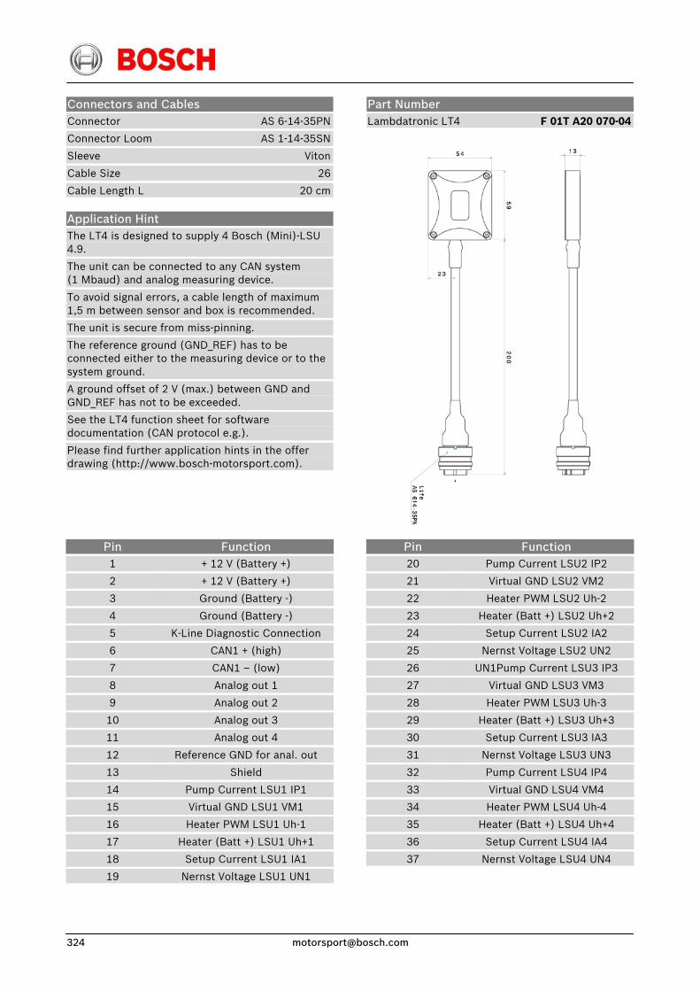
Connectors and Cables Connector AS 6-14-35PN
Connector Loom AS 1-14-35SN
Sleeve Viton
Cable Size 26
Cable Length L 20 cm
Application Hint The LT4 is designed to supply 4 Bosch (Mini)-LSU 4.9.
The unit can be connected to any CAN system (1 Mbaud) and analog measuring device.
To avoid signal errors, a cable length of maximum 1,5 m between sensor and box is recommended.
The unit is secure from miss-pinning.
The reference ground (GND_REF) has to be connected either to the measuring device or to the system ground.
A ground offset of 2 V (max.) between GND and GND_REF has not to be exceeded.
See the LT4 function sheet for software documentation (CAN protocol e.g.).
Please find further application hints in the offer drawing (http://www.bosch-motorsport.com).
Part Number Lambdatronic LT4 F 01T A20 070-04
Pin 1
2
3
4
5
6
7
8
9
10
11
12
13
14
15
16
17
18
19
Function + 12 V (Battery +)
+ 12 V (Battery +)
Ground (Battery -)
Ground (Battery -)
K-Line Diagnostic Connection
CAN1 + (high)
CAN1 – (low)
Analog out 1
Analog out 2
Analog out 3
Analog out 4
Reference GND for anal. out
Shield
Pump Current LSU1 IP1
Virtual GND LSU1 VM1
Heater PWM LSU1 Uh-1
Heater (Batt +) LSU1 Uh+1
Setup Current LSU1 IA1
Nernst Voltage LSU1 UN1
Pin 20
21
22
23
24
25
26
27
28
29
30
31
32
33
34
35
36
37
Function Pump Current LSU2 IP2
Virtual GND LSU2 VM2
Heater PWM LSU2 Uh-2
Heater (Batt +) LSU2 Uh+2
Setup Current LSU2 IA2
Nernst Voltage LSU2 UN2
UN1Pump Current LSU3 IP3
Virtual GND LSU3 VM3
Heater PWM LSU3 Uh-3
Heater (Batt +) LSU3 Uh+3
Setup Current LSU3 IA3
Nernst Voltage LSU3 UN3
Pump Current LSU4 IP4
Virtual GND LSU4 VM4
Heater PWM LSU4 Uh-4
Heater (Batt +) LSU4 Uh+4
Setup Current LSU4 IA4
Nernst Voltage LSU4 UN4
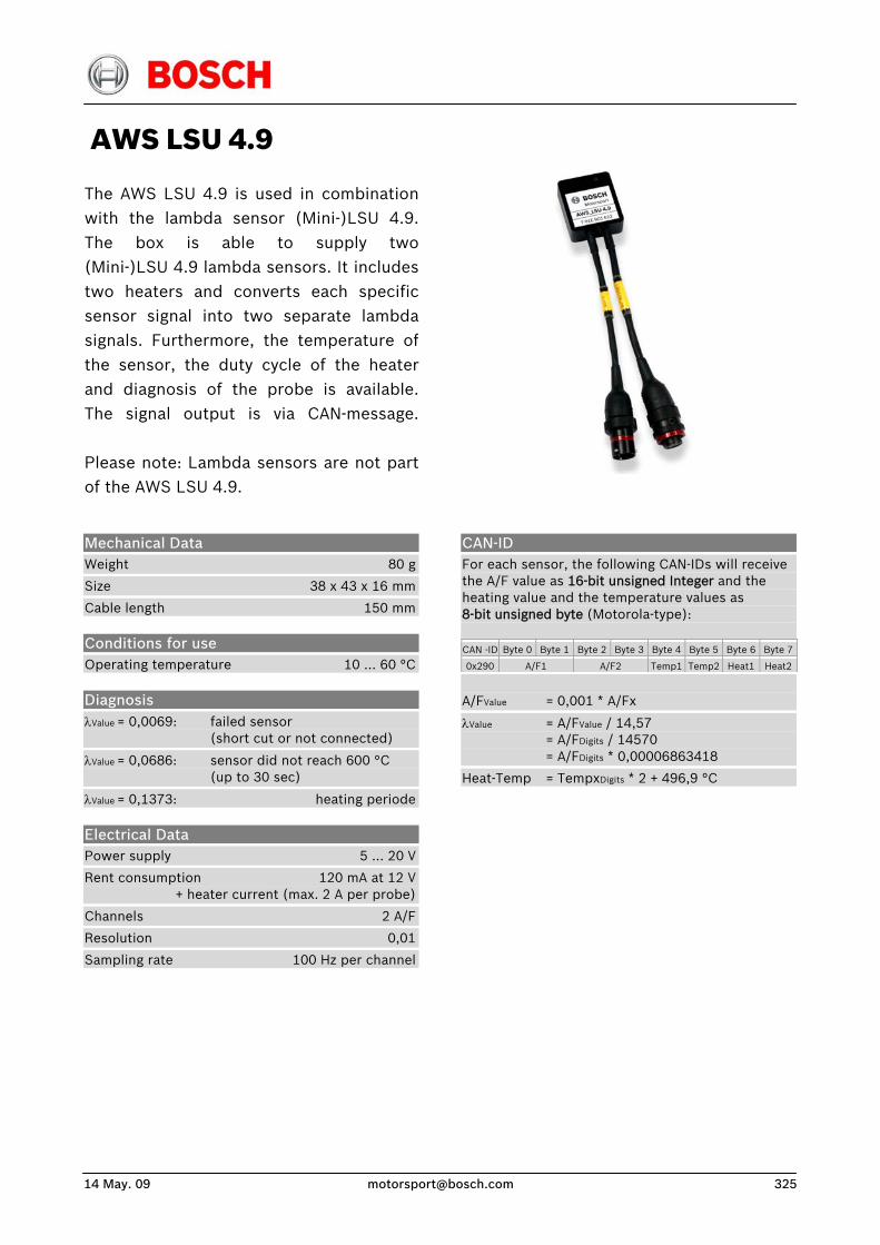
14 May. 09 [email protected] 325
AWS LSU 4.9
The AWS LSU 4.9 is used in combinationwith the lambda sensor (Mini-)LSU 4.9.The box is able to supply two(Mini-)LSU 4.9 lambda sensors. It includestwo heaters and converts each specificsensor signal into two separate lambdasignals. Furthermore, the temperature ofthe sensor, the duty cycle of the heaterand diagnosis of the probe is available.The signal output is via CAN-message. Please note: Lambda sensors are not partof the AWS LSU 4.9.
CAN-ID For each sensor, the following CAN-IDs will receive the A/F value as 16-bit unsigned Integer and the heating value and the temperature values as 8-bit unsigned byte (Motorola-type): CAN -ID Byte 0 Byte 1 Byte 2 Byte 3 Byte 4 Byte 5 Byte 6 Byte 7
0x290 A/F1 A/F2 Temp1 Temp2 Heat1 Heat2
Mechanical Data Weight 80 g
Size 38 x 43 x 16 mm
Cable length 150 mm
Conditions for use Operating temperature 10 … 60 °C
Diagnosis λValue = 0,0069: failed sensor (short cut or not connected)
λValue = 0,0686: sensor did not reach 600 °C (up to 30 sec)
λValue = 0,1373: heating periode
Electrical Data Power supply 5 … 20 V
Rent consumption 120 mA at 12 V + heater current (max. 2 A per probe)
Channels 2 A/F
Resolution 0,01
Sampling rate 100 Hz per channel
A/FValue = 0,001 * A/Fx
λValue = A/FValue / 14,57 = A/FDigits / 14570 = A/FDigits * 0,00006863418
Heat-Temp = TempxDigits * 2 + 496,9 °C
Pin assignment life connector Pin
1
2
3
4
9
10
11
12
Name
GND
GND LSU 1/2
Vext
LSU heater
CAN H
CAN L
TxD
RxD
Description
Ground
Ground LSU heater
External power supply 5 … 20 V
External power supply for LSU 1/2 heater
CAN Bus high
CAN Bus low
TxD serial interface
RxD serial interface
Pin assignment LSU-1/2 in connector Pin
1
2
3
4
5
6
7
8
9
10
11
12
Name
LSU1 IP
LSU1 VM
GND heater 1
Vext heater 1
LSU1 IA
LSU1 UN
LSU2 IP
LSU2 VM
GND heater 2
Vext heater 2
LSU2 IA
LSU2 UN
Description
Inv. Input of pump current amp
Virtual ground
Ground for heater 1
External power supply 5 … 20 V LSU1
Non Inv. input of pump current amp
Inv. input of pump current control
Non Inv. input of pump current amp
Virtual ground
Ground for heater 2
External power supply 5 … 20 V LSU2
Non Inv. input of pump current amp
Inv. input of pump current control
Accessories Lambda Sensor LSU 4.9 0 258 017 025
Lambda Sensor LSU 4.9 B 261 209 356
Lambda Sensor Mini-LSU 4.9 B 258 490 103-20
Part Number AWS LSU 4.9 F 01E B01 622
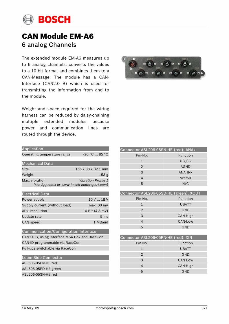
14 May. 09 [email protected] 327
CAN Module EM-A6 6 analog Channels
The extended module EM-A6 measures upto 6 analog channels, converts the valuesto a 10 bit format and combines them to aCAN-Message. The module has a CAN-Interface (CAN2.0 B) which is used fortransmitting the information from and tothe module.
Weight and space required for the wiringharness can be reduced by daisy-chainingmultiple extended modules becausepower and communication lines arerouted through the device.
Connector ASL206-05SN-HE (red); ANAx
Pin-No.
1
2
3
4
5
Function
UB_SG
AGND
ANA_INx
Vref50
N/C
Connector ASL206-05SD-HE (green), XOUT
Pin-No.
1
2
3
4
5
Function
UBATT
GND
CAN-High
CAN-Low
GND
Connector ASL206-05PN-HE (red), XIN
Pin-No.
1
2
3
4
5
Function
UBATT
GND
CAN-Low
CAN-High
GND
Application Operating temperature range -20 °C … 85 °C
Mechanical Data Size 155 x 38 x 32.1 mm
Weight 153 g
Max. vibration Vibration Profile 1 (see Appendix or www.bosch-motorsport.com)
Electrical Data Power supply 10 V … 18 V
Supply current (without load) max. 80 mA
ADC resolution 10 Bit (4.8 mV)
Update rate 5 ms
CAN speed 1 MBaud
Communication/Configuration Interface CAN2.0 B, using interface MSA-Box and RaceCon
CAN-ID programmable via RaceCon
Pull-ups switchable via RaceCon
Loom Side Connector ASL606-05PN-HE red
ASL606-05PD-HE green
ASL606-05SN-HE red

CAN Protocol Byte order Big endian (high-byte/low-byte, Motorola)
CAN Frame 1
Part Number CAN Module EM-A6 F 01T A20 007
Byte 0 1 2 3 4 5 6 7
Value
Row counter
= 0
AD channel 1
AD channel 2
AD channel 3
unused
CAN Frame 2 Byte 0 1 2 3 4 5 6 7
Value
Row counter
= 1
AD channel 4
AD channel 5
AD channel 6
unused
U [V] = raw value * 5 V / 1024
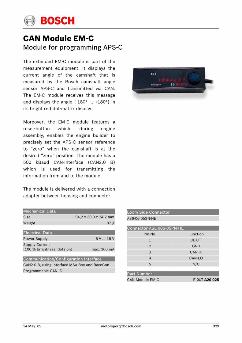
14 May. 09 [email protected] 329
CAN Module EM-C Module for programming APS-C
The extended EM-C module is part of themeasurement equipment. It displays the current angle of the camshaft that is measured by the Bosch camshaft anglesensor APS-C and transmitted via CAN. The EM-C module receives this messageand displays the angle (-180° … +180°) inits bright red dot-matrix display.
Moreover, the EM-C module features areset-button which, during engineassembly, enables the engine builder toprecisely set the APS-C sensor referenceto “zero” when the camshaft is at thedesired “zero” position. The module has a500 kBaud CAN-Interface (CAN2.0 B)which is used for transmitting theinformation from and to the module.
The module is delivered with a connectionadapter between housing and connector.
Loom Side Connector AS6-06-05SN-HE
Connector ASL-006-05PN-HE Pin-No.
1
2
3
4
5
Function
UBATT
GND
CAN-Hi
CAN-LO
N/C
Mechanical Data Size 94,2 x 30,0 x 24,2 mm
Weight 97 g
Electrical Data Power Supply 8 V … 18 V
Supply Current (100 % brightness, dots on) max. 300 mA
Communication/Configuration Interface CAN2.0 B, using interface MSA-Box and RaceCon
Programmable CAN-ID
Part Number CAN Module EM-C
F 01T A20 025
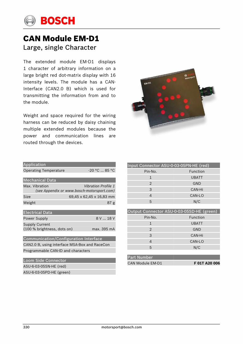
CAN Module EM-D1 Large, single Character
The extended module EM-D1 displays1 character of arbitrary information on a large bright red dot-matrix display with 16intensity levels. The module has a CAN-Interface (CAN2.0 B) which is used fortransmitting the information from and tothe module.
Weight and space required for the wiringharness can be reduced by daisy chainingmultiple extended modules because thepower and communication lines arerouted through the devices.
Input Connector ASU-0-03-05PN-HE (red) Pin-No.
1
2
3
4
5
Function
UBATT
GND
CAN-Hi
CAN-LO
N/C
Output Connector ASU-0-03-05SD-HE (green) Pin-No.
1
2
3
4
5
Function
UBATT
GND
CAN-Hi
CAN-LO
N/C
Application Operating Temperature -20 °C … 85 °C
Mechanical Data Max. Vibration Vibration Profile 1 (see Appendix or www.bosch-motorsport.com)
Size 69,45 x 62,45 x 16,83 mm
Weight 87 g
Electrical Data Power Supply 8 V … 18 V
Supply Current (100 % brightness, dots on) max. 395 mA
Communication/Configuration Interface CAN2.0 B, using interface MSA-Box and RaceCon
Programmable CAN-ID and characters
Loom Side Connector ASU-6-03-05SN-HE (red)
ASU-6-03-05PD-HE (green)
Part Number CAN Module EM-D1
F 01T A20 006
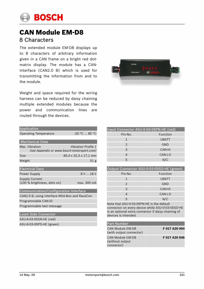
14 May. 09 [email protected] 331
CAN Module EM-D8 8 Characters The extended module EM-D8 displays upto 8 characters of arbitrary informationgiven in a CAN frame on a bright red dot-matrix display. The module has a CAN-Interface (CAN2.0 B) which is used fortransmitting the information from and tothe module.
Weight and space required for the wiringharness can be reduced by daisy chainingmultiple extended modules because thepower and communication lines arerouted through the devices.
Input Connector ASU-0-03-05PN-HE (red) Pin-No.
1
2
3
4
5
Function
UBATT
GND
CAN-Hi
CAN-LO
N/C
Output Connector ASU-0-03-05SD-HE (green) Pin-No.
1
2
3
4
5
Function
UBATT
GND
CAN-Hi
CAN-LO
N/C
Note that ASU-0-03-05PN-HE is the default connector on every device while ASU-0-03-05SD-HE is an optional extra connector if daisy chaining of devices is intended.
Application Operating Temperature -20 °C … 85 °C
Mechanical Data Max. Vibration Vibration Profile 1 (see Appendix or www.bosch-motorsport.com)
Size 85,4 x 32,3 x 17,1 mm
Weight 51 g
Electrical Data Power Supply 8 V … 18 V
Supply Current (100 % brightness, dots on) max. 300 mA
Communication/Configuration Interface CAN2.0 B, using interface MSA-Box and RaceCon
Programmable CAN-ID
Programmable text message
Loom Side Connector ASU-6-03-05SN-HE (red)
ASU-6-03-05PD-HE (green)
Part Number CAN Module EM-D8 (with output connector)
CAN Module EM-D8 (without output connector)
F 01T A20 004
F 01T A20 046
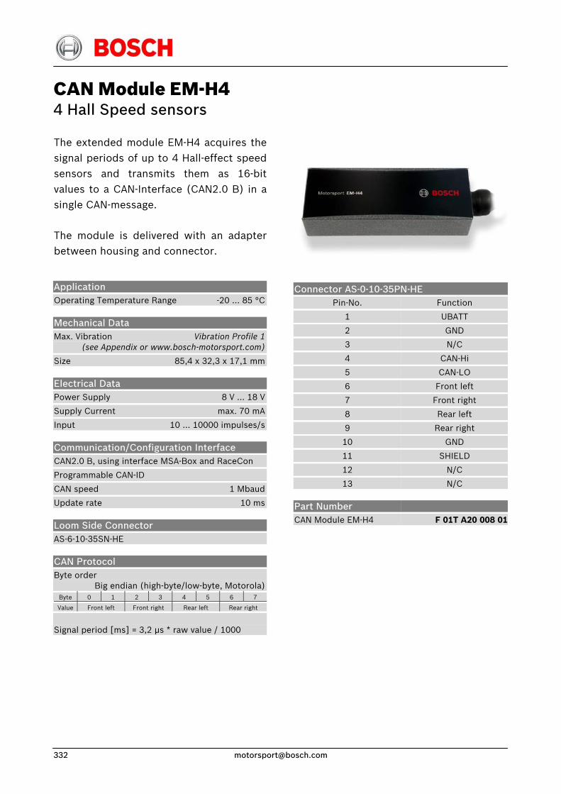
CAN Module EM-H4 4 Hall Speed sensors
The extended module EM-H4 acquires thesignal periods of up to 4 Hall-effect speedsensors and transmits them as 16-bit values to a CAN-Interface (CAN2.0 B) in asingle CAN-message.
The module is delivered with an adapterbetween housing and connector.
Connector AS-0-10-35PN-HE Application Operating Temperature Range -20 … 85 °C
Mechanical Data Max. Vibration Vibration Profile 1 (see Appendix or www.bosch-motorsport.com)
Size 85,4 x 32,3 x 17,1 mm
Electrical Data Power Supply 8 V … 18 V
Supply Current max. 70 mA
Input 10 … 10000 impulses/s
Communication/Configuration Interface CAN2.0 B, using interface MSA-Box and RaceCon
Programmable CAN-ID
CAN speed 1 Mbaud
Update rate 10 ms
Loom Side Connector AS-6-10-35SN-HE
CAN Protocol Byte order Big endian (high-byte/low-byte, Motorola)
Byte 0 1 2 3 4 5 6 7
Value Front left Front right Rear left Rear right
Signal period [ms] = 3,2 μs * raw value / 1000
Pin-No.
1
2
3
4
5
6
7
8
9
10
11
12
13
Part Number CAN Module EM-H4
Function
UBATT
GND
N/C
CAN-Hi
CAN-LO
Front left
Front right
Rear left
Rear right
GND
SHIELD
N/C
N/C
F 01T A20 008 01
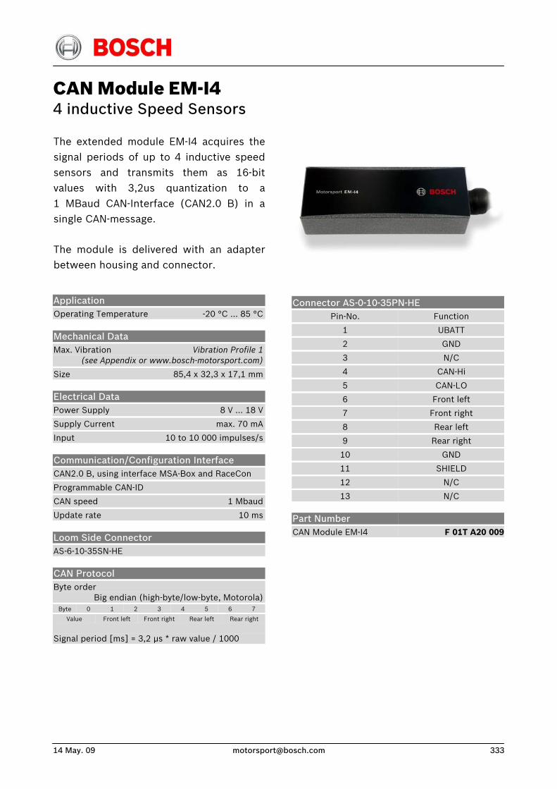
14 May. 09 [email protected] 333
CAN Module EM-I4 4 inductive Speed Sensors
The extended module EM-I4 acquires thesignal periods of up to 4 inductive speedsensors and transmits them as 16-bit values with 3,2us quantization to a1 MBaud CAN-Interface (CAN2.0 B) in asingle CAN-message.
The module is delivered with an adapterbetween housing and connector.
Connector AS-0-10-35PN-HE
Pin-No.
1
2
3
4
5
6
7
8
9
10
11
12
13
Function
UBATT
GND
N/C
CAN-Hi
CAN-LO
Front left
Front right
Rear left
Rear right
GND
SHIELD
N/C
N/C
Application Operating Temperature -20 °C … 85 °C
Mechanical Data Max. Vibration Vibration Profile 1 (see Appendix or www.bosch-motorsport.com)
Size 85,4 x 32,3 x 17,1 mm
Electrical Data Power Supply 8 V … 18 V
Supply Current max. 70 mA
Input 10 to 10 000 impulses/s
Communication/Configuration Interface CAN2.0 B, using interface MSA-Box and RaceCon
Programmable CAN-ID
CAN speed 1 Mbaud
Update rate 10 ms
Loom Side Connector AS-6-10-35SN-HE
Part Number CAN Module EM-I4
F 01T A20 009
CAN Protocol Byte order Big endian (high-byte/low-byte, Motorola)
Byte 0 1 2 3 4 5 6 7
Value Front left Front right Rear left Rear right
Signal period [ms] = 3,2 μs * raw value / 1000
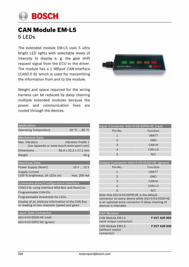
CAN Module EM-L5 5 LEDs
The extended module EM-L5 uses 5 ultrabright LED lights with selectable levels of intensity to display e. g. the gear shiftrequest signal from the ECU to the driver.The module has a 1 MBaud CAN-Interface(CAN2.0 B) which is used for transmittingthe information from and to the module.
Weight and space required for the wiringharness can be reduced by daisy chainingmultiple extended modules because thepower and communication lines arerouted through the devices.
Input Connector ASU-0-03-05PN-HE (red) Pin-No.
1
2
3
4
5
Function
UBATT
GND
CAN-Hi
CAN-LO
N/C
Output Connector ASU-0-03-05SD-HE (green) Pin-No.
1
2
3
4
5
Function
UBATT
GND
CAN-Hi
CAN-LO
N/C
Note that ASU-0-03-05PN-HE is the default connector on every device while ASU-0-03-05SD-HE is an optional extra connector if daisy chaining of devices is intended.
Application Operating Temperature -20 °C … 85 °C
Mechanical Data Max. Vibration Vibration Profile 1 (see Appendix or www.bosch-motorsport.com)
Dimensions 85,4 x 32,3 x 17,1 mm
Weight 50 g
Electrical Data Power Supply (Note!) 10 V … 15 V
Supply Current (100 % brightness, all LEDs on) max. 200 mA
Communication/Configuration Interface CAN2.0 B, using interface MSA-Box and RaceCon
Programmable CAN-IDs
Programmable thresholds for LEDs
Display of an arbitrary information of the CAN Bus or reading of two channels (speed and gear)
Loom Side Connector ASU-6-03-05SN-HE (red)
ASU-6-03-05PD-HE (green)
Part Number CAN Module EM-L5 (with output connector)
CAN Module EM-L5 (without output connector)
F 01T A20 002
F 01T A20 045
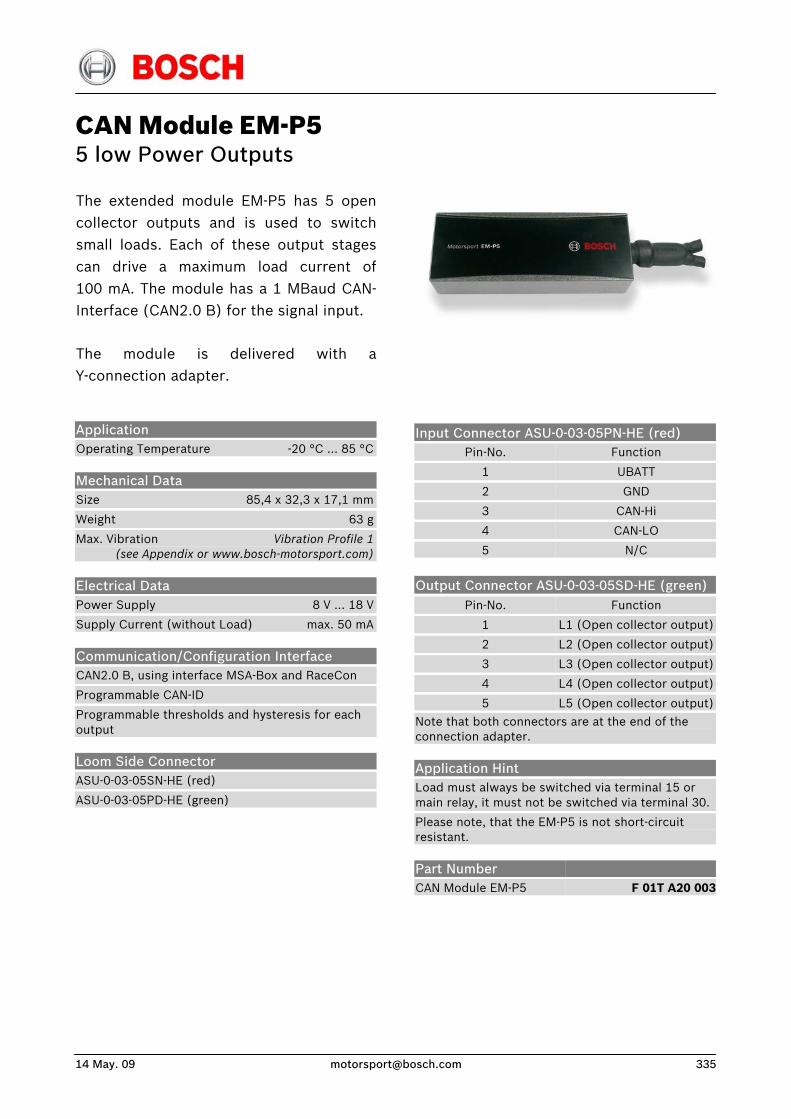
14 May. 09 [email protected] 335
CAN Module EM-P5 5 low Power Outputs
The extended module EM-P5 has 5 opencollector outputs and is used to switchsmall loads. Each of these output stagescan drive a maximum load current of100 mA. The module has a 1 MBaud CAN-Interface (CAN2.0 B) for the signal input.
The module is delivered with aY-connection adapter.
Input Connector ASU-0-03-05PN-HE (red) Pin-No.
1
2
3
4
5
Function
UBATT
GND
CAN-Hi
CAN-LO
N/C
Output Connector ASU-0-03-05SD-HE (green) Pin-No.
1
2
3
4
5
Function
L1 (Open collector output)
L2 (Open collector output)
L3 (Open collector output)
L4 (Open collector output)
L5 (Open collector output)
Note that both connectors are at the end of the connection adapter.
Application Hint Load must always be switched via terminal 15 or main relay, it must not be switched via terminal 30.
Please note, that the EM-P5 is not short-circuit resistant.
Application Operating Temperature -20 °C … 85 °C
Mechanical Data Size 85,4 x 32,3 x 17,1 mm
Weight 63 g
Max. Vibration Vibration Profile 1 (see Appendix or www.bosch-motorsport.com)
Electrical Data Power Supply 8 V … 18 V
Supply Current (without Load) max. 50 mA
Communication/Configuration Interface CAN2.0 B, using interface MSA-Box and RaceCon
Programmable CAN-ID
Programmable thresholds and hysteresis for each output
Loom Side Connector ASU-0-03-05SN-HE (red)
ASU-0-03-05PD-HE (green)
Part Number CAN Module EM-P5
F 01T A20 003
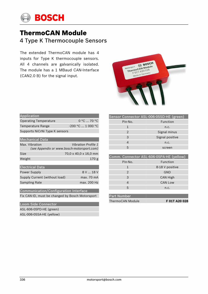
ThermoCAN Module 4 Type K Thermocouple Sensors
The extended ThermoCAN module has 4inputs for Type K thermocouple sensors.All 4 channels are galvanically isolated.The module has a 1 MBaud CAN-Interface(CAN2.0 B) for the signal input.
Sensor Connector ASL-006-05SD-HE (green) Pin-No.
1
2
3
4
5
Function
n.c.
Signal minus
Signal positive
n.c.
screen
Comm. Connector ASL-606-05PA-HE (yellow)
Application Operating Temperature 0 °C … 70 °C
Temperature Range -200 °C … 1 000 °C
Supports NiCrNi Type K sensors
Mechanical Data Max. Vibration Vibration Profile 1 (see Appendix or www.bosch-motorsport.com)
Size 70,0 x 40,0 x 16,0 mm
Weight 170 g
Electrical Data Power Supply 8 V … 18 V
Supply Current (without load) max. 70 mA
Sampling Rate max. 200 Hz
Communication/Configuration Interface Fix CAN-ID, must be changed by Bosch Motorsport
Loom Side Connector ASL-606-05PD-HE (green)
ASL-006-05SA-HE (yellow)
Pin-No.
1
2
3
4
5
Part Number ThermoCAN Module
Function
8-18 V positive
GND
CAN High
CAN Low
n.c.
F 01T A20 028
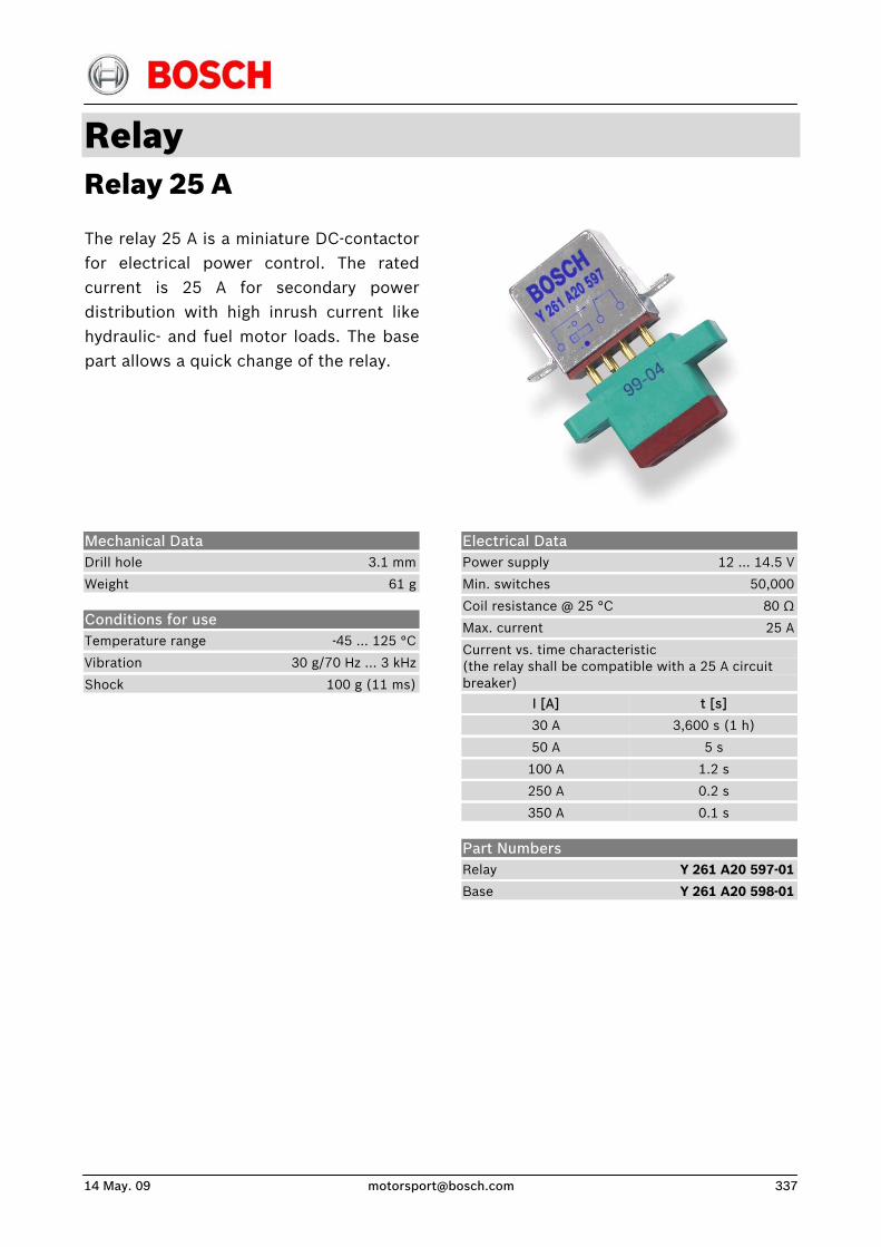
14 May. 09 [email protected] 337
Relay Relay 25 A
The relay 25 A is a miniature DC-contactorfor electrical power control. The ratedcurrent is 25 A for secondary powerdistribution with high inrush current likehydraulic- and fuel motor loads. The basepart allows a quick change of the relay.
Electrical Data Power supply 12 ... 14.5 V
Min. switches 50,000
Coil resistance @ 25 °C 80 Ω
Max. current 25 A
Current vs. time characteristic (the relay shall be compatible with a 25 A circuit breaker)
I [A]
30 A
50 A
100 A
250 A
350 A
t [s]
3,600 s (1 h)
5 s
1.2 s
0.2 s
0.1 s
Mechanical Data Drill hole 3.1 mm
Weight 61 g
Conditions for use Temperature range -45 … 125 °C
Vibration 30 g/70 Hz ... 3 kHz
Shock 100 g (11 ms)
Part Numbers Relay Y 261 A20 597-01
Base Y 261 A20 598-01
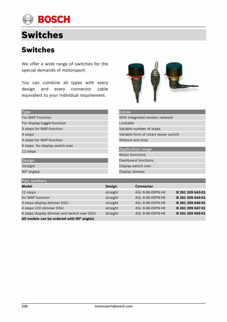
Switches Switches
We offer a wide range of switches for thespecial demands of motorsport.
You can combine all types with everydesign and every connector cableequivalent to your individual requirement.
Type For MAP Function
For display-toggle-function
3 steps for MAP-function
4 steps
4 steps for MAP-function
6 steps for display switch over
12 steps
Design Straight
90° angled
Extras With integrated resistor network
Lockable
Variable number of steps
Variable form of rotary waver switch
Without end stop
Application range Motor functions
Dashboard functions
Display switch over
Display dimmer
Part numbers Model Design Connector
12 steps straight ASL 6-06-05PN-HE B 261 209 643-01for MAP function straight ASL 6-06-05PN-HE B 261 209 644-014 steps display dimmer DDU straight ASL 6-06-05PN-HE B 261 209 646-014 steps LED dimmer DDU straight ASL 6-06-05PN-HE B 261 209 647-016 steps display dimmer and switch over DDU straight ASL 6-06-05PN-HE B 261 209 659-01All models can be ordered with 90° angled.

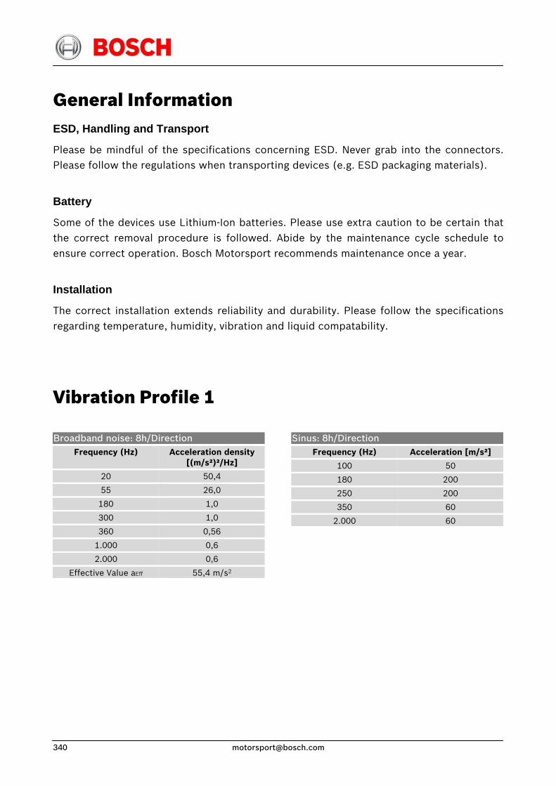
General Information ESD, Handling and Transport
Please be mindful of the specifications concerning ESD. Never grab into the connectors. Please follow the regulations when transporting devices (e.g. ESD packaging materials).
Battery
Some of the devices use Lithium-Ion batteries. Please use extra caution to be certain that the correct removal procedure is followed. Abide by the maintenance cycle schedule to ensure correct operation. Bosch Motorsport recommends maintenance once a year.
Installation
The correct installation extends reliability and durability. Please follow the specifications regarding temperature, humidity, vibration and liquid compatability.
Vibration Profile 1
Broadband noise: 8h/Direction Sinus: 8h/Direction Frequency (Hz)
20
55
180
300
360
1.000
2.000
Effective Value aEff
Acceleration density [(m/s²)²/Hz]
50,4
26,0
1,0
1,0
0,56
0,6
0,6
55,4 m/s2
Frequency (Hz)
100
180
250
350
2.000
Acceleration [m/s²]
50
200
200
60
60
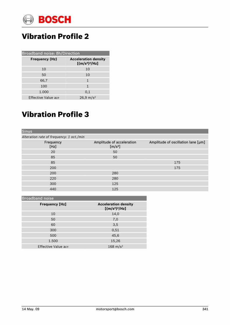
14 May. 09 [email protected] 341
Vibration Profile 2
Broadband noise: 8h/Direction Frequency (Hz)
10
50
66,7
100
1.000
Effective Value aEff
Acceleration density [(m/s²)²/Hz]
10
10
1
1
0,1
26,9 m/s2
Vibration Profile 3
Sinus Alteration rate of frequency: 1 oct./min
Frequency [Hz]
Amplitude of acceleration [m/s²]
Amplitude of oscillation lane [μm]
20 50 85 50 85 175
200 175 200 280 220 280
300 125 440 125
Broadband noise Frequency [Hz]
Acceleration density
[(m/s²)²/Hz] 10 14,0
50 7,0
60 3,5
300 0,51
500 45,6
1.500
Effective Value aEff
15,26
168 m/s2
Bosch Engineering GmbHMotorsport
An der Bracke 971706 Markgröningen
Germany
Phone: 00 49 (0) 711/811-3981Fax: 00 49 (0) 711/811-3982
North American Office:Bosch Engineering North AmericaMotorsports, Dep. BEG/MSD-NA
38000 Hills Tech DriveFarmington Hills, MI 48331-3417
Phone: 00 1 248 876-2977Fax: 00 1 248 876-7373
E-mail: [email protected]
© Bosch Engineering GmbH 2009Modifications reserved.
Warning: It is strictly forbidden to use Bosch Motorsport products on public roads. They are only developed for use in racing on private closed courses!