bcx1 series controller technical reference
TRANSCRIPT
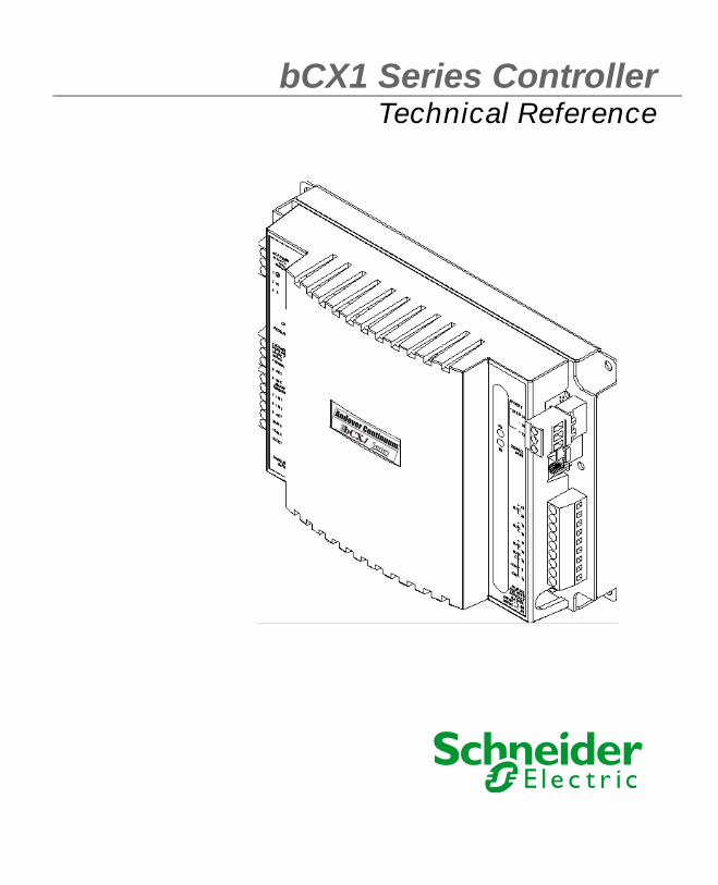
bCX1 Series ControllerTechnical Reference
bbCC1XX
Series
Andover Continuum

© 2010, Schneider Electric
All Rights Reserved
No part of this publication may be reproduced, read or stored in a retrieval system, ortransmitted, in any form or by any means, electronic, mechanical, photocopying, recording,or otherwise, without prior written permission of Schneider Electric.
This document is produced in the United States of America.
Andover Plain English™ is a trademark of Schneider Electric.Andover Infinet™ is a trademark of Schneider Electric.Andover Infinity™ is a trademark of Schneider Electric.
All other trademarks are the property of their respective owners.
Title: bCX1 Series Controller Technical ReferenceRevision: FDate: February, 2010
Schneider Electric part number: 30-3001-890
Firmware Version 1.2 for bCX1 Software Model 9640Firmware Version 4.5 for bCX1 Software Model 40x0
The information in this document is furnished for informational purposes only, is subjectto change without notice, and should not be construed as a commitment by TAC. TAC, as-sumes no liability for any errors or inaccuracies that may appear in this document.
On October 1st, 2009, TAC became the Buildings Business of its parent company SchneiderElectric. This document reflects the visual identity of Schneider Electric. However, thereremain references to TAC as a corporate brand throughout the Andover Continuum soft-ware. In those instances, the documentation text still refers to TAC - only to portray theuser interface accurately. As the software is updated, these documentation references willbe changed to reflect appropriate brand and software changes. All brand names, trade-marks, and registered marks are the property of their respective owners.
Schneider ElectricOne High StreetNorth Andover, MA 01845Phone: (978) 975-9600Fax: (978) 975-9782http://www.schneider-electric.com/buildings
bCX1 Series Controller Technical Reference
Rev. F
February, 2010


Regulatory Notices
Regulatory Notices
Federal Communications Commission
This equipment has been tested, and it complies with the limits for a Class A digital device, pursuant to Part 15 of the FCC Rules. These limits are designed to provide reasonable protection against harmful interference when the equipment is operated in a commercial environment. This equipment generates, uses, and can radiate radio frequency energy and, if not installed and used in accordance with the instructions in this manual, may cause harmful interference to radio communications. Operation of this equipment in a residential area is likely to cause harmful interference, in which case you will be required to correct the interference at your own expense.
Industry Canada
This Class A digital apparatus meets all requirements of the Canadian Interference Causing Equipment Regulations.
(Cet appareil numérique de la class A respecte toutes les exigences du Réglement sur le matérial brouilleur du Canada.)
C-Tick - Australian Communications Authority (ACA)
This equipment carries the C-Tick label and complies with EMC and radio communications regulations of the Australian Communications Authority (ACA), governing the Australian and New Zealand communities.
bCX1 Series Controller Technical Reference 5

Regulatory Notices
CE - Compliance to European Union (EU)
This equipment complies with the rules of the Official Journal of the European Communities specified in the EMC directive 89/336/EEC and/or the product-safety low voltage directive
73/23/EEC, governing the European community.
WEEE - Directive of the European Union (EU)
This equipment and its packaging carry the waste electrical and electronic equipment (WEEE) label, in compliance with European Union (EU) Directive 2002/96/EC, governing the disposal and recycling of electrical and electronic equipment in
the European community.
BACnet Testing Laboratories (BTL) (For the bCX1 Controller, Software Model 4040 and 4000 only)
The bCX1 controllers, Software Models 4040 and 4000, have been tested at the BACnet Testing Labs and found to comply with all the necessary interoperability requirements in place on the published test date. This listing for a BACnet Building Controller (B-BC) represents the tested capability of the Listed Product. For information on additional functionality that was not
covered in the test process, refer to the Manufacturer’s PICS statement on the BMA website.
6 Schneider Electric
Contents
Regulatory Notices................................................................ 5Federal Communications Commission ...................................... 5Industry Canada ......................................................................... 5C-Tick - Australian Communications Authority (ACA) ............ 5CE - Compliance to European Union (EU) ................................ 6WEEE - Directive of the European Union (EU) ........................ 6BACnet Testing Laboratories (BTL) (For the bCX1 Controller, Software Model 4040 and 4000 only) 6
Chapter 1 Introduction ........................................................................... 11bCX1 Series Router/Controller Features ....................................... 12
Easy Configuration ...................................................................... 12BBMD Support .............................................................................. 13Wireless Support ........................................................................... 13Dial-in Communication Support .................................................. 13Advanced Flash Memory Management ....................................... 14Controller/Router Combination Models ....................................... 14
bCX1 Series Characteristics ........................................................... 16Wiring Rules .................................................................................... 18
Chapter 2 bCX1 Series Mechanical Installation .................................. 19Physical Overview ........................................................................... 20
Attachment .................................................................................... 20Chassis Road Map ......................................................................... 21
Power Connection ............................................................................ 22Battery Connection & Replacement ............................................... 23
Battery Disposal/Replacement ..................................................... 24Battery Ventilation ....................................................................... 25
24VAC Connection .......................................................................... 26Powering Multiple bCX1 series Controllers ................................ 27
12 - 28 VDC Connection .................................................................. 28Building Ground Requirements .................................................... 29
Inspecting the Ground .................................................................. 29Lightning Protection ..................................................................... 30
Chapter 3 Connections .......................................................................... 31
bCX1 Series Controller Technical Reference 7
Table of Contents
Ethernet Connection ....................................................................... 32Ethernet Nodes ............................................................................. 32
10/100 BASE-T Ethernet ............................................................ 32Ethernet Installation .................................................................. 33
Field Bus Connection ...................................................................... 34RS-232 COMM Port Connections ................................................... 36
RS-232 COMM Port Configuration .............................................. 38Using COMM1 for Remote Access Operation (RAS) (Infinet support only) ............................................................................................... 38Using COMM1 for Serving PE-based Web Pages ....................... 38Using COMM2 for Wireless Field Bus Network ......................... 39
Chapter 4 Expansion Interface ............................................................. 41Expansion Interface Connector ...................................................... 42
Expansion Limitation ................................................................... 43bCX 96xx Expansion Differences ................................................. 43
Expansion Cable Connections .................................................... 44Basic Expansion (No Display) .................................................... 44Remote Expansion (No Display) ................................................ 45Basic Expansion (with External Display) .................................. 46Remote Expansion (with External Display) .............................. 47
More Information .......................................................................... 48Chapter 5 Operation/Programming ...................................................... 49
Operation/Programming for bCX1 Series Controller .................... 50Workstation ................................................................................. 51Plain English Programming ....................................................... 51Configuration .............................................................................. 51Operating System (Firmware) ................................................... 51Database ...................................................................................... 51SDRAM Memory ......................................................................... 52Flash Memory ............................................................................. 52
Advantages to Having Flash Memory ..................................... 52Flash Files ................................................................................. 52Limitations of Flash Memory ................................................... 53
Configuration Process ................................................................... 54Start-up From Power Failure ..................................................... 55
Available Restart Modes for 40x0 BACnet Controllers .............. 56Setting the Restart Mode for the 40x0 BACnet Controller .... 58
9640 Infinity Controller Restart Modes ....................................... 58Flash Memory Backup Variables and Tools .............................. 59Using the ACCStatusFlash System Variable ............................ 60
Using the ACCStatusBackup System variable ....................... 61
8 Schneider Electric
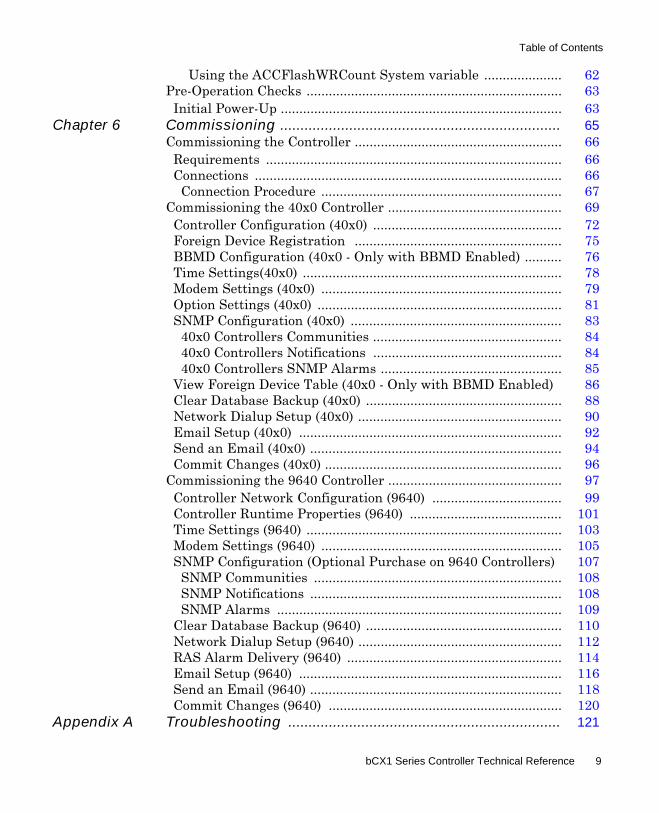
Table of Contents
Using the ACCFlashWRCount System variable ..................... 62Pre-Operation Checks ..................................................................... 63
Initial Power-Up ............................................................................ 63Chapter 6 Commissioning ..................................................................... 65
Commissioning the Controller ........................................................ 66Requirements ................................................................................ 66Connections ................................................................................... 66
Connection Procedure ................................................................. 67Commissioning the 40x0 Controller ............................................... 69
Controller Configuration (40x0) ................................................... 72Foreign Device Registration ........................................................ 75BBMD Configuration (40x0 - Only with BBMD Enabled) .......... 76Time Settings(40x0) ...................................................................... 78Modem Settings (40x0) ................................................................. 79Option Settings (40x0) .................................................................. 81SNMP Configuration (40x0) ......................................................... 83
40x0 Controllers Communities ................................................... 8440x0 Controllers Notifications ................................................... 8440x0 Controllers SNMP Alarms ................................................. 85
View Foreign Device Table (40x0 - Only with BBMD Enabled) 86Clear Database Backup (40x0) ..................................................... 88Network Dialup Setup (40x0) ....................................................... 90Email Setup (40x0) ....................................................................... 92Send an Email (40x0) .................................................................... 94Commit Changes (40x0) ................................................................ 96
Commissioning the 9640 Controller ............................................... 97Controller Network Configuration (9640) ................................... 99Controller Runtime Properties (9640) ......................................... 101Time Settings (9640) ..................................................................... 103Modem Settings (9640) ................................................................. 105SNMP Configuration (Optional Purchase on 9640 Controllers) 107
SNMP Communities ................................................................... 108SNMP Notifications .................................................................... 108SNMP Alarms ............................................................................. 109
Clear Database Backup (9640) ..................................................... 110Network Dialup Setup (9640) ....................................................... 112RAS Alarm Delivery (9640) .......................................................... 114Email Setup (9640) ....................................................................... 116Send an Email (9640) .................................................................... 118Commit Changes (9640) ............................................................... 120
Appendix A Troubleshooting ................................................................... 121
bCX1 Series Controller Technical Reference 9
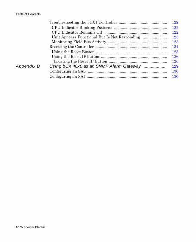
Table of Contents
Troubleshooting the bCX1 Controller ............................................ 122CPU Indicator Blinking Patterns ................................................ 122CPU Indicator Remains Off ......................................................... 122Unit Appears Functional But Is Not Responding ...................... 123Monitoring Field Bus Activity ...................................................... 123
Resetting the Controller ................................................................. 124Using the Reset Button ................................................................ 125Using the Reset IP button ............................................................ 126
Locating the Reset IP Button ..................................................... 126Appendix B Using bCX 40x0 as an SNMP Alarm Gateway .................... 129
Configuring an SAG ........................................................................ 130Configuring an SAI ......................................................................... 130
10 Schneider Electric
Chapter 1Introduction
This chapter contains the following topics:
bCX1 Series Router/Controller FeaturesbCX1 Series CharacteristicsWiring Rules
bCX1 Series Controller Technical Reference 11
Chapter 1: Introduction
bCX1 Series Router/Controller Features
The Continuum® bCX1 is a series of Infinet and Native BACnet routers and controller/ routers. The bCX1 controllers that support Infinet can function either of the following:
Ethernet-to-Infinet routers (supporting up to 127 Infinet devices)Wireless field bus routers
The BACnet bCX1 controllers can function as either of the following:
BACnet/IP-to-MS/TP (supporting up to 127 BACnet MS/TP devices)Wireless field bus routers
The BACnet bCX1 controllers can also serve as a router for any combination of IP, Ethernet and MS/TP connections.
As a Native BACnet controller and in strict accordance with ANSI/ASHRAE standard 135-2004, the BACnet bCX1 devices can communicate directly with other third-party BACnet/IP, BACnet Ethernet, BACnet MS/TP devices and Schneider Electric BACnet devices. It can also communicate with other non-BACnet Schneider Electric Continuum products via Ethernet, using our own proprietary protocol. The bCX1 is designed to meet the requirements of the B-BC (BACnet Building Controller) profile, supporting all required objects and services, such as Device Management, Scheduling, and Trend Log functionality. The BACnet PICS document for the BACnet bCX 4000/4040 can be downloaded from our technical support web site. To access the website, contact Schneider Electric technical support.
Easy Configuration
The bCX1 is designed with ease-of-installation in mind. All configuration settings, such as setting the IP address, are done via a standard web browser and are saved to non-volatile Flash memory. All connections to the bCX1 series controller are accomplished with removable connectors for easy installation, providing the ability to pre-wire panels and service the unit simply. LEDs provide simple troubleshooting information and indicate communication activity for all ports.
12 Schneider Electric
Chapter 1: Introduction
BBMD Support
All BACnet bCX1 series devices can be configured to function as BACnet Broadcast Management Devices, or BBMDs. It is the BBMD’s job to pass BACnet broadcasts across IP/Routers to other IP segments. As a result of having BBMDs in place, BACnet devices are able to fully communicate though IP routers. The Continuum Operator workstation or the bCX BBMD configuration web page provides a user-friendly interface to configure and manage all the BBMDs on the network, allowing changes in one BBMD to be distributed to all other BBMDs.
Wireless Support
The bCX1 controllers can be configured to support a wireless field bus network of controllers. A Wireless Adapter is connected to each controller’s COMM2 port, and the network signals are strengthened where necessary by the use of Wireless Repeaters to carry the signal across the wireless mesh network. Configuration of the wireless network is supported through CyberStation®, Continuum’s Operator Workstation. For information about field bus connections, see “Field Bus Connection” on page 34.
For more information about Schneider Electric support for wireless networks and wireless products, see the Wireless Mesh Network Concepts and Best Practices Guide, 30-3001-912, the Wireless Maintenance Tool (WMT) User’s Guide, 30-3001-913, the Wireless Adapter/Repeater Installation Instructions, 30-3001-887, and the CyberStation online help.
Dial-in Communication Support
The bCX1 controllers supporting Infinet can be accessed via CyberStation®, Continuum’s Operation Workstation, as a remote controller (RAS site). The controller can also be configured to use a modem as a redundant connection to CyberStation, in the event of a LAN failure (this feature is an available option).
bCX1 Series Controller Technical Reference 13
Chapter 1: Introduction
Advanced Flash Memory Management
The bCX1 series uses non-volatile Flash memory to store the operating system, application programs, and configuration data. When a power loss is sensed, battery-backed RAM maintains all trend logs and other run-time data. When power is restored, both application and run-time data are restored. Memory backup and restore settings are configurable (BACnet only). The Flash-based operation system simplifies feature upgrades.
Controller/Router Combination Models
The bCX1 Controller/Router “-CR” models combine a fully programmable controller with a router in a single device. The “-CR” models support the additional features described below which are not included in the “-R”, router-only, models:
Programmable The dynamic memory of the bCX1-CR can be allocated for any combination of programs, scheduling, alarming, and data logging using the Schneider Electric Plain English® programming language. Our object-oriented Plain English, with intuitive keywords, provides an easy method to tailor the controller to meet your exact requirements.
WebServer With Plain English, standard HTML web pages can be created and embedded into the bCX1-CR to provide a simple-to use, browser-based interface for monitoring or changing data points. The embedded web pages are fully customizable to meet any special customer requirements.
Expansion I/O The bCX1-CR contains an I/O expansion port for the addition of up to two xP expansion modules directly on the bottom of the controller. The xP family of modules includes both digital and analog inputs and outputs as well as a combination of the two. In addition to these xP expansion modules, the I/O bus supports the xP Local Display Module, which allows the user to view and change point values.
14 Schneider Electric

Chapter 1: Introduction
SNMP Support All bCX1-CR series controllers are compatible with SNMP monitoring tools, which allows the controller to be interrogated for basic SNMP information, or to be configured for SNMP Alarms (available option).
bCX1 Series Controller Technical Reference 15
Chapter 1: Introduction
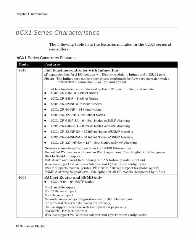
bCX1 Series Characteristics
The following table lists the features included in the bCX1 series of controllers:
bCX1 Series Controllers Features
Model Features9640 Full function controller with Infinet Bus
xP expansion bus for 2 I/O modules + 1 Display module, 1 Infinet and 1 RS232 portNote: The Infinet port can be alternatively configured for Raw port operation with a
limited RS232 connection, Rxd Txd, and ground
Infinet bus limitations are indicated by the bCX1 part number, and include: bCX1-CR-0-INF = 0 Infinet Nodes
bCX1-CR-8-INF = 8 Infinet Nodes
bCX1-CR-32-INF = 32 Infinet Nodes
bCX1-CR-64-INF = 64 Infinet Nodes
bCX1-CR-127-INF = 127 Infinet Nodes
bCX1-CR-0-INF-SA = 0 Infinet Nodes w/SMNP Alarming
bCX1-CR-8-INF-SA = 8 Infinet Nodes w/SNMP Alarming
bCX1-CR-32-INF-SA = 32 Infinet Nodes w/SNMP Alarming
bCX1-CR-64-INF-SA = 64 Infinet Nodes w/SNMP Alarming
bCX1-CR-127-INF-SA = 127 Infinet Nodes w/SNMP Alarming
Network connectivity/configuration via 10/100 Ethernet portEmbedded Web server with custom Web Pages using Plain English (PE) LanguageDial-In /Dial-Out support RAS Alarm and Event Redundancy on LAN failure (available option)Wireless support via Wireless Adapter and CyberStation configurationRS232 supports modem, printer, PE Driver, XDriver support (available option)SNMP Alarming Support (available option for all CR models, designated by “- SA”)
4000 BACnet Router and BBMD onlybCX1-R-64 = 64 MS/TP Nodes
No xP module supportNo PE Driver supportNo XDriver supportNetwork connectivity/configuration via 10/100 Ethernet portEmbedded Web server (for configuration only)Dial-In support to browse Web Configuration pages onlyBACnet/IP, BACnet/EthernetWireless support via Wireless Adapter and CyberStation configuration
16 Schneider Electric
Chapter 1: Introduction
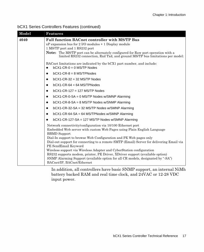
In addition, all controllers have basic SNMP support, an internal NiMh battery backed RAM and real time clock, and 24VAC or 12-28 VDC input power.
4040 Full function BACnet controller with MS/TP BusxP expansion bus for 2 I/O modules + 1 Display module1 MS/TP port and 1 RS232 portNote: The MS/TP port can be alternately configured for Raw port operation with a
limited RS232 connection, Rxd Txd, and ground MS/TP bus limitations per model:
BACnet limitations are indicated by the bCX1 part number, and include:bCX1-CR-0 = 0 MS/TP Nodes
bCX1-CR-8 = 8 MS/TPNodes
bCX1-CR-32 = 32 MS/TP Nodes
bCX1-CR-64 = 64 MS/TPNodes
bCX1-CR-127 = 127 MS/TP Nodes
bCX1-CR-0-SA = 0 MS/TP Nodes w/SMNP Alarming
bCX1-CR-8-SA = 8 MS/TP Nodes w/SNMP Alarming
bCX1-CR-32-SA = 32 MS/TP Nodes w/SMNP Alarming
bCX1-CR-64-SA = 64 MS/TPNodes w/SMNP Alarming
bCX1-CR-127-SA = 127 MS/TP Nodes w/SMNP Alarming
Network connectivity/configuration via 10/100 Ethernet portEmbedded Web server with custom Web Pages using Plain English LanguageBBMD SupportDial-In support to browse Web Configuration and PE Web pages onlyDial-out support for connecting to a remote SMTP (Email) Server for delivering Email via PE SendEmail KeywordWireless support via Wireless Adapter and CyberStation configurationRS232 supports modem, printer, PE Driver, XDriver support (available option)SNMP Alarming Support (available option for all CR models, designated by “-SA”)BACnet/IP, BACnet/Ethernet
bCX1 Series Controllers Features (continued)
Model Features
bCX1 Series Controller Technical Reference 17
Chapter 1: Introduction
Wiring Rules
For reliable input operation, follow these input wiring guidelines:
Never lay wires across the surface of the printed circuit board.Wires should never be within 1 in. or 25 mm of any component on the printed circuit board.Use shielded input wire. Do not use the shield as the signal return wire.Terminate the shield of the input wires at one end of the run only, preferably at the end where your controller is located.Be careful when stripping wire not to drop small pieces of wire inside the cabinet.Don't run your input wiring in the same conduit with AC power.Don't run your input wiring in the same conduit with your output wiring.
CAUTIONDo not remotely ground any part of sensor wiringRemote grounds connected to the return terminals of a bCX controller with an expansion module could make the controller operate incorrectly or damage the equipment. The signal return is not true earth ground. It is an electronic reference point necessary to interpret the sensor properly.
Failure to observe this precaution can result in incorrect controller operation or equipment damage.
CAUTIONExternal ground of expansion inputsDo not externally ground any expansion input connected to the Controller. This may damage the unit. Signal return terminals are not connected to Earth Ground.
Failure to observe this precaution can result in equipment damage.
18 Schneider Electric
Chapter 2bCX1 Series Mechanical
Installation
This chapter contains the following topics:
Physical OverviewPower ConnectionBattery Connection & Replacement24VAC Connection12 - 28 VDC ConnectionBuilding Ground Requirements
bCX1 Series Controller Technical Reference 19
Chapter 2: bCX1 Series Mechanical Installation
Physical Overview
Attachment
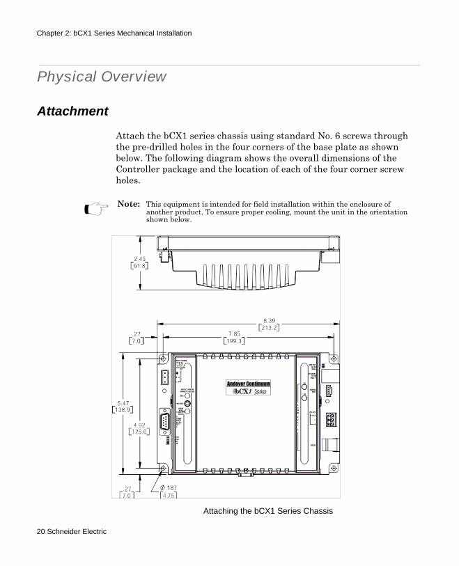
Attach the bCX1 series chassis using standard No. 6 screws through the pre-drilled holes in the four corners of the base plate as shown below. The following diagram shows the overall dimensions of the Controller package and the location of each of the four corner screw holes.
Note: This equipment is intended for field installation within the enclosure of another product. To ensure proper cooling, mount the unit in the orientation shown below.
Attaching the bCX1 Series Chassis
bbCC 1XX Series
Andover Continuum
20 Schneider Electric

Chapter 2: bCX1 Series Mechanical Installation
Chassis Road Map
This diagram indicates the locations of each of the main connection points.
This diagram shows the location of the various operational status indicators and the reset button on the controller.
Main Connection Points
Status Indicators and Reset Button
bCX1 Series Controller Technical Reference 21
Chapter 2: bCX1 Series Mechanical Installation
Power Connection
The bCX1 series Controllers are operated via an individual external 24 Volt AC or a 12-28 VDC source. An internal power converter creates the necessary voltages to supply the microprocessor circuitry.
DANGERELECTRIC SHOCK HAZARDBe sure that AC power is not applied (switch is off) to the power supply while you are connecting the bCX1. The bCX1 could be damaged or you could receive an electrical shock that is life threatening.
Failure to observe these instructions will result in death or serious injury.
CAUTIONESD WarningTo avoid damaging electronic components because of the discharge of static electricity, always ground yourself before touching any boards or other internal components of Schneider Electric Devices.
Discharge yourself by touching metal first
If possible, use a grounding strap or heel plate
Failure to observe this precaution can result equipment damage.
22 Schneider Electric
Chapter 2: bCX1 Series Mechanical Installation
Battery Connection & Replacement
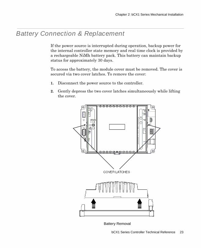
If the power source is interrupted during operation, backup power for the internal controller state memory and real time clock is provided by a rechargeable NiMh battery pack. This battery can maintain backup status for approximately 30 days.
To access the battery, the module cover must be removed. The cover is secured via two cover latches. To remove the cover:
1. Disconnect the power source to the controller.
2. Gently depress the two cover latches simultaneously while lifting the cover.
Battery Removal
bCX1 Series Controller Technical Reference 23
Chapter 2: bCX1 Series Mechanical Installation
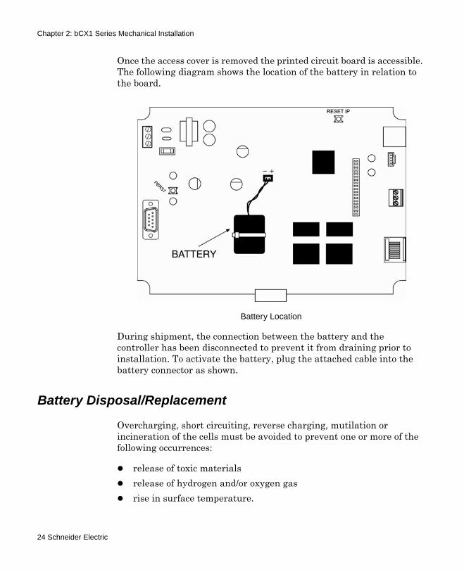
Once the access cover is removed the printed circuit board is accessible. The following diagram shows the location of the battery in relation to the board.
During shipment, the connection between the battery and the controller has been disconnected to prevent it from draining prior to installation. To activate the battery, plug the attached cable into the battery connector as shown.
Battery Disposal/Replacement
Overcharging, short circuiting, reverse charging, mutilation or incineration of the cells must be avoided to prevent one or more of the following occurrences:
release of toxic materialsrelease of hydrogen and/or oxygen gasrise in surface temperature.
Battery Location
24 Schneider Electric
Chapter 2: bCX1 Series Mechanical Installation
If a cell has leaked or vented, it should be replaced immediately using protective gloves.
Power-down controller before replacing battery Replace with Schneider Electric battery PN BCX1-BAT-KIT ONLY. A fully discharged battery will take 33 hours to fully recharge.
Battery Ventilation
The cabinet in which the controller is mounted must provide adequate ventilation to allow for escape of any released gasses under normal conditions.
bCX1 Series Controller Technical Reference 25
Chapter 2: bCX1 Series Mechanical Installation
24VAC Connection
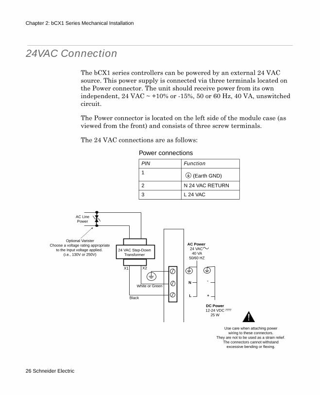
The bCX1 series controllers can be powered by an external 24 VAC source. This power supply is connected via three terminals located on the Power connector. The unit should receive power from its own independent, 24 VAC ~ +10% or -15%, 50 or 60 Hz, 40 VA, unswitched circuit.
The Power connector is located on the left side of the module case (as viewed from the front) and consists of three screw terminals.
The 24 VAC connections are as follows:
Power connections
PIN Function
1(Earth GND)
2 N 24 VAC RETURN
3 L 24 VAC
AC LinePower
24 VAC Step-DownTransformer
Black
White or Green
X1 X2
Use care when attaching powerwiring to these connectors.
They are not to be used as a strain relief.The connectors cannot withstand
excessive bending or flexing.
Optional VaristerChoose a voltage rating appropriate
to the Input voltage applied.(i.e., 130V or 250V)
AC Power24 VAC40 VA
50/60 HZ
N
L
-
+
DC Power12-24 VDC
25 W
26 Schneider Electric
Chapter 2: bCX1 Series Mechanical Installation
The 24 VAC connection consists of both terminals from the secondary of a power-line to 24 VAC transformer. Connection to the Controller is via a screw-type connector. The ground wire to the controller should not exceed 12 inches in length and it must be connected to a good earth ground. See “Building Ground Requirements” on page 29.
Powering Multiple bCX1 series Controllers
Unless all the bCX1 series controllers you intend to power are resident in the same cabinet, it is imperative that you use a separate transformer for each controller. When you attempt to power multiple remotely located controllers from a single power source, the voltage drop caused by the current draw per controller results in marginal operation and may prevent proper communications between controllers.
bCX1 Series Controller Technical Reference 27
Chapter 2: bCX1 Series Mechanical Installation
12 - 28 VDC Connection
The bCX1 series controllers can be powered by an external 12-28 VDC source. This power supply is connected via three terminals located on the Power connector.
The Power connector is located on the left side of the module case (as viewed from the front) and consists of three screw terminals.
The 12-28 VDC connections are as follows:
Power connections
PIN Function
1(Earth GND)
2 N VDC RETURN
3 L 12-28 VDC
+ 12 to 28 VDC
VDC Return
AC Power24 VAC40 VA
50/60 HZ
N
L
-
+
DC Power12-24 VDC
25 W
28 Schneider Electric

Chapter 2: bCX1 Series Mechanical Installation
Building Ground Requirements
Be sure that all equipment from Schneider Electric is grounded to true Earth ground. True Earth ground protects the equipment from transients and other power surges in the area. We cannot guarantee that the controller system will operate as documented without a properly grounded installation.
An example of a sub-standard ground is a galvanized steel cold water pipe. As the pipe corrodes, it does not act as a true ground. The corrosion acts as an insulator, raising the potential of the pipe with respect to the ground.
When lightning strikes in the area of the installation, it drastically changes the potential of the Earth. Since properly grounded Schneider Electric units respond to changes in potential more rapidly than poorly grounded electrical systems, a poorly grounded building tries to reach ground through the Schneider Electric system. The surge of current can destroy electronic components on the controller board. Surges of much lower potential than lightning also impact the reliability of the equipment.
Inspecting the Ground
Be sure to have your grounds inspected before you begin the installation process to ensure your municipality follows the National Electrical Code. Many municipalities do not follow the code and often have substandard electrical grounds. Check your ground as follows:
Inspect the building power distribution panel for Earth-ground termination. If the ground termination is any of the following, it is not adequate and must be corrected:
Does not exist.Is connected to a corroded or galvanized pipeIs connected using a small gauge wire (less than 14 AWG)
Be sure your Schneider Electric cabinet is connected to the ground with a copper conductor that terminates at the distribution panel.
bCX1 Series Controller Technical Reference 29

Chapter 2: bCX1 Series Mechanical Installation
Lightning Protection
Although metal oxide varistors are built into the board to protect against power line transients, this protection is not sufficient to protect against lightning. Lightning arresters are required at each point where field bus cables enter or exit a building.
The following lightning arrester is recommended:
TAC # 01-2100-299, two pair gas tube lightning arrester
30 Schneider Electric
Chapter 3Connections
This chapter contains the following topics:
Ethernet ConnectionField Bus ConnectionRS-232 COMM Port Connections
bCX1 Series Controller Technical Reference 31
Chapter 3: Connections
Ethernet Connection
The bCX1 series controllers can be connected to workstations and other controllers via a 10/100Mb Ethernet interface. These connections are accomplished via 10/100 BASE-T (RJ-45).
The Ethernet is a high-speed CSMA/CD local area network (LAN) that includes all Schneider Electric network-level controllers, third-party network level controllers and workstations and the network software that makes them communicate.
Ethernet Nodes
The bCX1 series controllers require two types of IDs:
1. One you assign strictly for use by the local network, called the ACCNet ID, and
2. Another, called the IP Address, that allows the unit to be used not only on your Ethernet, but on a world-wide Internet.
A complete procedure for configuring these addresses can be found in Chapter 6, “Commissioning” on page 65 of this book.
10/100 BASE-T Ethernet
Cable Limitations:
The bCX1 provides a standard RJ-45 connector for Ethernet. Unshielded twisted pair cable is used to form this type of network (you actually use a cable with dual twisted pairs-one for the transmit signal, and one for the receive signal). The maximum cable length you can use between two nodes is 327 feet (100 meters). The maximum length for the network segment is 1,635 feet (500 meters). If you need to use a cable that exceeds the recommended maximum length, use a network repeater.
32 Schneider Electric
Chapter 3: Connections
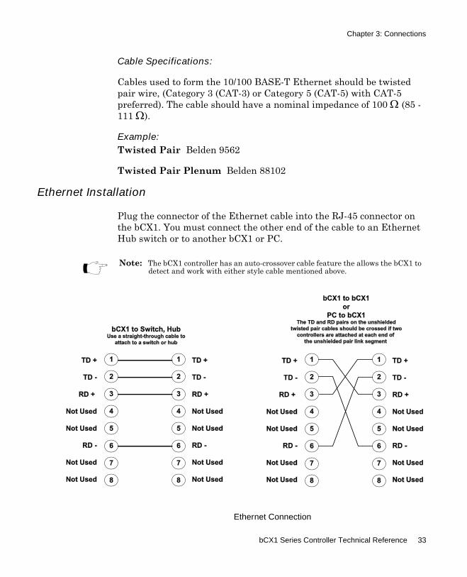
Cable Specifications:
Cables used to form the 10/100 BASE-T Ethernet should be twisted pair wire, (Category 3 (CAT-3) or Category 5 (CAT-5) with CAT-5 preferred). The cable should have a nominal impedance of 100 Ω (85 -111 Ω).
Example: Twisted Pair Belden 9562
Twisted Pair Plenum Belden 88102
Ethernet Installation
Plug the connector of the Ethernet cable into the RJ-45 connector on the bCX1. You must connect the other end of the cable to an Ethernet Hub switch or to another bCX1 or PC.
Note: The bCX1 controller has an auto-crossover cable feature the allows the bCX1 to detect and work with either style cable mentioned above.
Ethernet Connection
bCX1 Series Controller Technical Reference 33
Chapter 3: Connections
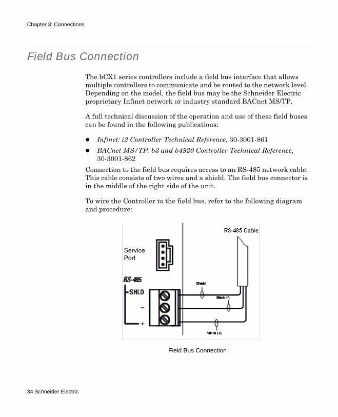
Field Bus Connection
The bCX1 series controllers include a field bus interface that allows multiple controllers to communicate and be routed to the network level. Depending on the model, the field bus may be the Schneider Electric proprietary Infinet network or industry standard BACnet MS/TP.
A full technical discussion of the operation and use of these field buses can be found in the following publications:
Infinet: i2 Controller Technical Reference, 30-3001-861BACnet MS/TP: b3 and b4920 Controller Technical Reference, 30-3001-862
Connection to the field bus requires access to an RS-485 network cable. This cable consists of two wires and a shield. The field bus connector is in the middle of the right side of the unit.
To wire the Controller to the field bus, refer to the following diagram and procedure:
Field Bus Connection
ServicePort
34 Schneider Electric

Chapter 3: Connections
To wire the Controller to the field bus, follow these steps:
1. Trim the outer jacket of the RS-485 cable to reveal the internal wires.
2. Strip the insulation from the white wire and loosen the screw at the + position.
3. Insert the stripped end of the white wire into the + position of the terminal block. Tighten the screw.
4. Strip the insulation from the black wire and loosen the screw at the - position.
5. Insert the stripped end of the black wire into the - position of the terminal block. Tighten the screw.
6. Insert the shield wire into the SHLD position of the terminal block. Tighten the screw.
The bCX1 controllers can be configured to support a wireless field bus network of controllers. A Wireless Adapter is connected to each controller’s COMM2 port Service Port, and the network signals are strengthened where necessary by the use of Wireless Repeaters to carry the signal across the wireless mesh network. Configuration of the wireless network is supported through CyberStation®, Continuum’s Operator Workstation.
For more information about Schneider Electric support for wireless networks and wireless products, see the Wireless Mesh Network Concepts and Best Practices Guide, 30-3001-912, the Wireless Maintenance Tool (WMT) User’s Guide, 30-3001-913, the Wireless Adapter/Repeater Installation Instructions, 30-3001-887, and the CyberStation online help.
Note: Wire colors are included for clarity. The colors of your cable may vary. However, be sure that all Infinet connections are consistent on their connections.
bCX1 Series Controller Technical Reference 35
Chapter 3: Connections
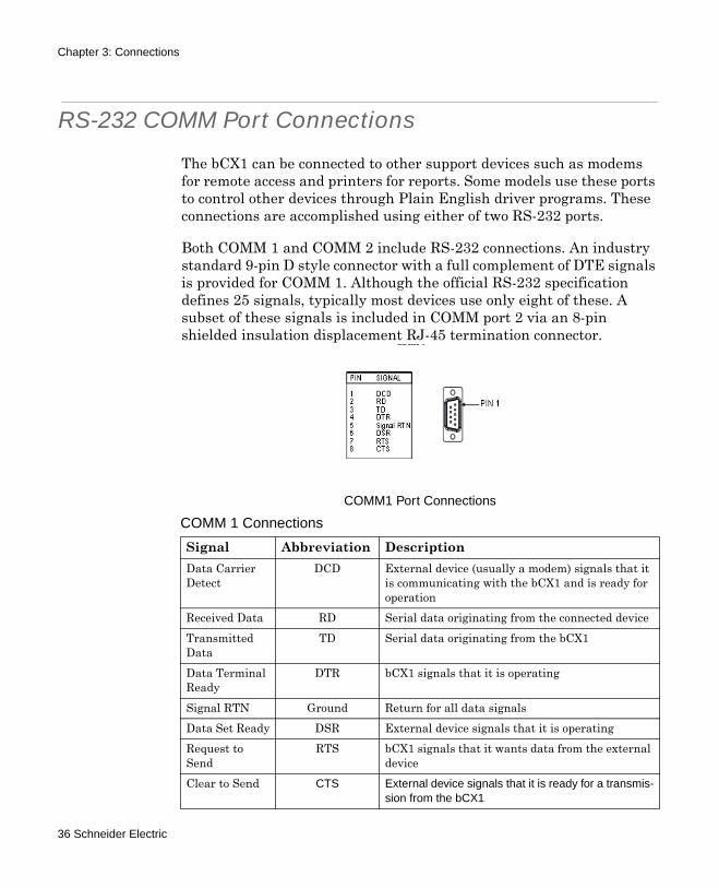
RS-232 COMM Port Connections
The bCX1 can be connected to other support devices such as modems for remote access and printers for reports. Some models use these ports to control other devices through Plain English driver programs. These connections are accomplished using either of two RS-232 ports.
Both COMM 1 and COMM 2 include RS-232 connections. An industry standard 9-pin D style connector with a full complement of DTE signals is provided for COMM 1. Although the official RS-232 specification defines 25 signals, typically most devices use only eight of these. A subset of these signals is included in COMM port 2 via an 8-pin shielded insulation displacement RJ-45 termination connector.
COMM1 Port Connections
COMM 1 Connections
Signal Abbreviation DescriptionData Carrier Detect
DCD External device (usually a modem) signals that it is communicating with the bCX1 and is ready for operation
Received Data RD Serial data originating from the connected deviceTransmitted Data
TD Serial data originating from the bCX1
Data Terminal Ready
DTR bCX1 signals that it is operating
Signal RTN Ground Return for all data signalsData Set Ready DSR External device signals that it is operatingRequest to Send
RTS bCX1 signals that it wants data from the external device
Clear to Send CTS External device signals that it is ready for a transmis-sion from the bCX1
36 Schneider Electric
Chapter 3: Connections
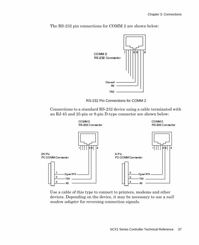
The RS-232 pin connections for COMM 2 are shown below:
Connections to a standard RS-232 device using a cable terminated with an RJ-45 and 25-pin or 9-pin D-type connector are shown below:
Use a cable of this type to connect to printers, modems and other devices. Depending on the device, it may be necessary to use a null modem adapter for reversing connection signals.
RS-232 Pin Connections for COMM 2
bCX1 Series Controller Technical Reference 37

Chapter 3: Connections
RS-232 COMM Port Configuration
After physical connection, the COMM Port must be configured properly as an RS-232 device through the Continuum workstation. Configuration requires selecting the type of device to be connected (i.e., Printer, Autoset, etc.) and setting various communications-related parameters. Refer to the section on COMM port configuration for Controller objects found in the Continuum on-line help system.
Using COMM1 for Remote Access Operation (RAS) (Infinet support only)
The bCX1 series controllers may be accessed by a remote workstation through the use of a modem connected to COMM1. This capability allows remote networks of controllers, sub-controllers and their inputs/outputs being made available to all other similar networks. Setup is fully detailed in the Schneider Electric publication entitled, Remote Access Configuration. This document is provided as an Adobe Acrobat file that is automatically installed along with Continuum files into the Continuum directory. A shortcut to the file is listed under Start>Programs>Continuum>Documentation.
Using COMM1 for Serving PE-based Web Pages
The bCX1 Series controllers include an internal web server capable of serving Plain English based HTML pages through the COMM port. The serving bCX1 Series controller is located at a remote site. It is assumed that, from your PC, you are bringing up these web pages in your Web browser, using a modem-to-modem, network-dialup connection to the controller's COMM port. Full instructions for utilizing the web server can be found in the publication entitled Remote Access Setup for Controller Web Pages which can be found on the Schneider Electric TSD web site.
Note: This feature will be added to BACnet support in a future release.
38 Schneider Electric
Chapter 3: Connections
Using COMM2 for Wireless Field Bus Network
The bCX1 Series controllers include a Service Port connector on COMM port 2. A Wireless Adapter is connected to the Service Port connector, and the network signals are strengthened where necessary by the use of Wireless Repeaters to carry the signal across the wireless mesh network.
You can configure COMM port 2 as a wireless mesh network by selecting Wireless as the Mode in the CommPort editor in CyberStation. Refer to the CommPort editor in the Continuum online help system.
bCX1 Series Controller Technical Reference 39

Chapter 3: Connections
40 Schneider Electric
Chapter 4Expansion Interface
This chapter contains the following topics:
Expansion Interface ConnectorExpansion LimitationbCX 96xx Expansion Differences
bCX1 Series Controller Technical Reference 41
Chapter 4: Expansion Interface
Expansion Interface Connector
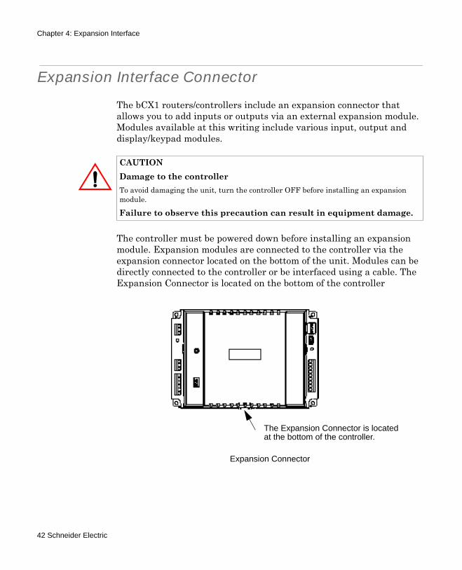
The bCX1 routers/controllers include an expansion connector that allows you to add inputs or outputs via an external expansion module. Modules available at this writing include various input, output and display/keypad modules.
The controller must be powered down before installing an expansion module. Expansion modules are connected to the controller via the expansion connector located on the bottom of the unit. Modules can be directly connected to the controller or be interfaced using a cable. The Expansion Connector is located on the bottom of the controller
CAUTIONDamage to the controllerTo avoid damaging the unit, turn the controller OFF before installing an expansion module.
Failure to observe this precaution can result in equipment damage.
Expansion Connector
The Expansion Connector is locatedat the bottom of the controller.
42 Schneider Electric
Chapter 4: Expansion Interface
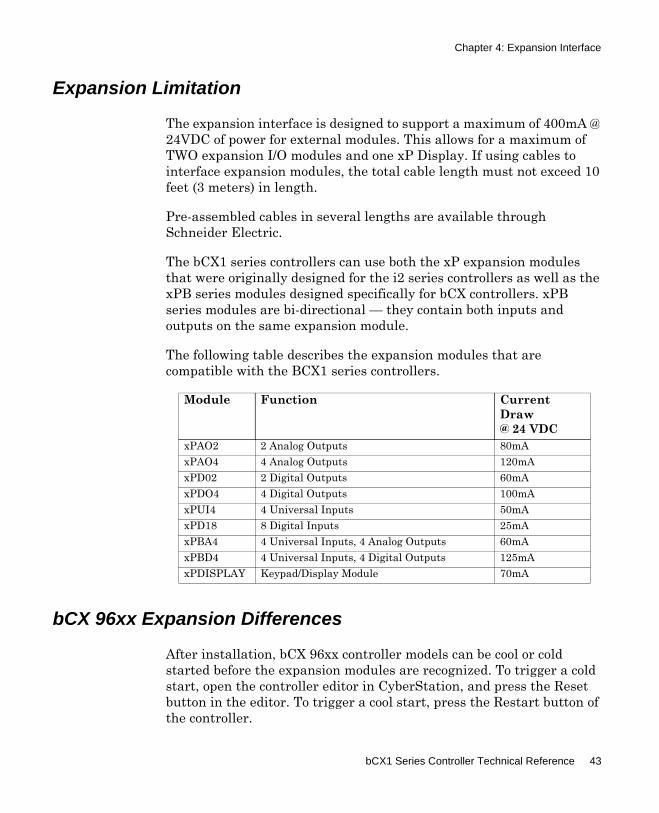
Expansion Limitation
The expansion interface is designed to support a maximum of 400mA @ 24VDC of power for external modules. This allows for a maximum of TWO expansion I/O modules and one xP Display. If using cables to interface expansion modules, the total cable length must not exceed 10 feet (3 meters) in length.
Pre-assembled cables in several lengths are available through Schneider Electric.
The bCX1 series controllers can use both the xP expansion modules that were originally designed for the i2 series controllers as well as the xPB series modules designed specifically for bCX controllers. xPB series modules are bi-directional — they contain both inputs and outputs on the same expansion module.
The following table describes the expansion modules that are compatible with the BCX1 series controllers.
bCX 96xx Expansion Differences
After installation, bCX 96xx controller models can be cool or cold started before the expansion modules are recognized. To trigger a cold start, open the controller editor in CyberStation, and press the Reset button in the editor. To trigger a cool start, press the Restart button of the controller.
Module Function Current Draw @ 24 VDC
xPAO2 2 Analog Outputs 80mAxPAO4 4 Analog Outputs 120mAxPD02 2 Digital Outputs 60mAxPDO4 4 Digital Outputs 100mAxPUI4 4 Universal Inputs 50mAxPD18 8 Digital Inputs 25mAxPBA4 4 Universal Inputs, 4 Analog Outputs 60mAxPBD4 4 Universal Inputs, 4 Digital Outputs 125mAxPDISPLAY Keypad/Display Module 70mA
bCX1 Series Controller Technical Reference 43
Chapter 4: Expansion Interface
Expansion Cable Connections
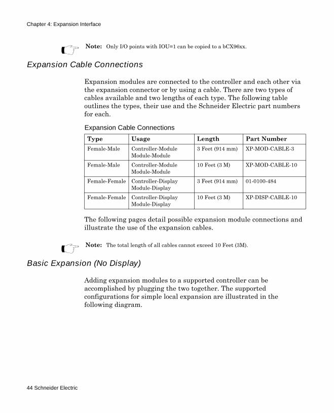
Expansion modules are connected to the controller and each other via the expansion connector or by using a cable. There are two types of cables available and two lengths of each type. The following table outlines the types, their use and the Schneider Electric part numbers for each.
The following pages detail possible expansion module connections and illustrate the use of the expansion cables.
Basic Expansion (No Display)
Adding expansion modules to a supported controller can be accomplished by plugging the two together. The supported configurations for simple local expansion are illustrated in the following diagram.
Note: Only I/O points with IOU=1 can be copied to a bCX96xx.
Expansion Cable Connections
Type Usage Length Part NumberFemale-Male Controller-Module
Module-Module3 Feet (914 mm) XP-MOD-CABLE-3
Female-Male Controller-Module Module-Module
10 Feet (3 M) XP-MOD-CABLE-10
Female-Female Controller-Display Module-Display
3 Feet (914 mm) 01-0100-484
Female-Female Controller-Display Module-Display
10 Feet (3 M) XP-DISP-CABLE-10
Note: The total length of all cables cannot exceed 10 Feet (3M).
44 Schneider Electric
Chapter 4: Expansion Interface
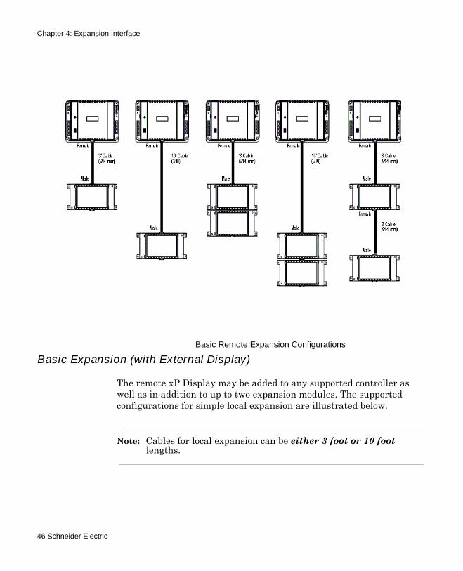
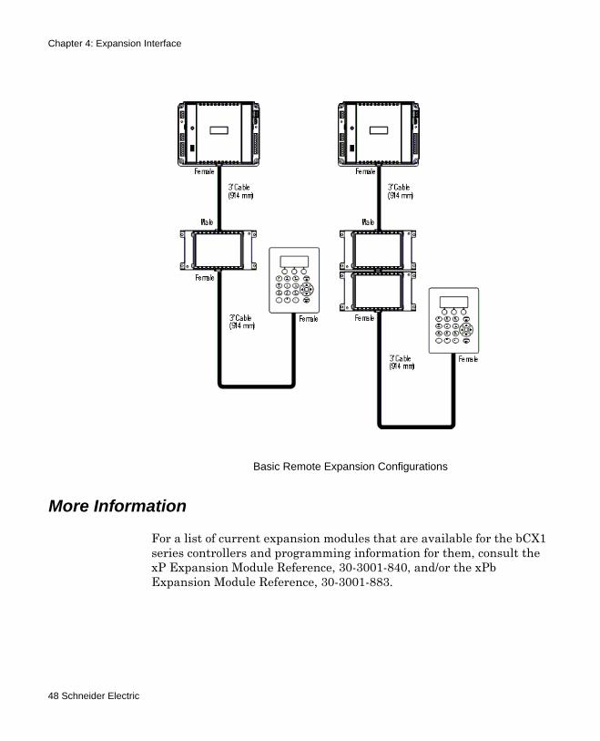
Remote Expansion (No Display)
The system allows modules to be located up to 10 foot (3M) from the main controller. Expansion cables are available in 3 feet (914mm) and 10 feet (3M) lengths. The supported basic remote expansion configurations are illustrated below.
Simple Local Expansion
bCX1 Series Controller Technical Reference 45
Chapter 4: Expansion Interface
Basic Expansion (with External Display)
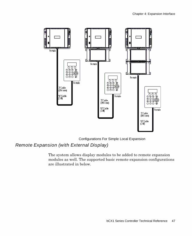
The remote xP Display may be added to any supported controller as well as in addition to up to two expansion modules. The supported configurations for simple local expansion are illustrated below.
Note: Cables for local expansion can be either 3 foot or 10 foot lengths.
Basic Remote Expansion Configurations
46 Schneider Electric
Chapter 4: Expansion Interface
Remote Expansion (with External Display)
The system allows display modules to be added to remote expansion modules as well. The supported basic remote expansion configurations are illustrated in below.
Configurations For Simple Local Expansion
bCX1 Series Controller Technical Reference 47
Chapter 4: Expansion Interface
More Information
For a list of current expansion modules that are available for the bCX1 series controllers and programming information for them, consult the xP Expansion Module Reference, 30-3001-840, and/or the xPb Expansion Module Reference, 30-3001-883.
Basic Remote Expansion Configurations
48 Schneider Electric
Chapter 5Operation/Programming
This chapter contains the following topics
Operation/Programming for bCX1 Series ControllerConfiguration ProcessAvailable Restart Modes for 40x0 BACnet Controllers9640 Infinity Controller Restart ModesPre-Operation Checks
bCX1 Series Controller Technical Reference 49
Chapter 5: Operation/Programming
Operation/Programming for bCX1 Series Controller
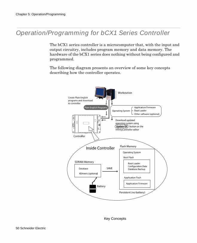
The bCX1 series controller is a microcomputer that, with the input and output circuitry, includes program memory and data memory. The hardware of the bCX1 series does nothing without being configured and programmed.
The following diagram presents an overview of some key concepts describing how the controller operates.
Key Concepts
XDrivers (optional)
50 Schneider Electric
Chapter 5: Operation/Programming
Workstation
The user interacts with the system through a workstation (desktop or laptop computer). The user configures, programs, monitors and operates the controller using workstation software called CyberStation.
Plain English Programming
Programs, written in a BASIC-like language called Plain English, are created on the workstation and downloaded to the controller where they execute. The Plain English programs are stored in the database on the controller.
Configuration
The configuration process is where the specific settings for the controller are applied. Configuration information includes such things as the setting of each input type.
Operating System (Firmware)
The controller’s internal microprocessor requires its own operating system (firmware), consisting of a boot loader, application firmware, and sometimes additional software or options. This program is created at the factory and is loaded into the controller's two non-volatile flash memories before shipment. As newer versions of the firmware become available it is possible to reload the controller’s flash memory using the built-in boot loader program. For more information on this process refer to the description of the Update OS button on the InfinityController editor in the CyberStation online Help.
Database
All the information that describes the structure and operation of your building is stored in a software database. The values of each point in the system, the settings for limits, the configuration of the hardware, and more are contained within this software structure.
The database is the key to the entire system and can be saved to Flash memory for backup security.
bCX1 Series Controller Technical Reference 51
Chapter 5: Operation/Programming
SDRAM Memory
SDRAM provides active storage locations for the internal software of the bCX as well as the current copy of the database. SDRAM is battery backed-up in case of power failure via an internal rechargeable NiMH battery pack.
Flash Memory
Flash memory holds configuration data and the programs the controller uses during operation. Flash memory is persistent, meaning it has the ability to retain its contents even during a power failure and does not require batteries to retain this information.
In the bCX controller there are actually two Flash memory areas:
Boot Flash is used to store the boot loader, configuration data and a backup copy of the database. Application Flash is used to store the application firmware that the user loads into the controller.
Advantages to Having Flash Memory
Initially it may seem redundant to include a flash memory along with battery-backed memory to hold application data. However, it is this redundancy that makes its addition attractive.
Although it is unlikely that the battery will fail or that the data in that memory will become corrupted, it is an extra layer of protection for your configuration data to be able periodically to lock it into flash.
Flash Files
Periodically, newer versions of the operating system are released. You can find and download the latest version from the Schneider Electric Technical Support web site. These new versions consist of one or more “flash files”. Workstation software (Continuum CyberStation 1.7 or higher) includes provisions to upload these flash files directly to the controller.
Note: When using the Backup to Flash command, only the Database is loaded into Flash memory.
52 Schneider Electric
Chapter 5: Operation/Programming
Limitations of Flash Memory
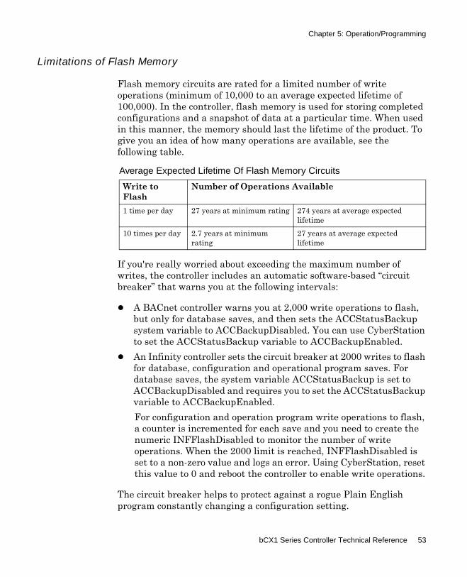
Flash memory circuits are rated for a limited number of write operations (minimum of 10,000 to an average expected lifetime of 100,000). In the controller, flash memory is used for storing completed configurations and a snapshot of data at a particular time. When used in this manner, the memory should last the lifetime of the product. To give you an idea of how many operations are available, see the following table.
If you're really worried about exceeding the maximum number of writes, the controller includes an automatic software-based “circuit breaker” that warns you at the following intervals:
A BACnet controller warns you at 2,000 write operations to flash, but only for database saves, and then sets the ACCStatusBackup system variable to ACCBackupDisabled. You can use CyberStation to set the ACCStatusBackup variable to ACCBackupEnabled.An Infinity controller sets the circuit breaker at 2000 writes to flash for database, configuration and operational program saves. For database saves, the system variable ACCStatusBackup is set to ACCBackupDisabled and requires you to set the ACCStatusBackup variable to ACCBackupEnabled.For configuration and operation program write operations to flash, a counter is incremented for each save and you need to create the numeric INFFlashDisabled to monitor the number of write operations. When the 2000 limit is reached, INFFlashDisabled is set to a non-zero value and logs an error. Using CyberStation, reset this value to 0 and reboot the controller to enable write operations.
The circuit breaker helps to protect against a rogue Plain English program constantly changing a configuration setting.
Average Expected Lifetime Of Flash Memory Circuits
Write to Flash
Number of Operations Available
1 time per day 27 years at minimum rating 274 years at average expected lifetime
10 times per day 2.7 years at minimum rating
27 years at average expected lifetime
bCX1 Series Controller Technical Reference 53
Chapter 5: Operation/Programming
Configuration Process
The controller is shipped from the factory with all the operating system firmware pre-programmed into its flash memory. This firmware allows the controller to communicate with a workstation. After saving the initial setup, it can be configured and programmed to meet the requirements of its intended task.
Before the controller can operate at your site it must be configured and programmed. Detailed descriptions of configuration can be found under Controller objects in the Continuum online help system.
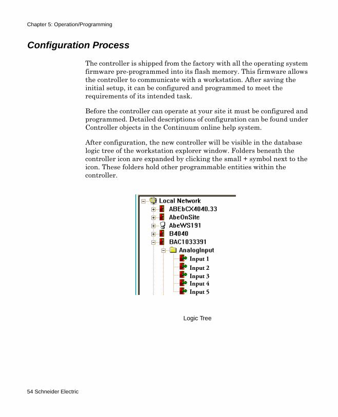
After configuration, the new controller will be visible in the database logic tree of the workstation explorer window. Folders beneath the controller icon are expanded by clicking the small + symbol next to the icon. These folders hold other programmable entities within the controller.
Logic Tree
Input 1Input 2Input 3Input 4Input 5
54 Schneider Electric
Chapter 5: Operation/Programming
Start-up From Power Failure
In general, after a power failure, there are three possible restart modes for any controller.
Cold Start The controller powers up from reset with no user objects or configuration in place.
Cool Start The controller powers up from reset and restores the user configuration from Flash memory. It is assumed that a configuration was explicitly saved by the user at some point prior to power down. Point log data is not restored (with the exception of manual arrays on setpoints), Plain English programs are started at their beginning, and user points, whose SetPoint attribute has been set, have their values restored. Cool start can be thought of as a “self reload”.
Warm Start The controller powers up from a loss of power with a user configuration in place. The user configuration is that which was present in the controller and preserved due to the battery-backed memory when power was lost. Point log data is preserved, Plain English programs are restarted at the same logical line that was being interpreted when the controller shut down (40x0 BACnet only, 9640 Infinity controllers resume the PE lines at the point they stopped at power loss), and all user points have their values restored.
Between the 9640 Infinity and the 40x0 BACnet controllers, there are differences in how each controller reacts to a power loss and restarts. Although both controllers have a default start-up mode, the 40x0 controllers have additional system variables for selecting a specific restart mode. The 9640 restart mode is not configurable.
The restart modes for each controller are described on the following pages:
“Available Restart Modes for 40x0 BACnet Controllers” on page 56“9640 Infinity Controller Restart Modes” on page 58
Note: Pressing the external Reset button on the controller board will cause SDRAM memory to be lost and the controller will be restarted with a Cool Start.
bCX1 Series Controller Technical Reference 55
Chapter 5: Operation/Programming
Available Restart Modes for 40x0 BACnet Controllers
One of the settings during the controller definition phase of the configuration process is to determine the restart mode. The following modes are available:
ACCWarmStartOnly The controller, upon recovery from reset, attempts a warm start; if that fails, it proceeds with a cold start.
ACCCoolStartOnly The controller, upon recovery from reset, attempts a cool start; if that fails, it proceeds with a cold start.
ACCWarmToCool The controller, upon recovery from reset, attempts warm start; if that fails, attempts a cool start; if that fails, proceeds with a cold start. This is the default mode for the 40x0 BACnet controller.
Warm StartOnly (40x0)
Selected by:
Continuum System Variable:+ACCRestartMode = ACCWarmStartOnly
In this mode, after a reset the controller examines the database in its internal RAM, attempts to correct any data corruption that may have been caused by an untimely reset/power loss, validates the database and attempts to use it if it is found to be valid.
Point values (with the exception of input points) are restored.Input point values are purged and a fresh sample is obtained from the hardware before the Scanner runs.Output points are marked for hardware update so their values will be refreshed to the hardware upon completion of the Scan (pulsed output values are assumed to have expired).All log data are retained.Plain English programs, that were running when the system went down, are re-started at the same logical line that was “CurrentLine” when the controller shut down. The Status, and State attributes are left unchanged. Line start times are left at whatever value they had when the controller went down and ts, tm, th, td will be incremented (from whatever value they had before power down) by the time delta imposed by the first time sync message after warm start. The elapsed time variables are actually
56 Schneider Electric
Chapter 5: Operation/Programming
computed values, hence their behavior is a side effect of the fact that the line start times are left unchanged.
Cool Start Only(40x0)
Selected by:
Continuum System Variable:+ACCRestartMode = ACCCoolStartOnly
In this mode, the user database is backed-up to the User Backup Area of Flash memory upon user command only (manually). When the controller powers up after a reset, it examines the backup area in Flash memory, and if a valid backup is found, the data is restored to RAM. Certain portions of the data are re-initialized:
Point values whose SetPoint attribute are TRUE have their values restored. Input point values are purged and a fresh sample obtained from the hardware before the Scanner runs.Output points are purged.All automatic log data are purged.Manual array data are retained at the value when the last flash backup was accomplished for setpoint variables only.The CurrentLine attribute of Plain English programs is set to its first line. The program is run ONLY if the AutoStart attribute is TRUE. The State attribute is restored and its value observed.
Warm to Cool(40x0 Default)
Selected by:
Continuum System Variable:+ACCRestartMode = ACCWarmToCool
In this mode, the user database is backed-up to the User Backup Area of Flash memory only when the user specifically requests a backup. When the controller powers-up after a reset, it examines the database in RAM, attempts to correct any data corruption that may have been caused by an untimely reset/power loss, validates the database (against things like bad pointers etc.) and attempts to use it if it is found to be valid. If this fails, it examines the User Backup Area of Flash memory, and if a valid backup is found then data is restored to RAM (cool start).
bCX1 Series Controller Technical Reference 57
Chapter 5: Operation/Programming
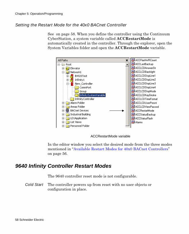
Setting the Restart Mode for the 40x0 BACnet Controller
See on page 58. When you define the controller using the Continuum CyberStation, a system variable called ACCRestartMode is automatically created in the controller. Through the explorer, open the System Variables folder and open the ACCRestartMode variable.
In the editor window you select the desired mode from the three modes mentioned in “Available Restart Modes for 40x0 BACnet Controllers” on page 56.
9640 Infinity Controller Restart Modes
The 9640 controller reset mode is not configurable.
Cold Start The controller powers up from reset with no user objects or configuration in place.
ACCRestartMode variable
58 Schneider Electric
Chapter 5: Operation/Programming
Cool Start(9640 Default)
In this mode, the user database is backed-up to the User Backup Area of Flash memory upon user command only (manually). When the controller powers up after a reset, it examines the backup area in Flash memory, and if a valid backup is found, the data is restored to RAM. Certain portions of the data are re-initialized:
Point values whose SetPoint attribute are TRUE have their values restored.Input point values are purged and a fresh sample obtained from the hardware before the Scanner runs.Output points are purged.All automatic log data are purged.Manual array data are retained at the value when the last flash backup was accomplished for setpoint variables only.The CurrentLine attribute of Plain English programs is set to its first line. The program is run ONLY if the AutoStart attribute is TRUE. The State attribute is restored and its value observed.
However, in the event of an immediate loss of power (not a reset), and if the battery is connected and supplying power to the SDRAM, the 9640 will attempt to execute the following restart mode:
Warm to Cool(9640 Power
Loss RestartAttempt)
When the controller powers-up after a reset, it attempts to resume operation from the point where it stopped when power was lost.
Flash Memory Backup Variables and Tools
For the 40x0 controllers, with the restart mode set to ACCCoolStartOnly or ACCWarmToCool, you have the option of backing up your database to Flash Memory.
Although the 9640 does not have a system variable to specify the restart mode, users always have the option of backing up the database to Flash.
There are several system variables that can be monitored to determine the current state of the information in the flash area.
bCX1 Series Controller Technical Reference 59
Chapter 5: Operation/Programming
ACCStatusFlash Indicates the state (empty, valid or failure) of the Flash memory device. In this case “valid” indicates that a valid database is present.
ACCStatusBackup Indicates the operational state (backup needed, backup done, backup in progress, etc.) of the Flash memory. It also includes provisions to initiate a backup operation.
ACCFlashWRCount Stores a running tally of the number of write operations performed on the Flash memory.
ACCLastBackup Indicates the date and time of the last backup of the object system to Flash memory. The controller updates this variable to the current time after successfully performing a backup operation.
There are two features that prevent loss of operations:
Flash Circuit Breaker Prevents you from unintentionally performing more write operations than the Flash memory allows.
Automatic Notification of Backup Needed Visual indication in the Continuum Explorer of the need to backup a controller.
Using the ACCStatusFlash System Variable
A system variable called ACCStatusFlash is automatically created when the controller is defined.
The ACCStatusFlash system variable indicates the current state (empty, valid or failure) of the Flash memory device. The controller stores status information into this variable.
ACCStatusFlash can have the following values:
ACCFlashEmpty There is no database in Flash memory.
ACCFlashValid There is a valid database in Flash memory.
ACCFlashFailure An error was encountered while trying to perform a backup to Flash memory. In this state, the data in Flash memory is unusable.
60 Schneider Electric
Chapter 5: Operation/Programming
Using the ACCStatusBackup System variable
The ACCStatusBackup system variable indicates the operational state (backup needed, backup done, backup in progress, etc.) of the memory. It is also used to initiate a backup operation. The controller stores status information into this variable and the user initiates a manual backup operation through this variable.
A system variable called ACCStatusBackup is automatically created when the controller is defined.
ACCStatusBackup, when used as an indicator, can have the following values:
ACCBackupDone A backup to Flash memory has been successfully completed, or the controller has not been configured, or after a cold start.
ACCBackupNeeded A configuration item has changed value since the last successful backup to Flash memory.
ACCBackupInProgress A backup operation is underway.
ACCBackupDisabled The database has been saved to Flash memory 2000 times and the user has attempted further backup operations without re-setting the Flash Circuit Breaker (see “ACCBackupEnable” on page 62). For as long as this condition persists, further backup operations are disabled.
ACCBackupInactive The system has been placed in WarmStartOnly mode and therefore, Flash memory user backup area is not available for use. (40x0 BACnet controller only)
ACCFlashingBackUp This indicates that the copy-to-RAM phase of a backup has completed and the scratch RAM is being copied to Flash. The controller is fully operational during this phase, which can take several minutes.
Note: To command a flash backup, PE programs use the above system variable, while end-users would use the CyberStation (v 1.7 or higher) user interface.
Note: The database is available on a read-only basis during the backup operation. For the 40x0 BACnet controller, this indicates that the data is being copied to scratch RAM as the first phase of a backup.
bCX1 Series Controller Technical Reference 61
Chapter 5: Operation/Programming
ACCStatusBackup, when used to initiate a backup can have the following values:
ACCBackupEnable This value can only be set from the command line, not from a Plain English program. This allows you to override the Flash Circuit Breaker and perform further backup operations. Further backup operations will be uninhibited until an additional 2,000 Flash memory write cycles have been incurred.
ACCBackupNow This value can be set from the command line or from a Plain English program. This causes the system to initiate a backup of the current database to Flash memory.
Using the ACCFlashWRCount System variable
The ACCFlashWRCount system variable Stores a running tally of the number of write operations performed on the Flash memory. The controller stores the count information into this variable.
A system variable called ACCFlashWRCount is automatically created when the controller is defined.
Note: These values can only be set from Plain English or the command line (Not the object editor). Be careful if setting this using Plain English. Remember, there is a maximum number of Flash memory writes.
62 Schneider Electric
Chapter 5: Operation/Programming
Pre-Operation Checks
1. Be sure the internal battery is connected.
2. Make sure the input power is wired properly. Check to be sure that both wires have been connected.
3. Be sure the controller has a true earth ground.
4. Make sure you have used the proper cables and wires at correct lengths.
5. Be sure the Infinet cables and shields have been properly wired.
Initial Power-Up
1. Once power is supplied to the controller, the controller starts automatically.
2. The initial indicator flash patterns for a cold or cool start are as follows:
a. The LED flashes green for a few seconds. (The boot loader program isbooting.)
b. Then it turns solid yellow (96xx) or green (40x0) for almost a minute.(The controller is testing RAM and hardware.)
c. Upon boot, it flashes green or yellow, depending on the model.
d. Any other blink pattern than the one mentioned in step two indicates afailure. In this case, recheck your connections, refer to Appendix A,“Troubleshooting” on page 121 in this manual, or contact yourSchneider Electric representative.
Note: For normal operation, the CPU indicator flashes five times per second. The indicator color is yellow for 96xx model controllers and green for 40xx models.
bCX1 Series Controller Technical Reference 63

Chapter 5: Operation/Programming
64 Schneider Electric
Chapter 6Commissioning
This chapter contains the following topics:
Commissioning the ControllerRequirementsConnectionsCommissioning the 40x0 ControllerCommissioning the 9640 Controller
bCX1 Series Controller Technical Reference 65
Chapter 6: Commissioning
Commissioning the Controller
In order to operate the bCX1 as a Network Gateway, the controller’s network address information must be entered so the Continuum software can communicate with the controller. This operation is called “commissioning”.
Requirements
Commissioning a bCX1 controller requires the following:
A laptop or other computerAn Ethernet adapter for the above computerWeb browser softwareCable (CAT-5, twisted pair)
Connections
You connect to the bCX1 directly through its Ethernet port using a cable connected to the Ethernet port of your PC.
As received from the factory, the bCX1 is set to a default IP address of (169.254.1.1), with a subnet mask of (255.255.0.0). Once commissioned, a more permanent IP can be assigned. In order to communicate successfully with the controller while it is set to its default IP address, your computer must be set to a similar address.
There are many ways to assure communication between the two depending upon your Operating System. It is beyond the scope of this document to explain network communications. However, the following procedure is one simple method that will assure communication.
66 Schneider Electric
Chapter 6: Commissioning
Connection Procedure
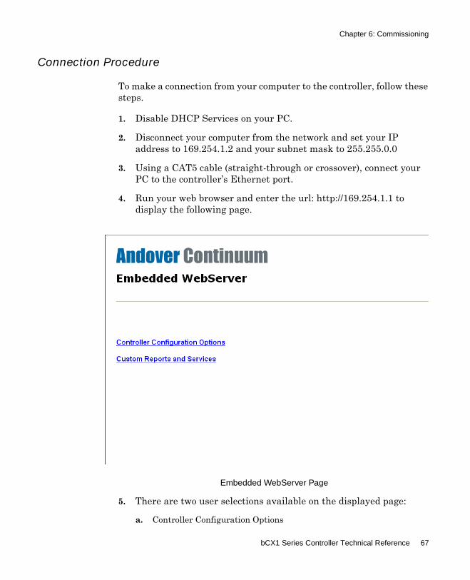
To make a connection from your computer to the controller, follow these steps.
1. Disable DHCP Services on your PC.
2. Disconnect your computer from the network and set your IP address to 169.254.1.2 and your subnet mask to 255.255.0.0
3. Using a CAT5 cable (straight-through or crossover), connect your PC to the controller’s Ethernet port.
4. Run your web browser and enter the url: http://169.254.1.1 to display the following page.
5. There are two user selections available on the displayed page:
a. Controller Configuration Options
Embedded WebServer Page
bCX1 Series Controller Technical Reference 67
Chapter 6: Commissioning
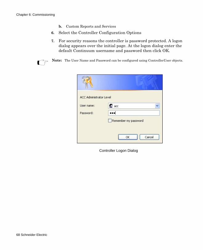
b. Custom Reports and Services6. Select the Controller Configuration Options
7. For security reasons the controller is password protected. A logon dialog appears over the initial page. At the logon dialog enter the default Continuum username and password then click OK.
Note: The User Name and Password can be configured using ControllerUser objects.
Controller Logon Dialog
68 Schneider Electric
Chapter 6: Commissioning
Commissioning the 40x0 Controller
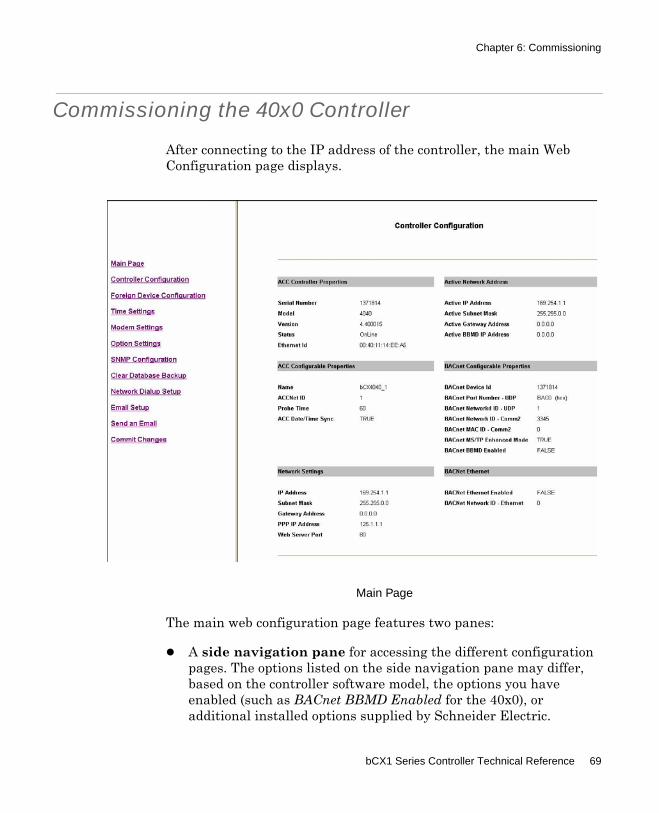
After connecting to the IP address of the controller, the main Web Configuration page displays.
Main Page
The main web configuration page features two panes:
A side navigation pane for accessing the different configuration pages. The options listed on the side navigation pane may differ, based on the controller software model, the options you have enabled (such as BACnet BBMD Enabled for the 40x0), or additional installed options supplied by Schneider Electric.
bCX1 Series Controller Technical Reference 69
Chapter 6: Commissioning
The main display pane shows the currently active controller configuration page.
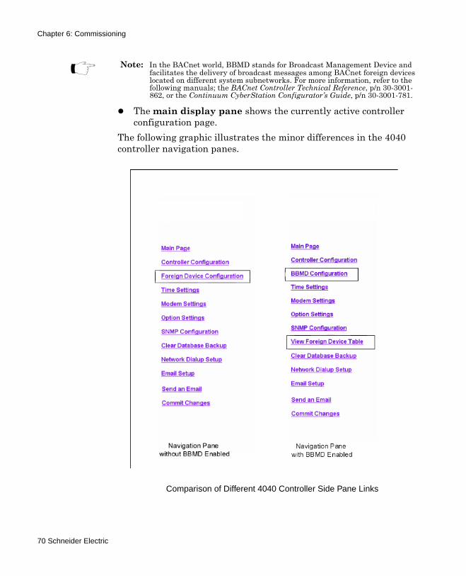
The following graphic illustrates the minor differences in the 4040 controller navigation panes.
Comparison of Different 4040 Controller Side Pane Links
Note: In the BACnet world, BBMD stands for Broadcast Management Device and facilitates the delivery of broadcast messages among BACnet foreign devices located on different system subnetworks. For more information, refer to the following manuals; the BACnet Controller Technical Reference, p/n 30-3001-862, or the Continuum CyberStation Configurator’s Guide, p/n 30-3001-781.
70 Schneider Electric
Chapter 6: Commissioning
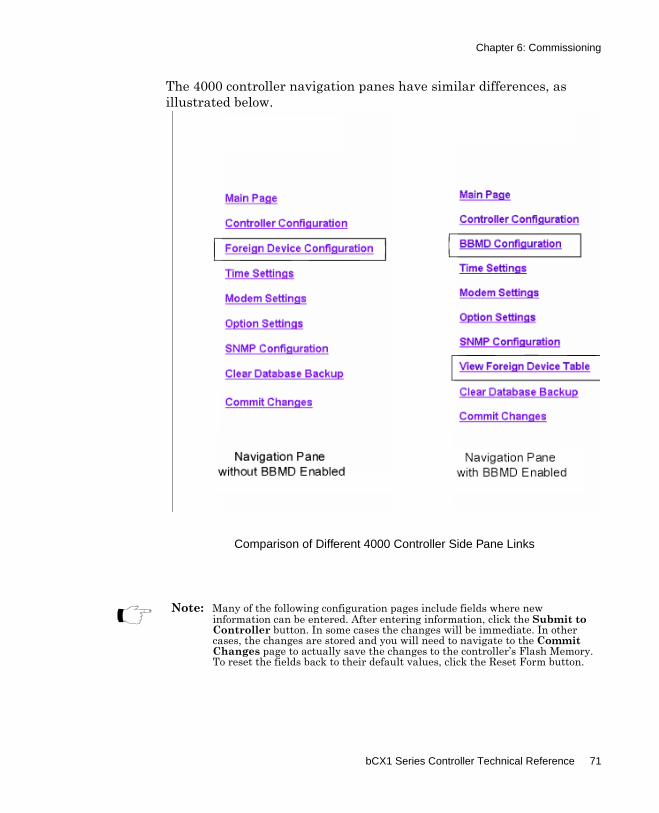
The 4000 controller navigation panes have similar differences, as illustrated below.
Comparison of Different 4000 Controller Side Pane Links
Note: Many of the following configuration pages include fields where new information can be entered. After entering information, click the Submit to Controller button. In some cases the changes will be immediate. In other cases, the changes are stored and you will need to navigate to the Commit Changes page to actually save the changes to the controller’s Flash Memory. To reset the fields back to their default values, click the Reset Form button.
bCX1 Series Controller Technical Reference 71
Chapter 6: Commissioning
Controller Configuration (40x0)
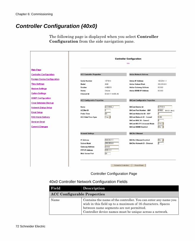
The following page is displayed when you select Controller Configuration from the side navigation pane.
Controller Configuration Page
40x0 Controller Network Configuration Fields
Field DescriptionACC Configurable PropertiesName Contains the name of the controller. You can enter any name you
wish in this field up to a maximum of 16 characters. Spaces between name segments are not permitted.Controller device names must be unique across a network.
72 Schneider Electric
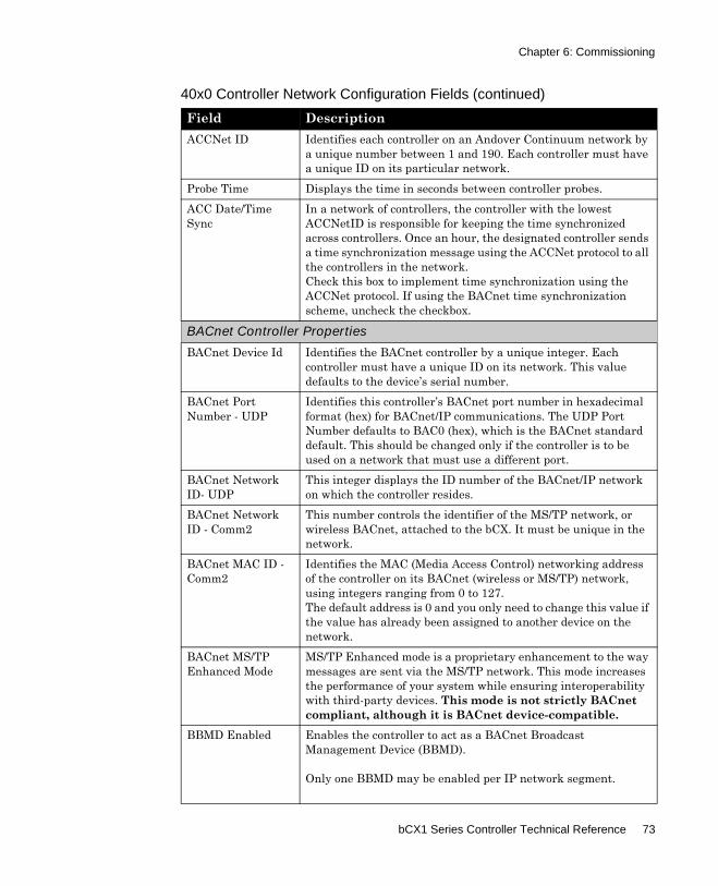
Chapter 6: Commissioning
ACCNet ID Identifies each controller on an Andover Continuum network by a unique number between 1 and 190. Each controller must have a unique ID on its particular network.
Probe Time Displays the time in seconds between controller probes.ACC Date/Time Sync
In a network of controllers, the controller with the lowest ACCNetID is responsible for keeping the time synchronized across controllers. Once an hour, the designated controller sends a time synchronization message using the ACCNet protocol to all the controllers in the network.Check this box to implement time synchronization using the ACCNet protocol. If using the BACnet time synchronization scheme, uncheck the checkbox.
BACnet Controller Properties
BACnet Device Id Identifies the BACnet controller by a unique integer. Each controller must have a unique ID on its network. This value defaults to the device’s serial number.
BACnet Port Number - UDP
Identifies this controller’s BACnet port number in hexadecimal format (hex) for BACnet/IP communications. The UDP Port Number defaults to BAC0 (hex), which is the BACnet standard default. This should be changed only if the controller is to be used on a network that must use a different port.
BACnet Network ID- UDP
This integer displays the ID number of the BACnet/IP network on which the controller resides.
BACnet Network ID - Comm2
This number controls the identifier of the MS/TP network, or wireless BACnet, attached to the bCX. It must be unique in the network.
BACnet MAC ID - Comm2
Identifies the MAC (Media Access Control) networking address of the controller on its BACnet (wireless or MS/TP) network, using integers ranging from 0 to 127.The default address is 0 and you only need to change this value if the value has already been assigned to another device on the network.
BACnet MS/TP Enhanced Mode
MS/TP Enhanced mode is a proprietary enhancement to the way messages are sent via the MS/TP network. This mode increases the performance of your system while ensuring interoperability with third-party devices. This mode is not strictly BACnet compliant, although it is BACnet device-compatible.
BBMD Enabled Enables the controller to act as a BACnet Broadcast Management Device (BBMD).
Only one BBMD may be enabled per IP network segment.
40x0 Controller Network Configuration Fields (continued)
Field Description
bCX1 Series Controller Technical Reference 73
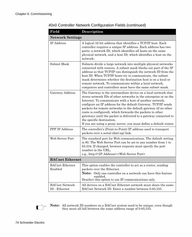
Chapter 6: Commissioning
Network SettingsIP Address A logical 32-bit address that identifies a TCP/IP host. Each
controller requires a unique IP address. Each address has two parts: a network ID, which identifies all hosts on the same physical network, and a host ID, which identifies a host on the network.
Subnet Mask Subnets divide a large network into multiple physical networks connected with routers. A subnet mask blocks out part of the IP address so that TCP/IP can distinguish the network ID from the host ID. When TCP/IP hosts try to communicate, the subnet mask determines whether the destination host is on a local or remote network. To communicate within a local network, computers and controllers must have the same subnet mask.
Gateway Address The Gateway is the intermediate device on a local network that stores network IDs of other networks in the enterprise or on the Internet. To communicate with a host of another network, configure an IP address for the default Gateway. TCP/IP sends packets for remote networks to the default gateway (if no other route is configured), which forwards the packets to other gateways until the packet is delivered to a gateway connected to the specific destination.If you are using a proxy server, you must define a default router.
PPP IP Address The controller’s (Point-to-Point) IP address used to transport packets over a serial (dial-up) link.
Web Server Port The standard port for Web communications. The default setting is 80. The Web Server Port can be set to any number from 1 to 65,534. If changed, browser requests must specify the port number in the URL, e.g., http://<IP Address>:<Web Server Port>
BACnet EthernetBACnet Ethernet Enabled
This option enables the controller to act as a router, sending packets over the Ethernet. Note: Only one controller on a network can have this feature
enabled.Deselect this option to use IP communications only.
BACnet Network ID - Ethernet
All devices on a BACnet Ethernet network must share the same BACnet Network ID. Enter a number between 0-65,535.
40x0 Controller Network Configuration Fields (continued)
Field Description
Note: All network ID numbers on a BACnet system need to be unique, even though they must all fall between the same address range of 0-65,535.
74 Schneider Electric
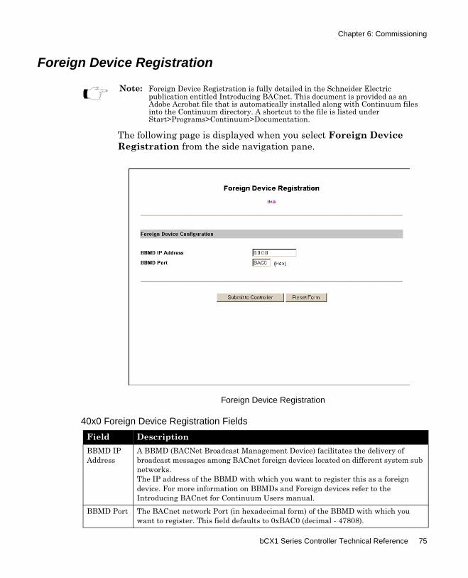
Chapter 6: Commissioning
Foreign Device Registration
The following page is displayed when you select Foreign Device Registration from the side navigation pane.
Foreign Device Registration
Note: Foreign Device Registration is fully detailed in the Schneider Electric publication entitled Introducing BACnet. This document is provided as an Adobe Acrobat file that is automatically installed along with Continuum files into the Continuum directory. A shortcut to the file is listed under Start>Programs>Continuum>Documentation.
40x0 Foreign Device Registration Fields
Field DescriptionBBMD IP Address
A BBMD (BACNet Broadcast Management Device) facilitates the delivery of broadcast messages among BACnet foreign devices located on different system sub networks.The IP address of the BBMD with which you want to register this as a foreign device. For more information on BBMDs and Foreign devices refer to the Introducing BACnet for Continuum Users manual.
BBMD Port The BACnet network Port (in hexadecimal form) of the BBMD with which you want to register. This field defaults to 0xBAC0 (decimal - 47808).
bCX1 Series Controller Technical Reference 75
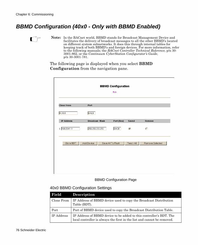
Chapter 6: Commissioning
BBMD Configuration (40x0 - Only with BBMD Enabled)
The following page is displayed when you select BBMD Configuration from the navigation pane.
BBMD Configuration Page
Note: In the BACnet world, BBMD stands for Broadcast Management Device and facilitates the delivery of broadcast messages to all the other BBMD’s located on different system subnetworks. It does this through internal tables for keeping track of both BBMD’s and foreign devices. For more information, refer to the following manuals; the BACnet Controller Technical Reference, p/n 30-3001-862, or the Continuum CyberStation Configurator’s Guide, p/n 30-3001-781.
40x0 BBMD Configuration Settings
Field DescriptionClone From IP Address of BBMD device used to copy the Broadcast Distribution
Table (BDT).Port Port of BBMD device used to copy the Broadcast Distribution Table.IP Address IP Address of BBMD device to be added to this controller’s BDT. The
local controller is always the first in the list and cannot be removed.
76 Schneider Electric
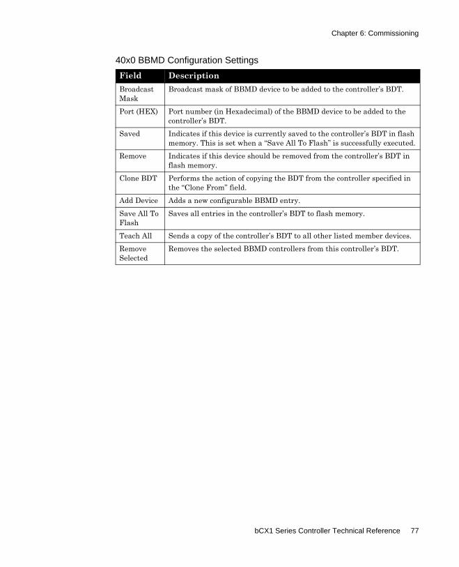
Chapter 6: Commissioning
Broadcast Mask
Broadcast mask of BBMD device to be added to the controller’s BDT.
Port (HEX) Port number (in Hexadecimal) of the BBMD device to be added to the controller’s BDT.
Saved Indicates if this device is currently saved to the controller’s BDT in flash memory. This is set when a “Save All To Flash” is successfully executed.
Remove Indicates if this device should be removed from the controller’s BDT in flash memory.
Clone BDT Performs the action of copying the BDT from the controller specified in the “Clone From” field.
Add Device Adds a new configurable BBMD entry.Save All To Flash
Saves all entries in the controller’s BDT to flash memory.
Teach All Sends a copy of the controller’s BDT to all other listed member devices.Remove Selected
Removes the selected BBMD controllers from this controller’s BDT.
40x0 BBMD Configuration Settings
Field Description
bCX1 Series Controller Technical Reference 77
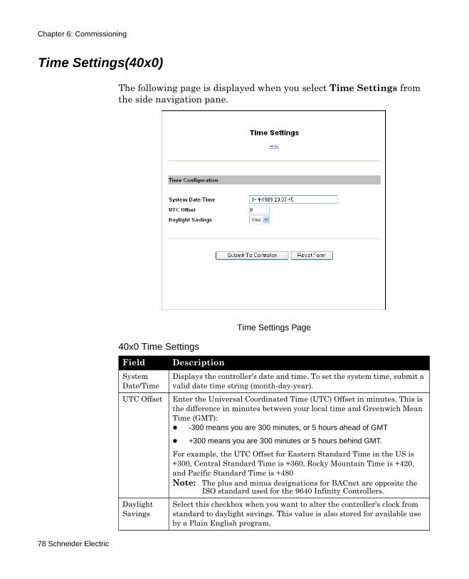
Chapter 6: Commissioning
Time Settings(40x0)
The following page is displayed when you select Time Settings from the side navigation pane.
Time Settings Page
40x0 Time Settings
Field DescriptionSystem Date/Time
Displays the controller's date and time. To set the system time, submit a valid date time string (month-day-year).
UTC Offset Enter the Universal Coordinated Time (UTC) Offset in minutes. This is the difference in minutes between your local time and Greenwich Mean Time (GMT):
-300 means you are 300 minutes, or 5 hours ahead of GMT
+300 means you are 300 minutes or 5 hours behind GMT.
For example, the UTC Offset for Eastern Standard Time in the US is +300, Central Standard Time is +360, Rocky Mountain Time is +420, and Pacific Standard Time is +480Note: The plus and minus designations for BACnet are opposite the
ISO standard used for the 9640 Infinity Controllers.Daylight Savings
Select this checkbox when you want to alter the controller's clock from standard to daylight savings. This value is also stored for available use by a Plain English program.
78 Schneider Electric
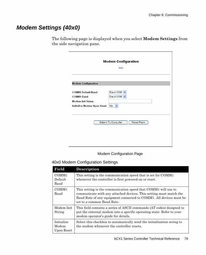
Chapter 6: Commissioning
Modem Settings (40x0)
The following page is displayed when you select Modem Settings from the side navigation pane.
Modem Configuration Page
40x0 Modem Configuration Settings
Field DescriptionCOMM1 Default Baud
This setting is the communication speed that is set for COMM1 whenever the controller is first powered-on or reset.
COMM1 Baud
This setting is the communication speed that COMM1 will use to communicate with any attached devices. This setting must match the Baud Rate of any equipment connected to COMM1. All devices must be set to a common Baud Rate.
Modem Init String
This field contains a series of ASCII commands (AT codes) designed to put the external modem into a specific operating state. Refer to your modem operator’s guide for details.
Initialize Modem Upon Reset
Select this checkbox to automatically send the initialization string to the modem whenever the controller resets.
bCX1 Series Controller Technical Reference 79
Chapter 6: Commissioning
Submit To Controller
Submit all form data to the controller. After submitting data, navigate to the Commit Changes page to write the changes to flash memory and restart the controller.
Reset Form Undo any changes that were previously submitted.
40x0 Modem Configuration Settings
Field Description
80 Schneider Electric
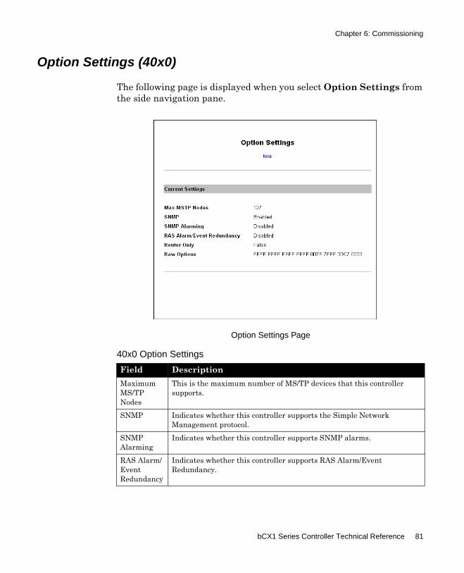
Chapter 6: Commissioning
Option Settings (40x0)
The following page is displayed when you select Option Settings from the side navigation pane.
Option Settings Page
40x0 Option Settings
Field DescriptionMaximum MS/TP Nodes
This is the maximum number of MS/TP devices that this controller supports.
SNMP Indicates whether this controller supports the Simple Network Management protocol.
SNMP Alarming
Indicates whether this controller supports SNMP alarms.
RAS Alarm/Event Redundancy
Indicates whether this controller supports RAS Alarm/Event Redundancy.
bCX1 Series Controller Technical Reference 81
Chapter 6: Commissioning
Router Only Indicates the up-rev capabilities supported by the firmware license. False indicates this controller can be up-revved to a different model within the bCX controller family.
True indicates controller's license is for bCX4000 only.
Raw Options
This hexadecimal field contains the option settings as read from the controller's flash memory. This information can be of use to our Technical Support department.
40x0 Option Settings
Field Description
82 Schneider Electric
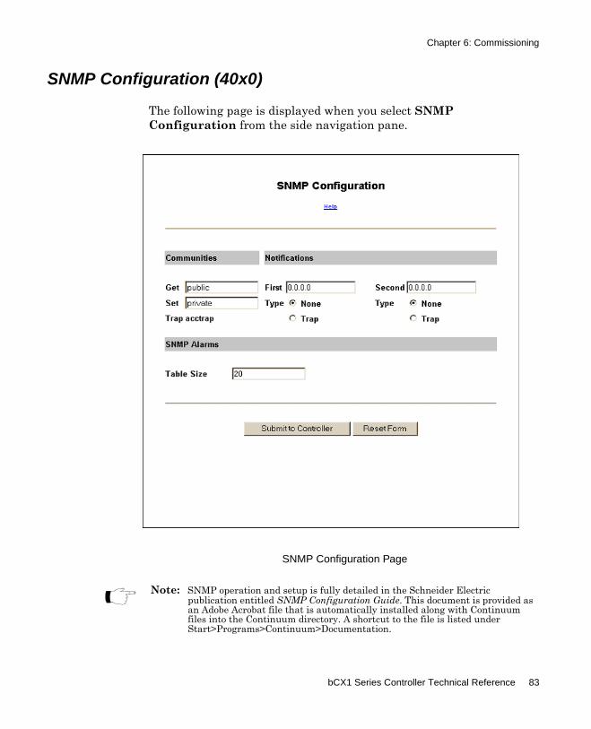
Chapter 6: Commissioning
SNMP Configuration (40x0)
The following page is displayed when you select SNMP Configuration from the side navigation pane.
SNMP Configuration Page
Note: SNMP operation and setup is fully detailed in the Schneider Electric publication entitled SNMP Configuration Guide. This document is provided as an Adobe Acrobat file that is automatically installed along with Continuum files into the Continuum directory. A shortcut to the file is listed under Start>Programs>Continuum>Documentation.
bCX1 Series Controller Technical Reference 83
Chapter 6: Commissioning
40x0 Controllers Communities
SNMP community is part of the simple security scheme. The entries in this group (Get and Set) are passwords. These passwords exist in your Network Management Software (NMS) management scheme. Learn the correct passwords then insert for each entry.
40x0 Controllers Notifications
Controller SNMP alarms can be sent to up to 12 other devices (SNMP NMS devices). The first two of them are non-volatile. Their IP addresses are entered on this form and are saved in the controller’s non-volatile memory, and will not be lost even if the Controller resets. The other 10 possible notification target IP addresses are stored in RAM. If the controller resets, their IP addresses will be initialized to 0.0.0.0, and the notification types will be initialized to None.
SNMP Community Passwords
Field DescriptionGet Enter a password for the Get action. The GET action allows NMS to retrieve
information from the Controller. The Get password has maximum length of 8 characters.
Set Enter a password for the Set action. SET allows NMS to write information to the controller. The Set password has maximum length of 8 characters.
Trap The Trap community is not editable. It is permanently set to acctrap.
SNMP Notifications
Field DescriptionFirst, Second Enter the IP addresses of the first two SNMP Alarm target PCs.Type Two notification types are supported:
None - Alarms will not be automatically delivered to the notification target. However, any NMS device with the ACC MIB files loaded can retrieve alarms from the controller using the GET command.Trap - Alarms will be automatically delivered to the notification target via SNMPv2c trap.
84 Schneider Electric
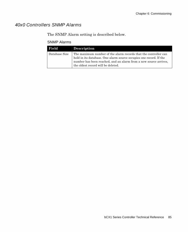
Chapter 6: Commissioning
40x0 Controllers SNMP Alarms
The SNMP Alarm setting is described below.
SNMP Alarms
Field DescriptionDatabase Size The maximum number of the alarm records that the controller can
hold in its database. One alarm source occupies one record. If the number has been reached, and an alarm from a new source arrives, the oldest record will be deleted.
bCX1 Series Controller Technical Reference 85
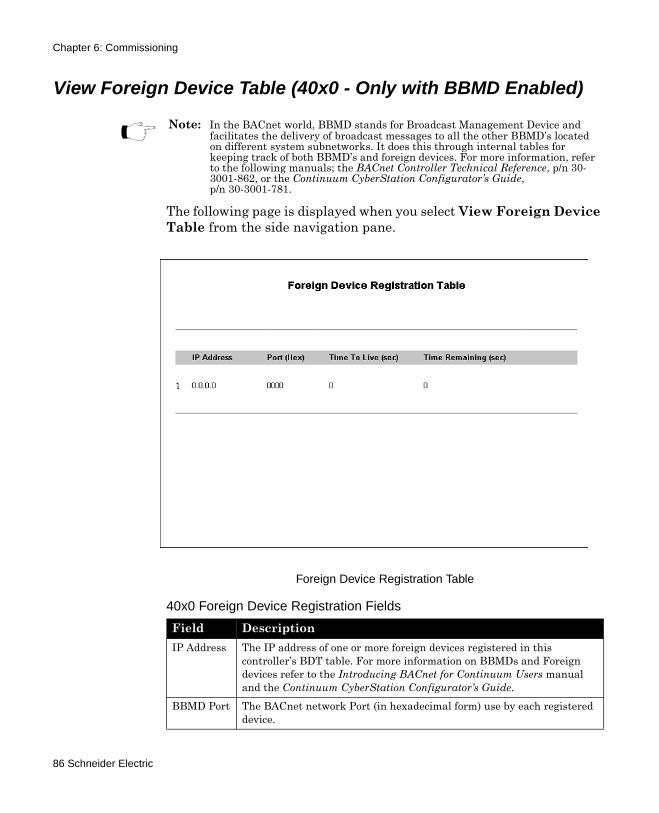
Chapter 6: Commissioning
View Foreign Device Table (40x0 - Only with BBMD Enabled)
The following page is displayed when you select View Foreign Device Table from the side navigation pane.
Foreign Device Registration Table
Note: In the BACnet world, BBMD stands for Broadcast Management Device and facilitates the delivery of broadcast messages to all the other BBMD’s located on different system subnetworks. It does this through internal tables for keeping track of both BBMD’s and foreign devices. For more information, refer to the following manuals; the BACnet Controller Technical Reference, p/n 30-3001-862, or the Continuum CyberStation Configurator’s Guide, p/n 30-3001-781.
40x0 Foreign Device Registration Fields
Field DescriptionIP Address The IP address of one or more foreign devices registered in this
controller’s BDT table. For more information on BBMDs and Foreign devices refer to the Introducing BACnet for Continuum Users manual and the Continuum CyberStation Configurator’s Guide.
BBMD Port The BACnet network Port (in hexadecimal form) use by each registered device.
86 Schneider Electric
Chapter 6: Commissioning
Time to Live
The time in seconds listed in this controller’s BDT table for communicating acknowledgements. This value is set by the foreign device
Time Remaining
The time remaining from the initial “Time to Live” setting when the foreign device communicated with this BBMD enabled controller.
40x0 Foreign Device Registration Fields
Field Description
bCX1 Series Controller Technical Reference 87
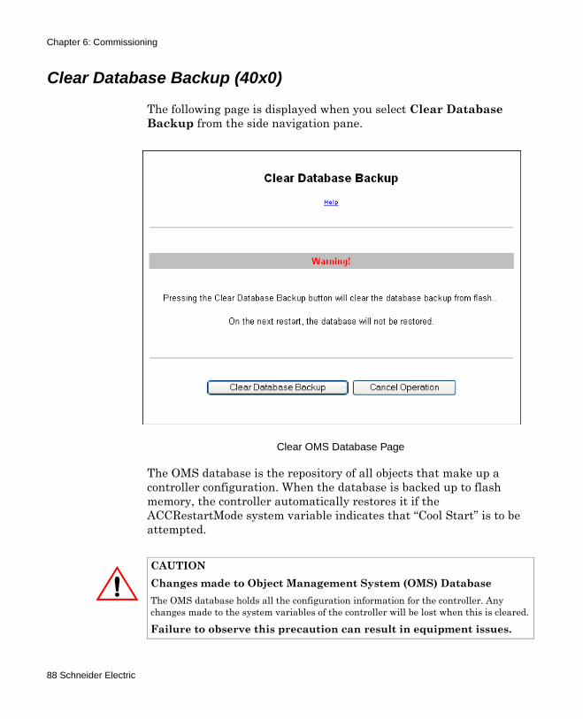
Chapter 6: Commissioning
Clear Database Backup (40x0)
The following page is displayed when you select Clear Database Backup from the side navigation pane.
Clear OMS Database Page
The OMS database is the repository of all objects that make up a controller configuration. When the database is backed up to flash memory, the controller automatically restores it if the ACCRestartMode system variable indicates that “Cool Start” is to be attempted.
CAUTIONChanges made to Object Management System (OMS) DatabaseThe OMS database holds all the configuration information for the controller. Any changes made to the system variables of the controller will be lost when this is cleared.
Failure to observe this precaution can result in equipment issues.
88 Schneider Electric
Chapter 6: Commissioning
Under certain conditions, it may be desirable to erase the backed up database from flash memory. Press this button to clear the database previously backed up to the controller's flash memory.
To reset the controller after erasing the database from flash memory, press the Restart Controller button.
Note: You can also clear the OMS database using the IP Reset button located on the controller board. Refer to ““Using the Reset IP button” on page 126 for more information.
bCX1 Series Controller Technical Reference 89
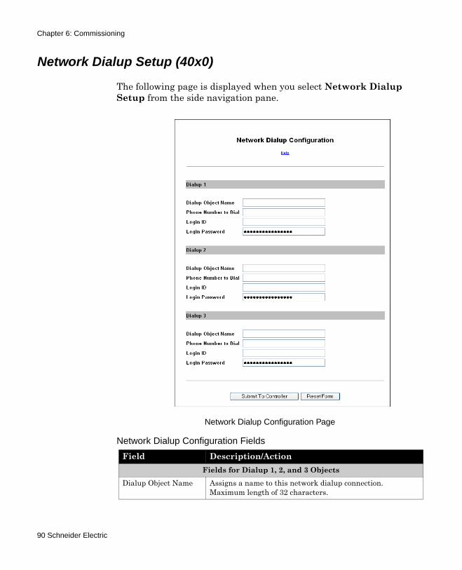
Chapter 6: Commissioning
Network Dialup Setup (40x0)
The following page is displayed when you select Network Dialup Setup from the side navigation pane.
Network Dialup Configuration Page
Network Dialup Configuration Fields
Field Description/ActionFields for Dialup 1, 2, and 3 Objects
Dialup Object Name Assigns a name to this network dialup connection. Maximum length of 32 characters.
90 Schneider Electric
Chapter 6: Commissioning
Phone Number to Dial Defines the phone number for this network dialup connection. Maximum length of 32 characters.
Some telephone systems require a pause or delay between numbers. To indicate a ½ second pause, use a comma (,) between numbers. For example, the following number string indicates a one second pause (2 commas) after the first digit of the dialup number.
9,,1 978 470 0555Logon ID Identifies the logon ID for accessing the remote network
using Point-to-Point (PPP) Authentication.
Maximum length of 32 characters.Logon Password Identifies the logon password for accessing the remote
network using PPP Authentication.
Maximum length of 32 characters.Submit To Controller Submit all of the data in the form to be saved.
Submitted changes take effect immediately.Reset Form Undo changes that have not been submitted.
Network Dialup Configuration Fields
Field Description/Action
bCX1 Series Controller Technical Reference 91
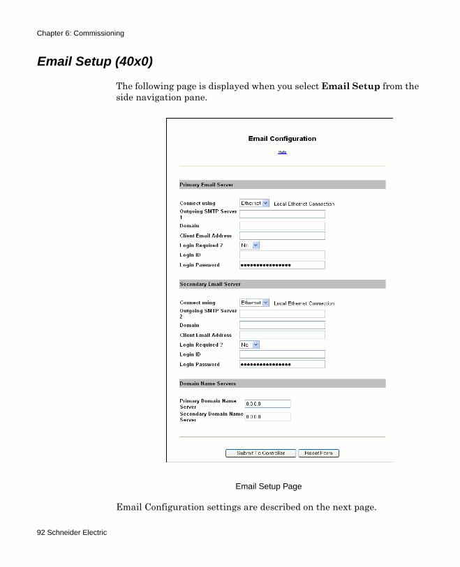
Chapter 6: Commissioning
Email Setup (40x0)
The following page is displayed when you select Email Setup from the side navigation pane.
Email Setup Page
Email Configuration settings are described on the next page.
92 Schneider Electric

Chapter 6: Commissioning
Email Configuration Settings
Field Description/ActionPrimary Email Server and optional Secondary* Email Server fields
Connect using… You can select the connection to the Email server through the controller's Local Ethernet Connection or one of the 3 Dialup Object numbers defined on the Network Dialup Configuration Page.
Outgoing SMTP Server 1 or 2
Identifies the primary and secondary (optional) SMTP server using either an IP address or the DNS name.Maximum of 32 characters and requires a fully qualified domain server name in the format, Servername.domain.com. An IP address in dotted decimal format may also be used, for example, 192.14.132.1.
Domain Identifies the network domain of the primary or secondary SMTP server. (optional)Maximum of 32 characters.
Client Email Address Identifies the controller's own email address (From: address).Maximum of 64 characters.
Login Required? Select YES, if the SMTP server requires an authorization login. Select NO, if the server does not required an authorization login.
Login ID A user name that authorizes the controller to access the SMTP server. (optional)Maximum of 32 characters.
Login Password A password that authorizes the controller to access the SMTP server. (optional)Maximum of 32 characters.
Domain Name ServersPrimary Domain Name Server
The server used by the Email servers on the network to identify and convert DNS names into IP addresses.
Secondary* Domain Name Server
Secondary (optional) server used by the Email servers on the network to identify and convert DNS names into IP addresses.
* Secondary servers are used if the connection to the primary server fails.Submit To Controller Submit all of the data in the form to be saved. Submitted
changes take effect immediately.Reset Form Undo changes that have not been submitted.
bCX1 Series Controller Technical Reference 93
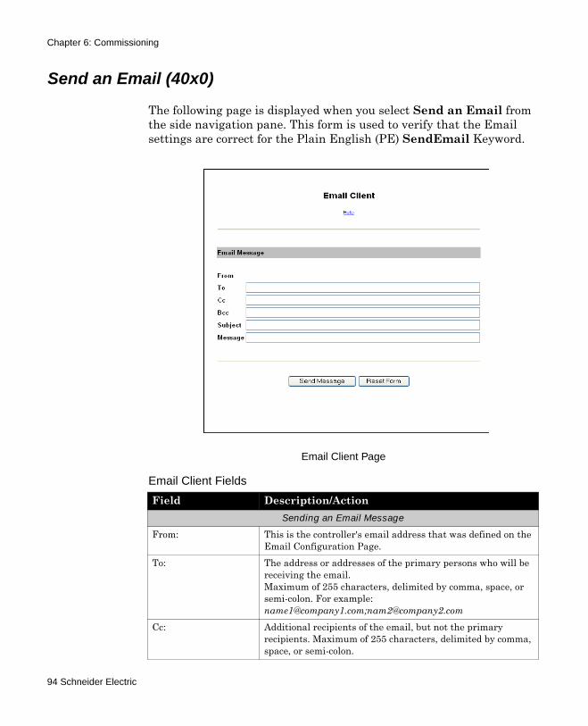
Chapter 6: Commissioning
Send an Email (40x0)
The following page is displayed when you select Send an Email from the side navigation pane. This form is used to verify that the Email settings are correct for the Plain English (PE) SendEmail Keyword.
Email Client Page
Email Client Fields
Field Description/ActionSending an Email Message
From: This is the controller's email address that was defined on the Email Configuration Page.
To: The address or addresses of the primary persons who will be receiving the email.Maximum of 255 characters, delimited by comma, space, or semi-colon. For example: [email protected];[email protected]
Cc: Additional recipients of the email, but not the primary recipients. Maximum of 255 characters, delimited by comma, space, or semi-colon.
94 Schneider Electric
Chapter 6: Commissioning
Bcc Hidden recipients of the email. The email address(es) will not appear on any recipients' copy of this email. Maximum of 255 characters, delimited by comma, space, or semi-colon.
Subject Brief description of the purpose of this email. Maximum of 255 characters.
Message Actual message content of this email. Maximum of 255 characters.
Submit To Controller Submit all of the data in the form to be saved.Submitted changes take effect immediately.
Reset Form Undo changes that have not been submitted.
Email Client Fields
Field Description/Action
bCX1 Series Controller Technical Reference 95
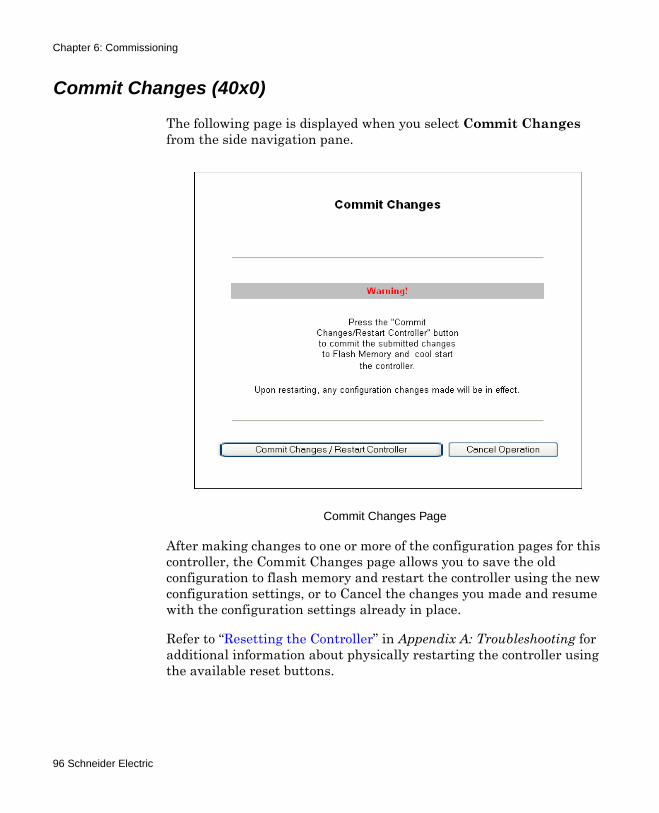
Chapter 6: Commissioning
Commit Changes (40x0)
The following page is displayed when you select Commit Changes from the side navigation pane.
Commit Changes Page
After making changes to one or more of the configuration pages for this controller, the Commit Changes page allows you to save the old configuration to flash memory and restart the controller using the new configuration settings, or to Cancel the changes you made and resume with the configuration settings already in place.
Refer to “Resetting the Controller” in Appendix A: Troubleshooting for additional information about physically restarting the controller using the available reset buttons.
96 Schneider Electric

Chapter 6: Commissioning
Commissioning the 9640 Controller
After connecting to the IP address of the controller (See “Connection Procedure” on page 67), the main Web Configuration page displays.
9640 Controller Configuration Main Page
The main web configuration page features two panes; a side navigation pane and the main display pane that shows the current key network and controller configuration settings.
Use the side navigation pane to access the configuration pages you need to view or change.
Note: There are some differences between the 40x0 and 9640 controllers that require different configuration screens. The commissioning process for the 9640 Infinity controller is presented on the following pages.
bCX1 Series Controller Technical Reference 97

Chapter 6: Commissioning
Note: Many of the following configuration pages include fields where new information can be entered. After entering information, click the Submit to Controller button. In some cases the changes will be immediate. In other cases, the changes are stored and you will need to navigate to the Commit Changes page to actually save the changes to the controller’s Flash Memory. To reset the fields back to their default values, click the Reset Form button.
98 Schneider Electric
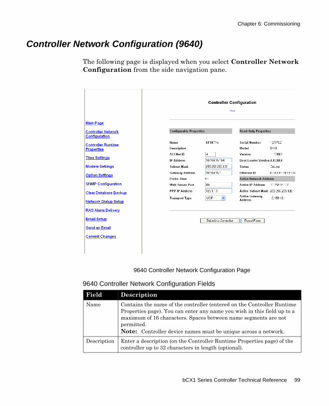
Chapter 6: Commissioning
Controller Network Configuration (9640)
The following page is displayed when you select Controller Network Configuration from the side navigation pane.
9640 Controller Network Configuration Page
9640 Controller Network Configuration Fields
Field DescriptionName Contains the name of the controller (entered on the Controller Runtime
Properties page). You can enter any name you wish in this field up to a maximum of 16 characters. Spaces between name segments are not permitted.Note: Controller device names must be unique across a network.
Description Enter a description (on the Controller Runtime Properties page) of the controller up to 32 characters in length (optional).
bCX1 Series Controller Technical Reference 99
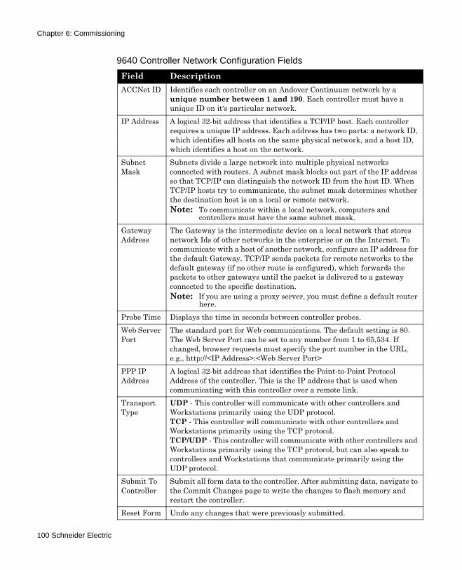
Chapter 6: Commissioning
ACCNet ID Identifies each controller on an Andover Continuum network by a unique number between 1 and 190. Each controller must have a unique ID on it's particular network.
IP Address A logical 32-bit address that identifies a TCP/IP host. Each controller requires a unique IP address. Each address has two parts: a network ID, which identifies all hosts on the same physical network, and a host ID, which identifies a host on the network.
Subnet Mask
Subnets divide a large network into multiple physical networks connected with routers. A subnet mask blocks out part of the IP address so that TCP/IP can distinguish the network ID from the host ID. When TCP/IP hosts try to communicate, the subnet mask determines whether the destination host is on a local or remote network.Note: To communicate within a local network, computers and
controllers must have the same subnet mask.Gateway Address
The Gateway is the intermediate device on a local network that stores network Ids of other networks in the enterprise or on the Internet. To communicate with a host of another network, configure an IP address for the default Gateway. TCP/IP sends packets for remote networks to the default gateway (if no other route is configured), which forwards the packets to other gateways until the packet is delivered to a gateway connected to the specific destination.Note: If you are using a proxy server, you must define a default router
here.Probe Time Displays the time in seconds between controller probes.Web Server Port
The standard port for Web communications. The default setting is 80. The Web Server Port can be set to any number from 1 to 65,534. If changed, browser requests must specify the port number in the URL, e.g., http://<IP Address>:<Web Server Port>
PPP IP Address
A logical 32-bit address that identifies the Point-to-Point Protocol Address of the controller. This is the IP address that is used when communicating with this controller over a remote link.
Transport Type
UDP - This controller will communicate with other controllers and Workstations primarily using the UDP protocol.TCP - This controller will communicate with other controllers and Workstations primarily using the TCP protocol.TCP/UDP - This controller will communicate with other controllers and Workstations primarily using the TCP protocol, but can also speak to controllers and Workstations that communicate primarily using the UDP protocol.
Submit To Controller
Submit all form data to the controller. After submitting data, navigate to the Commit Changes page to write the changes to flash memory and restart the controller.
Reset Form Undo any changes that were previously submitted.
9640 Controller Network Configuration Fields
Field Description
100 Schneider Electric
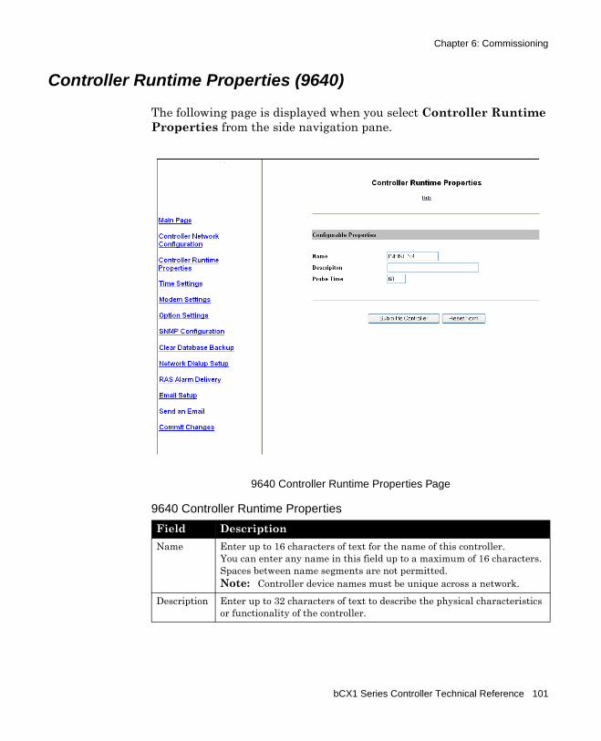
Chapter 6: Commissioning
Controller Runtime Properties (9640)
The following page is displayed when you select Controller Runtime Properties from the side navigation pane.
9640 Controller Runtime Properties Page
9640 Controller Runtime Properties
Field DescriptionName Enter up to 16 characters of text for the name of this controller.
You can enter any name in this field up to a maximum of 16 characters. Spaces between name segments are not permitted.Note: Controller device names must be unique across a network.
Description Enter up to 32 characters of text to describe the physical characteristics or functionality of the controller.
bCX1 Series Controller Technical Reference 101
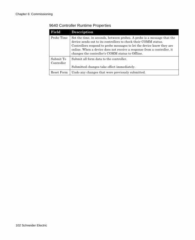
Chapter 6: Commissioning
Probe Time Set the time, in seconds, between probes. A probe is a message that the device sends out to its controllers to check their COMM status. Controllers respond to probe messages to let the device know they are online. When a device does not receive a response from a controller, it changes the controller's COMM status to Offline.
Submit To Controller
Submit all form data to the controller.
Submitted changes take effect immediately.Reset Form Undo any changes that were previously submitted.
9640 Controller Runtime Properties
Field Description
102 Schneider Electric
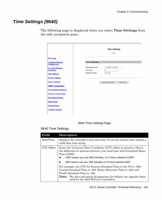
Chapter 6: Commissioning
Time Settings (9640)
The following page is displayed when you select Time Settings from the side navigation pane.
9640 Time Settings Page
9640 Time Settings
Field DescriptionDate/Time Displays the controller's date and time. To set the system time, submit a
valid date time string. UTC Offset Enter the Universal Time Coordinate (UTC) offset in minutes. This is
the difference in minutes between your local time and Greenwich Mean Time (GMT):
+300 means you are 300 minutes, or 5 hours ahead of GMT.
-300 means you are 300 minutes or 5 hours behind GMT.
For example, the UTC for Eastern Standard Time in the US is -300, Central Standard Time is -360, Rocky Mountain Time is -420, and Pacific Standard Time is -480Note: The plus and minus designations for Infinity are opposite those
used for the 40x0 BACnet Controllers.
bCX1 Series Controller Technical Reference 103
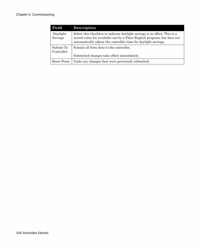
Chapter 6: Commissioning
Daylight Savings
Select this checkbox to indicate daylight savings is in effect. This is a stored value for available use by a Plain English program, but does not automatically adjust the controller time for daylight savings.
Submit To Controller
Submit all form data to the controller.
Submitted changes take effect immediately.Reset Form Undo any changes that were previously submitted.
Field Description
104 Schneider Electric
Chapter 6: Commissioning
Modem Settings (9640)
The following page is displayed when you select Modem Settings from the side navigation pane.
9640 Modem Configuration Page
9640 Modem Settings
Field DescriptionCOMM1 Default Baud
Enter the baud rate you want COMM1 to have when the controller starts.
COMM1 Baud
Select the baud rate that matches the one required by the equipment connected to COMM1. The baud rate represents the speed, measured in bits per second, at which the controller sends information to the device that you are connecting to the comm port.
bCX1 Series Controller Technical Reference 105
Chapter 6: Commissioning
Modem Init String
Different modems can’t necessarily talk to each other as configured by default. Modems use many different settings and protocols. In order for two modems to communicate, they must agree on many things such as speed, error correction, compression algorithms, etc. By sending a modem init string, you can control some of these parameters.Enter up to 255 characters in this field for a modem initialization string.
Initialize Modem Upon Reset
Check this checkbox to instruct the controller to send the modem initialization string to the modem on start up.
Submit To Controller
Submit all form data to the controller. After submitting data, navigate to the Commit Changes page to write the changes to flash memory and restart the controller.
Reset Form Undo any changes that were previously submitted.
9640 Modem Settings
Field Description
106 Schneider Electric
Chapter 6: Commissioning
SNMP Configuration (Optional Purchase on 9640 Controllers)
The following page is displayed when you select SNMP Configuration from the side navigation pane.
9640 SNMP Configuration Page
Field descriptions for Communities, Notifications and SNMP Alarms are described in the following paragraphs.
Note: SNMP operation and setup is fully detailed in the Schneider Electric publication entitled SNMP Configuration Guide. This document is provided as an Adobe Acrobat file that is automatically installed along with Continuum files into the Continuum directory. A shortcut to the file is listed under Start>Programs>Continuum>Documentation.
bCX1 Series Controller Technical Reference 107
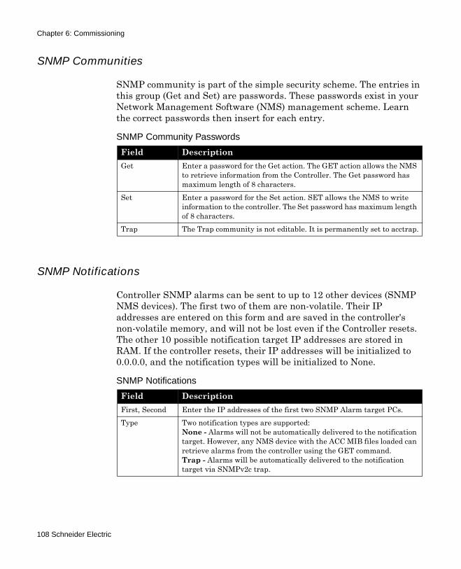
Chapter 6: Commissioning
SNMP Communities
SNMP community is part of the simple security scheme. The entries in this group (Get and Set) are passwords. These passwords exist in your Network Management Software (NMS) management scheme. Learn the correct passwords then insert for each entry.
SNMP Notifications
Controller SNMP alarms can be sent to up to 12 other devices (SNMP NMS devices). The first two of them are non-volatile. Their IP addresses are entered on this form and are saved in the controller's non-volatile memory, and will not be lost even if the Controller resets. The other 10 possible notification target IP addresses are stored in RAM. If the controller resets, their IP addresses will be initialized to 0.0.0.0, and the notification types will be initialized to None.
SNMP Community Passwords
Field DescriptionGet Enter a password for the Get action. The GET action allows the NMS
to retrieve information from the Controller. The Get password has maximum length of 8 characters.
Set Enter a password for the Set action. SET allows the NMS to write information to the controller. The Set password has maximum length of 8 characters.
Trap The Trap community is not editable. It is permanently set to acctrap.
SNMP Notifications
Field DescriptionFirst, Second Enter the IP addresses of the first two SNMP Alarm target PCs.Type Two notification types are supported:
None - Alarms will not be automatically delivered to the notification target. However, any NMS device with the ACC MIB files loaded can retrieve alarms from the controller using the GET command.Trap - Alarms will be automatically delivered to the notification target via SNMPv2c trap.
108 Schneider Electric
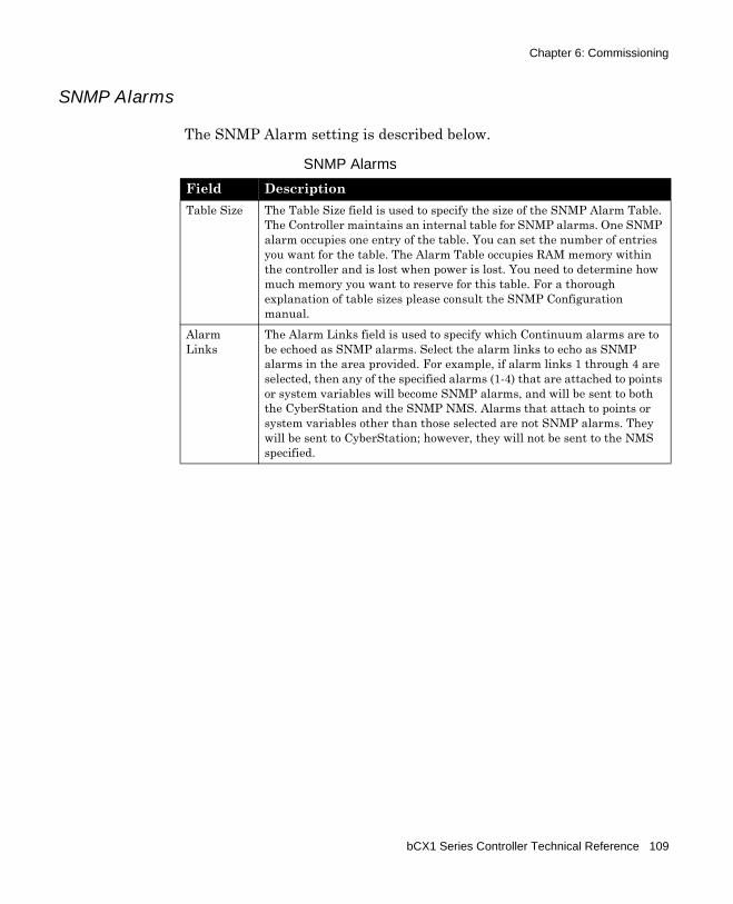
Chapter 6: Commissioning
SNMP Alarms
The SNMP Alarm setting is described below.
SNMP Alarms
Field DescriptionTable Size The Table Size field is used to specify the size of the SNMP Alarm Table.
The Controller maintains an internal table for SNMP alarms. One SNMP alarm occupies one entry of the table. You can set the number of entries you want for the table. The Alarm Table occupies RAM memory within the controller and is lost when power is lost. You need to determine how much memory you want to reserve for this table. For a thorough explanation of table sizes please consult the SNMP Configuration manual.
Alarm Links
The Alarm Links field is used to specify which Continuum alarms are to be echoed as SNMP alarms. Select the alarm links to echo as SNMP alarms in the area provided. For example, if alarm links 1 through 4 are selected, then any of the specified alarms (1-4) that are attached to points or system variables will become SNMP alarms, and will be sent to both the CyberStation and the SNMP NMS. Alarms that attach to points or system variables other than those selected are not SNMP alarms. They will be sent to CyberStation; however, they will not be sent to the NMS specified.
bCX1 Series Controller Technical Reference 109
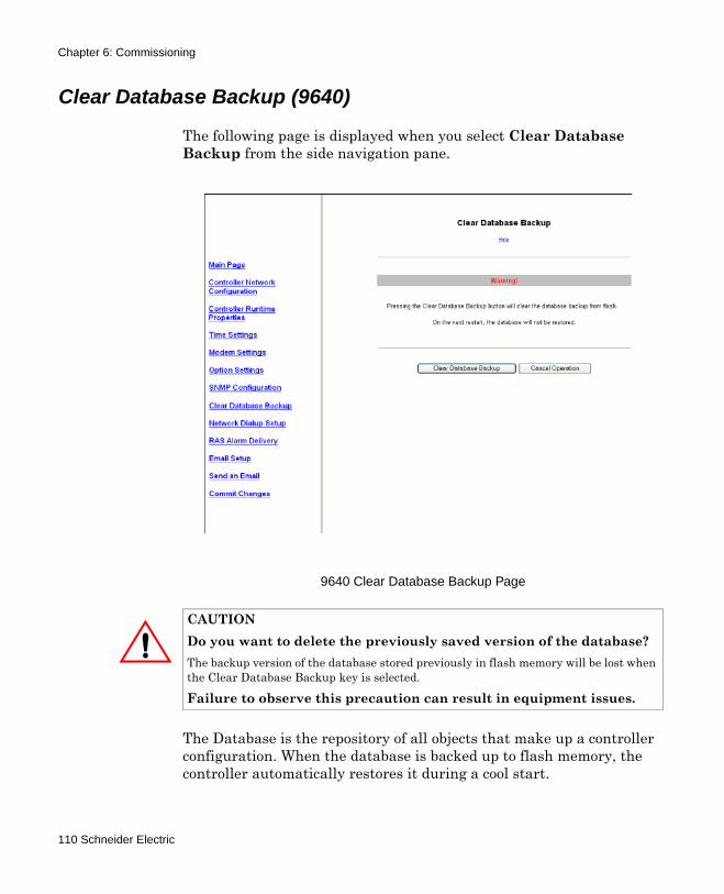
Chapter 6: Commissioning
Clear Database Backup (9640)
The following page is displayed when you select Clear Database Backup from the side navigation pane.
9640 Clear Database Backup Page
The Database is the repository of all objects that make up a controller configuration. When the database is backed up to flash memory, the controller automatically restores it during a cool start.
CAUTIONDo you want to delete the previously saved version of the database?The backup version of the database stored previously in flash memory will be lost when the Clear Database Backup key is selected.
Failure to observe this precaution can result in equipment issues.
110 Schneider Electric
Chapter 6: Commissioning
Under certain conditions, it may be desirable to erase the backed up database from flash memory.
After pressing the Clear Database Backup button, you are instructed to navigate to the Commit Changes page, where you will actually execute the clear request (along with any other changes made on other configuration pages) and restart the controller.
Note: You can also clear the database using the IP Reset button located on the controller board. Refer to “Using the Reset IP button” on page 126 for more information.
Clear Database Backup Fields
Action Description/ActionClear OMS Database Press this button to clear the OMS database previously
backed up to the controller's flash memory.
The database is the repository of all objects that make up a controller configuration. Once the OMS database is backed up to flash memory, the controller will automatically restore it at start up time.
Under certain conditions, it may be desirable to erase the backed up database from flash memory.
After Clearing the Database, navigate to the Commit Changes page to write the changes to flash memory and restart the controller.
Cancel Operation Cancel clearing the OMS Database.
bCX1 Series Controller Technical Reference 111
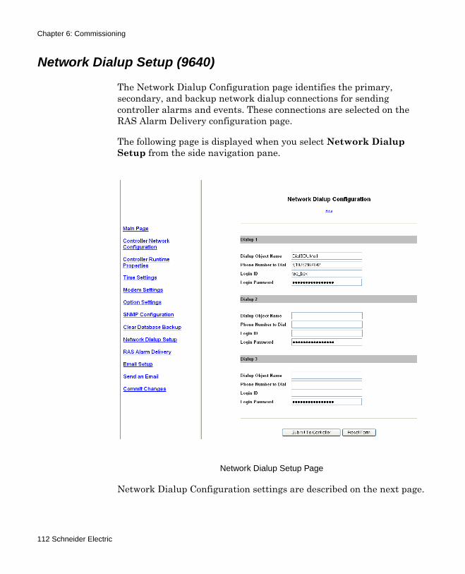
Chapter 6: Commissioning
Network Dialup Setup (9640)
The Network Dialup Configuration page identifies the primary, secondary, and backup network dialup connections for sending controller alarms and events. These connections are selected on the RAS Alarm Delivery configuration page.
The following page is displayed when you select Network Dialup Setup from the side navigation pane.
Network Dialup Setup Page
Network Dialup Configuration settings are described on the next page.
112 Schneider Electric
Chapter 6: Commissioning
Network Dialup Configuration Settings
Field Description/ActionFields for Dialup 1, 2, and 3 Objects
Dialup Object Name Assigns a name to this network dialup connection.
Maximum length of 32 characters.Phone Number to Dial Defines the phone number for this network dialup
connection.
Maximum length of 32 characters.
Some telephone systems require a pause or delay between numbers. To indicate a ½ second pause, use a comma (,) between numbers. For example, the following number string indicates a one second pause (2 commas) after the first digit of the dialup number.
9,,1 978 470 0555Logon ID Identifies the logon ID for accessing the remote network
using Point-to-Point (PPP) Authentication.
Maximum length of 32 characters.Logon Password Identifies the logon password for accessing the remote
network using PPP Authentication.
Maximum length of 32 characters.Submit To Controller Submit all of the data in the form to be saved.
Submitted changes take effect immediately.Reset Form Undo changes that have not been submitted.
bCX1 Series Controller Technical Reference 113
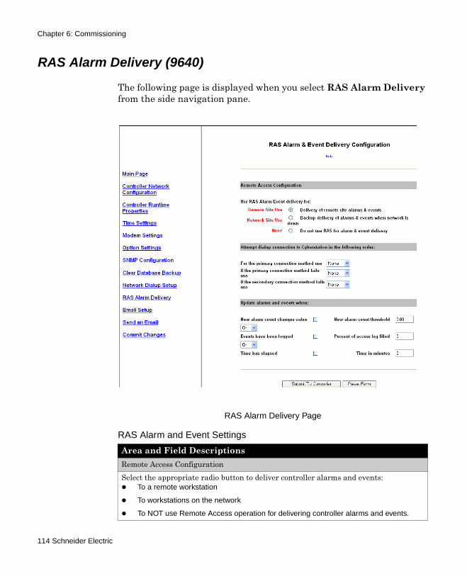
Chapter 6: Commissioning
RAS Alarm Delivery (9640)
The following page is displayed when you select RAS Alarm Delivery from the side navigation pane.
RAS Alarm Delivery Page
RAS Alarm and Event Settings
Area and Field DescriptionsRemote Access ConfigurationSelect the appropriate radio button to deliver controller alarms and events:
To a remote workstation
To workstations on the network
To NOT use Remote Access operation for delivering controller alarms and events.
114 Schneider Electric
Chapter 6: Commissioning
Attempt dialup connection to CyberStation in the following order:Select the primary, secondary, and backup network dialup connections for sending controller alarms and events. The Dialup connections are defined on the Network Dialup Configuration page.Update alarms and events when:Set the conditions for updating the alarms and event messages using AND/OR logic, alarm count thresholds, access log volume (%), or time.Submit To Controller Submit all of the data in the form to be saved.
Submitted changes take effect immediately.Reset Form Undo changes that have not been submitted.
RAS Alarm and Event Settings
Area and Field Descriptions
bCX1 Series Controller Technical Reference 115
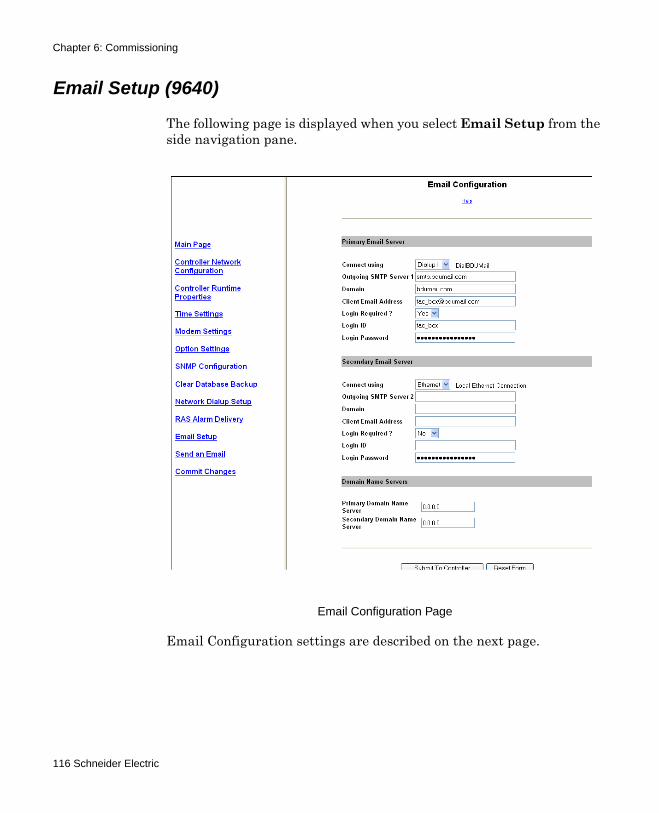
Chapter 6: Commissioning
Email Setup (9640)
The following page is displayed when you select Email Setup from the side navigation pane.
Email Configuration Page
Email Configuration settings are described on the next page.
116 Schneider Electric
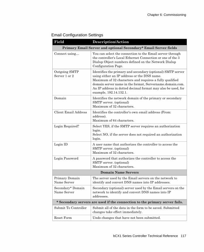
Chapter 6: Commissioning
Email Configuration Settings
Field Description/ActionPrimary Email Server and optional Secondary* Email Server fields
Connect using… You can select the connection to the Email server through the controller's Local Ethernet Connection or one of the 3 Dialup Object numbers defined on the Network Dialup Configuration Page.
Outgoing SMTP Server 1 or 2
Identifies the primary and secondary (optional) SMTP server using either an IP address or the DNS name.Maximum of 32 characters and requires a fully qualified domain server name in the format, Servername.domain.com. An IP address in dotted decimal format may also be used, for example, 192.14.132.1.
Domain Identifies the network domain of the primary or secondary SMTP server. (optional)Maximum of 32 characters.
Client Email Address Identifies the controller's own email address (From: address).Maximum of 64 characters.
Login Required? Select YES, if the SMTP server requires an authorization login. Select NO, if the server does not required an authorization login.
Login ID A user name that authorizes the controller to access the SMTP server. (optional)Maximum of 32 characters.
Login Password A password that authorizes the controller to access the SMTP server. (optional)Maximum of 32 characters.
Domain Name ServersPrimary Domain Name Server
The server used by the Email servers on the network to identify and convert DNS names into IP addresses.
Secondary* Domain Name Server
Secondary (optional) server used by the Email servers on the network to identify and convert DNS names into IP addresses.
* Secondary servers are used if the connection to the primary server fails.Submit To Controller Submit all of the data in the form to be saved. Submitted
changes take effect immediately.Reset Form Undo changes that have not been submitted.
bCX1 Series Controller Technical Reference 117
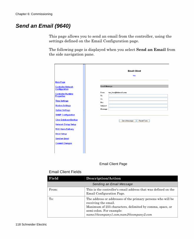
Chapter 6: Commissioning
Send an Email (9640)
This page allows you to send an email from the controller, using the settings defined on the Email Configuration page.
The following page is displayed when you select Send an Email from the side navigation pane.
Email Client Page
Email Client Fields
Field Description/ActionSending an Email Message
From: This is the controller's email address that was defined on the Email Configuration Page.
To: The address or addresses of the primary persons who will be receiving the email.Maximum of 255 characters, delimited by comma, space, or semi-colon. For example: [email protected];[email protected]
118 Schneider Electric
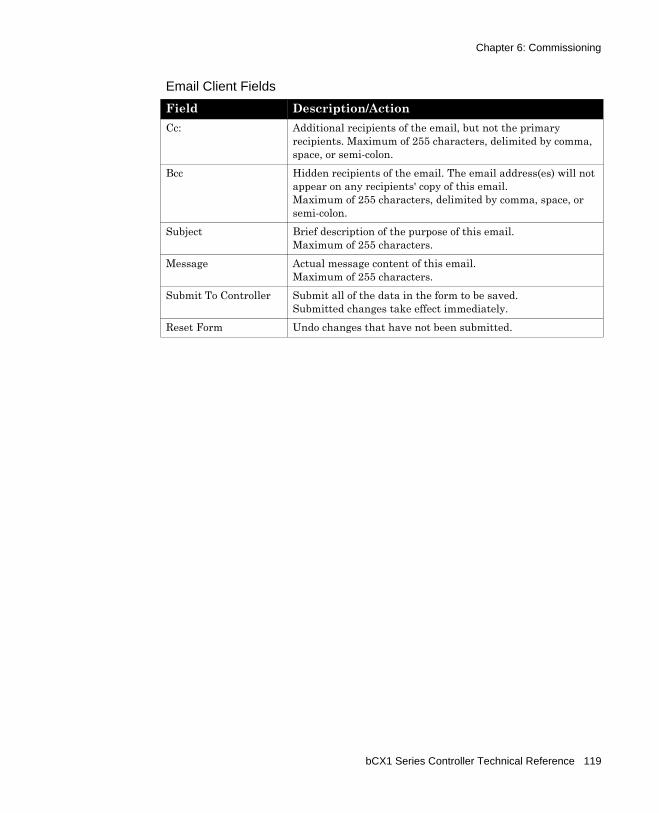
Chapter 6: Commissioning
Cc: Additional recipients of the email, but not the primary recipients. Maximum of 255 characters, delimited by comma, space, or semi-colon.
Bcc Hidden recipients of the email. The email address(es) will not appear on any recipients' copy of this email. Maximum of 255 characters, delimited by comma, space, or semi-colon.
Subject Brief description of the purpose of this email. Maximum of 255 characters.
Message Actual message content of this email. Maximum of 255 characters.
Submit To Controller Submit all of the data in the form to be saved.Submitted changes take effect immediately.
Reset Form Undo changes that have not been submitted.
Email Client Fields
Field Description/Action
bCX1 Series Controller Technical Reference 119
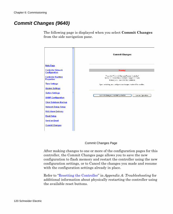
Chapter 6: Commissioning
Commit Changes (9640)
The following page is displayed when you select Commit Changes from the side navigation pane.
Commit Changes Page
After making changes to one or more of the configuration pages for this controller, the Commit Changes page allows you to save the new configuration to flash memory and restart the controller using the new configuration settings, or to Cancel the changes you made and resume with the configuration settings already in place.
Refer to “Resetting the Controller” in Appendix A: Troubleshooting for additional information about physically restarting the controller using the available reset buttons.
120 Schneider Electric
Appendix ATroubleshooting
This appendix contains the following topics:
Troubleshooting the bCX1 ControllerCPU Indicator Blinking PatternsCPU Indicator Remains OffUnit Appears Functional But Is Not RespondingMonitoring Field Bus ActivityResetting the ControllerUsing the Reset ButtonUsing the Reset IP button
bCX1 Series Controller Technical Reference 121
Appendix A: Troubleshooting
Troubleshooting the bCX1 Controller
CPU Indicator Blinking Patterns
There are three potential blinking patterns for the CPU indicator:
The normal blinking pattern is a consistent blinking of approximately five times a second (5 Hz at 50% duty) and indicates that no serious problems have been detected.The error blinking pattern is approximately two times a second (2 Hz at 25% duty), and indicates one or more error conditions have been detected and recorded in the Error Log.The bootloader blinking pattern is approximately two times a second (2 Hz at 50% duty) and indicates that a serious problem has caused the controller to erase its application program and drop into the boatloader mode, awaiting an upload of new firmware.
CPU Indicator Remains Off
If the CPU indicator remains off, then the unit is not operating. This could be because of loss of primary AC power or an internal dysfunction.
Check that 24VAC ~ (or 12-28VDC) is available and connected properly to the power terminals. Use a multimeter, reading the voltage across the 24VAC and GND terminals.
If power appears to be OK, remove power and all other connections from the unit. The fuse within the unit may have failed. To access the fuse, the controller housing itself must be disassembled. The housing consists of two pieces that are snapped together.
Note: If the CPU indicator remains on, without a blinking pattern for longer than one minute, this indicates an internal failure.
122 Schneider Electric
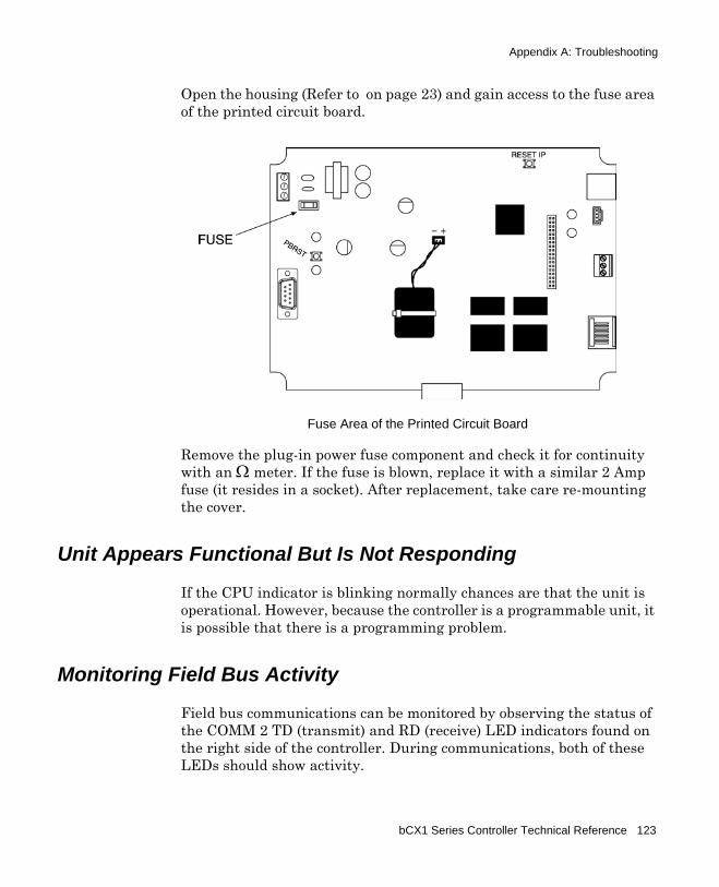
Appendix A: Troubleshooting
Open the housing (Refer to on page 23) and gain access to the fuse area of the printed circuit board.
Remove the plug-in power fuse component and check it for continuity with an Ω meter. If the fuse is blown, replace it with a similar 2 Amp fuse (it resides in a socket). After replacement, take care re-mounting the cover.
Unit Appears Functional But Is Not Responding
If the CPU indicator is blinking normally chances are that the unit is operational. However, because the controller is a programmable unit, it is possible that there is a programming problem.
Monitoring Field Bus Activity
Field bus communications can be monitored by observing the status of the COMM 2 TD (transmit) and RD (receive) LED indicators found on the right side of the controller. During communications, both of these LEDs should show activity.
Fuse Area of the Printed Circuit Board
bCX1 Series Controller Technical Reference 123
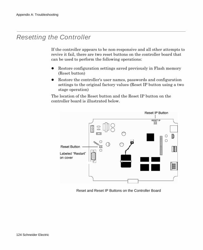
Appendix A: Troubleshooting
Resetting the Controller
If the controller appears to be non-responsive and all other attempts to revive it fail, there are two reset buttons on the controller board that can be used to perform the following operations:
Restore configuration settings saved previously in Flash memory (Reset button)Restore the controller's user names, passwords and configuration settings to the original factory values (Reset IP button using a two stage operation)
The location of the Reset button and the Reset IP button on the controller board is illustrated below.
Reset and Reset IP Buttons on the Controller Board
124 Schneider Electric
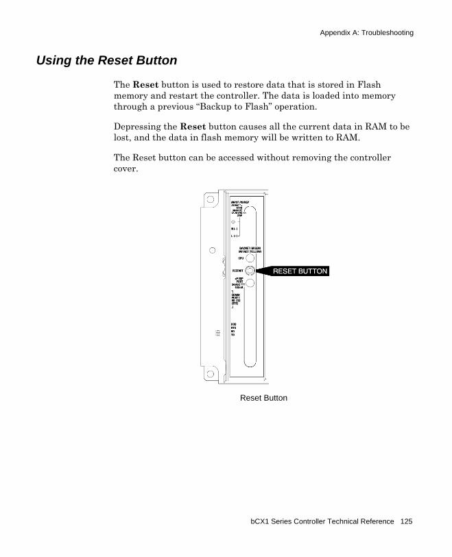
Appendix A: Troubleshooting
Using the Reset Button
The Reset button is used to restore data that is stored in Flash memory and restart the controller. The data is loaded into memory through a previous “Backup to Flash” operation.
Depressing the Reset button causes all the current data in RAM to be lost, and the data in flash memory will be written to RAM.
The Reset button can be accessed without removing the controller cover.
Reset Button
bCX1 Series Controller Technical Reference 125
Appendix A: Troubleshooting
Using the Reset IP button
The Reset IP button has two stages of operation:
Stage 1 is initiated by depressing the button for 5 seconds. After 5 seconds, the IP address, and all network-related addresses entered on the Network Configuration page, are returned to the original factory default values.Stage 2 is initiated by depressing the button for 35 seconds. After 35 seconds, the database is cleared and all persistent configuration data is erased, with the exception of the error log.
When you initially depress the Reset IP button, the CPU Indicator LED will begin blinking. At 5 seconds, the LED will stop blinking and remain lighted in a continuous state.
If you release the button before 5 seconds has passed, no changes are made.
If you release the button after 5 seconds, but before 35 seconds, stage 1 is executed, but stage 2 is not. The IP address has returned to the original factory value, but the database has not changed.
Locating the Reset IP Button
To access the Reset IP button, remove the module cover by depressing the two force fitting plastic tabs (cover latches) on each side of the controller.
The location of the Reset IP button and the CPU LED indicator on the controller board is illustrated in below.
Note: Depressing the button for 35 seconds performs both operations, setting the IP address back to the factory default setting and clearing the database.
126 Schneider Electric
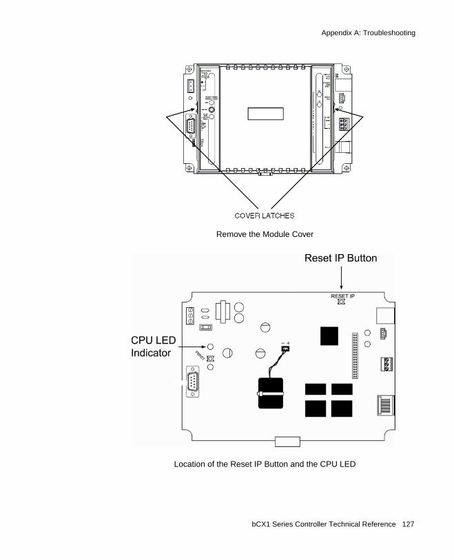
Appendix A: Troubleshooting
Remove the Module Cover
Location of the Reset IP Button and the CPU LED
bCX1 Series Controller Technical Reference 127

Appendix A: Troubleshooting
128 Schneider Electric

Appendix BUsing bCX 40x0 as an SNMP
Alarm Gateway
The routing of SNMP alarms is supported in Schneider Electric bCX 40x0 controllers. Likewise, Schneider Electric and third-party BACnet controllers can deliver alarms, via a bCX 40x0 "gateway" controller, without being configured in an NMS.
Specifically:A bCX 40x0 controller can serve as an SNMP Alarm Gateway (SAG) controller, through which SNMP alarms are received from multiple BACnet devices and then deliver them to NMS devices.A Schneider Electric or third-party BACnet controllers (not configured in an NMS) can be configured as an SNMP Alarm Initiator (SAI), whereby any SNMP alarms it receives are automatically routed to the SAG for delivery.
Note: SNMP is a message protocol, whereby network administrators can manage network communication - usually alarm routing - among Continuum controllers and other devices on corporate Ethernet networks that support SNMP. Continuum's implementation of SNMP resides at the controller level. An NMS is a device (usually a PC) running the appropriate software to manage SNMP-capable devices over the network using the SNMP protocol. Examples of such software are: HP OpenView and MG-Soft's MIB Browser. There can be one or more NMS on the network. Alarms are received, reformatted, and sent from one NMS-configured BACnet controller to its configured NMS devices. (See also the SNMP Configuration Guide, 30-3001-855.)
bCX1 Series Controller Technical Reference 129
Appendix B: Using bCX 40x0 as an SNMP Alarm Gateway
Configuring an SAG
Any bCX 40x0 controller can be configured as an SAG, through which SNMP alarms are received from Schneider Electric and third-party SAI controllers and delivered to its configured NMS devices. When the SAG receives the alarm notification, it verifies that it is an SNMP alarm and sends it to the configured NMSs with SNMP Trap messages. The SAG also records the alarm in its internal database. Any NMS can poll this database at any time using the SNMP protocol.
Configure a 40x0 controller as an SAG in the controller's SNMP Configuration internal commissioning web page. In the Notifications section, in the First and Second fields, enter the address of the controllers to which these SNMP alarms should be routed.
Configuring an SAI
A Schneider Electric or third-party BACnet controller can be configured as an SAI using the Continuum EventEnrollment and EventNotification editors. When an SAI initiates a BACnet alarm, it labels it as an SNMP alarm and sends it, with a BACnet confirmed or un-confirmed event notification, to the configured SAG, which in turn delivers it to the NMS controllers using the SNMP protocol. SAIs do not need the SNMP alarming software, and usually do not have it. There can be many SAIs on the network.
Note: An SAG controller (bCX 40x0) can also be an SAI, because if it is also configured as an SAI, it can initiate alarms to itself.
130 Schneider Electric
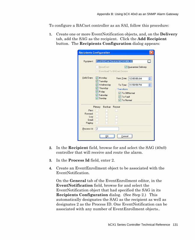
Appendix B: Using bCX 40x0 as an SNMP Alarm Gateway
To configure a BACnet controller as an SAI, follow this procedure:
1. Create one or more EventNotification objects, and, on the Delivery tab, add the SAG as the recipient. Click the Add Recipient button. The Recipients Configuration dialog appears:
2. In the Recipient field, browse for and select the SAG (40x0) controller that will receive and route the alarm.
3. In the Process Id field, enter 2.
4. Create an EventEnrollment object to be associated with the EventNotification.
On the General tab of the EventEnrollment editor, in the EventNotification field, browse for and select the EventNotification object that had specified the SAG in its Recipients Configuration dialog. (See Step 2.) This automatically designates the SAG as the recipient as well as designates 2 as the Process ID. One EventNotification can be associated with any number of EventEnrollment objects..
bCX1 Series Controller Technical Reference 131

Appendix B: Using bCX 40x0 as an SNMP Alarm Gateway
5. Configure the remainder of the EventNotification and EventEnrollment objects as you normally would. (See the Continuum online help for those editors.)
Note: If you use other BACnet workstations instead of Continuum Cyberstation, specify the SAG in the Recipient_List of the NotificationClass object, and set the processidentifier of the recipient (targeted to the SAG in the Recipient_List) to 2.
Note: For information on the 9640 and 40x0 support of SNMP Alarming for SNMP Networked Management Systems, refer to the following guide:
Continuum SNMP Configuration Guide, p/n 30-3001-855
132 Schneider Electric


bCX1 Series Technical ReferenceDocument Number 30-3001-890
Revision F