banking example of e-r diagram
TRANSCRIPT
Banking Example of E-R Diagram
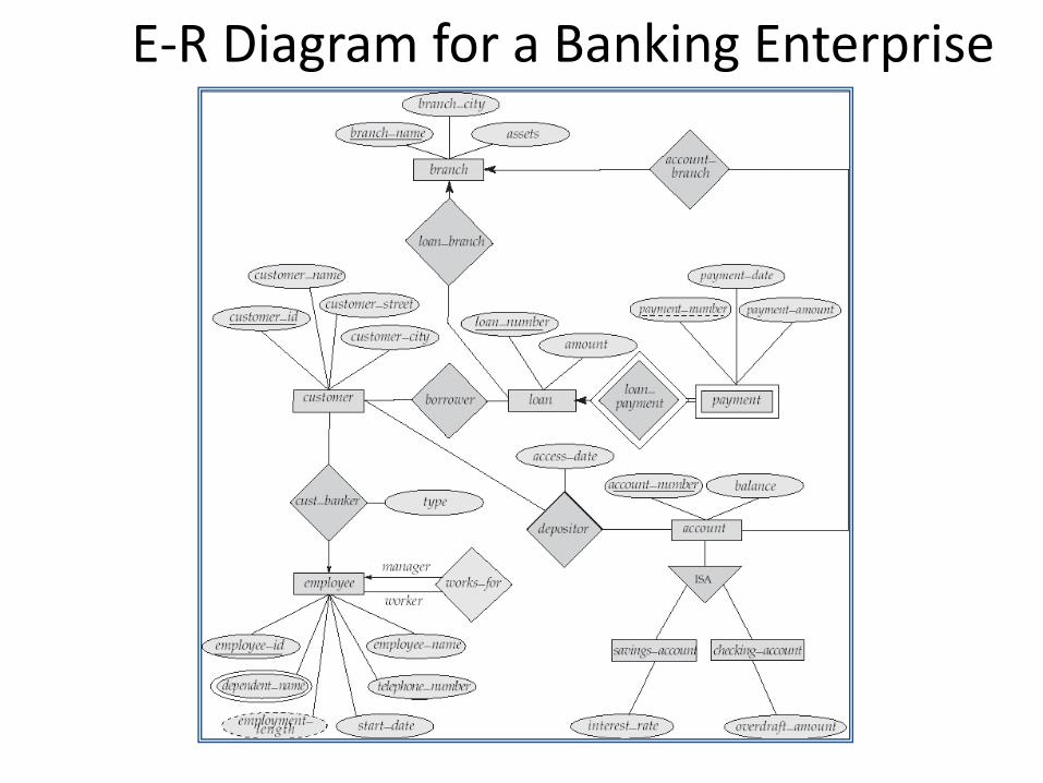
E-R Diagram for a Banking Enterprise
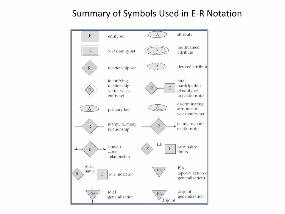
Summary of Symbols Used in E-R Notation
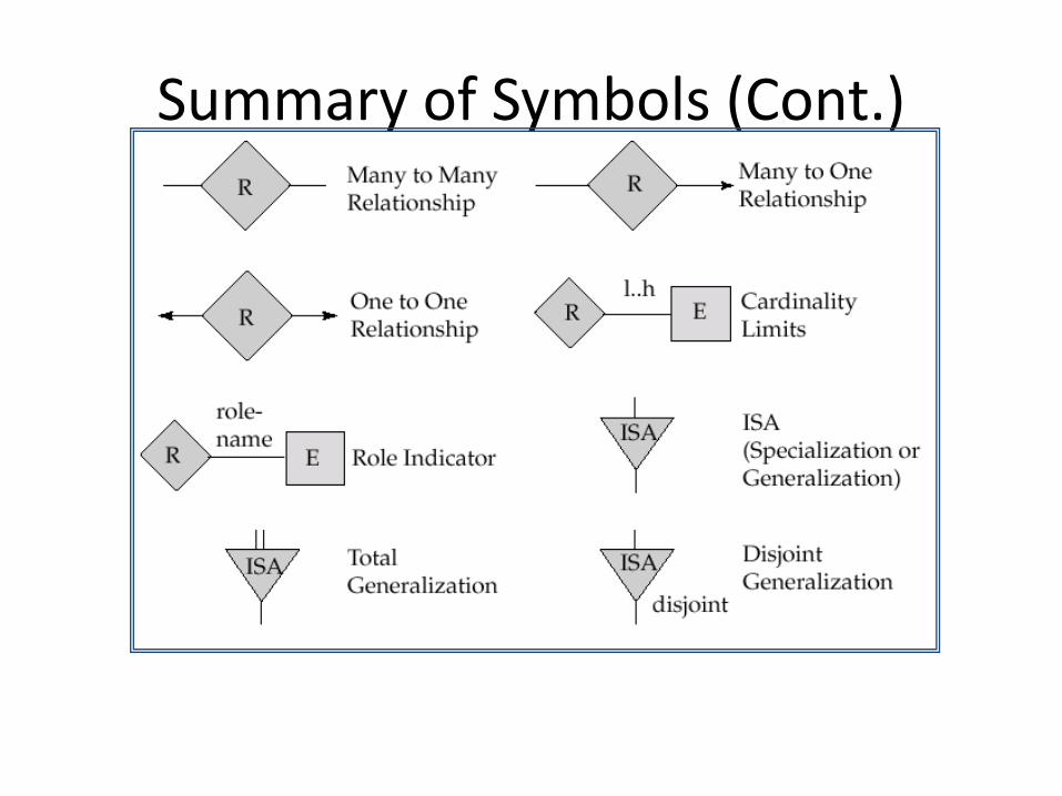
Summary of Symbols (Cont.)
Reduction to Relation Schemas
• Primary keys allow entity sets and relationship sets to be expressed uniformly as relation schemas that represent the contents of the database.
• A database which conforms to an E-R diagram can be represented by a collection of schemas.
• For each entity set and relationship set there is a unique schema that is assigned the name of the corresponding entity set or relationship set.
• Each schema has a number of columns (generally corresponding to attributes), which have unique names.
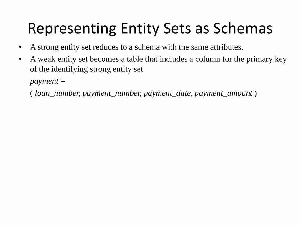
Representing Entity Sets as Schemas • A strong entity set reduces to a schema with the same attributes.
• A weak entity set becomes a table that includes a column for the primary key
of the identifying strong entity set
payment =
( loan_number, payment_number, payment_date, payment_amount )
Representing Relationship Sets as Schemas
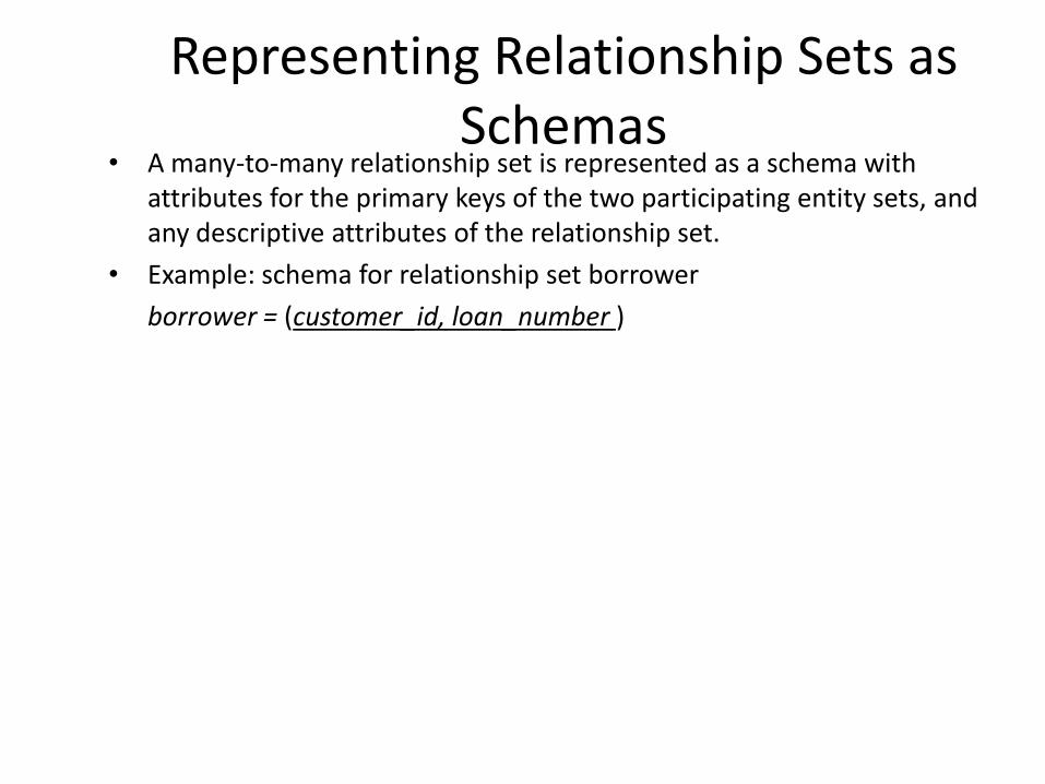
• A many-to-many relationship set is represented as a schema with attributes for the primary keys of the two participating entity sets, and any descriptive attributes of the relationship set.
• Example: schema for relationship set borrower
borrower = (customer_id, loan_number )
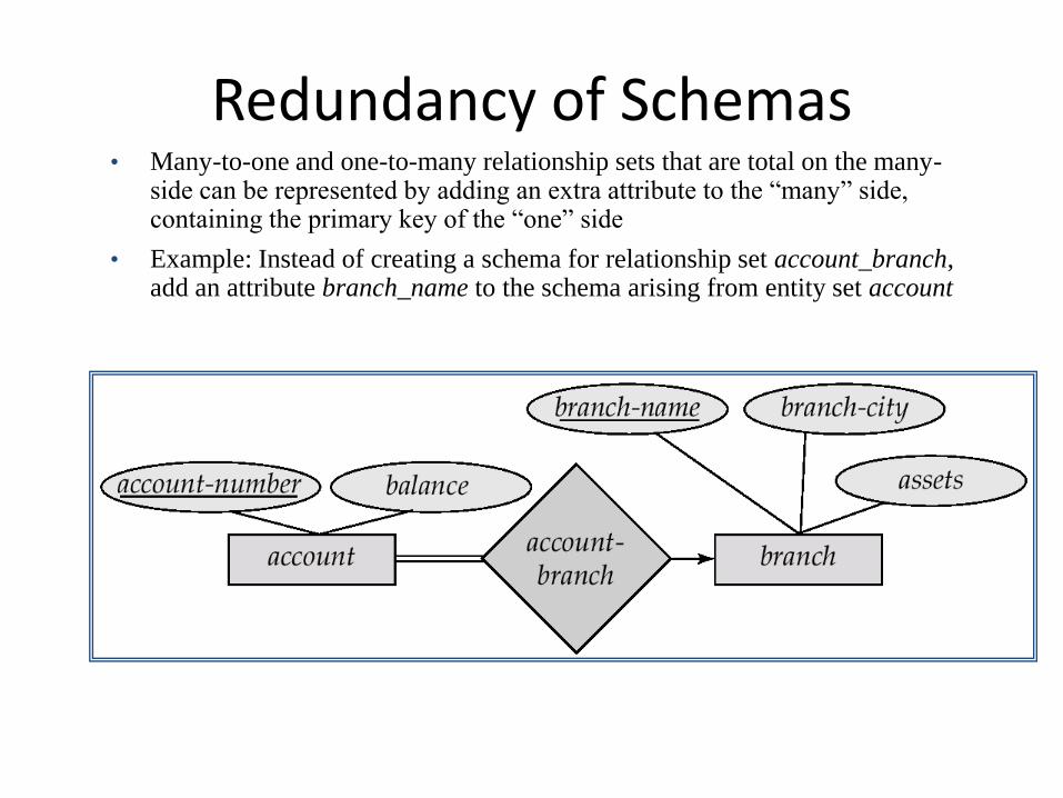
Redundancy of Schemas • Many-to-one and one-to-many relationship sets that are total on the many-
side can be represented by adding an extra attribute to the “many” side, containing the primary key of the “one” side
• Example: Instead of creating a schema for relationship set account_branch, add an attribute branch_name to the schema arising from entity set account
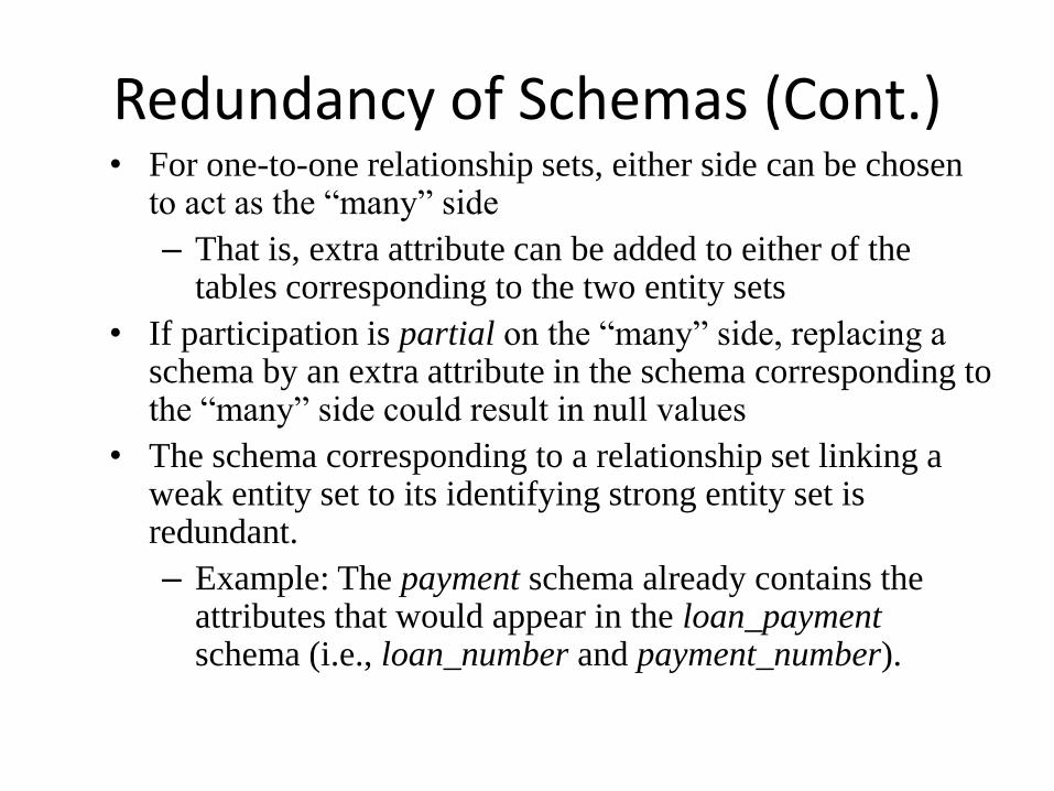
Redundancy of Schemas (Cont.) • For one-to-one relationship sets, either side can be chosen
to act as the “many” side
– That is, extra attribute can be added to either of the tables corresponding to the two entity sets
• If participation is partial on the “many” side, replacing a schema by an extra attribute in the schema corresponding to the “many” side could result in null values
• The schema corresponding to a relationship set linking a weak entity set to its identifying strong entity set is redundant.
– Example: The payment schema already contains the attributes that would appear in the loan_payment schema (i.e., loan_number and payment_number).
Composite and Multivalued Attributes
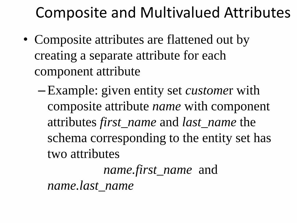
• Composite attributes are flattened out by
creating a separate attribute for each
component attribute
–Example: given entity set customer with
composite attribute name with component
attributes first_name and last_name the
schema corresponding to the entity set has
two attributes
name.first_name and
name.last_name
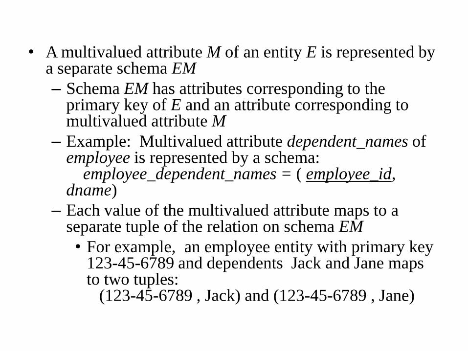
• A multivalued attribute M of an entity E is represented by a separate schema EM
– Schema EM has attributes corresponding to the primary key of E and an attribute corresponding to multivalued attribute M
– Example: Multivalued attribute dependent_names of employee is represented by a schema: employee_dependent_names = ( employee_id, dname)
– Each value of the multivalued attribute maps to a separate tuple of the relation on schema EM
• For example, an employee entity with primary key 123-45-6789 and dependents Jack and Jane maps to two tuples: (123-45-6789 , Jack) and (123-45-6789 , Jane)
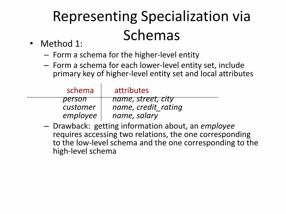
Representing Specialization via Schemas
• Method 1: – Form a schema for the higher-level entity – Form a schema for each lower-level entity set, include
primary key of higher-level entity set and local attributes schema attributes person name, street, city customer name, credit_rating employee name, salary
– Drawback: getting information about, an employee requires accessing two relations, the one corresponding to the low-level schema and the one corresponding to the high-level schema
Representing Specialization as Schemas (Cont.)
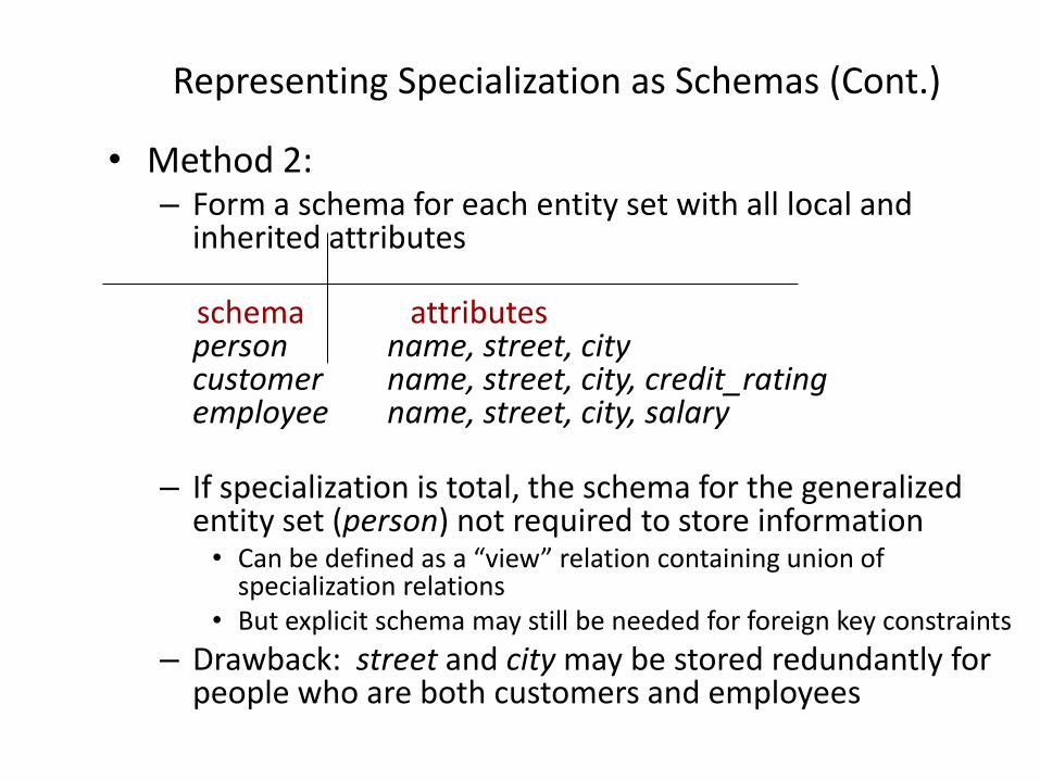
• Method 2: – Form a schema for each entity set with all local and
inherited attributes
schema attributes person name, street, city customer name, street, city, credit_rating employee name, street, city, salary
– If specialization is total, the schema for the generalized entity set (person) not required to store information • Can be defined as a “view” relation containing union of
specialization relations • But explicit schema may still be needed for foreign key constraints
– Drawback: street and city may be stored redundantly for people who are both customers and employees
Schemas Corresponding to Aggregation
To represent aggregation, create a schema
containing
• primary key of the aggregated
relationship,the primary key of the
associated entity set any descriptive
attributes
Schemas Corresponding to Aggregation (Cont.)
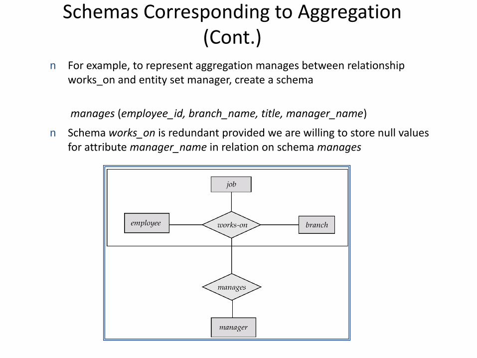
n For example, to represent aggregation manages between relationship works_on and entity set manager, create a schema
manages (employee_id, branch_name, title, manager_name)
n Schema works_on is redundant provided we are willing to store null values for attribute manager_name in relation on schema manages
UML • UML: Unified Modeling Language
• UML has many components to graphically model different aspects of an entire software system
• UML Class Diagrams correspond to E-R Diagram, but several differences.
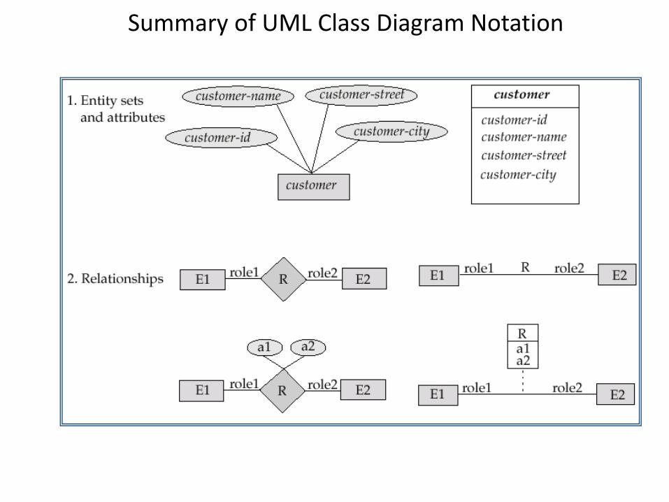
Summary of UML Class Diagram Notation
UML Class Diagrams (Cont.)
• Entity sets are shown as boxes, and attributes are shown within the box, rather than as separate ellipses in E-R diagrams.
• Binary relationship sets are represented in UML by just drawing a line connecting the entity sets. The relationship set name is written adjacent to the line.
• The role played by an entity set in a relationship set may also be specified by writing the role name on the line, adjacent to the entity set.
• The relationship set name may alternatively be written in a box, along with attributes of the relationship set, and the box is connected, using a dotted line, to the line depicting the relationship set.
• Non-binary relationships drawn using diamonds, just as in ER diagrams
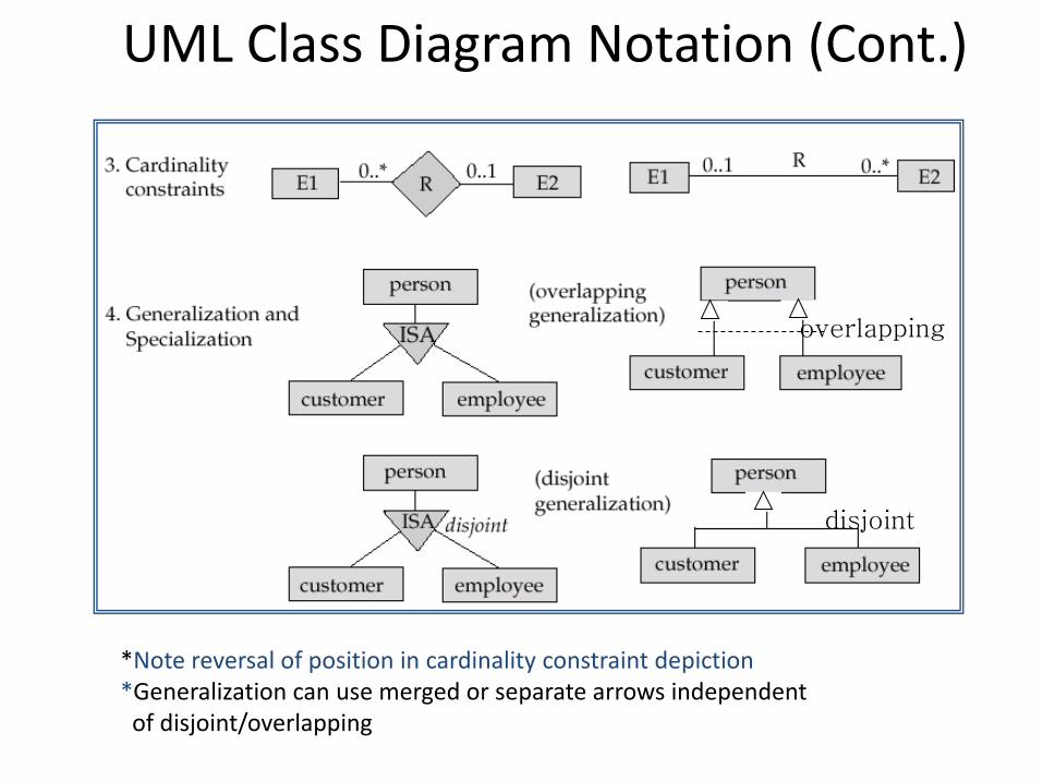
UML Class Diagram Notation (Cont.)
*Note reversal of position in cardinality constraint depiction *Generalization can use merged or separate arrows independent of disjoint/overlapping
overlapping
disjoint
UML Class Diagrams (Contd.)
• Cardinality constraints are specified in the form l..h,
where l denotes the minimum and h the maximum
number of relationships an entity can participate in.
• Beware: the positioning of the constraints is exactly
the reverse of the positioning of constraints in E-R
diagrams.
• The constraint 0..* on the E2 side and 0..1 on the E1
side means that each E2 entity can participate in at
most one relationship, whereas each E1 entity can
participate in many relationships; in other words, the
relationship is many to one from E2 to E1.
• Single values, such as 1 or * may be written on
edges; The single value 1 on an edge is treated as
equivalent to 1..1, while * is equivalent to 0..*.
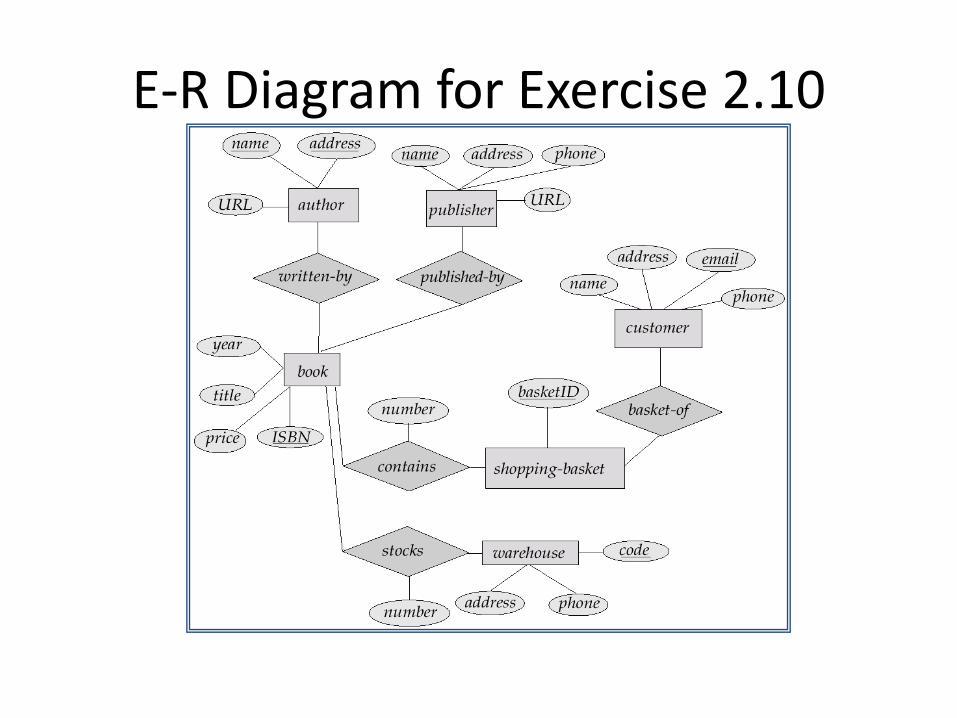
E-R Diagram for Exercise 2.10
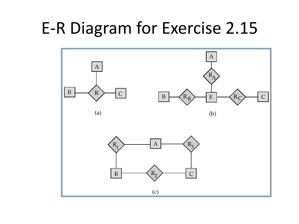
E-R Diagram for Exercise 2.15
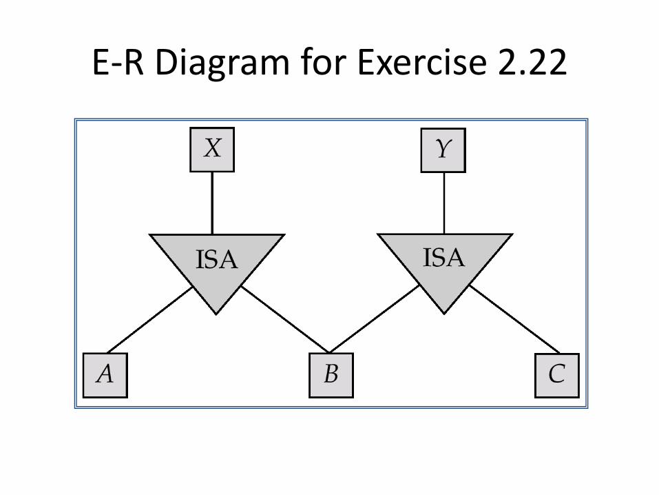
E-R Diagram for Exercise 2.22
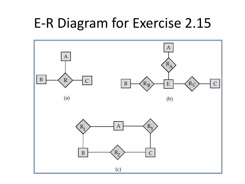
E-R Diagram for Exercise 2.15
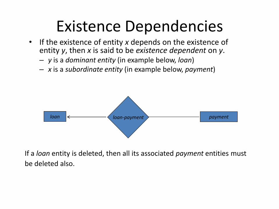
Existence Dependencies • If the existence of entity x depends on the existence of
entity y, then x is said to be existence dependent on y. – y is a dominant entity (in example below, loan) – x is a subordinate entity (in example below, payment)
loan-payment payment loan
If a loan entity is deleted, then all its associated payment entities must
be deleted also.
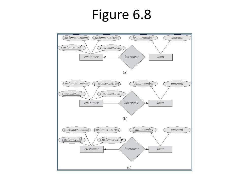
Figure 6.8
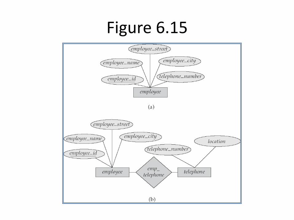
Figure 6.15
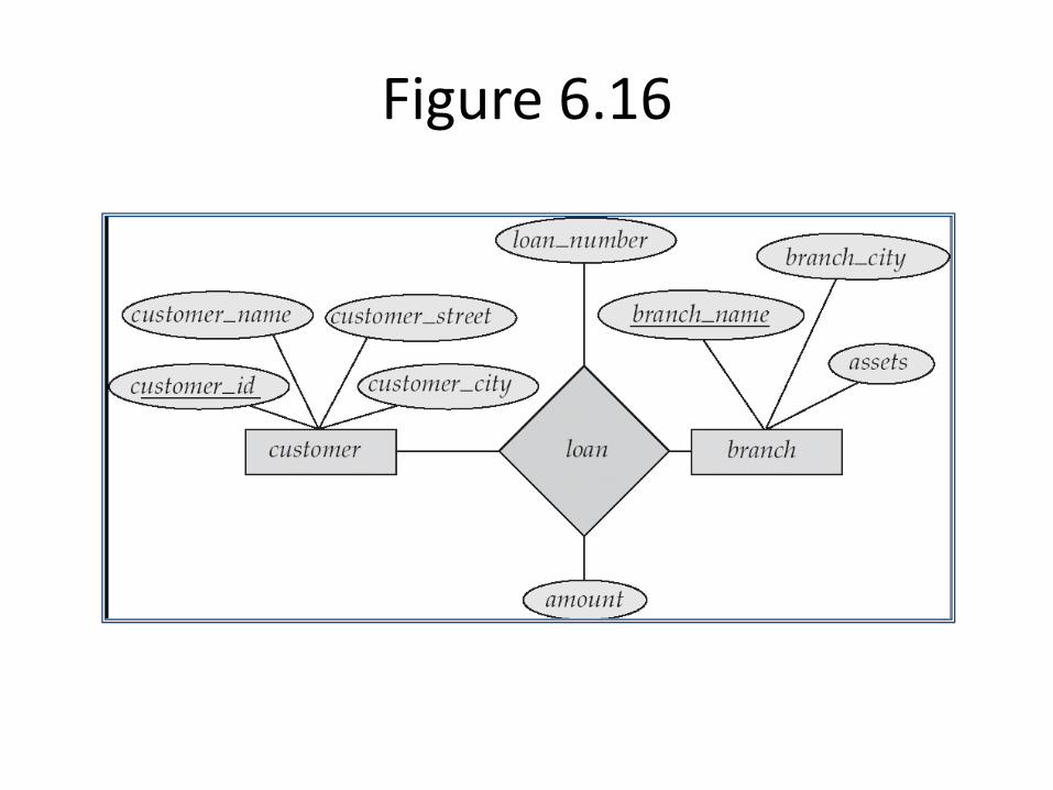
Figure 6.16
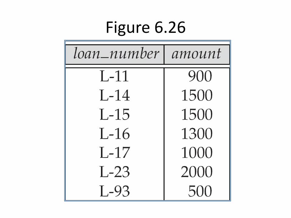
Figure 6.26
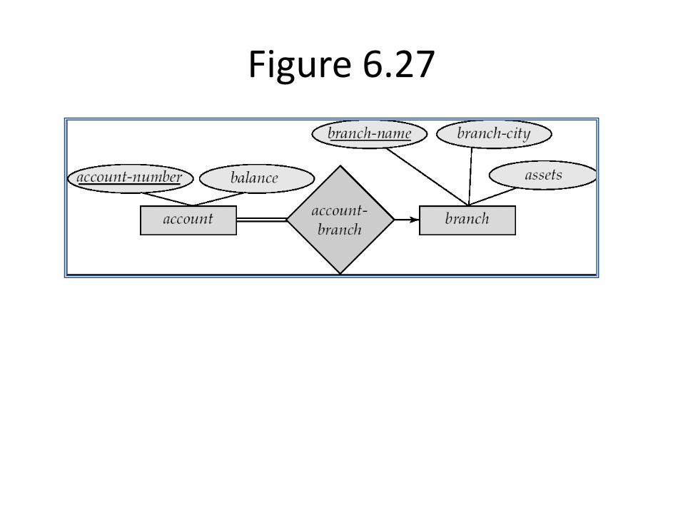
Figure 6.27
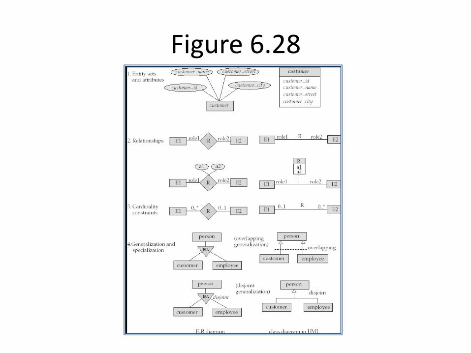
Figure 6.28
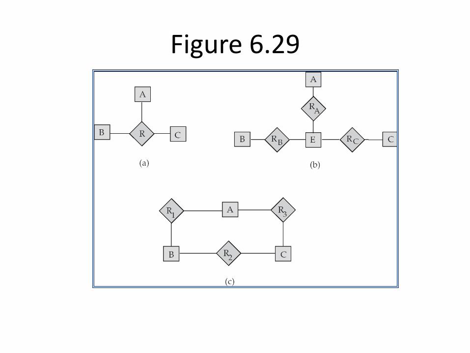
Figure 6.29
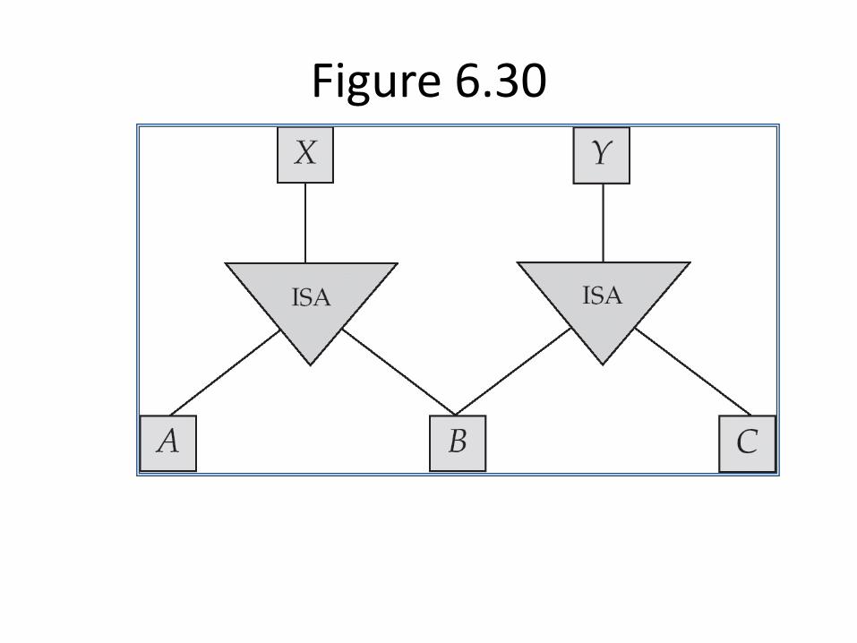
Figure 6.30
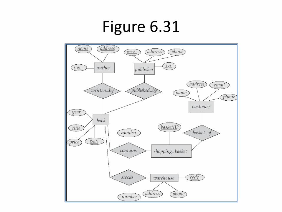
Figure 6.31
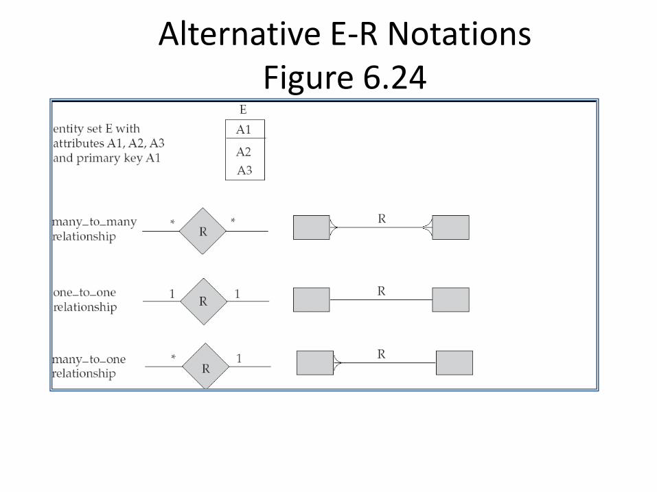
Alternative E-R Notations Figure 6.24

Assignment-06
Que. Draw ER Diagram of library system and explain Strong entity set, Weak entity Set, and Multi value Attributes?