avaya aura administration with system manager r8
TRANSCRIPT
TRAINING GUIDE
Avaya Aura Administration
with System Manager R8
March 27, 2019
P a g e | 1
NOTES:
TABLE OF CONTENTS
❖ Login to Avaya Aura® System Manager .........................................................................................2
❖ Change the administrative password ............................................................................................3
❖ Editing Password Policies .............................................................................................................4
❖ The SMGR Dashboard ..................................................................................................................5
❖ SMGR License Server ....................................................................................................................6
❖ System Manager Administrator Accounts ......................................................................................7
➢ LAB – Create a new Administrator Account .................................................................................... 7
❖ LDAP Directory Synchronization Overview .....................................................................................8
➢ Synchronization by using the user provisioning rule ....................................................................... 9
❖ Create new User ......................................................................................................................... 10
➢ LAB – Create a user profile and extension data for lab phone ...................................................... 11
❖ MADN in Communication Manager 8 ........................................................................................... 12
➢ LAB – Department numbers using MADN ..................................................................................... 12
❖ Managing CM with SMGR ........................................................................................................... 13
➢ LAB – Create Hunt Group for your row .......................................................................................... 14
❖ Session Manager Routing ............................................................................................................ 16
➢ SIP Entities...................................................................................................................................... 17
➢ LAB – View status of monitored SIP entities .................................................................................. 17
➢ Entity Links ..................................................................................................................................... 18
➢ Deny new service state .................................................................................................................. 18
➢ Dial Patterns ................................................................................................................................... 19
➢ LAB – Create a Dial Pattern to deny calls to your cell phone number ........................................... 19
➢ Routing Policies .............................................................................................................................. 20
➢ Locations ........................................................................................................................................ 20
❖ Reports ...................................................................................................................................... 22
➢ LAB – Daily Trunk Group Report .................................................................................................... 22
P a g e | 2
NOTES:
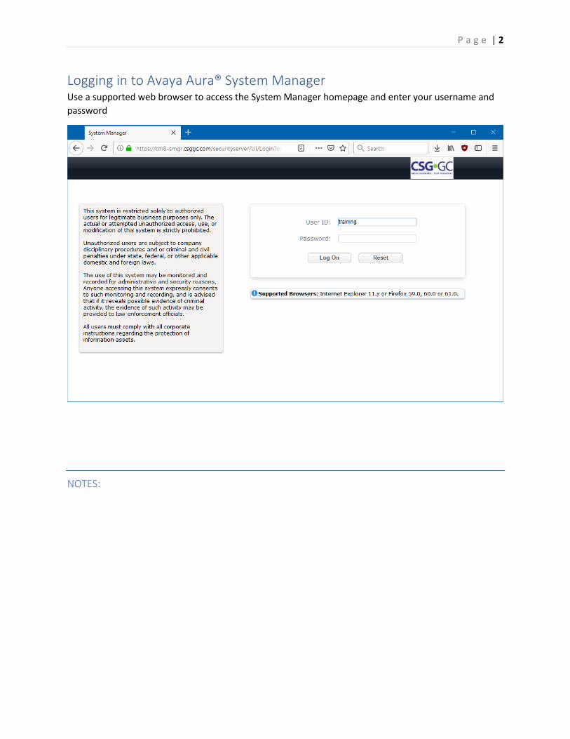
Logging in to Avaya Aura® System Manager Use a supported web browser to access the System Manager homepage and enter your username and
password
P a g e | 3
NOTES:
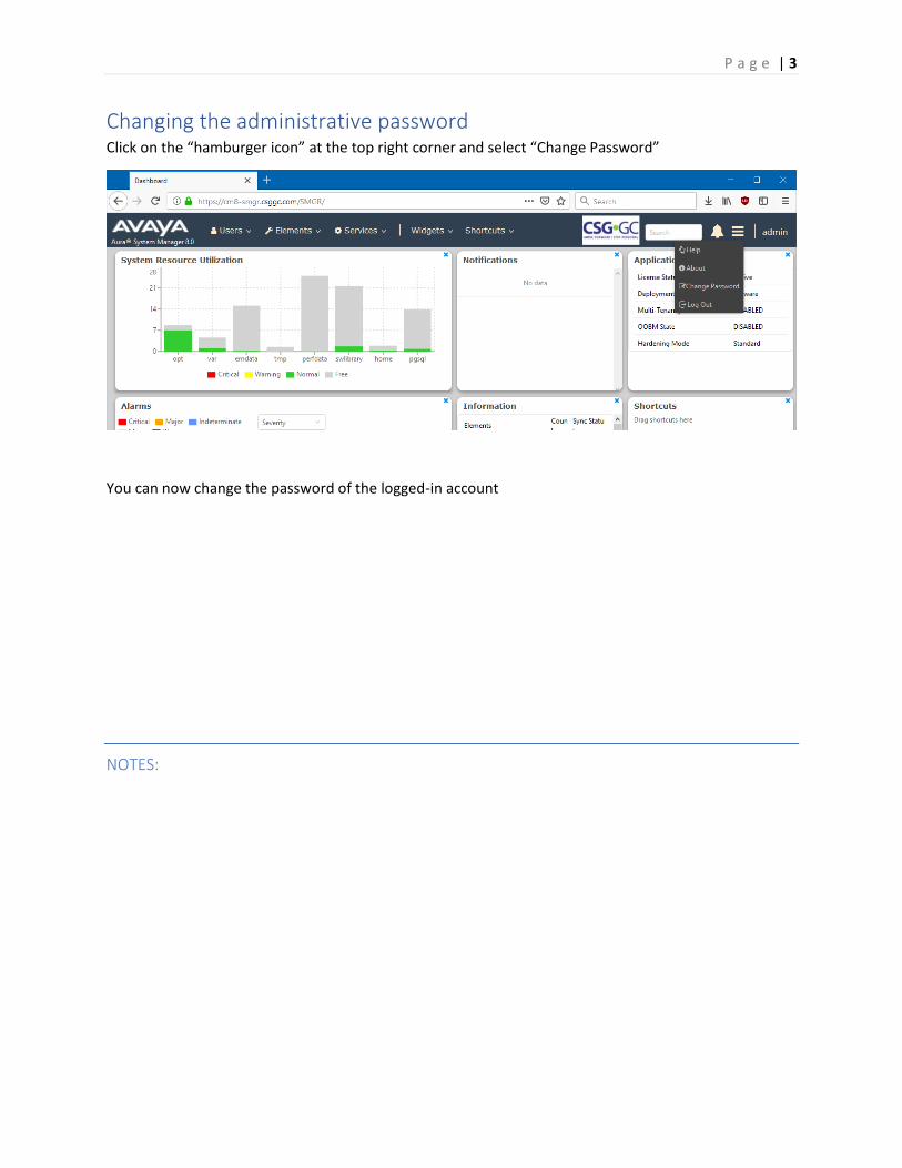
Changing the administrative password Click on the “hamburger icon” at the top right corner and select “Change Password”
You can now change the password of the logged-in account
P a g e | 4
NOTES:
Editing Password Policies
Only an administrator can edit the password settings.
Procedure
1. On the System Manager web console, click Users > Administrators.2. In the navigation pane, click Security > Policies.3. In the Password Policy section, click Edit.4. On the Password Policy page, edit the required fields.5. Click Save.
To undo your changes and return to the previous page, click Cancel.
P a g e | 5
NOTES:
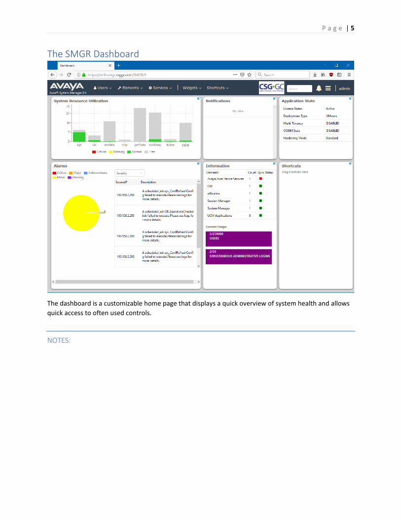
The SMGR Dashboard
The dashboard is a customizable home page that displays a quick overview of system health and allows
quick access to often used controls.
P a g e | 6
NOTES:
SMGR License Server System manager includes a WebLM server
- The SMGR license server must be used to hold licenses for System Manager and Session
Manager
- In smaller systems, the SMGR license server can hold all Avaya Aura licenses
- Best practice recommendation is to use a separate WebLM server for all other elements
P a g e | 7
NOTES:
System Manager Administrator Accounts System Manager offers the following features for Administrator Accounts
- Role Based Access Control (RBAC)
- Local or External authentication
- External Authentications using
o LDAP (Active Directory or other)
o RADIUS
o Kerberos
o SAML
LAB – Create a new Administrator Account
1. On the System Manager web console, click Users > Administrators.2. In the navigation pane, click User Services > Administrative Users.3. On the Administrative Users page, click Add.4. On the Add New Administrative User page, enter the user ID, full name, and email address.5. In the Authentication Type field, select Local or External.6. Do one of the following:
o In the Temporary password and Re-enter password fields, type the same password.o Click Generate Password.
7. Click Commit and Continue.8. Select the required roles to be assigned to the user and click Commit.
P a g e | 8
NOTES:
LDAP Directory Synchronization Overview
System Manager integrates with a number of Lightweight Directory Access Protocol (LDAP) directory servers to provide the following functions:
• Synchronization of users from the LDAP directory server to System Manager User Management.• Bidirectional synchronization of the selected user attributes from System Manager to the LDAP
directory server.
LDAP supports the following directory servers for synchronization:
• Active Directory 2003• Active Directory 2008• Active Directory 2012• OpenLDAP 2.4.21• IBM Domino 7.0• Novell eDirectory 8.8• SunOne Directory/Java System Directory 6.3
From the System Manager web console, you can run the directory synchronization engine as an on-demand job. You can also schedule the data synchronization to and from the enterprise directory. During synchronization of information to the enterprise directory server, System Manager modifies the user data that is stored in the LDAP directory server.
From the System Manager web console, you can configure bidirectional attribute mapping through the Directory Synchronization user interface. The bidirectional synchronization does not synchronize the user in the LDAP directory synchronization that is created from the System Manager web console and the System Manager bulk import utility. The bidirectional synchronization only synchronizes the attributes for the user that you synchronized from the LDAP directory server.

P a g e | 9
NOTES:
You can perform LDAP synchronization of Active Directory administrator roles with System Manager administrator roles. The capability includes system roles and custom roles on System Manager.
Synchronization by using the user provisioning rule
You can synchronize the communication data, such as extensions, Messaging mail box, and telephone numbers, by using the user provisioning rule. You can map the user provisioning rule to more than one LDAP attribute. However, you cannot map the user provisioning rule to the same LDAP attribute twice.
P a g e | 10
NOTES:
Create new User
You can create new user account using this section or by providing the user provisioning rule.
Before you begin
• You require permission to add a new user account.• The role must have the following permissions assigned:
For resource type elements, all permissions in the Role Resource Type Actions section.
Procedure
1. On the System Manager web console, click Users > User Management > Manage Users.2. On the Manage Users page, click New.3. On the User Profile | Add page, complete the following steps:
a. Optional: In the Organization section, select a tenant from the Tenant field.
You must select a tenant only if the user must belong to a tenant.
b. Optional: On the Identity tab, in the Basic Info section, in the User Provisioning Rulefield, select a user provisioning rule.
You can provide only one user provisioning rule.
c. Enter the required information in the remaining fields.4. Perform one of the following:
o To save the changes, click Commit.o To save the changes and stay on the same page, click Commit & Continue.
P a g e | 11
NOTES:
Before you click Commit, ensure that all mandatory fields have valid information.
LAB – Create a user profile and extension data for lab phone
1. Create a user profile with a unique name. The username should be in <extension>@csggc.com
2. Set the communication profile password to be same as the extension
Note: This is not a good security practice, but OK for a training lab
3. Create a Communication address of type “Avaya SIP”
4. Create a Session Manager profile
5. Create a Communication Manager profile
6. Login lab telephone set to verify process
7. Select “Elements” -> “Session Manager” -> “Dashboard”
8. In the menu on the left hand border, select “System Status” -> “User Registrations”
9. Verify that your phone is registered
P a g e | 12
NOTES:
MADN in Communication Manager 8
- CM 8 uses the new line selection “a” (all) on the brdg-appr key to implement MADN
- Principal (MARP) must be a call-appr on a physical phone or an “X” port station
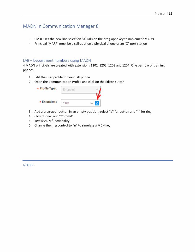
LAB – Department numbers using MADN 4 MADN principals are created with extensions 1201, 1202, 1203 and 1204. One per row of training
phones
1. Edit the user profile for your lab phone
2. Open the Communication Profile and click on the Editor button
3. Add a brdg-appr button in an empty position, select “a” for button and “r” for ring
4. Click “Done” and “Commit”
5. Test MADN functionality
6. Change the ring control to “n” to simulate a MCN key
P a g e | 13
NOTES:
Managing CM with SMGR System Manager provides a common, central administration of some IP Telephony Systems. Some features of System Manager include:
• Endpoint management
• Template management
• Mailbox management
• Inventory management
• Element cut through to native administration screens
System Manager displays a collection of Communication Manager objects under Communication Manager. From System Manager, you can add, edit, view, or delete the objects through Communication Manager.
Endpoint management Using endpoint management, you can create and manage endpoint objects, and add, change, remove, and view the endpoint data.
Templates Using Templates, you can specify specific parameters of an endpoint or a subscriber once and then reuse the template for subsequent add endpoint or subscriber tasks. You can use default templates or add your own custom templates.
There are two categories of templates: default templates and user-defined templates. You cannot edit or delete the default templates. However, you can modify or remove user-defined templates at any time.
Subscriber management Using Subscriber Management, you can manage, add, change, remove, and view subscriber data. Subscriber management supports Avaya Aura® Messaging, Communication Manager Messaging, and Messaging objects.
P a g e | 14
NOTES:
With System Manager Communication Manager capabilities, you can:
• Add Communication Manager for endpoints and Modular Messaging for subscribers to the listof managed elements.
• Create templates to simplify endpoint and subscriber management.
• Administer endpoints, subscribers, and create user profiles with communication profiles.
• Associate user profiles with the required endpoints and subscribers.
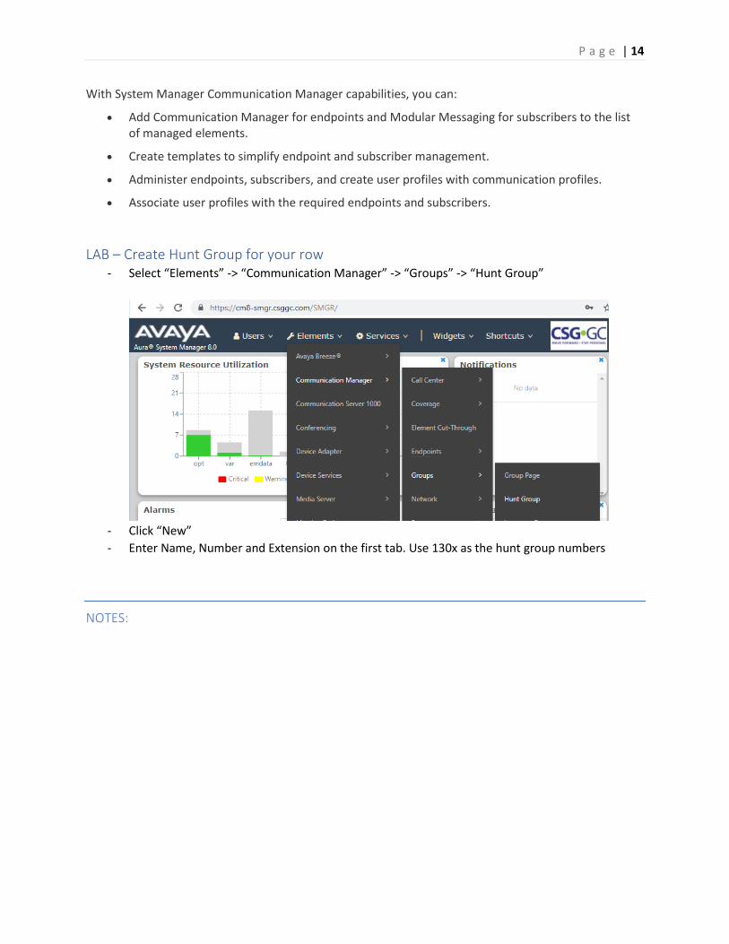
LAB – Create Hunt Group for your row - Select “Elements” -> “Communication Manager” -> “Groups” -> “Hunt Group”
- Click “New”
- Enter Name, Number and Extension on the first tab. Use 130x as the hunt group numbers
P a g e | 15
NOTES:
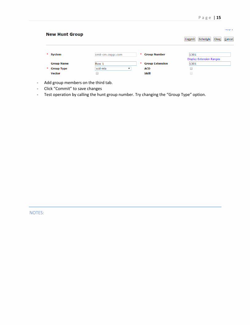
- Add group members on the third tab.
- Click “Commit” to save changes
- Test operation by calling the hunt group number. Try changing the “Group Type” option.
P a g e | 16
NOTES:
Session Manager Routing SIP entities send session creation requests to Session Manager. Session Manager routes these requests to other SIP entities using the address specified in the session creation request. Session Manager associates SIP entities with specific locations and makes routing decisions based on the location from which a session creation request arrives.
The addresses specify the identity of the destination of a session creation request and use the SIP Uniform Resource Identifier (URI) format. The identifier consists of a user part and a domain part. Session Manager uses both parts of the identifier to make routing decisions.
When you make any configuration changes in Session Manager, System Manager saves the data to the System Manager database. System Manager then synchronizes and distributes the data to all the Session Manager instances in the network. For example, renaming an adaptation changes the data on the SIP Entities Details screen, or changing dial pattern data changes the data in the routing policy where that dial pattern is used.
Session Manager uses routing policy data in the following manner:
1. First, Session Manager tries to match the domain to one of the authoritative domains.
2. If Session Manager is authoritative for the domain, then the Session Manager tries to match thedigit pattern.
3. If a digit pattern is not matched, Session Manager tries to use the regular expression table.
4. If no regular expression match is found, Session Manager sends the request to a SessionManager-provisioned outbound proxy.
5. If no outbound proxy has been administered for the Session Manager and Session Manager isnot authoritative for the domain, then Session Manager routes the request to the destination inthe request-URI.
6. If the request-URI does not contain an IP address, then Session Manager uses DNS or the LocalHost Name Resolution table to determine where to route the request.
7. If the Session Manager cannot resolve the hostname to an IP address, the call fails.
P a g e | 17
NOTES:
SIP Entities A SIP network consists of a number of SIP entities. Examples of a SIP Entity include:
• Session Manager
• Communication Manager
• Session Border Controller
• SIP trunks
Calls can be received from SIP entities or routed to SIP Entities.
Calls from Trusted SIP Entities do not require user authentication.
SIP Entities can be monitored.
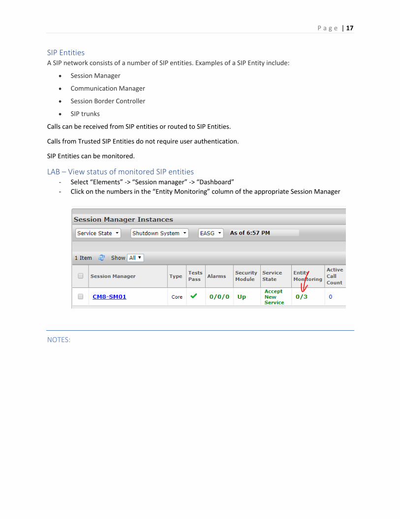
LAB – View status of monitored SIP entities - Select “Elements” -> “Session manager” -> “Dashboard”
- Click on the numbers in the “Entity Monitoring” column of the appropriate Session Manager
P a g e | 18
NOTES:
Entity Links Routing entity links connect two SIP entities through the Session Manager to define the network topology for SIP routing.
• Entity Links connect two SIP entities.
• Trusted Hosts are indicated by assigning the Trust State to the link that connects the entities.
Session Manager uses an Entity Link to send or receive messages directly from the entity. You must configure an entity link between Session Manager and any administered SIP entity.
To communicate with other SIP entities in the network, each Session Manager instance must identify the port and transport protocol of the entity link to the SIP entities. The Session Manager listens on the local port for connections from the remote entity using the given transport protocol. If the Override Port & Transport check box is selected for the SIP entity, Session Manager uses DNS information to determine the port and transport information to the remote entity. If the Override Port & Transport check box is not selected for the SIP entity, Session Manager determines the port and transport information to the remote entity using the data administered in the Entity Link table.
Deny new service state When in the deny new service state, Entity Links do not accept new incoming calls and Session Manager does not route outgoing calls over these links. Link monitoring continues over these links but no alarms are generated for the denied links.
When placing an Entity Link into the Deny New Service state, you can:
• Take selected SIP Entities out of service for upgrades and repair without receiving numerous SIPMonitoring alarms.
• Test alternate routing paths by denying the primary link Session Manager uses on a given route.
• Deny selected links during a planned WAN outage.
P a g e | 19
NOTES:
Dial Patterns A dial pattern specifies routing policies to route a call based on the digits dialed by a user. The system
matches a dial pattern and then routes the call based on the dial pattern. Session Manager matches the
dialed digits after applying any administered ingress adaptation.
Session Manager matches patterns using the following algorithm:
• Valid digits are 0-9.
• Valid characters for the leading position are,+, *, and #. Any other characters are not matched.
• A lowercase x is a wildcard character that matches a character from the allowed characters mentioned above. Spaces are not allowed.
• Longer matches have a higher priority over shorter matches. For example, +1601555 has a higher priority as compared to +1601.
• For matches of equal length, exact matches have a higher priority over wildcard matches. For example, +1601555 has a higher priority as compared to +1xxx555.
• Longer matches with trailing wildcard character x have a higher priority over shorter matches. Therefore you should not use wildcard character x as trailing character. For example +650xxxxxxx has a higher priority as compared to +6504.
LAB – Create a Dial Pattern to deny calls to your cell phone number
1. Call your cell phone (or other phone number that you can test with) to verify that the call goes through.
2. On the home page of System Manager web console, click Elements > Routing > Dial Patterns > Dial Patterns.
3. Click New.
P a g e | 20
NOTES:
4. In the General section, enter the general information about the dial pattern.
5. In the Originating Locations, Origination Dial Pattern Sets, and Routing Policies section,click Add.
6. In the Denied Originating Locations and Origination Dial Pattern Sets section, click Add.
7. Select all the locations to be denied.
8. Click Commit.
9. Make another test call to the same number to verify that the call is denied.
Routing Policies Routing Policies can include the Origination of the caller, the Dialed digits of the called party, the Domain of the called party and the actual time the call occurs.
Optionally, you can define a Regular Expression in place of the Dialed digits and the Domain of the called party.
Session Manager determines the destination of the call depending on one or more inputs as mentioned above.
If you qualify the destination using the Deny option, Session Manager does not route the call.
Session Manager uses the data configured in the routing policy to find the best match against the number or address of the called party.
All Routing Policies together form the Enterprise wide dial plan.
Locations Use the Locations page to configure gateway and user locations. The IP address of the device determines the physical location of the caller or the called user.
P a g e | 21
NOTES:
1. The Session Manager tries to match the IP address of the bottom-most VIA header of thereceived INVITE against the IP patterns on the Locations.
2. If no IP address match is found, the Session Manager uses the assigned location on the sendingSIP Entity.
3. If no assigned Location is found, the Session Manager uses the assigned location of the SessionManager SIP Entity.
If dial patterns are administered for the specific location, the Session Manager uses the originating location to determine which dial pattern is suitable for routing the call. Locations are also used to limit the number of calls originating from or terminating to a physical location. This is known as Call Admission Control (CAC) and is useful to manage the network bandwidth of locations. You specify CAC details using the Overall Managed Bandwidth and Per-Call Bandwidth Parameters sections on the Location Details page.
You can use the following wildcard characters to specify a location:
• "*" (star) specifies any number of allowed characters at the end of the string.
• "x" specifies a digit.
The Locations page can contain one or several IP addresses. Each SIP Entity has a particular IP address. Depending on the physical and geographic location of each SIP Entity, some of the SIP Entities can be grouped into a single location. For example, if there are two Communication Manager servers located in Denver, the Communication Manager servers can form one location named Denver.
The order in which the Session Manager matches the IP address is as follows:
1. Wildcard patterns (* and x)
2. Ranges
3. Netmask
P a g e | 22
NOTES:
Reports The System Manager Reports feature can be used to run on-demand or scheduled reports of the
Communication Manager system state. There are about 350 predefined list, display and status
commands that can be used in reports.
Reports can be saved locally on System Manager, on another server or emailed.
Reports can be output in CSV, PDF, HTML or text formats.
LAB – Daily Trunk Group Report We will create a report that will save the usage history of trunk groups in PDF format.
1. Select “Services” -> “Reports” -> “Generation”
2. Click “New”
3. Select the Communication Manager system and click “Next”
4. Select “List” for Report Type and “measurements trunk-group yesterday-peak” as the
object
5. Click “Next”
6. Name the Report – use your name in the title
7. Select “PDF” as file format
8. Select “Later” for Schedule Job
9. Set to repeat daily at 12:15 am and end after 7 occurrences
10. Click on “Generate Report” to save and exit
11. On the Reports Definition List, select the report and click “Run Now”
12. Click on History and click the link for the report to display it.