application notes for configuring avaya aura
TRANSCRIPT
HG; Reviewed:
SPOC 8/8/2016
Solution & Interoperability Test Lab Application Notes
©2016 Avaya Inc. All Rights Reserved.
1 of 113
CLTLSCM7SM7SBC7
Avaya Solution & Interoperability Test Lab
Application Notes for Configuring Avaya Aura®
Communication Manager Rel. 7.0, Avaya Aura® Session
Manager Rel. 7.0 and Avaya Session Border Controller for
Enterprise Rel. 7.0 to support Clearcom SIP Trunking
Services using TLS – Issue 1.0
Abstract
These Application Notes describe the procedures for configuring Session Initiation Protocol
(SIP) Trunking service for an enterprise solution consisting of Avaya Aura® Communication
Manager Rel. 7.0, Avaya Aura® Session Manager Rel. 7.0, and Avaya Session Border
Controller for Enterprise Rel. 7.0 to support Clearcom SIP Trunking Services using TLS.
The test was performed to verify SIP trunk features including basic calls, call forward (all
calls, busy, no answer), call transfer (blind and consult), conference, and voice mail. The calls
were placed to and from the PSTN with various Avaya endpoints. For privacy, TLS for
Signaling, SRTP for media encryption was used inside of the enterprise (private network side)
and TLS for Signaling, RTP for media was used outside of the enterprise (public network
side).
Readers should pay attention to Section 2, in particular the scope of testing as outlined in
Section 2.1 as well as the observations noted in Section 2.2, to ensure that their own use cases
are adequately covered by this scope and results.
Information in these Application Notes has been obtained through DevConnect compliance
testing and additional technical discussions. Testing was conducted via the DevConnect
Program at the Avaya Solution and Interoperability Test Lab.
HG; Reviewed:
SPOC 8/8/2016
Solution & Interoperability Test Lab Application Notes
©2016 Avaya Inc. All Rights Reserved.
2 of 113
CLTLSCM7SM7SBC7
Table of Contents
1. Introduction ............................................................................................................................. 4 2. General Test Approach and Test Results ................................................................................ 4
2.1. Interoperability Compliance Testing ................................................................................ 4 2.2. Test Results ...................................................................................................................... 6 2.3. Support ............................................................................................................................. 7
3. Reference Configuration ......................................................................................................... 8 4. Equipment and Software Validated ...................................................................................... 10
5. Configure Avaya Aura® Communication Manager ............................................................. 11 5.1. Licensing and Capacity .................................................................................................. 12 5.2. System Features.............................................................................................................. 16
5.3. IP Node Names............................................................................................................... 17 5.4. Codecs and Media Encryption ....................................................................................... 18 5.5. IP Network Region ......................................................................................................... 19
5.6. Signaling Group ............................................................................................................. 20 5.7. Trunk Group ................................................................................................................... 22 5.8. Calling Party Information............................................................................................... 26
5.9. Inbound Routing ............................................................................................................. 27 5.10. Outbound Routing ...................................................................................................... 28
6. Configure Avaya Aura® Session Manager .......................................................................... 31 6.1. System Manager Login and Navigation ......................................................................... 32 6.2. Specify SIP Domain ....................................................................................................... 33
6.3. Add Location .................................................................................................................. 34
6.4. Adaptations..................................................................................................................... 37 6.5. SIP Entities ..................................................................................................................... 39 6.6. Entity Links .................................................................................................................... 43
6.7. Routing Policies ............................................................................................................. 46 6.8. Dial Patterns ................................................................................................................... 47
6.9. Add/View Avaya Aura® Session Manager ................................................................... 50 7. Configure Avaya Session Border Controller for Enterprise ................................................. 52
7.1. Log in Avaya SBCE ....................................................................................................... 52 7.2. TLS Management ........................................................................................................... 56
7.2.1. TLS Certificates ...................................................................................................... 56
7.2.2. TLS Client Profile – Avaya Session Manager ........................................................ 56
7.2.3. TLS Client Profile – Service Provider .................................................................... 57
7.2.4. TLS Server Profile – Avaya Session Manager ....................................................... 59
7.2.5. TLS Server Profile – Service Provider ................................................................... 60
7.3. Global Profiles................................................................................................................ 61 7.3.1. Server Interworking Avaya-SM .............................................................................. 61
7.3.2. Server Interworking SP-General ............................................................................. 63
7.3.3. Signaling Manipulation ........................................................................................... 64
7.3.4. Server Configuration ............................................................................................... 66
HG; Reviewed:
SPOC 8/8/2016
Solution & Interoperability Test Lab Application Notes
©2016 Avaya Inc. All Rights Reserved.
3 of 113
CLTLSCM7SM7SBC7
7.3.5. Routing Profiles ...................................................................................................... 74
7.3.6. Topology Hiding ..................................................................................................... 78
7.4. Domain Policies ............................................................................................................. 82 7.4.1. Application Rules.................................................................................................... 82
7.4.2. Media Rules ............................................................................................................ 83
7.4.3. Signaling Rules ....................................................................................................... 88
7.4.4. End Point Policy Groups ......................................................................................... 89
7.5. Device Specific Settings................................................................................................. 92 7.5.1. Network Management ............................................................................................. 92
7.5.2. Media Interface ....................................................................................................... 94
7.5.3. Signaling Interface .................................................................................................. 96
7.5.4. End Point Flows ...................................................................................................... 99
8. Clearcom SIP Trunking Service Configuration .................................................................. 103
9. Verification and Troubleshooting ....................................................................................... 104 9.1. Troubleshooting ........................................................................................................... 104
9.1.1. Communication Manager...................................................................................... 104
9.1.2. Session Manager ................................................................................................... 104
9.1.3. Avaya Session Border Controller for Enterprise (Avaya SBCE) ......................... 105
9.2. TraceSBC Tool ............................................................................................................. 109
10. Conclusion ....................................................................................................................... 110
11. References ........................................................................................................................ 111 12. Appendix A: SigMa Script............................................................................................... 112
HG; Reviewed:
SPOC 8/8/2016
Solution & Interoperability Test Lab Application Notes
©2016 Avaya Inc. All Rights Reserved.
4 of 113
CLTLSCM7SM7SBC7
1. Introduction These Application Notes describe the steps required to configure Session Initiation Protocol
(SIP) trunk service between the service provider Clearcom in Mexico and an Avaya SIP-enabled
enterprise solution using Transport Layer Security (TLS).
In the sample configuration, the Avaya SIP-enabled enterprise solution consists of an Avaya
Aura® Communication Manager Rel. 7.0 (hereafter referred to as Communication Manager),
Avaya Aura® Session Manager Rel. 7.0 (hereafter referred to as Session Manager), Avaya
Session Border Controller for Enterprise Rel. 7.0 (hereafter referred to as Avaya SBCE), and
various Avaya endpoints. This solution does not extend to configurations without the Avaya
Session Border Controller for Enterprise or Avaya Aura® Session Manager.
For privacy, TLS for Signaling, SRTP for media encryption was used inside of the enterprise
(private network side) and TLS for Signaling, RTP for media was used outside of the enterprise
(public network side) (refer to Section 2.2).
During interoperability testing, feature test cases were executed to ensure interoperability
between Clearcom and Communication Manager.
Customers using an Avaya SIP-enabled enterprise solution with Clearcom SIP Trunking Service
are able to place and receive PSTN calls via the SIP protocol. The converged network solution is
an alternative to traditional analog trunks and/or PSTN trunks such as ISDN-PRI. This approach
generally results in lower cost for the enterprise.
The terms “Service Provider” and “Clearcom” will be used interchangeable throughout these
Application Notes.
2. General Test Approach and Test Results The general test approach was to simulate an enterprise site in the Avaya Solution &
Interoperability Test Lab by connecting Communication Manager, Session Manager and the
Avaya SBCE to Clearcom SIP Trunking Service via the public internet, as depicted in Figure 1.
DevConnect Compliance Testing is conducted jointly by Avaya and DevConnect members. The
jointly-defined test plan focuses on exercising APIs and/or standards-based interfaces pertinent
to the interoperability of the tested products and their functionalities. DevConnect Compliance
Testing is not intended to substitute for full product performance or feature testing performed by
DevConnect members, nor is it to be construed as an endorsement by Avaya of the suitability or
completeness of a DevConnect member’s solution.
2.1. Interoperability Compliance Testing
To verify SIP trunk interoperability, the following areas were tested for compliance:
SIP Trunk Registration (Dynamic Authentication).
Response to SIP OPTIONS queries.
HG; Reviewed:
SPOC 8/8/2016
Solution & Interoperability Test Lab Application Notes
©2016 Avaya Inc. All Rights Reserved.
5 of 113
CLTLSCM7SM7SBC7
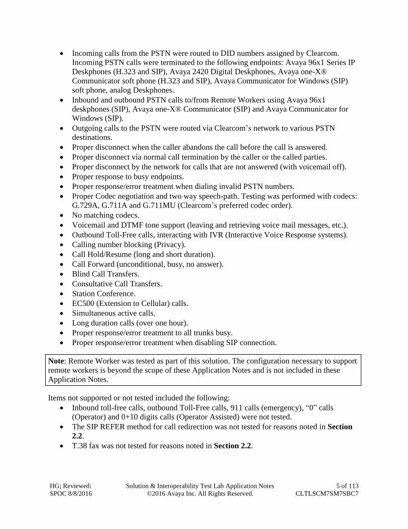
Incoming calls from the PSTN were routed to DID numbers assigned by Clearcom.
Incoming PSTN calls were terminated to the following endpoints: Avaya 96x1 Series IP
Deskphones (H.323 and SIP), Avaya 2420 Digital Deskphones, Avaya one-X®
Communicator soft phone (H.323 and SIP), Avaya Communicator for Windows (SIP)
soft phone, analog Deskphones.
Inbound and outbound PSTN calls to/from Remote Workers using Avaya 96x1
deskphones (SIP), Avaya one-X® Communicator (SIP) and Avaya Communicator for
Windows (SIP).
Outgoing calls to the PSTN were routed via Clearcom’s network to various PSTN
destinations.
Proper disconnect when the caller abandons the call before the call is answered.
Proper disconnect via normal call termination by the caller or the called parties.
Proper disconnect by the network for calls that are not answered (with voicemail off).
Proper response to busy endpoints.
Proper response/error treatment when dialing invalid PSTN numbers.
Proper Codec negotiation and two way speech-path. Testing was performed with codecs:
G.729A, G.711A and G.711MU (Clearcom’s preferred codec order).
No matching codecs.
Voicemail and DTMF tone support (leaving and retrieving voice mail messages, etc.).
Outbound Toll-Free calls, interacting with IVR (Interactive Voice Response systems).
Calling number blocking (Privacy).
Call Hold/Resume (long and short duration).
Call Forward (unconditional, busy, no answer).
Blind Call Transfers.
Consultative Call Transfers.
Station Conference.
EC500 (Extension to Cellular) calls.
Simultaneous active calls.
Long duration calls (over one hour).
Proper response/error treatment to all trunks busy.
Proper response/error treatment when disabling SIP connection.
Note: Remote Worker was tested as part of this solution. The configuration necessary to support
remote workers is beyond the scope of these Application Notes and is not included in these
Application Notes.
Items not supported or not tested included the following:
Inbound toll-free calls, outbound Toll-Free calls, 911 calls (emergency), “0” calls
(Operator) and 0+10 digits calls (Operator Assisted) were not tested.
The SIP REFER method for call redirection was not tested for reasons noted in Section
2.2.
T.38 fax was not tested for reasons noted in Section 2.2.
HG; Reviewed:
SPOC 8/8/2016
Solution & Interoperability Test Lab Application Notes
©2016 Avaya Inc. All Rights Reserved.
6 of 113
CLTLSCM7SM7SBC7
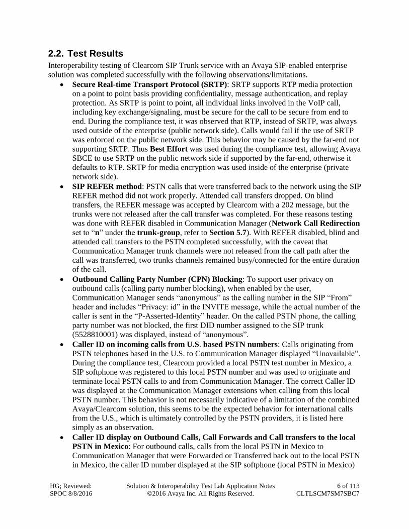
2.2. Test Results
Interoperability testing of Clearcom SIP Trunk service with an Avaya SIP-enabled enterprise
solution was completed successfully with the following observations/limitations.
Secure Real-time Transport Protocol (SRTP): SRTP supports RTP media protection
on a point to point basis providing confidentiality, message authentication, and replay
protection. As SRTP is point to point, all individual links involved in the VoIP call,
including key exchange/signaling, must be secure for the call to be secure from end to
end. During the compliance test, it was observed that RTP, instead of SRTP, was always
used outside of the enterprise (public network side). Calls would fail if the use of SRTP
was enforced on the public network side. This behavior may be caused by the far-end not
supporting SRTP. Thus Best Effort was used during the compliance test, allowing Avaya
SBCE to use SRTP on the public network side if supported by the far-end, otherwise it
defaults to RTP. SRTP for media encryption was used inside of the enterprise (private
network side).
SIP REFER method: PSTN calls that were transferred back to the network using the SIP
REFER method did not work properly. Attended call transfers dropped. On blind
transfers, the REFER message was accepted by Clearcom with a 202 message, but the
trunks were not released after the call transfer was completed. For these reasons testing
was done with REFER disabled in Communication Manager (Network Call Redirection
set to “n” under the trunk-group, refer to Section 5.7). With REFER disabled, blind and
attended call transfers to the PSTN completed successfully, with the caveat that
Communication Manager trunk channels were not released from the call path after the
call was transferred, two trunks channels remained busy/connected for the entire duration
of the call.
Outbound Calling Party Number (CPN) Blocking: To support user privacy on
outbound calls (calling party number blocking), when enabled by the user,
Communication Manager sends “anonymous” as the calling number in the SIP “From”
header and includes “Privacy: id” in the INVITE message, while the actual number of the
caller is sent in the “P-Asserted-Identity” header. On the called PSTN phone, the calling
party number was not blocked, the first DID number assigned to the SIP trunk
(5528810001) was displayed, instead of “anonymous”.
Caller ID on incoming calls from U.S. based PSTN numbers: Calls originating from
PSTN telephones based in the U.S. to Communication Manager displayed “Unavailable”.
During the compliance test, Clearcom provided a local PSTN test number in Mexico, a
SIP softphone was registered to this local PSTN number and was used to originate and
terminate local PSTN calls to and from Communication Manager. The correct Caller ID
was displayed at the Communication Manager extensions when calling from this local
PSTN number. This behavior is not necessarily indicative of a limitation of the combined
Avaya/Clearcom solution, this seems to be the expected behavior for international calls
from the U.S., which is ultimately controlled by the PSTN providers, it is listed here
simply as an observation.
Caller ID display on Outbound Calls, Call Forwards and Call transfers to the local
PSTN in Mexico: For outbound calls, calls from the local PSTN in Mexico to
Communication Manager that were Forwarded or Transferred back out to the local PSTN
in Mexico, the caller ID number displayed at the SIP softphone (local PSTN in Mexico)
HG; Reviewed:
SPOC 8/8/2016
Solution & Interoperability Test Lab Application Notes
©2016 Avaya Inc. All Rights Reserved.
7 of 113
CLTLSCM7SM7SBC7
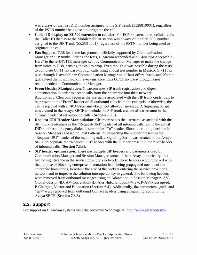
was always of the first DID number assigned to the SIP Trunk (5528810001), regardless
of the PSTN number being used to originate the call.
Caller ID display on EC500 extension to cellular: For EC500 extension to cellular calls
the Caller ID display at the Mobile/cellular station was always of the first DID number
assigned to the SIP Trunk (5528810001), regardless of the PSTN number being used to
originate the call.
Fax Support: T.38 fax is the fax protocol officially supported by Communication
Manager on SIP trunks. During the tests, Clearcom responded with “488 Not Acceptable
Here” to the re-INVITE messages sent by Communication Manager to make the change
from voice to T.38, causing the call to drop. Even though it was possible during the tests
to complete G.711 fax pass-through calls using a local test number in Mexico, G.711 fax
pass-through is available in Communication Manager on a “best effort” basis, and it’s not
guaranteed that it will work in every instance, thus G.711 fax pass-through is not
recommended in Communication Manager.
From Header Manipulation: Clearcom uses SIP trunk registration and digest
authentication in order to accept calls from the enterprise into their network.
Additionally, Clearcom requires the username associated with the SIP trunk credentials to
be present in the “From” header of all outbound calls from the enterprise. Otherwise, the
call is rejected with a “403 Username=From not allowed” message. A Signaling Script
was created in the Avaya SBCE to include the SIP trunk credential’s username in the
“From” header of all outbound calls. (Section 7.3.3).
Request-URI Header Manipulation: Clearcom sends the username associated with the
SIP trunk credentials in the “Request-URI” header of all inbound calls, while the actual
DID number of the party dialed is sent in the “To” header. Since the routing decision in
Session Manager is based on Dial Patterns, by inspecting the number present in the
“Request-URI” header of the incoming call, a Signaling Script was created in the Avaya
SBCE to populate the “Request URI” header with the number present in the “To” header
of inbound calls. (Section 7.3.3).
SIP header optimization: There are multiple SIP headers and parameters used by
Communication Manager and Session Manager, some of them Avaya proprietary, that
had no significance in the service provider’s network. These headers were removed with
the purpose of blocking enterprise information from being propagated outside of the
enterprise boundaries, to reduce the size of the packets entering the service provider’s
network and to improve the solution interoperability in general. The following headers
were removed from outbound messages using an Adaptation in Session Manager: AV-
Global-Session-ID, AV-Correlation-ID, Alert-Info, Endpoint-View, P-AV-Message-id,
P-Charging-Vector and P-Location (Section 6.4). Additionally, the parameters “gsid” and
“epv” were removed from outbound Contact headers using a Signaling Script in the
Avaya SBCE (Section 7.3.3).
2.3. Support
For support on Clearcom systems visit the corporate Web page at: http://www.clearcom.mx/
HG; Reviewed:
SPOC 8/8/2016
Solution & Interoperability Test Lab Application Notes
©2016 Avaya Inc. All Rights Reserved.
8 of 113
CLTLSCM7SM7SBC7
Avaya customers may obtain documentation and support for Avaya products by visiting
http://support.avaya.com. Alternatively, in the United States, (866) GO-AVAYA (866-462-8292)
provides access to overall sales and service support menus.
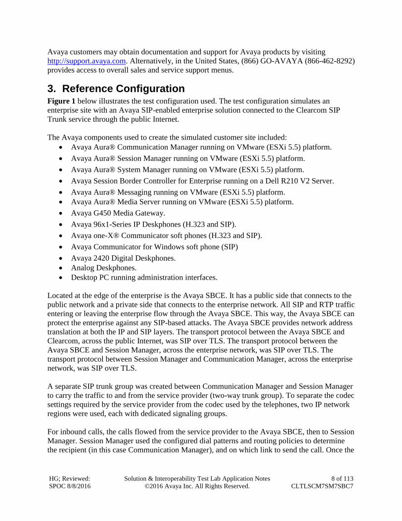
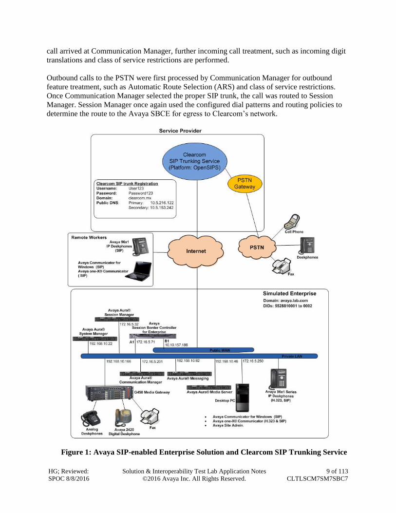
3. Reference Configuration Figure 1 below illustrates the test configuration used. The test configuration simulates an
enterprise site with an Avaya SIP-enabled enterprise solution connected to the Clearcom SIP
Trunk service through the public Internet.
The Avaya components used to create the simulated customer site included:
Avaya Aura® Communication Manager running on VMware (ESXi 5.5) platform.
Avaya Aura® Session Manager running on VMware (ESXi 5.5) platform.
Avaya Aura® System Manager running on VMware (ESXi 5.5) platform.
Avaya Session Border Controller for Enterprise running on a Dell R210 V2 Server.
Avaya Aura® Messaging running on VMware (ESXi 5.5) platform.
Avaya Aura® Media Server running on VMware (ESXi 5.5) platform.
Avaya G450 Media Gateway.
Avaya 96x1-Series IP Deskphones (H.323 and SIP).
Avaya one-X® Communicator soft phones (H.323 and SIP).
Avaya Communicator for Windows soft phone (SIP)
Avaya 2420 Digital Deskphones.
Analog Deskphones.
Desktop PC running administration interfaces.
Located at the edge of the enterprise is the Avaya SBCE. It has a public side that connects to the
public network and a private side that connects to the enterprise network. All SIP and RTP traffic
entering or leaving the enterprise flow through the Avaya SBCE. This way, the Avaya SBCE can
protect the enterprise against any SIP-based attacks. The Avaya SBCE provides network address
translation at both the IP and SIP layers. The transport protocol between the Avaya SBCE and
Clearcom, across the public Internet, was SIP over TLS. The transport protocol between the
Avaya SBCE and Session Manager, across the enterprise network, was SIP over TLS. The
transport protocol between Session Manager and Communication Manager, across the enterprise
network, was SIP over TLS.
A separate SIP trunk group was created between Communication Manager and Session Manager
to carry the traffic to and from the service provider (two-way trunk group). To separate the codec
settings required by the service provider from the codec used by the telephones, two IP network
regions were used, each with dedicated signaling groups.
For inbound calls, the calls flowed from the service provider to the Avaya SBCE, then to Session
Manager. Session Manager used the configured dial patterns and routing policies to determine
the recipient (in this case Communication Manager), and on which link to send the call. Once the
HG; Reviewed:
SPOC 8/8/2016
Solution & Interoperability Test Lab Application Notes
©2016 Avaya Inc. All Rights Reserved.
9 of 113
CLTLSCM7SM7SBC7
call arrived at Communication Manager, further incoming call treatment, such as incoming digit
translations and class of service restrictions are performed.
Outbound calls to the PSTN were first processed by Communication Manager for outbound
feature treatment, such as Automatic Route Selection (ARS) and class of service restrictions.
Once Communication Manager selected the proper SIP trunk, the call was routed to Session
Manager. Session Manager once again used the configured dial patterns and routing policies to
determine the route to the Avaya SBCE for egress to Clearcom’s network.
Figure 1: Avaya SIP-enabled Enterprise Solution and Clearcom SIP Trunking Service
HG; Reviewed:
SPOC 8/8/2016
Solution & Interoperability Test Lab Application Notes
©2016 Avaya Inc. All Rights Reserved.
10 of 113
CLTLSCM7SM7SBC7
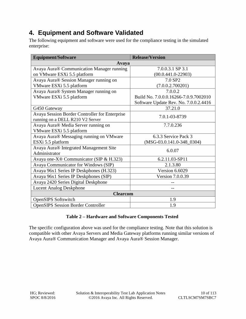
4. Equipment and Software Validated The following equipment and software were used for the compliance testing in the simulated
enterprise:
Equipment/Software Release/Version
Avaya
Avaya Aura® Communication Manager running
on VMware ESXi 5.5 platform
7.0.0.3.1 SP 3.1
(00.0.441.0-22903)
Avaya Aura® Session Manager running on
VMware ESXi 5.5 platform
7.0 SP2
(7.0.0.2.700201)
Avaya Aura® System Manager running on
VMware ESXi 5.5 platform
7.0.0.2
Build No. 7.0.0.0.16266-7.0.9.7002010
Software Update Rev. No. 7.0.0.2.4416
G450 Gateway 37.21.0
Avaya Session Border Controller for Enterprise running on a DELL R210 V2 Server
7.0.1-03-8739
Avaya Aura® Media Server running on
VMware ESXi 5.5 platform
7.7.0.236
Avaya Aura® Messaging running on VMware
ESXi 5.5 platform
6.3.3 Service Pack 3
(MSG-03.0.141.0-348_0304)
Avaya Aura® Integrated Management Site
Administrator 6.0.07
Avaya one-X® Communicator (SIP & H.323) 6.2.11.03-SP11
Avaya Communicator for Windows (SIP) 2.1.3.80
Avaya 96x1 Series IP Deskphones (H.323) Version 6.6029
Avaya 96x1 Series IP Deskphones (SIP) Version 7.0.0.39
Avaya 2420 Series Digital Deskphone --
Lucent Analog Deskphone --
Clearcom
OpenSIPS Softswitch 1.9
OpenSIPS Session Border Controller 1.9
Table 2 – Hardware and Software Components Tested
The specific configuration above was used for the compliance testing. Note that this solution is
compatible with other Avaya Servers and Media Gateway platforms running similar versions of
Avaya Aura® Communication Manager and Avaya Aura® Session Manager.
HG; Reviewed:
SPOC 8/8/2016
Solution & Interoperability Test Lab Application Notes
©2016 Avaya Inc. All Rights Reserved.
11 of 113
CLTLSCM7SM7SBC7
5. Configure Avaya Aura® Communication Manager This section describes the procedure for configuring Communication Manager. A SIP trunk is
established between Communication Manager and Session Manager for use by signaling traffic
to and from Clearcom. It is assumed that the general installation of Communication Manager, the
Avaya G450 Media Gateway and the Avaya Aura® Media Server has been previously
completed.
In configuring Communication Manager, various components such as ip-network-regions,
signaling groups, trunk groups, etc. need to be selected or created for use with the SIP
connection to the Service Provider. Unless specifically stated otherwise, any unused ip-network-
region, signaling group, trunk group, etc. can be used for this purpose.
The Communication Manager configuration was performed using the Avaya Integrated
Management Site Administrator. Some screens in this section have been abridged and
highlighted for brevity and clarity in presentation. Note that the public IP addresses shown
throughout these Application Notes have been edited so that the actual public IP addresses of the
network elements are not revealed. Some screens captures will show the use of the change
command instead of the add command, since the configuration used for the testing was
previously added.
HG; Reviewed:
SPOC 8/8/2016
Solution & Interoperability Test Lab Application Notes
©2016 Avaya Inc. All Rights Reserved.
12 of 113
CLTLSCM7SM7SBC7
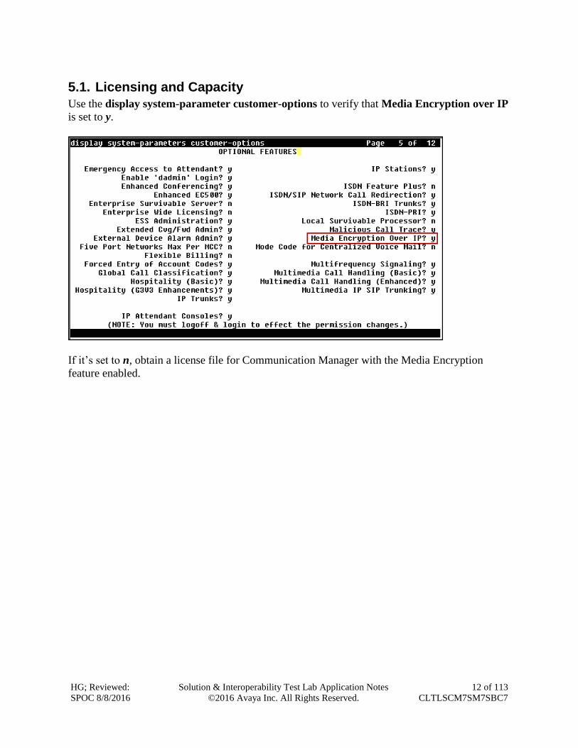
5.1. Licensing and Capacity
Use the display system-parameter customer-options to verify that Media Encryption over IP
is set to y.
If it’s set to n, obtain a license file for Communication Manager with the Media Encryption
feature enabled.
HG; Reviewed:
SPOC 8/8/2016
Solution & Interoperability Test Lab Application Notes
©2016 Avaya Inc. All Rights Reserved.
13 of 113
CLTLSCM7SM7SBC7
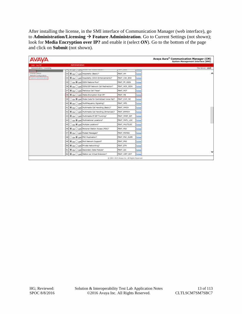
After installing the license, in the SMI interface of Communication Manager (web interface), go
to Administration/Licensing Feature Administration. Go to Current Settings (not shown);
look for Media Encryption over IP? and enable it (select ON). Go to the bottom of the page
and click on Submit (not shown).
HG; Reviewed:
SPOC 8/8/2016
Solution & Interoperability Test Lab Application Notes
©2016 Avaya Inc. All Rights Reserved.
14 of 113
CLTLSCM7SM7SBC7
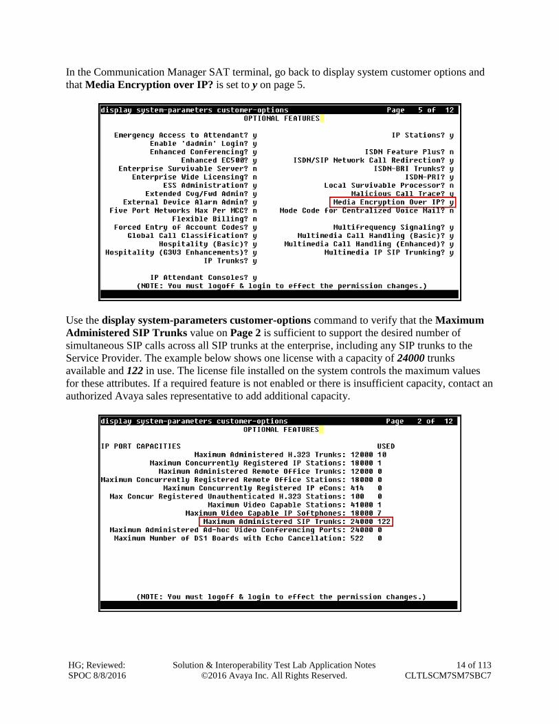
In the Communication Manager SAT terminal, go back to display system customer options and
that Media Encryption over IP? is set to y on page 5.
Use the display system-parameters customer-options command to verify that the Maximum
Administered SIP Trunks value on Page 2 is sufficient to support the desired number of
simultaneous SIP calls across all SIP trunks at the enterprise, including any SIP trunks to the
Service Provider. The example below shows one license with a capacity of 24000 trunks
available and 122 in use. The license file installed on the system controls the maximum values
for these attributes. If a required feature is not enabled or there is insufficient capacity, contact an
authorized Avaya sales representative to add additional capacity.
HG; Reviewed:
SPOC 8/8/2016
Solution & Interoperability Test Lab Application Notes
©2016 Avaya Inc. All Rights Reserved.
15 of 113
CLTLSCM7SM7SBC7
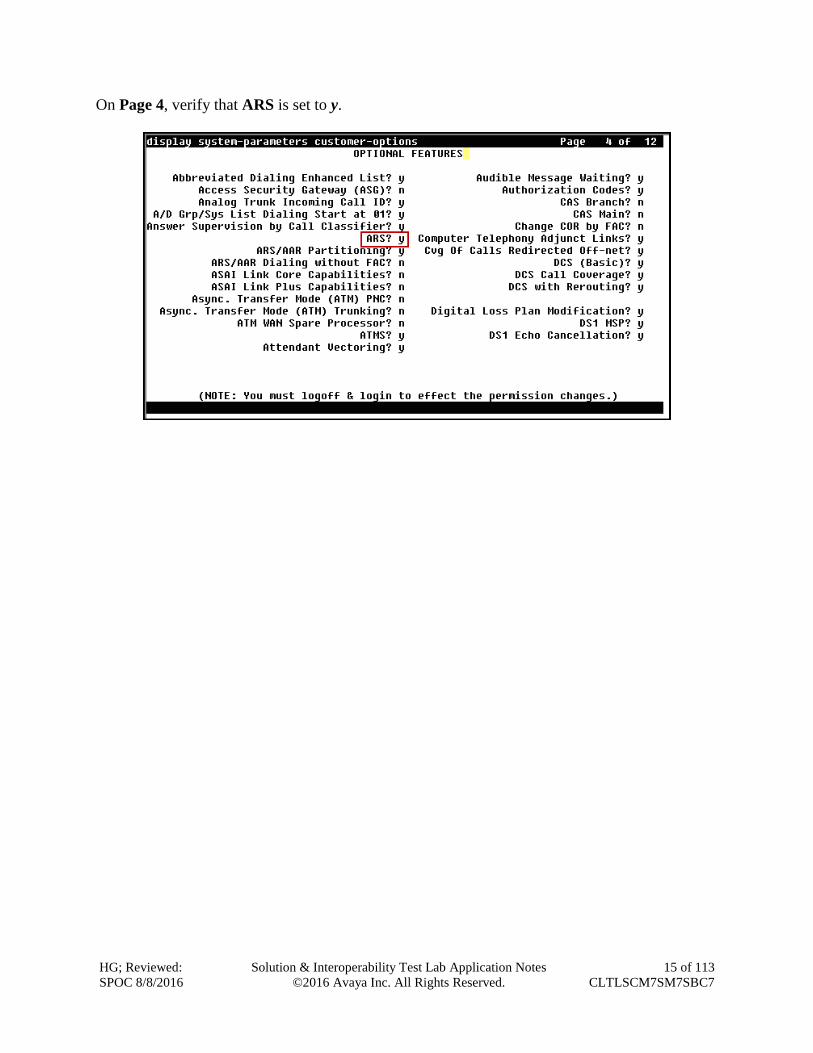
On Page 4, verify that ARS is set to y.
HG; Reviewed:
SPOC 8/8/2016
Solution & Interoperability Test Lab Application Notes
©2016 Avaya Inc. All Rights Reserved.
16 of 113
CLTLSCM7SM7SBC7
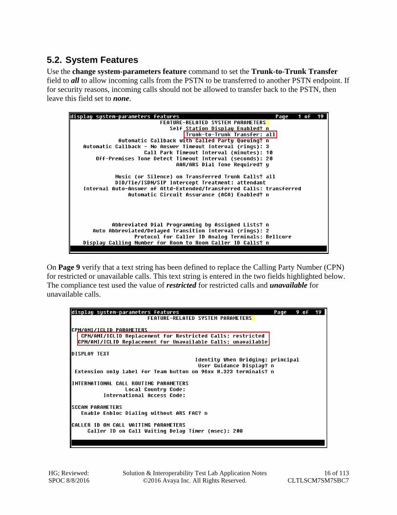
5.2. System Features
Use the change system-parameters feature command to set the Trunk-to-Trunk Transfer
field to all to allow incoming calls from the PSTN to be transferred to another PSTN endpoint. If
for security reasons, incoming calls should not be allowed to transfer back to the PSTN, then
leave this field set to none.
On Page 9 verify that a text string has been defined to replace the Calling Party Number (CPN)
for restricted or unavailable calls. This text string is entered in the two fields highlighted below.
The compliance test used the value of restricted for restricted calls and unavailable for
unavailable calls.
HG; Reviewed:
SPOC 8/8/2016
Solution & Interoperability Test Lab Application Notes
©2016 Avaya Inc. All Rights Reserved.
17 of 113
CLTLSCM7SM7SBC7
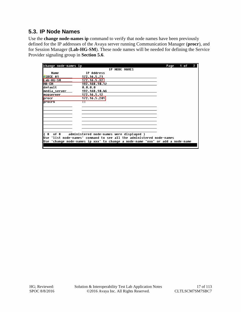
5.3. IP Node Names
Use the change node-names ip command to verify that node names have been previously
defined for the IP addresses of the Avaya server running Communication Manager (procr), and
for Session Manager (Lab-HG-SM). These node names will be needed for defining the Service
Provider signaling group in Section 5.6.
HG; Reviewed:
SPOC 8/8/2016
Solution & Interoperability Test Lab Application Notes
©2016 Avaya Inc. All Rights Reserved.
18 of 113
CLTLSCM7SM7SBC7
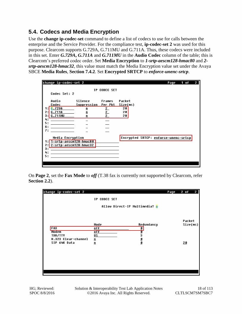
5.4. Codecs and Media Encryption
Use the change ip-codec-set command to define a list of codecs to use for calls between the
enterprise and the Service Provider. For the compliance test, ip-codec-set 2 was used for this
purpose. Clearcom supports G.729A, G.711MU and G.711A. Thus, these codecs were included
in this set. Enter G.729A, G.711A and G.711MU in the Audio Codec column of the table; this is
Clearcom’s preferred codec order. Set Media Encryption to 1-srtp-aescm128-hmac80 and 2-
srtp-aescm128-hmac32, this value must match the Media Encryption value set under the Avaya
SBCE Media Rules, Section 7.4.2. Set Encrypted SRTCP to enforce-unenc-srtcp.
On Page 2, set the Fax Mode to off (T.38 fax is currently not supported by Clearcom, refer
Section 2.2).
HG; Reviewed:
SPOC 8/8/2016
Solution & Interoperability Test Lab Application Notes
©2016 Avaya Inc. All Rights Reserved.
19 of 113
CLTLSCM7SM7SBC7
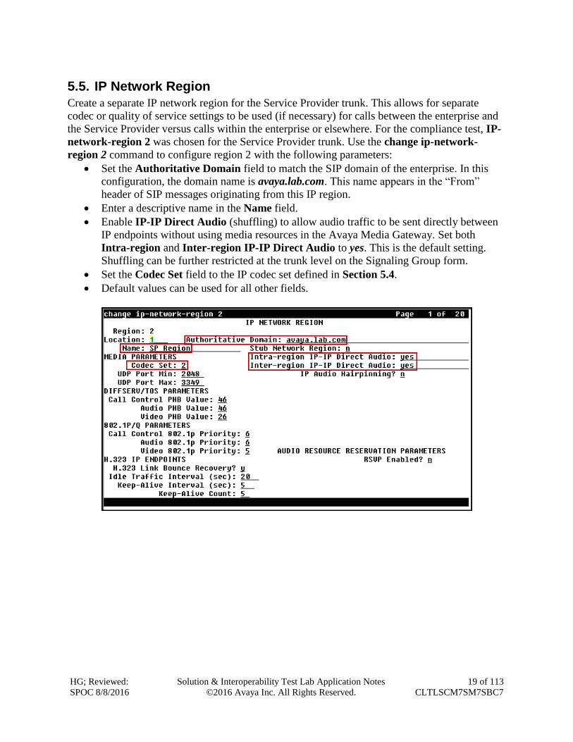
5.5. IP Network Region
Create a separate IP network region for the Service Provider trunk. This allows for separate
codec or quality of service settings to be used (if necessary) for calls between the enterprise and
the Service Provider versus calls within the enterprise or elsewhere. For the compliance test, IP-
network-region 2 was chosen for the Service Provider trunk. Use the change ip-network-
region 2 command to configure region 2 with the following parameters:
Set the Authoritative Domain field to match the SIP domain of the enterprise. In this
configuration, the domain name is avaya.lab.com. This name appears in the “From”
header of SIP messages originating from this IP region.
Enter a descriptive name in the Name field.
Enable IP-IP Direct Audio (shuffling) to allow audio traffic to be sent directly between
IP endpoints without using media resources in the Avaya Media Gateway. Set both
Intra-region and Inter-region IP-IP Direct Audio to yes. This is the default setting.
Shuffling can be further restricted at the trunk level on the Signaling Group form.
Set the Codec Set field to the IP codec set defined in Section 5.4.
Default values can be used for all other fields.
HG; Reviewed:
SPOC 8/8/2016
Solution & Interoperability Test Lab Application Notes
©2016 Avaya Inc. All Rights Reserved.
20 of 113
CLTLSCM7SM7SBC7
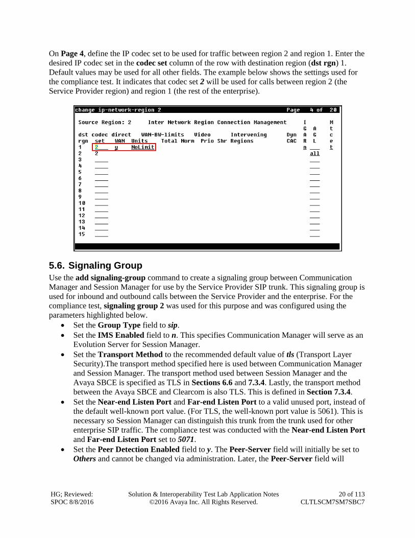
On Page 4, define the IP codec set to be used for traffic between region 2 and region 1. Enter the
desired IP codec set in the codec set column of the row with destination region (dst rgn) 1.
Default values may be used for all other fields. The example below shows the settings used for
the compliance test. It indicates that codec set 2 will be used for calls between region 2 (the
Service Provider region) and region 1 (the rest of the enterprise).
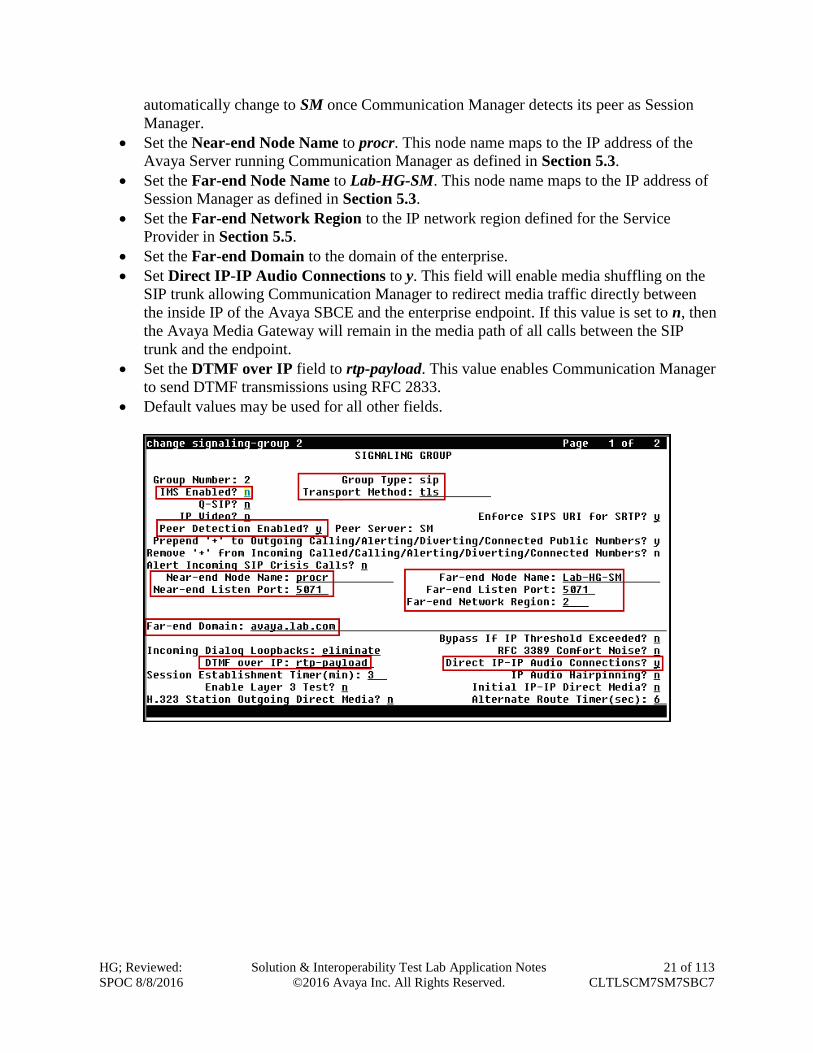
5.6. Signaling Group
Use the add signaling-group command to create a signaling group between Communication
Manager and Session Manager for use by the Service Provider SIP trunk. This signaling group is
used for inbound and outbound calls between the Service Provider and the enterprise. For the
compliance test, signaling group 2 was used for this purpose and was configured using the
parameters highlighted below.
Set the Group Type field to sip.
Set the IMS Enabled field to n. This specifies Communication Manager will serve as an
Evolution Server for Session Manager.
Set the Transport Method to the recommended default value of tls (Transport Layer
Security).The transport method specified here is used between Communication Manager
and Session Manager. The transport method used between Session Manager and the
Avaya SBCE is specified as TLS in Sections 6.6 and 7.3.4. Lastly, the transport method
between the Avaya SBCE and Clearcom is also TLS. This is defined in Section 7.3.4.
Set the Near-end Listen Port and Far-end Listen Port to a valid unused port, instead of
the default well-known port value. (For TLS, the well-known port value is 5061). This is
necessary so Session Manager can distinguish this trunk from the trunk used for other
enterprise SIP traffic. The compliance test was conducted with the Near-end Listen Port
and Far-end Listen Port set to 5071.
Set the Peer Detection Enabled field to y. The Peer-Server field will initially be set to
Others and cannot be changed via administration. Later, the Peer-Server field will
HG; Reviewed:
SPOC 8/8/2016
Solution & Interoperability Test Lab Application Notes
©2016 Avaya Inc. All Rights Reserved.
21 of 113
CLTLSCM7SM7SBC7
automatically change to SM once Communication Manager detects its peer as Session
Manager.
Set the Near-end Node Name to procr. This node name maps to the IP address of the
Avaya Server running Communication Manager as defined in Section 5.3.
Set the Far-end Node Name to Lab-HG-SM. This node name maps to the IP address of
Session Manager as defined in Section 5.3.
Set the Far-end Network Region to the IP network region defined for the Service
Provider in Section 5.5.
Set the Far-end Domain to the domain of the enterprise.
Set Direct IP-IP Audio Connections to y. This field will enable media shuffling on the
SIP trunk allowing Communication Manager to redirect media traffic directly between
the inside IP of the Avaya SBCE and the enterprise endpoint. If this value is set to n, then
the Avaya Media Gateway will remain in the media path of all calls between the SIP
trunk and the endpoint.
Set the DTMF over IP field to rtp-payload. This value enables Communication Manager
to send DTMF transmissions using RFC 2833.
Default values may be used for all other fields.
HG; Reviewed:
SPOC 8/8/2016
Solution & Interoperability Test Lab Application Notes
©2016 Avaya Inc. All Rights Reserved.
22 of 113
CLTLSCM7SM7SBC7
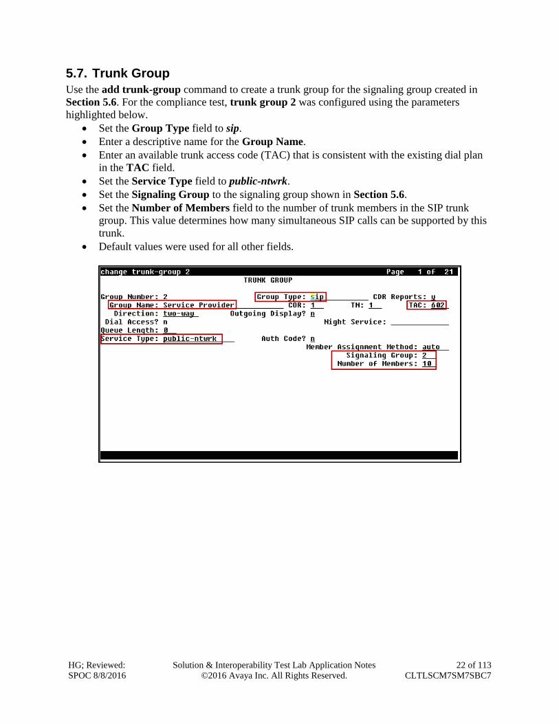
5.7. Trunk Group
Use the add trunk-group command to create a trunk group for the signaling group created in
Section 5.6. For the compliance test, trunk group 2 was configured using the parameters
highlighted below.
Set the Group Type field to sip.
Enter a descriptive name for the Group Name.
Enter an available trunk access code (TAC) that is consistent with the existing dial plan
in the TAC field.
Set the Service Type field to public-ntwrk.
Set the Signaling Group to the signaling group shown in Section 5.6.
Set the Number of Members field to the number of trunk members in the SIP trunk
group. This value determines how many simultaneous SIP calls can be supported by this
trunk.
Default values were used for all other fields.
HG; Reviewed:
SPOC 8/8/2016
Solution & Interoperability Test Lab Application Notes
©2016 Avaya Inc. All Rights Reserved.
23 of 113
CLTLSCM7SM7SBC7
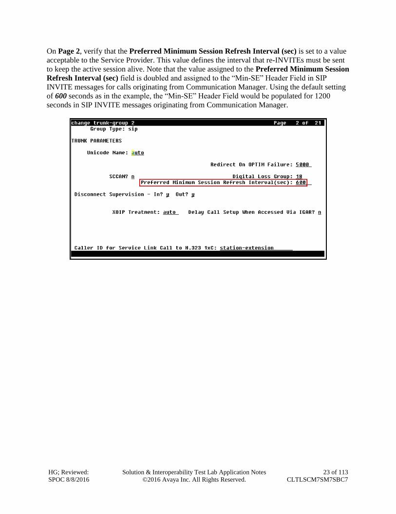
On Page 2, verify that the Preferred Minimum Session Refresh Interval (sec) is set to a value
acceptable to the Service Provider. This value defines the interval that re-INVITEs must be sent
to keep the active session alive. Note that the value assigned to the Preferred Minimum Session
Refresh Interval (sec) field is doubled and assigned to the “Min-SE” Header Field in SIP
INVITE messages for calls originating from Communication Manager. Using the default setting
of 600 seconds as in the example, the “Min-SE” Header Field would be populated for 1200
seconds in SIP INVITE messages originating from Communication Manager.
HG; Reviewed:
SPOC 8/8/2016
Solution & Interoperability Test Lab Application Notes
©2016 Avaya Inc. All Rights Reserved.
24 of 113
CLTLSCM7SM7SBC7
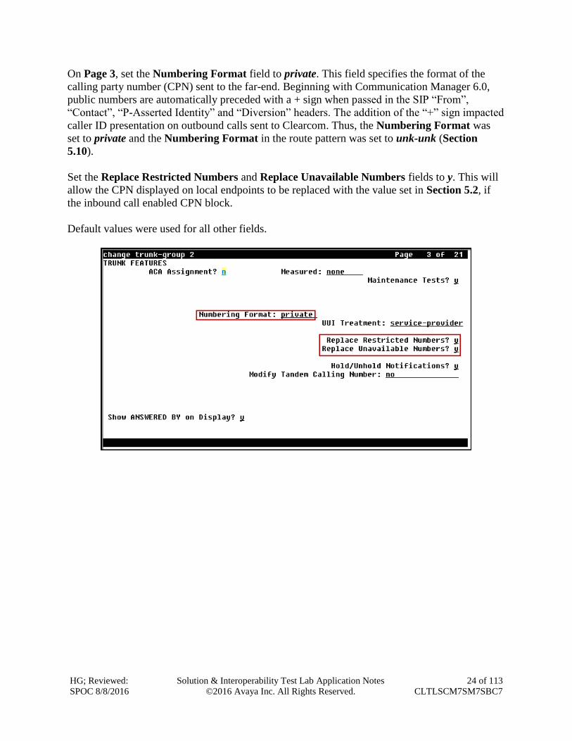
On Page 3, set the Numbering Format field to private. This field specifies the format of the
calling party number (CPN) sent to the far-end. Beginning with Communication Manager 6.0,
public numbers are automatically preceded with a + sign when passed in the SIP “From”,
“Contact”, “P-Asserted Identity” and “Diversion” headers. The addition of the “+” sign impacted
caller ID presentation on outbound calls sent to Clearcom. Thus, the Numbering Format was
set to private and the Numbering Format in the route pattern was set to unk-unk (Section
5.10).
Set the Replace Restricted Numbers and Replace Unavailable Numbers fields to y. This will
allow the CPN displayed on local endpoints to be replaced with the value set in Section 5.2, if
the inbound call enabled CPN block.
Default values were used for all other fields.
HG; Reviewed:
SPOC 8/8/2016
Solution & Interoperability Test Lab Application Notes
©2016 Avaya Inc. All Rights Reserved.
25 of 113
CLTLSCM7SM7SBC7
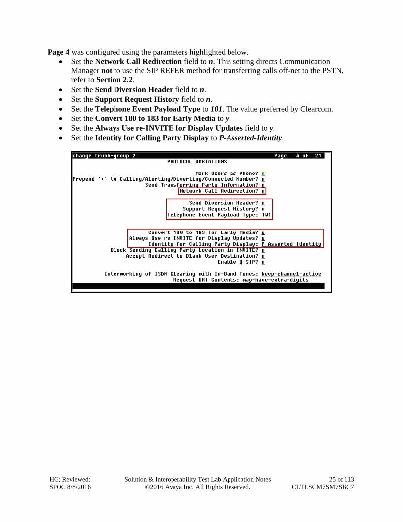
Page 4 was configured using the parameters highlighted below.
Set the Network Call Redirection field to n. This setting directs Communication
Manager not to use the SIP REFER method for transferring calls off-net to the PSTN,
refer to Section 2.2.
Set the Send Diversion Header field to n.
Set the Support Request History field to n.
Set the Telephone Event Payload Type to 101. The value preferred by Clearcom.
Set the Convert 180 to 183 for Early Media to y.
Set the Always Use re-INVITE for Display Updates field to y.
Set the Identity for Calling Party Display to P-Asserted-Identity.
HG; Reviewed:
SPOC 8/8/2016
Solution & Interoperability Test Lab Application Notes
©2016 Avaya Inc. All Rights Reserved.
26 of 113
CLTLSCM7SM7SBC7
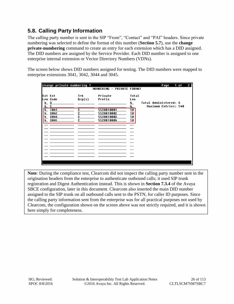
5.8. Calling Party Information
The calling party number is sent in the SIP “From”, “Contact” and “PAI” headers. Since private
numbering was selected to define the format of this number (Section 5.7), use the change
private-numbering command to create an entry for each extension which has a DID assigned.
The DID numbers are assigned by the Service Provider. Each DID number is assigned to one
enterprise internal extension or Vector Directory Numbers (VDNs).
The screen below shows DID numbers assigned for testing. The DID numbers were mapped to
enterprise extensions 3041, 3042, 3044 and 3045.
Note: During the compliance test, Clearcom did not inspect the calling party number sent in the
origination headers from the enterprise to authenticate outbound calls; it used SIP trunk
registration and Digest Authentication instead. This is shown in Section 7.3.4 of the Avaya
SBCE configuration, later in this document. Clearcom also inserted the main DID number
assigned to the SIP trunk on all outbound calls sent to the PSTN, for caller ID purposes. Since
the calling party information sent from the enterprise was for all practical purposes not used by
Clearcom, the configuration shown on the screen above was not strictly required, and it is shown
here simply for completeness.
HG; Reviewed:
SPOC 8/8/2016
Solution & Interoperability Test Lab Application Notes
©2016 Avaya Inc. All Rights Reserved.
27 of 113
CLTLSCM7SM7SBC7
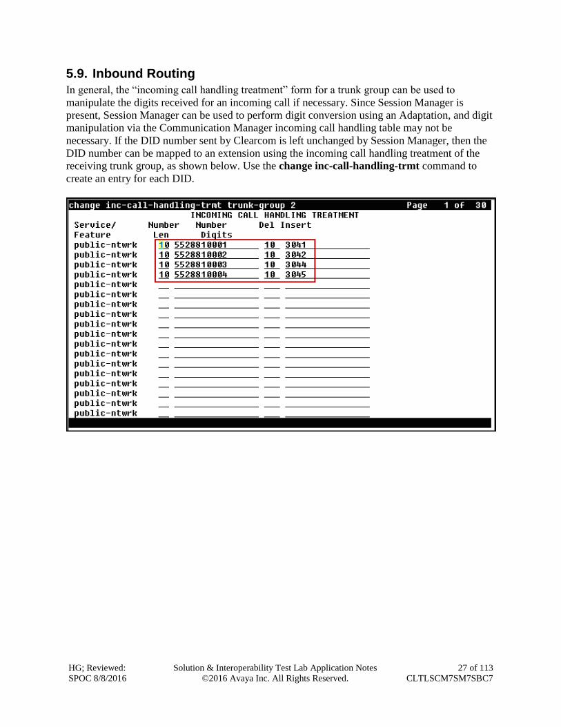
5.9. Inbound Routing
In general, the “incoming call handling treatment” form for a trunk group can be used to
manipulate the digits received for an incoming call if necessary. Since Session Manager is
present, Session Manager can be used to perform digit conversion using an Adaptation, and digit
manipulation via the Communication Manager incoming call handling table may not be
necessary. If the DID number sent by Clearcom is left unchanged by Session Manager, then the
DID number can be mapped to an extension using the incoming call handling treatment of the
receiving trunk group, as shown below. Use the change inc-call-handling-trmt command to
create an entry for each DID.
HG; Reviewed:
SPOC 8/8/2016
Solution & Interoperability Test Lab Application Notes
©2016 Avaya Inc. All Rights Reserved.
28 of 113
CLTLSCM7SM7SBC7
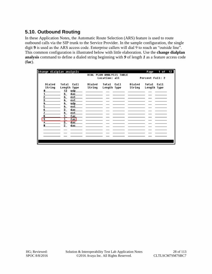
5.10. Outbound Routing
In these Application Notes, the Automatic Route Selection (ARS) feature is used to route
outbound calls via the SIP trunk to the Service Provider. In the sample configuration, the single
digit 9 is used as the ARS access code. Enterprise callers will dial 9 to reach an “outside line”.
This common configuration is illustrated below with little elaboration. Use the change dialplan
analysis command to define a dialed string beginning with 9 of length 1 as a feature access code
(fac).
HG; Reviewed:
SPOC 8/8/2016
Solution & Interoperability Test Lab Application Notes
©2016 Avaya Inc. All Rights Reserved.
29 of 113
CLTLSCM7SM7SBC7
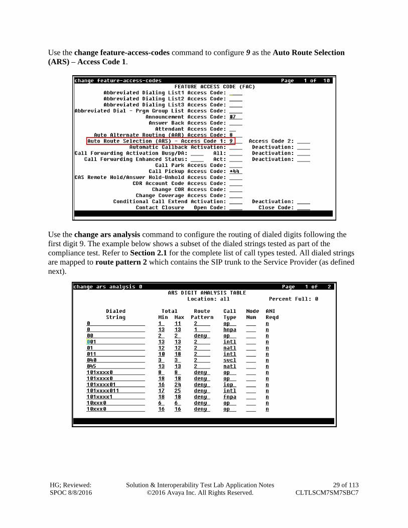
Use the change feature-access-codes command to configure 9 as the Auto Route Selection
(ARS) – Access Code 1.
Use the change ars analysis command to configure the routing of dialed digits following the
first digit 9. The example below shows a subset of the dialed strings tested as part of the
compliance test. Refer to Section 2.1 for the complete list of call types tested. All dialed strings
are mapped to route pattern 2 which contains the SIP trunk to the Service Provider (as defined
next).
HG; Reviewed:
SPOC 8/8/2016
Solution & Interoperability Test Lab Application Notes
©2016 Avaya Inc. All Rights Reserved.
30 of 113
CLTLSCM7SM7SBC7
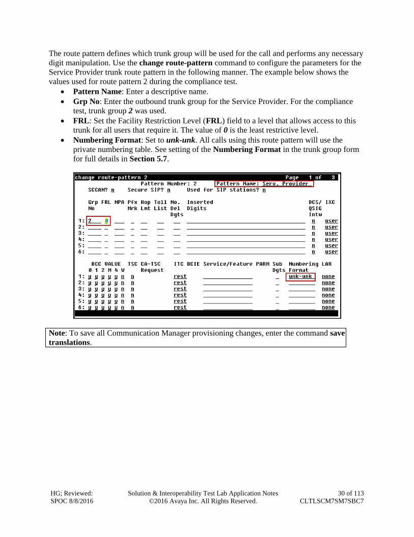
The route pattern defines which trunk group will be used for the call and performs any necessary
digit manipulation. Use the change route-pattern command to configure the parameters for the
Service Provider trunk route pattern in the following manner. The example below shows the
values used for route pattern 2 during the compliance test.
Pattern Name: Enter a descriptive name.
Grp No: Enter the outbound trunk group for the Service Provider. For the compliance
test, trunk group 2 was used.
FRL: Set the Facility Restriction Level (FRL) field to a level that allows access to this
trunk for all users that require it. The value of 0 is the least restrictive level.
Numbering Format: Set to unk-unk. All calls using this route pattern will use the
private numbering table. See setting of the Numbering Format in the trunk group form
for full details in Section 5.7.
Note: To save all Communication Manager provisioning changes, enter the command save
translations.
HG; Reviewed:
SPOC 8/8/2016
Solution & Interoperability Test Lab Application Notes
©2016 Avaya Inc. All Rights Reserved.
31 of 113
CLTLSCM7SM7SBC7
6. Configure Avaya Aura® Session Manager This section provides the procedures for configuring Session Manager. The procedures include
adding the following items:
SIP domain
Logical/physical Location that can be occupied by SIP Entities
Adaptation module to perform dial plan manipulation.
SIP Entities corresponding to Communication Manager, the Avaya SBCE and Session
Manager
Entity Links, which define the SIP trunk parameters used by Session Manager when
routing calls to/from SIP Entities
Routing Policies, which control call routing between the SIP Entities
Dial Patterns, which govern to which SIP Entity a call is routed
Session Manager, corresponding to the Session Manager server to be managed by System
Manager.
It may not be necessary to create all the items above when configuring a connection to the
Service Provider since some of these items would have already been defined as part of the initial
Session Manager installation. This includes items such as certain SIP domains, Locations,
Adaptations, SIP Entities, and Session Manager itself. However, each item should be reviewed to
verify the configuration.
Note: Some of the default information in the screenshots that follow may have been cut out (not
included) for brevity.
Note: Some Avaya products are shipped with a default identity TLS certificate signed by Avaya,
to enable out-of-box support for TLS sessions. These are considered “demo” certificates which
do not meet the current National Institute of Standards and Technology (NIST) security
standards. For security reasons these default “demo” certificates should not be used in
Production.
Avaya recommends using 3rd Party Certificate Authority (CA) signed identity certificates
for enhanced security.
On the enterprise side (or private side), testing was done with the default “demo” TLS identity
certificates. The procedure to obtain and install 3rd Party CA TLS certificates is outside the
scope of these Application Notes. Refer to items [3], [5] and [8] in Section 11.
HG; Reviewed:
SPOC 8/8/2016
Solution & Interoperability Test Lab Application Notes
©2016 Avaya Inc. All Rights Reserved.
32 of 113
CLTLSCM7SM7SBC7
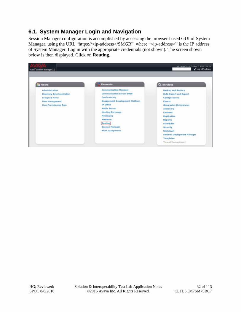
6.1. System Manager Login and Navigation
Session Manager configuration is accomplished by accessing the browser-based GUI of System
Manager, using the URL “https://<ip-address>/SMGR”, where “<ip-address>” is the IP address
of System Manager. Log in with the appropriate credentials (not shown). The screen shown
below is then displayed. Click on Routing.
HG; Reviewed:
SPOC 8/8/2016
Solution & Interoperability Test Lab Application Notes
©2016 Avaya Inc. All Rights Reserved.
33 of 113
CLTLSCM7SM7SBC7
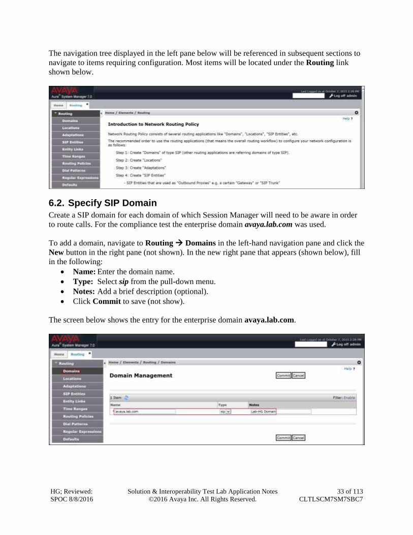
The navigation tree displayed in the left pane below will be referenced in subsequent sections to
navigate to items requiring configuration. Most items will be located under the Routing link
shown below.
6.2. Specify SIP Domain
Create a SIP domain for each domain of which Session Manager will need to be aware in order
to route calls. For the compliance test the enterprise domain avaya.lab.com was used.
To add a domain, navigate to Routing Domains in the left-hand navigation pane and click the
New button in the right pane (not shown). In the new right pane that appears (shown below), fill
in the following:
Name: Enter the domain name.
Type: Select sip from the pull-down menu.
Notes: Add a brief description (optional).
Click Commit to save (not show).
The screen below shows the entry for the enterprise domain avaya.lab.com.
HG; Reviewed:
SPOC 8/8/2016
Solution & Interoperability Test Lab Application Notes
©2016 Avaya Inc. All Rights Reserved.
34 of 113
CLTLSCM7SM7SBC7
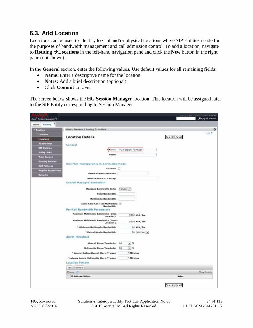
6.3. Add Location
Locations can be used to identify logical and/or physical locations where SIP Entities reside for
the purposes of bandwidth management and call admission control. To add a location, navigate
to Routing Locations in the left-hand navigation pane and click the New button in the right
pane (not shown).
In the General section, enter the following values. Use default values for all remaining fields:
Name: Enter a descriptive name for the location.
Notes: Add a brief description (optional).
Click Commit to save.
The screen below shows the HG Session Manager location. This location will be assigned later
to the SIP Entity corresponding to Session Manager.
HG; Reviewed:
SPOC 8/8/2016
Solution & Interoperability Test Lab Application Notes
©2016 Avaya Inc. All Rights Reserved.
35 of 113
CLTLSCM7SM7SBC7
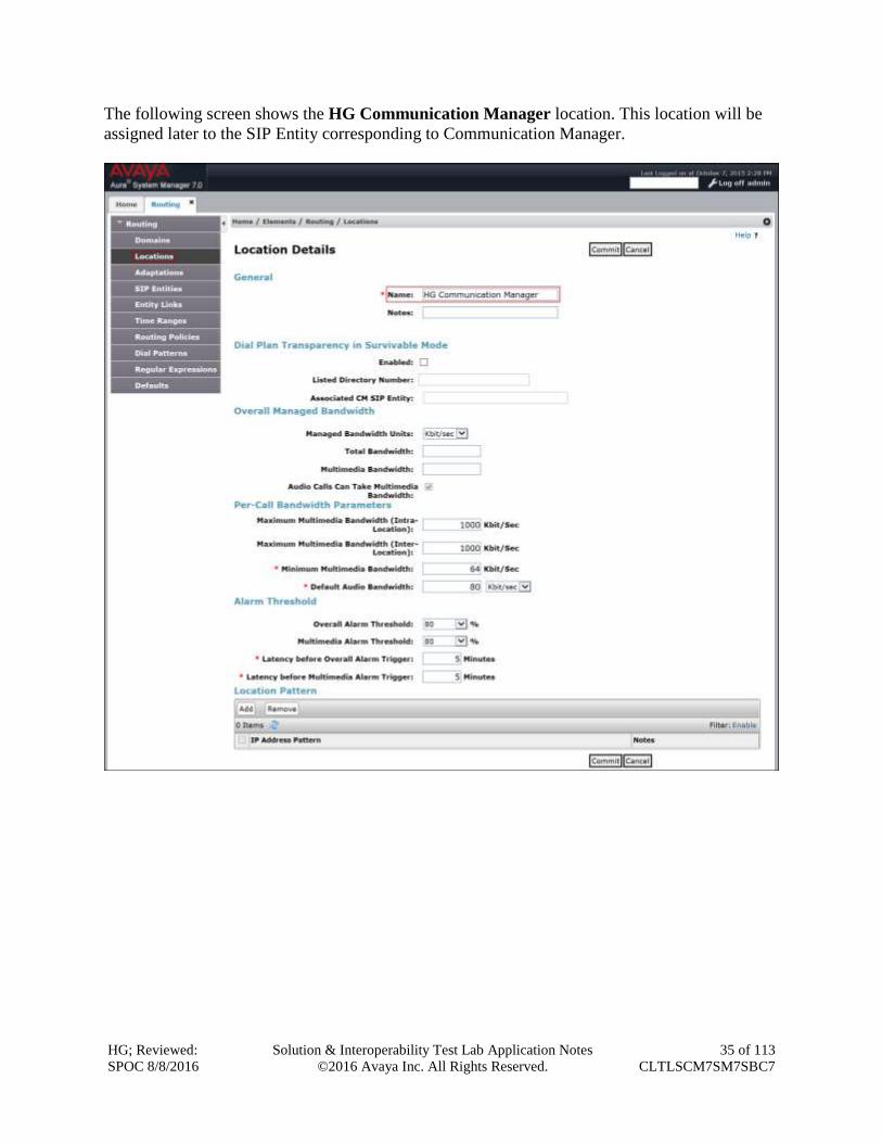
The following screen shows the HG Communication Manager location. This location will be
assigned later to the SIP Entity corresponding to Communication Manager.
HG; Reviewed:
SPOC 8/8/2016
Solution & Interoperability Test Lab Application Notes
©2016 Avaya Inc. All Rights Reserved.
36 of 113
CLTLSCM7SM7SBC7
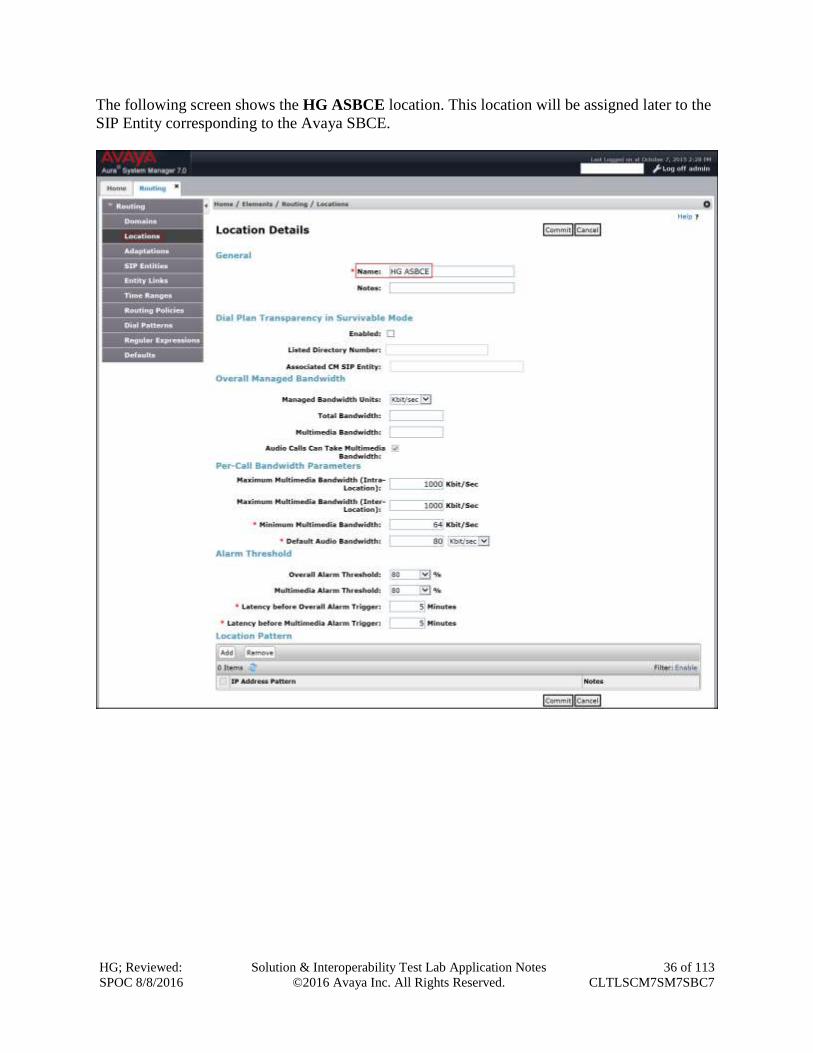
The following screen shows the HG ASBCE location. This location will be assigned later to the
SIP Entity corresponding to the Avaya SBCE.
HG; Reviewed:
SPOC 8/8/2016
Solution & Interoperability Test Lab Application Notes
©2016 Avaya Inc. All Rights Reserved.
37 of 113
CLTLSCM7SM7SBC7
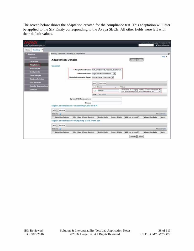
6.4. Adaptations
In order to improve interoperability with third party elements, Session Manager 7.0 incorporates
the ability to use Adaptation modules to remove specific headers that are either Avaya
proprietary or deemed excessive/unnecessary for non-Avaya elements.
For the compliance test, an Adaptation named “CM_Outbound_Header_Removal” was created
to block the following headers from outbound messages, before they were forwarded to the
Avaya SBCE: Alert-Info, P-Charging-Vector, AV-Global-Session-ID, AV-Correlation-ID, P-
AV-Message-id, P-Location, and Endpoint-View. These headers contain private information
from the enterprise, which should not be propagated outside of the enterprise boundaries. They
also add unnecessary size to outbound messages, while they have no significance to the service
provider.
Navigate to Routing Adaptations in the left-hand navigation pane and click the New button
in the right pane (not shown). In the new right pane that appears (shown below), fill in the
following:
Adaptation Name: Enter an appropriate name.
Module Name: Select the DigitConversionAdapter option.
Module Parameter Type: Select Name-Value Parameter.
Click Add to add the name and value parameters.
Name: Enter eRHdrs. This parameter will remove the specified headers from
messages in the egress direction.
Value: Enter “Alert-Info, P-Charging-Vector, AV-Global-Session-ID,
AV-Correlation-ID, P-AV-Message-id, P-Location, Endpoint-View”
HG; Reviewed:
SPOC 8/8/2016
Solution & Interoperability Test Lab Application Notes
©2016 Avaya Inc. All Rights Reserved.
38 of 113
CLTLSCM7SM7SBC7
The screen below shows the adaptation created for the compliance test. This adaptation will later
be applied to the SIP Entity corresponding to the Avaya SBCE. All other fields were left with
their default values.
HG; Reviewed:
SPOC 8/8/2016
Solution & Interoperability Test Lab Application Notes
©2016 Avaya Inc. All Rights Reserved.
39 of 113
CLTLSCM7SM7SBC7
6.5. SIP Entities
A SIP Entity must be added for Session Manager and for each SIP telephony system connected
to it, which includes Communication Manager and the Avaya SBCE. Navigate to Routing
SIP Entities in the left-hand navigation pane and click on the New button in the right pane (not
shown).
In the General section, enter the following values. Use default values for all remaining fields:
Name: Enter a descriptive name.
FQDN or IP Address: Enter the FQDN or IP address of the SIP Entity interface
that is used for SIP signaling.
Type: Enter Session Manager for Session Manager, CM for
Communication Manager and SIP Trunk (or Other) for the
Avaya SBCE.
Adaptation: This field is only present if Type is not set to Session
Manager. If applicable, select the Adaptation Name.
Location: Select one of the locations defined previously.
Time Zone: Select the time zone for the location above.
To define the ports used by Session Manager, scroll down to the Port section of the SIP Entity
Details screen. This section is only present for Session Manager SIP entities.
In the Port section, click Add and enter the following values. Use default values for all
remaining fields:
Port: Port number on which the Session Manager will listen for SIP
requests.
Protocol: Transport protocol to be used to send SIP requests.
Default Domain: The domain used for the enterprise.
Click Commit to save.
HG; Reviewed:
SPOC 8/8/2016
Solution & Interoperability Test Lab Application Notes
©2016 Avaya Inc. All Rights Reserved.
40 of 113
CLTLSCM7SM7SBC7
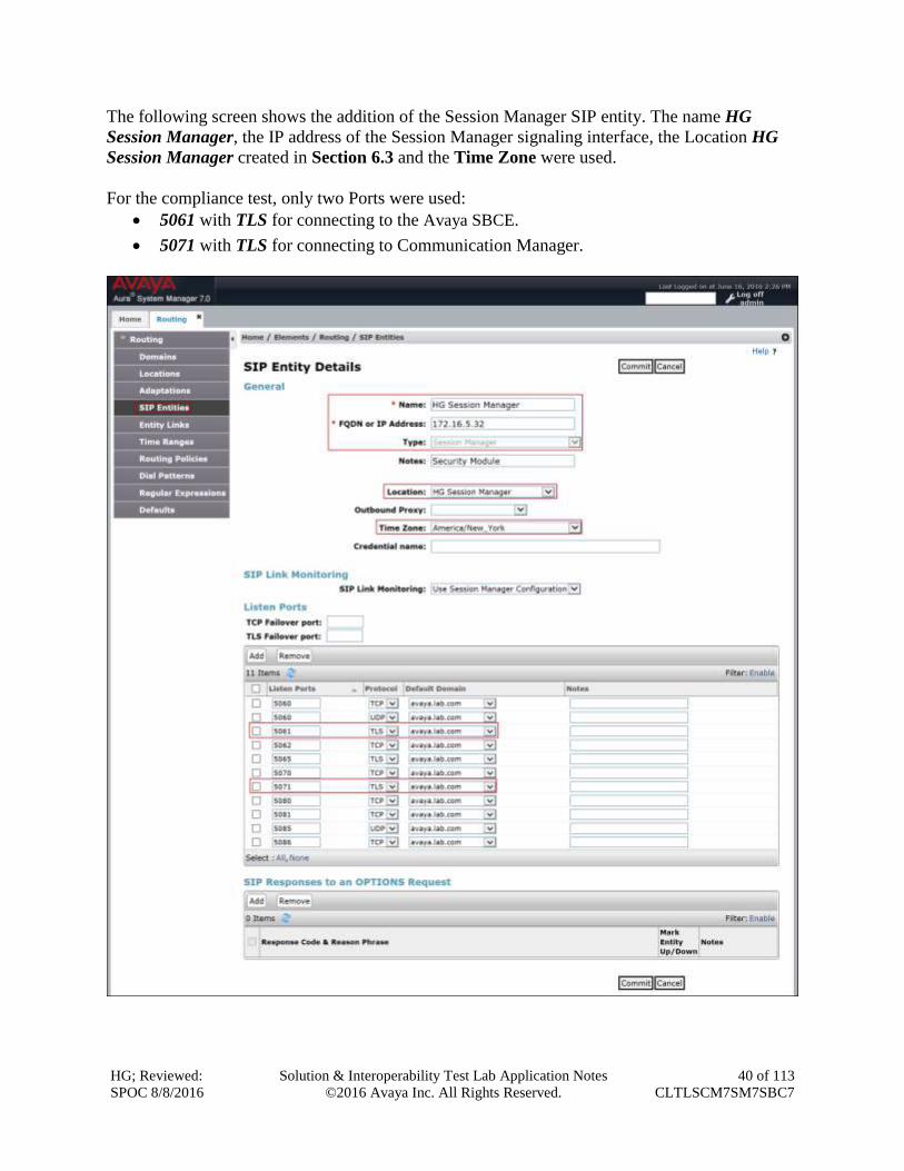
The following screen shows the addition of the Session Manager SIP entity. The name HG
Session Manager, the IP address of the Session Manager signaling interface, the Location HG
Session Manager created in Section 6.3 and the Time Zone were used.
For the compliance test, only two Ports were used:
5061 with TLS for connecting to the Avaya SBCE.
5071 with TLS for connecting to Communication Manager.
HG; Reviewed:
SPOC 8/8/2016
Solution & Interoperability Test Lab Application Notes
©2016 Avaya Inc. All Rights Reserved.
41 of 113
CLTLSCM7SM7SBC7
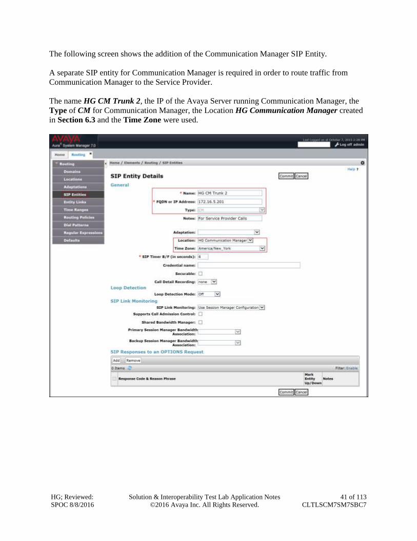
The following screen shows the addition of the Communication Manager SIP Entity.
A separate SIP entity for Communication Manager is required in order to route traffic from
Communication Manager to the Service Provider.
The name HG CM Trunk 2, the IP of the Avaya Server running Communication Manager, the
Type of CM for Communication Manager, the Location HG Communication Manager created
in Section 6.3 and the Time Zone were used.
HG; Reviewed:
SPOC 8/8/2016
Solution & Interoperability Test Lab Application Notes
©2016 Avaya Inc. All Rights Reserved.
42 of 113
CLTLSCM7SM7SBC7
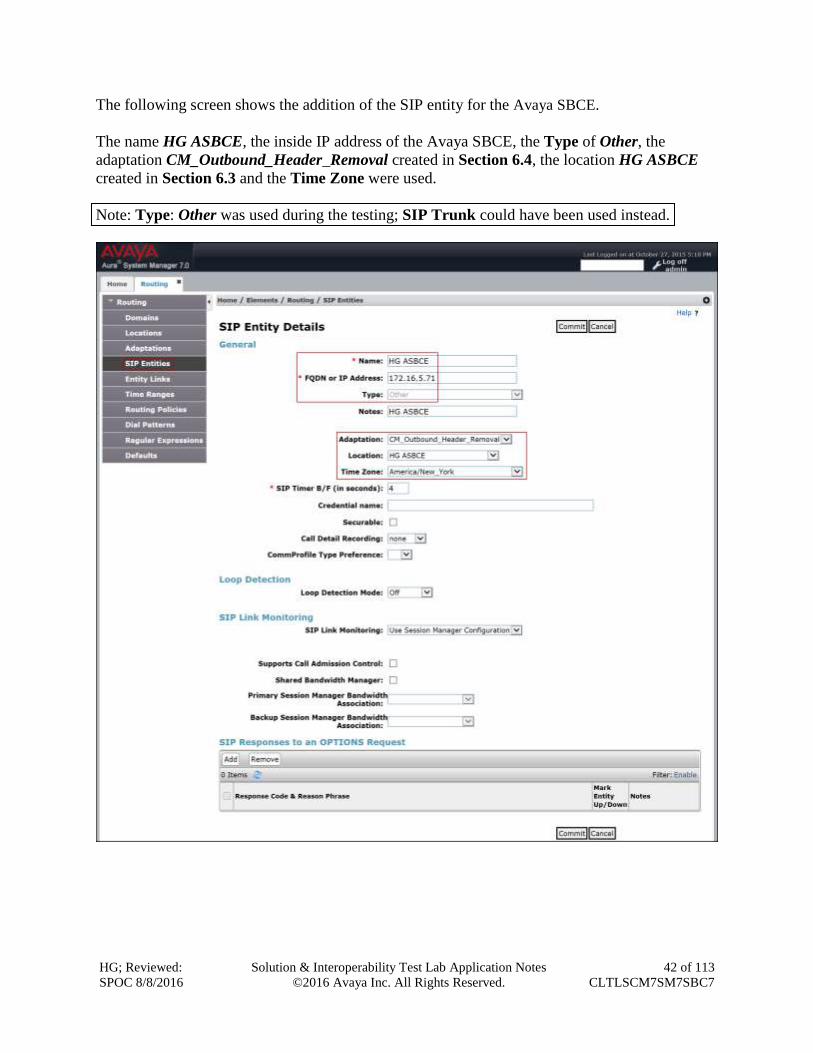
The following screen shows the addition of the SIP entity for the Avaya SBCE.
The name HG ASBCE, the inside IP address of the Avaya SBCE, the Type of Other, the
adaptation CM_Outbound_Header_Removal created in Section 6.4, the location HG ASBCE
created in Section 6.3 and the Time Zone were used.
Note: Type: Other was used during the testing; SIP Trunk could have been used instead.
HG; Reviewed:
SPOC 8/8/2016
Solution & Interoperability Test Lab Application Notes
©2016 Avaya Inc. All Rights Reserved.
43 of 113
CLTLSCM7SM7SBC7
6.6. Entity Links
A SIP trunk between Session Manager and a telephony system is described by an Entity Link.
Two entity links were created; one to Communication Manager and one to the Avaya SBCE, to
be used only for Service Provider traffic. To add an entity link, navigate to Routing Entity
Links in the left-hand navigation pane and click on the New button in the right pane (not
shown). Fill in the following fields in the new row that is displayed:
Name: Enter a descriptive name.
SIP Entity 1: Select the Session Manager.
Protocol: Select the transport protocol used for this link. For Communication
Manager this was matched to the Transport Method defined on the
Communication Manager signaling group in Section 5.6. For the
Avaya SBCE, this was matched to the Transport defined on the
Server Configuration for Session Manager (Call Server) in Section
7.3.4.
Port: Port number on which Session Manager will receive SIP requests from
the far-end. For Communication Manager, this was matched to the
Far-end Listen Port defined on the Communication Manager
signaling group in Section 5.6. For the Avaya SBCE, this was matched
to the Port defined on the Server Configuration for Session Manager
(Call Server) in Section 7.3.4.
SIP Entity 2: Select the name of the other system. For Communication Manager or
the Avaya SBCE select the respective SIP Entity defined in Section
6.5.
Port: Port number on which the other system will receive SIP requests from
Session Manager. For Communication Manager, this was matched to
the Near-end Listen Port defined on the Communication Manager
signaling group in Section 5.6. For the Avaya SBCE, this was matched
to the TLS Port defined for the private Signaling Interface on the
Avaya SBCE in Section 7.5.3.
Connection Policy: Select Trusted.
Click Commit to save.
The following screens illustrate the entity links to Communication Manager and to the Avaya
SBCE.
HG; Reviewed:
SPOC 8/8/2016
Solution & Interoperability Test Lab Application Notes
©2016 Avaya Inc. All Rights Reserved.
44 of 113
CLTLSCM7SM7SBC7
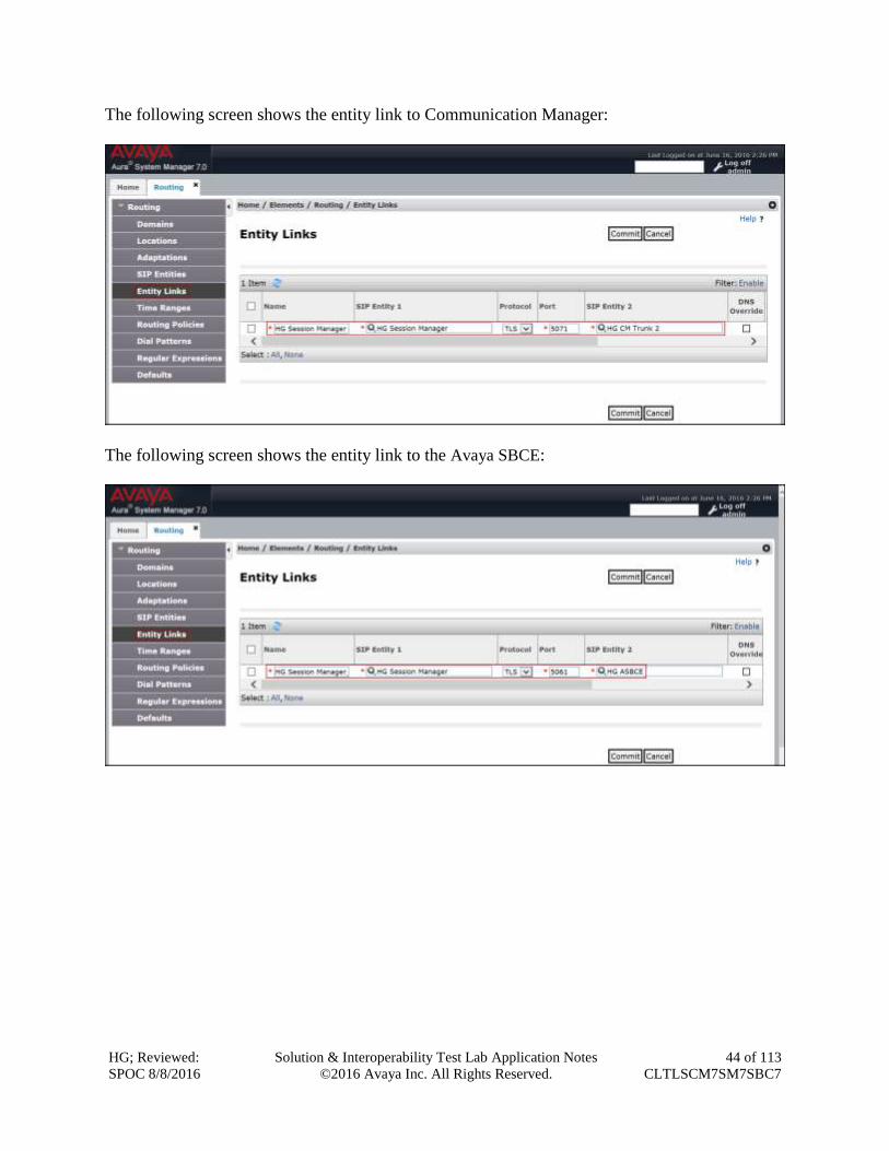
The following screen shows the entity link to Communication Manager:
The following screen shows the entity link to the Avaya SBCE:
HG; Reviewed:
SPOC 8/8/2016
Solution & Interoperability Test Lab Application Notes
©2016 Avaya Inc. All Rights Reserved.
45 of 113
CLTLSCM7SM7SBC7
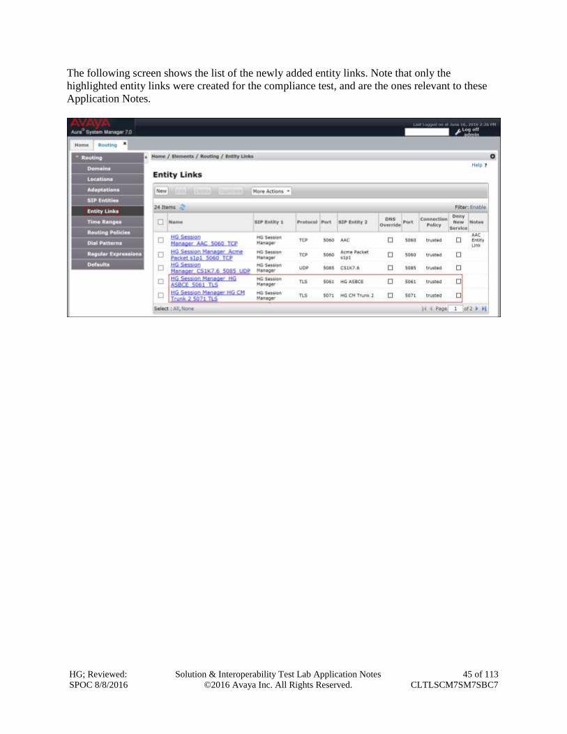
The following screen shows the list of the newly added entity links. Note that only the
highlighted entity links were created for the compliance test, and are the ones relevant to these
Application Notes.
HG; Reviewed:
SPOC 8/8/2016
Solution & Interoperability Test Lab Application Notes
©2016 Avaya Inc. All Rights Reserved.
46 of 113
CLTLSCM7SM7SBC7
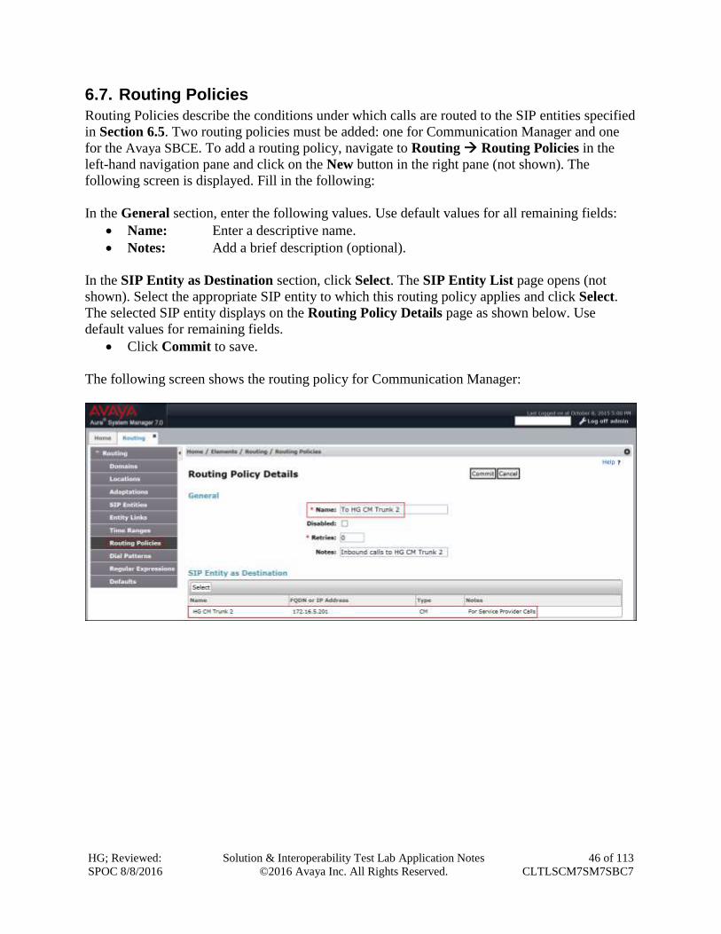
6.7. Routing Policies
Routing Policies describe the conditions under which calls are routed to the SIP entities specified
in Section 6.5. Two routing policies must be added: one for Communication Manager and one
for the Avaya SBCE. To add a routing policy, navigate to Routing Routing Policies in the
left-hand navigation pane and click on the New button in the right pane (not shown). The
following screen is displayed. Fill in the following:
In the General section, enter the following values. Use default values for all remaining fields:
Name: Enter a descriptive name.
Notes: Add a brief description (optional).
In the SIP Entity as Destination section, click Select. The SIP Entity List page opens (not
shown). Select the appropriate SIP entity to which this routing policy applies and click Select.
The selected SIP entity displays on the Routing Policy Details page as shown below. Use
default values for remaining fields.
Click Commit to save.
The following screen shows the routing policy for Communication Manager:
HG; Reviewed:
SPOC 8/8/2016
Solution & Interoperability Test Lab Application Notes
©2016 Avaya Inc. All Rights Reserved.
47 of 113
CLTLSCM7SM7SBC7
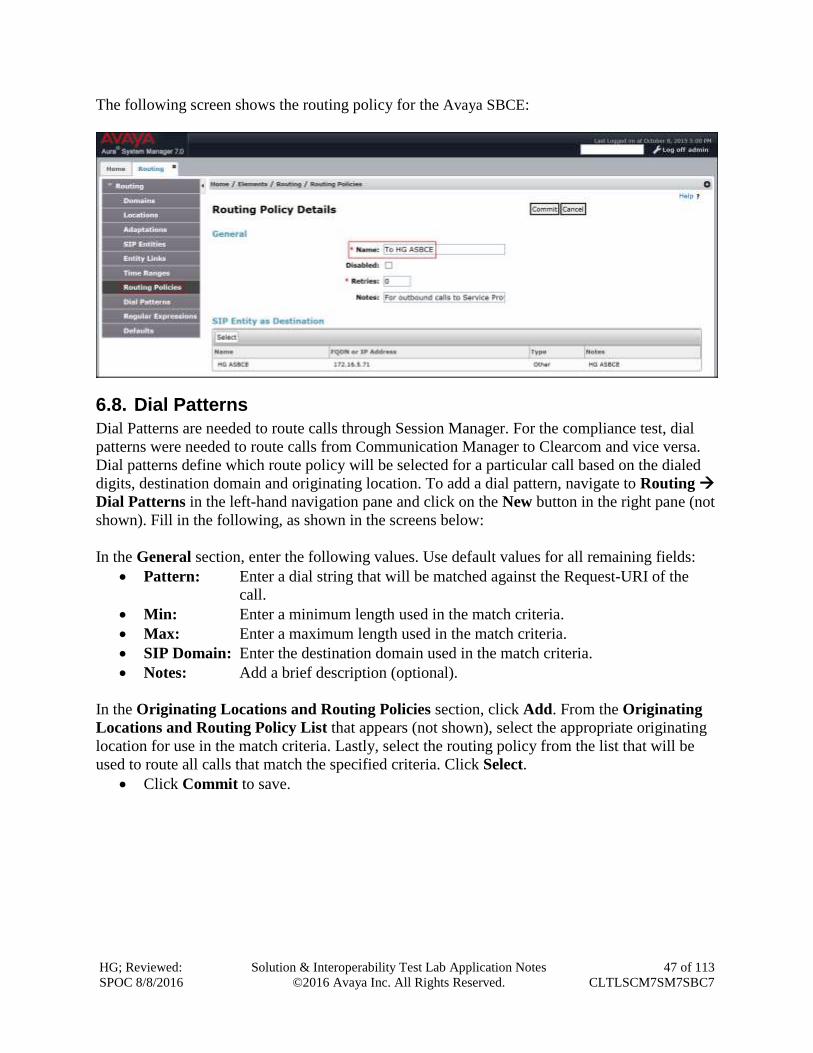
The following screen shows the routing policy for the Avaya SBCE:
6.8. Dial Patterns
Dial Patterns are needed to route calls through Session Manager. For the compliance test, dial
patterns were needed to route calls from Communication Manager to Clearcom and vice versa.
Dial patterns define which route policy will be selected for a particular call based on the dialed
digits, destination domain and originating location. To add a dial pattern, navigate to Routing
Dial Patterns in the left-hand navigation pane and click on the New button in the right pane (not
shown). Fill in the following, as shown in the screens below:
In the General section, enter the following values. Use default values for all remaining fields:
Pattern: Enter a dial string that will be matched against the Request-URI of the
call.
Min: Enter a minimum length used in the match criteria.
Max: Enter a maximum length used in the match criteria.
SIP Domain: Enter the destination domain used in the match criteria.
Notes: Add a brief description (optional).
In the Originating Locations and Routing Policies section, click Add. From the Originating
Locations and Routing Policy List that appears (not shown), select the appropriate originating
location for use in the match criteria. Lastly, select the routing policy from the list that will be
used to route all calls that match the specified criteria. Click Select.
Click Commit to save.
HG; Reviewed:
SPOC 8/8/2016
Solution & Interoperability Test Lab Application Notes
©2016 Avaya Inc. All Rights Reserved.
48 of 113
CLTLSCM7SM7SBC7
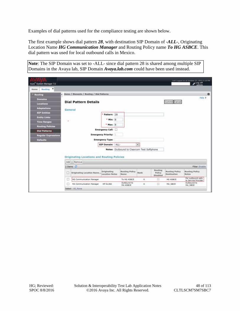
Examples of dial patterns used for the compliance testing are shown below.
The first example shows dial pattern 28, with destination SIP Domain of -ALL-, Originating
Location Name HG Communication Manager and Routing Policy name To HG ASBCE. This
dial pattern was used for local outbound calls in Mexico.
Note: The SIP Domain was set to -ALL- since dial pattern 28 is shared among multiple SIP
Domains in the Avaya lab, SIP Domain Avaya.lab.com could have been used instead.
HG; Reviewed:
SPOC 8/8/2016
Solution & Interoperability Test Lab Application Notes
©2016 Avaya Inc. All Rights Reserved.
49 of 113
CLTLSCM7SM7SBC7
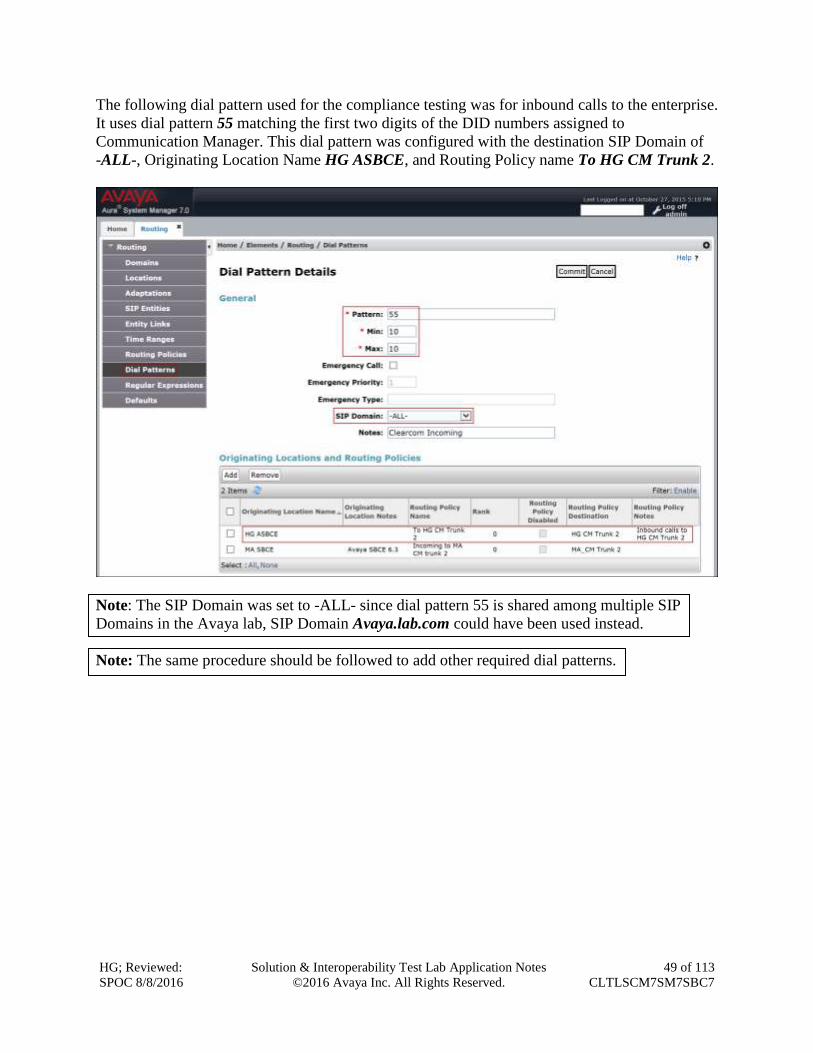
The following dial pattern used for the compliance testing was for inbound calls to the enterprise.
It uses dial pattern 55 matching the first two digits of the DID numbers assigned to
Communication Manager. This dial pattern was configured with the destination SIP Domain of
-ALL-, Originating Location Name HG ASBCE, and Routing Policy name To HG CM Trunk 2.
Note: The SIP Domain was set to -ALL- since dial pattern 55 is shared among multiple SIP
Domains in the Avaya lab, SIP Domain Avaya.lab.com could have been used instead.
Note: The same procedure should be followed to add other required dial patterns.
HG; Reviewed:
SPOC 8/8/2016
Solution & Interoperability Test Lab Application Notes
©2016 Avaya Inc. All Rights Reserved.
50 of 113
CLTLSCM7SM7SBC7
6.9. Add/View Avaya Aura® Session Manager
The creation of a Session Manager element provides the linkage between System Manager and
Session Manager. This was most likely done as part of the initial Session Manager installation.
To add Session Manager, navigate to Elements Session Manager Session Manager
Administration in the left-hand navigation pane and click on the New button in the right pane
(not shown). If Session Manager already exists, click View (not shown) to view the
configuration. Enter/verify the data as described below and shown in the following screen:
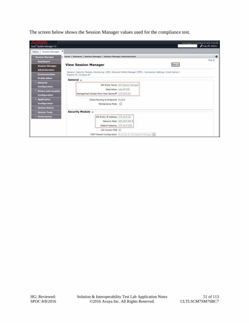
In the General section, enter the following values:
SIP Entity Name: Select the SIP Entity created for Session
Manager.
Description: Add a brief description (optional).
Management Access Point Host Name/IP: Enter the IP address of the Session Manager
management interface.
In the Security Module section, enter the following values:
SIP Entity IP Address: Should be filled in automatically based on the SIP Entity
Name. Otherwise, enter IP address of the Session Manager
signaling interface.
Network Mask: Enter the network mask corresponding to the IP address of
the Session Manager signaling interface.
Default Gateway: Enter the IP address of the default gateway for Session
Manager.
Use default values for the remaining fields.
Click Save (not shown).
HG; Reviewed:
SPOC 8/8/2016
Solution & Interoperability Test Lab Application Notes
©2016 Avaya Inc. All Rights Reserved.
51 of 113
CLTLSCM7SM7SBC7
The screen below shows the Session Manager values used for the compliance test.
HG; Reviewed:
SPOC 8/8/2016
Solution & Interoperability Test Lab Application Notes
©2016 Avaya Inc. All Rights Reserved.
52 of 113
CLTLSCM7SM7SBC7
7. Configure Avaya Session Border Controller for Enterprise This section describes the required configuration of the Avaya SBCE to connect to Clearcom’s
SIP Trunking service.
It is assumed that the Avaya SBCE was provisioned and is ready to be used; the configuration
shown here is accomplished using the Avaya SBCE web interface.
Note: In the following pages, and for brevity in these Application Notes, not every provisioning
step will have a screenshot associated with it. Some of the default information in the screenshots
that follow may have been cut out (not included) for brevity.
7.1. Log in Avaya SBCE
Use a web browser to access the Avaya SBCE web interface, enter https://<ip-addr>/sbc in the
address field of the web browser, where <ip-addr> is the management IP address of the Avaya
SBCE.
Enter the appropriate credentials and then click Log In.
HG; Reviewed:
SPOC 8/8/2016
Solution & Interoperability Test Lab Application Notes
©2016 Avaya Inc. All Rights Reserved.
53 of 113
CLTLSCM7SM7SBC7
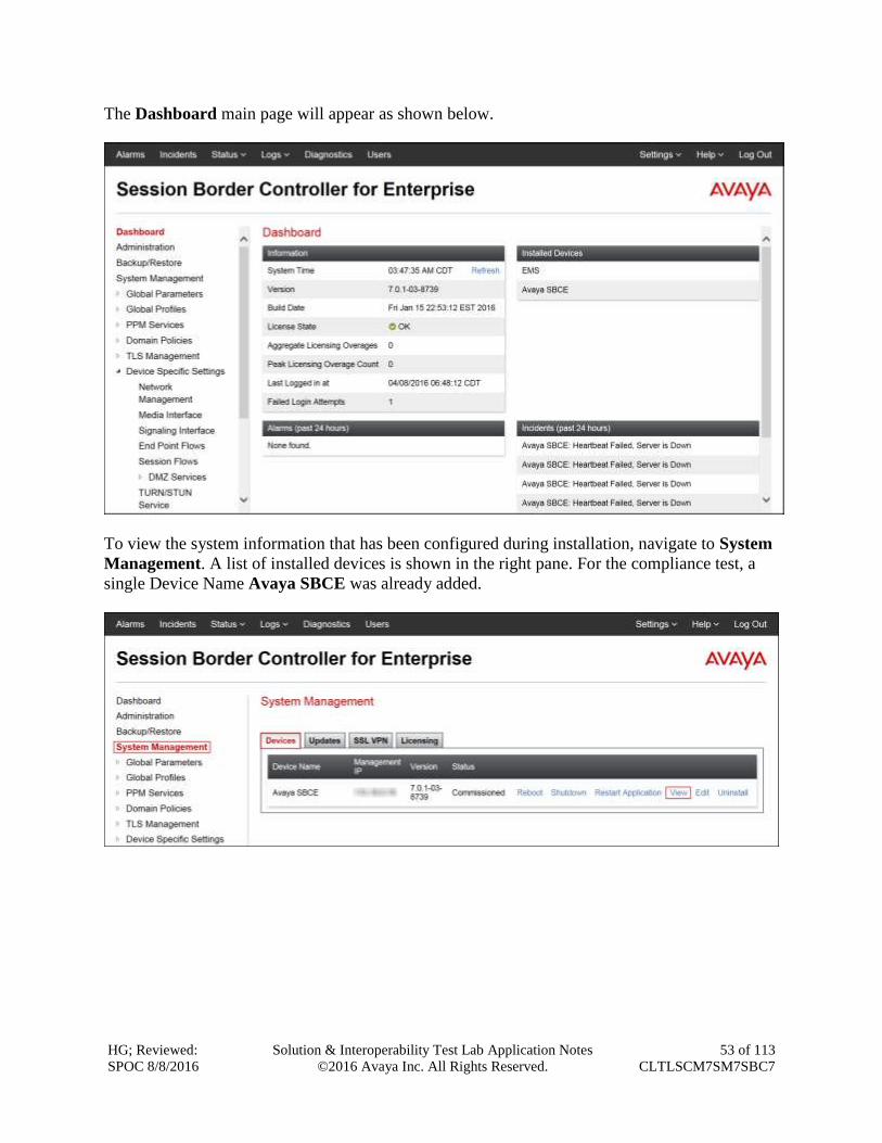
The Dashboard main page will appear as shown below.
To view the system information that has been configured during installation, navigate to System
Management. A list of installed devices is shown in the right pane. For the compliance test, a
single Device Name Avaya SBCE was already added.
HG; Reviewed:
SPOC 8/8/2016
Solution & Interoperability Test Lab Application Notes
©2016 Avaya Inc. All Rights Reserved.
54 of 113
CLTLSCM7SM7SBC7
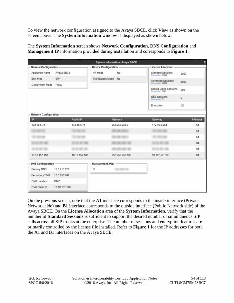
To view the network configuration assigned to the Avaya SBCE, click View as shown on the
screen above. The System Information window is displayed as shown below.
The System Information screen shows Network Configuration, DNS Configuration and
Management IP information provided during installation and corresponds to Figure 1.
On the previous screen, note that the A1 interface corresponds to the inside interface (Private
Network side) and B1 interface corresponds to the outside interface (Public Network side) of the
Avaya SBCE. On the License Allocation area of the System Information, verify that the
number of Standard Sessions is sufficient to support the desired number of simultaneous SIP
calls across all SIP trunks at the enterprise. The number of sessions and encryption features are
primarily controlled by the license file installed. Refer to Figure 1 for the IP addresses for both
the A1 and B1 interfaces on the Avaya SBCE.
HG; Reviewed:
SPOC 8/8/2016
Solution & Interoperability Test Lab Application Notes
©2016 Avaya Inc. All Rights Reserved.
55 of 113
CLTLSCM7SM7SBC7
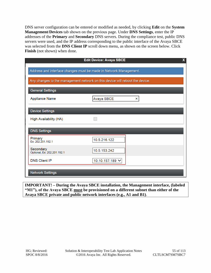
DNS server configuration can be entered or modified as needed, by clicking Edit on the System
Management/Devices tab shown on the previous page. Under DNS Settings, enter the IP
addresses of the Primary and Secondary DNS servers. During the compliance test, public DNS
servers were used, and the IP address corresponding to the public interface of the Avaya SBCE
was selected from the DNS Client IP scroll down menu, as shown on the screen below. Click
Finish (not shown) when done.
IMPORTANT! – During the Avaya SBCE installation, the Management interface, (labeled
“M1”), of the Avaya SBCE must be provisioned on a different subnet than either of the
Avaya SBCE private and public network interfaces (e.g., A1 and B1).
HG; Reviewed:
SPOC 8/8/2016
Solution & Interoperability Test Lab Application Notes
©2016 Avaya Inc. All Rights Reserved.
56 of 113
CLTLSCM7SM7SBC7
7.2. TLS Management
7.2.1. TLS Certificates
Transport Layer Security (TLS) is a standard protocol that is used extensively to provide a secure
channel by encrypting communications over IP networks. It enables clients to authenticate
servers or, optionally, servers to authenticate clients. UC-Sec security products utilize TLS
primarily to facilitate secure communications with remote servers.
This section describes the TLS profiles that were created for the Avaya SBCE, including the
following:
Create TLS client and server profiles to identify which certificates will be used in various
TLS connections on the Avaya SBCE.
It is assumed that generation and installation of certificates on the Avaya SBCE, and the
exchange of TLS CA certificates with the Service Provider, have been previously completed, and
is not discussed in this document. Refer to items [8] in Section 11.
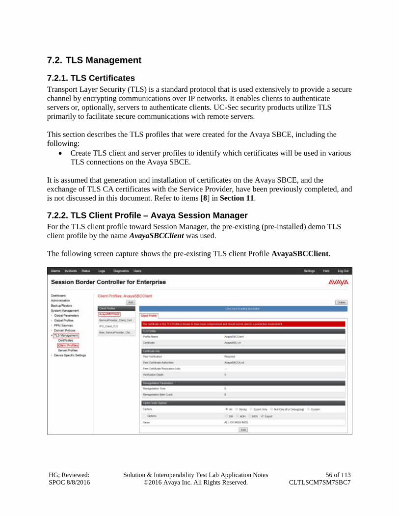
7.2.2. TLS Client Profile – Avaya Session Manager
For the TLS client profile toward Session Manager, the pre-existing (pre-installed) demo TLS
client profile by the name AvayaSBCClient was used.
The following screen capture shows the pre-existing TLS client Profile AvayaSBCClient.
HG; Reviewed:
SPOC 8/8/2016
Solution & Interoperability Test Lab Application Notes
©2016 Avaya Inc. All Rights Reserved.
57 of 113
CLTLSCM7SM7SBC7
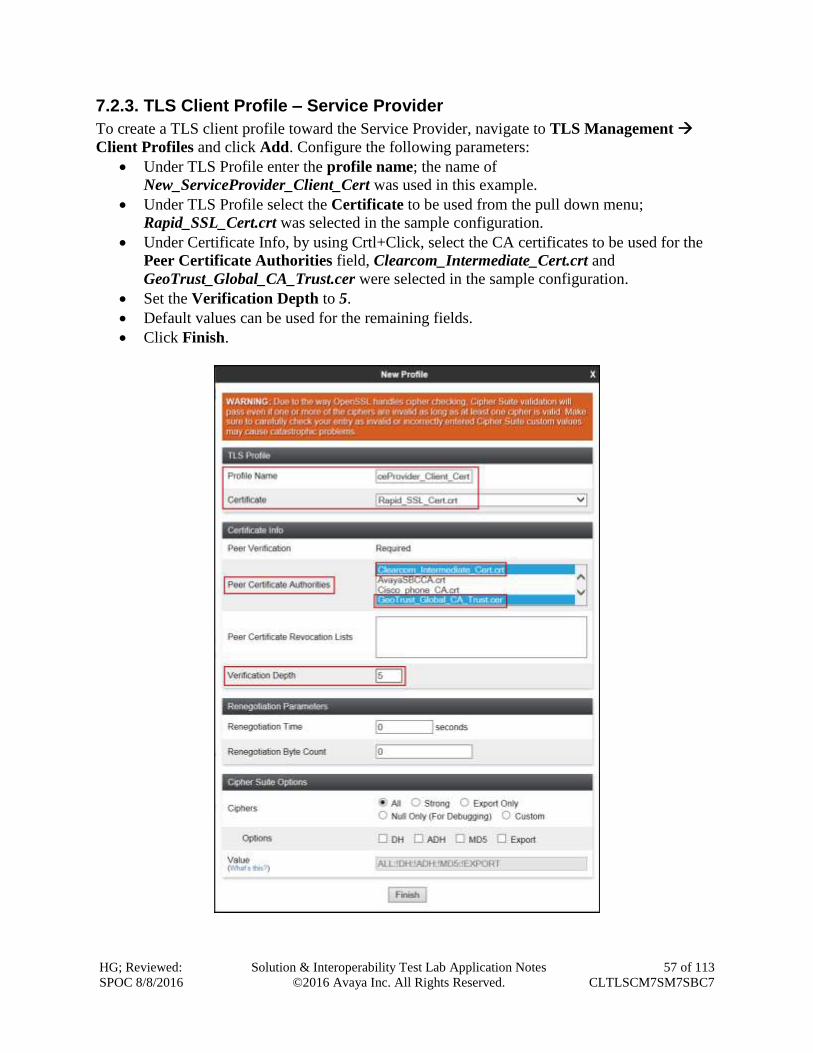
7.2.3. TLS Client Profile – Service Provider
To create a TLS client profile toward the Service Provider, navigate to TLS Management
Client Profiles and click Add. Configure the following parameters:
Under TLS Profile enter the profile name; the name of
New_ServiceProvider_Client_Cert was used in this example.
Under TLS Profile select the Certificate to be used from the pull down menu;
Rapid_SSL_Cert.crt was selected in the sample configuration.
Under Certificate Info, by using Crtl+Click, select the CA certificates to be used for the
Peer Certificate Authorities field, Clearcom_Intermediate_Cert.crt and
GeoTrust_Global_CA_Trust.cer were selected in the sample configuration.
Set the Verification Depth to 5.
Default values can be used for the remaining fields.
Click Finish.
HG; Reviewed:
SPOC 8/8/2016
Solution & Interoperability Test Lab Application Notes
©2016 Avaya Inc. All Rights Reserved.
58 of 113
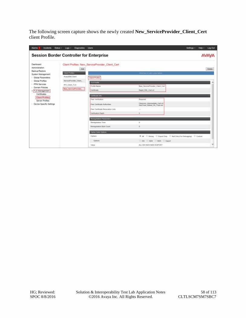
CLTLSCM7SM7SBC7
The following screen capture shows the newly created New_ServiceProvider_Client_Cert
client Profile.
HG; Reviewed:
SPOC 8/8/2016
Solution & Interoperability Test Lab Application Notes
©2016 Avaya Inc. All Rights Reserved.
59 of 113
CLTLSCM7SM7SBC7
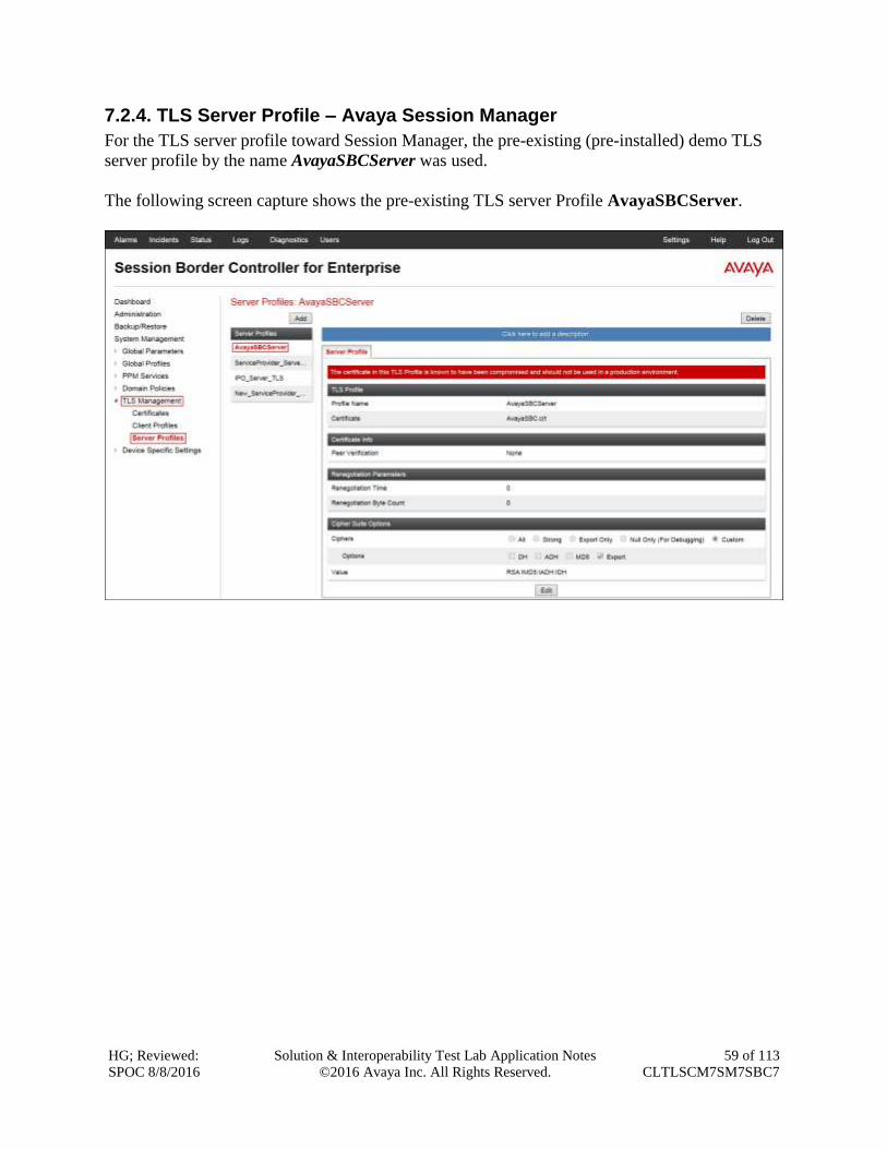
7.2.4. TLS Server Profile – Avaya Session Manager
For the TLS server profile toward Session Manager, the pre-existing (pre-installed) demo TLS
server profile by the name AvayaSBCServer was used.
The following screen capture shows the pre-existing TLS server Profile AvayaSBCServer.
HG; Reviewed:
SPOC 8/8/2016
Solution & Interoperability Test Lab Application Notes
©2016 Avaya Inc. All Rights Reserved.
60 of 113
CLTLSCM7SM7SBC7
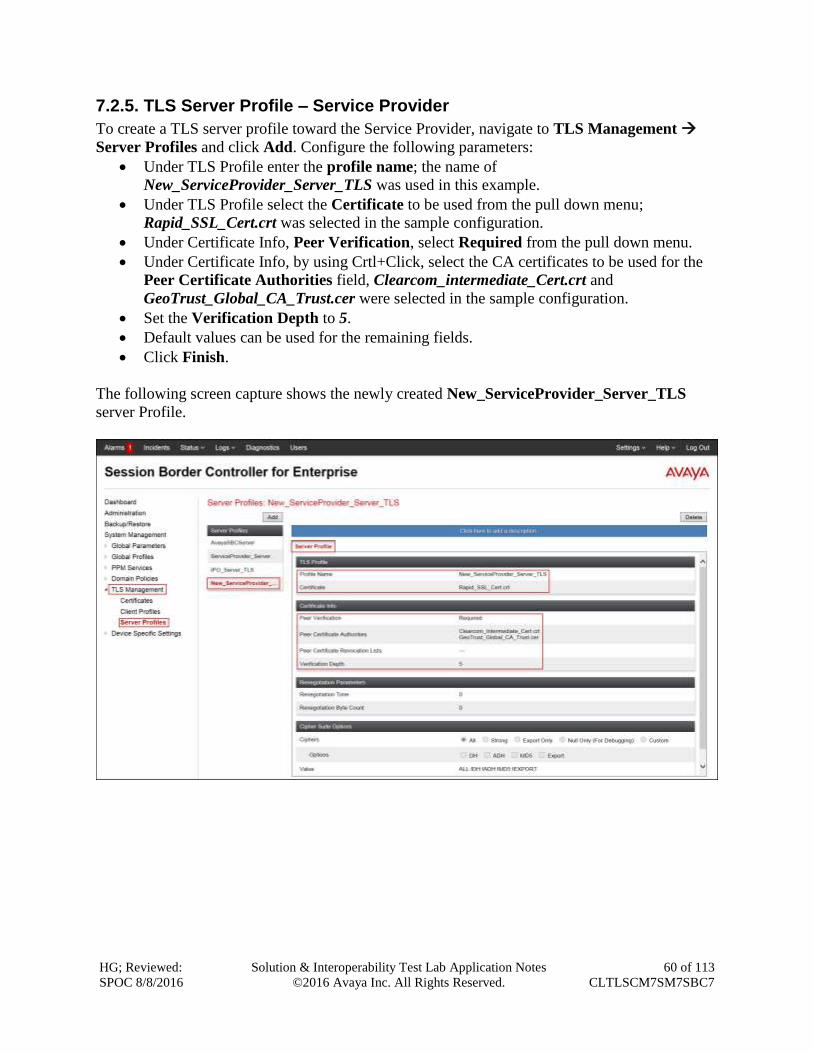
7.2.5. TLS Server Profile – Service Provider
To create a TLS server profile toward the Service Provider, navigate to TLS Management
Server Profiles and click Add. Configure the following parameters:
Under TLS Profile enter the profile name; the name of
New_ServiceProvider_Server_TLS was used in this example.
Under TLS Profile select the Certificate to be used from the pull down menu;
Rapid_SSL_Cert.crt was selected in the sample configuration.
Under Certificate Info, Peer Verification, select Required from the pull down menu.
Under Certificate Info, by using Crtl+Click, select the CA certificates to be used for the
Peer Certificate Authorities field, Clearcom_intermediate_Cert.crt and
GeoTrust_Global_CA_Trust.cer were selected in the sample configuration.
Set the Verification Depth to 5.
Default values can be used for the remaining fields.
Click Finish.
The following screen capture shows the newly created New_ServiceProvider_Server_TLS
server Profile.
HG; Reviewed:
SPOC 8/8/2016
Solution & Interoperability Test Lab Application Notes
©2016 Avaya Inc. All Rights Reserved.
61 of 113
CLTLSCM7SM7SBC7
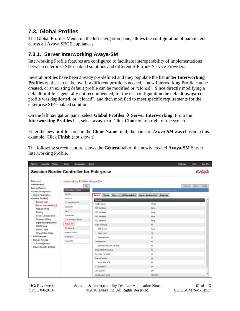
7.3. Global Profiles
The Global Profiles Menu, on the left navigation pane, allows the configuration of parameters
across all Avaya SBCE appliances.
7.3.1. Server Interworking Avaya-SM
Interworking Profile features are configured to facilitate interoperability of implementations
between enterprise SIP-enabled solutions and different SIP trunk Service Providers.
Several profiles have been already pre-defined and they populate the list under Interworking
Profiles on the screen below. If a different profile is needed, a new Interworking Profile can be
created, or an existing default profile can be modified or “cloned”. Since directly modifying a
default profile is generally not recommended, for the test configuration the default avaya-ru
profile was duplicated, or “cloned”, and then modified to meet specific requirements for the
enterprise SIP-enabled solution.
On the left navigation pane, select Global Profiles Server Interworking. From the
Interworking Profiles list, select avaya-ru. Click Clone on top right of the screen.
Enter the new profile name in the Clone Name field; the name of Avaya-SM was chosen in this
example. Click Finish (not shown).
The following screen capture shows the General tab of the newly created Avaya-SM Server
Interworking Profile.
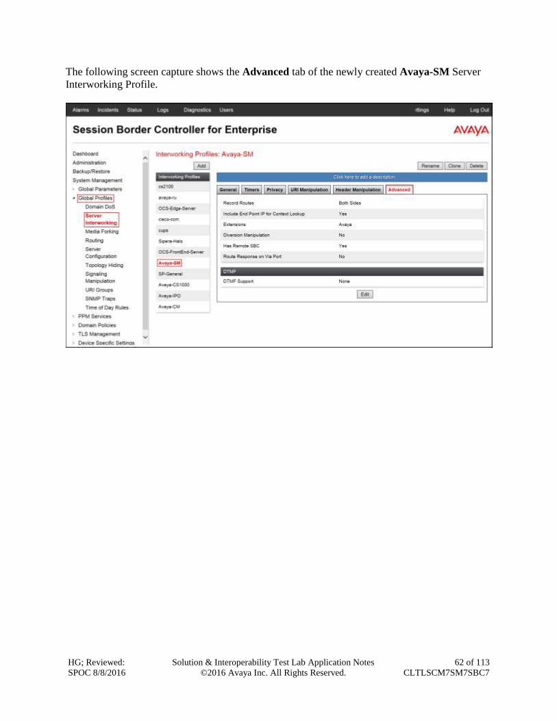
HG; Reviewed:
SPOC 8/8/2016
Solution & Interoperability Test Lab Application Notes
©2016 Avaya Inc. All Rights Reserved.
62 of 113
CLTLSCM7SM7SBC7
The following screen capture shows the Advanced tab of the newly created Avaya-SM Server
Interworking Profile.
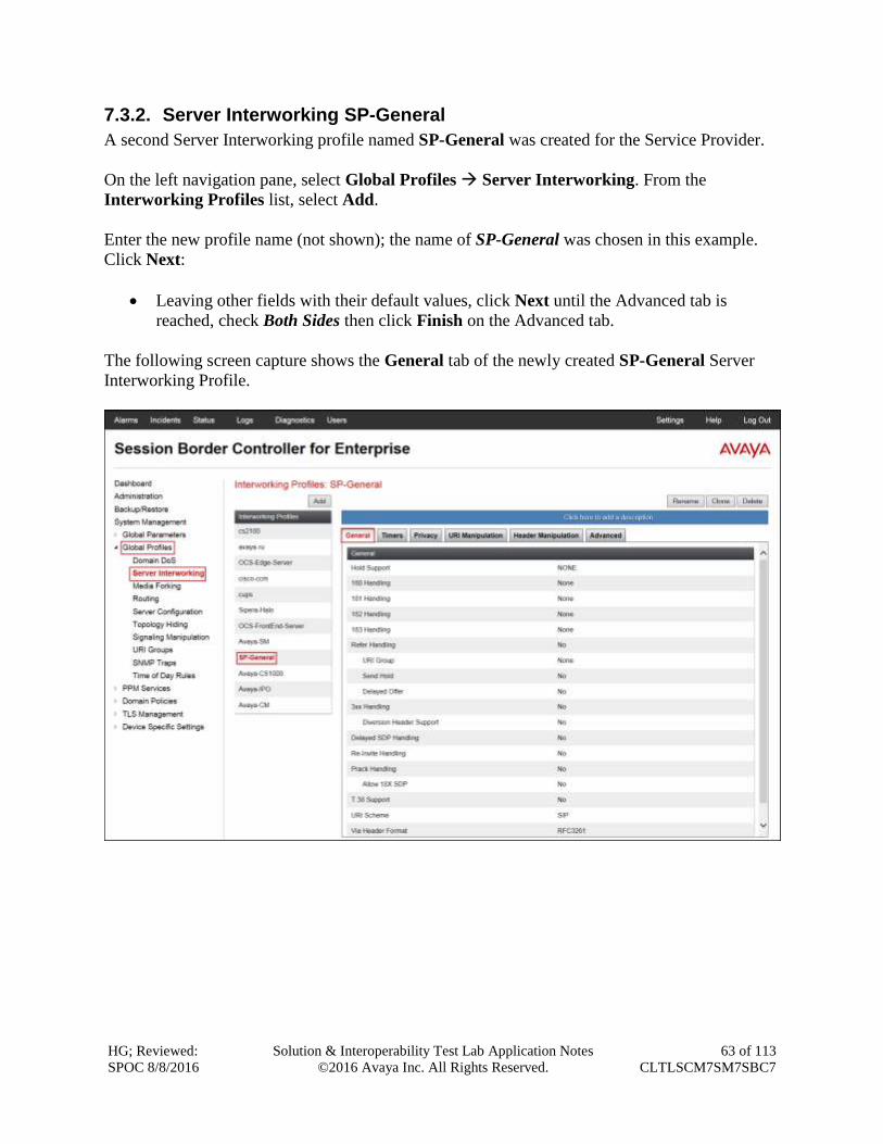
HG; Reviewed:
SPOC 8/8/2016
Solution & Interoperability Test Lab Application Notes
©2016 Avaya Inc. All Rights Reserved.
63 of 113
CLTLSCM7SM7SBC7
7.3.2. Server Interworking SP-General
A second Server Interworking profile named SP-General was created for the Service Provider.
On the left navigation pane, select Global Profiles Server Interworking. From the
Interworking Profiles list, select Add.
Enter the new profile name (not shown); the name of SP-General was chosen in this example.
Click Next:
Leaving other fields with their default values, click Next until the Advanced tab is
reached, check Both Sides then click Finish on the Advanced tab.
The following screen capture shows the General tab of the newly created SP-General Server
Interworking Profile.
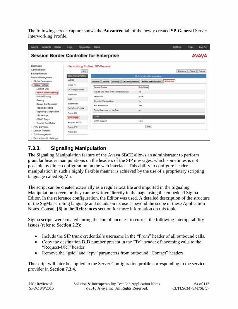
HG; Reviewed:
SPOC 8/8/2016
Solution & Interoperability Test Lab Application Notes
©2016 Avaya Inc. All Rights Reserved.
64 of 113
CLTLSCM7SM7SBC7
The following screen capture shows the Advanced tab of the newly created SP-General Server
Interworking Profile.
7.3.3. Signaling Manipulation
The Signaling Manipulation feature of the Avaya SBCE allows an administrator to perform
granular header manipulations on the headers of the SIP messages, which sometimes is not
possible by direct configuration on the web interface. This ability to configure header
manipulation in such a highly flexible manner is achieved by the use of a proprietary scripting
language called SigMa.
The script can be created externally as a regular text file and imported in the Signaling
Manipulation screen, or they can be written directly in the page using the embedded Sigma
Editor. In the reference configuration, the Editor was used. A detailed description of the structure
of the SigMa scripting language and details on its use is beyond the scope of these Application
Notes. Consult [8] in the References section for more information on this topic.
Sigma scripts were created during the compliance test to correct the following interoperability
issues (refer to Section 2.2):
Include the SIP trunk credential’s username in the “From” header of all outbound calls.
Copy the destination DID number present in the “To” header of incoming calls to the
“Request-URI” header.
Remove the “gsid” and “epv” parameters from outbound “Contact” headers.
The script will later be applied to the Server Configuration profile corresponding to the service
provider in Section 7.3.4.
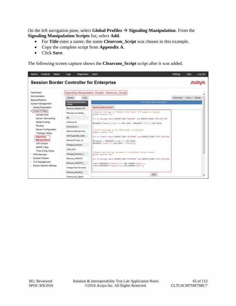
HG; Reviewed:
SPOC 8/8/2016
Solution & Interoperability Test Lab Application Notes
©2016 Avaya Inc. All Rights Reserved.
65 of 113
CLTLSCM7SM7SBC7
On the left navigation pane, select Global Profiles Signaling Manipulation. From the
Signaling Manipulation Scripts list, select Add.
For Title enter a name; the name Clearcom_Script was chosen in this example.
Copy the complete script from Appendix A.
Click Save.
The following screen capture shows the Clearcom_Script script after it was added.
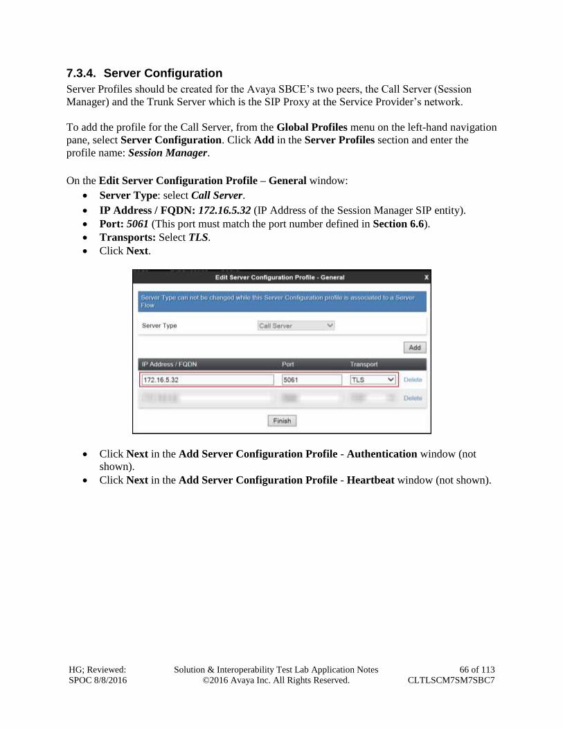
HG; Reviewed:
SPOC 8/8/2016
Solution & Interoperability Test Lab Application Notes
©2016 Avaya Inc. All Rights Reserved.
66 of 113
CLTLSCM7SM7SBC7
7.3.4. Server Configuration
Server Profiles should be created for the Avaya SBCE’s two peers, the Call Server (Session
Manager) and the Trunk Server which is the SIP Proxy at the Service Provider’s network.
To add the profile for the Call Server, from the Global Profiles menu on the left-hand navigation
pane, select Server Configuration. Click Add in the Server Profiles section and enter the
profile name: Session Manager.
On the Edit Server Configuration Profile – General window:
Server Type: select Call Server.
IP Address / FQDN: 172.16.5.32 (IP Address of the Session Manager SIP entity).
Port: 5061 (This port must match the port number defined in Section 6.6).
Transports: Select TLS.
Click Next.
Click Next in the Add Server Configuration Profile - Authentication window (not
shown).
Click Next in the Add Server Configuration Profile - Heartbeat window (not shown).
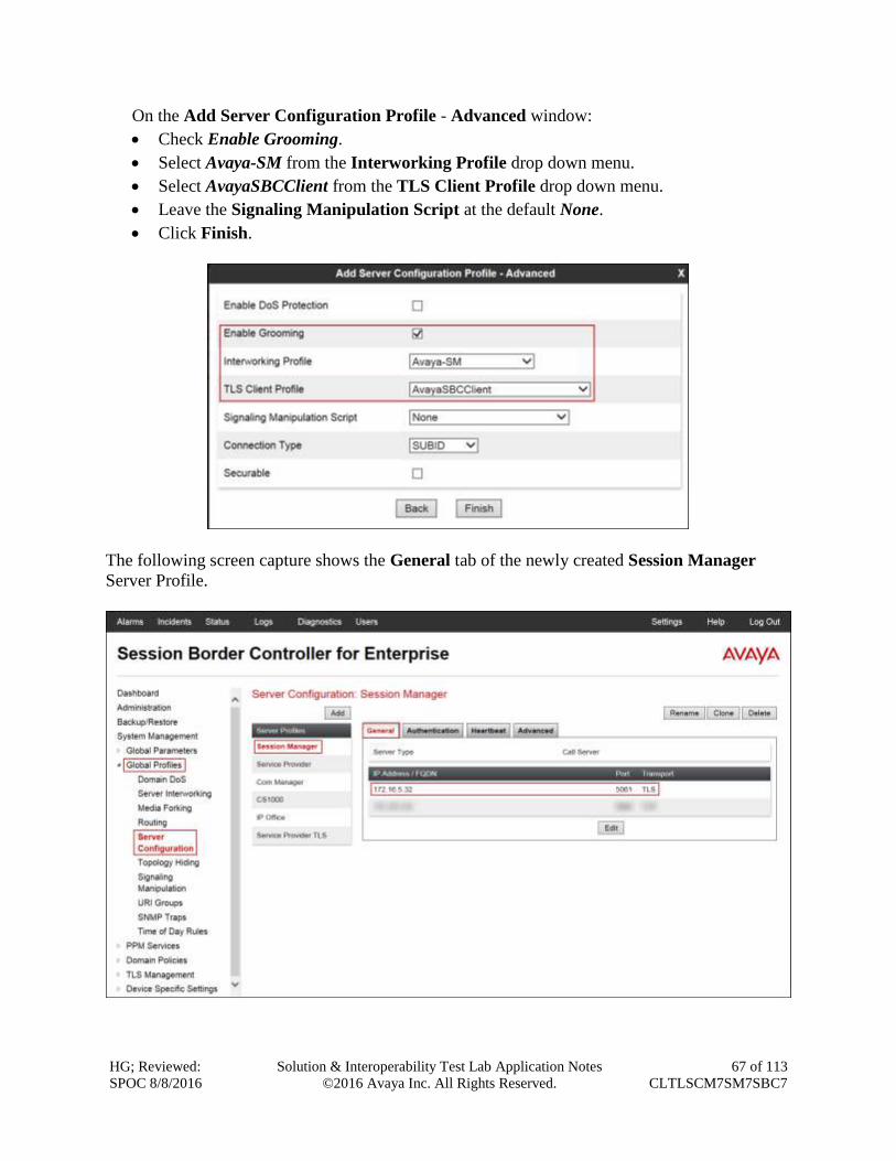
HG; Reviewed:
SPOC 8/8/2016
Solution & Interoperability Test Lab Application Notes
©2016 Avaya Inc. All Rights Reserved.
67 of 113
CLTLSCM7SM7SBC7
On the Add Server Configuration Profile - Advanced window:
Check Enable Grooming.
Select Avaya-SM from the Interworking Profile drop down menu.
Select AvayaSBCClient from the TLS Client Profile drop down menu.
Leave the Signaling Manipulation Script at the default None.
Click Finish.
The following screen capture shows the General tab of the newly created Session Manager
Server Profile.
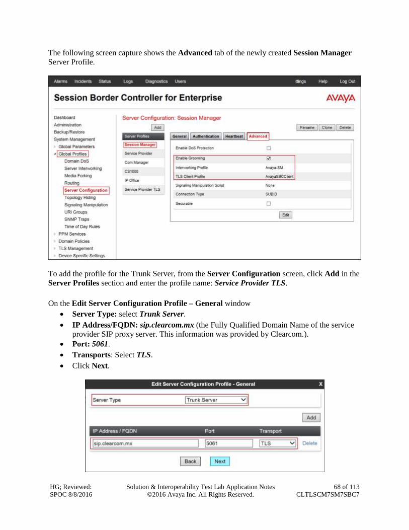
HG; Reviewed:
SPOC 8/8/2016
Solution & Interoperability Test Lab Application Notes
©2016 Avaya Inc. All Rights Reserved.
68 of 113
CLTLSCM7SM7SBC7
The following screen capture shows the Advanced tab of the newly created Session Manager
Server Profile.
To add the profile for the Trunk Server, from the Server Configuration screen, click Add in the
Server Profiles section and enter the profile name: Service Provider TLS.
On the Edit Server Configuration Profile – General window
Server Type: select Trunk Server.
IP Address/FQDN: sip.clearcom.mx (the Fully Qualified Domain Name of the service
provider SIP proxy server. This information was provided by Clearcom.).
Port: 5061.
Transports: Select TLS.
Click Next.
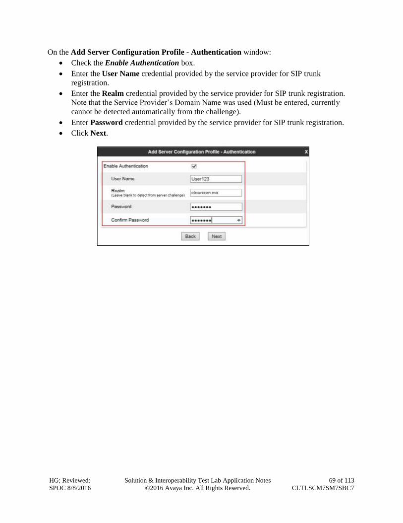
HG; Reviewed:
SPOC 8/8/2016
Solution & Interoperability Test Lab Application Notes
©2016 Avaya Inc. All Rights Reserved.
69 of 113
CLTLSCM7SM7SBC7
On the Add Server Configuration Profile - Authentication window:
Check the Enable Authentication box.
Enter the User Name credential provided by the service provider for SIP trunk
registration.
Enter the Realm credential provided by the service provider for SIP trunk registration.
Note that the Service Provider’s Domain Name was used (Must be entered, currently
cannot be detected automatically from the challenge).
Enter Password credential provided by the service provider for SIP trunk registration.
Click Next.
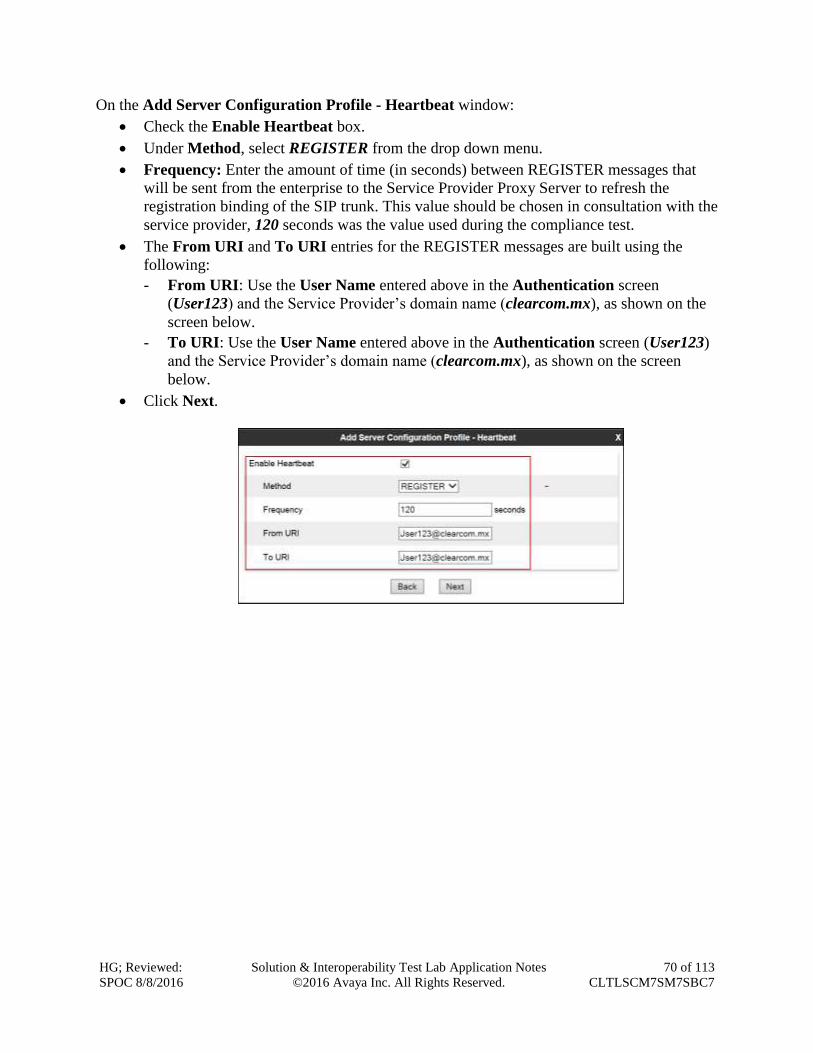
HG; Reviewed:
SPOC 8/8/2016
Solution & Interoperability Test Lab Application Notes
©2016 Avaya Inc. All Rights Reserved.
70 of 113
CLTLSCM7SM7SBC7
On the Add Server Configuration Profile - Heartbeat window:
Check the Enable Heartbeat box.
Under Method, select REGISTER from the drop down menu.
Frequency: Enter the amount of time (in seconds) between REGISTER messages that
will be sent from the enterprise to the Service Provider Proxy Server to refresh the
registration binding of the SIP trunk. This value should be chosen in consultation with the
service provider, 120 seconds was the value used during the compliance test.
The From URI and To URI entries for the REGISTER messages are built using the
following:
- From URI: Use the User Name entered above in the Authentication screen
(User123) and the Service Provider’s domain name (clearcom.mx), as shown on the
screen below.
- To URI: Use the User Name entered above in the Authentication screen (User123)
and the Service Provider’s domain name (clearcom.mx), as shown on the screen
below.
Click Next.
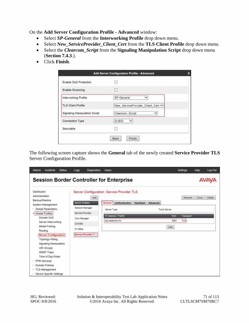
HG; Reviewed:
SPOC 8/8/2016
Solution & Interoperability Test Lab Application Notes
©2016 Avaya Inc. All Rights Reserved.
71 of 113
CLTLSCM7SM7SBC7
On the Add Server Configuration Profile - Advanced window:
Select SP-General from the Interworking Profile drop down menu.
Select New_ServiceProvider_Client_Cert from the TLS Client Profile drop down menu
Select the Clearcom_Script from the Signaling Manipulation Script drop down menu
(Section 7.4.3.).
Click Finish.
The following screen capture shows the General tab of the newly created Service Provider TLS
Server Configuration Profile.
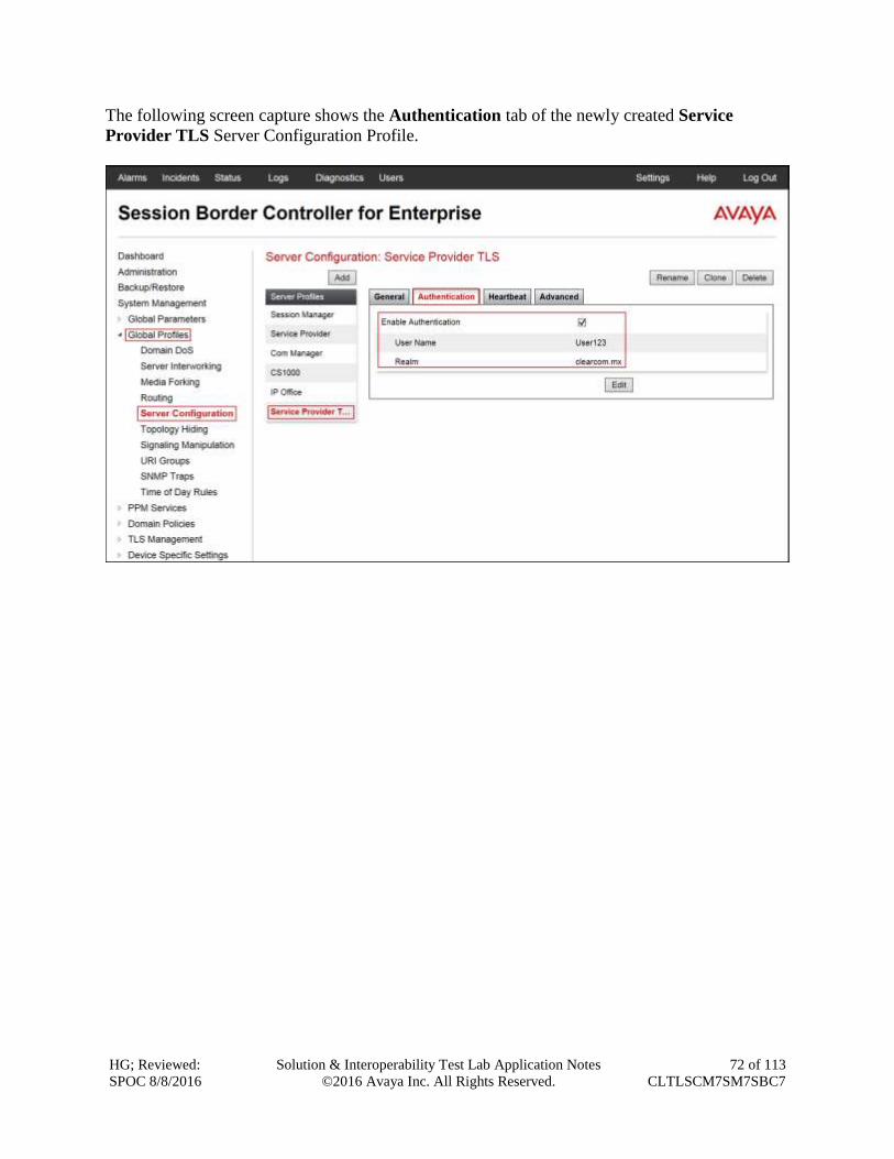
HG; Reviewed:
SPOC 8/8/2016
Solution & Interoperability Test Lab Application Notes
©2016 Avaya Inc. All Rights Reserved.
72 of 113
CLTLSCM7SM7SBC7
The following screen capture shows the Authentication tab of the newly created Service
Provider TLS Server Configuration Profile.
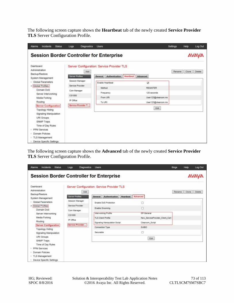
HG; Reviewed:
SPOC 8/8/2016
Solution & Interoperability Test Lab Application Notes
©2016 Avaya Inc. All Rights Reserved.
73 of 113
CLTLSCM7SM7SBC7
The following screen capture shows the Heartbeat tab of the newly created Service Provider
TLS Server Configuration Profile.
The following screen capture shows the Advanced tab of the newly created Service Provider
TLS Server Configuration Profile.
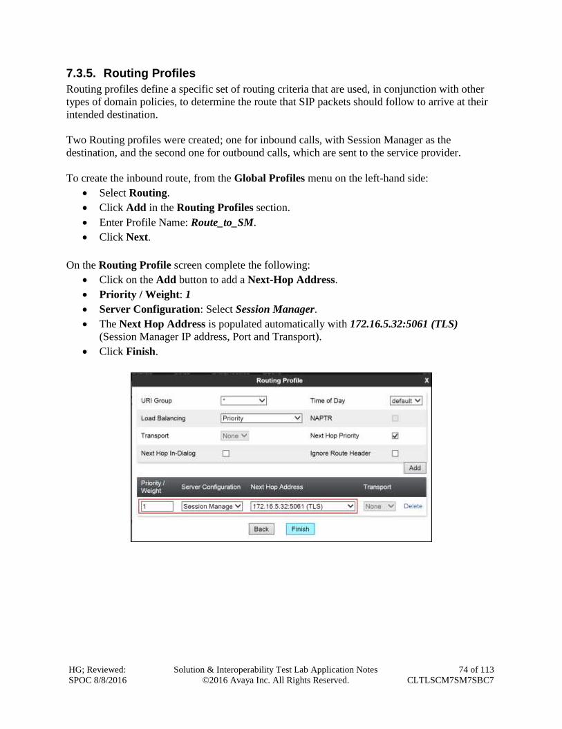
HG; Reviewed:
SPOC 8/8/2016
Solution & Interoperability Test Lab Application Notes
©2016 Avaya Inc. All Rights Reserved.
74 of 113
CLTLSCM7SM7SBC7
7.3.5. Routing Profiles
Routing profiles define a specific set of routing criteria that are used, in conjunction with other
types of domain policies, to determine the route that SIP packets should follow to arrive at their
intended destination.
Two Routing profiles were created; one for inbound calls, with Session Manager as the
destination, and the second one for outbound calls, which are sent to the service provider.
To create the inbound route, from the Global Profiles menu on the left-hand side:
Select Routing.
Click Add in the Routing Profiles section.
Enter Profile Name: Route_to_SM.
Click Next.
On the Routing Profile screen complete the following:
Click on the Add button to add a Next-Hop Address.
Priority / Weight: 1
Server Configuration: Select Session Manager.
The Next Hop Address is populated automatically with 172.16.5.32:5061 (TLS)
(Session Manager IP address, Port and Transport).
Click Finish.

HG; Reviewed:
SPOC 8/8/2016
Solution & Interoperability Test Lab Application Notes
©2016 Avaya Inc. All Rights Reserved.
75 of 113
CLTLSCM7SM7SBC7
The following screen capture shows the newly created Route_to_SM Routing Profile.
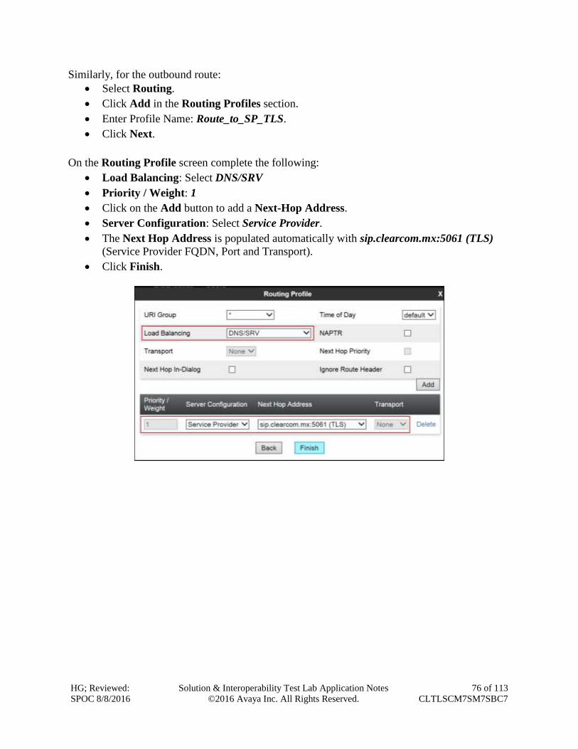
HG; Reviewed:
SPOC 8/8/2016
Solution & Interoperability Test Lab Application Notes
©2016 Avaya Inc. All Rights Reserved.
76 of 113
CLTLSCM7SM7SBC7
Similarly, for the outbound route:
Select Routing.
Click Add in the Routing Profiles section.
Enter Profile Name: Route_to_SP_TLS.
Click Next.
On the Routing Profile screen complete the following:
Load Balancing: Select DNS/SRV
Priority / Weight: 1
Click on the Add button to add a Next-Hop Address.
Server Configuration: Select Service Provider.
The Next Hop Address is populated automatically with sip.clearcom.mx:5061 (TLS)
(Service Provider FQDN, Port and Transport).
Click Finish.
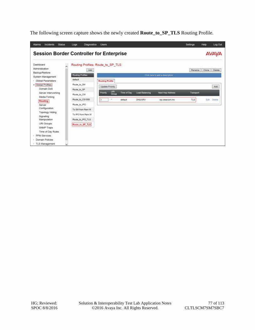
HG; Reviewed:
SPOC 8/8/2016
Solution & Interoperability Test Lab Application Notes
©2016 Avaya Inc. All Rights Reserved.
77 of 113
CLTLSCM7SM7SBC7
The following screen capture shows the newly created Route_to_SP_TLS Routing Profile.
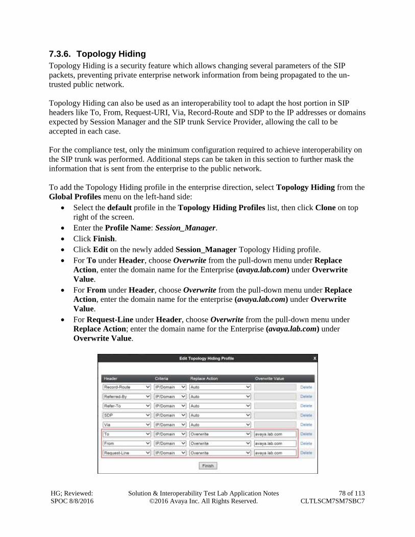
HG; Reviewed:
SPOC 8/8/2016
Solution & Interoperability Test Lab Application Notes
©2016 Avaya Inc. All Rights Reserved.
78 of 113
CLTLSCM7SM7SBC7
7.3.6. Topology Hiding
Topology Hiding is a security feature which allows changing several parameters of the SIP
packets, preventing private enterprise network information from being propagated to the un-
trusted public network.
Topology Hiding can also be used as an interoperability tool to adapt the host portion in SIP
headers like To, From, Request-URI, Via, Record-Route and SDP to the IP addresses or domains
expected by Session Manager and the SIP trunk Service Provider, allowing the call to be
accepted in each case.
For the compliance test, only the minimum configuration required to achieve interoperability on
the SIP trunk was performed. Additional steps can be taken in this section to further mask the
information that is sent from the enterprise to the public network.
To add the Topology Hiding profile in the enterprise direction, select Topology Hiding from the
Global Profiles menu on the left-hand side:
Select the default profile in the Topology Hiding Profiles list, then click Clone on top
right of the screen.
Enter the Profile Name: Session_Manager.
Click Finish.
Click Edit on the newly added Session_Manager Topology Hiding profile.
For To under Header, choose Overwrite from the pull-down menu under Replace
Action, enter the domain name for the Enterprise (avaya.lab.com) under Overwrite
Value.
For From under Header, choose Overwrite from the pull-down menu under Replace
Action, enter the domain name for the enterprise (avaya.lab.com) under Overwrite
Value.
For Request-Line under Header, choose Overwrite from the pull-down menu under
Replace Action; enter the domain name for the Enterprise (avaya.lab.com) under
Overwrite Value.

HG; Reviewed:
SPOC 8/8/2016
Solution & Interoperability Test Lab Application Notes
©2016 Avaya Inc. All Rights Reserved.
79 of 113
CLTLSCM7SM7SBC7
The following screen capture shows the newly created Session_Manager Topology Hiding
Profile.
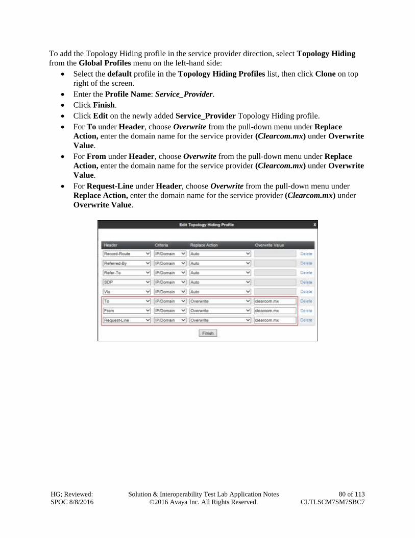
HG; Reviewed:
SPOC 8/8/2016
Solution & Interoperability Test Lab Application Notes
©2016 Avaya Inc. All Rights Reserved.
80 of 113
CLTLSCM7SM7SBC7
To add the Topology Hiding profile in the service provider direction, select Topology Hiding
from the Global Profiles menu on the left-hand side:
Select the default profile in the Topology Hiding Profiles list, then click Clone on top
right of the screen.
Enter the Profile Name: Service_Provider.
Click Finish.
Click Edit on the newly added Service_Provider Topology Hiding profile.
For To under Header, choose Overwrite from the pull-down menu under Replace
Action, enter the domain name for the service provider (Clearcom.mx) under Overwrite
Value.
For From under Header, choose Overwrite from the pull-down menu under Replace
Action, enter the domain name for the service provider (Clearcom.mx) under Overwrite
Value.
For Request-Line under Header, choose Overwrite from the pull-down menu under
Replace Action, enter the domain name for the service provider (Clearcom.mx) under
Overwrite Value.
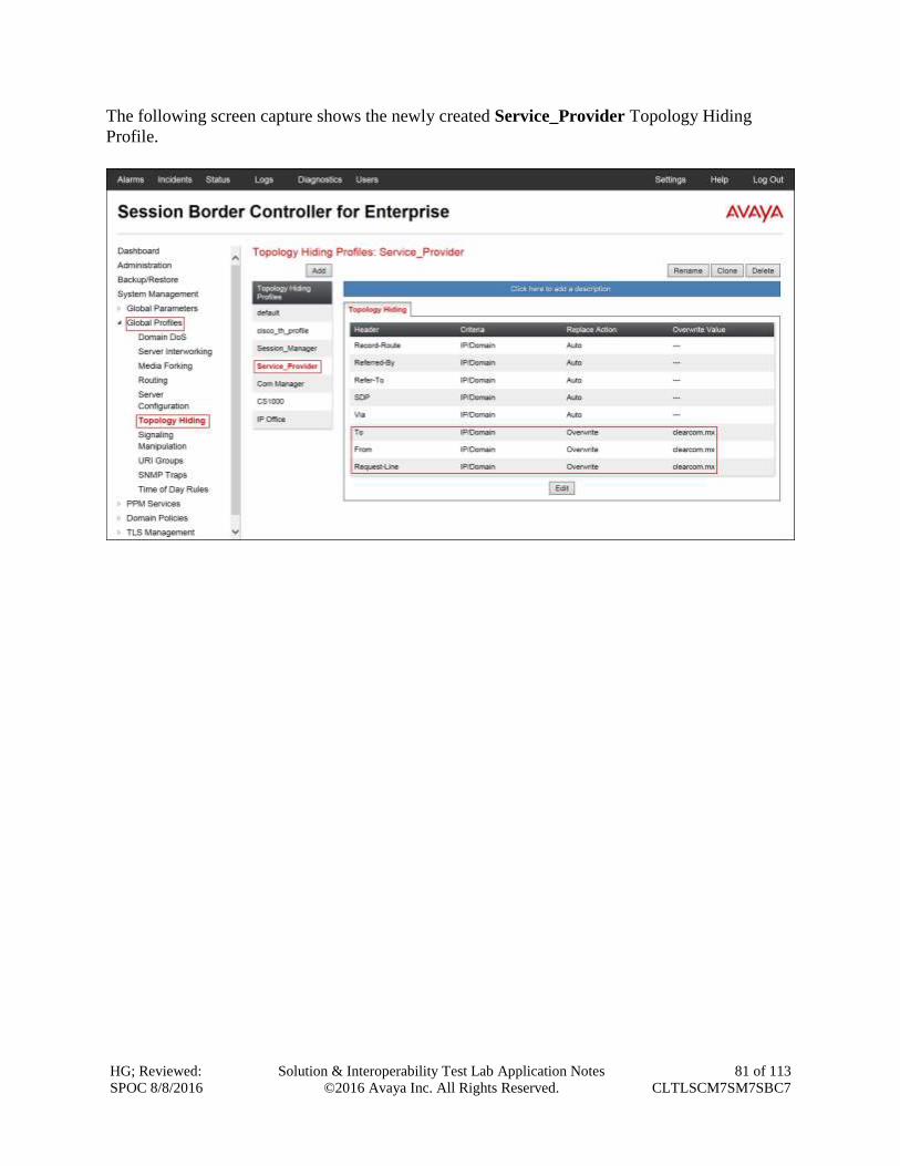
HG; Reviewed:
SPOC 8/8/2016
Solution & Interoperability Test Lab Application Notes
©2016 Avaya Inc. All Rights Reserved.
81 of 113
CLTLSCM7SM7SBC7
The following screen capture shows the newly created Service_Provider Topology Hiding
Profile.
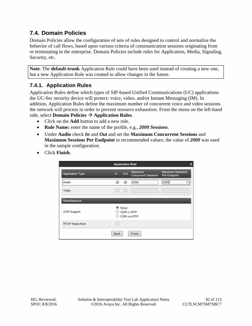
HG; Reviewed:
SPOC 8/8/2016
Solution & Interoperability Test Lab Application Notes
©2016 Avaya Inc. All Rights Reserved.
82 of 113
CLTLSCM7SM7SBC7
7.4. Domain Policies
Domain Policies allow the configuration of sets of rules designed to control and normalize the
behavior of call flows, based upon various criteria of communication sessions originating from
or terminating in the enterprise. Domain Policies include rules for Application, Media, Signaling,
Security, etc.
Note: The default-trunk Application Rule could have been used instead of creating a new one,
but a new Application Rule was created to allow changes in the future.
7.4.1. Application Rules
Application Rules define which types of SIP-based Unified Communications (UC) applications
the UC-Sec security device will protect: voice, video, and/or Instant Messaging (IM). In
addition, Application Rules define the maximum number of concurrent voice and video sessions
the network will process in order to prevent resource exhaustion. From the menu on the left-hand
side, select Domain Policies Application Rules.
Click on the Add button to add a new rule.
Rule Name: enter the name of the profile, e.g., 2000 Sessions.
Under Audio check In and Out and set the Maximum Concurrent Sessions and
Maximum Sessions Per Endpoint to recommended values; the value of 2000 was used
in the sample configuration.
Click Finish.
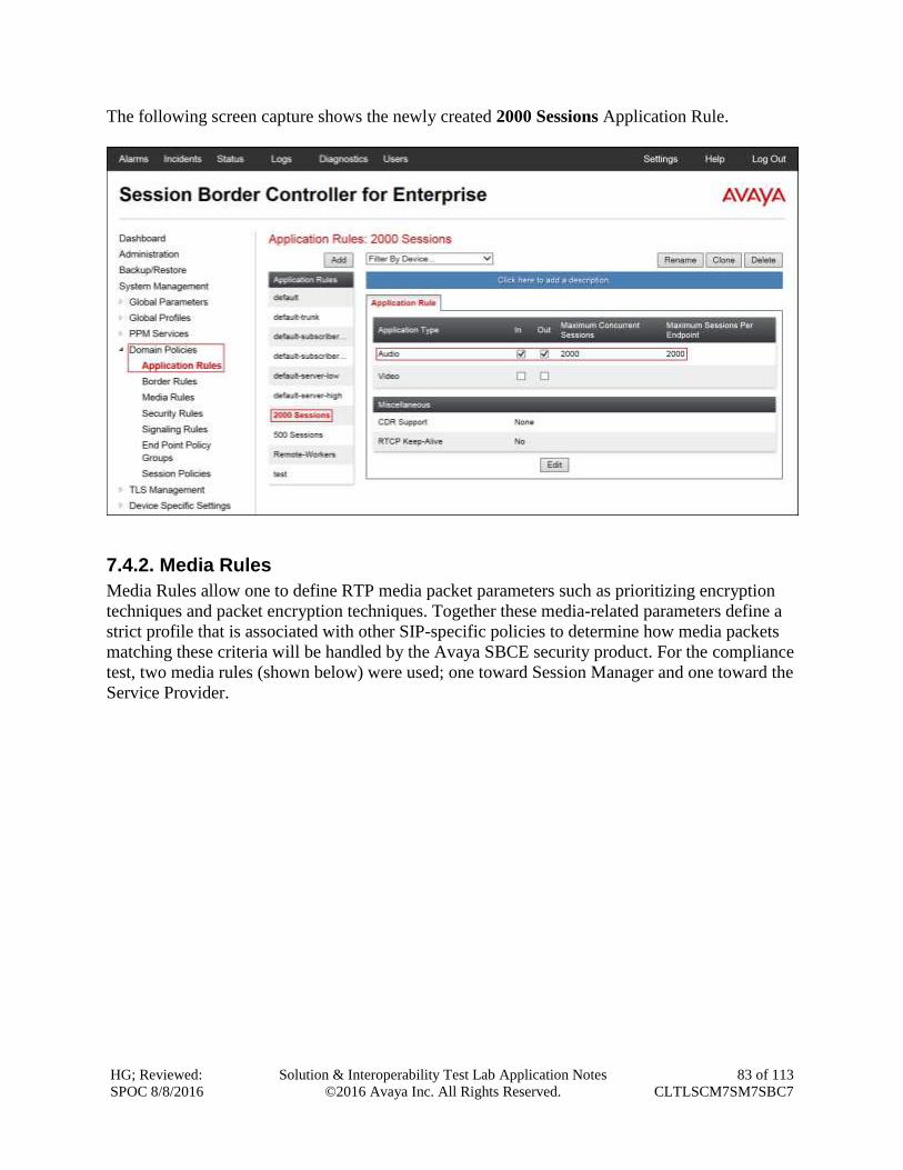
HG; Reviewed:
SPOC 8/8/2016
Solution & Interoperability Test Lab Application Notes
©2016 Avaya Inc. All Rights Reserved.
83 of 113
CLTLSCM7SM7SBC7
The following screen capture shows the newly created 2000 Sessions Application Rule.
7.4.2. Media Rules
Media Rules allow one to define RTP media packet parameters such as prioritizing encryption
techniques and packet encryption techniques. Together these media-related parameters define a
strict profile that is associated with other SIP-specific policies to determine how media packets
matching these criteria will be handled by the Avaya SBCE security product. For the compliance
test, two media rules (shown below) were used; one toward Session Manager and one toward the
Service Provider.
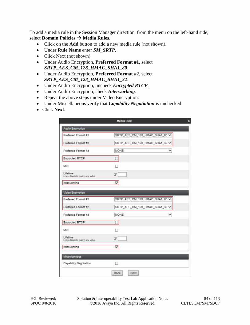
HG; Reviewed:
SPOC 8/8/2016
Solution & Interoperability Test Lab Application Notes
©2016 Avaya Inc. All Rights Reserved.
84 of 113
CLTLSCM7SM7SBC7
To add a media rule in the Session Manager direction, from the menu on the left-hand side,
select Domain Policies Media Rules.
Click on the Add button to add a new media rule (not shown).
Under Rule Name enter SM_SRTP.
Click Next (not shown).
Under Audio Encryption, Preferred Format #1, select
SRTP_AES_CM_128_HMAC_SHA1_80.
Under Audio Encryption, Preferred Format #2, select
SRTP_AES_CM_128_HMAC_SHA1_32.
Under Audio Encryption, uncheck Encrypted RTCP.
Under Audio Encryption, check Interworking.
Repeat the above steps under Video Encryption.
Under Miscellaneous verify that Capability Negotiation is unchecked.
Click Next.
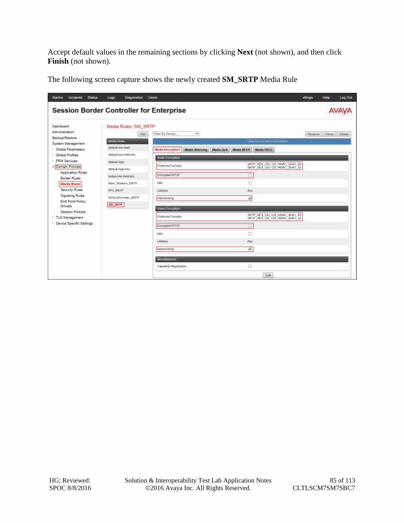
HG; Reviewed:
SPOC 8/8/2016
Solution & Interoperability Test Lab Application Notes
©2016 Avaya Inc. All Rights Reserved.
85 of 113
CLTLSCM7SM7SBC7
Accept default values in the remaining sections by clicking Next (not shown), and then click
Finish (not shown).
The following screen capture shows the newly created SM_SRTP Media Rule
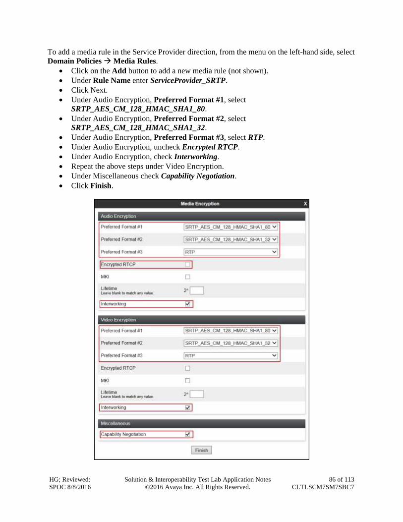
HG; Reviewed:
SPOC 8/8/2016
Solution & Interoperability Test Lab Application Notes
©2016 Avaya Inc. All Rights Reserved.
86 of 113
CLTLSCM7SM7SBC7
To add a media rule in the Service Provider direction, from the menu on the left-hand side, select
Domain Policies Media Rules.
Click on the Add button to add a new media rule (not shown).
Under Rule Name enter ServiceProvider_SRTP.
Click Next.
Under Audio Encryption, Preferred Format #1, select
SRTP_AES_CM_128_HMAC_SHA1_80.
Under Audio Encryption, Preferred Format #2, select
SRTP_AES_CM_128_HMAC_SHA1_32.
Under Audio Encryption, Preferred Format #3, select RTP.
Under Audio Encryption, uncheck Encrypted RTCP.
Under Audio Encryption, check Interworking.
Repeat the above steps under Video Encryption.
Under Miscellaneous check Capability Negotiation.
Click Finish.
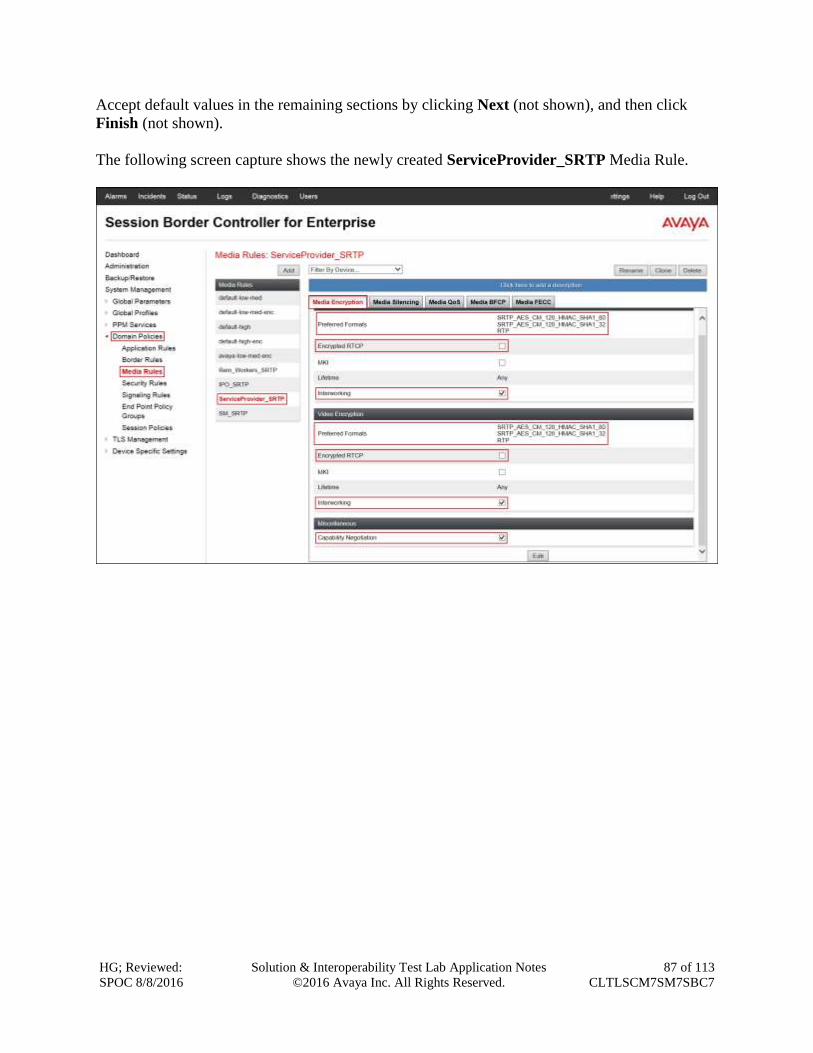
HG; Reviewed:
SPOC 8/8/2016
Solution & Interoperability Test Lab Application Notes
©2016 Avaya Inc. All Rights Reserved.
87 of 113
CLTLSCM7SM7SBC7
Accept default values in the remaining sections by clicking Next (not shown), and then click
Finish (not shown).
The following screen capture shows the newly created ServiceProvider_SRTP Media Rule.
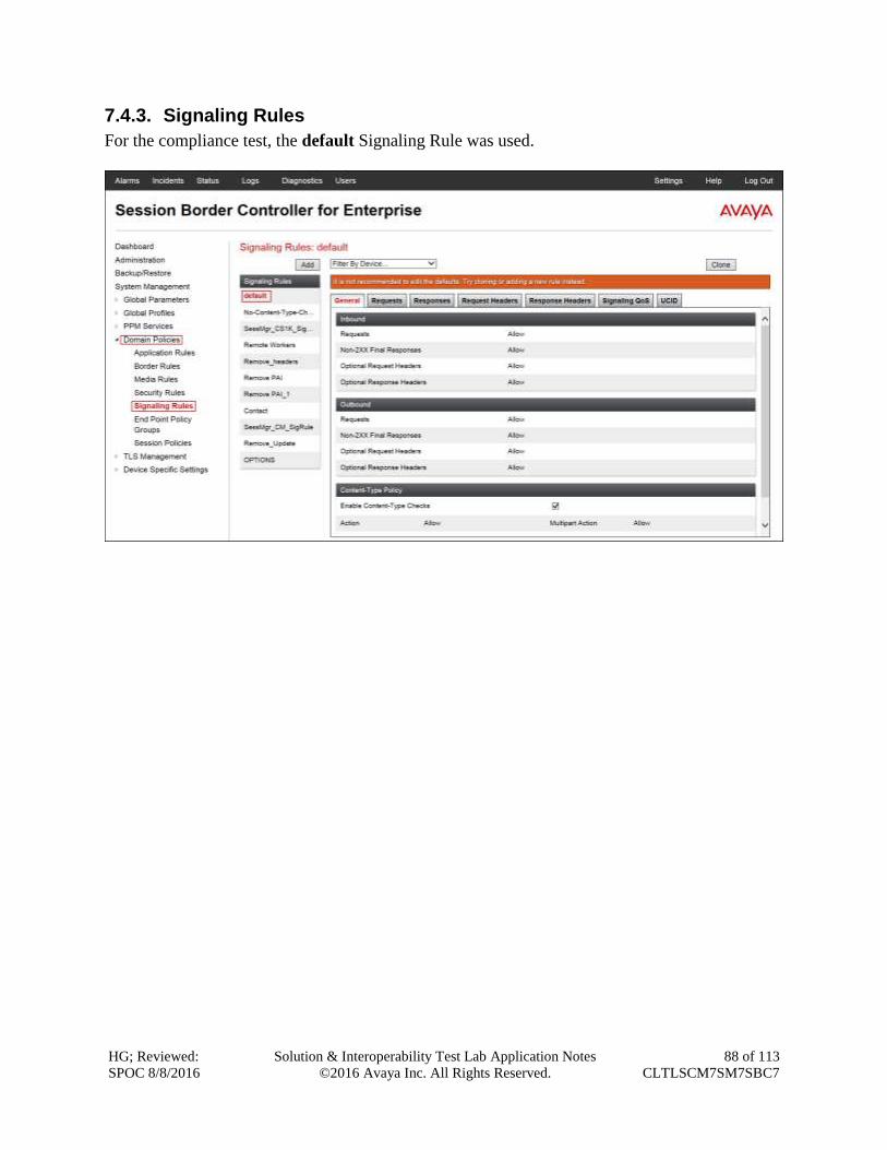
HG; Reviewed:
SPOC 8/8/2016
Solution & Interoperability Test Lab Application Notes
©2016 Avaya Inc. All Rights Reserved.
88 of 113
CLTLSCM7SM7SBC7
7.4.3. Signaling Rules
For the compliance test, the default Signaling Rule was used.
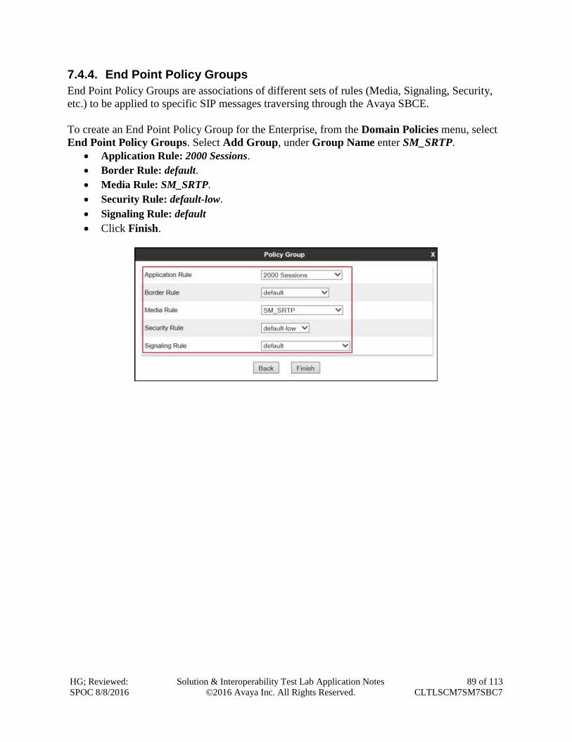
HG; Reviewed:
SPOC 8/8/2016
Solution & Interoperability Test Lab Application Notes
©2016 Avaya Inc. All Rights Reserved.
89 of 113
CLTLSCM7SM7SBC7
7.4.4. End Point Policy Groups
End Point Policy Groups are associations of different sets of rules (Media, Signaling, Security,
etc.) to be applied to specific SIP messages traversing through the Avaya SBCE.
To create an End Point Policy Group for the Enterprise, from the Domain Policies menu, select
End Point Policy Groups. Select Add Group, under Group Name enter SM_SRTP.
Application Rule: 2000 Sessions.
Border Rule: default.
Media Rule: SM_SRTP.
Security Rule: default-low.
Signaling Rule: default
Click Finish.
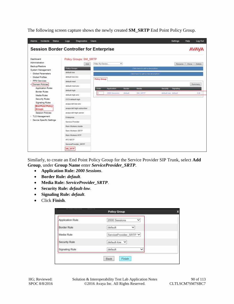
HG; Reviewed:
SPOC 8/8/2016
Solution & Interoperability Test Lab Application Notes
©2016 Avaya Inc. All Rights Reserved.
90 of 113
CLTLSCM7SM7SBC7
The following screen capture shows the newly created SM_SRTP End Point Policy Group.
Similarly, to create an End Point Policy Group for the Service Provider SIP Trunk, select Add
Group, under Group Name enter ServiceProvider_SRTP.
Application Rule: 2000 Sessions.
Border Rule: default.
Media Rule: ServiceProvider_SRTP.
Security Rule: default-low.
Signaling Rule: default.
Click Finish.
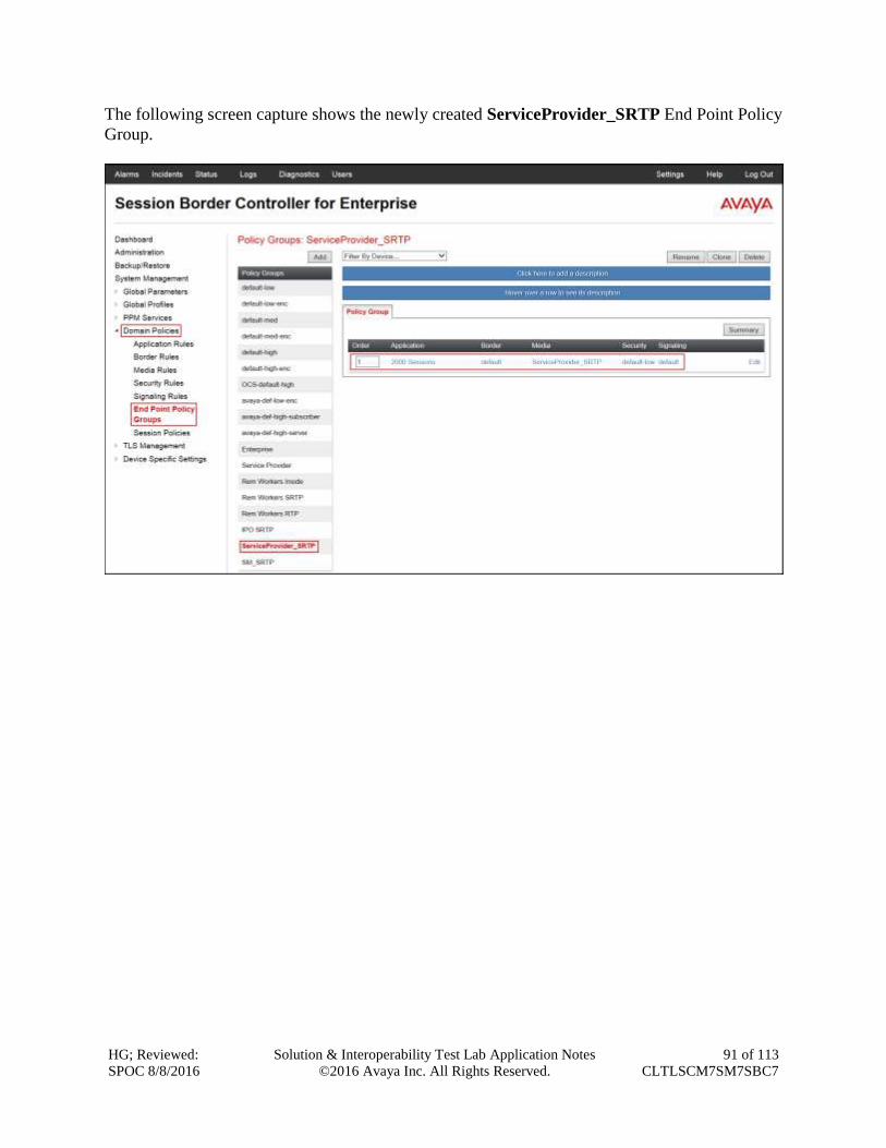
HG; Reviewed:
SPOC 8/8/2016
Solution & Interoperability Test Lab Application Notes
©2016 Avaya Inc. All Rights Reserved.
91 of 113
CLTLSCM7SM7SBC7
The following screen capture shows the newly created ServiceProvider_SRTP End Point Policy
Group.
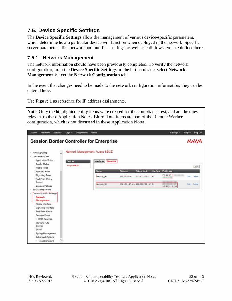
HG; Reviewed:
SPOC 8/8/2016
Solution & Interoperability Test Lab Application Notes
©2016 Avaya Inc. All Rights Reserved.
92 of 113
CLTLSCM7SM7SBC7
7.5. Device Specific Settings
The Device Specific Settings allow the management of various device-specific parameters,
which determine how a particular device will function when deployed in the network. Specific
server parameters, like network and interface settings, as well as call flows, etc. are defined here.
7.5.1. Network Management
The network information should have been previously completed. To verify the network
configuration, from the Device Specific Settings on the left hand side, select Network
Management. Select the Network Configuration tab.
In the event that changes need to be made to the network configuration information, they can be
entered here.
Use Figure 1 as reference for IP address assignments.
Note: Only the highlighted entity items were created for the compliance test, and are the ones
relevant to these Application Notes. Blurred out items are part of the Remote Worker
configuration, which is not discussed in these Application Notes.
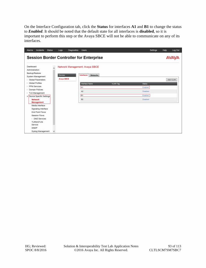
HG; Reviewed:
SPOC 8/8/2016
Solution & Interoperability Test Lab Application Notes
©2016 Avaya Inc. All Rights Reserved.
93 of 113
CLTLSCM7SM7SBC7
On the Interface Configuration tab, click the Status for interfaces A1 and B1 to change the status
to Enabled. It should be noted that the default state for all interfaces is disabled, so it is
important to perform this step or the Avaya SBCE will not be able to communicate on any of its
interfaces.
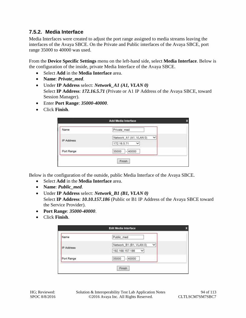
HG; Reviewed:
SPOC 8/8/2016
Solution & Interoperability Test Lab Application Notes
©2016 Avaya Inc. All Rights Reserved.
94 of 113
CLTLSCM7SM7SBC7
7.5.2. Media Interface
Media Interfaces were created to adjust the port range assigned to media streams leaving the
interfaces of the Avaya SBCE. On the Private and Public interfaces of the Avaya SBCE, port
range 35000 to 40000 was used.
From the Device Specific Settings menu on the left-hand side, select Media Interface. Below is
the configuration of the inside, private Media Interface of the Avaya SBCE.
Select Add in the Media Interface area.
Name: Private_med.
Under IP Address select: Network_A1 (A1, VLAN 0)
Select IP Address: 172.16.5.71 (Private or A1 IP Address of the Avaya SBCE, toward
Session Manager).
Enter Port Range: 35000-40000.
Click Finish.
Below is the configuration of the outside, public Media Interface of the Avaya SBCE.
Select Add in the Media Interface area.
Name: Public_med.
Under IP Address select: Network_B1 (B1, VLAN 0)
Select IP Address: 10.10.157.186 (Public or B1 IP Address of the Avaya SBCE toward
the Service Provider).
Port Range: 35000-40000.
Click Finish.
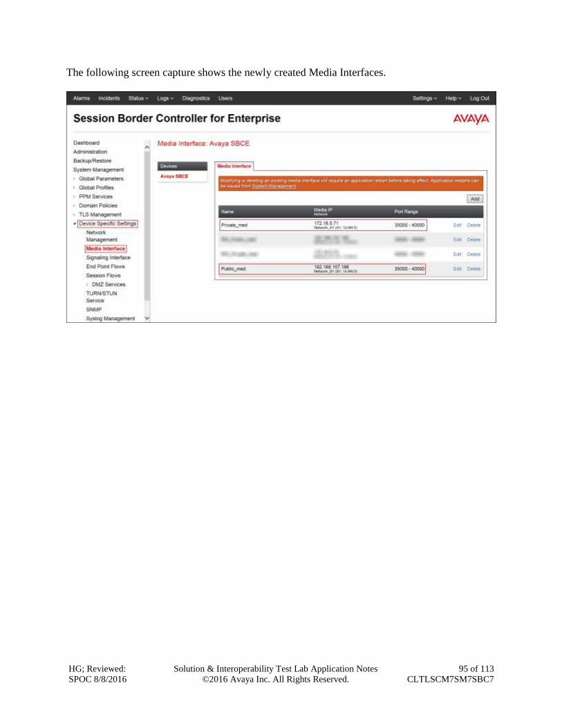
HG; Reviewed:
SPOC 8/8/2016
Solution & Interoperability Test Lab Application Notes
©2016 Avaya Inc. All Rights Reserved.
95 of 113
CLTLSCM7SM7SBC7
The following screen capture shows the newly created Media Interfaces.
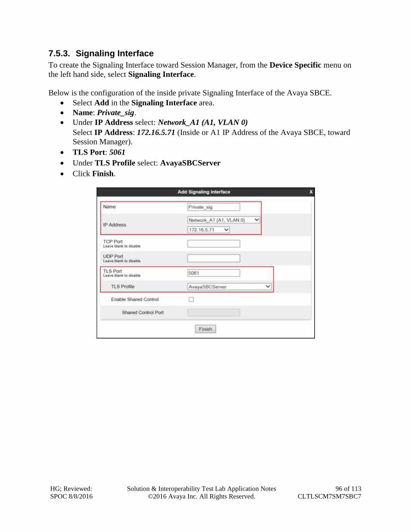
HG; Reviewed:
SPOC 8/8/2016
Solution & Interoperability Test Lab Application Notes
©2016 Avaya Inc. All Rights Reserved.
96 of 113
CLTLSCM7SM7SBC7
7.5.3. Signaling Interface
To create the Signaling Interface toward Session Manager, from the Device Specific menu on
the left hand side, select Signaling Interface.
Below is the configuration of the inside private Signaling Interface of the Avaya SBCE.
Select Add in the Signaling Interface area.
Name: Private_sig.
Under IP Address select: Network_A1 (A1, VLAN 0)
Select IP Address: 172.16.5.71 (Inside or A1 IP Address of the Avaya SBCE, toward
Session Manager).
TLS Port: 5061
Under TLS Profile select: AvayaSBCServer
Click Finish.
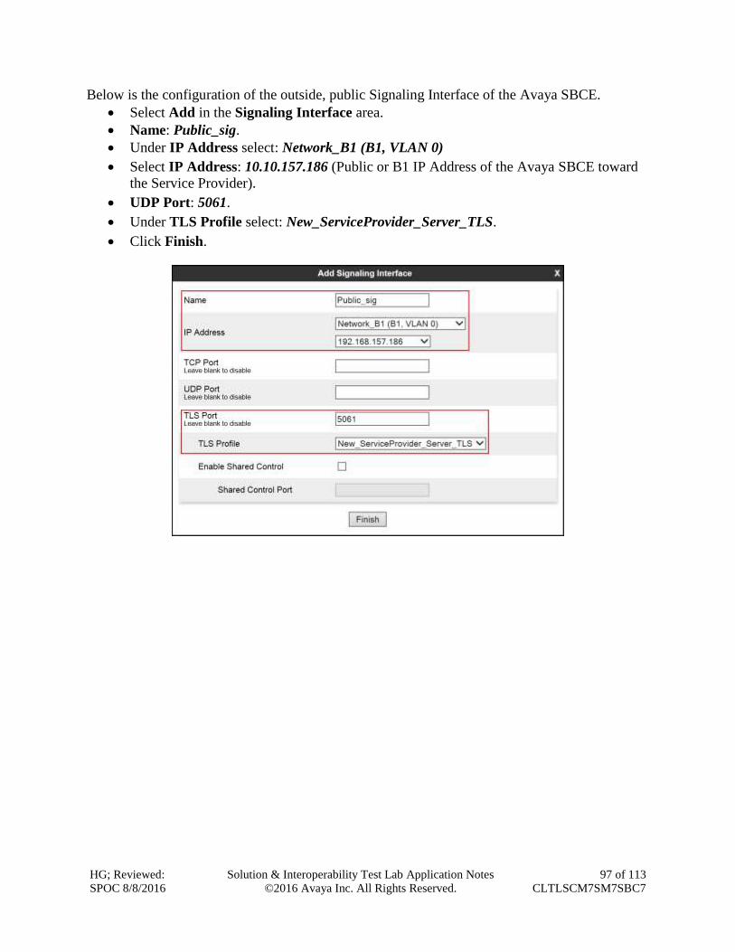
HG; Reviewed:
SPOC 8/8/2016
Solution & Interoperability Test Lab Application Notes
©2016 Avaya Inc. All Rights Reserved.
97 of 113
CLTLSCM7SM7SBC7
Below is the configuration of the outside, public Signaling Interface of the Avaya SBCE.
Select Add in the Signaling Interface area.
Name: Public_sig.
Under IP Address select: Network_B1 (B1, VLAN 0)
Select IP Address: 10.10.157.186 (Public or B1 IP Address of the Avaya SBCE toward
the Service Provider).
UDP Port: 5061.
Under TLS Profile select: New_ServiceProvider_Server_TLS.
Click Finish.
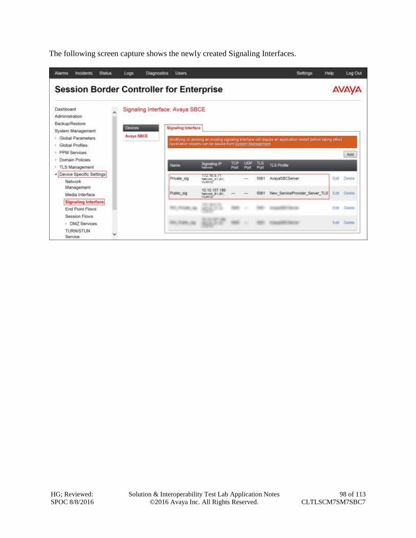
HG; Reviewed:
SPOC 8/8/2016
Solution & Interoperability Test Lab Application Notes
©2016 Avaya Inc. All Rights Reserved.
98 of 113
CLTLSCM7SM7SBC7
The following screen capture shows the newly created Signaling Interfaces.
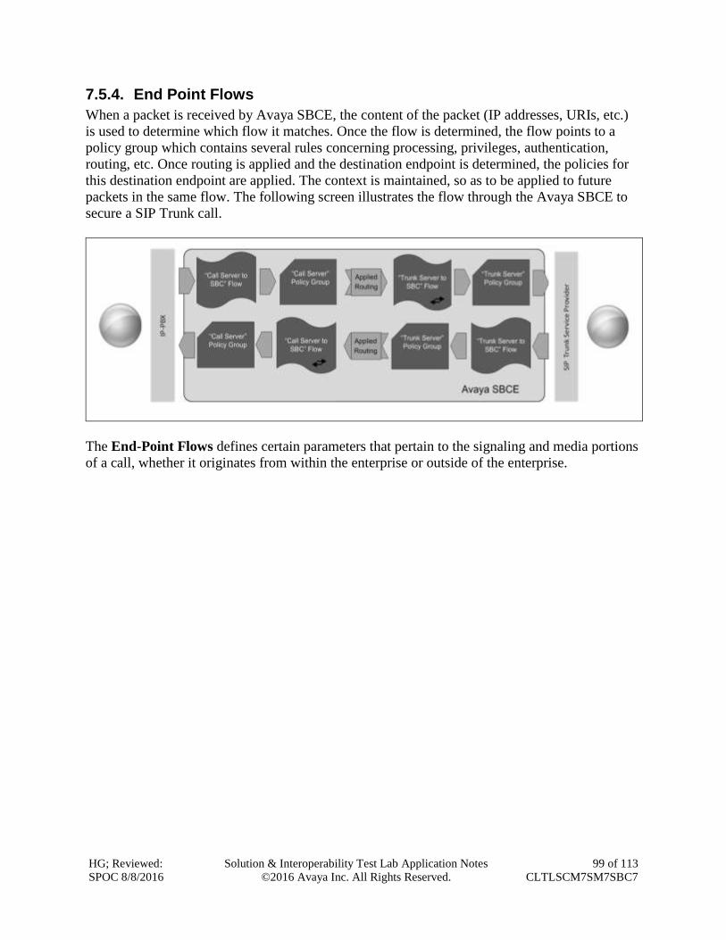
HG; Reviewed:
SPOC 8/8/2016
Solution & Interoperability Test Lab Application Notes
©2016 Avaya Inc. All Rights Reserved.
99 of 113
CLTLSCM7SM7SBC7
7.5.4. End Point Flows
When a packet is received by Avaya SBCE, the content of the packet (IP addresses, URIs, etc.)
is used to determine which flow it matches. Once the flow is determined, the flow points to a
policy group which contains several rules concerning processing, privileges, authentication,
routing, etc. Once routing is applied and the destination endpoint is determined, the policies for
this destination endpoint are applied. The context is maintained, so as to be applied to future
packets in the same flow. The following screen illustrates the flow through the Avaya SBCE to
secure a SIP Trunk call.
The End-Point Flows defines certain parameters that pertain to the signaling and media portions
of a call, whether it originates from within the enterprise or outside of the enterprise.
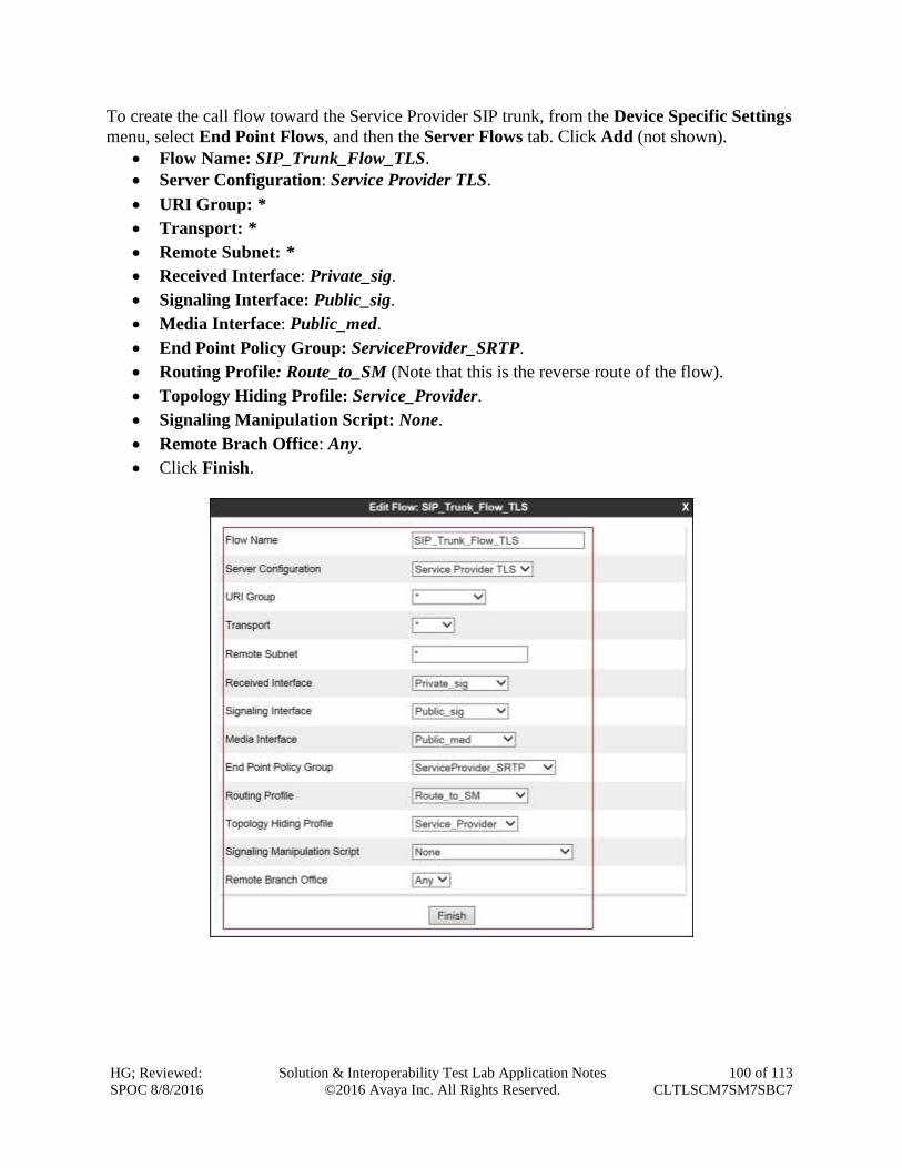
HG; Reviewed:
SPOC 8/8/2016
Solution & Interoperability Test Lab Application Notes
©2016 Avaya Inc. All Rights Reserved.
100 of 113
CLTLSCM7SM7SBC7
To create the call flow toward the Service Provider SIP trunk, from the Device Specific Settings
menu, select End Point Flows, and then the Server Flows tab. Click Add (not shown).
Flow Name: SIP_Trunk_Flow_TLS.
Server Configuration: Service Provider TLS.
URI Group: *
Transport: *
Remote Subnet: *
Received Interface: Private_sig.
Signaling Interface: Public_sig.
Media Interface: Public_med.
End Point Policy Group: ServiceProvider_SRTP.
Routing Profile: Route_to_SM (Note that this is the reverse route of the flow).
Topology Hiding Profile: Service_Provider.
Signaling Manipulation Script: None.
Remote Brach Office: Any.
Click Finish.
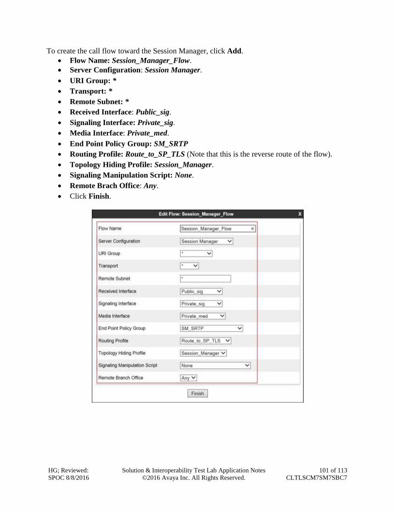
HG; Reviewed:
SPOC 8/8/2016
Solution & Interoperability Test Lab Application Notes
©2016 Avaya Inc. All Rights Reserved.
101 of 113
CLTLSCM7SM7SBC7
To create the call flow toward the Session Manager, click Add.
Flow Name: Session_Manager_Flow.
Server Configuration: Session Manager.
URI Group: *
Transport: *
Remote Subnet: *
Received Interface: Public_sig.
Signaling Interface: Private_sig.
Media Interface: Private_med.
End Point Policy Group: SM_SRTP
Routing Profile: Route_to_SP_TLS (Note that this is the reverse route of the flow).
Topology Hiding Profile: Session_Manager.
Signaling Manipulation Script: None.
Remote Brach Office: Any.
Click Finish.
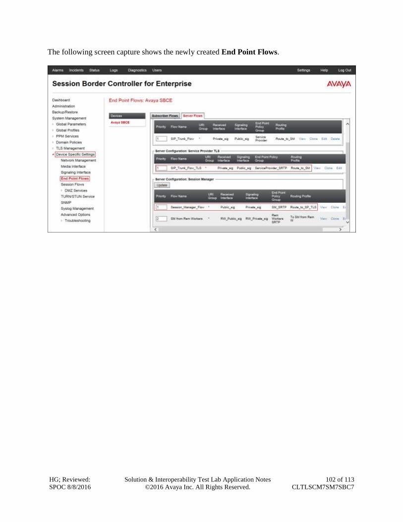
HG; Reviewed:
SPOC 8/8/2016
Solution & Interoperability Test Lab Application Notes
©2016 Avaya Inc. All Rights Reserved.
102 of 113
CLTLSCM7SM7SBC7
The following screen capture shows the newly created End Point Flows.
HG; Reviewed:
SPOC 8/8/2016
Solution & Interoperability Test Lab Application Notes
©2016 Avaya Inc. All Rights Reserved.
103 of 113
CLTLSCM7SM7SBC7
8. Clearcom SIP Trunking Service Configuration To use Clearcom’s SIP Trunking Service, a customer must request the service from Clearcom
using the established sales processes. The process can be started by contacting Clearcom via the
corporate web site at: http://www.clearcom.mx/ and requesting information.
During the signup process, Clearcom and the customer will discuss details about the preferred
method to be used to connect the customer’s enterprise network to Clearcom’s network.
Clearcom is responsible for the configuration of Clearcom SIP Services. The customer will need
to provide a public IP address to be used to reach the Avaya SBCE at the enterprise. In the case
of the compliance test, this is the outside or public IP address of the Avaya SBCE (B1 interface).
The customer will also need the IP addresses for the primary and the secondary public DNS
servers, these addresses can be obtained from the local ISP in Mexico.
Clearcom will provide the following information:
SIP Trunk registration credentials (user name, password, SIP domain).
Fully Qualified Domain Name of the Clearcom SIP proxy server.
DID numbers.
Supported codecs and order of preference.
Any IP addresses and port numbers used for signaling or media that will need access to
the enterprise network through any security devices.
HG; Reviewed:
SPOC 8/8/2016
Solution & Interoperability Test Lab Application Notes
©2016 Avaya Inc. All Rights Reserved.
104 of 113
CLTLSCM7SM7SBC7
9. Verification and Troubleshooting This section provides verification steps that may be performed in the field to verify that the
solution is configured properly. This section also provides a list of useful troubleshooting
commands that can be used to troubleshoot the solution.
Verification Steps:
1. Verify that endpoints at the enterprise site can place calls to the PSTN and that the call
remains active for more than 35 seconds. This time period is included to verify that
proper routing of the SIP messaging has satisfied SIP protocol timers.
2. Verify that endpoints at the enterprise site can receive calls from the PSTN and that the
call can remain active with two-way audio for more than 35 seconds.
3. Verify that the user on the PSTN can end an active call by hanging up.
4. Verify that an endpoint at the enterprise site can end an active call by hanging up.
9.1. Troubleshooting
9.1.1. Communication Manager
list trace station <extension number>
Traces calls to and from a specific station.
list trace tac <trunk access code number>
Traces calls over a specific trunk group.
status signaling-group <signaling group number>
Displays signaling group service state.
status trunk <trunk group number>
Displays trunk group service state.
status station <extension number>
Displays signaling and media information for an active call on a specific station.
9.1.2. Session Manager
traceSM -x – Session Manager command line tool for traffic analysis. Login to the
Session Manager management CLI interface to run this command.
Call Routing Test - The Call Routing Test verifies the routing for a particular source and
destination. To run the routing test, navigate to Home Elements Session Manager
System Tools Call Routing Test. Enter the requested data to run the test.
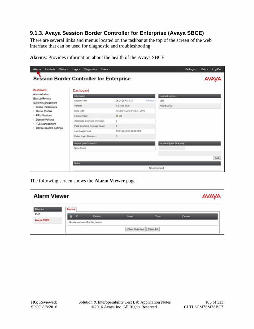
HG; Reviewed:
SPOC 8/8/2016
Solution & Interoperability Test Lab Application Notes
©2016 Avaya Inc. All Rights Reserved.
105 of 113
CLTLSCM7SM7SBC7
9.1.3. Avaya Session Border Controller for Enterprise (Avaya SBCE)
There are several links and menus located on the taskbar at the top of the screen of the web
interface that can be used for diagnostic and troubleshooting.
Alarms: Provides information about the health of the Avaya SBCE.
The following screen shows the Alarm Viewer page.
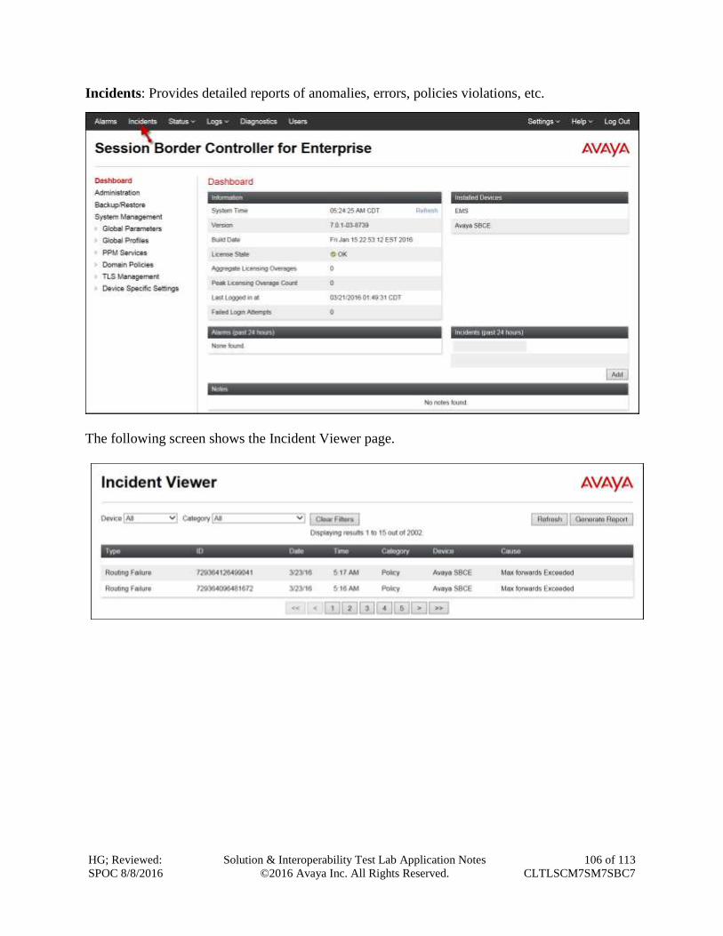
HG; Reviewed:
SPOC 8/8/2016
Solution & Interoperability Test Lab Application Notes
©2016 Avaya Inc. All Rights Reserved.
106 of 113
CLTLSCM7SM7SBC7
Incidents: Provides detailed reports of anomalies, errors, policies violations, etc.
The following screen shows the Incident Viewer page.
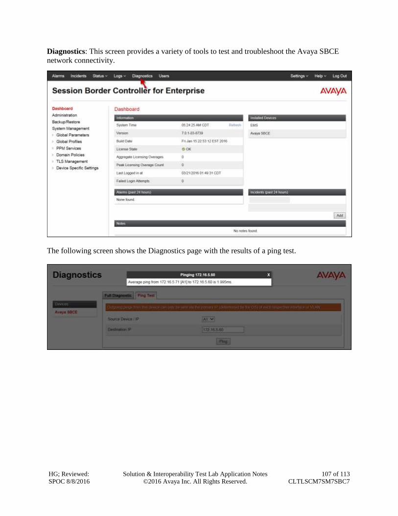
HG; Reviewed:
SPOC 8/8/2016
Solution & Interoperability Test Lab Application Notes
©2016 Avaya Inc. All Rights Reserved.
107 of 113
CLTLSCM7SM7SBC7
Diagnostics: This screen provides a variety of tools to test and troubleshoot the Avaya SBCE
network connectivity.
The following screen shows the Diagnostics page with the results of a ping test.
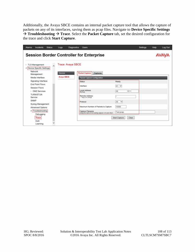
HG; Reviewed:
SPOC 8/8/2016
Solution & Interoperability Test Lab Application Notes
©2016 Avaya Inc. All Rights Reserved.
108 of 113
CLTLSCM7SM7SBC7
Additionally, the Avaya SBCE contains an internal packet capture tool that allows the capture of
packets on any of its interfaces, saving them as pcap files. Navigate to Device Specific Settings
Troubleshooting Trace. Select the Packet Capture tab, set the desired configuration for
the trace and click Start Capture.
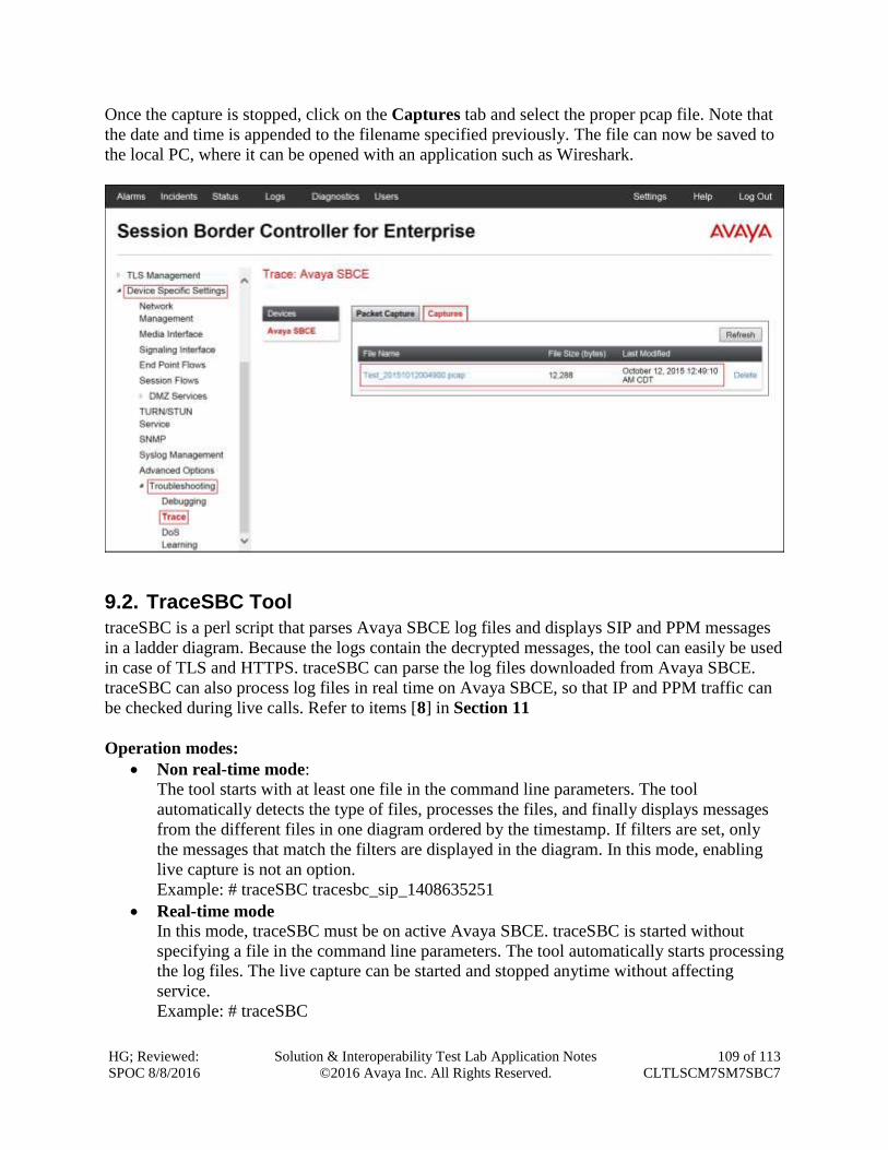
HG; Reviewed:
SPOC 8/8/2016
Solution & Interoperability Test Lab Application Notes
©2016 Avaya Inc. All Rights Reserved.
109 of 113
CLTLSCM7SM7SBC7
Once the capture is stopped, click on the Captures tab and select the proper pcap file. Note that
the date and time is appended to the filename specified previously. The file can now be saved to
the local PC, where it can be opened with an application such as Wireshark.
9.2. TraceSBC Tool
traceSBC is a perl script that parses Avaya SBCE log files and displays SIP and PPM messages
in a ladder diagram. Because the logs contain the decrypted messages, the tool can easily be used
in case of TLS and HTTPS. traceSBC can parse the log files downloaded from Avaya SBCE.
traceSBC can also process log files in real time on Avaya SBCE, so that IP and PPM traffic can
be checked during live calls. Refer to items [8] in Section 11
Operation modes:
Non real-time mode:
The tool starts with at least one file in the command line parameters. The tool
automatically detects the type of files, processes the files, and finally displays messages
from the different files in one diagram ordered by the timestamp. If filters are set, only
the messages that match the filters are displayed in the diagram. In this mode, enabling
live capture is not an option.
Example: # traceSBC tracesbc_sip_1408635251
Real-time mode
In this mode, traceSBC must be on active Avaya SBCE. traceSBC is started without
specifying a file in the command line parameters. The tool automatically starts processing
the log files. The live capture can be started and stopped anytime without affecting
service.
Example: # traceSBC
HG; Reviewed:
SPOC 8/8/2016
Solution & Interoperability Test Lab Application Notes
©2016 Avaya Inc. All Rights Reserved.
110 of 113
CLTLSCM7SM7SBC7
Log Files:
Avaya SBCE can log SIP messages as processed by different subsystems and also log PPM
messages. The traceSBC utility can process the log files real-time by opening the latest log files
in the given directories. TraceSBC also checks regularly if a new file is generated, in which case
the old one is closed and processing continues with the new one. A new log file is generated
every time the relevant processes restart, or when the size reaches the limit of ~10 Megabytes.
Log Locations:
SIP messages are found at /archive/log/tracesbc/tracesbc_sip/ and PPM messages can be found at
/archive/log/tracesbc/tracesbc_ppm/.
Active files are of the following format: -rw-rw---- 1 root root 112445 Aug 21 10:12 tracesbc_sip_1408631651
Inactive or closed files are of the following format: -rw-rw---- 1 root root 175236 Aug 21 06:33 tracesbc_sip_1408617250_1408620820_1
or -rw-rw---- 1 root root 31706 Jul 10 13:34 tracesbc_sip_1436549674_1436553270_1.gz
10. Conclusion These Application Notes describe the procedures necessary for configuring Session Initiation
Protocol (SIP) Trunk service for an enterprise solution consisting of Avaya Aura®
Communication Manager Release 7.0, Avaya Aura® Session Manager Release 7.0, and Avaya
Session Border Controller for Enterprise Release 7.0 to support Clearcom SIP Trunking Service
using TLS, as shown in Figure 1.
Interoperability testing was completed successfully with the observations/limitations outlined in
the scope of testing in Section 2.1 as well as under test results in Section 2.2.
HG; Reviewed:
SPOC 8/8/2016
Solution & Interoperability Test Lab Application Notes
©2016 Avaya Inc. All Rights Reserved.
111 of 113
CLTLSCM7SM7SBC7
11. References This section references the documentation relevant to these Application Notes.
Product documentation for Avaya Aura® Communication Manager, including the following, is
available at: http://support.avaya.com/
[1] Administering Avaya Aura® Communication Manager, Release 7.0, August 2015, Document
Number 03-300509.
[2] Avaya Aura® Communication Manager Feature Description and Implementation, Release
7.0, August 2015, Document Number 555-245-205.
[3] Avaya Aura® Communication Manager Security Design, Release 6.3, Issue 6, June 2015,
Document Number 03-601973.
Product documentation for Avaya Aura® System Manager, including the following, is available
at: http://support.avaya.com/
[4] Administering Avaya Aura® System Manager for Release 7.0, Release 7.0, Issue 1, August
2015.
[5] Avaya Aura® System Manager Release 7.0 Security Guide, Release 7.0, Issue 1, August
2015
Product documentation for Avaya Aura® Session Manager, including the following, is available
at: http://support.avaya.com/
[6] Administering Avaya Aura® Session Manager, Release 7.0, August 2015.
Product documentation for the Avaya Session Border Controller for Enterprise, including the
following, is available at: http://support.avaya.com/
[7] Deploying Avaya Session Border Controller for Enterprise, Release 7.0, August 2015.
[8] Administering Avaya Session Border Controller for Enterprise, Release 7.0, August 2015.
Product documentation for Avaya Aura® Media Server, is available at: http://support.avaya.com/
[9] Implementing and Administering Avaya Aura® Media Server. Release 7.7. August 2015.
[10] Quick Start Guide to Using the Avaya Aura® Media Server with Avaya Aura®
Communication Manager. White Paper. August 2015.
Other resources:
[11] RFC 3261 SIP: Session Initiation Protocol, http://www.ietf.org/.
[12] RFC 2833 RTP Payload for DTMF Digits, Telephony Tones and Telephony Signals,
http://www.ietf.org/
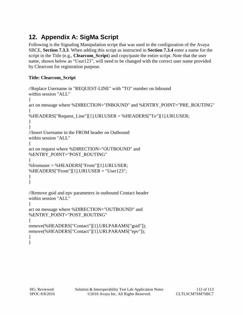
HG; Reviewed:
SPOC 8/8/2016
Solution & Interoperability Test Lab Application Notes
©2016 Avaya Inc. All Rights Reserved.
112 of 113
CLTLSCM7SM7SBC7
12. Appendix A: SigMa Script Following is the Signaling Manipulation script that was used in the configuration of the Avaya
SBCE, Section 7.3.3. When adding this script as instructed in Section 7.3.4 enter a name for the
script in the Title (e.g., Clearcom_Script) and copy/paste the entire script. Note that the user
name, shown below as “User123”, will need to be changed with the correct user name provided
by Clearcom for registration purpose.
Title: Clearcom_Script
//Replace Username in "REQUEST-LINE" with "TO" number on Inbound
within session "ALL"
{
act on message where %DIRECTION="INBOUND" and %ENTRY_POINT="PRE_ROUTING"
{
%HEADERS["Request_Line"][1].URI.USER = %HEADERS["To"][1].URI.USER;
}
}
//Insert Username in the FROM header on Outbound
within session "ALL"
{
act on request where %DIRECTION="OUTBOUND" and
%ENTRY_POINT="POST_ROUTING"
{
%fromuser = %HEADERS["From"][1].URI.USER;
%HEADERS["From"][1].URI.USER = "User123";
}
}
//Remove gsid and epv parameters in outbound Contact header
within session "ALL"
{
act on message where %DIRECTION="OUTBOUND" and
%ENTRY_POINT="POST_ROUTING"
{
remove(%HEADERS["Contact"][1].URI.PARAMS["gsid"]);
remove(%HEADERS["Contact"][1].URI.PARAMS["epv"]);
}
}
HG; Reviewed:
SPOC 8/8/2016
Solution & Interoperability Test Lab Application Notes
©2016 Avaya Inc. All Rights Reserved.
113 of 113
CLTLSCM7SM7SBC7
©2016 Avaya Inc. All Rights Reserved.
Avaya and the Avaya Logo are trademarks of Avaya Inc. All trademarks identified by ® and
™ are registered trademarks or trademarks, respectively, of Avaya Inc. All other trademarks
are the property of their respective owners. The information provided in these Application
Notes is subject to change without notice. The configurations, technical data, and
recommendations provided in these Application Notes are believed to be accurate and
dependable, but are presented without express or implied warranty. Users are responsible for
their application of any products specified in these Application Notes.
Please e-mail any questions or comments pertaining to these Application Notes along with the
full title name and filename, located in the lower right corner, directly to the Avaya
DevConnect Program at [email protected].