automatic transfer switch (ats) yes1 series ga model
TRANSCRIPT
Automatic Transfer Switch (ATS)YES1 series GA model
Instruction Book
P-01
Contents Index
1 Types and Meanings-------------------------------------042 Main Technology Parameters --------------------------043 Products Structure instruction--------------------------054 Outline Overall and installing dimensions------------065 Usage Method--------------------------------------------086 DC24V/DC48V-------------------------------------------147 With Controller use explain------------------------------158 Method of terminal connection--------------------------199 Correct installation method for switch------------------1910 wiring methods of switch--------------------------------2011 Note of debug switch-------------------------------------20
P-02
Before you operate this Automtic transfer switch (hereinafter ATS),please read and understand these instructions carefully.
Notice
Before you install or operate the ATS,please read and understand these instructions carefully.Only professional ATS personnel can carry out this installation,adjustment, repair and maintenance.Many parts of the ATS, including printed circuit boards, when it work on-line voltage, can not touch these parts. Use insulated tools only.Do not touch the components which not protected.Before maintenance the line of ATS, we should take the following preventive measures:Disconnect all power.Put a "prohibited closing" signs before the locate of the switchswitch to "0" position and then hang padlock.
Dangerous
Inconsistent with the line voltage Before Power and configuration for the ATS , we must ensure the line voltage is in the scope of the power supply voltage in the name plate of the ATS If theline voltage and power supply voltage range is different ,it is possible to damage ATS. Not in accordance with the instructions will result in the damage of the equipment.
Warning
Install the ATS
Wiring the ATS
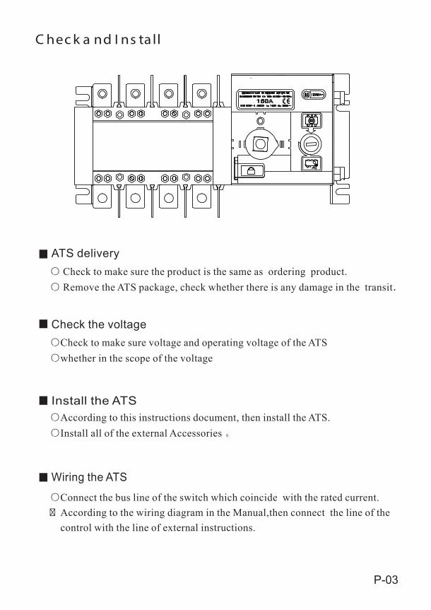
C hec k a nd I ns ta ll
Check the voltage
P-03
ATS delivery Check to make sure the product is the same as ordering product. Remove the ATS package, check whether there is any damage in the transit
Check to make sure voltage and operating voltage of the ATSwhether in the scope of the voltage
According to this instructions document, then install the ATS.Install all of the external Accessories
Connect the bus line of the switch which coincide with the rated current.� According to the wiring diagram in the Manual,then connect the line of the control with the line of external instructions.
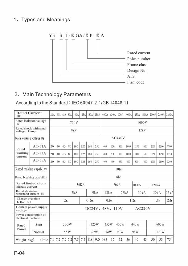
Rated shock withstandvoltage Uimp
Rate working voltage Ue
750V
8kV
AC440V
10Ie
8Ie
50KA
7kA
2s
AC220V
7.0 7.2
1000V
12kV
AC-31A
AC-33A
AC-35A
20 40 63 80 100 125 160 250 400 630 800 1000 1250 1600
20 40 63 80 100 125 160 250 400 630 800 1000
20 40 63 80 100 125 160 250 400 630 800 1000 1600
800400
1000
70kA 100kA 120kA
9kA
0.6s
13kA
1.2s
26kA 50kA
300W
55W
325W
62W
355W
74W
400W
90W
440W
98W
7.2 7.2 7.5 7.5 8.8 9.0 16.5 17 32 36 40 43
P-04
20A 40A 63A 80A 100A 125A 160A 250A 400A 630A 800A 1000A 1250A 1600A 2000A 2500A 3200A
2000
2000
1250
2500
2500
1250
3200
3200
1250
55kA50kA
1.8s 2.4s
600W
120W
50 53 75
0.6s
Start
Normal
Rated working currentIe
Rated making capability
Rated breaking capability
Rated limited short-circuit currentRated short-time withstand current 1s
Control power supply voltagePower consumption of electrical machine
According to the Standard:IEC 60947-2-1/GB 14048.11
Rated Current Ith
Rated isolation voltage Ui
Rated Power
1 Types and Meanings
YE S 1 - � GA / � P � A
Rated currentPoles numberFrame classDesign No.ATSFirm code
2 Main Technology Parameters
Change-over timeI- IIor II- I
Weight(kg) 4Pole
DC24V 48V 110V
220V~
P-05
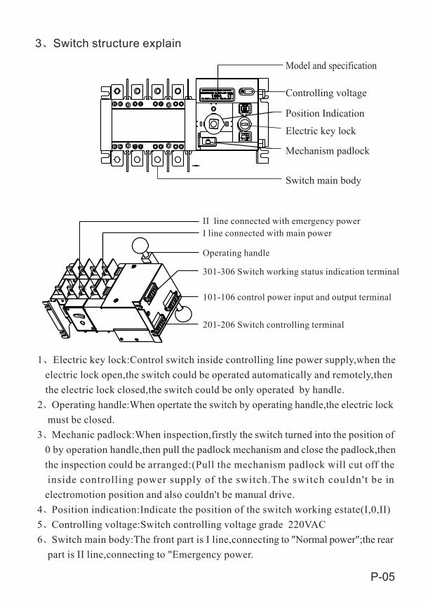
Model and specification
Controlling voltage
Position Indication
Electric key lock
Mechanism padlock
Switch main body
3 Switch structure explain
II line connected with emergency powerI line connected with main power
Operating handle
301-306 Switch working status indication terminal
101-106 control power input and output terminal
201-206 Switch controlling terminal
1 Electric key lock:Control switch inside controlling line power supply,when the electric lock open,the switch could be operated automatically and remotely,then the electric lock closed,the switch could be only operated by handle.2 Operating handle:When opertate the switch by operating handle,the electric lock must be closed.3 Mechanic padlock:When inspection,firstly the switch turned into the position of 0 by operation handle,then pull the padlock mechanism and close the padlock,then the inspection could be arranged:(Pull the mechanism padlock will cut off the inside controlling power supply of the switch.The switch couldn't be in electromotion position and also couldn't be manual drive.4 Position indication:Indicate the position of the switch working estate(I,0,II)5 Controlling voltage:Switch controlling voltage grade 220VAC6 Switch main body:The front part is I line,connecting to "Normal power";the rear part is II line,connecting to "Emergency power.
E
B1
S
GC
Y1Y
T T
KUBH
Z
A1
A
V P P P
R
JO N
L
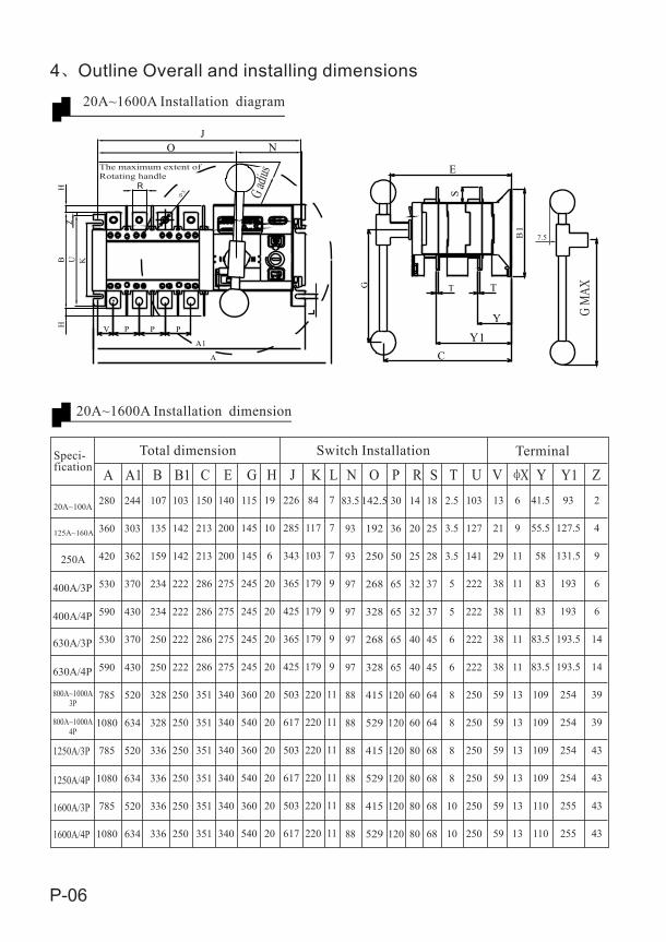
A A1 B B1 C E G H J K L N O P R S T U V X Y Y1 Z
P-06
7.5
20A~100A
125A~160A
250A
400A/3P
400A/4P
630A/3P
630A/4P
800A~1000A3P
800A~1000A4P
1250A/3P
1250A/4P
1600A/3P
1600A/4P
280
360
420
530
590
530
590
785
1080
785
1080
785
1080
244
303
362
370
430
370
430
520
634
520
634
520
634
107
135
159
234
234
250
250
328
328
336
336
336
336
103
142
142
222
222
222
222
250
250
250
250
250
250
150
213
213
286
286
286
286
351
351
351
351
351
351
140
200
200
275
275
275
275
340
340
340
340
340
340
115
145
145
245
245
245
245
360
540
360
540
360
540
19
10
6
20
20
20
20
20
20
20
20
20
20
226
285
343
365
425
365
425
503
617
503
617
503
617
84
117
103
179
179
179
179
220
220
220
220
220
220
7
7
7
9
9
9
9
11
11
11
11
11
11
83.5
93
93
97
97
97
97
88
88
88
88
88
88
142.5
192
250
268
328
268
328
415
529
415
529
415
529
30
36
50
65
65
65
65
120
120
120
120
120
120
14
20
25
32
32
40
40
60
60
80
80
80
80
18
25
28
37
37
45
45
64
64
68
68
68
68
2.5
3.5
3.5
5
5
6
6
8
8
8
8
10
10
103
127
141
222
222
222
222
250
250
250
250
250
250
13
21
29
38
38
38
38
59
59
59
59
59
59
6
9
11
11
11
11
11
13
13
13
13
13
13
41.5
55.5
58
83
83
83.5
83.5
109
109
109
109
110
110
93
127.5
131.5
193
193
193.5
193.5
254
254
254
254
255
255
2
4
9
6
6
14
14
39
39
43
43
43
43
4 Outline Overall and installing dimensions
The maximum extent ofRotating handle
G adiu
s
G M
AX
20A~1600A Installation diagram
H
20A~1600A Installation dimension
Speci-fication
Total dimension Switch Installation Terminal
3516
.5
8040 2020
40
3560
1010
12.5
35
7-7
68
5-5
4
3-3
2
1-1
480 C 48
0
200
V
O
J
A1A
B
R
220
250
11
P-07
6.5
800A~1000A 1250A~1600A
6.5
G
2000A~3200A
18
2000A~3200A
120
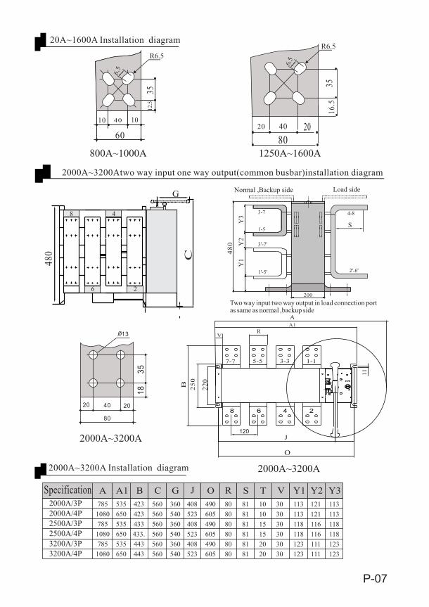
A A1 B C G J O R S T V Y1 Y2 Y32000A/3P2000A/4P2500A/3P2500A/4P3200A/3P3200A/4P
785108078510807851080
535650535650535650
423423433433.443443
560560560560560560
360540360540360540
408523408523408523
490605490605490605
808080808080
818181818181
101015152020
303030303030
113113118118123123
121121116116111111
113113118118123123
S
Y1
Y2
Y38 4
6 2
1'-5'
3'-7'
3-7
1-5
2'-6'
4-8
R6.5R6.5
Two way input two way output in load connection port as same as normal ,backup side
Normal ,Backup side Load side
Specification
20A~1600A Installation diagram
2000A~3200Atwo way input one way output(common busbar)installation diagram
2000A~3200A Installation diagram
P-08
302 303 304 3 05 302 303 304 702 7013 05
Fig.b:3P switch connection diagram
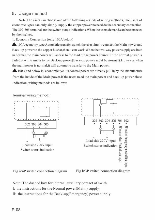
5 Usage method Note:The users can choose one of the following 6 kinds of wiring methods,The users of economic types can only simply supply the copper power,no need do the secondary connection. The 302-305 terminal are the switch status indications,When the users demand,can be connectedby themselves.1: Economy Connection (only 100A below) 100A economy type Automatic transfer switch,the user simply connect the Main power andBack-up power to the copper busbar,then it can work.When the two-way power supply are bothin normal,the main power will access to the load of the power source .If the normal power isfailed,it will transfer to the Back-up power(Back-up power must be normal).However,whenthe mainpower is normal,it will automatic transfer to the Main power. 100A and below is economic tye ,its control power are directly pull in by the manufacture
from the inside of the Main power.If the users need the main power and back-up power close
indication, wiring methods are belows:
Terminal wiring method:
Load side 220V inputSwitch status indication
Fig.a:4P switch connection diagram
Load side 220V inputSwitch status indication
3P switch Emergency neutral line input3P switch Main Neutral Line input
Note: The dashed box for internal auxiliary contact of swith.I: the instructions for the Normal power(Main ) supplyII: the instructions for the Back-up(Emergency) power supply
201 202 203 204 205 206
AC220V AC220V
FU1 FU2 HL1 HL2
HD1 HD2
101 102 103 104 105 106 501 502 503 504 505 506
301 302 303 304 305 306 401 402 403 404 405 406
YES1
P-09
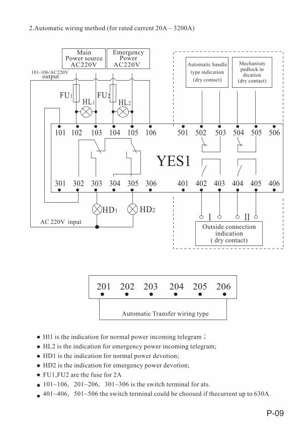
2.Automatic wiring method (for rated current 20A ~ 3200A)
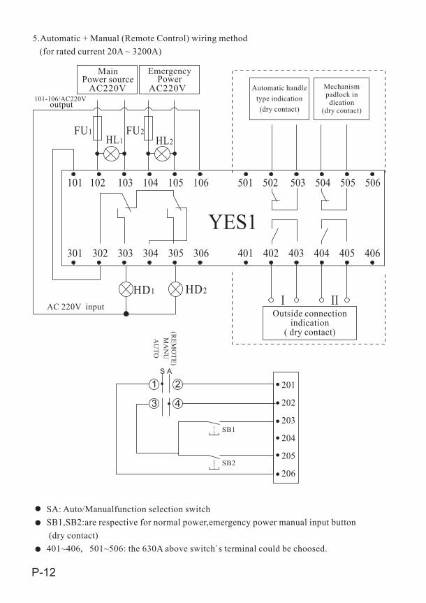
Hl1 is the indication for normal power incoming telegram;HL2 is the indication for emergency power incoming telegram;HD1 is the indication for normal power devotion;HD2 is the indication for emergency power devotion;FU1,FU2 are the fuse for 2A101~106,201~206,301~306 is the switch terminal for ats.401~406,501~506 the switch terminal could be choosed if thecurrent up to 630A.
Automatic Transfer wiring type
Main Power source
EmergencyPower
Automatic handle type indication(dry contact)
Mechanismpadlock indication
(dry contact)101-106/AC220V
output
AC 220V inputOutside connection
indication( dry contact)
P-10
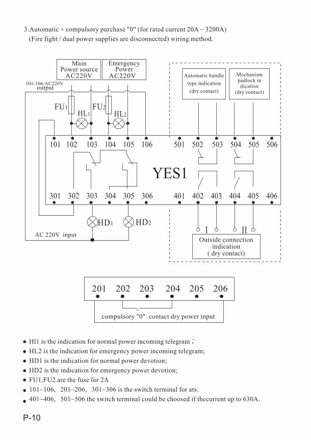
3.Automatic + compulsory purchase "0" (for rated current 20A ~ 3200A) (Fire fight / dual power supplies are disconnected) wiring method.
Hl1 is the indication for normal power incoming telegram;HL2 is the indication for emergency power incoming telegram;HD1 is the indication for normal power devotion;HD2 is the indication for emergency power devotion;FU1,FU2 are the fuse for 2A101~106,201~206,301~306 is the switch terminal for ats.401~406,501~506 the switch terminal could be choosed if thecurrent up to 630A.
compulsory "0" contact dry power input
201 202 203 204 205 206
AC220V AC220V
FU1 FU2 HL1 HL2
HD1 HD2
101 102 103 104 105 106 501 502 503 504 505 506
301 302 303 304 305 306 401 402 403 404 405 406
YES1
Main Power source
EmergencyPower
Automatic handle type indication(dry contact)
Mechanismpadlock indication
(dry contact)101-106/AC220V
output
AC 220V inputOutside connection
indication( dry contact)
Uge1
301 306
301 302 303 304 305 306
P-11
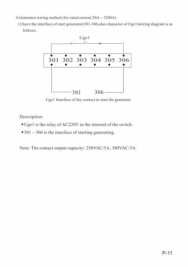
4.Generator wiring method (for rated current 20A ~ 3200A) 1):have the interface of start generator(301-306,also charactor of Uge1)wiring diagram is as follows:
Uge1 Interface of dry contact to start the generator
Description:
Uge1 is the relay of AC220V in the internal of the switch.
301 ~ 306 is the interface of starting generating.
Note: The contact output capacity: 250VAC/5A, 380VAC/3A.
201
202
203
204
205
206
1 2
3 4
SB1
SB2
S A
P-12
SA: Auto/Manualfunction selection switchSB1,SB2:are respective for normal power,emergency power manual input button (dry contact)401~406,501~506: the 630A above switch`s terminal could be choosed.
5.Automatic + Manual (Remote Control) wiring method (for rated current 20A ~ 3200A)
AC220V AC220V
FU1 FU2 HL1 HL2
HD1 HD2
101 102 103 104 105 106 501 502 503 504 505 506
301 302 303 304 305 306 401 402 403 404 405 406
YES1
Main Power source
EmergencyPower
Automatic handle type indication(dry contact)
Mechanismpadlock indication
(dry contact)101-106/AC220V
output
AC 220V inputOutside connection
indication( dry contact)A
UTO
MA
NU
(REM
OTE)

201 202 203 204 205 206
SB1 SB2SB0
P-13
6. Remote Control (for manual operate)wiring method (for rated current 20A ~ 3200A)
AC220V AC220V
FU1 FU2 HL1 HL2
HD1 HD2
101 102 103 104 105 106 501 502 503 504 505 506
301 302 303 304 305 306 401 402 403 404 405 406
YES1
Main Power source
EmergencyPower
Automatic handle type indication(dry contact)
Mechanismpadlock indication
(dry contact)101-106/AC220V
output
AC 220V inputOutside connection
indication( dry contact)
SB0 SB1 SB2 are respective for compulsary position"0",normal power,emergencypower input control button (only connect dry contact)401~406,501~506 the switch terminal could be choosedRated Current 20A ~ 630A compulsory "0" function can be selected.
141 142 143 146 201 202 203 204 205 206
SB1 SB2SB0
0FU1
+24V/+48VDC24V/DC48V input
0
220V input
401 402 403 404 4 05 406 501 502 503 504 5 05 506301 302 303 304 3 05 306
P-14
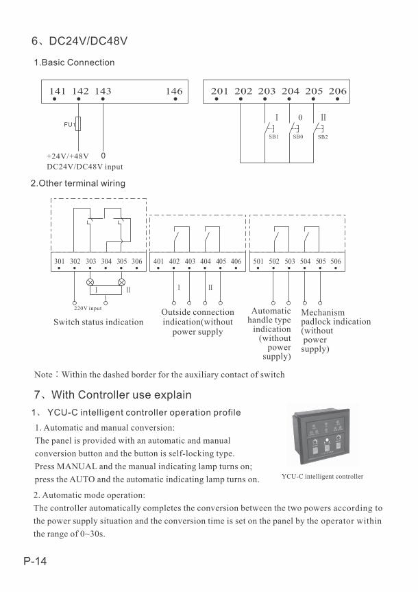
6 DC24V/DC48V
1.Basic Connection
2.Other terminal wiring
Note:Within the dashed border for the auxiliary contact of switch
Switch status indicationOutside connectionindication(without
power supply
Automatichandle type
indication(without
power supply)
Mechanismpadlock indication(without power supply)
7 With Controller use explain1 YCU-C intelligent controller operation profile1. Automatic and manual conversion:The panel is provided with an automatic and manual conversion button and the button is self-locking type. Press MANUAL and the manual indicating lamp turns on; press the AUTO and the automatic indicating lamp turns on. YCU-C intelligent controller
2. Automatic mode operation: The controller automatically completes the conversion between the two powers according tothe power supply situation and the conversion time is set on the panel by the operator withinthe range of 0~30s.
P-15
1
2
34
5
OVER VOLTAGEUNDER VOLTAGELOST PHASE
OVER VOLTAGEUNDER VOLTAGELOST PHASE
AUTO-TRANSFER AND AUTO-RE-TRANSFER
AUTO TRANFER NO AUTO-RE-TRANSFER
MAIN POWER ONMAIN POWER PRIORITY
EMERGENCY ONEMERGENCY PRIORITY
Turn on genset stop Fire Protection Device Query CommunicationLOAD
MAIN POWER EMERGENCY POWER
A power ON B Power ON MANU/AUTO DUAL BREAK/SET
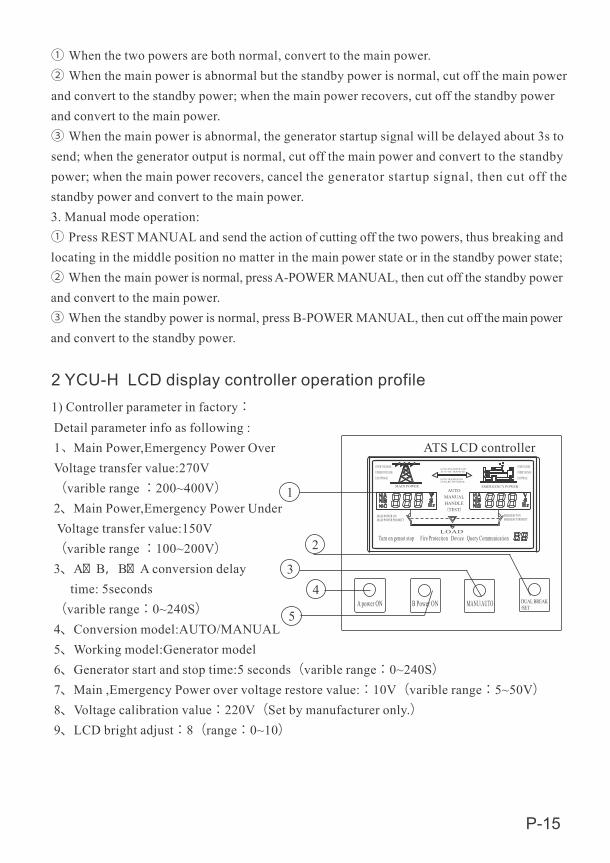
① When the two powers are both normal, convert to the main power.② When the main power is abnormal but the standby power is normal, cut off the main powerand convert to the standby power; when the main power recovers, cut off the standby powerand convert to the main power.③ When the main power is abnormal, the generator startup signal will be delayed about 3s tosend; when the generator output is normal, cut off the main power and convert to the standbypower; when the main power recovers, cancel the generator startup signal, then cut off the standby power and convert to the main power. 3. Manual mode operation: ① Press REST MANUAL and send the action of cutting off the two powers, thus breaking andlocating in the middle position no matter in the main power state or in the standby power state; ② When the main power is normal, press A-POWER MANUAL, then cut off the standby powerand convert to the main power. ③ When the standby power is normal, press B-POWER MANUAL, then cut off the main powerand convert to the standby power.
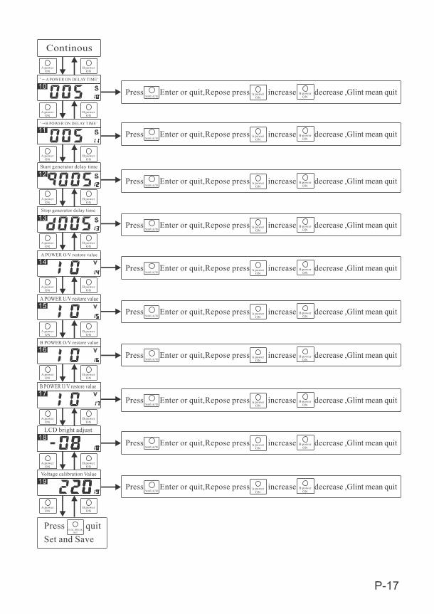
2 YCU-H LCD display controller operation profile1) Controller parameter in factory:Detail parameter info as following :1 Main Power,Emergency Power Over Voltage transfer value:270V(varible range :200~400V)2、Main Power,Emergency Power Under Voltage transfer value:150V(varible range :100~200V)3、A� B,B� A conversion delay time: 5seconds (varible range:0~240S)4、Conversion model:AUTO/MANUAL5、Working model:Generator model6、Generator start and stop time:5 seconds(varible range:0~240S)7、Main ,Emergency Power over voltage restore value::10V(varible range:5~50V)8、Voltage calibration value:220V(Set by manufacturer only.)9、LCD bright adjust:8(range:0~10)
AUTOMANUALHANDLE(TEST)
ATS LCD controller
P-16
1
2
3
4
5
6
7
8
9
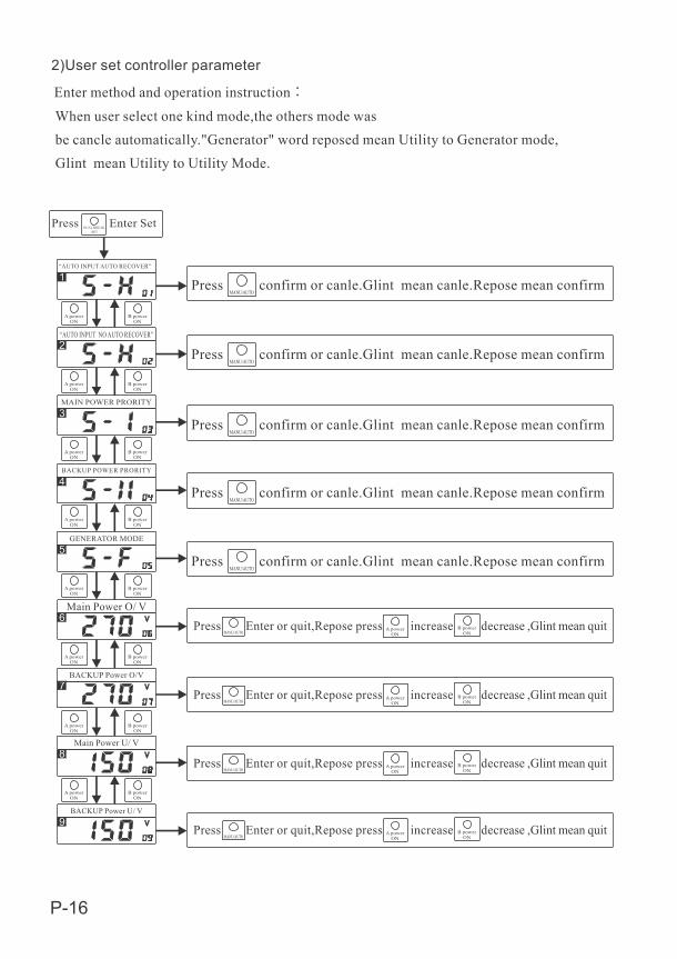
2)User set controller parameter
Enter method and operation instruction:When user select one kind mode,the others mode was be cancle automatically."Generator" word reposed mean Utility to Generator mode,Glint mean Utility to Utility Mode.
Press Enter SetDUAL BREAK/SET
“AUTO INPUT AUTO RECOVER”
Press confirm or canle.Glint mean canle.Repose mean confirmMANU/AUTO
Press confirm or canle.Glint mean canle.Repose mean confirmMANU/AUTO
“AUTO INPUT NO AUTO RECOVER”
A powerON
B powerON
MAIN POWER PRORITY
A powerON
B powerON
A powerON
B powerON
BACKUP POWER PRORITY
A powerON
B powerON
A powerON
B powerON
GENERATOR MODE
A powerON
B powerON
Main Power O/ V
BACKUP Power O/V
Main Power U/ V
BACKUP Power U/ V
A powerON
B powerON
A powerON
B powerON
Press confirm or canle.Glint mean canle.Repose mean confirmMANU/AUTO
Press confirm or canle.Glint mean canle.Repose mean confirmMANU/AUTO
Press confirm or canle.Glint mean canle.Repose mean confirmMANU/AUTO
Press Enter or quit,Repose press increase decrease ,Glint mean quitMANU/AUTO
A powerON
B powerON
Press Enter or quit,Repose press increase decrease ,Glint mean quitMANU/AUTO
A powerON
B powerON
Press Enter or quit,Repose press increase decrease ,Glint mean quitMANU/AUTO
A powerON
B powerON
Press Enter or quit,Repose press increase decrease ,Glint mean quitMANU/AUTO
A powerON
B powerON
P-17
10
11
12
13
14
15
16
17
18
19
Press Enter or quit,Repose press increase decrease ,Glint mean quitMANU/AUTO
A powerON
B powerON
Press Enter or quit,Repose press increase decrease ,Glint mean quitMANU/AUTO
A powerON
B powerON
Press Enter or quit,Repose press increase decrease ,Glint mean quitMANU/AUTO
A powerON
B powerON
Press Enter or quit,Repose press increase decrease ,Glint mean quitMANU/AUTO
A powerON
B powerON
Press Enter or quit,Repose press increase decrease ,Glint mean quitMANU/AUTO
A powerON
B powerON
Press Enter or quit,Repose press increase decrease ,Glint mean quitMANU/AUTO
A powerON
B powerON
Press Enter or quit,Repose press increase decrease ,Glint mean quitMANU/AUTO
A powerON
B powerON
Press Enter or quit,Repose press increase decrease ,Glint mean quitMANU/AUTO
A powerON
B powerON
Press Enter or quit,Repose press increase decrease ,Glint mean quitMANU/AUTO
A powerON
B powerON
Press Enter or quit,Repose press increase decrease ,Glint mean quitMANU/AUTO
A powerON
B powerON
A powerON
B powerON
A powerON
B powerON
A powerON
B powerON
A powerON
B powerON
A powerON
B powerON
A powerON
B powerON
A powerON
B powerON
A powerON
B powerON
A powerON
B powerON
A powerON
B powerON
A powerON
B powerON
Press quitSet and Save
DUAL BREAK/SET
Continous
A POWER ON DELAY TIME’
B POWER ON DELAY TIME’
Start generator delay time
Stop generator delay time
A POWER O/V restore value
A POWER U/V restore value
B POWER O/V restore value
B POWER U/V restore value
LCD bright adjust
Voltage calibration Value

P-18
BACKUP POWERU V WN2 N1C B A
FU1
FU2
FU3
ATSE SWITCH BODY
M4 A2 B2 C2 N2 F2 F N1 C1 B1 A1 L1 M2 M1 F1 T1 T2
FU4
FU5
FU6
LP 3LP 1 LP 2
203 103205105
204302 303 304 305
106
202
101102104
AC220V input
R1 R2 F1 F F2 L1 L2
M3 L2
MAIN POWER
3 YCU-C/YCU-H controller wiring terminal
YCU-C Controller wiring terminal diagram
F2, F and F1, which is used to start up and close the generator.F is the common point,when mainly power in normal,F and F2 is closed,F and F1 is break;when main powerin abnormal and Backup power source no power,F and F1 delay about 3 secondsthen closed,meanwhile F and F2 is break.R1,R2 turn on,controller will bring ATS switch changeover to double break position(fire fight input)L1,L2 according user requirement to additional(standby).
4 YCU-C/YCU-H Controller installation and outline dimension
YCU—C intelligent controller installation bore holediagram(Total depth: 76mm, inner depth of the installedcabinet: 65mm)
130134
111
114
4- 3 6
YCU-C H type controller connect with GA diagram
CONTROLLERTERMINAL
Wiring explain: LP 1:Main Power Source exterior closing indication LP 2:Switch dual break indication LP 3:Backup Power Source exterior closing indication FU 1 - 6 FUSE 6A
5 Controller and switch connection diagram
P-19
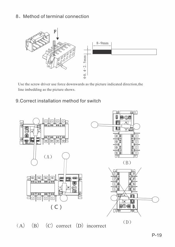
8 Method of terminal connection
8~9mm
04
25m
mUse the screw driver use force downwards as the picture indicated direction,the line imbedding as the picture shows.
9.Correct installation method for switch
A)(B)(C)correct (D)incorrect
P-20
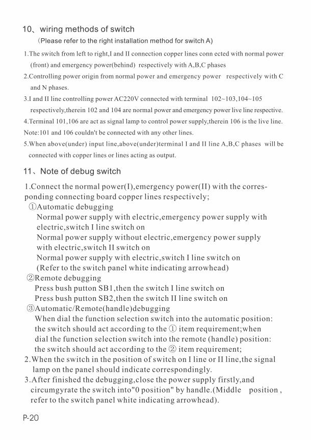
10 wiring methods of switch
1.The switch from left to right,I and II connection copper lines conn ected with normal power
(front) and emergency power(behind) respectively with A,B,C phases
2.Controlling power origin from normal power and emergency power respectively with C
and N phases.
3.I and II line controlling power AC220V connected with terminal 102~103,104~105
respectively,therein 102 and 104 are normal power and emergency power live line respective.
4.Terminal 101,106 are act as signal lamp to control power supply,therein 106 is the live line.
Note:101 and 106 couldn't be connected with any other lines.
5.When above(under) input line,above(under)terminal I and II line A,B,C phases will be
connected with copper lines or lines acting as output.
Please refer to the right installation method for switch A)
11 Note of debug switch
1.Connect the normal power(I),emergency power(II) with the corres-ponding connecting board copper lines respectively; Automatic debugging Normal power supply with electric,emergency power supply with electric,switch I line switch on Normal power supply without electric,emergency power supply with electric,switch II switch on Normal power supply with electric,switch I line switch on (Refer to the switch panel white indicating arrowhead) Remote debugging Press bush putton SB1,then the switch I line switch on Press bush putton SB2,then the switch II line switch on Automatic/Remote(handle)debugging When dial the function selection switch into the automatic position: the switch should act according to the item requirement;when dial the function selection switch into the remote (handle) position: the switch should act according to the item requirement; 2.When the switch in the position of switch on I line or II line,the signal lamp on the panel should indicate correspondingly.3.After finished the debugging,close the power supply firstly,and circumgyrate the switch into"0 position" by handle.(Middle position , refer to the switch panel white indicating arrowhead).