automatic integration of facade textures into 3d building models with a projective geometry based...
TRANSCRIPT
EUROGRAPHICS 2002 / G. Drettakis and H.-P. Seidel(Guest Editors)
Volume 21 (2002), Number 3
Automatic Integration of Facade Textures into 3D BuildingModels with a Projective Geometry Based Line Clustering
Sung Chun Leey, Soon Ki Jungz and Ram. Nevatiay
yInstitute for Robotics and Intelligent Systems, and Computer Science Department, University of Southern California, CA, USAzDepartment of Computer Engineering, Kyungpook National Univeristy, Daegu, Korea
AbstractVisualization of city scenes is important for many applications including entertainment and urban mission plan-ning. Models covering wide areas can be efficiently constructed from aerial images. However, only roof detailsare visible from aerial views; ground views are needed to provide details of the building facades for high quality’fly-through’ visualization or simulation applications. We present an automatic method of integrating facade tex-tures from ground view images into 3D building models for urban site modeling. We first segment the input imageinto building facade regions using a hybrid feature extraction method, which combines global feature extractionwith Hough transform on an adaptively tessellated Gaussian Sphere and local region segmentation. We estimatethe external camera parameters by using the corner points of the extracted facade regions to integrate the facadetextures into the 3D building models. We validate our approach with a set of experiments on some urban sites.
Categories and Subject Descriptors (according to ACM CCS): I.3.3 [Computer Graphics]: Modeling packages
1. Introduction
Accurate 3D models of buildings in a city are needed fora variety of applications, such as fly-through rendering andsimulation for mission planning. Many methods for extrac-tion of such 3D models from aerial images have been devel-oped in recent years 1; 2; 3. Aerial images provide wide areacoverage, however, the walls of buildings are either not vis-ible or seen at a very low resolution. We need to utilize im-ages taken from the ground to get accurate facade textures.We propose to integrate the use of such ground views withmodels obtained from aerial views. To do this, we need toestimate the global position and orientation of the cameraused for taking the ground view images; then we can attachfacade textures to 3D building model correctly.
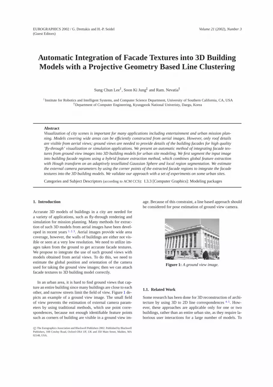
In an urban area, it is hard to find ground views that cap-ture an entire building since many buildings are close to eachother, and narrow streets limit the field of view. Figure 1 de-picts an example of a ground view image. The small fieldof view prevents the estimation of external camera param-eters by using traditional methods, which use point corre-spondences, because not enough identifiable feature pointssuch as corners of building are visible in a ground view im-
age. Because of this constraint, a line based approach shouldbe considered for pose estimation of ground view camera.
Figure 1: A ground view image.
1.1. Related Work
Some research has been done for 3D reconstruction of archi-tecture by using 3D to 2D line correspondences 4; 5. How-ever, these approaches are applicable only for one or twobuildings, rather than an entire urban site, as they require la-borious user interactions for a large number of models. To
c The Eurographics Association and Blackwell Publishers 2002. Published by BlackwellPublishers, 108 Cowley Road, Oxford OX4 1JF, UK and 350 Main Street, Malden, MA02148, USA.
Lee, Jung and Nevatia / Automatic Integration of Facade Textures into 3D Building Models
reduce user interactions for the correspondences, automat-ically obtainable image features such as vanishing pointsthat indicate the external and some internal parameters ofcamera are proposed 5; 6; 7; 8. Previous methods describe tech-niques to calibrate the camera rotational parameters if thereare more two or three orthogonal vanishing points 7; 11. Sta-mos and Allen 11 use high precision range data from groundview to fit them into building facade planes through cam-era calibration with three orthogonal vanishing points. Coorgand Teller construct a large set of 3D building models by us-ing spherical mosaics produced from accurately calibratedground view cameras with a GPS device 10.
1.2. Overview
In our approach, 3D building models are obtained fromaerial images by using a previous approach 1; 9 (the processof obtaining these models does not affect the rest of our op-erations; the 3D models could also be derived from LIDARrange sensors, for example). Aerial views provide not onlythe global (world) position and 3D geometry of buildingsin a site, but also give the roof information such as textureand multiple layer structures as shown in Figure 2. We wantto extract facade information of such buildings from groundview images.
Figure 2: 3D building models of a D.C. site derived fromaerial images.
In this paper, we present an automatic method for integrat-ing ground view images to 3D complex buildings in an urbanarea by using projective geometry. We first cluster lines hav-ing a common vanishing point and extract building facaderegions by using spatial locality of the vertical and horizon-tal line clusters. Each facade gives us two vanishing points.However, since we already have 3D solid models from aerialviews, the requirement of orthogonal vanishing points is notnecessary in our approach. Furthermore, the roof corners ofthe extracted facade regions are used to estimate the positionof the camera. For the automatic process of camera pose es-timation, we derive multiple hypotheses of 3D to 2D corre-spondences, and search for the best match.
Section 2 explains how to extract facade image regionsautomatically by using vanishing points, followed by a pose
estimation method with the extracted facade and vanishingpoints in the section 3. Some results and conclusion are dis-cussed in section 4 and section 5.
2. Feature Extraction Methodology
Vanishing points from a set of parallel image lines have beenshown to be useful for estimating camera parameters in pre-vious work 5; 6; 7; 8. Given vanishing points and a 3D build-ing model, the world position and rotation of ground viewimages, can be recovered. We can exploit vanishing points,which are not necessarily orthogonal, as long as the anglesbetween the corresponding lines can be known by referringto the 3D building model. We then recover the world posi-tion of ground view cameras by 3D to 2D surface correspon-dences.
2.1. Overview of vanishing point detection
Vanishing points can be extracted from a group of paral-lel lines in an image, which can be obtained by an auto-matic approach or given by a user. Many methods have usedthe concept of a Gaussian sphere 12; 13; 14; 15, which is one ofglobal feature extraction methods such as the Hough trans-form. Shufelt 13 requires intrinsic camera parameters of im-ages to use the orthogonality of 3D building models, whichare not available directly from the uncalibrated ground viewimages due to possible variations of the focal length. Fur-thermore, Gaussian sphere approaches are applicable onlyfor one simple structured building that has one or two sur-faces, as a global feature approach does not consider the lo-cal proximity of lines in the image, i.e., line clusters frommultiple surfaces of buildings cannot be separated.
Other automatic vanishing point detection methods thatoperate in the image space instead of Gaussian sphere havebeen proposed 16. Liebowitz and Zisserman 16 try to groupthe image lines that have the same dominant orientation. Theintersection point of these lines with minimum distance errorcan be a vanishing point. Such methods are simple and usethe spatial proximity well, but if there exist real parallel linesin the image, they fail to compute the intersection point. Inaddition, they are applicable only to a single surface at atime.
In this paper, we use a hybrid method of Gaussian sphereapproach and image-based approach. First, each line seg-ment is transformed into a unit vector on Gaussian sphereto get the dominant line directions. Then, The lines that be-long to the chosen directions are grouped according to imageproximities.
2.2. Global line clustering
A vanishing points detection technique using a Hough trans-form was introduced by Barnard 12, which transforms all im-age lines (or edges) into a Gaussian sphere space. Each im-age line has an interpretation plane, and the intersection of
c The Eurographics Association and Blackwell Publishers 2002.

Lee, Jung and Nevatia / Automatic Integration of Facade Textures into 3D Building Models
this plane with the Gaussian sphere forms a great circle asdepicted in Figure 3. In the geometry of Gaussian sphere,the center of the sphere is the center of projection and its ra-dius is normalized by camera focal length so that the metricinformation (such as angle) is preserved.
The Gaussian sphere is tessellated uniformly and a greatcircle corresponding to an image line is accumulated on thesphere, i.e. the strength of the line (usually its length) is ac-cumulated into each cell around the circle. The lines on thesame great circle contribute to the same group of cells. Af-ter processing all image lines, the cells located at dominantvanishing points such as horizontal or vertical ones shouldhave high values.
Interpretation plane
Vanishing point (unit vector) on Gaussian sphere
Vanishing point on the image plane
The center of Gaussian sphere
Gaussian sphere
Image plane
Great circles w.r.t. image lines
Image lines
Figure 3: Gaussian sphere geometry.
If the focal length is known, we construct a metric Gaus-sian sphere, so that two orthogonal vanishing points in 3Dare also located orthogonally in the Gaussian sphere. Sincewe are interested in only the image location of the vanishingpoints rather than the location on the Gaussian sphere, we ar-bitrarily choose half of the image dimension as the distancebetween the centers of the Gaussian sphere and the imageplane. Regardless of the distance between the image planeand the center of the Gaussian sphere, the image location ofvanishing points should remain same. As illustrated in Fig-ure 3, the image plane is moved to be adjacent to the surfaceof the Gaussian sphere so that the distance between the im-age plane and the center of the Gaussian sphere is the radiusof the sphere.
By using half of the image dimension as the radius ofthe Gaussian sphere, we convert image coordinate vectorsto Gaussian space vectors as followings:
gx = xi� r; gy = yi� r; gz = r; (1)
where (xi;yi)T is an image coordinate, (gx;gy;gz)
T is aGaussian space coordinate vector, and r is the radius of thesphere. An image line has two end points, which are trans-formed to two Gaussian coordinate vectors and each corre-sponding great circle plane can be described by its normalvector:
n = (g1x g1
y g1z )
T� (g2
x g2y g2
z )T
; (2)
where n is a normal vector of a great circle corresponding toan image line, (g1
x g1y g1
z )T and (g2
x g2y g2
z )T are Gaussian
space vectors for the image line, and ‘�’ denotes a vectorcross product.
To represent Gaussian sphere, we use a ‘quad tree’ struc-ture to tessellate a quadrangular pyramid to form the sphere’ssurface. We use only a half sphere instead of the full spherebecause great circles intersect each other at two points onthe sphere and one of intersecting points should be on thehalf sphere. We first start with a quadrangular pyramid tocover a half sphere and keep tessellating each triangle of thepyramid until we get enough resolution (as shown in Fig-ure 4, according to our experiments, five or six tessellationsare sufficient)
(a) Quadrangular pyramid (b) 1st tessellation
(c) 3rd tessellation (d) 5th tessellation
Figure 4: Uniform tessellation of a half sphere.
Due to the hierarchical property of a quad tree, we cansave computation time by tessellating a triangle only whenany great circle, i.e. any interpretation plane, intersects withthis triangle. If not, we do not tessellate and the trianglebecomes a leaf cell. In order to check the intersection of agreat circle plane and a triangle plane, we make the follow-ing measurement: let m be a 3 bit mask variable, then
great circle and a triangle have
�No intersection, if m = ’111’ or m = ’000’
Intersection, otherwise(3)
where ith bit of m: mi =
�1, if n�Pi�0
0, if n�Pi<0
n : the normal vector of a great circle
Pi : ith point(Gaussian vector) of a triangle, 1 � i � 3
� : vector inner product
As depicted in Figure 5, if the inner products of three
c The Eurographics Association and Blackwell Publishers 2002.

Lee, Jung and Nevatia / Automatic Integration of Facade Textures into 3D Building Models
Gaussian points (vectors), Pi , of a triangle with the nor-mal vector n all have positive or negative values, the triangleshould be located above or below the great circle respec-tively, and this triangle becomes a leaf cell. Otherwise, thistriangle intersects with the great circle and it becomes a non-leaf cell so that it can be tessellated in the next iteration.
A great circle plane
n : normal vector of a great circle plane
Pi : a point of a triangle cell represented as a Gaussian vector (unit vector)
The center of Gaussian sphere
Figure 5: Intersection between a great circle and a triangle.
Figure 6 shows an adaptive tessellation of the sphere. Weshow just two lines on the Gaussian sphere to illustrate thebenefit of the adaptive tessellation. Not much computationis required to go from 4th tessellation to 7th tessellation asshown in Figure 6.
(a) 4th tessellation (b) 7th tessellation
Figure 6: Adaptive tessellation.
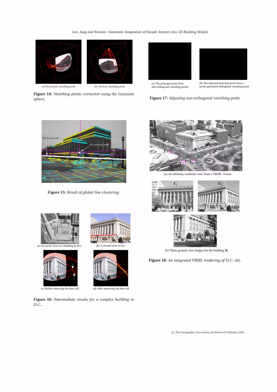
If a triangle intersects with a great circle, which meansthat an image line passes this cell on the sphere, we accu-mulate the length of this line to this cell. When a non-leaftriangle is tessellated, it hands over its accumulation valueto its child cells. After tessellation process is done to a suffi-cient resolution level, each cell has accumulation value fromthose lines that pass through it. Thus, vanishing points onthe image plane should have large accumulation values onthe Gaussian sphere. Figure 14 (see color plates) shows anexample of the accumulated cells on the Gaussian spherespace: (brighter cells have higher accumulation values).
Since we use line length as an accumulating value, a pairof long horizontal and vertical lines, which are unrelated toform a vanishing point, could still create a bright noise cellwhere they are intersect. To avoid such noise cells, we firstclassify image lines into two groups based on their line di-rections in the image; horizontal and vertical line groups,and transform them to the separate Gaussian spheres. Hori-zontal group includes the image lines whose angles are closeto the horizontal line (0Æ degree) as vertical group includesthe others. Even though this separation process might notbe completely accurate since the direction of image lines isvariable under perspective projection, it is still effective infiltering potential noise cells. Figure 14(a) and (b) show thehorizontal and vertical line groups respectively.
After the accumulation process is done, we have to searchthe vanishing point candidates that have significantly highaccumulation value, through the Gaussian sphere surface.Many search algorithms for vanishing points on the Gaus-sian sphere have been developed 13; 14; 15. Most of them ex-ploit the orthogonality of vanishing points under the knownfocal length to find meaningful vanishing points, which isnot applicable for our problem. Quan et al. 15 use a greedyapproach, which selects the highest accumulation cell andremoves it together with lines that contribute to that cell. Toremove a line from the Gaussian sphere, its weight is sub-tracted from the cells along the great circle. This procedureis repeated until no more meaningful cells remain. This algo-rithm is simple but very effective for our application becausewe deal with building facades, which have only two domi-nant directional line groups.
The automatic vanishing points detection method basedon the Gaussian sphere is summarized in Algorithm 1.
2.3. Local line clustering
We collect the image lines that are removed in the global lineclustering process. Figure 15 (see color plates) illustratesthe horizontal line groups from the global line clustering.The center point in Figure 15 is the location of the princi-pal point, which is the orthocenter of the triangle formed bythree orthogonal vanishing points in the image plane. Thethick line in the middle of Figure 15 indicates the image lo-cation of the horizon, which connects two horizontal vanish-ing points. The image line of the horizon is related to theheight of the camera, which is usually at a human’s heightin our approach. The image lines under the horizon are notmeaningful in building modeling application because suchlines would correspond to objects such as walking humans,cars and trees; we discard such lines.
Like other global feature extraction methods, the clusteredlines may not have any spatial proximity. We need to seg-ment the clustered lines by using the region locality to findthe facade surfaces of buildings. A facade of architecturalbuildings consists of a horizontal and a vertical line group.
c The Eurographics Association and Blackwell Publishers 2002.

Lee, Jung and Nevatia / Automatic Integration of Facade Textures into 3D Building Models
Algorithm 1 : Automatic Vanishing Points Detection1. Classify image lines into two groups (horizontal and ver-
tical groups).2. Compute a Gaussian space vector of each line from each
group by using equation (1).3. Compute the normal vector of a great circle correspond-
ing to each image line by using equation (2).4. Perform the following tessellation and accumulation
process:1) Take image lines and check any intersections with all
triangles of the current tessellation by using equation(3). If intersections are found, add the line to the in-tersecting cell and accumulate line’s weight to thecell.
2) Label those triangles that do not intersect with anylines as leaf cells.
3) Tessellate all non-leaf cells and hand over itsaccumulation value to its children cells.
4) Repeat steps 1) through 3) until sufficient resolutionacquired.
5. Find the maximum accumulating cell.6. Mark those lines that intersect with the maximum cell.7. Find those cells that have the marked lines in their line
list and remove them and subtract the weights of thelines.
8. Repeat steps 5 through 7 until the accumulation value forthe next maximum cell is less than a predefined thresh-old value, which is the minimum number of line weightsto form a facade.
Since there is only one vertical line group in regular build-ings, we do not use vertical line group to segment facaderegions. Rather we segment facade regions by using onlyhorizontal line groups.
The segmentation procedure with horizontal line groupsis straightforward. In order to do region-based segmentationwith line features, we use a voting method. We first parti-tion the image with small square blocks whose dimension ispredefined in proportion to the image dimension. We then la-bel each block by voting result from nearby image lines. Foreach block, we collect the nearby lines that have one or twointersections. The line that has one intersection point has oneof its end points within the intersecting block and the linethat has two intersection points passes through that block.The collected lines might have different line clustering. Asshown in Figure 7, two different line direction groups belongto one block. Each line votes for its line direction with itslength. After voting, we label this block with the line groupthat has the highest voting count.
After segmentation, there exist some blocks that do nothave any labels due to lack of line feature within it. Theseblock regions can be either background (non-building ob-ject) or the regions that are located in the middle of build-ing facade but have no lines within them. To discard back-ground blocks and label building facade blocks, we scan the
Figure 7: An image block and lines intersected.
image in the y direction from top to bottom and fill unlabeledblocks that are located in between the labeled blocks.
The segmented regions are shown in Figure 8. The dif-ferent regions in a surface of the small building in Figure 8are generated because there is a small cubic structure in thatarea. No region is extracted in the leftmost part of Figure 8because the lines of that area are not sufficient to form abuilding facade.
Figure 8: Result of the segmented regions.
2.4. Automatic generation of 2D correspondencecandidates
After obtaining vanishing points and facade area in an im-age, we can estimate the rotational camera parameters of theground view, as explained in the next section. We still needtwo 3D to 2D point correspondences to get the camera trans-lation parameters without scale ambiguity. In this section,we explain how to obtain the 2D correspondence candidatesautomatically.
First we find the candidate blocks for the roof cornerpoints. We search for the blocks that have differently la-beled neighbor blocks, i.e. the boundary of the segmentedregions. Then, we collect the blocks that have only one endpoint within it, i.e. corner point candidates. The lines thatbelong to the collected corner blocks indicate candidates forthe roofline segments of buildings as shown in Figure 9(a). Aline segment that has one or two corner point candidates, canbe a 2D line segment correspondence candidate. One cornercandidate block can have multiple 2D line segment corre-spondence candidates. Among the candidate line segments
c The Eurographics Association and Blackwell Publishers 2002.

Lee, Jung and Nevatia / Automatic Integration of Facade Textures into 3D Building Models
in a block, we pick the one that has the highest y coordi-nate value for one of its end points, as it is more likely tobe a roofline segment. As depicted in Figure 9(a), some linesegments are disconnected due to a poor edge detection atthe beginning. We connect such segment candidates if theperpendicular distances from the end point to the other aresmall; Figure 9(b) shows the candidates after such process-ing. The evaluation of these candidates is discussed in thenext section.
(a) The collected end points and lines
(b) The final 2D line correspondence candidates
Figure 9: The automatically generated 2D line segment cor-respondence candidates.
The automatic 2D line correspondence candidate genera-tion method is summarized in Algorithm 2.
3. Pose Estimation
In this section, we discuss how to recover the external cam-era parameters from the obtained vanishing points, not nec-essarily orthogonal, and the segmented facade surfaces. Tocompute the location of the ground view camera withoutscale factor ambiguity, we need at least two 3D to 2D corre-spondences. Because we already know the orientation infor-mation from the vanishing points, the candidate correspon-dences can be evaluated by error measurements between im-age edges and the predicted (projected) lines. We analyzecase-by-case situations; three, two orthogonal, or three butnon-orthogonal vanishing points in an image. More detailsmay be found in Lee et al. 17.
3.1. Inference of orthogonal vanishing points
In the case that only one side of a building is visible, twovanishing points can be found from the sides, which are usu-
Algorithm 2 : Generation of 2D Line Segment Corre-spondence Candidates1. Obtain significant vanishing points using Algorithm 1.2. Remove the image lines below the horizon.3. Cluster and classify the filtered image lines that have the
same vanishing point (Global line clustering).4. Partition the ground view image into small square
blocks.5. For each block, do the following:
1) Collect image lines that intersect with this block.2) Vote the weight (length) of the collected lines for
their directional class from step 3.3) Label this box with the class that has the largest vot-
ing score.6. Cluster those blocks which have the same label and are
located nearby(Local line clustering).7. Search for the boundary blocks of the segmented re-
gions.8. For each block boundary, do the following:
1) Collect the image lines, which intersect with thisblock and have one of their end points within thisblock.
2) Pick the line segment which has the highest y coordi-nate value (a roof boundary candidate) among thecollected lines.
9. Connect disconnected candidate line segments.
ally orthogonal. A third orthogonal vanishing point can thenbe recovered if we are given the principal point (or assumeit to be in the center of the image), which is the orthocenterof the triangle form by three orthogonal vanishing points.
In case of non-rectangular rooftop buildings, the observedvanishing points from two different facades in the directionsof say x and y are not necessarily orthogonal. However, aswe know the angle between the two facades from the mod-els computed from the aerial views, we can adjust the non-orthogonal vanishing points to estimate orthogonal ones ifthe position of camera center is known, as shown in Fig-ure 10. In this figure, a newly inferred orthogonal vanishingpoint Vn is on the horizon line, which is the line-connectingx and y directional vanishing points, V1 and V2 in the image.
C0 : Camera Center
V1:Vanishing Point
V3
V2:Vanishing Point
Vn : Inferred orthogonal vanishing point
P0 : Principal Point
F : Focal Length
A known angle from 3D model
Image Plane
Cr l
Figure 10: Inferring a non-orthogonal vanishing point.
Now imagine rotating the unknown camera center, C0 to
c The Eurographics Association and Blackwell Publishers 2002.
Lee, Jung and Nevatia / Automatic Integration of Facade Textures into 3D Building Models
the image plane about the axis of the horizon line V1V2. Therotated point, say Cr, should be on the line L3 as shown inFigure 10. The angles V1C0V2 and V1CrV2 are same, whichare given from the 3D model. We conduct a binary searchfor the unknown point Cr through the line L3 so that the an-gle V1CrV2 equals the known value. Once the location of Cr
is found, the new orthogonal vanishing point Vn can be lo-cated since Vn is on the horizon line and the angle V1CrVn issupposed to be perpendicular.
Figures 16 and 17 (see color plates) show some intermedi-ate results for the non-orthogonal vanishing points case. Asshown in Figure 16(a) and (b), there exists a non-rectangularshape roof-top building. Figure 16(c) and (d) illustrate howthe ‘greedy’ search algorithm for vanishing points in theGaussian sphere works in the presence of noise. Due to asignificantly long image red line on the left side of the build-ing in Figure 16(b), there are two potential vanishing pointsin the right side as indicated by two arrows in Figure 16(c).After removing the best cell with all intersected lines, theambiguity disappears since the noise line is removed at thestage of the best cell removal operation as depicted in Fig-ure 16(d). Because the three obtained vanishing points fromFigure 16, are not actually orthogonal (refer Figure 16(a)),the obtained principal point is far off the center of the im-age as depicted in Figure 17(a). Figure 17(b) shows the cor-rect principal point as a result of adjusting a non-orthogonalvanishing point. We can validate correctness of the inferrednew orthogonal point (red point) on the horizon (white line)at the right bottom of the image by connecting another linefrom an adjacent building (see Figure 16(a)), which has thesame directional vanishing point as the modeled building.
3.2. Estimation of camera rotation
Three orthogonal vanishing points give the camera externalparameters relative to a 3D model and the internal parame-ters of focal length and principal point 5; 6; 7. Since we can in-fer the locations of three orthogonal vanishing points regard-less of the cases explained in Section 3.1, we can recover theinternal parameters of the ground view camera assuming thatthe camera has no skew and that its aspect ratio is known.
Since three orthogonal vanishing points are the image pro-jection of the points at infinity of 3D model coordinate vec-tors, the following equation can be derived:
[Vx Vy Vz] = M[Ix Iy Iz]; (4)
where Ix = (1;0;0;0)T; Iy = (0;1;0;0)T
; Iz = (0;0;1;0)T ,and Vx;Vy;Vz are 3� 1 scaled vectors of vanishing points,and M is a projection matrix. Cipolla et al. 7 derive the fol-lowing equation to get the external rotation matrix, R :
R =
24
λ1(u1� u0)= f λ2(u2� u0)= f λ3(u3� u0)= fλ1(v1� v0)= f λ2(v2� v0)= f λ3(v3� v0)= f
λ1 λ2 λ3
35 ;
(5)where λ1;λ2;λ3 are scaling factors, (u0, v0) is the principal
point, f is the focal length, and (u1;v1); (u2;v2); (u3;v3) arex, y, and z directional vanishing points respectively. Thereexist an ambiguity in the signs of λ1;λ2;λ3 in Cipolla et al. 7,which needs to be resolved.
Each column of the rotation matrix, R in Equation (5)represents a unit vector of the selected vanishing points inthe camera coordinate system. Thus, each λi indicates thez coordinate of that vector in the camera coordinate system.Thus, when we know which model points are visible, we caninfer the sign of λi.
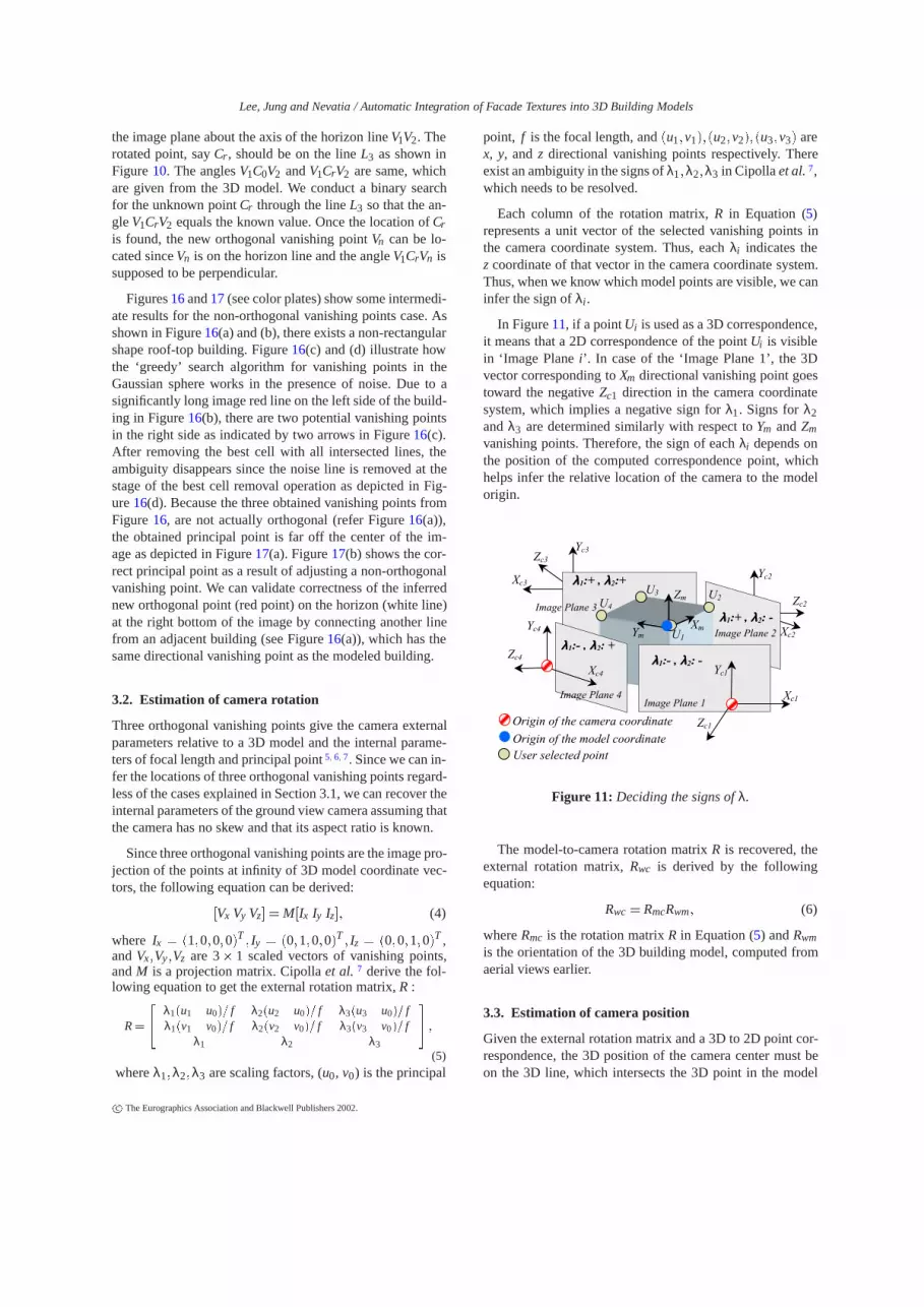
In Figure 11, if a point Ui is used as a 3D correspondence,it means that a 2D correspondence of the point Ui is visiblein ‘Image Plane i’. In case of the ‘Image Plane 1’, the 3Dvector corresponding to Xm directional vanishing point goestoward the negative Zc1 direction in the camera coordinatesystem, which implies a negative sign for λ1. Signs for λ2and λ3 are determined similarly with respect to Ym and Zm
vanishing points. Therefore, the sign of each λi depends onthe position of the computed correspondence point, whichhelps infer the relative location of the camera to the modelorigin.
Xc2
Zc2
Yc2 Xc3
Zc3
Yc3
Origin of the camera coordinate
Origin of the model coordinate User selected point
Ym
Zm
Xm
Xc1
Zc1
Yc1 Xc4
Zc4
Yc4
Image Plane 1 Image Plane 4
Image Plane 3
Image Plane 2 U1
U4
U3 U2
λλλλ1:- , λλλλ2: -
λλλλ1:+ , λλλλ2: -
λλλλ1:+ , λλλλ2:+
λλλλ1:- , λλλλ2: +
Figure 11: Deciding the signs of λ.
The model-to-camera rotation matrix R is recovered, theexternal rotation matrix, Rwc is derived by the followingequation:
Rwc = RmcRwm; (6)
where Rmc is the rotation matrix R in Equation (5) and Rwm
is the orientation of the 3D building model, computed fromaerial views earlier.
3.3. Estimation of camera position
Given the external rotation matrix and a 3D to 2D point cor-respondence, the 3D position of the camera center must beon the 3D line, which intersects the 3D point in the model
c The Eurographics Association and Blackwell Publishers 2002.
Lee, Jung and Nevatia / Automatic Integration of Facade Textures into 3D Building Models
and has a directional vector from the center of projectionto the corresponding 2D point. With two point correspon-dences, the exact position of the camera can be obtained byintersecting two lines.
3.4. Evaluation of correspondence hypotheses
When we have one 3D to 2D point correspondence betweena 3D model and its 2D image, we can recover the rotationalcamera parameters as explained in the Section 3.2. Two pointcorrespondences are required to estimate the camera posi-tion as explained the Section 3.3. We use one 3D to 2Dline segment correspondence to get the two correspondencepoints. We generate 3D to 2D line segment correspondencehypotheses by considering all pairs between 2D line seg-ment candidates (as described in the Section 2.4) and the3D lines of a building model. Each hypothesis is evaluatedas described below and the best one is selected.
With a given correspondence hypothesis and the obtainedvanishing points, a hypothesized camera projection can begenerated. Under a hypothesized camera projection, wecompute visible 3D points by checking intersections of thehypothesized camera rays (from the center of projection toeach 3D points) and the surfaces of the 3D building model.The 3D points that belong to the surfaces having the closestintersection point with the hypothesized ray, are recognizedas visible points. The set of hypothesized 3D visible pointsis projected to a ground view image to compute image evi-dence for it.
The evidence may be positive (supporting) or negative(conflicting) as provided by the underlying image features.Positive support edges are located near and parallel to theboundary of a roof hypothesis. Negative support edges arealso located near the boundary of a roof hypothesis but in-tersect the roof boundary 1. The line segment hypothesis pro-viding the best score is selected as the correct 3D to 2D cor-respondence.
The automatic 3D to 2D line segment correspondence ex-traction method is summarized in Algorithm 3.
4. Implementation and Experimental Results
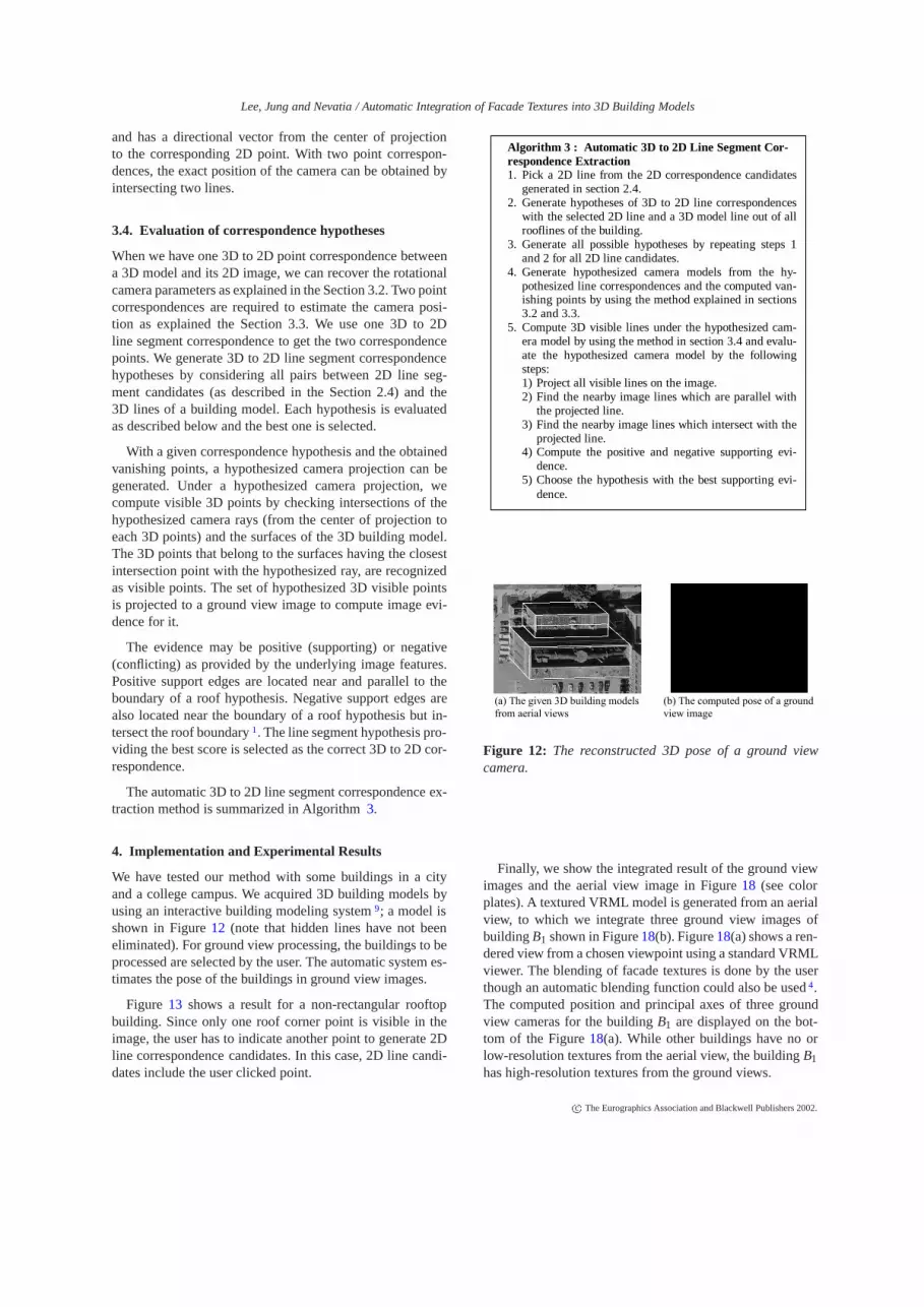
We have tested our method with some buildings in a cityand a college campus. We acquired 3D building models byusing an interactive building modeling system 9; a model isshown in Figure 12 (note that hidden lines have not beeneliminated). For ground view processing, the buildings to beprocessed are selected by the user. The automatic system es-timates the pose of the buildings in ground view images.
Figure 13 shows a result for a non-rectangular rooftopbuilding. Since only one roof corner point is visible in theimage, the user has to indicate another point to generate 2Dline correspondence candidates. In this case, 2D line candi-dates include the user clicked point.
Algorithm 3 : Automatic 3D to 2D Line Segment Cor-respondence Extraction1. Pick a 2D line from the 2D correspondence candidates
generated in section 2.4.2. Generate hypotheses of 3D to 2D line correspondences
with the selected 2D line and a 3D model line out of allrooflines of the building.
3. Generate all possible hypotheses by repeating steps 1and 2 for all 2D line candidates.
4. Generate hypothesized camera models from the hy-pothesized line correspondences and the computed van-ishing points by using the method explained in sections3.2 and 3.3.
5. Compute 3D visible lines under the hypothesized cam-era model by using the method in section 3.4 and evalu-ate the hypothesized camera model by the followingsteps:1) Project all visible lines on the image.2) Find the nearby image lines which are parallel with
the projected line.3) Find the nearby image lines which intersect with the
projected line.4) Compute the positive and negative supporting evi-
dence.5) Choose the hypothesis with the best supporting evi-
dence.
(a) The given 3D building modelsfrom aerial views
(b) The computed pose of a ground view image
Figure 12: The reconstructed 3D pose of a ground viewcamera.
Finally, we show the integrated result of the ground viewimages and the aerial view image in Figure 18 (see colorplates). A textured VRML model is generated from an aerialview, to which we integrate three ground view images ofbuilding B1 shown in Figure 18(b). Figure 18(a) shows a ren-dered view from a chosen viewpoint using a standard VRMLviewer. The blending of facade textures is done by the userthough an automatic blending function could also be used 4.The computed position and principal axes of three groundview cameras for the building B1 are displayed on the bot-tom of the Figure 18(a). While other buildings have no orlow-resolution textures from the aerial view, the building B1has high-resolution textures from the ground views.
c The Eurographics Association and Blackwell Publishers 2002.

Lee, Jung and Nevatia / Automatic Integration of Facade Textures into 3D Building Models
User clicked point
Figure 13: A result of non-rectangular rooftop building.
5. Conclusion
We have presented a method for automatically integratingground view images and 3D models to obtain high resolu-tion facade textures for 3D architectural models. We pro-posed a hybrid feature extraction method, which exploits aglobal line clustering based on the Gaussian sphere and a lo-cal line clustering based on a region-based segmentation ap-proach. We also implemented an automatic method for gen-erating and evaluating 3D to 2D line correspondences if atleast two roof corners are visible in an image. The automaticsystem still requires some predefined values such as imagesub-block size and the significant number of lines in Gaus-sian Sphere processing. In addition, we derived a novel poseestimation method for the ground view camera by using theautomatically obtained vanishing points, not necessarily or-thogonal, and the selected 3D to 2D line correspondence. Arefinement process for 3D model parameters will be neces-sary not only because 3D models from aerial views are nothighly accurate, but also because some facade detail struc-tures are not visible from the aerial views.
Acknowledgements
This research was supported in part by U.S. Army STRI-COM under contract N61339-02-C-0053.
References
1. S. Noronha and R. Nevatia. Detection and Modelingof Buildings from Multiple Aerial Images IEEE Trans-actions on Pattern Analysis and Machine Intelligence,23(5):501–518, 2001. 1, 2, 8
2. Y. Hsieh, SiteCity: A Semi-Automated Site ModelingSystem. Proceedings of IEEE Conference on ComputerVision and Pattern Recognition, 499–506, 1996. 1
3. A. Gruen and R. Nevatia (Editors). Special Issue onAutomatic Building Extraction from Aerial Images.Computer Vision and Image Understanding, 1998. 1
4. P. E. Debevec, C. J. Taylor and J. Malik. Modeling
and Rendering Architecture from Photographs: A Hy-brid Geometry- and Image-Based Approach. In Pro-ceedings of SIGGRAPH,11–20, 1996. 1, 8
5. D. Liebowitz, A. Criminisi and A. Zisserman. CreatingArchitectural Models from Images. Computer Graph-ics Forum, 18(3):39–50, 1999. 1, 2, 7
6. B. Caprile and V. Torre. Using Vanishing Points ForCamera Calibration. International Journal of ComputerVision, 127–140, 1990. 2, 7
7. R. Cipolla, T. Drummond and D.P. Robertson. Cam-era Calibration from Vanishing Points in Images of Ar-chitectural Scenes. In Proceedings of British MachineVision Conference, 2:382–391, 1999. 2, 7
8. E. Guillou, D. Meneveaux, E. Maisel. and K. Boua-touch. Using Vanishing Points for Camera Calibrationand Coarse 3D Reconstruction from A Single Image.The Visual Computer, 16:396-410, 2000. 2
9. S. C. Lee, A. Huertas, and R. Nevatia. Modeling 3-DComplex Buildings With User Assistance. Proceed-ings of IEEE Workshop on Applications of ComputerVision, 170–177, 2000. 2, 8
10. Satyan Coorg and Seth Teller. Extracting Textured Ver-tical Facades from Controlled Close-Range Imagery.Proceedings of IEEE Conference on Computer Visionand Pattern Recognition, 625–632, 1999 2
11. Ioannis Stamos and Peter K. Allen. Automatic Reg-istration of 2-D with 3-D Imagery in Urban Environ-ments. Proceedings of IEEE International Conferenceon Computer Vision, 2:731–736, 2001. 2
12. S. Barnard. Interpreting Perspective Images. ArtificialIntelligence, 21:435–462, 1983. 2
13. J. A. Shufelt. Performance Evaluation and Analysis ofVanishing Point Detection Techniques. IEEE Trans-actions on Pattern Analysis and Machine Intelligence,21(3):282–288, 1999. 2, 4
14. F.A. van den Heuvel. Vanishing Point Detection for Ar-chitectural Photogrammetry. International archives ofphotogrammetry and remote sensing, 32(5):652–659,1998. 2, 4
15. L. Quan and R. Mohr. Determining Perspective Struc-tures Using Hierarchical Hough Transform. PatternRecognition Letter, 9:279–286, 1989. 2, 4
16. D. Liebowitz and A. Zisserman. Metric Rectificationfor Perspective Images of Planes. In Proceedingsof IEEE Conference on Computer Vision and PatternRecognition, 482–488, 1998. 2
17. Sung Chun Lee, Soon Ki Jung, and Ram. Nevatia. Inte-grating Ground and Aerial Views for Urban Site Model-ing. International Conference on Pattern Recognition,2002. 6
c The Eurographics Association and Blackwell Publishers 2002.
Lee, Jung and Nevatia / Automatic Integration of Facade Textures into 3D Building Models
(a) Horizontal vanishing point (b) Vertical vanishing point
Figure 14: Vanishing points extraction using the Gaussiansphere.
The principal point
The horizon line
Figure 15: Result of global line clustering.
(a) An aerial view of a building in D.C.
(c) Before removing the best cell
(b) A ground view of (a)
(d) After removing the best cell
Figure 16: Intermediate results for a complex building inD.C..
(b) The adjusted principal point from a newly generated orthogonal vanishing point
(a) The principal point from non-orthogonal vanishing points
Figure 17: Adjusting non-orthogonal vanishing point.
B2 B1
C1
C2 C3
(a) An arbitrary rendered view from a VRML viewer
(b) Three ground view images for the building B1
C1 C2
C3
Figure 18: An integrated VRML rendering of D.C. site.
c The Eurographics Association and Blackwell Publishers 2002.