author's personal copy analysis of a semi-empirical sprinkler spray model
TRANSCRIPT

This article appeared in a journal published by Elsevier. The attachedcopy is furnished to the author for internal non-commercial researchand education use, including for instruction at the authors institution
and sharing with colleagues.
Other uses, including reproduction and distribution, or selling orlicensing copies, or posting to personal, institutional or third party
websites are prohibited.
In most cases authors are permitted to post their version of thearticle (e.g. in Word or Tex form) to their personal website orinstitutional repository. Authors requiring further information
regarding Elsevier’s archiving and manuscript policies areencouraged to visit:
http://www.elsevier.com/authorsrights
Author's personal copy
Analysis of a semi-empirical sprinkler spray model
Hamed Aghajani, Siaka Dembele n, Jennifer X. WenSchool of Mechanical and Automotive Engineering, Kingston University, London SW15 3DW, UK
a r t i c l e i n f o
Article history:Received 13 December 2012Received in revised form4 October 2013Accepted 21 January 2014Available online 7 February 2014
Keywords:SprinklerSprayDropletsAtomization
a b s t r a c t
Modelling the atomization process in fire sprinklers has remained a challenge mainly due to thecomplexity of sprinkler geometry. A review of existing fire sprinkler spray modelling approaches,including film flow and sheet tracking models, showed that they mainly assumed a constant sheetvelocity and linear attenuation of the sheet thickness before its disintegration. In the present study,a liquid sheet trajectory sub-model based on the solution of stream-wise conservation equations hasbeen used to predict both sheet thickness and velocity as it radially expands. This will also help toinvestigate the extent to which a change in the release angle can affect the sheet characteristics. Theanalysis carried out shows that the proposed approach improves the predictions of mean dropletdiameter and initial droplet speed. A semi-empirical approach is further introduced in the study by usingexperimental volume fraction measurements to characterize sprinkler sprays in the near field. For agiven direction predictions have been conducted for droplet volume median diameter, water volume fluxand droplet average velocity at different elevation and azimuthal locations. A reasonably good agreementis found for the near field measurements.
& 2014 Elsevier Ltd. All rights reserved.
1. Introduction
Modelling sprinkler atomization is a challenging task, due tothe stochastic nature of the breakup process. This complexity ispredominantly influenced by the sprinkler geometry. Predictivemodels are required to evaluate sprinkler spray characteristics forcoupling with fire models to predict sprinkler suppression perfor-mance. Droplet dispersion models are available [1] for trackingdroplets after the initial atomization process is completed, butthere is no general atomization model to predict the initial spraycharacteristics for sprinklers and this is a critical missing link inthe modelling of fire suppression with sprinklers.
Various experimental studies have been conducted to charac-terize droplet's size and velocity in sprinkler spray using methodssuch as photographic techniques [2], laser-light shadow imagingmethod [3–4], Phase Doppler Interferometer [5] and ParticleImage Velocimetry [6]. These studies have provided valuable datafor the development of atomization and spray models. One of thefirst correlations presented from droplet size measurements wassuggested by Dundas [2], in the form dV50=D0 ¼ CWe0�1=3. Mea-surements of spray undertaken by Yu [3] showed that any changein the injection orifice diameter and the deflector geometry in anupright sprinkler affects directly the coefficient of proportionality,C. The droplet size distributions of the experimentally studied
sprinklers were expressed as an amalgamated form of log-normaland Rosin–Rammler distributions. Despite the insensitivity ofthese distributions and correlations to some key parametersrelevant to the initial spray, they are still used as primitivepredictive models. Yu [3] noticed a deviation from the Δp�1=3
scaling law for droplet size at low pressures (around 69 kPa). Theexperiments of Sheppard [6] presented the variation of radialvelocity with polar angle at various azimuthal angles, as well as arough approximation of the radial velocity close to the sprinklerð � 200 mmÞ, which is described by 0:6ðΔp=ρf Þ1=2. Ren et al. [7]and Zhou and Yu [8] conducted series of experiments on simpli-fied and commercial sprinklers, respectively. Both studies investi-gated the effect of sprinkler geometrical components on the sprayformation process and provided more insight to some essentialphysics of the atomization process.
Research was also undertaken by many researchers on themodelling of sprinklers sprays. The underlying simplified atomiza-tion physics resulting from a jet impinging on an axisymmetrichorizontal disc (deflector plate) are thoroughly discussed in theliterature [1,9–10]. At the first stage the jet transforms into a filmflow upon impact, moving radially outwards on the deflectorsurface. The film is transformed into an unconfined sheet as itexpands beyond the deflector edge. A sinuous wave grows on thedecaying thickness sheet due to existing inertia, surface tension,viscous force and the pressure difference between the sheet upperand lower surfaces. At critical wave amplitudes, the sheet eitherbreaks up into cylindrical strands (ligaments) or disintegratesdirectly to droplet depending on the jet Weber number [9].
Contents lists available at ScienceDirect
journal homepage: www.elsevier.com/locate/firesaf
Fire Safety Journal
0379-7112/$ - see front matter & 2014 Elsevier Ltd. All rights reserved.http://dx.doi.org/10.1016/j.firesaf.2014.01.004
n Corresponding author. Tel.: þ44 208 417 4720; fax: þ44 208 417 7992.E-mail address: [email protected] (S. Dembele).
Fire Safety Journal 64 (2014) 1–11
Author's personal copy
As the ligaments expand outwards, aerodynamic forces causedilatational waves to grow along the ligament. When thesedilatational waves reach their critical amplitude, the ligamentsbreak into smaller fragments which contract to form drops due tosurface tension.
The featured physics in atomization process have been inves-tigated and reported in the literature. The film flow developmentover a flat plate is predicted by two main models. One of theapproaches is an analytical model based on a free-surface similar-ity boundary layer concept developed by Watson [10]. This modelhas been a popular choice in numerous applications, hence is usedin the present study. Another film model is the integral approachrecently formulated by Zhou and Yu [8] where the sheet thicknesscan be calculated for different degrees of viscous effects. To trackthe trajectory of the water sheet emerging from a deflector plate,the most widely used and simplest approach assumes an inverselylinear decay of sheet thickness and constant velocity of the radiallyexpanding sheet prior to its breakup point known as the Taylorhypothesis [11]. An alternative more rigorous model and detailedsheet tracking approach consists in solving a set of stream-wisecontinuity equation to resolve the sheet trajectory characteristicsas derived by Ibrahim and McKinney [12] and mentioned in [13].The work presented in the present study builds on this lattermodel which is referred to as “Detailed Trajectory Model” (DTM)throughout this paper. The aerodynamic instability and disinte-gration of viscous and inviscid liquid sheets to ligaments anddroplets have been studied and reported in the literature [14,15].
The overall goal of the present study is to develop andthoroughly investigate a methodology that is more accurate withfurther capabilities to predict the near-field initial sprinkleratomization building on and extending some existing models. Toachieve this target, two liquid sheet tracking sub-models have
been implemented and their accuracy is investigated to shed morelight on their capability for the sprinkler initial spray prediction.The present work also further introduces and explores the conceptof a semi-empirical approach which is capable of predicting thevolume median diameter, average droplet velocity and volumeflux of the spray at different elevation and azimuthal locationsunder the sprinkler with a relatively good degree of fidelity.
2. Mathematical modelling
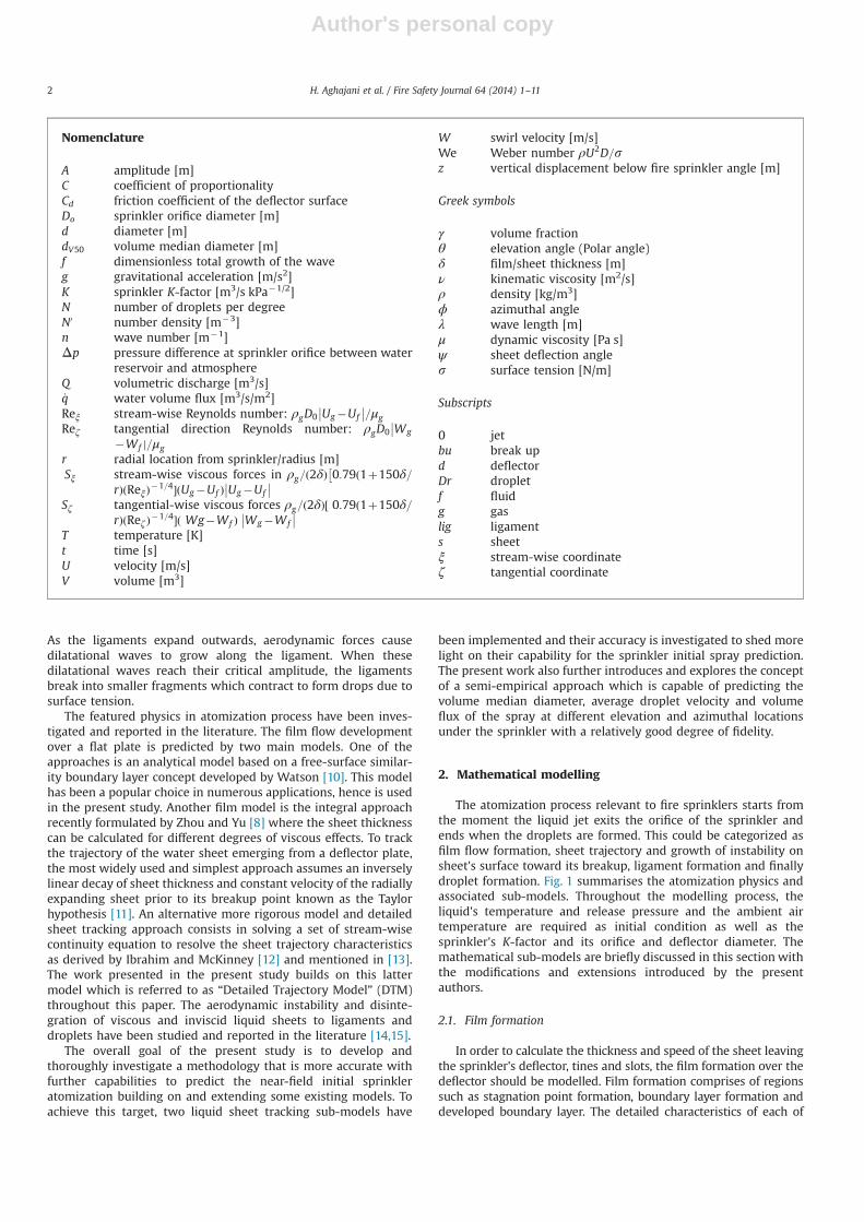
The atomization process relevant to fire sprinklers starts fromthe moment the liquid jet exits the orifice of the sprinkler andends when the droplets are formed. This could be categorized asfilm flow formation, sheet trajectory and growth of instability onsheet's surface toward its breakup, ligament formation and finallydroplet formation. Fig. 1 summarises the atomization physics andassociated sub-models. Throughout the modelling process, theliquid's temperature and release pressure and the ambient airtemperature are required as initial condition as well as thesprinkler's K-factor and its orifice and deflector diameter. Themathematical sub-models are briefly discussed in this section withthe modifications and extensions introduced by the presentauthors.
2.1. Film formation
In order to calculate the thickness and speed of the sheet leavingthe sprinkler's deflector, tines and slots, the film formation over thedeflector should be modelled. Film formation comprises of regionssuch as stagnation point formation, boundary layer formation anddeveloped boundary layer. The detailed characteristics of each of
Nomenclature
A amplitude [m]C coefficient of proportionalityCd friction coefficient of the deflector surfaceDo sprinkler orifice diameter [m]d diameter [m]dV50 volume median diameter [m]f dimensionless total growth of the waveg gravitational acceleration [m/s2]K sprinkler K-factor [m3/s kPa�1/2]N number of droplets per degreeN0 number density [m�3]n wave number [m�1]Δp pressure difference at sprinkler orifice between water
reservoir and atmosphereQ volumetric discharge [m3/s]_q water volume flux [m3/s/m2]Reξ stream-wise Reynolds number: ρgD0 Ug�Uf
�� ��=μgReζ tangential direction Reynolds number: ρgD0 Wg
���Wf j=μg
r radial location from sprinkler/radius [m]Sξ stream-wise viscous forces in ρg=ð2δÞ 0:79ð1þ150δ=
�rÞðReξÞ�1=4�ðUg�Uf Þ Ug�Uf
�� ��Sζ tangential-wise viscous forces ρg=ð2δÞ½ 0:79ð1þ150δ=
rÞðReζÞ�1=4�ð Wg�Wf Þ Wg�Wf
�� ��T temperature [K]t time [s]U velocity [m/s]V volume [m3]
W swirl velocity [m/s]We Weber number ρU2D=sz vertical displacement below fire sprinkler angle [m]
Greek symbols
γ volume fractionθ elevation angle (Polar angle)δ film/sheet thickness [m]ν kinematic viscosity [m2/s]ρ density [kg/m3]ϕ azimuthal angleλ wave length [m]μ dynamic viscosity [Pa s]ψ sheet deflection angles surface tension [N/m]
Subscripts
0 jetbu break upd deflectorDr dropletf fluidg gaslig ligaments sheetξ stream-wise coordinateζ tangential coordinate
H. Aghajani et al. / Fire Safety Journal 64 (2014) 1–112
Author's personal copy
these stages based on the boundary layer modelling approach ofWatson [10] are discussed by Wu et al. [16]. For sprinkler applica-tions the film reaching the edge of the deflector might fall either inthe boundary layer formation region, with sheet thickness given byEq. (1), or in the developed boundary layer region, with sheetthickness obtained from Eq. (2):
δd ¼r02rd
þC1 �7νfU0
� �1=5
r4=5d for rdrrl ð1Þ
δd ¼ C2 �νfQ
� �1=4r9=4d þ l9=4
rdfor rd4rl ð2Þ
In Eqs. (1) and (2) the constants are C1 ¼ 1:659� 10�2; C2 ¼ 2:11�10�2, and l¼ 4:126� r0ðQ=νf r0Þ1=9. The criterion for the radiallocation, measured from the jet/plate stagnation point, where theboundary layer affects the main stream is rl ¼ 0:183D0Re
1=30 . The
stagnation point is the centre of deflector or boss in sprinklers.The speed of the sheet leaving the deflector edge can be
calculated from the mass conservation principle Q ¼ πD20U0 ¼
2πrdδdUd. In sprinkler applications the volumetric discharge iscommonly defined as Q ¼ KΔp1=2.The velocity at the sprinklerorifice could be determined from the Bernoulli's equationU0 ¼ ð2Δp=ρf Þ1=2 assuming negligible loss in the dischargingprocess. The hydraulic radius, r0, is then r0 ¼D0=2¼ ð4Q=
πU0Þ1=2=2. Eqs. (1) and (2) have been employed in the presentstudy for the film/sheet thickness calculations during the forma-tion process.
2.2. Sheet trajectory model
The sheet characteristics (local thickness and velocity) shouldbe tracked rigorously after it leaves the deflector for a goodprediction of the sheet breakup distance (distance that is takesfor ligaments to disintegrate into droplets), initial droplet locationsand droplet median diameter. A sheet trajectory model is neededfor this purpose.
A popular hypothesis for predicting the characteristics of anattenuating sheet formed in sprinkler applications is to assume(i) that the sheet velocity, Us, remains unchanged and (ii) that thesheet thickness δ at any arbitrary point is inversely proportional toits radial distance from the stagnation point, r, i.e.:
δ¼ δdrdr
ð3Þ
This hypothesis is referred to as “Inversely Linear ThicknessDecay (ILTD)” model in Fig. 1.
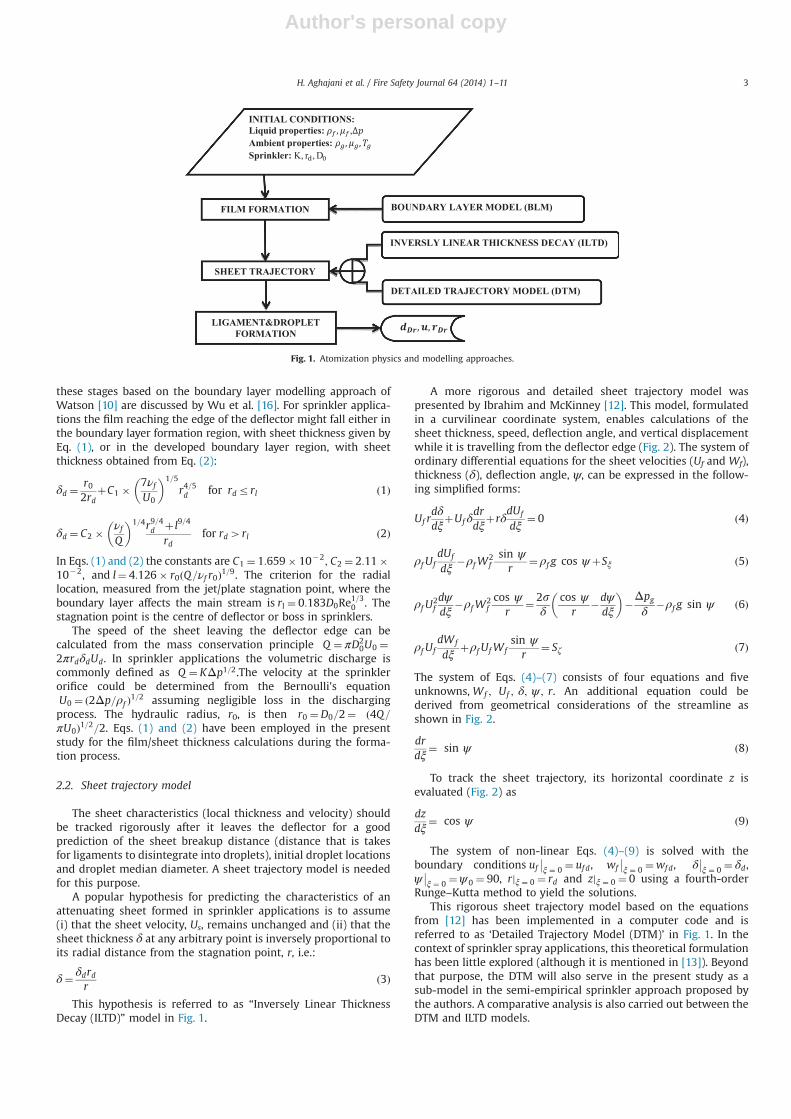
A more rigorous and detailed sheet trajectory model waspresented by Ibrahim and McKinney [12]. This model, formulatedin a curvilinear coordinate system, enables calculations of thesheet thickness, speed, deflection angle, and vertical displacementwhile it is travelling from the deflector edge (Fig. 2). The system ofordinary differential equations for the sheet velocities (Uf and Wf),thickness (δ), deflection angle, ψ, can be expressed in the follow-ing simplified forms:
Uf rdδdξ
þUf δdrdξ
þrδdUf
dξ¼ 0 ð4Þ
ρf UfdUf
dξ�ρfW
2fsin ψr
¼ ρf g cos ψþSξ ð5Þ
ρf U2fdψdξ
�ρfW2fcos ψ
r¼ 2s
δcos ψ
r�dψ
dξ
� ��Δpg
δ�ρf g sin ψ ð6Þ
ρf UfdWf
dξþρf UfWf
sin ψr
¼ Sζ ð7Þ
The system of Eqs. (4)–(7) consists of four equations and fiveunknowns, Wf ; Uf ; δ; ψ ; r. An additional equation could bederived from geometrical considerations of the streamline asshown in Fig. 2.
drdξ
¼ sin ψ ð8Þ
To track the sheet trajectory, its horizontal coordinate z isevaluated (Fig. 2) as
dzdξ
¼ cos ψ ð9Þ
The system of non-linear Eqs. (4)–(9) is solved with theboundary conditions uf
��ξ ¼ 0 ¼ ufd, wf
��ξ ¼ 0 ¼wfd, δ
��ξ ¼ 0 ¼ δd,
ψ��ξ ¼ 0 ¼ψ0 ¼ 90, rjξ ¼ 0 ¼ rd and zjξ ¼ 0 ¼ 0 using a fourth-order
Runge–Kutta method to yield the solutions.This rigorous sheet trajectory model based on the equations
from [12] has been implemented in a computer code and isreferred to as ‘Detailed Trajectory Model (DTM)’ in Fig. 1. In thecontext of sprinkler spray applications, this theoretical formulationhas been little explored (although it is mentioned in [13]). Beyondthat purpose, the DTM will also serve in the present study as asub-model in the semi-empirical sprinkler approach proposed bythe authors. A comparative analysis is also carried out between theDTM and ILTD models.
INITIAL CONDITIONS: Liquid properties: ,Ambient properties: Sprinkler: K, r , D
LIGAMENT&DROPLET FORMATION
FILM FORMATION BOUNDARY LAYER MODEL (BLM)
SHEET TRAJECTORY
INVERSLY LINEAR THICKNESS DECAY (ILTD)
DETAILED TRAJECTORY MODEL (DTM)
Fig. 1. Atomization physics and modelling approaches.
H. Aghajani et al. / Fire Safety Journal 64 (2014) 1–11 3
Author's personal copy
2.3. Sheet break-up and ligament formation
Due to the existing pressure force between the upper and lowersurfaces, surface tension force, inertial force and viscous force, asinuous wave starts to grow on the attenuating sheet. According toDombrowski [14], the growth of aerodynamic waves on a liquidsheet could be represented as
ρf δ∂f∂t
� �2
þμf δn2 ∂f
∂t
� ��2ρgnU
2þ2sn2 ¼ 0 ð10Þ
Eq. (10) is the balance of the four aforementioned forces aftermany simplifications, and the dimensionless total growth of thewave, f ¼ lnðA=A0Þ, is the natural logarithm of the ratio of waveamplitude to amplitude of initial disturbances. It is found that thebreakup of the liquid sheets due to the wave growth occurs as thetotal growth of the wave, f, approaches a constant value of 12 [14].The solution to Eq. (10) is
f ¼ 2=ρf ðρgUs2n�sn2Þ
h i1=2 Z t
0δ�1=2dt ð11Þ
Differentiating Eq. (11) with respect to n and equating to zero,∂f =∂n¼ 0, gives the wave with maximum growth. Thus,ninviscid ¼ ρgUs
2=ð2sÞ and the corresponding values of total growthf,
f ¼Z t
0ρgUs
2=ð2δρlsÞ1=2 dt ð12Þ
For a parallel-sided sheet, Eq. (12) reduces to f ¼ ρgUs2t=
ð2δρfsÞ1=2. It is known that the attenuating sheet will disintegrateafter some time, which may be called as breakup time, at alocation denoted as sheet breakup radius. As the sheet thicknessvaries with radial location in time and its breakup time value is notknown, Eq. (12) is rearranged into t ¼ f ð2ρfsδÞ1=2= ðρgUs
2Þ.If the ILTD model, Eq. (3), is employed, and taking into account
that the sheet disintegration distance from stagnation point is,rbu ¼ rdþUstbu, then the sheet breakup time is found from:
Ust3buþrdt2bu�δdrdðf
ffiffiffiffiffiffiffiffiffiffiffi2ρfs
q=ðρU2
s ÞÞ2 ¼ 0 ð13Þ
If the detailed sheet trajectory model (DTM) is employed thenthe sheet disintegration time is calculated using Eq. (12) in thefollowing form f ¼ ρg=ð2ρfsÞ1=2
R t0 Us
2δ�1=2 dt, by taking intoaccount the fact that both sheet speed and sheet thickness varyin time.
In the present study, the total growth of the wave has beenevaluated numerically employing recursive adaptive Simpsonquadrature method. The breakup time is the one for which thedimensionless total growth of the wave, f, matches its desiredvalue, here 12.
In the sheet breakup model, the sheet is assumed to breakupinto cylindrical strands having radial width of one-half wavelengthas assumed by Wu et al. [16]. To get the ligament diameter,the volume of ligaments is calculated by two methods. In thefirst method the volume is calculated from the multiplicationof the ligament's cross section by length of cylindrical strandV1 ¼ πr2lig 2πðrbuþ rligÞ
� �, and in the second method the volume is
determined by the product of torroid area by sheet thickness at apoint at which fragmentation happens, V2 ¼ π ðr1þπ=nÞ2�r21
h iδ.
Equating these two volumes (V1 and V2) in equality and rearran-ging, the ligament diameter could be obtained from:
π4δ
d3ligþπ2δ
rbud2lig� rbuþ
πn
� 2�r2bu
�¼ 0 ð14Þ
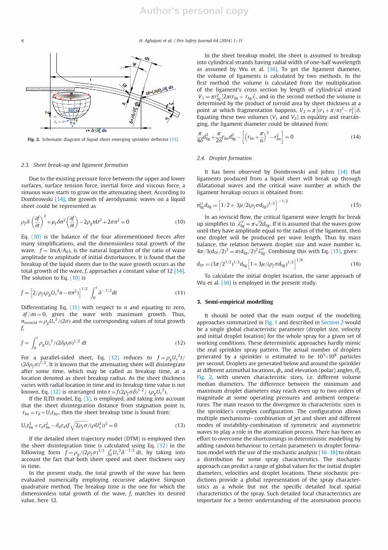
2.4. Droplet formation
It has been observed by Dombrowski and Johns [14] thatligaments produced from a liquid sheet will break up throughdilatational waves and the critical wave number at which theligament breakup occurs is obtained from:
ncrligdlig ¼ 1=2þ 3μ=2ðρfsdligÞ1=2
h i�1=2ð15Þ
In an inviscid flow, the critical ligament wave length for breakup simplifies to λcrlig ¼ π
ffiffiffi2
pdlig . If it is assumed that the waves grow
until they have amplitude equal to the radius of the ligament, thenone droplet will be produced per wave length. Thus by massbalance, the relation between droplet size and wave number is,4π=3ðdDr=2Þ3 ¼ πðdlig=2Þ2λcrlig . Combining this with Eq. (15), gives:
dDr ¼ ð3π=21=2Þ1=3dlig 1þ3μ=ðρfsdligÞ1=2h i1=6
ð16Þ
To calculate the initial droplet location, the same approach ofWu et al. [16] is employed in the present study.
3. Semi-empirical modelling
It should be noted that the main output of the modellingapproaches summarized in Fig. 1 and described in Section 2 wouldbe a single global characteristic parameter (droplet size, velocityand initial droplet location) for the whole spray for a given set ofworking conditions. These deterministic approaches hardly mimicthe real sprinkler spray pattern. The actual number of dropletsgenerated by a sprinkler is estimated to be 105–108 particlesper second. Droplets are generated below and around the sprinklerat different azimuthal locations, ϕi, and elevation (polar) angles, θj,Fig. 2, with uneven characteristic sizes, i.e. different volumemedian diameters. The difference between the minimum andmaximum droplet diameters may reach even up to two orders ofmagnitude at some operating pressures and ambient tempera-tures. The main reason to the divergence in characteristic sizes isthe sprinkler's complex configuration. The configuration allowsmultiple mechanisms- combination of jet and sheet and differentmodes of instability-combination of symmetric and asymmetricwaves to play a role in the atomization process. There has been aneffort to overcome the shortcomings in deterministic modelling byadding random behaviour to certain parameters in droplet forma-tion model with the use of the stochastic analysis [16–18] to obtaina distribution for some spray characteristics. The stochasticapproach can predict a range of global values for the initial dropletdiameters, velocities and droplet locations. These stochastic pre-dictions provide a global representation of the spray character-istics as a whole but not the specific detailed local spatialcharacteristics of the spray. Such detailed local characteristics areimportant for a better understanding of the atomisation process
Fig. 2. Schematic diagram of liquid sheet emerging sprinkler deflector [13].
H. Aghajani et al. / Fire Safety Journal 64 (2014) 1–114
Author's personal copy
and also for fire suppression for instance, where the local watervolume flux is a key information. This shortcoming is addressed inthe present study, where a semi-empirical atomization model isdeveloped by building on a combination of models presented inSection 2 and an empirical input (experimentally evaluatedvolume fraction, γ). The spray characteristics (diameter, velocityand water fluxes) at various spatial locations could be predictedwith the semi-empirical approach. Another rational behind thissemi-empirical approach is that there is no existing sprinklerspray model to date (to the best of the authors' knowledge) thatincludes in its formulation the effects of some important geome-trical features of actual sprinklers such as frame arm, boss andtines. The experimentally measured volume fraction, which is theonly information needed as input to the semi-empirical model,could be easily obtained and provided by most manufacturers andwould take into account the effects of these complex geometricalfeatures.
The measurements of volume flux on 16 different types ofsprinklers [6] showed that the spray pattern along elevation anglesθj is distributed unevenly with at least one high density region. Inthis study we assumed there is a high probability for formation oflarge volume median diameters in areas of higher spray densities.This assumption is based on a comparative analysis of the dropletsizes and respective volume fluxes for ranges of sprinklers andworking conditions. The sprinklers investigated include onependant sprinkler and one upright sprinkler in Zhou et al. [4]and the 16 sprinklers experimentally studied by Sheppard [6],consisting of 9 pendant sprinkler and 7 upright sprinklers.
Non-uniformity of the spray can be translated into fractionaldistributions of the flow transported towards the high and lowdensity areas. In the current approach, these fractions are beingused to scale up the sheet thicknesses, which imply that the sheetis converted to multiple sheets.
To estimate the near field droplet diameter at different localspatial locations of interest, our adopted methodology employs thedeterministic approach to calculate the spray characteristics in thedirection of favourable spatial location (ϕi,θj). It is assumed thatthe initial sheet thickness Eqs. (1) or (2) is modified to account forthe fractional distribution as
δijd ¼ γij � δd ð17Þ
where γij is the volume fraction of the flow from azimuthalposition i transported towards elevation position j, as illustratedon the hemisphere of Fig. 2. This technique enables the predictionsof spray droplet size, velocities and initial droplet formation radiusat any spatial location (combinations of azimuthal and elevationspositions). In the authors' opinion the number of sheets (in thecurrent semi-empirical calculation) should be determined throughthe number of low density and high density regions identifiable ina typical spray. This depicts non uniformity of the spray. From theanalysed sprinklers these regions are found to be one of 5–10.
In the context of fire suppression, water flux is one of the mostimportant characteristics of the sprinkler spray. The water volumeflux defines howmuch water is transported to each location belowthe sprinkler, and it varies with both azimuthal location andelevation angle.
In spherical coordinates, the differential volumetric flow rate,d_q, passing through area of, dA can be quantified as
d_qðθ;ϕÞ ¼N0 π6d3
� Urðθ;ϕÞ ð18Þ
where N0 ¼N=dV is the number density of droplets in a probevolume, dV, and N is the number of droplets in the probe volume.The probe volume in an arbitrary radial location, surroundedbetween semi-cone with differential cross section, dA¼ðr sin θ dϕÞðrdθÞ and the length sweeps the region between initial
droplet formation radius, rDr , and the data collection location,rMeas, with respect to sprinkler position. Therefore the probevolume is calculated as
dV ¼ 13 dA ðrMeas�rDrÞ ð19Þ
The droplets will slow down due to continuous drag forceexerted by surroundings as they approach data collection pointuntil they level at a terminal velocity. In this study, the followingEqs. (20)–(21) are employed to track the droplets and find theirspeed when passing through any arbitrary measuring surface,where Reo1 and ReZ1, respectively [6]:
UdðtÞ ¼1
9νfρg
12gd2Drρf þe
� 18νf ρg
ρf d2Dr
t�12gd2Drρf þ9V0νfρg
� �" #for Reo1
ð20Þ
∂Ud
∂t¼ g� 3ρg
8rρf
12νfrUd
þ 6
1þffiffiffiffiffiffiffiffi2rUdνf
q þ0:4
264
375U2
d for Re41 ð21Þ
Eq. (21) is solved numerically in the present study.N in Eq. (18) has been estimated through the time it takes for
droplets to travel from rDr to rMeas. Knowing this time, the numberof sequences that ligaments will break up to droplets has beenevaluated. Considering that in each sequence N1 ¼ ðmlig=mDrÞ=360droplets will enter the probe volume. The following assumptionshave also been made dϕ¼ 1 3 and dθ¼ 1 3 .
4. Results and discussion
In Section 4.1 the DTM, which has been scarcely applied to firesprinklers, is investigated for a better understanding of the beha-viour of the sheet developed beyond the deflector edge. In Section4.2, a comparative analysis between the BLM-LTD-Dombrowskiapproach (Method-1) and the BLM-DTM-Dombrowski approach(Method-2) in predicting the initial droplet size and initial dropletlocation is conducted. The preliminary verifications study of theproposed semi-empirical approach is undertaken in Section 4.3.
For the calculations, the liquid properties are taken ass¼0.0728 N/m, mf¼0.798 mPa s, νf¼0.801 mm2/s, the ambient airproperties at 300 K are, mg¼19.83 mPa s, νg¼15.68 mm2/s, and thesprinkler configuration are assumed as K¼7.7�10�5 m3/s kPa�1/2
and rd¼12.5 mm.
4.1. Sheet trajectory characteristics
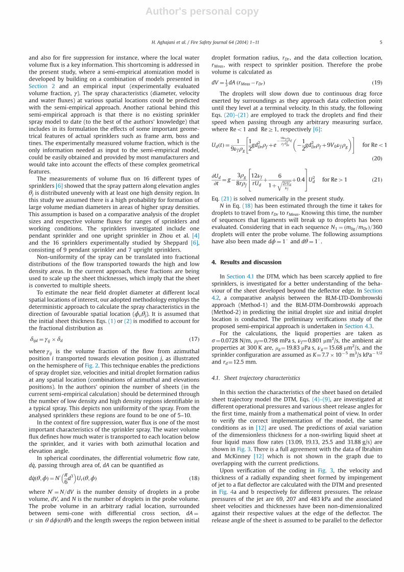
In this section the characteristics of the sheet based on detailedsheet trajectory model the DTM, Eqs. (4)–(9), are investigated atdifferent operational pressures and various sheet release angles forthe first time, mainly from a mathematical point of view. In orderto verify the correct implementation of the model, the sameconditions as in [12] are used. The predictions of axial variationof the dimensionless thickness for a non-swirling liquid sheet atfour liquid mass flow rates (13.09, 19.13, 25.5 and 31.88 g/s) areshown in Fig. 3. There is a full agreement with the data of Ibrahimand McKinney [12] which is not shown in the graph due tooverlapping with the current predictions.
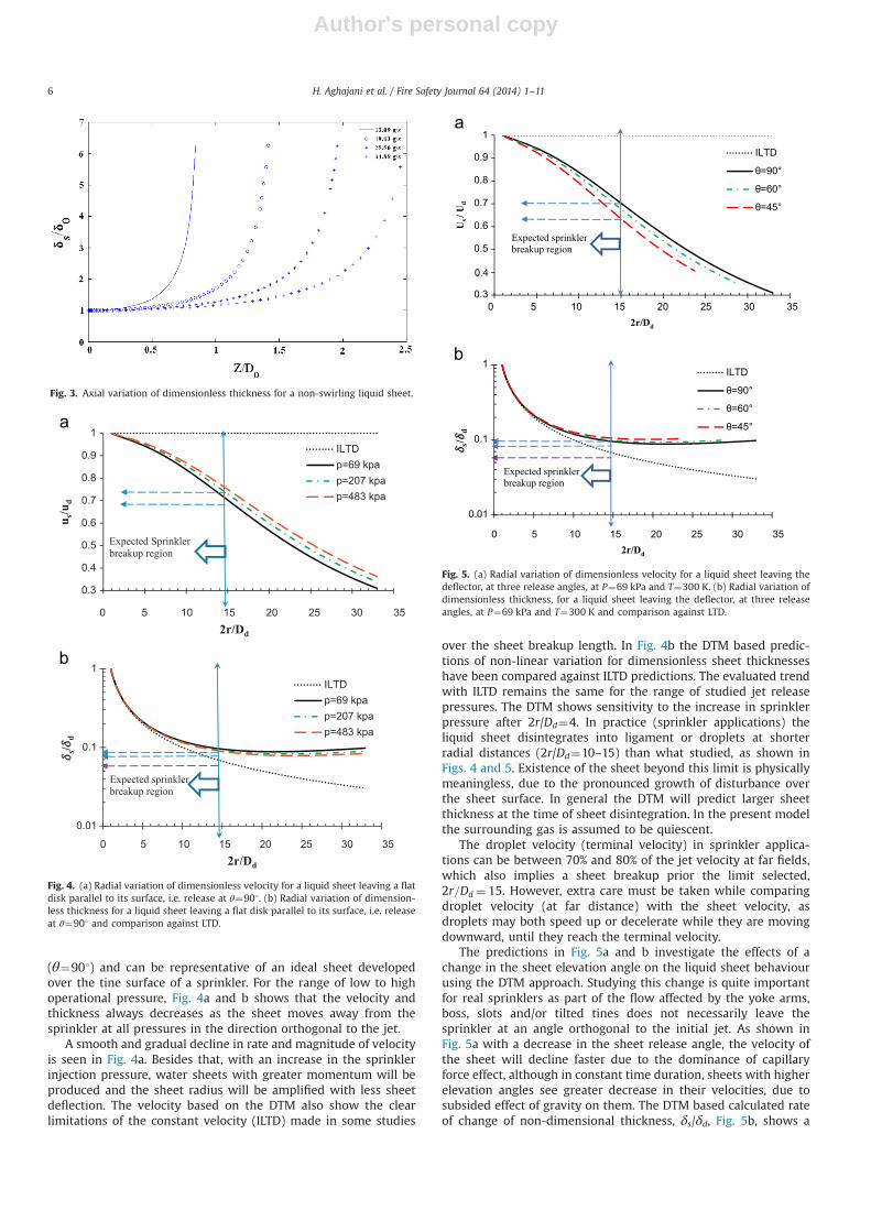
Upon verification of the coding in Fig. 3, the velocity andthickness of a radially expanding sheet formed by impingementof jet to a flat deflector are calculated with the DTM and presentedin Fig. 4a and b respectively for different pressures. The releasepressures of the jet are 69, 207 and 483 kPa and the associatedsheet velocities and thicknesses have been non-dimensionalizedagainst their respective values at the edge of the deflector. Therelease angle of the sheet is assumed to be parallel to the deflector
H. Aghajani et al. / Fire Safety Journal 64 (2014) 1–11 5
Author's personal copy
(θ¼901) and can be representative of an ideal sheet developedover the tine surface of a sprinkler. For the range of low to highoperational pressure, Fig. 4a and b shows that the velocity andthickness always decreases as the sheet moves away from thesprinkler at all pressures in the direction orthogonal to the jet.
A smooth and gradual decline in rate and magnitude of velocityis seen in Fig. 4a. Besides that, with an increase in the sprinklerinjection pressure, water sheets with greater momentum will beproduced and the sheet radius will be amplified with less sheetdeflection. The velocity based on the DTM also show the clearlimitations of the constant velocity (ILTD) made in some studies
over the sheet breakup length. In Fig. 4b the DTM based predic-tions of non-linear variation for dimensionless sheet thicknesseshave been compared against ILTD predictions. The evaluated trendwith ILTD remains the same for the range of studied jet releasepressures. The DTM shows sensitivity to the increase in sprinklerpressure after 2r/Dd¼4. In practice (sprinkler applications) theliquid sheet disintegrates into ligament or droplets at shorterradial distances (2r/Dd¼10–15) than what studied, as shown inFigs. 4 and 5. Existence of the sheet beyond this limit is physicallymeaningless, due to the pronounced growth of disturbance overthe sheet surface. In general the DTM will predict larger sheetthickness at the time of sheet disintegration. In the present modelthe surrounding gas is assumed to be quiescent.
The droplet velocity (terminal velocity) in sprinkler applica-tions can be between 70% and 80% of the jet velocity at far fields,which also implies a sheet breakup prior the limit selected,2r=Dd ¼ 15. However, extra care must be taken while comparingdroplet velocity (at far distance) with the sheet velocity, asdroplets may both speed up or decelerate while they are movingdownward, until they reach the terminal velocity.
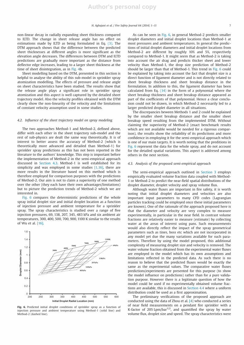
The predictions in Fig. 5a and b investigate the effects of achange in the sheet elevation angle on the liquid sheet behaviourusing the DTM approach. Studying this change is quite importantfor real sprinklers as part of the flow affected by the yoke arms,boss, slots and/or tilted tines does not necessarily leave thesprinkler at an angle orthogonal to the initial jet. As shown inFig. 5a with a decrease in the sheet release angle, the velocity ofthe sheet will decline faster due to the dominance of capillaryforce effect, although in constant time duration, sheets with higherelevation angles see greater decrease in their velocities, due tosubsided effect of gravity on them. The DTM based calculated rateof change of non-dimensional thickness, δs/δd, Fig. 5b, shows a
Fig. 3. Axial variation of dimensionless thickness for a non-swirling liquid sheet.
0.3
0.4
0.5
0.6
0.7
0.8
0.9
1
0 5 10 15 20 25 30 35
u s/u
d
2r/Dd
ILTDp=69 kpap=207 kpap=483 kpa
Expected Sprinkler breakup region
0.01
0.1
1
0 5 10 15 20 25 30 35
s/d
2r/Dd
2r/Dd
ILTDp=69 kpap=207 kpap=483 kpa
Expected sprinkler breakup region
Fig. 4. (a) Radial variation of dimensionless velocity for a liquid sheet leaving a flatdisk parallel to its surface, i.e. release at θ¼901. (b) Radial variation of dimension-less thickness for a liquid sheet leaving a flat disk parallel to its surface, i.e. releaseat θ¼901 and comparison against LTD.
0.3
0.4
0.5
0.6
0.7
0.8
0.9
1
0 5 10 15 20 25 30 35
Us /
Ud
2r/Dd
2r/Dd
ILTD
θ=90°
θ=60°
θ=45°
Expected sprinkler breakup region
0.01
0.1
1
0 5 10 15 20 25 30 35
s/d
ILTD
θ=90°
θ=60°
θ=45°
Expected sprinkler breakup region
Fig. 5. (a) Radial variation of dimensionless velocity for a liquid sheet leaving thedeflector, at three release angles, at P¼69 kPa and T¼300 K. (b) Radial variation ofdimensionless thickness, for a liquid sheet leaving the deflector, at three releaseangles, at P¼69 kPa and T¼300 K and comparison against LTD.
H. Aghajani et al. / Fire Safety Journal 64 (2014) 1–116
Author's personal copy
non-linear decay in radially expanding sheet thickness comparedto ILTD. The change in sheet release angle has no effect onestimations made by ILTD as being formulated in Eq. (3). TheDTM approach shows that the difference between the predictedsheet thicknesses at different angles is more significant as theelevation angle decreases. The differences between DTM and ILTDpredictions are gradually more important as the distance fromdeflector edge increases, leading to a larger sheet thickness at thetime of sheet disintegration, as in Fig. 4b.
Sheet modelling based on the DTM, presented in this section ishelpful to analyse the ability of this sub-model in sprinkler sprayatomization modelling. The effects of pressure and release angleon sheet characteristics have been studied. The results show thatthe release angle plays a significant role in sprinkler sprayatomization and this aspect is well captured by the detailed sheettrajectory model. Also the velocity profiles obtained with the DTMclearly show the non-linearity of the velocity and the limitationsof constant velocity assumption used in some studies.
4.2. Influence of the sheet trajectory model on spray modeling
The two approaches Method-1 and Method-2, defined above,differ with each other in the sheet trajectory sub-model and therest of sub-physics are dealt the same way theoretically. It is ofinterest to better assess the accuracy of Method-2 (which istheoretically more advanced and detailed than Method-1) forsprinkler spray predictions as this has not been reported in theliterature to the authors' knowledge. This step is important beforethe implementation of Method-2 in the semi-empirical approachdiscussed in Section 4.3. Method-1 is well established for itssimplicity and was employed in some studies [1,16], there aremore results in the literature based on this method which istherefore employed for comparison purposes with the predictionsof Method-2. Our aim is not to claim a superiority of one methodover the other (they each have their own advantages/limitations)but to picture the prediction trends of Method-2 which we areinterested in.
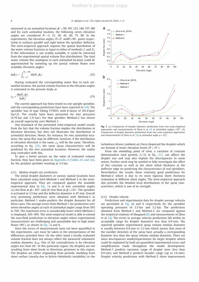
Fig. 6 compares the deterministic predictions of the wholespray initial droplet size and initial droplet location as a functionof injection pressure and ambient temperature for a sprinklerspray. The spray characteristics is studied over a range of fiveinjection pressures, 69, 138, 207, 345, 483 kPa and six ambient airtemperatures, 300, 400, 500, 700, 900, 1100 K similar to the resultsof Wu et al. [16].
As can be seen in Fig. 6, in general Method-2 predicts smallerdroplet diameters and initial droplet locations than Method-1 atmost pressures and ambient temperatures. In general the predic-tions of initial droplet diameters and initial droplet locations fromMethod-2 are different by roughly 10% and 5%, respectivelycompared to Method-1. It might seem that as Method-2 is takinginto account the air drag and predicts thicker sheet and lowervelocity than Method-1, the drop size prediction of Method-2should be larger than that of Method-1. This trend in Fig. 6 couldbe explained by taking into account the fact that droplet size is adirect function of ligament diameter and is not directly related tosheet breakup thickness and sheet breakup distance in theformulation. In addition to this, the ligament diameter has beencalculated from Eq. (14) in the form of a polynomial where thesheet breakup thickness and sheet breakup distance appeared aspart of the coefficients of that polynomial. Hence a clear conclu-sion could not be drawn, in which Method-2 necessarily led to alarger predicted droplet diameter in all situations.
The discrepancies beween Methods 1 and 2 could be explainedby the smaller sheet breakup distance and the smaller sheetbreakup speed resulting from the implemented DTM. Withoutclaiming the superiority of Method-2 (exact benchmark resultswhich are not available would be needed for a rigorous compar-ison), the results show the reliability of its predictions and moreconfidence in employing it for the semi-empirical approach whichis one of our main targets. It is worth noting that the preditions inFig. 6 represent the data for the whole spray, and do not accountfor the detailed spatial variations. This aspect is addresed amongothers in the next section.
4.3. Analysis of the proposed semi-empirical approach
The semi-empirical approach outlined in Section 3 employsempirically evaluated volume fraction data coupled with Method-1 or Method-2 to predict the near-field spatial distributions of thedroplet diameter, droplet velocity and spray volume flux.
Although water fluxes are important in fire safety, it is worthnoting that initial droplet diameters and velocities are alsoimportant input parameters to many CFD codes (Lagrangianparticles tracking could be employed once these initial parametersare known). One of the rationale of the approach proposed here isthat the diameter and velocity are very complex to measureexperimentally, in particular in the near field. In contrast volumefractions are relatively easier to measure (estimate) by collectingwater at the areas of interest using pans. Such measurementswould also directly reflect the impact of the spray geometricalparameters such as tines, boss etc which are not incorporated inany model yet due the many variations available for such para-meters. Therefore by using the model proposed, this additionalcomplexity of measuring droplet size and velocity is removed. Thewater volume fraction obtained from the experimental water fluxesare employed in the model which has its own assumptions andlimitations reflected in the predicted data. As such there is noreason to believe that the predicted fluxes would be exactly thesame as the experimental values. The comparative water fluxespredictions/experiments are presented for this purpose (to showthe model influence on predictions) rather than for a pure valida-tion purpose. However there is a legitimate question of how themodel could be used if no experimentally obtained volume frac-tions are available, this is discussed in Section 4.4 where a uniformdistribution could be used as a first approximation.
The preliminary verifications of the proposed approach areconducted using the data of Zhou et al. [4] who conducted a seriesof near field measurements on a pendant fire sprinkler with aK-factor of 205 Lpm/bar1/2, and quantified the spray by watervolume flux, droplet size and speed. The spray characteristics were
0
0.2
0.4
0.6
0.8
1
1.2
1.4
1.6
200 250 300 350 400 450 500 550 600
Dro
plet
Dia
met
er (m
m)
Initial Droplet Radial Location (mm)
300K400K
500K700K
900K1100K
69kPa
138kPa
207kPa
345kPa
483kPa
Fig. 6. Predicted initial droplet conditions of sprinkler spray as a function ofinjection pressure and ambient temperature using Method-1 (solid line) andMethod-2 (dashed line).
H. Aghajani et al. / Fire Safety Journal 64 (2014) 1–11 7
Author's personal copy
measured at six azimuthal locations ϕ1¼90, 107, 123, 140, 157, 180and for each azimuthal location, the following seven elevationangles are considered θ1¼3, 15, 30, 45, 60, 75, 90. In theexperiments, the elevation angles, θ¼01 andθ¼901, point respec-tively to surfaces parallel and right below the sprinkler deflector.The semi-empirical approach requires the spatial distribution ofthe water volume fractions as input to either of methods (1 and 2).If this information is not readily available, it could be extractedfrom the experimental spatial volume flux distributions. The totalwater volume flux analogous to each azimuthal location could beapproximated by summing up the partial volume fluxes overavailable elevation angles:
_qðϕiÞ ¼Z θj ¼ 90
θj ¼ 0d_qðθj;ϕiÞ ð22Þ
Having evaluated the corresponding water flux to each azi-muthal location, the partial volume fraction at the elevation anglesis estimated in the present study as
γij ¼d_qðθj;ϕiÞ
_qðϕiÞð23Þ
The current approach has been tested on one upright sprinkler,and the corresponding predictions have been reported in [19]. Thesprinkler was of type Viking TY5851, with K-factor of 161.4 lpm/bar1/2. The results have been presented for two pressures(0.76 bar and 1.31 bar). For that sprinkler Method-2 has shownan overall superiority over Method-1.
One drawback of the presented semi-empirical model resultsfrom the fact that the volume fraction implies the distribution inelevation direction, but does not illustrates the distribution inazimuthal direction. Hence, for instance, for two azimuthal loca-tions, the spray flux may be different; however, if the distributionin elevation direction is the same, γij will be the same. Therefore,according to Eq. (23), the same spray characteristics will bepredicted for the two azimuthal locations. However, the realitymay contradict with this.
To give a better picture on the value of evaluated volumefraction, they have been given in Appendix-A (Tables A1 and A2),for the pendant sprinkler working at 3.5 bar.
4.3.1. Median droplet size predictionsThe initial droplet diameters at various spatial locations have
been calculated using both Method-1 and Method-2 in the semi-empirical approach. They are compared against the availableexperimental data in Fig. 7a and b at two azimuthal angles(a) slot flow at ϕ¼1071 and (b) tine flow at ϕ¼1231. The sprinkleris activated at 3.5 bar and the deflector diameter is 47 mm. Overallvery promising predictions were obtained with Method-2 inparticular. Method-1 under-predicts the droplet diameter for allthree cases. The average errors fromMethod-1 for predictions overseven elevation angles at each of azimuthal angles range from 50%to 70%. The maximum error is considerably lower when Method-2is employed, 20%–40%. The semi-empirical model is able to extendthe near-field predictions to elevation angles where experimentalmeasurements are challenging and unavailable due to high waterfluxes (901), as shown in Fig. 7a and b.
Since the errors of measurements have not been quantified inthe experiments, care must be taken in the interpretation of thedifferences provided here. On the other hand a locally evaluatedvolume fraction does not always reflect the measured volumetricmedian diameter, dv50. One of the contradictions is for elevationangles less than 201. In this particular region, the droplets are notresulting from sheet break in directions pertinent to this region.The droplets are either originating from periodic shedding fromsheet surface (mostly due to Kelvin–Helmholtz instability) or the
turbulence driven (ambient air) force dispersed the droplets whichare formed at lower elevation levels (θ4151).
From the modelling point of view, a variation of constantdimensionless total growth, f¼12 in Eq. (11), can affects thedroplet size and may also explain the discrepancies to someextent. Further work may be needed to fully investigate the effectof this constant as well as the sheet initial thickness at thedeflector edge on predicting the characteristics of real sprinklers.Nevertheless the results show relatively good predictions forMethod-2 which is due to its more rigorous sheet thicknessevaluation at different sheet angles. The semi-empirical approachalso provides the detailed local distributions of the spray char-acteristics, which is one of its strength.
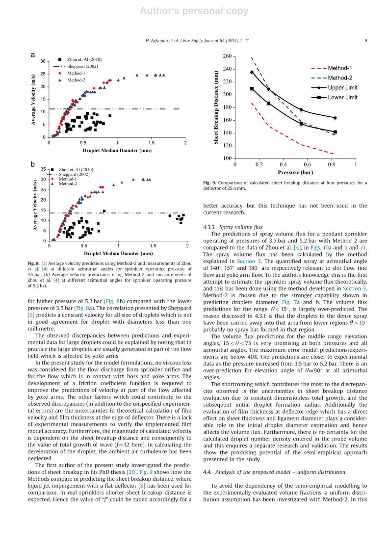
4.3.2. Droplet velocityPredictions and experimental data for droplet average velocity
are presented in Fig. 8a and b respectively for the sprinkleroperating pressures of 3.5 bar and 5.2 bar. The predictionsobtained from Method-1 and Method-2 are compared againstthe empirical relations of Sheppard [6] and measurements of Zhouet al. [4]. The errors in average velocity predictions fall within anacceptable range for droplet diameters less than 0.9 mm. Thereported sprinkler experimental spray volume median diameteris usually between 0.9 mm to 1.2 mm which means that most ofthe number densities of the spray have actually a correspondingdiameter less than the spray volume median diameter. There aremore discrepancies model/experiments for larger droplets whichcould be explained by both un-quantified experimental errors andsimplifications made throughout the model development.Method-1 predicts narrower range of droplet sizes (less than0.9 mm) and Method-2 predicts broader range (up to 1.6 mm).Droplet velocity predictions with Method-2 show improvement
0
0.2
0.4
0.6
0.8
1
1.2
1.4
1.6
1.8
0 10 20 30 40 50 60 70 80 90 100
Dro
plet
Siz
e (m
m)
Elevation Angle
Zhou et al. (2010)
Method-1
Method-2
0
0.5
1
1.5
2
2.5
0 10 20 30 40 50 60 70 80 90 100
Dro
plet
Siz
e (m
m)
Elevation Angle
Zhou et al. (2010)
Method-2
Method-1
Fig. 7. (a) Comparison of droplet diameter predictions from two semi-empiricalapproaches and measurements of Zhou et al. [4] at azimuthal angleϕ¼1071. (b)Comparison of droplet diameter predictions from two semi-empirical approachesand measurements of Zhou et al. [4] at azimuthal angle ϕ¼1231.
H. Aghajani et al. / Fire Safety Journal 64 (2014) 1–118
Author's personal copy
for higher pressure of 5.2 bar (Fig. 8b) compared with the lowerpressure of 3.5 bar (Fig. 8a). The correlation presented by Sheppard[6] predicts a constant velocity for all size of droplets which is notin good agreement for droplet with diameters less than onemillimetre.
The observed discrepancies between predictions and experi-mental data for large droplets could be explained by noting that inpractice the large droplets are usually generated in part of the flowfield which is affected by yoke arms.
In the present study for the model formulations, no viscous losswas considered for the flow discharge from sprinkler orifice andfor the flow which is in contact with boss and yoke arms. Thedevelopment of a friction coefficient function is required toimprove the predictions of velocity at part of the flow affectedby yoke arms. The other factors which could contribute to theobserved discrepancies (in addition to the unspecified experimen-tal errors) are the uncertainties in theoretical calculation of filmvelocity and film thickness at the edge of deflector. There is a lackof experimental measurements to verify the implemented filmmodel accuracy. Furthermore, the magnitude of calculated velocityis dependent on the sheet breakup distance and consequently tothe value of total growth of wave (f¼12 here). In calculating thedeceleration of the droplet, the ambient air turbulence has beenneglected.
The first author of the present study investigated the predic-tions of sheet breakup in his PhD thesis [20]. Fig. 9 shows how theMethods compare in predicting the sheet breakup distance, whereliquid jet impingement with a flat deflector [8] has been used forcomparison. In real sprinklers shorter sheet breakup distance isexpected. Hence the value of “f” could be tuned accordingly for a
better accuracy, but this technique has not been used in thecurrent research.
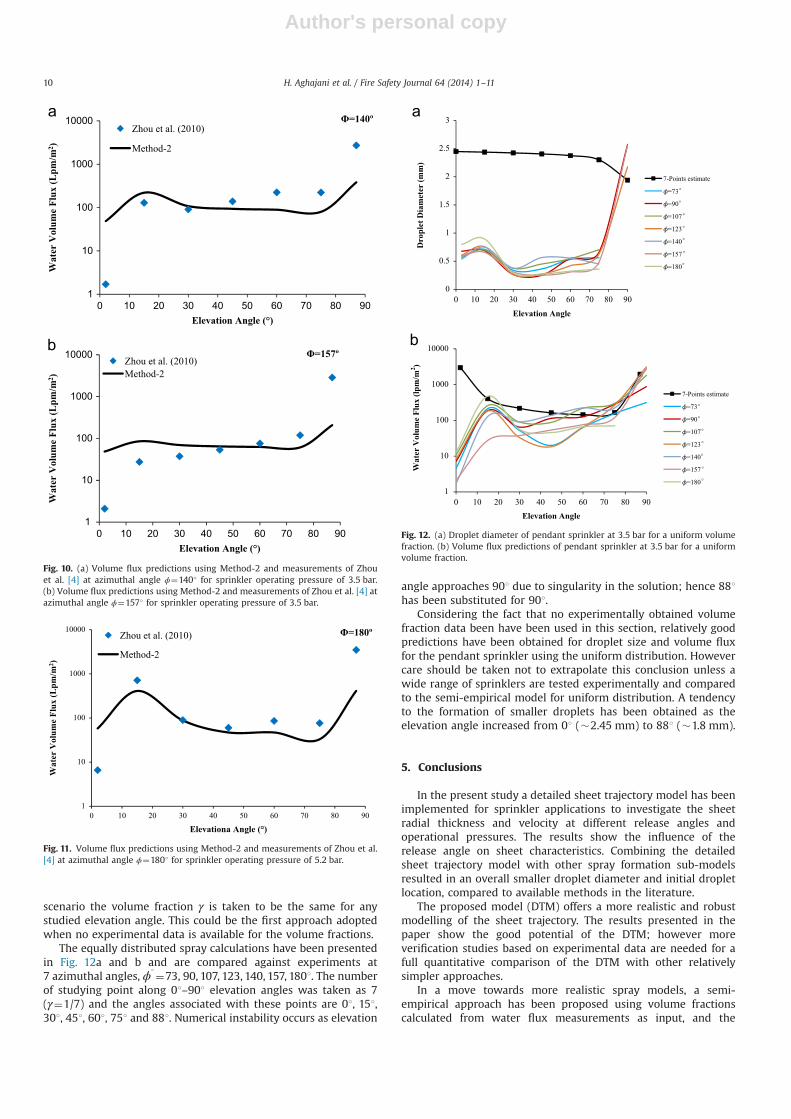
4.3.3. Spray volume fluxThe predictions of spray volume flux for a pendant sprinkler
operating at pressures of 3.5 bar and 5.2 bar with Method 2 arecompared to the data of Zhou et al. [4], in Figs. 10a and b and 11.The spray volume flux has been calculated by the methodexplained in Section 3. The quantified spray at azimuthal angleof 1401, 1571 and 1801 are respectively relevant to slot flow, tineflow and yoke arm flow. To the authors knowledge this is the firstattempt to estimate the sprinkler spray volume flux theoretically,and this has been done using the method developed in Section 3.Method-2 is chosen due to the stronger capability shown inpredicting droplets diameter, Fig. 7a and b. The volume fluxpredictions for the range, θo151, is largely over-predicted. Thereason discussed in 4.3.1 is that the droplets in the dense sprayhave been carried away into that area from lower regions θ4151probably no spray has formed in that region.
The volume flux predictions for the middle range elevationangles, 15rθr75 is very promising at both pressures and allazimuthal angles. The maximum error model predictions/experi-ments are below 40%. The predictions are closer to experimentaldata as the pressure increased from 3.5 bar to 5.2 bar. There is anover-prediction for elevation angle of θ¼901 at all azimuthalangles.
The shortcoming which contributes the most to the discrepan-cies observed is the uncertainties in sheet breakup distanceevaluation due to constant dimensionless total growth, and thesubsequent initial droplet formation radius. Additionally theevaluation of film thickness at deflector edge which has a directeffect on sheet thickness and ligament diameter plays a consider-able role in the initial droplet diameter estimation and henceaffects the volume flux. Furthermore, there is no certainty for thecalculated droplet number density entered in the probe volumeand this enquires a separate research and validation. The resultsshow the promising potential of the semi-empirical approachpresented in the study.
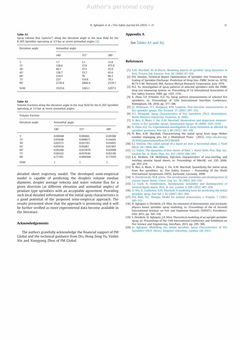
4.4. Analysis of the proposed model – uniform distribution
To avoid the dependency of the semi-empirical modelling tothe experimentally evaluated volume fractions, a uniform distri-bution assumption has been investigated with Method-2. In this
0
5
10
15
20
25
30
35
0 0.5 1 1.5 2
Ave
rage
Vel
ocity
(m/s
)
Droplet Median Diamter (mm)
Zhou et. Al (2010)Sheppard (2002)Method-1Method-2
0
5
10
15
20
25
30
0 0.5 1 1.5 2
Ave
rage
Vel
ocity
(m/s
)
Droplet Median Diamter (mm)
Zhou et. Al (2010)Sheppard (2002)Method-1Method-2
Fig. 8. (a) Average velocity predictions using Method-2 and measurements of Zhouet al. [4] at different azimuthal angles for sprinkler operating pressure of3.5 bar. (b) Average velocity predictions using Method-2 and measurements ofZhou et al. [4] at different azimuthal angles for sprinkler operating pressureof 5.2 bar.
100
120
140
160
180
200
220
240
260
0 0.2 0.4 0.6 0.8 1
Shee
t Bre
akup
Dis
tanc
e (m
m)
Pressure (bar)
Method-1
Method-2
Upper Limit
Lower Limit
Fig. 9. Comparison of calculated sheet breakup distance at four pressures for adeflector of 25.4 mm.
H. Aghajani et al. / Fire Safety Journal 64 (2014) 1–11 9
Author's personal copy
scenario the volume fraction γ is taken to be the same for anystudied elevation angle. This could be the first approach adoptedwhen no experimental data is available for the volume fractions.
The equally distributed spray calculations have been presentedin Fig. 12a and b and are compared against experiments at7 azimuthal angles, ϕ1¼73, 90, 107, 123, 140, 157, 1801. The numberof studying point along 01–901 elevation angles was taken as 7(γ¼1/7) and the angles associated with these points are 01, 151,301, 451, 601, 751 and 881. Numerical instability occurs as elevation
angle approaches 901 due to singularity in the solution; hence 881has been substituted for 901.
Considering the fact that no experimentally obtained volumefraction data been have been used in this section, relatively goodpredictions have been obtained for droplet size and volume fluxfor the pendant sprinkler using the uniform distribution. Howevercare should be taken not to extrapolate this conclusion unless awide range of sprinklers are tested experimentally and comparedto the semi-empirical model for uniform distribution. A tendencyto the formation of smaller droplets has been obtained as theelevation angle increased from 01 (�2.45 mm) to 881 (�1.8 mm).
5. Conclusions
In the present study a detailed sheet trajectory model has beenimplemented for sprinkler applications to investigate the sheetradial thickness and velocity at different release angles andoperational pressures. The results show the influence of therelease angle on sheet characteristics. Combining the detailedsheet trajectory model with other spray formation sub-modelsresulted in an overall smaller droplet diameter and initial dropletlocation, compared to available methods in the literature.
The proposed model (DTM) offers a more realistic and robustmodelling of the sheet trajectory. The results presented in thepaper show the good potential of the DTM; however moreverification studies based on experimental data are needed for afull quantitative comparison of the DTM with other relativelysimpler approaches.
In a move towards more realistic spray models, a semi-empirical approach has been proposed using volume fractionscalculated from water flux measurements as input, and the
1
10
100
1000
10000
0 10 20 30 40 50 60 70 80 90
Wat
er V
olum
e Fl
ux (L
pm/m
2 )
Elevation Angle (°)
Φ=140ºZhou et al. (2010)
Method-2
1
10
100
1000
10000
0 10 20 30 40 50 60 70 80 90
Wat
er V
olum
e Fl
ux (L
pm/m
2 )
Elevation Angle (°)
Φ=157ºZhou et al. (2010)Method-2
Fig. 10. (a) Volume flux predictions using Method-2 and measurements of Zhouet al. [4] at azimuthal angle ϕ¼1401 for sprinkler operating pressure of 3.5 bar.(b) Volume flux predictions using Method-2 and measurements of Zhou et al. [4] atazimuthal angle ϕ¼1571 for sprinkler operating pressure of 3.5 bar.
1
10
100
1000
10000
0 10 20 30 40 50 60 70 80 90
Wat
er V
olum
e Fl
ux (L
pm/m
2 )
Elevationa Angle (°)
Φ=180ºZhou et al. (2010)
Method-2
Fig. 11. Volume flux predictions using Method-2 and measurements of Zhou et al.[4] at azimuthal angle ϕ¼1801 for sprinkler operating pressure of 5.2 bar.
0
0.5
1
1.5
2
2.5
3
0 10 20 30 40 50 60 70 80 90
Dro
plet
Dia
met
er (m
m)
Elevation Angle
7-Points estimate
=73
=90
=107
=123
=140
=157
=180
°
°
°
°
°
°
°
°
°
°
°
°
°
°
1
10
100
1000
10000
0 10 20 30 40 50 60 70 80 90
Wat
er V
olum
e Fl
ux (l
pm/m
2 )
Elevation Angle
7-Points estimate
=73
=90
=107
=123
=140
=157
=180
Fig. 12. (a) Droplet diameter of pendant sprinkler at 3.5 bar for a uniform volumefraction. (b) Volume flux predictions of pendant sprinkler at 3.5 bar for a uniformvolume fraction.
H. Aghajani et al. / Fire Safety Journal 64 (2014) 1–1110
Author's personal copy
detailed sheet trajectory model. The developed semi-empiricalmodel is capable of predicting the droplets volume mediandiameter, droplet average velocity and water volume flux for agiven direction (at different elevation and azimuthal angles) ofpendant type sprinklers with an acceptable agreement. Providingsuch local detailed information of the initial spray characteristics isa good potential of the proposed semi-empirical approach. Theresults presented show that the approach is promising and it willbe further verified as more experimental data become available inthe literature.
Acknowledgements
The authors gratefully acknowledge the financial support of FMGlobal and the technical guidance from Drs. Hong Zeng Yu, YinbinXin and Xiangyang Zhou of FM Global.
Appendix A
See Tables A1 and A2.
References
[1] A.W. Marshall, M. di Marzo, Modeling aspects of sprinkler spray dynamics infires, Process Saf. Environ. Prot. 82 (2004) 97–104.
[2] P.H. Dundas, Technical Report Optimization of Sprinkler Fire Protection theScaling of Sprinkler Discharge: Prediction of Drop Size. FMRC Serial no. 18792RC73-T-40. Norwood, MA, Factory Mutual Research Corporation, June 1974.
[3] H.Z. Yu, Investigation of spray patterns of selected sprinklers with the FMRCdrop size measuring system, in: Proceeding of 1st Intenational Association ofFire Saftey Science, 1986, pp. 1165–1176.
[4] X. Zhou, S.P. D'Aniele, H.Z. Yu, Spray pattern measurements of selected firesprinklers, in: Proceedings of 12th International Interflam Conference,Nottingham, UK, 2010, pp. 177–188.
[5] J.F. Widmann, D.T. Sheppard, R.M. Lueptow, Non-intrusive measurements infire sprinkler sprays, Fire Technol. 37 (2001) 297–315.
[6] D.T. Sheppard, Spray Characteristics of Fire Sprinklers (Ph.D. dissertation),North-Western University, Evanston, IL, 2002.
[7] N. Ren, A. Blum, C. Do, A.W. Marshall, Atomization and dispersion measure-ments in fire sprinkler sprays, Atomization Sprays 19 (2009) 1125–1136.
[8] X. Zhou, H.Z. Yu, Experimental investigation of spray formation as affected bysprinkler geometry, Fire Saf. J. 46 (2011) 140–150.
[9] N. Ren, A.W. Marshall, Characterizing the initial spray from large Webernumber impinging jets, Int. J. Multiphase Flows (2012), http://dx.doi.org/10.1016/j.ijmultiphaseflow.2012.08.004.
[10] E.J. Watson, The radial spread of a liquid jet over a horizontal plane, J. FluidMech. 20 (1964) 481–499.
[11] G.I. Taylor, The dynamics of thin sheets of fluid: I. Water bells, Proc. Roy. Soc.London Ser. A: Math. Phys. Sci. 253 (1959) 289–295.
[12] E.A. Ibrahim, T.R. McKinney, Injection characteristics of non-swirling andswirling annular liquid sheets, in: Proceedings of IMechE, vol. 220, 2006,pp. 203–214.
[13] N. Ren, A. Blum, Y. Zheng, C. Do, A.W. Marshall, Quantifying the initial sprayfrom fire sprinklers, in: Fire Safety Science – Proceeding of the NinthInternational Symposium, IAFSS, Karlsruhe, Germany, 2008.
[14] N. Dombrowski, W.R. Johns, The aerodynamic instability and disintegration ofviscous liquid sheets, Chem. Eng. Sci. 18 (1963) 203–214.
[15] C.J. Clark, N. Dombrowski, Aerodynamic instability and disintegration ofinviscid liquid sheets, Proc. R. Soc. London A 329 (1972) 467–478.
[16] D. Wu, D. Guillemin, A.W. Marshall, A modeling basis for predicting the initialsprinkler spray, Fire Saf. J. 42 (2007) 283–294.
[17] N.K. Rizk, H.C. Mongia, Model for airblast atomization, J. Propuls. 7 (1991)305–311.
[18] H. Aghajani, S. Dembele, J.X. Wen, An extension of deterministic and stochasticphysics based sprinkler spray modeling, in: Proceedings of the of SeventhInternational Seminar on Fire and Explosion Hazards (ISFEH7), Providence,USA, 2013, pp. 501–510.
[19] S. Dembele, H. Aghajani, J.X. Wen, Theoretical modeling of an upright sprinklerspray, in: Proceedings of the 13th International Conference and Exhibition onFire Science and Engineering, Interflam, 2013, pp. 295–306.
[20] H. Aghajani, Modelling the Initial Sprinkler Spray Characteristics of fireSprinklers (Ph.D. thesis), Kingston University, London, UK, 2013.
Table A1Spray volume flux (Lpm/m2) along the elevation angle in the near field for theK-205 Sprinkler operating at 3.5 bar at seven azimuthal angles [4].
Elevation angle Azimuthal angle
1401 1571 1801
31 1.7 2.1 12.8151 128.6 27.6 475.8301 90.7 37.5 55.9451 138.7 53.7 45.6601 224.5 76 66.2751 223 119.8 70.5901 2718.4 2866.4 2570.7
SUM 3525.6 3183.1 3297.5
Table A2Volume fractions along the elevation angle in the near field for the K-205 Sprinkleroperating at 3.5 bar at seven azimuthal angles.
Volume fraction
Elevation angle Azimuthal angle
1401 1571 1801
31 0.00048 0.00066 0.00388151 0.03648 0.008671 0.14429301 0.02573 0.011781 0.01695451 0.03934 0.01687 0.01383601 0.06368 0.023876 0.02008751 0.06325 0.037636 0.02138901 0.77105 0.900506 0.77959
SUM 1 1 1
H. Aghajani et al. / Fire Safety Journal 64 (2014) 1–11 11