corresponding author's institution: tel aviv university
TRANSCRIPT
Elsevier Editorial System(tm) for Journal of Sound and Vibration Manuscript Draft Manuscript Number: Title: Nonlinear Tracking Control of Vibration Amplitude for a Parametrically Excited Microcantilever Beam Article Type: Full Length Article Section/Category: A Active and adaptive control of sound and vibration Keywords: MEM cantilever; parametric resonance; amplitude control; nonlinear tracking control; singularities; Lyapunov method Corresponding Author: Dr. Quoc Chi Nguyen, Corresponding Author's Institution: Tel Aviv University First Author: Quoc Chi Nguyen Order of Authors: Quoc Chi Nguyen; Slava Krylov Abstract: In this paper, a feedback control algorithm to regulate oscillation amplitude of a microelectromechanical (MEM) cantilever beam operated at parametric resonances is developed. The control objective is to drive the oscillation amplitude of the micro beam, which amplified using parametric excitation, to the desired values. The principle of the control algorithm is to establish an output tracking control based on the nonlinear dynamic model of the micro beam, where the supply voltage is considered as a control input. The tracking control algorithm is designed to solve the singularities resulting from the zero-defection state of the micro beam. The Galerkin method is applied in order to reduce the partial differential equation describing the dynamics of the beam into a set of ordinary differential equations (ODEs). Uniformly ultimate boundedness stability of the control system is proved using Lyapunov method. The effectiveness of the proposed control algorithm is illustrated via numerical simulations. Suggested Reviewers: Mohammad Younis Ph.D. Professor, Mechanical Engineering, Binghamton University, State University of New York [email protected] Sungsu Park Ph.D. Professor, Department of Aerospace Engineering, Sejong University [email protected] Qing Zheng Ph.D. Professor, Electrical & Computer Engineering, Gannon University [email protected]
October 3, 2013 Quoc Chi Nguyen, Ph. D.
Research Fellow
School of Mechanical Engineering
Tel Aviv University
Tel Aviv 69978, Israel
Tel.: +972-3-640-6246, Fax: +972-3-640-7617
Email: [email protected]
Professor Matthew P. Cartmell, Ph. D.
Department of Mechanical Engineering
University of Sheffield
Sheffield, United Kingdom
Dear Professor Cartmell,
We would like to submit the paper entitled, “Nonlinear tracking control of vibration
amplitude for a parametrically excited microcantilever beam,” authored by myself and
Prof. Slava Krylov for possible publication in the Journal of Sound and Vibration.
This paper has not been published elsewhere nor has it been submitted for publication
elsewhere.
We have listed three prospective reviewers from the literature on the next page.
Sincerely,
Quoc Chi Nguyen
Cover Letter

(1) Professor Mohammad Younis
Department of Mechanical Engineering
Binghamton University, State University of New York (SUNY)
Binghamton, NY 13902-6000
Tel: (607)-777-4983, Fax: (607)-777-4620
Email: [email protected]
URL reference: http://ws.binghamton.edu/me/Younis/index.html
(2) Professor Sungsu Park
Department of Aerospace Engineering
Sejong University
98, Gunja-dong, Kwangjin-gu
Seoul, Korea
Tel.: +82-2-3408-3769 , Fax: +82-2-3408-3333
Email: [email protected]
URL reference: http://fdcl.sejong.ac.kr/prof.html
(3) Professor Qing Zheng
Department of Electrical & Computer Engineering
Gannon University
109 University Square, Erie
Pennsylvania 16541, United States
Tel.: (814)-871-5617
Email: [email protected]
URL reference: http://www.gannon.edu/FacultyProfiles.aspx?profile=zheng003
Highlights
- Vibration amplitude control of a MEMS parametrically excited cantilever is
developed.
- Tracking control scheme is designed based on a nonlinear model of the cantilever
beam.
- The singularities resulting from the zero-defection of the cantilever beam is handled.
- Uniformly ultimately bounded stability of the control system is proved.
- The advantages of the proposed control method on performance and robustness are
shown.
Highlights (for review)
1
Nonlinear Tracking Control of Vibration Amplitude for a
Parametrically Excited Microcantilever Beam
Quoc Chi Nguyen† and Slava Krylov
School of Mechanical Engineering, Faculty of Engineering, Tel Aviv University, Tel Aviv
69978, Israel,
Tel.:+972-3-640-6246,+972-3-640-5930,
Emails:[email protected], [email protected]
† The author to whom all correspondence should be addressed
Abstract: In this paper, a feedback control algorithm to regulate oscillation amplitude of a
microelectromechanical (MEM) cantilever beam operated at parametric resonances is
developed. The control objective is to drive the oscillation amplitude of the micro beam,
which amplified using parametric excitation, to the desired values. The principle of the
control algorithm is to establish an output tracking control based on the nonlinear dynamic
model of the micro beam, where the supply voltage is considered as a control input. The
tracking control algorithm is designed to solve the singularities resulting from the zero-
defection state of the micro beam. The Galerkin method is applied in order to reduce the
partial differential equation describing the dynamics of the beam into a set of ordinary
differential equations (ODEs). Uniformly ultimate boundedness stability of the control system
is proved using Lyapunov method. The effectiveness of the proposed control algorithm is
illustrated via numerical simulations.
Keywords: MEM cantilever; Parametric resonance; Amplitude control; Nonlinear tracking
control; Singularities; Lyapunov method
ManuscriptClick here to download Manuscript: JSV 2013_Manuscript_Amplitude Vibration Control of PE Micro Beam.docxClick here to view linked References
2
1. Introduction
Microelectromechanical systems (MEMSs) have been developed to replace conventional
mechanical and electronic components such as actuators, transducers, and gears in microscale
devices [1-3]. The micro sensors and micro actuators have enabled development of smart
products that are able to sense and control the environment, applying to mechanical, thermal,
biological, chemical, optical, and magnetic systems [4-11]. MEMS cantilever is one of the
most popular MEMS structures widely used due to its ability to provide high sensitivity, high
selectivity, and flexibility of its working environment [7-11].
Large part of MEMS cantilever uses mechanical vibrating parts for sensing, where the
amplitude of the resonant peak and the bandwidth of resonance are important to achieve high
sensitivity. To increase the oscillation amplitude, design and fabrication techniques have been
developed in order to eliminate the effect of air damping [12,13]. In an active manner, the
oscillation amplitude of MEMS cantilevers can be increased externally using parametric
excitation [4,14-22], where the parametric pump voltage that yields electrostatic forces have
been employed. The periodic voltage signal provides a modulation of the stiffness of the
structure that and consequently, results in an increase of the oscillation amplitude
progressively at specific frequencies. The mechanical parametric excitation of MEMS was
introduced for the first time in [14]. Turner et al. [15] showed the measurement of the five
parametric resonances in MEMS and proposed the use of parametric excitation to improve the
quality of the MEMS sensing devices. Wang, Baskaran, & Turner [17] investigated the effect
of the nonlinearity to the parametrically excited resonant MEMS mass sensor. Baskaran &
Turner [18] provided an experimental result that shows parametric resonances of a torsional
MEMS resonator, considering two interacting mechanical modes of oscillation. Zhang, Meng,
& Wei [20] presented a study of nonlinear dynamics and chaos of a MEMS resonator under
two parametric and external excitations. Khirallah [22] proposed a parametric amplification of
3
a comb drive oscillator. Recently, Linzon et al. [4] introduced parametric excitation of silicon-
on-insulator microcantilever beams by fringing electrostatic fields.
The effectiveness of the parametric excitation to improve the performance of the MEMS
cantilevers has been verified. As shown in [4,16,21], with given amplitude, the specific
voltage and frequency of the pumping excitation can be determined through the resonance
curves. This can be considered as the open-loop control method for MEMS cantilever.
However, the dynamic nonlinearities affect significantly oscillations of the MEMS devices
and consequently, their sensitivity [23]. Besides, the imprecise fabrication and mechanical
and thermal noises limiting the performance of the MEMS devices are evident. Therefore,
reasonably prompt feedback control of oscillation amplitude for improvement of the
performance of a parametrically excited MEMS cantilever is desirable.
In recent years, there have been numerous papers published on control of MEMS [24–39].
The most focused control topic is to stabilize MEMS resonators [24-34]. Alsaleem & Younis
[31,32] used delay feedback controllers to stabilize MEMS resonators (especially near pull-in
point). The effects of the control gains in [31,32] were later investigated in [33]. Siewe &
Hegazy [34] indicated that reducing amplitude of parametric excitation can control chaotic
motion of a MEMS resonator. Seleim et al. [35] proposed a closed-loop control of a MEMS
resonator, providing optimal operating regions for the resonator.
There are a lot of researches investigating oscillation amplitude control of MEMS.
However, only linear resonant MEMS devices have been focused [26,36-39]. Leland [26]
designed two adaptive controllers for a MEMS gyroscope to regulate the amplitude of the
drive axis vibration. Batur, Sreeramreddy, & Khasawneh [36] used sliding mode control
algorithm to stabilize a MEMS gyroscope. Zheng et al. [37] proposed an active disturbance
rejection control strategy to regulate the output amplitude of the drive axis of a MEMS
gyroscope to a fixed level. Zhang, Meng, & Li [38] introduced an adaptive vibration control
4
of micro-cantilever beam to eliminate the useless high amplitude. Baghelani, Ghavifekr, &
Ebrahimi [39] used analytical formula to design an amplitude control for ring shape micro
disk resonator.
It is shown that, under parametric excitation, MEMS devices operated at nonlinear
parametric resonances possess much higher amplitude and consequently, higher sensitivity
than the ones operated at linear resonances. However, to the best of our knowledge, there has
not been a published research on control of vibration amplitude for parametric excited
MEMS. In this research, a control method to regulate vibration amplitude of a parametrically
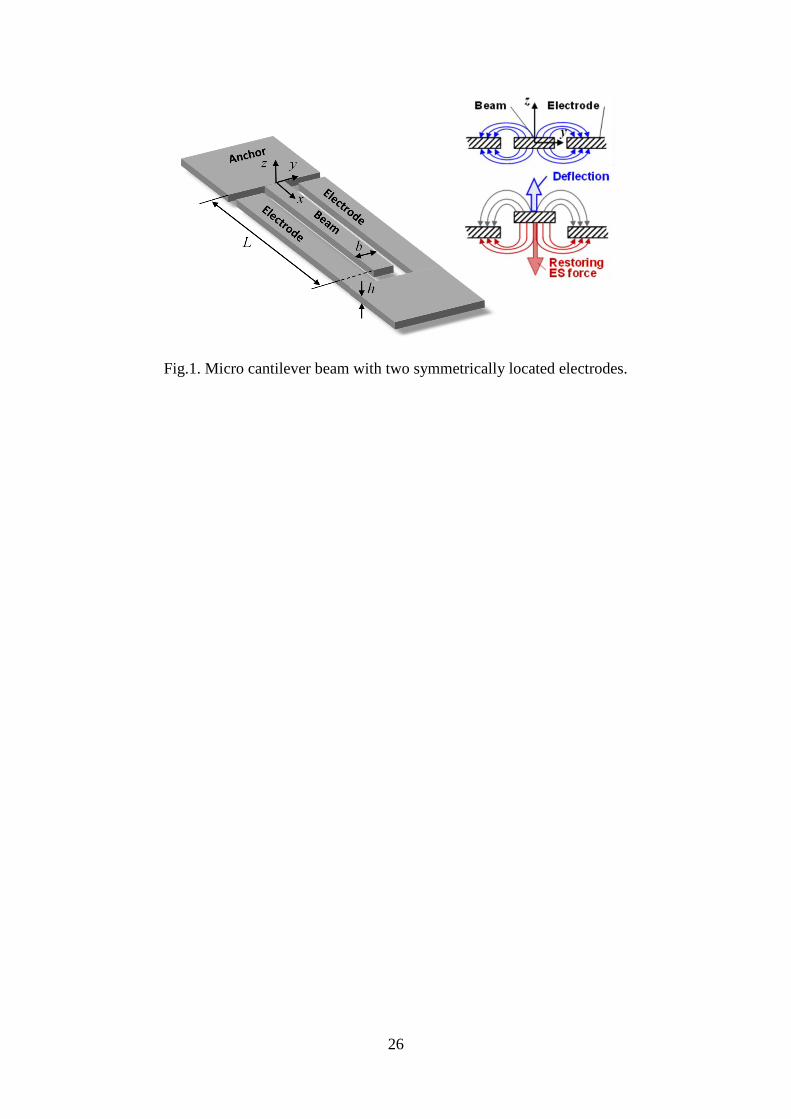
excited microcantilever structure, which is introduced in [4], is developed. The distributed
electrostatic forces by tailored asymmetries in fringing fields provided by single co-planar
electrode located symmetrically around the actuated cantilever (see Fig. 1). The distributed
electrostatic forces depend on the supply voltage and the deflection of the microcantilever.
Under the effects of the AC supply voltages, the parametric excitation is achieved. The
control objective is to drive the vibration amplitude of the micro beam parametrically excited
to the desired values. The principle of control algorithm is to establish a tracking control
based on the nonlinear dynamic model of the micro beam, where the supply voltage is
considered as a control input. For the control design purpose, the reduced order model of the
micro beam obtained using the Galerkin method [40-43] is employed.
Contributions of this paper are the following. First, a nonlinear tracking control of
vibration amplitude for a parametrically excited micro cantilever beam is developed, where
the tracking through the singularities are handled. Second, uniformly ultimate boundedness
stability of the control system is proved mathematically using Lyapunov function. Third,
simulations results show the advantages of the proposed control method on performance and
robustness.
5
The rest of this paper is organized as follows. Section 2 presents the dynamic model of the
microcantilever beam system. Section 3 introduces the proposed control algorithm design. A
Lyapunov function-based stability analysis of the closed-loop system and the proof of
stability also are discussed. Section 4 includes numerical simulation results that illustrate the
effectiveness of the proposed control scheme. Finally, Section 5 draws conclusions.
2. Dynamic models of the micro beam
2.1. Continuous model
As shown in Fig.1, the microcantilever beam is designed such that it can freely move in the
out-of-plane direction (z-axis). The planar electrode placed in the area surrounding the micro
beam provides the fringing field, which becomes asymmetric when the micro beam deflects
from the equilibrium position in the x-y plane.
Under the assumption that the defections are small in comparison with the length of the
beam, the following governing equations of the micro cantilever beam are derived based on
Euler-Bernoulli theory [44].
2 42
2 4ˆˆ ( ) ( ) 0,
w w wA c EI V t f w
t t x
(1)
where A bh and 3 /12I bh . Since the width of the beam b is larger than its thickness h,
the effective modulus (plain strain) 2/ (1 )E E v is employed, where v is the Poisson’s
ratio. The beam is subject to the following homogenous boundary conditions (2) and the
nonzero initial conditions (3).
2 3
2 3
0
(0, ) 0, 0, 0, 0.x x l x l
w w ww t EI EI
x x x
(2)
0
0
(0, ) ( ), 0.t
ww x w x
t
(3)
6
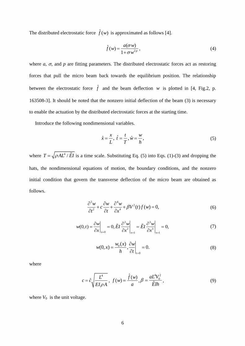
The distributed electrostatic force ˆ ( )f w is approximated as follows [4].
2
( )ˆ ( )1 p
a wf w
w
, (4)
where a, , and p are fitting parameters. The distributed electrostatic forces act as restoring
forces that pull the micro beam back towards the equilibrium position. The relationship
between the electrostatic force f and the beam deflection w is plotted in [4, Fig.2, p.
163508-3]. It should be noted that the nonzero initial deflection of the beam (3) is necessary
to enable the actuation by the distributed electrostatic forces at the starting time.
Introduce the following nondimensional variables.
ˆˆ ˆ, , ,x t w
x t wL T h
(5)
where 4 /T AL EI is a time scale. Substituting Eq. (5) into Eqs. (1)-(3) and dropping the
hats, the nondimensional equations of motion, the boundary conditions, and the nonzero
initial condition that govern the transverse deflection of the micro beam are obtained as
follows.
2 42
2 4( ) ( ) 0,
w w wc V t f w
t t x
(6)
2 3
2 3
0 1 1
(0, ) 0, 0,x x x
w w ww t EI EI
x x x
(7)
0
0
( )(0, ) , 0.
t
w x ww x
h t
(8)
where
4
ˆL
c cEI A
, ˆ ( )
( )f w
f wa
,
4 2
0aL V
EIh , (9)
where V0 is the unit voltage.
7
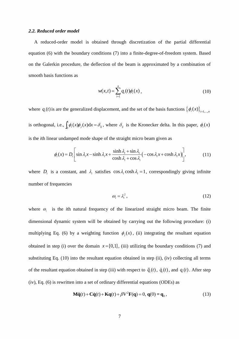
2.2. Reduced order model
A reduced-order model is obtained through discretization of the partial differential
equation (6) with the boundary conditions (7) into a finite-degree-of-freedom system. Based
on the Galerkin procedure, the deflection of the beam is approximated by a combination of
smooth basis functions as
1
( , ) ( ) ( )n
i i
i
w x t q t x
, (10)
where ( )iq t is are the generalized displacement, and the set of the basis functions 1, ,
( )i i nx
is orthogonal, i.e.,1
0( ) ( )di j ijx x x , where ij is the Kronecker delta. In this paper, ( )i x
is the ith linear undamped mode shape of the straight micro beam given as
sinh sin
( ) sin sinh cos cosh ,cosh cos
i ii i i i i i
i i
x D x x x x
(11)
where iD is a constant, and i satisfies cos cosh 1i i , correspondingly giving infinite
number of frequencies
2
i i , (12)
where i is the ith natural frequency of the linearized straight micro beam. The finite
dimensional dynamic system will be obtained by carrying out the following procedure: (i)
multiplying Eq. (6) by a weighting function ( )j x , (ii) integrating the resultant equation
obtained in step (i) over the domain [0,1]x , (iii) utilizing the boundary conditions (7) and
substituting Eq. (10) into the resultant equation obtained in step (ii), (iv) collecting all terms
of the resultant equation obtained in step (iii) with respect to ( )iq t , ( )iq t , and ( )iq t . After step
(iv), Eq. (6) is rewritten into a set of ordinary differential equations (ODEs) as
2
0( ) ( ) ( ) ( ) 0, (0)t t t V Mq Cq Kq F q q = q , (13)
8
where T
1( ) ( ) ( )nt q t q tq is the time-dependent vector of generalized coordinates, and
the elements of M, C, and K are given as
1
0dij ij i jm x , (14)
1
2
0dij ij i i jk x , (15)
ij ijc cm . (16)
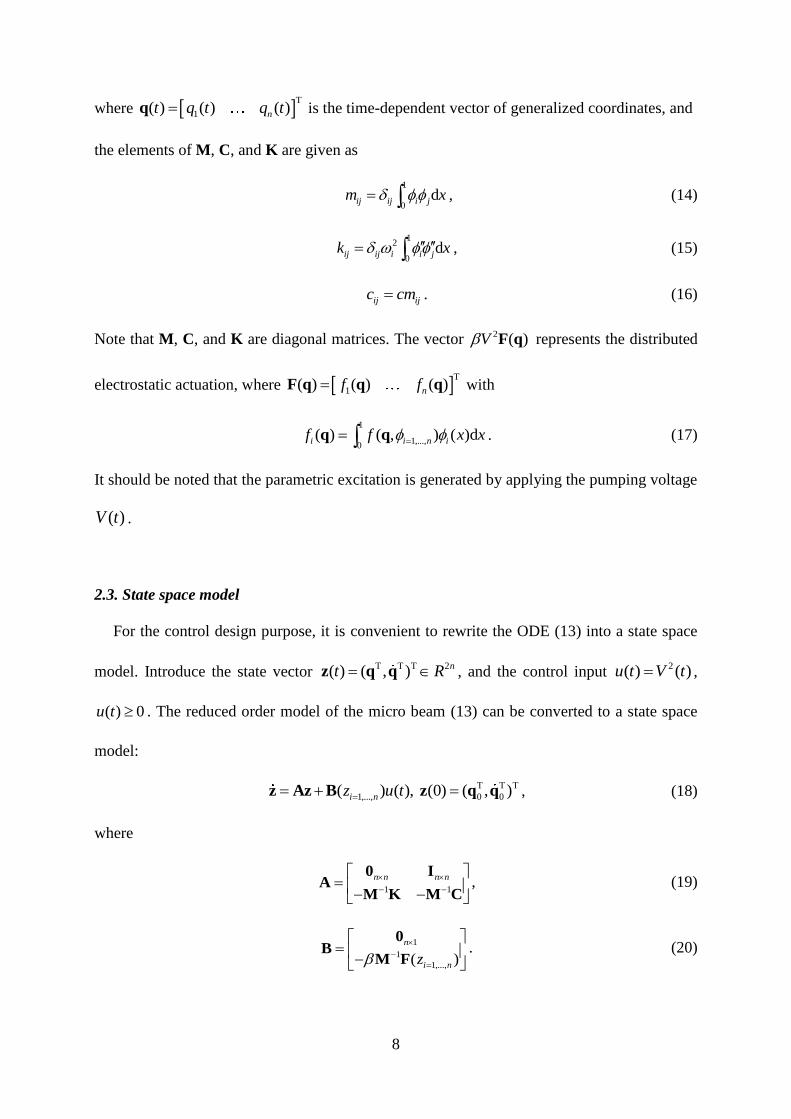
Note that M, C, and K are diagonal matrices. The vector 2 ( )V F q represents the distributed
electrostatic actuation, where T
1( ) ( ) ( )nf fF q q q with
1
1,...,0
( ) ( , ) ( )di i n if f x x q q . (17)
It should be noted that the parametric excitation is generated by applying the pumping voltage
( )V t .
2.3. State space model
For the control design purpose, it is convenient to rewrite the ODE (13) into a state space
model. Introduce the state vector T T T 2( ) ( , ) nt R z q q , and the control input
2( ) ( )u t V t ,
( ) 0u t . The reduced order model of the micro beam (13) can be converted to a state space
model:
T T T
1,..., 0 0( ) ( ), (0) ( , )i nz u t z Az B z q q , (18)
where
1 1
n n n n
0 IA
M K M C, (19)
1
1
1,...,( )
n
i nz
0B
M F. (20)
9
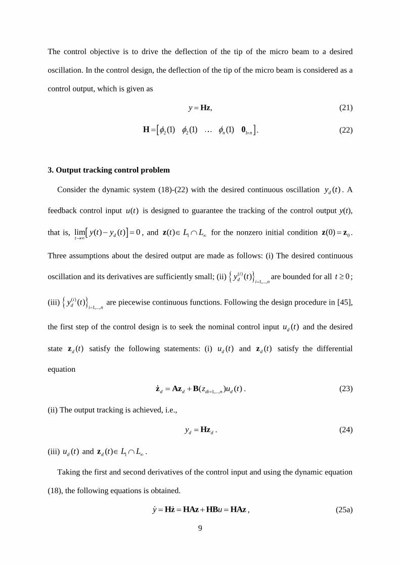
The control objective is to drive the deflection of the tip of the micro beam to a desired
oscillation. In the control design, the deflection of the tip of the micro beam is considered as a
control output, which is given as
,y Hz (21)
2 2 1(1) (1) (1)n n H 0 . (22)
3. Output tracking control problem
Consider the dynamic system (18)-(22) with the desired continuous oscillation ( )dy t . A
feedback control input ( )u t is designed to guarantee the tracking of the control output y(t),
that is, lim ( ) ( ) 0dt
y t y t
, and 1( )t L L z for the nonzero initial condition 0(0) z z .
Three assumptions about the desired output are made as follows: (i) The desired continuous
oscillation and its derivatives are sufficiently small; (ii) ( )
1,...,( )i
d i ny t
are bounded for all 0t ;
(iii) ( )
1,...,( )i
d i ny t
are piecewise continuous functions. Following the design procedure in [45],
the first step of the control design is to seek the nominal control input ( )du t and the desired
state ( )d tz satisfy the following statements: (i) ( )du t and ( )d tz satisfy the differential
equation
1,...,( ) ( )d d di n dz u t z Az B . (23)
(ii) The output tracking is achieved, i.e.,
d dy Hz . (24)
(iii) ( )du t and 1( )d t L L z .
Taking the first and second derivatives of the control input and using the dynamic equation
(18), the following equations is obtained.
y u Hz HAz HB HAz , (25a)
10
2y u HAz HA z HAB . (25b)
Let
2
1
( )( )
ni
i i i n
i i
Lt k z cz
m
HA z , (26)
1, ,
1
( ) ( ) ( )n
i i i i n
i
t L m f z
HAB . (27)
The Eq. (25) can be rewritten as
( ) ( ) ( )y t t u t . (28)
From Eq. (28), choose the nominal control input ( )du t as
1( ) ( )[ ( ) ( )]d du t t y t t . (29)
It should be noted that when 1,..., 0i nz (i.e., q 0 ), ( )t becomes zero, and consequently,
( )du t . Therefore, to avoid the unboundedness of the control input, for the neighborhood
of the singular point (.) ( ) ,nS t R r
q q q , the following nominal control input is
used.
1( ) ( )[ ( ) ( )]S
d r du t t y t t , (30)
where rt is the time when rq . Finally, the following control law is proposed.
( ) ( ) ( ( ) ( )) ( ( ) ( ))d p du t p t y t t t t k z z , (31)
where
sgn 1 1 sgn
( )2 ( ) 2 ( )r
r rp t
t t
q q
, (32)
and the control gain vector is given as
1 2p nk kk . (33)
11
Remark 1. The singularities of the system occur when the defection of micro beam is zero,
that is, the beam reaches the x-axis. At singular points, the electrostatic forces become zero,
and the system is temporarily uncontrollable.
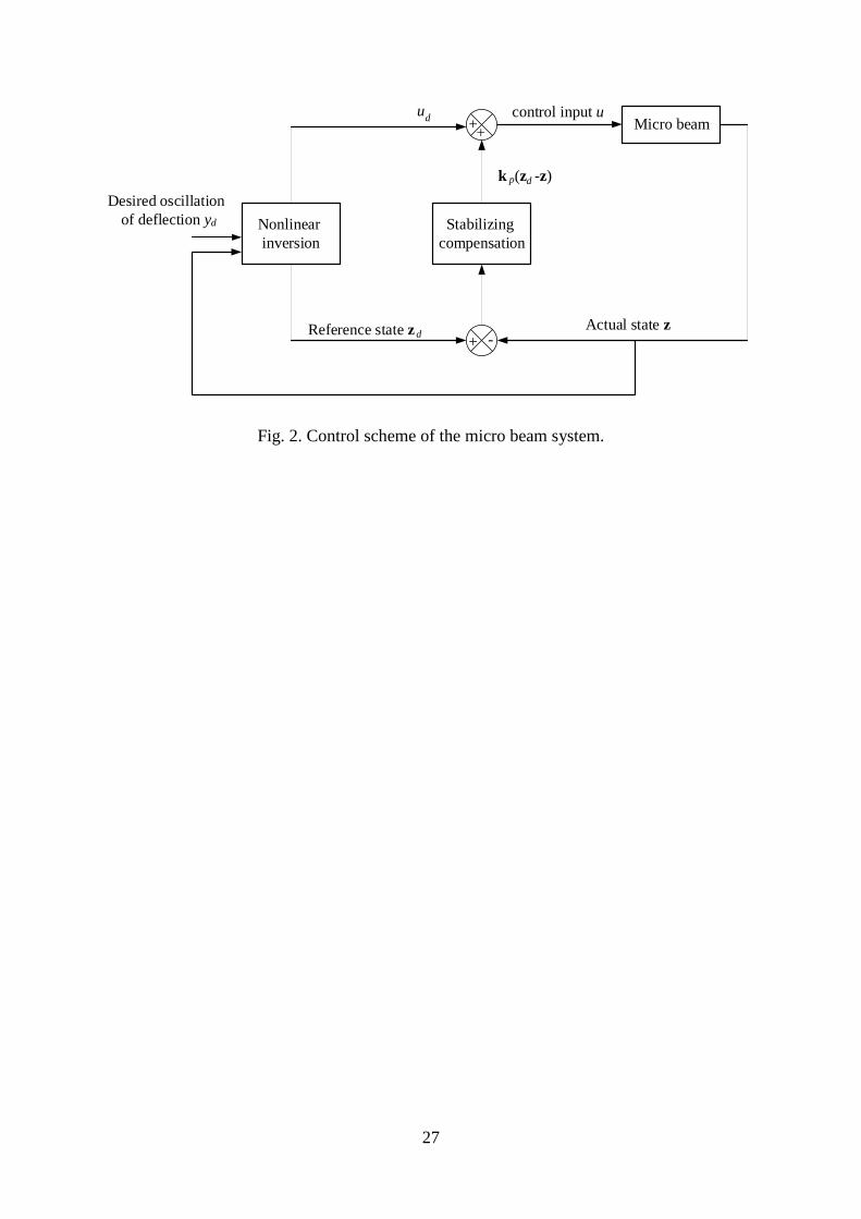
Remark 2. The control law (31) includes the feedfoward term ( )( ( ) ( ))dp t y t t and
feedback term ( ) ( ( ) ( ))p dp t t tk z z . With the feedfoward term, the system is partially
linearized, as shown in Eq. (36)-(38) below. Meanwhile, the feedback term provides a
stabilizing effect by adjusting the control gains 1,...,2i i n
k
.
Remark 3. It should be noted that the control law (31) is a combination of the exact tracking
control law 1( ) ( ) ( ( ) ( )) ( ( ) ( ))d p du t t y t t t t k z z and the approximate tracking
control law 1( ) ( ) ( ( ) ( )) ( ( ) ( ))r d p du t t y t t t t k z z , which work in the regions
(.) ( ) ,nS t R r
q q q and (.) ( ) ,nS t R r
q q q , respectively.
Introduce the change of the state variables
1
1
2
2
1 3
2 1
2 2 2
2
0 0 1
0 0 1
n
n n
n
zy
zy
z
zz
z
H
HA
ξ Nz , (34)
which yields the inverse transformation
1z N ξ . (35)
Using the new state variables, the system dynamics becomes
1 2
2
1
( ) ( ) ( )
( , ) ( )
t t u t
u t
η s χ η A N ξ B
(36)
where
12
2 2 2 2
1 1
n n n n
0 IA
M K M C, (37)
2 1
1
1,...,( )
n
i n
0B
M F, (38)
and ( , )η s χ η is the internal dynamics the system (36).
Define the tracking error e as follows:
T
d dy y y y e (39)
Using the control law (31), the feedback control of the nonlinear system (36) is now
considered as follows.
1
1 1
(1 ) ( 1) ( ) ( )
( , ) ( ( ) ( )) ( )
e d e p d
d p d
p p y p
p y t t
e A e k k N ξ ξ
η s χ η A N ξ B k N ξ ξ (40)
where
0 1
, 0,e e
e e
kk k
A (41)
1 2( ) ( )e e e nk L k L k . (42)
The Jacobian matrix of the internal dynamics (0, )J η is obtained as
1 2
0
0(0, ) c c
η
sJ η J J J
η, (43)
where 0η is the equilibrium point of the internal dynamics (0, )η s η . The matrices J , 1c
J ,
and 2cJ are given in Appendix A. It is shown that the following Lipschitz condition holds for
all 0t .
0 0 1 2( , ) (0, ) ( , ) (0, )a a a b b b a b a b s χ η J η η s χ η J η η χ χ η η , (44)
where
1 2 1
1 max , , p
A N BHA k N , (45)
13
1 2 1
2 0max , , , (0, )p
A N BHA k N J η . (46)
Theorem 1. Consider the system (36)-(38). The control gain vector pk is chosen to satisfy the
following conditions:
(i) 0(0, )J η has no eigenvalues on the imaginary axis (the method to determine pk can be
refer to [46]), i.e., the origin of the system (0, )η s η is hyperbolic .
(ii) 0(0, )J η has no positive eigenvalue, i.e., the origin of the system (0, )η s η is
asymptotically stable.
Then, the control law (31) guarantees the uniformly ultimate boundedness of the tracking
error e .
Proof. Since the hyperbolic system 0(0, )η J η η and the Lipschitz condition (44) guarantee
that the approximation of ( , )s χ η by 0(0, )J η η satisfies the Condition 1 in [45, p. 932], for
given bounded dχ (i.e., the desired output dy and its first derivative dy ), it follows from the
Theorem 1 in [45, p. 932] that the unique bounded solution,
0( ) ( , ) (0, ) dd t
η ζ s χ η J η η , (47)
exists and satisfies lim 0dt
η , where ( )tζ is the solution of the following equation.
0(0, ) , ( ) X J η X X 0 . (48)
If the condition (ii) is satisfied, referring to [47,49], there exists a locally Lyapunov
function 1( )V t such that
2 2
1 1 2( )V t η η , (49)
21
3(0, )V
s η ηη
, (50)
14(0, )
V
s η η
η, (51)
14
where ( 1,..,4)i i are the positive constants, (see Theorem 4.16, p. 167 in [47]). From Eqs.
(49)-(51), the following inequality is obtained [48,49]:
213 4 5(0, )
dy
V
s η η η e
η, (52)
where 5 z e η and dd yy are utilized.
Consider the following Lyapunov function candidate:
T
1( ) ( )V t V t e Pe , (53)
where 0 , and the positive definite matrix P is the solution of the following equation.
e e TA P A P I . (54)
where I is identity matrix.
In the region (.) ( ) ,nS t R r
q q q , the error dynamics of the system (40) becomes
1( ) ( )e e p d
e A e k k N ξ ξ . (55)
The time derivative of the Lyapunov function (53) is obtained as
2 2T 1
3 4 5
2 2 2
3 3 4 5
22
24 5 3 4 53
3 3
22
4 54 53
3 3
( ) ( ) ( )
12 2
2 2
d
d
dd
e p d y
y
yy
V t
e e P k k N ξ ξ η η e
e e η η e
e η e
η
(56)
where
1
3 ( )e p k k N P . (57)
There exist pk , ek , and satisfying the following inequality.
2
4 5
3
3
1 02
. (58)
15
Then, one is obtained
2
4 5
3
( ) ( )2
dy
SV t V t
, (59)
where
2 3
3 4 5 3 1
1
min 1 / 2 ,2
s
. (60)
The inequality (59) implies that
2
4 5
3
( ) (0)2
dSyt
S
V t V e
(61)
From Eq. (61), it is concluded that e is bounded in the region S .
Let (.) ( ) ,nt R r
q q q be the set of singularity points, and 1,..., i i mT t be the
set of the time when the system is at the singularity points. It is assumed that there exist two
sets, 1,..., i i m
and 1,..., i i m
, such that ( )i it r
q and ( )i it r
q . In the region
(.) ( ) ,nS t R r
q q q , the time derivative of ( )V t is obtained as
2 1 T
2
3 4 5
2 2 2
4 3 3 4 5
2
3 4 4
3 4
24 3 4 4
3 4
( ) (1 ) ( 1) ( ) ( )
2 2 4
4 2 2
2 2
d
d
d
d
d d d
d e p d
y
y
y
y
y y y
V t p p y p
e k k N ξ ξ e P
η η e
e η e e e η η e
e
e η η
2
2 2 22244
3 4 3 4
2 2 2244
3 4 3 4
2
12 2
( )2 2
1
d
d
d
d d
d
d
d d
y
y
y p
y y
y
yS
y y
p
p
V t
p
k e
k e (62)
16
where
6 , z e η2 , HA P
dd yy , 4 dy P , (63)
are employed. pk , ek , and are selected from sets of the values of pk , ek , and
satisfying the inequality (58) such that the following inequalities hold.
3 42 2 0dy , (64)
3 4 0dy . (65)
Then, it is concluded that
2 2 22244
13 4 3 4
( ) ( ) d2 2
i id
di i
d d
m ty
y pS tiy y
V t V t
k e ,
(66)
where
8 6 3 1 6 3 1min (2 2 ) / 4 , / 2s , (67)
From Eq. (66), the boundedness of ( )V t is obtained as follows
2 2 2 2
7 6 3
8 6 3 5 6 3
2
1
1( ) (0)
2 2
d ,
S
d
i i
i i
t
y
S
m tp
tiS
V t V e
k
e
(68)
From the inequalities (61) and (68), the uniformly ultimate boundedness of the tracking error
e is concluded. Since e and η are bounded, the boundedness of the control law (31) is
guaranteed.
Remark 4. When the micro beam operates in the region S , it is proved that V(t) converges
to the ball of radius 2
4 5 32dy S
, that is, V(t) can be pushed in an arbitrarily small
boundedness region by setting a sufficiently small . Meanwhile, in the region S , the
17
convergence ball (see Eq. (68)) cannot easily be adjusted by changing . Therefore, to
improve the control performance, the region S should be decreased by choosing small r.
However, the small r makes the small ( )rt and consequently, the large control input ( )u t ,
which yields the difficulty in implementing the control scheme due to the supply voltage
saturation in practice. Therefore, the value of r yielding the best control performance is
determined by the maximum voltage, which could be applied.
4. Simulation results
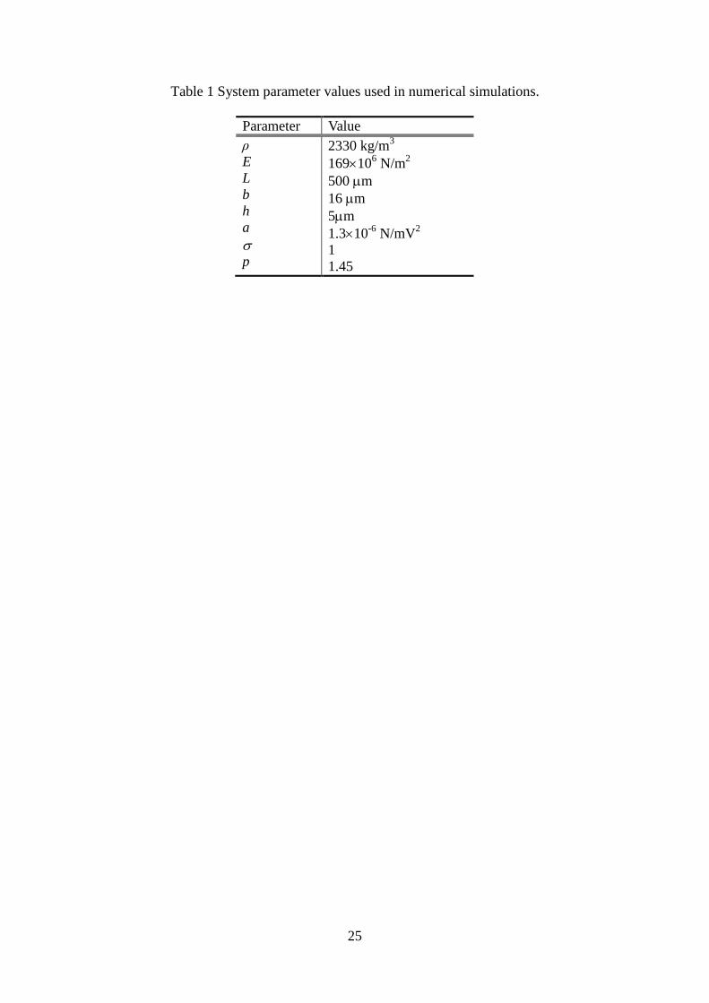
To verify the effectiveness of the proposed control algorithm, numerical simulations were
carried out with the system parameters listed in Table 1. The single mode model was used to
describe the micro beam. Let the initial condition of the micro beam system (6)-(9) be
0 1( ) ( / )w x x L m. The control gain vector kp is selected as follows: 120 10p k .
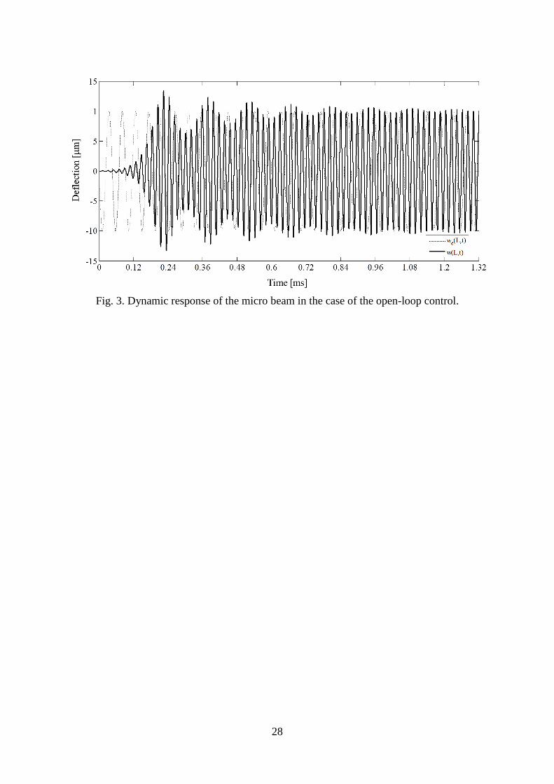
The dynamic responses of the beam were simulated in two cases: open-loop and closed-
loop controls in which the closed-loop control is proposed in this research. In the case of open
loop control, the resonance curves (see Fig. 4 in [4]) for the micro beam that can predict
amplitude of an oscillation of the beam with respect to the excitation voltage is used to
determine the control input (i.e., 2 2/ 2 ( / 2)cos( )AC ACu V V t ), corresponding to the given
desired deflection. As shown in Figs. 3 & 4, the output tracking can be achieved with either
the open-loop or closed-loop controllers. However, the settling time and the robustness are
different.
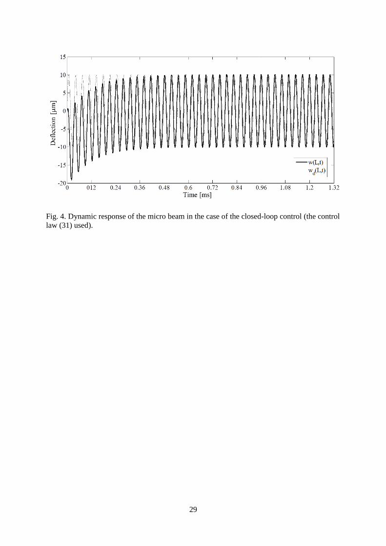
It is believed that the closed-loop controller can drive the defection of the beam tip to the
desired oscillation faster than the use of the open loop controller (0.36 ms in the case of the
closed-loop vs. 1.08 ms in the case of the open-loop). To illustrate the robustness of the two
methods to the variation of the system parameters, the micro beam dynamics were simulated
with the assumption: both the open-loop and closed-loop control laws are obtained by using
18
the nominal Young modulus while the actual Young modulus in the beam system is different.
It should be noted that the difference of the Young modulus is chosen to represent typically
the variation of the beam stiffness due to the change in environmental thermal conditions,
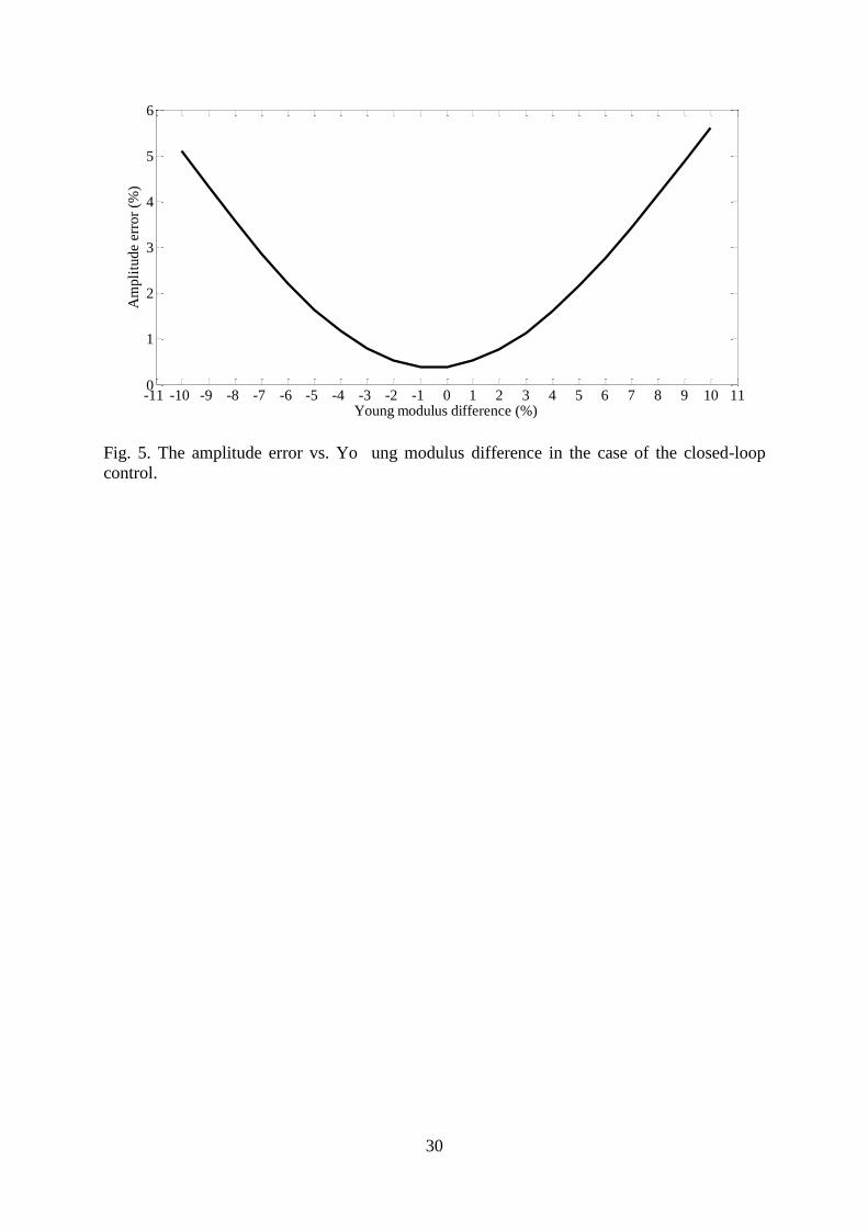
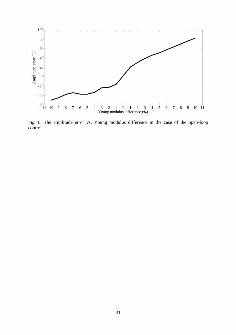
materials, geometric shapes of the beam. With the deviation of Young modulus
10% 10% , the steady error tracking in the case of closed-loop control is less than 6%
(see Fig. 5), whereas the one in the case of open-loop control reaches -50% and 80% (see Fig.
6). It is shown that the closed-loop control is more robust than the open-loop control. The
feedback term in the control law (31) compensates the difference of the system parameters
and consequently, makes the control system more robust.
5. Conclusions
A control algorithm of vibration amplitude for a parametrically excited microcantilever
beam has been developed. The proposed control algorithm has been designed based on the
nonlinear model of the microcantilever beam. The tracking through singularities has been
solved. Uniformly ultimate boundedness stability of the control system has been proved using
Lyapunov method. Through the simulation results, the advantages of the closed-loop control
have been shown. The proposed control algorithm can drive the oscillation of the beam tip to
the desired one faster than the open-loop control. The use of the feedback control has
consolidated the robustness of the proposed control method. One of the main advantages of
the proposed closed-loop control is its ability to provide the desired vibrational amplitude
even in the case of wide variation of the system parameters.
19
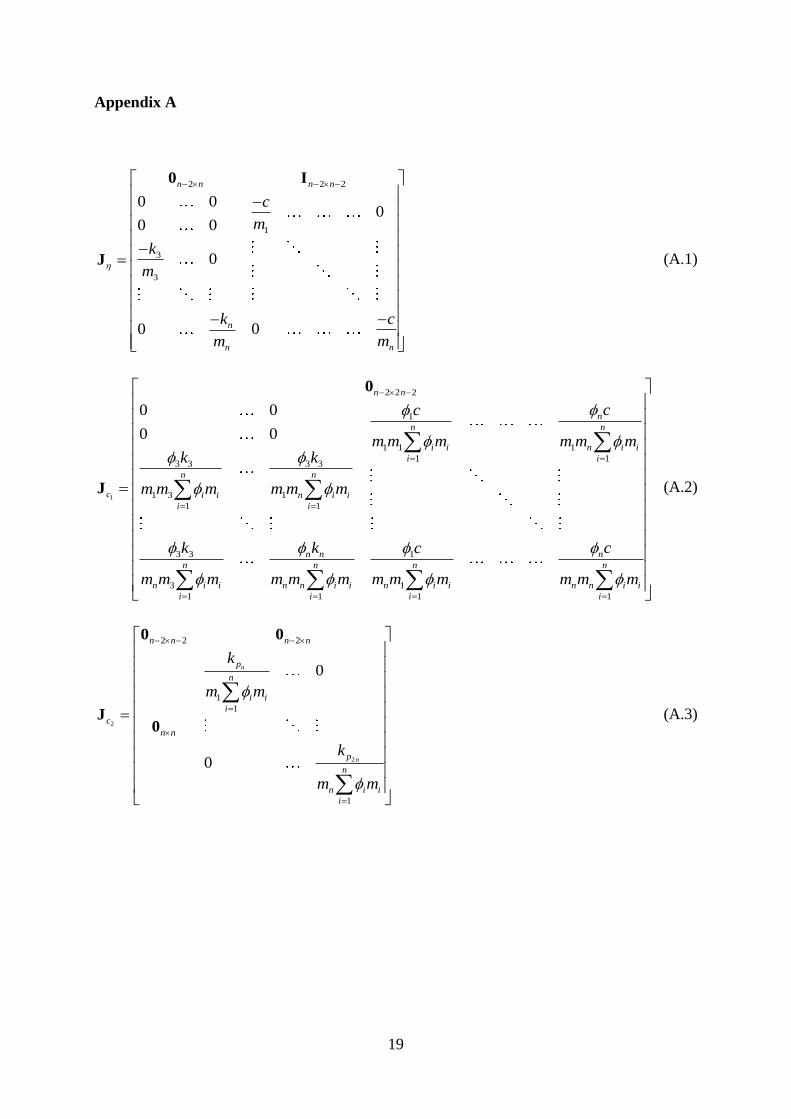
Appendix A
2 2 2
1
3
3
0 00
0 0
0
00
n n n n
n
nn
c
m
k
m
ck
mm
0 I
J (A.1)
1
2 2 2
1
1 1 1
1 13 3 3 3
1 3 1
1 1
3 3 1
3 1
1 1 1 1
0 0
0 0
n n
n
n n
i i n i i
i i
n n
c i i n i i
i i
n n n
n n n n
n i i n n i i n i i n n i i
i i i i
cc
m m m m m mk k
m m m m m m
k k cc
m m m m m m m m m m m m
0
J
(A.2)
2
2
2 2 2
1
1
1
0
0
n
n
n n n n
p
n
i i
i
c
n n
p
n
n i i
i
k
m m
k
m m
0 0
J0
(A.3)
20
References
[1] J. Bryzek, Impact of MEMS technology on society, Sensors and Actuators A: Physical
56 (1-2) (1996) 1-9.
[2] B. Vigna, Future of MEMS: an industry point of view, Proceeding of the 7th.
International Conference on Thermal, Mechanical and Multiphysics Simulation and
Experiments in Micro-Electronics and Micro-Systems, EuroSimE 2006, Como, Italy,
2006.
[3] N. S. Barker, The future of N/MEMS, IEEE Microwave Magazine 8 (6) (2007) 52-55.
[4] Y. Linzon, B. Ilic, S. Lulinsky, S. Krylov, Efficient parametric excitation of silicon-on-
insulator microcantilever beams by fringing electrostatic fields, Journal of Applied
Physics 113 (16) (2013) 163508-1-163508-11.
[5] E. Buks , Mass detection with a nonlinear nanomechanical resonator, Physical Review E
74 (4) (2006) 046619-1-046619-9.
[6] R. Southworth, L. M. Bellan, Y. Linzon, H. G. Craighead, J. M. Parpia, Stress-based
vapor sensing using resonant microbridges, Applied Physics Letters 96 (16) (2010)
163503-1-163503-3.
[7] J. Fritz , Cantilever biosensors, The Analyst 133 (7) (2008) 855-863.
[8] G. Keskar, B. Elliott, J. Gaillard, M. J. Skove, A. M. Rao, Using electric actuation and
detection of oscillations in microcantilevers for pressure measurements, Sensors and
Actuators A: Physical 147 (1) (2008) 203-209.
[9] D. J. Joe, Y. Linzon, V. P. Adiga, R. A. Barton, M. Kim, B. Ilic, S. Krylov, J. M. Parpia,
H. G. Craighead, Stress-based resonant volatile gas microsensor operated near the
critically buckled state, Journal of Applied Physics 111 (10) (2012) 104517-1- 104517-
9.
[10] S. Boisseau, G. Despesse, B. Ahmed Seddik, Electrostatic Conversion for Vibration
Energy Harvesting, Small-Scale Energy Harvesting, Intech (2012), DOI: 10.5772/3078.
[11] H. S. Wasisto, S. Merzsch, A. Waag, E. Uhde, T. Salthammer, E. Peiner, Airborne
engineered nanoparticle mass sensor based on a silicon resonant cantilever, Sensors and
Actuators B: Chemical 180 (2013) 77-89.
[12] N. Yazdi, F. Ayazi, A. K. Najafi, Micromachined inertial sensors, The Proceedings of
IEEE, 86 (8) (1998), 1640-1659.
[13] B. L. Foulgoc, T. Bourouina, O. L. Traon, A. Bosseboeuf, F. Marty, C. Bréluzeau, J.-P.
Grandchamp, S. Masson, Highly decoupled single-crystal silicon resonators: an
approach for the intrinsic quality, Journal of Micromechanics and Microengineering 16
(6) 2006 S45-S53.
21
[14] D. Rugar, P. Grùtter, Mechanical parametric amplification and thermomechanical noise
squeezing, Physical Review Letters 67 (6) (1991) 699–702.
[15] K. L. Turner, S. A. Miller, P. G. Hartwell, N. C. MacDonald, S. H. Strogatz, S. G.
Adams, Five parametric resonances in a microelectromechanical system, Nature 396
(1998) 149-152.
[16] A. Dâna, F. Ho, Y. Yamamoto, Mechanical parametric amplification in piezoresistive
gallium arsenide microcantilevers, Applied Physics Letters 72 (10) (1998) 1152-1154.
[17] W. Zhang, R. Baskaran, K. L. Turner, Effect of cubic nonlinearity on auto-
parametrically amplified resonant MEMS mass sensor, Sensors and Actuators A 102 (1-
2) (2002) 139–150.
[18] R. Baskaran, K. L. Turner, Mechanical domain coupled mode parametric resonance and
amplification in a torsional mode micro electro mechanical oscillator, Journal of
Micromechanics Microengineering 13 (5) (2003) 701–707.
[19] S. Krylov, I. Harari, Y. Cohen, Stabilization of electrostatically actuated microstructures
using parametric excitation, Journal of Micromechanics Microengineering 15 (6) (2005)
1188–1204.
[20] W. M. Zhang, G. Meng, K. X. Wei, Dynamics of nonlinear coupled electrostatic
micromechanical resonators under two frequency parametric and external excitations,
Shock and Vibration 17 (6) (2010) 759–770.
[21] S. Krylov, Y. Gerson, T. Nachmias, U. Keren, Excitation of large-amplitude parametric
resonance by the mechanical stiffness modulation of a microstructure, Journal of
Micromechanicsl Microengineering 20 (1) (2010) 015041-1-015041-12.
[22] K. Khirallah, Parametric excitation, amplification, and tuning of MEMS folded-beam
comb drive oscillator, Journal of Microelectromechanical Systems 22 (2) (2013) 318-
330.
[23] A. Franks, Progress towards traceable nanometric surface metrology, Nanotechnology 4
(4) (1993) 200–205.
[24] P. K. C. Wang, Feedback control of vibrations in mircomachined cantilever beam with
electrostatic actuators, Journal of Sound and Vibration 213 (3) (1998) 537-550.
[25] L. Chen, C. H. Hanssen, Nonlinear control of a parametrically excited system subject to
actuator saturation, Proceedings of the 42nd IEEE Conference on Decision and Control,
Hawaii, USA, 2003.
[26] R. P. Leland, Adaptive control of a MEMS gyroscope using Lyapunov methods, IEEE
Transactions on Control Systems Technology 14 (2) (2006) 278-283.
[27] K-S. Shen, K.-S. Ou, Command-shaping techniques for electrostatic MEMS actuation:
analysis and simulation, Journal of Microelectromechanical systems 16 (3) 2007 537-
549 .
22
[28] S. Park, R. Horowitz, C.-W. Tan, Dynamics and control of a MEMS angle measuring
gyroscope, Sensors and Actutors A 144 (1) (2008) 56–63.
[29] K. Park, Q. Chen, Y.-C. Lai, Energy enhancement and chaos control in
microelectromechanical systems, Physical Review Letters E 77 (2) (2008) 026210-1-
026210-6.
[30] Y. Fu, J. Zhang, Active control of the nonlinear static and dynamic responses for
piezoelectric viscoelastic microplates, Smart Materials and Structures 18 (9) (2009) 1-
9.
[31] F. M. Alsaleem, M. I. Younis, Stabilization of electrostatic MEMS resonators using a
delayed feedback controller, Smart Materials and Structures 19 (3) (2010) 1-11.
[32] F. M. Alsaleem, M. I. Younis, Integrity analysis of electrically actuated resonators with
delayed feedback controller, Journal of Dynamics System, Measurement, and Control–
Transactions of the ASME 133 (3) (2011) 031011-1-051003-8.
[33] S. Shao, K. M. Masri, M. I. Younis, The effect of time-delayed feedback controller on
an electrically actuated resonator, Nonlinear Dynamics 74 (1-2) (2013) 257-270.
[34] M. S. Siewe, U. H. Hegazy, Homoclinic bifurcation and chaos control in MEMS
resonators, Applied Mathematical Modelling 35 (12) (2011) 5533–5552.
[35] A. Seleim, S. Towfighian, E. Delande, E. Abdel-Rahman, G. Heppler, Dynamics of a
close-loop controlled MEMS resonator, Nonlinear Dynamics 69 (1-2) (2012) 615–633.
[36] C. Batur, T. Sreeramreddy, Q. Khasawneh, Sliding mode control of a simulated MEMS
gyroscope, ISA Transactions 45 (1) (2006) 99–108.
[37] Q. Zheng, L. Dong, D. H. Lee, and Z. Gao, Active disturbance rejection control for
MEMS gyroscopes, IEEE Transactions on Control of Systems Technology 17 (6) (2009)
1432-1438.
[38] W. Zhang, G. Meng, H. Li, Adaptive vibration control of micro-cantilever beam with
piezoelectric actuator in MEMS, International Journal of Advanced Manufacturing
Technology 28 (3-4) (2006) 321-327.
[39] M. Baghelani, H. Ghavifekr, A. Ebrahimi, MEMS based oscillator for UHF applications
with automatic amplitude control, Microelectronics Journal 44 (4) (2013) 292–300.
[40] F. Pellicano, F. Vestroni, Complex dynamics of high-speed axially moving systems,
Journal of Sound and Vibration 258 (1) (2002) 31-44.
[41] K. Marynowski, T. Kapitaniak, Kelvin-Voigt versus Burgers internal damping in
modeling of axially moving viscoelastic web, International Journal of Non-Linear
Mechanics 37 (7) (2002) 1147-1161.
23
[42] Q. C. Nguyen, K.-S. Hong, Stabilization of an axially moving web via regulation of
axial velocity, Journal of Sound and Vibration 330 (20) (2011) 4676-4688.
[43] Q. C. Nguyen, K.-S. Hong, Transverse vibration control of axially moving membranes
by regulation of axial velocity, IEEE Transactions on Control Systems Technology 19
(4) (2012) 1124 – 1131.
[44] P. Villagio, Mathematical Models for Elastic Structures, Cambridge University Press,
Cambridge, UK, 1997.
[45] S. Devasia, D. Chen, & B. Paden, Nonlinear inversion-based out tracking, IEEE
Transactions on Automatic Control 41 (7) (1996) 930-942.
[46] N. K. Bose, On real eigenvalues of real nonsymmetric matrices, Proceedings of IEEE 56
(8) (1968) 1380.
[47] H. K. Khalil, Nonlinear systems, Prentice-Hall, New Jersey, USA, 2001.
[48] J. Hauser, S. Sastry, P. Kokotovic, Nonlinear control via approximate input-output
linearization: the ball and beam example, Proceedings of the 28th Conference on
Decision and Control, Tampa, Florida, USA December, 1989.
[49] J. Hauser, S. Sastry, P. Kokotovic, Nonlinear control via approximate input-output
linearization: the ball and beam example, IEEE Transactions on Automatic Control 31
(3) (1992) 392-398.
24
List of table
Table 1 System parameter values used in numerical simulations.
List of figures
Fig. 1. Micro cantilever beam with two symmetrically located electrodes.
Fig. 2. Control scheme of the micro beam system.
Fig. 3. Dynamic response of the micro beam in the case of the open-loop control.
Fig. 4. Dynamic response of the micro beam in the case of the closed-loop control (the
control law (31) used).
Fig. 5. The amplitude error vs. Young modulus difference in the case of the closed-
loop control.
Fig. 6. The amplitude error vs. Young modulus difference in the case of the open-loop
control.
25
Table 1 System parameter values used in numerical simulations.
Parameter Value
ρ
E
L
b
h
a
p
2330 kg/m3
169106 N/m
2
500 m
16 m
5m
1.310-6
N/mV2
1
1.45
26
Fig.1. Micro cantilever beam with two symmetrically located electrodes.
27
Micro beamcontrol input u
Actual state z + -
Stabilizing
compensation
k (z -z)d
+
p
Nonlinear
inversion
dReference state z
+d
u
d
Desired oscillation
of deflection y
Fig. 2. Control scheme of the micro beam system.
28
Fig. 3. Dynamic response of the micro beam in the case of the open-loop control.
29
Fig. 4. Dynamic response of the micro beam in the case of the closed-loop control (the control
law (31) used).
30
Fig. 5. The amplitude error vs. Yo ung modulus difference in the case of the closed-loop
control.
-11 -10 -9 -8 -7 -6 -5 -4 -3 -2 -1 0 1 2 3 4 5 6 7 8 9 10 110
1
2
3
4
5
6
Young modulus difference (%)
Am
pli
tud
e err
or
(%)
31
Fig. 6. The amplitude error vs. Young modulus difference in the case of the open-loop
control.
-11 -10 -9 -8 -7 -6 -5 -4 -3 -2 -1 0 1 2 3 4 5 6 7 8 9 10 11-60
-40
-20
0
20
40
60
80
100
Young modulus difference (%)
Am
pli
tud
e err
or
(%)