assessment of the uncertainties in dose delivery of a commercial system for linac-based stereotactic...
TRANSCRIPT
PII S0360-3016(99)00020-6
PHYSICS CONTRIBUTION
ASSESSMENT OF THE UNCERTAINTIES IN DOSE DELIVERY OF ACOMMERCIAL SYSTEM FOR LINAC-BASED
STEREOTACTIC RADIOSURGERY
DIRK VERELLEN, PH.D.,* NADINE LINTHOUT, M.SC.,* ARJAN BEL, PH.D.,* GUY SOETE, M.D.,*DIRK VAN DEN BERGE, M.D.,* JEAN D’ HAENS, M.D.,† PH.D.,* AND GUY STORME, M.D., PH.D.*
Departments of *Radiotherapy and†Neurosurgery, Oncology Center, Academic Hospital, Free University Brussels, Brussels, Belgium
Purpose: Linac-based stereotactic radiosurgery (SRS) was introduced in our department in 1992, and since then,more than 200 patients have been treated with this method. An in-house-developed algorithm for targetlocalization and dose calculation has recently been replaced with a commercially available system. In this study,both systems have been compared, and positional accuracy, as well as dose calculation, have been verifiedexperimentally.Methods and Materials: The in-house-developed software for target localization and dose calculation is anextension to George Sherouse’s GRATIS® software for radiotherapy treatment planning, and has been replacedby a commercial (BrainSCAN version 3.1; BrainLAB, Germany) treatment planning system (TPS) for SRS. Thepositional accuracy for the entire SRS procedure (from image acquisition to treatment) has been investigated bytreatment of simulated targets in the form of 0.2-cm lead beads inserted into an anthropomorphic phantom. Bothdose calculation algorithms have been verified against manual calculations (based on basic beam data and CTdata from phantom and patients), and measurements with the anthropomorphic phantom applying ionizationchamber, thermoluminescent detectors, and radiographic film. This analysis has been performed on a variety ofexperimental situations, starting with static beams and simple one-arc treatments, to more complex and clinicalrelevant applications. Finally, 11 patients have been evaluated with both TPS in parallel for comparison andcontinuity of clinical experience.Results: Phantom studies evaluating the entire SRS procedure have shown that a target, localized by CT, can beirradiated with a positional accuracy of 0.08 cm in any direction with 95% confidence. Neglecting the influenceof dose perturbation when the beam passes through bone tissue or air cavities, the calculated dose values obtainedfrom both TPSs agreed within 1% (SD 1%) for phantom and patient studies. The application of a one-dimensional path length correction for tissue heterogeneity influences the treatment prescription 4% on average(SD 1%), which is in compliance with theoretical predictions. The phantom measurements confirmed thepredicted dose at isocenter within uncertainty for the different treatment schedules in this study.Conclusion: The full SRS procedure applied to an anthropomorphic phantom has been used as a comprehensivemethod to assess the uncertainties involved in dose delivery and target positioning. The results obtained with bothTPSs are in agreement with AAPM Report 54, TG 42 and clinical continuity is assured. However, the use of aone-dimensional path length correction will result in an increase of 4% in dose prescription, which is slightlymore than that predicted in the literature. © 1999 Elsevier Science Inc.
Linac radiosurgery, Positional accuracy, Dose delivery, Treatment planning.
INTRODUCTION
The main goal of (single fraction) stereotactic radiosurgery(SRS) is to deliver, with a high degree of spatial accuracy,a large radiation dose to a small target volume (typicallywith a diameter of 1–3 cm) within the brain, concurrently
with as small as possible a dose to the rest of the brain tissue(1). Usually, a target dose of 14–25 Gy is given in a singlefraction, requiring an accurate and reproducible head im-mobilization, based on a rigid stereotactic frame that isattached to the patient’s skull (invasive fixation). With theintroduction of reliable noninvasive fixation methods (2–7),
Reprint requests to: D. Verellen, Medical Physics, Departmentof Radiotherapy, Oncologic Center, Academic Hospital, Free Uni-versity Brussels (AZ-VUB), Laarbeeklann 101, B1090 Brussels,Belgium. E-mail: [email protected]—SRS, and in particular, linac radiosurgeryrequires close collaboration between the departments of neurosur-gery, radiology, and radiotherapy. The authors would like to thankthe other members of the SRS team, and in particular, HerbertRootjakkers, M.D., Florence Geffray, M.D., Johan Vangeneugden,
M.D., and Therese Buisseret, M.D., for the inter-departmental andefficient collaboration. The CT technicians were kind enough toperform the repeated CT acquisitions of the phantom after-hours.Marc Coghe is greatly acknowledged for his initial work with theGRATIS TPS, and Patrick Herregodts for initiating the SRS pro-gram in 1992. We also thank our engineering team, Luc Coppensand Iwein Van de Vondel, for ensuring sub-millimeter accuracyand reliability of the treatment machines and hardware.
Accepted for publication 30 December 1998.
Int. J. Radiation Oncology Biol. Phys., Vol. 44, No. 2, pp. 421–433, 1999Copyright © 1999 Elsevier Science Inc.Printed in the USA. All rights reserved
0360-3016/99/$–see front matter
421

the interest in fractionated radiosurgery or stereotactic ra-diotherapy (SRT) is increasing; however, this is not in thescope of this study. The different techniques to performexternal beam SRS can be classified in three major groups:(a) focused cobalt beams obtained from 201 cobalt sources(8–10); (b) heavy charged particle beams (11–13); and (c)X-rays obtained from a standard radiotherapy linear accel-erator (1, 14–20). Although the two former techniques aretheoretically well-suited for SRS and have proven theireffectiveness, the latter is less expensive. Linear accelera-tors are also readily available in most radiotherapy centersand may be used for SRS with only minor modifications.
Linear accelerator (linac)-based SRS was introduced atthe Academic Hospital of the Free University of Brussels in1992 on a conventional linac (KDS-2 Mevatron, SiemensSMS-OCS, Concord, CA). At the same time, a treatmentplanning system (TPS) was being developed at the radio-therapy department based on George Sherouse’s GRATIS®(gTPS) (21, 22), and it was decided to write the necessarycode for dose calculation and target localization for SRSbased on computed tomography (CT) on the same system.The in-house-developed gTPS proved to be reliable (23),and 190 patients (as of December 1997) have been treatedsince (first patient treated in August 1992). However, thegTPS was labor intensive and cumbersome to use in aclinical environment. Eventually, the absence of tissue in-homogeneity correction and image fusion of CT with mag-netic resonance (MR) images led to the introduction of acommercially available system for treatment planning(bsTPS) (BrainSCAN version 3.1, BrainLAB, Heimstetten,Germany). Apart from the TPS, the stereotactic frame,localization system, and table mounts (docking devices) forCT and treatment table were also replaced.
This study reports the evaluation of the commercialbsTPS and localization system, as well as on the comparisonwith the previous gTPS that had been in use for 5 years.This comparison was necessary to allow for continuity ofclinical experience. Accuracy requirements for SRS includedifferent processes: (a) target definition and localization; (b)accuracy of the dose calculation algorithm; and (c) machinespecifications of the dose delivery apparatus. Each of theseprocesses can again be divided in sub-processes (targetdefinition and localization depends, for instance, on theclinical knowledge of the target, tissue motion, CT pixelsize, spacing between consecutive CT slices, the localiza-tion system, and the methodology used to define the stereo-tactic coordinates), and it is difficult to break these apart foranalysis. Therefore, a comprehensive approach has beenchosen in verifying the SRS procedurein toto, both dosi-metric as well as with respect to the overall positionalaccuracy in delivering radiation to a target. An anthropo-morphic phantom (Alderson Rando Phantom for Radiother-apy, Radiology Support Devices, CA) (hereinafter called“phantom”) allowing the insertion of detectors and leadbeads was used in these experiments to mimic the clinicalsituation and allow an evaluation of the influence of tissueheterogeneity on the absorbed dose. Verification of mechan-
ical precision such as linac gantry, collimator, couch, androom lasers are regularly checked during the quality assur-ance (QA) procedures and are omitted from this study;however, these parameters are included indirectly throughthe verification of the full procedure. The same argumentholds for the implementation of the basic beam data andcommissioning of both TPS.
METHODS AND MATERIALS
SRS treatment unitA tertiary collimator holder (F. L. Fischer, Leibinger
GmbH, Pfizer Medical Technology Group, Freiburg, Ger-many) is used allowing SRS treatment with 6 MV photonson a conventional linac (Siemens). Ten different collimatorscan be inserted separately with diameters of 0.2, 0.5, 0.7,0.9, 1.1, 1.3, 1.5, 1.7, 2.0, and 2.3 cm, of which the 0.2 cmis not used clinically. The rotation axis of the gantry, col-limator, and treatment couch are checked prior to eachtreatment as part of an SRS QA program, and coincidewithin a sphere of 0.1-cm diameter. A conventional treat-ment couch (ZXT Treatment Table, Siemens SMS-OCS) isbeing used for patient support without the use of a couchlocking device.
Target localization hardware and reference systemInitially, the Fischer head ring had been used as a stereo-
tactic reference, together with the triangular-shaped CTlocalizers and docking devices for both CT and treatmentcouch. With the introduction of the bsTPS software, theFischer material - with the exception of the collimatorholder and collimators - has been replaced with the CTlocalizer box, the treatment localizer box, and table mount(or docking device) from BrainLAB and Leksell’s head ring(Leksell Micro-Stereotactic System, Elektra InstrumentsAB, Sweden) introduced as a reference system.
Treatment planning systemsThe in-house-developed gTPS software has been in-
stalled on a UNIX-based workstation (Sun SPARC 10, SunMicrosystems, Belgium) and allows for virtual simulationand target localization based on the Fischer reference sys-tem. The system enables the user to customize the grid size(from 0.01 to 10 cm) and dimensions of the volume for dosecalculation, as well as to perform a one-dimensional (1D)path length correction for tissue inhomogeneity. The latter,however, has been compromised in favor of calculationspeed. The system also allows for accurate calculation ofdose volume histograms (DVH).
The bsTPS software version 3.1 supports the Fischer, aswell as the Leksell head ring, but requires localizer infor-mation on each CT image for reconstruction. Therefore, theLeksell CT-localization frame (allowing a reconstruction ofa region of 12 cm in the cranio-caudal direction only)cannot be used for routine SRS, and a customized CT andtreatment localizer box is required from the manufacturer.The dimensions and grid size for dose calculation are re-
422 I. J. Radiation Oncology● Biology ● Physics Volume 44, Number 2, 1999

lated to the voxel size (volume elements in the 3D recon-struction based on CT pixel size and spacing between con-secutive slices of typically 0.13 0.1 3 0.2 cm3), yet theresolution can be increased by means of the zoom functionin a specific viewing plane. The DVHs are calculated for thereconstructed area (i.e., the entire skull) with a fixed gridsize of 0.23 0.23 0.2 cm3 that is larger than the voxel size,again compromising accuracy in favor of calculation speed.A 1D path length correction can be applied to predict theinfluence of tissue inhomogeneity to a first degree.
Verification of positional accuracyThree lead beads with a 0.2-cm diameter have been
inserted at different locations in the phantom prior to appli-cation of the stereotactic reference frame (Leksell head ring
and BrainLAB localization frame) and CT acquisition. Twodifferent types of CT scanner have been investigated: theSomatom-plus (Siemens Medical Division, Erlangen, Ger-many) and the Somatom-plus-4 (Siemens); the latter allow-ing both sequential and helical scanning modes with aminimal slice thickness (slice) of 0.1 cm, and 0.1 cm be-tween consecutive slices (feed). Currently, a slice and feedof 0.2 cm are used on both systems as default CT acquisitionfor SRS. Three different sets of images have been acquiredin both sequential and helical mode, and the dimensions ofthe reconstructed beads measured in a sagittal, coronal, andaxial plane through the center of the beads’ image using thebsTPS software. At each imaging session, the stereotacticcoordinates of the beads’ centers have been defined accord-ing to the reference system and CT localization frame by
Fig. 1. (a) Axial, (b) coronal, and (c) sagittal CT-based reconstruction of the anthropomorphic phantom through thecenter of a 0.2-cm lead bead that is used to define the bead’s stereotactic coordinates. The test film showing the relativeposition of the bead within the radiation beam resulted from an irradiation with a (d) 1.1-cm and (e) 0.5-cm diametercollimator at a gantry angle of 0° following the entire SRS procedure. Similar test films have been acquired at gantryangles 90°, 180°, and 270°.
423Evaluation of a treatment planning system for linac-based SRS● D. VERELLEN et al.
means of the distance measurement tools of the CT scanner(referred to as “manual calculation”) and compared to thosecalculated by the bsTPS.
The treatment localization error (i.e., the displacement ofthe center of the radiation distribution from the target cen-ter) has been measured by irradiating a radiographic film(X-Omatic cassette, Kodak, Rochester, NY) placed behindthe phantom, the target being one of the lead beads. Thisprocedure has been performed at gantry angles of 0°, 90°,180°, and 270°, with the 0.5 cm and 1.1 cm SRS collima-tors. The deviation of the projection of the bead from thecenter of the irradiated field allowed us to define the netlocalization error of the treatment in the x (patient’s left-right), the y (patient’s posterior-anterior), and z (patient’scaudal-cranial) direction according to Leksell’s referencesystem (Figs. 1a–e). Three separate treatments (i.e., theentire SRS procedure from CT acquisition to the actualtreatment) of 3 hidden lead beads each, have been per-formed based on sequentially generated CT images, to as-sess the overall uncertainty in target localization. Two dif-ferent methods of treatment set-up have been performed: (a)using the room lasers and (b) using the projection of thelight field generated by the 0.5-cm collimator at gantryangles 0°, 90°, and 270°. The systematic error has beendefined as the mean deviation along a specific coordinateand the standard deviation (SD) was used to estimate therandom component. The “overall treatment error”, ro, hasbeen defined as
ro 5 Î(Dx)2 1 (Dy)2 1 (Dz)2 (1)
whereDx is the deviation of the projected bead from thecenter of the radiation field in the x-direction. In addition, anaverage of all “absolute” deviations has been calculated todefine the “average treatment error”, ra, in any direction.Both parameters, ro and ra, give an estimate on the geomet-ric error resulting from the combined uncertainties from thelocalization frame, the CT reconstruction, the computercalculation, and the alignment of the linac with the treat-ment localization system.
Verification of dose calculation algorithmsStatic beams. The monitor unit settings have been calcu-
lated by the bsTPS (MU[bsTPS]) for a fixed target dose of1 Gy at different depths in water equivalent material withthe beam axis orthogonal to the surface. These settings havethen been used to calculate the predicted dose with thegTPS, as well as manually based on the basic beam dataaccording to
ID 5 MU(bsTPS)3 TMR(d) 3 Sc,p 3 NOF (2)
where ID is the dose at isocenter, TMR(d) the tissue max-imum ratio at depth d and Sc,p - the total scatter correctionfactor for a particular collimator - and NOF the nominaloutput factor. The dose monitor calibration of the linac isbeing performed at the depth of maximum dose dm for a
fixed source-surface distance (SSD) of 100 cm, and thebsTPS dose calculation algorithm applies a user definedNOF, whereas the gTPS applies an inverse square law (ISL)correction for isocentric treatments. The delivered dose hasbeen measured at different depths in polystyrene solid water(Veenstra Instruments, Eext, The Netherlands) with a planeparallel ionization chamber (MARKUS Plane Parallel Ion-ization Chamber, PTW, Freiburg, Germany) and thermolu-minescent detectors (TLD) (LiF: 700, NE Technology Ltd.,Edinburgh, Scotland) with a 0.50-cm diameter and 0.08-cmthickness. The TLDs were calibrated individually against agraphite wall ionization chamber (NE 2571 IonizationChamber, Nuclear Enterprises, Reading, UK) with a cali-bration factor traceable to the national standards laboratory,yielding an overall uncertainty of approximately 5% (1 SD).
Single arc: phantom study. To investigate the influence oftissue heterogeneity, a single arc of 260° (start and stop atgantry angles 230° and 130°, respectively) with a 0.9-cmcircular collimator has been created parallel to and focusingat the center of a phantom segment containing a large aircavity as well as bone tissue (Fig. 2a). The phantom hadpreviously been scanned using the Leksell head ring and theappropriate CT-localization box. The aim was to irradiate aplanning target volume (PTV), being a sphere containing acylindrical aperture that allows for insertion of TLD, ashomogeneously as possible. The MU(bsTPS) have beencalculated with and without a 1D path length correction fora 1-Gy isocenter dose, allowing comparison with both gTPSand manual dose calculation. The latter resulted from sum-ming the absorbed dose of 26 static beams (at equallyspaced intervals of 10°) based on both the depth, d, as wellas the equivalent path length, deq, obtained from the gTPSbased on CT data, following:
ID 5 Oi51
26
IDi (3)
where
IDi 51
26MU(bsTPS)3 TMRi 3 Sc,p 3 NOF (4)
with TMRi corresponding with either d or deq for the i-thstatic beam, depending on whether a 1D path length cor-rection has been used to define MU(bsTPS). Stacks of twoTLDs have been inserted in the cylindrical aperture of thephantom and sandwiched between tissue equivalent mate-rial. An average of three irradiations has been used tomeasure the absorbed dose resulting from the bsTPS pre-scription with 1D path length correction.
Single arc: patient study. A 260° arc similar to thephantom study has been simulated on CT data from anactual patient at 2 different sections, one containing thepituitary gland (comprising a large air cavity and bonetissue (Fig. 2b) and another containing the ventricles (bonetissue from the skull only (Fig 2c). Again, the MU(bsTPS)
424 I. J. Radiation Oncology● Biology ● Physics Volume 44, Number 2, 1999

have been calculated with and without a 1D path lengthcorrection to deliver a 20 Gy isocenter dose in the center ofa section. The isocenter dose calculated with the gTPS usingthe MU(bsTPS) without 1D path length correction and themanual calculation based on MU(bsTPS) with and without1D path length correction have been evaluated; the latterusing Eqs. 3 and 4.
Multiple arcs: phantom study.Three different clinicallyrelevant treatment schedules have been simulated and re-peated approximately 10 times each: (a) simulation of thetreatment of a solitary target in the center of the phantomclose to the brainstem, the pituitary gland, and the opticchiasm (a fictive organ at risk has been defined at 2 cm). Thetreatment consisted of 5 arcs between 85° and 100° evenly
Fig. 2. (a) View through the plane of a 260° arc parallel to a segment of the anthropomorphic phantom and orthogonalto the rotational axis of the CT scanner (i.e., at a treatment table position of 0°). This plane coincides with an axialreconstruction through the isocenter of the treatment. The gantry start and stop positions are at 230° and 130° for aclockwise rotational irradiation. The image also shows the reference system that is used with BrainLAB CT-localizerbox. The depth (d) and equivalent path length (deq) of the isocenter have been measured based on CT information every10°, allowing for a manual calculation of the isocenter dose. (b) A similar 260° arc in an axial plane through a patient’spituitary gland. (c) Axial arc through a section containing a patient’s ventricles. Note that the Fischer reference systemhas been used in patient studies (b) and (c).
425Evaluation of a treatment planning system for linac-based SRS● D. VERELLEN et al.
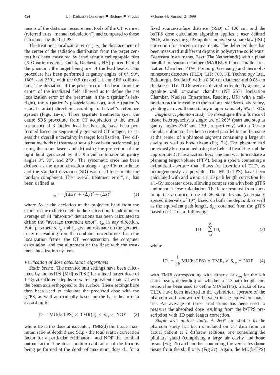
distributed between the table positions 270° and 90°, with a0.5-cm or 0.9-cm collimator each. (b) Simulation of thetreatment of a solitary and peripheral target in the parietallobe treated with either 3 or 5 arcs and 0.9-cm and 2.0-cmcollimator, respectively. (c) Both lesions treated simulta-neously (Fig. 3). The treatment configuration was designedto irradiate the volume containing the detectors as homoge-neously as possible, avoiding large dose gradients through-out the detector volume. Stacks of 1–3 TLDs have beeninserted in the cylindrical apertures and sandwiched be-tween tissue equivalent material. A mean of 10 differentdose calculations in points distributed at random inside thereconstructed detector volume have been applied to predictthe dose to the detector.
One particular experiment for the solitary target locatedcentrally has also been compared with calculations fromthe gTPS and manual calculations. The average depth,dav, and average equivalent path length, deq,av, have beenused to calculate the dose contribution from each arcaccording to
ID 5 Oj
IDj (5)
IDj 5 MU(bsTPS)j 3 TMRj 3 Sc,p 3 NOF (6)
with MU(bsTPS)j representing the monitor unit settings andTMRj corresponding with dav or deq,av for the jth arc.
Finally, the dose distribution has been evaluated with filmdosimetry by irradiating part of a silver halide-based film(X-OMAT V Ready Pack, Kodak) inside the phantom. Theoriginal film was cut and repackaged in dark room condi-tions to enable both irradiation and calibration on the samesheet. The remaining section was calibrated at a fixed depthwith a small circular field (2.3-cm diameter) against ioniza-tion chamber measurements MARKUS plame paralleliomizatiom chamber: PTW, Freiburg, delivering consecu-tive doses of 0.10 Gy up to 0.65 Gy, in steps of 0.05 Gy(sensitivity of the optical density [OD], influenced by theprocessing conditions, was optimal in the range from 0.0 to0.5 Gy and dropped significantly beyond 0.6 Gy) to differ-ent parts of the film which was then used to create theconversion curve from OD to absorbed dose. Both sectionsof the film have been developed (Curix 242 ug, Agfa-Gevaert, Mu¨nchen, Germany) simultaneously and analyzedwith a commercial available film densitometer (WP 102 andWP 700, Wellho¨fer Dosimetry, Schwarzenbruck, Germa-
Fig. 3. An example of the simultaneous treatment of a central target (five arcs) and a peripheral target (three arcs) inthe anthropomorphic phantom. The three images on the right-hand side show an axial (top), coronal (bottom-left), andsagittal (bottom-right) reconstruction and dose distribution through the central target. The TLDs in the target volume andorgans at risk are clearly visible, as well as the aperture for additional TLDs.
426 I. J. Radiation Oncology● Biology ● Physics Volume 44, Number 2, 1999
ny). The phantom has been irradiated to deliver a 0.50-Gyisocenter dose based on calculations from the bsTPS with a1D path length correction with four 60° arcs evenly distrib-uted between table positions 0° and 350°. The isodosesobtained from the densitometer have been superimposed onthe predicted isodoses for illustration.
Multiple arcs: patient studies. A comparison of both TPShas been performed based on 11 patient treatments that havebeen planned in parallel on both systems. The Fischer headring with appropriate docking device and localization framehas been used for immobilization and target localization.The target and organs at risk have been copied by eye fromone system to the other. Identical arcs, the same isocenter(s)and the same number of monitor units per arc were appliedon both TPS using the same sets of CT images. The calcu-lated dose at the isocenter, as well as visible differencesbetween isodose curves, have been used for comparison.The TMRs corresponding with both the average depth d(TMRd) and average tissue depth deq (TMRdeq) have beenobtained for the individual patient treatments based oncalculations from bsTPS. The mean ratio of TMRd andTMRddeq have then been compared with the mean ratio ofthe monitor unit settings calculated with and without 1Dpath length correction.
RESULTS
Verification of positional accuracyAveraging the dimensions of the three reconstructed lead
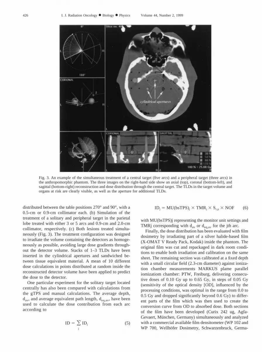
beads hidden inside the anthropomorphic phantom based on3 different reconstructions, each based on a new set of CTimages, yielded a cylinder (with radius a5 0.38 cm [SD0.02 cm] and length z5 0.41 cm [SD 0.06 cm]) when thesequential scanning mode was used (Fig. 4a), and an ellipticcylinder (with radii a5 0.33 cm [SD 0.05 cm] and b5 0.58cm [SD 0.15 cm], and length z5 0.54 cm [SD 0.10 cm])with the helical mode (Fig. 4b).
The difference between manual calculation of the stereo-tactic coordinates of the center of the hidden beads andthose generated with the bsTPS algorithm is shown in Table1. Table 2 shows the analysis with radiographic film of thelocalization error for the full SRS procedure based on 3separate treatments of 3 hidden lead beads each. The overalltreatment error ro for a target localized by CT was 0.100 cmand 0.036 cm for a treatment set-up based on room lasers orusing the projection of the light field with a 0.5-cm colli-mator, respectively. The average treatment error ra for the 9hidden targets was calculated at 0.068 cm (SD 0.049 cm)and 0.031 cm (SD 0.024 cm), respectively, for treatment
Fig. 4. (a) An axial (top), coronal (bottom-left), and sagittal (bottom-right) reconstruction of a 0.2 cm lead bead basedon CT data from the anthropomorphic phantom using a sequential scanning mode with a slice thickness and feed of 0.2cm. (b) A similar axial (top), coronal (bottom-left), and sagittal (bottom-right) reconstruction of the same lead beadusing a helical scanning mode (slice and feed of 0.2 cm), illustrating the enlarged streaking artifact.
427Evaluation of a treatment planning system for linac-based SRS● D. VERELLEN et al.
setup based on room lasers and light field. If a normaldistribution is assumed for the individual displacement er-rors with ra and its corresponding SD representing the truemean and SD, then the displacement error of a singletreatment would be less than 0.0681 0.0493 1.965 0.164cm. with a 95% confidence level using the room lasers and0.0311 0.0243 1.965 0.078 cm using the projection ofthe light field.
Verification of dose calculation algorithmsStatic beams. Table 3 summarizes the doses obtained at
isocenter from both dose calculations’ algorithms and man-ual calculation, as well as measurement at depths dm, 5.0 cmand 10.0 cm for a 0.9-cm and a 2.3-cm collimated beamorthogonal to the surface. Similar results have been obtainedwith the other circular collimators.
Single arc: phantom study. Averaging the ratios of d withdeq calculated for each of the 26 static beams (with a 0.9 cmcollimator) that together compose the 260° arc yields 1.04and 1.01 for depth data obtained with the gTPS and bsTPS,respectively. The corresponding TMR/TMReq ratios of 0.99and 1.00 show that the effect of tissue heterogeneity can beconsidered negligible in this particular situation. Applyingthe MU(bsTPS) for a 1-Gy isocenter dose according to thebsTPS yields 0.98 Gy with gTPS and 1.00 Gy calculatedmanually. Repeated irradiation of the phantom resulted in a1.01-Gy (SD 0.03 Gy) dose based on TLD measurements.
Single arc: patient study. The MU(bsTPS) calculatedwith and without a 1D path length correction for a 1-Gyisocenter dose resulted in a 1.02 ratio, whereas a 1.03 ratiohas been observed when averaging the ratios of the TMRand TMReq each obtained from the depths and equivalentpath lengths for the 26 static beams ([deq/d]av5 1.08) forthe arc through the pituitary gland section. A ratio of 1.04for MU(bsTPS) with and without 1D path length correctioncorresponded with a 1.03 TMR/TMReq ratio ([deq/d]av51.08) for the ventricles section.
Table 4 summarizes the results obtained from the differ-
ent dose calculation methods (bsTPS, gTPS, and manually)based on this patient’s CT data.
Multiple arcs: phantom study. Table 5 summarizes thedose values obtained with TLD for the simulation of acentral and peripheral target, treated both solitary and si-multaneously. The mean ratio of measured versus calcu-lated dose (with 1D path length correction) was 1.02 (SD0.01). The dose obtained at the organs at risk has beendivided by the corresponding calculated dose and averagedover all experiments, yielding a ratio of 0.98 (SD 0.14).
A particular 5-arc treatment with a 0.9-cm circular colli-mator has been applied to a solitary target located centrallyin the phantom to compare both dose calculation algorithmswith manual calculations and measurement. This resulted ina 1.05 Gy (SD 0.01 Gy) measured with TLD, whereas a1-Gy and 0.96-Gy isocenter dose were predicted by thebsTPS and manual dose calculation, respectively. Neglect-ing tissue heterogeneity, the 1-Gy isocenter dose predictedby the bsTPS dose calculation algorithm corresponded with0.97 Gy from both the gTPS and manual dose calculations.
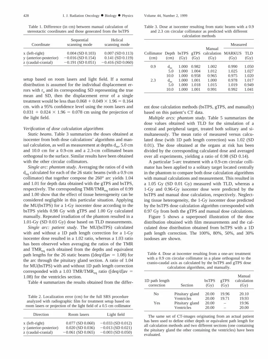
Figure 5 shows a superposed illustration of the dosedistribution obtained with film measurements and the cal-culated dose distribution obtained from bsTPS with a 1Dpath length correction. The 100%, 80%, 50%, and 30%isodoses are shown.
Table 1. Difference (in cm) between manual calculation ofstereotactic coordinates and those generated from the bsTPS
CoordinateSequential
scanning modeHelical
scanning mode
x (left-right) 0.004 (SD 0.103) 0.007 (SD 0.113)y (anterior-posterior) 20.016 (SD 0.154) 0.141 (SD 0.119)z (caudal-cranial) 20.191 (SD 0.051) 20.416 (SD 0.060)
Table 2. Localization error (cm) for the full SRS procedureanalyzed with radiographic film for treatment setup based onroom lasers or projection of the light field of a 0.5 cm collimator
Direction Room lasers Light field
x (left-right) 0.077 (SD 0.060) 20.033 (SD 0.012)y (anterior-posterior) 0.020 (SD 0.036)20.013 (SD 0.021)z (caudal-cranial) 20.061 (SD 0.065) 20.003 (SD 0.050)
Table 3. Dose at isocenter resulting from static beams with a 0.9and 2.3 cm circular collimator as predicted with different
calculation methods
Collimator(cm)
Depth(cm)
bsTPS(Gy)
gTPS(Gy)
Manualcalculation
(Gy)
Measured
MARKUS(Gy)
TLD(Gy)
0.9 dm 1.000 0.982 1.002 0.990 1.0505.0 1.000 1.004 1.012 1.025 1.027
10.0 1.000 0.958 0.965 0.975 1.0202.3 dm 1.000 1.001 1.000 0.978 1.017
5.0 1.000 1.018 1.015 1.019 0.94910.0 1.000 1.001 0.991 0.992 1.041
Table 4. Dose at isocenter resulting from a one-arc treatmentwith a 0.9 cm circular collimator in a plane orthogonal to thecranio-caudal axis as calculated by the bsTPS and gTPS dose
calculation algorithms, and manually.
1D path lengthcorrection Section
bsTPS(Gy)
gTPS(Gy)
Manualcalculation
(Gy)
No Pituitary gland 20.00 19.96 20.10Ventricles 20.00 19.71 19.93
Yes Pituitary gland 20.00 – 19.96Ventricles 20.00 – 20.00
The same set of CT-images originating from an actual patienthas been used to define either depth or equivalent path length forall calculation methods and two different sections (one containingthe pituitary gland the other containing the ventricles) have beenevaluated.
428 I. J. Radiation Oncology● Biology ● Physics Volume 44, Number 2, 1999
Multiple arcs: patient studies. The comparison of 11patient treatments calculated in parallel on both TPS usingidentical isocenter, arcs, and MU per arc yielded a meanratio of 1.01 (SD 0.01) between the isocenter dose calcu-lated with the gTPS algorithm and the bsTPS algorithmwithout a 1D path length correction for tissue heterogeneity.Analysis of the TMR versus TMReq ratio for these 11treatments yielded a mean ratio of 1.05 (SD 0.01). The meanratio of the average depth d and the average tissue depth deq
for all patients was 0.85 (SD 0.06). The corresponding ratio
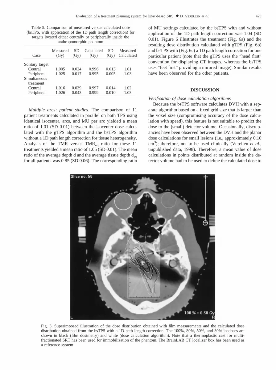
of MU settings calculated by the bsTPS with and withoutapplication of the 1D path length correction was 1.04 (SD0.01). Figure 6 illustrates the treatment (Fig. 6a) and theresulting dose distribution calculated with gTPS (Fig. 6b)and bsTPS with (Fig. 6c) a 1D path length correction for oneparticular patient (note that the gTPS uses the “head first”convention for displaying CT images, whereas the bsTPSuses “feet first” providing a mirored image). Similar resultshave been observed for the other patients.
DISCUSSION
Verification of dose calculation algorithmsBecause the bsTPS software calculates DVH with a sep-
arate algorithm based on a fixed grid size that is larger thanthe voxel size (compromising accuracy of the dose calcu-lation with speed), this feature is not suitable to predict thedose to the (small) detector volume. Occasionally, discrep-ancies have been observed between the DVH and the planardose calculations for small lesions (i.e., approximately 0.10cm3); therefore, not to be used clinically (Verellenet al.,unpublished data, 1998). Therefore, a mean value of dosecalculations in points distributed at random inside the de-tector volume had to be used to define the calculated dose to
Fig. 5. Superimposed illustration of the dose distribution obtained with film measurements and the calculated dosedistribution obtained from the bsTPS with a 1D path length correction. The 100%, 80%, 50%, and 30% isodoses areshown in black (film dosimetry) and white (dose calculation algorithm). Note that a thermoplastic cast for multi-fractionated SRT has been used for immobilization of the phantom. The BrainLAB CT localizer box has been used asa reference system.
Table 5. Comparison of measured versus calculated dose(bsTPS, with application of the 1D path length correction) for
targets located either centrally or peripherally inside theanthropomorphic phantom
CaseMeasured
(Gy)SD
(Gy)Calculated
(Gy)SD
(Gy)MeasuredCalculated
Solitary targetCentral 1.005 0.024 0.996 0.013 1.01Peripheral 1.025 0.017 0.995 0.005 1.03
SimultaneoustreatmentCentral 1.016 0.039 0.997 0.014 1.02Peripheral 1.026 0.043 0.999 0.010 1.03
429Evaluation of a treatment planning system for linac-based SRS● D. VERELLEN et al.
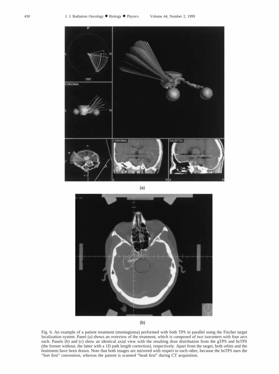
Fig. 6. An example of a patient treatment (meningioma) performed with both TPS in parallel using the Fischer targetlocalization system. Panel (a) shows an overview of the treatment, which is composed of two isocenters with four arcseach. Panels (b) and (c) show an identical axial view with the resulting dose distribution from the gTPS and bsTPS(the former without, the latter with a 1D path length correction), respectively. Apart from the target, both orbits and thebrainstem have been drawn. Note that both images are mirrored with respect to each other, because the bsTPS uses the“feet first” convention, whereas the patient is scanned “head first” during CT acquisition.
430 I. J. Radiation Oncology● Biology ● Physics Volume 44, Number 2, 1999

the detector. For the same reason, the comparison betweenthe gTPS and bsTPS dose calculation algorithms has beenbased on the dose predicted to the isocenter in preference,and not based on DVH. The interpretation of the DVH washampered even more because the structures had been copiedfrom one TPS to the other on-sight, which inevitably intro-duces differences in volume.
The dose calculation algorithm of the bsTPS version 3.1uses user-defined beam data such as TMR data, off axisratios, and total scatter correction factors for the differentSRS collimators. It is, however, not possible to verify di-rectly whether some errors had been introduced during thetransfer of beam data into the TPS. The in-house-developedgTPS, being an open system, allows for verification andediting of beam data if necessary. Moreover, the bsTPSrequires the user to specify the “site specific” NOF prior toeach dose calculation. Therefore, it was chosen to performthe dosimetric verification with simple (i.e., easy to verifyand allowing different techniques for verification) treatmentschedules initially and then to gradually increase the com-plexity. For some collimators (e.g., 0.9 cm) analysis of staticbeam treatments showed inconsistencies between the dosepredicted by the bsTPS and manual calculation based on the
original beam data for depths exceeding 9.0 cm. Both thegTPS dose calculation and measurements confirmed thesefindings, indicating a potential problem with the transfer ofthe TMR data in the bsTPS dose calculation algorithm.Calculation of the MU settings with bsTPS to generate a1.0-Gy dose at different depths allows to generate the TMRvalues that are used by the dose calculation algorithm indi-rectly. A comparison with the original TMR values showedan agreement within 1% for all collimators at a depthsmaller than 9.0 cm, and deviations of 3–4 % at largerdepths for some collimators (e.g., 0.9 cm).
The agreement between measurement and the differentdose calculation methods for the 1-arc treatments based onboth phantom and patient CT data suggests that a doseperturbation of 3 –4% can be expected from 8% changes inthe equivalent depth caused by bone and air cavities forrotational treatment schedules. The average depth andequivalent depth never exceeded 9.0 cm in these particularexperiments. Based on Monte Carlo simulations, Ayyangaret al. (24) calculated that for a 6 MV photon beam, a 10%increase in density resulted in a 2% dose decrease at iso-center, or that with a 1.0 cm increase in depth, the TMRdecreases by 3%, which confirms the observations pre-
Fig. 6. (Cont’d)
431Evaluation of a treatment planning system for linac-based SRS● D. VERELLEN et al.
sented here. However, slightly lower dose perturbations(1–2%) have been reported by Schellet al. (10) for beamenergies between 4–10 MV with the beam passing throughthe skull. These conclusions assume a good calibrated CTscanner with a correct conversion of Hounsfield units (HU)to electron densities. Geiseet al. (25) have shown that forconventional radiotherapy treatment schedules, uncertain-ties in relative densities of 4–10% can be tolerated if anerror of 2% in the correct dose is acceptable. Similar resultshave been observed during experimental tests on a Sim-CTdevice (26), suggesting the relative robustness of the gTPSdose calculation (applying a 1D path length correction) withrespect to the calibration of the CT scanners that have beenused in this study. An additional evaluation of both CTscanners showed an agreement of the HU within 5% of theexpected values. The relative difference of 4% betweendose calculations with and without 1D path length correc-tion in the bsTPS, however, will have its influence on thedose prescription with respect to former treatments thatwere based on the gTPS dose calculation algorithm withouta 1D path length correction. This department’s policy hasbeen not to alter the prescribed dose with the introduction oftissue heterogeneity in the dose calculation, but to accountfor this effect when comparing newly calculated with pasttreatment schedules.
The theoretical evaluation of the phantom and thepatient studies based on manual calculation of the pre-dicted dose at isocenter for multiple arc treatments (withor without a 1D path length correction) show that bothdose calculation algorithms (bsTPS and gTPS) are com-parable in clinical relevant situations. Again, the effect ofpossible erroneous transfer of TMR data has not beenobserved in these multiple arc experiments, which mightbe explained by the fact that the relative contribution ofthe few static beams with a depth exceeding 9 cm is smallin comparison with the large set of static beams themultiple arc rotational treatment schedule is composedof. The TL measurements confirmed that the dose deliv-ery is accurate within uncertainty (i.e., 5%), which is incompliance with AAPM Report 54, TG 42 recommenda-tions on dose accuracy (10). Alanine detectors (Verellenet al., unpublished data, 1998) (27) have also been usedwith the phantom to establish an independent check ofthe TL measurements for multi-arc treatments of a soli-tary target. An advantage of alanine is that it is indepen-dent of energy and dose rate and makes it possible toperform the entire SRS procedure (including CT acqui-sition and localization of the actual detectors) with thedetectors in place for each experiment (28). A disadvan-tage, however, is that the absorbed dose needs to be 10Gy or higher, which makes it rather cumbersome forrepeated measurements. The alanine measurementsyielded a ratio of 1 (SD 0.08) between measured andcalculated dose at isocenter averaged over 4 differenttreatments, confirming the previous result obtained withTLD. The efficacy and feasibility of alanine detectors fordynamic and rotational arc treatments are currently being
investigated; however, that is beyond the scope of thisarticle.
Finally, the dose distribution obtained on film agreedwith the predicted dose distribution. Although film is not asuitable detector for absolute dose measurements (28–31),the dose values confirmed the previous results within un-certainty.
Verification of positional accuracyReducing uncertainties in the accuracy of the absolute
dose is an important issue, yet the overall positionalaccuracy is the most critical parameter in evaluating theSRS procedure. The observed uncertainty in target posi-tioning was within a sphere of 0.08-cm radius for theentire SRS procedure with a 95% confidence based onphantom studies, which is far less than the clinicalknowledge of the lesion (based on CT). This geometricaccuracy, however, largely depends on the procedure thatis being used for acquisition of CT data and treatmentsetup. In addition to the volume averaging that has beenintroduced by the CT reconstruction process, the highZ-value of the lead beads introduces partial volume av-eraging. Both artifacts result in a streaked reconstructionof the lead sphere. Despite the fact that the same slice andfeed have been applied with both the sequential and thehelical scanning mode, the streaking is more pronouncedin the latter mode. This can easily be explained by theprinciple of helical scanning. To enable the reconstruc-tion of a planar section of the scanned object, the rawdata from the helical data set is interpolated to approxi-mate the acquisition of planar reconstruction or sequen-tial data. This also explains the elliptical distortion in theaxial views with the long b-axis at a 45° angle. Becausehigh Z-contrast media are often applied to visualize thetarget, the sequential scanning mode is preferred forclinical applications, reducing these artifacts to a mini-mum. The application of a different filter algorithm in theCT reconstruction process might reduce these artifacts;however, it also reduces tissue contrast, which remainsimportant for target delineation. Moreover, the imagesare used for dose calculation and therefore the defaultreconstruction filter is required. The positional uncer-tainty is obviously more pronounced in the cranio-caudaldirection because of the 0.2-cm spacing between consec-utive slices. Because the room lasers project a 0.15-cm-thick line on the localizer box, the positional accuracy isreduced, which clearly shows in the comparison betweenboth techniques for treatment setup (using either theroom lasers or the projection of the light field). There-fore, the treatment setup based on the projection of thelight field is to be preferred.
The observed accuracy limits are within the achievableuncertainties as they have been proposed in AAPM Re-port 54, TG 42 (10). The overall positional accuracymight be improved even more with the introduction ofhigh-precision room lasers (less than 0.10-cm projectionat isocenter) and 0.10-cm CT sequences. However, thetreatment procedure is a chain of events and is only as
432 I. J. Radiation Oncology● Biology ● Physics Volume 44, Number 2, 1999
strong as its weakest link, which is currently the clinicalknowledge of the lesion. Improvement of the latter isrequired, and both the introduction of angiography andMR imaging need special attention in future develop-ments (10, 32, 33). The option that is available in thebsTPS version 3.1 for fusion of CT and MR images,however, has not been evaluated in this study. The cur-rent software version does not allow for accurate corre-lation between both imaging modalities and a mismatchis visible by eye in most clinical applications (Verellenetal., unpublished data, 1998).
CONCLUSION
Phantom studies to evaluate the entire SRS procedurehave shown that a target, localized by CT, can be irradi-ated with a positional accuracy of 0.08 cm in any direc-tion, with 9% confidence. Neglecting the influence oftissue heterogeneity, both TPSs agree within 1%; how-ever, the use of 1D path length correction with the bsTPSwill result in an increase of 4% in dose prescription,which is slightly more than what is predicted in theliterature.
REFERENCES
1. Pike B, Podgorsak EB, Peters TM,et al.Dose distributions indynamic stereotactic radiosurgery.Med Phys1987;14:780–789.
2. Gill SS, Thomas DGT, Warrington AP,et al. Relocatableframe for stereotactic external beam radiotherapy.Int J RadiatOncol Biol Phys1991;20:599–603.
3. Hariz MI, Henriksson R, Lo¨froth PO, et al. A non-invasivemethod for fractionated stereotactic irradiation of brain tumorswith linear accelerator.Radiother Oncol1990;17:57–73.
4. Hodapp N, Nanko N, Rohner F,et al. Quality assurance fornon-invasive patient fixation during stereotactic convergentbeam beam irradiation.Acta Neurochir Wien1994;62:101–104.
5. Kooy HM, Dunbar SF, Tarbell NJet al. Adaptation andverification of the relocatable Gill-Thomas-Cosman frame instereotactic radiotherapy.Int J Radiat Oncol Biol Phys1994;30:685–691.
6. Rosenthal SA, Gall KP, Jackson M,et al. A precision cranialimmobilization system for conformal stereotactic fractionatedradiation therapy.Int J Radiat Oncol Biol Phys1995;33:1239–1245.
7. Willner J, Flentje M, Bratengeier K. CT simulation in stereo-tactic brain radiotherapy - analysis of isocenter reproducibilitywith mask fixation.Radiother Oncol1997;45:83–88.
8. Leksell DG. Stereotactic radiosurgery: Present status and fu-ture trends.Neurol Res1987;9:60.
9. Leksell LT. The stereotactic method and radiosurgery of thebrain.Acta Chir Scand1951; 102:316.
10. Schell MC, Bova FJ, Larson DA,et al.AAPM Report No. 54.Stereotactic radiosurgery. Report of AAPM Task Group 42.1995.
11. Kjellberg RN, Hanamura T, Davis KR,et al. Bragg-peakproton-beam therapy for arterio-venus malformation of thebrain.N Engl J Med1983;309:269.
12. Larsson B, Leksell L, Rexed B,et al. The high energy protonbeam as a neursurgical tool.Nature1958;182:1222.
13. Lawrence JH, Tobias CA, Born JL,et al. Heavy-particleirradiation in neoplastic and neurologic disease.J Neurosurg1962;19:717.
14. Colombo F, Benedetti A, Pozza F,et al. External stereotacticirradiation by linear accelerator.Neurosurgery1985;16:154–159.
15. Hartmann GH, Schlegel W, Sturm V,et al.Cerebral radiationsurgery using moving field irradiation at a linear acceleratorfacility. Int J Radiat Oncol Biol Phys1985;11:1185–1192.
16. Lutz W, Winston KR, Maleki N. A system for stereotacticradiosurgery with a linear accelerator.Int J Radiat Oncol BiolPhys1988;14:373–381.
17. Saunders WM, Winston KR, Siddon RL,et al. Radiosurgeryfor arteriovenous malformations of the brain using a standardlinear accelerator: Rationale and technique. Int J Radiat OncolBiol Phys1988;15:441–447.
18. Schell MC, Smith V, Larson DA,et al. Evaluation of radio-surgery techniques with cumulative dose volume histogramsin linac-based stereotactic external beam irradiation. Int JRadiat Oncol Biol Phys1991;20:1325–1330.
19. Tsai JS, Buck BA, Svensson GK,et al. Quality assurance instereotactic radiosurgery using a standard linear accelerator.Int J Radiat Oncol Biol Phys1991;21:737–748.
20. Winston KR, Lutz W. Linear accelerator as a neurosurgicaltool for stereotactic radiosurgery.Neurosurgery1988; 22:454–464.
21. Sherouse G, Chaney E. The portable virtual simulator.Int JRadiat Oncol Biol Phys1991; 21:475–482.
22. Sherouse GW, Thorn J, Novins K,et al. A portable 3Dradiotherapy treatment design system.Med Phys1989;16:466.
23. Coghe M, Van den Berge D, Herregodts P,et al. Adaptationand extension of Sherouse’s GRATIS three-dimensional treat-ment planning system for radiosurgery. (Abstr.)Acta Neuroch1993; 122:175.
24. Ayyangar KM, Jiang SB. An investigation on the feasibility ofusing OMEGA Monte Carlo codes for radiosurgery treatmentplanning. Proceedings of the XIIth ICCR, May 27–30, 1997.
25. Geise RA, McCullough EC. The use of CT scanners in mega-voltage photon-beam therapy planning.Radiology1977;124:133–141.
26. Verellen D, Vinh-Hung V, Bijdekerke P,et al.Characteristicsand clinical application of a treatment simulator with CT-option.Radiother Oncol(Submitted).
27. Schaeken B, Scalliet P. One year experience with alaninedosimetry in radiotherapy.Appl Radiat Isot1996; 47:1177–1182.
28. Verellen D, Linthout N, Van den Berge D,et al. Initialexperience with intensity-modulated conformal radiation ther-apy for treatment of the head and neck region.Int J RadiatOncol Biol Phys1997;39:99–114.
29. Hale JI, Kerr AT, Shragge PC. Calibration of film for accuratemegavoltage photon dosimetry.Med Dosim1994;19:43–46.
30. van Battum LJ, Heijmen BJM. Film dosimetry in water in a 23MV therapeutic photon beam.Radiother Oncol1995;34:152–159.
31. Williamson JF, Khan FM, Sharma SC. Film dosimetry ofmegavoltage phton beams: A practical method of isodensity-to-isodose curve conversion.Med Phys1981;8:94–98.
32. Schad LR, Ehricke H, Wowra B,et al. Correction of spatialdistortion in magnetic resonance angiography for radiosurgi-cal treatment planning of cerebral arteriovenous malforma-tions.Magn Reson Imaging1992;10:9.
33. Sumanaweera TS, Adler JR, Napel S. Characterization ofspatial distortion in magnetic resonance imaging and its im-plications for stereotactic surgery.Neurosurgery1994; 35:696.
433Evaluation of a treatment planning system for linac-based SRS● D. VERELLEN et al.