a.s.r. the autonomous sentry robot - department of ece ucf
TRANSCRIPT

A.S.R. The Autonomous Sentry Robot
Department of Electrical Engineering and Computer Science University of Central Florida
Spring 2015 Senior Design I
Group #9
Project Sponsored By Boeing
Brian Dodge (EE) [email protected] Nicholas Musco (EE) [email protected] Trevor Roman (CpE) [email protected]

1. Executive Summary
2. Project Description
2.1. Motivation 2.2. Objectives and Goals 2.3. Requirements and Specifications
2.3.1. Form Factor 2.3.2. Wheels and Motion 2.3.3. Control 2.3.4. Sensors 2.3.5. Processing 2.3.6. Power
3. Research
3.1. Similar Projects 3.1.1. T100 Watchdog 3.1.2. KnightCop 3.1.3. RHINO 3.1.4. Minerva 3.1.5. Heatseekr
3.2. Autonomous Vehicles 3.3. SLAM
3.3.1. RGBDSLAM 3.3.2. GMapping 3.3.3. HectorSLAM 3.3.4. BreezySLAM
3.4. Sensors 3.4.1. Kinect 3.4.2. Lidar 3.4.3. Sonar 3.4.4. Tactile 3.4.5. Webcam
3.5. Microprocessors 3.5.1. Raspberry Pi 1 Model B+ 3.5.2. Raspberry Pi 2 Model B 3.5.3. Beaglebone 3.5.4. BeagleBone Black 3.5.5. Benchmarks
3.6. Microcontrollers 3.6.1. ATmega328P vs. ATmega2560
3.7. Operating Systems 3.7.1. Raspbian 3.7.2. ROS
3.8. Memory 3.9. Wireless Communication 3.10. Movement
3.10.1. Tank Drive 3.10.2. Car Steering 3.10.3. Holonomic Drive Systems 3.10.4. “H” Drive
1
1 1 2 2 3 3 3 4 4 5
5 5 5 6 7 8 8 9 10 11 11 12 13 13 14 14 15 17 18 18 19 19 20 20 21 23 23 24 24 24 25 27 28 28 29 30 33 i
3.11. Wheels 3.11.1. Traction Wheels 3.11.2. Tank Treads 3.11.3. Mecanum Wheels 3.11.4. Omni Wheels
3.12. Motors 3.12.1. DC Motors
3.12.1.1. Brush DC 3.12.1.2. Brushless DC
3.12.2. AC Motors 3.12.2.1. Induction Motor 3.12.2.2. Synchronous Motors 3.12.2.3. Linear
3.13. Control and Navigation 3.13.1. Autonomous Control
3.13.1.1. SONAR 3.13.1.2. Tactile Sensor 3.13.1.3. Finite State Machine 3.13.1.4. Flood Fill Algorithm 3.13.1.5. Dijkstra’s Algorithm
3.13.2. User Control 3.13.2.1. Remote Access 3.13.2.2. Internet Application or Mobile Application
3.14. Batteries 3.14.1. Sealed LeadAcid 3.14.2. LiFePO4 3.14.3. NiCd 3.14.4. NiMH 3.14.5. LiPO
3.15. Voltage Regulators 3.15.1. Linear Voltage Regulators 3.15.2. Switching Voltage Regulators
3.16. Chassis 4. Related Standards
4.1. Standards Search 4.2. Design Impact
5. Design Constraints
5.1. Cost 5.2. Time 5.3. Size 5.4. Power Consumption
6. Hardware Design
6.1. Mechanical System 6.1.1. Chassis 6.1.2. Drive System 6.1.3. Wheels 6.1.4. Motors
6.2. Electrical System
33 34 34 34 35 36 36 37 40 42 42 44 45 45 46 47 47 48 48 49 49 49 50 52 53 54 55 56 57 58 58 58 59
61 61 62
62 62 63 63 63
63 64 64 64 65 66 68 ii

6.2.1. Battery 6.2.2. Charger 6.2.3. Charging Station 6.2.4. Power Distribution 6.2.5. Microcontroller 6.2.6. Sensors
7. Software Design
7.1. High Level Software System Architecture 7.2. User Application 7.3. Sensor Processor 7.4. State Manager 7.5. Autonomous Navigation
7.5.1. Autonomous Exploration 7.5.2. Autonomous Patrol 7.5.3. Autonomous Docking
7.6. Manual Navigation 7.6.1. Manual Exploration 7.6.2. Manual Patrol
7.7. Mapping and Localization 7.8. Motion Detection
8. Prototype Construction
8.1. PCB 8.2. Coding Plan
9. Prototype Testing
9.1. Hardware Testing 9.1.1. Environment 9.1.2. Chassis 9.1.3. Wheels 9.1.4. Power Distribution 9.1.5. Sensors 9.1.6. Microcontroller 9.1.7. Microprocessor 9.1.8. Hardware Integration Testing
9.2. Software Testing 9.2.1. Environment 9.2.2. User Application 9.2.3. Sensor Processor 9.2.4. State Manager 9.2.5. Autonomous Navigation 9.2.6. Manual Navigation 9.2.7. Mapping and Localization 9.2.8. Motion Detection 9.2.9. Software Integration Testing
10. Administrative
10.1. Project Milestones 10.2. Project Budget
68 69 70 71 72 72
73 73 74 76 77 78 79 80 81 81 82 82 83 83
84 85 86
87 87 87 87 88 88 89 90 91 92 93 93 94 95 96 96 98 100 100 101
101 102 103
iii

Appendices A. Copyright Permissions B. Works Cited C. Large Diagrams
Appendix 1 Appendix 1
Appendix 14 Appendix 16
iv

1. Executive Summary Robots are becoming more prevalent in the world. They are no longer just in movies. They are being used for industrial purposes, and research projects. Robots can be found being used by the military and police departments as drones for aerial surveillance or robots for Explosive Ordnance Disposal. Robots are now found in the home as toys, such as the MIP or Sphero, and cleaning assistants like the iRobot Roomba vacuum cleaner. They can be found in hospitals, being used for surgery. Robots are being developed in labs that can map and localize themselves. Most of the robots mentioned are teleoperated by humans, or perform simple, repetitive tasks. There is an area which seems to not be well covered in consumer robotics. The area is land based, autonomous surveillance robots that implement mapping and localization. The goal of this project is to create a robot that does this. The Autonomous Sentry Robot is a multifaceted security system for use in enclosed buildings. The ASR will be equipped with a variety of sensors and either a camera, or microsoft Kinect, allowing it to autonomously navigate and dynamically map it’s place in space. It will take the sensor data, and either use an onboard processor or a local computer to use the data for mapping and localization. From this map, it will plot an efficient path to patrol within this space, and it’s camera and vision capabilities will detect changes in the environment or motion. If changes are detected, the ASR’s owner will be alerted through a mobile app, and they will be able to access its camera feed, as well as take control of it’s movement. The robot is meant to be fully functional even when operating autonomously. When no users are around, it will need to keep track of its power level and return to the charging station when necessary. The robot must also be able to account for objects that are not picked up by the camera. Sonars and tactile sensors will be employed to ensure the robot doesn’t drive over an unseen object. Above all, the ASR must be low power, low maintenance, low latency, easy to operate, and able to map, navigate, and detect reliably.
2. Project Description In this section, we will provide an overview of the project. We will give details for our motivation for the project as well as goals and specifications that is should obtain. 2.1 Motivation The motivation of this project is to expand our knowledge of robotics and computer vision. Our group consists of two students studying electrical engineering and one studying computer engineering. We knew that we wanted to do a robotics project, one that had both hardware and software components. We did not want to solely design a
1

teleoperated robot, we wanted one that would be autonomous. We also wanted to build a platform that could be useful as a product, one that had not been widely seen. We wanted to work on a project that combined our experience in the two fields. For the electrical engineering students, we wanted to learn how to design and build electrical subsystems for the project, such as the power distribution board and charging station. We also wanted to increase our knowledge of embedded system programming, since we will be using microprocessors to interface with the motors, sensors, and the computer. The computer engineering student wanted to increase his knowledge and skills in computer vision and software engineering. We will use a computer to process the vision data for mapping and localization. We will all be learning how to use revision control by using GitHub. 2.2 Objectives and Goals The main goal for the project is to create a robot that is autonomous that can be used as a sentry for enclosed areas. The robot will be able to map an unknown room and localize itself on the map. It will be able to determine if a person has entered the room. Once the person is detected, it will alert the user and all the user to control the vehicle. The project has the following main objectives to help with these goals: Autonomous Control, Mapping and Localization, Object Avoidance, Object Detection, and Remote Control. A main objective for this project is Autonomous Control. The robot must be able to perform its tasks without user control. It must implement Mapping and Localization, Object Detection, and Object Avoidance. It must map the enclosed area and localize itself in that area, while avoiding any obstacles in its way. It must be able to detect objects, like humans, and alert the user when a person is found. The alert can include an image, or video, of what the robot discovered. Another main objective is Remote Control. Once a person is detected, the user will be alerted and be given the option to take control of the robot. The user will be able to control the robot on a computer, and if we have time, via a phone app. 2.3 Requirements and Specifications The basic requirements and specifications for the project will be listed below. The requirements and specifications will be our guide to successfully achieving the goals and objectives stated in the previous section. The requirements and specifications will be split into several categories. The categories are: Form Factor (Section 2.3.1), Wheels and Motion (Section 2.3.2), Control (Section 2.3.3), Sensors (Section 2.3.4), Processing (Section 2.3.5), and Power (Section 2.3.6).
2
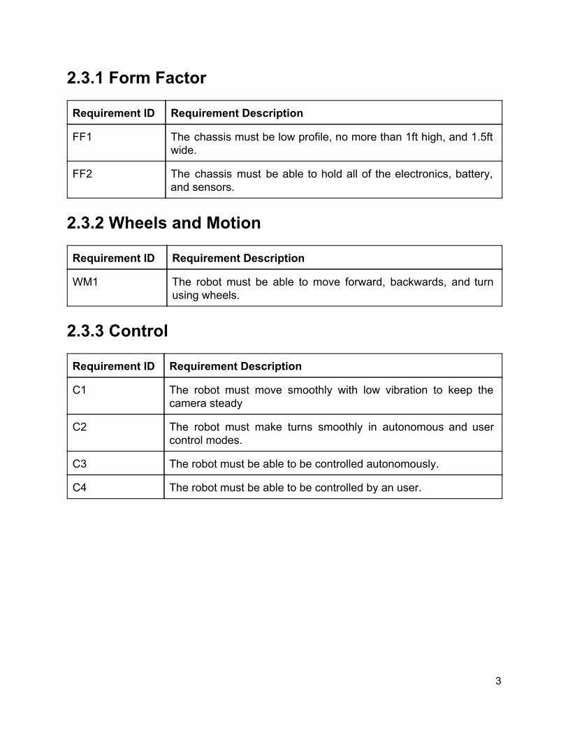
2.3.1 Form Factor Requirement ID Requirement Description
FF1 The chassis must be low profile, no more than 1ft high, and 1.5ft wide.
FF2 The chassis must be able to hold all of the electronics, battery, and sensors.
2.3.2 Wheels and Motion Requirement ID Requirement Description
WM1 The robot must be able to move forward, backwards, and turn using wheels.
2.3.3 Control Requirement ID Requirement Description
C1 The robot must move smoothly with low vibration to keep the camera steady
C2 The robot must make turns smoothly in autonomous and user control modes.
C3 The robot must be able to be controlled autonomously.
C4 The robot must be able to be controlled by an user.
3

2.3.4 Sensors Requirement ID Requirement Description
S1 The robot’s sensors must be able to detect collisions, distance, and depth.
S2 The robot’s sensors must be equipped with sufficient sensors to build a reliable map of its environment.
S3 The robot’s sensors must be able to detect motion or changes in the environment instantaneously.
S4 The robot must be able to operate reliably in light or darkness.
S5 The robot’s sensors must be able to detect pitfalls, stairs, and other obstacles from which it cannot escape.
2.3.5 Processing Requirement ID Requirement Description
P1 The robot must be able to autonomously navigate and map in real time.
P2 The robot must reliably operate, react, and make decisions within 13 seconds.
P3 The robot must be able to find its docking station and successfully dock to charge.
P4 The robot must have 75% certainty of detections before alerting its user.
P5 The user must receive alert notifications from ASR within 5 seconds of detection.
P6 The robot must alert user if damaged or stuck.
P6.1 If stuck, must attempt extricate itself for at least 10 seconds before alerting user, then continuing to try and escape
P7 If successful at extrication, the robot must alert user within 10 seconds.
4

2.3.6 Power Requirement ID Requirement Description
PW1 The robot must be able to operate for at least 5 hours on a full charge.
3. Research Research was divided among group members by our own sense of individual expertise and interest. Our EEs investigated primarily the hardware systems of our robot, while our CpE investigated the software systems.
3.1 Similar Projects We have found several similar projects to ours. There have been several robotics projects that have covered a few of the goals we plan to achieve. There are some that cover several to all of the goals we plan to achieve. Some of the projects are autonomous, some are manually controlled. Some do mapping and localization, some only do object detection and tracking. While we have ideas on how to obtain our goals, we have looked to these projects for insight on how to help achieve them. 3.1.1 T100 Watchdog The T100 Watchdog, shown in Fig. 3.1.1, is an University of Central Florida (UCF) Senior Design project from 2014. The project was the work of Ismael Rivera, Journey Sumlar, Chris Carmichael, and Warayut Techarutchatano. The T100 Watchdog is a home security robot. The group designed a robotic system that could detect and track targets. One of the goals of the project was to use OpenCV algorithms and a thermal camera to detect movement and then track a specific target. As the vehicle tracks and moves towards the targets, it autonomously maneuvers across a room while avoiding obstacles that might be in its way. The Watchdog also has a webcam to relay images and video to the user via a wireless communication system. The user can take control of the robot via a mobile application. While this project has many similar goals to ours, like autonomous control, obstacle avoidance, target detection and tracking using OpenCV, wireless communication, and user alert and control, it does not share one of our main goals, mapping and localization. Another difference is that the Watchdog only reacts to movement, where our robot would actively patrol rooms.
5

Fig. 3.1.1: T100 Watchdog
(Reprinted with Permission from Ismael Rivera) 3.1.2 KnightCop KnightCop, shown in Fig.3.1.2, is another UCF Senior Design project, from 2013. It was the work of Elean Atencio and Nitin Kundra. KnightCop was meant to be a tool for law enforcement to use in life threatening scenarios. It is equipped with a video camera, temperature sensors, ambient light sensors, lights, proximity sensors, which will give the user feedback, and a robotic arm that will allow the user to interact with the environment. The proximity sensors are used to add some autonomous functionality, while the robot is mainly teleoperated. Teleoperation is done over WiFi. While this project seems similar to ours, it is not. Its meant to be controlled mainly by a user, allowing them access to life threatening environments while allowing to manipulate their surroundings with the robotic arm. It does not autonomously patrol and map its surroundings, which is the focus of our project.
Fig.3.1.2: KnightCop
(Reprinted with Permission from Wesley Edmund)
6

3.1.3 RHINO RHINO, shown in Fig.3.1.3, was the University of Bonn’s entry to the 1994 AAAI, Association for the Advancement of Artificial Intelligence, Robotic Competition and Exhibition. RHINO was based on the B21 mobile robot platform from Real World Interface Inc. It is equipped with a sonar ring and a camera system for sensors. For processing, it had two onboard i486 computers and communicated with two SUN Sparcstations via tetherless Ethernet link. RHINO was a fully autonomous robot, with a neural network learning to adapt to “its sensors and the environment.” [1]. The key features of RHINO’s control software are Autonomy, Learning, Realtime operation, and Reactive control and deliberation. Rhino was designed to operate completely autonomously and used a neural network to interpret sonar data. It could act in realtime continuously with anytime algorithms to make decisions. During navigation, it would use a reactive obstacle avoidance algorithm with “knowledge and computation intense map building and planning algorithms.”[1] Our project will share some of the same features, but it will not incorporate any learning for interpretation. We plan on using sensor data to reactively avoid obstacles, and a control algorithm to determine how it should do so.
Fig. 3.1.3: Rhino [1]
7

3.1.4 Minerva Minerva, shown in Fig.3.1.4 (a) and (b), was an interactive tourguide for the Smithsonian Museum for two weeks. It was designed by the same team as RHINO. It goes beyond RHINO’s key features in several ways. Minerva had the ability to learn maps. For localization, it used ceiling mosaics. Its path planner took uncertainty into account, so it would avoid featureless spaces. Robotic Programming language, RPL, was used for high level control. According to Thrun et al., RPL used learning for creating tours “onthefly, and execution monitoring to accommodate exceptions.” [2] Minerva has able to interact with people using “emotional” states and used learning to develop its interactions. Minerva could use facial expression to convey “emotions.” Fig. 3.1.4(b) Is a closer view of its face. Minerva was designed for face to face human interaction, while our project will have comparatively minimal human interaction, via an app. Our project will also use mapping and localization, while Minerva could compare what its camera saw to a stored map for localization, we will be using a SLAM, Simultaneous Localization and Mapping, algorithm to map and determine the robot’s position.
Fig. 3.1.4: (a) Minerva. (b) Minerva’s Face [2]
3.1.5 Heatseekr Heatseeker, shown in fig. 3.1.5, is another UCF Senior Design project, from 2013. It was the design of Matt Erdelac, Erik Ferreira, Armin Sadri, and Bernadeau Charles. They designed Heatseekr to be an autonomous robot that detects and extinguishes fire. It uses ultraviolet radiation detectors to detect fires. Once a fire was detected by an ultraviolet sensor in a room, Heatseekr would respond to it. The fire sensors alert the
8
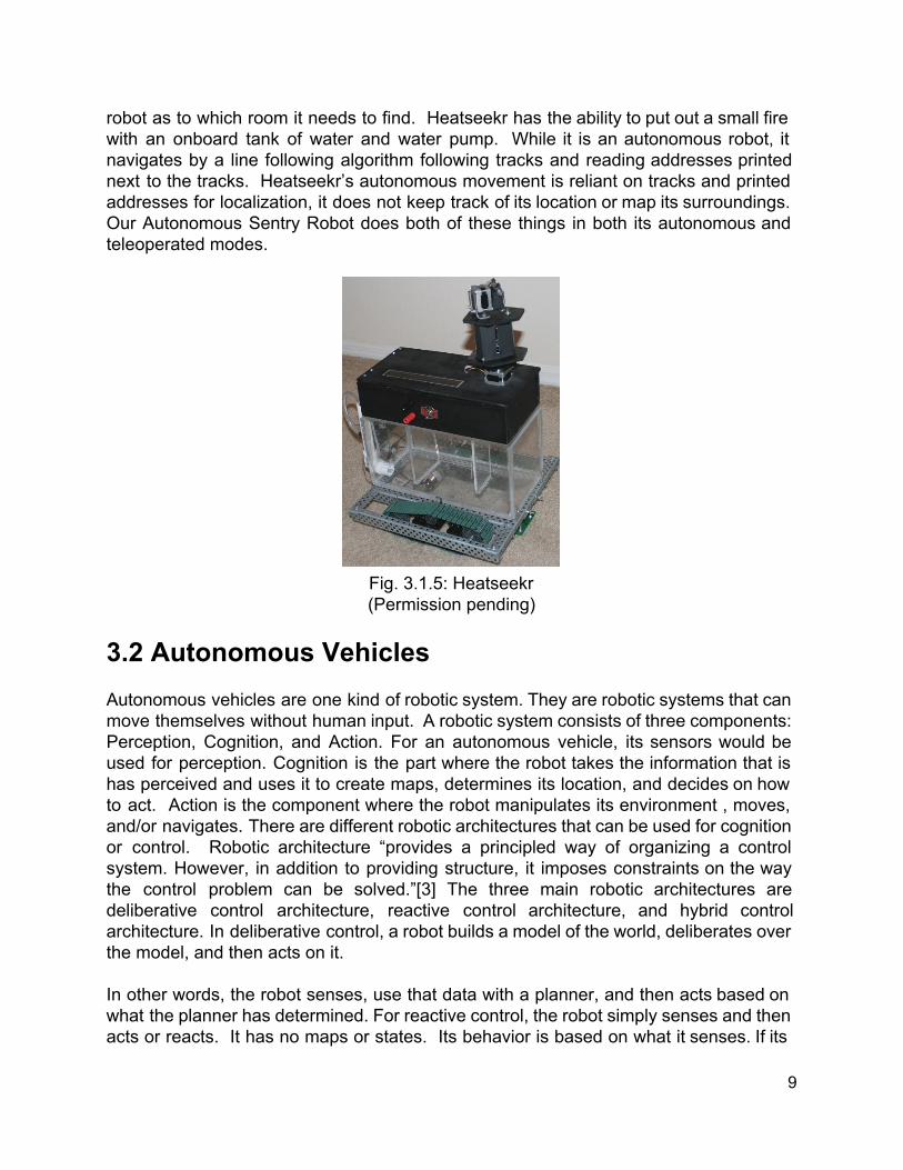
robot as to which room it needs to find. Heatseekr has the ability to put out a small fire with an onboard tank of water and water pump. While it is an autonomous robot, it navigates by a line following algorithm following tracks and reading addresses printed next to the tracks. Heatseekr’s autonomous movement is reliant on tracks and printed addresses for localization, it does not keep track of its location or map its surroundings. Our Autonomous Sentry Robot does both of these things in both its autonomous and teleoperated modes.
Fig. 3.1.5: Heatseekr (Permission pending)
3.2 Autonomous Vehicles Autonomous vehicles are one kind of robotic system. They are robotic systems that can move themselves without human input. A robotic system consists of three components: Perception, Cognition, and Action. For an autonomous vehicle, its sensors would be used for perception. Cognition is the part where the robot takes the information that is has perceived and uses it to create maps, determines its location, and decides on how to act. Action is the component where the robot manipulates its environment , moves, and/or navigates. There are different robotic architectures that can be used for cognition or control. Robotic architecture “provides a principled way of organizing a control system. However, in addition to providing structure, it imposes constraints on the way the control problem can be solved.”[3] The three main robotic architectures are deliberative control architecture, reactive control architecture, and hybrid control architecture. In deliberative control, a robot builds a model of the world, deliberates over the model, and then acts on it. In other words, the robot senses, use that data with a planner, and then acts based on what the planner has determined. For reactive control, the robot simply senses and then acts or reacts. It has no maps or states. Its behavior is based on what it senses. If its
9

design is to wander and it senses an obstacle, it will move to avoid the obstacle. However, it does not keep track of previous states, so it will not “remember” where the obstacle was. Hybrid control, also called threetiered architecture, is a combination of deliberative and reactive. This also a robot to have a model of the world, remember previous states, and quickly react to sensor data. For example, a robot that has been programmed to map an area can map it while quickly reacting to any obstacles that may be in its way. This architecture is by most real world robotic systems and will be the architecture that will be used in our project. 3.3 SLAM SLAM (Simultaneous Localization and Mapping) is the basis of our project. We seek to make a robot which can be released into a room, and without any outside knowledge, navigate and output a map of that room. After this first stage, the robot will enter its second stage, patrol mode, where it uses the map to plan a path through the room and watch for unexpected stimuli. SLAM is not so much an algorithm as it is a concept, there are no SLAM algorithms, but rather implementations of the concept. The only input from SLAM is from sensors, like Lidar or a Kinect point cloud, to measure distance of the robot relative to other objects. From this the robot will create a map (mapping), and determine its “pose” within the environment (localization). For the purposes of our project we do not seek to reinvent the wheel. This is not a project about inventing a new SLAM algorithm. Rather, we would like to utilize existing libraries to implement SLAM on our robot. There are many open source options available, and we should theoretically be able to tweak them to our needs. For our SLAM implementation we are most interested in using a Kinect sensor. The reason for this is because not only do we want to map and navigate, but we would also like to detect motion, and possibly, humans from the camera feed. The Kinect is an RGBD camera capable of both of these, where depth is measured via a 3D point cloud. Our idea right now is to take a horizontal slice of this point cloud to get something like a Lidar scan. Depending on how things go during the development phase, we may end up just using a Lidar. Because of this, we have focused our research on SLAM implementations that use Kinect or Lidar. OpenSLAM.com provides descriptions, documentation, and repositories for various SLAM algorithms, some of which have actually been integrated into ROS. The following examples are from OpenSLAM. It’s hard to say what will be most useful until we start digging into the code, but based on the documentation these seem like good candidates to work with and focus on. We will most likely implement some combination of the three, or simply use them as models for our own approach.
10

3.3.1 RGBDSLAM RGBDSLAM is a graph based approach which generates 3D models of objects and indoor scenes using the Kinect, but handheld and not on a robot. Therefore, it does not appear to use odometry data to evaluate error. It uses SURF or SIFT to match landmarks, and RANSAC to estimate the transformation between them. The graph is then optimized using HOGMan. It was developed on Ubuntu with ROS Diamondback. RGBDSLAM is now available as a ROS package, but it does not indicate that it is still being maintained.
Figure 3.3.1: RGBDSLAM 3D Scan Output (Left), Camera Image (Center), Camera
Image with Keypoints Visible (Right) (Permission Pending)
At a glance from the images, RGBDSLAM is not quite so much a map generator as it is a 3D scanner. Nowhere does the documentation indicate that it cannot be used for mapping however. For our purposes we probably wouldn’t use it to map but, rather to learn more about how they used the Kinect as a sensor. Since the code is open source, we may be able to modify or translate it to suit our purposes. Our current plan is to generate 2D maps, but should we decide to step our approach to modeling the rooms themselves, RGBDSLAM may provide us with the means to do so. 3.3.2 GMapping GMapping is a RaoBlackwellized particle filter that generates gridbased maps from laser data, where each particle carries it’s own map of the environment. The maps generated are 2D, it utilizes odometry data and requires a mounted laser rangefinder. GMapping was developed on Linux with the Carmen Robot Navigation Toolkit. It has already been used to successfully autonomously map old mining tunnels. The full library is available and can be modified, but only in C++. Gmapping is still being maintained and is available as a ROS package
11

Figure 3.3.2: Examples of GMapping Final Map Outputs
(Reprinted with Permission from Cyril Stachniss and Wolfram Burgard) The output of GMapping is much closer to what we imagine for our implementation of SLAM, since we desire 2D maps. None in our group are familiar with C++, so this would ramp our difficulty in terms of working with the code. Since a Lidar was used, we would have to figure out how to slice the point cloud if we decide to try it with a Kinect. 3.3.3 HectorSLAM HectorSLAM is a 2D grid based approach that can be used with or without odometry data. It uses Lidar to generate maps at a low computational cost. HectorSLAM has already been implemented on several unmanned ground, surface, and quadcopter vehicles. It is still being maintained and is available as a ROS package and coded in C++.
Figure 3.3.3 Examples of HectorSLAM Intermediate and Final Map Outputs
(Reprinted with Permission from Stefan Kohlbrecher) HectorSLAM is much the same as GMapping in terms of output, but interesting because of its computational efficiency. It can generate poses for the robot at the same refresh rate as the Lidar sensor used. Since we are planning to process on the robot, most likely on a Raspberry Pi 2, it would be advantageous for our SLAM approach to be as efficient as possible. This would hopefully also result in lower power consumption.
12
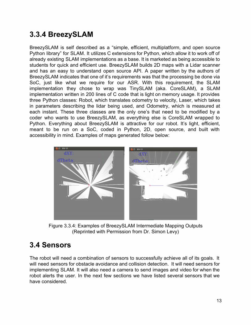
3.3.4 BreezySLAM BreezySLAM is self described as a “simple, efficient, multiplatform, and open source Python library” for SLAM. It utilizes C extensions for Python, which allow it to work off of already existing SLAM implementations as a base. It is marketed as being accessible to students for quick and efficient use. BreezySLAM builds 2D maps with a Lidar scanner and has an easy to understand open source API. A paper written by the authors of BreezySLAM indicates that one of it’s requirements was that the processing be done via SoC, just like what we require for our ASR. With this requirement, the SLAM implementation they chose to wrap was TinySLAM (aka. CoreSLAM), a SLAM implementation written in 200 lines of C code that is light on memory usage. It provides three Python classes: Robot, which translates odometry to velocity, Laser, which takes in parameters describing the lidar being used, and Odometry, which is measured at each instant. These three classes are the only one’s that need to be modified by a coder who wants to use BreezySLAM, as everything else is CoreSLAM wrapped to Python. Everything about BreezySLAM is attractive for our robot. It’s light, efficient, meant to be run on a SoC, coded in Python, 2D, open source, and built with accessibility in mind. Examples of maps generated follow below:
Figure 3.3.4: Examples of BreezySLAM Intermediate Mapping Outputs
(Reprinted with Permission from Dr. Simon Levy) 3.4 Sensors The robot will need a combination of sensors to successfully achieve all of its goals. It will need sensors for obstacle avoidance and collision detection. It will need sensors for implementing SLAM. It will also need a camera to send images and video for when the robot alerts the user. In the next few sections we have listed several sensors that we have considered.
13

3.4.1 Microsoft Kinect One of the sensors that is being considered for the vision portion of the project is the Microsoft Kinect. The Kinect was is a motion sensing device designed by Microsoft for their Xbox 360 game console. It allows controllerless control of games via gestures and spoken commands. According to Microsoft, the Kinect has four sensors, as seen below in Fig.3.4.1: a RGB camera, an infrared (IR) emitter and an IR depth sensor, a microphone array, and a 3axis accelerometer. The Kinect also has a tilt motor. The camera stores three channels of data in a 1280x960 resolution. The IR emitter emits a speckled pattern which the IR depth sensor can sense the reflected beams and convert that into depth information. The microphone is a multiarray microphone that contains four microphones. This array can be used to record audio while also finding the source and direction of the sound. The 3axis accelerometer can be used to determine the orientation of the Kinect. [5]
Fig.3.4.1: Microsoft Kinect
(Reprinted with Permission from Microsoft) The Kinect has several components that can be used for SLAM. If we were to use the Kinect, we would be using the camera and the IR emitter and IR depth sensors. If we have time, we might be able to use the microphone array to help determine the location of an intruder. A used Kinect and an adapter can be purchased for less than $50, making it very economical for all of the features it has. 3.4.2 LIDAR LIDAR is another technology that is being considered for the mapping and localization portion of our project. LIDAR is a sensing technology that uses a laser(s) to measure ranges. LIDAR stands for Light Detection and Ranging. A LIDAR scanner consists of a laser(s), a sensor(s) to detect the reflected laser beam(s) and one or more motors to
14

move the laser and scanner. A LIDAR system measures the timeofflight of light to determine distances to objects. LIDAR is used in 2D and 3D mapping. A 2D system will return a discrete line of points of data, while a 3D system will return a discrete point cloud of data. An example of a 3D point cloud can be seen below in Fig.3.4.2.
Fig. 3.4.2: Graphical example of a LIDAR point cloud
(Permission Pending)
LIDAR is where useful for SLAM and is used by many roboticists. It is very accurate. We would only be using it for 2D mapping. However, LIDAR systems can be very expensive, especially when compared to the Kinect. Systems can range from thousands of dollars to tens of thousands of dollars. 3.4.3 SONAR SONAR, Sound Navigation And Ranging, is being considered for obstacle avoidance. The SONAR sensors that would be considered are ultrasonic range finder. The sensors emit ultrasonic sound waves and measure the time of flight for the for a returning wave. Some sensors have a range from 2 centimeters to 3 meters. This would work well for obstacle avoidance and mapping small rooms, but not mapping large rooms. To get the best results, the sensor should be perpendicular to a surface or else false readings can occur as shown in Fig.3.4.3 below. To overcome this many robotics projects use multiple sonars and/or a ring of sonars around the robot. There are many ultrasonic distances sensors to choose from. Three have been listed below in Table 3.4.3, along with their specifications.
15

Fig. 3.4.3: Sonar Sensing (Permission Pending)
Sensor HCSR04 LVMaxSonarEZO PING))) Ultrasonic
Distance Sensor
Working Voltage (V) 5 2.55.5 5
Working Current (mA) 15 2 35
Minimum Range (cm) 2 15.2 2
Maximum Range (M) 4 6.45 3
Measuring Angle 15 degree varies 20 degrees
Price ($) 8.99/2 27.95 29.99
Table 3.4.3 Ultrasonic Rangefinders and Specifications The HCSR04 and PING)) Ultrasonic Distance Sensor can detect objects as close as 2 cm, while the LVMaxSonarEZ0 cannot. However, it can detect objects further than the other two. That would be useful for mapping, but these sensors are not being considered for mapping. The HCSR04 and PING have comparable specifications, but vary greatly in price. The lower cost, with similar specifications, makes the HCSR04 the more attractive of the two.
16

3.4.4 Tactile Another type of sensor that is being considered for obstacle avoidance are tactile sensors. Tactile, or bump, sensors are useful for detecting objects that the other sensors might miss. They are considered the last resort. Bump sensors are switches, they are activated when they are pressed by running, or bumping, into an object or wall. Since they will be part of the reactive control, as soon as they are activated, the robot will move away from the object. The VEX chassis kit that is being taken into consideration has some bump switches, seen in Fig. 3.4.41 (a), as well as limit switches, seen in Fig. 3.4.41 (b), that also can be used to detect bumping into something. SparkFun also has a limit switch, seen in Fig. 3.4.42, designed for their RedBot robot. The SparkFun limit switch act like whiskers, and have a longer range on the sides of the robot. If sonar is used for close range obstacle avoidance, the longer whiskers will not be needed. The VEX tactile sensors would make more sense to use. especially if we use the VEX chassis kit which comes with them.
Fig.3.4.41: (a) Vex Bumper Sensor and (b) Vex Limit Switch
(Reprinted with Permission from Vex)
Fig. 3.4.42: SparkFun RedBot with limit switches.
(Reprinted with Permission from Sparkfun)
17
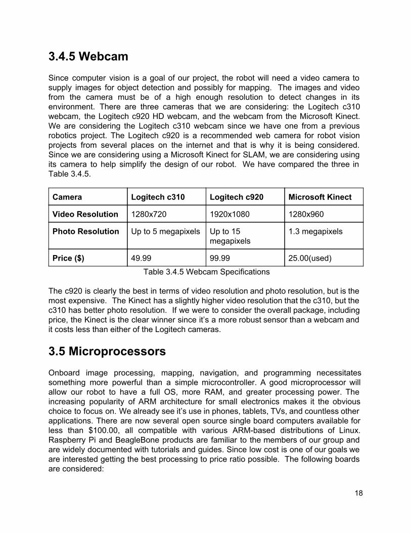
3.4.5 Webcam Since computer vision is a goal of our project, the robot will need a video camera to supply images for object detection and possibly for mapping. The images and video from the camera must be of a high enough resolution to detect changes in its environment. There are three cameras that we are considering: the Logitech c310 webcam, the Logitech c920 HD webcam, and the webcam from the Microsoft Kinect. We are considering the Logitech c310 webcam since we have one from a previous robotics project. The Logitech c920 is a recommended web camera for robot vision projects from several places on the internet and that is why it is being considered. Since we are considering using a Microsoft Kinect for SLAM, we are considering using its camera to help simplify the design of our robot. We have compared the three in Table 3.4.5. Camera Logitech c310 Logitech c920 Microsoft Kinect
Video Resolution 1280x720 1920x1080 1280x960
Photo Resolution Up to 5 megapixels Up to 15 megapixels
1.3 megapixels
Price ($) 49.99 99.99 25.00(used) Table 3.4.5 Webcam Specifications
The c920 is clearly the best in terms of video resolution and photo resolution, but is the most expensive. The Kinect has a slightly higher video resolution that the c310, but the c310 has better photo resolution. If we were to consider the overall package, including price, the Kinect is the clear winner since it’s a more robust sensor than a webcam and it costs less than either of the Logitech cameras. 3.5 Microprocessors Onboard image processing, mapping, navigation, and programming necessitates something more powerful than a simple microcontroller. A good microprocessor will allow our robot to have a full OS, more RAM, and greater processing power. The increasing popularity of ARM architecture for small electronics makes it the obvious choice to focus on. We already see it’s use in phones, tablets, TVs, and countless other applications. There are now several open source single board computers available for less than $100.00, all compatible with various ARMbased distributions of Linux. Raspberry Pi and BeagleBone products are familiar to the members of our group and are widely documented with tutorials and guides. Since low cost is one of our goals we are interested getting the best processing to price ratio possible. The following boards are considered:
18
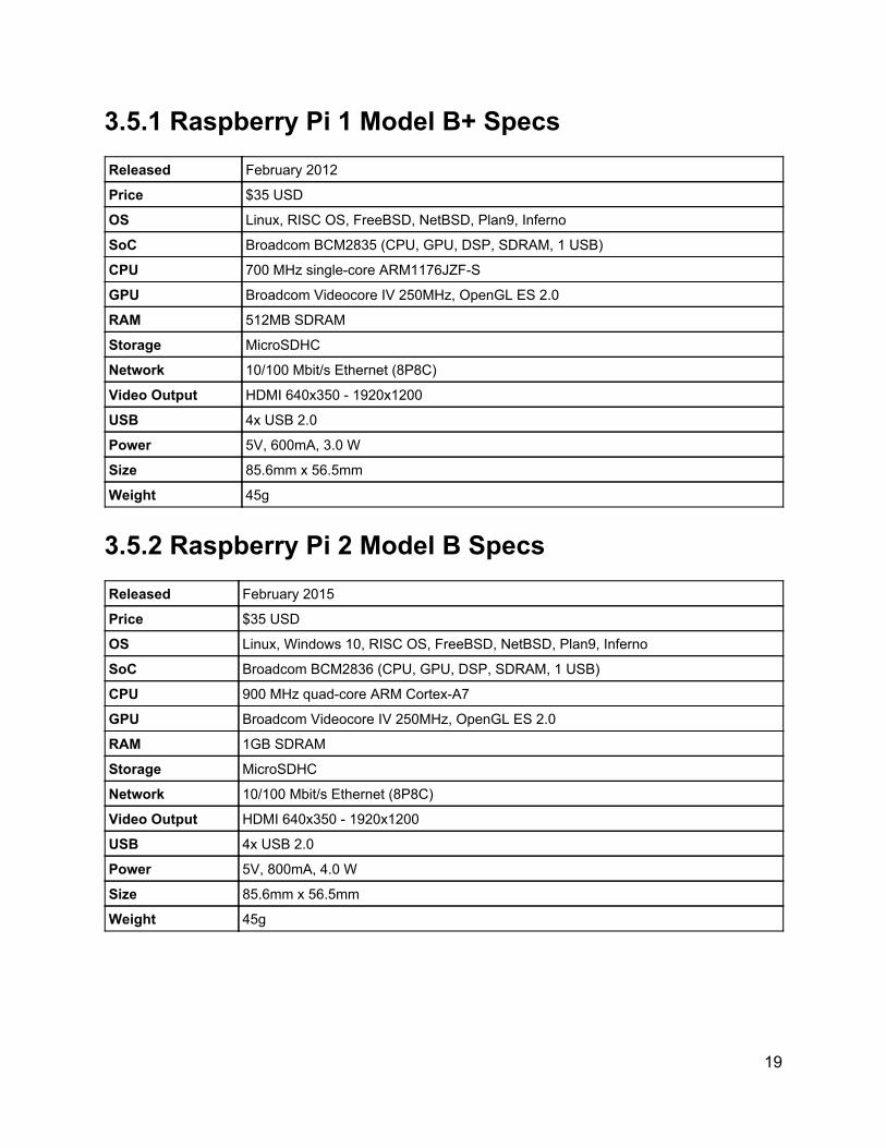
3.5.1 Raspberry Pi 1 Model B+ Specs Released February 2012
Price $35 USD
OS Linux, RISC OS, FreeBSD, NetBSD, Plan9, Inferno
SoC Broadcom BCM2835 (CPU, GPU, DSP, SDRAM, 1 USB)
CPU 700 MHz singlecore ARM1176JZFS
GPU Broadcom Videocore IV 250MHz, OpenGL ES 2.0
RAM 512MB SDRAM
Storage MicroSDHC
Network 10/100 Mbit/s Ethernet (8P8C)
Video Output HDMI 640x350 1920x1200
USB 4x USB 2.0
Power 5V, 600mA, 3.0 W
Size 85.6mm x 56.5mm
Weight 45g
3.5.2 Raspberry Pi 2 Model B Specs Released February 2015
Price $35 USD
OS Linux, Windows 10, RISC OS, FreeBSD, NetBSD, Plan9, Inferno
SoC Broadcom BCM2836 (CPU, GPU, DSP, SDRAM, 1 USB)
CPU 900 MHz quadcore ARM CortexA7
GPU Broadcom Videocore IV 250MHz, OpenGL ES 2.0
RAM 1GB SDRAM
Storage MicroSDHC
Network 10/100 Mbit/s Ethernet (8P8C)
Video Output HDMI 640x350 1920x1200
USB 4x USB 2.0
Power 5V, 800mA, 4.0 W
Size 85.6mm x 56.5mm
Weight 45g
19

3.5.3 BeagleBone Specs Released October 2011
OS Linux
SoC AM3358/9 (CPU, GPU, DSP)
CPU 720Mhz CortexA8 + 2xPRU(200Mhz)
GPU 200Mhz PowerVR SGX53
RAM 256MB DDR2
Storage MicroSD
Network MII Based “Fast Ethernet” 100Mbit/s
Video Output None, must be peripheral
USB 1x Standard, 1x Mini
Power 5V, 300500mA, 1.52.5W
3.5.4 BeagleBone Black Released April 2013
OS Linux
SoC AM3358/9 (CPU, GPU, DSP)
CPU 1000Mhz CortexA8 + 2xPRU(200Mhz)
GPU 200Mhz PowerVR SGX53
RAM 512MB DDR3
Storage MicroSD
Network MII Based “Fast Ethernet” 100Mbit/s
Video Output MicroHDMI
USB 1x Standard, 1x Mini
Power 5V, 210460mA, 1.052.3W
Size 86.4mm x 53.3mm
Weight 39.68g
20

3.5.5 Benchmarks After researching benchmarks for our boards of interest, some very clear results emerged. One enthusiast, David Hunt ran four sysbench tests on five boards, three of which we are interested in. He covers the Raspberry Pi 1 B+, Raspberry Pi2 B, BeagleBone Black, Intel Edison, and Imagination MIPS Creator C120. The first figure shows the specs for each of these microprocessors.
Figure 3.5.5a: Table of Specs for Various Microprocessors
(Reprinted with Permission from David Hunt)
The following benchmark tests were performed across all of the microprocessors in the above figure. A discussion of the results will follow.
Figure 3.5.5b: Sysbench CPU
Benchmark (Reprinted with Permission from David
Hunt)
Figure 3.5.5c: Sysbench Memory
Benchmark (Reprinted with Permission from David
Hunt)
21

3.5.5d: Sysbench Random Read
Benchmark (Reprinted with Permission from David
Hunt) 3.5.5e: Sysbench Random Write
Benchmark (Reprinted with Permission from David
Hunt) The results indicate that the Edison performs best, but only slightly better than the Raspberry Pi 2 overall. Our most important metric is CPU performance, and for these they are nearly identical. Reading and writing from memory are slightly less important to us, but we may be accessing memory often as we update our map and localize our bot within it, so it is important to consider. The BeagleBone Black’s performance in random memory read and write is quite poor, but we’re not sure how this differs from the normal memory test, where the BeagleBone Black performs on par with the Pi 2 and Edison. The clear winner for us is the Raspberry PI 2 B because it performs nearly as well as the Edison, which costs twice as much. The Pi 2 B far outperforms the Pi 1 B+ in every test, but costs the same amount. The BeagleBone Black performs less than half as well in all but the memory test, in comparison to the Pi 2 B, but costs more. What further makes the Pi 2 B attractive is the fact that it has twice as much RAM as the BeagleBone Black, and 4 cores. If we are able to optimize our SLAM algorithm for parallel processing we could potentially gain a performance boost.
22

3.6 Microcontrollers Our robot will be using a microcontroller to interface with the sensors, motors, and the microprocessor. One of its functions will be to use sensor data and react to obstacles by avoiding them. The other function is to send/receive sensor data to/from the microprocessor. It will use the data received from the microprocessor to move the motors. Due to the popularity of Arduino, and the are lots of resources and libraries to use. Arduino also has a simple programming environment. That is why we are considering the ATmega328P and ATmege2560. both with an Arduino bootloader. We have shown in the figures and tables below the pinouts for each chip, along with some specifications, compiled from each of the microcontrollers’ datasheets [4], that we used to consider for the design of our robot. 3.6.1 ATmega328P vs. ATmega2560 Appendix C: Fig.3.61: ATmega328 (with Arduino bootloader) Pinout Appendix C: Figure 3.62: ATmega2560 Pinout As seen in the table below, the ATMega328P has a faster clock frequency, but less Program Memory, less RAM, less I/O pins, and less USARTs/SPIs. They both have the same maximum operating voltage, 5.5 Volts. According to the Atmel datasheets for each microcontroller, they both have a maximum throughput of 1 million instructions per second per MHz. For our robot, the ATmega328P will be the microcontroller. It has more than enough I/0 pins than we need. It runs faster than the ATmega2560, and will not need the larger memory of the ATmega2560. Since we are counting on the microcontroller to control the robot’s reactive architecture, using a faster processor should help the robot react to sensor data more quickly. Microcontroller ATmega328 ATmega2560 Architecture (bits) 8 8
Frequency (MHz) 20 16
Max Operating Voltage (V) 5.5 5.5
Program Memory (KB) 32 256
RAM (KB) 2 8
USART/SPI 1/1 2/4
I2C 1 1
I/O Pins 23 86
Analog to Digital Convertors 8 ch, 10bit 16 channels, 10bit
Table 3.61 ATmega328P Specifications
23
3.7 Operating Systems Our choice of operating system is most directly affected by our choice of microprocessor. Since we opted for the Raspberry Pi 2, we have a wide variety of choices at our disposal. The Raspberry Pi 1 is a popular platform, and many ARM distributions of linux have been made to work with it, some even made specifically for it. The Raspberry Pi 2 is still very new, so not all of these distributions have been ported over to work with the new SoC in the Pi 2. There are however, still several linux options available. Even Microsoft has pledged to make a Pi 2 compatible version of Windows 10, however it is still in development. The linux distributions currently available are Raspian, OpenELEC, OSMC, Snappy Ubuntu Core, and Debian. OpenELEC and OSMC are for creating media centers, so we won’t be interested in them for this project. Raspbian, Debian, and Snappy Ubuntu Core are the only feasible options for the requirements of this project. Raspbian is our distribution of choice, and while not technically an operating system, ROS will also be explored as a robotics framework for our project, 3.7.1 Raspbian Due to the fact that we desire ease of programming, and maximum compatibility, we are interested primarily in Raspbian. Raspbian is a free, unofficial port of Debian Wheezy for ARM, optimized for use with Raspberry Pi 1 and 2 hardware. Both Raspbian and Debian are recognized for their stability by the Raspberry Pi and Linux community, and is recommended by the Raspberry Pi Foundation. After trying it out ourselves we found it to be very responsive and extremely easy to set up. It comes with around 35,000 packages by default, with most of the basic functionality one would expect from a normal Linux distribution. 3.7.2 ROS From the ROS website: “ROS is an open source, metaoperating system for your robot. It provides the services you would expect from an operating system, including hardware abstraction, lowlevel device control, implementation of commonlyused functionality, messagepassing between processes, and package management. It also provides tools and libraries for obtaining, building, writing, and running code across multiple computers. ROS is similar in some respects to 'robot frameworks'…”. ROS distributes processes across “nodes” which represent different functionality for a robot. The benefit of this is that we can simultaneously code, test, and implement different parts of our robot’s core functionality without worrying about collisions with other functions.
24

We will also be able to take advantage of ROS’s vast library of robotics functions for anything from mapping to locomotion. Because ROS is open source we can also work with the code directly and make modifications to suit our own needs. SLAM is a very difficult problem to solve, and probably out of our scope to code up from scratch. ROS has multiple implementations of SLAM using different sensors and algorithms, so having these at our disposal makes ROS a very attractive option. Additionally, ROS is compatible with Python, which is our desired programming language. 3.8 Memory Memory will be a necessary addition to the microprocessor we choose. While they all have RAM, most have no onboard memory for storing an OS or software that might be used, but they do have MicroSDHC slots. The external memory card of our robot is important because it constrains the size of our OS, libraries we may import, drivers for other hardware, stored navigation or mapping data, and any other software we may implement. In addition to that, the read and write speeds need to be sufficient so that accessing memory isn’t too costly. There are a plethora of affordable high quality SD cards available, and so we won’t worry too much about the individual sizes of OS installations or packages. Most ARM OS distributions recommend at least a 2GB SD card, so this will be at least our minimum. We will aim for more memory than we could hope to use, and instead focus on quality, cost, and transfer speed. Since read/write speed is important we will only be interested in speed class 10 (greater than or equal to 10 MB/s), or UHS MicroSDHCs. We will narrow our focus to two brands, Sandisk and Samsung, this choice is mostly arbitrary, but they are popular brands and known for their reliability. Brand and Model
MicroSDHC Card (Model No.)
Max Transfer Speed (MB/s)
Size (GBs) Cost (USD)
Samsung Evo MBMP32DA/AM 48 16, 32, 64 11, 17, 33
Samsung Pro MBMG32DA/AM 90 16, 32, 64 19, 28, 55
Sandisk Ultra SDSDQUAN032GG4A 48 8, 16, 32, 64
7, 12, 16, 33
Sandisk Extreme
SDSDQXN032GG46A 60 16, 32, 64 15, 23, 45
Figure 3.8a: Comparison of SDHC Cards The transfer speeds above represents the maximum capabilities of the card, however there are other factors which constrain and bottleneck our speed. The microprocessor itself will throttle this speed. Benchmarks on a variety of different microSDHC cards have already been performed on the Raspberry Pi and Pi 2. Since we are already
25

certain we’ll be using the Pi 2, and since the Pi 1 and 2 have a similar design, we’ll assume that these would be at least approximate for the Pi 2 as well. The following benchmarks are from crowdsourced data. We will only be interested in cards similar to or matching those listed above, and if available, tested on the Raspbian Linux distribution. MicroSDHC Card
Read (MB/s)
Write (MB/s)
Distro Kernel Notes
Samsung microSDHC 16GB Class 10 (MBMP16DA/AM)
17.33 13.1 Raspbian OS from NOOBS v1.4.0
Linux raspberrypi 3.18.7v7+ #755 SMP PREEMPT Thu Feb 12 17:20:48 GMT 2015 armv7l GNU/Linux
Tested on Pi 2 Model B by FastEddie 19 Mar 2015; More Details
Samsung PRO microSDHC 16GB Class 10 (MBMGAGB)
17.5 11.3 Debian Wheezy "Raspbian"
Linux raspberrypi 3.12.35+ #730 PREEMPT Fri Dec 19 18:31:24 GMT 2014 armv6l GNU/Linux
Model B+
SanDisk Ultra microSDHC 32GB class 10 "48MB/s" (SDSDQUAN032GC4A)
18.9 16.73 Debian Wheezy "Raspbian"
Linux raspberrypi 3.18.5+ #744 PREEMPT Fri Jan 30 18:19:07 GMT 2015 armv6l GNU/Linux
Raspberry Pi B, 20150212
SanDisk Extreme 16GB UHSI/U3 Micro SDHC Memory Card Up to 60MB/s Read with Adapter SDSDQXN016GG46A
19.8 24.7 OSMC Alpha 4
Linux osmc 3.18.5v7+ #225 SMP PREEMPT Fri Jan 30 18:53:55 GMT 2015 armv7l GNU/Linux
Raspberry Pi 2
Figure 3.8b: Crowdsourced Raspberry Pi Read/Write Speed Benchmarks with Different Memory Cards
26

Beyond what is listed here, across all cards tested, the read and write speeds seem to range from 2.5MB/s to 24.7MB/s. From this, we can assume that regardless of the card used, we will never achieve much better than 24.7MB/s. Immediately we can see that even though the stated transfer speed of all these cards is well beyond 20MB/s, we’re getting less than that in all but the SanDisk Extreme. SanDisk seems to have clear the edge as far as write speed goes, but is only slightly better in terms of read speed. In terms of cost at comparable maximum transfer speeds, all cards are nearly the same, but when we take into practical transfer speed, SanDisk has far better speed per cost. This data isn’t 100% reliable in that it is user reported, and all on separate models of the Pi 1 and 2. The SanDisk Extreme test was also also not run on Raspbian Linux. These numbers are more to give an approximation, or get a general idea of how the different cards might perform in practice. We will end up going with one of SanDisk cards listed, probably between 16 or 32 GBs so that we can have a comfortable buffer for extra data. 3.9 Wireless Connectivity While our robot may be autonomous in its primary use case, we are also interested in wireless connectivity for the sake of the user assuming manual control, as well as observing various outputs from the robot. There are also practical reasons, such as remote programming during development. To establish wireless connectivity is as simple as buying a wireless USB adapter, also known as a NIC (network interface card), however there are important considerations, such as data rate, frequency band, range, cost, security, and compatibility. The below table has three options. We will compare the merits of each and consider which device best fits our needs. Operating system and architecture compatibility is not considered because all three options are known to be compatible with Linux, specifically Raspbian on the Raspberry Pi. NIC Max Data Rate Frequency Security Cost
PAUO5 300Mbps 802.11n 2.4GHz 64b/128bit WEP, WPA and WPA2 (TKIP+AES)
$16
PAUO6 300Mbps 802.11n + 5dBi antenna
2.4Ghz 64b/128bit WEP, WPA and WPA2 (TKIP+AES)
$20
EW7811Un 150Mbps 802.11n 2.4Ghz 64/128bit WEP Encryption and WPAPSK, WPA2PSK security; WPS
$10
Figure 3.9: Comparison of NICs
27
Everything is fairly standardized across these NICs, differing only in cost and data rate. The cost difference is so small, it needn’t factor heavily into our decision. All are 802.11n compliant, which means they are backward compatible with older routers. No specific range could be found, but the additional antenna of the PAUO6 is a nice bonus. Since our focus is on a single room, wireless range shouldn’t be that big of an issue, assuming the router is local to the room. If we factor in the situation that the router is located a great distance away, it would be wise to choose a NIC with an antenna, or buy one separately. 3.10 Movement The style of movement for the Autonomous Sentry Robot is extremely important. The robot must be able to maneuver around several obstacles in a room that could be in different positions each time they are passed. Paths could be narrower or the robot could encounter obstacles that weren’t there before. The robot will need to be able to move around the room efficiently in order to function properly as a sentry vehicle. Our team has researched many different types of drive systems. They include:
Tank Drive Car Steering Holonomic Drive Systems
3.10.1 Tank Drive Tank drive is a very simple drivetrain. From the name it is clear that the system is modeled off of tanks. Tank drive is where the left side of the robot, whether it be individual wheels or wheels attached together by tank tread, moves in the same direction. The same goes for the right side. The robot responds as if there is one moving part on either side to propel it. This drive system has many pros to it. This drive system is very easy to program for simple movement. As there are essentially only two moving parts, the left and right side, motion is controlled by changing the speed and direction of motion for each side. For this system to move forward and backwards, both sides move in the same direction. When the robot wants to turn ninety degrees left or right, the left side moves one way and the right side moves a different way. If the robot needs to either side then the speed can be reduced on one side of the robot to force the robot to slowly turn in that direction.
28

Although this method is easy to manipulate it doesn’t have the best maneuverability. If the robot encounters an unexpected obstacle immediately in front of it, the robot would need to turn ninety degrees left or right to move around it or back up and then turn wasting time and power. In general this method would be hard to make autonomous as homes have narrow hallways and the margin for error when turning is very small. This method works better when under user control as it is intuitive and easy to learn. Figure 3.10.11 below illustrates how a tank drive system works. Note that the image is for a two wheel differential drive system. The concept is the same for a multi wheel system as the left side and right side each move as one.
Figure 3.10.11: Differential Drive Example (Reprinted with Permission from Robotoid)
3.10.2 Car Steering Car steering is exactly as it sounds. For most cars, the front two wheels turn and point in the direction the car is trying to go. If the robot needs to turn right, the wheels point diagonally right. If the robot needs to turn left, the wheels point to the left. This drive system is great because it is simple and once again intuitive for when the ASRis under user control. This type of drive system is more suited for turning corners smoothly than a traditional tank drive. If obstacles are never encountered at close range this drive system is incredibly maneuverable. However, it faces a similar drawback if an obstacle is encountered directly in front of the vehicle.
29

The robot will need to back up, and turn to get around the object as it doesn’t have the ability to strafe. There are two ways to create a car steering robot. The first is to have a steering motor attached to each of the front steering wheels. The motors will be attached in a way that causes the wheels to turn. The second way is using a rack and pinion system that physically connects the wheels. A single steering motor would be used to control the rack and pinion and turn the wheels together. This way is much easier to program. An example of the rack and pinion method is shown below. Note that the two methods function identically.
Figure 3.10.21: Car Steering
(Reprinted with Permission from Ikalogic) 3.10.3 Holonomic Drive Systems A holonomic drive system is a drive system that can move in any direction at any time. These drivetrains are generally more complicated but their maneuverability is unmatched. With this drive system, strafing becomes available. This means if an object is detected immediately in front of the robot, it can safely slide to the left or the right and continue on its way. There are a few drawbacks to this type of system. The first drawback is that it is complex to create. The system generally requires careful placement and fine tuning to run as expected. The drive system is also heavier due to the more complex components. The final drawback is it is more difficult to program and control. Being able to move in any direction is great but for the robot to be perfectly efficient its decision making must be very strong. There are two different types of holonomic drive systems our team has considered for the Autonomous Sentry Robot. The first is a swerve drive. A swerve drive works by turning all wheels in the direction that the robot wants to go. This works using steering motors for each of the drive wheels. When the robot needs to move in a different direction the wheels are adjusted accordingly. The drive system is modular and an example of this is in figure 3.10.31 below.
30

Figure 3.10.31: Swerve Module
(Reprinted with Permission from AndyMark) For this drive system, each wheel would need to use this module in order for the robot to run properly. This type of system allows for more traction than the others as it uses normal tread wheels to maneuver. However it is generally the most complicated and heaviest of the holonomic drives. As each wheel can spin completely around this drive system requires incredible programming and feedback to ensure no wheels are misaligned. However, if it was fully functional the ASR would be able to surveil and map a home with great speed. The next type of holonomic drives are based on fixed wheel designs. The wheels themselves are special and that is what allows for the holonomic motion. With these fixed wheel designs, varying which motors are active is how the robot moves. In general, the wheels of the robot fight each other in order to move forwards. The specifics of the wheels themselves will be discussed in the next section. Figure 3.10.32 below gives a general idea how a mecanum drive is implemented. Notice how the robot can maneuver in several different directions based on which wheels are active.
31

Figure 3.10.32: Mecanum Drive
(Reprinted with Permission from VEX Robotics) Figure 3.10.33 below is a holonomic drive system that uses omni wheels. This is only one variation as it is possible to use these wheels in many different ways.
Figure 3.10.33: Omni Wheel Drive
(Reprinted with Permission from VEX Robotics)
32

3.10.4 “H” Drive The “H” drive drivetrain is designed to allow for normal tank drive steering as well as the added bonus of being able to strafe. This is accomplished by using four omni wheels in place of traction wheels in a tank style setup. Then, a fifth omni wheel is placed in the center creating the “H” drive. This wheel is also powered and its sole purpose it to allow the robot to strafe left and right. This drive system has increased mobility compared to the tank drive without the complexity of a fully holonomic system. The layout of the “H” drive is shown in Figure 3.10.310.
Figure 3.10.34: “H” Drive System
(Reprinted with Permission from VEX Robotics) 3.11 Wheels The wheels chosen for a robot are just as important as the drive systems they are implemented in. In this section we will discuss the pros and cons of several wheel types.
33

3.11.1 Traction Wheels Traction wheels are your standard wheel for everyday use. They are on cars, trucks, machines, and many other things. Unless used in a swerve drive system, these wheels are not designed to be holonomic. Their purpose in robotics is to reduce slippage. When slippage occurs, the torque from the robot’s motors is essentially wasted and the robot becomes less efficient. These wheels are designed to ensure the robot continues to move in the intended direction even at high speeds and in adverse conditions. An example of a traction wheel in consideration for use on the ASR is shown in Figure 3.11.11 below.
Figure 3.11.11: Traction Wheel
(Reprinted with Permission from VEX Robotics) 3.11.2 Tank Treads Tank treads were designed for a similar purpose as the traction wheels. However they perform much better in adverse conditions. They are designed to get as much of the torque from the motors to the ground as possible. The tread’s themselves are used to put as much surface area on the ground as possible to facilitate this. The more contact there is with the ground the more traction the robot has. An example of tank tread can be seen in the photo below. 3.11.3 Mecanum Wheels Mecanum wheels are designed to allow omnidirectional movement. This is done by placing smaller wheels or rollers around the outside of a wheel at fortyfive degree angles. These wheels work in a four wheel tank drive system. The wheels are designed to carry a large amount of weight even though they have high mobility. This is helpful in robotics as weight capacity is very important. For the ASR weight capacity is not as important but mobility certainly is. Moving through a room requires a good range of motion that mecanum wheel can provide. Figure 3.11.31 below shows mecanum wheels designed by VEX robotics.
34

Figure 3.11.31: VEX Mecanum Wheel
(Reprinted with Permission from VEX Robotics) 3.11.4 Omni Wheels Omni wheels are designed to provide increased mobility much like mecanum wheels. However, these wheels use rollers/smaller wheels at ninety degree angles, instead of fortyfive, around the outside of the main wheel hub. This allows them to move forward as normal traction wheels do. These wheels have less friction when turning which allows for greater mobility. They can also be configured to allow the robot to move side to side by placing one or two omni wheels perpendicular to the main drive wheels. The perpendicular wheels would also have drive motors to allow the robot to move left and right. The wheels can also be configured to move in any direction as shown above in section 3.11.3 on holonomic drive systems. The system with the perpendicular wheels would work very well for the ASRas it would be less complicated to program. The robot would also be able to strafe which is incredibly helpful when navigating obstacles. Figure 3.11.41 below illustrates an omni wheel that could be used on the ASR.
Figure 3.11.41: VEX Omni Wheel
(Reprinted with Permission from VEX Robotics)
35
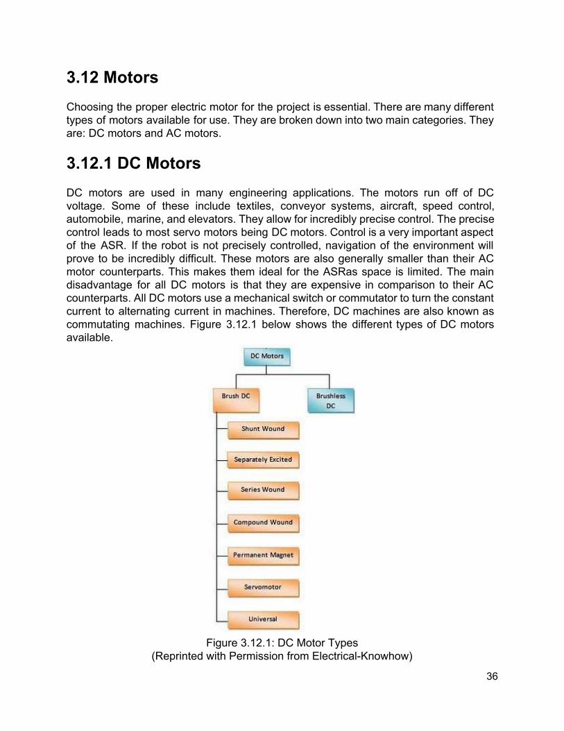
3.12 Motors Choosing the proper electric motor for the project is essential. There are many different types of motors available for use. They are broken down into two main categories. They are: DC motors and AC motors. 3.12.1 DC Motors DC motors are used in many engineering applications. The motors run off of DC voltage. Some of these include textiles, conveyor systems, aircraft, speed control, automobile, marine, and elevators. They allow for incredibly precise control. The precise control leads to most servo motors being DC motors. Control is a very important aspect of the ASR. If the robot is not precisely controlled, navigation of the environment will prove to be incredibly difficult. These motors are also generally smaller than their AC motor counterparts. This makes them ideal for the ASRas space is limited. The main disadvantage for all DC motors is that they are expensive in comparison to their AC counterparts. All DC motors use a mechanical switch or commutator to turn the constant current to alternating current in machines. Therefore, DC machines are also known as commutating machines. Figure 3.12.1 below shows the different types of DC motors available.
Figure 3.12.1: DC Motor Types
(Reprinted with Permission from ElectricalKnowhow)
36
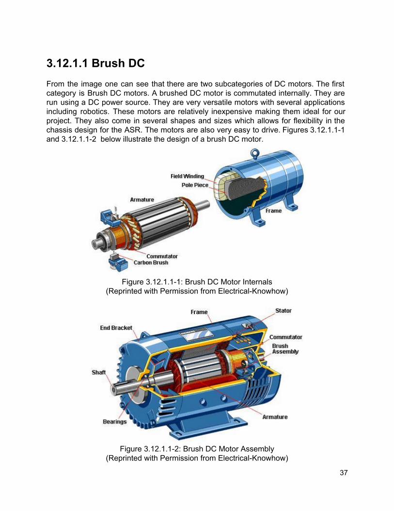
3.12.1.1 Brush DC From the image one can see that there are two subcategories of DC motors. The first category is Brush DC motors. A brushed DC motor is commutated internally. They are run using a DC power source. They are very versatile motors with several applications including robotics. These motors are relatively inexpensive making them ideal for our project. They also come in several shapes and sizes which allows for flexibility in the chassis design for the ASR. The motors are also very easy to drive. Figures 3.12.1.11 and 3.12.1.12 below illustrate the design of a brush DC motor.
Figure 3.12.1.11: Brush DC Motor Internals
(Reprinted with Permission from ElectricalKnowhow)
Figure 3.12.1.12: Brush DC Motor Assembly
(Reprinted with Permission from ElectricalKnowhow)
37

Brush DC motors do not require controllers to switch the current. Instead, the commutator mechanically switches the current. Carbon brushes move against the commutator to create a dynamic magnetic field[13]. The motion is important as it creates wear on the brushes and the commutator itself. Figure 3.12.1.13 below illustrates the operation of the commutator.
Figure 3.12.1.13: Commutator Operation
(Reprinted with Permission from ElectricalKnowhow)
Brush DC motors do have some disadvantages. The brushes are needed to connect to the rotor winding. This can lead to brush wear which decreases the use of the robot. This effect is intensified when the motor is in low pressure environments. This means that the ASR would be less effective as altitude increases. The sparks created by DC motors can also be dangerous. If explosive materials are in the area the sparks can ignite causing a possible explosion [13]. This is a factor as many homes use natural gas for cooking, heating, and other applications. A leak could cause major issues if the ASRis roaming the house. The brushes also create RF noise. The noise can interfere with televisions and other electronic devices. For our purpose the RF noise should have no effect as the ASR is meant to patrol the house at night or when no one is home to be watching TV. There are many types of brush DC motors available. We researched a few of the options to find out what the best possible option was for the ASR. The first is the permanent magnet. These motors have some advantages of the other types. The motors can be smaller because they do not need field windings. As previously stated, smaller motors allow for lighter weight and take up less space. They are also used in low power applications [13]. This means that they do not take as much power to run so the ASR can run longer. There are some disadvantages to these motors though. Excessive heat can demagnetize the permanent magnets. This would cause the motor and the ASR to fail. Excessive heat can be an issue with robotics. If the robot were to
38
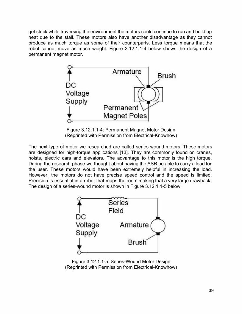
get stuck while traversing the environment the motors could continue to run and build up heat due to the stall. These motors also have another disadvantage as they cannot produce as much torque as some of their counterparts. Less torque means that the robot cannot move as much weight. Figure 3.12.1.14 below shows the design of a permanent magnet motor.
Figure 3.12.1.14: Permanent Magnet Motor Design (Reprinted with Permission from ElectricalKnowhow)
The next type of motor we researched are called serieswound motors. These motors are designed for hightorque applications [13]. They are commonly found on cranes, hoists, electric cars and elevators. The advantage to this motor is the high torque. During the research phase we thought about having the ASR be able to carry a load for the user. These motors would have been extremely helpful in increasing the load. However, the motors do not have precise speed control and the speed is limited. Precision is essential in a robot that maps the room making that a very large drawback. The design of a serieswound motor is shown in Figure 3.12.1.15 below.
Figure 3.12.1.15: SeriesWound Motor Design
(Reprinted with Permission from ElectricalKnowhow)
39

The final type of brushed DC motor we researched are servo motors. Servo motors are a special type of motor that consist of a DC motor, internal position sensor, and a gear system. Servo motors are very good for several reasons. The motors have superior position control when compared to most other motors. Position control is very important for the ASR. Navigation through space can be very difficult. If the motors do not move precisely, the robot could become stuck or crash into an object. Moving into the charging station would also become difficult as the robot must align itself accurately in order to enter the charger. Servo motors are designed to consistently move to the position the user tells them to go to making environment traversal much easier. Servo motors also have good speed control. They can move very quickly or very slowly. For the ASR this means that the robot can patrol at one speed and dock at another. When under user control the robot can go as fast or slow as the user would like. Finally, servo motors are able to move large loads. They can be configured to have high torque. With a high torque servo motor, the ASR would be able to carry more weight. This would be useful if more sensors or functionality were to be added in future models. Figure 3.12.1.16 below illustrates the inner workings of a standard servo motor.
Figure 3.12.1.16: Servo Motor Design
(Reprinted with Permission from ElectricalKnowhow) 3.12.1.2 Brushless DC Brushless DC motors have several advantages over their brushed counterparts. These include:
Higher Efficiency Longer Operating Life Noiseless Operation Higher Speed Capabilities Higher Dynamic Response Better Torque to Weight Ratio
40

These characteristics make brushless DC motors ideal for use on the ASR [13]. Efficiency is key as the battery only has so much capacity. Poor efficiency can drain battery power unnecessarily. The ASR is designed to patrol over a long period of time which makes efficiency important. The motors will also last longer as they do not have brushes. The noiseless operation is a nice bonus as well. The objective of the ASRis to patrol an area and alert the owner to any changes or if anyone is in the area that shouldn’t be. If the ASR can silently traverse its environment, then it can alert the owner to any suspicious activity without alerting the person in the room. The torque to weight ratio is also a great feature. The motors can move loads that are very heavy even though the motors remain smaller than the brushed DC motors. Figure 3.12.1.21 below shows the internal components of brushless DC motors.
Figure 3.12.1.21: Brushless DC Motor Design
(Reprinted with Permission from ElectricalKnowhow) Typical applications for these motors include[13]:
Constant Load Varying Load Positioning Applications
The ASR falls in line with these positioning applications. The dynamic speed response being very important in controlling the robot. Figure 3.12.1.22 below shows summarizes the differences between brushed and brushless DC motors.
41
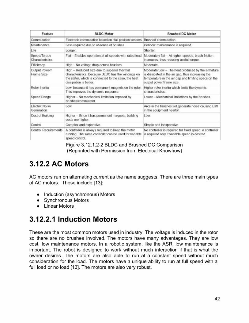
Figure 3.12.1.22 BLDC and Brushed DC Comparison (Reprinted with Permission from ElectricalKnowhow)
3.12.2 AC Motors AC motors run on alternating current as the name suggests. There are three main types of AC motors. These include [13]:
Induction (asynchronous) Motors Synchronous Motors Linear Motors
3.12.2.1 Induction Motors These are the most common motors used in industry. The voltage is induced in the rotor so there are no brushes involved. The motors have many advantages. They are low cost, low maintenance motors. In a robotic system, like the ASR, low maintenance is important. The robot is designed to work without much interaction if that is what the owner desires. The motors are also able to run at a constant speed without much consideration for the load. The motors have a unique ability to run at full speed with a full load or no load [13]. The motors are also very robust.
42

The ASR will have sensors to avoid obstacles but collisions will most likely still occur. Robustness is an important quality in motor selection. The motors also create no sparks as they have no brushes. This means they can be used safely in a hazardous environment. Figure 3.12.2.11 below shows the many different types of induction motors available today.
Figure 3.12.2.11: AC Motor Types
(Reprinted with Permission from ElectricalKnowhow) Induction motors have major drawbacks. It is very difficult to have variable speed control. They require a complicated variable frequency powerelectronic drive to have optimal speed control. They also have power lag issues. These issues would be detrimental to the ASR. Variable and precise speed control is necessary when traversing the environment.
43

3.12.2.2 Synchronous Motors In synchronous motors, the rotor tries to line up with the magnetic field in the stator. The motor runs at a constant speed caused by the frequency of the system. These motors require a direct current for excitation.There are many advantages to synchronous motors. Synchronous motors are designed to improve the power factor of a system. This helps to stabilize the systems voltage[13]. The motors run at the same speed no matter what load is applied. The ASR would be able to carry any load and continue to operate full if these motors were in use. Many of the synchronous motors are “DC excited” Figure 3.12.2.21 below shows the operation of the DC excited synchronous motor.
Figure 3.12.2.21: DC Excited Motor
(Reprinted with Permission from ElectricalKnowhow) These motors are more complicated as they require a DC excitation to operate and will not function without it. Another type of synchronous motor is the stepper motor. This type of motor is very common. It is designed to rotate by a specific number of degrees per electrical impulse. Stepper motors are often compared to servo motors as they are used in precise control applications. Advantages of a stepper motor include[13]:
Inexpensive No feedback is required Great holding torque Brushless Durable Precise precision control Do not need tuning
44
The motors would be great for the ASR they are inexpensive and have great precision. Traversing the environment and docking to charge would be made easy by these motors. The motors are brushless and durable meaning they are low maintenance. This lines up with the project goal of having the robot operate without much, if any, interaction from the owner. The motors are also ready to go out of the box meaning they don’t have to be tuned first. This would be useful when constructing the ASR and for ease of programming. However, the motors are not without disadvantages. These include[13]:
Noise level Poor torque at high speeds Can stall without a control loop Limited size availability Consumption of current without load Poor performance at low speeds
The noise level is bad because the point of the ASRis to patrol an area. If someone has broken into your house the ASR would never get close as the intruder would hear it coming. Losing torque with higher speed is also an issue. The ASR will not weigh a lot but it may not be able to run at a high speed at its weight. The issue with low speed operation is also problematic. When docking the robot will need to move fairly slowly in order to successfully dock. The robot needs to complete the docking process in a smooth motion. 3.12.2.3 Linear Motors During the research phase on motors our team came across linear motors. Linear motors are what propel magnetic levitation trains [13]. They are essentially rotary motors that have been cut in half and rolled out. They are sometimes used for creating large rotary motion. In our case these motors would be nearly unusable as the ASR is designed to find its own path around the environment and not run on a track. 3.13 Control and Navigation Our robot will have two modes of control. First and foremost, it’s primary mode of control will be autonomous. The main usage of our bot is intended to be as a sentry which will alert the user when exposed to various stimuli. This requires that the bot roam and navigate on it’s own accord, without any intervention from the user. There are, however, certain situations where the user’s intervention may be necessary. Because of this, we wish to include the ability for the user to assume control and receive a streamed view from the robot’s camera.
45

3.13.1 Autonomous Control As stated above, the purpose of our bot is to be used as a mobile security system. For it to be fully autonomous, we require it to have a phase of operation for mapping out the room, then using that map to plan a path for the patrol phase. In the mapping phase, a reactive exteroceptive sensor environment combined with a simple navigation algorithm will be implemented. A state machine with sonar, bump, and if possible Kinect depth sensor data as inputs will be relied upon for obstacle avoidance (note that this Kinect data is already being used elsewhere to generate the map). At this stage the map can’t be relied upon for obstacle avoidance because it will be incomplete. Instead, we will rely on this sublayer of sensors to split up the computation. In the event that the bot falls into an infinite cycle, getting stuck navigating the same segment of the room over and over, the map may be referenced to determine a new orientation. With this approach, we should be able to simultaneously navigate, localize, and map autonomously.
Figure 3.13.1: Reactive Behavior Model (Reprinted with Permission from Dr. Gita)
The patrol phase differs from the mapping phase in that there is already a fully developed map. The robot no longer needs to wander blind, but will still rely upon its sensors to avoid obstacles as it traverses the map. There are many different ways this map could be used and that navigation could be performed. Our goal for this project is to build a patrolling sentry, so ideally the robot should travel on a closed loop and report any important events on the way. There are two possibilities for how this can be handled. The first case is handled automatically by the robot. A flood fill algorithm can be implemented to create a navigation mesh for the map, where a certain amount of space in the coordinate system will represent a node which can be traversed by the robot. After the flood fill, all traversable space will be known. A pathfinding algorithm can then be used to find the best possible loop through the environment from node to node, either in terms of shortest/longest distance, or most observed area. Simultaneously, object avoidance and security algorithms will run and detect events such as motion.
46

The second case gives the user more control. After the map is generated, the user should be able to view it in the paired application. Rather than having the robot spend time on expensive computation, the user could simply plot navigation nodes through the areas that they desire from the application UI. They could specify a start and stop node, and indicate the direction of travel or sequence of nodes they wish to be traveled. In this way, the robot can simply seek directly toward nodes while falling back on it’s sensors for obstacle avoidance. This approach is overall much simpler and would probably be more appealing from a user standpoint, it also lowers the chance of the robot finding a bad path or getting stuck in an infinite cycle.. 3.13.1.1 SONAR Sonar sensors emit sound, and wait some span of time for return echoes. This time can be used to calculate distance to the objects which reflected the sound. The math to calculate this distance is simple. s: speed of sound in air, ~343 meters per second t: amount of time it took to send sound and receive echoes, seconds d: approximate distance of object from sensor, meters Distance Equation: s * (t / 2) = d
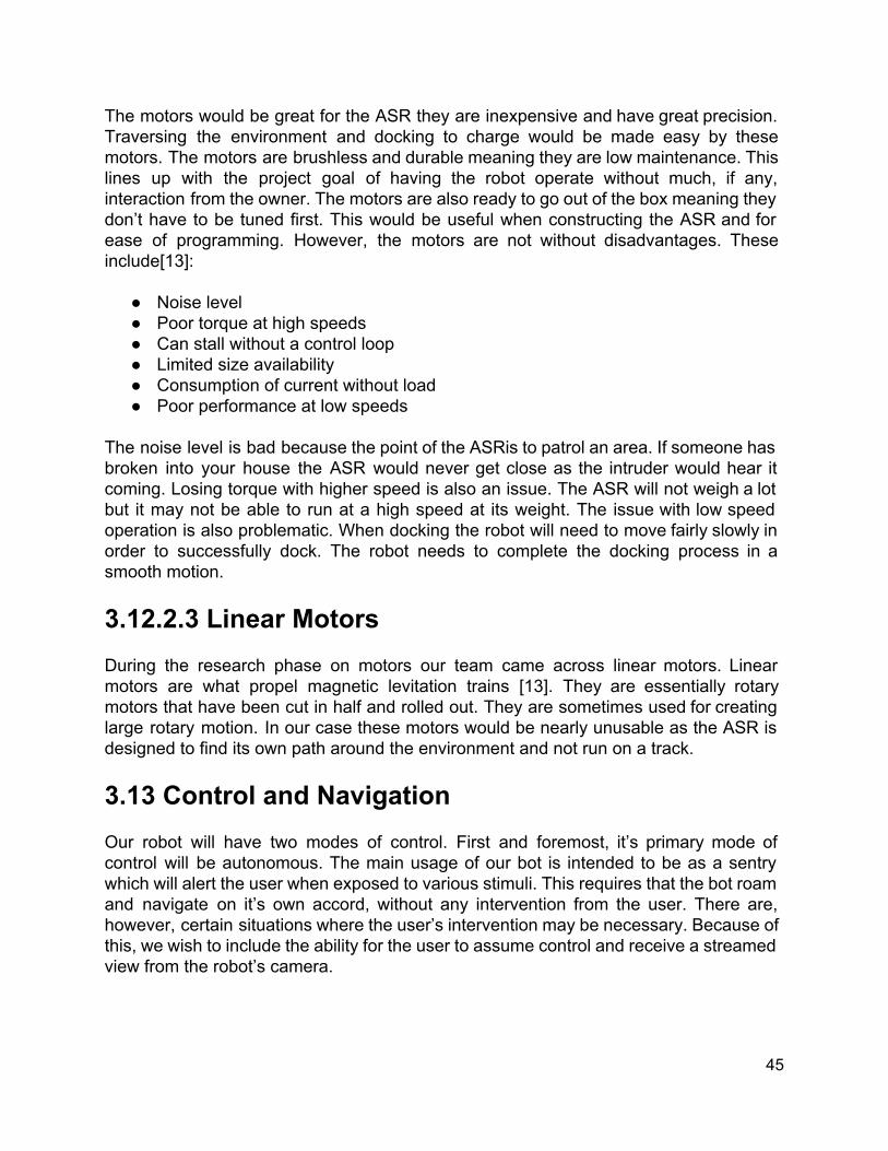
Figure 3.13.1.1: Example of How Sound Waves Bounce Back to the Sonar Sensor (Permission Pending)
Sonar is not the most reliable due to ghost echoes, and different materials’ ability to absorb sound waves. Should we be able to get our depth data from the kinect at the same time it is being used to generate the map, we will most likely drop sonar altogether. 3.13.1.2 Tactile Sensor Bump sensors are basically simple switch circuits. A mechanical button fixed to a “feeler” shorts the circuit when the feeler comes into contact with another object. They essentially have an on or off state; on means we’ve hit something, off mean’s we haven’t. We can use an array of them fixed to different sides of the robot to detect
47
collisions from all angles. Bump sensors will be our our last line of defense in the case that our bot has taken a bad path, and our sonar/kinect distance estimation has failed. In the event that we run straight into a wall, we want the robot to react, stop, and reorient itself, otherwise it would just continuously drive into the wall.
Figure 3.13.1.2: Example of Tactile Sensor Circuit
(Permission Pending) 3.13.1.3 Finite State Machine An abstract mathematical model for designing sequential logical via a finite set of states, where certain conditions force the transition of one state to the next. In our case, conditions would be things like specific, or ranges of sensor values, and our states would be what directions to move in, or what phase of operation the robot is in such as mapping or patrolling. 3.13.1.4 Flood Fill Algorithm The flood fill algorithm determines what areas are connected in a multidimensional array by traversing all possible connected locations. It can be implemented in various ways and tailored to suit the needs of its application. In generic terms, it has only three parameters. A starting node, a color to be searched for, and a color to replace searched nodes with. The basic algorithm is as follows: Flood Fill
1. If target color = replacement color, return 2. If color of node is not equal to target color, return 3. Set the color of node to replacement color 4. Perform Flood Fill recursively, one step in each direction (N, NE, E, SE, S, SW, W, NW) 5. Return
This algorithm is recursive and will overflow the stack given a large map, so this must be taken into account during implementation.
48

3.13.1.5 Dijkstra’s Algorithm Dijkstra’s Algorithm is a search algorithm used for finding the shortest path in a graph. Dijkstra utilizes nodes and weights between vertices to make this calculation, and its worse case performance is bounded by O(Edges + Vertices * log(Vertices). In our case, the nodes of the graph would be a connected navigation mesh projected onto our map, and the edges would the relative distance between points. The algorithm is as follows: Dijkstra:
1. Select a starting node, set tentative distance to all other nodes to infinite and the distance of this node to zero. Mark the starting node as visited and add all other nodes to the unvisited set.
2. Calculate tentative distance to this nodes neighbors, compare the current distance to each neighbor to its assigned distance and set the distance to the assigned distance to the smaller value.
3. After all neighbors are considered, mark this node as visited and remove it from the unvisited set so that it is never checked again.
4. If all nodes have been marked visited, algorithm complete 5. Otherwise select the node from the unvisited set with the current smallest distance and start again
from step 2. 3.13.2 User Control User control will be an entirely different system from autonomous control. There is no need for sensors. Instead, the user will be able to remotely control the locomotion of the robot while viewing a video feed from the robot’s camera. We’d like to allow this to occur during both mapping phase, and the patrol phase so that the user can map the room themselves if desired. The camera will either be the Kinect’s built in camera, or a separate camera, depending on the unexpected limitations of our approach. The user will have access to basic directional controls: forward, backward, strafe right, strafe left, turn right, turn left. We also expect the user to have the ability to send the robot to it’s docking station for recharging, and to turn the robot on and off. The implementation of this could come in multiple forms: 3.13.2.1 Remote Access Our robot will most likely be utilizing a Raspberry Pi 2, which can easily be set up as a server that can be SSH’d into, or be remotely accessed and have it’s graphical desktop viewed and interacted with from a different computer. We can develop a simple program that the user can run, and be granted access to the features outlined above. We would also include controls for switching between robot states, so that the user can put the robot back into autonomous mapping/patrol mode. We would also like the user to be able to see the map as it’s being generated, and the robot’s location within that map. Should the user remote into the system, we don’t expect it to interrupt any running processes on the robot. Rather, the user will be able to access the system during any state, and provide directives, or just check on the robot’s status, should they desire. This approach would
49

allow for robust control and operation of the robot, which would be beneficial for power users and technicallyinclined, computer literate people. It would also be easier on us from a coding and implementation standpoint. However, this approach would be nearly impossible for the average person, who is not familiar with remote access, Linux, and is unfamiliar with the system and it’s innerworkings. 3.13.2.2 Internet Application or Mobile Application An alternative for the less technically inclined would be a simple mobile application, or webbased application. With this approach, more tasks would be automated and streamlined. The user would open the app, and immediately get a camera feed of whatever the robot is viewing. This access would be preconfigured so the user does not need to worry about SSH or remote access. We would try and keep the number of options as minimal as possible. We would have a button for initiating the mapping phase, initiating the patrol phase, assuming control of the robot and driving it around manually, pausing, powering down, powering on, and charging. Should the user pick any of these options, what is displayed on screen would change. For example, if the user takes control, all other options would be cleared off the screen and and UI for maneuvering the robot would appear.
Figure 3.13.2.2a: Market Share for Browsers 3/15/2015
(Permission Pending) The above chart displays the market share of popular browsers as of March 15, 2015. With this knowledge, if we decide to go with the web based implementation, we know that we should target at least Internet Explorer for compatibility. This would enable over 50% percent of internet users the ability to use our application. If we target Chrome as well, we could capture over 75% of users.
50

Figure 3.13.2.2b: Market Share for Mobile Operating Systems
(Permission Pending)
The above chart is the market share of each popular mobile operating system as of March 2015. If we go the route of a mobile application, we know we should target at least Android to capture the majority of mobile users. If we implement the app for iOS users as well, we can capture almost 90% of mobile users.
Figure 3.13.2.2c: Market Share of
Android Versions (Permission Granted via Creative
Commons Attribution) The right chart shows the market share of each iOS version as of March 2015. If we target iOS 8, we know we can capture at least 78% of the iOS version market share. While it would be nice to deal with only one version of an OS, iOS is expensive to develop for and none of us own Mac hardware to develop on, so for now this will not be an option for us.
The left chart shows the market share of each version of Android as of April 2015. If we target Android 4.4 5.1, we know we can capture at least 45% Android’s version market share. Android doesn’t require an special permissions, hardware, or money to develop for, so it is also a more desirable option overall.
Figure 3.13.2.2d: Market Share of iOS
Versions (Permission Pending)
51

3.14 Batteries Power is an essential component of the Autonomous Sentry Robot. As the vehicle is meant to move throughout a large area, a power source must be included as there is no practical way to receive power on the go. We have chosen to use a battery for this purpose. There are many things that are important when selecting a power source. These include:
Capacity Recharging Ability Memory Effect Nominal Voltage Current
Capacity: The capacity of a battery is an incredibly important part of selecting a battery. Battery capacity is measured in Amphours. Amp hour rates are generally normalized to be 20 hour rates as a high discharge current lowers actual capacity. This means a 100 AH battery will be able to supply 5 amps for 20 hours. But it would more than likely not be able to supply 100A for 1 hour as that puts a lot of stress on the battery. For the purpose of the Recharging Ability: The Autonomous Sentry Robot is designed to move around on its own with little to no interaction with people. This means that it must have a battery that is rechargeable. With a rechargeable battery, the robot can move around the room and complete all of its tasks with no human interaction. When the tasks are complete or the batteries are low, the robot can find its way to the charging station and dock itself to charge. If the robot were to use non rechargeable batteries, it would need to find the owner in order for its batteries to be removed and replaced. Memory Effect: The memory effect is an important factor to consider when selecting a rechargeable battery. When a battery is not fully discharged between cycles, the battery has the possibly to “remember” the lower capacity [9]. This is known as the memory effect. If this is done several times. The battery will not store the proper amount of charge and the battery will become less efficient and effective. This is the newer term for voltage depression. Voltage depression is the over charging of a battery. Overcharging the battery can change the crystal structure of some batteries which results in a lower voltage. If a battery is chosen that can be adversely affected by the memory effect then it is important to only have the robot return to the charging station when the battery is considered to be low. Nominal Voltage: The voltage, or more specifically nominal voltage, of a battery is also an important starting factor in selecting a proper battery. The nominal voltage is the reference voltage of the battery as well as the normal operating voltage. This is extremely important when selecting a battery to run the various components on the
52
Autonomous Sentry Robot. For example if the motors on the robot require 12V to run, anything less would reduce the performance of the robot or would cause the robot to not run at all. The battery chosen will need to maintain the required voltage over the entire operation period, around five hours, until it can return to the charging station. Current: For batteries there are three very important current specifications to consider. The first is the standard discharge current. This is the discharge current that will allow the battery to use its fully listed capacity. Any discharge current that is higher will decrease available capacity and any value lower will extend it. If the battery capacity is lowered, the robot may not run for the required duration. The discharge rate is listed as a Crate A 1C rate for a battery means that it is going to discharge the entire battery in one hour. The second important specification is the maximum continuous discharge current. This is the maximum value of discharge current that a battery can handle without damaging the battery. This specification is important because a battery must be chosen that can handle the current draw of the Autonomous Sentry Robot. The final specification is the maximum charge current. The ASR will employ rechargeable batteries. Batteries have different charging rates. It is important to select a battery charger that is rated within the safe charge rate for the particular battery chosen. It is also important to select a charger with a high enough current that will allow the battery to charge at a reasonable pace. The ASR is only useful when on patrol. If it takes to much time to charge it reduces the robot's effectiveness. 3.14.1 Sealed LeadAcid Lead acid batteries were the first rechargeable batteries meant for commercial use [10]. The lead acid battery is still very common today being used in many automobiles, forklifts, and marine vehicles. The sealed lead acid battery is designed to be maintenance free. These specific lead acid batteries have a control valve to help vent gasses during a stressful charge or discharge. The batteries are also designed to be used in any orientation as the plates are no longer submerged in liquid. A moistened separator is used instead. This battery type is well known for being very dependable and inexpensive which makes it a great option for the Autonomous Sentry Robot. These batteries also have the ability to discharge a high amount of current at a time.
53

However, there are still many drawbacks to batteries of this type. These batteries are extremely heavy in comparison to other battery chemistries. Therefore they have a poor weight to energy ratio. These batteries also take a very long time to charge. Our system is designed to be on the move most of the time so spending ten plus hours to charge would be a large setback. Any backup batteries must be stored in a charged state as leaving batteries uncharged causes sulfation which can damage the battery. These batteries also have a lower limit to how many times they can be deep cycled, meaning that most of the capacity is used before it is charged again. These battery types are also not environmentally friendly. The advantages and limitations of SLA batteries are shown in figure 3.14.11 below.
Figure 3.14.11: Advantages and Limitations of SLA Batteries
(Permission Pending from Battery University) 3.14.2 LiFePO4 Lithium iron phosphate batteries are a type of Lithiumion battery. They are very energy dense meaning that they are extremely light in comparison to sealed lead acid batteries with the same capacity rating. These batteries also have a very low self discharge meaning they have a great shelf life after being charged [11]. The batteries also don’t share the sulfate problem that can adversely affect SLA batteries and are environmentally friendly. These batteries also contain no liquid so they can be mounted in any position. This is extremely useful in robotics projects where it may be necessary to mount a battery on its side instead of having it stand straight up. These batteries are specifically designed to be deep cycled meaning that there is no need to worry about damaging the battery from discharging almost the entire capacity between each charge. This property would allow the Autonomous Sentry Robot to
54

continue its patrols for longer periods of time. LiFePO4 batteries also can be charged very quickly so not only would the ASR be able to patrol for longer, it would be able to get back to its patrols more quickly. The largest drawback to this battery is that they are very expensive. Figure 3.14.2 illustrates advantages and limitations for all lithiumion batteries below.
Figure 3.14.21: Advantages and Limitations of Lithium Batteries
(Permission Pending from Battery University) 3.14.3 NiCd Nickelcadmium batteries were initially used in twoway radios, emergency medical equipment, video cameras, and power tools. They were improved to have a much larger capacity but they ended up with a shorter life cycle [12]. The batteries are very rugged which is a great advantage for use in a robot. However they need proper care to attain any sort of longevity. They batteries are extremely susceptible to the memory effect. Figure 3.14.31 below shows advantages and limitations of NiCd batteries.
55

Figure 3.14.31: Advantages and Disadvantages of NiCd Batteries
(Permission Pending from Battery University) 3.14.4 NiMH Nickelmetalhydride batteries have several advantages over other battery types. The batteries have a higher specific energy than NiCd batteries and use no toxic materials. They also have advantages in price and safety over Liion batteries [12]. Hybrid vehicle makers state that these batteries cost about one third of a Liion system. However the batteries are not robust enough for hybrid vehicles as they have about one third less capacity than current consumer batteries. The batteries also have a high self discharge of about twenty percent of its capacity within twenty four hours. Figure 3.14.41 below shows the advantages and limitations of NiMH batteries.
56
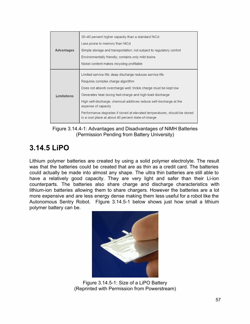
Figure 3.14.41: Advantages and Disadvantages of NiMH Batteries
(Permission Pending from Battery University) 3.14.5 LiPO Lithium polymer batteries are created by using a solid polymer electrolyte. The result was that the batteries could be created that are as thin as a credit card. The batteries could actually be made into almost any shape. The ultra thin batteries are still able to have a relatively good capacity. They are very light and safer than their Liion counterparts. The batteries also share charge and discharge characteristics with lithiumion batteries allowing them to share chargers. However the batteries are a lot more expensive and are less energy dense making them less useful for a robot like the Autonomous Sentry Robot. FIgure 3.14.51 below shows just how small a lithium polymer battery can be.
Figure 3.14.51: Size of a LiPO Battery
(Reprinted with Permission from Powerstream)
57

3.15 Voltage Regulators We plan to power the vehicle and all of its subsystems with a single battery. Since the motors, sensors, microcontroller, and microcomputer may require different voltages to operate than supplied by the battery, we will need to design a power distribution board to supply the correct voltages. We will consider common components for a power distribution board, such as linear voltage regulators, switching voltage regulators, and power boost converters, in the case of components needing a higher voltage than supplied. 3.15.1 Linear Voltage Regulator Using a Linear voltage regulator is one way to convert a higher supplied voltage to a lower one used by components. Linear voltage regulators take any input voltage, within a range, and outputs a regulated voltage. For the microcontrollers and the sensors that we are considering, we will need an output of 5 V to 5.5 V. We have experience with a 5 V voltage regulator from the Electronics II laboratory Experiment #3. In that lab, we used a LM7805. Some characteristics for the LM7805 are listed below in Table 3.15.1. Voltage Regulator LM7805
Max Input Voltage (V) 35
Output Voltage (V) 5
Peak Current (A) 2.2 Table 3.15.1: LM7805 Characteristics [6]
According to Digikey’s web article, “Understanding the Advantages and Disadvantages of Linear Regulators,” efficiency is high for small differences between input and output voltages. [7] We can see this in the power dissipation equation for the voltage regulator:
PREG = PIN POUT = (VIN VOUT)*IL + IQ*VIN
Where PREG is the power dissipated by the voltage regulator, PIN is the input power, POUT is the out power, VIN is the input voltage, VOUT is the output voltage, IL is the load current, IQ is the and quiescent current. 3.15.2 Switching Voltage Regulator Switching regulators are another way to convert voltages. They can step up (boost), step down (buck), and invert voltages. For our project, we would need a step down regulator. They tend to be more expensive and more complex than linear voltage
58

regulators. We also have experience with a switching voltage regulator from Electronics II laboratory Experiment #4. In that lab, we used a LM2576ADJ. Some characteristics for the LM2576ADJ are listed below in Table 3.15.2. Since the LM2576ADJ is an adjustable switching voltage regulator, we can adjust the output voltage to what we require. Figure 3.15.2 is an example of a circuit that has an output voltage of 5V.
Fig. 3.15.2: Circuit with a 5V output
(Reprinted with Permission from Texas Instruments) Voltage Regulator LM2576ADJ
Max Input Voltage (V) 40
Output Voltage (V) 1.23 to 37
Peak Current (A) 3 Table 3.15.2: LM2576ADJ Characteristics [8]
According to Digikey, efficiency is high “except at very low load currents” where the “quiescent current is usually higher.”[7] In our lab we learned that the power dissipated in the switching regulator comes from when the MOSFET in the regulator is on, when it is off, no power is dissipated. The power dissipated is:
PMOSFET = IL2 * RDS
Where PMOSFET is the power dissipated by the MOSFET, IL is the load current, and RDS is the drain to source resistance of the MOSFET. 3.16 Chassis The chassis is an important part of every robotic vehicle. There are many factors to consider when designing or selecting a chassis. The chassis for the ASR must be large enough to contain all of the electronics required for the robot, but also small enough to
59

maneuver around obstacles with ease. The chassis should be easy to assemble and disassemble for maintenance purposes. The cost of the chassis is also an important factor to consider. In our case the robot is not meant to bear much more weight than the electronics required to drive it. This means that minimizing component weight is not an issue for us. The largest component, other than the chassis and battery, is the Microsoft Kinect sensor we plan to use to map the environment. The Kinect weighs right around 2 lbs so our design will be able to handle it perfectly as we plan to use metal in our construction. For the ASR, our team decided that it would be best to purchase a chassis kit or easy to assemble chassis components rather than build one from scratch. We considered two different options for the ASR. Actobotics Chassis:The first chassis we considered was from Sparkfun. Sparkfun has created a robotic building system under the name Actobotics. Actobotics has many pre made aluminum channels that can intuitively come together to create a solid chassis. The components are relatively inexpensive and are designed for ease of use. The components come with two standardized hole patterns for use with any of Actobotics’ components and many others. Figure 3.161 below is of the 12” aluminum channel with the easy mounting hole pattern.
Figure 3.161: 12” Aluminum Channel
(Reprinted with Permission from SparkFun) VEX Chassis: The second chassis we considered was the VEX chassis kit. They come in several different sizes which allowed for flexibility in design. The components are very similar in design to the actobotics parts. They are designed with a single hole pattern for uniformity across the entire VEX robotics product line. The chassis kit comes with four rails and two bumpers. the rails are used for mounting wheels and motors. The inner rails can be moved closer to the outer rails or more towards the center to allow for larger or smaller wheels. The bumpers act as the front and the back chassis plates. Figure 3.162 below shows the assembled VEX chassis kit medium.
60
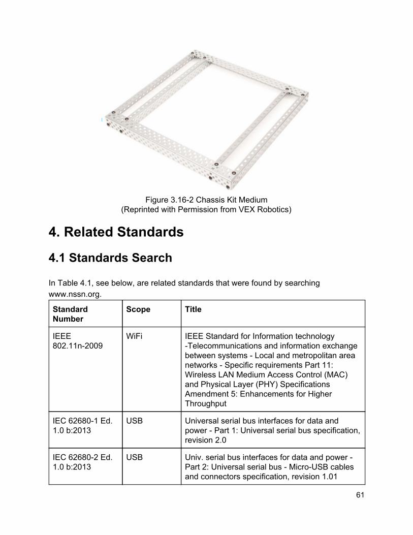
Figure 3.162 Chassis Kit Medium
(Reprinted with Permission from VEX Robotics)
4. Related Standards
4.1 Standards Search In Table 4.1, see below, are related standards that were found by searching www.nssn.org.
Standard Number
Scope Title
IEEE 802.11n2009
WiFi IEEE Standard for Information technology Telecommunications and information exchange between systems Local and metropolitan area networks Specific requirements Part 11: Wireless LAN Medium Access Control (MAC) and Physical Layer (PHY) Specifications Amendment 5: Enhancements for Higher Throughput
IEC 626801 Ed. 1.0 b:2013
USB Universal serial bus interfaces for data and power Part 1: Universal serial bus specification, revision 2.0
IEC 626802 Ed. 1.0 b:2013
USB Univ. serial bus interfaces for data and power Part 2: Universal serial bus MicroUSB cables and connectors specification, revision 1.01
61

BSR/IEEE 1873201x
Mapping Standard for Robot Map Data Representation for Navigation
IEC 60335229 Ed. 4.2 b:2010
Battery Charger
Household and similar electrical appliances Safety Part 229: Particular requirements for battery chargers
IEC 6267611 Ed. 1.0 b:2013
Video Surveillance
Video surveillance systems for use in security applications Part 11: System requirements General
IEC 6267622 Ed. 1.0 b:2013
IP video Video surveillance systems for use in security applications Part 22: Video transmission protocols IP interoperability implementation based on HTTP and REST services
Table 4.1: Related Standards
4.2 Design Impact Our design considerations will not be greatly impacted by the standards that we have found. This is the case since we will not be manufacturing hardware and will be using established software libraries. We will be using standard hardware components for this project, while only designing our own printed circuit board for power distribution and the microcontroller and a housing for the battery charger.
5. Design Constraints Listed below are several design constraints that our project will be facing. Many of the constraints pertain to restriction of design options due to cost, time, size, and etc. We do not foresee many constraints due to regulations or standards. 5.1 Cost Cost is a major factor in our design. In our initial budget, we understood this and were determined to use parts that we either had, were low cost, or could combine functionality. For our initial budget, we determined that we would need $901.77, which is what we requested from a Boeing sponsorship. We have been approved for funding from Boeing for $580.11. This is less than what we requested, however we are fortunate to be in possession of some of the parts that we require to complete the project.
62

5.2 Time Time is another main constraint. Since our section of Senior Design II will be held during UCF’s summer term, we will have less time to work than if it were during the fall or spring terms. We will have twelve weeks compared to sixteen weeks. 5.3 Size We have constrained the size of our robot in requirement FF1 to a maximum height of 1 foot and a maximum width of 1.5 feet. According to the specifications of the VEX kit which one of us owns, the chassis rails are 8 inches long and the chassis angles are 7.5 inches long. For the VEX medium chassis kit that we are considering, the chassis rails are 12.598 inches long. And according to the Actobotics specifications, the other chassis kit we are considering, the chassis channel lengths are 4.5 inches, 6 inches, 9 inches, 12 inches, 15 inches, 18 inches, or 24 inches. 5.4 Power Consumption Power consumption is an extremely important factor for the ASR. In our initial project description we listed that the battery was to last for 5 hours. If the budget was no concern this would be achievable. However, with a limited budget and limited space we felt that it was necessary to compromise on this factor. For example, a robot drawing 10A of continuous current would need a battery with a capacity of 50Ah to run for 5 hours. We expect our robot to draw around 10A of current. Therefore we have chosen to modify our run time to about a half hour. That means that we will need a battery with a capacity of 5Ah or more to achieve our new goal.
6. Hardware Design The ASR is made up of both mechanical and electrical hardware systems. These systems must work together in order for the ASR be successful. That being said, it is important to design the system components to be independent so that if a part needs to be modified or replaced it can be taken care of without affecting the entire system. This section contains the decisions made for the mechanical and electrical hardware of the robot as well as the reasons for those decisions.
63
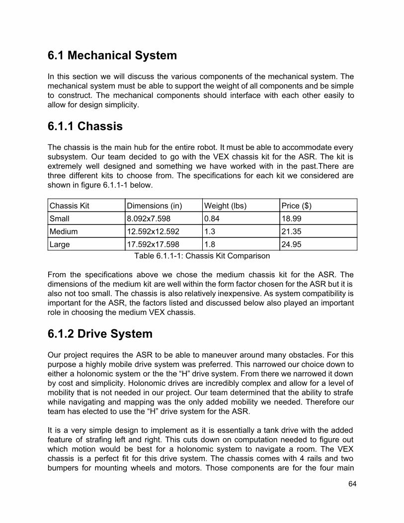
6.1 Mechanical System In this section we will discuss the various components of the mechanical system. The mechanical system must be able to support the weight of all components and be simple to construct. The mechanical components should interface with each other easily to allow for design simplicity. 6.1.1 Chassis The chassis is the main hub for the entire robot. It must be able to accommodate every subsystem. Our team decided to go with the VEX chassis kit for the ASR. The kit is extremely well designed and something we have worked with in the past.There are three different kits to choose from. The specifications for each kit we considered are shown in figure 6.1.11 below. Chassis Kit Dimensions (in) Weight (lbs) Price ($) Small 8.092x7.598 0.84 18.99 Medium 12.592x12.592 1.3 21.35 Large 17.592x17.598 1.8 24.95
Table 6.1.11: Chassis Kit Comparison From the specifications above we chose the medium chassis kit for the ASR. The dimensions of the medium kit are well within the form factor chosen for the ASR but it is also not too small. The chassis is also relatively inexpensive. As system compatibility is important for the ASR, the factors listed and discussed below also played an important role in choosing the medium VEX chassis. 6.1.2 Drive System Our project requires the ASR to be able to maneuver around many obstacles. For this purpose a highly mobile drive system was preferred. This narrowed our choice down to either a holonomic system or the the “H” drive system. From there we narrowed it down by cost and simplicity. Holonomic drives are incredibly complex and allow for a level of mobility that is not needed in our project. Our team determined that the ability to strafe while navigating and mapping was the only added mobility we needed. Therefore our team has elected to use the “H” drive system for the ASR. It is a very simple design to implement as it is essentially a tank drive with the added feature of strafing left and right. This cuts down on computation needed to figure out which motion would be best for a holonomic system to navigate a room. The VEX chassis is a perfect fit for this drive system. The chassis comes with 4 rails and two bumpers for mounting wheels and motors. Those components are for the four main
64

drive wheels. The chassis is very modular and components can be added to change the design. The ASR will utilize two smaller rails to mount the strafing wheel in the center. Figure 6.11 below illustrates the chassis design.
Figure 6.1.21: “H” Frame Chassis Design
6.1.3 Wheels The chassis design was huge factor in our wheel choice. The “H” drivetrain really only works effectively with omni wheels. The omni wheels will allow the robot to turn and strafe with less friction than any of the other wheels we looked into. Traction wheels would have way too much friction when trying to strafe as they do not have rollers. The mecanum wheels would require two center wheels in order to strafe perfectly horizontally. There are many types of omni wheels available. However, we decided to look at choices that VEX robotics had to offer as they would be directly compatible with our chassis. All of the VEX wheels are designed to support the VEX chassis and required electronics. As the ASR is not meant to carry a large load, there is no need to compare load specifications for the following wheels. The first option we looked into are 2.75 inch omni wheels with a single set of rollers around the outside of the wheels. The second option we looked into are 2.75 inch omni wheels with a double set of roller on the outside. The final set of omni wheels we looked into had a double set of rollers but a diameter of 4 inches. An example of the single and double set of rollers are shown in figure 6.1.31 below.
65

Figure 6.1.31: VEX Omni Wheels: Single (Left) and Double (Right) (Reprinted with Permission from VEX robotics)
Wheel (All Omni) Weight (lbs) Shaft Price 2.75" Single Roller 0.074 0.125" Square Bar $19.99 (for two) 2.75" Double Roller 0.154 0.125" Square Bar $19.99 (for two) 4" Double Roller 0.232 0.125" Square Bar $24.99 (for two)
Table 6.1.31: Omni Wheel Comparison In the table it can be seen that the smaller 2.75” wheels are less expensive and lighter than the 4” wheels. After consideration we narrowed the choice down between the two wheels with double rollers as they have more complete roller coverage for less friction. In the end we chose to go with the 4” double roller omni wheels. Although the smaller wheels are less expensive, the increased diameter of the 4” wheels allows the robot to move over bumps more easily which can be useful when navigating. If the ASR cannot enter a room because it cannot make it over a threshold, it loses some of its functionality. The ASR should be able to enter any room with ease so this was an easy decision. As we need five wheels total we would need to buy three kits leading to a total price of about $75.00. These wheels were chosen to work with the chassis. The chassis uses .182” standard VEX holes for mounting and the wheels use 0.125” square bars for shafts. The shafts of the wheels will properly fit though the chassis holes for mounting. Bearings and a shaft collars from VEX robotics will be used to hold the wheels in place. 6.1.4 Motors The motors chosen need to be able to support the weight of the robot and all of its components. The robot should weigh no more than 15 lbs. This means that the motors need to have a stall torque greater than 0.85 NM in order to run properly. The torque value is based on the weight of the robot and the radius of the wheels. The motors
66

should also not have a large current draw in order to maximize battery life. After conducting our motor research, we have determined that choosing to use a DC motor. Having chosen the VEX robotics chassis, we decided that looking at VEX motors would be a good start for compatibility. The VEX motors we researched are shown in table 6.1.41 below. Motor RPM Needs Controller Stall Current (A) Stall Torque (NM) Price ($) 393 100 Yes 4.8 1.67 14.99 3 wire 100 No Not Listed Not Listed Not Listed 269 100 Yes 2.6 0.972 12.99
Table 6.1.41: Motor Comparison The 3 wire motors are motors that we already have. The third wire is for PWM signals and therefore it doesn’t need a motor controller. However, there is not a lot of data available on them and we only have three. This eliminates them from being used on the ASR. The 2 wire 269 motors are less expensive than the 2 wire 393 motors. However, they have a much lower stall current and stall torques. Therefore we have chosen to go with the VEX two wire 393 motors. The motor is a DC motor meaning it runs using DC voltage. That makes it ideal for our system as we are using a battery. DC motors are very easy to control which is a necessity for the ASR. The motors are shown in figure 6.1.41 below.
Figure 6.1.41: VEX 2 Wire motor 393
(Reprinted with Permission from VEX Robotics) With these motors having two wires it is necessary to get a motor controller for them. As our microcontroller is able to generate PWM signals we have chosen to get the VEX motor controller 29. The motor controller is specifically designed to work with the VEX two wire 393 motors so we chose not to look into any other options. The motor and motor controller combo is priced at $24.98 on the VEX website making it a great option for our project.
67
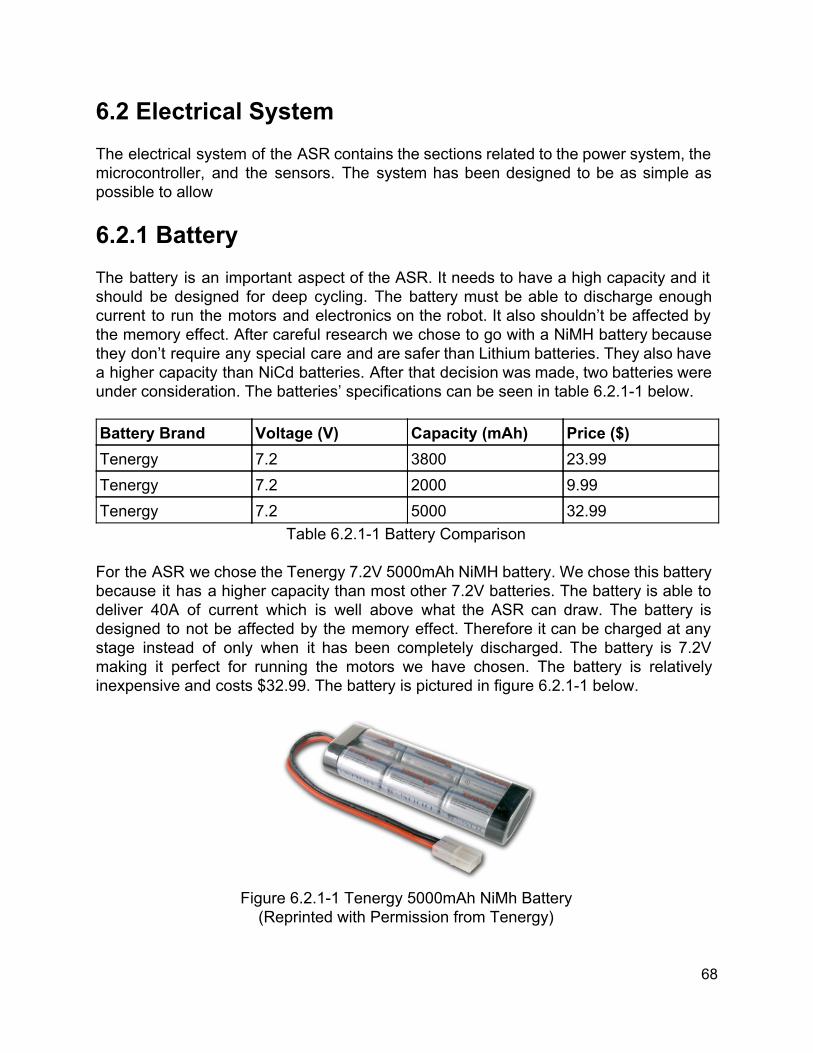
6.2 Electrical System The electrical system of the ASR contains the sections related to the power system, the microcontroller, and the sensors. The system has been designed to be as simple as possible to allow 6.2.1 Battery The battery is an important aspect of the ASR. It needs to have a high capacity and it should be designed for deep cycling. The battery must be able to discharge enough current to run the motors and electronics on the robot. It also shouldn’t be affected by the memory effect. After careful research we chose to go with a NiMH battery because they don’t require any special care and are safer than Lithium batteries. They also have a higher capacity than NiCd batteries. After that decision was made, two batteries were under consideration. The batteries’ specifications can be seen in table 6.2.11 below. Battery Brand Voltage (V) Capacity (mAh) Price ($) Tenergy 7.2 3800 23.99 Tenergy 7.2 2000 9.99 Tenergy 7.2 5000 32.99
Table 6.2.11 Battery Comparison For the ASR we chose the Tenergy 7.2V 5000mAh NiMH battery. We chose this battery because it has a higher capacity than most other 7.2V batteries. The battery is able to deliver 40A of current which is well above what the ASR can draw. The battery is designed to not be affected by the memory effect. Therefore it can be charged at any stage instead of only when it has been completely discharged. The battery is 7.2V making it perfect for running the motors we have chosen. The battery is relatively inexpensive and costs $32.99. The battery is pictured in figure 6.2.11 below.
Figure 6.2.11 Tenergy 5000mAh NiMh Battery (Reprinted with Permission from Tenergy)
68

6.2.2 Charger After selecting a battery there were two different options available to us for a charger. The first option was to design our own. The team decided that it would be safer to purchase a charger for the ASR battery as the robot is intended to complete many cycles. The chargers available to purchase are rigorously tested so we know they are safe to use with the NiMH battery. That left only the second option, purchase a charger, available to us. There were two charges under consideration for purchase. Table 6.2.21 below is a comparison of the two chargers. Brand Voltage (V) Charge Rate (A) Price ($) Tenergy 7.212 1.8 21.49 Tenergy 612 2 22.99
Table 6.2.21 Battery Charger Comparison From the table it can be seen that the price difference is negligible and the voltage rating for both is perfect for our battery. Therefore, our group has chosen to go with the second charger with the charge rate of 2A. This will allow a slightly faster charge time to get the ASR back out into the room for its patrol. The battery charger is able to detect the battery voltage to ensure a proper charge and is equipped with a temperature sensor to ensure that the battery doesn’t overheat. The charger is shown in figure 6.2.21 below.
Figure 6.2.21 NiMH Battery Charger
(Reprinted with Permission from Tenergy)
69

6.2.3 Charging Station The charging station must be designed in a way that accommodates the robot and charger but doesn’t interfere with daily life for the owner of the ASR. The charging station will be made out of wood so that it will be inexpensive. The design dimensions will be 12.7” X 12.7” X 14”. This way the robot will not have much room for error making the charger alignment problem much easier. The frontangled view of the charging station is shown in figure 6.2.31 below.
Figure 6.2.31: Charging Station: Front Angled View
The grey outer shell represents the wooden structure of the charging station. The black rectangle represents the empty space that the robot will be able to drive into in order to dock. There will be a secondary chamber behind the back wall that contains the charger. It will be partially open in the very back to allow proper charger cooling and to allow the charger to plug into any standard power outlet. There will be a stand made out of metal to keep the charger off of the wooden frame and household floor. The charger is not meant to be left on wooden floors as it gets hot when charging. The charger itself comes with alligator clips that will allow it to interface with the charging station. The alligator clips will be connected to two metal plates in the wall between the robot and charging chambers. The robot will plug into the metal plates in order to charge. The plates will normally be protected by a flap and a hinge to stop anyone and anything from shorting the charging leads. The robot will drive to the back of the charger with its charging plates extended. The plates will push the flap and reveal the battery charger’s charging plates. The robot will be in contact with the plates when it gets to the back wall and therefore charging will begin.
70
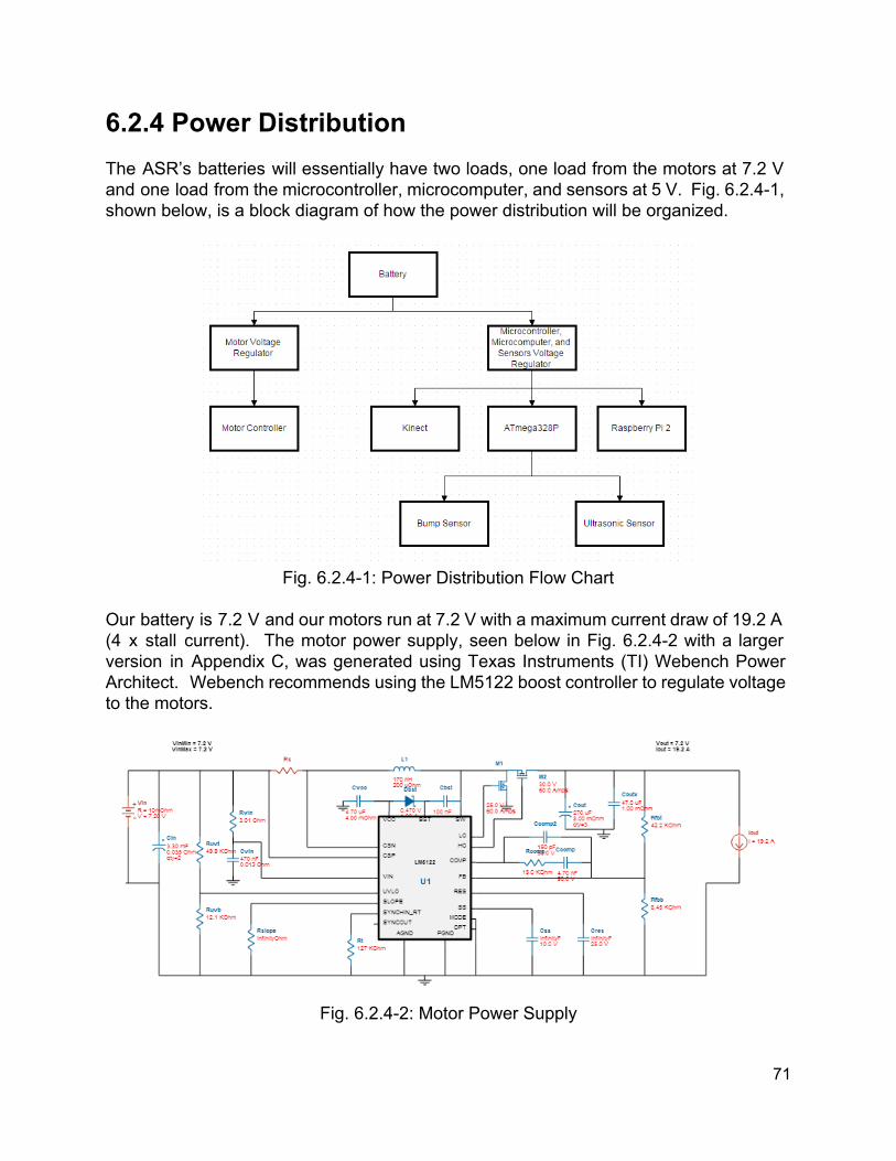
6.2.4 Power Distribution The ASR’s batteries will essentially have two loads, one load from the motors at 7.2 V and one load from the microcontroller, microcomputer, and sensors at 5 V. Fig. 6.2.41, shown below, is a block diagram of how the power distribution will be organized.
Fig. 6.2.41: Power Distribution Flow Chart
Our battery is 7.2 V and our motors run at 7.2 V with a maximum current draw of 19.2 A (4 x stall current). The motor power supply, seen below in Fig. 6.2.42 with a larger version in Appendix C, was generated using Texas Instruments (TI) Webench Power Architect. Webench recommends using the LM5122 boost controller to regulate voltage to the motors.
Fig. 6.2.42: Motor Power Supply
71
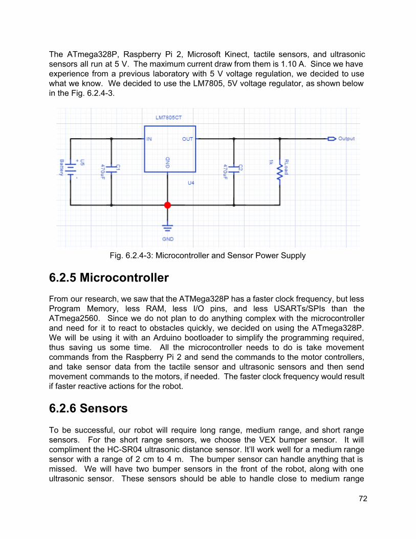
The ATmega328P, Raspberry Pi 2, Microsoft Kinect, tactile sensors, and ultrasonic sensors all run at 5 V. The maximum current draw from them is 1.10 A. Since we have experience from a previous laboratory with 5 V voltage regulation, we decided to use what we know. We decided to use the LM7805, 5V voltage regulator, as shown below in the Fig. 6.2.43.
Fig. 6.2.43: Microcontroller and Sensor Power Supply
6.2.5 Microcontroller From our research, we saw that the ATMega328P has a faster clock frequency, but less Program Memory, less RAM, less I/O pins, and less USARTs/SPIs than the ATmega2560. Since we do not plan to do anything complex with the microcontroller and need for it to react to obstacles quickly, we decided on using the ATmega328P. We will be using it with an Arduino bootloader to simplify the programming required, thus saving us some time. All the microcontroller needs to do is take movement commands from the Raspberry Pi 2 and send the commands to the motor controllers, and take sensor data from the tactile sensor and ultrasonic sensors and then send movement commands to the motors, if needed. The faster clock frequency would result if faster reactive actions for the robot. 6.2.6 Sensors To be successful, our robot will require long range, medium range, and short range sensors. For the short range sensors, we choose the VEX bumper sensor. It will compliment the HCSR04 ultrasonic distance sensor. It’ll work well for a medium range sensor with a range of 2 cm to 4 m. The bumper sensor can handle anything that is missed. We will have two bumper sensors in the front of the robot, along with one ultrasonic sensor. These sensors should be able to handle close to medium range
72

object detection. If they are triggered, the microcontroller will react and move the robot away from the object. We will also have the same configurations on the back of the robot. This will cover the cases when the robot backs up and it’ll ensure that it does not run into anything while backing up.
7. Software Design The ASR is a complex system of interconnected subsubsystems. The overall system has distinct inputs and outputs, and so should the individual subsystems. With this approach in mind, our design will attempt to be as modular as possible. This way modifications can be made to one system without too much impact on other systems. First, a high level view of the overall system architecture will be presented. Following this, each system will be looked at in more depth. 7.1 High Level Software System Architecture The overall system is contained within and being executed on the Raspberry Pi 2. The subsystems present are sensor processing, manual navigation, autonomous navigation, mapping and localization, motion detection, the state manager, and the user application, which is being executed on an external device. The inputs to the system are the map, streams of data from various sensors, input from the user, and the remaining battery life. The outputs of the system are the current generated map which is fed back in as an input, alerts which are pushed to the user app, and locomotion data to the motors.
73
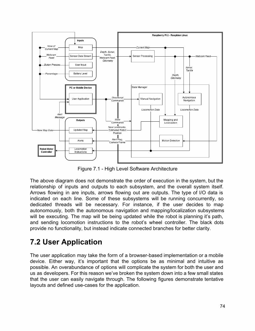
Figure 7.1 High Level Software Architecture
The above diagram does not demonstrate the order of execution in the system, but the relationship of inputs and outputs to each subsystem, and the overall system itself. Arrows flowing in are inputs, arrows flowing out are outputs. The type of I/O data is indicated on each line. Some of these subsystems will be running concurrently, so dedicated threads will be necessary. For instance, if the user decides to map autonomously, both the autonomous navigation and mapping/localization subsystems will be executing. The map will be being updated while the robot is planning it’s path, and sending locomotion instructions to the robot’s wheel controller. The black dots provide no functionality, but instead indicate connected branches for better clarity. 7.2 User Application The user application may take the form of a browserbased implementation or a mobile device. Either way, it’s important that the options be as minimal and intuitive as possible. An overabundance of options will complicate the system for both the user and us as developers. For this reason we’ve broken the system down into a few small states that the user can easily navigate through. The following figures demonstrate tentative layouts and defined usecases for the application.
74

Figure 7.2a User Application Default View
Figure 7.2b Autonomous Mode Selected Figure 7.2c Autonomous Mapping Mode Selected
75

Figure 7.2d Autonomous Patrol Mode Selected
Figure 7.2e Manual Mode Selected
Figure 7.2f Manual Mapping Mode Selected
Figure 7.2g Manual Patrol Mode Selected
7.3 Sensor Processor A number of sensors will be used during various state’s acted out by the robot. For any given state, only specific sensors will be active. For some states, no sensors will be active at all. For this reason it was determined a kind of management subsystem would be necessary for getting the desired sensor data at the right time. The flags variable will determine the logic controlling which sensors will be active. For example, if autonomous_nav and slam are flagged as true, then sonar, tactile, depth, and odometry will be actively being scanned and updated.
76

Periodic getSensor() calls will be made to the Sensor Processor, which will return the current sensor data for that frame of time. All scans will be made simultaneously so that their respective data is guaranteed to be in sync at the same time. It will be necessary to format some of the data so that it can be more easily used in other subsystems. For instance, depth data from the Kinect comes in the form of a 3D point cloud. When the Sensor Processor formats this data, it will essentially take a horizontal slice of the cloud, and return the depth data in the same form that a Lidar might. This way it can be used as intended in the SLAM subsystem.
Figure 7.3: Sensor Processor State Architecture
7.4 State Manager The state manager is a singleton class which sets the given state of the robot based on the input provided from the user application. Abstract states like “Autonomous Mapping Mode” selected in the user app are not actually representative of a single state in the manager, but rather two states operating simultaneously. This approach will help us eliminate redundancy and keep code more modular for ease of modification. The State Manager class is simple in terms of methods and variables. The SetState() method takes in a boolean array which flags states that are to be set active and inactive.
77

The current state can be retrieved with GetState() which retrieves the global variable flags[ ], containing whatever states were last set. The global variable mapComplete is set when the mapping state has completed and is used by the user application to decide which options are available to the user. The state manager needs no knowledge of sensors or any other input as these will be inputs to the classes of the subsystems. It needs no output except for other classes to be able to retrieve the current state for lower level decision making. Flags can be set by subclasses when certain procedures have been completed.
Figure 7.4: State Manager Architecture 7.5 Autonomous Navigation Autonomous navigation occurs during three different states in our robot; autonomous exploration, autonomous patrol, and autonomous docking.
78

7.5.1 Autonomous Exploration During autonomous exploration, the autonomous_nav and slam flags are marked true, therefore, the Autonomous Navigation and SLAM subsystems are both active and executing. This is the state that occurs when the user selects Autonomous Mapping in the user application. The autonomous navigation states essentially function like a finite state machines. Autonomous exploration starts by immediately moving forward while checking on sensor data, if no obstacles are detected it will briefly switch to the locomotion state to transmit motion data, then return to the wander state and repeat. If any obstacle avoidance warnings are triggered, then it will immediately trigger the stop state, switch to locomotion and transmit data, then return and switch to the avoid obstacle state. The avoid obstacle state contains logic for determining and calculating a new heading. Once the heading is calculated, it switches to the locomotion state and transmits data to reflect the new heading. Following this, it returns to the wander state and repeats the whole process. The wander state also checks if the standby flag has been triggered. If it has, the robot is told to stop and then exit this state and wait for instructions.
Figure 7.5.1: Autonomous Exploration State Architecture
79

7.5.2 Autonomous Patrol During autonomous patrol, the autonomous_nav and motion_detect flags are marked true, therefore, the Autonomous Navigation and Patrol subsystems are both active and executing. This is the state that occurs when the user selects Autonomous Patrol in the user application. First, the set of patrol nodes are read in from the user application so that the nearest node can be determined. Nodes are essentially just coordinates on the map, so calculation is fairly simple. Once a goal node is determined, the navigation state is triggered. In the navigation state, obstacle avoidance sensors are checked. If no warnings are triggered, the locomotion state it triggered and motion data is transmitted; moving the robot a unit of distance towards the goal, then returning to the navigation state. If an obstacle is detected or the standby flag is triggered, this state functions the same as in the autonomous exploration state. If the robot arrives at the node, it stops itself completely and transitions itself to the detect motion state. Motion detection is described later in the design section. Once motion detection is complete, it returns to the starting state and determines a new node to travel to, repeating the whole process.
Figure 7.5.2: Autonomous Patrol State Architecture
80

7.5.3 Autonomous Docking During autonomous docking, the autonomous_nav and docking flags are marked true, therefore, the Autonomous Navigation and Docking subsystems are both active and executing. This is the state that occurs when the user selects Autonomous Docking in the user application. This state functions the same as the autonomous patrol state except that an additional node, the dock node, is taken into account. The robot leverages the patrol path to get close to the dock node. During the navigation state it checks if it’s arrived at the dock. If it has, it stops and switches to standby mode.
Figure 7.5.1: Autonomous Docking State Architecture 7.6 Manual Navigation Manual navigation occurs during two different states in our robot; manual exploration, and manual patrol.
81

7.6.1 Manual Exploration During manual exploration, the manual_nav and slam flags are marked true, therefore, the Manual Navigation and SLAM subsystems are both active and executing. This is the state that occurs when the user selects Manual Mapping in the user application. This state is very simple. The starting state listens for user input from the user application. The input will be in the form of directions which the user wants the robot to move. If a command is received, the locomotion state is triggered, motion data is transmitted, and then it returns to the listener. If the standby flag is triggered, this state is exited and the robot waits for instruction.
Figure 7.6.1: Manual Exploration State Architecture 7.6.2 Manual Patrol During manual exploration, only the manual_nav flag is marked true, therefore, the Manual Navigation subsystem is active and executing. This is the state that occurs when the user selects Manual Patrol in the user application. This state state functions exactly the same as the Manual Exploration state, except that the user has the additional option to capture a frame from the webcam if they wish to take a picture.
82
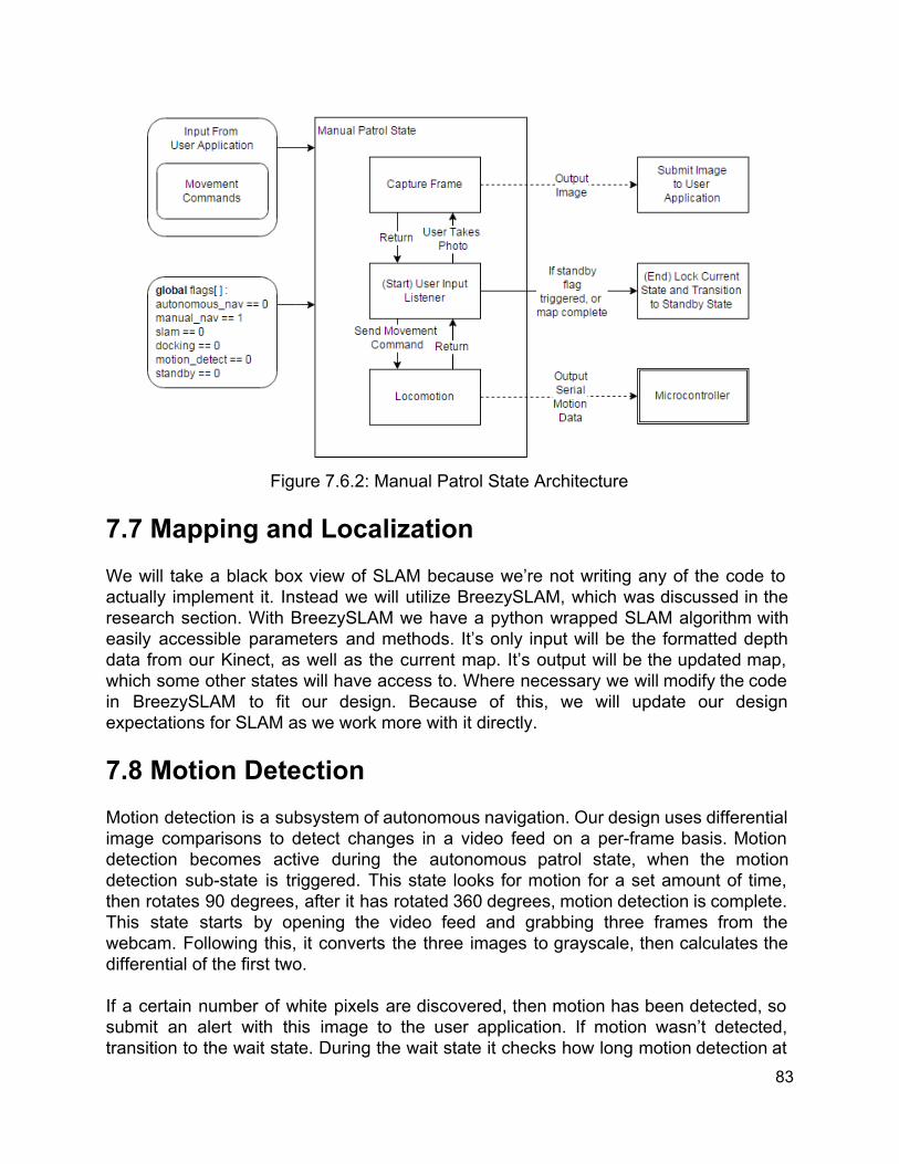
Figure 7.6.2: Manual Patrol State Architecture
7.7 Mapping and Localization We will take a black box view of SLAM because we’re not writing any of the code to actually implement it. Instead we will utilize BreezySLAM, which was discussed in the research section. With BreezySLAM we have a python wrapped SLAM algorithm with easily accessible parameters and methods. It’s only input will be the formatted depth data from our Kinect, as well as the current map. It’s output will be the updated map, which some other states will have access to. Where necessary we will modify the code in BreezySLAM to fit our design. Because of this, we will update our design expectations for SLAM as we work more with it directly. 7.8 Motion Detection Motion detection is a subsystem of autonomous navigation. Our design uses differential image comparisons to detect changes in a video feed on a perframe basis. Motion detection becomes active during the autonomous patrol state, when the motion detection substate is triggered. This state looks for motion for a set amount of time, then rotates 90 degrees, after it has rotated 360 degrees, motion detection is complete. This state starts by opening the video feed and grabbing three frames from the webcam. Following this, it converts the three images to grayscale, then calculates the differential of the first two. If a certain number of white pixels are discovered, then motion has been detected, so submit an alert with this image to the user application. If motion wasn’t detected, transition to the wait state. During the wait state it checks how long motion detection at
83

this angle has been running. If the time limit hasn’t been reached, then continue the loop of motion detection, reading in another frame and repeating the process. If the time limit of this detection has been reached, then instruct the robot to rotate 90 degrees and repeat the process like above. If the robot has rotated 360 degrees, then motion detection is complete, exit this state and return to the autonomous patrol state. If the standby flag is triggered, the robot exits this state and waits for instructions.
Figure 7.8: Motion Detection State Architecture
8. Prototype Construction The following sections discuss the logistics of building our robot. First we discuss our plan for a high level PCB design as well as how we plan to manufacture the PCB. Last we discuss the order in which we plan to implement our software systems.
84

8.1 PCB Designing our own circuits on a PCB, printed circuit board, is a requirement for Senior Design I. This will be a learning experience for us since there are no classes that teach printed circuit board, PCB, design. We will be using the online PCB design program Upverter.com. Upverter offers free membership for students. It is a PCB design site that let’s one design a circuit and PCB with a large database of parts, create a BOM, bill of materials, from the design, and export the design to numerous formats. Will be ordering our board from Advanced Circuits’ website, www.4pcb.com. They have student discounts for PCBs. They offer 2layer PCB’s for $33 each and 4layer PCB’s for $66 each. They also offer free PCB layout software. To reduce costs, we will be using one PCB. The PCB will contain the both voltage regulation circuits and the ATmega328P along with ports for the sensors and Raspberry Pi 2 to plug into. We will also add add power ports for the motors to connect to. Fig. 8.1, seen below, is a high level design of our PCB.
Fig. 8.1: High Level PCB Design
85

8.2 Coding Plan A coding plan is necessary to establish which systems will be implemented first, but it also helps us determine what systems are most important. We’ve already determined that we’re going to try and implement everything in Python, and that we will be using GitHub for source control. The following is our plan for the order in which we will implement our systems, followed by some justifications.
1. Sensor Processing a. All systems rely on input to be formatted in a way that is easy for us to
interpret, so this is critical to make implementing other subsystems easier. 2. Manual Navigation
a. Manual navigation will allow us to move the robot around fairly simply and enable us to start working on SLAM and testing some of our hardware functionality.
b. Since no user application exists a primitive debugger type placeholder application will be used.
3. Mapping and Localization a. This will be the hardest to implement as we will be trying to understand
someone else’s code, and how it will fit into ours. b. It’s important to start early because this will most likely be the lengthiest
system to implement. 4. Autonomous Navigation
a. This system will also be difficult and time consuming to implement as it will require more advanced algorithms.
b. Paves the way for motion detection system 5. Motion Detection
a. Our scheme is fairly simple and shouldn’t be difficult to implement later in development
6. State Manager a. After all our systems are in place we can finally implement the logic to
control which ones will be active and when. b. Necessary for the user application.
7. User Application a. This system basically requires everything else to be finished as it will be
responsible for sending instructions to the state manager. b. Will be fairly complex to implement, but not totally necessary to prove that
our robot works. For this reason we will be willing to sacrifice it if we are running low on time.
86

9. Prototype Testing In this section we will discuss the testing procedures of the ASR. We will begin by discussing the testing environment. We will continue by discussing the testing of the individual hardware components. Then we will discuss the testing procedure of the testing of integrated hardware. Next we will discuss our methods for testing the individual software components. Then we will discuss the software integration testing. 9.1 Hardware Testing This section includes the testing procedures for the individual mechanical and electrical hardware components as well as the fully integrated system hardware system. 9.1.1 Environment The testing environment will consist of the team members’ homes as well as the senior design lab. The senior design lab will be used for testing the electrical components of the ASR due to the available equipment. The other subsystems can be tested at in the individual homes. The software and mechanical components do not require any special special equipment to be tested properly. 9.1.2 Chassis Test Name Strength Test
Objective To ensure the chassis will support the weight of the electronics.
Supplies 1. Constructed VEX Medium Chassis 2. Lexan (for electronics) 3. 10lb weight
Preparation Place the chassis on the ground with the lexan facing up.
Procedure 1. Place weight in the center of the first lexan sheet 2. Wait to see if it breaks or bends and touches the ground 3. Place the weight in the center of the second lexan sheet 4. Wait to see if it breaks or bends and touches the ground
Expected Result
The weight simulates the electronics that will be utilized on the chassis. The lexan should be able to support the weight without bending too much or breaking entirely. The electronics should not weigh more than 10 lbs so this should be a good test.
87

9.1.3 Wheels Test name Spin Test
Objective To ensure that the small wheels spin properly
Supplies Omni Wheels
Preparation N/A
Procedure 1. Pick up wheel 2. Spin each of the small wheels by hand to ensure that they
move 3. Repeat with the other omni wheels
Expected Result
Each individual small wheel should spin freely. This ensures that the omni wheels are not damaged.
9.1.4 Power Distribution Test Name Power Test
Objective To ensure that the power distribution components of the PCB output 5 V and 7.2 V.
Supplies 1. PCB with power regulation circuitry 2. Battery 3. Multimeter
Preparation 1. Charge the battery before testing.
Procedure 1. Connect the battery to the PCB 2. Use multimeter to measure output of the motor voltage
regulator. 3. Use multimeter to measure output of the microcontroller,
microcomputer, etc. voltage regulator
Expected Result
The output of the motor voltage regulator is 7.2 V. The output of the microcontroller, microcomputer, etc. voltage regulator is 5 V.
88
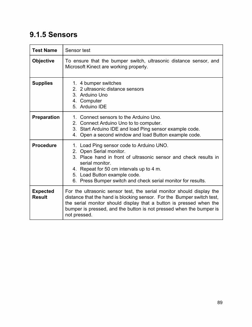
9.1.5 Sensors Test Name Sensor test
Objective To ensure that the bumper switch, ultrasonic distance sensor, and Microsoft Kinect are working properly.
Supplies 1. 4 bumper switches 2. 2 ultrasonic distance sensors 3. Arduino Uno 4. Computer 5. Arduino IDE
Preparation 1. Connect sensors to the Arduino Uno. 2. Connect Arduino Uno to to computer. 3. Start Arduino IDE and load Ping sensor example code. 4. Open a second window and load Button example code.
Procedure 1. Load Ping sensor code to Arduino UNO. 2. Open Serial monitor. 3. Place hand in front of ultrasonic sensor and check results in
serial monitor. 4. Repeat for 50 cm intervals up to 4 m. 5. Load Button example code. 6. Press Bumper switch and check serial monitor for results.
Expected Result
For the ultrasonic sensor test, the serial monitor should display the distance that the hand is blocking sensor. For the Bumper switch test, the serial monitor should display that a button is pressed when the bumper is pressed, and the button is not pressed when the bumper is not pressed.
89
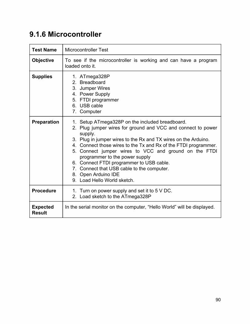
9.1.6 Microcontroller Test Name Microcontroller Test
Objective To see if the microcontroller is working and can have a program loaded onto it.
Supplies 1. ATmega328P 2. Breadboard 3. Jumper Wires 4. Power Supply 5. FTDI programmer 6. USB cable 7. Computer
Preparation 1. Setup ATmega328P on the included breadboard. 2. Plug jumper wires for ground and VCC and connect to power
supply. 3. Plug in jumper wires to the Rx and TX wires on the Arduino. 4. Connect those wires to the Tx and Rx of the FTDI programmer. 5. Connect jumper wires to VCC and ground on the FTDI
programmer to the power supply 6. Connect FTDI programmer to USB cable. 7. Connect that USB cable to the computer. 8. Open Arduino IDE 9. Load Hello World sketch.
Procedure 1. Turn on power supply and set it to 5 V DC. 2. Load sketch to the ATmega328P
Expected Result
In the serial monitor on the computer, “Hello World” will be displayed.
90

9.1.7 Microprocessor Test Name Microprocessor Test
Objective To check to see if the Raspberry Pi 2 is in working condition.
Supplies 1. Raspberry Pi 2 2. USB cable 3. USB charger 4. HDMI cable 5. Keyboard 6. Mouse 7. Monitor
Preparation 1. Plug in the keyboard and mouse into the Raspberry Pi 2. 2. Plug in the HDMI cable to the Raspberry Pi 2 and monitor. 3. Plug in the USB cable to the Raspberry Pi 2 and USB charger.
Procedure 1. Turn on monitor. 2. Plug the USB charger into a wall power socket. 3. Let Raspberry Pi 2 boot. 4. Log into the Raspberry Pi 2.
Expected Result
The Raspberry Pi 2 will boot into Raspbian desktop.
91

9.1.8 Hardware Integration Testing Test Name Hardware Integration Test
Objective Test all of the hardware components together.
Supplies 1. PCB with power regulation circuitry 2. Battery 3. 4 bumper switches 4. 2 ultrasonic distance sensors 5. ATmega328P 6. Breadboard 7. Jumper Wires 8. FTDI programmer 9. USB cable 10.Raspberry Pi 2 11.HDMI cable 12.Keyboard 13.Mouse 14.Monitor
Preparation 1. Use the preparation and procedure from the Power Distribution Test.
2. Use the preparation from the Microcontroller Test, but instead of using a power supply, use the Power Distribution circuit’s 5 V output as the power supply.
3. Use the preparation from the Sensor Test and plug them into the same pins on the ATmega328P instead of the Arduino Uno.
4. Use the preparation from the Microcomputer Test, but instead of using the USB charger as a power supply, use the Power Distribution circuit’s 5 V output as the power supply.
Procedure 1. Turn on monitor. 2. Plug in the battery to the Power Distribution test circuit. 3. Let Raspberry Pi 2 boot. 4. At the Raspbian Desktop, start the Arduino IDE. 5. Do the Sensor Test Procedure.
Expected Result
The Raspberry Pi 2 will boot to Raspbian Desktop. Once Sensor Test procedure is completed, the Arduino serial monitor will show the results from the sensor tests.
92
9.2 Software Testing Our software system is built up of smaller subsystems with known inputs and outputs, states, and use cases. Because of this, the following unit tests will be written in terms of those subsystems, which, at this prototyping stage, are still slightly high level representations. Our unit tests will be no different. Being that this a robotics project, hardware and software are very highly integrated in terms of functionality. Because of this, there may be some overlap between hardware testing and software testing, but we will do our best to separate the two areas. For ease of testing and to reduce the burden of how integrated our system is, our tests will be executed in a special testing mode which will output to our console as well as display any relevant material directly, rather than communicating it to one of the other subsystems. 9.2.1 Environment Our testing environment will simply be whatever workstations our team members have for personal use. Software development is portable so there is no need for a restricted lab area. The workstations will be running Ubuntu linux, must have adequate processing power for development and testing, and internet access. The Raspberry Pi 2 is responsible for running all but the user application systems, so access to the Pi will be necessary for whoever is running tests. We will utilize GitHub for source control, keeping our repository on GitHub’s servers to eliminate the possibility of losing code through hard drive failures or other unexpected issues. This will also allow us to easily manage conflicts and collisions in our code, and always have the most up to date version of the project for testing. Being that we are processing sensor data, whoever is currently performing tests must have access to the relevant sensors. We won’t have multiple sensors of the same type, so these will have to be traded among the members of the group when necessary.
93

9.2.2 User Application Test Name User Input and Menu Transition
Objective Verify that the application is receiving user input, and that the correct menus and options are displayed for the selections that the user makes.
Supplies 1. Workstation with internet browser or an Android mobile device
Preparation 1. Go to application URL or install application on mobile device
Procedure 1. Open the application 2. Make a selection in one of the menus
Expected Result
The correct menu state is transitioned to for the selection you have made. For example, at the main screen, select Autonomous Controls, the following screen should display Map, Patrol, and Dock.
Test Name Camera Feed
Objective Verify that the camera feed is being displayed in the user application
Supplies 1. Workstation with internet browser or an Android mobile device 2. Raspberry Pi 2 3. Webcam 4. WiFi dongle
Preparation 1. Go to application URL or install application on mobile device 2. Pi 2 is set up with camera, server, and Sensor Processing robot
software subsystem
Procedure 1. Open the application 2. View the camera feed window 3. Move camera around
Expected Result
Feed from the camera is visible to the user through the user application.
94

Test Name Map Display
Objective Verify that the map is displayed during the mapping state.
Supplies 1. Workstation with internet browser, or Android mobile device, Raspberry Pi 2, webcam, WiFi dongle, Kinect
Preparation 1. Go to application URL or install application on mobile device 2. Pi 2 is set up with camera, server, Sensor Processing, and
SLAM robot software subsystems.
Procedure 1. Open the application 2. Select autonomous or manual mapping mode
Expected Result
Mapping view is displayed in user application, and map is updated as the kinect sensor moves
9.2.3 Sensor Processor Test Name Sensor Processing
Objective Verify that sensor processor subsystem is receiving data from all sensors, and outputting data with the proper formatting.
Supplies 1. Python IDE 2. Raspberry Pi 2 3. Webcam 4. Kinect 5. Sonar sensor 6. Tactile sensor
Preparation 1. Pi 2 is set up with all sensors and sensor processor subsystem
Procedure 1. Open Python IDE 2. Execute the sensor processing subsystem in testing mode 3. Observe console output.
Expected Result
Streamed, formatted sensor data should be output to the console in real time.
95

9.2.4 State Manager Test Name State Manager
Objective Verify that the state manager changes robot state given the correct boolean state flags.
Supplies 1. Python IDE 2. Raspberry Pi 2
Preparation 1. Pi 2 is set up with state manager subsystem
Procedure 1. Open Python IDE 2. Execute the state manager subsystem in testing mode 3. Supply flags representative of various robot states. Observe
console output.
Expected Result
The state manager subsystem selects the correct state given corresponding state flags by the user. Nonexistent states return an error warning.
9.2.5 Autonomous Navigation Test Name Autonomous Exploration
Objective Verify the state behavior the the autonomous exploration subsystem.
Supplies 1. Python IDE 2. Raspberry Pi 2 3. Sonar sensor 4. Tactile sensor
Preparation 1. Pi 2 is set up with the above sensors, and the autonomous exploration subsystem
Procedure 1. Open Python IDE 2. Execute the autonomous exploration subsystem in testing mode 3. Allow it to run for a few moments 4. Place an object in front of the sonar sensor 5. Allow it to run for a few more moments 6. Touch the tactile sensors 7. Observe console output at all times
96
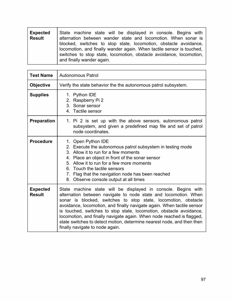
Expected Result
State machine state will be displayed in console. Begins with alternation between wander state and locomotion. When sonar is blocked, switches to stop state, locomotion, obstacle avoidance, locomotion, and finally wander again. When tactile sensor is touched, switches to stop state, locomotion, obstacle avoidance, locomotion, and finally wander again.
Test Name Autonomous Patrol
Objective Verify the state behavior the the autonomous patrol subsystem.
Supplies 1. Python IDE 2. Raspberry Pi 2 3. Sonar sensor 4. Tactile sensor
Preparation 1. Pi 2 is set up with the above sensors, autonomous patrol subsystem, and given a predefined map file and set of patrol node coordinates.
Procedure 1. Open Python IDE 2. Execute the autonomous patrol subsystem in testing mode 3. Allow it to run for a few moments 4. Place an object in front of the sonar sensor 5. Allow it to run for a few more moments 6. Touch the tactile sensors 7. Flag that the navigation node has been reached 8. Observe console output at all times
Expected Result
State machine state will be displayed in console. Begins with alternation between navigate to node state and locomotion. When sonar is blocked, switches to stop state, locomotion, obstacle avoidance, locomotion, and finally navigate again. When tactile sensor is touched, switches to stop state, locomotion, obstacle avoidance, locomotion, and finally navigate again. When node reached is flagged, state switches to detect motion, determine nearest node, and then then finally navigate to node again.
97
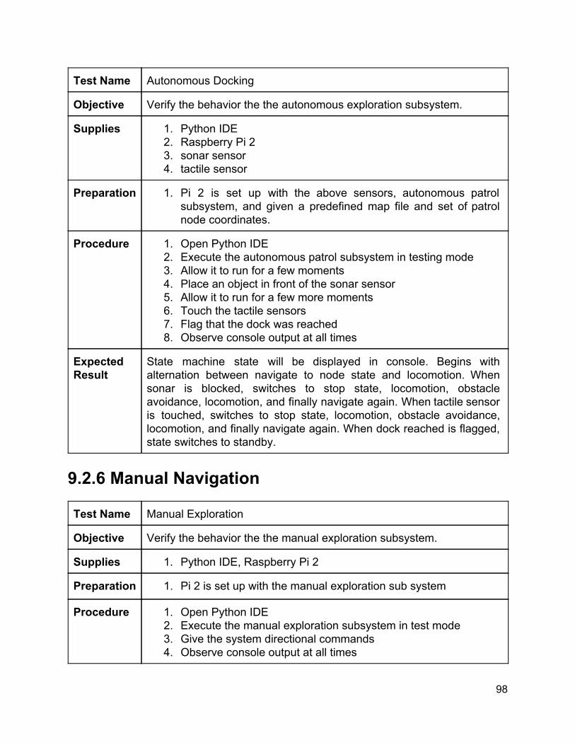
Test Name Autonomous Docking
Objective Verify the behavior the the autonomous exploration subsystem.
Supplies 1. Python IDE 2. Raspberry Pi 2 3. sonar sensor 4. tactile sensor
Preparation 1. Pi 2 is set up with the above sensors, autonomous patrol subsystem, and given a predefined map file and set of patrol node coordinates.
Procedure 1. Open Python IDE 2. Execute the autonomous patrol subsystem in testing mode 3. Allow it to run for a few moments 4. Place an object in front of the sonar sensor 5. Allow it to run for a few more moments 6. Touch the tactile sensors 7. Flag that the dock was reached 8. Observe console output at all times
Expected Result
State machine state will be displayed in console. Begins with alternation between navigate to node state and locomotion. When sonar is blocked, switches to stop state, locomotion, obstacle avoidance, locomotion, and finally navigate again. When tactile sensor is touched, switches to stop state, locomotion, obstacle avoidance, locomotion, and finally navigate again. When dock reached is flagged, state switches to standby.
9.2.6 Manual Navigation Test Name Manual Exploration
Objective Verify the behavior the the manual exploration subsystem.
Supplies 1. Python IDE, Raspberry Pi 2
Preparation 1. Pi 2 is set up with the manual exploration sub system
Procedure 1. Open Python IDE 2. Execute the manual exploration subsystem in test mode 3. Give the system directional commands 4. Observe console output at all times
98

Expected Result
State machine state will be displayed in console. Default state is listen for input. When a direction is supplied, the locomotion state is triggered. Serial motion data will be output to the console for the corresponding movement direction entered.
Test Name Manual Patrol
Objective Verify the behavior the the manual patrol subsystem.
Supplies 1. Python IDE 2. Raspberry Pi 2 3. Webcam
Preparation 1. Pi 2 is set up with the manual patrol sub system and webcam
Procedure 1. Open Python IDE 2. Execute the manual patrol subsystem in test mode 3. Give the system directional commands 4. Take a screenshot 5. Observe console output at all times.
Expected Result
State machine state will be displayed in console. Default state is listen for input. When a direction is supplied, the locomotion state is triggered. Serial motion data will be output to the console for the corresponding movement direction entered. When instructed to take a screenshot, the capture frame state is triggered. The image will be saved in the specified file directory.
99

9.2.7 Mapping and Localization Test Name Mapping and Localization
Objective Verify the behavior the the mapping and localization subsystem
Supplies 1. Python IDE, Raspberry Pi 2 2. Kinect
Preparation 1. Pi 2 is set up with the mapping and localization subsystem, and Kinect
Procedure 1. Open Python IDE 2. Execute the mapping and localization subsystem in test mode 3. Rotate the Kinect sensor 360 degrees 4. View the generated map at all times.
Expected Result
A debug window will open displaying an over the top view of a 2D map. The map is black by default. As the Kinect detects landmarks via SLAM, the map will begin to reveal walls and obstacles.
9.2.8 Motion Detection Test Name Motion Detection
Objective Verify the behavior the the motion detection subsystem
Supplies 1. Python IDE, Raspberry Pi 2 2. Webcam
Preparation 1. Pi 2 is set up with the motion detection subsystem, and webcam fixed in a static stable position facing no moving objects.
Procedure 1. Open Python IDE 2. Execute the motion detection subsystem in test mode 3. After some time, wave object in front of the webcam 4. View the video feed and console at all times.
Expected Result
A debug window will open displaying the video feed from the webcam. No motion should be detected. The current state should be reported in the console. While moving an object in front of the webcam, alerts should be generated in the console and the object should be surrounded with a bounding box. Captured frames will be stored in a specified directory.
100
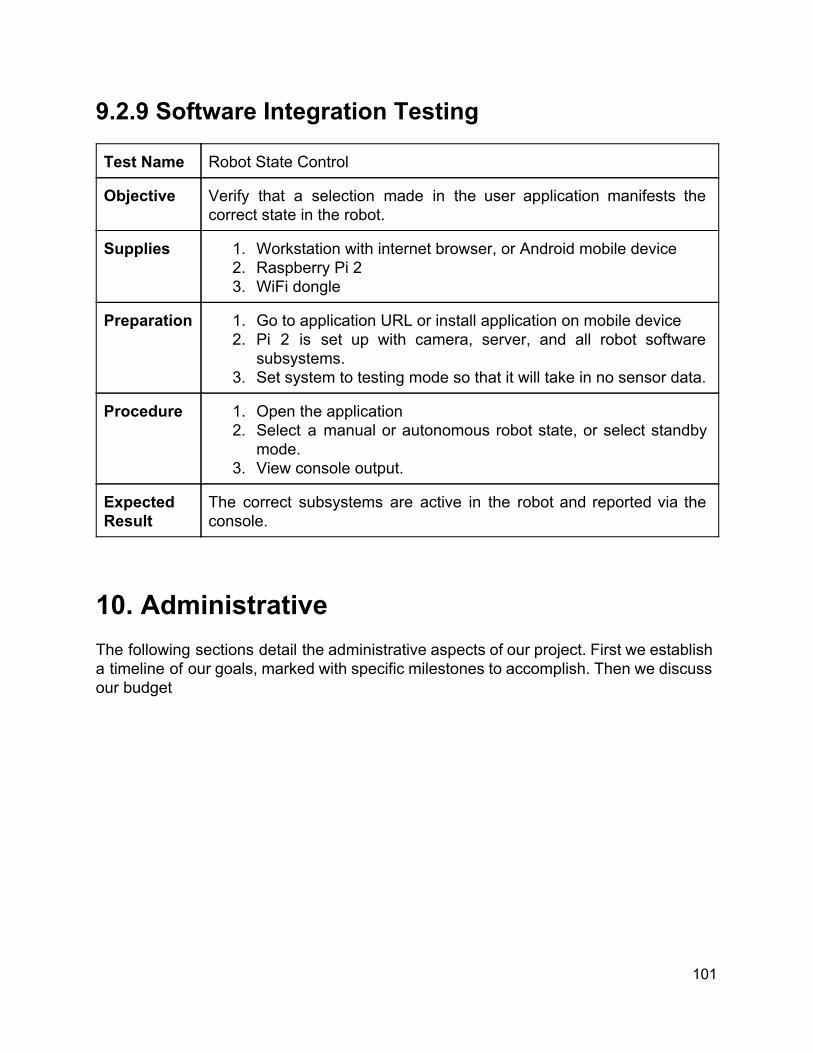
9.2.9 Software Integration Testing Test Name Robot State Control
Objective Verify that a selection made in the user application manifests the correct state in the robot.
Supplies 1. Workstation with internet browser, or Android mobile device 2. Raspberry Pi 2 3. WiFi dongle
Preparation 1. Go to application URL or install application on mobile device 2. Pi 2 is set up with camera, server, and all robot software
subsystems. 3. Set system to testing mode so that it will take in no sensor data.
Procedure 1. Open the application 2. Select a manual or autonomous robot state, or select standby
mode. 3. View console output.
Expected Result
The correct subsystems are active in the robot and reported via the console.
10. Administrative The following sections detail the administrative aspects of our project. First we establish a timeline of our goals, marked with specific milestones to accomplish. Then we discuss our budget
101
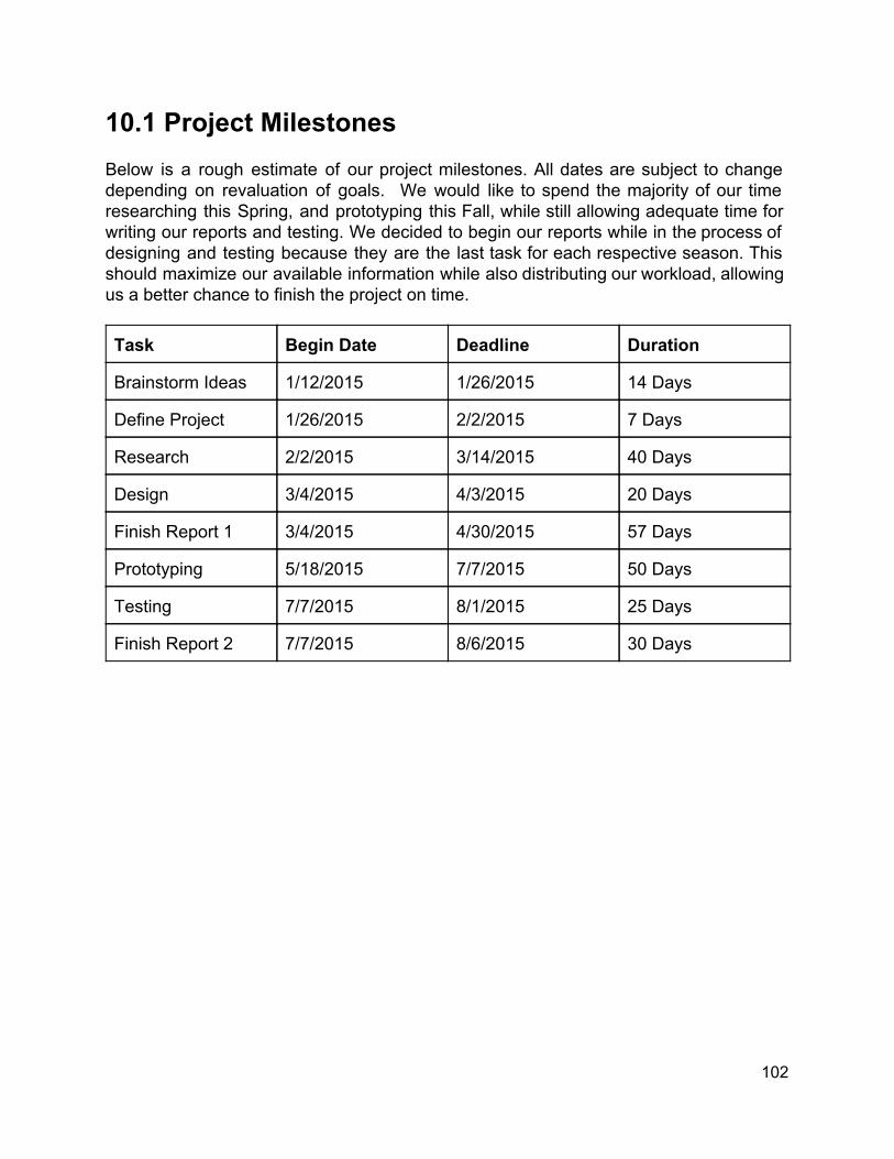
10.1 Project Milestones Below is a rough estimate of our project milestones. All dates are subject to change depending on revaluation of goals. We would like to spend the majority of our time researching this Spring, and prototyping this Fall, while still allowing adequate time for writing our reports and testing. We decided to begin our reports while in the process of designing and testing because they are the last task for each respective season. This should maximize our available information while also distributing our workload, allowing us a better chance to finish the project on time. Task Begin Date Deadline Duration
Brainstorm Ideas 1/12/2015 1/26/2015 14 Days
Define Project 1/26/2015 2/2/2015 7 Days
Research 2/2/2015 3/14/2015 40 Days
Design 3/4/2015 4/3/2015 20 Days
Finish Report 1 3/4/2015 4/30/2015 57 Days
Prototyping 5/18/2015 7/7/2015 50 Days
Testing 7/7/2015 8/1/2015 25 Days
Finish Report 2 7/7/2015 8/6/2015 30 Days
102
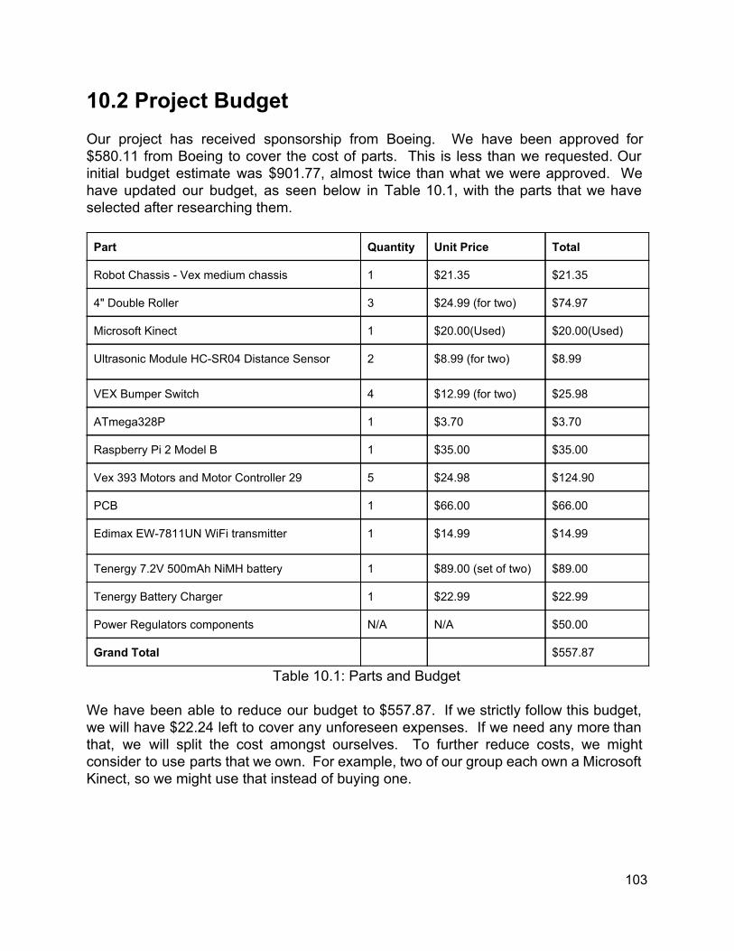
10.2 Project Budget Our project has received sponsorship from Boeing. We have been approved for $580.11 from Boeing to cover the cost of parts. This is less than we requested. Our initial budget estimate was $901.77, almost twice than what we were approved. We have updated our budget, as seen below in Table 10.1, with the parts that we have selected after researching them. Part Quantity Unit Price Total
Robot Chassis Vex medium chassis 1 $21.35 $21.35
4" Double Roller 3 $24.99 (for two) $74.97
Microsoft Kinect 1 $20.00(Used) $20.00(Used)
Ultrasonic Module HCSR04 Distance Sensor 2 $8.99 (for two) $8.99
VEX Bumper Switch 4 $12.99 (for two) $25.98
ATmega328P 1 $3.70 $3.70
Raspberry Pi 2 Model B 1 $35.00 $35.00
Vex 393 Motors and Motor Controller 29 5 $24.98 $124.90
PCB 1 $66.00 $66.00
Edimax EW7811UN WiFi transmitter 1 $14.99 $14.99
Tenergy 7.2V 500mAh NiMH battery 1 $89.00 (set of two) $89.00
Tenergy Battery Charger 1 $22.99 $22.99
Power Regulators components N/A N/A $50.00
Grand Total $557.87
Table 10.1: Parts and Budget We have been able to reduce our budget to $557.87. If we strictly follow this budget, we will have $22.24 left to cover any unforeseen expenses. If we need any more than that, we will split the cost amongst ourselves. To further reduce costs, we might consider to use parts that we own. For example, two of our group each own a Microsoft Kinect, so we might use that instead of buying one.
103

Appendices Appendix A Copyright Permissions
Fig.3.1.1 T100 Watchdog: Permission Obtained
Fig.3.1.2: KnightCop: Permission Obtianed
Appendix1

Fig. 3.1.5: Heatseekr: (Permission Pending)
Fig. 3.3.1: RGBDSLAM 3D Scan Output (Left), Camera Image (Center), Camera Image with Keypoints Visible (Right) Permission Pending
Appendix2

Fig. 3.3.2: Examples of GMapping Final Map Outputs Reprinted with Permission from Cyril Stachniss and Wolfram Burgard
Appendix3

Fig. 3.3.3 Examples of HectorSLAM Intermediate and Final Map Outputs Reprinted with Permission from Stefan Kohlbrecher
Figure 3.3.4: Examples of BreezySLAM Intermediate Mapping Outputs Reprinted with Permission from Dr. Simon Levy
Appendix4
Fig.3.4.1: Microsoft Kinect Permission Obtained Permission from Microsoft Developer Services Agreement: https://msdn.microsoft.com/enus/cc300389 Below is a image of the pertinent section
Fig. 3.4.2: Graphical example of a LIDAR point cloud Permission Obtained Fig. 3.4.3: Sonar Fig. 3.13.1: Reactive Behavior Model Permission Obtained
Appendix5

Fig. 3.4.42: SparkFun RedBot with limit switches. Permission Obtained “Photos: Please feel free to use our product photos in your project documentation or reports. If you would like to use a photo for a commercial venture, please contact us first at [email protected]. You can also find SparkFun photos on our Flickr page.” Figure 3.5.5a: Table of Specs for Various Microprocessors We Only Consider the First Three Figure 3.5.be:Microprocessor Benchmarks Reprinted with Permission from David Hunt
Figure 3.61:ATmega328 (with Arduino bootloader) Pinout. Permission Obtained Figure 3.62: ATmega2560 Pinout. Permission Obtained Permission obtained from: http://www.arduino.cc/en/Main/CopyrightNotice
Appendix6

Fig 3.13.1.1: Example of How Sound Waves Bounce Back to the Sonar Sensor Fig 3.13.1.2: Example of Tactile Sensor Circuit Permission Pending
Fig 3.13.2.2a: Market Share for Browsers 3/15/2015 Fig 3.13.2.2b: Market Share for Mobile Operating Systems Permission Pending
Figure 3.13.2.2c: Market Share of Android Versions Permission Granted via Creative Commons Attribution
Appendix7

Figure 3.13.2.2d: Market Share of iOS Versions Permission Pending
Appendix8
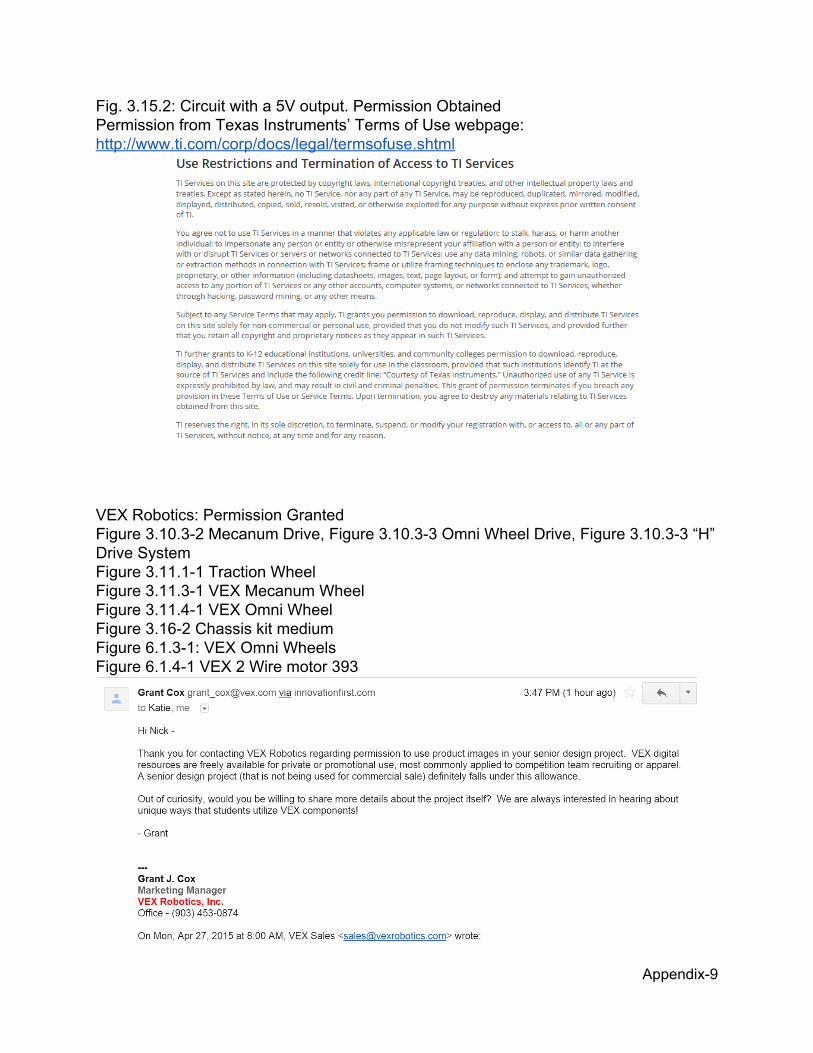
Fig. 3.15.2: Circuit with a 5V output. Permission Obtained Permission from Texas Instruments’ Terms of Use webpage: http://www.ti.com/corp/docs/legal/termsofuse.shtml
VEX Robotics: Permission Granted Figure 3.10.32 Mecanum Drive, Figure 3.10.33 Omni Wheel Drive, Figure 3.10.33 “H” Drive System Figure 3.11.11 Traction Wheel Figure 3.11.31 VEX Mecanum Wheel Figure 3.11.41 VEX Omni Wheel Figure 3.162 Chassis kit medium Figure 6.1.31: VEX Omni Wheels Figure 6.1.41 VEX 2 Wire motor 393
Appendix9

SparkFun: Permission Granted Figure 3.161 12” Aluminum Channel “Photos: Please feel free to use our product photos in your project documentation or reports. If you would like to use a photo for a commercial venture, please contact us first at [email protected]. You can also find SparkFun photos on our Flickr page.”
AndyMark: Permission Granted Figure 3.10.31 Swerve Module “Copyright:The entire content included in this site, including but not limited to text, graphics or code is copyrighted as a collective work under the United States and other copyright laws, and is the property of AndyMark, Inc.. The collective work includes works that are licensed to AndyMark, Inc.. Copyright 2003, AndyMark, Inc. ALL RIGHTS RESERVED. Permission is granted to electronically copy and print hard copy portions of this site for the sole purpose of placing an order with AndyMark, Inc. or purchasing AndyMark, Inc. products. You may display and, subject to any expressly stated restrictions or limitations relating to specific material, download or print portions of the material from the different areas of the site solely for your own noncommercial use, or to place an order with AndyMark, Inc. or to purchase AndyMark, Inc. products. Any other use, including but not limited to the reproduction, distribution, display or transmission of the content of this site is strictly prohibited, unless authorized by AndyMark, Inc.. You further agree not to change or delete any proprietary notices from materials downloaded from the site.”
Battery University: Permission Pending Figure 3.14.11 Advantages and Limitations of SLA Batteries Figure 3.14.21 Advantages and Limitations of Lithium Batteries Figure 3.14.31 Advantages and Disadvantages of NiCd Batteries Figure 3.14.41 Advantages and Disadvantages of NiMH Batteries
Appendix10

Robotoid: Permission Granted Figure 3.10.11 Differential Drive Example
Appendix11
Ikalogic: Permission Granted Figure 3.10.21 Car Steering
Appendix12

ElectricalKnowhow: Permission Granted Figure 3.12.1 DC Motor Types Figure 3.12.1.11 Brush DC Motor Internals Figure 3.12.1.12 Brush DC Motor Assembly Figure 3.12.1.13 Commutator Operation Figure 3.12.1.14 Permanent Magnet Motor Design Figure 3.12.1.15 SeriesWound Motor Design Figure 3.12.1.16 Servo Motor Design Figure 3.12.1.21 Brushless DC Motor Design Figure 3.12.1.22 BLDC and Brushed DC Comparison Figure 3.12.2.11 AC Motor Types Figure 3.12.2.21 DC Excited Motor
Tenergy: Permission Granted Figure 6.2.11 Tenergy 5000mAh NiMh Battery Figure 6.2.21 NiMH Battery Charger
Appendix13

Appendix B Works Cited [1] J. Buhmann, W. Burgard, A. Cremers, D. Fox, T. Hofmann, F. Schneider, J. Strikos and S. Thrun, 'The Mobile Robot RHINO', AI Magazine, vol. 16, no. 1, 1995. [2] Thrun, S.; Bennewitz, M.; Burgard, W.; Cremers, A.B.; Dellaert, F.; Fox, D.; Hahnel, D.; Rosenberg, C.; Roy, N.; Schulte, J.; Schulz, D., "MINERVA: a secondgeneration museum tourguide robot," Robotics and Automation, 1999. Proceedings. 1999 IEEE International Conference on , vol.3, no., pp.1999,2005 vol.3, 1999 [3] Mataric, M.J. Behaviorbased control: Main properties and implications. In: Proceedings, IEEE International Conference on Robotics and Automation, Workshop on Architectures for Intelligent Control Systems, pp. 4654 [4] ATmel “ATMEL 8BIT MICROCONTROLLER WITH 4/8/16/32KBYTES INSYSTEM PROGRAMMABLE FLASH” ATmega48A/PA/88A/PA/168A/PA/328/P datasheet, Oct. 2014
[5] Msdn.microsoft.com, 'Kinect for Windows Sensor Components and Specifications', 2015. [Online]. Available: https://msdn.microsoft.com/enus/library/jj131033.aspx. [Accessed: 29 Apr 2015].
[6] Fairchild “3Terminal 1 A Positive Voltage Regulator,” LM78XX/LM78XXA datasheet, Sept. 2004
[7] Digikey.com, 'Understanding the Advantages and Disadvantages of Linear Regulators DigiKey', 2015. [Online]. Available: http://www.digikey.com/en/articles/techzone/2012/may/understandingtheadvantagesanddisadvantagesoflinearregulators. [Accessed: 29 Apr 2015].
[8] Texas Instruments, “LM2576/LM2576HV Series SIMPLE SWITCHER® 3A StepDown Voltage Regulator ,” LM2756/LM2576HV datasheet, June 1999 [Revised April 2013]
[9] Zbattery.com, 'Memory Effect What it is and what you can do about it', 2015. [Online]. Available: http://www.zbattery.com/BatteryMemoryEffect. [Accessed: 29 Apr 2015].
[10] Batteryuniversity.com, 'Leadbased Batteries Information – Battery University', 2015. [Online]. Available: http://batteryuniversity.com/learn/article/lead_based_batteries. [Accessed: 29 Apr 2015].
[11]B. Steve Degeyter, 'BatteryStuff Articles | Lithium Iron Phosphate Battery FAQ', Batterystuff.com, 2015. [Online]. Available: http://www.batterystuff.com/kb/frequentlyaskedquestions/powersportsbatteriesfaq/lithiumironfaq.html. [Accessed: 29 Apr 2015].
Appendix14

[12] Batteryuniversity.com, 'Nickelbased Batteries Information – Battery University', 2015. [Online]. Available: http://batteryuniversity.com/learn/article/nickel_based_batteries. [Accessed: 29 Apr 2015].
[13] Electricalknowhow.com, 'Classification of Electric Motors ~ Electrical Knowhow', 2015. [Online]. Available: http://www.electricalknowhow.com/2012/05/classificationofelectricmotors.html. [Accessed: 29 Apr 2015].
Appendix15
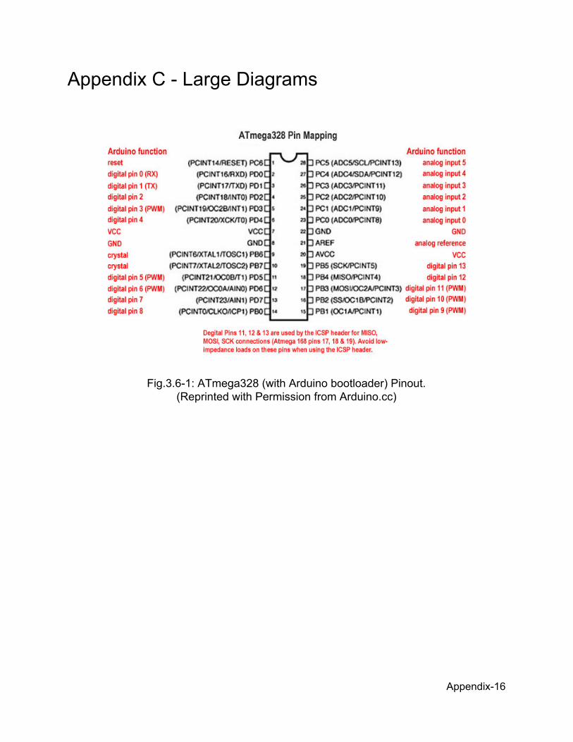
Appendix C Large Diagrams
Fig.3.61: ATmega328 (with Arduino bootloader) Pinout. (Reprinted with Permission from Arduino.cc)
Appendix16
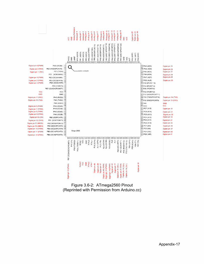
Figure 3.62: ATmega2560 Pinout (Reprinted with Permission from Arduino.cc)
Appendix17

Fig. 6.2.42: Motor Power Supply
Appendix18