sentinel network - cornell ece
TRANSCRIPT
SENTINEL NETWORK
A Design Project Report
Presented to the Engineering Division of the Graduate School
Of Cornell University
In Partial Fulfillment of the Requirements for the Degree of
Master of Engineering (Electrical)
By
Ruibing Wang
Project Advisor: Prof. Bruce Land
Degree Date: May, 2009
Abstract
Master of Electrical Engineering Program
Cornell University
Design Project Report
Project Title:
Sentinel Network
Author:
Ruibing Wang
Abstract:
The Sentinel Network is a sensor network intended for outdoor usage to detect the presence of trespassers in restricted, private areas. Multiple sensor nodes wirelessly communicate with a base node, extended through a relay node if necessary, to alert the user through an UI that a unique identified sensor node has been tripped.
In order to fulfill its solution as a low cost, low maintenance sensor network that is scalable to the needs of the user, the Sentinel Network was designed to be as easy to use as possible. Sensor and relay nodes can be easily added (or appended) to the network topology without requiring any firmware upgrades or changes. The process of monitoring the Sentinel Network was also simplified through the supplied UI for the user to access, monitor, and debug the Sentinel Network on any PC. Every sensor and relay node was also designed to run for a minimum of a year through solar powered daytime operation with a AA battery proving backup power during lowlight seasons and conditions. The network protocol was also designed to be as robust as possible with automatic CRC, CSMA‐CA, frame acknowledgement, and address filtering. Finally, every sensor is paired with a PIR sensor to detect moving trespassers.
The Sentinel Network provides a complete solution to detecting trespassers in remote areas. While the main focus is its ability as a PIR sensor network, it is, in fact, a network platform. Any sensor or data input can be attached on the sensor nodes to be relayed to the base node. With a small amount of modifications, it can even serve as a tracking system for the sensor node.
Report Approved by
Project Advisor: ________________________________________________ Date: __________________

Contents
1 Executive Summary ............................................................................................................................... 1
2 Introduction .......................................................................................................................................... 1
2.1 Background ................................................................................................................................... 1
2.2 Design Requirements .................................................................................................................... 2
2.3 Project Boundaries ........................................................................................................................ 3
2.4 Project Objectives ......................................................................................................................... 3
3 Conceptual Design ................................................................................................................................ 3
3.1 Conceptual System Structure ........................................................................................................ 4
3.2 Network ........................................................................................................................................ 4
3.3 Wireless Interface ......................................................................................................................... 5
3.4 Controller ...................................................................................................................................... 7
3.4.1 Embedded Programming Standard ....................................................................................... 8
3.4.2 Embedded Compiler ............................................................................................................. 9
3.5 Sensor ............................................................................................................................................ 9
3.6 Power .......................................................................................................................................... 11
3.7 UI ................................................................................................................................................. 13
4 Development ....................................................................................................................................... 14
4.1 Schedule ...................................................................................................................................... 14
4.2 Tools ............................................................................................................................................ 14
5 Overall System .................................................................................................................................... 14
5.1 Abstract ....................................................................................................................................... 14
5.2 Structure ..................................................................................................................................... 14
5.3 Design .......................................................................................................................................... 16
5.3.1 Abstract ............................................................................................................................... 16
5.3.2 Hardware............................................................................................................................. 16
5.3.3 Software .............................................................................................................................. 17
5.4 Implementation .......................................................................................................................... 20
5.4.1 Abstract ............................................................................................................................... 20
5.4.2 Hardware............................................................................................................................. 20
5.4.3 Software .............................................................................................................................. 26
5.5 Conclusion ................................................................................................................................... 28
5.6 Future Recommendations .......................................................................................................... 28
6 Controller ............................................................................................................................................ 28
6.1 Abstract ....................................................................................................................................... 28
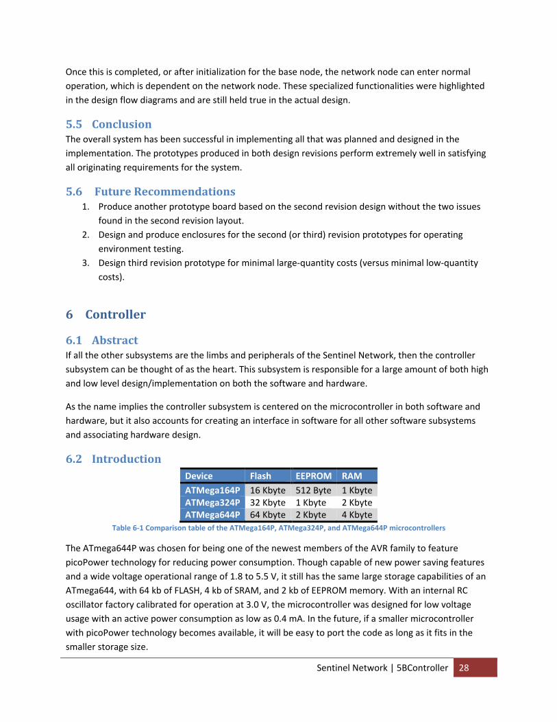
6.2 Introduction ................................................................................................................................ 28
6.3 Subsystem Requirements ........................................................................................................... 30
6.4 Hardware .................................................................................................................................... 31
6.4.1 Abstract ............................................................................................................................... 31
6.4.2 Introduction ........................................................................................................................ 31
6.4.3 Design .................................................................................................................................. 32
6.4.4 Implementation .................................................................................................................. 32
6.4.5 Conclusion ........................................................................................................................... 33
6.4.6 Future Recommendations .................................................................................................. 33
6.5 Software ...................................................................................................................................... 34
6.5.1 Abstract ............................................................................................................................... 34
6.5.2 Introduction ........................................................................................................................ 34
6.5.3 Design .................................................................................................................................. 36
6.5.4 Implementation .................................................................................................................. 38
6.5.5 Conclusion ........................................................................................................................... 43
6.5.6 Future Recommendations .................................................................................................. 43
7 RF ........................................................................................................................................................ 44
7.1 Abstract ....................................................................................................................................... 44
7.2 Introduction ................................................................................................................................ 44
7.3 Subsystem Requirements ........................................................................................................... 45
7.4 Hardware .................................................................................................................................... 45
7.4.1 Abstract ............................................................................................................................... 45
7.4.2 Introduction ........................................................................................................................ 46
7.4.3 Design .................................................................................................................................. 48
7.4.4 Implementation .................................................................................................................. 50
7.4.5 Conclusion ........................................................................................................................... 52
7.4.6 Future Recommendations .................................................................................................. 52
7.5 Software ...................................................................................................................................... 52
7.5.1 Abstract ............................................................................................................................... 52
7.5.2 Introduction ........................................................................................................................ 52
7.5.3 Design .................................................................................................................................. 58
7.5.4 Implementation .................................................................................................................. 62
7.5.5 Conclusion ........................................................................................................................... 63
7.5.6 Future Recommendations .................................................................................................. 63
8 Sensor ................................................................................................................................................. 63
8.1 Abstract ....................................................................................................................................... 63
8.2 Introduction ................................................................................................................................ 64
8.3 Subsystem Requirements ........................................................................................................... 64
8.4 Hardware .................................................................................................................................... 65
8.4.1 Abstract ............................................................................................................................... 65
8.4.2 Introduction ........................................................................................................................ 65
8.4.3 Design .................................................................................................................................. 65
8.4.4 Implementation .................................................................................................................. 66
8.4.5 Conclusion ........................................................................................................................... 67
8.4.6 Future Recommendations .................................................................................................. 67
8.5 Software ...................................................................................................................................... 67
8.5.1 Abstract ............................................................................................................................... 67
8.5.2 Introduction ........................................................................................................................ 67
8.5.3 Design .................................................................................................................................. 68
8.5.4 Implementation .................................................................................................................. 69
8.5.5 Conclusion ........................................................................................................................... 70
8.5.6 Future Recommendations .................................................................................................. 70
9 Power Supply ...................................................................................................................................... 70
9.1 Abstract ....................................................................................................................................... 70
9.2 Introduction ................................................................................................................................ 71
9.3 Subsystem Requirements ........................................................................................................... 72
9.4 Hardware .................................................................................................................................... 72
9.4.1 Abstract ............................................................................................................................... 72
9.4.2 Introduction ........................................................................................................................ 72
9.4.3 Design .................................................................................................................................. 74
9.4.4 Implementation .................................................................................................................. 74
9.4.5 Conclusion ........................................................................................................................... 77
9.4.6 Future Recommendations .................................................................................................. 77
9.5 Software ...................................................................................................................................... 77
9.5.1 Abstract ............................................................................................................................... 77
9.5.2 Future Recommendations .................................................................................................. 78
10 UI ..................................................................................................................................................... 78
10.1 Abstract ....................................................................................................................................... 78
10.2 Introduction ................................................................................................................................ 78
10.3 Subsystem Requirements ........................................................................................................... 79
10.4 Hardware .................................................................................................................................... 79
10.4.1 Abstract ............................................................................................................................... 79
10.4.2 Introduction ........................................................................................................................ 79
10.4.3 Design .................................................................................................................................. 80
10.4.4 Implementation .................................................................................................................. 81
10.4.5 Conclusion ........................................................................................................................... 81
10.4.6 Future Recommendations .................................................................................................. 82
10.5 Software ...................................................................................................................................... 82
10.5.1 Abstract ............................................................................................................................... 82
10.5.2 Introduction ........................................................................................................................ 82
10.5.3 Design .................................................................................................................................. 82
10.5.4 Implementation .................................................................................................................. 83
10.5.5 Conclusion ........................................................................................................................... 85
10.5.6 Future Recommendations .................................................................................................. 85
11 Analysis ........................................................................................................................................... 85
11.1 Performance Results ................................................................................................................... 86
11.2 Cost ............................................................................................................................................. 86
12 Conclusion ....................................................................................................................................... 88
12.1 Impact Statement ....................................................................................................................... 88
12.2 Future Recommendations .......................................................................................................... 88
13 User Manual .................................................................................................................................... 88
13.1 Sentinel Hardware ...................................................................................................................... 88

13.2 Sentinel Application .................................................................................................................... 89
14 Appendices ...................................................................................................................................... 92
14.1 Abbreviations .............................................................................................................................. 92
14.2 Embedded Code .......................................................................................................................... 95
14.2.1 Base Node ........................................................................................................................... 95
14.2.2 Relay Node ........................................................................................................................ 102
14.2.3 Sensor Node ...................................................................................................................... 114
14.2.4 Common Sentinel Library .................................................................................................. 128
14.2.5 Common ZigBee Library .................................................................................................... 137
14.2.6 Common UART Library ...................................................................................................... 172
14.2.7 Common MCU Library ....................................................................................................... 177
14.2.8 Common External Interrupt Library .................................................................................. 178
14.2.9 Common Timer Library ..................................................................................................... 185
14.3 Application Code ....................................................................................................................... 192
14.3.1 Sentinel Class .................................................................................................................... 192
14.3.2 Communicator Class ......................................................................................................... 201
14.3.3 Serial Class ......................................................................................................................... 215
14.3.4 Node Class ......................................................................................................................... 222
14.3.5 Static Data Class ................................................................................................................ 223
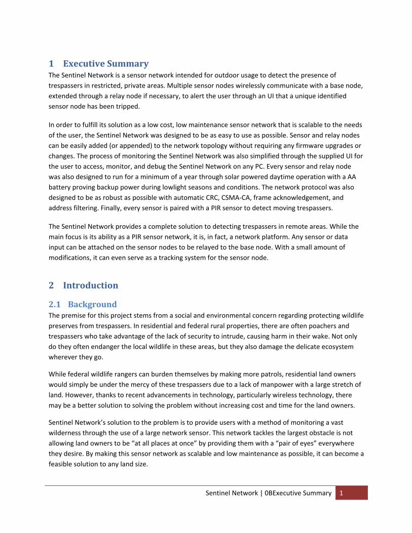
1 Executive Summary The Sentinel Network is a sensor network intended for outdoor usage to detect the presence of trespassers in restricted, private areas. Multiple sensor nodes wirelessly communicate with a base node, extended through a relay node if necessary, to alert the user through an UI that a unique identified sensor node has been tripped.
In order to fulfill its solution as a low cost, low maintenance sensor network that is scalable to the needs of the user, the Sentinel Network was designed to be as easy to use as possible. Sensor and relay nodes can be easily added (or appended) to the network topology without requiring any firmware upgrades or changes. The process of monitoring the Sentinel Network was also simplified through the supplied UI for the user to access, monitor, and debug the Sentinel Network on any PC. Every sensor and relay node was also designed to run for a minimum of a year through solar powered daytime operation with a AA battery proving backup power during lowlight seasons and conditions. The network protocol was also designed to be as robust as possible with automatic CRC, CSMA‐CA, frame acknowledgement, and address filtering. Finally, every sensor is paired with a PIR sensor to detect moving trespassers.
The Sentinel Network provides a complete solution to detecting trespassers in remote areas. While the main focus is its ability as a PIR sensor network, it is, in fact, a network platform. Any sensor or data input can be attached on the sensor nodes to be relayed to the base node. With a small amount of modifications, it can even serve as a tracking system for the sensor node.
2 Introduction
2.1 Background The premise for this project stems from a social and environmental concern regarding protecting wildlife preserves from trespassers. In residential and federal rural properties, there are often poachers and trespassers who take advantage of the lack of security to intrude, causing harm in their wake. Not only do they often endanger the local wildlife in these areas, but they also damage the delicate ecosystem wherever they go.
While federal wildlife rangers can burden themselves by making more patrols, residential land owners would simply be under the mercy of these trespassers due to a lack of manpower with a large stretch of land. However, thanks to recent advancements in technology, particularly wireless technology, there may be a better solution to solving the problem without increasing cost and time for the land owners.
Sentinel Network’s solution to the problem is to provide users with a method of monitoring a vast wilderness through the use of a large network sensor. This network tackles the largest obstacle is not allowing land owners to be “at all places at once” by providing them with a “pair of eyes” everywhere they desire. By making this sensor network as scalable and low maintenance as possible, it can become a feasible solution to any land size.
Sentinel Network | 0BExecutive Summary 1
2.2 Design Requirements In order to satisfy the solution of providing a sensor network with minimal maintenance yet maximum scalability, the following design (or system) requirements will be used as the basis of the design process. These design requirements will become the originating requirements for the rest of the system during the design process.
ID Requirement Type Abstract Name OR1 The system shall scale dynamically Functional Scale dynamically OR2 The system shall have a minimum MTBM of 1 year Performance Minimum MTBM OR3 The system shall detect moving trespassers Functional Detect trespassers OR4 The system shall notify the user of a detection Functional Notify user OR5 The system shall log all detections Functional Log detections OR6 The system shall feature an UI Structural Feature UI OR7 The system shall communicate wirelessly Interface Communicate wirelesslyTable 2‐1 Table of the Originating Requirements for the design is shown here along with its requirement use type and
abstraction requirement name
While the originating requirements in Table 2‐1 may be a bit vague, they do perform their tasks of being very high level requirements. During the system, subsystem, and component design process, these requirements will be used to derive lower level requirements.
• OR1 will ensure the network scales dynamically to minimize setup time and complexity. By also implying the dynamics of the network scaling in term of size, it ensures the design allows the network to take on just about any size or topology to fit the user’s needs.
• OR2 emphasizes the low maintenance of the system by dedicating that there will be no component in the system that will require maintenance within a 1 year period. It is important not to get this confused with MTBF or MTTR, as the system would still be completely functional after a one year period, only certain components need to be replaced or calibrated. For example, a brand new car needs annual maintenance at a local maintenance garage long before it is considered broken down.
• OR3, OR4, and OR5 all work together to ensure that the system and network fulfills its key functionalities of detecting trespassers, notifying the user, and logging the event. While there are numerous methods of detecting trespassers, the intent is to detect moving trespassers as they intrude upon private or federal land. The system must also notify the user through some methodology, whether by visual or audio cues. Finally, the system must also log the event for the benefit of the user and in case the user is absent when trespasser is detected. These three requirements lay down the principal functional requirements for the system.
• OR6 both aides the system in fulfilling certain key functionalities and reduces the complexity of the system by providing an UI for the user to use in interacting with the system. This UI will most likely be a GUI for the user to use in accessing, monitoring, and debugging the system.
• OR7 clarifies the intended interface type for the network. While there are numerous types of interface available for networks, a wireless interface will extend the network range beyond any physical medium without having a large setup cost. A wireless interface will allow the network
Sentinel Network | 1BIntroduction 2

to cover a very large area without having to set up physical interfaces and worrying about maintaining those interfaces.
2.3 Project Boundaries The scope of the Sentinel Network project will limit the design of the sensor network to only utilize COTS components for several reasons. While it does limit the amount of research the project will entail (e.g. the project will not try to research and design a new wireless communication interface standard or a new type of sensor), it ensures that ready‐made and available for sale components are used to reduce cost and development time. Not only does this reduce development cost by utilizing widely available components and time by buying them from well known distributors (e.g. Digi‐key), it also ensures that the maturity level of the technology behind these components is high enough to avoid large risks and obstacles during the development phase of the project. Finally, these COTS components will also reduce the low‐yield manufacturing cost of the system.
Aside from this, the project really has not boundaries so to speak. Due to time‐constraints, most of the development time will most likely be focused on certain key functional requirements that will ensure that the system performs as intended. For example, due to all the sensors that can be used for detecting moving trespassers and the ease with which they can be implemented, it is probably in the best interest of the project focus on the network system as the delivery vehicle of the detection data to the user rather than focusing on how the detection is made. In other words, the project should be focused on the Sentinel Network more as a network platform than a sensor network aspect due to the novelty of the network.
2.4 Project Objectives The primary objective of the Sentinel Network project is to provide a fully working prototype that, at the very least, satisfies all the design requirements in Table 2‐1. Due to time‐constraints and the scope of the project, this system prototype will only need to be verified in a laboratory environment to confirm the success of the project.
There are also numerous secondary objectives for the Sentinel Network. By focusing on the Sentinel Network as a network platform, the necessary steps to allow modifications to the platform must be made. For example, the design and documentation of the Sentinel Network must simply the process of changing the sensor type to accommodate different environments and needs. The Sentinel Network should also provide a fully documented embedded library for the wireless interface that it implements.
3 Conceptual Design During the conceptual design phase of the project, a number of concepts where generated for the Sentinel Network and its design. This part of the report will run through the different concepts and attributes considered for each subsystem of the Sentinel Network and justify the design decision through a textual argument.
Sentinel Network | 2BConceptual Design 3
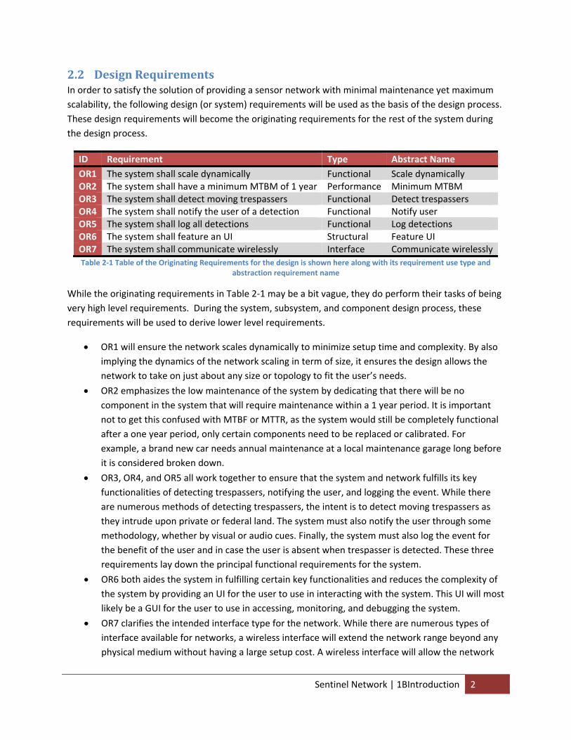
3.1 Conceptual System Structure
Figure 3‐1 System entity relationship diagram showing the relationship between the various conceptual subsystems in the
Sentinel Network system
The conceptual system must first be broken into as many distinct subsystems as possible, referring to Figure 3‐1, in order to analyze each effectively. While the entire system revolves around a central controller subsystem that will act as the “brain” of the system, all the other mission critical functionalities are assigned to other subsystems.
3.2 Network
Figure 3‐2 System entity relationship diagram of the Sentinel Network in its simplest form is shown here. The two blue blocks represents the two network node types. The two green blocks are two of the other components of the system. The red block
represents the user.
Sentinel Network | 2BConceptual Design 4
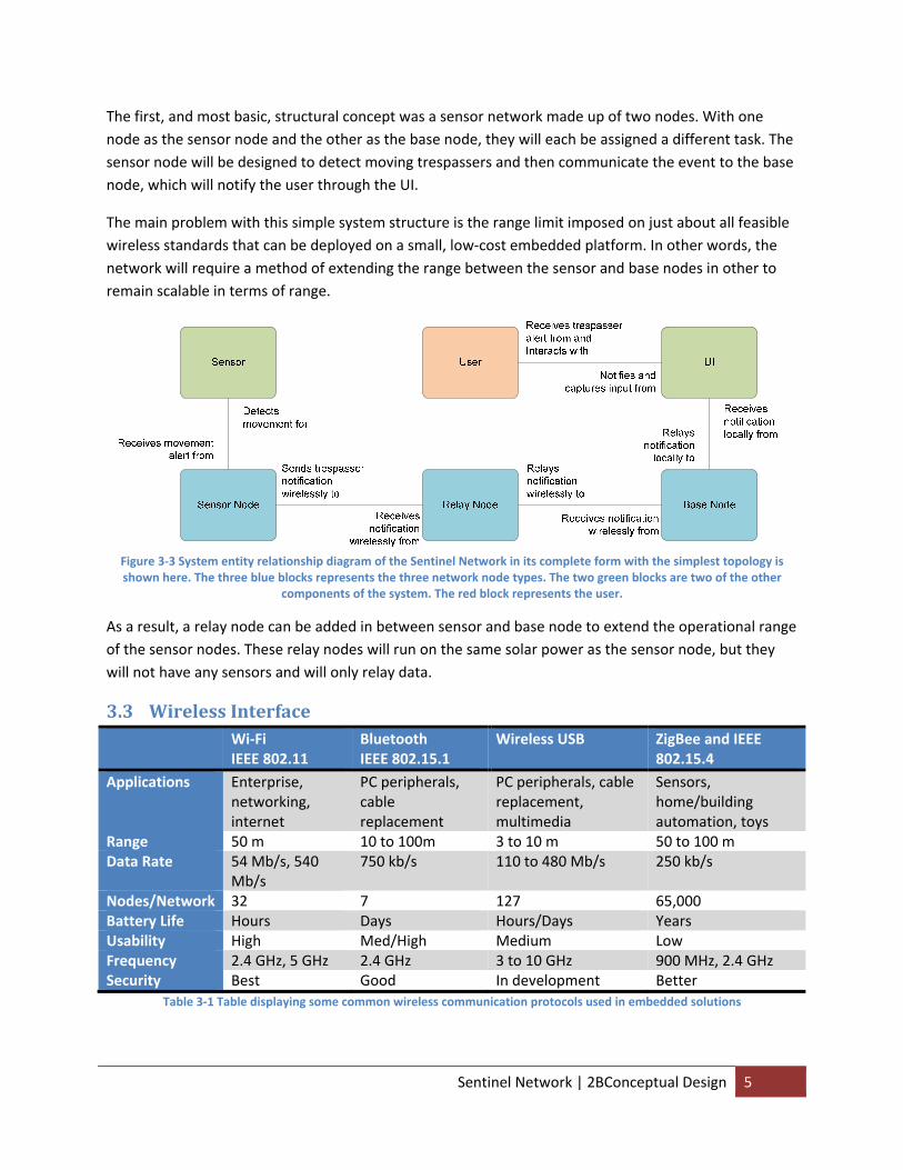
The first, and most basic, structural concept was a sensor network made up of two nodes. With one node as the sensor node and the other as the base node, they will each be assigned a different task. The sensor node will be designed to detect moving trespassers and then communicate the event to the base node, which will notify the user through the UI.
The main problem with this simple system structure is the range limit imposed on just about all feasible wireless standards that can be deployed on a small, low‐cost embedded platform. In other words, the network will require a method of extending the range between the sensor and base nodes in other to remain scalable in terms of range.
Figure 3‐3 System entity relationship diagram of the Sentinel Network in its complete form with the simplest topology is shown here. The three blue blocks represents the three network node types. The two green blocks are two of the other
components of the system. The red block represents the user.
As a result, a relay node can be added in between sensor and base node to extend the operational range of the sensor nodes. These relay nodes will run on the same solar power as the sensor node, but they will not have any sensors and will only relay data.
3.3 Wireless Interface Wi‐Fi
IEEE 802.11 Bluetooth IEEE 802.15.1
Wireless USB ZigBee and IEEE 802.15.4
Applications Enterprise, networking, internet
PC peripherals, cable replacement
PC peripherals, cable replacement, multimedia
Sensors, home/building automation, toys
Range 50 m 10 to 100m 3 to 10 m 50 to 100 m Data Rate 54 Mb/s, 540
Mb/s 750 kb/s 110 to 480 Mb/s 250 kb/s
Nodes/Network 32 7 127 65,000 Battery Life Hours Days Hours/Days Years Usability High Med/High Medium Low Frequency 2.4 GHz, 5 GHz 2.4 GHz 3 to 10 GHz 900 MHz, 2.4 GHz Security Best Good In development Better
Table 3‐1 Table displaying some common wireless communication protocols used in embedded solutions
Sentinel Network | 2BConceptual Design 5
In order to help choose the appropriate wireless communication protocol that can support a robust network topology while satisfying the design requirements, all the alternatives have been gathered on Table 3‐1 and characterized by their performance in each attribute.
Referring back to the originating requirements of providing a highly scalable, low maintenance sensor network, we analyze the desirability of each alternative. Starting with Wi‐Fi, the standard IEEE 802.11 WLAN computer communication protocol, we notice that the standard consumes too much power to fit Sentinel Network’s endeavor of utilizing small, embedded platforms. While Wireless USB fairs slightly better in terms of power consumption, its communication range is too short to fit our needs. While Bluetooth improves on both in terms of range and power consumption by sacrificing data throughput, it is quite limited in terms of the number of nodes that it can support. Despite being in the same IEEE 802.15 WPAN family as Bluetooth, IEEE 802.15.4 (e.g. Task group 4 of the IEEE 802.15 working group) I designed specifically to deliver very long battery life at the cost of low data rate and very low complexity. While the use of this communication protocol will limit the hardware‐supported network complexity and data throughput rate, the improvement in range and power consumption is worth the trade off. In fact, in regards to the Sentinel Network’s application of simply transmitting a trespasser notification accompanied by the sensor ID of where the detection occurred, the 250 kb/s data rate is more than satisfactory. The deficiencies in hardware network support can also be supplemented by software support.
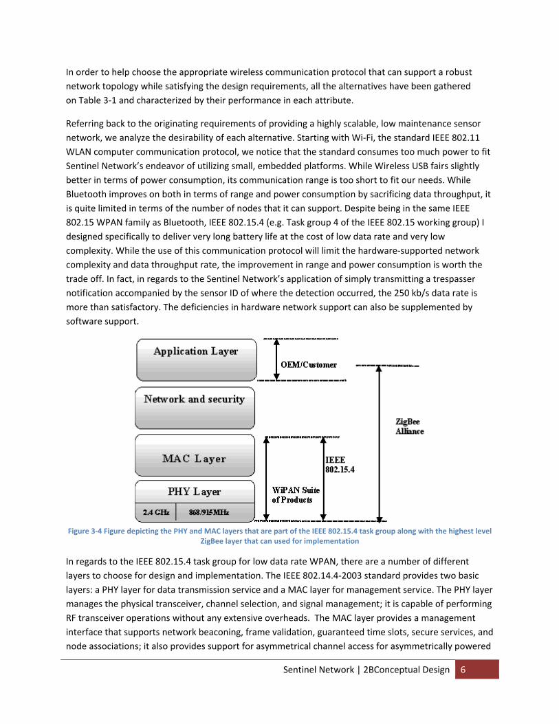
Figure 3‐4 Figure depicting the PHY and MAC layers that are part of the IEEE 802.15.4 task group along with the highest level
ZigBee layer that can used for implementation
In regards to the IEEE 802.15.4 task group for low data rate WPAN, there are a number of different layers to choose for design and implementation. The IEEE 802.14.4‐2003 standard provides two basic layers: a PHY layer for data transmission service and a MAC layer for management service. The PHY layer manages the physical transceiver, channel selection, and signal management; it is capable of performing RF transceiver operations without any extensive overheads. The MAC layer provides a management interface that supports network beaconing, frame validation, guaranteed time slots, secure services, and node associations; it also provides support for asymmetrical channel access for asymmetrically powered
Sentinel Network | 2BConceptual Design 6
devices. While it is based upon the PHY layer, meaning that it uses the PHY layer to perform the actual data transmissions, it acts to enhance the functionalities of the PHY layer. Beyond this, there is also the ZigBee specification, which is a suite of high level communication protocols based on the IEEE 802.15.4‐2006 standard for WPAN. As can be seen from Figure 3‐4 Figure depicting the PHY and MAC layers that are part of the IEEE 802.15.4 task group along with the highest level ZigBee layer that can used for implementationFigure 3‐4, the ZigBee specification utilizes the MAC and PHY layer by adding an additional level of network and security functionalities to it, much like how the Wi‐Fi specification added them to the IEEE 802.11 work group. ZigBee provides a low level QoS guarantee, support for a larger network order, and a selectable level of security.
After considering the functionalities required for the purposes of this project, the MAC layer has been chosen due to its native functionalities of address filtering, frame acknowledgements, and frame validation being supported by all 802.15.4‐2003
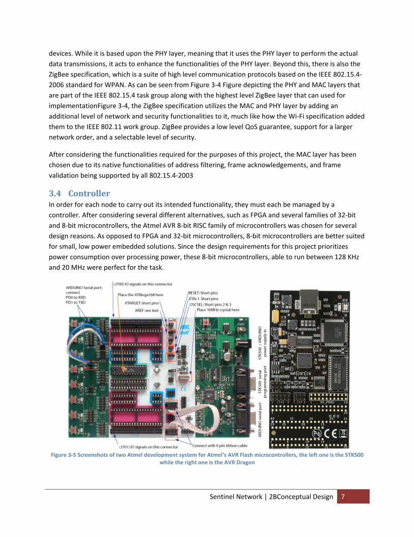
3.4 Controller In order for each node to carry out its intended functionality, they must each be managed by a controller. After considering several different alternatives, such as FPGA and several families of 32‐bit and 8‐bit microcontrollers, the Atmel AVR 8‐bit RISC family of microcontrollers was chosen for several design reasons. As opposed to FPGA and 32‐bit microcontrollers, 8‐bit microcontrollers are better suited for small, low power embedded solutions. Since the design requirements for this project prioritizes power consumption over processing power, these 8‐bit microcontrollers, able to run between 128 KHz and 20 MHz were perfect for the task.
Figure 3‐5 Screenshots of two Atmel development system for Atmel’s AVR Flash microcontrollers, the left one is the STK500
while the right one is the AVR Dragon
Sentinel Network | 2BConceptual Design 7

After focusing the trade study on 8‐bit microcontrollers, previous design experience would then narrow the choices down to the Microchip and Atmel family of 8‐bit Flash microcontrollers. While they both have a large offering of microcontrollers aimed at low power consumptions, the Atmel AVR 8‐bit RISC family of microcontrollers was chosen for several reasons. As opposed to the Microchip PIC microcontrollers, all the AVR microcontrollers can be programmed through the standard Atmel development systems, as shown in Figure 3‐5. Furthermore, the Atmel AVR microcontrollers can use the open‐source AVR‐GCC compiler and development suite to further drive the down development cost. Added on with Atmel’s well written datasheet and large library of supplemental application notes, all these factors will help reduce initial development cost and time on the controller side.
3.4.1 Embedded Programming Standard Because the controller will act as the central embedded platform where all the codes will be written, a certain standard (e.g. template) should be adopted for all development codes. The following structure was derived from past programming experience and designed to simply even the most complex code to a certain degree (as not all of the following structure applies to simpler test and prototype codes):
• Description
• Global preprocessor constants
• Global preprocessor macros
• Includes
• Local preprocessor constants
• Local preprocessor macros
• FLASH variables declaration and initialization
• EEPROM variables declaration and initialization
• Enumerator variables declaration
• Global variables declaration
• Prototype functions
• ISR
• Local functions
• Main function o Local variables declaration and initialization o Global variables initialization o Local initialization o External initialization o Enable ISR o Main Loop
• Initialization Functions
Beyond this, user changeable constants, such as the UART baud rate, the Timer2 compare match latency, and various software timers, are all automatically calculated and will be easily adjustable through the initialization function. This will allow each type of node to be easily, yet independently, modified.
Sentinel Network | 2BConceptual Design 8
3.4.2 Embedded Compiler Normally, the standard compiler to use for such a project would have been the CodevisionAVR compiler, due to its easy to use extensions for ISR, FLASH memory, EEPROM memory, bit level access for I/O registers, and more. However, an open source compiler would be a much better basis of development.
AVR‐GCC fits this requirement perfectly as a free, widely accepted and popular AVR compiler and assembler made available through the GNU project. Though it is much stricter and adheres to standard C than CodevisionAVR when it comes to variable, bitwise, register, and assembly manipulation, it is also much more robust due to its extensive C library. The WinAVR open source, software development suite makes development on it even easier by providing all the compiling, editing, debugging, and boot loading programs needed for any embedded programmer.
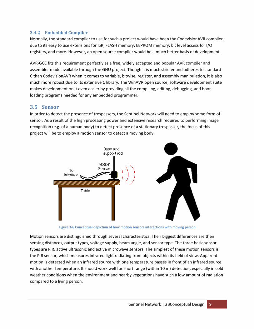
3.5 Sensor In order to detect the presence of trespassers, the Sentinel Network will need to employ some form of sensor. As a result of the high processing power and extensive research required to performing image recognition (e.g. of a human body) to detect presence of a stationary trespasser, the focus of this project will be to employ a motion sensor to detect a moving body.
Figure 3‐6 Conceptual depiction of how motion sensors interactions with moving person
Motion sensors are distinguished through several characteristics. Their biggest differences are their sensing distances, output types, voltage supply, beam angle, and sensor type. The three basic sensor types are PIR, active ultrasonic and active microwave sensors. The simplest of these motion sensors is the PIR sensor, which measures infrared light radiating from objects within its field of view. Apparent motion is detected when an infrared source with one temperature passes in front of an infrared source with another temperature. It should work well for short range (within 10 m) detection, especially in cold weather conditions when the environment and nearby vegetations have such a low amount of radiation compared to a living person.
Sentinel Network | 2BConceptual Design 9
Ultrasonic sensors, also known as transducers, work on a principle similar to radar or sonar, which evaluate attributes of a target by interpreting the echoes from the radio or sound waves respectively. Active ultrasonic sensors generate high frequency sound wave and evaluate the echo which is received back by the sensor. These sensors then measure the time interval between sending the signal and receiving the echo to calculate the distance of the object. The main problem with using such a sensor, which generates sound waves in the ultrasonic range of above 20 kHz, in a wildlife environment is the amount of damage it could bring to the animals and insects there. Ultrasonic sensors have often been used as animal (e.g. dogs and cats) and insect repellers, because they can hear these powerful ultra sonic sounds. Microwave sensors work on a similar principle to ultrasonic sensors, but it also share similar faults. Patients with cardiac pacemakers have often been warned to stay away from microwave ovens due to the stray high‐frequency, high‐intensity microwaves. These short waves can bypass the pacemaker’s noise protection and interfere with or permanently damage the pulse generator.
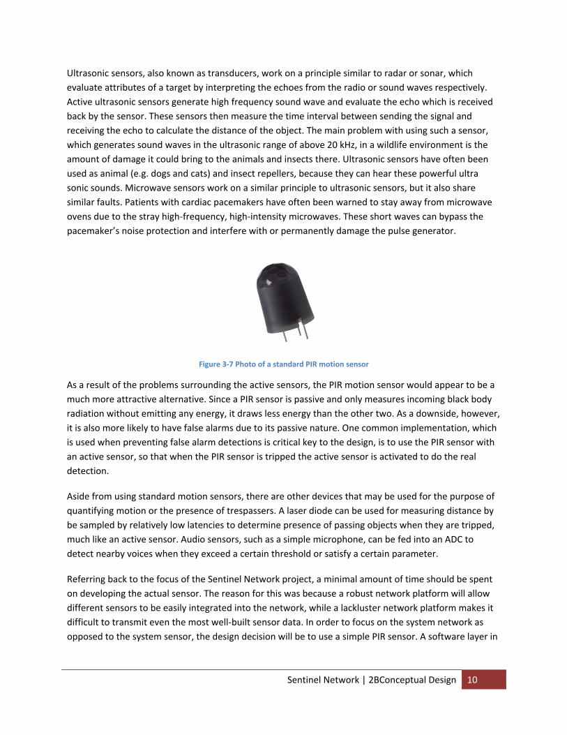
Figure 3‐7 Photo of a standard PIR motion sensor
As a result of the problems surrounding the active sensors, the PIR motion sensor would appear to be a much more attractive alternative. Since a PIR sensor is passive and only measures incoming black body radiation without emitting any energy, it draws less energy than the other two. As a downside, however, it is also more likely to have false alarms due to its passive nature. One common implementation, which is used when preventing false alarm detections is critical key to the design, is to use the PIR sensor with an active sensor, so that when the PIR sensor is tripped the active sensor is activated to do the real detection.
Aside from using standard motion sensors, there are other devices that may be used for the purpose of quantifying motion or the presence of trespassers. A laser diode can be used for measuring distance by be sampled by relatively low latencies to determine presence of passing objects when they are tripped, much like an active sensor. Audio sensors, such as a simple microphone, can be fed into an ADC to detect nearby voices when they exceed a certain threshold or satisfy a certain parameter.
Referring back to the focus of the Sentinel Network project, a minimal amount of time should be spent on developing the actual sensor. The reason for this was because a robust network platform will allow different sensors to be easily integrated into the network, while a lackluster network platform makes it difficult to transmit even the most well‐built sensor data. In order to focus on the system network as opposed to the system sensor, the design decision will be to use a simple PIR sensor. A software layer in
Sentinel Network | 2BConceptual Design 10
the controller can help reduce the false alarms without having to increase the power consumption, cost, and complexity of the sensor subsystem.
3.6 Power
Base NodeSensor Node Relay Node
DC Power Supply DC Power Supply AC Power Supply
Relays notification wirelessly to
Sends trespasser notification wirelessly to
Receives notification wirelessly from
Receives notification
wirelessly fromRequires power from
Supplies unlimited power to
Requires power from
Supplies limited
power to
Requires power from
Supplies limited
power to
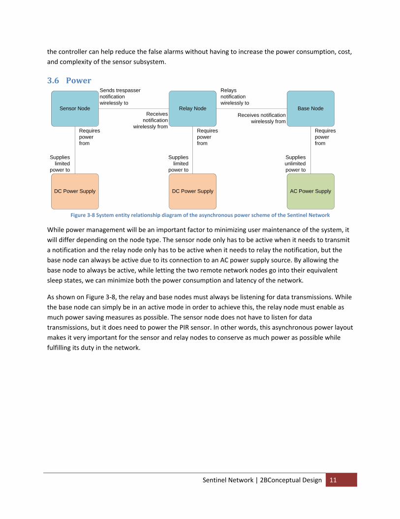
Figure 3‐8 System entity relationship diagram of the asynchronous power scheme of the Sentinel Network
While power management will be an important factor to minimizing user maintenance of the system, it will differ depending on the node type. The sensor node only has to be active when it needs to transmit a notification and the relay node only has to be active when it needs to relay the notification, but the base node can always be active due to its connection to an AC power supply source. By allowing the base node to always be active, while letting the two remote network nodes go into their equivalent sleep states, we can minimize both the power consumption and latency of the network.
As shown on Figure 3‐8, the relay and base nodes must always be listening for data transmissions. While the base node can simply be in an active mode in order to achieve this, the relay node must enable as much power saving measures as possible. The sensor node does not have to listen for data transmissions, but it does need to power the PIR sensor. In other words, this asynchronous power layout makes it very important for the sensor and relay nodes to conserve as much power as possible while fulfilling its duty in the network.
Sentinel Network | 2BConceptual Design 11
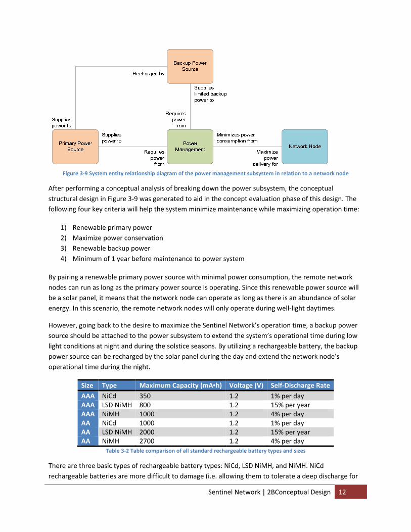
Figure 3‐9 System entity relationship diagram of the power management subsystem in relation to a network node
After performing a conceptual analysis of breaking down the power subsystem, the conceptual structural design in Figure 3‐9 was generated to aid in the concept evaluation phase of this design. The following four key criteria will help the system minimize maintenance while maximizing operation time:
1) Renewable primary power 2) Maximize power conservation 3) Renewable backup power 4) Minimum of 1 year before maintenance to power system
By pairing a renewable primary power source with minimal power consumption, the remote network nodes can run as long as the primary power source is operating. Since this renewable power source will be a solar panel, it means that the network node can operate as long as there is an abundance of solar energy. In this scenario, the remote network nodes will only operate during well‐light daytimes.
However, going back to the desire to maximize the Sentinel Network’s operation time, a backup power source should be attached to the power subsystem to extend the system’s operational time during low light conditions at night and during the solstice seasons. By utilizing a rechargeable battery, the backup power source can be recharged by the solar panel during the day and extend the network node’s operational time during the night.
Size Type Maximum Capacity (mA•h) Voltage (V) Self‐Discharge Rate AAA NiCd 350 1.2 1% per day AAA LSD NiMH 800 1.2 15% per year AAA NiMH 1000 1.2 4% per day AA NiCd 1000 1.2 1% per day AA LSD NiMH 2000 1.2 15% per year AA NiMH 2700 1.2 4% per day
Table 3‐2 Table comparison of all standard rechargeable battery types and sizes
There are three basic types of rechargeable battery types: NiCd, LSD NiMH, and NiMH. NiCd rechargeable batteries are more difficult to damage (i.e. allowing them to tolerate a deep discharge for
Sentinel Network | 2BConceptual Design 12
long periods and be stored in full discharge) and have a smaller self discharge rate in comparison to NiMH rechargeable batteries. NiMH batteries are new competitors to NiCd with higher charge density (e.g. ability to hold more charge with the same size), less toxic, and more cost effective. NiMH batteries also suffer less from the memory effect that plagues the NiCd batteries. In terms of comparing these two battery technology, NiMH would be a clear winner due to its more environmentally friendly nature, lower cost, and higher charge capacity.
The extreme toxicity of NiCd batteries makes it unethical to be used in a project that promotes wildlife protection. In fact, NiMH batteries’ higher discharge rate does not affect the operation of the system since the system is expected to enter a charge/discharge cycle every night after the primary power from the solar power is disconnected. In this respect, the NiCd is even more worrisome when memory and lazy battery effects are taken into account. The memory effect will cause the battery to eventually stop discharging on its own after being consistently discharged to the same level, and the lazy battery effect will cause rapid self discharge of the battery after being fully charged due to being repeated overcharging. The design of the system operation may make these two effects even more pronounced as the periodic discharge rate (e.g. night after night) will eventually trigger the memory effect while the potential lack of any regulation of the recharging operation of the battery can easily can cause repeatedly overcharging.
LSD (low self discharge) NiMH, also known as RTO (ready to use) NiMH, are low discharge NiMH rechargeable batteries that have extremely low discharge rate compared to NiMH batteries. They will, on average, retain 90% of their charged capacity after 6 months and 85% after a year when stored at 69°F. In comparison, standard Ni‐MH rechargeable batteries will only retain 75% after 6 months and no charge after a year under the same condition. Thanks to their low discharge rate, these batteries are always pre‐charged, like primary batteries, and ready for immediate use.
In terms of choosing between LSD and standard NiMH batteries, it doesn’t make much difference from a design perspective. Both battery types are usually available in 2300 mA•h capacity, and they can be easily replaced by one another. These batteries tend to have a typical maximum recharge cycle of 1000, which equates to nearly 3 years of daily usage, while its capacity gradually decrease.
3.7 UI The UI is designed to as a desktop application interface for the user to, while they can use it for any network nodes, mainly access and monitor the sensor network through the base node. It is designed to run through on any OS with the same graphical standard, so conceptual evaluation deemed Java to be the best choice for development. The network nodes can be connected to the UI through a serial communication interface.
Sentinel Network | 2BConceptual Design 13

4 Development
4.1 Schedule With a total development cycle time of two semesters, the following development cycle schedule was used:
1. Design initial revision of system schematic 2. Fabricate and build initial revision of system PCB 3. Build a full access library for the RF transmitter 4. Build UI 5. Implement and test PHY layer communication 6. Implement and test MAC layer communication 7. Add sensor functionality 8. Implement network topology 9. Build second revision of system PCB 10. Test network system functionality
The first semester was tasked with the first five phases of the development cycle, while the rest of the development phases were handed to the second semester.
4.2 Tools All schematic design will be made using ExpressSCH. All PCB layouts will be designed and fabricated through ExpressPCB. All embedded software development will be done through Programmer’s Notepad. Finally, application software development will be done through the Eclipse IDE.
5 Overall System
5.1 Abstract This section of the report will discuss the design and implementation of the overall system design and implementation before subsequent section discuss individual subsystems in greater detail.
5.2 Structure The first important step is performing a structural work breakdown of the Sentinel Network system into a set of unique subsystems. Each subsystem will have its own hardware and software requirements, design, and implementation whenever applicable.
Sentinel Network | 3BDevelopment 14
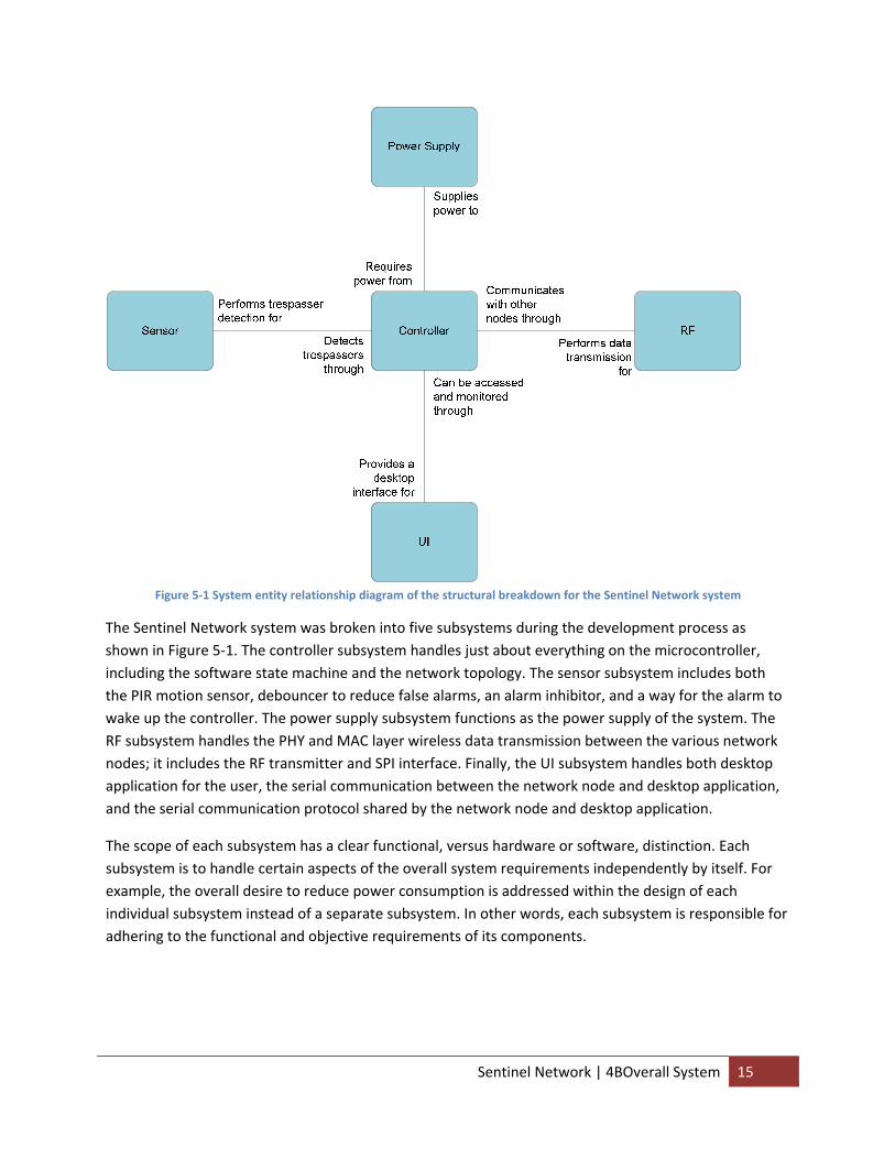
Figure 5‐1 System entity relationship diagram of the structural breakdown for the Sentinel Network system
The Sentinel Network system was broken into five subsystems during the development process as shown in Figure 5‐1. The controller subsystem handles just about everything on the microcontroller, including the software state machine and the network topology. The sensor subsystem includes both the PIR motion sensor, debouncer to reduce false alarms, an alarm inhibitor, and a way for the alarm to wake up the controller. The power supply subsystem functions as the power supply of the system. The RF subsystem handles the PHY and MAC layer wireless data transmission between the various network nodes; it includes the RF transmitter and SPI interface. Finally, the UI subsystem handles both desktop application for the user, the serial communication between the network node and desktop application, and the serial communication protocol shared by the network node and desktop application.
The scope of each subsystem has a clear functional, versus hardware or software, distinction. Each subsystem is to handle certain aspects of the overall system requirements independently by itself. For example, the overall desire to reduce power consumption is addressed within the design of each individual subsystem instead of a separate subsystem. In other words, each subsystem is responsible for adhering to the functional and objective requirements of its components.
Sentinel Network | 4BOverall System 15
5.3 Design
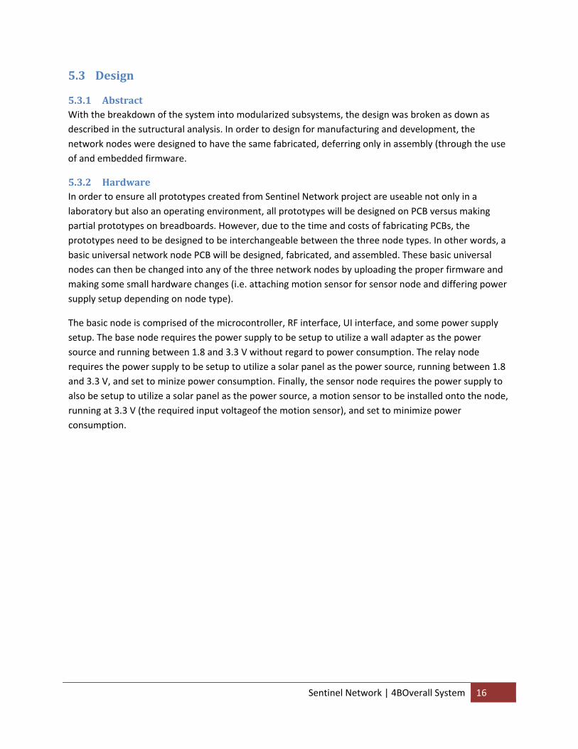
5.3.1 Abstract With the breakdown of the system into modularized subsystems, the design was broken as down as described in the sutructural analysis. In order to design for manufacturing and development, the network nodes were designed to have the same fabricated, deferring only in assembly (through the use of and embedded firmware.
5.3.2 Hardware In order to ensure all prototypes created from Sentinel Network project are useable not only in a laboratory but also an operating environment, all prototypes will be designed on PCB versus making partial prototypes on breadboards. However, due to the time and costs of fabricating PCBs, the prototypes need to be designed to be interchangeable between the three node types. In other words, a basic universal network node PCB will be designed, fabricated, and assembled. These basic universal nodes can then be changed into any of the three network nodes by uploading the proper firmware and making some small hardware changes (i.e. attaching motion sensor for sensor node and differing power supply setup depending on node type).
The basic node is comprised of the microcontroller, RF interface, UI interface, and some power supply setup. The base node requires the power supply to be setup to utilize a wall adapter as the power source and running between 1.8 and 3.3 V without regard to power consumption. The relay node requires the power supply to be setup to utilize a solar panel as the power source, running between 1.8 and 3.3 V, and set to minize power consumption. Finally, the sensor node requires the power supply to also be setup to utilize a solar panel as the power source, a motion sensor to be installed onto the node, running at 3.3 V (the required input voltageof the motion sensor), and set to minimize power consumption.
Sentinel Network | 4BOverall System 16
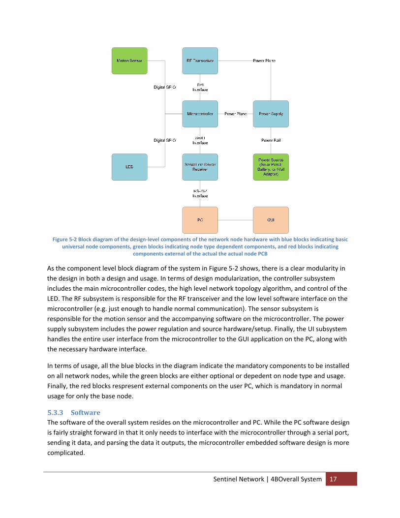
Figure 5‐2 Block diagram of the design‐level components of the network node hardware with blue blocks indicating basic
universal node components, green blocks indicating node type dependent components, and red blocks indicating components external of the actual the actual node PCB
As the component level block diagram of the system in Figure 5‐2 shows, there is a clear modularity in the design in both a design and usage. In terms of design modularization, the controller subsystem includes the main microcontroller codes, the high level network topology algorithm, and control of the LED. The RF subsystem is responsible for the RF transceiver and the low level software interface on the microcontroller (e.g. just enough to handle normal communication). The sensor subsystem is responsible for the motion sensor and the accompanying software on the microcontroller. The power supply subsystem includes the power regulation and source hardware/setup. Finally, the UI subsystem handles the entire user interface from the microcontroller to the GUI application on the PC, along with the necessary hardware interface.
In terms of usage, all the blue blocks in the diagram indicate the mandatory components to be installed on all network nodes, while the green blocks are either optional or depedent on node type and usage. Finally, the red blocks respresent external components on the user PC, which is mandatory in normal usage for only the base node.
5.3.3 Software The software of the overall system resides on the microcontroller and PC. While the PC software design is fairly straight forward in that it only needs to interface with the microcontroller through a serial port, sending it data, and parsing the data it outputs, the microcontroller embedded software design is more complicated.
Sentinel Network | 4BOverall System 17
As stated before in the structural breakdown of the system, the microcontroller embedded software is split across several subsystems. The controller subsystem makes up the bulk of the code by designing the structure, state machine, initialization, and standard operation of the firmware. While the RF subsystem is responsible for initialization of the RF transceiver through the microcontroller and implementing a complete PHY and MAC layered library for the main code to change states, access registers, and send/receive data, it is the controller subsystem that performs the high level network topology control. As for the sensor and UI subsystems, while they are responsible for the software implementation of sensor detection and UI interface respectively, there is a less clear disctinct between them and the main controller software subsystem. Since the sensor software requires timing and sleep functionalities, it relies on the controller software to handle those tasks. The UI software needs to not only implement the UART interface but also establish the communication protocol shared between the microcontroller and PC; this requires debug printouts to be established everywhere on software and ensure the microcontroller code checks for access requests from the PC.
SleepState
Power On
False
Active StateTrue
Send detection message to base
nodeTransmission Completed
Initialization
Detect Motion
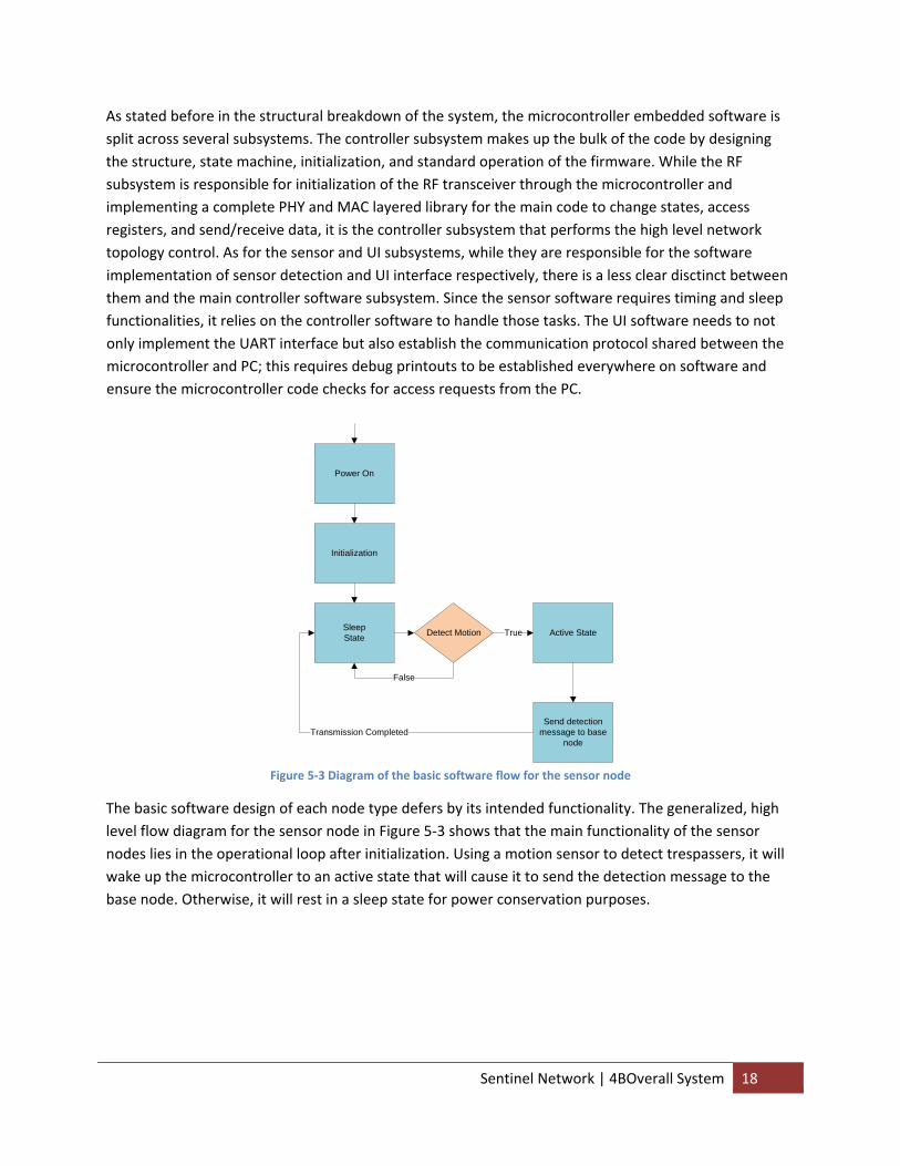
Figure 5‐3 Diagram of the basic software flow for the sensor node
The basic software design of each node type defers by its intended functionality. The generalized, high level flow diagram for the sensor node in Figure 5‐3 shows that the main functionality of the sensor nodes lies in the operational loop after initialization. Using a motion sensor to detect trespassers, it will wake up the microcontroller to an active state that will cause it to send the detection message to the base node. Otherwise, it will rest in a sleep state for power conservation purposes.
Sentinel Network | 4BOverall System 18
SleepState
Power On
False
Active StateTrue
Send relay transmission to
next nodeTransmission Completed
Initialization
Detection RFTransmission
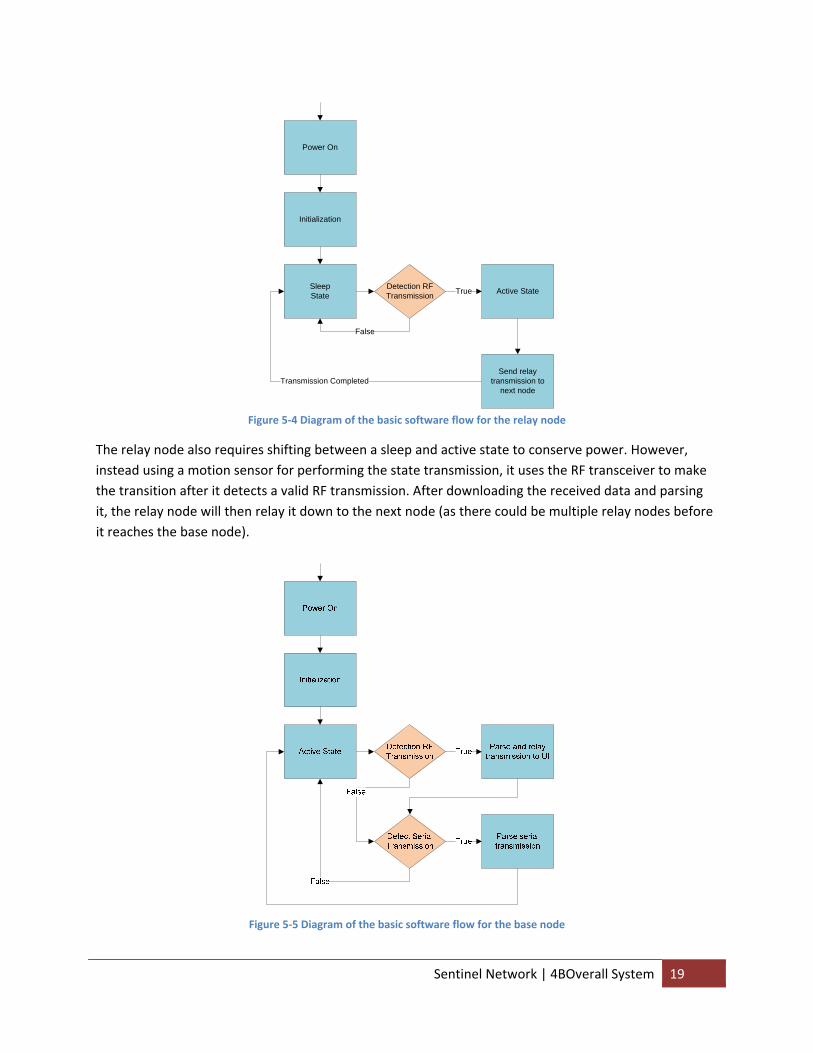
Figure 5‐4 Diagram of the basic software flow for the relay node
The relay node also requires shifting between a sleep and active state to conserve power. However, instead using a motion sensor for performing the state transmission, it uses the RF transceiver to make the transition after it detects a valid RF transmission. After downloading the received data and parsing it, the relay node will then relay it down to the next node (as there could be multiple relay nodes before it reaches the base node).
Figure 5‐5 Diagram of the basic software flow for the base node
Sentinel Network | 4BOverall System 19
Finally, the base node is different in its software design because it does not need to make a state transition to a sleep state to conserve power. It simply waits for RF transmissions to be detected by the RF transceiver and serial transmissions from the UI before performing the proper functions to parsing and outputting those data.
5.4 Implementation
5.4.1 Abstract The implementation of the design was an iterative process that required two hardware revisions and close to a hundred software revisions with multiple firmware packages. The end result was able to deliver an entire set of running prototype on both hardware revisions as a testament to the robust design of the system.
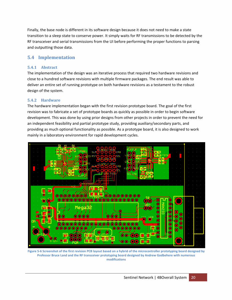
5.4.2 Hardware The hardware implementation began with the first revision prototype board. The goal of the first revision was to fabricate a set of prototype boards as quickly as possible in order to begin software development. This was done by using prior designs from other projects in order to prevent the need for an independent feasibility and partial prototype study, providing auxiliary/secondary parts, and providing as much optional functionality as possible. As a prototype board, it is also designed to work mainly in a laboratory environment for rapid development cycles.
Figure 5‐6 Screenshot of the first revision PCB layout based on a hybrid of the microcontroller prototyping board designed by
Professor Bruce Land and the RF transceiver prototyping board designed by Andrew Godbehere with numerous modifications
Sentinel Network | 4BOverall System 20
The key goal of the prototype board in Figure 5‐6 was to supply full development kit for the Atmel AT86RF230 RF transceiver that is compatible with most 40‐pin AVR microcontrollers, such as the ATmega32, ATmega644, and ATmega164P/324P/644P. The microcontroller was designed so that it can either use the MCU clock signal from the transceiver, its own internal RC oscillator, or an extra crystal oscillator. The system can also be powered by a wall adapter through a 2.1 mm power plug, but it can also use a pair of AAA batteries or a 9V battery. The pads for a DIP‐packaged MAX233 chip, which was found to work just fine with low supply voltage (despite being rated for only 5 V), is built‐in along with one for a DB9 serial port.
One key feature of the design was to improve noise immunity through a ground plane. Since the basic board provided by ExpressPCB only has two layers (e.g. top and bottom) without any inner layers, the bottom layer was used as a ground plane for the controller board. While helps the routing and signal of the design, it was important to watch out for isolated areas on the board without a connection to the ground plane and shorts to the ground plane during the assembly process.
Two independent transceiver boards were included on each board in order to improve the manufacturing yield to reduce the amount of money that would be needed to fabricate another board in case the assembly of one failed, which would render the entire board useless. The interface between the microcontroller prototyping area and the transceiver prototyping area is connected linked through a standard 10‐pin ribbon cable. By switching this cable, the main digital signals along with the supply voltage and ground connections would be switched as well. When this cable is removed, the transceiver prototype would become completely separated from the main microcontroller.
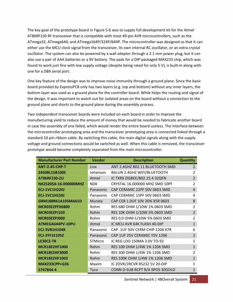
Manufacturer Part Number Vendor Description Quantity
ANT‐2.45‐CHP‐T Linx ANT 2.4GHZ 802.11 BLUETOOTH SMD 22450BL15B100E Johanson BALUN 2.4GHZ WIFI/BLUETOOTH 2AT86RF230‐ZU Atmel IC TXRX ZIGBEE/802.15.4 32QFN 2NX2520SA‐16.000000MHZ NDK CRYSTAL 16.000000 MHZ SMD 10PF 2ECJ‐1VC1H220J Panasonic CAP CERAMIC 22PF 50V 0603 SMD 4ECJ‐1VC1H150J Panasonic CAP CERAMIC 15PF 50V 0603 SMD 4GRM188R61A105MA61D Murata CAP CER 1.0UF 10V 20% X5R 0603 8MCR03EZPFX6800 Rohm RES 680 OHM 1/10W 1% 0603 SMD 2MCR03EZPJ103 Rohm RES 10K OHM 1/10W 5% 0603 SMD 2MCR03EZPJ000 Rohm RES 0.0 OHM 1/10W 5% 0603 SMD 2ATMEGA644PV‐10PU Atmel IC MCU AVR 64K FLASH 40‐DIP 1ECJ‐3VB1H104K Panasonic CAP .1UF 50V CERM CHIP 1206 X7R 6ECJ‐3YF1E105Z Panasonic CAP 1UF 25V CERAMIC Y5V 1206 2LE30CZ‐TR STMicro IC REG LDO 150MA 3.0V TO‐92 1MCR18EZHF1000 Rohm RES 100 OHM 1/4W 1% 1206 SMD 1MCR18EZHF3000 Rohm RES 300 OHM 1/4W 1% 1206 SMD 2MCR18EZHF1003 Rohm RES 100K OHM 1/4W 1% 1206 SMD 1MAX233CPP+G36 Maxim IC 2DVR/2RCVR RS232 5V 20‐DIP 15747844‐4 Tyco CONN D‐SUB RCPT R/A 9POS 30GOLD 1
Sentinel Network | 4BOverall System 21
PJ‐002A CUI CONN POWER JACK 2.1MM 1Table 5‐1 Bill of material for the first revision prototype board
As the bill of material in Table 5‐1 shows, there is fair number of components that requires assembly onto the board. While the majority of the components on the microcontroller side is either in DIP or large 1206 SMT packaging (residing on the lower half of the table), the main assembly effort will be distributed to the RF transceiver components. While the 0603 SMT components are not quite so difficult, the RF transceiver, balun, and crystal are quite difficult to solder onto the board, requiring special tools and procures. These instructions can be found in Andrew’s CURemote project report.
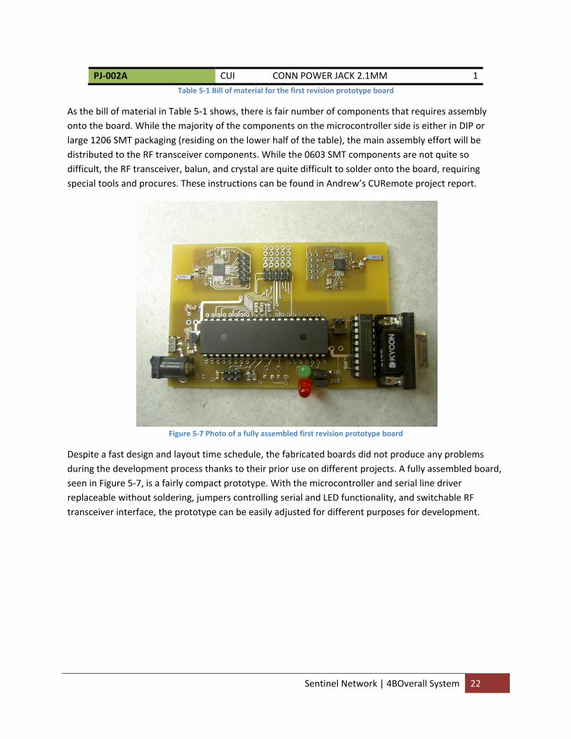
Figure 5‐7 Photo of a fully assembled first revision prototype board
Despite a fast design and layout time schedule, the fabricated boards did not produce any problems during the development process thanks to their prior use on different projects. A fully assembled board, seen in Figure 5‐7, is a fairly compact prototype. With the microcontroller and serial line driver replaceable without soldering, jumpers controlling serial and LED functionality, and switchable RF transceiver interface, the prototype can be easily adjusted for different purposes for development.
Sentinel Network | 4BOverall System 22
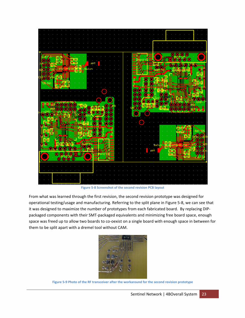
Figure 5‐8 Screenshot of the second revision PCB layout
From what was learned through the first revision, the second revision prototype was designed for operational testing/usage and manufacturing. Referring to the split plane in Figure 5‐8, we can see that it was designed to maximize the number of prototypes from each fabricated board. By replacing DIP‐packaged components with their SMT‐packaged equivalents and minimizing free board space, enough space was freed up to allow two boards to co‐oexist on a single board with enough space in between for them to be split apart with a dremel tool without CAM.
Figure 5‐9 Photo of the RF transceiver after the workaround for the second revision prototype
Sentinel Network | 4BOverall System 23
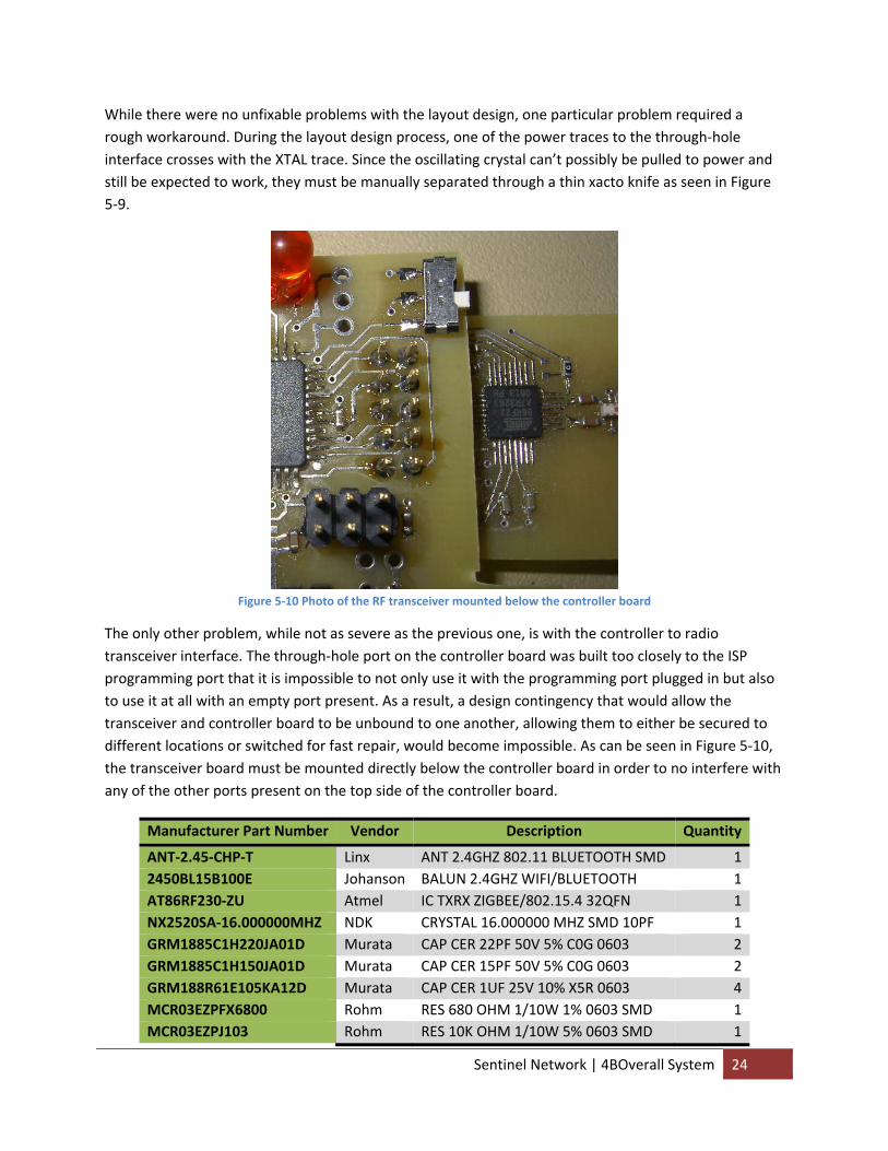
While there were no unfixable problems with the layout design, one particular problem required a rough workaround. During the layout design process, one of the power traces to the through‐hole interface crosses with the XTAL trace. Since the oscillating crystal can’t possibly be pulled to power and still be expected to work, they must be manually separated through a thin xacto knife as seen in Figure 5‐9.
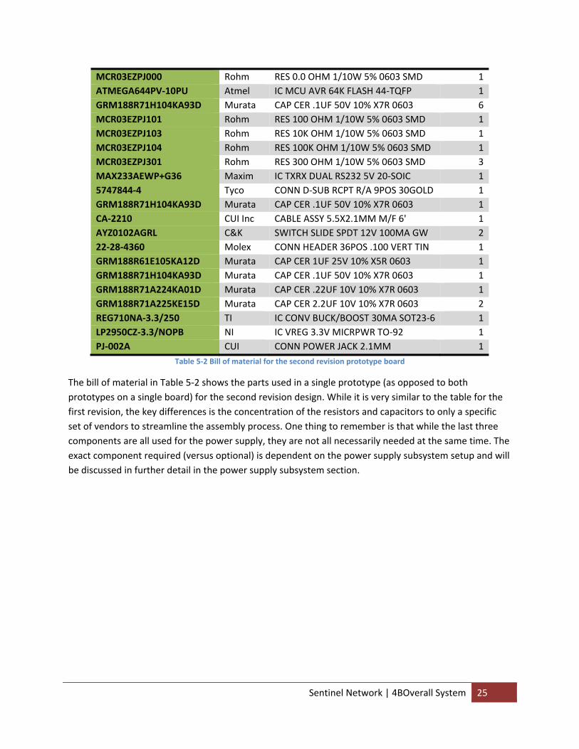
Figure 5‐10 Photo of the RF transceiver mounted below the controller board
The only other problem, while not as severe as the previous one, is with the controller to radio transceiver interface. The through‐hole port on the controller board was built too closely to the ISP programming port that it is impossible to not only use it with the programming port plugged in but also to use it at all with an empty port present. As a result, a design contingency that would allow the transceiver and controller board to be unbound to one another, allowing them to either be secured to different locations or switched for fast repair, would become impossible. As can be seen in Figure 5‐10, the transceiver board must be mounted directly below the controller board in order to no interfere with any of the other ports present on the top side of the controller board.
Manufacturer Part Number Vendor Description Quantity
ANT‐2.45‐CHP‐T Linx ANT 2.4GHZ 802.11 BLUETOOTH SMD 12450BL15B100E Johanson BALUN 2.4GHZ WIFI/BLUETOOTH 1AT86RF230‐ZU Atmel IC TXRX ZIGBEE/802.15.4 32QFN 1NX2520SA‐16.000000MHZ NDK CRYSTAL 16.000000 MHZ SMD 10PF 1GRM1885C1H220JA01D Murata CAP CER 22PF 50V 5% C0G 0603 2GRM1885C1H150JA01D Murata CAP CER 15PF 50V 5% C0G 0603 2GRM188R61E105KA12D Murata CAP CER 1UF 25V 10% X5R 0603 4MCR03EZPFX6800 Rohm RES 680 OHM 1/10W 1% 0603 SMD 1MCR03EZPJ103 Rohm RES 10K OHM 1/10W 5% 0603 SMD 1
Sentinel Network | 4BOverall System 24
MCR03EZPJ000 Rohm RES 0.0 OHM 1/10W 5% 0603 SMD 1ATMEGA644PV‐10PU Atmel IC MCU AVR 64K FLASH 44‐TQFP 1GRM188R71H104KA93D Murata CAP CER .1UF 50V 10% X7R 0603 6MCR03EZPJ101 Rohm RES 100 OHM 1/10W 5% 0603 SMD 1MCR03EZPJ103 Rohm RES 10K OHM 1/10W 5% 0603 SMD 1MCR03EZPJ104 Rohm RES 100K OHM 1/10W 5% 0603 SMD 1MCR03EZPJ301 Rohm RES 300 OHM 1/10W 5% 0603 SMD 3MAX233AEWP+G36 Maxim IC TXRX DUAL RS232 5V 20‐SOIC 15747844‐4 Tyco CONN D‐SUB RCPT R/A 9POS 30GOLD 1GRM188R71H104KA93D Murata CAP CER .1UF 50V 10% X7R 0603 1CA‐2210 CUI Inc CABLE ASSY 5.5X2.1MM M/F 6' 1AYZ0102AGRL C&K SWITCH SLIDE SPDT 12V 100MA GW 222‐28‐4360 Molex CONN HEADER 36POS .100 VERT TIN 1GRM188R61E105KA12D Murata CAP CER 1UF 25V 10% X5R 0603 1GRM188R71H104KA93D Murata CAP CER .1UF 50V 10% X7R 0603 1GRM188R71A224KA01D Murata CAP CER .22UF 10V 10% X7R 0603 1GRM188R71A225KE15D Murata CAP CER 2.2UF 10V 10% X7R 0603 2REG710NA‐3.3/250 TI IC CONV BUCK/BOOST 30MA SOT23‐6 1LP2950CZ‐3.3/NOPB NI IC VREG 3.3V MICRPWR TO‐92 1PJ‐002A CUI CONN POWER JACK 2.1MM 1
Table 5‐2 Bill of material for the second revision prototype board
The bill of material in Table 5‐2 shows the parts used in a single prototype (as opposed to both prototypes on a single board) for the second revision design. While it is very similar to the table for the first revision, the key differences is the concentration of the resistors and capacitors to only a specific set of vendors to streamline the assembly process. One thing to remember is that while the last three components are all used for the power supply, they are not all necessarily needed at the same time. The exact component required (versus optional) is dependent on the power supply subsystem setup and will be discussed in further detail in the power supply subsystem section.
Sentinel Network | 4BOverall System 25
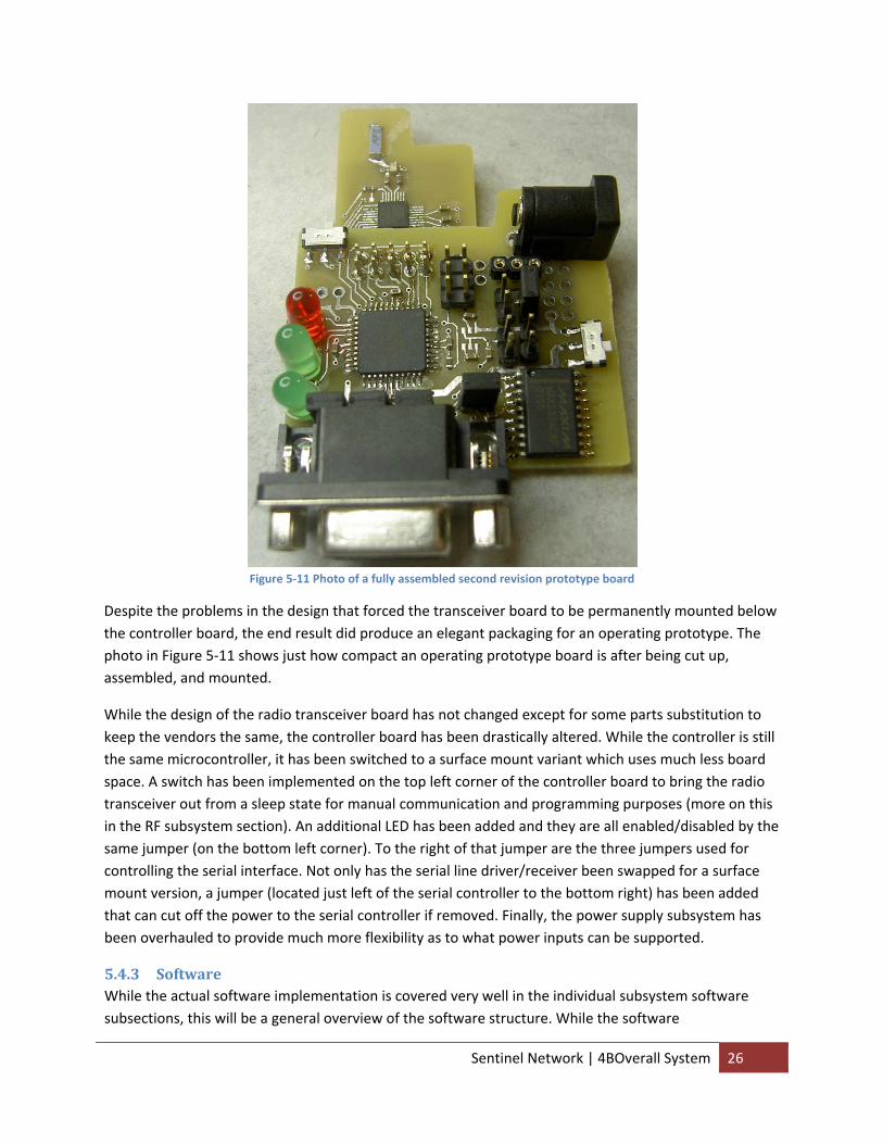
Figure 5‐11 Photo of a fully assembled second revision prototype board
Despite the problems in the design that forced the transceiver board to be permanently mounted below the controller board, the end result did produce an elegant packaging for an operating prototype. The photo in Figure 5‐11 shows just how compact an operating prototype board is after being cut up, assembled, and mounted.
While the design of the radio transceiver board has not changed except for some parts substitution to keep the vendors the same, the controller board has been drastically altered. While the controller is still the same microcontroller, it has been switched to a surface mount variant which uses much less board space. A switch has been implemented on the top left corner of the controller board to bring the radio transceiver out from a sleep state for manual communication and programming purposes (more on this in the RF subsystem section). An additional LED has been added and they are all enabled/disabled by the same jumper (on the bottom left corner). To the right of that jumper are the three jumpers used for controlling the serial interface. Not only has the serial line driver/receiver been swapped for a surface mount version, a jumper (located just left of the serial controller to the bottom right) has been added that can cut off the power to the serial controller if removed. Finally, the power supply subsystem has been overhauled to provide much more flexibility as to what power inputs can be supported.
5.4.3 Software While the actual software implementation is covered very well in the individual subsystem software subsections, this will be a general overview of the software structure. While the software
Sentinel Network | 4BOverall System 26
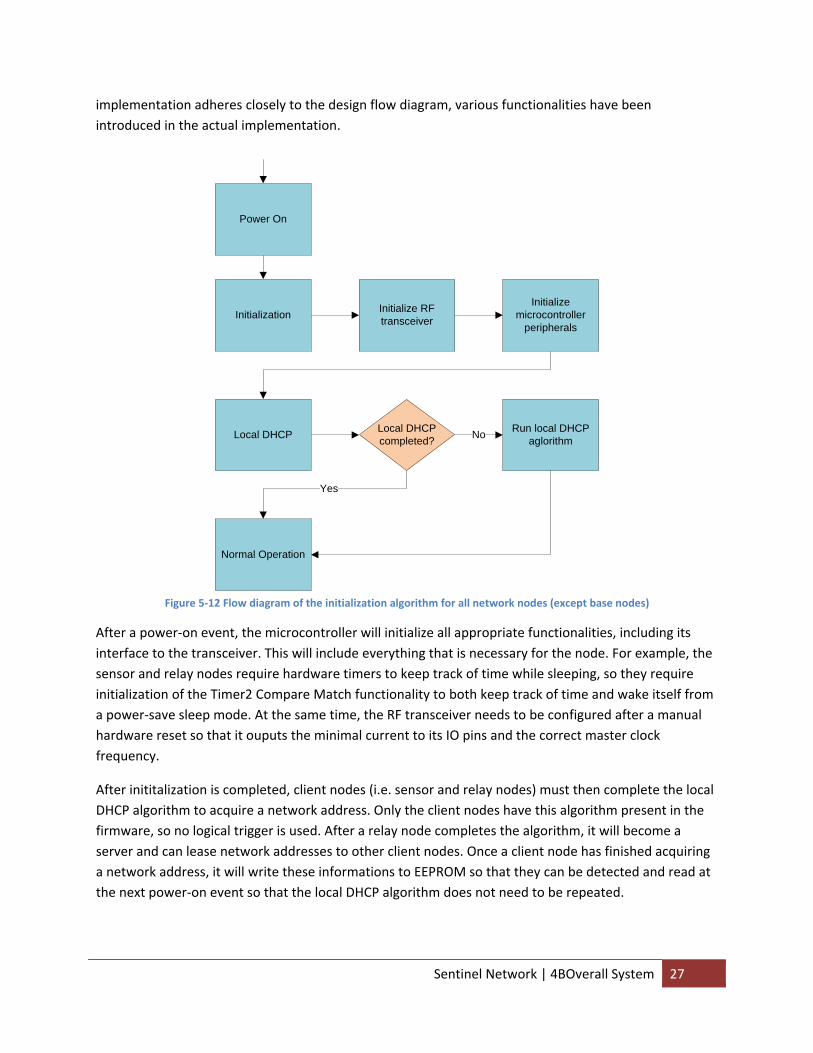
implementation adheres closely to the design flow diagram, various functionalities have been introduced in the actual implementation.
Power On
Initialization Initialize RF transceiver
Initialize microcontroller
peripherals
Local DHCP Run local DHCP aglorithm
Local DHCP completed? No
Normal Operation
Yes
Figure 5‐12 Flow diagram of the initialization algorithm for all network nodes (except base nodes)
After a power‐on event, the microcontroller will initialize all appropriate functionalities, including its interface to the transceiver. This will include everything that is necessary for the node. For example, the sensor and relay nodes require hardware timers to keep track of time while sleeping, so they require initialization of the Timer2 Compare Match functionality to both keep track of time and wake itself from a power‐save sleep mode. At the same time, the RF transceiver needs to be configured after a manual hardware reset so that it ouputs the minimal current to its IO pins and the correct master clock frequency.
After inititalization is completed, client nodes (i.e. sensor and relay nodes) must then complete the local DHCP algorithm to acquire a network address. Only the client nodes have this algorithm present in the firmware, so no logical trigger is used. After a relay node completes the algorithm, it will become a server and can lease network addresses to other client nodes. Once a client node has finished acquiring a network address, it will write these informations to EEPROM so that they can be detected and read at the next power‐on event so that the local DHCP algorithm does not need to be repeated.
Sentinel Network | 4BOverall System 27
Once this is completed, or after initialization for the base node, the network node can enter normal operation, which is dependent on the network node. These specialized functionalities were highlighted in the design flow diagrams and are still held true in the actual design.
5.5 Conclusion The overall system has been successful in implementing all that was planned and designed in the implementation. The prototypes produced in both design revisions perform extremely well in satisfying all originating requirements for the system.
5.6 Future Recommendations 1. Produce another prototype board based on the second revision design without the two issues
found in the second revision layout. 2. Design and produce enclosures for the second (or third) revision prototypes for operating
environment testing. 3. Design third revision prototype for minimal large‐quantity costs (versus minimal low‐quantity
costs).
6 Controller
6.1 Abstract If all the other subsystems are the limbs and peripherals of the Sentinel Network, then the controller subsystem can be thought of as the heart. This subsystem is responsible for a large amount of both high and low level design/implementation on both the software and hardware.
As the name implies the controller subsystem is centered on the microcontroller in both software and hardware, but it also accounts for creating an interface in software for all other software subsystems and associating hardware design.
6.2 Introduction Device Flash EEPROM RAM ATMega164P 16 Kbyte 512 Byte 1 KbyteATMega324P 32 Kbyte 1 Kbyte 2 KbyteATMega644P 64 Kbyte 2 Kbyte 4 Kbyte
Table 6‐1 Comparison table of the ATMega164P, ATMega324P, and ATMega644P microcontrollers
The ATmega644P was chosen for being one of the newest members of the AVR family to feature picoPower technology for reducing power consumption. Though capable of new power saving features and a wide voltage operational range of 1.8 to 5.5 V, it still has the same large storage capabilities of an ATmega644, with 64 kb of FLASH, 4 kb of SRAM, and 2 kb of EEPROM memory. With an internal RC oscillator factory calibrated for operation at 3.0 V, the microcontroller was designed for low voltage usage with an active power consumption as low as 0.4 mA. In the future, if a smaller microcontroller with picoPower technology becomes available, it will be easy to port the code as long as it fits in the smaller storage size.
Sentinel Network | 5BController 28
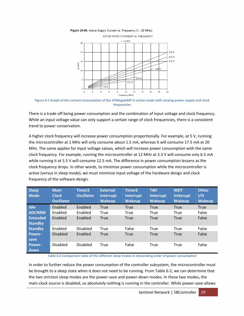
Figure 6‐1 Graph of the current consumption of the ATMega644P in active mode with varying power supply and clock
frequencies
There is a trade off being power consumption and the combination of input voltage and clock frequency. While an input voltage value can only support a certain range of clock frequencies, there is a consistent trend to power conservation.
A higher clock frequency will increase power consumption proportionally. For example, at 5 V, running the microcontroller at 1 MHz will only consume about 1.5 mA, whereas it will consume 17.5 mA at 20 MHz. The same applies for input voltage values, which will increase power consumption with the same clock frequency. For example, running the microcontroller at 12 MHz at 3.3 V will consume only 6.5 mA while running it at 5.5 V will consume 12.5 mA. The difference in power consumption lessens as the clock frequency drops. In other words, to minimize power consumption while the microcontroller is active (versus in sleep mode), we must minimize input voltage of the hardware design and clock frequency of the software design.
Sleep Mode
Main Clock Oscillator
Timer2 Oscillator
External Interrupt Wakeup
Timer2 Interrupt Wakeup
TWI Interrupt Wakeup
WDT Intterupt Wakeup
Other I/O Wakeup
Idle Enabled Enabled True True True True True ADCNRM Enabled Enabled True True True True False Extended Standby
Enabled Enabled True True True True False
Standby Enabled Disabled True False True True False Power‐save
Disabled Enabled True True True True False
Power‐down
Disabled Disabled True False True True False
Table 6‐2 Comparison table of the different sleep modes in descending order of power consumption
In order to further reduce the power consumption of the controller subsystem, the microcontroller must be brought to a sleep state when it does not need to be running. From Table 6‐2, we can determine that the two strictest sleep modes are the power‐save and power‐down modes. In these two modes, the main clock source is disabled, so absolutely nothing is running in the controller. While power‐save allows
Sentinel Network | 5BController 29
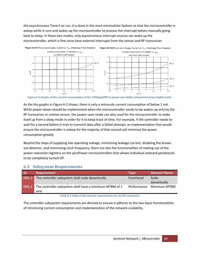
the asynchronous Timer2 to run, it is done in the most minimalistic fashion so that the microcontroller is asleep while it runs and wakes up the microcontroller to process the interrupt before manually going back to sleep. In these two modes, only asynchronous interrupt sources can wake up the microcontroller, which is fine since have external interrupts from the sensor and RF transceiver.
Figure 6‐2 Graphs of the current consumption of the ATMega644P in power‐save (left) and powerd‐down (right) mode
As the the graphs in Figure 6‐2 shows, there is only a miniscule current consumption of below 1 mA. While power‐down should be implemented when the microcontroller needs to be waken up only by the RF transceiver or motion sensor, the power‐save mode can also used for the microcontroller to wake itself up from a sleep mode in order for it to keep track of time. For example, if the controller needs to wait for a second before it tries to transmit data after a failed attempt, an implementation that would ensure the microcontroller is asleep for the majority of that second will minimize the power consumption greatly.
Beyond the steps of supplying low operating voltage, minimizing leakage current, disabling the brown out detector, and minimizing clock frequency, there are also the functionalities of making use of the power reduction registers on the picoPower microcontrollers that allows individual onboard peripherals to be completely turned off.
6.3 Subsystem Requirements ID Requirement Type Abstract Name OR1.1 The controller subsystem shall scale dynamically Functional Scale
dynamically OR2.1 The controller subsystem shall have a minimum MTBM of 1
year Performance Minimum MTBM
Table 6‐3 Table of the derived requirements for the RF subsystem
The controller subsystem requirements are derived to ensure it adheres to the two basic functionalities of minimizing current consumption and implementation of the network scalability.
Sentinel Network | 5BController 30
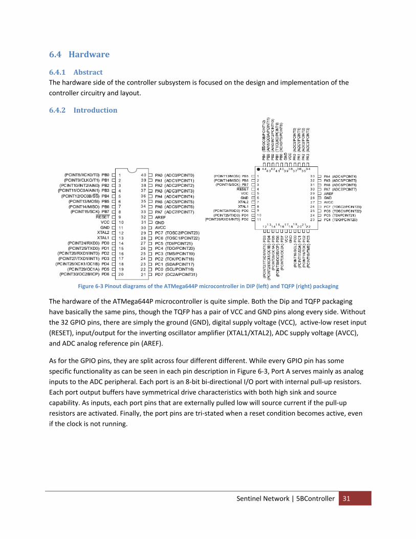
6.4 Hardware
6.4.1 Abstract The hardware side of the controller subsystem is focused on the design and implementation of the controller circuitry and layout.
6.4.2 Introduction
Figure 6‐3 Pinout diagrams of the ATMega644P microcontroller in DIP (left) and TQFP (right) packaging
The hardware of the ATMega644P microcontroller is quite simple. Both the Dip and TQFP packaging have basically the same pins, though the TQFP has a pair of VCC and GND pins along every side. Without the 32 GPIO pins, there are simply the ground (GND), digital supply voltage (VCC), active‐low reset input (RESET), input/output for the inverting oscillator amplifier (XTAL1/XTAL2), ADC supply voltage (AVCC), and ADC analog reference pin (AREF).
As for the GPIO pins, they are split across four different different. While every GPIO pin has some specific functionality as can be seen in each pin description in Figure 6‐3, Port A serves mainly as analog inputs to the ADC peripheral. Each port is an 8‐bit bi‐directional I/O port with internal pull‐up resistors. Each port output buffers have symmetrical drive characteristics with both high sink and source capability. As inputs, each port pins that are externally pulled low will source current if the pull‐up resistors are activated. Finally, the port pins are tri‐stated when a reset condition becomes active, even if the clock is not running.
Sentinel Network | 5BController 31
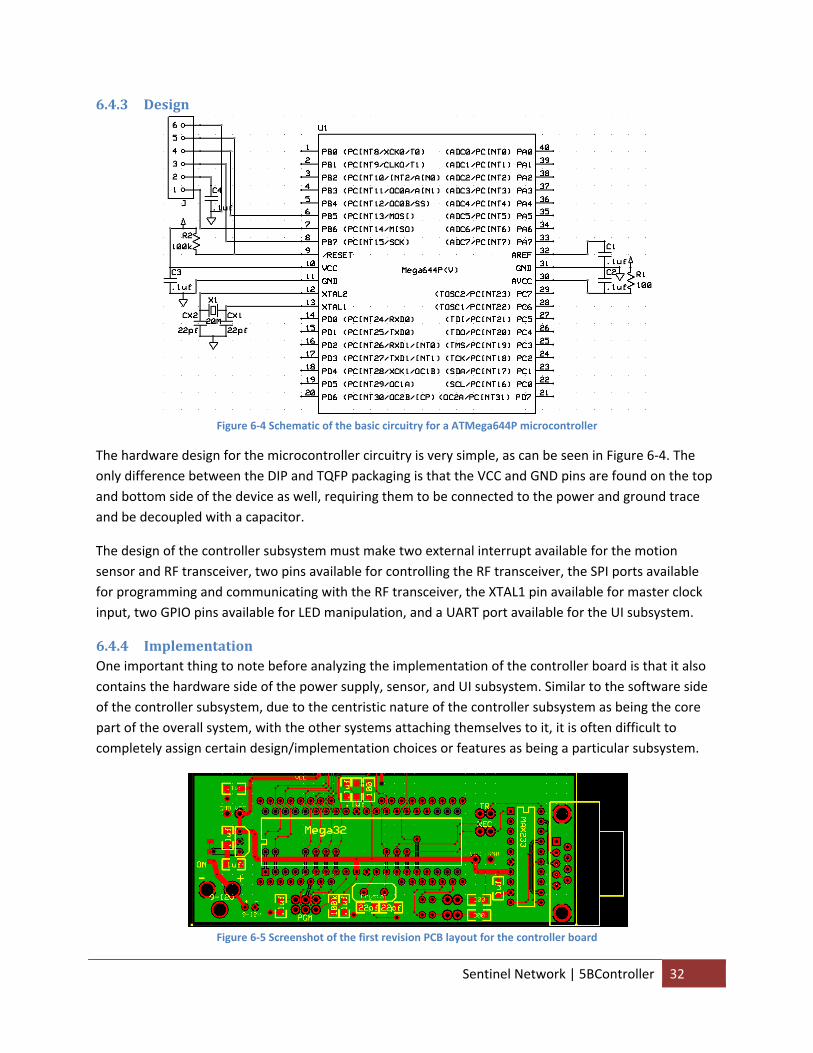
6.4.3 Design
Figure 6‐4 Schematic of the basic circuitry for a ATMega644P microcontroller
The hardware design for the microcontroller circuitry is very simple, as can be seen in Figure 6‐4. The only difference between the DIP and TQFP packaging is that the VCC and GND pins are found on the top and bottom side of the device as well, requiring them to be connected to the power and ground trace and be decoupled with a capacitor.
The design of the controller subsystem must make two external interrupt available for the motion sensor and RF transceiver, two pins available for controlling the RF transceiver, the SPI ports available for programming and communicating with the RF transceiver, the XTAL1 pin available for master clock input, two GPIO pins available for LED manipulation, and a UART port available for the UI subsystem.
6.4.4 Implementation One important thing to note before analyzing the implementation of the controller board is that it also contains the hardware side of the power supply, sensor, and UI subsystem. Similar to the software side of the controller subsystem, due to the centristic nature of the controller subsystem as being the core part of the overall system, with the other systems attaching themselves to it, it is often difficult to completely assign certain design/implementation choices or features as being a particular subsystem.
Figure 6‐5 Screenshot of the first revision PCB layout for the controller board
Sentinel Network | 5BController 32
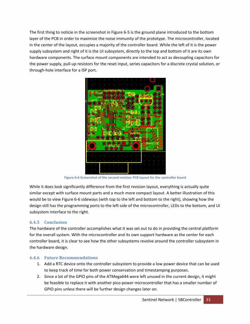
The first thing to noticie in the screenshot in Figure 6‐5 is the ground plane introduced to the bottom layer of the PCB in order to maximize the noise immunity of the prototype. The microcontroller, located in the center of the layout, occupies a majority of the controller board. While the left of it is the power supply subsystem and right of it is the UI subsystem, directly to the top and bottom of it are its own hardware components. The surface mount components are intended to act as decoupling capacitors for the power supply, pull‐up resistors for the reset input, series capacitors for a discrete crystal solution, or through‐hole interface for a ISP port.
Figure 6‐6 Screenshot of the second revision PCB layout for the controller board
While it does look significantly difference from the first revision layout, everything is actually quite similar except with surface mount parts and a much more compact layout. A better illustration of this would be to view Figure 6‐6 sideways (with top to the left and bottom to the right), showing how the design still has the programming ports to the left side of the microcontroller, LEDs to the bottom, and UI subsystem interface to the right.
6.4.5 Conclusion The hardware of the controller accomplishes what it was set out to do in providing the central platform for the overall system. With the microcontroller and its own support hardware as the center for each controller board, it is clear to see how the other subsystems revolve around the controller subsystem in the hardware design.
6.4.6 Future Recommendations 1. Add a RTC device onto the controller subsystem to provide a low power device that can be used
to keep track of time for both power conservation and timestamping purposes. 2. Since a lot of the GPIO pins of the ATMega644 were left unused in the current design, it might
be feasible to replace it with another pico‐power microcontroller that has a smaller number of GPIO pins unless there will be further design changes later on.
Sentinel Network | 5BController 33
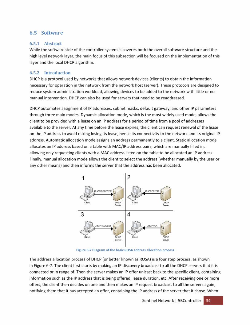
6.5 Software
6.5.1 Abstract While the software side of the controller system is coveres both the overall software structure and the high level network layer, the main focus of this subsection will be focused on the implementation of this layer and the local DHCP algorithm.
6.5.2 Introduction DHCP is a protocol used by networks that allows network devices (clients) to obtain the information necessary for operation in the network from the network host (server). These protocols are designed to reduce system administration workload, allowing devices to be added to the network with little or no manual intervention. DHCP can also be used for servers that need to be readdressed.
DHCP automates assignment of IP addresses, subnet masks, default gateway, and other IP parameters through three main modes. Dynamic allocation mode, which is the most widely used mode, allows the client to be provided with a lease on an IP address for a period of time from a pool of addresses available to the server. At any time before the lease expires, the client can request renewal of the lease on the IP address to avoid risking losing its lease, hence its connectivity to the network and its original IP address. Automatic allocation mode assigns an address permanently to a client. Static allocation mode allocates an IP address based on a table with MAC/IP address pairs, which are manually filled in, allowing only requesting clients with a MAC address listed on the table to be allocated an IP address. Finally, manual allocation mode allows the client to select the address (whether manually by the user or any other means) and then informs the server that the address has been allocated.
Figure 6‐7 Diagram of the basic ROSA address allocation process
The address allocation process of DHCP (or better known as ROSA) is a four step process, as shown in Figure 6‐7. The client first starts by making an IP discovery broadcast to all the DHCP servers that it is connected or in range of. Then the server makes an IP offer unicast back to the specific client, containing information such as the IP address that is being offered, lease duration, etc. After receiving one or more offers, the client then decides on one and then makes an IP request broadcast to all the servers again, notifying them that it has accepted an offer, containing the IP address of the server that it chose. When
Sentinel Network | 5BController 34
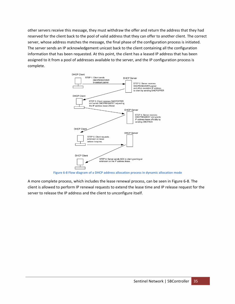
other servers receive this message, they must withdraw the offer and return the address that they had reserved for the client back to the pool of valid address that they can offer to another client. The correct server, whose address matches the message, the final phase of the configuration process is initiated. The server sends an IP acknowledgement unicast back to the client containing all the configuration information that has been requested. At this point, the client has a leased IP address that has been assigned to it from a pool of addresses available to the server, and the IP configuration process is complete.
Figure 6‐8 Flow diagram of a DHCP address allocation process in dynamic allocation mode
A more complete process, which includes the lease renewal process, can be seen in Figure 6‐8. The client is allowed to perform IP renewal requests to extend the lease time and IP release request for the server to release the IP address and the client to unconfigure itself.
Sentinel Network | 5BController 35
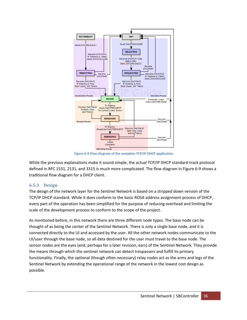
Figure 6‐9 Flow diagram of the complete TCP/IP DHCP application
While the previous explanations make it sound simple, the actual TCP/IP DHCP standard‐track protocol defined in RFC 1531, 2131, and 3315 is much more complicated. The flow diagram in Figure 6‐9 shows a traditional flow diagram for a DHCP client.
6.5.3 Design The design of the network layer for the Sentinel Network is based on a stripped down version of the TCP/IP DHCP standard. While it does conform to the basic ROSA address assignment process of DHCP, every part of the operation has been simplified for the purpose of reducing overhead and limiting the scale of the development process to conform to the scope of the project.
As mentioned before, in this network there are three different node types. The base node can be thought of as being the center of the Sentinel Network. There is only a single base node, and it is connected directly to the UI and accessed by the user. All the other network nodes communicate to the UI/user through the base node, so all data destined for the user must travel to the base node. The sensor nodes are the eyes (and, perhaps for a later revision, ears) of the Sentinel Network. They provide the means through which the sentinel network can detect trespassers and fulfill its primary functionality. Finally, the optional (though often necessary) relay nodes act as the arms and legs of the Sentinel Network by extending the operational range of the network in the lowest cost design as possible.
Sentinel Network | 5BController 36
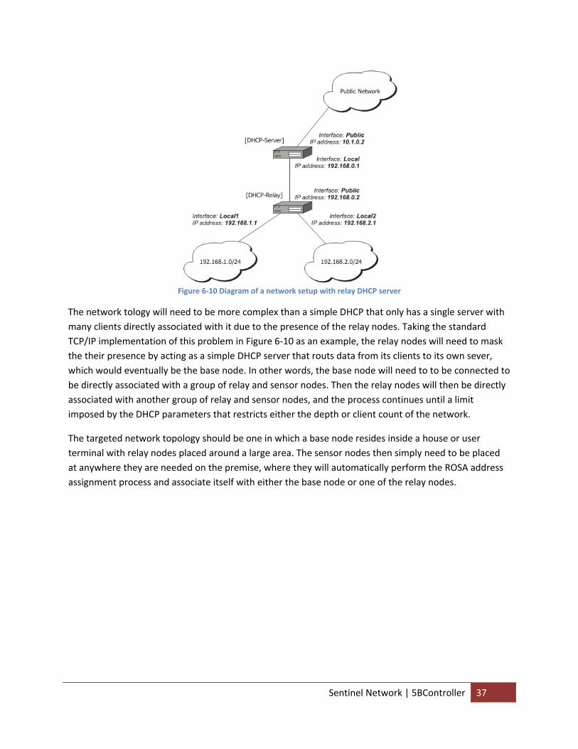
Figure 6‐10 Diagram of a network setup with relay DHCP server
The network tology will need to be more complex than a simple DHCP that only has a single server with many clients directly associated with it due to the presence of the relay nodes. Taking the standard TCP/IP implementation of this problem in Figure 6‐10 as an example, the relay nodes will need to mask the their presence by acting as a simple DHCP server that routs data from its clients to its own sever, which would eventually be the base node. In other words, the base node will need to to be connected to be directly associated with a group of relay and sensor nodes. Then the relay nodes will then be directly associated with another group of relay and sensor nodes, and the process continues until a limit imposed by the DHCP parameters that restricts either the depth or client count of the network.
The targeted network topology should be one in which a base node resides inside a house or user terminal with relay nodes placed around a large area. The sensor nodes then simply need to be placed at anywhere they are needed on the premise, where they will automatically perform the ROSA address assignment process and associate itself with either the base node or one of the relay nodes.
Sentinel Network | 5BController 37
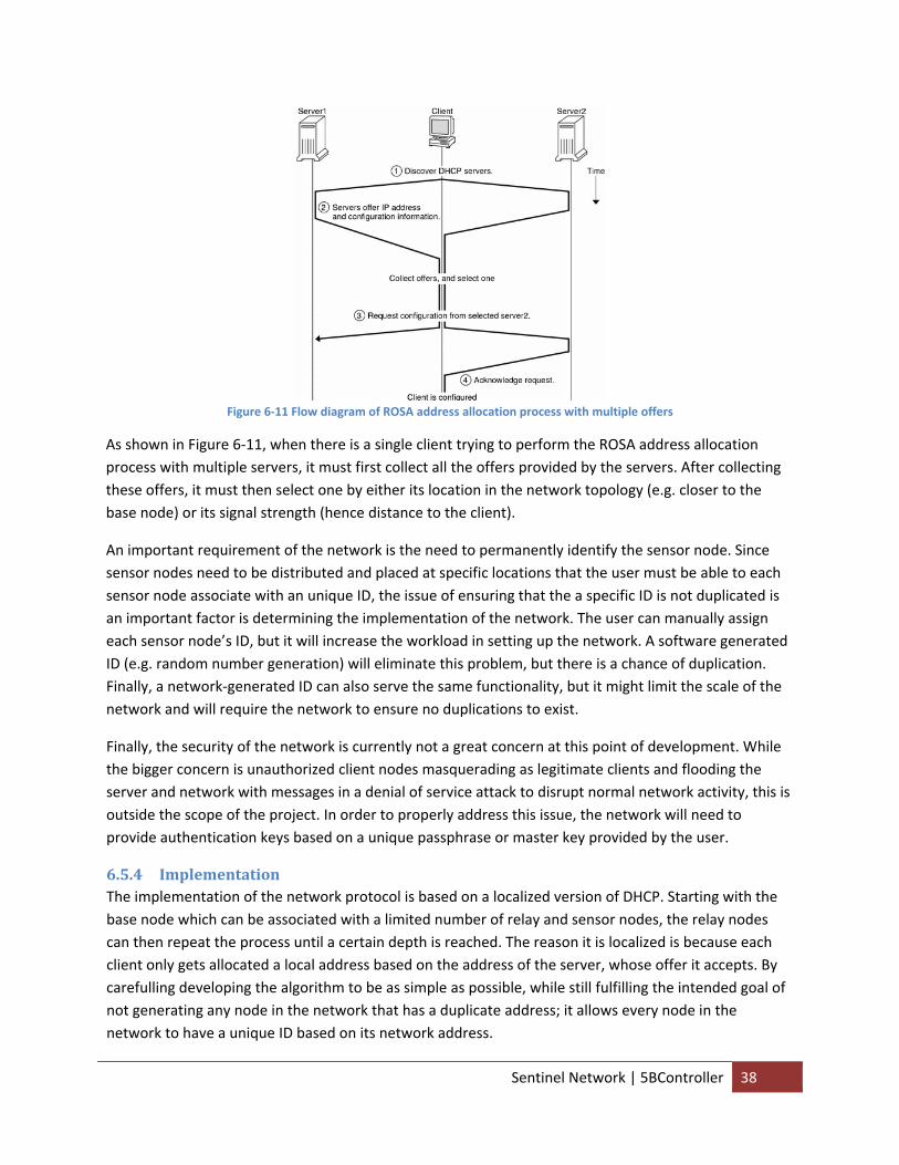
Figure 6‐11 Flow diagram of ROSA address allocation process with multiple offers
As shown in Figure 6‐11, when there is a single client trying to perform the ROSA address allocation process with multiple servers, it must first collect all the offers provided by the servers. After collecting these offers, it must then select one by either its location in the network topology (e.g. closer to the base node) or its signal strength (hence distance to the client).
An important requirement of the network is the need to permanently identify the sensor node. Since sensor nodes need to be distributed and placed at specific locations that the user must be able to each sensor node associate with an unique ID, the issue of ensuring that the a specific ID is not duplicated is an important factor is determining the implementation of the network. The user can manually assign each sensor node’s ID, but it will increase the workload in setting up the network. A software generated ID (e.g. random number generation) will eliminate this problem, but there is a chance of duplication. Finally, a network‐generated ID can also serve the same functionality, but it might limit the scale of the network and will require the network to ensure no duplications to exist.
Finally, the security of the network is currently not a great concern at this point of development. While the bigger concern is unauthorized client nodes masquerading as legitimate clients and flooding the server and network with messages in a denial of service attack to disrupt normal network activity, this is outside the scope of the project. In order to properly address this issue, the network will need to provide authentication keys based on a unique passphrase or master key provided by the user.
6.5.4 Implementation The implementation of the network protocol is based on a localized version of DHCP. Starting with the base node which can be associated with a limited number of relay and sensor nodes, the relay nodes can then repeat the process until a certain depth is reached. The reason it is localized is because each client only gets allocated a local address based on the address of the server, whose offer it accepts. By carefulling developing the algorithm to be as simple as possible, while still fulfilling the intended goal of not generating any node in the network that has a duplicate address; it allows every node in the network to have a unique ID based on its network address.
Sentinel Network | 5BController 38
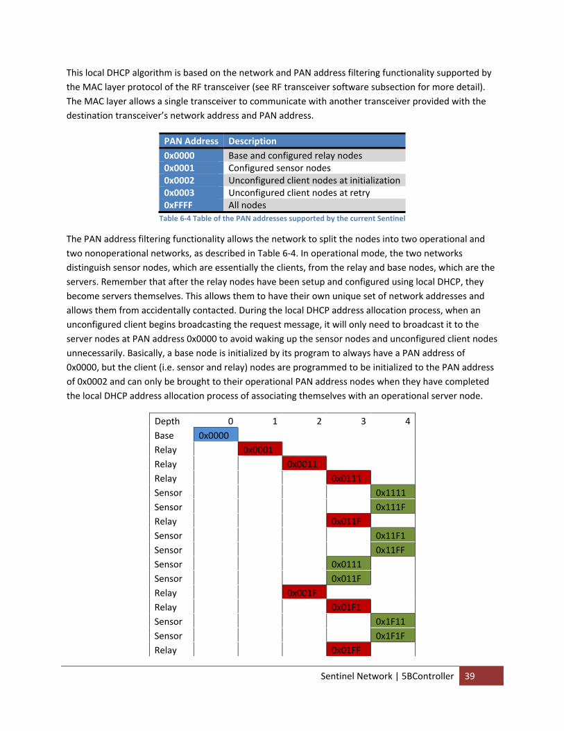
This local DHCP algorithm is based on the network and PAN address filtering functionality supported by the MAC layer protocol of the RF transceiver (see RF transceiver software subsection for more detail). The MAC layer allows a single transceiver to communicate with another transceiver provided with the destination transceiver’s network address and PAN address.
PAN Address Description 0x0000 Base and configured relay nodes 0x0001 Configured sensor nodes 0x0002 Unconfigured client nodes at initialization 0x0003 Unconfigured client nodes at retry 0xFFFF All nodes
Table 6‐4 Table of the PAN addresses supported by the current Sentinel
The PAN address filtering functionality allows the network to split the nodes into two operational and two nonoperational networks, as described in Table 6‐4. In operational mode, the two networks distinguish sensor nodes, which are essentially the clients, from the relay and base nodes, which are the servers. Remember that after the relay nodes have been setup and configured using local DHCP, they become servers themselves. This allows them to have their own unique set of network addresses and allows them from accidentally contacted. During the local DHCP address allocation process, when an unconfigured client begins broadcasting the request message, it will only need to broadcast it to the server nodes at PAN address 0x0000 to avoid waking up the sensor nodes and unconfigured client nodes unnecessarily. Basically, a base node is initialized by its program to always have a PAN address of 0x0000, but the client (i.e. sensor and relay) nodes are programmed to be initialized to the PAN address of 0x0002 and can only be brought to their operational PAN address nodes when they have completed the local DHCP address allocation process of associating themselves with an operational server node.
Depth 0 1 2 3 4 Base 0x0000 Relay 0x0001 Relay 0x0011 Relay 0x0111 Sensor 0x1111 Sensor 0x111F Relay 0x011F Sensor 0x11F1 Sensor 0x11FF Sensor 0x0111 Sensor 0x011F Relay 0x001F Relay 0x01F1 Sensor 0x1F11 Sensor 0x1F1F Relay 0x01FF
Sentinel Network | 5BController 39
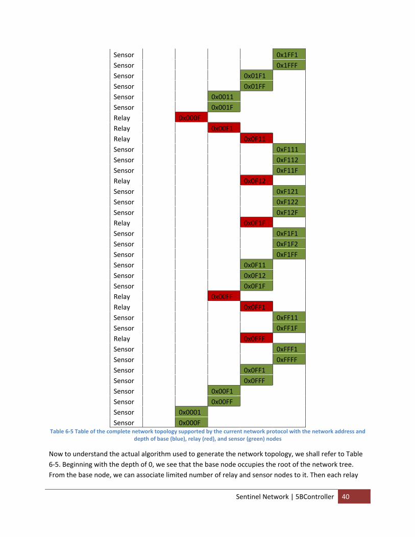
Sensor 0x1FF1 Sensor 0x1FFF Sensor 0x01F1 Sensor 0x01FF Sensor 0x0011 Sensor 0x001F Relay 0x000F Relay 0x00F1 Relay 0x0F11 Sensor 0xF111 Sensor 0xF112 Sensor 0xF11F Relay 0x0F12 Sensor 0xF121 Sensor 0xF122 Sensor 0xF12F Relay 0x0F1F Sensor 0xF1F1 Sensor 0xF1F2 Sensor 0xF1FF Sensor 0x0F11 Sensor 0x0F12 Sensor 0x0F1F Relay 0x00FF Relay 0x0FF1 Sensor 0xFF11 Sensor 0xFF1F Relay 0x0FFF Sensor 0xFFF1 Sensor 0xFFFF Sensor 0x0FF1 Sensor 0x0FFF Sensor 0x00F1 Sensor 0x00FF Sensor 0x0001 Sensor 0x000F
Table 6‐5 Table of the complete network topology supported by the current network protocol with the network address and depth of base (blue), relay (red), and sensor (green) nodes
Now to understand the actual algorithm used to generate the network topology, we shall refer to Table 6‐5. Beginning with the depth of 0, we see that the base node occupies the root of the network tree. From the base node, we can associate limited number of relay and sensor nodes to it. Then each relay
Sentinel Network | 5BController 40
node can then have the same limited number of relay and sensor nodes associated to it. This process can be repeated up to a depth of 4 for sensor nodes and 3 for relay nodes.
If we look at the network address assignments closely, we can see that starting with a base network address of 0x0000, all the addresses of its associated client nodes are simply generated by shifting that address left by 4 bits and then using the rightmost nibble to allocate to its clients. This means that, as a result of there being two independent networks (i.e. one for sensor clients and another for relay/base servers), there can be 15 sensor and 15 relay nodes associated with every single server node. While the relay nodes are limited to 15 per server since the value of 0 cannot be assigned because of its lack of significance from being shifted, sensor nodes can be set to the full 16 4‐bit, nibble per server.
By this algorithm, if the network address mode is set to use a short address of 16‐bit, the relays can be extended to a depth of 3 and the sensors to a depth of 4. If extended address mode of 64‐bit were used instead, the relays can then be extended to a depth of 15 and the sensors to a depth of 16. Or the address pool can be expanded beyond a nibble to byte, allowing each server to support up to 255 clients of each type and still allow the relays to be extended to a depth of 7 and sensors to a depth of 8.
The table shows that this algorithm ensures the sensor nodes, highlighted in green, cover the entire spectrum of network addresses for their own network from 0x0001 to 0xFFFF (although 0xFFFF is actually reserved for global network address). Every sensor node has a unique network address based on its position in the network tree, which is then used as its ID.
This network algorithm is a crossover between dynamic and automatic allocation modes. While addresses are assigned dynamically like in dynamic allocation modes, they are assigned permanently to the clients. The reason they must be permanently assigned is due to the need for the user to keep track of the sensor. For example, suppose that the user turns on a sensor node, lets it perform its local DHCP address assignment process, and then logs this address down as its ID along on where it is located. When a detection message comes from the particular sensor ID, the user can understand where the sensor detection occurred. However, if the sensor node renewals it’s DHCP with a new address, it now will report back a completely different ID that the user can’t associate with anything.
Sentinel Network | 5BController 41
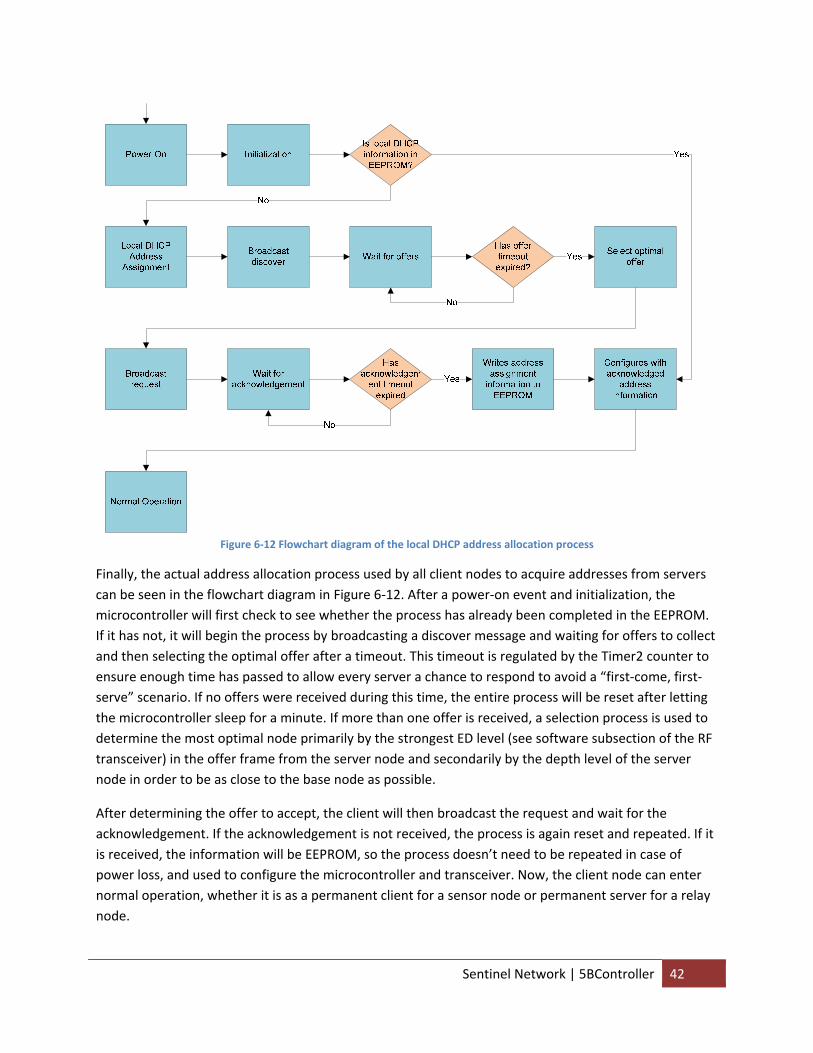
Figure 6‐12 Flowchart diagram of the local DHCP address allocation process
Finally, the actual address allocation process used by all client nodes to acquire addresses from servers can be seen in the flowchart diagram in Figure 6‐12. After a power‐on event and initialization, the microcontroller will first check to see whether the process has already been completed in the EEPROM. If it has not, it will begin the process by broadcasting a discover message and waiting for offers to collect and then selecting the optimal offer after a timeout. This timeout is regulated by the Timer2 counter to ensure enough time has passed to allow every server a chance to respond to avoid a “first‐come, first‐serve” scenario. If no offers were received during this time, the entire process will be reset after letting the microcontroller sleep for a minute. If more than one offer is received, a selection process is used to determine the most optimal node primarily by the strongest ED level (see software subsection of the RF transceiver) in the offer frame from the server node and secondarily by the depth level of the server node in order to be as close to the base node as possible.
After determining the offer to accept, the client will then broadcast the request and wait for the acknowledgement. If the acknowledgement is not received, the process is again reset and repeated. If it is received, the information will be EEPROM, so the process doesn’t need to be repeated in case of power loss, and used to configure the microcontroller and transceiver. Now, the client node can enter normal operation, whether it is as a permanent client for a sensor node or permanent server for a relay node.
Sentinel Network | 5BController 42
At all times, a server node knows all the sensor and relay nodes that are associated to it. Every sensor (hence client) node and relay node knows its server node. In normal operation, any message the sensor (or any) node wants to send to the base node can simply be sent to the associated server node, as it will eventually traverse to the root of the network tree, which is occupied by the base.
6.5.5 Conclusion The controller subsystem, which is arguably the most complicated and vital part of the system, was designed and implication to all the derived subsystem requirements assigned to it. Despite some hardware setbacks and software compromises, they were able to perform their intended functionality very well.
6.5.6 Future Recommendations 1. Use LED for only debug usage in order to reduce their current drain during normal, remote
operation by disabling the LED usage after local DHCP algorithm completion and then enabling it through the user interface.
2. Perform a detailed test and analysis of the trade‐off between the microcontroller running on higher frequency, thereby increasing current consumption but also reducing active time and amount of time the RF transceiver spends in active states waiting for the microcontroller.
3. Change the DHCP allocation from an automatic to a dynamic mode, where the address is leased rather than permanently assigned to client nodes by the server. This will need to be accompanied by a RTC on the controller board to make long‐term time tracking on either the server or client.
4. Implement a low level security feature on the DHCP protocol to prevent unauthorized clients from gaining access and masquerading as a legitimate sensor/relay node. One simple solution is to allow users to make changes to the base PAN address of the basic modes of operation.
5. Fix the address generation protocol in the local DHCP algorithm so that an address of 0xFFFF, which is the global broadcast network address, cannot be generated.
6. Modify the address allocation algorithm to allow the client nodes to renewal and find new servers when its current one does not respond after a long period of time. This can either be temporary, just allowing the sensor to still communicate back to the base, or permanent, changing the network address thus requiring some permanent form of ID generation, or semi‐permanent, changing the server but still keeping the same ID by using a different pool address.
7. Improve the offer selection algorithm to perform a more detailed calculation trade‐off between ED level and server node depth. Also add in server occupancy (e.g. the number of remaining available slots left for allocation) into the equation so that the network tree is evenly branched out. Most importantly, incorporate both RSSI/ED and LQI values to follow the rule of thumb of determine the best route between two nodes.
8. Add checks in the local DHCP algorithm to check for multiple, simulataneous requests to deter reservations from being improperly made.
9. Allow a transceiver to lower transmission power if its radio link to the destination node is strong enough. Implement an algorithm that will automatically adjust this threshold for an optimal value to reduce power consumption.
Sentinel Network | 5BController 43
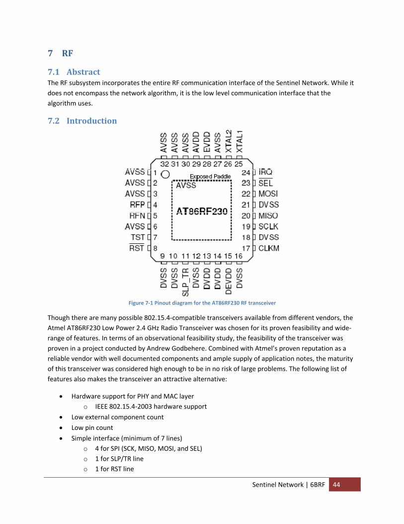
7 RF
7.1 Abstract The RF subsystem incorporates the entire RF communication interface of the Sentinel Network. While it does not encompass the network algorithm, it is the low level communication interface that the algorithm uses.
7.2 Introduction
Figure 7‐1 Pinout diagram for the AT86RF230 RF transceiver
Though there are many possible 802.15.4‐compatible transceivers available from different vendors, the Atmel AT86RF230 Low Power 2.4 GHz Radio Transceiver was chosen for its proven feasibility and wide‐range of features. In terms of an observational feasibility study, the feasibility of the transceiver was proven in a project conducted by Andrew Godbehere. Combined with Atmel’s proven reputation as a reliable vendor with well documented components and ample supply of application notes, the maturity of this transceiver was considered high enough to be in no risk of large problems. The following list of features also makes the transceiver an attractive alternative:
• Hardware support for PHY and MAC layer o IEEE 802.15.4‐2003 hardware support
• Low external component count
• Low pin count
• Simple interface (minimum of 7 lines) o 4 for SPI (SCK, MISO, MOSI, and SEL) o 1 for SLP/TR line o 1 for RST line
Sentinel Network | 6BRF 44
o 1 for IRQ line o Optional lines for MCU clock and continuous transmission mode lines
• Adjustable clock output to MCU
• Integrated battery monitor
• Low wide‐range supply voltage (1.8 to 3.6 V)
• Low power consumption o Sleep state: 20 nA o RX state: 15.5 mA o TX state: 16.5 mA
The transceiver’s hardware support for the 2003 revision of the task group, which added MAC layer, brings FCS computation, CCA, energy detection, automatic CSMA‐CA, automatic acknowledgement, and and automatic address filtering to the device. Since most radio transceiver opt for a QFN package in order to achieve a reduction to the lead inductance, a smaller footprint, and a smaller profile, it is always a good idea to minimize the pin count due to the difficulty to solder such a chip without special equipment. Its simple interface to the microcontroller, along with its ability to provide the master clock signal to it, makes a perfect companion for a small profile 8‐bit microcontroller. Its wide range of supply voltage and low power consumption helps ensure a steady performance for extended operation.
7.3 Subsystem Requirements ID Requirement Type Abstract Name OR1.2 The RF subsystem shall scale dynamically Functional Scale dynamically OR2.1 The RF subsystem shall have a minimum MTBM of 1
year Performance Minimum MTBM
OR7.1 The RF subsystem shall utilize the 802.15.4 radio protocol
Interface Communicate wirelessly
Table 7‐1 Table of the derived requirements for the RF subsystem
7.4 Hardware
7.4.1 Abstract The hardware aspect of the RF subsystem involves the circuit schematic, PCB layout, hardware manufacturing, and hardware assembly of the RF subsystem.
Sentinel Network | 6BRF 45
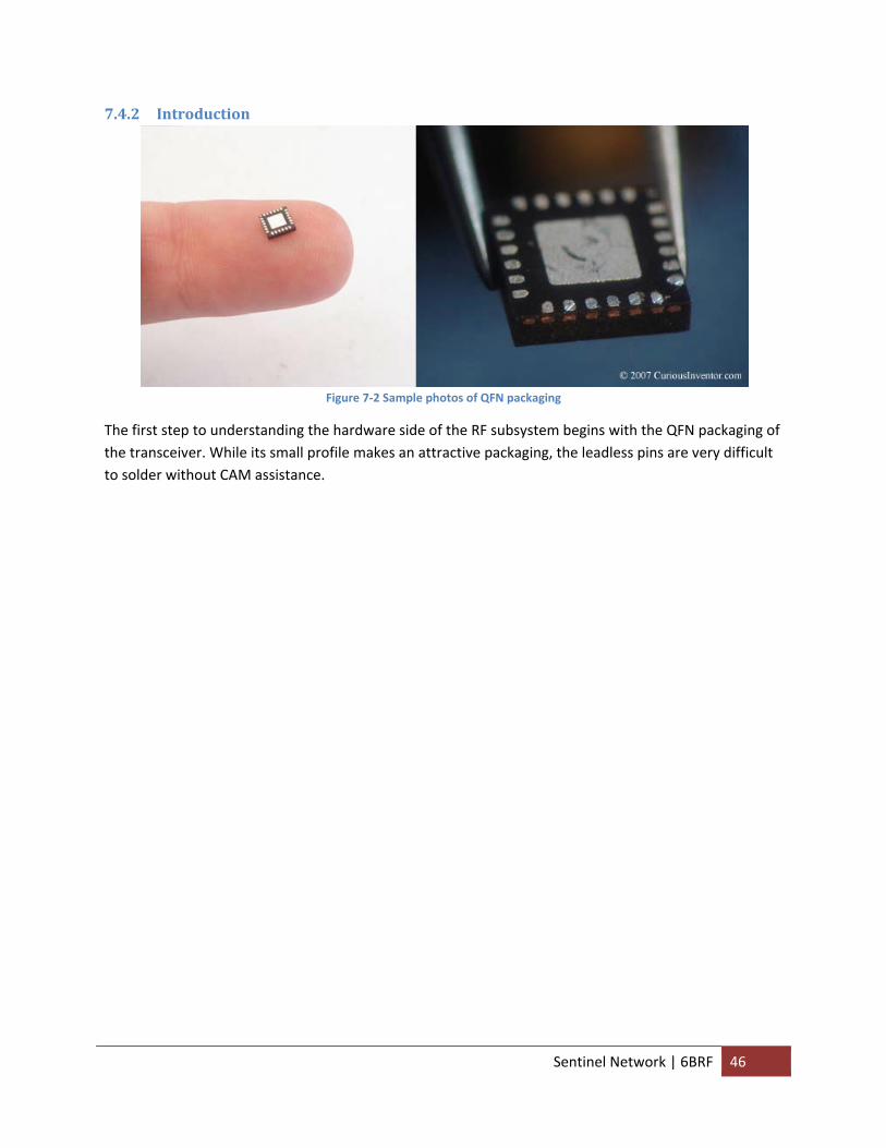
7.4.2 Introduction
Figure 7‐2 Sample photos of QFN packaging
The first step to understanding the hardware side of the RF subsystem begins with the QFN packaging of the transceiver. While its small profile makes an attractive packaging, the leadless pins are very difficult to solder without CAM assistance.
Sentinel Network | 6BRF 46
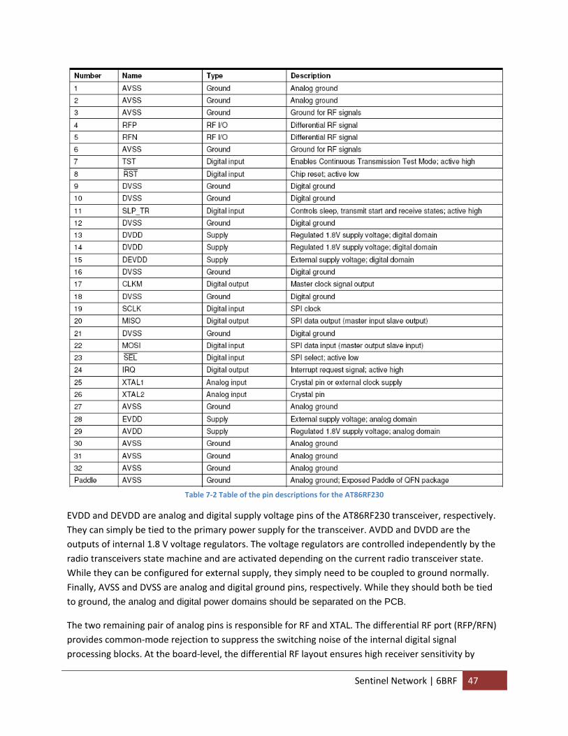
Table 7‐2 Table of the pin descriptions for the AT86RF230
EVDD and DEVDD are analog and digital supply voltage pins of the AT86RF230 transceiver, respectively. They can simply be tied to the primary power supply for the transceiver. AVDD and DVDD are the outputs of internal 1.8 V voltage regulators. The voltage regulators are controlled independently by the radio transceivers state machine and are activated depending on the current radio transceiver state. While they can be configured for external supply, they simply need to be coupled to ground normally. Finally, AVSS and DVSS are analog and digital ground pins, respectively. While they should both be tied to ground, the analog and digital power domains should be separated on the PCB.
The two remaining pair of analog pins is responsible for RF and XTAL. The differential RF port (RFP/RFN) provides common‐mode rejection to suppress the switching noise of the internal digital signal processing blocks. At the board‐level, the differential RF layout ensures high receiver sensitivity by
Sentinel Network | 6BRF 47
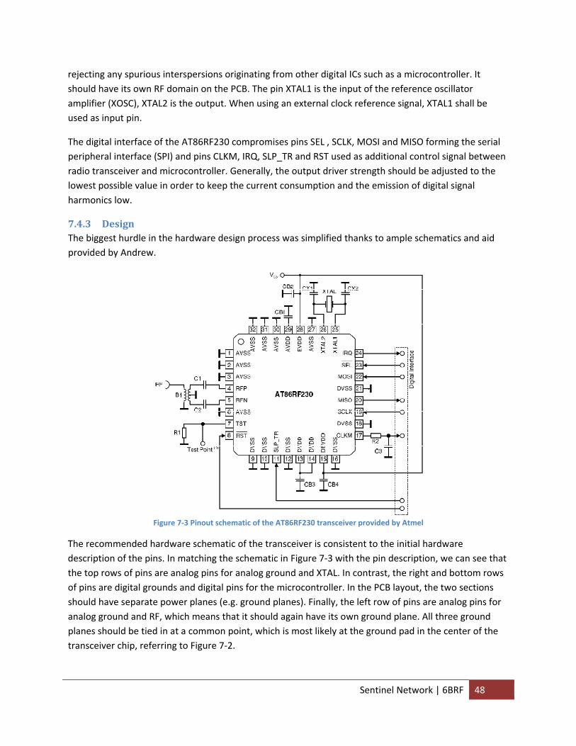
rejecting any spurious interspersions originating from other digital ICs such as a microcontroller. It should have its own RF domain on the PCB. The pin XTAL1 is the input of the reference oscillator amplifier (XOSC), XTAL2 is the output. When using an external clock reference signal, XTAL1 shall be used as input pin.
The digital interface of the AT86RF230 compromises pins SEL , SCLK, MOSI and MISO forming the serial peripheral interface (SPI) and pins CLKM, IRQ, SLP_TR and RST used as additional control signal between radio transceiver and microcontroller. Generally, the output driver strength should be adjusted to the lowest possible value in order to keep the current consumption and the emission of digital signal harmonics low.
7.4.3 Design The biggest hurdle in the hardware design process was simplified thanks to ample schematics and aid provided by Andrew.
Figure 7‐3 Pinout schematic of the AT86RF230 transceiver provided by Atmel
The recommended hardware schematic of the transceiver is consistent to the initial hardware description of the pins. In matching the schematic in Figure 7‐3 with the pin description, we can see that the top rows of pins are analog pins for analog ground and XTAL. In contrast, the right and bottom rows of pins are digital grounds and digital pins for the microcontroller. In the PCB layout, the two sections should have separate power planes (e.g. ground planes). Finally, the left row of pins are analog pins for analog ground and RF, which means that it should again have its own ground plane. All three ground planes should be tied in at a common point, which is most likely at the ground pad in the center of the transceiver chip, referring to Figure 7‐2.
Sentinel Network | 6BRF 48
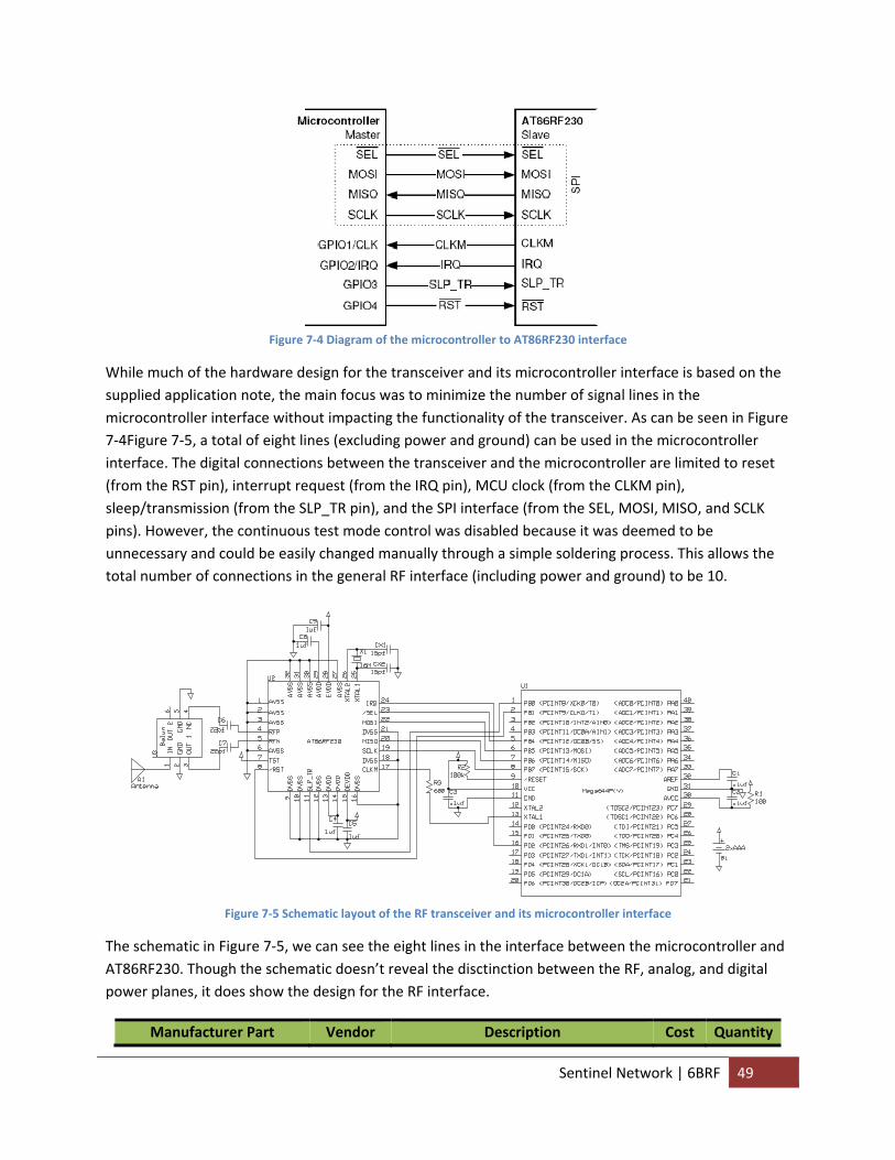
Figure 7‐4 Diagram of the microcontroller to AT86RF230 interface
While much of the hardware design for the transceiver and its microcontroller interface is based on the supplied application note, the main focus was to minimize the number of signal lines in the microcontroller interface without impacting the functionality of the transceiver. As can be seen in Figure 7‐4Figure 7‐5, a total of eight lines (excluding power and ground) can be used in the microcontroller interface. The digital connections between the transceiver and the microcontroller are limited to reset (from the RST pin), interrupt request (from the IRQ pin), MCU clock (from the CLKM pin), sleep/transmission (from the SLP_TR pin), and the SPI interface (from the SEL, MOSI, MISO, and SCLK pins). However, the continuous test mode control was disabled because it was deemed to be unnecessary and could be easily changed manually through a simple soldering process. This allows the total number of connections in the general RF interface (including power and ground) to be 10.
Figure 7‐5 Schematic layout of the RF transceiver and its microcontroller interface
The schematic in Figure 7‐5, we can see the eight lines in the interface between the microcontroller and AT86RF230. Though the schematic doesn’t reveal the disctinction between the RF, analog, and digital power planes, it does show the design for the RF interface.
Manufacturer Part Vendor Description Cost Quantity
Sentinel Network | 6BRF 49
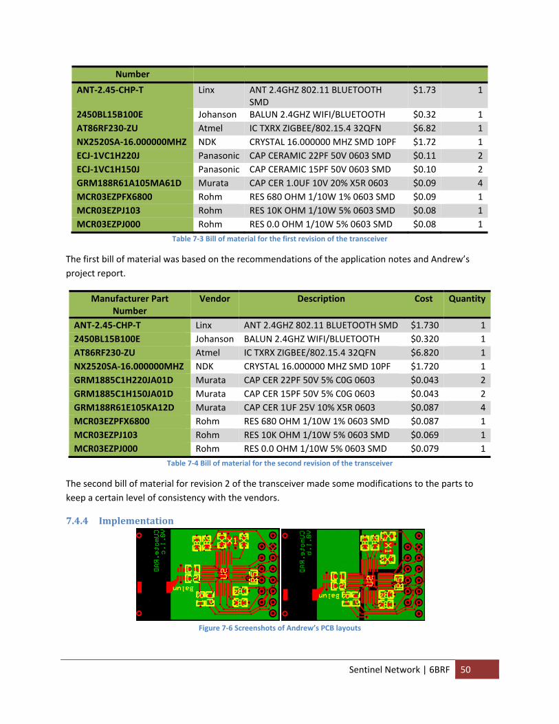
Number
ANT‐2.45‐CHP‐T Linx ANT 2.4GHZ 802.11 BLUETOOTH SMD
$1.73 1
2450BL15B100E Johanson BALUN 2.4GHZ WIFI/BLUETOOTH $0.32 1AT86RF230‐ZU Atmel IC TXRX ZIGBEE/802.15.4 32QFN $6.82 1NX2520SA‐16.000000MHZ NDK CRYSTAL 16.000000 MHZ SMD 10PF $1.72 1ECJ‐1VC1H220J Panasonic CAP CERAMIC 22PF 50V 0603 SMD $0.11 2ECJ‐1VC1H150J Panasonic CAP CERAMIC 15PF 50V 0603 SMD $0.10 2GRM188R61A105MA61D Murata CAP CER 1.0UF 10V 20% X5R 0603 $0.09 4MCR03EZPFX6800 Rohm RES 680 OHM 1/10W 1% 0603 SMD $0.09 1MCR03EZPJ103 Rohm RES 10K OHM 1/10W 5% 0603 SMD $0.08 1MCR03EZPJ000 Rohm RES 0.0 OHM 1/10W 5% 0603 SMD $0.08 1
Table 7‐3 Bill of material for the first revision of the transceiver
The first bill of material was based on the recommendations of the application notes and Andrew’s project report.
Manufacturer Part Number
Vendor Description Cost Quantity
ANT‐2.45‐CHP‐T Linx ANT 2.4GHZ 802.11 BLUETOOTH SMD $1.730 12450BL15B100E Johanson BALUN 2.4GHZ WIFI/BLUETOOTH $0.320 1AT86RF230‐ZU Atmel IC TXRX ZIGBEE/802.15.4 32QFN $6.820 1NX2520SA‐16.000000MHZ NDK CRYSTAL 16.000000 MHZ SMD 10PF $1.720 1GRM1885C1H220JA01D Murata CAP CER 22PF 50V 5% C0G 0603 $0.043 2GRM1885C1H150JA01D Murata CAP CER 15PF 50V 5% C0G 0603 $0.043 2GRM188R61E105KA12D Murata CAP CER 1UF 25V 10% X5R 0603 $0.087 4MCR03EZPFX6800 Rohm RES 680 OHM 1/10W 1% 0603 SMD $0.087 1MCR03EZPJ103 Rohm RES 10K OHM 1/10W 5% 0603 SMD $0.069 1MCR03EZPJ000 Rohm RES 0.0 OHM 1/10W 5% 0603 SMD $0.079 1
Table 7‐4 Bill of material for the second revision of the transceiver
The second bill of material for revision 2 of the transceiver made some modifications to the parts to keep a certain level of consistency with the vendors.
7.4.4 Implementation
Figure 7‐6 Screenshots of Andrew’s PCB layouts
Sentinel Network | 6BRF 50
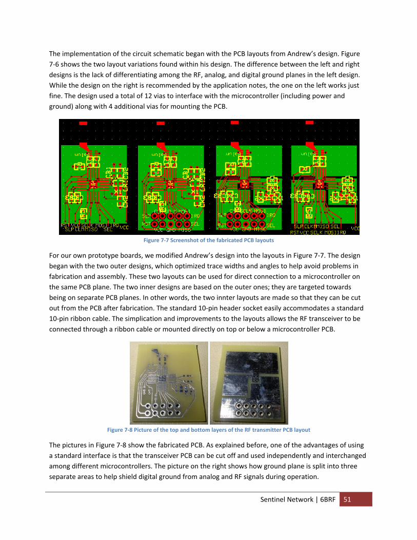
The implementation of the circuit schematic began with the PCB layouts from Andrew’s design. Figure 7‐6 shows the two layout variations found within his design. The difference between the left and right designs is the lack of differentiating among the RF, analog, and digital ground planes in the left design. While the design on the right is recommended by the application notes, the one on the left works just fine. The design used a total of 12 vias to interface with the microcontroller (including power and ground) along with 4 additional vias for mounting the PCB.
Figure 7‐7 Screenshot of the fabricated PCB layouts
For our own prototype boards, we modified Andrew’s design into the layouts in Figure 7‐7. The design began with the two outer designs, which optimized trace widths and angles to help avoid problems in fabrication and assembly. These two layouts can be used for direct connection to a microcontroller on the same PCB plane. The two inner designs are based on the outer ones; they are targeted towards being on separate PCB planes. In other words, the two innter layouts are made so that they can be cut out from the PCB after fabrication. The standard 10‐pin header socket easily accommodates a standard 10‐pin ribbon cable. The simplication and improvements to the layouts allows the RF transceiver to be connected through a ribbon cable or mounted directly on top or below a microcontroller PCB.
Figure 7‐8 Picture of the top and bottom layers of the RF transmitter PCB layout
The pictures in Figure 7‐8 show the fabricated PCB. As explained before, one of the advantages of using a standard interface is that the transceiver PCB can be cut off and used independently and interchanged among different microcontrollers. The picture on the right shows how ground plane is split into three separate areas to help shield digital ground from analog and RF signals during operation.
Sentinel Network | 6BRF 51
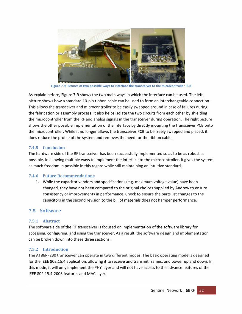
Figure 7‐9 Pictures of two possible ways to interface the transceiver to the microcontroller PCB
As explain before, Figure 7‐9 shows the two main ways in which the interface can be used. The left picture shows how a standard 10‐pin ribbon cable can be used to form an interchangeable connection. This allows the transceiver and microcontroller to be easily swapped around in case of failures during the fabrication or assembly process. It also helps isolate the two circuits from each other by shielding the microcontroller from the RF and analog signals in the transceiver during operation. The right picture shows the other possible implementation of the interface by directly mounting the transceiver PCB onto the microcontroller. While it no longer allows the transceiver PCB to be freely swapped and placed, it does reduce the profile of the system and removes the need for the ribbon cable.
7.4.5 Conclusion The hardware side of the RF transceiver has been successfully implemented so as to be as robust as possible. In allowing multiple ways to implement the interface to the microcontroller, it gives the system as much freedom in possible in this regard while still maintaining an intuitive standard.
7.4.6 Future Recommendations 1. While the capacitor vendors and specifications (e.g. maximum voltage value) have been
changed, they have not been compared to the original choices supplied by Andrew to ensure consistency or improvements in performance. Check to ensure the parts list changes to the capacitors in the second revision to the bill of materials does not hamper performance.
7.5 Software
7.5.1 Abstract The software side of the RF transceiver is focused on implementation of the software library for accessing, configuring, and using the transceiver. As a result, the software design and implementation can be broken down into these three sections.
7.5.2 Introduction The AT86RF230 transceiver can operate in two different modes. The basic operating mode is designed for the IEEE 802.15.4 application, allowing it to receive and transmit frames, and power up and down. In this mode, it will only implement the PHY layer and will not have access to the advance features of the IEEE 802.15.4‐2003 features and MAC layer.
Sentinel Network | 6BRF 52
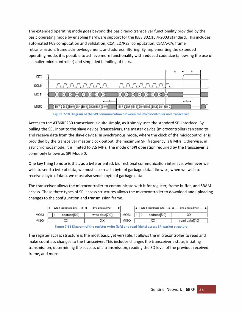
The extended operating mode goes beyond the basic radio transceiver functionality provided by the basic operating mode by enabling hardware support for the IEEE 802.15.4‐2003 standard. This includes automated FCS computation and validation, CCA, ED/RSSI computation, CSMA‐CA, frame retransmission, frame acknowledgement, and address filtering. By implementing the extended operating mode, it is possible to achieve more functionality with reduced code size (allowsing the use of a smaller microcontroller) and simplified handling of tasks.
Figure 7‐10 Diagram of the SPI communication between the microcontroller and transceiver
Access to the AT86RF230 transceiver is quite simply, as it simply uses the standard SPI interface. By pulling the SEL input to the slave device (transceiver), the master device (microcontroller) can send to and receive data from the slave device. In synchronous mode, where the clock of the microcontroller is provided by the transceiver master clock output, the maximum SPI frequency is 8 MHz. Otherwise, in asynchronous mode, it is limited to 7.5 MHz. The mode of SPI operation required by the transceiver is commonly known as SPI Mode 0.
One key thing to note is that, as a byte oriented, bidirectional communication interface, whenever we wish to send a byte of data, we must also read a byte of garbage data. Likewise, when we wish to receive a byte of data, we must also send a byte of garbage data.
The transceiver allows the microcontroller to communicate with it for register, frame buffer, and SRAM access. These three types of SPI access structures allows the microcontroller to download and uploading changes to the configuration and transmission frame.
Figure 7‐11 Diagram of the register write (left) and read (right) access SPI packet structure
The register access structure is the most basic yet versatile. It allows the microcontroller to read and make countless changes to the transceiver. This includes changes the transceiver’s state, intiating transmission, determining the success of a transmission, reading the ED level of the previous received frame, and more.
Sentinel Network | 6BRF 53
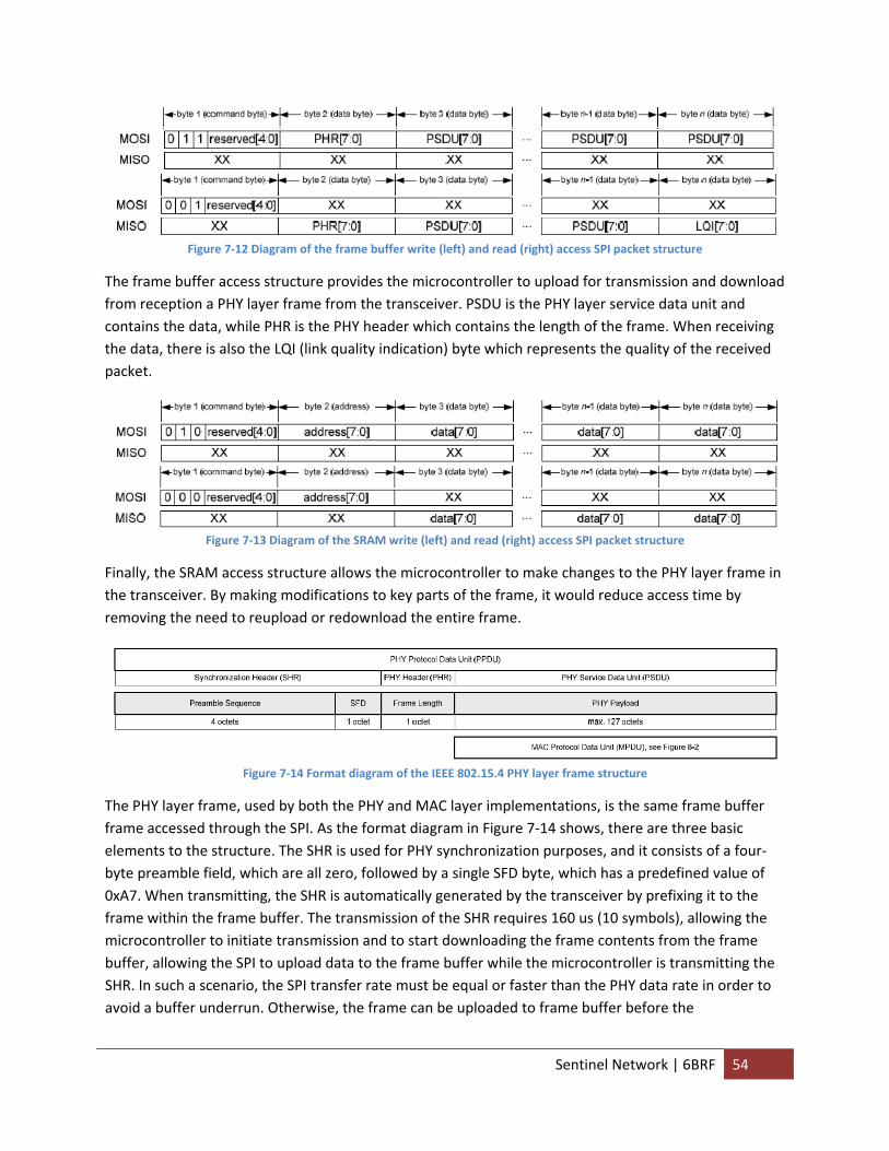
Figure 7‐12 Diagram of the frame buffer write (left) and read (right) access SPI packet structure
The frame buffer access structure provides the microcontroller to upload for transmission and download from reception a PHY layer frame from the transceiver. PSDU is the PHY layer service data unit and contains the data, while PHR is the PHY header which contains the length of the frame. When receiving the data, there is also the LQI (link quality indication) byte which represents the quality of the received packet.
Figure 7‐13 Diagram of the SRAM write (left) and read (right) access SPI packet structure
Finally, the SRAM access structure allows the microcontroller to make changes to the PHY layer frame in the transceiver. By making modifications to key parts of the frame, it would reduce access time by removing the need to reupload or redownload the entire frame.
Figure 7‐14 Format diagram of the IEEE 802.15.4 PHY layer frame structure
The PHY layer frame, used by both the PHY and MAC layer implementations, is the same frame buffer frame accessed through the SPI. As the format diagram in Figure 7‐14 shows, there are three basic elements to the structure. The SHR is used for PHY synchronization purposes, and it consists of a four‐byte preamble field, which are all zero, followed by a single SFD byte, which has a predefined value of 0xA7. When transmitting, the SHR is automatically generated by the transceiver by prefixing it to the frame within the frame buffer. The transmission of the SHR requires 160 us (10 symbols), allowing the microcontroller to initiate transmission and to start downloading the frame contents from the frame buffer, allowing the SPI to upload data to the frame buffer while the microcontroller is transmitting the SHR. In such a scenario, the SPI transfer rate must be equal or faster than the PHY data rate in order to avoid a buffer underrun. Otherwise, the frame can be uploaded to frame buffer before the
Sentinel Network | 6BRF 54
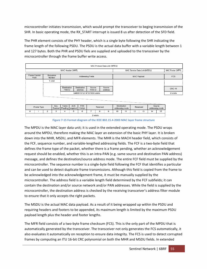
microcontroller initiates transmission, which would prompt the transceiver to beging transmission of the SHR. In basic operating mode, the RX_START interrupt is issued 8 us after detection of the SFD field.
The PHR element consists of the PHY header, which is a single byte following the SHR indicating the frame length of the following PSDU. The PSDU is the actual data buffer with a variable length between 1 and 127 bytes. Both the PHR and PSDU fiels are supplied and uploaded to the transceiver by the microcontroller through the frame buffer write access.
Figure 7‐15 Format diagram of the IEEE 802.15.4‐2003 MAC layer frame structure
The MPDU is the MAC layer data unit; it is used in the extended operating mode. The PSDU wraps around the MPDU, therefore making the MAC layer an extension of the basic PHY layer. It is broken down into the MHR, MSDU, and MFR elements. The MHR is the MACH header field, which consists of the FCF, sequence number, and variable‐lengthed addressing fields. The FCF is a two‐byte field that defines the frame type of the packet, whether there is a frame pending, whether an acknowledgement request should be enabled, whether this is an intra‐PAN (e.g. same source and destination PAN address) message, and defines the destination/source address mode. The entire FCF field must be supplied by the microcontroller. The sequence number is a single‐byte field following the FCF that identifies a particular and can be used to detect duplicate frame transmissions. Although this field is copied from the frame to be acknowledged into the acknowledgement frame, it must be manually supplied by the microcontroller. The address field is a variable length field determined by the FCF subfields; it can contain the destination and/or source network and/or PAN addresses. While the field is supplied by the microcontroller, the destination address is checked by the receiving transceiver’s address filter module to ensure that it only accepts the right packets.
The MSDU is the actual MAC data payload. As a result of it being wrapped up within the PSDU and requiring headers and footers to be appended, its maximum length is limited by the maximum PSDU payload length plus the header and footer lengths.
The MFR field consists of a two‐byte frame checksum (FCS). This is the only part of the MPDU that is automatically generated by the transceiver. The transceiver not only generates the FCS automatically, it also evaluates it automatically on reception to ensure data integrity. The FCS is used to detect corrupted frames by computing an ITU 16‐bit CRC polynomial on both the MHR and MSDU fields. In extended
Sentinel Network | 6BRF 55

operating mode, the transceiver automatically compute and append the FCS bytes on transmission, it also automatically applies an FCS check on each received frame.
The transceiver can use three different indiciators to determine the quality and/or quality of a radio link between two transceivers. The LQI value, obtained after a frame has been received by the radio transceiver as an additional byte attached to the received frame, is associated with the signal strength and distortion level. Signal distortions usually result from interference signals and/or multiplath propagation. The received signal power can also be indicated by the RSSI or ED value. However, they do not characterize the signal quality and the ability to decode a signal because at high signal power levels, the LQI value becomes independent of the actual signal strength. This is due to how packet error in such a scario tends to be close to zero and further increases of the signal strength from the transmission side will not decrease the error rate any further. Nonetheless, the RSSI and ED values can be used to evaluate the signal strength and the link margin.
In order to determine the nearby node with the best route, both the LQI and RSSI/ED values can be used depending on the optimization criteria. As a rule of thumb, the RSSI/ED value is used to differentiate between links with high LQI values, while transmission links with low LQI values should be discarded for routing descitions even if the RSSI/ED values are high.
The RSSI is a 5‐bit value indicating the received power in the selection channel, in steps of 3 dB. No attempt is made to distinguish between IEEE 802.15.4 signal and other signal source, only the received signal power evaluated. While the RSSI value (updated every 2 us) in the basic operating mode and can be read from the register, it is recommended to use the automatically generated ED value instead in extended operating mode.
The ED module defines 85 unique energy levels with a 1 dB resolution. The receiver ED measurement is used by a network layer as part of a channel selection algorithm. It is an estimation of the received signal power within the bandwidth of an IEEE 802.15.4‐2003 channel. It is calculated by averaging the RSSI valyes over eight symbols (128 us) with no attempts being made to identify or decode the signals on the channel. While a manual reading can be initiated by the registers, it is performed automatically by detecting a valid SFD of an incoming frame when using the extended operating mode. The ED value has a valid range from 0 to 84 with a resolution of 1 dB with zero indicating a measured energy of less than ‐91 dBm.
Sentinel Network | 6BRF 56
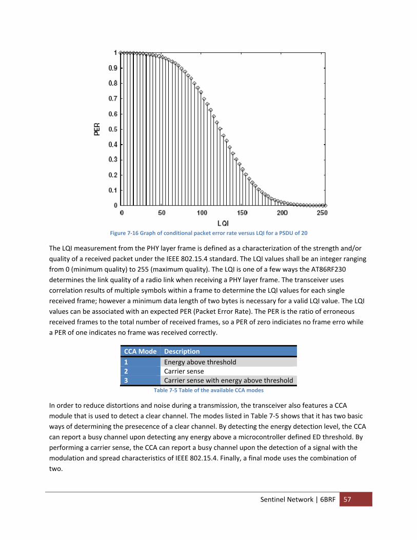
Figure 7‐16 Graph of conditional packet error rate versus LQI for a PSDU of 20
The LQI measurement from the PHY layer frame is defined as a characterization of the strength and/or quality of a received packet under the IEEE 802.15.4 standard. The LQI values shall be an integer ranging from 0 (minimum quality) to 255 (maximum quality). The LQI is one of a few ways the AT86RF230 determines the link quality of a radio link when receiving a PHY layer frame. The transceiver uses correlation results of multiple symbols within a frame to determine the LQI values for each single received frame; however a minimum data length of two bytes is necessary for a valid LQI value. The LQI values can be associated with an expected PER (Packet Error Rate). The PER is the ratio of erroneous received frames to the total number of received frames, so a PER of zero indiciates no frame erro while a PER of one indicates no frame was received correctly.
CCA Mode Description 1 Energy above threshold 2 Carrier sense 3 Carrier sense with energy above threshold
Table 7‐5 Table of the available CCA modes
In order to reduce distortions and noise during a transmission, the transceiver also features a CCA module that is used to detect a clear channel. The modes listed in Table 7‐5 shows that it has two basic ways of determining the presecence of a clear channel. By detecting the energy detection level, the CCA can report a busy channel upon detecting any energy above a microcontroller defined ED threshold. By performing a carrier sense, the CCA can report a busy channel upon the detection of a signal with the modulation and spread characteristics of IEEE 802.15.4. Finally, a final mode uses the combination of two.
Sentinel Network | 6BRF 57
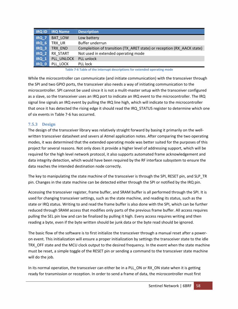
IRQ ID IRQ Name Description IRQ_7 BAT_LOW Low battery IRQ_6 TRX_UR Buffer underrun IRQ_3 TRX_END Compleition of transition (TX_ARET state) or reception (RX_AACK state) IRQ_2 RX_START Not used in extended operating mode IRQ_1 PLL_UNLOCK PLL unlock IRQ_0 PLL_LOCK PLL lock
Table 7‐6 Table of the interrupt descriptions for extended operating mode
While the microcontroller can communicate (and initiate communication) with the transceiver through the SPI and two GPIO ports, the transceiver also needs a way of initiating communication to the microcontroller. SPI cannot be used since it is not a mulit‐master setup with the transceiver configured as a slave, so the transceiver uses an IRQ port to indicate an IRQ event to the microcontroller. The IRQ signal line signals an IRQ event by pulling the IRQ line high, which will indicate to the microcontroller that once it has detected the rising edge it should read the IRQ_STATUS register to determine which one of six events in Table 7‐6 has occurred.
7.5.3 Design The design of the transceiver library was relatively straight forward by basing it primarily on the well‐written transceiver datasheet and severs al Atmel application notes. After comparing the two operating modes, it was determined that the extended operating mode was better suited for the purposes of this project for several reasons. Not only does it provide a higher level of addressing support, which will be required for the high level network protocol, it also supports automated frame acknowledgement and data integrity detection, which would have been required by the RF interface subsystem to ensure the data reaches the intended destination node correctly.
The key to manipulating the state machine of the transceiver is through the SPI, RESET pin, and SLP_TR pin. Changes in the state machine can be detected either through the SPI or notified by the IRQ pin.
Accessing the transceiver register, frame buffer, and SRAM buffer is all performed through the SPI. It is used for changing transceiver settings, such as the state machine, and reading its status, such as the state or IRQ status. Writing to and read the frame buffer is also done with the SPI, which can be further reduced through SRAM access that modifies only parts of the previous frame buffer. All access requires pulling the SEL pin low and can be finalized by pulling it high. Every access requires writing and then reading a byte, even if the byte written should be junk data or the byte read should be ignored.
The basic flow of the software is to first initialize the transceiver through a manual reset after a power‐on event. This initialization will ensure a proper initialization by settings the transceiver state to the idle TRX_OFF state and the MCU clock output to the desired frequency. In the event when the state machine must be reset, a simple toggle of the RESET pin or sending a command to the transceiver state machine will do the job.
In its normal operation, the transceiver can either be in a PLL_ON or RX_ON state when it is getting ready for transmission or reception. In order to send a frame of data, the microcontroller must first
Sentinel Network | 6BRF 58
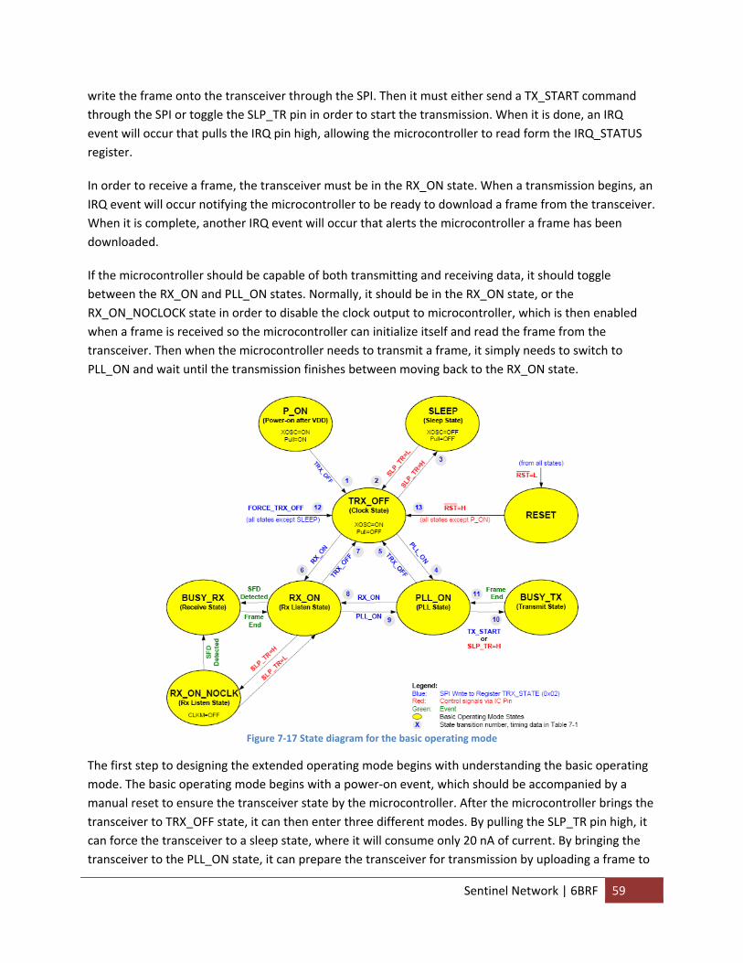
write the frame onto the transceiver through the SPI. Then it must either send a TX_START command through the SPI or toggle the SLP_TR pin in order to start the transmission. When it is done, an IRQ event will occur that pulls the IRQ pin high, allowing the microcontroller to read form the IRQ_STATUS register.
In order to receive a frame, the transceiver must be in the RX_ON state. When a transmission begins, an IRQ event will occur notifying the microcontroller to be ready to download a frame from the transceiver. When it is complete, another IRQ event will occur that alerts the microcontroller a frame has been downloaded.
If the microcontroller should be capable of both transmitting and receiving data, it should toggle between the RX_ON and PLL_ON states. Normally, it should be in the RX_ON state, or the RX_ON_NOCLOCK state in order to disable the clock output to microcontroller, which is then enabled when a frame is received so the microcontroller can initialize itself and read the frame from the transceiver. Then when the microcontroller needs to transmit a frame, it simply needs to switch to PLL_ON and wait until the transmission finishes between moving back to the RX_ON state.
Figure 7‐17 State diagram for the basic operating mode
The first step to designing the extended operating mode begins with understanding the basic operating mode. The basic operating mode begins with a power‐on event, which should be accompanied by a manual reset to ensure the transceiver state by the microcontroller. After the microcontroller brings the transceiver to TRX_OFF state, it can then enter three different modes. By pulling the SLP_TR pin high, it can force the transceiver to a sleep state, where it will consume only 20 nA of current. By bringing the transceiver to the PLL_ON state, it can prepare the transceiver for transmission by uploading a frame to
Sentinel Network | 6BRF 59
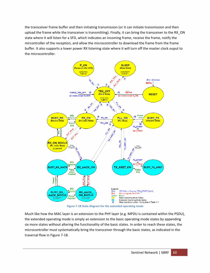
the transceiver frame buffer and then initiating transmission (or it can initiate transmission and then upload the frame while the transceiver is transmitting). Finally, it can bring the transceiver to the RX_ON state where it will listen for a SFD, which indicates an incoming frame, receive the frame, notify the mircontroller of the reception, and allow the microcontroller to download the frame from the frame buffer. It also supports a lower power RX listening state where it will turn off the master clock ouput to the microcontroller.
Figure 7‐18 State diagram for the extended operating mode
Much like how the MAC layer is an extension to the PHY layer (e.g. MPDU is contained within the PSDU), the extended operating mode is simply an extension to the basic operating mode states by appending six more states without altering the functionality of the basic states. In order to reach these states, the microcontroller must systematically bring the transceiver through the basic states, as indicated in the traversal flow in Figure 7‐18.
Sentinel Network | 6BRF 60
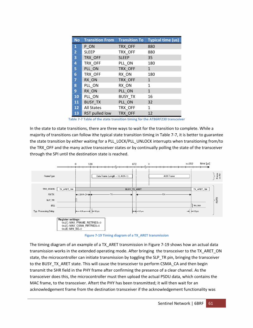
No Transition From Transition To Typical time (us) 1 P_ON TRX_OFF 880 2 SLEEP TRX_OFF 880 3 TRX_OFF SLEEP 35 4 TRX_OFF PLL_ON 180 5 PLL_ON TRX_OFF 1 6 TRX_OFF RX_ON 180 7 RX_ON TRX_OFF 1 8 PLL_ON RX_ON 1 9 RX_ON PLL_ON 1 10 PLL_ON BUSY_TX 16 11 BUSY_TX PLL_ON 32 12 All States TRX_OFF 1 13 RST pulled low TRX_OFF 12
Table 7‐7 Table of the state transition timing for the AT86RF230 transceiver
In the state to state transitions, there are three ways to wait for the transition to complete. While a majority of transitions can follow ithe typical state transition timing in Table 7‐7, it is better to guarantee the state transition by either waiting for a PLL_LOCK/PLL_UNLOCK interrupts when transitioning from/to the TRX_OFF and the many active transceiver states or by continually polling the state of the transceiver through the SPI until the destination state is reached.
Figure 7‐19 Timing diagram of a TX_ARET transmission
The timing diagram of an example of a TX_ARET transmission in Figure 7‐19 shows how an actual data transmission works in the extended operating mode. After bringing the transceiver to the TX_ARET_ON state, the microcontroller can initiate transmission by toggling the SLP_TR pin, bringing the transceiver to the BUSY_TX_ARET state. This will cause the transceiver to perform CSMA_CA and then begin transmit the SHR field in the PHY frame after confirming the presence of a clear channel. As the transceiver does this, the microcontroller must then upload the actual PSDU data, which contains the MAC frame, to the transceiver. Aftert the PHY has been transmitted; it will then wait for an acknowledgement frame from the destination transceiver if the acknowledgement functionality was
Sentinel Network | 6BRF 61
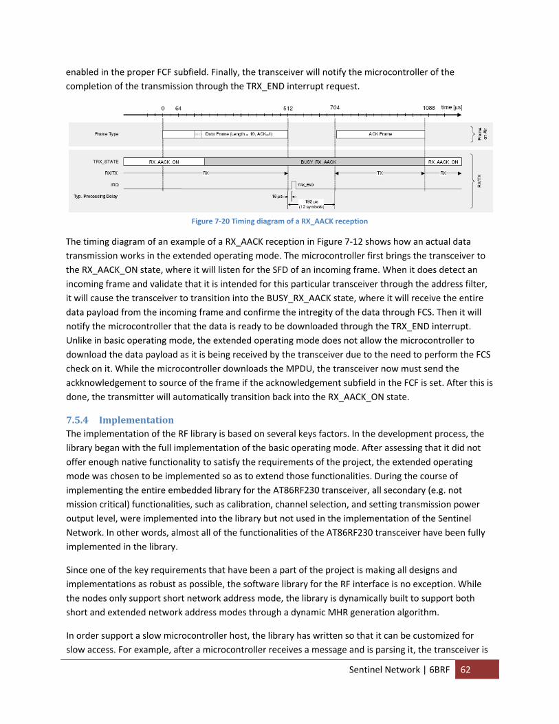
enabled in the proper FCF subfield. Finally, the transceiver will notify the microcontroller of the completion of the transmission through the TRX_END interrupt request.
Figure 7‐20 Timing diagram of a RX_AACK reception
The timing diagram of an example of a RX_AACK reception in Figure 7‐12 shows how an actual data transmission works in the extended operating mode. The microcontroller first brings the transceiver to the RX_AACK_ON state, where it will listen for the SFD of an incoming frame. When it does detect an incoming frame and validate that it is intended for this particular transceiver through the address filter, it will cause the transceiver to transition into the BUSY_RX_AACK state, where it will receive the entire data payload from the incoming frame and confirme the intregity of the data through FCS. Then it will notify the microcontroller that the data is ready to be downloaded through the TRX_END interrupt. Unlike in basic operating mode, the extended operating mode does not allow the microcontroller to download the data payload as it is being received by the transceiver due to the need to perform the FCS check on it. While the microcontroller downloads the MPDU, the transceiver now must send the ackknowledgement to source of the frame if the acknowledgement subfield in the FCF is set. After this is done, the transmitter will automatically transition back into the RX_AACK_ON state.
7.5.4 Implementation The implementation of the RF library is based on several keys factors. In the development process, the library began with the full implementation of the basic operating mode. After assessing that it did not offer enough native functionality to satisfy the requirements of the project, the extended operating mode was chosen to be implemented so as to extend those functionalities. During the course of implementing the entire embedded library for the AT86RF230 transceiver, all secondary (e.g. not mission critical) functionalities, such as calibration, channel selection, and setting transmission power output level, were implemented into the library but not used in the implementation of the Sentinel Network. In other words, almost all of the functionalities of the AT86RF230 transceiver have been fully implemented in the library.
Since one of the key requirements that have been a part of the project is making all designs and implementations as robust as possible, the software library for the RF interface is no exception. While the nodes only support short network address mode, the library is dynamically built to support both short and extended network address modes through a dynamic MHR generation algorithm.
In order support a slow microcontroller host, the library has written so that it can be customized for slow access. For example, after a microcontroller receives a message and is parsing it, the transceiver is
Sentinel Network | 6BRF 62
normally in a RX listening state once more where it can receive more data. However, the microcontroller in this scenario is not ready to process such data, so it will be lost, as a result the microcontroller is allowed to make a safe transition command for the transceiver so that as soon as it finishes sending the acknowledgement frame to the sender it will transition into the TRX_OFF state. The novelty of this implementation is that in the TRX_OFF state, it will not receive and hence send back any ackownledgement frames, so the sender will continue to try sending its message until the receiving node is ready to receive them by bringing the transceiver back to the RX listening state. This is particularly useful in the scenario of a client node receiving DHCP offers from servers. After broadcasting a DHCP offer message, all the server nodes in the vicinity will reply back simultaneously to the client node, causing the first to be received but all the rest to be potentially lost. This implementation allows them all to be received.
7.5.5 Conclusion The transceiver library was implemented to cover both basic and extended operating modes. While it does not implement the beacon and MAC command frame types, it is able to use the data and acknowledgement frame types, the only two required for the scope of the project, perfectly.
7.5.6 Future Recommendations 1. Implement the other MAC frame types, such the beacon frame, to allow the Sentinel Network to
adopt a synchronized, beacon topology instead of an asynchronously powered topology that it currently has.
2. It was mentioned earlier but, it should still be emphasized that more analysis needs to be placed on the trade off between using the master clock output from the transceiver for the microcontroller clock input. While it reduces the need for an external clock input for the microcontroller and could potentially reduce the power consumption of the microcontroller, it also requires the transceiver to be in TRX_OFF state instead of SLEEP state just so it can continue to supply the microcontroller with the clock. The best comparison should be between the external clock set at 1 MHz and the internal RC oscillator set at the same frequency.
3. The same needs to be done on just what clock frequency should be adopted for the solar powered, remote nodes. A higher clock frequency does increase current consumption, but it also reduces the amount of time the microcontroller has to be on. If the transceiver consumes much more current in its PLL states, then it does not make sense for it to wait for a slow microcontroller.
8 Sensor
8.1 Abstract The sensor subsystem is tasked with detecting intruders and notifying the controller that an alert must be sent to the base node. In other words, the sensor subsystem is simply a trigger mechanism which begins a specific stream of data transmission to the base node.
Sentinel Network | 7BSensor 63
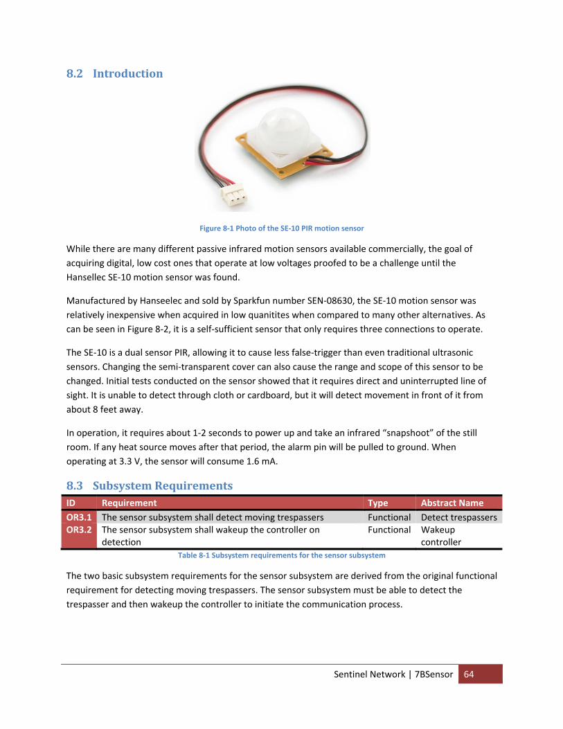
8.2 Introduction
Figure 8‐1 Photo of the SE‐10 PIR motion sensor
While there are many different passive infrared motion sensors available commercially, the goal of acquiring digital, low cost ones that operate at low voltages proofed to be a challenge until the Hansellec SE‐10 motion sensor was found.
Manufactured by Hanseelec and sold by Sparkfun number SEN‐08630, the SE‐10 motion sensor was relatively inexpensive when acquired in low quanitites when compared to many other alternatives. As can be seen in Figure 8‐2, it is a self‐sufficient sensor that only requires three connections to operate.
The SE‐10 is a dual sensor PIR, allowing it to cause less false‐trigger than even traditional ultrasonic sensors. Changing the semi‐transparent cover can also cause the range and scope of this sensor to be changed. Initial tests conducted on the sensor showed that it requires direct and uninterrupted line of sight. It is unable to detect through cloth or cardboard, but it will detect movement in front of it from about 8 feet away.
In operation, it requires about 1‐2 seconds to power up and take an infrared “snapshoot” of the still room. If any heat source moves after that period, the alarm pin will be pulled to ground. When operating at 3.3 V, the sensor will consume 1.6 mA.
8.3 Subsystem Requirements ID Requirement Type Abstract Name OR3.1 The sensor subsystem shall detect moving trespassers Functional Detect trespassers OR3.2 The sensor subsystem shall wakeup the controller on
detection Functional Wakeup
controller Table 8‐1 Subsystem requirements for the sensor subsystem
The two basic subsystem requirements for the sensor subsystem are derived from the original functional requirement for detecting moving trespassers. The sensor subsystem must be able to detect the trespasser and then wakeup the controller to initiate the communication process.
Sentinel Network | 7BSensor 64
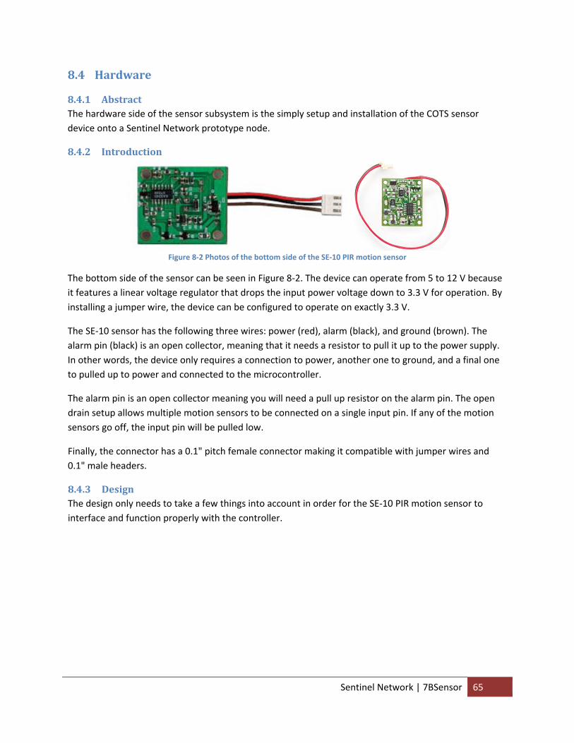
8.4 Hardware
8.4.1 Abstract The hardware side of the sensor subsystem is the simply setup and installation of the COTS sensor device onto a Sentinel Network prototype node.
8.4.2 Introduction
Figure 8‐2 Photos of the bottom side of the SE‐10 PIR motion sensor
The bottom side of the sensor can be seen in Figure 8‐2. The device can operate from 5 to 12 V because it features a linear voltage regulator that drops the input power voltage down to 3.3 V for operation. By installing a jumper wire, the device can be configured to operate on exactly 3.3 V.
The SE‐10 sensor has the following three wires: power (red), alarm (black), and ground (brown). The alarm pin (black) is an open collector, meaning that it needs a resistor to pull it up to the power supply. In other words, the device only requires a connection to power, another one to ground, and a final one to pulled up to power and connected to the microcontroller.
The alarm pin is an open collector meaning you will need a pull up resistor on the alarm pin. The open drain setup allows multiple motion sensors to be connected on a single input pin. If any of the motion sensors go off, the input pin will be pulled low.
Finally, the connector has a 0.1" pitch female connector making it compatible with jumper wires and 0.1" male headers.
8.4.3 Design The design only needs to take a few things into account in order for the SE‐10 PIR motion sensor to interface and function properly with the controller.
Sentinel Network | 7BSensor 65
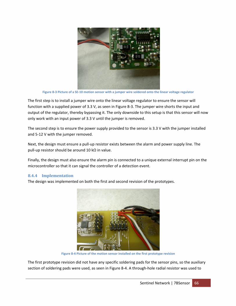
Figure 8‐3 Picture of a SE‐10 motion sensor with a jumper wire soldered onto the linear voltage regulator
The first step is to install a jumper wire onto the linear voltage regulator to ensure the sensor will function with a supplied power of 3.3 V, as seen in Figure 8‐3. The jumper wire shorts the input and output of the regulator, thereby bypassing it. The only downside to this setup is that this sensor will now only work with an input power of 3.3 V until the jumper is removed.
The second step is to ensure the power supply provided to the sensor is 3.3 V with the jumper installed and 5‐12 V with the jumper removed.
Next, the design must ensure a pull‐up resistor exists between the alarm and power supply line. The pull‐up resistor should be around 10 kΩ in value.
Finally, the design must also ensure the alarm pin is connected to a unique external interrupt pin on the microcontroller so that it can signal the controller of a detection event.
8.4.4 Implementation The design was implemented on both the first and second revision of the prototypes.
Figure 8‐4 Picture of the motion sensor installed on the first prototype revision
The first prototype revision did not have any specific soldering pads for the sensor pins, so the auxiliary section of soldering pads were used, as seen in Figure 8‐4. A through‐hole radial resistor was used to
Sentinel Network | 7BSensor 66
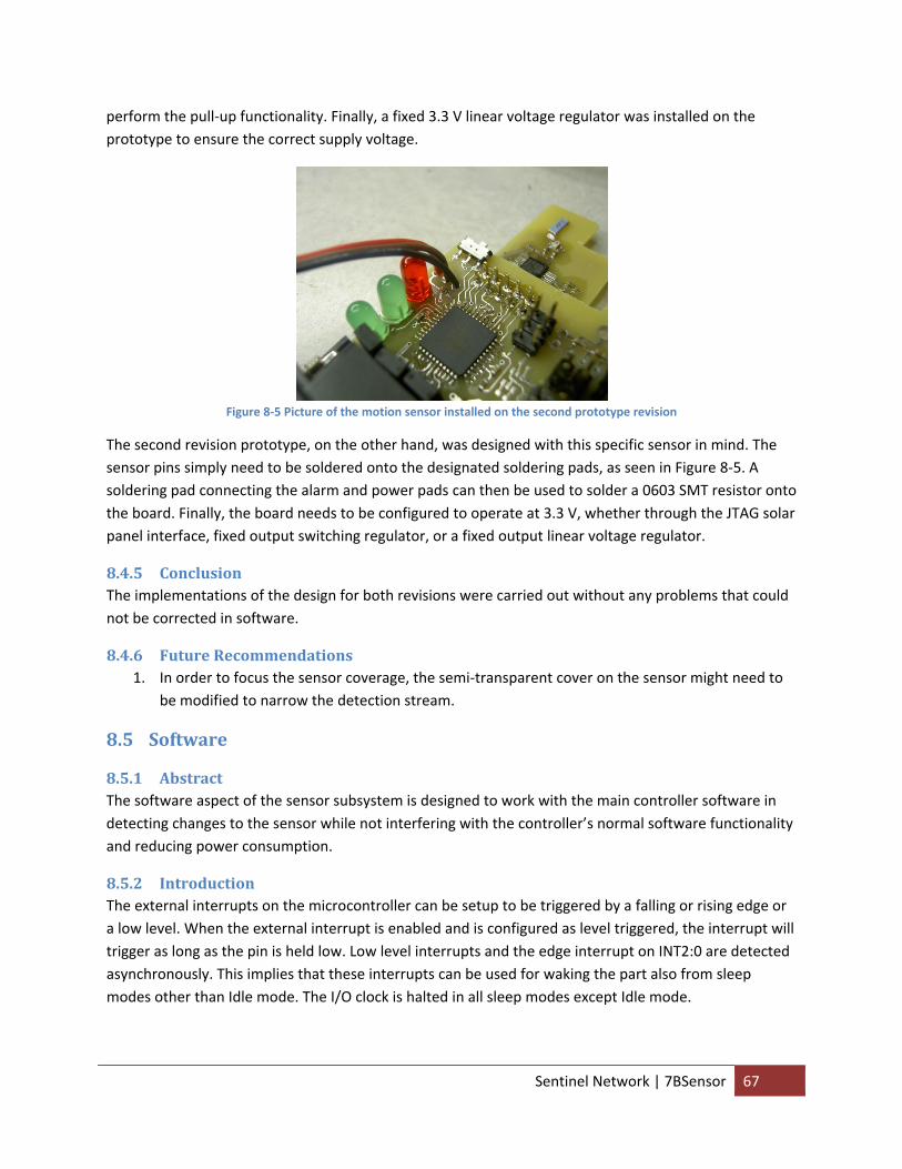
perform the pull‐up functionality. Finally, a fixed 3.3 V linear voltage regulator was installed on the prototype to ensure the correct supply voltage.
Figure 8‐5 Picture of the motion sensor installed on the second prototype revision
The second revision prototype, on the other hand, was designed with this specific sensor in mind. The sensor pins simply need to be soldered onto the designated soldering pads, as seen in Figure 8‐5. A soldering pad connecting the alarm and power pads can then be used to solder a 0603 SMT resistor onto the board. Finally, the board needs to be configured to operate at 3.3 V, whether through the JTAG solar panel interface, fixed output switching regulator, or a fixed output linear voltage regulator.
8.4.5 Conclusion The implementations of the design for both revisions were carried out without any problems that could not be corrected in software.
8.4.6 Future Recommendations 1. In order to focus the sensor coverage, the semi‐transparent cover on the sensor might need to
be modified to narrow the detection stream.
8.5 Software
8.5.1 Abstract The software aspect of the sensor subsystem is designed to work with the main controller software in detecting changes to the sensor while not interfering with the controller’s normal software functionality and reducing power consumption.
8.5.2 Introduction The external interrupts on the microcontroller can be setup to be triggered by a falling or rising edge or a low level. When the external interrupt is enabled and is configured as level triggered, the interrupt will trigger as long as the pin is held low. Low level interrupts and the edge interrupt on INT2:0 are detected asynchronously. This implies that these interrupts can be used for waking the part also from sleep modes other than Idle mode. The I/O clock is halted in all sleep modes except Idle mode.
Sentinel Network | 7BSensor 67
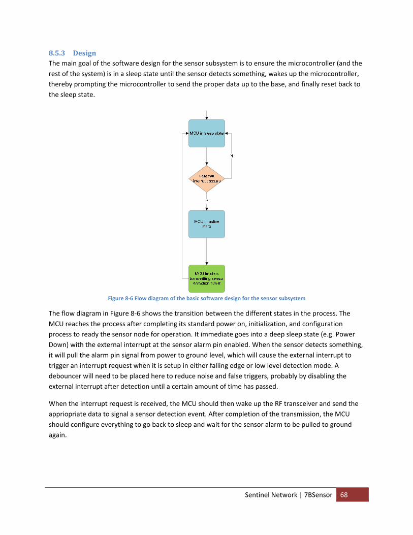
8.5.3 Design The main goal of the software design for the sensor subsystem is to ensure the microcontroller (and the rest of the system) is in a sleep state until the sensor detects something, wakes up the microcontroller, thereby prompting the microcontroller to send the proper data up to the base, and finally reset back to the sleep state.
Figure 8‐6 Flow diagram of the basic software design for the sensor subsystem
The flow diagram in Figure 8‐6 shows the transition between the different states in the process. The MCU reaches the process after completing its standard power on, initialization, and configuration process to ready the sensor node for operation. It immediate goes into a deep sleep state (e.g. Power Down) with the external interrupt at the sensor alarm pin enabled. When the sensor detects something, it will pull the alarm pin signal from power to ground level, which will cause the external interrupt to trigger an interrupt request when it is setup in either falling edge or low level detection mode. A debouncer will need to be placed here to reduce noise and false triggers, probably by disabling the external interrupt after detection until a certain amount of time has passed.
When the interrupt request is received, the MCU should then wake up the RF transceiver and send the appriopriate data to signal a sensor detection event. After completion of the transmission, the MCU should configure everything to go back to sleep and wait for the sensor alarm to be pulled to ground again.
Sentinel Network | 7BSensor 68
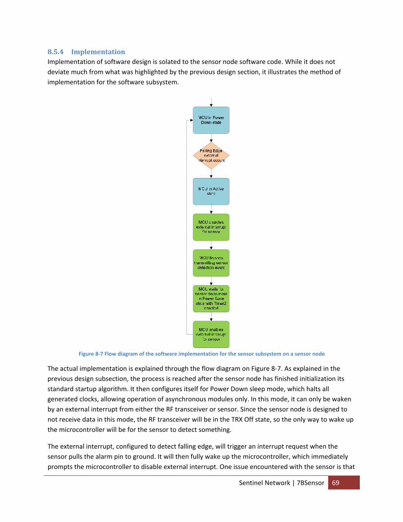
8.5.4 Implementation Implementation of software design is solated to the sensor node software code. While it does not deviate much from what was highlighted by the previous design section, it illustrates the method of implementation for the software subsystem.
Figure 8‐7 Flow diagram of the software implementation for the sensor subsystem on a sensor node
The actual implementation is explained through the flow diagram on Figure 8‐7. As explained in the previous design subsection, the process is reached after the sensor node has finished initialization its standard startup algorithm. It then configures itself for Power Down sleep mode, which halts all generated clocks, allowing operation of asynchronous modules only. In this mode, it can only be waken by an external interrupt from either the RF transceiver or sensor. Since the sensor node is designed to not receive data in this mode, the RF transceiver will be in the TRX Off state, so the only way to wake up the microcontroller will be for the sensor to detect something.
The external interrupt, configured to detect falling edge, will trigger an interrupt request when the sensor pulls the alarm pin to ground. It will then fully wake up the microcontroller, which immediately prompts the microcontroller to disable external interrupt. One issue encountered with the sensor is that
Sentinel Network | 7BSensor 69
it does not simply pull the alarm pin to ground and stay in that state for a fixed period of time, but rather it fluctuates for awhile. In other words, a large number of interrupt requests will be triggered sequentially after the first one unless the interrupt is disabled. The easiest way to disable it is to clear the interrupt mask so that the ISR function is never called.
After the microcontroller finishes communicating the sensor detection event, it will bring the RF transceiver back to the TRX Off state and wait for a latency timer for the sensor to expire. This latency timer is implemented in conjunction with the Power Save mode and Timer2 functionality. Power Save is identical to Power Down mode, except if Timer2 is enabled, it will keep running during sleep. The device can wake up from either Timer Overflow or Output Compare event from Timer2 if the corresponding Timer2 interrupt enable bits are set in TIMSK2, and the Global Interrupt Enable bit in SREG is set. So why running the Timer2 and placing the MCU in Power Save mode, we can minimize power consumption while waiting for enough time to expire before re‐enabling the sensor.
Whenever Timer2 triggers an interrupt request, the MCU wakes up, the tick counts are incremented, and the tick counts are compared to threshold values. If they don’t exceed the thresholds, the MCU goes back to Power Save sleep mode and wait for the next interrupt from Timer2. In order to minimize power consumption, the interrupts should occur as infrequently as possible (e.g. the largest common denominator to keep track of time) to ensure the MCU stays in Power Save for as long as possible and reduce the frequency for it to become Active. If they exceed the proper thresholds, the process is completed and the sensor can be re‐enabled, allowing the MCU to disable Timer2 and enter Power Down sleep mode and wait for the sensor to wake it up.
8.5.5 Conclusion The implementation achieved theoretical performance beyond the subsystem requirements. Not only does it perform the intended detection and conservation functionality, it also debounces the sensor detection to prevent subsequent interrupt requests from being triggered after the initial one and performs all functionality with minimal power consumption.
8.5.6 Future Recommendations 1. The current implementation requires the RF transceiver be on (e.g. not in sleep mode) so that it
can keep on generating the master clock for the microcontroller. A laboratory test should be conducted to conclude whether it is more power efficient for the microcontroller to generate its own system clock (e.g. through the internal RC oscillator) so that it can put the RF transceiver to sleep during normal operation and only wake it up for communication functionality. In other words, a test should be conducted to decide the source for the system clock of the microcontroller.
9 Power Supply
9.1 Abstract The power supply subsystem function as the hardware that supplies and regulates the power supply to the network nodes and the software that monitors and conserves the power source. While software
Sentinel Network | 8BPower Supply 70
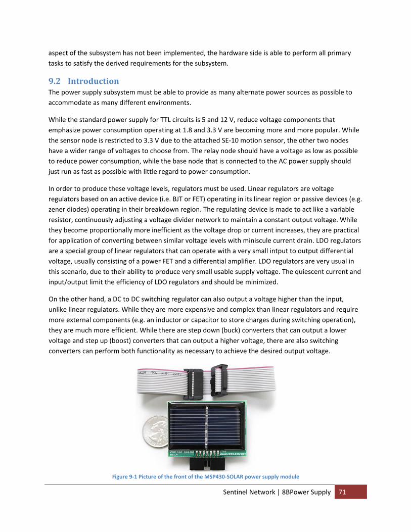
aspect of the subsystem has not been implemented, the hardware side is able to perform all primary tasks to satisfy the derived requirements for the subsystem.
9.2 Introduction The power supply subsystem must be able to provide as many alternate power sources as possible to accommodate as many different environments.
While the standard power supply for TTL circuits is 5 and 12 V, reduce voltage components that emphasize power consumption operating at 1.8 and 3.3 V are becoming more and more popular. While the sensor node is restricted to 3.3 V due to the attached SE‐10 motion sensor, the other two nodes have a wider range of voltages to choose from. The relay node should have a voltage as low as possible to reduce power consumption, while the base node that is connected to the AC power supply should just run as fast as possible with little regard to power consumption.
In order to produce these voltage levels, regulators must be used. Linear regulators are voltage regulators based on an active device (i.e. BJT or FET) operating in its linear region or passive devices (e.g. zener diodes) operating in their breakdown region. The regulating device is made to act like a variable resistor, continuously adjusting a voltage divider network to maintain a constant output voltage. While they become proportionally more inefficient as the voltage drop or current increases, they are practical for application of converting between similar voltage levels with miniscule current drain. LDO regulators are a special group of linear regulators that can operate with a very small intput to output differential voltage, usually consisting of a power FET and a differential amplifier. LDO regulators are very usual in this scenario, due to their ability to produce very small usable supply voltage. The quiescent current and input/output limit the efficiency of LDO regulators and should be minimized.
On the other hand, a DC to DC switching regulator can also output a voltage higher than the input, unlike linear regulators. While they are more expensive and complex than linear regulators and require more external components (e.g. an inductor or capacitor to store charges during switching operation), they are much more efficient. While there are step down (buck) converters that can output a lower voltage and step up (boost) converters that can output a higher voltage, there are also switching converters can perform both functionality as necessary to achieve the desired output voltage.
Figure 9‐1 Picture of the front of the MSP430‐SOLAR power supply module
Sentinel Network | 8BPower Supply 71
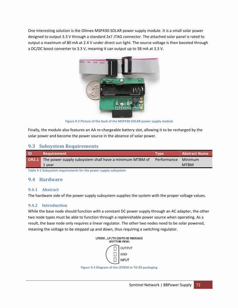
One interesting solution is the Olimex MSP430‐SOLAR power supply module. It is a small solar power designed to output 3.3 V through a standard 2x7 JTAG connector. The attached solar panel is rated to output a maximum of 80 mA at 2.4 V under direct sun light. The source voltage is then boosted through a DC/DC boost converter to 3.3 V, meaning it can output up to 58 mA at 3.3 V.
Figure 9‐2 Picture of the back of the MSP430‐SOLAR power supply module
Finally, the module also features an AA re‐chargeable battery slot, allowing it to be recharged by the solar power and become the power source in the absence of solar power.
9.3 Subsystem Requirements ID Requirement Type Abstract Name OR2.1 The power supply subsystem shall have a minimum MTBM of
1 year Performance Minimum
MTBM Table 9‐1 Subsystem requirements for the power supply subsystem
9.4 Hardware
9.4.1 Abstract The hardware side of the power supply subsystem supplies the system with the proper voltage values.
9.4.2 Introduction While the base node should function with a constant DC power supply through an AC adapter, the other two node types must be able to function through a replenishable power source when operating. As a result, the base node only requires a linear regulator. The other two nodes need to be solar powered, meaning the voltage to be stepped up and down, thus requiring a switching regulator.
Figure 9‐3 Diagram of the LP2950 in TO‐92 packaging
Sentinel Network | 8BPower Supply 72
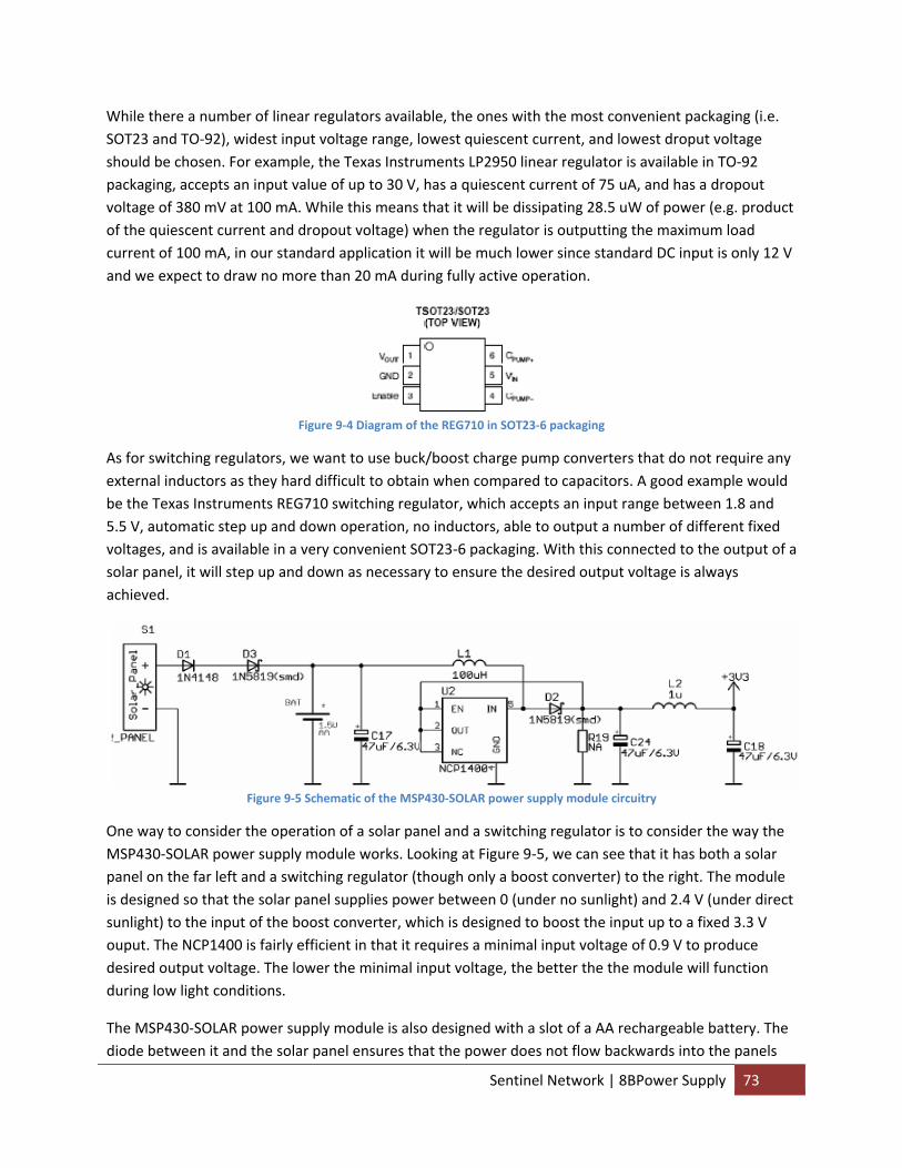
While there a number of linear regulators available, the ones with the most convenient packaging (i.e. SOT23 and TO‐92), widest input voltage range, lowest quiescent current, and lowest droput voltage should be chosen. For example, the Texas Instruments LP2950 linear regulator is available in TO‐92 packaging, accepts an input value of up to 30 V, has a quiescent current of 75 uA, and has a dropout voltage of 380 mV at 100 mA. While this means that it will be dissipating 28.5 uW of power (e.g. product of the quiescent current and dropout voltage) when the regulator is outputting the maximum load current of 100 mA, in our standard application it will be much lower since standard DC input is only 12 V and we expect to draw no more than 20 mA during fully active operation.
Figure 9‐4 Diagram of the REG710 in SOT23‐6 packaging
As for switching regulators, we want to use buck/boost charge pump converters that do not require any external inductors as they hard difficult to obtain when compared to capacitors. A good example would be the Texas Instruments REG710 switching regulator, which accepts an input range between 1.8 and 5.5 V, automatic step up and down operation, no inductors, able to output a number of different fixed voltages, and is available in a very convenient SOT23‐6 packaging. With this connected to the output of a solar panel, it will step up and down as necessary to ensure the desired output voltage is always achieved.
Figure 9‐5 Schematic of the MSP430‐SOLAR power supply module circuitry
One way to consider the operation of a solar panel and a switching regulator is to consider the way the MSP430‐SOLAR power supply module works. Looking at Figure 9‐5, we can see that it has both a solar panel on the far left and a switching regulator (though only a boost converter) to the right. The module is designed so that the solar panel supplies power between 0 (under no sunlight) and 2.4 V (under direct sunlight) to the input of the boost converter, which is designed to boost the input up to a fixed 3.3 V ouput. The NCP1400 is fairly efficient in that it requires a minimal input voltage of 0.9 V to produce desired output voltage. The lower the minimal input voltage, the better the the module will function during low light conditions.
The MSP430‐SOLAR power supply module is also designed with a slot of a AA rechargeable battery. The diode between it and the solar panel ensures that the power does not flow backwards into the panels
Sentinel Network | 8BPower Supply 73
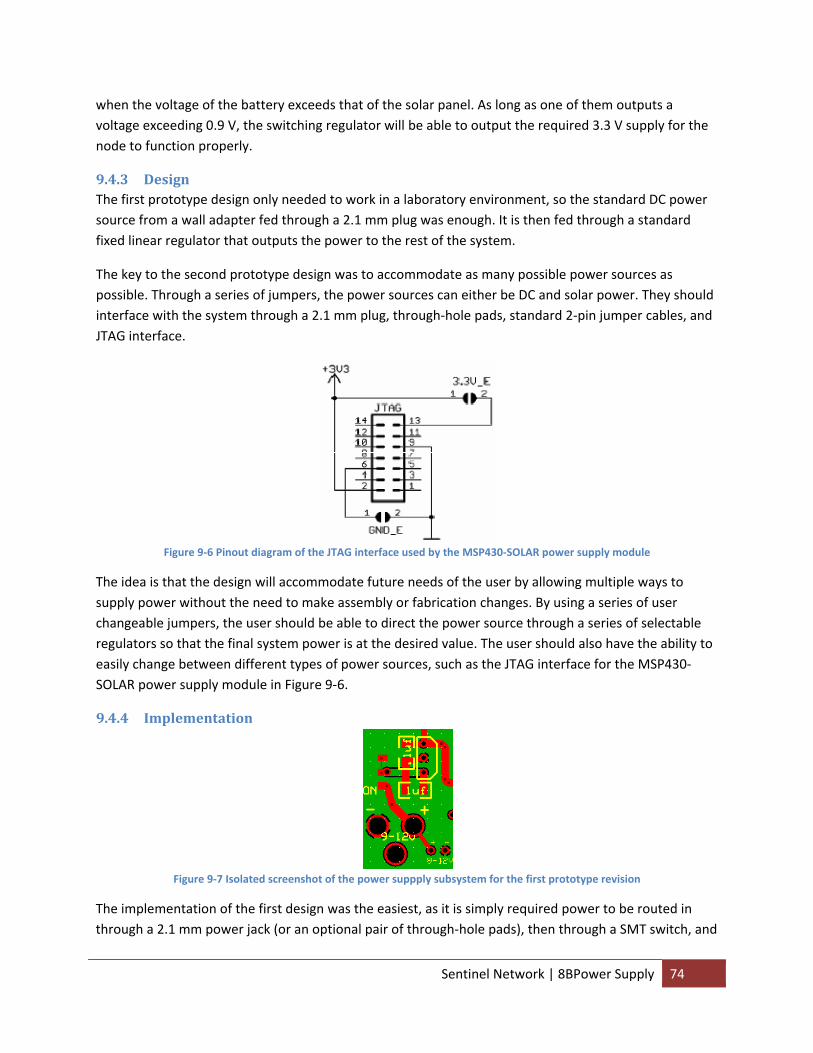
when the voltage of the battery exceeds that of the solar panel. As long as one of them outputs a voltage exceeding 0.9 V, the switching regulator will be able to output the required 3.3 V supply for the node to function properly.
9.4.3 Design The first prototype design only needed to work in a laboratory environment, so the standard DC power source from a wall adapter fed through a 2.1 mm plug was enough. It is then fed through a standard fixed linear regulator that outputs the power to the rest of the system.
The key to the second prototype design was to accommodate as many possible power sources as possible. Through a series of jumpers, the power sources can either be DC and solar power. They should interface with the system through a 2.1 mm plug, through‐hole pads, standard 2‐pin jumper cables, and JTAG interface.
Figure 9‐6 Pinout diagram of the JTAG interface used by the MSP430‐SOLAR power supply module
The idea is that the design will accommodate future needs of the user by allowing multiple ways to supply power without the need to make assembly or fabrication changes. By using a series of user changeable jumpers, the user should be able to direct the power source through a series of selectable regulators so that the final system power is at the desired value. The user should also have the ability to easily change between different types of power sources, such as the JTAG interface for the MSP430‐SOLAR power supply module in Figure 9‐6.
9.4.4 Implementation
Figure 9‐7 Isolated screenshot of the power suppply subsystem for the first prototype revision
The implementation of the first design was the easiest, as it is simply required power to be routed in through a 2.1 mm power jack (or an optional pair of through‐hole pads), then through a SMT switch, and
Sentinel Network | 8BPower Supply 74
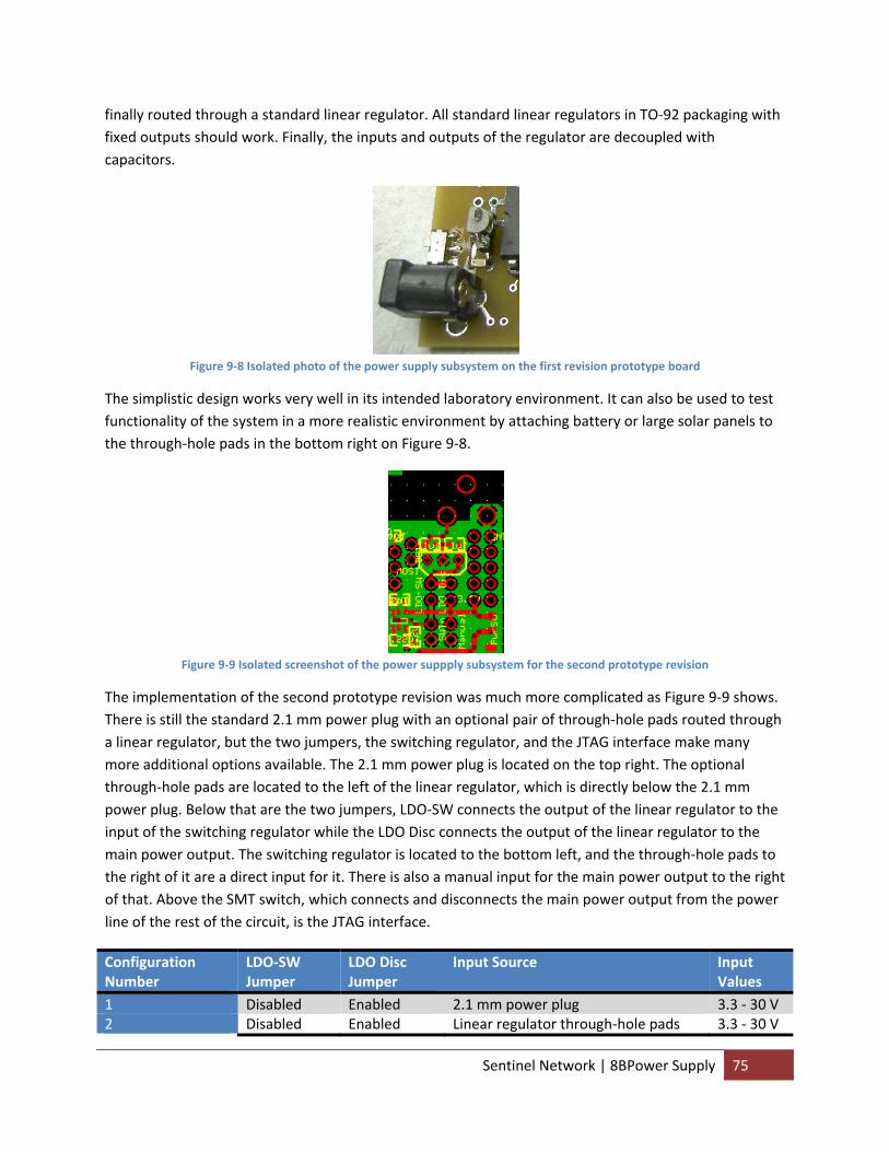
finally routed through a standard linear regulator. All standard linear regulators in TO‐92 packaging with fixed outputs should work. Finally, the inputs and outputs of the regulator are decoupled with capacitors.
Figure 9‐8 Isolated photo of the power supply subsystem on the first revision prototype board
The simplistic design works very well in its intended laboratory environment. It can also be used to test functionality of the system in a more realistic environment by attaching battery or large solar panels to the through‐hole pads in the bottom right on Figure 9‐8.
Figure 9‐9 Isolated screenshot of the power suppply subsystem for the second prototype revision
The implementation of the second prototype revision was much more complicated as Figure 9‐9 shows. There is still the standard 2.1 mm power plug with an optional pair of through‐hole pads routed through a linear regulator, but the two jumpers, the switching regulator, and the JTAG interface make many more additional options available. The 2.1 mm power plug is located on the top right. The optional through‐hole pads are located to the left of the linear regulator, which is directly below the 2.1 mm power plug. Below that are the two jumpers, LDO‐SW connects the output of the linear regulator to the input of the switching regulator while the LDO Disc connects the output of the linear regulator to the main power output. The switching regulator is located to the bottom left, and the through‐hole pads to the right of it are a direct input for it. There is also a manual input for the main power output to the right of that. Above the SMT switch, which connects and disconnects the main power output from the power line of the rest of the circuit, is the JTAG interface.
Configuration Number
LDO‐SW Jumper
LDO Disc Jumper
Input Source Input Values
1 Disabled Enabled 2.1 mm power plug 3.3 ‐ 30 V 2 Disabled Enabled Linear regulator through‐hole pads 3.3 ‐ 30 V
Sentinel Network | 8BPower Supply 75
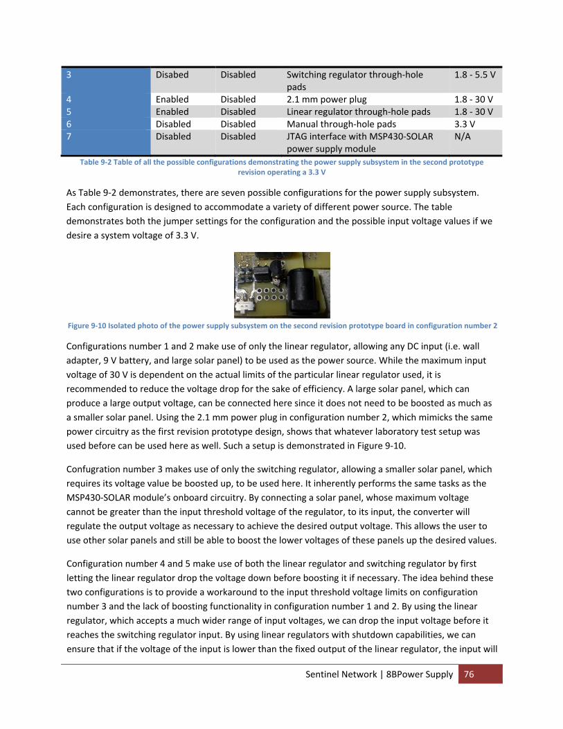
3 Disabed Disabled Switching regulator through‐hole pads
1.8 ‐ 5.5 V
4 Enabled Disabled 2.1 mm power plug 1.8 ‐ 30 V 5 Enabled Disabled Linear regulator through‐hole pads 1.8 ‐ 30 V 6 Disabled Disabled Manual through‐hole pads 3.3 V 7 Disabled Disabled JTAG interface with MSP430‐SOLAR
power supply module N/A
Table 9‐2 Table of all the possible configurations demonstrating the power supply subsystem in the second prototype revision operating a 3.3 V
As Table 9‐2 demonstrates, there are seven possible configurations for the power supply subsystem. Each configuration is designed to accommodate a variety of different power source. The table demonstrates both the jumper settings for the configuration and the possible input voltage values if we desire a system voltage of 3.3 V.
Figure 9‐10 Isolated photo of the power supply subsystem on the second revision prototype board in configuration number 2
Configurations number 1 and 2 make use of only the linear regulator, allowing any DC input (i.e. wall adapter, 9 V battery, and large solar panel) to be used as the power source. While the maximum input voltage of 30 V is dependent on the actual limits of the particular linear regulator used, it is recommended to reduce the voltage drop for the sake of efficiency. A large solar panel, which can produce a large output voltage, can be connected here since it does not need to be boosted as much as a smaller solar panel. Using the 2.1 mm power plug in configuration number 2, which mimicks the same power circuitry as the first revision prototype design, shows that whatever laboratory test setup was used before can be used here as well. Such a setup is demonstrated in Figure 9‐10.
Confugration number 3 makes use of only the switching regulator, allowing a smaller solar panel, which requires its voltage value be boosted up, to be used here. It inherently performs the same tasks as the MSP430‐SOLAR module’s onboard circuitry. By connecting a solar panel, whose maximum voltage cannot be greater than the input threshold voltage of the regulator, to its input, the converter will regulate the output voltage as necessary to achieve the desired output voltage. This allows the user to use other solar panels and still be able to boost the lower voltages of these panels up the desired values.
Configuration number 4 and 5 make use of both the linear regulator and switching regulator by first letting the linear regulator drop the voltage down before boosting it if necessary. The idea behind these two configurations is to provide a workaround to the input threshold voltage limits on configuration number 3 and the lack of boosting functionality in configuration number 1 and 2. By using the linear regulator, which accepts a much wider range of input voltages, we can drop the input voltage before it reaches the switching regulator input. By using linear regulators with shutdown capabilities, we can ensure that if the voltage of the input is lower than the fixed output of the linear regulator, the input will
Sentinel Network | 8BPower Supply 76
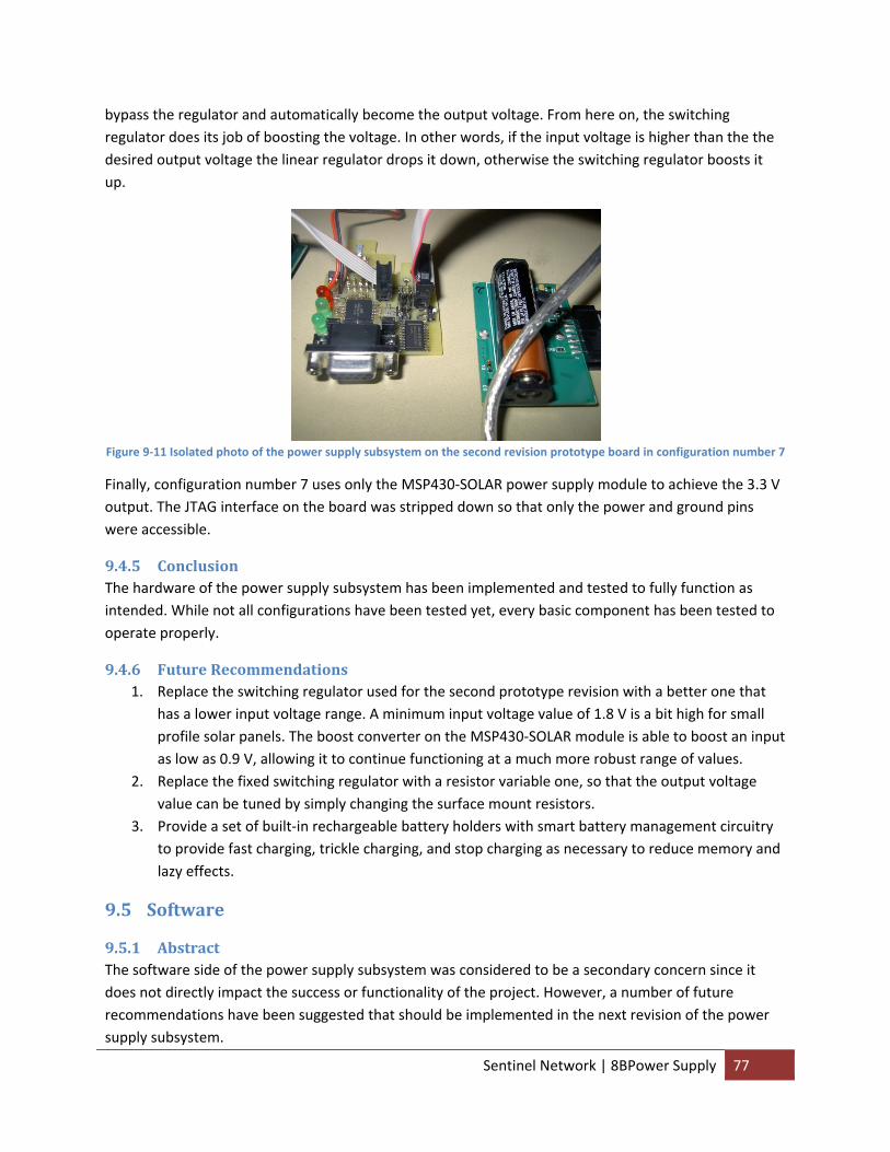
bypass the regulator and automatically become the output voltage. From here on, the switching regulator does its job of boosting the voltage. In other words, if the input voltage is higher than the the desired output voltage the linear regulator drops it down, otherwise the switching regulator boosts it up.
Figure 9‐11 Isolated photo of the power supply subsystem on the second revision prototype board in configuration number 7
Finally, configuration number 7 uses only the MSP430‐SOLAR power supply module to achieve the 3.3 V output. The JTAG interface on the board was stripped down so that only the power and ground pins were accessible.
9.4.5 Conclusion The hardware of the power supply subsystem has been implemented and tested to fully function as intended. While not all configurations have been tested yet, every basic component has been tested to operate properly.
9.4.6 Future Recommendations 1. Replace the switching regulator used for the second prototype revision with a better one that
has a lower input voltage range. A minimum input voltage value of 1.8 V is a bit high for small profile solar panels. The boost converter on the MSP430‐SOLAR module is able to boost an input as low as 0.9 V, allowing it to continue functioning at a much more robust range of values.
2. Replace the fixed switching regulator with a resistor variable one, so that the output voltage value can be tuned by simply changing the surface mount resistors.
3. Provide a set of built‐in rechargeable battery holders with smart battery management circuitry to provide fast charging, trickle charging, and stop charging as necessary to reduce memory and lazy effects.
9.5 Software
9.5.1 Abstract The software side of the power supply subsystem was considered to be a secondary concern since it does not directly impact the success or functionality of the project. However, a number of future recommendations have been suggested that should be implemented in the next revision of the power supply subsystem.
Sentinel Network | 8BPower Supply 77
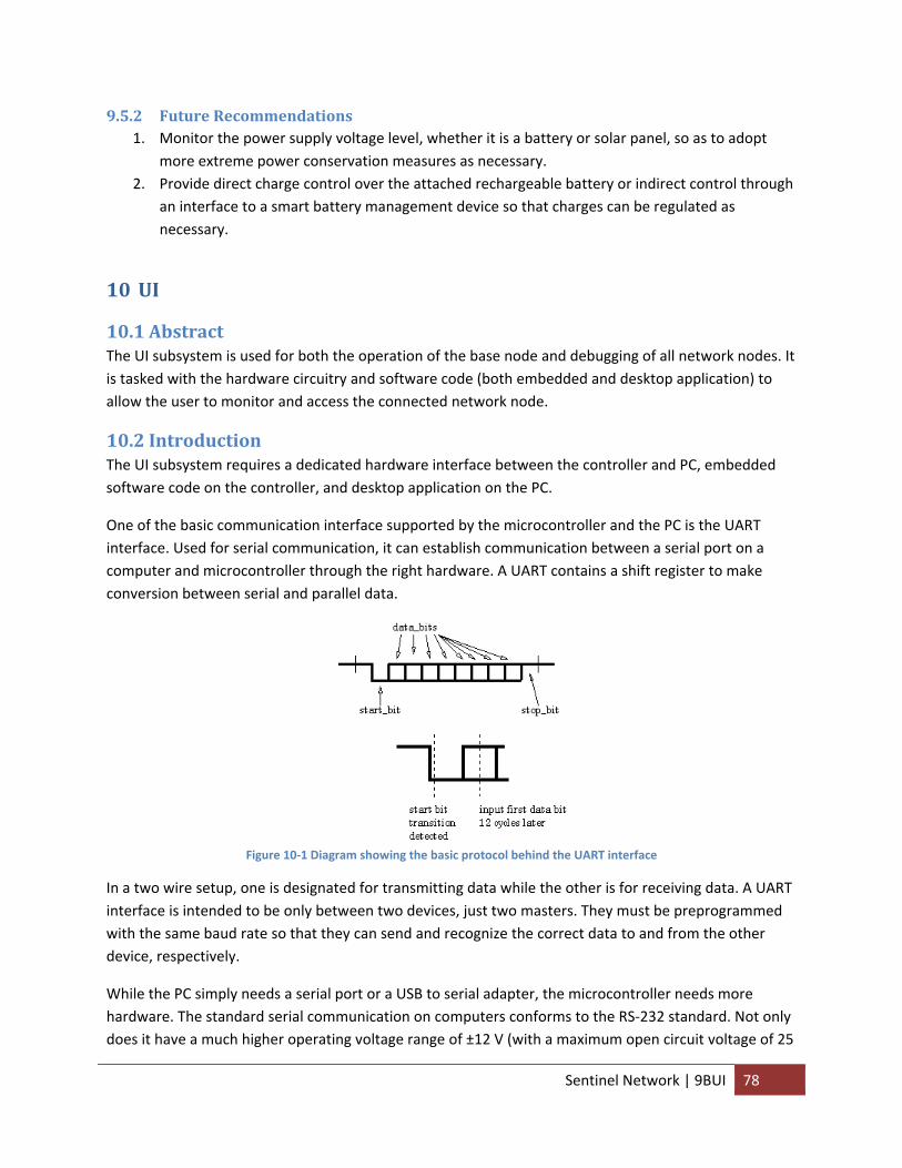
9.5.2 Future Recommendations 1. Monitor the power supply voltage level, whether it is a battery or solar panel, so as to adopt
more extreme power conservation measures as necessary. 2. Provide direct charge control over the attached rechargeable battery or indirect control through
an interface to a smart battery management device so that charges can be regulated as necessary.
10 UI
10.1 Abstract The UI subsystem is used for both the operation of the base node and debugging of all network nodes. It is tasked with the hardware circuitry and software code (both embedded and desktop application) to allow the user to monitor and access the connected network node.
10.2 Introduction The UI subsystem requires a dedicated hardware interface between the controller and PC, embedded software code on the controller, and desktop application on the PC.
One of the basic communication interface supported by the microcontroller and the PC is the UART interface. Used for serial communication, it can establish communication between a serial port on a computer and microcontroller through the right hardware. A UART contains a shift register to make conversion between serial and parallel data.
Figure 10‐1 Diagram showing the basic protocol behind the UART interface
In a two wire setup, one is designated for transmitting data while the other is for receiving data. A UART interface is intended to be only between two devices, just two masters. They must be preprogrammed with the same baud rate so that they can send and recognize the correct data to and from the other device, respectively.
While the PC simply needs a serial port or a USB to serial adapter, the microcontroller needs more hardware. The standard serial communication on computers conforms to the RS‐232 standard. Not only does it have a much higher operating voltage range of ±12 V (with a maximum open circuit voltage of 25
Sentinel Network | 9BUI 78
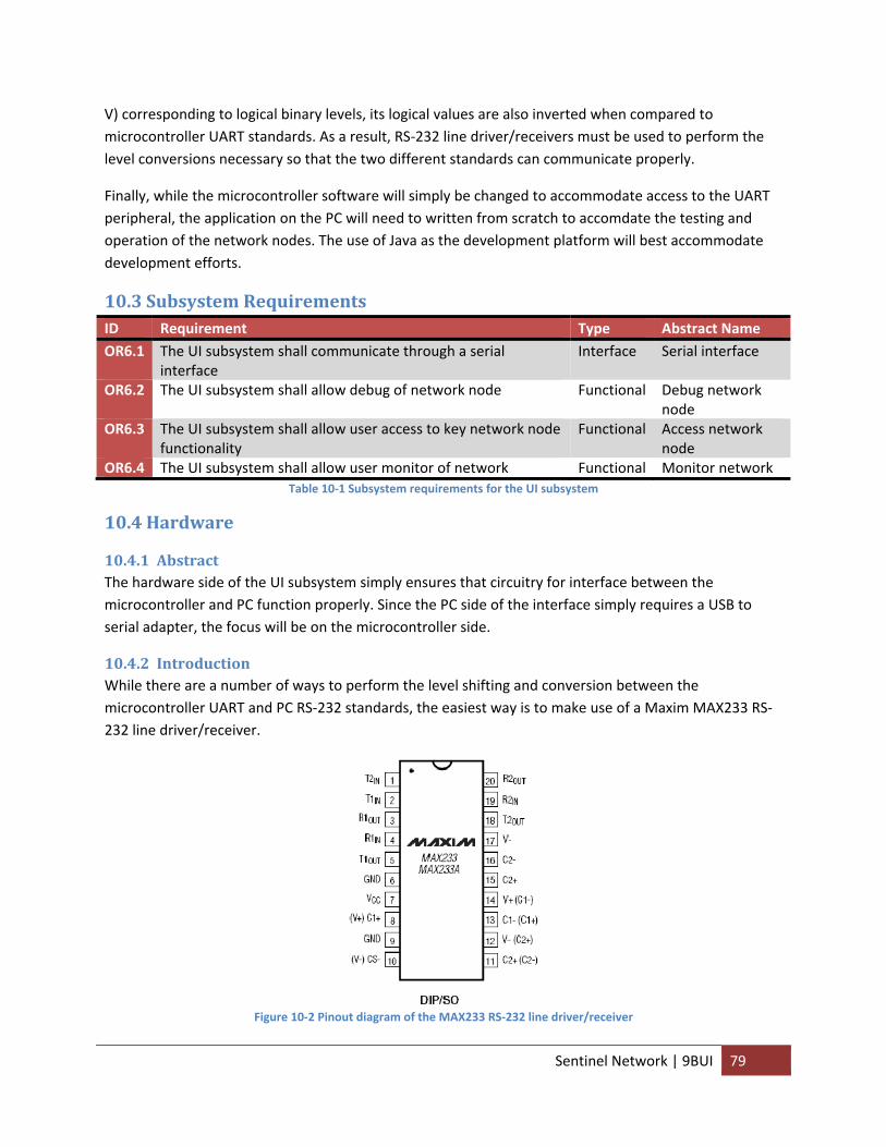
V) corresponding to logical binary levels, its logical values are also inverted when compared to microcontroller UART standards. As a result, RS‐232 line driver/receivers must be used to perform the level conversions necessary so that the two different standards can communicate properly.
Finally, while the microcontroller software will simply be changed to accommodate access to the UART peripheral, the application on the PC will need to written from scratch to accomdate the testing and operation of the network nodes. The use of Java as the development platform will best accommodate development efforts.
10.3 Subsystem Requirements ID Requirement Type Abstract Name OR6.1 The UI subsystem shall communicate through a serial
interface Interface Serial interface
OR6.2 The UI subsystem shall allow debug of network node Functional Debug network node
OR6.3 The UI subsystem shall allow user access to key network node functionality
Functional Access network node
OR6.4 The UI subsystem shall allow user monitor of network Functional Monitor network Table 10‐1 Subsystem requirements for the UI subsystem
10.4 Hardware
10.4.1 Abstract The hardware side of the UI subsystem simply ensures that circuitry for interface between the microcontroller and PC function properly. Since the PC side of the interface simply requires a USB to serial adapter, the focus will be on the microcontroller side.
10.4.2 Introduction While there are a number of ways to perform the level shifting and conversion between the microcontroller UART and PC RS‐232 standards, the easiest way is to make use of a Maxim MAX233 RS‐232 line driver/receiver.
Figure 10‐2 Pinout diagram of the MAX233 RS‐232 line driver/receiver
Sentinel Network | 9BUI 79
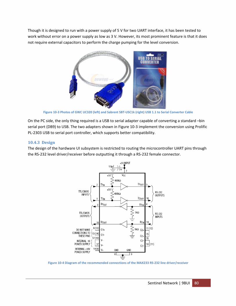
Though it is designed to run with a power supply of 5 V for two UART interface, it has been tested to work without error on a power supply as low as 3 V. However, its most prominent feature is that it does not require external capacitors to perform the charge pumping for the level conversion.
Figure 10‐3 Photos of GWC UC320 (left) and Sabrent SBT‐USC1k (right) USB 1.1 to Serial Converter Cable
On the PC side, the only thing required is a USB to serial adapter capable of converting a standard –bin serial port (DB9) to USB. The two adapters shown in Figure 10‐3 implement the conversion using Prolific PL‐2303 USB to serial port controller, which supports better compatibility.
10.4.3 Design The design of the hardware UI subsystem is restricted to routing the microcontroller UART pins through the RS‐232 level driver/receiver before outputting it through a RS‐232 female connector.
Figure 10‐4 Diagram of the recommended connections of the MAX233 RS‐232 line driver/receiver
Sentinel Network | 9BUI 80
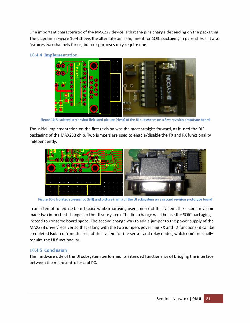
One important characteristic of the MAX233 device is that the pins change depending on the packaging. The diagram in Figure 10‐4 shows the alternate pin assignment for SOIC packaging in parenthesis. It also features two channels for us, but our purposes only require one.
10.4.4 Implementation
Figure 10‐5 Isolated screenshot (left) and picture (right) of the UI subsystem on a first revision prototype board
The initial implementation on the first revision was the most straight‐forward, as it used the DIP packaging of the MAX233 chip. Two jumpers are used to enable/disable the TX and RX functionality independently.
Figure 10‐6 Isolated screenshot (left) and picture (right) of the UI subsystem on a second revision prototype board
In an attempt to reduce board space while improving user control of the system, the second revision made two important changes to the UI subsystem. The first change was the use the SOIC packaging instead to conserve board space. The second change was to add a jumper to the power supply of the MAX233 driver/receiver so that (along with the two jumpers governing RX and TX functions) it can be completed isolated from the rest of the system for the sensor and relay nodes, which don’t normally require the UI functionality.
10.4.5 Conclusion The hardware side of the UI subsystem performed its intended functionality of bridging the interface between the microcontroller and PC.
Sentinel Network | 9BUI 81
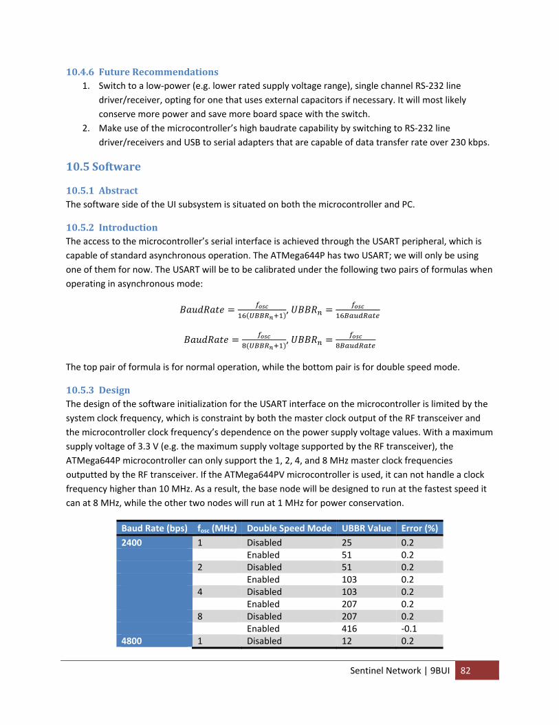
10.4.6 Future Recommendations 1. Switch to a low‐power (e.g. lower rated supply voltage range), single channel RS‐232 line
driver/receiver, opting for one that uses external capacitors if necessary. It will most likely conserve more power and save more board space with the switch.
2. Make use of the microcontroller’s high baudrate capability by switching to RS‐232 line driver/receivers and USB to serial adapters that are capable of data transfer rate over 230 kbps.
10.5 Software
10.5.1 Abstract The software side of the UI subsystem is situated on both the microcontroller and PC.
10.5.2 Introduction The access to the microcontroller’s serial interface is achieved through the USART peripheral, which is capable of standard asynchronous operation. The ATMega644P has two USART; we will only be using one of them for now. The USART will be to be calibrated under the following two pairs of formulas when operating in asynchronous mode:
,
,
The top pair of formula is for normal operation, while the bottom pair is for double speed mode.
10.5.3 Design The design of the software initialization for the USART interface on the microcontroller is limited by the system clock frequency, which is constraint by both the master clock output of the RF transceiver and the microcontroller clock frequency’s dependence on the power supply voltage values. With a maximum supply voltage of 3.3 V (e.g. the maximum supply voltage supported by the RF transceiver), the ATMega644P microcontroller can only support the 1, 2, 4, and 8 MHz master clock frequencies outputted by the RF transceiver. If the ATMega644PV microcontroller is used, it can not handle a clock frequency higher than 10 MHz. As a result, the base node will be designed to run at the fastest speed it can at 8 MHz, while the other two nodes will run at 1 MHz for power conservation.
Baud Rate (bps) fosc (MHz) Double Speed Mode UBBR Value Error (%) 2400 1 Disabled 25 0.2 Enabled 51 0.2 2 Disabled 51 0.2 Enabled 103 0.2 4 Disabled 103 0.2 Enabled 207 0.2 8 Disabled 207 0.2 Enabled 416 ‐0.1 4800 1 Disabled 12 0.2
Sentinel Network | 9BUI 82
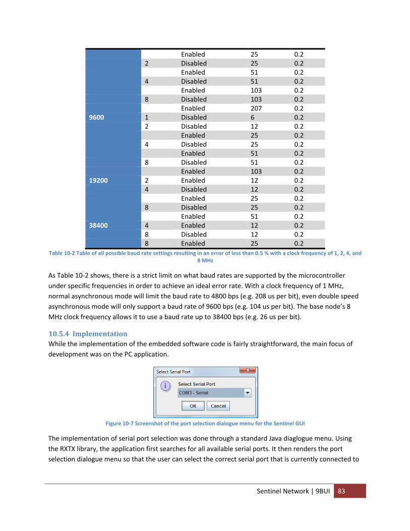
Enabled 25 0.2 2 Disabled 25 0.2 Enabled 51 0.2 4 Disabled 51 0.2 Enabled 103 0.2 8 Disabled 103 0.2 Enabled 207 0.2 9600 1 Disabled 6 0.2 2 Disabled 12 0.2 Enabled 25 0.2 4 Disabled 25 0.2 Enabled 51 0.2 8 Disabled 51 0.2 Enabled 103 0.2 19200 2 Enabled 12 0.2 4 Disabled 12 0.2 Enabled 25 0.2 8 Disabled 25 0.2 Enabled 51 0.2 38400 4 Enabled 12 0.2 8 Disabled 12 0.2 8 Enabled 25 0.2
Table 10‐2 Table of all possible baud rate settings resulting in an error of less than 0.5 % with a clock frequency of 1, 2, 4, and 8 MHz
As Table 10‐2 shows, there is a strict limit on what baud rates are supported by the microcontroller under specific frequencies in order to achieve an ideal error rate. With a clock frequency of 1 MHz, normal asynchronous mode will limit the baud rate to 4800 bps (e.g. 208 us per bit), even double speed asynchronous mode will only support a baud rate of 9600 bps (e.g. 104 us per bit). The base node’s 8 MHz clock frequency allows it to use a baud rate up to 38400 bps (e.g. 26 us per bit).
10.5.4 Implementation While the implementation of the embedded software code is fairly straightforward, the main focus of development was on the PC application.
Figure 10‐7 Screenshot of the port selection dialogue menu for the Sentinel GUI
The implementation of serial port selection was done through a standard Java diaglogue menu. Using the RXTX library, the application first searches for all available serial ports. It then renders the port selection dialogue menu so that the user can select the correct serial port that is currently connected to
Sentinel Network | 9BUI 83
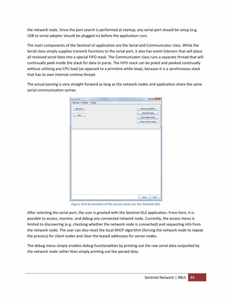
the network node. Since the port search is performed at startup, any serial port should be setup (e.g. USB to serial adapter should be plugged in) before the application runs.
The main components of the Sentinel UI application are the Serial and Communicator class. While the Serial class simply supplies transmit functions to the serial port, it also has event listeners that will place all received serial data into a special FIFO stack. The Communicator class runs a separate thread that will continually peek inside the stack for data to parse. The FIFO stack can be poled and peeked continually without utilizing any CPU load (as opposed to a primitive while loop), because it is a synchronous stack that has its own internal runtime thread.
The actual parsing is very straight forward as long as the network nodes and application share the same serial communication syntax.
Figure 10‐8 Screenshot of the access menu for the Sentinel GUI
After selecting the serial port, the user is greeted with the Sentinel GUI application. From here, it is possible to access, monitor, and debug any connected network node. Currently, the access menu is limited to discovering (e.g. checking whether the network node is connected) and requesting info from the network node. The user can also reset the local DHCP algorithm (forcing the network node to repeat the process) for client nodes and clear the leased addresses for server nodes.
The debug menu simply enables debug functionalities by printing out the raw serial data outputted by the network node rather than simply printing out the parsed data.
Sentinel Network | 9BUI 84
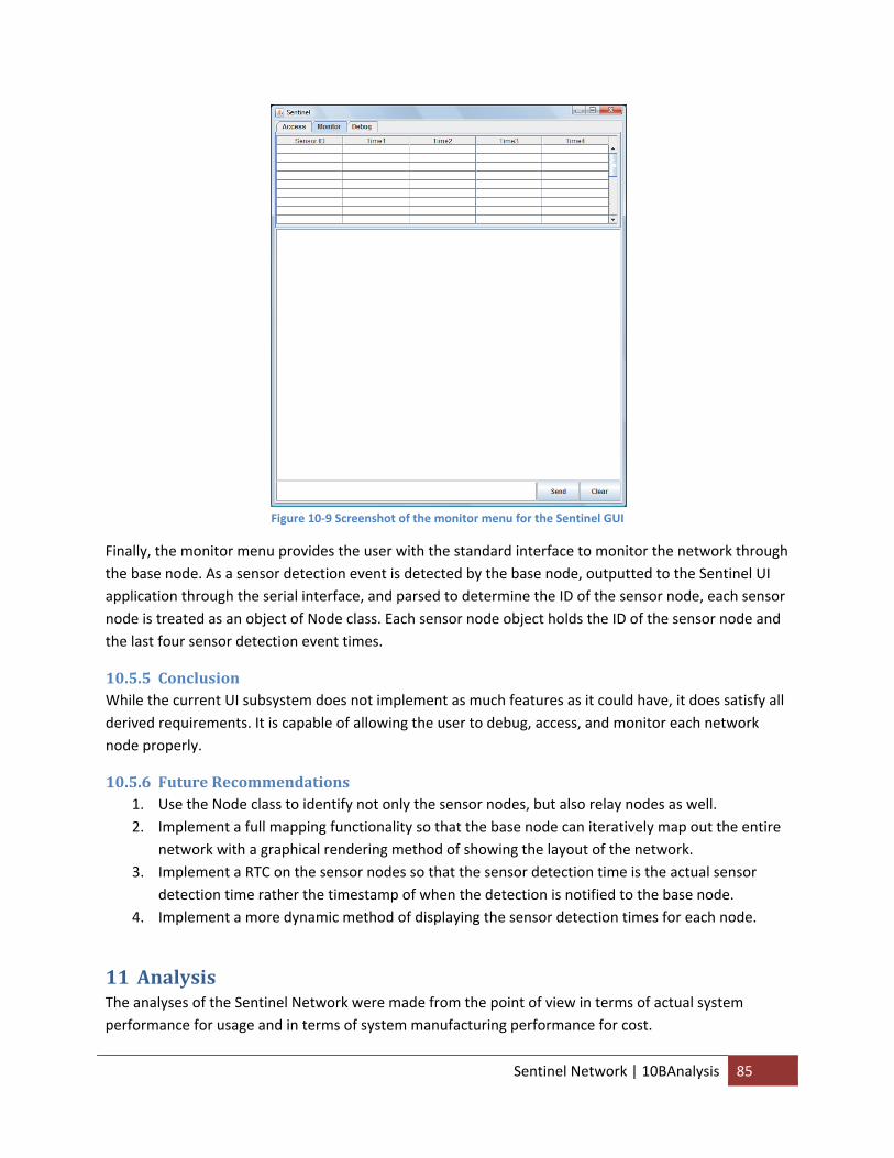
Figure 10‐9 Screenshot of the monitor menu for the Sentinel GUI
Finally, the monitor menu provides the user with the standard interface to monitor the network through the base node. As a sensor detection event is detected by the base node, outputted to the Sentinel UI application through the serial interface, and parsed to determine the ID of the sensor node, each sensor node is treated as an object of Node class. Each sensor node object holds the ID of the sensor node and the last four sensor detection event times.
10.5.5 Conclusion While the current UI subsystem does not implement as much features as it could have, it does satisfy all derived requirements. It is capable of allowing the user to debug, access, and monitor each network node properly.
10.5.6 Future Recommendations 1. Use the Node class to identify not only the sensor nodes, but also relay nodes as well. 2. Implement a full mapping functionality so that the base node can iteratively map out the entire
network with a graphical rendering method of showing the layout of the network. 3. Implement a RTC on the sensor nodes so that the sensor detection time is the actual sensor
detection time rather the timestamp of when the detection is notified to the base node. 4. Implement a more dynamic method of displaying the sensor detection times for each node.
11 Analysis The analyses of the Sentinel Network were made from the point of view in terms of actual system performance for usage and in terms of system manufacturing performance for cost.
Sentinel Network | 10BAnalysis 85

11.1 Performance Results The performance results of Sentinel Network in a laboratory environment with a lot of interference in the same band were quite favorable. Thanks to the clear channel assement, CRC, and the use of acknowledgements, no detection reports were ever missed or falsely interpreted.
With tests being performed in Philips Hall and Duffield Hall in the Cornell Campus where there is quite a large amount of interference in the 2.4 GHz bandwidth due to WiFi, no detection reports were ever lost between the sensors and base node.
Even with the addition of additional nodes made to broadcast “fake” 802.15.4 signals at random times, the system was able to overcome these issues through the use of MAC addresses and additional headers. As a result, no false detection reports were ever detected either.
These results should suggest that the Sentinel Network platform is capable of working in both a rural network environment and industrial/commercial environment as it is capable of ignoring and overcoming interference and chatter on the same band as itself.
11.2 Cost The cost analysis of the Sentinel Network will attempt to determine just how cost‐effective limited and full production of Sentinel Network is through an analysis on a single distributor.
Manufacturer Part Number Vendor Description Cost Quantity Total Cost
ANT‐2.45‐CHP‐T Linx ANT 2.4GHZ 802.11 BLUETOOTH SMD $1.73 2 $3.46
2450BL15B100E Johanson BALUN 2.4GHZ WIFI/BLUETOOTH $0.32 2 $0.64
AT86RF230‐ZU Atmel IC TXRX ZIGBEE/802.15.4 32QFN $6.82 2 $13.64
NX2520SA‐16.000000MHZ NDK CRYSTAL 16.000000 MHZ SMD 10PF $1.72 2 $3.44
ECJ‐1VC1H220J Panasonic CAP CERAMIC 22PF 50V 0603 SMD $0.11 4 $0.44
ECJ‐1VC1H150J Panasonic CAP CERAMIC 15PF 50V 0603 SMD $0.10 4 $0.38
GRM188R61A105MA61D Murata CAP CER 1.0UF 10V 20% X5R 0603 $0.09 8 $0.68
MCR03EZPFX6800 Rohm RES 680 OHM 1/10W 1% 0603 SMD $0.09 2 $0.17
MCR03EZPJ103 Rohm RES 10K OHM 1/10W 5% 0603 SMD $0.08 2 $0.16
MCR03EZPJ000 Rohm RES 0.0 OHM 1/10W 5% 0603 SMD $0.08 2 $0.16
Transmitter Total $23.17
ATMEGA644PV‐10PU Atmel IC MCU AVR 64K FLASH 40‐DIP $7.76 1 $7.76
ECJ‐3VB1H104K Panasonic CAP .1UF 50V CERM CHIP 1206 X7R $0.26 6 $1.56
ECJ‐3YF1E105Z Panasonic CAP 1UF 25V CERAMIC Y5V 1206 $0.29 2 $0.58
LE30CZ‐TR STMicro IC REG LDO 150MA 3.0V TO‐92 $0.99 1 $0.99
MCR18EZHF1000 Rohm RES 100 OHM 1/4W 1% 1206 SMD $0.05 1 $0.05
MCR18EZHF3000 Rohm RES 300 OHM 1/4W 1% 1206 SMD $0.05 2 $0.09
MCR18EZHF1003 Rohm RES 100K OHM 1/4W 1% 1206 SMD $0.47 1 $0.47
MAX233CPP+G36 Maxim IC 2DVR/2RCVR RS232 5V 20‐DIP $7.45 1 $7.45
5747844‐4 Tyco CONN D‐SUB RCPT R/A 9POS 30GOLD $3.00 1 $3.00
PJ‐002A CUI CONN POWER JACK 2.1MM $0.38 1 $0.38
Sentinel Network | 10BAnalysis 86
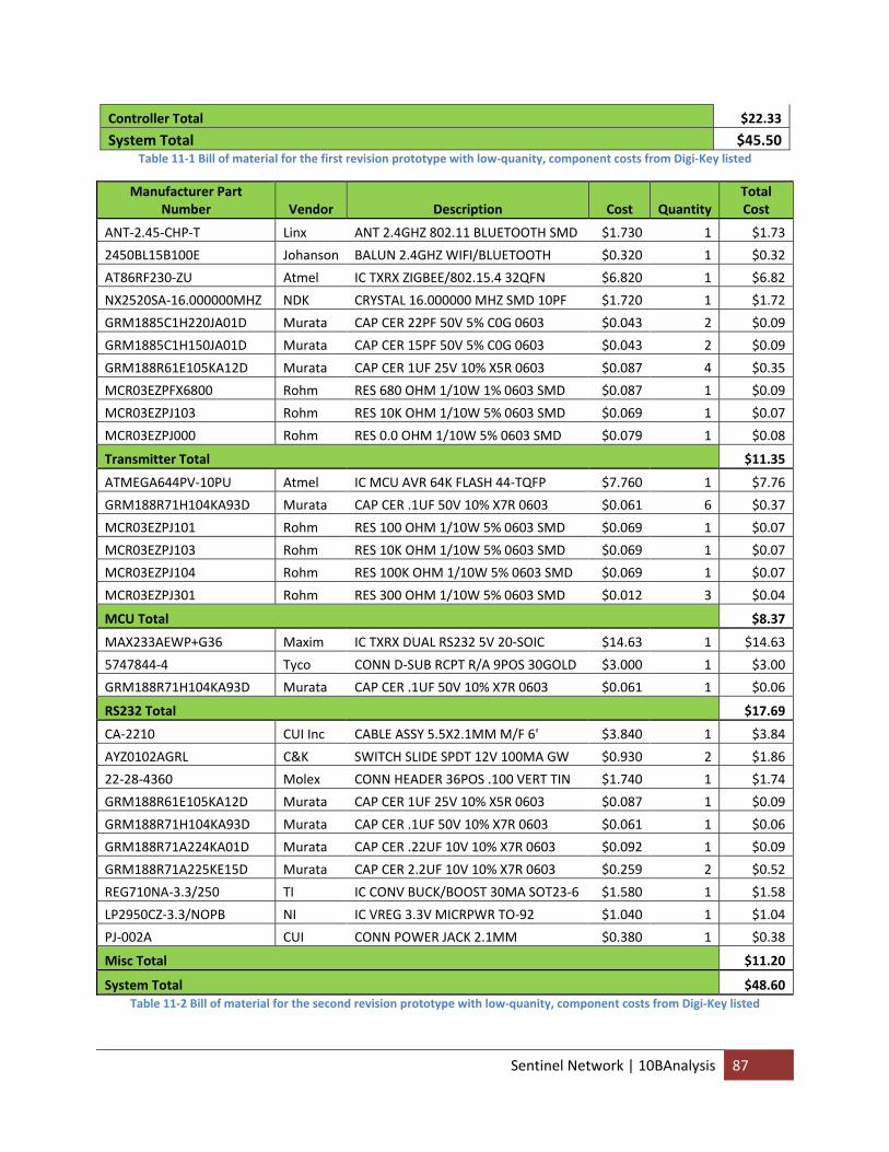
Controller Total $22.33
System Total $45.50 Table 11‐1 Bill of material for the first revision prototype with low‐quanity, component costs from Digi‐Key listed
Manufacturer Part Number Vendor Description Cost Quantity
Total Cost
ANT‐2.45‐CHP‐T Linx ANT 2.4GHZ 802.11 BLUETOOTH SMD $1.730 1 $1.73
2450BL15B100E Johanson BALUN 2.4GHZ WIFI/BLUETOOTH $0.320 1 $0.32
AT86RF230‐ZU Atmel IC TXRX ZIGBEE/802.15.4 32QFN $6.820 1 $6.82
NX2520SA‐16.000000MHZ NDK CRYSTAL 16.000000 MHZ SMD 10PF $1.720 1 $1.72
GRM1885C1H220JA01D Murata CAP CER 22PF 50V 5% C0G 0603 $0.043 2 $0.09
GRM1885C1H150JA01D Murata CAP CER 15PF 50V 5% C0G 0603 $0.043 2 $0.09
GRM188R61E105KA12D Murata CAP CER 1UF 25V 10% X5R 0603 $0.087 4 $0.35
MCR03EZPFX6800 Rohm RES 680 OHM 1/10W 1% 0603 SMD $0.087 1 $0.09
MCR03EZPJ103 Rohm RES 10K OHM 1/10W 5% 0603 SMD $0.069 1 $0.07
MCR03EZPJ000 Rohm RES 0.0 OHM 1/10W 5% 0603 SMD $0.079 1 $0.08
Transmitter Total $11.35
ATMEGA644PV‐10PU Atmel IC MCU AVR 64K FLASH 44‐TQFP $7.760 1 $7.76
GRM188R71H104KA93D Murata CAP CER .1UF 50V 10% X7R 0603 $0.061 6 $0.37
MCR03EZPJ101 Rohm RES 100 OHM 1/10W 5% 0603 SMD $0.069 1 $0.07
MCR03EZPJ103 Rohm RES 10K OHM 1/10W 5% 0603 SMD $0.069 1 $0.07
MCR03EZPJ104 Rohm RES 100K OHM 1/10W 5% 0603 SMD $0.069 1 $0.07
MCR03EZPJ301 Rohm RES 300 OHM 1/10W 5% 0603 SMD $0.012 3 $0.04
MCU Total $8.37
MAX233AEWP+G36 Maxim IC TXRX DUAL RS232 5V 20‐SOIC $14.63 1 $14.63
5747844‐4 Tyco CONN D‐SUB RCPT R/A 9POS 30GOLD $3.000 1 $3.00
GRM188R71H104KA93D Murata CAP CER .1UF 50V 10% X7R 0603 $0.061 1 $0.06
RS232 Total $17.69
CA‐2210 CUI Inc CABLE ASSY 5.5X2.1MM M/F 6' $3.840 1 $3.84
AYZ0102AGRL C&K SWITCH SLIDE SPDT 12V 100MA GW $0.930 2 $1.86
22‐28‐4360 Molex CONN HEADER 36POS .100 VERT TIN $1.740 1 $1.74
GRM188R61E105KA12D Murata CAP CER 1UF 25V 10% X5R 0603 $0.087 1 $0.09
GRM188R71H104KA93D Murata CAP CER .1UF 50V 10% X7R 0603 $0.061 1 $0.06
GRM188R71A224KA01D Murata CAP CER .22UF 10V 10% X7R 0603 $0.092 1 $0.09
GRM188R71A225KE15D Murata CAP CER 2.2UF 10V 10% X7R 0603 $0.259 2 $0.52
REG710NA‐3.3/250 TI IC CONV BUCK/BOOST 30MA SOT23‐6 $1.580 1 $1.58
LP2950CZ‐3.3/NOPB NI IC VREG 3.3V MICRPWR TO‐92 $1.040 1 $1.04
PJ‐002A CUI CONN POWER JACK 2.1MM $0.380 1 $0.38
Misc Total $11.20
System Total $48.60 Table 11‐2 Bill of material for the second revision prototype with low‐quanity, component costs from Digi‐Key listed
Sentinel Network | 10BAnalysis 87
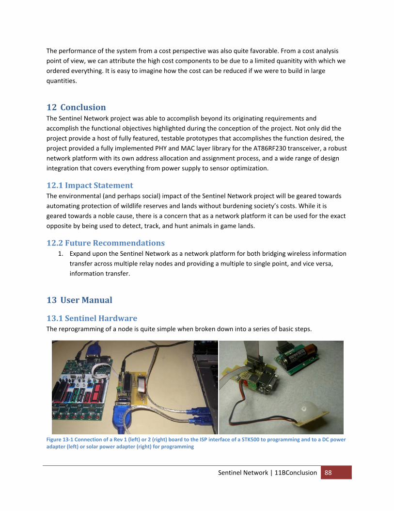
The performance of the system from a cost perspective was also quite favorable. From a cost analysis point of view, we can attribute the high cost components to be due to a limited quanitity with which we ordered everything. It is easy to imagine how the cost can be reduced if we were to build in large quantities.
12 Conclusion The Sentinel Network project was able to accomplish beyond its originating requirements and accomplish the functional objectives highlighted during the conception of the project. Not only did the project provide a host of fully featured, testable prototypes that accomplishes the function desired, the project provided a fully implemented PHY and MAC layer library for the AT86RF230 transceiver, a robust network platform with its own address allocation and assignment process, and a wide range of design integration that covers everything from power supply to sensor optimization.
12.1 Impact Statement The environmental (and perhaps social) impact of the Sentinel Network project will be geared towards automating protection of wildlife reserves and lands without burdening society’s costs. While it is geared towards a noble cause, there is a concern that as a network platform it can be used for the exact opposite by being used to detect, track, and hunt animals in game lands.
12.2 Future Recommendations 1. Expand upon the Sentinel Network as a network platform for both bridging wireless information
transfer across multiple relay nodes and providing a multiple to single point, and vice versa, information transfer.
13 User Manual
13.1 Sentinel Hardware The reprogramming of a node is quite simple when broken down into a series of basic steps.
Figure 13‐1 Connection of a Rev 1 (left) or 2 (right) board to the ISP interface of a STK500 to programming and to a DC power adapter (left) or solar power adapter (right) for programming
Sentinel Network | 11BConclusion 88
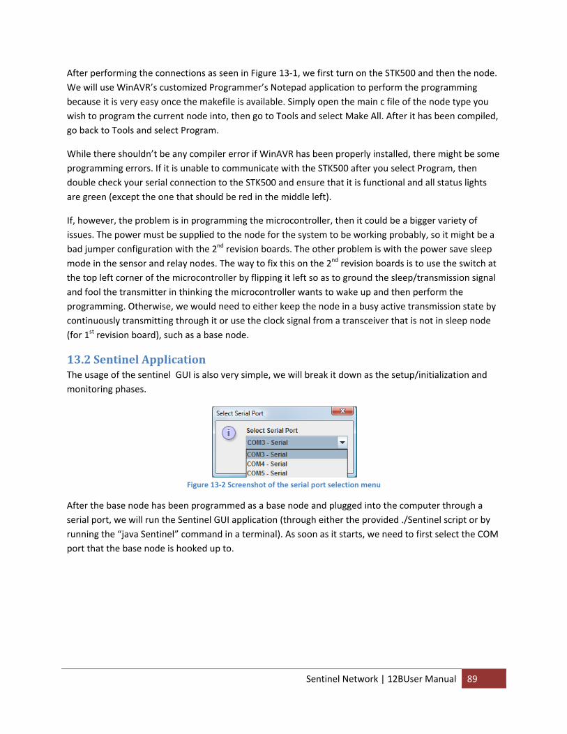
After performing the connections as seen in Figure 13‐1, we first turn on the STK500 and then the node. We will use WinAVR’s customized Programmer’s Notepad application to perform the programming because it is very easy once the makefile is available. Simply open the main c file of the node type you wish to program the current node into, then go to Tools and select Make All. After it has been compiled, go back to Tools and select Program.
While there shouldn’t be any compiler error if WinAVR has been properly installed, there might be some programming errors. If it is unable to communicate with the STK500 after you select Program, then double check your serial connection to the STK500 and ensure that it is functional and all status lights are green (except the one that should be red in the middle left).
If, however, the problem is in programming the microcontroller, then it could be a bigger variety of issues. The power must be supplied to the node for the system to be working probably, so it might be a bad jumper configuration with the 2nd revision boards. The other problem is with the power save sleep mode in the sensor and relay nodes. The way to fix this on the 2nd revision boards is to use the switch at the top left corner of the microcontroller by flipping it left so as to ground the sleep/transmission signal and fool the transmitter in thinking the microcontroller wants to wake up and then perform the programming. Otherwise, we would need to either keep the node in a busy active transmission state by continuously transmitting through it or use the clock signal from a transceiver that is not in sleep node (for 1st revision board), such as a base node.
13.2 Sentinel Application The usage of the sentinel GUI is also very simple, we will break it down as the setup/initialization and monitoring phases.
Figure 13‐2 Screenshot of the serial port selection menu
After the base node has been programmed as a base node and plugged into the computer through a serial port, we will run the Sentinel GUI application (through either the provided ./Sentinel script or by running the “java Sentinel” command in a terminal). As soon as it starts, we need to first select the COM port that the base node is hooked up to.
Sentinel Network | 12BUser Manual 89
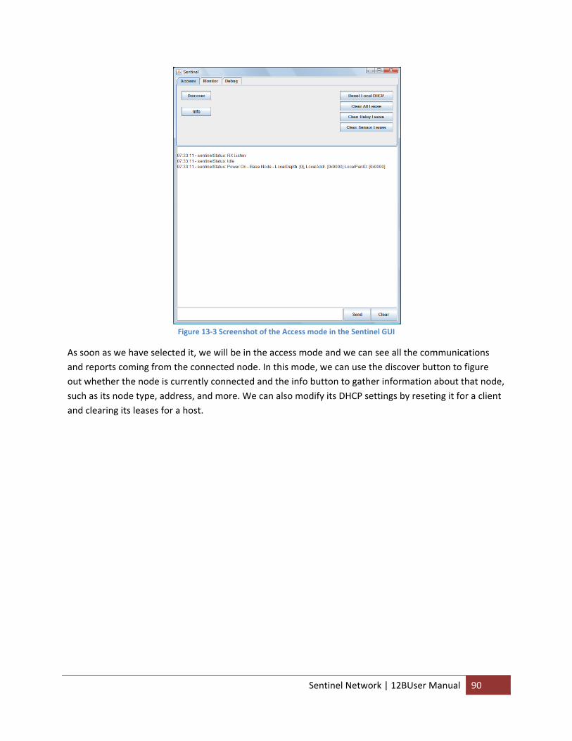
Figure 13‐3 Screenshot of the Access mode in the Sentinel GUI
As soon as we have selected it, we will be in the access mode and we can see all the communications and reports coming from the connected node. In this mode, we can use the discover button to figure out whether the node is currently connected and the info button to gather information about that node, such as its node type, address, and more. We can also modify its DHCP settings by reseting it for a client and clearing its leases for a host.
Sentinel Network | 12BUser Manual 90
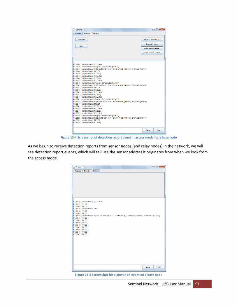
Figure 13‐4 Screenshot of detection report event in access mode for a base node
As we begin to receive detection reports from sensor nodes (and relay nodes) in the network, we will see detection report events, which will tell use the sensor address it originates from when we look from the access mode.
Figure 13‐5 Screenshot for a power‐on event on a base node
Sentinel Network | 12BUser Manual 91
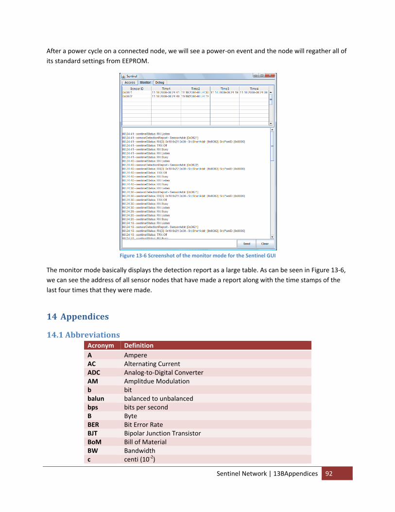
After a power cycle on a connected node, we will see a power‐on event and the node will regather all of its standard settings from EEPROM.
Figure 13‐6 Screenshot of the monitor mode for the Sentinel GUI
The monitor mode basically displays the detection report as a large table. As can be seen in Figure 13‐6, we can see the address of all sensor nodes that have made a report along with the time stamps of the last four times that they were made.
14 Appendices
14.1 Abbreviations Acronym Definition A Ampere AC Alternating Current ADC Analog‐to‐Digital Converter AM Amplitdue Modulation b bit balun balanced to unbalanced bps bits per second B Byte BER Bit Error Rate BJT Bipolar Junction Transistor BoM Bill of Material BW Bandwidth
centi (10‐2) c
Sentinel Network | 13BAppendices 92
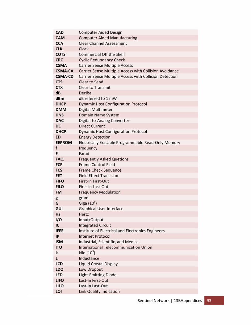
CAD Computer Aided Design CAM Computer Aided Manufacturing CCA Clear Channel Assessment CLK Clock COTS Commercial Off the Shelf CRC Cyclic Redundancy Check CSMA Carrier Sense Multiple Access CSMA‐CA Carrier Sense Multiple Access with Collision Avoidance CSMA‐CD Carrier Sense Multiple Access with Collision Detection CTS Clear to Send CTX Clear to Transmit dB Decibel dBm dB referred to 1 mW DHCP Dynamic Host Configuration Protocol DMM Digital Multimeter DNS Domain Name System DAC Digital‐to‐Analog Converter DC Direct Current DHCP Dynamic Host Configuration Protocol ED Energy Detection EEPROM Electrically Erasable Programmable Read‐Only Memory f frequency F Farad FAQ Frequently Asked Quetions FCF Frame Control Field FCS Frame Check Sequence FET Field Effect Transistor FIFO First‐In First‐Out FILO First‐In Last‐Out FM Frequency Modulation g gram
Giga (109) G GUI Graphical User Interface Hz Hertz I/O Input/Output IC Integrated Circuit IEEE Institute of Electrical and Electronics Engineers IP Internet Protocol ISM Industrial, Scientific, and Medical ITU International Telecommunication Union
kilo (103) k L Inductance LCD Liquid Crystal Display LDO Low Dropout LED Light‐Emitting Diode LIFO Last‐In First‐Out LILO Last‐In Last‐Out LQI Link Quality Indication
Sentinel Network | 13BAppendices 93
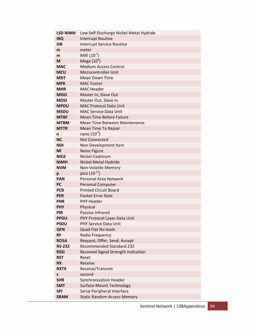
LSD NiMH Low Self Discharge Nickel‐Metal Hydride IRQ Interrupt Routine ISR Interrupt Service Routine m meter
Milli (10‐3) m Mega (106) M
MAC Medium Access Control MCU Microcontroller Unit MDT Mean Down Time MFR MAC Footer MHR MAC Header MISO Master In, Slave Out MOSI Master Out, Slave In MPDU MAC Protocol Data Unit MSDU MAC Service Data Unit MTBF Mean Time Before Failure MTBM Mean Time Between Maintenance MTTR Mean Time To Repair
nano (10‐9) n NC Not Connected NDI Non‐Development Item NF Noise Figure NiCd Nickel‐Cadmium NiMH Nickel‐Metal Hydride NVM Non‐Volatile Memory
pico (10‐12) p PAN Personal Area Network PC Personal Computer PCB Printed Circuit Board PER Packet Error Rate PHR PHY Header PHY Physical PIR Passive Infrared PPDU PHY Protocol Layer Data Unit PSDU PHY Service Data Unit QFN Quad Flat No leads RF Radio Frequency ROSA Request, Offer, Send, Accept RS‐232 Recommended Standard 232 RSSI Received Signal Strength Indication RST Reset RX Receive RXTX Receive/Transmit s second SHR Synchronization Header SMT Surface‐Mount Technology SPI Serial Peripheral Interface SRAM Static Random Access Memory
Sentinel Network | 13BAppendices 94
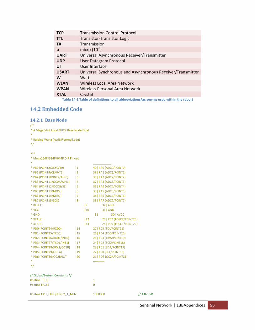
TCP Transmission Control Protocol TTL Transistor‐Transistor Logic TX Transmission
micro (10‐6) u UART Universal Asynchronous Receiver/Transmitter UDP User Datagram Protocol UI User Interface USART Universal Synchronous and Asynchronous Receiver/Transmitter W Watt WLAN Wireless Local Area Network WPAN Wireless Personal Area Network XTAL Crystal
Table 14‐1 Table of definitions to all abbreviations/acronyms used within the report
14.2 Embedded Code
14.2.1 Base Node /** * A Mega644P Local DHCP Base Node Final * * Ruibing Wang ([email protected]) */ /** * Mega164P/324P/644P DIP Pinout * ___________ * PB0 (PCINT8/XCK0/T0) |1 40| PA0 (ADC0/PCINT0) * PB1 (PCINT9/CLK0/T1) |2 39| PA1 (ADC1/PCINT1) * PB2 (PCINT10/INT2/AIN0) |3 38| PA2 (ADC2/PCINT2) * PB3 (PCINT11/OC0A/AIN1) |4 37| PA3 (ADC3/PCINT3) * PB4 (PCINT12/OCOB/SS) |5 36| PA4 (ADC4/PCINT4) * PB5 (PCINT13/MOSI) |6 35| PA5 (ADC5/PCINT5) * PB6 (PCINT14/MISO) |7 34| PA6 (ADC6/PCINT6) * PB7 (PCINT15/SCK) |8 33| PA7 (ADC7/PCINT7) * RESET |9 32| AREF * VCC |10 31| GND * GND |11 30| AVCC * XTAL2 |12 29| PC7 (TOSC2/PCINT23) * XTAL1 |13 28| PC6 (TOSC1/PCINT22) * PD0 (PCINT24/RXD0) |14 27| PC5 (TDI/PCINT21) * PD1 (PCINT25/TXD0) |15 26| PC4 (TDO/PCINT20) * PD2 (PCINT26/RXD1/INT0) |16 25| PC3 (TMS/PCINT19) * PD3 (PCINT27/TXD1/INT1) |17 24| PC2 (TCK/PCINT18) * PD4 (PCINT28/XCK1/OC1B) |18 23| PC1 (SDA/PCINT17) * PD5 (PCINT29/OC1A) |19 22| PC0 (SCL/PCINT16) * PD6 (PCINT30/OC2B/ICP) |20 21| PD7 (OC2A/PCINT31) * ‐‐‐‐‐‐‐‐‐‐‐ */ /* Global/System Constants */ #define TRUE 1 #define FALSE 0 #define CPU_FREQUENCY_1_MHZ 1000000 // 1.8‐5.5V
Sentinel Network | 13BAppendices 95
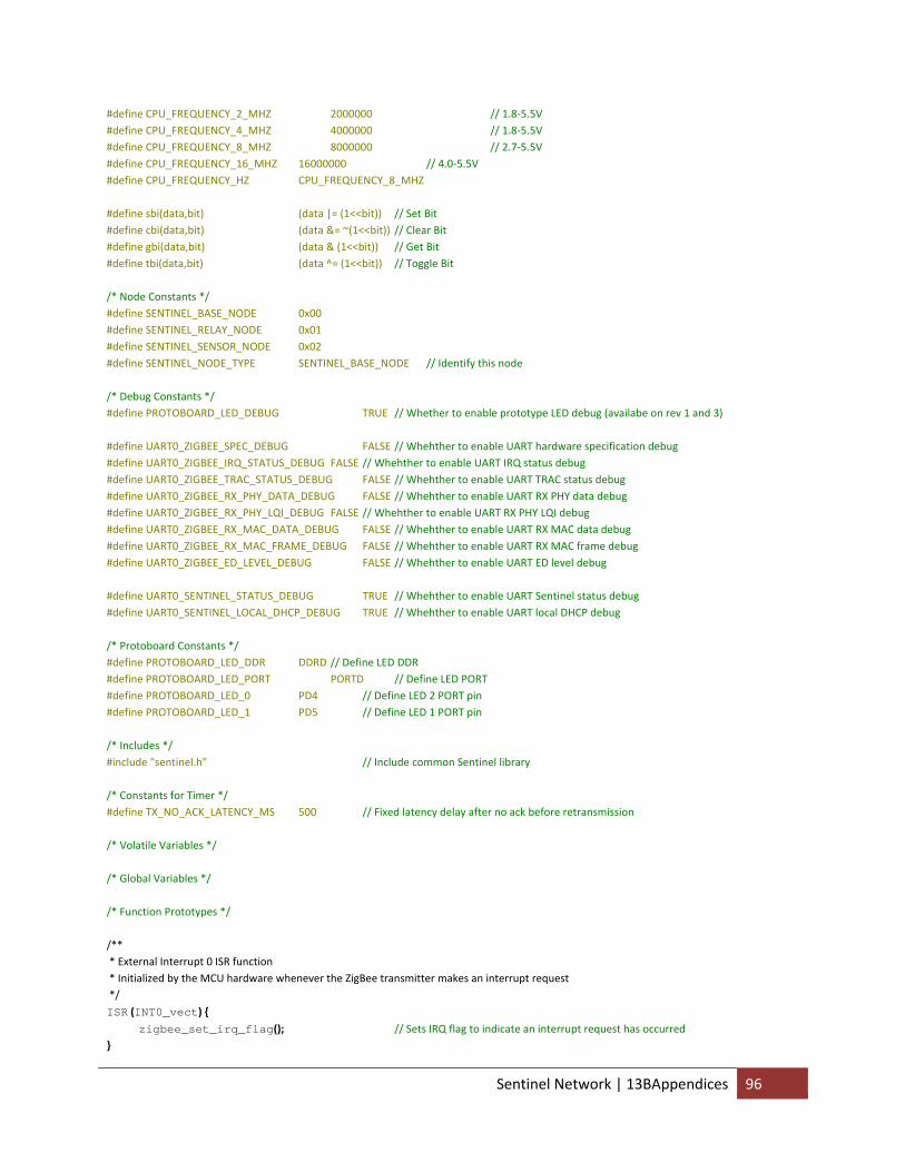
#define CPU_FREQUENCY_2_MHZ 2000000 // 1.8‐5.5V #define CPU_FREQUENCY_4_MHZ 4000000 // 1.8‐5.5V #define CPU_FREQUENCY_8_MHZ 8000000 // 2.7‐5.5V #define CPU_FREQUENCY_16_MHZ 16000000 // 4.0‐5.5V #define CPU_FREQUENCY_HZ CPU_FREQUENCY_8_MHZ #define sbi(data,bit) (data |= (1<<bit)) // Set Bit #define cbi(data,bit) (data &= ~(1<<bit)) // Clear Bit #define gbi(data,bit) (data & (1<<bit)) // Get Bit #define tbi(data,bit) (data ^= (1<<bit)) // Toggle Bit /* Node Constants */ #define SENTINEL_BASE_NODE 0x00 #define SENTINEL_RELAY_NODE 0x01 #define SENTINEL_SENSOR_NODE 0x02 #define SENTINEL_NODE_TYPE SENTINEL_BASE_NODE // Identify this node /* Debug Constants */ #define PROTOBOARD_LED_DEBUG TRUE // Whether to enable prototype LED debug (availabe on rev 1 and 3) #define UART0_ZIGBEE_SPEC_DEBUG FALSE // Whehther to enable UART hardware specification debug #define UART0_ZIGBEE_IRQ_STATUS_DEBUG FALSE // Whehther to enable UART IRQ status debug #define UART0_ZIGBEE_TRAC_STATUS_DEBUG FALSE // Whehther to enable UART TRAC status debug #define UART0_ZIGBEE_RX_PHY_DATA_DEBUG FALSE // Whehther to enable UART RX PHY data debug #define UART0_ZIGBEE_RX_PHY_LQI_DEBUG FALSE // Whehther to enable UART RX PHY LQI debug #define UART0_ZIGBEE_RX_MAC_DATA_DEBUG FALSE // Whehther to enable UART RX MAC data debug #define UART0_ZIGBEE_RX_MAC_FRAME_DEBUG FALSE // Whehther to enable UART RX MAC frame debug #define UART0_ZIGBEE_ED_LEVEL_DEBUG FALSE // Whehther to enable UART ED level debug #define UART0_SENTINEL_STATUS_DEBUG TRUE // Whehther to enable UART Sentinel status debug #define UART0_SENTINEL_LOCAL_DHCP_DEBUG TRUE // Whehther to enable UART local DHCP debug /* Protoboard Constants */ #define PROTOBOARD_LED_DDR DDRD // Define LED DDR #define PROTOBOARD_LED_PORT PORTD // Define LED PORT #define PROTOBOARD_LED_0 PD4 // Define LED 2 PORT pin #define PROTOBOARD_LED_1 PD5 // Define LED 1 PORT pin /* Includes */ #include "sentinel.h" // Include common Sentinel library /* Constants for Timer */ #define TX_NO_ACK_LATENCY_MS 500 // Fixed latency delay after no ack before retransmission /* Volatile Variables */ /* Global Variables */ /* Function Prototypes */ /** * External Interrupt 0 ISR function * Initialized by the MCU hardware whenever the ZigBee transmitter makes an interrupt request */
ISR (INT0_vect) { zigbee_set_irq_flag(); // Sets IRQ flag to indicate an interrupt request has occurred }
Sentinel Network | 13BAppendices 96
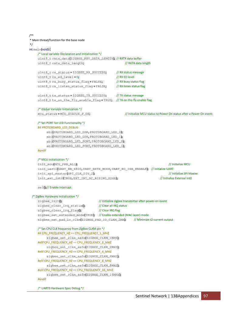
/** * Main thread/function for the base node */
int main(void) { /* Local variable Declaration and Initialization */
uint8_t rxtx_data[ZIGBEE_PHY_DATA_LENGTH]; // RXTX data buffer uint8_t rxtx_data_length; // RXTX data length
uint8_t rx_status = ZIGBEE_RX_SUCCESS; // RX status message
uint8_t rx_ed_level = 0; // RX ED level
uint8_t rx_busy_status_flag = FALSE; // RX busy status flag
uint8_t rx_listen_status_flag = FALSE; // RX listen status flag
uint8_t tx_status = ZIGBEE_TX_SUCCESS; // TX status message
uint8_t tx_on_the_fly_enable_flag = TRUE; // TX on‐the‐fly enable flag /* Global Variable Initialization */
mcu_status = MCU_STATUS_P_ON; // Initialize MCU status to Power On status after a Power On event /* Set PORT for LED Functionality */ #if PROTOBOARD_LED_DEBUG
sbi(PROTOBOARD_LED_DDR, PROTOBOARD_LED_0); sbi(PROTOBOARD_LED_DDR, PROTOBOARD_LED_1); sbi(PROTOBOARD_LED_PORT, PROTOBOARD_LED_0); sbi(PROTOBOARD_LED_PORT, PROTOBOARD_LED_1); #endif /* MCU Initialization */
init_mcu(MCU_PRR_ALL); // Initialize MCU
init_uart0(UART_BR_4800, UART_RXTX_MODE, UART_NO_ISR_ENABLE); // Initialize UART
init_spi_master(SPI_CLK_DIV_2); // Initialize SPI Master
init_ext_int0(TRUE, EXT_INT_SC_RISING_EDGE); // Initialize External Int0
sei();// Enable Interrupt /* ZigBee Hardware Initialization */
zigbee_init(); // Initialize zigbee transmitter after power‐on event
zigbee_clear_irq_status(); // Clear all IRQ status
zigbee_clear_irq_flag(); // Clear IRQ flag
zigbee_set_extended_mode(TRUE); // Enable extended (MAC layer) mode
zigbee_set_pad_io_clkm(ZIGBEE_PAD_IO_CLKM_2MA); // Minimize IO current output /* Set CPU CLK frequency from ZigBee CLKM pin */ #if CPU_FREQUENCY_HZ == CPU_FREQUENCY_1_MHZ
zigbee_set_clkm_safe(ZIGBEE_CLKM_1MHZ); #elif CPU_FREQUENCY_HZ == CPU_FREQUENCY_2_MHZ
zigbee_set_clkm_safe(ZIGBEE_CLKM_2MHZ); #elif CPU_FREQUENCY_HZ == CPU_FREQUENCY_4_MHZ
zigbee_set_clkm_safe(ZIGBEE_CLKM_4MHZ); #elif CPU_FREQUENCY_HZ == CPU_FREQUENCY_8_MHZ
zigbee_set_clkm_safe(ZIGBEE_CLKM_8MHZ); #elif CPU_FREQUENCY_HZ == CPU_FREQUENCY_16_MHZ
zigbee_set_clkm_safe(ZIGBEE_CLKM_16MHZ); #endif /* UART0 Hardware Spec Debug */
Sentinel Network | 13BAppendices 97
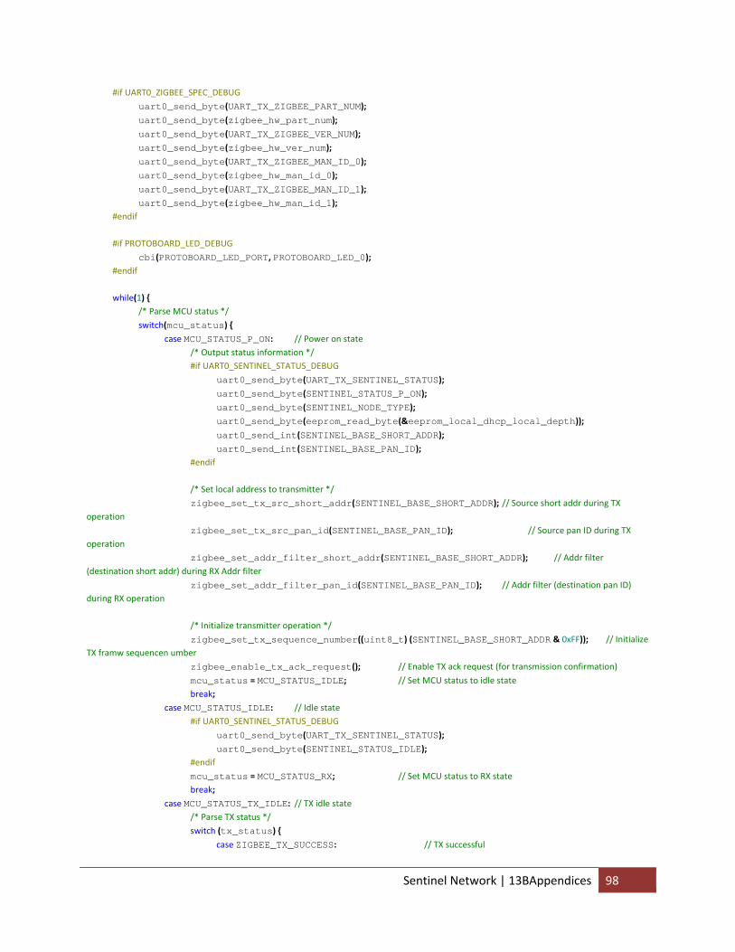
#if UART0_ZIGBEE_SPEC_DEBUG
uart0_send_byte(UART_TX_ZIGBEE_PART_NUM); uart0_send_byte(zigbee_hw_part_num); uart0_send_byte(UART_TX_ZIGBEE_VER_NUM); uart0_send_byte(zigbee_hw_ver_num); uart0_send_byte(UART_TX_ZIGBEE_MAN_ID_0); uart0_send_byte(zigbee_hw_man_id_0); uart0_send_byte(UART_TX_ZIGBEE_MAN_ID_1); uart0_send_byte(zigbee_hw_man_id_1); #endif #if PROTOBOARD_LED_DEBUG
cbi(PROTOBOARD_LED_PORT, PROTOBOARD_LED_0); #endif while(1) { /* Parse MCU status */
switch(mcu_status) { case MCU_STATUS_P_ON: // Power on state /* Output status information */ #if UART0_SENTINEL_STATUS_DEBUG
uart0_send_byte(UART_TX_SENTINEL_STATUS); uart0_send_byte(SENTINEL_STATUS_P_ON); uart0_send_byte(SENTINEL_NODE_TYPE); uart0_send_byte(eeprom_read_byte(&eeprom_local_dhcp_local_depth)); uart0_send_int(SENTINEL_BASE_SHORT_ADDR); uart0_send_int(SENTINEL_BASE_PAN_ID); #endif /* Set local address to transmitter */
zigbee_set_tx_src_short_addr(SENTINEL_BASE_SHORT_ADDR); // Source short addr during TX operation
zigbee_set_tx_src_pan_id(SENTINEL_BASE_PAN_ID); // Source pan ID during TX operation
zigbee_set_addr_filter_short_addr(SENTINEL_BASE_SHORT_ADDR); // Addr filter (destination short addr) during RX Addr filter
zigbee_set_addr_filter_pan_id(SENTINEL_BASE_PAN_ID); // Addr filter (destination pan ID) during RX operation /* Initialize transmitter operation */
zigbee_set_tx_sequence_number((uint8_t) (SENTINEL_BASE_SHORT_ADDR & 0xFF)); // Initialize TX framw sequencen umber
zigbee_enable_tx_ack_request(); // Enable TX ack request (for transmission confirmation)
mcu_status = MCU_STATUS_IDLE; // Set MCU status to idle state break;
case MCU_STATUS_IDLE: // Idle state #if UART0_SENTINEL_STATUS_DEBUG
uart0_send_byte(UART_TX_SENTINEL_STATUS); uart0_send_byte(SENTINEL_STATUS_IDLE); #endif
mcu_status = MCU_STATUS_RX; // Set MCU status to RX state break;
case MCU_STATUS_TX_IDLE: // TX idle state /* Parse TX status */
switch (tx_status) { case ZIGBEE_TX_SUCCESS: // TX successful
Sentinel Network | 13BAppendices 98
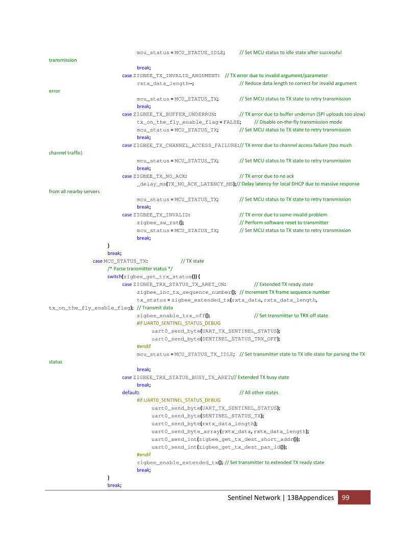
mcu_status = MCU_STATUS_IDLE; // Set MCU status to idle state after successful transmission break;
case ZIGBEE_TX_INVALID_ARGUMENT: // TX error due to invalid argument/parameter
rxtx_data_length‐‐; // Reduce data length to correct for invalid argument error
mcu_status = MCU_STATUS_TX; // Set MCU status to TX state to retry transmission break;
case ZIGBEE_TX_BUFFER_UNDERRUN: // TX error due to buffer underrun (SPI uploads too slow)
tx_on_the_fly_enable_flag = FALSE; // Disable on‐the‐fly transmission mode
mcu_status = MCU_STATUS_TX; // Set MCU status to TX state to retry transmission break;
case ZIGBEE_TX_CHANNEL_ACCESS_FAILURE: // TX error due to channel access failure (too much channel traffic)
mcu_status = MCU_STATUS_TX; // Set MCU status to TX state to retry transmission break;
case ZIGBEE_TX_NO_ACK: // TX error due to no ack
_delay_ms(TX_NO_ACK_LATENCY_MS);// Delay latency for local DHCP due to massive response from all nearby servers
mcu_status = MCU_STATUS_TX; // Set MCU status to TX state to retry transmission break;
case ZIGBEE_TX_INVALID: // TX error due to some invalid problem
zigbee_sw_rst(); // Perform software reset to transmitter
mcu_status = MCU_STATUS_TX; // Set MCU status to TX state to retry transmission break; } break;
case MCU_STATUS_TX: // TX state /* Parse transmitter status */
switch(zigbee_get_trx_status()) { case ZIGBEE_TRX_STATUS_TX_ARET_ON: // Extended TX ready state
zigbee_inc_tx_sequence_number(); // Increment TX frame sequence number
tx_status = zigbee_extended_tx(rxtx_data, rxtx_data_length, tx_on_the_fly_enable_flag); // Transmit data
zigbee_enable_trx_off(); // Set transmitter to TRX off state #if UART0_SENTINEL_STATUS_DEBUG
uart0_send_byte(UART_TX_SENTINEL_STATUS); uart0_send_byte(SENTINEL_STATUS_TRX_OFF); #endif
mcu_status = MCU_STATUS_TX_IDLE; // Set transmitter state to TX idle state for parsing the TX status break;
case ZIGBEE_TRX_STATUS_BUSY_TX_ARET:// Extended TX busy state break; default: // All other states #if UART0_SENTINEL_STATUS_DEBUG
uart0_send_byte(UART_TX_SENTINEL_STATUS); uart0_send_byte(SENTINEL_STATUS_TX); uart0_send_byte(rxtx_data_length); uart0_send_byte_array(rxtx_data, rxtx_data_length); uart0_send_int(zigbee_get_tx_dest_short_addr()); uart0_send_int(zigbee_get_tx_dest_pan_id()); #endif
zigbee_enable_extended_tx(); // Set transmitter to extended TX ready state break; } break;
Sentinel Network | 13BAppendices 99
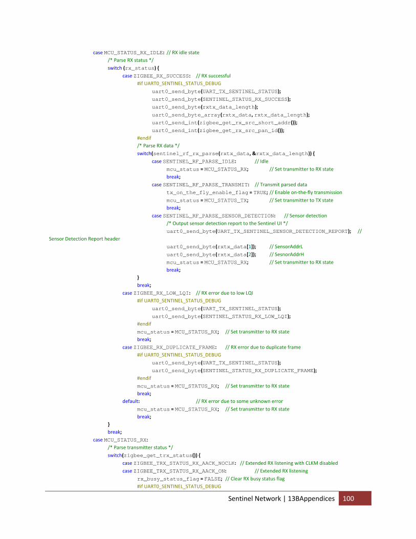
case MCU_STATUS_RX_IDLE: // RX idle state /* Parse RX status */
switch (rx_status) { case ZIGBEE_RX_SUCCESS: // RX successful #if UART0_SENTINEL_STATUS_DEBUG
uart0_send_byte(UART_TX_SENTINEL_STATUS); uart0_send_byte(SENTINEL_STATUS_RX_SUCCESS); uart0_send_byte(rxtx_data_length); uart0_send_byte_array(rxtx_data, rxtx_data_length); uart0_send_int(zigbee_get_rx_src_short_addr()); uart0_send_int(zigbee_get_rx_src_pan_id()); #endif /* Parse RX data */
switch(sentinel_rf_rx_parse(rxtx_data, &rxtx_data_length)) { case SENTINEL_RF_PARSE_IDLE: // Idle
mcu_status = MCU_STATUS_RX; // Set transmitter to RX state break;
case SENTINEL_RF_PARSE_TRANSMIT: // Transmit parsed data
tx_on_the_fly_enable_flag = TRUE; // Enable on‐the‐fly transmission
mcu_status = MCU_STATUS_TX; // Set transmitter to TX state break;
case SENTINEL_RF_PARSE_SENSOR_DETECTION: // Sensor detection /* Output sensor detection report to the Sentinel UI */
uart0_send_byte(UART_TX_SENTINEL_SENSOR_DETECTION_REPORT); // Sensor Detection Report header
uart0_send_byte(rxtx_data[1]); // SensorAddrL
uart0_send_byte(rxtx_data[2]); // SesnorAddrH
mcu_status = MCU_STATUS_RX; // Set transmitter to RX state break; } break;
case ZIGBEE_RX_LOW_LQI: // RX error due to low LQI #if UART0_SENTINEL_STATUS_DEBUG
uart0_send_byte(UART_TX_SENTINEL_STATUS); uart0_send_byte(SENTINEL_STATUS_RX_LOW_LQI); #endif
mcu_status = MCU_STATUS_RX; // Set transmitter to RX state break;
case ZIGBEE_RX_DUPLICATE_FRAME: // RX error due to duplicate frame #if UART0_SENTINEL_STATUS_DEBUG
uart0_send_byte(UART_TX_SENTINEL_STATUS); uart0_send_byte(SENTINEL_STATUS_RX_DUPLICATE_FRAME); #endif
mcu_status = MCU_STATUS_RX; // Set transmitter to RX state break; default: // RX error due to some unknown error
mcu_status = MCU_STATUS_RX; // Set transmitter to RX state break; } break;
case MCU_STATUS_RX: /* Parse transmitter status */
switch(zigbee_get_trx_status()) { case ZIGBEE_TRX_STATUS_RX_AACK_NOCLK: // Extended RX listening with CLKM disabled
case ZIGBEE_TRX_STATUS_RX_AACK_ON: // Extended RX listening
rx_busy_status_flag = FALSE; // Clear RX busy status flag #if UART0_SENTINEL_STATUS_DEBUG
Sentinel Network | 13BAppendices 100
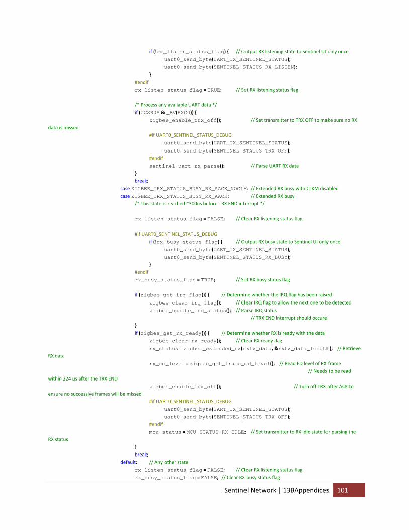
if (!rx_listen_status_flag) { // Output RX listening state to Sentinel UI only once
uart0_send_byte(UART_TX_SENTINEL_STATUS); uart0_send_byte(SENTINEL_STATUS_RX_LISTEN); } #endif
rx_listen_status_flag = TRUE; // Set RX listening status flag /* Process any available UART data */
if (UCSR0A & _BV(RXC0)) { zigbee_enable_trx_off(); // Set transmitter to TRX OFF to make sure no RX data is missed #if UART0_SENTINEL_STATUS_DEBUG
uart0_send_byte(UART_TX_SENTINEL_STATUS); uart0_send_byte(SENTINEL_STATUS_TRX_OFF); #endif
sentinel_uart_rx_parse(); // Parse UART RX data } break;
case ZIGBEE_TRX_STATUS_BUSY_RX_AACK_NOCLK: // Extended RX busy with CLKM disabled
case ZIGBEE_TRX_STATUS_BUSY_RX_AACK: // Extended RX busy /* This state is reached ~300us before TRX END interrupt */
rx_listen_status_flag = FALSE; // Clear RX listening status flag #if UART0_SENTINEL_STATUS_DEBUG
if (!rx_busy_status_flag) { // Output RX busy state to Sentinel UI only once
uart0_send_byte(UART_TX_SENTINEL_STATUS); uart0_send_byte(SENTINEL_STATUS_RX_BUSY); } #endif
rx_busy_status_flag = TRUE; // Set RX busy status flag
if (zigbee_get_irq_flag()) { // Determine whether the IRQ flag has been raised
zigbee_clear_irq_flag(); // Clear IRQ flag to allow the next one to be detected
zigbee_update_irq_status(); // Parse IRQ status // TRX END interrupt should occure }
if (zigbee_get_rx_ready()) { // Determine whether RX is ready with the data
zigbee_clear_rx_ready(); // Clear RX ready flag
rx_status = zigbee_extended_rx(rxtx_data, &rxtx_data_length); // Retrieve RX data
rx_ed_level = zigbee_get_frame_ed_level(); // Read ED level of RX frame // Needs to be read within 224 µs after the TRX END
zigbee_enable_trx_off(); // Turn off TRX after ACK to ensure no successive frames will be missed #if UART0_SENTINEL_STATUS_DEBUG
uart0_send_byte(UART_TX_SENTINEL_STATUS); uart0_send_byte(SENTINEL_STATUS_TRX_OFF); #endif
mcu_status = MCU_STATUS_RX_IDLE; // Set transmitter to RX idle state for parsing the RX status } break; default: // Any other state
rx_listen_status_flag = FALSE; // Clear RX listening status flag
Sentinel Network | 13BAppendices 101
rx_busy_status_flag = FALSE; // Clear RX busy status flag
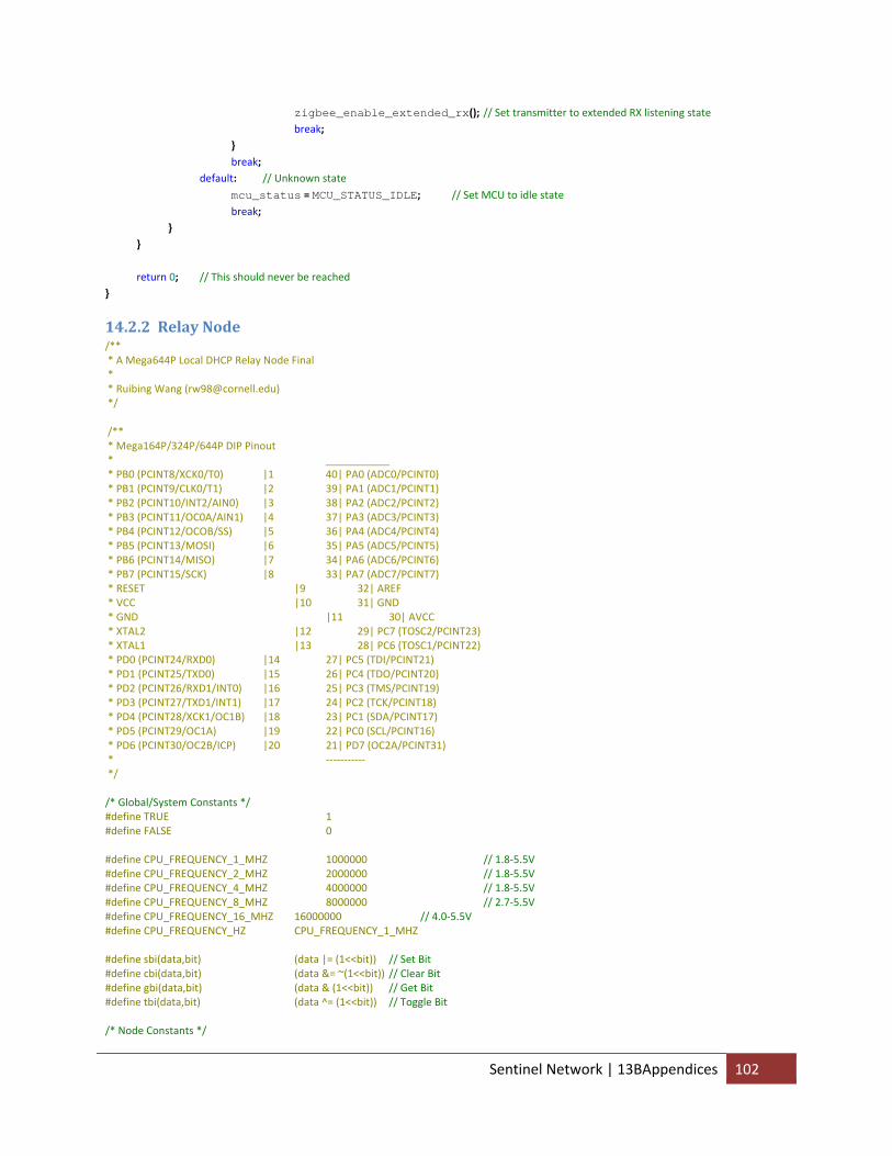
zigbee_enable_extended_rx(); // Set transmitter to extended RX listening state break; } break; default: // Unknown state
mcu_status = MCU_STATUS_IDLE; // Set MCU to idle state break; } } return 0; // This should never be reached }
14.2.2 Relay Node /** * A Mega644P Local DHCP Relay Node Final * * Ruibing Wang ([email protected]) */ /** * Mega164P/324P/644P DIP Pinout * ___________ * PB0 (PCINT8/XCK0/T0) |1 40| PA0 (ADC0/PCINT0) * PB1 (PCINT9/CLK0/T1) |2 39| PA1 (ADC1/PCINT1) * PB2 (PCINT10/INT2/AIN0) |3 38| PA2 (ADC2/PCINT2) * PB3 (PCINT11/OC0A/AIN1) |4 37| PA3 (ADC3/PCINT3) * PB4 (PCINT12/OCOB/SS) |5 36| PA4 (ADC4/PCINT4) * PB5 (PCINT13/MOSI) |6 35| PA5 (ADC5/PCINT5) * PB6 (PCINT14/MISO) |7 34| PA6 (ADC6/PCINT6) * PB7 (PCINT15/SCK) |8 33| PA7 (ADC7/PCINT7) * RESET |9 32| AREF * VCC |10 31| GND * GND |11 30| AVCC * XTAL2 |12 29| PC7 (TOSC2/PCINT23) * XTAL1 |13 28| PC6 (TOSC1/PCINT22) * PD0 (PCINT24/RXD0) |14 27| PC5 (TDI/PCINT21) * PD1 (PCINT25/TXD0) |15 26| PC4 (TDO/PCINT20) * PD2 (PCINT26/RXD1/INT0) |16 25| PC3 (TMS/PCINT19) * PD3 (PCINT27/TXD1/INT1) |17 24| PC2 (TCK/PCINT18) * PD4 (PCINT28/XCK1/OC1B) |18 23| PC1 (SDA/PCINT17) * PD5 (PCINT29/OC1A) |19 22| PC0 (SCL/PCINT16) * PD6 (PCINT30/OC2B/ICP) |20 21| PD7 (OC2A/PCINT31) * ‐‐‐‐‐‐‐‐‐‐‐ */ /* Global/System Constants */ #define TRUE 1 #define FALSE 0 #define CPU_FREQUENCY_1_MHZ 1000000 // 1.8‐5.5V #define CPU_FREQUENCY_2_MHZ 2000000 // 1.8‐5.5V #define CPU_FREQUENCY_4_MHZ 4000000 // 1.8‐5.5V #define CPU_FREQUENCY_8_MHZ 8000000 // 2.7‐5.5V #define CPU_FREQUENCY_16_MHZ 16000000 // 4.0‐5.5V #define CPU_FREQUENCY_HZ CPU_FREQUENCY_1_MHZ #define sbi(data,bit) (data |= (1<<bit)) // Set Bit #define cbi(data,bit) (data &= ~(1<<bit)) // Clear Bit #define gbi(data,bit) (data & (1<<bit)) // Get Bit #define tbi(data,bit) (data ^= (1<<bit)) // Toggle Bit /* Node Constants */
Sentinel Network | 13BAppendices 102
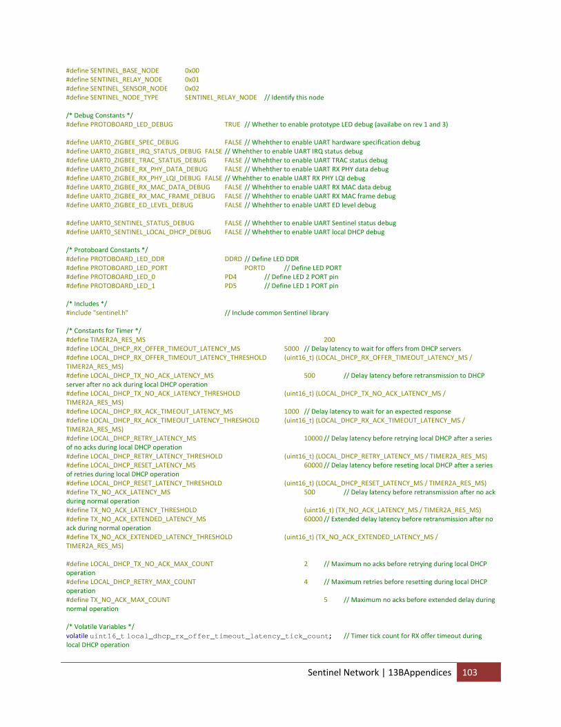
#define SENTINEL_BASE_NODE 0x00 #define SENTINEL_RELAY_NODE 0x01 #define SENTINEL_SENSOR_NODE 0x02 #define SENTINEL_NODE_TYPE SENTINEL_RELAY_NODE // Identify this node /* Debug Constants */ #define PROTOBOARD_LED_DEBUG TRUE // Whether to enable prototype LED debug (availabe on rev 1 and 3) #define UART0_ZIGBEE_SPEC_DEBUG FALSE // Whehther to enable UART hardware specification debug #define UART0_ZIGBEE_IRQ_STATUS_DEBUG FALSE // Whehther to enable UART IRQ status debug #define UART0_ZIGBEE_TRAC_STATUS_DEBUG FALSE // Whehther to enable UART TRAC status debug #define UART0_ZIGBEE_RX_PHY_DATA_DEBUG FALSE // Whehther to enable UART RX PHY data debug #define UART0_ZIGBEE_RX_PHY_LQI_DEBUG FALSE // Whehther to enable UART RX PHY LQI debug #define UART0_ZIGBEE_RX_MAC_DATA_DEBUG FALSE // Whehther to enable UART RX MAC data debug #define UART0_ZIGBEE_RX_MAC_FRAME_DEBUG FALSE // Whehther to enable UART RX MAC frame debug #define UART0_ZIGBEE_ED_LEVEL_DEBUG FALSE // Whehther to enable UART ED level debug #define UART0_SENTINEL_STATUS_DEBUG FALSE // Whehther to enable UART Sentinel status debug #define UART0_SENTINEL_LOCAL_DHCP_DEBUG FALSE // Whehther to enable UART local DHCP debug /* Protoboard Constants */ #define PROTOBOARD_LED_DDR DDRD // Define LED DDR #define PROTOBOARD_LED_PORT PORTD // Define LED PORT #define PROTOBOARD_LED_0 PD4 // Define LED 2 PORT pin #define PROTOBOARD_LED_1 PD5 // Define LED 1 PORT pin /* Includes */ #include "sentinel.h" // Include common Sentinel library /* Constants for Timer */ #define TIMER2A_RES_MS 200 #define LOCAL_DHCP_RX_OFFER_TIMEOUT_LATENCY_MS 5000 // Delay latency to wait for offers from DHCP servers #define LOCAL_DHCP_RX_OFFER_TIMEOUT_LATENCY_THRESHOLD (uint16_t) (LOCAL_DHCP_RX_OFFER_TIMEOUT_LATENCY_MS / TIMER2A_RES_MS) #define LOCAL_DHCP_TX_NO_ACK_LATENCY_MS 500 // Delay latency before retransmission to DHCP server after no ack during local DHCP operation #define LOCAL_DHCP_TX_NO_ACK_LATENCY_THRESHOLD (uint16_t) (LOCAL_DHCP_TX_NO_ACK_LATENCY_MS / TIMER2A_RES_MS) #define LOCAL_DHCP_RX_ACK_TIMEOUT_LATENCY_MS 1000 // Delay latency to wait for an expected response #define LOCAL_DHCP_RX_ACK_TIMEOUT_LATENCY_THRESHOLD (uint16_t) (LOCAL_DHCP_RX_ACK_TIMEOUT_LATENCY_MS / TIMER2A_RES_MS) #define LOCAL_DHCP_RETRY_LATENCY_MS 10000 // Delay latency before retrying local DHCP after a series of no acks during local DHCP operation #define LOCAL_DHCP_RETRY_LATENCY_THRESHOLD (uint16_t) (LOCAL_DHCP_RETRY_LATENCY_MS / TIMER2A_RES_MS) #define LOCAL_DHCP_RESET_LATENCY_MS 60000 // Delay latency before reseting local DHCP after a series of retries during local DHCP operation #define LOCAL_DHCP_RESET_LATENCY_THRESHOLD (uint16_t) (LOCAL_DHCP_RESET_LATENCY_MS / TIMER2A_RES_MS) #define TX_NO_ACK_LATENCY_MS 500 // Delay latency before retransmission after no ack during normal operation #define TX_NO_ACK_LATENCY_THRESHOLD (uint16_t) (TX_NO_ACK_LATENCY_MS / TIMER2A_RES_MS) #define TX_NO_ACK_EXTENDED_LATENCY_MS 60000 // Extended delay latency before retransmission after no ack during normal operation #define TX_NO_ACK_EXTENDED_LATENCY_THRESHOLD (uint16_t) (TX_NO_ACK_EXTENDED_LATENCY_MS / TIMER2A_RES_MS) #define LOCAL_DHCP_TX_NO_ACK_MAX_COUNT 2 // Maximum no acks before retrying during local DHCP operation #define LOCAL_DHCP_RETRY_MAX_COUNT 4 // Maximum retries before resetting during local DHCP operation #define TX_NO_ACK_MAX_COUNT 5 // Maximum no acks before extended delay during normal operation /* Volatile Variables */ volatile uint16_t local_dhcp_rx_offer_timeout_latency_tick_count; // Timer tick count for RX offer timeout during local DHCP operation
Sentinel Network | 13BAppendices 103
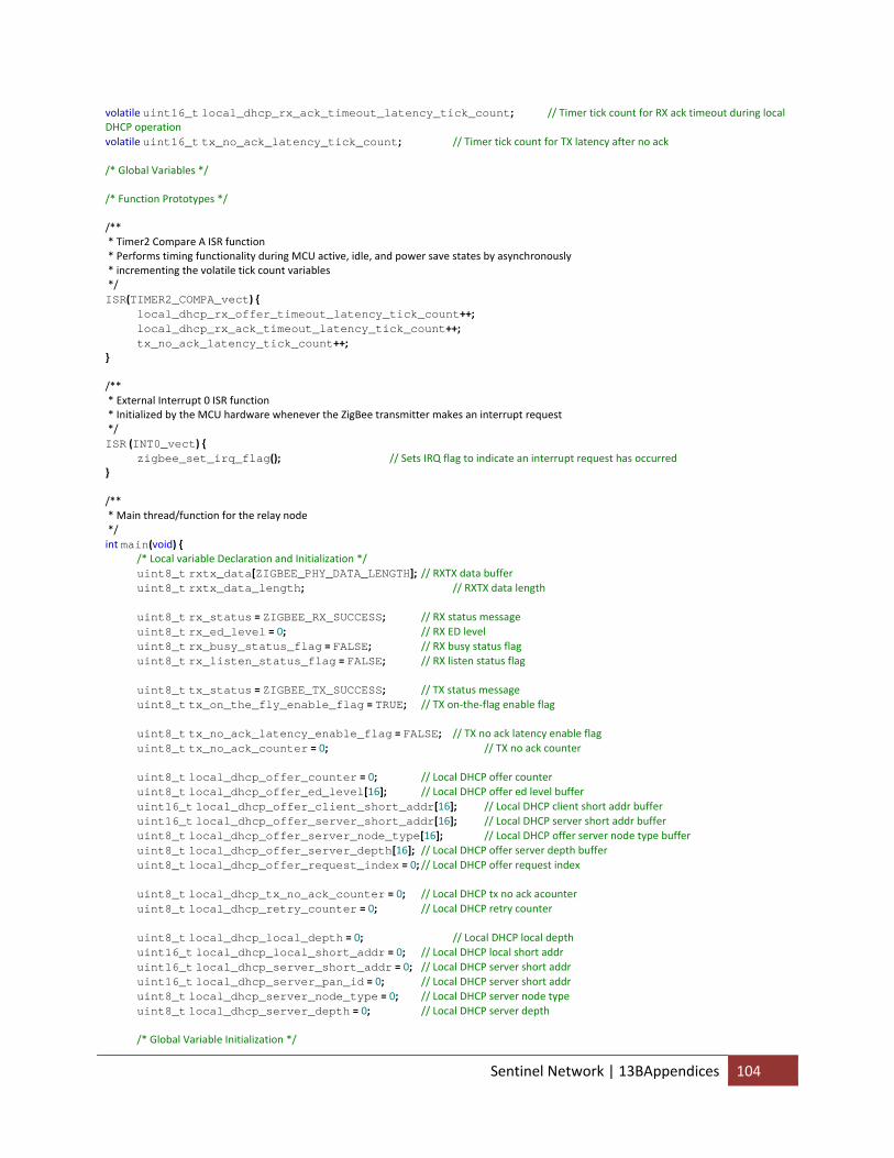
volatile uint16_t local_dhcp_rx_ack_timeout_latency_tick_count; // Timer tick count for RX ack timeout during local DHCP operation volatile uint16_t tx_no_ack_latency_tick_count; // Timer tick count for TX latency after no ack /* Global Variables */ /* Function Prototypes */ /** * Timer2 Compare A ISR function * Performs timing functionality during MCU active, idle, and power save states by asynchronously * incrementing the volatile tick count variables */ ISR(TIMER2_COMPA_vect) { local_dhcp_rx_offer_timeout_latency_tick_count++; local_dhcp_rx_ack_timeout_latency_tick_count++; tx_no_ack_latency_tick_count++; } /** * External Interrupt 0 ISR function * Initialized by the MCU hardware whenever the ZigBee transmitter makes an interrupt request */ ISR (INT0_vect) { zigbee_set_irq_flag(); // Sets IRQ flag to indicate an interrupt request has occurred } /** * Main thread/function for the relay node */ int main(void) { /* Local variable Declaration and Initialization */ uint8_t rxtx_data[ZIGBEE_PHY_DATA_LENGTH]; // RXTX data buffer uint8_t rxtx_data_length; // RXTX data length uint8_t rx_status = ZIGBEE_RX_SUCCESS; // RX status message uint8_t rx_ed_level = 0; // RX ED level uint8_t rx_busy_status_flag = FALSE; // RX busy status flag uint8_t rx_listen_status_flag = FALSE; // RX listen status flag uint8_t tx_status = ZIGBEE_TX_SUCCESS; // TX status message uint8_t tx_on_the_fly_enable_flag = TRUE; // TX on‐the‐flag enable flag uint8_t tx_no_ack_latency_enable_flag = FALSE; // TX no ack latency enable flag uint8_t tx_no_ack_counter = 0; // TX no ack counter uint8_t local_dhcp_offer_counter = 0; // Local DHCP offer counter uint8_t local_dhcp_offer_ed_level[16]; // Local DHCP offer ed level buffer uint16_t local_dhcp_offer_client_short_addr[16]; // Local DHCP client short addr buffer uint16_t local_dhcp_offer_server_short_addr[16]; // Local DHCP server short addr buffer uint8_t local_dhcp_offer_server_node_type[16]; // Local DHCP offer server node type buffer uint8_t local_dhcp_offer_server_depth[16]; // Local DHCP offer server depth buffer uint8_t local_dhcp_offer_request_index = 0; // Local DHCP offer request index uint8_t local_dhcp_tx_no_ack_counter = 0; // Local DHCP tx no ack acounter uint8_t local_dhcp_retry_counter = 0; // Local DHCP retry counter uint8_t local_dhcp_local_depth = 0; // Local DHCP local depth uint16_t local_dhcp_local_short_addr = 0; // Local DHCP local short addr uint16_t local_dhcp_server_short_addr = 0; // Local DHCP server short addr uint16_t local_dhcp_server_pan_id = 0; // Local DHCP server short addr uint8_t local_dhcp_server_node_type = 0; // Local DHCP server node type uint8_t local_dhcp_server_depth = 0; // Local DHCP server depth /* Global Variable Initialization */
Sentinel Network | 13BAppendices 104
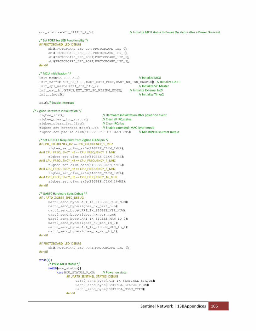
mcu_status = MCU_STATUS_P_ON; // Initialize MCU status to Power On status after a Power On event /* Set PORT for LED Functionality */ #if PROTOBOARD_LED_DEBUG sbi(PROTOBOARD_LED_DDR, PROTOBOARD_LED_0); sbi(PROTOBOARD_LED_DDR, PROTOBOARD_LED_1); sbi(PROTOBOARD_LED_PORT, PROTOBOARD_LED_0); sbi(PROTOBOARD_LED_PORT, PROTOBOARD_LED_1); #endif /* MCU Initialization */ init_mcu(MCU_PRR_ALL); // Initialize MCU init_uart0(UART_BR_4800, UART_RXTX_MODE, UART_NO_ISR_ENABLE); // Initialize UART init_spi_master(SPI_CLK_DIV_2); // Initialize SPI Master init_ext_int0(TRUE, EXT_INT_SC_RISING_EDGE); // Initialize External Int0 init_timer2(); // Initialize Timer2 sei();// Enable Interrupt /* ZigBee Hardware Initialization */ zigbee_init(); // Hardware initialization after power‐on event zigbee_clear_irq_status(); // Clear all IRQ status zigbee_clear_irq_flag(); // Clear IRQ flag zigbee_set_extended_mode(TRUE); // Enable extended (MAC layer) mode zigbee_set_pad_io_clkm(ZIGBEE_PAD_IO_CLKM_2MA); // Minimize IO current output /* Set CPU CLK frequency from ZigBee CLKM pin */ #if CPU_FREQUENCY_HZ == CPU_FREQUENCY_1_MHZ zigbee_set_clkm_safe(ZIGBEE_CLKM_1MHZ); #elif CPU_FREQUENCY_HZ == CPU_FREQUENCY_2_MHZ zigbee_set_clkm_safe(ZIGBEE_CLKM_2MHZ); #elif CPU_FREQUENCY_HZ == CPU_FREQUENCY_4_MHZ zigbee_set_clkm_safe(ZIGBEE_CLKM_4MHZ); #elif CPU_FREQUENCY_HZ == CPU_FREQUENCY_8_MHZ zigbee_set_clkm_safe(ZIGBEE_CLKM_8MHZ); #elif CPU_FREQUENCY_HZ == CPU_FREQUENCY_16_MHZ zigbee_set_clkm_safe(ZIGBEE_CLKM_16MHZ); #endif /* UART0 Hardware Spec Debug */ #if UART0_ZIGBEE_SPEC_DEBUG uart0_send_byte(UART_TX_ZIGBEE_PART_NUM); uart0_send_byte(zigbee_hw_part_num); uart0_send_byte(UART_TX_ZIGBEE_VER_NUM); uart0_send_byte(zigbee_hw_ver_num); uart0_send_byte(UART_TX_ZIGBEE_MAN_ID_0); uart0_send_byte(zigbee_hw_man_id_0); uart0_send_byte(UART_TX_ZIGBEE_MAN_ID_1); uart0_send_byte(zigbee_hw_man_id_1); #endif #if PROTOBOARD_LED_DEBUG cbi(PROTOBOARD_LED_PORT, PROTOBOARD_LED_0); #endif while(1) { /* Parse MCU status */ switch(mcu_status) { case MCU_STATUS_P_ON: // Power on state #if UART0_SENTINEL_STATUS_DEBUG uart0_send_byte(UART_TX_SENTINEL_STATUS); uart0_send_byte(SENTINEL_STATUS_P_ON); uart0_send_byte(SENTINEL_NODE_TYPE); #endif
Sentinel Network | 13BAppendices 105
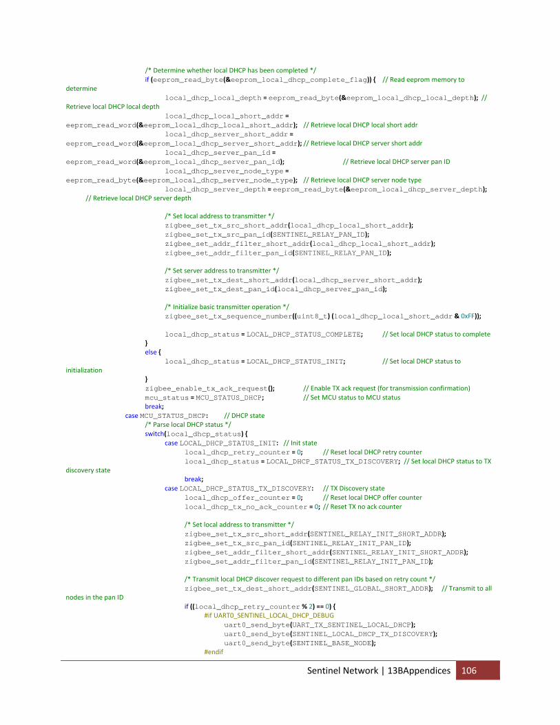
/* Determine whether local DHCP has been completed */ if (eeprom_read_byte(&eeprom_local_dhcp_complete_flag)) { // Read eeprom memory to determine local_dhcp_local_depth = eeprom_read_byte(&eeprom_local_dhcp_local_depth); // Retrieve local DHCP local depth local_dhcp_local_short_addr = eeprom_read_word(&eeprom_local_dhcp_local_short_addr); // Retrieve local DHCP local short addr local_dhcp_server_short_addr = eeprom_read_word(&eeprom_local_dhcp_server_short_addr); // Retrieve local DHCP server short addr local_dhcp_server_pan_id = eeprom_read_word(&eeprom_local_dhcp_server_pan_id); // Retrieve local DHCP server pan ID local_dhcp_server_node_type = eeprom_read_byte(&eeprom_local_dhcp_server_node_type); // Retrieve local DHCP server node type local_dhcp_server_depth = eeprom_read_byte(&eeprom_local_dhcp_server_depth); // Retrieve local DHCP server depth /* Set local address to transmitter */ zigbee_set_tx_src_short_addr(local_dhcp_local_short_addr); zigbee_set_tx_src_pan_id(SENTINEL_RELAY_PAN_ID); zigbee_set_addr_filter_short_addr(local_dhcp_local_short_addr); zigbee_set_addr_filter_pan_id(SENTINEL_RELAY_PAN_ID); /* Set server address to transmitter */ zigbee_set_tx_dest_short_addr(local_dhcp_server_short_addr); zigbee_set_tx_dest_pan_id(local_dhcp_server_pan_id); /* Initialize basic transmitter operation */ zigbee_set_tx_sequence_number((uint8_t) (local_dhcp_local_short_addr & 0xFF)); local_dhcp_status = LOCAL_DHCP_STATUS_COMPLETE; // Set local DHCP status to complete } else { local_dhcp_status = LOCAL_DHCP_STATUS_INIT; // Set local DHCP status to initialization } zigbee_enable_tx_ack_request(); // Enable TX ack request (for transmission confirmation) mcu_status = MCU_STATUS_DHCP; // Set MCU status to MCU status break; case MCU_STATUS_DHCP: // DHCP state /* Parse local DHCP status */ switch(local_dhcp_status) { case LOCAL_DHCP_STATUS_INIT: // Init state local_dhcp_retry_counter = 0; // Reset local DHCP retry counter local_dhcp_status = LOCAL_DHCP_STATUS_TX_DISCOVERY; // Set local DHCP status to TX discovery state break; case LOCAL_DHCP_STATUS_TX_DISCOVERY: // TX Discovery state local_dhcp_offer_counter = 0; // Reset local DHCP offer counter local_dhcp_tx_no_ack_counter = 0; // Reset TX no ack counter /* Set local address to transmitter */ zigbee_set_tx_src_short_addr(SENTINEL_RELAY_INIT_SHORT_ADDR); zigbee_set_tx_src_pan_id(SENTINEL_RELAY_INIT_PAN_ID); zigbee_set_addr_filter_short_addr(SENTINEL_RELAY_INIT_SHORT_ADDR); zigbee_set_addr_filter_pan_id(SENTINEL_RELAY_INIT_PAN_ID); /* Transmit local DHCP discover request to different pan IDs based on retry count */ zigbee_set_tx_dest_short_addr(SENTINEL_GLOBAL_SHORT_ADDR); // Transmit to all nodes in the pan ID if ((local_dhcp_retry_counter % 2) == 0) { #if UART0_SENTINEL_LOCAL_DHCP_DEBUG uart0_send_byte(UART_TX_SENTINEL_LOCAL_DHCP); uart0_send_byte(SENTINEL_LOCAL_DHCP_TX_DISCOVERY); uart0_send_byte(SENTINEL_BASE_NODE); #endif
Sentinel Network | 13BAppendices 106
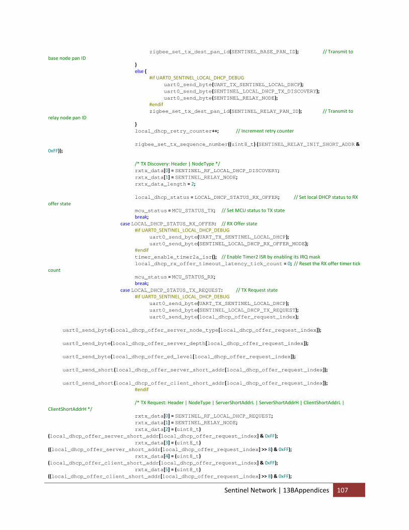
zigbee_set_tx_dest_pan_id(SENTINEL_BASE_PAN_ID); // Transmit to base node pan ID } else { #if UART0_SENTINEL_LOCAL_DHCP_DEBUG uart0_send_byte(UART_TX_SENTINEL_LOCAL_DHCP); uart0_send_byte(SENTINEL_LOCAL_DHCP_TX_DISCOVERY); uart0_send_byte(SENTINEL_RELAY_NODE); #endif zigbee_set_tx_dest_pan_id(SENTINEL_RELAY_PAN_ID); // Transmit to relay node pan ID } local_dhcp_retry_counter++; // Increment retry counter zigbee_set_tx_sequence_number((uint8_t) (SENTINEL_RELAY_INIT_SHORT_ADDR & 0xFF)); /* TX Discovery: Header | NodeType */ rxtx_data[0] = SENTINEL_RF_LOCAL_DHCP_DISCOVERY; rxtx_data[1] = SENTINEL_RELAY_NODE; rxtx_data_length = 2; local_dhcp_status = LOCAL_DHCP_STATUS_RX_OFFER; // Set local DHCP status to RX offer state mcu_status = MCU_STATUS_TX; // Set MCU status to TX state break; case LOCAL_DHCP_STATUS_RX_OFFER: // RX Offer state #if UART0_SENTINEL_LOCAL_DHCP_DEBUG uart0_send_byte(UART_TX_SENTINEL_LOCAL_DHCP); uart0_send_byte(SENTINEL_LOCAL_DHCP_RX_OFFER_MODE); #endif timer_enable_timer2a_isr(); // Enable Timer2 ISR by enabling its IRQ mask local_dhcp_rx_offer_timeout_latency_tick_count = 0; // Reset the RX offer timer tick count mcu_status = MCU_STATUS_RX; break; case LOCAL_DHCP_STATUS_TX_REQUEST: // TX Request state #if UART0_SENTINEL_LOCAL_DHCP_DEBUG uart0_send_byte(UART_TX_SENTINEL_LOCAL_DHCP); uart0_send_byte(SENTINEL_LOCAL_DHCP_TX_REQUEST); uart0_send_byte(local_dhcp_offer_request_index); uart0_send_byte(local_dhcp_offer_server_node_type[local_dhcp_offer_request_index]); uart0_send_byte(local_dhcp_offer_server_depth[local_dhcp_offer_request_index]); uart0_send_byte(local_dhcp_offer_ed_level[local_dhcp_offer_request_index]); uart0_send_short(local_dhcp_offer_server_short_addr[local_dhcp_offer_request_index]); uart0_send_short(local_dhcp_offer_client_short_addr[local_dhcp_offer_request_index]); #endif /* TX Request: Header | NodeType | ServerShortAddrL | ServerShortAddrH | ClientShortAddrL | ClientShortAddrH */ rxtx_data[0] = SENTINEL_RF_LOCAL_DHCP_REQUEST; rxtx_data[1] = SENTINEL_RELAY_NODE; rxtx_data[2] = (uint8_t) (local_dhcp_offer_server_short_addr[local_dhcp_offer_request_index] & 0xFF); rxtx_data[3] = (uint8_t) ((local_dhcp_offer_server_short_addr[local_dhcp_offer_request_index] >> 8) & 0xFF); rxtx_data[4] = (uint8_t) (local_dhcp_offer_client_short_addr[local_dhcp_offer_request_index] & 0xFF); rxtx_data[5] = (uint8_t) ((local_dhcp_offer_client_short_addr[local_dhcp_offer_request_index] >> 8) & 0xFF);
Sentinel Network | 13BAppendices 107
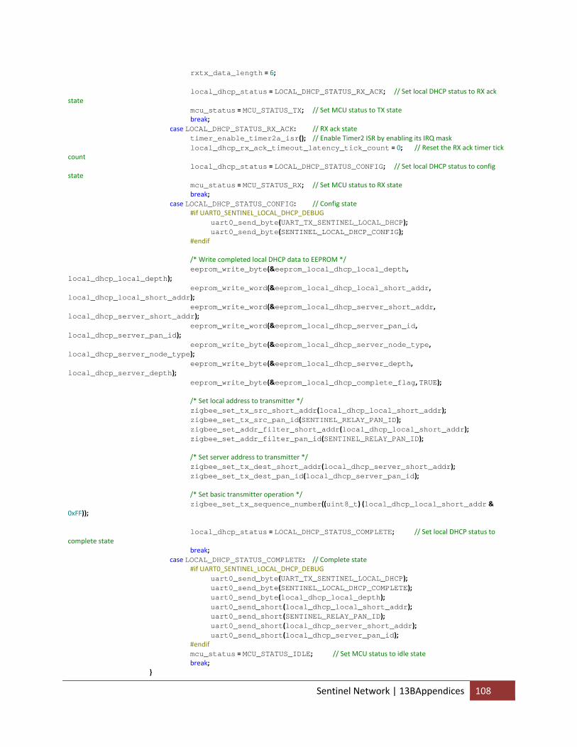
rxtx_data_length = 6; local_dhcp_status = LOCAL_DHCP_STATUS_RX_ACK; // Set local DHCP status to RX ack state mcu_status = MCU_STATUS_TX; // Set MCU status to TX state break; case LOCAL_DHCP_STATUS_RX_ACK: // RX ack state timer_enable_timer2a_isr(); // Enable Timer2 ISR by enabling its IRQ mask local_dhcp_rx_ack_timeout_latency_tick_count = 0; // Reset the RX ack timer tick count local_dhcp_status = LOCAL_DHCP_STATUS_CONFIG; // Set local DHCP status to config state mcu_status = MCU_STATUS_RX; // Set MCU status to RX state break; case LOCAL_DHCP_STATUS_CONFIG: // Config state #if UART0_SENTINEL_LOCAL_DHCP_DEBUG uart0_send_byte(UART_TX_SENTINEL_LOCAL_DHCP); uart0_send_byte(SENTINEL_LOCAL_DHCP_CONFIG); #endif /* Write completed local DHCP data to EEPROM */ eeprom_write_byte(&eeprom_local_dhcp_local_depth, local_dhcp_local_depth); eeprom_write_word(&eeprom_local_dhcp_local_short_addr, local_dhcp_local_short_addr); eeprom_write_word(&eeprom_local_dhcp_server_short_addr, local_dhcp_server_short_addr); eeprom_write_word(&eeprom_local_dhcp_server_pan_id, local_dhcp_server_pan_id); eeprom_write_byte(&eeprom_local_dhcp_server_node_type, local_dhcp_server_node_type); eeprom_write_byte(&eeprom_local_dhcp_server_depth, local_dhcp_server_depth); eeprom_write_byte(&eeprom_local_dhcp_complete_flag, TRUE); /* Set local address to transmitter */ zigbee_set_tx_src_short_addr(local_dhcp_local_short_addr); zigbee_set_tx_src_pan_id(SENTINEL_RELAY_PAN_ID); zigbee_set_addr_filter_short_addr(local_dhcp_local_short_addr); zigbee_set_addr_filter_pan_id(SENTINEL_RELAY_PAN_ID); /* Set server address to transmitter */ zigbee_set_tx_dest_short_addr(local_dhcp_server_short_addr); zigbee_set_tx_dest_pan_id(local_dhcp_server_pan_id); /* Set basic transmitter operation */ zigbee_set_tx_sequence_number((uint8_t) (local_dhcp_local_short_addr & 0xFF)); local_dhcp_status = LOCAL_DHCP_STATUS_COMPLETE; // Set local DHCP status to complete state break; case LOCAL_DHCP_STATUS_COMPLETE: // Complete state #if UART0_SENTINEL_LOCAL_DHCP_DEBUG uart0_send_byte(UART_TX_SENTINEL_LOCAL_DHCP); uart0_send_byte(SENTINEL_LOCAL_DHCP_COMPLETE); uart0_send_byte(local_dhcp_local_depth); uart0_send_short(local_dhcp_local_short_addr); uart0_send_short(SENTINEL_RELAY_PAN_ID); uart0_send_short(local_dhcp_server_short_addr); uart0_send_short(local_dhcp_server_pan_id); #endif mcu_status = MCU_STATUS_IDLE; // Set MCU status to idle state break; }
Sentinel Network | 13BAppendices 108
break; case MCU_STATUS_IDLE: // Idle state #if UART0_SENTINEL_STATUS_DEBUG uart0_send_byte(UART_TX_SENTINEL_STATUS); uart0_send_byte(SENTINEL_STATUS_IDLE); #endif if (local_dhcp_status == LOCAL_DHCP_STATUS_COMPLETE) { mcu_status = MCU_STATUS_RX; // Set MCU status to RX state if local DHCP is completed } else { mcu_status = MCU_STATUS_DHCP; // Set MCU status to RX state if local DHCP is still incomplete } break; case MCU_STATUS_SLEEP: // Sleep state zigbee_enable_extended_rx_sleep(); // Enable extended RX sleep state set_sleep_mode(SLEEP_MODE_PWR_DOWN); // Enable MCU Power Down sleep state sleep_mode(); // Enable sleep mode /* Wait until an interrupt request occurs from the transmitter */ mcu_status = MCU_STATUS_RX; // Set MCU status to RX state break; case MCU_STATUS_TX_IDLE: // TX idle state /* Parse TX status */ switch (tx_status) { case ZIGBEE_TX_SUCCESS: // TX sucessful /* Determine whether local DHCP has been completed */ if (local_dhcp_status == LOCAL_DHCP_STATUS_COMPLETE) { tx_no_ack_counter = 0; // Clear TX no ack counter mcu_status = MCU_STATUS_IDLE; // Set MCU status to Idle state } else { local_dhcp_tx_no_ack_counter = 0; // Clear local DHCP tx no ack counter mcu_status = MCU_STATUS_DHCP; // Set MCU status to DHCP state } break; case ZIGBEE_TX_INVALID_ARGUMENT: // TX error due to invalid argument rxtx_data_length‐‐; // Reduce data length to correct for invalid argument error mcu_status = MCU_STATUS_TX; // Set MCU status to TX state to retry transmission break; case ZIGBEE_TX_BUFFER_UNDERRUN: // TX error due to buffer underrun tx_on_the_fly_enable_flag = FALSE; // Disable on‐the‐fly transmission mode mcu_status = MCU_STATUS_TX; // Set MCU status to TX state to retry transmission break; case ZIGBEE_TX_CHANNEL_ACCESS_FAILURE: // TX error due to channel access failure mcu_status = MCU_STATUS_TX; // Set MCU status to TX state to retry transmission break; case ZIGBEE_TX_NO_ACK: // TX error due to no ack /* Determine whether transmission no ack latency functionality has been enabled */ if (tx_no_ack_latency_enable_flag) { tx_no_ack_latency_enable_flag = FALSE; // Clear tx no ack latency enable flag tx_no_ack_latency_tick_count = 0; // Reset tx no ack latency tick count local_dhcp_tx_no_ack_counter++; // Increment local DHCP tx no ack counter tx_no_ack_counter++; // Increment tx no ack counter timer_enable_timer2a_isr(); // Enable Timer2 ISR by enable IRQ mask set_sleep_mode(SLEEP_MODE_PWR_SAVE); // Enable Power Save sleep mode } sleep_mode(); // Enter Sleep mode /* Determine the course of action and latency before retransmission after no ack for normal operation */ if (local_dhcp_status == LOCAL_DHCP_STATUS_COMPLETE) { /* Determine whether tx no ack counter has exceeded threshold during normal operation */ if (tx_no_ack_counter > TX_NO_ACK_MAX_COUNT) { /* Wait for an extended delay before retrying transmission */
Sentinel Network | 13BAppendices 109
if (tx_no_ack_latency_tick_count > TX_NO_ACK_EXTENDED_LATENCY_THRESHOLD) { tx_no_ack_counter = 0; // Clear TX no ack counter timer_disable_timer2a_isr(); // Disable Timer2 ISR through IRQ mask mcu_status = MCU_STATUS_TX; // Set MCU status to TX state } } else { /* Wait for a normal delay before retrying transmission */ if (tx_no_ack_latency_tick_count > TX_NO_ACK_LATENCY_THRESHOLD) { timer_disable_timer2a_isr(); // Disable Timer2 ISR through IRQ mask mcu_status = MCU_STATUS_TX; // Set MCU status to TX state } } } /* Determine the course of action and latency before retransmission after no ack for local DHCP operation by tx no ack counter*/ else if (local_dhcp_tx_no_ack_counter > LOCAL_DHCP_TX_NO_ACK_MAX_COUNT) { /* Determine whether the number of local DHCP retries has exceeded the threshold */ if (local_dhcp_retry_counter > LOCAL_DHCP_RETRY_MAX_COUNT) { /* Wait for a reset delay before retrying local DHCP */ if (tx_no_ack_latency_tick_count > LOCAL_DHCP_RESET_LATENCY_THRESHOLD) { timer_disable_timer2a_isr(); // Disable Timer2 ISR through IRQ mask sentinel_reset_local_dhcp(); // Reset local DHCP } } else { /* Wait for a retry delay before retrying local DHCP */ if (tx_no_ack_latency_tick_count > LOCAL_DHCP_RETRY_LATENCY_THRESHOLD) { timer_disable_timer2a_isr(); // Disable Timer2 ISR through IRQ mask sentinel_retry_local_dhcp(); // Retry local DHCP } } } else { /* Wait for a normal delay before retrying transmission */ if (tx_no_ack_latency_tick_count > LOCAL_DHCP_TX_NO_ACK_LATENCY_THRESHOLD) { timer_disable_timer2a_isr(); // Disable Timer2 ISR through IRQ mask mcu_status = MCU_STATUS_TX; // Set MCU status to TX state } } break; case ZIGBEE_TX_INVALID: // TX error due to unknown error zigbee_sw_rst(); // Perform software reset to transmitter mcu_status = MCU_STATUS_TX; // Set MCU status to TX state to retry transmission break; } break; case MCU_STATUS_TX: // TX state /* Parse transmitter status */ switch(zigbee_get_trx_status()) { case ZIGBEE_TRX_STATUS_TX_ARET_ON: // Extended TX ready state zigbee_inc_tx_sequence_number(); // Increment TX frame sequence number tx_status = zigbee_extended_tx(rxtx_data, rxtx_data_length, tx_on_the_fly_enable_flag); // Transmit data zigbee_enable_trx_off(); // Set transmitter to TRX off state after waiting for TX of data and RX of ack #if UART0_SENTINEL_STATUS_DEBUG uart0_send_byte(UART_TX_SENTINEL_STATUS); uart0_send_byte(SENTINEL_STATUS_TRX_OFF); #endif
Sentinel Network | 13BAppendices 110
tx_no_ack_latency_enable_flag = TRUE; // Enable tx no latency enable flag in case of no ack mcu_status = MCU_STATUS_TX_IDLE; // Set MCU status to TX Idle state break; case ZIGBEE_TRX_STATUS_BUSY_TX_ARET: // Extended TX busy state break; default: // All other states #if UART0_SENTINEL_STATUS_DEBUG uart0_send_byte(UART_TX_SENTINEL_STATUS); uart0_send_byte(SENTINEL_STATUS_TX); uart0_send_byte(rxtx_data_length); uart0_send_byte_array(rxtx_data, rxtx_data_length); uart0_send_short(zigbee_get_tx_dest_short_addr()); uart0_send_short(zigbee_get_tx_dest_pan_id()); #endif zigbee_enable_extended_tx(); // Set transmitter to extended TX ready state break; } break; case MCU_STATUS_RX_IDLE: // RX Idle state /* Parse RX status */ switch (rx_status) { case ZIGBEE_RX_SUCCESS: // RX successful #if UART0_SENTINEL_STATUS_DEBUG uart0_send_byte(UART_TX_SENTINEL_STATUS); uart0_send_byte(SENTINEL_STATUS_RX_SUCCESS); uart0_send_byte(rxtx_data_length); uart0_send_byte_array(rxtx_data, rxtx_data_length); uart0_send_short(zigbee_get_rx_src_short_addr()); uart0_send_short(zigbee_get_rx_src_pan_id()); #endif /* Parse RX data */ switch(sentinel_rf_rx_parse(rxtx_data, &rxtx_data_length)) { case SENTINEL_RF_PARSE_IDLE: // Idle mcu_status = MCU_STATUS_IDLE; // Set transmitter to RX state break; case SENTINEL_RF_PARSE_TRANSMIT: // Transmit parsed data tx_on_the_fly_enable_flag = TRUE; // Enable on‐the‐fly transmission mcu_status = MCU_STATUS_TX; // Set MCU status to TX state break; case SENTINEL_RF_PARSE_DHCP_OFFER: // Parse offer from local DHCP server local_dhcp_offer_ed_level[local_dhcp_offer_counter] = rx_ed_level; // Store ED level local_dhcp_offer_server_node_type[local_dhcp_offer_counter] = rxtx_data[0];// Store server node type local_dhcp_offer_server_depth[local_dhcp_offer_counter] = rxtx_data[1]; // Store server depth local_dhcp_offer_client_short_addr[local_dhcp_offer_counter] = (((uint16_t) rxtx_data[3]) << 8) | ((uint16_t) rxtx_data[2]); // Store client short addr local_dhcp_offer_server_short_addr[local_dhcp_offer_counter] = (((uint16_t) rxtx_data[5]) << 8) | ((uint16_t) rxtx_data[4]); // Store server short addr #if UART0_SENTINEL_LOCAL_DHCP_DEBUG uart0_send_byte(UART_TX_SENTINEL_LOCAL_DHCP); uart0_send_byte(SENTINEL_LOCAL_DHCP_RX_OFFER); uart0_send_byte(local_dhcp_offer_counter); uart0_send_byte(local_dhcp_offer_server_node_type[local_dhcp_offer_counter]); uart0_send_byte(local_dhcp_offer_server_depth[local_dhcp_offer_counter]); uart0_send_byte(local_dhcp_offer_ed_level[local_dhcp_offer_counter]); uart0_send_short(local_dhcp_offer_client_short_addr[local_dhcp_offer_counter]);
Sentinel Network | 13BAppendices 111
uart0_send_short(local_dhcp_offer_server_short_addr[local_dhcp_offer_counter]); #endif local_dhcp_offer_counter++; // Increment local DHCP offer counter mcu_status = MCU_STATUS_RX; // Set MCU status to RX state break; case SENTINEL_RF_PARSE_DHCP_ACK: // Parse ack from local DHCP server local_dhcp_server_node_type = rxtx_data[0]; // Store server node type local_dhcp_server_depth = rxtx_data[1]; // Store server depth local_dhcp_local_depth = rxtx_data[2]; // Store local depth local_dhcp_local_short_addr = (((uint16_t) rxtx_data[4]) << 8) | ((uint16_t) rxtx_data[3]); // Store local short addr local_dhcp_server_short_addr = (((uint16_t) rxtx_data[6]) << 8) | ((uint16_t) rxtx_data[5]); // Store server short addr local_dhcp_server_pan_id = (((uint16_t) rxtx_data[8]) << 8) | ((uint16_t) rxtx_data[7]); // Store server pan ID mcu_status = MCU_STATUS_DHCP; // Set MCU status to DHCP state break; case SENTINEL_RF_PARSE_SENSOR_DETECTION: // Sensor detection /* Relay sensor detection data to local DHCP server */ zigbee_set_tx_dest_short_addr(local_dhcp_server_short_addr); zigbee_set_tx_dest_pan_id(local_dhcp_server_pan_id); #if UART0_SENTINEL_STATUS_DEBUG uart0_send_byte(UART_TX_SENTINEL_SENSOR_DETECTION_RELAY); uart0_send_byte(rxtx_data[1]); // SensorAddrL uart0_send_byte(rxtx_data[2]); // SensorAddrH uart0_send_short(zigbee_get_rx_src_short_addr()); uart0_send_short(zigbee_get_rx_src_pan_id()); #endif tx_on_the_fly_enable_flag = TRUE; // Enable on‐the‐fly transmission mode mcu_status = MCU_STATUS_TX; // Set MCU status to DHCP state break; } break; case ZIGBEE_RX_LOW_LQI: // RX error due to low LQI #if UART0_SENTINEL_STATUS_DEBUG uart0_send_byte(UART_TX_SENTINEL_STATUS); uart0_send_byte(SENTINEL_STATUS_RX_LOW_LQI); #endif mcu_status = MCU_STATUS_RX; // Set MCU status to RX state break; case ZIGBEE_RX_DUPLICATE_FRAME: // RX error due to duplicate frame detection #if UART0_SENTINEL_STATUS_DEBUG uart0_send_byte(UART_TX_SENTINEL_STATUS); uart0_send_byte(SENTINEL_STATUS_RX_DUPLICATE_FRAME); #endif mcu_status = MCU_STATUS_RX; // Set MCU status to RX state break; default: // RX error due to unknown error mcu_status = MCU_STATUS_RX; // Set MCU status to RX state break; } break; case MCU_STATUS_RX: // RX state /* Parse transmitter status */ switch(zigbee_get_trx_status()) { case ZIGBEE_TRX_STATUS_RX_AACK_NOCLK: // Extended RX listening with CLKM disabled case ZIGBEE_TRX_STATUS_RX_AACK_ON: // Extended RX listening rx_busy_status_flag = FALSE; // Clear RX busy status flag #if UART0_SENTINEL_STATUS_DEBUG
Sentinel Network | 13BAppendices 112
if (!rx_listen_status_flag) { // Output RX listening state to Sentinel UI only once uart0_send_byte(UART_TX_SENTINEL_STATUS); uart0_send_byte(SENTINEL_STATUS_RX_LISTEN); } #endif rx_listen_status_flag = TRUE; // Set RX listening status flag /* Determine whether RX offer timeout functionality should be enabled */ if ((local_dhcp_status == LOCAL_DHCP_STATUS_RX_OFFER) && (local_dhcp_rx_offer_timeout_latency_tick_count > LOCAL_DHCP_RX_OFFER_TIMEOUT_LATENCY_THRESHOLD)) { zigbee_enable_trx_off(); // Turn off transmitter to ensure no successive frames will be missed timer_disable_timer2a_isr(); // Disable Timer2 ISR through the IRQ mask #if UART0_SENTINEL_LOCAL_DHCP_DEBUG uart0_send_byte(UART_TX_SENTINEL_LOCAL_DHCP); uart0_send_byte(SENTINEL_LOCAL_DHCP_RX_OFFER_TIMEOUT); #endif local_dhcp_offer_request_index = 0; // Reset the local DHCP offer request index /* Determine whether any offers were received */ if (local_dhcp_offer_counter > 0) { /* Loop through all offers to find the one with the best attributes */ for (uint8_t i=0; i<local_dhcp_offer_counter; i++) { /* Determine whether ED level of the current offer is higher */ if (local_dhcp_offer_ed_level[i] > local_dhcp_offer_ed_level[local_dhcp_offer_request_index]) { local_dhcp_offer_request_index = i; // Set the current offer index as the offer request index } /* Determine whether the depth is closer to base if the ED level is the same */ else if ((local_dhcp_offer_ed_level[i] == local_dhcp_offer_ed_level[local_dhcp_offer_request_index]) && (local_dhcp_offer_server_depth[i] < local_dhcp_offer_server_depth[local_dhcp_offer_request_index])) { local_dhcp_offer_request_index = i; // Set the current offer index as the offer request index } } local_dhcp_status = LOCAL_DHCP_STATUS_TX_REQUEST; // Set the local DHCP status to the TX Request state } else { sentinel_retry_local_dhcp(); // Retry local DHCP } mcu_status = MCU_STATUS_DHCP; // Set MCU status to DHCP state } /* Determine whether RX ack timeout functionality should be enabled */ if (local_dhcp_status == LOCAL_DHCP_STATUS_RX_ACK && local_dhcp_rx_ack_timeout_latency_tick_count > LOCAL_DHCP_RX_ACK_TIMEOUT_LATENCY_THRESHOLD) { zigbee_enable_trx_off(); // Turn off transmitter to ensure no successive frames will be missed timer_disable_timer2a_isr(); #if UART0_SENTINEL_LOCAL_DHCP_DEBUG uart0_send_byte(UART_TX_SENTINEL_LOCAL_DHCP); uart0_send_byte(SENTINEL_LOCAL_DHCP_RX_ACK_TIMEOUT); #endif sentinel_retry_local_dhcp(); // Retry local DHCP } /* Determine whether to move to RX sleep state during normal operation */ if (local_dhcp_status == LOCAL_DHCP_STATUS_COMPLETE) { #if UART0_SENTINEL_STATUS_DEBUG
Sentinel Network | 13BAppendices 113
uart0_send_byte(UART_TX_SENTINEL_STATUS); uart0_send_byte(SENTINEL_STATUS_SLEEP); #endif mcu_status = MCU_STATUS_SLEEP; // Set MCU status to Sleep state } break; case ZIGBEE_TRX_STATUS_BUSY_RX_AACK_NOCLK: // Extended RX busy with CLKM disabled case ZIGBEE_TRX_STATUS_BUSY_RX_AACK: // Extended RX busy /* This state is reached ~300us before TRX END interrupt */ rx_listen_status_flag = FALSE; // Clear RX listening status flag #if UART0_SENTINEL_STATUS_DEBUG if (!rx_busy_status_flag) { // Output RX busy state to Sentinel UI only once uart0_send_byte(UART_TX_SENTINEL_STATUS); uart0_send_byte(SENTINEL_STATUS_RX_BUSY); } #endif rx_busy_status_flag = TRUE; // Set RX busy status flag if (zigbee_get_irq_flag()) { // Determine whether the IRQ flag has been raised zigbee_clear_irq_flag(); // Clear IRQ flag to allow the next one to be detected zigbee_update_irq_status(); // Parse IRQ status // TRX_END interrupt } if (zigbee_get_rx_ready()) { // Determine whether RX is ready with the data zigbee_clear_rx_ready(); // Clear RX ready flag rx_status = zigbee_extended_rx(rxtx_data, &rxtx_data_length); // Retrieve RX data rx_ed_level = zigbee_get_frame_ed_level(); // Read ED level of RX frame // Needs to be read within 224 µs after the TRX_END zigbee_enable_trx_off(); // Turn off transmitter to ensure no successive frames will be missed #if UART0_SENTINEL_STATUS_DEBUG uart0_send_byte(UART_TX_SENTINEL_STATUS); uart0_send_byte(SENTINEL_STATUS_TRX_OFF); #endif mcu_status = MCU_STATUS_RX_IDLE; // Set transmitter to RX idle state for parsing the RX status } break; default: // Any other state rx_listen_status_flag = FALSE; // Clear RX listening status flag rx_busy_status_flag = FALSE; // Clear RX busy status flag zigbee_enable_extended_rx(); // Set transmitter to extended RX listening state break; } break; default: // Unknown state mcu_status = MCU_STATUS_IDLE; // Set MCU to idle state break; } } return 0; // This should never be reached }
14.2.3 Sensor Node /** * A Mega644P Local DHCP Sensor Node Final * * Ruibing Wang ([email protected]) */ /** * Mega164P/324P/644P DIP Pinout
Sentinel Network | 13BAppendices 114
* ___________ * PB0 (PCINT8/XCK0/T0) |1 40| PA0 (ADC0/PCINT0) * PB1 (PCINT9/CLK0/T1) |2 39| PA1 (ADC1/PCINT1) * PB2 (PCINT10/INT2/AIN0) |3 38| PA2 (ADC2/PCINT2) * PB3 (PCINT11/OC0A/AIN1) |4 37| PA3 (ADC3/PCINT3) * PB4 (PCINT12/OCOB/SS) |5 36| PA4 (ADC4/PCINT4) * PB5 (PCINT13/MOSI) |6 35| PA5 (ADC5/PCINT5) * PB6 (PCINT14/MISO) |7 34| PA6 (ADC6/PCINT6) * PB7 (PCINT15/SCK) |8 33| PA7 (ADC7/PCINT7) * RESET |9 32| AREF * VCC |10 31| GND * GND |11 30| AVCC * XTAL2 |12 29| PC7 (TOSC2/PCINT23) * XTAL1 |13 28| PC6 (TOSC1/PCINT22) * PD0 (PCINT24/RXD0) |14 27| PC5 (TDI/PCINT21) * PD1 (PCINT25/TXD0) |15 26| PC4 (TDO/PCINT20) * PD2 (PCINT26/RXD1/INT0) |16 25| PC3 (TMS/PCINT19) * PD3 (PCINT27/TXD1/INT1) |17 24| PC2 (TCK/PCINT18) * PD4 (PCINT28/XCK1/OC1B) |18 23| PC1 (SDA/PCINT17) * PD5 (PCINT29/OC1A) |19 22| PC0 (SCL/PCINT16) * PD6 (PCINT30/OC2B/ICP) |20 21| PD7 (OC2A/PCINT31) * ‐‐‐‐‐‐‐‐‐‐‐ */ /* Global/System Constants */ #define TRUE 1 #define FALSE 0 #define CPU_FREQUENCY_1_MHZ 1000000 // 1.8‐5.5V #define CPU_FREQUENCY_2_MHZ 2000000 // 1.8‐5.5V #define CPU_FREQUENCY_4_MHZ 4000000 // 1.8‐5.5V #define CPU_FREQUENCY_8_MHZ 8000000 // 2.7‐5.5V #define CPU_FREQUENCY_16_MHZ 16000000 // 4.0‐5.5V #define CPU_FREQUENCY_HZ CPU_FREQUENCY_1_MHZ #define sbi(data,bit) (data |= (1<<bit)) // Set Bit #define cbi(data,bit) (data &= ~(1<<bit)) // Clear Bit #define gbi(data,bit) (data & (1<<bit)) // Get Bit #define tbi(data,bit) (data ^= (1<<bit)) // Toggle Bit /* Node Constants */ #define SENTINEL_BASE_NODE 0x00 #define SENTINEL_RELAY_NODE 0x01 #define SENTINEL_SENSOR_NODE 0x02 #define SENTINEL_NODE_TYPE SENTINEL_SENSOR_NODE // Identify this node /* Debug Constants */ #define PROTOBOARD_LED_DEBUG TRUE // Whether to enable prototype LED debug (availabe on rev 1 and 3) #define UART0_ZIGBEE_SPEC_DEBUG FALSE // Whehther to enable UART hardware specification debug #define UART0_ZIGBEE_IRQ_STATUS_DEBUG FALSE // Whehther to enable UART IRQ status debug #define UART0_ZIGBEE_TRAC_STATUS_DEBUG FALSE // Whehther to enable UART TRAC status debug #define UART0_ZIGBEE_RX_PHY_DATA_DEBUG FALSE // Whehther to enable UART RX PHY data debug #define UART0_ZIGBEE_RX_PHY_LQI_DEBUG FALSE // Whehther to enable UART RX PHY LQI debug #define UART0_ZIGBEE_RX_MAC_DATA_DEBUG FALSE // Whehther to enable UART RX MAC data debug #define UART0_ZIGBEE_RX_MAC_FRAME_DEBUG FALSE // Whehther to enable UART RX MAC frame debug #define UART0_ZIGBEE_ED_LEVEL_DEBUG FALSE // Whehther to enable UART ED level debug #define UART0_SENTINEL_STATUS_DEBUG FALSE // Whehther to enable UART Sentinel status debug #define UART0_SENTINEL_LOCAL_DHCP_DEBUG FALSE // Whehther to enable UART local DHCP debug /* Protoboard Constants */ #define PROTOBOARD_LED_DDR DDRD // Define LED DDR #define PROTOBOARD_LED_PORT PORTD // Define LED PORT #define PROTOBOARD_LED_0 PD4 // Define LED 2 PORT pin #define PROTOBOARD_LED_1 PD5 // Define LED 1 PORT pin
Sentinel Network | 13BAppendices 115
/* Includes */ #include "sentinel.h" // Include common Sentinel library /* Constants for Timer */ #define TIMER2A_RES_MS 200 #define SENSOR_LATENCY_MS 10000 // Delay latency before re‐enabling successive sensor detection #define SENSOR_LATENCY_THRESHOLD (uint16_t) (SENSOR_LATENCY_MS / TIMER2A_RES_MS) #define LOCAL_DHCP_RX_OFFER_TIMEOUT_LATENCY_MS 5000 // Delay latency to wait for offers from DHCP servers #define LOCAL_DHCP_RX_OFFER_TIMEOUT_LATENCY_THRESHOLD (uint16_t) (LOCAL_DHCP_RX_OFFER_TIMEOUT_LATENCY_MS / TIMER2A_RES_MS) #define LOCAL_DHCP_TX_NO_ACK_LATENCY_MS 500 // Delay latency before retransmission to DHCP server after no ack during local DHCP op #define LOCAL_DHCP_TX_NO_ACK_LATENCY_THRESHOLD (uint16_t) (LOCAL_DHCP_TX_NO_ACK_LATENCY_MS / TIMER2A_RES_MS) #define LOCAL_DHCP_RX_ACK_TIMEOUT_LATENCY_MS 1000 // Delay latency to wait for an expected response #define LOCAL_DHCP_RX_ACK_TIMEOUT_LATENCY_THRESHOLD (uint16_t) (LOCAL_DHCP_RX_ACK_TIMEOUT_LATENCY_MS / TIMER2A_RES_MS) #define LOCAL_DHCP_RETRY_LATENCY_MS 10000 // Delay latency before retrying local DHCP process after a series of no acks #define LOCAL_DHCP_RETRY_LATENCY_THRESHOLD (uint16_t) (LOCAL_DHCP_RETRY_LATENCY_MS / TIMER2A_RES_MS) #define LOCAL_DHCP_RESET_LATENCY_MS 60000 // Delay latency before reseting local DHCP process after a series of retries #define LOCAL_DHCP_RESET_LATENCY_THRESHOLD (uint16_t) (LOCAL_DHCP_RESET_LATENCY_MS / TIMER2A_RES_MS) #define TX_NO_ACK_LATENCY_MS 500 // Delay latency before retransmission after no ack during normal operation #define TX_NO_ACK_LATENCY_THRESHOLD (uint16_t) (TX_NO_ACK_LATENCY_MS / TIMER2A_RES_MS) #define TX_NO_ACK_EXTENDED_LATENCY_MS 60000 // Extended delay latency before retransmission after no ack during normal operation #define TX_NO_ACK_EXTENDED_LATENCY_THRESHOLD (uint16_t) (TX_NO_ACK_EXTENDED_LATENCY_MS / TIMER2A_RES_MS) #define LOCAL_DHCP_TX_NO_ACK_MAX_COUNT 2 // Maximum no acks before retrying during local DHCP operation #define LOCAL_DHCP_RETRY_MAX_COUNT 4 // Maximum retries before resetting during local DHCP operation #define TX_NO_ACK_MAX_COUNT 5 // Maximum no acks before extended delay during normal operation /* Volatile Variables */ volatile uint8_t sensor_detection_flag; // Sensor detection flag volatile uint16_t sensor_latency_tick_count; // Timer tick count for sensor latency before re‐enabling detection volatile uint16_t local_dhcp_rx_offer_timeout_latency_tick_count; // Timer tick count for RX offer timeout during local DHCP operation volatile uint16_t local_dhcp_rx_ack_timeout_latency_tick_count; // Timer tick count for RX ack timeout during local DHCP operation volatile uint16_t tx_no_ack_latency_tick_count; // Timer tick count for TX latency after no ack /* Global Variables */ /* Function Prototypes */ /** * Timer2 Compare A ISR function * Performs timing functionality during MCU active, idle, and power save states by asynchronously * incrementing the volatile tick count variables */ ISR(TIMER2_COMPA_vect) { sensor_latency_tick_count++; local_dhcp_rx_offer_timeout_latency_tick_count++; local_dhcp_rx_ack_timeout_latency_tick_count++; tx_no_ack_latency_tick_count++; } /**
Sentinel Network | 13BAppendices 116
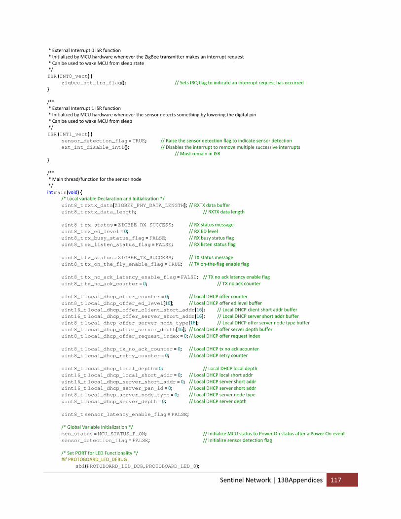
* External Interrupt 0 ISR function * Initialized by MCU hardware whenever the ZigBee transmitter makes an interrupt request * Can be used to wake MCU from sleep state */ ISR (INT0_vect) { zigbee_set_irq_flag(); // Sets IRQ flag to indicate an interrupt request has occurred } /** * External Interrupt 1 ISR function * Initialized by MCU hardware whenever the sensor detects something by lowering the digital pin * Can be used to wake MCU from sleep */ ISR (INT1_vect) { sensor_detection_flag = TRUE; // Raise the sensor detection flag to indicate sensor detection ext_int_disable_int1(); // Disables the interrupt to remove multiple successive interrupts // Must remain in ISR } /** * Main thread/function for the sensor node */ int main(void) { /* Local variable Declaration and Initialization */ uint8_t rxtx_data[ZIGBEE_PHY_DATA_LENGTH]; // RXTX data buffer uint8_t rxtx_data_length; // RXTX data length uint8_t rx_status = ZIGBEE_RX_SUCCESS; // RX status message uint8_t rx_ed_level = 0; // RX ED level uint8_t rx_busy_status_flag = FALSE; // RX busy status flag uint8_t rx_listen_status_flag = FALSE; // RX listen status flag uint8_t tx_status = ZIGBEE_TX_SUCCESS; // TX status message uint8_t tx_on_the_fly_enable_flag = TRUE; // TX on‐the‐flag enable flag uint8_t tx_no_ack_latency_enable_flag = FALSE; // TX no ack latency enable flag uint8_t tx_no_ack_counter = 0; // TX no ack counter uint8_t local_dhcp_offer_counter = 0; // Local DHCP offer counter uint8_t local_dhcp_offer_ed_level[16]; // Local DHCP offer ed level buffer uint16_t local_dhcp_offer_client_short_addr[16]; // Local DHCP client short addr buffer uint16_t local_dhcp_offer_server_short_addr[16]; // Local DHCP server short addr buffer uint8_t local_dhcp_offer_server_node_type[16]; // Local DHCP offer server node type buffer uint8_t local_dhcp_offer_server_depth[16]; // Local DHCP offer server depth buffer uint8_t local_dhcp_offer_request_index = 0; // Local DHCP offer request index uint8_t local_dhcp_tx_no_ack_counter = 0; // Local DHCP tx no ack acounter uint8_t local_dhcp_retry_counter = 0; // Local DHCP retry counter uint8_t local_dhcp_local_depth = 0; // Local DHCP local depth uint16_t local_dhcp_local_short_addr = 0; // Local DHCP local short addr uint16_t local_dhcp_server_short_addr = 0; // Local DHCP server short addr uint16_t local_dhcp_server_pan_id = 0; // Local DHCP server short addr uint8_t local_dhcp_server_node_type = 0; // Local DHCP server node type uint8_t local_dhcp_server_depth = 0; // Local DHCP server depth uint8_t sensor_latency_enable_flag = FALSE; /* Global Variable Initialization */ mcu_status = MCU_STATUS_P_ON; // Initialize MCU status to Power On status after a Power On event sensor_detection_flag = FALSE; // Initialize sensor detection flag /* Set PORT for LED Functionality */ #if PROTOBOARD_LED_DEBUG sbi(PROTOBOARD_LED_DDR, PROTOBOARD_LED_0);
Sentinel Network | 13BAppendices 117
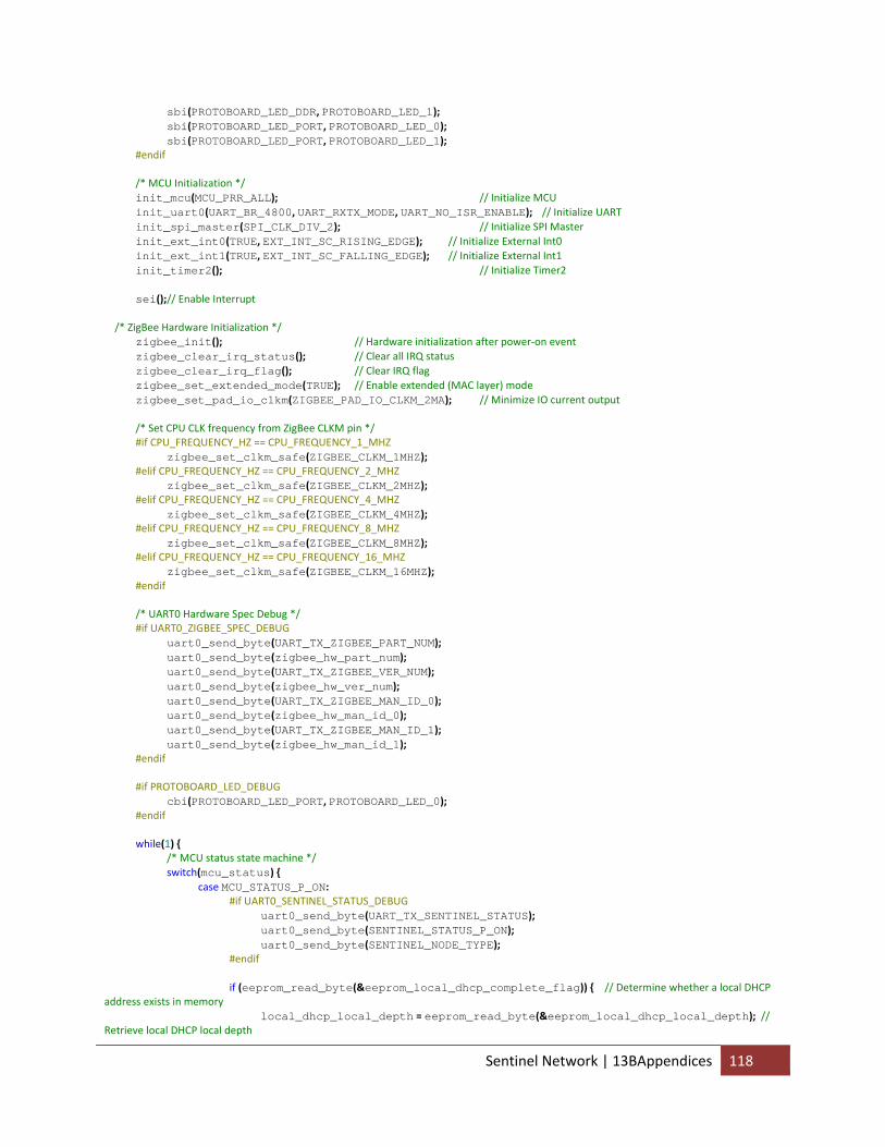
sbi(PROTOBOARD_LED_DDR, PROTOBOARD_LED_1); sbi(PROTOBOARD_LED_PORT, PROTOBOARD_LED_0); sbi(PROTOBOARD_LED_PORT, PROTOBOARD_LED_1); #endif /* MCU Initialization */ init_mcu(MCU_PRR_ALL); // Initialize MCU init_uart0(UART_BR_4800, UART_RXTX_MODE, UART_NO_ISR_ENABLE); // Initialize UART init_spi_master(SPI_CLK_DIV_2); // Initialize SPI Master init_ext_int0(TRUE, EXT_INT_SC_RISING_EDGE); // Initialize External Int0 init_ext_int1(TRUE, EXT_INT_SC_FALLING_EDGE); // Initialize External Int1 init_timer2(); // Initialize Timer2 sei();// Enable Interrupt /* ZigBee Hardware Initialization */ zigbee_init(); // Hardware initialization after power‐on event zigbee_clear_irq_status(); // Clear all IRQ status zigbee_clear_irq_flag(); // Clear IRQ flag zigbee_set_extended_mode(TRUE); // Enable extended (MAC layer) mode zigbee_set_pad_io_clkm(ZIGBEE_PAD_IO_CLKM_2MA); // Minimize IO current output /* Set CPU CLK frequency from ZigBee CLKM pin */ #if CPU_FREQUENCY_HZ == CPU_FREQUENCY_1_MHZ zigbee_set_clkm_safe(ZIGBEE_CLKM_1MHZ); #elif CPU_FREQUENCY_HZ == CPU_FREQUENCY_2_MHZ zigbee_set_clkm_safe(ZIGBEE_CLKM_2MHZ); #elif CPU_FREQUENCY_HZ == CPU_FREQUENCY_4_MHZ zigbee_set_clkm_safe(ZIGBEE_CLKM_4MHZ); #elif CPU_FREQUENCY_HZ == CPU_FREQUENCY_8_MHZ zigbee_set_clkm_safe(ZIGBEE_CLKM_8MHZ); #elif CPU_FREQUENCY_HZ == CPU_FREQUENCY_16_MHZ zigbee_set_clkm_safe(ZIGBEE_CLKM_16MHZ); #endif /* UART0 Hardware Spec Debug */ #if UART0_ZIGBEE_SPEC_DEBUG uart0_send_byte(UART_TX_ZIGBEE_PART_NUM); uart0_send_byte(zigbee_hw_part_num); uart0_send_byte(UART_TX_ZIGBEE_VER_NUM); uart0_send_byte(zigbee_hw_ver_num); uart0_send_byte(UART_TX_ZIGBEE_MAN_ID_0); uart0_send_byte(zigbee_hw_man_id_0); uart0_send_byte(UART_TX_ZIGBEE_MAN_ID_1); uart0_send_byte(zigbee_hw_man_id_1); #endif #if PROTOBOARD_LED_DEBUG cbi(PROTOBOARD_LED_PORT, PROTOBOARD_LED_0); #endif while(1) { /* MCU status state machine */ switch(mcu_status) { case MCU_STATUS_P_ON: #if UART0_SENTINEL_STATUS_DEBUG uart0_send_byte(UART_TX_SENTINEL_STATUS); uart0_send_byte(SENTINEL_STATUS_P_ON); uart0_send_byte(SENTINEL_NODE_TYPE); #endif if (eeprom_read_byte(&eeprom_local_dhcp_complete_flag)) { // Determine whether a local DHCP address exists in memory local_dhcp_local_depth = eeprom_read_byte(&eeprom_local_dhcp_local_depth); // Retrieve local DHCP local depth
Sentinel Network | 13BAppendices 118
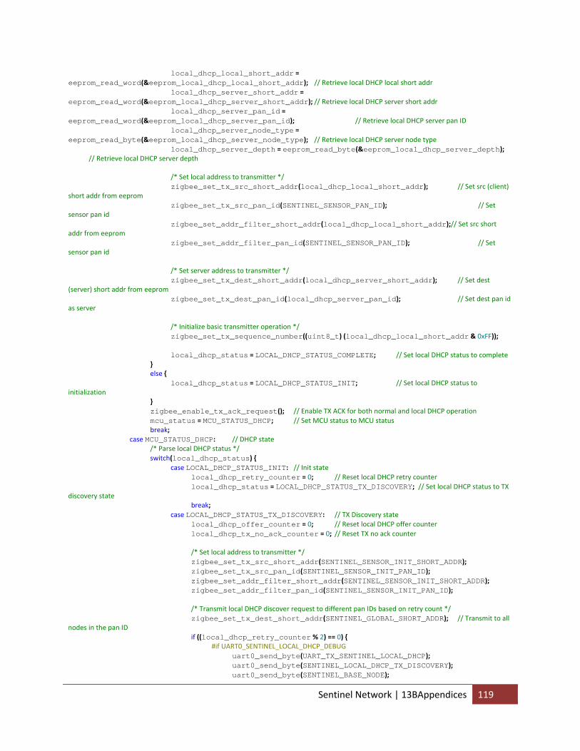
local_dhcp_local_short_addr = eeprom_read_word(&eeprom_local_dhcp_local_short_addr); // Retrieve local DHCP local short addr local_dhcp_server_short_addr = eeprom_read_word(&eeprom_local_dhcp_server_short_addr); // Retrieve local DHCP server short addr local_dhcp_server_pan_id = eeprom_read_word(&eeprom_local_dhcp_server_pan_id); // Retrieve local DHCP server pan ID local_dhcp_server_node_type = eeprom_read_byte(&eeprom_local_dhcp_server_node_type); // Retrieve local DHCP server node type local_dhcp_server_depth = eeprom_read_byte(&eeprom_local_dhcp_server_depth); // Retrieve local DHCP server depth /* Set local address to transmitter */ zigbee_set_tx_src_short_addr(local_dhcp_local_short_addr); // Set src (client) short addr from eeprom zigbee_set_tx_src_pan_id(SENTINEL_SENSOR_PAN_ID); // Set sensor pan id zigbee_set_addr_filter_short_addr(local_dhcp_local_short_addr);// Set src short addr from eeprom zigbee_set_addr_filter_pan_id(SENTINEL_SENSOR_PAN_ID); // Set sensor pan id /* Set server address to transmitter */ zigbee_set_tx_dest_short_addr(local_dhcp_server_short_addr); // Set dest (server) short addr from eeprom zigbee_set_tx_dest_pan_id(local_dhcp_server_pan_id); // Set dest pan id as server /* Initialize basic transmitter operation */ zigbee_set_tx_sequence_number((uint8_t) (local_dhcp_local_short_addr & 0xFF)); local_dhcp_status = LOCAL_DHCP_STATUS_COMPLETE; // Set local DHCP status to complete } else { local_dhcp_status = LOCAL_DHCP_STATUS_INIT; // Set local DHCP status to initialization } zigbee_enable_tx_ack_request(); // Enable TX ACK for both normal and local DHCP operation mcu_status = MCU_STATUS_DHCP; // Set MCU status to MCU status break; case MCU_STATUS_DHCP: // DHCP state /* Parse local DHCP status */ switch(local_dhcp_status) { case LOCAL_DHCP_STATUS_INIT: // Init state local_dhcp_retry_counter = 0; // Reset local DHCP retry counter local_dhcp_status = LOCAL_DHCP_STATUS_TX_DISCOVERY; // Set local DHCP status to TX discovery state break; case LOCAL_DHCP_STATUS_TX_DISCOVERY: // TX Discovery state local_dhcp_offer_counter = 0; // Reset local DHCP offer counter local_dhcp_tx_no_ack_counter = 0; // Reset TX no ack counter /* Set local address to transmitter */ zigbee_set_tx_src_short_addr(SENTINEL_SENSOR_INIT_SHORT_ADDR); zigbee_set_tx_src_pan_id(SENTINEL_SENSOR_INIT_PAN_ID); zigbee_set_addr_filter_short_addr(SENTINEL_SENSOR_INIT_SHORT_ADDR); zigbee_set_addr_filter_pan_id(SENTINEL_SENSOR_INIT_PAN_ID); /* Transmit local DHCP discover request to different pan IDs based on retry count */ zigbee_set_tx_dest_short_addr(SENTINEL_GLOBAL_SHORT_ADDR); // Transmit to all nodes in the pan ID if ((local_dhcp_retry_counter % 2) == 0) { #if UART0_SENTINEL_LOCAL_DHCP_DEBUG uart0_send_byte(UART_TX_SENTINEL_LOCAL_DHCP); uart0_send_byte(SENTINEL_LOCAL_DHCP_TX_DISCOVERY); uart0_send_byte(SENTINEL_BASE_NODE);
Sentinel Network | 13BAppendices 119
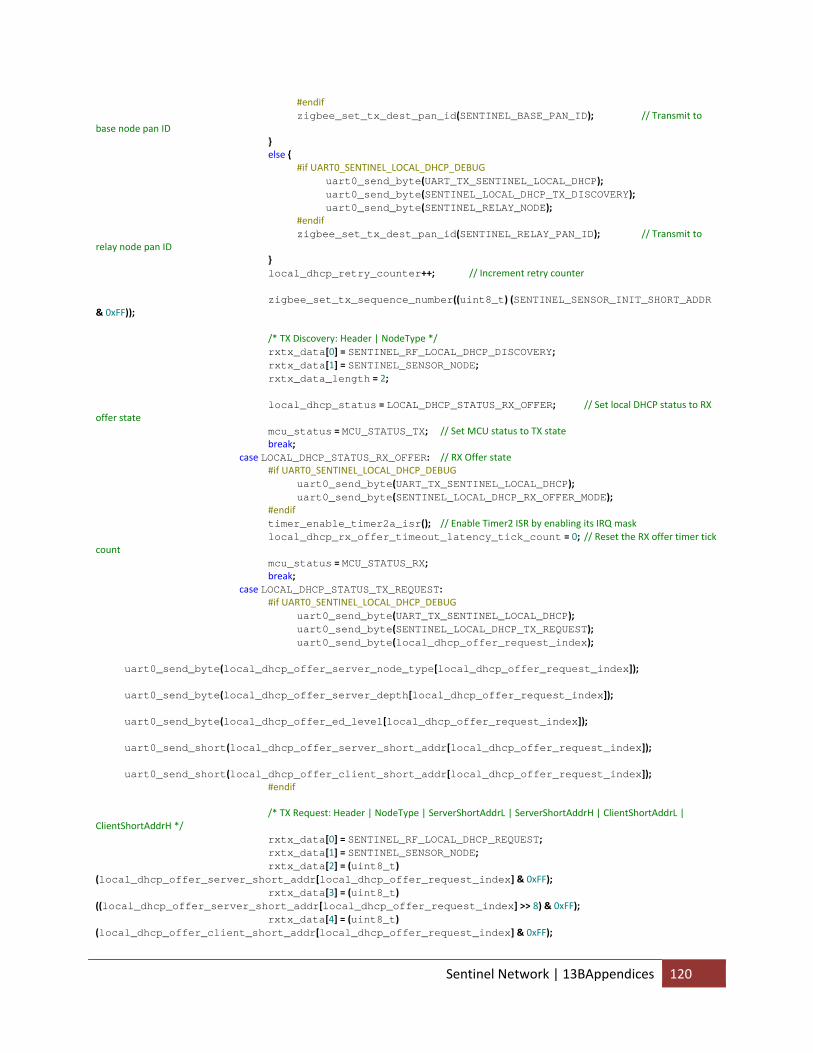
#endif zigbee_set_tx_dest_pan_id(SENTINEL_BASE_PAN_ID); // Transmit to base node pan ID } else { #if UART0_SENTINEL_LOCAL_DHCP_DEBUG uart0_send_byte(UART_TX_SENTINEL_LOCAL_DHCP); uart0_send_byte(SENTINEL_LOCAL_DHCP_TX_DISCOVERY); uart0_send_byte(SENTINEL_RELAY_NODE); #endif zigbee_set_tx_dest_pan_id(SENTINEL_RELAY_PAN_ID); // Transmit to relay node pan ID } local_dhcp_retry_counter++; // Increment retry counter zigbee_set_tx_sequence_number((uint8_t) (SENTINEL_SENSOR_INIT_SHORT_ADDR & 0xFF)); /* TX Discovery: Header | NodeType */ rxtx_data[0] = SENTINEL_RF_LOCAL_DHCP_DISCOVERY; rxtx_data[1] = SENTINEL_SENSOR_NODE; rxtx_data_length = 2; local_dhcp_status = LOCAL_DHCP_STATUS_RX_OFFER; // Set local DHCP status to RX offer state mcu_status = MCU_STATUS_TX; // Set MCU status to TX state break; case LOCAL_DHCP_STATUS_RX_OFFER: // RX Offer state #if UART0_SENTINEL_LOCAL_DHCP_DEBUG uart0_send_byte(UART_TX_SENTINEL_LOCAL_DHCP); uart0_send_byte(SENTINEL_LOCAL_DHCP_RX_OFFER_MODE); #endif timer_enable_timer2a_isr(); // Enable Timer2 ISR by enabling its IRQ mask local_dhcp_rx_offer_timeout_latency_tick_count = 0; // Reset the RX offer timer tick count mcu_status = MCU_STATUS_RX; break; case LOCAL_DHCP_STATUS_TX_REQUEST: #if UART0_SENTINEL_LOCAL_DHCP_DEBUG uart0_send_byte(UART_TX_SENTINEL_LOCAL_DHCP); uart0_send_byte(SENTINEL_LOCAL_DHCP_TX_REQUEST); uart0_send_byte(local_dhcp_offer_request_index); uart0_send_byte(local_dhcp_offer_server_node_type[local_dhcp_offer_request_index]); uart0_send_byte(local_dhcp_offer_server_depth[local_dhcp_offer_request_index]); uart0_send_byte(local_dhcp_offer_ed_level[local_dhcp_offer_request_index]); uart0_send_short(local_dhcp_offer_server_short_addr[local_dhcp_offer_request_index]); uart0_send_short(local_dhcp_offer_client_short_addr[local_dhcp_offer_request_index]); #endif /* TX Request: Header | NodeType | ServerShortAddrL | ServerShortAddrH | ClientShortAddrL | ClientShortAddrH */ rxtx_data[0] = SENTINEL_RF_LOCAL_DHCP_REQUEST; rxtx_data[1] = SENTINEL_SENSOR_NODE; rxtx_data[2] = (uint8_t) (local_dhcp_offer_server_short_addr[local_dhcp_offer_request_index] & 0xFF); rxtx_data[3] = (uint8_t) ((local_dhcp_offer_server_short_addr[local_dhcp_offer_request_index] >> 8) & 0xFF); rxtx_data[4] = (uint8_t) (local_dhcp_offer_client_short_addr[local_dhcp_offer_request_index] & 0xFF);
Sentinel Network | 13BAppendices 120
rxtx_data[5] = (uint8_t) ((local_dhcp_offer_client_short_addr[local_dhcp_offer_request_index] >> 8) & 0xFF); rxtx_data_length = 6; local_dhcp_status = LOCAL_DHCP_STATUS_RX_ACK; // Set local DHCP status to RX ack state mcu_status = MCU_STATUS_TX; // Set MCU status to TX state break; case LOCAL_DHCP_STATUS_RX_ACK: // RX ack state timer_enable_timer2a_isr(); // Enable Timer2 ISR by enabling its IRQ mask local_dhcp_rx_ack_timeout_latency_tick_count = 0; // Reset the RX ack timer tick count local_dhcp_status = LOCAL_DHCP_STATUS_CONFIG; // Set local DHCP status to config state mcu_status = MCU_STATUS_RX; // Set MCU status to RX state break; case LOCAL_DHCP_STATUS_CONFIG: // Config state #if UART0_SENTINEL_LOCAL_DHCP_DEBUG uart0_send_byte(UART_TX_SENTINEL_LOCAL_DHCP); uart0_send_byte(SENTINEL_LOCAL_DHCP_CONFIG); #endif /* Write completed local DHCP data to EEPROM */ eeprom_write_byte(&eeprom_local_dhcp_local_depth, local_dhcp_local_depth); eeprom_write_word(&eeprom_local_dhcp_local_short_addr, local_dhcp_local_short_addr); eeprom_write_word(&eeprom_local_dhcp_server_short_addr, local_dhcp_server_short_addr); eeprom_write_word(&eeprom_local_dhcp_server_pan_id, local_dhcp_server_pan_id); eeprom_write_byte(&eeprom_local_dhcp_server_node_type, local_dhcp_server_node_type); eeprom_write_byte(&eeprom_local_dhcp_server_depth, local_dhcp_server_depth); eeprom_write_byte(&eeprom_local_dhcp_complete_flag, TRUE); /* Set local address to transmitter */ zigbee_set_tx_src_short_addr(local_dhcp_local_short_addr); zigbee_set_tx_src_pan_id(SENTINEL_SENSOR_PAN_ID); zigbee_set_addr_filter_short_addr(local_dhcp_local_short_addr); zigbee_set_addr_filter_pan_id(SENTINEL_SENSOR_PAN_ID); /* Set server address to transmitter */ zigbee_set_tx_dest_short_addr(local_dhcp_server_short_addr); zigbee_set_tx_dest_pan_id(local_dhcp_server_pan_id); /* Set basic transmitter operation */ zigbee_set_tx_sequence_number((uint8_t) (local_dhcp_local_short_addr & 0xFF)); local_dhcp_status = LOCAL_DHCP_STATUS_COMPLETE; // Set local DHCP status to complete state break; case LOCAL_DHCP_STATUS_COMPLETE: // // Complete state #if UART0_SENTINEL_LOCAL_DHCP_DEBUG uart0_send_byte(UART_TX_SENTINEL_LOCAL_DHCP); uart0_send_byte(SENTINEL_LOCAL_DHCP_COMPLETE); uart0_send_byte(local_dhcp_local_depth); uart0_send_short(local_dhcp_local_short_addr); uart0_send_short(SENTINEL_SENSOR_PAN_ID); uart0_send_short(local_dhcp_server_short_addr); uart0_send_short(local_dhcp_server_pan_id); #endif mcu_status = MCU_STATUS_IDLE; // Set MCU status to idle state
Sentinel Network | 13BAppendices 121
break; } break; case MCU_STATUS_IDLE: // Idle state #if UART0_SENTINEL_STATUS_DEBUG uart0_send_byte(UART_TX_SENTINEL_STATUS); uart0_send_byte(SENTINEL_STATUS_IDLE); #endif if (local_dhcp_status == LOCAL_DHCP_STATUS_COMPLETE) { mcu_status = MCU_STATUS_SLEEP; // Set MCU status to Sleep state if local DHCP is completed } else { mcu_status = MCU_STATUS_DHCP; // Set MCU status to DHCP state if local DHCP is still incomplete } break; case MCU_STATUS_SLEEP: // Sleep state /* Determine whether the sensor latency functionality is currently enabled */ if (sensor_latency_enable_flag) { timer_enable_timer2a_isr(); // Enable Timer2 ISR through enabling the IRQ mask set_sleep_mode(SLEEP_MODE_PWR_SAVE); // Enable MCU Power Save sleep state } else { ext_int_enable_int1(); // Enable sensor detection ISR trhough enabling the IRQ mask set_sleep_mode(SLEEP_MODE_PWR_DOWN); // Enable MCU Power Down sleep state } sleep_mode(); // Enter sleep mode /* Wait until an interrupt request occurs from either Timer2, Sensor Detection, or Transmitter */ /* Determine whether a sensor detection flag has been raised */ if (sensor_detection_flag) { sensor_detection_flag = FALSE; // Clear sensor detection flag /* Sensor Detection: Header | LocalShortAddrL | Local ShortAddrH */ rxtx_data[0] = SENTINEL_RF_SENSOR_DETECTION; rxtx_data[1] = (uint8_t) (local_dhcp_local_short_addr & 0xFF); rxtx_data[2] = (uint8_t) ((local_dhcp_local_short_addr >> 8) & 0xFF); rxtx_data_length = 3; /* Set server as destination addr and pan id for transmitter */ zigbee_set_tx_dest_short_addr(local_dhcp_server_short_addr); zigbee_set_tx_dest_pan_id(local_dhcp_server_pan_id); tx_on_the_fly_enable_flag = TRUE; // Enable the on‐the‐fly TX flag sensor_latency_enable_flag = TRUE; // Enable sensor latency enable flag sensor_latency_tick_count = 0; // Reset the sensor timer tick count mcu_status = MCU_STATUS_TX; // Set the MCU status to the TX state } /* Wait until sensor latency has exceeded latency threshold before re‐enabling sensor detection */ if (sensor_latency_tick_count > SENSOR_LATENCY_THRESHOLD) { sensor_latency_enable_flag = FALSE; // Clear sensor latency enable flag timer_disable_timer2a_isr(); // Disable Timer2 ISR by disabling the IRQ mask ext_int_enable_int1(); // Enable Sensor Detection ISR by enabling the IRQ mask } /* Determine whether an interrupt service request has been received from the transmitter */ //if (zigbee_get_irq_flag()) { // sensor_latency_enable_flag = FALSE; // timer_disable_timer2a_isr(); // // mcu_status = MCU_STATUS_RX; //}
Sentinel Network | 13BAppendices 122
break; case MCU_STATUS_TX_IDLE: // TX idle state /* Parse TX status */ switch (tx_status) { case ZIGBEE_TX_SUCCESS: /* Determine whether local DHCP has been completed */ if (local_dhcp_status == LOCAL_DHCP_STATUS_COMPLETE) { tx_no_ack_counter = 0; // Clear TX no ack counter mcu_status = MCU_STATUS_IDLE; // Set MCU status to Idle state } else { local_dhcp_tx_no_ack_counter = 0; // Clear local DHCP tx no ack counter mcu_status = MCU_STATUS_DHCP; // Set MCU status to DHCP state } break; case ZIGBEE_TX_INVALID_ARGUMENT: // TX error due to invalid argument rxtx_data_length‐‐; // Reduce data length to correct for invalid argument error mcu_status = MCU_STATUS_TX; // Set MCU status to TX state to retry transmission break; case ZIGBEE_TX_BUFFER_UNDERRUN: // TX error due to buffer underrun tx_on_the_fly_enable_flag = FALSE; // Disable on‐the‐fly transmission mode mcu_status = MCU_STATUS_TX; // Set MCU status to TX state to retry transmission break; case ZIGBEE_TX_CHANNEL_ACCESS_FAILURE: // TX error due to channel access failure mcu_status = MCU_STATUS_TX; // Set MCU status to TX state to retry transmission break; case ZIGBEE_TX_NO_ACK: // TX error due to no ack /* Determine whether transmission no ack latency functionality has been enabled */ if (tx_no_ack_latency_enable_flag) { tx_no_ack_latency_enable_flag = FALSE; // Clear tx no ack latency enable flag tx_no_ack_latency_tick_count = 0; // Reset tx no ack latency tick count local_dhcp_tx_no_ack_counter++; // Increment local DHCP tx no ack counter tx_no_ack_counter++; // Increment tx no ack counter timer_enable_timer2a_isr(); // Enable Timer2 ISR by enable IRQ mask set_sleep_mode(SLEEP_MODE_PWR_SAVE); // Enable Power Save sleep mode } sleep_mode(); // Enter Sleep mode /* Determine the course of action and latency before retransmission after no ack for normal operation */ if (local_dhcp_status == LOCAL_DHCP_STATUS_COMPLETE) { /* Determine whether tx no ack counter has exceeded threshold during normal operation */ if (tx_no_ack_counter > TX_NO_ACK_MAX_COUNT) { /* Wait for an extended delay before retrying transmission */ if (tx_no_ack_latency_tick_count > TX_NO_ACK_EXTENDED_LATENCY_THRESHOLD) { tx_no_ack_counter = 0; // Clear TX no ack counter timer_disable_timer2a_isr(); // Disable Timer2 ISR through IRQ mask mcu_status = MCU_STATUS_TX; // Set MCU status to TX state } } else { /* Wait for a normal delay before retrying transmission */ if (tx_no_ack_latency_tick_count > TX_NO_ACK_LATENCY_THRESHOLD) { timer_disable_timer2a_isr(); // Disable Timer2 ISR through IRQ mask mcu_status = MCU_STATUS_TX; // Set MCU status to TX state } } } /* Determine the course of action and latency before retransmission after no ack for local DHCP operation by tx no ack counter*/ else if (local_dhcp_tx_no_ack_counter > LOCAL_DHCP_TX_NO_ACK_MAX_COUNT) { /* Determine whether the number of local DHCP retries has exceeded the threshold */
Sentinel Network | 13BAppendices 123
if (local_dhcp_retry_counter > LOCAL_DHCP_RETRY_MAX_COUNT) { /* Wait for a reset delay before retrying local DHCP */ if (tx_no_ack_latency_tick_count > LOCAL_DHCP_RESET_LATENCY_THRESHOLD) { timer_disable_timer2a_isr(); // Disable Timer2 ISR through IRQ mask sentinel_reset_local_dhcp(); // Reset local DHCP } } else { /* Wait for a retry delay before retrying local DHCP */ if (tx_no_ack_latency_tick_count > LOCAL_DHCP_RETRY_LATENCY_THRESHOLD) { timer_disable_timer2a_isr(); // Disable Timer2 ISR through IRQ mask sentinel_retry_local_dhcp(); // Retry local DHCP } } } else { /* Wait for a normal delay before retrying transmission */ if (tx_no_ack_latency_tick_count > LOCAL_DHCP_TX_NO_ACK_LATENCY_THRESHOLD) { timer_disable_timer2a_isr(); // Disable Timer2 ISR through IRQ mask mcu_status = MCU_STATUS_TX; // Set MCU status to TX state } } break; case ZIGBEE_TX_INVALID: // TX error due to unknown error zigbee_sw_rst(); // Perform software reset to transmitter mcu_status = MCU_STATUS_TX; // Set MCU status to TX state to retry transmission break; } break; case MCU_STATUS_TX: // TX state /* Parse transmitter status */ switch(zigbee_get_trx_status()) { case ZIGBEE_TRX_STATUS_TX_ARET_ON: // Extended TX ready state zigbee_inc_tx_sequence_number(); // Increment TX frame sequence number tx_status = zigbee_extended_tx(rxtx_data, rxtx_data_length, tx_on_the_fly_enable_flag); // Transmit data zigbee_enable_trx_off(); // Set transmitter to TRX off state after waiting for TX of data and RX of ack #if UART0_SENTINEL_STATUS_DEBUG uart0_send_byte(UART_TX_SENTINEL_STATUS); uart0_send_byte(SENTINEL_STATUS_TRX_OFF); #endif tx_no_ack_latency_enable_flag = TRUE; // Enable tx no latency enable flag in case of no ack mcu_status = MCU_STATUS_TX_IDLE; // Set MCU status to TX Idle state break; case ZIGBEE_TRX_STATUS_BUSY_TX_ARET: // Extended TX busy state break; default: // All other states #if UART0_SENTINEL_STATUS_DEBUG uart0_send_byte(UART_TX_SENTINEL_STATUS); uart0_send_byte(SENTINEL_STATUS_TX); uart0_send_byte(rxtx_data_length); uart0_send_byte_array(rxtx_data, rxtx_data_length); uart0_send_short(zigbee_get_tx_dest_short_addr()); uart0_send_short(zigbee_get_tx_dest_pan_id()); #endif zigbee_enable_extended_tx(); // Set transmitter to extended TX ready state break; } break; case MCU_STATUS_RX_IDLE: // RX Idle state
Sentinel Network | 13BAppendices 124
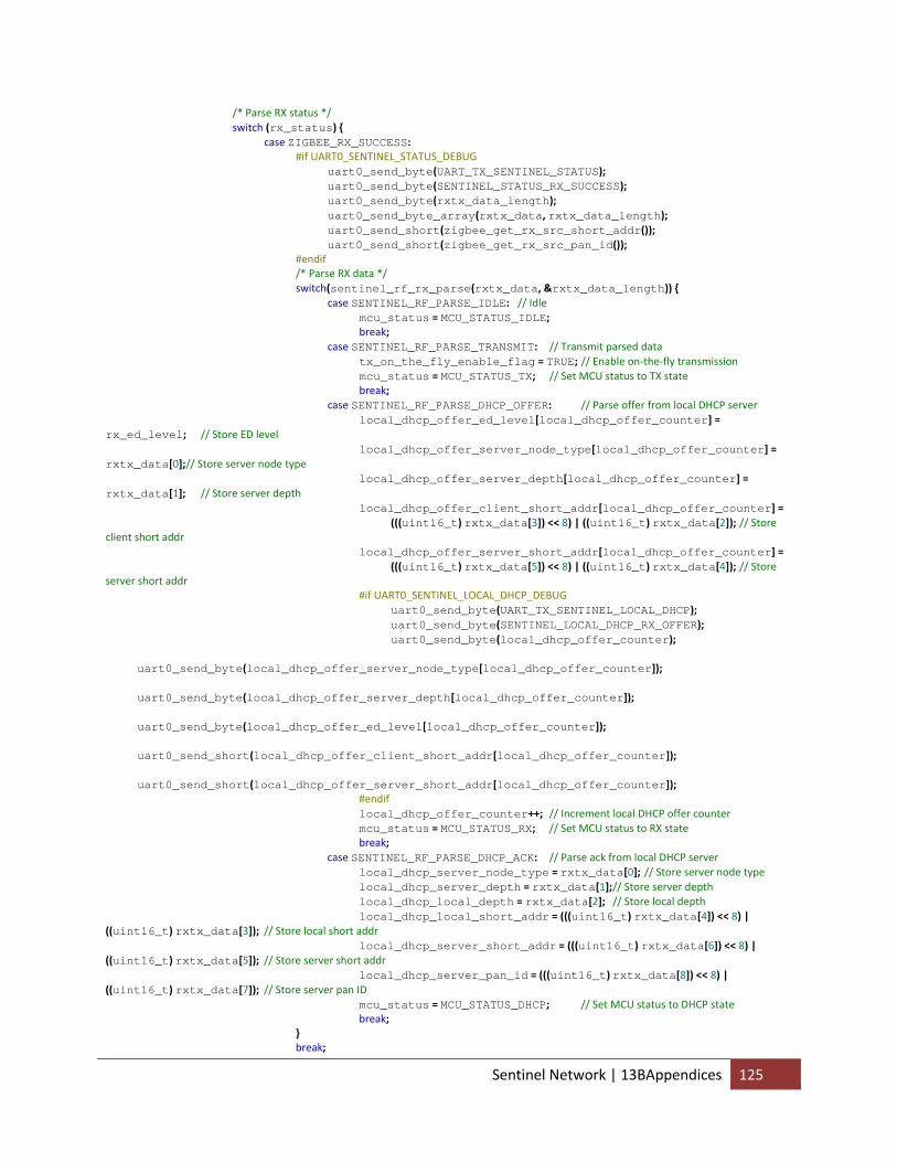
/* Parse RX status */ switch (rx_status) { case ZIGBEE_RX_SUCCESS: #if UART0_SENTINEL_STATUS_DEBUG uart0_send_byte(UART_TX_SENTINEL_STATUS); uart0_send_byte(SENTINEL_STATUS_RX_SUCCESS); uart0_send_byte(rxtx_data_length); uart0_send_byte_array(rxtx_data, rxtx_data_length); uart0_send_short(zigbee_get_rx_src_short_addr()); uart0_send_short(zigbee_get_rx_src_pan_id()); #endif /* Parse RX data */ switch(sentinel_rf_rx_parse(rxtx_data, &rxtx_data_length)) { case SENTINEL_RF_PARSE_IDLE: // Idle mcu_status = MCU_STATUS_IDLE; break; case SENTINEL_RF_PARSE_TRANSMIT: // Transmit parsed data tx_on_the_fly_enable_flag = TRUE; // Enable on‐the‐fly transmission mcu_status = MCU_STATUS_TX; // Set MCU status to TX state break; case SENTINEL_RF_PARSE_DHCP_OFFER: // Parse offer from local DHCP server local_dhcp_offer_ed_level[local_dhcp_offer_counter] = rx_ed_level; // Store ED level local_dhcp_offer_server_node_type[local_dhcp_offer_counter] = rxtx_data[0];// Store server node type local_dhcp_offer_server_depth[local_dhcp_offer_counter] = rxtx_data[1]; // Store server depth local_dhcp_offer_client_short_addr[local_dhcp_offer_counter] = (((uint16_t) rxtx_data[3]) << 8) | ((uint16_t) rxtx_data[2]); // Store client short addr local_dhcp_offer_server_short_addr[local_dhcp_offer_counter] = (((uint16_t) rxtx_data[5]) << 8) | ((uint16_t) rxtx_data[4]); // Store server short addr #if UART0_SENTINEL_LOCAL_DHCP_DEBUG uart0_send_byte(UART_TX_SENTINEL_LOCAL_DHCP); uart0_send_byte(SENTINEL_LOCAL_DHCP_RX_OFFER); uart0_send_byte(local_dhcp_offer_counter); uart0_send_byte(local_dhcp_offer_server_node_type[local_dhcp_offer_counter]); uart0_send_byte(local_dhcp_offer_server_depth[local_dhcp_offer_counter]); uart0_send_byte(local_dhcp_offer_ed_level[local_dhcp_offer_counter]); uart0_send_short(local_dhcp_offer_client_short_addr[local_dhcp_offer_counter]); uart0_send_short(local_dhcp_offer_server_short_addr[local_dhcp_offer_counter]); #endif local_dhcp_offer_counter++; // Increment local DHCP offer counter mcu_status = MCU_STATUS_RX; // Set MCU status to RX state break; case SENTINEL_RF_PARSE_DHCP_ACK: // Parse ack from local DHCP server local_dhcp_server_node_type = rxtx_data[0]; // Store server node type local_dhcp_server_depth = rxtx_data[1]; // Store server depth local_dhcp_local_depth = rxtx_data[2]; // Store local depth local_dhcp_local_short_addr = (((uint16_t) rxtx_data[4]) << 8) | ((uint16_t) rxtx_data[3]); // Store local short addr local_dhcp_server_short_addr = (((uint16_t) rxtx_data[6]) << 8) | ((uint16_t) rxtx_data[5]); // Store server short addr local_dhcp_server_pan_id = (((uint16_t) rxtx_data[8]) << 8) | ((uint16_t) rxtx_data[7]); // Store server pan ID mcu_status = MCU_STATUS_DHCP; // Set MCU status to DHCP state break; } break;
Sentinel Network | 13BAppendices 125
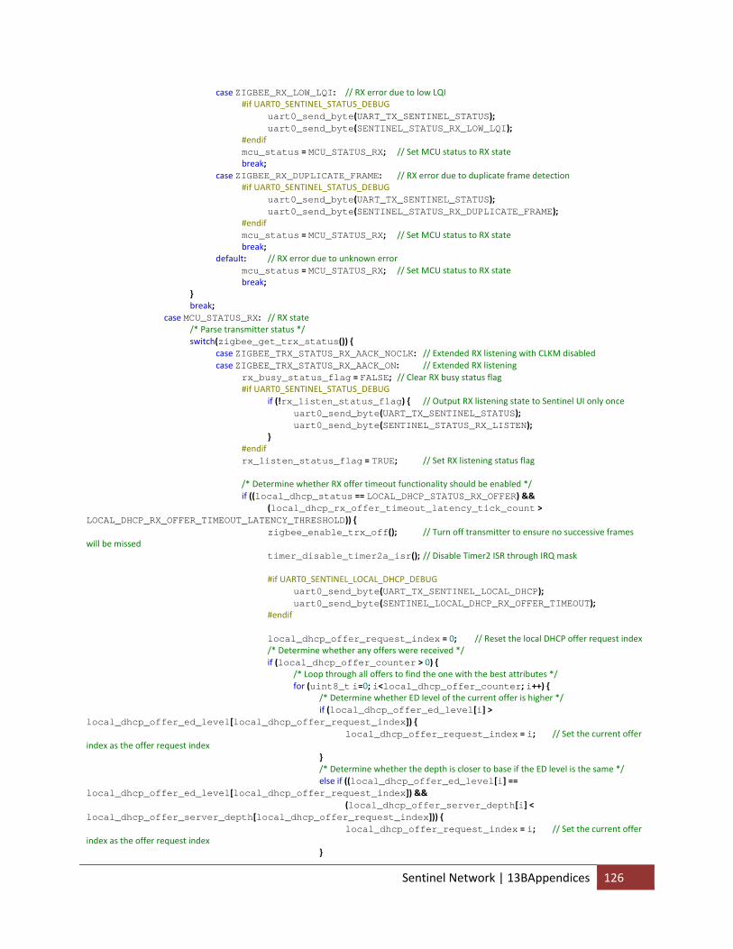
case ZIGBEE_RX_LOW_LQI: // RX error due to low LQI #if UART0_SENTINEL_STATUS_DEBUG uart0_send_byte(UART_TX_SENTINEL_STATUS); uart0_send_byte(SENTINEL_STATUS_RX_LOW_LQI); #endif mcu_status = MCU_STATUS_RX; // Set MCU status to RX state break; case ZIGBEE_RX_DUPLICATE_FRAME: // RX error due to duplicate frame detection #if UART0_SENTINEL_STATUS_DEBUG uart0_send_byte(UART_TX_SENTINEL_STATUS); uart0_send_byte(SENTINEL_STATUS_RX_DUPLICATE_FRAME); #endif mcu_status = MCU_STATUS_RX; // Set MCU status to RX state break; default: // RX error due to unknown error mcu_status = MCU_STATUS_RX; // Set MCU status to RX state break; } break; case MCU_STATUS_RX: // RX state /* Parse transmitter status */ switch(zigbee_get_trx_status()) { case ZIGBEE_TRX_STATUS_RX_AACK_NOCLK: // Extended RX listening with CLKM disabled case ZIGBEE_TRX_STATUS_RX_AACK_ON: // Extended RX listening rx_busy_status_flag = FALSE; // Clear RX busy status flag #if UART0_SENTINEL_STATUS_DEBUG if (!rx_listen_status_flag) { // Output RX listening state to Sentinel UI only once uart0_send_byte(UART_TX_SENTINEL_STATUS); uart0_send_byte(SENTINEL_STATUS_RX_LISTEN); } #endif rx_listen_status_flag = TRUE; // Set RX listening status flag /* Determine whether RX offer timeout functionality should be enabled */ if ((local_dhcp_status == LOCAL_DHCP_STATUS_RX_OFFER) && (local_dhcp_rx_offer_timeout_latency_tick_count > LOCAL_DHCP_RX_OFFER_TIMEOUT_LATENCY_THRESHOLD)) { zigbee_enable_trx_off(); // Turn off transmitter to ensure no successive frames will be missed timer_disable_timer2a_isr(); // Disable Timer2 ISR through IRQ mask #if UART0_SENTINEL_LOCAL_DHCP_DEBUG uart0_send_byte(UART_TX_SENTINEL_LOCAL_DHCP); uart0_send_byte(SENTINEL_LOCAL_DHCP_RX_OFFER_TIMEOUT); #endif local_dhcp_offer_request_index = 0; // Reset the local DHCP offer request index /* Determine whether any offers were received */ if (local_dhcp_offer_counter > 0) { /* Loop through all offers to find the one with the best attributes */ for (uint8_t i=0; i<local_dhcp_offer_counter; i++) { /* Determine whether ED level of the current offer is higher */ if (local_dhcp_offer_ed_level[i] > local_dhcp_offer_ed_level[local_dhcp_offer_request_index]) { local_dhcp_offer_request_index = i; // Set the current offer index as the offer request index } /* Determine whether the depth is closer to base if the ED level is the same */ else if ((local_dhcp_offer_ed_level[i] == local_dhcp_offer_ed_level[local_dhcp_offer_request_index]) && (local_dhcp_offer_server_depth[i] < local_dhcp_offer_server_depth[local_dhcp_offer_request_index])) { local_dhcp_offer_request_index = i; // Set the current offer index as the offer request index }
Sentinel Network | 13BAppendices 126
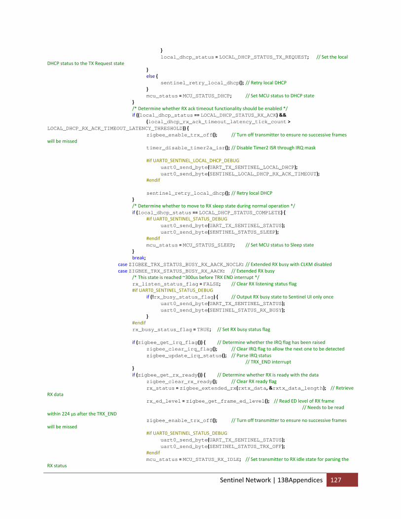
} local_dhcp_status = LOCAL_DHCP_STATUS_TX_REQUEST; // Set the local DHCP status to the TX Request state } else { sentinel_retry_local_dhcp(); // Retry local DHCP } mcu_status = MCU_STATUS_DHCP; // Set MCU status to DHCP state } /* Determine whether RX ack timeout functionality should be enabled */ if ((local_dhcp_status == LOCAL_DHCP_STATUS_RX_ACK) && (local_dhcp_rx_ack_timeout_latency_tick_count > LOCAL_DHCP_RX_ACK_TIMEOUT_LATENCY_THRESHOLD)) { zigbee_enable_trx_off(); // Turn off transmitter to ensure no successive frames will be missed timer_disable_timer2a_isr(); // Disable Timer2 ISR through IRQ mask #if UART0_SENTINEL_LOCAL_DHCP_DEBUG uart0_send_byte(UART_TX_SENTINEL_LOCAL_DHCP); uart0_send_byte(SENTINEL_LOCAL_DHCP_RX_ACK_TIMEOUT); #endif sentinel_retry_local_dhcp(); // Retry local DHCP } /* Determine whether to move to RX sleep state during normal operation */ if (local_dhcp_status == LOCAL_DHCP_STATUS_COMPLETE) { #if UART0_SENTINEL_STATUS_DEBUG uart0_send_byte(UART_TX_SENTINEL_STATUS); uart0_send_byte(SENTINEL_STATUS_SLEEP); #endif mcu_status = MCU_STATUS_SLEEP; // Set MCU status to Sleep state } break; case ZIGBEE_TRX_STATUS_BUSY_RX_AACK_NOCLK: // Extended RX busy with CLKM disabled case ZIGBEE_TRX_STATUS_BUSY_RX_AACK: // Extended RX busy /* This state is reached ~300us before TRX END interrupt */ rx_listen_status_flag = FALSE; // Clear RX listening status flag #if UART0_SENTINEL_STATUS_DEBUG if (!rx_busy_status_flag) { // Output RX busy state to Sentinel UI only once uart0_send_byte(UART_TX_SENTINEL_STATUS); uart0_send_byte(SENTINEL_STATUS_RX_BUSY); } #endif rx_busy_status_flag = TRUE; // Set RX busy status flag if (zigbee_get_irq_flag()) { // Determine whether the IRQ flag has been raised zigbee_clear_irq_flag(); // Clear IRQ flag to allow the next one to be detected zigbee_update_irq_status(); // Parse IRQ status // TRX_END interrupt } if (zigbee_get_rx_ready()) { // Determine whether RX is ready with the data zigbee_clear_rx_ready(); // Clear RX ready flag rx_status = zigbee_extended_rx(rxtx_data, &rxtx_data_length); // Retrieve RX data rx_ed_level = zigbee_get_frame_ed_level(); // Read ED level of RX frame // Needs to be read within 224 µs after the TRX_END zigbee_enable_trx_off(); // Turn off transmitter to ensure no successive frames will be missed #if UART0_SENTINEL_STATUS_DEBUG uart0_send_byte(UART_TX_SENTINEL_STATUS); uart0_send_byte(SENTINEL_STATUS_TRX_OFF); #endif mcu_status = MCU_STATUS_RX_IDLE; // Set transmitter to RX idle state for parsing the RX status
Sentinel Network | 13BAppendices 127
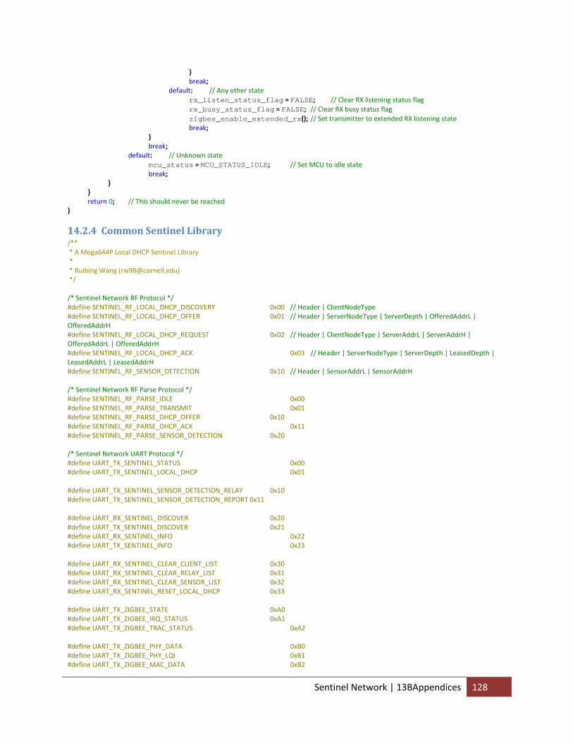
} break; default: // Any other state rx_listen_status_flag = FALSE; // Clear RX listening status flag rx_busy_status_flag = FALSE; // Clear RX busy status flag zigbee_enable_extended_rx(); // Set transmitter to extended RX listening state break; } break; default: // Unknown state mcu_status = MCU_STATUS_IDLE; // Set MCU to idle state break; } } return 0; // This should never be reached }
14.2.4 Common Sentinel Library /** * A Mega644P Local DHCP Sentinel Library * * Ruibing Wang ([email protected]) */ /* Sentinel Network RF Protocol */ #define SENTINEL_RF_LOCAL_DHCP_DISCOVERY 0x00 // Header | ClientNodeType #define SENTINEL_RF_LOCAL_DHCP_OFFER 0x01 // Header | ServerNodeType | ServerDepth | OfferedAddrL | OfferedAddrH #define SENTINEL_RF_LOCAL_DHCP_REQUEST 0x02 // Header | ClientNodeType | ServerAddrL | ServerAddrH | OfferedAddrL | OfferedAddrH #define SENTINEL_RF_LOCAL_DHCP_ACK 0x03 // Header | ServerNodeType | ServerDepth | LeasedDepth | LeasedAddrL | LeasedAddrH #define SENTINEL_RF_SENSOR_DETECTION 0x10 // Header | SensorAddrL | SensorAddrH /* Sentinel Network RF Parse Protocol */ #define SENTINEL_RF_PARSE_IDLE 0x00 #define SENTINEL_RF_PARSE_TRANSMIT 0x01 #define SENTINEL_RF_PARSE_DHCP_OFFER 0x10 #define SENTINEL_RF_PARSE_DHCP_ACK 0x11 #define SENTINEL_RF_PARSE_SENSOR_DETECTION 0x20 /* Sentinel Network UART Protocol */ #define UART_TX_SENTINEL_STATUS 0x00 #define UART_TX_SENTINEL_LOCAL_DHCP 0x01 #define UART_TX_SENTINEL_SENSOR_DETECTION_RELAY 0x10 #define UART_TX_SENTINEL_SENSOR_DETECTION_REPORT 0x11 #define UART_RX_SENTINEL_DISCOVER 0x20 #define UART_TX_SENTINEL_DISCOVER 0x21 #define UART_RX_SENTINEL_INFO 0x22 #define UART_TX_SENTINEL_INFO 0x23 #define UART_RX_SENTINEL_CLEAR_CLIENT_LIST 0x30 #define UART_RX_SENTINEL_CLEAR_RELAY_LIST 0x31 #define UART_RX_SENTINEL_CLEAR_SENSOR_LIST 0x32 #define UART_RX_SENTINEL_RESET_LOCAL_DHCP 0x33 #define UART_TX_ZIGBEE_STATE 0xA0 #define UART_TX_ZIGBEE_IRQ_STATUS 0xA1 #define UART_TX_ZIGBEE_TRAC_STATUS 0xA2 #define UART_TX_ZIGBEE_PHY_DATA 0xB0 #define UART_TX_ZIGBEE_PHY_LQI 0xB1 #define UART_TX_ZIGBEE_MAC_DATA 0xB2
Sentinel Network | 13BAppendices 128
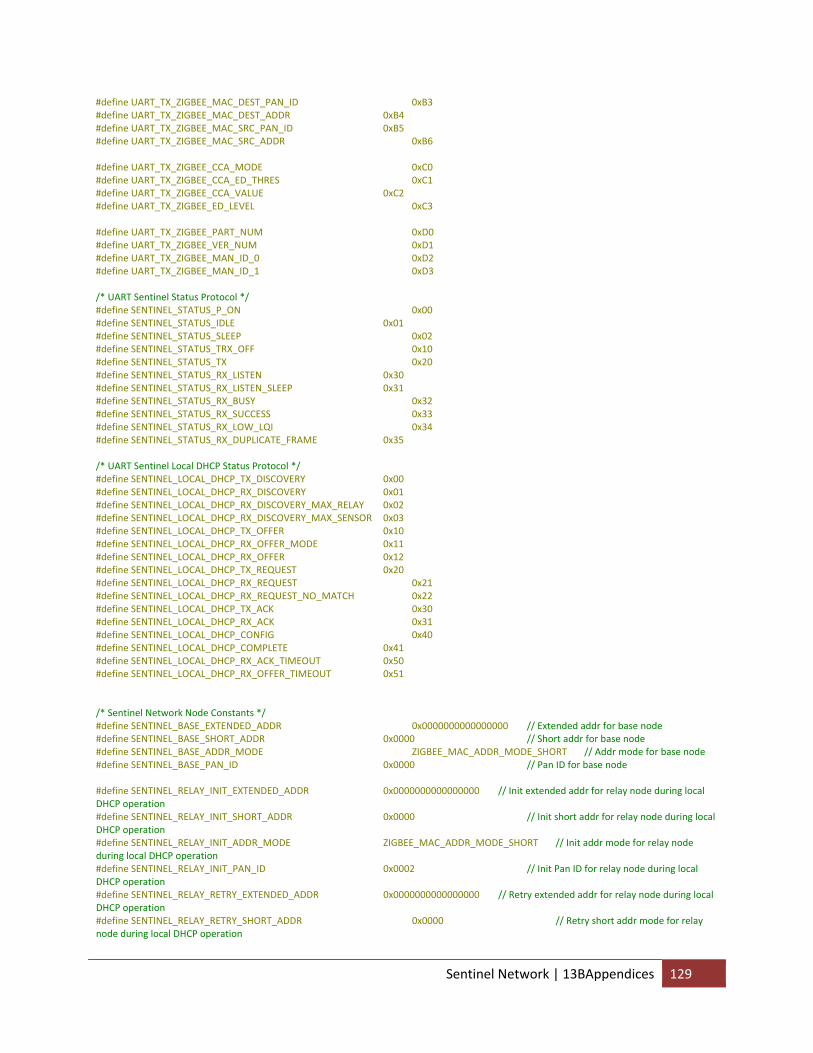
#define UART_TX_ZIGBEE_MAC_DEST_PAN_ID 0xB3 #define UART_TX_ZIGBEE_MAC_DEST_ADDR 0xB4 #define UART_TX_ZIGBEE_MAC_SRC_PAN_ID 0xB5 #define UART_TX_ZIGBEE_MAC_SRC_ADDR 0xB6 #define UART_TX_ZIGBEE_CCA_MODE 0xC0 #define UART_TX_ZIGBEE_CCA_ED_THRES 0xC1 #define UART_TX_ZIGBEE_CCA_VALUE 0xC2 #define UART_TX_ZIGBEE_ED_LEVEL 0xC3 #define UART_TX_ZIGBEE_PART_NUM 0xD0 #define UART_TX_ZIGBEE_VER_NUM 0xD1 #define UART_TX_ZIGBEE_MAN_ID_0 0xD2 #define UART_TX_ZIGBEE_MAN_ID_1 0xD3 /* UART Sentinel Status Protocol */ #define SENTINEL_STATUS_P_ON 0x00 #define SENTINEL_STATUS_IDLE 0x01 #define SENTINEL_STATUS_SLEEP 0x02 #define SENTINEL_STATUS_TRX_OFF 0x10 #define SENTINEL_STATUS_TX 0x20 #define SENTINEL_STATUS_RX_LISTEN 0x30 #define SENTINEL_STATUS_RX_LISTEN_SLEEP 0x31 #define SENTINEL_STATUS_RX_BUSY 0x32 #define SENTINEL_STATUS_RX_SUCCESS 0x33 #define SENTINEL_STATUS_RX_LOW_LQI 0x34 #define SENTINEL_STATUS_RX_DUPLICATE_FRAME 0x35 /* UART Sentinel Local DHCP Status Protocol */ #define SENTINEL_LOCAL_DHCP_TX_DISCOVERY 0x00 #define SENTINEL_LOCAL_DHCP_RX_DISCOVERY 0x01 #define SENTINEL_LOCAL_DHCP_RX_DISCOVERY_MAX_RELAY 0x02 #define SENTINEL_LOCAL_DHCP_RX_DISCOVERY_MAX_SENSOR 0x03 #define SENTINEL_LOCAL_DHCP_TX_OFFER 0x10 #define SENTINEL_LOCAL_DHCP_RX_OFFER_MODE 0x11 #define SENTINEL_LOCAL_DHCP_RX_OFFER 0x12 #define SENTINEL_LOCAL_DHCP_TX_REQUEST 0x20 #define SENTINEL_LOCAL_DHCP_RX_REQUEST 0x21 #define SENTINEL_LOCAL_DHCP_RX_REQUEST_NO_MATCH 0x22 #define SENTINEL_LOCAL_DHCP_TX_ACK 0x30 #define SENTINEL_LOCAL_DHCP_RX_ACK 0x31 #define SENTINEL_LOCAL_DHCP_CONFIG 0x40 #define SENTINEL_LOCAL_DHCP_COMPLETE 0x41 #define SENTINEL_LOCAL_DHCP_RX_ACK_TIMEOUT 0x50 #define SENTINEL_LOCAL_DHCP_RX_OFFER_TIMEOUT 0x51 /* Sentinel Network Node Constants */ #define SENTINEL_BASE_EXTENDED_ADDR 0x0000000000000000 // Extended addr for base node #define SENTINEL_BASE_SHORT_ADDR 0x0000 // Short addr for base node #define SENTINEL_BASE_ADDR_MODE ZIGBEE_MAC_ADDR_MODE_SHORT // Addr mode for base node #define SENTINEL_BASE_PAN_ID 0x0000 // Pan ID for base node #define SENTINEL_RELAY_INIT_EXTENDED_ADDR 0x0000000000000000 // Init extended addr for relay node during local DHCP operation #define SENTINEL_RELAY_INIT_SHORT_ADDR 0x0000 // Init short addr for relay node during local DHCP operation #define SENTINEL_RELAY_INIT_ADDR_MODE ZIGBEE_MAC_ADDR_MODE_SHORT // Init addr mode for relay node during local DHCP operation #define SENTINEL_RELAY_INIT_PAN_ID 0x0002 // Init Pan ID for relay node during local DHCP operation #define SENTINEL_RELAY_RETRY_EXTENDED_ADDR 0x0000000000000000 // Retry extended addr for relay node during local DHCP operation #define SENTINEL_RELAY_RETRY_SHORT_ADDR 0x0000 // Retry short addr mode for relay node during local DHCP operation
Sentinel Network | 13BAppendices 129
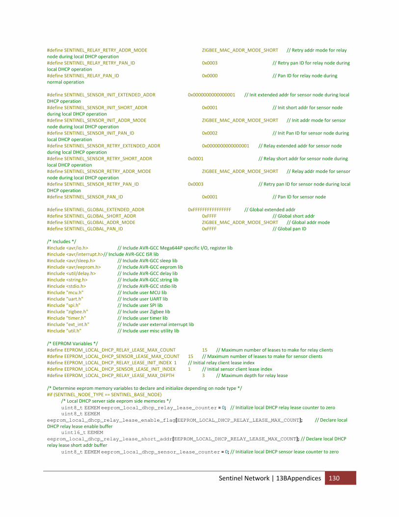
#define SENTINEL_RELAY_RETRY_ADDR_MODE ZIGBEE_MAC_ADDR_MODE_SHORT // Retry addr mode for relay node during local DHCP operation #define SENTINEL_RELAY_RETRY_PAN_ID 0x0003 // Retry pan ID for relay node during local DHCP operation #define SENTINEL_RELAY_PAN_ID 0x0000 // Pan ID for relay node during normal operation #define SENTINEL_SENSOR_INIT_EXTENDED_ADDR 0x0000000000000001 // Init extended addr for sensor node during local DHCP operation #define SENTINEL_SENSOR_INIT_SHORT_ADDR 0x0001 // Init short addr for sensor node during local DHCP operation #define SENTINEL_SENSOR_INIT_ADDR_MODE ZIGBEE_MAC_ADDR_MODE_SHORT // Init addr mode for sensor node during local DHCP operation #define SENTINEL_SENSOR_INIT_PAN_ID 0x0002 // Init Pan ID for sensor node during local DHCP operation #define SENTINEL_SENSOR_RETRY_EXTENDED_ADDR 0x0000000000000001 // Relay extended addr for sensor node during local DHCP operation #define SENTINEL_SENSOR_RETRY_SHORT_ADDR 0x0001 // Relay short addr for sensor node during local DHCP operation #define SENTINEL_SENSOR_RETRY_ADDR_MODE ZIGBEE_MAC_ADDR_MODE_SHORT // Relay addr mode for sensor node during local DHCP operation #define SENTINEL_SENSOR_RETRY_PAN_ID 0x0003 // Retry pan ID for sensor node during local DHCP operation #define SENTINEL_SENSOR_PAN_ID 0x0001 // Pan ID for sensor node #define SENTINEL_GLOBAL_EXTENDED_ADDR 0xFFFFFFFFFFFFFFFF // Global extended addr #define SENTINEL_GLOBAL_SHORT_ADDR 0xFFFF // Global short addr #define SENTINEL_GLOBAL_ADDR_MODE ZIGBEE_MAC_ADDR_MODE_SHORT // Global addr mode #define SENTINEL_GLOBAL_PAN_ID 0xFFFF // Global pan ID /* Includes */ #include <avr/io.h> // Include AVR‐GCC Mega644P specific I/O, register lib #include <avr/interrupt.h> // Include AVR‐GCC ISR lib #include <avr/sleep.h> // Include AVR‐GCC sleep lib #include <avr/eeprom.h> // Include AVR‐GCC eeprom lib #include <util/delay.h> // Include AVR‐GCC delay lib #include <string.h> // Include AVR‐GCC string lib #include <stdio.h> // Include AVR‐GCC stdio lib #include "mcu.h" // Include user MCU lib #include "uart.h" // Include user UART lib #include "spi.h" // Include user SPI lib #include "zigbee.h" // Include user Zigbee lib #include "timer.h" // Include user timer lib #include "ext_int.h" // Include user external interrupt lib #include "util.h" // Include user misc utility lib /* EEPROM Variables */ #define EEPROM_LOCAL_DHCP_RELAY_LEASE_MAX_COUNT 15 // Maximum number of leases to make for relay clients #define EEPROM_LOCAL_DHCP_SENSOR_LEASE_MAX_COUNT 15 // Maximum number of leases to make for sensor clients #define EEPROM_LOCAL_DHCP_RELAY_LEASE_INIT_INDEX 1 // Initial relay client lease index #define EEPROM_LOCAL_DHCP_SENSOR_LEASE_INIT_INDEX 1 // Initial sensor client lease index #define EEPROM_LOCAL_DHCP_RELAY_LEASE_MAX_DEPTH 3 // Maximum depth for relay lease /* Determine eeprom memory variables to declare and initialize depending on node type */ #if (SENTINEL_NODE_TYPE == SENTINEL_BASE_NODE) /* Local DHCP server side eeprom side memories */ uint8_t EEMEM eeprom_local_dhcp_relay_lease_counter = 0; // Initialize local DHCP relay lease counter to zero uint8_t EEMEM eeprom_local_dhcp_relay_lease_enable_flag[EEPROM_LOCAL_DHCP_RELAY_LEASE_MAX_COUNT]; // Declare local DHCP relay lease enable buffer uint16_t EEMEM eeprom_local_dhcp_relay_lease_short_addr[EEPROM_LOCAL_DHCP_RELAY_LEASE_MAX_COUNT]; // Declare local DHCP relay lease short addr buffer uint8_t EEMEM eeprom_local_dhcp_sensor_lease_counter = 0; // Initialize local DHCP sensor lease counter to zero
Sentinel Network | 13BAppendices 130
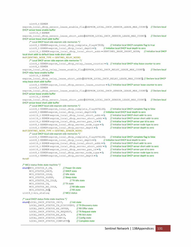
uint8_t EEMEM eeprom_local_dhcp_sensor_lease_enable_flag[EEPROM_LOCAL_DHCP_SENSOR_LEASE_MAX_COUNT]; // Declare local DHCP sensor lease enable buffer uint16_t EEMEM eeprom_local_dhcp_sensor_lease_short_addr[EEPROM_LOCAL_DHCP_SENSOR_LEASE_MAX_COUNT]; // Declare local DHCP sensor lease short addr buffer /* Local DHCP local side eeprom side memories */ uint8_t EEMEM eeprom_local_dhcp_complete_flag = TRUE; // Initialize local DHCP complete flag to true uint8_t EEMEM eeprom_local_dhcp_local_depth = 0; // Initialize local DHCP local depth to zero uint16_t EEMEM eeprom_local_dhcp_local_short_addr = SENTINEL_BASE_SHORT_ADDR; // Initialize local DHCP local short addr to default base node short addr #elif (SENTINEL_NODE_TYPE == SENTINEL_RELAY_NODE) /* Local DHCP server side eeprom side memories */ uint8_t EEMEM eeprom_local_dhcp_relay_lease_counter = 0; // Initialize local DHCP relay lease counter to zero uint8_t EEMEM eeprom_local_dhcp_relay_lease_enable_flag[EEPROM_LOCAL_DHCP_RELAY_LEASE_MAX_COUNT]; // Declare local DHCP relay lease enable buffer uint16_t EEMEM eeprom_local_dhcp_relay_lease_short_addr[EEPROM_LOCAL_DHCP_RELAY_LEASE_MAX_COUNT]; // Declare local DHCP relay lease short addr buffer uint8_t EEMEM eeprom_local_dhcp_sensor_lease_counter = 0; // Initialize local DHCP sensor lease counter to zero uint8_t EEMEM eeprom_local_dhcp_sensor_lease_enable_flag[EEPROM_LOCAL_DHCP_SENSOR_LEASE_MAX_COUNT]; // Declare local DHCP sensor lease enable buffer uint16_t EEMEM eeprom_local_dhcp_sensor_lease_short_addr[EEPROM_LOCAL_DHCP_SENSOR_LEASE_MAX_COUNT]; // Declare local DHCP sensor lease short addr buffer /* Local DHCP local side eeprom side memories */ uint8_t EEMEM eeprom_local_dhcp_complete_flag = FALSE; // Initialize local DHCP complete flag to false uint8_t EEMEM eeprom_local_dhcp_local_depth = 0; // Initialize local DHCP local depth to zero uint16_t EEMEM eeprom_local_dhcp_local_short_addr = 0; // Initialize local DHCP short addr to zero uint16_t EEMEM eeprom_local_dhcp_server_short_addr = 0; // Initialize local DHCP server short addr to zero uint16_t EEMEM eeprom_local_dhcp_server_pan_id = 0; // Initialize local DHCP server pan id to zero uint8_t EEMEM eeprom_local_dhcp_server_node_type = 0; // Initialize local DHCP server node type to zero uint8_t EEMEM eeprom_local_dhcp_server_depth = 0; // Initialize local DHCP server depth to zero #elif (SENTINEL_NODE_TYPE == SENTINEL_SENSOR_NODE) /* Local DHCP local side eeprom side memories */ uint8_t EEMEM eeprom_local_dhcp_complete_flag = FALSE; // Initialize local DHCP complete flag to false uint8_t EEMEM eeprom_local_dhcp_local_depth = 0; // Initialize local DHCP local depth to zero uint16_t EEMEM eeprom_local_dhcp_local_short_addr = 0; // Initialize local DHCP short addr to zero uint16_t EEMEM eeprom_local_dhcp_server_short_addr = 0; // Initialize local DHCP server short addr to zero uint16_t EEMEM eeprom_local_dhcp_server_pan_id = 0; // Initialize local DHCP server pan id to zero uint8_t EEMEM eeprom_local_dhcp_server_node_type = 0; // Initialize local DHCP server node type to zero uint8_t EEMEM eeprom_local_dhcp_server_depth = 0; // Initialize local DHCP server depth to zero #endif /* MCU status finite state machine */ enum{MCU_STATUS_P_ON, // Power On state MCU_STATUS_DHCP, // DHCP state MCU_STATUS_IDLE, // Idle state MCU_STATUS_SLEEP, // Sleep state MCU_STATUS_TX_IDLE, // TX Idle state MCU_STATUS_TX, // TX state MCU_STATUS_RX_IDLE, // RX Idle state MCU_STATUS_RX}; // RX state uint8_t mcu_status; // MCU status /* Local DHCP status finite state machine */ enum{LOCAL_DHCP_STATUS_INIT, // Init state LOCAL_DHCP_STATUS_TX_DISCOVERY, // TX Discovery state LOCAL_DHCP_STATUS_RX_OFFER, // RX Offer state LOCAL_DHCP_STATUS_TX_REQUEST, // TX Request state LOCAL_DHCP_STATUS_RX_ACK, // RX Ack state LOCAL_DHCP_STATUS_CONFIG, // Config state LOCAL_DHCP_STATUS_COMPLETE}; // Complete state
Sentinel Network | 13BAppendices 131
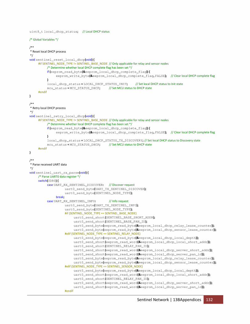
uint8_t local_dhcp_status; // Local DHCP status /* Global Variables */ /** * Reset local DHCP process */ void sentinel_reset_local_dhcp(void) { #if SENTINEL_NODE_TYPE != SENTINEL_BASE_NODE // Only applicable for relay and sensor nodes /* Determine whether local DHCP complete flag has been set */ if (eeprom_read_byte(&eeprom_local_dhcp_complete_flag)) { eeprom_write_byte(&eeprom_local_dhcp_complete_flag, FALSE); // Clear local DHCP complete flag } local_dhcp_status = LOCAL_DHCP_STATUS_INIT; // Set local DHCP status to Init state mcu_status = MCU_STATUS_DHCP; // Set MCU status to DHCP state #endif } /** * Retry local DHCP process */ void sentinel_retry_local_dhcp(void) { #if SENTINEL_NODE_TYPE != SENTINEL_BASE_NODE // Only applicable for relay and sensor nodes /* Determine whether local DHCP complete flag has been set */ if (eeprom_read_byte(&eeprom_local_dhcp_complete_flag)) { eeprom_write_byte(&eeprom_local_dhcp_complete_flag, FALSE); // Clear local DHCP complete flag } local_dhcp_status = LOCAL_DHCP_STATUS_TX_DISCOVERY; // Set local DHCP status to Discovery state mcu_status = MCU_STATUS_DHCP; // Set MCU status to DHCP state #endif } /** * Parse received UART data */ void sentinel_uart_rx_parse(void) { /* Parse UART0 data register */ switch(UDR0) { case UART_RX_SENTINEL_DISCOVER: // Discover request uart0_send_byte(UART_TX_SENTINEL_DISCOVER); uart0_send_byte(SENTINEL_NODE_TYPE); break; case UART_RX_SENTINEL_INFO: // Info request uart0_send_byte(UART_TX_SENTINEL_INFO); uart0_send_byte(SENTINEL_NODE_TYPE); #if (SENTINEL_NODE_TYPE == SENTINEL_BASE_NODE) uart0_send_short(SENTINEL_BASE_SHORT_ADDR); uart0_send_short(SENTINEL_BASE_PAN_ID); uart0_send_byte(eeprom_read_byte(&eeprom_local_dhcp_relay_lease_counter)); uart0_send_byte(eeprom_read_byte(&eeprom_local_dhcp_sensor_lease_counter)); #elif (SENTINEL_NODE_TYPE == SENTINEL_RELAY_NODE) uart0_send_byte(eeprom_read_byte(&eeprom_local_dhcp_local_depth)); uart0_send_short(eeprom_read_word(&eeprom_local_dhcp_local_short_addr)); uart0_send_short(SENTINEL_RELAY_PAN_ID); uart0_send_short(eeprom_read_word(&eeprom_local_dhcp_server_short_addr)); uart0_send_short(eeprom_read_word(&eeprom_local_dhcp_server_pan_id)); uart0_send_byte(eeprom_read_byte(&eeprom_local_dhcp_relay_lease_counter)); uart0_send_byte(eeprom_read_byte(&eeprom_local_dhcp_sensor_lease_counter)); #elif (SENTINEL_NODE_TYPE == SENTINEL_SENSOR_NODE) uart0_send_byte(eeprom_read_byte(&eeprom_local_dhcp_local_depth)); uart0_send_short(eeprom_read_word(&eeprom_local_dhcp_local_short_addr)); uart0_send_short(SENTINEL_RELAY_PAN_ID); uart0_send_short(eeprom_read_word(&eeprom_local_dhcp_server_short_addr)); uart0_send_short(eeprom_read_word(&eeprom_local_dhcp_server_pan_id)); #endif
Sentinel Network | 13BAppendices 132
break; case UART_RX_SENTINEL_CLEAR_CLIENT_LIST: // Clear all client list request #if ((SENTINEL_NODE_TYPE == SENTINEL_RELAY_NODE) || (SENTINEL_NODE_TYPE == SENTINEL_BASE_NODE)) // Applicable to only the relay and base node eeprom_write_byte(&eeprom_local_dhcp_relay_lease_counter, 0); // Clear relay lease counter eeprom_write_byte(&eeprom_local_dhcp_sensor_lease_counter, 0); // Clear sensor lease counter /* Loop through the relay lease pool to clear all enabled leases */ for (uint8_t i=0; i<EEPROM_LOCAL_DHCP_RELAY_LEASE_MAX_COUNT; i++) { /* Determine whether the current index in the relay lease pool is enabled */ if (eeprom_read_byte(&eeprom_local_dhcp_relay_lease_enable_flag[i])) { eeprom_write_byte(&eeprom_local_dhcp_relay_lease_enable_flag[i], FALSE); // Clear the relay lease enable flag } } /* Loop through the sensor lease pool to clear all enabled leases */ for (uint8_t i=0; i<EEPROM_LOCAL_DHCP_SENSOR_LEASE_MAX_COUNT; i++) { /* Determine whether the current index in the sensor lease pool is enabled */ if (eeprom_read_byte(&eeprom_local_dhcp_sensor_lease_enable_flag[i])) { eeprom_write_byte(&eeprom_local_dhcp_sensor_lease_enable_flag[i], FALSE); // Clear the sensor lease enable flag } } #endif break; case UART_RX_SENTINEL_CLEAR_RELAY_LIST: // Clear relay client list request #if ((SENTINEL_NODE_TYPE == SENTINEL_RELAY_NODE) || (SENTINEL_NODE_TYPE == SENTINEL_BASE_NODE)) // Applicable to only the relay and base node eeprom_write_byte(&eeprom_local_dhcp_relay_lease_counter, 0); // Clear relay lease counter /* Loop through the relay lease pool to clear all enabled leases */ for (uint8_t i=0; i<EEPROM_LOCAL_DHCP_RELAY_LEASE_MAX_COUNT; i++) { /* Determine whether the current index in the relay lease pool is enabled */ if (eeprom_read_byte(&eeprom_local_dhcp_relay_lease_enable_flag[i])) { eeprom_write_byte(&eeprom_local_dhcp_relay_lease_enable_flag[i], FALSE); // Clear the relay lease enable flag } } #endif break; case UART_RX_SENTINEL_CLEAR_SENSOR_LIST: // Clear sensor client list request #if ((SENTINEL_NODE_TYPE == SENTINEL_RELAY_NODE) || (SENTINEL_NODE_TYPE == SENTINEL_BASE_NODE)) // Application to only the relay and base node eeprom_write_byte(&eeprom_local_dhcp_sensor_lease_counter, 0); /* Loop through the sensor lease pool to clear all enabled leases */ for (uint8_t i=0; i<EEPROM_LOCAL_DHCP_RELAY_LEASE_MAX_COUNT; i++) { /* Determine whether the current index in the sensor lease pool is enabled */ if (eeprom_read_byte(&eeprom_local_dhcp_sensor_lease_enable_flag[i])) { eeprom_write_byte(&eeprom_local_dhcp_sensor_lease_enable_flag[i], FALSE); // Clear the sensor lease enable flag } } #endif break; case UART_RX_SENTINEL_RESET_LOCAL_DHCP: // Reset local DHCP process #if ((SENTINEL_NODE_TYPE == SENTINEL_SENSOR_NODE) || (SENTINEL_NODE_TYPE == SENTINEL_RELAY_NODE)) // Applicable to only the sensor and relay node sentinel_reset_local_dhcp(); // Reset the local DHCP variables #endif break; } } /** * Parse received RF data */
Sentinel Network | 13BAppendices 133
uint8_t sentinel_rf_rx_parse(uint8_t *rxtx_data, uint8_t *rxtx_data_length) { /* Initialize local variables for local DHCP */ uint16_t local_dhcp_offered_short_addr = 0; // Local DHCP offered short addr uint8_t local_dhcp_server_depth = 0; // Local DHCP server depth uint8_t local_dhcp_server_node_type = 0; // Local DHCP server node type uint16_t local_dhcp_server_short_addr = 0; // Local DHCP server short addr uint16_t local_dhcp_server_pan_id = 0; // Local DHCP server pan ID uint8_t local_dhcp_leased_depth = 0; // Local DHCP leased depth uint16_t local_dhcp_leased_short_addr = 0; // Local DHCP leased short addr /* Parse header information */ switch(rxtx_data[0]) { #if (SENTINEL_NODE_TYPE != SENTINEL_SENSOR_NODE) case SENTINEL_RF_LOCAL_DHCP_DISCOVERY: // Discovery request from client #if UART0_SENTINEL_LOCAL_DHCP_DEBUG uart0_send_byte(UART_TX_SENTINEL_LOCAL_DHCP); uart0_send_byte(SENTINEL_LOCAL_DHCP_RX_DISCOVERY); uart0_send_byte(rxtx_data[1]); #endif /* Parse the client node type */ switch (rxtx_data[1]) { case SENTINEL_SENSOR_NODE: // Sensor client /* Determine whether the sensor lease counter has already exceeded threshold */ if (eeprom_read_byte(&eeprom_local_dhcp_sensor_lease_counter) == EEPROM_LOCAL_DHCP_SENSOR_LEASE_MAX_COUNT) { #if UART0_SENTINEL_LOCAL_DHCP_DEBUG uart0_send_byte(UART_TX_SENTINEL_LOCAL_DHCP); uart0_send_byte(SENTINEL_LOCAL_DHCP_RX_DISCOVERY_MAX_SENSOR); #endif return SENTINEL_RF_PARSE_IDLE; // Set RX status message to Idle } else { /* Loop through the sensor lease pool to find an available slot */ for (uint8_t i=0; i<EEPROM_LOCAL_DHCP_SENSOR_LEASE_MAX_COUNT; i++) { /* Determine whether the sensor lease slot is available at the current index */ if (!eeprom_read_byte(&eeprom_local_dhcp_sensor_lease_enable_flag[i])) { local_dhcp_offered_short_addr = (eeprom_read_word(&eeprom_local_dhcp_local_short_addr) << 4) | (uint16_t) (i + EEPROM_LOCAL_DHCP_SENSOR_LEASE_INIT_INDEX);// Generate offered short addr from the local short addr and available slot index i = EEPROM_LOCAL_DHCP_SENSOR_LEASE_MAX_COUNT; // End loop } } } break; case SENTINEL_RELAY_NODE: // Relay client /* Determine whether the relay lease counter has already exceeded threshold and the relay lease depth does not exceed threshold */ if ((eeprom_read_byte(&eeprom_local_dhcp_relay_lease_counter) == EEPROM_LOCAL_DHCP_RELAY_LEASE_MAX_COUNT) || (eeprom_read_byte(&eeprom_local_dhcp_local_depth) == EEPROM_LOCAL_DHCP_RELAY_LEASE_MAX_DEPTH)) { #if UART0_SENTINEL_LOCAL_DHCP_DEBUG uart0_send_byte(UART_TX_SENTINEL_LOCAL_DHCP); uart0_send_byte(SENTINEL_LOCAL_DHCP_RX_DISCOVERY_MAX_RELAY); #endif return SENTINEL_RF_PARSE_IDLE; // Set RX status message to Idle } else { /* Loop through the relay lease pool to find an available slot */ for (uint8_t i=0; i<EEPROM_LOCAL_DHCP_RELAY_LEASE_MAX_COUNT; i++) { /* Determine whether the relay lease slot is available at the current index */ if (!eeprom_read_byte(&eeprom_local_dhcp_relay_lease_enable_flag[i])) {
Sentinel Network | 13BAppendices 134
local_dhcp_offered_short_addr = (eeprom_read_word(&eeprom_local_dhcp_local_short_addr) << 4) | (uint16_t) (i + EEPROM_LOCAL_DHCP_RELAY_LEASE_INIT_INDEX); // Generate offered short addr from the local short addr and available slot index i = EEPROM_LOCAL_DHCP_RELAY_LEASE_MAX_COUNT; // End loop } } } break; } local_dhcp_server_depth = eeprom_read_byte(&eeprom_local_dhcp_local_depth); // Retrieve local depth /* TX Offer: Header | NodeType | ServerDepth | OfferedShortAddrL | OfferedShortAddrH */ rxtx_data[0] = SENTINEL_RF_LOCAL_DHCP_OFFER; rxtx_data[1] = SENTINEL_NODE_TYPE; rxtx_data[2] = local_dhcp_server_depth; rxtx_data[3] = (uint8_t) (local_dhcp_offered_short_addr & 0xFF); rxtx_data[4] = (uint8_t) ((local_dhcp_offered_short_addr >> 8) & 0xFF); *rxtx_data_length = 5; /* Set destination addr and pan ID */ zigbee_set_tx_dest_pan_id(zigbee_get_rx_src_pan_id()); // Set received src pan ID as the transmitter dest pan ID zigbee_set_tx_dest_short_addr(zigbee_get_rx_src_short_addr()); // Set received src short addr as the transmitter dest short addr #if UART0_SENTINEL_LOCAL_DHCP_DEBUG uart0_send_byte(UART_TX_SENTINEL_LOCAL_DHCP); uart0_send_byte(SENTINEL_LOCAL_DHCP_TX_OFFER); uart0_send_short(local_dhcp_offered_short_addr); #endif return SENTINEL_RF_PARSE_TRANSMIT; // Set RX status message to Transmit break; #endif case SENTINEL_RF_LOCAL_DHCP_OFFER: // Offer received from server local_dhcp_server_node_type = rxtx_data[1]; // Retrieve server node type local_dhcp_server_depth = rxtx_data[2]; // Retrieve server depth local_dhcp_offered_short_addr = (((uint16_t) rxtx_data[4]) << 8) | ((uint16_t) rxtx_data[3]); // Retrieve offered short addr local_dhcp_server_short_addr = zigbee_get_rx_src_short_addr(); // Retrieve server short addr /* Parse Offer : ServerNodeType | ServerDepth | OfferedShortAddrL | OfferedShortAddrH | ServerShortAddrL | ServerShortAddrH */ rxtx_data[0] = local_dhcp_server_node_type; rxtx_data[1] = local_dhcp_server_depth; rxtx_data[2] = (uint8_t) (local_dhcp_offered_short_addr & 0xFF); rxtx_data[3] = (uint8_t) ((local_dhcp_offered_short_addr >> 8) & 0xFF); rxtx_data[4] = (uint8_t) (local_dhcp_server_short_addr & 0xFF); rxtx_data[5] = (uint8_t) ((local_dhcp_server_short_addr >> 8) & 0xFF); *rxtx_data_length = 6; return SENTINEL_RF_PARSE_DHCP_OFFER; // Set RX status message to DHCP Offer break; #if SENTINEL_NODE_TYPE != SENTINEL_SENSOR_NODE case SENTINEL_RF_LOCAL_DHCP_REQUEST: // Request request from client local_dhcp_server_node_type = rxtx_data[1]; // Retrieve server node type local_dhcp_server_short_addr = (((uint16_t) rxtx_data[3]) << 8) | ((uint16_t) rxtx_data[2]); // Retrieve server short addr local_dhcp_offered_short_addr = (((uint16_t) rxtx_data[5]) << 8) | ((uint16_t) rxtx_data[4]); // Retrieve offered short addr #if UART0_SENTINEL_LOCAL_DHCP_DEBUG uart0_send_byte(UART_TX_SENTINEL_LOCAL_DHCP); uart0_send_byte(SENTINEL_LOCAL_DHCP_RX_REQUEST); uart0_send_short(local_dhcp_server_short_addr); #endif
Sentinel Network | 13BAppendices 135
/* Determine whether whether the designated server short addr matches own local short addr */ if (local_dhcp_server_short_addr == eeprom_read_word(&eeprom_local_dhcp_local_short_addr)) { uint8_t local_dhcp_offered_index; // Local DHCP offered lease slot /* Parse client node type */ switch (rxtx_data[1]) { case SENTINEL_SENSOR_NODE: // Sensor client local_dhcp_offered_index = (uint8_t) (local_dhcp_offered_short_addr & 0x0F) ‐ (uint8_t) EEPROM_LOCAL_DHCP_SENSOR_LEASE_INIT_INDEX; // Retrieve sensor lease slot of the offered addr eeprom_write_byte(&eeprom_local_dhcp_sensor_lease_counter, eeprom_read_byte(&eeprom_local_dhcp_sensor_lease_counter)+1); // Increment sensor lease counter eeprom_write_word(&eeprom_local_dhcp_sensor_lease_short_addr[local_dhcp_offered_index], local_dhcp_offered_short_addr); // Store offered short addr to sensor lease pool eeprom_write_byte(&eeprom_local_dhcp_sensor_lease_enable_flag[local_dhcp_offered_index], TRUE); // Store sensor lease pool slot as true break; case SENTINEL_RELAY_NODE: // Relay client local_dhcp_offered_index = (uint8_t) (local_dhcp_offered_short_addr & 0x0F) ‐ (uint8_t) EEPROM_LOCAL_DHCP_RELAY_LEASE_INIT_INDEX; // Retrieve sensor lease slot of the offered addr eeprom_write_byte(&eeprom_local_dhcp_relay_lease_counter, eeprom_read_byte(&eeprom_local_dhcp_relay_lease_counter)+1); // Increment sensor lease counter eeprom_write_word(&eeprom_local_dhcp_relay_lease_short_addr[local_dhcp_offered_index], local_dhcp_offered_short_addr); // Store relay short addr to sensor lease pool eeprom_write_byte(&eeprom_local_dhcp_relay_lease_enable_flag[local_dhcp_offered_index], TRUE); // Store relay lease pool slot as true break; } local_dhcp_leased_short_addr = local_dhcp_offered_short_addr; // Retrieve leased short addr from offered short addr local_dhcp_server_depth = eeprom_read_byte(&eeprom_local_dhcp_local_depth); // Retrieve server depth local_dhcp_leased_depth = local_dhcp_server_depth + 1; // Retrieve leased depth /* TX Ack: Header | NodeType | ServerDepth | LeasedDepth | LeasedShortAddrL | LeasedShortAddrH */ rxtx_data[0] = SENTINEL_RF_LOCAL_DHCP_ACK; rxtx_data[1] = SENTINEL_NODE_TYPE; rxtx_data[2] = local_dhcp_server_depth; rxtx_data[3] = local_dhcp_leased_depth; rxtx_data[4] = (uint8_t) (local_dhcp_leased_short_addr & 0xFF); rxtx_data[5] = (uint8_t) ((local_dhcp_leased_short_addr >> 8) & 0xFF); *rxtx_data_length = 6; /* Set destination addr and pan ID */ zigbee_set_tx_dest_pan_id(zigbee_get_rx_src_pan_id()); zigbee_set_tx_dest_short_addr(zigbee_get_rx_src_short_addr()); #if UART0_SENTINEL_LOCAL_DHCP_DEBUG uart0_send_byte(UART_TX_SENTINEL_LOCAL_DHCP); uart0_send_byte(SENTINEL_LOCAL_DHCP_TX_ACK); uart0_send_byte(local_dhcp_leased_depth); uart0_send_short(local_dhcp_leased_short_addr); #endif return SENTINEL_RF_PARSE_TRANSMIT; // Set RX status message to Transmit } else { #if UART0_SENTINEL_LOCAL_DHCP_DEBUG
Sentinel Network | 13BAppendices 136
uart0_send_byte(UART_TX_SENTINEL_LOCAL_DHCP); uart0_send_byte(SENTINEL_LOCAL_DHCP_RX_REQUEST_NO_MATCH); uart0_send_short(eeprom_read_word(&eeprom_local_dhcp_local_short_addr)); #endif return SENTINEL_RF_PARSE_IDLE; // Set RX status message to Idle } break; #endif case SENTINEL_RF_LOCAL_DHCP_ACK: // Ack received from server local_dhcp_server_node_type = rxtx_data[1]; // Retrieve server node type local_dhcp_server_depth = rxtx_data[2]; // Retrieve server depth local_dhcp_leased_depth = rxtx_data[3]; // Retrieve leased depth local_dhcp_leased_short_addr = (((uint16_t) rxtx_data[5]) << 8) | ((uint16_t) rxtx_data[4]); // Retrieve leased short addr local_dhcp_server_short_addr = zigbee_get_rx_src_short_addr(); // Retrieve server short addr local_dhcp_server_pan_id = zigbee_get_rx_src_pan_id(); // Retrieve server pan ID #if UART0_SENTINEL_LOCAL_DHCP_DEBUG uart0_send_byte(UART_TX_SENTINEL_LOCAL_DHCP); uart0_send_byte(SENTINEL_LOCAL_DHCP_RX_ACK); uart0_send_byte(local_dhcp_server_node_type); uart0_send_short(local_dhcp_offered_short_addr); uart0_send_short(local_dhcp_server_short_addr); #endif /* Parse Ack: */ /* Parse Offer : ServerNodeType | ServerDepth | LeasedDepth | LeasedShortAddrL | LeasedShortAddrH | ServerShortAddrL | ServerShortAddrH | ServerPanIdL | ServerPanIdH */ rxtx_data[0] = local_dhcp_server_node_type; rxtx_data[1] = local_dhcp_server_depth; rxtx_data[2] = local_dhcp_leased_depth; rxtx_data[3] = (uint8_t) (local_dhcp_leased_short_addr & 0xFF); rxtx_data[4] = (uint8_t) ((local_dhcp_leased_short_addr >> 8) & 0xFF); rxtx_data[5] = (uint8_t) (local_dhcp_server_short_addr & 0xFF); rxtx_data[6] = (uint8_t) ((local_dhcp_server_short_addr >> 8) & 0xFF); rxtx_data[7] = (uint8_t) (local_dhcp_server_pan_id & 0xFF); rxtx_data[8] = (uint8_t) ((local_dhcp_server_pan_id >> 8) & 0xFF); *rxtx_data_length = 9; return SENTINEL_RF_PARSE_DHCP_ACK; // Set RX status message to DHCP Ack break; case SENTINEL_RF_SENSOR_DETECTION: // Sensor detection received from client return SENTINEL_RF_PARSE_SENSOR_DETECTION; // Set RX status message to Sensor Detection } return SENTINEL_RF_PARSE_IDLE; // Set RX status message to Idle }
14.2.5 Common ZigBee Library /** * An AT86F230 Extended ZigBee Library * * Ruibing Wang ([email protected]) */ /* ZigBee Constants */ #define ZIGBEE_RX_DUPLICATE_FRAME_DETECTION_ENABLE FALSE // Whether to enable RX duplicate frame detection algorithm #define ZIGBEE_TX_START_REG_ENABLE TRUE // Whether to initiate TX Start by writing to register (vs toggling SLP_TR pin) /* ZigBee Frame Constants */ #define ZIGBEE_PHY_DATA_LENGTH 127 // Maximum PHY Service Data Unit (PSDU) length #define ZIGBEE_MAC_FOOTER_LENGTH 2 // MAC Footer length (contains 16‐bit CRC) /* ZigBee MCU Ports */ #define ZIGBEE_DDR DDRB // Zigbee DDR #define ZIGBEE_PORT PORTB // Zigbee PORT #define ZIGBEE_SLP_TR PB0 // Zigbee SLP_TR pin #define ZIGBEE_RST PB1 // Zigbee RST pin
Sentinel Network | 13BAppendices 137
/* ZigBee Registers */ #define ZIGBEE_REG_TRX_STATUS 0x01 // Contains current state of the radio transceiver and the the status of the CCA measurement. // 7 ‐ CCA_DONE ‐ indicates if a CCA request is completed (clears by read) // 0 ‐ CCA calculation CCA_DONE in progress (*) // 1 ‐ CCA calculation finished // 6 ‐ CCA_STATUS ‐ indicates the result of a CCA request (clears by read) // 0 ‐ Channel is busy (*) // 1 ‐ Channel is idle // 5 ‐ Reserved // 4:0 ‐ TRX_STATUS ‐ current radio transceiver status // (see below) #define ZIGBEE_REG_TRX_STATE 0x02 // Controls the radio transceiver states via register bits TRX_CMD // 7:5 ‐ TRAC_STATUS ‐ status of the TX_ARET algorithm // (see below) // 4:0 ‐ TRX_CMD ‐ initiates a state transition towards the new state // (see below) #define ZIGBEE_REG_TRX_CTRL_0 0x03 // Controls the drive current of the digital output pads and the CLKM clock rate // 7:6 ‐ PAD_IO ‐ sets the output driver current of digital output MISO and IRQ // 0 ‐ 2mA (*) // 1 ‐ 4mA // 2 ‐ 6mA // 3 ‐ 8mA // 5:4 ‐ PAD_IO_CLKM ‐ sets the output driver current of pin CLKM // 0 ‐ 2mA // 1 ‐ 4mA (*) // 2 ‐ 6mA // 3 ‐ 8mA // 3 ‐ CLKM_SHA_SEL ‐ defines the commencement of the CLKM clock rate modifications when changing register bits CLKM_CTRL // 0 ‐ CLKM clock rate changes immediately // 1 ‐ CLKM clock rate changes after SLEEP cycle (*) // 2:0 ‐ CLKM_CTRL // (see below) #define ZIGBEE_REG_PHY_TX_PWR 0x05 // Sets the transmit power and controls the FCS algorithm for TX operation // 7 ‐ TX_AUTO_CRC_ON ‐ controls the automatic FCS generation for TX operation // 0 ‐ Disabled (*) // 1 ‐ Enabled // 6:4 ‐ Reserved // 3:0 ‐ TX_PWR ‐ sets the TX output power (dBm) of the AT86RF230 // 0b0000 ‐ +3.0 (*) // 0b0001 ‐ +2.6 // 0b0010 ‐ +2.1 // 0b0011 ‐ +1.6 // 0b0100 ‐ +1.1 // 0b0101 ‐ +0.5 // 0b0110 ‐ ‐0.2 // 0b0111 ‐ ‐1.2 // 0b1000 ‐ ‐2.2 // 0b1001 ‐ ‐3.2 // 0b1010 ‐ ‐4.2 // 0b1011 ‐ ‐5.2 // 0b1100 ‐ ‐7.2 // 0b1101 ‐ ‐9.2 // 0b1110 ‐ ‐12.2 // 0b1111 ‐ ‐17.2 #define ZIGBEE_REG_PHY_RSSI 0x06 // Indicates the current received signal strength (RSSI) and the FCS validity of a received frame // 7 ‐ RX_CRC_VALID ‐ indicates whether a received frame has a valid FCS // 0 ‐ Invalid (*)
Sentinel Network | 13BAppendices 138
// 1 ‐ Valid // 6:5 ‐ Reserved // 4:0 ‐ RSSI ‐ contain the result of the automated RSSI measurement // 0 ‐ RF input power of < ‐91 dBm // ... // 28 ‐ " ≥ ‐10 dBm #define ZIGBEE_REG_PHY_ED_LEVEL 0x07 // Energy Detection Level #define ZIGBEE_REG_PHY_CC_CCA 0x08 // Contains control bits for the CCA measurement and the channel center frequency // 7 ‐ CCA_REQUEST ‐ initiates manual CCA measurement request // 6:5 ‐ CCA_MODE // 0 ‐ Reserved // 1 ‐ Mode 1, Energy above threshold (*) // 2 ‐ Mode 2, Carrier sense only // 3 ‐ Mode 3, Carrier sense with energy above threshold // 4:0 ‐ CHANNEL ‐ define the RX/TX channel // (see below) #define ZIGBEE_REG_CCA_THRES 0x09 // Contains the threshold level for CCA‐ED measurement // 7:4 ‐ Reserved // 3:0 ‐ CCA_ED_THRES ‐ define the threshold value of the CCA‐ED measurement // A cannel is indicated as busy when RSSI_BASE_VAL + 2 � CCA_ED_THRES [dBm] // 0b0111 ‐ (*) #define ZIGBEE_REG_IRQ_MASK 0x0E // Used to enable (1) or disable (0) interrupt events // 7 ‐ MASK_BAT_LOW // 6 ‐ MASK_TRX_UR // 5:4 ‐ Reserved // 3 ‐ MASK_TRX_END // 2 ‐ MASK_RX_START // 1 ‐ MASK_PLL_UNLOCK // 0 ‐ MASK_PLL_LOCK #define ZIGBEE_REG_IRQ_STATUS 0x0F // Contains the status of the individual interrupts (clears by read) // 7 ‐ BAT_LOW // 6 ‐ TRX_UR // 5:4 ‐ Reserved // 3 ‐ TRX_END // 2 ‐ RX_START // 1 ‐ PLL_UNLOCK // 0 ‐ PLL_LOCK #define ZIGBEE_REG_VREG_CTRL 0x10 // controls the use of the voltage regulators and indicates the status of these // 7 ‐ AVREG_EXT ‐ defines supply for the analog low voltage building blocks of the radio transceiver // 0 ‐ Use internal voltage regulator (*) // 1 ‐ Use external voltage regulator, internal voltage regulator is disabled // 6 ‐ AVDD_OK ‐ indicates if the internal 1.8V regulated supply voltage AVDD has settled. // 0 ‐ Analog voltage regulator disabled or supply voltage not stable (*) // 1 ‐ Analog supply voltage has settled or if AVREG_EXT = 1 // 5:4 ‐ Reserved // 3 ‐ DVREG_EXT ‐ defines supply for the digital low voltage building blocks of the radio transceiver // 0 ‐ Use internal voltage regulator (*) // 1 ‐ Use external voltage regulator, internal voltage regulator is disabled // 2 ‐ DVDD_OK ‐ indicates if the internal 1.8V regulated supply voltage DVDD has settled. // 0 ‐ Digital voltage regulator disabled or supply voltage not stable (*) // 1 ‐ Digital supply voltage has settled or if DVREG_EXT = 1 // 1:0 ‐ Reserved #define ZIGBEE_REG_BATMON 0x11 // Configures the battery monitor // 7:6 ‐ Reserved
Sentinel Network | 13BAppendices 139
// 5 ‐ BATMON_OK ‐ indicates the external supply voltage compared to the programmed threshold BATMON_VTH // 0 ‐ VDD < BATMON_VTH (*) // 1 ‐ VDD > BATMON_VTH // 4 ‐ BATMON_HR ‐ selects the range and resolution of the battery monitor // 0 ‐ Enables the low range, see BATMON_VTH (*) // 1 ‐ Enables the high range, see BATMON_VTH // 3:0 ‐ BATMON_VTH ‐ The threshold value for the battery monitor // BATMON_HR = 1 " = 2 // 0x0 2.550 1.70 // 0x1 2.625 1.75 // 0x2 2.700 1.80 (*) // 0x3 2.775 1.85 // 0x4 2.850 1.90 // 0x5 2.925 1.95 // 0x6 3.000 2.00 // 0x7 3.075 2.05 // 0x8 3.150 2.10 // 0x9 3.225 2.15 // 0xA 3.300 2.20 // 0xB 3.375 2.25 // 0xC 3.450 2.30 // 0xD 3.525 2.35 // 0xE 3.600 2.40 // 0xF 3.675 2.45 #define ZIGBEE_REG_XOSC_CTRL 0x12 // Controls the operation of the crystal oscillator // 7:4 ‐ XTAL_MODE ‐ sets the operating mode of the crystal oscillator // 0x0 ‐ Crystal oscillator disabled, no clock signal is fed to the internal circuitry // 0x4 ‐ Internal crystal oscillator disabled, use external reference frequency // 0xF ‐ Internal crystal oscillator enabled (*) // 3:0 ‐ XTAL_TRIM ‐ control two internal capacitance arrays connected to pins XTAL1 and XTAL2 // 0x0 ‐ 0.0 pF, trimming capacitors disconnected (*) // 0x1 ‐ 0.3 pF, trimming capacitor switched on // ... // 0xF ‐ 4.5 pF, trimming capacitor switched on #define ZIGBEE_REG_FTN_CTRL 0x18 // #define ZIGBEE_REG_PLL_CF 0x1A // Controls the operation of the center frequency calibration loop // 7 ‐ PLL_CF_START ‐ initiates the center frequency calibration, 80us // 6:0 ‐ Reserved #define ZIGBEE_REG_PLL_DCU 0x1B // Controls the operation of the delay cell calibration loop // 7 ‐ PLL_DCU_START ‐ initiates the delay cell calibration, 6us // 6:0 ‐ Reserved #define ZIGBEE_REG_PART_NUM 0x1C // Contains the radio transceiver part number. #define ZIGBEE_REG_VER_NUM 0x1D // Contains the radio transceiver version number. #define ZIGBEE_REG_MAN_ID_0 0x1E // Contains bits [7:0] of the 32 bit JEDEC manufacturer ID #define ZIGBEE_REG_MAN_ID_1 0x1F // Contains bits [15:8] of " #define ZIGBEE_REG_SHORT_ADDR_0 0x20 // Contains bits [7:0] of the 16 bit short address for address filtering #define ZIGBEE_REG_SHORT_ADDR_1 0x21 // Contains bits [15:8] of " #define ZIGBEE_REG_PAN_ID_0 0x22 // Contains bits [7:0] of the 16 bit PAN ID for address filtering #define ZIGBEE_REG_PAN_ID_1 0x23 // Contains bits [15:8] of " #define ZIGBEE_REG_IEEE_ADDR_0 0x24 // Contains bits [7:0] of the 64 bit IEEE address for address filtering #define ZIGBEE_REG_IEEE_ADDR_1 0x25 // Contains bits [15:8] of " #define ZIGBEE_REG_IEEE_ADDR_2 0x26 // Contains bits [23:16] of " #define ZIGBEE_REG_IEEE_ADDR_3 0x27 // Contains bits [31:24] of " #define ZIGBEE_REG_IEEE_ADDR_4 0x28 // Contains bits [39:32] of " #define ZIGBEE_REG_IEEE_ADDR_5 0x29 // Contains bits [47:40] of " #define ZIGBEE_REG_IEEE_ADDR_6 0x2A // Contains bits [55:48] of " #define ZIGBEE_REG_IEEE_ADDR_7 0x2B // Contains bits [63:56] of " #define ZIGBEE_REG_XAH_CTRL 0x2C // Controls the TX_ARET transaction in the Extended Mode // 7:4 ‐ MAX_FRAME_RETRIES ‐ specifies the max # of frame retransmission in TX_ARET transaction
Sentinel Network | 13BAppendices 140
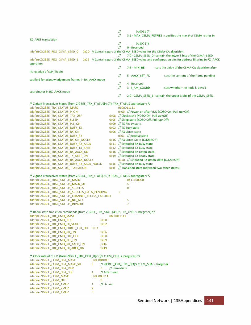
// 0b0011 (*) // 3:1 ‐ MAX_CSMA_RETRIES ‐ specifies the max # of CSMA retries in TX_ARET transaction // 0b100 (*) // 0 ‐ Reserved #define ZIGBEE_REG_CSMA_SEED_0 0x2D // Contains part of the CSMA_SEED value for the CSMA‐CA algorithm. // 7:0 ‐ CSMA_SEED_0 ‐ contain the lower 8 bits of the CSMA_SEED #define ZIGBEE_REG_CSMA_SEED_1 0x2E // Contains part of the CSMA_SEED value and configuration bits for address filtering in RX_AACK operation // 7:6 ‐ MIN_BE ‐ sets the delay of the CSMA‐CA algorithm after rising edge of SLP_TR pin // 5 ‐ AACK_SET_PD ‐ sets the content of the frame pending subfield for acknowledgement frames in RX_AACK mode // 4 ‐ Reserved // 3 ‐ I_AM_COORD ‐ sets whether the node is a PAN coordinator in RX_AACK mode // 2:0 ‐ CSMA_SEED_1 ‐ contain the upper 3 bits of the CSMA_SEED /* ZigBee Transceiver States (from ZIGBEE_TRX_STATUS[4:0]'s TRX_STATUS subregister) */ #define ZIGBEE_TRX_STATUS_MASK 0b00011111 #define ZIGBEE_TRX_STATUS_P_ON 0x00 // Power‐on after VDD (XOSC=On, Pull‐up=On) #define ZIGBEE_TRX_STATUS_TRX_OFF 0x08 // Clock state (XOSC=On, Pull‐up=Off) #define ZIGBEE_TRX_STATUS_SLEEP 0x0F // Sleep state (XOSC=Off, Pull‐up=Off) #define ZIGBEE_TRX_STATUS_PLL_ON 0x09 // TX Ready state #define ZIGBEE_TRX_STATUS_BUSY_TX 0x02 // TX Busy state #define ZIGBEE_TRX_STATUS_RX_ON 0x06 // RX Listen state #define ZIGBEE_TRX_STATUS_BUSY_RX 0x01 // Receive state #define ZIGBEE_TRX_STATUS_RX_ON_NOCLK 0x1C // RX Listen State (CLKM=Off) #define ZIGBEE_TRX_STATUS_BUSY_RX_AACK 0x11 // Extended RX Busy state #define ZIGBEE_TRX_STATUS_BUSY_TX_ARET 0x12 // Extended TX Busy state #define ZIGBEE_TRX_STATUS_RX_AACK_ON 0x16 // Extended RX Listen state #define ZIGBEE_TRX_STATUS_TX_ARET_ON 0x19 // Extended TX Ready state #define ZIGBEE_TRX_STATUS_RX_AACK_NOCLK 0x1D // Extended RX Listen state (CLKM=Off) #define ZIGBEE_TRX_STATUS_BUSY_RX_AACK_NOCLK 0x1E // Extended RX Busy state #define ZIGBEE_TRX_STATUS_TRANSITION 0x1F // Transition state (between two other states) /* ZigBee Transceiver States (from ZIGBEE_TRX_STATE[7:5]'s TRAC_STATUS subregister) */ #define ZIGBEE_TRAC_STATUS_MASK 0b11100000 #define ZIGBEE_TRAC_STATUS_MASK_SH 5 #define ZIGBEE_TRAC_STATUS_SUCCESS 0 #define ZIGBEE_TRAC_STATUS_SUCCESS_DATA_PENDING 1 #define ZIGBEE_TRAC_STATUS_CHANNEL_ACCESS_FAILURE 3 #define ZIGBEE_TRAC_STATUS_NO_ACK 5 #define ZIGBEE_TRAC_STATUS_INVALID 7 /* Radio state transition commands (from ZIGBEE_TRX_STATE[4:0]'s TRX_CMD subregister) */ #define ZIGBEE_TRX_CMD_MASK 0b00011111 #define ZIGBEE_TRX_CMD_NOP 0x00 #define ZIGBEE_TRX_CMD_TX_START 0x02 #define ZIGBEE_TRX_CMD_FORCE_TRX_OFF 0x03 #define ZIGBEE_TRX_CMD_RX_ON 0x06 #define ZIGBEE_TRX_CMD_TRX_OFF 0x08 #define ZIGBEE_TRX_CMD_PLL_ON 0x09 #define ZIGBEE_TRX_CMD_RX_AACK_ON 0x16 #define ZIGBEE_TRX_CMD_TX_ARET_ON 0x19 /* Clock rate of CLKM (from ZIGBEE_TRX_CTRL_0[2:0]'s CLKM_CTRL subregister) */ #define ZIGBEE_CLKM_SHA_MASK 0b00001000 #define ZIGBEE_CLKM_SHA_MASK_SH 3 // ZIGBEE_TRX_CTRL_0[3]'s CLKM_SHA subregister #define ZIGBEE_CLKM_SHA_IMM 0 // Immediate #define ZIGBEE_CLKM_SHA_SLP 1 // After sleep #define ZIGBEE_CLKM_MASK 0b00000111 #define ZIGBEE_CLKM_OFF 0 #define ZIGBEE_CLKM_1MHZ 1 // Default #define ZIGBEE_CLKM_2MHZ 2 #define ZIGBEE_CLKM_4MHZ 3
Sentinel Network | 13BAppendices 141
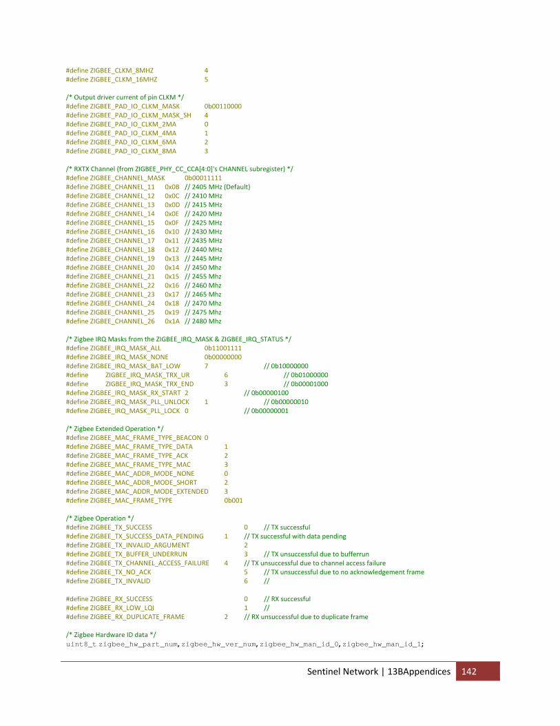
#define ZIGBEE_CLKM_8MHZ 4 #define ZIGBEE_CLKM_16MHZ 5 /* Output driver current of pin CLKM */ #define ZIGBEE_PAD_IO_CLKM_MASK 0b00110000 #define ZIGBEE_PAD_IO_CLKM_MASK_SH 4 #define ZIGBEE_PAD_IO_CLKM_2MA 0 #define ZIGBEE_PAD_IO_CLKM_4MA 1 #define ZIGBEE_PAD_IO_CLKM_6MA 2 #define ZIGBEE_PAD_IO_CLKM_8MA 3 /* RXTX Channel (from ZIGBEE_PHY_CC_CCA[4:0]'s CHANNEL subregister) */ #define ZIGBEE_CHANNEL_MASK 0b00011111 #define ZIGBEE_CHANNEL_11 0x0B // 2405 MHz (Default) #define ZIGBEE_CHANNEL_12 0x0C // 2410 MHz #define ZIGBEE_CHANNEL_13 0x0D // 2415 MHz #define ZIGBEE_CHANNEL_14 0x0E // 2420 MHz #define ZIGBEE_CHANNEL_15 0x0F // 2425 MHz #define ZIGBEE_CHANNEL_16 0x10 // 2430 MHz #define ZIGBEE_CHANNEL_17 0x11 // 2435 MHz #define ZIGBEE_CHANNEL_18 0x12 // 2440 MHz #define ZIGBEE_CHANNEL_19 0x13 // 2445 MHz #define ZIGBEE_CHANNEL_20 0x14 // 2450 Mhz #define ZIGBEE_CHANNEL_21 0x15 // 2455 Mhz #define ZIGBEE_CHANNEL_22 0x16 // 2460 Mhz #define ZIGBEE_CHANNEL_23 0x17 // 2465 Mhz #define ZIGBEE_CHANNEL_24 0x18 // 2470 Mhz #define ZIGBEE_CHANNEL_25 0x19 // 2475 Mhz #define ZIGBEE_CHANNEL_26 0x1A // 2480 Mhz /* Zigbee IRQ Masks from the ZIGBEE_IRQ_MASK & ZIGBEE_IRQ_STATUS */ #define ZIGBEE_IRQ_MASK_ALL 0b11001111 #define ZIGBEE_IRQ_MASK_NONE 0b00000000 #define ZIGBEE_IRQ_MASK_BAT_LOW 7 // 0b10000000 #define ZIGBEE_IRQ_MASK_TRX_UR 6 // 0b01000000 #define ZIGBEE_IRQ_MASK_TRX_END 3 // 0b00001000 #define ZIGBEE_IRQ_MASK_RX_START 2 // 0b00000100 #define ZIGBEE_IRQ_MASK_PLL_UNLOCK 1 // 0b00000010 #define ZIGBEE_IRQ_MASK_PLL_LOCK 0 // 0b00000001 /* Zigbee Extended Operation */ #define ZIGBEE_MAC_FRAME_TYPE_BEACON 0 #define ZIGBEE_MAC_FRAME_TYPE_DATA 1 #define ZIGBEE_MAC_FRAME_TYPE_ACK 2 #define ZIGBEE_MAC_FRAME_TYPE_MAC 3 #define ZIGBEE_MAC_ADDR_MODE_NONE 0 #define ZIGBEE_MAC_ADDR_MODE_SHORT 2 #define ZIGBEE_MAC_ADDR_MODE_EXTENDED 3 #define ZIGBEE_MAC_FRAME_TYPE 0b001 /* Zigbee Operation */ #define ZIGBEE_TX_SUCCESS 0 // TX successful #define ZIGBEE_TX_SUCCESS_DATA_PENDING 1 // TX successful with data pending #define ZIGBEE_TX_INVALID_ARGUMENT 2 #define ZIGBEE_TX_BUFFER_UNDERRUN 3 // TX unsuccessful due to bufferrun #define ZIGBEE_TX_CHANNEL_ACCESS_FAILURE 4 // TX unsuccessful due to channel access failure #define ZIGBEE_TX_NO_ACK 5 // TX unsuccessful due to no acknowledgement frame #define ZIGBEE_TX_INVALID 6 // #define ZIGBEE_RX_SUCCESS 0 // RX successful #define ZIGBEE_RX_LOW_LQI 1 // #define ZIGBEE_RX_DUPLICATE_FRAME 2 // RX unsuccessful due to duplicate frame /* Zigbee Hardware ID data */ uint8_t zigbee_hw_part_num, zigbee_hw_ver_num, zigbee_hw_man_id_0, zigbee_hw_man_id_1;
Sentinel Network | 13BAppendices 142
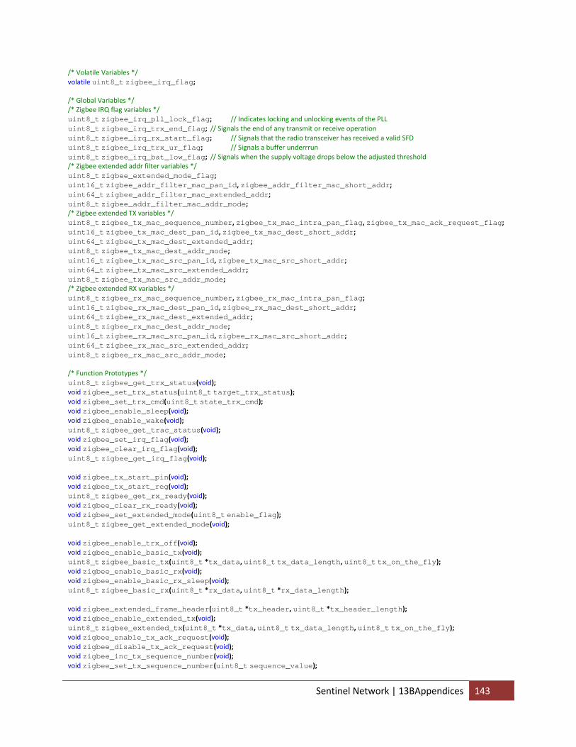
/* Volatile Variables */ volatile uint8_t zigbee_irq_flag; /* Global Variables */ /* Zigbee IRQ flag variables */ uint8_t zigbee_irq_pll_lock_flag; // Indicates locking and unlocking events of the PLL uint8_t zigbee_irq_trx_end_flag; // Signals the end of any transmit or receive operation uint8_t zigbee_irq_rx_start_flag; // Signals that the radio transceiver has received a valid SFD uint8_t zigbee_irq_trx_ur_flag; // Signals a buffer underrrun uint8_t zigbee_irq_bat_low_flag; // Signals when the supply voltage drops below the adjusted threshold /* Zigbee extended addr filter variables */ uint8_t zigbee_extended_mode_flag; uint16_t zigbee_addr_filter_mac_pan_id, zigbee_addr_filter_mac_short_addr; uint64_t zigbee_addr_filter_mac_extended_addr; uint8_t zigbee_addr_filter_mac_addr_mode; /* Zigbee extended TX variables */ uint8_t zigbee_tx_mac_sequence_number, zigbee_tx_mac_intra_pan_flag, zigbee_tx_mac_ack_request_flag; uint16_t zigbee_tx_mac_dest_pan_id, zigbee_tx_mac_dest_short_addr; uint64_t zigbee_tx_mac_dest_extended_addr; uint8_t zigbee_tx_mac_dest_addr_mode; uint16_t zigbee_tx_mac_src_pan_id, zigbee_tx_mac_src_short_addr; uint64_t zigbee_tx_mac_src_extended_addr; uint8_t zigbee_tx_mac_src_addr_mode; /* Zigbee extended RX variables */ uint8_t zigbee_rx_mac_sequence_number, zigbee_rx_mac_intra_pan_flag; uint16_t zigbee_rx_mac_dest_pan_id, zigbee_rx_mac_dest_short_addr; uint64_t zigbee_rx_mac_dest_extended_addr; uint8_t zigbee_rx_mac_dest_addr_mode; uint16_t zigbee_rx_mac_src_pan_id, zigbee_rx_mac_src_short_addr; uint64_t zigbee_rx_mac_src_extended_addr; uint8_t zigbee_rx_mac_src_addr_mode; /* Function Prototypes */ uint8_t zigbee_get_trx_status(void); void zigbee_set_trx_status(uint8_t target_trx_status); void zigbee_set_trx_cmd(uint8_t state_trx_cmd); void zigbee_enable_sleep(void); void zigbee_enable_wake(void); uint8_t zigbee_get_trac_status(void); void zigbee_set_irq_flag(void); void zigbee_clear_irq_flag(void); uint8_t zigbee_get_irq_flag(void); void zigbee_tx_start_pin(void); void zigbee_tx_start_reg(void); uint8_t zigbee_get_rx_ready(void); void zigbee_clear_rx_ready(void); void zigbee_set_extended_mode(uint8_t enable_flag); uint8_t zigbee_get_extended_mode(void); void zigbee_enable_trx_off(void); void zigbee_enable_basic_tx(void); uint8_t zigbee_basic_tx(uint8_t *tx_data, uint8_t tx_data_length, uint8_t tx_on_the_fly); void zigbee_enable_basic_rx(void); void zigbee_enable_basic_rx_sleep(void); uint8_t zigbee_basic_rx(uint8_t *rx_data, uint8_t *rx_data_length); void zigbee_extended_frame_header(uint8_t *tx_header, uint8_t *tx_header_length); void zigbee_enable_extended_tx(void); uint8_t zigbee_extended_tx(uint8_t *tx_data, uint8_t tx_data_length, uint8_t tx_on_the_fly); void zigbee_enable_tx_ack_request(void); void zigbee_disable_tx_ack_request(void); void zigbee_inc_tx_sequence_number(void); void zigbee_set_tx_sequence_number(uint8_t sequence_value);
Sentinel Network | 13BAppendices 143
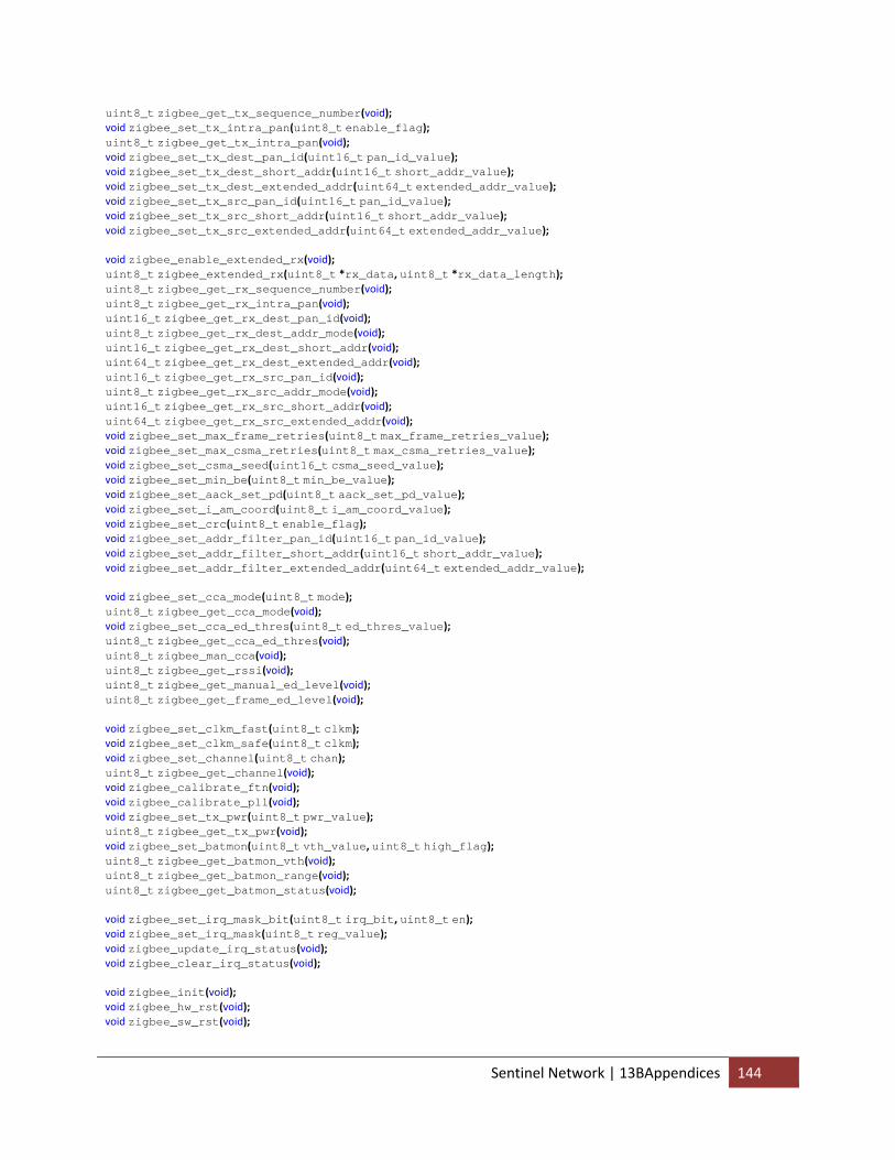
uint8_t zigbee_get_tx_sequence_number(void); void zigbee_set_tx_intra_pan(uint8_t enable_flag); uint8_t zigbee_get_tx_intra_pan(void); void zigbee_set_tx_dest_pan_id(uint16_t pan_id_value); void zigbee_set_tx_dest_short_addr(uint16_t short_addr_value); void zigbee_set_tx_dest_extended_addr(uint64_t extended_addr_value); void zigbee_set_tx_src_pan_id(uint16_t pan_id_value); void zigbee_set_tx_src_short_addr(uint16_t short_addr_value); void zigbee_set_tx_src_extended_addr(uint64_t extended_addr_value); void zigbee_enable_extended_rx(void); uint8_t zigbee_extended_rx(uint8_t *rx_data, uint8_t *rx_data_length); uint8_t zigbee_get_rx_sequence_number(void); uint8_t zigbee_get_rx_intra_pan(void); uint16_t zigbee_get_rx_dest_pan_id(void); uint8_t zigbee_get_rx_dest_addr_mode(void); uint16_t zigbee_get_rx_dest_short_addr(void); uint64_t zigbee_get_rx_dest_extended_addr(void); uint16_t zigbee_get_rx_src_pan_id(void); uint8_t zigbee_get_rx_src_addr_mode(void); uint16_t zigbee_get_rx_src_short_addr(void); uint64_t zigbee_get_rx_src_extended_addr(void); void zigbee_set_max_frame_retries(uint8_t max_frame_retries_value); void zigbee_set_max_csma_retries(uint8_t max_csma_retries_value); void zigbee_set_csma_seed(uint16_t csma_seed_value); void zigbee_set_min_be(uint8_t min_be_value); void zigbee_set_aack_set_pd(uint8_t aack_set_pd_value); void zigbee_set_i_am_coord(uint8_t i_am_coord_value); void zigbee_set_crc(uint8_t enable_flag); void zigbee_set_addr_filter_pan_id(uint16_t pan_id_value); void zigbee_set_addr_filter_short_addr(uint16_t short_addr_value); void zigbee_set_addr_filter_extended_addr(uint64_t extended_addr_value); void zigbee_set_cca_mode(uint8_t mode); uint8_t zigbee_get_cca_mode(void); void zigbee_set_cca_ed_thres(uint8_t ed_thres_value); uint8_t zigbee_get_cca_ed_thres(void); uint8_t zigbee_man_cca(void); uint8_t zigbee_get_rssi(void); uint8_t zigbee_get_manual_ed_level(void); uint8_t zigbee_get_frame_ed_level(void); void zigbee_set_clkm_fast(uint8_t clkm); void zigbee_set_clkm_safe(uint8_t clkm); void zigbee_set_channel(uint8_t chan); uint8_t zigbee_get_channel(void); void zigbee_calibrate_ftn(void); void zigbee_calibrate_pll(void); void zigbee_set_tx_pwr(uint8_t pwr_value); uint8_t zigbee_get_tx_pwr(void); void zigbee_set_batmon(uint8_t vth_value, uint8_t high_flag); uint8_t zigbee_get_batmon_vth(void); uint8_t zigbee_get_batmon_range(void); uint8_t zigbee_get_batmon_status(void); void zigbee_set_irq_mask_bit(uint8_t irq_bit, uint8_t en); void zigbee_set_irq_mask(uint8_t reg_value); void zigbee_update_irq_status(void); void zigbee_clear_irq_status(void); void zigbee_init(void); void zigbee_hw_rst(void); void zigbee_sw_rst(void);
Sentinel Network | 13BAppendices 144
/** * Read the radio transceiver status from TRX_STATUS */ uint8_t zigbee_get_trx_status(void) { uint8_t trx_status = spi_read_register(ZIGBEE_REG_TRX_STATUS) & ZIGBEE_TRX_STATUS_MASK; return trx_status; } /** * Transition the radio transceiver to a new status */ void zigbee_set_trx_status(uint8_t tgt_trx_status) { uint8_t src_trx_status = zigbee_get_trx_status(); while (src_trx_status == ZIGBEE_TRX_STATUS_TRANSITION) { // Do not try to initiate further state changes while in transition src_trx_status = zigbee_get_trx_status(); } switch(tgt_trx_status) { case ZIGBEE_TRX_STATUS_TRX_OFF: switch(src_trx_status) { case ZIGBEE_TRX_STATUS_TRX_OFF: case ZIGBEE_TRX_STATUS_SLEEP: // TODO: Add SLP_TR pin pull low command here break; case ZIGBEE_TRX_STATUS_P_ON: case ZIGBEE_TRX_STATUS_PLL_ON: // Any PLL active state case ZIGBEE_TRX_STATUS_RX_ON: case ZIGBEE_TRX_STATUS_RX_AACK_ON: case ZIGBEE_TRX_STATUS_TX_ARET_ON: zigbee_set_trx_cmd(ZIGBEE_TRX_CMD_TRX_OFF); _delay_us(1); break; case ZIGBEE_TRX_STATUS_BUSY_TX: case ZIGBEE_TRX_STATUS_BUSY_RX: case ZIGBEE_TRX_STATUS_RX_ON_NOCLK: case ZIGBEE_TRX_STATUS_BUSY_RX_AACK: case ZIGBEE_TRX_STATUS_BUSY_TX_ARET: zigbee_set_trx_cmd(ZIGBEE_TRX_CMD_FORCE_TRX_OFF); _delay_us(1); if (zigbee_irq_flag) { // Check for interrupt zigbee_irq_flag = FALSE; zigbee_update_irq_status(); // TRX_END interrupt } break; } while(zigbee_get_trx_status() != ZIGBEE_TRX_STATUS_TRX_OFF); break; case ZIGBEE_TRX_STATUS_SLEEP: // TODO: Add toggle SLP_TR pin command here break; case ZIGBEE_TRX_STATUS_PLL_ON: switch(src_trx_status) { case ZIGBEE_TRX_STATUS_P_ON: case ZIGBEE_TRX_STATUS_SLEEP: break; case ZIGBEE_TRX_STATUS_TRX_OFF: zigbee_set_trx_cmd(ZIGBEE_TRX_CMD_PLL_ON); while (!zigbee_irq_flag); // Typically delays for 180us zigbee_irq_flag = FALSE; zigbee_update_irq_status(); // PLL_LOCK interrupt break; case ZIGBEE_TRX_STATUS_PLL_ON: break; case ZIGBEE_TRX_STATUS_RX_ON: // Any PLL active state case ZIGBEE_TRX_STATUS_RX_AACK_ON: case ZIGBEE_TRX_STATUS_TX_ARET_ON:
Sentinel Network | 13BAppendices 145
zigbee_set_trx_cmd(ZIGBEE_TRX_CMD_PLL_ON); _delay_us(1); break; case ZIGBEE_TRX_STATUS_BUSY_TX: case ZIGBEE_TRX_STATUS_BUSY_RX: case ZIGBEE_TRX_STATUS_BUSY_RX_AACK: case ZIGBEE_TRX_STATUS_BUSY_TX_ARET: zigbee_set_trx_cmd(ZIGBEE_TRX_CMD_PLL_ON); _delay_us(1); if (zigbee_irq_flag) { zigbee_irq_flag = FALSE; zigbee_update_irq_status(); // TRX_END interrupt } break; } while(zigbee_get_trx_status() != ZIGBEE_TRX_STATUS_PLL_ON); // PLL_ON state break; case ZIGBEE_TRX_STATUS_BUSY_TX: // TODO: Add toggle SLP_TR pin command here break; case ZIGBEE_TRX_STATUS_RX_ON: switch(src_trx_status) { case ZIGBEE_TRX_STATUS_P_ON: case ZIGBEE_TRX_STATUS_SLEEP: break; case ZIGBEE_TRX_STATUS_TRX_OFF: zigbee_set_trx_cmd(ZIGBEE_TRX_CMD_RX_ON); while (!zigbee_irq_flag); // Typically delays for 180us zigbee_irq_flag = FALSE; zigbee_update_irq_status(); // PLL_LOCK interrupt break; case ZIGBEE_TRX_STATUS_RX_ON: break; case ZIGBEE_TRX_STATUS_PLL_ON: // Any PLL active state case ZIGBEE_TRX_STATUS_RX_AACK_ON: case ZIGBEE_TRX_STATUS_TX_ARET_ON: zigbee_set_trx_cmd(ZIGBEE_TRX_CMD_RX_ON); _delay_us(1); break; case ZIGBEE_TRX_STATUS_BUSY_TX: case ZIGBEE_TRX_STATUS_BUSY_RX: case ZIGBEE_TRX_STATUS_BUSY_RX_AACK: case ZIGBEE_TRX_STATUS_BUSY_TX_ARET: zigbee_set_trx_cmd(ZIGBEE_TRX_CMD_RX_ON); _delay_us(1); if (zigbee_irq_flag) { zigbee_irq_flag = FALSE; zigbee_update_irq_status(); // TRX_END interrupt } break; } while(zigbee_get_trx_status() != ZIGBEE_TRX_STATUS_RX_ON); // RX_ON state break; case ZIGBEE_TRX_STATUS_BUSY_RX: // Transitions after SFD detection break; case ZIGBEE_TRX_STATUS_RX_ON_NOCLK: break; case ZIGBEE_TRX_STATUS_BUSY_RX_AACK: // Transitions after SFD detection break; case ZIGBEE_TRX_STATUS_BUSY_TX_ARET: // TODO: Add toggle SLP_TR pin command here break; case ZIGBEE_TRX_STATUS_RX_AACK_ON: switch(src_trx_status) { case ZIGBEE_TRX_STATUS_P_ON: case ZIGBEE_TRX_STATUS_SLEEP: break;
Sentinel Network | 13BAppendices 146
case ZIGBEE_TRX_STATUS_TRX_OFF: zigbee_set_trx_status(ZIGBEE_TRX_STATUS_RX_ON); // Transition to RX_ON case ZIGBEE_TRX_STATUS_PLL_ON: case ZIGBEE_TRX_STATUS_RX_ON: zigbee_set_trx_cmd(ZIGBEE_TRX_CMD_RX_AACK_ON); _delay_us(1); break; case ZIGBEE_TRX_STATUS_RX_AACK_ON: break; case ZIGBEE_TRX_STATUS_TX_ARET_ON: zigbee_set_trx_status(ZIGBEE_TRX_STATUS_PLL_ON);// Transition to PLL_ON zigbee_set_trx_cmd(ZIGBEE_TRX_CMD_RX_AACK_ON); _delay_us(1); break; case ZIGBEE_TRX_STATUS_BUSY_TX: case ZIGBEE_TRX_STATUS_BUSY_RX: case ZIGBEE_TRX_STATUS_BUSY_RX_AACK: case ZIGBEE_TRX_STATUS_BUSY_TX_ARET: zigbee_set_trx_cmd(ZIGBEE_TRX_CMD_RX_AACK_ON); _delay_us(1); if (zigbee_irq_flag) { zigbee_irq_flag = FALSE; zigbee_update_irq_status(); // TRX_END interrupt } break; } while(zigbee_get_trx_status() != ZIGBEE_TRX_STATUS_RX_AACK_ON); // RX_AACK_ON state break; case ZIGBEE_TRX_STATUS_TX_ARET_ON: switch(src_trx_status) { case ZIGBEE_TRX_STATUS_TRX_OFF: zigbee_set_trx_status(ZIGBEE_TRX_STATUS_PLL_ON);// Transition to PLL_ON case ZIGBEE_TRX_STATUS_PLL_ON: case ZIGBEE_TRX_STATUS_RX_ON: zigbee_set_trx_cmd(ZIGBEE_TRX_CMD_TX_ARET_ON); _delay_us(1); break; case ZIGBEE_TRX_STATUS_RX_AACK_ON: zigbee_set_trx_status(ZIGBEE_TRX_STATUS_RX_ON); // Transition to RX_ON zigbee_set_trx_cmd(ZIGBEE_TRX_CMD_TX_ARET_ON); _delay_us(1); case ZIGBEE_TRX_STATUS_BUSY_TX: case ZIGBEE_TRX_STATUS_BUSY_RX: case ZIGBEE_TRX_STATUS_BUSY_RX_AACK: case ZIGBEE_TRX_STATUS_BUSY_TX_ARET: zigbee_set_trx_cmd(ZIGBEE_TRX_CMD_TX_ARET_ON); _delay_us(1); if (zigbee_irq_flag) { zigbee_irq_flag = FALSE; zigbee_update_irq_status(); // TRX_END interrupt } break; } while(zigbee_get_trx_status() != ZIGBEE_TRX_STATUS_TX_ARET_ON); // TX_ARET_ON state break; } } /** * Transition the radio transceiver to sleep mode * * Force the device into TRX_OFF * Enter sleep through SLP_TR */
Sentinel Network | 13BAppendices 147
void zigbee_enable_sleep(void) { zigbee_enable_trx_off(); cbi(ZIGBEE_PORT, ZIGBEE_SLP_TR); _delay_us(1); sbi(ZIGBEE_PORT, ZIGBEE_SLP_TR); } /** * Transition the radio transceiver from sleep mode * * Check if the radio transceiver is actually sleeping. * Pull SLP_TR Low * Delay to transition to TRX_OFF * Read to ensure TRX_OFF state */ void zigbee_wake(void) { sbi(ZIGBEE_PORT, ZIGBEE_SLP_TR); _delay_us(1); cbi(ZIGBEE_PORT, ZIGBEE_SLP_TR); } /** * The radio transceiver state is controlled by two signal pins (SLP_TR, RST ) * and the register 0x02 (TRX_STATE). A successful state change shall be * confirmed by reading the radio transceiver status from register 0x01 (TRX_STATUS). */ void zigbee_set_trx_cmd(uint8_t trx_cmd) { uint8_t trx_status = zigbee_get_trx_status(); while (trx_status == ZIGBEE_TRX_STATUS_TRANSITION) { // Do not try to initiate further state changes while in transition trx_status = zigbee_get_trx_status(); } uint8_t trx_state_value = spi_read_register(ZIGBEE_REG_TRX_STATE); trx_state_value = (trx_state_value & ~ZIGBEE_TRX_CMD_MASK) | trx_cmd; // TRX_STATE = TRAC_STATUS | TRX_CMD spi_write_register(ZIGBEE_REG_TRX_STATE, trx_state_value); } /** * Read the radio transceiver status from TRX_STATUS */ uint8_t zigbee_get_trac_status(void) { uint8_t trac_status = (spi_read_register(ZIGBEE_REG_TRX_STATE) & ZIGBEE_TRAC_STATUS_MASK) >> ZIGBEE_TRAC_STATUS_MASK_SH; #if UART0_ZIGBEE_TRAC_STATUS_DEBUG uart0_send_byte(UART_TX_ZIGBEE_TRAC_STATUS); uart0_send_byte(trac_status); #endif return trac_status; } /** * */ void zigbee_set_irq_flag(void) { zigbee_irq_flag = TRUE; } /** * */ void zigbee_clear_irq_flag(void) { zigbee_irq_flag = FALSE; } /**
Sentinel Network | 13BAppendices 148
* */ uint8_t zigbee_get_irq_flag(void) { return zigbee_irq_flag; } /** * */ void zigbee_tx_start_pin(void) { sbi(ZIGBEE_PORT, ZIGBEE_SLP_TR); _delay_us(1); // Actual delay should be 65 ns cbi(ZIGBEE_PORT, ZIGBEE_SLP_TR); } /** * */ void zigbee_tx_start_reg(void) { zigbee_set_trx_cmd(ZIGBEE_TRX_CMD_TX_START); } /** * */ void zigbee_clear_rx_ready(void) { if (zigbee_extended_mode_flag) { zigbee_irq_trx_end_flag = FALSE; } else { zigbee_irq_trx_end_flag = FALSE; zigbee_irq_rx_start_flag = FALSE; } } /** * */ uint8_t zigbee_get_rx_ready(void) { if (zigbee_extended_mode_flag) { return zigbee_irq_trx_end_flag; } else { return zigbee_irq_trx_end_flag && zigbee_irq_rx_start_flag; } } /** * */ void zigbee_set_extended_mode(uint8_t enable_flag) { zigbee_extended_mode_flag = enable_flag; } /** * */ uint8_t zigbee_get_extended_mode(void) { return zigbee_extended_mode_flag; } /** * */ void zigbee_force_trx_off(void) {
Sentinel Network | 13BAppendices 149
zigbee_set_trx_status(ZIGBEE_TRX_STATUS_TRX_OFF); } /** * */ void zigbee_enable_trx_off(void) { switch(zigbee_get_trx_status()) { case ZIGBEE_TRX_STATUS_P_ON: case ZIGBEE_TRX_STATUS_SLEEP: case ZIGBEE_TRX_STATUS_TRX_OFF: break; case ZIGBEE_TRX_STATUS_BUSY_TX: while(zigbee_get_trx_status() != ZIGBEE_TRX_STATUS_PLL_ON); case ZIGBEE_TRX_STATUS_PLL_ON: zigbee_set_trx_status(ZIGBEE_TRX_STATUS_TRX_OFF); break; case ZIGBEE_TRX_STATUS_BUSY_RX: while(zigbee_get_trx_status() != ZIGBEE_TRX_STATUS_RX_ON); case ZIGBEE_TRX_STATUS_RX_ON: zigbee_set_trx_status(ZIGBEE_TRX_STATUS_TRX_OFF); break; case ZIGBEE_TRX_STATUS_BUSY_RX_AACK: while(zigbee_get_trx_status() != ZIGBEE_TRX_STATUS_RX_AACK_ON); case ZIGBEE_TRX_STATUS_RX_AACK_ON: zigbee_set_trx_status(ZIGBEE_TRX_STATUS_TRX_OFF); break; case ZIGBEE_TRX_STATUS_BUSY_TX_ARET: while(zigbee_get_trx_status() != ZIGBEE_TRX_STATUS_TX_ARET_ON); case ZIGBEE_TRX_STATUS_TX_ARET_ON: zigbee_set_trx_status(ZIGBEE_TRX_STATUS_TRX_OFF); break; } } /** * Changes the TRX to the PLL_ON state for transmission */ void zigbee_enable_basic_tx(void) { zigbee_set_trx_status(ZIGBEE_TRX_STATUS_PLL_ON); } /** * Performs a manual basic transmission * * The transceiver must be in the PLL_ON state beforehand * The SPI data rate must be higher than 250 kBit/s to ensure that no Frame Buffer under run occurs */ uint8_t zigbee_basic_tx(uint8_t *tx_data, uint8_t tx_data_length, uint8_t tx_on_the_fly) { if (tx_data_length > ZIGBEE_PHY_DATA_LENGTH) { return ZIGBEE_TX_INVALID_ARGUMENT; } #if PROTOBOARD_LED_DEBUG cbi(PROTOBOARD_LED_PORT, PROTOBOARD_LED_1); #endif if (tx_on_the_fly) { #if ZIGBEE_TX_START_REG_ENABLE zigbee_tx_start_reg(); #else zigbee_tx_start_pin(); #endif spi_write_frame_buffer(tx_data_length, tx_data); }
Sentinel Network | 13BAppendices 150
else { // Uploads the entire frame before transmission to prevent a buffer underrun interrupt spi_write_frame_buffer(tx_data_length, tx_data); #if ZIGBEE_TX_START_REG_ENABLE zigbee_tx_start_reg(); #else zigbee_tx_start_pin(); #endif } while (!zigbee_irq_flag); zigbee_irq_flag = FALSE; zigbee_update_irq_status(); // TRX_END interrupt /* PLL_ON state */ #if PROTOBOARD_LED_DEBUG sbi(PROTOBOARD_LED_PORT, PROTOBOARD_LED_1); #endif if (zigbee_irq_trx_ur_flag) { // TRX_UR interrupt occurs when the frame was incorrectly transmitted zigbee_irq_trx_ur_flag = FALSE; return ZIGBEE_TX_BUFFER_UNDERRUN; } return ZIGBEE_TX_SUCCESS; } /** * */ void zigbee_enable_basic_rx(void) { zigbee_clear_rx_ready(); zigbee_set_trx_status(ZIGBEE_TRX_STATUS_RX_ON); } /** * */ void zigbee_enable_basic_rx_sleep(void) { zigbee_enable_basic_rx(); cbi(ZIGBEE_PORT, ZIGBEE_SLP_TR); _delay_us(1); sbi(ZIGBEE_PORT, ZIGBEE_SLP_TR); } /** * */ uint8_t zigbee_basic_rx(uint8_t *rx_data, uint8_t *rx_data_length) { #if PROTOBOARD_LED_DEBUG cbi(PROTOBOARD_LED_PORT, PROTOBOARD_LED_1); #endif //ZigBee networks require to determine the “best� route between two nodes. Both, the // LQI and the RSSI/ED can be used for this, depending on the optimization criteria. As a // rule of thumb RSSI/ED is useful to differentiate between links with high LQI values. // Transmission links with low LQI values should be discarded for routing decisions even if // the RSSI/ED values are high. uint8_t rx_data_lqi; spi_read_frame_buffer(rx_data_length, rx_data, &rx_data_lqi); #if UART0_ZIGBEE_RX_PHY_LQI_DEBUG uart0_send_byte(UART_TX_ZIGBEE_PHY_LQI); uart0_send_byte(rx_data_lqi); #endif
Sentinel Network | 13BAppendices 151
#if PROTOBOARD_LED_DEBUG sbi(PROTOBOARD_LED_PORT, PROTOBOARD_LED_1); #endif if (rx_data_lqi == 0) { *rx_data_length = 0; return ZIGBEE_RX_LOW_LQI; } return ZIGBEE_RX_SUCCESS; } /** * IEEE 802.15.4‐2003 Frame Header Generation * * Intra PAN subfield is enabled, so PAN ID is omitted from source address field * Source and destination address mode are fixed at 16‐bit * Source address is simply the zigbee MAC address * Frame header length fixed at 9 */ void zigbee_extended_frame_header(uint8_t *tx_header, uint8_t *tx_header_length) { /* tx_frame[0] = 0b01100001; //FCF. tx_frame[1] = 0b10001000; //FCF. tx_frame[2] = zigbee_extended_frame_sequence_number++; //Sequence number set during frame transmission. tx_frame[3] = PAN_ID & 0xFF; //Dest. PANID. tx_frame[4] = (PAN_ID >> 8 ) & 0xFF; //Dest. PANID. tx_frame[5] = DEST_ADDRESS & 0xFF; //Dest. Addr. tx_frame[6] = (DEST_ADDRESS >> 8 ) & 0xFF; //Dest. Addr. tx_frame[7] = SHORT_ADDRESS & 0xFF; //Source Addr. tx_frame[8] = (SHORT_ADDRESS >> 8 ) & 0xFF; //Source Addr. */ /** * MAC Header * 2:0 ‐ Frame Types * 000 ‐ Beacon * 001 ‐ Data * 010 ‐ Acknowledge * 011 ‐ MAC command * 1xx ‐ Reserved * 3 ‐ Secuirty enabled subfield (ignore for AT86RF230) * 4 ‐ Frame pending subfield indicating if the device sending the frame has additional data to send to the recipient * If more data are pending, the recipient shall retrieve them by sending another data request command to the device * The frame pending subfield shall be used only in frames transmitted either during the CAP by devices * operating on a beacon‐enabled PAN or at any time by devices operating on a nonbeacon‐enabled PAN. * This field can be set in an acknowledgement frame. It indicates that the transmitter of the acknowledgement * frame has more data to send for the recipient of the acknowledgement frame. * 5 ‐ Acknowledgement request subfield indicating whether an acknowledgment is required from the recipient device * on receipt of a data or MAC command frame. * 6 ‐ Intra‐PAN subfield indicating whether the MAC frame is to be sent within the same PAN (intra‐PAN) or to another PAN (inter‐PAN). * 11:10 ‐ Destination addressing mode subfield * 00 ‐ No dest PAN id or address ‐ If not an acknowledgement or beacon frame, the source addressing subfield must * be non‐zero, implying the frame is directed to the PAN coordinator with the PAN identifier as specified * in the source PAN identifier field. * 01 ‐ Reserved * 10 ‐ 16‐bit short address * 11 ‐ 64‐bit extended address * 15:14 ‐ Source addressing mode subfield * 00 ‐ No src PAN id or address ‐ If not an acknowledgement frame, the destination addressing subfield must be * non‐zero, implying that the frame has originated from the PAN coordinator with the PAN identifier as * specified in the destination PAN identifier field. * 01 ‐ Reserved * 10 ‐ 16‐bit short address * 11 ‐ 64‐bit extended address
Sentinel Network | 13BAppendices 152
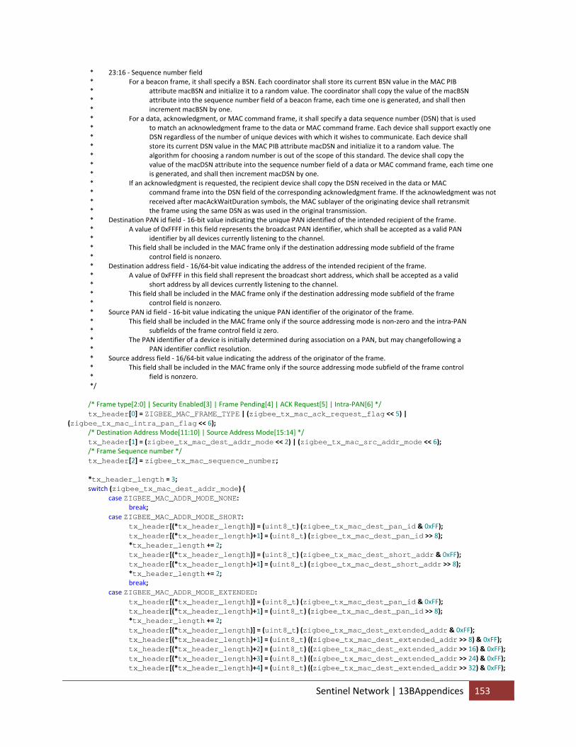
* 23:16 ‐ Sequence number field * For a beacon frame, it shall specify a BSN. Each coordinator shall store its current BSN value in the MAC PIB * attribute macBSN and initialize it to a random value. The coordinator shall copy the value of the macBSN * attribute into the sequence number field of a beacon frame, each time one is generated, and shall then * increment macBSN by one. * For a data, acknowledgment, or MAC command frame, it shall specify a data sequence number (DSN) that is used * to match an acknowledgment frame to the data or MAC command frame. Each device shall support exactly one * DSN regardless of the number of unique devices with which it wishes to communicate. Each device shall * store its current DSN value in the MAC PIB attribute macDSN and initialize it to a random value. The * algorithm for choosing a random number is out of the scope of this standard. The device shall copy the * value of the macDSN attribute into the sequence number field of a data or MAC command frame, each time one * is generated, and shall then increment macDSN by one. * If an acknowledgment is requested, the recipient device shall copy the DSN received in the data or MAC * command frame into the DSN field of the corresponding acknowledgment frame. If the acknowledgment was not * received after macAckWaitDuration symbols, the MAC sublayer of the originating device shall retransmit * the frame using the same DSN as was used in the original transmission. * Destination PAN id field ‐ 16‐bit value indicating the unique PAN identified of the intended recipient of the frame. * A value of 0xFFFF in this field represents the broadcast PAN identifier, which shall be accepted as a valid PAN * identifier by all devices currently listening to the channel. * This field shall be included in the MAC frame only if the destination addressing mode subfield of the frame * control field is nonzero. * Destination address field ‐ 16/64‐bit value indicating the address of the intended recipient of the frame. * A value of 0xFFFF in this field shall represent the broadcast short address, which shall be accepted as a valid * short address by all devices currently listening to the channel. * This field shall be included in the MAC frame only if the destination addressing mode subfield of the frame * control field is nonzero. * Source PAN id field ‐ 16‐bit value indicating the unique PAN identifier of the originator of the frame. * This field shall be included in the MAC frame only if the source addressing mode is non‐zero and the intra‐PAN * subfields of the frame control field iz zero. * The PAN identifier of a device is initially determined during association on a PAN, but may changefollowing a * PAN identifier conflict resolution. * Source address field ‐ 16/64‐bit value indicating the address of the originator of the frame. * This field shall be included in the MAC frame only if the source addressing mode subfield of the frame control * field is nonzero. */ /* Frame type[2:0] | Security Enabled[3] | Frame Pending[4] | ACK Request[5] | Intra‐PAN[6] */ tx_header[0] = ZIGBEE_MAC_FRAME_TYPE | (zigbee_tx_mac_ack_request_flag << 5) | (zigbee_tx_mac_intra_pan_flag << 6); /* Destination Address Mode[11:10] | Source Address Mode[15:14] */ tx_header[1] = (zigbee_tx_mac_dest_addr_mode << 2) | (zigbee_tx_mac_src_addr_mode << 6); /* Frame Sequence number */ tx_header[2] = zigbee_tx_mac_sequence_number; *tx_header_length = 3; switch (zigbee_tx_mac_dest_addr_mode) { case ZIGBEE_MAC_ADDR_MODE_NONE: break; case ZIGBEE_MAC_ADDR_MODE_SHORT: tx_header[(*tx_header_length)] = (uint8_t) (zigbee_tx_mac_dest_pan_id & 0xFF); tx_header[(*tx_header_length)+1] = (uint8_t) (zigbee_tx_mac_dest_pan_id >> 8); *tx_header_length += 2; tx_header[(*tx_header_length)] = (uint8_t) (zigbee_tx_mac_dest_short_addr & 0xFF); tx_header[(*tx_header_length)+1] = (uint8_t) (zigbee_tx_mac_dest_short_addr >> 8); *tx_header_length += 2; break; case ZIGBEE_MAC_ADDR_MODE_EXTENDED: tx_header[(*tx_header_length)] = (uint8_t) (zigbee_tx_mac_dest_pan_id & 0xFF); tx_header[(*tx_header_length)+1] = (uint8_t) (zigbee_tx_mac_dest_pan_id >> 8); *tx_header_length += 2; tx_header[(*tx_header_length)] = (uint8_t) (zigbee_tx_mac_dest_extended_addr & 0xFF); tx_header[(*tx_header_length)+1] = (uint8_t) ((zigbee_tx_mac_dest_extended_addr >> 8) & 0xFF); tx_header[(*tx_header_length)+2] = (uint8_t) ((zigbee_tx_mac_dest_extended_addr >> 16) & 0xFF); tx_header[(*tx_header_length)+3] = (uint8_t) ((zigbee_tx_mac_dest_extended_addr >> 24) & 0xFF); tx_header[(*tx_header_length)+4] = (uint8_t) ((zigbee_tx_mac_dest_extended_addr >> 32) & 0xFF);
Sentinel Network | 13BAppendices 153
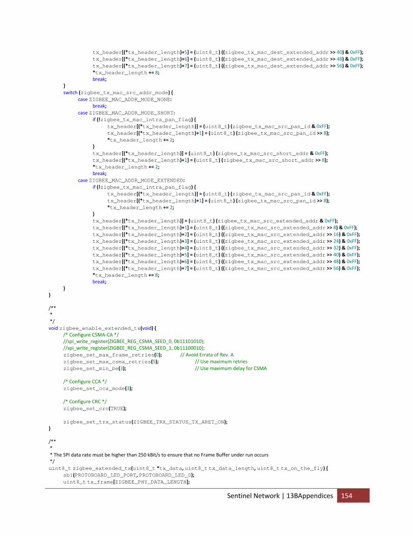
tx_header[(*tx_header_length)+5] = (uint8_t) ((zigbee_tx_mac_dest_extended_addr >> 40) & 0xFF); tx_header[(*tx_header_length)+6] = (uint8_t) ((zigbee_tx_mac_dest_extended_addr >> 48) & 0xFF); tx_header[(*tx_header_length)+7] = (uint8_t) ((zigbee_tx_mac_dest_extended_addr >> 56) & 0xFF); *tx_header_length += 8; break; } switch (zigbee_tx_mac_src_addr_mode) { case ZIGBEE_MAC_ADDR_MODE_NONE: break; case ZIGBEE_MAC_ADDR_MODE_SHORT: if (!zigbee_tx_mac_intra_pan_flag) { tx_header[(*tx_header_length)] = (uint8_t) (zigbee_tx_mac_src_pan_id & 0xFF); tx_header[(*tx_header_length)+1] = (uint8_t) (zigbee_tx_mac_src_pan_id >> 8); *tx_header_length += 2; } tx_header[(*tx_header_length)] = (uint8_t) (zigbee_tx_mac_src_short_addr & 0xFF); tx_header[(*tx_header_length)+1] = (uint8_t) (zigbee_tx_mac_src_short_addr >> 8); *tx_header_length += 2; break; case ZIGBEE_MAC_ADDR_MODE_EXTENDED: if (!zigbee_tx_mac_intra_pan_flag) { tx_header[(*tx_header_length)] = (uint8_t) (zigbee_tx_mac_src_pan_id & 0xFF); tx_header[(*tx_header_length)+1] = (uint8_t) (zigbee_tx_mac_src_pan_id >> 8); *tx_header_length += 2; } tx_header[(*tx_header_length)] = (uint8_t) (zigbee_tx_mac_src_extended_addr & 0xFF); tx_header[(*tx_header_length)+1] = (uint8_t) ((zigbee_tx_mac_src_extended_addr >> 8) & 0xFF); tx_header[(*tx_header_length)+2] = (uint8_t) ((zigbee_tx_mac_src_extended_addr >> 16) & 0xFF); tx_header[(*tx_header_length)+3] = (uint8_t) ((zigbee_tx_mac_src_extended_addr >> 24) & 0xFF); tx_header[(*tx_header_length)+4] = (uint8_t) ((zigbee_tx_mac_src_extended_addr >> 32) & 0xFF); tx_header[(*tx_header_length)+5] = (uint8_t) ((zigbee_tx_mac_src_extended_addr >> 40) & 0xFF); tx_header[(*tx_header_length)+6] = (uint8_t) ((zigbee_tx_mac_src_extended_addr >> 48) & 0xFF); tx_header[(*tx_header_length)+7] = (uint8_t) ((zigbee_tx_mac_src_extended_addr >> 56) & 0xFF); *tx_header_length += 8; break; } } /** * */ void zigbee_enable_extended_tx(void) { /* Configure CSMA‐CA */ //spi_write_register(ZIGBEE_REG_CSMA_SEED_0, 0b11101010); //spi_write_register(ZIGBEE_REG_CSMA_SEED_1, 0b11100010); zigbee_set_max_frame_retries(0); // Avoid Errata of Rev. A zigbee_set_max_csma_retries(5); // Use maximum retries zigbee_set_min_be(3); // Use maximum delay for CSMA /* Configure CCA */ zigbee_set_cca_mode(3); /* Configure CRC */ zigbee_set_crc(TRUE); zigbee_set_trx_status(ZIGBEE_TRX_STATUS_TX_ARET_ON); } /** * * The SPI data rate must be higher than 250 kBit/s to ensure that no Frame Buffer under run occurs */ uint8_t zigbee_extended_tx(uint8_t *tx_data, uint8_t tx_data_length, uint8_t tx_on_the_fly) { sbi(PROTOBOARD_LED_PORT, PROTOBOARD_LED_0); uint8_t tx_frame[ZIGBEE_PHY_DATA_LENGTH];
Sentinel Network | 13BAppendices 154
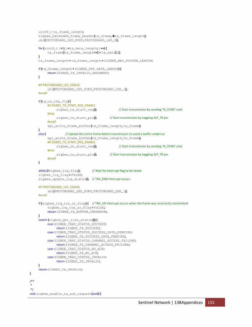
uint8_t tx_frame_length; zigbee_extended_frame_header(tx_frame, &tx_frame_length); cbi(PROTOBOARD_LED_PORT, PROTOBOARD_LED_0); for (uint8_t i=0; i<tx_data_length; i++) { tx_frame[tx_frame_length++] = tx_data[i]; } tx_frame_length = tx_frame_length + ZIGBEE_MAC_FOOTER_LENGTH; if (tx_frame_length > ZIGBEE_PHY_DATA_LENGTH) { return ZIGBEE_TX_INVALID_ARGUMENT; } #if PROTOBOARD_LED_DEBUG cbi(PROTOBOARD_LED_PORT, PROTOBOARD_LED_1); #endif if (tx_on_the_fly) { #if ZIGBEE_TX_START_REG_ENABLE zigbee_tx_start_reg(); // Start transmission by sending TX_START cmd #else zigbee_tx_start_pin(); // Start transmission by toggling SLP_TR pin #endif spi_write_frame_buffer(tx_frame_length, tx_frame); } else { // Upload the entire frame before transmission to avoid a buffer underrun spi_write_frame_buffer(tx_frame_length, tx_frame); #if ZIGBEE_TX_START_REG_ENABLE zigbee_tx_start_reg(); // Start transmission by sending TX_START cmd #else zigbee_tx_start_pin(); // Start transmission by toggling SLP_TR pin #endif } while (!zigbee_irq_flag); // Wait for interrupt flag to be raised zigbee_irq_flag = FALSE; zigbee_update_irq_status(); // TRX_END interrupt occurs #if PROTOBOARD_LED_DEBUG sbi(PROTOBOARD_LED_PORT, PROTOBOARD_LED_1); #endif if (zigbee_irq_trx_ur_flag) { // TRX_UR interrupt occurs when the frame was incorrectly transmitted zigbee_irq_trx_ur_flag = FALSE; return ZIGBEE_TX_BUFFER_UNDERRUN; } switch (zigbee_get_trac_status()) { case ZIGBEE_TRAC_STATUS_SUCCESS: return ZIGBEE_TX_SUCCESS; case ZIGBEE_TRAC_STATUS_SUCCESS_DATA_PENDING: return ZIGBEE_TX_SUCCESS_DATA_PENDING; case ZIGBEE_TRAC_STATUS_CHANNEL_ACCESS_FAILURE: return ZIGBEE_TX_CHANNEL_ACCESS_FAILURE; case ZIGBEE_TRAC_STATUS_NO_ACK: return ZIGBEE_TX_NO_ACK; case ZIGBEE_TRAC_STATUS_INVALID: return ZIGBEE_TX_INVALID; } return ZIGBEE_TX_INVALID; } /** * */ void zigbee_enable_tx_ack_request(void) {
Sentinel Network | 13BAppendices 155
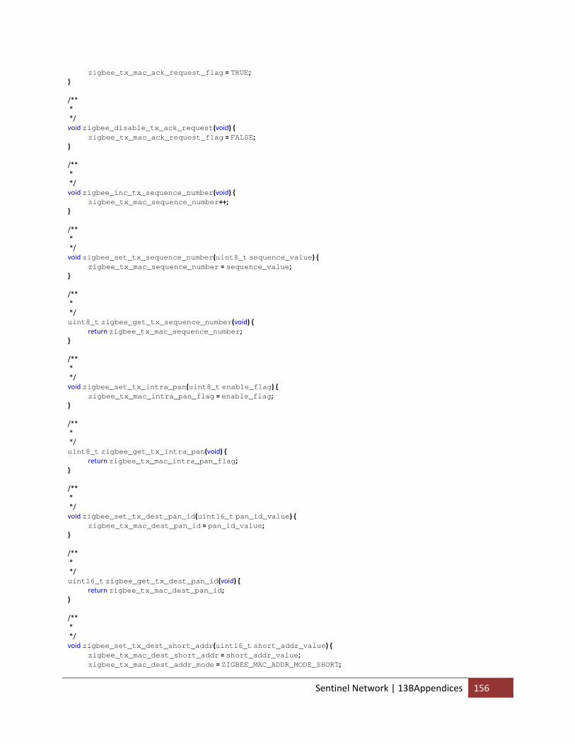
zigbee_tx_mac_ack_request_flag = TRUE; } /** * */ void zigbee_disable_tx_ack_request(void) { zigbee_tx_mac_ack_request_flag = FALSE; } /** * */ void zigbee_inc_tx_sequence_number(void) { zigbee_tx_mac_sequence_number++; } /** * */ void zigbee_set_tx_sequence_number(uint8_t sequence_value) { zigbee_tx_mac_sequence_number = sequence_value; } /** * */ uint8_t zigbee_get_tx_sequence_number(void) { return zigbee_tx_mac_sequence_number; } /** * */ void zigbee_set_tx_intra_pan(uint8_t enable_flag) { zigbee_tx_mac_intra_pan_flag = enable_flag; } /** * */ uint8_t zigbee_get_tx_intra_pan(void) { return zigbee_tx_mac_intra_pan_flag; } /** * */ void zigbee_set_tx_dest_pan_id(uint16_t pan_id_value) { zigbee_tx_mac_dest_pan_id = pan_id_value; } /** * */ uint16_t zigbee_get_tx_dest_pan_id(void) { return zigbee_tx_mac_dest_pan_id; } /** * */ void zigbee_set_tx_dest_short_addr(uint16_t short_addr_value) { zigbee_tx_mac_dest_short_addr = short_addr_value; zigbee_tx_mac_dest_addr_mode = ZIGBEE_MAC_ADDR_MODE_SHORT;
Sentinel Network | 13BAppendices 156
} /** * */ uint16_t zigbee_get_tx_dest_short_addr(void) { return zigbee_tx_mac_dest_short_addr; } /** * */ void zigbee_set_tx_dest_extended_addr(uint64_t extended_addr_value) { zigbee_tx_mac_dest_extended_addr = extended_addr_value; zigbee_tx_mac_dest_addr_mode = ZIGBEE_MAC_ADDR_MODE_EXTENDED; } /** * */ uint64_t zigbee_get_tx_dest_extended_addr(void) { return zigbee_tx_mac_dest_extended_addr; } /** * */ void zigbee_set_tx_src_pan_id(uint16_t pan_id_value) { zigbee_tx_mac_src_pan_id = pan_id_value; } /** * */ uint16_t zigbee_get_tx_src_pan_id(void) { return zigbee_tx_mac_src_pan_id; } /** * */ void zigbee_set_tx_src_short_addr(uint16_t short_addr_value) { zigbee_tx_mac_src_short_addr = short_addr_value; zigbee_tx_mac_src_addr_mode = ZIGBEE_MAC_ADDR_MODE_SHORT; } /** * */ uint16_t zigbee_get_tx_src_short_addr(void) { return zigbee_tx_mac_src_short_addr; } /** * */ void zigbee_set_tx_src_extended_addr(uint64_t extended_addr_value) { zigbee_tx_mac_src_extended_addr = extended_addr_value; zigbee_tx_mac_src_addr_mode = ZIGBEE_MAC_ADDR_MODE_EXTENDED; } /** * */ uint64_t zigbee_get_tx_src_extended_addr(void) {
Sentinel Network | 13BAppendices 157
return zigbee_tx_mac_src_extended_addr; } /** * */ void zigbee_enable_extended_rx(void) { zigbee_set_aack_set_pd(TRUE); zigbee_set_i_am_coord(FALSE); zigbee_set_crc(TRUE); zigbee_clear_rx_ready(); zigbee_set_trx_status(ZIGBEE_TRX_STATUS_RX_AACK_ON); } /** * */ void zigbee_enable_extended_rx_sleep(void) { zigbee_enable_extended_rx(); cbi(ZIGBEE_PORT, ZIGBEE_SLP_TR); _delay_us(1); sbi(ZIGBEE_PORT, ZIGBEE_SLP_TR); /* The CLKM pin is disabled 35 clock cycles after the rising edge at SLP_TR pin. */ //_delay_us(880); } /** * */ uint8_t zigbee_extended_rx(uint8_t *rx_data, uint8_t *rx_data_length) { #if PROTOBOARD_LED_DEBUG cbi(PROTOBOARD_LED_PORT, PROTOBOARD_LED_1); #endif uint8_t rx_frame[ZIGBEE_PHY_DATA_LENGTH], rx_frame_length, rx_frame_lqi; *rx_data_length = 0; //zigbee_get_trac_status(); // Determine whether the transmission was successful spi_read_frame_buffer(&rx_frame_length, rx_frame, &rx_frame_lqi); #if UART0_ZIGBEE_RX_PHY_LQI_DEBUG uart0_send_byte(UART_TX_ZIGBEE_PHY_LQI); uart0_send_byte(rx_frame_lqi); #endif #if UART0_ZIGBEE_RX_PHY_DATA_DEBUG uart0_send_byte(UART_TX_ZIGBEE_PHY_DATA); uart0_send_byte(rx_frame_length); uart0_send_byte_array(rx_frame, rx_frame_length); #endif if ((rx_frame_lqi > 0) && (rx_frame_length > 0)) { // TODO zigbee_rx_mac_intra_pan_flag = FALSE; if (rx_frame[0] & _BV(6)) { zigbee_rx_mac_intra_pan_flag = TRUE; } zigbee_rx_mac_sequence_number = rx_frame[2]; zigbee_rx_mac_dest_addr_mode = (rx_frame[1] >> 2) & 0b11; zigbee_rx_mac_src_addr_mode = (rx_frame[1] >> 6) & 0b11; uint8_t rx_frame_index = 3; switch(rx_frame[0] & 0b111) { // Parse frame type case ZIGBEE_MAC_FRAME_TYPE_BEACON:
Sentinel Network | 13BAppendices 158
/* src_pan_id = (((uint16_t) zigbee_rx_frame[4]) << 8) | ((uint16_t) zigbee_rx_frame[3]); switch(src_address_mode) { case ZIGBEE_MAC_ADDR_MODE_SHORT: src_short_address = (((uint16_t) zigbee_rx_frame[6]) << 8) | ((uint16_t) zigbee_rx_frame[5]); break; case ZIGBEE_MAC_ADDR_MODE_EXTENDED: src_extended_address = (((uint64_t) zigbee_rx_frame[12]) << 56) | (((uint64_t) zigbee_rx_frame[11]) << 48) | (((uint64_t) zigbee_rx_frame[10]) << 40) | (((uint64_t) zigbee_rx_frame[9]) << 32) | (((uint64_t) zigbee_rx_frame[8]) << 24) | (((uint64_t) zigbee_rx_frame[7]) << 16) | (((uint64_t) zigbee_rx_frame[6]) << 8) | ((uint64_t) zigbee_rx_frame[5]); break; } */ break; case ZIGBEE_MAC_FRAME_TYPE_DATA: switch(zigbee_rx_mac_dest_addr_mode) { case ZIGBEE_MAC_ADDR_MODE_NONE: break; case ZIGBEE_MAC_ADDR_MODE_SHORT: zigbee_rx_mac_dest_pan_id = (((uint16_t) rx_frame[rx_frame_index+1]) << 8) | ((uint16_t) rx_frame[rx_frame_index]); #if UART0_ZIGBEE_RX_MAC_FRAME_DEBUG uart0_send_byte(UART_TX_ZIGBEE_MAC_DEST_PAN_ID); uart0_send_short(zigbee_rx_mac_dest_pan_id); #endif rx_frame_index += 2; zigbee_rx_mac_dest_short_addr = (((uint16_t) rx_frame[rx_frame_index+1]) << 8) | ((uint16_t) rx_frame[rx_frame_index]); #if UART0_ZIGBEE_RX_MAC_FRAME_DEBUG uart0_send_byte(UART_TX_ZIGBEE_MAC_DEST_ADDR); uart0_send_byte(2); uart0_send_short(zigbee_rx_mac_dest_short_addr); #endif rx_frame_index += 2; break; case ZIGBEE_MAC_ADDR_MODE_EXTENDED: zigbee_rx_mac_dest_pan_id = (((uint16_t) rx_frame[rx_frame_index+1]) << 8) | ((uint16_t) rx_frame[rx_frame_index]); #if UART0_ZIGBEE_RX_MAC_FRAME_DEBUG uart0_send_byte(UART_TX_ZIGBEE_MAC_DEST_PAN_ID); uart0_send_short(zigbee_rx_mac_dest_pan_id); #endif rx_frame_index += 2; zigbee_rx_mac_dest_extended_addr = (((uint64_t) rx_frame[rx_frame_index+7]) << 56) | (((uint64_t) rx_frame[rx_frame_index+6]) << 48) | (((uint64_t) rx_frame[rx_frame_index+5]) << 40) | (((uint64_t) rx_frame[rx_frame_index+4]) << 32) | (((uint64_t) rx_frame[rx_frame_index+3]) << 24) | (((uint64_t) rx_frame[rx_frame_index+2]) << 16) | (((uint64_t) rx_frame[rx_frame_index+1]) << 8) | ((uint64_t) rx_frame[rx_frame_index]); #if UART0_ZIGBEE_RX_MAC_FRAME_DEBUG uart0_send_byte(UART_TX_ZIGBEE_MAC_DEST_ADDR); uart0_send_byte(8); uart0_send_extended(zigbee_rx_mac_dest_extended_addr); #endif rx_frame_index += 8;
Sentinel Network | 13BAppendices 159
break; } switch(zigbee_rx_mac_src_addr_mode) { case ZIGBEE_MAC_ADDR_MODE_NONE: break; case ZIGBEE_MAC_ADDR_MODE_SHORT: if (!zigbee_rx_mac_intra_pan_flag) { zigbee_rx_mac_src_pan_id = (((uint16_t) rx_frame[rx_frame_index+1]) << 8) | ((uint16_t) rx_frame[rx_frame_index]); #if UART0_ZIGBEE_RX_MAC_FRAME_DEBUG uart0_send_byte(UART_TX_ZIGBEE_MAC_SRC_PAN_ID); uart0_send_short(zigbee_rx_mac_src_pan_id); #endif rx_frame_index += 2; } zigbee_rx_mac_src_short_addr = (((uint16_t) rx_frame[rx_frame_index+1]) << 8) | ((uint16_t) rx_frame[rx_frame_index]); #if UART0_ZIGBEE_RX_MAC_FRAME_DEBUG uart0_send_byte(UART_TX_ZIGBEE_MAC_SRC_ADDR); uart0_send_byte(2); uart0_send_short(zigbee_rx_mac_src_short_addr); #endif rx_frame_index += 2; break; case ZIGBEE_MAC_ADDR_MODE_EXTENDED: if (!zigbee_rx_mac_intra_pan_flag) { zigbee_rx_mac_src_pan_id = (((uint16_t) rx_frame[rx_frame_index+1]) << 8) | ((uint16_t) rx_frame[rx_frame_index]); #if UART0_ZIGBEE_RX_MAC_FRAME_DEBUG uart0_send_byte(UART_TX_ZIGBEE_MAC_SRC_PAN_ID); uart0_send_short(zigbee_rx_mac_src_pan_id); #endif rx_frame_index += 2; } zigbee_rx_mac_src_extended_addr = (((uint64_t) rx_frame[rx_frame_index+7]) << 56) | (((uint64_t) rx_frame[rx_frame_index+6]) << 48) | (((uint64_t) rx_frame[rx_frame_index+5]) << 40) | (((uint64_t) rx_frame[rx_frame_index+4]) << 32) | (((uint64_t) rx_frame[rx_frame_index+3]) << 24) | (((uint64_t) rx_frame[rx_frame_index+2]) << 16) | (((uint64_t) rx_frame[rx_frame_index+1]) << 8) | ((uint64_t) rx_frame[rx_frame_index]); #if UART0_ZIGBEE_RX_MAC_FRAME_DEBUG uart0_send_byte(UART_TX_ZIGBEE_MAC_SRC_ADDR); uart0_send_byte(8); uart0_send_extended(zigbee_rx_mac_src_extended_addr); #endif rx_frame_index += 8; break; } break; case ZIGBEE_MAC_FRAME_TYPE_ACK: break; case ZIGBEE_MAC_FRAME_TYPE_MAC: break; } #if ZIGBEE_RX_DUPLICATE_FRAME_DETECTION_ENABLE static uint8_t static_zigbee_rx_mac_sequence_number; static uint16_t static_zigbee_rx_mac_src_short_addr; static uint16_t static_zigbee_rx_mac_src_pan_id;
Sentinel Network | 13BAppendices 160
if ((zigbee_rx_mac_sequence_number == static_zigbee_rx_mac_sequence_number) && (zigbee_rx_mac_src_short_addr == static_zigbee_rx_mac_src_short_addr) && (zigbee_rx_mac_src_pan_id == static_zigbee_rx_mac_src_pan_id)) { *rx_data_length = 0; return ZIGBEE_RX_DUPLICATE_FRAME; } static_zigbee_rx_mac_sequence_number = zigbee_rx_mac_sequence_number; static_zigbee_rx_mac_src_short_addr = zigbee_rx_mac_src_short_addr; static_zigbee_rx_mac_src_pan_id = zigbee_rx_mac_src_pan_id; #endif *rx_data_length = 0; for(uint8_t i=rx_frame_index; i<(rx_frame_length‐ZIGBEE_MAC_FOOTER_LENGTH); i++) { rx_data[(*rx_data_length)++] = rx_frame[i]; } } else { return ZIGBEE_RX_LOW_LQI; } #if UART0_ZIGBEE_RX_MAC_DATA_DEBUG uart0_send_byte(UART_TX_ZIGBEE_MAC_DATA); uart0_send_byte(*rx_data_length); uart0_send_byte_array(rx_data, *rx_data_length); #endif #if PROTOBOARD_LED_DEBUG sbi(PROTOBOARD_LED_PORT, PROTOBOARD_LED_1); #endif return ZIGBEE_RX_SUCCESS; } /** * */ uint8_t zigbee_get_rx_sequence_number(void) { return zigbee_rx_mac_sequence_number; } /** * */ uint16_t zigbee_get_rx_dest_pan_id(void) { return zigbee_rx_mac_dest_pan_id; } /** * */ uint8_t zigbee_get_rx_dest_addr_mode(void) { return zigbee_rx_mac_dest_addr_mode; } /** * */ uint16_t zigbee_get_rx_dest_short_addr(void) { return zigbee_rx_mac_dest_short_addr; } /** *
Sentinel Network | 13BAppendices 161
*/ uint64_t zigbee_get_rx_dest_extended_addr(void) { return zigbee_rx_mac_dest_extended_addr; } /** * */ uint16_t zigbee_get_rx_src_pan_id(void) { return zigbee_rx_mac_src_pan_id; } /** * */ uint8_t zigbee_get_rx_src_addr_mode(void) { return zigbee_rx_mac_src_addr_mode; } /** * */ uint16_t zigbee_get_rx_src_short_addr(void) { return zigbee_rx_mac_src_short_addr; } /** * */ uint64_t zigbee_get_rx_src_extended_addr(void) { return zigbee_rx_mac_src_extended_addr; } /** * Defines the maximum number of frame retransmissions. * * Note: MAX_FRAME_RETRIES must always equal zero. * A frame will not be retried after the CSMA‐CA algorithm has failed. * This must be handled in software. */ void zigbee_set_max_frame_retries(uint8_t max_frame_retries_value) { uint8_t reg_value = spi_read_register(ZIGBEE_REG_XAH_CTRL); reg_value = (reg_value & ~0b11110000) | (max_frame_retries_value << 4); spi_write_register(ZIGBEE_REG_XAH_CTRL, reg_value); } /** * Configures how often the radio transceiver retries the CSMA‐CA algorithm * after a busy channel is detected * * MAX_CSMA_RETRIES specifies the maximum number of retries in TX_ARET * transaction to repeat the random back‐off/CCA procedure before the transaction gets * cancelled. */ void zigbee_set_max_csma_retries(uint8_t max_csma_retries_value) { uint8_t reg_value = spi_read_register(ZIGBEE_REG_XAH_CTRL); reg_value = (reg_value & ~0b00001110) | (max_csma_retries_value << 1); spi_write_register(ZIGBEE_REG_XAH_CTRL, reg_value); } /** * Defines a random seed for the back‐off‐time randomnumber generator in the transmitter * Lower 8‐bits in CSMA_SEED_0, and upper 3‐bits in CSMA_SEED_1 * * Note: The CSMA_SEED parameter should not be altered from its reset value,
Sentinel Network | 13BAppendices 162
* since this will corrupt the operation of the random number generator. */ void zigbee_set_csma_seed(uint16_t csma_seed_value) { uint8_t reg_value = (uint8_t) (csma_seed_value & 0xFF); spi_write_register(ZIGBEE_REG_CSMA_SEED_0, reg_value); reg_value = spi_read_register(ZIGBEE_REG_CSMA_SEED_1); reg_value = (reg_value & ~0b00000111) | (((uint8_t) (csma_seed_value >> 8)) & 0b00000111) ; spi_write_register(ZIGBEE_REG_CSMA_SEED_1, reg_value); } /** * Sets the minimum back‐off exponent exponent used in the CSMA‐CA * algorithm to generate a pseudo random number for back‐off the CCA. * If set to zero, the start of the CCA algorithm is not delayed. */ void zigbee_set_min_be(uint8_t min_be_value) { uint8_t reg_value = spi_read_register(ZIGBEE_REG_CSMA_SEED_1); reg_value = (reg_value & ~0b11000000) | (min_be_value << 6); spi_write_register(ZIGBEE_REG_CSMA_SEED_1, reg_value); } /** * Sets the content of the frame pending subfield for acknowledgement * frames in RX_AACK mode. * * If this bit is enabled the frame pending subfield of the * acknowledgment frame is set in response to a MAC command data request frame, * otherwise not. The register bit has to be set before finishing the SHR transmission of * the acknowledgment frame. This is 352 μs (192 μs ACK wait time + 160 μs SHR * transmission) after the TRX_END interrupt issued by the frame to be acknowledged. */ void zigbee_set_aack_set_pd(uint8_t aack_set_pd_value) { uint8_t reg_value = spi_read_register(ZIGBEE_REG_CSMA_SEED_1); reg_value = (reg_value & ~0b00100000) | (aack_set_pd_value << 5); spi_write_register(ZIGBEE_REG_CSMA_SEED_1, reg_value); } /** * This register bit has to be set if the node is a PAN coordinator. * This register bit is used for address filtering in RX_AACK. * * If I_AM_COORD = 1 and if only source addressing fields are included in a data * or MAC command frame, the frame shall be accepted only if the device is the * PAN coordinator and the source PAN identifier matches macPANId, */ void zigbee_set_i_am_coord(uint8_t i_am_coord_value) { uint8_t reg_value = spi_read_register(ZIGBEE_REG_CSMA_SEED_1); reg_value = (reg_value & ~0b00001000) | (i_am_coord_value << 3); spi_write_register(ZIGBEE_REG_CSMA_SEED_1, reg_value); } /** * Set the CRC mode * * When using the automatic CRC mechanism the data length must be increased * by two (16 bit CRC) bytes and two bytes must be added to the frame payload. * Typically two 0x00 bytes will be appended at the end of the frame during * download to the radio transceiver’s frame buffer. * * The last two bytes need not to be downloaded, because the FCS is * calculated internally by the radio transceiver */ void zigbee_set_crc(uint8_t enable_flag) { uint8_t reg_value = spi_read_register(ZIGBEE_REG_PHY_TX_PWR);
Sentinel Network | 13BAppendices 163
reg_value = (reg_value & ~_BV(7)) | (enable_flag << 7); spi_write_register(ZIGBEE_REG_PHY_TX_PWR, reg_value); } /** * Sets the 16 bit short address for address filtering. */ void zigbee_set_addr_filter_short_addr(uint16_t short_addr_value) { zigbee_addr_filter_mac_short_addr = short_addr_value; zigbee_addr_filter_mac_addr_mode = ZIGBEE_MAC_ADDR_MODE_SHORT; uint8_t reg_value = (uint8_t) (short_addr_value & 0xFF); spi_write_register(ZIGBEE_REG_SHORT_ADDR_0, reg_value); reg_value = (uint8_t) ((short_addr_value >> 8) & 0xFF); spi_write_register(ZIGBEE_REG_SHORT_ADDR_1, reg_value); } /** * Sets the 16 bit PAN ID for address filtering. */ void zigbee_set_addr_filter_pan_id(uint16_t pan_id_value) { zigbee_addr_filter_mac_pan_id = pan_id_value; uint8_t reg_value = (uint8_t) (pan_id_value & 0xFF); spi_write_register(ZIGBEE_REG_PAN_ID_0, reg_value); reg_value = (uint8_t) ((pan_id_value >> 8) & 0xFF); spi_write_register(ZIGBEE_REG_PAN_ID_1, reg_value); } /** * Sets the 64 bit IEEE address for address filtering. */ void zigbee_set_addr_filter_extended_addr(uint64_t extended_addr_value) { zigbee_addr_filter_mac_extended_addr = extended_addr_value; zigbee_addr_filter_mac_addr_mode = ZIGBEE_MAC_ADDR_MODE_EXTENDED; uint8_t reg_value = (uint8_t) (extended_addr_value & 0xFF); spi_write_register(ZIGBEE_REG_IEEE_ADDR_0, reg_value); reg_value = (uint8_t) ((extended_addr_value >> 8) & 0xFF); spi_write_register(ZIGBEE_REG_IEEE_ADDR_1, reg_value); reg_value = (uint8_t) ((extended_addr_value >> 16) & 0xFF); spi_write_register(ZIGBEE_REG_IEEE_ADDR_2, reg_value); reg_value = (uint8_t) ((extended_addr_value >> 24) & 0xFF); spi_write_register(ZIGBEE_REG_IEEE_ADDR_3, reg_value); reg_value = (uint8_t) ((extended_addr_value >> 32) & 0xFF); spi_write_register(ZIGBEE_REG_IEEE_ADDR_4, reg_value); reg_value = (uint8_t) ((extended_addr_value >> 40) & 0xFF); spi_write_register(ZIGBEE_REG_IEEE_ADDR_5, reg_value); reg_value = (uint8_t) ((extended_addr_value >> 48) & 0xFF); spi_write_register(ZIGBEE_REG_IEEE_ADDR_6, reg_value); reg_value = (uint8_t) ((extended_addr_value >> 56) & 0xFF); spi_write_register(ZIGBEE_REG_IEEE_ADDR_7, reg_value); } /** * Set CCA Mode */ void zigbee_set_cca_mode(uint8_t cca_mode) { /** * Mode Description * 1 Energy Above Threshold: A busy channel shall be reported upon detecting any energy above the threshold. * 2 Carrier Sense Only: A busy channel is reported if signals with the same * modulation and spreading characteristics of IEEE 802.15.4 are detected. * The energy of these signals is not checked.
Sentinel Network | 13BAppendices 164
* 3 Carrier Sense with Energy Above Threshold: A busy channel is reported if * signals with the same modulation and spreading characteristics of IEEE 802.15.4 * and energy above a threshold are detected. */ uint8_t reg_value = spi_read_register(ZIGBEE_REG_PHY_CC_CCA); reg_value = (reg_value & ~0b01100000) | (cca_mode << 5); // CCA Mode is defined in [6:5] of ZIGBEE_REG_PHY_CC_CCA spi_write_register(ZIGBEE_REG_PHY_CC_CCA, reg_value); } /** * Read CCA Mode */ uint8_t zigbee_get_cca_mode(void) { uint8_t reg_value = spi_read_register(ZIGBEE_REG_PHY_CC_CCA); reg_value = (reg_value & 0b01100000) >> 5; return reg_value; } /** * Set the CCA ED threshold value */ void zigbee_set_cca_ed_thres(uint8_t ed_thres_value) { uint8_t reg_value = spi_read_register(ZIGBEE_REG_CCA_THRES); reg_value = (reg_value & ~0b00001111) | ed_thres_value; spi_write_register(ZIGBEE_REG_CCA_THRES, reg_value); } /** * Read the CCA ED threshold value */ uint8_t zigbee_get_cca_ed_thres(void) { uint8_t reg_value = spi_read_register(ZIGBEE_REG_CCA_THRES); reg_value = (reg_value & 0b00001111); return reg_value; } /** * Perform a manual CCA (Clear Channel Assessment) * * Using the Basic Operating Mode, a CCA request can be initiated manually by setting * CCA_REQUEST = 1 in register 0x08 (PHY_CC_CCA), if the AT86RF230 is in any RX * state. The CCA computation is done over eight symbol periodes and the result is * accessible 140 μs after the request. * Note, it is not recommended to initiate manually a CCA measurement when using the * Extended Operating Mode. * * CCA measurements can be done from state PLL_ON. * The measurement is started by switching to state RX_ON and writing the value 1 to the sub register SR_CCA_REQUEST. * The measurement is finished after 140us and the radio transceiver is switched back to state PLL_ON. * * Return value: 0 = medium is busy * 1 ‐ medium is free */ uint8_t zigbee_man_cca(void) { zigbee_set_trx_status(ZIGBEE_TRX_STATUS_RX_ON); uint8_t reg_value = spi_read_register(ZIGBEE_REG_PHY_CC_CCA); reg_value = reg_value | _BV(7); spi_write_register(ZIGBEE_REG_PHY_CC_CCA, reg_value); _delay_us(140); reg_value = spi_read_register(ZIGBEE_REG_TRX_STATUS); while (!(reg_value & _BV(7))) { reg_value = spi_read_register(ZIGBEE_REG_TRX_STATUS); }
Sentinel Network | 13BAppendices 165
reg_value = reg_value & _BV(6); /* RX_ON state*/ return reg_value; } /** * Read the RSSI value * * The RSSI is a 5‐bit value indicating the receive power in the selected channel, in steps of 3 dB. * An RSSI value of 0 indicates an RF input power of < ‐91 dBm. For an RSSI value in the * range of 1 to 28, the RF input power can be calculated as follows: * PRF = RSSI_BASE_VAL + 3•(RSSI ‐ 1) * * Using the Basic Operating Mode, the RSSI value is valid at any RX state, and is * updated every 2 μs. * The RSSI value for the currently received frame can be read from the sub register SR_RSSI * right after the TRX_IRQ_RX_START interrupt and before the corresponding TRX_IRQ_TRX_END interrupt. * Note, it is not recommended to read the RSSI value when using the Extended Operating Mode. * The automatically generated ED value should be used alternatively. */ uint8_t zigbee_get_rssi(void) { uint8_t reg_value = spi_read_register(ZIGBEE_REG_PHY_RSSI); return reg_value & 0b00011111; } /** * Perform a manual ED value request * * The receiver Energy Detection measurement is used by a network layer as part of a * channel selection algorithm. It is an estimation of the received signal power within the * bandwidth of an IEEE 802.15.4‐2003 channel. No attempt is made to identify or decode * signals on the channel. The ED value is calculated by averaging RSSI values over eight * symbols (128 μs). * * For manually initiated ED measurement the radio transceiver needs to be in one of the * states RX_ON or BUSY_RX. */ uint8_t zigbee_get_manual_ed_level(void) { zigbee_enable_basic_rx(); spi_write_register(ZIGBEE_REG_PHY_ED_LEVEL, 0); _delay_us(140); uint8_t reg_value = spi_read_register(ZIGBEE_REG_PHY_ED_LEVEL); zigbee_enable_trx_off(); #if UART0_ZIGBEE_ED_LEVEL_DEBUG uart0_send_byte(UART_TX_ZIGBEE_ED_LEVEL); uart0_send_byte(reg_value); #endif return reg_value; } /** * Read the ED measurement value of the last frame * * By using the Extended Operating Mode, the RX_START interrupt is always masked * and cannot be used as timing reference. Here successful frame reception is only * signalized by the TRX_END interrupt. The minimum time between a TRX_END * interrupt and a following SFD detection is 96 μs. Including the ED measurement time, * the ED value needs to be read within 224 μs after the TRX_END interrupt; otherwise, * it could be overwritten by the result of the next measurement cycle. */ uint8_t zigbee_get_frame_ed_level(void) { uint8_t reg_value = spi_read_register(ZIGBEE_REG_PHY_ED_LEVEL); #if UART0_ZIGBEE_ED_LEVEL_DEBUG
Sentinel Network | 13BAppendices 166
uart0_send_byte(UART_TX_ZIGBEE_ED_LEVEL); uart0_send_byte(reg_value); #endif return reg_value; } /** * The fast CLKM frequency change sequence can be used, if a clock change can happen on the fly, * e.g. if a GPIO or a timer input is driven. */ void zigbee_set_clkm_fast(uint8_t clkm_value) { uint8_t reg_value = spi_read_register(ZIGBEE_REG_TRX_CTRL_0); reg_value = (reg_value & ~ZIGBEE_CLKM_MASK & ~ZIGBEE_CLKM_SHA_MASK) | (ZIGBEE_CLKM_SHA_IMM << ZIGBEE_CLKM_SHA_MASK_SH) | clkm_value; spi_write_register(ZIGBEE_REG_TRX_CTRL_0, reg_value); _delay_us(1); } /** * If the CLKM signal is used as clock source for the MCU and therefore no on the fly frequency change is allowed, * the safe CLKM frequency change sequence is used doing a clock change using a wake‐sleep‐wake transition. * * The MCU needs to be prepped to bring the MCU to a state, where a clock change is allowed. * After asserting ZIGBEE_SLP_TR = HIGH the CLKM signal delivers 35 cycles before it is turned off. */ void zigbee_set_clkm_safe(uint8_t clkm_value) { uint8_t reg_value = spi_read_register(ZIGBEE_REG_TRX_CTRL_0); reg_value = (reg_value & ~ZIGBEE_CLKM_MASK & ~ZIGBEE_CLKM_SHA_MASK) | (ZIGBEE_CLKM_SHA_SLP << ZIGBEE_CLKM_SHA_MASK_SH) | clkm_value; spi_write_register(ZIGBEE_REG_TRX_CTRL_0, reg_value); sbi(ZIGBEE_PORT, ZIGBEE_SLP_TR); /* 35 clk cycles (35 us at 1 MHz) to Prep MCU */ cbi(ZIGBEE_PORT, ZIGBEE_SLP_TR); _delay_us(880); // Takes up to 880 us to move back to TRX_OFF } /** * */ uint8_t zigbee_get_clkm(void) { uint8_t reg_value = spi_read_register(ZIGBEE_REG_TRX_CTRL_0); return reg_value & ZIGBEE_CLKM_MASK; } /** * */ void zigbee_set_pad_io_clkm(uint8_t pad_io_clkm_value) { uint8_t reg_value = spi_read_register(ZIGBEE_REG_TRX_CTRL_0); reg_value = (reg_value & ~ZIGBEE_PAD_IO_CLKM_MASK) | (pad_io_clkm_value << ZIGBEE_PAD_IO_CLKM_MASK_SH); spi_write_register(ZIGBEE_REG_TRX_CTRL_0, reg_value); } /** * */ uint8_t zigbee_get_pad_io_clkm(void) { uint8_t reg_value = spi_read_register(ZIGBEE_REG_TRX_CTRL_0); return (reg_value & ZIGBEE_PAD_IO_CLKM_MASK) >> ZIGBEE_PAD_IO_CLKM_MASK_SH; } /** * The channel is set by writing the channel number to the sub register * under ZIGBEE_PHY_CC_CCA.
Sentinel Network | 13BAppendices 167
* The channel number which must be in the range 11<=channel<=26. * * Depending on the state of the radio transceiver, the current channel number * and the selected channel number, the sequence may cause a PLL Lock interrupt */ void zigbee_set_channel(uint8_t chan_value) { uint8_t reg_value = spi_read_register(ZIGBEE_REG_PHY_CC_CCA); reg_value = (reg_value & ~ZIGBEE_CHANNEL_MASK) | chan_value; spi_write_register(ZIGBEE_REG_PHY_CC_CCA, reg_value); switch(zigbee_get_trx_status()) { case ZIGBEE_TRX_STATUS_RX_ON: case ZIGBEE_TRX_STATUS_PLL_ON: case ZIGBEE_TRX_STATUS_TX_ARET_ON: case ZIGBEE_TRX_STATUS_RX_AACK_ON: while (!zigbee_irq_flag); // 150us zigbee_irq_flag = FALSE; zigbee_update_irq_status(); // PLL_LOCK interrupt break; } } /** * */ uint8_t zigbee_get_channel(void) { uint8_t reg_value = spi_read_register(ZIGBEE_REG_PHY_CC_CCA); return reg_value & ZIGBEE_CHANNEL_MASK; } /** * The filter calibration algorithm is done automatically, whenever a state change from the states P_ON * or SLEEP to the state TRX_OFF occurs or a transceiver reset is performed. The PLL is calibrated during * a state change from state TRX_OFF to any of the [PLL_ACTIVE] states. If these state changes does not * occur during the normal operation of the radio transceiver frequently every 5 minutes, it is recommended * to start it manually within this period. If the operating conditions of the radio transceiver (temperature, voltage) * are nearly constant, the recalibration period may be increased. */ void zigbee_calibrate_ftn(void) { uint8_t reg_value; switch(zigbee_get_trx_status()) { // Only possible to do filter calibration from TRX_OFF or PLL_ON case ZIGBEE_TRX_STATUS_TRX_OFF: case ZIGBEE_TRX_STATUS_PLL_ON: reg_value = spi_read_register(ZIGBEE_REG_FTN_CTRL); reg_value = (reg_value & ~_BV(7)) | _BV(7); spi_write_register(ZIGBEE_REG_FTN_CTRL, reg_value); _delay_us(25); //Wait for the calibration to finish while(spi_read_register(ZIGBEE_REG_FTN_CTRL) & _BV(7)); // Verify the calibration result break; default: break; } } /** * */ void zigbee_calibrate_pll(void) { uint8_t reg_value; switch(zigbee_get_trx_status()) { // Only possible to calibrate PLL from PLL_ON state case ZIGBEE_TRX_STATUS_PLL_ON: reg_value = spi_read_register(ZIGBEE_REG_PLL_DCU); reg_value = (reg_value & ~_BV(7)) | _BV(7); spi_write_register(ZIGBEE_REG_PLL_DCU, reg_value);
Sentinel Network | 13BAppendices 168
reg_value = spi_read_register(ZIGBEE_REG_PLL_CF); reg_value = (reg_value & ~_BV(7)) | _BV(7); spi_write_register(ZIGBEE_REG_PLL_CF, reg_value); while (!zigbee_irq_flag); // 150us zigbee_irq_flag = FALSE; zigbee_update_irq_status(); // PLL_LOCK interrupt break; while(spi_read_register(ZIGBEE_REG_PLL_DCU) & _BV(7)); // Verify the calibration result while(spi_read_register(ZIGBEE_REG_PLL_CF) & _BV(7)); break; } } /** * */ void zigbee_set_tx_pwr(uint8_t pwr_value) { uint8_t reg_value = spi_read_register(ZIGBEE_REG_PHY_TX_PWR); reg_value = (reg_value & ~0b1111) | pwr_value; spi_write_register(ZIGBEE_REG_PHY_TX_PWR, reg_value); } /** * */ uint8_t zigbee_get_tx_pwr(void) { uint8_t reg_value = spi_read_register(ZIGBEE_REG_PHY_TX_PWR); return reg_value & 0b1111; } /** * */ void zigbee_set_batmon(uint8_t vth_value, uint8_t high_flag) { uint8_t reg_value = spi_read_register(ZIGBEE_REG_BATMON); reg_value = (reg_value & ~0b11111) | (high_flag << 4) | vth_value; spi_write_register(ZIGBEE_REG_BATMON, reg_value); } /** * */ uint8_t zigbee_get_batmon_vth(void) { uint8_t reg_value = spi_read_register(ZIGBEE_REG_BATMON); return reg_value & 0b111; } /** * */ uint8_t zigbee_get_batmon_range(void) { uint8_t reg_value = spi_read_register(ZIGBEE_REG_BATMON); return (reg_value & _BV(4)) >> 4; } /** * */ uint8_t zigbee_get_batmon_status(void) { uint8_t reg_value = spi_read_register(ZIGBEE_REG_BATMON); return (reg_value & _BV(5)) >> 5; }
Sentinel Network | 13BAppendices 169
/** * */ void zigbee_set_irq_mask_bit(uint8_t irq_bit, uint8_t enable_flag) { uint8_t reg_value = spi_read_register(ZIGBEE_REG_IRQ_MASK); reg_value = (reg_value & ~_BV(irq_bit)) | (enable_flag << irq_bit); spi_write_register(ZIGBEE_REG_IRQ_MASK, reg_value); } /** * */ void zigbee_set_irq_mask(uint8_t reg_value) { spi_write_register(ZIGBEE_REG_IRQ_MASK, reg_value); } /** * */ void zigbee_update_irq_status(void) { uint8_t irq_state = spi_read_register(ZIGBEE_REG_IRQ_STATUS); #if UART0_ZIGBEE_IRQ_STATUS_DEBUG uart0_send_byte(UART_TX_ZIGBEE_IRQ_STATUS); uart0_send_byte(irq_state); #endif if (irq_state & _BV(ZIGBEE_IRQ_MASK_BAT_LOW)) { zigbee_irq_bat_low_flag = TRUE; } if (irq_state & _BV(ZIGBEE_IRQ_MASK_TRX_UR)) { zigbee_irq_trx_ur_flag = TRUE; } if (irq_state & _BV(ZIGBEE_IRQ_MASK_TRX_END)) { zigbee_irq_trx_end_flag = TRUE; } if (irq_state & _BV(ZIGBEE_IRQ_MASK_RX_START)) { zigbee_irq_rx_start_flag = TRUE; } if (irq_state & _BV(ZIGBEE_IRQ_MASK_PLL_UNLOCK)) { zigbee_irq_pll_lock_flag = FALSE; } if (irq_state & _BV(ZIGBEE_IRQ_MASK_PLL_LOCK)) { zigbee_irq_pll_lock_flag = TRUE; } } /** * */ void zigbee_clear_irq_status(void) { zigbee_irq_bat_low_flag = FALSE; zigbee_irq_trx_ur_flag = FALSE; zigbee_irq_trx_end_flag = FALSE; zigbee_irq_rx_start_flag = FALSE; zigbee_irq_pll_lock_flag = FALSE; } /** * Brings the radio transceiver into the TRX_OFF state * after a power‐on event. */ void zigbee_init(void) { /* Set PORT for ZigBee Functionality */
Sentinel Network | 13BAppendices 170
sbi(ZIGBEE_DDR, ZIGBEE_SLP_TR); sbi(ZIGBEE_DDR, ZIGBEE_RST); /* Transceiver Initialization */ _delay_us(510); // Delay 510us for transition to P_ON state /* Transceiver Reset */ cbi(ZIGBEE_PORT, ZIGBEE_SLP_TR); // Pull SLP low cbi(ZIGBEE_PORT, ZIGBEE_RST); // Pull RST low _delay_us(6); // Delay 6us for hardware reset //_delay_us(6/CPU_FREQ_RATIO); sbi(ZIGBEE_PORT, ZIGBEE_RST); // Pull RST high /* Read Hardware Identification Data */ zigbee_hw_part_num = spi_read_register(ZIGBEE_REG_PART_NUM); zigbee_hw_ver_num = spi_read_register(ZIGBEE_REG_VER_NUM); zigbee_hw_man_id_0 = spi_read_register(ZIGBEE_REG_MAN_ID_0); zigbee_hw_man_id_1 = spi_read_register(ZIGBEE_REG_MAN_ID_1); /* Disable IRQ Mask and dummy read IRQ Status to avoid unhandled interrupts */ zigbee_set_irq_mask(ZIGBEE_IRQ_MASK_NONE); spi_read_register(ZIGBEE_REG_IRQ_STATUS); /* Send TRX_OFF Command */ zigbee_set_trx_cmd(ZIGBEE_TRX_CMD_TRX_OFF); // Set to TRX Off state _delay_us(510); // Delay 510us for transition from P_ON to TRX_OFF /* Get current state */ while(zigbee_get_trx_status() != ZIGBEE_TRX_STATUS_TRX_OFF); // Wait for TRX Off state /* Enable IRQ Mask */ zigbee_set_irq_mask(ZIGBEE_IRQ_MASK_ALL); } /** * Resets the Zigbee Transceiver from any state except P_ON * * The programming sequence will typically be used to recover * from fatal errors and bring the radio transceiver to a known state. * All registers will have their default values and the state machine * will be in TRX_OFF state. */ void zigbee_hw_rst(void) { /* Transceiver Reset */ cbi(ZIGBEE_PORT, ZIGBEE_SLP_TR); // Pull SLP low cbi(ZIGBEE_PORT, ZIGBEE_RST); // Pull RST low _delay_us(6); // Delay 6us for hardware reset sbi(ZIGBEE_PORT, ZIGBEE_RST); // Pull RST high /* Disable IRQ Mask and dummy read IRQ Status to avoid unhandled interrupts */ zigbee_set_irq_mask(ZIGBEE_IRQ_MASK_NONE); spi_read_register(ZIGBEE_REG_IRQ_STATUS); _delay_us(120); // Delay for 120us for hardware reset while(zigbee_get_trx_status() != ZIGBEE_TRX_STATUS_TRX_OFF); // Wait for TRX Off state /* Enable IRQ Mask */ zigbee_set_irq_mask(ZIGBEE_IRQ_MASK_ALL); } /** * Resets the state machine of the radio transceiver to the TRX_OFF state. */ void zigbee_sw_rst(void) {
Sentinel Network | 13BAppendices 171
/* State Machine Reset */ cbi(ZIGBEE_PORT, ZIGBEE_SLP_TR); // Pull SLP low _delay_us(6); // Delay 6us for hardware reset /* Set to TRX_OFF state */ zigbee_set_trx_cmd(ZIGBEE_TRX_CMD_TRX_OFF); // Set to TRX Off state _delay_us(6); // Delay 6us for software reset while(zigbee_get_trx_status() != ZIGBEE_TRX_STATUS_TRX_OFF); // Wait for TRX Off state }
14.2.6 Common UART Library /** * A Mega644P UART Library * * Ruibing Wang ([email protected]) */ /** * CPU_FREQ (MHz) BAUD_RATE (bps) Error (%) * 1 2400 0.2 * 4800 0.2 * 9600 ‐7.0 (Errors) * 14400 8.5 (Errors) * 19200 8.5 (Errors) * 28800 8.5 (Errors) * 38400 ‐18.6 * 2 2400 0.2 * 4800 0.2 * 9600 0.2 * 14400 ‐3.5 * 19200 ‐7.0 * 28800 8.5 * 38400 8.5 * 4 2400 0.2 * 4800 0.2 * 9600 0.2 * 14400 2.1 * 19200 0.2 * 28800 ‐3.5 * 38400 ‐7.0 * 8 2400 0.2 * 4800 0.2 * 9600 0.2 * 14400 ‐0.8 * 19200 0.2 * 28800 2.1 * 38400 0.2 */ /* UART Constants */ #define UART_BR_2400 2400 #define UART_BR_4800 4800 #define UART_BR_9600 9600 #define UART_BR_14400 14400 #define UART_BR_19200 19200 #define UART_BR_28800 28800 #define UART_BR_38400 38400 #define UART_RXTX_MODE 0 #define UART_RX_MODE 1 #define UART_TX_MODE 2 #define UART_RXTX_ISR_ENABLE 0 #define UART_RX_ISR_ENABLE 1
Sentinel Network | 13BAppendices 172
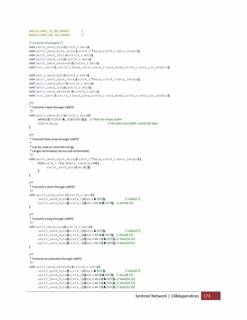
#define UART_TX_ISR_ENABLE 2 #define UART_NO_ISR_ENABLE 3 /* Function Prototypes */ void uart0_send_byte(uint8_t data); void uart0_send_byte_array(uint8_t *data, uint8_t data_length); void uart0_send_short(uint16_t data); void uart0_send_long(uint32_t data); void uart0_send_extended(uint64_t data); void init_uart0(uint16_t baud_rate, uint8_t rxtx_mode, uint8_t rxtx_isr_enable); void uart1_send_byte(uint8_t data); void uart1_send_byte_array(uint8_t *data, uint8_t data_length); void uart1_send_short(uint16_t data); void uart1_send_long(uint32_t data); void uart1_send_extended(uint64_t data); void init_uart1(uint16_t baud_rate, uint8_t rxtx_mode, uint8_t rxtx_isr_enable); /** * Transmit a byte through UART0 */ void uart0_send_byte(uint8_t data) { while ( !( UCSR0A & _BV(UDRE0)) ); // Wait for empty buffer UDR0 = data; // Put data into buffer, sends the data } /** * Transmit byte array through UART0 * * Can be used to transmitt strings * Length terminated (versus null terminated) */ void uart0_send_byte_array(uint8_t *data, uint8_t data_length) { for (uint8_t i=0; i<data_length; i++) { uart0_send_byte(data[i]); } } /** * Transmit a short through UART0 */ void uart0_send_short(uint16_t data) { uart0_send_byte((uint8_t) (data & 0xFF)); // data[0:7] uart0_send_byte((uint8_t) ((data >> 8) & 0xFF)); // data[8:15] } /** * Transmit a long through UART0 */ void uart0_send_long(uint32_t data) { uart0_send_byte((uint8_t) (data & 0xFF)); // data[0:7] uart0_send_byte((uint8_t) ((data >> 8) & 0xFF)); // data[8:15] uart0_send_byte((uint8_t) ((data >> 16) & 0xFF)); // data[16:23] uart0_send_byte((uint8_t) ((data >> 24) & 0xFF)); // data[24:31] } /** * Transmit an extended through UART0 */ void uart0_send_extended(uint64_t data) { uart0_send_byte((uint8_t) (data & 0xFF)); // data[0:7] uart0_send_byte((uint8_t) ((data >> 8) & 0xFF)); // data[8:15] uart0_send_byte((uint8_t) ((data >> 16) & 0xFF)); // data[16:23] uart0_send_byte((uint8_t) ((data >> 24) & 0xFF)); // data[24:31] uart0_send_byte((uint8_t) ((data >> 32) & 0xFF)); // data[32:39]
Sentinel Network | 13BAppendices 173
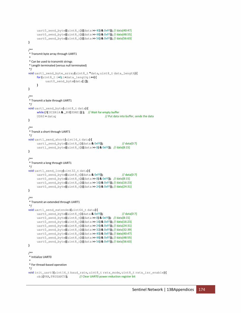
uart0_send_byte((uint8_t) ((data >> 40) & 0xFF)); // data[40:47] uart0_send_byte((uint8_t) ((data >> 48) & 0xFF)); // data[48:55] uart0_send_byte((uint8_t) ((data >> 56) & 0xFF)); // data[56:63] } /** * Transmit byte array through UART1 * * Can be used to transmitt strings * Length terminated (versus null terminated) */ void uart1_send_byte_array(uint8_t *data, uint8_t data_length) { for (uint8_t i=0; i<data_length; i++) { uart0_send_byte(data[i]); } } /** * Transmit a byte through UART1 */ void uart1_send_byte(uint8_t data) { while ( !( UCSR1A & _BV(UDRE1)) ); // Wait for empty buffer UDR0 = data; // Put data into buffer, sends the data } /** * Transit a short through UART1 */ void uart1_send_short(uint16_t data) { uart1_send_byte((uint8_t) (data & 0xFF)); // data[0:7] uart1_send_byte((uint8_t) ((data >> 8) & 0xFF)); // data[8:15] } /** * Transmit a long through UART1 */ void uart1_send_long(uint32_t data) { uart0_send_byte((uint8_t) (data & 0xFF)); // data[0:7] uart0_send_byte((uint8_t) ((data >> 8) & 0xFF)); // data[8:15] uart0_send_byte((uint8_t) ((data >> 16) & 0xFF)); // data[16:23] uart0_send_byte((uint8_t) ((data >> 24) & 0xFF)); // data[24:31] } /** * Transmit an extended through UART1 */ void uart1_send_extended(uint64_t data) { uart0_send_byte((uint8_t) (data & 0xFF)); // data[0:7] uart0_send_byte((uint8_t) ((data >> 8) & 0xFF)); // data[8:15] uart0_send_byte((uint8_t) ((data >> 16) & 0xFF)); // data[16:23] uart0_send_byte((uint8_t) ((data >> 24) & 0xFF)); // data[24:31] uart0_send_byte((uint8_t) ((data >> 32) & 0xFF)); // data[32:39] uart0_send_byte((uint8_t) ((data >> 40) & 0xFF)); // data[40:47] uart0_send_byte((uint8_t) ((data >> 48) & 0xFF)); // data[48:55] uart0_send_byte((uint8_t) ((data >> 56) & 0xFF)); // data[56:63] } /** * Initialize UART0 * * For thread‐based operation */ void init_uart0(uint16_t baud_rate, uint8_t rxtx_mode, uint8_t rxtx_isr_enable) { cbi(PRR, PRUSART0); // Clear UART0 power reduction register bit
Sentinel Network | 13BAppendices 174
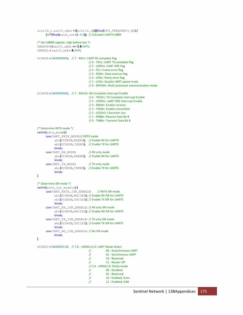
uint16_t uart0_ubbr = ((uint16_t) (((float)CPU_FREQUENCY_HZ) / (16*(float)baud_rate) ‐ 0.5)); // Calculate UART0 UBBR /* Set UBBR0 register, high before low */ UBRR0H = (uart0_ubbr >> 8) & 0xFF; UBRR0L = uart0_ubbr & 0xFF; UCSR0A = 0b00000000; // 7 ‐ RXCn: UART RX complete flag // 6 ‐ TXCn: UART TX complete flag // 5 ‐ UDREn: UART DRE flag // 4 ‐ FEn: Frame error flag // 3 ‐ DORn: Data overrun flag // 2 ‐ UPEn: Parity error flag // 1 ‐ U2Xn: Double UART speed mode // 0 ‐ MPCMn: Multi processor communication mode UCSR0B = 0b00000000; // 7 ‐ RXCIEn: RX Complete Interrupt Enable // 6 ‐ TXCIEn: TX Complete Interrupt Enable // 5 ‐ UDRIEn: UART DRE Interrupt Enable // 4 ‐ RXENn: Enable receiver // 3 ‐ TXENn: Enable transmitter // 2 ‐ UCSZn2: Character size // 1 ‐ RXB8n: Receive Data Bit 8 // 0 ‐ TXB8n: Transmit Data Bit 8 /* Determine RXTX mode */ switch(rxtx_mode) { case UART_RXTX_MODE: // RXTX mode sbi(UCSR0B, RXEN0); // Enable RX for UART0 sbi(UCSR0B, TXEN0); // Enable TX for UART0 break; case UART_RX_MODE: // RX only mode sbi(UCSR0B, RXEN0); // Enable RX for UART0 break; case UART_TX_MODE: // TX only mode sbi(UCSR0B, TXEN0); // Enable TX for UART0 break; } /* Determine ISR mode */ switch(rxtx_isr_enable) { case UART_RXTX_ISR_ENABLE: // RXTX ISR mode sbi(UCSR0B, RXCIE0); // Enable RX ISR for UART0 sbi(UCSR0B, TXCIE0); // Enable TX ISR for UART0 break; case UART_RX_ISR_ENABLE: // RX only ISR mode sbi(UCSR0B, RXCIE0); // Enable RX ISR for UART0 break; case UART_TX_ISR_ENABLE: // TX only ISR mode sbi(UCSR0B, TXCIE0); // Enable TX ISR for UART0 break; case UART_NO_ISR_ENABLE: // No ISR mode break; } UCSR0C = 0b00000110; // 7:6 ‐ UMSELn1:0: UART Mode Select // 00 ‐ Asynchronous UART // 01 ‐ Synchronous UART // 10 ‐ Reserved // 11 ‐ Master SPI // 5:4 ‐ UPMn1:0: Parity mode // 00 ‐ Disabled // 01 ‐ Reserved // 10 ‐ Enabled, Even // 11 ‐ Enabled, Odd
Sentinel Network | 13BAppendices 175
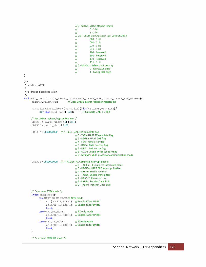
// 3 ‐ USBSn: Select stop bit length // 0 ‐ 1‐bit // 1 ‐ 2‐bit // 2:1 ‐ UCSZn1:0: Character size, with UCSRB.2 // 000 ‐ 5 bit // 001 ‐ 6 bit // 010 ‐ 7 bit // 011 ‐ 8 bit // 100 ‐ Reserved // 101 ‐ Reserved // 110 ‐ Reserved // 111 ‐ 9 bit // 0 ‐ UCPOLn: Select clock polarity // 0 ‐ Rising XCK edge // 1 ‐ Falling XCK edge } /** * Initialize UART1 * * For thread‐based operation */ void init_uart1(uint16_t baud_rate, uint8_t rxtx_mode, uint8_t rxtx_isr_enable) { cbi(PRR, PRUSART1); // Clear UART1 power reduction register bit uint16_t uart1_ubbr = ((uint16_t) (((float)CPU_FREQUENCY_HZ) / (16*(float)baud_rate) ‐ 0.5)); // Calculate UART1 UBBR /* Set UBBR1 register, high before low */ UBRR1H = (uart1_ubbr >> 8) & 0xFF; UBRR1L = uart1_ubbr & 0xFF; UCSR1A = 0b00000000; // 7 ‐ RXCn: UART RX complete flag // 6 ‐ TXCn: UART TX complete flag // 5 ‐ UDREn: UART DRE flag // 4 ‐ FEn: Frame error flag // 3 ‐ DORn: Data overrun flag // 2 ‐ UPEn: Parity error flag // 1 ‐ U2Xn: Double UART speed mode // 0 ‐ MPCMn: Multi processor communication mode UCSR1B = 0b00000000; // 7 ‐ RXCIEn: RX Complete Interrupt Enable // 6 ‐ TXCIEn: TX Complete Interrupt Enable // 5 ‐ UDRIEn: UART DRE Interrupt Enable // 4 ‐ RXENn: Enable receiver // 3 ‐ TXENn: Enable transmitter // 2 ‐ UCSZn2: Character size // 1 ‐ RXB8n: Receive Data Bit 8 // 0 ‐ TXB8n: Transmit Data Bit 8 /* Determine RXTX mode */ switch(rxtx_mode) { case UART_RXTX_MODE: // RXTX mode sbi(UCSR1B, RXEN1); // Enable RX for UART1 sbi(UCSR1B, TXEN1); // Enable TX for UART1 break; case UART_RX_MODE: // RX only mode sbi(UCSR1B, RXEN1); // Enable RX for UART1 break; case UART_TX_MODE: // TX only mode sbi(UCSR1B, TXEN1); // Enable TX for UART1 break; } /* Determine RXTX ISR mode */
Sentinel Network | 13BAppendices 176
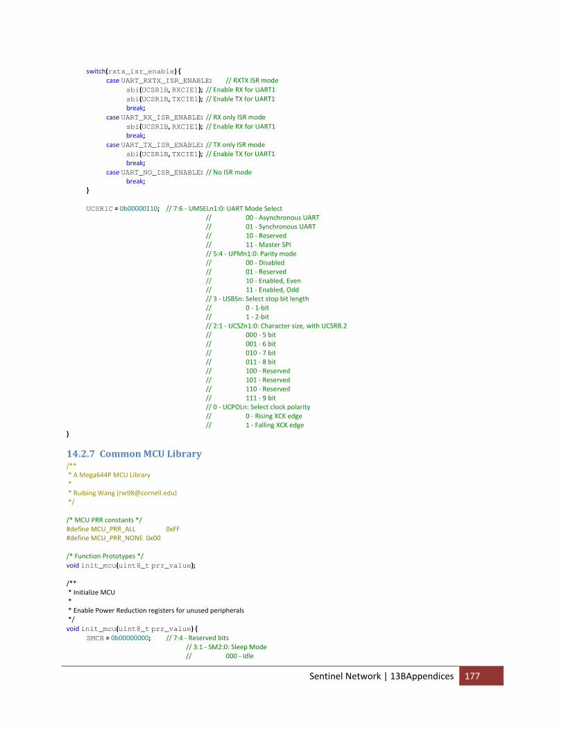
switch(rxtx_isr_enable) { case UART_RXTX_ISR_ENABLE: // RXTX ISR mode sbi(UCSR1B, RXCIE1); // Enable RX for UART1 sbi(UCSR1B, TXCIE1); // Enable TX for UART1 break; case UART_RX_ISR_ENABLE: // RX only ISR mode sbi(UCSR1B, RXCIE1); // Enable RX for UART1 break; case UART_TX_ISR_ENABLE: // TX only ISR mode sbi(UCSR1B, TXCIE1); // Enable TX for UART1 break; case UART_NO_ISR_ENABLE: // No ISR mode break; } UCSR1C = 0b00000110; // 7:6 ‐ UMSELn1:0: UART Mode Select // 00 ‐ Asynchronous UART // 01 ‐ Synchronous UART // 10 ‐ Reserved // 11 ‐ Master SPI // 5:4 ‐ UPMn1:0: Parity mode // 00 ‐ Disabled // 01 ‐ Reserved // 10 ‐ Enabled, Even // 11 ‐ Enabled, Odd // 3 ‐ USBSn: Select stop bit length // 0 ‐ 1‐bit // 1 ‐ 2‐bit // 2:1 ‐ UCSZn1:0: Character size, with UCSRB.2 // 000 ‐ 5 bit // 001 ‐ 6 bit // 010 ‐ 7 bit // 011 ‐ 8 bit // 100 ‐ Reserved // 101 ‐ Reserved // 110 ‐ Reserved // 111 ‐ 9 bit // 0 ‐ UCPOLn: Select clock polarity // 0 ‐ Rising XCK edge // 1 ‐ Falling XCK edge }
14.2.7 Common MCU Library /** * A Mega644P MCU Library * * Ruibing Wang ([email protected]) */ /* MCU PRR constants */ #define MCU_PRR_ALL 0xFF #define MCU_PRR_NONE 0x00 /* Function Prototypes */ void init_mcu(uint8_t prr_value); /** * Initialize MCU * * Enable Power Reduction registers for unused peripherals */ void init_mcu(uint8_t prr_value) { SMCR = 0b00000000; // 7:4 ‐ Reserved bits // 3:1 ‐ SM2:0: Sleep Mode // 000 ‐ Idle
Sentinel Network | 13BAppendices 177
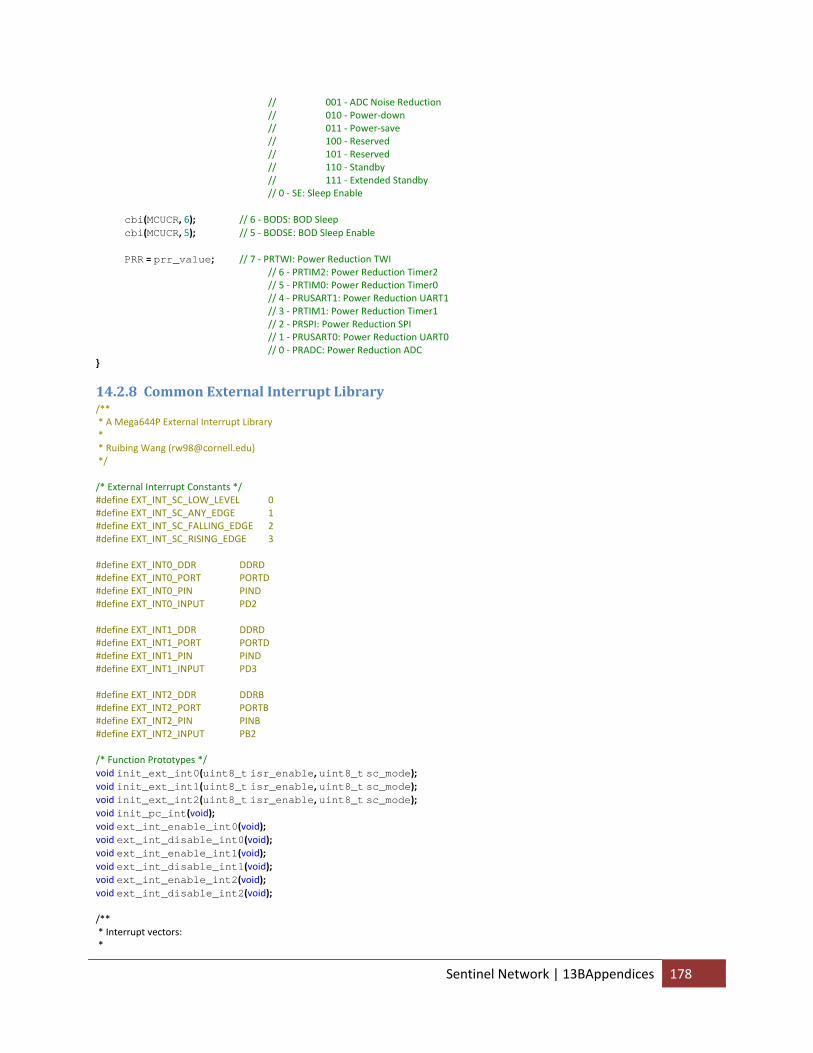
// 001 ‐ ADC Noise Reduction // 010 ‐ Power‐down // 011 ‐ Power‐save // 100 ‐ Reserved // 101 ‐ Reserved // 110 ‐ Standby // 111 ‐ Extended Standby // 0 ‐ SE: Sleep Enable cbi(MCUCR, 6); // 6 ‐ BODS: BOD Sleep cbi(MCUCR, 5); // 5 ‐ BODSE: BOD Sleep Enable PRR = prr_value; // 7 ‐ PRTWI: Power Reduction TWI // 6 ‐ PRTIM2: Power Reduction Timer2 // 5 ‐ PRTIM0: Power Reduction Timer0 // 4 ‐ PRUSART1: Power Reduction UART1 // 3 ‐ PRTIM1: Power Reduction Timer1 // 2 ‐ PRSPI: Power Reduction SPI // 1 ‐ PRUSART0: Power Reduction UART0 // 0 ‐ PRADC: Power Reduction ADC }
14.2.8 Common External Interrupt Library /** * A Mega644P External Interrupt Library * * Ruibing Wang ([email protected]) */ /* External Interrupt Constants */ #define EXT_INT_SC_LOW_LEVEL 0 #define EXT_INT_SC_ANY_EDGE 1 #define EXT_INT_SC_FALLING_EDGE 2 #define EXT_INT_SC_RISING_EDGE 3 #define EXT_INT0_DDR DDRD #define EXT_INT0_PORT PORTD #define EXT_INT0_PIN PIND #define EXT_INT0_INPUT PD2 #define EXT_INT1_DDR DDRD #define EXT_INT1_PORT PORTD #define EXT_INT1_PIN PIND #define EXT_INT1_INPUT PD3 #define EXT_INT2_DDR DDRB #define EXT_INT2_PORT PORTB #define EXT_INT2_PIN PINB #define EXT_INT2_INPUT PB2 /* Function Prototypes */ void init_ext_int0(uint8_t isr_enable, uint8_t sc_mode); void init_ext_int1(uint8_t isr_enable, uint8_t sc_mode); void init_ext_int2(uint8_t isr_enable, uint8_t sc_mode); void init_pc_int(void); void ext_int_enable_int0(void); void ext_int_disable_int0(void); void ext_int_enable_int1(void); void ext_int_disable_int1(void); void ext_int_enable_int2(void); void ext_int_disable_int2(void); /** * Interrupt vectors: *
Sentinel Network | 13BAppendices 178
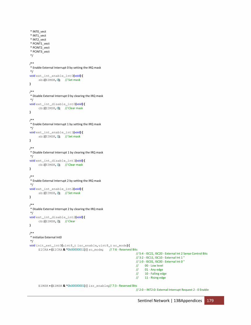
* INT0_vect * INT1_vect * INT2_vect * PCINT1_vect * PCINT2_vect * PCINT3_vect */ /** * Enable External Interrupt 0 by setting the IRQ mask */ void ext_int_enable_int0(void) { sbi(EIMSK, 0); // Set mask } /** * Disable External Interrupt 0 by clearing the IRQ mask */ void ext_int_disable_int0(void) { cbi(EIMSK, 0); // Clear mask } /** * Enable External Interrupt 1 by setting the IRQ mask */ void ext_int_enable_int1(void) { sbi(EIMSK, 1); // Set mask } /** * Disable External Interrupt 1 by clearing the IRQ mask */ void ext_int_disable_int1(void) { cbi(EIMSK, 1); // Clear mask } /** * Enable External Interrupt 2 by setting the IRQ mask */ void ext_int_enable_int2(void) { sbi(EIMSK, 2); // Set mask } /** * Disable External Interrupt 2 by clearing the IRQ mask */ void ext_int_disable_int2(void) { cbi(EIMSK, 2); // Clear } /** * Initialize External Int0 */ void init_ext_int0(uint8_t isr_enable, uint8_t sc_mode) { EICRA = (EICRA & ~0b00000011) | sc_mode; // 7:6 ‐ Reserved Bits // 5:4 ‐ ISC21, ISC20 ‐ External Int 2 Sense Control Bits // 3:2 ‐ ISC11, ISC10 ‐ External Int 1 " // 1:0 ‐ ISC01, ISC00 ‐ External Int 0 " // 00 ‐ Low level // 01 ‐ Any edge // 10 ‐ Falling edge // 11 ‐ Rising edge EIMSK = (EIMSK & ~0b00000001) | isr_enable;// 7:3 ‐ Reserved Bits // 2:0 – INT2:0: External Interrupt Request 2 ‐ 0 Enable
Sentinel Network | 13BAppendices 179
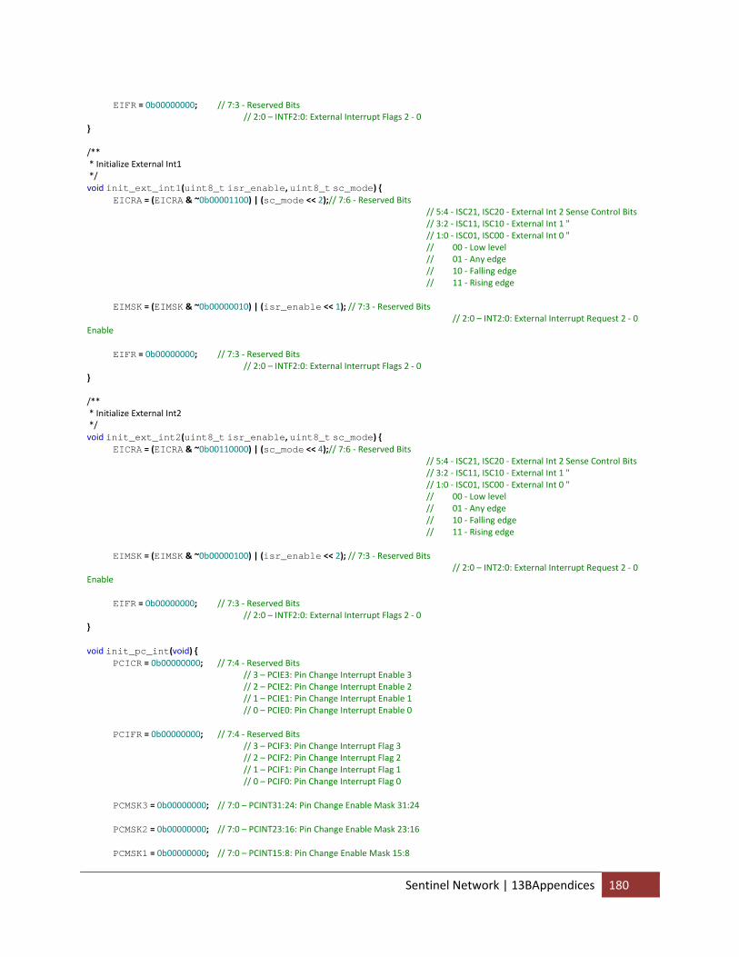
EIFR = 0b00000000; // 7:3 ‐ Reserved Bits // 2:0 – INTF2:0: External Interrupt Flags 2 ‐ 0 } /** * Initialize External Int1 */ void init_ext_int1(uint8_t isr_enable, uint8_t sc_mode) { EICRA = (EICRA & ~0b00001100) | (sc_mode << 2);// 7:6 ‐ Reserved Bits // 5:4 ‐ ISC21, ISC20 ‐ External Int 2 Sense Control Bits // 3:2 ‐ ISC11, ISC10 ‐ External Int 1 " // 1:0 ‐ ISC01, ISC00 ‐ External Int 0 " // 00 ‐ Low level // 01 ‐ Any edge // 10 ‐ Falling edge // 11 ‐ Rising edge EIMSK = (EIMSK & ~0b00000010) | (isr_enable << 1); // 7:3 ‐ Reserved Bits // 2:0 – INT2:0: External Interrupt Request 2 ‐ 0 Enable EIFR = 0b00000000; // 7:3 ‐ Reserved Bits // 2:0 – INTF2:0: External Interrupt Flags 2 ‐ 0 } /** * Initialize External Int2 */ void init_ext_int2(uint8_t isr_enable, uint8_t sc_mode) { EICRA = (EICRA & ~0b00110000) | (sc_mode << 4);// 7:6 ‐ Reserved Bits // 5:4 ‐ ISC21, ISC20 ‐ External Int 2 Sense Control Bits // 3:2 ‐ ISC11, ISC10 ‐ External Int 1 " // 1:0 ‐ ISC01, ISC00 ‐ External Int 0 " // 00 ‐ Low level // 01 ‐ Any edge // 10 ‐ Falling edge // 11 ‐ Rising edge EIMSK = (EIMSK & ~0b00000100) | (isr_enable << 2); // 7:3 ‐ Reserved Bits // 2:0 – INT2:0: External Interrupt Request 2 ‐ 0 Enable EIFR = 0b00000000; // 7:3 ‐ Reserved Bits // 2:0 – INTF2:0: External Interrupt Flags 2 ‐ 0 } void init_pc_int(void) { PCICR = 0b00000000; // 7:4 ‐ Reserved Bits // 3 – PCIE3: Pin Change Interrupt Enable 3 // 2 – PCIE2: Pin Change Interrupt Enable 2 // 1 – PCIE1: Pin Change Interrupt Enable 1 // 0 – PCIE0: Pin Change Interrupt Enable 0 PCIFR = 0b00000000; // 7:4 ‐ Reserved Bits // 3 – PCIF3: Pin Change Interrupt Flag 3 // 2 – PCIF2: Pin Change Interrupt Flag 2 // 1 – PCIF1: Pin Change Interrupt Flag 1 // 0 – PCIF0: Pin Change Interrupt Flag 0 PCMSK3 = 0b00000000; // 7:0 – PCINT31:24: Pin Change Enable Mask 31:24 PCMSK2 = 0b00000000; // 7:0 – PCINT23:16: Pin Change Enable Mask 23:16 PCMSK1 = 0b00000000; // 7:0 – PCINT15:8: Pin Change Enable Mask 15:8
Sentinel Network | 13BAppendices 180
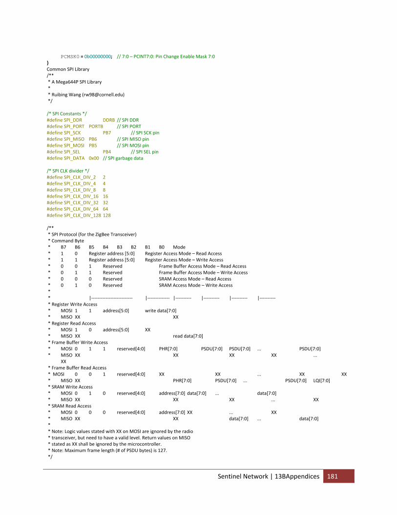
PCMSK0 = 0b00000000; // 7:0 – PCINT7:0: Pin Change Enable Mask 7:0 } Common SPI Library /** * A Mega644P SPI Library * * Ruibing Wang ([email protected]) */ /* SPI Constants */ #define SPI_DDR DDRB // SPI DDR #define SPI_PORT PORTB // SPI PORT #define SPI_SCK PB7 // SPI SCK pin #define SPI_MISO PB6 // SPI MISO pin #define SPI_MOSI PB5 // SPI MOSI pin #define SPI_SEL PB4 // SPI SEL pin #define SPI_DATA 0x00 // SPI garbage data /* SPI CLK divider */ #define SPI_CLK_DIV_2 2 #define SPI_CLK_DIV_4 4 #define SPI_CLK_DIV_8 8 #define SPI_CLK_DIV_16 16 #define SPI_CLK_DIV_32 32 #define SPI_CLK_DIV_64 64 #define SPI_CLK_DIV_128 128 /** * SPI Protocol (for the ZigBee Transceiver) * Command Byte * B7 B6 B5 B4 B3 B2 B1 B0 Mode * 1 0 Register address [5:0] Register Access Mode – Read Access * 1 1 Register address [5:0] Register Access Mode – Write Access * 0 0 1 Reserved Frame Buffer Access Mode – Read Access * 0 1 1 Reserved Frame Buffer Access Mode – Write Access * 0 0 0 Reserved SRAM Access Mode – Read Access * 0 1 0 Reserved SRAM Access Mode – Write Access * * |‐‐‐‐‐‐‐‐‐‐‐‐‐‐‐‐‐‐‐‐‐‐‐‐‐‐ |‐‐‐‐‐‐‐‐‐‐‐‐‐‐ |‐‐‐‐‐‐‐‐‐‐ |‐‐‐‐‐‐‐‐‐‐ |‐‐‐‐‐‐‐‐‐‐ |‐‐‐‐‐‐‐‐‐‐ * Register Write Access * MOSI 1 1 address[5:0] write data[7:0] * MISO XX XX * Register Read Access * MOSI 1 0 address[5:0] XX * MISO XX read data[7:0] * Frame Buffer Write Access * MOSI 0 1 1 reserved[4:0] PHR[7:0] PSDU[7:0] PSDU[7:0] ... PSDU[7:0] * MISO XX XX XX XX ... XX * Frame Buffer Read Access * MOSI 0 0 1 reserved[4:0] XX XX ... XX XX * MISO XX PHR[7:0] PSDU[7:0] ... PSDU[7:0] LQI[7:0] * SRAM Write Access * MOSI 0 1 0 reserved[4:0] address[7:0] data[7:0] ... data[7:0] * MISO XX XX XX ... XX * SRAM Read Access * MOSI 0 0 0 reserved[4:0] address[7:0] XX ... XX * MISO XX XX data[7:0] ... data[7:0] * * Note: Logic values stated with XX on MOSI are ignored by the radio * transceiver, but need to have a valid level. Return values on MISO * stated as XX shall be ignored by the microcontroller. * Note: Maximum frame length (# of PSDU bytes) is 127. */
Sentinel Network | 13BAppendices 181
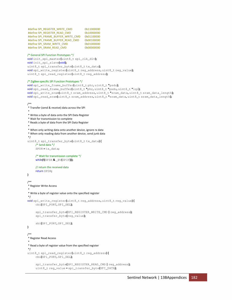
#define SPI_REGISTER_WRITE_CMD 0b11000000 #define SPI_REGISTER_READ_CMD 0b10000000 #define SPI_FRAME_BUFFER_WRITE_CMD 0b01100000 #define SPI_FRAME_BUFFER_READ_CMD 0b00100000 #define SPI_SRAM_WRITE_CMD 0b01000000 #define SPI_SRAM_READ_CMD 0b00000000 /* General SPI Function Prototypes */ void init_spi_master(uint8_t spi_clk_div); void init_spi_slave(void); uint8_t spi_transfer_byte(uint8_t tx_data); void spi_write_register(uint8_t reg_address, uint8_t reg_value); uint8_t spi_read_register(uint8_t reg_address); /* ZigBee‐specific SPI Function Prototypes */ void spi_write_frame_buffer(uint8_t phr, uint8_t *psdu); void spi_read_frame_buffer(uint8_t *phr, uint8_t *psdu, uint8_t *lqi); void spi_write_sram(uint8_t sram_address, uint8_t *sram_data, uint8_t sram_data_length); void spi_read_sram(uint8_t sram_address, uint8_t *sram_data, uint8_t sram_data_length); /** * Transfer (send & receive) data across the SPI * * Writes a byte of data onto the SPI Data Register * Wait for transmission to complete * Reads a byte of data from the SPI Data Register * * When only writing data onto another device, ignore rx data * When only reading data from another device, send junk data */ uint8_t spi_transfer_byte(uint8_t tx_data) { /* Send data */ SPDR = tx_data; /* Wait for transmission complete */ while(!(SPSR & _BV(SPIF))); // return the received data return SPDR; } /** * Register Write Access * * Write a byte of register value onto the specified register */ void spi_write_register(uint8_t reg_address, uint8_t reg_value) { cbi(SPI_PORT, SPI_SEL); spi_transfer_byte(SPI_REGISTER_WRITE_CMD | reg_address); spi_transfer_byte(reg_value); sbi(SPI_PORT, SPI_SEL); } /** * Register Read Access * * Read a byte of register value from the specified register */ uint8_t spi_read_register(uint8_t reg_address) { cbi(SPI_PORT, SPI_SEL); spi_transfer_byte(SPI_REGISTER_READ_CMD | reg_address); uint8_t reg_value = spi_transfer_byte(SPI_DATA);
Sentinel Network | 13BAppendices 182
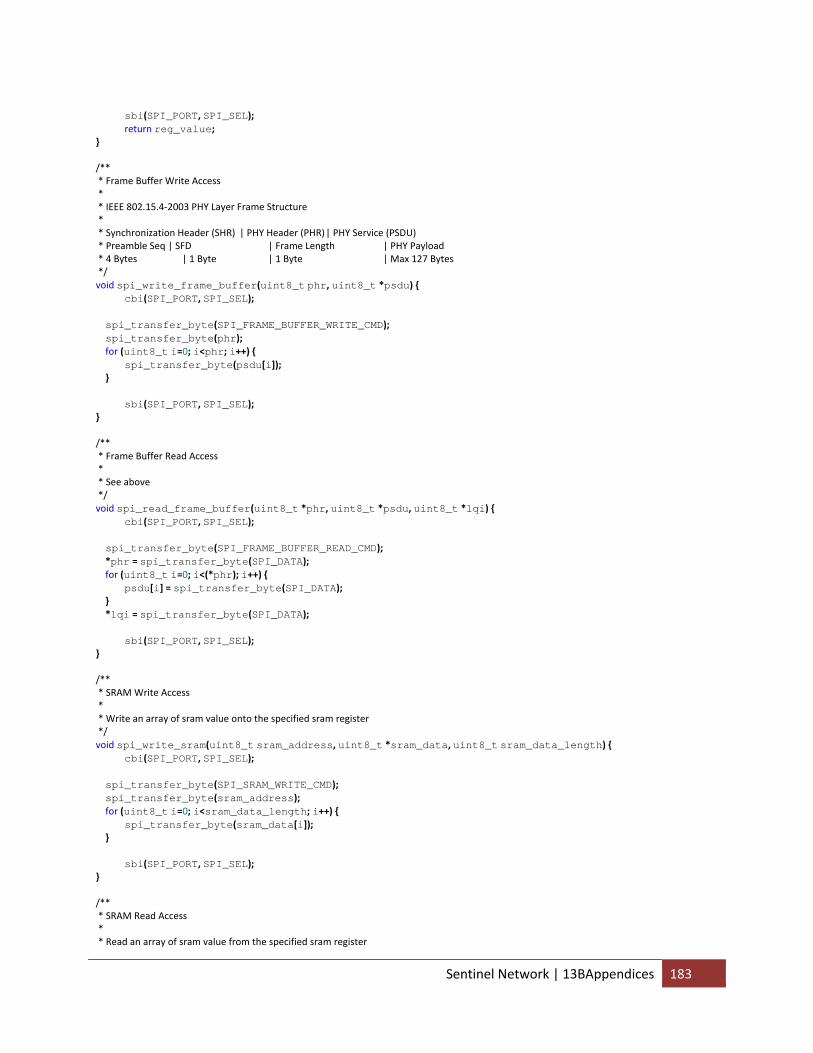
sbi(SPI_PORT, SPI_SEL); return reg_value; } /** * Frame Buffer Write Access * * IEEE 802.15.4‐2003 PHY Layer Frame Structure * * Synchronization Header (SHR) | PHY Header (PHR) | PHY Service (PSDU) * Preamble Seq | SFD | Frame Length | PHY Payload * 4 Bytes | 1 Byte | 1 Byte | Max 127 Bytes */ void spi_write_frame_buffer(uint8_t phr, uint8_t *psdu) { cbi(SPI_PORT, SPI_SEL); spi_transfer_byte(SPI_FRAME_BUFFER_WRITE_CMD); spi_transfer_byte(phr); for (uint8_t i=0; i<phr; i++) { spi_transfer_byte(psdu[i]); } sbi(SPI_PORT, SPI_SEL); } /** * Frame Buffer Read Access * * See above */ void spi_read_frame_buffer(uint8_t *phr, uint8_t *psdu, uint8_t *lqi) { cbi(SPI_PORT, SPI_SEL); spi_transfer_byte(SPI_FRAME_BUFFER_READ_CMD); *phr = spi_transfer_byte(SPI_DATA); for (uint8_t i=0; i<(*phr); i++) { psdu[i] = spi_transfer_byte(SPI_DATA); } *lqi = spi_transfer_byte(SPI_DATA); sbi(SPI_PORT, SPI_SEL); } /** * SRAM Write Access * * Write an array of sram value onto the specified sram register */ void spi_write_sram(uint8_t sram_address, uint8_t *sram_data, uint8_t sram_data_length) { cbi(SPI_PORT, SPI_SEL); spi_transfer_byte(SPI_SRAM_WRITE_CMD); spi_transfer_byte(sram_address); for (uint8_t i=0; i<sram_data_length; i++) { spi_transfer_byte(sram_data[i]); } sbi(SPI_PORT, SPI_SEL); } /** * SRAM Read Access * * Read an array of sram value from the specified sram register
Sentinel Network | 13BAppendices 183
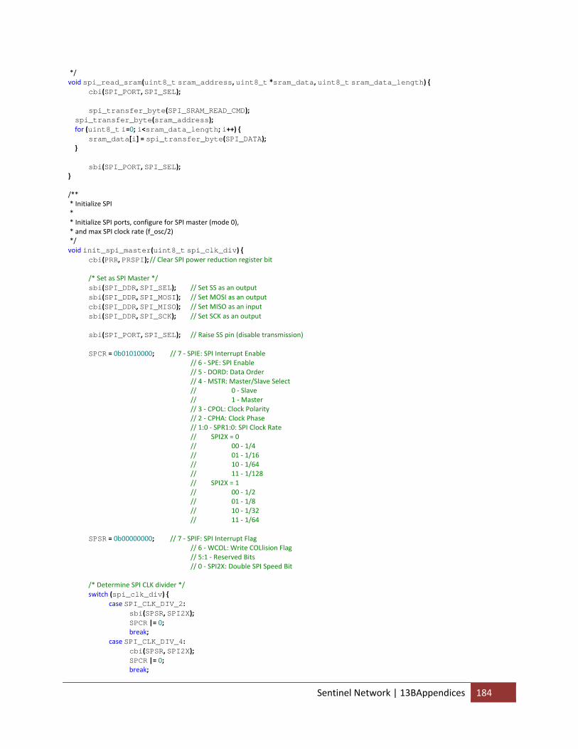
*/ void spi_read_sram(uint8_t sram_address, uint8_t *sram_data, uint8_t sram_data_length) { cbi(SPI_PORT, SPI_SEL); spi_transfer_byte(SPI_SRAM_READ_CMD); spi_transfer_byte(sram_address); for (uint8_t i=0; i<sram_data_length; i++) { sram_data[i] = spi_transfer_byte(SPI_DATA); } sbi(SPI_PORT, SPI_SEL); } /** * Initialize SPI * * Initialize SPI ports, configure for SPI master (mode 0), * and max SPI clock rate (f_osc/2) */ void init_spi_master(uint8_t spi_clk_div) { cbi(PRR, PRSPI); // Clear SPI power reduction register bit /* Set as SPI Master */ sbi(SPI_DDR, SPI_SEL); // Set SS as an output sbi(SPI_DDR, SPI_MOSI); // Set MOSI as an output cbi(SPI_DDR, SPI_MISO); // Set MISO as an input sbi(SPI_DDR, SPI_SCK); // Set SCK as an output sbi(SPI_PORT, SPI_SEL); // Raise SS pin (disable transmission) SPCR = 0b01010000; // 7 ‐ SPIE: SPI Interrupt Enable // 6 ‐ SPE: SPI Enable // 5 ‐ DORD: Data Order // 4 ‐ MSTR: Master/Slave Select // 0 ‐ Slave // 1 ‐ Master // 3 ‐ CPOL: Clock Polarity // 2 ‐ CPHA: Clock Phase // 1:0 ‐ SPR1:0: SPI Clock Rate // SPI2X = 0 // 00 ‐ 1/4 // 01 ‐ 1/16 // 10 ‐ 1/64 // 11 ‐ 1/128 // SPI2X = 1 // 00 ‐ 1/2 // 01 ‐ 1/8 // 10 ‐ 1/32 // 11 ‐ 1/64 SPSR = 0b00000000; // 7 ‐ SPIF: SPI Interrupt Flag // 6 ‐ WCOL: Write COLlision Flag // 5:1 ‐ Reserved Bits // 0 ‐ SPI2X: Double SPI Speed Bit /* Determine SPI CLK divider */ switch (spi_clk_div) { case SPI_CLK_DIV_2: sbi(SPSR, SPI2X); SPCR |= 0; break; case SPI_CLK_DIV_4: cbi(SPSR, SPI2X); SPCR |= 0; break;
Sentinel Network | 13BAppendices 184
case SPI_CLK_DIV_8: sbi(SPSR, SPI2X); SPCR |= 1; break; case SPI_CLK_DIV_16: cbi(SPSR, SPI2X); SPCR |= 1; break; case SPI_CLK_DIV_32: sbi(SPSR, SPI2X); SPCR |= 2; break; case SPI_CLK_DIV_64: cbi(SPSR, SPI2X); SPCR |= 2; break; case SPI_CLK_DIV_128: cbi(SPSR, SPI2X); SPCR |= 3; break; } } /** * Initialize SPI * * Initialize SPI ports, configure for SPI master (mode 0), * and max SPI clock rate (f_osc/2) */ void init_spi_slave(void) { cbi(PRR, PRSPI); // Clear SPI power reduction register bit cbi(SPI_DDR, SPI_SEL); // Set SS as an input cbi(SPI_DDR, SPI_MOSI); // Set MOSI as an input sbi(SPI_DDR, SPI_MISO); // Set MISO as an output cbi(SPI_DDR, SPI_SCK); // Set SCK as an input SPCR = 0b01000000; // 7 ‐ SPIE: SPI Interrupt Enable // 6 ‐ SPE: SPI Enable // 5 ‐ DORD: Data Order // 4 ‐ MSTR: Master/Slave Select // 0 ‐ Slave // 1 ‐ Master // 3 ‐ CPOL: Clock Polarity // 2 ‐ CPHA: Clock Phase // 1:0 ‐ SPR1:0: SPI Clock Rate // SPI2X = 0 // 00 ‐ 1/4 // 01 ‐ 1/16 // 10 ‐ 1/64 // 11 ‐ 1/128 // SPI2X = 1 // 00 ‐ 1/2 // 01 ‐ 1/8 // 10 ‐ 1/32 // 11 ‐ 1/64 SPSR = 0b00000000; // 7 ‐ SPIF: SPI Interrupt Flag // 6 ‐ WCOL: Write COLlision Flag // 5:1 ‐ Reserved Bits // 0 ‐ SPI2X: Double SPI Speed Bit }
14.2.9 Common Timer Library /**
Sentinel Network | 13BAppendices 185
* A Mega644P Timer Library * * Ruibing Wang ([email protected]) */ /** * Interrupt vectors: * * TIMER0_COMPA_vect * TIMER0_COMPB_vect * TIMER0_OVF_vect * TIMER1_CAPT_vect * TIMER1_COMPA_vect * TIMER1_COMPB_vect * TIMER1_OVF_vect * TIMER2_COMPA_vect * TIMER2_COMPB_vect * TIMER2_OVF_vect */ /* Timer Constants */ #define TIMER_DIV_0 0 #define TIMER_DIV_1 1 #define TIMER_DIV_8 8 #define TIMER_DIV_32 32 // Timer2 Only #define TIMER_DIV_64 64 #define TIMER_DIV_128 128 // Timer2 Only #define TIMER_DIV_256 256 #define TIMER_DIV_1024 1024 /* Timer0 Constants */ #define TIMER0A_ISR_ENABLE TRUE #define TIMER0B_ISR_ENABLE FALSE #define TIMER0A_DEBUG FALSE #define TIMER0A_RES_US 200000 #define TIMER0B_RES_US 50 #define TIMER0_DIV TIMER_DIV_1024 #define TIMER0_DIV_MASK 0b00000111 #define TIMER0_OCR0A (uint8_t) (((float)CPU_FREQUENCY_HZ/(float)TIMER0_DIV) / ((float)1000000/(float)TIMER0A_RES_US) + 0.5) #define TIMER0_OCR0B (uint8_t) (((float)CPU_FREQUENCY_HZ/(float)TIMER0_DIV) / ((float)1000000/(float)TIMER0B_RES_US) + 0.5) #define TIMER0_DDR DDRB #define TIMER0_PORT PORTB #define TIMER0_PIN PINB #define TIMER0A_OUTPUT PB3 #define TIMER0B_OUTPUT PB4 /* Timer1 Constants */ #define OCR1A_FREQUENCY_HZ 153600 // Set Timer1 clock oscillator output frequency #define TIMER1_DIV TIMER_DIV_1 // Set Timer1 divider (lowest has the highest acurracy) #define TIMER1_DIV_MASK 0b00000111 // Define Timer1 divider register mask #define TIMER1_OCR1A (uint16_t) ((float)CPU_FREQUENCY_HZ / ((float)TIMER1_DIV*(float)OCR1A_FREQUENCY_HZ*2) + 0.5) // Caculate Timer1 OCR1A register value (for clock oscillator) #define TIMER1_DDR DDRD // Set Timer1 OCR1A DDR port #define TIMER1_PORT PORTD #define TIMER1_PIN PIND #define TIMER1A_OUTPUT PD5 // Set Timer1 OCR1A pin #define TIMER1B_OUTPUT PD4 /* Timer2 Constants */ #define TIMER2A_ISR_ENABLE FALSE #define TIMER2B_ISR_ENABLE FALSE #define TIMER2A_DEBUG FALSE #define TIMER2A_RES_US 200000 #define TIMER2B_RES_US 32 #define TIMER2_DIV TIMER_DIV_1024 // Set Timer2 divider #define TIMER2_DIV_MASK 0b00000111 // Define Timer2 divider register mask
Sentinel Network | 13BAppendices 186
#define TIMER2_OCR2A (uint8_t) (((float)CPU_FREQUENCY_HZ/(float)TIMER2_DIV) / ((float)1000000/(float)TIMER2A_RES_US) + 0.5) // Calculate Timer2 OCR2A register compare match value #define TIMER2_OCR2B (uint8_t) (((float)CPU_FREQUENCY_HZ/(float)TIMER2_DIV) / ((float)1000000/(float)TIMER2B_RES_US) + 0.5) // Calculate Timer2 OCR2A register compare match value #define TIMER2_DDR DDRD #define TIMER2_PIN PIND #define TIMER2A_OUTPUT PD7 #define TIMER2B_OUTPUT PD6 /* Timer0 Function Prototypes */ void init_timer0(void); void timer_enable_timer0a_isr(void); void timer_disable_timer0a_isr(void); void timer_enable_timer0b_isr(void); void timer_disable_timer0b_isr(void); /* Timer1 Function Prototypes */ void init_timer1(void); void timer_enable_timer1a_isr(void); void timer_disable_timer1a_isr(void); void timer_enable_timer1b_isr(void); void timer_disable_timer1b_isr(void); /* Timer2 Function Prototypes */ void init_timer2(void); void timer_enable_timer2a_isr(void); void timer_disable_timer2a_isr(void); void timer_enable_timer2b_isr(void); void timer_disable_timer2b_isr(void); /** * Enable Timer0A trough the IRQ mask */ void timer_enable_timer0a_isr(void) { sbi(TIMSK0, OCIE0A); // Set IRQ mask } /** * Disable Timer0A through the IRQ mask */ void timer_disable_timer0a_isr(void) { cbi(TIMSK0, OCIE0A); // Clear IRQ mask } /** * Enable Timer0B trough the IRQ mask */ void timer_enable_timer0b_isr(void) { sbi(TIMSK0, OCIE0B); // Set IRQ mask } /** * Disable Timer0B trough the IRQ mask */ void timer_disable_timer0b_isr(void) { cbi(TIMSK0, OCIE0B); // Clear IRQ mask } /** * Enable Timer1A trough the IRQ mask */ void timer_enable_timer1a_isr(void) { sbi(TIMSK1, OCIE1A); // Set IRQ mask }
Sentinel Network | 13BAppendices 187
/** * Disable Timer1A trough the IRQ mask */ void timer_disable_timer1a_isr(void) { cbi(TIMSK1, OCIE1A); // Clear IRQ mask } /** * Enable Timer1B trough the IRQ mask */ void timer_enable_timer1b_isr(void) { sbi(TIMSK1, OCIE1B); // Set IRQ mask } /** * Disable Timer1B trough the IRQ mask */ void timer_disable_timer1b_isr(void) { cbi(TIMSK1, OCIE1B); // Clear IRQ mask } /** * Enable Timer2A trough the IRQ mask */ void timer_enable_timer2a_isr(void) { sbi(TIMSK2, OCIE2A); // Set IRQ mask } /** * Disable Timer2A trough the IRQ mask */ void timer_disable_timer2a_isr(void) { cbi(TIMSK2, OCIE2A); // Clear IRQ mask } /** * Enable Timer2B trough the IRQ mask */ void timer_enable_timer2b_isr(void) { sbi(TIMSK2, OCIE2B); // Set IRQ mask } /** * Disable Timer2B trough the IRQ mask */ void timer_disable_timer2b_isr(void) { cbi(TIMSK2, OCIE2B); // Clear IRQ mask } /** * Initialize Timer1 * * For interrupt‐based CTC mode */ void init_timer0(void) { cbi(PRR, PRTIM0); // Clear the Timer0 power reduction register bit TCCR0A = 0b00000010; // 7:6 ‐ COM0A1:0: Compare Match Output A Mode // 5:4 ‐ COM0B1:0: Compare Match Output B Mode // 3:2 ‐ Reserved Bits // 1:0 ‐ WGM01:0: Waveform Generation Mode // 000 ‐ Normal (0xFF) // 001 ‐ PWM, Phase Correct (0xFF) // 010 ‐ CTC (OCRA) // 011 ‐ Fast PWM (0xFF)
Sentinel Network | 13BAppendices 188
// 100 ‐ Reserved // 101 ‐ PWM, Phase Correct (OCRA) // 110 ‐ Reserved // 111 ‐ Fast PWM (OCRA) /* Enable OCR0A output for digital debug */ #if TIMER0A_DEBUG sbi(TIMER0_DDR, TIMER0A_OUTPUT); TCCR0A |= (0b01 << 6); #endif TCCR0B = 0b00000000; // 7 ‐ FOC0A: Force Output Compare A // 6 ‐ FOC0B: Force Output Compare B // 5:4 ‐ Reserved Bits // 3 ‐ WGM02: Waveform Generation Mode // 2:0 ‐ CS02:0: Clock select // 000 ‐ Timer stopped // 001 ‐ 1 // 010 ‐ 8 // 011 ‐ 64 // 100 ‐ 256 // 101 ‐ 1024 // 110 ‐ External clock source on T0 pin, falling edge // 111 ‐ ", rising edge /* Determine timer clock divider for Timer0 */ #if TIMER1_DIV == TIMER_DIV_0 TCCR0B = (TCCR0B & ~TIMER1_DIV_MASK) | 0b000; #elif TIMER1_DIV == TIMER_DIV_1 TCCR0B = (TCCR0B & ~TIMER1_DIV_MASK) | 0b001; #elif TIMER1_DIV == TIMER_DIV_8 TCCR0B = (TCCR0B & ~TIMER1_DIV_MASK) | 0b010; #elif TIMER1_DIV == TIMER_DIV_64 TCCR0B = (TCCR0B & ~TIMER1_DIV_MASK) | 0b011; #elif TIMER1_DIV == TIMER_DIV_256 TCCR0B = (TCCR0B & ~TIMER1_DIV_MASK) | 0b100; #elif TIMER1_DIV == TIMER_DIV_1024 TCCR0B = (TCCR0B & ~TIMER1_DIV_MASK) | 0b101; #endif TIMSK0 = 0b00000000; // 7:3 ‐ Reserved bits for other timer interrupts // 2 ‐ OCIE0B: Timer0 Timer/Counter Output Compare Match B Interrupt Enable // 1 ‐ OCIE0A: Timer0 Timer/Counter Output Compare Match A Interrupt Enable // 0 ‐ TOIE0: Timer/Counter0 Overflow Interrupt Enable /* Determine whether to enable Timer0A ISR */ #if TIMER0A_ISR_ENABLE OCR0A = TIMER0_OCR0A; // Set Timer0 OCR0A value TIMSK0 |= _BV(OCIE0A); // Set IRQ mask #endif /* Determine whether to enable Timer0B ISR */ #if TIMER0B_ISR_ENABLE OCR0B = TIMER0_OCR0B; // Set Timer0 OCR0B value TIMSK0 |= _BV(OCIE0B); // Set IRQ mask #endif } /** * Initialize Timer1 * * For compare output mode on OCR1A */ void init_timer1(void) { cbi(PRR, PRTIM1); // Clear the Timer1 power reduction register bit
Sentinel Network | 13BAppendices 189
sbi(TIMER1_DDR, TIMER1A_OUTPUT); // Enable OCR1A output for digital debug TCCR1A = 0b01000000; // 7:6 – COMnA1:0: Compare Output Mode for Channel A // 5:4 ‐ COMnB1:0: Compare Output Mode for Channel B // 3:2 ‐ Reserved // 1:0 ‐ WGMn1:0: Waveform Generation Mode // 0000 ‐ Normal (0xFFFF) // 0001 ‐ PWM, Phase Correct, 8‐bit (0x00FF) // 0010 ‐ PWM, Phase Correct, 9‐bit (0x01FF) // 0011 ‐ PWM, Phase Correct, 10‐bit (0x03FF) // 0100 ‐ CTC (OCRnA) // 0101 ‐ Fast PWM, 8‐bit (0x00FF) // 0110 ‐ Fast PWM, 9‐bit (0x01FF) // 0111 ‐ Fast PWM, 10‐bit (0x03FF) // 1000 ‐ PWM, Phase and Frequency Correct (ICRn) // 1001 ‐ PWM, Phase and Frequency Correct (OCRnA) // 1010 ‐ PWM, Phase Correct (ICRn) // 1011 ‐ PWM, Phase Correct (OCRnA) // 1100 ‐ CTC (ICRn) // 1101 ‐ Reserved // 1110 ‐ Fast PWM (ICRn) // 1111 ‐ Fast PWM (OCRnA) TCCR1B = 0b00001000; // 7 ‐ ICNCn: Input Capture Noise Canceler // 6 ‐ ICESn: Input Capture Edge Select // 5 ‐ Reserved // 4:3 ‐ WGMn3:2: Waveform Generation Mode // 2:0 ‐ CSn2:0: Clock Select // 000 ‐ Timer stopped // 001 ‐ 1 // 010 ‐ 8 // 011 ‐ 64 // 100 ‐ 256 // 101 ‐ 1024 // 110 ‐ External clock source on T0 pin, falling edge // 111 ‐ ", rising edge /* Determine timer clock divider for Timer1 */ #if TIMER1_DIV == TIMER_DIV_0 TCCR1B = (TCCR1B & ~TIMER1_DIV_MASK) | 0; #elif TIMER1_DIV == TIMER_DIV_1 TCCR1B = (TCCR1B & ~TIMER1_DIV_MASK) | 1; #elif TIMER1_DIV == TIMER_DIV_8 TCCR1B = (TCCR1B & ~TIMER1_DIV_MASK) | 2; #elif TIMER1_DIV == TIMER_DIV_64 TCCR1B = (TCCR1B & ~TIMER1_DIV_MASK) | 3; #elif TIMER1_DIV == TIMER_DIV_256 TCCR1B = (TCCR1B & ~TIMER1_DIV_MASK) | 4; #elif TIMER1_DIV == TIMER_DIV_1024 TCCR1B = (TCCR1B & ~TIMER1_DIV_MASK) | 5; #endif TCCR1C = 0b00000000; // 7 ‐ FOCnA: Force Output Compare for Channel A // 6 ‐ FOCnB: Force Output Compare for Channel B // 5:0 ‐ Reserved /* Set Timer1 OCR1A value */ OCR1AH = (TIMER1_OCR1A) >> 8; OCR1AL = (TIMER1_OCR1A << 8) >> 8; TIMSK1 = 0b00000000; // 7:6 ‐ Reserved // 5 ‐ ICIE1: Timer/Counter1, Input Capture Interrupt Enable // 4:3 ‐ Reserved // 2 ‐ OCIE1B: Timer/Counter1, Output Compare B Match Interrupt Enable // 1 ‐ OCIE1A: Timer/Counter1, Output Compare A Match Interrupt Enable
Sentinel Network | 13BAppendices 190
// 0 ‐ TOIE1: Timer/Counter1, Overflow Interrupt Enable } /** * Initialize Timer2 * * For interrupt‐based CTC mode */ void init_timer2(void) { cbi(PRR, PRTIM2); // Clear the Timer2 power reduction register bit TCCR2A = 0b00000010; // 7:6 – COM2A1:0: Compare Match Output A Mode // 5:4 – COM2B1:0: Compare Match Output B Mode // 3:2 – Reserved Bits // 1:0 – WGM21:0: Waveform Generation Mode /* Determine whether to enable OCR2A output for digital debug */ #if TIMER2A_DEBUG sbi(TIMER2_DDR,TIMER2A_OUTPUT); sbi(TCCR2A,6); #endif TCCR2B = 0b00000000; // 7 – FOC2A: Force Output Compare A // 6 – FOC2B: Force Output Compare B // 5:4 – Reserved Bits // 3 – WGM22: Waveform Generation Mode // 2:0 – CS22:0: Clock Select // 000 ‐ No clk // 001 ‐ 1 // 010 ‐ 8 // 011 ‐ 32 // 100 ‐ 64 // 101 ‐ 128 // 110 ‐ 256 // 111 ‐ 1024 /* Determine timer clock divider for Timer2 */ #if TIMER2_DIV == TIMER_DIV_0 TCCR2B = (TCCR2B & ~TIMER2_DIV_MASK) | 0; #elif TIMER2_DIV == TIMER_DIV_1 TCCR2B = (TCCR2B & ~TIMER2_DIV_MASK) | 1; #elif TIMER2_DIV == TIMER_DIV_8 TCCR2B = (TCCR2B & ~TIMER2_DIV_MASK) | 2; #elif TIMER2_DIV == TIMER_DIV_32 TCCR2B = (TCCR2B & ~TIMER2_DIV_MASK) | 3; #elif TIMER2_DIV == TIMER_DIV_64 TCCR2B = (TCCR2B & ~TIMER2_DIV_MASK) | 4; #elif TIMER2_DIV == TIMER_DIV_128 TCCR2B = (TCCR2B & ~TIMER2_DIV_MASK) | 5; #elif TIMER2_DIV == TIMER_DIV_256 TCCR2B = (TCCR2B & ~TIMER2_DIV_MASK) | 6; #elif TIMER2_DIV == TIMER_DIV_1024 TCCR2B = (TCCR2B & ~TIMER2_DIV_MASK) | 7; #endif ASSR = 0b00000000; // 6 – EXCLK: Enable External Clock Input // 5 – AS2: Asynchronous Timer/Counter2 // 4 – TCN2UB: Timer/Counter2 Update Busy // 3 – OCR2AUB: Output Compare Register2 Update Busy // 2 – OCR2BUB: Output Compare Register2 Update Busy // 1 – TCR2AUB: Timer/Counter Control Register2 Update Busy // 0 – TCR2BUB: Timer/Counter Control Register2 Update Busy
Sentinel Network | 13BAppendices 191
TIMSK2 = 0b00000000; // 7:3 ‐ Reserved Bits // 2 ‐ OCIE2B: Timer/Counter2 Output Compare Match B Interrupt Enable // 1 – OCIE2A: Timer/Counter2 Output Compare Match A Interrupt Enable // 0 – TOIE2: Timer/Counter2 Overflow Interrupt Enable /* Determine whether to enable Timer2A ISR */ #if TIMER2A_ISR_ENABLE OCR2A = TIMER2_OCR2A; // Set Timer2 OCR2A value TIMSK2 |= _BV(OCIE2A); // Set IRQ mask #endif /* Determine whether to enable Timer2A ISR */ #if TIMER2B_ISR_ENABLE OCR2B = TIMER2_OCR2B; // Set Timer2 OCR2A value TIMSK2 |= _BV(OCIE2B); // Set IRQ mask #endif }
14.3 Application Code
14.3.1 Sentinel Class import javax.swing.SwingUtilities; import javax.swing.JPanel; import javax.swing.JFrame; import java.awt.Rectangle; import javax.swing.JTextArea; import javax.swing.JScrollPane; import javax.swing.JButton; import javax.swing.JTabbedPane; import java.util.GregorianCalendar; import java.util.Vector; import java.util.Calendar; import javax.swing.JTextField; import javax.swing.JTable; /** * The main Sentinel UI class responsible for the UI, initializing the Communicator class, * and managing all high level funcitonalities. * * @author Ruibing Wang ([email protected]) * */ public class Sentinel extends JFrame { private static final long serialVersionUID = 1L; private JPanel jContentPane = null; private JTextArea textArea = null; private JScrollPane textScrollPane = null; private JTabbedPane tabbedPane = null; private JPanel accessPanel = null; private JPanel monitorPanel = null; private JPanel debugPanel = null; private JButton discoverButton = null; private JButton syncButton = null; private JButton mapButton = null; private JTextField inputTextField = null; private JButton sendTextButton = null; private JButton clearButton = null; private JButton infoButton = null; private JButton ResetLocalDHCPButton = null; private JButton ClearAllLeaseButton = null; private JButton ClearRelayLeaseButton = null;
Sentinel Network | 13BAppendices 192
private JButton ClearSensorLeaseButton = null; private Vector sensorNodeList = null; private JScrollPane jScrollPane = null; private JTable jNodeTable = null; private Communicator communicator = null; private GregorianCalendar calendar = null; /** * This method initializes displayPane * * @return javax.swing.JTextPane */ private JTextArea getTextArea() { if (textArea == null) { textArea = new JTextArea(); textArea.setEditable(false); textArea.setLineWrap(true); //textArea.setFont(new Font(Font.MONOSPACED, Font.BOLD, 12)); } return textArea; } /** * This method initializes textScrollPane * * @return javax.swing.JScrollPane */ private JScrollPane getTextScrollPane() { if (textScrollPane == null) { textScrollPane = new JScrollPane(); textScrollPane.setBounds(new Rectangle(2, 198, 629, 460)); textScrollPane.setViewportView(getTextArea()); textScrollPane.setWheelScrollingEnabled(true); } return textScrollPane; } /** * This method initializes tabbedPane * * @return javax.swing.JTabbedPane */ private JTabbedPane getTabbedPane() { if (tabbedPane == null) { tabbedPane = new JTabbedPane(); tabbedPane.setBounds(new Rectangle(0, 0, 631, 196)); tabbedPane.addTab("Access", null, getAccessPanel(), null); tabbedPane.addTab("Monitor", null, getMonitorPanel(), null); tabbedPane.addTab("Debug", null, getDebugPanel(), null); tabbedPane.addChangeListener(new javax.swing.event.ChangeListener() { public void stateChanged(javax.swing.event.ChangeEvent e) { if (tabbedPane.getSelectedComponent() == getAccessPanel()) { communicator.disableSerialDebug(); } else if (tabbedPane.getSelectedComponent() == getMonitorPanel()) { communicator.disableSerialDebug(); } else if (tabbedPane.getSelectedComponent() == getDebugPanel()) { communicator.enableSerialDebug(); } } }); } return tabbedPane;
Sentinel Network | 13BAppendices 193
} /** * This method initializes accessPanel * * @return javax.swing.JPanel */ private JPanel getAccessPanel() { if (accessPanel == null) { accessPanel = new JPanel(); accessPanel.setLayout(null); accessPanel.add(getDiscoverButton(), null); accessPanel.add(getSyncButton(), null); accessPanel.add(getMapButton(), null); accessPanel.add(getInfoButton(), null); accessPanel.add(getResetLocalDHCPButton(), null); accessPanel.add(getClearAllLeaseButton(), null); accessPanel.add(getClearRelayLeaseButton(), null); accessPanel.add(getClearSensorLeaseButton(), null); } return accessPanel; } /** * This method initializes monitorPanel * * @return javax.swing.JPanel */ private JPanel getMonitorPanel() { if (monitorPanel == null) { monitorPanel = new JPanel(); monitorPanel.setLayout(null); monitorPanel.add(getJScrollPane(), null); } return monitorPanel; } /** * This method initializes debugPanel * * @return javax.swing.JPanel */ private JPanel getDebugPanel() { if (debugPanel == null) { debugPanel = new JPanel(); debugPanel.setLayout(null); } return debugPanel; } /** * This method initializes discoverButton * * @return javax.swing.JButton */ private JButton getDiscoverButton() { if (discoverButton == null) { discoverButton = new JButton(); discoverButton.setText("Discover"); discoverButton.setBounds(new Rectangle(14, 15, 84, 26)); discoverButton.addActionListener(new java.awt.event.ActionListener() { public void actionPerformed(java.awt.event.ActionEvent e) { communicator.requestDiscover(); } }); }
Sentinel Network | 13BAppendices 194
return discoverButton; } /** * This method initializes syncButton * * @return javax.swing.JButton */ private JButton getSyncButton() { if (syncButton == null) { syncButton = new JButton(); syncButton.setText("Sync"); syncButton.setBounds(new Rectangle(120, 15, 62, 26)); } return syncButton; } /** * This method initializes mapButton * * @return javax.swing.JButton */ private JButton getMapButton() { if (mapButton == null) { mapButton = new JButton(); mapButton.setText("Map"); mapButton.setBounds(new Rectangle(210, 15, 58, 26)); } return mapButton; } /** * This method initializes inputTextField * * @return javax.swing.JTextField */ private JTextField getInputTextField() { if (inputTextField == null) { inputTextField = new JTextField(); inputTextField.setBounds(new Rectangle(2, 658, 475, 37)); } return inputTextField; } /** * This method initializes sendTextButton * * @return javax.swing.JButton */ private JButton getSendTextButton() { if (sendTextButton == null) { sendTextButton = new JButton(); sendTextButton.setBounds(new Rectangle(478, 658, 76, 37)); sendTextButton.setText("Send"); sendTextButton.addActionListener(new java.awt.event.ActionListener() { public void actionPerformed(java.awt.event.ActionEvent e) { //println("Send"); // TODO Auto‐generated Event stub actionPerformed() } }); } return sendTextButton; } /** * This method initializes clearButton
Sentinel Network | 13BAppendices 195
* * @return javax.swing.JButton */ private JButton getClearButton() { if (clearButton == null) { clearButton = new JButton(); clearButton.setBounds(new Rectangle(555, 658, 75, 37)); clearButton.setText("Clear"); clearButton.addActionListener(new java.awt.event.ActionListener() { public void actionPerformed(java.awt.event.ActionEvent e) { textArea.setText(""); //println("Clear"); // TODO Auto‐generated Event stub actionPerformed() } }); } return clearButton; } /** * This method initializes infoButton * * @return javax.swing.JButton */ private JButton getInfoButton() { if (infoButton == null) { infoButton = new JButton(); infoButton.setBounds(new Rectangle(14, 60, 84, 26)); infoButton.setText("Info"); infoButton.addActionListener(new java.awt.event.ActionListener() { public void actionPerformed(java.awt.event.ActionEvent e) { communicator.requestInfo(); } }); } return infoButton; } /** * This method initializes ResetLocalDHCPButton * * @return javax.swing.JButton */ private JButton getResetLocalDHCPButton() { if (ResetLocalDHCPButton == null) { ResetLocalDHCPButton = new JButton(); ResetLocalDHCPButton.setBounds(new Rectangle(465, 15, 151, 26)); ResetLocalDHCPButton.setText("Reset Local DHCP"); ResetLocalDHCPButton.addActionListener(new java.awt.event.ActionListener() { public void actionPerformed(java.awt.event.ActionEvent e) { communicator.requestClearLocalDHCP(); } }); } return ResetLocalDHCPButton; } /** * This method initializes ClearAllLeaseButton * * @return javax.swing.JButton */ private JButton getClearAllLeaseButton() { if (ClearAllLeaseButton == null) { ClearAllLeaseButton = new JButton(); ClearAllLeaseButton.setBounds(new Rectangle(465, 45, 151, 26)); ClearAllLeaseButton.setText("Clear All Lease"); ClearAllLeaseButton.addActionListener(new java.awt.event.ActionListener() {
Sentinel Network | 13BAppendices 196
public void actionPerformed(java.awt.event.ActionEvent e) { communicator.requestClearClientList(); } }); } return ClearAllLeaseButton; } /** * This method initializes ClearRelayLeaseButton * * @return javax.swing.JButton */ private JButton getClearRelayLeaseButton() { if (ClearRelayLeaseButton == null) { ClearRelayLeaseButton = new JButton(); ClearRelayLeaseButton.setBounds(new Rectangle(465, 75, 151, 26)); ClearRelayLeaseButton.setText("Clear Relay Lease"); ClearRelayLeaseButton.addActionListener(new java.awt.event.ActionListener() { public void actionPerformed(java.awt.event.ActionEvent e) { communicator.requestClearRelayList(); } }); } return ClearRelayLeaseButton; } /** * This method initializes ClearSensorLeaseButton * * @return javax.swing.JButton */ private JButton getClearSensorLeaseButton() { if (ClearSensorLeaseButton == null) { ClearSensorLeaseButton = new JButton(); ClearSensorLeaseButton.setBounds(new Rectangle(465, 105, 151, 26)); ClearSensorLeaseButton.setText("Clear Sensor Lease"); ClearSensorLeaseButton.addActionListener(new java.awt.event.ActionListener() { public void actionPerformed(java.awt.event.ActionEvent e) { communicator.requestClearSensorList(); } }); } return ClearSensorLeaseButton; } /** * This method initializes jScrollPane * * @return javax.swing.JScrollPane */ private JScrollPane getJScrollPane() { if (jScrollPane == null) { jScrollPane = new JScrollPane(); jScrollPane.setBounds(new Rectangle(0, 3, 623, 162)); jScrollPane.setViewportView(getJNodeTable()); } return jScrollPane; } /** * This method initializes jNodeTable * * @return javax.swing.JTable */ private JTable getJNodeTable() { if (jNodeTable == null) { // Adds column names to the node monitor table String[] columnNames = {"Sensor ID", "Time1", "Time2", "Time3", "Time4"};
Sentinel Network | 13BAppendices 197
// Adds blank data to node monitor table Object[][] data = { {"", "", "", "", ""}, {"", "", "", "", ""}, {"", "", "", "", ""}, {"", "", "", "", ""}, {"", "", "", "", ""}, {"", "", "", "", ""}, {"", "", "", "", ""}, {"", "", "", "", ""}, {"", "", "", "", ""}, {"", "", "", "", ""}, {"", "", "", "", ""}, {"", "", "", "", ""}, {"", "", "", "", ""}, {"", "", "", "", ""}, {"", "", "", "", ""}, {"", "", "", "", ""}, {"", "", "", "", ""}, {"", "", "", "", ""}, {"", "", "", "", ""}, {"", "", "", "", ""}, {"", "", "", "", ""}, {"", "", "", "", ""}, {"", "", "", "", ""} }; jNodeTable = new JTable(data, columnNames); } return jNodeTable; } /** * @param args */ public static void main(String[] args) { // TODO Auto‐generated method stub SwingUtilities.invokeLater(new Runnable() { public void run() { Sentinel thisClass = new Sentinel(); thisClass.setDefaultCloseOperation(JFrame.EXIT_ON_CLOSE); thisClass.setVisible(true); } }); } /** * This is the default constructor */ public Sentinel() { super(); initialize(); communicator = new Communicator(this); communicator.start(); sensorNodeList = new Vector(); } /** * This method initializes this * * @return void */ private void initialize() { this.setSize(649, 733); this.setContentPane(getJContentPane()); this.setTitle("Sentinel"); }
Sentinel Network | 13BAppendices 198
/** * This method initializes jContentPane * * @return javax.swing.JPanel */ private JPanel getJContentPane() { if (jContentPane == null) { jContentPane = new JPanel(); jContentPane.setLayout(null); jContentPane.add(getTabbedPane(), null); jContentPane.add(getInputTextField(), null); jContentPane.add(getSendTextButton(), null); jContentPane.add(getClearButton(), null); jContentPane.add(getTextScrollPane(), null); } return jContentPane; } /** * This method returns the date with the parameter divider * For example, a parameter of "/" would yield "01/01/08" * * @param divider * @return String */ public String getDate(String divider) { calendar = new GregorianCalendar(); String date; int month = calendar.get(Calendar.MONTH); if (month < 10) { date = "0" + month; } else { date = "" + month; } int day = calendar.get(Calendar.DATE); if (day < 10) { date = date + divider + "0" + day; } else { date = date + divider + day; } int year = calendar.get(Calendar.YEAR); if (year < 10) { date = date + divider + "0" + year; } else { date = date + divider + year; } return date; } /** * This method returns the time with the parameter divider * For example, a parameter of ":" would yield "01:23:45" * * @param divider * @return String */ public String getTime(String divider) { calendar = new GregorianCalendar(); String time; int hour = calendar.get(Calendar.HOUR); if (hour < 10) { time = "0" + hour;
Sentinel Network | 13BAppendices 199
} else { time = "" + hour; } int minute = calendar.get(Calendar.MINUTE); if (minute < 10) { time = time + divider + "0" + minute; } else { time = time + divider + minute; } int second = calendar.get(Calendar.SECOND); if (second < 10) { time = time + divider + "0" + second; } else { time = time + divider + second; } return time; } /** * This method inserts a new line of text to the UI textArea * * @param msg */ public void println(String msg) { /* Insert from the Top */ msg = "\n" + getTime(":") + " ‐ " + msg; textArea.insert(msg, 0); /* Insert from the Bottom */ //msg = getTime(":") + " ‐ " + msg + "\n"; //textArea.append(msg); } /** * This methods appends a line of text to an existing line in the UI textArea * * @param msg */ public void print(String msg) { textArea.insert(msg, 0); // Top //textArea.append(msg); // Bottom } /** * This method updates the monitorTable with the sensorNodeList data * */ public void updateMonitorTable() { Node sensorNode = null; for (int i=0; i<sensorNodeList.size(); i++) { sensorNode = ((Node)sensorNodeList.get(i)); jNodeTable.setValueAt(sensorNode.getShortAddr(), i, 0); for (int j=0; j<3; j++) { System.out.println(sensorNode.getSensorDetection(j)); jNodeTable.setValueAt(sensorNode.getSensorDetection(j), i, j+1); } } } /** * This method updates the sensorNodeList with a new sensor detection source address. * If the source address matches an existing sensorNode, it will update the occurance time. * Otherwise, it would creaste a new sensorNode, add the new date, and append the sensorNode to the list.
Sentinel Network | 13BAppendices 200
* * @param shortAddr */ public void sensorDetection(String shortAddr) { Node sensorNode = null; boolean sensorFoundFlag = false; for (int i=0; i<sensorNodeList.size(); i++) { sensorNode = ((Node)sensorNodeList.get(i)); if (sensorNode.getShortAddr().equals(shortAddr)) { sensorNode.appendSensorDetection(getDate(":")+"‐"+getTime(":")); sensorFoundFlag = true; i = sensorNodeList.size(); } } if (!sensorFoundFlag) { sensorNode = new Node(shortAddr); sensorNode.appendSensorDetection(getDate("/")+"‐"+getTime(":")); sensorNodeList.add(sensorNode); } updateMonitorTable(); } } // @jve:decl‐index=0:visual‐constraint="5,‐9"
14.3.2 Communicator Class import java.util.concurrent.TimeUnit; /** * The communication class that acts as a bridge between the high levle Sentinel UI class * and the low level Serial communication class. This class is responsible for polling the FIFO * buffer in the Serial class performing the parsing. * * @author Ruibing Wang ([email protected]) * */ public class Communicator extends Thread { /* UART RXTX Protocol */ final private int UART_RX_SENTINEL_STATUS = 0x00; final private int UART_RX_SENTINEL_LOCAL_DHCP = 0x01; final private int UART_RX_SENTINEL_SENSOR_DETECTION_RELAY = 0x10; final private int UART_RX_SENTINEL_SENSOR_DETECTION_REPORT = 0x11; final private int UART_TX_SENTINEL_DISCOVER = 0x20; final private int UART_RX_SENTINEL_DISCOVER = 0x21; final private int UART_TX_SENTINEL_INFO = 0x22; final private int UART_RX_SENTINEL_INFO = 0x23; final private int UART_TX_SENTINEL_CLEAR_CLIENT_LIST= 0x30; final private int UART_TX_SENTINEL_CLEAR_RELAY_LIST = 0x31; final private int UART_TX_SENTINEL_CLEAR_SENSOR_LIST= 0x32; final private int UART_TX_SENTINEL_CLEAR_LOCAL_DHCP = 0x33; final private int UART_RX_ZIGBEE_STATE = 0xA0; final private int UART_RX_ZIGBEE_IRQ_STATUS = 0xA1; final private int UART_RX_ZIGBEE_TRAC_STATUS = 0xA2; final private int UART_RX_ZIGBEE_PHY_DATA = 0xB0; // UART_TX_ZIGBEE_RX_DATA | length | data final private int UART_RX_ZIGBEE_PHY_LQI = 0xB1; final private int UART_RX_ZIGBEE_MAC_DATA = 0xB2; final private int UART_RX_ZIGBEE_MAC_DEST_PAN_ID = 0xB3; final private int UART_RX_ZIGBEE_MAC_DEST_ADDR = 0xB4; final private int UART_RX_ZIGBEE_MAC_SRC_PAN_ID = 0xB5; final private int UART_RX_ZIGBEE_MAC_SRC_ADDR = 0xB6;
Sentinel Network | 13BAppendices 201
final private int UART_RX_ZIGBEE_ED_LEVEL = 0xC3; final private int UART_RX_ZIGBEE_PART_NUM = 0xD0; final private int UART_RX_ZIGBEE_VER_NUM = 0xD1; final private int UART_RX_ZIGBEE_MAN_ID_0 = 0xD2; final private int UART_RX_ZIGBEE_MAN_ID_1 = 0xD3; final private int SENTINEL_BASE_NODE = 0x00; final private int SENTINEL_RELAY_NODE = 0x01; final private int SENTINEL_SENSOR_NODE = 0x02; /* Zigbee Status */ final private int ZIGBEE_TRX_STATUS_P_ON = 0x00; // Power‐on after VDD (XOSC=On, Pull‐up=On) final private int ZIGBEE_TRX_STATUS_TRX_OFF = 0x08; // Clock state (XOSC=On, Pull‐up=Off) final private int ZIGBEE_TRX_STATUS_SLEEP = 0x0F; // Sleep State (XOSC=Off, Pull‐up=Off) final private int ZIGBEE_TRX_STATUS_PLL_ON = 0x09; // PLL State final private int ZIGBEE_TRX_STATUS_BUSY_TX = 0x02; // Transmit State final private int ZIGBEE_TRX_STATUS_RX_ON = 0x06; // Rx Listen State final private int ZIGBEE_TRX_STATUS_BUSY_RX = 0x01; // Receive State final private int ZIGBEE_TRX_STATUS_RX_ON_NOCLK = 0x1C; // Rx Listen State (CLKM=Off) final private int ZIGBEE_TRX_STATUS_BUSY_RX_AACK = 0x11; final private int ZIGBEE_TRX_STATUS_BUSY_TX_ARET = 0x12; final private int ZIGBEE_TRX_STATUS_RX_AACK_ON = 0x16; final private int ZIGBEE_TRX_STATUS_TX_ARET_ON = 0x19; final private int ZIGBEE_TRX_STATUS_RX_AACK_NOCLK = 0x1D; final private int ZIGBEE_TRX_STATUS_BUSY_RX_AACK_NOCLK = 0x1E; final private int ZIGBEE_TRX_STATUS_TRANSITION = 0x1F; /* Sentinel Status Protocol */ final private int SENTINEL_STATUS_P_ON = 0x00; final private int SENTINEL_STATUS_IDLE = 0x01; final private int SENTINEL_STATUS_SLEEP = 0x02; final private int SENTINEL_STATUS_TRX_OFF = 0x10; final private int SENTINEL_STATUS_TX = 0x20; final private int SENTINEL_STATUS_RX_LISTEN = 0x30; final private int SENTINEL_STATUS_RX_LISTEN_SLEEP = 0x31; final private int SENTINEL_STATUS_RX_BUSY = 0x32; final private int SENTINEL_STATUS_RX_SUCCESS = 0x33; final private int SENTINEL_STATUS_RX_LOW_LQI = 0x34; final private int SENTINEL_STATUS_RX_DUPLICATE_FRAME = 0x35; /* Sentinel Local DHCP Protocol */ final private int SENTINEL_LOCAL_DHCP_TX_DISCOVERY = 0x00; final private int SENTINEL_LOCAL_DHCP_RX_DISCOVERY = 0x01; final private int SENTINEL_LOCAL_DHCP_RX_DISCOVERY_MAX_RELAY = 0x02; final private int SENTINEL_LOCAL_DHCP_RX_DISCOVERY_MAX_SENSOR = 0x03; final private int SENTINEL_LOCAL_DHCP_TX_OFFER = 0x10; final private int SENTINEL_LOCAL_DHCP_RX_OFFER_MODE = 0x11; final private int SENTINEL_LOCAL_DHCP_RX_OFFER = 0x12; final private int SENTINEL_LOCAL_DHCP_TX_REQUEST = 0x20; final private int SENTINEL_LOCAL_DHCP_RX_REQUEST = 0x21; final private int SENTINEL_LOCAL_DHCP_RX_REQUEST_NO_MATCH = 0x22; final private int SENTINEL_LOCAL_DHCP_TX_ACK = 0x30; final private int SENTINEL_LOCAL_DHCP_RX_ACK = 0x31; final private int SENTINEL_LOCAL_DHCP_CONFIG = 0x40; final private int SENTINEL_LOCAL_DHCP_COMPLETE = 0x41; final private int SENTINEL_LOCAL_DHCP_RX_ACK_TIMEOUT = 0x50; final private int SENTINEL_LOCAL_DHCP_RX_OFFER_TIMEOUT = 0x51; private Serial serial = null; private Sentinel sentinel = null; private boolean serialDebug = false; private Integer rxHeader, rxLength, rxData;
Sentinel Network | 13BAppendices 202
private String rxOutput; /** * This method constructs the Communicator class by passing the Sentinel initialization class * It also calls the lower Serial class to handle the low level serial/uart transmission * * @param sentinel */ public Communicator(Sentinel sentinel) { this.sentinel = sentinel; serial = new Serial(this); } /** * This method calls the Thread superclass for the JVM to start the separate thread */ public void start() { super.start(); } /** * This method is initialized and run by the JVM through the start function * It is intented to run and continue parsing of the received data from a FIFO LinkedBlockQueue in the Serial class */ public void run() { while (true) { rxHeader = pollRxQueue(); if (rxHeader != null) { switch (rxHeader.intValue()) { case UART_RX_SENTINEL_STATUS: rxOutput = "sentinelStatus: "; rxData = pollRxQueue(); if (rxData != null) { switch(rxData.intValue()) { case SENTINEL_STATUS_P_ON: rxOutput += "Power On ‐ "; rxData = pollRxQueue(); if (rxData != null) { switch(rxData.intValue()) { case SENTINEL_BASE_NODE: rxOutput += "Base Node ‐ LocalDepth: [" + pollByteAsInt() + "], LocalAddr: [" + pollShortAsHex() + "] LocalPanID: [" + pollShortAsHex() + "]"; break; case SENTINEL_RELAY_NODE: rxOutput += "Relay Node"; break; case SENTINEL_SENSOR_NODE: rxOutput += "Sensor Node"; break; } } else { rxOutput += "Error"; } break; case SENTINEL_STATUS_IDLE: rxOutput += "Idle"; break; case SENTINEL_STATUS_SLEEP: rxOutput += "Sleep"; break; case SENTINEL_STATUS_TRX_OFF: rxOutput += "TRX Off"; break; case SENTINEL_STATUS_TX: rxOutput += "TX";
Sentinel Network | 13BAppendices 203
rxLength = pollRxQueue(); if (rxLength != null) { rxOutput += "[" + rxLength.intValue() + "]: " + pollByteArrayAsHex(rxLength.intValue()); rxOutput += " ‐ DestShortAddr: [" + pollShortAsHex() + "], DestPanID: [" + pollShortAsHex() + "]"; } else { rxOutput += ": ERROR"; } break; case SENTINEL_STATUS_RX_LISTEN: rxOutput += "RX Listen"; break; case SENTINEL_STATUS_RX_LISTEN_SLEEP: rxOutput += "RX Listen Sleep"; break; case SENTINEL_STATUS_RX_BUSY: rxOutput += "RX Busy"; break; case SENTINEL_STATUS_RX_SUCCESS: rxOutput += "RX"; rxLength = pollRxQueue(); if (rxLength != null) { rxOutput += "[" + rxLength.intValue() + "]: " + pollByteArrayAsHex(rxLength.intValue()); rxOutput += " ‐ SrcShortAddr: [" + pollShortAsHex() + "], SrcPanID: [" + pollShortAsHex() + "]"; } else { rxOutput += ": ERROR"; } break; case SENTINEL_STATUS_RX_LOW_LQI: rxOutput += "RX Low LQI"; break; case SENTINEL_STATUS_RX_DUPLICATE_FRAME: rxOutput += "RX Duplicate Frame"; break; default: rxOutput += "Error"; break; } } else { rxOutput += " Error"; } break; case UART_RX_SENTINEL_LOCAL_DHCP: rxOutput = "localDHCP: "; rxData = pollRxQueue(); if (rxData != null) { switch(rxData.intValue()) { case SENTINEL_LOCAL_DHCP_TX_DISCOVERY: rxOutput += "TX Discovery ‐ "; rxData = pollRxQueue(); if (rxData != null) { switch(rxData.intValue()) { case SENTINEL_BASE_NODE: rxOutput += "Base Node Pan ID"; break; case SENTINEL_RELAY_NODE: rxOutput += "Relay Node Pan ID"; break; case SENTINEL_SENSOR_NODE: rxOutput += "Sensor Node Pan ID";
Sentinel Network | 13BAppendices 204
break; } } else { rxOutput += "Error"; } break; case SENTINEL_LOCAL_DHCP_RX_DISCOVERY: rxOutput += "RX Discovery ‐ "; rxData = pollRxQueue(); if (rxData != null) { switch(rxData.intValue()) { case SENTINEL_BASE_NODE: rxOutput += "Base Node"; break; case SENTINEL_RELAY_NODE: rxOutput += "Relay Node"; break; case SENTINEL_SENSOR_NODE: rxOutput += "Sensor Node"; break; } } else { rxOutput += "Error"; } break; case SENTINEL_LOCAL_DHCP_RX_DISCOVERY_MAX_RELAY: rxOutput += "RX Discovery Max Relay"; break; case SENTINEL_LOCAL_DHCP_RX_DISCOVERY_MAX_SENSOR: rxOutput += "RX Discovery Max Sensor"; break; case SENTINEL_LOCAL_DHCP_TX_OFFER: rxOutput += "TX Offer ‐ OfferedAddr: [" + pollShortAsHex() + "]"; break; case SENTINEL_LOCAL_DHCP_RX_OFFER_MODE: rxOutput += "RX Offer Mode"; break; case SENTINEL_LOCAL_DHCP_RX_OFFER: rxOutput += "RX Offer ‐ OfferNo. " + pollByteAsInt() + ", ServerType: "; rxData = pollRxQueue(); if (rxData != null) { switch(rxData.intValue()) { case SENTINEL_BASE_NODE: rxOutput += "Base Node"; break; case SENTINEL_RELAY_NODE: rxOutput += "Relay Node"; break; case SENTINEL_SENSOR_NODE: rxOutput += "Sensor Node"; break; } } else { rxOutput += "Error"; } rxOutput += ", ServerDepth: [" + pollByteAsInt() + "], ED Level: [" + pollByteAsInt() + "], OfferedAddr: [" + pollShortAsHex() + "] ServerAddr: [" + pollShortAsHex() + "]"; break; case SENTINEL_LOCAL_DHCP_TX_REQUEST: rxOutput += "TX Request ‐ OfferNo. " + pollByteAsInt() + ", ServerType: "; rxData = pollRxQueue(); if (rxData != null) { switch(rxData.intValue()) {
Sentinel Network | 13BAppendices 205
case SENTINEL_BASE_NODE: rxOutput += "Base Node"; break; case SENTINEL_RELAY_NODE: rxOutput += "Relay Node"; break; case SENTINEL_SENSOR_NODE: rxOutput += "Sensor Node"; break; } } else { rxOutput += "Error"; } rxOutput += ", ServerDepth: [" + pollByteAsInt() + "], ED Level: [" + pollByteAsInt() + "], ServerAddr: [" + pollShortAsHex() + "], OfferedAddr: [" + pollShortAsHex() + "]"; break; case SENTINEL_LOCAL_DHCP_RX_REQUEST: rxOutput += "RX Request ‐ ServerAddr: [" + pollShortAsHex() + "]"; break; case SENTINEL_LOCAL_DHCP_RX_REQUEST_NO_MATCH: rxOutput += "RX Request No Match ‐ LocalAddr: [" + pollShortAsHex() + "]"; break; case SENTINEL_LOCAL_DHCP_TX_ACK: rxOutput += "TX Acknowledgement ‐ OfferedDepth: [" + pollByteAsInt() + "], OfferedAddr: [" + pollShortAsHex() + "]"; break; case SENTINEL_LOCAL_DHCP_RX_ACK: rxOutput += "RX Acknowledgement ‐ ServerType: "; rxData = pollRxQueue(); if (rxData != null) { switch(rxData.intValue()) { case SENTINEL_BASE_NODE: rxOutput += "Base Node"; break; case SENTINEL_RELAY_NODE: rxOutput += "Relay Node"; break; case SENTINEL_SENSOR_NODE: rxOutput += "Sensor Node"; break; } } else { rxOutput += "Error"; } rxOutput += ", OfferedAddr: [" + pollShortAsHex() + "], ServerAddr: [" + pollShortAsHex() + "]"; break; case SENTINEL_LOCAL_DHCP_CONFIG: rxOutput += "Configuration"; break; case SENTINEL_LOCAL_DHCP_COMPLETE: rxOutput += "Complete ‐ Depth: [" + pollByteAsInt() + "], LocalAddr: [" + pollShortAsHex() + "], LocalPanID: [" + pollShortAsHex() + "], ServerAddr: [" + pollShortAsHex() + "], ServerPanID: [" + pollShortAsHex() + "]"; break; case SENTINEL_LOCAL_DHCP_RX_ACK_TIMEOUT: rxOutput += "RX Timeout"; break; case SENTINEL_LOCAL_DHCP_RX_OFFER_TIMEOUT: rxOutput += "Offer Timeout"; break; default: rxOutput += "Error"; break; }
Sentinel Network | 13BAppendices 206
} else { rxOutput += " Error"; } break; case UART_RX_SENTINEL_SENSOR_DETECTION_RELAY: rxOutput = "sensorDetectionRelay ‐ SensorAddr: [" + pollShortAsHex() + "], SrcAddr: [" + pollShortAsHex() + "], SrcPanID: [" + pollShortAsHex() + "]"; break; case UART_RX_SENTINEL_SENSOR_DETECTION_REPORT: rxOutput = pollShortAsHex(); sentinel.sensorDetection(rxOutput); rxOutput = "sensorDetectionReport ‐ SensorAddr: [" + rxOutput + "]"; break; case UART_RX_SENTINEL_DISCOVER: rxOutput = "discover: "; rxData = pollRxQueue(); if (rxData != null) { switch(rxData.intValue()) { case SENTINEL_BASE_NODE: rxOutput += "Base Node"; break; case SENTINEL_RELAY_NODE: rxOutput += "Relay Node"; break; case SENTINEL_SENSOR_NODE: rxOutput += "Sensor Node"; break; } } else { rxOutput += "Error"; } break; case UART_RX_SENTINEL_INFO: rxOutput = "info: "; rxData = pollRxQueue(); if (rxData != null) { switch(rxData.intValue()) { case SENTINEL_BASE_NODE: rxOutput += "Base Node ‐ "; rxOutput += "OwnAddr: [" + pollShortAsHex() + "], OwnPanID: [" + pollShortAsHex() + "], "; rxOutput += "#ofRelayClients: [" + pollByteAsInt() + "], #ofSensorClients: [" + pollByteAsInt() + "]"; break; case SENTINEL_RELAY_NODE: rxOutput += "Relay Node ‐ "; rxOutput += "OwnDepth: [" + pollByteAsInt() + "], OwnAddr: [" + pollShortAsHex() + "], OwnPanID: [" + pollShortAsHex() + "], "; rxOutput += "ServerAddr: [" + pollShortAsHex() + "], ServerPanID: [" + pollShortAsHex() + "], "; rxOutput += "#ofRelayClients: [" + pollByteAsInt() + "], #ofSensorClients: [" + pollByteAsInt() + "]"; break; case SENTINEL_SENSOR_NODE: rxOutput += "Sensor Node ‐ "; rxOutput += "OwnDepth: [" + pollByteAsInt() + "], OwnAddr: [" + pollShortAsHex() + "], OwnPanID: [" + pollShortAsHex() +"], "; rxOutput += "ServerAddr: [" + pollShortAsHex() + "], ServerPanID: [" + pollShortAsHex() +"]"; break; } } else { rxOutput += "Error";
Sentinel Network | 13BAppendices 207
} break; case UART_RX_ZIGBEE_STATE: // ZIGBEE_STATE rxOutput = "state: "; rxData = pollRxQueue(); if (rxData != null) { switch(rxData.intValue()) { case ZIGBEE_TRX_STATUS_P_ON: rxOutput += "P_ON"; break; case ZIGBEE_TRX_STATUS_TRX_OFF: rxOutput += "TRX_OFF"; break; case ZIGBEE_TRX_STATUS_SLEEP: rxOutput += "SLEEP"; break; case ZIGBEE_TRX_STATUS_PLL_ON: rxOutput += "PLL_ON"; break; case ZIGBEE_TRX_STATUS_BUSY_TX: rxOutput += "BUSY_TX"; break; case ZIGBEE_TRX_STATUS_RX_ON: rxOutput += "RX_ON"; break; case ZIGBEE_TRX_STATUS_BUSY_RX: rxOutput += "BUSY_RX"; break; case ZIGBEE_TRX_STATUS_RX_ON_NOCLK: rxOutput += "RX_ON_NOCLK"; break; case ZIGBEE_TRX_STATUS_BUSY_RX_AACK: rxOutput += "BUSY_RX_AACK"; break; case ZIGBEE_TRX_STATUS_BUSY_TX_ARET: rxOutput += "BUSY_TX_ARET"; break; case ZIGBEE_TRX_STATUS_RX_AACK_ON: rxOutput += "RX_AACK_ON"; break; case ZIGBEE_TRX_STATUS_TX_ARET_ON: rxOutput += "TX_ARET_ON"; break; case ZIGBEE_TRX_STATUS_RX_AACK_NOCLK: rxOutput += "RX_AACK_NOCLK"; break; case ZIGBEE_TRX_STATUS_BUSY_RX_AACK_NOCLK: rxOutput += "BUSY_RX_AACK_NOCLK"; break; case ZIGBEE_TRX_STATUS_TRANSITION: rxOutput += "TRANSITION"; break; default: rxOutput += "Unknown"; break; } } else { rxOutput += "Error"; } break; case UART_RX_ZIGBEE_IRQ_STATUS: // IRQ_STATUS rxOutput = "irqStatus: "; rxData = pollRxQueue(); if (rxData != null) { rxOutput += "0b" + Data.intToBinary(rxData.intValue()) + " ";
Sentinel Network | 13BAppendices 208
if (Data.intToBinary(rxData.intValue()).charAt(7) == '1') { rxOutput += "‐ PLL Lock"; } if (Data.intToBinary(rxData.intValue()).charAt(6) == '1') { rxOutput += "‐ PLL Unlock"; } if (Data.intToBinary(rxData.intValue()).charAt(5) == '1') { rxOutput += "‐ RX Start"; } if (Data.intToBinary(rxData.intValue()).charAt(4) == '1') { rxOutput += "‐ TRX End"; } if (Data.intToBinary(rxData.intValue()).charAt(1) == '1') { rxOutput += "‐ TRX UR"; } if (Data.intToBinary(rxData.intValue()).charAt(0) == '1') { rxOutput += "‐ BAT Low"; } } else { rxOutput += "Error"; } break; case UART_RX_ZIGBEE_TRAC_STATUS: // TRAC_STATUS rxOutput = "tracStatus: "; rxData = pollRxQueue(); if (rxData != null) { switch(rxData.intValue()) { case 0: rxOutput += "Success"; break; case 1: rxOutput += "Success Data Pending"; break; case 3: rxOutput += "Success Access Failure"; break; case 5: rxOutput += "No Ack"; break; case 7: rxOutput += "Invalid"; break; default: rxOutput += "Unknown"; break; } } else { rxOutput += "Error"; } break; case UART_RX_ZIGBEE_PHY_DATA: // PHY_DATA rxOutput = "phyData"; rxLength = pollRxQueue(); if (rxLength != null) { rxOutput += "[" + rxLength.intValue() + "]: " + pollByteArrayAsHex(rxLength.intValue()); } else { rxOutput += ": ERROR"; } break; case UART_RX_ZIGBEE_PHY_LQI: // PHY_LQI rxOutput = "phyLQI: " + pollByteAsInt(); break; case UART_RX_ZIGBEE_MAC_DATA:
Sentinel Network | 13BAppendices 209
rxOutput = "macData"; rxLength = pollRxQueue(); if (rxLength != null) { rxOutput += "[" + rxLength.intValue() + "]: " + pollByteArrayAsHex(rxLength.intValue()); } else { rxOutput += ": ERROR"; } break; case UART_RX_ZIGBEE_MAC_DEST_PAN_ID: rxOutput = "macDestPanID: " + pollShortAsHex(); break; case UART_RX_ZIGBEE_MAC_DEST_ADDR: rxOutput = "macDestAddr: "; rxLength = pollRxQueue(); if (rxLength != null) { switch (rxLength.intValue()) { case 2: rxOutput += pollShortAsHex(); break; case 8: rxOutput += pollExtendedAsHex(); break; default: rxOutput += "ERROR"; break; } } break; case UART_RX_ZIGBEE_MAC_SRC_PAN_ID: rxOutput = "macSrcPanID: " + pollShortAsHex(); break; case UART_RX_ZIGBEE_MAC_SRC_ADDR: rxOutput = "macSrcAddr: "; rxLength = pollRxQueue(); if (rxLength != null) { switch (rxLength.intValue()) { case 2: rxOutput += pollShortAsHex(); break; case 8: rxOutput += pollExtendedAsHex(); break; default: rxOutput += "ERROR"; break; } } break; case UART_RX_ZIGBEE_ED_LEVEL: rxOutput = "edLevel: " + pollByteAsInt(); break; case UART_RX_ZIGBEE_PART_NUM: rxOutput = "partNum: " + pollByteAsHex(); break; case UART_RX_ZIGBEE_VER_NUM: rxOutput = "verNum: " + pollByteAsHex(); break; case UART_RX_ZIGBEE_MAN_ID_0: rxOutput = "manID0: " + pollByteAsHex(); break; case UART_RX_ZIGBEE_MAN_ID_1: rxOutput = "manID1: " + pollByteAsHex(); break; default: rxOutput = "Unknown";
Sentinel Network | 13BAppendices 210
break; } println(rxOutput); } } } /** * This method polls the Serial queue for a byte array, starting the with the length, * and then outputting it as a String of hex * * @return String */ private String pollByteArrayAsHex() { Integer rxLength = pollRxQueue(); if (rxLength != null) { return pollByteArrayAsHex(rxLength.intValue()); } else { return " ERROR"; } } /** * This method polls the Serial queue for a byte array of the given length, * and then outputting it as a String of hex * * @param rxLength * @return String */ private String pollByteArrayAsHex(int rxLength) { Integer rxData; String rxOutput = ""; for (int i=0; i<rxLength; i++) { rxData = pollRxQueue(); if (rxData != null) { rxOutput += "0x" + Data.intToHex(rxData.intValue()); if (i < (rxLength‐1)) { rxOutput += " "; } } else { rxOutput += "ERROR"; i = rxLength; } } return rxOutput; } /** * This method polls the Serial queue for a byte and then output it in decimal form in String * * @return String */ private String pollByteAsInt() { Integer rxData = pollRxQueue(); String rxOutput = null; if (rxData != null) { rxOutput = "" + rxData.intValue(); } else { rxOutput = "Error"; } return rxOutput; }
Sentinel Network | 13BAppendices 211
/** * This method polls the Serial queue for a byte and then output it in hex form in String * * @return String */ private String pollByteAsHex() { Integer rxData = pollRxQueue(); String rxOutput = null; if (rxData != null) { rxOutput = "0x" + Data.intToHex(rxData.intValue()); } else { rxOutput = "Error"; } return rxOutput; } /** * This method polls the Serial queue for a short (16‐bit) and then output it in hex form in String * * @return String */ private String pollShortAsHex() { Integer rxData = pollRxQueue(); String rxOutput; if (rxData != null) { rxOutput = Data.intToHex(rxData.intValue()); rxData = pollRxQueue(); if (rxData != null) { rxOutput = "0x" + Data.intToHex(rxData.intValue()) + rxOutput; } else { rxOutput = "ERROR"; } } else { rxOutput = "Error"; } return rxOutput; } /** * This method polls the Serial queue for an extended (64‐bit) and then output it in hex form in String * * @return String */ private String pollExtendedAsHex() { Integer rxData; String rxOutput = ""; for (int i=0; i<8; i++) { rxData = pollRxQueue(); if (rxData != null) { rxOutput = Data.intToHex(rxData.intValue()) + rxOutput; } else { rxOutput += " ERROR"; i = 8; } } rxOutput = "0x" + rxOutput; return rxOutput; } /** * This method polls the Serial queue for a byte and then output it as an integer *
Sentinel Network | 13BAppendices 212
* @return Integer */ public Integer pollRxQueue() { Integer data = null; try { data = (Integer) serial.getRxQueue().poll(1000, TimeUnit.MILLISECONDS); } catch (InterruptedException e) { System.err.println(e); } if (data != null && serialDebug) { println("RX: " + Data.intToHex(data.intValue())); } return data; } /** * This method peeks the Serial queue for a byte and then output it as an integer * * @return Integer */ public Integer peekRxQueue() { Integer data = null; data = (Integer) serial.getRxQueue().peek(); if (data != null && serialDebug) { println("RX: " + Data.intToHex(data.intValue())); } return data; } /** * This method sends a discover request to the attached network node * */ public void requestDiscover() { serial.sendByte((byte)UART_TX_SENTINEL_DISCOVER); println("requestDiscover"); } /** * This method sends a info request to the attached network node * */ public void requestInfo() { serial.sendByte((byte)UART_TX_SENTINEL_INFO); println("requestInfo"); } /** * This method sends a request of clearing the all lease list to the attached network node * */ public void requestClearClientList() { serial.sendByte((byte)UART_TX_SENTINEL_CLEAR_CLIENT_LIST); println("requestClearClientList"); } /** * This method sends a request of clearing relay lease list to the attached network node * */ public void requestClearRelayList() { serial.sendByte((byte)UART_TX_SENTINEL_CLEAR_RELAY_LIST); println("requestClearRelayList"); }
Sentinel Network | 13BAppendices 213
/** * This method sends a request of clearing sensor lease list to the attached network node * */ public void requestClearSensorList() { serial.sendByte((byte)UART_TX_SENTINEL_CLEAR_SENSOR_LIST); println("requestClearSensorList"); } /** * This method sends a request of reset the local DHCP to the attached network node * */ public void requestClearLocalDHCP() { serial.sendByte((byte)UART_TX_SENTINEL_CLEAR_LOCAL_DHCP); println("requestClearLocalDHCP"); } /** * This method enables serial debug for the communicator * */ public void enableSerialDebug() { serialDebug = true; } /** * This method disables serial debug for the communicator * */ public void disableSerialDebug() { serialDebug = false; } /** * This method returns whether the serial debug has been enabled * * @return boolean */ public boolean getSerialDebug() { return serialDebug; } /** * This method prints out a line of String either on the Sentinel UI textArea or the Java * console terminal if the Sentinel class is unavailable * * @param str */ public void println(String str) { if (sentinel != null) { sentinel.println(str); } else { System.out.println(str); } } /** * This method initializes the Communicator class without a Sentinel class * * @param args */ public static void main(String[] args) { Communicator communicator = new Communicator(null); communicator.start();
Sentinel Network | 13BAppendices 214
} }
14.3.3 Serial Class import gnu.io.CommPortIdentifier; import gnu.io.CommPort; import gnu.io.PortInUseException; import gnu.io.SerialPort; import gnu.io.SerialPortEvent; import gnu.io.SerialPortEventListener; import gnu.io.UnsupportedCommOperationException; import java.io.IOException; import java.io.InputStream; import java.io.OutputStream; import java.util.Enumeration; import java.util.TooManyListenersException; import java.util.Vector; import java.util.concurrent.LinkedBlockingQueue; import javax.swing.JOptionPane; /** * The low‐level serial port class, responsible for sending data through it * and listening for data then placing it in a FIFO buffer. * * @author Ruibing Wang ([email protected]) * */ public class Serial implements SerialPortEventListener { private LinkedBlockingQueue rxQueue = null; /** * Serial Port Config along with all the possible options possible */ private SerialPort serialPort = null; // Linux/Mac/Unix ‐ /dev/tty* // Win ‐ COM* private String comPort = null; // SerialPort.PARITY_NONE // SerialPort.PARITY_ODD // SerialPort.PARITY_EVEN // SerialPort.PARITY_MARK // SerialPort.PARITY_SPACE private int parity = SerialPort.PARITY_NONE; // SerialPort.STOPBITS_1 // SerialPort.STOPBITS_2 private int stopBits = SerialPort.STOPBITS_1; // 2400 // 4800 // 9600 // 19200 // 38400 // 57600 // 115200 private int baudRate = 4800; // SerialPort.DATABITS_8 // SerialPort.DATABITS_7 // SerialPort.DATABITS_6 // SerialPort.DATABITS_5 private int dataBits = SerialPort.DATABITS_8; /* Declaring local variable */
Sentinel Network | 13BAppendices 215
private InputStream inputStream = null; private OutputStream outputStream = null; private Communicator communicator = null; /** * Main constructor responsible for selecting the local com port, taking * over it, and starting the queue. * */ public Serial(Communicator communicator) { System.out.println("Starting Serial Module..."); rxQueue = new LinkedBlockingQueue(); this.communicator = communicator; comPort = selectSerialPort("Select Serial Port"); updateSerialPort(); System.out.println("...Serial Module Ready\n"); } /** * Serial event listener responsible for decrypting serial port evetns. Only * really care about when data becomes available. * * @param event ‐ the event that was just detected */ public void serialEvent(SerialPortEvent event) { switch (event.getEventType()) { case SerialPortEvent.BI: case SerialPortEvent.OE: case SerialPortEvent.FE: case SerialPortEvent.PE: case SerialPortEvent.CD: case SerialPortEvent.CTS: case SerialPortEvent.DSR: case SerialPortEvent.RI: System.out.println("Bad data received. Ignoring the most recent received data packet"); break; case SerialPortEvent.OUTPUT_BUFFER_EMPTY: break; case SerialPortEvent.DATA_AVAILABLE: try { while (inputStream.available() > 0) { int i = inputStream.read(); //System.out.println("RX: " + Data.intToHex(i)); try { rxQueue.put(new Integer(i)); // Appends the data to the FIFO queue } catch (InterruptedException e) { System.err.println(e); } } } catch (IOException e) { System.err.println("IO Exception occurred while trying to read the data from inputStream."); System.err.println(e); } break; } } /** * Send a string to the serial port * * @param str ‐ a text String
Sentinel Network | 13BAppendices 216
*/ public void sendString(String str) { try { outputStream.write(str.getBytes()); } catch (IOException e) { System.err.println(e); } } /** * Send a byte to the serial port * * @param b ‐ a byte */ public void sendByte(byte b) { if (communicator != null) { if (communicator.getSerialDebug()) { communicator.println("TX: " + Data.intToHex((int)b)); } } else { System.out.println("TX: " + Data.intToHex((int)b)); } try { outputStream.write(b); } catch (IOException e) { System.err.println(e); } } /** * Send a byte array to the serial port using a new instance everything * * @param b ‐ a byte array */ public void sendByteArray(byte[] b) { try { outputStream.write(b); } catch (IOException e) { System.out.println("Error writing to outputStream"); System.err.println(e); } } /** * Sets the current com port and then updates the program to reflect that change. * * @param newCPort ‐ a string of the name of the new com port */ public void setComPort(String newCPort) { comPort = newCPort; updateSerialPort(); } /** * Returns the current com port * * @return the name of current com port as a String */ public String getComPort() { return comPort; } /**
Sentinel Network | 13BAppendices 217
* Sets the current parity and then updates the program to reflect that change. * * @param newParity ‐ the new parity */ public void setParity(int newParity) { parity = newParity; updateSerialPort(); } /** * Returns the current parity of the com port * * @return the parity of com port */ public int getParity() { return parity; } /** * Sets the current stopbits and then updates the program to reflect that change. * * @param newStopBits ‐ the new stopbits */ public void setStopBits(int newStopBits) { stopBits = newStopBits; updateSerialPort(); } /** * Returns the current stopbits of the com port * * @return the stopbits of com port */ public int getStopBits() { return stopBits; } /** * Sets the current baudrate and then updates the program to reflect that change. * * @param newBRate ‐ the new baudrate */ public void setBaudRate(int newBRate) { baudRate = newBRate; updateSerialPort(); } /** * Returns the current baudrate of the com port * * @return the baudrate of com port */ public int getBaudRate() { return baudRate; } /** * Sets the current databits and then updates the program to reflect that change. * * @param newDBits ‐ the new databits */ public void setDataBits(int newDBits) { dataBits = newDBits; updateSerialPort(); }
Sentinel Network | 13BAppendices 218
/** * Returns the current databits of the com port * * @return the databits of com port */ public int getDataBits() { return dataBits; } /** * Updates the serial port with these specific settings and then calls to * updateSerialPort() * * @param cPort ‐ string representation of com port * @param parity ‐ parity * @param sBits ‐ stopbits * @param bRate ‐ baudrate * @param dBits ‐ databits */ public void updateSerialPort(String cPort, int parity, int sBits, int bRate, int dBits) { this.comPort = cPort; this.parity = parity; this.stopBits = sBits; this.baudRate = bRate; this.dataBits = dBits; updateSerialPort(); } /** * Updates the serial port with the current settings and retrieves * appropriate information about the port * */ public void updateSerialPort() { CommPortIdentifier portId = null; Enumeration portList = null; boolean portFound = false; if (serialPort != null) { serialPort.close(); } // Retrieve a list of the ports and loop through them until the com port // we want is found // TODO: This might be simplified since we already know the name of the // one we want and we know it is already available portList = CommPortIdentifier.getPortIdentifiers(); while (portList.hasMoreElements() && !portFound) { portId = (CommPortIdentifier) portList.nextElement(); if (portId.getPortType() == CommPortIdentifier.PORT_SERIAL) { // Tests whether this is the com port we want if (portId.getName().equals(comPort)) { portFound = true; /* now put a thread to listen to the Serial port's events */ try { if (serialPort != null) { serialPort.close(); } serialPort = (SerialPort) portId.open("topobocom", 10000); // wait up to 10 sec for the port to open // set the Serial Port parameters
Sentinel Network | 13BAppendices 219
serialPort.setSerialPortParams(baudRate, dataBits, stopBits, parity); // set teh flow control to hardware ‐ none serialPort.setFlowControlMode(SerialPort.FLOWCONTROL_NONE); // get the streams associated with the serial port inputStream = serialPort.getInputStream(); outputStream = serialPort.getOutputStream(); // start listening for events serialPort.addEventListener(this); serialPort.notifyOnDataAvailable(true); } catch (PortInUseException e) { System.out.println("Serial Port already in use."); System.err.println(e); } catch (IOException e) { System.out.println("An IO Exception occurred."); System.err.println(e); } catch (TooManyListenersException e) { System.out.println("too many listeners."); System.err.println(e); } catch (UnsupportedCommOperationException e) { System.out.println("Some Unknown Comm Exception Occurred."); System.err.println(e); } } } } if (!portFound) { System.out.println("Port " + comPort + " was not found!"); } } /** * Returns an array of String (though it is uncasted as an Object[]) that * contains a list of comports that are serial. * TODO: Filter through tty.cu, bluetooth, etc * * @param available ‐ * a boolean that determines whether we only return a list * containing available ports or not. * @return a list of ports */ public Object[] listPorts(boolean available) { Vector result = new Vector(); Enumeration portEnum = CommPortIdentifier.getPortIdentifiers(); while (portEnum.hasMoreElements()) { CommPortIdentifier com = (CommPortIdentifier) portEnum .nextElement(); if (available) { switch (com.getPortType()) { case CommPortIdentifier.PORT_SERIAL: try { // Test open the port to see if it's available for 50ms CommPort thePort = com.open("commtest", 50); thePort.close(); result.add(new String(com.getName() + " ‐ " + getPortTypeName(com.getPortType()))); } catch (PortInUseException e) { System.err.println(e); } catch (Exception e) { System.err.println(e); }
Sentinel Network | 13BAppendices 220
} } else { result.add(new String(com.getName() + " ‐ " + getPortTypeName(com.getPortType()))); } } return result.toArray(); } /** * Returns the port type of the com port * TODO: Can be removed. * * @param portType ‐ an int representation of the port type * @return ‐ a String representation of the port type (serial, i2c, etc) */ public String getPortTypeName(int portType) { switch (portType) { case CommPortIdentifier.PORT_I2C: return "I2C"; case CommPortIdentifier.PORT_PARALLEL: return "Parallel"; case CommPortIdentifier.PORT_RAW: return "Raw"; case CommPortIdentifier.PORT_RS485: return "RS485"; case CommPortIdentifier.PORT_SERIAL: return "Serial"; default: return "unknown type"; } } /** * Allows the user to select a serial com port from a list of available ones * * @param msg ‐ message to be displayed to the user when asking them to select * @return the String name of the serial com port */ private String selectSerialPort(String msg) { Object[] list = listPorts(true); String port = null; if (list.length > 0) { port = (String) JOptionPane.showInputDialog(null, msg, "Select Serial Port", JOptionPane.INFORMATION_MESSAGE, null, list, list[0]); } else { System.out.println("Must connect a serial port"); System.exit(0); } if (port == null) { System.out.println("Exiting"); System.exit(0); } port = port.substring(0, port.indexOf(" ‐ ")); System.out.println(port); return port; } /** * This method returns rxQueue * * @return LinkedBlockingQueue */ public LinkedBlockingQueue getRxQueue() { return rxQueue; }
Sentinel Network | 13BAppendices 221
/** * This method initializes the Serial class without a Communicator class * for testing purposes * * @param args */ public static void main(String[] args) { Serial serial = new Serial(null); } }
14.3.4 Node Class /** * The sensor node class, responsible for representing a sensor node and latest times * of sensor detections * * @author Ruibing Wang ([email protected]) * */ public class Node { /* Local protected variables */ protected String shortAddr; protected String[] sensorDetectionList = {"","","",""}; /** * This method constructs the Node class with the short address ID of the sensor node * * @param shortAddr */ public Node(String shortAddr) { this.shortAddr = shortAddr; } /** * This method returns the short address of the sensor node * * @return String */ public String getShortAddr() { return shortAddr; } /** * This method sets the short address of the sensor node * * @param shortAddr */ public void setShortAddr(String shortAddr) { this.shortAddr = shortAddr; } /** * This method appends the sensor detection array of occurance date/time with a new one * while moving older data down (disgarding the oldest if neccessary). * * @param detectionTime */ public void appendSensorDetection(String detectionTime) { sensorDetectionList[3] = sensorDetectionList[2]; sensorDetectionList[2] = sensorDetectionList[1]; sensorDetectionList[1] = sensorDetectionList[0]; sensorDetectionList[0] = detectionTime; }
Sentinel Network | 13BAppendices 222
/** * This method returns the occurrance time for the sensor node of the given index * * @param index * @return String */ public String getSensorDetection(int index) { if (index > 3) { return ""; } return sensorDetectionList[index]; } }
14.3.5 Static Data Class /** * The data manipulation class, containing static methods responsible for * converting between different formats such as hex, byte, int, and binary. * * @author Ruibing Wang ([email protected]) * */ public class Data { /** * A static method that converts a single byte to hex. * @param b ‐ a byte * @return a hex character in a String */ public static String byteToHex(byte b) { Byte by = new Byte(b); String str = Integer.toString((b & 0xff) + 0x100, 16 /* radix */).substring(1); str = str.toUpperCase(); return str; //return Integer.toHexString(by.intValue()); } /** * A static method that converts an array of bytes to hex. * * @param in ‐ a byte array * @return a String of hex characters representing the byte array */ public static String byteArrayToHex(byte in[]) { byte ch = 0x00; int i = 0; if (in == null || in.length <= 0) return null; String pseudo[] = { "0", "1", "2", "3", "4", "5", "6", "7", "8", "9", "A", "B", "C", "D", "E", "F" }; StringBuffer out = new StringBuffer(in.length * 2); while (i < in.length) { ch = (byte) (in[i] & 0xF0); ch = (byte) (ch >>> 4); ch = (byte) (ch & 0x0F); out.append(pseudo[(int) ch]); ch = (byte) (in[i] & 0x0F); out.append(pseudo[(int) ch]); i++; } String rslt = new String(out); rslt = rslt.toUpperCase(); return rslt; }
Sentinel Network | 13BAppendices 223
/** * A static method that converts a hex to an array of bytes. * * @param s ‐ a String of hex * @return a byte array representing the hex String */ public static byte[] hexToByteArray(String s) { int stringLength = s.length(); if ((stringLength & 0x1) != 0) { System.out.println("hexToByteArray() requires an even number of hex characters"); return null; } byte[] b = new byte[stringLength / 2]; for (int i = 0, j = 0; i < stringLength; i += 2, j++) { int high = charToNibble(s.charAt(i)); int low = charToNibble(s.charAt(i + 1)); if (high == 666 | low == 666) { System.out.println("Invalid hex character"); return null; } b[j] = (byte) ((high << 4) | low); } return b; } /** * A static method that converts a hex character to an int. * * @param char ‐ a char * @return an int representing the char */ private static int charToNibble(char c) { if ('0' <= c && c <= '9') { return c ‐ '0'; } else if ('a' <= c && c <= 'f') { return c ‐ 'a' + 0xa; } else if ('A' <= c && c <= 'F') { return c ‐ 'A' + 0xa; } else { return 666; } } /** * A static method that converts a hex to int. * No lead 0x, case sensitive, lower case. * * @param str ‐ a single hex with no leading 0x in lower case * @return an int representing the hex */ public static int hexToInt(String str) { return Integer.parseInt(str.trim(), 16); } /** * A static method that converts an int to hex. * * @param i ‐ an int * @return a hex String representing the int */ public static String intToHex(int i) { //String hex = Integer.toHexString(i); String hex = Integer.toHexString(0x100 | (0x0ff & i)).substring(1); if (hex.length() == 1) { hex = "0" + hex;
Sentinel Network | 13BAppendices 224
Sentinel Network | 13BAppendices 225
} hex = hex.toUpperCase(); return hex; } /** * A static method that converts an int to an array of bytes * * @param integer ‐ an int * @return a byte array representing the int */ public static byte[] intToByteArray(int integer) { int byteNum = (40 ‐ Integer.numberOfLeadingZeros(integer < 0 ? ~integer : integer)) / 8; byte[] byteArray = new byte[4]; for (int n = 0; n < byteNum; n++) byteArray[3 ‐ n] = (byte) (integer >>> (n * 8)); return (byteArray); } /** * A static method that converts a hex string to a binary string. * It doesn't keep leading zeroes * * @param hex ‐ hex string being converted * @return a binary string */ public static String hexToBinary(String hex) { return Integer.toString(hexToInt(hex),2); } /** * A static method that converts an integer value to a binary String * zero padded to ensure a length of 8. * * @param value * @return String */ public static String intToBinary(int value) { String data = Integer.toString(value,2); for (int i=data.length(); i<8; i++) { data = "0" + data; } return data; } }