architecture and applications of dynamic survivable resource pooling in battlefield networks
TRANSCRIPT
Architecture and Applications of Dynamic SurvivableResource Pooling in Battlefield Networks
Mariusz A. Feckoa, Ulas C. Kozatb, Sunil Samtania, M. Umit Uyarc, Ibrahim Hokelekc
aApplied Research Area, Telcordia Technologies, Inc., Piscataway, New Jersey, USA;bECE Dept. & ISR, University of Maryland, College Park, Maryland, USA;
cElectrical Engineering Dept., CCNY, The City University of New York, New York, USA
(Battlespace Digitization and Network-Centric Systems IV,Proc. SPIE Defense and Security Symposium 5441, Orlando, FL, April 12-16, 2004)
ABSTRACT
We present Dynamic Survivable Resource Pooling (DSRP) that provides survivable access to resources andservices in battlefield networks. The servers accessed by mobile users (e.g., FCS backbone managers, TPKI,Bandwidth Brokers, Situation Awareness/Common Network Picture, SIP) are pooled together for higher avail-ability and failover; the Name Servers (NSs) are responsible for maintaining server pools, load balancing, andserver discovery. In the DSRP scheme, NSs are placed on a virtual backbone (VB): a highly distributed, scalable,and survivable network formed and maintained through one-hop beacons. By making locally scoped decisions,VB is capable of reorganizing both itself and pool registrations in response to mobility, failures, and partitioning.A proof-of-concept of the DSRP successfully demonstrated its survivability.
Keywords: reliable server pooling; ad-hoc networks; battlefield networks; failover; virtual backbone
1. INTRODUCTION
Reliability of services is of paramount importance in tactical mobile ad hoc networks (MANETs) (RFC2501),which suffer from a harsh communication environment due to node mobility and peculiarities of the wirelessmedium such as fading, interference, and asymmetric links. The reliable server pooling (RSP)1–5 is one ofthe frameworks6–11 that address the reliability of services by introducing redundancy in the number of serversavailable to a client. Unfortunately, the existing RSP architectures1, 5 are unsuitable for ad-hoc networks, asshown in our earlier work.3, 4
In the RSP, the client can access the functionally equivalent servers as a single entity, termed server pool.The client resolves the mapping from a server-pool handle to the addresses of servers registered in this pool byquerying its Primary Name Server (PNS). The PNS is one of the Name Servers (NSs) that are responsible formaintaining server pools, load balancing, and server discovery. To provide an efficient and dynamic scheme forNSs, we propose to implement the RSP in MANETs by utilizing the concept of virtual backbone (VB).12 In thenew scheme, called Dynamic Survivable Resource Pooling (DSRP), the NSs are dynamically placed on a VB.The NSs in VB constitute a dominating set—each node in the network is either a member of this set or is onlyone-hop away from a member—and thus provide a fast name-resolution for a resource request.
VB is formed by Distributed Service Discovery Protocol (DSDP)13 that creates a mesh structure consistingof stable nodes that act as lightweight directory servers. The backbone constitutes a highly distributed, scalable,and survivable network formed and maintained through one-hop beacons. DSDP also creates a subset of paths(also called virtual links) connecting VB nodes; and distributes service registrations, requests, and replies withinthe controlled scope. In this paper, we adapt VB for providing a dynamic and survivable naming scheme to
Prepared through collaborative participation in the Communications & Networks Consortium sponsored by the U.S.Army Research Lab under the Collaborative Technol. Alliance Program, Cooperative Agreement DAAD19-01-2-0011.The U.S. Government is authorized to reproduce and distribute reprints for Government purposes notwithstanding anycopyright notation thereon.U.C. Kozat was an intern at Telcordia Applied Research when this work was performed.Copyright c© 2004 Telcordia Technologies, Inc., City University of New York, and University of Maryland. All rightsreserved.
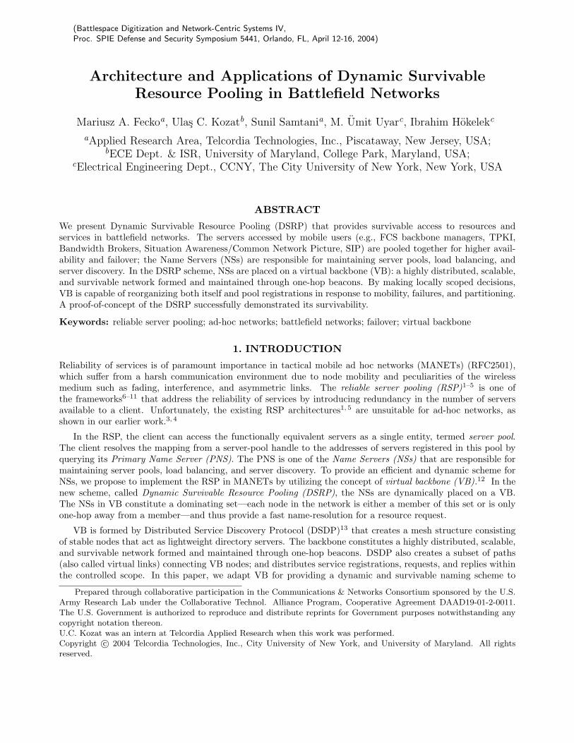
PE (a,1) PE (a,i) PE (a,n)Pool a Pool b
NS
PU PU PU
Proxy/ Gateway
Other clients
NS: Name ServerPE: Pool ElementPU: Pool User
NS
PE (b,1) PE (b,i) PE (b,m)
NSs can• be assigned statically or dynamically • have global or local view of the name space
Figure 1. Architecture of the reliable server pooling.
the pool users. We also propose to extend the concept of pools to resources that include servers, services, andhardware entities with specific capabilities (e.g., sensors used in robotics and battlefield applications).
The DSRP overcomes the known problems of the existing RSP architectures such as IETF’s RSerPool, wherethe global synchronization of pool registrations is prohibitively inefficient for mobile networks when the domainssplit, merge, or partition.3–5 The DSRP architecture has no fixed infrastructure since the set of NSs is changingin response to network events. Such a distributed and efficient directory system
• is able to reorganize itself in response to mobility, failures, and partitioning;• offers fast response time via a local name resolution;• provides load balancing of resources via NSs or users;• scales well with the network size;• is simple enough to be deployed on resource-constrained nodes; and• enables distributed resource selection modeled as policy-based resource allocation.
While the presented DSRP architecture is applicable to any resources that can be pooled together, in therest of this paper, we will focus on pooling servers and services as a particular type of resource. The NSs canserve as distributed configuration/network managers that are responsible for providing the mobile users withaccess to servers. This paper explains the advantages of DSRP in highly mobile networks and the specifics ofthe associated protocols.
2. DSRP IN BATTLEFIELD APPLICATIONS
The RSP, whose basic architecture is shown in Fig. 1, mainly refers to the services that are survivable transparentto client applications. A server pool, which is identified by a unique identifier (also called a pool handle),1, 2 isa collection of server locations (i.e., <IP address, port number>), where clients can access a given service. Thepooled servers are also called Pool Element (PEs). Clients (also called Pool Users (PUs)) access the service byproviding only the corresponding pool handle.
As an alternative to the RSP, one may use an infrastructure-based approach. A centralized ConfigurationManager (CM) is deployed in a tactical network to provide communication between users and services. The CMis responsible for selecting and monitoring services and advertising these services to users. A serious problemwith the CM is that it creates a single point of failure. Although limited survivability can be provided throughthe CM replication, it requires significant cost to recreate the CM and its state in a partitioned network. Thereare additional disadvantages of deploying the CM-based approach:
• large signaling cost of periodic advertisements;• potential inconsistency of service advertisements;• cost of maintenance of multicast trees for more efficient communication;• difficulty in maintaining and synchronizing the CM state.
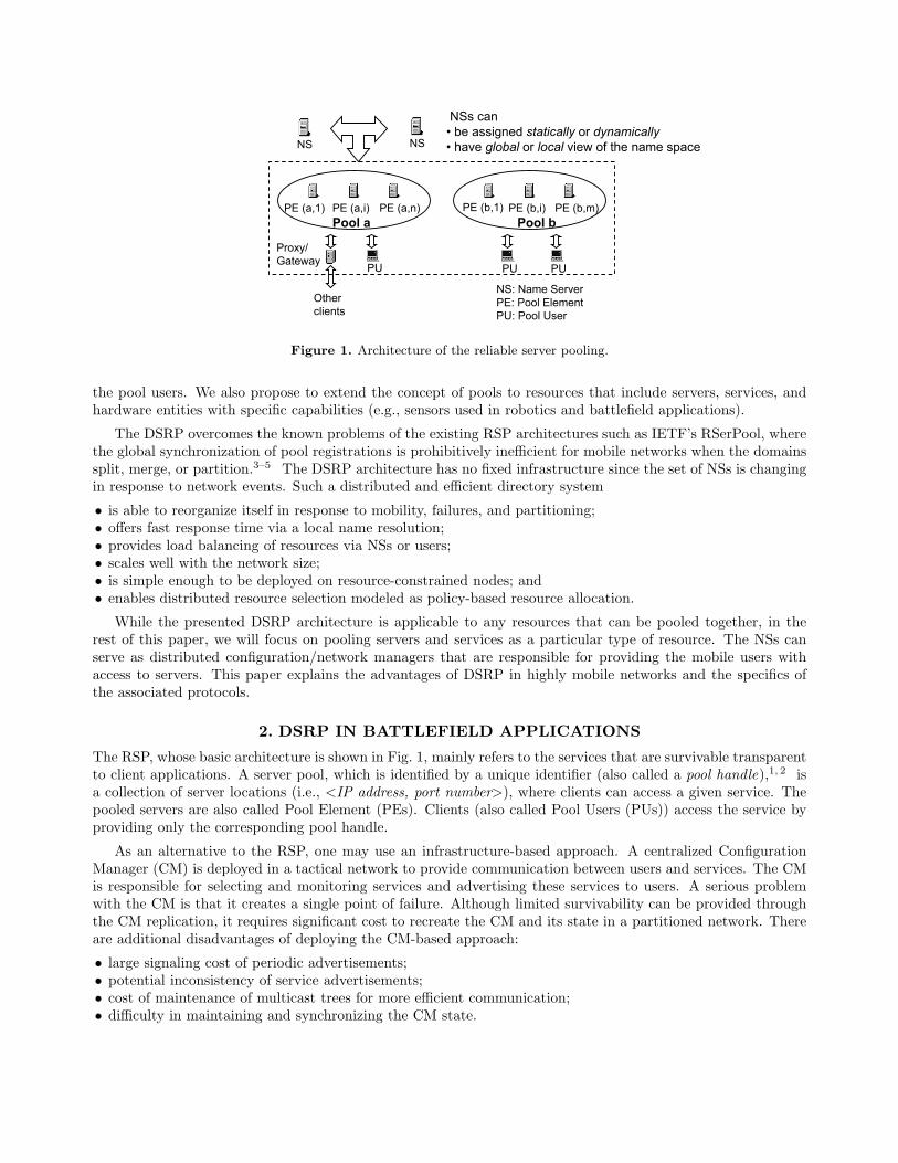
DREs
pRE-(1) pRE-(2)ac
b
x•
*CachingServer
Authentication Server Analysis
Server
Mobile Command & Information Center
DDE
Figure 2. Situation Awareness application.
The DSRP, which provisions RSP dynamically, is particularly well suited to survivable services in mobile ad-hoc environments such as battlefield and robotics communications. The servers that can be pooled together forhigher availability and failover14 include FCS15 backbone managers, Tactical Public Key Infrastructure (TPKI),Bandwidth Brokers,16 Situation Awareness (SA), Common Network Picture (CNP), SIP,17 distributed robotics,and others.
2.1. Situation Awareness
Consider a hypothetical distributed system providing SA on a battlefield, as shown in Fig. 2. Such a systemmight include data reporting elements (DREs)—vehicles reporting their GPS coordinates, direction and velocity,fuel level—and data display elements (DDE) that provide personnel at various echelons with displays of thebattlefield appropriate to their mission, rank, and authorization. In addition, several levels of relays may bedeployed to avoid single points of failure by providing failover and redundant gathering of information. First-level relay elements RE-(1)s (e.g., orange sensors) gather data directly from DREs (e.g., blue and green sensors),and aggregate data together into a more useful and compact form for transmission to RE-(2)s and higher. Forexample, individual positions of enemy vehicles within a battle group would be summarized into a boundingpolygon with the number of vehicles present.
In such a system, DREs and DDEs can act as PUs, whereas relays act as PEs. First, each DRE establishesa persistent on-the-move session with RE-(1). The DSRP pools relay elements into server pools, one for a givenreporting level, e.g., pRE-(1), . . . , pRE-(N). For example, DRE x becomes a PU and locates both a primaryRE-(1) a and a secondary RE-(1) b by requesting two PEs on level 1. DRE x then maintains its session with aand sends updates to a as needed. Meanwhile, a periodically updates b with sufficient state to allow seamlessfailover of x’s data-reporting session to b. To preserve a failover capability, the DRSP layer on x can then reissuea pool request to its PNS, receiving b and c in reponse. Similarly, at each level, the RE-(k) would establisha persistent on-the-move session with both a primary and a secondary RE-(k+1). The session between RE-(k)and RE-(k+1) uses the same DRSP mechanisms as described above for the session between DREs and RE-(1).Similarly, DDEs would establish persistent on-the-move sessions with REs at the level appropriate to the detailof the display needed, with both a primary and secondary element chosen by the DSRP protocols.
2.2. Public Key Infrastructure: Certification Authority
Consider a certificate-based approach that utilizes the public key infrastructure (PKI), which has been the foun-dation of several recent network security protocols. The RSA key pair of the system certification authority (CA)
is denoted as {SK,PK}, where SK and PK are the system secret/private and public keys, respectively. SK isused to sign certificates for all entities in the network. SK can be shared among the network entities throughthe so-called threshold secret sharing. Each entity vi holds a secret share Pi, and any K of such secret-shareholders can collectively function as CA. However, SK is not visible or known by any component of the networkexcept at the system bootstrapping phase. Kong et al.18 propose to distribute CA’s functionality to each localneighborhood. A coalition of K neighbors that is formed on-the-fly serve as the CA, and jointly provide cer-tification services for a requesting mobile entity. Once the requester locally collects K such partial certificates(each signed by SKi derived from Pi), it combines them to obtain the complete certificate signed by SK.
A problem with the above scheme in a mobile environment is that K one-hop neighbors may not be availableto the requesting node. In that case, Kong et al. suggest that the node broadcast a limited number of requestsover a time window, expecting new mobile entities to serve it. Alternatively, the requesting node may move toa new location, where it can find at least K share holders. However, the above suggestions are trial-and-errorapproaches that may or may not yield a desired result in a timely manner.
To efficiently localize K secret-share holders in this security scheme, a node that requests a certificate canutilize the DSRP. Each share holder registers to the SK pool as a PE, whereas the requesting node becomesa PU. As described in Section 4.2, the PU is able to specify the (minimal) requested number of PEs. Here thePU asks its PNS to resolve a pool handle for SK with the desired number of PEs set to K ′ ≥ K. The PUthen tries to obtain a partial certificate from K PEs in the pool. If fewer than K PEs respond, PU reissues thepool-resolution request, additionally including the non-responding PEs in the list of undesired PEs. The processrepeats until K responses are gathered or the maximum allowable time is exceeded.
2.3. RoboticsTraditional distributed robotics systems lack the robustness, dynamic configuration, and scalability of commu-nication capabilities. We intend to utilize the DSRP to create a reliable distributed robotics environment.
An example of such an environment can be an earthquake rescue mission, where hundreds of robots are sentinto the disaster site, some equipped with video cameras and some with CO2 detectors. Typically, these robotswould form two pools: one for video transmission and the other for CO2 detection. While a user is receivingservice from the camera pool, if the robot providing the video wanders away or fails, another robot will take overand continue sending the video. In another application, user may request a different pool element for a differentcamera angle. Pools may span different domains (i.e., concentration of robots in a location). For example, ifthere are no CO2 detector robots in a domain, a pool request from a user brings detector robots into this domain.
Although the robots could be physically identical, there are two different functionalities required to realizeDSRP: coordinator robots and worker robots, each reconfigurable to function as either. Worker robots formpools to provide reliable services under the guidance of coordinator robots, whereas the coordinator robots areresponsible for establishing and maintaining worker robot pools. (In this system, worker robots do not need totalk to each other.) Coordinator and worker robots correspond to the NSs and PEs of the DSRP, respectively.Reconfigurable robots are able to adopt the roles of workers or supervisors, as dynamically decided by the DSRPbased on their capabilities and movement patterns (Section 3.2).
Such a reliable distributed robotics environment will require two sets of communication protocols (other thanthe data transfer protocol). One set is for communications among coordinator robots to locate other coordinatorsand to jointly resolve pool requests from the users. In the DSRP, this communication is provided by the VBformation and maintenance, and service discovery over VB. A second set of protocols should be defined forcommunication between the worker and coordinator robots to register (or de-register) in (or out of) pools, whichis provided in the DSRP by the soft-state service registration.
3. RSP OVER VB: OVERVIEW AND CHALLENGESThis section first outlines our earlier research efforts3–5 in the service reliability for ad-hoc networks, whichfocused on the IETF RSerPool.3–5 It then shows how the obtained results can be combined with the work ofKozat and Tassiulas12, 13 that formulated the DSDP protocol. After the necessary augmentations of the DSDP,we are able to provide a highly distributed, scalable, and survivable naming scheme for the RSP in mobile,infrastructure-less environments.
3.1. Reliable Server Pooling
The RSP layer resides between the application and the transport layer. Therefore, PU’s payload packets arefirst processed by the RSP layer, which maps the logical pool handle to the actual server (PE) location. Upondetection of a PE failure or QoS degradation, RSP layer can change the current end-point in the middle of analready-established session between the PU and the PE. Hence, a PU fails over to a new PE for a persistentconnection. Although an issue of session migration is clearly among the major components of establishinga transparent failover, it has been studied elsewhere,19 and is beyond the scope of our immediate interests.Instead, we focus on the following questions:
� How can we discover and maintain the available server pools in a highly dynamic network environment such asthe FCS Unit of Action (UA)? Is a directory system, in which name servers/directory agents collect and maintainthe server-pool information, preferred to a directory-less system or vice versa? To what extent a global view ofthe available network services is required in a directory system? In other words, do the name servers need tosynchronize a common view of the namespace?
� How are PE failures or QoS degradations detected to effect switchover of the service to an alternate PE?Should applications be involved in the decision process? To what extent should the RSP layer be responsiblefor monitoring PEs, and what kind of feedback is needed from the PUs, PEs, and other layers (e.g., MAC ortransport layer)?
� How can we perform the PE allocations when we have a global view as well as when we have a local view ofthe available server pools?
The existing RSP solutions such as IETF’s RSerPool are too rigid to perform satisfactorily under the highlyvarying network topologies.5 We found out that the global synchronization of the pool registrations is pro-hibitively inefficient3, 4 for mobile networks when the domains split, merge, or partition. The RSerPool archi-tecture (Fig. 1) relies on statically assigned NSs and global synchronization among them. In other words, oncecertain nodes are assigned to be NSs, they stay as such even though the network conditions change dynamically.NSs go through a peer-discovery phase at the start-up. They also advertise themselves to the PUs and PEs.Additionally, a PE/PU may follow a server-hunt process to locate its PNS. All of these discovery and synchro-nization efforts require multicasting support, which can incur significant load in the network. In addition tothe overhead, the RSerPool has no provisioning against network partitioning, which may be a common event inMANETs. Some partitions may be left without any name server; as a result, survivability of the entire RSParchitecture becomes questionable.
3.2. Service Discovery through Virtual Backbone
An architecture using dynamic NSs can be effectively implemented in MANETs with the help of a VB. We use theDSDP12 to create a VB as a minimum connected dominating set of lightweight directory servers. Besides definingthe distributed algorithm to build and maintain VB, Ref.12 demonstrates the feasibility of a directory/name-server system on VBs with respect to the signaling overhead. It also shows the performance advantages over thepeer-to-peer systems, where clients directly discover the end servers by utilizing multicast or anycast routing.
There are two parts in the VB-based service discovery12, 13: Backbone Management (BBM) and DistributedService Discovery (DSD).
3.2.1. Backbone Management
BBM is based on backbone-node selection, mesh formation, and maintenance phases of the DSDP proposal.12
The key feature of the BBM operations is that these phases are all accomplished by 1-hop light-weight hellobeacons (∼50 bytes). In BBM, nodes are grouped as decided and undecided (the latter also called white nodes),where decided nodes are further divided into backbone (also called black) and non-backbone (also called green)nodes. Another grouping rule is applied in terms of the normalized link failure frequency (nlff), which simplyis the number of link losses within a time-window, but normalized by the number of total links at the end ofthe time-window. Under this rule, nodes are differentiated depending on whether or not they have nlff lowerthan a constant threshold. The selection and maintenance phases guarantee that the set of backbone nodes is adominating set.
1
6
2.1
1
3.1
4.1
5.1 6
57.6
BackboneNS
BackboneNS
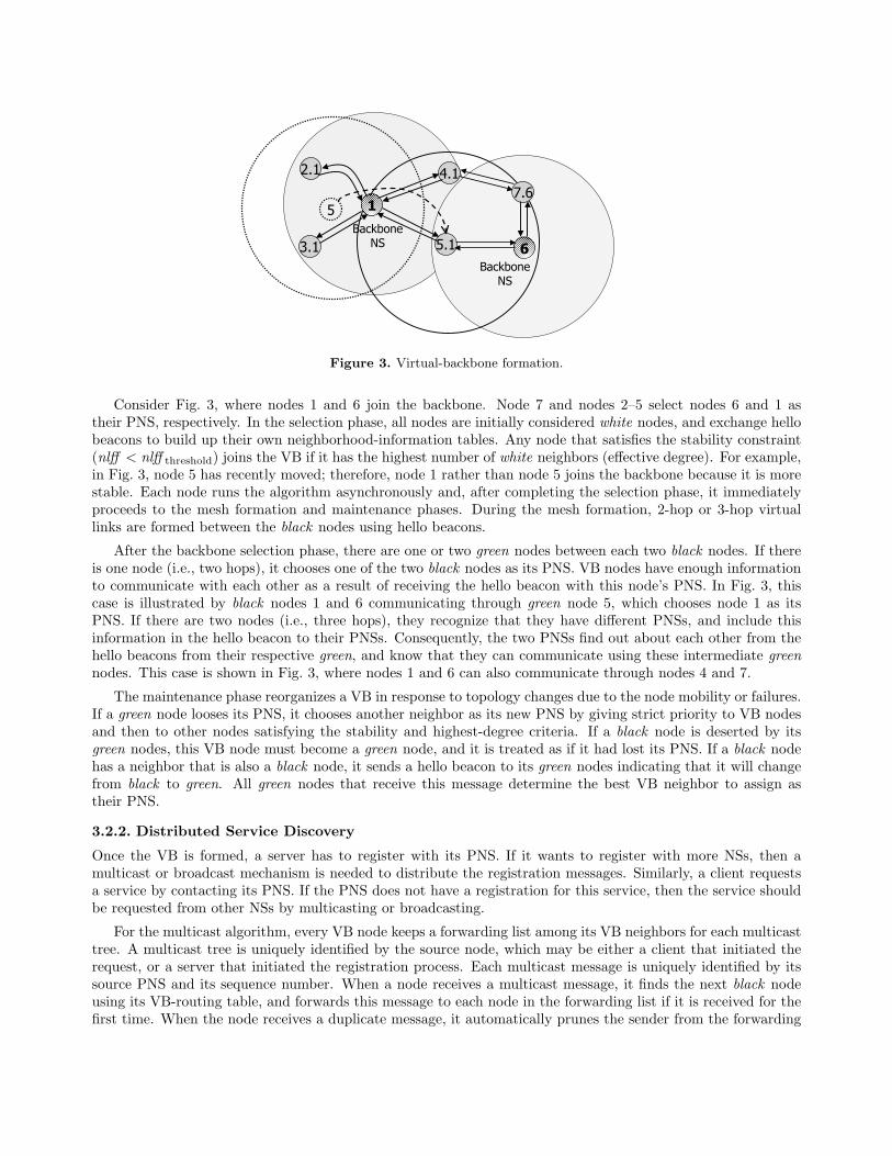
Figure 3. Virtual-backbone formation.
Consider Fig. 3, where nodes 1 and 6 join the backbone. Node 7 and nodes 2–5 select nodes 6 and 1 astheir PNS, respectively. In the selection phase, all nodes are initially considered white nodes, and exchange hellobeacons to build up their own neighborhood-information tables. Any node that satisfies the stability constraint(nlff < nlff threshold) joins the VB if it has the highest number of white neighbors (effective degree). For example,in Fig. 3, node 5 has recently moved; therefore, node 1 rather than node 5 joins the backbone because it is morestable. Each node runs the algorithm asynchronously and, after completing the selection phase, it immediatelyproceeds to the mesh formation and maintenance phases. During the mesh formation, 2-hop or 3-hop virtuallinks are formed between the black nodes using hello beacons.
After the backbone selection phase, there are one or two green nodes between each two black nodes. If thereis one node (i.e., two hops), it chooses one of the two black nodes as its PNS. VB nodes have enough informationto communicate with each other as a result of receiving the hello beacon with this node’s PNS. In Fig. 3, thiscase is illustrated by black nodes 1 and 6 communicating through green node 5, which chooses node 1 as itsPNS. If there are two nodes (i.e., three hops), they recognize that they have different PNSs, and include thisinformation in the hello beacon to their PNSs. Consequently, the two PNSs find out about each other from thehello beacons from their respective green, and know that they can communicate using these intermediate greennodes. This case is shown in Fig. 3, where nodes 1 and 6 can also communicate through nodes 4 and 7.
The maintenance phase reorganizes a VB in response to topology changes due to the node mobility or failures.If a green node looses its PNS, it chooses another neighbor as its new PNS by giving strict priority to VB nodesand then to other nodes satisfying the stability and highest-degree criteria. If a black node is deserted by itsgreen nodes, this VB node must become a green node, and it is treated as if it had lost its PNS. If a black nodehas a neighbor that is also a black node, it sends a hello beacon to its green nodes indicating that it will changefrom black to green. All green nodes that receive this message determine the best VB neighbor to assign astheir PNS.
3.2.2. Distributed Service Discovery
Once the VB is formed, a server has to register with its PNS. If it wants to register with more NSs, then amulticast or broadcast mechanism is needed to distribute the registration messages. Similarly, a client requestsa service by contacting its PNS. If the PNS does not have a registration for this service, then the service shouldbe requested from other NSs by multicasting or broadcasting.
For the multicast algorithm, every VB node keeps a forwarding list among its VB neighbors for each multicasttree. A multicast tree is uniquely identified by the source node, which may be either a client that initiated therequest, or a server that initiated the registration process. Each multicast message is uniquely identified by itssource PNS and its sequence number. When a node receives a multicast message, it finds the next black nodeusing its VB-routing table, and forwards this message to each node in the forwarding list if it is received for thefirst time. When the node receives a duplicate message, it automatically prunes the sender from the forwarding
list. If the same message is not already sent to the pruned interface or later on the replicas continue to bereceived from a pruned interface, the node issues an explicit prune message to the sender. VB nodes monitornew additions or parent node losses to update their forwarding list as well as to issue an unprune message forsetting the forwarding lists.12, 13 This way, a multicast tree from any VB node to any other VB node in thenetwork is formed.
4. RSP OVER VIRTUAL BACKBONE
In summary, the DSDP (1) forms a VB by creating a mesh structure that consists of stable nodes actingas service brokers and a subset of paths (also called virtual links) connecting them; and (2) distribute serviceregistrations, requests, and replies within controlled scope. The DSDP provides scalable, robust, and fast locationof the services. It is adaptive to the topology changes including network partitioning and flexible in terms ofscoping the PE registrations as either local or global. It also operates efficiently with individual NSs having onlypartial knowledge of pool registrations; hence, there is no need for costly namespace-synchronization among NSs.However, it does not fully meet the RSP requirements2:
• DSDP does not support the discovery of more than one PE;• DSDP does not support switch-over functionality. A PU must issue a query and, upon receiving a response,
must re-establish a connection with the new PE by itself;• DSDP does not clarify the interactions or primitives between the application and the DSDP layer;• DSDP does not establish reliable communications for PE registrations.
To address the above shortcomings, we have adapted the DSDP and a virtual backbone that it creates sothat the RSP requirements could be satisfied. In the resulting DSRP architecture, we defined two entities thatshare RSP functionalities: (1) BackBone Manager (BBM) and (2) Backbone Service Manager (BSM). BBM ismainly responsible for the formation and maintenance of the virtual backbone. It also provides the signalingsupport among the backbone nodes to disseminate the server-pool query and registration messages. On theother hand, BSM handles the actual communication between the PEs/PUs and the RSP layer. BSM utilizesthe BBM services to register PEs and to resolve the queries (Fig. 4(a)). The propagation of control messagesis determined by the close interaction between the BSM and BBM. Any pool allocation to individual PUs isdecided by the BSM. (Note that, although all the PUs, PEs, and NSs have active BBMs and BSMs processes,only the virtual-backbone nodes assume the functionality of NSs.)
4.1. BBM Operations in DSRPFormally, we represent the snapshot of a network at time t as a topology graph G(V,E), where the vertex set Vand the edge set E correspond to the set of network nodes and symmetric links, respectively. Graph G can berepresented in a canonical form as the union of two mutually exclusive subgraphs: Gd(Vd, Ed) and its complementGc
d(Vcd , Ec
d)∗, where Gd consists of all decided nodes and edges incident on them. Similarly, G can be expressed
as the union of Gnlff(Vnlff , Enlff) and Gcnlff(V c
nlff , Ecnlff), where Gnlff is the subgraph that contains vertices with nlff
lower than a given threshold and the edges incident on them. For each k ∈ V , let N(k) and deg(k) be the set ofk’s neighbors and the degree of k in G, respectively.
� Backbone-node selection: At periodic time epochs, each vertex k ∈ V cd asynchronously checks the following
conditions:
Condition 1. k ∈ Vnlff ∧ (∀j ∈ V cd deg(j) ≤ deg(k)).
Condition 2. k 6∈ Vnlff ∧ N(k) ∩ Vnlff = ∅ ∧ (∀j ∈ V cd deg(j) ≤ deg(k)). If vertex k satisfies Conditions 1
or 2, it joins the backbone. In these conditions, the ties are broken by giving strict priority to the nodes with thehigher ID. Undecided nodes become decided non-backbone (i.e., green) nodes when they detect a black neighbor,and label that neighbor as their PNS.
� Mesh formation: Apart from selecting the VB nodes, BBM also instruments the mesh formation by informingeach VB node about the identities of other VB nodes within its 3-hop neighborhood. This mesh enables dissem-ination of control messages among the VB neighbors by forming distribution trees, as described in Sections 3.2.2and 4.2.
∗Complement of subgraph A ⊆ G is the subgraph obtained by removing vertices and edges of A from G.
BSM
BBM
PE
BSM
BBM
PNSREGISTER (1)
REGISTER (2)
ACK (3)
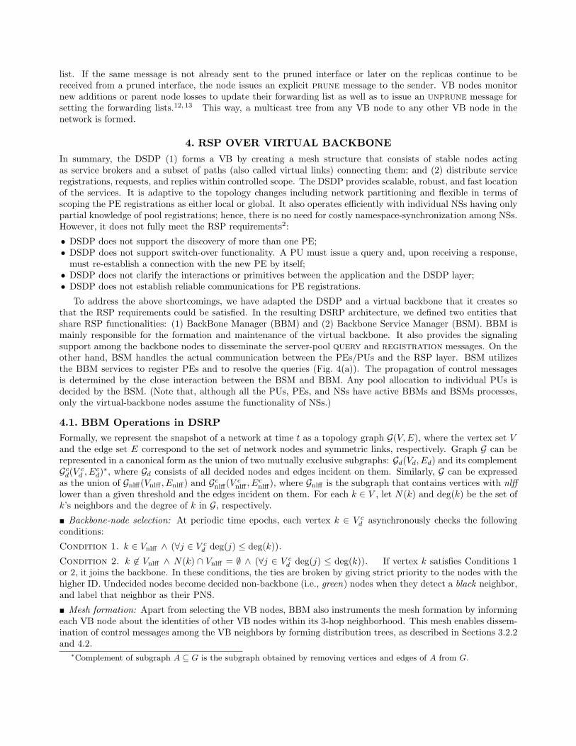
(a) PE registers with PE side RSP layer. Registrations haveto be periodically renewed.
BSM
BBM
PE
BSM
BBM
PNS
REGISTER (2)
ACK (3)
{PE1;PE2}
NOTIFY (1)
(b) BBM notifies BSM of PNS hand-off for renewing pool reg-istrations.
Figure 4. Pool registration events.
� Maintenance: While undecided nodes of the network run the selection phase, the decided portion runs themaintenance phase, which locally adapts VB upon the following events: (1) some VB node is not PNS of anynode; (2) some green node lost its PNS; and (3) there are too many of VB nodes in certain areas. The procedurefor preserving the dominating-set feature of the VB is described in Section 3.2.1.13
4.2. BSM Operations in DSRP
The DSRP proactively constructs and maintains the server pools through PE registrations, while reactivelyresolving the pool requests. PE communicates with its BSM sublayer, indicating the lease duration and thescope of the registration. Regardless of the scope, which determines the depth of the registration along thevirtual backbone, BSM sublayer reliably registers the service with BSM sublayer on the PNS side (Fig. 4(a)).At PNS, PE is added into the requested pool. If the scope of the registration is set to a value greater thanone, registration is propagated unreliably to the next tier of NSs within three physical hops. The propagation iscontinued until the number of traversed tiers (i.e., virtual links) reaches the requested registration scope. Unlessthe PE extends the lease by sending another registration, it will be removed from the server pool upon the leaseexpiry (soft-state registration). When a PE/PU hands off to a new PNS, the BBM sublayer first notifies theBSM sublayer of this event. Second, the BSM reliably registers all the unexpired PE entries with the new PNStransparent to the local PE. Regardless of the original scope, the PE registration due to PNS handoff is scopedto be 1-hop, i.e., only the new PNS will receive the registration (Fig. 4(b)).
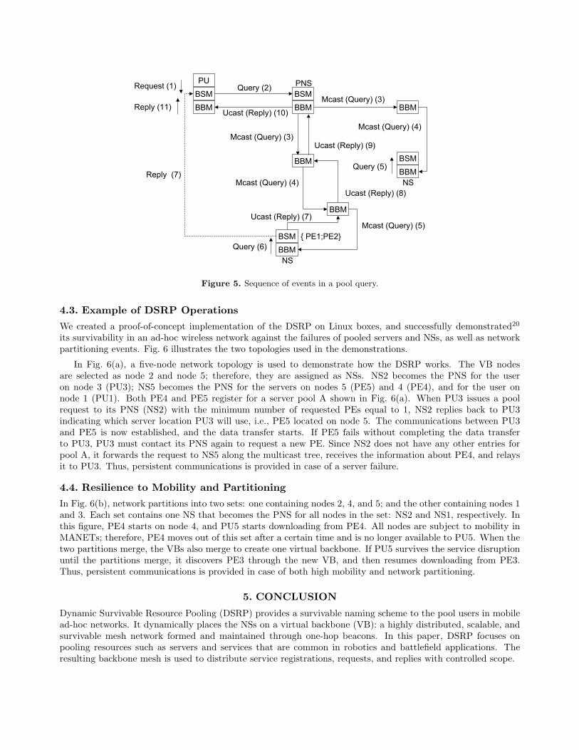
Fig. 5 illustrates how the pool request from a PU is resolved. The PU’s BSM sublayer sends a direct querymessage to the PNS’s BSM. If PNS does not have any PEs registered for the requested pool, it encapsulatesthe message and sends it toward other NSs that it is aware of. If there is no routing support, each message istransmitted through the IP broadcast to the well-known port address of the BBM (note that all BBMs share thesame port number). Encapsulation is required to specify the address of the destination NS and the relay node.Hence, the BBM performs its own routing in the application layer on a hop-by-hop basis. In the case wherethe BBM works in coordination with the routing layer, instead of encapsulation and application layer routing,network layer routing can be exploited to find routes toward the destination NSs.
To further increase efficiency, the BBM forms a multicast tree while query is propagated between NSs.When any NS can resolve the query, the NS’s BSM creates a reply message. Again, assuming no routing layersupport, this reply can be encapsulated and relayed hop-by-hop by the BBM layer. Otherwise, reply can besent directly to the BSM on the PU side using UDP sockets and BSM address of PU. Both options are shown inFig. 5 as Ucast (reply) and reply labels.
PUs can request the desired degree of the session survivability as well as their willingness to access the servicesin remote locations. They do that by specifying both the requested number of PEs and a list of undesired PEs.(See Section 2.2 for the illustration of the usefulness of this feature.) In addition, PU’s client applications aregiven some control over the PE selection by raising the change end point flag in the RSP header that is placedin front of each payload data. This way, a client can proactively request a new PE from the pool by notifyingits RSP layer that QoS degradation occurred or the current PE failed.
Reply (11)BSM
BBM
PU
BBM
BSM
BBM
PNS
BSM
BBMNS
BBM
BBM
BSM
BBMNS
Request (1) Query (2)
Ucast (Reply) (10)
Mcast (Query) (3)
Mcast (Query) (4)
Mcast (Query) (3)
Mcast (Query) (4)
Query (5)
{ PE1;PE2}Mcast (Query) (5)
Reply (7)
Ucast (Reply) (7)
Ucast (Reply) (9)
Ucast (Reply) (8)
Query (6)
Figure 5. Sequence of events in a pool query.
4.3. Example of DSRP Operations
We created a proof-of-concept implementation of the DSRP on Linux boxes, and successfully demonstrated20
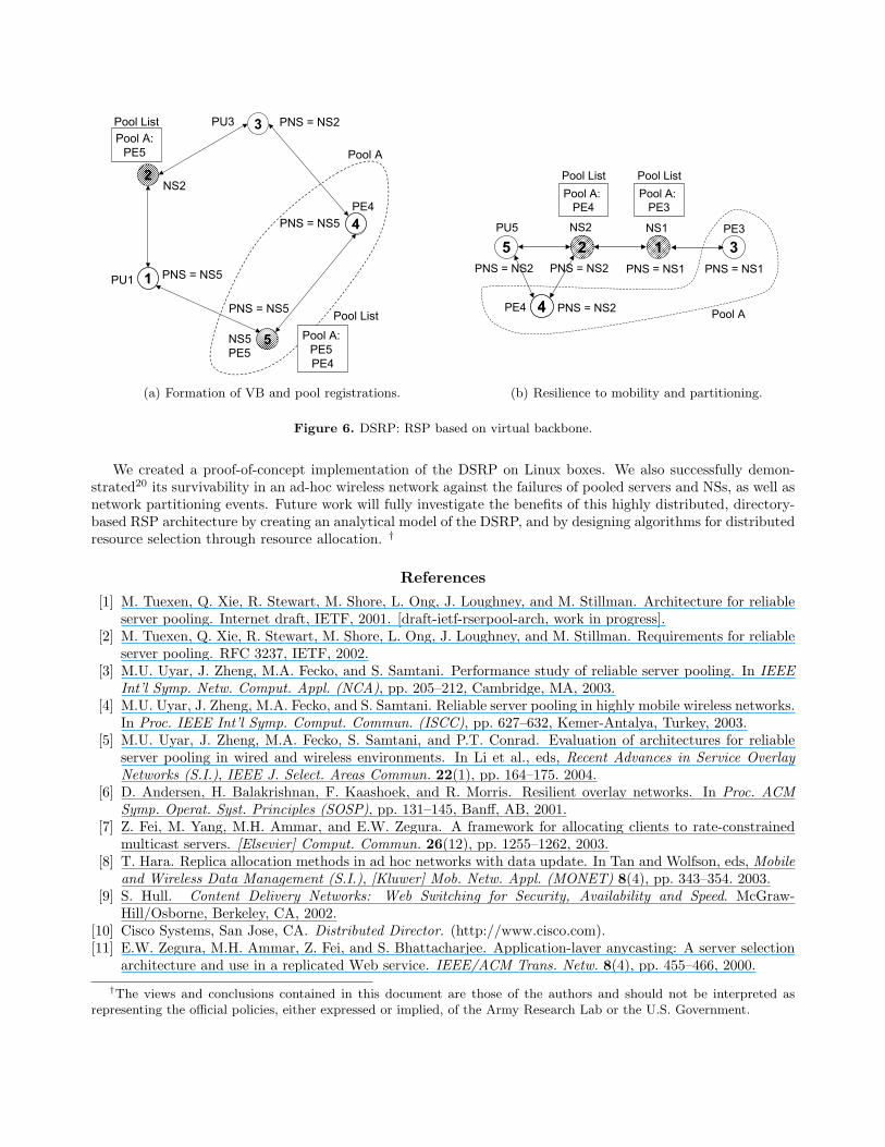
its survivability in an ad-hoc wireless network against the failures of pooled servers and NSs, as well as networkpartitioning events. Fig. 6 illustrates the two topologies used in the demonstrations.
In Fig. 6(a), a five-node network topology is used to demonstrate how the DSRP works. The VB nodesare selected as node 2 and node 5; therefore, they are assigned as NSs. NS2 becomes the PNS for the useron node 3 (PU3); NS5 becomes the PNS for the servers on nodes 5 (PE5) and 4 (PE4), and for the user onnode 1 (PU1). Both PE4 and PE5 register for a server pool A shown in Fig. 6(a). When PU3 issues a poolrequest to its PNS (NS2) with the minimum number of requested PEs equal to 1, NS2 replies back to PU3indicating which server location PU3 will use, i.e., PE5 located on node 5. The communications between PU3and PE5 is now established, and the data transfer starts. If PE5 fails without completing the data transferto PU3, PU3 must contact its PNS again to request a new PE. Since NS2 does not have any other entries forpool A, it forwards the request to NS5 along the multicast tree, receives the information about PE4, and relaysit to PU3. Thus, persistent communications is provided in case of a server failure.
4.4. Resilience to Mobility and Partitioning
In Fig. 6(b), network partitions into two sets: one containing nodes 2, 4, and 5; and the other containing nodes 1and 3. Each set contains one NS that becomes the PNS for all nodes in the set: NS2 and NS1, respectively. Inthis figure, PE4 starts on node 4, and PU5 starts downloading from PE4. All nodes are subject to mobility inMANETs; therefore, PE4 moves out of this set after a certain time and is no longer available to PU5. When thetwo partitions merge, the VBs also merge to create one virtual backbone. If PU5 survives the service disruptionuntil the partitions merge, it discovers PE3 through the new VB, and then resumes downloading from PE3.Thus, persistent communications is provided in case of both high mobility and network partitioning.
5. CONCLUSION
Dynamic Survivable Resource Pooling (DSRP) provides a survivable naming scheme to the pool users in mobilead-hoc networks. It dynamically places the NSs on a virtual backbone (VB): a highly distributed, scalable, andsurvivable mesh network formed and maintained through one-hop beacons. In this paper, DSRP focuses onpooling resources such as servers and services that are common in robotics and battlefield applications. Theresulting backbone mesh is used to distribute service registrations, requests, and replies with controlled scope.
1
2
3
4
5
4
1 PNS = NS5
Pool A: PE5 PE4
Pool List
NS5PE5
NS2
PE4
PU3
PU1
Pool A: PE5
Pool List PNS = NS2
PNS = NS5
PNS = NS5
Pool A
(a) Formation of VB and pool registrations.
2 3
4
5
4
1
PNS = NS2
Pool A: PE4
Pool List
PU5 NS2
PE4
PNS = NS1PNS = NS2
NS1 PE3
PNS = NS1PNS = NS2
Pool A: PE3
Pool List
Pool A
(b) Resilience to mobility and partitioning.
Figure 6. DSRP: RSP based on virtual backbone.
We created a proof-of-concept implementation of the DSRP on Linux boxes. We also successfully demon-strated20 its survivability in an ad-hoc wireless network against the failures of pooled servers and NSs, as well asnetwork partitioning events. Future work will fully investigate the benefits of this highly distributed, directory-based RSP architecture by creating an analytical model of the DSRP, and by designing algorithms for distributedresource selection through resource allocation. †
References[1] M. Tuexen, Q. Xie, R. Stewart, M. Shore, L. Ong, J. Loughney, and M. Stillman. Architecture for reliable
server pooling. Internet draft, IETF, 2001. [draft-ietf-rserpool-arch, work in progress].[2] M. Tuexen, Q. Xie, R. Stewart, M. Shore, L. Ong, J. Loughney, and M. Stillman. Requirements for reliable
server pooling. RFC 3237, IETF, 2002.[3] M.U. Uyar, J. Zheng, M.A. Fecko, and S. Samtani. Performance study of reliable server pooling. In IEEE
Int’l Symp. Netw. Comput. Appl. (NCA), pp. 205–212, Cambridge, MA, 2003.[4] M.U. Uyar, J. Zheng, M.A. Fecko, and S. Samtani. Reliable server pooling in highly mobile wireless networks.
In Proc. IEEE Int’l Symp. Comput. Commun. (ISCC), pp. 627–632, Kemer-Antalya, Turkey, 2003.[5] M.U. Uyar, J. Zheng, M.A. Fecko, S. Samtani, and P.T. Conrad. Evaluation of architectures for reliable
server pooling in wired and wireless environments. In Li et al., eds, Recent Advances in Service OverlayNetworks (S.I.), IEEE J. Select. Areas Commun. 22(1), pp. 164–175. 2004.
[6] D. Andersen, H. Balakrishnan, F. Kaashoek, and R. Morris. Resilient overlay networks. In Proc. ACMSymp. Operat. Syst. Principles (SOSP), pp. 131–145, Banff, AB, 2001.
[7] Z. Fei, M. Yang, M.H. Ammar, and E.W. Zegura. A framework for allocating clients to rate-constrainedmulticast servers. [Elsevier] Comput. Commun. 26(12), pp. 1255–1262, 2003.
[8] T. Hara. Replica allocation methods in ad hoc networks with data update. In Tan and Wolfson, eds, Mobileand Wireless Data Management (S.I.), [Kluwer] Mob. Netw. Appl. (MONET) 8(4), pp. 343–354. 2003.
[9] S. Hull. Content Delivery Networks: Web Switching for Security, Availability and Speed. McGraw-Hill/Osborne, Berkeley, CA, 2002.
[10] Cisco Systems, San Jose, CA. Distributed Director. (http://www.cisco.com).[11] E.W. Zegura, M.H. Ammar, Z. Fei, and S. Bhattacharjee. Application-layer anycasting: A server selection
architecture and use in a replicated Web service. IEEE/ACM Trans. Netw. 8(4), pp. 455–466, 2000.
†The views and conclusions contained in this document are those of the authors and should not be interpreted asrepresenting the official policies, either expressed or implied, of the Army Research Lab or the U.S. Government.
[12] U.C. Kozat and L. Tassiulas. Service discovery in mobile ad hoc networks: An overall perspective onarchitectural choices and network layer support issues. [Elsevier] Ad-Hoc Netw. 2(1), pp. 23–44, 2004.
[13] U.C. Kozat and L. Tassiulas. Network layer support for service discovery in mobile ad hoc networks. InProc. IEEE INFOCOM, San Francisco, CA, 2003.
[14] M.U. Uyar, J. Zheng, M.A. Fecko, S. Samtani, and P.T. Conrad. Reliable server pooling for future combatsystems. In Proc. IEEE Military Commun. Conf. (MILCOM), Boston, MA, 2003.
[15] P. Sass and J. Freebersyser. FCS communications: Technology for the objective force. In Proc. SPIEAeroSense, Orlando, FL, 2002.
[16] E. Pagani and G.P. Rossi. Distributed bandwidth broker for QoS multicast traffic. In Proc. IEEE Int’lConf. Distrib. Comput. Syst. (ICDCS), pp. 319–326, Vienna, Austria, 2002.
[17] H. Schulzrinne and E. Wedlung. Application-layer mobility using SIP. ACM Mob. Comput. Commun. Rev.1(5), 1999.
[18] J. Kong, P. Zerfos, H. Luo, S. Lu, and L. Zhang. Providing robust and ubiquitous security support formobile ad hoc networks. In Proc. IEEE Int’l Conf. Netw. Protocols (ICNP), pp. 251–260, Riverside, CA,2001.
[19] L. Alvisi, T.C. Bressoud, A. El-Khashab, K. Marzullo, and D. Zagorodnov. Wrapping server-side TCP tomask connection failures. In Proc. IEEE INFOCOM, Anchorage, Alaska, 2001.
[20] Telcordia Technologies, Inc. Dynamic survivable server pooling. Exhibition, SAIC booth at MILCOM,Boston, MA, 2003.