appendix g noise analysis report - northland power
TRANSCRIPT

Appendix G Noise Analysis Report

ENVIRONMENTAL NOISE IMPACT ASSESSMENT
McLEANS MOUTAIN WIND FARM MANITOULIN ISLAND, ONTARIO PREPARED FOR: Northland Power Inc. 30 ST CLAIR AVE W, Toronto, ON M4V 3A1 PREPARED BY: ____________________________ Payam Ashtiani, B.A.Sc. ____________________________ Werner Richarz, P.Eng., PhD, FASA AERCOUSTICS ENGINEERING LIMITED 50 Ronson Drive, Suite 165 Toronto, Ontario M9W 1B3 22 July 2009

A E R C O U S T I C S _______________________________________________________________________________E N G I N E E R I N G L I M I T E D
Executive Summary The purpose of this environmental noise impact assessment, prepared for the Northland Power Inc (“NPI”) M1 Wind Project (the “Project”), is to fulfill NPI’s requirements under Ontario Regulation 116/01 of the Environmental Assessment Act and to provide the basis for the Certificate of Approval – Air [“C of A (Air)”] under Section 9 of the Environmental Protection Act (“EPA”). The objective of this assessment is to demonstrate, by means of technical assessment, that the noise impact from the operation of the Project will comply with the Ministry of the Environment’s (“MOE”) environmental noise guidelines for wind turbines. Building upon the project specific guidelines, noise impact prediction modelling was undertaken. The noise impact from the Project’s wind turbine array and transformers and including neighbouring wind turbines operating at maximum rated power on the nearest points of reception was predicted using an acoustic model, ISO 9613, as required by the MOE. The analysis shows that the noise impact from the Project does not exceed the most restrictive noise limits that apply for areas with acoustic designation of Class 3 (Rural) as defined by the MOE. Consequently, there is no need for the application of any additional mitigation measures and no further studies are contemplated for environmental noise in relation to the Project.

A E R C O U S T I C S _______________________________________________________________________________E N G I N E E R I N G L I M I T E D
Table of Contents
1.0 INTRODUCTION ............................................................................................................................ 2
2.0 DISCUSSION OF ACOUSTIC TERMINOLOGY ....................................................................... 3
3.0 DESCRIPTION OF WIND TURBINE SITE AND SURROUNDS ............................................. 4
3.1 DESCRIPTION OF RECEPTORS ........................................................................................................... 5 3.2 MOE ENVIRONMENTAL NOISE LIMITS ............................................................................................ 5
3.2.1 Wind Turbine Installations in Class 1 & 2 Areas (Urban): Wind Speeds Below 8m/s ........... 5 3.2.2 Wind Turbine Installations In Class 3 Areas (Rural): Wind Speeds Below 6m/s ................... 5 3.2.3 Wind Turbine Installations In Class 1 & 2 and Class 3 Areas: Wind Speeds Above 8m/s and 6m/s Respectively ................................................................................................................................... 6
4.0 DESCRIPTION OF SOURCES ...................................................................................................... 7 4.1 M1 TRANSFORMER STATION ............................................................................................................ 7 4.2 WIND TURBINE GENERATORS .......................................................................................................... 7
4.2.1 Potential Sources of Noise ....................................................................................................... 8 4.2.2 M1 Wind Turbine Noise Emission Rating ............................................................................... 9 4.2.3 Providence Bay Wind Farm ................................................................................................... 11
5.0 NOISE ASSESSMENT RESULTS ............................................................................................... 11 5.1 TRANSFORMER STATION IMPACT ASSESSMENT ............................................................................. 11 5.2 WIND TURBINE IMPACT ASSESSMENT ............................................................................................ 11 5.3 WIND TURBINE SUMMARY TABLES ............................................................................................... 12
6.0 CONCLUSION ............................................................................................................................... 13
REFERENCES: ......................................................................................................................................... 14

A E R C O U S T I C S _______________________________________________________________________________E N G I N E E R I N G L I M I T E D
List of Tables Table 1: MOE Sound Level Limits at Points of Reception for Wind Plants .......................................... 6 Table 2: Sound Level Limits for Class 3 Areas ......................................................................................... 7 Table 3: Vestas V90, Sound Power Spectrums @ wind speeds from 6m/s to 10m/s ............................. 9 Table 4: Wind Turbine Locations ............................................................................................................ 10 Table 5: Total Noise Impact without Transformer Noise Controls, 6m/s wind speed ........................ 11 List of Figures Figure 1: Key Plan Figure 2: Turbine Layout Figure 3: M1Noise Contours, 6m/s wind, 100% downwind ATTACHMENT A REPRINT OF: NOISE GUIDELINES FOR WIND FARMS, INTERPRETATION FOR APPLYING MOE NPC PUBLICATIONS TO WIND POWER GENERATION FACILITIES, ONTARIO MINISTRY OF ENVIRONMENT, OCTOBER 2008 ATTACHMENT B VESTAS TURBINE DATA ATTACHMENT D SAMPLE CALCULATION FOR NIGHTTIME NOISE IMPACT ON R282

A E R C O U S T I C S _______________________________________________________________________________E N G I N E E R I N G L I M I T E D
GLOSSARY agl above ground level C of A (Air) Certificate of Approval – Air Northland Northland Power Inc. M1 Northland Power McLean’s Mountain Wind Farm dB(A) decibel A-weighted ENIA Environmental Noise Impact Assessment EPA Environmental Protection Act IEC International Electrotechnical Commission ISO International Organization for Standardization kW kilowatt kV kilovolt LLA Licence and Option to Lease Agreement m metre m/s metres per second MOE Ontario Ministry of the Environment MW Megawatt PWL Sound Power Level

McLeans Mountain Wind Farm – Environmental Noise Impact Assessment 2
A E R C O U S T I C S _______________________________________________________________________________E N G I N E E R I N G L I M I T E D
1.0 INTRODUCTION Northland Power Inc. (“NPI”) has retained Aercoustics Engineering Limited (“Aercoustics”) to prepare an environmental noise impact assessment (“ENIA”) of the proposed 77.4 mega Watt (“MW”) M1 Manitoulin Island Wind Project (“Project”). The Project is situated near little current, in the Municipality of North-eastern Manitoulin and the Islands, Ontario. The Government of Ontario has made a commitment to the generation of electricity from renewable sources an important part of Ontario’s energy future. Specifically, the Government of Ontario has set the target of having 2,700 MW of renewable electricity in service by 2010. To assist in meeting these targets, NPI will secure a renewable energy supply contract from the Ontario Power Authority (OPA) for the Project. The purpose of this ENIA is to fulfill NPI’s requirements under Ontario Regulation 116/01 of the Environmental Assessment Act and to provide the basis for the Certificate of Approval – Air [“C of A (Air)”] under Section 9 of the Environmental Protection Act (“EPA”). Consequently, in fulfilling these requirements, the objective of this assessment is to:
1. Predict the noise impacts from the Project at the nearest points of reception and to demonstrate, by means of technical assessment, that the noise impact from the operation of the Project will comply with the Ministry of the Environment’s (“MOE”) environmental noise guidelines for wind turbines.
The sound level limits and the noise assessment procedures are defined by the MOE in their October 2008 publication: “Noise Guidelines for Wind Farms, Interpretation for Applying MOE NPC Publications to Wind Power Generation Facilities” ref[17]. For continued reference, the MOE Interpretation (ATTACHMENT A) was prepared to assist proponents of wind turbine installations in determining what information should be submitted when applying for a C of A (Air), under the EPA. The noise assessment was based on all of the recommended procedures outlined in the MOE’s “Noise Guidelines for Wind farms, October 2008” ref [17].

McLeans Mountain Wind Farm – Environmental Noise Impact Assessment 3
A E R C O U S T I C S _______________________________________________________________________________E N G I N E E R I N G L I M I T E D
2.0 DISCUSSION OF ACOUSTIC TERMINOLOGY In order to fully understand the analysis presented in this ENIA, a brief discussion of the technical terms utilized throughout the report is included below. The noise data presented in this report has been given in terms of sound pressure level. Sound pressure levels are measured in decibels (“dB”). It is common practice to sum sound pressure levels over the entire audible spectrum to give an overall sound pressure level. The MOE requires that instantaneous sound pressure be processed by a special filter (i.e., A-weighting). As human hearing is less sensitive to low frequency sound, the weighting emphases the frequencies in the range 500 Hertz (“Hz”) to 4000 Hz; while progressively diminishing the relative contributions at high and low frequencies. This corresponds approximately to the hearing response to humans at normal sound levels (e.g., 50 dB). The resulting “A-weighted” sound level is often used as a criterion to indicate a maximum allowable sound level. The MOE defines a “point of reception” as any point on the premises of a person within 30 m of a dwelling or camping area, where sound or vibration originating from other than those premises is received. The MOE designates points of reception into three classes:
• Class 1 refers to an acoustical environment typical of a major population centre where the background noise is dominated by the urban hum. These areas are highly urbanized and have moderate to high noise levels throughout the day and night.
• Class 2 means an area with an acoustic environment that has low ambient sound levels between 19:00 hours and 07:00 hours; where the evening and night-time levels are defined by natural sounds and infrequent human activity and there are no clearly audible sounds from stationary sources (e.g., industrial, commercial, etc,).
• Class 3 refers to areas that are rural and/or small communities with a population of less than 1,000 with an acoustic environment that is dominated by natural sounds and has little or no road traffic during the night-time period.

McLeans Mountain Wind Farm – Environmental Noise Impact Assessment 4
A E R C O U S T I C S _______________________________________________________________________________E N G I N E E R I N G L I M I T E D
3.0 DESCRIPTION OF WIND TURBINE SITE AND SURROUNDS
The Project is located near Little Current, in the town of North Eastern Manitoulin Island, Ontario. The closest communities in the vicinity of the Project is the Town of Little Current. The dominant environmental feature in the vicinity of the Project is the North Channel in Georgian Bay, located north and east of the study area. (Figure 1). The wind plant will have a nominal rated nameplate capacity of 77.4 MW and will include one transformer at a substation near Green Bush Rd between McLean’s Mountain Rd and Columbus Mountain Rd (Figure 2). Within this agricultural / rural area, the main sources of ambient sound that currently exist include:
1. Vehicular traffic on County and Concession roads.
2. Sounds due to human activity as well as agricultural and rural activities.
3. Sounds due to human domestic activities such as property maintenance and recreation.
4. Natural sounds from wind noise, insects, wildlife, atmospheric effects, etc. The acoustic classification of the area is generally Class 3 (rural).

McLeans Mountain Wind Farm – Environmental Noise Impact Assessment 5
A E R C O U S T I C S _______________________________________________________________________________E N G I N E E R I N G L I M I T E D
3.1 Description of Receptors Noise receptors have been selected for this analysis based on two criteria: i) their spatial proximity to the Project (i.e., receptors within 1,500 metres of a wind turbine); and ii) level of benefit derived from the Project (e.g., participating or non-participating receptors). A total of 297 receptor dwellings are located within 1,500 metres of a proposed wind turbine and have been included for assessment. All receptors in the study area were provided to Aercoustics by NPI. Each receptor has been assigned a unique identifier for modelling and reporting purposes. Their locations relative to the wind turbines and transformer station are shown in Figure 2. For the purposes of this ENIA, points of reception have been modelled at the worst case scenario of either two storey dwelling, or single storey dwelling with one point of reception 4.5m above the centre of the house. 3.2 MOE Environmental Noise Limits The sound limit requirements for a wind turbine or an array of such units, termed a “wind plant”, have been established in accordance with the existing MOE publications (NPC-205/232/233) as well as the wind induced background noise level. The specific definition of sound limits, expressed as a function of wind speed and ambient noise levels, as outlined in the MOE Interpretation, includes the following: 3.2.1 Wind Turbine Installations in Class 1 & 2 Areas (Urban): Wind Speeds Below 8m/s The lowest sound level limit at a Point of Reception in Class 1 and 2 Areas (Urban), under conditions of average wind speed up to 8 m/s (i.e., 29km/h), expressed in terms of the hourly Leq is 45.0 dB(A) or the minimum hourly background sound level established in accordance with requirements in Publications NPC-205/NPC-233, whichever is higher. 3.2.2 Wind Turbine Installations In Class 3 Areas (Rural): Wind Speeds Below 6m/s The lowest sound level limit at a Point of Reception in Class 3 Areas (Rural), under conditions of average wind speed up to 6 m/s (i.e., 22km/h), expressed in terms of the hourly Leq is 40.0 dB(A) or the minimum hourly background sound level established in accordance with requirements in Publications NPC-232/NPC-233, whichever is higher.

McLeans Mountain Wind Farm – Environmental Noise Impact Assessment 6
A E R C O U S T I C S _______________________________________________________________________________E N G I N E E R I N G L I M I T E D
3.2.3 Wind Turbine Installations In Class 1 & 2 and Class 3 Areas: Wind Speeds Above
8m/s and 6m/s Respectively The sound level limit at a Point of Reception in Class Areas 1 & 2 (Urban) or in Class 3 Areas (Rural), under conditions of average wind speed above 8 m/s and 6m/s respectively, expressed in terms of the hourly Leq, is the wind induced background sound level, expressed in terms of ninetieth percentile sound level (LA90) plus 7 dB, or the minimum hourly background sound level established in accordance with requirements in Publications NPC-205/NPC-232/NPC-233, whichever is higher. A summary of the above limits is shown in Table 1 for continued reference.
Table 1: MOE Sound Level Limits at Points of Reception for Wind PlantsWind Speed (m/s) 4 m/s 5 m/s 6 m/s 7 m/s 8 m/s 9 m/s 10 m/sWind Turbine Noise Criterion NPC‐232 (dBA) Class 3
40.0 dBA
40.0 dBA
40.0 dBA
43.0 dBA
45.0 dBA
49.0 dBA
51.0 dBA
Wind Turbine Noise Criterion NPC‐205 (dBA) Class 1 & 2
45.0 dBA
45.0 dBA
45.0 dBA
45.0 dBA
45.0 dBA
49.0 dBA
51.0 dBA
Notes: 1. The measurement of wind induced background sound level is not required to establish the applicable criterion. The wind
induced background sound level reference curve was determined by correlating the ninetieth percentile sound level (LA90) with the average wind speed measured at a particularly quiet site.
2. If the existing minimum hourly background sound level, established in accordance with requirements in Publications NPC‐205/NPC‐232/NPC‐233, is selected as the sound level limit, the measurement of wind speed (for the purpose of determination of wind induced background sound level) is not required. The selected limit applies in the entire range of wind speed under consideration from 4m/s to 11m/s with the exception of wind turbine noise criterion values higher than the existing minimum hourly background sound level.
3. Wind Turbine Noise Criterion at wind speeds expressed as fractional values of m/s should be interpolated from the above table.

McLeans Mountain Wind Farm – Environmental Noise Impact Assessment 7
A E R C O U S T I C S _______________________________________________________________________________E N G I N E E R I N G L I M I T E D
The Project sound limits are ultimately a function of several variables: 1. current ambient levels due to sound levels caused by both natural and human activity (e.g.,
traffic) sounds 2. acoustic classification of the study area (e.g., Class 2 and/or Class 3 as defined by MOE) 3. Wind induced background sound levels. It should be noted that the ENIA has opted to apply the more conservative Class 3 (Rural) values to all territories within the study area. For the purposes of this environmental noise impact assessment, the Class 3 minimum sound level limit has been applied to the all receptors. Table 2: Sound Level Limits for Class 3 AreasWind Speed (m/s) 4 m/s 5 m/s 6 m/s 7 m/s 8 m/s 9 m/s 10 m/sWind Turbine Sound Level Limit [dB(A)] (Class 3 Area, NPC‐232)
40.0 dBA
40.0 dBA
40.0 dBA
43.0 dBA
45.0 dBA
49.0 dBA
51.0 dBA
4.0 DESCRIPTION OF SOURCES 4.1 M1 Transformer Station NPI plans to build a transformer substation near Green Bush Rd between McLean’s Mountain Rd and Columbus Mountain Rd as part of the Project. This substation will contain one transformer unit. The manufacturer for the transformer has not yet been chosen. A maximum sound power rating of 86.5 dBA was selected for the transformer unit. At or below this sound power level no noise controls are required. Transformer noise is comprised of casing noise emitted from the operating transformer itself and cooling fan noise. Transformer noise has a pronounced audible tonal quality and appropriate sound level adjustments have been made in the analysis that follows. The noise contribution from the substation is calculated using the DataKustik CadnaA version 3.7 environmental noise prediction software. The calculations are based on established prediction methods approved by the MOE: ISO 9613-2 standard entitled “Acoustics – Attenuation of sound during propagation outdoors – Part 2: General method of calculation”. For this analysis, the noise contribution from the substation was added to the noise contributions of the wind turbines to assess the total cumulative effect of the Project. 4.2 Wind Turbine Generators The Project will utilize Vestas model V90 1.8MW wind turbines. These turbines are designed for medium and high-wind sites and are well suited for energy extraction in the Manitoulin Island area. The Vestas V90 has a nominal rating of 1.8 MW. It is a variable speed, pitch regulated upwind turbine with active yaw control and three blade rotor. A separate hydraulic

McLeans Mountain Wind Farm – Environmental Noise Impact Assessment 8
A E R C O U S T I C S _______________________________________________________________________________E N G I N E E R I N G L I M I T E D
pitch cylinder for each blade is situated within the nacelle. The generator and associated gearing are housed in a nacelle that is mounted on an 80 m high tower. The nacelle units are equipped with yaw motors to turn the nacelle into the wind. Additional information on the Vestas V90 turbine is provided in ATTACHMENT B. Turbine coordinates are listed in Table 4. 4.2.1 Potential Sources of Noise There are several sources that contribute to the sound emitted by a typical wind turbine. As the rotating blades of the turbine extract power from the air-stream, the blades experience lift and drag forces. These forces generate sound, much in the same manner as a rotating propeller or fan – also known as aerodynamic noise. The sound is predominantly tonal, with the fundamental sound established by the blade passage frequency, which is the product of the total number of blades and the rotation rate. For the proposed turbines the blade passage has a maximum frequency of 1 Hz. This is well below the audible frequency range (i.e., 20 Hz to 16,000 Hz). INFRASOUND Sounds with frequency contents below 20 Hz are referred to as infrasound. There are many other sources of infrasound such as those generated by winds, waterfalls, and the sound of waves breaking on the beach. Measurements at 200 m from typical units have shown that the infrasound levels are well below the level of perceptibility [1], [2]. As noted above, there are no non-participating Points of Reception within 400 m of a wind turbine and thus the potential effect of infrasound is not anticipated. AMPLITUDE MODULATION Perceptible sounds are generated predominantly by mechanical bearings, the electric generator and a characteristic “swoosh” which is essentially higher frequency broadband noise that is amplitude modulated at a low frequency [3]. In contrast to the first-generation wind turbines, some 30 years ago, innovations in blade geometry, materials, and mechanical systems have significantly lowered the sound power levels of present generation wind turbines. A recent study of wind turbine noise amplitude modulation [3] by the University of Salford, UK found that amplitude modulation occurs between 7% and 15% of the time, but the causes of amplitude modulation are still open to debate therefore the causes are not fully understood and that amplitude modulation cannot be fully predicted by current state of the art. The Salford study concludes that further research is recommended to improve understanding of amplitude modulation. The MOE does not impose a penalty applied to wind turbine noise due to amplitude modulation, ref [17]. WIND SHEAR EFFECTS Vertical Wind shear, sometimes referred to as wind shear or wind gradient, is a vertical difference in wind speed and direction over a relatively short distance in the atmosphere. For acoustic purposes, vertical wind shear is used as a measure of the change in wind speed at various vertical heights above ground level. Wind shear has been accounted for in the M1 noise assessment by adjusting the standard neutral stability wind turbine emission to an emission which accounts for

McLeans Mountain Wind Farm – Environmental Noise Impact Assessment 9
A E R C O U S T I C S _______________________________________________________________________________E N G I N E E R I N G L I M I T E D
the site specific average summer nighttime wind shear exponent. This approach is consistent with the recommendations of the MOE’s Noise Guidelines for Wind Farms [17]. 4.2.2 M1 Wind Turbine Noise Emission Rating The Vestas V90 has a rotor speed of 9 to 14.5 rpm therefore the resultant blade passage frequency is 0.24 Hz. Vestas has provided NPI with noise emission performance for the Vestas V90 wind turbines for wind speeds of 6ms/ to 10m/s. See Table 3 below and Attachment B. Typical noise emission for 6m/s, 7m/s, 8m/s, 9m/s and 10m/s wind speed, for wind at a 10m reference height was provided by Vestas (see Attachment B). Table 3 presents all the turbine noise emission spectrums that were used in the noise assessment calculations.
Table 3: Vestas V90, Sound Power Spectrums @ wind speeds from 6m/s to 10m/s Vestas V90 Electrical Rating: 1.8 MW Hub Height (m): 80m Wind Shear coefficient: 0.435 Octave Band Sound Power Level (dB)
Manufacturer’s Emission Levels Adjusted Emission Levels Wind Speed (m/s) 6 7 8 9 10 6 7 8 9 10 Frequency (Hz) 63 85.0 86.2 89.9 85.2 85.7 86 ‐ ‐ ‐ ‐ 125 89.4 90.8 90.7 89.8 90.4 90.5 ‐ ‐ ‐ ‐ 250 92.7 93.5 93.2 92.1 92.7 93.8 ‐ ‐ ‐ ‐ 500 95.1 95.9 95.7 94.6 95.1 96.2 ‐ ‐ ‐ ‐ 1000 97.8 98.4 98.5 97.6 98.2 98.9 ‐ ‐ ‐ ‐ 2000 96.2 96.9 97.5 96.8 97.4 97.3 ‐ ‐ ‐ ‐ 4000 94.3 95.3 96.0 98.0 96.4 95.3 ‐ ‐ ‐ ‐ 8000 85.3 88.7 89.3 90.2 91.8 86.4 ‐ ‐ ‐ ‐ Total dBA 102.3 103.1 103.5 103.5 103.5 104.0 ‐ ‐ ‐ ‐
The site specific average summer nighttime wind shear exponent was provided by AWS Truewind, wind engineering consultants for Northland Power Inc on this project. Given the wind shear coefficient of 0.435, Vestas was unable to provide spectral data for such high shear values. As such, the maximum sound power of 104 dBA was used for all wind speeds. The spectrum values were provided for reference purposes only.

McLeans Mountain Wind Farm – Environmental Noise Impact Assessment 10
A E R C O U S T I C S _______________________________________________________________________________E N G I N E E R I N G L I M I T E D
Table 4: Wind Turbine Locations
Identifier Equipment Make & Model UTM Coordinates
Remarks X (m) Y (m) T1 Vestas V90 1.8MW 426031 5089472 M1 Windfarm T2 Vestas V90 1.8MW 425406 5089290 M1 WindfarmT3 Vestas V90 1.8MW 420126 5086400 M1 WindfarmT4 Vestas V90 1.8MW 426896 5088982 M1 WindfarmT5 Vestas V90 1.8MW 425967 5088867 M1 WindfarmT6 Vestas V90 1.8MW 425113 5088724 M1 WindfarmT7 Vestas V90 1.8MW 423700 5088499 M1 WindfarmT8 Vestas V90 1.8MW 422874 5088445 M1 WindfarmT9 Vestas V90 1.8MW 426960 5088349 M1 WindfarmT10 Vestas V90 1.8MW 426243 5088273 M1 WindfarmT11 Vestas V90 1.8MW 419436 5088245 M1 WindfarmT12 Vestas V90 1.8MW 424701 5088124 M1 WindfarmT13 Vestas V90 1.8MW 425578 5087836 M1 WindfarmT14 Vestas V90 1.8MW 423989 5087892 M1 WindfarmT15 Vestas V90 1.8MW 426514 5087605 M1 WindfarmT16 Vestas V90 1.8MW 424453 5087387 M1 WindfarmT17 Vestas V90 1.8MW 420764 5087030 M1 WindfarmT18 Vestas V90 1.8MW 422955 5086507 M1 WindfarmT19 Vestas V90 1.8MW 426002 5086354 M1 WindfarmT20 Vestas V90 1.8MW 425290 5086246 M1 WindfarmT21 Vestas V90 1.8MW 421074 5086236 M1 WindfarmT22 Vestas V90 1.8MW 424656 5085962 M1 WindfarmT23 Vestas V90 1.8MW 422957 5085855 M1 WindfarmT24 Vestas V90 1.8MW 425220 5085501 M1 WindfarmT25 Vestas V90 1.8MW 415527 5085163 M1 WindfarmT26 Vestas V90 1.8MW 416240 5085139 M1 WindfarmT27 Vestas V90 1.8MW 417139 5085034 M1 WindfarmT28 Vestas V90 1.8MW 424761 5085016 M1 WindfarmT29 Vestas V90 1.8MW 423558 5084877 M1 WindfarmT30 Vestas V90 1.8MW 424211 5084627 M1 WindfarmT31 Vestas V90 1.8MW 417060 5084415 M1 WindfarmT32 Vestas V90 1.8MW 416127 5084476 M1 WindfarmT33 Vestas V90 1.8MW 415323 5084475 M1 WindfarmT34 Vestas V90 1.8MW 423477 5084121 M1 WindfarmT35 Vestas V90 1.8MW 415291 5083842 M1 WindfarmT36 Vestas V90 1.8MW 416261 5083707 M1 WindfarmT37 Vestas V90 1.8MW 414740 5083392 M1 WindfarmT38 Vestas V90 1.8MW 415358 5083208 M1 WindfarmT39 Vestas V90 1.8MW 417149 5082643 M1 WindfarmT40 Vestas V90 1.8MW 416485 5082856 M1 WindfarmT41 Vestas V90 1.8MW 415818 5082495 M1 WindfarmT42 Vestas V90 1.8MW 417914 5082299 M1 WindfarmT43 Vestas V90 1.8MW 416627 5082216 M1 Windfarm

McLeans Mountain Wind Farm – Environmental Noise Impact Assessment 11
A E R C O U S T I C S _______________________________________________________________________________E N G I N E E R I N G L I M I T E D
4.2.3 Providence Bay Wind Farm The Providence Bay Wind Farm is an operating 1.6 MW wind farm located near the towns of Providence Bay and Spring Bay, in the Township of Central Manitoulin, Manitoulin Island Ontario. Two Enercon E-48 800 kW wind turbine generators were commissioned and put into operation at Providence Bay on March 25, 2007. The related Providence Bay Expansion Project is in the Advanced-Stage of development. As the Providence Bay is located more than 10km away from boundary of M1 wind farm, the total noise impact assessment on the M1 wind farm points of reception does not include the noise impact from Providence Bay wind farm
5.0 NOISE ASSESSMENT RESULTS 5.1 Transformer Station Impact Assessment At the time of the noise impact assessment, the transformer manufacturer had not been finalized. As such, the noise model accounted for a point source with a flat noise spectrum with a maximum sound power of 86.5 dBA. This sound power level will represent that maximum sound power that a transformer can have without any noise controls in place. DataKustik CadnaA environmental noise model generated the worst-case results shown in Table 5. These results include sound power levels that account for tonality and contributions of the wind turbines. As indicated in the Table, and applying the conservative application of Class 3 (rural) areas to all Points of Reception, the transformers are not expected to meet the applicable noise guidelines without the application of abatement measures. The receptors identified in Table 5 are the worst-case receptors, closest to the transformer. Table 5: Total Noise Impact without Transformer Noise Controls, 6m/s wind speedReceptor Description Distance to
Transformer (m) Calculated Sound Level (dBA)
Allowable Level
R282 Residence,
(on Green Bush Road) 260 39.1 dBA 40.0 dBA
5.2 Wind Turbine Impact Assessment The noise impact at 297 receptor dwellings has been predicted using a formula based on ISO 9613-2 Part 2; consistent with the MOE’s modelling requirements. The locations and sound power levels of all the wind turbine sources, the transformer station sources and the location of the receptors were integrated into a master data file. Noise was predicted based on the following noise modelling protocol:
• Temperature = 10C • Humidity = 70% • G = 0.70 global ground attenuation factor • Sound Level Limit = 40.0 dBA @6m/s wind @ 10m agl, i.e. precision to 1/10th of
decibel

McLeans Mountain Wind Farm – Environmental Noise Impact Assessment 12
A E R C O U S T I C S _______________________________________________________________________________E N G I N E E R I N G L I M I T E D
• Turbine noise emission adjusted to M1 specific conditions of average summer nighttime wind shear exponent =0.435
• Analysis to include only turbines within 5km of a receptor for those receptors whose closest turbine is within 1.5km
• Two storey dwelling = 4.5m receptor height @ center of dwelling • Single storey dwelling = 4.5m receptor height @ center of dwelling
The highest noise level for each receptor, which represents the worst-case prediction, is outlined below in the assessment summary table. The programme computes the octave band levels at the receptors from all the sound sources, including the transformers. The resultant A-weighted sound pressure levels are then transferred to the site map that shows both source and receiver locations. The detailed maps showing the locations of the wind turbines, transformer station, and the receptors are found in Figure 2. Maximum sound levels have been predicted at all 297 dwellings. A Sample detailed calculation is provided in Attachment C. The maximum predicted sound levels at all non-participating receptors are predicted to be within the MOE environmental noise limits for Class 3 (rural) areas. 5.3 Wind Turbine Summary Tables The sound power emitted by the wind turbines and transformer station, as well as their location with respect to the receptors determines the sound pressure levels induced by the operation of all Project components. The acoustic power of each wind turbine as provided by the manufacturer is shown in ATTACHMENT B. The total noise impact at each receptor, including all wind turbines and transformer stations, has been summarized in the noise assessment summary table. The noise impact from the simultaneous operation of all wind turbines and transformers is less than or equal to the sound level limit associated with NPC 232 (i.e., 40.0 dBA). The noise assessment summary table presents the predicted sound levels for all 297 dwellings that are located within 1,500m of a M1 wind turbine. The closest non-participating receptor dwellings is R019 which is dwelling located 554m from turbine # 37 and R284 which is a located 553m away from turbine #1. All other non-participating receptor dwellings are more than 554m from a proposed M1 wind turbine.

McLeans Mountain Wind Farm – Environmental Noise Impact Assessment 13
A E R C O U S T I C S ___________________________________________________________________________________E N G I N E E R I N G L I M I T E D
6.0 CONCLUSION The project site is rural: therefore the MOE’s Class 3 (rural) designation applies. Building upon the project specific sound limit guidelines, noise impact prediction modelling was undertaken. The noise impact on the nearest points of reception was predicted using an acoustic model, ISO 9613, as required by the MOE, based on noise from the Project’s wind turbine array, coupled with transformers with transformer tonality penalty. The noise assessment was based on all of the recommended procedures outlined in the MOE’s “Noise Guidelines for Wind farms, October 2008” ref [17] The analysis shows that the cumulative noise impact from the Project does not exceed the most restrictive noise limits that apply for areas with an acoustic designation of Class 3 (Rural) as defined by the MOE. Consequently, there is no need for the application of any additional mitigation measures and no further studies are contemplated for environmental noise in relation to the Project.

McLeans Mountain Wind Farm – Environmental Noise Impact Assessment 14
A E R C O U S T I C S ___________________________________________________________________________________E N G I N E E R I N G L I M I T E D
REFERENCES: 1. Infrasound Emission from Wind Turbines, Jorgen Jakobsen, Danish Environmental
Protection Agency, 17 Aug 2005 2. Infrasound from Wind Turbines-Fact, Fiction or Deception, Geoff Leventhall, Journal of
Canadian Acoustical Association, 2006 3. Research into Aerodynamic Modulation of Wind Turbine Noise, University of Salford,
Dr. Andy Moorhouse, Malcolm Hayes, Dr. Sabine von Hunerbein, Ben Piper, Dr. Mags Adams, for Department for Business Enterprise, & Regulatory Reform, UK, July 2007.
4. Wind Turbine Facilities Noise Issues, for the MOE, by Aiolos Engineering Corporation, Dr. Ramani Ramakrishnan, December 2007.
5. NPC-102 – Instrumentation, Ontario Ministry of Environment 6. NPC-103 – Procedures, Ontario Ministry of Environment 7. NPC-104 – Sound Level Adjustments, Ontario Ministry of Environment 8. NPC-205 – Sound Level Limits for Stationary Sources in Class 1 & 2 Areas (Urban) ,
Ontario Ministry of Environment 9. NPC-206 – Sound Levels due to Road Traffic, Ontario Ministry of Environment 10. NPC-232 – Sound Level Limits for Stationary Sources in Class 3 Areas (Rural) , Ontario
Ministry of Environment 11. NPC-233 – Information to be Submitted for Approval of Stationary Sources of Sound,
Ontario Ministry of Environment 12. IEC 61400-11- “Wind turbine generator systems – Part 11: Acoustic noise measurement
techniques – International Restrictions”, Dec. 2002 13. ISO-9613-2 – “Acoustics – Attenuation of sound propagation outdoors – Part 2: General
method of calculation”, Dec. 1996 14. ETSU-R-97 – “The Assessment and Rating of Noise from Wind Farms”, Final Report,
September 1996. 15. IEEE C57.12.90-1993 – Part I: IEEE Standard Test Code for Liquid – Immersed,
Distribution, Power, and Regulating Transformers 16. CAN/CSA-C88-M90 – Power Transformers and Reactors – Electrical Power Systems and
Equipment – A National Standard of Canada (Reaffirmed 2004) 17. PIBS 4709e - Noise Guidelines for Wind Farms, Interpretation for Applying MOE NPC
Publications to Wind Power Generation Facilities, Ontario Ministry of Environment, October 2008
18. Environmental Noise Impact Assessment, Port Alma Wind Power Project, Aercoustics Engineering Limited, 31 March 2008

McLeans Mountian Wind Farm ‐ Noise Impact Summary Table [non participating receptors] 1 OF 7
Easting Northing <=6 7 8 9 10 <=6 7 8 9 10R001 4.5 Residence 425848 5083118 2187 T28 26.9 26.9 26.9 26.9 26.9 40 43 45 49 51 YesR002 4.5 Residence 425770 5083073 2189 T28 26.9 26.9 26.9 26.9 26.9 40 43 45 49 51 YesR003 4.5 Residence 425207 5083180 1757 T30 28.9 28.9 28.9 28.9 28.9 40 43 45 49 51 YesR004 4.5 Residence 424906 5082966 1801 T30 28.7 28.7 28.7 28.7 28.7 40 43 45 49 51 YesR005 4.5 Residence 424795 5083040 1691 T30 29.4 29.4 29.4 29.4 29.4 40 43 45 49 51 YesR006 4.5 Residence 424422 5082993 1472 T34 30 30 30 30 30 40 43 45 49 51 YesR007 4.5 Residence 424307 5083188 1249 T34 31.5 31.5 31.5 31.5 31.5 40 43 45 49 51 YesR008 4.5 Residence 423155 5083142 1031 T34 31.7 31.7 31.7 31.7 31.7 40 43 45 49 51 YesR009 4.5 Residence 422309 5083084 1562 T34 27.8 27.8 27.8 27.8 27.8 40 43 45 49 51 YesR010 4.5 Residence 421365 5083081 2354 T34 23.4 23.4 23.4 23.4 23.4 40 43 45 49 51 YesR011 4.5 Residence 414344 5081036 2074 T41 28 28 28 28 28 40 43 45 49 51 YesR012 4.5 Residence 414311 5081196 1990 T41 28.4 28.4 28.4 28.4 28.4 40 43 45 49 51 YesR013 4.5 Residence 414299 5081242 1969 T41 28.6 28.6 28.6 28.6 28.6 40 43 45 49 51 YesR014 4.5 Residence 414412 5081942 1487 T37 31.8 31.8 31.8 31.8 31.8 40 43 45 49 51 YesR015 4.5 Residence 414235 5081847 1625 T37 30.5 30.5 30.5 30.5 30.5 40 43 45 49 51 YesR016 4.5 Residence 414339 5082499 979 T37 33.9 33.9 33.9 33.9 33.9 40 43 45 49 51 YesR017 4.5 Residence 414409 5082880 610 T37 37.3 37.3 37.3 37.3 37.3 40 43 45 49 51 YesR018 4.5 Residence 414380 5082933 583 T37 37.7 37.7 37.7 37.7 37.7 40 43 45 49 51 YesR019 4.5 Residence 414270 5083098 554 T37 37.8 37.8 37.8 37.8 37.8 40 43 45 49 51 YesR020 4.5 Residence 413725 5082956 1105 T37 31.5 31.5 31.5 31.5 31.5 40 43 45 49 51 YesR021 4.5 Residence 413701 5082942 1132 T37 31.3 31.3 31.3 31.3 31.3 40 43 45 49 51 YesR022 4.5 Residence 413750 5082896 1107 T37 31.3 31.3 31.3 31.3 31.3 40 43 45 49 51 YesR023 4.5 Residence 413784 5082742 1156 T37 29.9 29.9 29.9 29.9 29.9 40 43 45 49 51 YesR024 4.5 Residence 413775 5082673 1203 T37 29.6 29.6 29.6 29.6 29.6 40 43 45 49 51 YesR025 4.5 Residence 413675 5082506 1385 T37 28.3 28.3 28.3 28.3 28.3 40 43 45 49 51 YesR026 4.5 Residence 413581 5082369 1546 T37 27.7 27.7 27.7 27.7 27.7 40 43 45 49 51 YesR027 4.5 Residence 413606 5082202 1644 T37 26.7 26.7 26.7 26.7 26.7 40 43 45 49 51 YesR028 4.5 Residence 413448 5082021 1884 T37 26.6 26.6 26.6 26.6 26.6 40 43 45 49 51 YesR029 4.5 Residence 413396 5081968 1958 T37 26.2 26.2 26.2 26.2 26.2 40 43 45 49 51 YesR030 4.5 Residence 413345 5081912 2034 T37 26.1 26.1 26.1 26.1 26.1 40 43 45 49 51 YesR031 4.5 Residence 413290 5081850 2117 T37 25.8 25.8 25.8 25.8 25.8 40 43 45 49 51 YesR032 4.5 Residence 413255 5081810 2170 T37 25.5 25.5 25.5 25.5 25.5 40 43 45 49 51 YesR033 4.5 Residence 413185 5081718 2285 T37 24.4 24.4 24.4 24.4 24.4 40 43 45 49 51 YesR034 4.5 Residence 413172 5081643 2349 T37 24.1 24.1 24.1 24.1 24.1 40 43 45 49 51 YesR035 4.5 Residence 413128 5081605 2407 T37 23.9 23.9 23.9 23.9 23.9 40 43 45 49 51 YesR036 4.5 Residence 413108 5081561 2453 T37 23.4 23.4 23.4 23.4 23.4 40 43 45 49 51 YesR037 4.5 Residence 413089 5081537 2483 T37 23.3 23.3 23.3 23.3 23.3 40 43 45 49 51 YesR038 4.5 Residence 413062 5081495 2533 T37 23.1 23.1 23.1 23.1 23.1 40 43 45 49 51 YesR039 4.5 Residence 413030 5081446 2591 T37 22.9 22.9 22.9 22.9 22.9 40 43 45 49 51 YesR040 4.5 Residence 413002 5081405 2640 T37 22.1 22.1 22.1 22.1 22.1 40 43 45 49 51 YesR041 4.5 Residence 412988 5081382 2666 T37 22 22 22 22 22 40 43 45 49 51 YesR042 4.5 Residence 412964 5081349 2707 T37 21.5 21.5 21.5 21.5 21.5 40 43 45 49 51 YesR043 4.5 Residence 412949 5081327 2733 T37 21.4 21.4 21.4 21.4 21.4 40 43 45 49 51 YesR044 4.5 Residence 412942 5081315 2747 T37 21.4 21.4 21.4 21.4 21.4 40 43 45 49 51 Yes
Sound Level Limit [dBA] at Selected Windspeed [m/s]
Compiance with Limit [Yes/No]
Turbine IDPoint of
Reception IDReceptor Height [m]
Distance to nearest
Turbine [m]
Receptor DescriptionCalculated Sound Pressure Level [dBA] at
Selected Windspeed [m/s]
A E R C O U S T I C SENGINEERING LIMTIED.

McLeans Mountian Wind Farm ‐ Noise Impact Summary Table [non participating receptors] 2 OF 7
Easting Northing <=6 7 8 9 10 <=6 7 8 9 10
Sound Level Limit [dBA] at Selected Windspeed [m/s]
Compiance with Limit [Yes/No]
Turbine IDPoint of
Reception IDReceptor Height [m]
Distance to nearest
Turbine [m]
Receptor DescriptionCalculated Sound Pressure Level [dBA] at
Selected Windspeed [m/s]
R045 4.5 Residence 413762 5083132 1012 T37 32.1 32.1 32.1 32.1 32.1 40 43 45 49 51 YesR046 4.5 Residence 413720 5083178 1042 T37 31.9 31.9 31.9 31.9 31.9 40 43 45 49 51 YesR047 4.5 Residence 413696 5083199 1062 T37 31.7 31.7 31.7 31.7 31.7 40 43 45 49 51 YesR048 4.5 Residence 413683 5083273 1064 T37 31.9 31.9 31.9 31.9 31.9 40 43 45 49 51 YesR049 4.5 Residence 413601 5083352 1140 T37 31.5 31.5 31.5 31.5 31.5 40 43 45 49 51 YesR050 4.5 Residence 413574 5083324 1168 T37 31.3 31.3 31.3 31.3 31.3 40 43 45 49 51 YesR051 4.5 Residence 413495 5083401 1245 T37 31 31 31 31 31 40 43 45 49 51 YesR052 4.5 Residence 413491 5083827 1323 T37 31.2 31.2 31.2 31.2 31.2 40 43 45 49 51 YesR053 4.5 Residence 413825 5084524 1456 T37 32.1 32.1 32.1 32.1 32.1 40 43 45 49 51 YesR054 4.5 Residence 414213 5084742 1142 T33 33.9 33.9 33.9 33.9 33.9 40 43 45 49 51 YesR055 4.5 Residence 414370 5083886 617 T37 38.1 38.1 38.1 38.1 38.1 40 43 45 49 51 YesR056 4.5 Residence 414371 5083958 676 T37 37.6 37.6 37.6 37.6 37.6 40 43 45 49 51 YesR057 4.5 Residence 414879 5085178 648 T25 37.5 37.5 37.5 37.5 37.5 40 43 45 49 51 YesR058 4.5 Residence 414972 5085133 556 T25 38.4 38.4 38.4 38.4 38.4 40 43 45 49 51 YesR059 4.5 Residence 414307 5085243 1223 T25 32.9 32.9 32.9 32.9 32.9 40 43 45 49 51 YesR060 4.5 Residence 414272 5085861 1436 T25 30.2 30.2 30.2 30.2 30.2 40 43 45 49 51 YesR061 4.5 Residence 414215 5085774 1447 T25 30.3 30.3 30.3 30.3 30.3 40 43 45 49 51 YesR062 4.5 Residence 414183 5085687 1443 T25 30.6 30.6 30.6 30.6 30.6 40 43 45 49 51 YesR063 4.5 Residence 414143 5085669 1474 T25 30.4 30.4 30.4 30.4 30.4 40 43 45 49 51 YesR064 4.5 Residence 414087 5085618 1510 T25 30.3 30.3 30.3 30.3 30.3 40 43 45 49 51 YesR065 4.5 Residence 414056 5085605 1536 T25 29.8 29.8 29.8 29.8 29.8 40 43 45 49 51 YesR066 4.5 Residence 415497 5086237 1074 T25 32 32 32 32 32 40 43 45 49 51 YesR067 4.5 Residence 415594 5086574 1413 T25 29.7 29.7 29.7 29.7 29.7 40 43 45 49 51 YesR068 4.5 Residence 415432 5086625 1465 T25 29.2 29.2 29.2 29.2 29.2 40 43 45 49 51 YesR069 4.5 Residence 415396 5086649 1492 T25 29.1 29.1 29.1 29.1 29.1 40 43 45 49 51 YesR070 4.5 Residence 415344 5086540 1389 T25 29.7 29.7 29.7 29.7 29.7 40 43 45 49 51 YesR071 4.5 Residence 415301 5086495 1351 T25 29.9 29.9 29.9 29.9 29.9 40 43 45 49 51 YesR072 4.5 Residence 415476 5086730 1568 T25 28.7 28.7 28.7 28.7 28.7 40 43 45 49 51 YesR073 4.5 Residence 415503 5086756 1593 T25 28.6 28.6 28.6 28.6 28.6 40 43 45 49 51 YesR074 4.5 Residence 415549 5086772 1609 T25 28.5 28.5 28.5 28.5 28.5 40 43 45 49 51 YesR075 4.5 Residence 415571 5086817 1655 T25 28.3 28.3 28.3 28.3 28.3 40 43 45 49 51 YesR076 4.5 Residence 415627 5086826 1666 T25 28.3 28.3 28.3 28.3 28.3 40 43 45 49 51 YesR077 4.5 Residence 415617 5086891 1730 T25 27.9 27.9 27.9 27.9 27.9 40 43 45 49 51 YesR078 4.5 Residence 415731 5086962 1811 T25 27.4 27.4 27.4 27.4 27.4 40 43 45 49 51 YesR079 4.5 Residence 415781 5087030 1884 T25 27 27 27 27 27 40 43 45 49 51 YesR080 4.5 Residence 415836 5087086 1948 T25 26.8 26.8 26.8 26.8 26.8 40 43 45 49 51 YesR081 4.5 Residence 415995 5087198 2074 T26 26.2 26.2 26.2 26.2 26.2 40 43 45 49 51 YesR082 4.5 Residence 415941 5087220 2098 T25 26.1 26.1 26.1 26.1 26.1 40 43 45 49 51 YesR083 4.5 Residence 415453 5087273 2111 T25 26.3 26.3 26.3 26.3 26.3 40 43 45 49 51 YesR084 4.5 Residence 416012 5087285 2158 T26 25.8 25.8 25.8 25.8 25.8 40 43 45 49 51 YesR085 4.5 Residence 416038 5087334 2204 T26 25.6 25.6 25.6 25.6 25.6 40 43 45 49 51 YesR086 4.5 Residence 416093 5087356 2222 T26 25.5 25.5 25.5 25.5 25.5 40 43 45 49 51 YesR087 4.5 Residence 416094 5087400 2266 T26 25.3 25.3 25.3 25.3 25.3 40 43 45 49 51 YesR088 4.5 Residence 416150 5087427 2290 T26 25.2 25.2 25.2 25.2 25.2 40 43 45 49 51 Yes
A E R C O U S T I C SENGINEERING LIMTIED.

McLeans Mountian Wind Farm ‐ Noise Impact Summary Table [non participating receptors] 3 OF 7
Easting Northing <=6 7 8 9 10 <=6 7 8 9 10
Sound Level Limit [dBA] at Selected Windspeed [m/s]
Compiance with Limit [Yes/No]
Turbine IDPoint of
Reception IDReceptor Height [m]
Distance to nearest
Turbine [m]
Receptor DescriptionCalculated Sound Pressure Level [dBA] at
Selected Windspeed [m/s]
R089 4.5 Residence 416234 5087588 2449 T26 24.5 24.5 24.5 24.5 24.5 40 43 45 49 51 YesR092 4.5 Residence 419681 5089119 908 T11 31.1 31.1 31.1 31.1 31.1 40 43 45 49 51 YesR093 4.5 Residence 419277 5090192 1953 T11 23.7 23.7 23.7 23.7 23.7 40 43 45 49 51 YesR094 4.5 Residence 419206 5090217 1985 T11 23.5 23.5 23.5 23.5 23.5 40 43 45 49 51 YesR095 4.5 Residence 418890 5089158 1064 T11 29.1 29.1 29.1 29.1 29.1 40 43 45 49 51 YesR096 4.5 Residence 418649 5089115 1173 T11 28 28 28 28 28 40 43 45 49 51 YesR097 4.5 Residence 418572 5089260 1333 T11 26.8 26.8 26.8 26.8 26.8 40 43 45 49 51 YesR098 4.5 Residence 418439 5089067 1292 T11 27.1 27.1 27.1 27.1 27.1 40 43 45 49 51 YesR099 4.5 Residence 418387 5089036 1314 T11 26.9 26.9 26.9 26.9 26.9 40 43 45 49 51 YesR100 4.5 Residence 418218 5088922 1394 T11 26.3 26.3 26.3 26.3 26.3 40 43 45 49 51 YesR101 4.5 Residence 418170 5088875 1414 T11 26.2 26.2 26.2 26.2 26.2 40 43 45 49 51 YesR102 4.5 Residence 418135 5088810 1418 T11 26.2 26.2 26.2 26.2 26.2 40 43 45 49 51 YesR103 4.5 Residence 418091 5088876 1486 T11 25.7 25.7 25.7 25.7 25.7 40 43 45 49 51 YesR104 4.5 Residence 418054 5088846 1507 T11 25.6 25.6 25.6 25.6 25.6 40 43 45 49 51 YesR105 4.5 Residence 418002 5088790 1534 T11 25.4 25.4 25.4 25.4 25.4 40 43 45 49 51 YesR106 4.5 Residence 417938 5088736 1576 T11 25.1 25.1 25.1 25.1 25.1 40 43 45 49 51 YesR107 4.5 Residence 417895 5088692 1605 T11 25 25 25 25 25 40 43 45 49 51 YesR108 4.5 Residence 417814 5088726 1692 T11 24.4 24.4 24.4 24.4 24.4 40 43 45 49 51 YesR109 4.5 Residence 417813 5088662 1676 T11 24.5 24.5 24.5 24.5 24.5 40 43 45 49 51 YesR110 4.5 Residence 417775 5088658 1712 T11 24.3 24.3 24.3 24.3 24.3 40 43 45 49 51 YesR111 4.5 Residence 417685 5088674 1803 T11 23.8 23.8 23.8 23.8 23.8 40 43 45 49 51 YesR112 4.5 Residence 417653 5088682 1836 T11 23.6 23.6 23.6 23.6 23.6 40 43 45 49 51 YesR113 4.5 Residence 417684 5088577 1783 T11 24 24 24 24 24 40 43 45 49 51 YesR114 4.5 Residence 417611 5088617 1863 T11 23.5 23.5 23.5 23.5 23.5 40 43 45 49 51 YesR115 4.5 Residence 417792 5088013 1660 T11 24.9 24.9 24.9 24.9 24.9 40 43 45 49 51 YesR116 4.5 Residence 417573 5088557 1889 T11 23.4 23.4 23.4 23.4 23.4 40 43 45 49 51 YesR117 4.5 Residence 417528 5088537 1930 T11 23.3 23.3 23.3 23.3 23.3 40 43 45 49 51 YesR118 4.5 Residence 417399 5088504 2053 T11 23 23 23 23 23 40 43 45 49 51 YesR119 4.5 Residence 417294 5088398 2147 T11 22.9 22.9 22.9 22.9 22.9 40 43 45 49 51 YesR120 4.5 Residence 417204 5088344 2234 T11 22.7 22.7 22.7 22.7 22.7 40 43 45 49 51 YesR121 4.5 Residence 417184 5088328 2254 T11 22.7 22.7 22.7 22.7 22.7 40 43 45 49 51 YesR122 4.5 Residence 416992 5088231 2444 T11 22.4 22.4 22.4 22.4 22.4 40 43 45 49 51 YesR123 4.5 Residence 417136 5088293 2301 T11 22.6 22.6 22.6 22.6 22.6 40 43 45 49 51 YesR124 4.5 Residence 417278 5088168 2159 T11 22.9 22.9 22.9 22.9 22.9 40 43 45 49 51 YesR125 4.5 Residence 417267 5088106 2173 T11 23 23 23 23 23 40 43 45 49 51 YesR126 4.5 Residence 416826 5088186 2611 T11 22.8 22.8 22.8 22.8 22.8 40 43 45 49 51 YesR127 4.5 Residence 416752 5088186 2685 T11 22.8 22.8 22.8 22.8 22.8 40 43 45 49 51 YesR128 4.5 Residence 416648 5087998 2799 T11 23.2 23.2 23.2 23.2 23.2 40 43 45 49 51 YesR129 4.5 Residence 416489 5087841 2713 T26 23.6 23.6 23.6 23.6 23.6 40 43 45 49 51 YesR130 4.5 Residence 416429 5087760 2628 T26 23.9 23.9 23.9 23.9 23.9 40 43 45 49 51 YesR131 4.5 Residence 416284 5087570 2431 T26 24.5 24.5 24.5 24.5 24.5 40 43 45 49 51 YesR132 4.5 Residence 416332 5087677 2540 T26 24.1 24.1 24.1 24.1 24.1 40 43 45 49 51 Yes
A E R C O U S T I C SENGINEERING LIMTIED.

McLeans Mountian Wind Farm ‐ Noise Impact Summary Table [non participating receptors] 4 OF 7
Easting Northing <=6 7 8 9 10 <=6 7 8 9 10
Sound Level Limit [dBA] at Selected Windspeed [m/s]
Compiance with Limit [Yes/No]
Turbine IDPoint of
Reception IDReceptor Height [m]
Distance to nearest
Turbine [m]
Receptor DescriptionCalculated Sound Pressure Level [dBA] at
Selected Windspeed [m/s]
R133 4.5 Residence 428315 5088492 1363 T9 31 31 31 31 31 40 43 45 49 51 YesR134 4.5 Residence 427915 5089033 1020 T4 33.1 33.1 33.1 33.1 33.1 40 43 45 49 51 YesR135 4.5 Residence 427850 5089177 974 T4 33.2 33.2 33.2 33.2 33.2 40 43 45 49 51 YesR136 4.5 Residence 427616 5089226 760 T4 35 35 35 35 35 40 43 45 49 51 YesR137 4.5 Residence 427256 5087044 930 T15 35 35 35 35 35 40 43 45 49 51 YesR138 4.5 Residence 427499 5086978 1168 T15 33.4 33.4 33.4 33.4 33.4 40 43 45 49 51 YesR139 4.5 Residence 427540 5087122 1134 T15 33.6 33.6 33.6 33.6 33.6 40 43 45 49 51 YesR140 4.5 Residence 428065 5087013 1660 T15 30.6 30.6 30.6 30.6 30.6 40 43 45 49 51 YesR141 4.5 Residence 428189 5087035 1769 T15 30.1 30.1 30.1 30.1 30.1 40 43 45 49 51 YesR142 4.5 Residence 420751 5089072 1553 T11 27.3 27.3 27.3 27.3 27.3 40 43 45 49 51 YesR143 4.5 Residence 420871 5089092 1666 T11 27.1 27.1 27.1 27.1 27.1 40 43 45 49 51 YesR144 4.5 Residence 420985 5089087 1763 T11 27.1 27.1 27.1 27.1 27.1 40 43 45 49 51 YesR145 4.5 Residence 421348 5089190 1698 T8 27.4 27.4 27.4 27.4 27.4 40 43 45 49 51 YesR146 4.5 Residence 421557 5089211 1524 T8 28.4 28.4 28.4 28.4 28.4 40 43 45 49 51 YesR147 4.5 Residence 422092 5089042 984 T8 31 31 31 31 31 40 43 45 49 51 YesR148 4.5 Residence 422176 5089170 1006 T8 30.7 30.7 30.7 30.7 30.7 40 43 45 49 51 YesR149 4.5 Residence 422257 5089097 898 T8 31.8 31.8 31.8 31.8 31.8 40 43 45 49 51 YesR150 4.5 Residence 422606 5088962 582 T8 37 37 37 37 37 40 43 45 49 51 YesR151 4.5 Residence 422536 5089145 777 T8 29.5 29.5 29.5 29.5 29.5 40 43 45 49 51 YesR152 4.5 Residence 422516 5089548 1160 T8 29.8 29.8 29.8 29.8 29.8 40 43 45 49 51 YesR153 4.5 Residence 422511 5089612 1222 T8 29.4 29.4 29.4 29.4 29.4 40 43 45 49 51 YesR154 4.5 Residence 422460 5089645 1269 T8 29.1 29.1 29.1 29.1 29.1 40 43 45 49 51 YesR155 4.5 Residence 422502 5089691 1300 T8 29.1 29.1 29.1 29.1 29.1 40 43 45 49 51 YesR156 4.5 Residence 422501 5089754 1361 T8 28.8 28.8 28.8 28.8 28.8 40 43 45 49 51 YesR157 4.5 Residence 422590 5089829 1413 T8 28.7 28.7 28.7 28.7 28.7 40 43 45 49 51 YesR158 4.5 Residence 422596 5089787 1370 T8 28.9 28.9 28.9 28.9 28.9 40 43 45 49 51 YesR159 4.5 Residence 422609 5089684 1267 T8 29.5 29.5 29.5 29.5 29.5 40 43 45 49 51 YesR160 4.5 Residence 422680 5089676 1246 T8 29.7 29.7 29.7 29.7 29.7 40 43 45 49 51 YesR161 4.5 Residence 422678 5089714 1284 T8 29.4 29.4 29.4 29.4 29.4 40 43 45 49 51 YesR162 4.5 Residence 422675 5089755 1325 T8 29.3 29.3 29.3 29.3 29.3 40 43 45 49 51 YesR163 4.5 Residence 422680 5089791 1360 T8 29.1 29.1 29.1 29.1 29.1 40 43 45 49 51 YesR164 4.5 Residence 422707 5089868 1433 T8 28.7 28.7 28.7 28.7 28.7 40 43 45 49 51 YesR165 4.5 Residence 422748 5089886 1446 T8 28.7 28.7 28.7 28.7 28.7 40 43 45 49 51 YesR166 4.5 Residence 422800 5089905 1462 T8 28.7 28.7 28.7 28.7 28.7 40 43 45 49 51 YesR167 4.5 Residence 422731 5089673 1236 T8 29.8 29.8 29.8 29.8 29.8 40 43 45 49 51 YesR168 4.5 Residence 422731 5089718 1281 T8 29.5 29.5 29.5 29.5 29.5 40 43 45 49 51 YesR169 4.5 Residence 422731 5089757 1320 T8 29.4 29.4 29.4 29.4 29.4 40 43 45 49 51 YesR170 4.5 Residence 422732 5089824 1386 T8 29 29 29 29 29 40 43 45 49 51 YesR171 4.5 Residence 422788 5089835 1393 T8 29 29 29 29 29 40 43 45 49 51 YesR172 4.5 Residence 422789 5089778 1336 T8 29.4 29.4 29.4 29.4 29.4 40 43 45 49 51 YesR173 4.5 Residence 422789 5089728 1286 T8 29.7 29.7 29.7 29.7 29.7 40 43 45 49 51 YesR174 4.5 Residence 422791 5089680 1238 T8 29.9 29.9 29.9 29.9 29.9 40 43 45 49 51 YesR175 4.5 Residence 422788 5089603 1161 T8 30.2 30.2 30.2 30.2 30.2 40 43 45 49 51 YesR176 4.5 Residence 422782 5089544 1103 T8 30.6 30.6 30.6 30.6 30.6 40 43 45 49 51 Yes
A E R C O U S T I C SENGINEERING LIMTIED.

McLeans Mountian Wind Farm ‐ Noise Impact Summary Table [non participating receptors] 5 OF 7
Easting Northing <=6 7 8 9 10 <=6 7 8 9 10
Sound Level Limit [dBA] at Selected Windspeed [m/s]
Compiance with Limit [Yes/No]
Turbine IDPoint of
Reception IDReceptor Height [m]
Distance to nearest
Turbine [m]
Receptor DescriptionCalculated Sound Pressure Level [dBA] at
Selected Windspeed [m/s]
R177 4.5 Residence 422786 5089501 1060 T8 30.8 30.8 30.8 30.8 30.8 40 43 45 49 51 YesR178 4.5 Residence 422837 5089596 1152 T8 30.5 30.5 30.5 30.5 30.5 40 43 45 49 51 YesR179 4.5 Residence 423019 5089466 1031 T8 28.9 28.9 28.9 28.9 28.9 40 43 45 49 51 YesR180 4.5 Residence 422713 5089969 1532 T8 28.2 28.2 28.2 28.2 28.2 40 43 45 49 51 YesR181 4.5 Residence 422729 5090005 1567 T8 29.2 29.2 29.2 29.2 29.2 40 43 45 49 51 YesR182 4.5 Residence 422810 5090000 1556 T8 28.6 28.6 28.6 28.6 28.6 40 43 45 49 51 YesR183 4.5 Residence 422847 5090085 1640 T8 29.1 29.1 29.1 29.1 29.1 40 43 45 49 51 YesR184 4.5 Residence 422929 5090093 1649 T8 29.2 29.2 29.2 29.2 29.2 40 43 45 49 51 YesR185 4.5 Residence 422011 5090004 1782 T8 27.2 27.2 27.2 27.2 27.2 40 43 45 49 51 YesR186 4.5 Residence 422479 5090116 1717 T8 28 28 28 28 28 40 43 45 49 51 YesR187 4.5 Residence 422506 5090166 1760 T8 28.1 28.1 28.1 28.1 28.1 40 43 45 49 51 YesR188 4.5 Residence 422513 5090218 1809 T8 27.9 27.9 27.9 27.9 27.9 40 43 45 49 51 YesR189 4.5 Residence 422602 5090178 1754 T8 28.2 28.2 28.2 28.2 28.2 40 43 45 49 51 YesR190 4.5 Residence 422663 5090181 1749 T8 28.4 28.4 28.4 28.4 28.4 40 43 45 49 51 YesR191 4.5 Residence 422739 5090180 1740 T8 28.5 28.5 28.5 28.5 28.5 40 43 45 49 51 YesR192 4.5 Residence 422656 5090359 1926 T8 27.6 27.6 27.6 27.6 27.6 40 43 45 49 51 YesR193 4.5 Residence 422623 5090394 1965 T8 27.7 27.7 27.7 27.7 27.7 40 43 45 49 51 YesR194 4.5 Residence 422589 5090438 2013 T8 27.5 27.5 27.5 27.5 27.5 40 43 45 49 51 YesR195 4.5 Residence 422822 5090202 1758 T8 28.6 28.6 28.6 28.6 28.6 40 43 45 49 51 YesR196 4.5 Residence 422903 5090183 1738 T8 28.8 28.8 28.8 28.8 28.8 40 43 45 49 51 YesR197 4.5 Residence 422960 5090180 1737 T8 28.9 28.9 28.9 28.9 28.9 40 43 45 49 51 YesR198 4.5 Residence 423010 5090182 1742 T8 29 29 29 29 29 40 43 45 49 51 YesR199 4.5 Residence 423041 5090182 1745 T8 29 29 29 29 29 40 43 45 49 51 YesR200 4.5 Residence 423104 5090182 1752 T8 29.2 29.2 29.2 29.2 29.2 40 43 45 49 51 YesR201 4.5 Residence 423190 5090177 1754 T7 29.6 29.6 29.6 29.6 29.6 40 43 45 49 51 YesR202 4.5 Residence 423098 5090087 1657 T8 29.5 29.5 29.5 29.5 29.5 40 43 45 49 51 YesR203 4.5 Residence 423147 5090088 1666 T8 29.6 29.6 29.6 29.6 29.6 40 43 45 49 51 YesR204 4.5 Residence 423094 5090033 1603 T8 29.7 29.7 29.7 29.7 29.7 40 43 45 49 51 YesR205 4.5 Residence 422948 5089472 1030 T8 28.7 28.7 28.7 28.7 28.7 40 43 45 49 51 YesR206 4.5 Residence 422895 5089462 1017 T8 28.6 28.6 28.6 28.6 28.6 40 43 45 49 51 YesR207 4.5 Residence 422844 5089599 1154 T8 30.5 30.5 30.5 30.5 30.5 40 43 45 49 51 YesR208 4.5 Residence 422845 5089639 1194 T8 30.2 30.2 30.2 30.2 30.2 40 43 45 49 51 YesR209 4.5 Residence 422845 5089691 1246 T8 29.9 29.9 29.9 29.9 29.9 40 43 45 49 51 YesR210 4.5 Residence 422846 5089739 1294 T8 29.7 29.7 29.7 29.7 29.7 40 43 45 49 51 YesR211 4.5 Residence 422844 5089791 1346 T8 29.4 29.4 29.4 29.4 29.4 40 43 45 49 51 YesR212 4.5 Residence 422845 5089844 1399 T8 29.1 29.1 29.1 29.1 29.1 40 43 45 49 51 YesR213 4.5 Residence 422892 5089867 1422 T8 29.1 29.1 29.1 29.1 29.1 40 43 45 49 51 YesR214 4.5 Residence 422889 5089810 1365 T8 29.4 29.4 29.4 29.4 29.4 40 43 45 49 51 YesR215 4.5 Residence 422890 5089736 1291 T8 29.8 29.8 29.8 29.8 29.8 40 43 45 49 51 YesR216 4.5 Residence 422890 5089639 1194 T8 30.3 30.3 30.3 30.3 30.3 40 43 45 49 51 YesR217 4.5 Residence 422890 5089639 1194 T8 30.3 30.3 30.3 30.3 30.3 40 43 45 49 51 YesR218 4.5 Residence 422890 5089590 1145 T8 30.6 30.6 30.6 30.6 30.6 40 43 45 49 51 YesR219 4.5 Residence 422889 5089547 1102 T8 30.7 30.7 30.7 30.7 30.7 40 43 45 49 51 YesR220 4.5 Residence 422948 5089552 1109 T8 30.8 30.8 30.8 30.8 30.8 40 43 45 49 51 Yes
A E R C O U S T I C SENGINEERING LIMTIED.

McLeans Mountian Wind Farm ‐ Noise Impact Summary Table [non participating receptors] 6 OF 7
Easting Northing <=6 7 8 9 10 <=6 7 8 9 10
Sound Level Limit [dBA] at Selected Windspeed [m/s]
Compiance with Limit [Yes/No]
Turbine IDPoint of
Reception IDReceptor Height [m]
Distance to nearest
Turbine [m]
Receptor DescriptionCalculated Sound Pressure Level [dBA] at
Selected Windspeed [m/s]
R221 4.5 Residence 422946 5089602 1159 T8 30.6 30.6 30.6 30.6 30.6 40 43 45 49 51 YesR222 4.5 Residence 422948 5089653 1210 T8 30.3 30.3 30.3 30.3 30.3 40 43 45 49 51 YesR223 4.5 Residence 422948 5089704 1261 T8 30.1 30.1 30.1 30.1 30.1 40 43 45 49 51 YesR224 4.5 Residence 422948 5089749 1306 T8 29.8 29.8 29.8 29.8 29.8 40 43 45 49 51 YesR225 4.5 Residence 422948 5089815 1372 T8 29.4 29.4 29.4 29.4 29.4 40 43 45 49 51 YesR226 4.5 Residence 422951 5089869 1426 T8 29.4 29.4 29.4 29.4 29.4 40 43 45 49 51 YesR227 4.5 Residence 422995 5089931 1491 T8 29.3 29.3 29.3 29.3 29.3 40 43 45 49 51 YesR228 4.5 Residence 422932 5089974 1530 T8 29 29 29 29 29 40 43 45 49 51 YesR229 4.5 Residence 423145 5090030 1608 T8 29.8 29.8 29.8 29.8 29.8 40 43 45 49 51 YesR230 4.5 Residence 423146 5090090 1667 T8 29.5 29.5 29.5 29.5 29.5 40 43 45 49 51 YesR231 4.5 Residence 423191 5090099 1679 T7 29.6 29.6 29.6 29.6 29.6 40 43 45 49 51 YesR232 4.5 Residence 423219 5090091 1663 T7 29.7 29.7 29.7 29.7 29.7 40 43 45 49 51 YesR233 4.5 Residence 423271 5090090 1648 T7 29.8 29.8 29.8 29.8 29.8 40 43 45 49 51 YesR234 4.5 Residence 423351 5090090 1629 T7 29.8 29.8 29.8 29.8 29.8 40 43 45 49 51 YesR235 4.5 Residence 423309 5090243 1787 T7 29.7 29.7 29.7 29.7 29.7 40 43 45 49 51 YesR236 4.5 Residence 423340 5090227 1765 T7 29.8 29.8 29.8 29.8 29.8 40 43 45 49 51 YesR237 4.5 Residence 423365 5090198 1732 T7 30 30 30 30 30 40 43 45 49 51 YesR238 4.5 Residence 423343 5090178 1717 T7 29.9 29.9 29.9 29.9 29.9 40 43 45 49 51 YesR239 4.5 Residence 423451 5090198 1717 T7 30.1 30.1 30.1 30.1 30.1 40 43 45 49 51 YesR240 4.5 Residence 423498 5090196 1709 T7 30 30 30 30 30 40 43 45 49 51 YesR241 4.5 Residence 423572 5090189 1695 T7 30.2 30.2 30.2 30.2 30.2 40 43 45 49 51 YesR242 4.5 Residence 423672 5090170 1671 T7 30.5 30.5 30.5 30.5 30.5 40 43 45 49 51 YesR243 4.5 Residence 423723 5090202 1703 T7 30.4 30.4 30.4 30.4 30.4 40 43 45 49 51 YesR244 4.5 Residence 423707 5090089 1590 T7 30.9 30.9 30.9 30.9 30.9 40 43 45 49 51 YesR245 4.5 Residence 423552 5089992 1500 T7 31.1 31.1 31.1 31.1 31.1 40 43 45 49 51 YesR246 4.5 Residence 423828 5090048 1554 T7 31.3 31.3 31.3 31.3 31.3 40 43 45 49 51 YesR247 4.5 Residence 423935 5090074 1592 T7 31.4 31.4 31.4 31.4 31.4 40 43 45 49 51 YesR248 4.5 Residence 423960 5090021 1544 T7 31.7 31.7 31.7 31.7 31.7 40 43 45 49 51 YesR249 4.5 Residence 424053 5089936 1480 T7 32.4 32.4 32.4 32.4 32.4 40 43 45 49 51 YesR250 4.5 Residence 423953 5089829 1354 T7 32.7 32.7 32.7 32.7 32.7 40 43 45 49 51 YesR251 4.5 Residence 424006 5090163 1650 T2 31.2 31.2 31.2 31.2 31.2 40 43 45 49 51 YesR252 4.5 Residence 424053 5090175 1617 T2 31.2 31.2 31.2 31.2 31.2 40 43 45 49 51 YesR253 4.5 Residence 424051 5090082 1569 T2 31.7 31.7 31.7 31.7 31.7 40 43 45 49 51 YesR254 4.5 Residence 424114 5090178 1568 T2 31.3 31.3 31.3 31.3 31.3 40 43 45 49 51 YesR255 4.5 Residence 424124 5090094 1513 T2 31.7 31.7 31.7 31.7 31.7 40 43 45 49 51 YesR256 4.5 Residence 424562 5090170 1219 T2 32.5 32.5 32.5 32.5 32.5 40 43 45 49 51 YesR257 4.5 Residence 424572 5090066 1139 T2 33.2 33.2 33.2 33.2 33.2 40 43 45 49 51 YesR259 4.5 Residence 424854 5090155 1026 T2 33.7 33.7 33.7 33.7 33.7 40 43 45 49 51 YesR260 4.5 Residence 424251 5089057 784 T7 37.1 37.1 37.1 37.1 37.1 40 43 45 49 51 YesR262 4.5 Residence 426208 5090025 581 T1 37 37 37 37 37 40 43 45 49 51 YesR263 4.5 Residence 426302 5090035 625 T1 36.4 36.4 36.4 36.4 36.4 40 43 45 49 51 YesR264 4.5 Residence 426427 5090016 673 T1 35.9 35.9 35.9 35.9 35.9 40 43 45 49 51 Yes
A E R C O U S T I C SENGINEERING LIMTIED.

McLeans Mountian Wind Farm ‐ Noise Impact Summary Table [non participating receptors] 7 OF 7
Easting Northing <=6 7 8 9 10 <=6 7 8 9 10
Sound Level Limit [dBA] at Selected Windspeed [m/s]
Compiance with Limit [Yes/No]
Turbine IDPoint of
Reception IDReceptor Height [m]
Distance to nearest
Turbine [m]
Receptor DescriptionCalculated Sound Pressure Level [dBA] at
Selected Windspeed [m/s]
R265 4.5 Residence 426470 5090076 747 T1 35.1 35.1 35.1 35.1 35.1 40 43 45 49 51 YesR266 4.5 Residence 426400 5090220 834 T1 34.1 34.1 34.1 34.1 34.1 40 43 45 49 51 YesR267 4.5 Residence 426654 5090101 885 T1 33.9 33.9 33.9 33.9 33.9 40 43 45 49 51 YesR268 4.5 Residence 426803 5089870 869 T1 34.7 34.7 34.7 34.7 34.7 40 43 45 49 51 YesR269 4.5 Residence 426680 5089805 729 T1 35.9 35.9 35.9 35.9 35.9 40 43 45 49 51 YesR270 4.5 Residence 426571 5089815 640 T1 35.7 35.7 35.7 35.7 35.7 40 43 45 49 51 YesR271 4.5 Residence 426605 5089636 597 T1 36.7 36.7 36.7 36.7 36.7 40 43 45 49 51 YesR272 4.5 Residence 426686 5090278 1039 T1 32.5 32.5 32.5 32.5 32.5 40 43 45 49 51 YesR273 4.5 Residence 426560 5090519 1173 T1 32 32 32 32 32 40 43 45 49 51 YesR274 4.5 Residence 426669 5090525 1231 T1 31.6 31.6 31.6 31.6 31.6 40 43 45 49 51 YesR275 4.5 Residence 426494 5090859 1462 T1 30.1 30.1 30.1 30.1 30.1 40 43 45 49 51 YesR276 4.5 Residence 427119 5091071 1934 T1 27.9 27.9 27.9 27.9 27.9 40 43 45 49 51 YesR277 4.5 Residence 427330 5091149 2121 T1 27.2 27.2 27.2 27.2 27.2 40 43 45 49 51 YesR278 4.5 Residence 427400 5091255 2248 T1 26.6 26.6 26.6 26.6 26.6 40 43 45 49 51 YesR279 4.5 Residence 427452 5091277 2297 T1 26.5 26.5 26.5 26.5 26.5 40 43 45 49 51 YesR280 4.5 Residence 427503 5091292 2341 T1 26.3 26.3 26.3 26.3 26.3 40 43 45 49 51 YesR281 4.5 Residence 422386 5085971 583 T23 38.5 38.5 38.5 38.5 38.5 40 43 45 49 51 YesR282 4.5 Residence 423985 5086985 617 T16 39.8 39.8 39.8 39.8 39.8 40 43 45 49 51 YesR283 4.5 Residence 426527 5090176 862 T1 33.8 33.8 33.8 33.8 33.8 40 43 45 49 51 YesR284 4.5 Residence 426010 5090024 553 T1 37.5 37.5 37.5 37.5 37.5 40 43 45 49 51 YesR285 4.5 Residence 424926 5090047 896 T2 34.6 34.6 34.6 34.6 34.6 40 43 45 49 51 YesR286 4.5 Residence 424200 5089019 721 T7 37 37 37 37 37 40 43 45 49 51 YesR287 4.5 Residence 427148 5087039 850 T15 35.5 35.5 35.5 35.5 35.5 40 43 45 49 51 YesR288 4.5 Residence 425189 5087124 781 T16 39.4 39.4 39.4 39.4 39.4 40 43 45 49 51 YesR289 4.5 Residence 423357 5087054 679 T18 38.2 38.2 38.2 38.2 38.2 40 43 45 49 51 YesR290 4.5 Residence 422517 5087064 709 T18 36.7 36.7 36.7 36.7 36.7 40 43 45 49 51 YesR291 4.5 Residence 422500 5087404 1006 T18 35.5 35.5 35.5 35.5 35.5 40 43 45 49 51 YesR292 4.5 Residence 425210 5083512 1497 T30 30.2 30.2 30.2 30.2 30.2 40 43 45 49 51 YesR293 4.5 Residence 414364 5084702 985 T33 34.9 34.9 34.9 34.9 34.9 40 43 45 49 51 YesR294 4.5 Residence 417895 5087741 1621 T11 25.2 25.2 25.2 25.2 25.2 40 43 45 49 51 YesR295 4.5 Residence 420407 5088789 1113 T11 29.4 29.4 29.4 29.4 29.4 40 43 45 49 51 YesR296 4.5 Residence 422517 5086964 633 T18 37.3 37.3 37.3 37.3 37.3 40 43 45 49 51 YesR297 4.5 Residence 424447 5086782 605 T16 39.4 39.4 39.4 39.4 39.4 40 43 45 49 51 Yes
A E R C O U S T I C SENGINEERING LIMTIED.

McLeans Mountian Wind Farm ‐ Noise Impact Summary Table [participating receptors] 1 OF 1
Easting Northing <=6 7 8 9 10 <=6 7 8 9 10
Sound Level Limit [dBA] at Selected Windspeed [m/s]
Compiance with Limit [Yes/No]
Turbine IDPoint of
Reception IDReceptor Height [m]
Distance to nearest
Turbine [m]
Receptor DescriptionCalculated Sound Pressure Level [dBA] at
Selected Windspeed [m/s]
R090 4.5 Residence 419777 5089027 853 T11 31.9 31.9 31.9 31.9 31.9 40 43 45 49 51 YesR091 4.5 Residence 419708 5089143 938 T11 30.8 30.8 30.8 30.8 30.8 40 43 45 49 51 YesR258 4.5 Residence 424757 5090092 1032 T2 33.7 33.7 33.7 33.7 33.7 40 43 45 49 51 YesR261 4.5 Residence 425766 5090096 678 T1 36.4 36.4 36.4 36.4 36.4 40 43 45 49 51 Yes
A E R C O U S T I C SENGINEERING LIMTIED.

R001R002R003
R004R005R006R007R008R009R010
R014
R015
R016
R017R018
R019R020R021R022R023R024
R025R026R027
R028R029R030R031R032R033R034R035R036R037R038R039R040R041R042
R045R046R047R048R049R050R051
R052
R053
R054
R055
R056
R057
R058R059
R060R061R062R063R064R065
R066
R067R068R069R070R071
R072R073R074R075R076R077R078R079R080
R081R082R083 R084R085R086R087R088R089
R090R091R092
R093R094
R095R096R097
R098R099R100R101R102R103R104R105R106R107R108R109R110R111R112
R113R114
R115
R116R117R118R119R120R121
R122R123R124R125R126R127R128
R129R130
R131R132
R133
R134
R135R136
R137
R138
R139
R140R141
R142
R143
R144
R145 R146
R147
R148
R149 R150
R151
R152R153R154R155R156R157R158R159R160R161R162R163R164R165R166
R167R168R169R170R171R172R173R174R175R176R177R178
R179
R180R181R182R183R184
R185R186R187R188R189R190R191
R192R193R194
R195R196R197R198R199R200R201R202R203R204
R205R206R207R208R209R210R211R212R213R214R215R216R217R218R219R220R221R222R223R224R225R226R227R228R229
R230R231R232R233R234R235R236R237R238R239R240R241R242R243
R244R245R246
R247R248R249
R250
R251R252R253R254R255 R256
R257R258R259
R260
R261
R262
R263
R264R265
R266
R267
R268
R269R270
R271
R272
R273 R274
R281
R282
R283
R284R285
R286
R287R288R289R290
R291
R292
R293
R294
R295
R296R297
Xfrmr
T01T02
T03
T04T05
T06
T07T08T09T10T11
T12
T13T14
T15
T16
T17
T18T19
T20T21
T22T23
T24
T25 T26T27 T28
T29
T30
T31T32T33
T34
T35T36
T37T38
T39
T40
T41T42
T43
414000
414000
416000
416000
418000
418000
420000
420000
422000
422000
424000
424000
426000
426000
428000
42800050
8200
0
5082
000
5084
000
5084
000
5086
000
5086
000
5088
000
5088
000
5090
000
5090
000
50 Ronson Drive Suite 165 Toronto, Canada M9W 1B3
M1 Manitoulin Island Wind FarmTurbine and Transformer Layout
VESTAS V90 WTGs
Drawn:PA
Eng:WR
Drawing:Noise Contour
Date:July 22, 2009
Scale: NTS
Fig2


R001R002R003
R004R005R006R007R008R009R010
R014
R015
R016
R017R018
R019R020R021R022R023R024
R025R026R027
R028R029R030R031R032R033R034R035R036R037R038R039R040R041R042
R045R046R047R048R049R050R051
R052
R053
R054
R055
R056
R057
R058R059
R060R061R062R063R064R065
R066
R067R068R069R070R071
R072R073R074R075R076R077R078R079R080
R081R082R083 R084R085R086R087R088R089
R090R091R092
R093R094
R095R096R097
R098R099R100R101R102R103R104R105R106R107R108R109R110R111R112
R113R114
R115
R116R117R118R119R120R121
R122R123R124R125R126R127R128
R129R130
R131R132
R133
R134
R135R136
R137
R138
R139
R140R141
R142
R143
R144
R145 R146
R147
R148
R149 R150
R151
R152R153R154R155R156R157R158R159R160R161R162R163R164R165R166
R167R168R169R170R171R172R173R174R175R176R177R178
R179
R180R181R182R183R184
R185R186R187R188R189R190R191
R192R193R194
R195R196R197R198R199R200R201R202R203R204
R205R206R207R208R209R210R211R212R213R214R215R216R217R218R219R220R221R222R223R224R225R226R227R228R229
R230R231R232R233R234R235R236R237R238R239R240R241R242R243
R244R245R246
R247R248R249
R250
R251R252R253R254R255 R256
R257R258R259
R260
R261
R262
R263
R264R265
R266
R267
R268
R269R270
R271
R272
R273 R274
R281
R282
R283
R284R285
R286
R287R288R289R290
R291
R292
R293
R294
R295
R296R297
Xfrmr
T01T02
T03
T04T05
T06
T07T08T09T10T11
T12
T13T14
T15
T16
T17
T18T19
T20T21
T22T23
T24
T25 T26T27 T28
T29
T30
T31T32T33
T34
T35T36
T37T38
T39
T40
T41T42
T43
414000
414000
416000
416000
418000
418000
420000
420000
422000
422000
424000
424000
426000
426000
428000
42800050
8200
0
5082
000
5084
000
5084
000
5086
000
5086
000
5088
000
5088
000
5090
000
5090
000
50 Ronson Drive Suite 165 Toronto, Canada M9W 1B3
M1 Manitoulin Island Wind FarmVESTAS V90 WTGs
Windspeed: 6m/s m=0.435
Drawn:PA
Eng:WR
Drawing:Noise Contour
Date:July 22, 2009
Scale: NTS
Fig3

A E R C O U S T I C S___________________________________________________________________________________E N G I N E E R I N G L I M I T E D
ATTACHMENT A
REPRINT OF MOE PUBLICATION, OCTOBER 2008
NOISE GUIDELINES FOR WIND FARMSINTERPRETATION FOR APPLYING MOE NPC
PUBLICATIONS TO WIND POWER GENERATION FACILITIES

Noise Guidelines for Wind Farms Interpretation for Applying MOE NPC Publications to Wind Power Generation Facilities Ministry of the Environment October 2008

© Queen’s Printer for Ontario, 2008 PIBS 4709e

Ministry of the Environment
NOISE GUIDELINES FOR WIND FARMS Interpretation for Applying MOE NPC Publications to Wind Power Generation Facilities October 2008 This document establishes the sound level limits for land-based wind power generating facilities and describes the information required for noise assessments and submissions under the Environmental Assessment Act and the Environmental Protection Act. It replaces the document “Interpretation for Applying MOE NPC Technical Publications to Wind Turbine Generators,” Version 1.0, July 6, 2004.
Table of Contents
1. SCOPE ........................................................................................................................................ 3
2. REFERENCES ............................................................................................................................ 3
3. DEFINITIONS .............................................................................................................................. 3
4. DESCRIPTION OF WIND FARM NOISE..................................................................................... 5
5. SOUND LEVEL LIMITS FOR WIND FARMS............................................................................... 5 5.1 Limits for Wind Turbine Generators ..........................................................................................5 5.2 Limits for Wind Turbine Generators and Transformer Substations...........................................7 5.3 Limits for Transformer Substations............................................................................................7
6. NOISE ASSESSMENT REPORT ................................................................................................ 7 6.1 Project Layout............................................................................................................................7 6.2 Noise Sources ...........................................................................................................................8
6.2.1 Description....................................................................................................................8 6.2.2 Wind Turbines ..............................................................................................................8 6.2.3 Adjustment to Wind Turbine Generator Acoustic Emissions for Wind Speed Profile ..9 6.2.4 Transformer Substation................................................................................................9 6.2.5 Noise Sources and Locations.......................................................................................9
6.3 Receptors ..................................................................................................................................9 6.3.1 Wind Farm Does Not Include Transformer Substation ..............................................10 6.3.2 Wind Farm Includes Transformer Substation.............................................................10 6.3.3 Vacant Lots.................................................................................................................10 6.3.4 Area Classification of Receptors ................................................................................11 6.3.5 Receptors and Locations............................................................................................11
6.4 Detailed Noise Impact Assessment.........................................................................................11 6.4.1 Distance Requirement ................................................................................................11 6.4.2 Whole Wind Farm Assessment ..................................................................................12 6.4.3 Transformer Substation Assessment .........................................................................12 6.4.4 Impact of Adjacent Approved Wind Farms.................................................................12 6.4.5 Impact of Adjacent Wind Farms in the Process of Being Planned.............................12 6.4.6 Assessment of Participating Receptors......................................................................13 6.4.7 Prediction Method.......................................................................................................13 6.4.8 Adjustment for Special Quality of Sound....................................................................13 6.4.9 Sound Level Contributions from Distant Wind Turbine Generators ...........................13 6.4.10 Specific Parameters ...................................................................................................14
6.5 Results and Compliance..........................................................................................................14 6.5.1 Presentation of Results ..............................................................................................14 6.5.2 Assessment of Compliance........................................................................................15
Page 1 of 18

Ministry of the Environment
Page 2 of 18
6.6 Summary Tables .....................................................................................................................15 6.6.1 Wind Turbine Acoustic Emissions Summary Table ...................................................15 6.6.2 Locations of Wind Turbine Generators, Transformer Substations and Receptors ....16 6.6.3 Noise Impact Assessment Summary Tables..............................................................17
6.7 Appendices..............................................................................................................................18 TABLES Table 1 Summary of Sound Level Limits for Wind Turbines ..................................................................6 Table 2 Atmospheric Absorption Coefficients ......................................................................................14 Table 3 Wind Turbine Acoustic Emissions Summary...........................................................................15 Table 4 Wind Turbine Locations...........................................................................................................16 Table 5 Point of Reception Locations...................................................................................................16 Table 6 Participating Receptor Locations.............................................................................................16 Table 7 Combined Noise Impact Summary – Points of Reception ......................................................17 Table 8 Combined Noise Impact Summary – Participating Receptors ................................................17 Table 9 Wind Turbine Noise Impact Summary – Points of Reception .................................................17 Table 10 Wind Turbine Noise Impact Summary – Participating Receptors ...........................................18 Table 11 Transformer Substation Noise Impact Summary – Points of Reception.................................18 Table 12 Transformer Substation Noise Impact Summary – Participating Receptors...........................18 FIGURE Figure 1 Summary of Sound Level Limits for Wind Turbines ..................................................................6

Noise Guidelines for Wind Farms Ministry of the Environment
1. SCOPE
Noise impacts of proposed land-based wind power generation facilities, i.e. Wind Farms, are considered in the course of assessing an application for a Certificate of Approval (Air/Noise), in accordance with section 9 of the Environmental Protection Act. Wind Farms two megawatts or more are subject to review under the Environmental Screening Process, in accordance with Ontario Regulation 116/01 under the Environmental Assessment Act, and noise impacts are also considered during review under the screening process. The purpose of this document is to describe the applicable sound level limits and to specify the information proponents are to submit to the Ministry of the Environment when seeking approval for a proposed land-based Wind Farm. This document has been developed to provide consistency in the submissions and to streamline the review and approval process. Accordingly, the guidance contained herein is intended to provide uniformity in planning of Wind Farms in Ontario.
Proponents of Wind Farms are to prepare and submit to the Ministry of the Environment (MOE) a Noise Assessment Report that includes details of the wind turbine design and operation, location of the wind turbine(s) within the specific site and surrounding area, as well as summary of compliance with the applicable sound level limits. If applicable, the Noise Assessment Report must also include similar details of the Transformer Substation used for transforming the power from the wind turbine units. This document defines a template for the Noise Assessment Report to be submitted to the MOE.
This document also provides guidance on the assessment of the combined noise impact produced by the proposed Wind Farm in combination with the noise impact of approved Wind Farms or Wind Farms that are in the process of being planned.
2. REFERENCES
Reference is made to the following publications:
[1] NPC-104, “Sound Level Adjustments,” Ontario Ministry of the Environment
[2] NPC-205, “Sound Level Limits for Stationary Sources in Class 1 & 2 Areas (Urban),” Ontario Ministry of the Environment
[3] NPC-206, “Sound Levels due to Road Traffic,” Ontario Ministry of the Environment
[4] NPC-232, “Sound Level Limits for Stationary Sources in Class 3 Areas (Rural),” Ontario Ministry of the Environment
[5] CAN/CSA-C61400-11-07, “Wind Turbine Generator Systems - Part 11: Acoustic Noise Measurement Techniques”
[6] ISO 9613-2, “Acoustics-Attenuation of sound during propagation outdoors - Part 2: General method of calculation”
[7] ANSI/IEEE C57.12.90, “Distribution, Power, and Regulating Transformers”
3. DEFINITIONS
For the purpose of this document, the following definitions apply:
“Environmental Screening Process” is a prescribed planning process for electricity projects set out in Part B of the Guide to Environmental Assessment Requirements for Electricity Projects. As set out in Ontario Regulation 116/01 under the Environmental Assessment Act, certain electricity projects are subject to review under the Environmental Screening Process.
October 2008 Page 3 of 18

Noise Guidelines for Wind Farms Ministry of the Environment
“Noise Assessment Report” means a report for wind power electricity generation projects, prepared in accordance with the guidance described in this document.
“Participating Receptor” means a property that is associated with the Wind Farm by means of a legal agreement with the property owner for the installation and operation of wind turbines or related equipment located on that property.
“Switching Station” means a collection point for the outputs of the wind turbine generators. Switching Stations are not significant noise sources.
“Transformer Substation” means a central facility comprised of power transformer(s) and associated equipment such as cooling fans for transforming the electrical outputs from the wind turbine generators to a higher voltage for input to the grid transmission system. Transformer Substations are significant noise sources.
“Wind Farm” means an electrical generating facility comprised of an array of wind turbine generators and a common electrical connection point such as a Transformer Substation or a Switching Station.
The following definitions are also included in the current Publications NPC-205 and NPC-232, References [2] and [4]:
“Class 1 Area” means an area with an acoustical environment typical of a major population centre, where the background noise is dominated by the urban hum.
“Class 2 Area” means an area with an acoustical environment that has qualities representative of both Class 1 and Class 3 Areas, and in which a low ambient sound level, normally occurring only between 23:00 and 07:00 hours in Class 1 Areas, will typically be realized as early as 19:00 hours.
Other characteristics which may indicate the presence of a Class 2 Area include:
i. absence of urban hum between 19:00 and 23:00 hours; ii. evening background sound level defined by natural environment and infrequent
human activity; and iii. no clearly audible sound from stationary sources other than from those under
consideration.
“Class 3 Area” means a rural area with an acoustical environment that is dominated by natural sounds having little or no road traffic, such as the following:
i. a small community with less than 1000 population; ii. agricultural area; iii. a rural recreational area such as a cottage or a resort area; or iv. a wilderness area.
The following definition is also included in the current Publication NPC-232, Reference [4]:
“Point of Reception” means any point on the premises of a person within 30 m of a dwelling or a camping area, where sound or vibration originating from other than those premises is received.
For the purpose of approval of new sources, including verifying compliance with section 9 of the Environmental Protection Act, the Point of Reception may be located on any of the following existing or zoned for future use premises: permanent or seasonal residences,
October 2008 Page 4 of 18

Noise Guidelines for Wind Farms Ministry of the Environment
hotels/motels, nursing/retirement homes, rental residences, hospitals, camp grounds, and noise sensitive buildings such as schools and places of worship.
For equipment/facilities proposed on premises such as nursing/retirement homes, rental residences, hospitals, and schools, the Point of Reception may be located on the same premises.
4. DESCRIPTION OF WIND FARM NOISE
A Wind Farm is a collection of wind turbines, located in the same area, used for the production of electric power. As the individual wind turbines are separated by several hundred metres from each other, a large wind farm covers an area of tens of square kilometres. Larger Wind Farms may include a Transformer Substation that collects and increases the voltage produced by the turbines to the higher voltage for the grid transmission system.
A typical wind turbine consists of a tall tower with a hub (nacelle or housing) containing the drive-train and generator mounted on top of the tower. Three rotating blades (typically) are connected to a horizontal hub. In general, the significant noise sources associated with the operation of a Wind Farm are the wind turbines and the Transformer Substation. Noise from wind turbines consists of the aerodynamic noise caused by blades passing through the air, and mechanical noise created by the operation of mechanical elements of the drive-train. Close to the turbine, the noise typically exhibits a swishing sound as the blades rotate; and the whirr of the drive-train and generator. However, as distance from the turbine increases, these effects are reduced. The wind turbine noise perceived at receptors is typically broadband in nature. Any tonal character associated with the wind turbine noise is generally associated with maintenance issues.
The Transformer Substation noise is produced by the vibration of the transformer core and associated components, and by the operation of other equipment such as cooling fans. The noise produced by a Transformer Substation generally exhibits a pronounced hum, associated with the fundamental electrical frequency and its harmonics. Consequently, the Transformer Substation noise perceived at receptors is typically tonal.
The noise produced by wind turbines, as well as the background noise, typically increases with wind speed. The noise produced by a Transformer Substation is unaffected by the wind speed.
5. SOUND LEVEL LIMITS FOR WIND FARMS
5.1 Limits for Wind Turbine Generators
The sound level limits for wind turbines are set relative to the existing MOE Noise Guidelines in Publications NPC-205 and NPC-232, References [2] and [4], as well as to a reference wind induced background sound level. Consistent with these guidelines, the sound level limits, expressed in terms of the hourly, “A-weighted,” equivalent sound level (Leq), apply at Points of Reception.
a) Receptors in Class 1 & 2 Areas (Urban)
The sound level limits at a Point of Reception in Class 1 & 2 Areas (Urban) are given by the applicable values in Table 1 and Figure 1, or by the sound level limits, established in accordance with requirements in Publication NPC-205.
October 2008 Page 5 of 18

Noise Guidelines for Wind Farms Ministry of the Environment
b) Receptors in Class 3 Areas (Rural)
The sound level limits at a Point of Reception in Class 3 Areas (Rural) are given by the applicable values in Table 1 and Figure 1, or by the sound level limits, established in accordance with requirements in Publication NPC-232.
The wind turbine sound level limits are given at integer values of the wind speed and are shown as the solid lines in Figure 1. The dashed line in Figure 1 does not represent a limit and is included only for information purposes1. These sound level limits range from the lowest value of 40 dBA for Class 3 Areas and wind speeds at or below 4 m/s to the maximum value of 51 dBA for wind speeds at or above 10 m/s.
Table 1 Summary of Sound Level Limits for Wind Turbines
Wind Speed (m/s) at 10 m height 4 5 6 7 8 9 10
Wind Turbine Sound Level Limits Class 3 Area, dBA 40.0 40.0 40.0 43.0 45.0 49.0 51.0
Wind Turbine Sound Level Limits Class 1 & 2 Areas, dBA 45.0 45.0 45.0 45.0 45.0 49.0 51.0
Wind Speed (km/h) at 10 m height36322925221814
20
25
30
35
40
45
50
55
4 5 6 7 8 9 10Wind Speed (m/s) at 10 m height
Soun
d Le
vel (
dBA
)
Wind Turbine Sound Level Limit Class 3 Area Leq (dBA)Wind Turbine Sound Level Level Limit Class 1 & 2 Areas Leq (dBA)Reference Wind Induced Background Sound Level L90 (dBA)
Figur
e 1 Summary of Sound Level Limits for Wind Turbines
1 The measurement of wind induced background sound level is not required to establish the applicable limit. The wind
induced background sound level reference curve, dashed line in Figure 1, was determined by correlating the A-weighted ninetieth percentile sound level (L90) with the average wind speed measured at a particularly quiet site. The applicable Leq sound level limits at higher wind speeds are given by adding 7 dB to the wind induced background L90 sound level reference values, using the principles for establishing sound level limits described in Publication NPC-232, Reference [4].
October 2008 Page 6 of 18

Noise Guidelines for Wind Farms Ministry of the Environment
5.2 Limits for Wind Turbine Generators and Transformer Substations
In cases where the noise impact at a Point of Reception is composed of combined contributions due to the Transformer Substation as well as the wind turbine generators, the applicable limits are those shown in Table 1 and Figure 1, as described in Section 5.1.
The combined noise impact must comply with the limits at all the wind speeds from 0 m/s to 10 m/s. It should be noted that the acoustic emissions from a Transformer Substation are independent and unrelated to the wind speed, unlike the acoustic emissions from wind turbine generators which are wind speed dependent.
In determining the combined impact, a 5 dB adjustment must be added to the Transformer Substation noise in accordance with Publication NPC-104, Reference [1].
5.3 Limits for Transformer Substations
In unique cases where the noise impact assessment at a Point of Reception is limited to the operation of the Transformer Substation, as in a case described in Section 6.4.1, the sound level limit at a Point of Reception is given in the Publication NPC-205, Reference [2] or Publication NPC-232, Reference [4], whichever is applicable. The limit is independent of wind induced noise.
In order to account for the tonal characteristics of Transformer Substation noise, a 5 dB adjustment must be added to the acoustic emissions in accordance with Publication NPC-104, Reference [1].
6. NOISE ASSESSMENT REPORT
A Noise Assessment Report must be prepared for all proposed Wind Farms. The requirements for a detailed noise impact assessment depend on the proximity of the Wind Farm to receptors and are described in Section 6.4. The report must be submitted in a hard copy as well as in an electronic format.
The Noise Assessment Report must demonstrate compliance with the applicable sound level limits and the supporting information must be organized in a clear and concise manner. The report must be prepared by a qualified acoustical consultant and the cover document must be signed by the proponent for the project.
The Noise Assessment Report should be performed early in the planning of the project, as part of the Environmental Screening Process. The expectation of the MOE is that the submitted Noise Assessment Report be complete and accurate. Results of the Noise Assessment Report should be included in the Screening Report or Environmental Review Report prepared under the Environmental Screening Process. Any revisions to the Noise Assessment Report following the completion of the Environmental Screening Process should be very limited and clearly identified. In cases where complete information about the Wind Farm (e.g., information relating the transformer equipment) was not available at the environmental screening stage, such information must be provided to the MOE with the application for the Certificate of Approval under section 9 of the Environmental Protection Act for the Wind Farm.
As a minimum, the report must include the following sections in the given sequence:
6.1 Project Layout
The overall plan of the Wind Farm must be described in detail for the purpose of supporting the noise impact assessment calculations and for demonstrating compliance with the sound level
October 2008 Page 7 of 18

Noise Guidelines for Wind Farms Ministry of the Environment
limits. General project layout description must be supported with clear maps of the site and surrounding area, complete with scale, northing, and legend information. A suitable minimum drawing scale for the overall plan of the project is 1 cm : 500 m.
The following details must be included:
a) Geographic location of the project study area; b) Locations of wind turbines; c) Location of Transformer Substation or Switching Station; d) Locations of all receptors including buildings, dwellings, campsites, places of worship, and
institutions, up to 2000 m from any wind turbine location; and e) Property boundaries of lands associated with the project and location of dwellings therein.
The following additional information must be included, if applicable:
f) Municipal zoning and land-use plans; g) Topographical features including roadways, terrain elevations, and ground cover; and h) Available information regarding the location and scope of other approved2 Wind Farms, and
Wind Farms in the process of being planned3, located within 5 km of any wind turbine generators of the proposed Wind Farm.
6.2 Noise Sources
For the purposes of this document, noise sources mean land-based wind turbine generators and Transformer Substations.
6.2.1 Description
The Noise Assessment Report must include the description of the wind turbine generators, including: manufacturer’s make and model, maximum electrical output rating, hub height above grade, range of rotational speeds, and mode of operation.
The Noise Assessment Report must also include the description of the Transformer Substation, including all available information at the time of submission on the manufacturer’s make and model designations, maximum electrical output rating, primary and secondary voltages, method of cooling, physical dimensions, drawing showing elevation and plan views of the unit, and any noise abatement measures.
Manufacturer’s specifications should be included in an Appendix.
6.2.2 Wind Turbines
The acoustic emissions of the wind turbine must be specified by the manufacturer for the full range of rated operation and wind speeds. As a minimum, the information must include the sound power levels, frequency spectra in octave bands (63 to 8000 Hz), and tonality at integer
2 For the purposes of this document, a Wind Farm is considered to be “approved” if a Certificate of Approval (Noise) under
section 9 of the Environmental Protection Act has been issued. 3 For the purposes of this document, a Wind Farm is considered to be “in the process of being planned” if a Notice of
Commencement has been issued for the project in accordance with the Environmental Screening Process prescribed under Ontario Regulation 116/01 under the Environmental Assessment Act, but for which a Certificate of Approval (Noise) under section 9 of the Environmental Protection Act has not yet been issued.
October 2008 Page 8 of 18

Noise Guidelines for Wind Farms Ministry of the Environment
wind speeds from 6 to 10 m/s. The acoustic emission information must be determined and reported in accordance with the international standard CAN/CSA-C61400-11-07, Reference [5].
6.2.3 Adjustment to Wind Turbine Generator Acoustic Emissions for Wind Speed Profile
The wind speed profile on site of the Wind Farm may have an effect on the manufacturer’s wind turbine acoustic emission data and, consequently, on the sound levels predicted at a Point of Reception. Therefore, the wind turbine generator acoustic emission levels must be consistent with the wind speed profile of the project area.
To address this issue, the assessment must use manufacturer’s acoustic emission data adjusted for the average summer night time wind speed profile, representative of the site.
The adjusted acoustic emissions data must be used in the noise impact assessment at each receptor. The manufacturer’s acoustic emissions data and the adjusted acoustic emission data used in the noise impact assessment must be tabulated in Table 3.
6.2.4 Transformer Substation
The acoustic emissions of each transformer unit must be specified by the manufacturer and conform to the standard ANSI/IEEE C57.12.90, Reference [7]. In cases where the specific information is not available in the early stages of planning the proposed Wind Farm, as described in the introduction to Section 6, proponents must submit a maximum rated value of the transformer acoustic emissions.
The requirements do not apply to the small transformer units attached to each wind turbine. These small transformers are insignificant noise sources and, therefore, their contributions do not require assessment.
The acoustic emissions data must be used in the noise impact assessment at each receptor.
6.2.5 Noise Sources and Locations
All wind turbine units and Transformer Substations must be assigned a unique source identification and must be listed along with their Universal Transverse Mercator (UTM) coordinates in a table in the report. The table should be provided in electronic form along with the report. A sample table format is shown in Table 4.
The source identifications should remain consistent throughout the submission and review process. Any changes to source identifications in revised versions of the Noise Assessment Report should be explicitly stated.
6.3 Receptors
For the purposes of this document, receptors mean Points of Reception and Participating Receptors, including vacant lots described in Section 6.3.3.
The definitions of a Point of Reception and a Participating Receptor are given in Section 3. The distance requirements for detailed noise assessments at receptors are described in Section 6.4.1. To provide clarity and consistency in the detailed noise assessments, the following describes the specific receptor locations for assessment purposes:
October 2008 Page 9 of 18

Noise Guidelines for Wind Farms Ministry of the Environment
6.3.1 Wind Farm Does Not Include Transformer Substation
a) Single Storey Dwelling
- 4.5 m above grade at the centre of the dwelling; or
- 1.5 m above grade and 30 m horizontally from the façade of the dwelling in the direction of each wind turbine location. If the 30 m radius spans beyond the property line of the dwelling then the receptor location is at the property line.
Either of the two locations is acceptable for assessment4.
b) Two Storey Dwelling (or Raised Bungalow)
- 4.5 m above grade at the centre of the dwelling.
c) Three Storey or Higher Dwelling
- at the centre of the highest storey of the dwelling.
6.3.2 Wind Farm Includes Transformer Substation
a) Dwellings up to Two Storey High
- 4.5 m above grade at the centre of the dwelling; or
- 1.5 m above grade and 30 m horizontally from the façade of the dwelling in the direction of each wind turbine location. If the 30 m radius spans beyond the property line of the dwelling then the receptor location is at the property line.
The location that results in the higher noise impact must be selected5.
b) Three Storey or Higher Dwelling
- at the centre of the highest storey of the dwelling; or
- 1.5 m above grade and 30 m horizontally from the façade of the dwelling in the direction of each wind turbine location. If the 30 m radius spans beyond the property line of the dwelling then the receptor location is at the property line.
The location that results in the higher noise impact must be selected6.
6.3.3 Vacant Lots
Receptors include vacant lots that have been zoned by the local municipality to permit residential or similar noise-sensitive uses, as described in the definition of a Point of Reception in Section 3.
The receptor location, if unknown at the time of the proposal, shall be based on a 1 hectare (10,000 m²) building envelope within the vacant lot property that would reasonably be expected to
4 Assessment at the centre of the dwelling is simpler. The sound level at 4.5 m above grade at the centre of the dwelling
is generally higher. 5 Assessment at the centre of the dwelling is simpler. The sound level at 4.5 m above grade at the centre of the dwelling
is generally higher except where transformer substation noise is a factor. 6 Assessment at the centre of the dwelling is simpler. The sound level at the highest storey at the centre of the dwelling is
generally higher except where transformer substation noise is a factor.
October 2008 Page 10 of 18

Noise Guidelines for Wind Farms Ministry of the Environment
contain the use, and that conforms with the municipal zoning by-laws in effect. The specific receptor location for assessment purposes should be assumed to be 4.5 m above grade and:
- consistent with the typical building pattern in the area, or - at the centre of the 1 hectare building envelope.
6.3.4 Area Classification of Receptors
Based on the rural nature of the areas surrounding most wind power projects, the Class 3 Area sound level limits shown in Table 1 and Figure 1 apply to all receptors, regardless of their proximity to a roadway, unless it can be shown clearly that less restrictive sound level limits are justified.
Less restrictive sound level limits for receptors within their designated area classification must be justified by analysis of hourly-traffic volumes data or by hourly acoustic monitoring results consistent with Publication NPC-206, Reference [3]. The use of general estimates, such as the Annual Average Daily Traffic data (AADT), is an insufficient method for determining the minimum hourly sound level of the background.
6.3.5 Receptors and Locations
All receptors must be assigned a unique receptor identification and must be tabulated along with their precise coordinates in the report. The table should be provided in electronic form along with the report. A sample table format is shown in Table 5 and Table 6.
The receptor identifications should remain consistent throughout the review process. Any changes to receptor identifications in revised versions of the Noise Assessment Report must be explicitly stated.
6.4 Detailed Noise Impact Assessment
Assessment of the sound levels produced by a Wind Farm, i.e. detailed noise impact assessment, must be made at each Point of Reception and Participating Receptor, within the distance requirements described in Section 6.4.1. In the event that all Points of Reception and Participating Receptors are outside the distance requirements described in Section 6.4.1, a detailed noise impact assessment is not required and the provisions contained in Sections 6.4.2 through to 6.4.10 are not applicable. Note that all proposals for Wind Farm projects must address the requirements described in Sections 6.1, 6.2 and 6.3, and Table 4, Table 5 and Table 6, even if a detailed noise assessment is not required.
The noise assessment must represent the maximum rated output of the Wind Farm, and reflect the principle of “predictable worst case” noise impact, Publications NPC-205 and NPC-232, References [2] and [4].
6.4.1 Distance Requirement
a) Wind Farm Does Not Include Transformer Substation
- A detailed noise impact assessment of the Wind Farm is required if one or more Points of Reception or Participating Receptors are located within 1500 m of a wind turbine generator.
October 2008 Page 11 of 18

Noise Guidelines for Wind Farms Ministry of the Environment
b) Wind Farm Includes Transformer Substation
- A detailed noise impact assessment of the Wind Farm including a Transformer Substation is required if one or more Points of Reception or Participating Receptors are located within 1500 m of a wind turbine generator.
- A detailed noise impact assessment limited to the Transformer Substation is required if no Points of Reception or Participating Receptors are located within 1500 m of a wind turbine generator but a Point of Reception or a Participating Receptor is located within 1000 m of a Transformer Substation.
6.4.2 Whole Wind Farm Assessment
In the event that a detailed noise impact assessment is required, the assessment must not be limited to a 1500 m radius from a receptor, but must consider the impact of the whole Wind Farm subject to the limitations relating to very large distances described in Section 6.4.9.
6.4.3 Transformer Substation Assessment
In general, Transformer Substation noise impact must be assessed in combination with the noise impact from the wind turbine generators. In the unique case where the noise impact is caused only by the Transformer Substation, as described in Section 6.4.1 b), the detailed noise impact assessment is only required to consider the sound levels from the Transformer Substation.
6.4.4 Impact of Adjacent Approved Wind Farms
If a Point of Reception or a Participating Receptor is or can be affected by adjacent, approved7 Wind Farms, the detailed noise impact assessment must address the combined impact of the proposed and the adjacent Wind Farms. The distance requirements described in Sections 6.4.1 and 6.4.9 apply.
Note that in accordance with Section 6.4.2, where a detailed noise impact assessment is required, it must consider all the wind turbine generators and Transformer Substations in the proposed as well as in the adjacent approved Wind Farms, subject to the limitations relating to very large distances described in Section 6.4.9.
6.4.5 Impact of Adjacent Wind Farms in the Process of Being Planned
If a Point of Reception or a Participating Receptor is or can be affected by adjacent Wind Farms in the process of being planned8, the detailed noise impact assessment must address, subject to available information9, the combined impact of the proposed and the adjacent Wind Farms. The distance requirements described in Sections 6.4.1 and 6.4.9 apply.
7 For the purposes of this document, a Wind Farm is considered to be “approved” if a Certificate of Approval (Noise) under
section 9 of the Environmental Protection Act has been issued. 8 For the purposes of this document, a Wind Farm is considered to be “in the process of being planned” if a Notice of
Commencement has been issued for the project in accordance with the Environmental Screening Process prescribed under Ontario Regulation 116/01 under the Environmental Assessment Act, but for which a Certificate of Approval (Noise) under section 9 of the Environmental Protection Act has not yet been issued.
9 The combined impact would be expected to be assessed if, for example, the information on turbine locations and models at an adjacent proposed Wind Farm is publicly available (e.g., through a Screening Report or Environmental Review Report under the Environmental Screening Process).
October 2008 Page 12 of 18

Noise Guidelines for Wind Farms Ministry of the Environment
Note that in accordance with Section 6.4.2, where a detailed noise impact assessment is required, it must consider all the wind turbine generators and Transformer Substations in the proposed Wind Farm as well as in the adjacent Wind Farm in the process of being planned, subject to the limitations relating to very large distances described in Section 6.4.9.
6.4.6 Assessment of Participating Receptors
A receptor is a Participating Receptor and not considered as a Point of Reception if the property of the receptor is associated with the Wind Farm, see definition in Section 3. The sound level limits stated in Section 5 do not apply to Participating Receptors.
Despite this exemption, it is prudent to design Wind Farms so as to minimize the noise impact on all receptors, including Participating Receptors.
In some cases, a detailed noise assessment may be required of a receptor that was considered a Participating Receptor for an adjacent approved Wind Farm, or is being considered as a Participating Receptor for an adjacent Wind Farm in the process of being planned. Unless the property owner has also entered into an agreement with the proponent of the proposed Wind Farm, the receptor shall be considered a Point of Reception for the purposes of the detailed noise impact assessment for the proposed Wind Farm.
6.4.7 Prediction Method
Predictions of the total sound level at a Point of Reception or a Participating Receptor must be carried out according to the method described in the standard ISO 9613-2, Reference [6]. The calculations are subject to the specific parameters indicated in Section 6.4.10.
6.4.8 Adjustment for Special Quality of Sound
Should the manufacturer’s data indicate that the wind turbine acoustic emissions are tonal, the acoustic emissions must be adjusted by 5 dB for tonality, in accordance with Publication NPC-104, Reference [1]. Otherwise, the prediction should assume that the wind turbine noise requires no adjustments for special quality of sound described in Publication NPC-104, Reference [1].
No special adjustments are necessary to address the variation in wind turbine sound level (swishing sound) due to the blade rotation, see Section 4. This temporal characteristic is not dissimilar to other sounds to which no adjustments are applied. It should be noted that the adjustments for special quality of sound described in Publication NPC-104, Reference [1], were not designed to apply to sounds exhibiting such temporal characteristic.
The calculations of the transformer noise must be consistent with the provisions of Section 6.2.4. Furthermore, since transformer acoustic emissions are tonal, an adjustment of 5 dB must be added to the specified acoustic emissions in accordance with Publication NPC-104, Reference [1].
6.4.9 Sound Level Contributions from Distant Wind Turbine Generators
The standard on which the noise impact prediction method is based, namely standard ISO 9613-2, Reference [6], is designed for source/receiver distances up to about 1000 m. Although the use of the standard may be extended to larger distances, other factors affecting sound level contributions from the distant sources may need to be considered. In practice, sound level contributions from sources such as wind turbines located at very large distances from receptors are affected by additional attenuation effects.
October 2008 Page 13 of 18

Noise Guidelines for Wind Farms Ministry of the Environment
To address the above in a prediction method, contributions from sources located at very large distances from receptors, larger than approximately 5 km, do not need to be included in the calculation.
6.4.10 Specific Parameters
The assessment must use the following parameters that have been designed to provide clarity and consistency as well as reflect the principle of the “predictable worst case” noise impact.
a) All calculations must be performed in terms of octave band sound levels (63 to 8000 Hz) and for each integer wind speed from 6 to 10 m/s.
b) The attenuation due to atmospheric absorption must be based on the atmospheric
attenuation coefficients for 10ºC temperature and 70% relative humidity, specifically:
Table 2 Atmospheric Absorption Coefficients
Centre Octave Band Frequency (Hz) 63 125 250 500 1000 2000 4000 8000
Atmospheric Absorption Coefficient (dB/km) 0.1 0.4 1.0 1.9 3.7 9.7 32.8 117.0
c) The term for Ground Attenuation must be calculated using the “General” method in the
standard ISO 9613-2, Reference [6]. For Class 2 and 3 Areas, the assessment must use ground factor values not exceeding the following:
Gs = 1.0 Gm = 0.8 Gr = 0.5
Where Gs is ground factor for the source region, Gm is ground factor for the middle region, and Gr is ground factor for the receiver region.
Alternatively, a global value ground factor not exceeding 0.7 may be used.
Ground factor values for assessments in Class 1 Areas are not specified in this document. The choice of the ground factor values for assessments in Class 1 Areas is site-specific.
6.5 Results and Compliance
6.5.1 Presentation of Results
Results of the noise impact assessment calculations must be presented in accordance with the Noise Impact Assessment Summary Tables, Table 7 and Table 8. In addition, the results should be plotted on drawings of the site plan, showing property boundaries, noise sources and receptor locations with their identifications. A suitable scale for these drawings is 1 cm : 250 m.
A separate drawing must be presented for each of the following wind speeds: 6, 8 and 10 m/s. The sound level scale should be the same on all drawings. If practical, each drawing should show the sound level contours for the 40 dBA level as well as the contour for the applicable sound level limit. The drawings should be included as an Appendix.
October 2008 Page 14 of 18

Noise Guidelines for Wind Farms Ministry of the Environment
6.5.2 Assessment of Compliance
Compliance must be based on the comparison of the combined sound levels from all sources, described in Section 6, at each Point of Reception with the sound level limits stated in Section 5. All calculations and the determination of compliance with the sound level limits must be presented to a precision of one decimal place.
6.6 Summary Tables
6.6.1 Wind Turbine Acoustic Emissions Summary Table
The wind turbine acoustic emissions data used in the calculations must be presented as shown in Table 3. Separate tables should be used if the project involves different models of equipment.
Table 3 Wind Turbine Acoustic Emissions Summary
Make and Model: Electrical Rating: Hub Height (m): Wind shear coefficient, as per Section 6.2.310:
Octave Band Sound Power Level (dB)
Manufacturer’s Emission Levels Adjusted Emission Levels
Wind Speed11 (m/s) 6 7 8 9 10 6 7 8 9 10
Frequency12 (Hz)
63
125
250
500
1000
2000
4000
8000
A-weighted
10 Adjustment based on the differences in wind shear factors reflecting manufacturer’s data and on-site data. 11 At 10 m reference height. 12 Centre Octave Band Frequency.
October 2008 Page 15 of 18

Noise Guidelines for Wind Farms Ministry of the Environment
6.6.2 Locations of Wind Turbine Generators, Transformer Substations and Receptors
Location coordinates of all wind turbine generators, Transformer Substations, Points of Reception and Participating Receptors must be given in accordance with Table 4, Table 5 and Table 6.
Table 4 Wind Turbine Locations
Project Name:
UTM Coordinates Identifier Equipment
Make & Model X Y Remarks
Changes in ID or location in revised submissions must be clearly identified under the “Remarks” column.
Table 5 Point of Reception Locations
Project Name:
UTM Coordinates Point of Reception ID Description
X Y
Table 6 Participating Receptor Locations
Project Name:
UTM Coordinates Receptor ID Description
X Y
October 2008 Page 16 of 18

Noise Guidelines for Wind Farms Ministry of the Environment
6.6.3 Noise Impact Assessment Summary Tables
Table 7 Combined Noise Impact Summary – Points of Reception
Calculated Sound Level at Selected
Wind Speeds (dBA)
Sound Level Limit (dBA)
Point of Reception
ID Description Height
(m)
Distance to Nearest
Turbine (m)
Nearest Turbine
ID
6 7 8 9 10 6 7 8 9 10
Values in the table that exceed the applicable limit should be Underlined and Bolded.
Table 8 Combined Noise Impact Summary – Participating Receptors
Calculated Sound Level at Selected Wind Speeds
(dBA) Participating Receptor ID Description Height
(m)
Distance to Nearest Turbine
(m)
Nearest Turbine
ID 6 7 8 9 10
Table 9 Wind Turbine Noise Impact Summary – Points of Reception
Calculated Sound Level at Selected
Wind Speeds (dBA)
Sound Level Limit(dBA)
Point of Reception
ID Description Height
(m)
Distance to Nearest
Turbine (m)
Nearest Turbine
ID
6 7 8 9 10 6 7 8 9 10
Values in the table that exceed the applicable limit should be Underlined and Bolded.
October 2008 Page 17 of 18

Noise Guidelines for Wind Farms Ministry of the Environment
October 2008 Page 18 of 18
Table 10 Wind Turbine Noise Impact Summary – Participating Receptors
Calculated Sound Level at Selected Wind Speeds
(dBA) Participating Receptor ID Description Height
(m)
Distance to Nearest Turbine
(m)
Nearest Turbine
ID 6 7 8 9 10
6.7 Appendices
All information necessary to support the conclusions of the report, but not specifically described as required in Section 6, should be referenced and attached as Appendices to the report. Supporting information includes but is not limited to specifications, drawings, letters/agreements, photos, measurements and miscellaneous technical information.
In addition, sample calculation should be included in the Appendices. The sample calculation must include at least one detailed calculation for a source to receiver “pair,” preferably addressing the closest wind turbine unit. The sample calculation must represent all other “pairs.” If applicable, a sample calculation for the Transformer Substation is also required.
In cases where a Transformer Substation is part of the Wind Farm, Table 11 and Table 12 must be included in the Appendices:
Table 11 Transformer Substation Noise Impact Summary – Points of Reception
Point of Reception ID Description
Distance to Transformer Substation
(m)
Calculated Sound Level (dBA)
Sound Level Limit (dBA)
Values in the table that exceed the applicable limit should be Underlined and Bolded.
Table 12 Transformer Substation Noise Impact Summary – Participating Receptors
Point of Reception ID Description
Distance to Transformer Substation
(m) Calculated Sound Level
(dBA)

A E R C O U S T I C S___________________________________________________________________________________E N G I N E E R I N G L I M I T E D
ATTACHMENT B
VESTAS V90 TURBINE DATA
JULY, 2009

Vestas Wind Systems A/S · Alsvej 21 · 8900 Randers · Denmark · www.vestas.com
Class I Document no.: 0000-6153 V00
2008-03-06
General Specification V90 – 1.8 MW VCUS

Document no.: 0000-6153 V00 Date: 2008-03-06 Issued by: Technology R&D Class: I Type:T05 - General Description Page 2 of 37
General Specification Table of Contents
Vestas Wind Systems A/S · Alsvej 21 · 8900 Randers · Denmark · www.vestas.com
Table of Contents
1 General Description............................................................................................................... 4 2 Mechanical Design ................................................................................................................ 4 2.1 Rotor ........................................................................................................................................ 4 2.2 Blades...................................................................................................................................... 5 2.3 Blade Bearing .......................................................................................................................... 5 2.4 Pitch System............................................................................................................................ 5 2.5 Hub .......................................................................................................................................... 6 2.6 Main Shaft................................................................................................................................ 6 2.7 Bearing Housing ...................................................................................................................... 6 2.8 Main Bearings.......................................................................................................................... 7 2.9 Machine Foundation ................................................................................................................ 7 2.10 Gearbox ................................................................................................................................... 7 2.11 Generator Bearings ................................................................................................................. 7 2.12 High Speed Shaft Coupling ..................................................................................................... 7 2.13 Yaw System............................................................................................................................. 8 2.14 Crane ....................................................................................................................................... 8 2.15 Tower Structure (Onshore) ...................................................................................................... 8 2.16 Nacelle Base-Frame and Cover .............................................................................................. 9 2.17 Cooling................................................................................................................................... 10 2.18 Generator Cooling ................................................................................................................. 10 2.19 Converter Cooling.................................................................................................................. 11 2.19.1 Gearbox- and Hydraulic Cooling............................................................................................ 11 2.19.2 Transformer Cooling .............................................................................................................. 12 2.19.3 Nacelle Cooling...................................................................................................................... 12 3 Electrical Design.................................................................................................................. 13 3.1 Generator (VCUS – 60 Hz).................................................................................................... 13 3.2 HV Cables.............................................................................................................................. 13 3.3 Transformer ........................................................................................................................... 14 3.4 Converter ............................................................................................................................... 14 3.5 AUX System .......................................................................................................................... 15 3.6 Wind Sensors ........................................................................................................................ 15 3.7 VMP (Vestas Multi Processor) Controller .............................................................................. 15 3.8 Uninterruptible Power Supply (UPS) ..................................................................................... 16 4 Turbine Protection Systems ............................................................................................... 17 4.1 Braking Concept .................................................................................................................... 17 4.2 Short Circuit Protections ........................................................................................................ 17 4.3 Overspeed Protection ............................................................................................................ 18 4.4 Lightning System ................................................................................................................... 18 4.5 Earthing (also known as grounding) ...................................................................................... 18 4.6 Corrosion Protection .............................................................................................................. 19 5 Safety .................................................................................................................................... 20 5.1 Access ................................................................................................................................... 20 5.2 Escape................................................................................................................................... 20 5.3 Rooms/Working Areas........................................................................................................... 20 5.4 Floors, Platforms, Standing and Working Places .................................................................. 20 5.5 Climbing Facilities.................................................................................................................. 20 5.6 Moving Parts, Guards and Blocking Devices......................................................................... 21 5.7 Lighting .................................................................................................................................. 21 5.8 Noise...................................................................................................................................... 21 5.9 Emergency Stop .................................................................................................................... 21 5.10 Power Disconnection ............................................................................................................. 21 5.11 Fire Protection/First Aid ......................................................................................................... 21

Document no.: 0000-6153 V00 Date: 2008-03-06 Issued by: Technology R&D Class: I Type:T05 - General Description Page 3 of 37
General Specification Table of Contents
Vestas Wind Systems A/S · Alsvej 21 · 8900 Randers · Denmark · www.vestas.com
5.12 Warning Signs ....................................................................................................................... 21 5.13 Offshore Installation............................................................................................................... 22 5.14 Manuals and Warnings .......................................................................................................... 22 6 Environment......................................................................................................................... 22 6.1 Chemicals .............................................................................................................................. 22 7 Approvals, Certificates and Design Codes ....................................................................... 23 7.1 Type Approvals...................................................................................................................... 23 7.2 Design Codes – Structural Design......................................................................................... 23 7.3 Design Codes - Mechanical Equipment................................................................................. 23 7.4 Design Codes - Electrical Equipment .................................................................................... 24 7.5 Design Codes - I/O Network System ..................................................................................... 25 7.6 Design Codes - Lightning Protection ..................................................................................... 25 7.7 Design Codes – Earthing....................................................................................................... 25 8 Colour and Surface Treatment ........................................................................................... 26 8.1 Nacelle Colour and Surface Treatment ................................................................................. 26 8.2 Tower Colour and Surface Treatment ................................................................................... 26 8.3 Blades Colour ........................................................................................................................ 26 9 Operational Envelope and Performance Guidelines ........................................................ 27 9.1 Climate and Site Conditions .................................................................................................. 27 9.1.1 Complex Terrain .................................................................................................................... 28 9.1.2 Altitude................................................................................................................................... 28 9.1.3 Wind Farm Layout ................................................................................................................. 28 9.2 Operational Envelope – Temperature and Wind ................................................................... 28 9.3 Operational Envelope - Grid Connection *............................................................................. 28 9.4 Performance – Own Consumption......................................................................................... 29 9.5 Operational Envelope - Conditions for Power Curve, Noise Levels, Cp & Ct Values (at
Hub Height)............................................................................................................................ 30 10 Drawings............................................................................................................................... 31 10.1 Structural Design - Illustration of Outer Dimensions.............................................................. 31 10.2 Structural Design - Side View Drawing.................................................................................. 32 10.3 Electrical Design – Main Wiring 60 Hz................................................................................... 33 11 General Reservations, Notes and Disclaimers ................................................................. 34 12 Appendices .......................................................................................................................... 35 12.1 Performance – Cp & Ct Values............................................................................................... 35 12.2 Performance - Estimated Power Curves ............................................................................... 36 12.2.1 Power Curve, Mode 0 ............................................................................................................ 36 12.3 Noise Levels .......................................................................................................................... 37 12.3.1 Noise Curve V90 – 1.8 MW, 60 Hz, Mode 0.......................................................................... 37
Buyer acknowledges that these general specifications are for Buyer’s informational purposes only and do not create or constitute a warranty, guarantee, promise, commitment, or other representation by supplier, all of which are disclaimed by supplier except to the extent expressly provided by supplier in writing elsewhere.
See section 11 ‘General Reservations, Notes and Disclaimers’, p. 34 for general reservations, notes, and disclaimers applicable to these general specifications.

Document no.: 0000-6153 V00 Date: 2008-03-06 Issued by: Technology Class: I Type:T05 General Description Page 4 of 37
General Specification General Description
Vestas Wind Systems A/S · Alsvej 21 · 8900 Randers · Denmark · www.vestas.com
1 General Description
The Vestas V90-1.8 MW wind turbine is a pitch regulated upwind turbine with active yaw and a three-blade rotor. The Vestas V90-1.8 MW turbine has a rotor diameter of 90 m with a generator rated at 1.8 MW. The turbine utilizes a microprocessor pitch control system called OptiTip® and the Variable Speed concepts (VCUS: Vestas Converter Unity System). With these features the wind turbine is able to operate the rotor at variable speed (RPM), helping to maintain the output at or near rated power.
2 Mechanical Design
2.1 Rotor The V90-1.8 MW is equipped with a 90 meter rotor consisting of three blades and the hub. Based on the prevailing wind conditions, the blades are continuously positioned to help optimise the pitch angle.
Rotor Diameter 90 m
Swept Area 6362 m2
Rotational Speed Static, Rotor 14.5 rpm
Speed, Dynamic Operation Range 9.0 – 14.5 rpm
Rotational Direction Clockwise (front view)
Orientation Upwind
Tilt 6°
Blade Coning 2°
Number of Blades 3
Aerodynamic Brakes Full feathering
Table 2-1: Rotor data

Document no.: 0000-6153 V00 Date: 2008-03-06 Issued by: Technology Class: I Type:T05 General Description Page 5 of 37
General Specification Mechanical Design
Vestas Wind Systems A/S · Alsvej 21 · 8900 Randers · Denmark · www.vestas.com
2.2 Blades The 44 m Prepreg (PP) blades are made of carbon and glass fibre and consist of two airfoil shells bonded to a supporting beam.
PP Blades Type Description Airfoil shells bonded to supporting
beam Blade Length 44 m Material Fibreglass reinforced epoxy and
carbon fibres Blade Connection Steel roots inserted Air Foils RISØ P + FFA –WA Chord: Blade root 3.512 m Blade tip 0.391 m Twist (blade root/blade tip) 17.5° Weight 6,700 kg
Table 2-2: PP blades data
2.3 Blade Bearing The blade bearings are double row 4-point contact ball bearings.
Blade Bearing Type 2 row 4-point contact ball bearing Lubrication Grease lubrication, manually re-greased
Table 2-3: Blade bearing data
2.4 Pitch System The energy input from the wind to the turbine is adjusted by pitching the blades according to the control strategy. The pitch system also works as the primary brake system by pitching the blades out of the wind. This causes the rotor to idle.
Double row 4-point contact ball bearings are used to connect the blades to the hub. The pitch system relies on hydraulics and uses a cylinder to pitch each blade. Hydraulic power is supplied to the cylinder from the hydraulic power unit in the nacelle through the main gearbox and the main shaft via a rotating transfer.
Hydraulic accumulators inside the rotor hub ensure sufficient power to stop the turbine in case of grid failure.

Document no.: 0000-6153 V00 Date: 2008-03-06 Issued by: Technology Class: I Type:T05 General Description Page 6 of 37
General Specification Mechanical Design
Vestas Wind Systems A/S · Alsvej 21 · 8900 Randers · Denmark · www.vestas.com
Pitch System Type Hydraulic Cylinder Ø125/80 – 760 Number 1 pcs./ blade Range -5º to 90º
Table 2-4: Pitch system data
Hydraulic System Pump capacity: 44 l/min Working pressure: 180 - 200 bar Oil quantity: 160 l Motor: 18.5 kW
Table 2-5: Hydraulic system data
2.5 Hub The hub supports the 3 blades and transfers the reaction forces to the main bearing. The hub structure also supports blade bearings and pitch cylinder.
Hub Type Cast ball shell hub Material Cast iron EN GJS 400-18U-LT /
EN1560 Weight 8,400 kg.
Table 2-6: Hub Data
2.6 Main Shaft Type: Forged, trumpet shaft Material: 42 CrMo4 QT / EN 10083
2.7 Bearing Housing Type: Cast foot housing with lowered centre Material: EN-GJS-400-18U-LT

Document no.: 0000-6153 V00 Date: 2008-03-06 Issued by: Technology Class: I Type:T05 General Description Page 7 of 37
General Specification Mechanical Design
Vestas Wind Systems A/S · Alsvej 21 · 8900 Randers · Denmark · www.vestas.com
2.8 Main Bearings Type: Spherical roller bearings Lubrication Grease lubrication, manually re-greased
2.9 Machine Foundation Type: Cast EN-GJS-400-18U-LT
2.10 Gearbox The main gearbox transmits torque and revolutions from the rotor to the generator.
The main gearbox consists of a planetary stage combined with a two-stage parallel gearbox, torque arms and vibration dampers.
Torque is transmitted from the high-speed shaft to the generator via a flexible composite coupling, located behind the disc brake. The disc brake is mounted directly on the high-speed shaft.
Gearbox Type: 1 planetary stage / 2 helical stages Ratio: 60 Hz: 1:92.6 nominal Cooling: Oil pump with oil cooler Oil heater: 2 kW Max gear oil temp: 80°c Oil cleanliness: -/15/12 ISO 4406
Table 2-7: Gearbox data
2.11 Generator Bearings The bearings are greased and grease is supplied continuously from an automatic lubrication unit when the nacelle temperature is above -10°C. The yearly grease flow is approximately 2,400 cm³/year.
2.12 High Speed Shaft Coupling The flexible coupling transmits the torque from the gearbox high speed output shaft to the generator input shaft. The flexible coupling is designed to minimize misalignments between gearbox and generator. The coupling consists of two composite discs and an intermediate tube with two aluminium flanges and a glass fibre tube. The coupling is fitted to 3-armed hubs on the brake disc and the generator hub.

Document no.: 0000-6153 V00 Date: 2008-03-06 Issued by: Technology Class: I Type:T05 General Description Page 8 of 37
General Specification Mechanical Design
Vestas Wind Systems A/S · Alsvej 21 · 8900 Randers · Denmark · www.vestas.com
High Speed Shaft Coupling Type Description VK 420
Table 2-8: High speed shaft coupling data
2.13 Yaw System The yaw system is designed to keep the turbine upwind when the operating mode is RUN or PAUSE. The nacelle is mounted on the yaw plate, which is bolted to the turbine tower. The yaw bearing system is a plain bearing system with built-in friction. Asynchronous yaw motors with brakes enable the nacelle to rotate on top of the tower.
The VMP controller receives information of the wind direction from the wind sensor. Automatic yawing is deactivated when the mean wind speed is below 3 m/s.
Yaw System Type Plain bearing system with built in
friction Material Forged yaw ring heat-treated. Plain
bearings PETP Yawing Speed < 0.5˚/sec.
Table 2-9: Yaw system data
Yaw Gear Type Non-locking combined worm gear and
planetary gearbox Electrical motor brake
Motor 1.5 kW, 6 pole, asynchronous
Number of yaw gears 6 Ratio Total (4 planetary stages) 1,120 : 1 Rotational Speed at Full Load Approx. 1 rpm at output shaft
Table 2-10: Yaw gear data
2.14 Crane The nacelle houses the service crane. The crane is a single system chain hoist.
Crane Lifting Capacity Max. 800 kg
Table 2-11: Crane data
2.15 Tower Structure (Onshore) Tubular towers with flange connections, certified according to relevant type approvals, are available in different standard heights. Magnets provide load support in a horizontal direction and internals, such as platforms, ladders, etc.,

Document no.: 0000-6153 V00 Date: 2008-03-06 Issued by: Technology Class: I Type:T05 General Description Page 9 of 37
General Specification Mechanical Design
Vestas Wind Systems A/S · Alsvej 21 · 8900 Randers · Denmark · www.vestas.com
are supported vertically (i.e. in the gravitational direction) by a mechanical connection.
The hub heights listed include a distance from the foundation section to the ground level of approximately 0.6 m depending on the thickness of the bottom flange and a distance from the tower top flange to the centre of the hub of 1.95 m.
Tower Structure Type Description Conical tubular Hub Heights 80 m/105 m Material S355 (A709/A572-50) Weight 80 m IEC 2A 160 metric tons*
105 m IEC 2A 245 metric tons**
Table 2-12: Tower structure (Onshore) data
*/** Typical values. Dependant on wind class, and can vary with site / project conditions.
2.16 Nacelle Base-Frame and Cover The nacelle cover is made of fibreglass. Hatches are positioned in the floor for lowering or hoisting equipment to the nacelle and evacuation of personnel.
The roof section is equipped with wind sensors and skylights which can be opened from inside the nacelle to access the roof and from outside to access the nacelle. The nacelle cover is mounted on the girder structure. Access from the tower to the nacelle is through the yaw system.
The nacelle bedplate is in two parts and consists of a cast iron front part and a girder structure rear part. The front of the nacelle bedplate is the foundation for the drive train, which transmits forces from the rotor to the tower, through the yaw system. The bottom surface is machined and connected to the yaw bearing and the yaw-gears are bolted to the front nacelle bedplate.
The nacelle bedplate carries the crane beams through vertical beams positioned along the site of the nacelle. Lower beams of the girder structure are connected at the rear end.
The rear part of the bedplate serves as foundation for controller panels, cooling system and transformer.
NOTE

Document no.: 0000-6153 V00 Date: 2008-03-06 Issued by: Technology Class: I Type:T05 General Description Page 10 of 37
General Specification Mechanical Design
Vestas Wind Systems A/S · Alsvej 21 · 8900 Randers · Denmark · www.vestas.com
Type Description Material Nacelle Cover GRP Base Frame Front SG cast iron Base Frame Rear Welded Grid Structure
Table 2-13: Nacelle base-frame and cover data
2.17 Cooling The cooling systems for the main components in the turbine shown below are all placed inside the nacelle and therefore conditioned by nacelle air. The transformer is conditioned by ambient air as it is placed in the air intake. The mass flow of air through the nacelle is mainly driven by the generator external fan and the gear oil cooler fans which lead the heated air out of the nacelle.
Component Cooler type Internal heating at low temperature
Nacelle Forced air No (yes LT/off shore)
Hub/nose cone Natural air No (yes LT/off shore)
Gear Forced oil/air Yes
Generator Forced air/air Yes
Slip rings Forced air/air Yes
Transformer Forced air No (heat source) VCS Forced water/air No (heat source) VRUS Forced water/air No (heat source)
VMP section Forced air/air Yes
Hydraulics Forced air Yes All other heat generating systems are also equipped with fans and or coolers but are considered as minor contributors to nacelle thermodynamics.
2.18 Generator Cooling The generator cooling system consists of an air to air cooler mounted on the top of the generator and two internal fans and one external fan. All the fans can run at high or low speed (1800/3600 rpm.).
Generator Cooling Air Inlet Temp. – External: 35° Nominal Air Flow – Internal: 2.2 m3/s Nominal Air Flow – External: 1.95 m3/s Cooling Capacity 75 kW
Table 2-14: Cooling, generator data

Document no.: 0000-6153 V00 Date: 2008-03-06 Issued by: Technology Class: I Type:T05 General Description Page 11 of 37
General Specification Mechanical Design
Vestas Wind Systems A/S · Alsvej 21 · 8900 Randers · Denmark · www.vestas.com
2.19 Converter Cooling The converter cooling system consists of a water pump that circulates the cooling water through the converter modules and a water cooler with a two-speed fan.
Converter Cooling Nominal Water Flow Approx. 45 l/min (50% glycol) Water Inlet Pressure Max 2.0 bar Water Inlet Temperature Max. 56 ºC Cooling Capacity 10 kW
Table 2-15: Cooling, converter data
2.19.1 Gearbox- and Hydraulic Cooling The gearbox cooling system consists of two oil circuits and two oil coolers. The first circuit is equipped with a mechanically driven oil pump and oil cooler with built-in thermo bypass valve and the second circuit is equipped with an electrically driven oil pump and oil cooler.
Gearbox Cooling Gear Oil Cooler 1 (Mechanically driven oil pump) Nominal Oil Flow 72 l/min Oil Inlet Pressure 80 °C Air Inlet Temperature 45 °C Nominal Air Flow 1.5 m3/s Cooling Capacity 32 kW Gear Oil Cooler 2 (Electrically driven oil pump) Nominal Oil Flow 105 l/min Oil Inlet Temp. 80 °C Air Inlet Temp. 45 °C Nominal Air Flow 3.2 m3/s Cooling Capacity 60 kW
Table 2-16: Cooling, gearbox data
The combined lubrication/cooling system is driven by a mechanical pump, mounted on the gear. This pumps oil, whenever gear is rotating. The cooling pump circuit is electric, and only activated when the mechanical circuit cannot meet the cooling demand.

Document no.: 0000-6153 V00 Date: 2008-03-06 Issued by: Technology Class: I Type:T05 General Description Page 12 of 37
General Specification Mechanical Design
Vestas Wind Systems A/S · Alsvej 21 · 8900 Randers · Denmark · www.vestas.com
Hydraulic Cooling Nominal Water Flow Approx. 50 l/min (50% glycol) Water Inlet Pressure Max 2.0 bar Water Inlet Temperature Max. 53 ºC Cooling Capacity 12 kW
Table 2-17: Cooling, hydraulic data
2.19.2 Transformer Cooling The transformer is equipped with forced air cooling. The ventilator consists of six fans, located below the transformer leading the cooling air to locations beneath and between the HV and LV windings of the transformer.
Transformer Cooling Nominal Air Flow 1470 m3/h Air Inlet Temperature Max. 30°C
Table 2-18: Cooling, transformer data
2.19.3 Nacelle Cooling Heated air generated by mechanical and electrical equipment is removed from the nacelle by the 3 oil cooler fans and the generator cooling fan. The airflow enters the nacelle through louver dampers in the weather shield underneath the nacelle. The fans can run at low or high speed depending on the temperature in the nacelle, gear and generator.
Nacelle Cooling Nominal Airflow 7.3 m3/s Air Inlet Temperature Max. 40°C
Table 2-19: Cooling, nacelle data

Document no.: 0000-6153 V00 Date: 2008-03-06 Issued by: Technology Class: I Type:T05 General Description Page 13 of 37
General Specification Electrical Design
Vestas Wind Systems A/S · Alsvej 21 · 8900 Randers · Denmark · www.vestas.com
3 Electrical Design
3.1 Generator (VCUS – 60 Hz) The generator is a 3-phase asynchronous generator with wound rotor, which is connected to the Vestas Converter Unity System (VCUS) via a slip ring system. The generator is an air-to-air cooled generator with an internal and external cooling circuit. The external circuit uses air from the nacelle and exhausts it out through the rear end of the nacelle.
The generator has six poles. The generator is wound with form windings in both rotor and stator. The stator is connected in star at low power and delta at high power. The rotor is connected in star and is insulated from the shaft. A slip ring unit is mounted to the rotor for the purpose of the VCUS control.
Generator Type Description Asynchronous with wound rotor, slip
rings and VCUS Rated Power (PN) 1.86 MW Rated Apparent Power 1.86 MVA (Cosφ = 1.00) Frequency 60 Hz Voltage, Generator 690 Vac Voltage, Converter 480 Vac Number of Poles 6 Winding Type (Stator/Rotor) Form/Form Winding Connection, Stator Star/Delta Rated Efficiency (generator only) > 96.5 % Power Factor (cos) 1.0 Over Speed Limit acc. to IEC (2 min.) 2,900 rpm Vibration Level ≤ 1.8 mm/s Weight Approx. 8,100 kg Generator Bearing - Temperature 2 Pt100 sensors Generator Stator Windings - Temperature
3 Pt100 sensors placed at hot spots and 3 as back-up
Table 3-1: Generator data
3.2 HV Cables HV cable runs from the transformer in the nacelle down the tower to the switchgear (switchgear not included). The cable is a 4-conductor rubber insulated halogen free cable.

Document no.: 0000-6153 V00 Date: 2008-03-06 Issued by: Technology Class: I Type:T05 General Description Page 14 of 37
General Specification Electrical Design
Vestas Wind Systems A/S · Alsvej 21 · 8900 Randers · Denmark · www.vestas.com
HV Cables Type NTSCGEHXOEU Cross Section 3x70/70 mm2 Rated Voltage 12/20 kV and 20/35 kV depending on
the transformer voltage.
Table 3-2: HV cables data
3.3 Transformer The transformer is located in a separate locked room in the nacelle with surge arresters mounted on the high voltage side of the transformer. The transformer is a two winding, three-phase dry-type transformer, which is self-extinguishing. The windings are delta-connected on the high voltage side unless otherwise specified.
The low voltage windings have a voltage of 690 V and a tapping at 480 V and are star-connected. The 690 V and 480 V systems in the nacelle are a TN-system, which means the star point is connected to earth.
Transformer Type Description Dry-type cast resin Primary Voltage 10-33 kV Rated Apparent Power 2,100 kVA Secondary Voltage 1 690 V Rated Power 1 at 1000 V 1,900 kVA Secondary Voltage 2 480 V Rated Power 2 at 400 V 200 kVA Vector Group Dyn5 (option YNyn0) Frequency 60 Hz HV-tappings ± 2 x 2.5 % offload Inrush Current 6-10 x În depending on type. Short-circuit Impedance 7.8 % ±10% @ 690V, 1,900 kVA,
120°C Insulation Class F Climate Class C2 Environmental Class E2 Fire behaviour Class F1
Table 3-3: Transformer data
3.4 Converter The converter controls the energy conversion in the generator. The VCUS converter feeds power from the grid into the generator rotor at sub sync speed and feeds power from the generator rotor to the grid at super sync speed.

Document no.: 0000-6153 V00 Date: 2008-03-06 Issued by: Technology Class: I Type:T05 General Description Page 15 of 37
General Specification Electrical Design
Vestas Wind Systems A/S · Alsvej 21 · 8900 Randers · Denmark · www.vestas.com
Converter Rated Slip 12% Rated RPM 1,344 RPM Rated Rotor Power (slip=12%, 400V) 185 kW Rated Grid Current (slip = 12%) 210 A Rated Rotor Current 101 A Rated Rotor Current (cos φ= 1.0, slip = 12%)
576 A
Table 3-4: Converter data
3.5 AUX System The AUX System is supplied from the 690/480 V outlet from the HV transformer. All motors, pumps, fans and heaters are supplied from this system.
All 110 V power sockets are supplied from a 690/110 V transformer.
Power Sockets Single Phase 110 V (20 A) Three Phase 690 V (16 A)
Table 3-5: AUX system data
3.6 Wind Sensors The turbine is equipped with 2 ultrasonic wind sensors with built in heaters.
Wind Sensors Type FT702LT Principle Acoustic Resonance Built in Heat 99 W
Table 3-6: Wind sensor data
3.7 VMP (Vestas Multi Processor) Controller The turbine is controlled and monitored by the VMP5000 control system.
VMP5000 is a multiprocessor control system comprised of 4 main processors (Ground, Nacelle, Hub and Converter) interconnected by an optical-based 2.5 Mbit ArcNet network.
I/O modules are connected to CAN interface modules by a serial digital bus, CTBus.

Document no.: 0000-6153 V00 Date: 2008-03-06 Issued by: Technology Class: I Type:T05 General Description Page 16 of 37
General Specification Electrical Design
Vestas Wind Systems A/S · Alsvej 21 · 8900 Randers · Denmark · www.vestas.com
The VMP5000 controller serves the following main functions:
• Monitoring and supervision of overall operation • Synchronizing of the generator to the grid during connection sequence in
order to limit the inrush current • Operating the wind turbine during various fault situations • Automatic yawing of the nacelle • OptiTip® - blade pitch control • Noise emission control • Monitoring of ambient conditions • Monitoring of the grid • Monitoring of the smoke detection system VMP5000 is built from the following main modules: Module Function Network CT3601 Main processor. Control and
monitoring (ground, nacelle and hub) ArcNet, CAN
CT318 Main processor. Converter control and monitoring
ArcNet
CT3218 Counter/encoder module. RPM and Azimuth measurement
CTBus
CT3134 Digital in CT3153 Digital out
24 VDC digital input/output. 4 channels configurable for either input or output.
CTBus
CT3215 2 Ch. RS 422/485 port. Serial interface for e.g. wind sensors.
CTBus
CT3220 Pigiback C 2 Ch. Analogue input 0.24 mA (Configurable).
CTBus
CT3220 Pigiback F 3 Ch. PT100 interface module. 4 wire pt100 measurement technology
CTBus
CT218 Operator Panel. RS422 interface -----
Table 3-7: VMP controller data
3.8 Uninterruptible Power Supply (UPS) The UPS is equipped with AC/DC DC/AC converter (double conversions), which receives power from battery cells in the same cabinet as the UPS. During grid outage, the UPS will supply the specified component with 230V AC.
The back-up time for the UPS system is proportional to the power consumption. Actual back-up time may vary.

Document no.: 0000-6153 V00 Date: 2008-03-06 Issued by: Technology Class: I Type:T05 General Description Page 17 of 37
General Specification Turbine Protection Systems
Vestas Wind Systems A/S · Alsvej 21 · 8900 Randers · Denmark · www.vestas.com
UPS Battery Type Valve-Regulated Lead Acid (VRLA) Rated Battery Voltage 2 x 8 x 12 V (192 V) Converter Type Double conversion online Rated Output Voltage 230 V AC Rated Output Voltage 230 V AC Converter Input 230 V +/-20%
Controller system 30 seconds Back-up Time* Safety Systems 35 minutes
Re-charging Time Typical Approx. 2.5 hours
Table 3-8: UPS data
* For alternative back-up times, please consult Vestas!
4 Turbine Protection Systems
4.1 Braking Concept The main brake on the turbine is aerodynamic. Braking the turbine is done by feathering the three blades. Each blade can be feathered individually to slow the turbine in an emergency stop.
In addition there is a mechanical disc brake on the high speed shaft of the gearbox. The mechanical brake is only used as a parking brake, and when activating the emergency stop push buttons.
4.2 Short Circuit Protections
Breakers Generator / Q8 ABB S7H 1600 690 V
Controller / Q15 ABB S3X 690 V
VCS-VCUS / Q7 ABB S5H 400 480 V
Breaking Capacity Icu, Ics
25, 20 KA 75, 75 KA 40, 40 KA
Making Capacity Icm (415V Data)
143 KA 440 KA 143 KA
Thermo Release Ith
1600 A 100 A 400 A
Magnetic Release Im
9.6 KA 1.0 KA 1600 A
Table 4-1: Short circuit protection data
NOTE

Document no.: 0000-6153 V00 Date: 2008-03-06 Issued by: Technology Class: I Type:T05 General Description Page 18 of 37
General Specification Turbine Protection Systems
Vestas Wind Systems A/S · Alsvej 21 · 8900 Randers · Denmark · www.vestas.com
4.3 Overspeed Protection The generator RPM and the main shaft RPM are registered by inductive sensors and calculated by the wind turbine controller in order to protect against over-speed and rotating errors.
The turbine is also equipped with a VOG (Vestas Overspeed Guard), which is an independent computer module measuring the rotor RPM, and in case of an overspeed situation the VOG activates full feathering of the three blades independently of the turbine controller in the turbine.
Overspeed Protection VOG Sensors Type Inductive
Trip Levels 19.36 (Rotor RPM)/2,110 (Generator RPM)
Table 4-2: Overspeed protection data
4.4 Lightning System The Lightning System (LS) consists of three main parts.
• Lightning receptors • Down conducting system • Earthing System Lightning Protection Design Parameters Protection Level I Current Peak Value imax [kA] 200
Total Charge Qtotal [C] 300
Specific Energy W/R [MJ/Ω] 10
Average Steepness di/dt [kA/μs] 200
Table 4-3: Lightning design parameters
Lightning system is designed according to IEC (see 7.7). Lightning strikes are considered force majeure, i.e. damage caused by lightning strikes is not warranted by Vestas.
4.5 Earthing (also known as grounding) A separate set of documents describe the earthing system in detail, depending on the type of foundation the turbine has been installed on.
Requirements in the Vestas Earthing System specifications and work descriptions are minimum requirements from Vestas and IEC. Local and national requirements, as well as project requirements, may require additional measures.
NOTE

Document no.: 0000-6153 V00 Date: 2008-03-06 Issued by: Technology Class: I Type:T05 General Description Page 19 of 37
General Specification Turbine Protection Systems
Vestas Wind Systems A/S · Alsvej 21 · 8900 Randers · Denmark · www.vestas.com
4.6 Corrosion Protection Classification of corrosion categories for atmospheric corrosion is according to ISO 9223:1992
Corrosion Protection External Areas Internal Areas Nacelle C5 C3 and C4
Climate strategy: Heating the air inside the nacelle compared to the outside air temperature lowers the relative humidity and helps ensure a controlled corrosion level.
Hub C5 C3 Tower C5-I C3
Table 4-4: Corrosion protection data for nacelle, hub and tower

Document no.: 0000-6153 V00 Date: 2008-03-06 Issued by: Technology Class: I Type:T05 General Description Page 20 of 37
General Specification Safety
Vestas Wind Systems A/S · Alsvej 21 · 8900 Randers · Denmark · www.vestas.com
5 Safety
The safety specifications in Section 5 provide limited general information about the safety features of the turbine and are not a substitute for Buyer and its agents taking all appropriate safety precautions, including but not limited to (a) complying with all applicable safety, operation, maintenance, and service agreements, instructions, and requirements, (b) complying with all safety-related laws, regulations, and ordinances, (c) conducting all appropriate safety training and education and (d) reading and understanding all safety-related manuals and instructions. See section 5.14 Manuals and Warnings, p. 22 for additional guidance.
5.1 Access Access to the turbine from the outside is through the bottom of the tower. The door is equipped with a lock. Access to the top platform in the tower is by a ladder or lift (optional). Access to the nacelle from the top platform is by ladder. Access to the transformer room in the nacelle is equipped with a lock. Unauthorized access to electrical switch boards and power panels in the turbine is prohibited according to IEC 60204-1 2006.
5.2 Escape In addition to the normal access routes, alternative escape routes from the nacelle are through the crane hatch or from the roof of the nacelle.
The hatch in the roof can be opened from both the inside and outside.
Escape from the tower lift is by ladder.
5.3 Rooms/Working Areas The tower and nacelle are equipped with connection points for electrical tools for service and maintenance of the turbine.
5.4 Floors, Platforms, Standing and Working Places There is one floor per tower section.
There are places to stand at various locations along the ladder.
The floors have anti-slip surfaces.
Foot supports are placed in the turbine for maintenance and service purposes.
5.5 Climbing Facilities A ladder with a fall arrest system (rigid rail or wire system) is mounted through the tower.
Rest platforms are provided at intervals of 9 metres along the tower ladder between platforms.
There are anchorage points in the tower, nacelle, hub and on the roof for attaching a fall arrest harness.

Document no.: 0000-6153 V00 Date: 2008-03-06 Issued by: Technology Class: I Type:T05 General Description Page 21 of 37
General Specification Safety
Vestas Wind Systems A/S · Alsvej 21 · 8900 Randers · Denmark · www.vestas.com
Over the crane hatch there is an anchorage point for the emergency descent equipment.
Anchorage points are coloured yellow and are calculated and tested to 22.2 kN
5.6 Moving Parts, Guards and Blocking Devices Moving parts in the nacelle are shielded.
The turbine is equipped with a rotor lock to block the rotor and drive train.
It is possible to block the pitch of the cylinder with mechanical tools in the hub.
5.7 Lighting The turbine is equipped with light in the tower, nacelle, transformer room and in the hub.
There is emergency light in case of loss of electrical power.
5.8 Noise When the turbine is out of operation for maintenance, the sound level in the nacelle is below 80 dB(A). In operation mode ear protection is required.
5.9 Emergency Stop There are emergency stops in the nacelle, hub and in the bottom of the tower.
5.10 Power Disconnection The turbine is designed to allow for disconnection from all its power sources during inspection or maintenance. The switches are marked with signs and are located in the nacelle and in the bottom of the tower.
5.11 Fire Protection/First Aid A 5 kg CO2 fire extinguisher must be located in the nacelle at the left yaw gear. The location of the fire extinguisher, and how to use it, must be confirmed before operating the turbine.
A first aid kit must be placed by the wall at the back end of the nacelle. The location of the first aid kit, and how to use it, must be confirmed before operating the turbine.
Above the generator there is a fire blanket which can be used to put out small fires.
5.12 Warning Signs Additional warning signs inside or on the turbine must be reviewed before operating or servicing of the turbine.

Document no.: 0000-6153 V00 Date: 2008-03-06 Issued by: Technology Class: I Type:T05 General Description Page 22 of 37
General Specification Environment
Vestas Wind Systems A/S · Alsvej 21 · 8900 Randers · Denmark · www.vestas.com
5.13 Offshore Installation In addition to the safety equipment mentioned above, offshore turbines are provided with a fire extinguisher and first aid box at the bottom of the tower, and a survival kit on the second platform in the tower.
5.14 Manuals and Warnings Vestas OH&S manual and manuals for operation, maintenance and service of the turbine provide additional safety rules and information for operating, servicing or maintaining the turbine.
6 Environment
6.1 Chemicals Chemicals used in the turbine are evaluated according to Vestas Wind Systems A/S Environmental system certified according to ISO 14001:2004.
• Anti-freeze liquid to help prevent the cooling system from freezing.
• Gear oil for lubricating the gearbox.
• Hydraulic oil to pitch the blades and operate the brake.
• Grease to lubricate bearings.
• Various cleaning agents and chemicals for maintenance of the turbine.

Document no.: 0000-6153 V00 Date: 2008-03-06 Issued by: Technology Class: I Type:T05 General Description Page 23 of 37
General Specification Approvals, Certificates and Design Codes
Vestas Wind Systems A/S · Alsvej 21 · 8900 Randers · Denmark · www.vestas.com
7 Approvals, Certificates and Design Codes
7.1 Type Approvals The turbine is type certified according to the certification standards listed below:
Standard Conditions Hub Height IEC Class 2A 80 m IEC SoC IEC Class 2A 105 m
Table 7-1: Type approvals data
7.2 Design Codes – Structural Design The structural design has been developed and tested with regard to, but not limited to, the following main standards.
Design Codes - Structural Design Nacelle and Hub IEC 61400-1:2005
EN 50308
Tower IEC 61400-1:2005
Eurocode 3
Table 7-2: Structural design codes
7.3 Design Codes - Mechanical Equipment The mechanical equipment has been developed and tested with regard to, but not limited to, the following main standards:
Design Codes – Mechanical Equipment Gear Designed in accordance to rules in ISO 81400-4
Blades
DNV-OS-J102 IEC 1024-1 IEC 60721-2-4 IEC 61400 (Part 1, 12 and 23) IEC WT 01 IEC DEFU R25 ISO 2813 DS/EN ISO 12944-2
Table 7-3: Mechanical equipment design codes

Document no.: 0000-6153 V00 Date: 2008-03-06 Issued by: Technology Class: I Type:T05 General Description Page 24 of 37
General Specification Approvals, Certificates and Design Codes
Vestas Wind Systems A/S · Alsvej 21 · 8900 Randers · Denmark · www.vestas.com
7.4 Design Codes - Electrical Equipment The electrical equipment has been developed and tested with regard to, but not limited to, the following main standards:
Design Codes – Electrical Equipment High Voltage ac circuit breakers IEC 60056
High Voltage testing techniques IEC 60060
Power Capacitors IEC 60831
Insulating bushings for ac voltage above 1kV IEC 60137
Insulation co-ordination BS EN 60071
AC Disconnectors and earth switches BS EN 60129
Current Transformers IEC 60185
Voltage Transformers IEC 60186
High Voltage switches IEC 60265
Disconnectors and Fuses IEC 60269
Flame Retardant Standard for MV Cables IEC 60332
Transformer IEC 60076-11
Generator IEC 60034
Specification for sulphur hexafluoride for electrical equipment IEC 60376
Rotating electrical machines IEC 34
Dimensions and output ratings for rotating electrical machines IEC 72 & IEC 72A
Classification of insulation, materials for electrical machinery IEC 85
Safety of machinery – Electrical equipment of machines IEC 60204-1
Table 7-4: Electrical equipment design codes

Document no.: 0000-6153 V00 Date: 2008-03-06 Issued by: Technology Class: I Type:T05 General Description Page 25 of 37
General Specification Approvals, Certificates and Design Codes
Vestas Wind Systems A/S · Alsvej 21 · 8900 Randers · Denmark · www.vestas.com
7.5 Design Codes - I/O Network System The distributed I/O network system has been developed and tested with regard to, but not limited to, the following main standards:
Design Codes – I/O Network System Salt Mist Test IEC 60068-2-52
Damp Head, Cyclic IEC 60068-2-30
Vibration Sinus IEC 60068-2-6
Cold IEC 60068-2-1
Enclosure IEC 60529
Damp Head, Steady State IEC 60068-2-56
Vibration Random IEC 60068-2-64
Dry Heat IEC 60068-2-2
Temperature Shock IEC 60068-2-14
Free Fall IEC 60068-2-32
Table 7-5: I/O Network system design codes
7.6 Design Codes - Lightning Protection The LPS is designed according to Lightning Protection Level (LPL) I:
Design Codes – Lightning Protection
Designed according to
IEC 62305-1: 2006
IEC 62305-3: 2006
IEC 62305-4: 2006
Non Harmonized Standard and Technically Normative Documents IEC/TR 61400-24:2002
Table 7-6: Lightning protection design codes
7.7 Design Codes – Earthing The Vestas Earthing System design is based on and complies with the following international standards and guidelines:
• IEC 62305-1 Ed. 1.0: Protection against lightning – Part 1: General principles. • IEC 62305-3 Ed. 1.0: Protection against lightning – Part 3: Physical damage
to structures and life hazard. • IEC 62305-4 Ed. 1.0: Protection against lightning – Part 4: Electrical and
electronic systems within structures.

Document no.: 0000-6153 V00 Date: 2008-03-06 Issued by: Technology Class: I Type:T05 General Description Page 26 of 37
General Specification Colour and Surface Treatment
Vestas Wind Systems A/S · Alsvej 21 · 8900 Randers · Denmark · www.vestas.com
• IEC/TR 61400-24. First edition. 2002-07. Wind turbine generator systems - Part 24: Lightning protection.
• IEC 60364-5-54. Second edition 2002-06. Electrical installations of buildings - Part 5-54: Selection and erection of electrical equipment – Earthing arrangements, protective conductors and protective bonding conductors.
• IEC 61936-1. First edition. 2002-10. Power installations exceeding 1kV a.c.- Part 1: Common rules.
8 Colour and Surface Treatment
8.1 Nacelle Colour and Surface Treatment Surface Treatment of Vestas Nacelles
Standard Nacelle Colours RAL 7035 (light grey)
RAL 9010 (pure white)
Gloss According to ISO 2813
Table 8-1: Surface treatment, nacelle
8.2 Tower Colour and Surface Treatment Surface Treatment of Vestas Tower Section External: Internal:
Tower Colour Variants RAL 7035 (light grey)
RAL 9010 (pure white) – only Onshore
RAL 9001 (cream white)
Gloss 50-75% UV resistant Maximum 50%
Table 8-2: Surface treatment, tower
8.3 Blades Colour There is a range of available blade colours depending on country specific requirements.
Blades Colour
Blade Colour Variants RAL 7035 (Light Grey), RAL 9010 (White), RAL 7038 (Agate Grey)
Tip-End Colour Variants RAL 2009 (Traffic Orange), RAL 3000 (Flame Red), RAL 3020 (Traffic Red)
Gloss < 20%
Table 8-3: Colours, blades

Document no.: 0000-6153 V00 Date: 2008-03-06 Issued by: Technology Class: I Type:T05 General Description Page 27 of 37
General Specification Operational Envelope and Performance Guidelines
Vestas Wind Systems A/S · Alsvej 21 · 8900 Randers · Denmark · www.vestas.com
9 Operational Envelope and Performance Guidelines
Actual climatic and site conditions have many variables and must be considered in evaluating actual turbine performance. The design and operating parameters set forth in this section do not constitute warranties, guarantees, or representations as to turbine performance at actual sites.
As evaluation of climate and site conditions is complex, it is needed to consult Vestas for every project.
9.1 Climate and Site Conditions Values refer to hub height:
Extreme Design Parameters Wind Climate IEC 2A IEC 3A Ambient Temperature Interval (Normal Temperature Turbine)
-30° to +50 °C
Extreme Wind Speed (10 min. average) 42.5 m/s 37.5 m/s
Survival Wind Speed (3 sec. gust) 59.5 m/s 52.5 m/s
Table 9-1: Extreme design parameters
Average Design Parameters Wind Climate IEC 2A IEC 3A Wind Speed 8.5 m/s 7.5 m/s
A-factor 9.59 m/s 8.46 m/s
Form Factor, c 2.0 2.0
Turbulence Intensity acc. to IEC 61400-1, including Wind Farm Turbulence (@15 m/s – 90% quantile)
18%
Wind Shear 0.20
Inflow Angle (vertical) 8°
Table 9-2: Average design parameters
NOTE

Document no.: 0000-6153 V00 Date: 2008-03-06 Issued by: Technology Class: I Type:T05 General Description Page 28 of 37
General Specification Operational Envelope and Performance Guidelines
Vestas Wind Systems A/S · Alsvej 21 · 8900 Randers · Denmark · www.vestas.com
9.1.1 Complex Terrain Classification of complex terrain acc. to IEC 61400-1:2005 Chapter 11.2.
For sites classified as complex appropriate measures are to be included in site assessment.
9.1.2 Altitude The turbine is designed for use at altitudes up to 1000 m above sea level as standard.
Above 1000 m special considerations must be taken regarding e.g. HV installations and cooling performance. Consult Vestas for further information.
9.1.3 Wind Farm Layout Turbine spacing to be evaluated site-specifically. Spacing in any case not below three rotor diameters (3D).
As evaluation of climate and site conditions is complex, consult Vestas for every project. If conditions exceed the above parameters Vestas must be consulted!
9.2 Operational Envelope – Temperature and Wind Values refer to hub height and as determined by the sensors and control system of the turbine.
Operational Envelope – Temperature and Wind Ambient Temperature Interval (Normal Temperature Turbine)
-20° to +40° C
Cut-in (10 min. average) 3.5 m/s
Cut-out (100 sec. exponential average) 25 m/s
Re-cut in (100 sec. exponential average) 20 m/s
Table 9-3: Operational envelope - temperature and wind
9.3 Operational Envelope - Grid Connection * Values refer to hub height and as determined by the sensors and control system of the turbine.
Operational Envelope - Grid Connection Nominal Phase Voltage UP, nom 400 V
Nominal Frequency f nom 60 Hz
Table 9-4: Operational envelope - grid connection
DISCLAIMER

Document no.: 0000-6153 V00 Date: 2008-03-06 Issued by: Technology Class: I Type:T05 General Description Page 29 of 37
General Specification Operational Envelope and Performance Guidelines
Vestas Wind Systems A/S · Alsvej 21 · 8900 Randers · Denmark · www.vestas.com
The Generator and the converter will be disconnected if:
UP UN
Voltage above 110 % of nominal for 60 sec.
440 V 759 V
Voltage above 113.5 % of nominal for 0.2 sec.
454 V 783 V
Voltage above 120 % of nominal for 0.08 sec.
480 V 828 V
Voltage below 90 % of nominal for 60 sec.
360 V 621 V
Voltage below 85 % of nominal for 0.4 sec.
340 V 586 V
Voltage below 75 % of nominal for 0.08 sec.
300 V 517 V
Frequency is above [Hz] for 0.2 sec. 62 Hz
Frequency is below [Hz] for 0.2 sec. 57 Hz
Table 9-5: Generator and converter disconnecting values
* Over the lifetime of the turbine, grid dropouts are to be limited to no more than once a month on average as calculated over one year.
9.4 Performance – Own Consumption The consumption of electrical power by the wind turbine is defined as consumption when the wind turbine is not producing energy (generator is not connected to the grid). This is defined in the control system as Production Generator (zero).
The following components have the largest influence on the power consumption of the wind turbine:
Own Consumption Hydraulic Motor 18.6 kW
Yaw Motors 6 x 1.75 kW 10.5 kW
Oil Heating 3 x 0.76 kW 2.3 kW
Air Heaters 3 x 3.4 kW 10.2 kW
Oil Pump for Gearbox Lubrication 3.5 kW
HV Transformer located in the nacelle has a no-load loss of
Max. 3.9 kW
Table 9-6: Own consumption data
NOTE

Document no.: 0000-6153 V00 Date: 2008-03-06 Issued by: Technology Class: I Type:T05 General Description Page 30 of 37
General Specification Operational Envelope and Performance Guidelines
Vestas Wind Systems A/S · Alsvej 21 · 8900 Randers · Denmark · www.vestas.com
9.5 Operational Envelope - Conditions for Power Curve, Noise Levels, Cp & Ct Values (at Hub Height)
See Appendix 1 for Cp & Ct values, Appendix 2 for power curve and Appendix 3 for noise level.
Conditions for Power Curve, Noise Levels, Cp & Ct Values (at Hub Height) Wind Shear 0.10 - 0.16 (10 min. average)
Turbulence Intensity 8 - 12% (10 min. average)
Blades Clean
Rain No
Ice/Snow on Blades No
Leading Edge No damage
Terrain IEC 61400-12-1
Inflow Angle (Vertical) 0 ± 2 °
Grid Frequency 60 ± 0.5 Hz
Table 9-7: Conditions for power curve, noise levels, Cp & Ct values

Document no.: 0000-6153 V00 Date: 2008-03-06 Issued by: Technology Class: I Type:T05 General Description Page 31 of 37
General Specification Drawings
Vestas Wind Systems A/S · Alsvej 21 · 8900 Randers · Denmark · www.vestas.com
10 Drawings
10.1 Structural Design - Illustration of Outer Dimensions
Figure 10-1: Illustration of outer dimensions – structure (Drawing no. 956042)

Document no.: 0000-6153 V00 Date: 2008-03-06 Issued by: Technology Class: I Type:T05 General Description Page 32 of 37
General Specification Drawings
Vestas Wind Systems A/S · Alsvej 21 · 8900 Randers · Denmark · www.vestas.com
10.2 Structural Design - Side View Drawing
Figure 10-2: Side view drawing

Document no.: 0000-6153 V00 Date: 2008-03-06 Issued by: Technology Class: I Type:T05 General Description Page 33 of 37
General Specification Drawings
Vestas Wind Systems A/S · Alsvej 21 · 8900 Randers · Denmark · www.vestas.com
10.3 Electrical Design – Main Wiring 60 Hz
Figure 10-3: Main wiring 60 Hz

Document no.: 0000-6153 V00 Date: 2008-03-06 Issued by: Technology Class: I Type:T05 General Description Page 34 of 37
General Specification General Reservations, Notes and Disclaimers
Vestas Wind Systems A/S · Alsvej 21 · 8900 Randers · Denmark · www.vestas.com
11 General Reservations, Notes and Disclaimers
• These general specifications apply to the current version of the V90 wind turbine. Updated versions of the V90 wind turbine, which may be manufactured in the future, may have general specifications that differ from these general specifications. In the event that Vestas supplies an updated version of the V90 wind turbine, Vestas will provide updated general specifications applicable to the updated version.
• Periodic operational disturbances and generator power de-rating may be caused by combination of high winds, low voltage or high temperature.
• Vestas recommends that the electrical grid be as close to nominal as possible with little variation in frequency.
• A certain time allowance for turbine warm-up must be expected following grid dropout and/or periods of very low ambient temperature.
• The estimated power curve for the different estimated noise levels (sound power levels) is for wind speeds at 10 minute average value at hub height and perpendicular to the rotor plane.
• All listed start/stop parameters (e. g. wind speeds and temperatures) are equipped with hysteresis control. This can, in certain borderline situations, result in turbine stops even though the ambient conditions are within the listed operation parameters.
• The earthing system must comply with the minimum requirements from Vestas, and be in accordance with local and national requirements, and codes of standards.
• Lightning strikes are considered force majeure, i.e. damage caused by lightning strikes is not warranted by Vestas.
• For the avoidance of doubt, this document ‘General Specifications’ is not, and does not contain, any guarantee, warranty and/or verification of the power curve and noise (including, without limitation, the power curve and noise verification method). Any guarantee, warranty and/or verification of the power curve and noise (including, without limitation, the power curve and noise verification method) must be agreed to separately in writing.

Document no.: 0000-6153 V00 Date: 2008-03-06 Issued by: Technology Class: I Type:T05 General Description Page 35 of 37
General Specification Appendices
Vestas Wind Systems A/S · Alsvej 21 · 8900 Randers · Denmark · www.vestas.com
12 Appendices
12.1 Performance – Cp & Ct Values Performance – Cp & Ct Values – Air Density 1.225 kg/m3 Wind Speed Cp (Mode 0) Ct (Mode 0) m/s [-] [-]
3 0.4246 0.8470
4 0.4836 0.7962
5 0.4841 0.8007
6 0.4841 0.8008
7 0.4841 0.8009
8 0.4839 0.7805
9 0.4696 0.6990
10 0.4343 0.6047
11 0.3775 0.4915
12 0.2907 0.3556
13 0.2287 0.2725
14 0.1831 0.2153
15 0.1489 0.1740
16 0.1227 0.1432
17 0.1023 0.1196
18 0.0861 0.1012
19 0.0732 0.0866
20 0.0628 0.0748
21 0.0542 0.0652
22 0.0472 0.0572
23 0.0413 0.0506
24 0.0363 0.0450
25 0.0322 0.0403
Table 12-1: Cp & Ct values

Document no.: 0000-6153 V00 Date: 2008-03-06 Issued by: Technology Class: I Type:T05 General Description Page 36 of 37
General Specification Appendices
Vestas Wind Systems A/S · Alsvej 21 · 8900 Randers · Denmark · www.vestas.com
12.2 Performance - Estimated Power Curves At 1000V / 400V, low voltage side of the high voltage transformer.
Wind speed at hub height, 10 min average.
12.2.1 Power Curve, Mode 0 Wind speed [m/s]
1.225 0.97 1 1.03 1.06 1.09 1.12 1.15 1.18 1.21 1.24 1.27
3 18 12 12 13 13 14 15 16 16 17 18 19 4 88 63 66 69 72 75 78 81 84 87 90 93 5 202 153 159 165 171 176 182 188 194 199 205 211 6 363 280 289 299 309 319 328 338 348 358 367 377 7 589 459 474 490 505 520 536 551 566 582 597 612 8 888 695 718 741 764 786 809 831 854 877 899 922 9 1226 965 995 1026 1057 1088 1119 1149 1180 1211 1241 1271 10 1548 1235 1273 1311 1349 1387 1426 1461 1496 1531 1564 1594 11 1758 1492 1531 1569 1607 1645 1684 1705 1726 1747 1764 1775 12 1808 1700 1719 1737 1755 1773 1791 1796 1801 1805 1809 1811 13 1815 1789 1793 1798 1803 1807 1812 1813 1814 1815 1815 1815 14 1815 1812 1813 1813 1814 1814 1815 1815 1815 1815 1815 1815 15 1815 1815 1815 1815 1815 1815 1815 1815 1815 1815 1815 1815 16 1815 1815 1815 1815 1815 1815 1815 1815 1815 1815 1815 1815 17 1815 1815 1815 1815 1815 1815 1815 1815 1815 1815 1815 1815 18 1815 1815 1815 1815 1815 1815 1815 1815 1815 1815 1815 1815 19 1815 1815 1815 1815 1815 1815 1815 1815 1815 1815 1815 1815 20 1815 1815 1815 1815 1815 1815 1815 1815 1815 1815 1815 1815 21 1815 1815 1815 1815 1815 1815 1815 1815 1815 1815 1815 1815 22 1815 1815 1815 1815 1815 1815 1815 1815 1815 1815 1815 1815 23 1815 1815 1815 1815 1815 1815 1815 1815 1815 1815 1815 1815 24 1815 1815 1815 1815 1815 1815 1815 1815 1815 1815 1815 1815 25 1815 1815 1815 1815 1815 1815 1815 1815 1815 1815 1815 1815 Figure 12-1: Power curve, mode 0
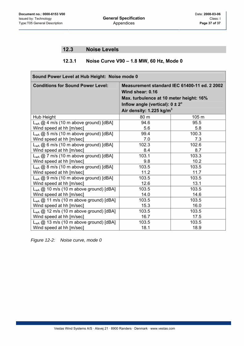
Document no.: 0000-6153 V00 Date: 2008-03-06 Issued by: Technology Class: I Type:T05 General Description Page 37 of 37
General Specification Appendices
Vestas Wind Systems A/S · Alsvej 21 · 8900 Randers · Denmark · www.vestas.com
12.3 Noise Levels
12.3.1 Noise Curve V90 – 1.8 MW, 60 Hz, Mode 0
Sound Power Level at Hub Height: Noise mode 0
Conditions for Sound Power Level: Measurement standard IEC 61400-11 ed. 2 2002 Wind shear: 0.16 Max. turbulence at 10 meter height: 16% Inflow angle (vertical): 0 ± 2o Air density: 1.225 kg/m3
Hub Height 80 m 105 m LwA @ 4 m/s (10 m above ground) [dBA] Wind speed at hh [m/sec]
94.6 5.6
95.5 5.8
LwA @ 5 m/s (10 m above ground) [dBA] Wind speed at hh [m/sec]
99.4 7.0
100.3 7.3
LwA @ 6 m/s (10 m above ground) [dBA] Wind speed at hh [m/sec]
102.3 8.4
102.6 8.7
LwA @ 7 m/s (10 m above ground) [dBA] Wind speed at hh [m/sec]
103.1 9.8
103.3 10.2
LwA @ 8 m/s (10 m above ground) [dBA] Wind speed at hh [m/sec]
103.5 11.2
103.5 11.7
LwA @ 9 m/s (10 m above ground) [dBA] Wind speed at hh [m/sec]
103.5 12.6
103.5 13.1
LwA @ 10 m/s (10 m above ground) [dBA] Wind speed at hh [m/sec]
103.5 14.0
103.5 14.6
LwA @ 11 m/s (10 m above ground) [dBA] Wind speed at hh [m/sec]
103.5 15.3
103.5 16.0
LwA @ 12 m/s (10 m above ground) [dBA] Wind speed at hh [m/sec]
103.5 16.7
103.5 17.5
LwA @ 13 m/s (10 m above ground) [dBA] Wind speed at hh [m/sec]
103.5 18.1
103.5 18.9
Figure 12-2: Noise curve, mode 0

A E R C O U S T I C S___________________________________________________________________________________E N G I N E E R I N G L I M I T E D
ATTACHMENT C
SOUND PRESSURE LEVELS PREDICTED BY AERCOUSTICS SOUND PROPAGATION MODEL
JULY, 2009

ISO Protocol Sample Calculations: R282
Receiver: R282 Total (dBA)ID: R282 40X: 423985Y: 5086985Z: 316.18Ground: 311.68
ID T16 T14 Xfrmr T18 T22 T12 T20 T23 T07 T13 T08
X 424453 423989 423978 422955 424656 424701 425290 422957 423700 425578 422874Y 5087387 5087892 5087255 5086507 5085962 5088124 5086246 5085855 5088499 5087836 5088445Z 395.57 395.52 319.78 391.95 380 392.26 373.75 384.8 373 366.47 381.55Ground 315.57 315.52 316.78 311.95 300 312.26 293.75 304.8 293 286.47 301.55ReflOrd 0 0 0 0 0 0 0 0 0 0 0LxT 103.4 103.4 91.5 103.4 103.4 103.4 103.4 103.4 103.4 103.4 103.4LxN 103.4 103.4 91.5 103.4 103.4 103.4 103.4 103.4 103.4 103.4 103.4L/A 1 1 1 1 1 1 1 1 1 1 1Dist. 622.04 910.47 270.11 1138.04 1225.09 1347.5 1500.82 1529.18 1541.64 1806.76 1835.81hm 42.13 37.96 3.92 43.08 44.21 37.07 42.91 43.94 35.97 37.35 34.47Freq 0 0 0 0 0 0 0 0 0 0 0Adiv 66.88 70.19 59.63 72.12 72.76 73.59 74.53 74.69 74.76 76.14 76.28K0b 0 0 0 0 0 0 0 0 0 0 0Agr -0.68 -0.64 -1.31 -0.61 -0.6 -0.59 -0.57 -0.57 -0.57 -0.55 -0.54Abar 0 0 0 0 0 0 0 0 0 0 0z 0 0 0 0 0 0 0 0 0 0 0Aatm 2.41 3.24 1.57 3.82 4.02 4.31 4.64 4.7 4.73 5.27 5.32Afol 0 0 0 0 0 0 0 0 0 0 0Ahous 0 0 0 0 0 0 0 0 0 0 0Cmet 0 0 0 0 0 0 0 0 0 0 0CmetN 0 0 0 0 0 0 0 0 0 0 0Dc 0 0 0 0 0 0 0 0 0 0 0RL 0 0 0 0 0 0 0 0 0 0 0LtotT 34.81 30.64 31.64 28.1 27.24 26.12 24.83 24.6 24.5 22.56 22.36LtotN 34.81 30.64 31.64 28.1 27.24 26.12 24.83 24.6 24.5 22.56 22.36
1 OF 3 AERCOUSTICS ENGINEERING LIMITED

T24 T06 T19 T28 T29 T30 T10 T15 T02 T05 T34 T21
425220 425113 426002 424761 423558 424211 426243 426514 425406 425967 423477 4210745085501 5088724 5086354 5085016 5084877 5084627 5088273 5087605 5089290 5088867 5084121 5086236368.74 370.24 350.11 363.67 372.32 366.5 363.64 355.27 370.88 370 370.62 391.62288.74 290.24 270.11 283.67 292.32 286.5 283.64 275.27 290.88 290 290.62 311.62
0 0 0 0 0 0 0 0 0 0 0 0103.4 103.4 103.4 103.4 103.4 103.4 103.4 103.4 103.4 103.4 103.4 103.4103.4 103.4 103.4 103.4 103.4 103.4 103.4 103.4 103.4 103.4 103.4 103.4
1 1 1 1 1 1 1 1 1 1 1 11931.38 2073.51 2113.67 2116.93 2151.54 2369.34 2599.95 2604.18 2708.37 2733.71 2909.21 3006.76
42.2 32.92 40.33 41.69 43.22 41.42 41.44 43.72 38.2 39.67 45.08 420 0 0 0 0 0 0 0 0 0 0 0
76.72 77.33 77.5 77.51 77.66 78.49 79.3 79.31 79.65 79.74 80.28 80.560 0 0 0 0 0 0 0 0 0 0 0
-0.53 -0.52 -0.52 -0.52 -0.52 -0.5 -0.51 -0.52 -0.55 -0.56 -0.62 -0.650 0 0 0 0 0 0 0 0 0 0 00 0 0 0 0 0 0 0 0 0 0 0
5.51 5.77 5.84 5.85 5.91 6.29 6.67 6.68 6.85 6.89 7.15 7.30 0 0 0 0 0 0 0 0 0 0 00 0 0 0 0 0 0 0 0 0 0 00 0 0 0 0 0 0 0 0 0 0 00 0 0 0 0 0 0 0 0 0 0 00 0 0 0 0 0 0 0 0 0 0 00 0 0 0 0 0 0 0 0 0 0 0
21.73 20.84 20.6 20.58 20.37 19.14 17.96 17.95 17.48 17.37 16.62 16.2221.73 20.84 20.6 20.58 20.37 19.14 17.96 17.95 17.48 17.37 16.62 16.22
2 OF 3 AERCOUSTICS ENGINEERING LIMITED

T01 T17 T09 T04 T03 T11
426031 420764 426960 426896 420126.08 4194365089472 5087030 5088349 5088982 5086400.14 5088245
372 400.49 359.21 359.86 392 357.36292 320.49 279.21 279.86 312 277.36
0 0 0 0 0 0103.4 103.4 103.4 103.4 103.4 103.4103.4 103.4 103.4 103.4 103.4 103.4
1 1 1 1 1 13220.93 3222.42 3273.07 3530.42 3903.72 4720.46
41.89 41.91 44.42 41.2 40.02 28.150 0 0 0 0 0
81.16 81.16 81.3 81.96 82.83 84.480 0 0 0 0 0
-0.72 -0.72 -0.73 -0.81 -0.9 -1.090 0 0 0 0 00 0 0 0 0 -0.02
7.61 7.61 7.68 8.03 8.51 9.450 0 0 0 0 00 0 0 0 0 00 0 0 0 0 00 0 0 0 0 00 0 0 0 0 00 0 0 0 0 0
15.37 15.37 15.18 14.24 12.98 10.5815.37 15.37 15.18 14.24 12.98 10.58
3 OF 3 AERCOUSTICS ENGINEERING LIMITED