analysis of the combined injection of pulverized coal and
TRANSCRIPT
ANALYSIS OF THE COMBINED INJECTION OF PULVERIZED COAL AND CHARCOAL INTO LARGE BLAST
FURNACES BY MULTIPHASE MODEL1
Jose Adilson de Castro2
Vagner Silva Guilherme2
Alexandre Bôscaro França2
Yasushi Sazaki3 Jun-ichiro Yagi4
Abstract The simultaneous injection of pulverized coal and charcoal in the blast furnace has recently received remarkable attention due to its potential to decrease the coke consumption and increase productivity. This paper is focused on modeling the simultaneous injection of pulverized coal and charcoal into the blast furnace through the tuyeres with oxygen enrichment. This model treats the blast furnace as a multi-phase reactor and six phases are considered simultaneously, namely: gas, lump solids (lump iron ore, sinter, pellets, coke and small coke), hot metal, molten slag, pulverized coal and charcoal. Conservation equations of mass, momentum, energy and chemical species are solved simultaneously based on the finite volume method. The model is validated with a base case of actual operation using 215kg/thm of pulverized coal injection and afterwards mixed injection of coal and charcoal are simulated for injection rate of 250kg/thm. Model results indicated that the productivity of the blast furnace could be increased up to 28% with simultaneous injection combined with oxygen enrichment. Keywords:Pulverized charcoal; Modeling; Pulverized coal; Combined injection.
1 Technical contribution to the 6th International Congresso on the Sicence and Technology of Ironmaking – ICSTI,42ndInternational Meeting on Ironmaking and 13thInternational Symposium on Iron Ore, October14th to18th,2012, Rio de Janeiro, RJ, Brazil.
2 Federal Fluminense University - Graduate Program on Metallurgical Engineering and Mechanical Engineering- Volta Redonda, RJ, Brazil, 27255-125 Tel: +55 24-2107-3756
3 Environmental Laboratory Graduate Institute of Ferrous Technology-POSTECH-Pohang University of Science and Technology, San 31 Hyojay-Dong, Nam-Gu, Pohang, 790-784, South Korea
4 Emeritus Professor at Tohoku University, Sendai, Japan
ISSN 2176-3135
338
1INTRODUCTION In the present status of technological development the technology to produce hot metal in the steel industry is based on the blast furnace-BOF processes route. However, this route is recognized as intensive energy consuming and demands high quality of raw materials such as lump coke and sinter. In the integrated route of crude steel production the blast furnace is responsible of around 70% of total energy input and about 60% of the total cost of pig iron production in this process is due to the reducing agent consumed in the blast furnace as lump coke or pulverized coal injected through the tuyeres. Therefore, tremendous efforts have been made in order to reduce the reducing agent rate of the blast furnace, or at least, replace the coke consumption by less precious materials injected through the blast furnace tuyere.(1-
6)Based on this perspective, the simultaneous injection of pulverized charcoal and coal in the blast furnace tuyeres has the attractive feature of improving the pulverized coal combustion within the raceway in addition to the environmental benefits that can be obtained by capturing CO2 from the atmosphere in a relatively short cycle (about 7 years), if one considers the charcoal produced by forestation. Therefore, it is a competitive technology for producing hot metal, especially for region where the climate is favorable to the plantation of biomass and will demand to increase steel production by constructing new blast furnaces in near future. The combustion rate of charcoal is quite high compared with those of coal and coke.(4-8) When pulverized charcoal is injected into the raceway, it combusts first and furnishes heat and CO2 which is used for gasification of the pulverized coal by solution loss reaction in addition to partial and full combustion directly with the oxygen. Composition of charcoal is quite different from that of coal usually injected into the blast furnace.(4-8) The charcoal used in this study has very low ash, sulfur and silica content, however, volatile matter is usually higher, as shown in Table 1. The gas produced due to gasification reaction within the raceway has higher hydrogen content and lower ignition temperature is needed(around 700 oC). In addition, the technology for injection of pulverized coal already get maturity and several blast furnaces over the world have been continuously operated with pulverized coal rates around 200 kg/thm. However, there is clear limitation for further increases in the injection rates of pulverized coal mainly due to the gas and particles flows in the lower part of the furnace and unburned coal or ash that can remain in the raceway, which could deteriorates the permeability of this region leading to unstable operation. In the same hand, the pulverized charcoal injection technology applied for small blast furnaces based on granular charcoal has entered in a stage of high technological development.(2-4) Aiming at contributing to clarify the in-furnace phenomena and show the feasibility of simultaneous injection, this paper focuses the analysis of the coke based blast furnace process with simultaneous injection of charcoal and coal in the raceway in order to demonstrate the advantages of both technologies. The injection of charcoal into the blast furnace tuyere substitutes the coke charged from the blast furnace top and furnishes higher amount of hydrogen, which replace carbon monoxide as reducing gas in the shaft of the blast furnace. The hydrogen gas is a better reducing agent if compared with carbon monoxide and allows savings of energy by decreasing the amount of direct reduction which can take place in the lower part of the furnace. Several authors have addressed the multiple injections of carbonaceous materials into the blast furnace by theoretical and experimental analysis.(1,4-9)However, only detailed mathematical model based on fundamental phenomena is expected to fully considers the important aspects of simultaneous
ISSN 2176-3135
339
injection. In this paper a mathematical model of the blast furnace is proposed to simulate the blast furnace operation with simultaneous injection of pulverized charcoal and coal. The present model uses similar approach as those presented by Yagi,(10) Austin, Nogami and Yagi(11,12) and Castro, Nogami and Yagi,(13,14) which applied multiphase theory to describe the motion, energy and chemical species of each phase inside the furnace. Although some hybrid models based on DEM(Discrete Element Method) have been discussed,(15-18) the multiphase theory is considered suitable and enough accurate to describe the actual operation of the blast furnace, since DEM approach has shown severe limitations to deal with realistic situation within the blast furnace regarding to accuratecalculations of physical changes of the particles due to reactions and melting, in addition to need of large memory and computation time that has limited to apply for a number of simulation cases. Table 1: Compositions of reducing agents and thermophysical properties used in this study (Mass %) Coke Pulverized coal
(PCI) Pulverized Charcoal (PCH)
C(fixed) 87.20 72.20 71.24 Volatile matter 1.00 19.50 25.80 Humidity 0.15 0.01 0.01 SiO2 6.52 5.70 1.10 Al2O3 3.61 2.12 0.11 MgO 0.18 0.01 CaO 0.47 0.30 1.58 S 0.65 0.39 0.0022 FeS 0.22 - - P(P2O5) - - 0.170 Na(Na2O) - - - K(K2O) - - 0.40 Ash 11.60 8.52 2.96 Volatile matter (Mass %) C 74.40 68.30 72.00 N 8.40 4.50 7.35 H 12.60 25.20 16.50 O 4.60 2.00 4.15 Thermo-physical properties used in this study Average particle diameter(µm)
- 150 120
True density(kg/m3) 1820 1545 1150 Particle porosity(-) 0.45 0.7 0.85 Pore tortuosity (-) 0.8 0.8 0.9 Thermal conductivity(W/mK)
- 0.6 0.6
Calorific value (kJ/kg)
34276 32415 31162
Therefore, the continuum approach is a better tool to evaluate the performance of the whole blast furnace process under multiple injection operation.(10-15,19-22) In this paper, the pulverized charcoal injection is treated as an independent phase due to the significantdifference in the thermo-physical properties and phase interactions of
ISSN 2176-3135
340
momentum and energy compared with the pulverized coal phase. Also, kinetic rate equations are quite different between charcoal and coal. Therefore, in the present study a detailed model able to take into account particular phenomena and mechanism of simultaneous injection of pulverized coal and charcoal is used. Thus, this model aims to address new features of the simultaneous injection of pulverized coal and charcoal to the blast furnace and to investigate new operation possibilities, which could contribute to lower coke consumption and suggest new environmentally cleaner process operation techniques. 2MODELING 2.1 Model Approach The mathematical model is three-dimensional and analyses the packed bed region within the blast furnace, from the slag surface in the hearth up to the burden surface in the throat. Six-phases are treated: gas, lump solids(coke, sinter, pellets, lumpore), hot metal, slag, pulverized charcoal and pulverized coal. All phases are treated simultaneously due to mutual interactions. Thus, the governing equations of all phases, that form a large set of strongly coupled non-linear equations, are solved simultaneously. In this model, conservation equations of motion, energy and chemical species are considered and coupled with chemical reactions and physical properties. For the sake of simplicity, all the conservation equations are represented in a compact form, as in Equation(1).
ii
SgraddivVdivt iiiiii
iii
(1)
In this equation, is the dependent variable, expressing the component velocities for the phase momentum equations, the enthalpy for the phase energy equations and the chemical species for the phase continuity equations, irepresents the phase being considered or the chemical species ofeach phase. ε and ρ are phase volume fraction and density, respectively. V and t are phase velocity field and time, respectively.
i is
the effective transfer coefficient which represents effective dynamic viscosity in the momentum equations, effective thermal conductivity in the energy equations and effective diffusion coefficient of the chemical species in the materials equation of each phase. The source terms(Sϕ) are due to inter-phase interactions that canappear through chemical reactions, surface interactions and external force.(10-22)Each phase is composed of various chemical species and the general conservation equation is used to calculate the phase motion, the phase energy and the mass fraction of chemical species in each phase. 2.2 Source Terms The source terms in the conservation equations take into account chemical reactions, phase transformations, momentum exchange, external force and so on. The continuity and species conservation equations have mass sources due to chemical reactions and phase transformations. Enthalpy sources arise from inter-phase heat transfer, heat of reaction and sensible heat accompanied with mass transfer due to chemical reactions and phase transformations. The formulations for the phase
ISSN 2176-3135
341
interactions and chemical reactions have been published in previous reports.(10-
15)This model considers the pulverized charcoal injected through a separated lance into the raceway channel. The charcoal injected through the blast furnace tuyeres is mixed with the gas stream and, in contact with oxygen, combusts partially and the volatile matter evolves in the interior of the raceway and finally almostcomplete combustion in the raceway is achieved. The unburned pulverized coal or ash continues to reacts and meltdown when particle temperature is higher than the melting temperature. The chemical reaction models for pulverized charcoal and coal used in this study have similar rate expressions, however, the parameters of reactivity and inner particle structure are quite different, which gives high difference in reaction rates.(6) The thermo-physical properties used in this model is presented in Table 1. 2.3 Boundary Conditions, Assumptions and Numerical Features The boundary conditions were applied on the boundary of the computational domain surrounded at the bottom by the slag surface, at the top by the burden surface and bylateral walls. At the top, the gas phase is assumed as fully developed flow while solid inflow is modeled assuming no gradient velocity, with the inflow rate given by solid mass consumption due to chemical reactions and melting. At the tuyere inlet of blast, additional oxygen and pulverized coal are given by their inflow rates. The blast flow rate are fixed and pulverized coal and charcoal are iteratively calculated to reach the aimed pulverized coal and charcoal injection rates, which are specified at the beginning of the iterative calculation. The blast temperature are specified as a fixed value throughout the calculation. At the side wall, momentum and mass fluxesacross the wall are assumed null while heat transfer is allowed by setting an overall heat transfer coefficient. For the gas velocity it is assumed null values perpendicular and tangential to the furnace wall. The solid tangential velocity on the wall surface assumes coulomb attrition law with a specified coefficient of 0.3 and the normal force is calculated using the local solid pressure. The burden distribution is determined by the relative volume fractions of the inlet solids and their average diameter. The numerical method used to solve the transport equations is based on the finite volume method (FVM) formulated for a general non-orthogonal coordinate system.(23) The numerical mesh is constructed based on a body fitted coordinate system which allows accurate description of the blast furnace wall shape.(23) To solve the governing (momentum)equations of continuous phases the SIMPLE(Semi-Implicit Method for Pressure-Linked Equations) algorithm is applied on a staggered grid for covariant projections of the velocities and the numerical coefficients of the discretized equations are determined by using the power low scheme.(23-25) 3RESULTS AND DISCUSSIONS 3.1 Model Validation with Industrial Blast Furnace Data The proposed model was verified by using measured data obtained in anindustrial blast furnace which has working volume of 3970 m3 and instrumentations based on temperature probes at the burden surface level.The burden distribution is assumed in the model for the charging materials with radial distribution of mean solid diameter and their volume fractions. In order to validate the model input data of 24h operation
ISSN 2176-3135
342
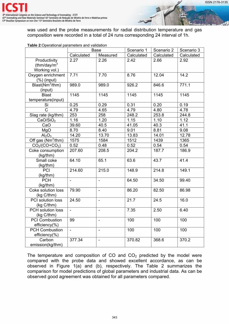
was used and the probe measurements for radial distribution temperature and gas composition were recorded in a total of 24 runs corresponding 24 interval of 1h. Table 2:Operational parameters and validation Base Scenario 1 Scenario 2 Scenario 3
Calculated Measured Calculated Calculated Calculated Productivity (thm/day/m3 Working vol.)
2.27 2.26 2.42 2.66 2.92
Oxygen enrichment (%) (input)
7.71 7.70 8.76 12.04 14.2
Blast(Nm3/thm) (input)
989.0 989.0 926.2 846.6 771.1
Blast temperature(input)
1145 1145 1145 1145 1145
Si 0.25 0.29 0.31 0.20 0.19 C 4.79 4.65 4.79 4.80 4.78
Slag rate (kg/thm) 253 258 248.2 253.8 244.8 CaO/SiO2 1.16 1.20 1.15 1.10 1.12
CaO 39.60 40.5 41.05 40.3 41.1 MgO 8.70 8.40 9.01 8.81 9.08 Al2O3 14.20 13.70 13.83 14.01 12.78
Off gas (Nm3/thm) 1575 1584 1512 1439 1365 CO2/(CO+CO2) 0.52 0.48 0.52 0.54 0.54
Coke consumption (kg/thm)
207.60 208.5 204.2 187.7 186.9
Small coke (kg/thm)
64.10 65.1 63.6 43.7 41.4
PCI (kg/thm)
214.60 215.0 148.9 214.8 149.1
PCH (kg/thm)
- - 64.50 34.50 99.40
Coke solution loss (kg C/thm)
79.90 - 86.20 82.50 86.98
PCI solution loss (kg C/thm)
24.50 - 21.7 24.5 16.0
PCH solution loss (kg C/thm)
- - 7.35 2.50 6.40
PCI Combustion efficiency(%)
99 - 100 100 100
PCH Combustion efficiency(%)
- - 100 100 100
Carbon emission(kg/thm)
377.34 - 370.82 368.6 370.2
The temperature and composition of CO and CO2 predicted by the model were compared with the probe data and showed excellent accordance, as can be observed in Figure 1(a) and (b), respectively. The Table 2 summarizes the comparison for model predictions of global parameters and industrial data. As can be observed good agreement was obtained for all parameters compared.
ISSN 2176-3135
343
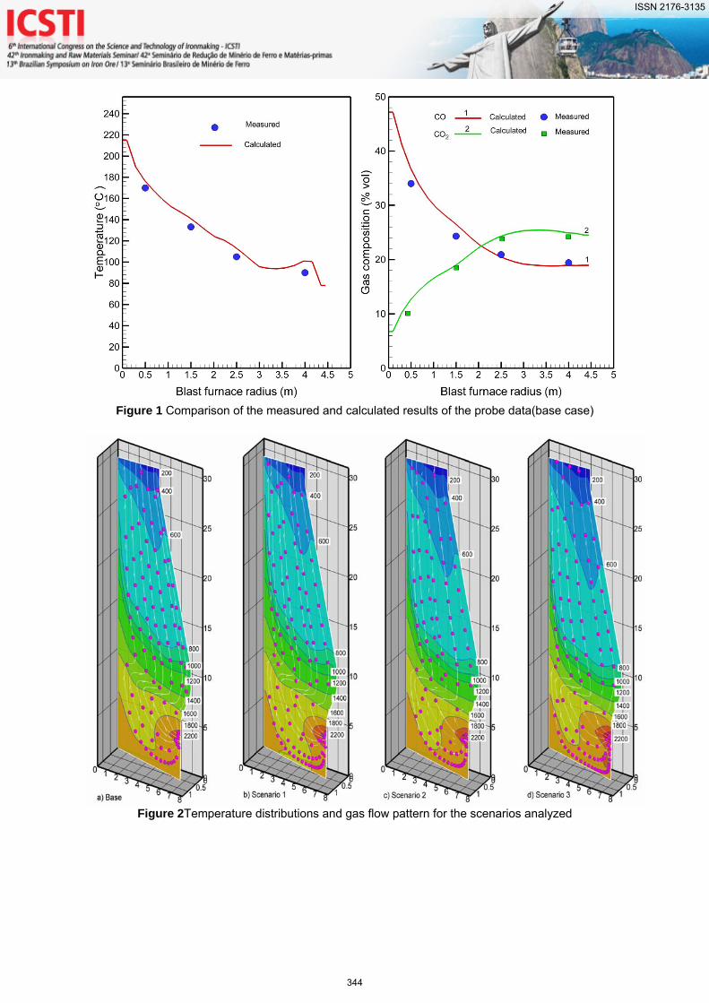
Figure 1 Comparison of the measured and calculated results of the probe data(base case)
Figure 2Temperature distributions and gas flow pattern for the scenarios analyzed
ISSN 2176-3135
344
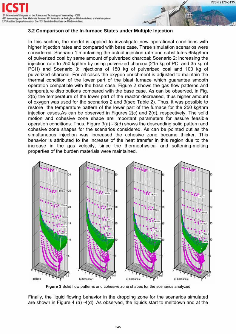
3.2 Comparison of the In-furnace States under Multiple Injection In this section, the model is applied to investigate new operational conditions with higher injection rates and compared with base case. Three simulation scenarios were considered: Scenario 1:mantaining the actual injection rate and substitutes 65kg/thm of pulverized coal by same amount of pulverized charcoal; Scenario 2: increasing the injection rate to 250 kg/thm by using pulverized charcoal(215 kg of PCI and 35 kg of PCH) and Scenario 3: injections of 150 kg of pulverized coal and 100 kg of pulverized charcoal. For all cases the oxygen enrichment is adjusted to maintain the thermal condition of the lower part of the blast furnace which guarantee smooth operation compatible with the base case. Figure 2 shows the gas flow patterns and temperature distributions compared with the base case. As can be observed, in Fig. 2(b) the temperature of the lower part of the reactor decreased, thus higher amount of oxygen was used for the scenarios 2 and 3(see Table 2). Thus, it was possible to restore the temperature pattern of the lower part of the furnace for the 250 kg/thm injection cases.As can be observed in Figures 2(c) and 2(d), respectively. The solid motion and cohesive zone shape are important parameters for assure feasible operation conditions. Thus, Figure 3(a) - 3(d) shows the descending solid pattern and cohesive zone shapes for the scenarios considered. As can be pointed out as the simultaneous injection was increased the cohesive zone became thicker. This behavior is attributed to the increase of the heat transfer in this region due to the increase in the gas velocity, since the thermophysical and softening-melting properties of the burden materials were maintained.
Figure 3 Solid flow patterns and cohesive zone shapes for the scenarios analyzed
Finally, the liquid flowing behavior in the dropping zone for the scenarios simulated are shown in Figure 4 (a) -4(d). As observed, the liquids start to meltdown and at the
ISSN 2176-3135
345
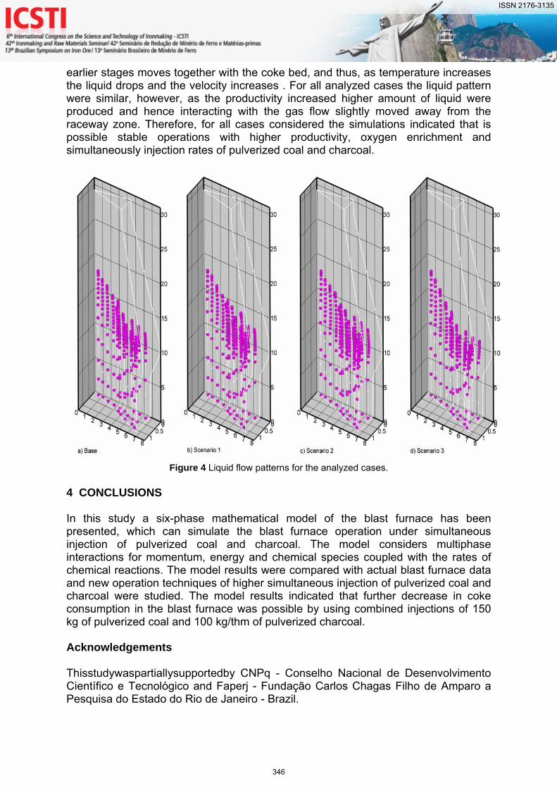
earlier stages moves together with the coke bed, and thus, as temperature increases the liquid drops and the velocity increases . For all analyzed cases the liquid pattern were similar, however, as the productivity increased higher amount of liquid were produced and hence interacting with the gas flow slightly moved away from the raceway zone. Therefore, for all cases considered the simulations indicated that is possible stable operations with higher productivity, oxygen enrichment and simultaneously injection rates of pulverized coal and charcoal.
Figure 4 Liquid flow patterns for the analyzed cases.
4 CONCLUSIONS In this study a six-phase mathematical model of the blast furnace has been presented, which can simulate the blast furnace operation under simultaneous injection of pulverized coal and charcoal. The model considers multiphase interactions for momentum, energy and chemical species coupled with the rates of chemical reactions. The model results were compared with actual blast furnace data and new operation techniques of higher simultaneous injection of pulverized coal and charcoal were studied. The model results indicated that further decrease in coke consumption in the blast furnace was possible by using combined injections of 150 kg of pulverized coal and 100 kg/thm of pulverized charcoal.
Acknowledgements Thisstudywaspartiallysupportedby CNPq - Conselho Nacional de Desenvolvimento Científico e Tecnológico and Faperj - Fundação Carlos Chagas Filho de Amparo a Pesquisa do Estado do Rio de Janeiro - Brazil.
ISSN 2176-3135
346
REFERENCES
1 A. Babich, S. Yaroshevskii, A. Formoso, A. Cores, L. Garcia and V. Nozdrachev, ISIJ Int., 39 (1999), No. 3, 229.
2 J. A. Castro, A. J. Silva, H. Nogami and J. Yagi: Tecnologia em Metalurgia, Materiais e Mineração, 1(2004), No. 2, 59.
3 A.W.S. Baltazar, J.A. Castro and A.J. Silva: Estudos Tecnologicos em Engenharia, 2(2006), No 2, 65.
4 J. G. M. S. Machado1, E. Osorio, A. C. F. Vilela, A. Babich, D. Senk and H. W. Gudenau: Steel Research Int., 81(2010), No 1, 9.
5 P.S. Assis, W.B. Martins and C.B. Vieira: REM-Revista da Escola de Minas, 56(2003), No 4, 281.
6 J. A. Castro, Y. A.J. Silva, Y. Sazaki and J. Yagi: ISIJ Int. 51 (2011), No 5, 748. 7 J.A. Castro, A.W.S. Baltazar and A.J. Silva: WIT Trans. Eng. Sci. , 50(2005), No 1, 207. 8 A. Babich, D. Senk and M. Fernandez: ISIJ Int. 50 (2010), No 1, 81. 9 J.A. Castro and A. W. S. Baltazar: TMM-Tecnologia em Metalurgia e Materiais e
Mineração, 6,(2009), No. 1, 13. 10 J. Yagi: ISIJ Int., 33(1993), No. 6, 619. 11 P. R. Austin, H. Nogami and J. Yagi: ISIJ Int., 37(1997), No. 5, 458 12 P. R. Austin, H. Nogami and J. Yagi: ISIJ Int., 37(1997), No. 8, 748. 13 J. A. Castro, H. Nogami and J. Yagi: ISIJ Int. 40 (2000), No. 7, 637. 14 J. A. Castro, H. Nogami and J. Yagi: ISIJ Int. 41 (2001), No. 1, 18. 15 X.F. Dong, A.B. Yu, S.J. Chew and P.Zulli: Metallurgical and Materials Transactions B,
41B(2010), No. 2, 330. 16 S. Ueda, S. Natsui, H. Nogami, J. Yagi and T. Ariyama: ISIJ Int., 50(2010), No 7, 914. 17 Z. Zhou, H. Zhu, A. Yu, B. Wright, D. Pinson and P. Zulli: ISIJ Int., 45(2005), No. 12,
1828. 18 A.T.Adema, Y. Yang and R.Boom: ISIJ Int., 50(2010), No 7, 954. 19 Z. Zhou, H. Zhu, A. Yu, B. Wright, D. Pinson and P. Zulli: Powder Technology 208(2011),
No. 1, 72. 20 X.F. Dong, A.B. Yu, J. Yagi and P. Zulli: ISIJ Int., 47(2007), No. 11, 1553. 21 J. A. Castro, H. Nogami and J. Yagi: ISIJ Int. 42 (2002), No. 11, 1203. 22 J. A. Castro, H. Nogami and J. Yagi: ISIJ Int. 42 (2002), No.1, 44. 23 M.C. Melaen: Numerical Heat Transfer, B, 21(1992), No. 1, 1. 24 S. V. Patankar and D. B. Spalding: Int. J. Heat Mass Transfer, 15(1972), No. 1, 1787. 25 K. C. Karki and S. V. Patankar: Numer. Heat Transfer, B, 14 (1988), No. 3, 295.
ISSN 2176-3135
347