analysis of steel silo structures on discrete
TRANSCRIPT

ANALYSIS OF STEEL SILO STRUCTURES
ON DISCRETE SUPPORTS
BY
Hongyu Li
A thesis submitted in fulfilment of the requirements
for the degree of Doctor of Philosophy
Department of Civil Engineering & Building Science
The University of Edinburgh
Edinburgh, Scotland, UK
September 1994

ABSTRACT
The objective of this thesis is to broaden current knowledge of the strength and
buckling/collapse of shells, with special reference to steel silo structures on discrete supports,
and thus to provide design guidance of practical value for future silo design and construction
and to develop new research aspects for further investigation.
A linear elastic solution of the cylindrical shell bending equations is presented for local
loadings, with special attention to local longitudinal distributed loadings. Algebraic
expressions for the displacements and stresses induced by a rectangular patch of longitudinal
load on a simply supported cylindrical shell are derived using double Fourier series. The
solution of this problem is general, and therefore can be applied to cylindrical shells under local I loadings in any direction and with different boundary conditions.
Linear elastic analyses of discretely supported perfect cylinders under axial compression are
presented using the finite element method. The pre-buckling meridional membrane stress
distribution above the support centreline is examined in detail, and is followed by investigations
of the linear bifurcation behaviour of the cylinders. The effects on the stress distribution and
the buckling strength of different loading patterns and different geometric configurations are
extensively examined.
Geometrically nonlinear elastic buckling analyses are also performed using large deflection
theory. Both perfect and imperfect cylinders are studied with various geometric configurations
and under different loading conditions. The nonlinear elastic buckling behaviour, the buckling
strength and the buckling configuration are thoroughly investigated for discretely supported
cylinders
Further studies extend the work into the plastic range. Discretely supported cylinders obeying
the von Mises yield criterion are analysed. Limit analyses of perfect cylinders are first
conducted using small deflection theory. Geometrically nonlinear elastic-plastic collapse
analyses of both perfect and imperfect cylinders are performed next. Studies of different
loading conditions and parametric studies of varying geometries and material strengths are
presented in both types of analysis. The nonlinear elastic-plastic behaviour of discretely
supported cylinders is thus explored.

A complete silo which consists of a cylindrical shell, a conical roof hopper and a conical
discharge hopper is briefly examined, with the aim of exploring the applicability of the
established cylinder model in the elastic buckling analysis of silo structures.
Finally, the conclusions drawn from this research are summarised and recommendations are
also made for further research on locally supported shells.
ii
ACKNOWLEDGEMENTS
I am indebted to my supervisor, Professor J.M. Rotter, for his encouragement, help and
guidance in carrying out this research and in producing this thesis.
I would like to thank all those who have helped me in various ways during my PhD studies,
particularly the former and present members of the Silo Research Group in the Department of
Civil Engineering, University of Edinburgh.
I would like to express my special thanks to my parents, my sisters and friends for their love,
care and support during the last three years.
Finally, financial support from the ORS Award and the Faculty of Science & Engineering
Postgraduate Scholarship, University of Edinburgh, the Edinburgh University Crisis/Hardship
Fund, the Great Britain-China Educational Trust Fund and the Henry Lester Trust Ltd. Fund is
greatly acknowledged.
H.Y. LI
. . . 111

DECLARATION
This thesis, entitled Analysis of Steel Silo Structures on Discrete Supports, is submitted for
the Degree of Doctor of Philosophy, in the Department of Civil Engineering, at the University
of Edinburgh, Scotland, UK.
The research, on which this thesis is based was carried out between February 1991 and May
1994 under the supervision of Professor J.M. Rotter. It is solely the work of the author except
where otherwise acknowledged in the text and has not formed the basis of a submission for any
other degree.
Two supporting papers which are based on the work described in this thesis have been
presented in:
1. Rotter, J.M. and Teng, J.G. and Li, H.Y. (1991), “Buckling in Thin Elastic Cylinders on
Column Supports”, in Buckling of Shell Structures, on Land, in the Sea and in the Air, edt. J.F.
Jullien, Elsevier Applied Science, London and New York.
2. Rotter, J.M., Greiner, R., Guggenberger, W., Li, H.Y., and She, K.M. (1993) “Proposed
Design Rule for Buckling Strength Assessment of Cylindrical Shells under Local Axial
Loads”, Submission to ECCS TWG8.4 Buckling of Shells, Edinburgh Meeting, September
1993.
Signed
2Qs& eb-yp Date.. . . . . . . . . . . . . . . . .
iv

CONTENTS
Abstract
Acknowledgements
Declaration
Contents
Notations
Chapter I INTRODUCTION 1
1.1
1;2
1.3
1.4
1.5
1.6
1.7
Steel Silos
Loads on Silo Walls
Failure Modes in Steel Silos
1.3.1 Failure Modes in the Cylindrical Shell
1.3.2 Failure Modes in the Conical Hopper
1.3.3 Failure Modes in the Transition Ring
Structural Analysis and Design of Steel Silos
Buckling Failures in Cylindrical Silo Walls
Strategy for Attacking the Stability Problem
1.6.1 Introduction
1.6.2 Simplified Loading Cases
1.6.3 Characterisation of Strength
Contents of the Thesis
Chapter 2 HISTORICAL REVIEW 30
2.1 Introduction 30
2.2 Loads on Silo Walls from Bulk Solids: Wall Pressures 30
2.2.1 Loads in Cylinders after Initial Filling 30
2.2.2 Loads in Hoppers after Initial Filling 31
2.2.3 Loads in Cylinders during Flow 32
2.2.4 Loads in Hoppers during Flow 32
2.3 Theory of Circular Cylindrical Shells 33
2.3.1 Introduction 33
2.3.2 Elastic Theories of Cylindrical Shells 34
2.3.3 Elastic Buckling of Cylindrical Shells under Axial Compression 3.5
Page
i . . . 111
iv
V
ix
1
2
4
4
6
7
7
9
11
11
12
14
16

2.3.4 Elastic Buckling and Plastic Collapse of Cylindrical Shells
under Internal Pressure and Axial Compression
2.3.5 Plastic Analysis of Cylindrical Shells
2.3.6 Conclusions
2.4 Structural Design of Steel Silos
2.5 Computer Programs Used in Silo Structure Analysis
2.5.1 Introduction
2.5.2 The FELASH Suite of Computer Programs
2.5.3 ABAQUS Finite Element Program
2.6 Summary
Chapter 3 NONLINEAR ELASTIC BEHAVIOUR AND BUCKLING
IN DISCRETELY SUPPORTED CYLINDERS .
3.1 Introduction 58
3.2 Finite Element Modelling 59
3.3 Typical Behaviour of a Discretely Supported Cylinder 60
3.3.1 A Perfect Cylinder 60
3.3.2 An Imperfect Cylinder 61
3.4 Parametric Studies 62 -
3.4.1 Variation with Wall Thickness t 62
3.4.2 Variation with Cylinder Height H/R 62
3.4.3 Variation with Number of Supports n 63
3.4.4 Variation with Width of the Supports d/R 63
3.4.5 Variation with Imperfection Amplitude S& 63
3.4.6 Variation with Imperfection Position 2, 64
3.5 Conclusions 64
Chapter 4 ALGEBRAIC ANALYSIS OF ELASTIC CIRCULAR
CYLINDRICAL SHELLS UNDER LOCAL LOADINGS
4.1 Introduction
4.2 General Theory of Cyhmirical Shells
4.3 Analysis for Longitudinal Load Distributions
4.3.1 The Differential Equations of Equilibrium
4.3.2 General Case : Expressions for Displacements u,v and w
4.3.3 Special Case for Harmonic m=l
4.3.4 General Case of Expressions of Stress Resultants 2’
41
42
45
45
47
47
48
49
51
58
74
74
75
77
77
78
89
93
vi
4.3.5 Special Case of Harmonic m= 1: Expressions for Stress Resultants
4.3.6 Expressions of Load Coefficient X,
4.4 Computer Evaluation for A Circular Cylindrical Shell
4.5 Summary and Conclusions
Chapter 5 LINEAR ELASTIC STRESS AND BIFURCATION ANALYSES
OF DISCRETELY SUPPORTED PERFECT CYLINDERS
5.1 Introduction
5.2 Finite Element Modelling
5.3 Pre-buckling Stress Analysis
5.4 Bifurcation Analysis
5.4.1 Example Study . 5.4.2 Parametric Studies
5.5 Summary and Conclusions
Chapter 6 NONLINEAR ELASTIC BUCKLING ANALYSIS OF
6.1
6.2
6.3
6.4
6.5
6.6
DISCRETELY SUPPORTED CYLINDERS
Introduction
Finite Element Modelling
Behaviour of Perfect Elastic Cylinders
6.3.1 The Effect of the Position of the Applied Axial Compression Load
6.3.2 The Effect of Internal Pressurization
Behaviour of Imperfect Elastic Cylinders with a Local Inward
Axisymmetric Imperfection
6.4.1 The Effect of the Position of the Applied Axial Compression Load
6.4.2 The Effect of Internal Pressurization
Behaviour of Imperfect Elastic Cylinders with a Local Outward
Axisymmetric Imperfection
6.5.1 The Effect of the Position of the Applied Axial Compression Load
6.5.2 The Effect of Internal Pressurization
Summary and Conclusions
Chapter 7 ELASTIC-PLASTIC STABILITY ANALYSIS OF
DISCRETELY SUPPORTED CYLINDERS
175
7.1 Introduction / 175
99
104
107
109
119
119
120
121
123 -
123
124
125
141
141
142
144
144
145
147
147
148
149
149
150
151
vii
7.2 Finite Element Modelling 176
7.3 Mesh Refinement Study 177
7.4 Limit Analysis of Perfect Cylinders 179
7.4.1 Study of the Three Loading Cases 179
7.4.2 Parametric Studies 180
7.4.3 Conclusions 181
7.5 Nonlinear Elastic-Plastic Collapse Analysis of Cylinders 182
7.5.1 Study of Alternative Analysis Control Procedures 182
7.5.2 Behaviour of Perfect Cylinders 184
7.5.3 Behaviour of Imperfect Cylinders 187
7.6 Summary and Conclusions 189
qhapter 8 NONLINEAR ELASTIC BUCKLING ANALYSIS OF
A DISCRETELY SUPPORTED SILO
206
8.1 Introduction 206
8.2 Finite Element Modelling 207
8.3 Behaviour of an Elastic Perfect Silo on Discrete Supports 208
8.4 Conclusions 209
Chapter 9 CONCLUSIOSS AND RECOMMENDATIONS 214
9.1 Summary
9.2 Conclusions
9.2.1 Algebraic Analysis of Elastic Cylindrical Shells under Local Loadings
9.2.2 Linear Elastic Stress and Bifurcation Analyses of Discretely Supported
Perfect Cylinders
214
216
216
216
9.2.3 Nonlinear Elastic Buckling Analysis of Perfect and Imperfect Cylinders on
Discrete Supports
217
9.2.4 Elastic-Plastic Stability Analysis of Discretely Supported Cylinders 218
9.2.5 Nonlinear Elastic Buckling Analysis of a Discretely Supported Silo 219
9.3 Recommendations for Future Work 220
REFERENCES 222
. . . Vlll
NOTATIONS
The symbols listed below are those that appear in this thesis. They are of either general interest
or particular specification. Only one meaning is assigned to each symbol unless otherwise
defined in the text where it occurs.
Symbols
a, R
b
bl
b* D
d
E
H
1
Mx, MO
MX4
m, n
Nx, Ni$P Nx(l
n
PL
p*
P.
P+
P
P*
PI
Pv t
u, v, w
x, y, z
x2 Y, z
Meaning
radius of cylindrical shell
co-ordinate x of centre of loading surface
half-length of loading surface in circumferential direction
half-length of loading surface in longitudinal direction
Et3 / 12( 1 - v2 )
width of support
Young’s modulus
height of cylinder
length of cylindrical shell
bending moments in shell wall per unit length of axial section and a
section perpendicular to the axis of a cylindrical shell, respectively
twisting moment in shell wall per unit length of an axial section of
a cylindrical shell
integer numbers
membrane forces in shell wall per unit length of axial section and
a section perpendicular to the axis of a cylindrical shell
number of supports
limit load
equally distributed longitudinal load in a rectangle.
statically admissible load parameter
kinematically admissible load parameter
internal pressure
dimensionless internal pressure parameter (pR/t CLI )
uniformly distributed line load
uniformly distributed R-all friction load
wall thickness of shell
components of displacements in the x, y, and z directions respectively
components of the intensity of the external load on a shell parallel to
x, y, and z axes, respectively
global co-ordinates
ix

x, 44 z Z
ZC
zo
Xx+ V
h
cyhndrical co-ordinates
vertical distance from the bottom edge of cylinder
critical position of the imperfection
distance from the centre of an imperfection to the bottom edge of
cylinder
I/a
b, /a
b, la
imperfection amplitude
characteristic amplitude of a local imperfection
unit elongations in x and 4 directions
shear strain in cylindrical co-ordinates
half angle of conical roof
half angle of conical hopper
changes of curvature of a cylindrical shell in axial plane and in a
plane perpendicular to the axis, respectively
change of curvature in cylindrical co-ordinates
Poisson’s ratio
nrra/l
or buckling half wave length
classical elastic critical stress of a cylinder under uniform axial
compression
mean meridional membrane stress above support
meridional membrane stress
yield stress in tension or compression.

INTRODUCTION
1.1 STEEL SJLOS
Containers for the storage of bulk solids are usually called bins, bunkers, silos or tanks. While
there is no generally accepted definition for each of these terms, shallow containers for coal,
coke, ore, crushed stone, gravel, etc. are often called bins or bunkers, and tall containers for
materials such as grain and cement are usually called silos. In this thesis, silo is an inclusive
term for all steel structures for the storage of bulk solids.
Steel silos differ principally from their concrete counterparts in that they are much lighter
structures, quick to erect and dismantle, carrying their loads by different structural
mechanisms, deforming readily and reversibly when subject to unsymmetrical loads, and
placing smaller loads on their foundations. Thus steel silos are widely used for short and long
term storage of large quantities of bulk solids and have been built increasingly in recent years
in many industries including mining, chemical, electric power generation, agriculture and food
processing.
Steel silos in common use are usually circular in cross section, and may be ground-supported
(Fig. l-la) or elevated. Typical elevated silos generally consist of a conical roof, a cylindrical
shell and a conical hopper (Fig. 1-2) and may be supported on a load-bearing skirt (Fig. l-2a)
or on discrete supports. The junction between the vertical wall and the hopper is termed the
transition. A stiff ring is usually provided at the transition. Typical forms of the transition
junction are shown in Figure 1-3. In practice, there are many forms of support, which locally
contact the shell, and which may be described as discrete supports. Columns of various widths
have been widely used as supports and these may terminate below the transition junction (Fig.
l-2b), extend to the eaves (Fig. 1-2~) or engage into the shell for a short distance (Fig. l-2d).
In this thesis, the term ‘discretely supported silo’ is used to mean that the silo cylinder is
directly supported on local supports of a defined width.
Elevated silos have the advantage that the bulk solid can be discharged by gravity flow. The pattern of flow depends on the shape of the silo, the roughness of its interior surfaces, and the
properties of the stored material. Several patterns of flow are possible during emptying (Fig.
1.4). A silo which consists of a vertical cylinder with smooth walls and a steep smooth-walled
hopper is likely to develop mass flow (Fig. 1-4a). This is a first-in, first-out flow pattern. By

contrast, one with a shallow rough-walled hopper is likely to develop funnel flow (Fig. 1-4b),
or pipe flow (Fig. lk), which is generally a last-in, first-out flow sequence. An expanded
flow silo (Fig. 1-4d) is a funnel-flow silo with a small mass flow hopper which can obviate the
&advantages of the funnel-flow silo. This type of silo is useful for the storage of large
quantities of nondegrading solids such as mineral ores.
Steel silos are generally very light and thin structures for their size. The radius-to-thickness
ratio of the cylinder R/t is generally in the range 200-3000. Squat silos with a height-to-radius
ratio H/R less than 2 are being built increasingly, as they have a large ratio of stored volume to
structural construction cost.
1.2 LOADS ON SILO WALLS
The walls of silos are subjected to both normal pressures and vertical fktional shears or
tractions which come from the stored material inside the silo and vary all over the wall. The
magnitude and distribution of these pressures may be symmetric or non-symmetric and depend
on whether the silo is being filled or discharged. Geometric imperfections in the silo wall,
which are caused inevitably during its fabrication and by the flexibility of the wall, may also
strongly Sect the pressures on the walls.
In simple terms, it is to be expected that normal pressures on the cylindrical wall will give rise
to circumferential (or hoop) tensions, and that frictional tractions will cause cumulative axial
(or vertical) compressive stresses in the silo wall. In practice, the real loading is very complex:
different load cases may give rise to different stress patterns in the shell.
A strenuous effort has been put into exploring the pressures on silo walls from bulk solids over
the last two or three decades. The simplest useful theory for predicting the pressures on the
vertical walls of a silo is probably that of Janssen [1895] (Fig. l-lb). It is widely accepted that
pressures cl&e to Janssen values are exerted on the walls of a silo when it is first Clled. Much
larger pressures have frequently been observed during discharge. These high pressures, termed
over-pressures or flow pressures (or sometimes ‘switch’ pressures) (Fig. l-5), can be two to
four times as large as the initial pressures, even in silos with a concentric discharge
arrangement. Further, many tests have shown that large peak pressures can occur in either the
cylinder or the hopper. Many empirical approximations and several theories have been
developed to predict the magnitudes of flow pressures. The differences between these theories
are also reflected in silo design standards, where considerable differences exist between
different national and international codes. I
2
Practical steel silo designs in different countries are usually very similar even though there is a
wide discrepancy between the flow pressures defined by different codes. This fact has caused
some confusion amongst designers. The reason is that normal wall pressures do not control the
design of most cylindrical walls. Instead, the vertical forces in the wall induced by friction
control the design, and these do not vary markedly from filling to discharge. In addition, for
hoppers the initial filling condition is generally critical, so the flow condition may affect the
design only slightly.
Almost all the theories and empirical approximations for predicting pressures on silo walls
assume a perfect silo geometry with homogeneous isotropic stored solid behaviour. They
consequently predict wall pressures which do not vary around the circumference at a given
height. The cylindrical silo structure is well suited to carrying symmetrical pressures of this
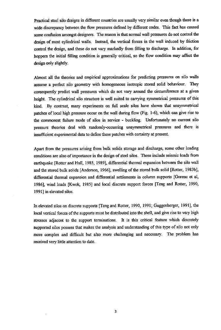
kind. By contrast, many experiments on Ml scale silos have shown that unsymmetrical
patches of local high pressure occur on the wall during flow (Pig. l-6), which can give rise to
the commonest failure mode of silos in service - buckling. Un.Sortunately no current silo
pressure theories deal with randomlyoccurring unsymmetrical pressures and there is
insufficient experimental data to define these patches with certainty at present.
Apart from the pressures arising from bulk solids storage and discharge, some other loading
conditions are also of importance in the design of steel silos. These include seismic loads from
earthquake [Rotter and Hull, 1985, 19891, differential thermal expansion between the silo wall
and the stored bulk solids [Anderson, 19661, swelling of the stored bulk solid [Rotter, 1983b],
differential thermal expansion and differential settlements in column supports [Gorenc et al,
19861, wind loads [Kwok, 19851 and local discrete support forces peng and Rotter, 1990,
199 I] in elevated silos.
In elevated silos on discrete supports fleng and Rotter, 1990, 199 1; Guggenberger, 199 11, the
local vertical forces of the supports must be distributed into the shell, and give rise to very high
stresses adjacent to the support terminations. It is this critical feature which discretely
supported silos possess that makes the analysis and understanding of this type of silo not only
more complex and difficult but also more challenging and necessary. The problem has
received very little attention to date.

1.3 FAILURE MODES IN STEEL SILOS
Silos are subjected to many different loading conditions, so that many different modes of
failure are possible. Nevertheless, the critical stress conditions in the wall generally lead
ultimately to one of only a few modes of failure. These may be simply listed as:
For the cylindrical shell
bursting
buckling under axial (vertical) compression
buckling under circumferential (hoop) compression
buckling under membrane shear
local collapse near the support of the silo
For the conical hopper
collapse or rupture in the hopper body
plastic collapse or rupture of the hopper/ring junction
For the transition ring
buckling of the transition ring
plastic collapse of the transition ring
1.3.1 Failure Modes in the Cylindrical Shell
The bulk solid applies both internal pressure and a downward frictional drag on the silo wall
[Janssen, 18951 (Fig. l-lb). Theoretical studies of flow pressures in silos suggest that the
occurrence of very high ‘switch’ pressures on limited zones of the wall should cause the
bursting failure of the cylindrical shell of many silos. However, very few bursting failures
occur in steel silos in service. There are several reasons for this: usually the steel of which a
silo is made is ductile. It can locally bulge outwards without failure. Further, the solid stored
in a silo has a high stifihess, and can sometimes dissipate the local high internal pressure when
yielding occurs. In addition, the design thickness for the wall is chiefly governed by its
buckling strength under axial compression. Therefore, high local internal pressures are not a
serious design concern in many silos, but do have a marked influence on the buckling strength
under axial compression for quite different reasons.
However, there are some special circumstances in which bursting failures are to be expected
and have been observed in the field. These are swelling of the stored solid [Rotter,1986d], and
a sudden decrease in the ambient temperature which cools a steel silo but not its contents
[Anderson, 1986; Manbeck et al, 19851. Silos in which circumferential and vertical loads are
4

carried by different mechanisms (e.g. vertically stiffened circumferentially corrugated
cylinders) may also sometimes fail by bursting.
The commonest failure mode of silos in service is probably buckling under axial or vertical
compression. Under axisymmetric filling conditions, this is usually the controlling design
consideration for most of the silo wall. Under other loading conditions, higher axial
compressions may develop over limited parts of the wall. In particular, eccentric discharge,
eccentric filling, earthquake loading on squat silos, and forces from discrete supports in
elevated silos are all potential causes of buckling failure.
The buckling strengths of silo walls are normally related to the classical elastic critical stress
[ECCS, 19871. Measured buckling strengths in the laboratory are, however, extremely
variable (Fig. l-7). Many factors affect the buckling strength under vertical compressive
loads. They include the amplitudes of the wall’s initial geometric imperfections, the magnitude
of normal pressures on the silo wall, the elastic properties of the stored material, the type of
joints used, the use of ring or vertical stiffeners and the boundary conditions at the base detail.
Only a few studies have investigated the buckling strength under locally raised stresses which
are introduced by the discrete supports in elevated silos [Peter, 1974; Teng and Rotter, 1990,
1991; Guggenberger, 1991, 1992; Rotter and She, 19931, patch loads and eccentric discharge
[Jumikis et al, 1986; Fitz-Henry, 1986; Rotter, 19851 and even fewer studies have addressed
the question of imperfection-sensitivity under local high stresses, so that much further work in
this area is needed.
Silos may buckle under external pressure occasionally. Two conditions cause most of these
failures: rapid withdrawal of the contents with inadequate venting or rapid cooling, and severe
windstorms when the silo is empty. Squat ground-supported structures are particularly
susceptible to wind buckling because the wall construction is lighter and the diameter is larger
than for elevated storages. Squat ground-supported silo structures are also susceptible to being
tom from their foundations in windstorms.
In practice, silos can be of uniform or variable wall thickness; they cau be stiffened or
unstiffened. They can also stand isolated or in a group, and their roofs can be fixed or free to
displace radially. Each of these factors has a strong influence on the buckling strength under
external pressure or wind.
Silos which are subject to unbalanced horizontal shears from eccentric filling (Fig. 1-Sa),
eccentric cleanout (Fig. 1-8b), earthquake or mechanical handling equipment carry these loads
principally in membrane shear. A number of failures due to buckling in shear have been
reported, but the design of shells against this mode of failure has always been difficult because
buckling predictions are not yet available for cylinders with appropriate stress distributions.
A local plastic stability collapse can also occur in axially compressed cylindrical walls just
near the base of a silo, or at rings and changes of plate thickness when the internal pressure is
high. This mode of failure has commonly known as ‘elephant’s foot’ buckling (Fig. l-9), in
which an axisymmetric outward bulge occurs around a significant part of the shell [Rotter,
1985, 19901.
1.3.2 Failure Modes in the Conical Hopper
The conical hopper on a silo is used to allow gravity discharge. The hopper and its supporting
ring are susceptible to a number of failure modes.
Conical hoppers on elevated silos are generally in a state of biaxial membrane tension as a
result of the applied internal pressure and the frictional drag on the wall (Fig. I-10). The most
severe loading condition for the body of the hopper is usually initial filling [Rotter, 1986b].
Stresses in the hopper body follow the predictions of the membrane theory of shells closely, but
the location of the most highly stressed point varies according to the relative sizes of the hopper
and surmounting cylinder. Welded hoppers may fail by formation of a plastic collapse
mechanism (Fig. l-l 1) [Teng and Rotter, 1989a], whilst bolted hoppers are likely to rupture
down a meridional seam under the circumferential stresses [Rotter, 199Oa]. In silos with a
large hopper beneath a small cylinder, these potential failures occur in quite different locations
[Rotter, 1986b, 199Oa].
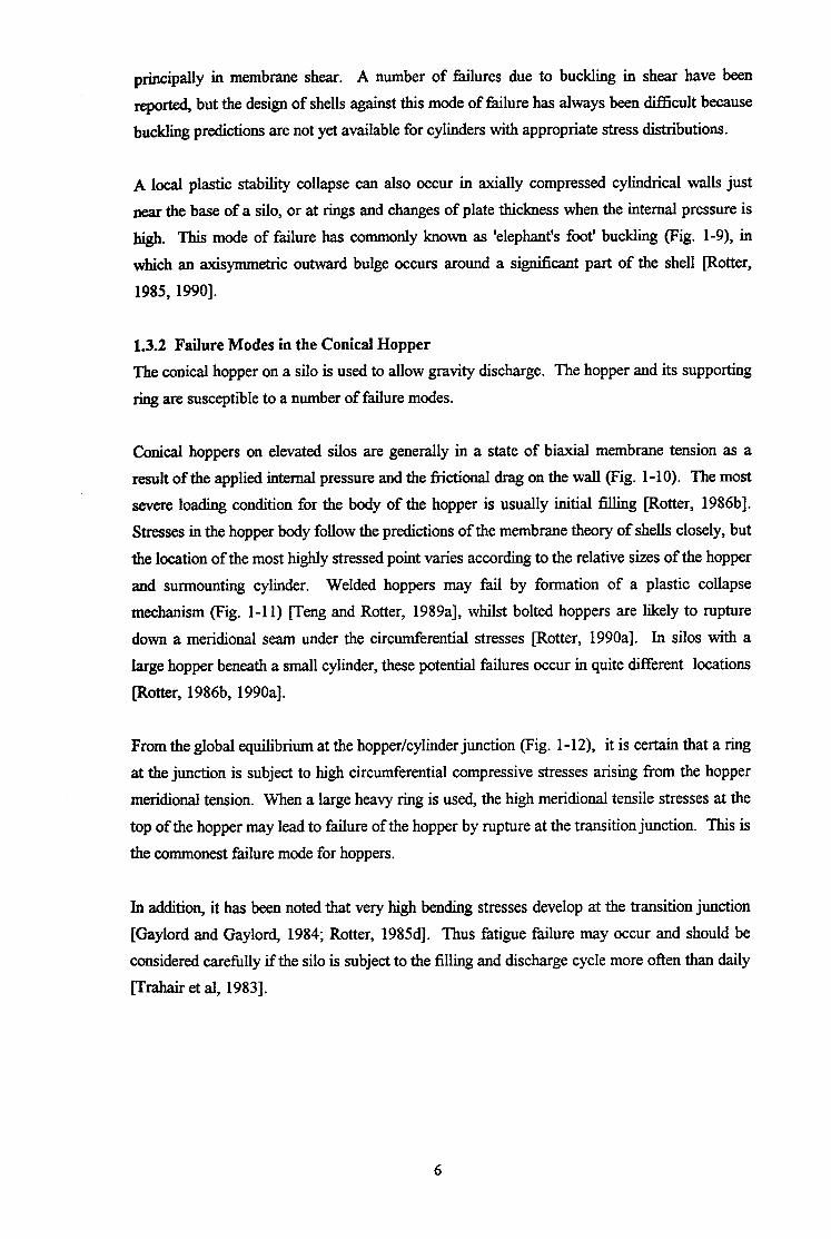
From the global equilibrium at the hopper/cylinder junction (Fig. l-12), it is certain that a ring
at the junction is subject to high circumferential compressive stresses arising from the hopper
meridional tension. When a large heavy ring is used, the high meridional tensile stresses at the
top of the hopper may lead to failure of the hopper by rupture at the transition junction. This is
the commonest failure mode for hoppers.
In addition, it has been noted that very high bending stresses develop at the transition junction
[Gaylord and Gaylord, 1984; Rotter, 1985d]. Thus fatigue failure may occur and should be
considered carefully if the silo is subject to the filling and discharge cycle more often than daily
frrahair et al, 19831.
6

1.3.3 Failure Modes in the Transition Ring
Failure modes of the transition ring involve the hopper, cylinder and shirt either by plastic
collapse or by buckling. Even under axisymmetric loading conditions, the transition ring may
fail by elastic or plastic buckling or by plastic collapse of the junction. A buckling failure of
the ring incurs a periodic rotational deformation about the attached point (Fig. I-13a), whilst
plastic collapse of the junction causes large radial inward deformations (Fig. I-13b).
It seems that additional circumferential bending and warping stresses in quite complex patterns
arise in the rings of discretely supported silos (Fig. l-14), where the ring is required to fklfil the
role of a bowgirder beam flange spanning between supports [Rotter, 1984; 1985d]. In large
silos, either multiple rings or a beam section in the style of that indicated in Fig. l-15d is often
designed, but lighter silos are usually built either with terminating engaged discrete supports
(Fig. l-15b) or supports extending to the eaves (Fig. 1-15~). These four structural types
shown in Fig. 1 - 15 behave in quite different ways and are not simple to analyse.
The majority of researchers have demonstrated through their studies on ring buckling that in-
plane buckling of the ring is almost always prevented by the hopper, but Greiner [ 199 l] has
suggested that there are some special geometries where in-plane buckling can occur. In
addition, out-of-plane buckling into a mode involving many circumferential waves is a potential
mode of failure and has been studied for both uniformly and discretely supported
configurations. Buckling is however a problem only when thin annular plate rings are used.
1.4 STRUCTIJRAL ANALYSIS AND DESIGN OF STEEL SILOS
Numerous steel silos have been built for a wide variety of industrial applications, but there are
no specific codes of practice in the world for the structural design of large steel silos, although
a few design guides are available [Ketchum, 1909; Lambert, 1968; Wozniak, 1979; Trahair et
al, 1983; Gaylord and Gaylord, 1984; Rotter, 1985d, 19901. Limited structural design advice
for small steel silos is given in the British draft code [BMHB, 19871 and a Japanese code for
aluminium silos was produced recently [JIS, 19891. For silo designers, the basic
understandings required are in the definition of loads to be used in design in the stress analysis
of these shell structures, and in recognising the many potential failure modes.
As mentioned above, the patterns of loading on silos containing bulk solids are complex and
sometimes unpredictable, with significant interactions between the structure and its contained
solid. Silos must sustain the internal pressure and the downward frictional traction exerted on
the wall caused by the stored bulk solid. The failure modes vary from elastic buckling at very
low stresses with acute imperfection-sensitivity to plastic collapse with post-collapse stiffening
where the failure load is not easily clarified. Rival predictions of pressures on silo walls in
several design codes and existing theories vary by as much as a factor of 4. Reliable
appropriate values are often difficult to choose.
Knowledge of the structural behaviour of steel silos has advanced rapidly in recent decades.
The membrane and bending theories of shells have wide applications to silo and tank structures
which are of circular planform, dete r-mining the linear behaviour and stresses in steel cylinders
and hoppers [Rotter, 1985a, 1985b].
These theories are described extensively by Timoshenko and Woinowsky-Krieger [ 19561,
Novozhilov [1959], Fhigge, [1973], Seide [1975], Gould [1977], and Calladine [1983], as well
as in many other texts.
The membrane theory of shells is based on the assumption that there are no bending moments
or transverse shears on a shell element. Thus there are only three stress resultants on an
element and three equations of equilibrium for the element. The stress distribution in the shell
can then be determined by considering equilibrium alone.
Membrane theory often provides an accurate picture of the stress state in the silo, and is a good
basis for the design of silo structures, except in regions adjacent to boundaries, junctions,
stiffeners, supports and load concentrations, where bending stresses and transverse shears
develop in addition to the membrane stress resultants. Such bending in silos and hoppers is
usually localised and is sometimes called an edge effect. The bending theory for silos can be
used to evaluate these effects. It is relatively simple for a circular cylindrical shell loaded
symmetrically with respect to its axis.
A linear elastic analysis of the structure can provide both membrane stresses and bending
stresses and is therefore a useful step in understanding the structural behaviour. However, thin
shell structures such as silos can undergo large deflections and significant stress redistributions
as plasticity develops. To give a precise indication of when these will occur is beyond the
scope of a linear stress analysis. A nonlinear analysis is therefore required to obtain an
accurate determination of the failure load of the structure.
A number of classical theories for thin shells of revolution have been developed since the
beginning of this century. These involve classical linear bifurcation analysis, nonlinear elastic
buckling analysis, small deflection limit analysis, nonlinear elastic-plastic collapse analysis and
plastic buckling analysis. However, applications of these theories to silo structures have been
8

rather few. The elastic buckling of cylinders under axial compression is probably the most
significantly and intensively researched subject in silos.
Recent structural analyses [Trahair et al, 1983; Gaylord and Gaylord, 1984; Rotter, 19854
1990; Rotter et al, 1991; Teng and Rotter, 1989,1990, 1991; Guggenberger, 1991; Rotter and
She 19931 have paid special attention to the buckling and collapse behaviour of silo structures
and have provided significant guides in design, but lack of knowledge has still left many
problems unsolved. It is already known that for discretely supported silos, local supports give
rise to high local stresses in the silo wall adjacent to the support terminations which can lead to
buckling failure of the shell at a load much lower than a uniformly supported shell. Discretely
supported silo structures have been receiving more attention in recent years. It is believed that
more research studies of these structures will bring about better design guidance for practical
design use.
1.5 BUCKLING FAlLURES IN CYLINDRICAL SILO WALLS
Many possible failure modes of silos have been discussed above. However, the evidence from
field observations shows that the commonest failure mode for silos is buckling of the
cylindrical wall under axial compression (both local and axisymmetric).
Classical theoretical analysis has been able to predict the buckling strength of unstifXened
unpressurized uniformly supported perfect cylinders under axisymmetric axial compression.
However, real silos in service contain significant geometric imperfections and are subject to
complex loadings. Asymptotic analyses [following Koiter, 19451 and nonlinear analyses
vamaki, 1984; Rotter and Teng, 19891 have shown that the strength is very sensitive to the
amplitudes of initial wall imperfections (Fig. l-16), which are in turn dependent on the quality
of fabrication. Both experiments and analyses reveal that the size and shape of the most
detrimental imperfection is probably that of a depression which extends around a significant
part of the circumference of the shell at a given height but covers only over a short height
[Ding et al, 19921. These imperfections can be represented as axisymmetric.
The normal pressure exerted by the bulk solid on a silo wall is another factor which influences
the strength for buckling under axial compression. The strength of a cylindrical shell increases
significantly when it is internally pressurized [Rotter and Teng, 19891 (Fig. l-17). But the
magnitude of the increase in strength is still uncertain.
The silo is not a pressure vessel, but is filled with a bulk solid with finite shear strength. As a
result, the solid restrains the silo wall against buckling, and may cause a stable post-buckling
response in a shell which would otherwise have had an unstable response. Thus, the stifIhess
of the solid is also important, but this depends on both the stress in the solid, and its stress
hiSt0l.y.
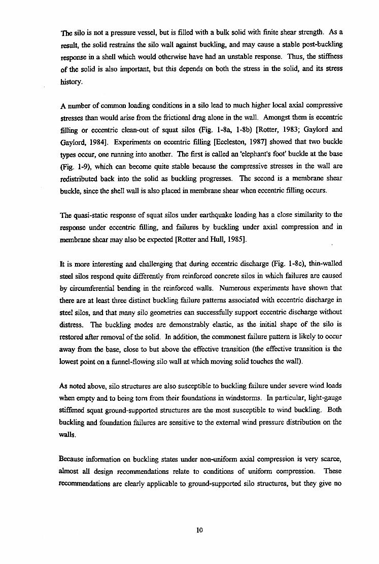
A number of common loading conditions in a silo lead to much higher local axial compressive
stresses than would arise from the frictional drag alone in the wall. Amongst them is eccentric
filling or eccentric clean-out of squat silos (Fig. l-8a, l-8b) [Rotter, 1983; Gaylord and
Gaylord, 19841. Experiments on eccentric filling @Zccleston, 19871 showed that two buckle
types occur, one running into another. The first is called an ‘elephant’s foot’ buckle at the base
(Fig. l-9), which can become quite stable because the compressive stresses in the wall are
redistributed back into the solid as buckling progresses. The second is a membrane shear
buckle, since the shell wall is also placed in membrane shear when eccentric filling occurs.
The quasi-static response of squat silos under earthquake loading has a close similarity to the
response under eccentric filling, and failures by buckling under axial compression and in
membrane shear may also be expected [Roteer and Hull, 19851.
It is more interesting and challenging that during eccentric discharge (Fig. l-8c), thin-walled
steel silos respond quite differently from reinforced concrete silos in which failures are caused
by circumferential bending in the reinforced walls. Numerous experiments have shown that
there are at least three distinct buckling failure patterns associated with eccentric discharge in
steel silos, and that many silo geometries can successfully support eccentric discharge without
distress. The buckling modes are demonstrably elastic, as the initial shape of the silo is
restored after removal of the solid. In addition, the commonest failure pattern is likely to occur
away from the base, close to but above the effective transition (the effective transition is the
lowest point on a funnel-flowing silo wall at which moving solid touches the wall).
As noted above, silo structures are also susceptible to buckling failure under severe wind loads
when empty and to being tom from their foundations in windstorms. In particular, light-gauge
stiffened squat ground-supported structures are the most susceptible to wind buckling. Both
buckling and foundation failures are sensitive to the external wind pressure distribution on the
walls.
Because information on buckling states under non-uniform axial compression is very scarce,
almost all design recommendations relate to conditions of uniform compression. These
recommendations are clearly applicable to ground-supported silo structures, but they give no
10

advice at all on the design of silo walls for locally increased axial compression. In particular,
in elevated silos on discrete supports, the local vertical forces of the discrete supports must be
distributed into the shell and give rise to local high axial compressive stresses (Fig. l-1 8),
which may induce the buckling failure of the wall veng and Rotter 1990, 199 I]. Information
on the buckling behaviour of discretely supported silos is extremely rare, and no study appears
to have addressed the question of the imperfection-sensitivity of silos on discrete supports until
the studies of which this thesis represents a part. Similar work is being undertaken
simultaneously at the Technical University of Graz, Austria.
1.6 STRATEGY FOR ATTACKING THE STABILITY PROBLEM
1.6.1 Introduction
It is evident that many fundamental theories have been developed and a great deal of research
effort invested on thin shell structures since the beginning of this century. However, very little
attention has been paid to practical silo structures, and especially those on discrete supports,
which are widely used as storage containers in the chemical process, mining, agricultural, food
processing and transportation industries. Many disastrous structural failures of silos have
occurred throughout the world [Ravenet, 1976; Jenkyn and Goodwill, 19871. New research
and development in this field is urgently needed.
Current knowledge on the stability of discretely supported silos is still almost entirely confined
to the linear bifurcation of perfect cylinders. Only limited non-linear elastic analyses of
imperfect cylinders have been carried out because of the enormous amount of work involved.
Very little investigation has been made of the structural behaviour in the plastic region
[Guggenberger, 19911. Because current understanding of discretely supported cylinders is
both inadequate and fragmentary, no current theory is able to provide adequate advice for
practical design.
Both theoretical studies and practical experience have revealed that many factors have a
substantial influence on the stability (buckling or collapse) of silo structures. Amongst them,
the shell geometry and boundary conditions, the amplitude and profile of imperfection, and the
loading pattern are the most important. The discrete supports widely used for large elevated
silo structures induce high local stresses adjacent to the support terminations, leading to
potential local buckling failures of the shell at a total load much lower than that for a uniformly
supported shell. Local loads introduce more complexity and difficulties for new research in
this field.
11

The work of this thesis is mainly focused on the elastic and plastic stability of cylindrical shells
under local loading, with special reference to for discretely supported silo structures. Intensive
systematic studies are conducted on a few aspects: the formal solution of the shell equations
under local loadings; numerical analysis of cylindrical shells under local loading; linear stress
and bifurcation analyses; nonlinear elastic buckling analyses, and both limit and elastic-plastic
geometrically nonlinear analyses of cylindrical shells on discrete supports. Finally, the
complete form of a silo (a cylindrical shell together with a roof and a bottom conical hopper) is
examined to investigate the applicability of the simpler modelling using a cylinder instead of a
silo, and to gain a more realistic insight into the behaviour of silo structures.
It should be noted that most of the work described in this thesis was undertaken using finite
element analyses. However, early analyses of the problem showed that the buckling mode is
very local and sensitive to the stress distribution adjacent to the support. As a result, an
analytical solution for the stress distribution near the support was developed. This is the first
known solution of the shell bending equations for a distributed patch of load in meridional
direction. Although the solution is very involved, it gives some insight into the controlling
parameters of the problem, and indicates the scale of complexity which would be involved if
analytical solutions of the nonlinear behaviour were attempted,
The remaining studies in this thesis all exploit numerical finite element analysis. Only the
isolated silo of circular planform is considered. Its finite element modelling is individually
described in the relevant chapters.
With regard to the loads on silo walls from bulk solids, which have been briefly described
above and will be extensively discussed in Chapter 2, several simplified loading cases are
chosen to apply to the structural model. The corresponding strength obtained under each of
these loading cases is usually represented in this thesis by the dimensionless mean stress above
the support at buckling or collapse.
1.6.2 Simplified Loading Cases
In previous investigations of cylindrical silo shells carried out by other researchers [Rotter,
1982, 1983, 1985, 1990; Teng and Rotter, 1989, 1990, 1991, Rotter and She, 19931, a
uniformly distributed axisymmetric downward meridional traction has usually been assumed to
model the frictional force imposed on the silo wall by the stored bulk solids. Many research
results have been obtained on the basis of this type of loading pattern. Such a loading case is
also involved in the analyses carried out in this thesis and is referred to as wall frictional load.
Moreover, in this thesis, other two loading cases have been extensively used: one is a uniform
vertical line load around the lower edge of the cylinder, referred to as the.hopper load. The
12

other is a uniform vertical line load around the upper edge of the cylinder, and referred to as
the roof load. The reasons why these three loading cases are important are to be found in the
patterns of real silo loads:
According to Janssen’s theory [ 18951, the pressures on the vertical walls of silos (Fig. l-19a) H
change their magnitude according to the height of the cylinder, measured in terms of y = 0
2H,u k 7 (where H is the cylinder height, Z, is the depth below the effective surface, p is the
coefficient of wall friction, and k is the ratio of horizontal to vertical stress in the stored solid).
Thus, it can be seen that the pressure distribution on the wall depends not just on f, but also p
and k which are bulk solids properties (Fig. l-19b).
(a) If the silo is fairly tall, a lot of the weight of the stored solids is transmitted through wall
fiction. Jn this circumstance, the pressure distribution on the wall involves much of the wall
under uniform pressure, so there is also almost uniform wall friction (Fig. l-19c). Therefore,
the uniform wall friction is an extreme load case for the silo.
(b) If pk is small or F is small, only a small amount of the weight is transmitted through wall
friction, whilst most of the weight of the solids in the silo rests on the hopper. Thus the real
loading is very like the hopper load case. This is a second extreme load case.
Accordingly, it can be seen that all symmetrical bulk solids loading cases lie somewhere
between the hopper load case and the uniform wall friction case (all others are typically close
to combinations of these two).
(c) Since tests in the laboratory are almost always arranged with loading at the top edge, the
roof load case is really a modelling of the loading occurring in a laboratory experiment.
The axial stress distributions for uniformly supported cylinders under the three loading
conditions are shown in Fig. l-20. It is evident that these three loading cases can induce
different patterns of stress distribution in the cylindrical shells of silos.
As the bulk solid applies internal pressure on the silo wall in addition to a downward frictional
drag, a combined loading pattern is represented as a uniform roof load applied on the upper
boundary of a cylinder together with an internal pressure uniformly distributed on the cylinder
wall in the nonlinear elastic buckling analysis conducted in Chapter 6.
13
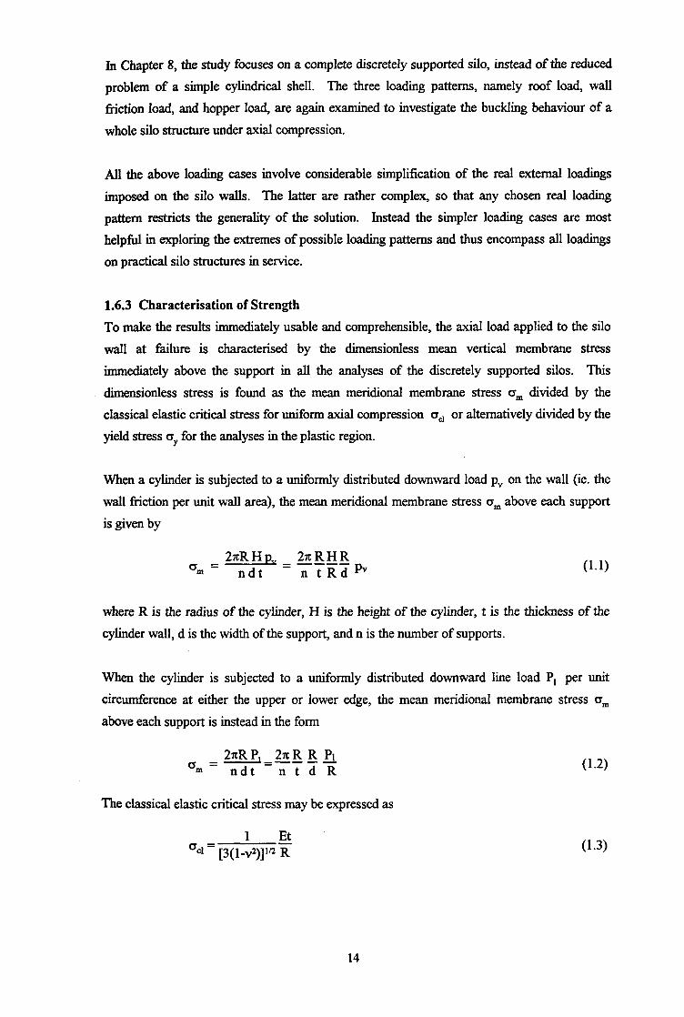
In Chapter 8, the study focuses on a complete discretely supported silo, instead of the reduced
problem of a simple cylindrical shell. The three loading patterns, namely roof load, wall
friction load, and hopper load, are again examined to investigate the buckling behaviour of a
whole silo structure under axial compression.
All the above loading cases involve considerable simplification of the real external loadings
imposed on the silo walls. The latter are rather complex, so that any chosen real loading
pattern restricts the generality of the solution. Instead the simpler loading cases are most
helpful in exploring the extremes of possible loading patterns and thus encompass all loadings
on practical silo structures in service.
1.6.3 Characterisation of Strength
To make the results immediately usable and comprehensible, the axial load applied to the silo
wall at failure is characterised by the dimensionless mean vertical membrane stress
immediately above the support in all the analyses of the discretely supported silos. This
dimensionless stress is found as the mean meridional membrane stress crm divided by the
classical elastic critical stress for uniform axial compression oc, or alternatively divided by the
yield stress oY for the analyses in the plastic region.
When a cylinder is subjected to a uniformly distributed downward load p, on the wall (ie. the
wall diction per unit wall area), the mean meridional membrane stress o, above each support
is given by
om = 2rtRHp, 2rrRHR
ndt = -g-i-F2 pv (1.1)
where R is the radius of the cylinder, H is the height of the cylinder, t is the thickness of the
cylinder wall, d is the width of the support, and n is the number of supports.
When the cylinder is subjected to a uniformly distributed downward line load P, per unit
circumference at either the upper or lower edge, the mean meridional membrane stress cr,
above each support is instead in the form
27rRP, 2xR R PI 0, = =-- --
ndt ntdR
The classical elastic critical stress may be expressed as
1 Et a~, = [3( 1-~*)]‘~ R
14
(1.3)
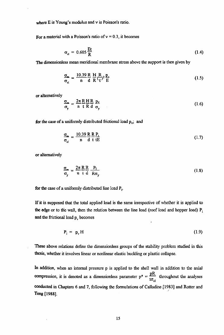
where E is Young’s modulus and v is Poisson’s ratio.
For a material with a Poisson’s ratio of v = 0.3, it becomes
=ccl = 0.605 E (1.4)
The dimensionless mean meridional membrane stress above the support is then given by
0 10.39 R H R E - - ------a &I2 E Oc1 - n
(1.5)
or alternatively a 21cRHR pv --p1- ---- =Y
-ntRday
for the case of a uniformly distributed frictional load pv; and
CT 1039RRL -m-A-- QC1 - n dttE
or alternatively
U-6)
(1.7)
(1.8)
for the case of a uniformly distributed line load P,.
Ifit is supposed that the total applied load is the same irrespective of whether it is applied to
the edge or to the wall, then the relation between the line load (roof load and hopper load) P,
and the frictional load p, becomes
p, = P”H (1.9
These above relations define the dimensionless groups of the stability problem studied in this
thesis, whether it involves linear or nonlinear elastic buckling or plastic collapse.
In addition, when an internal pressure p is applied to the shell wall in addition to the axial pR Compression, it is denoted as a dimensionless parameter p* = ta throughout the analyses
cl
conducted in Chapters 6 and 7, following the formulations of Calladine [ 19831 and Rotter and ,-
Teng [1988].
15

1.8 CONTENTS OF THE THESIS
The objective of this thesis is to broaden current knowledge of the strength and
buckling/collapse of shells, with special reference to steel silo structures on discrete supports.
Its conclusions provide design guidance of practical value for future silo design and
construction. The material in this thesis is presented in nine chapters together with the
references. The work presented in this thesis only relates to isolated silos of circular
planform, under axisymmetric loads from the bulk solids contained in the silos and directly
supported on rigid discrete supports.
This chapter, Chapter 1, provides a general introduction. The existing knowledge of silo
structures has been described in the following categories: loads on silo walls, failure modes
in steel silos, structural analysis and design of steel silos and buckling failures in cylindrical
silo walls. Then, the strategy for attacking the stability problem in this thesis was
introduced, including the simplified loading cases and the characterisation of strength
adopted in the studies of this thesis. The contents of the thesis are finally outlined to
introduce the range of the work carried out.
Current background knowledge in the field of silo structures is described in Chapter 2, which
is entitled Historical Review, and focuses on the aspects to which this thesis is related.
These aspects include the loads on silo walls from bulk solids, theory of circular cylindrical
shells, structural design of steel silos, and computer programs used in this research.
Extensive references to more detailed sources are given.
Chapter 3 briefly describes Rotter and She’s recent studies of the nonlinear and stability
behaviour of discretely supported thin elastic cylinders. These exploratory investigations of
the geometrically nonlinear buckling behaviour, buckling mode and buckling strength for
discretely supported perfect and imperfect cylinders provide a conceptual background on
which the research of this thesis relates.
In Chapter 4, a linear elastic solution of the cylinderical shell bending equations is presented
for local loadings, with special attention to local longitudinal distributed loadings. Algebraic
expressions for the displacements and stresses induced by a rectangular patch of longitudinal
load on a simply supported cylindrical shell are derived using double Fourier series. The
solution of this problem is general and therefore can be applied to cylindrical shells under
local loadings in any direction and with different boundary conditions.
16

Linear elastic analyses of discretely supported perfect cylinders under axial compression are
presented in Chapter 5, using the finite element method. The pre-buckling meridional
membrane stress distribution above the support centreline is examined in detail, and is followed
by investigations of the linear bifurcation behaviour of the cylinders. The effects on the stress
distribution and the buckling strength of different loading patterns and different sets of
geometric parameters are extensively examined.
Using large deflection theory, Chapter 6 presents geometrically nonlinear elastic buckling
analyses of cylinders on discrete supports. Both perfect and imperfect cylinders are examined.
Two forms of imperfection are employed. The effect of the loading pattern applied to the shell
which has been discussed in Chapter 5 is reexamined to show the comparison between the
linear and nonlinear buckling strengths. Axial compression in silo cylinders is almost always
accompanied by internal pressure. An internal pressure is next introduced with the axial
compression. Under the combination of internal pressure and axial compression, the nonlinear
elastic buckling behaviour, the buckling strength and the buckling configuration are thoroughly
investigated for discretely supported cylinders.
Chapter 7 extends the work into the plastic range. Discretely supported cylinders obeying the
von Mises yield criterion are analysed. Limit analyses of perfect cylinders are first conducted
using small deflection theory. Geometrically nonlinear elastic-plastic collapse analyses of both
perfect and imperfect cylinders are performed next. Studies of different loading conditions and
parametric studies of varying geometries and material strengths are presented in both types of
analysis. The nonlinear elastic-plastic collapse behaviour of discretely supported cylinders is
thus explored.
A complete silo which consists of a cylindrical shell, a conical roof hopper and a conical
discharge hopper is briefly examined in Chapter 8, with the aim of exploring the applicability
of the established cylinder model in the elastic buckling analysis of silo structures.
Finally, the conclusions drawn from this research are summarised in Chapter 9.
Recommendations are also made for further research on locally supported shells.
17

NormaI Wail Pressure
Vertical Wail Comoression _
(a) On-Ground Silo (b) Typical Pattern of Wall Forces
Figure l-l Silo and Wall Loads
Ccrkal Rcci
Eaves Ri-@e3m
Cytim5c3l 5110
Trarsiticn R&beam
CClJUfidl
Conical Fqpf
(a) Deep Skirt Silo (b) Column-Supported Silo with Columns Terminating at the Transition Ring
(c) Column-Supported Silo with Columns (d) Column-Supported Silo with Extending to the Eaves Ring Engaged Column
Figure l-2 Support Arrangements of Elevated Silo;
18
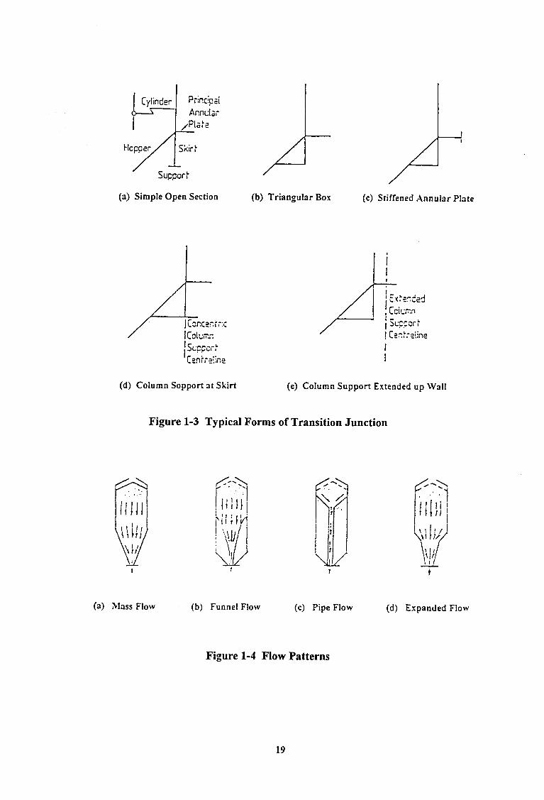
(a) Simple Open Section
(d) Column Sopport at Skirt
(b) Triangular Box (c) Stiffened Annular Plate
(e) Column Support Extended up Wall
Figure l-3 Typical Forms of Transition Junction
(a) Mass Flow (b) Funnel Flow (c) Pipe Flow (d) Expanded Flow
Figure l-4 Flow Patterns
19

0 F
(3) Initial Pressures
3 P
(b) Flow Pressures
Figure 1-5 Theoretical Pressure Distribution on Silo Walls
20

/L-h- /l
E./U=.f
Ear= R/t=800 2 * Jansscn 27/H-0.25
,Light Ring
\ Jansscn
(a) Example Silo
t-!i;h stress m7y c;iuse buckling
(b) Vertical Wall Stresses near Silo Base
Figure l-6 Buckling Consequence of a Local Patch of High Pressure
21

Clcaicd iLlattIc
t
.
1
.
. 0 . .
;
Critlcc! stress
. . l
‘6, : . .
- . .
Figure l-7 Experimental Buckling Strenghs under Axial Compression
!
. . . ‘... . .* *. . .
PI
. . . . ,. .: :.. . . . **. . : ;** . . - . . . . . . a*- **
* * ,:. . . . *. :. * . * . . . * . . . . . . * ,
(a) Eccentric Filling (b) Lnsymmetricsl Cleanout (c) Eccentric Discharge
Figure l-8 Eccentric Filling and Eccentric Discharge
22
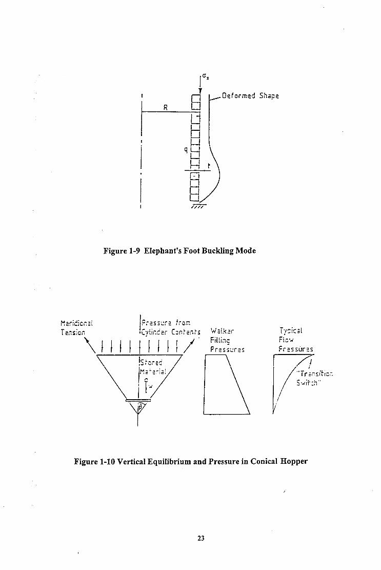
Figure l-9 Elephant’s Foot Buckling Mode
Figure l-10 Vertical Equilibrium and Pressure in Conical Hopper
23
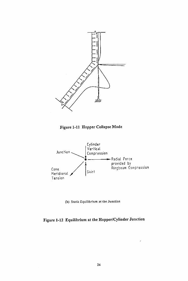
Figure 1-11 Hopper Collapse Mode
Cylinder Ver kicai Junc~io” \~comPress~~~ Radial Force I cone Meridional /I provided by Rino>:;m Csng;eSSiOn - Skir k
(b) Static Equilibrium at the Junction
Figure 1-12 Equilibrium at the Hopper/Cylinder Junction
24
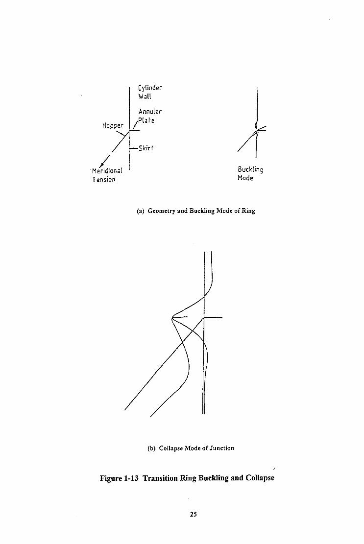
Cylinder Wall Annular
Tension GucklinS Mode (a) Geometry and Buckling Mode of Ring
(b) Collapse Mode of Junction
Figure 1-13 Transition Ring Buckling and Collapse
25

All dimensions in mm.
Stresses in MPa
legend: C Continuously Supported S Stresses over Support M Stresses at Midspan
Figure 1-14 Stresses in the Ring of a Column-Supported Silo
(a) Very Light Bins: Terminating Columns with Ring
(b) Light Bins: Engaged Columns
(c) Medium 2nd Heavy Bins: Columns to Eaves
(d) .)lcdium and Heavy Bins: SrrongRinqbeam
Figure 1-15 Light Column-Supported Silos
26

. Inward Local Deviation (FEM) 0 Outward Local Davialion (FEM) 0 Sinusoidal I. :~erlccllon (FEW . Amarlgo and Eudiansky (1912)
o2 _ R/t - iqoo. LIR = 3 aA0 = 0.707. p.- 0
0 1 1 1 I 0 OS 1.0 15 20
lmperlaction Amplltuda 6,/t
Figure 1-16 Effect of Imperfection Amplitude on Axial Compression Buckling Strength
Type A R/t=1000 Dimensionless lriternal Pressure P=pR/a,, t
Figure 1-17 Effect of Internal Pressure on Buckling Strengths
27
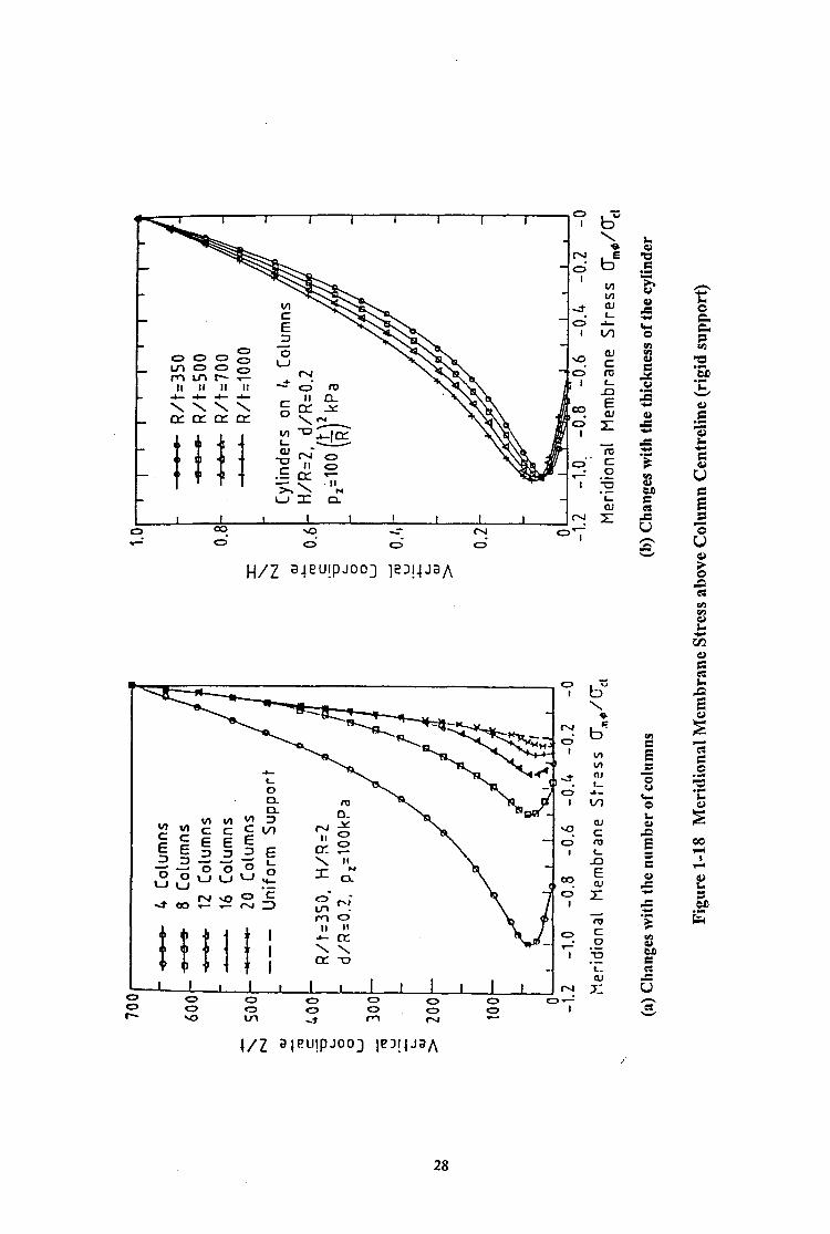
H/Z a-ie’-‘!PJool 1?‘!4JJA
28

(a) Pressure Distribution on Silo Wall (b) Influence of Bulk Solids Properties
(c) Simplification of Uniform Wall Friction
Figure 1-19 Simplification of Loading on Silo Wall
Pv
roof unifoxm typical shorter squat hopper load wall friction tall silo silo silo load only
(a) @I (bl) (bz) (bs) (c)
Figure l-20 Axial Stress Distribution for Uniformly Supported Cylinders , under Three Loading Conditions
29
CHAPTER 2 HISTORICAL REVIEW
2.1 INTRODUCTION
This chapter presents a review of current knowledge of steel silo structures, with special
emphasis on the theories for buckling and collapse in circular cylindrical thin-walled silo
mxtures and the existing design criteria used for steel silo structures.
This chapter starts with a description of the existing theories for predicting the loads (wall
pressures) on silo walls from the stored bulk solids. Next, a brief review is given of the
development of the theories most often used in the research studies of silo structures. Attention
is first placed on a few typical theories of circular cylindrical shells, and then turned onto
buckling and collapse analyses of circular cylindrical shells with different geometries and
boundary conditions and under various loading conditions. Current available criteria for
design against many failure modes of silo structures are subsequently discussed. Finally the
computer programs which are later used in the studies of this thesis are described.
2.2 LOADS ON SILO WALLS FROM BULK SOLIDS: WALL PRESSURES
2.2.1 Loads in Cylinders after Initial Filling
Early designers of silos for the storage of bulk solids assumed that the stored materials behaved
like liquids and designed the silos for equivalent fluid pressures. No frictional forces were
considered and the weight of the ensiled material was assumed to rest entirely on the bottom of
the silo.
In 1882, Roberts in England made the first tests on models and full-size silos to determine the
static horizontal and vertical pressures in silos due to a stored bulk solid IRoberts, 18821. The
results of these tests showed that the pressures attained a sustained maximum value at a depth
of stored material equal to about twice the diameter of the silo [Roberts, 18841. These tests
demonstrated that the fluid theory previously used in the analysis of silos is incorrect because
some of the weight of the stored materials is transferred to the walls by friction, and the
horizontal and vertical pressures in the solid are not equal.
30
Janssen confirmed Roberts’ conclusion and in 1895 published a theory that describes the
pressures on the vertical walls of silos (Fig. l-lb). In this simple theory, the pressures depend
on the bulk density of solid, the silo radius, the depth below the effective surface, the
coefficient of wall friction and the ratio of horizontal to vertical stress in the stored solid k (Fig.
1-17).
Since that time, the distribution of wall loads (Fig. I-5a) used in the design of taller silos has
most often been based on Janssen’s equation [ 18951. Other authors Boenen, 1896; Jaky,
1948; Pieper and Wenzel, 1969; Walker, 1966; Homes, 1972; Walters, 1973; Jenike et al,
1973; Haaker and Scott, 1983; Hartlen et al, 1984; Arnold et al, 1978; Rotter, 19881 modified
the *lateral pressure ratio k in their studies. According to Jenike et al [1973], k=O.4 gives
results that compare favourably with filling pressures determined experimentally with many
materidS.
Difficulties arise in the application of Janssen’s theory to squatter silos, because it does not
properly satisfy the top surface boundary condition, which is affected by the conical pile of
stored material. Reimbert and Reimbert [ 19761 produced an alternative solution to Janssen’s
differential equation which is suitable for squat silos. In this solution, the value of the lateral
pressure ratio k varies with depth. Rankine’s [ 18571 and Coulomb’s [ 17761 theories were often
proposed for squat silos, but both of these theories only apply to straight walls, not to the
curved walls which are commonly used in silos. In more recent work [Ooi and Rotter, 1986,
19871, the limitations of the above approaches have been overcome using the finite element
method.
2.2.2 Loads in Hoppers after Initial Filling
In elevated silos, the majority of the total weight of stored bulk solid rests on the hopper. The
total load on the hopper is defined by the hopper volume, and the vertical stress in the stored
solid at the transition junction (Fig. l-10). More effort must be put into the definition of the
vertical stress in the stored solid at the level of the hopper/cylinder transition junction than that
of loading which derives from the stored solid, since the volume of the hopper is known, and
the density of the stored material does not change greatly.
The simplest assumption for hopper filling pressures is that of Walker [ 19661. In his theory,
the stored bulk solid carries no shear stresses, leading to a linear variation of pressure (Fig. l-
10). This is often the worst pressure distribution for steel hoppers [Arnold et al, 1978; Rotter,
1986b]. Whether the pressures can be as high as the predictions of Walker’s theory is
doubtful, so this pressure distribution may be unduly conservative.
31

Walker’s theory for initial filling is adopted in some codes [Gorenc et al, 1986; BMHB, 19871,
but not in others PIN 1055, 1986; ACI, 19771. It should be noted that the frictional drag has
&en omitted in drafting some code rules based on Walker’s theory [BMI-IE& 19871 leading to
an unsafe definition, since the hopper is deemed to carry less than the total load acting on it.
2.2.3 Loads in Cylinders during Flow
It was noted as early as 1896 that pressures during discharge may be larger than those after
filling. The patterns of flow from silos (Fig. l-4) are known to tiect both the patterns and
magnitudes of pressures on silo walls.
The Janssen equations [ 18951 have long been used as a convenient means for the calculation of
normal pressures, vertical pressures and frictional forces on the wall from which the values
during flow can be estimated. The design values of loads on the silo wall are thus obtained by
using flow load multipliers or overpressure factors applied to the Janssen pressures. This
approach has been widely used over many years and was adopted in the AC1 3 13 [ 19771 code.
Flow load multipliers were also derived from the minimum strain energy theory of Jenike et al
[ 19731 by Arnold et al [ 19781 and McLean et al [ 19831. Alternatively, the flow pressures may
be calculated directly from Janssen’s equation, but using unrealistic values of the lateral
pressure ratio k and wall friction coefficient p which lead to a close modelling of the expected
maximum flow pressures on the vertical walls of the silo [Pieper and Wenzel, 19691. This
approach was used in the DIN 1055 [1964] code, but presents considerable difficulties when
applied to both steel and concrete silos because the stress resultants controlling the failure
modes are different.
Problems with many silos in service have led to a substantial research effort on silo loads to
determine whether existing design procedures are adequate. Under certain conditions, the loads
on silo walls can be expected to exceed the predictions of the AC1 and DIN codes walker,
1966; Jenike et al, 1973; Walters, 1973; Nielsen and Andersen, 1981; McLean et al, 1983;
Arnold et al, 19781. Very much larger flow pressures have been suggested on theoretical
grounds by some researchers [Walters, 1973; Van Zanten et al, 19771, but these have not been
supported by experimental evidence and have been rejected by code committees as
unnecessarily conservative.
2.2.4 Loads in Hoppers during Flow
Flow pressures in a mass flow silo (Fig. 1-4a) are usually well defined and reproducible
because the flow channel is well defined and constant walker, 1966; Walters, 1973; Home
and Nedderman, 1978; Jenike et al, 19731. It is widely recognised that the pressure at the
outlet decreases during discharge and that a local high pressure (‘switch’ pressure) develops at
32

the transition. Most design guides recommended that this ‘switch’ pressure be considered. The
transition ‘switch’ pressure has been examined both experimentally and theoretically [Walker,
1966; Clague, 1973; Walters, 1973, Jenike et al, 1973; Mot&us, 1974; Moriyama and Jotaki,
1980; Haussler and Eibl, 1984; Rotter, 1986b, 19881. It has been concluded that the switch
pressure only becomes really large when a very steep hopper is used.
The pressures on hopper walls during funnel flow (including pipe flow) (Fig. 1-4b and 1-4~)
are more difficult to define. The theoretical equations of Jenike et al [1973], Arnold et aI
[1978] and Gorenc et al [1986] are often quoted for hopper flow pressures. The above funnel
flow theories mostly only apply to tall silos with small hoppers, because the material inside the
hopper is ignored. Because of the poor current understanding of funnel flow pressure
distributions on hopper walls, Rotter [ 19881 suggested that all hoppers should be designed for
the pressures which are known to occur under mass flow conditions.
Eccentric discharge of the stored material, and dynamic conditions such as rapid filling with
powdery solids and impact loads from relatively large lumps, can lead to significant additional
loads on the silo structure. Of these, eccentric discharge pressures are probably the most
critical and difficult to define. A number of experimental studies have explored the wall
pressures occurring during eccentric discharge [Jamieson, 1904; Pieper, 1969; Ravenet, 1976;
Nielsen et al, 1979, 1981; Hartlen et al, 1984; Gale et al, 19861 but the results are not entirely
consistent. Evidently more work is required to clarify the question of design loads to be used
for eccentrically discharged silos.
2.3 THEORY OF CIRCULAR CYLINDRICAL SHELLS
2.3.1 Introduction
Since the thin-walled circular cylindrical shell is very widely used as a structural element in
light-weight, it is important to clarity the elastic and plastic stability of circular cylindrical
shells under various loading conditions. With the development of aircraft structures, since the
beginning of this century, numerous research studies have been carried out on the buckling and
collapse of circular cylindrical shells [Donnell, 1933; Fltigge, 1932, Timoshenko, 1940;
Sanders, 1963; Timoshenko and Gere, 1961; Hodge, 1963; Koiter, 1967; Olszak and
Sawczuk, 1967; Save and Massonnet, 1972; Brush and Almroth, 1975; Calladine, 1983;
Kollar and Dulacska, 1984; Yamaki, 1984; Esslinger and Geier, 1977; Rotter et al., 1983,
1985, 1989, 19901. Many review articles on various aspects of shell buckling and collapse
have appeared in the literature [Nash, 1960; Budiansky and Hutchinson, 1966; Hutchinson and
Koiter, 1970; Sewell, 1972; Bud&sky, 1974; Hutchinson, 1974; Sechlec’ 1974; Tvergaard,
33

1976; Budhsky and Hutchinson, 1979; Bushnell, 1981b, Babcock, 1983; Simitses, 19861. A
number of symposia have also been held [e.g. Fung and Sechler, 1974; Koiter and Mikhailov,
1980; Thompson and Hunt, 1983; Ramm, 19831.
No attempt is made in this section to give a complete review of the development of analytical
theories for circular cylindrical shells, but only those which are closely related to the particular
problems tackled in this thesis are briefly discussed. In the first part, several elastic theories
for circular cylindrical shells are briefly introduced. Then, buckling and collapse analyses of
both axially compressed and axially compressed pressurized cylindrical shells with different
boundary conditions are also reviewed. Finally an introduction to the plastic analysis of
circular cylindrical shells is given.
2.3.2 Elastic Theories of Cylindrical Shells
In this section, some well-known elastic theories for circular cylindrical shells are briefly
described. These are the theories developed by Donnell, Timoshenko, Fliigge and Sanders,
which have often provided the governing equations for many analyses throughout the historical
development of the elastic stability of shells.
Donnell’s nonlinear theory for circular cylindrical shells was developed by Donnell in 1933 for
application to aircraft structures, in connection with the analysis of torsional buckling of thin-
walled tubes [ 19331. Owing to its relative simplicity and practical accuracy, this theory has
been very widely used for analysing stress distributions, and for both buckling and post-
buckling problems, despite criticisms concerning its scope and applicability.
Based upon Donnell’s theory, Timoshenko developed his work on shells in the 1940s. In his
theory for circular cylindrical shells, Timoshenko modified one of the assumptions on which
the Donnell’s theory is based and thus extended Donnell’s theory. He took into consideration
the infhrence of the axial displacement u and the circumferential displacement v on the
curvature changes which were neglected by Donnell. Thus, Timoshenko’s theory has a greater
range of applicability than Donnell theory, and has therefore been widely used.
Donnell’s theory has a shortcoming, commonly described as the shallow shell approximation, in
that the bending curvature is assumed to derive only from the normal displacements. Thus, it
is not applicable to the analysis of deformations in a cylinder where the magnitude of the in-
plane displacement is of the same order as that of the normal displacement. For example,
bending deformations of a long cylinder with the circumferential wave number N less than 4
are poorly represented by Donnell’s equations. On the other hand, Fhigge derived basic
equations for the buckling of circular cylindrical shells under typical loading conditions [ 19321,
34

without resort to the shallow shell approximation. These equations apply to problems with any
buckling configuration, including Euler buckling in long shells under axial compression.
However, they are not sufficiently accurate for some purposes because the prebuckling state is
assumed to be a membrane stress state, neglecting the effect of bending deformations near
boundary conditions or under unsymmetrical loading.
Sanders’ theory for finite deformations of thin shells [Sanders, 19631 was first published in
1963. Taking the finite deformations of non-shallow shells with small strains and moderately
small rotations into account, Sanders’ equations are much more complex than those of Donnell
but somewhat simpler than those of the modified Fhigge theory. Since its generality makes it
directly applicable to non-shallow shells with any geometric configuration, Sanders’ theory has
been favoured in structnral analysis especially using the finite element method.
On the basis of these many elastic theories of Donnell, Timoshenko, Fliigge and Sanders,
theoretical solutions for many buckling problems have been derived, and the elastic stability
characteristics of circular cylindrical shells examined for a wide range of shell geometries and
boundary conditions under both fir&mental loads such as uniform torsion, pressure and axial
compression and combinations of these loads ~amaki, 1984 1. However, relatively few studies
have considered non-uniform loading conditions.
2.3.3 Elastic Buckling of Cylindrical Shells under Axial Compression
The buckling of cylindrical shells under axial compression has long been one of the most
fascinating problems in the theory of elastic stability, because of the perplexing significant
discrepancies between theoretical and experimental results, along with its technical importance
in the design of light-weight structures. A brief description is given here of the developments
of elastic buckling analysis which are particularly useful in relation to silo structures.
The first theoretical solutions for the buckling strength of cylinders under axial compression
were presented by Lorenz [ 19081, Timoshenko [ 19 lo] and Southwell [ 19 141. These earliest
solutions were restricted to typical perfect cylinders with simple boundary conditions and
assumed a uniform membrane stress state prior to buckling. The buckling stress derived on the
basis of the assumptions of simple end supports, perfect shell geometry, elastic material
behaviour and a uniform membrane prebuckling stress distribution is commonly referred to as
the ‘classical elastic axial buckling stress’, oe,, which is expressed in Equation (1.3) of Chapter
1.
35
In spite of its limitations, the classical elastic buckling stress is useful in providing a very
simple upper bound to the buckling stress for an axially loaded cylinder and is therefore
commonly used as the reference value for buckling calculations.
Early test results [Robertson, 1929; Flugge, 1932; Wilson and Newmark, 1933; Lrmdquist,
19331 indicated that practical cylinders buckle at loads well below the classical buckling stress
(Fig. l-7). Buckling loads as small as 30% of the classical value are common. This large
discrepancy between the theoretical and experimental results led to extensive studies and a
major research effort since the 1930s on (a) the effects of boundary conditions; (b) the effects
of prebuckling deformations; and (c) the effects of initial imperfections. These studies continue
up to the present time.
The effects of various boundary conditions were first studied by Ohira [1961, 19631, Hoff
[1965], Hoff and Rehfield [ 19651, Hoff and Soong [ 19651 and Thielmann and Esslinger
[ 19641. Solutions of a precise nature were obtained on the basis of the Donnell basic equations
using the membrane stress assumption. It was found that the critical compressive load reduces
to almost one half of the classical value when both edges of the shell are free to displace
circumferentially during buckling. However, in practical structures and in experiments, the
shell edges are usually connected to relatively stiff end plates and considerable bending
deformations are likely to occur near the loaded edges when compressed in the axial direction.
Under similar relaxed boundary conditions where the edges are simply supported and are not
constrained in the circumferential direction during buckling, the study conducted by Stein
[I9641 showed that the critical stress may be reduced to less than half the classical value.
Further studies poff, 1965; Hoff and Rehfield, 19651 revealed that this reduction was mainly
due to the special boundary conditions, which could be obtained through analyses by neglecting
the prebuckling edge rotations. Later, taking the effect of prebuckling deformations into
consideration, studies carried out by Fischer [ 1963, 19651, Ahnroth [ 19661, Gorman and Evan-
Iwanowski [ 19701 and Yamaki and Kodama [ 1972, 19731 showed that, for shells of medium
length, consideration of the prebuckling edge rotations generally leads to between 8 and 15%
reduction in the critical stress from those previously obtained, while it leads to a slight increase
in the critical stress under the special relaxed boundary conditions described above. In these
studies, only a symmetric buckling mode with respect to the central section of the shell was
considered and the calculations on the basis of Donnell and Fliigge theories were confined to
relatively long shells.
A variety of research studies have been conducted on the effect of initial imperfections on the
buckling strength of cylinders under axial compression. Two methods have mainly been used.
One is to directly analyse the nonlinear post-buckling behaviour of cylindrical shells with
36

specified initial deflection. However, due to an excessive complexity in this approach,
solutions of only an approximate nature were obtained [Donnell and Wan, 1950; Loo, 19541.
The other method is to apply an asymptotic analysis based upon the general theory of the initial
post-buckling behaviour as developed by Koiter [ 19451. With this method, Budiansky,
Hutchinson and others performed many studies on the initial post-buckling behaviour and the
critical load degradation due to imperfections, usually in the shape of the relevant buckling
mode, for a variety of shell structures including cylindrical shells [Budiansky, 1969; Budiansky
and Amazigo, 1968; Hutchinson and Amazigo, 1967; Hutchinson, 19681. In these studies, the
linear prebuckling state was assumed for simplicity. Taking the effect of nonlinear prebuckling
deflections into account, similar analyses were also performed for stiffened cylindrical shells
under compression [Hutchinson and Frauenthal, 1969; Cohen, 19711. On the other hand, by
assuming a variety of axisymmetric initial imperfections, a series of studies have clarified the
imperfection sensitivity of cylindrical shells under compression [Loiter, 1963; Tennyson and
Muggeridge, 1969; Arbocz and Babcock, 1969; Hutchinson et al., 197 1; Amazigo and
Bud&sky, 1972; Budiansky and Hutchinson, 1972; Pedersen, 1973; Arbocz and Sechler,
1974; Arbocz, 1974, 1982, 1983; Sheinman and Simitses, 1977; Yamaki, 1977, 1984; Rotter,
1985; Rotter and Teng, 1989; Teng and Rotter, 1989, 1990; Guggenberger, 1991,1992; Rotter
and She, 19931.
More importantly, experimental techniques to measure the shape of geometric imperfections in
the shell surface were developed by Arbocz and others [Arbocz, 1974, 1982, 1983; Arbocz and
Babcock, 1969; Arbocz and Sechler, 19741, and these measured imperfections were then
introduced into shell analyses to predict the strength of cylinders with known imperfections.
Singer [1980] also developed vibration techniques to make an experimental evaluation of the
boundary conditions, so that both of these former uncertainties could be properly assessed.
The ensuing analyses have generally indicated that measured boundary conditions and
geometric imperfections lead to accurate predictions of experimental strength, but some
anomalous tests still occasionally occur [e.g. Blachut and Galletly, 19941, suggesting that there
may be other unknown quantities which need further investigation.
The aforestated studies on the buckling of circular cylindrical shells under axial compression
have revealed that the close agreement between theoretical and experimental results may exist
when the effect of imperfections and the boundary conditions are taken into consideration. The
strengths are acutely sensitive to the amplitude of the initial imperfection in the shell surface.
The shape of the initial imperfection is important in assessing the buckling strength: in
particular, axisymmetric imperfections which often occur in silos, appear to be very
detrimental. The buckling modes are relatively local and are directly associated with a critical
imperfection. Although many researchers have explored the problem, the results obtained are
37

difficult to generalize, since they are very dependent on the shell geometry and boundary
conditions, the shape of imperfection, the shell theory used, and the approximations made.
All the above theories for circular cylindrical shells have been comprehensively applied in the
analysis of silo structures under uniform compression. However, many silo structures in
service are elevated or subjected to non-uniform compression. It is therefore of practical
importance to clarify the elastic stability of locally supported circular cylindrical shells.
Current information on the behaviour of discretely supported silos is scarce. Some studies
[Ory et al, 1958; Gould et al, 1976; Rotter, 1982, 1985; Bodarski et al, 1984; Or-y and
Reimerdes, 1987; Samuelson, 1987, Teng and Rotter, 1990, 19911 have investigated linear
prebuckling stress distributions and the linear bifurcation in discretely supported silos, but
none appears to have investigated the nonlinear buckling behaviour until recent research
studies being carried on by the Silos Research Group in the Department of Civil Engineering,
University of Edinburgh.
Despite extensive research efforts on shell buckling over the last few decades, only a few
studies [Abir and Nardo, 1958; Bijlaard and Gallagher, 1959; Hoff et al., 1964; Johns, 1966;
and Libai and Durban, 1973, 19771 have examined the buckling behaviour of cylindrical shells
under axial loads which vary in any pattern around the circumference. A simple general
conclusion from this work on perfect shells might be that buckling occurs under a
circumferentially non-uniform distribution of axial stress when the maximum stress is similar
to the classical elastic critical value for uniform axial compression. Libai and Durban [1973,
19771 gave simple expressions which describe the increase in buckling stress above this simple
rule, but the strength gains are generally small. All the above authors only dealt with perfect
shells, even though shell buckling under axial compression is normally acutely imperfection-
sensitive. The loading and boundary conditions considered by them did not involve discrete
local support forces in the shell.
Initial exploratory investigations of the buckling behaviour of perfect and imperfect steel
cylinders on discrete supports were made by Rotter and Teng [ 1990, 19911. Their studies were
restricted to a single shell geometry with several different numbers of column supports and the
supports were modelled to terminate at the lower edge of the shell (Fig. 2-la), forcing a
uniform displacement to the lower edge (rigid support). An axisymmetric geometric
imperfection was introduced for the imperfect shell to simulate a local weld depression (Fig. 2-
lb).
Their studies of perfect cylinders showed that very high local compressive membrane stresses
can develop in the vicinity of the column support but decay rapidly from this point (Fig. 1-18).
38

The region of high vertical compressive stress is quite limited, and the stress changes markedly
&bin an area comparable in size with typical buckles. The buckling deformations occur
above the column support in the zone of rapidly varying stress. Thus, any factors which
change the rate of stress dispersal in the cylinder (support width, radius-to-thickness ratio, ring
stiffeners, and support rigidity) lead to significantly changed buckling strengths. Jn their
studies, the shell buckling strength was defined in terms of the mean membrane stress above
each support. It was found that the normalised buckling strength is almost invariant with the
number of supports, provided that the shell is supported on a small number of supports of
practical width. It was similarly found to be invariant with the height of the shell unless it falls
below a certain value. Therefore, in most practical silo structures, both the number of supports
and the cylinder height are not important factors in influencing the buckling strength.
Rotter and Teng’s studies of column-supported imperfect cylinders showed that a deep
imperfection induces much larger local compressive circumferential stresses (Fig. 2-2b) than
occur in perfect cylinders (Fig. 2-2a). These high compressive stresses can significantly reduce
the buckling strength. The buckling mode and strength of an imperfect cylinder were also
found to be sensitive to the boundary condition used at the bottom edge of the cylinder. The
removal of rotational and/or horizontal translational restraints at the bottom edge can reduce
the buckling strength of the cylinder very markedly. In particular, the buckling modes were
also found to change radically when translational restraints are absent. However, all the
above conclusions were derived from linear bifurcation studies, so careful checking of these
tidings is needed using nonlinear analysis.
Most of Rotter and Teng’s studies were of linear bifurcation buckling in perfect cylinders with
the variations of support width, radius-to-thickness ratio, cylinder height, boundary conditions,
number of discrete supports and some imperfections etc. Bifurcation studies may give a useful
indication of the character of the phenomena, but they often do not define the strength
accurately, especially for imperfect shells. The restriction of most of their study to bifurcation
was a consequence of the computing package LUSAS which they were using.
The nonlinear response of discretely supported silo structures was not extensively explored
until the two theoretical studies recently undertaken by Guggenberger [ 199 1, 19921 and Rotter
and She [1993], using large displacement theory and the finite element method. The finite
element program ABAQUS was employed in both studies to undertake nonlinear calculations
from which bifurcation points could be found. Guggenberger [ 1991, 19921 performed the
analyses of the buckling of cylindrical shells under local axial loads. The nonlinear axial
buckling behaviour was examined for both unstiffened and stiffened circular cylindrical shells
with various local support constructions. The effects of geometric nonlinearity, elastic-plastic
39

material nonlinearity and initial geometric imperfections on the buckling behaviour and the
buckling strength of the shells were explored (Fig. 2-4). Rotter and She [I9931 performed
fundamental studies of the geometrically nonlinear behaviour and stability of discretely
supported thin elastic cylinders. The nonlinear bifurcation phenomena in both perfect and
imperfect cylinders were explored. The effects of the cylinder geometric parameters and initial
geometric imperfections on the nonlinear behaviour and the buckling strength were
investigated.
Both studies assumed that the cylinder is locally supported on an integer number of equally
spaced supports of finite width situated at the lower edge of the shell; the lower edge is
effectively restrained against normal and circumferential deformations; and the cylinder is
subjected to axial compression only. However, there are slightly different assumptions used in
the two studies concerning loading, support boundary conditions and the assumed geometric
imperfections. In Guggenberger’s studies, two different loading conditions were used for
different calculations: a) symmetry at the half height of the cylinder; b) uniform applied loading
at the upper edge. The support was assumed to apply a uniform stress to the lower edge of the
cylinder (flexible support). A local imperfection of b&cubic form was adopted, which is not
very different from the buckling mode (Fig. 2-3). In addition, local rings and meridional
stiffeners were adopted to model the practical stiffened silo structures. In Rotter and She’s
studies, only a uniform shear pressure on the whole surface of the shell was analysed. The
support was assumed to apply a uniform displacement to the lower edge of the cylinder (rigid
support) (Fig. 2-la). A local axisymmetric imperfection (Fig. 2-lb) was adopted in line with
the previous research on uniformly compressed cylinders and imperfection measurements from
full scale silo structures potter and Teng, 1989; Teng and Rotter, 1989; Teng, 19901. Rotter
and She’s work promotes Teng and Rotter’s studies into geometrically nonlinear analyses and
fundamentally assist the research undertaken in this thesis. Their work is briefly described in
the next chapter - Chapter 3.
It has been clarified [Rotter et al, 19931 (Fig. 2-5) that the differences in assumptions between
Guggenberger’s studies and Rotter and She’s studies do not make for marked differences in the
calculated strengths because the buckle is quite locally situated a little above the support. The
greatest discrepancies appear to arise from the choice of flexible or rigid modelling of the
support.
These studies of Rotter and Teng, Guggenberger and Rotter and She represent a first step
towards a better understanding of the complicated buckling problem in practical discretely
supported silos. The objective of this thesis is to present further studies on the structural
stability of discretely supported silos. i’
40

2.3.4 Elastic Buckling and Plastic Collapse of Cylindrical Shells under Internal
Pressure and Axial Compression
Although axial compression is one of the most basic and common loading conditions, it is not
unusual for a cylindrical structure to be subjected to the combined action of both axial
compression and internal pressurization. For example, the aforestated silos in service are
subjected to internal pressure from stored materials, together with axial compression from the
frictional drag of stored materials on the walls.
The buckling of circular cylindrical shells under combined internal pressure and axial load has
been studied by many researchers. Initially, approximate solutions based on the membrane
prebuckling assumption were obtained by Lei and Cheng [1969] and Zyczkowski and Bucko
[1971]. Taking the effect of prebuckling bending deformations into consideration, more
accurate solutions were obtained by Fischer [ 1963, 19651 and Ahnroth [ 19661 under various
boundary conditions, assuming a symmetric buckling mode with respect to the mid-section of
the shell, The effect of axisymmetric initial imperfections on the buckling strength under
combined loads was approximately analysed by Hutchinson [ 19651 while more accurate
solutions were obtained by Esslinger and Geier [1977], Tennyson et al. [1978, 19791, Kodama
and Yamaki [ 19831, and Rotter and Teng [ 1989, 19921. Experimental studies were conducted
by Weingarten and Seide [1965], Weingarten et al. [I9651 (Fig. 2-6), and Saal et al. [1979] to
examine and to improve available design formulas and by Tennyson et al. [1978, 19791 to
check the validity of their theoretical analyses.
Through these studies, it has been repeatedly shown that, when an axially compressed cylinder
is internally pressurized, the tensile circumferential membrane stress reduces the deleterious
effects of the imperfections, and buckling axial load increases. At very low internal pressures,
the cylindrical shell fails near an imperfection by elastic buckling in a mode similar to that for
unpressurized cylinders [Rotter and Teng, 19891. At high internal pressures, the buckling
mode becomes axisymmetric Fung and Sechler, 1957; Harris et al, 1957; Weingarten et al,
1965; Rotter and Teng, 19891. The changing buckling mode reflects the declining
imperfection-sensitivity of the buckling load.
In thin steel cylinders (R/t > 250), the buckling collapse stress for axial compression is usually
low compared with the yield stress, so elastic investigations are directly relevant. However,
once the internal pressure becomes significant, high bending as well as membrane stresses
arise near the base of the cylinder, and local yielding may then occur. This failure mode is
commonly known as ‘elephant’s foot’ buckling (Fig. l-9). First yield in a thin cylinder occurs
in the zone of local bending adjacent to a boundary support, change in wall thickness, stiffener,
or other local disturbance. The strength appears to be less sensitive to random imperfections
41

but dependent on the form of local stress raisers [Esslinger and Geier, 19771. The collapse
modes of many silos that have failed in service show that this zone is critical in design.
The nonlinear elastic behaviour of internally pressurized axially loaded thin perfect cylinders
near a boundary was explored by Rotter [ 19831. A first yield criterion was devised to provide
a lower bound to the strengths of perfect cylinders failing in this mode. His further studies
[Rotter, 19901 of the geometrically nonlinear elastic-plastic collapse and instability of these
cylinders revealed that the collapse load is typically lo-20% higher than first-yield conditions,
except for thin cylinders without internal pressurization, when elastic buckling is predicted.
The transition from elastic buckling to elastic-plastic collapse occurs at similar levels of
circumferential stress (approximately pR/t = 042) for different yield stresses (he studied yield
stresses of 250 MPa and 350 MPa). The importance of elastic-plastic collapse as a failure
mode is therefore not dependent on the steel grade used. He also developed a simple empirical
design rule to predict the strengths of simply supported cylinders under high internal pressure
and low axial loads, such as are encountered in large tanks and in squat silos. All the elastic
buckling and elastic-plastic collapse analyses carried out by Rotter [1983, 19901 are confined
to uniformly compressed and uniformly supported cylinders with clamped or simply-supported
boundary conditions.
For elevated silos on discrete supports, current knowledge of elastic buckling is rather limited
and fragmentary. The field of plastic collapse analysis remains completely unexplored so far.
However, such topics as the elastic buckling, yielding, and plastic behaviour are of great
practical importance for design, and they are not studied only for theoretical interest.
2.3.5 Plastic Analysis of Circular Cylindrical Shells
The classical approach to structuraI analysis was based upon the assumption that the stresses
in the structure are within the elastic limit of the material used and that the deflections are
small. The approach has been widely used for many purposes. However, it is evident that any
structure can be made to fall down (collapse) ,by applying loading of a sufficient magnitude.
The purpose of collapse or limit analysis is to find that magnitude. It requires a knowledge of
what happens at collapse and how structures behave when the stresses in the material exceed
the elastic limit. This philosophy is embodied in the plastic methods of analysis and design.
The foundations of the theory of plasticity were laid by Tresca [ 18981 and von Mises [ 19 131.
The plastic behaviour of plates and shells received serious attention after the publication of
Hopkins and Prager’s [ 19531 paper on plates and Drucker’s [ 19541 work on cylindrical shells.
The increasing use of plastic design and the present trend towards applying its methods to
structures indicates that the basic advantages of plastic analysis are more and,,more appreciated
42
by engineers: accurate estimate of the collapse load, simplicity of application, and economy of
design. Plastic methods for steel and concrete plate and shell structures have been develops
by many authors since the 1950s wll, 1950; Prager, 1959; Hedge, 1963; Save and
&SSOM&, 1972; Moy, 1981; Save, 19851.
For relatively complex stmctnres such as plates and shells, the emphasis of plastic analysis is
usually on the direct determination of the limit state in which the plastic deformation in the
plastic zones is no longer contained by the adjacent non-plastic zones and the deformations of
the structure become unbounded. The intensity of loading for this limit state is called the limit
load PL. Limit analysis is concerned with evaluating these limit states. In many problems, it is
-cult to find the exact limit load, but there are two theorems of limit analysis [Hill, 195 1]
which provide a means of identifying a lower bound and an upper bounds on PL.
Theorem 1 - Statical (or lower bound) theorem: The limit load PL is the largest of all possible
loads P- corresponding to statically admissible stress fields.
Theorem 2 - Kinematical (or upper bound) theorem: The limit load PL is the smallest of all
possible loads P, corresponding to kinematically admissible mechanisms.
It follows from the two theorems of limit analysis that the exact limit load is the only load for
which a statically and kinematically admissible solution can be found. The calculation of the
exact value of the limit load is called a complete solution.
Both of the fundamental theorems were introduced by Gvozdev [ 19601, Hill [ 195 11, and Prager
[1955, 19581 for the case of a rigid-perfectly plastic body, and by Drucker, Prager, and
Greenberg [ 19521 for elastic-perfectly plastic materials. Both idealizations are appropriate and
absolutely identical for the purposes of limit analysis [Prager, 19581.
Limit analysis of a rigid-perfectly plastic continuum is based on the following three concepts:
(1) a yield condition and related flow rule; (2) a statically admissible stress field; and (3) a
kinematically admissible flow mechanism. The yield condition of von Mises for a shell that
has rotational symmetry in shape and loading was derived independently by Ilyushin [ 19561
and Hodge [ 196 I]. The corresponding Tresca condition was derived by Onat and Prager
[I954]. Both conditions are nonlinear, so their application is difficult. One method of tackling
the problem is to simplify the yield condition. If this is done, the theorems of limit analysis
provide a means of bounding the error introduced. The other approximation is to replace the
uniform shell by an idealised sandwich shell with the same plastic resistance to pure tension or
pure bending. One such approximation was proposed by Drucker and Shield [ 19591. They
43

ignored the circumferential bending moment and retained the meridional bending moment in
rotationally symmetric shells to satisfl the boundary conditions, but neglected any interaction
between the longitudinal moment and the direct stresses. The resulting yield condition
corresponding to this approximation is termed as the one-moment limited-interaction surface.
An improved approximation, proposed by Hodge [1960], took all interactions between forces
in the two principal directions and between moments in the two principal directions into
account, but neglected all interactions between forces and moments. This is referred to as the
two-moment limited interaction yield surface. A further improved approximation was
presented by Fhigge and Nakarnura [ 19651. However, both the one-moment limited interaction
and the two-moment limited interaction curves are identical for cylindrical shells subjected to
rotationally symmetric loads, because the circumferential bending moment disappears as a
reaction (a stress resultant which does not contribute to the dissipation of energy in the process
of irreversible deformation) [Save and Massonet, 19721.
Drucker [ 19541 was the first to derive a simple approximate yield surface for a circular
cylindrical shell in stress resultant space. He considered a cylindrical shell under axisymmetric
loads without axial forces and solved the problem of a cylinder of infinite length loaded by a
ring of force and by a band of uniform pressure using the limited interaction yield locus and the
exact Tresca yield condition. This work was extended by Hodge [ 19541 and Onat [1955] to
include axial force. Based on the linearized (sandwich) Tresca yield surface and the limited
interaction yield surface, further studies were conducted for shells under external pressure
and/or axial force [e.g. Paul and Hodge, 1958; Drucker and Shield, 1959; Ball and Lee, 19631.
Some detailed solutions have been given with a Tresca and a von Mises material respectively
[e.g. Hodge and Panarelli, 1962; Hodge, 1963; Save and Massonnet, 19721. Sawczuk and
Hodge [ 19601 made a comparison of the yield conditions for cylindrical shells.
It should be noted that all the limit loads obtained above are based on the rigid-perfectly plastic
material idealisation. However, real shells are neither rigid nor perfectly plastic but elastic-
plastic work-hardening. When circular cylindrical shells are subjected to both internal pressure
and axial loads, the outward radial deflection provides a lever arm for the compressive axial
force, introducing supplementary bending moments. These second order effects occur in the
elastic-plastic range and are likely to decrease the load required to cause unrestrained plastic
flow, if we neglect the counteracting influence of work-hardening. To include those second
order effects, the equilibrium equations must be written for the deformed state: thus the
theorems of limit analysis no longer apply. Hodge [1956] and Paul and Hodge [1958]
demonstrated in examples that a load as high as 98% of the limit load could be attained for
some~loading configurations and structural geometries without the maximum elastic-plastic
deflection exceeding five times the maximum elastic deflection. Hodge and Nardo [ 19581

found that working hardening seems to have a very small effect on the load-carrying capacity
for thick cylinders under external uniform pressure, but in any case it should increase the
strength with respect to theoretical predictions based on perfect plasticity. Also, the use of a
&arized yield condition ‘inscribed’ to the exact Tresca condition and in turn to the more
realistic von Mises condition, should also result in collapse predictions on the safe side.
In the studies described in this thesis, the loading applied to the cylindrical shell (local
meridional load at the edge) induces only a small amount of primary bending in the structure.
Moreover, the silo structures being investigated are relatively thin. As a result, the limit
analyses described above have only limited relevance to the real collapse strength.
Nevertheless, finite element based limit analyses are described in the early part of Chapter 7,
and these show how the primary bending action in the shell affects the limit load.
2.3.6 Conclusions
In this section, a brief outline of elastic buckling and plastic collapse theories for circular
cylindrical shells has been given. Although numerous theoretical solutions are available for
tackling many shell problems, they are generally limited to very simple geometries, loading and
boundary conditions and might not be directly of use in the design of steel silo structures.
Nevertheless, these classical solutions are informative for structural engineers to understand
the buckling and collapse behaviour of more complicated shell configurations, and are
fimdamental to all further work.
As a result of the development of computers and computer analyses of structures since the
196Os, more accurate analyses of the buckling and collapse behaviour of practical structures
have become possible. As a result, attention has increasingly turned onto developing the
computer analysis of structures rather than the development of classical solutions.
2.4 STRUCTUR4L DESIGN OF STEEL SILOS
A large number of steel silos have been built for a huge variety of industrial applications, but
there are no codes of practice or standard specification in the world for the structural design of
large steel silos, although a few design guides are available [Ketchum, 1909; Lambert, 1968;
W~zniak, 1979; Trahair et al, 1983; Gaylord and Gaylord, 1984; Rotter, 1985d, 1990; Rotter
et 4 19931. Limited structural design advice for small steel silos is given in the British draft
code [BMHB, 19871 and a Japanese code for aluminium silos was produced recently [JJS, 19891.
45

As stated in Chapter 1, the basic understandings required for silo designers are in the definition
of loads to be used in design, in the stress analysis of these shell structures, and in
quantitatively predicting the many potential failure modes. The following discussion is
concerned with current design information with reference to the problem studied in this thesis.
Design procedures for the prevention of buckling under axial compression were first developed
from the strengths of unstiffened unpressurized uniformly compressed cylinders under axial
compression. A relatively wide range of empirical design equations of this sort have been in
common use in the design of steel silos. Two approaches were used in developing design rules
[Rotter, 1985a]: the first was simply to draw a lower bound curve on all available reliable test
results; the second attempted to use an equation relating the strength to an imperfection
amplitude, and thus to categorize the test results into groups of specimens of different quality.
Empirical relationships were then proposed for the maximum level of imperfection to be
expected in a shell of given quality.
An early lower bound equation proposed by Donnell [1933] is still quite widely used in the
USA even though it was based on limited early data and suffers the disadvantage of predicting
zero strength for Eut > 2450. A proposal by Weingarten et al [1965a] was derived from a
large data base gathered chiefly for aerospace applications with a higher quality of
construction, but it has been widely used in civil engineering.
In the AWWA [ 19791 standard, the Boardman equation for the buckling stress of a shell in
membrane compression was adopted, with a limit (15,000 psi) placed on the allowable
compressive stress. This is based on quite old data [Wilson and Newmark, 1933; Wilson,
1937; Wilson and Olson, 19411, but does relate to civil engineering welded and rivet-ted
construction at R/t ratios up to 1000. An equation was also proposed by Steinhardt and
Schultz [1971], based on a very complete set of data (70 < R/t < 2800). This provides a 90
percentile lower bound on experimental results.
Amongst the design guides, Wozniak [1979], API 620 [1978], Johnston 119761, Trahair et al.
[ 19831 and Gaylord and Gaylord [ 19841 refer to the AWWA (Boardman) equation. Trahair et
al. [1983] restrict the use of this equation to R/t < 1030 and use the test results of Weingarten
et al. [1965a] at higher radius to thiclmess ratios. Gaylord and Gaylord [ 19841 also quote
Steinhardt and Schultz [ 19711 and the early ECCS [ 19771 code.
In the second approach [Rotter, 1985a], the strength was directly related to a defined level of
imperfection. Design recommendations in this group include those of Hoff and Soong [ 19671,
ESDU [1974], Odland [1978], the ECCS [1984, 19881, Rotter [1985a, 19901 and Rotter and
46

Tag [l%g, 19901. Of these, the ECCS [1988] code does not strictly relate strength to
imperfection, but provides a limit on measurable inward imperfection over a length roughly
equal to the axisymmetric buckling mode wavelength which was the basis of Koiter’s equation
[1945], and describes a simple measurement technique for imperfections in prototype
structures. In addition, the strengthening effect of internal pressurization is included in more
recent design guides [ESDU, 1974; Trahair et al, 1983; ECCS, 1984; Gaylord and Gaylord
1984; API, 1988, Rotter, 1985, 19901.
The design equations in this second group are less frequently quoted for silo design. Guidance
was provided by the British Farm Silo Code pS5061, 19741 that the buckling strength of
axially compressed cylinders should be assessed using the ESDU [1974] recommendation.
Rotter [1985a] suggested the use of an equation modified from that of Odland [ 19781 to match
the soundly based Steinhardt and Schultz [ 19711 equation. This has the advantage that the
large data base of the latter’s work can be used with a clear definition of the corresponding
assumed imperfections of the type given in Koiter’s strength-imperfection relationship.
For locally supported silos, the existing literature matter and Teng, 1990, 1991; Rotter et al.
19911 on theoretical studies of the buckling of discretely supported cylinders are so few as to
provide wholly inadequate advice and no general understanding for designers. Experiments on
the buckling of discretely supported cylinder [Rotter and She, 19941 have only been performed
at the time of writing of this thesis and remain unpublished. However, a high incidence of
failures in discretely supported silos, together with a relentless trend towards the construction
of larger elevated silos is making strong demands for more research work to expand the
knowledge of structural behaviour, techniques of strength prediction and design requirements
for locally supported silos.
2.5 COMPUTER PROGRAMS USED IN SILO STRUCTURE ANALYSIS
2.5.1 Introduction
The circular cylindrical shell constitutes a fundamental element in light-weight structures and
the realistic determination of its stability has been a critical problem for the design and
development of these structures. Thus, many studies have been conducted on this subject since
the basic equations were established by Fhigge and Donnell in the 1930s. In the early stages of
the development, only rough approximate solutions were obtained owing to the excessive
complexity of the problems. Accurate analyses became possible only after the advent of the
high-speed digital computer in the 1960s. Following the rapid spreading of computers, the
finite element, finite difference and numerical integration techniques underwent vigorous
47
development. In particular, the finite element method is now very widely used for its
flexibility. Many computer programs have been developed and effectively applied to shell
structure analyses. Numerical formulations for different types of analysis have been
sloped: those of special interest here may be s ummarized as (a) linear stress analysis, (b)
linear bifbrcation analysis, (c) elastic large deflection analysis, (d) elastic-plastic small
deflection analysis and (e) elastic-plastic large deflection analysis. Very few programs [e.g.
Bishara et al., 1977; Chandrangsu and Bishara, 1978; Eibl and Haussler, 1984; Askari and
Elwi, 19881 have been developed specifically for the analysis of silo structures. These were all
developed to study the loads applied to silo walls by the bulk solids, and were not at all
concerned with the stresses in the structure. In particular, buckling and collapse analyses of
the shell wall were untouched.
In this section, only a brief description of finite element computer programs which mainly
undertake the calculation of silo structures in this thesis is given. They are FELASH program
suite and ABAQUS program package.
2.5.2 The FELASH Suite of Computer Programs
A suite of finite element computer programs named FELASH (Finite ELement analysis for
Axisymmetric SHells) has been developed by Rotter and his co-workers for stress, buckling
and collapse analysis of axisymmetric shells with special applications to storage structures like
silos and tanks [Rotter, 19891. The FELASH suite consists of many finite element programs
of which some important ones are the pre-processor PASHA, the post-processor SUMP, and
LEASH, NEPAC, NEPAS etc. It has been widely applied to the analysis of steel silo
structures [Rotter, 1981, 1982, 1983a, 1983c, 1984, 1986a, 1987a; Jumikis and Rotter, 1983,
1986; Rotter and Jumikis, 1985; Sharma et al., 1987; Teng and Rotter, 19891.
The FELASH suite is able to create an efficient and accurate finite element model for analyses.
With powerful pre- and post-processors incorporating special features pertinent to silo
structures, this program suite has many advantages. They are that all the programs included in
the suite are free of ‘black box’ routines, a clear understanding of all the working features of the
program can be maintained, and control is kept over the evolution of the program to suit new
types of problem.
Program PASHA (Pi-e-processor for Axisymmetric SHell Analysis) is used to prepare the input
data file for any of the FELASH finite element programs of structural analysis. All information is given through interactive interrogation. The program can automatically generate
my loading conditions pertinent to silo structures such as wind loading, loadings from stored
b* solids, eccentric discharge and local discrete supports. I’
48

program LEASH (Linear Elastic Analysis for Stresses using Harmonics) performs linear
elastic stress analysis on axisymmetric shells under non-symmetric loads [Rotter, 1987a]. The
&U theory of Sanders [Budiansky and Sanders, 19631 is used. The non-symmetric loads,
&fiirndO~ and stresses are all expanded in harmonic series and each harmonic is analysed
separately. The results from each harmonic are summed up to provide the complete solution.
Program SUMP (SUhJmation and Plotting of stresses, reactions and deformations) is the post-
processor for the FELASH program suite. It sums harmonic series and interactively plots the
deformations, stresses and buckling modes.
2.5.3 ABAQUS Finite Element Package
ABAQUS, developed and supported by Hibbitt, Karlsson & Sorensen, Inc. (HKS) [ 19921, is a
general purpose finite element analysis program package. It is designed specially to serve
advanced structural analysis needs. The most challenging of these applications involves large
models with highly nonlinear response.
The theoretical formulation of ABAQUS is based on the finite element sti&ess method. The
aspects of the problem that are particularly well addressed with ABAQUS are the great variety
of geometry modelling, kinematics, material modelling, boundary and loading conditions, and
analyses. In the aspect of geometry modelling, the models can include structures and continua.
One-, two- and three-dimensional continuum models are provided, as well as beams and shells.
The beam and shell elements are based on modem discrete Kirchhoff or shear flexible methods.
Shell elements are provided for heat transfer, as well as for stress analysis. Except for some
special purpose elements, all of the elements in ABAQUS are formulated to provide accurate
modelling for arbitrary magnitudes of displacements, rotations and strains. In material
modelling, models are provided for metals, rubber, plastics, composites, concrete, sand, clay
and crushable foam. The material response can be highly nonlinear. Very general elastic,
elastic-plastic and elastic-viscoplastic models are provided. Boundary conditions can include
prescribed kinematic conditions (single point and multi-point constraints) and prescribed
foundation conditions. Loading conditions can include point forces, described loads and
thermal loading. Follower force effects (for example, pressure, centrifugal and Coriolis forces,
fhtid drag and buoyancy) are included where appropriate.
Primarily using implicit integration for time (or load) stepping with automatic choice of the
time (or load) increments, ABAQUS provides both static and dynamic, linear and nonlinear
stress analyses; eigen-value buckling analysis; nonlinear elastic and plastic stability analyses;
transient and steady-state heat transfer analysis; etc. In nonlinear problems, the challenge is
~WVS to provide a convergent solution at minimum cost. This is addressed in ABAQUS by
49
automatic control of time (or load) stepping which is provided for all analysis procedures.
provided that the user defines a ‘step’ (a portion of the analysis history) and certain tolerance or
error measures, then AFJAQUS can automatically select the increments to model the step. This
approach is highly effective for nonlinear problems, because the model’s response may change
&&ically during an analysis step. Automatic control allows nonlinear problems to be run
with confidence without extensive experience with the problem. For nonlinear static
stress/displacement analysis, ABAQUS offers two approaches. One is for cases when a
prescribed history of loading must be followed. The alternative is an arc-length (modified
R&s) method, which is provided for unstable static problems such as post-collapse or post-
buckling cases.
The finite element program AEIAQUS is used in this thesis to undertake the studies of the
stability of steel silo structures on discrete supports. Analyses of several types are performed
for discretely supported thin cylindrical shells: linear stress analysis, linear bifurcation
analysis, geometrically nonlinear elastic buckling analysis, limit analysis and geometrically
nonlinear elastic-plastic analysis. The eigenvalue extraction method is used in the linear
bifurcation analysis. The modified Riks method is adopted in all the nonlinear analyses. The
definitions of geometry modelling, kinematics, material modelling, and boundary and loading
conditions are specified in detail for each analysis, which is presented in the corresponding
chapter of this thesis.
50

2.6 SUMMARY
A brief review has been presented of the existing knowledge revelant to the theories of thin
cylindrical shells and the structural analysis and design of steel silo structures. Current
~ovvledge of the pressures on silo walls from the stored bulk solids was initially discussed. A
brief description of the development of the theories of buckling and collapse of thin-walled
circular cylindrical shell structures was followed by a short summary of the current design
criteria used for steel silo structures. Extensive references to more detailed sources have been
gdl.
From the above general review, it is known that cylindrical silos in service are mainly subjected
to internal pressure from stored materials together with axial compression from the frictional
drag of stored materials on the walls and from roof loads. The governing failure mode of silos
is fkquently buckling under axial compression. Under axisymmetric filling conditions, this is
usually the controlling design consideration for most of the silo wall. Under other loading
conditions such as eccentric filling, eccentric discharge and discrete support forces in elevated
silos etc, higher axial compressions may develop over limited parts of the wall and quite
possibly lead to the buckling failure of the structure. The internal pressure can significantly
enhance the buckling strength, but high internal pressures lead to severe local bending near the
base. Local yielding, alternatively known as ‘elephant’s foot’ buckling, then might happen prior
to a buckling failure. The buckling strength of a thin cylindrical shell is notoriously sensitive
to the magnitude of the geometric imperfections in the wall, but the imperfection-sensitivity is
much reduced when the cylinder is internally pressurized.
It is evident that the classical theories of thin shell structures have undergone vigorous
development over the second half of this century. Many rigorous theoretical solutions as well
as reliable experimental information are now available for the buckling and collapse of shells
with simple geometries, loading and boundary conditions, which now provide a basic viewpoint
for understanding the shell buckling and collapse problems. The finite element method plays
an important role in computing analysis. Numerous computer programs have been developed
for various engineering applications.
However, those classical shell theories have mostly relied on for the analysis and design of silo
structures. Modem powerful numerical methods have generally made little impact on silo
designers. There are very few computer programs written specifically for silos, except for
those which are only concerned with the calculation of stresses in the bulk solids, the pressures
on the silo wall and sometimes the wall/bulk solid interaction. General shell analysis programs
are seldom employed to study buckling and collapse problems in silos. In addition, a shortage
51
of sufficient experimental information on silo buckling and collapse may be another rmon for
slow development of silo design codes.
It is the complexity of the silo geometry and loading patterns which has been making the
&j& of solving the buckling and collapse problems more challenging and a great effort on it
more worthwhile and valuable. This thesis is intended to attack some of these problems to
broaden current understanding in the fields of elastic and plastic stability of shell structures,
with special attention to discretely supported silo structures.
52
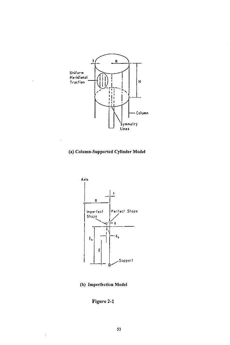
Uniiorm Hcridional Traction -
(a) Column-Supported Cylinder Model
\ u\ - Column
Symmetry Lines
Axis
Imperfect
!
Perfect Shape
Shape
\ /
Q-6
(b) Imperfection Model
Figure 2-l
53
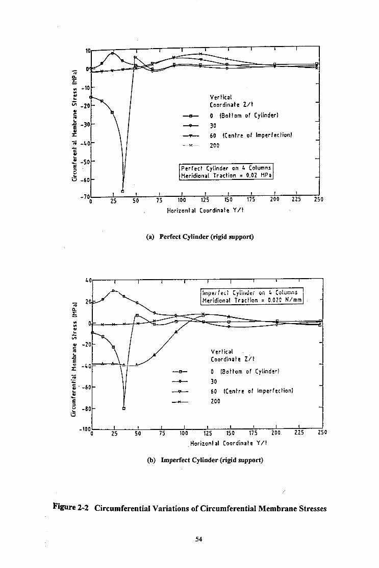
Vertical Coordinate Z/t
+ 0 (Bottom of Cylinder)
- 30
- 60 (Centre of Imperfection]
- 200
Perfect Cylinder on 4 Columns Meridional Traction = 0.02 HPa
cl 1 I I 25 50 7k 100 1;s 150 175 *A0 2;s 250
Horizontal Coordinate Y/t
(a) Perfect Cylinder (rigid support)
Imperfect Cylinder on L Columns
Vertical Coordinate Zit
0 Bottom of Cylinder)
--o- 60 (Centre of Imperfection)
.Horizontal Coordinate Y/t
(b) Imperfect Cylinder (rigid support)
Figure 2-2 Circumferential Variations of Circumferential Membrane Stresses
54

I I
Figure 2-3 Shape of Local Geometrical Imperfection
- GNL-MAX - --. BEV-CLASS.
GNL-MIN - --a BEV-APPROX.
54- ;: :
I GNIJ --+---a BEV-CHAO
---I)-. GMNLI - . . . . . . . . . . KAPPA-2 DIN
I
SUPPORT WIDTH RATIO b/B [-]
Figure 2-4 Eigenvalue Buckling Stresses and ImperfectlElastoplastic Buckling Stresses for Variable Support Widths
55
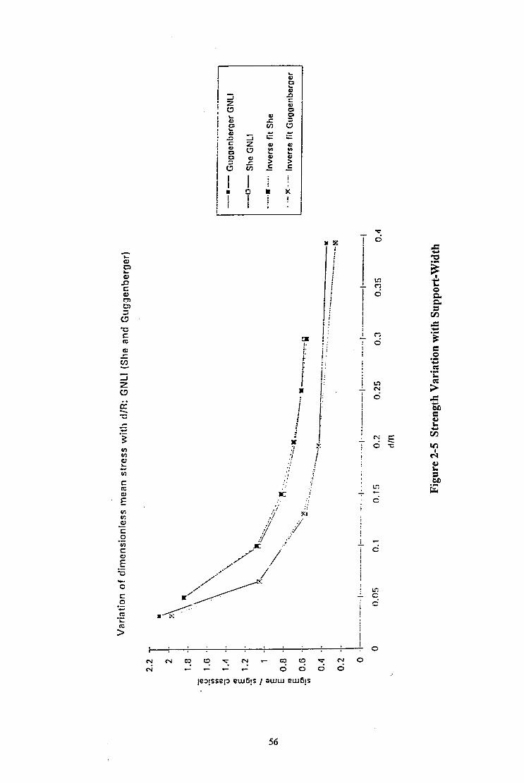
56

~~ 0 1 2 3 k 5 6
Normalised Internal Pressure PR SF
Figure 2-6 Elastic Buckling of Internally Pressurized Cylinders
57
CHAplEX 3
NONLINEAR ELASTIC BEHAVIOUR AND BUCKLING IN DISCRETELY SUPPORTED CYLINDERS
3.1 INTRODUCTION
From the previous introduction and historical review described in Chapters 1 and 2, it is
evident that the governing failure mode of a metal silo is frequently buckling under axial
compression. The practical problem of buckling in a discretely supported steel silo has many
fkatures, which camiot be addressed all at once. A large deflection analysis is needed to give
an accurate prediction of the buckling or collapse load. Local plasticity, geometric
imperfections and interactions between the cylinder, the transition ring and other shell segments
must also be included.
These factors make the number of variables in the problem vary large, so no comprehensive
understanding can be gained without some simplifying assumptions. Usually, the study starts
by modelling the elevated silo structure as an isolated elastic structure, resting on equally
spaced supports of uniform width placed at the lower edge of the cylindrical shell. Some
investigations r]reng and Rotter, 199 1, 1992; Guggenberger, 199 1,1992; Ramm and Buechter,
1991; Rotter and She, 19931 were concerned with such a structural model.
Among them, Rotter and She’s recent studies [1993] dealt with the nonlinear behaviour and
stability of discretely supported thin elastic unuressurised cylinders, using the finite element
method. In their studies, the nonlinear response, bifurcation behaviour and post-buckling
response of the cylinders were extensively explored. The effects of variations in geometry and
initial geometric imperfections on the buckling strength of the cylinder were thoroughly
examined. It was hoped that the essential features of the real structures were captured through
these simplified investigations, and that the buckling strength predictions were transformable
into rules which could be used to design structures.
This chapter presents the essential nonlinear features of elastic cylinders discretely supported at
the lower edge which have been explored recently [Rotter and She, 19931. The work done by
Rotter and She is described since it forms the background to some of the work of this thesis.
The following summary of the study by Rotter and She is the candidate’s own summary and
58

critical review. This thesis represents both a major extension of their work and some
mvestigations into the validity of their assumptions.
3.2 FINITE ELEMENT MODELLING
The study of the elastic buckling behaviour of discretely supported isolated cylinders was
undertaken using the ABAQUS finite element program. Nonlinear analyses were performed
with the modified Riks method.
An elastic isotropic cylinder of radius R wall thickness t and height H was assumed to be
directly supported on n equally spaced discrete supports of finite width along the lower edge, as
shown in Fig. 2-la. The cylinder was subjected only to symmetrical vertical load. The
geometric symmetry of the cylinder and the loading condition permits the computational model
to be restricted to only 1/(2n) of the whole circumference provided that the cylinder is only
supported on a small number of fairly narrow supports (typically 4, 6, 8 or 12) [Teng and
Rotter, 1990,199l; Rotter and She, 19931. For the case when the cylinder rests on four
discrete supports, only one eighth of the cylinder is modelled (Fig. 2-la). Both the upper and
lower edges were restrained against radial and circumferential displacements. The parts of the
lower edge in contact with the supports were completely restrained against any displacement or
rotation, modelling the support as ideal rigid.
The geometry of a perfect discretely supported cylinder was characterised in a dimensionless
manner by four nondimensional parameters: the radius-to-thickness ratio R/t, the height-to-
radius ratio H/R, the support-width-to-radius ratio d/R and the number of supports n.
The imperfection-sensitivity of the buckling strength was investigated using a local
axisymmetric inward imperfection, which was designed to represent a local weld depression
which commonly occurs in a metal silo. The form of this imperfection is the Type A shape
(Fig. 2-lb) used in previous studies [Rotter and Teng, 1989; Rotter and Zhang, 1990; Teng
and Rotter, 1990, 19921. The shape of this local imperfection was defined by Rotter and Teng
119891 as
6 = 6, edh [ sin (xdh) + cos(xz/h) ] z= Iz-z,l
(3.1) (3.2)
where 6 is the local amplitude of the imperfection at height Z above the bottom edge. 1 is the
linear elastic meridional bending half wavelength of the cylinder (~2.44 (Rt)lD). 6, is the imperfection amplitude at the centre of the imperfection. Z, is the distance from the centre of
59
the imperfection to the bottom edge of the cylinder. Such an imperfection was introduced into
an initially unstressed perfect cylinder and in the inward radial direction.
In the studies of imperfect cylinders, two further parameters were used to define the local
imperfection: the ratio of the imperfection amplitude 6, to the cylinder thiclaiess t, and the ratio
of the distance Z, to the cylinder thickness t.
The cylinders were assumed to be linear and isotropic and made of steel with Young’s modulus
E = 2x10’ MPa and Poisson’s ratio v = 0.3. The results obtained can be applied to other
materials, though small errors are present if Poisson’s ratio is very different from v = 0.3.
In Rotter and She’s studies, a uniformly distributed axial force pV was assumed to model the
wall friction load component imposed by the stored bulk solids on the silo wall. The forces
carried by the supports were represented in terms of the mean meridional membrane stress
above each support. The mean meridional membrane stress above the support q,,+ was
normahsed by the classical elastic critical stress for a cylinder under uniform axial
compression a,,. The conditions at buckling of the cylinder were presented in terms of the
normalised mean meridional membrane stress above the support, ie. o, /crcl . The relationship
between this parameter and the applied loading has been given in Chapter 1. It is
%a &!!aRH11,L =c1 n d R(t) E
for a Poisson’s ratio of v= 0.3.
3.3 TYPICAL BEHAVIOUR OF A DISCRETELY SUPPORTED CYLINDER
3.3.1 A Perfect Cylinder The elastic pre-buckling stress distribution in discretely supported perfect cylinders was
previously investigated by Teng and Rotter [1990, 19911, as shown in Figs 1-18 and 2-2. It
was recognized that very high local compressive membrane stresses can develop in the vicinity
of the support but decay rapidly from this point.
Rotter and She paid attention to the detailed form of the stress distribution at the bottom edge
of the cylinder and its influence on the buckling strength. The geometry of an example cylinder
was defined as R&350, wR=2.0, d&=0.2 and n=4. Two forms of finite element mesh model
were used with the same number of elements: one with elements of equal size covering twice
60

the support width, the other with smaller elements near the support edge. The stress
distributions near the bottom edge are shown in Fig. 3-1 for both meshes. It is evident that the
second mesh produces a much smoother transition from the highly stressed region above the
support to the stress-free part of the bottom edge. However, the buckling strength, or the mean
meridional membrane stress above the support at buckling, obtained by using these two
different mesh arrangements, remains virtually the same. This indicates that a local inaccuracy
in stress distribution near the support edge has little effect on the elastic buckling strength of
the shell. This simple conclusion, which is valid for elastic cylinders, led to some difficulties
when elastic-plastic limit calculations were performed as part of this thesis. The sensitivity of
these plastic calculations to mesh form is described in Chapter 7.
The linear bifurcation of discretely supported perfect cylinders was previously investigated by
Teng and Rotter [ 1990, 199 I]. The nonlinear behaviour of these cylinders was studied by
Rotter and She [ 19931. A typical nonlinear load-displacement curve is shown in Fig. 3-2. The
axial displacements of a node at the top edge of the cylinder above the support centreline are
very small until the load has reached the bifurcation point. Large displacements follow and a
single buckle occurs a moderate distance above the support if there is only a single bifurcation
point on the curve. The radial displacements of a point near the centre of the buckle are shown
in Fig. 3-3. Again the initial displacements are small, followed by large radial displacements
after the bifurcation point. The buckling mode of the example cylinder is shown in Fig. 3-4. It
was found that the buckle is very local above the support, in the zone of high and rapidly
varying stresses. The local nature of the buckle corresponds to the rapidly changing stress in
the cylinder. Therefore, it is clear that the locally higher stress above the support is very
important and critical to the formation of the buckle and can strongly influence the buckling
strength of the cylinder. By comparing the nonlinear bifurcation load with the linear
bifurcation load previously obtained by Teng and Rotter [1990], it was found that the nonlinear
strength is typically lower than the linear bifurcation stress by about 40%. This clearly shows
the importance of large displacement effects on the buckling strength of the shell.
3.3.2 An Imperfect Cylinder
The effect of geometrical imperfections in practical silo structures is well-known. They can
significantly reduce the buckling strength of the shell. In Rotter and She’s studies, an inward
imperfect cylinder (Fig. 3-5) was investigated with the same values of the geometric
parameters FM, H/R d/R and n as defined above for the example cylinder and with the
imperfect geometric parameters SJt and Zdt chosen as 1.0 and 60, respectively. The
corresponding nonlinear load-displacement curve is shown by Curve 6 of Fig. 3-9 for this
dkcretely supported imperfect cylinder. No bifurcation point can be observed on this curve.
61
This characteristic of the buckling behaviour corresponds to the chosen a,mpk&z of the
imperfection 6, = t.
If the buckling strength of the imperfect cylinder is measured in terms of the maximum
dimensionless mean meridional membrane stress above the support, the weakening effect of the
introduced imperfection can be clearly seen by comparing the buckling strength with that
obtained for the example perfect cylinder (Fig. 3-2). It has previously been shown matter and
Teng, 19891 that the inward imperfection gives rise to compressive circumferential membrane
stresses near the centre of the imperfection and tensile circumferential membrane stresses
above and below the centre, as shown in Fig. 2-2b. According to an idea proposed by
Calladine [1983], in an axially compressed cylinder, a compressive circumferential membrane
stress in the buckle area helps to promote buckling, whilst a tensile circumferential stress helps
to resist buckling. Thus, it may be supposed that buckling will occur in an imperfect cylinder
at the point where detrimental compressive stresses in both the meridional and circumferential
directions co-exist. For this cylinder with an inward axisymmetric imperfection (Fig. 3-5), the
buckle area occurs around the centre of the imperfection, and the buckling strength becomes
lower than that of the perfect cylinder by 42%.
In the next section, parametric studies conducted by Rotter and She of the effects of changes in
the geometry of the cylinder are described.
3.4 PARAMETRIC STUDIES
3.4.1 Variation with Wail Thickness t The effect of the wall thickness on the buckling strength was examined for both perfect and
imperfect cylinders with a range of R/t varying from 350 to 950. Other geometric parameters
remain unchanged, defined by n=4, d/R=O.2, H/R=2, S&=1 and Z&=60. The variation of the
elastic buckling strength with R/t is relatively small for both perfect and imperfect cylinders as
shown in Fig. 3-6. Nevertheless, Teng and Rotter [ 19921 found a significant decrease in the
buckling strength as the wall thickness became smaller. Their observation was obtained from
linear bifurcation analysis, which can provide misleading results for a problem of this kind.
3.4.2 Variation with Cylinder Height H/R Since the buckling deformations are found to be localised near the support, the height of the
cylinder is not an important parameter unless it falls below a certain value. Short cylinders are
strongly affected by the proximity of the upper boundary condition, and if the upper boundary
is held circular, significant increases in the buckling strength are found. For,most practical silo
62

geometries of reasonable height, the dimensionless mean buckling stress above the support may
be considered to be independent of the shell height.
3.4.3 Variation with Number of Supports n Figure 3-7 shows the variation of the buckling strength with the nun&r of the supports.
Where the cylindrical shell is supported on a small number of columns of practical width, the
buckling strength, as characterised here, is almost constant regardless of the number of
supports. This means that there is little interaction between adjacent supports. Therefore, only
a single buckle is formed above each support, as shown in Fig. 3-4 (n=4). When the supports
become very numerous (@16), the buckling mode begins to display interaction between adjacent buckling locations: thus the buckling strength experiences an increase there. The
following decrease in the buckling strength is accompanied by several changes in the buckling
mode from a single buckle, to several buckles, to stacked rows of buckles and finally to the
ring buckle mode. However, the effect is not dramatically deleterious, and supports so
numerous that this becomes significant are very rare. Thus, it is easiest to ignore the effect and
treat the mean stress above each support as independent of the number of supports, n.
3.4.4 Variation with Width of the Supports d/R A range of the support-width-to-radius ratio d/R varying Corn 0.05 to 0.3 was examined. The
relationship between the normalised mean stress above the support at buckling and the varying
ratio d/R is shown in Fig. 3-8. With d/R decreasing from 0.3 to 0.15, there is only a small
change in the buckling strength. Further decrease in d/R results in a sharp increase in the
buckling strength. The same observation was obtained in Teng and Rotter’s linear bifurcation
analyses of discretely supported perfect cylinders.
As the support width becomes smaller, the buckle size reduces and the distance between the
centre of the buckle and the top of the support shortens. This distance is about equal to the
buckling half wave length 1(=2.44 (Rt)*n) for d/R=O. 15. For d/R=O.O5, the distance becomes
even smaller and the buckling deformation becomes extremely localised. This indicates that the
buckling strength may be strongly affected by the support width only if the centre of the buckle
is within a distance of the buckling half wave length from the support. This fact was not
nxqnised by Rotter and She [ 19931.
3.4.5 Variation with Imperfection Amplitude Z&It A range of dimensionless imperfection amplitudes Sdt was studied varying from 0.05 to 2.0.
The corresponding load-displacement response curves are shown in Fig 3-9. The buckling
strength reduces as the imperfection amplitude increases. However, the post-buckling response
63

becomes progressively more ductile (Figs 3-9 and 3-10) so that the strength is insensitive to the
imperfection amplitude once this amplitude exceeds about S,,/t = 1.
3.4.6 Variation with Imperfection Position Z, An inward axisymmetric imperfection was placed at a variety of different heights above the
mpport. Figure 3-11 shows the buckling strength as function of Z, for R/t of 350, 650 and
950, and demonstrates that the critical position Z, corresponding to the largest reduction in the
buckling strength is approximately proportional to (R/t)7’8(R/t)*n. This means that for the same
support width, the critical position of the weld depression imperfection is related to the radius-
to-thickness ratio, R/t, and the buckling half wave length 1. It is also clear that the critical
position is lower in thin cylinders than in thick cylinders, and that the buckling strength is not
very sensitive to the position of the imperfection if Z, varies slightly in the vicinity of the
critical value Z,.
3.5 CONCLUSIONS
Nonlinear analyses of discretely supported elastic cylinders were performed by Rotter and She
[1993], using the finite element method. Both perfect and imperfect cylinders of a constant
height-to-radius ratio were studied. The effects of the cylinder geometric parameters and
simple imperfections on the buckling behaviour and the buckling strength were examined.
It was recognized that the buckling phenomenon is very local above the support. It occurs in a
region of rapidly changing stresses above the support. This illustrates the fact that the stresses
just above the support are very important. Therefore, it is appropriate that the buckling
strength should be characterised in the manner first proposed by Teng and Rotter [ 19901 as the
ratio of the mean meridional membrane stress above the support to the classical elastic critical
stress for a uniformly supported cylindrical shell.
The buckling deformations were found to be localised near the support, so that the height of the
cylinder is not an important parameter unless it falls below a certain value. Where the cylinder
is supported on a small number of supports of practical width, the dimensionless buckling
stress is almost constant regardless of the number of supports. Thus, for most practical
discretely supported silo structures, the dimensionless mean buckling stress above each support
may be considered to be independent of both the shell height and the number of supports. It
was also found that the change of wall thickness brings about little change in this dimensionless
buckling strength. However, the parameter which most strongly affects the buckling strength is
64

&e width of the support. Wider supports lead to higher buckling loads but buckling occurs at
a lower mean meridional membrane stress immediately above the support.
A geometric imperfection results in a significant reduction in the buckling strength. The
position of the imperfection affects the level of the buckling strength reduction. For a constant
number of supports, the critical position, corresponding to the largest loss of the buckling
strength, depends on the support width and the cylinder wall thickness. The imperfection
amplitude naturally influences the buckling strength. However, no fbther reduction in the
buckling strength occurs if the imperfection amplitude exceeds a certain level. With a local
axisymmetric inward imperfection of amplitude Sdt = 1 placed at the critical height Z,, the
buckling strength of this imperfect cylinder is reduced to about half that of a perfect cylinder.
65

R&350, dLko.2, HlR=2.0, xi=4
Dashed curve: 1st mesh arrangement; Solid curve: 2nd mesh arrangement.
t
-3.00 -3.00- .
-3.50 -3.50 I I I 1 1 5 5 I I , , 1 1 I I I I L L 0.00 0.00 10.00 10.00 20.00 20.00 30.00 30.00 40.00 40.00
0 (degrees)
Figure 3-l Meridional Stress Distribution near the Lower Edge of the Cylinder for Different Mesh Arrangements
66

0.00 +
0.00 -0.50 -1.00 -1.50 -2.00 ‘-2.50
kial Displacement at Top Edge above Support Centreline u/t
Figure 3-2 Load-Deflection Curve for a Perfect Cylinder under Axial Compression
L
1.00 -
0.75 -
0.50 -
R/t=350, dlIhO.2, HR=2.0, n=4
0.25 -
I
0.00 -l I 1 I I 1 1 I 1 1 I I -r
0.00 -2.00 -4.00 -6.00 -8.00 -10.00 -12.00
Radial Displacement at Z&=20 above Support Centreline w/t
Figure 3-3 Load-Deflection Curve for a Perfect Cylinder under Axial Compression :
67

68

69

2.00 -
1.50 -
o : Perfect cylinder, n=4, d/R=O.ZO, H/R=Z.
A : Imperfect cylinder, n=4, d/R=O.ZO, H/R=2, 6,=1.0
0: Stress ratio between imperfect and perfect cylinders.
0 4-g 1.00 -
050 ~ .
1
0.00 IL------ 300.00 500.00 700.00 900.00
Radius-t~Thickness Ratio Wt Figure 3-6 Buckling Strength of Axially Compressed Perfect and
Imperfect Cylinders at Different Ratios of R/t
0.50 - Perfect Cylfnder: R/t=350, d/R=0.20, H/R=2.
o.oo,,, , , ‘, , 11, *, ‘ (1 1 ,.I 0 4 8 12 18 20 24 28 32 3i
Number of Supports n
Figure 3-7 Buckling Strength of Axially Compressed Perfect and Imperfect Cylinders on Different Number of Supports n
70

2.80
1.80
1.00
0.20 -l-
Q: Perfect cylinder;
\
n-4; R/t=350; H/R=2 A: Imperfsct cylinder;
n-4; R/t=350; H/R=2; d,/t=l. o: Stress ratlo between imperfect
\ and perfect cylinders.
: , ‘ I 1 I ‘ 1 ’ t
0.00 0.10 0.20 fl.30
Support Width-to-Radius Ratio d/R
O.(o
Figure 3-8 Buckling Strength of Axially Compressed Perfect and Imperfect Cylinders at Different Ratios of d/R
71

t.loddns aaoqrr ssa~~g uea~,~ pasymx~~o~
72
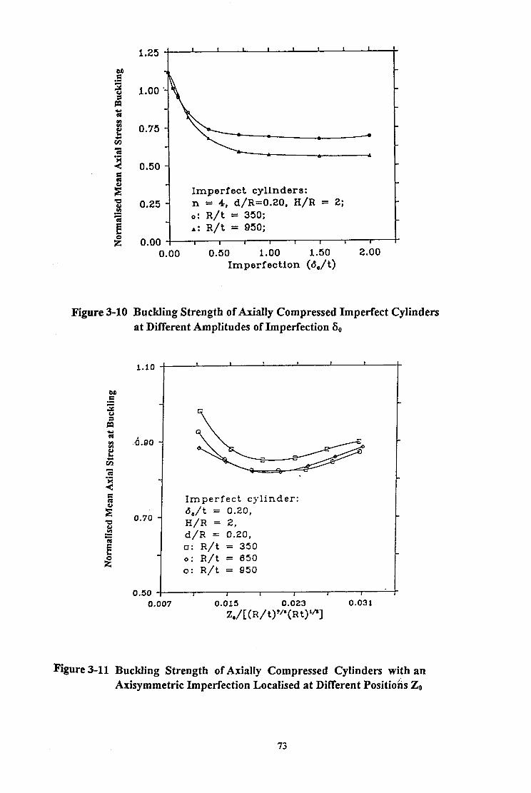
E? -I ‘;: yo 1.00 .- fz 2 a ; 0.75 - v) z .e 4 z 0.50 - 3 s! Imperfect cylinders: w 2 0.25 - n = 4, d/R=0.20, H/R = 2; i=
i!
o: R/t = 350; r: R/t = 950;
s 0.00 -- 1 I I I I I I I 0.00 0.50 1.00 1.50 2.00
Imperfection (6,/t)
Figure 3-10 Byckling Strength of Axially Compressed Imperfect Cylinders at Different Amplitudes of Imperfection 6,,
-I
.&so -
0.70 -
Imperfect cylinder: 6,/t = 0.20, H/R = 2, d/R = 0.20, o: R/t = 350 o: R/t = 650 o: R/t = 950
0.007 0.015 0.023 0.031
z,/t(R/t)"'(Rt)'?
Figure 3-11 Buckling Strength of Axially Compressed Cylinders with an Axisymmetric Imperfection Localised at Different Positio& 2,
73

ALGEBRAIC ANALYSIS OF ELASTIC CIRCULAR CYLINDRICAL SHELLS UNDER LOCAL LOADINGS
4.1 INTRODUCTION
The formal algebraic analysis of the stresses and displacements in elastic circular cyhndrical
shell structures has been carried on for many years. Several studies have developed
mathematicalfoundationsfor calculating the displacements and stresses induced in cylindrical
shells by local loadings, mainly focussing on the analysis of practical pressure vessels.
However, these analyses have beeen almost exclusively concerned only with loads normal to
the shell surface. In this chapter, an algebraic analysis is developed for more general local
loads, and fully solved for local loads parallel to the cylinder axis, a problem which does not
appear to have been solved before.
A silo structure generally consists of a cylindrical shell together with a conical roof and a
bottom discharge hopper. The emphasis of research has usually been on the main part of a
silo - the circular cylindrical shell, since many disastrous structural failures of silos occur in
the cylindrical shell. In practice, the cylindrical shell has to sustain all the possible external
loads applied to a silo in service. As has been discussed in Chapter 1, many different loading
conditions are likely to occur. Among them, local loadings may arise from eccentric filling or
discharge and attachments such as the local discrete supports and lugs, leading to local high
stresses which cannot be neglected in design. The objective of this chapter is to examine the
stresses caused by local loads on a cylindrical shells.
The first important studies were undertaken by Bijlaard [ 1954, 195.51. He solved the Donned
shell equations to find the displacements, and the membrane and bending stresses induced by
both radial and circumferential loads and external moments (represented by non-uniform radial
loads) in horizontal axis cylindrical pressure vessels which were simply supported at both ends.
He used a double Fourier series technique. Longitudinal or axial loading was excluded in his
studies. However, in an elevated silo, the discrete supports locally afked to the shell wall
transmit large longitudinal or axial loads to the shell, inducing high stresses near the attached
areas. Therefore, the pattern of stresses caused by local axial loads in cylindrical shells needs
investigation.
74

JJ& chapter describes the algebraic analysis of cylindrical shells under longitudinal local
loadings and uses a double Fourier series technique. General formulas for the displacements
h&ed by local loads are derived. The boundary conditions are taken as simply supported at
b&h ends. The corresponding expressions for stress resultants (resultant forces and bending
and twisting moments) are obtained Corn the constitutive relations.
4.2 GENERAL THEORY OF CYLINDRICAL SHELLS
A circular cylindrical shell of radius a and length 1 and the global axis system are shown in Fig.
4-1. The x axis is along a genera& of the cylinder, y or the angle + varies around the
ciraderence, and z is normal to middle surface, inward positive. The displacements in the x,
t$ and z directions are denoted by u, v, and w respectively. To establish the general dif?ferential
equations for the displacements u, v, and w which define the deformation of the cylindrical
shell, an element is cut out from the cylindrical shell (Fig. 4-l) by two adjacent axial sections
and by two adjacent sections perpendicular to the axis of the cylinder. External forces X, Y,
and Z per unit surface in the x, I$ and z directions respectively are applied on the element.
Three differential equilibrium equations can be derived under thin-shell theory by considering
the equilibrium of the element under the external forces X, Y, and Z, which are written as
following .
(4.1)
iN+ + p$-2cJt$$+$?$+z=o
in which N,, N, and N, are membrane forces and M,, M, are bending moments and M+ x
twisting moment in shell wall per unit length of axial section and a section perpendicular to the
axis of a cylindrical shell, respectively.
For a circular cylindrical shell, the straindisplacement (kinematic) equations may be found
(4.2)
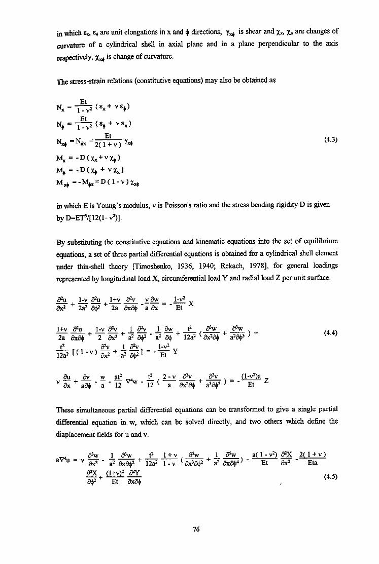
in which sx, E+ are unit elongations in x and + directions, y,+ is shear and xx, x+ are changes of
~rvature of a cylindrical shell in axial plane and in a plane perpendicular to the axis
respectively, xti is change of curvature.
The stress-strain relations (constitutive equations) may also be obtained as
Et Nx = 5 t&x+ -+I
Et N+ = 5 (E+ + VEX)
NM =N,x = 2( 1”: v ) yx+ (4.3)
%= -Wxx+v~+)
MO = -D(q + vxxl
Md =-M+x =DU-v)Xx+
in which E is Young’s modulus, v is Poisson’s ratio and the stress bending rigidity D is given
by D=ET3/[12(1- v’)].
By substituting the constitutive equations and kinematic equations into the set of equilibrium
equations, a set of three partial differential equations is obtained for a cylindrical shell element
under thin-shell theory [Timoshenko, 1936, 1940; Rekach, 19781, for general loadings
represented by longitudinal load X, circumferential load Y and radial load Z per unit surface.
azu+--+ l-v #u 1+v Sv v aw l-v2 3x2 2a2 &?
-----=--x 2a aXC+ a i?x Et
1+v z&l l-v &I 18% lav t2 SW fi --+--+--- --+- - 2a &a# 2 f?x2 a2 w a2 3 12a2 ( aX2i3+ + a2q3 ) + t2 r% 1 Sv 1-G
igUl-v)~+-- a2 2421 = -Et y
(4.4)
These simultaneous partial differential equations can be transformed to give a single partial
differential equation in w, which can be solved directly, and two others which define the
displacement fields for u and v.
2( 1 + v ) a( 1 - v2) aZX Et s- Eta
8X g+vy 8Y -+ Et G w (4.5)
i’
76

1 a3w 2+v a% t2 aV+ 5 - - + 2a8w 3-v&
a3 W --_-
a 8x2* 12a2 [l-v&Z$ + --+$$I+ a(1 - v) iYx2i?jb3 8X 2(1+v)aSY 1-v2#Y
i@’ --
Et % - Eta i3+2 (4.6)
(4.7)
For a cylindrical shell subject to external loadings in the axial x, circumferential y and radial z
directions, the relevant deformations u, v, and w in the three directions can be obtained from
the above equations. From the displacement fields ah other effects can be found, including the
stresses arising in the shell.
4.3 ANALYSIS FOR LONGITUDINAL LOAD DISTRIBUTION
4.3.1 The Differential Equations of Equilibrium
As solutions already exist for the simpler cases of radial and circumferential loadings (Y and
Z) [Bijlaard 1954, 19551, the following analysis is concerned only with local longitudinal
loads. Other loads may be added to those of this analysis by superposition.
A cylinder (Fig. 4-1) of radius a and length 1 is subjected to a rectangular patch 2b,x2b, of
load located at a distance b from the origin end. The circumferential coordinate is arranged to
have its origin at the centre of the loaded patch. For this loading case, Y = Z = 0 in the above
differential equations (4.4), (4.5), (4.6) and (4.7), so the differential equations of equilibrium
become
8U z+
l-v &l 1+v 8% v aV l-v2 --+-- 2a2 Z+ 2a &&-iK=-EtX
(4.8)
al aV w at2 t2 2-v a% 3% V~+~-;-ipv-~(~Tj-&$+ IggY) =o
77
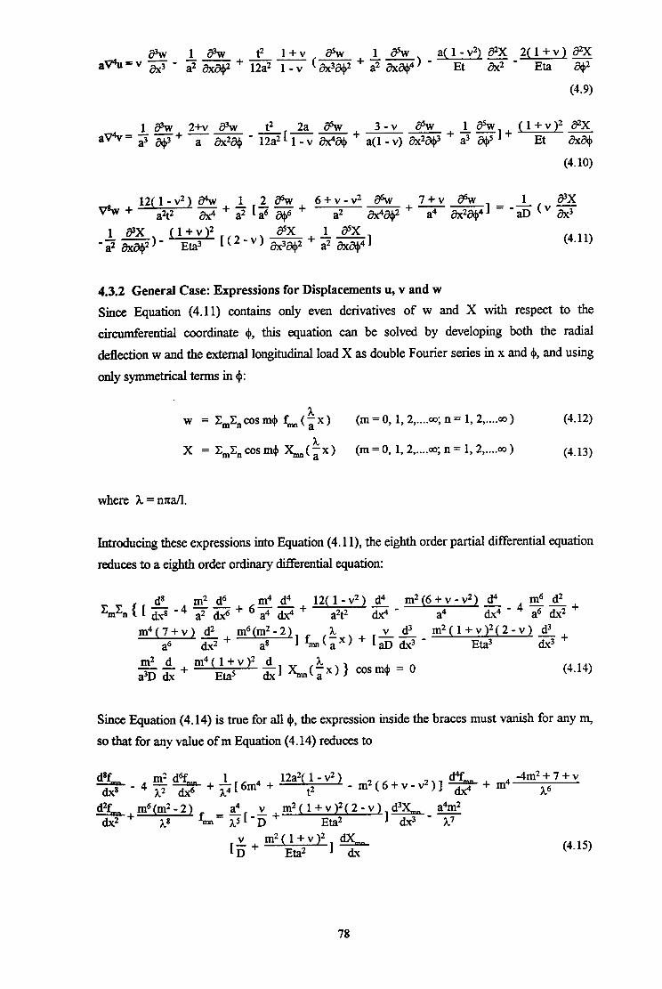
2(l+v) a2X a(l-v2) a2X Et g’ Eta s
(4.9)
1 SW 2+v SW t2 2aSw 3-v& 1 CPW Jl+v)Z a?x --+2$+ Et &q a(1 - v) &2*3
(4.10)
* + 12(;2;2v2) C+ + 1 z a6w + 6+;-vZ d6w + 7+v 8w ax4 a2 [ a6 Chj+ Mab2
-- =---&~ a4 &2Ck$41
1 8X -1.z -~[(24&+-- a2 &a#?) a2 &L3+41 (4.11)
4.3.2 General Case: Expressions for Displacements u, v and w
Since Equation (4.11) contains only even derivatives of w and X with respect to the
circumferential coordinate 4, this equation can be solved by developing both the radial
deflection w and the external longitudinal load X as double Fourier series in x and 4, and using
only symmetrical terms in 4:
w = C,C,cosm+ f,,(ix) (m = 0, 1, 2 ,.... 00; n = 1, 2 ,.... a3 ) (4.12)
h X = C,C,cosm+ &(;x) (m = 0, 1, 2 ,.... 00; n = 1, 2 ,.... 00 ) (4.13)
where h = m&l.
Introducing these expressions into Equation (4.1 l), the eighth order partial differential equation
reduces to a eighth order ordinary differential equation:
m2 d -- a3D dx + cos rn$ = 0 (4.14)
Since JZquation (4.14) is true for all 4, the expression inside the braces must vanish for any m,
So that for any value of m Equation (4.14) reduces to
d8f,, rn’a + $[6m4 + 12a2(;-v2) d‘Y -4m2+7+v d.x* ‘4% &6 - m2(6+v-v2)] z + m4 hp
d2f -&TL+IzE@$21 fin= $[$ +m2(l+;;yy2&Lm F
[D v+ m2( l+v)2
Eta2 (4.15)
78
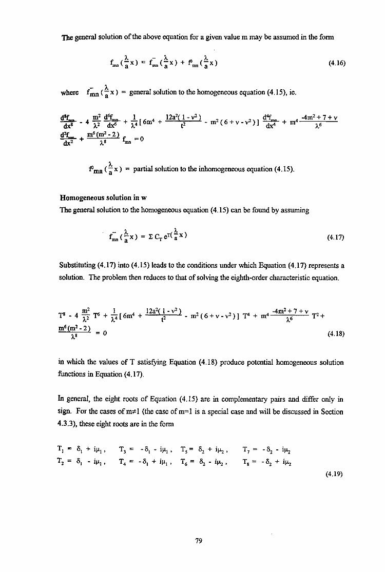
The general solution of the above equation for a given value m may be assumed in the form
%(ix) = f&, + f&(:x, (4.16)
where f;$n ( 1 x > = general solution to the homogeneous equation (4.15), ie.
% _ 4 $ 5 + &em4 + 12a2(j-v2) d4f - m2(6+v-v2)] c + m4
-4m2+7+v h6
Pmn ( P x ) = partial solution to the inhomogeneous equation (4.15).
Homogeneous solution in w
The general solution to the homogeneous equation (4.15) can be found by assuming
(4.17)
Substituting (4.17) into (4.15) leads to the conditions under which Equation (4.17) represents a
solution. The problem then reduces to that of solving the eighth-order characteristic equation.
T8 - 4 5 p + *[6m4 + 12a2(i-v21 - m2(6+v-v2)] T4 + m4 -4m2+7+v
3~6 F+
(4.18)
in which the values of T satisfying Equation (4.18) produce potential homogeneous solution
functions in Equation (4.17).
In general, the eight roots of Equation (4.15) are in complementary pairs and differ onIy in
sign. For the cases of m#l (the case of m=l is a special case and will be discussed in Section
4.3.3), these eight roots are in the form
T, = 6, + ipL1 , T3 = - 6, - Q.+ , T, = S, + i& , T,= -S,-ik
T2 = 6, - ig, , T4 = - 6, + ipl , T6 = S, - iy , T,= -S2+icc,
(4.19)
79

It should be noted that Eq. (4.19) is a general representation of a solution form of Eq. (4.18).
nus 6, > 6, and ~1 > h should be regarded as general coefficients of real and imaginary
parts of the roots of Eq. (4.18). They do not represent any particular values.
Adopting Eq. (4.19) as the solution, the general solution for f-mn ( a ’ x ) may be expanded as
A. f’ (‘Xl = esl(Px)(ClcOspl;x + $sinp,tx) + c+(ex) (C3cosp,~x + ma
x C,sinp,$x) + es2(ix) (C,cos~~x + C,sinktx) + edz(aX)
(C,cosk$x + C,sinkix) (4.20)
in which Ci are real arbitrary constants (8 constants are required for each term of the double
Fourier series).
The arbitrary constants in Eq. (4.17) must be found from eight boundary conditions at the two
ends of the cylinder (x = 0 and x = 1). This matter will be pursued further after the
inhomogeneous solution has been discussed.
Inhomogeneous solution in w
To solve the inhomogeneous part of Eq. (4.15), a partial solution Pmn ( t x ) will be sought in
the form
h. f&($x) = wmn cos(;x) (4.2 1)
To represent a rectangular patch of loading at some point within the length of the cylinder (0
< b-b,, b+b, < 1), the loading must be represented as
X,,(ix) = Xm sin(ix) (4.22)
in which L = load coefficient for the mn th term of the solution, and it will be recalled that
A = nxail.
The expressions of the load coefficient X,, depend on the pattern of load chosen. The
derivation of the expressions for load coefficient & are described in Section 4.3.6.
bertion of Eqs (4.21) and (4.22) into Eq. (4.15) yields
80

(4.23)
Since Eq. (4.23) must be satisfied for all values of x, the expression within the outer square
brackets must be zero for ah values of 1 (ie. n) , from which
a2m2t2 l+v li {a41(vI.2-m2) - l2((l-v)) [(2-v)A2 + m2]}&
wlrm = D{ (3L2+m2)4 +
12a2 1 - v2) (t2 A4 - m2[2m4 + (6+v-v2)h4 +(7+v)m2A2]}
(4.24)
Substituting the solutions for f: ( t x ) and Pmn ( i x ) in Eq. (4.12), the general expression
for displacement w is found as
w = C,C,cosm+ f,.($x)
3L h h = X,X, [ es* ( a ‘x) (Clcosp,;x + C,sinp,;x) + e -sl(iX) (C,cosp,;x +
x C,sinp,$) + eS2(tx) (C,cos~~x + C,sinj+$x) + ed2(,x)(C,coskix +
C8sink3x) + wm cos($x)] cosm+ (m = 0, 1, 2 ,.... 00; n = 1, 2 ,.... 00 )
(4.25)
Displacements u and v
The other displacements, u and v, which satisfy Eqs (4.9) and (4.10) respectively, can also be
solved by being developed into double Fourier series. Again, the symmetry of the axis system
with respect to the position of the load determines that the displacements u and v must be
represented in the forms:
u = C,C,cosm+ umn (ix) (m = 0, 1, 2 ,.... 03; n = 1, 2 ,.... co ) (4.26)
v = C,C,sinm+ vmm (tx) (m = 0, 1, 2 ,.... CQ; n = 1, 2 ,.... 00 ) (4.27)
Longitudinal displacement u
For the longitudinal displacement u, insertion of Eqs (4.26), (4.12), (4.16), (4.13) and (4.22)
into EQ. (4.9) gives
81
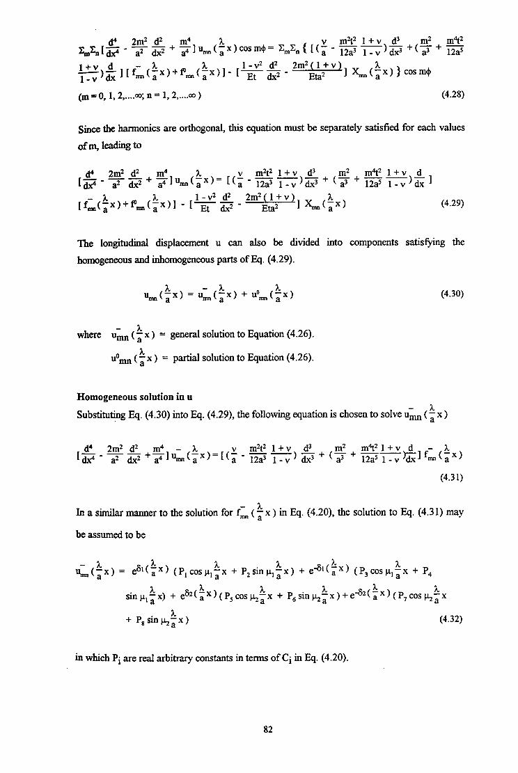
m2t2 1 + v d3 m2 m4t2 c,c,{[(;--- - - 12a3 l-v)dx3 +(a’+ 12a5
l+v d ~~z~~f~+~+~~~~~~~- $j&$j- 2m2&2+v)l &&Ob=4
(m = 0, 1, 2 ,.... Q); n = 1, 2 ,.... QJ) (4.28)
Since the harmonics are orthogonal, this equation must be separately satisfied for each values
of m, leading to
a4 2m2 d2 [a>p’ --+
a2 dx2 $]um(;x)= [(Z
h [fL(;x)+Pm(
1 - v2 d2 ix)] - [--- Et dx2
The longitudinal displacement u can also be divided into components satisfying the
homogeneous and inhomogeneous parts of Eq. (4.29).
um(ix, = u,, (ix, + uO,(~x)
where umn ( i x ) = general solution to Equation (4.26).
uom&, = partial solution to Equation (4.26).
Homogeneous solution in u
(4.30)
Substituting Eq. (4.30) into Eq. (4.29), the following equation is chosen to solve umn (s x )
d4 2m2 d2 m4 - h m2t2 1 + v d3 m2 -- [s - a2 &2 +pl&x)=[(~ - - - 12a3 I-v)G+(a3+
In a similar manner to the solution for fz ( p x ) in Eq. (4.20), the solution to Eq. (4.3 1) may
be assumed to be
cC:x) = esl(ix) (P,cosp,$x + P,sinp,ix) + e*l(ix) (P3cos~,~x + P4
I. h I. sinp,ix) + e62(aX)(P5cosk;x + P,sin&; x)+e-61($x)(P,coskix
+ P,sinhtx) (4.32)
~II which Pi are real arbitrary constants in terms of Ci in Eq. (4.20).
82

‘l%e relationships between Pi and Ci can be established by substituting Eqs (4.32) and (4.20)
hto Eq. (4.3 1) and equating coefficients of like terms which involve the multiplication of the
relevant exponential and trigonometric functions on the both sides of the equation, respectively.
This produces a set of 8 ~im~ltane~~~ equations relating Pi and Ci:
P,4& [-~2(%2-pL,2)+m21 + P2[L2( S14+j.k14 -66,2p12) - 2m2(6,2-p,2) + $1 =
C*PI[-(v-12a2 1 -v Efif =)~(36,2-~,2) - $1+ g$ E,l + q, rev- g$fi)l
(6,2- 3cc,2 1 + $+igq-J mztz l+v>],
m4 PI [A’( $4+PL14 -ti,2P,2) - 2m2(6,2-p12) + F] + P246,pL, [3L2($2-p,2) - m2] =
c,q (v-~~)h.(S,2-3Iq) ++(l+$fi)] + C,p,[(v- gp)l
( 3512 - CL*? 1 + $+sl., m2t2 lfv)],
P346,p, [ A2(6,2-p,2)-m2] + P4[h2( 6,4+p,4 -66,2~,2 ) - 2m2(6,2-p,2) + f] =
c#,[-(V-S +5X(36,2-$) - $1+g$ fi)] + c,s, [-(V-S E)l
( $2 - 31+2 1 - $1+
P3 [ A2 ( 6,4+ p14 - 66,2p12 ) - 2m2 ( S12 - p12 ) + $1 + P446,p, [-3Lz(cj12-p12)+m2] =
C,6,[-(v-g$ ++(6,2-3$) + 1+ g$E,l + C4P, [(V’ gp)l
( 3612 - PI2 1 + $l+gp)],
p~4$k[--2(622-~2)+m2] + Pg[h2( S24+k4 -6S22h2) - 2m2(s22-k2) + f] =
Ps [I.2( zi24+cLp -66,2& - 2m2(6,2-k2) + $] + P,462~[A2(ti22-~2) _ m2] =
C,S,[ (v-5 fi)k(s,2-3$) + $( 1+ SE,1 + C&LLW g$E,h
(39g) + $1+ $fi,l,
P74a2y[ A2(S,2-k2)-m2] + Ps[h2( S2+b4 -662~12~ ) - 2m2(6,2-cLL2/) + $I=
83

m2t2 1 + v c;pJ-(v-5 i-gU36,2-Iq) - $1+ gp)] + C,S,[-(v- %$=)A
p,[J.2< 624+k4 -6822k2) - 2m2(622-k2) + $1 + Ps4S2~[-h2(~22-~2)+m2] =
(4.33)
The solution of these simultaneous equations may be presented by the following. First, the
following terms are defined.
a11 = 46,pL, [ - A2 ( 6,2- p12 ) + m2 ] ,
a12 = ii2 ( ~3,~+ J.L,~ - 66,2p,2 ) - 2m2 ( 6,2- p12 ) + $,
%,, = aI2 , % = -a,, ,
%I = - a11 9 a32 = a12 9
a41 = a12 ’ a42 = a11 ’
as1 = 462&[-3t2(622-J+2)+m2]
as2 = h2( ~3,~+cLp -6622&2) - 2m2(622-k2) + f
a6l = a52 ’ a62 = - a5l ,
%l = -a,, , + = a,, ,
%I = a52 ’ %?. = a51 ’
(4.34)
and
b,, = -(v-z +$)h(36,2-~,2) m2t2 1 + v &+-- 12a2 1 -v )
m2t2 1 + v b12 = (“12a2 1-v - -)h(6,2-3$) +
m2t2 1 + v $1+-- 12a2 1 - v )
b,, = b,, , b, = -b,, , b31 = b,, , b,, = -b,, , b41 = -b,, , b42 = -b,, , b,, = -(v-f5 f+.(3s,2-~2)
m2t2 1 + v ++-- 12a2 1 -v ) m2t2 1 + v
b,, = (v-s ~)A(~22-3j.52) + F( I+- - 12a2 1 - v )
b6,= bs2, b62=-bS,, b,, = b,, , b, = - bs2 , b,, = - bS2 , b,, = -b,, .
(4.35)
84
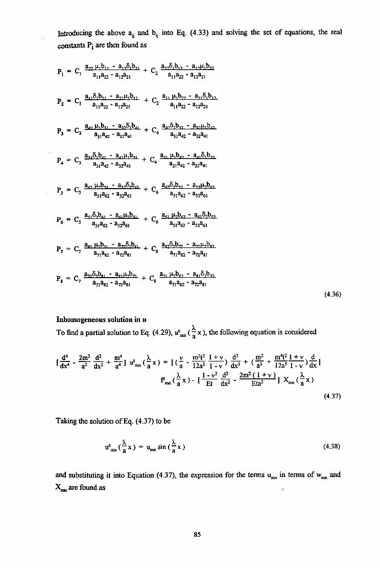
introducing the above aij and b, into IQ. (4.33) and solving the set of equations, the real
CQXI.SW~S Pi are then found a~
PI = c, a.,,, Oil - alAb,
+ C2
a&b,, - a,,p,b- a1922 - a12?21 a1922 - %2%1
p2 = c, a,,W,, - a,,O,, + c, a11 I4
b,, - a&b,, w22 - %2%1 %%2 - %2%1
p4 = c3 G4ba, - a,lO,l + c hl OAT - a&b,,
%la42 - ?32a4l 4
%la42 - %2a4l
aSla62 - a52a61
‘6 = c, a&bK, - a,,p,b,,
+ ‘6 a,, p,b,, - an,6,bcr
a5la62 - a52a61 a5la62 - a52a61
(4.36)
Inhomogeneous solution in u
To find a partial solution to Eq. (4.29), u”,,,,, ( 3 x ), the following equation is considered
d4 2m2 d2 m4 h [dzp- a2 &.$ 31 uOm(,x) = --+
(4.37)
Taking the solution of Eq. (4.37) to be
uom(ix) = umsin(ix) (4.38)
and substituting it into Equation (4.37), the expression for the terms urn in terms of wm and
&,,, are found as i
85

2. (m2 + 3c2)2 [ VA2 - m2
m2t2 1 + v -(m2+h2)] wmn +
a2 %n= -Es l-v
JqQ(l-v) (m2 + h2)2 Et
+ 2m2] & (4.39)
Thus, the final form of the longitudinal displacement u is gived by
u = ZZmCncos m+ Us (tx)
=EmXn[eS1(a 3”x) (P,cosp,ix + P,sinp,ix) + e -6,(ix) I..
(P3cosp,;x + P4
sin j.+$x) + S2($x) e (P,coskix + P,sinkix) + ed2(%x)(P,coskix
+ P, sin hkx) + umn sin(kx)] cos(m(b) (m=0,1,2 ,.... ao;n=l,2 ,.... 00)
(4.40)
Circumferential displacement v
The circumferential displacement v is found Corn Eq. (4.10) by dividing it again into
homogeneous and inhomogeneous parts as
l&(:x) = vi(ix, + tim(ix) (4.41)
Substituting the corresponding Eqs (4.27), (4.41), (4.12), (4.17) and (4.13) into Eq. (4.10)
results in
Homogeneous solution in v
To solve vmn ( a hx)bymeansof fi(i x ), the following equation from IQ. (4.42) is
considered
d4 [s-
2m2 d2 m4 - 3t --+ a2 dx2 21 y&p)
(4.43)
Hence, the corresponding expression for vmn ( 1 x ) can be represented by
86
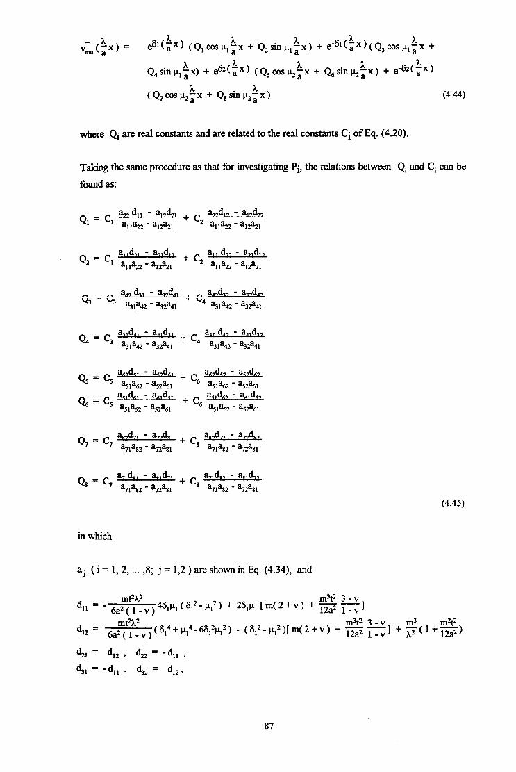
vL(fx, = h 3t e”($‘) (Q, cospI;x + Q,sinp,;x) +
h e -+~(Q3cosp~;x +
A. h c?,+sinp,%x) + es2(ix) (Q5cos~~x + Qgsinktx) + eqz(,x)
(Q,cos~~x + Q,sinkkx) (4.44)
where Qi are real constants and are related to the real constants Ci of Eq. (4.20).
Taking the same procedure as that for investigating Pi, the relations between Qi and Ci can be
found as:
Ql h,, 4, - wh
= ‘1 a,,+ a,,d,, - a&,,
- %2%1 + c2 a1922 - %2%1
a,, d,, - a,,d,, + c2 a,,%!2 - a,,%21
a,, 4, - a.,,dA, Q3 = ’ %la42 - t32a4l
a,,&, - &,d,, + ” %la42 - %2a41
wL, - wL 44 = ” ?31a42 - ?32a4l
&,, 4, - wL + ” %la42 - %32a4l
Q5 = c5 &,d,, - ac,dn, + c aA,dZ, - az,d6,
a51a62 - a52a61 ’ a51a62 - a52a61
Cl Al /;l 21 I?7 kl 27
46 = ‘5 15p%, : ;2: + ‘6 :5,:62 1 ,aj2t,
+ c* a,,d,, - h&.,
%%2 - haSI
(4.45)
in which
au ( i = 1,2, . . . , , 8. j = 1,2 ) are shown in Eq. (4.34), and
d m3t2 3-v
= 6a2~t~v ) 461h ( 612 PI2 ) + - -
11 - - 26lpl [ m( 2 + v ) + 12a2 1 I -V
d 6a~t~~v)(6,*‘~~4-6612P,2) m3t2 3-v m3
(612’p12)[m(2+v) + 12a2 1 1 m2t2
12 = -- - + -V $-(‘+12a2)
% = 4, 9 42 = 4, ,
‘&I = 4, , 42 = d,, ,
87

d 41 = d,, , & = d,, , mt2h2 m%2 3-v
d = - 51 6a2 ( 1 - v ) 4$kL2($2-k2) + 262k+(2+v) + s =I
42 =
4, = d52 ’ d62 = - 4, ’
4,=-41~ 42= d523
$1 = d52 ’ $2 = 4, * (4.46)
Inhomogeneous solution in v
The inhomogeneous or partial solution for the function v”,, ( i x ) is sought in the form
3L v”&p) = “&os(~x) (4.47)
and determined from the following equation which is associated with Eq. (4.42)
d4 2m2 d2 m4 --+ is - a2 &2 2m d4 m3 3-v d2
12$(1-v s - --- a2 1-vdx2 ms
+ ,411 pm(kx) -
(4.48)
Insertion of Eq (4.47), (4.21) and (4.22) into Eq. (4.48) leads to the expression of v,, in terms
ofw,,andX,,as
1 t2 2m m3t2 3 - v m2t2 vm = tm2+h?)2{5~-4 + bW+v) + sGlA2 + m3(‘+12a2)~wmn
1 mw( 1 + v )2 - (m2+ h2)2 Et Km
(4.49)
The general expression for displacement v is then given by
v = C,C,sinm+ v,, (ix)
= EmC,[eS1(a ‘x) (Q,cosp - ,tx + Q2sinp,i x) + edl(ix) (Q3cosp
Shp,~x) + e62($X) (Qscoskix + Qgsinfi$x) + e~2($X)(Q,cos~~x+
?L $sinkix) + V~COS(;X)] sinm+ (m = 0, 1, 2 ,.... 00; n = 1, 2 ,.... 00 >
,’ (4.50)
88
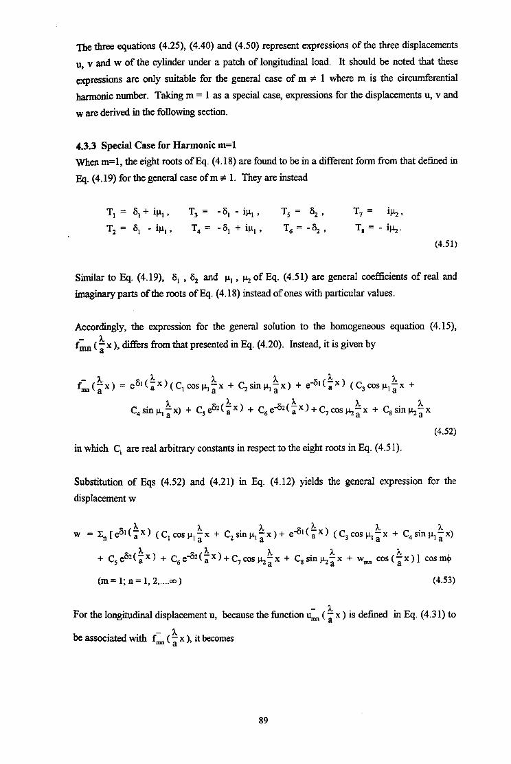
The three equations (4.25), (4.40) and (4.50) represent expressions of the three displacements
u, v and w of the cylinder under a patch of longitudinal load. It should be noted that these
expressions are only suitable for the general case of m f 1 where m is the circumferential
harmonic number. Taking m = 1 as a special case, expressions for the displacements u, v and
w are derived in the following section.
4.3.3 Special Case for Harmonic m=l
When m=l, the eight roots of Eq. (4.18) are found to be in a different form from that defined in
Eq. (4.19) for the general case of m f 1. They are instead
T,= Zi,+ip,, T,= -6,-iu,, T, = 6, , T, = ik,
T, = 6, - ipl, T4 = - 6, + il.+ , T6 = -6,) T, = - il.+.
(4.5 1)
Similar to Eq. (4.19), 6, , 6, and p, , h of Eq. (4.5 1) are general coefficients of real and
imaginary parts of the roots of Eq. (4.18) instead of ones with particular values.
Accordingly, the expression for the general solution to the homogeneous equation (4.15),
fBm ( ix ), differs from that presented in Eq. (4.20). Instead, it is given by
fi(ix, = 3t h
esl($X)(C,cospl;x + C2sinp,:x) + ea,(kx) (C,cosp,;x +
C,sin p,tx) + C, eS2( a xx) + C,e42(~x)+C,cos~~x + C,sinktx
(4.52)
in which Ci are real arbitrary constants in respect to the eight roots in Eq. (4.5 1).
Substitution of Eqs (4.52) and (4.21) in Eq. (4.12) yields the general expression for the
displacement w
= X,[eB1(iX) (Clcospla h
W ‘x + C,sinp,;x)+ e -61(%x) (C,cosp,$x + C,sinp,tx)
+ C,ek(iX, + C,e~2($X)+C,ccs~~x + C,sinh$X + wmn cos($x)] cosm+
(m = 1; n = 1, 2,....co) (4.53)
For the longitudinal displacement u, because the function ui ( i x ) is defined in Eq. (4.3 1) to
be associated with f;;l, ( i x ), it becomes
89

c(fx) = eslca XX)(P,cosp,~x + P2sinpla 2.
&x) + eq,(BX)(P3cosP,ax + P4
a. I. sinp,ix)+ P,es2(ax) + Pgeq2(;x) + P,cos~~x + P,sinkkx
(4.54)
in which Pi are real constants and related to the arbitrary constants Ci in Eq. (4.52).
Taking the same procedure as before, the relationships between Pi and Ci can be found as
PI = c, a,,, Ml1 - aI Ah
+ c2 a&b,, - a,,p,b,,
a,,?22 - al2% w22 - %2%1
p2 = c, a,,W,, - wh, + c2 aI1 Mb, - %Ab,,
a,?22 - a,,%, a,,%2 - a,,%
ha42 - %2a4l 4
%la42 - %2a4l
p7 =c ~ 8 %I ’
P, = c, e
(4.55)
in which
a,, = 46,p, [-h2(6,2-~,2)+m2],
a12 = k2( cJ4+p14 -66,2p,2) - 2m2(i5,2-p,2) + $,
%I = a12 ’ ?22 = -a,, ’
?I, = - %I ’ %2 = a12 ’
a41 = a12 ’ a42 = %I ’
a51 = h2624 - 2m2622 + $,
a6l = aSl ’
%I = J.zcl_p + 2m2h2 + $,
%I = %I. (4.56)
and
b ‘(V - m2t2 1 + v
II = s -i7-)U3$2-$) - m2t2 1 + v $1+-- 12a2 1 -v )’
b (v m2t2 1 + v m2t2 1 + v
12 = -ig ~)wy-3I+2) + $1+ - 12a2 1 -v -1,
90

b,, = b,, , b, = -b,, , b 31 = b,, , b32 = -b,2 9
b4, = -b,, , b42 = -b,, ,
b 51 = A.q(v- ~~)+~(‘+!!El+y), 12a2 1 -v
b6, = -b,, , m2t2 1 + v
b 71 = -'k2 (' - 12a2 1-v m212I+v))+$,+--
12a2 1 -v )’
b 81 = -b7, -
(4.57)
The expression for the longitudinal displacement u can therefore be written as
Lx)(P,cosp h
U= Xn[e*l(a + P2 sin CL,; x) + eql(ix) (P3cos~,~x + P,sinp,ix) +
P,esz(ix) + P6e-sz(ix) + P,cosk$x + P,sinkix + umsin(kx)] cos(m+)
(m = 1; n = 1, 2,....co )
(4.58)
and similarly the circumferential displacement v can be found by solving Eq. (4.43) to give
vi(ix) = es’<, 4X) (Q,cosp - ,tx + Q,sinp,$x) + e -61(:X) (Q,cosp,;x + Q
sin CI, a &x) + Q5es2(%X) + C&eG2(ix) + Q,cosk$x + Q8sinkkx
(4.59)
in which Qi are real constants and are related to the Ci of Eq. (4.52).
The relations between Qi and Ci can be found by solving Eq. (4.43) tier inserting Eqs (4.59)
and (4.52) into it, yielding
Q2 = c, alldw - bd,J + c2 a11 47 - a71 d,, a,,%2 - a,,%!, a,?22 - al2%?l
Q3 = c, "$i2 : 2;:' + ~4 a4'4' - a"d47 ?31a42 - %2a4l
91

d QS =c -
5 as, ’ %=‘6%
Q7 = c, AzL
% ’ QS = ‘8 %
(4. w
in which
m3t2 3 - v d,, = - 6a?~~~v)461h (612-h2) + 26#1 lrn(2+v) + --- 12a2 1 - v I 3
m3t2 3 - v 6a?ty v ) ( 614 + p14’ 6612p12 ) - ( 61~ - p12 )[ m ( 2 + v ) + - -
m3 m2t2 d 12 = 12a2 1 -V 1+ $I+ 12a2L
41 = 42 7 42 = - 41 ’
4, = - 4, ’ 42 = 42 ’
d4, = d,, , d42 = d,, 9
d mt23L2
51 = 6a2 ( 1 - v )
d L 61 =
4, = mt2A2
6a2( l-v)k 4 + [m(2+v)
(4.61)
Thus, in the special case of m=l , the circumferential displacement v may be expressed as
I. 1 v = ZZn[esl(kx) (Q,cosp,~x + Q2sinp,kx) + eql(ix) (Q,cosp,~x + Q,sin)I,ix)
+Q5eS2($x)+ Qea2(ix) + Q,coskkx + Q8sinkix + V~COS($X)] sinm$
(m = 1; n = 1, 2,....ao ) (4.62)
92
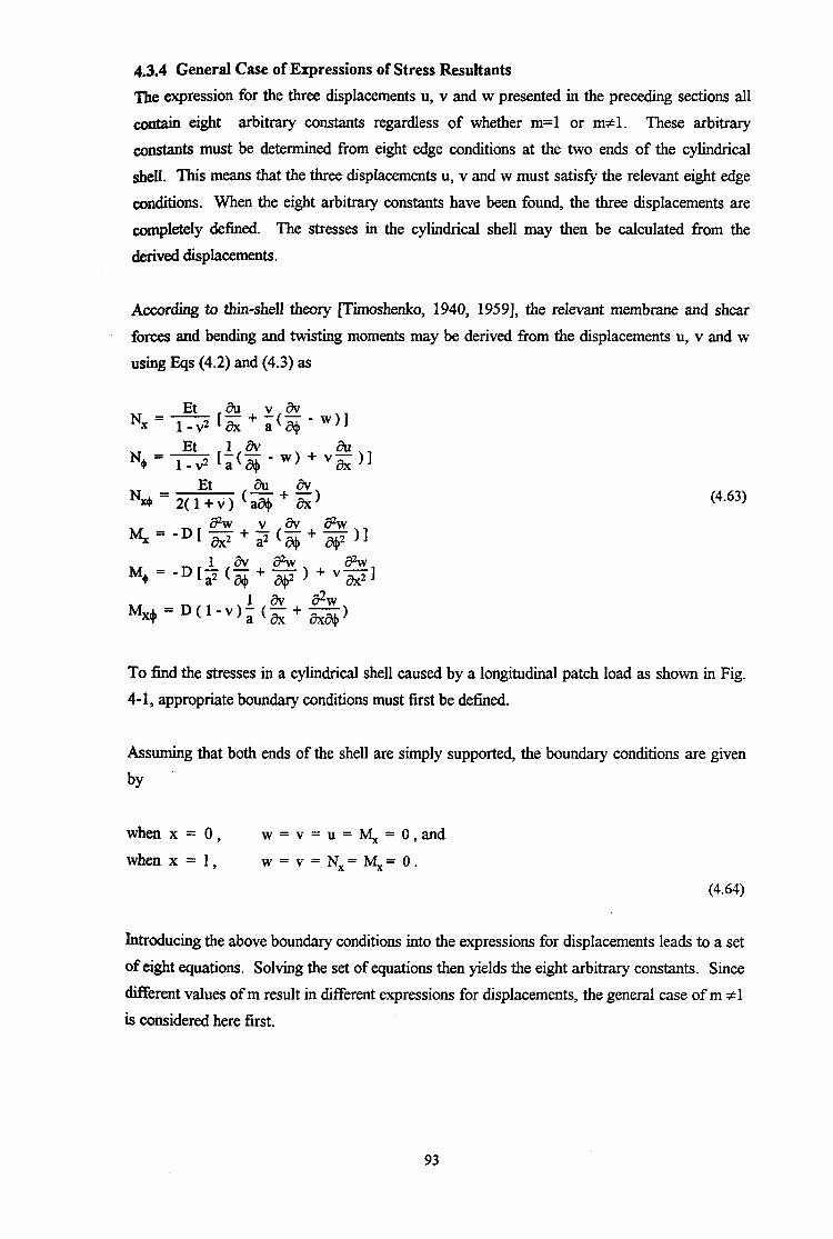
4.3.4 General Case of Expressions of Stress Resultants
The expression for the three displacements u, v and w presented in the preceding sections all
contain eight arbitrary constants regardless of whether m=l or m+l . These arbitrary
constants must be determined from eight edge conditions at the two ends of the cylindrical
shell. This means that the three displacements u, v and w must satisfy the relevant eight edge
~&ions. When the eight arbitrary constants have been found, the three displacements are
completely defined. The stresses in the cylindrical shell may then be calculated from the
derived displacements.
According to thin-shell theory [Timoshenko, 1940, 19591, the relevant membrane and shear
forces and bending and twisting moments may be derived from the displacements u, v and w
using Eqs (4.2) and (4.3) as
Et au vav N, = l-v2 1, + a$- - ~11
No = * r$$ -w)+vx ?I
NM = Et *+
2(l+V) (a* (4.63)
lap-D[s+j(g+$)] M+=-D&($+$)+vs]
MX4) 1 av Bw
= D( 1-v); (z + G)
To find the stresses in a cylindrical shell caused by a longitudinal patch load as shown in Fig.
4-1, appropriate boundary conditions must first be defkd.
Assuming that both ends of the shell are simply supported, the boundary conditions are given
by
when x = 0, w=v=u=y,=o,and
when x = 1, w = v = N,= 4= 0.
(4.64)
Introducing the above boundary conditions into the expressions for displacements leads to a set
of eight equations. Solving the set of equations then yields the eight arbitrary constants. Since
different values of m result in different expressions for displacements, the general case of m fl
is considered here first.
93

For the conditions of w = 0 at x = 0 and x=1 respectively, the boundary conciitions inserted into
E.q. (4.25) yield the two conditions relating to w
c, + c, + c, + c, = -wm (4.65)
c,e6~(~lkos p,il + C2es1( a ‘l)sinp,’ x
;l + C3e-6,(,1 kos j.+ a &l + C4ed,(i1)sinplh a’
+ C5es2(k1 kos kh al + C6eS2($1kink’ a 1 + C7ed2(i1 kos k’ al + C8eG2(pl)
siu& = -wmcosql (4.66)
and for v = 0 at x = 0,l; Eq. (4.50) gives two further conditions
Q, + Q3 + Qs + Q7 = - v,,m (4.67)
Q,e% ~l)cosplA hl al + Q2e8,(, )sin~,a ‘1 + Q3ed,(~lkos pIi1 + Q4e~,(~l)sinp,$l
‘1 x x I. + QSeS2ta )cos~+il + Qses2(a1)sinkil + Q7e~2(~l)COs~~l + Q,ea(al>
sinka % A.
= -vmcQs;l (4.68)
Making use of Eq. (4.45), Qi is replaced by Ci in the above equations as follows
c, a,, 4, - a,,&, + c2 wk - a, 4, a,, d.,, - q,d,, a,,%?2 - %2% a,922 - a,2%?,
+ C3 %la42 - ?32a4l
+ c4
aA,&, - a,d,, + c5
ar;,dq, - ac,dF;, a51a62 - a52a61
+c a,,d,, - aS,d6,
%la42 - ?32a4l ’ a5la62 - a52a61 + c7
w%, - a-,4,, d ws2 - %2%
+ c, --a,,, -vm %‘I%2 - %2a8l
‘1 “I ( a % - ad ) [ :pad .Y ayF2L ‘OS hi l + :fz2 _ a,,%: sin CL~ a &l] + C,&(a 1 ll
[ a& - a&, 11 7 alla, - a,,%,
‘OS htl + ‘alla, 1 a12:, ’ ” sinj.+il] + C3ed,(i1)
Ia~$~2:~~$1 COSP,~~ + t$J2~~~~~ siny~ll + C4e4t1)
21 41 cos & + aqPa, : sin P, a &l] + C,es2(a ) %
[ a,,d,, - a,,d,,
cm& + a,,d,,
a5la62 - aS2a61 ‘51’62 - a52a61 sink311 + C6eS2(a %)
I a,,d,, - az,dA, a51a62 - aS2a61
cos& + ac,dr;, - ak,dC, a5,a62 - a52a61
sinj+il] + C7eq2(t1)
cos & + a71d91 - aa,&,
?‘I%2 - %Za81 sink:11 + Q8e*2($1)
(4.69)
94
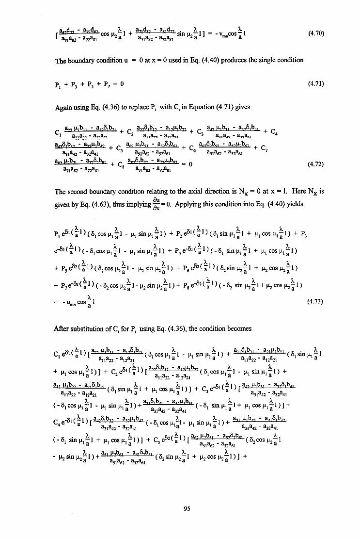
m a-,,d, L1 + w-b - wb, -an% coscl,a %I’82 - %%I
sink:11 = -v,coskl (4.70)
The boundary condition u = 0 at x = 0 used in Eq. (4.40) produces the single condition
p, + P3 + PS + P, = 0 (4.71)
Again using Eq. (4.36) to replace Pi with Ci in Equation (4.71) gives
Cl a,, ~,b,, - alAbu a.&b,, - a,+,b,, 4, p,b,, - a&b,, + c
a,,%2 - %2% + c2
w22 - a,2?2, +qa
q’a42 ,:i:
4
a &b,, - a,,p,b,, + c a,, hb,, - a&bxl + c a&b,, - a %la42 - %2a4l
5 a5,a62 - a52a61
6 aS,a62 - a52a61
+ c7
a, bb,, - a-$&b,, + c 8
a&b, - a+,b,, = o w432 - %2% w82 - %?%I
(4.72)
The second boundary condition relating to the axial direction is N, = 0 at x = 1. Here Nx is
given by Eq. (4.63), thus implying dx u = 0. Applying this condition into Eq. (4.40) yields
P,eS,(~1)(6,cosj.k ’ ,;l - i+sink+a ‘1) + P2e6,(a )(S,sinp,~l + ~,cosj.+~l) + P, 3”l
ed*(~l)(-glcosp ,$l - p, sin p,: 1) + P4ed,(k1)(-8, sinp ,il + p, cos $1)
+ PSeS2( i1)(82cosj+fj1 - hsinki 1) + P6eS2(a )(G,sinhil + p2C0Sp2$l) ‘1
+ P7e~(~l)(-gzcos~~l-~sin~~l)+ P,e a2(i1)(-S2 sin~~l+j+cos~~l)
h = mu &OS;1 (4.73)
After substitution of Ci for Pi using Eq. (4.36), the condition becomes
C, esI($l) 1%’ p’b11 - a”6’b7L(~,cos $1 _ cr, Sin &) + a1161b71 - %IpL,bll a,$22 - a,,%, all%22 - aI,%
(6 * % I ‘ln PI a
+ ~lcOSj.+~l)] + C,CG*(a ‘l) [ a761b” - a17p’b’2 ( 6, co.5 p, 11 - p, sin p, i 1) + a,+22 - a,,%,
1 a1’ p’b” - q1,,6’b1’ (6,siny~l + p,cosp,~l)] + C3&,(~l) [
a,, p,b,, - a&b,, all%2 - a,,%, %la42 - %2a4l
(-8, sinp,%l+ ~,cos~,~l)]+
95

The final two boundary conditions are for longitudinal bending at the ends, and require M, = 0
at x = 0,l. The moment M, is given by Eq. (4.63), which can be converted to h2 - &-Oatx=O
and x = 1. The following equations are then obtained from Eq. (4.25).
(6,2-p12)tc, + q + %+(C2 - c4) + ($2-j$2) (c5 + q) + 262k(c6 - c8) = wm (4.75)
and
C, es* ( 2.
e1),(~,2-p,2)coSp,- a 1 - 2$1+ sin P, a ‘11 + C2e’,(a )[(6,2-p,2)sinp,a .l .1+
26,p,cosp,~1] + C3e~,(~1)[(~,2-p,2)cosp,~1 + 26,ysin~,~l] + C4e-61(P1)
[(6,++~)sinp,~1 - 26,~,cosp,~ l] + C,eFz(B1)[(6,2-~2)“s~~1 - 262k
sinkLl] + C6e62(31)((S,2-HZ)sin~~l + 26,kcosk$l] + C7eq2($l) a
[(iS~-~2)cos~~1 + 26,j.,+inktl] + C8e~2(~1)[(S,2-~22)sin~~1 -
= wmcos$
(4.76)
The eight real constants Ci can be found by solving the eight equations (4.65), (4.66), (4.68),
(4.70), (4.72), (4.74), (4.75), and (4.76). The constants Pi and Qi, which have been expressed
in terms of C, can then be found from Ci using Eqs (4.36) and (4.45).
The real constants C, Pi and Qi have now been determined. This indicates that the associated
displacements of the cylindrical shell under these boundary conditions are completely known.
96
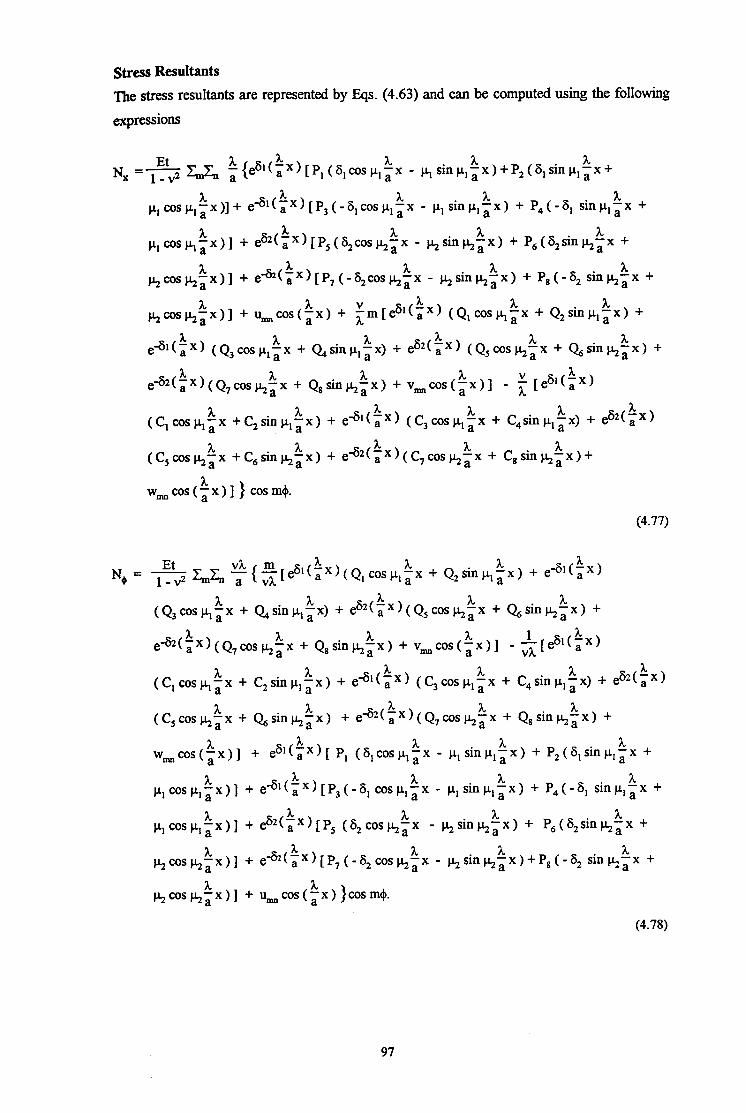
Stress Resultants
The stress resultants are represented by Eqs. (4.63) and can be computed using the following
expressions
Nx =s I&Z& ~~eSl(tX)~P,(6,c0s~,~x - 1(,sinp,~x)+P2(6,sin~,$x+
p,cosp,~x)]+ e-61(5x)[P3(-glc0sp,ffx - A
p,sinp,ix) + P4(-6, sinp,;x +
A PI C0s h a ‘x)] + eGz(,x)[P5(S2cos~~x - j.l.+‘l~~X) + P,(G,siq+;x +
A kcoskkx)] + e-GZ(,x)[P7(-G,cosktx - ksinkix) + P,(-6, sinkix +
~cos~~x)] + I&COS(~X) + fm[es,(ix) (Q,cosp,~x + Q,sinp,~~) +
e4*(tx) (Q3cosp ,tx + Qsinp,: x) + es2(ix) (Q5cos~~x + Q,sinhix) +
e42($x)(Q7coskix + Q8sinhtx) + v,,cos(~x)] - t [ea,(a Xx)
(C,WSp,~X +C,Siop,~X) + e-6*(ix) (C3wsp,~x + C,sinp,~x) + e~t~x)
A (C,WS&iX +C6Sh&3x) + e42(,x)(C7cos~~x + C,sin~~x)+
w,cos(~x)]} cosm+.
(4.77)
N+ = yf$ ZJ,, ~(~[es*($x)(Q,coslr,~x + Q,sinp,ix) + eq,(kx)
(Q3~w,$ + Q,sin~Ia A A ‘x) + e62(,x)(Q5cospgx + Q,sinp$x) +
e42(~x)(Q7cos~~x + Q8sink$x) + v,,cos($x)] - $[e’,(a &x)
A &x) + eql(ix) (C3cospla
A (C,cosp,~X + C2sinC(,a ‘x + C,sinp,;x) + e 62(%x)
(C,cos~~x + &sin&ix) + ea2(px)(Q7coskix + Q8sinkix) +
A w,,cos(~x)] + e6*(ix)[ P, (6,cosp,;x a - CL, sinp,$x) + P,(S,sinp,ix +
~,cosj.+~x)] + e4,(px)[P3(-6,cosp,ix - A
j.+sinj.+kx) + P4(-6, sinp,;x +
A h C0s h a &x)] + e*2(,x)[P, (6,coskix - ksinhkx) + P,(6,sinj+ix +
~cos~~x)] + ea(~x)[P7(-S2cos~~x - k sin etx ) + P, ( - 6, sin j+$x +
hcoskix)] + u,,cos(ix) )cosm+.
(4.78)
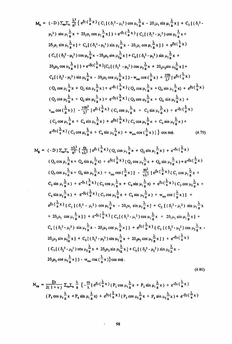
& = t-D)&,& ~~e~*~~X)~C,~(~12-~,2)~S~l~X - 26,p,sinp,~x] + c,[(s,~-
A A cL12) sinb& + 2~l~,~s~,~xl}+ed*(,X)(C3~(*,2-~,2)c0s~,~x+
26,p,sinp,~x]+ C4[(S12-p12)sinp,kx - 26,p, cos p,ix] ) + es2tbx)
{C,[ts,1-t+2)WS&$x -26,lr,sinj.$x]+C,[(S;--k)sinbix +
2S2kcoshtx] )+ea(~x)(C7[(S,2 -h2)c0s)LItx + 26,p+inj.$x]+
c,[(s,‘-&2)sin& - 262&cOS)LIix] I-w,,cos(tx) + z[es*ta &x)
A A ‘6’(:x)(Q3cosp
A tQl~s~,;x + Q,sinp,;x)+ e 1px +Q,sinyix) + eh(aX)
A (QsCOSJ+~X + Qtik+$x)+ e-Gz(iX)(Q7ccxh$x + Q8 sinhkx) +
VmWS(~X)] - T$ [e5*(ix) (C,wsp,~x + C2klp,~x) + eG*($x)
(~~SP,~x + C,sinp,tx) + e62(~x)(C,c0s~~~ + C,sinj+$x)+
(4.79)
M+ = (-D)Z&,, %{ $ (es,(~X)(Q,cosp,~x + Q,sinp,$x) + e4,(bx)
(Q3cos~,~x+ Qsinp,: x) + e62(kx)(Q5cosk$x + Qsin~~x)+e~2(~X)
A A A m2 (Q7c0s~gx+ Q,s~II~~x) + v,,cos(;x)] - z [$‘(a
A ~x)(c,cosp,~x +
(Y+sinp,kx) + e4,(~X)(C3cosp,~x + C,sinp,kx) + e62($x)(C5cos~$x +
C,sink$x) + eq2(ix)(C7coshix + Cgsin&ix) + wmcos(kx)] +
es’(tx){Cl [(S12 - jl12) cosp,~x A
- 26,p, sinyix] + C, [(S12-p12) sinp,;x
A + 26,p, cosp,;x] } + e -6’~~x)(s[(8,2-~,2)c0s~ ,$x + 26,j.q sinp - ,;x1 +
c4H~,2-P*2) S~P,~X A A
- 26,~,cosp,;x]} + ez2(ix){ C, [(622-~2)co~~~~ -
2S,ksinkix] + C6[(Sz2-k2)sink$x + 26,~cos~~x]} + ea2(ix)
{C7[(822-~2)COS~~X + 26,~sin$x]+C8[(6,2-~2)sin~~x -
26,qcos~~x]}- w,,cos(ix)Jcosm+.
(4.80)
NX$ = 2(fiv) &I& $ (-~[e61($x)(P,cosp,%x + P,sinp,kx) + e4,($x)
(P3w+~x +P4sinCIla A
‘x) + eh($x)(P5coshix + P,sink:x)+ eq2(ax)
98

(P7cos~~x + P8sin~~x)+~sin(~x)]+e~*(~x)[Q,(~lcos~,~x -
u,sinp,ix) + Q2(S,sinp,$ x +~,cosp,~x)] +ed*(~x)[Q3(-g,Ms11,~x -
A A ~,sinu,~x) + 44(-S, sinp,;x + ~,cosj.+; x)] + es2(iX)[Q5 (6,cosy~x -
A j+sinhix) + C& (6,sink;x
A + kcoskkx)] + ea(aX)[Q7 (-G,COS~~X -
j$sinkixf + Qg(-62 sin&:x + k ccskkx)] - v,,sin(kx)) sinm&
(4.81)
Mx+ =Dtl-v)&&, $ {e6*($x)[Q, (~,cosy~x - ~,sinp,~x)+Q2(~,siny~x + A A
p,cosp,~x)] + eG1(~X)[Q3(-6,cosp,;x - A
)1,sin~,~x) + 44(-S, sin~,;x
A + ~,cosp,~x~] + e6-r(ax)[Qs(G2cosy~x - kssinkkx) + Qs(S,sinkix
A + h.$ws~~x)] + e42(aX)[Q7 (-S,coskix - bsinhtx) + Q8
(‘6, sinp2~x + p.pxx~px)] - vmsin($x) i
- m(es,(~X)[C,(~,cos~l~x -
A j.+sink+fx)+C2(G,sin~,~x + ~,cos~,~x)] + e
A 41(~x)[c3(-slcosp,~x -
A A Ir,sinp,tx) + C,(-6,sin~,;x + p,cosp,;~)] + e ~2(~x)[c5(~2cmp2~x -
A ksinkix) + C,(S,sinkix + hccshix)] + e”2(~X)[C7(-~2ccs&~x -
ksinhix) + C,(-S,sinkix + ~cos~~x)] - w,,sin($x)]} sinm+
(1.82)
All the above solutions for stress resultants are valid provided m f 1 (m = 0, 2, 3,...,co; I, = 1,
2 ,..., m). The special case of m = 1 is considered next.
4.3.5 Special Case of Harmonic m=l: Expressions for Stress Resultants
For the case m = 1, the expressions for displacements u, v and w have been given in Equations
(4.53), (4.58) and (4.62) respectively in the previous discussion. In order to produce the
corresponding relations for the stress resultants, the relevant boundary conditions presented in
Eq. (4.63) are introduced into these expressions for the displacements.
For w = 0 at x = 0,l; Eq. (4.53) gives
c, + c, + c, + c, + c7 = - w,lU, (4.83) I’

C,$‘(a kOS)I,$l + C2G’(a El A l kin j.+ il + C3ed*t$1kos p,’ a 1 + C4e4*(i1 kin p,’ a1
+ ~5~S2(:‘, + C6eq2(t1) + C7cosj+t1 + C,sinkil = -WmcOs$l (4.84)
For v = 0 at x = 0, 1, Eq. (4.62) gives
Q, + Q3 + Qs + Qcj +Q7 = -v,,,,, (4.85)
Q,‘*(a %0s pIA % al + Q,e’,(a kinpla ‘1 + Q3ed,(~1kos~l~l + ~e**(~l)sin~,$l
+ Q5es2(t1)+ Qe -s2(i1) + Q,cos~~l + Q,sinkkl = -vmcos~l
(4-N)
Converting the above equations in Qi into the corresponding equations in Ci using Eq. (4.60)
leadsto
+ c2 hd,, - a,&,, a,, 4, - &,d,, a,,?22 - %,??I + ” %la42 - ?32a4l
+ c4
%la42 - %94, +cL+c6 a +c, AtiL &CL-
5 a5, --vm
61 $I
Foru = Oat x=0, Eq(4.58)gives
p, + P3 + Ps + p6 + p7 = ’ (4.89)
Again rewriting it after introducing Eq. (4.55)
c, %,, p,b,, - a,$,b,, + c2 aJ+,~ - a&b72 + c3 a~7 hb7i - q7 61b4’ %la42 - %2a41
+ c a,,%?2 - 32% alla, - %2%1
4
a&b,, - a,p,b,, +cQ=+cs++cg 5 h&o %la42 - %2a41 %I 61 %
(4.87)
(4.88)
(4.90)
100

men x = 1, N, = 0, ie. e= 0, as before, Eq. (4.58) gives
% P,@,(a )($ccsl$a ‘1 - ~,sin)l,$l) + P2e6,(, )(S,sin~,~l + ~.+cos~,~1) + P3 x1
e-s1(~1)(-6,C0Sp ,il - ~,sin~,$l) + P4ed*(~l)(-$ sinpI: + ~,cos~,~l)
+ P56,e62(i1) - P6S2ea(p1)- P7ksinkil + P,~cos~~l = -u&os~l (3.91)
and similarly replacing Pi with C, using Eq. (4.55) it becomes
Finally applying M, = 0 (converted into h2 - azw- 0) at x = 0 and x= 1, Eq. (4.53) gives
(6,2-,‘$2)(c, + c3) + 26,,+(c2 - c4> + 622(c5 + c,) - k2 c, = wm (4.93)
Clesl(pl)[(~12-~,2)cos~,~l - 2S,ysinc1,~1] + C2cG1(a )[(S,2-~,2)sin)r,~l + Xl
2iQ.~,cos~,~1] + C3ed,(~1)[(8,2-~,2)cos~,~l -t 26,~,sin~,~l] + C4e-s,(i1)
[(S12-p12)sin~,~l - 26,~.~,c0s~,, &l] + C5S22e52(i l) + C6S22e42($1) - C7~2cos~~l
- C, b2sinj+kl = w,cos~l (4.94)
solving the eight equations (4.80), (4.81), (4.84), (4.85), (4.87), (4.89), (4.90) and (4.91) gives
the corresponding eight real constants Ci as well as Pi and Qi in the special case of m = 1.
According to the general formulas (4.63) for stress resultants, the solutions for the Stress
resuhants N, N+, Nx+ , M, M+ and q are given by
101

Et NYC =g ~~(e~,($x)[P,(~,cosp,~x - p,sinp,kx)+ P,(G,sinp,ix +
~.+cosp,~x)] + e4,(~x)[P3(-S,cosp,~x - p, sinp,kx) + P4(-6, sinp,ix +
‘x)] + P5S,eh(iX)- P6Zj2eq2(ix)- P,ksinbix + P,~cosy~x + PI C0s h a
u&os(~x) + f m[eG,(Px)(Q,cosp A
,ix + Q,sinp,kx) + e4*(aX)
(Bcw,~x + Q4wla ‘x) + Q5t&(~X) +(&82($x) + Q7cos~ix +
Q8sinhix + v~cos(~x)] - t [esl(a xx) (C,cosp ,kx A
+ qsin p,;x) +
A e4*(ix) (C,cosp,;x + C,sinp,a x) + C5esz(9x) + C6ea(iX) + C7cos~~x
A A + C,sink;x + w~cos(;x)]} cosm+. (4.95)
N.+= 1”:2 G,$ {$[es’(ix) (Q,cos~.~,~x + Q2sinp,$x) + e4,(ix) (Q3cospl~x
A + Qsinp,kx) + Q5eS2(a X) +Qe*2(tX) + Q7cos~~x + Q8sinkkx + vmn
cos~~x)l - $ [ es* ( a 3L A ‘x) (C,cosp,~x + C,sinp,;x) + e
A -6’(kX) (C,cosp,;x
A +C,sinp,ix) + C,eS2(a
A x) + C6e*tax) + C7cosk$x + C,sink3x + wm
ais( + e6*(ix)[ P, (6,cosp,ix - p, sinp,kx) + P2($ SinIr,kx + VI
A cosp,~x)] + e4,(ZX)[P3(-6, cosp,ix - p,sinp,ix) + P4(-6, sinp,kx + p,
‘x)] +P562e62($x)- P6S2ea(tx)- P,ksinkix + P,&cosk$l + U’s P, a
hcos(ix) )cosm+. (4.96)
M, = (-D)~~{es*(~X){C,[(F,2-~,2)cosp,~x - 26,plSinpl~X] + C2[(6,2-p12)
A sin j.+ix + 26,p, cos p,; x]} + e4*(tx)(C3 [(6,2-p,2)cosp ,$ + qcL,
sinp,ix]+ C4[(6,2-p,2)sinpl~x A
- 28,P, cos P, a &x] } + C5622es2(,x) +
A C6S,2e62(ax) - C
A 7j$2cosp2;X - C, ~2sinj+~x)-w~cos(~x) + $
A A [ea(~x)(Q,cos,,a, + Q,sinp,;x)+ e
A A -6*(~x)(Q3cosp,px +Q+sinp,;x)
+ Q5&(3x) +Qea2(ix) + Q,cos~~x + Q8sinkix + V~COS(~X)]
2
-F [e ~*t~~)(C,~sp,~x A A
+ $sinp,$x) + e4,(Yx)(C3cosp,;x + C,
A sin P, a &x) + C, es2(, Xl +C,f$j2ttx) + C7cos&$x + C,siny’x + w,,
,.a
102

cos($x)] } cosm+. (4.97)
M+ =(-D)C, ${-$j [es’(~X)(Q,cospl~x + Q,sinp,:x)+ ed1($x)(Q3cOsj.+~x
+ Q,sinp,ix) + QSesz(, ‘xl + Qt$2($X) + Q7cosk$x + Qssink$x + vmn
m2 ws(~x)] - z [esl(a kx)(C,COSp*a ‘x + C2sinpIa &x) + e41(~X)(C3cospl~x
+ C, sin pL1 a &x) + C,e 62 “x) +Cse42($x) + C,cos~~x + C,SinlqkX + Wmn (a
cosf~x)] +eslca hx){c, [(612 -p12)cosy~x - 2Q, sinyixl+C, [($2-P12)
h sinp,;x+ 26,p, cos p,; x] )+ed1(~X)fC,[(S,2-~12)cos~ ,px+ 26,p, sinp - $1
x + C,[(612-p12) sinp,;x - 26,p1cosp,a &xl} + C,6, 2 62(:X) + C,6,2&(iX) - e
C, k2sinj+ix - w,cos(ix)) cam+. (4.98)
NN = x+P,sinp,tx)+ e-S1(iX)(P3cosplix
h +P,sinpltx) + PSeS2(a
h h x, + P6e*(ax) + P,coskkx + P,sink;x + u,,
sin(kx)] + eS1(, 3c
‘x)[Q, (8,cosp,,x - p,sinp,ix) + Q2 (S,sinp,ix + p,
1 cosp,~x)] +e4*(,X)[Qj(-G,cosy~x - p,sinp,ix) + a,(-6, sinp,ix +pl
cosp,~x)] + Qs62eh(~X)- QCi2ea($x)- Q,ksink$x + Qs~cos~~x
- rosin} sinm+. (4.99)
Mx+ =D(l-v)C, 3 { esl(ix)[Ql (8,cosp,~x - p,sinpItx) +Q,(6,sinp,tx +p, h h
cosp,~x)] +es1(,X)[Q3(-61cospl;x - v, sin h a ‘x)+Q,+(-6, sinp,bx +pl
‘x)] + Q56,es2(, 03s P, a ‘X)-Q682ea(~x)-Q,j+sin~~x + Qs~cos~~x
- v,,sin(Px) h
- m(es’(Px)rC,(s,coS~,ax h
- pIsiny~x)+C2(S,sinp,;x
A. li + p,cosp,3x)] + e41(~x)[C,(-61cospl~x -
h ~lsin)r,$x)+C,(-G,sin~,ax
+ p,cosp,~x)] + C,S2es2( h h ~X)-C,62e-62(,x)-C, hssinkkx + C,~COSp.$X
- w,,sin(ix) )} sinm+ (4.100)
where m = 1, and n = I,2 ,..., a3 for Eq. (4.95) to Eq. (4.100).
103
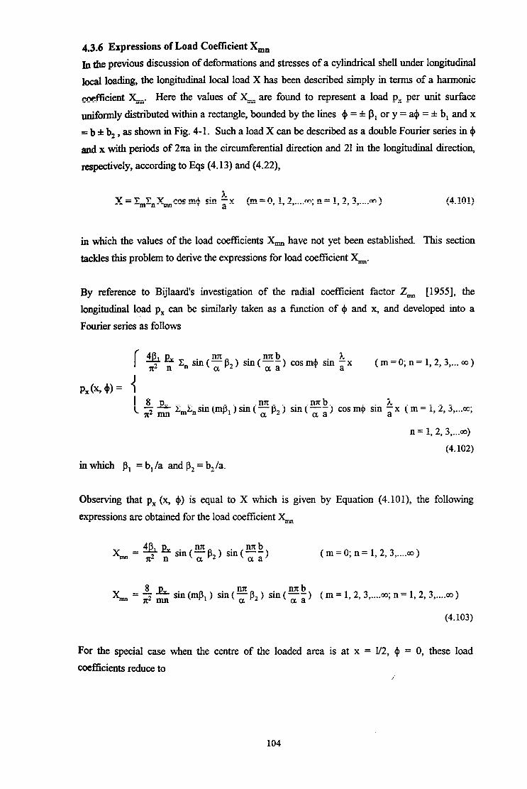
4.3.6 Expressions of Load Coefficient X,,
b the previous discussion of deformations and stresses of a cyh.ndrical shell under longitudinal
local loading, tbe longitudinal local load X has been described simply in terms of a harmonic
coefficient &,. Here the values of ;Y, are found to represent a load px per unit surface
uniformly distributed within a rectangle, bounded by the lines $ = f p, or y = a+ = f b, and x
5: b f b, , as shown in Fig. 4-l. Such a load X can be described as a double Fourier series in 4
and x with periods of 2za in the circumferential direction and 21 in the longitudinal direction,
respectively, according to Eqs (4.13) and (4.22),
X=&Z,&cosm+ sin ;x (m=O, 1,2 ,.... co;n= 1,2,3 ,.... 00) (4.101)
in which the values of the load coefficients X,, have not yet been established. This section
tackles this problem to derive the expressions for load coefficient X=.
By reference to Bijlaard’s investigation of tbe radial coefficient factor Z,, [1955], the
longitudinal load px can be similarly taken as a function of 4 and x, and developed into a
Fourier series as follows
r 9 ff C n Sill(E~2) sin(“Xb) cosm$ sin Lx a aa a ( m = 0; n = 1,2, 3,... co )
P&A)= (
c 8J&L ?r2 m &En sin (mP, 1 sin ( ff fJ2 ) sin (Fi) cos rn$ sin ix ( m = 1,2, 3,...co;
n = 1, 2, 3,...m)
(4.102)
in which PI = b, la and p2 = b,/a.
Observing that px (x, +) is equal to X which is given by Equation (4. lOl), the following
expressions are obtained for tbe load coefficient &
;Y, = 9 2 sin(zB2) sin(“Rb) aa ( m = 0; n = 1,2, 3 ,.... co )
L=$S sin(mP,) sin(zP,) sin(Fk) (m= 1,2,3 ,.... oo;n= 1,2,3 ,.... 00)
(4.103)
For tbe special case when the centre of the loaded area is at x = l/2, I$ = 0, these load
coefficients reduce to
104
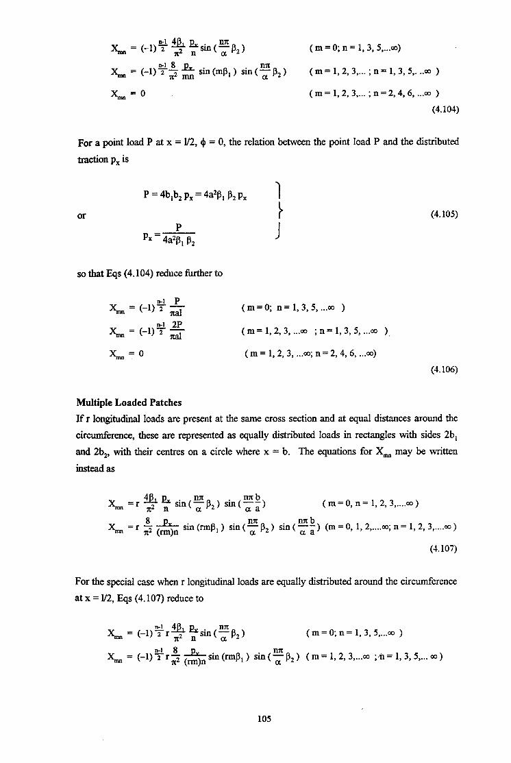
( m = 0; n = 1,3, $...a)
2& = (-l)Y$ $ sin(mpi) sin(Ep2) ( m = 1, 2, 3,... ; n = 1,3,5,. ..a )
L=O (m = 1,2, 3 ,... ; n = 2,4,6, . ..a0 )
(4.104)
For a point load P at x = l/2, + = 0, the relation between the point load P and the distributed
traction px is
or
P = 4b,b, px = 4a2B, P2 px I
1 P
px = 4a2j3, B2 I
so tbat Eqs (4.104) reduce fktber to
q = (-I)? -&
J& = (-I)+ 5
&=O
(4.105)
(m=O; n=l,3,5,...a, )
(m = 1,2,3, . ..a ; n= 1,3, 5, . ..a )
( m = 1, 2, 3, . ..a. n = 2, 4, 6, ..a)
(4.106)
Multiple Loaded Patches
If r longitudinal loads are present at the same cross section and at equal distances around the
circumference, these are represented as equally distributed loads in rectangles with sides 2b,
and 2b,, with their centres on a circle where x = b. The equations for X,, may be written
insteadas
& =r 9 2 sin(FPt) sin(nnb) aa ( m = 0, n = 1, 2, 3 ,.... 00 )
k =r 8P, n2 (mjn sin @Ml 1 sin ( a EP2) sin(ffi) (m=O, 1,2 ,.... oo;n= 1,2,3 ,.... CO)
(4.107)
For the special case when r longitudinal loads are equally distributed around the circumference
at x = l/2, Eqs (4.107) reduce to
& = (-l)Yr$$ %sin(FP2) ( m = 0; n = 1, 3, 5,...a1 )
& = (-l?+y$&pM-mp,) sin(Ffi2) (m=l,2,3 ,... 00 ;a=1,3,5 ,... ~0)
105

&=O ( m = 1,2, 3 ,... co ; n = 2, 4,6 ,... 00 )
(4.108)
For r concentrated loads P equally distributed around a circle at x = l/2, these expressions can
be reduced further to
&= (-l)?r-$- ( m = 0; n = 1, 3,5,... 00 )
& = (-l)$rz (m = 1, 2, 3,... w ; n = 1,3,5,...a )
G=O ( m = 1, 2, 3 ,... OJ ; n = 2,4,6 ,... 00 )
(4.109)
Computational technique
For all the above defined loading cases, the longitudinal load X and the three displacements w,
u and v cau be redefined by expanding into double Fourier series as follows, instead of Eqs
(4.101), (4.12), (4.26) and (4.27),
X = ZZ&,Lsin a .x cos (rm)4
w=~~~,f~(~x)c0s(rm)~
u=Xp,um(fx)COs(rm)~
h v=E,E,v,,(;x)sin(rm)$
(m = 0, 1, 2 ,.... co; n = 1, 2, 3 ,.... m ) (4.110)
(m = 0, 1, 2 ,.... w; n = 1, 2, 3 ,.... w ) (4.111)
(m = 0, 1, 2 ,.... 03; n = 1, 2, 3 ,.... w ) (4.112)
(m = 0, 1, 2 ,.... w; n = 1, 2, 3 ,.... w ) (4.113)
Comparison of all tbe above equations for displacements u, v and w as well as stress resultants
shows that if a table of the values of the functions fi (i x), II: ($ x) and vi (i x) is found for
each harmonic term, solutions for different amplitudes of terms can be easily deduced. Thus
many different load cases can easily be solved, once the individual harmonic terms have been
found. Multiple load cases can be solved also by substituting rm for m and retaining n in the
relevant equations. For the factors of We, umn and v~, by doing tbe same substitution of rm
for m, the corresponding result must also be multiplied by r.
106

4.4 COMPUTER EVALUATION FOR A CIRCULAR CYLINDRICAL SHELL
Following the derivation of expressions for the deflections, resultant forces and moments in a
&xlar cylindrical shell caused by longitudinal local loading, these formulas were evaluated
numerically.
A Fortran computer program was written, named LECS (Linear Elastic analysis of Cylindrical
Shells), with the aim of calculating the relevant displacements and stress resultants induced by
local loadings in a simply-supported cylindrical shell. The program includes functions for
analysing various loading patterns involving longitudinal, radial and circumferential loads and
longitudinal and circumferential moments as well as any combination of these individual
loading cases. The computed results from the actions of radial and circumferential loads were
compared with both Bijlaard’s results and predictions from a FELASH finite element analysis.
The comparison demonstrated a good agreement. In this section, it is not intended to present
these results for the cases when the shell is subjected to local radial or circumferential loads.
The main purpose is to use the above derived expressions to predict the displacements and
stresses of a example cylindrical shell which is simply supported at the two ends and subjected
to a local longitudinal patch load alone, in view of the fact that a cylindrical silo structure often
takes such a loading in service. Finite element calculations using the FELASH program suite
(PASHA and LEASH) were also performed for comparisons.
An example cylindrical shell was chosen with a unit thickness t=l, the radius-to-thickness ratio
a/t = 500 and the height-to-radius ratio l/a = 2.0. An equally distributed longitudinal load pX =
0.1 MPa was applied on the surface of the shell wall within a square with sides 2b, = 2b, =
0.2% ie. /3r = pz = 0.1, and with its centre at x = l/4, + = 0. The material of this elastic
cylindrical shell was taken to be steel with a Young’s modulus E = 2 x lo5 and Poisson’s ratio u
= 0.3. The total number of double harmonics m and n was taken as 100 respectively in the
calculations using both the LECS and LEASH programs. The ends of the cylindrical shell
were assumed to be simply supported with the same boundary conditions as expressed
previously in Sections 4.3.4 and 4.3.5. The displacements and stress resultants were calculated
for this simply-supported cylindrical shell under the local longitudinal load. All membrane
forces and moments were those per unit width of shell wall. Tensile forces were considered as
positive.
Predictions of the stresses and displacements in this sample cylinder were conducted, using
both the LECS program and the LEASH &rite element program. For a cylindrical shell
subjected to a longitudinal load symmetrically distributed to the generatrix at $ = 0 within a
local area, the membrane stress in the axial direction is significant compared with the other
107

stresses caused by this local load, and the circumferential displacement v is trivially small
compared with the displacements in the radial and axial directions. Thus the following
comparative studies mainly focused on the longitudinal (axial) membrane force and
circumferential bending moment and the axial and radial displacements, which are shown in
Fig. 4-2 to Fig. 4-9.
Figures 4-2 and 4-3 give the axial (longitudinal) membrane force N, caused by the local square
load in the shell wall. The former shows the dispersal of the axial membrane force N, along
the genera&ix at + = 0 whilst the latter shows the variations of N, in the circumferential
direction at differing heights. Comparing the results of N, predicted by LECS and LEASH, it
was found that they matched reasonably well both in value and in trend. In general, the LECS
results are higher than the LEASH ones. However, it can be observed from Fig. 4-2 that the
differences between the two results increases in the region adjacent to the edge of the loaded
area (x=200) to the end of the cylinder (x=0). At the end x=0, the LECS value is about 1.7
times as large as the LEASH value. The discrepancy between the results in that region from
these two adopted methods may be due to the fact that the loading area is closer to the end
(x=0) of the cylinder and the predictions are accordingly influenced by the boundary
conditions. It is also possible that some part of the discrepancy is attributable to the
differences between the Timoshenko shell theory used in this algebraic analysis and the
Sanders shell theory used in the finite element analysis LEASH.
The comparisons of the circumferential bending moment M,, along the generatrix at 4 = 0 and
at different levels in the cylinder are shown in Figs 4-4 and 4-5 respectively. Similarly the
axial displacement u and the radial displacement w are shown in Fig. 4-6 to Fig. 4-9. Again,
they also give similar findings to those for the axial membrane force N,. In summary, the
LECS and the LEASH results agreed fairly well, though in general, LECS gives slightly higher
values than LEASH does.
It can be concluded from the above comparative studies that the linear elastic solution of the
shell bending equations derived using the double Fourier series is applicable to practical design
and analysis, and would lead to slightly conservative (higher) results than the finite element
method.
108

4.5 SUM.MARY AND CONCLUSIONS
Algebraic expressions for the displacements and stresses in a circular cylindrical shell under
local longitudinal loadings have been developed in this chapter. A double Fourier series has
been used to express both the local loads applied to the shell and the displacements and stresses
induced by the local loads. These expressions for displacements and stresses have been
&cmnented for the case of simply supported boundary conditions at both ends of the shell.
The method discussed in this chapter is of a general nature and therefore can be applied to
other cases where a circular cylindrical shell is subjected to local loadings in any other
direction and may have different boundary conditions.
A computer program has been developed to evaluate the expressions derived in this chapter and
the results have been compared with those obtained from finite element analysis. A
satisfactory match has been found.
It should be noted that the algebraic method presented in this chapter is only applicable when
the local load is be applied away from the ends of the shell. However, present studies for
practical elevated silo structures are intended to start from a simple case - the discretely
supported cylindrical shell, where local loads from the discrete supports are assumed to be
applied immediately at the edge of the shell. To fulfil1 the main objective of this thesis, the
later chapters of the thesis are solely concerned with the analysis of discretely supported
cylindrical shells using the finite element method. Although this algebraic analysis has not
been used further in this thesis, it provides a useful basis for further studies of cylindrical shell
structures.
109

A L v h -h . t
\ .-.-. .-
2bl ‘\ /- Px Y,’
*\ ,’ ‘\.\ p ,/
t /.‘;/
‘\f .‘.1 \;I ___.______ $1. -.-.-.-.- -
D
a ;
it t
Fiure 4-l Cylindrical Shell under a Uniformly Distributed Longitudinal Load
110
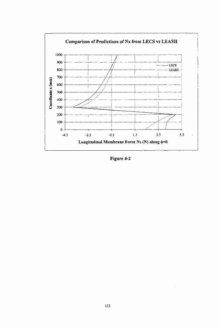
Comparison of Predictions of Nx from LECS vs LEASH
4.5 -2.5 -0.5 1.5 3.5 5.5
Longitudinal Membrane Force Nx (N) along $=O
Figure 4-2
111

1 /
..-.-+- ..-
-........~- ..-
1
I .i.
1
1 I
1
+ ]
!
1
! i.
!
!
I
I A_
! I
f
+
1 !
!
-.
1 /
1 !
&. !
*
!
c
1
! I
! ..- ___- ..- !
!
1
/ I . ..--‘.-.y-- ..-
..- -f _.... -__
!
!
! ..- +...-----
_..__
_ .._...
- -...
/ , .c- 1 ! 1 f i.- I ! 1 I .- 1 I ! I
.t._ I
! 1 .i.-
.I -
! ! 1
!
-i 4.. c
-....-..
-...._ I
- -...
Ty-- -.__
!
!
/
!
!
.&-
1
I
.+-
1
+--
!
1
&
P
- .._ +....--..-
- &...- - !
f
I ‘t- !
i
5
I
.+
1
!
/
i
-1 I
112

Comparison of Predictions of My from LECS vs LEASH
t i
; \_ / .\ :
3 700 ..--- -.A.- -eT.-..-...L .._.... ~, ; _li.
L! :~~-. ..- _..~_ - .._ I - -...i - --.I !\. i i\ /
-10 -5 0 5 lo 15 20 25 30 35
Circumferential Bending Moment My (Nmm) along $=O I
Figure 4-4
113

1 !
_-.--- 1 / ) 1 1 .--..-.---i 1 1 1
/ ‘-~---‘1 I
I
1 -_.. 4
1 1 1 I
-.-. f 1
I
] 1
g&J-.--
!
1
1
+-..c..-- I
1 !
j
q----
1 ! f 1 I
+.J- . . .._....
1
7
1 j ! t / 1 1
+.i ..__.... t -;- 1 / ! ! I !
1 ! I ___- 1 ) I 1
. . ..q 1 ! I I’
-f i
~“--t I t
1
! ..-j.-
1
1
!
I
]
1 .--7
!
!
7 /
!
1
1
I -j-
!
1
!
8
-g
I
1
I
!
+-
!
!
:r ..-.._ i ..-._.._. -_.- .+ ._..__,
/ 1 1 ! /
1 !
-...-..
1 I
1 -_..-.I -t
!
i
.$
i
! .+.
!
.._. -,_.
..-.__
..- _
-m
/
! ! .-.... i ..__..___.. a- - i _________
i /
_. i .~ _.
~
i . ..-I _.,.. .,_. >...’ 1 __/
,d / ..c i :
114
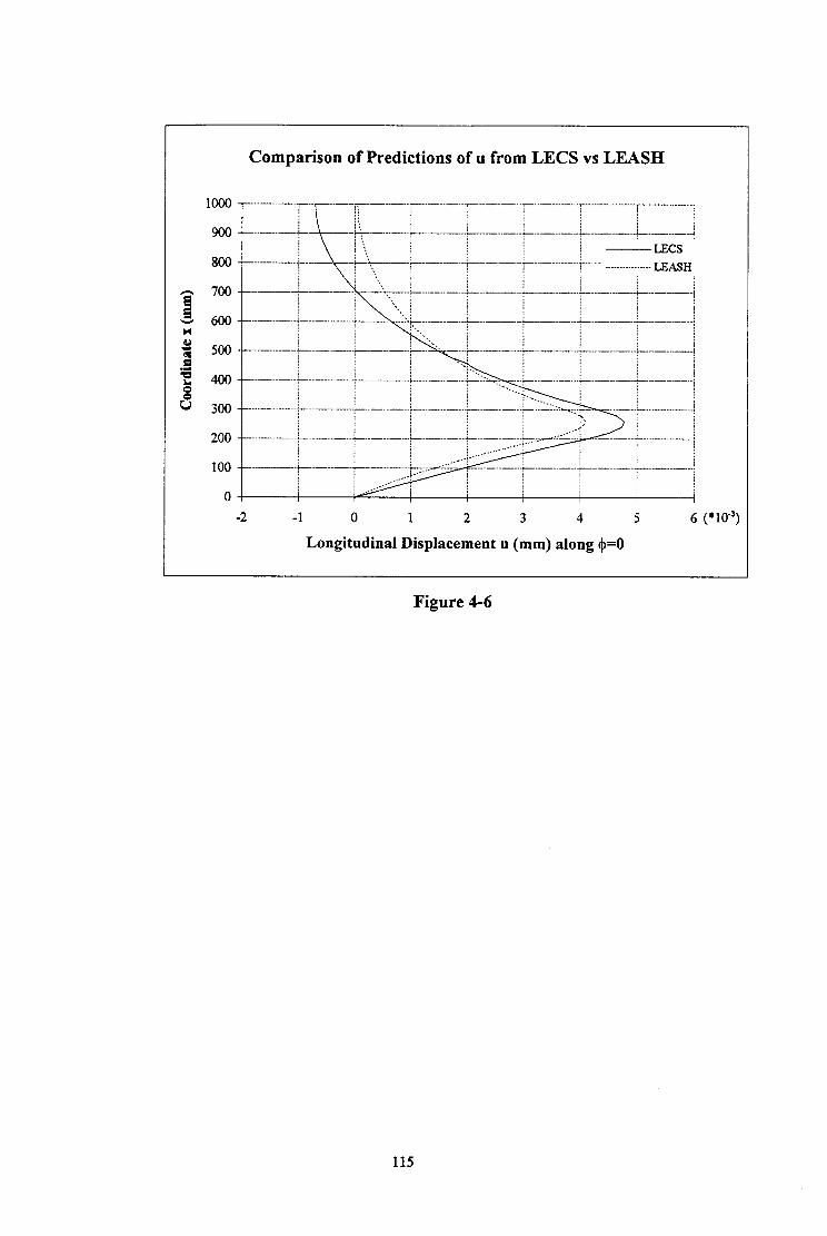
Comparison of Predictions of II from LECS vs LEASH
-2 -1 0 1 2 3 4 5 6 (*lo-‘)
Longitudinal Displacement u (mm) along $=O
Figure 4-6
115

A&- .._.... -
.-.g..- -..-.
-g-.- ..--
-.!$ _._.._ -.
. ..g+-. . -.
.q...- -.
.-g-..-- -.
..s&-.- -.
..s-.-- -.
lb-
116

1000
900
800
700
600
500
400
300
200
100
0
Comparison of Predictions of w from LECS vs LEASH
I!!! /
/ / . . . . . . . . . ,.: ; ~~~~-~~~
- +...-- __.. e....--*--..+..- _____ i _._.. -...li -... --.-.- _... -_.r- .___ -._!
.__.... -_ .~~ 1
- -.;.- _... -..i.-- .._ -j
.+-- -..+-.. -..j_- -.‘.-...-.i.-...-.
-_.-._- -..;_- -...- -.&-.--.:.- --j
I I I I I I 4 I
-6 0 6 12 18 24 30 36 42 48 54 60 66 (*lo”)
Radial Displacement w (mm) along $=O
Figure 4-8
117
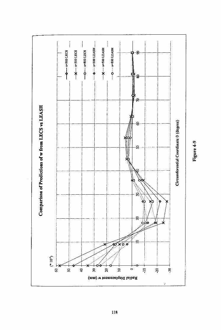
1
j
L
1
/
1 !
1
!
!
!
i-
1
1
!
/ i
!
! 1
!
j
t
!
I
1
I
c
I
t
f-
/
I
1 / c
!
!
!
L;
118

CHAPTER 5
LINEAR ELASTIC STRESS AND BIFURCATION ANALYSES OF DISCRETELY SUPPORTED PERFECT CYLINDERS
5.1 INTRODUCTION
It is widely accepted that the governing loading on the walls of metal silos is usually axial
(longitudina.l) compression, combined with circumferential tension, caused by the bulk solids
stored in silos. Large elevated silo structures are generally supported on a number of discrete
supports of finite width. The discrete supports induce high stresses adjacent to the support
termination. In particular, very high meridional membrane stresses arise above the support,
which can cause buckling of the shell at a load much lower than that for a uniformly supported
shell. Most elevated silos are thin shells so that the buckling behaviour is entirely elastic.
Practical field observations indicate that the governing failure mode of silos is frequently
buckling under axial compression.
Initial exploratory investigations [Teng and Rotter, 1989, 1990, 1991; Rotter et al, 1991;
Guggenberger, 1991; Rotter and She, 19931 of the buckling of elevated silos under axial
compression have focused on thin-walled cylinders directly supported on discrete supports of
finite width. The axial compression from bulk solids has been modelled by a uniformly
distributed downward traction on the cylinder wall. Because the loading from the support is
intense and local, the stresses decay rapidly away from the support, and when buckling occurs,
it is in a regime of very non-uniform stress. Studies of the linear elastic stress distribution and
the linear bifurcation mode are therefore very helpful in developing an understanding of the
problem.
Linear elastic bifurcation analyses of perfect cylinders are based upon small deflection theory
and yield linear buckling loads which usually provide an upper bound to the actual elastic
buckling strength. It is therefore difficult to develop design standards from them. However,
because of the much quicker computer running time when extracting buckling eigenvalues,
linear bifurcation analysis is still of value in providing a starting point for more complex
analysis and developing a basic understanding of the structural behaviour of practical silos in
an approximate manner.
119
To broaden current knowledge of the bifurcation behaviour of discretely supported perfect
cylinders, this chapter presents linear elastic pre-buckling stress and buckling eigenvalue
analyses, with special emphasis on the stress distribution immediately above the support and
the bifurcation loads of the cylinder under different loading patterns. The &rite element
analysis is performed by using the ABAQUS program package. The effects on the buckling
strength of many of the governing geometric parameters of the cylinder are also examined
5.2 FINITE ELEMENT MODELLING
All the numerical calculations of the study described here were performed using the finite
element program ABAQUS . The g-node quadrilateral shell element S9R5 available in
ABAQUS was chosen.
The discretely supported cylinder was assumed to have its discrete supports terminating at the
lower edge of the cylinder. The supports were assumed to be equally spaced around the
circumference of the lower edge. They were modelled as rigid supports, in which all the
displacements and rotations of the lower edge in contact with the supports were completely
restrained. Apart from the connections with supports, both the lower edge and the upper edge
were assumed to be restrained against both radial and circumferential displacements. Three
types of axial loading were applied to model extreme cases of practical loadings on the silo
walls from the stored bulk solids as shown in Fig. 5-l . These three are: a) a roof load:
uniform applied loading at the upper edge of the cylinder (as in a lab test), b) uniform wall
fiction: uniform shear pressure on the whole surface of the shell (the most serious case which
can arise in a silo structure), and c) a hopper load: uniform applied loading on the lower edge
of the cylinder (as from a hopper in a silo). The definitions of the three loading cases were
described in Section 1.6.2 of Chapter 1. For the purpose of this analysis, the whole cylinder
was divided into 2n symmetric individual sections, exploiting the geometric and loading
symmetry. For simplicity, any 1/2n section of the cylinder (Fig. 5-la) may be modelled for
finite element analysis instead of the whole shell, provided that the number of supports n is not
very large [Teng and Rotter, 199 1; She and Rotter, 19931. The boundary conditions for the
two vertical (meridional) edges of the modelled section are determined by symmetry
considerations. Very fine meshes were used for the analyses undertaken in this chapter,
especially in the areas near the support, in order to model the local stresses and deformations
effectively.
The geometry of the cylinder (Fig. 5-la) may be defined in terms of the following geometric
parameters: the radius-to-thickness ratio R/t, the height-to-radius ratio H/R,;.the support-width-
120
to-radius ratio d/R and the number of supports n. Many calculations were performed to
examine the effect of these parameters on the stress distribution and the buckling strength.
The cylinders were assumed to be linear and isotropic and made of steel with Young’s modulus
E = 2~10~ MPa and P oisson’s ratio v = 0.3. The results obtained can be applied to other
materials, though small errors are present if Poisson’s ratio is very different.
To illustrate the results in a manner which can be easily assimilated, the meridional membrane
stress arising in the cylinder a,+ is normalised by the classical elastic critical stress for a
cylinder under uniform axial compression CT~,. The total load applied to the cylinder at linear
bitkcation is presented in terms of the normalised mean meridional membrane stress above
each support, ie. crm/crc, . The relationships between this parameter and the applied loadings
have been given in Chapter 1.
5.3 PRE-BUCKLING STRESS ANALYSIS
In discretely supported perfect cylinders, linear bifurcation analysis [Teng and Rotter, 19911
has suggested that the buckling behaviour may mostly depend on the meridional membrane
stress distribution above the support. For cylinders on rigid supports, the highest meridional
membrane stresses occur in a zone slightly above the support termination instead of along the
extreme bottom edge, where strong restraints are present. The buckling deformations are
localised in the zone with the highest meridional compressive stress. The geometric parameters
of R/t, H/R, d/R and n were found to alter the rate of stress dispersal in the cylinder and lead to
significant changes in the buckling strength. This knowledge considerably assists the
understanding of buckling phenomena of practical silo structures.
The study described in this section is mainly focused on examining the effect of the position of
axial loading on the pre-buckling stress distribution (Fig. 5-la). Only the meridional
membrane stress arising above the support centreline is investigated because this dominates the
buckling behaviour. For all the cases analysed, the same total axial load was assumed to be
applied to the cylinders.
Figure 5-2 shows the vertical variation of the meridional membrane stress above the support
centreline in a cylinder on four discrete supports and subjected to the three types of axial
compressive loading. The three curves relate to the cases of roof load, wall friction load and
hopper load respectively. It can be observed that for the same total load applied, in general, the
roof load gives rise to the highest stresses above the support centreline, theihopper load brings
121

about the lowest and the wall friction load gives an intermediate result. In addition, the
highest stresses from the three loading cases are found to occur in the same region (0 < Z/t <
loo), and in a similar pattern. In this small region, the curve for uniform wall friction appears
to be very close to that for roof loading. This indicates that both the roof load and the wall
friction may induce nearly the same stress state adjacent to the bottom of the cylinder.
However, the hopper load curve is quite distant from other two curves. The reason why the
stresses from the hopper load are smaller is that this loading puts large parts of the cylinder
into meridional tension. In addition, some of the hopper load is transferred directly into the
support from below and never reaches the cylinder, as shown in Fig. 5-lb. Moving upwards
into the shell, the meridional membrane stress decreases rapidly within a short distance. The
rate of stress decrease is caused by dispersal of the stresses into a larger part of the shell and
further up, the rate of stress decrease becomes almost constant. At the upper edge, the wall
friction and hopper load curves both reach zero. This is because the wall friction load and the
hopper load have no effect on the stress there. By contrast, for the roof load, the stress
reaches the value of the load applied at the top edge of the shell.
As the height of the cylinder changes, the meridional membrane stress distribution above the
support centreline under these three loading patterns is observed to have the same form as
above, except in a very short shell. In a very short cylinder of HiR=O.2, the modified stress
dispersal is illustrated in Fig. 5-3. The form of the curves differs very much from the pattern
of Fig. 5-2, especially in the area close to the bottom edge of the cylinder. In that area, the
three curves show that the stress continues to increase approaching to the bottom edge even
though the support is rigid. Because of the short height and the higher stress at the lower edge,
the stress reduces throughout the whole height of the shell and is thus more non-uniform.
As the width of the support changes, the stress distribution pattern remains unchanged until the
support becomes very narrow or very wide. Normally the support width used in practical silos
lies between dR=O.O5 and d/R=O.3. Figures 5-4 and 5-5 show the stress distribution profiles
for the cases when a cylinder is supported on 4 very narrow supports with d/R=O.O5 and on 4
very wide supports with dR=O.3. It can be seen that a narrow support induces a very high
meridional membrane stress in the cylinder and changes the pattern of stress distribution
dramatically. In this case, the maximum stress occurs at the bottom edge rather than at a short
distance above the edge as shown in Fig. 5.2. By contrast, a wide support leads to relatively
low stresses in the small area above the support. The difference between the maximum stresses
due to the roof load and the wall friction increases with an increase in the support width as
shown in Figs. 5-2 and 5-5. The distance between the point where the maximum stress occurs
and the bottom edge of the cylinder is dependant on the support width. In general, a wider
122

support yields a higher position for the maximum stress. This also affects the bifurcation
buckling modes, illustrated in Figs. 5-10 and 5- 11.
The effect of the number of discrete supports on the stress distribution was also investigated.
The same conclusions were reached as those of Teng and Rotter [ 19911. As shown in Fig. l-
18a of Chapter 1, as the number of supports increases, the peak meridional membrane stress
induced in the cylinder declines rapidly in the small region near the bottom edge, and the
stresses become more uniform throughout the height of the shell. When there are many
supports, the stress distribution profile approaches that formed in a uniformly supported shell.
The effect of the thickness of the cylinder was also studied. The variation of the stress above
the support centreline was found to be similar to that obtained by Teng and Rotter [ 19911 as
shown in Fig. l-18b of Chapter 1. If the same total load is applied to the shell, as the radius-
to-thickness ratio R/t varies from 200 to 1000 (R remains constant whilst t varies), the
dimensionless meridional membrane stress above the support centreline alters slightly but its
distribution retains a similar pattern. For a very thin cylinder (R&1000), the highest stress at
a short distance above the support increases by around 10% over that for a thick cylinder
(R/t=200).
From the results obtained so far, it can be concluded that the type of loading applied to a
discretely supported perfect cylinder may alter the stress distribution significantly, and
therefore it is expected that it may induce significant changes in the buckling strength of the
shell.
5.4 BIJRJRCATION ANALYSIS
In this section, linear eigenvalue buckling loads were obtained using the ABAQUS program.
Only the lowest buckling load (i.e. the first eigenvalue) was calculated. The corresponding
buckling modes were also obtained.
5.4.1 Example Study
A perfect cylinder with R&500, H/R=2.0, d/R=O.2 and n=4 was initially used as an example.
Linear buckling eigenvalue analysis was conducted to examine the buckling behaviour of the
cylinder subject to the three axial load cases of Fig. 5-la. The initial loads, the corresponding
buckling eigenvalues, and the dimensionless mean buckling stresses are listed in Table 5-1. It
can be seen that, of the three loading cases, the roof load results in the lowest buckling load,
which is 1.6% and 25% lower than the ones calculated for the wall friction load case and the
123
hopper load case respectively. The buckling deformations in the cylinder under the three load
cases are found to be in a similar pattern. The buckle occurs in the zone of high and rapidly
varying stresses just above the support. The buckling mode in a cylinder subject to a roof load
is shown in Fig. 5-6.
The results from the bifurcation analysis are consistent with those from the pre-buckling stress
analysis described in Section 5.3. It demonstrates that the magnitude of the buckling load
varies with the magnitude of the maximum stress. A higher pre-buckling local stress induces a
smaller buckling load. Therefore, it is clear that the locally higher stress above the support is
crucial to the formation of the buckle and strongly influences the buckling strength of the
cylinder. In the next section, parameters which have been discovered to strongly affect the
stress distribution in the critical area are also examined to explore their influence on the
buckling strength.
5.4.2 Parametric Studies The cylindrical barrels of practical silos are generally thin shells with radius-to-thickness
ratios ranging between 200 and 1000, support-width-to-radius ratios between 0.05 and 0.3,
and shell height-to-radius ratios between 0 and 20. The parametric study in this section is
intended to explore the buckling behaviour and buckling strength of discretely supported
perfect cylinders of various geometries, characterised by R/t, d/R and H/R, which are varied
within the above ranges. Throughout the study, four discrete rigid supports are used to
support the cylinder.
The dimensionless mean meridional membrane stresses above the support at linear bifurcation
buckling are listed in Tables 5-2 and 5-3 and plotted in Figs 5-7 and 5-8, for the cases where
the cylinder has a higher aspect ratio (H&=2.0) and a lower aspect ratio (HiR=O.2)
respectively. In both cases, the radius-to-thickness ratios were chosen as 200, 500 and 1000
and the support-width-to-radius ratios as 0.05,0.2 and 0.3.
From the bifurcation analyses, it was discovered that the dimensionless buckling strength
generally varies inversely with both the radius-to-thickness ratio R/t and the support-width-to-
radius ratio d/R (Figs 5-7 and 5-8). For each set of R/t, d/R and H/R, the roof load case
always produces the lowest buckling load, wall friction leads to a slightly higher buckling load,
and the hopper load case produces the highest strength. All the buckling deformations are
found to occur in the highly stressed local area immediately above the support.
When the parameter R/t changes, the total load at buckling and the normalised mean buckling
stress above the support both reduce with an increase in R/t. Changes in the corresponding
124

buckling modes can be seen in Fig. 5-9. It is noted that more meridional buckling waves occur
in the buckle area for thinner cylinders but the waves get smaller in size with increasing R/t.
When the three loading cases are compared, the differences in strength between the wall
friction, hopper load and roof load are found to decline as R/t increases (Figs 5-7 and 5-8).
Variations in the support width, represented by the parameter d/R, induce notable changes in
both the strength and buckling deformation. As the support becomes narrower, the total
buckling load of the cylinder becomes smaller. When this is converted into the dimensionless
mean buckling stress above the support (using the Equation (1.5) or (1.6) of Chapter l), the
mean buckling stress is found to increase as the parameter d/R becomes smaller. As shown in
the stress analysis of Section 5.3, the large strength variation reflects the changes in the pre-
buckling stresses above the support termination. On the other hand, it is discovered that when
the support is very narrow with d/R=O.O5 or very wide with d/R=O.3, the strength differences
between the wall friction or hopper load cases and the roof load are much larger than the
differences for the situation where the support has an intermediate width with d/R=O.2. The
buckling modes for roof-loaded cylinders with d/R at 0.05, 0.2 and 0.3 and other parameters
R/t and H/R remaining at 200 and 2.0 respectively are shown in Fig. 5-l 0. The buckling
deformations are much more localised for narrow supports than for wide supports.
The effect of the height of the shell is found to be significant on both the buckling strength and
the buckling mode. Table 5-3 shows the same results as Table 5-2, but for a squat cylinder
(HR=O.2). The low aspect ratio changes the buckling strength very much and irregularly (Fig.
5-8), so that it is difficult to draw a general conclusion. Buckling modes under various loading
cases were examined and in general they illustrate similar patterns. For the roof load case,
buckling modes for various values of d/R and R/t are shown in Figs. 5-l 1 and 5-12
respectively. The different load cases are compared in Fig. 5-13, for a cylinder with R/t-500,
dR=O.2 and H/R=O.2. For the wall friction and hopper load cases, the centre of the buckle
area occurs near the middle of the cylinder, because the cylinder is so short that the entire wall
participates in the buckling mode. However, for the roof load case, the centre of the buckle
moves towards the top edge, indicating that the reduced restraint at this edge (no restraint
against warping at all) attracts the buckle, whilst the rigid support at the bottom edge restrains
it.
5.5 SUMMARY AND CONCLUSIONS
Linear elastic pre-buckling stress analyses and bitircation buckling analyses were conducted
for perfect cylinders which are rigidly supported on discrete supports. Only’ axial compression
125
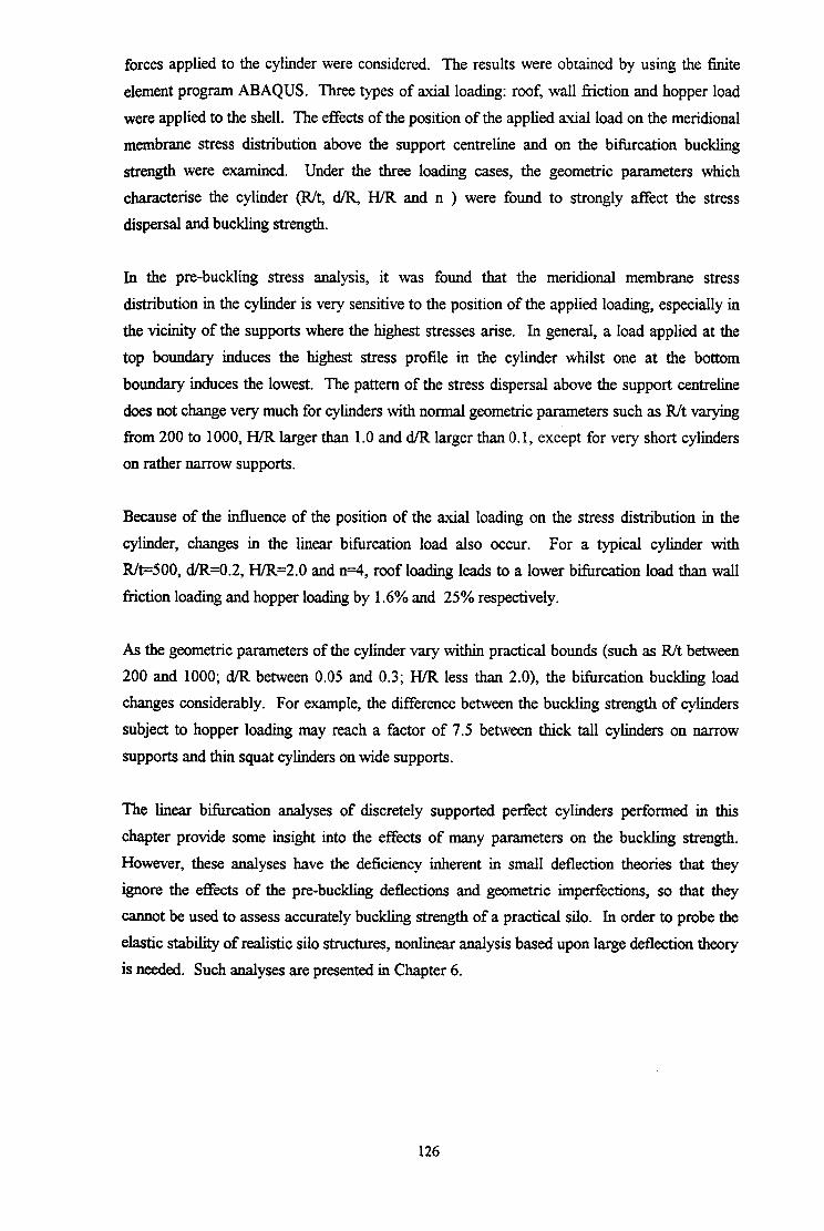
forces applied to the cylinder were considered. The results were obtained by using the finite
element program ABAQUS. Three types of axial loading: roof, wall friction and hopper load
were applied to the shell. The effects of the position of the applied axial load on the meridional
membrane stress distribution above the support centreline and on the bifurcation buckling
strength were examined. Under the three loading cases, the geometric parameters which
characterise the cylinder (R/t, d/R, H/R and n ) were found to strongly affect the stress
dispersal and buckling strength.
In the pre-buckling stress analysis, it was found that the meridional membrane stress
distribution in the cylinder is very sensitive to the position of the applied loading, especially in
the vicinity of the supports where the highest stresses arise. In general, a load applied at the
top boundary induces the highest stress profile in the cylinder whilst one at the bottom
boundary induces the lowest. The pattern of the stress dispersal above the support centreline
does not change very much for cylinders with normal geometric parameters such as R/t varying
from 200 to 1000, H/R larger than 1.0 and d/R larger than 0.1, except for very short cylinders
on rather narrow supports.
Because of the influence of the position of the axial loading on the stress distribution in the
cylinder, changes in the linear bifurcation load also occur. For a typical cylinder with
R/t=500, d/R=O.2, H/R=2.0 and n=4, roof loading leads to a lower bifurcation load than wall
friction loading and hopper loading by 1.6% and 25% respectively.
As the geometric parameters of the cylinder vary within practical bounds (such as R/t between
200 and 1000; d/R between 0.05 and 0.3; H/R less than 2.0), the bifurcation buckling load
changes considerably. For example, the difference between the buckling strength of cylinders
subject to hopper loading may reach a factor of 7.5 between thick tall cylinders on narrow
supports and thin squat cylinders on wide supports.
The linear bifurcation analyses of discretely supported perfect cylinders performed in this
chapter provide some insight into the effects of many parameters on the buckling strength,
However, these analyses have the deficiency inherent in small deflection theories that they
ignore the effects of the pre-buckling deflections and geometric imperfections, so that they
cannot be used to assess accurately buckling strength of a practical silo. In order to probe the
elastic stability of realistic silo structures, nonlinear analysis based upon large deflection theory
is needed. Such analyses are presented in Chapter 6.
126

t .
7
radial and circumferatial displacements restrained at top and bottom of
ziy””
load cylinder
hopper lw
vertical displacements restrained at rigid supports
I
x
1 ftiteelement model section
symmetric line A B
(a) Axially Compressed Cylinder on Discrete Supports
(b) Hopper Load Transference
Figure 5-l Discretely Supported Cylinder Model
127

Stress above Support Centreline for Different Load Positions (Rigid Supports)
n=4, M=500, d/R=O.2,H/R=2
-0.45 -0.4 -0.35 -0.3 -0.25 -0.2 -0.15 -0.1 -0.05 0
Meridional Membrane Stress G= Joel
Figure 5-2
Stress above Support Centreline in Short Cylinders (Rigid Supports)
n=4; Rk500; dlR=O.2;HlR= 0.2 - - Roofload
-0.35 -0.3 -0.25 AI.2 -0.15 -0.1 -0.05 0
Meridional Membrane Stress &, ,/ (Td
Figure 5-3
128

Stress above Support Centreline with Narrow Supports (Rigid Supports)
n=4, Rk500, dfR70.05, H/R=2
-1.8 -1.6 -1.4 -1.2 -1 -0.8 -0.6 -0.4 -0.2 0
Meridional Membrane Stress CT,,, + / CT~
Figure 5-4
Stress above Support Centreline with Wide Supports (Rigid Supports)
n=4, R&=500, dBO.3, H/R=2
- - - Roof bad
-0.3 -0.25 -0.2 -0.15 -0.1 -0.05 0
Meridional Membrane Stress G,,, + / 0,~
Figure 5-5
129

Bifurcation Buckling Mode for a Perfect Cylinder under Roof Load n=4, Rk500, d/R=0.2, H./R=2.0
Figure 5-6
130

*RoofLoad
-&- Wall Friction Load
-0- Hopper LOad
R/t
(a) d/R=O.OS
.I n 1 I 1 I I I I I 8 I I
0 100 200 300 400 500 600 700 800 900 1000
R/t
(b) d/R=o.2
~~I:~ -“““_
.I 2 6 E 1.5 -- 6 .I n 1 I I I I I I I I I I I
0 100 200 300 400 500 600 700 800 900 1000
R/t
(c) d/R = 0.3
Figure 5-7 Bifurcation Buckling Strengths of Perfect ‘Tall Cylinders under Three Loading Patterns (lWR=2.0, n=4)
131

----;.r.tl\
I I I I 0 , 1 I I , I I 0 100 200 300 400 500 600 700 800 900 1000
R/t
(a) d/R = 0.05
s 8- -0-RoofLoad
w 2 7--
-&- Wall Friction Load
U Hopper Load
.- a 2 2 .I R 1 1 I I I I I I I , -1
0 100 200 300 400 500 600 700 800 900 1000
R/t
(b) d/R=o.2
24 3.5 - -0- Roof Load
z --A- Wall Friction Load
-U- Hopper Load
.I n 0.5 , I I I , I I I b I I I
0 100 200 300 400 500 600 700 800 900 1000
R/t
(c) d/R= 0.3
Figure 5-8 Bifurcation Buckling Strengths of PerfectSquat Cylinders under Three Loading Patterns (H/R=O.2, n=4)
132

=:
x C .I
e
133

134

Linear Bifurcation Buckling Modes for a Perfect Cylinder : Changes with Support Width d for a Squat Cylinder
R/t = 1000, H/R = 0.2, n=4
(a) d/ R = 0.05 : narrow support
(b) d/R = 0.2 : intermediate support
(c) d/R = 0.3 : wide support
Figure 5-11
135

Linear Bifurcation Buckling Modes for a Perfect Cylinder : Changes with Cylinder Thickness t for a Squat Cylinder
H/R = 0.2, d/R=0.3, n=4
(a) R/t=200 : thick shell
(h) Rlt=500: intermediate shell
(c) R/t = 1000 : thin shell
Figure 5-12
136

Linear Bifurcation Buckling Modes for a Perfect Cylinder: Changes with Load Case
R&500, H/R = 0.2, d/R = 0.2, n=4
(a) Roof Load
(b) Wall Friction Load
(c) Hopper Load
Figure 5-13
137

Bifurcation Buckling Analysis for a Perfect Cylinder
n=4, R/t=500, dhGO.2, H&=2.0
Load Pattern Load Pattern Initial Load Initial Load
Roof Load Roof Load 0.04 0.04 N/mm N/mm
Wall Friction Wall Friction 0.0002 0.0002 N/mm”2 N/mm”2
Hopper Load Hopper Load 0.04 0.04 N/mm N/mm
Dimensionless Dimensionless Eigenvalue Buckling Strength Eigenvalue Buckling Strength
271.79 271.79 1.764 1.764
276.18 276.18 1.793 1.793
363.43 363.43 2.359 2.359
Table 5-l
138
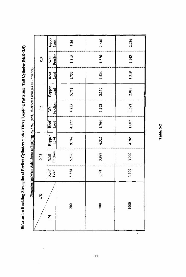
t3 B? & . . . . . . . . . .
f gj
. . . . . . . . . . k-c 2: h
b R-j L2- . . . . . . . . . .
: = .L 61 32
139
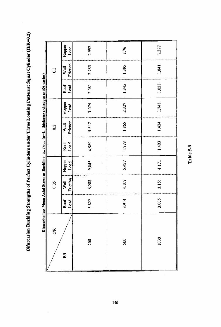
b 87 s! ? F 8s
9 A hl e4 A . . . . . . . . . . . . . . . . . . . . . . . . . . . . . . . . . . . . . . . . . . . . . . . . . . . . . . . . . . . . . . . . . . . . . . . . . . . . . . . . . . . . . . . . . . . . . . . . . . . . . . . . . . . . . . . . . . . . . . . . . . . . . . ....................
3 2 Q ii? 2 d m B Pi v-i l-i
. . . . . . . . . . . . . . . . . . . . . . . . . . . . . . . . . . . . . . . . . . . . . ..,...,...,,,..... . ,,..,... ““..,, . . . . . . . . . .* . . . . . . . . . . * . . . . . . . . . . . . . . . . . . . . . . . . . . . . . . . . . . . . . . . . . . . k-u 8” z d3 9 i? zi
0 c\l 4 2
g-0 z t- 00
#I
N 9 c? P I? e4 4
. . . . . . . . . . . . . . . . . . . . . . . . . . . . . . . . . . . . . . . . . . . . . . . . . . . . . . . . . . . . . . . . . . . . . . . . . . . . . . . . . . . . . . . . . . . . . . * . . . . . . . . . . . . . . ..I................................. .
c
gg:j v; 5 2 3 vi A
. . . . . . . . . . . . . . . . . . . . . . . . . . . . . . . . . . . . . . . . . . . . . . . . . . . . . . . . . . . . . . . . . . . . . . . . . . . . . . . . . . . . . . . . . . . . . . . . . . . . . . . . . . . . . . . . . . . . . . . . . . . . . . . . . . . . . . . . . . . . . . . . . .
*a 8 z!
&Id E
cz b ?
4 lA A
b-0 0
@
g ’ l- 4
G 2
0; vi 4
. . . . . . . . . . . . . . . . . . . . . . . . . . . . . . . . . . . . . . . . . . . . . . . . . . . . . . . . . . . . . . . . . . . . . . . . . . . . . ..*....................... . . . . . . . . . . . . . . . . . . . . . . . . . . . . . . . . . . . . . . . . . .
ti
2 Q
09
z s $; 4 +
\d + t-4
. . . . . . . . . . . . . . . . . . . . . . . . . . . . . . . . . . . . . . . . . . . . . . . . . . . . . . . . . . . . . . . . . . . . . . . . . . . . . . . . . . . . . . . . . . . . . . . . . . . . . . . . . . . . . . . . . . . . . . . . . . . . . . . . . . . . . . . . . . . . . . . . .
G-5 8”
63 s
d VI
z s ti m’ ti
140
CHAPTER 6
NONLINEAR ELASTIC BUCKLING ANALYSIS OF DISCRETELY SUPPORTED CYLINDERS
6.1 INTRODUCTION
The linear bifurcation analysis of cylindrical shells discussed in the previous chapter was based
upon small deflection theory and was only concerned with perfect cylinders under axial
compression. However, a practical silo structure may have geometric imperfections and
experience rather complex loadings. The results of the linear bifurcation analyses probably
provide only an upper bound to the buckling strengths of cylinders, and therefore these results
are of uncertain value for practical design. Precise prediction of the buckling strengths of
cylinders requires a large deflection analysis which can take into account the possible
geometric imperfections found in prototype structures.
Studies carried out by other researchers [Fhigge, 1932; Koiter, 1945; Donnell and Wan, 1950;
Budiansky, 1964; Hutchinson and Amazigo, 1967; Hutchinson et al, 1971; Narasimhan and
Hoff, 1971; Arbocz and Sechler, 1974; Brush and Ahnroth, 1975; Singer et al, 1980; Yamaki,
1984; Rotter and Teng, 1989, 19901 have shown that the strengths of cylindrical shells are
sensitive to the magnitude of initial imperfections in the shell surface. The size and shape of
the most detrimental imperfection may be that of a depression extending around the
circumference but over a short height. The buckling modes are relatively local and are directly
associated with the critical imperfection.
Although the governing failure mode in practical silos is buckling under axial compression,
many researchers [Weingarten et al, 1965; Lei and Cheng, 1969; Zyczkowski and Bucko, 197 1;
Fischer, 1963, 1965; Ahnroth, 1966; Hutchinson, 1965; Esslinger and Geier, 1977; Tennyson
et al., 1978, 1979; Kodama and Yamaki, 1983; Rotter and Teng, 19891 have discovered that
the buckling strength of a cylindrical shell is significantly increased by internal pressure on the
walls. When an axially compressed cylinder is internally pressurized, the tensile
circumferential membrane stresses arising in the wall reduce the effects of the geometric
imperfection and considerably enhance its buckling strength. To date, the study of this matter
has been confined to cylinders under uniform axial compression with uniform support.
Discrete supports were never considered.
141

It is widely accepted that the critical load for a silo cylinder is very dependent on the nature of
the geometric imperfections in the wall, the loading conditions, and the boundary conditions.
In order to reduce the discrepancies between the theoretical analysis and reality for these
&ects on silos, it is necessary to perform a geometrically nonlinear analysis.
This chapter presents some geometrically nonlinear elastic buckling analyses of perfect and
imperfect thin cylinders on discrete supports (Fig. 6-l). The finite element computer program
ABAQUS was used in the study. Studies of the effect of the axial loading position were not
only performed on perfect cylinders (Fig. 6-la) but also expanded to probe imperfect
cylinders (Fig. 6-lb & 6-1~). For imperfect cylinders, two types of axisymmetric geometric
imperfection (Fig. 6-lb & 6-1~) were assumed to model practical fabrication imperfections:
one with an inward shape, the other with an outward shape. The form of the inward
imperfection was chosen as the Type A shape used in previous studies [Rotter and Teng,
1989; Rotter and Zhang, 1990; Teng and Rotter, 1990, 1992; Rotter and She, 19931,
modelling a type of circumferential welded joint depression in a full scale silo. The outward
imperfection has an identical shape but the opposite amplitude. The location of the
imperfections was taken as the critical position, producing the lowest critical load at buckling
failure for a discretely supported cylinder with a local axisymmetric inward imperfection
potter and She, 1993; Rotter et al, 19931. A loading pattern of a uniform internal pressure
together with an applied axial load was used. The strengthening effect of the internal
pressurization on the elastic buckling of perfect and imperfect cylinders were examined. The
buckling behaviour, mode and strength of both unpressurized and pressurizcd cylinders under
axial compression were thoroughly investigated.
6.2 FINITE ELEMENT MODELLING
The finite element results presented in this study were obtained by geometrically nonlinear
elastic buckling analyses using the modified Riks method available in the ABAQUS finite
element program. The g-node doubly curved quadrilateral shell element type S9R5 which is
recommended by the ABAQUS User’s Guide [ 19911 for thin shell applications was again
adopted.
In the study, the same geometric model of a cylinder which was used in the linear analysis of
Chapter 5 (Fig. 5-l) was adopted and rigid discrete supports under the cylinder were again
assumed. For cylinders under axial compression alone, the three loading patterns (Fig. 5-l)
defined in Chapter 5 were again applied so that the structural behaviour could be compared
with those found in the linear bifurcation investigation of Chapter 5. For the pressurized
142

cylinders, the axial compression was applied only as a line load at the top boundary; the
internal pressure was assumed to be uniform on the wall (Fig. 6-2). This was studied in
Chapter 5 and found to lead to lower collapse load predictions than the other two (Fig. 5-l).
Hence it may be expected that the results obtained here under combined loads will provide a
lower bound to the real buckling strength.
It has been noted that four dimensionless parameters can be used to characterise the geometry
of a discretely supported petiect cylinder. These are the number of supports n, the radius-to-
thickness ratio R/t, the height-to-radius ratio H/R and the support-width-to-radius ratio d/R. In
the studies of imperfect cylinders, the imperfection was assumed to be both local and
axisymmetric. As described in Chapter 3, two further parameters are used to define the local
imperfection (Fig. 6-1~): the ratio Sdt of the imperfection amplitude 6, at the centre of the
imperfection to the cylinder thickness t and the ratio Zdt of the distance Z, from the centre of
the imperfection to the bottom edge of the cylinder to the cylinder thickness t. Both the inward
and outward imperfection shapes (Figs 6-lb and 6-1~) are intended to represent local severe
imperfections at a circumferential weld, which was assumed to resist flexural yielding
completely during cooling (Type A weld) [Rotter and Teng, 1989, 19911. The shape of the
local imperfection was defined by Rotter and Teng [ 1989, 19911 and has been given in Chapter
3a.s
6 = 6, edA [ sin (xdh) + cos(xz/3L) ]
z= Iz-ZJ
where 6 is the local amplitude of the imperfection at height Z above the bottom edge and h is
the linear elastic meridional bending half wavelength of the cylinder (~2.44 (Rt)iO).
Throughout this study, a single geometry was used for the cylinder, defined by R&500,
d/R=O.2, H/R=2 and n=4. The local imperfection amplitude was chosen as one wall thickness
(ie. S,,/t = 1). The centre of the imperfection was located at the critical position proposed by
Rotter and She [1993] in their recent nonlinear studies of cylinders (refer to Fig. 3-12 of
Chapter 3). That is
Zdt = 0.02 y [Iup = 103 (6.1)
Figure 6-1 illustrates the finite element models for the perfect and imperfect cylinders on four
discrete supports respectively. Symmetry was again exploited so that only one eighth of the
cylinder circumference was modelled.
143
The material of the cylinders was taken to be steel with a Young’s modulus E=2x lo5 MPa and
Poisson’s ratio v=O .3.
As previously indicated in Chapter 1, the strength of the perfect and imperfect cylinders was
characterised by the mean meridional membrane stress above the support, o,,,, divided by the
classical elastic critical stress for uniform axial compression oc,. The load versus deflection
curve is examined throughout the loading history so that the bifurcation behaviour can be
closely monitored. Here, the load is defined as the dimensionless mean meridional membrane
stress above the support, whilst deflection is referred to u/t or w/t, where u represents the
vertical displacement of the intersection point of the support centreline and the upper edge of
the cylinder and w is the normal displacement of a point near the centre of the buckle above the
support centreline for a perfect cylinder.
6.3 BEHAVIOUR OF PERFECT ELASTIC CYLINDERS
Various nonlinear analyses of perfect cylindrical shells have been carried out as described in
Chapter 3, but some further critical aspects, such as the position of the applied load and the
internal pressurization, have been ignored. Thus the research in this chapter begins by
investigating the influence of these two aspects on perfect cylinders in order to obtain a
comprehensive rmderstanding of practical elevated silo structures.
6.3.1 The Effect of the Position of the Applied Axial Compression Load
A perfect cylinder, solely under axial compression, was first examined with R/t=500, dR=O.2,
HAG2.0 and n=4. The three loading patterns previously described, roof, hopper and wall
friction loads shown in Fig. 5-1, were again used. The bifurcation behaviour and the buckling
mode and strength of a perfect cylinder under the three loading cases were studied.
Because the shell is a two dimensional surface, curved in the third dimension, the deflection of
the shell may be characterised by many different measures. The measures chosen here are
judged to be those which present the clearest picture of the behaviour: these are the vertical
displacement of the top of the shell above the support centreline and the radial displacement of
a point situated at the centre of the initial buckle. The latter is easily understood, but the
vertical displacement at the top of the shell is sometimes far from the applied load, especially in
the case of hopper loading. It was chosen because it is far from the local support, and its
displacement effectively integrates the membrane strains and arc length changes through the
complete buckle.
144
The load-deflection curves for these two displacements are shown in Fig. 6-3 and Fig. 6-4. It
can be observed that both the vertical and radial displacements are very small until the load
rises to the bifurcation point, when a single buckle occurs in a local zone above the support.
Large displacements follow as the single buckle progressively grows. As expected, the three
types of axial loading produce similar bifurcation behaviour but occur at different bifurcation
loads. The hopper loading leads to the highest critical load, the roof loading the lowest and the
wall friction loading a value between them. This exhibits the same feature as that discovered in
the linear bifurcation analyses of Chapter 5. The values of these critical loads, which are listed
in Table 6-1, are generally around 0.6 of the linear bifurcation load for the same geometry.
The buckling modes for the three loading patterns display a similar profile. Only one buckle
appears above each support. This corresponds to a single bifurcation point on the load versus
displacement curve. Figure 6-5 shows the deformed shape of the roof-loaded cylinder at the
point A on the load deflection curve of Figs 6-3 and 6-4.
6.3.2 The Effect of Internal Pressurisation
A uniform internal pressure p was applied to an axially compressed cylinder. In the study, the
dimensionless parameter p* was used. It has been defined in Chapter 1 as
where p is internal pressure, R the radius of the cylinder, t the thickness of the cylinder, and a,,
the classical elastic critical stress for a perfect cylinder under uniform axial compression. For
each value of p* (which was incremented from 0.1 to 1.5), the bifurcation behaviour and
buckling modes of an axially compressed cylinder were carefully explored. The axial
compression on the cylinder was represented by a uniformly distributed roof load.
The relationship between the normalised mean stress above the support and the dimensionless
axial displacement at the top of the shell is shown in Figs. 6-6, 6-7 and 6-8 respectively, as the
dimensionless internal pressure p* progressively increases from 0.0 to 1.5. When the structure
is subjected to only small internal pressures (0 I p* I 0.2) (Fig. 6-6), a sharp bifurcation and
reversing axial displacements are found. The shape of the relevant load versus displacement
curve does not change discernibly for low-pressurized cylinders (0.0 < p* I 0.2), but the
increase in strength is marked. As the internal pressure rises (p* 1 0.4) (Fig. 6-7), further
increases in strength are found. No reversal of axial displacements is seen in the post-buckling
zone and the shape of the load-displacement curve changes markedly, becoming flatter and
smoother. At higher levels of pressurization (p* > 0.8) (Fig. 6-8), no obvious bifurcation point
is observed on the curve.
145

In Fig. 6-8, it is noticeable that the pre-buckling axial stiffness is much lower for a cylinder
with no internal pressure than for cylinders with internal pressures in excess of p* = 0.4. This
changing pre-buckling stitiess, taken from the curves in Fig. 6-8 is plotted in Fig. 6-9. The
reduced axial stifli~ess in unpressurised perfect cylinders in the pre-buckling phase appears to
be caused by a non-linear geometric effect as the shell displaces inwardly just above the
support. This explanation is reinforced by the observable curvature of the load-deflection
curve and the significant change in sti&ess from a load level of crm/b,, = 0.2 to ~,Jcr~, = 1.0
(Fig.6-9).
A further interesting phenomenon may be observed in Fig. 6-10. The buckling strengths
associated with internal pressurisation are depicted in this figure. The strengthening effect of
internal pressurisation can be seen to cause a progressive increase in strength throughout the
studied range 0 I p* I 1.5. For a uniformly compressed perfect cylinder, there is effectively no
change in buckling strength as a result of internal pressurisation (Fig. 1-17) potter and Teng,
19891. The strength gains due to pressurisation relate entirely to a reduction in the
imperfection-sensitivity of imperfect cylinders (Fig. 1-17). By contrast, for locally supported
cylinders, even perfect cylinders display a strong increase in strength in the elastic range (Fig.
6-10). This is caused by the f&t that the pre-buckling stress state for locally supported
cylinders involves high local circumferential membrane stresses which cause strength
reductions comparable with those of geometric imperfections. The internal pressure
progressively reduces the circumferential compressions, leading to a considerable strength gain,
with no obvious limit.
The deformed shapes of the cylinder at maximum load for several pressurised perfect cylinders
are shown in Fig. 6-11 for the cases of p* = 0.1, 0.6 and 1.5, respectively. These deformed
shape are at the points indicated as A, B, and C on the corresponding load-displacement curves
shown in Fig. 6-8. At very low internal pressures, the buckle occurs locally at a small distance
above the base of the cylinder and its mode is similar to that for the unpressurized cylinder.
This is consistent with the observation from the load-displacement curves shown in Fig. 6-6.
As the internal pressure increases, these buckles become shorter in the axial direction and
closer to the local support. By contrast, they extend in the circumferential direction. This
change in the form of the buckles with internal pressurisation is identical to that observed
experimentally in uniformly compressed cylinders subject to internal pressurisation. However,
the prebuckling deformations which trigger the buckle in this instance are quite different in
form from the geometric imperfections of the uniformly compressed cylinder, and this suggests
that these buckle forms, ostensibly interchangeable with others on the Koiter circle, are in
reality preferred buckle shapes.
146

At high internal pressures, the buckle is much more locally located in the zone of local bending
immediately above the discrete support. In such a zone, the circumferential membrane and
bending stresses are amplified by the axial compression and the restraint of the local support,
and thus may induce local yield in the cylinder wall. Therefore, the buckling strength may be
affected by local yielding, presenting a similar mode to an “elephant’s foot” buckling mode
which was discussed in Chapter 2. This problem is discussed again in the context of elastic-
plastic behaviour in Chapter 7.
6.4 BEHAVIOUR OF IMPERFECT ELASTIC CYLINDERS WITH
A LOCAL INWARD AXISYMMETRIC IMPERFECTION
Studies carried out by Teng and Rotter [ 1990, 19911 have indicated that circumferentialiy
welded joint imperfections may play an important part in the imperfection-sensitivity of
practical silo structures. A range of imperfection shapes was studied: the findings allow us to
focus attention on imperfection forms which lead to low strengths whilst having a practical
imperfection form. Thus it is possible to produce useful and reliable research results for
practical engineering purposes.
In this section, an inward axisymmetric imperfection form, as shown in Fig. 6-lb, was
examined, similar in form to those measured in full scale silos by Ding et al [ 19921. An
imperfect cylinder with an imperfection amplitude of one wall thickness (S,,/t = 1) placed in the
critical location found by Rotter and She [ 19931 was studied here.
6.4.1 The Effect of the Position of the Applied Axial Compression Load
The load-displacement curves for the three axial compression load cases are illustrated in Fig.
6-12. These curves have a similar shape to one another but significantly differ from those of
the perfect cylinder shown in Fig. 6-4. No bifurcation is observed. Before the load reaches the
maximum value the vertical displacement of the studied point remains small. When the
maximum load is exceeded, the displacement grows rapidly whilst the axial load decreases only
slightly. This response is similar to that previously shown in Fig. 3-6 of Chapter 3 for
cylinders under wall friction loading [Rotter and She, 19931: the behaviour is not affected by
the way in which the axial compression is introduced.
By comparison with the strengths in Table 6-l for perfect cylinders, the introduction of a
geometric imperfection is found to cause a significant reduction in the buckling strength. For
this particular geometry, the reduction in the buckling strength may be as much as 44% for the
cases of roof loading and wall friction loading and 33% for the case of hopper loading.
147

The deformed shapes for the three loading cases were very similar. The buckling mode of a
cylinder subject to roof loading (point C in Fig. 6-12) is shown in Fig. 6-13. The buckle
occurs in the zone where the inward imperfection has been introduced, leading to a substantial
increase in the amplitude of the differences between the deformed and the perfect geometries.
6.4.2 The Effect of Internal Pressurisation
The strengthening effect of internal pressurization on the buckling strength was explored next.
Internal pressure was applied first, and the axial compression then progressively applied to a
cylinder with an inward local axisymmetric imperfection (Fig. 6-lb),
The relation between the axial load and the axial displacement at the top of the cylinder is
shown in Fig. 6-14. For all the values of p* studied, the shape of the curve is similar. No
bitkation points occur on the curves. The corresponding relationship between the maximum
strength and the internal pressure is shown in Fig 6- 15, where it can be compared with that for
a perfect cylinder. The curve is particularly interesting when compared with the corresponding
behaviour of uniformly compressed cylinders (Fig. 1-17). It was noted previously that internal
pressure leads to increases in the buckling strength of perfect locally supported elastic
cylinders (Fig. 6-lo), though it does not significantly alter that of uniformly supported elastic
cylinders. The strengths of both locally and uniformly supported cylinders are reduced by a
local inward imperfection (Figs. 3-l 1 and l-16), because the inward imperfection causes
compressive circumferential membrane stresses. It is therefore reasonable to suppose that the
effect of internal pressure on an imperfect elastic locally supported cylinder might be to
increase its strength progressively until it approaches that of a perfect cylinder.
By contrast with the above speculation, it is found (Fig. 6-15) that, for locally supported
cylinders, the strength of a pressurised elastic imperfect cylinder increases faster than that of a
perfect cylinder, and higher strengths are attained by the imperfect than by the perfect cylinder
when the pressurisation exceeds p* = pR/to,, = 0.6. This surprising condition deserves further
investigation. The load-deflection curves of perfect and imperfect cylinders for the case of
p*=O.6 are compared in Fig. 6-16, where it may be seen that the maximum loads are very
similar. It is evident that, although the calculated strengths are almost identical, the load-
deflection curves are quite different, with a strong bifurcation and a weakening post-buckling
path clearly visible in the perfect cylinder, whilst the imperfect cylinder displays a stable post-
buckling response, and indeed reaches the maximum load at much larger displacements. It is
clear that at high internal pressures, this is a problem in which the minimum of the post-
buckling curve for a perfect cylinder is very different from the strength of an imperfect
148

cylinder. At very large amplitudes, the imperfection may function as a reinforcement ring or
corrugation which resists rather than induces buckling.
The buckling modes at the indicated points A and B on the curves for p* = 0.6 and 1.5 (Fig. 6-
14) are shown in Fig. 6-17. Inspection of the buckling modes shows that, as the internal
pressure increases, the buckle centring in the imperfect area above the support becomes shorter
in the axial direction, wider in the circumferential direction and slightly closer to the support.
At higher internal pressures, very large deformations in the zone adjacent to the support are
seen. This demonstrates that the critical position for the imperfection is moving downwards.
As discussed by Rotter [ 199 11, the local yield may occur in that zone, affecting the buckling
strength of the structure if the level of internal pressurization is high.
6.5 BEHAVIOUR OF IMPERFECT ELASTIC CYLINDERS WITH
A LOCAL OUTWARD AXISYMMETRIC IMPERFECTION
Although outward local imperfections are less common than inward forms, outward
imperfections do occur, and a study of their effect is valuable to assist with an understanding
of the buckling behaviour. The following study is similar to that conducted in Section 6.4, but
considers an imperfect cylinder (Fig. 6-1~) with the same imperfection magnitude and location
as previously introduced but with an outward instead of an inward local defect. No previous
study of an outward imperfection near a local support is known.
6.5.1 The Effect of the Position of the Applied Axial Compression Load
The load-axial shortening curves for the three different load cases of Fig. 5-l are shown in Fig.
6-18, for axial loading without internal pressure. The three load-displacement curves show a
very different response from those for cylinders with an inward imperfection (Fig. 6-12), but
are similar to those for a perfect cylinder (Fig. 6-3). Bifurcation points appear on the curves
with one bifurcation point on each curve. The values of the corresponding bifurcation loads
are listed in Table 6-l and shown in Fig. 6-19. These are larger than those for the inward
imperfection cylinder by about 13 % for the cases of roof load and wall friction load and by
about 5 % for the case of hopper load. They are smaller than those for the perfect cylinder by
about 37 % for the cases of roof load and wall friction load and by about 30 % for the case of
hopper load. It reveals that, apart from the magnitude and position of the imperfection, the
imperfection form is a very influential factor which affects the structural behaviour and
buckling strength of locally supported cylinders.
149
The buckling mode at Point A on the load-displacement curve shown in Fig. 6-18 is shown in
Fig. 6-20 for a roof-loaded cylinder with an outward axisymmetric imperfection. The buckle is
centred a short distance above the centre of the imperfection rather than effectively at the
centre, as in the cylinder with an inward imperfection (Fig. 6-13). This mode reflects the
changed state of stress caused by the outward imperfection around the area of imperfection.
By contrast with the stresses associated with the inward imperfection (Fig. 2-2b), the outward
imperfection gives rise to tensile circumferential stresses near the centre of imperfection and
compressive circumferential stresses above and below the centre. In an axially compressed
cylinder, a tensile circumferential stress in the buckle area helps to resist buckling, whilst a
compressive circumferential stress helps to promote buckling [Calladine, 19831. Based upon
this principle, it may be supposed that buckling will occur in an imperfect cylinder at the point
where detrimental compressive stresses in both the meridional and circumferential directions
co-exist. For this cylinder with an outward axisymmetric imperfection, this area is found
above the centre of the imperfection, as indicated by the contour of meridinal stress at buckling
shown in Fig. 6-20b.
6.5.2 The Effect of Internal Pressurisation
The nonlinear elastic buckling behaviour of cylinders with local outward axisymmetric
imperfections and subject to internal pressure together with axial compression load applied
along the top edge of the cylinder was then analysed.
The load-deflection curves for cylinders with different levels of internal pressure are shown in
Fig. 6-2 1. As soon as the internal pressure rises above zero, the behaviour is similar to that for
the inward imperfection (Fig. 6-14). The buckling modes of pressurized cylinders display the
same changes with internal pressure, as shown in Fig. 6-22a and 6.22b. The centre of the
buckle moves to below the centre of imperfection in pressurised cylinders. As described in
Section 6.5.1, the buckle occurs above the centre of the imperfection at p* = 0 (Fig. 6-20),
because circumferential compressions occurs above and below the imperfection, and above is
the worst for p * = 0. For the cases when p * > 0, because of internal pressure, the worst
position shifts to below the centre of the imperfection, thus the buckle occurs below the centre
of the imperfection (Fig. 6-22~).
The load-deflection curves of Fig. 6-21 all show a more complex post-peak behaviour. The
curve for the case of p*=O.4 is separately drown in Fig. 6-23, and Figure 6-24 shows the
corresponding deformed shapes at the different points A, B C and D marked on the curve of
Fig. 6-23. The early part of the curve is almost linear, but deformations below the
imperfection grow in a non-linear manner (Fig. 6-24), leading to a peak in the load-deflection
curve at point B. Thereafter, the deflections in the buckle below the impetiection continue to
150

grow, but a bifurcation occurs above the imperfection, causing the load-axial shortening curve
to reverse, with reducing loads and reducing deformations, similar to those in uniformly
compressed perfect cylinders potter and Teng, 19891, but more strongly marked. Following
the bifurcation, the load stabilises and the displacements grow again (Point D),
The changes in the buckling strength with internal pressure are shown in Fig. 6-25, where they
are compared with those for perfect cylinders and cylinders with an inward axisymmetric
imperfection. The strength gains are generally smaller than those for an inward imperfection,
and the strength is always lower than that of the perfect cylinder.
6.6 SUMMARY AND CONCLUSIONS
The nonlinear analyses carried out in this chapter concerned the elastic buckling of discretely
supported thin cylindrical shells under axial compression. The study examined shells which
were both geometrically perfect and imperfect, and both unpressurized and pressurized. The
geometric parameters of the shells were kept constant at R&500, H/R=2.0, d/R=O.2 and n=4.
A rigid discrete support for the cylinder was assumed. Two local axisymmetric imperfection
forms, one with an inward shape and the other with an outward shape, were chosen and placed
at a detrimental position on the basis of the studies described in Chapter 3. Three types of
axial compression loading were studied to explore the sensitivity of the buckling behaviour,
mode and strength to the position of the applied loading. The effect of internal pressurization
on the nonlinear behaviour and elastic buckling of a discretely supported cylinder under axial
compression was explored.
It was found that the position of the applied axial load has only a small effect on the buckling
behaviour and buckling mode of a locally supported cylinder on discrete supports. However,
the changes in buckling strength with load position are remarkable. The roof loading case
leads to the lowest strengths. The difference between this and wall friction loading is generally
around 2% and between roof loading and hopper loading is generally around 22% for perfect
cylinders. This trend in the buckling loads is the same as that found in the linear bifurcation
analyses of perfect cylinders described in Chapter 5.
The sensitivity of the buckling strength to the position of the applied load may or may not be as
strong for an imperfect cylinder as that for a perfect cylinder, depending on the pattern of the
imperfection form. For an outward imperfection, the increase in buckling strength over the
value for roof loading is about 3% for wall friction loading and 44% for hopper loading. For
an inward imperfection, the corresponding increases are about 3% and 55%. Thus, hopper
151

loading always produces very high strengths compared with other load cases, which are very
Similar.
The geometric imperfection, whether inward or outward, results in a notable reduction in the
buckling strength. The imperfection form affects both the buckling strength and the buckling
behaviour. With an imperfection of amplitude of one wall thickness (S& = 1) placed at the
critical height 2, for inward imperfections with wall friction loading, strength reductions
relative to the value for a perfect cylinder of about 40% were found for the inward imperfection
form and about 34% for the outward imperfection.
Previous studies of geometrically imperfect elastic axially compressed cylinders weingarten et
al, 1965; Lei and Cheng, 1969; Zyczkowski and Bucko,l971; Fischer, 1963, 1965; Almroth,
1966; Hutchinson, 1965; Esslinger and Geier, 1977; Tennyson et al., 1978, 1979; Kodama and
Yamaki, 1983; Rotter and Teng, 19891 showed that internal pressure reduces the imperfection-
sensitivity and increases the buckling strength significantly. In this first-ever study of the
effects of internal pressure in discretely supported cylinders, the same effect has been found,
and has been shown to vary according to the form of the imperfection. However, contrary to
the findings for uniformly compressed cylinders, the buckling strength of a perfect locally
supported cylinder has also been found to be considerably increased by internal pressure.
For a perfect cylinder, the buckling behaviour and mode do not change significantly from the
unpressurized case until the internal pressurization reaches a high level. For an imperfect
cylinder with inward imperfections, the buckling behaviour remains similar as the internal
pressure increases. However, for a cylinder with an outward local imperfection, the internal
pressure seriously alters its behaviour and buckling mode from the case of axial compression
alone. The buckling modes are very local in the zone immediately above the support. Only a
single buckle has been found for the chosen cylinder geometry and relatively narrow supports
used in the study.
Although the internal pressure can significantly enhance the buckling strength, the governing
failure mode of a cylindrical silo is generally buckling under axial compression. From this
study it is still difficult to produce a general proposal for estimating the strength gains due to
internal pressurization. This is because high internal pressures give rise to severe local bending
near the base of the cylinder and local yielding may then precipitate a buckling failure.
Therefore, it is vital that the present study is extended to cover elastic-plastic behaviour before
practical design proposals are formulated.
152

u)
'"--r---- e-b-__ -t
153

P-4 line bad
la&lial ad Izimlmferential
displm r&rained at top
and bottom of cyhder
finite element model section
I 1 1 I
symmetric line A B
Axially Compressed Pressurized Cylinder on Rigid Supports
Figure 6-2
154

Load-Deflection Curves for Perfect Cylinders under Axial Compression
n=4, Rlt=500, d&=0.2, H/R=2 _.__.___.... - - -r---- -.... _..._..._. - -
-Roofload f
1: y-;-;;;;;;; load ]i
. Max. load ..-...- -.. 1
-;
..- - -..+. -.... - ..-.. -...-..1
! “-.‘..-.y- ..-...-....-... -__j
j I
..- -f..- --....-...-..- ---.--I
..___._...___.... -....-.+ ....I_._._... -_._-_._-...-I ,
1 I
0 0.5 1 1.5 2
Axial Displacement at Top Edge above Support Centreline u/t
Figure 6-3
1.6 !z 4
1.4
‘;: 0.4 I E 0.2 .- n 0
I Load-Deflection Curves for Perfect Cylinders under Axial
‘Compression n=4, Rk500, dfR=O.2, H/R=2
- . Wall tiiction load
0 2 4 6 8 10 12
Radial Displacement at Z&t=103 above Support Centreline
14
Figure 6-4
155

Buckling Mode for A Perfect Cylinder under Roof Load n=4, Rk500, d/R=0.2, EUR=2.0
Figure 6-5
156

3 P . . . . . . . . . . . . . .
. . . . . . . . . . . . . . . . .
, i
z ___. . . . . . . . . . . . . . . . .
_. . . . . . . . . . . . . .
. . . . . . . . . . . . . .
: . . . . . . . . . . k
pop0 poddns a,ioqa ssa.x$g naaM ssapo!snam!a
157
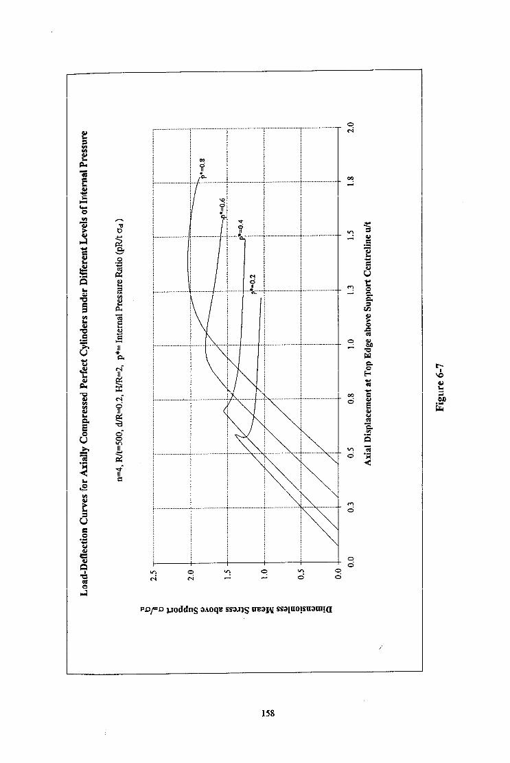
; __ . . . .
i --A----
pD/m~ poddns aaoqa ssaJ)g rraaH ssapo!snam!a
158

y! ii *a
____. _ . . . . . . . . . . . . . . .
1 ve
. . . . . . . . . .
1
.-.. .
. . . . . . . . . . .-. . . . . . . .
__.._ . . . . . . . . . . . . . . . . 9 i h ._ ____ . . . . . . . . . .
\ \ . _. . . . . . . Q
. . . . . . . . . . \ \ . . . . . . \ \ \ h
PQ~ poddns aaoqe ssaJ)g mat\I ssalaoymn!a
159
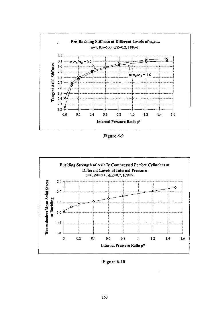
Pre-Buckling Stiffness at Different Levels of q,,/c~,~ n=4, R&500, cMGO.2, HiR=2
z p 3.0 3 2.9 z 3
2.8 4 2.7
z 2.6 &I 2.5 $ 2.4
2.3 2.2 I I I I
0.0 0.2 0.4 0.6 0.8 1.0 1.2 1.4 1.6
Internal Pressure Ratio p*
Figure 6-9
Buckling Strength of Axially Compressed Perfect Cylinders at Different Levels of Internal Pressure
n=4, R&500, d/R=O.2, H/R=2
0 0.2 0.4 0.6 0.8 1 1.2 1.4 1.6
Internal Pressure Ratio p*
Figure 6-10
160
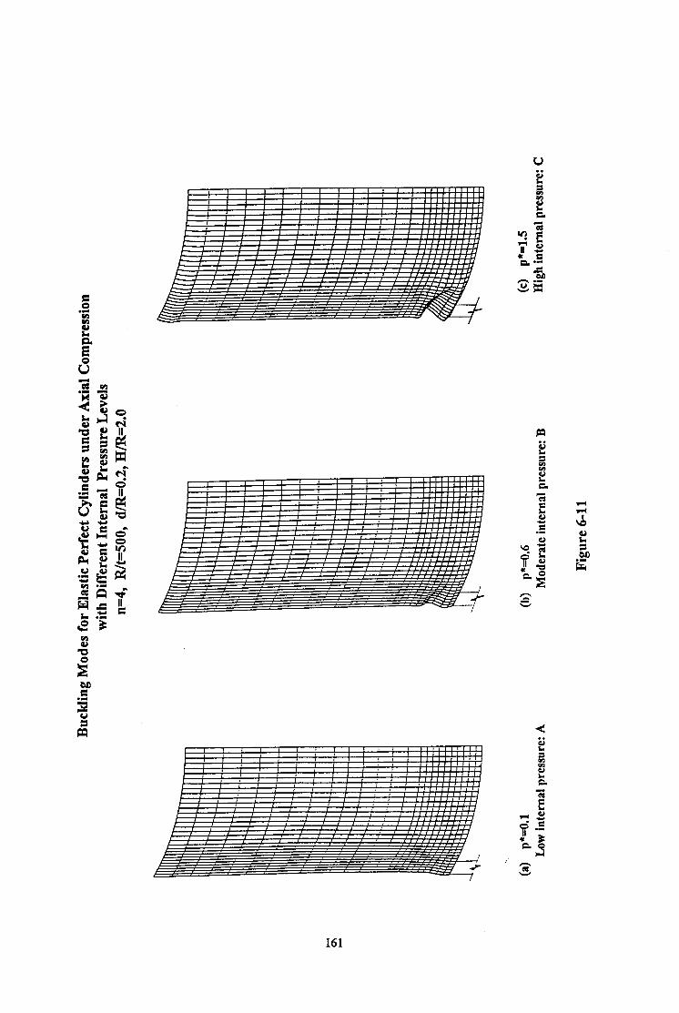
c c
161
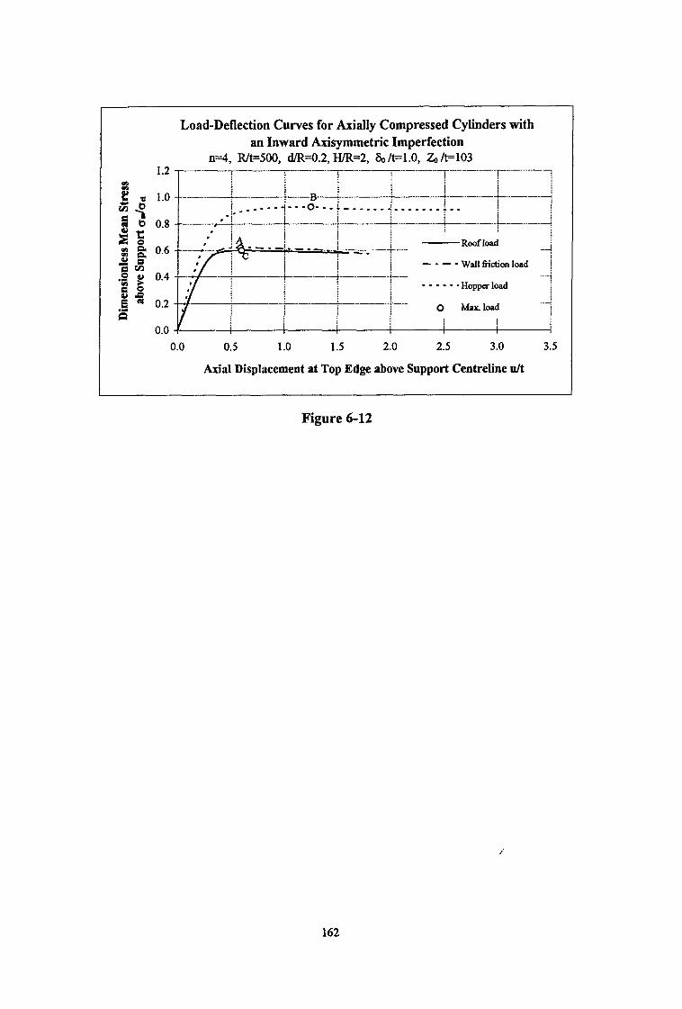
Load-Deflection Curves for Axially Compressed Cylinders with an Inward Axisymmetric Imperfection
n=4, Rk500, cUR=O.2, wR=2, &/t=l.O, Z0k103
0.0 0.5 1.0 1.5 2.0 2.5 3.0 3.5
Axial Displacement at Top Edge above Support Centreline u/t
Figure 6-12
162
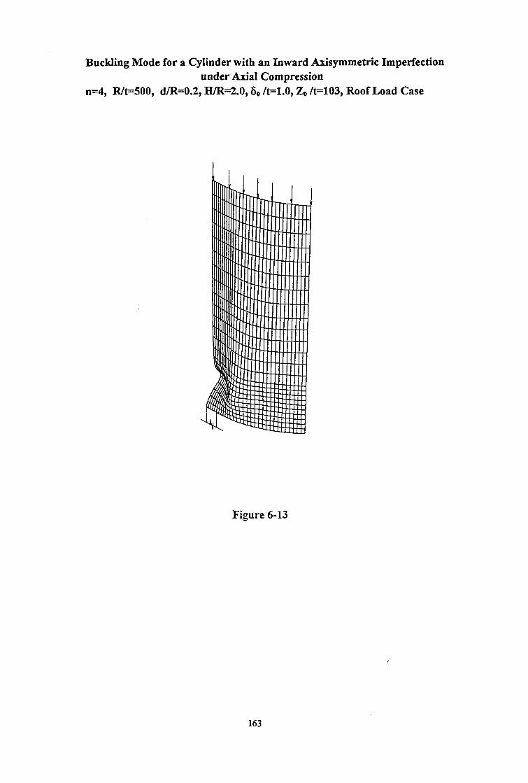
Buckling Mode for a Cylinder with an Inward Axisymmetric Imperfection under Axial Compression
n=4, R&500, d/R=0.2, H./R=2.0,60 k1.0, Z,, /t=103, Roof Load Case
Figure 6-13
163
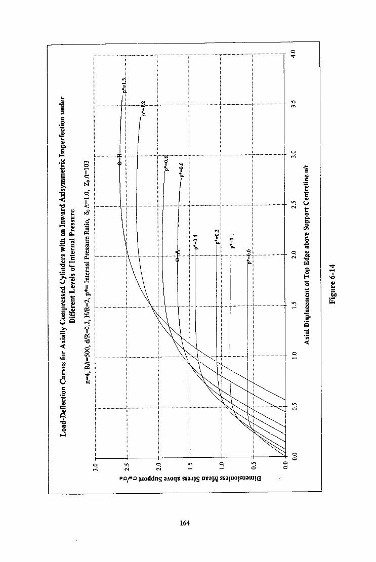
”
j I
I ,. . . . . . . . . . . . . . . . .
. . . . . . . . .
0
. . . . . . . . . . . .
. . . . . . . .-..
t-4 _... . ..i;;i . . . . . . II
b
___._ . . . . . . . . .
___ . . . . . .
. . . . . .
. . . . .
, a
. . . . . .
. . . . .
I
. .
............. : ..........
............. i.. ........
............. ) .... . . . .
_______...... f . . . . . . . . .
.............. . ...... . .
.............. . . . .... . .
.........
..........
.........
. . . . . . . .
\
\ . . . .
\ \ \
\
164

Buckling Strength of Axially Compressed Perfect Cylinders at Different Levels of Internal Pressure
n=4,lvt=500, d/R=o.2, H/R=2 3.0 ---.--i---.-i
0.0 0.2 0.4 0.6 0.8 1.0 1.2 1.4 1.6
Internal Pressure Ratio p*
P 2.0
2 1.8
4 g ;:;
52 1.2
3% 1.0 r: 2 0.8
2 e 2 0.6 .s B 0.4
2 0.2 .I n 0.0
Figure 6-15
1 Comparison of Load-Deflection Curves for Perfect and Imperfect
Cylinders under Moderate Internal Pressure n=4, Rlt=500, cYR=O.2, HiR=2, p+=O.6
0.0 0.5 1.0 1.5 2.0 2.5 3.0 3.5 4.0
Axial Displacement at Top Edge above Support Centreline u/t
Figure 6-16
165
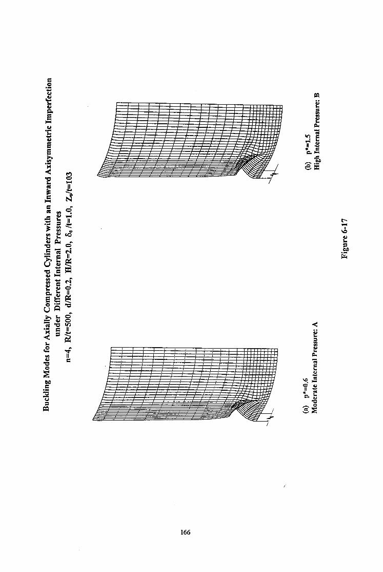
c
166
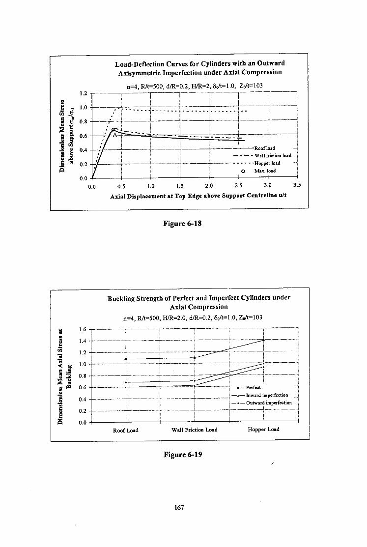
Load-Deflection Curves for Cylinders with an Outward Axisymmetric Imperfection under Axial Compression
x.1=4, FUt=500, dR=0.2, H/R=2, &It=1 .O, ZcWlO3 1.2 - _____~__________. -_..-._.-_..- ..-.
1 I i _...._...___ i’ __._._.... -...‘““--.-‘-l
! !
I I I 1.0 --
l I / I _____ ;‘;; ___..________ +.-.. ___________ + _..____. ----+----- -+--..-- ..-... t - - - . _ _ --I -.--mm- 4 -_me_m. I __..___ +--
- ..--. -;
’ ! ! . ;
0.8 ..-. ; ; + _______.___..__! ____.__.... -...-I-...-..-.-I
_____.___ L - - -I..---d -..-.-.-... -Roof load -: / ! --- - Wall friction load
..- -.&.- - -g-..-F&- ..-... f
_ _ _ - _ - Hoppcr load -i ! 0 Max. load /
/ i , , I
0.5 1.0 1.5 2.0 2.5 3.0 3.5
Axial Displacement at Top Edge above Support Centreline u/t
Figure 6-18
Buckling Strength of Perfect and Imperfect Cylinders under Axial Compression
n=4, Fut=500, HR=2.0, cllR=O.2, S&=1.0, &It=103
a 1 .6 ___ ____________ 7- .__..___.__.... __~ .-.-.... -v.---...- -“-‘-‘i-..“-‘..~.-‘-
i 1 .4 ___....___.._____ -ii.-- ..-...-.... 4 ..-....
3i __...._.___....__ i ..______. - 3
1 .2
4 ~
fj 5 EB p m s s 0.4 ! -.-Inward imperfection __...._....__._..__ J- _.._...._ - _....” ..-_.... - - f.-- .-....-....- ] . ..d
‘S i -a- Outward imperfection / 0.2 ___,___ ..______..___._ + ,..._.... - - L..- -..--....- ).. I....-....-....-. +-- - -.+ !
! I ! 0.0 I I I I
Roof Load Wall Friction Load Hopper Load
Figure 6-19
167

168

.......................
.......................
m
.......................
Y . . . . . . . .
. . . . . . . .
\
\ . . . . .
\
\ \
\
169
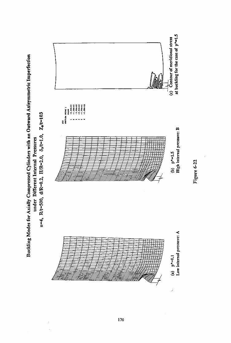
M d
170

. . . . ._. . . . .
!?.I. \
0’
\ . i’ 0
...............
...............
...............
...............
..............
..............
..............
..............
..............
_ . . . . . . . . . ..-.
. . . . . . . . . . . . . . .
-.<,
9 c! 9 09 \9 3 c! 0 0 0 0 0 d
pryQj.~oddn~a~oqa ssa~~gnaa~ssa~no~snam~~
171

172
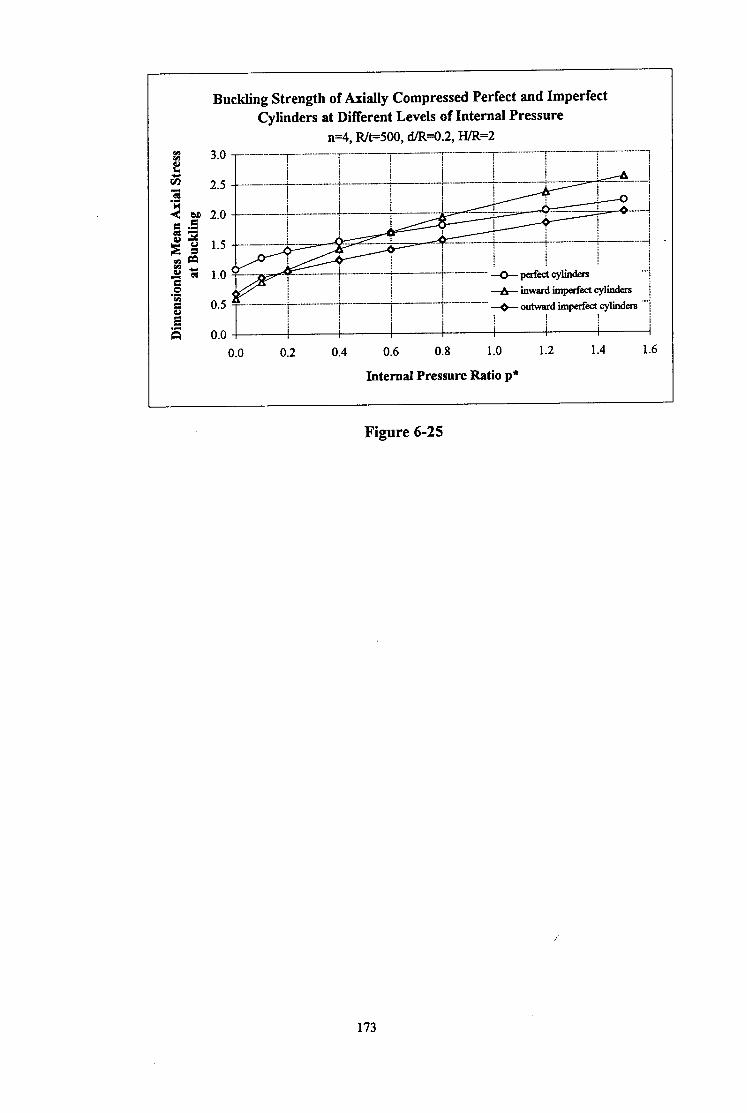
Buckling Strength of Axially Compressed Perfect and Imperfect Cylinders at Different Levels of Internal Pressure
n=4, Rk500, dAH.2, H/R=2
0.0 0.2 0.4 0.6 0.8 1.0 1.2 1.4 1.6
Internal Pressure Ratio p*
Figure 6-25
173
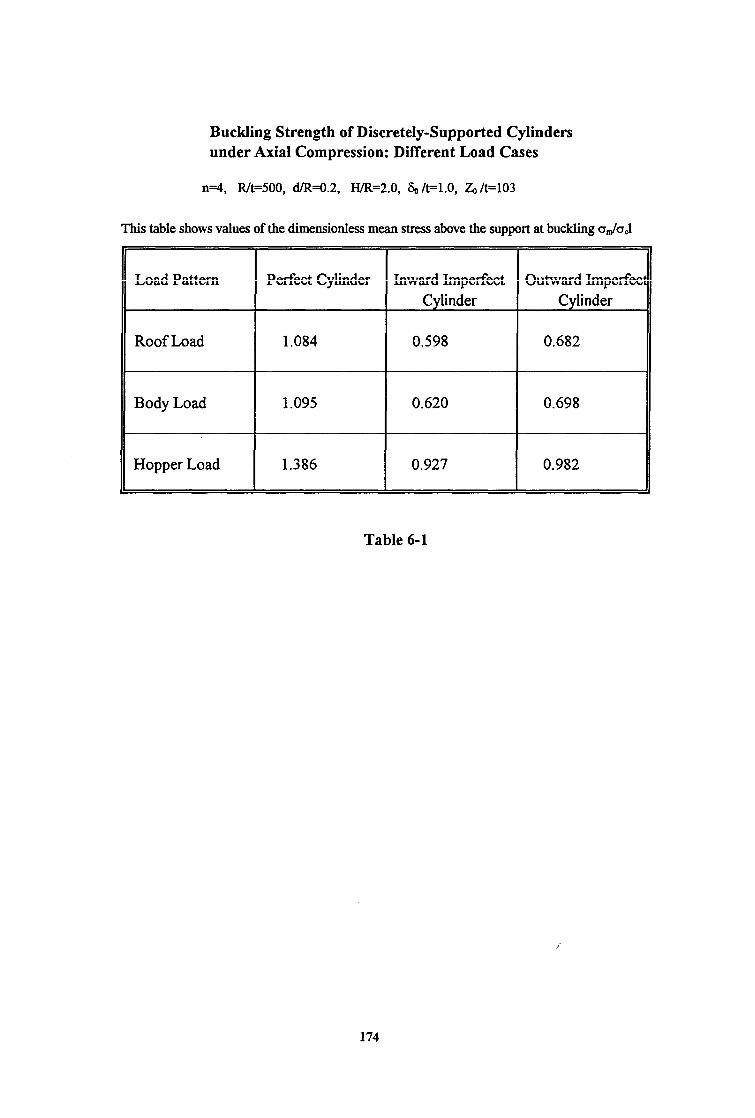
Buckling Strength of Discretely-Supported Cylinders under Axial Compression: Different Load Cases
n=4, RfF500, cVR=O.2, lYR=2.0, &/t=l.O, G/t=103
This table shows values of the dimensionless mean stress above the support at buckling a&J
Load Pattern
Roof Load
Body Load
Hopper Load
Perfect Cylinder Inward Imperfect Outward Imperfec Cylinder Cylinder
1.084 0.598 0.682
1.095 0.620 0.698
1.386 0.927 0.982
Table 6-l
174

CHAPTER 7
ELASTIC-PLASTIC STABILITY ANALYSIS OF DISCRETELY SUPPORTED CYLINDERS
7.1 INTRODUCTION
Studies in the preceding chapters have been entirely focused on the elastic behaviour of
discretely supported cylinders. This chapter extends the study into the elastic-plastic range.
There are numerous practical situations in which thin-walled silo structures are loaded beyond
the elastic limit of the material even when uniformly supported. For instance, when an axially
compressed cylinder is subjected to high internal pressures on the wall, the pressures may
induce severe local bending near the bottom edge of the shell. Local yielding may then
precipitate a buckling failure, leading to a so-called “elephant’s foot” buckle [Rotter, 1985,
19901. Current knowledge of the elastic-plastic behaviour of practical silo structures is still
fragmentary and extremely rare. Existing design rules for axially compressed cylinders
[Johnston, 1976; Wozniak, 1979; AWWA, 1984; API, 1978; API, 1988; ESDU, 1974; ECCS,
1984; Gaylord and Gaylord, 19841 do not allow for local elastic-plastic failure near the
boundary. In older design guides [Johnston, 1976; Wozniak, 1979; AWWA, 1979; API,
19781, no allowance is made for the beneficial effects of internal pressure, and the
unpressurized cylinder buckling load dominates design for almost the entire range of internal
pressures. The strengthening effects of internal pressure on the elastic buckling strength are
included in some guides and codes [ESDU, 1974; Trahair et al, 1983; ECCS, 1984, 1988;
Gaylord and Gaylord, 1984, AWWA, 1984; API, 19881, with the von Mises membrane yield
criterion included as a test for plasticity in some cases. Local plastic collapse in these
structures has only been recently investigated [Rotter, 1985, 1990; Teng and Rotter, 19891.
These investigations have only examined the local collapse of uniformly supported perfect
cylinders. To date, only the limited study of Guggenberger [ 19911 has examined plasticity in
discretely supported silos.
This chapter describes the elastic-plastic stability analysis of discretely supported cylinders.
The aim is to explore the behaviour of such structures in the elastic-plastic region, and hence to
draw preliminary guidance for practical design use.
175

The studies of this chapter are based upon both small displacement and large displacement
theories and the von Mises yielding condition. Small displacement or limit analyses are first
described, followed by geometrically nonlinear elastic-plastic collapse analyses. The finite
element program ABAQUS was used to calculate the collapse loads of cylinders with a range
of geometries, and to monitor the incremental load-displacement history and the relevant
yielding modes. Prior to undertaking both of these analyses, a finite element mesh refinement
study was executed to develop a mesh which is adequately fine to model the failure mode of the
structure under this loading configuration. For both the limit analysis and the nonlinear elastic-
plastic collapse analysis, parametric studies were conducted to examine the effects of some
primary factors on the elastic-plastic stability of the cylinders. These factors involve the
loading pattern, the material strength cry, the radius-to-thickness ratio of the cylinder R/t, the
internal pressure p and the position of the imperfection in the cylinder wall Z, and the
amplitude of the imperfection 6,.
As a start in this new aspect of discretely supported cylinders, this chapter describes studies in
the elastic-plastic region on the matters discussed in the previous elastic buckling analyses of
Chapters 5 and 6. This is intended to provide a systematic picture of the behaviour of locally
supported silo structures in the elastic-plastic domain.
7.2 FINITE ELEMENT MODELLING
The cylinders studied in this chapter were assumed to be directly supported on 4 discrete
supports which were modelled as rigid supports, as described in Chapters 5 and 6. The finite
element model of the cylinder was the same as that of Chapter 5 (Fig. 5-l). The height of the
cylinder was fixed at H/R=2. Axial compression was applied to the cylinder in the same three
loading patterns (Fig. 5-l). Throughout the studies of this chapter, the material of the cylinder
was treated as isotropic and ideally elastic-plastic, obeying the von Mises yield criterion with a
normal flow rule. The yield stress of the material, denoted by oY, was varied. The elastic
modulus was taken as E = 2 x lo5 MPa and Poisson’s ratio as u = 0.3.
A perfect cylinder was adopted as a reference structure, with the geometry defined by Rk500,
d/R=O.2, H/R=2.0 and n=4 and with a yield stress 0,,=250 MPa. In the parametric studies,
when one of these parameters was chosen as a variable to be examined, the other parameters
were retained at the values defined here.
For the study using small displacement or limit analysis, only perfect cylinders under axial
compression (Fig. 5-l) were considered. The radius-to-thickness ratio Rft was varied between
176

200 and 1000, and three values of yield stress were studied: o,, = 100, 250 and 500 MPa. For
the study using nonlinear elastic-plastic collapse analysis, both perfect and imperfect cylinders
were examined. Apart from the three loading cases (Fig. 5-l), a combination of a uniform
internal pressure p together with an axial roof load (Fig. 6-2) was used to investigate the
influence of internal pressurization on the nonlinear elastic-plastic collapse behaviour of the
cylinders. In the study of imperfect cylinders, initial geometric imperfections with an
axisymmetric pattern were again introduced in the walls, but only the detrimental inward
imperfection (Fig. 6-lb) was explored. Four positions for the centre of the inward
imperfection, Z&, were selected to examine the effect of the imperfection location on the
elastic-plastic collapse strength of the cylinder. With reference to the case when ZJt is equal
to 103, which was described in Chapter 6, these positions may be specified as (Z&/103 =
0.25, 0.5, 1 and 1.25 respectively. Subsequently, the effect of varying the magnitude of the
imperfection, S,-Jt, was investigated. Thus, a range of Sdt was particularly chosen as 0.1, 0.5,
1.0 and 2.0. The effect of internal pressure on the nonlinear elastic-plastic collapse behaviour
was explored for an imperfect cylinder with a local axisymmetric imperfection with a
amplitude of S,,/t =l .O and located at (Z&)=103.
Two methods of describing the shell collapse strength are used in the studies of this chapter.
Both are specified as the dimensionless mean stress above the support at collapse. In the first,
the mean membrane stress above the support o,,, is normalised by the classical elastic critical
stress ocl (ie. cr,,,/crcl). In the other, it is normalised by the yield stress cry (ie. o&j. The
description using o,,,/oc, is adopted to illustrate the loss of strength due to yielding, while the
description using o,,,/oY is used more generally to express the collapse strength of the cylinder
in the plastic region.
The g-node quadrilateral shell element type S9R5 in ABAQUS was chosen again. To obtain
reliable strength predictions an appropriate mesh model of the cylinder must be devised before
undertaking the main analyses of this chapter. This was achieved in the mesh refinement study
which is described first.
7.3 MESH REFINEMENT STUDY
An inappropriate mesh would give rather inaccurate and unreliable results, producing a
misleading understanding of the problem. A careful mesh refinement study is therefore
essential. As shown in the elastic analyses of discretely supported cylinders of Chapters 5 and
6, large bending stresses and local deformations develop above the discrete support. Thus, a
dense mesh arrangement is definitely required in that area. The mesh refinement study was
177

mostly undertaken using small displacement analyses, but the fine meshes were also analysed
using large deflection theory. The following description relates to the small deflection theory
study, unless otherwise specified.
For the mesh refinement study, the reference geometry introduced in Section 7.2 was
considered. A uniformly distributed downward frictional load was imposed on the whole wall
of the cylinder. The six shell element meshes shown in Fig. 7-1A and 7-1B were analysed to
investigate the accuracy and convergence of the elastic-plastic collapse behaviour with respect
to meshing. Details of these mesh arrangements and the corresponding plastic collapse
strengths (o&r,) are summarised in Table 7-l.
The collapse strength of the cylinder is very sensitive to the mesh arrangement. A coarse mesh
such as Mesh I or Mesh 2 leads to a higher predicted stress at collapse. Mesh 2 is much finer
near the bottom edge of the cylinder than Mesh I, whilst it retains the same refinement in the
circumferential direction as Mesh 1. However, the normalised collapse strengths obtained with
both meshes exceed the absolute theoretical limit of om=l. 1550~ which is the maximum of the
von Mises yield interaction envelope of plane stress [Hedge, 1963; Save and Massonnet,
19721. This verifies that coarse mesh arrangements in both the vertical and circumferential
directions, especially in the small area above the support, are unable to present the structural
behaviour accurately. Therefore, a very fine mesh is needed for elastic-plastic work.
In Mesh 3 and Mesh 4, the mesh is refined above the support in the circumferential direction.
The collapse loads obtained with them are lower than the theoretical limit of 1.155. The finer
Mesh 4 produces a lower strength prediction than Mesh 3. By investigating the yielding
history of the structure, first-yield was found to occur at the intersection between the bottom
edge of the cylinder and the support edge, where the membrane stresses in the cylinder reach
their maximum value. At collapse, yielding is spread over only a small area immediately above
the support. Thus, to adequately model such a yielding failure, a very fine mesh is needed in
the critical area, especially at the bottom edge of the cylinder and near the edge of the support.
Meshes 5 and 6 were consequently designed after considering these characteristics of the
discretely supported cylinder. In Mesh 5, the element size is reduced near both edges. Mesh 6
has a similar arrangement to Mesh 5, but the element sizes are halved in the small area above
the support in both directions.
When the small deflection theory results for Mesh 5 and Mesh 6 are compared, it is found that,
although Mesh 6 has much smaller elements than Mesh 5 and the total number of elements in
the former is double that of the latter, their collapse strengths differ by only 2%. However, the
computing time for Mesh 6 was approximately three times longer than that for Mesh 5. Table
178

7-l also shows a comparison of the nonlinear elastic-plastic collapse strengths obtained with
both meshes and shows that the difference between the strengths is only about 2%. Again, to
achieve this collapse load, the job running time with Mesh 6 was about four times as long as
that of Mesh 5. Therefore, from these comparisons, it can be concluded that the mesh
arrangement of Mesh 5 is probably adequate for estimates of the structural strength within
perhaps 3%, whilst still being cost effective. This mesh model was therefore adopted in the
following studies.
The results listed in Table 7-1 also demonstrate that within the yielded area, a fine mesh
arrangement either near the bottom edge of the cylinder or near the support edge alone cannot
produce accurate estimates of the collapse strength, as are shown by Mesh 3 and Mesh 4.
Only finer meshes near both edges can give an acceptable and reliable result, regardless of the
total number of elements used. For instance, the total number of elements in Mesh 5 is less
than that in Mesh 4, but the collapse prediction is evidently more accurate with Mesh 5.
The study of this section illustrates that, for discretely supported cylinders on rigid supports,
there is a great sensitivity to local mesh refinement in plastic stability problems. This is much
more severe than for elastic stability problems. When the nonlinear elastic buckling strengths
were calculated using the above five mesh arrangements, the results obtained differed by no
more than 12 % between Mesh 1 and Mesh 5.
7.4 LIMIT ANALYSIS OF PERFECT CYLINDERS
At the time this study was undertaken, very little was known about the post-yield behaviour of
locally supported cylinders. If an analogy is made with simple pin-ended supports, one might
suppose that the strength of different support lengths can be characterised well by defining the
Euler buckling stress and the plastic squash load, and then exploring the transition between
these two for intermediate slendemesses [Rankine, 18571. The elastic buckling strength has
been well explored in Chapters 5 and 6, so it was natural to begin the elastic-plastic studies by
trying to define the plastic limit load, which is the equivalent of a column’s squash load. At the
end of the study, it was apparent that this investigation of limit loads was not so useful, but the
investigation is recorded here for the sake of completeness.
7.4.1 Study of the Three Loading Cases
The three axial loading cases discussed in Chapters 5 and 6 were applied to the example
cylinder with R/t=500, H/R=2.0, d/R=O.2, n=4 and cry=250 MPa, with the aim of examining
the influence of the position of the loading on the collapse strength of the di$cretely supported
179

cylinder. The calculated normalised mean collapse stress o&r,, above the support are shown
in Table 7-2. The trend in the collapse strength for the three loading conditions was found to
be different from that of the buckling strength. The hopper load case leads to the lowest
strength among the three rather than the highest which was obtained from elastic buckling
analysis. The strength calculated for the hopper load case is 34% lower than the strength
under wall friction load, which is the highest of the three.
During the loading history, several common phenomena were observed regardless of the
positions of the applied axial load. First yield occurred at the intersection of the bottom edge
of the cylinder and the edge of the support. After first yield, the yielded zone gradually
extended from that intersection point in towards the support centreline and upwards a certain
distance above the lower boundary of the cylinder, until the maximum load condition was
reached. At collapse, the yielded zone was localised immediately above the support
termination. Comparing these with the results of the stress analysis of Chapter 5, it is known
that the maximum membrane stresses caused by the local support occur precisely at the
intersection point of the lower edge of the cylinder and the support edge, and that, above the
support centreline, higher stresses develop in the area above the top of the support than are
found at the support-shell contact point (Fig. 5-2). This stress pattern in the shell wall induces
the yielding phenomena described above.
7.4.2 Parametric Studies
The effect of the thickness of the cylinder was first investigated. A range of radius-to-thickness
ratios R/t = 200, 500, and 1000 was studied. The cylinder was subjected to a uniform wall
friction load.
Collapse predictions (o&r,,) for the range of R/t are shown in Fig. 7-2. For comparison, the
relevant linear bifurcation buckling strengths obtained in Chapter 5 are also shown in this
figure. The differences between the small displacement buckling strength and the small
displacement plastic collapse strength are apparent from this comparison. For a thick cylinder
with R/t=200, its plastic collapse strength is much lower than its elastic buckling strength, so
plastic collapse occurs long before elastic buckling. By contrast, the governing failure mode of
a thin cylinder with R/t=1000 is elastic buckling rather than plastic collapse since the buckling
strength is low compared with the plastic collapse strength. For cylinders with R/t between
500 and 1000, the differences between the calculated strengths will be small. When R/t rises to
a certain value, the two strengths will be equal. At low values of R/t, yielding dominates the
failure of the structure, so the plastic collapse stress is important in design. At high values of
R/t (ie. a thin cylinder), elastic buckling becomes the most significant failure mode, so the
elastic buckling stress is critical in design. i’
180

The linear elastic-plastic (limit analysis) and nonlinear elastic-plastic collapse loads are
compared in Fig. 7-3. The collapse loads obtained with R/t = 200, 500 and 1000 show the
expected pattern. For relatively thick cylinders (R/t=200), the two loads are almost identical
(1.5% different), indicating that nonlinear geometrical phenomena have little effect on the
collapse load. By contrast, for thin cylinders (R/t=lOOO), the geometrical nonlinear collapse
load falls far below the limit analysis load, as stability effects become important. In addition to
the effect on nonlinear geometrical factors, it is also useful to examine the variation in the limit
analysis collapse load with R/t. The thickest cylinder (R/t=200) is stronger than the thinnest
cylinder (R/t=lOOO), but the difference is small (5.7%). Therefore, based upon small
displacement limit analysis, the collapse strength of the discretely supported perfect cylinder
may be considered to be independent of the thickness of the shell.
The effect of the material yield stress o,, was examined next. Cylinders with a yield stress of
100, 250 and 500 MPa were analysed. The calculated collapse strengths are listed in Table 7-
3. The effect of the yield stress cry on the dimensionless collapse strength above the support is
insignificant and certainly within the error bounds for these calculations. The use of the yield
stress to define the dimensionless collapse strength is therefore well justified.
7.4.3 Conclusions
Limit analysis is based on small deflection theory. In these limit analyses, the effects of
varying the loading position, the radius-to-thickness ratio R/t and the material strength oY have
been investigated.
It has been found that first-yield in the shell occurs at the intersection point of the bottom edge
of the cylinder and the edge of the support. Under increasing axial compression, the yielded
zone spreads and at collapse of the structure, the yielded zone reaches the support centreline.
The position of the axial load has been found to have a marked effect on the dimensionless
mean stress above the support at plastic collapse. The slenderness of the cylinder represented
by the radius-to-thickness ratio R/t significantly affects the collapse strength ratio q&rcl.
However, the dimensionless collapse strength, om/oY, may be considered to be independent of
the radius-to-thickness ratio R/t as well as of the yield stress of the material oY.
It should be emphasised that these remarks apply only to small deflection limit analysis
calculations. Nevertheless, these conclusions offer a useful insight into the plastic behaviour of
locally supported silo structures. To understand the behaviour of a practical silo structure in
depth, geometrical nonlinear phenomena and the post-yielding response must also be
considered. In the following section, elastic-plastic stability analyses are described which
181
explore the nonlinear response of discretely supported cylinders using large displacement
theory.
7.5 NONLINEAR ELASTIC-PLASTIC COLLAPSE ANALYSIS OF
CYLINDERS
Geometrically nonlinear elastic-plastic stability analyses of discretely supported cylinders were
next conducted. The mesh chosen in the previous limit analysis was also used here. Since the
mesh convergence test (Table 7-l) demonstrated that the nonlinear elastic-plastic collapse
strength obtained with this mesh (Mesh 5) was very close to that of the finer mesh (Mesh 6)
(only 2% difference), the chosen mesh was judged to be adequate to model the nonlinear
elastic-plastic collapse modes of discretely supported cylinders.
Both perfect and imperfect cylinders were studied. For consistency with all the preceding
stability analyses using the ABAQUS program, the studies of this section used five integration
points through the shell wall. This was found to be adequate to provide accurate modelling of
the progress of yielding through the section of the thickness in all the cases analysed.
7.5.1 Study of Alternative Analysis Control Procedures
For geometrically nonlinear analysis, the finite element program ABAQUS provides two
approaches - one for cases where the loading variations must follow a prescribed history, and
another in which the loads are increased proportionally, so that the load factor is considered to
be part of the solution. ln ABAQUS, the loading history for which a structure’s response is
sought is defined by a sequence of steps. Each step is a period of response of a particular type
such as the static loading used in the present studies.
ln the cases where the loading variations during the step must follow a prescribed history, the
entire load applied to the structure is usually divided into a number of increments during which
loads are changed gradually. The automatic incrementation provided by this program has been
used in most of this study. The automatic scheme for this procedure is based on the
convergence of the iteration process at each increment. ABAQUS checks the convergence rate
and estimates if convergence is likely to be achieved within the maximum number of iterations
specified by a particular parameter. If so, one increment procedure finishes. If this results in a
smaller increment than is specified as a minimum, the run is terminated. Using this approach
to predict the nonlinear elastic-plastic collapse load of the discretely supported cylinder, the
value of the last increment which is achieved within the given minimum load increment value
can be considered to be an accurate estimate of the collapse load, so long asthe minimum load
182

increment value is assigned to be small enough. A default value of 10V5 times the loading
period of the step is assumed in ABAQUS.
The modified Riks method is provided for cases where load magnitude is considered to be part
of the solution. This method of choosing increments is based on controlling the path length
along the load-displacement response curve, and thus obtains a solution regardless of whether
the response is stable or unstable. It should be noted that a solution at a predefined load or
displacement value cannot be easily obtained using this method, because both are treated as
unknowns - termination of the solution process occurs at the first solution that exceeds the load
proportionality factor if the maximum value of it is specified, or at the end of the increment
during which the maximum total displacement value assigned is crossed. Nevertheless, in
structural buckling or collapse analysis, if the maximum and minimum values of the load
increment are made small enough, then the solution when the load proportionality factor
reaches the limiting value may be accepted as an adequate criterion to define the buckling or
collapse load.
The example cylinder with IUt=500, d/R=O.2, H/R=2.0, n=4 and 0,=250 MPa and subject to a
uniform wall friction was used to study these two different calculation methods. The forestated
two approaches were used: the corresponding nonlinear collapse strengths obtained are listed in
Table 7-4. The time (loading) period, the minimum load increment and the maximum load
increment values assigned in these ABAQUS runs are also noted in this table. Within the
assumed limits shown in Table 7-4, the collapse strength achieved using the first approach can
be treated as the accurate solution. Two cases were analysed using the modified Riks method.
For Case I, the analysis ends when convergence is deemed to be unlikely within the minimum
load increment specified, so that no solution is gained. The problem encountered in Case 1,
however, can be avoided by giving appropriate and efficient load increment limits, as in Case
2. For Case 2, the expected solution is achieved and agrees quite well with the accurate
solution obtained using the first approach. The difference between the results using the two
approaches is only about 0.5%. Such a close agreement illustrates that the modified Riks
method can give accurate fast solutions provided that the minimum and maximum values of
load increment are defined well. However, to achieve the collapse load of the cylinder, when
the same initial load increment value is specified, the ABAQUS running-time required using
the first approach is 5 times longer than using the modified Riks method. It is apparent that the
modified Riks method is much more efficient. In addition to the achievement of the collapse
load of the structure, the modified Riks method can also perform the post-yielding analysis,
providing an incremental load-displacement response for this problem.
183
As a result of this study of alternative analysis procedures, the modified Riks method was
adopted for the following nonlinear elastic-plastic collapse analyses of discretely supported
cylinders. It was found that the value of the assigned load increment limits had a strong
influence on the accuracy of the prediction of the collapse load of the cylinder. Thus, for all
the cases studied in the following analyses, the time (loading) period value was fixed at 1 .O; the
default minimum load increment value of 10m5 was selected; and the maximum load increment
value was specified as 0.1.
7.5.2 Behaviour of Perfect Cylinders
The example cylinder under axial compression was analysed first. The three axial loading
conditions shown in Fig. 5-l of Chapter 5 were again adopted. The nonlinear collapse
strengths obtained under these three loading cases are compared in Table 7-2 with the previous
small displacement limit analysis results. The collapse strengths show the same trend as was
found in the elastic buckling analyses: the hopper load leads to the highest strength whilst the
roof load gives the lowest. Again, the importance of large displacement effects is apparent
when comparing the results of nonlinear elastic-plastic analysis and limit analysis.
When the loading history is examined, it is found that the nonlinear behaviour of the cylinder
under the three loads is essentially similar. The load-displacement response for a typical
cylinder under a uniform wall friction load is shown in Fig. 7-4. The axial displacements
recorded in this figure are again those at the top edge of the cylinder above the support
centreline. The axial displacements increase slowly until the load reaches the bifurcation point,
which is also the point of maximum strength (point B). After this bifurcation point, the axial
displacement first reduces under reducing load, and then increases rapidly as the load decays
further. The pre-collapse, collapse and post-collapse deformed shapes, corresponding to the
three points A, B and C on this curve, are illustrated in Fig. 7-6. First yield occurs at the
intersection point of the lower edge of the cylinder and the edge of the support at the point
indicated on this load-displacement path of Fig. 7-4. Yielding then gradually develops along
the bottom edge of the cylinder back towards the support centreline and up the cylinder. At the
bifurcation point, the yielded zone in the shell wall is localised immediately above the support,
as shown in Fig. 7-7a. After this collapse condition, the cylinder enters into the post-collapse
phase, when yielding develops more extensively in the shell (Fig. 7-7b).
Both the load-displacement curves obtained from the previous nonlinear elastic analysis and the
present nonlinear elastic-plastic analysis are shown in Fig. 7-5 for this example perfect
cylinder. In this figure, the load is represented by the calculated dimensionless mean stress
above the support (cr,,,/oc,). The influence of the yielding on the b&u-cation loads and the
deflections is apparent from this comparison. i’
184

The effect of varying the radius-to-thickness ratio R/t was examined next. Values of R/t were
chosen at 200, 350, 500, 1000 and 2000 and the uniform wall friction load case adopted.
Figure 7-3 compares the collapse strengths of the limit analysis and the nonlinear analysis for
three cylinder slendemesses (R/t=200, 500 and 1000) to show the increasing influence of large
displacement effects in thin cylinders. The nonlinear response is very different from the small
displacement response, especially as the cylinder becomes thinner. For the thickest cylinder
(R/t = 200), the large displacement theory collapse load was found to be lower than its small
displacement theory value by only 1.3%, but at R/t = 500 and 1000, the difference increased to
2 1% and 29% respectively. Such large differences demonstrate that large displacement effects
are much more significant and influential in thin cylinders than in thicker ones. Further, it is
evident that the small displacement limit analysis cannot offer reliable solutions to this
particular problem for very thin cylinders. The limit analysis always overestimates the actual
collapse strength of a discretely supported cylinder.
The changes in the collapse strength with the cylinder slenderness (R/t) are shown in Fig. 7-8.
Large deflection effects on the yielding for the cylinders of different thicknesses are clearly
seen.
In practice, shells that are thick enough to yield before buckling under uniform axial
compression alone are rarely found in silo structures. However, if a high level of internal
pressurization is present in the cylinder, even very thin cylinders under uniform compression
approach the yield condition. Previous investigations [Rotter, 1985, 19901 examined the
geometrically nonlinear elastic-plastic collapse and the instability of perfect thin, internally
pressurized cylinders under axial compression. These investigations revealed that first yield
occurs in the zone of local bending adjacent to the shell boundary, where the circumferential
membrane and the bending stresses are amplified by axial compression, leading to an
“elephant’s foot” buckling mode. The importance of elastic-plastic collapse as a failure mode is
not dependent on the grade of steel used. Collapse loads are generally lo-20% higher than
first-yield conditions, except for thin cylinders without internal pressurization, when elastic
buckling occurs.
The influence of internal pressurization on the nonlinear elastic buckling strength of discretely
supported cylinders was described in Chapter 6. The effect of yielding on changing these
buckling predictions is investigated here.
The influence of internal pressurisation on the elastic-plastic collapse strength was explored, by
considering the example perfect cylinder loaded by a combination of uniform roof load and
185

internal pressure p. One limiting condition is defined by uniform membrane circumferential
yield, which occurs in internally pressurized cylinders without axial load when pR/t = oY. For
the chosen cry = 250 MPa in the present study, membrane circumferential yield does not occur
until p reaches to 0.5 MPa or the internal pressure ratio p* rises to 1.033. Therefore, 1.033 is
the maximum possible value for p* in the study here. All the p* specified must be lower than
this value.
A range of the internal pressure ratios p * = 0.1, 0.2, 0.4, 0.6, and 1.0 was analysed. Figure 7-
9 shows the nonlinear elastic-plastic collapse strengths of these axially compressed pressurized
cylinders together with the strength of a cylinder under a uniform roof load alone (p*=O.O).
The weakening effect of internal pressurization (p* > 0.0) is evident on the yielding strength
above the local support. In particular, higher levels of internal pressure lead to collapse of the
cylinder at an axial load much smaller than the lower pressure levels. The strength declines
markedly as p* increases. When p* rises to 1.0, the internal pressure induces wide scale
yielding in the body of the cylinder, so that even a very small axial load is enough to cause
collapse of the structure.
At low internal pressures, a uniformly supported imperfect cylinder experiences an increase in
buckling strength with internal pressure, because the internal pressure reduces the effect of
circumferential compressions which are implicated in the imperfection sensitivity [Calladine,
19831. Here, the local bending effect of the discrete support serves in the role of the
imperfection, as shown in Chapter 6, and the buckling strength rises with internal pressure.
However, yielding effects soon interfere, and the strength begins to fall. For the geometry of
this example cylinder, the range of pressure in which strength increases are found is very
limited. When the internal pressure ratio p* is larger than around 0.1, as shown in Fig. 7-9, the
strength reaches its maximum and then goes down continuously. Thus at most pressurisation
levels, elastic-plastic collapse is the governing failure mode.
The load-deflection curves for cylinders undergone these different internal pressures are shown
in Fig. 7-10. For all the cylinders pressurized below p * = 0.6, the load-deflection curve has a
steadily changing form. At zero internal pressure, the sharp bifurcation and reversing axial
displacements are found. As the internal pressure is raised, the sharpness of the bifurcation
steadily declines, and by p* = 0.6 the curve demonstrates no reversal of axial displacements in
the post-buckling zone. At higher internal pressures, the response becomes steadily more and
more ductile. The deformed shapes at maximum load for the three levels of pressurisation p* =
0.1, 0.4 and 0.6 are shown in Fig. 7-l 1. These figures do not show the buckling mode or post-
buckling pattern because they are drawn at the maximum load condition. Nevertheless, a local
“elephant’s foot” buckling mode can be identified just above the support at p*, = 0.6.
186

7.5.3 Behaviour of Imperfect Cylinders
Attention was next directed to the imperfection-sensitivity of pressurised cylinders. A local
axisymmetric imperfection with an inward shape, as shown in Fig. 6-lb of Chapter 6, was
introduced in the cylinder wall.
Studies were first concentrated on the effect of the position of the imperfection, with a constant
amplitude of S,,/t =l .O. Four positions for the centre of the imper-hection were chosen as
(Z&l103 = 0.25, 0.5, 1.0 and 1.25. Figure 7-12 shows the collapse strength of the example
cylinder with these three imperfection positions, together with the strength of a perfect cylinder
discussed in Section 7.5.2. It is apparent that the collapse strengths of imperfect cylinders are
considerably lower than that of the perfect cylinder. Among the four positions studied, the one
specified as (Z&/103 = 1.0 leads to the lowest strength, a reduction of about 73% from the
perfect cylinder strength. For elastic cylinders, the buckling strength reduction for an imperfect
cylinder with Zdt = 103 was about 60% (see Chapter 6), so it appears that the imperfection-
sensitivity is greater in this elastic-plastic domain than for the elastic buckling problem. It can
be concluded from Fig. 7-12 that the position of the centre of the imperfection (Z&)/l 03 at 1 .O
is the worst for this cylinder with R/t=500. This conclusion is consistent with that drawn by
Rotter and She [ 19931 in their studies of the nonlinear elastic buckling of discretely supported
cylinders which were described in Chapter 3.
The load versus displacement response curves obtained for imperfect cylinders with an inward
imperfection introduced at these different positions in the shell wall are found to be similar in
form. Figure 7-13 shows the load-displacement curve of the imperfect cylinder with S&=1 .O
and (Z&)/103=1 .O. The shape of this curve is clearly different from that of a perfect cylinder
shown in Fig. 7-4. The behaviour is relatively ductile and no bifurcation point is observed on
the curve. The magnitudes of the axial displacements are much larger than those for the
perfect case. In particular, as the displacements develop after the maximum strength, the load
declines only slightly. Because the initial imperfection was placed near the bottom edge of the
cylinder, it is involved in the development of local yielding above the support and leads to early
yielding of the shell wall.
The deformed shapes of the imperfect cylinder at the point of maximum strength are shown in
Fig. 7-14 for the inward imperfection at three positions of (Z&)/l03 = 0.25, 1.0, and 1.25. It
can be observed that the centre of the yielded zone occurs almost at the centre of the
imperfection introduced in the shell wall, and among three modes, the one with the imperfection
centred at (Z&)/103 = 1 .O demonstrates the severest deformed configuration at collapse.
Therefore, for this typical cylinder, an imperfection with its centre at (Z&l103 = 1 .O can be
considered to be of the critical effect on the structural collapse. I
187
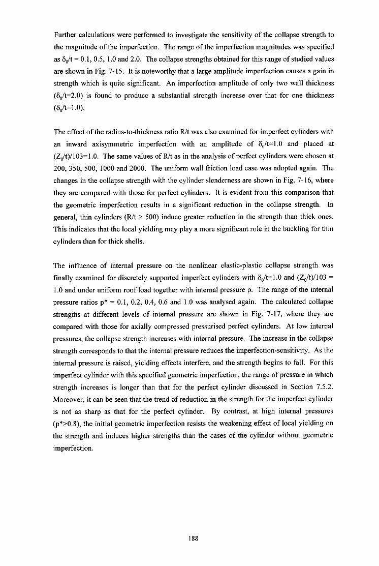
Further calculations were performed to investigate the sensitivity of the collapse strength to
the magnitude of the imperfection. The range of the imperfection magnitudes was specified
as 6,/t = 0.1, 0.5, 1.0 and 2.0. The collapse strengths obtained for this range of studied values
are shown in Fig. 7-15. It is noteworthy that a large amplitude imperfection causes a gain in
strength which is quite significant. An imperfection amplitude of only two wall thickness
(S&=2.0) is found to produce a substantial strength increase over that for one thickness
(S&=1 .O).
The effect of the radius-to-thickness ratio R/t was also examined for imperfect cylinders with
an inward axisymmetric imperfection with an amplitude of 6,/t=l .O and placed at
(Z,/t)/103=1.0. The same values of R/t as in the analysis of perfect cylinders were chosen at
200, 350, 500, 1000 and 2000. The uniform wall friction load case was adopted again. The
changes in the collapse strength with the cylinder slenderness are shown in Fig. 7-16, where
they are compared with those for perfect cylinders. It is evident from this comparison that
the geometric imperfection results in a significant reduction in the collapse strength. In
general, thin cylinders (R/t 2 500) induce greater reduction in the strength than thick ones.
This indicates that the local yielding may play a more significant role in the buckling for thin
cylinders than for thick shells.
The influence of internal pressure on the nonlinear elastic-plastic collapse strength was
finally examined for discretely supported imperfect cylinders with 6,/t=l .O and (Z&)/103 =
1 .O and under uniform roof load together with internal pressure p. The range of the internal
pressure ratios p* = 0.1, 0.2, 0.4, 0.6 and 1.0 was analysed again. The calculated collapse
strengths at different levels of internal pressure are shown in Fig. 7-17, where they are
compared with those for axially compressed pressurised perfect cylinders. At low internal
pressures, the collapse strength increases with internal pressure. The increase in the collapse
strength corresponds to that the internal pressure reduces the imperfection-sensitivity. As the
internal pressure is raised, yielding effects interfere, and the strength begins to fall. For this
imperfect cylinder with this specified geometric imperfection, the range of pressure in which
strength increases is longer than that for the perfect cylinder discussed in Section 7.5.2.
Moreover, it can be seen that the trend of reduction in the strength for the imperfect cylinder
is not as sharp as that for the perfect cylinder. By contrast, at high internal pressures
(p*>O.8), the initial geometric imperfection resists the weakening effect of local yielding on
the strength and induces higher strengths than the cases of the cylinder without geometric
imperfection.
188
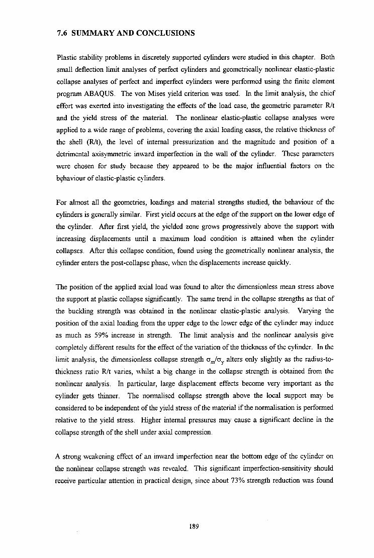
7.6 SUMMARY AND CONCLUSIONS
Plastic stability problems in discretely supported cylinders were studied in this chapter. Both
small deflection limit analyses of perfect cylinders and geometrically nonlinear elastic-plastic
collapse analyses of perfect and imperfect cylinders were performed using the finite element
program ABAQUS. The von Mises yield criterion was used. In the limit analysis, the chief
effort was exerted into investigating the effects of the load case, the geometric parameter R/t
and the yield stress of the material. The nonlinear elastic-plastic collapse analyses were
applied to a wide range of problems, covering the axial loading cases, the relative thickness of
the shell (R/t), the level of internal pressurization and the magnitude and position of a
detrimental axisymmetric inward imperfection in the wall of the cylinder. These parameters
were chosen for study because they appeared to be the major influential factors on the
behaviour of elastic-plastic cylinders.
For almost all the geometries, loadings and material strengths studied, the behaviour of the
cylinders is generally similar. First yield occurs at the edge of the support on the lower edge of
the cylinder. After first yield, the yielded zone grows progressively above the support with
increasing displacements until a maximum load condition is attained when the cylinder
collapses. After this collapse condition, found using the geometrically nonlinear analysis, the
cylinder enters the post-collapse phase, when the displacements increase quickly.
The position of the applied axial load was found to alter the dimensionless mean stress above
the support at plastic collapse significantly. The same trend in the collapse strengths as that of
the buckling strength was obtained in the nonlinear elastic-plastic analysis. Varying the
position of the axial loading from the upper edge to the lower edge of the cylinder may induce
as much as 59% increase in strength. The limit analysis and the nonlinear analysis give
completely different results for the effect of the variation of the thickness of the cylinder. In the
limit analysis, the dimensionless collapse strength o,& alters only slightly as the radius-to-
thickness ratio R/t varies, whilst a big change in the collapse strength is obtained from the
nonlinear analysis. In particular, large displacement effects become very important as the
cylinder gets thinner. The normalised collapse strength above the local support may be
considered to be independent of the yield stress of the material if the normalisation is performed
relative to the yield stress. Higher internal pressures may cause a significant decline in the
collapse strength of the shell under axial compression.
A strong weakening effect of an inward imperfection near the bottom edge of the cylinder on
the nonlinear collapse strength was revealed. This significant imperfection-sensitivity should
receive particular attention in practical design, since about 73% strength reduction was found
189

for a typical inward imperfection with the amplitude of Sdt = 1 .O and localised at the critical
height of Zdt = 103. However, no further reduction in the collapse strength occurs once the
imperfection amplitude exceeds a certain level. Higher internal pressures may induce the
collapse strength of imperfect cylinders with a local inward axisymmetric imperfection slightly
higher than that of axially compressed pressurised perfect cylinders.
A further investigation of the elastic stability response of a discretely supported complete silo
structure is described in Chapter 8.
190
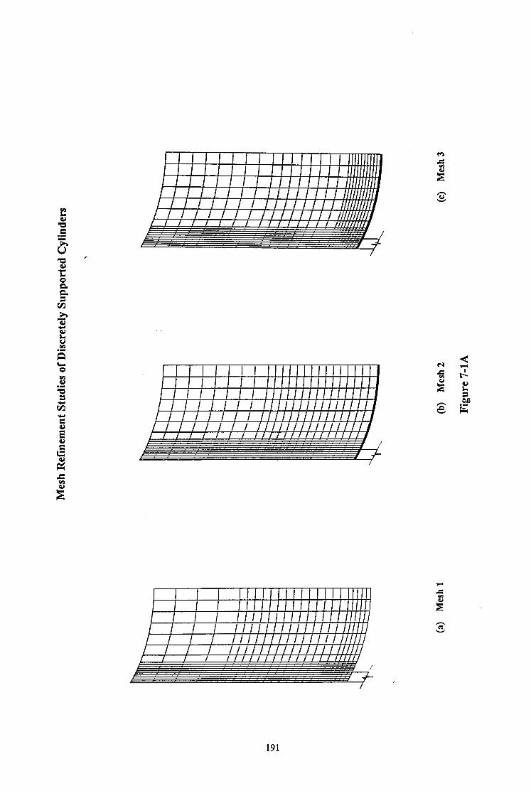
h a s t;
.z! R

192

Linear Buckling and Limit Analysis Strengths of Perfect Cylinders under Axial Compression
d/‘&0.2, H/R=2.0, n=4, a,=25OMPa, Wall friction load
Cylinder Radius-to-Thickness Ratio
fl Linear Etuckling Analysis q Limit Analysis
Figure 7-2
Collapse Strength of Perfect Cylinders under Axial Compression
d/R=O.2, H/R=2.0, n=4, cry=250 MPa, Wall friction load
R&200 RJt=soo wt=1ooo
Cylinder Radius-to-Thickness Ratio
0 Iimit Analysis 8 Nonhear Elastic-Plastic Analysis
Figure 7-3
193

Load-Deflection Curve for A Perfect Cylinder under Uniform Wall Friction Load
n=4, R/t=SOO, diSO.2, H/R=2, o,=250MPa . . . . . . . . . . . . . . . . . . . . . . . . . . . :‘..........................: . . . . . . . . . . . . . . . . . . . . . . . . . . . . . . . . . . . . . . . . . . . . . . . . . . . . . ..j . . . . . . . . . . . . . . . . . . . . . . . . . . . i . . . . . . . . . . . . . . . . . . . . . . . . . . . . j _ . . . . . . . . . _ . . . . . . . . . . . . . . ..c . . . . . . . . . . . . . . . . . . . . . . . . . . j
i ; . . . . . . . . . . . . . . . . . . . . . . . . . . . j. . . . . . . . . . . . . . . . . . . . . . . . . . . j . . . . . . . . . . . . . . . . . . . . . . . . . . . i . . . . . . . . . . . . . . . . . . . . . . . . . . . . . . . . . . . . . . . . . . . . . . . . . . . . . . . (........................... ./ . . . . . . . . . . . . . . . . . . . . . . . . . . . j. . . . . . . . . . . . . . . . . . . . . . . . . . . J . . . . . . . . . . . . . . . . . . . . . . . . . ..j . . . . . . . . . . . . . . . . . . . . . . . . . . . 4 . . . . . . . . . . . . . . . . . . . . . . . . . . . . . . . . . . . . . . . . . . . . . ..I....... 4
I I 0.0 0.5 1.0 1.5 2.0 2.5
Axial Displacement at Top Edge above Support Centreline u/t
Figure 7-4
Comparison of Load-Deflection Curves for a Perfect Cylinder under Wall Friction Load Using Nonlinear Elastic-Plastic
Collapse and Elastic Buckling Analyses n=4, Rlt=500, diR=0.2, HiR=2.0, o,=250MPa
1 .2 C..._..._____ i _.. -.. - - -1-- - -- - ..-- / ..-..-....--.....-.-......-.....- ~ ..-...--... -....-.... ~ I . : 1 J) __.____..__.... ,‘-..&- -...- - . ..-..- ..-....-.....-...-- j... -....--. -Elastic-Plastic 1
‘r i ! -m--e -Elastic / ..__...._ -.;...-... -- - ..-. r ..--...---....-....-.... 4
!
..----.-~-....-....-....-....~-.--..--.... I I I
0.5 1.0 1.5 2.0 2.5
Axial Displacement at Top Edge above Support Centreline u/t
Figure 7-5 i
194
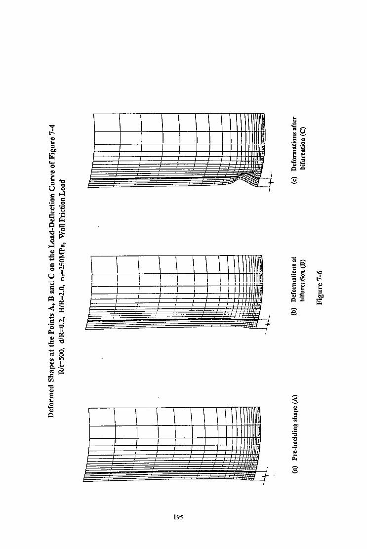
195
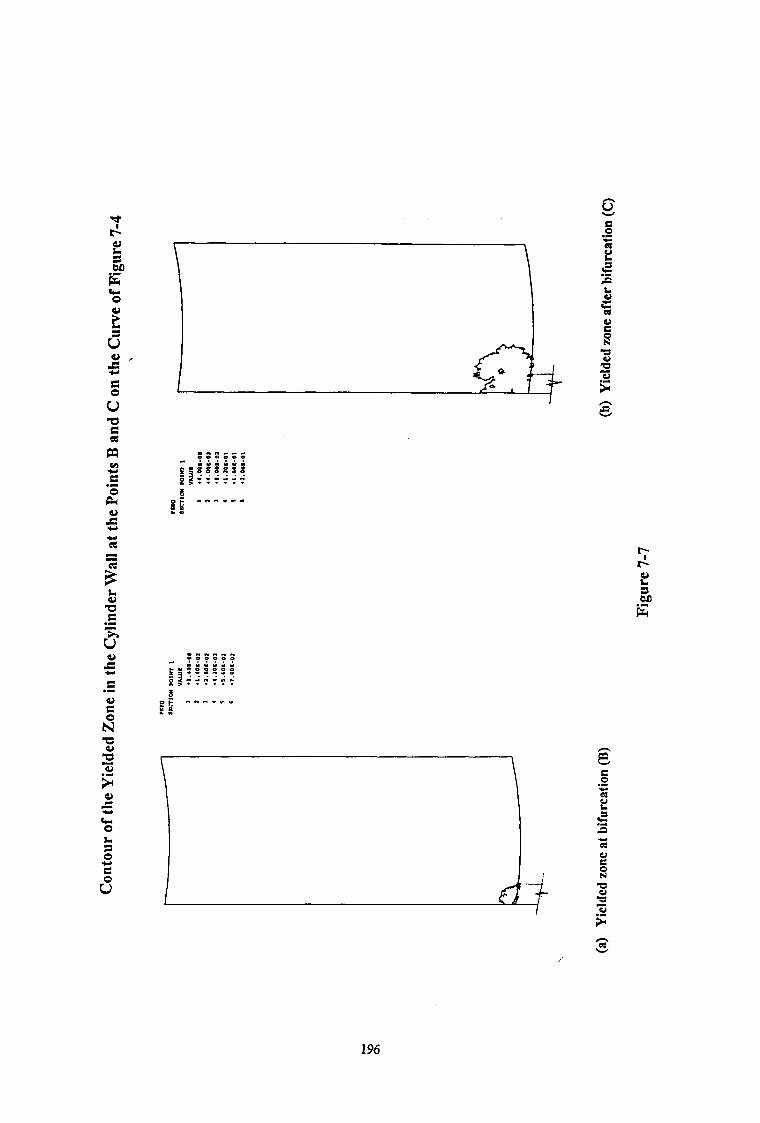
196

Nonlinear Elastic-Plastic Collapse strength of Axially Compressed Perfect Cylinders at Different Values of R/t
n=4, R/t-500, d/R=O.2, H/R=2, uy=250h4Pa, wall friction load 1.2
%
3 g I.0
= % 6’
-2
0.8
$ 5 0.6
Ii B o.4 0 0.2
i .
0.0
0 200 400 600 800 1000 1200 1400 1600 1800 2000
Radius-to-Thickness Ratio R/t
Figure 7-8
Collapse Strength of Axially Compressed Perfect Cylinders at Different Levels of Internal Pressure
n=4, Rlt=500, dLR=O.2, H/R=2, o,=250MPa, roof load
0.4 0.6
Internal Pressure Ratio p*
0.8 1.0
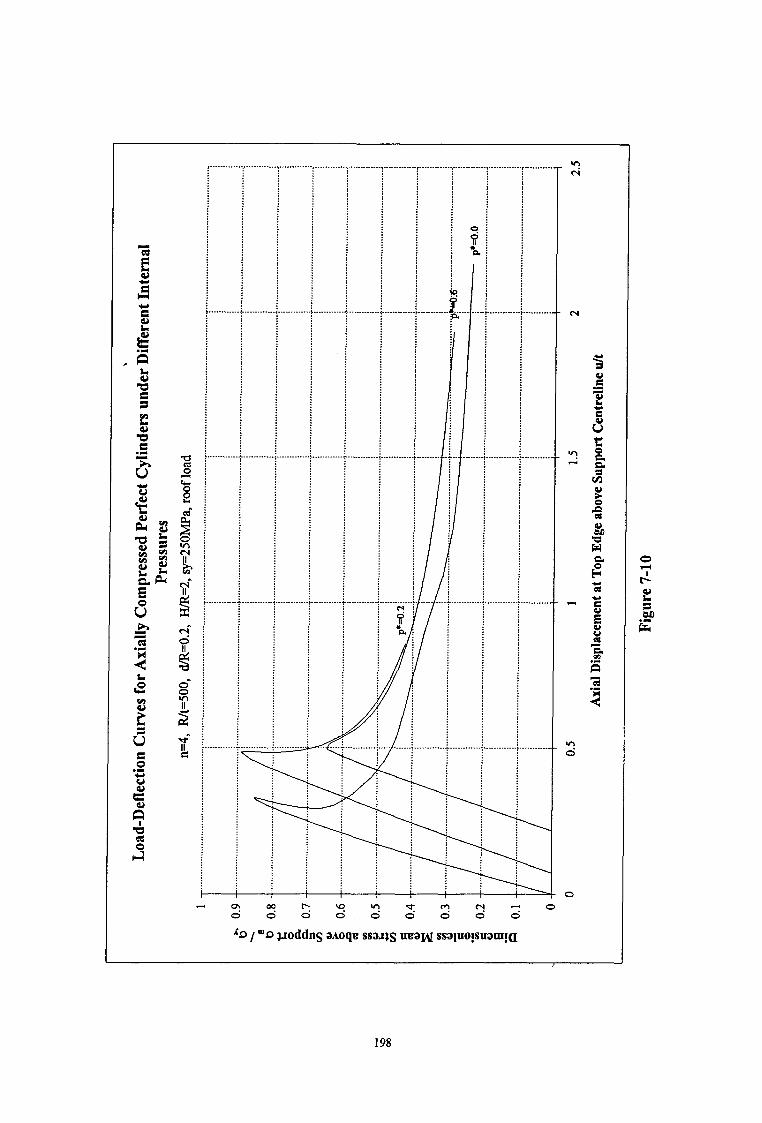
\ I
\
c
. . . . . . .
4 / . . . . . . . . j . . . . . . . . . . . . 4 -\ -\ i \
\
\
,... . . .
. . . . .
. . . .
. . . . .
. .
\
\
1 e m CI \D m 0 6 09 0 d d 0 v! 0 9 d c! 0 0 -!
b / -0 troddns aaoqe ssa.xts naaM ssapo!snam!a
198

199

Collapse Strength of Axially Compressed Imperfect Cylinders with an Inward Axisymmetric Imperfection at
Different Positions of ZJt
n=4, R/t=500, dAM.2, H/R=2, W=l.O, 0,=25OMPa, wall frcition load
0.00 0.25 0.50 0.75 1.00 1.25
Dimensionless Position of the Imperfection (&It)/103
Figure 7-12
Load-Deflection Curve for an Imperfect Cylinder under Wall Frictional Load
n=4, Rk500, dAM.2, H/R=2,& b1.0, & /t=103,0,=25OMPa 0.30 _.................. 1 . . . . . . . . . . . . . . . . . . . T . . . . . . . . . . . . . . . . . . . i’ . . . . . . . . . . . . . . . . . . ~ . . . . . . . . . . . . . . . . . . f’ . . . . . . . . . . . i’ . . . . . . . . . . . . . . . . . . . ...................i
o-3 ____________.__.....; . . . . . . . . . .._____._. j . . . . . . . . . . . . . . . . . . . . . . . . . . . . . . . . ..___._ ;.__...............; . . . . . . . . . . . . . . . . . . . . ;................... i . ..-............... 1
i................... f.. . . . . . . . . . . . . . . . i . . . . . . . . . . . . . . . . . . . +...+ . . . . . . . 1 . . . . . . . . . . . . . . . . ..i
.! . . . . . . . . . . . . . . . . . . . i . . . . . . . . . . . . . . . . . ..i . . . . . . . . . . . . . . . . . . . j . . . . . . . . . . . . . . . . . . . i . . . . . . . . . . . . . . . . . . j . . . . . . . . . . . . . . . . . . . 1
$ . . . . . . . . . . . . . . . . . . . . . . . . . . . . . . . . . . . . . . i . . . . . . . . . . . . . . . . . . . . . . . . . . . . . . . . . . . . . . . . i................... i . . . . . . . . . . . . . . . . . . 1
.i . . . . . . . . . . . . . . . . . ..i . . . . . . . . . . . . . . . . . . f . . . . . . . . . . . . . . . . . . . j....................! . . . . . . . . . . . . . . . . . . . . . . . . . . . . . . . . . . . . . ..i
i I I a I I I
0 1 2 3 4 5 6 7 8 Axial Displacement at top Edge above Support Centreline u/t
Figure 7-13
200

201

Collapse Strength of Axially Compressed Imperfect Cylinders with Different Amplitudes of Imperfection 6,,
n=4, Rk500, diR=O.2, HfR=2, ZOk103, o,=250hPa, wall friction load
Figure 7-15
Nonlinear Elastic-Plastic Collapse strength of Axially Compressed Imperfect and Perfect Cylinders at Different Values of R/t
1 .2 n=4, d&=0.2, H/R=2, S&=1.0, Z&103, a,=250MPa, wall friction load - - _ - -... _.~_ -.~-...--- y--- ! i-~-...- ~-~-.“-.-~-.-. ! --j -0- perfect cyliidem
0 200 400 600 800 1000 1200 1400 1600 1800 2000
Radius-to-Thickness Ratio R/t
Figure 7-16
202
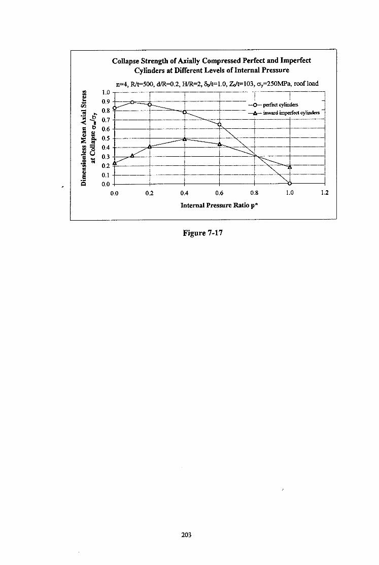
Collapse Strength of kially Compressed Perfect and Imperfect Cylinders at Different Levels of Internal Pressure
n=4, R&500, d/F+O.2, HR=2, &&=l.0,&h.=103,0y=250MPa, roof load
0.2 0.4 0.6 0.8
Internal Pressure Ratio p*
1.0 1.2
Figure 7-17
203
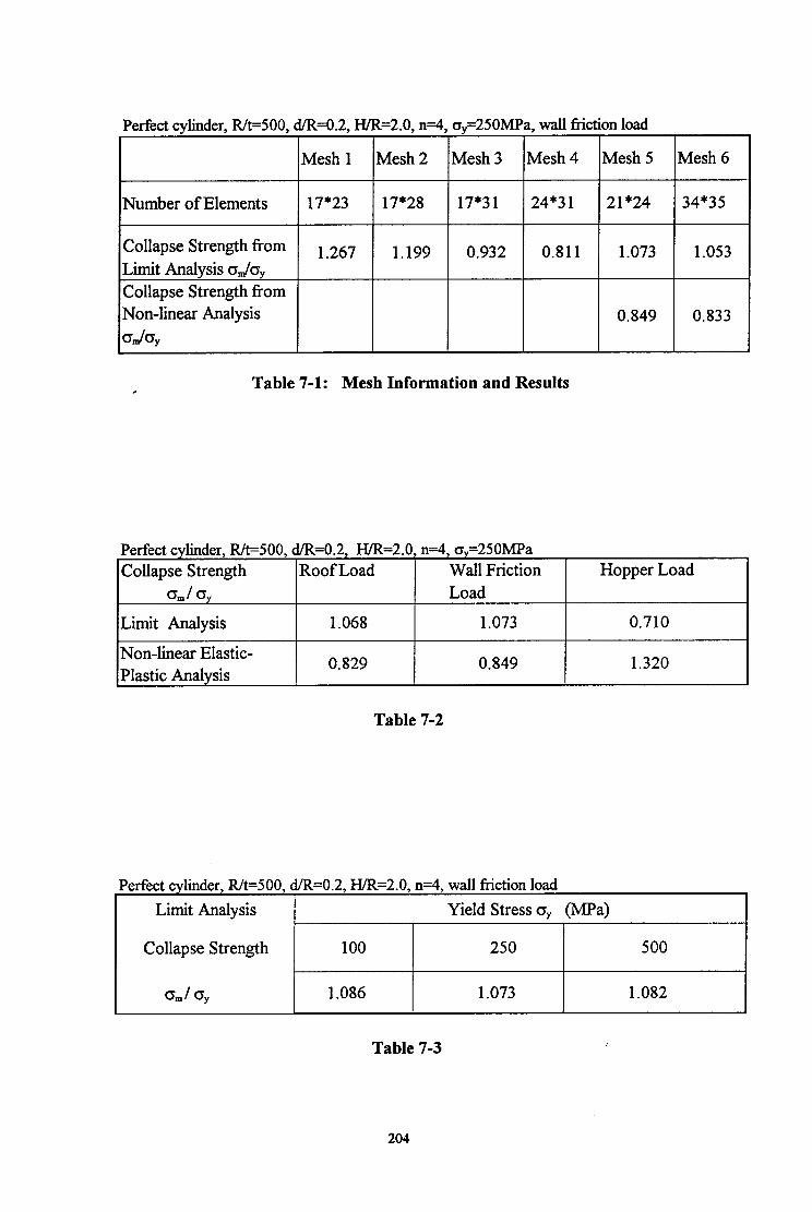
Perfect cylinder, Rk500, d.R=O.2, H/R=2.0, n=4, ay=250MPa, wall friction load
Mesh 1 Mesh 2 Mesh 3 Mesh 4 Mesh 5 Mesh 6
Number of Elements 17*23 17*28 17*31 24*3 1 21*24 34*35
Collapse Strength from 1.267 1.199 0.932 0.811 1.073 1,053 Limit Analysis qJq Collapse Strength from
I Non-linear Analysis I 0.849 0.833 dq
Table 7-l: Mesh Information and Results ,
Perfect cylinder, R/t=500, d/R=O.2, H/R=2.0, n=4, o,=250MPa Collapse Strength Roof Load Wall Friction
d q Load
Limit Analysis 1.068 1.073
Non-linear Elastic- Plastic Analysis
0.829 0,849
Hopper Load
0.710
1.320
Table 7-2
Perfect cylinder, R/t=500, d/R=O.2, H/R=2.0, n=4, wall friction load
Limit Analysis Yield Stress o, (MPa)
Collapse Strength 100 250 500
GJ 0, 1.086 1.073 1.082
Table 7-3 i
204

Perfect cylinder, R/t=500, dR=O.2, HIR=2.0, n=4, oy=250MPa, wall friction load
Approach 1 Modified Riks Method
Case 1 Case 2
Time Period 1.0 1.0 1.0
Min. Load Increment 1 .OE-5 0.01 1 .OE-5
Max. Load Increment 0.1 0.2 0.1
Collapse Strength oJq 0.854 0.660 0.849
Table 7-4 Study of Alternative Nonlinear Analysis Control Procedure
205

CHAPTER 8
NONLINEAR ELASTIC BUCKLING ANALYSIS OF A DISCRETELY SUPPORTED SILO
8.1 INTRODUCTION
The failure of a discretely supported silo structure is an interesting problem of nonlinear
structural response, and in this sense that discretely supported silos are different from ground
supported silos. In a discretely supported thin-walled steel silo, the buckling failure under
axial compression usually occurs in the cylinder. The cylinder buckles into a pattern of small,
diamond shaped waves above the local supports. The peak axial stress is therefore a useful
design parameter. In the preceding buckling analyses of Chapters 5 and 6, a discretely
supported silo structure was simplified into a discretely supported cylinder, using the
assumption that the buckling strength of this cylinder adequately represents the buckling
strength of a complete silo structure. Accordingly, investigations of the linear bifurcation
buckling behaviour and the nonlinear elastic buckling behaviour of discretely supported
cylinders became the main objectives of those chapters.
Previous studies of the stability of silo structures have never addressed the relationship between
buckling strength estimates for both a complete silo and an isolated cylinder. Such a
investigation is carried out here to explore the validity of the simplified cylinder model as a
substitute for a complete silo. This study will be beneficial to designers and to silo analysts
who carry on further studies.
The limited time of this PhD research has meant that only a few analyses on this topic have
been performed. In this chapter, the main focus is on a nonlinear elastic buckling analysis of
an example complete practical silo on discrete supports, with the aim of providing a basis for
further study of the subject. For this purpose, a discretely supported perfect silo has been
modelled in the finite element analysis and the elastic buckling behaviour of the silo under axial
compression examined.
206
8.2 FINITE ELEMENT MODELLING
The complete example silo used in the analysis of this chapter is shown in Fig. 8-l. It is a
discretely-supported thin-walkd silo which consists of a conical roof, a cylinder and a conical
hopper. Discrete supports of a certain width were again assumed to terminate at the
transition junction between the cylinder and the conical hopper. They were chosen to be
equally spaced and to provide rigid supports. As in the previous buckling analyses of
discretely supported cylinders, any 1/2n section of the silo (Fig. 8-1) can be modelled instead of
the whole silo by taking the geometric and loading symmetries into consideration. The
botmdary conditions for the two vertical (meridional) edges of the modelled section were
determined from symmetry considerations. Both the apices of the conical roof and hopper were
assumed to move freely in the axial direction but to be fully restrained against displacements in
other directions and all rotations. The axial compression developing in the silo wall was
represented in terms of the three axial loading patterns shown in Fig. 8- 1.
The finite element program ABAQUS was again used to perform all the numerical calculations
of this chapter using the modified Riks method. Both shell element types STRI65 and S9R5
were used. The STRI65 triangular elements were assigned at the apices of the conical roof and
hopper to fit the triangular mesh division there whilst the S9R5 elements were placed for all the
other quadrilateral element meshes.
To define the geometry of a complete silo, two new geometric parameters were adopted in
addition to the previous parameters R/t , d/R, H/R, n. The two parameters were defined in
terms of the half angle of the conical roof and hopper, 8, and 0,, respectively (Fig. 8-l).
Only an elastic perfect silo was examined in this study. The geometry of the example silo was
specified by the geometric parameters R/MOO, d/R=O.2, H/R=2.0, n=4 (for the cylindrical
shell of the silo), and 8, =60 deg. and 6, = 40 deg. (regarding the conical roof and hopper
respectively).
This example silo was assumed to be made of steel with the same Young’s modulus E = 2x 10’
MPa and Poisson’s ratio v = 0.3 as before. It is evident that the results obtained may also be
applied to other materials by suitable dimensionless interpretation.
In this chapter, the results are presented in the dimensionless manner introduced in Chapter 1.
The buckling behaviour, buckling strength and buckling mode of the example silo are
described.
207

8.3 BEHAVIOUR OF AN ELASTIC PERFECT SILO ON DISCRETE
SUPPORTS
In this study, the example elastic perfect silo defined in Section 8.2 was analysed. The
behaviour of the silo under the three axial loading cases (Fig. S-l) was investigated.
It was found that for the cases when the silo was subjected to a ring load at the upper edge of
the cylindrical shell (roof load) or a uniform frictional load on the surface of the entire
cylindrical wall (wall friction load), the ABAQUS program was not able to find a bifurcation
point when the silo fails by elastic buckling. For both loading cases, the nonlinear incremental
calculation terminated automatically at a certain load proportionality factor when convergence
was judged unlikely above that load within the program’s default minimum load increment of
1W. This might indicate a limitation in the ABAQUS program in analysing the particular silo
structural model, or a load path which is very difficult to follow in the neighbourhood of this
final load level.
A bifurcation point was obtained for the case when the silo is subjected to a ring load at the
lower edge of the cylindrical shell (elsewhere termed hopper load). The relation between the
axial load and the axial displacement of the point on the upper edge of the cylindrical shell
above the support centreline is shown in Fig. 8-2. This load versus displacement curve
exhibits a similar form to that of the curve obtained for an axially compressed perfect cylinder,
which was shown in Fig. 6-3 of Chapter 6. The vertical displacements are very small until the
load rises to the bifurcation point and then large displacements follow as the load decreases.
Comparing the critical loads of the complete silo and the cylinder under the same hopper
loading condition, it was found that the bifurcation load of the silo is higher than that of the
cylinder by 17%. The buckling mode of the silo under the ring load at the lower edge of the
cylinder is shown in Fig. 8-3. A single buckle occurs in a local zone in the cylindrical shell of
the silo and presents a similar deformed configuration to that of an isolated cylinder at buckling
as shown in Fig. 6-5 of Chapter 6.
The buckling strength of the silo under the hopper load, together with the available maximum
converged strengths under the roof load and the wall friction load respectively, is listed in
Table 8- 1. Although the maximum load levels under the roof load and the wall friction cannot
be assumed to be the strengths of the silo at buckling, it is certain that the buckling strengths
for the silo under the roof load or the wall friction load are equal to or higher than the obtained
values. Comparing with the results shown in Table 6-1 of Chapter 6, it can be seen that the
buckling strength obtained for a complete silo is about 9 - 17% higher than that for a perfect
cylinder of the same geometry. I’
208

The above analysis demonstrates that the simplification of modelling a silo as an isolated
cylinder may give relatively conservative predictions for the buckling strength of a silo
structure. The buckling behaviour and buckling mode found when using a discretely supported
cylinder to model a discretely supported silo represent realistic models of the behaviour and
buckling mode of a complete silo structure. Therefore it can be inferred that the results for the
nonlinear elastic buckling analysis of discretely supported perfect cylinders are acceptable and
conservative for the design of silo structures.
8.4 CONCLUSIONS
A complete practical silo structure was chosen and investigated. Studies were focused on the
nonlinear elastic buckling of a discretely supported perfect silo with the same geometry of the
cylindrical shell as that of a cylinder previously analysed in Chapter 6 and under the same axial
loading conditions as described before. The buckling behaviour, buckling strength and
buckling mode of the studied silo structure were examined.
From the results of this analysis, it is clear that the simplification of modelling a discretely
supported silo into a discretely supported cylinder gives a conservative prediction of the
practical buckling strength of the silo structure. Also, this simplification of using a discretely
supported cylinder to model a complete silo represents the realistic behaviour and mode of a
silo structure at buckling. Therefore it can be concluded that in practical design for a
discretely supported thin-walled silo structure, using a cylinder to model a complete silo may
not only simplify the calculation but also provide acceptable and conservative results for design
use.
209

kR+ conical
foofIoad I/
\ - iinite element model section
symmetric line A B
Discretely Supported Silo Model
Figure 8-l
210

Load-Deflection Curve for a Discretely Supported Silo under Hopper Load
~4, R&=500, dlbO.2, HlR=2,0p60 degree, Cl&O degree
0 0.1 0.2 0.3 0.4 0.5
Axial Displacement at Upper Edge above Support Centreline u/t
0.6
Figure 8-2
211

Buckling Mode for a Discretely Supported Perfect Silo under Hopper Load n=4, Rh500, d/R=0.2, H.iR=2.0, &=60 degree, &=40 degree
Figure 8-3
212
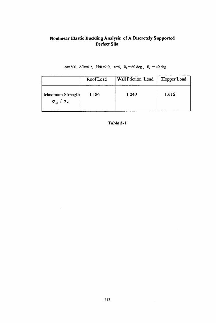
Nonlinear Elastic Buckling Analysis of A Discretely Supported Perfect Silo
R&500, dhWI.2, H/R=2.0, n=4, Cl, = 60 deg., & = 40 deg.
Roof Load Wall Friction Load Hopper Load
Maximum Strength 1.186 1.240 1.616
0, / 001
Table 8-l
213
CHAPTER 9 CONCLUSIONS AND RECOMMENDATIONS
9.1 SUMMARY
Many analyses of steel silo structures on discrete supports have been carried out in this thesis.
The studies performed in this thesis were concerned with linear elastic shell bending problems
in cylindrical shells under local longitudinal loadings and stability (buckling and collapse)
problems in isolated cylinders on discrete supports under a variety of geometric and loading
conditions.
.
Before attacking the complex stability problems of elastic buckling and elastic-plastic collapse
in locally supported silo structures using the finite element method, an analytical method was
used to study elastic cylindrical shells under local loadings, with special attention to patches of
longitudinal loading. A linear elastic algebraic solution of the shell bending equations was
derived using double Fourier series. A computer program was developed to evaluate the
expressions derived using this analytical method and the results were compared with those
obtained from finite element analysis.
For the stability analyses, the discretely supported silo structure was first considerably
simplified. It was modelled as a thin-walled cylinder directly supported on discrete rigid
supports of a finite width at the lower edge. These rigid supports were assumed to fully
restrained the vertical displacements at the lower edge of the cylinder. The finite element
program ABAQUS was used to perform all the calculations. The geometry of the discretely
supported perfect cylinder was characterised by four dimensionless parameters: the radius-to-
thickness ratio R/t, the support-width-to-radius ratio d/R, the height-to-radius ratio H/R and
the number of supports n. Two other parameters were used to define a local imperfection
introduced in the cylinder wall: the ratio (SJt) of the imperfection amplitude 6, at the centre of
the imperfection to the cylinder thickness t and the ratio (ZJt) of the distance 2, between the
centre of the imperfection and the bottom edge of the cylinder to the cylinder thickness t. The
local imperfection was assumed to be axisymmetric and of either an inward or an outward
shape, representing a local severe imperfection at a circumferential weld in the shell wall.
Three types of axial loading: roof, wall friction and hopper load were assumed to model
extreme cases of practical loadings on the silo walls from the stored bulk solids and were
analysed in all the stability studies. A uniform internal pressure on the cylinder wall was
assumed to represent the normal pressure imposed by the bulk solids stored in the shell and
214

was applied to the cylinder together with axial compression. The axial compression load
applied to the cylinder wall was characterised by the ratio of the mean meridional (axial) stress
above the support to the classical elastic critical stress for a cylindrical shell under uniform
axial compression, cr&~,, or to the yield stress, q,&,. The strength of the cylinder at
buckling or collapse was defined in terms of the maximum value of the dimensionless mean
axial stress above support.
A typical perfect cylinder with R/t=500, d/R=O.2, H&=2.0 and n=4 was most widely analysed
as an example structure in the studies. An example imperfect cylinder was defined by
introducing an inward axisymmetric imperfection with S,$=l .O and Z&=103 in the wall of the
example perfect cylinder. The steel material of which the silos are made was assumed to be
linear and isotropic with elastic modulus E = 2x lo5 MPa and Poisson’s ratio o = 0.3. The
plastic response of the material was assumed to be ideally elastic-plastic, obeying the von
Mises yield criterion with a normal flow rule. The yield stress of the material cry was mostly
chosen as 250 MPa.
Linear elastic stability analyses of discretely supported perfect cylinders under axial
compression were first carried out. The linear elastic stress analysis examined the pre-buckling
meridional membrane stress distribution above the support centreline for perfect cylinders with
various geometries and under different loading conditions. Next, linear bifurcation analyses
investigated the linear bifurcation behaviour, mode and strength of these cylinders. Only axial
compression forces applied to the cylinder were considered.
Taking large displacements in the cylinder into account, geometrically nonlinear elastic
buckling analyses of discretely supported cylinders were performed next. Cylinders were
studied which were both geometrically perfect and imperfect, and both unpressurized and
pressurized. The effects of the position of the applied axial compression loading and internal
pressurization on the nonlinear elastic buckling behaviour, mode and strength of discretely
supported perfect and imperfect cylinders were examined.
Further, elastic-plastic stability problems in discretely supported cylinders were analysed.
Both small deflection limit analyses of perfect cylinders and geometrically nonlinear elastic-
plastic collapse analyses of both perfect and imperfect cylinders were performed. In the limit
analysis, the chief effort was exerted on investigating the effects of the axial loading case, the
geometric parameter R/t and the yield stress of the material Nonlinear elastic-plastic collapse
analyses were conducted on a wide range of problems, covering the different loading cases, the
cylinder slenderness R/t, the level of internal pressurization and the magnitude and position of a
detrimental axisymmetric inward imperfection in the wall of the cylinder. ’
215

Finally a complete practical silo structure was chosen and investigated. Studies were focused
on the nonlinear elastic buckling of a discretely supported perfect silo with the same geometry
of the cylindrical shell as that of the previously analysed cylinders in Chapter 6 and under the
same axial loading conditions as described before. The buckling behaviour, buckling strength
and buckling mode of the studied silo structure were examined.
9.2 CONCLUSIONS
9.2.1 Algebraic Analysis of Elastic Cylindrical Shells under Local Loadings
A linear elastic solution of the shell bending equations was presented for cylindrical shells
under local loadings, with special attention to local longitudinal distributed patch loads.
Algebraic expressions for the displacements and stresses induced by a patch of longitudinal
load on a simply supported cylindrical shell were derived using double Fourier series. A
satisfactory match has been found from the comparative studies between the predictions of
stresses and displacements using these obtained expressions and the finite element results using
the finite element program LEASH for a sample problem.
The method discussed in this chapter is of a general nature and therefore can be applied to
many cases when cylindrical shells are subjected to local loadings in any direction and with
different boundary conditions.
9.2.2 Linear Elastic Stress and Bifurcation Analyses of Discretely Supported
Perfect Cylinders
Linear elastic pre-buckling stress analyses were used to explore the meridional membrane
stress distribution in the cylinder. It was found that the distribution is very sensitive to the
position of the applied loading, especially in the vicinity of the supports where the highest
stresses arise. In general, a load applied at the top boundary induces the highest stress profile
in the cylinder whilst one at the bottom boundaT induces the lowest. The pattern of the stress
dispersal above the support centreline does not change very much for cylinders with typical
geometric parameters such as R/t varying from 200 to 1000, IVR larger than 1.0 and d/R
larger than 0.1, except for very short cylinders on rather narrow supports.
Because of the influence of the position of the axial loading on the stress distribution in the
cylinder, changes in the linear bifurcation load also occur. The magnitude of the buckling load
varies with the magnitude of the maximum stress induced by a given loading pattern. A higher
pre-buckling local stress generally leads to a smaller buckling load. It was found that the local
high stress above the support is crucial to the formation of the buckle and strongly influences
216

the buckling strength of the cylinder. For the example perfect cylinder with R&500, d&=0.2,
H/R=2.0 and n=4, a ring load applied at the roof leads to a lower bifurcation load than wall
friction loading or hopper loading by 1.6% and 25% respectively.
As the geometric parameters of the cylinder vary within practical bounds (such as R/t between
200 and 1000; d/R between 0.05 and 0.3; H/R less than 2.0), the bifurcation buckling load
changes considerably. For example, the difference between the buckling strengths of cylinders
subject to hopper loading may reach a factor of 7.5 between thick tall cylinders on narrow
supports and thin squat cylinders on wide supports, even when expressed in the dimensionless
terms used in this thesis, which substantially account for thickness effects.
The linear bifurcation analyses of discretely supported perfect cylinders have the deficiency
inherent in small deflection theories that they ignore the effects of the pre-buckling deflections
and geometric imperfections, so that these analyses cannot be used to accurately assess the
buckling strength of a cylinder. In order to probe the elastic stability of cylinders, nonlinear
analysis based upon large deflection theory is needed.
9.2.3 Nonlinear Elastic Buckling Analysis of Perfect and Imperfect Cylinders
on Discrete Supports
Based upon large displacement theory, geometrically nonlinear elastic buckling analyses of
cylinders under axial compression discovered that the position of the applied axial load has
only a small effect on the buckling behaviour and buckling mode of a locally supported
cylinder on discrete supports. However, the changes in buckling strength with load position
are significant. The roof loading case leads to the lowest strengths. The difference between
this and wall friction loading is generally around 2% and between roof loading and hopper
loading is generally around 22% for perfect cylinders. This trend in the buckling loads is the
same as that found in the preceding linear bifurcation analyses of perfect cylinders.
The sensitivity of the buckling strength to the position of the applied load may or may not be as
strong for an imperfect cylinder as that for a perfect cylinder, depending on the pattern of the
imperfection form. For an outward imperfection, the increase in buckling strength over the
value for roof loading is about 3% for wall friction loading and 44% for hopper loading. For
an inward imperfection, the corresponding increases are about 3% and 55%. Thus, hopper
loading always produces very high strengths compared with other load cases, which are very
similar.
The geometric imperfection, whether inward or outward, results in a major reduction in the
buckling strength. The imperfection form affects both the buckling strength and the buckling
217

behaviour. With an imperfection amplitude of one wall thickness (Sdt = 1) placed at the
critical height Z, for inward imperfections with wall friction loading, strength reductions
relative to the value for a perfect cylinder of about 40% were found for the inward imperfection
form and about 34% for the outward imperfection.
Previous investigations of uniformly compressed and uniformly supported cylinders showed
that internal pressure reduces the imperfection-sensitivity and increases the buckling strength
significantly. In this first-ever study of the effects of internal pressure in discretely supported
cylinders, the same effect was found, and was shown to vary according to the form of the
imperfection. However, by contrast with the findings for uniformly axially compressed
cylinders, the buckling strength of a perfect locally supported cylinder was also found to be
considerably increased by internal pressure.
For a perfect cylinder, the buckling behaviour and mode do not change significantly from the
unpressurized case until the internal pressurization reaches a high level. For an imperfect
cylinder with inward imperfections, the buckling behaviour is similar as the internal pressure
increases. However, for a cylinder with an outward local imperfection, the internal pressure
seriously alters its behaviour and buckling mode Corn the case of axial compression alone.
The buckling modes are very local in the zone immediately above the support. Only a single
buckle was found for the chosen cylinder geometry and relatively narrow supports used in the
study.
Although internal pressure can significantly enhance the buckling strength, the governing
failure mode of a cyh.ndrical silo is generally buckling under axial compression. From this
study it is still difficult to produce a general proposal for estimating the strength gains due to
internal pressurization. This is because high internal pressures give rise to severe local bending
near the base of the cylinder and local yielding may then precipitate a buckling failure.
Therefore, the study of this thesis was naturally extended to cover the elastic-plastic behaviour
of discretely supported cylinders.
9.2.4 Elastic-Plastic Stability Analysis of Discretely Supported Cylinders
For almost all the geometries, loadings and material strengths studied, the behaviour of the
cylinders in the elastic-plastic region was found to be generally similar, from both the small
displacement limit analysis and the geometrically nonlinear elastic-plastic collapse analysis.
First yield occurs at the edge of the support on the lower edge of the cylinder. After first yield,
the yielded zone grows progressively above the support with increasing displacements until a
maximum load condition is attained when the cylinder collapses. After this collapse condition,
218

found using the geometrically nonlinear analysis, the cylinder enters the post-collapse phase,
when the displacements increase quickly.
The position of the applied axial load was found to alter the dimensionless mean stress above
the column at plastic collapse significantly. The same trend in the collapse strengths as that
of the buckling strength was obtained from nonlinear elastic-plastic analysis. Varying the
position of the axial loading from the upper edge to the lower edge of the cylinder may
induce an increase in strength by as much as 59%. The limit analysis and the nonlinear
analysis give completely different results for the effect of the variation of the thickness of the
cylinder. In the limit analysis, the dimensionless collapse strength (o,.&,) alters only
slightly as the radius-to-thickness ratio R/t varies, whilst a big change in the collapse strength
is obtained from the nonlinear analysis. In particular, large displacement effects become
very important as the cylinder gets thinner. The normalised limit load strength above the
local support may be considered to be independent of the yield stress of the material if the
normalisation is performed relative to the yield stress. Higher internal pressures may cause a
significant decline in the collapse strength of the shell under axial compression.
An inward imperfection near the bottom edge of the cylinder was found to have a significant
weakening effect on the nonlinear collapse strength. This significant imperfection-
sensitivity should receive particular attention in practical design, since about 73% strength
reduction was found for a typical inward imperfection with the amplitude of 6,/t =l .O and
localised at the critical height of Z,/t = 103. However, no further reduction in the collapse
strength occurs once the imperfection amplitude exceeds a certain level. Higher internal
pressures may cause the collapse strength of an imperfect cylinder with a local inward
axisymmetric imperfection to be slightly higher than that of an axially compressed
pressurised perfect cylinder.
9.2.5 Nonlinear Elastic Buckling Analysis of a Discretely Supported Silo
This analysis has demonstrated that the simplification of modelling a discretely supported
silo into a discretely supported cylinder gives a conservative prediction of the practical
buckling strength of a silo structure. Also, this simplification of using a discretely supported
cylinder to model a complete silo provides a satisfactory model of the behaviour and mode of
a complete silo structure at buckling.
Therefore it can be concluded that in practical design for a discretely supported thin-walled
silo structure, using a cylinder to model a complete silo may not only simplify the calculation
but also provide acceptable and conservative results for design use.
219
9.3 RECOMMENDATIONS FOR FUTURE WORK
In this thesis, studies have been carried out on thin cylindrical shells under local loadings, with
special reference to locally supported steel silo structures. Knowledge of the behaviour of
practical silo structures has been extended through the theoretical analyses of this thesis. The
conclusions drawn from this research may provide design guidance for practical silo design and
construction. However, because of the time limitation of carrying out this PhD research, some
parts of the work have not be conducted very comprehensively. To investigate the structural
behaviour of realistic silo structures sufficiently for comprehensive design guidance to be
developed, more extensive and probing work is needed. This section presents some
recommendations for future work.
9.3.1 Algebraic Analysis of Elastic Cylindrical Shell under Local Loadings
In Chapter 4, a method of finding the loads and displacements, caused in cylindrical shells by
local loadings, was described using double Fourier series. With this method, expressions were
derived for the deflections, bending moments and membrane forces induced in a simply
supported circular cylindrical shell subjected to local longitudinal distributed loadings. It is
evident that these expressions are of special nature, only suitable for the shell with the assumed
simply supported boundary condition and under a patch of load in the longitudinal direction.
However, this method is general. Therefore, using this method and solving the general
equilibrium equations for cyhndrical shells under local loadings in three directions, defined by
Equation (4.4) of Chapter 4, a general solution could be derived, and applied to cylindrical
shells under local loadings in any direction and with different boundary conditions.
In addition, more computer calculations should be performed to predict the stresses and
deflections in the shell caused by local loadings.
9.3.2 Nonlinear Stability Analysis of Locally Supported Silos
Analyses using large deflection theory lead to more accurate predictions of the buckling and
collapse strengths of practical locally supported silos. In all the stability studies performed in
this thesis, some assumptions concerning loadin g, material, support boundary conditions and
the assumed geometric imperfections have been used to simplify the complex silo structures
which exist in practice. In reality, failures and damage which occur to an elevated silo
structure may be caused by more complex factors than those considered in this thesis.
Therefore, the research in this thesis is basic and should be extended.
In this thesis, only rigid supports have been examined. However, in reality, a local support is
neither completely rigid nor completely flexible, but lies between the two. In the case of
220

modelling the local supports as rigid, an upper bound on the strengths of practical locally
supported silo structures has been derived. Assuming the discrete supports to be completely
flexible is another limiting case which predicts the lower bound of the actual strength of silo
structures. Therefore, it deserves further study, even though practical supports appear to be
close to the rigid condition.
It is widely recognised that axial compression and internal pressure on the cylindrical wall of a
silo during filling or flow are not as uniform as has been assumed in this thesis. As described
in Chapters 1 and 2, they are actually rather complex and of a dynamic nature. Except for the
loads from the bulk solids stored in the shell, other external loads, such as earthquake and wind
loads may be applied to the structure. So far all the studies have been focused on simplified
static loading conditions. Therefore more complex loading conditions should be taken into
account in future studies of silo structures.
A locally supported silo in service is usually stiffened by the transition ring at the
cylinder/hopper and the cylinder/roof transition junction or by the local supports engaging into
the cylindrical shell for a short distance or extending to the eaves. Moreover, non-
axisymmetric geometric imperfections and non-axisymmetric boundary conditions often arise
in practical silo structures. These different structural forms may present different structural
behaviours from those discovered in this thesis for the silo cylinders directly supported on
discrete supports. Thus, analysis models should be generated to reflect these realistic
structural forms and characters of silos. The nonlinear buckling and collapse analyses of
practical silo structures using these advanced models will lead to more accurate and reliable
results and findings for practical design use.
221

REFERENCES
ABAQUS Theory Manual, Users Manual, Version 4.8 (1989), Version 5.2 (1992), Hibbitt,
Karlsson & Sorensen, Inc.
AC1 3 13-77 (1977) Recommended Practice for Design and Construction of Concrete Bins,
Silos and Bunkers for Storing Granular Materials, with commentary, American Concrete
Institute, Detroit, (Revised 1983).
API 620 (1978) Recommended Rules for the Design and Construction of Large Welded,
Low-pressure Storage Tanks, American Petroleum Institute, 6th Edn, Washington, D.C..
Arbocz, J. (1974) “The Effect of Initial Imperfection on Shell Stability”, in Thin Shell
Structures, edited by Y.C. Fung and E.E. Sechler, Prentice Hall, pp 205-246.
Arbocz, J. (1983a), “The Imperfection Data Bank: A Means to Obtain Realistic Buckling
Loads”, in Buckling of Shells, edited by E. Ramm, Springer Verlag, Berlin 1982, pp 535-
567.
Arbocz, J. and Babcock, C.D. (1969), “The effect of General Imperfection on the Buckling
of Cylindrical Shells”, Journal of Applied Mechanics, Vol. 36, pp 28-38.
Arbocz, J. and Sechler, E.E. (1974), “On the Buckling of Axially Compressed Imperfect
Cylindrical Shells”, Journal of Applied Mechanics, ASME, Vol. 4 1, No. 3, pp 737-743.
Arbocz, J. (199 l), “Towards an Improved Design Procedure for Buckling Critical
Structures”, Buckling of Shell Structures, on Land, In the Sea and In the Air, Edited by J.F.
Jullien, Elsevier Applied Science, 199 1.
AWWA DlOO-79 (1979), Standard for Welded Steel Tanks for Water Storage, American
Water Works Association, Denver, Colorado.
Baker, E.H., Kovalevsky, L. and Rish, F.L. (1972), Structural Analysis of Shells, McGraw-
Hill.
Bavilacqua, L., Feijoo, R. and Valid, R. (1985), Inelastic Behaviour of Plates and Shells,
IUTAM Symposium, Rio de Janeiro, Brazil, August 5-9, 1985, Springer-Verlag, Berlin
Heidelberg New York London Paris Tokyo.
222
Bijlaard, P.P. (1954), “Stresses from Radial Loads in Cylindrical Pressure Vessels”, Welding
Journal (Supplement), Vol. 33, December 1954, pp 615-s - 623-s.
Bijlaard, P.P. (1955), “Stresses from Local Loadings in Cylindrical Pressure Vessels”,
Transactions of ASME, Vol. 77, August 1955, pp 805816.
Bijlaard, P.P. (1955), “Stresses from Radial Loads and External Moments in Cylindrical
Pressure Vessels”, Welding Journal, Vol. 34, December 1955, pp 608-s - 617-s.
Blacker, M.J. (1988), “Buckling of Steel Silos under Wind Action”, Proc. Int. Conf. ‘Silos-
Forschung und Praxis’, Universitat Karlsruhe, October, pp 3 19-332.
Bornscheuer, F.W. and Hafner, L. (1983), “The Influence of an Imperfect Circumferential
Weld on the Buckling Strength of Axially Loaded Circular Cylindrical Shells”, 3rd
International Colloquium on Stability of Metal Structures, Preliminary Report, Paris,
November, 1983.
Briassoulis, D. and Curtis, J. (1985), “Design and Analysis of Silos for Friction Forces”,
Journal of Structural Engineering, Vol. 111, No. 6, June, 1985, pp 1377-1398.
Brush, D.O. and Almroth, B.O. (1975), Buckling of Bars, Plates and Shells, McGraw-Hill,
New York.
Budiansky, B. (1976), Buckling of Structures, International Union of Theoretical and
Applied Mechanics, Symposium Cambridge/USA 1974, Springer-Verlag Berlin Heidelberg
N.Y..
Budiansky, B. and Radkowski, P.P. (1963) “Numerical Analysis of Unsymmetrical Bending
of Shells of Revolution”, AIAA Journal, Vol. 1, No.8, pp 1833-l 842.
Budiansky, B. and Sanders, J.L. (1963), “On the Bset First-Order Linear Shell Theory”,
Progress in Applied Mechanics, The Prager Anniversary Volumn, Macmillan, pp 129-140.
Calladine, C.R. (1983), Theory of Shell Structures, Cambridge University Press.
Calladine, C.R. (1985), Plasticity for Engineers, Ellis Hot-wood, Chichester.
Clarke, M.J. and Rotter, J.M. (1988), “A Technique for the Measurement of Imperfections in
Prototype Silos and Tanks”, Research Report R565, School of Civil and Mining
Engineering, University of Sydney, Australia.
223

Delpak, R. (1980), “Static Analysis of Thin Rotational Shells”, Computers and Structures,
Vol. 10, No. 4, pp 305-325.
DIN 1055 (1964) Design Loads for Buildings: Loads on Silos: B1.6, German Standards
Institute, Berlin.
DIN 1055 (1986) Design Loads for Buildings: Loads on Silo Bins - Part 6, German
Standards Institute, Berlin.
Donnell, L.H. (1933), “Stability of Thin-Walled Tubes under Torsion”, NACA Technical
Report, No. 479, pp 95-l 16.
Donnell, L.H. (1933), “A New Theory for the Buckling of Thin Cylinders under Axial
Compression and Bending”, ASME Transactions, Vol. 56, pp 795-806.
Drucker, D.C. and Shield, R.T. (1959) “Limit Analysis of Symmetrically Loaded Thin Shells
of Revolution”, Journal of Applied Mechanics, Vol. 26, March.
Dubas, P. and Gehri, E. (1986), Behaviour and Design of Steel Plated Structures, ECCS-
CECM-EKS, Applied Statics and Steel Structures, Swiss Federal Institute of Technology
Zurich, CH-8093 Zurich/Switzerland.
Flugge, W. (1973), Stress in Shells, 2nd edn, Springer-Verlag Berlin Heidelberg NewYork
1973.
Gaylord, E.H. and Gaylord, C.N. (1984) Design of Steel Bins for Storage of Bulk Solids,
Prentice-Hall 1984.
Gould, P.L., Sen, S.K. (1974), “Column Moments in Eccentrically Supported Tanks”,
Journal of the Structural Division, Proc. of ASCE, Vol. 100(3), No. STlO, October, pp 2165-
2169.
Gould, P.L., Sen, S.K., Wang, R.S.C., and Lowrey, D. (1976), “Column Supported
Cylindrical-Conical Tanks”, Journal of the Structural Division, ASCE, No. ST2, February, pp
429-447.
Greiner, R. (199 l), “Elastic Plastic Buckling at Cone Cylinder Junctions of Silos”, Buckling
of Shell Structures, on Land, In the Sea and In the Air, Edited by J.F. Jullien, Elsevier Applied
Science, 199 1.
Guggenberger, W. (1991), “Buckling of Cylindrical Shells under Local Axial Loads”,
Buckling of Shell Structures, on Land, In the Sea and In the Air, Edited by J.F. Jullien,
Elsevier Applied Science, 199 1.
Guggenberger, W. (199 l), Nichtlineares Beulverhalten von Kreiszylinderschalen unter
Lokaler Axialbelastung, PhD Thesis, der Technischen Universitat Graz.
Hill, R. (1950), Mathematical Theory of Plasticity, Oxford University Press.
Hodge, P.G. Jr. (1956), “Displacements in an Elastic-Plastic Cylindrical Shell”, Journal of
Applied Mechanics, Vol. 23, 1956.
Hodge, P.G. Jr. (1960), “Yield Conditions for Rotationally Symmetric Shells under
Axisymmetric Loading”, Journal of Applied Mechanics, Vol. 27, June.
Hodge, P.G. Jr. (1963), Limit Analysis of Rotationally Symmetric Plates and Shells,
PRENTICE-HALL, INC., Englewood Cliffs, New Jersey.
Hodge, P.G. Jr. (1964), “Plastic Design of a Closed Cylindrical Structure”, Journal of
Mechanics and Physics of Solids, Vol. 12, pp l-10.
Hodge, P.G. Jr. and Brooklyn, N.Y. (1954) ‘Rigid-Plastic Analysis of Symmetrically Loaded
Cylindrical Shells”, Journal of Applied Mechanics, Vol. 2 1, December.
Hodge, P.G. Jr. and Joseph Panarelli (1962), “Interaction Curves for Circular Cylindrical
Shells According to the Mises or Tresca Yield Criterion”, Journal of Applied Mechanics, Vol.
29, No. 2, June.
Hodge, P.G. Jr. and Nardo, S.V. (1958), “Cartying Capacity of an Elastic-Plastic Cylindrical
Shell with Linear Strsin-hardening”, Journal of Applied Mechanics, Vol. 25: Trans. ASME,
Vol. 80, 1958.
Hoff, N.J. (1954), “Boundary-Value Problems of the Thin-Walled Circular Cylinder”,
Journal of Applied Mechanics, Trans. ASME, Vol. 76, 1954, pp. 343-350. /.
225
Hoff, N.J. and Rehfield, W. (1965), “Buckling of Axially Compressed Cylindrical Shells at
Stresses Smaller Than the Classical Critical Value”, Journal of Applied Mechanics, ASME,
Vol. 32, pp 542-546.
Hoff, N.J. and Soong, T.C. (1965), “Buckling of Circular Cylindrical Shells in Axial
Compression”, International Journal of Mechanical Sciences, Vol. 7, pp 489-520.
Hoff, N.J. and Soong, T.C. (1967), “Buckling of Axially Compressed Cylindrical Shells with
Non-Uniform Boundary Conditions”, Proceedings, Symposium on Thin Walled Steel
Structures, University College, Swansea, pp 6 l-80.
Hutchinson, J.W. (1965), “Axial Buckling of Pressurized Imperfect Cylindrical Shells”,
AIAA Journal, Vol. 3, pp 1461-1466.
Hutchinson, J.W. (1967), “Imperfection-Sensitivity of Externally Pressurized Spherical
Shells”, Journal of Applied Mechanics, ASME, Vol. 34, pp 49-55.
Hutchinson, J.W. (1974), “Plastic Buckling”, Advances in Applied Mechanics, ed. C.S. Yih,
Vol. 14, Academic Press, Ontario, pp 85-197.
Hutchinson, J.W. and Koiter, W.T. (1970), “Postbuckling Theory”, Applied Mechanics
Reviews, Vol. 23, pp 1353-1366.
Hutchinson, J.W. and Tennyson, R.C. and Muggeridge, D.B. (1971), “Effect of a Local
Imperfection on the Buckling Behaviour of a Circular Cylindrical Shell under Axial
Compression”, AIAA Journal, Vol. 9, No. 1, pp 48-53.
Ignatenko, V.M. (1978), “Failure of Structural Steel Bins and Critical Design
Considerations”, Proceedings, Metal Structures Conference, Institute of Engineers, Australia,
Perth.
Irons, B.M. (1976) “The Semi-Loof Shell Element”, in Finite Elements for Thin Shells and
Curved Members, eds. Ashwell and Gallagher, Wiley.
Irons, B.M. and Zienkiewicz, O.C. (1970) “Analysis of Thick and Thin Shell Structures by
Curved Finite Elements”, Int. Jnl for Numerical Methods in Engineering, Vol. 2, pp 4 19-45 1.
226

Jaky, J. (1948), “Pressure in Silos”, Proceedings, 2nd International Conference on Soil
Mechanics and Foundation Engineering, Rotterdam, June, Vol. 1, pp 103-107.
Janssen, H.A. (1895), “Versuche uber Getreidedruck in Silozellen”, Zeitschrift des vareines
Deutscher Ingenieure, Vol. 29, No. 35, pp 1045-1049.
Javaherian, H. and Dowling, P.J. (1985) “Large Deflection Elastic-Plastic Analysis of Thin
Shells”, Engineer Structures, Vol. 7, pp 154-162.
Jenkyn, R.T. and Goodwill, D.J. (1987) “Silo Failures: Lessons to be Learned”, Engineering
Digest, September, 1987, pp 19-22.
Jones, R.E. and Strome, D.R. (1966), “Direct Stiffness Method of Analysis of Shells of
Revolution Utilizing Curved Elements”, AIAA Journal, Vol. 4, No. 9, pp 1519-1525.
Jumikis, P.T. (1987), Stability Problems in Silo Structures, PhD Thesis, School of Civil and
Mining Engineering, University of Sydney, N.S.W., Australia.
Kempner, J. (1955), “Remarks on Donnell’s Equations”, Journal of Applied Mechanics,
ASME, march, 1955, pp 117-l 18.
Kildegaard, A. (1967), “Bending of a Cylindrical Shell Subject to Axial Loading”, 2nd
Symposium on Theory of Thin Shells, IUTAM, Copenhagen, September 1967, pp 30 l-3 15,
Springer 1969.
Koiter, W.T. (1963), “The Effect of Axisymmetric Imperfection on the Buckling of
Cylindrical Shells under Axial Compression”, Proceedings, Kon. Ned. Akad. Wet.,
Proceedings Ser. B66, pp 265-279. (See also Applied Mechanics Reviews, Vol. 18, Review
3387, 1965).
Koiter, W.T. and Mikhailov, G.K. (eds) (1980) Theory of Shells, Proceedings, 3rd IUTAM
Symposium on Shell Theory, 1978, North-Holland, Amsterdam.
Libai, A. and Durban, D. (1973), “A Method for Approximate Stability Analysis and its
Application to Circular Cylindrical Shells under Circumferentially Varying Edge Loads”,
Journal of Applied Mechanics, December, pp 971-976.
227
Libai, A. and Durban, D. (1973), “Buckling of Cylindrical Shells Subjected to Nonuniform
Axial Loads”, Journal of Applied Mechanics, ASME, Vol. 44, December, pp 714-720.
Lukasiewicz, S. (1979), Local Loads in Plates and Shells, Sijthoff & Noordhoff, PWN-Polish
Scientific Publishers, Warszawa.
Maeda, Y. and Ishizaki, S. (1979), “Analysis of Cylindrical Shells for Design of Steel Silos”,
Journal of Civil Engineering Design, Vol. 1, No. 4, pp 325-354.
Marcal, P.V. (1970), “Large Deflection Analysis of Elastic-Plastic Shells od Revolution”,
AIAA Journal, Vol. 8, No. 9, pp 1627-1633.
Meek, H.R. (1961), “Bending of a Thin Cylindrical Shell Subjected to a Line Load around a
Circumference”, Journal of Applied Mechanics, September, 196 1, pp 427-433.
Navaratna, D.R., Pian, T.H.H. and Witmer, E.A. (1968), “Stability Analysis of Shells of
Revolution by the Finite Element Method”, AIAA Journal, Vol. 6, No. 2, pp 355-36 1.
Onat, E.T. (1955), “Plastic Collapse of Cylindrical Shells under Axially Symmetric Loading”,
Quarterly of Applied Mathematics, Vol. 13, pp 63-72.
Ooi, J.Y. and Rotter, J.M. (1986): “Wall Pressures in Squat Styeel Silos from Simple Finite
Element Analysis”, Research Report R538, School of Civil and Mining Engineering,
University of Sydney, Australia.
Ooi, J.Y. and Rotter, J.M. (1987) “Elastic Predictions of Pressure in Conical Silo Hoppers”
Research Report 555, School of Civil and Mining Engineering, University of Sydney,
Australia.
Or-y, H. and Reimerdes, H.G. (1987), “Stresses in and Stability of Thin Walled Shells under
Non-Ideal Load Distribution”, Proc. Int. Colloquium on the Stability of Plate and Shell
Structures, Gent, Belgium, April, ECCS, pp 555-561.
Paul, B, and Hodge, P.G. Jr, (1958) “Carrying Capacity of Elastic-Plastic Shells under
Hydrostatic Pressure”, Proc. 3rd U.S. Cong. Appl. Mech., pp 63 l-640, 1958.
Pederson, P.T. (1974), “On the Collapse Load of Cylindrical Shells”, in Buckling of
Structures, edited by B. Budiansky, Springer, New York.
228

Ramm, E. and Buechter, N. (1991) “Buckling of Cylindrical and Conical Shells under
Concentrated Loading”, International Colloquium on Buckling of Shell Structures on Land, in
the Sea and in the Air, Villeurbanne, Lyon, France, 17-19 Sept 1991, pp 3 13-322.
Rekach, V.G. (1978), Static Theory of Thin-Walled Space Structures, Translated from the
Russian by A. Petrosyan, Mir Publishers . Moscow.
Resinger, F. and Greiner, R. (1982) Buckling of Wind-Loaded Cylindrical Shells: Application
to Unstiffened and Ring-Stiffened Tanks, in Buckling of Shells, ed. E. Ramm, Springer-Verlag,
Berlin, pp 305-332.
Riks, E. (1979) “An Incremental Approach to the Solution of Snapping and Buckling
Pfoblems”, International Journal of Solids and Structures, Vol. 15, pp 529-55 1.
Rotter, J.M. (1981), “Axisymmetric Shells under General Loading”, in Structural Aspects of
Steel Silos and Tanks, School of Civil and Mining Engineering, University of Sydney,
Australia, August, pp 6.1-6.39.
Rotter, J.M. (1982), “Analysis of Ringbeams in Column-Supported Bins”, Proc., 8th
Australian Conference on the Mechanics of Structures and Materials, University of
Newcastle, Aug., pp 33.1-33.6.
Rotter, J.M. (1983a), “Structural Effects of Eccentric Loading in Shallow Steel Bins”, Proc.,
2nd Int. Conf. Design of Silos for Strength and Flow, pp 446-463.
Rotter, J.M. (1983b), “The Effect of Increasing Moisture Content on the Stresses in Silo
Walls”, Investigation Report S444, School of Civil and Mining Engineering, Universiv of
Sydney, Australia.
Rotter, J.M. (1983~) “Stress Amplification in Unstiffened Steel Silos and Tanks”, Research
Report R347, School of Civil and Mining Engineering, University of Sydney, Australia.
Rotter, J.M. (1985a), “Membrane Theory of Shells for Bins and Silos”, Design of Steel Bins
for the Storage of Bulk Solids, School of Civil and Mining Engineering, University of Sydney,
pp 58-70.
229

Rotter, J.M.( 1985b), “Bending Theory of Shells for Bins and Silos”, Design of Steel Bins for
the Storage of Bulk Solids, School of Civil and Mining Engineering, University of Sydney, pp
71-81.
Rotter, J.M.( 1985c), “Buckling under Axial Compression”, Design of Steel Bins for the
Storage of Bulk Solids, School of Civil and Mining Engineering, University of Sydney, pp
122-137.
Rotter, J.M.( 1985d), “Analysis and Design of Ringbeams”, Design of Steel Bins for the
Storage of Bulk Solids, School of Civil and Mining Engineering, University of Sydney, pp
164-183.
Rotter, J.M. (ed.) (1985e), Design of Steel Bins for the Storage of Bulk Solids, School of Civil
and Mining Engineering, University of Sydney, Australia.
Rotter, J.M. (1986a), “The Analysis of Steel Bins Subject to Eccentric Discharge”,
Proceedings, Second International Conference on Bulk Materials Storage, Handing and
Transportation, Institution of Engineers, Australia, Wollongong, July, pp 264-27 1.
Rotter, J.M. (1986b), “On the Significance of Switch Pressures at the Transition in Elevated
Steel Bins”, Proceedings, Second International Conference on Bulk Materials Storage: Handing
and Transportation, Institution of Engineers Australia, Wollongong, July, pp 82-88.
Rotter, J.M. (1987), “The Buckling and Plastic Collapse of Ring Stiffeners at Cone/Cylinder
Junctions”, Proceedings, International Colloquim on Stability of Plate and Shell Structures,
Gent, Belgium, April, pp 449-456.
Rotter, J.M. (1988a), “The Structural Design of Light Gauge Silo Hoppers”, Research Report
R57 1, School of Civil and Mining Engineering, University of Sydney.
Rotter, J.M. (1988b), “The Structural Design of Steel Silos for Agricultural Applications”,
Proceedings, Conference on Agricultural Engineering 1988, Institution of Engineers, Australia,
Sydney, pp 333-345.
Rotter, J.M. (1988c), “Recent Research on the Strength of Circular Steel Silos”, Proceedings,
International Conference, October, pp 265-284.
230

Rotter, J.M. (1989a), “The FELASH Suite of Computer Programs for the Analysis of
Axisymmetric Shells”, Proceedings, 4th International Conference on Civil and Structural
Engineeimg Computing, Vol. 1, pp 323-328.
Rotter, J.M. (1989b), “Stress Amplification in Unstiffened Cylindrical Steel Silos and Tanks”,
Civil Engineering Transactions, Institution of Engineers, Australia.
Rotter, J.M. (1990a), “Local Collapse of Axially Compressed Pressurized Thin Steel
Cylinders”, Journal of Structural Engineering, ASCE, Vol. 116, No. 7, July, pp 1955-1970.
Rotter, J.M. (1990b), “Structural Design of Light-Gauge Silo Hoppers”, Journal of Structural
Engineeing, ASCE, Vol. 116, No. 7, July, pp 1907-1922.
I
Rotter, J.M. (199Oc), “Critical Design Features of Steel Industrical Storage Structures”, in
Developments in Structural Engineeimg, Proceedings of the 4th Bridge Century Conference,
ed. B.H.V. topping, London, pp 909-928.
Rotter, J.M. and Hull, T.S. (1985), “Wall Loads in Squat Steel Silos during Earthquake”,
Research Report R509, School of Civil and Mining Engineering, University of Sydney,
Australia.
Rotter, J.M. and Hull, T.S. (1989), “Wall Loads in Squat Steel Silos during Earthquake”,
Engineering Structures, Vol. 11, No. 3, pp 139-147.
Rotter, J.M. and Jumikis, P.T. (1985), “Elastic Buckling of Stiffened Ringbeams for Large
Elevated Bins”, Proceedings, Metal Structures Conference, Institution of Engineers, Australia,
Melbourne, May, pp 104- 111.
Rotter, J.M. and Jumikis, P.T. (1988), “Non-Linear Strain-Displacement Relations for Thin
Shells of Revolution”, Research Report R563, School of Civil and Mining Engineering,
University of Sydney, Australia.
Rotter, J.M. and Seide, P. (1987) “On the Design of Unstiffened Cylindrical Shells Subject to
Axial Load and Internal Pressure”, Proceedings, International Colloquim on Stability of Plate
and Shell Structures, Gent, Belgium, April, pp 539-548.
Rotter, J.M. and Teng, J.G. (1989), “Elastic Stability of Cylindrical Shells with Weld
Depressions”, Journal of Structural Engineering, ASCE. 115(5), 1989, pp 1244-1263.
231

Rotter, J.M. and Teng, J.G. and Li, H.Y. (1991), “Buckling in Thin Elastic Cylinders on
Column Supports”, in Buckling of Shell Structures, on Land, in the Sea and in the Air, edt. J.F.
Jullien, Elsevier Applied Science, London and New York.
Rotter, J.M., Greiner, R., Guggenberger, W., Li, H.Y ., and She, K.M. (1993) “Proposed
Design Rule for Buckling Strength Assessment of Cylindrical Shells under Local Axial
Loads”, Submission to ECCS TWG8.4 Buckling of Shells, Edinburgh Meeting, September
1993.
Rotter, J.M., Trahair, N.S. and Ansourian, P. (1980), “Stability of Plate Structures”,
Proceedings, Symposium on Steel Bins for Bulk Solids, Australian Institute of Steel
Construction and the Australian Welding Research Association, Melbourne, September, pp 36-
4_2.
Sanders, J.L. (1963), “Nonlinear Theories for Thin Shells”, Quarterly of Appled Mathematics,
Vol. 20, No. 1, pp 21-36.
Save, M.A. (1985), “Limit Analysis of Plates and Shells: Research over Two Decades”,
Journal of Structural Mechanics, Vol. 13, Nos 3 & 4, pp 343-370.
Save, M.A. and Massomret, C.E. (1972), Plastic Analysis and Design of Plates, Shells and
Disks, North-Holland Publishing Company-Amsterdam . London.
Sanders, J.L. (1963) “Nonlinear Theories for Thin Shells”, Quarterly of Applied
Mathematics, Vol. 20, No. 1, pp 21-36.
Samuelson, L.A. (1987) “Design of Cylindrical Shells Subjected to Local Loads in
Combination with Axial or Radial Pressure”, Proc. Int. Colloquium on the Stability of Plate
and Shell Structures, Gent, Belgium, April, ECCS, pp 589-596.
Sukhvarsh, J. and Arthur, P.B. (1979), “Stress Analysis of Bins by Shell Bending Theory”,
Journal of the Structural Division, Vol. 105, No. ST6, ASCE, June, 1979, pp 1069-1087.
Teng, J.G. (1990), Buckling and Collapse of Shells and Rings for Steel Silos, Ph.D Thesis,
University of Sydney, Australia.
Teng, J.G. and Rotter, J.M. (1988) “Plastic Collapse of Steel Silo Hoppers”, Research
Report R568, School of Civil and Mining Engineering, University of Sydney, Australia.
232

Teng, J.G. and Rotter, J.M. (1990) “A Study of Buckling in Column-Supported Cylinders”,
Proceedings, International Union for Theoretical and Applied Mechanics, Symposium on
Contact Loading and Local Effects in Thin-Walled Plated and Shell Structures, Prague,
August, 1990, Preliminary Report, Springer, Berlin, pp 39-48.
Teng, J.G. and Rotter, J.M. (1991a), “Linear Bifurcation of Perfect Cylinders on Column
Supports”, Research Report No. 91.02, Department of Civil Engineering and Building
Science, University of Edinburgh.
.
Teng, J.G. and Rotter, J.M. (1991b), “Linear Bifurcation of Column-Supported Perfect
Cylinders: Support Modelling and Boundary Conditions”, Research Report No. 91.03,
Department of Civil Engineering and Building Science, University of Edinburgh.
Timoshenko, S.P. (1940), Theory of Plates and Shells, McGraw-Hill Book Company, Inc.,
New York and London.
Trahair, N.S., et al. (1983), Structural Design of Steel Bins for Bulk Solids, Australian
Institution of Steel Construction, Sydney, Australia.
Walker, D.M. (1966), “An Approximate Theory for Pressure and Arching in Hoppers”,
Chem. Engrg. Sci., Vol. 21, pp 975-997.
Wang, Robert S.C. and Gould, Phillip L. (1974), “Continuously Supported Cylindrical-
Conical Tanks”, Proc. of ASCE, Jml. Struct. Div., Vol. 100(3), No. STlO, October, pp 2037-
2052.
Weingarten, V.I. (1962) “The Buckling of Cylindrical Shells under Longitudinally Varying
Loads”, Journal of Applied Mechanics, Vol. 9, No. 1, March.
Yamaki, N. (1984) Elastic Stability of Circular Cylindrical Shells, North-Holland,
Amsterdam, The Netherlands.
Zienkiewicz, O.C. and Taylor, R.L. (1989), The Finite Element Method, Fourth Edition, Vol.
1, Basic Formulation and Linear Problems, McGraw-Hill, New York.
233