an5247 application note - stmicroelectronics
TRANSCRIPT

February 2021 AN5247 Rev 3 1/36
1
AN5247Application note
Over-the-air application and wireless firmware update for STM32WB Series microcontrollers
Introduction
This document describes the procedure for over-the-air (OTA) firmware update on ST32WB devices with Bluetooth® Low Energy (BLE) connection. It explains how to use the OTA application provided within the STM32Cube firmware package.
This application can update the user application, the wireless firmware and the firmware upgrade service.
www.st.com
Contents AN5247
2/36 AN5247 Rev 3
Contents
1 Glossary . . . . . . . . . . . . . . . . . . . . . . . . . . . . . . . . . . . . . . . . . . . . . . . . . . . 6
2 Reference documents . . . . . . . . . . . . . . . . . . . . . . . . . . . . . . . . . . . . . . . . 6
3 OTA application on STM32WB devices . . . . . . . . . . . . . . . . . . . . . . . . . . 7
3.1 Over-the-air firmware update . . . . . . . . . . . . . . . . . . . . . . . . . . . . . . . . . . . 7
3.1.1 Principle . . . . . . . . . . . . . . . . . . . . . . . . . . . . . . . . . . . . . . . . . . . . . . . . . . 7
3.1.2 OTA application . . . . . . . . . . . . . . . . . . . . . . . . . . . . . . . . . . . . . . . . . . . . 9
3.1.3 Memory architecture . . . . . . . . . . . . . . . . . . . . . . . . . . . . . . . . . . . . . . . . 9
3.1.4 User application update . . . . . . . . . . . . . . . . . . . . . . . . . . . . . . . . . . . . . 12
3.1.5 Wireless firmware update . . . . . . . . . . . . . . . . . . . . . . . . . . . . . . . . . . . 12
3.2 BLE service and characteristics for firmware update . . . . . . . . . . . . . . . . 13
3.2.1 BLE application – Reboot request characteristics . . . . . . . . . . . . . . . . . 13
3.2.2 OTA application - Service and characteristics . . . . . . . . . . . . . . . . . . . . 15
3.2.3 Advertising . . . . . . . . . . . . . . . . . . . . . . . . . . . . . . . . . . . . . . . . . . . . . . . 15
3.3 Flow description . . . . . . . . . . . . . . . . . . . . . . . . . . . . . . . . . . . . . . . . . . . . 16
3.4 Wireless and FUS update procedure . . . . . . . . . . . . . . . . . . . . . . . . . . . . 17
3.5 Updater clients . . . . . . . . . . . . . . . . . . . . . . . . . . . . . . . . . . . . . . . . . . . . . 18
3.5.1 ST BLE Sensor . . . . . . . . . . . . . . . . . . . . . . . . . . . . . . . . . . . . . . . . . . . 18
3.5.2 STM32CubeMonitor-RF . . . . . . . . . . . . . . . . . . . . . . . . . . . . . . . . . . . . . 19
4 OTA step by step . . . . . . . . . . . . . . . . . . . . . . . . . . . . . . . . . . . . . . . . . . . 21
4.1 Project setup . . . . . . . . . . . . . . . . . . . . . . . . . . . . . . . . . . . . . . . . . . . . . . 22
4.1.1 User applications . . . . . . . . . . . . . . . . . . . . . . . . . . . . . . . . . . . . . . . . . . 22
4.1.2 OTA application . . . . . . . . . . . . . . . . . . . . . . . . . . . . . . . . . . . . . . . . . . . 24
4.2 Firmware update with ST BLE Sensor . . . . . . . . . . . . . . . . . . . . . . . . . . . 25
4.2.1 Device connection . . . . . . . . . . . . . . . . . . . . . . . . . . . . . . . . . . . . . . . . . 25
4.2.2 Update of user application . . . . . . . . . . . . . . . . . . . . . . . . . . . . . . . . . . . 28
4.2.3 Update of wireless stack or FUS . . . . . . . . . . . . . . . . . . . . . . . . . . . . . . 31
4.3 Firmware update with STM32CubeMonitor-RF . . . . . . . . . . . . . . . . . . . . 31
4.3.1 Transparent mode . . . . . . . . . . . . . . . . . . . . . . . . . . . . . . . . . . . . . . . . . 31
4.3.2 Update of the user application . . . . . . . . . . . . . . . . . . . . . . . . . . . . . . . . 32
5 Conclusion . . . . . . . . . . . . . . . . . . . . . . . . . . . . . . . . . . . . . . . . . . . . . . . . 34
AN5247 Rev 3 3/36
AN5247 Contents
3
6 Revision history . . . . . . . . . . . . . . . . . . . . . . . . . . . . . . . . . . . . . . . . . . . 35
List of tables AN5247
4/36 AN5247 Rev 3
List of tables
Table 1. Reboot request characteristics . . . . . . . . . . . . . . . . . . . . . . . . . . . . . . . . . . . . . . . . . . . . . . 14Table 2. OTA Service and characteristics declaration . . . . . . . . . . . . . . . . . . . . . . . . . . . . . . . . . . . 15Table 3. AD structure - Main. . . . . . . . . . . . . . . . . . . . . . . . . . . . . . . . . . . . . . . . . . . . . . . . . . . . . . . 16Table 4. AD structure - Manufacturer specific field . . . . . . . . . . . . . . . . . . . . . . . . . . . . . . . . . . . . . . 16Table 5. AD structure – Group B features . . . . . . . . . . . . . . . . . . . . . . . . . . . . . . . . . . . . . . . . . . . . 16Table 6. Services and characteristics of example applications. . . . . . . . . . . . . . . . . . . . . . . . . . . . . 22Table 7. Example (device Bluetooth MAC address = 80:E1:25:00:50:D6) . . . . . . . . . . . . . . . . . . . . 25Table 8. Document revision history . . . . . . . . . . . . . . . . . . . . . . . . . . . . . . . . . . . . . . . . . . . . . . . . . 35
AN5247 Rev 3 5/36
AN5247 List of figures
5
List of figures
Figure 1. STM32WB dual core FW architecture . . . . . . . . . . . . . . . . . . . . . . . . . . . . . . . . . . . . . . . . . 7Figure 2. Update of STM32WB firmware through BLE connection . . . . . . . . . . . . . . . . . . . . . . . . . . . 8Figure 3. OTA procedure sequence. . . . . . . . . . . . . . . . . . . . . . . . . . . . . . . . . . . . . . . . . . . . . . . . . . . 9Figure 4. Simplified memory map of applications . . . . . . . . . . . . . . . . . . . . . . . . . . . . . . . . . . . . . . . 10Figure 5. BLE application and wireless firmware architecture . . . . . . . . . . . . . . . . . . . . . . . . . . . . . . 11Figure 6. User application update . . . . . . . . . . . . . . . . . . . . . . . . . . . . . . . . . . . . . . . . . . . . . . . . . . . 12Figure 7. wireless firmware update . . . . . . . . . . . . . . . . . . . . . . . . . . . . . . . . . . . . . . . . . . . . . . . . . . 13Figure 8. OTA reboot characteristic added in BLE user application . . . . . . . . . . . . . . . . . . . . . . . . . 14Figure 9. OTA dataflow . . . . . . . . . . . . . . . . . . . . . . . . . . . . . . . . . . . . . . . . . . . . . . . . . . . . . . . . . . . 17Figure 10. ST BLE Sensor mobile application . . . . . . . . . . . . . . . . . . . . . . . . . . . . . . . . . . . . . . . . . . . 18Figure 11. STM32CubeMonitor-RF . . . . . . . . . . . . . . . . . . . . . . . . . . . . . . . . . . . . . . . . . . . . . . . . . . . 19Figure 12. STM32CubeMonitor-RF with USB dongle in transparent mode . . . . . . . . . . . . . . . . . . . . . 20Figure 13. Applicative projects . . . . . . . . . . . . . . . . . . . . . . . . . . . . . . . . . . . . . . . . . . . . . . . . . . . . . . . 21Figure 14. User application update - Use case . . . . . . . . . . . . . . . . . . . . . . . . . . . . . . . . . . . . . . . . . . 22Figure 15. Peer-to-peer server device detection . . . . . . . . . . . . . . . . . . . . . . . . . . . . . . . . . . . . . . . . . 26Figure 16. Peer-to-peer application / LED switch . . . . . . . . . . . . . . . . . . . . . . . . . . . . . . . . . . . . . . . . 27Figure 17. Firmware update ST BLE Sensor panel and OTA service detected. . . . . . . . . . . . . . . . . . 28Figure 18. Download of new application . . . . . . . . . . . . . . . . . . . . . . . . . . . . . . . . . . . . . . . . . . . . . . . 29Figure 19. Heart rate profile after update. . . . . . . . . . . . . . . . . . . . . . . . . . . . . . . . . . . . . . . . . . . . . . . 30Figure 20. Update of wireless stack or FUS . . . . . . . . . . . . . . . . . . . . . . . . . . . . . . . . . . . . . . . . . . . . 31Figure 21. USB Dongle programming in USB DFU mode with STM32CubeProgrammer. . . . . . . . . . 32Figure 22. Update of the user application . . . . . . . . . . . . . . . . . . . . . . . . . . . . . . . . . . . . . . . . . . . . . . 33Figure 23. Wireless or FUS update . . . . . . . . . . . . . . . . . . . . . . . . . . . . . . . . . . . . . . . . . . . . . . . . . . . 33
Glossary AN5247
6/36 AN5247 Rev 3
1 Glossary
2 Reference documents
All these documents are available on www.st.com.
BLE Bluetooth® Low Energy (Bluetooth® standard)
CPU1 Cortex® M4 (executes user application)
CPU2 Cortex® M0+ (executes FUS and wireless firmware)
IDE Integrated development environment
IPCC Inter-processor communication controller
FUS Firmware update service
OTA Over-the-air firmware update
SBRSA Option byte - Secure backup RAM start address
SBRV Option byte - Secure boot reset vector
SFSA Option byte - Secure Flash memory start address
SIG Bluetooth® special interest group
SNBRSA Option byte - Secure non-backup RAM start address
[1] RM0434: Multiprotocol wireless 32-bit MCU Arm®-based Cortex®-M4 with FPU, Bluetooth® Low-Energy and 802.15.4 radio solution
[2] AN5185: STM32WB ST firmware upgrade services
[3] UM2288: STM32CubeMonitor-RF software tool for wireless performance measurements

AN5247 Rev 3 7/36
AN5247 OTA application on STM32WB devices
35
3 OTA application on STM32WB devices
3.1 Over-the-air firmware update
3.1.1 Principle
Updating firmware during device lifetime is mandatory to guarantee state-of-art performance, to update the application with new features or corrected patches, and to keep the highest security level.
User application, wireless firmware and FUS update
The STM32WB Series microcontrollers are based on a dual Arm®(a) core.
The user application runs on CPU1 (Cortex® M4), while wireless firmware and FUS run on CPU2 (Cortex® M0+). The three applications can be updated independently.
As wireless and FUS are delivered in encrypted format, their update procedure relies on the STM32WB secure firmware for decryption and installation in the protected area of the Flash memory.
Figure 1. STM32WB dual core FW architecture
Over the air
Update of firmware can be done thanks to typical physical links such as USB, UART or I2C but this procedure requires a physical access with specific connectors on the device. Thanks to OTA it is possible to remotely update the firmware by using a wireless connection. In this application note, the wireless connection uses the BLE protocol.
a. Arm is a registered trademark of Arm Limited (or its subsidiaries) in the US and/or elsewhere.
MS51778V3
Wireless stack FUS
BLE user application
OTA application
CPU2
CPU1
Updatable by OTA
Not updatable by OTA
OTA application on STM32WB devices AN5247
8/36 AN5247 Rev 3
Update clients
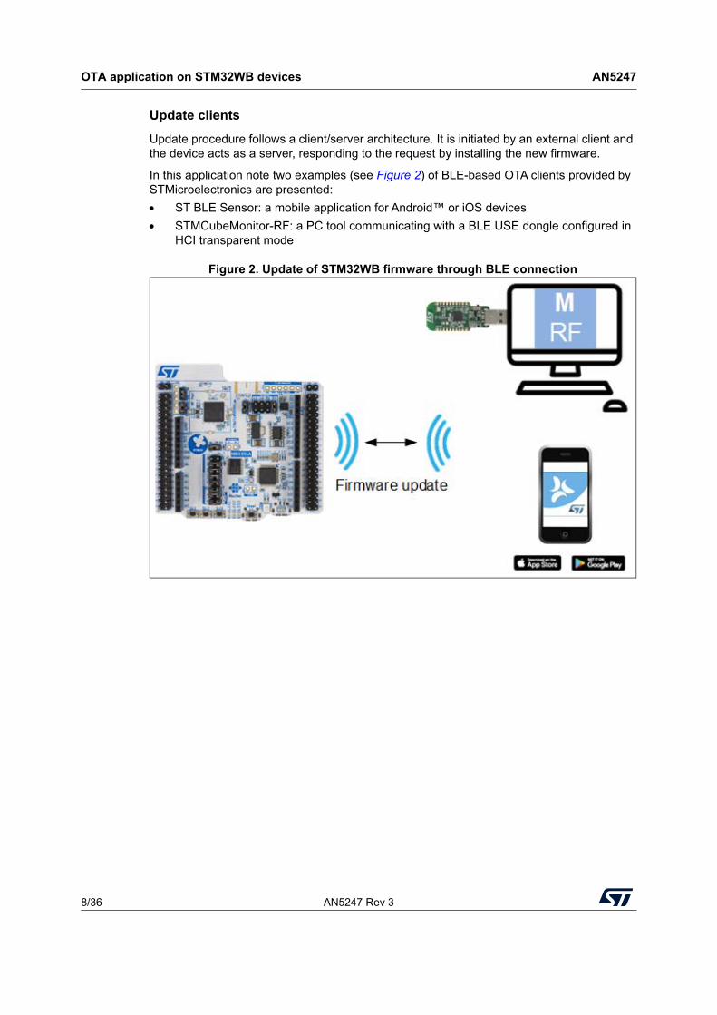
Update procedure follows a client/server architecture. It is initiated by an external client and the device acts as a server, responding to the request by installing the new firmware.
In this application note two examples (see Figure 2) of BLE-based OTA clients provided by STMicroelectronics are presented:
ST BLE Sensor: a mobile application for Android™ or iOS devices
STMCubeMonitor-RF: a PC tool communicating with a BLE USE dongle configured in HCI transparent mode
Figure 2. Update of STM32WB firmware through BLE connection

AN5247 Rev 3 9/36
AN5247 OTA application on STM32WB devices
35
3.1.2 OTA application
OTA application is designed as a standalone application with BLE services for managing firmware transfer on client request, and its installation at the right place in the Flash memory. It is active and executed by CPU1 after an OTA request has been received by the user application.
The sequence is shown in Figure 3, where the numbers in red indicate the different stages.
Initial state is the user application running (1). When an OTA request is received (2), a system reset is triggered (3) and the OTA application becomes active (4) listening for client requests (5). Different services are provided for the update of wireless firmware or user application (6 and 7).
Figure 3. OTA procedure sequence
Note: With this firmware architecture, the current user application is responsible for receiving OTA requests for both the user application and the wireless firmware. This is the entry point of the procedure. OTA application then communicates with the client to update either one or the other firmware.
3.1.3 Memory architecture
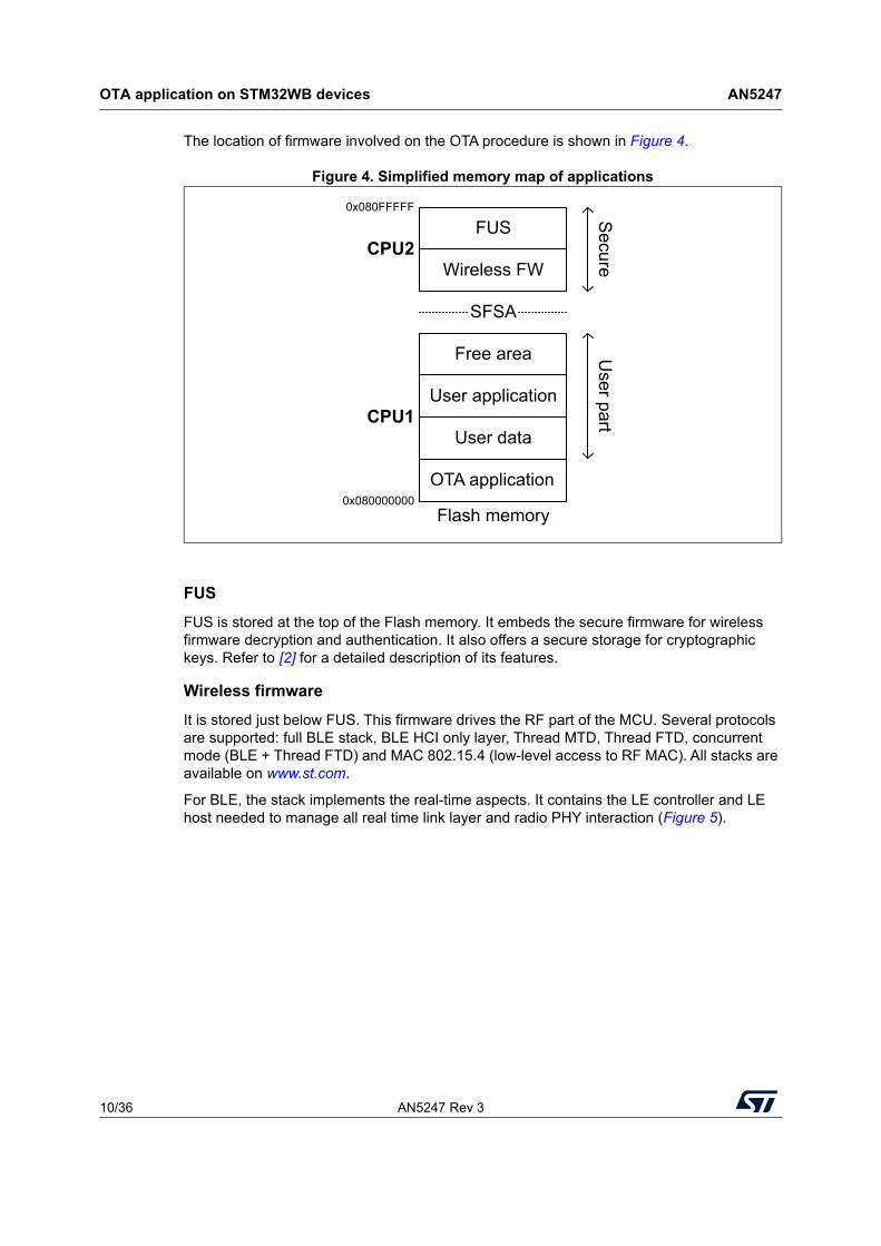
The Flash memory of STM32WB is split in two parts, a user and a secure one. The user part is accessible by CPU1 and contains the OTA application as well as the user application code and data. The secure part is accessible by CPU2 only, and contains FUS and the wireless firmware. This part is not accessible by the debug port, by the user application or by the bootloader. The boundary between the two areas is given by the option byte SFSA, the memory above is secure (see Figure 4). The SFSA value depends on the wireless firmware size, it is adjusted during the install procedure.
MS51780V1
System reset
OTA request?
Application update service
Wirelessupdate service
RSS wireless update service
OTA client User app
3 Reboot service
2 OTA request 4 Yes
1 No
6 User FW or wireless stack update request
7 Update
5 OTA app activeOTA appOTA client
OTA application on STM32WB devices AN5247
10/36 AN5247 Rev 3
The location of firmware involved on the OTA procedure is shown in Figure 4.
Figure 4. Simplified memory map of applications
FUS
FUS is stored at the top of the Flash memory. It embeds the secure firmware for wireless firmware decryption and authentication. It also offers a secure storage for cryptographic keys. Refer to [2] for a detailed description of its features.
Wireless firmware
It is stored just below FUS. This firmware drives the RF part of the MCU. Several protocols are supported: full BLE stack, BLE HCI only layer, Thread MTD, Thread FTD, concurrent mode (BLE + Thread FTD) and MAC 802.15.4 (low-level access to RF MAC). All stacks are available on www.st.com.
For BLE, the stack implements the real-time aspects. It contains the LE controller and LE host needed to manage all real time link layer and radio PHY interaction (Figure 5).
MS51781V2
OTA application
User data
User application
Free area
Wireless FW
FUS
Flash memory
SFSA
CPU2
CPU1
0x080000000
0x080FFFFF Secure
User part

AN5247 Rev 3 11/36
AN5247 OTA application on STM32WB devices
35
Figure 5. BLE application and wireless firmware architecture
User application and data
This is the main user application. It is the applicative part of the device, implementing the BLE profiles and services relying on a wireless protocol. Communication between the user application and the wireless part is done through a mailbox system implemented thanks to the SRAM2 and IPCC hardware blocks (Figure 5). It is stored just above the OTA application in the user Flash memory.
For convenience, a sector for application data not be erased during firmware update can be reserved between the two applications.
Note: A free area of the Flash memory must be available for the new wireless image download in case of updates.

OTA application on STM32WB devices AN5247
12/36 AN5247 Rev 3
OTA application
It is stored in the six first sectors of the Flash memory ([0x08000000: 0x08006000]). It is the active process just after a system reset (CPU1 boot address is at the beginning of the Flash memory). If no OTA request has been issued, the application jumps directly to the user application after having checked it has been fully programmed, otherwise the OTA application is running and is ready to receive commands from the client.
Note: OTA application must be not be removed; if a problem occurs during the procedure, the device cannot recover. It is advised to set a write protection around the OTA application.
3.1.4 User application update
Figure 6 shows the sequence of operation performed by OTA application once a request has been sent for user application update.
Figure 6. User application update
First, the sectors receiving the new firmware are deleted. This procedure is mandatory to be able to reprogram the Flash memory. It is advised to write-protect areas containing application data that need to remain unchanged.
The second step consists in downloading the new image. When firmware transfer is complete, OTA application jumps to the new application.
3.1.5 Wireless firmware update
Wireless firmware is delivered encrypted and signed. A secure FUS firmware is required to decrypt the stack and install it within the secure part of the Flash memory.
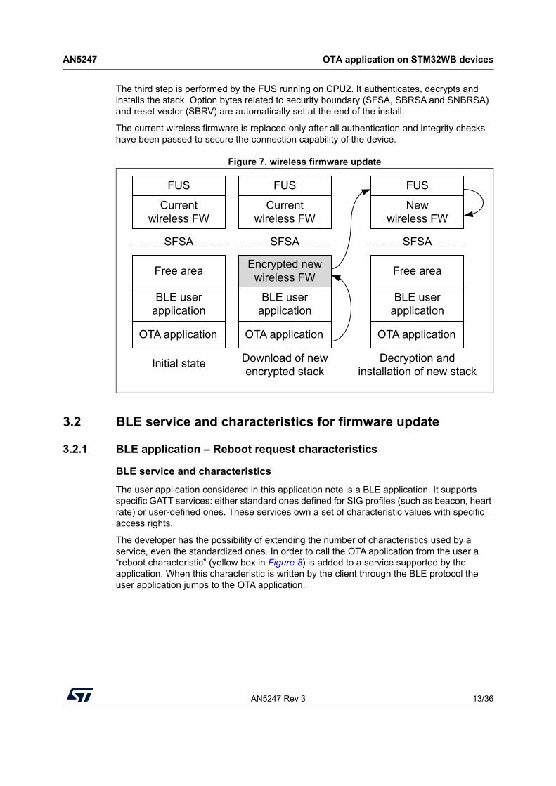
First step of the wireless installation is the same as for user application: sectors of the user Flash memory needed to store the encrypted image are deleted (“Free area” in Figure 7).
In the second step, OTA application downloads the encrypted stack (including the new firmware, in gray in Figure 7) and FUS update service is requested.
MS51782V2
Current application removal
OTA application
Free area
FUS + Wireless
SFSA
OTA application
BLE user application
Free area
FUS + Wireless
SFSA
Initial state
OTA application
New BLE user application
Free area
FUS + Wireless
SFSA
Download of new application
AN5247 Rev 3 13/36
AN5247 OTA application on STM32WB devices
35
The third step is performed by the FUS running on CPU2. It authenticates, decrypts and installs the stack. Option bytes related to security boundary (SFSA, SBRSA and SNBRSA) and reset vector (SBRV) are automatically set at the end of the install.
The current wireless firmware is replaced only after all authentication and integrity checks have been passed to secure the connection capability of the device.
Figure 7. wireless firmware update
3.2 BLE service and characteristics for firmware update
3.2.1 BLE application – Reboot request characteristics
BLE service and characteristics
The user application considered in this application note is a BLE application. It supports specific GATT services: either standard ones defined for SIG profiles (such as beacon, heart rate) or user-defined ones. These services own a set of characteristic values with specific access rights.
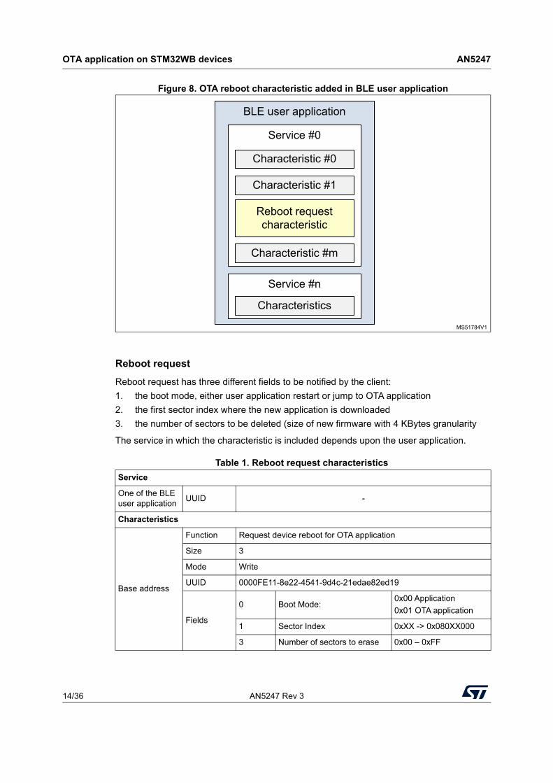
The developer has the possibility of extending the number of characteristics used by a service, even the standardized ones. In order to call the OTA application from the user a “reboot characteristic” (yellow box in Figure 8) is added to a service supported by the application. When this characteristic is written by the client through the BLE protocol the user application jumps to the OTA application.
MS51783V2
Download of new encrypted stack
OTA application
Encrypted new wireless FW
SFSA
OTA application
BLE user application
Free area
Currentwireless FW
SFSA
Initial state
OTA application
BLE user application
Free area
SFSA
Decryption and installation of new stack
FUS
BLE user application
Currentwireless FW
FUS
Newwireless FW
FUS
OTA application on STM32WB devices AN5247
14/36 AN5247 Rev 3
Figure 8. OTA reboot characteristic added in BLE user application
Reboot request
Reboot request has three different fields to be notified by the client:
1. the boot mode, either user application restart or jump to OTA application
2. the first sector index where the new application is downloaded
3. the number of sectors to be deleted (size of new firmware with 4 KBytes granularity
The service in which the characteristic is included depends upon the user application.
Table 1. Reboot request characteristics
Service
One of the BLE user application
UUID -
Characteristics
Base address
Function Request device reboot for OTA application
Size 3
Mode Write
UUID 0000FE11-8e22-4541-9d4c-21edae82ed19
Fields
0 Boot Mode:0x00 Application
0x01 OTA application
1 Sector Index 0xXX -> 0x080XX000
3 Number of sectors to erase 0x00 – 0xFF
BLE user application
Service #n
MS51784V1
Characteristics
Service #0
Characteristic #m
Characteristic #0
Characteristic #1
Reboot request characteristic
AN5247 Rev 3 15/36
AN5247 OTA application on STM32WB devices
35
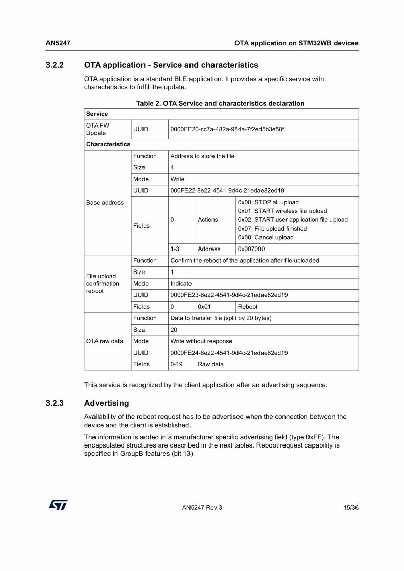
3.2.2 OTA application - Service and characteristics
OTA application is a standard BLE application. It provides a specific service with characteristics to fulfill the update.
This service is recognized by the client application after an advertising sequence.
3.2.3 Advertising
Availability of the reboot request has to be advertised when the connection between the device and the client is established.
The information is added in a manufacturer specific advertising field (type 0xFF). The encapsulated structures are described in the next tables. Reboot request capability is specified in GroupB features (bit 13).
Table 2. OTA Service and characteristics declaration
Service
OTA FW Update
UUID 0000FE20-cc7a-482a-984a-7f2ed5b3e58f
Characteristics
Base address
Function Address to store the file
Size 4
Mode Write
UUID 000FE22-8e22-4541-9d4c-21edae82ed19
Fields0 Actions
0x00: STOP all upload
0x01: START wireless file upload
0x02: START user application file upload
0x07: File upload finished
0x08: Cancel upload
1-3 Address 0x007000
File upload confirmation reboot
Function Confirm the reboot of the application after file uploaded
Size 1
Mode Indicate
UUID 0000FE23-8e22-4541-9d4c-21edae82ed19
Fields 0 0x01 Reboot
OTA raw data
Function Data to transfer file (split by 20 bytes)
Size 20
Mode Write without response
UUID 0000FE24-8e22-4541-9d4c-21edae82ed19
Fields 0-19 Raw data
OTA application on STM32WB devices AN5247
16/36 AN5247 Rev 3
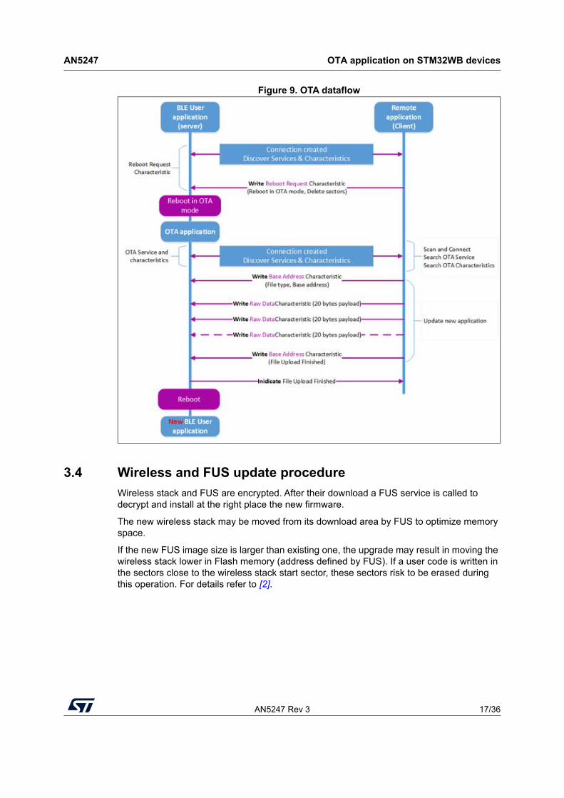
3.3 Flow description
Figure 9 details the messages and data exchanges between the device and the client during an update procedure.
The first connection is made by the user application. It advertises a Reboot request characteristic to the client (step 1). When the client requests for a device reboot a new connection is established, this time between OTA application and the client (step 2).
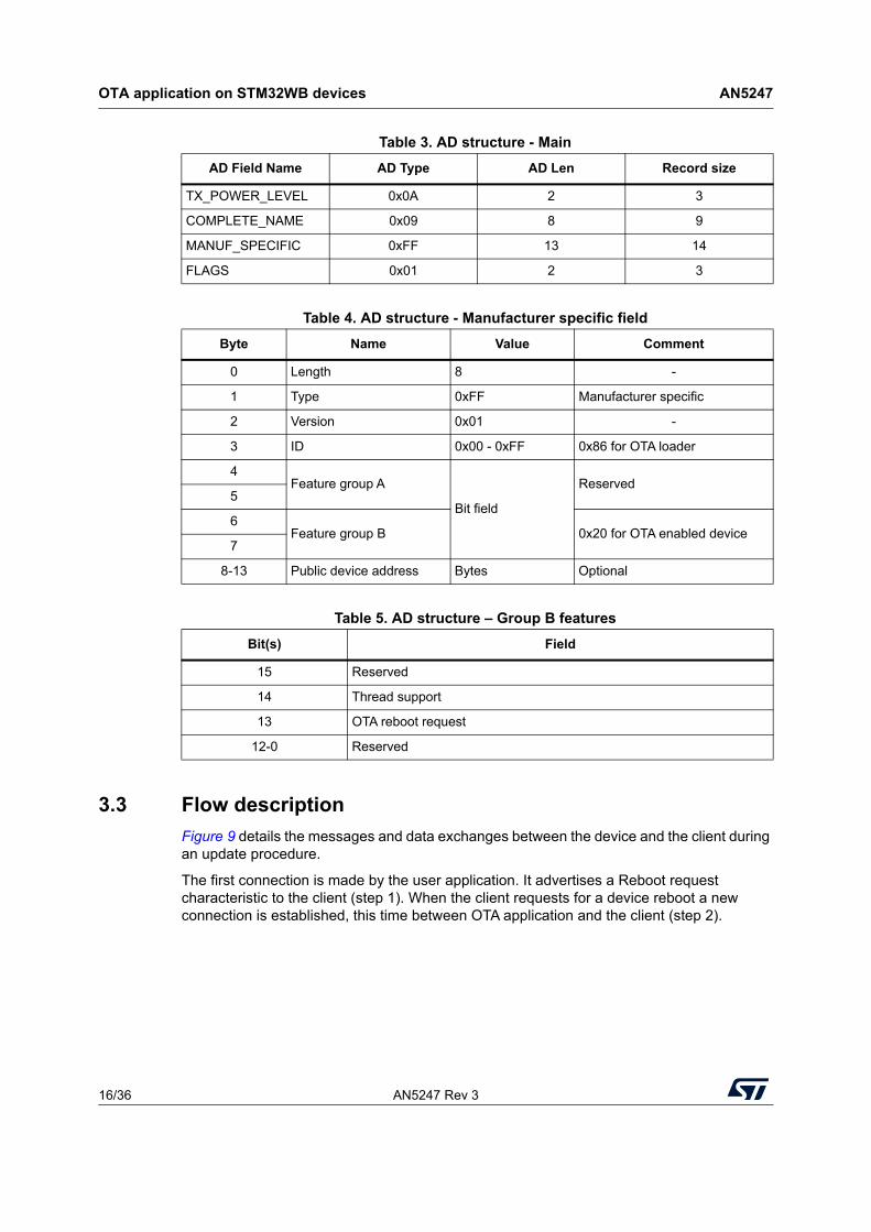
Table 3. AD structure - Main
AD Field Name AD Type AD Len Record size
TX_POWER_LEVEL 0x0A 2 3
COMPLETE_NAME 0x09 8 9
MANUF_SPECIFIC 0xFF 13 14
FLAGS 0x01 2 3
Table 4. AD structure - Manufacturer specific field
Byte Name Value Comment
0 Length 8 -
1 Type 0xFF Manufacturer specific
2 Version 0x01 -
3 ID 0x00 - 0xFF 0x86 for OTA loader
4Feature group A
Bit field
Reserved5
6Feature group B 0x20 for OTA enabled device
7
8-13 Public device address Bytes Optional
Table 5. AD structure – Group B features
Bit(s) Field
15 Reserved
14 Thread support
13 OTA reboot request
12-0 Reserved
AN5247 Rev 3 17/36
AN5247 OTA application on STM32WB devices
35
Figure 9. OTA dataflow
3.4 Wireless and FUS update procedure
Wireless stack and FUS are encrypted. After their download a FUS service is called to decrypt and install at the right place the new firmware.
The new wireless stack may be moved from its download area by FUS to optimize memory space.
If the new FUS image size is larger than existing one, the upgrade may result in moving the wireless stack lower in Flash memory (address defined by FUS). If a user code is written in the sectors close to the wireless stack start sector, these sectors risk to be erased during this operation. For details refer to [2].
OTA application on STM32WB devices AN5247
18/36 AN5247 Rev 3
3.5 Updater clients
OTA request comes from a BLE client with dedicated applications. STMicroelectronics provides two clients with this capability:
1. ST BLE Sensor, a mobile application that supports both types of update (application and wireless firmware)
2. STM32CubeMonitor RF, a PC tool that allows the user to update its application with a dongle featuring a BLE transparent mode implementation.
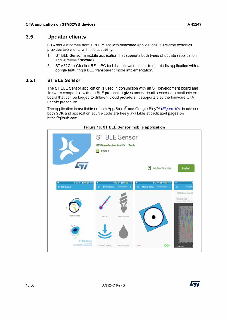
3.5.1 ST BLE Sensor
The ST BLE Sensor application is used in conjunction with an ST development board and firmware compatible with the BLE protocol. It gives access to all sensor data available on board that can be logged to different cloud providers. It supports also the firmware OTA update procedure.
The application is available on both App Store® and Google Play™ (Figure 10). In addition, both SDK and application source code are freely available at dedicated pages on https://github.com.
Figure 10. ST BLE Sensor mobile application
AN5247 Rev 3 19/36
AN5247 OTA application on STM32WB devices
35
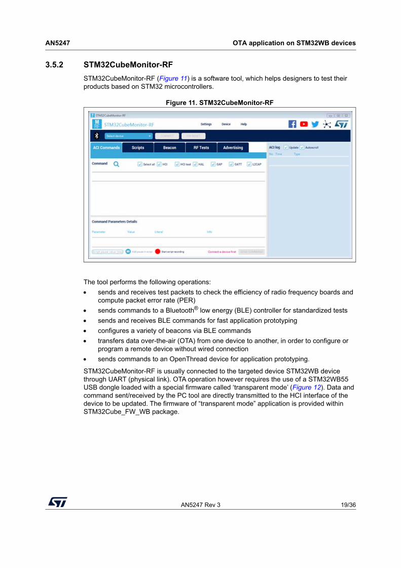
3.5.2 STM32CubeMonitor-RF
STM32CubeMonitor-RF (Figure 11) is a software tool, which helps designers to test their products based on STM32 microcontrollers.
Figure 11. STM32CubeMonitor-RF
The tool performs the following operations:
sends and receives test packets to check the efficiency of radio frequency boards and compute packet error rate (PER)
sends commands to a Bluetooth® low energy (BLE) controller for standardized tests
sends and receives BLE commands for fast application prototyping
configures a variety of beacons via BLE commands
transfers data over-the-air (OTA) from one device to another, in order to configure or program a remote device without wired connection
sends commands to an OpenThread device for application prototyping.
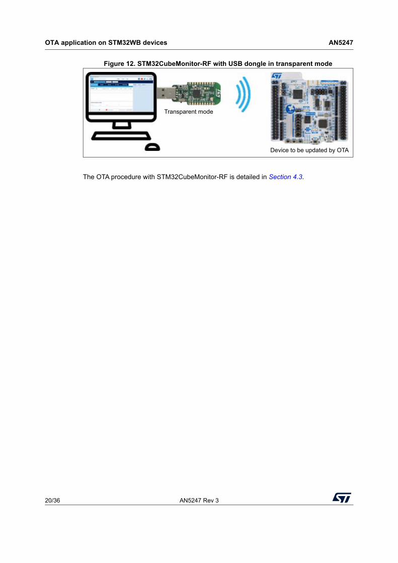
STM32CubeMonitor-RF is usually connected to the targeted device STM32WB device through UART (physical link). OTA operation however requires the use of a STM32WB55 USB dongle loaded with a special firmware called ‘transparent mode’ (Figure 12). Data and command sent/received by the PC tool are directly transmitted to the HCI interface of the device to be updated. The firmware of “transparent mode” application is provided within STM32Cube_FW_WB package.
OTA application on STM32WB devices AN5247
20/36 AN5247 Rev 3
Figure 12. STM32CubeMonitor-RF with USB dongle in transparent mode
The OTA procedure with STM32CubeMonitor-RF is detailed in Section 4.3.
Transparent mode
Device to be updated by OTA
AN5247 Rev 3 21/36
AN5247 OTA step by step
35
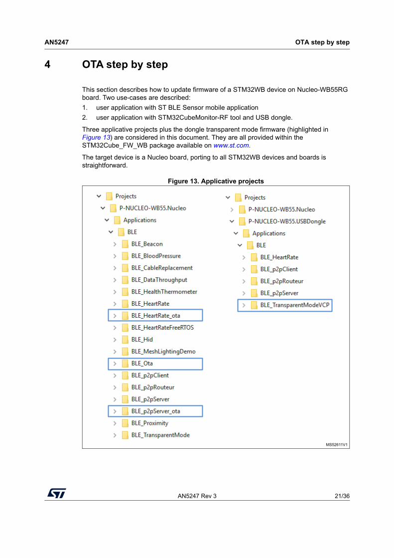
4 OTA step by step
This section describes how to update firmware of a STM32WB device on Nucleo-WB55RG board. Two use-cases are described:
1. user application with ST BLE Sensor mobile application
2. user application with STM32CubeMonitor-RF tool and USB dongle.
Three applicative projects plus the dongle transparent mode firmware (highlighted in Figure 13) are considered in this document. They are all provided within the STM32Cube_FW_WB package available on www.st.com.
The target device is a Nucleo board, porting to all STM32WB devices and boards is straightforward.
Figure 13. Applicative projects
MS52611V1
OTA step by step AN5247
22/36 AN5247 Rev 3
4.1 Project setup
4.1.1 User applications
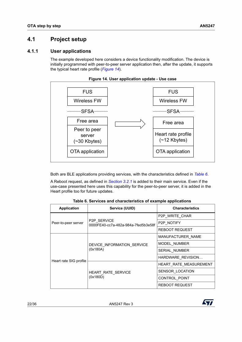
The example developed here considers a device functionality modification. The device is initially programmed with peer-to-peer server application then, after the update, it supports the typical heart rate profile (Figure 14).
Figure 14. User application update - Use case
Both are BLE applications providing services, with the characteristics defined in Table 6.
A Reboot request, as defined in Section 3.2.1 is added to their main service. Even if the use-case presented here uses this capability for the peer-to-peer server, it is added in the Heart profile too for future updates.
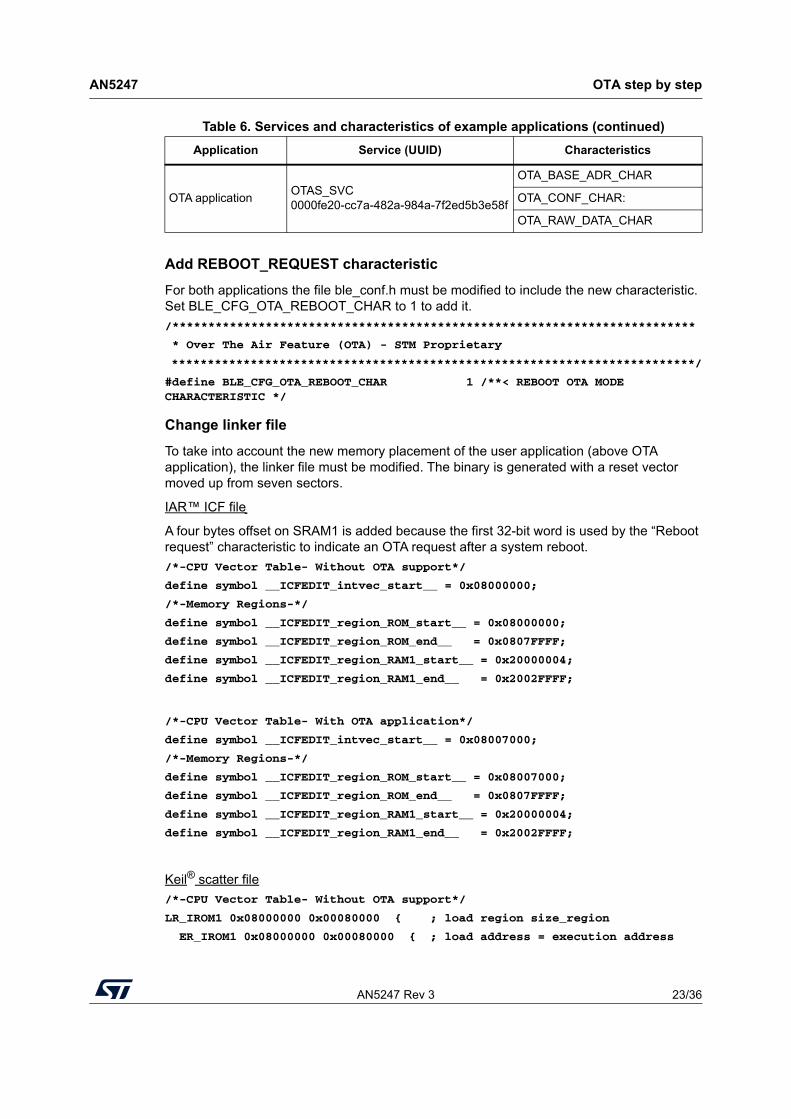
Table 6. Services and characteristics of example applications
Application Service (UUID) Characteristics
Peer-to-peer serverP2P_SERVICE0000FE40-cc7a-482a-984a-7fed5b3e58f
P2P_WRITE_CHAR
P2P_NOTIFY
REBOOT REQUEST
Heart rate SIG profile
DEVICE_INFORMATION_SERVICE(0x180A)
MANUFACTURER_NAME
MODEL_NUMBER
SERIAL_NUMBER
HARDWARE_REVISION…
HEART_RATE_SERVICE(0x180D)
HEART_RATE_MEASUREMENT
SENSOR_LOCATION
CONTROL_POINT
REBOOT REQUEST
MS51786V2
OTA application
SFSA
OTA application
Peer to peer server
(~30 Kbytes)
Free area
Wireless FW
SFSA
FUS
Heart rate profile (~12 Kbytes)
Wireless FW
FUS
Free area
AN5247 Rev 3 23/36
AN5247 OTA step by step
35
Add REBOOT_REQUEST characteristic
For both applications the file ble_conf.h must be modified to include the new characteristic. Set BLE_CFG_OTA_REBOOT_CHAR to 1 to add it.
/*************************************************************************
* Over The Air Feature (OTA) - STM Proprietary
*************************************************************************/
#define BLE_CFG_OTA_REBOOT_CHAR 1 /**< REBOOT OTA MODE CHARACTERISTIC */
Change linker file
To take into account the new memory placement of the user application (above OTA application), the linker file must be modified. The binary is generated with a reset vector moved up from seven sectors.
IAR™ ICF file
A four bytes offset on SRAM1 is added because the first 32-bit word is used by the “Reboot request” characteristic to indicate an OTA request after a system reboot.
/*-CPU Vector Table- Without OTA support*/
define symbol __ICFEDIT_intvec_start__ = 0x08000000;
/*-Memory Regions-*/
define symbol __ICFEDIT_region_ROM_start__ = 0x08000000;
define symbol __ICFEDIT_region_ROM_end__ = 0x0807FFFF;
define symbol __ICFEDIT_region_RAM1_start__ = 0x20000004;
define symbol __ICFEDIT_region_RAM1_end__ = 0x2002FFFF;
/*-CPU Vector Table- With OTA application*/
define symbol __ICFEDIT_intvec_start__ = 0x08007000;
/*-Memory Regions-*/
define symbol __ICFEDIT_region_ROM_start__ = 0x08007000;
define symbol __ICFEDIT_region_ROM_end__ = 0x0807FFFF;
define symbol __ICFEDIT_region_RAM1_start__ = 0x20000004;
define symbol __ICFEDIT_region_RAM1_end__ = 0x2002FFFF;
Keil® scatter file
/*-CPU Vector Table- Without OTA support*/
LR_IROM1 0x08000000 0x00080000 { ; load region size_region
ER_IROM1 0x08000000 0x00080000 { ; load address = execution address
OTA applicationOTAS_SVC0000fe20-cc7a-482a-984a-7f2ed5b3e58f
OTA_BASE_ADR_CHAR
OTA_CONF_CHAR:
OTA_RAW_DATA_CHAR
Table 6. Services and characteristics of example applications (continued)
Application Service (UUID) Characteristics
OTA step by step AN5247
24/36 AN5247 Rev 3
*.o (RESET, +First)
*(InRoot$$Sections)
.ANY (+RO)
}
RW_IRAM1 0x20000004 0x2FFFC { ; RW data
.ANY (+RW +ZI)
}
/*-CPU Vector Table- With OTA application*/
LR_IROM1 0x08007000 0x260 { ; load region size_region
ER_IROM1_LOW 0x08007000 0x260 { ; load address = execution address
*.o(RESET, +First)
*.o (TAG_OTA_START)
}
RW_IRAM1 0x20000004 0x0002FFFC { ; RW data
.ANY (+RW +ZI)
}
Delete the VTOR table configuration
When the application is expected to be downloaded by OTA, the SCB→VTOR must be not modified as it has already been set to the correct value by the BLE_Ota application before jumping to the current application.
Comment out this line of code in SstemInit():
// SCB->VTOR = VECT_TAB_OFFSET;
Compilation and programming
Compile and download peer-to-peer application in the Nucleo board.
Compile Heart rate application. The generated binary is downloaded by the OTA client. With EWARM IDE, the file is available in the project under EWARM/with_ota/Exe directory BLE_HeartRate_ota.bin.
Copy this binary to the smartphone running the ST BLE Sensor application.
4.1.2 OTA application
OTA application setup is straightforward. Compile and download the binary at the beginning of Flash memory (0x08000000).
To check if the full firmware has been written, a magic keyword is written at the end of the firmware. At startup, the Ble_Ota application checks whether this magic keyword is there or not at the end of the application thanks to CheckFwAppValidity() function.
In case of a reset during upload (which could result in a partial image to be written), the magic keyword is not there and the corrupted application is ignored by the Ble_Ota startup.
As the application length information is not present, the address of the magic keyword is written at address 0x0800 7140.

AN5247 Rev 3 25/36
AN5247 OTA step by step
35
To make the calculation transparent to the user, two constants are defined in the firmware:
one holds the address of the magic keyword and is associated with section TAG_OTA_START
the other one holds the magic keyword and is associated with TAG_OTA_END.
4.2 Firmware update with ST BLE Sensor
4.2.1 Device connection
Check the device correct behavior by initiating a Peer-to-peer connection with the smartphone hosting ST BLE Sensor application.
Device Bluetooth MAC address
MAC address of Nucleo board is set from the device unique ID. It can be retrieved at addresses 0x 0x1FFF7580 and 0x1FFF7584.
Table 7. Example (device Bluetooth MAC address = 80:E1:25:00:50:D6)
Register address Value Field
0x1FFF7580 0xXX0050D6 LSB part of MAC @
0x1FFF7584 0xXX80E125 MSB part of MAC @
OTA step by step AN5247
26/36 AN5247 Rev 3
Connection
Follow the steps listed below.
1. Press the reset button (SW4) of the Nucleo board to start the device advertising (peripheral role).
Note: The green led (LED2) of the Nucleo board has to blink during the smartphone scan. If this is not the case, it is because the advertising stops after 1 minute. Press the Nucleo board reset button (SW4) to start again the advertising.
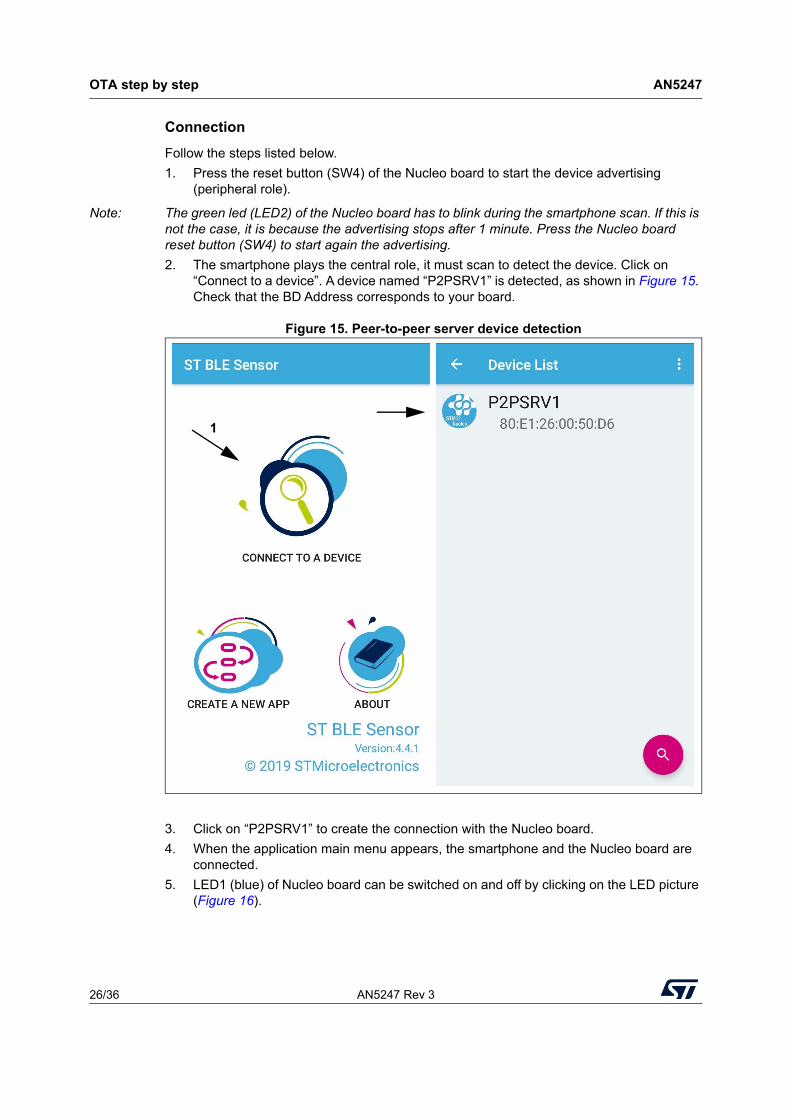
2. The smartphone plays the central role, it must scan to detect the device. Click on “Connect to a device”. A device named “P2PSRV1” is detected, as shown in Figure 15. Check that the BD Address corresponds to your board.
Figure 15. Peer-to-peer server device detection
3. Click on “P2PSRV1” to create the connection with the Nucleo board.
4. When the application main menu appears, the smartphone and the Nucleo board are connected.
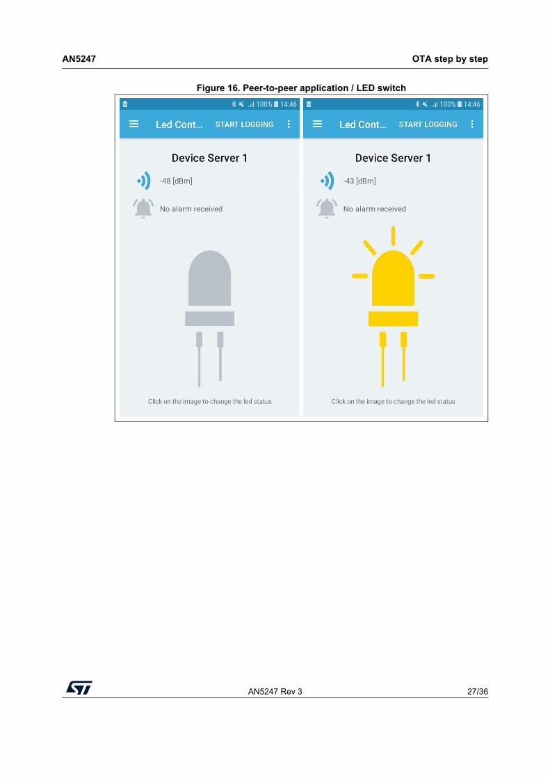
5. LED1 (blue) of Nucleo board can be switched on and off by clicking on the LED picture (Figure 16).
21
AN5247 Rev 3 27/36
AN5247 OTA step by step
35
Figure 16. Peer-to-peer application / LED switch
OTA step by step AN5247
28/36 AN5247 Rev 3
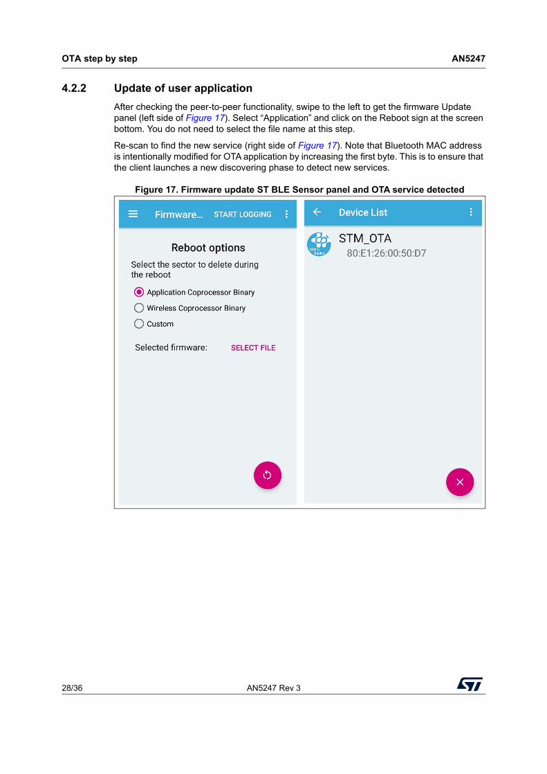
4.2.2 Update of user application
After checking the peer-to-peer functionality, swipe to the left to get the firmware Update panel (left side of Figure 17). Select “Application” and click on the Reboot sign at the screen bottom. You do not need to select the file name at this step.
Re-scan to find the new service (right side of Figure 17). Note that Bluetooth MAC address is intentionally modified for OTA application by increasing the first byte. This is to ensure that the client launches a new discovering phase to detect new services.
Figure 17. Firmware update ST BLE Sensor panel and OTA service detected
AN5247 Rev 3 29/36
AN5247 OTA step by step
35
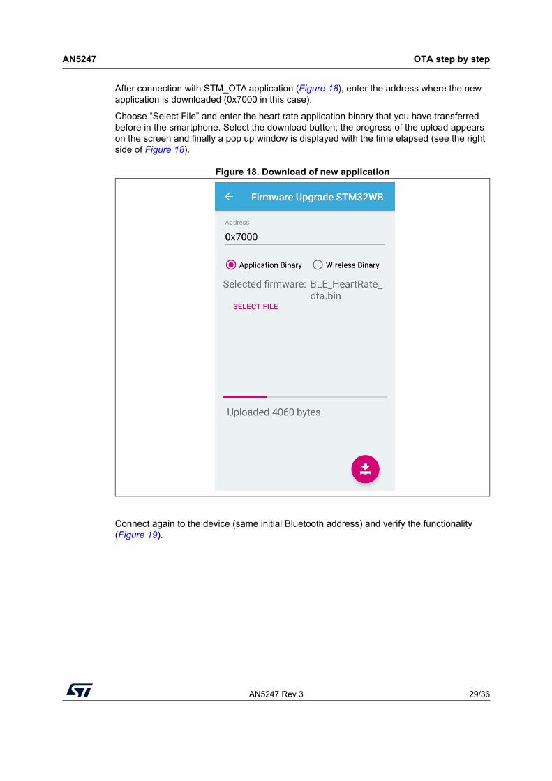
After connection with STM_OTA application (Figure 18), enter the address where the new application is downloaded (0x7000 in this case).
Choose “Select File” and enter the heart rate application binary that you have transferred before in the smartphone. Select the download button; the progress of the upload appears on the screen and finally a pop up window is displayed with the time elapsed (see the right side of Figure 18).
Figure 18. Download of new application
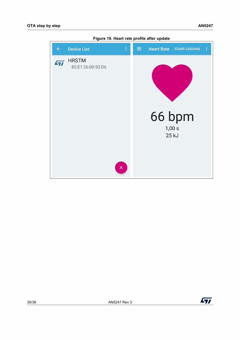
Connect again to the device (same initial Bluetooth address) and verify the functionality (Figure 19).
OTA step by step AN5247
30/36 AN5247 Rev 3
Figure 19. Heart rate profile after update
AN5247 Rev 3 31/36
AN5247 OTA step by step
35
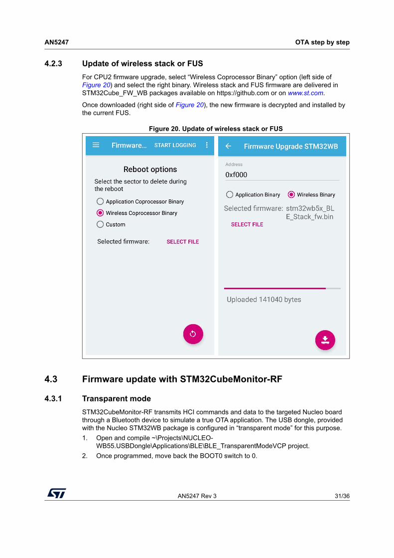
4.2.3 Update of wireless stack or FUS
For CPU2 firmware upgrade, select “Wireless Coprocessor Binary” option (left side of Figure 20) and select the right binary. Wireless stack and FUS firmware are delivered in STM32Cube_FW_WB packages available on https://github.com or on www.st.com.
Once downloaded (right side of Figure 20), the new firmware is decrypted and installed by the current FUS.
Figure 20. Update of wireless stack or FUS
4.3 Firmware update with STM32CubeMonitor-RF
4.3.1 Transparent mode
STM32CubeMonitor-RF transmits HCI commands and data to the targeted Nucleo board through a Bluetooth device to simulate a true OTA application. The USB dongle, provided with the Nucleo STM32WB package is configured in “transparent mode” for this purpose.
1. Open and compile ~\Projects\NUCLEO-WB55.USBDongle\Applications\BLE\BLE_TransparentModeVCP project.
2. Once programmed, move back the BOOT0 switch to 0.
OTA step by step AN5247
32/36 AN5247 Rev 3
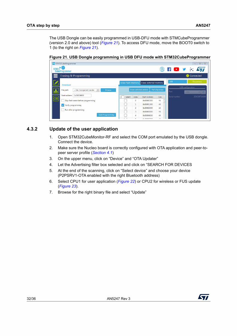
The USB Dongle can be easily programmed in USB-DFU mode with STMCubeProgrammer (version 2.0 and above) tool (Figure 21). To access DFU mode, move the BOOT0 switch to 1 (to the right on Figure 21).
Figure 21. USB Dongle programming in USB DFU mode with STM32CubeProgrammer
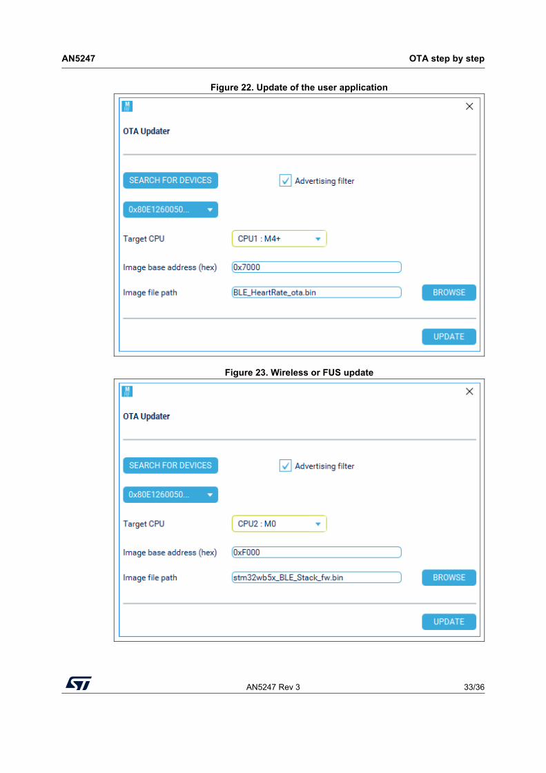
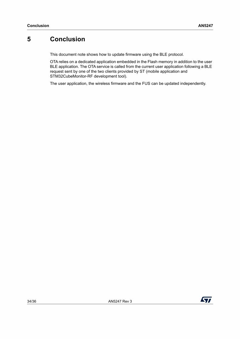
4.3.2 Update of the user application
1. Open STM32CubeMonitor-RF and select the COM port emulated by the USB dongle. Connect the device.
2. Make sure the Nucleo board is correctly configured with OTA application and peer-to-peer server profile (Section 4.1)
3. On the upper menu, click on “Device” and “OTA Updater”
4. Let the Advertising filter box selected and click on “SEARCH FOR DEVICES
5. At the end of the scanning, click on “Select device” and choose your device (P2PSRV1-OTA enabled with the right Bluetooth address)
6. Select CPU1 for user application (Figure 22) or CPU2 for wireless or FUS update (Figure 23).
7. Browse for the right binary file and select “Update”
AN5247 Rev 3 33/36
AN5247 OTA step by step
35
Figure 22. Update of the user application
Figure 23. Wireless or FUS update
Conclusion AN5247
34/36 AN5247 Rev 3
5 Conclusion
This document note shows how to update firmware using the BLE protocol.
OTA relies on a dedicated application embedded in the Flash memory in addition to the user BLE application. The OTA service is called from the current user application following a BLE request sent by one of the two clients provided by ST (mobile application and STM32CubeMonitor-RF development tool).
The user application, the wireless firmware and the FUS can be updated independently.
AN5247 Rev 3 35/36
AN5247 Revision history
35
6 Revision history
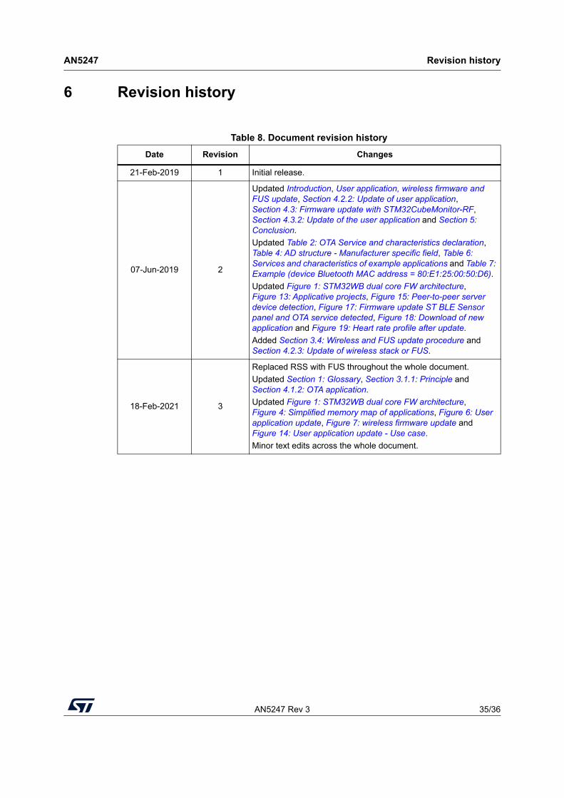
Table 8. Document revision history
Date Revision Changes
21-Feb-2019 1 Initial release.
07-Jun-2019 2
Updated Introduction, User application, wireless firmware and FUS update, Section 4.2.2: Update of user application, Section 4.3: Firmware update with STM32CubeMonitor-RF, Section 4.3.2: Update of the user application and Section 5: Conclusion.
Updated Table 2: OTA Service and characteristics declaration, Table 4: AD structure - Manufacturer specific field, Table 6: Services and characteristics of example applications and Table 7: Example (device Bluetooth MAC address = 80:E1:25:00:50:D6).
Updated Figure 1: STM32WB dual core FW architecture, Figure 13: Applicative projects, Figure 15: Peer-to-peer server device detection, Figure 17: Firmware update ST BLE Sensor panel and OTA service detected, Figure 18: Download of new application and Figure 19: Heart rate profile after update.
Added Section 3.4: Wireless and FUS update procedure and Section 4.2.3: Update of wireless stack or FUS.
18-Feb-2021 3
Replaced RSS with FUS throughout the whole document.
Updated Section 1: Glossary, Section 3.1.1: Principle and Section 4.1.2: OTA application.
Updated Figure 1: STM32WB dual core FW architecture, Figure 4: Simplified memory map of applications, Figure 6: User application update, Figure 7: wireless firmware update and Figure 14: User application update - Use case.
Minor text edits across the whole document.
AN5247
36/36 AN5247 Rev 3
IMPORTANT NOTICE – PLEASE READ CAREFULLY
STMicroelectronics NV and its subsidiaries (“ST”) reserve the right to make changes, corrections, enhancements, modifications, and improvements to ST products and/or to this document at any time without notice. Purchasers should obtain the latest relevant information on ST products before placing orders. ST products are sold pursuant to ST’s terms and conditions of sale in place at the time of order acknowledgment.
Purchasers are solely responsible for the choice, selection, and use of ST products and ST assumes no liability for application assistance or the design of Purchasers’ products.
No license, express or implied, to any intellectual property right is granted by ST herein.
Resale of ST products with provisions different from the information set forth herein shall void any warranty granted by ST for such product.
ST and the ST logo are trademarks of ST. For additional information about ST trademarks, please refer to www.st.com/trademarks. All other product or service names are the property of their respective owners.
Information in this document supersedes and replaces information previously supplied in any prior versions of this document.
© 2021 STMicroelectronics – All rights reserved