an offline email implementation based on delay tolerant network (dtn)
TRANSCRIPT
AN OFFLINE EMAIL IMPLEMENTATION BASED ON DELAY TOLERANT NETWORK
(DTN)
MOHD KHAIRUN NASIR BIN SA‟ADI
A thesis submitted
In fulfillment of the requirements for the Master of Advanced Information Technology
Faculty of Computer Science and Information Technology
UNIVERSITI MALAYSIA SARAWAK
2013

ii
DEDICATION
“This thesis is dedicated to my mom and dad, who was giving the infinite support
and also to my wife, brothers and sisters who always giving encouragement”
iii
ACKNOWLEDGEMENTS
Firstly, thanks to the project supervisor, Dr. Kartinah Zen for the guidance on matters
related to Offline Email based on Delay Tolerant Network project and her encouragement to
complete this project.
Advice and support from families also help in the completion of this thesis as well as help
from friends who incessantly give guidance and knowledge to me.
iv
ABSTRACT
This thesis focuses on extending offline email system in a local area network environment to the
internet connected email system in online environment based on delay tolerant network. This
offline email system will allow the rural users to have an access to the internet connected email
system. It allows the user to read, write and send email in an offline local network environment.
This offline email system will be able to connect to online email system via infomediary device
based on delay tolerant network concept. Even though in an offline environment, user also able to
read, write and send email as if he or she is in an online environment. This offline email system
will allow the email flow through the offline environment to the online environment and vice
versa. The most important part of this offline email system is an implementation of email
database synchronization between offline mail server and infomediary device and between online
mail server and infomediary device. Another part is an implementation of offline and online
email system consist of mail server and mail client for both sides. This offline email system will
be using operating system Windows XP 32bit, wireless local area network, and internet
connection 1MB/s TMnet Streamyx Dynamic IP with the conjunction of Uniform Server for
personal home server. This offline email system consists of offline mail client, offline mail
server, database synchronization at offline server, infomediary device, online mail client, online
mail server and database synchronization at online server.

v
ABSTRAK
Tesis ini memberi tumpuan ke atas melanjutkan sistem emel luar talian dalam persekitaran
rangkaian kawasan tempatan ke sistem emel bersambungan internet dalam persekitaran dalam
talian berdasarkan rangkaian toleransi kelewatan. Sistem emel luar talian ini akan membolehkan
pengguna luar bandar untuk mempunyai akses kepada sistem emel yang bersambungan internet.
Ia membolehkan pengguna untuk membaca, menulis dan menghantar emel dalam persekitaran
rangkaian kawasan tempatan luar talian. Sistem emel luar talian ini akan boleh menyambung ke
sistem emel dalam talian melalui alat informediari berdasarkan konsep rangkaian toleransi
kelewatan. Walaupun dalam persekitaran luar talian, pengguna juga boleh membaca, menulis dan
menghantar emel seolah-olah dia berada dalam persekitaran dalam talian. Sistem emel luar talian
ini akan membolehkan aliran emel melalui persekitaran luar talian ke persekitaran dalam talian
dan sebaliknya. Bahagian yang paling penting dalam sistem emel ini adalah perlaksanaan
penyegerakan pangkalan data emel antara pelayan mel luar talian dan alat informediari dan antara
pelayan mel dalam talian dan alat informediari. Sebahagian yang lain adalah perlaksanaan sistem
emel luar talian dan dalam talian yang terdiri daripada pelayan mel dan klien mel untuk kedua-
dua pihak. Sistem emel luar talian ini akan menggunakan sistem operasi Windows XP 32 bit,
rangkaian kawasan tempatan tanpa wayar dan sambungan internet 1MB/s TMNet Streamyx IP
Dinamik bersama dengan Uniform Server untuk pelayan rumah peribadi. Sistem emel luar talian
ini terdiri daripada klien mel luar talian, pelayan mel luar talian, penyegerakan pangkalan data di
pelayan luar talian, alat informediari, klien mel dalam talian, pelayan mel dalam talian dan
penyegerakan pangkalan data di pelayan dalam talian.
vi
TABLE OF CONTENTS
1. INTRODUCTION ................................................................................................................... 1
1.1 Overview ............................................................................................................................ 1
1.2 Problem Statement ............................................................................................................. 4
1.3 Objective ............................................................................................................................ 5
1.4 The Proposed System ........................................................................................................ 6
1.5 System Implications ........................................................................................................... 8
1.6 System Advantages ............................................................................................................ 9
1.7 Summary of chapters ....................................................................................................... 11
2. LITERATURE REVIEW ...................................................................................................... 13
2.1 Transmission Control Protocol and Internet Protocol (TCP/IP) ...................................... 13
2.1.1 Detailed explanation in each TCP/IP Layers ........................................................... 14
2.1.2 Internet Addressing .................................................................................................. 20
2.1.3 TCP/IP Operation ..................................................................................................... 22
2.2 Delay Tolerant Network (DTN) ...................................................................................... 24
2.2.1 Reason to use DTN ................................................................................................... 24
2.2.2 Architecture of DTN ................................................................................................ 26
2.3 Comparison of TCP/IP and DTN .................................................................................... 32
2.3.1 DTN vs. TCI/IP: Protocol Architecture ................................................................... 32
2.3.2 DTN Router vs. TCP/IP Router ............................................................................... 36
2.3.3 Naming and addressing mechanism: Endpoint IDs ................................................. 38
2.4 Network Architecture: Emails ......................................................................................... 40
2.5 Similar Works .................................................................................................................. 43
2.5.1 Bytewalla 5 ............................................................................................................... 43
2.5.2 Offline Gmail ........................................................................................................... 44
2.6 Summary .......................................................................................................................... 45
3. METHODOLOGY ................................................................................................................ 46
4. OFFLINE EMAIL SYSTEM DESIGN ARCHITECTURE ................................................. 49
4.1 TCP/IP Mail System works as a DTN Mail System........................................................ 49
vii
4.2 Idea and Concept Analysis .............................................................................................. 52
4.3 Abstraction of TCP/IP Mail System based on DTN ........................................................ 53
4.4 Application and Network Topology ................................................................................ 59
4.5 Network Protocol Design ................................................................................................ 61
4.6 Offline Email System Detail Design ............................................................................... 63
4.7 Database Synchronization ............................................................................................... 66
4.8 Summary .......................................................................................................................... 67
5. SYSTEM IMPLEMENTATION ........................................................................................... 69
5.1 System Platform and Environment .................................................................................. 69
5.2 Implementation Issues ..................................................................................................... 70
5.3 Requirements ................................................................................................................... 72
5.4 Implementation Details .................................................................................................... 75
5.4.1 Server Computer ....................................................................................................... 75
5.4.2 Web server Application ............................................................................................ 76
5.4.3 External IP Address .................................................................................................. 78
5.4.4 Mail Server ............................................................................................................... 82
5.4.5 Mail Client ................................................................................................................ 83
5.4.6 Process of Database Synchronization ....................................................................... 87
5.4.7 Related Data for Synchronization ............................................................................ 88
5.4.8 Database Synchronization Application .................................................................... 89
5.4.9 System Control Graphical User Interface (GUI) ...................................................... 96
5.5 Summary ........................................................................................................................ 100
6. SYSTEM TEST ................................................................................................................... 101
6.1 New Account Registration Test ..................................................................................... 101
6.1.1 Test Design ............................................................................................................. 101
6.1.2 Expected Outcome ................................................................................................. 102
6.1.3 Test result ............................................................................................................... 102
6.2 Connectivity Test ........................................................................................................... 104
6.2.1 Test Design ............................................................................................................. 104
6.2.2 Expected Outcome ................................................................................................. 105
viii
6.2.3 Test Result .............................................................................................................. 106
6.3 Delay Test ...................................................................................................................... 108
6.3.1 Test Design ............................................................................................................. 108
6.3.2 Expected Outcome ................................................................................................. 109
6.3.3 Test Result .............................................................................................................. 109
6.4 Limitation of Infomediary Device Pass by Movement Speed ....................................... 110
6.4.1 Test Design ............................................................................................................. 110
6.4.2 Expected Outcome ................................................................................................. 110
6.4.3 Test Result .............................................................................................................. 111
6.5 Size of Data Test ............................................................................................................ 113
6.5.1 Test Design ............................................................................................................. 113
6.5.2 Expected Outcome ................................................................................................. 114
6.5.3 Test Result .............................................................................................................. 114
6.6 Types of Data Test ......................................................................................................... 115
6.6.1 Test Design ............................................................................................................. 115
6.6.2 Expected Outcome ................................................................................................. 116
6.6.3 Test Result .............................................................................................................. 116
6.7 Multiple of Senders and Receivers Test ........................................................................ 117
6.7.1 Test Design ............................................................................................................. 117
6.7.2 Expected Outcome ................................................................................................. 117
6.7.3 Test Result .............................................................................................................. 118
6.8 Multiple of Communications Test ................................................................................. 118
6.8.1 Test Design ............................................................................................................. 118
6.8.2 Expected Outcome ................................................................................................. 119
6.8.3 Test Result .............................................................................................................. 120
6.9 Discussion of Results ..................................................................................................... 122
6.10 Summary .................................................................................................................... 123
7. CONCLUSION .................................................................................................................... 124
7.1 Future Work ................................................................................................................... 124
7.2 Conclusion ..................................................................................................................... 125

ix
REFERENCES ............................................................................................................................ 127
APPENDIX ................................................................................................................................. 129
x
LIST OF FIGURES
Figure 1.1: Offline email system overview ...................................................................................... 4
Figure 1.2: Offline email system components .................................................................................. 7
Figure 2.1: TCP/IP Protocol Architecture ...................................................................................... 14
Figure 2.2: TCP/IP Layer ............................................................................................................... 15
Figure 2.3: Hypertext Transfer Protocol (HTTP) ........................................................................... 15
Figure 2.4: Simple Mail Transfer Protocol (SMTP) ...................................................................... 16
Figure 2.5: Address Classes [5] ...................................................................................................... 21
Figure 2.6: Subnet Address ............................................................................................................ 22
Figure 2.7: TCP/IP operation of accessing a website ..................................................................... 23
Figure 2.8: Store and forward delivery .......................................................................................... 26
Figure 2.9: Bundles ........................................................................................................................ 27
Figure 2.10: Bundle Space ............................................................................................................. 28
Figure 2.11: Bundle Overlay .......................................................................................................... 30
Figure 2.12: Bundle Routing .......................................................................................................... 31
Figure 2.13: Bundle Authentication Block (BAB) ......................................................................... 31
Figure 2.14: Comparison Internet Protocol Layers with DTN Protocol Layers ............................ 33
Figure 2.15: Bundle Encapsulation [9] ........................................................................................... 34
Figure 2.16: Minimal conversational lower layer protocols [9] ..................................................... 35
Figure 2.17: Class of Bundle Service [9] ....................................................................................... 36
Figure 2.18: Internet Router [9] ..................................................................................................... 37
Figure 2.19: DTN Router [9] .......................................................................................................... 37
Figure 2.20: DTN Naming and addressing mechanism [9] ............................................................ 40
Figure 2.21: Internet Mail .............................................................................................................. 41
Figure 2.22: DTN Mail ................................................................................................................... 42
Figure 3.1: Iterative Approach ....................................................................................................... 46
Figure 4.1: IMAP vs POP............................................................................................................... 50
Figure 4.2: Offline Email System Architecture .............................................................................. 60
Figure 4.3: Networking Protocol flow ........................................................................................... 62
Figure 4.4: Store and Forward ........................................................................................................ 63
Figure 4.5: Offline Email System Network Protocol layout .......................................................... 64
Figure 4.6: Online Email System Network Protocol layout ........................................................... 66
Figure 5.1: Uniform Server Binary Codes ..................................................................................... 80
Figure 5.2: TMnet SMTP relayer ................................................................................................... 83
Figure 5.3: Process of database synchronization ............................................................................ 88
Figure 5.4: Database Synchronization Path ................................................................................... 91
Figure 5.5: Realtime Synchronize Setting ...................................................................................... 93
xi
Figure 5.6: Samba File sharing application configuration ............................................................. 95
Figure 5.7: Pemail system control Graphical User Interface (GUI) ............................................... 97
Figure 5.8: Uniform Server Core Control ...................................................................................... 98
Figure 6.1: New Email User Registration .................................................................................... 101
Figure 6.2: New account registration test result ........................................................................... 103
Figure 6.3: Test sample ................................................................................................................ 105
Figure 6.4: Range and speed for mail data synchronization ........................................................ 113
Figure 6.5: Multiple communication ............................................................................................ 119
xii
LIST OF TABLES
Table 1.1: Estimated Cost for Offline Email System based on DTN ............................................. 10
Table 1.2: Cost for DANAWA Wi-Fi Hotspot implementation .................................................... 11
Table 2.1: Private addressing ......................................................................................................... 21
Table 2.2: Reserved and available IP addresses [5] ....................................................................... 22
Table 2.3: TCP/IP Endpoint ID ...................................................................................................... 38
Table 2.4: DTN Endpoint ID .......................................................................................................... 39
Table 4.1: Store, Carry and Forward Scenario ............................................................................... 50
Table 4.2: Comparison of DTN Email ........................................................................................... 55
Table 4.3: Comparison of Web server ............................................................................................ 56
Table 4.4: Comparison of Mail Server software ............................................................................ 57
Table 4.5: Comparison of Mail Client ............................................................................................ 57
Table 4.6: Comparison of File Synchronize software .................................................................... 58
Table 4.7: Comparison of Infomediary Device .............................................................................. 59
Table 5.1: D-Link DWL-2100AP indoors and outdoors coverage range ...................................... 70
Table 5.2: Hardware Requirements ................................................................................................ 73
Table 5.3: Software Requirements ................................................................................................. 75
Table 5.4: Enable Web server External Access Script ................................................................... 76
Table 5.5: Enable Cron ................................................................................................................... 80
Table 5.6: Enable Cron automatic update on Uniserver ................................................................ 81
Table 5.7: Apache. MySQL and Cron startup script configuration ............................................... 81
Table 5.8: Enable Mail Client External Access Script ................................................................... 85
Table 5.9: Enable New User Registration Page Script ................................................................... 86
Table 5.10: hMailServer SQL Database driver name setting ......................................................... 86
Table 5.11: Domain name setting ................................................................................................... 86
Table 5.12: Infomediary Device Data Synchronization Folder ..................................................... 91
Table 5.13: Mail Server Data Synchronization Folder ................................................................... 91
Table 5.14: StartFFS.bat Script ...................................................................................................... 94
Table 5.15: Offline Server Computer Start script (Start_Server.bat) ............................................. 98
Table 5.16: Offline Server Computer Stop script (Stop_Server.bat) ............................................. 99
Table 5.17: Mail Server Start and Stop script .............................................................................. 100
Table 6.1: Send and receive email test result on each node ......................................................... 107
Table 6.2: Delay Period Test Result ............................................................................................. 109
Table 6.3 Transfer rate, read speed and write speed comparisons ............................................... 112
Table 6.4: Testing email data size ................................................................................................ 115
Table 6.5: Testing types of data attachment ................................................................................. 116
Table 6.6: Multiple sender and receiver test result ...................................................................... 118

xiii
Table 6.7: Multiple communication test result ............................................................................. 121
LIST OF EQUATIONS
Equation 6.1 Infomediary device movement speed ..................................................................... 112
1
1. INTRODUCTION
1.1 Overview
Email application has been commonly used as one of the communication tools
which are cheap and easy to use as long as the person has internet connection. Email
application is tolerant to delay and the email sender and recipient not required to be online
at the same time. Email is suitable especially for those who not in urgency and delay in
sending and receiving is acceptable. For those who live in the rural area without the
Internet connection, even the application such as an email application is impossible. Rural
area such as Bario has a telecentre which is built with the Internet facilities only offer the
Internet connection in four kilometers diameter around the telecentre [1]. Therefore, the
best approach to provide email services for users who has no internet connection at other
areas is by introducing an offline email system. This offline email system using
Transmission Control Protocol and Internet Protocol (TCP/IP) with the database
synchronization application as a data mule where it works as a network bridge by bringing
the pending emails from offline server computer to the online server computer.
TCP/IP has been used widely in the email application as well as in World Wide
Web (WWW), File Transfer Protocol (FTP) and Voice-over-IP (VoIP). TCP/IP
fundamental assumption is, there is always end-to-end communication between sender
and receiver. End-to-end communication means that the network provides a reliable
transport layer with immediate data transmission to the receiver and to provide data
integrity, delivery guarantees, delivery acknowledgement, duplicate message suppression,
per packet encryption and transaction management [2]. However, end-to-end
communications cannot be applied in this offline email system because of the rural area is
2
lack of continuous connection from sender to receiver. TCP/IP drops the packets if the
next connection cannot be found immediately. Delay tolerant network (DTN) protocol is
used in this thesis to solve this problem. DTN used store and forward operation and
introduced a bundle protocol in between the application layer and the transport layer.
Delay tolerant network (DTN) is an approach to computer network to overcome
the lack of end-to-end network connectivity. DTN tolerates delay and disruption with
acceptable performance in high loss and delay error environments. DTN tries to solve
some of the issues by relaxing some of the TCP/IP end-to-end communication
assumptions by introducing bundle protocol. The bundle protocol defines a series of data
blocks as a bundle. Bundles are routed in Store and Forward operation from source node
to the destination node. Store and Forward operation is a DTN fundamentals where it is
designed to use storage within the network and perform incremental progress before
proceeding to another path.
This thesis focuses on an offline email system implementation in a rural area with
some modification to the protocol because it is designed as such the email needs to be
transferred to another different device before it can be transmitted. This offline email
system is designed for rural users with no internet connection to allow them to access their
email account and compose new messages or check the last reply as shown in Figure 1.1.
Village A and Village B are located very far from the telecentre, from three kilometers to
40 kilometers. Rural villagers send their emails using their laptop or handphone and send
it to the nearby offline mail server. From this offline mail server, the appointed person
with infomediary device will collect all the emails from the offline mail server by
positioning his infomediary device close to the offline mail server so that the transmission
3
takes place wirelessly based on wireless local area network (WLAN) based on IEEE
802.11 standards. Conventionally, there is a need of a more internet hotspot datacenter at
each village to stay connected which will require a higher cost.
Email application is asynchronous in nature and do not need end-to-end
connectivity. Therefore, DTN store and forward fundamental is suitable for use to
implement an offline email system in a rural area. In this thesis work, the store and
forward process implemented by using file synchronization method. Store and forward
process is a technique in which data is sent to an intermediate station and kept temporarily
before sent to the final destination or to another intermediate station [3]. The file
synchronization process is critical because the offline email on the offline mail server
should capable to synchronize its database with the intermediate device and the online
mail server. The intermediate device, known as an infomediary device is a temporary
storage for the email database. This device collects the emails from the offline
environment and brings them to the online environment.
4
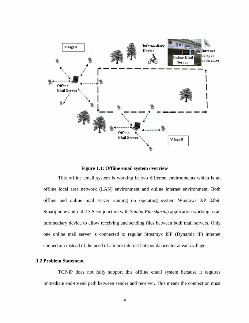
Figure 1.1: Offline email system overview
This offline email system is working in two different environments which is an
offline local area network (LAN) environment and online internet environment. Both
offline and online mail server running on operating system Windows XP 32bit.
Smartphone android 2.3.5 conjunction with Samba File sharing application working as an
infomediary device to allow receiving and sending files between both mail servers. Only
one online mail server is connected to regular Streamyx ISP (Dynamic IP) internet
connection instead of the need of a more internet hotspot datacenter at each village.
1.2 Problem Statement
TCP/IP does not fully support this offline email system because it requires
immediate end-to-end path between sender and receiver. This means the connection must
5
exist at the same time sender send the email because the email packets will travel through
the transport layer and finally to the destination. The email client is disconnected from
email server if there is no end-to-end path and the user cannot access their email account.
However, if the Gmail offline application is used, the user has to bring their device to the
connected area. In rural area, this seems not practical. Delay tolerant network (DTN) is
designed to overcome this limitation by implementing store and forward message
switching by overlaying a new protocol layer called the bundle layer. DTN use storage
within the network to support the store and forward operation over networking paths. The
problem arises when the emails have to be collected into another device before it is
brought physically to the connected area. The store and forward process of DTN is
integrated using the file synchronization method because it involves the third device and
the third person to bring the emails to the connected area.
1.3 Objective
The objective of this thesis is to provide an offline email system at rural area that
has no internet connection. There are three research questions in this thesis as below:
1) Implementation: How the user registration page should be implemented and
how the store and forward process in delay tolerant network (DTN) supports
the offline email system in terms of email connectivity from the offline
environment network to online environment network?
2) Functionality: Can the email data maintain in the mail server for a very long
time delay until it synchronized with infomediary device? What is the
limitation size of email data which include email content and file attachment?
6
What are the types of data supported when uploading an attachment? Can the
email data synchronization process avoid conflict when the email sent and
replied from multiple sender and receiver or when the email sent and replied
through multiple communications?
3) Performance: What is the limitation movement speed of an infomediary device
when moving through a mail server and performing a database
synchronization?
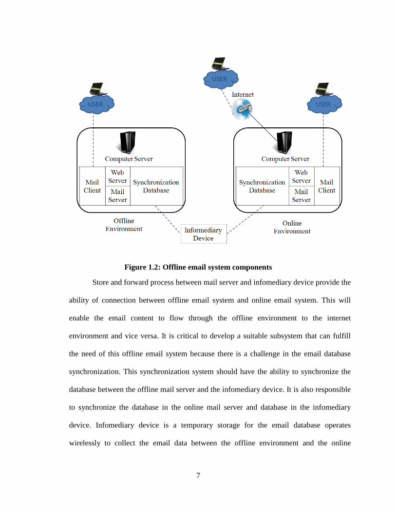
1.4 The Proposed System
An offline mail server in the rural area local area network (LAN) is where rural
users can read, send and receive email locally in the LAN. Meanwhile the external email
content to be sent online will be stored temporarily until it is transferred to infomediary
device. The database synchronization system in the offline server computer will transfer
and receive new database from the infomediary device as shown in Figure 1.2.
Infomediary device working as a temporary storage and can be accessible via Wi-Fi or
wireless local area network (WLAN). Then the database synchronization system in the
online server computer will transfer and receive new email data from this infomediary
device. Online mail server has all the features as offline mail server where the user in that
area can use the offline email system locally through LAN. Online mail server is
connected to the internet. This offline email system can be access from the internet
through the online mail server. The external email content to be sent offline will be stored
temporarily until it is being transferred to infomediary device and then to the offline mail
server at rural area.
7
Figure 1.2: Offline email system components
Store and forward process between mail server and infomediary device provide the
ability of connection between offline email system and online email system. This will
enable the email content to flow through the offline environment to the internet
environment and vice versa. It is critical to develop a suitable subsystem that can fulfill
the need of this offline email system because there is a challenge in the email database
synchronization. This synchronization system should have the ability to synchronize the
database between the offline mail server and the infomediary device. It is also responsible
to synchronize the database in the online mail server and database in the infomediary
device. Infomediary device is a temporary storage for the email database operates
wirelessly to collect the email data between the offline environment and the online
8
environment. It should be portable, secured and has a long life battery. There are two
different environments for this offline email system which is offline and online. Both
sides consist of mail server and mail client for their respective environment. At the online
side, the online mail system is connected to the internet using a personal home server.
This mail server is running on Streamyx dynamic IP conjunction with Uniform Server.
The Uniform Server is a Windows Apache, MySQL and PHP, Perl or Python (WAMP)
package that allows the user to run a server on any Microsoft Windows Operating System
based computer.
1.5 System Implications
At offline mail server, users have a local mail access. They can manage, read, send
or receive email locally to another person in the local area network. Infomediary device
allows email data to be sent from offline network to online network and vice versa. This
extends the offline email system network by allowing user to read, send and receive email
in an offline environment or in an online environment. At the online mail server, users
also have a local mail access. Since the online mail server is connected to the internet,
users able to send and receive email from other Internet Mail such as Gmail and Hotmail
directly. With the help of infomediary device, online users can receive or send email to
the rural users at the offline mail server. This offline email system is not using native
DTN protocol but applies a DTN store and forward fundamentals in TCP/IP by using a
database synchronization process.
9
1.6 System Advantages
There is only one mail server required to be connected to the internet and rural
mail server can be extended to more than one. This offline email system is based on DTN
fundamentals, store and forward operation by using TCP/IP. It is easy for implementation
and system requirement is easy for maintenance. Finding of hardware malfunction
replacement can be done easily. This system offers simplicity usage with a less
complicated system and fulfills the typical user experience. User only need a web browser
application to access the offline email system either from their personal computer, tablet
PC or Smartphone. By using a windows based system, awkward environment can be
avoided especially for inexperienced user and hence there is no need for special training if
it was using Mac OS, Linux or other Unix system. There is no needs for the rural users to
travel very far to the internet connected area to have the opportunity as equal as the people
who live near to the internet connection. Only one user is moving instead of all users
moving to the internet connected area. The system is affordable where there are no
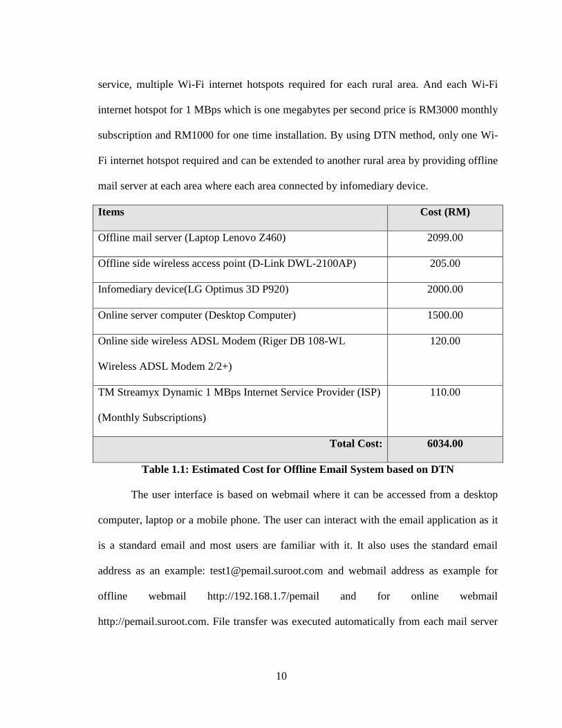
complicated requirements needed. There is the hardware cost needed for this offline email
system implementation. Related software required is a free and open source. Estimated
cost for this offline email system is RM6034.00 as shown in Table 1.1. This total cost
consists of one offline mail server, one informediary device, one online mail server and
one month internet subscription cost. The additional cost will be needed to support
another rural area by providing another offline mail server which will cost RM2304 for
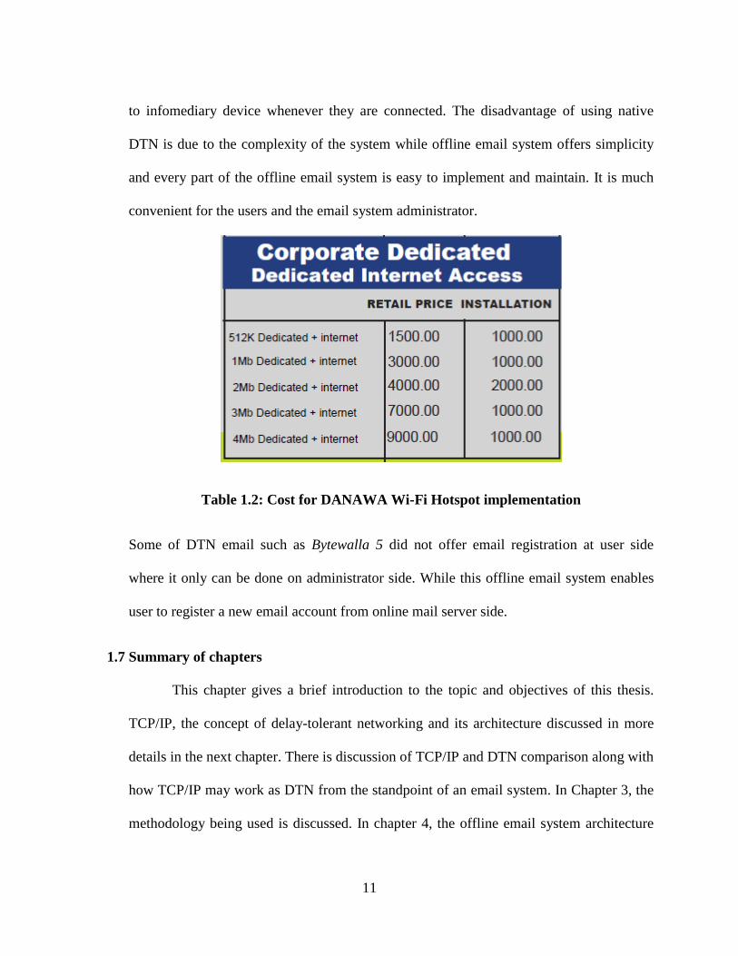
offline mail server computer and wireless access point. Compared to other Wireless
Service Provider such as Danawa Wireless Solution Provider, the cost is very high as
shown in Table 1.2. Appendix A shows the details of the Danawa service. To use Danawa
10
service, multiple Wi-Fi internet hotspots required for each rural area. And each Wi-Fi
internet hotspot for 1 MBps which is one megabytes per second price is RM3000 monthly
subscription and RM1000 for one time installation. By using DTN method, only one Wi-
Fi internet hotspot required and can be extended to another rural area by providing offline
mail server at each area where each area connected by infomediary device.
Items Cost (RM)
Offline mail server (Laptop Lenovo Z460) 2099.00
Offline side wireless access point (D-Link DWL-2100AP) 205.00
Infomediary device(LG Optimus 3D P920) 2000.00
Online server computer (Desktop Computer) 1500.00
Online side wireless ADSL Modem (Riger DB 108-WL
Wireless ADSL Modem 2/2+)
120.00
TM Streamyx Dynamic 1 MBps Internet Service Provider (ISP)
(Monthly Subscriptions)
110.00
Total Cost: 6034.00
Table 1.1: Estimated Cost for Offline Email System based on DTN
The user interface is based on webmail where it can be accessed from a desktop
computer, laptop or a mobile phone. The user can interact with the email application as it
is a standard email and most users are familiar with it. It also uses the standard email
address as an example: [email protected] and webmail address as example for
offline webmail http://192.168.1.7/pemail and for online webmail
http://pemail.suroot.com. File transfer was executed automatically from each mail server
11
to infomediary device whenever they are connected. The disadvantage of using native
DTN is due to the complexity of the system while offline email system offers simplicity
and every part of the offline email system is easy to implement and maintain. It is much
convenient for the users and the email system administrator.
Table 1.2: Cost for DANAWA Wi-Fi Hotspot implementation
Some of DTN email such as Bytewalla 5 did not offer email registration at user side
where it only can be done on administrator side. While this offline email system enables
user to register a new email account from online mail server side.
1.7 Summary of chapters
This chapter gives a brief introduction to the topic and objectives of this thesis.
TCP/IP, the concept of delay-tolerant networking and its architecture discussed in more
details in the next chapter. There is discussion of TCP/IP and DTN comparison along with
how TCP/IP may work as DTN from the standpoint of an email system. In Chapter 3, the
methodology being used is discussed. In chapter 4, the offline email system architecture

12
was designed based on the input from chapter 2 and the approach proposed from chapter
3. In chapter 5, the design concepts from earlier chapters are implemented. The system
test and the result discussed in chapter 6. Final chapter summarizes the thesis by
reviewing what was done and pointing out potential directions for future development.
13
2. LITERATURE REVIEW
In this chapter, the background to Transmission Control Protocol and Internet Protocol
(TCP/IP) and delay and disruption tolerant networking (DTN) presented. The details begin by
describing the TCP/IP layers, internet addressing and how TCP/IP works. Then continue by
describing the basic problem when using internet protocols and outline the reason to use
DTN. After that architecture of DTN is discussed and then the TCP/IP and DTN is compared.
2.1 Transmission Control Protocol and Internet Protocol (TCP/IP)
The Transmission Control Protocol and Internet Protocol (TCP/IP) enable
communications across a vast and heterogeneous collection of networks. Transmission
Control Protocol (TCP) is a reliable data delivery and connection service protocol. TCP
making sure the packet delivery is acknowledged and transmitted as needed.
The TCP/IP offers two basic communication services that operate on top of IP
which is Transmission Control Protocol (TCP) and User Datagram Protocol (UDP). There
are five main layers in TCP/IP which is Application Layer, Host-to-Host Transport Layer,
Network/Internet Layer, Data link/Network Access Layer and Physical Layer [4]. Figure
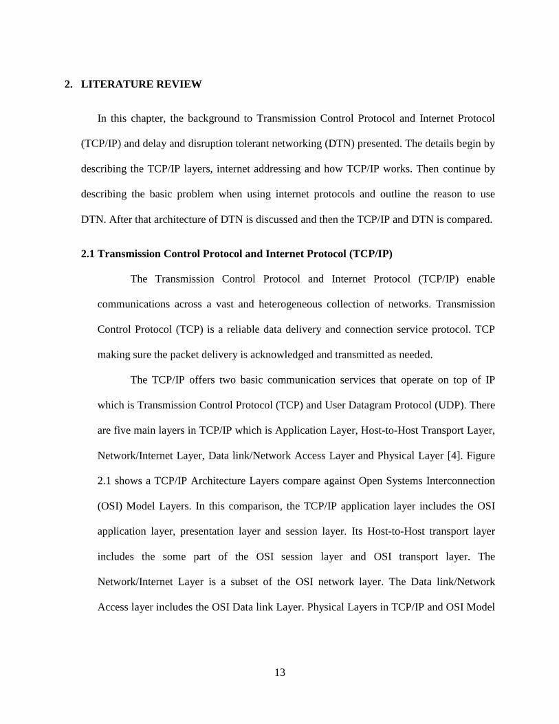
2.1 shows a TCP/IP Architecture Layers compare against Open Systems Interconnection
(OSI) Model Layers. In this comparison, the TCP/IP application layer includes the OSI
application layer, presentation layer and session layer. Its Host-to-Host transport layer
includes the some part of the OSI session layer and OSI transport layer. The
Network/Internet Layer is a subset of the OSI network layer. The Data link/Network
Access layer includes the OSI Data link Layer. Physical Layers in TCP/IP and OSI Model
14
is on the same level. Mostly TCP/IP Physical Layer is included in Data link/Network
Access layer and also called Network Interface Layer.
Figure 2.1: TCP/IP Protocol Architecture
2.1.1 Detailed explanation in each TCP/IP Layers
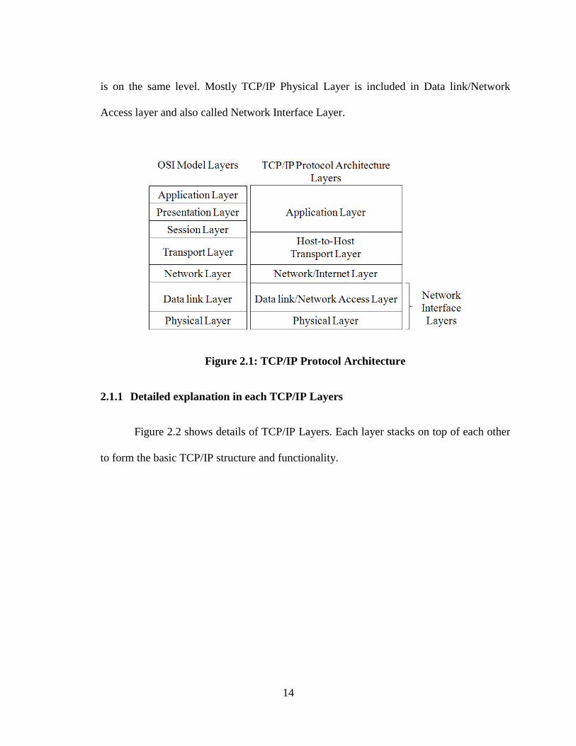
Figure 2.2 shows details of TCP/IP Layers. Each layer stacks on top of each other
to form the basic TCP/IP structure and functionality.
15
Figure 2.2: TCP/IP Layer
A) Application Layer
The top layer is an Application Layer. It is used by most applications for network
communication such as Telnet, Hypertext Transfer Protocol (HTTP), File Transfer
Protocol (FTP), Simple Mail Transfer Protocol (SMTP), Domain Name System (DNS),
Routing Information Protocol (RIP) and Simple Network Management Protocol (SNMP).
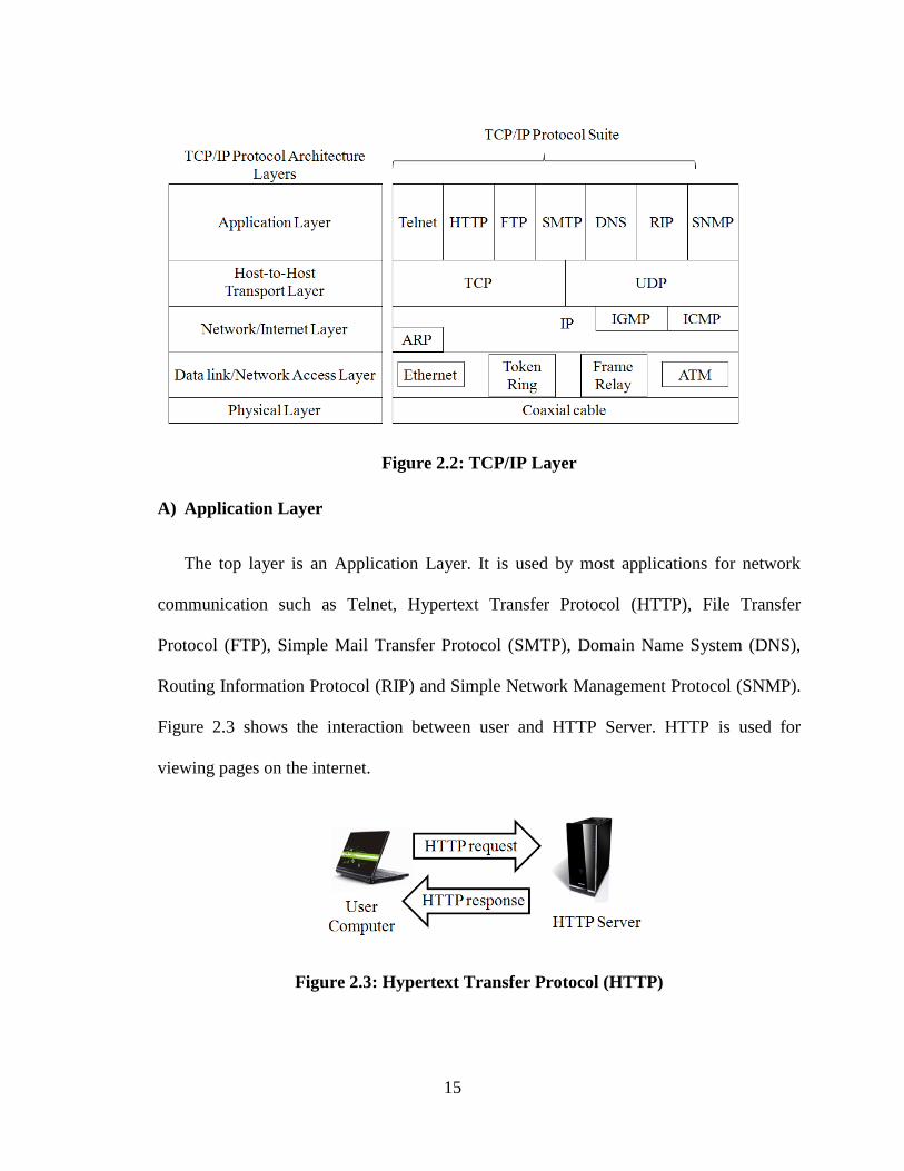
Figure 2.3 shows the interaction between user and HTTP Server. HTTP is used for
viewing pages on the internet.
Figure 2.3: Hypertext Transfer Protocol (HTTP)
16
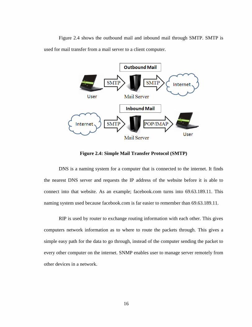
Figure 2.4 shows the outbound mail and inbound mail through SMTP. SMTP is
used for mail transfer from a mail server to a client computer.
Figure 2.4: Simple Mail Transfer Protocol (SMTP)
DNS is a naming system for a computer that is connected to the internet. It finds
the nearest DNS server and requests the IP address of the website before it is able to
connect into that website. As an example; facebook.com turns into 69.63.189.11. This
naming system used because facebook.com is far easier to remember than 69.63.189.11.
RIP is used by router to exchange routing information with each other. This gives
computers network information as to where to route the packets through. This gives a
simple easy path for the data to go through, instead of the computer sending the packet to
every other computer on the internet. SNMP enables user to manage server remotely from
other devices in a network.
17
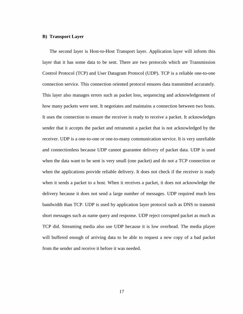
B) Transport Layer
The second layer is Host-to-Host Transport layer. Application layer will inform this
layer that it has some data to be sent. There are two protocols which are Transmission
Control Protocol (TCP) and User Datagram Protocol (UDP). TCP is a reliable one-to-one
connection service. This connection oriented protocol ensures data transmitted accurately.
This layer also manages errors such as packet loss, sequencing and acknowledgement of
how many packets were sent. It negotiates and maintains a connection between two hosts.
It uses the connection to ensure the receiver is ready to receive a packet. It acknowledges
sender that it accepts the packet and retransmit a packet that is not acknowledged by the
receiver. UDP is a one-to-one or one-to-many communication service. It is very unreliable
and connectionless because UDP cannot guarantee delivery of packet data. UDP is used
when the data want to be sent is very small (one packet) and do not a TCP connection or
when the applications provide reliable delivery. It does not check if the receiver is ready
when it sends a packet to a host. When it receives a packet, it does not acknowledge the
delivery because it does not send a large number of messages. UDP required much less
bandwidth than TCP. UDP is used by application layer protocol such as DNS to transmit
short messages such as name query and response. UDP reject corrupted packet as much as
TCP did. Streaming media also use UDP because it is low overhead. The media player
will buffered enough of arriving data to be able to request a new copy of a bad packet
from the sender and receive it before it was needed.
18
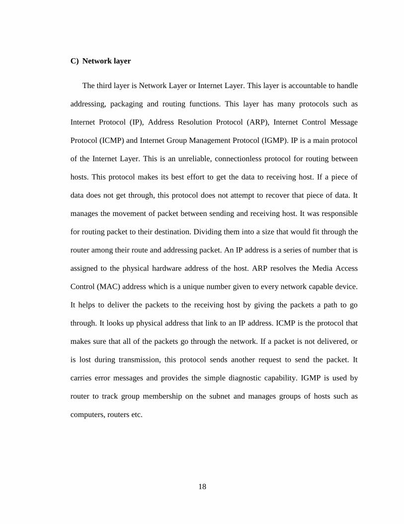
C) Network layer
The third layer is Network Layer or Internet Layer. This layer is accountable to handle
addressing, packaging and routing functions. This layer has many protocols such as
Internet Protocol (IP), Address Resolution Protocol (ARP), Internet Control Message
Protocol (ICMP) and Internet Group Management Protocol (IGMP). IP is a main protocol
of the Internet Layer. This is an unreliable, connectionless protocol for routing between
hosts. This protocol makes its best effort to get the data to receiving host. If a piece of
data does not get through, this protocol does not attempt to recover that piece of data. It
manages the movement of packet between sending and receiving host. It was responsible
for routing packet to their destination. Dividing them into a size that would fit through the
router among their route and addressing packet. An IP address is a series of number that is
assigned to the physical hardware address of the host. ARP resolves the Media Access
Control (MAC) address which is a unique number given to every network capable device.
It helps to deliver the packets to the receiving host by giving the packets a path to go
through. It looks up physical address that link to an IP address. ICMP is the protocol that
makes sure that all of the packets go through the network. If a packet is not delivered, or
is lost during transmission, this protocol sends another request to send the packet. It
carries error messages and provides the simple diagnostic capability. IGMP is used by
router to track group membership on the subnet and manages groups of hosts such as
computers, routers etc.
19
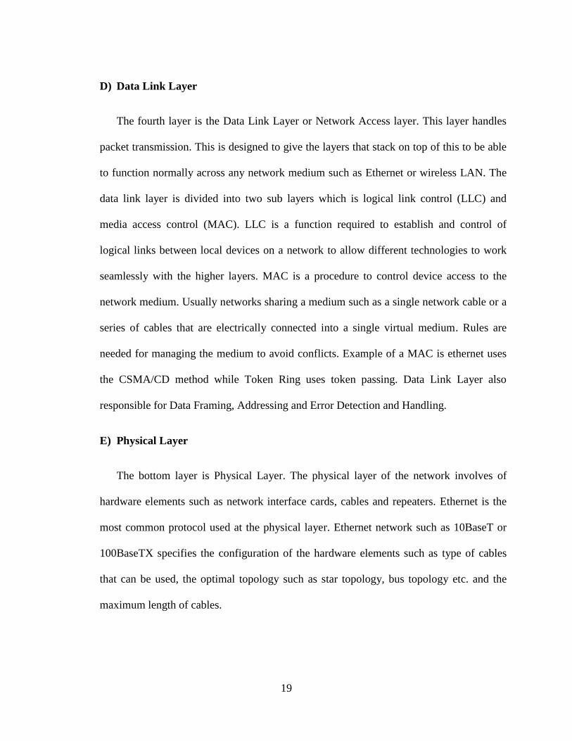
D) Data Link Layer
The fourth layer is the Data Link Layer or Network Access layer. This layer handles
packet transmission. This is designed to give the layers that stack on top of this to be able
to function normally across any network medium such as Ethernet or wireless LAN. The
data link layer is divided into two sub layers which is logical link control (LLC) and
media access control (MAC). LLC is a function required to establish and control of
logical links between local devices on a network to allow different technologies to work
seamlessly with the higher layers. MAC is a procedure to control device access to the
network medium. Usually networks sharing a medium such as a single network cable or a
series of cables that are electrically connected into a single virtual medium. Rules are
needed for managing the medium to avoid conflicts. Example of a MAC is ethernet uses
the CSMA/CD method while Token Ring uses token passing. Data Link Layer also
responsible for Data Framing, Addressing and Error Detection and Handling.
E) Physical Layer
The bottom layer is Physical Layer. The physical layer of the network involves of
hardware elements such as network interface cards, cables and repeaters. Ethernet is the
most common protocol used at the physical layer. Ethernet network such as 10BaseT or
100BaseTX specifies the configuration of the hardware elements such as type of cables
that can be used, the optimal topology such as star topology, bus topology etc. and the
maximum length of cables.
20
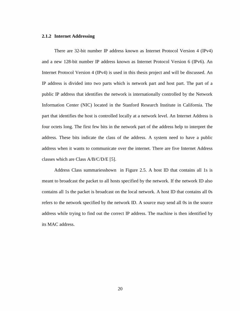
2.1.2 Internet Addressing
There are 32-bit number IP address known as Internet Protocol Version 4 (IPv4)
and a new 128-bit number IP address known as Internet Protocol Version 6 (IPv6). An
Internet Protocol Version 4 (IPv4) is used in this thesis project and will be discussed. An
IP address is divided into two parts which is network part and host part. The part of a
public IP address that identifies the network is internationally controlled by the Network
Information Center (NIC) located in the Stanford Research Institute in California. The
part that identifies the host is controlled locally at a network level. An Internet Address is
four octets long. The first few bits in the network part of the address help to interpret the
address. These bits indicate the class of the address. A system need to have a public
address when it wants to communicate over the internet. There are five Internet Address
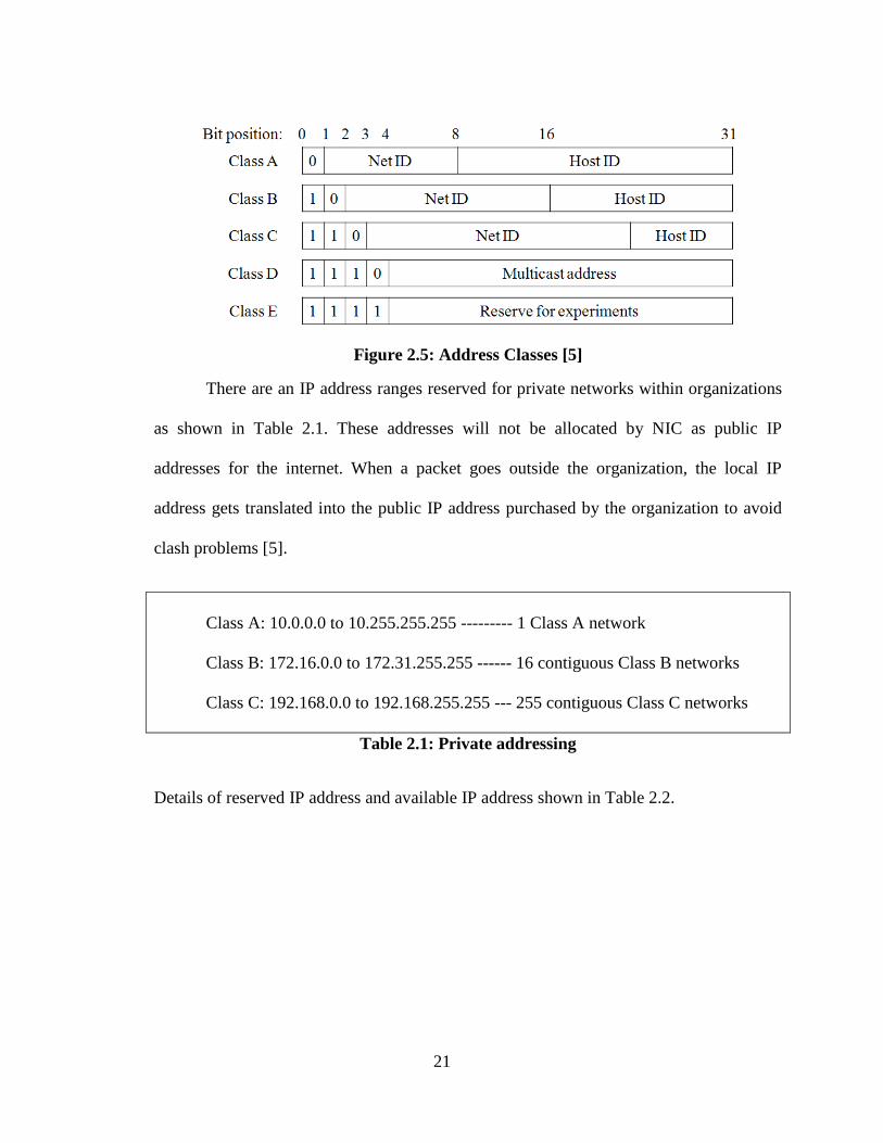
classes which are Class A/B/C/D/E [5].
Address Class summariesshown in Figure 2.5. A host ID that contains all 1s is
meant to broadcast the packet to all hosts specified by the network. If the network ID also
contains all 1s the packet is broadcast on the local network. A host ID that contains all 0s
refers to the network specified by the network ID. A source may send all 0s in the source
address while trying to find out the correct IP address. The machine is then identified by
its MAC address.
21
Figure 2.5: Address Classes [5]
There are an IP address ranges reserved for private networks within organizations
as shown in Table 2.1. These addresses will not be allocated by NIC as public IP
addresses for the internet. When a packet goes outside the organization, the local IP
address gets translated into the public IP address purchased by the organization to avoid
clash problems [5].
Class A: 10.0.0.0 to 10.255.255.255 --------- 1 Class A network
Class B: 172.16.0.0 to 172.31.255.255 ------ 16 contiguous Class B networks
Class C: 192.168.0.0 to 192.168.255.255 --- 255 contiguous Class C networks
Table 2.1: Private addressing
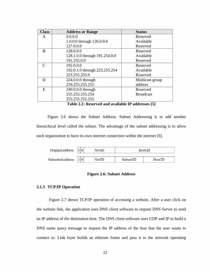
Details of reserved IP address and available IP address shown in Table 2.2.
22
Class Address or Range Status
A 0.0.0.0
1.0.0.0 through 126.0.0.0
127.0.0.0
Reserved
Available
Reserved
B 128.0.0.0
128.1.0.0 through 191.254.0.0
191.255.0.0
Reserved
Available
Reserved
C 192.0.0.0
192.0.1.0 through 223.255.254
223.255.255.0
Reserved
Available
Reserved
D 224.0.0.0 through
239.255.255.255
Multicast group
address
E 240.0.0.0 through
255.255.255.254
255.255.255.255
Reserved
Broadcast
Table 2.2: Reserved and available IP addresses [5]
Figure 2.6 shows the Subnet Address. Subnet Addressing is to add another
hierarchical level called the subnet. The advantage of the subnet addressing is to allow
each organization to have its own internet connection within the internet [6].
Figure 2.6: Subnet Address
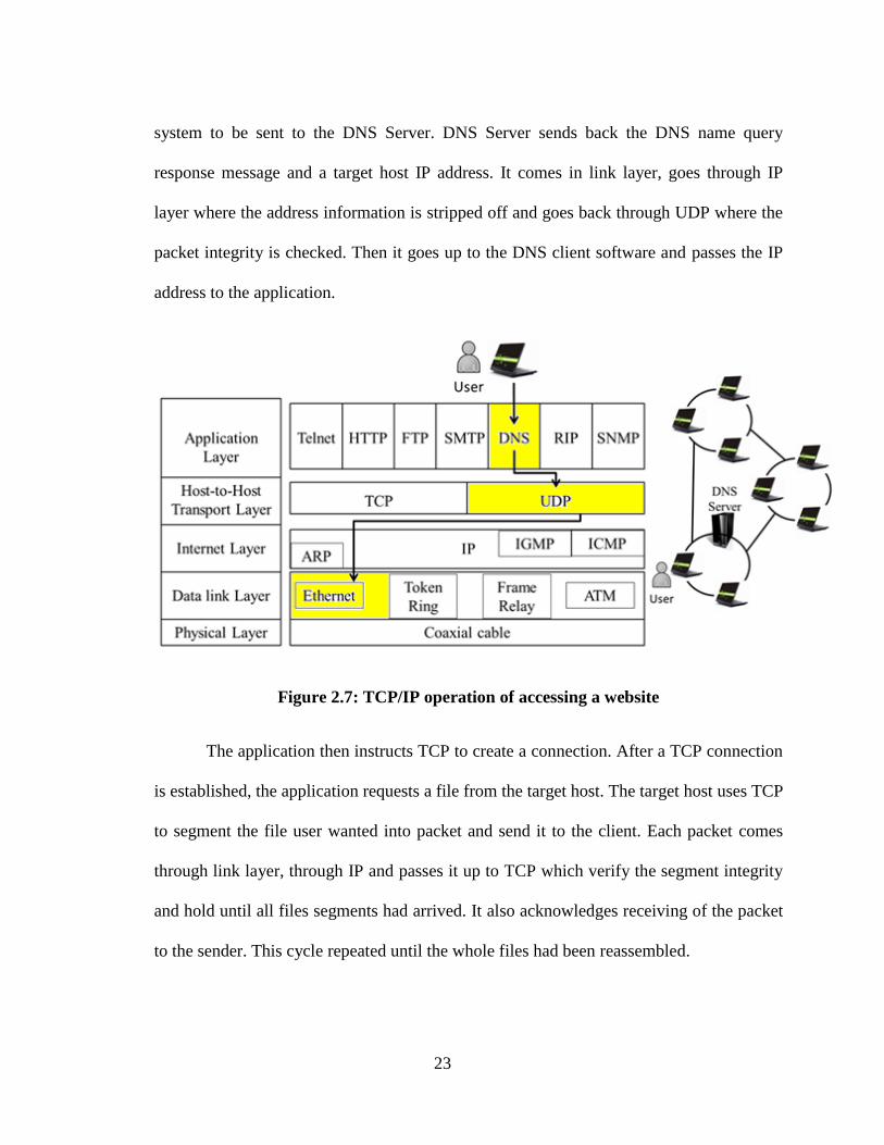
2.1.3 TCP/IP Operation
Figure 2.7 shows TCP/IP operation of accessing a website. After a user click on
the website link, the application uses DNS client software to request DNS Server to send
an IP address of the destination host. The DNS client software uses UDP and IP to build a
DNS name query message to request the IP address of the host that the user wants to
connect to. Link layer builds an ethernet frame and pass it to the network operating
23
system to be sent to the DNS Server. DNS Server sends back the DNS name query
response message and a target host IP address. It comes in link layer, goes through IP
layer where the address information is stripped off and goes back through UDP where the
packet integrity is checked. Then it goes up to the DNS client software and passes the IP
address to the application.
Figure 2.7: TCP/IP operation of accessing a website
The application then instructs TCP to create a connection. After a TCP connection
is established, the application requests a file from the target host. The target host uses TCP
to segment the file user wanted into packet and send it to the client. Each packet comes
through link layer, through IP and passes it up to TCP which verify the segment integrity
and hold until all files segments had arrived. It also acknowledges receiving of the packet
to the sender. This cycle repeated until the whole files had been reassembled.
24
If the packet arrive does not pass the integrity check, TCP discarded it and not
send acknowledgement to the sender. If the last packet was not acknowledged within a lot
of time, the sender retransmit it. When the last packet arrives, the files are reassembled
and acknowledged to the sender. The client then closed TCP connection. The completed
files passed to the application where users can access it.
2.2 Delay Tolerant Network (DTN)
Delay and disruption tolerant networking (DTN) approach is to overcome the
network connection problem when there is no end-to-end connectivity in Internet
Transport Protocols. DTN is an approach to computer network architecture that seeks to
address the technical issues in heterogeneous network that may lack continuous network
connectivity. The DTN application must tolerate delay and disruption with acceptable
performance in high loss or delay error environments.
2.2.1 Reason to use DTN
Internet Protocols (IP) required end-to-end connectivity. It operates poorly in an
environment with a very long delay path and frequent network partitions which causes by
severe power or memory constraints by end nodes which make the network infrastructure
lacking „always-on‟ environment. Delay and disruption can be caused by long distance
and time. There are some fundamental assumptions in the internet architecture that can
cause a break in the network under long delays and intermittent connectivity such as [7]
[3]:
i. There is always an end-to-end path between source and destination exists.
25
ii. Need to establish at least one round-trip or transmission and response
before any application data can flow. This means that there is a
requirement of the sender and receiver negotiate a connection to regulate
the flow of data.
iii. Retransmissions from the source are good way to provide reliable
communication.
iv. End-to-end loss is relatively small.
v. Endpoint-based security is sufficient to meet most security concerns.
DTN is used to tolerate long delays and intermittent connectivity which is a weakness in
Internet Protocols. DTN is able to enable a connection when there is no end-to-end path
between the source and destination, the round-trip is not needed to regulate the flow of
data, retransmission from data receivers is not in use for repairing errors because there is
no end-to-end path and unlike IP, DTN is ignoring the end-to-end dependency such as in
IP fundamental assumptions (iv) and (v). There are environments that exhibiting some of
these characteristics which are:
i. Space communications where there are high latencies, intermittent
connectivity due to antenna schedule.
ii. Sensor networks when nodes need to power down to conserve energy.
iii. Line of sight radios especially for urban area with wooded/hill
environments.
iv. Mobile networks
26
2.2.2 Architecture of DTN
The DTN architecture implements store and forward message switching by
overlaying the bundle layer on top of heterogeneous regional networks. Bundles also
called messages (message switched). The bundle layer stores and forward bundle
fragments between nodes. A single bundle layer protocol is used in all regional networks
and make up a DTN.
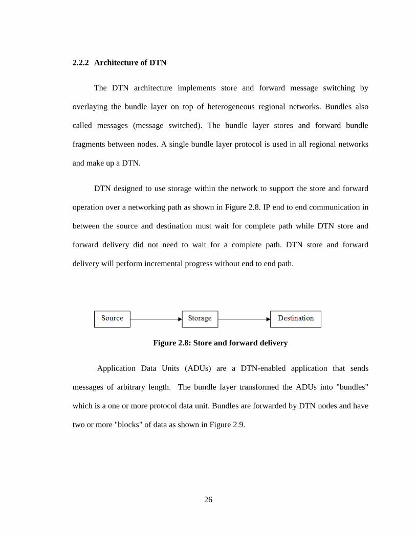
DTN designed to use storage within the network to support the store and forward
operation over a networking path as shown in Figure 2.8. IP end to end communication in
between the source and destination must wait for complete path while DTN store and
forward delivery did not need to wait for a complete path. DTN store and forward
delivery will perform incremental progress without end to end path.
Figure 2.8: Store and forward delivery
Application Data Units (ADUs) are a DTN-enabled application that sends
messages of arbitrary length. The bundle layer transformed the ADUs into "bundles"
which is a one or more protocol data unit. Bundles are forwarded by DTN nodes and have
two or more "blocks" of data as shown in Figure 2.9.

27
Figure 2.9: Bundles
Application data or other information in each block used to deliver the containing
bundle to its destinations. Blocks used to hold information in the header or payload
portion of protocol data units in other protocol architectures. It is called "block" instead
of "header" because blocks may not appear at the beginning of a bundle due to particular
processing requirements [8].
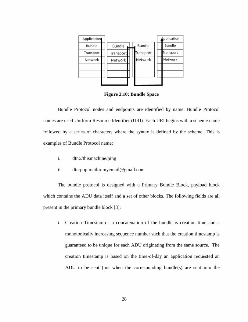
Bundle layer as shown in Figure 2.10 support end to end transfer across
heterogeneous network protocol stacks. An essential element of the bundle-based style of
forwarding is that bundles have a place to wait in a queue until a communication contact
is available. Size of storage used in this operation is depending on the system
requirement. The assumptions for this operation as follows:
i. Storage is available and well-distributed throughout the network.
ii. Storage is sufficiently persistent and robust to store bundles until
forwarding can occur.
iii. This "store-and-forward" model is a better choice than attempting to effect
continuous connectivity or other alternatives.
28
Figure 2.10: Bundle Space
Bundle Protocol nodes and endpoints are identified by name. Bundle Protocol
names are used Uniform Resource Identifier (URI). Each URI begins with a scheme name
followed by a series of characters where the syntax is defined by the scheme. This is
examples of Bundle Protocol name:
i. dtn://thismachine/ping
ii. dtn:pop:mailto:[email protected]
The bundle protocol is designed with a Primary Bundle Block, payload block
which contains the ADU data itself and a set of other blocks. The following fields are all
present in the primary bundle block [3]:
i. Creation Timestamp - a concatenation of the bundle is creation time and a
monotonically increasing sequence number such that the creation timestamp is
guaranteed to be unique for each ADU originating from the same source. The
creation timestamp is based on the time-of-day an application requested an
ADU to be sent (not when the corresponding bundle(s) are sent into the

29
network). DTN nodes are assumed to have a basic time synchronization
capability.
ii. Lifespan - the time-of-day at which the message is no longer useful. If a
bundle is stored in the network (including the source is DTN node) when its
lifespan is reached, it may be discarded. The lifespan of a bundle is expressed
as an offset relative to its creation time.
iii. Class of Service Flags - indicates the delivery options and priority class for the
bundle.
iv. Source EID - EID of the source.
v. Destination EID - EID of the destination.
vi. Report-To Endpoint ID - an EID identifying where should be sent. This may
or may not identify the same endpoint as the Source EID.
vii. Custodian EID - EID of the current custodian of a bundle.
The lifespan field is very useful in an attempt to keep the email data in this offline email
system for a longer period of time until it transferred to another device. Another block
such as metadata block is used to identify the content. It could be used to implement
„network as a database‟ and can be encrypted separately from the payload. The payload
block indicates information about the contained payload and the payload itself.
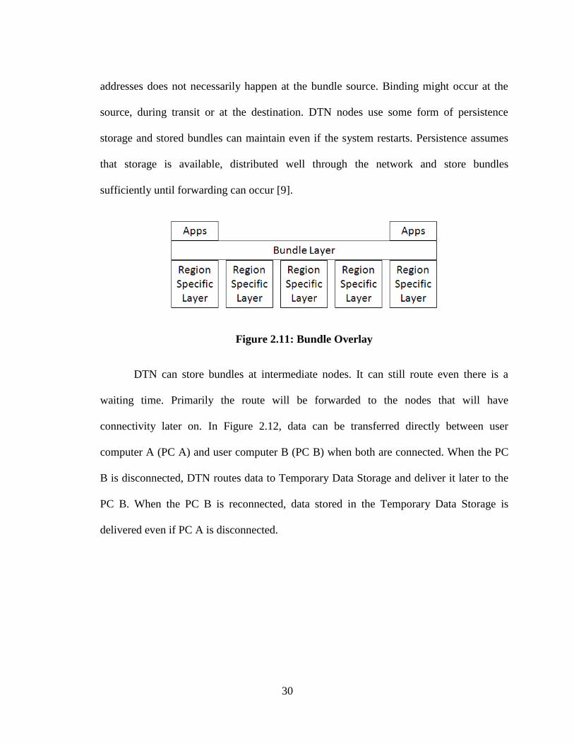
Binding interprets an endpoint identifier (EID) to select the next hop or next
region specific layer the bundle can be forwarded toward its destination. Figure 2.11
shows the bundle layer through every region specific layer. Late binding means that the
binding of a bundle is a destination to a particular set of destination identifiers or
30
addresses does not necessarily happen at the bundle source. Binding might occur at the
source, during transit or at the destination. DTN nodes use some form of persistence
storage and stored bundles can maintain even if the system restarts. Persistence assumes
that storage is available, distributed well through the network and store bundles
sufficiently until forwarding can occur [9].
Figure 2.11: Bundle Overlay
DTN can store bundles at intermediate nodes. It can still route even there is a
waiting time. Primarily the route will be forwarded to the nodes that will have
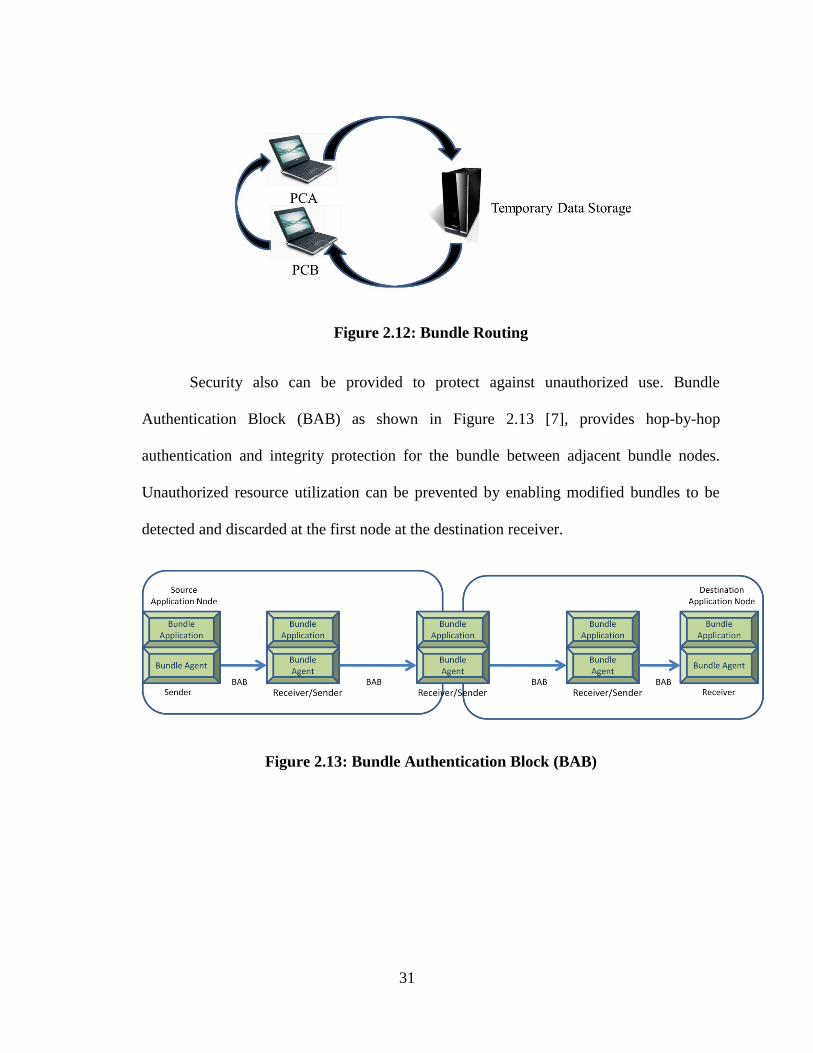
connectivity later on. In Figure 2.12, data can be transferred directly between user
computer A (PC A) and user computer B (PC B) when both are connected. When the PC
B is disconnected, DTN routes data to Temporary Data Storage and deliver it later to the
PC B. When the PC B is reconnected, data stored in the Temporary Data Storage is
delivered even if PC A is disconnected.
31
Figure 2.12: Bundle Routing
Security also can be provided to protect against unauthorized use. Bundle
Authentication Block (BAB) as shown in Figure 2.13 [7], provides hop-by-hop
authentication and integrity protection for the bundle between adjacent bundle nodes.
Unauthorized resource utilization can be prevented by enabling modified bundles to be
detected and discarded at the first node at the destination receiver.
Figure 2.13: Bundle Authentication Block (BAB)
32
2.3 Comparison of TCP/IP and DTN
2.3.1 DTN vs. TCI/IP: Protocol Architecture
Internet layers and DTN layers are identical except that DTN architecture
implements store and forward message switching by overlaying a new protocol layer
called bundle layer. It is placed on top of Transport layers. The bundle layer ties together
the Transport layers and below with application programs to communicate across multiple
regions. Bundles are also called messages switched. The bundle layer stores and forwards
entire bundles or bundle fragments between nodes. A single bundle layer protocol is used
across all networks that make up a DTN. By contrast, the layers below the bundle layer
which is transport layer and below are chosen for their appropriateness to the
communication environment of each region.
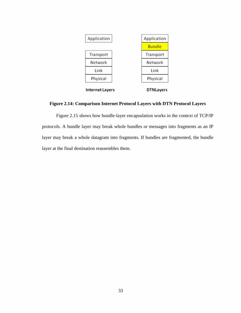
Figure 2.14 shows the DTN layer compares to the Internet layer [9]. Bundle
consists of a source-application user data, Control Information provided by source
application and destination application which describes how to process, store, dispose and
handle user data and a Bundle header. Bundles extend the hierarchy of data-object
encapsulation performed by the Internet protocols.
33
Figure 2.14: Comparison Internet Protocol Layers with DTN Protocol Layers
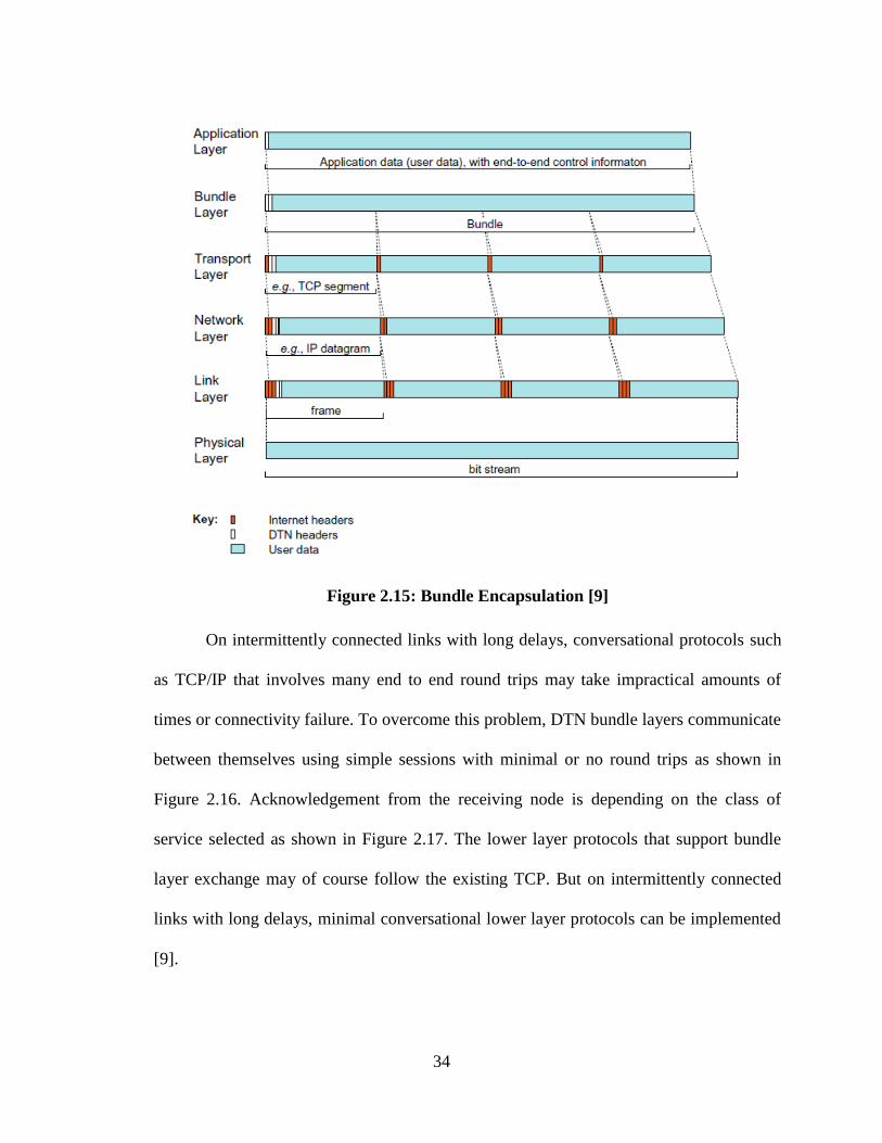
Figure 2.15 shows how bundle-layer encapsulation works in the context of TCP/IP
protocols. A bundle layer may break whole bundles or messages into fragments as an IP
layer may break a whole datagram into fragments. If bundles are fragmented, the bundle
layer at the final destination reassembles them.
34
Figure 2.15: Bundle Encapsulation [9]
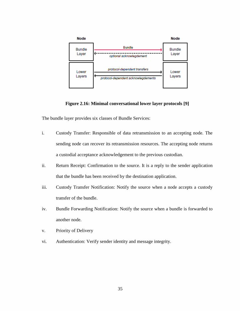
On intermittently connected links with long delays, conversational protocols such
as TCP/IP that involves many end to end round trips may take impractical amounts of
times or connectivity failure. To overcome this problem, DTN bundle layers communicate
between themselves using simple sessions with minimal or no round trips as shown in
Figure 2.16. Acknowledgement from the receiving node is depending on the class of
service selected as shown in Figure 2.17. The lower layer protocols that support bundle
layer exchange may of course follow the existing TCP. But on intermittently connected
links with long delays, minimal conversational lower layer protocols can be implemented
[9].
35
Figure 2.16: Minimal conversational lower layer protocols [9]
The bundle layer provides six classes of Bundle Services:
i. Custody Transfer: Responsible of data retransmission to an accepting node. The
sending node can recover its retransmission resources. The accepting node returns
a custodial acceptance acknowledgement to the previous custodian.
ii. Return Receipt: Confirmation to the source. It is a reply to the sender application
that the bundle has been received by the destination application.
iii. Custody Transfer Notification: Notify the source when a node accepts a custody
transfer of the bundle.
iv. Bundle Forwarding Notification: Notify the source when a bundle is forwarded to
another node.
v. Priority of Delivery
vi. Authentication: Verify sender identity and message integrity.
36
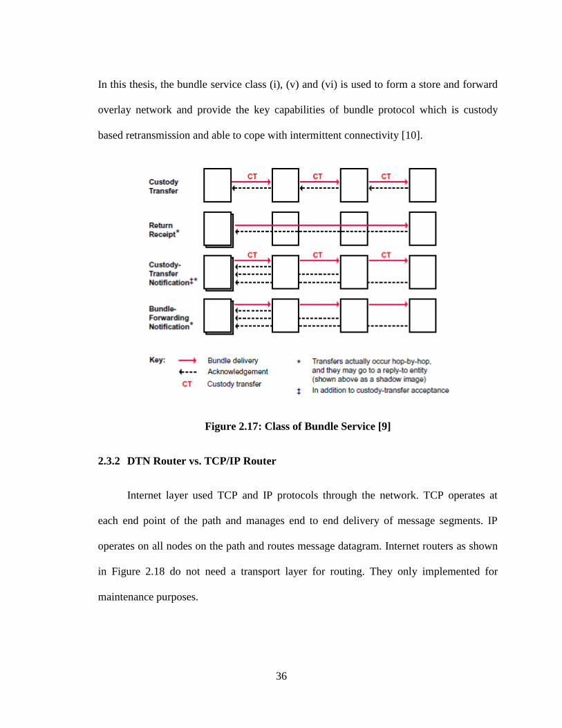
In this thesis, the bundle service class (i), (v) and (vi) is used to form a store and forward
overlay network and provide the key capabilities of bundle protocol which is custody
based retransmission and able to cope with intermittent connectivity [10].
Figure 2.17: Class of Bundle Service [9]
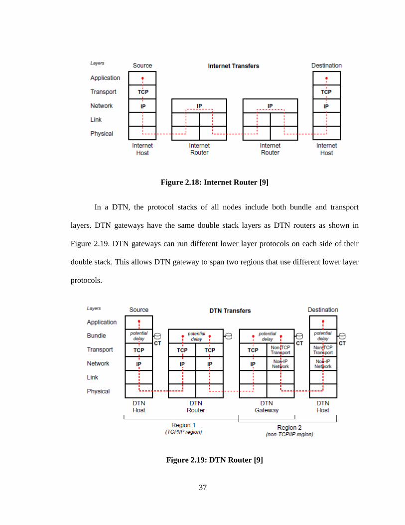
2.3.2 DTN Router vs. TCP/IP Router
Internet layer used TCP and IP protocols through the network. TCP operates at
each end point of the path and manages end to end delivery of message segments. IP
operates on all nodes on the path and routes message datagram. Internet routers as shown
in Figure 2.18 do not need a transport layer for routing. They only implemented for
maintenance purposes.
37
Figure 2.18: Internet Router [9]
In a DTN, the protocol stacks of all nodes include both bundle and transport
layers. DTN gateways have the same double stack layers as DTN routers as shown in
Figure 2.19. DTN gateways can run different lower layer protocols on each side of their
double stack. This allows DTN gateway to span two regions that use different lower layer
protocols.
Figure 2.19: DTN Router [9]
38
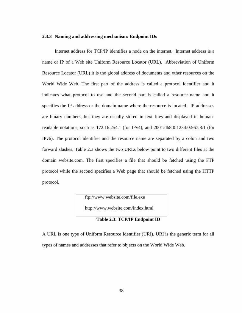
2.3.3 Naming and addressing mechanism: Endpoint IDs
Internet address for TCP/IP identifies a node on the internet. Internet address is a
name or IP of a Web site Uniform Resource Locator (URL). Abbreviation of Uniform
Resource Locator (URL) it is the global address of documents and other resources on the
World Wide Web. The first part of the address is called a protocol identifier and it
indicates what protocol to use and the second part is called a resource name and it
specifies the IP address or the domain name where the resource is located. IP addresses
are binary numbers, but they are usually stored in text files and displayed in human-
readable notations, such as 172.16.254.1 (for IPv4), and 2001:db8:0:1234:0:567:8:1 (for
IPv6). The protocol identifier and the resource name are separated by a colon and two
forward slashes. Table 2.3 shows the two URLs below point to two different files at the
domain website.com. The first specifies a file that should be fetched using the FTP
protocol while the second specifies a Web page that should be fetched using the HTTP
protocol.
ftp://www.website.com/file.exe
http://www.website.com/index.html
Table 2.3: TCP/IP Endpoint ID
A URL is one type of Uniform Resource Identifier (URI). URI is the generic term for all
types of names and addresses that refer to objects on the World Wide Web.
39
In a DTN, Bundle Protocol endpoints are identified by name. Bundle Protocol
names are Uniform Resource Identifier (URI). Table 2.4 shows examples of Bundle
Protocol name.
dtn://thismachine/ping
dtn:pop:mailto:[email protected]
Table 2.4: DTN Endpoint ID
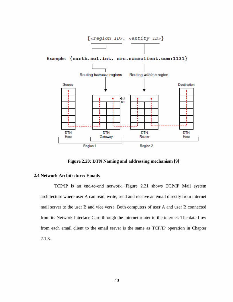
In URI terminology, each URI begins with a scheme name followed by a series of
characters where the syntax is defined by the scheme. Each DTN node has a two part
name consist of a region ID and entity ID as shown in Figure 2.20. Routing between
regions is based only on region IDs, which are bound to their corresponding addresses
throughout the DTN. Routing within regions is based only on entity IDs which are bound
to their corresponding address only within that region. Thus each region uses a different
mapping of entity IDs to address and no bandwidth is needed to copy name address
mappings between regions. Gateways belong to two or more regions and move bundles
between regions. It has multiple region IDs. Region IDs use the same namespace syntax
as the internet DNS [9].
40
Figure 2.20: DTN Naming and addressing mechanism [9]
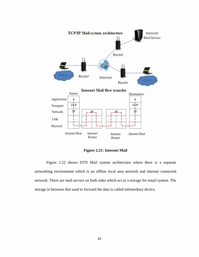
2.4 Network Architecture: Emails
TCP/IP is an end-to-end network. Figure 2.21 shows TCP/IP Mail system
architecture where user A can read, write, send and receive an email directly from internet
mail server to the user B and vice versa. Both computers of user A and user B connected
from its Network Interface Card through the internet router to the internet. The data flow
from each email client to the email server is the same as TCP/IP operation in Chapter
2.1.3.
41
Figure 2.21: Internet Mail
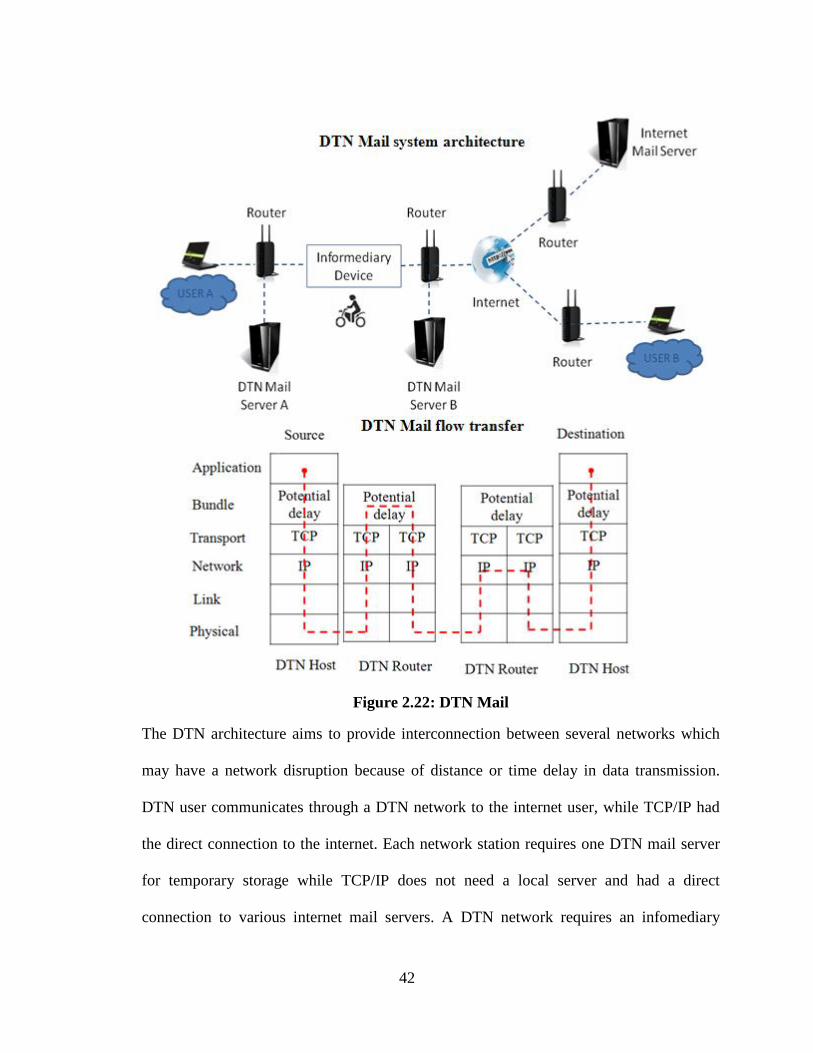
Figure 2.22 shows DTN Mail system architecture where there is a separate
networking environment which is an offline local area network and internet connected
network. There are mail servers on both sides which act as a storage for email system. The
storage in between that used to forward the data is called infomediary device.
42
Figure 2.22: DTN Mail
The DTN architecture aims to provide interconnection between several networks which
may have a network disruption because of distance or time delay in data transmission.
DTN user communicates through a DTN network to the internet user, while TCP/IP had
the direct connection to the internet. Each network station requires one DTN mail server
for temporary storage while TCP/IP does not need a local server and had a direct
connection to various internet mail servers. A DTN network requires an infomediary
43
device to transfer and receive data between network stations while TCP/IP does not need
it.
2.5 Similar Works
2.5.1 Bytewalla 5
Bytewalla 5 is a delay tolerant network on Android phones. This project uses
android phones with delay-tolerant networking to connect African rural villages. The idea
is that the android mobile phone will store and carry data from villages to cities. In the
village, the data will be downloaded to android mobile phone from a Wi-Fi access point
for example in a telecentre with no internet connectivity. When in the city, the Android
phone will connect to another Wi-Fi access point and upload the data. This "data mule"
operation will enable emails downloaded at the village to be delivered in the city.
The Bytewalla 5 approaches are the same as this thesis project, the difference is the
data transfer in Bytewalla 5 being done by the DTN application on android phone while
this thesis project data transfer being done by file synchronization application on a server
computer. The details comparison is discussed in chapter 4.4 and illustrated in Table 4.2.
Bytewalla 5 and this thesis project similarly use android phone as a data mule. This data
mule has no Bundle Protocol layer implemented since Bytewalla 5 and this thesis project
only use android phone as Bundle Protocol carriers. The bundle data for Bytewalla 5 is
stored in one single file while this thesis project bundle data is the exact copy of data from
the server with no alteration. Bytewalla 5 uses Ubuntu 8.04 for its DTN Server and this
thesis project use Windows XP for its DTN Server. Bytewalla 5 follows very closely the
design of DTN2, the DTN reference implementation written in C++ by the DTNRG while
44
this thesis project only follows the concept of store and forward in DTN and applied it in
TCP/IP using a suitable application for its email application.
2.5.2 Offline Gmail
Offline Gmail is an email system by Google which is separated from Gmail itself.
It is designed for accessing, managing and sending email while user disconnected from
the web. Offline Gmail originally build based off the tablet version which designed to
function with or without internet access. It contains all the features needed while offline
including organizing, starring, labeling, archiving reading and responding to email. When
sending email offline, the email will be stored in the Outbox. The stored email will
automatically sent when connected to the internet.
Offline Gmail data were updated only on mail client and every user needs to bring
their mail client from offline to online environment. Therefore, it does not need any
database synchronization. Comparison of Offline Gmail and this thesis work is also
discussed in chapter 4.4 and illustrated in Table 4.2. Offline Gmail only available in
Chrome Browser while others such as Firefox needed Google Gears installed. Google
Gears adding new features to the web browser to allow some online files to be used
offline. Unfortunately Google Gears was discontinued on 19 February 2010. The ordinary
mail client being used in this thesis which mean any web browser can be used to access
this offline email system. A third party mail client such as Mozilla Thunderbird and
Microsoft Outlook can be used.
45
2.6 Summary
The DTN architecture aims to provide interconnection between several networks
which may have a poor performance characteristic because of distance or time delay in
data transmission. There are differences in TCP/IP compare to delay tolerant network
protocol. But for some application such as email, there is some similarity in term of
operation where email is a delay tolerant application and no need for end-to-end
connectivity. This makes it possible to implement a TCP/IP email system to work as a
delay tolerant network (DTN) with some additional method to establish a connection
between separate terminal locations by using data mule. In the next chapter, methodology
is discussed.
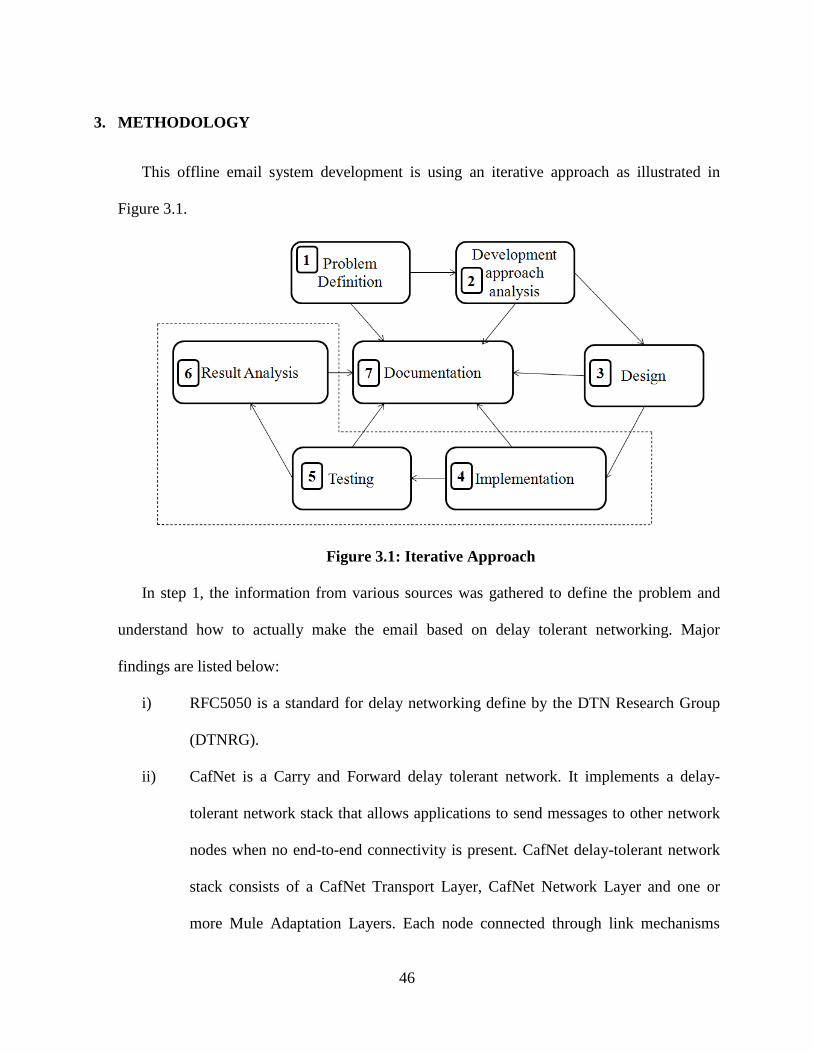
46
3. METHODOLOGY
This offline email system development is using an iterative approach as illustrated in
Figure 3.1.
Figure 3.1: Iterative Approach
In step 1, the information from various sources was gathered to define the problem and
understand how to actually make the email based on delay tolerant networking. Major
findings are listed below:
i) RFC5050 is a standard for delay networking define by the DTN Research Group
(DTNRG).
ii) CafNet is a Carry and Forward delay tolerant network. It implements a delay-
tolerant network stack that allows applications to send messages to other network
nodes when no end-to-end connectivity is present. CafNet delay-tolerant network
stack consists of a CafNet Transport Layer, CafNet Network Layer and one or
more Mule Adaptation Layers. Each node connected through link mechanisms
47
where the data is physically carried on a USB key. CafNet prioritizes messages
such that data with a higher priority is sent during short bursts of connectivity.
iii) The Architecture of Email [11] and protocols such as TCP/IP, delay tolerant
network (DTN) [10], simple mail transfer protocol (SMTP) [12] and internet
message access protocol (IMAP) [13].
In step 2, the development approach of this offline email system is selected and related
information is identified. CafNet concept is used in this offline email system where the data is
physically carried on a USB Key. The difference is this system data is carried and transferred
automatically when it reaches the terminal location through a wireless local area network and
database synchronization. The standard for delay networking defines by DTN Research
Group (DTNRG) concept applied on data mule and data bundling for its store and forward
operation. There are several possible ways to implement the systems including:
i) Implementation from scratch by following the native DTN protocol
ii) Implementation from scratch by using TCP/IP mail system works as a DTN
mail system
iii) Implementation using existing application to fulfill requirement of TCP/IP
mail system working as a DTN mail system.
The third approach is selected because of the design effort is fairly follows the TCP/IP
thus adding some new design to make it working as DTN, a free and open source software is
used and adaptation of standard email usage to the end user.
In step 3, the system is designed closely as standard TCP/IP email architecture except for
the infomediary device and emails data synchronization implemented to make a connection
48
between separate terminal locations. Step 4, step 5 and step 6 which is implementation,
system testing and result analysis progressed simultaneously starting from setting up a local
server computer, home server accessible to the internet implementation, mail server, mail
client and infomediary device which includes the database synchronization. This is to ensure
every part of the implementation is working accordingly and produced the expected result.
Finally in step 7, documentations were recorded including the system requirement, design,
implementation, testing and result. The documentation progress simultaneously from the
beginning of the project until completed and then finalize at the end. In the next chapter
system design architecture is discussed.
49
4. OFFLINE EMAIL SYSTEM DESIGN ARCHITECTURE
In this chapter the network architecture of the TCP/IP email system and DTN email
system briefly presented. The approach of using a TCP/IP on a DTN email system discussed
by presenting the idea of using TCP/IP mail system as a DTN mail system, analysis of the
idea and abstraction of the TCP/IP mail system based on DTN. Then the application and
network topology being used for this offline email system discussed. After that, network
protocol and details of the design for this offline email system is discussed and then go on to a
design solution for database synchronization.
4.1 TCP/IP Mail System works as a DTN Mail System
Email is a method of exchanging digital messages from a sender to one or more
recipients. Email system commonly operates across the internet and is based on a store
and forward operation. Users on both sides are not required to be online at the same time.
User only needs to connect to mail server briefly for them to read, write or send messages.
Unique of email system is it tolerant to delay and disruption. Email applications are
asynchronous in nature. No need for "always on" connectivity. It does not communicate
most of the time and does not require end-to-end connectivity. Since email system briefly
is a DTN system, TCP/IP email system can be implemented as a DTN email system [14].
Table 4.1 shows a Store, Carry and Forward Scenario for Internet (TCP/IP), Email and
DTN.
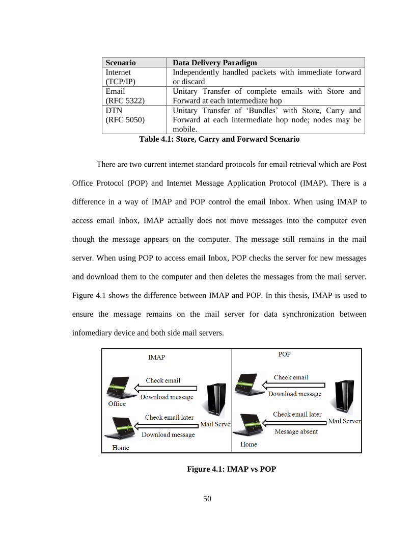
50
Scenario Data Delivery Paradigm
Internet
(TCP/IP)
Independently handled packets with immediate forward
or discard
(RFC 5322)
Unitary Transfer of complete emails with Store and
Forward at each intermediate hop
DTN
(RFC 5050)
Unitary Transfer of „Bundles‟ with Store, Carry and
Forward at each intermediate hop node; nodes may be
mobile.
Table 4.1: Store, Carry and Forward Scenario
There are two current internet standard protocols for email retrieval which are Post
Office Protocol (POP) and Internet Message Application Protocol (IMAP). There is a
difference in a way of IMAP and POP control the email Inbox. When using IMAP to
access email Inbox, IMAP actually does not move messages into the computer even
though the message appears on the computer. The message still remains in the mail
server. When using POP to access email Inbox, POP checks the server for new messages
and download them to the computer and then deletes the messages from the mail server.
Figure 4.1 shows the difference between IMAP and POP. In this thesis, IMAP is used to
ensure the message remains on the mail server for data synchronization between
infomediary device and both side mail servers.
Figure 4.1: IMAP vs POP
51
There are several commercials and free mail server available such as hMailServer,
AtMail etc. HMailServer is a free mail server for Microsoft Windows. It supports the
common email protocols such as IMAP, SMTP and POP3. ) HMailServer can easily be
integrated with many existing webmail systems. It has a flexible score-based spam
protection using Bayesian spam filtering which is an email filtering based on statistical
technique. This technique classified collection of words to identify spam email. It also can
attach email to the virus scanner to scan all incoming and outgoing email [15]. AtMail is a
webmail client written in PHP. It provides an elegant Ajax webmail client for existing
IMAP mail servers, with less bloat and a focus on an intuitive, simple user interface.
Atmail supports a variety of platforms. It offers a web interface feature [16]. In this thesis
work, hMailServer is used for a mail server since it is easy to use, open source, free and
Windows based application.
There are also several commercials and free mail client available such as
SquirrelMail, Rmail, roundcube. SquirrelMail is a standards-based webmail package
written in PHP. It includes built-in pure PHP support for the IMAP and SMTP protocols,
and all pages render in pure HTML 4.0 (with no JavaScript required) for maximum
compatibility across browsers. It has very few requirements and is very easy to configure
and install. SquirrelMail has all the functionality as an email client, including strong
MIME support, address books, and folder manipulation. Rmail is a Java[TM] library for
sending and receiving e-mail messages with Mime extensions (attachments, html), SMTP
(sending) and POP3 (receiving) protocols [17].
52
Roundcube webmail is a browser-based multilingual IMAP client with an application-like
user interface. It provides full functionality as an e-mail client, including MIME support,
address book, folder management, message searching and spell checking. Roundcube
webmail is written in PHP and requires the MySQL, PostgreSQL or SQLite database. Its
plugin API is easily extendable and the user interface is fully customizable using skins
which are pure XHTML and CSS 2.Roundcube webmail is used in this thesis work since
it supports IMAP and browser based which mean of portability [18].
4.2 Idea and Concept Analysis
The email system is based on store and forward operation. This operation is
matched with the DTN system operation where it needs storage to store a data from the
sender before it forwarded to a receiver. The native DTN protocol is much complicated
for the average user. The DTN system is mostly Linux based. Average user mostly not
familiar with command line and DTN Endpoint ID. TCP/IP email implementation based
on DTN concept is much convenient for the average user. The usage is much familiar
since it uses native TCP/IP approach for the system. Average users mostly familiar with
Windows operating system and this approach maintain the TCP/IP Endpoint ID.
Offline Gmail provides the ability for the user to read and manage their email in an
offline environment. But, it is still required each user to move their device to the internet
connected area for the pending email being sent, receive and synchronize. The advantage
for this thesis work is there is only one device need to move in between terminal location
to establish a network. The user can read, send and manage their account normally at each
terminal location. The updated data such as new email will be pending in the local mail
53
server until that data is collected by the infomediary device and transferred to the internet
connected mail server.
4.3 Abstraction of TCP/IP Mail System based on DTN
There are several of the DTN Email system exists such as Bytewalla 5, DTNmailex
and offline Gmail. Mail client for this thesis offline email system, Bytewalla 5 and offline
Gmail is a web based. User can use a web browser to access the webmail. There are two
mail servers for the offline email system which is an offline local mail server and an
online local mail server. Bytewalla 5 also has two mail servers which are offline DTN
mail server and online DTN mail server while there is only internet mail server available
for offline Gmail.
DTN implementation of this offline email system is based on TCP/IP. The
advantage of this approach is the user can use the offline email system as it was a normal
email system and may not even noticed it was a DTN email system. The Bytewalla 5 uses
a native DTN implementation designed by Delay Tolerant Networking Research Group
(DTNRG) while offline Gmail uses Google Gears.
This offline email system use Windows operating system for its web server, mail
server application and database synchronization application. Bytewalla 5 uses Ubuntu
8.04 LTS a Linux operating system for its DTN mail server and offline Gmail is browser
based where it use Google mail server.
Data mule for being used is an android phone where it acts as an infomediary
device. The Samba File sharing application is used to enable a network storage
connection with a mail server where it receives an email data from database
54
synchronization software to be sent to the destination mail server. Bytewalla 5 also use
android phone as a data mule. It has three main applications running which is DTNService
for handling DTN communication, DTN Manager to configure, monitor and manage
DTNService and DTNApps (DTNSend for sending messages and DTNReceive for
receiving messages). Offline Gmail use Web Browser with Google Gears to store some
online files to be used offline.
Temporary storage location for a pending email data in this offline email system
and Bytewalla 5 is stored in email server computer while offline Gmail storage is in the
mail client computer. Endpoint ID for this offline email system and offline Gmail is a
standard email address where there is a local part, @ sign, and domain part. As an
example: [email protected]. [19]. Table 4.2 shows a comparison of this thesis project
offline email system with Bytewalla 5 and offline Gmail.
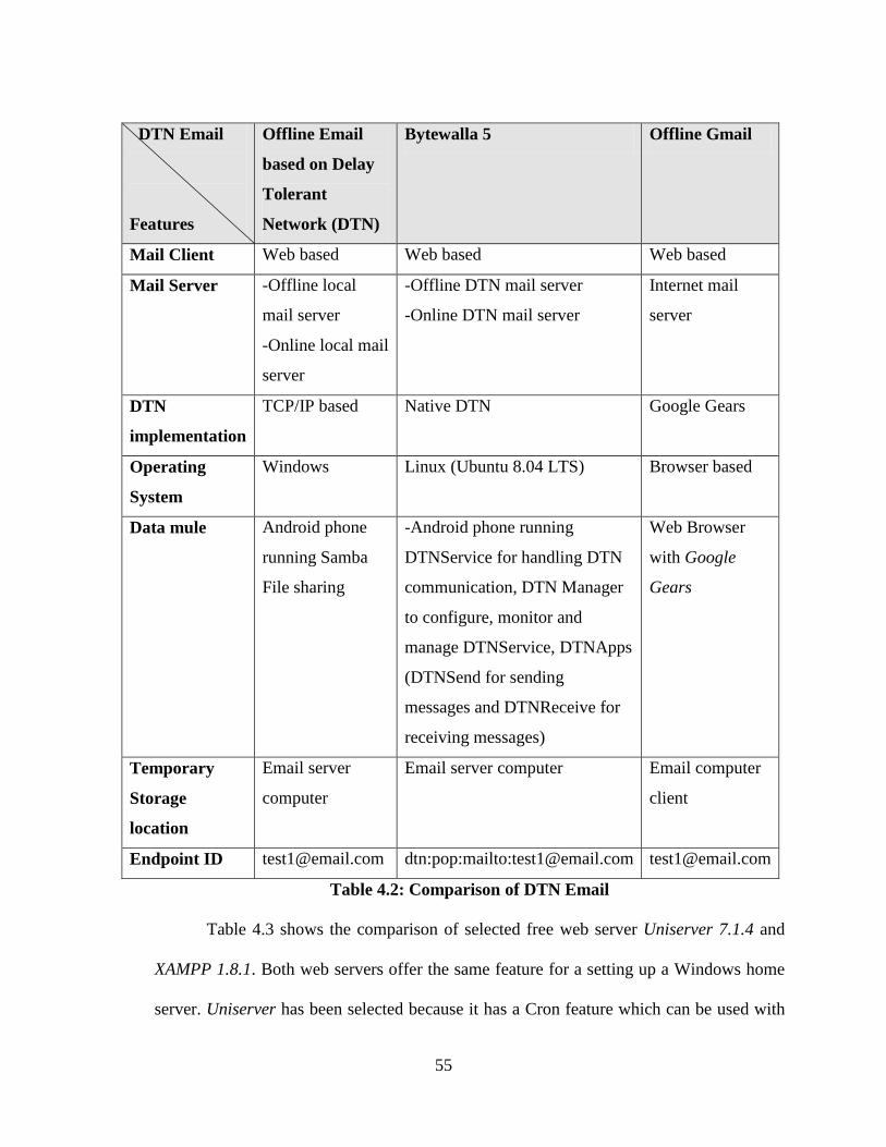
55
DTN Email
Features
Offline Email
based on Delay
Tolerant
Network (DTN)
Bytewalla 5 Offline Gmail
Mail Client Web based Web based Web based
Mail Server -Offline local
mail server
-Online local mail
server
-Offline DTN mail server
-Online DTN mail server
Internet mail
server
DTN
implementation
TCP/IP based Native DTN Google Gears
Operating
System
Windows Linux (Ubuntu 8.04 LTS) Browser based
Data mule Android phone
running Samba
File sharing
-Android phone running
DTNService for handling DTN
communication, DTN Manager
to configure, monitor and
manage DTNService, DTNApps
(DTNSend for sending
messages and DTNReceive for
receiving messages)
Web Browser
with Google
Gears
Temporary
Storage
location
Email server
computer
Email server computer Email computer
client
Endpoint ID [email protected] dtn:pop:mailto:[email protected] [email protected]
Table 4.2: Comparison of DTN Email
Table 4.3 shows the comparison of selected free web server Uniserver 7.1.4 and
XAMPP 1.8.1. Both web servers offer the same feature for a setting up a Windows home
server. Uniserver has been selected because it has a Cron feature which can be used with
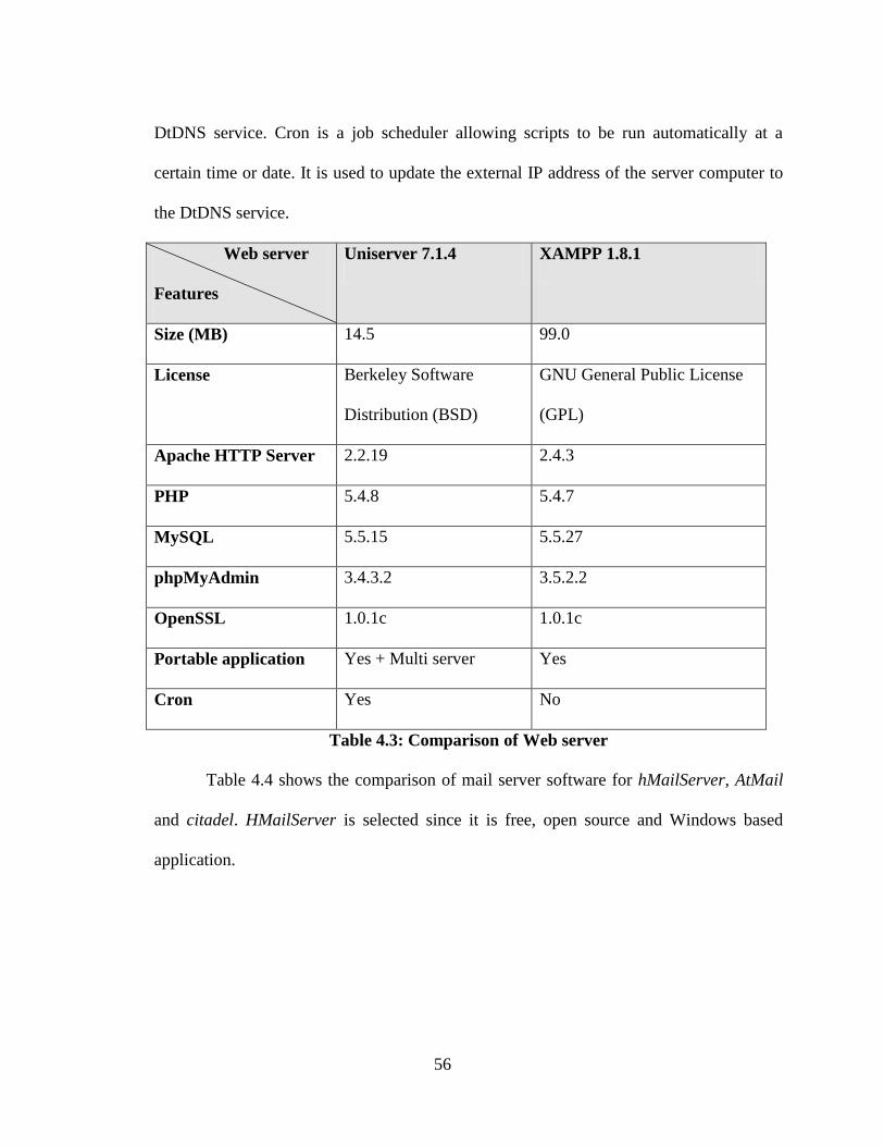
56
DtDNS service. Cron is a job scheduler allowing scripts to be run automatically at a
certain time or date. It is used to update the external IP address of the server computer to
the DtDNS service.
Web server
Features
Uniserver 7.1.4 XAMPP 1.8.1
Size (MB) 14.5 99.0
License Berkeley Software
Distribution (BSD)
GNU General Public License
(GPL)
Apache HTTP Server 2.2.19 2.4.3
PHP 5.4.8 5.4.7
MySQL 5.5.15 5.5.27
phpMyAdmin 3.4.3.2 3.5.2.2
OpenSSL 1.0.1c 1.0.1c
Portable application Yes + Multi server Yes
Cron Yes No
Table 4.3: Comparison of Web server
Table 4.4 shows the comparison of mail server software for hMailServer, AtMail
and citadel. HMailServer is selected since it is free, open source and Windows based
application.
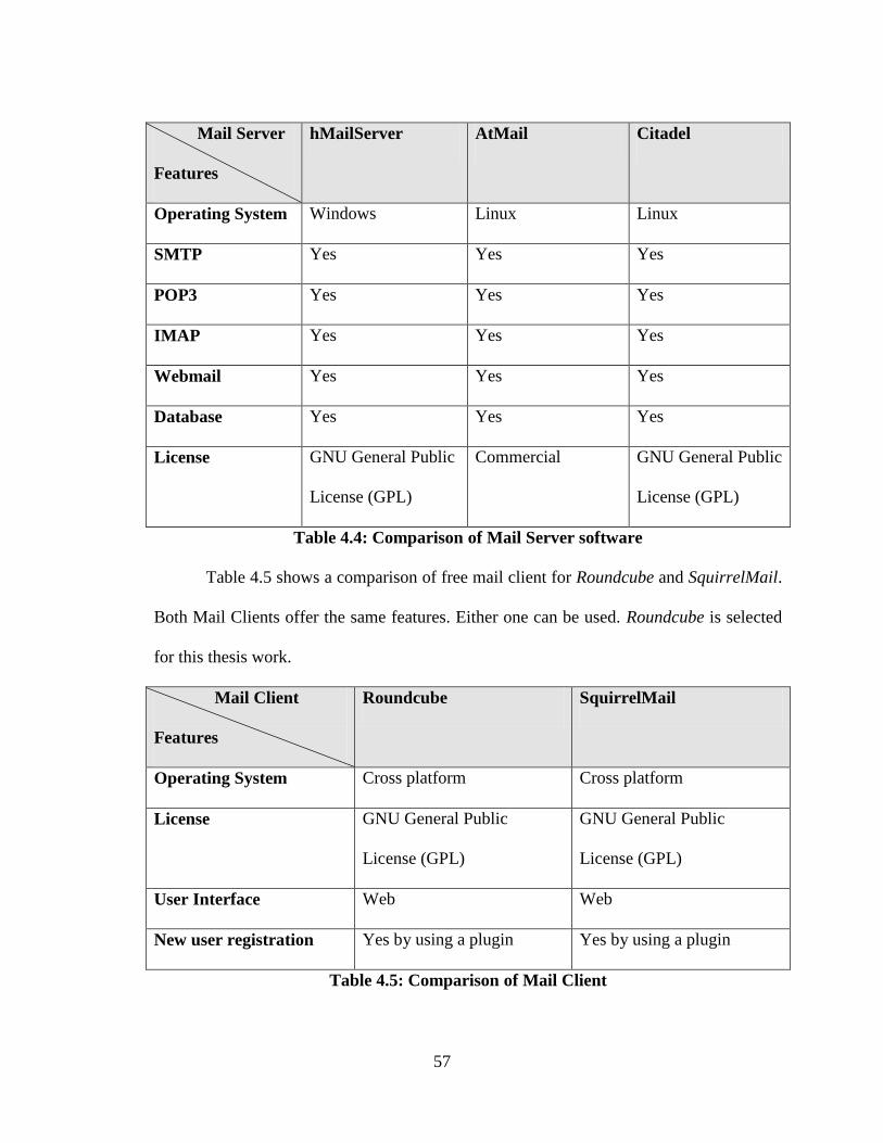
57
Mail Server
Features
hMailServer AtMail Citadel
Operating System Windows Linux Linux
SMTP Yes Yes Yes
POP3 Yes Yes Yes
IMAP Yes Yes Yes
Webmail Yes Yes Yes
Database Yes Yes Yes
License GNU General Public
License (GPL)
Commercial GNU General Public
License (GPL)
Table 4.4: Comparison of Mail Server software
Table 4.5 shows a comparison of free mail client for Roundcube and SquirrelMail.
Both Mail Clients offer the same features. Either one can be used. Roundcube is selected
for this thesis work.
Mail Client
Features
Roundcube SquirrelMail
Operating System Cross platform Cross platform
License GNU General Public
License (GPL)
GNU General Public
License (GPL)
User Interface Web Web
New user registration Yes by using a plugin Yes by using a plugin
Table 4.5: Comparison of Mail Client
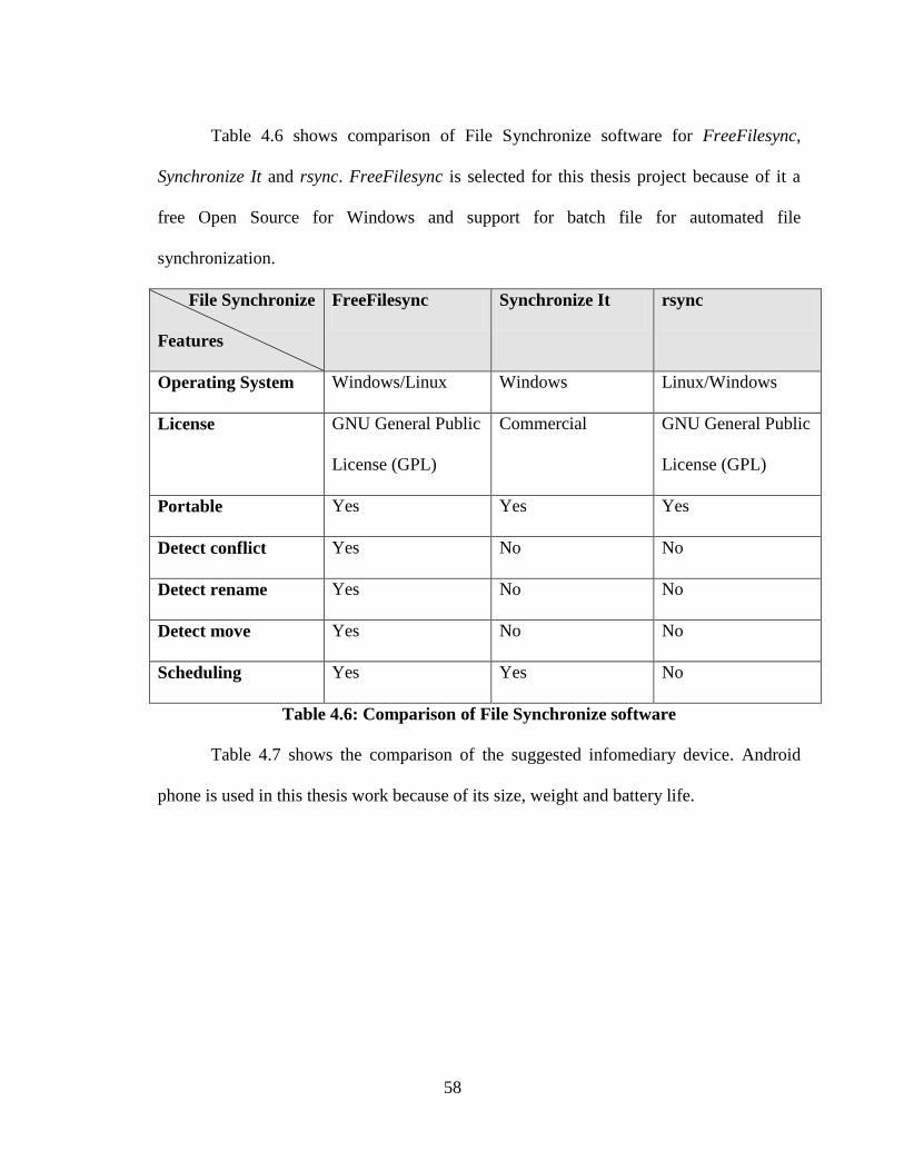
58
Table 4.6 shows comparison of File Synchronize software for FreeFilesync,
Synchronize It and rsync. FreeFilesync is selected for this thesis project because of it a
free Open Source for Windows and support for batch file for automated file
synchronization.
File Synchronize
Features
FreeFilesync Synchronize It rsync
Operating System Windows/Linux Windows Linux/Windows
License GNU General Public
License (GPL)
Commercial GNU General Public
License (GPL)
Portable Yes Yes Yes
Detect conflict Yes No No
Detect rename Yes No No
Detect move Yes No No
Scheduling Yes Yes No
Table 4.6: Comparison of File Synchronize software
Table 4.7 shows the comparison of the suggested infomediary device. Android
phone is used in this thesis work because of its size, weight and battery life.
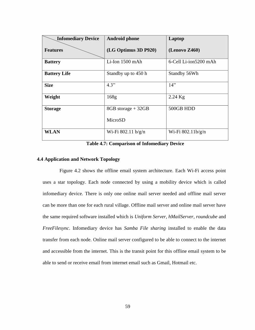
59
Infomediary Device
Features
Android phone
(LG Optimus 3D P920)
Laptop
(Lenovo Z460)
Battery Li-Ion 1500 mAh 6-Cell Li-ion5200 mAh
Battery Life Standby up to 450 h Standby 56Wh
Size 4.3” 14”
Weight 168g 2.24 Kg
Storage 8GB storage + 32GB
MicroSD
500GB HDD
WLAN Wi-Fi 802.11 b/g/n Wi-Fi 802.11b/g/n
Table 4.7: Comparison of Infomediary Device
4.4 Application and Network Topology
Figure 4.2 shows the offline email system architecture. Each Wi-Fi access point
uses a star topology. Each node connected by using a mobility device which is called
infomediary device. There is only one online mail server needed and offline mail server
can be more than one for each rural village. Offline mail server and online mail server have
the same required software installed which is Uniform Server, hMailServer, roundcube and
FreeFilesync. Infomediary device has Samba File sharing installed to enable the data
transfer from each node. Online mail server configured to be able to connect to the internet
and accessible from the internet. This is the transit point for this offline email system to be
able to send or receive email from internet email such as Gmail, Hotmail etc.
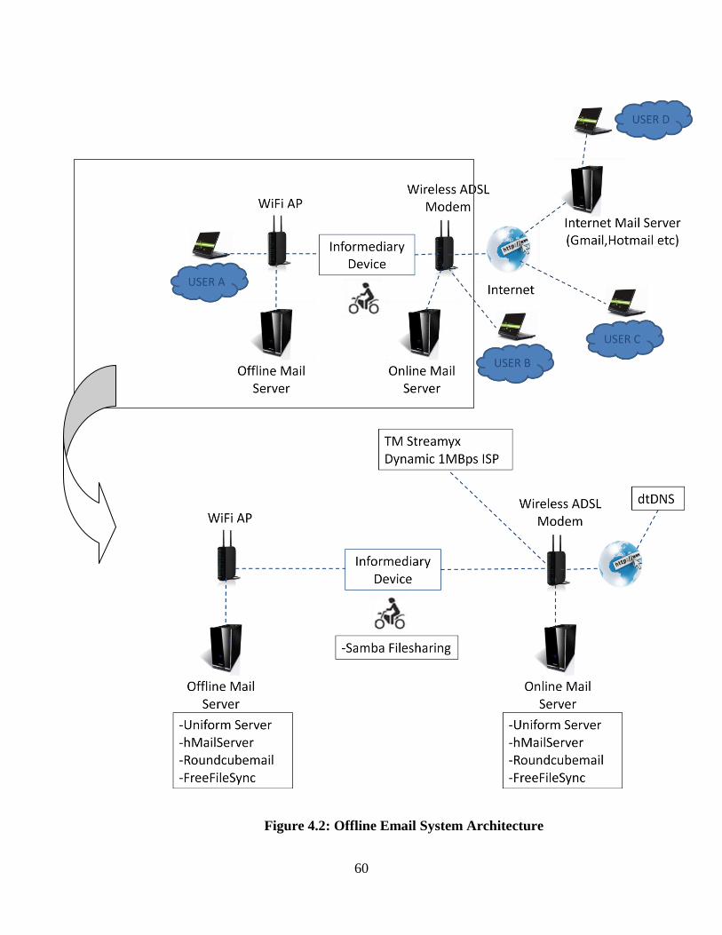
60
Figure 4.2: Offline Email System Architecture
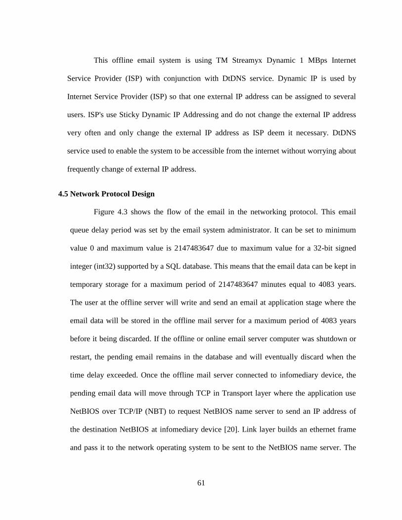
61
This offline email system is using TM Streamyx Dynamic 1 MBps Internet
Service Provider (ISP) with conjunction with DtDNS service. Dynamic IP is used by
Internet Service Provider (ISP) so that one external IP address can be assigned to several
users. ISP's use Sticky Dynamic IP Addressing and do not change the external IP address
very often and only change the external IP address as ISP deem it necessary. DtDNS
service used to enable the system to be accessible from the internet without worrying about
frequently change of external IP address.
4.5 Network Protocol Design
Figure 4.3 shows the flow of the email in the networking protocol. This email
queue delay period was set by the email system administrator. It can be set to minimum
value 0 and maximum value is 2147483647 due to maximum value for a 32-bit signed
integer (int32) supported by a SQL database. This means that the email data can be kept in
temporary storage for a maximum period of 2147483647 minutes equal to 4083 years.
The user at the offline server will write and send an email at application stage where the
email data will be stored in the offline mail server for a maximum period of 4083 years
before it being discarded. If the offline or online email server computer was shutdown or
restart, the pending email remains in the database and will eventually discard when the
time delay exceeded. Once the offline mail server connected to infomediary device, the
pending email data will move through TCP in Transport layer where the application use
NetBIOS over TCP/IP (NBT) to request NetBIOS name server to send an IP address of
the destination NetBIOS at infomediary device [20]. Link layer builds an ethernet frame
and pass it to the network operating system to be sent to the NetBIOS name server. The
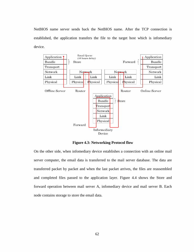
62
NetBIOS name server sends back the NetBIOS name. After the TCP connection is
established, the application transfers the file to the target host which is infomediary
device.
Figure 4.3: Networking Protocol flow
On the other side, when infomediary device establishes a connection with an online mail
server computer, the email data is transferred to the mail server database. The data are
transferred packet by packet and when the last packet arrives, the files are reassembled
and completed files passed to the application layer. Figure 4.4 shows the Store and
forward operation between mail server A, infomediary device and mail server B. Each
node contains storage to store the email data.
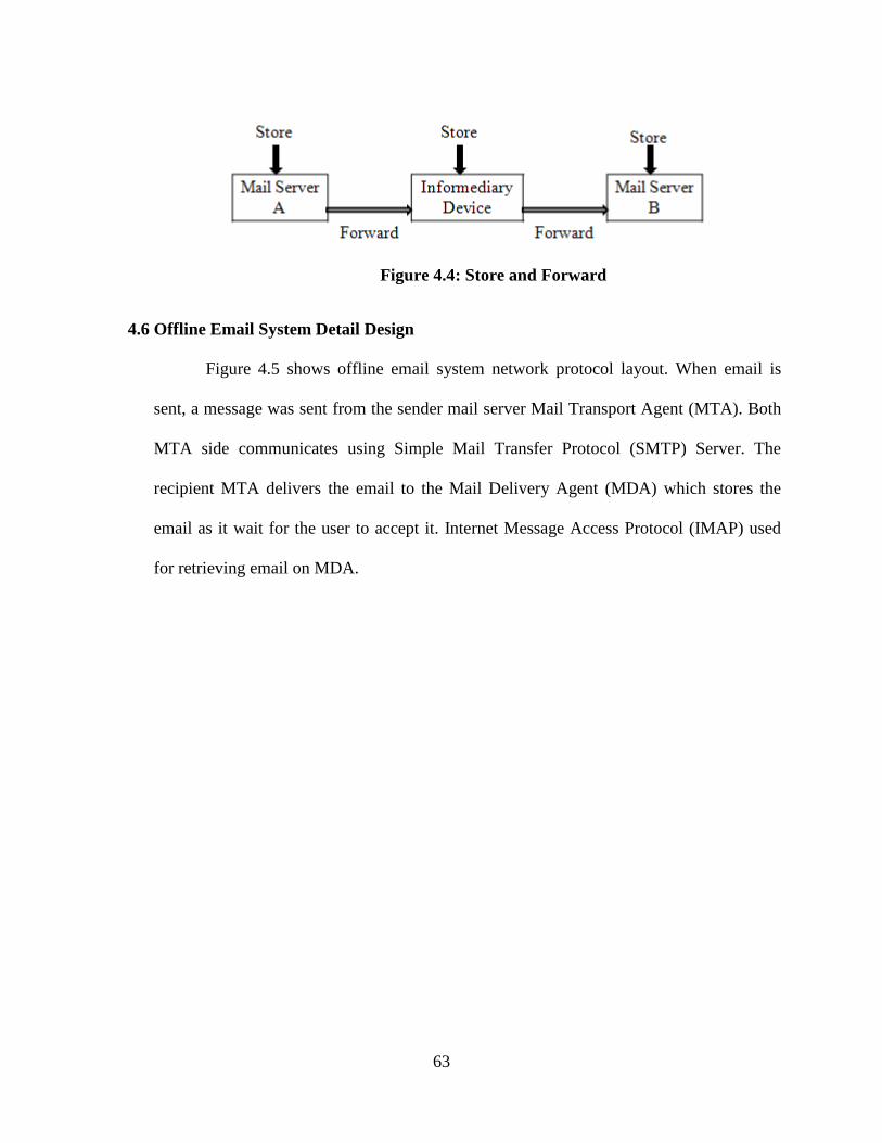
63
Figure 4.4: Store and Forward
4.6 Offline Email System Detail Design
Figure 4.5 shows offline email system network protocol layout. When email is
sent, a message was sent from the sender mail server Mail Transport Agent (MTA). Both
MTA side communicates using Simple Mail Transfer Protocol (SMTP) Server. The
recipient MTA delivers the email to the Mail Delivery Agent (MDA) which stores the
email as it wait for the user to accept it. Internet Message Access Protocol (IMAP) used
for retrieving email on MDA.
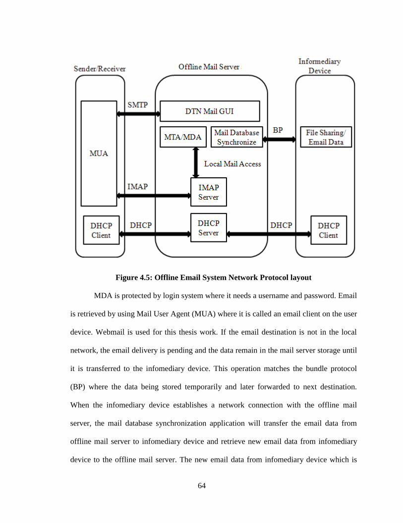
64
Figure 4.5: Offline Email System Network Protocol layout
MDA is protected by login system where it needs a username and password. Email
is retrieved by using Mail User Agent (MUA) where it is called an email client on the user
device. Webmail is used for this thesis work. If the email destination is not in the local
network, the email delivery is pending and the data remain in the mail server storage until
it is transferred to the infomediary device. This operation matches the bundle protocol
(BP) where the data being stored temporarily and later forwarded to next destination.
When the infomediary device establishes a network connection with the offline mail
server, the mail database synchronization application will transfer the email data from
offline mail server to infomediary device and retrieve new email data from infomediary
device to the offline mail server. The new email data from infomediary device which is
65
received from online mail server will be in the new pending email delivery where it is
being sent immediately since the destination was in the network until it reaches the user to
accept it. The Dynamic Host Configuration Protocol (DHCP) is a network protocol used
to configure devices that are connected to a network. The SSID and security codes for the
access points are chosen by the administrators. This offline email system used static IP
addresses. Both the online and offline server computers are configured as DHCP servers.
This enables the servers to allocate IP addresses to any DHCP client.
Figure 4.6 shows online email system network protocol layout. The process is the
same as when the infomediary device establishes a network connection with online mail
server, the mail database synchronization application will retrieve email data from
infomediary device to online mail server and transfer the new email data from online mail
server to the infomediary device to be sent to the offline mail server. The email data from
infomediary device which is received from the offline mail server will be in pending
delivery where the delivery is executed immediately because of the destination is
available in the network until it reaches the user to accept it.
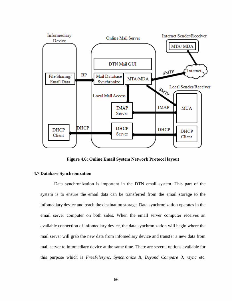
66
Figure 4.6: Online Email System Network Protocol layout
4.7 Database Synchronization
Data synchronization is important in the DTN email system. This part of the
system is to ensure the email data can be transferred from the email storage to the
infomediary device and reach the destination storage. Data synchronization operates in the
email server computer on both sides. When the email server computer receives an
available connection of infomediary device, the data synchronization will begin where the
mail server will grab the new data from infomediary device and transfer a new data from
mail server to infomediary device at the same time. There are several options available for
this purpose which is FreeFilesync, Synchronize It, Beyond Compare 3, rsync etc.
67
FreeFilesync is a free Open Source software for Windows and able to compare and
synchronize files and synchronize folders. It supports filters, file sizes greater than 4GB
and creation of batch files for automated synchronization. Synchronize It is a commercial
folders comparison and data synchronize for Windows. It also supports command line
switches for unattended synchronization. Beyond Compare 3 is the commercial folders
comparison and data synchronization for Windows. Rsync is a batch of folders and file
synchronization tools for UNIX systems. Rsync can copy or display directory contents
optionally using compression and recursion. FreeFilesync is suitable for this thesis project
being it is a free Open Source for Windows and support for batch file for automated file
synchronization.
Infomediary device is working as a data mule. It carries data storage between data
communication link. It is able to automatically load and unload the data when arrives at
its terminal location. In this thesis, infomediary device requires to establish network
connection at the terminal location which is a mail server and Storage to store the email
data. A laptop, Tablet PC or a Smartphone can be used for this purpose. An Android
Smartphone is used in this thesis project because of its less power consumption and
prolongs battery life. An Android Smartphone is smaller and easy to move in between
terminal location and able to establish a connection through Wi-Fi. Samba File Sharing is
used to provide network storage for the Terminal Location for data synchronization.
4.8 Summary
This system main requirement consists of a two mail servers, mail client at each
mail server and an infomediary device. This offline email system architecture depends on
68
data synchronization among DTN nodes for four primary purposes which are bundled and
fragment identification, routing with scheduled and bundle expiration time computations.
This design architecture can enable the email to be sent locally in an offline environment
or online environment and a delay network connection between this two environment
created by infomediary device. This system offers an advantage compare to conventional
Wi-Fi Hotspot and native DTN implementation in term of simplicity, user experience and
affordability. System implementation is discussed in the next chapter.
69
5. SYSTEM IMPLEMENTATION
This chapter started by explaining the system platform and environment. Then the issues
arise during implementation and system requirement is discussed. This offline email system is
implemented by using suitable existing application to fulfill requirement of TCP/IP mail
system working as a DTN mail system. The details of this offline email system
implementation are discussed starting from the server computer, web server application,
external IP address solution, mail server, mail client, explanation of the database
synchronization process, related data for synchronization, database synchronization
application and System Control Graphical User Interface (GUI).
5.1 System Platform and Environment
Operating system for server computer is Windows XP 32bit because of convenient
development and maintenance. Infomediary device runs on android 2.3.5 to support
interoperability with Windows XP 32bit. User can use any standard web browser from
any platform such as Linux or MAC to access this offline email system. There are two
types of networking environment involve in this offline email system which is offline
networking and online networking. Offline networking is a local area network with no
internet connectivity while online networking is a local area network with internet
connectivity. Offline mail client, offline mail server and offline server computer are
running on offline networking. Online mail client, online mail server and online server
computer are running on online networking. Infomediary device is working in both offline
and online networking environment.
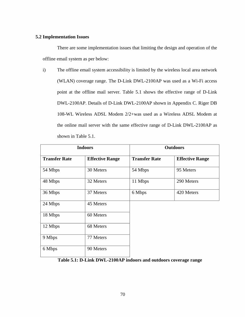
70
5.2 Implementation Issues
There are some implementation issues that limiting the design and operation of the
offline email system as per below:
i) The offline email system accessibility is limited by the wireless local area network
(WLAN) coverage range. The D-Link DWL-2100AP was used as a Wi-Fi access
point at the offline mail server. Table 5.1 shows the effective range of D-Link
DWL-2100AP. Details of D-Link DWL-2100AP shown in Appendix C. Riger DB
108-WL Wireless ADSL Modem 2/2+was used as a Wireless ADSL Modem at
the online mail server with the same effective range of D-Link DWL-2100AP as
shown in Table 5.1.
Indoors Outdoors
Transfer Rate Effective Range Transfer Rate Effective Range
54 Mbps 30 Meters 54 Mbps 95 Meters
48 Mbps 32 Meters 11 Mbps 290 Meters
36 Mbps 37 Meters 6 Mbps 420 Meters
24 Mbps 45 Meters
18 Mbps 60 Meters
12 Mbps 68 Meters
9 Mbps 77 Meters
6 Mbps 90 Meters
Table 5.1: D-Link DWL-2100AP indoors and outdoors coverage range
71
ii) The speed of database synchronization process limited by the network data
transfer rate of the Wi-Fi access point at each server computers. The D-Link
DWL-2100AP used as a Wi-Fi access point at the offline mail server has network
data transfer rate up to 54 Mbps which is 54 megabits per second for Standards
IEEE 802.11b/g. Riger DB 108-WL Wireless ADSL Modem 2/2+was used as a
Wireless ADSL Modem at the online mail server. The network data transfer rate is
up to 54 Mbps for Standards IEEE 802.11b/g. It is the same as shown in Table 5.1
for D-Link DWL-2100AP. The ADSL, ADSL2 and ADSL2+ network data
transfer rate are up to 24 Mbps.
iii) Infomediary device battery life is important to ensure the data can be moved from
both offline and online side without interruption. LG Optimus 3D (P920) can offer
up to 250 hours in standby mode as shown in Appendix D.
iv) User only can register a new email account at online mail server side. This offline
email system did not enable email registration page on the offline mail server
because of conflict may occur with online mail server registration database or
several other offline mail server registration databases. Since an offline mail server
can be more than one and only one online mail server required, registration system
only implemented on online mail server to avoid database conflict. Data conflict
most likely happen when same username registered on several mail servers. This
will cause database synchronization cannot be done when either data might be
deleted or both.
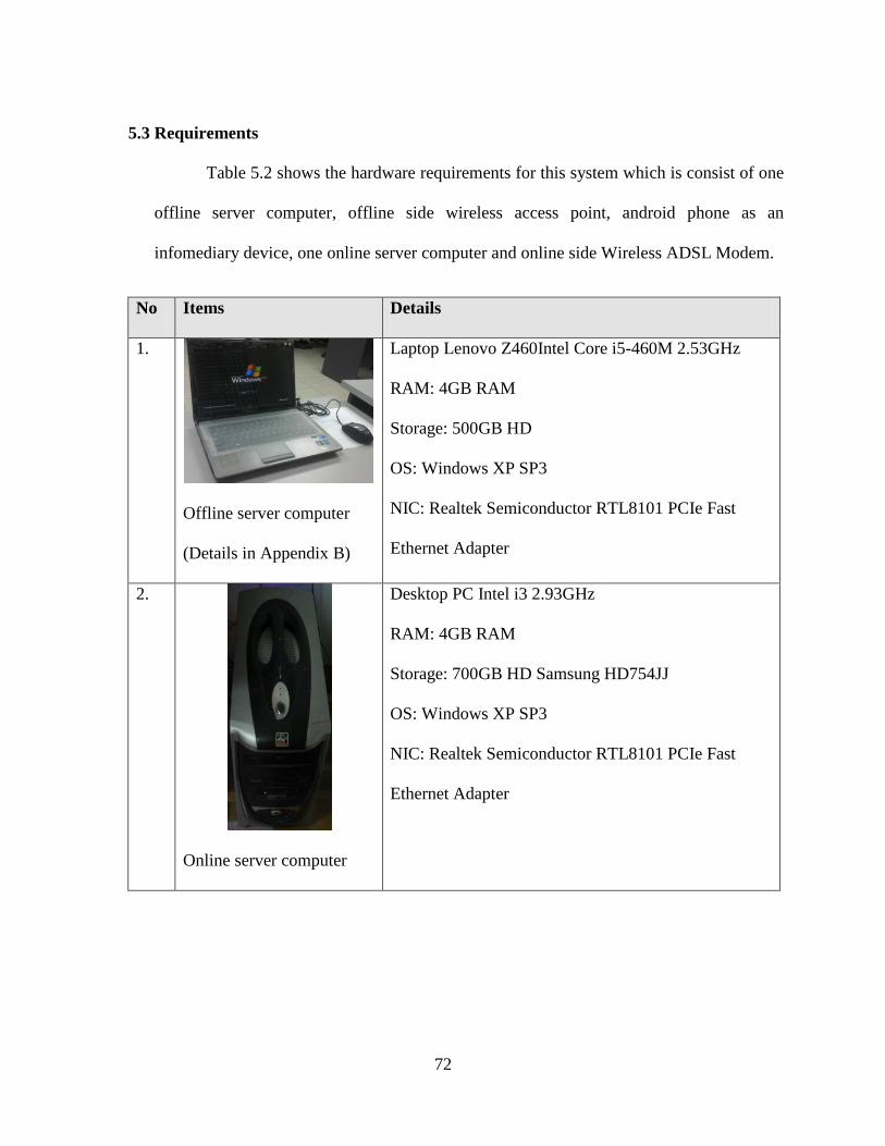
72
5.3 Requirements
Table 5.2 shows the hardware requirements for this system which is consist of one
offline server computer, offline side wireless access point, android phone as an
infomediary device, one online server computer and online side Wireless ADSL Modem.
No Items Details
1.
Offline server computer
(Details in Appendix B)
Laptop Lenovo Z460Intel Core i5-460M 2.53GHz
RAM: 4GB RAM
Storage: 500GB HD
OS: Windows XP SP3
NIC: Realtek Semiconductor RTL8101 PCIe Fast
Ethernet Adapter
2.
Online server computer
Desktop PC Intel i3 2.93GHz
RAM: 4GB RAM
Storage: 700GB HD Samsung HD754JJ
OS: Windows XP SP3
NIC: Realtek Semiconductor RTL8101 PCIe Fast
Ethernet Adapter
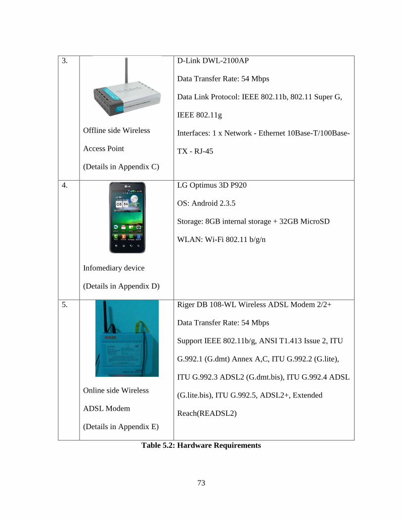
73
3.
Offline side Wireless
Access Point
(Details in Appendix C)
D-Link DWL-2100AP
Data Transfer Rate: 54 Mbps
Data Link Protocol: IEEE 802.11b, 802.11 Super G,
IEEE 802.11g
Interfaces: 1 x Network - Ethernet 10Base-T/100Base-
TX - RJ-45
4.
Infomediary device
(Details in Appendix D)
LG Optimus 3D P920
OS: Android 2.3.5
Storage: 8GB internal storage + 32GB MicroSD
WLAN: Wi-Fi 802.11 b/g/n
5.
Online side Wireless
ADSL Modem
(Details in Appendix E)
Riger DB 108-WL Wireless ADSL Modem 2/2+
Data Transfer Rate: 54 Mbps
Support IEEE 802.11b/g, ANSI T1.413 Issue 2, ITU
G.992.1 (G.dmt) Annex A,C, ITU G.992.2 (G.lite),
ITU G.992.3 ADSL2 (G.dmt.bis), ITU G.992.4 ADSL
(G.lite.bis), ITU G.992.5, ADSL2+, Extended
Reach(READSL2)
Table 5.2: Hardware Requirements
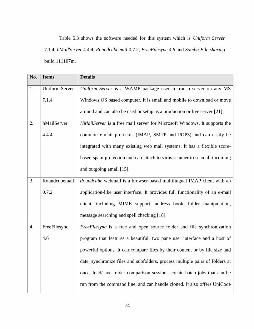
74
Table 5.3 shows the software needed for this system which is Uniform Server
7.1.4, hMailServer 4.4.4, Roundcubemail 0.7.2, FreeFilesync 4.6 and Samba File sharing
build 111107m.
No. Items Details
1. Uniform Server
7.1.4
Uniform Server is a WAMP package used to run a server on any MS
Windows OS based computer. It is small and mobile to download or move
around and can also be used or setup as a production or live server [21].
2. hMailServer
4.4.4
HMailServer is a free mail server for Microsoft Windows. It supports the
common e-mail protocols (IMAP, SMTP and POP3) and can easily be
integrated with many existing web mail systems. It has a flexible score-
based spam protection and can attach to virus scanner to scan all incoming
and outgoing email [15].
3. Roundcubemail
0.7.2
Roundcube webmail is a browser-based multilingual IMAP client with an
application-like user interface. It provides full functionality of an e-mail
client, including MIME support, address book, folder manipulation,
message searching and spell checking [18].
4. FreeFilesync
4.6
FreeFilesync is a free and open source folder and file synchronization
program that features a beautiful, two pane user interface and a host of
powerful options. It can compare files by their content or by file size and
date, synchronize files and subfolders, process multiple pairs of folders at
once, load/save folder comparison sessions, create batch jobs that can be
run from the command line, and can handle cloned. It also offers UniCode
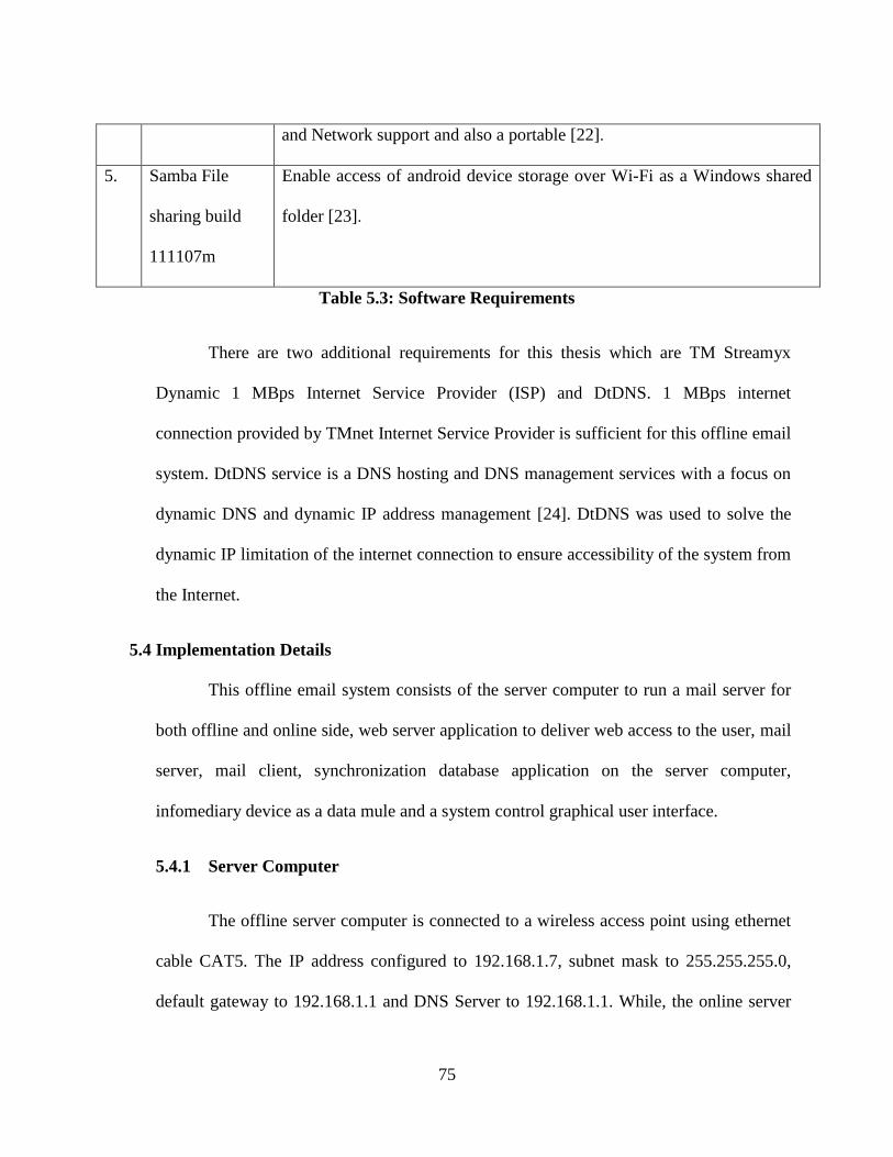
75
and Network support and also a portable [22].
5. Samba File
sharing build
111107m
Enable access of android device storage over Wi-Fi as a Windows shared
folder [23].
Table 5.3: Software Requirements
There are two additional requirements for this thesis which are TM Streamyx
Dynamic 1 MBps Internet Service Provider (ISP) and DtDNS. 1 MBps internet
connection provided by TMnet Internet Service Provider is sufficient for this offline email
system. DtDNS service is a DNS hosting and DNS management services with a focus on
dynamic DNS and dynamic IP address management [24]. DtDNS was used to solve the
dynamic IP limitation of the internet connection to ensure accessibility of the system from
the Internet.
5.4 Implementation Details
This offline email system consists of the server computer to run a mail server for
both offline and online side, web server application to deliver web access to the user, mail
server, mail client, synchronization database application on the server computer,
infomediary device as a data mule and a system control graphical user interface.
5.4.1 Server Computer
The offline server computer is connected to a wireless access point using ethernet
cable CAT5. The IP address configured to 192.168.1.7, subnet mask to 255.255.255.0,
default gateway to 192.168.1.1 and DNS Server to 192.168.1.1. While, the online server
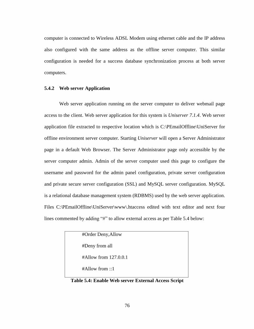
76
computer is connected to Wireless ADSL Modem using ethernet cable and the IP address
also configured with the same address as the offline server computer. This similar
configuration is needed for a success database synchronization process at both server
computers.
5.4.2 Web server Application
Web server application running on the server computer to deliver webmail page
access to the client. Web server application for this system is Uniserver 7.1.4. Web server
application file extracted to respective location which is C:\PEmailOffline\UniServer for
offline environment server computer. Starting Uniserver will open a Server Administrator
page in a default Web Browser. The Server Administrator page only accessible by the
server computer admin. Admin of the server computer used this page to configure the
username and password for the admin panel configuration, private server configuration
and private secure server configuration (SSL) and MySQL server configuration. MySQL
is a relational database management system (RDBMS) used by the web server application.
Files C:\PEmailOffline\UniServer\www\.htaccess edited with text editor and next four
lines commented by adding “#” to allow external access as per Table 5.4 below:
#Order Deny,Allow
#Deny from all
#Allow from 127.0.0.1
#Allow from ::1
Table 5.4: Enable Web server External Access Script
77
This will disable server security limitation access from localhost only and enable access
using the server IP address. The PHP value for maximum message size located in “.
htaccess” file in "...UniServer\www\pemail" and “php.ini” file in
"...UniServer\usr\local\php" also configured to upload maximum file size is 10MB, post
maximum size is 50MB and memory limit is 64MB. This value is to give a size limit of
attachment file.
This offline email system uses MIME standards and do not specify any file size
limits for maximum upload size to be allowed [25]. Limits for maximum upload size can
be configured in web server setting file “php.ini”, where the maximum attachment size is
2147483647 MB which is a maximum value for a 32-bit signed integer supported by a
SQL database. The maximum message size is unlimited by setting the value to zero. The
maximum disk space that the account may use is limited to the server computer hard disk
storage available space. If the hard disk is full, the limit is reached and the account will
not be able to receive any more email. If a maximum message size is specified, the mail
server will reject messages larger than that size. It is recommended to set a maximum
message size limit to prevent the server from any types of attack. As an example, attackers
could send a big size message and fills the server hard disk which will cause a problem to
the server computer.
This offline email system maximum message size is set to 50MB. The mail server
will reject messages larger than this size. Email content size is small and usually 1MB or
less. This offline email system maximum message size is set to 10MB. Limiting
maximum attachment size default value 10MB is acceptable to ensure the mail server
78
network performance is not dropping when multiple users uploading a very big file at the
same time to the mail server. Limiting the size of email attachments to 10MB is also a
safe setting for the maximum size of an email since other email services commonly used
10MB as a maximum size of an email attachment. If the maximum size of an email
attachment is 30MB or greater than 10MB and this offline email system is successfully
send the email to the receiver, there is no guarantee that the receiver can receive the email
since there is a different maximum size limitation of email attachment on every email
service. Gmail limiting the size of email attachments to 25MB with no specified limit to
the number of attachment as long the total size is 25MB [26]. Yahoo Mail allows user to
upload up to 50 files to an email message as long as the total message size remains under
25MB [27].
Every email account has total allocated maximum size storage. If an email is sent
to this account when the quota has been used, the mail server will deliver a notification to
the sender containing the information that the quota for the recipient had been reached.
After that, the email message will be dropped. Each email in this offline email system
allocated size is set to 250MB.
5.4.3 External IP Address
The Uniform Server setup for online web server is the same as for offline server.
The IP address used is 192.168.1.7. The difference is that the online server is connected to
the internet. The Internet Service Provider being used in this research is TM Streamyx
Dynamic 1 MBps. This ISP provides an internet with dynamic IP address connection. The
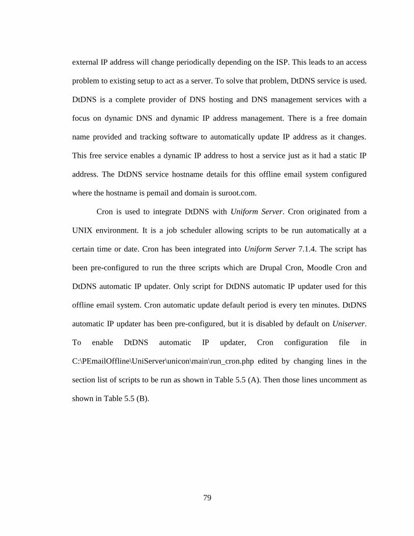
79
external IP address will change periodically depending on the ISP. This leads to an access
problem to existing setup to act as a server. To solve that problem, DtDNS service is used.
DtDNS is a complete provider of DNS hosting and DNS management services with a
focus on dynamic DNS and dynamic IP address management. There is a free domain
name provided and tracking software to automatically update IP address as it changes.
This free service enables a dynamic IP address to host a service just as it had a static IP
address. The DtDNS service hostname details for this offline email system configured
where the hostname is pemail and domain is suroot.com.
Cron is used to integrate DtDNS with Uniform Server. Cron originated from a
UNIX environment. It is a job scheduler allowing scripts to be run automatically at a
certain time or date. Cron has been integrated into Uniform Server 7.1.4. The script has
been pre-configured to run the three scripts which are Drupal Cron, Moodle Cron and
DtDNS automatic IP updater. Only script for DtDNS automatic IP updater used for this
offline email system. Cron automatic update default period is every ten minutes. DtDNS
automatic IP updater has been pre-configured, but it is disabled by default on Uniserver.
To enable DtDNS automatic IP updater, Cron configuration file in
C:\PEmailOffline\UniServer\unicon\main\run_cron.php edited by changing lines in the
section list of scripts to be run as shown in Table 5.5 (A). Then those lines uncomment as
shown in Table 5.5 (B).
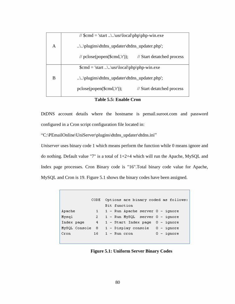
80
A
// $cmd = 'start ..\..\usr\local\php\php-win.exe
..\..\plugins\dtdns_updater\dtdns_updater.php';
// pclose(popen($cmd,'r')); // Start detatched process
B
$cmd = 'start ..\..\usr\local\php\php-win.exe
..\..\plugins\dtdns_updater\dtdns_updater.php';
pclose(popen($cmd,'r')); // Start detatched process
Table 5.5: Enable Cron
DtDNS account details where the hostname is pemail.suroot.com and password
configured in a Cron script configuration file located in:
“C:\PEmailOnline\UniServer\plugins\dtdns_updater\dtdns.ini”
Uniserver uses binary code 1 which means perform the function while 0 means ignore and
do nothing. Default value "7" is a total of 1+2+4 which will run the Apache, MySQL and
Index page processes. Cron Binary code is "16".Total binary code value for Apache,
MySQL and Cron is 19. Figure 5.1 shows the binary codes have been assigned.
Figure 5.1: Uniform Server Binary Codes
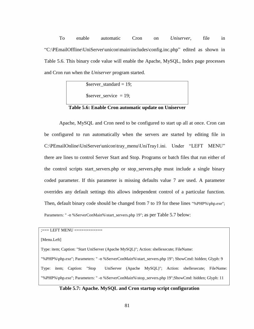
81
To enable automatic Cron on Uniserver, file in
“C:\PEmailOffline\UniServer\unicon\main\includes\config.inc.php” edited as shown in
Table 5.6. This binary code value will enable the Apache, MySQL, Index page processes
and Cron run when the Uniserver program started.
$server_standard = 19;
$server_service = 19;
Table 5.6: Enable Cron automatic update on Uniserver
Apache, MySQL and Cron need to be configured to start up all at once. Cron can
be configured to run automatically when the servers are started by editing file in
C:\PEmailOnline\UniServer\unicon\tray_menu\UniTray1.ini. Under “LEFT MENU”
there are lines to control Server Start and Stop. Programs or batch files that run either of
the control scripts start_servers.php or stop_servers.php must include a single binary
coded parameter. If this parameter is missing defaults value 7 are used. A parameter
overrides any default settings this allows independent control of a particular function.
Then, default binary code should be changed from 7 to 19 for these lines "%PHP%\php.exe";
Parameters: " -n %ServerConMain%\start_servers.php 19"; as per Table 5.7 below:
;=== LEFT MENU ============
[Menu.Left]
Type: item; Caption: "Start UniServer (Apache MySQL)"; Action: shellexecute; FileName:
"%PHP%\php.exe"; Parameters: " -n %ServerConMain%\start_servers.php 19"; ShowCmd: hidden; Glyph: 9
Type: item; Caption: "Stop UniServer (Apache MySQL)"; Action: shellexecute; FileName:
"%PHP%\php.exe"; Parameters: " -n %ServerConMain%\stop_servers.php 19";ShowCmd: hidden; Glyph: 11
Table 5.7: Apache. MySQL and Cron startup script configuration
82
5.4.4 Mail Server
Offline mail server and online mail server should use the same configuration. This
is to enable mail data synchronization where both mail servers should share the same
content and configuration for data synchronization purposes. HMailServer version 4.4.4
being used as mail server application. HMailServer installed to respective location as
“Full installation” with Server and Administrative tool component included. A database
server is an external database which is a new hMailServer database created on MySQL
Server and running on Uniserver. The database server address is “localhost” and TCP Port
is 3306. The database name for this offline email system is “pemail” and should be the
same for both offline server computer and online server computer. HMailServer security
password configured accordingly. The created database location is:
“C:\PEmailOffline\UniServer\usr\local\mysql\data\pemail”
The domain name for this offline email system is pemail.suroot.com which can be
configured accordingly at hMailServer Administrator welcome pages. A public host name
also configured as “mail.pemail.suroot.com” under Settings -> Protocols -> SMTP,
Delivery of e-mail tab. SMTP relayer setting depends on ISP either port 25 is open or not.
If port 25 is open, a free SMTP relayer can be used such as “mail.hmailserver.com 25”.
Since 03 November 2008, TM Streamyx was blocking outgoing port 25 [28]. TM had
suggested using the configuration for SMTP relayer as “smtp-proxy.tm.net.my”.
The port can be tested by running the command: telnet smtp-proxy.tm.net.my 25
and the result should a success connection as in Figure 5.2. The offline mail server is not
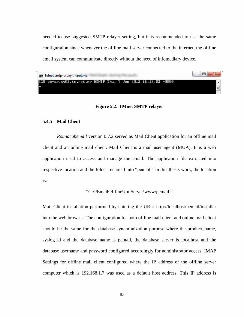
83
needed to use suggested SMTP relayer setting, but it is recommended to use the same
configuration since whenever the offline mail server connected to the internet, the offline
email system can communicate directly without the need of infomediary device.
Figure 5.2: TMnet SMTP relayer
5.4.5 Mail Client
Roundcubemail version 0.7.2 served as Mail Client application for an offline mail
client and an online mail client. Mail Client is a mail user agent (MUA). It is a web
application used to access and manage the email. The application file extracted into
respective location and the folder renamed into “pemail”. In this thesis work, the location
is:
“C:\PEmailOffline\UniServer\www\pemail.”
Mail Client installation performed by entering the URL: http://localhost/pemail/installer
into the web browser. The configuration for both offline mail client and online mail client
should be the same for the database synchronization purpose where the product_name,
syslog_id and the database name is pemail, the database server is localhost and the
database username and password configured accordingly for administrator access. IMAP
Settings for offline mail client configured where the IP address of the offline server
computer which is 192.168.1.7 was used as a default host address. This IP address is
84
accessible only in LAN. IMAP common port which is 143 was set for default port with
username domain is “pemail.suroot.com” which is used for email address. SMTP settings
for offline mail client configured where the IP address of the offline server computer also
used for the SMTP Server address. SMTP common port is 25. The current IMAP
username and password was used for SMTP authentication. This option can be configured
under SMTP settings.
SMTP settings for online mail client configured where the domain name of the
online server computer which is “pemail.suroot.com” was used for the SMTP Server
address. This domain is accessible through internet. SMTP common port is 25. The
current IMAP username and password also used for SMTP authentication and configured
under SMTP settings.
When the configuration is completely configured, this mail client configuration is
saved through “create config” button where it will create two configuration files which are
“main.inc.php” and “db.inc.php”. This configuration files transferred into a mail client
application folder such as:
“C:\PEmailOffline\UniServer\www\pemail\config”
The configuration can be tested through “Test config” button. The configuration is correct
and working when everything was remark with “OK”. Then the “installer” folder can be
removed from mail client application folder.
The files “.htaccess” in temp, logs and config folder which located in mail client
folder “C:\PEmailOffline\UniServer\www\pemail” need to be configured to enable access
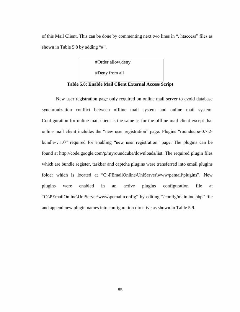
85
of this Mail Client. This can be done by commenting next two lines in “. htaccess” files as
shown in Table 5.8 by adding “#”.
#Order allow,deny
#Deny from all
Table 5.8: Enable Mail Client External Access Script
New user registration page only required on online mail server to avoid database
synchronization conflict between offline mail system and online mail system.
Configuration for online mail client is the same as for the offline mail client except that
online mail client includes the “new user registration” page. Plugins “roundcube-0.7.2-
bundle-v.1.0” required for enabling “new user registration” page. The plugins can be
found at http://code.google.com/p/myroundcube/downloads/list. The required plugin files
which are bundle register, taskbar and captcha plugins were transferred into email plugins
folder which is located at “C:\PEmailOnline\UniServer\www\pemail\plugins”. New
plugins were enabled in an active plugins configuration file at
“C:\PEmailOnline\UniServer\www\pemail\config” by editing “/config/main.inc.php” file
and append new plugin names into configuration directive as shown in Table 5.9.
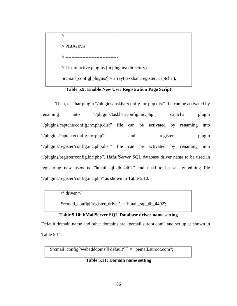
86
// ----------------------------------
// PLUGINS
// ----------------------------------
// List of active plugins (in plugins/ directory)
$rcmail_config['plugins'] = array('taskbar','register','captcha');
Table 5.9: Enable New User Registration Page Script
Then, taskbar plugin “/plugins/taskbar/config.inc.php.dist” file can be activated by
renaming into “/plugins/taskbar/config.inc.php”, captcha plugin
“/plugins/captcha/config.inc.php.dist” file can be activated by renaming into
“/plugins/captcha/config.inc.php” and register plugin
“/plugins/register/config.inc.php.dist” file can be activated by renaming into
“/plugins/register/config.inc.php”. HMailServer SQL database driver name to be used in
registering new users is “'hmail_sql_db_4402” and need to be set by editing file
“/plugins/register/config.inc.php” as shown in Table 5.10.
/* driver */
$rcmail_config['register_driver'] = 'hmail_sql_db_4402';
Table 5.10: hMailServer SQL Database driver name setting
Default domain name and other domains are “pemail.suroot.com” and set up as shown in
Table 5.11.
$rcmail_config['webadddoms']['default'][] = "pemail.suroot.com";
Table 5.11: Domain name setting
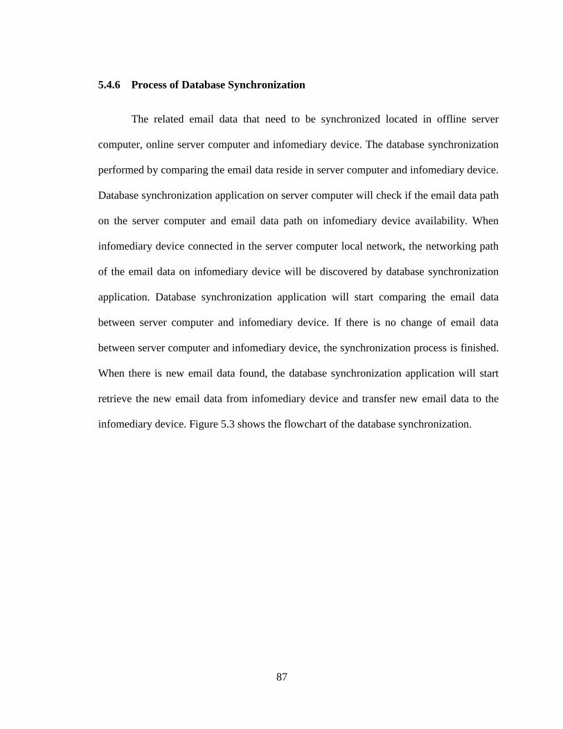
87
5.4.6 Process of Database Synchronization
The related email data that need to be synchronized located in offline server
computer, online server computer and infomediary device. The database synchronization
performed by comparing the email data reside in server computer and infomediary device.
Database synchronization application on server computer will check if the email data path
on the server computer and email data path on infomediary device availability. When
infomediary device connected in the server computer local network, the networking path
of the email data on infomediary device will be discovered by database synchronization
application. Database synchronization application will start comparing the email data
between server computer and infomediary device. If there is no change of email data
between server computer and infomediary device, the synchronization process is finished.
When there is new email data found, the database synchronization application will start
retrieve the new email data from infomediary device and transfer new email data to the
infomediary device. Figure 5.3 shows the flowchart of the database synchronization.
88
Figure 5.3: Process of database synchronization
5.4.7 Related Data for Synchronization
Related data that need to be synchronized is mail server data and web server data.
Mail server data contain the pending email data that need to be synchronized. This email
data consists of a folder named with the email domain name, folders named based on
email username and email messages in a ".eml" format. This email message contains the
full message headers, DomainKeys Identified Mail (DKIM) Signature and full
Multipurpose Internet Mail Extensions (MIME) encoded message content. Email message
consists of three main components which is message envelope, message header and the
message body. Full message headers formed by message envelope header and message
header. The message envelope header contains a delivery parameter such as sender and
receiver email address. This data used by SMTP for transporting email messages.
89
Message header structured into fields such as From, To, CC, Subject, Date, and other
information about the email [19]. DomainKeys Identified Mail (DKIM) Signature
provides a method for validating a domain name identity that is associated with a message
through cryptographic authentication [29]. Message body uses a MIME version 1.0
format. MIME redefines the format of messages to allow textual message bodies in
character sets other than US-ASCII, an extensible set of different formats for non-textual
message bodies, multi-part message bodies and textual header information in character
sets other than US-ASCII [25].
Web server data contain the webmail client MySQL database. This MySQL
database stores the user login details, email messages and email settings. Whenever new
user was registered, the new complete transaction of email messages and new updated
email settings will be stored in this MySQL database.
5.4.8 Database Synchronization Application
There are two database storage devices involve in each synchronization process
which are between server computer and infomediary device. The process of the database
synchronization is the same on both offline server computer and online server computer.
Infomediary device acted as a data mule where later on, the database storage being
synchronized with the server computer. Both side synchronization performed by the
database synchronization application. FreeFilesync version 4.6 used as a database
synchronization application and running on a server computer. Samba File sharing
application bridged the data flow between server computers and infomediary device.
90
Server computer synchronization discussed in Part A and infomediary device discussed in
Part B.
Part A: Server Computer Synchronization
Offline server computer and online server computer configured identically for the
database synchronization purpose. FreeFilesync installed as “Portable” to respective
location such as “C:\PEmailOffline\FreeFileSync” to enable the application mobility
features where it can be transfer and use on other machine. These options remove
dependencies on a dedicated computer and enable the portable database synchronization.
Following the configuration in Part B, infomediary device can be accessed by
opening “Windows Explorer” and entering location path such as “\\data mule”. Accessing
this path for the first time will require the username and password as per configuration on
infomediary device. Windows XP automatically store logon information for network
locations. This stored username and password can be edited later from the user accounts
menu in windows control panel. When infomediary device is connected to the server
computer network, the server computer automatically have access to the infomediary
device network sharing path. New folders to stored email data for database
synchronization created in infomediary device network sharing path such as “\\data
mule\share2\”. Two email data path for storing mail server data and web server data
which are required for database synchronization created in infomediary device storage as
the example shown in Table 5.12.
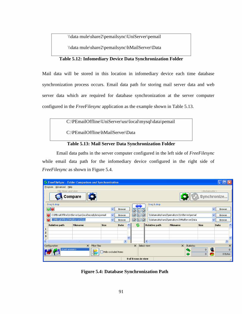
91
\\data mule\share2\pemailsync\UniServer\pemail
\\data mule\share2\pemailsync\hMailServer\Data
Table 5.12: Infomediary Device Data Synchronization Folder
Mail data will be stored in this location in infomediary device each time database
synchronization process occurs. Email data path for storing mail server data and web
server data which are required for database synchronization at the server computer
configured in the FreeFilesync application as the example shown in Table 5.13.
C:\PEmailOffline\UniServer\usr\local\mysql\data\pemail
C:\PEmailOffline\hMailServer\Data
Table 5.13: Mail Server Data Synchronization Folder
Email data paths in the server computer configured in the left side of FreeFilesync
while email data path for the infomediary device configured in the right side of
FreeFilesync as shown in Figure 5.4.
Figure 5.4: Database Synchronization Path
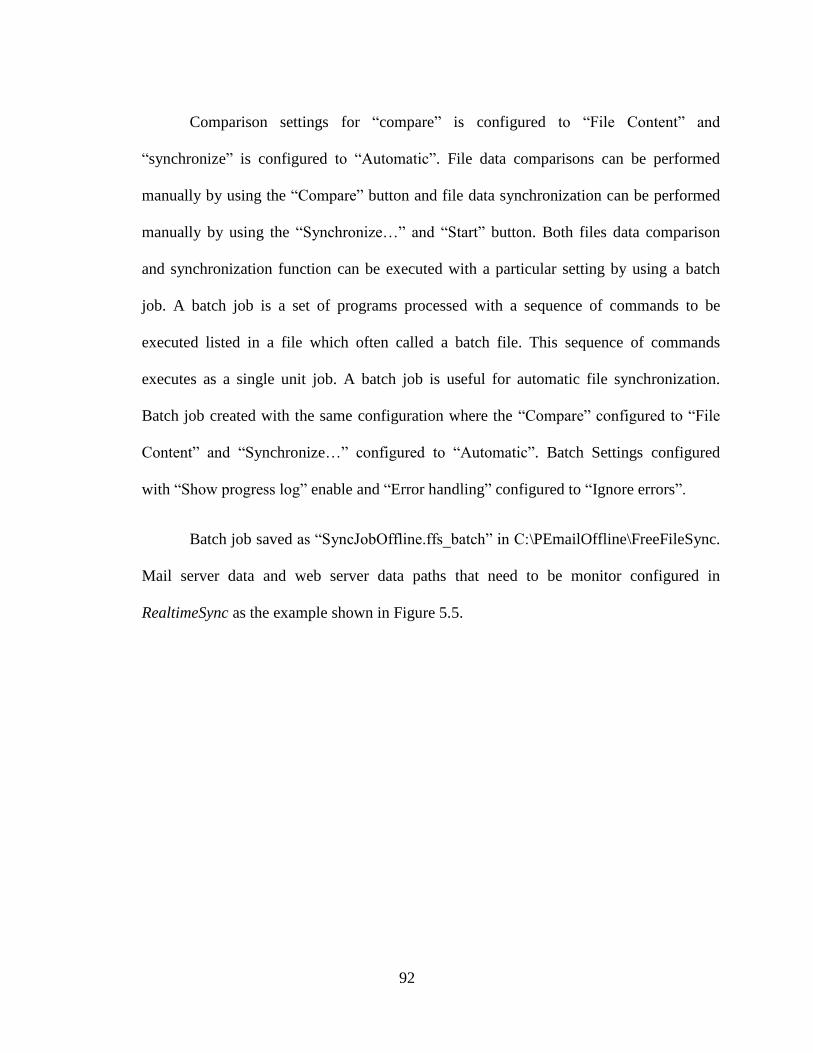
92
Comparison settings for “compare” is configured to “File Content” and
“synchronize” is configured to “Automatic”. File data comparisons can be performed
manually by using the “Compare” button and file data synchronization can be performed
manually by using the “Synchronize…” and “Start” button. Both files data comparison
and synchronization function can be executed with a particular setting by using a batch
job. A batch job is a set of programs processed with a sequence of commands to be
executed listed in a file which often called a batch file. This sequence of commands
executes as a single unit job. A batch job is useful for automatic file synchronization.
Batch job created with the same configuration where the “Compare” configured to “File
Content” and “Synchronize…” configured to “Automatic”. Batch Settings configured
with “Show progress log” enable and “Error handling” configured to “Ignore errors”.
Batch job saved as “SyncJobOffline.ffs_batch” in C:\PEmailOffline\FreeFileSync.
Mail server data and web server data paths that need to be monitor configured in
RealtimeSync as the example shown in Figure 5.5.
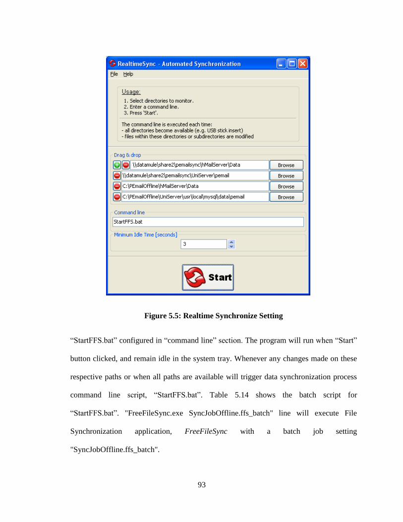
93
Figure 5.5: Realtime Synchronize Setting
“StartFFS.bat” configured in “command line” section. The program will run when “Start”
button clicked, and remain idle in the system tray. Whenever any changes made on these
respective paths or when all paths are available will trigger data synchronization process
command line script, “StartFFS.bat”. Table 5.14 shows the batch script for
“StartFFS.bat”. "FreeFileSync.exe SyncJobOffline.ffs_batch" line will execute File
Synchronization application, FreeFileSync with a batch job setting
"SyncJobOffline.ffs_batch".
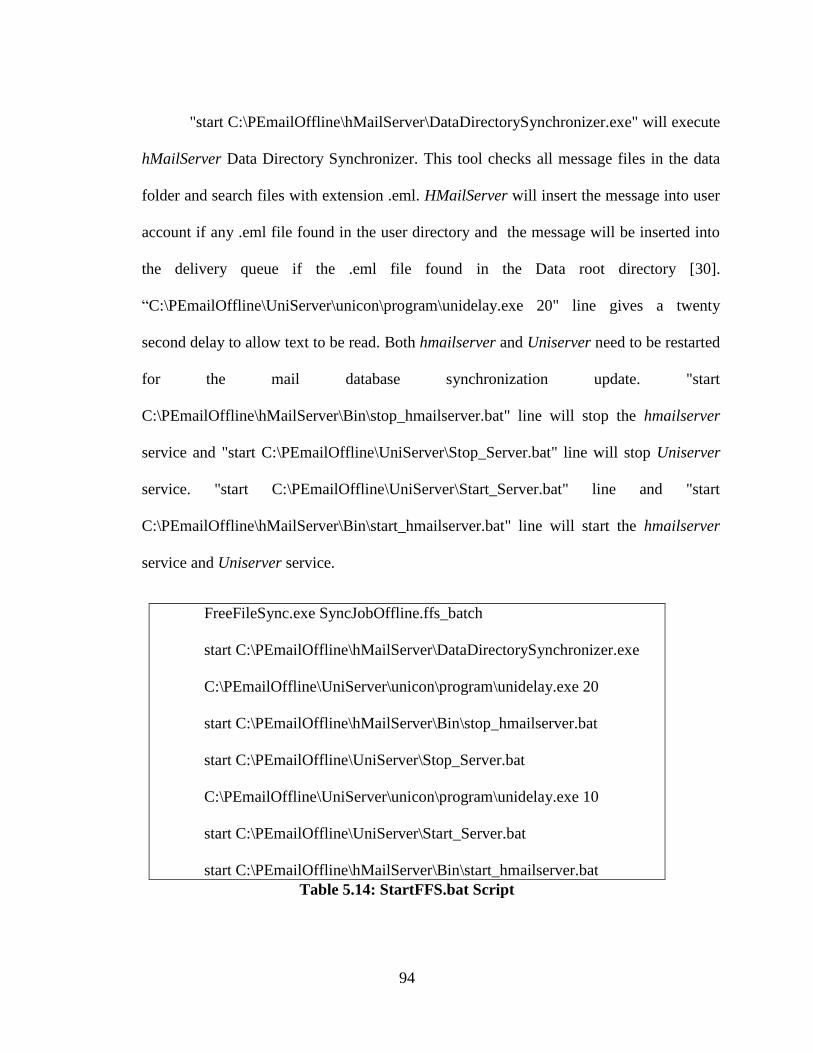
94
"start C:\PEmailOffline\hMailServer\DataDirectorySynchronizer.exe" will execute
hMailServer Data Directory Synchronizer. This tool checks all message files in the data
folder and search files with extension .eml. HMailServer will insert the message into user
account if any .eml file found in the user directory and the message will be inserted into
the delivery queue if the .eml file found in the Data root directory [30].
“C:\PEmailOffline\UniServer\unicon\program\unidelay.exe 20" line gives a twenty
second delay to allow text to be read. Both hmailserver and Uniserver need to be restarted
for the mail database synchronization update. "start
C:\PEmailOffline\hMailServer\Bin\stop_hmailserver.bat" line will stop the hmailserver
service and "start C:\PEmailOffline\UniServer\Stop_Server.bat" line will stop Uniserver
service. "start C:\PEmailOffline\UniServer\Start_Server.bat" line and "start
C:\PEmailOffline\hMailServer\Bin\start_hmailserver.bat" line will start the hmailserver
service and Uniserver service.
FreeFileSync.exe SyncJobOffline.ffs_batch
start C:\PEmailOffline\hMailServer\DataDirectorySynchronizer.exe
C:\PEmailOffline\UniServer\unicon\program\unidelay.exe 20
start C:\PEmailOffline\hMailServer\Bin\stop_hmailserver.bat
start C:\PEmailOffline\UniServer\Stop_Server.bat
C:\PEmailOffline\UniServer\unicon\program\unidelay.exe 10
start C:\PEmailOffline\UniServer\Start_Server.bat
start C:\PEmailOffline\hMailServer\Bin\start_hmailserver.bat
Table 5.14: StartFFS.bat Script
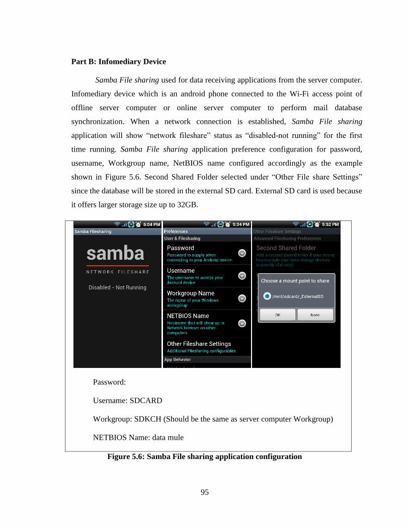
95
Part B: Infomediary Device
Samba File sharing used for data receiving applications from the server computer.
Infomediary device which is an android phone connected to the Wi-Fi access point of
offline server computer or online server computer to perform mail database
synchronization. When a network connection is established, Samba File sharing
application will show “network fileshare” status as “disabled-not running” for the first
time running. Samba File sharing application preference configuration for password,
username, Workgroup name, NetBIOS name configured accordingly as the example
shown in Figure 5.6. Second Shared Folder selected under “Other File share Settings”
since the database will be stored in the external SD card. External SD card is used because
it offers larger storage size up to 32GB.
Password:
Username: SDCARD
Workgroup: SDKCH (Should be the same as server computer Workgroup)
NETBIOS Name: data mule
Figure 5.6: Samba File sharing application configuration
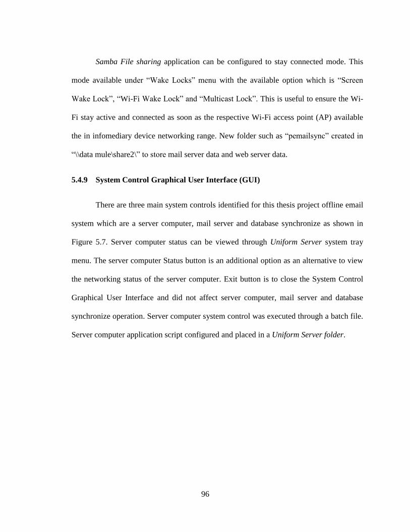
96
Samba File sharing application can be configured to stay connected mode. This
mode available under “Wake Locks” menu with the available option which is “Screen
Wake Lock”, “Wi-Fi Wake Lock” and “Multicast Lock”. This is useful to ensure the Wi-
Fi stay active and connected as soon as the respective Wi-Fi access point (AP) available
the in infomediary device networking range. New folder such as “pemailsync” created in
“\\data mule\share2\” to store mail server data and web server data.
5.4.9 System Control Graphical User Interface (GUI)
There are three main system controls identified for this thesis project offline email
system which are a server computer, mail server and database synchronize as shown in
Figure 5.7. Server computer status can be viewed through Uniform Server system tray
menu. The server computer Status button is an additional option as an alternative to view
the networking status of the server computer. Exit button is to close the System Control
Graphical User Interface and did not affect server computer, mail server and database
synchronize operation. Server computer system control was executed through a batch file.
Server computer application script configured and placed in a Uniform Server folder.
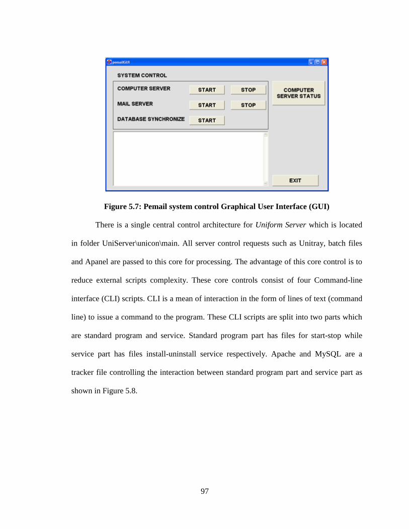
97
Figure 5.7: Pemail system control Graphical User Interface (GUI)
There is a single central control architecture for Uniform Server which is located
in folder UniServer\unicon\main. All server control requests such as Unitray, batch files
and Apanel are passed to this core for processing. The advantage of this core control is to
reduce external scripts complexity. These core controls consist of four Command-line
interface (CLI) scripts. CLI is a mean of interaction in the form of lines of text (command
line) to issue a command to the program. These CLI scripts are split into two parts which
are standard program and service. Standard program part has files for start-stop while
service part has files install-uninstall service respectively. Apache and MySQL are a
tracker file controlling the interaction between standard program part and service part as
shown in Figure 5.8.
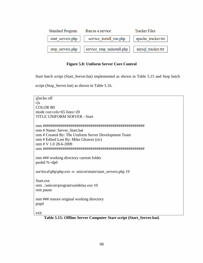
98
Figure 5.8: Uniform Server Core Control
Start batch script (Start_Server.bat) implemented as shown in Table 5.15 and Stop batch
script (Stop_Server.bat) as shown in Table 5.16.
@echo off
cls
COLOR B0
mode con:cols=65 lines=20
TITLE UNIFORM SERVER - Start
rem ###################################################
rem # Name: Server_Start.bat
rem # Created By: The Uniform Server Development Team
rem # Edited Last By: Mike Gleaves (ric)
rem # V 1.0 28-6-2009
rem ###################################################
rem ### working directory current folder
pushd %~dp0
usr\local\php\php.exe -n unicon\main\start_servers.php 19
Start.exe
rem ..\unicon\program\unidelay.exe 10
rem pause
rem ### restore original working directory
popd
exit
Table 5.15: Offline Server Computer Start script (Start_Server.bat)
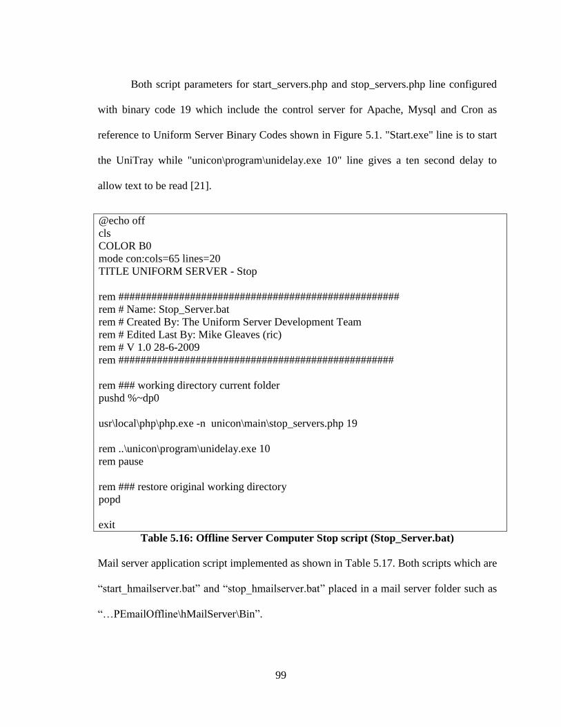
99
Both script parameters for start_servers.php and stop_servers.php line configured
with binary code 19 which include the control server for Apache, Mysql and Cron as
reference to Uniform Server Binary Codes shown in Figure 5.1. "Start.exe" line is to start
the UniTray while "unicon\program\unidelay.exe 10" line gives a ten second delay to
allow text to be read [21].
@echo off
cls
COLOR B0
mode con:cols=65 lines=20
TITLE UNIFORM SERVER - Stop
rem ###################################################
rem # Name: Stop_Server.bat
rem # Created By: The Uniform Server Development Team
rem # Edited Last By: Mike Gleaves (ric)
rem # V 1.0 28-6-2009
rem ##################################################
rem ### working directory current folder
pushd %~dp0
usr\local\php\php.exe -n unicon\main\stop_servers.php 19
rem ..\unicon\program\unidelay.exe 10
rem pause
rem ### restore original working directory
popd
exit
Table 5.16: Offline Server Computer Stop script (Stop_Server.bat)
Mail server application script implemented as shown in Table 5.17. Both scripts which are
“start_hmailserver.bat” and “stop_hmailserver.bat” placed in a mail server folder such as
“…PEmailOffline\hMailServer\Bin”.
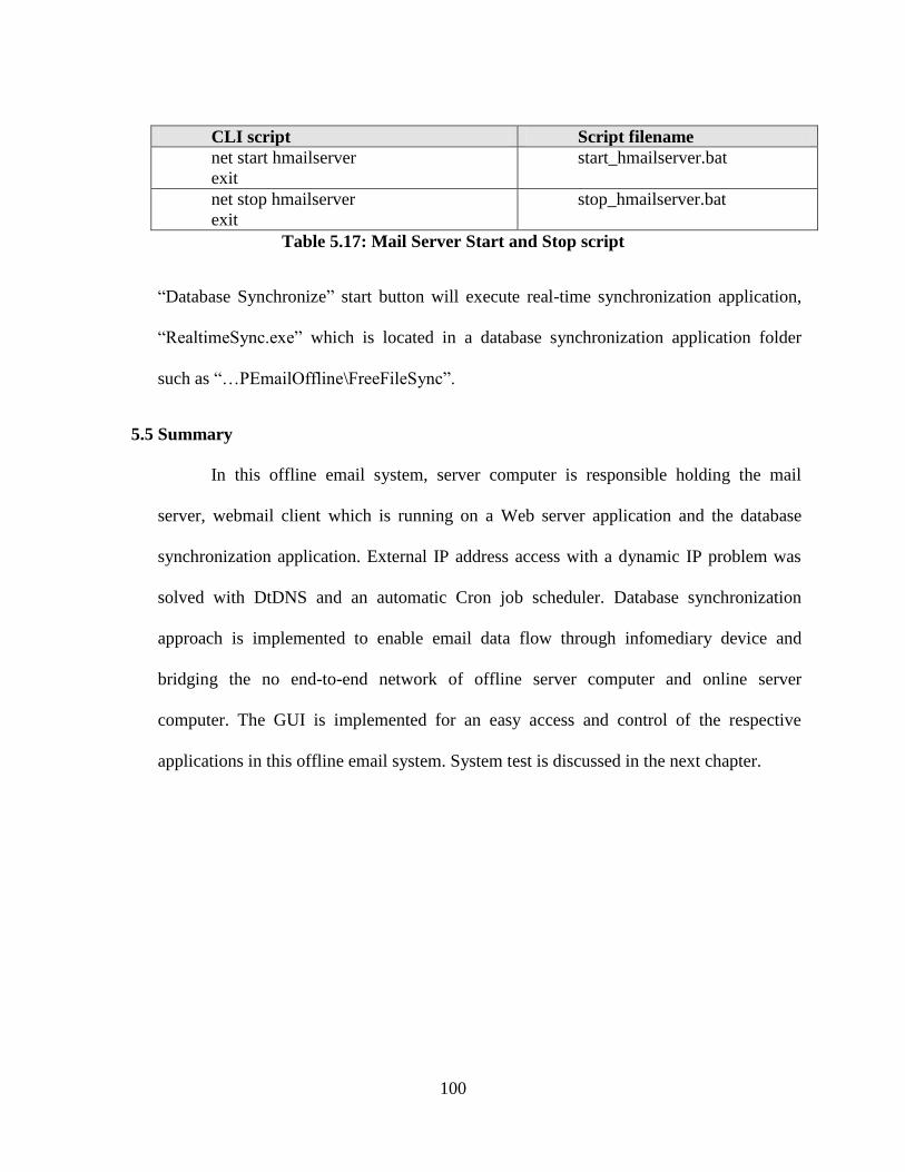
100
CLI script Script filename
net start hmailserver
exit
start_hmailserver.bat
net stop hmailserver
exit
stop_hmailserver.bat
Table 5.17: Mail Server Start and Stop script
“Database Synchronize” start button will execute real-time synchronization application,
“RealtimeSync.exe” which is located in a database synchronization application folder
such as “…PEmailOffline\FreeFileSync”.
5.5 Summary
In this offline email system, server computer is responsible holding the mail
server, webmail client which is running on a Web server application and the database
synchronization application. External IP address access with a dynamic IP problem was
solved with DtDNS and an automatic Cron job scheduler. Database synchronization
approach is implemented to enable email data flow through infomediary device and
bridging the no end-to-end network of offline server computer and online server
computer. The GUI is implemented for an easy access and control of the respective
applications in this offline email system. System test is discussed in the next chapter.
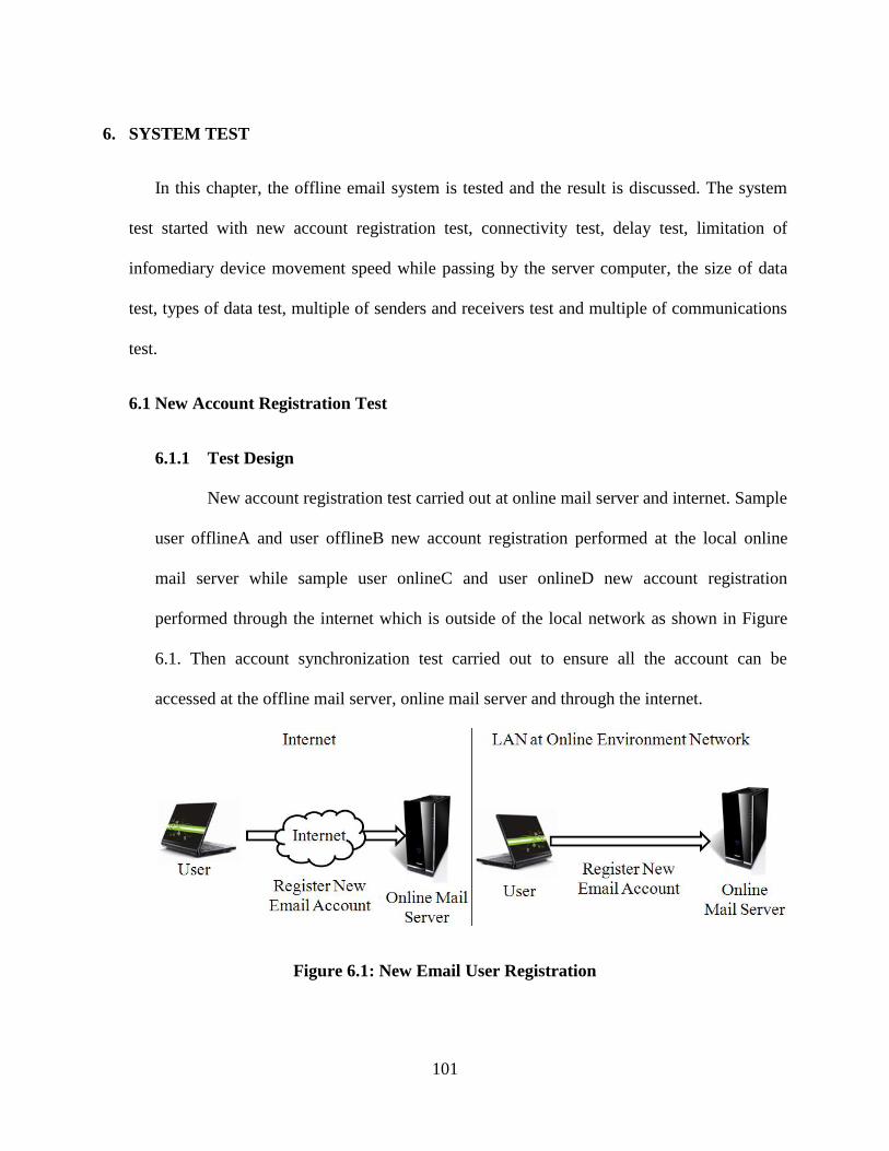
101
6. SYSTEM TEST
In this chapter, the offline email system is tested and the result is discussed. The system
test started with new account registration test, connectivity test, delay test, limitation of
infomediary device movement speed while passing by the server computer, the size of data
test, types of data test, multiple of senders and receivers test and multiple of communications
test.
6.1 New Account Registration Test
6.1.1 Test Design
New account registration test carried out at online mail server and internet. Sample
user offlineA and user offlineB new account registration performed at the local online
mail server while sample user onlineC and user onlineD new account registration
performed through the internet which is outside of the local network as shown in Figure
6.1. Then account synchronization test carried out to ensure all the account can be
accessed at the offline mail server, online mail server and through the internet.
Figure 6.1: New Email User Registration
102
6.1.2 Expected Outcome
Expected outcome from this test as per below:
i) Registration page accessibility: Email account registration page can be
access from online mail server local area network and from the internet.
ii) User registration: New email account which is offlineA, offlineB
successfully created from online mail server local area network and
onlineC and onlineD successfully created from the internet.
iii) Email account access: All email accounts which are offlineA, offlineB,
onlineC and onlineD can be access from the online mail server local area
network, from the internet and from the offline mail server local area
network after database synchronization.
6.1.3 Test result
The registration page is only accessible from LAN which connected to online mail
server or through internet. Characters such as "? * | \ / < >" does not supported in creating
an email account. Figure 6.2 shows new account registration test result through internet at
webmail address which is http://pemail.suroot.com by following the register button,
filling in the anti spam security code and setup the username and password for the new
email. The same procedure also performed on the local online mail server at the local
webmail address which is http://192.168.1.7/pemail.
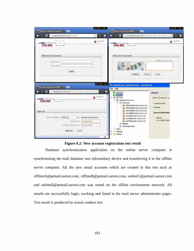
103
Figure 6.2: New account registration test result
Database synchronization application on the online server computer is
synchronizing the mail database into infomediary device and transferring it to the offline
server computer. All the new email accounts which are created in this test such as
[email protected], [email protected], [email protected]
and [email protected] was tested on the offline environment network. All
emails are successfully login, working and listed in the mail server administrator pages.
Test result is produced by actual conduct test.
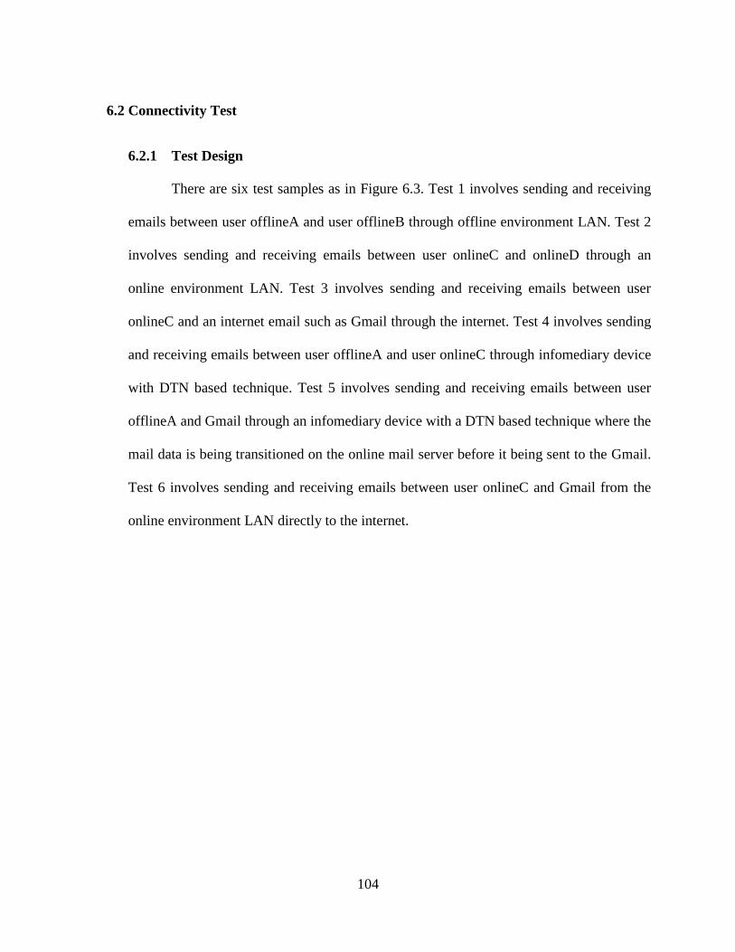
104
6.2 Connectivity Test
6.2.1 Test Design
There are six test samples as in Figure 6.3. Test 1 involves sending and receiving
emails between user offlineA and user offlineB through offline environment LAN. Test 2
involves sending and receiving emails between user onlineC and onlineD through an
online environment LAN. Test 3 involves sending and receiving emails between user
onlineC and an internet email such as Gmail through the internet. Test 4 involves sending
and receiving emails between user offlineA and user onlineC through infomediary device
with DTN based technique. Test 5 involves sending and receiving emails between user
offlineA and Gmail through an infomediary device with a DTN based technique where the
mail data is being transitioned on the online mail server before it being sent to the Gmail.
Test 6 involves sending and receiving emails between user onlineC and Gmail from the
online environment LAN directly to the internet.
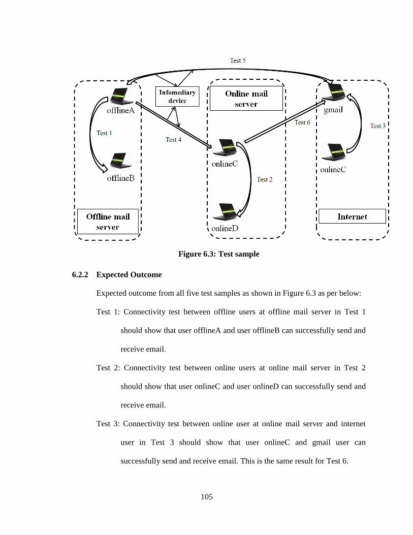
105
Figure 6.3: Test sample
6.2.2 Expected Outcome
Expected outcome from all five test samples as shown in Figure 6.3 as per below:
Test 1: Connectivity test between offline users at offline mail server in Test 1
should show that user offlineA and user offlineB can successfully send and
receive email.
Test 2: Connectivity test between online users at online mail server in Test 2
should show that user onlineC and user onlineD can successfully send and
receive email.
Test 3: Connectivity test between online user at online mail server and internet
user in Test 3 should show that user onlineC and gmail user can
successfully send and receive email. This is the same result for Test 6.
106
Test 4: Connectivity test between offline user at offline mail server and online user
at online mail server in Test 4 should show that user offlineA and user
onlineC can successfully send and receive email with the help of
infomediary device.
Test 5: Connectivity test between offline user at offline mail server and internet
user in Test 5 should show that user offlineA and gmail user can
successfully send and receive email with the help of infomediary device.
6.2.3 Test Result
The email system functionality result for each test 1, test 2, test3, test4, test 5 and
test 6 shown in Table 6.1. Test result is produced by actual conduct test. Test 1 is testing
send and receives of email between user offlineA and user offlineB, test 2 is testing send
and receives of email between user onlineC and user onlineD, test 3 is testing send and
receives of email between user onlineC and Gmail through internet, test 4 is testing send
and receives of email between user offlineA and user onlineC, test5 is testing send and
receives of email between user offlineA and Gmail and test 6 is testing send and receives
of email between user onlineC and Gmail from local mail server to the internet. All email
communication tests contain sample attachment files.
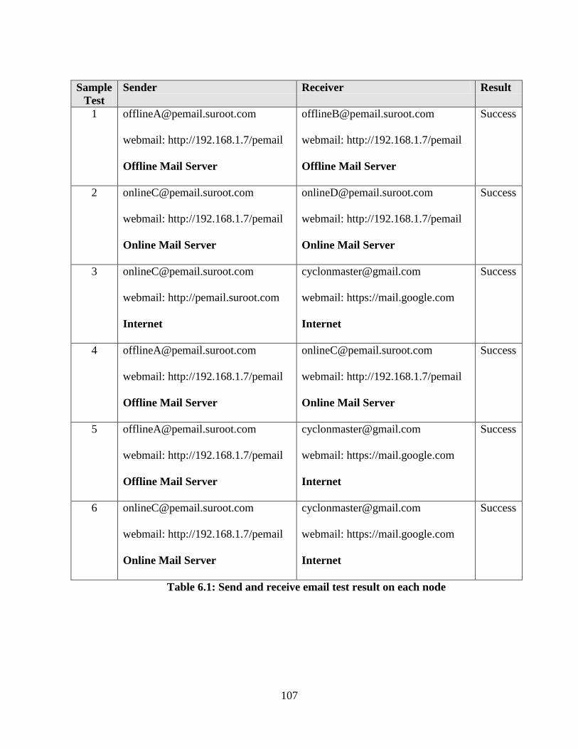
107
Sample
Test
Sender Receiver Result
webmail: http://192.168.1.7/pemail
Offline Mail Server
webmail: http://192.168.1.7/pemail
Offline Mail Server
Success
webmail: http://192.168.1.7/pemail
Online Mail Server
webmail: http://192.168.1.7/pemail
Online Mail Server
Success
webmail: http://pemail.suroot.com
Internet
webmail: https://mail.google.com
Internet
Success
webmail: http://192.168.1.7/pemail
Offline Mail Server
webmail: http://192.168.1.7/pemail
Online Mail Server
Success
webmail: http://192.168.1.7/pemail
Offline Mail Server
webmail: https://mail.google.com
Internet
Success
webmail: http://192.168.1.7/pemail
Online Mail Server
webmail: https://mail.google.com
Internet
Success
Table 6.1: Send and receive email test result on each node
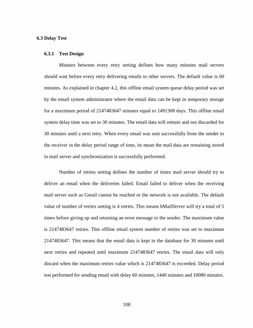
108
6.3 Delay Test
6.3.1 Test Design
Minutes between every retry setting defines how many minutes mail servers
should wait before every retry delivering emails to other servers. The default value is 60
minutes. As explained in chapter 4.2, this offline email system queue delay period was set
by the email system administrator where the email data can be kept in temporary storage
for a maximum period of 2147483647 minutes equal to 1491308 days. This offline email
system delay time was set to 30 minutes. The email data will remain and not discarded for
30 minutes until a next retry. When every email was sent successfully from the sender to
the receiver in the delay period range of time, its mean the mail data are remaining stored
in mail server and synchronization is successfully performed.
Number of retries setting defines the number of times mail server should try to
deliver an email when the deliveries failed. Email failed to deliver when the receiving
mail server such as Gmail cannot be reached or the network is not available. The default
value of number of retries setting is 4 retries. This means hMailServer will try a total of 5
times before giving up and returning an error message to the sender. The maximum value
is 2147483647 retries. This offline email system number of retries was set to maximum
2147483647. This means that the email data is kept in the database for 30 minutes until
next retries and repeated until maximum 2147483647 retries. The email data will only
discard when the maximum retries value which is 2147483647 is exceeded. Delay period
test performed for sending email with delay 60 minutes, 1440 minutes and 10080 minutes.
109
6.3.2 Expected Outcome
This offline email system expected to be able to tolerate with a long period of
delay communication between offline network environment and online network
environment. The email data expected to be remain in the mail server and keep in pending
status for 60 minutes ( one hour), 1440 minutes (one day) or 10080 minutes (one week)
and successfully reach the destination after process of database synchronization
completed.
6.3.3 Test Result
This offline email system queue delay period was set to30 minutes with maximum
retries value 2147483647. The status of the queue message available in the mail server
administrator control pages. The email from user offlineA was sent to user onlineC and
found that pending email data was remaining on the Mail Server after a period of testing
time as shown in the Table 6.2. Test result is produced by actual conduct test.
Sample test Date & time
email sent
Date & time email
received Delay period
(Minutes)
Result
1 09 June 2013
0800H
09 June 2013
0900H
60 Mail data remain
2 09 June 2013
0900H
10 June 2013
0900H
1440 Mail data remain
3 09 June 2013
1000H
16 June 2013
1000H
10080 Mail data remain
Table 6.2: Delay Period Test Result
110
6.4 Limitation of Infomediary Device Pass by Movement Speed
6.4.1 Test Design
The time required for database synchronization process between infomediary
device and server computer calculated to find the recommended movement speed of the
infomediary device for ensuring the database synchronization is complete. It is to find an
ideal period of time infomediary device should remain in Wi-Fi access point range of
server computer. The range of the network connection between infomediary device and
Wi-Fi access point of server computer measured. The transfer rate of Wi-Fi access point is
compared with the offline email system storage read and write speed limitation. Based on
this transfer rate, size of data and network range, the speed movement of the infomediary
device passes by server computer network connection can be calculated. This test is to
ensure the database synchronization process is performed completely successfully.
6.4.2 Expected Outcome
This test is expected to produced is the maximum recommended speed of
infomediary device movement through the Wi-Fi range of the server computer based on
identified value of:
i) Server computer effective Wi-Fi range for outdoors
ii) Size of data sample data
iii) Transfer rate based on Wi-Fi access point transfer rate, online server
computer storage read and write speed, offline server computer storage
read and write speed and infomediary device storage read and write speed.
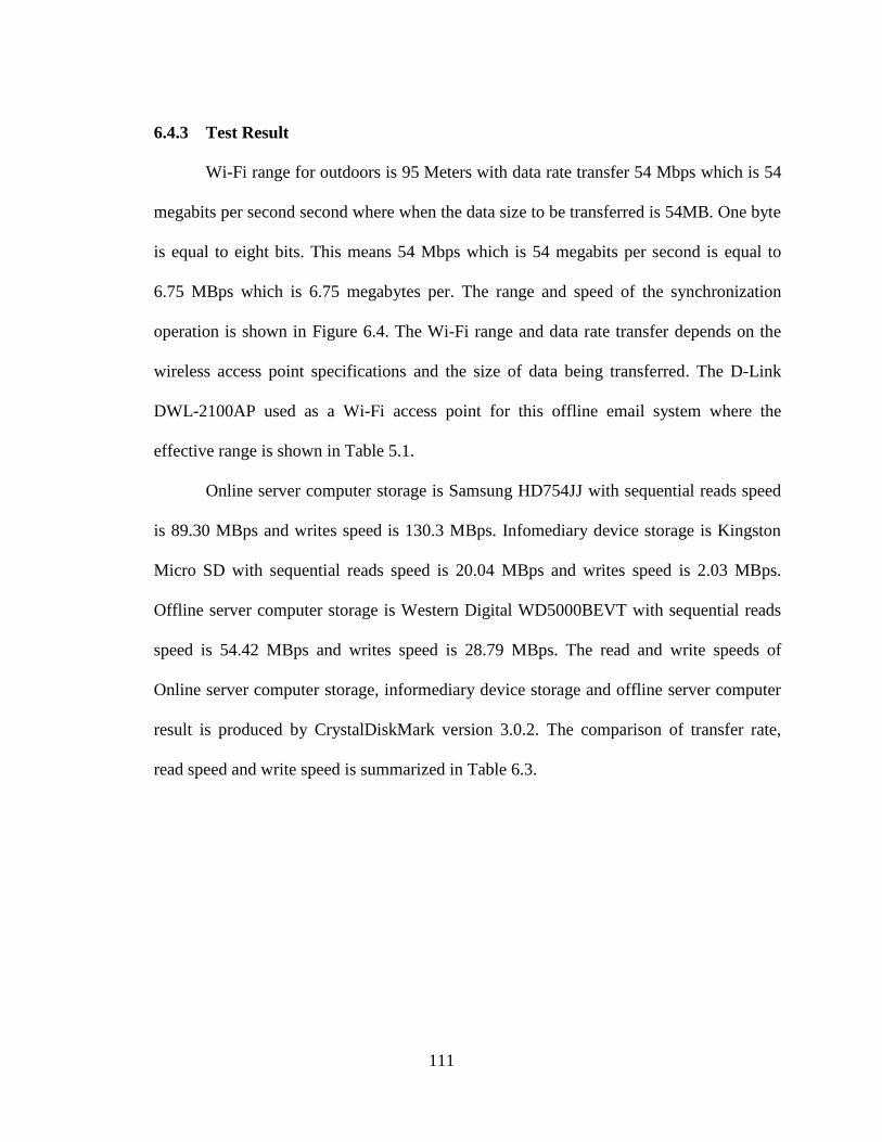
111
6.4.3 Test Result
Wi-Fi range for outdoors is 95 Meters with data rate transfer 54 Mbps which is 54
megabits per second second where when the data size to be transferred is 54MB. One byte
is equal to eight bits. This means 54 Mbps which is 54 megabits per second is equal to
6.75 MBps which is 6.75 megabytes per. The range and speed of the synchronization
operation is shown in Figure 6.4. The Wi-Fi range and data rate transfer depends on the
wireless access point specifications and the size of data being transferred. The D-Link
DWL-2100AP used as a Wi-Fi access point for this offline email system where the
effective range is shown in Table 5.1.
Online server computer storage is Samsung HD754JJ with sequential reads speed
is 89.30 MBps and writes speed is 130.3 MBps. Infomediary device storage is Kingston
Micro SD with sequential reads speed is 20.04 MBps and writes speed is 2.03 MBps.
Offline server computer storage is Western Digital WD5000BEVT with sequential reads
speed is 54.42 MBps and writes speed is 28.79 MBps. The read and write speeds of
Online server computer storage, informediary device storage and offline server computer
result is produced by CrystalDiskMark version 3.0.2. The comparison of transfer rate,
read speed and write speed is summarized in Table 6.3.
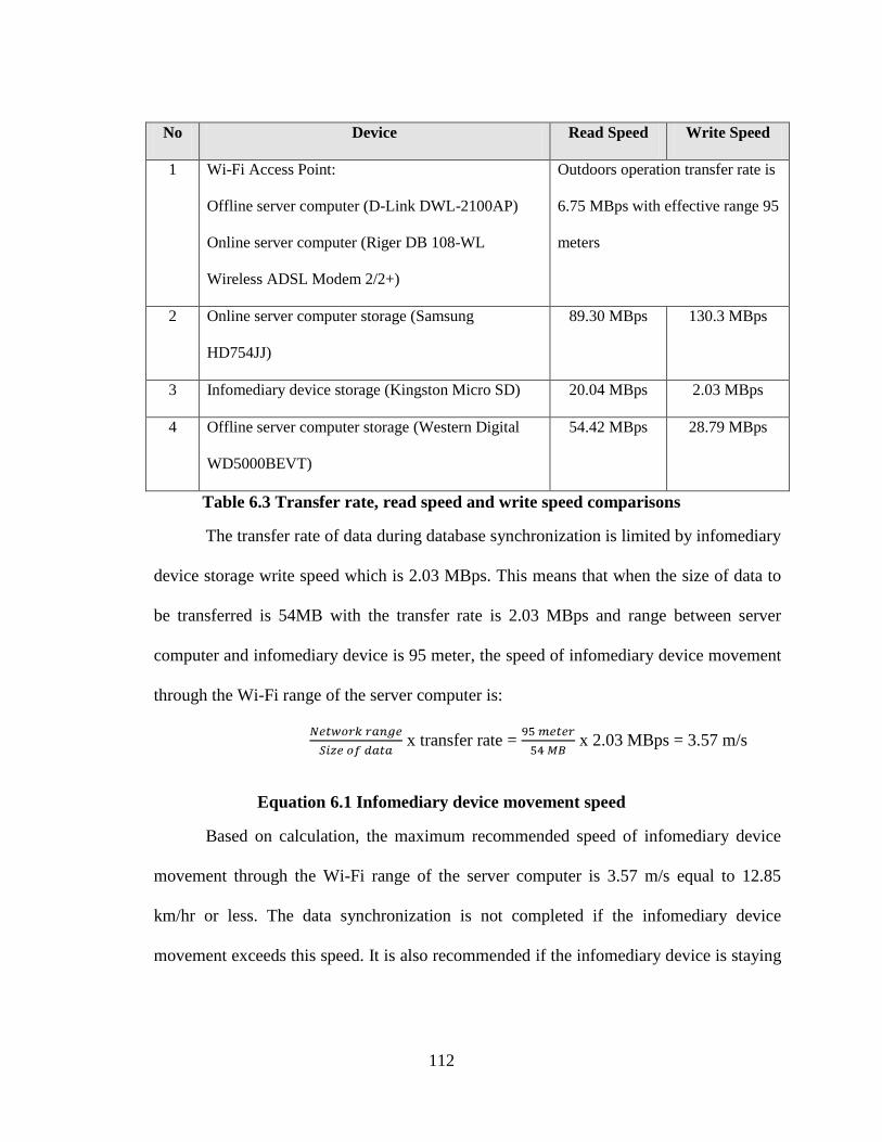
112
No Device Read Speed Write Speed
1 Wi-Fi Access Point:
Offline server computer (D-Link DWL-2100AP)
Online server computer (Riger DB 108-WL
Wireless ADSL Modem 2/2+)
Outdoors operation transfer rate is
6.75 MBps with effective range 95
meters
2 Online server computer storage (Samsung
HD754JJ)
89.30 MBps 130.3 MBps
3 Infomediary device storage (Kingston Micro SD) 20.04 MBps 2.03 MBps
4 Offline server computer storage (Western Digital
WD5000BEVT)
54.42 MBps 28.79 MBps
Table 6.3 Transfer rate, read speed and write speed comparisons
The transfer rate of data during database synchronization is limited by infomediary
device storage write speed which is 2.03 MBps. This means that when the size of data to
be transferred is 54MB with the transfer rate is 2.03 MBps and range between server
computer and infomediary device is 95 meter, the speed of infomediary device movement
through the Wi-Fi range of the server computer is:
x transfer rate = x 2.03 MBps = 3.57 m/s
Equation 6.1 Infomediary device movement speed
Based on calculation, the maximum recommended speed of infomediary device
movement through the Wi-Fi range of the server computer is 3.57 m/s equal to 12.85
km/hr or less. The data synchronization is not completed if the infomediary device
movement exceeds this speed. It is also recommended if the infomediary device is staying
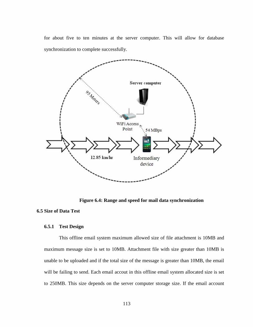
113
for about five to ten minutes at the server computer. This will allow for database
synchronization to complete successfully.
Figure 6.4: Range and speed for mail data synchronization
6.5 Size of Data Test
6.5.1 Test Design
This offline email system maximum allowed size of file attachment is 10MB and
maximum message size is set to 10MB. Attachment file with size greater than 10MB is
unable to be uploaded and if the total size of the message is greater than 10MB, the email
will be failing to send. Each email accout in this offline email system allocated size is set
to 250MB. This size depends on the server computer storage size. If the email account
114
used up all 250MB quota, the email account will fail to send or receive any email.
Different size of data test performed with an attachment size of 1MB, 5MB, 9MB, 10MB,
20MB and two 10MB files.
6.5.2 Expected Outcome
This offline email system expected to allow user uploading an attachment files
with the maximum size of 10MB. The email message is expected to be send successfully
with limitation of message size is 50MB or below.
6.5.3 Test Result
Email size content limitation is depending on the hard disk available storage. This
offline email system maximum attachment size is 10MB, maximum message size is
50MB and allocated maximum size storage for each email is 250MB. A test result of
sending an email with attachment size 1MB, 5MB, 9MB, 10MB, 20MB and two 10MB
files shown in the Table 6.4. Test result is produced by actual conduct test.
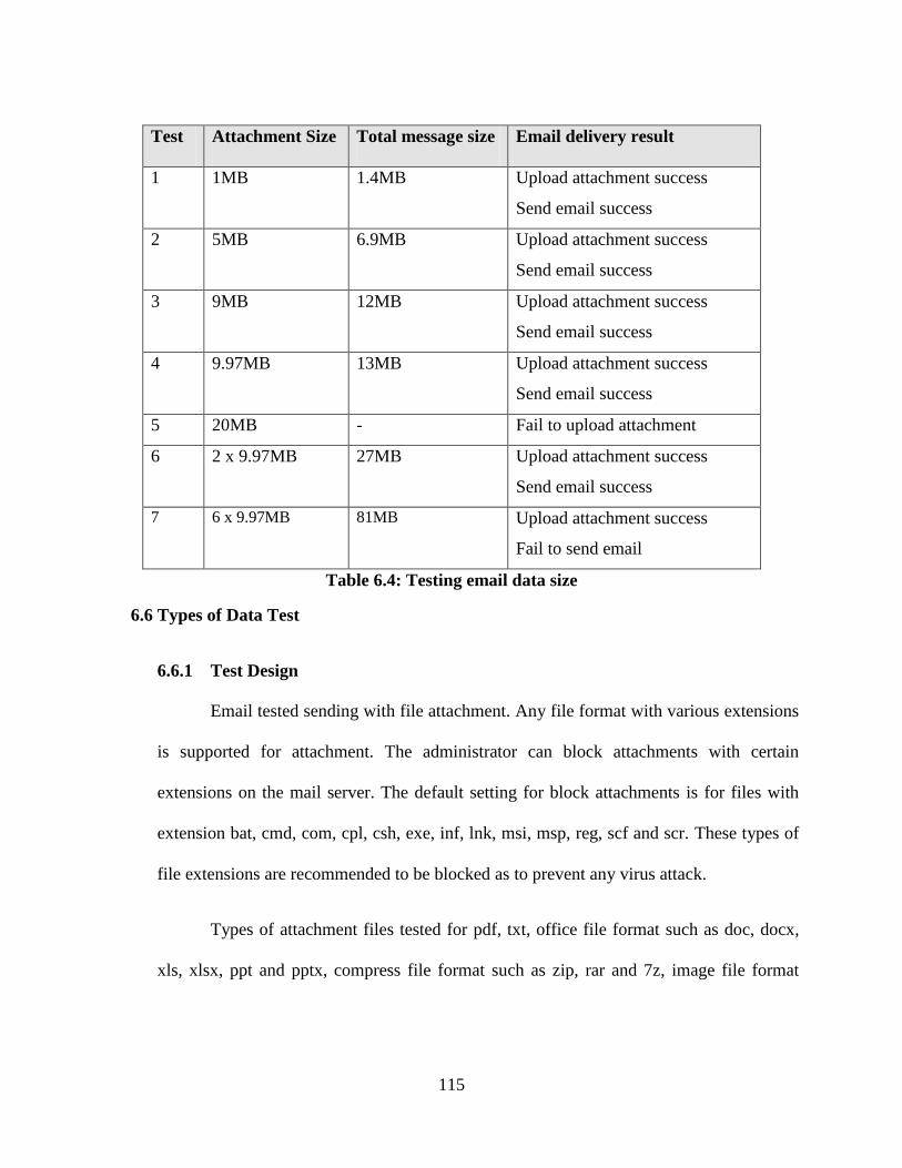
115
Test Attachment Size Total message size Email delivery result
1 1MB 1.4MB Upload attachment success
Send email success
2 5MB 6.9MB Upload attachment success
Send email success
3 9MB 12MB Upload attachment success
Send email success
4 9.97MB 13MB Upload attachment success
Send email success
5 20MB - Fail to upload attachment
6 2 x 9.97MB 27MB Upload attachment success
Send email success
7 6 x 9.97MB 81MB Upload attachment success
Fail to send email
Table 6.4: Testing email data size
6.6 Types of Data Test
6.6.1 Test Design
Email tested sending with file attachment. Any file format with various extensions
is supported for attachment. The administrator can block attachments with certain
extensions on the mail server. The default setting for block attachments is for files with
extension bat, cmd, com, cpl, csh, exe, inf, lnk, msi, msp, reg, scf and scr. These types of
file extensions are recommended to be blocked as to prevent any virus attack.
Types of attachment files tested for pdf, txt, office file format such as doc, docx,
xls, xlsx, ppt and pptx, compress file format such as zip, rar and 7z, image file format
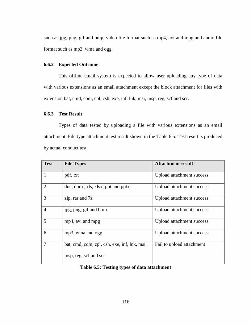
116
such as jpg, png, gif and bmp, video file format such as mp4, avi and mpg and audio file
format such as mp3, wma and ogg.
6.6.2 Expected Outcome
This offline email system is expected to allow user uploading any type of data
with various extensions as an email attachment except the block attachment for files with
extension bat, cmd, com, cpl, csh, exe, inf, lnk, msi, msp, reg, scf and scr.
6.6.3 Test Result
Types of data tested by uploading a file with various extensions as an email
attachment. File type attachment test result shown in the Table 6.5. Test result is produced
by actual conduct test.
Test File Types Attachment result
1 pdf, txt Upload attachment success
2 doc, docx, xls, xlsx, ppt and pptx Upload attachment success
3 zip, rar and 7z Upload attachment success
4 jpg, png, gif and bmp Upload attachment success
5 mp4, avi and mpg Upload attachment success
6 mp3, wma and ogg Upload attachment success
7 bat, cmd, com, cpl, csh, exe, inf, lnk, msi,
msp, reg, scf and scr
Fail to upload attachment
Table 6.5: Testing types of data attachment
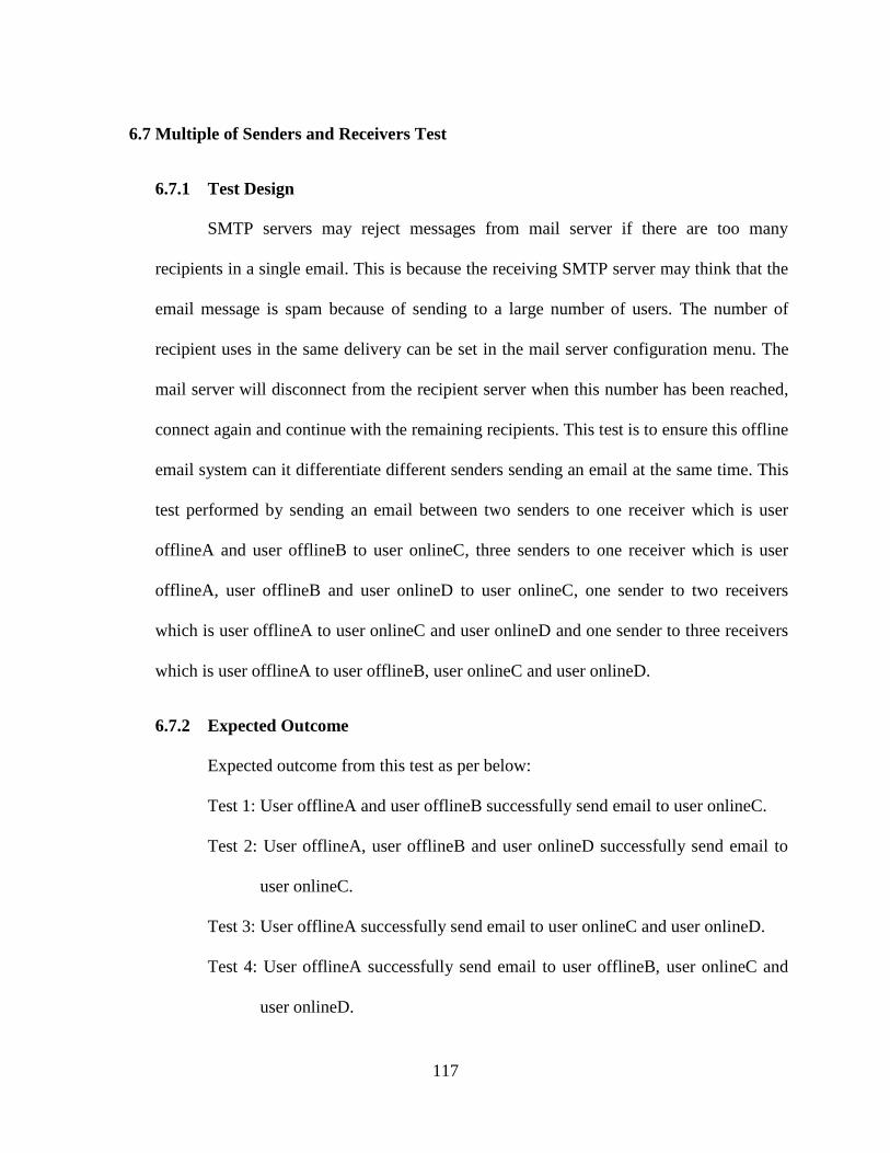
117
6.7 Multiple of Senders and Receivers Test
6.7.1 Test Design
SMTP servers may reject messages from mail server if there are too many
recipients in a single email. This is because the receiving SMTP server may think that the
email message is spam because of sending to a large number of users. The number of
recipient uses in the same delivery can be set in the mail server configuration menu. The
mail server will disconnect from the recipient server when this number has been reached,
connect again and continue with the remaining recipients. This test is to ensure this offline
email system can it differentiate different senders sending an email at the same time. This
test performed by sending an email between two senders to one receiver which is user
offlineA and user offlineB to user onlineC, three senders to one receiver which is user
offlineA, user offlineB and user onlineD to user onlineC, one sender to two receivers
which is user offlineA to user onlineC and user onlineD and one sender to three receivers
which is user offlineA to user offlineB, user onlineC and user onlineD.
6.7.2 Expected Outcome
Expected outcome from this test as per below:
Test 1: User offlineA and user offlineB successfully send email to user onlineC.
Test 2: User offlineA, user offlineB and user onlineD successfully send email to
user onlineC.
Test 3: User offlineA successfully send email to user onlineC and user onlineD.
Test 4: User offlineA successfully send email to user offlineB, user onlineC and
user onlineD.
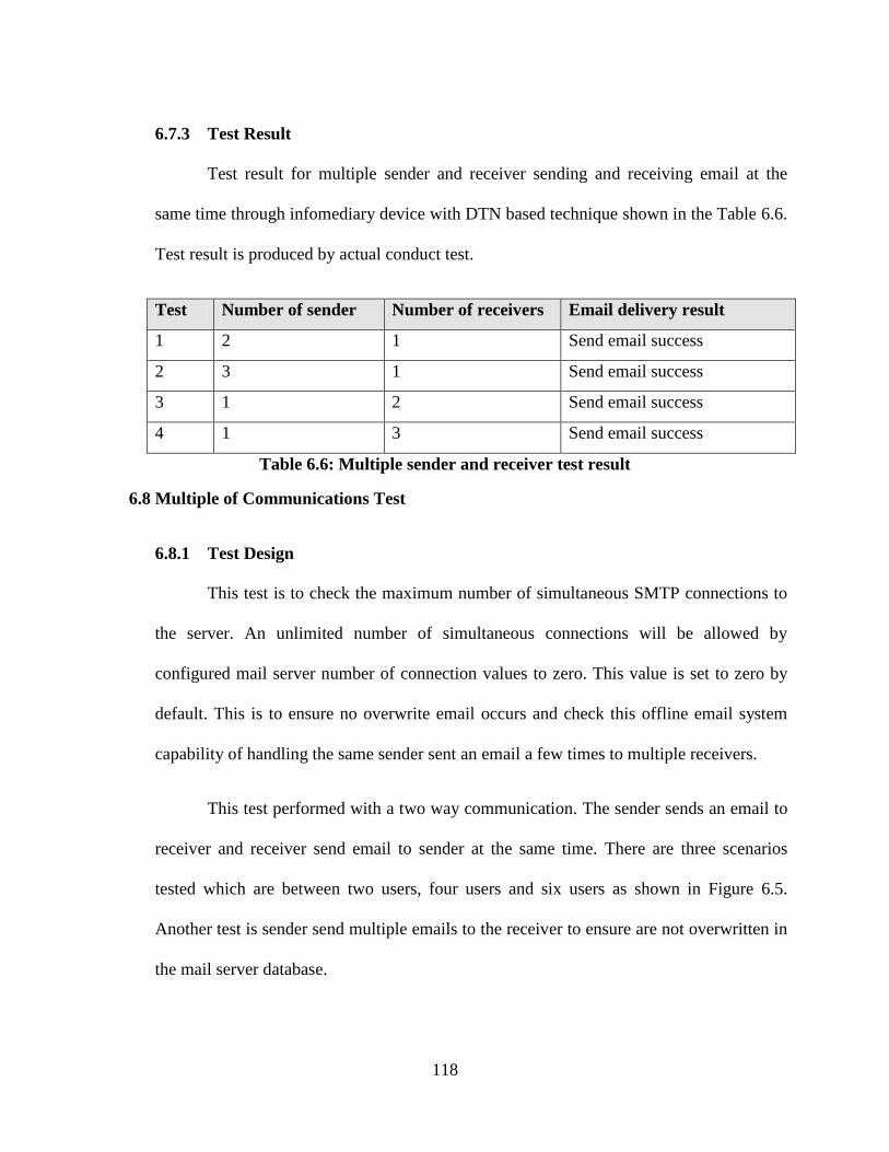
118
6.7.3 Test Result
Test result for multiple sender and receiver sending and receiving email at the
same time through infomediary device with DTN based technique shown in the Table 6.6.
Test result is produced by actual conduct test.
Test Number of sender Number of receivers Email delivery result
1 2 1 Send email success
2 3 1 Send email success
3 1 2 Send email success
4 1 3 Send email success
Table 6.6: Multiple sender and receiver test result
6.8 Multiple of Communications Test
6.8.1 Test Design
This test is to check the maximum number of simultaneous SMTP connections to
the server. An unlimited number of simultaneous connections will be allowed by
configured mail server number of connection values to zero. This value is set to zero by
default. This is to ensure no overwrite email occurs and check this offline email system
capability of handling the same sender sent an email a few times to multiple receivers.
This test performed with a two way communication. The sender sends an email to
receiver and receiver send email to sender at the same time. There are three scenarios
tested which are between two users, four users and six users as shown in Figure 6.5.
Another test is sender send multiple emails to the receiver to ensure are not overwritten in
the mail server database.
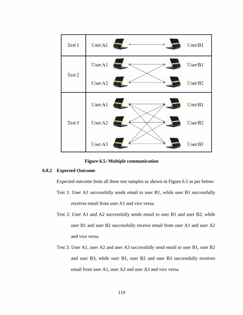
119
Figure 6.5: Multiple communication
6.8.2 Expected Outcome
Expected outcome from all three test samples as shown in Figure 6.5 as per below:
Test 1: User A1 successfully sends email to user B1, while user B1 successfully
receives email from user A1 and vice versa.
Test 2: User A1 and A2 successfully sends email to user B1 and user B2, while
user B1 and user B2 successfully receive email from user A1 and user A2
and vice versa.
Test 3: User A1, user A2 and user A3 successfully send email to user B1, user B2
and user B3, while user B1, user B2 and user B3 successfully receives
email from user A1, user A2 and user A3 and vice versa.
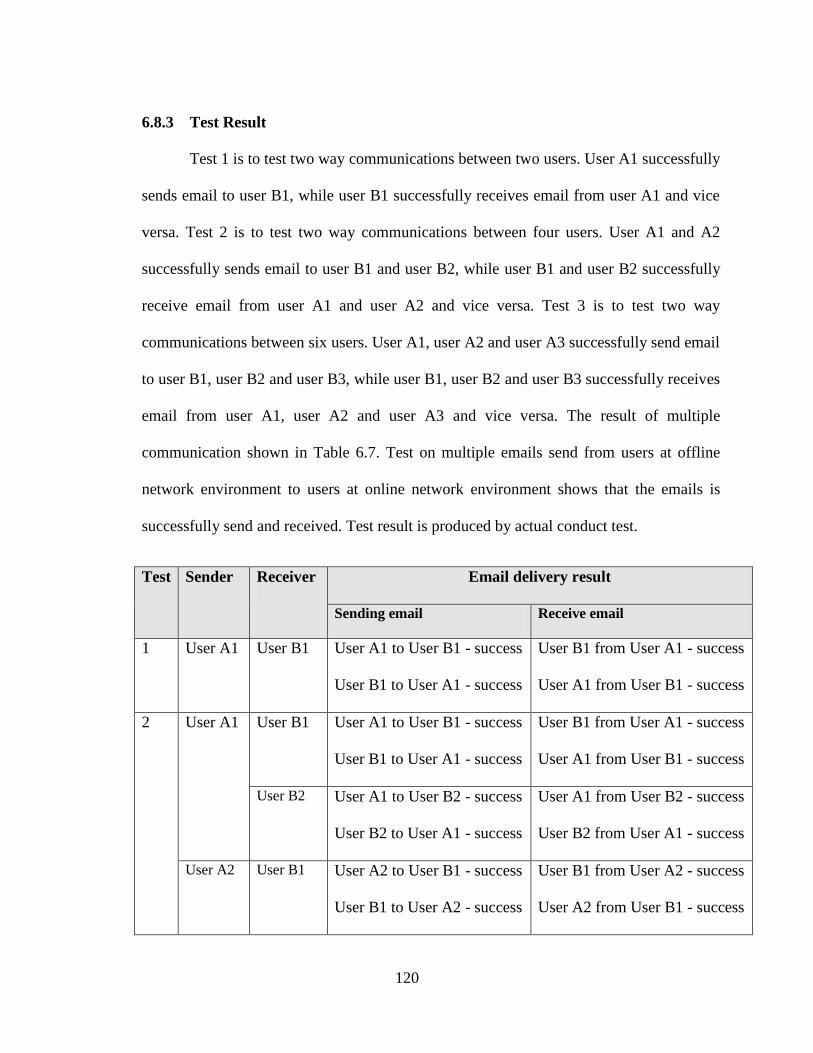
120
6.8.3 Test Result
Test 1 is to test two way communications between two users. User A1 successfully
sends email to user B1, while user B1 successfully receives email from user A1 and vice
versa. Test 2 is to test two way communications between four users. User A1 and A2
successfully sends email to user B1 and user B2, while user B1 and user B2 successfully
receive email from user A1 and user A2 and vice versa. Test 3 is to test two way
communications between six users. User A1, user A2 and user A3 successfully send email
to user B1, user B2 and user B3, while user B1, user B2 and user B3 successfully receives
email from user A1, user A2 and user A3 and vice versa. The result of multiple
communication shown in Table 6.7. Test on multiple emails send from users at offline
network environment to users at online network environment shows that the emails is
successfully send and received. Test result is produced by actual conduct test.
Test Sender Receiver Email delivery result
Sending email Receive email
1 User A1 User B1 User A1 to User B1 - success
User B1 to User A1 - success
User B1 from User A1 - success
User A1 from User B1 - success
2 User A1 User B1 User A1 to User B1 - success
User B1 to User A1 - success
User B1 from User A1 - success
User A1 from User B1 - success
User B2 User A1 to User B2 - success
User B2 to User A1 - success
User A1 from User B2 - success
User B2 from User A1 - success
User A2 User B1 User A2 to User B1 - success
User B1 to User A2 - success
User B1 from User A2 - success
User A2 from User B1 - success
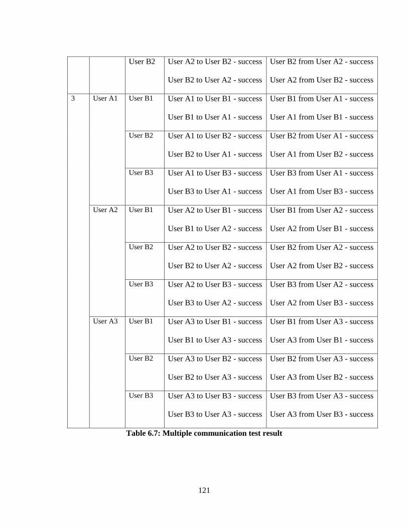
121
User B2 User A2 to User B2 - success
User B2 to User A2 - success
User B2 from User A2 - success
User A2 from User B2 - success
3 User A1 User B1 User A1 to User B1 - success
User B1 to User A1 - success
User B1 from User A1 - success
User A1 from User B1 - success
User B2 User A1 to User B2 - success
User B2 to User A1 - success
User B2 from User A1 - success
User A1 from User B2 - success
User B3 User A1 to User B3 - success
User B3 to User A1 - success
User B3 from User A1 - success
User A1 from User B3 - success
User A2 User B1 User A2 to User B1 - success
User B1 to User A2 - success
User B1 from User A2 - success
User A2 from User B1 - success
User B2 User A2 to User B2 - success
User B2 to User A2 - success
User B2 from User A2 - success
User A2 from User B2 - success
User B3 User A2 to User B3 - success
User B3 to User A2 - success
User B3 from User A2 - success
User A2 from User B3 - success
User A3 User B1 User A3 to User B1 - success
User B1 to User A3 - success
User B1 from User A3 - success
User A3 from User B1 - success
User B2 User A3 to User B2 - success
User B2 to User A3 - success
User B2 from User A3 - success
User A3 from User B2 - success
User B3 User A3 to User B3 - success
User B3 to User A3 - success
User B3 from User A3 - success
User A3 from User B3 - success
Table 6.7: Multiple communication test result
122
6.9 Discussion of Results
The test result shows that user were able to register a new email account locally at
online mail server or through internet. Email account created at online mail server is
accessible at the offline mail server, online mail server and through internet after mail data
synchronization between infomediary device and each mail server. Email system found to
be successfully functional to send or receive email through the offline mail server, online
mail server and internet. Pending email data is tested for a period of time and found to be
able remains in the database and not discarded. Wireless LAN range between server
computer access point and infomediary device for it to establish mail data synchronization
is 95 Meters or less with a data rate transfer is 54 Mbps which is 54 megabits per second
equal to 6.75 MBps which is 6.75 megabytes per second and limited by infomediary
device storage write speed which is 2.03 Mbps. The recommended infomediary device
move speed through the Wi-Fi range of the server computer is 3.57 m/s equal to 12.85
km/h or less to ensure the mail data synchronization is completed successfully. The
maximum size of an email attachment is 10MB with total message size limit is 50MB. It
is also recommended to limit the size to lower 10MB to prevent spam attack and viruses.
Each email account size quota is set to 250MB. It is dependable on the server computer
hard drive storage size. All tested emails are successfully sent and receive within the mail
server email size limitation. This offline email system can upload any types of file and
have the ability to block attachments with certain extensions on the mail server. Number
of email connections is unlimited. It can send or receive emails multiple times without
worrying of the mail data overwritten on the mail server database.

123
6.10 Summary
A brief result of the different testing approach was provided in this chapter 6. A
demonstration setup was also explained to show various application scenarios of the
offline email system. Next chapter, conclusions and future work are discussed.
124
7. CONCLUSION
In this final chapter, a brief summary of the research and development work is provided. A
recommendation for future work is concluded and conclusions of the research objectives and
results are discussed.
In the beginning, an introduction and objective to the thesis work was presented. A
comparison between TCP/IP and DTN was discussed. An email architecture and overview of
similar work was given. Next, the design of TCP/IP mail system working using a DTN store and
forward fundamentals is discussed including the network protocol design followed by offline
email system detail design. The idea of using database synchronization as DTN store and forward
fundamentals is discussed. Then, the system implementation issues and implementation details of
server computer, web server application, mail server, mail client and database synchronization.
Lastly, the system test and result of the offline email system was presented.
7.1 Future Work
There is a possibility of this offline email system can support Government‟s
“Kampung Tanpa Wayar” project where it can benefit in term of cost to expand a portion
of internet access such as the email application to rural area. It is also good to improve
email security by implementing encrypt and decrypt process in data synchronization
between Mail Server and infomediary device. A proper dedicated online mail server with
a static IP internet connection is better to replace the current approach to reduce
dependency to external services such as DtDNS. This will improve reliability of the
system. Additional mail client feature can be added such as email labeling, priority email,
125
send and achieve message etc. Database synchronization speed can be improved with
better hardware, especially when dealing with many mail data and bigger attachment files.
In the process of database synchronization, there is a need of checking the database path
availability continuously between server computer and infomediary device. This process
will consume much more power while in rural area there is are constrained that there is a
need to conserve power consumption since the power in rural area mostly dependable to
electric power generator. Instead of continuously checking the database path availability,
the process can be done by checking the database path availability at a set of time or only
when the infomediary device is available in the server computer network.
7.2 Conclusion
In this thesis, the TCP/IP was used on top of delay tolerant network fundamentals
where store and forward operation perform by data synchronization at each mail server.
This approach enables the email flow through the offline mail server to infomediary
device and then to the online mail server and internet. The user registration page is
implemented at online mail server and accessible from online mail server local area
network or from the internet. The email data can remain in the mail server more than one
week time delay until it synchronized with infomediary device. Limitation size of the
offline email system file attachment is 10MB and total email message is 50MB. This
limitation is depending on the size storage of the server computer. All types of data
supported for uploading an attachment and system administrator can block various file
extension such as bat, cmd, com, cpl, csh, exe, inf, lnk, msi, msp, reg, scf and scr from
being uploaded as an email attachment. Multiple sender and receiver can send and receive
126
emails simultaneously and supporting multiple communications between users
successfully. Based on calculation, the maximum recommended speed of infomediary
device movement through the Wi-Fi range of the server computer is 12.85 km/hr or less
and depend on the hardware specifications such as Wi-Fi data transfer rate and storage
read and write speed. This offline email system fulfills the objective of this thesis work
where the system can be used at the area that has no internet connection such as rural area.
This offline email system implementation based on DTN approach can be used for other
web application such as blogging.
127
REFERENCES
[1] J. Tarawe and R. W. Harris, "“Stories from e-bario,” In conference of Living the
Information Society, Philippine," 2007.
[2] R. Austein Ed J. Kempf Ed, "The Rise of the Middle and the Future of End-to-End:
Reflections on the Evolution of the Internet Architecture, RFC3724," 2004.
[3] S. Burleigh, A. Hooke, L. Torgerson, R. Durst, K. Scott, K. Fall, H. Weiss V. Cerf, "Delay-
Tolerant Networking Architecture," RFC4838, pp. 4, 15, April 2007.
[4] William Stallings, Data And Computer Communications, Eight Edition.: Prentice Hall,
2007.
[5] J. Reynolds, "Assigned Numbers," RFC3232, 2002.
[6] J. Postel J. Mogul, "Internet Standard Subnetting Procedure," RFC950, 1985.
[7] Dr. Keith Scott, "Delay/Disruption Tolerant Networking," in Large Installation System
Administration Conference (LISA‟09), 2009.
[8] Alex McMahon and Stephen Farrell, "Delay and Disruption Tolerant Networking," 2009.
[9] Forrest Warthman, "Delay-Tolerant Networks (DTNs)," 2003.
[10] K. Scott and S. Burleigh, "Bundle Protocol Specification," RFC5050, 2007.
[11] Craig Partridge, "The Technical Development of Internet Email," 2008.
[12] J. Klensin, "Simple Mail Transfer Protocol," RFC5321, 2008.
[13] M. Crispin, "Internet Message Access Protocol," RFC3501, 2003.
[14] Kevin Fall, "A Delay Tolerant Network Architecture for Challenged Internets," 2003.
[15] Martin Knafve. (2011, August) hMailServer. [Online]. http://www.hmailserver.com
[16] Ben Duncan. (2011, Aug.) @mail Open: PHP Webmail client - Open Source Webmail.
[Online]. http://atmail.org/
[17] Paul Lesniewski. (2011, Aug.) SquirrelMail - Webmail for Nuts. [Online].
128
http://squirrelmail.org
[18] The RoundCube Team. (2012, March) roundcube. [Online]. http://roundcube.net
[19] Ed P. Resnick and Qualcomm Incorporated, "Internet Message Format," RFC5322, 2008.
[20] Network Working Group, "Protocol standard for a NetBIOS service on a TCP/UDP
transport," RFC 1002, 1987.
[21] Uniform Server Development Team. (2011, August) Uniform Server. [Online].
http://www.uniformserver.com
[22] Zenju. (2011, December) FreeFileSync. [Online]. http://freefilesync.sourceforge.net/
[23] JimmyChingala. (2012, February) xda-developers. [Online]. http://forum.xda-
developers.com/showpost.php?p=8239139
[24] Justin Scott. (2012, January) DtDNS. [Online]. http://www.dtdns.com
[25] N. Freed, Innosoft, and N. Borenstein, "Multipurpose Internet Mail Extensions (MIME)
Part One:Format of Internet Message Bodies," RFC2045, November 1996.
[26] Google Inc. (2013, June) Gmail. [Online].
https://support.google.com/mail/answer/6584?rd=1
[27] Yahoo Inc. (2013, June) Yahoo Mail. [Online].
http://help.yahoo.com/kb/index?page=content&y=PROD_MAIL_ML&locale=en_US&id=
SLN3408
[28] Telekom Malaysia Berhad (TM). (2008, November) Streamyx. [Online].
http://www.tm.com.my/PublishingImages/unifi/pdf/Third%20Party%20Email%20Setting.p
df
[29] Ed. D. Crocker, Ed. T. Hansen, and Ed. M. Kucherawy, "DomainKeys Identified Mail
(DKIM) Signatures," RFC6376, September 2011.
[30] Team Uniform Server. (2011, August) hMailServer. [Online].
http://www.hmailserver.com/documentation/latest/?page=userguide_dds

129
APPENDIX
APPENDIX A
DANAWA Wireless Solution Provider Brochure
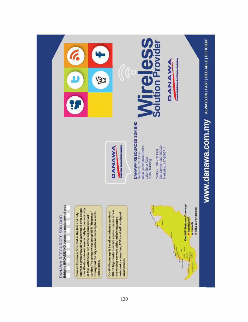
130
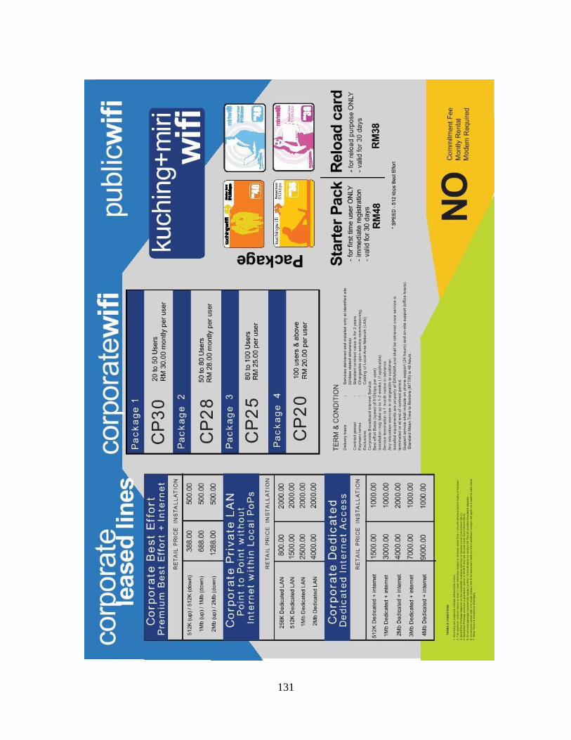
131

132
APPENDIX B
Lenovo IdeaPad Z460 Specifications
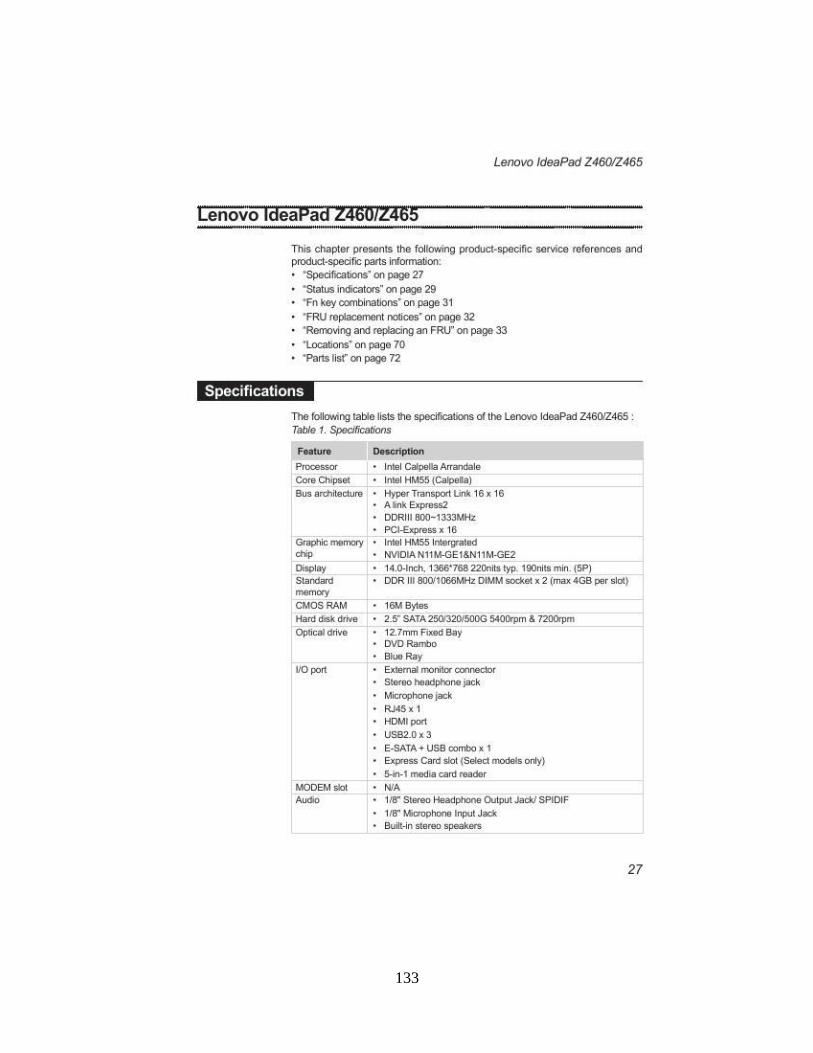
133
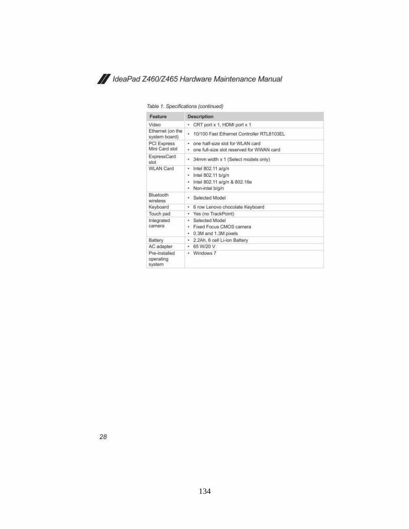
134

135
APPENDIX C
D-Link DWL-2100AP Specifications

136
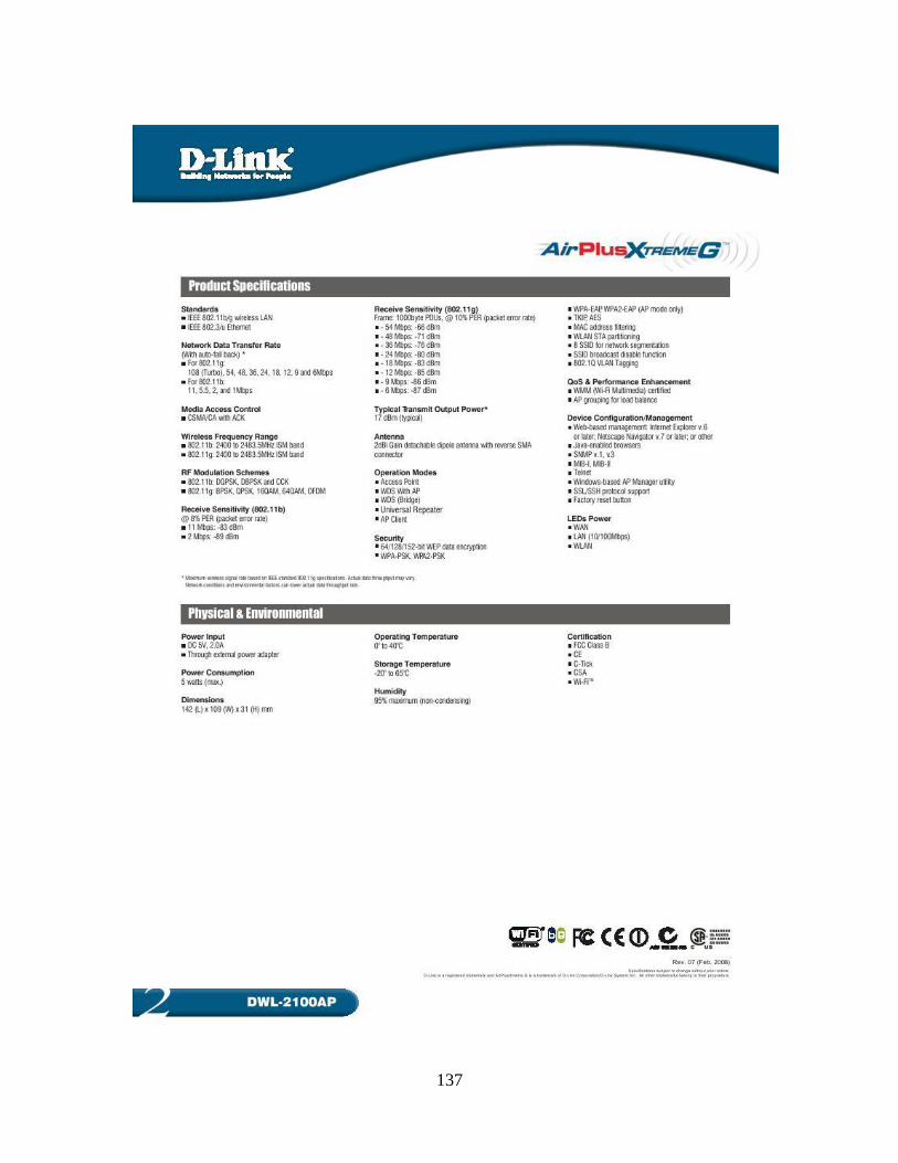
137

138
APPENDIX D
LG Optimus 3D (P920) Specifications
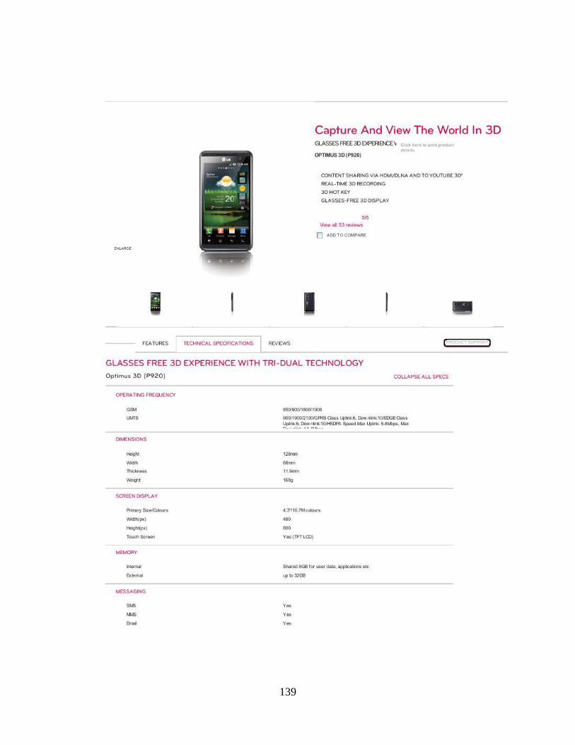
139
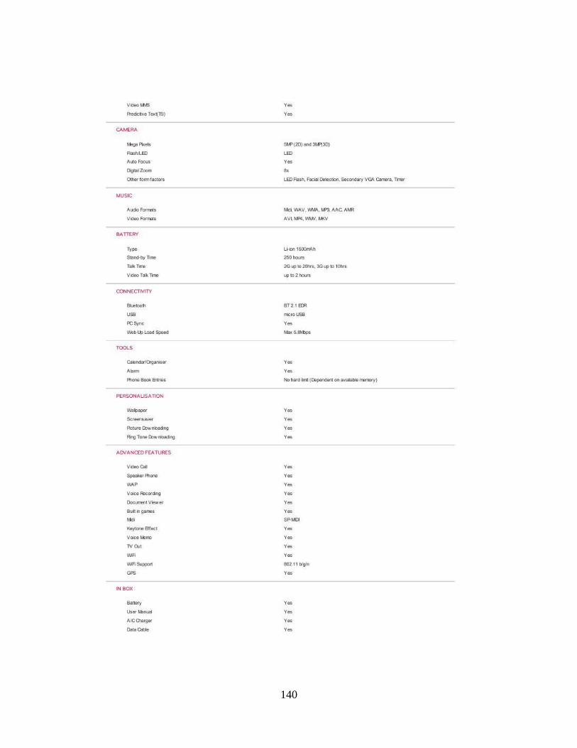
140

141
APPENDIX E
Riger DB 108-WL Wireless ADSL Modem 2/2+
142