air sampling and industrial hygiene engineering
TRANSCRIPT


Air Samplingand
Industrial HygieneEngineering
© 2001 CRC Press LLC
LEWIS PUBLISHERSBoca Raton London New York Washington, D.C.
Air Samplingand
Industrial HygieneEngineering
Martha J. Bossand
Dennis W. Day
© 2001 CRC Press LLC
This book contains information obtained from authentic and highly regarded sources. Reprinted material isquoted with permission, and sources are indicated. A wide variety of references are listed. Reasonable effortshave been made to publish reliable data and information, but the author and the publisher cannot assumeresponsibility for the validity of all materials or for the consequences of their use.
Neither this book nor any part may be reproduced or transmitted in any form or by any means, electronic ormechanical, including photocopying, microfilming, and recording, or by any information storage or retrievalsystem, without prior permission in writing from the publisher.
The consent of CRC Press LLC does not extend to copying for general distribution, for promotion, for creatingnew works, or for resale. Specific permission must be obtained in writing from CRC Press LLC for suchcopying.
Direct all inquiries to CRC Press LLC, 2000 N.W. Corporate Blvd., Boca Raton, Florida 33431, or visit ourWeb site at www.crcpress.com
Trademark Notice: Product or corporate names may be trademarks or registered trademarks, and are usedonly for identification and explanation, without intent to infringe.
© 2001 by CRC Press LLCLewis Publishers is an imprint of CRC Press LLC
No claim to original U.S. Government worksInternational Standard Book Number 1-56670-417-0
Library of Congress Card Number 00-048666Printed in the United States of America 1 2 3 4 5 6 7 8 9 0
Printed on acid-free paper
Library of Congress Cataloging-in-Publication Data
Boss, Martha J.Air sampling and industrial hygiene engineering / Martha J. Boss, Dennis W. Day.
p. cm.Includes bibliographical references and index.ISBN 1-56670-417-0 (alk. paper) 1. Air—Pollution—Measurement. 2. Industrial hygiene. 3. Air sampling apparatus. I.
Day, Dennis W. II. Title.
TD890 .B66 2000628.5′3′0287—dc21 00-048666
CIP
© 2001 CRC Press LLC
Preface
Many have endeavored to make our outdoor environment cleaner and safer. The learn-ing process that occurred showed us the limitations of our planet and also the sustainabil-ity of our ecosystem if given a chance. As a community, we learned about the water, the soil,and the air. We learned about the underground river that flowed to the surface lake. Welearned about air currents that transported airstreams around our globe. We discovered thereality of plate tectonics and the ever-changing hydrogeological system. Using this knowl-edge, we continued to learn how to clean our environment and prevent further damage.
Our science careers began with teaching and working on environmental issues. Duringthat time our concern for 1 ppm benzene at an underground storage tank (UST) locationwas intense. Then as we learned more, we began to see what had been invisible to usbefore—the air in our factories, hospitals, schools, homes, and cars. We began to realize thatenvironmental concerns and our accumulated knowledge on how to protect people andthe environment was not being translated into knowledge about buildings in which peo-ple live and work. Many people routinely work in factories where exposure to hundreds ofparts per million of benzene is commonplace.
Six years ago we received a call from a farm family in the Midwest. For three genera-tions they had farmed their land. Now their children, their farm animals, and they them-selves were sick. A chemical storage fire had burned out of control and covered their landand homes with oily soot. Yet that spring they planted their fields and tried to live theirlives as before.
As the planting season progressed, farmers sickened in the fields. Upon returning totheir homes, the sickness increased. The vehicles they used in the field became more andmore contaminated. The farmers began buying old cars and abandoning them when theycould ride in them no longer. Two combines were also abandoned. They left their homes,in some cases the original farm homesteads that had housed three generations.
Planting was over and the hogs were farrowing. The animals were born deformed; themother animals died. Eventually most of the animals sickened and were sacrificed. Thefarmers began looking for answers.
Fall approached and with that the harvest. The farmers reentered the fields and becameincreasingly sick. What to do? Should they even harvest these crops? Should their childrenbe sent away?
Winter came—was it all in their imagination? The doctors and scientists they had con-tacted were without answers. Perhaps it would be better in the spring.
Spring arrived, planting began, and the cycle continued. From somewhere, they weregiven our name. We arrived and began investigating. These farmers and their families hadnot benefited at that time from the collective knowledge available pertaining to fires andchemical dispersion. Particulates laced with chemicals can exit the periphery of a firestorm.The chemicals could remain intact or even recombine. Many chemicals can remain in oursoil and water; after plowing with combines, these chemicals reenter the airstream andbecome available once again for us to breathe and carry home on our clothing.
These farmers were carrying home the vestiges of chemicals we use as pesticides andherbicides. Chemicals that had changed in the fire became more toxic at lower levels.Chemicals were rendered more easily available by their current adsorption to airborne soilparticulates. Upon entry of these particulates into their lungs, the new chemical mix off-gassed and became biologically active. In the heartland of America, these farmers hadunwittingly participated in an experiment in chemical warfare!
v© 2001 CRC Press LLC
We decided then to write a book to open a dialogue on air monitoring, risk, and engineering—a book to show that collectively we as scientists and engineers need todevelop an interdisciplinary approach to applying our knowledge.
Before any art must come the science. Chapter 1 (Air Sampling Introduction), 2 (AirSampling Instrumentation Options), and 3 (Calibration Techniques) present the currentstate-of-the-art techniques for air sampling. Chapter 4 discusses statistical analysis and rel-evance issues.
In Chapters 5 (Chemical Risk Assessment) and 6 (Biological Risk Assessment), we dis-cuss how air sampling and other environmental sampling are used to determine risk—risks of acute effect, chronic effect, and carcinogenic effect. Biological risk always has theadded element of reproduction, as biologicals, unlike chemicals, can enlarge their numbersover time and distance from their source.
We then turn our attention to Chapter 7 (Indoor Air Quality and Environments) andChapter 8 (Area Monitoring and Contingency Planning). Once we know how to monitorpotential risk, how do we evaluate our buildings, our city air, and all the places we live andwork? What do we do in an emergency? Are there times as illustrated in Chapter 9 whenwe will need to use microcircuitry and remote monitoring? What about our workplaces asaddressed in Chapter 10 (Occupational Health—Air Monitoring Strategies)?
Finally we need to consider monitoring for toxicological risk (Chapter 11). If we findrisk is evident, what tools (Chapter 12, Risk Communication and Environmental Moni-toring) will be needed?
This book is the start of an interdisciplinary look at many issues that in fact are justone—can we live and work in places that are healthy? Do we have the knowledge andresources to ensure that our hospitals and schools have clean air? Can we now build andmaintain ventilation systems that do not foul over time?
After World War I, Martha’s grandfather returned to work in a cement plant. He washaving some trouble breathing after he inhaled mustard agent in the trenches of France. Atthe cement plant he dug into the earth at a quarry using shovels and eventually poweredequipment. The dust swirled around him and coated his clothing. Every night he wasracked with convulsive coughing. In the morning he felt better, could even smoke on theway to work. Over the next 30 years, he slowly died. No one knew then to tell him—getanother job, quit smoking, protect your damaged lungs.
Dennis’s father was a plumber. He watched pipe fitters carry buckets of gray slurry tothe work site. The slurry was applied to pipe junctures and hardened to ensure pipeintegrity. The pipe fitters used their hands and wiped the excess slurry on their clothing.They returned home, where their clothes were washed with their family’s clothes; often thelaundry room was next to the air intake for their home furnace. Over the years Dennis’sfather watched all these men die as their lungs, scarred with asbestosis, failed.
How many men and women to this day still do not know that the factories and work-places they occupy are poisoning them and often their families? Do they not know becausethe knowledge is unavailable? No. However, we have been slow to realize the need to com-municate our knowledge. The simplest concepts have been lost. You do not have to die towork. Ventilation systems can be improved. Healthier workers are more productive work-ers and happier people.
As our buildings age, and as we use ventilation systems designed to heat buildings—and to cool them—our indoor air problems have multiplied. The heat and cool cycles oftencause condensation within the air-handling systems. The fiberglass duct liners that havecaptured particulates become slightly wetted. With time molds and fungi begin their lifecycles hidden from us and amplify in number. Their spores ride the duct’s airstream to ourrooms and hallways. Maintenance personnel cannot reach the biological hiding ground.
© 2001 CRC Press LLC

Our residents begin to notice their health decline. Biological risk? Yes. In our hospitals andschools? Yes.
Our hope is that this book will be used to begin these dialogues. Engineers and scien-tists need to look holistically at building design and maintenance. Business people need torealize the financial risk associated with accepting a nice building front rather than a state-of-the-art ventilation system. We all need to begin talking and learning together, so that ourchildren can live and work without concern for the very air that they breathe.
Martha J. BossDennis W. Day
© 2001 CRC Press LLC

About the Authors
Martha Boss is a practicing industrial hygienist and safety engineer living in Omaha,NE and various airports throughout the United States. Many years ago, Martha won theArmy Science award at the Des Moines, IA science fair. As fate would have it, Martha even-tually worked for the Army and through the auspices of EPA grants was trained in indus-trial hygiene. All of this surprised Martha because she had intended to teach high schoolscience and had prepared herself for that endeavor with a B.A. in biological education(University of Northern Iowa) and later a BS in biology (University of Nebraska).
During Desert Shield that became Desert Storm, Martha was tasked under the WarPowers Act to assist in the preparation of a western Army base to house and train specialforces. Dennis was also so commissioned, and their professional association began.
Martha worked with her fellow Army industrial hygienists and engineers to assessbiological, radiological, and chemical warfare sites and find solutions. The Army contin-ued her training at such institutions as Johns Hopkins, Harvard, and other top centersthroughout the nation.
After five years of traveling throughout the country to various very scary places,Martha decided to settle down in a regional engineering firm. After a couple of years,Martha realized she did not want to settle down and joined a national engineering firmwhere she is employed to this day. Martha is a principal toxicologist for URS Corporationand continues her practice as a certified industrial hygienist and certified safety profes-sional (safety engineer). Martha is a member of the Hazardous Substances Research CenterT3 board for Region 7 of the EPA, a diplomate of the American Academy of IndustrialHygiene, serves on the editorial advisory board for Stevens Publishing, and is a member ofthe American Industrial Hygiene Association and the American Society of SafetyEngineers.
Dennis Day is a practicing industrial hygienist and safety engineer living in Omaha,NE and various airports throughout the United States. Dennis began his career as aforester. For several years, he traveled through the forests of the East and South cruisingtimber. Then he decided to become a high school science teacher. Dennis used his B.S. inforestry (University of Missouri) to enable him to pursue additional studies in chemistryand biology (Creighton University) and become a professional teacher. After teaching forawhile Dennis was persuaded to join the Army Safety Office and ultimately the OmahaDistrict engineering division.
Dennis continued for ten years to work with various Army, EPA, and Department ofDefense missions. His work included sites throughout the nation and in Europe. Dennisconcentrated his efforts on streamlining site assessment protocols, community outreachwith protective action plans for chemical warfare sites, and training industrial hygienistsentering the Army work force.
Eventually, Forrest Terrell of Dames & Moore (now URS) convinced Dennis to join thatfirm to develop an interdisciplinary industrial hygiene, safety, and engineering service tocommercial and governmental clients. Dennis is a principal toxicologist for URSCorporation and continues his practice as a certified industrial hygienist and certifiedsafety professional (safety engineer). Dennis is a diplomate of the American Academy ofIndustrial Hygiene and a member of the American Conference of Governmental IndustrialHygienists, the American Industrial Hygiene Association, and the American Society ofSafety Engineers. In 1992 Dennis received the Achievement Medal for Civilian Service forhis emergency industrial hygiene support following Hurricane Andrew.
© 2001 CRC Press LLC
Contents
1 Air Sampling Introduction1.1 Documentation1.2 Sample Documentation1.3 Competency for Sampling Technicians1.4 Sampling Activity Hazard Analysis (AHA)1.5 Security
1.5.1 Sample Containers—Laboratory1.5.2 Sample Handling and Decontamination1.5.3 Procedures for Packing and Shipping Low
Concentration Samples1.5.4 Procedures for Packing and Shipping Medium
Concentration Samples1.5.5 Chain-of-Custody Records1.5.6 Mailing—Bulk and Air Samples
1.6 Equipment Precautions1.6.1 Batteries
1.6.1.1 Alkaline Batteries1.6.1.2 Rechargeable Nickel-Cadmium (Ni-Cad) Batteries
1.7 Adverse Temperature Effects1.8 Explosive Atmospheres1.9 Atmospheres Containing Carcinogens
2 Air Sampling Instrumentation Options2.1 Volatile Organic Compounds
2.1.1 Photoionization Detector (PID)2.1.1.1 Calibration2.1.1.2 Maintenance
2.1.2 Infrared Analyzers2.1.2.1 Calibration2.1.2.2 Maintenance
2.1.3 Remote Collection2.1.4 Oxygen/Combustible Gas Indicators (O2/CGI)/Toxin Sensors
2.1.4.1 Remote Probes and Diffusion Grids2.1.4.2 Calibration Alert and Documentation2.1.4.3 Alarms2.1.4.4 Recommendations for Oxygen/Combustible Gas Indicators2.1.4.5 Relative Response2.1.4.6 Relative Response and Toxic Atmosphere Data2.1.4.7 Special Considerations2.1.4.8 Calibration2.1.4.9 Maintenance
2.1.5 Oxygen Meters2.1.6 Solid Sorbent Tubes
2.1.6.1 Calibration Procedures2.1.7 Vapor Badges
© 2001 CRC Press LLC
2.1.8 Detector Tubes2.1.8.1 Performance Data2.1.8.2 Leakage Test2.1.8.3 Calibration Test2.1.8.4 Special Considerations
2.1.9 Formaldehyde2.2 Ozone Meter
2.2.1 Calibration2.2.2 Maintenance
2.3 Toxic Gas Meters2.3.1 Calibration
2.4 Semivolatile Organic Compounds (SVOC)2.4.1 Polynuclear Aromatic Hydrocarbons2.4.2 Polychlorinated Biphenyls and Creosote2.4.3 Pesticides and PAHs—PUF
2.5 Acid Gases or Caustics2.5.1 Impingers2.5.2 Sorbent Tubes2.5.3 Detectors2.5.4 pH Litmus Paper or Meter
2.5.4.1 Calibration2.6 Mercury Analyzer—Gold Film Analyzer
2.6.1 Jerome Mercury Analyzer2.6.2 Survey Procedures2.6.3 Precautions for Area Surveys
2.6.3.1 Calibration2.6.3.2 Maintenance
2.7 Particulates—Sampled by Filtration/Impaction2.8 Gravimetric Filter Weighing Procedure2.9 Total Dust and Metal Fumes2.10 Respirable Dust
2.10.1 Cyclones2.10.1.1 Silica Respirable Dust—Cyclone Collection2.10.1.2 Cyclone Cleaning
2.11 Inhalable Dusts2.12 Personnel Environmental Monitors (PEMs)2.13 Welding Fumes2.14 Asbestos2.15 Direct-Reading Dust Monitors
2.15.1 Condensation Nuclei Counters (CNCs)2.15.1.1 Calibration2.15.1.2 Maintenance2.15.1.3 Photodetection2.15.1.4 Calibration2.15.1.5 Maintenance
2.15.2 Diesel Particulate Matter (DPM)2.16 Biologicals
2.16.1 General Sampling Protocols2.16.2 Contact and Grab Sampling2.16.3 Reuter Central Fugal System (RCS)
© 2001 CRC Press LLC
2.16.4 Exit Requirements2.16.5 Static Placement Impingement2.16.6 Bioaerosols
2.17 Radiation Monitors and Meters2.17.1 Light Meter
2.17.1.1 Calibration2.17.1.2 Maintenance
2.18 Ionizing Radiation2.18.1 Ionization Detectors
2.18.1.1 Gas Proportional Detectors2.18.1.2 Ion Chamber2.18.1.3 GM Detector
2.18.2 Scintillation Detectors2.18.3 Counting Efficiency2.18.4 Monitoring for Radioactive Contamination2.18.5 Daily Use Checks2.18.6 Survey Instrument Calibration
2.19 Nonionizing Radiation2.19.1 Guidance2.19.2 Broadband Field Strength Meters
2.19.2.1 Calibration2.19.2.2 Maintenance
3 Calibration Techniques3.1 Calibration Requirements
3.1.1 Calibration Assurance3.1.2 Decontamination3.1.3 Maintenance
3.2 Manual Buret Bubble Meter Technique (Primary Calibration)3.2.1 Bubble Meter Method
3.3 Electronic Flow Calibrators3.3.1 Cleaning before Use3.3.2 Leak Testing3.3.3 Verification of Calibration3.3.4 Shipping and Handling3.3.5 Precautions and Warnings
3.4 Electronic Bubble Meter Method3.5 Dry Flow Calibration3.6 Precision Rotameter Method (Secondary)
3.6.1 Replacing the Bubble Meter with a Precision Rotameter3.7 Span Gas3.8 Bump Testing
4 Statistical Analysis and Relevance4.1 Definitions4.2 Example—Outline of Bulk Sampling QA/QC Procedure4.3 Example—Outline of the NIOSH 7400 QA Procedure
4.3.1 Precision: Laboratory Uses a Precision of .454.3.2 Precision: Laboratory Uses a Precision SR That Is Better Than .454.3.3 Records to Be Kept in a QA/QC System
© 2001 CRC Press LLC
4.3.4 Field Monitoring Procedures—Air Sample4.3.5 Calibration4.3.6 Negative Air Pressure4.3.7 Compressor4.3.8 Recordkeeping and Sample Storage
4.4 Sampling and Analytical Errors4.4.1 Determining SAEs4.4.2 Environmental Variables4.4.3 Confidence Limits
4.5 Sampling Methods4.5.1 Full-Period, Continuous Single Sampling4.5.2 Full-Period, Consecutive Sampling4.5.3 Grab Sampling
4.6 Calculations4.6.1 Calculation Method for a Full-Period, Continuous Single Sample4.6.2 Sample Calculation for a Full-Period, Continuous Single Sample4.6.3 Calculation Method for Full-Period Consecutive Sampling4.6.4 Sample Calculation for Full-Period Consecutive Sampling
4.7 Grab Sampling4.8 SAEs—Exposure to Chemical Mixtures
5 Chemical Risk Assessment5.1 Baseline Risk Assessment5.2 Conceptual Site Model
5.2.1 Source Areas5.2.2 Possible Receptors
5.3 Chemicals of Potential Concern5.4 Human Health BLRA Criteria5.5 Toxicity Assessment5.6 Toxicological Profiles5.7 Uncertainties Related to Toxicity Information5.8 Potentially Exposed Populations
5.8.1 Exposure Pathways5.8.2 Sources
5.9 Environmental Fate and Transport of COPCs5.10 Exposure Points and Exposure Routes5.11 Complete Exposure Pathways Evaluated5.12 Ecological Risk Assessment5.13 Data Evaluation and Data Gaps5.14 Uncertainties
5.14.1 Uncertainties Related to Toxicity Information5.14.2 Uncertainties in the Exposure Assessment
5.15 Risk Characterization5.16 Headspace Monitoring—Volatiles5.17 O2/CGI5.18 Industrial Monitoring—Process Safety Management5.19 Bulk Samples
6 Biological Risk Assessment6.1 Fungi, Molds, and Risk
6.1.1 What Is the Difference between Molds, Fungi, and Yeasts?
© 2001 CRC Press LLC

6.1.2 How Would I Become Exposed to Fungi That Would Create a Health Effect?6.1.3 What Types of Molds Are Commonly Found Indoors?6.1.4 Are Mold Counts Helpful?6.1.5 What Can Happen with Mold-Caused Health Disorders?
6.2 Biological Agents and Fungi Types6.2.1 Alternaria6.2.2 Aureobasidium6.2.3 Cladosporium6.2.4 Rhodotorula6.2.5 Stemphylium6.2.6 Sterile Fungi6.2.7 Yeast
6.3 Aspergillus6.3.1 What Color Are These Molds?6.3.2 How Is Aspergillus Spread?6.3.3 How Does Aspergillus Grow/Amplify?6.3.4 What Conditions Help Aspergillus Grow/Amplify?6.3.5 Can Mold/Fungi Make You Sick?6.3.6 What Are the Symptoms of Aspergillosis?6.3.7 Does Aspergillus Cause Deterioration of Materials?6.3.8 What Happens If Aspergillus Colonies Grow inside
Construction Layers?6.3.9 How Is Aspergillus Identified?6.3.10 How Are Levels of Aspergillus Communicated?6.3.11 Why Do Aspergillus Colonies Look Black?6.3.12 What Will Biotesting of the Air Show?6.3.13 What Can Be Done to Prevent Aspergillus Growth?
6.4 Penicillium6.4.1 What Do Samples Look Like?6.4.2 What Species of Penicillium Are Used to Produce Antibiotics?6.4.3 What Other Fungi Grow Where Penicillium Grows?6.4.4 If Penicillium Grows Everywhere, What Is the Concern?6.4.5 How Does Penicillium Enter the Body?6.4.6 Are There Particular Species of Penicillium about Which I
Should Be Concerned?6.5 Fungi and Disease
6.5.1 Blastomyces dermatitidis6.5.2 Coccidioides immitis6.5.3 Histoplasma capsulatum6.5.4 Sporothrix schenckii6.5.5 Pathogenic Members of the Genera Epidermophyton,
Microsporum, and Trichophyton6.5.6 Miscellaneous Molds6.5.7 Fusarium
6.6 Fungi Control6.6.1 Ubiquitous Fungi6.6.2 Infection6.6.3 Immediate Worker Protection6.6.4 Decontamination6.6.5 Fungi and VOCs
© 2001 CRC Press LLC
6.6.6 Controlling Fungi6.7 Abatement
7 Indoor Air Quality and Environments7.1 Ventilation Design Guide7.2 Example Design Conditions Guidance
7.2.1 Outside Design Conditions7.2.2 Inside Design Conditions
7.3 Mechanical Room Layout Requirements7.4 Electrical Equipment/Panel Coordination7.5 General Piping Requirements7.6 Roof-Mounted Equipment7.7 Vibration Isolation/Equipment Pads7.8 Instrumentation7.9 Redundancy7.10 Exterior Heat Distribution System
7.10.1 Determination of Existing Heat Distribution Systems7.10.2 Selection of Heat Distribution Systems
7.10.2.1 AG Systems7.10.2.2 CST Systems7.10.2.3 Buried Conduit (preapproved type)7.10.2.4 Buried Conduit (not preapproved type)
7.10.3 Design of Heat Distribution Systems7.10.4 Existing System Capacity7.10.5 General Design Considerations
Identification7.11 Thermal Insulation of Mechanical Systems7.12 Plumbing System
7.12.1 Piping Run7.12.1.1 Back-Siphonage
7.13 Compressed Air System7.13.1 Compressor Selection and Analysis7.13.2 Compressor Capacity7.13.3 Compressor Location and Foundations7.13.4 Makeup Air7.13.5 Compressed Air Outlets7.13.6 Refrigerated Dryer
7.14 Air Supply and Distribution System7.14.1 Basic Design Principles7.14.2 Temperature Settings7.14.3 Air-Conditioning Loads7.14.4 Infiltration7.14.5 Outdoor Air Intakes7.14.6 Filtration7.14.7 Economizer Cycle
7.15 Ductwork Design7.15.1 Variable Air Volume (VAV) Systems7.15.2 Special Criteria for Humid Areas7.15.3 Evaporative Cooling
© 2001 CRC Press LLC
7.16 Ventilation and Exhaust Systems7.16.1 Supply and Exhaust Fans7.16.2 General Items
7.17 Testing, Adjusting, and Balancing of HVAC Systems7.18 Ventilation Adequacy7.19 Laboratory Fume Hood Performance Criteria7.20 Flow Hoods
7.20.1 Calibration7.20.2 Maintenance
7.21 Thermoanemometers7.21.1 Calibration7.21.2 Maintenance
7.22 Other Velometers
8 Area Monitoring and Contingency Planning8.1 Area of Influence Perimeter
8.1.1 Evaluation of Hazardous Waste/Chemical Risk Sites8.1.2 Off-Site Characterization before Site Entry
8.1.2.1 Interview/Records Research8.1.3 On-Site Survey
8.1.3.1 Potential IDLH Conditions8.1.3.2 Perimeter Reconnaissance8.1.3.3 On-Site Survey
8.1.4 Chemical Hazard Monitoring8.1.4.1 Skin and Dermal Hazards8.1.4.2 Potential Eye Irritation8.1.4.3 Explosion and Flammability Ranges
8.1.5 Monitoring8.1.6 Field Logbook Entries8.1.7 Radiation Monitoring
8.1.7.1 Area Monitoring8.1.7.2 Contamination Surveys8.1.7.3 Exposure Rate Surveys8.1.7.4 Personnel Monitoring
8.2 Evacuation Zones8.2.1 Emergency Equipment Locations8.2.2 Site Security and Control8.2.3 Incident/Accident Report
8.3 Site Work Zone8.3.1 Integrated Sampling Example8.3.2 Field QA and QC Example8.3.3 Invasive Work Sampling Example8.3.4 Sampling and Initial Site Work Hazard Analysis Example
8.3.4.1 Perimeter Monitoring8.3.4.2 Air Sampling and Monitoring Example8.3.4.3 Water Sampling Example8.3.4.4 Surface Soil/Sediment Sampling Example
8.4 Radiation Sites8.4.1 Atomic Structure
© 2001 CRC Press LLC
8.4.2 Radioactive Decay8.4.3 Activity8.4.4 Decay Law8.4.5 Half-Life8.4.6 Types of Ionizing Radiation
8.4.6.1 Alpha Particles8.4.6.2 Beta Particles8.4.6.3 Gamma Rays8.4.6.4 X-rays
8.4.7 Rules of Thumb8.4.8 Excitation/Ionization8.4.9 Characteristics of Different Types of Ionizing Radiation8.4.10 Exposure (roentgen)8.4.11 Absorbed Dose (rad)8.4.12 Dose Equivalent (rem)8.4.13 Effective Dose Equivalent8.4.14 Biological Effects of Ionizing Radiation
8.4.14.1 Radiosensitivity8.4.15 Human Health Effects
8.4.15.1 Stochastic Effects8.4.15.2 Nonstochastic Effects
8.4.16 Determinants of Dose8.4.16.1 External Exposures8.4.16.2 Internal Exposures
8.4.17 Sources of Exposure8.4.17.1 Occupational Exposure8.4.17.2 Nonoccupational Exposure
8.4.18 Exposure Limits8.4.19 Basis of Recent Guidelines8.4.20 Regulatory Limits for Occupational Exposure8.4.21 Recommended Exposure Limits for Pregnant Workers8.4.22 Radiation Risk8.4.23 Philosophy of Current Radiation Safety Practice
8.4.23.1 Internal Radiation Protection8.4.23.2 Protection against Ingestion8.4.23.3 Protection against Inhalation8.4.23.4 Protection against Absorption
8.4.24 External Radiation Protection8.4.25 Minimizing Exposure Time8.4.26 Maximizing Distance from Source8.4.27 Shielding the Source8.4.28 Emergency Procedures
8.4.28.1 Personal Contamination8.4.28.2 Minor Spills (Microcurie Quantities of Most Nuclides)8.4.28.3 For Major Spills (Millicurie Quantities of Most
Nuclides)
9 Microcircuitry and Remote Monitoring9.1 Continuous IAQ Monitoring in Buildings
9.1.1 IAQ Evaluations9.1.1.1 Characterization for IAQ Assessment
© 2001 CRC Press LLC
9.1.1.2 Source Assessment and Remediation9.1.1.3 IAQ Risk Assessment
9.2 Industrial/Remediation Process Monitoring9.2.1 Process Safety Management Example Scope of Work9.2.2 Provide List for Hazard and Operability Study9.2.3 Process Hazard Analysis
9.2.3.1 Hazard and Operability Study9.2.3.2 Failure Modes and Effects Analysis (FMEA)9.2.3.3 Fault Tree Analysis
9.2.4 Design Analysis9.2.4.1 Site Safety and Health Plans9.2.4.2 Health and Safety Design Analysis (HSDA)9.2.4.3 Drawings9.2.4.4 Specifications9.2.4.5 Design Analysis Example—Wastewater Treatment
10 Occupational Health—Air Monitoring Strategies10.1 Exposure Measurements10.2 STEL Sampling10.3 Exposure Fluctuations10.4 Air-Sampling Pump User Operation
10.4.1 Pump Donning10.4.2 Pump Checking10.4.3 Pump Doffing
10.5 Air Sampling—Asbestos10.5.1 Sampling Prior to Asbestos Work10.5.2 Sampling during Asbestos Abatement Work10.5.3 Sampling after Final Cleanup (Clearance Sampling)10.5.4 NIOSH Method10.5.5 Air Sampling Documentation10.5.6 Asbestos Exposure Monitoring (29 CFR 1910.1001 and
29 CFR 1926.1101)10.5.7 Initial Monitoring10.5.8 Historical Documentation for Initial Monitoring10.5.9 Objective Data for Initial Monitoring
10.6 Crystalline Silica Samples Analyzed by X-Ray Diffraction (XRD)10.6.1 Air Samples
10.6.1.1 Laboratory Results for Air Samples10.6.2 Bulk Samples10.6.3 Sample Calculations for Crystalline Silica Exposures10.6.4 Sample Calculation for Silica Exposure
10.7 Metals—Welding10.8 General Technique for Wipe Sampling
10.8.1 Filter Media and Solvents10.8.2 Wipe Sampling Procedures10.8.3 Special Technique for Wipe Sampling with Acids and Bases10.8.4 Direct-Reading Instruments10.8.5 Aromatic Amines10.8.6 Special Considerations
10.8.6.1 Fluorescent Screening for Carcinogenic Aromatic Amines10.8.6.2 Alternate Screening Methods for Aromatic Amines
© 2001 CRC Press LLC
11 Monitoring for Toxicological Risk11.1 Types of Sampling
11.1.1 Long-Term Samples11.1.2 Short-Term Samples11.1.3 Area Samples11.1.4 Wipe Samples
11.2 Quality Control11.3 Exposure Evaluation Criteria11.4 Examples of Chemicals That Require Monitoring
11.4.1 Carbon Monoxide (CO)11.4.2 Hydrogen Sulfide (H2S)11.4.3 Sulfur Dioxide (SO2)11.4.4 Ammonia (NH3)11.4.5 Benzene11.4.6 Hydrogen Cyanide or Hydrocyanic Acid (HCN)11.4.7 Lead11.4.8 Flammable Chemicals11.4.9 Reactive Hazards—Oxidizers11.4.10 Paint11.4.11 Cleaning Supplies11.4.12 Compressed Gases
11.5 Confined Space Monitoring11.5.1 Entry Permits11.5.2 Bump Testing11.5.3 Monitoring for LEL and O2 Levels11.5.4 Isolation11.5.5 Confined Space—Cautionary Statements11.5.6 Stratified Atmospheres
11.6 Welding11.6.1 Effects of Toxic Gases11.6.2 Ventilation11.6.3 Ventilation in Confined Spaces during Welding11.6.4 Fume Avoidance11.6.5 Light Rays11.6.6 Infrared Rays11.6.7 Noise11.6.8 Gas Welding and Cutting
12 Risk Communication and Environmental Monitoring12.1 Federal Legislation
12.1.1 The Clean Air Act Amendments of 1990 (CAAA90)12.1.2 The Federal Water Pollution Control Act.12.1.3 Resource Conservation and Recovery Act (RCRA) of 197612.1.4 State/Local Regulations
12.2 Key Compliance Requirements12.2.1 Steam-Generating Units [greater than 29 MW (100 MBtu/h)]12.2.2 Steam-Generating Units [2.9 MW (10 MBtu/h) to 29 MW]12.2.3 Fuel-Burning Facilities12.2.4 Stationary Gas Turbines12.2.5 Municipal Waste Combustor
© 2001 CRC Press LLC
12.2.6 Incinerators12.2.6.1 Sewage Sludge Incinerators12.2.6.2 Beryllium Incinerators12.2.6.3 Incineration of Sewage Sludge
12.2.7 Gasoline Dispensing12.2.8 Rotogravure Printing Presses12.2.9 Fugitive Emissions12.2.10 Sulfuric and Nitric Acid Plants12.2.11 CFCs and Halons12.2.12 Degreasing Operations
12.3 Key Compliance Definitions12.4 Community Relations
12.4.1 Notification12.4.2 Fact Sheets12.4.3 Explaining Air Monitoring to the General Public12.4.4 Employee Education12.4.5 Public Accessibility12.4.6 Repository12.4.7 Dialogue
Glossary of Terms
© 2001 CRC Press LLC
CHAPTER 1
Air Sampling Introduction
This chapter provides an overview of air sampling and site monitoring that is legally defensible.It answers questions about monitoring protocols that must be initiated for emergency and contin-gency situations.
1.1 DOCUMENTATION
Essentially in any sampling endeavor, without documentation, you have what is called“personal opinion.’’ The intent of documentation is to provide the basis for professionalopinion. The documentation then becomes a dialogue of historical perspective and theempirical sampling event.
When assembling historical documentation, make sure that you define how the infor-mation is used. Often in order to understand sampling results, the environment, includingwork practices, must be analyzed. Work practices include human factors; therefore, you mustbe very careful to present a dialogue of these work practices that is not individually invasive.
When you decide on documentation techniques, before you write the first chronicle,enter field notes, or take that first picture, make sure that everyone understands what thepurpose of the information is and who will have access to this information.
Be very careful when the original scope of work calls for only general information.Often as the investigation continues, you may be asked to provide very specific reasons forgeneral information development. Consequently, even for general information screeningor limited audits, you may need to keep very specific information available to substantiateyour opinions.
Whenever a review of human factors is required, especially interviews, all parties mustunderstand the limitations on personal anecdotal information. If you do not intend to per-sonally name the interviewee, make sure all parties understand.
The overriding message here is define your scope of work and write this definition forall to see. If you need to work under the auspice of attorney/client privilege or through anyother set boundaries, make sure the scope of work reflects these facts.
1.2 SAMPLE DOCUMENTATION
To assist in determining appropriate engineering controls, take photographs (as appro-priate) and detailed notes concerning the following:
© 2001 CRC Press LLC
• Visible airborne contaminants• Work practices• Potential interferences• Movements• Other conditions
Prepare blanks during the sample period for each type of sample collected. One blank willsuffice for up to 20 samples for any given analysis. These blanks may include opened, butunused, charcoal tubes.
1.3 COMPETENCY FOR SAMPLING TECHNICIANS
When deciding who is defined as a competent sampling technician, the first criterionis as follows: Is the scope of work completely defined according to sampling requirements?If you have any doubts about the situation with which samplers are involved, whetherthose doubts stem from a lack of background knowledge of the site or unknown hazards,the sampling scope is not completely defined.
For undefined sampling scopes, a senior sampling professional will need to initiate thesite work. If the sampling choices once in the field are multifactorial, in that circumstanceson-site are very dynamic, a team of senior sampling professionals is required.
Remember that a phenomenon known as perceptual shift will occur during sampling.As we become more or less secure with our environment, we start to see things differently.A strong team is able to keep its members on target, thus providing a more complete pic-ture of the sampling environment.
Once a scope of work is defined, sampling can often be delegated to less senior per-sonnel. The purpose of this text is to provide information to assist in the standardization ofboth the initial and the delegated work effort. Despite the many ways of communicatingbefore the sampling event, dialogue must be continued throughout the sampling event.Unfortunately this dialogue may not be free-flowing conversation without limitations. Theoriginal team that defined the scope of work must be available to the on-site personnel. Theactual conversations on-site, while delimited by many events, must give way to free-flowing discussions within this team so that the collected data are useful and relevant.
1.4 SAMPLING ACTIVITY HAZARD ANALYSIS
To analyze the activities involved in sampling, an Activity Hazard Analysis (AHA)may be required. An example AHA is given in Table 1.1.
1.5 SECURITY
Whenever confidential or security issue data are collected, this information must besecured. One of the most difficult issues when on-site is just what to write down or recordon media. Too much information is as bad as too little information.
For the junior sampling technician, raw data should not be interpreted in the fieldwithout consultation with the scope development team. Usually this consultation will pro-duce advice to the sampling technician; do not record that advice other than through a ver-bal discussion with senior staff.
© 2001 CRC Press LLC
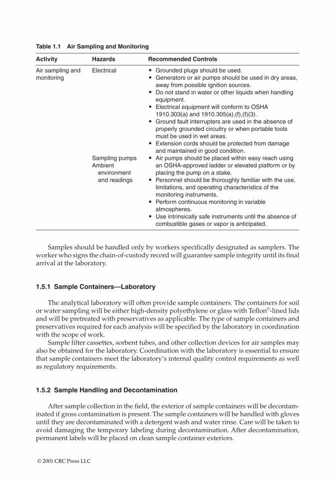
Table 1.1 Air Sampling and Monitoring
Activity Hazards Recommended Controls
Air sampling and Electrical • Grounded plugs should be used.monitoring • Generators or air pumps should be used in dry areas,
away from possible ignition sources.• Do not stand in water or other liquids when handling
equipment.• Electrical equipment will conform to OSHA
1910.303(a) and 1910.305(a),(f),(f)(3).• Ground fault interrupters are used in the absence of
properly grounded circuitry or when portable toolsmust be used in wet areas.
• Extension cords should be protected from damageand maintained in good condition.
Sampling pumps • Air pumps should be placed within easy reach using Ambient an OSHA-approved ladder or elevated platform or by
environment placing the pump on a stake.and readings • Personnel should be thoroughly familiar with the use,
limitations, and operating characteristics of themonitoring instruments.
• Perform continuous monitoring in variableatmospheres.
• Use intrinsically safe instruments until the absence of combustible gases or vapor is anticipated.
Samples should be handled only by workers specifically designated as samplers. Theworker who signs the chain-of-custody record will guarantee sample integrity until its finalarrival at the laboratory.
1.5.1 Sample Containers—Laboratory
The analytical laboratory will often provide sample containers. The containers for soilor water sampling will be either high-density polyethylene or glass with Teflon®-lined lidsand will be pretreated with preservatives as applicable. The type of sample containers andpreservatives required for each analysis will be specified by the laboratory in coordinationwith the scope of work.
Sample filter cassettes, sorbent tubes, and other collection devices for air samples mayalso be obtained for the laboratory. Coordination with the laboratory is essential to ensurethat sample containers meet the laboratory’s internal quality control requirements as wellas regulatory requirements.
1.5.2 Sample Handling and Decontamination
After sample collection in the field, the exterior of sample containers will be decontam-inated if gross contamination is present. The sample containers will be handled with glovesuntil they are decontaminated with a detergent wash and water rinse. Care will be taken toavoid damaging the temporary labeling during decontamination. After decontamination,permanent labels will be placed on clean sample container exteriors.
© 2001 CRC Press LLC
The sample containers will be well cushioned with packing materials and packaged asdescribed below for transportation to the laboratory. Care will be taken to seal bottle capstightly. The samples will be shipped to the laboratory under chain-of-custody protocols.
Asbestos samples should never be sent with packing peanuts because the static chargegenerated during shipping will alter the pattern of fiber deposition on the cassette filters.Volatile samples must be sent in cooling chests to maintain a 4°C atmosphere during ship-ment. Semivolatiles should also be sent in cooling chests.
1.5.3 Procedures for Packing and Shipping Low Concentration Samples
Samples will be packaged as follows:
• Use waterproof metal (or equivalent strength plastic) ice chests or coolers only.• After determining the specific samples to be submitted and filling out the perti-
nent information on the sample label and tag, put the label on the bottle or vialprior to packing.
• Secure the lid with strapping tape (tape on volatile organic compound [VOC]vials may cause contamination).
• Mark volume level on bottle with grease pencil.• Place about 3 in. of inert cushioning material, such as vermiculite, in the bottom
of the cooler.• Enclose the bottles in clear plastic bags through which sample tags and labels are
visible and seal the bags. Pack bottles upright in the cooler and isolate them insuch a way that they do not touch and will not touch during shipment.
• Place bubble wrap and/or packing material around and among the sample bot-tles to partially cover them (no more than halfway).
• Add sufficient ice (double bagged) between and on top of the samples to cool themand keep them at approximately 4°C until received by the analytical laboratory.
• Fill cooler with cushioning material.• Put paperwork (chain-of-custody record) in a waterproof plastic bag and tape it
with duct tape to the inside.• Tape the drain of the cooler shut with duct tape.• Secure the lid by wrapping the cooler completely with strapping, duct, or clear
shipping tape at a minimum of two locations. Do not cover any labels.• Attach completed shipping label to the top of the cooler.• Label “This Side Up’’ on the top of the cooler, “Up’’ with arrow denoting direc-
tion on all four sides, and “Fragile’’ on at least two sides.• Affix numbered and signed custody seals on front right and back left of cooler.
Cover seals with wide, clear tape.
1.5.4 Procedures for Packing and Shipping Medium Concentration Samples
An effort will be made to identify samples suspected of having elevated contaminantconcentrations based on field observations and screening tests. These samples will be seg-regated and packed in a separate container to the extent allowed by prevailing field con-ditions. Lids for these samples will be sealed to the containers with tape. Medium
© 2001 CRC Press LLC
concentration samples will be packed in the same manner as described for low concentra-tion samples.
1.5.5 Chain-of-Custody Records
Chain-of-custody protocols will be established to provide documentation that sampleswere handled by authorized individuals as a means to maintain sample integrity. Thechain-of-custody record will contain the following information:
• Sample identification number• Date, time, and depth of sample collection• Sample type (e.g., sludge)• Type and number of container• Requested analyses• Field notes and laboratory notes• Project name and location• Name of collector• Laboratory name and contact person• Signature of person relinquishing or receiving samples
Chain-of-custody records will be maintained for each laboratory sample. At the end ofeach day on which samples are collected, and prior to the transfer of the samples off-site,chain-of-custody documentation will be completed for each sample. Information on thechain-of-custody record will be verified to ensure that the information is consistent withthe information on the container labels and in the field logbook.
Upon receipt of the sample cooler at the laboratory, the laboratory custodian will breakthe shipping container seal, inspect the condition of the samples, and sign the chain-of-custody record to document receipt of the sample containers. Information on the chain-of-custody record will be verified to ensure that the information is consistent with the information on the container labels. If the sample containers appear to have been openedor tampered with, this discrepancy should be noted by the person receiving the samplesunder the section entitled “Remarks.’’ The completed chain-of-custody records will beincluded with the analytical report prepared by the laboratory.
1.5.6 Mailing—Bulk and Air Samples
Mail bulk samples and air samples separately to avoid cross-contamination:
• Pack the samples securely to avoid any rattle or shock damage. Do not useexpanded polystyrene packaging.
• Use bubble sheeting as packing.• Put identifying paperwork in every package.• Do not send samples in plastic bags or envelopes.• Do not use polystyrene packing peanuts.• Print legibly on all forms.
For exceptional sampling conditions or high flow rates, contact a Certified IndustrialHygienist (CIH) or the chosen analytical laboratory (approved by the American IndustrialHygiene Association [AIHA]).
© 2001 CRC Press LLC
1.6 EQUIPMENT PRECAUTIONS
1.6.1 BATTERIES
1.6.1.1 Alkaline Batteries
Replace frequently (once a month) and carry fresh replacements.
1.6.1.2 Rechargeable Nickel-Cadmium (Ni-Cad) Batteries
Check the batteries under load (e.g., turn pump on and check voltage at charging jack)before use. See the manufacturer’s instructions for locations to check voltage. Use 1.3 to 1.4 Vper Ni-Cad cell for an estimate of the fully charged voltage of a rechargeable battery pack.
It is undesirable to discharge a multicell Ni-Cad battery pack to voltage levels that are70% or less of its rated voltage; this procedure will drive a reverse current through some ofthe cells and can permanently damage them. When the voltage of the battery pack dropsto 70% of its rated value; it is considered depleted and should be recharged.
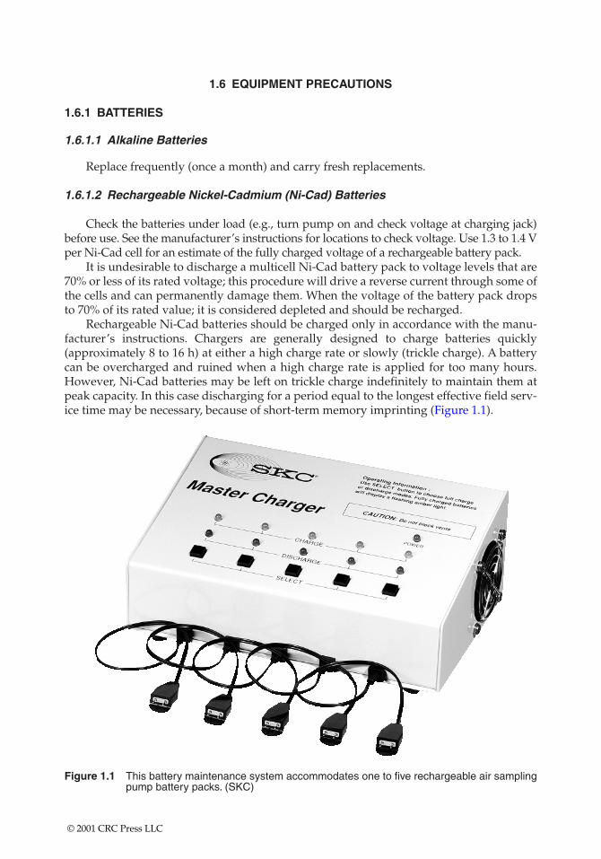
Rechargeable Ni-Cad batteries should be charged only in accordance with the manu-facturer’s instructions. Chargers are generally designed to charge batteries quickly(approximately 8 to 16 h) at either a high charge rate or slowly (trickle charge). A batterycan be overcharged and ruined when a high charge rate is applied for too many hours.However, Ni-Cad batteries may be left on trickle charge indefinitely to maintain them atpeak capacity. In this case discharging for a period equal to the longest effective field serv-ice time may be necessary, because of short-term memory imprinting (Figure 1.1).
Figure 1.1 This battery maintenance system accommodates one to five rechargeable air samplingpump battery packs. (SKC)
© 2001 CRC Press LLC
1.7 ADVERSE TEMPERATURE EFFECTS
High ambient temperature, above 100°F and/or radiant heat (e.g., from nearby moltenmetal) can cause flow faults in air sampling pumps. If these conditions are likely, use thepump with a higher operating temperature range (e.g., Dupont Alpha-1) as opposed to apump with a lower operating temperature range (e.g., SKC).
1.8 EXPLOSIVE ATMOSPHERES
Instruments must not be used in atmospheres where the potential for explosion exists(29 CFR 1910.307). Instruments must be intrinsically safe and certified by the
• Mine Safety and Health Administration (MSHA)• Underwriter’s Laboratory (UL)• Factory Mutual (FM)• Other testing laboratories recognized by the Occupational Safety and Health
Administration (OSHA)
When batteries are being replaced, use only the type of battery specified on the safetyapproval label.
Do not assume that an instrument is intrinsically safe. If you are uncertain, verify itssafety by contacting the instrument’s manufacturer.
1.9 ATMOSPHERES CONTAINING CARCINOGENS
A plastic bag should be used to cover equipment when carcinogens are present.Decontamination procedures for special environments should be followed after usingequipment in carcinogenic environments.
© 2001 CRC Press LLC
CHAPTER 2
Air Sampling Instrumentation Options
This chapter details and discusses the options available for monitoring various contaminants.It includes information for contaminant mixes, thermal enthalpy, interferences, and basis calibra-tion. It also provides cross-section diagrams to illustrate the internal function of various detectorand sensor elements.
2.1 VOLATILE ORGANIC COMPOUNDS
Sampling for volatile organics essentially means sampling for carbon-containing com-pounds that can get into the air. The term volatile usually means that the chemical gets intothe air through a change of phase from liquid to gas. This phase change occurs when tem-peratures approach, equal, and exceed the boiling point and continue until equilibrium isestablished in the environment.
For a chemical with a boiling point over 100°F, we would not expect to find that chem-ical volatilizing at room temperatures. A chemical with a boiling point of 75°F, on the otherhand, would be expected to readily volatilize into the environment.
Unfortunately, like so many rules, this one is not always true. Volatilization can implythat the chemical is being transported in the airstream by mechanical means that exposessurface area. An example of this anomaly is mercury, which has a boiling point of 674°F.Mercury as a liquid can be dispersed into the airstream as tiny droplets. The phase changeoccurs around each of these droplets as an equilibrium is established between the mercuryliquid and the mercury in the immediate area gas phase. Thus mercury vapor is dispersedinto the atmosphere by an equilibrium volatilization phenomenon that is more dependenton mechanical dispersion than on temperature differentials.
2.1.1 Photoionization Detector (PID)
Some volatile chemicals can be ionized using light energy. Ionization is based on thecreation of electrically charged atoms or molecules and the flow of these positively chargedparticles toward an electrode. Photoionization (Figure 2.1) is accomplished by applying theenergy from an ultraviolet (UV) lamp to a molecule to promote this ionization. A PID is aninstrument that measures the total concentration of various organic vapors the in the air.
Molecules are given an ionization potential (IP) number based on the energy needed tomolecularly rip them apart as ions. Chemicals normally found in the solid and liquid state
© 2001 CRC Press LLC
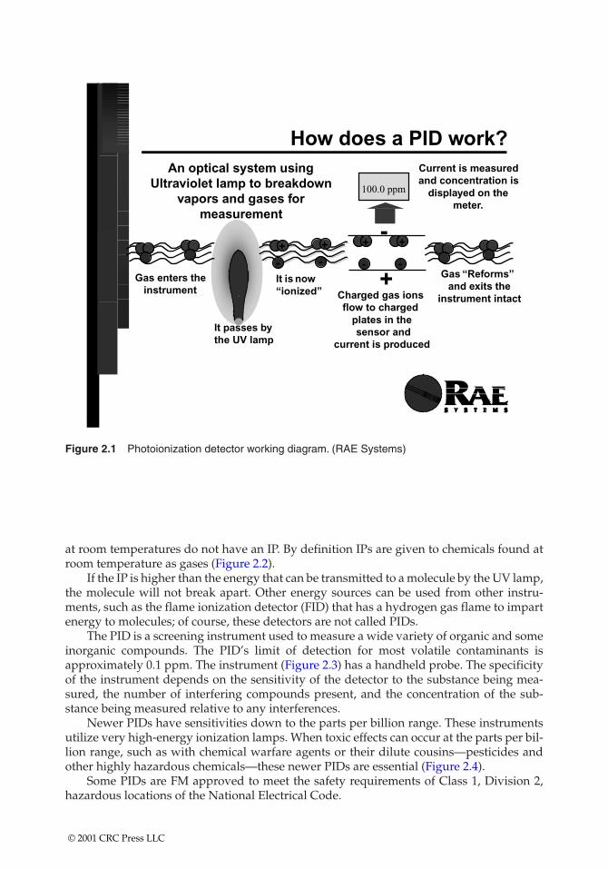
at room temperatures do not have an IP. By definition IPs are given to chemicals found atroom temperature as gases (Figure 2.2).
If the IP is higher than the energy that can be transmitted to a molecule by the UV lamp,the molecule will not break apart. Other energy sources can be used from other instru-ments, such as the flame ionization detector (FID) that has a hydrogen gas flame to impartenergy to molecules; of course, these detectors are not called PIDs.
The PID is a screening instrument used to measure a wide variety of organic and someinorganic compounds. The PID’s limit of detection for most volatile contaminants isapproximately 0.1 ppm. The instrument (Figure 2.3) has a handheld probe. The specificityof the instrument depends on the sensitivity of the detector to the substance being mea-sured, the number of interfering compounds present, and the concentration of the sub-stance being measured relative to any interferences.
Newer PIDs have sensitivities down to the parts per billion range. These instrumentsutilize very high-energy ionization lamps. When toxic effects can occur at the parts per bil-lion range, such as with chemical warfare agents or their dilute cousins—pesticides andother highly hazardous chemicals—these newer PIDs are essential (Figure 2.4).
Some PIDs are FM approved to meet the safety requirements of Class 1, Division 2,hazardous locations of the National Electrical Code.
Figure 2.1 Photoionization detector working diagram. (RAE Systems)
© 2001 CRC Press LLC
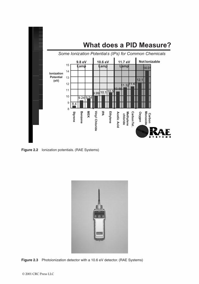
Figure 2.3 Photoionization detector with a 10.6 eV detector. (RAE Systems)
Figure 2.2 Ionization potentials. (RAE Systems)
© 2001 CRC Press LLC
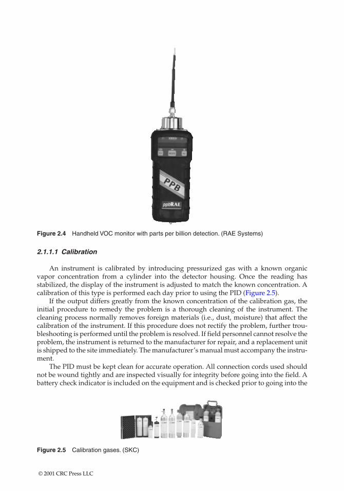
Figure 2.4 Handheld VOC monitor with parts per billion detection. (RAE Systems)
2.1.1.1 Calibration
An instrument is calibrated by introducing pressurized gas with a known organicvapor concentration from a cylinder into the detector housing. Once the reading hasstabilized, the display of the instrument is adjusted to match the known concentration. Acalibration of this type is performed each day prior to using the PID (Figure 2.5).
If the output differs greatly from the known concentration of the calibration gas, theinitial procedure to remedy the problem is a thorough cleaning of the instrument. Thecleaning process normally removes foreign materials (i.e., dust, moisture) that affect thecalibration of the instrument. If this procedure does not rectify the problem, further trou-bleshooting is performed until the problem is resolved. If field personnel cannot resolve theproblem, the instrument is returned to the manufacturer for repair, and a replacement unitis shipped to the site immediately. The manufacturer’s manual must accompany the instru-ment.
The PID must be kept clean for accurate operation. All connection cords used shouldnot be wound tightly and are inspected visually for integrity before going into the field. Abattery check indicator is included on the equipment and is checked prior to going into the
Figure 2.5 Calibration gases. (SKC)
© 2001 CRC Press LLC
field and prior to use. The batteries are fully charged each night. The PID should be packedsecurely and handled carefully to minimize the risk of damage.
A rapid procedure for calibration involves bringing the probe close to the calibrationgas and checking the instrument reading. For precise analyses it is necessary to calibratethe instrument with the specific compound of interest. The calibration gas should be pre-pared in air.
2.1.1.2 Maintenance
Keeping an instrument in top operating shape means charging the battery, cleaning theUV lamp window and light source, and replacing the dust filter. The exterior of the instru-ment can be wiped clean with a damp cloth and mild detergent if necessary. Keep the clothaway from the sample inlet, however, and do not attempt to clean the instrument while itis connected to an electrical power source.
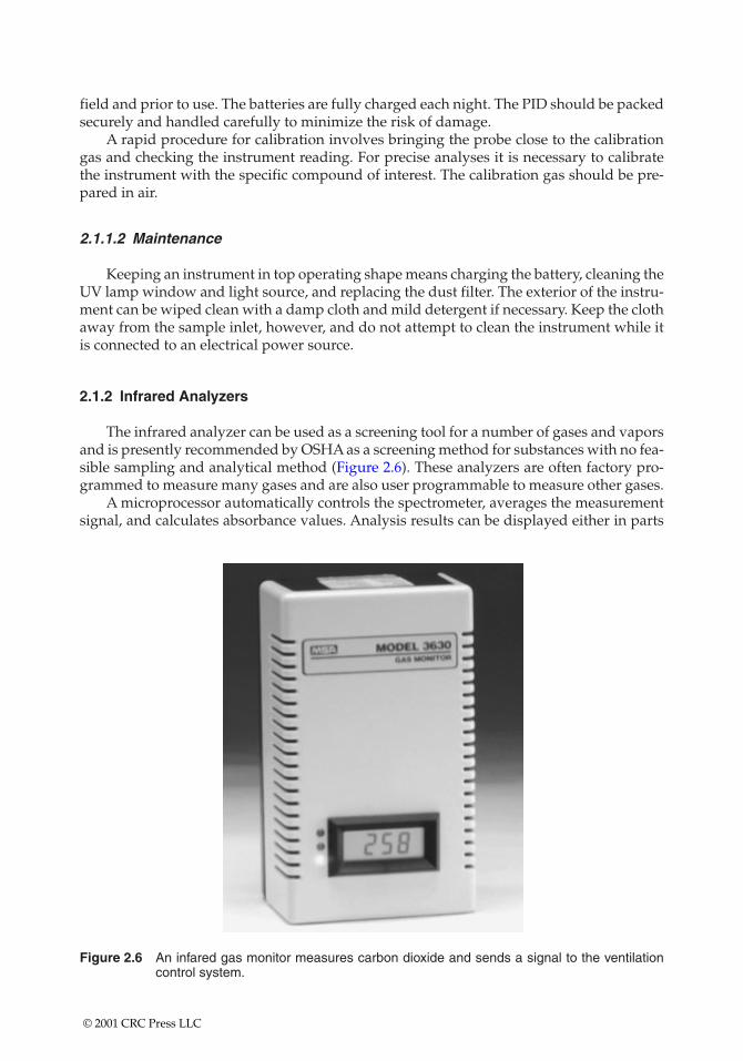
2.1.2 Infrared Analyzers
The infrared analyzer can be used as a screening tool for a number of gases and vaporsand is presently recommended by OSHA as a screening method for substances with no fea-sible sampling and analytical method (Figure 2.6). These analyzers are often factory pro-grammed to measure many gases and are also user programmable to measure other gases.
A microprocessor automatically controls the spectrometer, averages the measurementsignal, and calculates absorbance values. Analysis results can be displayed either in parts
Figure 2.6 An infared gas monitor measures carbon dioxide and sends a signal to the ventilationcontrol system.
© 2001 CRC Press LLC
per million or absorbance units (AU). The variable path-length gas cell gives the analyzerthe capability of measuring concentration levels from below 1 ppm up to percent levels.
Some typical screening applications are as follows:
• Carbon monoxide and carbon dioxide, especially useful for indoor air assessments• Anesthetic gases, e.g., nitrous oxide, halothane, enflurane, penthrane, and iso-
flurane• Ethylene oxide• Fumigants, e.g., ethylene dibromide, chloropicrin, and methyl bromide
The infrared analyzer may be only semispecific for sampling some gases and vaporsbecause of interference from other chemicals with similar absorption wavelengths.
2.1.2.1 Calibration
The analyzer and any strip-chart recorder should be calibrated before and after eachuse in accordance with the manufacturer’s instructions.
2.1.2.2 Maintenance
No field maintenance of this device should be attempted except for items specificallydetailed in the instruction book, such as filter replacement and battery charging.
2.1.3 Remote Collection
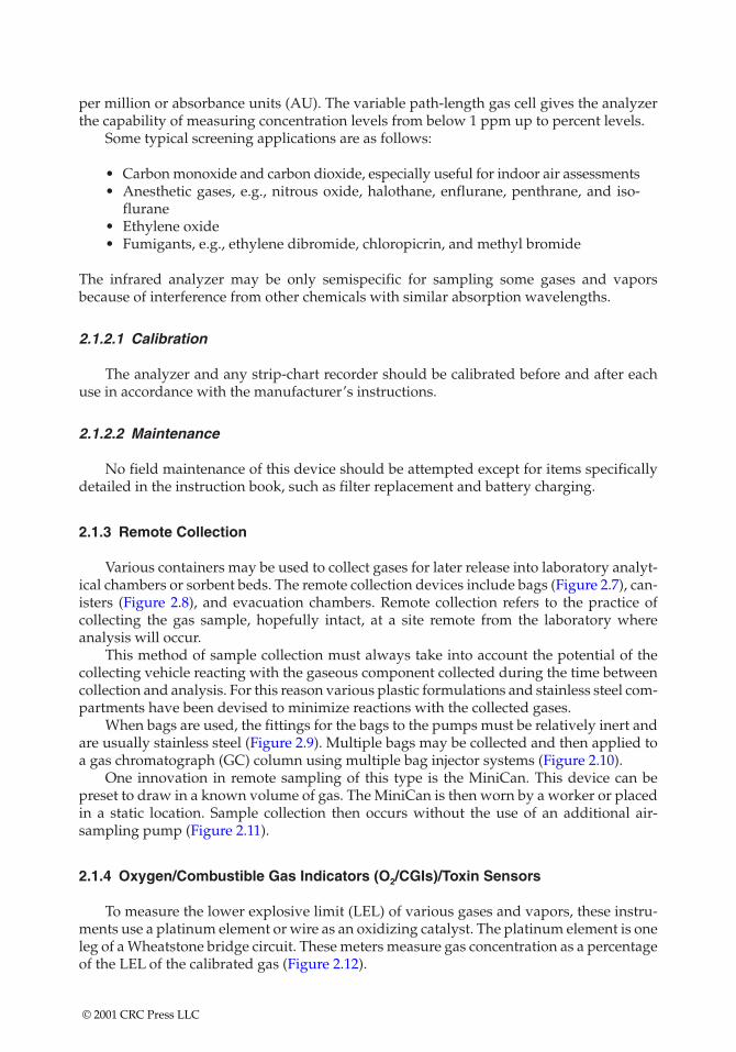
Various containers may be used to collect gases for later release into laboratory analyt-ical chambers or sorbent beds. The remote collection devices include bags (Figure 2.7), can-isters (Figure 2.8), and evacuation chambers. Remote collection refers to the practice ofcollecting the gas sample, hopefully intact, at a site remote from the laboratory whereanalysis will occur.
This method of sample collection must always take into account the potential of thecollecting vehicle reacting with the gaseous component collected during the time betweencollection and analysis. For this reason various plastic formulations and stainless steel com-partments have been devised to minimize reactions with the collected gases.
When bags are used, the fittings for the bags to the pumps must be relatively inert andare usually stainless steel (Figure 2.9). Multiple bags may be collected and then applied toa gas chromatograph (GC) column using multiple bag injector systems (Figure 2.10).
One innovation in remote sampling of this type is the MiniCan. This device can bepreset to draw in a known volume of gas. The MiniCan is then worn by a worker or placedin a static location. Sample collection then occurs without the use of an additional air-sampling pump (Figure 2.11).
2.1.4 Oxygen/Combustible Gas Indicators (O2/CGIs)/Toxin Sensors
To measure the lower explosive limit (LEL) of various gases and vapors, these instru-ments use a platinum element or wire as an oxidizing catalyst. The platinum element is oneleg of a Wheatstone bridge circuit. These meters measure gas concentration as a percentageof the LEL of the calibrated gas (Figure 2.12).
© 2001 CRC Press LLC
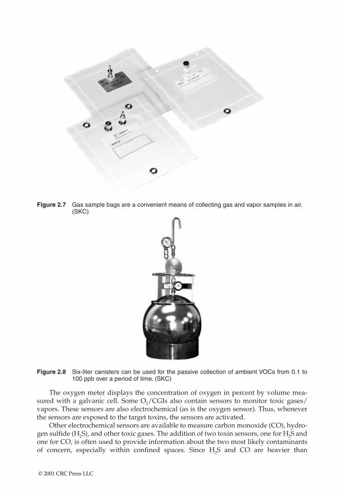
Figure 2.7 Gas sample bags are a convenient means of collecting gas and vapor samples in air.(SKC)
Figure 2.8 Six-liter canisters can be used for the passive collection of ambient VOCs from 0.1 to100 ppb over a period of time. (SKC)
The oxygen meter displays the concentration of oxygen in percent by volume mea-sured with a galvanic cell. Some O2/CGIs also contain sensors to monitor toxic gases/vapors. These sensors are also electrochemical (as is the oxygen sensor). Thus, wheneverthe sensors are exposed to the target toxins, the sensors are activated.
Other electrochemical sensors are available to measure carbon monoxide (CO), hydro-gen sulfide (H2S), and other toxic gases. The addition of two toxin sensors, one for H2S andone for CO, is often used to provide information about the two most likely contaminantsof concern, especially within confined spaces. Since H2S and CO are heavier than
© 2001 CRC Press LLC
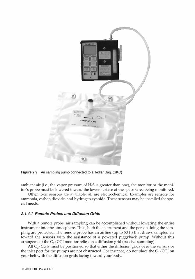
Figure 2.9 Air sampling pump connected to a Tedlar Bag. (SKC)
ambient air (i.e., the vapor pressure of H2S is greater than one), the monitor or the moni-tor’s probe must be lowered toward the lower surface of the space/area being monitored.
Other toxic sensors are available; all are electrochemical. Examples are sensors forammonia, carbon dioxide, and hydrogen cyanide. These sensors may be installed for spe-cial needs.
2.1.4.1 Remote Probes and Diffusion Grids
With a remote probe, air sampling can be accomplished without lowering the entireinstrument into the atmosphere. Thus, both the instrument and the person doing the sam-pling are protected. The remote probe has an airline (up to 50 ft) that draws sampled airtoward the sensors with the assistance of a powered piggyback pump. Without thisarrangement the O2/CGI monitor relies on a diffusion grid (passive sampling).
All O2/CGIs must be positioned so that either the diffusion grids over the sensors orthe inlet port for the pumps are not obstructed. For instance, do not place the O2/CGI onyour belt with the diffusion grids facing toward your body.
© 2001 CRC Press LLC
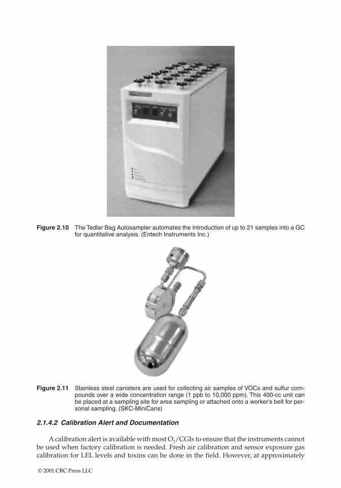
Figure 2.10 The Tedlar Bag Autosampler automates the introduction of up to 21 samples into a GCfor quantitative analysis. (Entech Instruments Inc.)
Figure 2.11 Stainless steel canisters are used for collecting air samples of VOCs and sulfur com-pounds over a wide concentration range (1 ppb to 10,000 ppm). This 400-cc unit canbe placed at a sampling site for area sampling or attached onto a worker’s belt for per-sonal sampling. (SKC-MiniCans)
2.1.4.2 Calibration Alert and Documentation
A calibration alert is available with most O2/CGIs to ensure that the instruments cannotbe used when factory calibration is needed. Fresh air calibration and sensor exposure gascalibration for LEL levels and toxins can be done in the field. However, at approximately
© 2001 CRC Press LLC
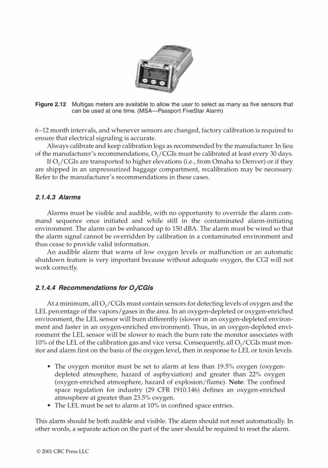
Figure 2.12 Multigas meters are available to allow the user to select as many as five sensors thatcan be used at one time. (MSA—Passport FiveStar Alarm)
6–12 month intervals, and whenever sensors are changed, factory calibration is required toensure that electrical signaling is accurate.
Always calibrate and keep calibration logs as recommended by the manufacturer. In lieuof the manufacturer’s recommendations, O2/CGIs must be calibrated at least every 30 days.
If O2/CGIs are transported to higher elevations (i.e., from Omaha to Denver) or if theyare shipped in an unpressurized baggage compartment, recalibration may be necessary.Refer to the manufacturer’s recommendations in these cases.
2.1.4.3 Alarms
Alarms must be visible and audible, with no opportunity to override the alarm com-mand sequence once initiated and while still in the contaminated alarm-initiating environment. The alarm can be enhanced up to 150 dBA. The alarm must be wired so thatthe alarm signal cannot be overridden by calibration in a contaminated environment andthus cease to provide valid information.
An audible alarm that warns of low oxygen levels or malfunction or an automatic shutdown feature is very important because without adequate oxygen, the CGI will notwork correctly.
2.1.4.4 Recommendations for O2/CGIs
At a minimum, all O2/CGIs must contain sensors for detecting levels of oxygen and theLEL percentage of the vapors/gases in the area. In an oxygen-depleted or oxygen-enrichedenvironment, the LEL sensor will burn differently (slower in an oxygen-depleted environ-ment and faster in an oxygen-enriched environment). Thus, in an oxygen-depleted envi-ronment the LEL sensor will be slower to reach the burn rate the monitor associates with10% of the LEL of the calibration gas and vice versa. Consequently, all O2/CGIs must mon-itor and alarm first on the basis of the oxygen level, then in response to LEL or toxin levels.
• The oxygen monitor must be set to alarm at less than 19.5% oxygen (oxygen-depleted atmosphere, hazard of asphyxiation) and greater than 22% oxygen(oxygen-enriched atmosphere, hazard of explosion/flame). Note: The confinedspace regulation for industry (29 CFR 1910.146) defines an oxygen-enrichedatmosphere at greater than 23.5% oxygen.
• The LEL must be set to alarm at 10% in confined space entries.
This alarm should be both audible and visible. The alarm should not reset automatically. Inother words, a separate action on the part of the user should be required to reset the alarm.
© 2001 CRC Press LLC
The oxygen sensor is an electrochemical sensor that will degrade as the sensor isexposed to oxygen. Thus, whether the sensor is used or not, the oxygen sensor will degradein a period of 6 to 12 months.
Some manufacturers recommend storing the monitor in a bag placed in a refrigeratedcompartment. This procedure has minimal value. Because the oxygen sensor is constantlyexposed to oxygen and will degrade (regardless of usage), O2/CGIs should be used oftenand continuously—“there is no saving them!’’ In other words, once the O2/CGI is turnedon, leave the O2/CGI on. Do not turn the monitor “on and off.’’
2.1.4.5 Relative Response
When using O2/CGIs to monitor the LEL, remember that calibration to a known stan-dard is necessary; all responses to any other gases/vapors will be relative to this calibra-tion standard. Thus, if the O2/CGI is calibrated to pentane (five-carbon chain), the responseto methane (one-carbon chain) will be faster. In other words, less of the methane will benecessary in order for the monitor to show 10% of the LEL than if the sensor was exposedto pentane.
The LEL sensor is a platinum wire/filament located on one side of a Wheatstone bridgeelectrical circuit. As the wire is exposed to gases/vapors, the burn rate of the filament isaltered. Thus, the resistance of the filament side of the Wheatstone bridge is changed. TheO2/CGI measures this change in resistance.
• The LEL sensor functions only when the O2/CGI is in use; therefore, some man-ufacturers will state that usage of the O2/CGI accelerates the breakdown of thissensor. However, because the oxygen sensor is much more susceptible to degra-dation regardless of usage, turning the monitors on and off just to preserve theLEL sensor is not recommended.
• Remember that the LEL readout is a percentage of the LEL listed for each chemi-cal. Thus, if the LEL for a particular calibration gas is 2%, at 10% of the LEL, 0.2%of the calibration gas is present. This comparison is not possible for other than thecalibrated gas/vapor atmospheres. As an example, when an O2/CGI is calibratedto pentane and then taken into an unknown atmosphere, then at 10% of the LEL,the sensor’s burn rate is the same as if the sensor had been exposed to 10% of theLEL for pentane.
If atmospheres of methane or acetylene are known to be present, the O2/CGI must be cali-brated for these gases.
2.1.4.6 Relative Response and Toxic Atmosphere Data
No direct correlation can be made under field conditions between the LEL monitor andthe level of toxins. Thus, 10% (1 � 10�2) LEL readings cannot be converted to parts per mil-lion (ppm, 1 � 10�6) by simply multiplying by 10,000. In a controlled laboratory atmos-phere using only the atmosphere to which the CGIs were calibrated, and then using manytrials of differing atmospheres, relative monitoring responses and correlation to toxin lev-els may be obtained. However, in the field, and particularly in relatively unknown con-stituent atmospheres, such correlations cannot be made.
© 2001 CRC Press LLC
2.1.4.7 Special Considerations
• Silicone compound vapors, leaded gasoline, and sulfur compounds will causedesensitization of the combustible sensor and produce erroneous (low) readings.
• High relative humidity (90–100%) causes hydroxylation, which reduces sensitiv-ity and causes erratic behavior, including inability to calibrate.
• Oxygen deficiency or enrichment such as in steam or inert atmospheres willcause erroneous readings for combustible gases.
• In drying ovens or unusually hot locations, solvent vapors with high boilingpoints may condense in the sampling lines and produce erroneous (low) readings.
• High concentrations of chlorinated hydrocarbons such as trichloroethylene oracid gases such as sulfur dioxide will depress the meter reading in the presenceof a high concentration of combustible gas.
• High-molecular-weight alcohols can burn out the meter’s filaments.• If the flash point is greater than the ambient temperature, an erroneous (low) con-
centration is indicated. If the closed vessel is then heated by welding or cutting,the vapors will increase, and the atmosphere may become explosive.
• For gases and vapors other than those for which a device was calibrated, usersshould consult the manufacturer’s instructions and correction curves.
2.1.4.8 Calibration
Before using the monitor each day, calibrate the instrument to a known concentrationof combustible gas (usually methane) equivalent to 25–50% LEL full-scale concentration.The monitor must be calibrated to the altitude at which it is used. Changes in total atmos-pheric pressure due to changes in altitude will influence the instrument’s measurement ofthe air’s oxygen content. The instrument must measure both the level of oxygen in theatmosphere and the level a combustible gas reaches before igniting; consequently, the calibration of the instrument is a two-step process.
1. The oxygen portion of the instrument is calibrated by placing the meter in normalatmospheric air and determining that the oxygen meter reads exactly 20.8% oxy-gen. This calibration should be done once per day when the instrument is in use.
2. The CGI is calibrated to pentane to indicate directly the percentage LEL of pen-tane in air. The CGI detector is also calibrated daily when used during samplingevents and whenever the detector filament is replaced. The calibration kitincluded with the CGI contains a calibration gas cylinder, a flow control, and anadapter hose.
The unit’s instruction manual provides additional details on sensor calibration.
2.1.4.9 Maintenance
The instrument requires no short-term maintenance other than regular calibration andbattery recharging. Use a soft cloth to wipe dirt, oil, moisture, or foreign material from the instrument. Check the bridge sensors periodically, at least every 6 months, for properfunctioning.
© 2001 CRC Press LLC
2.1.5 Oxygen Meters
Oxygen-measuring devices can include coulometric and fluorescence measurement,paramagnetic analysis, and polarographic methods.
2.1.6 Solid Sorbent Tubes
Organic vapors and gases may be collected on activated charcoal, silica gel, or otheradsorption tubes using low-flow pumps. Tubes may be furnished with either caps orflame-sealed glass ends. If using the capped version, simply uncap during the samplingperiod and recap at the end of the sampling period.
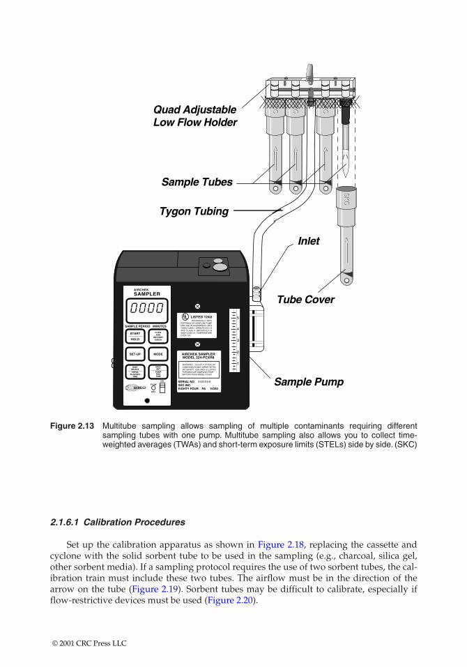
Multiple tubes can be collected using one pump. Flow regulation for each tube isaccomplished using critical orifices and valved regulation of airflow. Calibration of paral-lel or y-connected multiple tube drawing stations must be done individually for each tube,even in cases where the pump is drawing air through more than one tube in a parallel series(Figure 2.13). In instances where tubes are connected in series, only one calibration draw isdone through the conjoined tubes that empty air, one directly into the other (Figure 2.14).
Sorbent tubes may be used just to collect gases and vapors or to both collect and reactwith the collected chemicals. Some of the reactions may produce chemicals that when off-gassed could harm the pumps being used to pull air through the sorbent media bed. Inthese cases either filters or intermediate traps must be used to protect the pumps (Figure2.15). The following protocols should be followed:
• Immediately before sampling, break off the ends of the flame-sealed tube to pro-vide an opening approximately half the internal diameter of the tube. Take carewhen breaking these tubes—shattering may occur. A tube-breaking device thatshields the sampler should be used.
• Wear eye protection.• Use tube holders, if available, to minimize the hazards of broken glass (Figure 2.16).• Do not use the charging inlet or the exhaust outlet of the pump to break the ends
of the tubes.• Use the smaller section of the tube as a backup and position it near the sampling
pump.• The tube should be held or attached in an approximately vertical position with
the inlet either up or down during sampling (Figure 2.17).• Draw the air to be sampled directly into the inlet of the tube. This air is not to be
passed through any hose or tubing before entering the tube. A short length of pro-tective tape, a tube holder, or a short length of tubing should be placed on the cuttube end to protect the worker from the jagged glass edges.
• Cap the tube with the supplied plastic caps immediately after sampling and sealas soon as possible.
• Do not ship the tubes with bulk material.
For organic vapors and gases, low-flow pumps are required. With sorbent tubes, flowrates may have to be lowered or smaller air volumes (half the maximum) used when thereis high humidity (above 90%) in the sampling area or when relatively high concentrationsof other organic vapors are present.
© 2001 CRC Press LLC
AIRCHEK
SAMPLER
SAMPLE PERIOD MINUTES
START
HOLD
FLOWAND
BATTERYCHECK
DIGITSET
PUMPRUNTIME
DIGITSELECT
TOTALELAPSED
TIME
SET-UP MODE
FLOW
ADJ
ON
5
4
3
2
1
AIRCHEK SAMPLERMODEL 224-PCXR8
UL¤LISTED 124U
SERIAL NO.SKC INC.EIGHTY FOUR PA 15330
WARNING - SUBSTITUTION OFCOMPONENTS MAY IMPAIR INTRINSIC SAFETY. USE ONLY UL LISTEDPORTABLE AIR SAMPLING PUMPBATTERY PACK MODEL P21661
INTRINSICALLY SAFEPORTABLE AIR SAMPLING PUMPFOR USE IN HAZARDOUS LOCATIONS CLASS I, GROUPS A B C DAND CLASS II, GROUPS E F GAND CLASS III, TEMPERATURECODE T3C.
SK
CS
KC
SK
CS
KC
SK
CS
KC
SK
CS
KC
Figure 2.13 Multitube sampling allows sampling of multiple contaminants requiring differentsampling tubes with one pump. Multitube sampling also allows you to collect time-weighted averages (TWAs) and short-term exposure limits (STELs) side by side. (SKC)
2.1.6.1 Calibration Procedures
Set up the calibration apparatus as shown in Figure 2.18, replacing the cassette andcyclone with the solid sorbent tube to be used in the sampling (e.g., charcoal, silica gel,other sorbent media). If a sampling protocol requires the use of two sorbent tubes, the cal-ibration train must include these two tubes. The airflow must be in the direction of thearrow on the tube (Figure 2.19). Sorbent tubes may be difficult to calibrate, especially ifflow-restrictive devices must be used (Figure 2.20).
© 2001 CRC Press LLC
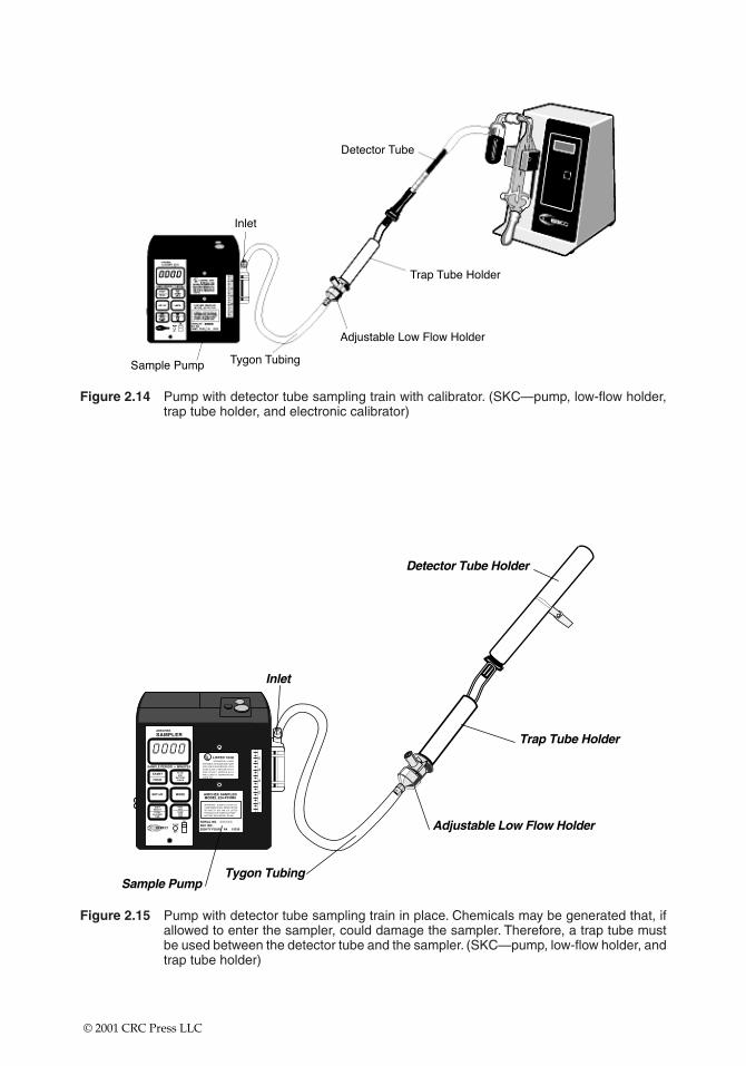
Figure 2.14 Pump with detector tube sampling train with calibrator. (SKC—pump, low-flow holder,trap tube holder, and electronic calibrator)
Figure 2.15 Pump with detector tube sampling train in place. Chemicals may be generated that, ifallowed to enter the sampler, could damage the sampler. Therefore, a trap tube mustbe used between the detector tube and the sampler. (SKC—pump, low-flow holder, andtrap tube holder)
© 2001 CRC Press LLC
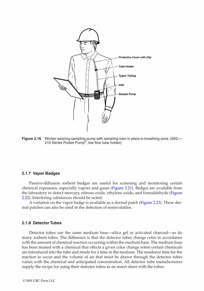
Figure 2.16 Worker wearing sampling pump with sampling train in place in breathing zone. (SKC—210 Series Pocket Pump®, low flow tube holder)
2.1.7 Vapor Badges
Passive-diffusion sorbent badges are useful for screening and monitoring certainchemical exposures, especially vapors and gases (Figure 2.21). Badges are available fromthe laboratory to detect mercury, nitrous oxide, ethylene oxide, and formaldehyde (Figure2.22). Interfering substances should be noted.
A variation on the vapor badge is available as a dermal patch (Figure 2.23). These der-mal patches can also be used in the detection of semivolatiles.
2.1.8 Detector Tubes
Detector tubes use the same medium base—silica gel or activated charcoal—as domany sorbent tubes. The difference is that the detector tubes change color in accordancewith the amount of chemical reaction occurring within the medium base. The medium basehas been treated with a chemical that effects a given color change when certain chemicalsare introduced into the tube and reside for a time in the medium. The residence time for thereaction to occur and the volume of air that must be drawn through the detector tubesvaries with the chemical and anticipated concentration. All detector tube manufacturerssupply the recipe for using their detector tubes as an insert sheet with the tubes.
© 2001 CRC Press LLC
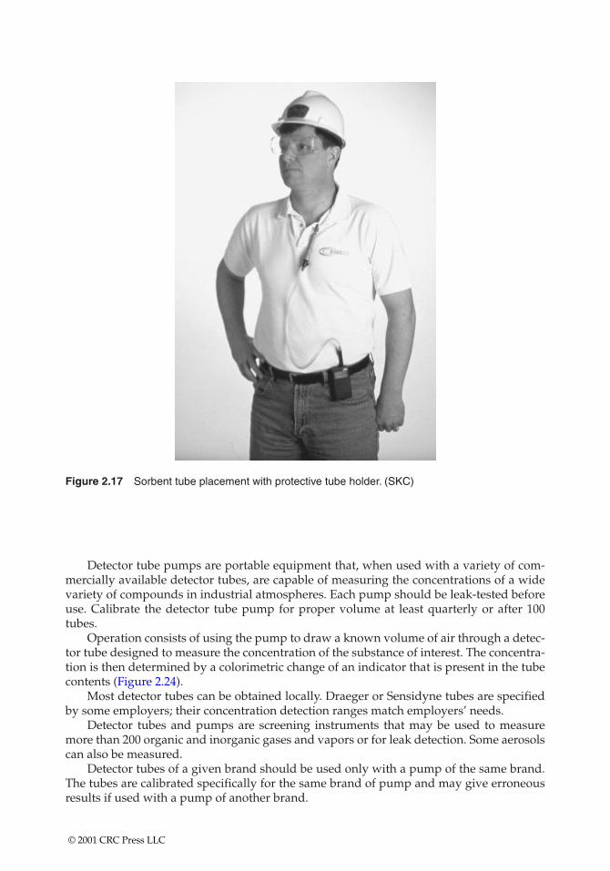
Figure 2.17 Sorbent tube placement with protective tube holder. (SKC)
Detector tube pumps are portable equipment that, when used with a variety of com-mercially available detector tubes, are capable of measuring the concentrations of a widevariety of compounds in industrial atmospheres. Each pump should be leak-tested beforeuse. Calibrate the detector tube pump for proper volume at least quarterly or after 100tubes.
Operation consists of using the pump to draw a known volume of air through a detec-tor tube designed to measure the concentration of the substance of interest. The concentra-tion is then determined by a colorimetric change of an indicator that is present in the tubecontents (Figure 2.24).
Most detector tubes can be obtained locally. Draeger or Sensidyne tubes are specifiedby some employers; their concentration detection ranges match employers’ needs.
Detector tubes and pumps are screening instruments that may be used to measuremore than 200 organic and inorganic gases and vapors or for leak detection. Some aerosolscan also be measured.
Detector tubes of a given brand should be used only with a pump of the same brand.The tubes are calibrated specifically for the same brand of pump and may give erroneousresults if used with a pump of another brand.
© 2001 CRC Press LLC
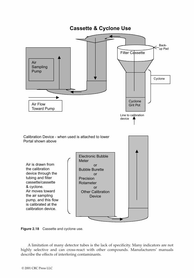
Figure 2.18 Cassette and cyclone use.
A limitation of many detector tubes is the lack of specificity. Many indicators are nothighly selective and can cross-react with other compounds. Manufacturers’ manualsdescribe the effects of interfering contaminants.
© 2001 CRC Press LLC
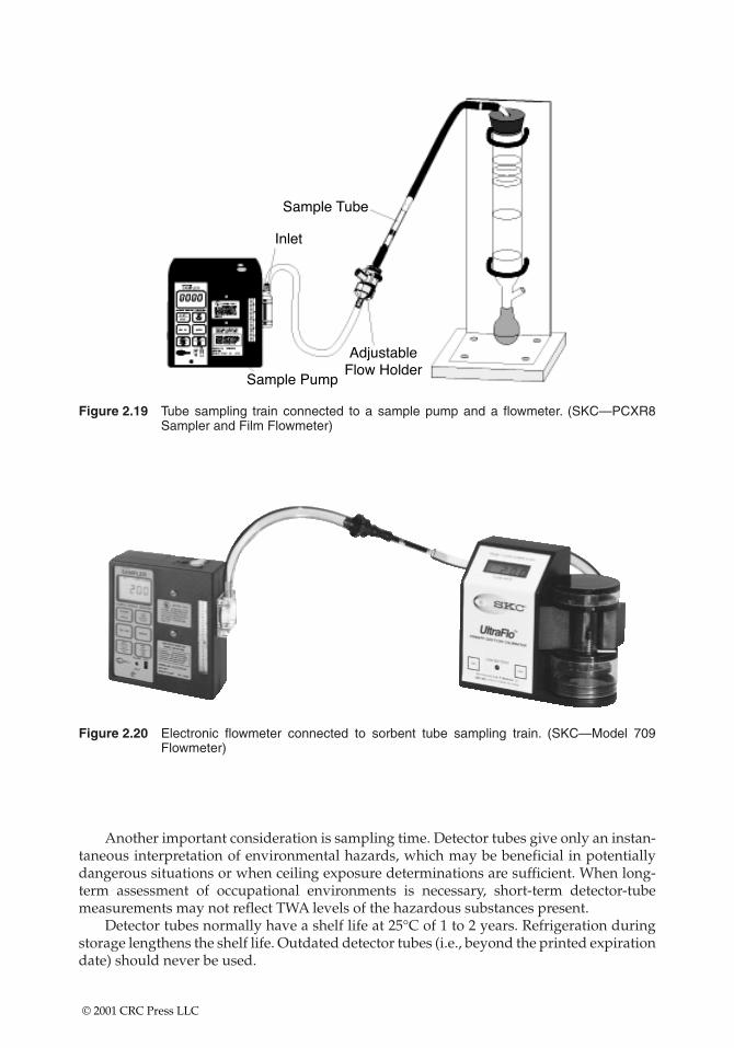
Figure 2.19 Tube sampling train connected to a sample pump and a flowmeter. (SKC—PCXR8Sampler and Film Flowmeter)
Figure 2.20 Electronic flowmeter connected to sorbent tube sampling train. (SKC—Model 709Flowmeter)
Another important consideration is sampling time. Detector tubes give only an instan-taneous interpretation of environmental hazards, which may be beneficial in potentiallydangerous situations or when ceiling exposure determinations are sufficient. When long-term assessment of occupational environments is necessary, short-term detector-tubemeasurements may not reflect TWA levels of the hazardous substances present.
Detector tubes normally have a shelf life at 25°C of 1 to 2 years. Refrigeration duringstorage lengthens the shelf life. Outdated detector tubes (i.e., beyond the printed expirationdate) should never be used.
© 2001 CRC Press LLC
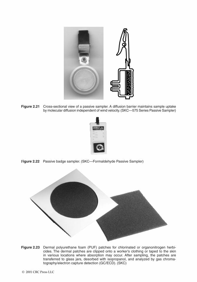
Figure 2.21 Cross-sectional view of a passive sampler. A diffusion barrier maintains sample uptakeby molecular diffusion independent of wind velocity. (SKC—575 Series Passive Sampler)
Figure 2.22 Passive badge sampler. (SKC—Formaldehyde Passive Sampler)
Figure 2.23 Dermal polyurethane foam (PUF) patches for chlorinated or organonitrogen herbi-cides. The dermal patches are clipped onto a worker’s clothing or taped to the skin in various locations where absorption may occur. After sampling, the patches are transferred to glass jars, desorbed with isopropanol, and analyzed by gas chroma-tography/electron capture detection (GC/ECD). (SKC)
© 2001 CRC Press LLC
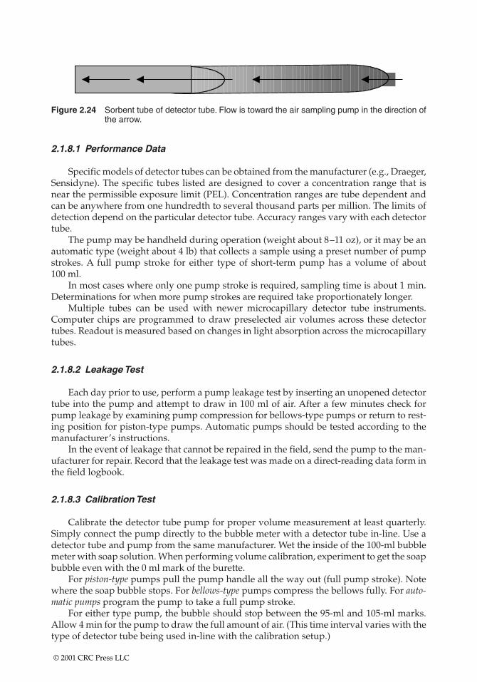
Figure 2.24 Sorbent tube of detector tube. Flow is toward the air sampling pump in the direction ofthe arrow.
2.1.8.1 Performance Data
Specific models of detector tubes can be obtained from the manufacturer (e.g., Draeger,Sensidyne). The specific tubes listed are designed to cover a concentration range that isnear the permissible exposure limit (PEL). Concentration ranges are tube dependent andcan be anywhere from one hundredth to several thousand parts per million. The limits ofdetection depend on the particular detector tube. Accuracy ranges vary with each detectortube.
The pump may be handheld during operation (weight about 8–11 oz), or it may be anautomatic type (weight about 4 lb) that collects a sample using a preset number of pumpstrokes. A full pump stroke for either type of short-term pump has a volume of about 100 ml.
In most cases where only one pump stroke is required, sampling time is about 1 min.Determinations for when more pump strokes are required take proportionately longer.
Multiple tubes can be used with newer microcapillary detector tube instruments.Computer chips are programmed to draw preselected air volumes across these detectortubes. Readout is measured based on changes in light absorption across the microcapillarytubes.
2.1.8.2 Leakage Test
Each day prior to use, perform a pump leakage test by inserting an unopened detectortube into the pump and attempt to draw in 100 ml of air. After a few minutes check forpump leakage by examining pump compression for bellows-type pumps or return to rest-ing position for piston-type pumps. Automatic pumps should be tested according to themanufacturer’s instructions.
In the event of leakage that cannot be repaired in the field, send the pump to the man-ufacturer for repair. Record that the leakage test was made on a direct-reading data form inthe field logbook.
2.1.8.3 Calibration Test
Calibrate the detector tube pump for proper volume measurement at least quarterly.Simply connect the pump directly to the bubble meter with a detector tube in-line. Use adetector tube and pump from the same manufacturer. Wet the inside of the 100-ml bubblemeter with soap solution. When performing volume calibration, experiment to get the soapbubble even with the 0 ml mark of the burette.
For piston-type pumps pull the pump handle all the way out (full pump stroke). Notewhere the soap bubble stops. For bellows-type pumps compress the bellows fully. For auto-matic pumps program the pump to take a full pump stroke.
For either type pump, the bubble should stop between the 95-ml and 105-ml marks.Allow 4 min for the pump to draw the full amount of air. (This time interval varies with thetype of detector tube being used in-line with the calibration setup.)
© 2001 CRC Press LLC
Also check the volume for 50 ml (one half pump stroke) and 25 ml (one quarter pumpstroke) if pertinent.
• A variance of �5% error is permissible.• If the error is greater than �5%, send the pump for repair and recalibration.
Record the calibration information required on the calibration log. It may be necessaryto clean or replace the rubber bung or tube holder if a large number of tubes have beentaken with any pump.
2.1.8.4 Special Considerations
Detector tubes should be refrigerated when not in use to prolong shelf life. Detectortubes should not be used when they are cold. They should be kept at room temperature orin a shirt pocket for 1 h prior to use. Lubrication of the piston pump may be required if vol-ume error is greater than 5%.
Draeger, Model 31 (Bellows)
When checking the pump for leaks with an unopened tube, the bellows should not becompletely expanded after 10 min.
Draeger, Quantimeter 1000, Model 1 (Automatic)
A battery pack is an integral part of this pump.
• The pack must be charged prior to initial use.• One charge is good for 1000 pump strokes.• During heavy use, it should be recharged daily.
If a “U’’ (undervoltage) message is continuously displayed in the readout window of thispump, the battery pack should be immediately recharged.
Matheson-Kitagawa, Model 8014-400a (Piston)
When checking the pump for leaks with an unopened tube, the pump handle shouldbe pulled back to the 100-ml mark and locked.
• After 2 min, the handle should be released carefully.• The handle should return to a point �6 mm from zero or resting position.
After taking 100–200 samples, the pump should be cleaned and relubricated. This pro-cedure involves removing the piston from the cylinder, removing the inlet and pressure-relief valve from the front end of the pump, cleaning, and relubricating.
Mine Safety Appliances, Samplair Pump, Model A, Part No. 46399 (Piston)
The pump contains a flow-rate control orifice protected by a plastic filter that periodi-cally needs to be cleaned or replaced. To check the flow rate, the pump is connected to aburette, and the piston is withdrawn to the 100-ml position with no tube in the tube holder.
© 2001 CRC Press LLC
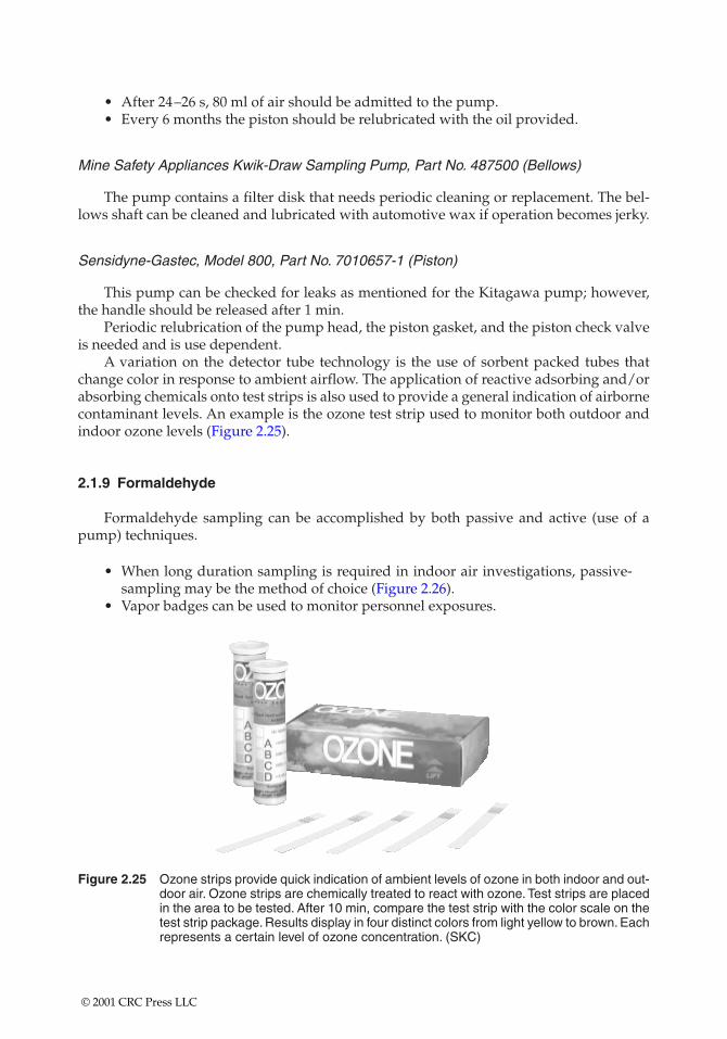
• After 24–26 s, 80 ml of air should be admitted to the pump.• Every 6 months the piston should be relubricated with the oil provided.
Mine Safety Appliances Kwik-Draw Sampling Pump, Part No. 487500 (Bellows)
The pump contains a filter disk that needs periodic cleaning or replacement. The bel-lows shaft can be cleaned and lubricated with automotive wax if operation becomes jerky.
Sensidyne-Gastec, Model 800, Part No. 7010657-1 (Piston)
This pump can be checked for leaks as mentioned for the Kitagawa pump; however,the handle should be released after 1 min.
Periodic relubrication of the pump head, the piston gasket, and the piston check valveis needed and is use dependent.
A variation on the detector tube technology is the use of sorbent packed tubes thatchange color in response to ambient airflow. The application of reactive adsorbing and/orabsorbing chemicals onto test strips is also used to provide a general indication of airbornecontaminant levels. An example is the ozone test strip used to monitor both outdoor andindoor ozone levels (Figure 2.25).
2.1.9 Formaldehyde
Formaldehyde sampling can be accomplished by both passive and active (use of apump) techniques.
• When long duration sampling is required in indoor air investigations, passive-sampling may be the method of choice (Figure 2.26).
• Vapor badges can be used to monitor personnel exposures.
Figure 2.25 Ozone strips provide quick indication of ambient levels of ozone in both indoor and out-door air. Ozone strips are chemically treated to react with ozone. Test strips are placedin the area to be tested. After 10 min, compare the test strip with the color scale on thetest strip package. Results display in four distinct colors from light yellow to brown. Eachrepresents a certain level of ozone concentration. (SKC)
© 2001 CRC Press LLC
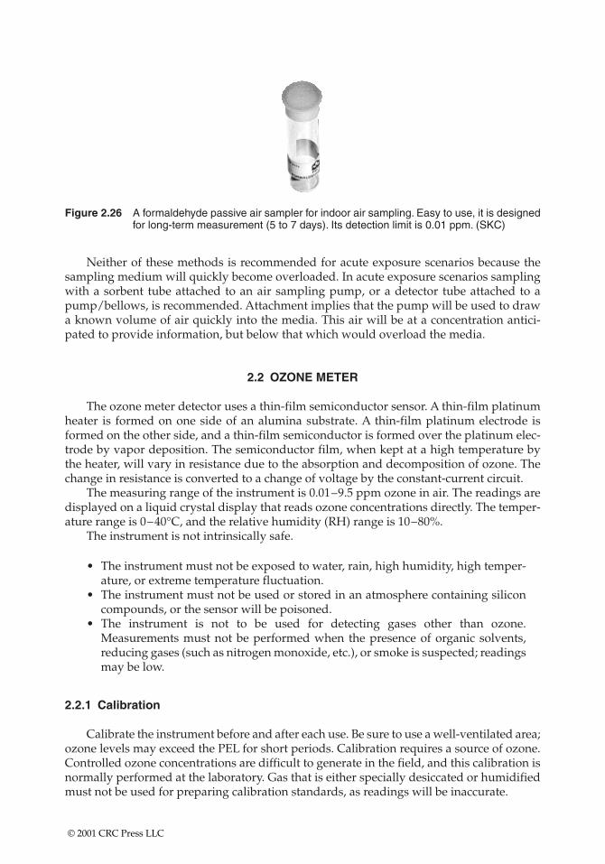
Figure 2.26 A formaldehyde passive air sampler for indoor air sampling. Easy to use, it is designedfor long-term measurement (5 to 7 days). Its detection limit is 0.01 ppm. (SKC)
Neither of these methods is recommended for acute exposure scenarios because thesampling medium will quickly become overloaded. In acute exposure scenarios samplingwith a sorbent tube attached to an air sampling pump, or a detector tube attached to apump/bellows, is recommended. Attachment implies that the pump will be used to drawa known volume of air quickly into the media. This air will be at a concentration antici-pated to provide information, but below that which would overload the media.
2.2 OZONE METER
The ozone meter detector uses a thin-film semiconductor sensor. A thin-film platinumheater is formed on one side of an alumina substrate. A thin-film platinum electrode isformed on the other side, and a thin-film semiconductor is formed over the platinum elec-trode by vapor deposition. The semiconductor film, when kept at a high temperature bythe heater, will vary in resistance due to the absorption and decomposition of ozone. Thechange in resistance is converted to a change of voltage by the constant-current circuit.
The measuring range of the instrument is 0.01–9.5 ppm ozone in air. The readings aredisplayed on a liquid crystal display that reads ozone concentrations directly. The temper-ature range is 0–40°C, and the relative humidity (RH) range is 10–80%.
The instrument is not intrinsically safe.
• The instrument must not be exposed to water, rain, high humidity, high temper-ature, or extreme temperature fluctuation.
• The instrument must not be used or stored in an atmosphere containing siliconcompounds, or the sensor will be poisoned.
• The instrument is not to be used for detecting gases other than ozone.Measurements must not be performed when the presence of organic solvents,reducing gases (such as nitrogen monoxide, etc.), or smoke is suspected; readingsmay be low.
2.2.1 Calibration
Calibrate the instrument before and after each use. Be sure to use a well-ventilated area;ozone levels may exceed the PEL for short periods. Calibration requires a source of ozone.Controlled ozone concentrations are difficult to generate in the field, and this calibration isnormally performed at the laboratory. Gas that is either specially desiccated or humidifiedmust not be used for preparing calibration standards, as readings will be inaccurate.
© 2001 CRC Press LLC
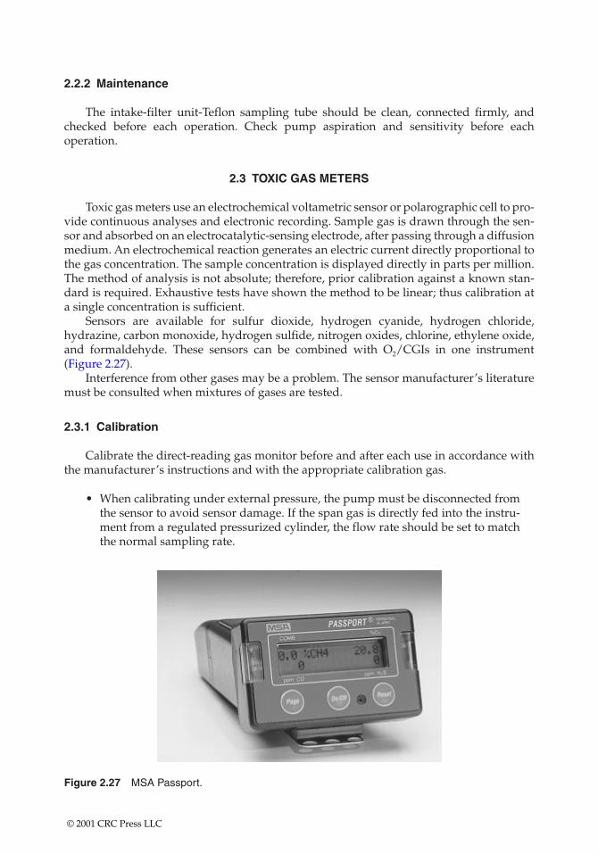
2.2.2 Maintenance
The intake-filter unit-Teflon sampling tube should be clean, connected firmly, andchecked before each operation. Check pump aspiration and sensitivity before each operation.
2.3 TOXIC GAS METERS
Toxic gas meters use an electrochemical voltametric sensor or polarographic cell to pro-vide continuous analyses and electronic recording. Sample gas is drawn through the sen-sor and absorbed on an electrocatalytic-sensing electrode, after passing through a diffusionmedium. An electrochemical reaction generates an electric current directly proportional tothe gas concentration. The sample concentration is displayed directly in parts per million.The method of analysis is not absolute; therefore, prior calibration against a known stan-dard is required. Exhaustive tests have shown the method to be linear; thus calibration ata single concentration is sufficient.
Sensors are available for sulfur dioxide, hydrogen cyanide, hydrogen chloride,hydrazine, carbon monoxide, hydrogen sulfide, nitrogen oxides, chlorine, ethylene oxide,and formaldehyde. These sensors can be combined with O2/CGIs in one instrument(Figure 2.27).
Interference from other gases may be a problem. The sensor manufacturer’s literaturemust be consulted when mixtures of gases are tested.
2.3.1 Calibration
Calibrate the direct-reading gas monitor before and after each use in accordance withthe manufacturer’s instructions and with the appropriate calibration gas.
• When calibrating under external pressure, the pump must be disconnected fromthe sensor to avoid sensor damage. If the span gas is directly fed into the instru-ment from a regulated pressurized cylinder, the flow rate should be set to matchthe normal sampling rate.
Figure 2.27 MSA Passport.
© 2001 CRC Press LLC
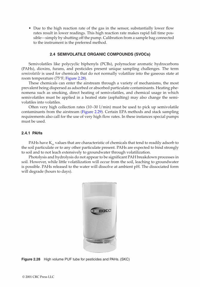
• Due to the high reaction rate of the gas in the sensor, substantially lower flowrates result in lower readings. This high reaction rate makes rapid fall time pos-sible—simply by shutting off the pump. Calibration from a sample bag connectedto the instrument is the preferred method.
2.4 SEMIVOLATILE ORGANIC COMPOUNDS (SVOCs)
Semivolatiles like polycyclic biphenyls (PCBs), polynuclear aromatic hydrocarbons(PAHs), dioxins, furans, and pesticides present unique sampling challenges. The termsemivolatile is used for chemicals that do not normally volatilize into the gaseous state atroom temperature (75°F; Figure 2.28).
These chemicals can enter the airstream through a variety of mechanisms, the mostprevalent being dispersed as adsorbed or absorbed particulate contaminants. Heating phe-nomena such as smoking, direct heating of semivolatiles, and chemical usage in whichsemivolatiles must be applied in a heated state (asphalting) may also change the semi-volatiles into volatiles.
Often very high collection rates (10–30 l/min) must be used to pick up semivolatilecontaminants from the airstream (Figure 2.29). Certain EPA methods and stack samplingrequirements also call for the use of very high flow rates. In these instances special pumpsmust be used.
2.4.1 PAHs
PAHs have Koc values that are characteristic of chemicals that tend to readily adsorb tothe soil particulate or to any other particulate present. PAHs are expected to bind stronglyto soil and to not leach extensively to groundwater through volatilization.
Photolysis and hydrolysis do not appear to be significant PAH breakdown processes insoil. However, while little volatilization will occur from the soil, leaching to groundwateris possible. PAHs released to the water will dissolve at ambient pH. The dissociated formwill degrade (hours to days).
Figure 2.28 High volume PUF tube for pesticides and PAHs. (SKC)
© 2001 CRC Press LLC
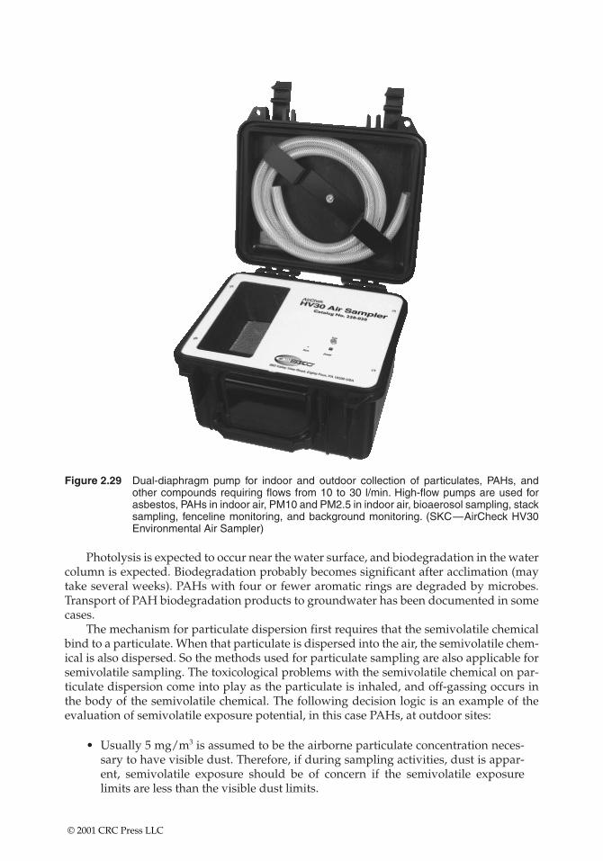
Figure 2.29 Dual-diaphragm pump for indoor and outdoor collection of particulates, PAHs, andother compounds requiring flows from 10 to 30 l/min. High-flow pumps are used forasbestos, PAHs in indoor air, PM10 and PM2.5 in indoor air, bioaerosol sampling, stacksampling, fenceline monitoring, and background monitoring. (SKC—AirCheck HV30Environmental Air Sampler)
Photolysis is expected to occur near the water surface, and biodegradation in the watercolumn is expected. Biodegradation probably becomes significant after acclimation (maytake several weeks). PAHs with four or fewer aromatic rings are degraded by microbes.Transport of PAH biodegradation products to groundwater has been documented in somecases.
The mechanism for particulate dispersion first requires that the semivolatile chemicalbind to a particulate. When that particulate is dispersed into the air, the semivolatile chem-ical is also dispersed. So the methods used for particulate sampling are also applicable forsemivolatile sampling. The toxicological problems with the semivolatile chemical on par-ticulate dispersion come into play as the particulate is inhaled, and off-gassing occurs inthe body of the semivolatile chemical. The following decision logic is an example of theevaluation of semivolatile exposure potential, in this case PAHs, at outdoor sites:
• Usually 5 mg/m3 is assumed to be the airborne particulate concentration neces-sary to have visible dust. Therefore, if during sampling activities, dust is appar-ent, semivolatile exposure should be of concern if the semivolatile exposurelimits are less than the visible dust limits.
© 2001 CRC Press LLC
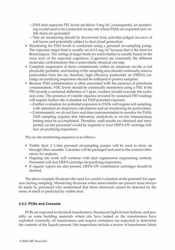
—PAH dust exposure PEL levels are below 5 mg/m3; consequently, air monitor-ing would need to be conducted on any site where PAHs are expected and vis-ible dusts are generated.
—This air monitoring should be downwind from activities judged invasive ofsoil layers and potentially subject to dust cloud generation.
• Monitoring for PAH levels is conducted using a personal air-sampling pump.The exposure target limit is usually set at 0.2 mg/m3 because that is the limit forBenzo(a)pyre. The setting of target limits for semivolatiles is usually based on themost toxic of the expected cogenitors. Cogenitors are essentially the differentmolecular conformations that a semivolatile chemical can take.
• Complete suspension of these contaminants within an airstream on-site is notphysically probable, and misting of the sampling area should continually removeparticulates from the air; therefore, high efficiency particulate air (HEPA) car-tridge air-purifying respirators should be sufficient to protect samplers.
• Because PAH contamination is often associated with the presence of petroleumcontamination, VOC levels should be continually monitored using a PID. If thePID records a sustained deflection of 1 ppm, workers should evacuate the exclu-sion zone. The presence of volatile organics revealed by sustained PID readingswill require further site evaluation for PAH potential exposure.—Further evaluation for potential exposures to PAHs will require soil sampling,
with attendant air dispersion calculations and air monitoring for particulates.—Unfortunately, we do not have real-time instrumentation to monitor for PAHs.
PAH sampling requires that laboratory analyticals or on-site immunoassaytesting must be accomplished. Therefore, until results are obtained and inter-preted, on-site personnel would be required to wear HEPA-OV cartridge full-face air-purifying respirators.
The on-site monitoring sequence is as follows:
• Visible dust: 2 l/min personal air-sampling pumps will be used to draw airthrough filter cassettes. Cassettes will be packaged and sent to the contract labo-ratory for analysis.
• Ongoing site work will continue with dust suppression engineering controls.Personnel will don HEPA cartridge air-purifying respirators.
• If organic vapors are also present, HEPA-OV combination cartridges should bedonned.
The above example illustrates the need for careful evaluation of the potential for expo-sure during sampling. Monitoring decisions when semivolatiles are present must alwaysbe made by personnel who understand that these chemicals cannot be detected by thesense of smell or predicted by visible dust.
2.4.2 PCBs and Creosote
PCBs are expected in electrical transformers, fluorescent light fixture ballasts, and pos-sibly on some building materials where oils have leaked or the transformers haveexploded. Generally, all transformers and suspect containers are inspected to determinethe contents of the liquids present. Site inspections include a review of transformer labels
© 2001 CRC Press LLC
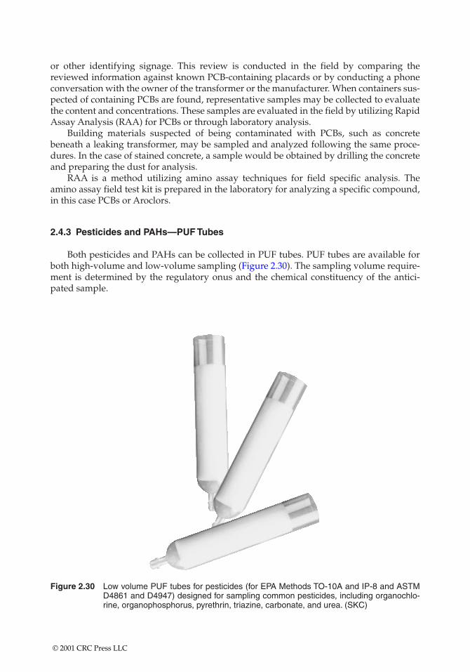
or other identifying signage. This review is conducted in the field by comparing thereviewed information against known PCB-containing placards or by conducting a phoneconversation with the owner of the transformer or the manufacturer. When containers sus-pected of containing PCBs are found, representative samples may be collected to evaluatethe content and concentrations. These samples are evaluated in the field by utilizing RapidAssay Analysis (RAA) for PCBs or through laboratory analysis.
Building materials suspected of being contaminated with PCBs, such as concretebeneath a leaking transformer, may be sampled and analyzed following the same proce-dures. In the case of stained concrete, a sample would be obtained by drilling the concreteand preparing the dust for analysis.
RAA is a method utilizing amino assay techniques for field specific analysis. Theamino assay field test kit is prepared in the laboratory for analyzing a specific compound,in this case PCBs or Aroclors.
2.4.3 Pesticides and PAHs—PUF Tubes
Both pesticides and PAHs can be collected in PUF tubes. PUF tubes are available forboth high-volume and low-volume sampling (Figure 2.30). The sampling volume require-ment is determined by the regulatory onus and the chemical constituency of the antici-pated sample.
Figure 2.30 Low volume PUF tubes for pesticides (for EPA Methods TO-10A and IP-8 and ASTMD4861 and D4947) designed for sampling common pesticides, including organochlo-rine, organophosphorus, pyrethrin, triazine, carbonate, and urea. (SKC)
© 2001 CRC Press LLC
2.5 ACID GASES OR CAUSTICS
Volatile acid gases may be an inappropriate designation. Acid gases are often gener-ated during a reaction, and the latent volatility of the acid gas is really not an issue. Thermalvolatilization based on boiling point predictions and mechanical dispersion may be of lessimportance than the rate of the reaction generating the acid gas or caustic. However, inaddition to this reaction phenomenon, acid gases such as chlorine are given off when theliquid solution is distributed around an area. Here we have a classic case of the liquid togas interface seeking an equilibrium. If air currents sweep the generated gas concentrationaway from this equilibrium site, the liquid will again yield molecules to the gas phase toagain achieve another equilibrium.
Acid gases and caustics with their corrosive or caustic properties can have healtheffects that include both acute toxicological and physical manifestations, such as wateringeyes and respiratory tract irritation. Because of these effects, sampling for acid gases andcaustics must begin upon approach to the area of concern.
Sampling for acid gases and caustics may use all of the techniques specified for anyvolatile. Some acid gases and caustics are dispersed and adsorbed to particulate; therefore,particulate sampling techniques apply.
The reaction phenomenon must always be considered during any sampling of acidgases or caustics. Any real-time instrumentation with unprotected metal sensors, lamp fil-aments, or sensor housings will often be rendered useless, as the acid gases or causticsinteract with the metals through reduction-oxidation (redox) reactions.
2.5.1 Impingers
Impingers may be used to bring acid/caustic-laced particulates into solutions that areretained within the impinger’s vessel. Vapors, mists, and gases may also be introduced intothe impinger solution. When the reaction within the impinger vessel may cause off-gassing, a filter or media barrier (see Figures 2.31, 2.32, and 2.33) may be required betweenthe air sampling pump and the impinger vessel tubing to the pump (Figure 2.34).
Midget impingers may be worn as personal sampling devices (Figure 2.35). The mainconcern with impingers as sampling devices, especially for personnel, is the danger of spills.
2.5.2 Sorbent Tubes
Sampling media must also be acid and caustic resistant. Sampling for acids and caus-tics is often discussed in terms of using silica gel sorbent tubes. The procedure for this sam-pling is the same as that for volatiles where charcoal tubes are often used. The essentialproblem with the silica gel tubes is that they tend to plug up! The use of dual flow tubes issome insurance that if one tube plugs up, the other might still remain effective to providedata from the sampling interval.
In instances where silica gel tubes continue to plug up, switching to larger bore silica geltubes or altering the sampling interval (less time) may be needed. If this procedure does notwork, switching to charcoal tubes may be the only other solvent tube option. These sam-pling routines (see Figure 2.36) may be at odds with the recommended National Instituteof Occupational Safety and Health (NIOSH) methods that may call for small bore silica geltubes at low flow rates for extended periods of time. If so, decision logic must be docu-mented, with this documentation linked to the competency of the individual who devisedthe sampling plan.
© 2001 CRC Press LLC
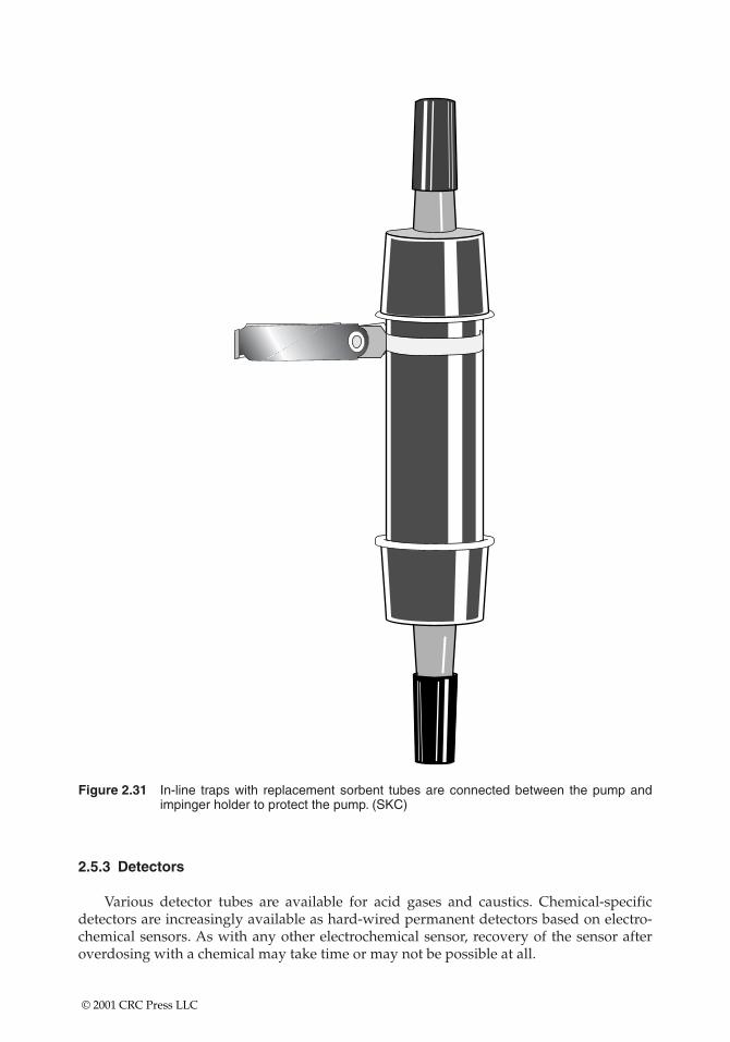
Figure 2.31 In-line traps with replacement sorbent tubes are connected between the pump andimpinger holder to protect the pump. (SKC)
2.5.3 Detectors
Various detector tubes are available for acid gases and caustics. Chemical-specificdetectors are increasingly available as hard-wired permanent detectors based on electro-chemical sensors. As with any other electrochemical sensor, recovery of the sensor afteroverdosing with a chemical may take time or may not be possible at all.
© 2001 CRC Press LLC
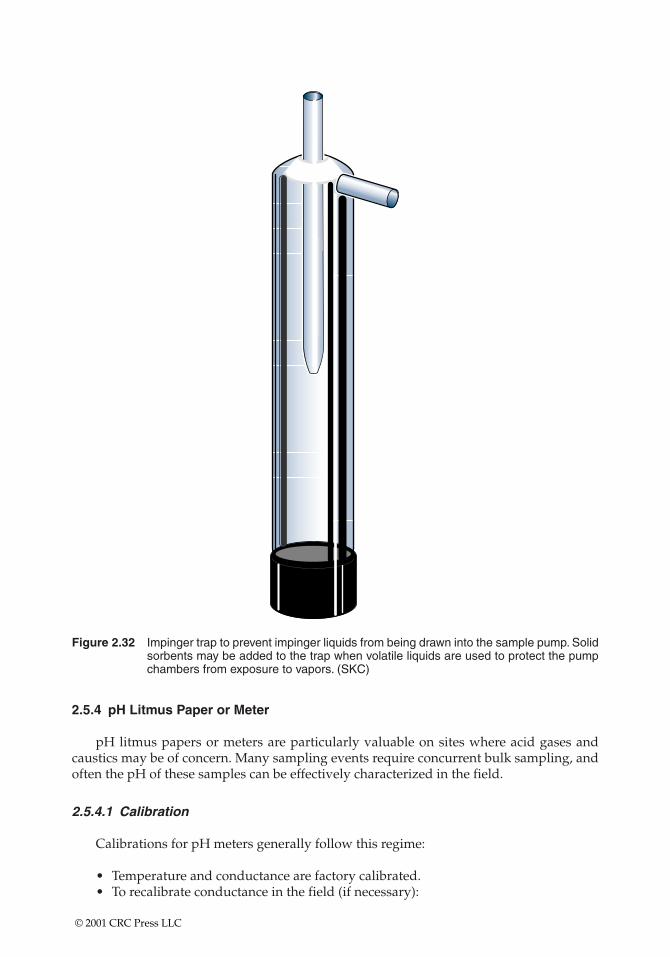
Figure 2.32 Impinger trap to prevent impinger liquids from being drawn into the sample pump. Solidsorbents may be added to the trap when volatile liquids are used to protect the pumpchambers from exposure to vapors. (SKC)
2.5.4 pH Litmus Paper or Meter
pH litmus papers or meters are particularly valuable on sites where acid gases andcaustics may be of concern. Many sampling events require concurrent bulk sampling, andoften the pH of these samples can be effectively characterized in the field.
2.5.4.1 Calibration
Calibrations for pH meters generally follow this regime:
• Temperature and conductance are factory calibrated.• To recalibrate conductance in the field (if necessary):
© 2001 CRC Press LLC
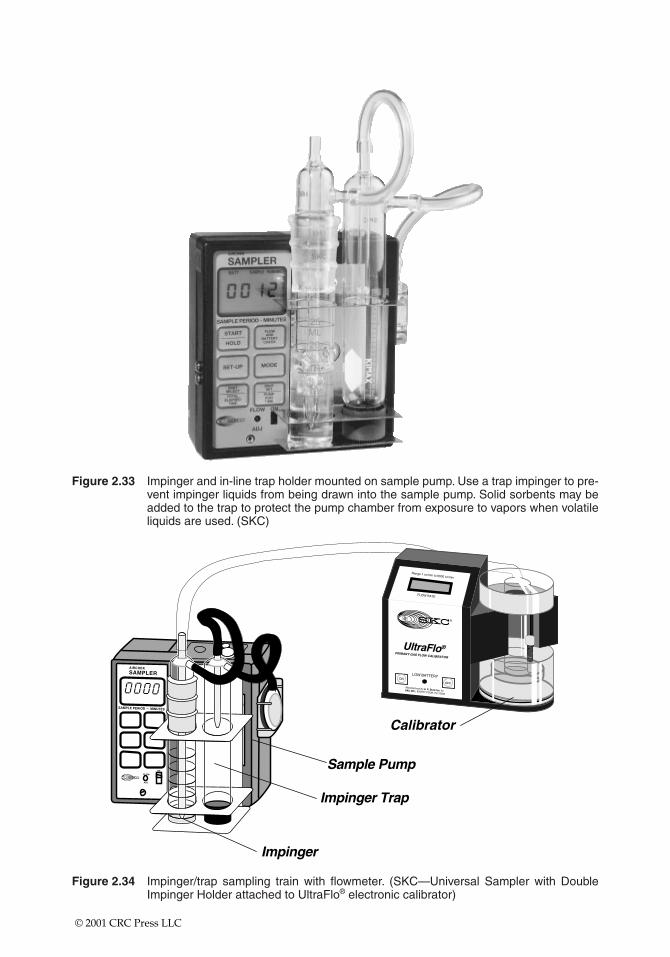
Figure 2.33 Impinger and in-line trap holder mounted on sample pump. Use a trap impinger to pre-vent impinger liquids from being drawn into the sample pump. Solid sorbents may beadded to the trap to protect the pump chamber from exposure to vapors when volatileliquids are used. (SKC)
Figure 2.34 Impinger/trap sampling train with flowmeter. (SKC—Universal Sampler with DoubleImpinger Holder attached to UltraFlo® electronic calibrator)
© 2001 CRC Press LLC
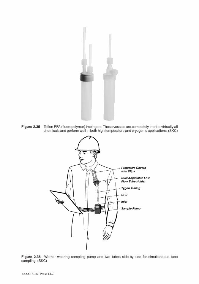
Figure 2.35 Teflon PFA (fluoropolymer) impingers.These vessels are completely inert to virtually allchemicals and perform well in both high temperature and cryogenic applications. (SKC)
Figure 2.36 Worker wearing sampling pump and two tubes side-by-side for simultaneous tubesampling. (SKC)
© 2001 CRC Press LLC
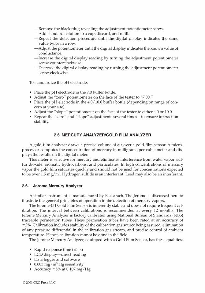
—Remove the black plug revealing the adjustment potentiometer screw.—Add standard solution to a cup, discard, and refill.—Repeat the detection procedure until the digital display indicates the same
value twice in a row.—Adjust the potentiometer until the digital display indicates the known value of
conductance.—Increase the digital display reading by turning the adjustment potentiometer
screw counterclockwise.—Decrease the digital display reading by turning the adjustment potentiometer
screw clockwise.
To standardize the pH electrode:
• Place the pH electrode in the 7.0 buffer bottle.• Adjust the “zero’’ potentiometer on the face of the tester to “7.00.’’• Place the pH electrode in the 4.0/10.0 buffer bottle (depending on range of con-
cern at your site).• Adjust the “slope’’ potentiometer on the face of the tester to either 4.0 or 10.0.• Repeat the “zero’’ and “slope’’ adjustments several times—to ensure interaction
stability.
2.6 MERCURY ANALYZER/GOLD FILM ANALYZER
A gold-film analyzer draws a precise volume of air over a gold-film sensor. A micro-processor computes the concentration of mercury in milligrams per cubic meter and dis-plays the results on the digital meter.
This meter is selective for mercury and eliminates interference from water vapor, sul-fur dioxide, aromatic hydrocarbons, and particulates. In high concentrations of mercuryvapor the gold film saturates quickly and should not be used for concentrations expectedto be over 1.5 mg/m3. Hydrogen sulfide is an interferant. Lead may also be an interferant.
2.6.1 Jerome Mercury Analyzer
A similar instrument is manufactured by Baccarach. The Jerome is discussed here toillustrate the general principles of operation in the detection of mercury vapors.
The Jerome 431 Gold Film Sensor is inherently stable and does not require frequent cal-ibration. The interval between calibrations is recommended at every 12 months. TheJerome Mercury Analyzer is factory calibrated using National Bureau of Standards (NBS)traceable permeation tubes. These permeation tubes have been rated at an accuracy of�2%. Calibration includes stability of the calibration gas source being assured, eliminationof any pressure differential in the calibration gas stream, and precise control of ambienttemperature. Hence, calibration cannot be done in the field.
The Jerome Mercury Analyzer, equipped with a Gold Film Sensor, has these qualities:
• Rapid response time (�4 s)• LCD display—direct reading• Data logger and software• 0.003 mg/m3 Hg sensitivity• Accuracy �5% at 0.107 mg/Hg
© 2001 CRC Press LLC
2.6.2 Survey Procedures
• Document that the instrument is calibrated.• Obtain and record a background reading.• Survey with the Jerome Mercury Analyzer:
—Insert the probe in or near the area to be surveyed.—For surface areas hold the probe 6 in. or closer to the survey point.—For sink traps do not put the probe in water; allow a 10-s residence time of
the probe in the headspace of the trap prior to sample readout.• Document readings in the field logbook.• Photograph general locations and specific areas of concern.
2.6.3 Precautions for Area Surveys
• Include all suspected rooms, hallways, adjacent administrative space, and stor-age rooms, including behind and underneath cabinets, refrigerators, sinks, andequipment.
• Include all locations where mercury was used or stored.• Include all cracks, crevices, and delaminated surface areas.
2.6.3.1 Calibration
Calibration should be performed by the manufacturer or a laboratory with specialfacilities to generate known concentrations of mercury vapor. Instruments should bereturned to the manufacturer or a calibration laboratory on a regular schedule.
2.6.3.2 Maintenance
Mercury vapor instruments generally contain rechargeable battery packs, filtermedium, pumps, and valves that require periodic maintenance. Except for routine charg-ing of the battery pack, most periodic maintenance will be performed during scheduledcalibrations.
2.7 PARTICULATES—SAMPLED BY FILTRATION/IMPACTION (FIGURE 2.37)
In sampling for particulates, the particulates must be filtered out or removed from theairstream by impaction. Particulates that are suspended in the airstream come in manysizes; therefore, the first question is whether exposure standards are based on the respirablefraction or the total particulate levels.
Multiple-use calibration chambers may be used as protective environments around thevarious filters, cyclones, and inhalable particulate monitors. These calibration chamberseffectively protect the particulate collection devices from extraneous particulate loadingduring calibration cycles and airstream fluctuations. Total particulates are often analyzedby gravimetric methods.
© 2001 CRC Press LLC
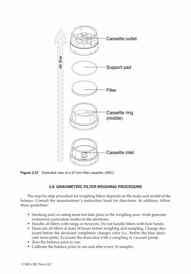
Figure 2.37 Exploded view of a 37-mm filter cassette. (SKC)
2.8 GRAVIMETRIC FILTER WEIGHING PROCEDURE
The step-by-step procedure for weighing filters depends on the make and model of thebalance. Consult the manufacturer’s instruction book for directions. In addition, followthese guidelines:
• Smoking and/or eating must not take place in the weighing area—both generateextraneous particulate matter in the airstream.
• Handle all filters with tongs or tweezers. Do not handle filters with bare hands.• Desiccate all filters at least 24 hours before weighing and sampling. Change des-
iccant before the dessicant completely changes color (i.e., before the blue desic-cant turns pink). Evacuate the desiccator with a sampling or vacuum pump.
• Zero the balance prior to use.• Calibrate the balance prior to use and after every 10 samples.
© 2001 CRC Press LLC
• Immediately prior to placement on the balance, pass all filters over an ionizationunit to remove static charges. (After 12 months of use, return the unit to the dis-tributor for disposal.)
• Weigh all filters at least twice.—If there is more than a 0.005 mg difference in the two weighings, repeat the zero
calibration and reweigh.—If there is less than a 0.005 mg difference in the two weighings, average the
weights for the final weight.• Note: To avoid damage to the weighing mechanism, take care not to exert down-
ward pressure on the weighing pan(s).• Record all the appropriate weighing information (in ink) in the weighing log.• In reassembling the cassette assembly, remember to add the unweighed backup pad.
When weighing the filter after sampling, desiccate first and include any loose materialfrom an overloaded filter and cassette.
2.9 TOTAL DUST AND METAL FUMES
A variety of filtration options is available to collect particulates. Sampling options aredefined based on the regulatory onus and the sampling environment. Some examples ofthese options are as follows:
• Collect total dust on a preweighed, low-ash polyvinyl chloride (PVC) filter at aflow rate of about 2 l/min, depending on the rate required to prevent overload-ing. Weigh PVC filters before and after taking the sample.
• Collect metal fumes on a 0.8-�m mixed cellulose ester filter at approximately 1.5 l/min, not to exceed 2.0 l/min.
• When the gravimetric weight needs to be determined for welding fumes, collectthese fumes on a low-ash PVC filter.
Take care to avoid overloading the filter, as revealed by any loose particulate in the fil-ter cassette housing.
Personal sampling pumps must be calibrated before and after each day of sampling,using a bubble meter method (electronic or mechanical) or the precision rotameter method(which has been calibrated against a bubble meter).
2.10 RESPIRABLE DUST
Respirable dust is a component of particulates in the airstream that will deposit withinthe gaseous exchange areas of the lung (Figure 2.38). Respirable particles are just the rightsize to travel with inspired air into the alveoli of the lung. Once in the alveoli, these parti-cles may be a simple irritant or may dissolve and, thus, become chemicals in suspensionwith tissue fluids. These suspended chemicals are then available to exert toxic and car-cinogenic effects.
Respirable dusts that do not go into solution pose another danger. These insolubledusts/particulates/fibers associated with respirable dusts are easy to breathe in, proceed with ease deeply into the lung, and once in the lung may stay in the tissue bed forever.
© 2001 CRC Press LLC
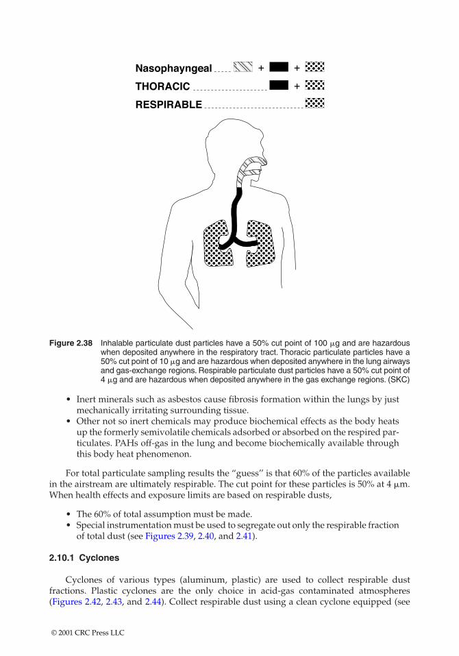
Figure 2.38 Inhalable particulate dust particles have a 50% cut point of 100 �g and are hazardouswhen deposited anywhere in the respiratory tract. Thoracic particulate particles have a50% cut point of 10 �g and are hazardous when deposited anywhere in the lung airwaysand gas-exchange regions. Respirable particulate dust particles have a 50% cut point of4 �g and are hazardous when deposited anywhere in the gas exchange regions. (SKC)
• Inert minerals such as asbestos cause fibrosis formation within the lungs by justmechanically irritating surrounding tissue.
• Other not so inert chemicals may produce biochemical effects as the body heatsup the formerly semivolatile chemicals adsorbed or absorbed on the respired par-ticulates. PAHs off-gas in the lung and become biochemically available throughthis body heat phenomenon.
For total particulate sampling results the “guess’’ is that 60% of the particles availablein the airstream are ultimately respirable. The cut point for these particles is 50% at 4 �m.When health effects and exposure limits are based on respirable dusts,
• The 60% of total assumption must be made.• Special instrumentation must be used to segregate out only the respirable fraction
of total dust (see Figures 2.39, 2.40, and 2.41).
2.10.1 Cyclones
Cyclones of various types (aluminum, plastic) are used to collect respirable dustfractions. Plastic cyclones are the only choice in acid-gas contaminated atmospheres(Figures 2.42, 2.43, and 2.44). Collect respirable dust using a clean cyclone equipped (see
© 2001 CRC Press LLC
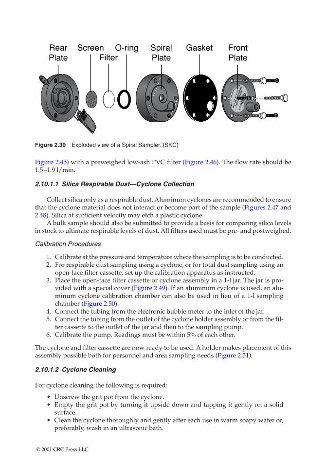
Figure 2.39 Exploded view of a Spiral Sampler. (SKC)
Figure 2.45) with a preweighed low-ash PVC filter (Figure 2.46). The flow rate should be1.5–1.9 l/min.
2.10.1.1 Silica Respirable Dust—Cyclone Collection
Collect silica only as a respirable dust. Aluminum cyclones are recommended to ensurethat the cyclone material does not interact or become part of the sample (Figures 2.47 and2.48). Silica at sufficient velocity may etch a plastic cyclone.
A bulk sample should also be submitted to provide a basis for comparing silica levelsin stock to ultimate respirable levels of dust. All filters used must be pre- and postweighed.
Calibration Procedures
1. Calibrate at the pressure and temperature where the sampling is to be conducted.2. For respirable dust sampling using a cyclone, or for total dust sampling using an
open-face filter cassette, set up the calibration apparatus as instructed.3. Place the open-face filter cassette or cyclone assembly in a 1-l jar. The jar is pro-
vided with a special cover (Figure 2.49). If an aluminum cyclone is used, an alu-minum cyclone calibration chamber can also be used in lieu of a 1-l samplingchamber (Figure 2.50).
4. Connect the tubing from the electronic bubble meter to the inlet of the jar.5. Connect the tubing from the outlet of the cyclone holder assembly or from the fil-
ter cassette to the outlet of the jar and then to the sampling pump.6. Calibrate the pump. Readings must be within 5% of each other.
The cyclone and filter cassette are now ready to be used. A holder makes placement of thisassembly possible both for personnel and area sampling needs (Figure 2.51).
2.10.1.2 Cyclone Cleaning
For cyclone cleaning the following is required:
• Unscrew the grit pot from the cyclone.• Empty the grit pot by turning it upside down and tapping it gently on a solid
surface.• Clean the cyclone thoroughly and gently after each use in warm soapy water or,
preferably, wash in an ultrasonic bath.
© 2001 CRC Press LLC
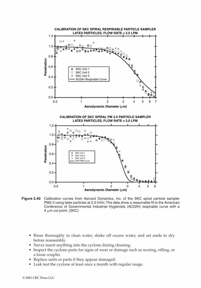
Figure 2.40 Calibration curves from Aerosol Dynamics, Inc. of the SKC spiral particle samplerPM2.5 using latex particles at 2.0 l/min.The data show a reasonable fit to the AmericanConference of Governmental Industrial Hygienists (ACGIH) respirable curve with a 4 �m cut point. (SKC)
• Rinse thoroughly in clean water, shake off excess water, and set aside to drybefore reassembly.
• Never insert anything into the cyclone during cleaning.• Inspect the cyclone parts for signs of wear or damage such as scoring, rifling, or
a loose coupler.• Replace units or parts if they appear damaged.• Leak test the cyclone at least once a month with regular usage.
© 2001 CRC Press LLC
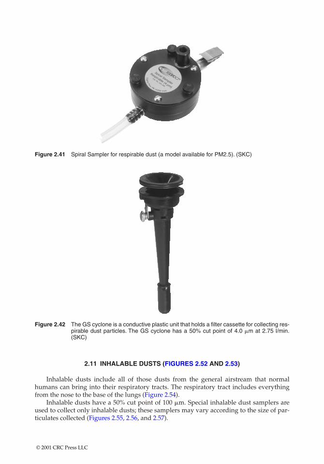
Figure 2.41 Spiral Sampler for respirable dust (a model available for PM2.5). (SKC)
Figure 2.42 The GS cyclone is a conductive plastic unit that holds a filter cassette for collecting res-pirable dust particles. The GS cyclone has a 50% cut point of 4.0 �m at 2.75 l/min.(SKC)
2.11 INHALABLE DUSTS (FIGURES 2.52 AND 2.53)
Inhalable dusts include all of those dusts from the general airstream that normalhumans can bring into their respiratory tracts. The respiratory tract includes everythingfrom the nose to the base of the lungs (Figure 2.54).
Inhalable dusts have a 50% cut point of 100 �m. Special inhalable dust samplers areused to collect only inhalable dusts; these samplers may vary according to the size of par-ticulates collected (Figures 2.55, 2.56, and 2.57).
© 2001 CRC Press LLC
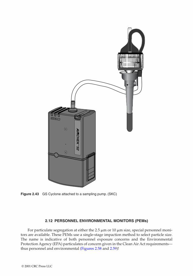
Figure 2.43 GS Cyclone attached to a sampling pump. (SKC)
2.12 PERSONNEL ENVIRONMENTAL MONITORS (PEMs)
For particulate segregation at either the 2.5 �m or 10 �m size, special personnel moni-tors are available. These PEMs use a single-stage impaction method to select particle size.The name is indicative of both personnel exposure concerns and the EnvironmentalProtection Agency (EPA) particulates of concern given in the Clean Air Act requirements—thus personnel and environmental (Figures 2.58 and 2.59)!
© 2001 CRC Press LLC
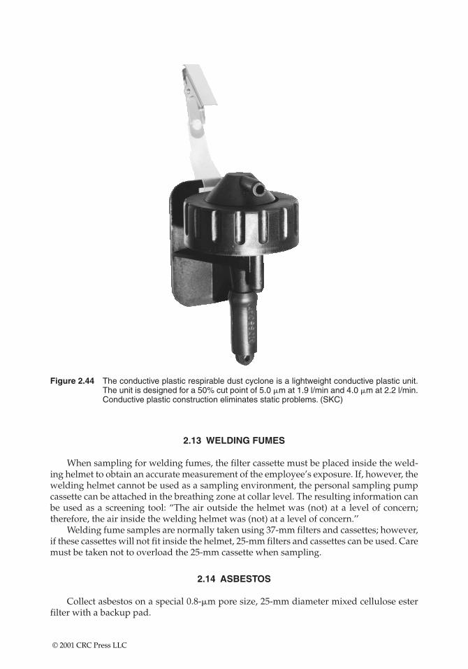
Figure 2.44 The conductive plastic respirable dust cyclone is a lightweight conductive plastic unit.The unit is designed for a 50% cut point of 5.0 �m at 1.9 l/min and 4.0 �m at 2.2 l/min.Conductive plastic construction eliminates static problems. (SKC)
2.13 WELDING FUMES
When sampling for welding fumes, the filter cassette must be placed inside the weld-ing helmet to obtain an accurate measurement of the employee’s exposure. If, however, thewelding helmet cannot be used as a sampling environment, the personal sampling pumpcassette can be attached in the breathing zone at collar level. The resulting information canbe used as a screening tool: “The air outside the helmet was (not) at a level of concern;therefore, the air inside the welding helmet was (not) at a level of concern.’’
Welding fume samples are normally taken using 37-mm filters and cassettes; however,if these cassettes will not fit inside the helmet, 25-mm filters and cassettes can be used. Caremust be taken not to overload the 25-mm cassette when sampling.
2.14 ASBESTOS
Collect asbestos on a special 0.8-�m pore size, 25-mm diameter mixed cellulose esterfilter with a backup pad.
© 2001 CRC Press LLC
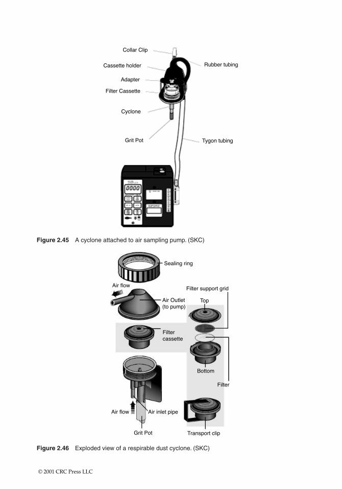
Figure 2.45 A cyclone attached to air sampling pump. (SKC)
Figure 2.46 Exploded view of a respirable dust cyclone. (SKC)
© 2001 CRC Press LLC
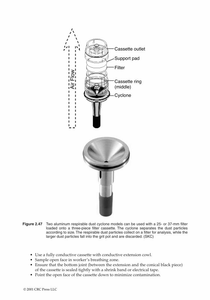
Figure 2.47 Two aluminum respirable dust cyclone models can be used with a 25- or 37-mm filterloaded onto a three-piece filter cassette. The cyclone separates the dust particlesaccording to size. The respirable dust particles collect on a filter for analysis, while thelarger dust particles fall into the grit pot and are discarded. (SKC)
• Use a fully conductive cassette with conductive extension cowl.• Sample open face in worker’s breathing zone.• Ensure that the bottom joint (between the extension and the conical black piece)
of the cassette is sealed tightly with a shrink band or electrical tape.• Point the open face of the cassette down to minimize contamination.
© 2001 CRC Press LLC
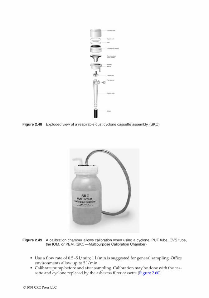
Figure 2.48 Exploded view of a respirable dust cyclone cassette assembly. (SKC)
Figure 2.49 A calibration chamber allows calibration when using a cyclone, PUF tube, OVS tube,the IOM, or PEM. (SKC—Multipurpose Calibration Chamber)
• Use a flow rate of 0.5–5 l/min; 1 l/min is suggested for general sampling. Officeenvironments allow up to 5 l/min.
• Calibrate pump before and after sampling. Calibration may be done with the cas-sette and cyclone replaced by the asbestos filter cassette (Figure 2.60).
© 2001 CRC Press LLC
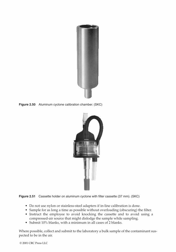
Figure 2.50 Aluminum cyclone calibration chamber. (SKC)
Figure 2.51 Cassette holder on aluminum cyclone with filter cassette (37 mm). (SKC)
• Do not use nylon or stainless-steel adapters if in-line calibration is done.• Sample for as long a time as possible without overloading (obscuring) the filter.• Instruct the employee to avoid knocking the cassette and to avoid using a
compressed-air source that might dislodge the sample while sampling.• Submit 10% blanks, with a minimum in all cases of 2 blanks.
Where possible, collect and submit to the laboratory a bulk sample of the contaminant sus-pected to be in the air.
© 2001 CRC Press LLC
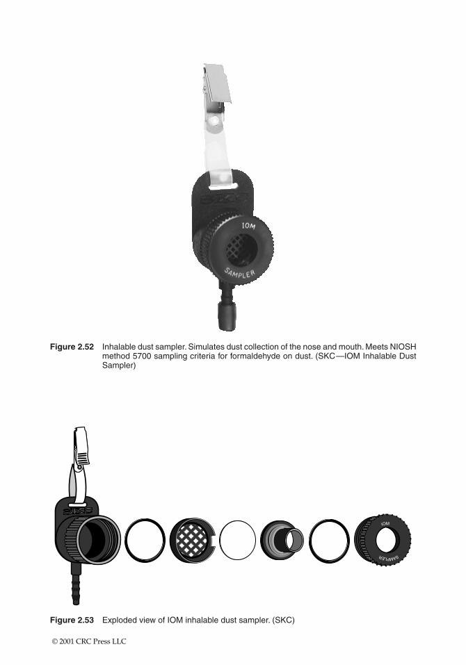
Figure 2.52 Inhalable dust sampler. Simulates dust collection of the nose and mouth. Meets NIOSHmethod 5700 sampling criteria for formaldehyde on dust. (SKC—IOM Inhalable DustSampler)
IOM
SAMPLER
Figure 2.53 Exploded view of IOM inhalable dust sampler. (SKC)
© 2001 CRC Press LLC
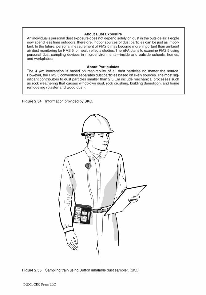
About Dust ExposureAn individual’s personal dust exposure does not depend solely on dust in the outside air. Peoplenow spend less time outdoors; therefore, indoor sources of dust particles can be just as impor-tant. In the future, personal measurement of PM2.5 may become more important than ambientair dust monitoring for PM2.5 for health effects studies.The EPA plans to examine PM2.5 usingpersonal dust sampling devices in microenvironments—inside and outside schools, homes,and workplaces.
About ParticulatesThe 4 �m convention is based on respirability of all dust particles no matter the source.However, the PM2.5 convention separates dust particles based on likely sources.The most sig-nificant contributors to dust particles smaller than 2.5 �m include mechanical processes suchas rock weathering that causes windblown dust, rock crushing, building demolition, and homeremodeling (plaster and wood dust).
AIRCHEKSAMPLER
SAMPLE PERIOD MINUTESSTART
HOLD
FLOWAND
BATTERYCHECK
DIGITSET
PUMPRUNTIME
DIGITSELECTTOTAL
ELAPSEDTIME
SET-UPMODE
FLOW
ADJ
ON
5
4
3
2
1
AIRCHEK SAMPLERMODEL 224-PCXR8
UL¤ LISTED 124U
SERIAL NO.SKC INC.EIGHTY FOUR PA 15330
WARNING - SUBSTITUTION OFCOMPONENTS MAY IMPAIR INTRINSIC SAFETY. USE ONLY UL LISTEDPORTABLE AIR SAMPLING PUMPBATTERY PACK MODEL P21661
INTRINSICALLY SAFEPORTABLE AIR SAMPLING PUMPFOR USE IN HAZARDOUS LOCATIONS CLASS I, GROUPS A B C DAND CLASS II, GROUPS E F GAND CLASS III, TEMPERATURECODE T3C.
Figure 2.55 Sampling train using Button inhalable dust sampler. (SKC)
Figure 2.54 Information provided by SKC.
© 2001 CRC Press LLC
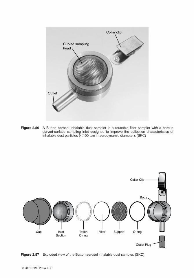
Figure 2.56 A Button aerosol inhalable dust sampler is a reusable filter sampler with a porouscurved-surface sampling inlet designed to improve the collection characteristics ofinhalable dust particles (�100 �m in aerodynamic diameter). (SKC)
Figure 2.57 Exploded view of the Button aerosol inhalable dust sampler. (SKC)
© 2001 CRC Press LLC
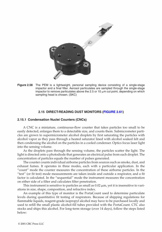
Figure 2.58 The PEM is a lightweight, personal sampling device consisting of a single-stageimpactor and a final filter. Aerosol particulates are sampled through the single-stageimpactor to remove particulates above the 2.5 or 10 �m cut point, depending on whichsampling head is chosen. (SKC)
2.15 DIRECT-READING DUST MONITORS (FIGURE 2.61)
2.15.1 Condensation Nuclei Counters (CNCs)
A CNC is a miniature, continuous-flow counter that takes particles too small to be easily detected, enlarges them to a detectable size, and counts them. Submicrometer parti-cles are grown to supermicrometer alcohol droplets by first saturating the particles withalcohol vapor as they pass through a heated saturator lined with alcohol soaked felt andthen condensing the alcohol on the particles in a cooled condenser. Optics focus laser lightinto the sensing volume.
As the droplets pass through the sensing volume, the particles scatter the light. Thelight is directed onto a photodiode that generates an electrical pulse from each droplet. Theconcentration of particles equals the number of pulses generated.
The counter counts individual airborne particles from sources such as smoke, dust, andexhaust fumes. It operates in three modes, each with a particular application. In the“count’’ mode the counter measures the concentration of these airborne particles. In the“test’’ (or fit test) mode measurements are taken inside and outside a respirator, and a fitfactor is calculated. In the “sequential’’ mode the instrument measures the concentrationon either side of a filter and calculates filter penetration.
This instrument is sensitive to particles as small as 0.02 �m, yet it is insensitive to vari-ations in size, shape, composition, and refractive index.
An example of this type of monitor is the PortaCount used to determine particulatelevels during quantitative fit testing of respirators. Because of shipping regulations forflammable liquids, reagent-grade isopropyl alcohol may have to be purchased locally andused to refill the small plastic alcohol-fill tubes provided with the PortaCount. CTC alsostocks and ships this alcohol. For long-term storage (over 14 days), follow the steps listedbelow:
© 2001 CRC Press LLC
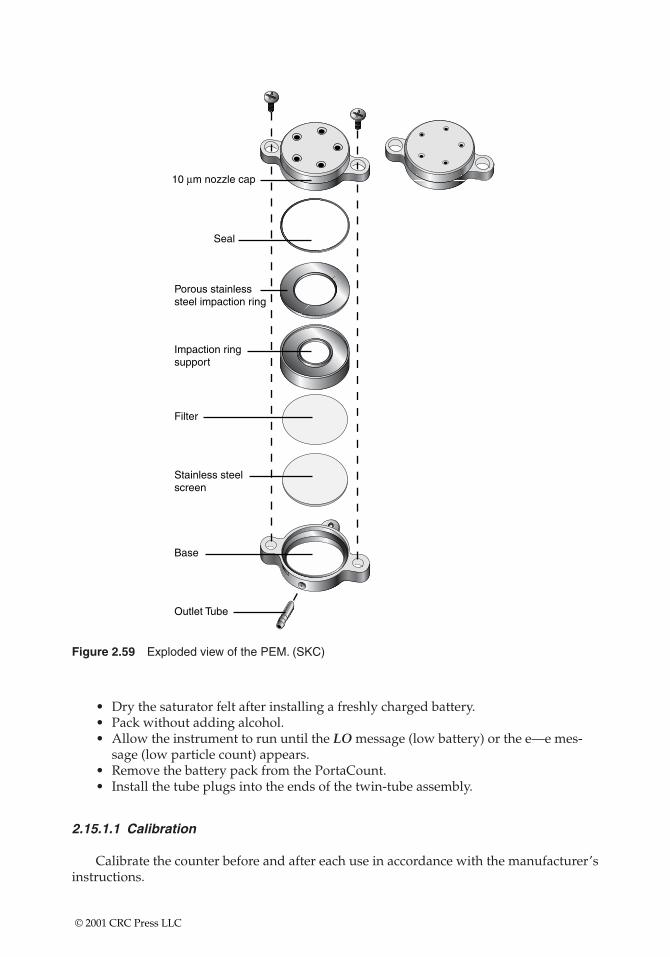
Stainless steelscreen
Outlet Tube
Base
Filter
Impaction ringsupport
Porous stainlesssteel impaction ring
Seal
10 µm nozzle cap
Figure 2.59 Exploded view of the PEM. (SKC)
• Dry the saturator felt after installing a freshly charged battery.• Pack without adding alcohol.• Allow the instrument to run until the LO message (low battery) or the e—e mes-
sage (low particle count) appears.• Remove the battery pack from the PortaCount.• Install the tube plugs into the ends of the twin-tube assembly.
2.15.1.1 Calibration
Calibrate the counter before and after each use in accordance with the manufacturer’sinstructions.
© 2001 CRC Press LLC
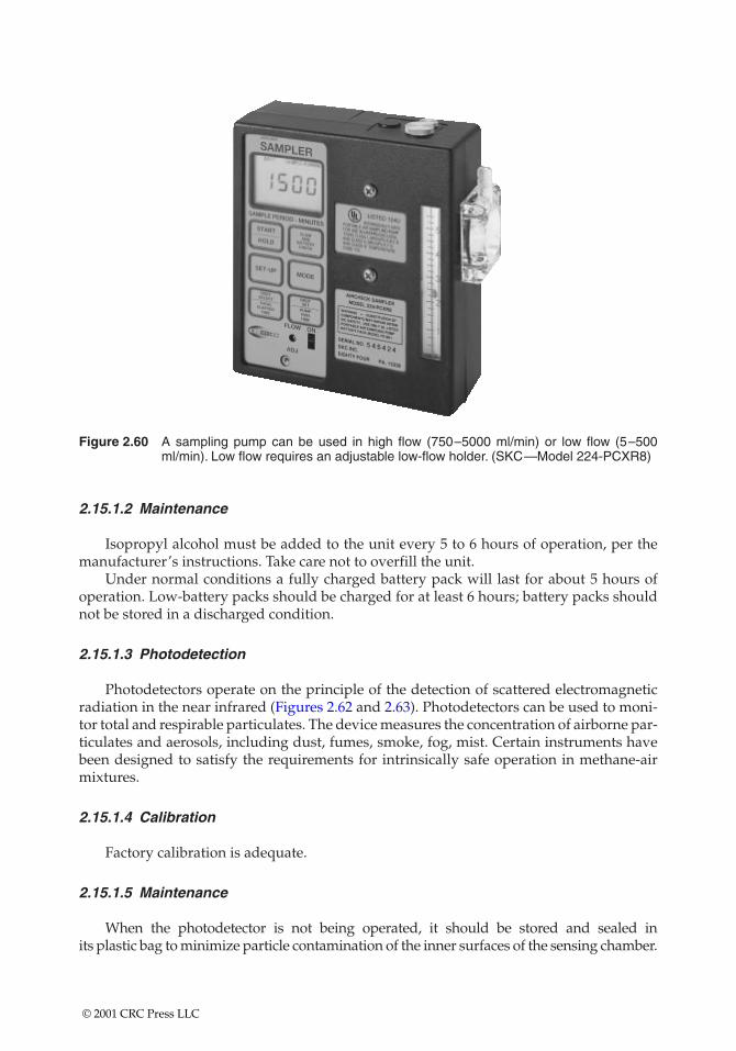
Figure 2.60 A sampling pump can be used in high flow (750–5000 ml/min) or low flow (5–500ml/min). Low flow requires an adjustable low-flow holder. (SKC—Model 224-PCXR8)
2.15.1.2 Maintenance
Isopropyl alcohol must be added to the unit every 5 to 6 hours of operation, per themanufacturer’s instructions. Take care not to overfill the unit.
Under normal conditions a fully charged battery pack will last for about 5 hours ofoperation. Low-battery packs should be charged for at least 6 hours; battery packs shouldnot be stored in a discharged condition.
2.15.1.3 Photodetection
Photodetectors operate on the principle of the detection of scattered electromagneticradiation in the near infrared (Figures 2.62 and 2.63). Photodetectors can be used to moni-tor total and respirable particulates. The device measures the concentration of airborne par-ticulates and aerosols, including dust, fumes, smoke, fog, mist. Certain instruments havebeen designed to satisfy the requirements for intrinsically safe operation in methane-airmixtures.
2.15.1.4 Calibration
Factory calibration is adequate.
2.15.1.5 Maintenance
When the photodetector is not being operated, it should be stored and sealed in its plastic bag to minimize particle contamination of the inner surfaces of the sensing chamber.
© 2001 CRC Press LLC
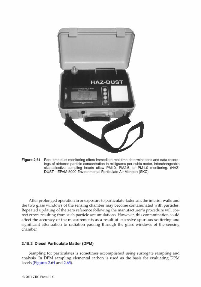
Figure 2.61 Real-time dust monitoring offers immediate real-time determinations and data record-ings of airborne particle concentration in milligrams per cubic meter. Interchangeablesize-selective sampling heads allow PM10, PM2.5, or PM1.0 monitoring. (HAZ-DUST—EPAM-5000 Environmental Particulate Air Monitor) (SKC)
After prolonged operation in or exposure to particulate-laden air, the interior walls andthe two glass windows of the sensing chamber may become contaminated with particles.Repeated updating of the zero reference following the manufacturer’s procedure will cor-rect errors resulting from such particle accumulations. However, this contamination couldaffect the accuracy of the measurements as a result of excessive spurious scattering and significant attenuation to radiation passing through the glass windows of the sensingchamber.
2.15.2 Diesel Particulate Matter (DPM)
Sampling for particulates is sometimes accomplished using surrogate sampling andanalysis. In DPM sampling elemental carbon is used as the basis for evaluating DPM levels (Figures 2.64 and 2.65).
© 2001 CRC Press LLC
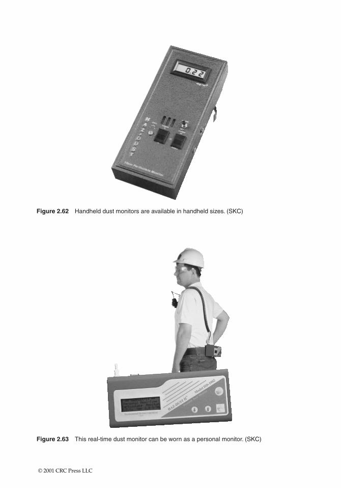
Figure 2.62 Handheld dust monitors are available in handheld sizes. (SKC)
Figure 2.63 This real-time dust monitor can be worn as a personal monitor. (SKC)
© 2001 CRC Press LLC
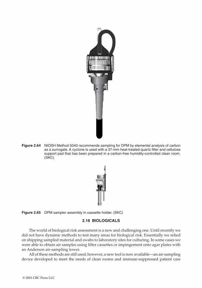
Figure 2.64 NIOSH Method 5040 recommends sampling for DPM by elemental analysis of carbonas a surrogate. A cyclone is used with a 37-mm heat-treated quartz filter and cellulosesupport pad that has been prepared in a carbon-free humidity-controlled clean room.(SKC)
Figure 2.65 DPM sampler assembly in cassette holder. (SKC)
2.16 BIOLOGICALS
The world of biological risk assessment is a new and challenging one. Until recently wedid not have dynamic methods to test many areas for biological risk. Essentially we reliedon shipping sampled material and swabs to laboratory sites for culturing. In some cases wewere able to obtain air samples using filter cassettes or impingement onto agar plates withan Anderson air-sampling tower.
All of these methods are still used; however, a new tool is now available—an air-samplingdevice developed to meet the needs of clean rooms and immune-suppressed patient care
© 2001 CRC Press LLC
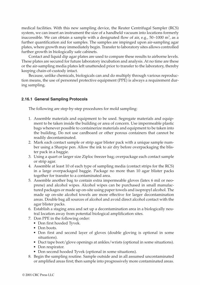
medical facilities. With this new sampling device, the Reuter Centrifugal Sampler (RCS)system, we can insert an instrument the size of a handheld vacuum into locations formerlyinaccessible. We can obtain a sample with a designated flow of air, e.g., 50–1000 m3, as afurther quantification aid for samples. The samples are impinged upon air-sampling agarplates, where growth may immediately begin. Transfer to laboratory sites allows controlledfurther growth in biologically safe cabinets.
Contact and liquid dip agar plates are used to compare these results to airborne levels.These plates are secured for future laboratory incubation and analysis. At no time are theseor the air-sampling media plates left unattended prior to transfer to the laboratory, therebykeeping chain-of-custody intact.
Because, unlike chemicals, biologicals can and do multiply through various reproduc-tion means, the use of personnel protective equipment (PPE) is always a requirement dur-ing sampling.
2.16.1 General Sampling Protocols
The following are step-by-step procedures for mold sampling:
1. Assemble materials and equipment to be used. Segregate materials and equip-ment to be taken inside the building or area of concern. Use impermeable plasticbags whenever possible to containerize materials and equipment to be taken intothe building. Do not use cardboard or other porous containers that cannot bereadily decontaminated.
2. Mark each contact sample or strip agar blister pack with a unique sample num-ber using a Sharpie pen. Allow the ink to air dry before overpackaging the blis-ter pack in a baggie.
3. Using a quart or larger size Ziploc freezer bag; overpackage each contact sampleor strip agar.
4. Assemble at least 10 of each type of sampling media (contact strips for the RCS)in a large overpackaged baggie. Package no more than 10 agar blister packstogether for transfer to a contaminated area.
5. Assemble another bag to contain extra impermeable gloves (latex 6 mil or neo-prene) and alcohol wipes. Alcohol wipes can be purchased in small manufac-tured packages or made up on-site using paper towels and isopropyl alcohol. Themade up on-site alcohol towels are more effective for larger decontaminationareas. Double bag all sources of alcohol and avoid direct alcohol contact with theagar blister packs.
6. Establish a staging area and set up a decontamination area in a biologically neu-tral location away from potential biological amplification sites.
7. Don PPE in the following order:• Don first hooded Tyvek.• Don boots.• Don first and second layer of gloves (double gloving is optional in some
situations).• Duct tape boot/glove openings at ankles/wrists (optional in some situations).• Don respirator.• Don second hooded Tyvek (optional in some situations).
8. Begin the sampling routine. Sample outside and in all assumed uncontaminatedor amplified areas first; then sample into progressively more contaminated areas.
© 2001 CRC Press LLC
Use the same protocols for all sampling events, including the same pressure andmotion when using contact plates and the same walking routines or static place-ment when using the RCS.
2.16.2 Contact and Grab Sampling
Contact and specimen grab-sampling routines are as follows:
1. Open sample overbag at first location to be sampled.2. Sample mold by applying the contact plate to the area with some pressure, by
swabbing, or by obtaining a small sample of contaminated building (or other)material.
3. Place mold-contaminated item into the sample bag or swab vial.4. Seal the overbag.5. Decontaminate gloves if contaminated by direct contact or if pathogenic fungi
are suspected.6. Place used decon pad into small waste bag.7. Decontaminate spatula or any other tools used.8. Place decon pad (if used) into small waste bag. Decon pads can be baggies or
small pieces of precut plastic.9. Decontaminate outside of sealed sample bag if contaminated by direct contact or
if pathogenic fungi are suspected.10. Place used decon pad into small waste bag.11. Repeat steps 1–10 for additional sampling locations.
2.16.3 Reuter Central Fugal System (RCS)
Both high-volume and low-volume RCS units are available (see Figures 2.66 and 2.67).The RCS units can be mounted on stands if necessary (Figure 2.68). RCS sampling routinesare as follows:
Figure 2.66 Biological air sampling instrument. (Biotest Diagnostic Corp. Air Sampler RCS)
© 2001 CRC Press LLC
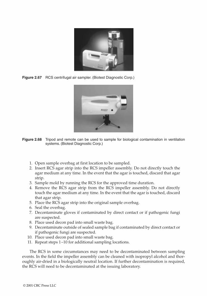
Figure 2.67 RCS centrifugal air sampler. (Biotest Diagnostic Corp.)
Figure 2.68 Tripod and remote can be used to sample for biological contamination in ventilationsystems. (Biotest Diagnostic Corp.)
1. Open sample overbag at first location to be sampled.2. Insert RCS agar strip into the RCS impeller assembly. Do not directly touch the
agar medium at any time. In the event that the agar is touched, discard that agarstrip.
3. Sample mold by running the RCS for the approved time duration.4. Remove the RCS agar strip from the RCS impeller assembly. Do not directly
touch the agar medium at any time. In the event that the agar is touched, discardthat agar strip.
5. Place the RCS agar strip into the original sample overbag.6. Seal the overbag.7. Decontaminate gloves if contaminated by direct contact or if pathogenic fungi
are suspected.8. Place used decon pad into small waste bag.9. Decontaminate outside of sealed sample bag if contaminated by direct contact or
if pathogenic fungi are suspected.10. Place used decon pad into small waste bag.11. Repeat steps 1–10 for additional sampling locations.
The RCS in some circumstances may need to be decontaminated between samplingevents. In the field the impeller assembly can be cleaned with isopropyl alcohol and thor-oughly air-dried in a biologically neutral location. If further decontamination is required,the RCS will need to be decontaminated at the issuing laboratory.
© 2001 CRC Press LLC
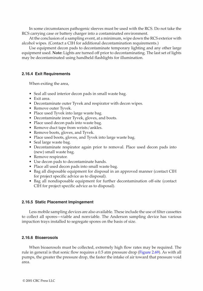
In some circumstances pathogenic sleeves must be used with the RCS. Do not take theRCS carrying case or battery charger into a contaminated environment.
At the conclusion of a sampling event, at a minimum, wipe down the RCS exterior withalcohol wipes. (Contact a CIH for additional decontamination requirements.)
Use equipment decon pads to decontaminate temporary lighting and any other largeequipment used. Note: Lights are turned off prior to decontaminating. The last set of lightsmay be decontaminated using handheld flashlights for illumination.
2.16.4 Exit Requirements
When exiting the area,
• Seal all used interior decon pads in small waste bag.• Exit area.• Decontaminate outer Tyvek and respirator with decon wipes.• Remove outer Tyvek.• Place used Tyvek into large waste bag.• Decontaminate inner Tyvek, gloves, and boots.• Place used decon pads into waste bag.• Remove duct tape from wrists/ankles.• Remove boots, gloves, and Tyvek.• Place used boots, gloves, and Tyvek into large waste bag.• Seal large waste bag.• Decontaminate respirator again prior to removal. Place used decon pads into
(new) small waste bag.• Remove respirator.• Use decon pads to decontaminate hands.• Place all used decon pads into small waste bag.• Bag all disposable equipment for disposal in an approved manner (contact CIH
for project specific advice as to disposal).• Bag all nondisposable equipment for further decontamination off-site (contact
CIH for project specific advice as to disposal).
2.16.5 Static Placement Impingement
Less mobile sampling devices are also available. These include the use of filter cassettesto collect all spores—viable and nonviable. The Anderson sampling device has variousimpaction trays installed to segregate spores on the basis of size.
2.16.6 Bioaerosols
When bioaerosols must be collected, extremely high flow rates may be required. Therule in general is that sonic flow requires a 0.5 atm pressure drop (Figure 2.69). As with allpumps, the greater the pressure drop, the faster the intake of air toward that pressure voidarea.
© 2001 CRC Press LLC
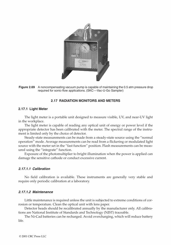
Figure 2.69 A noncompensating vacuum pump is capable of maintaining the 0.5 atm pressure droprequired for sonic-flow applications. (SKC—Vac-U-Go Sampler)
2.17 RADIATION MONITORS AND METERS
2.17.1 Light Meter
The light meter is a portable unit designed to measure visible, UV, and near-UV lightin the workplace.
The light meter is capable of reading any optical unit of energy or power level if theappropriate detector has been calibrated with the meter. The spectral range of the instru-ment is limited only by the choice of detector.
Steady-state measurements can be made from a steady-state source using the “normaloperation’’ mode. Average measurements can be read from a flickering or modulated lightsource with the meter set in the “fast function’’ position. Flash measurements can be meas-ured using the “integrate’’ function.
Exposure of the photomultiplier to bright illumination when the power is applied candamage the sensitive cathode or conduct excessive current.
2.17.1.1 Calibration
No field calibration is available. These instruments are generally very stable andrequire only periodic calibration at a laboratory.
2.17.1.2 Maintenance
Little maintenance is required unless the unit is subjected to extreme conditions of cor-rosion or temperature. Clean the optical unit with lens paper.
Detector heads should be recalibrated annually by the manufacturer only. All calibra-tions are National Institute of Standards and Technology (NIST) traceable.
The Ni-Cad batteries can be recharged. Avoid overcharging, which will reduce batterylife.
© 2001 CRC Press LLC
2.18 IONIZING RADIATION
Because ionizing radiation cannot be detected by the human senses, detection andquantification must be accomplished by specifically designed instruments. All such meth-ods of measurement employ a substance that responds to radiation in a measurable wayand a system or apparatus to measure the extent of the response. Most radiation detectorsoperate by one of two methods: ionization or scintillation.
The selection of instruments is based on the type and energy range of the radiationexpected on-site. Survey instruments will be chosen for their sensitivity to the type of radi-ation present in the area to be surveyed. The method of relating the instrument reading tomilliroentgens per hour will be included.
Some instruments can measure multiple types of radiation and require methods fordetermining which type of radiation is being measured. For example, neutron detectors forneutron dose can be quantified using boron trifluoride (BF3) detectors.
The ionizing radiation survey meter is useful for measuring radon decay productsfrom air samples collected on filters.
• The barometric pressure should be noted for ionizing radiation chambers.• Wipe samples collected on a filter can also be counted with this detector, and gen-
eral area sampling can be done.• The survey meter with the scintillation detector can be used to measure the pres-
ence of radon-decay products in a dust sample.
2.18.1 Ionization Detectors
Most ionization detectors consist of a gas-filled chamber with a voltage applied; a cen-tral wire becomes the anode, and the chamber wall becomes the cathode. Any ion pairs pro-duced by radiation interacting with the chamber move to the electrodes, where they arecollected to form an electronic pulse that can be measured and quantified. Depending onthe voltage applied to the chamber, the detector may be considered a gas proportionaldetector, a Geiger-Muller (GM) detector, or an ion chamber.
2.18.1.1 Gas Proportional Detectors
Thin-window gas proportional detectors may be used to detect alpha and betaradiation. Distinction between alpha and beta is achieved by adjusting the voltage of thedetector.
2.18.1.2 Ion Chamber
An ionization chamber is a gas-filled chamber containing an anode and a cathode. Asradiation passes through the gas, it ionizes some of the gas molecules. These ion pairs areattracted to the anode and cathode and create an electrical pulse. The pulses are counted,integrated, and displayed on the meter face in roentgens per hour. Ion chambers provide anearly linear response to gamma and X-ray radiation above a few kiloelectron volts inenergy and at radiation levels above 0.1 mR/h. For this reason an ion chamber is the onlyinstrument for quantifying radiation exposures. Ion chambers may be used to quantify thebeta, gamma, or X-ray dose at a location.
© 2001 CRC Press LLC
Sodium iodide (NaI) scintillation detectors, used on survey meters, provide bettercounting efficiency for gamma and X-rays, but have a more limited range of energies,depending on the size of the crystal and the density of the window. NaI detectors may beused to detect the presence of gamma radiation, but only if the energy level of the radiationis known, and the correct size crystal is used.
2.18.1.3 GM Detector
Because of its versatility and dependability, the GM detector is the most widely usedportable survey instrument. A GM detector with a thin window can detect alpha, beta, andgamma radiation. The GM is particularly sensitive to medium-to-high energy beta particles (e.g., as from 32P), X-rays, and gamma rays. The GM detector is fairly insensitive to low-energy X-rays or gamma rays, such as those emitted from 125I, and to low-energybeta particles, such as those emitted by 35S and 14C; it cannot detect the weak betas from 3H.
Unlike the ion chamber the GM detector does not actually “measure’’ exposure rate. Itinstead “detects’’ the number of particles interacting in its sensitive volume per unit time.The readout of the GM is in counts per minute (cpm), although it can be calibrated toapproximate milliroentgens per hour for certain situations. With these advantages and lim-itations a GM detector on a rugged survey meter is the instrument of choice for initial entryand survey of field radiation sources and radioactive contamination.
GM detectors are calibrated to one energy level of the electromagnetic spectrum—usually 662 keV, the gamma energy from the decay of 137Cs, and are read out in milliroent-gens per hour. GM detector efficiency for radiation at other energies is not linear. GM detectors can be used to detect the presence of radiation, but only as a rough estimateof the dose rate. Beta shields will compensate for blocking betas and reading gamma or X-ray radiation. Subtraction of the gamma or X-ray radiation readings will yield anapproximation of the beta contribution. Beta contribution should be read in counts per minute.
2.18.2 Scintillation Detectors
Scintillation detectors are based upon the use of various phosphors (or scintillators)that emit light in proportion to the quantity and energy of the radiation they absorb. Thelight flashes are converted to photoelectrons that are multiplied in a series of dynodes (i.e.,a photomultiplier) to produce a large electrical pulse. Because the light output and result-ant electrical pulse from a scintillator is proportionate to the amount of energy depositedby the radiation, scintillators are useful in identifying the amount of specific radionuclidespresent (i.e., scintillation spectrometry).
Solid scintillation detectors are particularly useful in identifying and quantifyinggamma-emitting radionuclides. NaI scintillation detectors, used on survey meters, providebetter counting efficiency for gamma and X-rays, but have a more limited range of ener-gies, depending on the size of the crystal and the density of the window. NaI detectors maybe used to detect the presence of gamma radiation, but only if the energy level of the radi-ation is known, and the correct size crystal is used.
The common gamma counter employs a large (e.g., 2� � 2� or 3� � 3�) NaI crystalwithin a lead-shielded well. The sample vial is lowered directly into a hollow chamber
© 2001 CRC Press LLC
within the crystal for counting. Such systems are extremely sensitive, but do not have theresolution of more recently developed semiconductor counting systems. Portable scintilla-tion detectors are also widely used for conducting various types of radiation surveys. Ofparticular use to researchers working with radioiodine is the NaI thin crystal detector capa-ble of detecting the emissions from 125I with efficiencies nearing 20% (a GM detector is lessthan 1% efficient for 125I).
The most common means of quantifying the presence of beta-emitting radionuclides isthrough the use of liquid scintillation counting. In these systems the sample and phosphorare combined in a solvent within the counting vial. The vial is then lowered into a wellbetween two photomultiplier tubes for counting. Liquid scintillation counting has been anessential tool of research involving radiotracers such as 3H, 14C, 35S, and 45Ca.
One problem that occurs with liquid scintillation counting is determining the effi-ciency of the system. The low-energy photons produced by the beta particles interactingwith the scintillation cocktail are easily shielded from the photomultiplier tubes due tooptical and chemical quenching. To account for this artifact, a quench curve must be com-puted using a set of increasingly quenched standards and a method of determining a quench-indicating parameter for each standard. The quench curve is a graph for a certain nuclide ofeach standard’s quench-indicating parameter (QIP) vs. the efficiency of the counter. The effi-ciency for an unknown sample is then determined by measuring its QIP, with the graphdetermining the counter’s efficiency for that sample. Then use that quantity and the countsper minute of the sample to determine the disintegration rate (dpm) of the sample.
Fortunately, most modern counters compute and store quench curves from a singlecounting of a standard set, use an external standard to determine the QIP, and automati-cally output sample counts in disintegrations per minute.
The other common problem with liquid scintillation counting is chemiluminescence.Certain chemicals when mixed with some scintillation cocktails will cause the cocktail toemit photons, resulting in a higher count rate than actually exists from the radionuclideitself. Rule of thumb: Let scintillation vials wait for a few hours after mixing the cocktailand the material to be assayed to allow for the initial chemiluminescence to be exhausted.
2.18.3 Counting Efficiency
The purpose of radiation counting systems is to determine sample activity (microcuriesor disintegrations per minute). However, because of numerous factors related to both thecounting system and the specific radionuclide(s) in the sample, the radiation detector can never see 100% of the disintegrations occurring in the sample. The counts per minutedisplayed by the counter must therefore be distinguished from the disintegration rate ofthe sample.
The ratio of the count rate to the disintegration rate expressed as a percent is the effi-ciency of the counting system.
cpm/dpm � 100% � efficiency (1)
Because every counting system will register a certain number of counts from environmen-tal radiation and electronic noise in the counter (i.e., background), a more correct formulais as follows:
[(Sample cpm – bkg cpm)/Sample dpm] � 100% � efficiency (2)
© 2001 CRC Press LLC
Example 1
A 1-ml sample of a solution of 125I is counted in a gamma scintillation spectrometer with a window of 15 keV to 75 keV. A 0.1 �Ci 125I standard and a background sample arecounted along with the solution for 1-min each. The results are as follows:
0.1 �Ci � 2,220,000 dpm � 2.22 � 106 dpm/�Ci
Background (bkg) � 35 cpm
Standard � 110,658 cpm
Sample � 3,246,770 cpm
Efficiency of the counter:
� [(Sample cpm – bkg cpm)/Sample dpm] � 100% � efficiency
� [(110,658 – 35)/(0.1 � 2.22 � 106 dpm/�Ci)] � 100% � 0.4983
� 49.8% efficiency of the counter
Activity of the sample:
� (Sample cpm – Background)/(efficiency � dpm per �Ci)
� (3,246,770 – 35)/[0.4983 � (2.22 � 106 dpm/�Ci)]
� 2.935 �Ci/ml of sample
Example 2
A sample containing a 14C-labeled amino acid is counted in a liquid scintillationcounter. The sample count rate is 1200 cpm, and the background is 30 cpm. If the counteris 85% efficient for 14C, what is the activity within the sample?
Sample cpm – bkg cpm/Sample dpm � efficiency
� (1200 � 30)/85 � 1376
1376 dpm � 2.22 � 106 dpm/�Ci
� 6.2 � 10 � 4 �Ci
2.18.4 Monitoring for Radioactive Contamination
Monitoring instruments must be chosen for their sensitivity to the type of radiation tobe monitored. A method of relating the instrument reading to microcuries must beincluded.
Monitoring must be performed slowly and at distances of 1 to 2 mm from the surfaceto detect low-intensity radiations. The monitoring results must be documented and mustinclude the following:
© 2001 CRC Press LLC
• Identification of the instrument used to monitor• Name of the person performing the monitoring• Location, date, and time of monitoring• Results of the monitoring• Comments on any factors that might influence the readings
2.18.5 Daily Use Checks
Each survey instrument must have an appropriate check source attached or assignedto the instrument. The check source for the instrument must be surveyed immediately aftercalibration, and the reading must be written on the calibration sticker on the instrument.
Before each use of the instrument, the check source must be monitored, and the read-ing compared to the reading noted on the calibration sticker. Any meter not measuringwithin �10% of the reading on the calibration sticker must be tagged as requiring mainte-nance and must not be used until maintenance and recalibration have been performed.Surveys must be performed slowly; the instrument needs time to integrate and display themeasurement.
Survey results must be documented and must include the following:
• Identification of the instrument used to perform the survey• Name of the person performing the survey• Location, date, and time of the survey• Results of the survey• Comments on any factors that might influence the survey
2.18.6 Survey Instrument Calibration
Survey instruments must be calibrated periodically using procedures outlined in theinstrument manual, within the following guidelines:
• All sources used to calibrate instruments must be traceable to NIST.• The survey meter and the probe must be calibrated as a unit. If probes are
changed, the unit must be recalibrated prior to use.• Instruments must be calibrated at least annually.• Instruments must be calibrated after every maintenance or repair operation.
The date of calibration, the date the next calibration is due, and the initials of the personperforming the calibration must be written on a calibration sticker attached to the instru-ment.
2.19 NONIONIZING RADIATION
Electromagnetic fields (EMFs) produced by computer terminals, cellular phones, elec-tric blankets, and power lines can be measured. Microwave radiation, whether used forcommunication, electron wave propulsion, or food warming, can also be measured.
EMFs are generated any time charged particles move through a medium. Two fieldsare actually produced, one electric and one magnetic. Both are always found together.
© 2001 CRC Press LLC
The earth itself is the largest source for a magnetic field, and lightning generates one of thestrongest electric fields. Electricity transmitted through a wire produces an EMF propor-tional in size to the current flow and the voltage drop.
Another issue associated with EMFs is the corona phenomenon, where air around ahigh voltage power line is ionized and interferes with TV and radio reception. This ioniza-tion can also generate ozone that may be a health concern.
The electromagnetic spectrum is very broad and consists of low-frequency, low-energywaves, such as those generated by power lines, through high-energy, high-frequency cos-mic rays.
• The wavelength of most interest is around 60 Hz. This frequency is the one mostcommonly used in the United States for electrical power transmission and fallsinto a range known as extremely low frequency EMF. The extremely low fre-quency EMF range is from 5 Hz to 2000 Hz. These waves are extremely long andcan be easily shielded or attenuated.
• Cellular phones broadcast radio signals at around 850 MHz. These radio signalsare equivalent to most television transmission frequencies. Cellular phones oper-ate at a much higher frequency than most household sources of EMF.
• Ionizing radiation, such as X-rays, have a frequency of around 2.5 � 1015 Hz.Ionizing radiation, in very high doses, is known to lead to an increase in cancerincidence.
2.19.1 Guidance
No legally enforceable exposure standards are in place for any nonionizing radiation.The non-Ionizing Radiation Committee of the International Radiation Protection Asso-ciation recommends the following standards for 60 Hz EMF:
Magnetic field strength:• 5 Gs—occupational exposure• 1 Gs—public exposureElectric field strength:• 10,000 V/m3—occupational exposure• 5,000 V/m3—public exposure
Surveys of ten commonly used video display terminals gave readings in the followingranges:
• Magnetic field strength of 0.0006 to 0.0077 Gs• Electric field strength of 1.6 to 15 V/m3
2.19.2 Broadband Field Strength Meters
Broadband field strength meters are available for measuring electromagnetic radiationin the frequency range from 0.5 MHz to 6000 MHz. Each meter comes with probes formeasuring either magnetic or electric field strength, batteries, headset, and carrying case.
This unit is designed for laboratory and field use to measure magnetic and electricfields near radio frequency (RF) induction heaters, RF heat sealers, radio and TV antennas,or any other RF sources.
© 2001 CRC Press LLC
• All units have automatic zeroing. There is no need to place the unit in a zero-fieldcondition to zero it.
• All units have a peak memory-hold circuit that retains the highest reading inmemory.
• All units operate with either electric (E) or magnetic (H) field probes based ondiode-dipole antenna design. Total field strength is measured at the meterregardless of the field orientation or probe-receiving angle. The diode-dipoleantenna design of the probe is much more resistant to burnout from overloadthan the thermocouple design of probes used with other meters.
2.19.2.1 Calibration
No field calibration is available. Periodic calibration by a laboratory is essential.
2.19.2.2 Maintenance
No field maintenance is required other than battery-pack charging or replacement.
© 2001 CRC Press LLC
CHAPTER 3
Calibration Techniques
This chapter contains theoretical and real-world discussions about the intricacies of calibration.It gives special emphasis to situations where the knowledge of calibration techniques is a prerequi-site for sampling adequacy.
Calibration is the means used to provide evidence that instrumentation is workingaccurately and that results are reliable and repeatable within the tolerance levels prescribedfor these instruments. The calibration of real-time instruments is very specific, and manu-facturer’s instructions must be followed. Increasingly, instrumentation is calibrated usingelectronic circuitry, with empirical tests against standards in accordance with the manu-facturer’s requirements at prescribed intervals.
Collection efficiency must also be taken into account when calibration curves aredeveloped. As filters, cartridges, or sorbent tubes load, air intake and calibrated airflowvolumes across the media can be expected to change (Figure 3.1).
3.1 CALIBRATION REQUIREMENTS
Instrument calibration records must be reviewed periodically by the users to assessaccuracy of documentation and to evaluate instrument performance. Assessment is basedon the instrument operating instructions and knowledge of the user.
• Users will check minimum calibration frequency requirements for the instrumentand calibrate according to the applicable operating instruction manual.
• Calibrating the instrument at the worksite under actual field conditions is animportant requirement.
• Air-sampling instrument readings for calibration will be corrected for tempera-ture and barometric pressure.
Record calibration and challenge results as follows in the field logbook and include thefollowing information:
• Instrument identification• Date (if not on page in logbook)• Precalibration readings as found or as set• Readings after calibration and span settings, if applicable
© 2001 CRC Press LLC
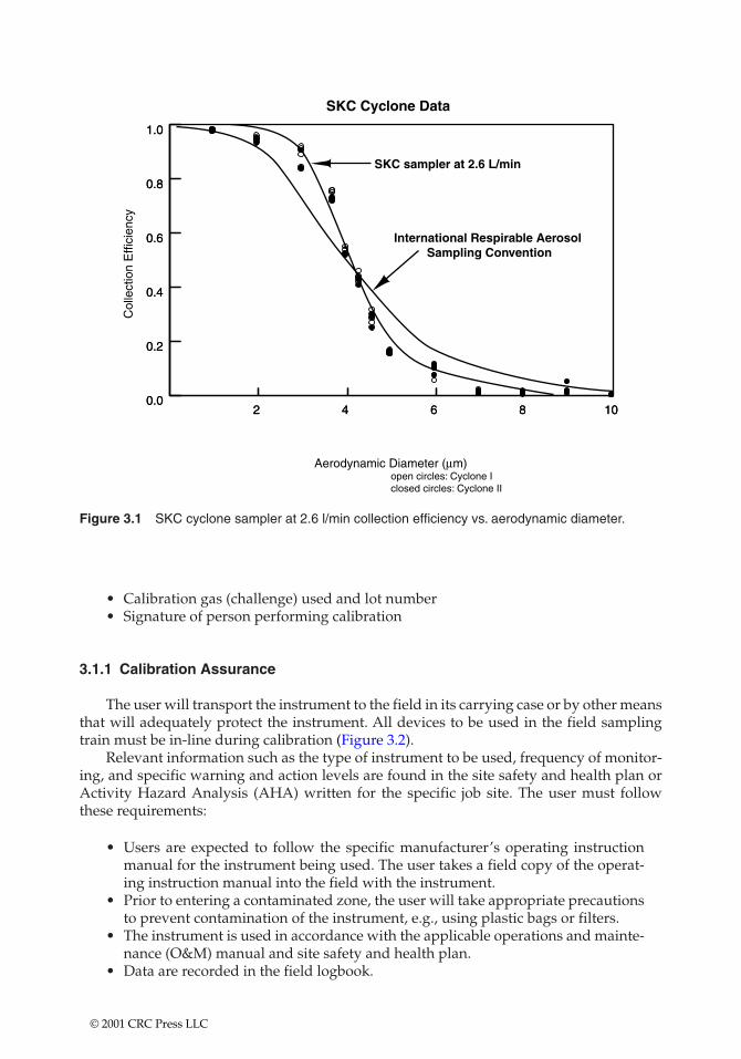
108642
Figure 3.1 SKC cyclone sampler at 2.6 l/min collection efficiency vs. aerodynamic diameter.
• Calibration gas (challenge) used and lot number• Signature of person performing calibration
3.1.1 Calibration Assurance
The user will transport the instrument to the field in its carrying case or by other meansthat will adequately protect the instrument. All devices to be used in the field samplingtrain must be in-line during calibration (Figure 3.2).
Relevant information such as the type of instrument to be used, frequency of monitor-ing, and specific warning and action levels are found in the site safety and health plan orActivity Hazard Analysis (AHA) written for the specific job site. The user must followthese requirements:
• Users are expected to follow the specific manufacturer’s operating instructionmanual for the instrument being used. The user takes a field copy of the operat-ing instruction manual into the field with the instrument.
• Prior to entering a contaminated zone, the user will take appropriate precautionsto prevent contamination of the instrument, e.g., using plastic bags or filters.
• The instrument is used in accordance with the applicable operations and mainte-nance (O&M) manual and site safety and health plan.
• Data are recorded in the field logbook.
© 2001 CRC Press LLC
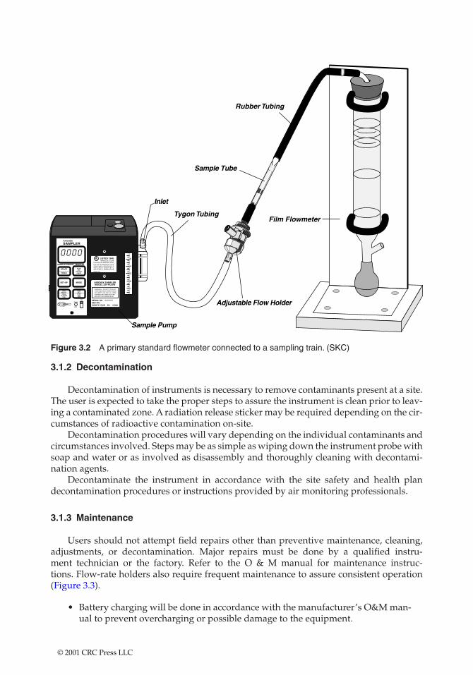
AIRCHEK
SAMPLER
SAMPLE PERIOD MINUTES
START
HOLD
FLOWAND
BATTERYCHECK
DIGITSET
PUMPRUNTIME
DIGITSELECT
TOTALELAPSED
TIME
SET-UP MODE
FLOW
ADJ
ON
5
4
3
2
1
AIRCHEK SAMPLERMODEL 224-PCXR8
UL¤LISTED 124U
SERIAL NO.SKC INC.EIGHTY FOUR PA 15330
WARNING - SUBSTITUTION OFCOMPONENTS MAY IMPAIR INTRINSIC SAFETY. USE ONLY UL LISTEDPORTABLE AIR SAMPLING PUMPBATTERY PACK MODEL P21661
INTRINSICALLY SAFEPORTABLE AIR SAMPLING PUMPFOR USE IN HAZARDOUS LOCATIONS CLASS I, GROUPS A B C DAND CLASS II, GROUPS E F GAND CLASS III, TEMPERATURECODE T3C.
Figure 3.2 A primary standard flowmeter connected to a sampling train. (SKC)
3.1.2 Decontamination
Decontamination of instruments is necessary to remove contaminants present at a site.The user is expected to take the proper steps to assure the instrument is clean prior to leav-ing a contaminated zone. A radiation release sticker may be required depending on the cir-cumstances of radioactive contamination on-site.
Decontamination procedures will vary depending on the individual contaminants andcircumstances involved. Steps may be as simple as wiping down the instrument probe withsoap and water or as involved as disassembly and thoroughly cleaning with decontami-nation agents.
Decontaminate the instrument in accordance with the site safety and health plandecontamination procedures or instructions provided by air monitoring professionals.
3.1.3 Maintenance
Users should not attempt field repairs other than preventive maintenance, cleaning,adjustments, or decontamination. Major repairs must be done by a qualified instru-ment technician or the factory. Refer to the O & M manual for maintenance instruc-tions. Flow-rate holders also require frequent maintenance to assure consistent operation (Figure 3.3).
• Battery charging will be done in accordance with the manufacturer’s O&M man-ual to prevent overcharging or possible damage to the equipment.
© 2001 CRC Press LLC
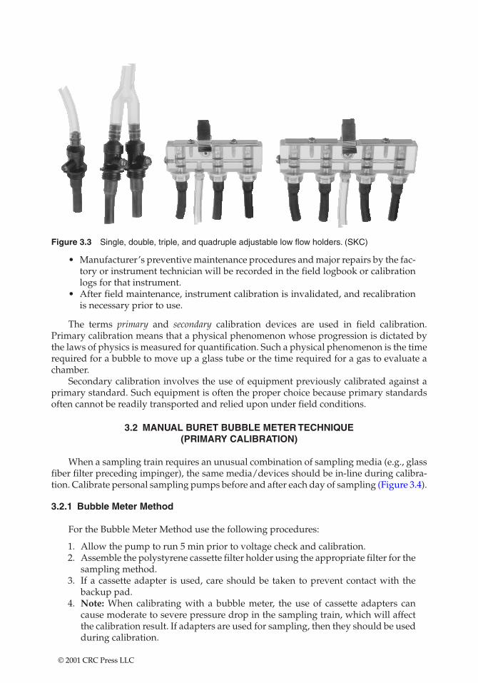
Figure 3.3 Single, double, triple, and quadruple adjustable low flow holders. (SKC)
• Manufacturer’s preventive maintenance procedures and major repairs by the fac-tory or instrument technician will be recorded in the field logbook or calibrationlogs for that instrument.
• After field maintenance, instrument calibration is invalidated, and recalibrationis necessary prior to use.
The terms primary and secondary calibration devices are used in field calibration.Primary calibration means that a physical phenomenon whose progression is dictated bythe laws of physics is measured for quantification. Such a physical phenomenon is the timerequired for a bubble to move up a glass tube or the time required for a gas to evaluate achamber.
Secondary calibration involves the use of equipment previously calibrated against aprimary standard. Such equipment is often the proper choice because primary standardsoften cannot be readily transported and relied upon under field conditions.
3.2 MANUAL BURET BUBBLE METER TECHNIQUE (PRIMARY CALIBRATION)
When a sampling train requires an unusual combination of sampling media (e.g., glassfiber filter preceding impinger), the same media/devices should be in-line during calibra-tion. Calibrate personal sampling pumps before and after each day of sampling (Figure 3.4).
3.2.1 Bubble Meter Method
For the Bubble Meter Method use the following procedures:
1. Allow the pump to run 5 min prior to voltage check and calibration.2. Assemble the polystyrene cassette filter holder using the appropriate filter for the
sampling method.3. If a cassette adapter is used, care should be taken to prevent contact with the
backup pad.4. Note: When calibrating with a bubble meter, the use of cassette adapters can
cause moderate to severe pressure drop in the sampling train, which will affectthe calibration result. If adapters are used for sampling, then they should be usedduring calibration.
© 2001 CRC Press LLC
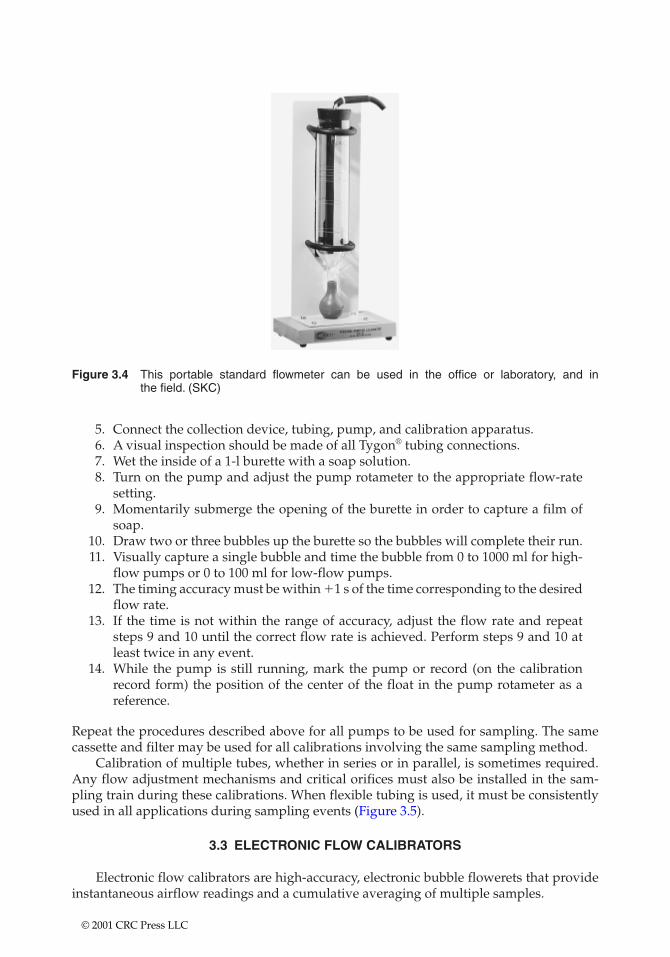
Figure 3.4 This portable standard flowmeter can be used in the office or laboratory, and inthe field. (SKC)
5. Connect the collection device, tubing, pump, and calibration apparatus.6. A visual inspection should be made of all Tygon® tubing connections.7. Wet the inside of a 1-l burette with a soap solution.8. Turn on the pump and adjust the pump rotameter to the appropriate flow-rate
setting.9. Momentarily submerge the opening of the burette in order to capture a film of
soap.10. Draw two or three bubbles up the burette so the bubbles will complete their run.11. Visually capture a single bubble and time the bubble from 0 to 1000 ml for high-
flow pumps or 0 to 100 ml for low-flow pumps.12. The timing accuracy must be within �1 s of the time corresponding to the desired
flow rate.13. If the time is not within the range of accuracy, adjust the flow rate and repeat
steps 9 and 10 until the correct flow rate is achieved. Perform steps 9 and 10 atleast twice in any event.
14. While the pump is still running, mark the pump or record (on the calibrationrecord form) the position of the center of the float in the pump rotameter as a reference.
Repeat the procedures described above for all pumps to be used for sampling. The samecassette and filter may be used for all calibrations involving the same sampling method.
Calibration of multiple tubes, whether in series or in parallel, is sometimes required.Any flow adjustment mechanisms and critical orifices must also be installed in the sam-pling train during these calibrations. When flexible tubing is used, it must be consistentlyused in all applications during sampling events (Figure 3.5).
3.3 ELECTRONIC FLOW CALIBRATORS
Electronic flow calibrators are high-accuracy, electronic bubble flowerets that provideinstantaneous airflow readings and a cumulative averaging of multiple samples.
© 2001 CRC Press LLC
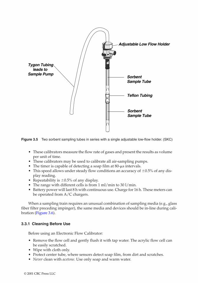
Figure 3.5 Two sorbent sampling tubes in series with a single adjustable low-flow holder. (SKC)
• These calibrators measure the flow rate of gases and present the results as volumeper unit of time.
• These calibrators may be used to calibrate all air-sampling pumps.• The timer is capable of detecting a soap film at 80-�s intervals.• This speed allows under steady flow conditions an accuracy of �0.5% of any dis-
play reading.• Repeatability is �0.5% of any display.• The range with different cells is from 1 ml/min to 30 l/min.• Battery power will last 8 h with continuous use. Charge for 16 h. These meters can
be operated from A/C chargers.
When a sampling train requires an unusual combination of sampling media (e.g., glassfiber filter preceding impinger), the same media and devices should be in-line during cali-bration (Figure 3.6).
3.3.1 Cleaning Before Use
Before using an Electronic Flow Calibrator:
• Remove the flow cell and gently flush it with tap water. The acrylic flow cell canbe easily scratched.
• Wipe with cloth only.• Protect center tube, where sensors detect soap film, from dirt and scratches.• Never clean with acetone. Use only soap and warm water.
© 2001 CRC Press LLC
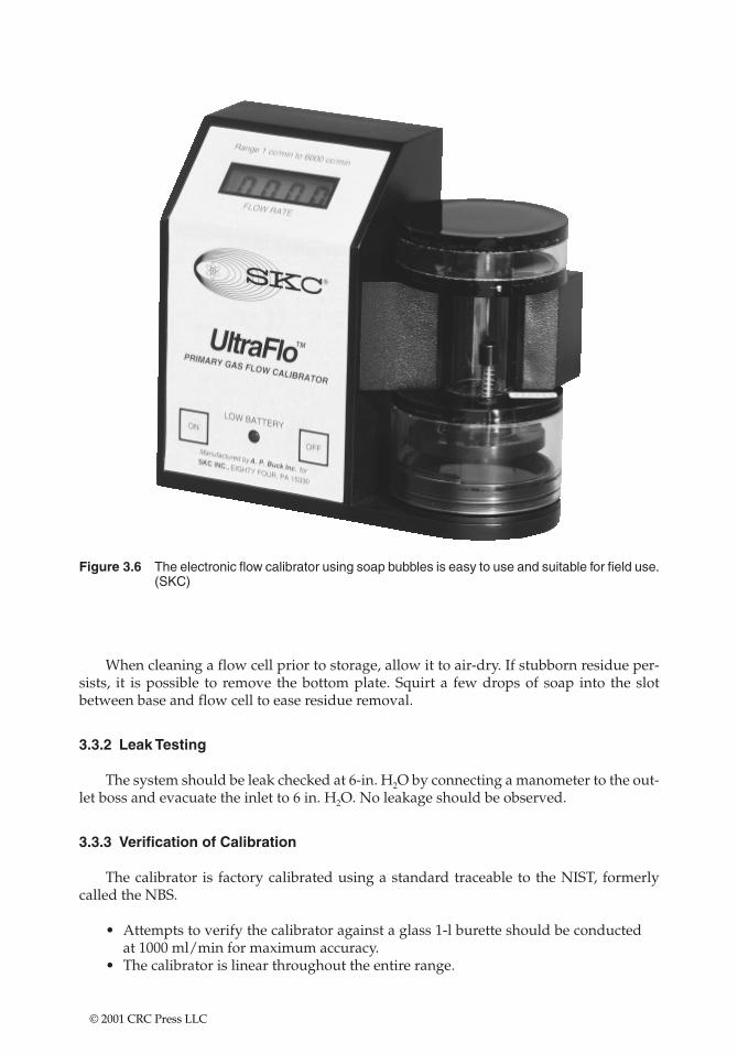
Figure 3.6 The electronic flow calibrator using soap bubbles is easy to use and suitable for field use.(SKC)
When cleaning a flow cell prior to storage, allow it to air-dry. If stubborn residue per-sists, it is possible to remove the bottom plate. Squirt a few drops of soap into the slotbetween base and flow cell to ease residue removal.
3.3.2 Leak Testing
The system should be leak checked at 6-in. H2O by connecting a manometer to the out-let boss and evacuate the inlet to 6 in. H2O. No leakage should be observed.
3.3.3 Verification of Calibration
The calibrator is factory calibrated using a standard traceable to the NIST, formerlycalled the NBS.
• Attempts to verify the calibrator against a glass 1-l burette should be conductedat 1000 ml/min for maximum accuracy.
• The calibrator is linear throughout the entire range.
© 2001 CRC Press LLC
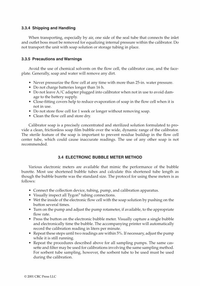
3.3.4 Shipping and Handling
When transporting, especially by air, one side of the seal tube that connects the inletand outlet boss must be removed for equalizing internal pressure within the calibrator. Donot transport the unit with soap solution or storage tubing in place.
3.3.5 Precautions and Warnings
Avoid the use of chemical solvents on the flow cell, the calibrator case, and the face-plate. Generally, soap and water will remove any dirt.
• Never pressurize the flow cell at any time with more than 25-in. water pressure.• Do not charge batteries longer than 16 h.• Do not leave A/C adapter plugged into calibrator when not in use to avoid dam-
age to the battery supply.• Close-fitting covers help to reduce evaporation of soap in the flow cell when it is
not in use.• Do not store flow cell for 1 week or longer without removing soap.• Clean the flow cell and store dry.
Calibrator soap is a precisely concentrated and sterilized solution formulated to pro-vide a clean, frictionless soap film bubble over the wide, dynamic range of the calibrator.The sterile feature of the soap is important to prevent residue buildup in the flow cell center tube, which could cause inaccurate readings. The use of any other soap is not recommended.
3.4 ELECTRONIC BUBBLE METER METHOD
Various electronic meters are available that mimic the performance of the bubbleburette. Most use shortened bubble tubes and calculate this shortened tube length asthough the bubble burette was the standard size. The protocol for using these meters is asfollows:
• Connect the collection device, tubing, pump, and calibration apparatus.• Visually inspect all Tygon® tubing connections.• Wet the inside of the electronic flow cell with the soap solution by pushing on the
button several times.• Turn on the pump and adjust the pump rotameter, if available, to the appropriate
flow rate.• Press the button on the electronic bubble meter. Visually capture a single bubble
and electronically time the bubble. The accompanying printer will automaticallyrecord the calibration reading in liters per minute.
• Repeat these steps until two readings are within 5%. If necessary, adjust the pumpwhile it is still running.
• Repeat the procedures described above for all sampling pumps. The same cas-sette and filter may be used for calibrations involving the same sampling method.For sorbent tube sampling, however, the sorbent tube to be used must be usedduring the calibration.
© 2001 CRC Press LLC
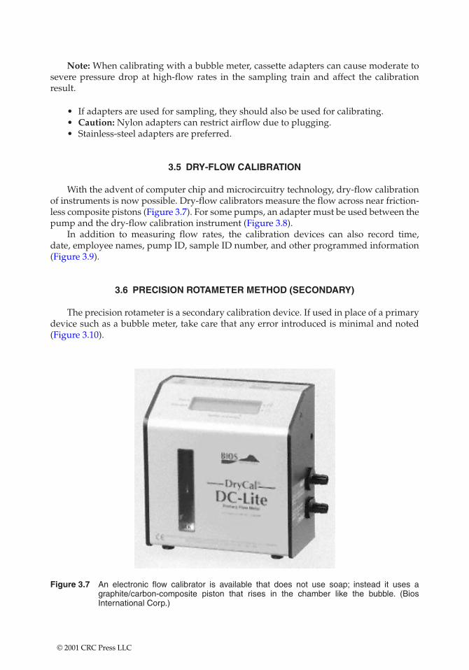
Note: When calibrating with a bubble meter, cassette adapters can cause moderate tosevere pressure drop at high-flow rates in the sampling train and affect the calibrationresult.
• If adapters are used for sampling, they should also be used for calibrating.• Caution: Nylon adapters can restrict airflow due to plugging.• Stainless-steel adapters are preferred.
3.5 DRY-FLOW CALIBRATION
With the advent of computer chip and microcircuitry technology, dry-flow calibrationof instruments is now possible. Dry-flow calibrators measure the flow across near friction-less composite pistons (Figure 3.7). For some pumps, an adapter must be used between thepump and the dry-flow calibration instrument (Figure 3.8).
In addition to measuring flow rates, the calibration devices can also record time, date, employee names, pump ID, sample ID number, and other programmed information(Figure 3.9).
3.6 PRECISION ROTAMETER METHOD (SECONDARY)
The precision rotameter is a secondary calibration device. If used in place of a primarydevice such as a bubble meter, take care that any error introduced is minimal and noted(Figure 3.10).
Figure 3.7 An electronic flow calibrator is available that does not use soap; instead it uses agraphite/carbon-composite piston that rises in the chamber like the bubble. (BiosInternational Corp.)
© 2001 CRC Press LLC
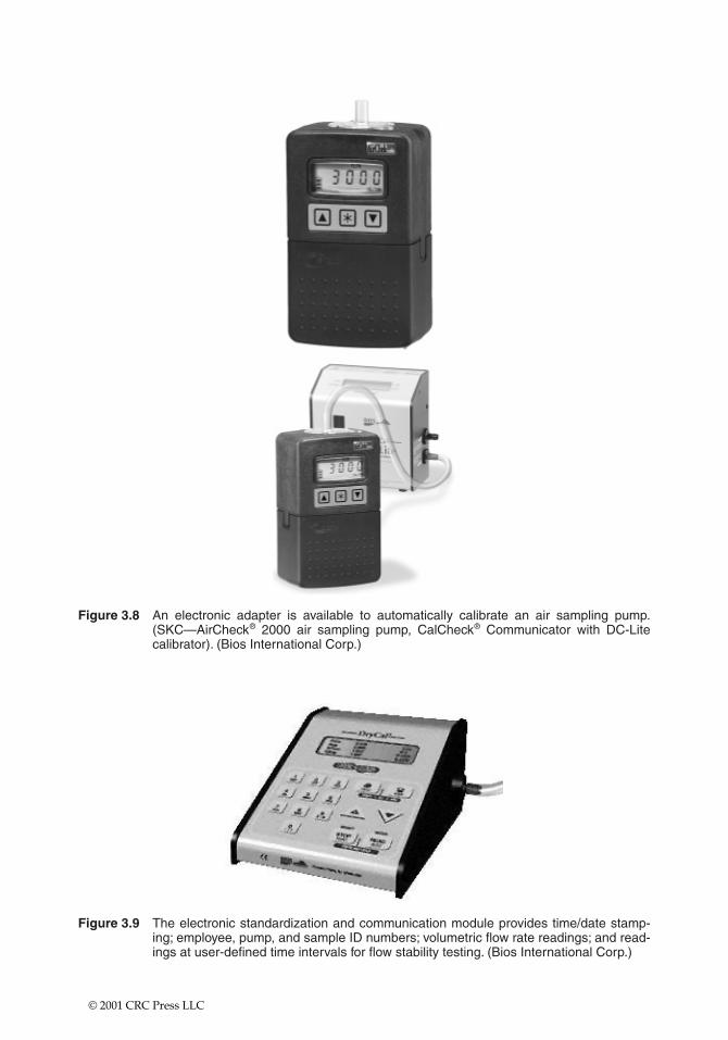
Figure 3.8 An electronic adapter is available to automatically calibrate an air sampling pump.(SKC—AirCheck® 2000 air sampling pump, CalCheck® Communicator with DC-Litecalibrator). (Bios International Corp.)
Figure 3.9 The electronic standardization and communication module provides time/date stamp-ing; employee, pump, and sample ID numbers; volumetric flow rate readings; and read-ings at user-defined time intervals for flow stability testing. (Bios International Corp.)
© 2001 CRC Press LLC
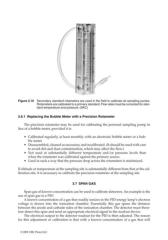
Figure 3.10 Secondary standard rotameters are used in the field to calibrate air-sampling pumps.Rotameters are calibrated to a primary standard. Flow rates must be corrected for stan-dard temperature and pressure. (SKC)
3.6.1 Replacing the Bubble Meter with a Precision Rotameter
The precision rotameter may be used for calibrating the personal sampling pump inlieu of a bubble meter, provided it is
• Calibrated regularly, at least monthly, with an electronic bubble meter or a bub-ble meter.
• Disassembled, cleaned as necessary, and recalibrated. (It should be used with careto avoid dirt and dust contamination, which may affect the flow.)
• Not used at substantially different temperature and/or pressure levels thanwhen the rotameter was calibrated against the primary source.
• Used in such a way that the pressure drop across the rotameters is minimized.
If altitude or temperature at the sampling site is substantially different from that at the cal-ibration site, it is necessary to calibrate the precision rotameter at the sampling site.
3.7 SPAN GAS
Span gas of known concentration can be used to calibrate detectors. An example is theuse of span gas in a PID.
A known concentration of a gas that readily ionizes in the PID energy lamp’s electronvoltage is drawn into the ionization chamber. Essentially this gas spans the distancebetween the anode and cathode sides of the ionization chamber. The detector must there-fore detect this span and send an appropriate electrical signal to the readout device.
The electrical output to the detector readout for the PID is then adjusted. The reasonfor this adjustment or calibration is that with a known concentration of a gas that will
© 2001 CRC Press LLC
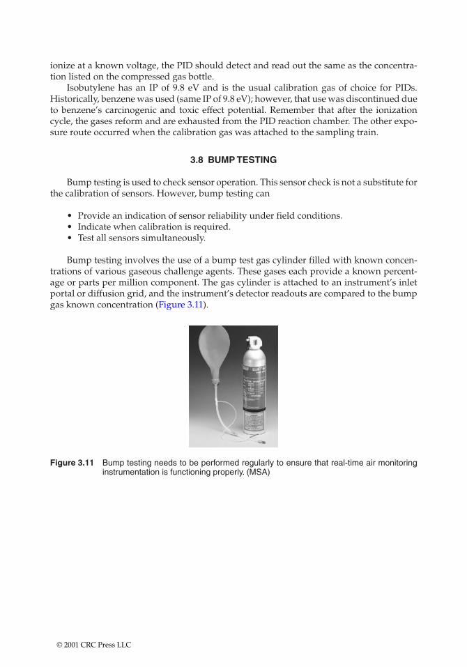
ionize at a known voltage, the PID should detect and read out the same as the concentra-tion listed on the compressed gas bottle.
Isobutylene has an IP of 9.8 eV and is the usual calibration gas of choice for PIDs.Historically, benzene was used (same IP of 9.8 eV); however, that use was discontinued dueto benzene’s carcinogenic and toxic effect potential. Remember that after the ionizationcycle, the gases reform and are exhausted from the PID reaction chamber. The other expo-sure route occurred when the calibration gas was attached to the sampling train.
3.8 BUMP TESTING
Bump testing is used to check sensor operation. This sensor check is not a substitute forthe calibration of sensors. However, bump testing can
• Provide an indication of sensor reliability under field conditions.• Indicate when calibration is required.• Test all sensors simultaneously.
Bump testing involves the use of a bump test gas cylinder filled with known concen-trations of various gaseous challenge agents. These gases each provide a known percent-age or parts per million component. The gas cylinder is attached to an instrument’s inletportal or diffusion grid, and the instrument’s detector readouts are compared to the bumpgas known concentration (Figure 3.11).
Figure 3.11 Bump testing needs to be performed regularly to ensure that real-time air monitoringinstrumentation is functioning properly. (MSA)
© 2001 CRC Press LLC
CHAPTER 4
Statistical Analysis and Relevance
This chapter contains theoretical and real-world discussions about statistical analysis. It givesspecial emphasis to situations where knowledge of statistical relevance is a prerequisite for samplingadequacy. It also illustrates the difference between log-normal and normal distribution and para-metric monitoring data.
4.1 DEFINITIONS
In statistical analysis and relevance, certain standard definitions are used. The follow-ing standard definitions and examples illustrate the basic concepts.
• Accuracy: Agreement of the measured value (i.e., empirical value) and the “truevalue’’ (i.e., accepted reference value) of the sample given valid sampling tech-niques, proper sample preparation, and reliable and accurate instrumentationand/or other procedures.
Accuracy is often estimated by adding (or “spiking’’) known amounts of thetarget parameters. For asbestos quality assurance (QA) sampling, accuracy isevaluated by comparing analyses of duplicate samples that have been evaluatedin proficiency in analytical testing (PAT) round robins (for air samples) or NISTNational Voluntary Laboratory Accreditation Program (NVLAP) proficiency test-ing (for bulk and transmission electron microscopy [TEM]).
Accuracy is a measure of the bias of the method and may be expressed as thedifference between two values, a ratio, or the percentage difference.
• Analysis: Combination of sample preparation and evaluation.• Audit: Systematic determination of the function or activity quality.• Bias: Systemic error either inherent in the method or caused by measurement sys-
tem artifacts or idiosyncrasies.• Blind sample: Presented to the laboratory as indistinguishable from field sam-
ples (syn: performance audit samples). All field blanks are to be presented to thelaboratory as blind samples for asbestos air samples.
• Calibration: Comparative procedure in which singular measurements are evalu-ated against an accepted group of measurements. The evaluation may be againsta primary, intermediate, or secondary standard.
© 2001 CRC Press LLC
• Calibration curve: Range over which measurement can take place (syn: standardcurve, multipoint calibration).
• Calibration standard: Instruments or other measurement techniques used toevaluate the measurement system. Ideally, these standards do not directly incor-porate or use the target parameters to be measured.
• Chain-of-custody: Defined sample custody procedures that must be followed todocument the transition from field collection to subsequent transfer sites (com-mon carriers, laboratories, storage facilities, etc.).
• Check standard: Used to verify that the initial standard or calibration curveremains in effect. It ideally incorporates standard materials (syn: daily standard,calibration check or standard, reference standard, control standard, single pointresponse factor, single point drift check).
• Comparability: Confidence with which one set of empirical data can be com-pared to another.
• Completeness: Amount of valid data obtained from a measurement systemcompared to the amount expected.
• Data quality: Totality of data parameters that identify ability to satisfy or repre-sent a given condition; includes accuracy, precision, representativeness, and com-parability.
• Data reduction: Using standard curves to interpret raw data.• Data validation: Review process that compares a body of data against a set of cri-
teria to provide data adequacy assurance given the data’s intended use; includesdata editing, screening, checking, auditing, verification, certification, and review.
• Detection limit: Minimum target parameter quantity that can be identified, i.e.,distinguished from background or “zero’’ signal.
• Double-blind sample: When neither the composition nor identification of thesample is known to the analyst.
• Duplicate sample (field or laboratory): Sample divided into two portions, withboth portions carried through the sample preparation process at the same time.For asbestos air samples, field duplicates are air samples collected at the sametime as the compliance air samples, and lab duplicates are portions of one filterthat are fixed and analyzed separately.
• Environmentally related measurements: Field or laboratory investigations thatgenerate data involving chemical, physical, or biological parameters characteris-tic of the environment.
• Field blanks: Generated at the time of sampling, field blanks provide a check oncontamination, starting with the sampling process and proceeding through the fullanalysis scheme. For asbestos fiber concentration sampling, field blanks are filtercassettes transported to the site and exposed to ambient conditions. The filter capsare removed from the filter cassettes; however, a vacuum air pump is not used topull air across the filter cassettes. Thus, the cassettes are exposed to the environ-mental airstream of the surrounding environment outside the asbestos control area.
• Good laboratory practices: Performing a basic laboratory operation or activity soas not to influence data generation quality.
• Instrument blank: Used to obtain information on instrument aberrationabsence/presence. The measurement instrument is presented with materials normally within the instrument and cycled through the measurement sequence.The resulting signal is then defined as the baseline instrument signal level.
• Internal standard: A nontarget parameter added to samples just prior to measure-ment to monitor variation in sample introduction and stability and to normalize
© 2001 CRC Press LLC
data for quantitation purposes. Internal standards are not usually used in bulk(phase light microscopy [PLM]) or phase contrast microscopy (PCM); however,these standards may be applicable to TEM protocol.
• Laboratory blank: Prepared in the laboratory after receipt of samples from thefield. These blanks are prepared using a material assumed not to contain the tar-get parameter. Lab blanks for asbestos sampling are filter membranes obtainedfrom filter cassettes that have been retained in the laboratory without removal ofthe filter cassette caps. The lab blank is a check on all the chemicals and reagentsused in the method as well as the influence of the general laboratory environment(syn: analytical blank, system blank, method blank, process blank).
• Measurement: Creating quantitative data from a prepared sample.• Method check sample: Prepared in the laboratory by spiking a clean reference
matrix with known quantities of the target parameters. For asbestos air-samplinganalysis, method check samples are previously prepared filters evaluated by sep-arate analysts within the same laboratory. These duplicate analyses are defined inthe National Institute of Occupational Safety & Health (NIOSH) 7400 method asquality assurance, and the acceptable statistical parameters are outlined therein.
• Method detection limit: Minimum quantity that a method (i.e., both samplepreparation and target parameter measurement steps) can be expected to distin-guish from background or “zero’’ signal. This limit takes into account losses dur-ing preparation and measurement and instrument sensitivity that may contributeto qualification or quantification of results. This limit does not apply to physicalparameters (i.e., density, temperature).
• Performance evaluation (PE) sample: Sample with known “true’’ values that ispresented to the laboratory as a “performance evaluation sample.’’ These sam-ples are biased by the analyst’s knowledge of the intent of the sample. Forasbestos air-sampling analysis, “true’’ value samples may be defined as the PATsamples with their inclusive statistical ranges.
• Precision: Measure of the reproducibility of a set of results obtained under simi-lar conditions. Precision is determined by multiplicate analysis of samples, dupli-cates, replicates, or splits. Standard deviation is used as a measure of precision.
• Procedure: Systematic instructions and operations for using a method of sam-pling or measurement.
• Proficiency sample: Samples for which known composition values are availablefor accuracy comparisons. The composition values may be qualitative, quantita-tive, or statistical ranges of acceptable qualitative/quantitative results.
• Quality assurance: An orderly assemblage of management policies, objectives,principles, and general procedures by which a laboratory outlines the methodsused to produce quality data. QA is an intralaboratory function. Note: TheNIOSH 7400 method defines QA in terms of both intralaboratory and interlabo-ratory methods and/or sequencing. However, for the purposes of specifiedQA/quality control (QC) documents, interlaboratory methods are defined as QC.
• Quality control: Routine application of procedures used to develop prescribedperformance standards in the monitoring and measurement of standards. QC isan interlaboratory function.
• QC samples: Analyzed concurrently with field samples to insure that analyticalsystems are operating properly, i.e., in control. These samples provide an estimateof the precision and accuracy of the sampling and analysis system. QC samplesfor asbestos sampling are sent between laboratories for interlaboratory compar-isons of methodology and analytical proficiency.
© 2001 CRC Press LLC
• Quality of method: Degree to which the method functions free of systemic error,bias, and random error.
• Quantitation limits: Maximum and minimum levels or quantities of a reliablyquantified target parameter. These limits are bounded by the standard curve lim-its and are generally related to standard curve data.
• Reagent blank: Used to identify contamination sources. These blanks incorpo-rate specific reagents during sample preparation to identify lab blank contami-nate sources (syn: dilution blank).
• Recovery/percent recovery: Generally used to report accuracy based on themeasurement of target parameters, comparison of these concentrations, and cor-relating these measurements to the predicted amounts. Recovery in asbestos airsampling is the statistical percentage differential observed during accuracy eval-uation (i.e., percentage difference in fiber concentrations).
• Replicate samples (field or laboratory): A sample is divided into two portionsand is processed as two completely separate and nonparallel samples, i.e., pre-pared and analyzed at different times or by different people. Field replicates inasbestos air sampling are defined as filters that are obtained from two separatefilter cassettes drawn separately or from a y-juncture. These are then transported,fixed, and analyzed separately. Lab replicates are taken from a singular filter,which is sectioned, fixed, and analyzed separately.
• Representativeness: Degree to which data accurately and precisely represent aparameter variation characteristic at a sampling point and portray an environ-mental condition.
• Sample custody: Verification and documentation procedure for the transfer ofsamples from the field to the laboratory, within the laboratory, and to the finalstorage or disposal destination.
• Sample Operation Procedure (SOP): Procedure adopted for repetitive use whenperforming a specific measurement or sampling operation.
• Sample preparation: Transformation of the sample into appropriate forms fortransfer and/or measurement.
• Sampling: Removal of a process stream representative portion or a portion of alarger quantity of material for subsequent evaluation.
• Sensitivity: An instrument’s detection limit given the minimum quantity of a tar-get parameter that can be consistently identified, i.e., distinguished from back-ground or “zero’’ signal by the instrument; ideally established using the materialsthat are used for standardization.
• Split samples (field or laboratory): A sample, divided into aliquots, that is sentto a different laboratory for preparation and measurement. These split samplesmay be replicates or duplicates that are then defined as splits when sent toanother laboratory for QC analysis. For asbestos air samples this shipmentinvolves either the shipping of capped filter cassettes (field split) or the shippingof fixed slides (lab split).
• Standard materials: Materials, such as mixtures of the target parameters atknown concentration and purity, used to carry out standardizations. For asbestosair sampling these materials may be PAT samples.
• Standardization: Establishing a quantitative relationship between known targetparameters input and instrument readout.
• Target parameters: Entity for which qualitative or quantitative information isdesired.
© 2001 CRC Press LLC
• Trip blanks: Essentially field blanks that do not have the caps removed. Theseblanks provide insight into the contamination generated as a result of the shippingprocess. These blanks are generally not required for asbestos sample shipment.
4.2 EXAMPLE—OUTLINE OF BULK SAMPLING QA/QC PROCEDURE
Bulk sample analysis procedures are defined in the NIOSH method for PLM and theNIOSH 7402 method for TEM. Because bulk sample analysis is done by an independentlaboratory off-site, this QA/QC document will not address bulk sampling as a field-verified procedure. The NVLAP is currently used to ascertain laboratory effectiveness. Thecontractor must provide proof that NVLAP certification is current for the laboratory des-ignated to receive both the initial bulk samples and the 10% bulk sample duplicates.
The optical properties and ID of fibers are as follows:
• Determine 13 specific items for asbestos.• ID other fibers with some optical data.• ID matrix components.
In addition record
• Special procedures or solvents• Sampling of layers• Deviations from EPA test procedure
The 10% bulk sample duplicates are provided by physically dividing 10% of the sam-ples collected. This division should occur concurrently with the collection of field samples.The rationale for splitting the samples at a time and location removed from the field col-lection site must be provided.
All field collection procedures, sample labeling, and transport and disposal proceduresmust be addressed in the QA/QC document. Provide the rationale for the classificationand remediation of errors. The following is a sample of error classification:
Major Error
• False positive• False negative (asbestos actually �1%)• Incorrect asbestos type classification• Analysis quantification in error by 25%
Minor Error
• Incorrect ID of tremolite or actinolite as another type of asbestos• False negative (asbestos actually �1% or trace)• Analysis quantification in error by 15%• Incomplete lab data sheets (repeated omissions may equal major error)
Corrective Steps—Major Errors
• Take immediate action.
© 2001 CRC Press LLC
• Review documents for transcription errors.• Review sample, especially matrix description.• Reanalyze sample; submit to other labs for analysis.• Check environment for contamination and out of calibration equipment.• For misidentification of asbestos species review literature and reference samples.
Corrective Steps—Minor Errors
• One to two weeks or after monthly summaries• Steps 1 through 4 above.• Review to determine if error is systematic estimation bias, then retrain on esti-
mation techniques and/or sample preparation techniques.• Completed data sheets are required; frequent omissions should be considered a
major error.• Review sampling and stereomicroscope sample preparation procedures.• To recalibrate estimation techniques, reanalyze known samples; review literature
on estimation training.• Review; retrain on reference samples, especially in problem matrix mixtures.
Review specific problems like tremolite or crocidolite samples.• Review lab’s special sample preparations for Vinyl Asbestos Tile (VAT) or tar
matrix materials. Practice on known materials including blanks.
4.3 EXAMPLE—OUTLINE OF THE NIOSH 7400 QA PROCEDURE
4.3.1 Precision: Laboratory Uses a Precision of 0.45
Current guide specifications give a precision of 0.45 as acceptable in calculation of the95% upper confidence level (UCL). Using a precision of 0.45 implies that the standard devi-ation divided by the arithmetic mean gives a value of 0.45. This ratio is variously called thecoefficient of variation (CV) or the SR in the NIOSH 7400 method. With the 90% confidenceinterval of mean count, which includes a subjective component of 0.45 plus the Poissoncomponent, 0.45 precision implies that reproducibility of results is questionable. Thus, theuse of the 0.45 value in the calculation of the UCL must be clearly identified. For compli-ance purposes the following equation is acceptable:
Measured � (air quality) (0.45) (1.645) concentration (standard)
The QA procedures given in the NIOSH 7400 method must be referenced in a discus-sion of the 0.45 precision value used. Detailed outlines of the intralaboratory proceduresare not necessary. Proof of acceptable PAT participation (i.e., judged proficient for the tar-get parameter in four successive round robins) as administered by the American Board ofIndustrial Hygiene (ABIH) must be provided.
4.3.2 Precision: Laboratory Uses a Precision SR that is Better Than 0.45
When a precision better than 0.45 is suggested, an outline of the NIOSH 7400 QA pro-cedures used and a current CV curve must be provided in addition to the proof of accept-able PAT participation. The outline must include the following:
© 2001 CRC Press LLC

• Document the laboratory’s precision for each counter for replicate fiber counts byusing this procedure.
• Maintain as part of the QA program a set of reference slides to be used daily.These slides should consist of filter preparations including a range of loading andbackground dust levels from a variety of sources including both field and PATsamples.—Have the QA officer maintain custody of the reference slides and supply each
counter with a minimum of one reference slide per workday. Change the labelson the reference slides periodically so that the counter does not become famil-iar with the samples.
—From blind repeat counts on the reference slides, estimate the laboratory intra-and intercounter SR.
—Determine separate values of relative standard deviation for each samplematrix analyzed in each of the following ranges. Maintain control charts foreach of these data files.• 15 to 20 fibers in 100 graticule fields• �20 to 50 fibers in 100 graticule fields• �50 to 100 fibers in 100 graticule fields• 100 fibers in less than 100 graticule fields
Note: Certain sample matrices (e.g., asbestos cement) have been shown to give poorprecision. Prepare and count field blanks along with the field samples. Report counts oneach field blank.
Note 1: The identity of blank filters should be unknown to the counter until all countshave been completed.
Note 2: If a field blank yields greater than 7 fibers per graticule fields, report possiblecontamination of the samples.
• Perform blind recounts by the same counter on 10% of filters counted (slides rela-beled by a person other than the counter). Use the following test to determinewhether a pair of counts by the same counter on the same filter should be rejectedbecause of possible bias:
• Discard the sample if the absolute value of the difference between the squareroots of the two counts (in fiber/mm2) exceeds 2.8 (x) 2 � 8 � SR, where x � theaverage of the square roots of the two fiber counts (in fiber/mm2) and SR � onehalf the intracounter relative standard deviation for the appropriate count range(in fibers).
Note 1: Fiber counting is the measurement of randomly placed fibers that may bedescribed by a Poisson distribution; therefore, a square root transformation of the fibercount data will result in approximately normally distributed data.
Note 2: If a pair of counts is rejected by this test, recount the remaining samples in theset and test the new counts against the first counts. Discard all rejected paired counts. It isnot necessary to use this statistic on blank counts.
The analyst is a critical part of this analytical procedure. Care must be taken to providea nonstressful and comfortable environment for fiber counting. An ergonomicallydesigned chair should be used. With the microscope eyepiece situated at a comfortableheight for viewing. External lighting should be set at an intensity level similar to the illu-mination level in the microscope to reduce eye fatigue. Counters should take 10–20 min
© 2001 CRC Press LLC
breaks from the microscope every 1 to 2 hours to limit fatigue. During these breaks botheye and upper back/neck exercises should be performed to relieve strain.
Calculation of compliance uses the same equation with the substitution of a differentvalue for 0.45. Use of this different value requires prior approval. All filters selected for the10% recount should be randomly selected, rather than selecting every tenth filter.
4.3.3 Records to Be Kept in a QA/QC System
Records include:
• Sample logbook• Chain-of-custody record
4.3.4 Field Monitoring Procedures—Air Sample
Collection of 10% duplicates as provided by specifications are not to be confused withthe 10% duplication used for QA in the NIOSH 7400 method. The 10% duplicates providedby specifications are for QC interlaboratory determination of reliability. These duplicatesare collected in the field using simultaneous collection devices or analysis preparatorytechniques. Running two pumps on one individual is feasible for personal air sampling.
Running a Y shunt to two separate collection cassettes may be the technique used forarea monitoring simultaneous collection. This method may also be feasible for personnelmonitoring.
When neither type of collection alternative is feasible, duplication of prepared slidesthrough duplicate filter media mounting is acceptable. The rationale and techniques for allprospective alternatives must be provided in the QA/QC document.
Caution: Field blanks must indeed be field blanks, not randomly prepared laboratoryblanks. The purpose of field blanks is to access ambient air particulates hypotheticallyunassociated with abatement activities, but existing in the same general geographic loca-tion. Thus, field blanks must be filter-loaded cassettes that are open faced and stored out-side the asbestos control area in an associated support zone. Occasionally, hygienists carrythe field blanks in their pockets. This practice, if employed, must be documented, withassociated persuasive rationale.
4.3.5 Calibration
All calibration techniques and schedules must be provided. Calibration of air-samplingdevices may be accomplished using a primary standard (such as a bubble burette) or usinga precision rotameter calibrated against a primary standard. The bubble gauge installed onthe front vertical face of personal air-sampling pumps is not a reliable or precise calibrationtool. Calibration must be done using dial settings versus primary standard timings.Rotameters offer an advantage in that their portability makes it possible to calibrate cas-settes with the associated vacuum pump-generated airstream (or train) at the worksite.
Precision rotameters, while preferred, can be supplemented with standard rotameters.Techniques for rotameter use and calibration must be sequentially and clearly defined. Theuse of long-gauge range, 0–20 l/min, rotameters in the measure of personal air-samplingpumps with expected 2.5 l/min is prohibited due to lack of precision. Short-gauge range,0–5 l/min rotameters, are allowed for use in the calibration of personal air samplingpumps. Example calibration curves and associated calculations must be provided.
© 2001 CRC Press LLC
Calibration of Phase Contrast Microscopy (PCM) microscopes used on-site must becompletely defined. All NVLAP and American Conference Governmental IndustryHygienists (ACGIH) calibration procedures are enforceable for on-site activities. While notgenerally defined as a calibration technique, cleanliness and relative stability of the PCMmicroscopic location must be addressed. Sample calibration checklists used daily andweekly must be provided.
4.3.6 Negative Air Pressure
When negative air pressure is used in gross containment areas, monitoring criteriamust be provided. Specifications should require continued real-time instrument monitor-ing independent of the HEPA vacuum system monitors. Monitors must be located outsidethe containment area and removed from the effluent HEPA vacuum airstream. Appropriatemonitoring checklists and sample direct readout tapes must be provided. The readouttapes and associated calculations, if needed, can either be generically presented or be sam-ples from previous monitoring efforts.
4.3.7 Compressor
In the event that compressed air is used on-site, certification of Grade D breathing airmust be provided. If a filter bank is used in conjunction with an oil-lubricated compressor,monitoring of the filter bank is required. This monitoring includes carbon monoxide, tem-perature, oil breakthrough, and air pressure criteria. In addition to audible alarms andescape air, visual monitoring of the compressor filter bank status is necessary. Provide sam-ple monitoring check sheets. Certain specifications call for the use of colorimetric tubes tocertify continued Grade D breathing air supply. Provide sample monitoring check sheetsthat clearly indicate sampling intervals.
4.3.8 Recordkeeping and Sample Storage
Recordkeeping priorities and samples of format used must be provided. Recordsinclude documentation of air sampling and air sample analysis, bulk sampling and bulksample analysis, and negative air pressure maintenance. Personnel records includerésumés, certifications, medical surveillance, and training. Environmental records detailwork sequencing and ambient conditions. All specified documents must be accessible andmaintained as per specifications. Sample storage and accessibility must be discussed.
The following equipment and documentation lists are examples of those that shouldbe appraised for asbestos bulk sampling. Other laboratory protocols will require similarlists.
Laboratory Procedures
• Logbook• Calibration of refractive index oils• Daily microscope alignment• Daily microscope calibration check• Daily microscope contamination check• Equipment maintenance• Equipment calibration• Personnel records, including hierarchy, training, certification, and job descriptions
© 2001 CRC Press LLC
• Monthly records of each analyst• QA and QC results for their work• Proficiency results (PAT)• Precision and accuracy ratings, including explanation of rating protocols
QA Logbook
• Samples• Results• Discrepancies• Analysis repeats (minimum 10%)• Intralaboratory analysis of proficiency samples• Intralaboratory analysis of duplicates and replicates• Blank analysis• Summary of results from each analyst• Summary of results for the laboratory
QC Logbook
• Deficiency corrections• Samples• Results• Discrepancies• Frequency of duplicate/replicate analysis per total samples• Interlaboratory analysis of proficiency samples• Timing of QC analysis• Same day, next shift, next day• Monthly proficiency samples, WULAP samples in-house or past EPA asbestos
bulk sample analysis, QA program samples, blanks, and contamination samples
Interlaboratory Analyses (summary of results for the laboratory)
• Outliers• Interlaboratory analysis schedules• Time, including expected turnaround time• Labs participating• Contamination testing and control logbook• Lab data sheet/notebook• Analysis report sheet• QA manual revision documentation• Training procedures for staff• Analysis error correction correspondence
4.4 SAMPLING AND ANALYTICAL ERRORS
When an employee’s personal exposure or the area exposure is sampled and the resultsanalyzed, the measured exposure will rarely be the same as the true exposure. This varia-tion is due to sampling and analytical errors or SAEs. The total error depends on the com-bined effects of the contributing errors inherent in sampling, analysis, and pump flow.
© 2001 CRC Press LLC
Error factors determined by statistical methods shall be incorporated into the sampleresults to obtain:
• The lowest value that the true exposure could be (with a given degree of confidence)• The highest value the true exposure could be (also with some degree of confidence)
The lower value is called the lower confidence limit (LCL), and the upper value is the UCL.These confidence limits are one sided, since the only concern is with being confident thatthe true exposure is on one side of the Permissible Exposure Limit (PEL).
4.4.1 Determining SAEs
SAEs that provide a 95% confidence limit have been developed and are listed on theOSHA-91B report form (most current SAEs). If there is no SAE listed in the OSHA-91B fora specific substance, call the laboratory. If using detector tubes or direct-reading instru-ments, use the SAEs provided by the manufacturer.
4.4.2 Environmental Variables
Environmental variables generally far exceed SAE. Samples taken on a given day are used by OSHA to determine compliance with PELs. However, where samples are taken over a period of time (as is the practice of some employers), the industrial hygienist should review the long-term pattern and compare it with the results. WhenOSHA’s samples fit the long-term pattern, it helps to support the compliancedetermination. When OSHA’s results differ substantially from the historical pattern, theindustrial hygienist should investigate the cause of this difference and perhaps conductadditional sampling.
4.4.3 Confidence Limits
One-sided confidence limits can be used by OSHA to classify the measured exposureinto the following categories.
95% Confident That the Employer Is in Compliance
• Measured exposure results do not exceed the PEL.• UCL of that exposure does not exceed the PEL.
95% Confident That the Employer Is NOT in Compliance
• Measured exposure results do exceed the PEL.• LCL of that exposure does exceed the PEL.
95% Confident That the Employer Is in Compliance � Possible Overexposure
• Measured exposure results do not exceed the PEL.• UCL of that exposure does exceed the PEL.
© 2001 CRC Press LLC
NOT 95% Confident That the Employer Is NOT in Compliance �Possible Overexposure
• Measured exposure results do exceed the PEL.• LCL of that exposure does not exceed the PEL.
A violation is not established if the measured exposure is in the “possible over-exposure’’ region. It should be noted that the closer the LCL comes to exceeding the PEL,the more probable it becomes that the employer is in noncompliance.
If measured results are in this region, the industrial hygienist should consider furthersampling, taking into consideration the seriousness of the hazard, pending citations, andhow close the LCL is to exceeding the PEL.
If further sampling is not conducted, or if additional measured exposures still fall intothe “possible overexposure’’ region, the industrial hygienist should carefully explain to theemployer and employee that the exposed employee(s) may be overexposed, but that therewere insufficient data to document noncompliance. The employer should be encouragedto voluntarily reduce the exposure and/or to conduct further sampling to assure that expo-sures are not in excess of the standard.
4.5 SAMPLING METHODS
The LCL and UCL are calculated differently depending on the type of samplingmethod used. Sampling methods can be classified into one of three categories:
4.5.1 Full-Period, Continuous Single Sampling
Full-period, continuous single sampling is defined as sampling over the entire sampleperiod with only one sample. The sampling may be for a full-shift sample or for a shortperiod ceiling determination.
4.5.2 Full-Period, Consecutive Sampling
Full-period, consecutive sampling is defined as sampling using multiple consecutivesamples of equal or unequal time duration that, if combined, equal the total duration of thesample period. An example would be taking four 2-hour charcoal tube samples.
There are several advantages to this type of sampling. If a single sample is lost duringthe sampling period due to pump failure, gross contamination, etc., at least some data willhave been collected to evaluate the exposure. The use of multiple samples will result inslightly lower SAE. The collection of several samples leads to conclusions concerning themanner in which differing segments of the workday affect overall exposure.
4.5.3 Grab Sampling
Grab sampling is defined as collecting a number of short-term samples at various timesduring the sample period that, when combined, provide an estimate of exposure over thetotal period. Common examples include the use of detector tubes or direct-reading instru-mentation (with intermittent readings).
© 2001 CRC Press LLC
4.6 CALCULATIONS
If the initial and final calibration flow rates are different, a volume calculated using thehighest flow rate should be reported to the laboratory. If compliance is not establishedusing the lowest flow rate, further sampling should be considered.
Sampling is generally conducted at approximately the same temperature and baro-metric pressure as calibration, in which case no correction for temperature and pressure isrequired, and the sample volume reported to the laboratory is the volume actually meas-ured. Where sampling is conducted at a substantially different temperature or pressurethan calibration, an adjustment to the measured air volume may be required depending onsampling pump used, in order to obtain the actual air volume sampled. The actual volumeof air sampled at the sampling site is reported and used in all calculations.
For particulates the laboratory reports milligrams per cubic meter of contaminantusing the actual volume of air collected at the sampling site. This value can be compareddirectly to OSHA Toxic and Hazardous Substances Standards (e.g., 29 CFR 1910.1000).
The laboratory normally does not measure concentrations of gases and vapors directlyin parts per million. Rather, most analytical techniques determine the total weight of con-taminant in a collection medium. Using the air volume provided by the industrial hygien-ist, the lab calculates the concentration in milligrams per cubic meter and converts this toparts per million at 25°C and 760 mmHg. This result is to be compared with the PEL with-out adjustment for temperature and pressure at the sampling site.
ppm(NTP) � mg/m3(24.45)/(Mwt)where
• 24.45 � molar volume at 25°C (298 K) and 760 mmHg• Mwt � molecular weight• NTP � normal temperature and pressure at 25°C and 760 mmHg
If it is necessary to know the actual concentration in parts per million at the sam-pling site, it can be derived from the laboratory results reported by using the followingequation:
ppm(PT) � ppm(NTP) (760)/(P) (T)/(298)where
• P � sampling site pressure (mmHg)• T � sampling site temperature (K)• 298 � temperature in K
Since ppm(NTP) � mg/m3 (24.45)/(Mwt)ppm(PT) � mg/m3 � 24.45/Mwt � 760/P � T/298
Note: When a laboratory result is reported as milligrams per cubic meter contaminant,concentrations expressed as parts per million (PT) cannot be compared directly to the stan-dards table without converting to NTP.
Note: Barometric pressure can be obtained by calling the local weather station or air-port and requesting the unadjusted barometric pressure. If these sources are not available,then a rule of thumb is for every 1000 ft increase in elevation, the barometric pressuredecreases by 1 in.Hg.
© 2001 CRC Press LLC
4.6.1 Calculation Method for a Full-Period, Continuous SingleSample
Obtain the full-period sampling result (value X), the PEL, and the SAE. The SAE can beobtained from the OSHA Chemical Information Manual. Divide X by the PEL to determineY, the standardized concentration, that is, Y � X/PEL.
Compute the UCL (95%) as follows: UCL(95%) � Y � SAE
Compute the LCL (95%) as follows: LCL(95%) � Y – SAE
Classify the exposure according to the following classification system:
• If the UCL � 1.0, a violation does not exist.• If the LCL � 1.0 and the UCL � 1, classify as possible overexposure.• If the LCL � 1.0, a violation exists.
4.6.2 Sample Calculation for a Full-Period, Continuous SingleSample
A single fiberglass filter and personal pump were used to sample for carbaryl for a 7-hperiod. The industrial hygienist was able to document that the exposure during theremaining unsampled 0.5 h of the 8-h shift would equal the exposure measured during the7-h period. The laboratory reported 6.07 mg/m3. The SAE for this method is 0.23. The PELis 5.0 mg/m3.
Step 1. Calculate the standardized concentration.Y � 6.07/5.0 � 1.21
Step 2. Calculate confidence limits.LCL � 1.21 – 0.23 � 0.98Since the LCL does not exceed 1.0, noncompliance is not established. The UCL isthen calculated: UCL � 1.21 � 0.23 � 1.44
Step 3. Classify the exposure.Since the LCL � 1.0 and the UCL � 1.0, classify as possible overexposure.
4.6.3 Calculation Method for a Full-Period Consecutive Sampling
The use of multiple consecutive samples will result in slightly lower SAEs than the useof one continuous sample because the inherent errors tend to partially cancel each other.The mathematical calculations, however, are somewhat more complicated. If preferred, theindustrial hygienist may first determine if compliance or noncompliance can be establishedusing the calculation method noted for a full-period, continuous, single-sample measure-ment. If results fall into the “possible overexposure’’ region using this method, a more exactcalculation should be performed as follows.
© 2001 CRC Press LLC
Compile X(1), X(2) . . . , X(n), and the n consecutive concentrations on one workshift.
Compile their time durations, T(1), T(2), . . . , T(n).Compile the SAE.Compute the TWA exposure.Divide the TWA exposure by the PEL to find Y, the standardized average (TWA/PEL).Compute the UCL (95%) as follows: UCL (95%) � Y � SAE (Equation E).Compute the LCL (95%) as follows: LCL (95%) � Y � SAE (Equation F).
Classify the exposure according to the following classification system:
• If the UCL � 1.0, a violation does not exist.• If the LCL � 1.0, and the UCL � 1, classify as possible overexposure.• If the LCL � 1.0, a violation exists.
When the LCL � 1.0 and the UCL � 1.0, the results are in the “possible overexposure’’region, and the industrial hygienist must analyze the data using the more exact calculationfor full-period consecutive sampling, as follows:
LCL �
4.6.4 Sample Calculation for Full-Period Consecutive Sampling
Two consecutive samples were taken for carbaryl instead of one continuous sample,and the following results were obtained:
Sample A B
Sampling rate (L/min) 2.0 2.0Time (min) 240.0 210.0Volume (L) 480.0 420.0Weight (mg) 3.005 2.457Concentration (mg/m3) 6.26 5.85
The SAE for carbaryl is 0.23.
Step 1. Calculate the UCL and the LCL from the sampling and analytical results:TWA � (6.26 mg/m3 � 240 min � (5.85 mg/m3) � 210 min450 min � 6.07 mg/m3
Y � 6.07 mg/m3/PEL � 6.07/5.0 � 1.21Assuming a continuous sample: LCL � 1.21 – 0.23 � 0.98
UCL � 1.21 � 0.23 � 1.44Step 2. Since the LCL � 1.0 and the UCL � 1.0, the results are in the possible over-
exposure region, and the industrial hygienist must analyze the data using amore exact calculation for full-period consecutive sampling. If the LCL � 1.0,a violation is established.
Y � SAE(T12X1
2 � T22X2
2 . . . � Tn2Xn
2)1/2
�����PEL(T1 � T2 � Tn)
© 2001 CRC Press LLC
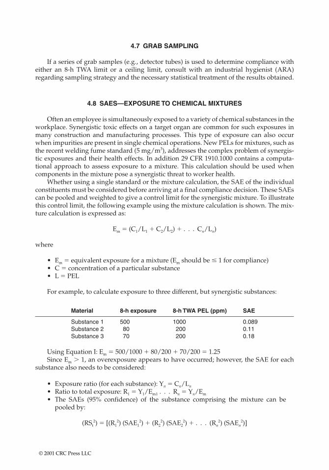
4.7 GRAB SAMPLING
If a series of grab samples (e.g., detector tubes) is used to determine compliance witheither an 8-h TWA limit or a ceiling limit, consult with an industrial hygienist (ARA)regarding sampling strategy and the necessary statistical treatment of the results obtained.
4.8 SAES—EXPOSURE TO CHEMICAL MIXTURES
Often an employee is simultaneously exposed to a variety of chemical substances in theworkplace. Synergistic toxic effects on a target organ are common for such exposures inmany construction and manufacturing processes. This type of exposure can also occurwhen impurities are present in single chemical operations. New PELs for mixtures, such asthe recent welding fume standard (5 mg/m3), addresses the complex problem of synergis-tic exposures and their health effects. In addition 29 CFR 1910.1000 contains a computa-tional approach to assess exposure to a mixture. This calculation should be used whencomponents in the mixture pose a synergistic threat to worker health.
Whether using a single standard or the mixture calculation, the SAE of the individualconstituents must be considered before arriving at a final compliance decision. These SAEscan be pooled and weighted to give a control limit for the synergistic mixture. To illustratethis control limit, the following example using the mixture calculation is shown. The mix-ture calculation is expressed as:
Em � (C1/L1 � C2/L2) � . . . Cn/Ln)
where
• Em � equivalent exposure for a mixture (Em should be � 1 for compliance)• C � concentration of a particular substance• L � PEL
For example, to calculate exposure to three different, but synergistic substances:
Material 8-h exposure 8-h TWA PEL (ppm) SAE
Substance 1 500 1000 0.089Substance 2 80 200 0.11Substance 3 70 200 0.18
Using Equation I: Em � 500/1000 � 80/200 � 70/200 � 1.25Since Em � 1, an overexposure appears to have occurred; however, the SAE for each
substance also needs to be considered:
• Exposure ratio (for each substance): Yn � Cn/Ln
• Ratio to total exposure: R1 � Y1/Em1 . . . Rn � Yn/Em
• The SAEs (95% confidence) of the substance comprising the mixture can bepooled by:
(RSt2) � [(R1
2) (SAE12) � (R2
2) (SAE22) � . . . (Rn
2) (SAEn2)]
© 2001 CRC Press LLC

• The mixture control limit (CL) is equivalent to 1 � RSt.
—If Em � CL1, then an overexposure has not been established at the 95% confi-dence level; further sampling may be necessary.—If Em � 1 and Em � CL1, then an overexposure has occurred (95% confidence).
• Using the mixture data above:
Y1 � 500/1000 Y2 � 80/200 Y3 � 70/200Y1 � 0.5 Y2 � 0.4 Y3 � 0.35R1 � Y1/Em � 0.4 R2 � 0.32 R3 � 0.28
• (RSt)2 � (0.42)(0.0892) � (0.322)(0.112) � (0.282)(0.182)
• RSt � [(RSt)2)](1/2) � 0.071
• CL � 1 � RSt � 1.071• Em � 1.25
Therefore Em � CL and an overexposure has occurred within 95% confidence limits.This calculation is also used when considering a standard such as the one for total weldingfumes.
© 2001 CRC Press LLC
CHAPTER 5
Chemical Risk Assessment
Real-world examples portray the decision logic needed to conduct chemical sampling whenassessing risk. This chapter includes a troubleshooting section/checklist to assist samplers in eitherchoosing a consultant or appraising in-house sampling methodology.
Chemical risk assessment is a twofold process. One part occurs off-site as known chem-ical information is assessed and calculations based on accepted formulas are done. The EPAbaseline risk assessments (BLRAs), screening assessments, and remedial investigationstudies rely on a body of knowledge accumulated over the last 20 years. Decisions aboutsupportive air monitoring and actual on-site monitoring required during sampling eventsshould also be made at this time.
The second stage is the actual accumulation of data during which workers must be pro-tected against airborne hazards, including those resulting from their sampling efforts,including disturbance of the on-site medium (soil, water). Decision-making concerningpersonal protection and engineering controls may require air monitoring of personnel, areaof influence, and the site perimeter.
In order to understand the context under which air monitoring protocols are devel-oped, an understanding of chemical risk assessment for these sites is necessary. Keep inmind that the term site is an all inclusive one for this section and may include active indus-trial and/or construction sites.
5.1 BASELINE RISK ASSESSMENT
Monitoring to determine chemical risk may lead to a BLRA consistent with U.S. EPAComprehensive Environmental Resource Conservation Liability Act (CERCLA) guidancedocuments that address:
• Potentially contaminated groundwater• Surface water runoff, sediment, and river area• Soils
The results of the BLRA may be used to
• Prioritize the need for site remediation or abatement activities.• Provide the basis for quantification of remedial objectives.• Assist in planning objectives to minimize risk.
©2001 CRC Press LLC
5.2 CONCEPTUAL SITE MODEL
The first step in developing a BLRA is to provide a conceptual site model that has beendeveloped to evaluate source areas, migration pathways, and possible exposure points forreceptors. Migration pathways are potential conduits for contaminants to reach on-site and off-site receptors. This model is then used to determine the medium that needs to besampled.
5.2.1 Source Areas
The source areas are limited to the areas delineated by the model. Source areas such assoil areas, bodies of water, and air emissions are areas for concern. Soils in particular maybe primary and secondary source areas—primary as particulates that may lead to ingestionor dermal hazard, and secondary as soils that may be dispersed in the airstream throughon-site activities.
5.2.2 Possible Receptors
In accordance with the EPA standard default exposure factors (SDEFs) guidance, construction worker, commercial/industrial, and recreational populations are consideredpossible receptors in the human health evaluation. Sampling efforts to quantify and qual-ify the potential exposure pathways will focus on predictive sampling of the medium ofconcern, including surface soil, subsurface soil, groundwater, and air. The source areas aredefined as the current industrial use soil contamination.
5.3 CHEMICALS OF POTENTIAL CONCERN
Groundwater and soil analytical data from samples collected from the site area areevaluated for preliminary determination of chemicals of potential concern (COPCs).Samples are from known hot spots as a worst-case scenario for soils and are evalu-ated using log-normal distribution, Kriging, or Monte Carlo analysis. Ground- and surface-water samples are collected (20 samples per location) and are evaluated using nor-mal distribution assumptions.
The frequency of detection of chemicals in each medium is calculated as the number oftotal detections out of the total number of analytical samples for each medium. Duplicatesample data will not considered in this calculation.
The positively identified chemicals for each medium are reviewed to identify chemi-cals that could potentially result in adverse health effects in humans or in adverse envi-ronmental effects. Detected concentrations are compared to potential applicable or relevantand appropriate requirements (ARARs). ARARs include Safe Drinking Water Act (SDWA)maximum contaminant levels (MCLs), lifetime health advisory levels (HALs), and U.S.EPA Region VII preliminary remediation goals (PRGs). If detected concentrations are sig-nificantly below health-based ARARs or if compounds are known to be nontoxic, they areeliminated from further consideration.
© 2001 CRC Press LLC
5.4 HUMAN HEALTH BLRA CRITERIA
To understand the rationale for selecting sample sites, the sampler must have a basicunderstanding of risk assessment criteria. The following components of a risk assessmentare normally part of all risk assessment discussions—even if those discussions are ulti-mately negative declarations—“we do not have to worry about that.’’
5.5 TOXICITY ASSESSMENT
The toxicity assessment weighs available evidence that COPCs may cause adversehealth effects in exposed humans or other biota. The assessment estimates the extent ofpotential chemical exposure and the increased likelihood and/or severity of adverseeffects. The toxicity assessment at the site location is accomplished in two steps:
1. Chemical hazard identification determines whether potential chemical exposurecauses an increased incidence or severity of an adverse health or environmentaleffect. Toxicological data for COPCs are reviewed, and toxicological profiles areprepared for the COPCs.
2. The dose-response evaluation consists of quantitatively evaluating the toxicityinformation. Then the relationship between the chemical dose and the resultantincidence/severity of adverse health or environmental effects are reviewed.
The risk characterization portion of the BLRA estimates the likelihood of adverseeffects occurring under the exposure scenarios. For the chemicals identified (except lead)the toxicity values have been derived by the U.S. EPA and are summarized in theIntegrated Risk Information System (IRIS) database.
The EPA has not developed a reference dose (RfD) or carcinogenic potency slope fac-tor (SF) for elemental lead. The EPA considers lead a special case because lead is ubiquitousin all media; therefore, human exposure comes from multiple sources. Thus most peoplewould exceed an RfD level under “background’’ conditions. The EPA Office of Solid Wasteand Emergency Response (OSWER) has released a directive on BLRA and cleanup of resi-dential soil lead. This directive recommends that soil lead levels less than 400 ppm are con-sidered safe for residential use. The EPA action level (SDWA) for lead in drinking water is15 �g/l. An RfD, 1 � 10�7 mg/kg/day, has been provided for tetraethyl lead, formerly acommon additive for gasolines in the U.S. The current accepted site usage levels for leadare evaluated in concert with the surrounding area soil levels.
For noncarcinogens, an RfD is established by the EPA as a result of hazard identifica-tion and dose-response evaluation. The RfD is an estimate of an exposure level judgedlikely to be without an appreciable risk of adverse health effects over a specified time ofexposure. A critical study (or studies) in which a dose causing an adverse effect is identi-fied at a lower level of exposure as either having no effect or minimal effect—yields theRfD. Chronic RfDs reflect a level of exposure that would not result in adverse effects whenexperienced for 7 years to a lifetime (Baseline Risk Assessment Guidance for Superfund[RAGS] Part A). If the RfD is expressed as an administered dose, dermal toxicity values are derived by adjusting the oral toxicity value (i.e., multiplying by a chemical absorp-tion factor).
The noncarcinogenic effects potential is evaluated by comparing the chemical intakewith an RfD. This ratio is referred to as a hazard quotient (HQ). The HQ assumes that
© 2001 CRC Press LLC
below a certain level of exposure, even sensitive populations will not experience adverseeffects. Based on this assumption, if exposure is equivalent to or less than the RfD and theHQ is 1.0 or less, a hazard is not likely to exist. If the HQ exceeds 1.0, a hazard may exist.
For carcinogens a cancer SF and a weight-of-evidence classification are the toxicity val-ues used in the characterization of potential human carcinogenic risks. The relationshiprelating exposure level to the probability of developing cancer (i.e., the incidence) isexpressed as a cancer SF.
The SF is a plausible upper-bound estimate of the probability of developing cancer perunit intake of a chemical over a lifetime. SFs are expressed as (mg/kg-day)�1. If the SF isexpressed as an administered dose, a dermal toxicity value is derived by adjusting the oraltoxicity value (i.e., dividing by the chemical absorption factor).
The potential for carcinogenic effects is estimated by multiplying a chemical’s SF by thelifetime average daily chemical intake. Exposure to carcinogens resulting in an increasedcarcinogenic risk of 1 � 10�6 or greater may be cause for potential concern and may indi-cate the need for remedial action.
The risk of developing cancer as a result of exposure to carcinogens can also beexpressed as a unit risk. This toxicity value represents a risk per unit concentration in theparticular medium contacted. Unit risks reflect risks resulting from continuous lifetimeexposures. Unit risks are expressed as (�g/m3)�1 for inhalation exposures or (�g/l)�1 fororal exposures. A unit risk in the range of 1 � 10�4 to 1 � 10�6 implies that an individualhas between a 1 in 10,000 and a 1 in 1,000,000 chance of developing cancer in excess of abackground incidence if exposed to 1 �g/m3 air or 1 �g/l water of a carcinogenic chemicalfor a lifetime.
The carcinogenic potential of a chemical is classified into one of the following groupsaccording to the weight of evidence from epidemiological and animal studies:
• A—human carcinogen• B1—probable human carcinogen (limited evidence of carcinogenicity in humans)• B2—probable human carcinogen (sufficient evidence in animals with inadequate
evidence in humans)• C—possible human carcinogen (limited evidence of carcinogenicity in animals or
lack of human data)• D—not classifiable as a human carcinogen• E—evidence of noncarcinogenicity in humans
5.6 TOXICOLOGICAL PROFILES
The Agency for Toxic Substances and Disease Registry (ATSDR) data and IRIS infor-mation are used to prepare toxicological profiles for COPCs. The toxicological profiles willinclude specific toxicological information (e.g., toxicological effects, target organs, criticaleffect).
5.7 UNCERTAINTIES RELATED TO TOXICITY INFORMATION
The RfDs established for COPCs are a major source of uncertainty in a BLRA. The RfDis the estimate of daily exposure likely to be without an appreciable risk of deleteriouseffects during a lifetime. The RfD is derived by the application of uncertainty factors toselected exposure levels identified in animal or human studies. Identified exposure levelsare divided by these uncertainty factors to assure that the RfD will not be overestimated.
© 2001 CRC Press LLC
For example, an uncertainty factor of 10 is used to account for variations in human sensi-tivity when using data from valid human studies involving long-term exposure of average,healthy subjects. Additional uncertainty factors of 10 are applied to account for uncertain-ties in extrapolating from observation of toxicity in animals to predicted toxicity inhumans, to account for uncertainties in identifying threshold dose from experimental data,and to account for uncertainties in extrapolating from subchronic to chronic studies. Anyadditional uncertainty factor or modifying factor ranging from �0 to �10 may be appliedto reflect professional assessment of other uncertainties that may exist in the toxicity data-base for a specific compound.
Considerable uncertainties are involved in identifying whether or not a compound isa likely potential human carcinogen and at what level of exposure an increased risk of can-cer may exist.
Uncertainties in quantifying the exposure level that may result in elevated carcino-genic risk for specific compounds are compensated for by using the 95% UCL of the esti-mated slope. This slope refers to the line that relates chemical exposure to the probabilityof developing cancer—thus the term slope factor for carcinogens. Using the 95% UCL is astatistical path to assure that the actual SF is highly unlikely to be greater than the SF listedfor that chemical. These dose-response assumptions provide an upper, but plausible, esti-mate of the limit of risk when the SF is used to estimate risk associated with an estimatedlevel of exposure.
5.8 POTENTIALLY EXPOSED POPULATIONS
For the future land-use scenario the assumption is that the site property will remain asite. The population to be considered includes on-site workers, site visitors, and possiblefuture construction workers. The population may be exposed to surface soil, subsurfacesoil, and groundwater through inhalation, ingestion, and dermal contact.
The monitoring results of the well survey efforts are used to determine completedexposure pathways. The site does not have on-site residential or adjacent residential prop-erty; therefore, the soil exposure pathway is not applicable (i.e., complete) for on-site oradjacent sites.
Recreational receptors to be evaluated will include site trespassers and users of the site.
5.8.1 Exposure Pathways
The exposure pathway is the course a chemical takes from the source to the exposedindividual. The exposure pathway is characterized by the source (the contaminatedmedium), the mechanism of release, a retention or transport medium, a point of potentialhuman contact with a contaminated medium, and an exposure route at the point of contact(i.e., ingestion). An exposure pathway is complete only when each of these elements ispresent. Air monitoring may be used to supplement theoretical calculations of air disper-sion pathways.
5.8.2 Sources
Surface soil and subsurface hydrogeological formations (i.e., soil/groundwater sys-tem) that have been affected by the site’s former usage are the source areas that come underconsideration.
© 2001 CRC Press LLC
5.9 ENVIRONMENTAL FATE AND TRANSPORT OF COPCs
The inorganic contaminants identified at the site may not be generally consideredmobile in the soil/groundwater system. Mobility is affected by soil pH and groundwaterfor aqueous transport. Factors influencing dust generation and movement from the soilsurfaces to the air migration pathway must also be considered. Inorganic contaminantmobility through storm water runoff and surface water transport are evaluated. Existingsite conditions are evaluated to estimate the migration of contaminants to subsurface soil,groundwater, and surface water, and air.
5.10 EXPOSURE POINTS AND EXPOSURE ROUTES
Only complete exposure pathways involving current or future contact with contami-nated media are cause for concern. Exposure pathways, in that the potentially exposedpopulation is not likely to experience significant contaminated medium contact or the envi-ronmental medium contacted is not significantly contaminated, will not be considered.Therefore, before determining that the pathways are complete and that the possible recep-tors are likely to be exposed at significant levels, site-specific information is gathered. Thisinformation will also be used to develop site-specific exposure parameters. An interimBLRA deliverable is prepared to propose the exposure scenarios that are used in the finalBLRA.
5.11 COMPLETE EXPOSURE PATHWAYS EVALUATED
A well survey is conducted to determine if any down-gradient domestic wells at thesite may be affected. Based on the proximity of the wells, their depth, construction, and use,the potential for these wells to be affected by the site are determined. Irrigation wells, ifwithin the site’s vicinity, are a potential exposure pathway vector to the fields that are irrigated.
For the industrial exposure scenario, on-site workers and site visitors are consideredfor exposure to contamination through surface soil, subsurface soil, and air. The recre-ational exposure scenarios are considered for site trespassers and visitors to the site.
5.12 ECOLOGICAL RISK ASSESSMENT
Pathways for terrestrial and aquatic environmental receptors regarding exposure tosubsurface soil, surface soil, sediment, surface water, and air are considered in the ecolog-ical component of the risk assessment. The ecological component of the BLRA characteri-zation includes the following:
• Identification of habitats and predominant species occurring at the site includingthe river areas
• Selection of representative species that may have the greatest exposure based onfeeding habits, habitat usage, and exposure duration (Receptors of concern willalso be evaluated based on available published eco-toxicological data.)
• Verification that contaminants of potential ecological concern are limited toheavy metals
© 2001 CRC Press LLC
• Research into toxicological reference values in published material (Ambientwater quality criteria [AWQC] are used for contaminants.)
• Evaluation of environmental data to adequately estimate existing and potentialfuture ecological risks
• Development of a sampling and analysis plan (SAP) for data collection to evalu-ate ecological exposure
• Determination whether background data are required or if other informationsuch as surface water hardness is necessary to evaluate toxicity
• Quantification of exposure by estimating the magnitude and rate of exposure forreceptors of concern. (This quantification will include evaluation of contaminantconcentrations, bioavailability, bioaccumulation, bioconcentration, and biomag-nification potential; feeding rates; habitat usage; and food chain considerations.)
• Review of the results of the toxicity and exposure assessments• Comparisons of exposure concentrations to appropriate toxicological reference
values to complete a risk characterization (This characterization will include anevaluation of the spatial distribution of contamination with regard to ecologicalreceptors.)
Decisions on whether an ecological impact exists are based on this risk characteriza-tion. Sampling to determine contaminant exposure potential then follows the same criteriaas for the human health risk assessment, except that sampling routines may be specializedto deal with species-specific exposures. An example would be the exposure of burrowinganimals to soils through ingestion, inhalation, and dermal contact.
5.13 DATA EVALUATION AND DATA GAPS
Existing data for concentrations of contaminants in the medium of concern—surfacesoil, subsurface soil, groundwater, and air—are evaluated. This evaluation will determineif data are adequate to estimate exposure point concentrations and to evaluate contaminantmigration and toxicity. Existing data will also be evaluated to determine if data are of ade-quate quality for use in a risk assessment according to the methods specified in the U.S.EPA guidance, Data Usability in Risk Assessments.
If additional environmental data are necessary to complete the BLRA, an SAP is devel-oped. In addition to chemical data, collection of water quality data (i.e., hardness) may bespecified in the SAP because the toxicity and mobility of metals in surface water is hard-ness dependent.
At this time an evaluation of existing data indicates that on-site groundwater data areavailable. Current groundwater data and new empirical data are evaluated for backgroundand down-gradient information. The arithmetic means and 95% UCLs of the mean are cal-culated for COPCs. For the groundwater pathways a well survey is conducted within 1 mile of the site to verify the locations and uses of all wells.
If recontouring of the soil surface has occurred to direct storm water runoff toward col-lection points, additional surface soil samples (0–2 in.) may be necessary for the analysis ofCOPCs in the soil ingestion and air pathways.
Data collection points are designed to identify hot spots and to calculate average con-centrations over the entire site and in the areas of concern. Soil pH must also be measuredbecause soil pH influences metals transport.
Surface water data for up-gradient and down-gradient points and sample collectionpoints for this data are identified. No surface water or sediment data from on-site
© 2001 CRC Press LLC
drainages, or drainage pathways from the site, may be available to provide information onthe extent of contaminant migration. Sediment data from the surface water pathway pro-vide information on whether the rivers or standing bodies of water subject to runoff areanother source of contamination to other surface waters. Collect surface water and sedi-ment samples from these areas.
The level of generation of dust at the site is required information. This information maybe collected via real-time particulate measurements and/or by collecting samples for lab-oratory analysis. The level of dust generation is assumed to vary significantly with timeand climatic data. The collection of dust generation data is planned carefully so that dustgeneration is neither underestimated or overestimated.
5.14 UNCERTAINTIES
Uncertainties may relate to several factors, such as toxicity information or exposureassessments.
5.14.1 Uncertainties Related to Toxicity Information
The RfDs for COPCs are a major source of uncertainty in a BLRA. A chronic RfD is anestimate of the daily exposure unlikely to present an appreciable risk of deleterious effectsduring a lifetime. Uncertainty factors are applied to selected exposure levels identified inanimal or human studies to derive the RfD. To avoid overestimating the RfD, identifiedexposure levels are divided by these uncertainty factors. An uncertainty factor of 10 is usedto account for variations in human sensitivity when using data from valid human studiesinvolving long-term exposure of average, healthy subjects. When extrapolating fromobservations of toxicity in animals to predicted toxicity in humans, additional uncertaintyfactors of 10 are applied.
Uncertainties are also present when identifying whether a compound is a likely humancarcinogen and at what level of exposure an increased risk of cancer may exist. Uncertaintiesin quantifying the exposure levels that may result in elevated carcinogenic risk for specificcompounds are corrected for by using the 95% UCL of the slope relating exposure to the prob-ability of developing cancer. The actual slope may be greater, but is unlikely to be greater.
The lack of an RfD and a cancer SF for lead will introduce uncertainty into the BLRA iflead is a COPC.
5.14.2 Uncertainties in the Exposure Assessment
Uncertainties in the exposure assessment are introduced in estimating the concentra-tions to which receptors may be exposed to in the future and in identifying exposed popu-lations. The future land use at the facility and prediction of the future surrounding use adduncertainty to this assessment. The exposure scenarios selected are developed to model thehighest reasonable potential exposures to site contaminants. These estimates are unlikelyto underestimate future potential risk.
Estimates of exposure frequency and duration are also uncertain. Reasonable levelswere selected that are not likely to underestimate the risk associated with site-relatedactivities.
• Uncertainty is present in exposure point concentration estimations.• All data for metals in groundwater are based on unfiltered groundwater
samples.
© 2001 CRC Press LLC
5.15 RISK CHARACTERIZATION
Based on intake calculations and the identification of complete exposure pathways, anoverall site characterization and a risk characterization are completed. This will include thefollowing:
• Written justification for the assumptions used to calculate human dose or intake• Characterization of carcinogenic risk using EPA-established carcinogenic SFs• Estimation of carcinogenic risk expressed as the incremental increase in the prob-
ability of an individual developing cancer over a lifetime (incremental lifetimecancer risks [ILCRs])
• Summation of ILCRs for individual COPCs across pathways and within receptorexposure scenarios (e.g., on-site worker exposed to groundwater)
• Estimation of potential adverse health effects from exposure to systemic toxicantsvia comparing an exposure intake to a standard RfD (This ratio is the HQ.)
• Estimation of HQs for each COPC for which toxicity values are available• Assumption of individual COPC HQ additivity applied to chemicals that induce
the same effect on the same target organ
The summation of HQs is judged to form valid upper-bound hazard indices. Thesesummations are considered only when chemicals within the mixture exhibit “dilution typeinteraction’’ (Science Advisory Board Review of the OSWER draft RAGS, Human HealthEvaluation Manual [HHEM], EPA-SAB-EHC-93-007). These chemicals within a mixturemust have interactions that are independent mechanisms; synergistic and/or antagonisticinteractions invalidate the summation of HQs.
Consider indirect exposures (e.g., through the food chain) when receptors have beenidentified as currently present on-site or potentially identified given reuse options. Grazingscenarios are to be considered both as indirect exposures to humans and with the ecologi-cal assessment.
Consider exposure pathways related to soil contamination in terms of dermal andinhalation of fugitive dust hazards.
5.16 HEADSPACE MONITORING—VOLATILES
The PID is a quantitative instrument that measures the total concentration of variousVOCs in the air. The PID may be used as an approach instrument to monitor for safeapproach to the site’s hot spots and also for headspace analysis of any samples taken.
When wells are drilled and/or soil borings are taken, the headspace in the borehole ismonitored to assure safety to the drill crew. The PID measures in the parts per millionrange; therefore, sustained deflection of over 5 ppm for 1 min is a good indicator of volatilepresence long before most volatile chemicals reach an explosive potential.
PIDs are also used for ongoing monitoring of personnel exposures. If a detection ofvolatiles occurs, either detector tube or solvent tube sampling may be required to identifythe exact volatile chemical constituency.
5.17 O2/CGI
The O2/CGI is an air-monitoring device designed to indicate the level of oxygen pres-ent and monitor for a flammable/explosive atmosphere. The CGI registers combustible gas
© 2001 CRC Press LLC
or vapors in terms of their LEL, which is the lowest concentration at which a combustiblegas may ignite (or explode) under normal atmospheric conditions.
These instruments are required on all sites where volatiles may be expected to reachLEL levels and for all sampling requiring confined space entry.
5.18 INDUSTRIAL MONITORING—PROCESS SAFETY MANAGEMENT
Sampling at industrial sites to determine chemical risk proceeds to determineemployee exposure potential and ultimately chemical risk. The chemical risk assessmentscenarios used by the EPA may or may not be applicable or relevant. In cases where expo-sure can be compared to OSHA PELs and STELs, calculation of risk may not be necessary.
Screening with portable monitors (PIDs and O2/CGIs) or detector tubes can be used toevaluate the following:
• Exposures to substances as to PELs in relatively dust-free atmospheres• Intermittent processes using substances that do not have STELs• Engineering controls• Work practices• Isolation of process
A sufficient number of samples must be taken to obtain a representative estimate ofexposure. Contaminant concentrations vary seasonally, with weather, with production lev-els, and in a single location or job class. When determining exposure levels, you may electto turn off or remove sampling pumps before employees leave a potentially contaminatedarea (such as when they go to lunch or on a break). If you follow this OSHA-allowed pro-tocol, you MUST document and be able to prove zero exposure during the time interval themonitor was turned off.
5.19 BULK SAMPLES
Bulk samples are often required to assist the industrial hygienist in the proper analysisof field samples at industrial sites. Bulk samples can also be taken and analyzed to supportany hazard communication inspections (i.e., Material Safety Data Sheet determinations).
© 2001 CRC Press LLC
CHAPTER 6
Biological Risk Assessment
Given that many of the indoor air problems (whether on remediation sites or elsewhere) arecaused by biological contaminants and their decomposition products, Chapter 6 provides real-worldexamples of biological monitoring protocols.
All sampling for biologicals must take into account surrounding environmental factorsand building usage. Drawing a complete history and in some cases additional types of airsampling for other contaminants are required. In discussing sampling for biologicals wewill also discuss the reasons for concern and control mechanisms that can be used.
You must always remember that biologicals, unlike chemical contaminants, have thepotential to reproduce and thus grow in numbers. Care must be taken to sample in a con-sistent fashion in as short a period as possible.
Reproduction of biologicals also calls into question the relative viability of spores andbacterial colonies that are encysted. In cases where amplification is primarily bacterial,these colonies may inhibit spores from developing into vegetative structures. Conse-quently comparative levels for bacterial counts and mold colony forming units (CFUs) maybe required, especially since spores in and of themselves can be problematic. Thus, theabsence of visible mold growth may not be indicative of a clean environment.
When molds are amplified to the extent that the building is increasingly hospitable tofurther mold growth, we may begin to see pathogenic colonies (that would not otherwisebe present) taking hold in a building’s interior. All of us exhibit great concern when con-fronted with possible Stachybotrys atra (Stachy). Airstream movement does not readilyspread Stachy, as the spores become less viable in dry airstream environments. However,in moisture-laden airstreams or within homes with other amplified mold colonies, Stachymay begin to flourish.
In areas where bird or other animal droppings are prevalent, we begin to be concernedabout histoplasmosis and coccidiomycosis. Histoplasma (Histo) is the more likely diseasevector where other molds are flourishing, given that Histo is better able to survive in wet-ter environments.
Keep in mind that the term wet is a relative one. Some of these molds do not need “wet’’environments in the traditional sense to grow well; any condensation will do, even thatcaused by very slight temperature differences.
The old way of thinking that fiberglass will not grow biologicals is also not correct. Thefiberglass itself may not be a good food source; however, the fiberglass forms a nice nestand traps other food sources. Fiberglass filters, lined fiberglass ducts, and fiberglass panels
© 2001 CRC Press LLC
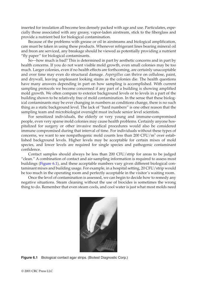
Figure 6.1 Biological contact agar strips. (Biotest Diagnostic Corp.)
inserted for insulation all become less densely packed with age and use. Particulates, espe-cially those associated with any greasy, vapor-laden airstream, stick to the fiberglass andprovide a nutrient bed for biological contamination.
Because of the problems with grease or oil in airstreams and biological amplification,care must be taken in using these products. Whenever refrigerant lines bearing mineral oiland freon are serviced, any breakage should be viewed as potentially providing a nutrient“fly paper’’ for biological contaminants.
So—how much is bad? This is determined in part by aesthetic concerns and in part byhealth concerns. If you do not want visible mold growth, even small colonies may be toomuch. Larger colonies, even if no health effects are forthcoming, are certainly unacceptableand over time may even do structural damage. Aspergillus can thrive on cellulose, paint,and drywall, leaving unpleasant looking stains as the colonies die. The health questionshave many answers depending in part on how sampling is accomplished. With currentsampling protocols we become concerned if any part of a building is showing amplifiedmold growth. We often compare to exterior background levels or to levels in a part of thebuilding shown to be relatively free of mold contamination. In the sense that these biolog-ical contaminants may be ever changing in numbers as conditions change, there is no suchthing as a static background level. The lack of “hard numbers’’ is one other reason that thesampling team and microbiologist oversight must include senior level scientists.
For sensitized individuals, the elderly or very young and immune-compromisedpeople, even very sparse mold colonies may cause health problems. Certainly anyone hos-pitalized for surgery or other invasive medical procedures would also be consideredimmune compromised during that interval of time. For individuals without these types ofconcerns, we want to see nonpathogenic mold counts less than 200 CFU/m3 over estab-lished background levels. Higher levels may be acceptable for certain mixes of moldspecies, and lower levels are required for single species and pathogenic contaminantconfidence.
Contact samples should always be less than 200 CFU/strip for areas to be judged“clean.’’ A combination of contact and air-sampling information is required to assess mostbuildings (Figure 6.1), and these acceptable numbers vary given different biological con-taminant mixes and building usage. For example, in a hospital setting, 20 CFU/strip wouldbe too much in the operating room and perfectly acceptable in the visitor’s waiting room.
Once the level of contamination is assessed, we can begin to decide how to remedy anynegative situations. Steam cleaning without the use of biocides is sometimes the wrongthing to do. Remember that even steam cools, and cool water is just what most molds need
© 2001 CRC Press LLC
to increase their amplification rate. Steam cleaning can be beneficial with adequate dryingcycles and in some instances the concurrent use of biocides.
Biocide usage can also be problematic. Chemicals that work in the laboratory maycause aesthetic and even health problems in the real world. Biocides often have limitedresidual time and may not even be tested against the particular biological contaminant mixof concern.
Residual time for any chemical mix has many unresolved questions; sometimes thechemicals’ residual time in your particular circumstances is not even known. In other casesresidual time may make the chemical unattractive because the toxic properties of the chem-ical remain and can cause contamination problems in and of themselves. We must alwaysremember that the basic cellular structure of these biological contaminants and ourselvesis the same, so chemicals that harm these contaminants may also harm us.
Recently, biocides with FDA and EPA approval have been developed and can be usedin areas where biocides were formerly unacceptable. The decision in selecting the appro-priate biocide that will not harm humans, animal occupants, or damage structural materi-als can be a difficult one. Decontamination and rehabitation methodologies must be part ofa coordinated remedial design effort.
One of the more common replies to all of this information is—why now? The answeris twofold; first, we probably always had these concerns once we lived for any length oftime indoors; second, we have increasingly closed our buildings and relied on forced airventilation systems. Both of these answers are also applicable to closed cab modes of trans-portation—airplanes, automobiles, rail cars, and ships.
In the past we thought that endpoint filtration of airstreams was sufficient to renderdelivered air relatively pure. We have now learned that filtration only works for a time, andexcessive biological amplification can be transmitted through most current HVAC systemsonce established in ductwork or plenums.
If you suspect biological contamination, see visible mold growth, have personnel withrepetitive mycosial infections, or have indoor air quality (IAQ) problems that haveremained undiagnosed, you need to consult a team of professionals to find answers tothese problems. In these cases not only is the mold growth itself problematic, but also wehave to worry about the chemicals formed as colonies die. Dieback causes the chemicalsformed during decomposition to be spread throughout building, and these are the sameVOCs we worry about from chemical spills or misuse. The following sections speakdirectly to hazards associated with mold and fungi.
6.1 FUNGI, MOLDS, AND RISK
When inhaled, microscopic fungal spores or fragments of fungi may cause allergicrhinitis. Because they are so small, mold spores may evade the protective mechanisms ofthe nose and upper respiratory tract to reach the lungs and bring on asthma symptoms. Thebuildup of mucus, wheezing, and difficulty in breathing are the result. Less frequently,exposure to spores or fragments may lead to a lung disease known as hypersensitivitypneumonitis.
Molds are present in our exterior environments, and, hopefully, to a lesser extent in ourinterior environments. People allergic to molds may have allergic symptoms from springto late fall. The mold season often peaks from July to late summer. Unlike pollens, moldsmay persist after the first killing frost. Some can grow at subfreezing temperatures, butmost become dormant. Snow cover lowers the outdoor mold count drastically, but does notkill molds. After the spring thaw, molds thrive on the vegetation that has been killed by the
© 2001 CRC Press LLC

winter cold. In the warmest areas of the world, however, molds thrive year-round and cancause perennial allergic problems. Molds growing indoors can cause perennial allergicrhinitis even in the coldest climates.
If indoor areas show signs of amplification identified by visual assessment, air sam-pling, and contact/liquid sampling, amplification must be suspected. Amplification is theprocess whereby biological organisms continue to increase over time. If this increase is notcontrolled, sufficient mold spores and vegetative structures may be present to create indoorair problems.
Hot spots of mold growth in the home include damp basements and closets, bathrooms(especially shower stalls), places where fresh food is stored, refrigerator drip trays, houseplants, air conditioners, humidifiers, garbage pails, mattresses, upholstered furniture, andold foam rubber pillows.
6.1.1 What Is the Difference between Molds, Fungi, and Yeasts?
Molds and yeasts are two groups of plants in the fungus family. Yeasts are single cellsthat divide to form clusters. Molds consist of many cells that grow as branching threadscalled hyphae. The seeds or reproductive particles of fungi are called spores. They differ insize, shape, and color among species. Each spore that germinates can give rise to new moldgrowth, which in turn can produce millions of spores.
6.1.2 How Would I Become Exposed to Fungi That Would Create aHealth Effect?
The route of exposure may be inhalation or ingestion accompanied by inhalation.When inhaled, microscopic fungal spores or fragments of fungi may cause health prob-lems. Because they are so small, mold spores may evade the protective mechanisms of thenose and upper respiratory tract to reach the lungs and bring on asthma symptoms. Thebuildup of mucus, wheezing, and difficulty in breathing are the result. Less frequently,exposure to spores or fragments may lead to a lung disease known as hypersensitivitypneumonitis.
6.1.3 What Types of Molds Are Commonly Found Indoors?
In general, Alternaria and Cladosporium (Hormodendrum) are the molds most commonlyfound both indoors and outdoors throughout the U.S. Aspergillus, Penicillium, Helmintho-sporium, Epicoccum, Fusarium, Mucor, Rhizopus, and Aureobasidium (Pullularia) are alsocommon.
6.1.4 Are Mold Counts Helpful?
Similar to pollen counts, mold counts may suggest the types and relative quantities ofmold present at a certain time and place. For several reasons, however, these counts prob-ably cannot be used as a constant guide for daily activities. One reason is that the numberand types of spores actually present in the mold count may have changed considerably in24 h because weather and spore dispersal are directly related. Many of the common aller-genic molds are of the dry spore type—they release their spores during dry, windy weather.
© 2001 CRC Press LLC

Other molds need high humidity, fog, or dew to release their spores. Although rain washesmany larger spores out of the air, it also releases some smaller spores into the air.
6.1.5 What Can Happen with Mold-Caused Health Disorders?
Fungi or microorganisms related to them may cause other health problems similar toan allergy. Fungi may lodge in the airways or a distant part of the lung and grow until theyform a compact sphere known as a “fungus ball.’’ In people with lung damage or seriousunderlying illnesses, Aspergillus may grasp the opportunity to invade and actually infectthe lungs or the whole body. In some individuals exposure to these fungi can also lead toasthma or to an illness known as “allergic bronchopulmonary aspergillosis.’’ This lattercondition, which occurs occasionally in people with asthma, is characterized by wheezing,low-grade fever, and coughing up of brown-flecked masses or mucous plugs. Skin testing,blood tests, X-rays, and examination of the sputum for fungi can help establish the diag-nosis. The occurrence of allergic aspergillosis suggests that other fungi might cause similarrespiratory conditions.
Inhalation of spores from fungus-like bacteria, called actinomycetes, and from moldscan cause a lung disease called hypersensitivity pneumonitis. This condition is often asso-ciated with specific occupations. Hypersensitivity pneumonitis develops in people wholive or work where an air-conditioning or a humidifying unit is contaminated with andemits these spores. The symptoms of hypersensitivity pneumonitis may resemble those ofa bacterial or viral infection such as the flu. If hypersensitivity pneumonitis is allowed toprogress, it can lead to serious heart and lung problems.
6.2 BIOLOGICAL AGENTS AND FUNGI TYPES
A host of fungi are commonly found in ventilation systems and indoor environments.The main hazardous species belong to the following genera: Absidia, Alternaria, Aspergillus,Fusarium, Cladosporium, Cryptostroma, Mucor, Penicillium, and Stachybotrys. Various strainsof these genera of molds have been implicated in being causative agents in asthma, hyper-sensitivity pneumonitis, and pulmonary mycosis.
Fungi commonly found in ventilation systems and indoor environments includeAbsidia, Acremonium, Alternaria, Aspergillus, Aureobasidium, Botrytis, Cephalosporium,Chrysosporium, Cladosporium, Epicoccum, Fusarium, Helminthosporium, Mucor, Nigrospora,Penicillium, Phoma, Pithomyces, Rhinocladiella, Rhizopus, Scopulariopsis, Stachybotrys,Streptomyces, Stysanus, Ulocladium, Yeast, and Zygosporium. Eleven types of fungi are typi-cally found in homes: Aspergillus, Cladosporium, Chrysosporium, Epicoccum, Fonsecaea,Penicillium, Stachybotrys, and Trichoderma.
6.2.1 Alternaria
A number of very similar, related species are usually grouped together as Alternaria.The spores of Alternaria are multicelled and developed in chains, head-to-toe, from whichtheir name derives. Spores are multiseptate, both transverse and longitudinally. They varyin width and length according to species, usually 8–75 �m long; some species such as A.longissima are up to 0.5 mm long. Alternaria, which is both ubiquitous and abundant, is bothsaprophytic and parasitic on plant material and is found on rotting vegetation as well as indamp indoor areas, such as bathrooms. Some species of Alternaria are the imperfect, asex-ual, anamorph spores of the ascomycete Pleospora.
© 2001 CRC Press LLC

6.2.2 Aureobasidium
Aureobasidium is common in both outdoor and indoor air, bathroom walls, and showercurtains. Aureobasidium causes mildew and has been isolated in flooded areas of buildings,as well as from soils, plants, and other substrates. Aureobasidium has been associated withhypersensitivity pneumonitis in some individuals.
6.2.3 Cladosporium
Cladosporium, composed of over 500 species, is found in outdoor as well as indoor air.Cladosporium has been isolated from fuels, wood, plant tissues, straw, face cream, air, soil,foods, paint, and textiles. Cladosporium spores are often found in higher concentrations inthe air than any other fungal spore type.
Cladosporium bears copious numbers of spores on branched conidiophores. The sporesusually have distinctive “scars’’ at both ends where they are joined both to the spore at oneend and to the conidiophore at the other. Although often identified as single-celled spores,spores are frequently seen with a single transverse septum or several transverse septa.Their length ranges from 4 to 20 �m.
Cladosporium (Hormodendrum) is the most commonly identified outdoor fungus and isa common indoor air allergen. Indoors Cladosporium may be different from the speciesidentified outdoors. Cladosporium is commonly found on the surface of fiberglass duct lin-ers in the interior of supply ducts. Cladosporium can cause mycosis and is a common causeof extrinsic asthma (immediate-type hypersensitivity: type I). Acute symptoms includeedema and bronchiospasms; chronic cases may develop pulmonary emphysema.
6.2.4 Rhodotorula
Rhodotorula is a commonly isolated yeast that is frequently isolated from humidifiersand soil. Rhodotorula may be allergenic to susceptible individuals when present in sufficientconcentrations.
6.2.5 Stemphylium
Stemphylium is a saprophytic fungus (grows on nonliving organic material) commonlyfound on cellulosic materials (that is, of plant origin, including livestock feed, cotton cloth,ceiling tiles, paper). Stemphylium is an example of a diurnal sporulator. An alternating lightand dark cycle is required for spore development. This fungus requires ultraviolet light forthe production of conidiophores; however, the second developmental phase, when theconidia are produced, requires a dark period. Stemphylium also requires wet conditions forgrowth. Stemphylium spores range from 23 to 75 �m in length.
6.2.6 Sterile Fungi
Sterile fungi are common to both outdoor and indoor air. These fungi produce vegeta-tive growth, but yield no spores for identification. Their presence will increase CFU/l.Derived from ascospores or basidiospores, the spores of which are likely to be allergenic,these fungi should be considered allergenic.
© 2001 CRC Press LLC
6.2.7 Yeast
Various yeasts are commonly identified on air samples. Yeasts are not known to beallergenic, but they may cause problems if a person has had previous exposure and devel-oped hypersensitivities. Yeasts may be allergenic to susceptible individuals when presentin sufficient concentrations. Yeast grows when moisture, food, and just the right tempera-tures are available.
6.3 ASPERGILLUS
Aspergillus and Penicillium are molds prevalent in soils. These molds can cause asthma-like symptoms or other lung irritation in humans and deterioration in buildings and othermaterials. When conditions within buildings cause the buildup of moisture on surfaces andtemperatures are right, Aspergillus grows well and is evidenced by a black deposit.
Aspergillus is a type of mold called Ascomycota or sac fungi. Sac fungi have sexualspores that are produced in an ascus or saclike structure. Their asexual spores, called coni-diospores (from the word conidia, which means “dust’’), are produced in long chains froma conidiophore. The characteristic arrangement of the conidiospores is used to identify thedifferent molds. Penicillium is another mold that is also called Ascomycetes.
6.3.1 What Color Are These Molds?
Aspergillus is black, and Penicillium is white. Also, Aspergillus is not the black mold onbread. That mold is Rhizopus nigricans. The difference is evident in the differing structuresfor black asexual spores (sporangiospores).
6.3.2 How Is Aspergillus Spread?
Aspergillus spores are carried in the wind and through ventilation airstreams in homes.The asexual spores freely detach from the conidiophore chain and, with the slightest dis-turbance, float in the air like dust. The easiest way to get Aspergillus started in the home isto bring the spores in on shoes and deposit the spores on carpet fibers.
6.3.3 How Does Aspergillus Grow/Amplify?
When the spores are placed on wet surfaces, the spores grow hyphae. The hyphaegrow, form a mass, and are soon visible to the naked eye. The vegetative mycelium processfoods, and reproductive mycelium create more spores. At this time the mold/fungiappears as a black fuzzy mass. (Amplification is the process whereby Aspergillus or otherbiological organisms continue to increase in number over time.)
6.3.4 What Conditions Help Aspergillus Grow/Amplify?
Fungi generally grow better with an acidic pH. The growth is usually on the surfacerather than embedded within a substrate (under the surface).
Fungi are able to grow on surfaces with a low moisture content, in contrast to the mois-ture required for bacterial growth. Therefore, even a slight difference in temperature andsurface moisture facilitates the growth of fungi.
© 2001 CRC Press LLC

Fungi are capable of using complex carbohydrates, such as lignin (wood). Thus, witha little moisture, fungi can easily grow on wood or other complex organic materials. Theseadaptations allow fungi to grow readily on painted walls and shoe leather.
6.3.5 Can Mold/Fungi Make You Sick?
Fungal diseases are called mycoses, which are chronic, long-lasting infections.Aspergillosis is an opportunistic infection that can become pathogenic (disease-causing) ina weakened individual host. The inhalation of spores is a possible mode of entry into thebody as spore size ranges from 2 to 10 �m.
6.3.6 What Are the Symptoms of Aspergillosis?
The incubation period varies with different individuals. People with other weakeningmedical problems or general ill health are most susceptible. Aspergillus niger (A. niger) pro-duces mycotoxins that can induce asthma-like symptoms. In situations when A. niger wasfound growing with Penicillium sp., massive inhalation of spores has been documented ascausing an acute, diffuse, self-limiting pneumonitis (lung irritation). Healthy individualscan exhibit otitis externa (inflammation of the outer ear canal) as a result of Aspergillusgrowth.
6.3.7 Does Aspergillus Cause Deterioration of Materials?
Members of the Aspergillus genus are known as biodeteriogens (organisms that causedeterioration of materials). A. niger causes damage, discoloration, and softening of the sur-faces of woods, even in the presence of wood preservatives. A. niger also causes damage tocellulose materials, hides, and cotton fibers. A. niger can also attack plastics and polymers(i.e., cellulose nitrate, polyvinyl acetate, polyester type polyurethanes).
6.3.8 What Happens If Aspergillus Colonies Grow insideConstruction Layers?
In cases of extensive growth, colonies will grow into wood, plaster, and/or dry-wall, causing a soft bulging area. This area lacks structural integrity and is subject to earlydeterioration.
6.3.9 How Is Aspergillus Identified?
Soy agar will grow Aspergillus and a wide range of other microbiologicals. Thus,Tryptic Soy Agar or Potato Dextrose Agar is the original screening tool used to determinethe presence of biologicals. Once biological contamination has been established, selectivemedia can be used to grow suspect organisms for identification. Using a special type of pro-tein gelatin (called Rose Bengal Agar) that has been made with special nutrients, Aspergilluscultures can be selectively and quickly grown.
© 2001 CRC Press LLC

6.3.10 How Are Levels of Aspergillus Communicated?
Aspergillus is reported in terms of colony forming units per cubic meter. The presenceof any one fungi in excess of 200 CFU/m3 is indicative of an indoor source of fungalamplification. The presence of any colony forming units per cubic meter is indicative oftransmission of fungal spores from surface to surface and/or from exterior to interiorlocations.
6.3.11 Why Do Aspergillus Colonies Look Black?
Aspergillus is black or brown-black. Also, active biological contamination creates a sur-face to which dusts and other debris “stick.’’ If biological contamination is extensive andcharacterized by amplification and “kill’’ cycle condition, the fungi/molds will decay andproduce toxins. These toxins can be identified with Aspergillus contamination as a blackstain or tarlike liquid residue.
6.3.12 What Will Biotesting of the Air Show?
Biotesting using a BIOTEST air monitor will reveal whether colony forming units arefound in the air. Biotesting by surface culturing on agar reveals the presence of biologicalson surfaces and in waters.
6.3.13 What Can Be Done to Prevent Aspergillus Growth?
Keep the air dry, provide filtered replacement air, and have sufficient air exchanges.Prevent accumulation of standing water or leaks.
6.4 PENICILLIUM
Penicillium is a very large group of fungi valued as a producer of antibiotics. Penicilliumis commonly found in the soil; in the air; on living vegetation, seeds, grains, and animals;and on wet insulation. Penicillium has been associated with hypersensitivity pneumonitisin some individuals when it is present in high concentrations.
Penicillium is a source of antibiotic lines that have aided humanity. However, not allspecies of Penicillium are helpful. Some can cause allergic reactions and other adversehealth effects when dispersed through indoor air. Currently, more and more is beinglearned about the effects of Penicillium and other microbiologicals in indoor air. This sec-tion represents a starting discussion of the risks associated with the growth of Penicilliumwithin indoor air environments.
Penicillium is a fungus that grows when moisture, food, and just the right temperaturesare available. Penicillium’s spherical spores are produced in long, unbranched chains ofeach conidiophore. These usually fragment into individual spores, although chains ofspores are seen periodically on slides. Although some species of Penicillium appear toreproduce solely by asexual means, some species of Penicillium are the anamorph (asexual)stage of the ascomycete genus Talaromyces.
© 2001 CRC Press LLC
6.4.1 What Do Samples Look Like?
When samples are freshly prepared from culture, the spores are pale green, althoughthis fades with age. Their size ranges from 3 to 5 �m. When using visual methods of iden-tification, Aspergillus and Penicillium cannot be differentiated because the spores are so sim-ilar that they are grouped together into the Aspergillus/Penicillium group. Spores from thisgroup are found almost all year-round.
6.4.2 What Species of Penicillium Are Used to Produce Antibiotics?
Penicillin, as produced by Alexander Fleming in 1929, was a product of Penicilliumnotatum. Since that time, other species of Penicillium have been used to form other antibi-otics. As an example, Griseofulvin is an antifungal antibiotic formed from a species ofPenicillium.
6.4.3 What Other Fungi Grow Where Penicillium Grows?
Aspergillus, Penicillium, Verticillium, Alternaria, and Fusarium are all found in the orderMoniliales and have similar morphology. Thus, where Aspergillus is found, one may expectto find Penicillium and vice versa. The key here is the relative presence of moisture that mayaccelerate the growth of one particular fungus rather than another.
6.4.4 If Penicillium Grows Everywhere, What Is the Concern?
The concern is that, in most cases, we do not want Penicillium growing inside us. Thiswarning is especially true if an individual is immune compromised.
People sensitized to Penicillium, the very young, the aging population, and people withcertain illnesses, could be considered immune compromised. These individuals may reactmore strongly (and often more negatively) to some Penicillium species entering theirbodies.
6.4.5 How Does Penicillium Enter the Body?
The route of entry into the body is unknown. However, the respiratory route is used bymany other fungi with abundant conidia. Penicillium may have abundant conidia; thus, therespiratory route of entry is expected. Skin trauma has been associated with local infection,but not with systemic disease. Infection via the digestive route is unusual for filamentousfungi.
6.4.6 Are There Particular Species of Penicillium about Which IShould Be Concerned?
Within current medical literature, the primary concern is with Penicillium marneffei(P. marneffei). This species has two life formations and is the only Penicillium species that is termed dimorphic. The prevalence of one form over another is dependent on temper-ature. At 37°C the fungus grows as yeasts forming white-to-tan, soft, or convolutedcolonies. Microscopically, the yeasts are spherical or oval and divide by fission rather thanbudding.
© 2001 CRC Press LLC

At 25°C the fungus produces a fast-growing, grayish floccose colony. Microscopicexamination reveals septate branching hyphae with lateral and terminal conidiophoresthat produce unbranched, broomlike chains of oval conidia.
Inside the body P. marneffei first proliferates in the reticuloendothelial system and thenis disseminated. The lungs and liver are usually the most severely involved organs. Othercommonly involved organs include skin, bone marrow, intestine, spleen, kidney, lymphnodes, and tonsils.
The reticuloendothelial system is made up of special cells called phagocytes locatedthroughout the body; they can be found in the liver, spleen, bone marrow, brain, spinalcord, and lungs. When functioning correctly, phagocytes destroy disease-causing organ-isms by ingesting the organisms. An example of these cells are histiocytes. Histiocytes tryto ingest and kill P. marneffei. Unfortunately when the P. marneffei do not die, the histiocytescarry them throughout the body.
6.5 FUNGI AND DISEASE
The main hazardous species belong to the following genera: Absidia, Alternaria,Aspergillus, Fusarium, Cladosporium, Cryptostroma, Mucor, Penicillium, and Stachybotrys.Various strains of these genera of molds have been implicated in being causative agents inasthma, hypersensitivity pneumonitis, and pulmonary mycosis. Fungi commonly found inventilation systems and indoor environments include Absidia, Acremonium, Alternaria,Aspergillus, Aureobasidium, Botrytis, Cephalosporium, Chrysosporium, Cladosporium, Epicoc-cum, Fusarium, Helminthosporium, Mucor, Nigrospora, Penicillium, Phoma, Pithomyces,Rhinocladiella, Rhizopus, Scopulariopsis, Stachybotrys, Streptomyces, Stysanus, Ulocladium,Yeast, and Zygosporium.
6.5.1 Blastomyces dermatitidis
Local infections have occurred following accidental parenteral inoculation withinfected tissues or cultures containing yeast forms of B. dermatitidis. Parenteral (subcuta-neous) inoculation of these materials may cause local granulomas.
Pulmonary infections have occurred following the presumed inhalation of conidia;two individuals developed pneumonia and one had an osteolytic lesion from which B. der-matitidis was cultured. Presumably, pulmonary infections are associated only with sporu-lating mold forms (conidia).
6.5.2 Coccidioides immitis
Clinical disease may occur in 90% of an exposed indoor population. Infectionsacquired in nature are asymptomatic in 50% of these outdoor cases. Because of their size(2–5 nm), the arthroconidia are conducive to ready dispersal in air and retention in deeppulmonary spaces. The much larger size of the spherule (30–60 nm) considerably reducesthe effectiveness of this form of the fungus as an airborne pathogen. Spherules of the fun-gus may be present in clinical specimens and animal tissues, and infectious arthroconidiamay be present in mold cultures and soil samples. Inhalation of arthroconidia from soilsamples, mold cultures, or following transformation from the spherule form in clinicalmaterials is the primary hazard. Accidental percutaneous inoculation of the spherule formmay result in local granuloma formation.
© 2001 CRC Press LLC

6.5.3 Histoplasma capsulatum
Pulmonary infections have resulted from handling mold from cultures. Collecting andprocessing soil samples from endemic areas have caused pulmonary infections in labora-tory workers. Encapsulated spores are resistant to drying and may remain viable for longperiods. The small size of the infective conidia (less than 5 �m) is conducive to airborne dis-persal and intrapulmonary retention. The infective stage of this dimorphic fungus (coni-dia) is present in sporulating mold from cultures and in soil from endemic areas. The yeastform is in tissues or fluids from infected animals and may produce local infection follow-ing parenteral inoculation.
6.5.4 Sporothrix schenckii
Sporothrix schenckii has caused a substantial number of local skin or eye infections inlaboratory personnel. Most cases have been associated with accidents and have involvedsplashing culture material into the eye, scratching or injecting infected material into theskin, or being bitten by an experimentally infected animal. Skin infections have alsoresulted from handling cultures or from the necropsy of animals. No pulmonary infectionshave been reported to result from laboratory exposure, although naturally occurring lungdisease is thought to result from inhalation.
6.5.5 Pathogenic Members of the Genera Epidermophyton,Microsporum, and Trichophyton
Skin, hair, and nail infections by these dermatophytid molds are among the mostprevalent of human infections. Agents are present in the skin, hair, and nails of human andanimal hosts. Contact with infected animals with inapparent or apparent infections is theprimary hazard. Cultures and clinical materials are not an important source of humaninfection.
6.5.6 Miscellaneous Molds
Several molds have caused serious infection in immunocompetent hosts following pre-sumed inhalation or accidental subcutaneous inoculation from environmental sources.These agents are Cladosporium (Xylohypha) trichoides, Cladosporium bantianum, Penicilliummarnefii, Exophiala (Wangiella) dermatitidis, Fonsecaea pedrosoi, and Dactylaria gallopava(Ochroconis gallopavum). The gravity of naturally acquired illness is sufficient to merit spe-cial precautions. Inhalation of conidia from sporulating mold cultures or accidental injec-tion into the skin is a risk.
6.5.7 Fusarium
The corn fungus Fusarium moniliforme produces fusaric acid that behaves like a weakanimal toxin, but combined with other mold toxins, it exaggerates the effects of the othertoxins. Scientists consider that this may be the important role for fusaric acid. All isolatesof the Fusarium-type molds produce this toxin, suggesting that this compound is probablymore prevalent in the environment than was initially considered. These results indicate
© 2001 CRC Press LLC
that analyses and toxicity studies should also include this toxin along with other suspecttoxins under field conditions. Fumonisins might be teratogenic to humans.
6.6 FUNGI CONTROL
Call in professional help! If you are unsure of the biological condition of your facilityor have ongoing unidentified indoor air problems, assume you have a biological emer-gency. The standing rules are as follows: Bleach what you can bleach. Use biocides withcaution. Throw out what you can throw out. If you are unsure about any of these protocols,get help!
6.6.1 Ubiquitous Fungi
Fungi are ubiquitous in the environment, particularly in soil, and many are also part ofthe normal gastrointestinal and skin flora in humans and animals. In some areas of the U.S.,certain types of fungi are endemic and occur naturally in the soil. These soil fungi includeHistoplasma capsulatum, found in some midwestern states, and Coccidioides immitis, whichis found in the southwestern U.S. and parts of Central and South America. If the soil habi-tat of these fungi is disturbed by activities such as construction or natural disasters, the fun-gal spores become airborne; when they are inhaled, they can cause infection.
6.6.2 Infection
Fungal infections can cause a variety of symptoms. Some types of fungi can infect per-sons with normal immune systems. Examples are the airborne spores of Blastomyces der-matidis, Coccidioides immitis, or Histoplasma capsulatum, which cause respiratory symptomsranging from mild illness to pneumonia to severe disseminated disease. Other pathogenicmolds, called dermatophytes, cause ringworm infections of the skin, hair, and nails, suchas athlete’s foot, jock itch, and scalp ringworm. Unlike most fungi these can be transmittedfrom person to person.
Mushrooms are also fungi, and some can cause life-threatening food poisoning. Thefungi that are responsible for the recent increase in mycotic infections are those causingopportunistic infections. These organisms include Candida species, Cryptococcus neofor-mans, Aspergillus species, Fusarium species, Coccidioides immitis, and Histoplasma capsulatum.Persons at high risk for opportunistic fungal infections are those with HIV infection orAIDS, those who have undergone bone marrow or organ transplants, those receivingchemotherapy for cancer, and others who have had debilitating illness, severe injuries, pro-longed hospitalization, or long-term treatment with corticosteroid or antibacterial drugs.
6.6.3 Immediate Worker Protection
Whenever possible, use remote methods for cleanup. If you must enter a biologicalenvironment, consult a certified industrial hygienist and microbiologist with experience inbiological environments. At a minimum, when entering an area where any invasive activ-ities will occur, use HEPA filters for pulmonary protection and wear dermal protection forhands. All material worn or used must be either decontaminated or properly disposed.
© 2001 CRC Press LLC
6.6.4 Decontamination
Decontamination may consist of washing with chlorinated or other oxidizing chemi-cals (i.e., bleach or oxidizing, color-safe bleach; ozone). Biocides may also be used; how-ever, make sure that the biocides are proven effective for the particular biologicals present.All of these chemicals have in and of themselves some risk to workers. For porous surfaces,including fiberglass liners inside ducts, encapsulation of the porous surface may berequired.
6.6.5 Fungi and VOCs
As molds and fungi grow, they give off emissions of metabolic gases that containVOCs. Some of the volatile compounds that we have found are primary solvents. Many ofthese emitted chemicals are identical to those originating from solvent-based buildingmaterials and cleaning supplies, including hexane, methylene chloride, benzene, andacetone.
6.6.6 Controlling Fungi
Moisture, heat, and dirt or dusts are the ingredients needed to grow fungi. Remove oneor more, and you’ll likely have a healthier building.
Furnace filters—often used in homes, schools, and small office buildings—don’t catchand trap all the microbes and the dust the microbes feed upon. Consequently, the filterstransmit the microbes and catch large particulates for a time and release a certain percent-age of the smaller particles (including spores). Then as the filters become dirtier, the filtermaterial itself begins to catch more of the microbes, provides a growth location, and trans-fers some of the microbial contamination into the airstream.
Another hot spot for microbial growth is the humidifier assembly on furnaces. Typicalhumidifier reservoirs are pools of standing, stagnant water throughout much of the yearthat allow mold to grow and infiltrate the ducts.
In many buildings, fiberglass-lined ductwork (often used for noise or thermal control)is used in lofts because of continual airflow. These lofted spaces collect dirt and become“microbial nests.’’ The microbes grow and multiply and then are blown all over the build-ing to infest other areas.
6.7 ABATEMENT
Should removal of contaminated items be the only option, workers and building occu-pants must be protected during the abatement. Control of airstreams in and out of the con-taminated area is a requirement to limit contamination in other areas of building.
These biologicals grow and reproduce; therefore concentrations of biologicals are notequivalent to such things as chemical concentrations. A dilute concentration of biologicalsin a good growth environment will result in a concentrated level of contamination overtime.
All abated buildings must be sampled and certified as suitable for reentry prior to nor-mal building usage. This certification states that the building’s biological contaminationhas been diminished through abatement activities and is now in equilibrium with theambient exterior conditions or interior baseline conditions previously agreed upon.
© 2001 CRC Press LLC

Certification does not state that the building cannot be recontaminated in the future.Always ask for recommendations for preventing future recontamination of your facility.Any porous materials that have been contaminated, removed from the facility, andreturned must be decontaminated; facility users must be advised that recontaminationmay be inevitable.
© 2001 CRC Press LLC
CHAPTER 7
Indoor Air Quality and Environments
This chapter evaluates the operations and maintenance decisions that must be made for airmonitoring appropriate for testing ventilation adequacy. It includes a discussion of current air- monitoring instrumentation and methodology.
7.1 VENTILATION DESIGN GUIDE
Mechanical designs should be economical, maintainable, and energy efficient, with fullconsideration given to the functional requirements and planned life of the facility.Mechanical design should also consider life-cycle operability, maintenance, and repair ofthe facility and real property–installed equipment, components, and systems. Ease ofaccess to components and systems in accordance with industry standards and safe work-ing practices is a design requirement.
The best way to prevent IAQ problems is to have appropriate and effective engineer-ing controls in place to maintain the indoor air quality. The following is an example ofdesign criteria guidance that should be discussed throughout the design phase. Variousboxes throughout the chapter illustrate the real-world concerns from which this guidancewas derived.
7.2 EXAMPLE DESIGN CONDITIONS GUIDANCE
The following conditions should be used and will need to be investigated in designingthe mechanical systems:
• Site Elevation: Equipment design elevation is {insert} feet (meters) abovesea level. Appropriate corrections should be made when calculating the capacityof all mechanical equipment installed at this elevation.
• Latitude: {insert} Deg N• Heating Degree Days: {insert} annual• Cooling Degree Days: {insert} annual
© 2001 CRC Press LLC
7.2.1 Outside Design Conditions
Winter:
{insert} °F (°C) for outside makeup air and infiltration loads
{insert} °F (°C) for air transmission loads
Summer:
{insert} °F (°C) dry bulb
{insert} °F (°C) maximum condensation wet bulb
7.2.2 Inside Design Conditions
Winter:
{insert} °F (°C) for occupied administration areas
{insert} °F (°C) for mechanical/electrical areas
Summer:
{insert} °F (°C) for occupied administration areas
{insert} °F (°C) for mechanical/electrical areas
7.3 MECHANICAL ROOM LAYOUT REQUIREMENTS
Mechanical equipment room layout should have ample floor space to accommodateroutine maintenance of equipment and adequate headroom to accommodate specifiedequipment. Ample space should be provided around equipment to allow unobstructedaccess for servicing and routine maintenance. This space allotment should include ampleareas for service and/or replacement of coils, tubes, motors, and other equipment.
Provisions for installation and future replacement of equipment should be coordinatedwith the architectural design. The arrangement and selection of mechanical equipmentshould not interfere with complete removal of the largest piece of equipment without dis-mantling adjacent systems or structures. Doors should be located to facilitate such service.
7.4 ELECTRICAL EQUIPMENT/PANEL COORDINATION
Arrangement of all mechanical equipment and piping should be coordinated withelectrical work to provide dedicated space for panels, conduit, and switches. Clearancerequired by the NEC above and in front of electrical panels and devices should be pro-vided. Mechanical equipment (pipes, ducts, etc.) should not be installed within space thatis dedicated to electrical switchboards and panel boards (see NFPA 70 Article 384-4). When
© 2001 CRC Press LLC

electrical equipment is located in a mechanical equipment room, dedicated electrical spaceincluding a proper safety envelope must be available.
7.5 GENERAL PIPING REQUIREMENTS
As applicable, the following should be provided for all piping systems:
• All pumps, regardless of design service, should be nonoverloading during oper-ation so the pump can operate at any point on its characteristic pump curve.
• Air vents should be installed on all high points in piping systems.
Air vent location is critical to air actually being vented versus just moving to the nextlower air pressure area of the piping. Air and the odors associated with volatile compo-nents in the air accumulate in pipes when there is inadequate venting. Ultimately this airis then available to the building proper if there is an “escape route’’ from the piping.Common escape routes are dry floor drains, through toilet waters, across sink traps andinto sink drain-head spaces, and any breaks in piping.
• Valves—Vent and drain valves with hose-end connections should be provided on all
mechanical systems.—Drain valves should be installed at low points and for equipment that must be
dismantled for routine servicing.—Isolation valves, balancing valves, flow measuring devices, and pressure/
temperature test plugs should be provided at all heating and/or cooling ter-minal units.
—Bypass piping with isolation valves should be provided around all nonredun-dant control and system regulating valves.
• Pipe taps, suitable for use with either a 0.125 in. (3.2 mm) outside diameter (OD)temperature or pressure probe, should be located at each pressure gauge.
• Coils—All coils should be provided with valved drain and air vent connections.—On air-handling units with multiple coils, isolation valves should be installed
on the supply piping and a balancing valve on the return piping of each coil.—A thermometer should be installed on the supply piping of each coil.—Temperature/pressure taps should be provided on the supply and return pip-
ing of each coil.• Strainers should be provided with a valved blowdown connection and piped to
a floor drain.• All underground metallic lines, fittings, and valves, except for cast iron soil and
storm drain piping systems, should be cathodically protected.• All exterior, underground nonmetallic piping should be buried with pipe detec-
tion tape.
These design criteria ensure that system components can be located and isolated formaintenance. Areas where piping will be breached after isolation should be identifiedbecause in these areas exposure to workers and the environment from pipe contents is mostlikely during maintenance events. Identification of these areas should then be keyed togeneral building ventilation systems, location of PPE, and provisions for emergency exit-ing of the building proper.
© 2001 CRC Press LLC
7.6 ROOF-MOUNTED EQUIPMENT
Except for intake or relief penthouses, no mechanical equipment should be located onthe roof of the facility.
7.7 VIBRATION ISOLATION/EQUIPMENT PADS
Provide vibration-isolation devices on all floor-mounted and suspended mechanicalequipment that could transmit noise and vibration to occupied areas. All floor-mountedmechanical equipment should be provided with 6-in. (152-mm) housekeeping pads.
Vibration isolation is also important to prevent the transmission of vibrations to nearbyequipment, piping, and control systems. The transmission of vibrations is an issue; sus-tained vibration of equipment may “shake loose’’ equipment components.
7.8 INSTRUMENTATION
Sufficient instrumentation must be provided to aid maintenance personnel in balanc-ing and/or troubleshooting mechanical systems. During design the following systemsshould be assessed for instrumentation requirements:
• Media at each change in temperature point and at all mixing points in chilledwater and air-handling systems
• Discharges of air handlers• Chilled water-blending stations• Chilled water zone return mains
Pressure gauges, thermometers, flow indicators, and sight glasses should be easilyread from the adjacent floor. The following design elements should be addressed:
• Isolation valves on each pressure gauge• Thermometers with separable socket thermo-wells
The removal, repair, or cleaning of flow-measuring devices should be possible withouthaving to shut down the entire system. In order to accomplish integral system isolation, thefollowing installations should be considered:
• A portable meter, with appropriate range, for each type of flow-measuring deviceinstalled
• Separate pressure gauges on both the suction end and the discharge end ofpumps
The simple fact is that the easier a system is to maintain, the more likely that mainte-nance schedules will be followed and that prescribed maintenance will be effective.
7.9 REDUNDANCY
Spare parts that are difficult to obtain or are manufacturer unique, and any specialservice tools, should be obtained and stored prior to system startup.
© 2001 CRC Press LLC
7.10 EXTERIOR HEAT DISTRIBUTION SYSTEM
The heat distribution system for the structure extends from and includes the point ofconnection at the existing system to the service entrance.
7.10.1 Determination of Existing Heat Distribution Systems
Generally, any new distribution systems will have to connect to existing distributionsystems at the installation. The first step for the designer is to determine what media areavailable at the installation. The media distributed in these systems are as follows:
• High-temperature hot water (HTHW) (201–450°F [94–232°C])• Low-temperature water (LTW) (150–200°F [66–93°C])• Low-pressure steam (LPS) (up to 15 psig [103 kPa])• High-pressure steam (HPS) (over 15 psig [103 kPa])• Condensate return (up to 200°F [93°C])
7.10.2 Selection of Heat Distribution Systems
After the medium type has been determined, the heat distribution system type mustthen be selected. There are four basic types of distribution systems that can be used:
1. Above ground (AG) (high and low profile)2. Concrete shallow trench (CST)3. Buried conduit (BC) (preapproved type)4. Buried conduit (BC) (not preapproved type)
7.10.2.1 AG Systems
AG systems are the least expensive and lowest cost (for labor) maintenance sys-tems available. However, aesthetic reasons may prevent the use of AG systems. Thesesystems are a good application in industrial areas where the entire piping systems areaboveground. The AG system design should include the following:
• Detailed piping layouts• Pipe support design (low- or high-profile type)• Piping insulation selection• Jacketing selection (to protect against moisture)• Transition details to buried systems• Vent, drain, and trap designs
7.10.2.2 CST Systems
CST systems are the preferred buried system. These systems consist of concrete, atgrade tunnels, that allow access along the entire route. These systems can be used for allthe listed media. The CST design should include the following:
• Detailed piping layouts showing all support locations• Clearances inside the trench system, insulation, and jacketing selection
© 2001 CRC Press LLC
• Concrete trench wall and floor design (cast-in-place)• Concrete top design (precast or cast-in-place) complete with lifting devices• All road crossings• Grading to keep groundwater from ponding over the trench system• Sealant types and locations• System slope 1 in./20 ft [25 mm/6096 mm] minimum, to ensure the trench floor
will drain to the valve manholes)• Vent locations
All drains and traps must be located in the valve manholes. Vents may be located inthe trench system only if access is provided to them with manhole lids poured in the trench top.
The use of manholes in these systems to provide housing for drains and traps must beevaluated concerning confined space entry provisions.
7.10.2.3 Buried Conduit (preapproved type)Due to many premature failures, buried conduit (preapproved type) is the last
choice in buried distribution systems. These systems consist of insulated steel carrier pipe enclosed in a drainable and dryable steel conduit. These systems are not preferredexcept in an unusual situation that precludes the use of any other system (e.g., flood plain areas).
Manufacturer’s Responsibility
Buried conduit systems are transported to the site in factory assembled sections. Themanufacturer is responsible for the design of pipe supports, expansion compensationdevices, end seals, insulation types, conduit design, and universal protection of the con-duit. The manufacturer must submit expansion stress calculations for the designer toreview compliance with project specifications.
Designer’s Responsibility
The designer is responsible for all the general design considerations listed previouslyand should also include the design of the buried conduit system’s penetration into the con-crete valve manhole and the detailed routing of the system on the site.
The use of manholes in these systems to provide housing for drains and traps must beevaluated concerning confined space entry provisions.
7.10.2.4 Buried Conduit (not preapproved type)
BC systems (not preapproved type) consist of an insulated metallic or nonmetallic car-rier pipe covered by a nonmetallic conduit. Due to the lower pressures and temperaturesof these media, these systems have proven effective.
BC systems (not preapproved type) are similar to the preapproved buried conduit in thatthese systems are delivered to the site in factory assembled sections. However, the designer
© 2001 CRC Press LLC

has less control with the not preapproved system. The designer chooses the items listed forgeneral design considerations, and, in addition, provides detailed piping layouts, insulationtype and thickness, conduit selection, carrier pipe selection, and valve manhole entrances.
The use of manholes in these systems to provide housing for drains and traps must beevaluated concerning confined space entry provisions.
7.10.3 Design of Heat Distribution Systems
The design of heat distribution systems includes, but is not limited to the following:
• Mechanical—expansion compensation, piping system design (fittings, valves,insulation), equipment selection, equipment sizing, and pipe sizing and routing
• Structural—reinforced concrete design, pipe supports, valve manhole design,and other miscellaneous structural designs
• Electrical—electrical service to equipment and controls, and universal protection(if required)
• Civil—excavation and backfill, grading, road crossings for buried systems, areadrainage design, system plans and profiles, and site coordination to ensure sys-tem integrity (especially for CST) fits into the site properly
7.10.4 Existing System Capacity
The designer must determine if the system has adequate capacity to tie into the exist-ing heat distribution system. The designer must also determine if the connecting points forthe existing lines have adequate hydraulic capacity (are large enough) to satisfactorily han-dle the new loadings under variable operational scenarios.
Each installation should have hydraulic analysis data to indicate what the new loadingimpact is on the existing system. This information must be provided by the designer. Thedesigner must update the hydraulic analysis, while considering possible future expansionimpacts, as part of any new system design.
7.10.5 General Design Considerations
The following general design considerations should always be considered:
• Survey—A survey in the location of the distribution system must be done com-plete with soil borings and information on groundwater, soil types, and soil resis-tivity. The survey data should be noted.
• Utilities—A utility investigation must identify all existing utilities within a mini-mum utility corridor of 25 ft (7.6 m) of the new distribution system (includinginformation on type, piping material, size, and depth). This investigationincludes the engineering determination of where to connect the new distributionsystem to the existing system. All new connections must be at or near existingsystem anchor points to avoid damage to the existing utility system.
• Pipe sizing—All new pipes must be sized in accordance with prescribed engi-neering design procedures. Minimum line sizes for any system should be 1.5 in.(38 mm) (nominal). The use of better performing pipe materials for specific trenchsoils should be a consideration.
© 2001 CRC Press LLC
• Expansion—Expansion compensation calculations are necessary to ensure the newlines are properly designed under the engineering allowable values for stresses,forces, and moments. A computer finite element analysis program can be used todetermine these values. Only loops and bends are to be used for expansion com-pensation. No expansion joints should be permitted in the design and installation.
• Valve manholes—Concrete valve manholes must be completely designed includ-ing structural grated or concrete covers, internals (including valves, traps anddrip legs), clearances, and reinforced concrete design.
• Drainage—All valve manholes must either be gravity drained to an existing stormdrain line with backflow protection or to a remote sump basin complete withduplex sump pumps, which discharge to an existing storm drain line or to grade.
• Grading—Regardless of the system, grading must be designed to preventgroundwater from entering the valve manholes.
• Plan/profile—Plans and profiles should be drawn for all systems showing, at aminimum:—System routing and piping slope elevations—System stationing—All existing utility and other major interferences (depths if known)—All adjacent roads and buildings clearly labeled—Current types of surface conditions along the new utility corridor (asphalt,
grass)—Both new and existing grade contour lines (plan)—Exact support locations for the new utility system—Dimensioning (consistent English or metric units) to ensure accurate utility
routing
7.10.6 Identification
Provide a brass name tag for each valve and temperature control device installed in allmechanical systems.
All exposed or concealed piping in accessible spaces should be identified with color-coded bands and titles in accordance with American National Standards Institute (ANSI)Standard A13.1, Scheme for Identification of Piping Systems.
• Pipes in buildings are categorized as pipes related to—Fire protection systems—Critical piping in essential and hazardous facilities—All other piping
• All water pipes for fire protection systems in seismic zones 1, 2, 3, and 4 will bedesigned under the provisions of the current issue of the Standard for theInstallation of Sprinkler Systems of the National Fire Protection Association(NFPA No. 30). To avoid conflict with these NFPA recommendations, the criteriain the following subsection are not applicable to piping expressly designed forfire protection.
• Ductwork in buildings is categorized as—Critical ductwork in essential and hazardous facilities—All other ductwork
Consistent system identification provides a basis for future communication to mainte-nance and operations personnel, users of the system, and emergency providers.
© 2001 CRC Press LLC
7.11 THERMAL INSULATION OF MECHANICAL SYSTEMS
This section contains requirements for the insulation of mechanical systems, includinginsulation of plumbing systems and equipment, roof storm drain system, hot water pipingsystems and equipment, chilled water piping and equipment, and the insulation of theduct systems.
• Air-conditioning return ducts located in ceiling spaces used as return air plenumsdo not require insulation.
• Hot water and chilled water circulating pumps should not be insulated.• Provide reusable insulation covers at
—All check valves—Control valves—Strainers—Filters—Any other piping component requiring access for routine maintenance
• Insulation exposed to the weather or possible physical damage should be cov-ered by appropriate metal jackets. All piping with metal jackets should be identi-fied on the drawings.
The use of insulation must also be evaluated regarding the potential for leakage frompiping and/or condensation, which renders insulation a potential site of biologicalamplification.
7.12 PLUMBING SYSTEM
The plumbing system consists of the water supply distribution system; fixtures andfixture traps; soil, waste, and vent piping; storm water drainage; and acid and industrialwaste disposal systems. It extends from connections within the structure to a point 5 ft (1.5 m) outside the structure. The design of all plumbing must comply with the most cur-rent National Standard Plumbing Code, unless otherwise stated.
• Pipe materials for the domestic water system should be specified as nonferrous.• Underground water pipes must be installed below the recognized frost line or
insulated to prevent freezing.—Service lines enter the building in an accessible location, and when entering
through the floor, a displacement type water entrance should be provided.—When the incoming pressure of water supply exceeds the water pressure nec-
essary for proper building operation by 10 psig (68.9 kPa), a pressure-reducingvalve must be provided.
7.12.1 Piping Run
Piping runs should be designed to minimize interference with ordinary movement ofpersonnel and equipment.
• The water supply piping is distributed throughout the building, with watermains generally running near the ceiling of the lowest floor.
© 2001 CRC Press LLC
Neither water nor drainage piping should be located over electrical wiring or equip-ment unless adequate protection against water intrusion (including condensation) damagehas been provided. Insulation alone is not adequate protection against condensation.
• Water and waste piping should not be located in exterior walls, attics, or otherspaces wherever a danger of freezing exists. Where piping is to be concealed inwall spaces or pipe chases, such spaces should be checked to insure that clear-ances are adequate to properly accommodate the piping. Water piping should bedesigned for a maximum flow velocity of 8 ft/s.
Pipe chases and collocation of piping must be evaluated for accessibility and the poten-tial for hosting contaminant repositories if leakage occurs. Both biological and chemicalrisk should be evaluated, particularly for spaces where small leaks may go unnoticed.
• Cross connections between water supply piping and waste, drain, vent, or sewerpiping are prohibited.—Piping should be designed so that a negative pressure in the water supply pipe
and/or a stopped-up waste, drain, vent, or sewer pipe will not cause backflowof wastewater into the water supply piping.
—Single check valves are not considered adequate protection against wastewaterbackflow.
7.12.1.1 Back-Siphonage
The supply outlet connection to each fixture or appliance that is subject to back-siphonage of nonpotable liquids, solids, or gases must be protected in accordance with theNational Standard Plumbing Code.
Depending on the severity of the backflow situation, an air gap, atmospheric vacuumbreaker, double check valve assembly, or reduced-pressure device may be required. Severebackflow situations may include systems connected to boilers or converters containing gly-col mixtures, which should require a reduced-pressure device.
• Air gaps will conform to the National Standard Plumbing Code.• Double-check valve assemblies, reduced-pressure assemblies, atmospheric (non-
pressure) type vacuum breakers, and pressure type vacuum breakers will betested, approved, and listed by the Foundation for Cross-Connection Control andHydraulic Research.
• Atmospheric type vacuum breakers, hose connection vacuum breakers, and back-flow preventers with intermediate atmospheric vents will be in accordance withAmerican Society of Sanitary Engineering (ASSE) Standards 1001, 1011, and 1012.
• Servicing stop valves should be installed in all water connections to all installedequipment items, as necessary for normal maintenance or replacement, andshould be shown on the drawings, except when called for in project specifications.
• Water conservation fixtures (low-flow type) conforming to the guide specifica-tions will be used for all toilets, urinals, lavatory faucets, and shower heads,except where the sewer system will not adequately dispose of the waste materialon the reduced amount of water.
• Commercially available water hammer arresters should be provided at all quickclosing valves, such as solenoid valves, and will be installed according to manu-facturers’ recommendations. Vertical capped pipe columns are not permitted.
© 2001 CRC Press LLC
• Electric, refrigerated water coolers should be used for all drinking water require-ments, except in hazardous areas per NEC Article 500. Refrigerant R-12 should benot be used if possible; use Refrigerant R-22 or R-134a instead.
• Freeze-proof wall hydrants with vacuum breaker backflow preventers should belocated on outside walls so that, with no more than 100 ft (30.5 m) of garden hose,an area can be watered without crossing the main building entrances.
• Emergency showers and eyewash stations should be provided where hazardousmaterials are stored or used or as required by the installation facility manager andshould be installed in accordance with ANSI Standard Z385.1, the current version.—Where the eyes or body of any person may be exposed to injurious corrosive
materials, an emergency shower and eyewash station should be provided con-forming to the ANSI Standard Z385.1.
—In accordance with ANSI Standard Z385.1, a heated water system should pro-vide tempered water (60–100°F [16–38°C]) for a 15-min duration at the flowrate required by the installed shower/eyewash.
• The domestic hot-water heating energy source should be steam, HTHW, naturalgas, fuel-oil, or electricity. The use of electricity should be avoided if possible.Electricity is permitted for point-of-use water heaters only. Domestic hot-waterdesign temperatures should be 120°F (49°C).
• Criteria determining the need for circulating pumps as shown in the AmericanSociety of Heating, Refrigerating, and Air-Conditioning (ASHRAE) HandbookHVAC Applications must be followed. Within buildings operated on a nominal 40-h week or on a nominal two-shift basis (either a 5-day or a 7-day week), adesign should include installation of a clock or other automatic control on thedomestic hot-water circulating pumps to permit operation only during periods ofoccupancy, plus 30 min before and after working hours.
• Floor drains should be provided in toilet rooms with three or more toilets.Provide floor drains in shower drying areas serving two or more showers.Provide enough floor drains in utility and boiler rooms to avoid running equip-ment drain pipes above the floor.
• The selection of pipe and fitting materials for acid waste and vent applications willbe based on the type, concentration, and temperature of acid waste to be handled.Acid neutralization tanks should be provided for all acid waste drainage systems.
All acid waste systems must be evaluated for potential worker exposure in case over-head leaks occur. Collocation of caustic and thermal hazard lines must also be evaluatedfor increased hazard.
• Where feasible, provide circuit vents in a concealed space to a main vent throughthe roof in lieu of an excessive number of individual roof vents. Waste and ventpiping should be concealed unless otherwise specifically instructed.
• Storm drainage will include roof drains, leaders, and conductors within thebuilding and to a point 5 ft (1.5 m) outside the building. Roof drainage systemswill be designed in accordance with rainfall intensity-frequency data in theNational Standard Plumbing Code.
7.13 COMPRESSED AIR SYSTEM
Low-pressure compressed air systems have a maximum design operating pressure of200 psig (1378 kPa), including piping and compressors. Compressed air systems must be
© 2001 CRC Press LLC
designed in accordance with ASME B19.1-1985 and B19.1a-1985, Safety Standards forCompressor Systems, the current version.
7.13.1 Compressor Selection and Analysis
A central compressed air system will be utilized to serve multiple points of use.Compressors and all accessories will conform to American Society of Mechanical Engineers(ASME) B19.1 and B19.3; ASME Boiler and Pressure Vessel Code Section VIII, PTC-9 & PTC-10; and the Instrumentation, Systems, and Automation Society (ISA) S7.3, as applicable.
• Where lubricating oils cannot be tolerated at the point of use, oil-free air com-pressors will be used.
• For isolated areas where oil-free air is required in a nonoil-free compressed airsystem, coalescing filters may be used to remove solids, moisture, and oil fromthe airstream in lieu of an oil-free compressor.
Comparisons of such items including, but not limited to, brake horsepower (bhp) per100 CFM (47.2 l/s), unloaded horsepower, expected compressor life, and expected opera-tion and maintenance costs should be made between the different types of compressorsbefore a final selection is made.
7.13.2 Compressor Capacity
The total air requirement will not be based on the total of individual maximum requirements, but will based on the sum of the average air consumption of air-operateddevices. Determination of the average air consumption is based on the concept of loadfactor (the ratio of actual air consumption to the maximum continuous fully loaded airconsumption).
The Compressed Air and Gas Institute (CAGI) Compressed Air and Gas Handbookexplains the procedure for using load factors to determine compressor capacity. After mak-ing the calculation, add 10% to the estimated consumption for air leakage. The total air isthe calculated compressor capacity required for design. More capacity may be added toallow for future growth of the facility or serviced area over the next 2 years.
7.13.3 Compressor Location and Foundations
Locate compressors within a ground floor utility or mechanical equipment room with adequate space to permit easy access for cleaning, inspection, and any necessarydismantling. Adequate aisle space is also needed between equipment for normal mainte-nance as well as for equipment removal and replacement. Foundations that are isolatedfrom the building structure should be provided for all compressors.
7.13.4 Makeup Air
For large air compressors located in closed mechanical rooms, a wall opening shouldbe provided for makeup air. Exterior wall openings should be provided with louvers andmotorized dampers.
© 2001 CRC Press LLC

7.13.5 Compressed Air Outlets
A ball valve, a pressure-reducing valve, a filter, and a quick-disconnect couplingshould be provided at each compressed air outlet.
7.13.6 Refrigerated Dryer
Some compressed air applications require moisture removal in addition to that providedby an aftercooler. Such commercial applications include paint spraying, sandblasting, the useof air-operated tools and devices, pneumatic automatic temperature controls, lines run out-side in cold or subfreezing locations, and lines passing through cold storage rooms. Wheremoisture removal is required, provide a refrigerated type air dryer located downstream fromthe compressor initial exhaust duct area and prior to discharge to the environment.
7.14 AIR SUPPLY AND DISTRIBUTION SYSTEM
The design of all systems must comply with the ASHRAE handbook and to the require-ments of NFPA Standards Nos. 90A, 90B, and 91.
7.14.1 Basic Design Principles
All designs will be based on the following basic principles:
• Interior design conditions, including temperature, humidity, filtration, ventila-tion, and air changes, will be suitable for the intended occupancy.
• The designer will evaluate all energy conservation items that appear to havepotential for savings, such as heat recovery for HVAC and service water heating,economizer cycles, and plastic door strips for load docks, and will include thoseitems in the design that are life cycle cost-effective.
• The design will be as simple as possible.• Adequate space will be provided for maintenance access to ancillary equipment
such as filters, coils and drain pans, and strainers.• To the extent practical, system airflow will be minimized. Integrated air-
conditioning and lighting systems will be used whenever the general lightinglevel is 100 fc or greater.
• Recovered heat will be used for reheat where possible.
7.14.2 Temperature Settings
HVAC sequence of control should include procedures for personnel to reset HVACcontrol settings in occupied zones from 76°F (24°C) up to 78°F (26°C) if future energy con-servation actions are required.
• The design relative humidity will be at least 50% or the design temperature equalto the outside air dew point design temperature, whichever is less.
• The indoor design specific humidity will not exceed the outdoor design specifichumidity; otherwise the indoor design relative humidity will be 50%.
• The indoor design temperature provided by evaporative cooling or comfortmechanical ventilation will be 80°F.
© 2001 CRC Press LLC
7.14.3 Air-Conditioning Loads
• Air-conditioning loads should be calculated using ASHRAE methods. Thedesigner should plot the following on a psychometric chart:—Entering and leaving air temperature conditions for the coil—Expected room conditions—Outside air conditions for each air system
7.14.4 Infiltration
Where acceptable, air distribution systems for the central HVAC systems will be designedto maintain a slight positive pressure within the area served to reduce or eliminate infiltration.
7.14.5 Outdoor Air Intakes
Outdoor air intakes will be located in areas where the potential for air contaminationis lowest. This is a common design problem that routinely needs correction. Basic guide-lines for air intake location include the following:
• Maximize distance between the air intakes and all cooling towers, plumbingvents, loading docks, and traffic stations
• Maintain a minimum distance of 30 ft (9.2 m) between air intakes and exhausts—more if possible
• Locate air intakes and exhausts on different building faces
7.14.6 Filtration
For administrative facilities, commercial facilities, and similar occupancies where IAQis of primary concern, the combined supply air, including return and outside air, should befiltered. Filtration uses a combination of 25 to 30% efficient prefilters and 80 to 85% efficientfinal filters as determined by the dust spot test specified in ASHRAE Standard 52.
Due to the decrease in system airflow as the pressure drop across the filters increases,fans should be sized for the “dirty’’ filter condition. This sizing will ensure that the fan has adequate capacity to deliver the design airflow as the filter becomes loaded. To ensure that this fan capacity is “available,’’ test and balance criteria need to estimatedappropriately.
7.14.7 Economizer Cycle
• Provide outside air “temperature economizer cycle’’ for comfort air-conditioningor equipment cooling only when humidity control is not required.
• Provide economizer cycle only on systems greater than 3000 CFM (1,416 l) thatare operated 8 or more hours per day.
• Enthalpy control for the economizer cycle should not be provided.
7.15 DUCTWORK DESIGN
All ductwork for heating/ventilating-only systems should be insulated where futureair-conditioning of the building is anticipated.
© 2001 CRC Press LLC
• Return air ductwork should be routed into each area isolated by walls, whichextend to the roof structure. The designer should not use transfer ducts or openings.
• The use of round or oval prefabricated ductwork is recommended. Round/ovalprefabricated ductwork reduces leakage and friction losses and reduces theamount of conditioning and fan energy required. The additional material cost forround/oval prefabricated ductwork would be at least partially offset by cost andtime savings.
7.15.1 Variable Air Volume (VAV) Systems
VAV air handling systems and their associated HVAC control systems, due to com-plexity, require more critical and thorough design. When VAV is selected over other types,the following questions must be discussed during design:
• Were other HVAC systems considered and why were they not selected?• Was a constant volume system with VAV bypass boxes considered?• How will outside ventilation air be controlled during periods of low cooling loads?• How will adequate heating be provided along outside walls and perimeter zones,
including the need for supplemental baseboard heat?• Was a multizone system with space discriminator reset of hot and cold deck tem-
peratures or a single zone system with space discriminator control of supply airtemperature considered in the design process?
7.15.2 Special Criteria for Humid Areas
The criteria described in this section must be used in the design of air-conditioned facil-ities located in areas where the
• Wet bulb temperature is 67°F (19°C) or higher for over 3000 h and outside designrelative humidity of 50% or higher
• Wet bulb temperature is 73°F (23°C) or higher for over 1500 h and the outsidedesign relative humidity is 50% or higher, based on 2.5% dry bulb and 5.0% wetbulb temperatures
Air-conditioning will be provided by an all-air system. The system may consist of acentral air-handling unit with chilled water coils or a unitary direct expansion-type unitcapable of controlling the dew point of the supply air for all load conditions. The followingsystems should be considered:
• Variable volume constant temperature• Bypass variable air volume• Variable temperature constant volume• Terminal air blenders
In addition to life-cycle cost considerations, system selection will be based on the capa-bility of the air-conditioning system to control the humidity in the conditioned space con-tinuously under full load and part load conditions.
• System selection should be supported by an energy analysis computer programthat will consider the latent heat gain due to
© 2001 CRC Press LLC

—Vapor flow through the building structure—Air bypassed through cooling coils—Dehumidification performance of the air-conditioning system under varying
external and internal load conditions• Low sensible loads and high latent loads (relatively cool cloudy days) will, in
some cases, raise the inside relative humidity higher than desired. If analysis indi-cates that this condition will occur, reheat must be used in the design selection.
• Room fan coil units will not be used unless dehumidified ventilation air is sup-plied to each unit or separately to the space served by the unit and positive pres-sure is maintained in the space.
• Draw-through type air-handling units will be specified to use the fan energy forreheat. The air distribution system will be designed to prevent infiltration at thehighest anticipated sustained prevailing wind.
• Outside air will be conditioned at all times through a continuously operating air-conditioning system.
• The supply air temperature and quantity and chilled water temperature will bebased on the—Sensible heat factor—Coil bypass factor—Apparatus dew point
• The 1% wet bulb temperature will be used in cooling calculations and equipmentselections.
• Closets and storage areas should be either directly air-conditioned or providedwith exhaust to transfer conditioned air from adjacent spaces.
• Where reheat is required to maintain indoor relative humidity below 60%, heatrecovery, such as reclamation of condenser heat, should be considered in life cyclecost analysis.
• Economizer cycles will generally not be used due to the high moisture content ofoutside air.
7.15.3 Evaporative Cooling
Evaporative cooling may be used where the facility in question is eligible for air-conditioning, and evaporative cooling can provide the required indoor design conditionsbased on the appropriate outdoor design conditions. For special applications where closetemperature or humidity control is required, two-stage evaporative cooling or indirectevaporative cooling should be considered in life-cycle cost analysis as a supplement to, notin lieu of, a primary cooling system.
7.16 VENTILATION AND EXHAUST SYSTEMS
The design of all systems should comply with the ASHRAE handbook, ASHRAEStandard 62, and the requirements of NFPA Standards Nos. 90A, 90B, and 91. Motorizedlow-leakage dampers, with blade and jamb seals, should be provided at all outside airintakes and exhausts.
7.16.1 Supply and Exhaust Fans
Exterior wall and roof-mounted supply or exhaust fans should be avoided; connectinterior fans with ductwork and louvers.
© 2001 CRC Press LLC
Except for interior wall-mounted propeller units, all fans should be centrifugal typeand connected directly to weatherproof louvers or roof vents via ductwork.
• Fans larger than 2000 CFM (944 l/s) should be provided with V-belt drives.• Care should be taken to prevent the noise level generated by exhaust fans and
associated relief louvers from being transmitted to the exterior of the building.Any in-line fans located outside the main mechanical and electrical areas shouldbe provided with acoustical enclosures to inhibit noise transmission to the adjoin-ing occupied spaces, depending on occupant use.
Where possible, exhaust fans in all buildings in housing, recreational, hospital, andadministrative areas should be of the centrifugal type, discharging through louvers in theside wall of the building using ductwork, as necessary. Roof-mounted fans of the low-silhouette type may be used.
Centrifugal type roof exhausters should be used in shop, flight line, or ware-house areas. Where exhaust ventilating fans or intakes are provided in buildings, a positive means (gravity dampers are not acceptable) of closing the fan housing or ductsshould be provided to prevent heat loss in cold weather, except as prohibited by NFPAStandard 96.
7.16.2 General Items
Incorporate the following:
• Ventilation for VAV systems will ensure proper ventilation rates at low and highsystem airflow.
• Year-round supply (makeup) air should be provided to equal the total quantityof all exhaust hoods.
• Where desirable, incorporate a purge mode into system design. This mode couldbe used, for example, to purge the building with outside air during off-hours orto purge the affected zone during building maintenance, such as painting.
• The toilet rooms and janitor closet should be exhausted at a rate of 2 CFM/ft2
(10 l/s/m2) by insulated in-line fans to maintain a negative room pressure. Therequired makeup air for the exhaust system should be from undercut doors or, ifnecessary, through door grilles. Exhaust registers, in lieu of grilles, should be pro-vided in areas with rigid ceilings.
• Shower areas have a 2.5 CFM/ft2 (13 l/s/m2) exhaust rate to maintain a negativeroom pressure.
• Where practical, photocopiers, laser printers, and print equipment should belocated in a separate room. Copy rooms with photocopiers and laser printersshould not be directly conditioned, but should be maintained at a negative pres-sure relative to adjacent areas by exhausting air from these adjacent areas directlyto the outdoors. All conditioned supply air to the room should be exhausted andnot returned to the air-handling unit system due to contaminants.
• Mechanical and electrical equipment rooms should be ventilated and cooled withoutside air by thermostatically controlled fans set to operate when the tempera-ture exceeds 85°F (29°C).
• The boiler room should be ventilated and cooled with outside air at a minimumrate of 20 air changes/h by a thermostatically controlled supply or exhaust fan setto operate when temperature exceeds 85°F (29°C). Supply fans should be usedwhen atmospheric burners are permitted.
© 2001 CRC Press LLC
• The fire protection room should be ventilated and cooled with outside air by a thermostatically controlled fan set to operate when the temperature exceeds 85°F (29°C).
• Provide exhaust fans in laundry rooms sized for a minimum of 3-min air changes.• Automotive maintenance shops must be provided with a suitable engine exhaust
ventilating system. General ventilation should be provided at 1.5 CFM/ft2
(8 l/s/m2) of outside air.• Battery rooms should be ventilated at a rate of four air changes per hour.
7.17 TESTING, ADJUSTING, AND BALANCING OF HVAC SYSTEMS
All test and inspection reports and the following should be completed before startingthe distributed control system (DCS) field test.
• Testing, adjusting, and balancing should be performed by an independent firmusing certified technicians under the direct supervision of a registered engineer.—Technicians should be certified by the National Environmental Balancing
Bureau (NEBB) or by the Associated Air Balance Council (AABC).—The firm should select AABC MN-1, or NEBB-01 as the standard for testing,
adjusting, and balancing the mechanical systems.• Air-handling unit filters should be artificially loaded during testing and balanc-
ing operations. Air-handling unit airflow should be set for maximum with the fil-ters fully loaded.
7.18 VENTILATION ADEQUACY
Ventilation systems are designed to protect the health of individuals by removingphysical and chemical stresses from the workplace. To ensure that these ventilation systems are operating effectively, ventilation flow rates may require periodic checking.Manufacturer’s specifications and applicable guidelines for specific types of equip-ment and applications are utilized to ensure the proper operation of local exhaust ventilation.
Capture velocities may vary depending on contaminant size, generation rate, air cur-rents, and other variables. Each local exhaust ventilation system must be independentlyevaluated to determine adequate operating parameters.
• Local exhaust ventilation systems without a static pressure manometer shouldhave performance evaluations conducted annually.
• Local exhaust ventilation systems with a static pressure manometer must haveperformance evaluations every 3 years.
7.19 LABORATORY FUME HOOD PERFORMANCE CRITERIA
Face velocity measurements must be 90–150 fpm with the fume hood sash fullyopened, unless superseded by manufacturer’s specifications or other applicable guide-lines. Readings should be obtained and recorded every 3 months for fume hoods both with and without a static pressure manometer. If the static pressure deviates �10%, thefume hood will be inspected and reevaluated. Inspections need to be documented.
© 2001 CRC Press LLC
7.20 FLOW HOODS
Flow hoods measure air velocities at air supply or exhaust outlets.
7.20.1 Calibration
No field calibration is available for flow hoods. Periodic calibration by a laboratory isessential.
7.20.2 Maintenance
Flow hoods typically require little field maintenance other than battery-pack servicingand zero balancing of analog scales. (Check the applicable manufacturer’s manual.)
7.21 THERMOANEMOMETERS
Thermoanemometers monitor the effectiveness of ventilation by measuring air velocities.
7.21.1 Calibration
No field calibration is available for thermoanemometers. Periodic calibration by a lab-oratory is essential.
7.21.2 Maintenance
Thermoanemometers typically require little field maintenance other than battery-packservicing and zero balancing of analog scales. (Check the applicable manufacturer’smanual.)
7.22 OTHER VELOMETERS
Other velometers include rotating-vane and swinging vane velometers.Note: Barometric pressure and air temperature should be noted when using air veloc-
ity meters.
© 2001 CRC Press LLC
CHAPTER 8
Area Monitoring and Contingency Planning
All sites and facilities with over ten employees are required to have contingency plans; this chap-ter discusses the requirements for air monitoring in such facilities. Air monitoring for sites knownto be hazardous is also discussed, again with real-world emphasis and examples.
8.1 AREA OF INFLUENCE PERIMETER
8.1.1 Evaluation of Hazardous Waste/Chemical Risk Sites
Site characterization provides the information necessary to identify site hazards andselect worker protection methods. The more accurate, detailed, and comprehensive theinformation available about a site, the more the protective measures will be tailored to theactual hazards workers may encounter. Site characterization generally proceeds in twophases:
1. Obtain as much information as possible before site entry so hazards can be eval-uated and preliminary controls established to protect initial entry personnel.
2. Initial information-gathering missions will focus on identifying all potential orsuspected conditions that may present inhalation hazards, which are immedi-ately dangerous to life or health (IDLH), and any other conditions that may causedeath or serious personal harm.
8.1.2 Off-Site Characterization before Site Entry
Before going to the hazardous waste/chemical risk site, the off-site characterizationwill be used to develop a site safety and health plan. The site safety and health planaddresses the work to be accomplished and prescribes the procedures to protect the safetyand health of the entry team.
In the site safety and health plan, after careful evaluation of probable site conditions,priorities will be established for hazard assessment and site activities. Because team mem-bers may enter a largely unknown environment, caution and conservative actions areappropriate, which should be reflected in the site safety and health plan for the hazardouswaste/chemical risk site.
© 2001 CRC Press LLC
8.1.2.1 Interview/Records Research
Collect as much data as possible before any personnel go onto the hazardous waste/chemical risk site. When possible, obtain the following information:
• On-site conditions; exact location of the site• Detailed description of the activities that have occurred or are occurring at the site• Duration of the activity• Meteorological data, e.g., current weather and forecast, prevailing wind direc-
tion, precipitation levels, temperature profiles• Terrain, e.g., historical and current site maps, site photographs, U.S. Geological
Survey topographic quadrangle maps, land use maps, and land cover maps• Geologic and hydrologic data • Habitation, including population center, population at risk, and ecological receptors• Accessibility by air and roads• Pathways of contaminant dispersion• Present status of response (Who has responded?)• Hazardous substances involved and their chemical and physical properties• Historical records search:
—Company records, receipts, logbooks, or ledgers—Records from state and federal pollution control regulatory and enforcement
agencies, state attorney general offices, state occupational safety and healthagencies, or state fire marshal offices
—Waste storage inventories, manifests, or shipping papers—Generator and transporter records—Water department and sewage district records—Local fire and police department records—Court records—Utility company records
• Interviews with personnel and their families (Verify all interview information, ifpossible. Note: Issues of confidentiality may be involved.)
• Interviews with nearby residents (Note possible site-related medical problemsand verify all information from interviews, if possible.)
• Media reports (Verify all information from the media, if possible.)
8.1.3 On-Site Survey
During on-site surveys site entry will be restricted to reconnaissance personnel.Particular attention will be given to potentially IDLH conditions. The purpose of the on-site survey is to verify and supplement information gained from the off-sitecharacterization.
The composition of the entry team depends on the site characteristics, but shouldalways consist of at least four persons. Two workers will enter the site [exclusion zone (EZ)and contamination reduction zone (CRZ)]. The other two persons will remain in the sup-port zone (SZ), suited up in the same PPE as the personnel in the EZ/CRZ. The supportpersonnel are on alert in case of emergency and will be prepared to enter immediately if anemergency occurs.
Ongoing monitoring will provide a continuous source of information about site con-ditions. Site characterization is a continuous process. During each phase information will
© 2001 CRC Press LLC
be collected and evaluated to define the hazards present at the site. In addition to the for-mal information gathering described here, all site personnel will be constantly alert for newinformation about site conditions.
• Areas on-site or at facilities that may be subject to chemical exposures need to bemonitored both to determine potential worker exposures and off-site effects.
• Monitoring must be conducted before site entry at uncontrolled hazardous wastesites to identify IDLH conditions, such as oxygen-deficient atmospheres andareas where toxic substance exposures are above permissible limits.
• Accurate information on the identification and quantification of airborne con-taminants is useful for—Selecting PPE—Delineating areas where protection and controls are needed—Assessing the potential health effects of exposure—Determining the need for specific medical monitoring
After a hazardous waste cleanup operation begins, periodic monitoring of thoseemployees who are likely to have higher exposures must be conducted to determine if theyhave been exposed to hazardous substances in excess of the OSHA PELs. Monitoring mustalso be conducted for any potential IDLH condition or for higher exposures that may occuras a result of new work operations.
8.1.3.1 Potential IDLH Conditions
Visible indicators of potential IDLH and other dangerous conditions include thefollowing:
• Containers or tanks that will be entered• Enclosed spaces such as buildings or trenches that will be entered• Potentially explosive or flammable situations indicated by bulging drums, effer-
vescence (bubbles like carbonated water), gas generation, or instrument readings• Extremely hazardous materials e.g., cyanide, phosgene, or some radiation
sources • Vapor clouds• Areas where biological indicators (such as dead animals or vegetation) are
located
8.1.3.2 Perimeter Reconnaissance
Research previous soil surveys, ground-penetrating radar and manometer data, andair sampling and monitoring data. Monitor atmospheric conditions and airborne pollu-tants. Such data are not a definitive indicator of the site conditions, but assists in the pre-liminary evaluation.
Perimeter reconnaissance of a site will involve the following actions:
• Develop a preliminary site map that shows the locations of buildings, containers,impoundments, pits, ponds, existing wells, and tanks.
• Review historical and recent aerial photographs. Note any of the following:—Disappearance of natural depressions, quarries, or pits—Variation in revegetation of disturbed areas
© 2001 CRC Press LLC
—Mounding or uplift in disturbed areas or paved surfaces or modifications ingrade
—Changes in vegetation around buildings or anywhere else on-site—Changes in traffic patterns at the site—Labels, markings, or placards on containers or vehicles—Amount of deterioration or damage to containers or vehicles—Biologic indicators, e.g., dead animals or plants, discolored soils and/or plants,
or the total lack of vegetation in some areas—Unusual conditions, e.g., clouds, discolored liquids, oil slicks, vapors, or other
suspicious substances—Toxic substances—Combustible and flammable gases or vapors—Oxygen deficiency—Ionizing radiation—Unusual odors
• Collect and analyze off-site samples, including the following:—Soil—Drinking water—Groundwater—Site runoff—Surface water
8.1.3.3 On-Site Survey
After entering the site, the entry personnel will gather the following information asquickly and carefully as possible:
• Monitor the air for IDLH and other conditions that may cause death or serious harm(combustible or explosive atmospheres, oxygen deficiency, toxic substances, etc.).
• Monitor for ionizing radiation (survey for alpha, beta, and gamma radiation).• Look for signs of actual or potential IDLH or other dangerous conditions. Any
indication of IDLH hazards or other dangerous conditions will be regarded as asign to proceed with caution, if at all. If the site safety and health plan does notcover the conditions encountered, exit the site and reevaluate the plan. Exerciseextreme caution in conducting site surveys when such hazards are indicated. IfIDLH or other dangerous conditions are not present, or if proper precautions canbe taken, continue the survey after field modifying the site safety and health plan.
• Survey the on-site storage systems and contained materials. Note the types ofcontainers, impoundments, or other storage systems present, such as—Paper or wood packages—Metal or plastic barrels or drums—Underground tanks—Aboveground tanks—Compressed gas cylinders—Pits, ponds, or lagoons
• Note the condition of the waste containers and storage systems, such as—Structurally sound (undamaged)—Visibly rusted or corroded—Leaking—Bulging
© 2001 CRC Press LLC

• Note the types and quantities of material in containers, such as labels on con-tainers indicating corrosive, explosive, flammable, radioactive, or toxic materials
• Note the physical condition of the materials:—Gas, liquid, or solid—Color and turgidity—Chemical activity, e.g., corroding, foaming, or vaporizing—Conditions conducive to splash or contact
• Identify natural wind barriers:—Buildings—Hills—Aboveground tanks
• Determine potential dispersion pathways:—Air—Biologic routes, e.g., animals and food chains—Groundwater—Land surface—Surface water
If necessary, use one or more of the following remote sensing or subsurface investiga-tive methods to find buried wastes or contaminant plumes:
• Electromagnetic resistivity• Seismic refraction• Magnetometry• Metal detection• Ground-penetrating radar
Note any indicators that hazardous substances may be present, such as
• Dead fish, animals, or vegetation• Dust or spray in the air• Fissures or cracks in solid surfaces that expose deep waste layers• Pools of liquid• Foams or oils on liquid surfaces• Gas generation or effervescence• Deteriorating containers• Cleared land areas or possible land-filled areas
Note any safety hazards. Consider the following:
• Condition(s) of site structures• Obstacles to entry or exit• Terrain homogeneity, e.g., smooth or uneven surfaces, depressions• Terrain stability, e.g., signs of cave-in or unstable soils• Stability of stacked material• Reactive, incompatible, flammable, or highly corrosive wastes
Note land features. Note the presence of any potential naturally occurring skin irritantsor dermatitis agents, such as poison oak, poison ivy, or poison sumac.
© 2001 CRC Press LLC
8.1.4 Chemical Hazard Monitoring
Once the presence and concentrations of specific chemicals or classes of chemicals havebeen established, the hazards associated with these chemicals will be determined by refer-ring to standard reference sources for data and guidelines on toxicity, flammability, andother hazards.
Proper documentation and document control are important for ensuring accurate com-munication, ensuring the quality of data collected, preserving and providing the rationalefor safety decisions, and substantiating possible legal actions.
Documentation can be accomplished by recording information pertinent to field activ-ities, sampling analysis, and site conditions in any of several ways, including, but notlimited to
• Logbooks• Field data records• Graphs• Photographs• Sample labels• Chain-of-custody records• Analytical records
Ensure all documents are accounted for when the project is completed. Each group thatperforms work at hazardous waste/chemical risk sites is responsible for setting up a doc-ument control system.
Document control will be assigned to one individual on the project team and willinclude the following responsibilities:
• Know the current location of documents (including sample labels).• Record the location of each document in a separate document register so that any
document can be easily located. (In particular, the names and assignments of sitepersonnel with custody of documents will be recorded.)
• Collect all documents at the end of each work period.
8.1.4.1 Skin and Dermal Hazards
Information on skin absorption is provided in the ACGIH publication, Threshold LimitValues for Chemical Substances and Physical Agents, in OSHA standard 29 CFR 1910.1000, andin other standard references. These documents identify substances that can be readilyabsorbed through skin, mucous membranes, and/or eyes from either airborne exposure orfrom direct contact with a liquid. This information is qualitative and indicates whether asubstance may pose a dermal hazard, but not to what extent. Thus, decisions made con-cerning skin hazards are necessarily judgmental, and more conservative protective meas-ures will be selected.
Many chemicals, although not absorbed, may cause skin irritation at the point of con-tact. Signs of skin irritation range from redness, swelling, or itching to burns that destroyskin tissue. Standard references will be used to determine the level of personal protectionnecessary for hazardous waste/chemical risk site workers.
© 2001 CRC Press LLC
8.1.4.2 Potential Eye Irritation
Quantitative data on eye irritation are not always available. Where a review of the lit-erature indicates that a substance causes eye irritation, but no threshold is specified, havea competent health professional evaluate the data to determine the level of protection nec-essary for hazardous waste/chemical risk site workers.
8.1.4.3 Explosion and Flammability Ranges
When evaluating the fire or explosion potential at a hazardous waste site, all equip-ment used should be explosion proof or intrinsically safe.
Where flammable or explosive atmospheres are detected, ventilation may dilute themixture to below the LEL. Ventilation is generally not recommended if concentrationsexceed the UEL because the mixture will pass through the flammable/explosive range asdilution occurs. Note: O2/CGI readings may not be accurate when oxygen concentrationsin air are less than 19.5%.
8.1.5 Monitoring
Because site activities and weather conditions change, an ongoing air monitoring pro-gram should be implemented after the hazardous waste/chemical risk site characterizationhas shown that the site is safe for the commencement of further hazardous waste/chemical risk work.
Ongoing atmospheric chemical hazard monitoring will be conducted using a combi-nation of stationary sampling equipment, personnel monitoring devices, and direct-reading instruments used for periodic area monitoring.
Where necessary, routes of exposure (other than inhalation) will be monitored.Depending on the physical properties and toxicity of the hazardous waste/chemical risksite materials, areas outside the actual waste site may have to be assessed for potentialexposures resulting from hazardous waste/chemical risk site work.
Monitoring also includes continual evaluation of any changes in site conditions orwork activities that could affect worker safety. When a significant change occurs, the haz-ards should be reassessed. Some indicators of the need for such reassessments are asfollows:
• Commencement of a new work phase• Change in job tasks during a work phase• Change in season• Change in weather, e.g., high- versus low-pressure systems• Change in ambient contaminant levels
Collect samples from the following:
• Air• Drainage ditches• Soil, e.g., surface and subsurface• Standing pools of liquids
© 2001 CRC Press LLC
• Storage containers• Streams, ponds, and springs• Groundwater, e.g., upgradient, beneath site, downgradient
Sample for or otherwise identify
• Biological or pathological hazards• Radiological hazards
8.1.6 Field Logbook Entries
Field personnel will record all hazardous waste/chemical risk site activities and obser-vations in a field logbook (a bound book with consecutively numbered pages). To ensurethoroughness and accuracy, entries will be made during or just after completing a task. Alldocument entries should be made in waterproof black ink, reproducible to four copies.Field logbook entries to describe sampling will include the following:
• Date and time entry• Purpose of sampling• Name, address, and organizational element of personnel performing sampling• Name and address of the sampled material’s producer• Type of material, e.g., sludge, wastewater• Description of the sampled material’s container• Description of sample• Chemical components and concentrations• Number and size of samples taken• Sampling point description and location• Date and time sample collected• Difficulties experienced in obtaining sample, e.g., sample representative of the
bulk of the material• Visual references, e.g., maps or photographs of the sampling site• Field observations, e.g., weather conditions during the sampling period• Field measurements of material properties, e.g., explosiveness, pH, flammability
Note whether chain-of-custody records have been filled out for the samples.Photographs can be an accurate, objective addition to a field worker’s written obser-
vations. Record the following information for each photograph in the field logbook:
• Date, time, and name of site• Name of photographer• Location of the subject within the site by drawing a simple sketch or general ori-
entation (compass direction) of the photograph• General description of the subject• Film roll and exposure numbers• Camera, lens, and film type used
Provide sampling team members with serially numbered sample labels or tags:
• Tags assigned to each person will be recorded in the field logbook.• Lost, voided, or damaged labels will be noted in the field logbook.
© 2001 CRC Press LLC
• Labels will be firmly affixed to the sample containers using either gummed labelsor labels attached by a string or wire.
Label information will include the following:
• The unique sample log number• Date and time collected• Source of the sample, e.g., name, location, and type of sample• Preservative(s) used, e.g., additions to the sample, special storage necessary• Analysis required• Name of collector• Pertinent field data, e.g., weather conditions and temperature
In addition to supporting litigation, written records of sample collection, transfer, stor-age, analysis, and destruction help ensure analytical results are interpreted properly.
Chain-of-custody information must be included on a chain-of-custody record thataccompanies the sample from collection to destruction.
8.1.7 Radiation Monitoring
To ensure that internal and external exposures to radiation are as low as reasonablyachievable (ALARA), all radioactive materials must remain confined to designated workand storage locations; exposures resulting from the storage and use of these materials mustbe adequately known and controlled.
Because some forms of radiation cannot be detected by the human senses, these objec-tives can be met only through the routine use of instruments and devices specificallydesigned for the detection and quantification of radiation. Radiation-monitoring activitiesutilizing such devices generally assess either the extent and location of radiation hazardsin an area or the exposure received by personnel.
8.1.7.1 Area Monitoring
Routine monitoring of radiation levels in areas where radioactive materials are storedor used is essential for ensuring the control of these materials and for managing personnelexposure. Such monitoring activities can generally be classified as either contaminationsurveys or exposure rate surveys. Contamination can be defined as radioactive material inan unwanted place.
8.1.7.2 Contamination Surveys
Depending upon the types and quantities of radioactive materials in use, contamina-tion surveys may be made directly with portable survey instruments or indirectly (remov-able contamination survey, wipe, or swipe survey) by wiping surfaces (approximately 100 cm2) with a filter paper and counting the wipes in a liquid scintillation system.
A direct contamination survey is performed using a meter and detector appropriate tothe nuclides in use in the area. For example, in surveying for 32P contamination, one woulduse a GM detector (probe); for 125I use a thin-window NaI scintillation detector (probe). Anion chamber would not be appropriate for a contamination survey.
© 2001 CRC Press LLC
When surveying an area for contamination, check the meter before every use forproper operation using a suitable check source, then move the probe with a slow, steadymotion over the area. The meter has an integrator circuit and will take time to properlyrespond. Meters should be equipped with audio circuits so a surveyor can discriminate achange in “click’’ rates and resurvey suspected “hot spots.’’
Removable contamination consisting of 3H, 14C, or 35S is best detected through the useof wipes and liquid scintillation counting; beta emissions from these radionuclides haveinsufficient energy to be efficiently detected by portable survey instruments. Wipes mayalso be appropriate when attempting to detect contamination in areas with higher thanbackground radiation levels. For example, the use of a GM survey meter to detect 32P con-tamination on the lip of a hood would not be practical if radiation levels at that point werealready elevated from 32P stored within the hood.
When performing a contamination survey, move the probe slowly and steadily, as closeas possible to the object to be monitored to allow the meter time to respond and to preventair absorption from reducing the count rate.
When radiation levels in an area are normal background, portable survey instrumentscan be quite effective in detecting certain types of radioactive contamination. Most GMmeters can detect 32P with efficiencies exceeding 20%, and 125I can be detected at efficienciesnearing 20% with a thin crystal (NaI) scintillation probe. All survey instruments are only asgood as their maintenance. A portable survey meter must be calibrated every 6 months andverified before each use by monitoring a suitable check source.
8.1.7.3 Exposure Rate Surveys
In addition to contamination monitoring, it is also important to assess exposure ratesresulting from the storage and use of relatively large quantities of high-energy beta orgamma emitters. This information is important in planning and evaluating the control ofthe factors of time, distance, and shielding for the particular situation in order to minimizepersonnel exposure. In most situations a properly calibrated GM meter can give a reason-able estimate of the exposure rate. An ion chamber will give the most accurate estimate ofexposure and should be used whenever measuring exposures to determine regulatoryposting, measuring exposure to determine the transport index of a package, or measuringexposures that are more than a few millirems.
8.1.7.4 Personnel Monitoring
State and federal regulations mandate that employers whose workers receive occupa-tional exposure to radiation must advise the worker annually of the worker’s exposure toradiation. All workers who might receive a radiation dose greater than 10% of the applica-ble value in Table 8.1 must be issued a suitable radiation-monitoring device. The readingsfrom these devices are recorded by the employer for review by the state. These readingsmake up the individual’s official exposure record.
There are a number of types of materials or devices that are used to assess an individ-ual’s cumulative external radiation exposure, collectively termed dosimeters. The most com-monly used dosimeter is the film badge, which consists of a small piece ofradiation-sensitive film placed in a special holder containing various filters. The film badgeis worn by the radiation worker somewhere on the torso whenever working with or nearradioactive materials emitting penetrating radiations (i.e., energetic beta particles or
© 2001 CRC Press LLC
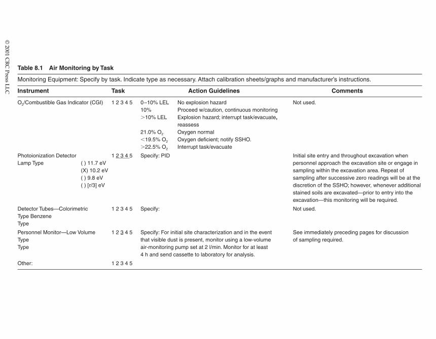
Table 8.1 Air Monitoring by Task
Monitoring Equipment: Specify by task. Indicate type as necessary. Attach calibration sheets/graphs and manufacturer’s instructions.
Instrument Task Action Guidelines Comments
O2/Combustible Gas Indicator (CGI) 1 2 3 4 5 0–10% LEL No explosion hazard Not used.10% Proceed w/caution, continuous monitoring�10% LEL Explosion hazard; interrupt task/evacuate,
reassess21.0% O2 Oxygen normal�19.5% O2 Oxygen deficient; notify SSHO.�22.5% O2 Interrupt task/evacuate
Photoionization Detector 1 2 3 4 5 Specify: PID Initial site entry and throughout excavation whenLamp Type ( ) 11.7 eV personnel approach the excavation site or engage in
(X) 10.2 eV sampling within the excavation area. Repeat of ( ) 9.8 eV sampling after successive zero readings will be at the ( ) [r/3] eV discretion of the SSHO; however, whenever additional
stained soils are excavated—prior to entry into the excavation—this monitoring will be required.
Detector Tubes—Colorimetric 1 2 3 4 5 Specify: Not used.Type BenzeneType
Personnel Monitor—Low Volume 1 2 3 4 5 Specify: For initial site characterization and in the event See immediately preceding pages for discussionType that visible dust is present, monitor using a low-volume of sampling required.Type air-monitoring pump set at 2 l/min. Monitor for at least
4 h and send cassette to laboratory for analysis.
Other: 1 2 3 4 5
© 2001 C
RC
Press LL
C
gamma rays). Periodically the film in the badge is replaced, and the exposed film is for-warded to a laboratory for analysis. The density of the developed film is proportional tothe exposure received. The various filters reveal the type and energy of the radiation. Thusthe badge report can indicate deep exposure that can be construed as whole body exposureor shallow exposure that represents skin exposure. These values are measured to insurethat exposures are below those listed in Table 8.1.
Another commonly used dosimeter is the thermo-luminescent dosimeter (TLD). TheTLD consists of a small chip of material (e.g., LiF or CaF2) that, when heated after anexposure to penetrating radiation, gives off light in proportion to the exposure received.TLDs are commonly found in badges with filters similar to film badges and are often usedwithin rings worn by individuals handling relatively large quantities of energetic beta- orgamma-emitting radionuclides (e.g., 32P, 137Cs). Ring badges are used to determine the doseto extremities.
By examining monthly exposure reports, trends in exposures or higher than usualexposures may indicate that there is a problem with contamination or radiation safety pro-cedures.
Assessing internal radiation exposures is far more difficult than determining externalexposure. Procedures with this purpose are collectively termed bioassays. For many watersoluble compounds containing low-energy beta emitters (e.g., 3H, 14C), the bioassay con-sists of a urinalysis utilizing liquid scintillation counting. For radioiodine internal exposuremay be assessed by using a NaI scintillation probe to externally measure the amount ofradiation coming from the thyroid.
8.2 EVACUATION ZONES
Air monitoring is one of the tools used to determine the location of evacuation zones.Evacuation zones are used to provide safe refuge for on-site personnel and the approach-ing public in emergency contaminant release situations. Air monitoring is also used todetermine the effect of contaminant releases on the surrounding environment. Emergencyresponse plans must include air-monitoring protocols for area and perimeter monitoringwhenever the potential for area and off-site contaminant dispersion is present.
All evacuation routes will be designated to move personnel away from a hazardousarea in a safe and efficient manner and to establish efficient traffic patterns for fire andemergency equipment during an emergency response. These evacuation routes will belocated at a safe distance upwind of all areas of activities. Personnel accounting should bea requirement at each emergency evacuation assembly point.
8.2.1 Emergency Equipment Locations
The anticipated dispersion pathways of site or facility contaminant also determine thelocation of emergency equipment on-site. Emergency equipment should be stored nearhazardous areas; however, not so near that during an incident, approach cannot be madeto don emergency equipment. Multiple storage locations out of the anticipated path of con-taminants may be necessary to access emergency equipment.
Safety and emergency equipment should include the following:
• For rescue purposes, two positive pressure self-contained breathing apparatus(SCBA) units dedicated and marked “for emergency only’’
© 2001 CRC Press LLC
• Emergency eyewashes and showers in compliance with ANSIZ Z358.1• Fire extinguishers with a minimum rating of 20-A: 120-B: C, or as appropriate to
the chemical hazard (The use of fire extinguishers and fire suppressions systemsmay influence air-monitoring protocol changes.)
Emergency equipment containing neoprene seals may fail in an atmospheric emer-gency when ammonia or high concentrations of volatiles are present. Self ContainedBreathing Apparatus (SCBA) regulator valves have neoprene seals and, thus, SCBAs usedon certain atmospheres may fail. Use air monitoring to determine whether approach orsustained presence in a chemical risk area can be maintained.
8.2.2 Site Security and Control
In cases where an emergency situation does not pose a threat to the public and off-siteemergency response teams are not dispatched to the site, a responsible on-site party mustcoordinate the appropriate emergency response and communicate with the public asnecessary.
However, if an emergency arises that presents an immediate threat to the public or oth-erwise requires additional support, the emergency response system for the site or facilityshould be activated in the manner prescribed by the off-site emergency response organiza-tion. This response should include air monitoring to determine the extent of off-site riskand to establish site zones.
Emergency response teams at hazardous waste sites are led by an incident commander.Emergency response at other chemical or radioactive sites may also be led by an incidentcommander. All air-monitoring results should be made available to the incidentcommander.
8.2.3 Incident/Accident Report
Reports of incidents/accidents should include the following:
• Name and telephone number of reporter• Name and address of facility• Time and type of incident (e.g., release, fire)• Name and quantity of material(s) involved, to the extent known, and the location
of the discharge within the facility• The extent of injuries• The possible hazards to human health, or the environment, outside the site area• Actions the person reporting the discharge proposes to take to contain, clean up,
and remove the substance
For sites with airborne hazard potential, air-monitoring information must be includedin this report to substantiate the hazard analysis and provide information on personnelexposures. Area and perimeter air-monitoring results must also be attached.
All real-time air-monitoring results that could influence needed medical treat-ment and decisions at emergency rooms must be provided to the medical staff. The air-monitoring results, both real time and laboratory analytical, should be made part of theemployee personnel records and also provided to the medical staff after an environmentalincident.
© 2001 CRC Press LLC
8.3 SITE WORK ZONE
Sample for breathing zone (BZ) concentrations of contaminants to establish respiratoryand other PPE requirements. All exposures are calculated without regard to respiratoryprotection.
8.3.1 Integrated Sampling Example
Collect full shift (for at least 7 continuous hours) personal samples, including at leastone sample for jobs classified as worst-case scenarios of the worker’s regular, daily expo-sure to lead. An air-sampling pump will be worn by the individual with the highest poten-tial for exposure. A filter cassette attached to the pump will be used to collect particulatesfor later analysis to determine particulate exposure during on-site work. The TWA will be calculated using the “real time,’’ not defaulting to a value of 8 h (e.g., if workers wearthe pump 3 h, the TWA will be for that 3 h, not for 8 h with assumed nonexposure for theother 5 h).
• Each day before use, perform a leak test on the pumps according to the manu-facturer’s instructions.
• Calibrate each personal sampling pump with a representative sampler in line.• Use the sample and analysis procedures prescribed in the NIOSH 7105 or
7300 method for the lead particulate samples collected using the air-samplingpumps.
• Sample at an accurately known flow rate between 1 and 4 l/min.• Do not exceed a filter loading of 2 mg total dust.• Take readings in the BZ of the employee expected to have the greatest exposure
potential.
A Mini-Ram will be used in addition to integrated air sampling to monitor exposures.The Mini-Ram is a real-time instrument. Action levels (ALs) will be based on the adjustedexposure limits (AELs). When the AELs exceed the AL for lead (0.03 mg/m3), respiratoryprotection will be required. The AELs are calculated as follows:
AELs � [(1 � 106 mg/kg)(0.03 mg/m3)]/soil concentration
The “worst-case’’ soil concentration of lead is 380,000 mg/kg. Using this value, whenthe Mini-Ram reading is 0.08, respiratory protection will be required. When the Mini-Ramreading is 4.0, back off the site.
If worker exposure data based on air-monitoring measurements confirm that noemployee is exposed to airborne lead concentrations at or above the AL, make a writtenrecord of this determination. This record will include as a minimum the date of determi-nation, location within the worksite, and the name and social security number of eachemployee monitored.
Additional personal monitoring will be required if an employee develops symptomsindicating possible exposure to hazardous substances or if increased sampling frequencyis required by the site’s air-monitoring professional.
© 2001 CRC Press LLC
8.3.2 Field QA and QC Example
Implement the following controls to ensure monitoring is accurate, reliable, and repre-sentative of the probable worst conditions:
• Monitor employees with the highest expected exposures.• Ensure air sample analyses are performed by a laboratory that has been judged
proficient in four successive round robins of the AIHA PAT program.• Together with sample results, keep records on laboratory procedures, including
analyses of sealed field and lab blanks, equipment checks and calibration, andnotations on problems that may have affected the sample results.
8.3.3 Invasive Work Sampling Example
Oxygen, explosive atmospheres (methane), and toxic substances (benzene, hydrogensulfide, and vinyl chloride) will be monitored to determine respirator, engineering control,and ventilation requirements. All workers will initially wear HEPA cartridge-equippednegative air pressure respirators.
• Test for oxygen, flammable gases, and hydrogen sulfide using a calibrated O2/CGIsequipped with additional toxin sensors for hydrogen sulfide. The LEL readoutwill be used as an indication of the presence of flammable gases, includingmethane.
• If testing indicates the presence of less than 19.5% oxygen, more than 10% LEL,or more than 5 ppm hydrogen sulfide, back off and ventilate the space until test-ing shows the levels are within permissible limits.
To detect if any chemicals are being volatilized, a PID PI-101 will be used to scan thesampling sites. If methane has been detected using the CGI, PID readings will be suspect.
In the event that the PID displays a sustained deflection of 1 ppm (defined as needledeflection that indicates a reading of 1 ppm or 1 ppm above background for 1 min withoutintervening zero readings) or any reading above 5 ppm, sampling will cease, and all on-siteworkers will don organic vapor cartridges in addition to HEPA cartridges. (Respiratorsmust have stacked cartridge holders, or combination HEPA-organic vapor cartridges mustbe available.)
• Benzene and vinyl chloride colorimetric Sensidyne detector tubes are used toindicate if either chemical is being volatilized.
• If the benzene detector tube indicates the benzene concentration is greater than0.5 ppm, but less than 20 ppm, continue work using HEPA-organic vapor-equipped negative air pressure respirators.
• If the vinyl chloride detector tube indicates vinyl chloride is present in concen-trations greater than 1 ppm, back off. Cartridge-equipped negative air pressurerespirators are not available for vinyl chloride and other volatiles in combination,thus, negative air pressure respirators will not be used when vinyl chloride isdetected above 1 ppm.
© 2001 CRC Press LLC
8.3.4 Sampling and Initial Site Work Hazard Analysis Example
8.3.4.1 Perimeter Monitoring
The site boundaries clearly mark off the “clean’’ off-site areas from the “contaminated’’on-site areas; chemical contamination from the site should not be a hazard associated withperimeter and off-site monitoring.
Site Walk-Through, Site Surveys, Sample Grid Layout
General hazards associated with site walk-through, site surveys, and sampling gridlayout include the following:
• Exposure to irritant and toxic plants such as poison ivy and sticker bushes maycause allergic reactions.
• Surfaces covered with heavy vegetation and undergrowth create a tripping hazard.• Back strain may be due to carrying instruments.• Native wildlife such as rodents, ticks, and snakes present the possibility of bites;
many animals and insects are disease vectors for diseases such as Lyme disease.• Driving vehicles on uneven or unsafe surfaces can result in accidents such as
overturned vehicles or flat tires.• Avoid heat stress/cold stress exposure.• Avoid on-site chemical hazards depending on contaminant location and contact
or disturbances of contaminated areas.
Hazard Prevention
• Wear long-sleeved disposable clothing to minimize contact with irritant and toxicplants and to protect against insect bites.
• Render appropriate first aid for an individual’s known allergic reactions.• Step carefully to avoid terrain hazards and to minimize slips and falls. Steel-toed
boots provide additional support and stability.• Use proper lifting techniques to prevent back strain.• Avoid wildlife when possible. In case of an animal bite, perform first aid and cap-
ture the animal, if possible, for rabies testing.• Check for ticks after leaving a wooded or vegetated area.• A site surveillance on foot might be necessary to choose clear driving paths.
Vehicles are prohibited on the site with the exception of the drill rig equipment.• Implement heat stress management techniques such as shifting work hours, fluid
intake, and monitoring employees for symptoms, especially high-risk workers.
8.3.4.2 Air Sampling and Monitoring Example
General hazards frequently encountered during air sampling and monitoring includethe following:
• Hazards associated with the sampling the ambient environment.• Readings indicating nonexplosive atmospheres, low concentrations of toxic sub-
stances, or other conditions may increase or decrease suddenly, changing theassociated risks
© 2001 CRC Press LLC
Hazard Prevention
• Familiarize workers with the use, limitations, and operating characteristics of themonitoring instruments.
• Use only intrinsically safe equipment.• Perform continuous monitoring in variable atmospheres.• Use intrinsically safe instruments.
8.3.4.3 Water Sampling Example
Both physical and chemical hazards are associated with water sampling, and theyinclude contact with contaminated water.
Hazard Prevention
• The buddy system must be used at all times.• Use chemical resistant clothing.
8.3.4.4 Surface Soil/Sediment Sampling Example
For the purposes of this hazard identification section, surface soil/sediment samplingwill be considered for any soil sampling completed by hand using a trowel, split spoon,shovel, auger, or other type of handheld tool. Hazards generally associated with soil andtailings/spoils sampling include the following:
• Contact with or inhalation of contaminants, potentially in high concentrations insampling media.
• Back strain and muscle fatigue due to lifting, shoveling, and augering techniques.• Contact with or inhalation of decontamination solutions.
Hazard Prevention
To minimize exposure to chemical contaminants, a thorough review of suspected con-taminants must be completed and an adequate protection program implemented.
• Proper lifting (prelift weight assessment, use of legs, multiple personnel) tech-niques will prevent back strain. Use slow easy motions when shoveling, auger-ing, and digging to decrease muscle strain.
• Note: The surface soils will be disturbed. In order to guard against dust genera-tion, any dry soils will be wetted down with a light mist. The mist will be applied with handheld low-pressure misting bottles or a fire hose equipped with a mist nozzle, whichever is most efficient. Thus inhalation of dust parti-culates and the chemicals of concern potentially absorbed to these particles shouldnot be a primary exposure pathway for workers 6–8 ft from the sampling sites.However, if during the site activities, visible dust is apparent due to windy con-ditions or lack of effective wetting, further wetting of the work area surface isnecessary.
© 2001 CRC Press LLC
8.4 RADIATION SITES
Radionuclides in various chemical and physical forms have become extremely impor-tant tools in modern business, industry, research, and teaching. Radioactive materials areincorporated in many manufactured goods and are used in many industrial services. Theuse of radioactive materials generates radioactive waste. The ionizing radiations emittedby these materials and wastes, however, can pose a hazard to human health. For this rea-son special handling precautions must be observed with radionuclides.
8.4.1 Atomic Structure
The atom, which has been referred to as the “fundamental building block of matter,’’ isitself composed of three primary particles: the proton, the neutron, and the electron.Protons and neutrons are relatively massive compared to electrons and occupy the densecore of the atom known as the nucleus. Protons are positively charged, while neutrons, astheir name implies, are neutral. The negatively charged electrons are found in an extendedcloud surrounding the nucleus.
The number of protons within the nucleus defines the atomic number, designated bythe symbol Z. In an electrically neutral atom (i.e., one with equal numbers of protons andelectrons), Z also indicates the number of electrons within the atom. The number of protonsplus neutrons in the nucleus is termed the atomic mass, symbol A. For lighter elements thenumber of neutrons in a stable nucleus approximately equals the number of protons.
The atomic number of an atom designates its specific elemental identity. For example,an atom with a Z � 1 is hydrogen, an atom with Z � 2 is helium, while Z � 3 identifies anatom of lithium. Atoms characterized by a particular atomic number and atomic mass arecalled nuclides. A specific nuclide is represented by its chemical symbol with the atomicmass in a superscript (e.g., 3H, 14C, 125I). Nuclides with the same number of protons (i.e.,same Z) but different number of neutrons (i.e., different A) are called isotopes. Isotopes ofa particular element have nearly identical chemical properties.
8.4.2 Radioactive Decay
Depending on the ratio of neutrons to protons within its nucleus, an isotope of a par-ticular element may be stable or unstable. Over time, the nuclei of unstable isotopes spon-taneously disintegrate or transform in a process known as radioactive decay orradioactivity. As part of this process, various types of ionizing radiation may be emittedfrom the nucleus. Nuclides that undergo radioactive decay are called radionuclides. Thisis a general term as opposed to the term radioisotope that is used to describe a particularrelationship. For example, 3H, 14C, and 125I are radionuclides. Tritium (3H), on the otherhand, is a radioisotope of hydrogen.
Some radionuclides such as 14C, 40P, and 238U occur naturally in the environment, whileothers such as 32Ph or 32Na are produced in nuclear reactors or particle accelerators. Anymaterial that contains measurable amounts of one or more radionuclides is referred to as aradioactive material.
8.4.3 Activity
The quantity that expresses the degree of radioactivity or radiation-producing poten-tial of a given amount of radioactive material is activity. The most commonly used unit of
© 2001 CRC Press LLC
activity is the curie (Ci), which was originally defined as that amount of any radioactivematerial that disintegrates at the same rate as 1 g of pure radium, which equals 3.7 � 1010
disintegrations per second (dps). A millicurie (mCi) � 3.7 � 107 dps (2.22 � 109 dpm) anda microcurie (�Ci). � 3.7 � 104 dps (2.22 � 106 dpm). The activity of a given amount ofradioactive material is independent of the mass of the element present and is determinedonly by the disintegration rate. Thus, two 1-Ci sources of 137Cs might have very differentmasses depending on the relative proportion of nonradioactive atoms present in eachsource.
8.4.4 Decay Law
The rate at which a quantity of radioactive material decays is proportional to the num-ber of radioactive atoms present. This quantity can be expressed by the equation
dN/dt � �N (1)
where dN/dt is the disintegration rate of the radioactive atoms, � is the decay constant, andN is the number of radioactive atoms present at time t. Integration of this equation andexpressing it in exponential form yields:
N � Noe��t (2)
where No is the initial number of radioactive atoms present and e is the base of the naturallogarithms. Because activity A is proportional to N, the equation is often expressed as
A � Aoe��t (3)
8.4.5 Half-Life
As N decreases over time, dN/dt decreases proportionately. For example, when half ofthe radioactive atoms in a given quantity of radioactive material have decayed, the disin-tegration rate (or activity) is also halved. The time required for the activity of a quantity ofa particular radionuclide to decrease to half its original value is called the half-life (T1/2) forthe radionuclide. Table 8.2 indicates half-lives and other characteristics of several radionu-clides used in research.
It can be shown mathematically that the T1/2 of a particular radionuclide is related to �as follows:
� � �Tln
1/
2
2� � �
0T.6
1/
9
2
3� (4)
Substituting this value of � into Equation 3, one gets:
A � Aoe (5)�0.693t�
T1/2
© 2001 CRC Press LLC
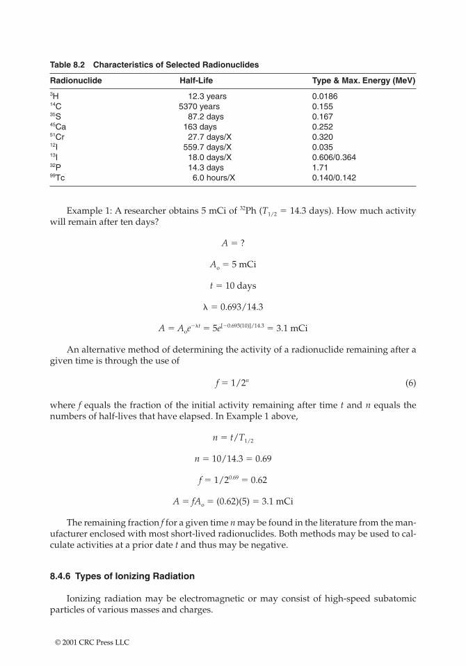
Table 8.2 Characteristics of Selected Radionuclides
Radionuclide Half-Life Type & Max. Energy (MeV)
3H 12.3 years 0.018614C 5370 years 0.15535S 87.2 days 0.16745Ca 163 days 0.25251Cr 27.7 days/X 0.32012I 559.7 days/X 0.03513I 18.0 days/X 0.606/0.36432P 14.3 days 1.7199Tc 6.0 hours/X 0.140/0.142
Example 1: A researcher obtains 5 mCi of 32Ph (T1/2 � 14.3 days). How much activitywill remain after ten days?
A � ?
Ao � 5 mCi
t � 10 days
� � 0.693/14.3
A � Aoe��t � 5e[�0.693(10)]/14.3 � 3.1 mCi
An alternative method of determining the activity of a radionuclide remaining after agiven time is through the use of
f � 1/2n (6)
where f equals the fraction of the initial activity remaining after time t and n equals thenumbers of half-lives that have elapsed. In Example 1 above,
n � t/T1/2
n � 10/14.3 � 0.69
f � 1/20.69 � 0.62
A � fAo � (0.62)(5) � 3.1 mCi
The remaining fraction f for a given time n may be found in the literature from the man-ufacturer enclosed with most short-lived radionuclides. Both methods may be used to cal-culate activities at a prior date t and thus may be negative.
8.4.6 Types of Ionizing Radiation
Ionizing radiation may be electromagnetic or may consist of high-speed subatomicparticles of various masses and charges.
© 2001 CRC Press LLC
8.4.6.1 Alpha Particles
Certain radionuclides of high atomic mass (e.g., 226Ra, 238U, 239Pu) decay by the emissionof alpha particles. These are tightly bound units of two neutrons and two protons each (ahelium nucleus). Emission of an alpha particle results in a decrease of two units of atomicnumber (Z) and four units of atomic mass (A). Alpha particles are emitted with discreteenergies characteristic of the particular transformation from which they originate.
8.4.6.2 Beta Particles
A nucleus with a slightly unstable ratio of neutrons to protons may decay through theemission of a high-speed electron called a beta particle. This emission results in a netincrease of one unit of atomic number (Z). The beta particles emitted by a specific radionu-clide range in energy from near zero up to a maximum value characteristic of the particu-lar transformation.
8.4.6.3 Gamma Rays
A nucleus that is in an excited state may emit one or more photons (i.e., particles of elec-tromagnetic radiation) of discrete energies. The emission of these gamma rays does notalter the number of protons or neutrons in the nucleus, but instead has the effect of mov-ing the nucleus from a higher to a lower energy state. Gamma-ray emission frequently fol-lows beta decay, alpha decay, and other nuclear decay processes.
X-rays and gamma rays are electromagnetic radiation, as is visible light. The frequen-cies of X-rays and gamma rays are much higher than that of visible light and so each car-ries much more energy. Gamma and X-rays cannot be completely shielded. They can beattenuated by shielding, but not stopped completely. A gamma-emitting nuclide may yieldmultiple gamma rays and X-rays, each with its own discrete energy. It is possible to iden-tify a gamma-emitting nuclide by its spectrum.
8.4.6.4 X-rays
X-rays are also part of the electromagnetic spectrum and are distinguished fromgamma rays only by their source (i.e., orbital electrons, rather than the nucleus). X-rays areemitted with discrete energies by electrons as they shift orbits following certain types ofnuclear decay processes.
8.4.7 Rules of Thumb
The activity of any radionuclide is reduced to less than 1% after 7 half-lives and lessthan 0.1% after 10 half-lives (i.e., 2�7 � 100 � 0.8% and 2�10 � 100 � 0.09%) (Table 8.3).
8.4.8 Excitation/Ionization
The various types of radiation (e.g., alpha particles, beta particles, and gamma rays)impart their energy to matter primarily through excitation and ionization of orbital elec-trons. The term excitation is used to describe an interaction where electrons acquire energy
© 2001 CRC Press LLC
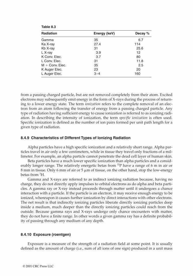
Table 8.3
Radiation Energy (keV) Decay %
Gamma 35 6.7Ka X-ray 27.4 114Kb X-ray 31 25.6L X-ray 3.9 12K Conv. Elec. 3.7 80L Conv. Elec. 31 11.8M Conv. Elec. 35 2.5K Auger Elec. 23 20L Auger Elec. 3–4 160
from a passing charged particle, but are not removed completely from their atom. Excitedelectrons may subsequently emit energy in the form of X-rays during the process of return-ing to a lower energy state. The term ionization refers to the complete removal of an elec-tron from an atom following the transfer of energy from a passing charged particle. Anytype of radiation having sufficient energy to cause ionization is referred to as ionizing radi-ation. In describing the intensity of ionization, the term specific ionization is often used.Specific ionization is defined as the number of ion pairs formed per unit path length for agiven type of radiation.
8.4.9 Characteristics of Different Types of Ionizing Radiation
Alpha particles have a high specific ionization and a relatively short range. Alpha par-ticles travel in air only a few centimeters, while in tissue they travel only fractions of a mil-limeter. For example, an alpha particle cannot penetrate the dead cell layer of human skin.
Beta particles have a much lower specific ionization than alpha particles and a consid-erably longer range. The relatively energetic betas from 32P have a range of 6 m in air or 8 mm in tissue. Only 6 mm of air or 5 �m of tissue, on the other hand, stop the low-energybetas from 3H.
Gamma and X-rays are referred to as indirect ionizing radiation because, having nocharge, they do not directly apply impulses to orbital electrons as do alpha and beta parti-cles. A gamma ray or X-ray instead proceeds through matter until it undergoes a chanceinteraction with a particle. If the particle is an electron, it may receive enough energy to beionized, whereupon it causes further ionization by direct interactions with other electrons.The net result is that indirectly ionizing particles liberate directly ionizing particles deepinside a medium, much deeper than the directly ionizing particles could reach from theoutside. Because gamma rays and X-rays undergo only chance encounters with matter,they do not have a finite range. In other words a given gamma ray has a definite probabil-ity of passing through any medium of any depth.
8.4.10 Exposure (roentgen)
Exposure is a measure of the strength of a radiation field at some point. It is usuallydefined as the amount of charge (i.e., sum of all ions of one sign) produced in a unit mass
© 2001 CRC Press LLC
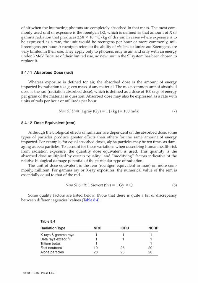
of air when the interacting photons are completely absorbed in that mass. The most com-monly used unit of exposure is the roentgen (R), which is defined as that amount of X orgamma radiation that produces 2.58 � 10�4 C/kg of dry air. In cases where exposure is tobe expressed as a rate, the unit would be roentgens per hour or more commonly, mil-liroentgens per hour. A roentgen refers to the ability of photons to ionize air. Roentgens arevery limited in their use. They apply only to photons, only in air, and only with an energyunder 3 MeV. Because of their limited use, no new unit in the SI system has been chosen toreplace it.
8.4.11 Absorbed Dose (rad)
Whereas exposure is defined for air, the absorbed dose is the amount of energyimparted by radiation to a given mass of any material. The most common unit of absorbeddose is the rad (radiation absorbed dose), which is defined as a dose of 100 ergs of energyper gram of the material in question. Absorbed dose may also be expressed as a rate withunits of rads per hour or millirads per hour.
New SI Unit: 1 gray (Gy) � 1 J/kg (� 100 rads) (7)
8.4.12 Dose Equivalent (rem)
Although the biological effects of radiation are dependent on the absorbed dose, sometypes of particles produce greater effects than others for the same amount of energyimparted. For example, for equal absorbed doses, alpha particles may be ten times as dam-aging as beta particles. To account for these variations when describing human health riskfrom radiation exposure, the quantity dose equivalent is used. This quantity is theabsorbed dose multiplied by certain “quality’’ and “modifying’’ factors indicative of therelative biological damage potential of the particular type of radiation.
The unit of dose equivalent is the rem (roentgen equivalent in man) or, more com-monly, millirem. For gamma ray or X-ray exposures, the numerical value of the rem isessentially equal to that of the rad.
New SI Unit: 1 Sievert (Sv) � 1 Gy � Q (8)
Some quality factors are listed below. (Note that there is quite a bit of discrepancybetween different agencies’ values (Table 8.4).
Table 8.4
Radiation Type NRC ICRU NCRP
X-rays & gamma rays 1 1 1Beta rays except 3H 1 1 1Tritium betas 1 1Fast neutrons 10 25 20Alpha particles 20 25 20
© 2001 CRC Press LLC
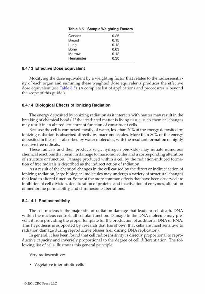
8.4.13 Effective Dose Equivalent
Modifying the dose equivalent by a weighting factor that relates to the radiosensitiv-ity of each organ and summing these weighted dose equivalents produces the effectivedose equivalent (see Table 8.5). (A complete list of applications and procedures is beyondthe scope of this guide.)
8.4.14 Biological Effects of Ionizing Radiation
The energy deposited by ionizing radiation as it interacts with matter may result in thebreaking of chemical bonds. If the irradiated matter is living tissue, such chemical changesmay result in an altered structure of function of constituent cells.
Because the cell is composed mostly of water, less than 20% of the energy deposited byionizing radiation is absorbed directly by macromolecules. More than 80% of the energydeposited in the cell is absorbed by water molecules, with the resultant formation of highlyreactive free radicals.
These radicals and their products (e.g., hydrogen peroxide) may initiate numerouschemical reactions that result in damage to macromolecules and a corresponding alterationof structure or function. Damage produced within a cell by the radiation-induced forma-tion of free radicals is described as the indirect action of radiation.
As a result of the chemical changes in the cell caused by the direct or indirect action ofionizing radiation, large biological molecules may undergo a variety of structural changesthat lead to altered function. Some of the more common effects that have been observed areinhibition of cell division, denaturation of proteins and inactivation of enzymes, alterationof membrane permeability, and chromosome aberrations.
8.4.14.1 Radiosensitivity
The cell nucleus is the major site of radiation damage that leads to cell death. DNAwithin the nucleus controls all cellular function. Damage to the DNA molecule may pre-vent it from providing the proper template for the production of additional DNA or RNA.This hypothesis is supported by research that has shown that cells are most sensitive toradiation damage during reproductive phases (i.e., during DNA replication).
In general, it has been found that cell radiosensitivity is directly proportional to repro-ductive capacity and inversely proportional to the degree of cell differentiation. The fol-lowing list of cells illustrates this general principle:
Very radiosensitive:
• Vegetative intermitotic cells
Table 8.5 Sample Weighting Factors
Gonads 0.25Breast 0.15Lung 0.12Bone 0.03Marrow 0.12Remainder 0.30
© 2001 CRC Press LLC
• Mature lymphocytes• Erythroblasts and spermatogonia• Basal cells • Endothelial cells
Moderately radiosensitive:
• Blood vessels and interconnective tissue• Osteoblasts• Granulocytes and osteocytes• Sperm erythrocytes
Relatively radioresistant:
• Fixed postmitotic cells• Fibrocytes• Chondrocytes • Muscle and nerve cells
The considerable variation in the radiosensitivities of various tissues is due, in part, tothe differences in the sensitivities of the cells that compose the tissues. Also important indetermining tissue sensitivity are such factors as the state of nourishment of the cells, inter-actions between various cell types within the tissue, and the ability of the tissue to repairitself.
The relatively high radiosensitivity of tissues consisting of undifferentiated, rapidlydividing cells suggest that, at the level of the human organism, a greater potential exists for damage to the fetus or young child than to an adult for a given dose. This tendency has,in fact, been observed in the form of increased birth defects following irradiation of thefetus and an increased incidence of certain cancers in individuals who were irradiated aschildren.
8.4.15 Human Health Effects
The effects of ionizing radiation described at the level of the human organism can bedivided broadly into one of two categories: stochastic or nonstochastic effects.
8.4.15.1 Stochastic Effects
As implied from the name, “stochastic’’ effects occur by chance. Stochastic effectscaused by ionizing radiation consist primarily of genetic defects and cancer. As the dose toan individual increases, the probability that cancer or a genetic defect will occur alsoincreases. However, at no time, even for high doses, is it certain that cancer or genetic dam-age will result. Similarly, for stochastic effects, there is no threshold dose below which it isrelatively certain that an adverse effect cannot occur. Because stochastic effects can occur inunexposed individuals, one can never be certain that the occurrence of cancer or geneticdamage in an exposed individual is due to radiation.
© 2001 CRC Press LLC
8.4.15.2 Nonstochastic Effects
Unlike stochastic effects, nonstochastic effects are characterized by a threshold dosebelow which they do not occur. The magnitude of the effect is directly proportional to thesize of the dose. Furthermore, for nonstochastic effects there is a clear causal relationshipbetween radiation exposure and the effect. Examples of nonstochastic effects include steril-ity, erythema (skin reddening), and cataract formation. Each of these effects differs from theother in both its threshold dose and in the time over which this dose must be received tocause the effect (i.e., acute vs. chronic exposure).
The range of nonstochastic effects resulting from an acute exposure to radiation is col-lectively termed “radiation syndrome.’’ This syndrome may be subdivided as follows:
• Hemopoietic syndrome—characterized by depression or destruction of bonemarrow activity with resultant anemia and susceptibility to infection (wholebody dose of about 200 rads)
• Gastrointestinal syndrome—characterized by destruction of the intestinal epithe-lium with resultant nausea, vomiting, and diarrhea (whole body dose of about1000 rads)
• Central nervous system syndrome—direct damage to nervous system with lossof consciousness within minutes (whole body doses in excess of 2000 rads). TheLD50 (i.e., dose that would cause death in half of the exposed population) foracute whole body exposure to radiation in humans is about 450 rads.
8.4.16 Determinants of Dose
The effect of ionizing radiation upon humans or other organisms is directly dependenton the size of the dose received (although dose rate may also be important). The dose, inturn, is dependent on a number of factors, including the strength of the source, the distancefrom the source to the affected tissue, and the time over which the tissue is irradiated. Themanner in which these factors operate to determine the dose from a given exposure differssignificantly for exposures that are “external’’ (i.e., resulting from a radiation sourcelocated outside the body) and those that are “internal’’ (i.e., resulting from a radiationsource located within the body).
8.4.16.1 External Exposures
Exposures to sources of radiation located outside the body are of concern primarily forsources emitting gamma rays, X-rays, or high-energy beta particles. External exposuresfrom radioactive sources that emit alpha or low-to-medium energy beta particles are notsignificant because these radiations do not penetrate the dead outer cell layer of the skin.
As with all radiation exposures, the size of the dose resulting from an external expo-sure is a function of
• The strength of the source• The distance from the source to the tissue being irradiated• The duration of the exposure
In contrast to the situation for internal exposures, however, these factors can be altered(either intentionally or inadvertently) for a particular external exposure situation, with aresultant modification of the dose received.
© 2001 CRC Press LLC
The effectiveness of a given dose of external radiation in causing biological damage isdependent on the portion of the body irradiated. For example, because of differences in theradiosensitivity of constituent tissues, the hand is far less likely to suffer biological damagefrom a given dose of radiation than are the gonads. Similarly, a given dose to the wholebody has a greater potential for causing adverse health effects than does the same dose toonly a portion of the body.
8.4.16.2 Internal Exposures
Exposures to ionizing radiation from sources located within the body create cause forconcern. Of particular concern are internally emitted alpha and beta particles that causesignificant damage to tissue when they deposit their energy along highly localized paths.
In contrast to the situation for external exposures, the source to tissue distance, expo-sure duration, and source strength cannot be altered for internal radiation sources. Instead,once a quantity of radioactive material is taken up by the body (e.g., by inhalation, inges-tion, or absorption), an individual is “committed’’ to the dose that will result from thequantities of the particular radionuclide(s) involved.
In general, radionuclides taken up by the body do not distribute equally throughoutthe body’s tissues. Often, a radionuclide concentrates in a critical organ (defined as theorgan for which damage from uptake of the particular radionuclide leads to the greatestdamage to the body as a whole). For example, 131I and 125I concentrate in the thyroid, 45Caand 32P in the bone, and 59Fe in the spleen.
The dose committed to a particular organ or portion of the body depends, in part, onthe time over which these areas of the body are irradiated by the radionuclide. This dose,in turn, is determined by the radionuclide’s physical and biological half-lives (i.e., the effec-tive half-life). The biological half-life of a radionuclide is defined as the time required forone half of a given amount of radionuclide to be removed from the body by normal bio-logical turnover.
8.4.17 Sources of Exposure
Exposures to ionizing radiation can be classified broadly according to whether theyresult from sources within the work environment (i.e., occupational exposures) or fromsources outside the work environment (i.e., nonoccupational exposures).
8.4.17.1 Occupational Exposure
Occupational exposures are those received by individuals as a result of working withor near radiation sources (i.e., radioactive material or radiation-producing devices).Occupational exposures differ from nonoccupational exposures in that they are generallyreceived during the course of a 40-hour work week (exposures from natural backgroundare received continuously over 168 hours per week). Whereas the nonoccupational expo-sure received by a given individual is largely unknown, an individual’s occupational expo-sure is closely monitored and controlled.
8.4.17.2 Nonoccupational Exposure
Nonoccupational exposures can be divided into one of two categories: those originat-ing from natural sources or those resulting from man-made sources.
© 2001 CRC Press LLC
All individuals are continuously exposed to ionizing radiation from various naturalsources. These sources include cosmic radiation and naturally occurring radionuclideswithin the environment and within the human body. The radiation levels resulting fromnatural sources are collectively referred to as “natural background.’’ Natural backgroundand the associated dose it imparts varies considerably from one location to another in theU.S. It is estimated that the average whole body dose equivalent from natural backgroundin the U.S. is about 250 mrem/person/year.
The primary source of man-made nonoccupational exposures is medical irradiation,particularly diagnostic procedures (e.g., X-ray and nuclear medicine examinations). Suchprocedures, on average, contribute an additional 100 mrem/person/year in the U.S. Allother sources of man-made, nonoccupational exposures, such as nuclear weapon fallout,nuclear power plant operations, and the use of radiation sources in industry and universi-ties, contribute an average of less than 1 mrem/person/year in the U.S.
8.4.18 Exposure Limits
Concern over the biological effects of ionizing radiation began shortly after the dis-covery of X-rays in 1895. From that time to the present, numerous recommendationsregarding occupational exposure limits have been proposed and modified by various radi-ation protection groups, the most important being the International Commission onRadiological Protection (ICRP). These guidelines have, in turn, been incorporated into reg-ulatory requirements for controlling the use of materials and devices emitting ionizingradiation.
8.4.19 Basis of Recent Guidelines
The guidelines established for radiation exposure generally have two principalobjectives:
1. The prevention of acute radiation effects (e.g., erythema, sterility)2. The limiting of the risks of late, stochastic effects (e.g., cancer, genetic damage) to
“acceptable’’ levels
Numerous revisions of standards and guidelines have been made over the years toreflect both changes in the understanding of the risk associated with various levels of expo-sure and changes in the perception of what constitutes an “acceptable’’ level of risk.
Current guidelines for radiation exposure are based on the conservative assumptionthat there is no safe level of exposure. In other words even the smallest exposure has someprobability of causing a late effect such as cancer or genetic damage. This assumption hasled to the general philosophy of not only keeping exposures below recommended levels orregulatory limits but also of maintaining all exposures at ALARA levels. This is a funda-mental tenet of current radiation safety practice.
8.4.20 Regulatory Limits for Occupational Exposure
Many of the recommendations of the ICRP and other radiation protection groupsregarding radiation exposure have been incorporated into regulatory requirements by var-ious countries. In the U.S. radiation exposure limits are found in Title 10, Part 20 of the Codeof Federal Regulations (10 CFR 20).
© 2001 CRC Press LLC
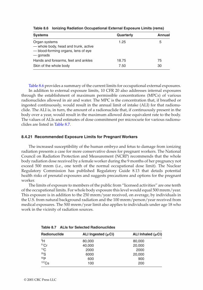
Table 8.6 provides a summary of the current limits for occupational external exposures.In addition to external exposure limits, 10 CFR 20 also addresses internal exposures
through the establishment of maximum permissible concentrations (MPCs) of variousradionuclides allowed in air and water. The MPC is the concentration that, if breathed oringested continuously, would result in the annual limit of intake (ALI) for that radionu-clide. The ALI is, in turn, the amount of a radionuclide that, if continuously present in thebody over a year, would result in the maximum allowed dose equivalent rate to the body.The values of ALIs and estimates of dose commitment per microcurie for various radionu-clides are listed in Table 8.7.
8.4.21 Recommended Exposure Limits for Pregnant Workers
The increased susceptibility of the human embryo and fetus to damage from ionizingradiation presents a case for more conservative doses for pregnant workers. The NationalCouncil on Radiation Protection and Measurement (NCRP) recommends that the wholebody radiation dose received by a female worker during the 9 months of her pregnancy notexceed 500 mrem (i.e., one tenth of the normal occupational dose limit). The NuclearRegulatory Commission has published Regulatory Guide 8.13 that details potential health risks of prenatal exposures and suggests precautions and options for the pregnantworker.
The limits of exposure to members of the public from “licensed activities’’ are one tenthof the occupational limits. For whole body exposure this level would equal 500 mrem/year.This exposure is in addition to the 250 mrem/year received, on average, by individuals inthe U.S. from natural background radiation and the 100 mrem/person/year received frommedical exposures. The 500 mrem/year limit also applies to individuals under age 18 whowork in the vicinity of radiation sources.
Table 8.6 Ionizing Radiation Occupational External Exposure Limits (rems)
Systems Quarterly Annual
Organ systems 1.25 5— whole body, head and trunk, active— blood-forming organs, lens of eye— gonadsHands and forearms, feet and ankles 18.75 75Skin of the whole body 7.50 30
Table 8.7 ALIs for Selected Radionuclides
Radionuclide ALI Ingested (�Ci) ALI Inhaled (�Ci)
3H 80,000 80,00051Cr 40,000 20,00014C 2000 200035S 6000 20,00032P 600 900137Cs 100 200
© 2001 CRC Press LLC
8.4.22 Radiation Risk
The risk associated with various levels of exposure to ionizing radiation can be ade-quately understood only when viewed in the context of other health risks routinelyencountered in life. The risk associated with various activities or situations is most oftenexpressed as an annual mortality rate. For example, the annual mortality rate from homeaccidents in the U.S. is 1.1 � 10�4. Thus, the risk of death from a home accident is approxi-mately 1 in 10,000/year.
The American Cancer Society has reported that approximately 25% of all adults 20–65years old will develop cancer at some time from all possible causes, such as smoking, food,alcohol, drugs, air pollutants, and natural background radiation. Thus, in any group of10,000 workers not exposed to radiation on the job, we can expect about 2,500 to developcancer. If this entire group of 10,000 workers were to receive an occupational radiation doseof 1000 mrem each, we could estimate that three additional cases might occur, giving a totalof about 2,503. This means that a 1000 mrem dose to each of 10,000 workers might increasethe cancer rate from 25% to 25.03%, an increase of about 0.03%.
As an individual, if your cumulative occupational radiation dose is 1000 mrem, yourchances of developing cancer during your entire lifetime may have increased from 25% to25.03%. If your lifetime occupational dose is 10,000 mrems, we could estimate a 25.3%chance of developing cancer. Using a simple linear model, a lifetime dose of 100,000 mremsmay have increased your chances of developing cancer from 25% to 28%.
8.4.23 Philosophy of Current Radiation Safety Practice
Current regulatory limits for radiation exposure have been conservatively set to pre-vent all acute effects of radiation exposure and to limit the risk of chronic effects, such ascancer, to very low levels. As a primary objective, then, radiation safety practice attemptsto ensure that all exposures are below these limits. The accomplishment of this objective,however, is not the ultimate aim of current radiation safety practice. The RadiationProtection Guidance of the Federal Agencies for Occupational Exposure, January 20, 1987,expresses the fundamental principle that:
There shall not be any occupational exposure of workers to ionizingradiation without the expectation of an overall benefit from the activ-ity causing the exposure.
An overriding principle of radiation protection philosophy is that all exposures mustbe maintained at ALARA levels. Thus, even if a given exposure to an individual is withinregulatory limits, it may not be acceptable if the exposure could have been limited furtherby “reasonable’’ means.
8.4.23.1 Internal Radiation Protection
Any radionuclide, whether it be an alpha, beta, or gamma emitter, poses a potentialhazard to health if it enters the body. Once within the body, the radionuclide will continueto irradiate living tissue until it is removed by natural processes. Because there is no easyway of increasing the rate of these processes, radionuclides must be prevented from beingtaken into the body in the first place.
© 2001 CRC Press LLC
To adequately protect against the uptake of radionuclides, it is important to understandthe ways radionuclides enter the body. The three primary routes of uptake are as follows:
1. Ingestion2. Inhalation3. Absorption through the skin
8.4.23.2 Protection against Ingestion
In protecting against ingesting radioactive material, the importance of observing strictcontamination control measures on-site and in the laboratory, including monitoring hands,clothing, and work areas after each procedure involving the use of radioactive material,cannot be overemphasized.
8.4.23.3 Protection against Inhalation
Certain chemical forms of particular radionuclides volatilize easily and thus pose ahazard through inhalation. Examples of these include tritiated water and radioiodine (e.g.,125I, 131I) in solution as NaI. Because of the volatility of these materials, procedures involv-ing their use should always be carried out within a fume hood.
8.4.23.4 Protection against Absorption
Many of the same types of radioactive materials that pose inhalation hazards also posea hazard by absorption through the skin. Both tritiated water and various chemical formsof radioiodine are readily absorbed through the skin. Such materials have been shown todiffuse fairly quickly through the thickness of a single plastic glove. For this reason it isimportant to wear two pairs of gloves and to change the outer pair frequently during pro-cedures using these materials.
8.4.24 External Radiation Protection
Medium-to-high energy beta particles, gamma rays, and X-rays are often referred to as“penetrating’’ radiations because of their ability to pass through considerable thicknessesof matter. Because of this ability, penetrating radiation can originate from sources externalto the body and still impart a significant dose to living tissue. Radionuclides that emit suchradiations thus pose an “external’’ radiation hazard. Examples of such radionuclides thatare used in radiotracer research are the beta emitter 32P and the beta/gamma emitter 137Cs.
Certain gamma emitters (e.g., 137Cs, 60Co) that are routinely encapsulated as sealedsources can also pose significant external hazards. On the other hand such commonly usedradionuclides as 3H, 14C, and 35S are primarily internal radiation hazards because the betaparticles they emit do not have sufficient energy to penetrate the skin (although if applieddirectly to the skin’s surface in sufficiently large quantities, 14C or 35S can damage livingskin cells).
The dose resulting from a given exposure situation depends on the duration of theexposure, the distance from the source to the tissue, and the strength of the source. Forinternal exposures, these factors cannot be easily modified. However, for external expo-sures, the dose received can be limited by controlling these factors.
© 2001 CRC Press LLC
8.4.25 Minimizing Exposure Time
In general, the dose (D) received from a particular exposure situation is the product ofthe exposure rate (I) times the exposure time (t):
D � It (9)
It follows, then, that any reduction in t spent in a radiation field (I) will decrease the totaldose received.
Example 1: In order to synthesize a particular radioactive compound, a chemist mustwork in a radiation field of 1 mR/h. If he works 5 days per week, what is the maximumamount of time he can work in this radiation field each day and not exceed one tenth of hisdaily limit?
1/10th of (5000 mR/year)/daily limit � 250 workdays/year � 0.1 � 2 mR/day
t � D/I � 2 mR/day/1 mR/h � 2 h/day
8.4.26 Maximizing Distance from Source
If one assumes that a radiation source occupies a single point, it can be shown mathe-matically that I varies inversely with the square of the distance (d) from the source:
I2 � (I1) � d12/d2
2 (10)
where I2 is the exposure rate at a distance of d2 from the source and I1 is the exposure rateat distance d1. From this equation it is apparent that doubling the distance from a radiationsource decreases the exposure rate by a factor of four. Increasing the distance by a factor ofthree decreases the exposure rate by a factor of nine.
Example 2: A veterinary radiologist must manipulate a 60Co source with an exposurerate of 500 mR/h at 1 ft. If the source must be handled for 1 h each day, what should be thelength of remote handling equipment to ensure that the individual’s daily dose limit is notexceeded?
I1 � 500 mR/h
d1 � 1 ft
I2 � (500 mR/year)/250 workdays/year � 20 mR/day
I1d12/d2
2 � I2 � 500 � 12/20
d22 � 25 ft2
d2 � 5 ft
© 2001 CRC Press LLC
A useful adaptation for estimating the dose rate from a source of medium- to high-energy beta particles such as 32P is
D � 200 A/d2 (11)
where D is the dose rate in millirads per hour, A is the activity of the source in curies, andd is the distance from the source in centimeters.
8.4.27 Shielding the Source
The dose from a particular exposure situation can also be reduced by decreasing thesource strength (i.e., exposure rate) through the use of shielding. The amount by which agiven shield reduces the exposure rate from gamma rays or X-rays is given by the follow-ing equation:
I � Ioe��x
where
• Io � exposure rate at 0 absorber thickness • x � absorber (i.e., shield) thickness• I � exposure rate from source shielded by absorber of thickness x• � � attenuation coefficient (fraction of beam removed per unit thickness of
absorber)
Example 3: The exposure rate from a source that emits 1 MeV gamma rays is 100 mR/hat 1 m. What will be the exposure rate if a lead brick is placed in front of the source? Theattenuation coefficient (�) for 1 MeV gamma in lead is 0.85 cm�1.
� � 0.85 cm�1
x � 5 cm
Io � 100 mR/h
I � ?
I � Ioe��x � 100e�(.85)(5) � 1.4 mR/h at 1 m
If instead of lead, the same thickness of Lucite (approximately the same density aswater) had been utilized:
� � 0.71 cm�1
I � Ioe��x � 100e�(.071)(5) � 70.1 mR/h at 1 m
© 2001 CRC Press LLC
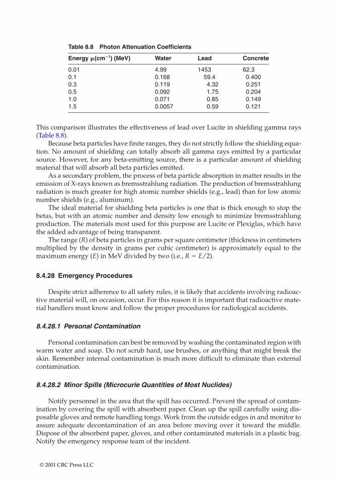
Table 8.8 Photon Attenuation Coefficients
Energy �(cm�1) (MeV) Water Lead Concrete
0.01 4.99 1453 62.30.1 0.168 59.4 0.4000.3 0.119 4.32 0.2510.5 0.092 1.75 0.2041.0 0.071 0.85 0.1491.5 0.0057 0.59 0.121
This comparison illustrates the effectiveness of lead over Lucite in shielding gamma rays(Table 8.8).
Because beta particles have finite ranges, they do not strictly follow the shielding equa-tion. No amount of shielding can totally absorb all gamma rays emitted by a particularsource. However, for any beta-emitting source, there is a particular amount of shieldingmaterial that will absorb all beta particles emitted.
As a secondary problem, the process of beta particle absorption in matter results in theemission of X-rays known as bremsstrahlung radiation. The production of bremsstrahlungradiation is much greater for high atomic number shields (e.g., lead) than for low atomicnumber shields (e.g., aluminum).
The ideal material for shielding beta particles is one that is thick enough to stop thebetas, but with an atomic number and density low enough to minimize bremsstrahlungproduction. The materials most used for this purpose are Lucite or Plexiglas, which havethe added advantage of being transparent.
The range (R) of beta particles in grams per square centimeter (thickness in centimetersmultiplied by the density in grams per cubic centimeter) is approximately equal to themaximum energy (E) in MeV divided by two (i.e., R � E/2).
8.4.28 Emergency Procedures
Despite strict adherence to all safety rules, it is likely that accidents involving radioac-tive material will, on occasion, occur. For this reason it is important that radioactive mate-rial handlers must know and follow the proper procedures for radiological accidents.
8.4.28.1 Personal Contamination
Personal contamination can best be removed by washing the contaminated region withwarm water and soap. Do not scrub hard, use brushes, or anything that might break theskin. Remember internal contamination is much more difficult to eliminate than externalcontamination.
8.4.28.2 Minor Spills (Microcurie Quantities of Most Nuclides)
Notify personnel in the area that the spill has occurred. Prevent the spread of contam-ination by covering the spill with absorbent paper. Clean up the spill carefully using dis-posable gloves and remote handling tongs. Work from the outside edges in and monitor toassure adequate decontamination of an area before moving over it toward the middle.Dispose of the absorbent paper, gloves, and other contaminated materials in a plastic bag.Notify the emergency response team of the incident.
© 2001 CRC Press LLC

8.4.28.3 For Major Spills (Millicurie Quantities of Most Nuclides)
Clear the area. Prevent the spread of the contamination as above. Confine the move-ment of personnel potentially contaminated to prevent the spread. Shield the source if itcan be done without further contamination or significantly increasing your radiation expo-sure. Close off the area to prevent entry. Notify the emergency response team immediately.
© 2001 CRC Press LLC
CHAPTER 9
Microcircuitry and Remote Monitoring
With the advent of microcircuitry, GIS locators, and the Internet, this chapter discusses the newmonitoring options available. These protocols are particularly important in monitoring remote sitesfor remediation or process adequacy and safety (explosive limits and toxic chemical limitdeterminations).
9.1 CONTINUOUS IAQ MONITORING IN BUILDINGS
Continuous IAQ monitoring empowers IAQ professionals and facility managers tofind and resolve IAQ issues quickly, before they become problems or crises. Intermittentcontinuous IAQ monitoring supplements the qualified professional with permanentlyinstalled scientific sensors that measure, record, and archive the indoor air quality in abuilding 24 h per day, 365 days per year.
One of the indicators of air quality is carbon dioxide levels within the total airstream.Carbon dioxide is generated through respiratory exhalation and incomplete combustion offuels. Continuous monitoring systems often use infrared beams to detect carbon monoxidefluctuations (see Figure 2.6 on page 13).
Continous IAQ monitoring:
• Creates an early warning system for targeting and correcting IAQ issues• Shows precisely when complaints disappear while demonstrating when most
building occupants are comfortable• Assures, through operational linkage, proper equipment operation and mainte-
nance, even on remote sites• Provides building owners and operators with ongoing proof of acceptable indoor
air quality• Yields a continuous historical record of contaminant levels
The early warning capability, when it is combined with multiple small unobtrusivemonitoring devices, makes monitoring in sensitive areas possible. Using remote sensors,monitoring is possible within laboratories, hospitals, vehicle shops, paint booths, haz-ardous waste storage bunkers, and vehicular housings. In the event that the sensors detecta problem, IAQ professionals can be summoned to assess the immediate situation.
© 2001 CRC Press LLC
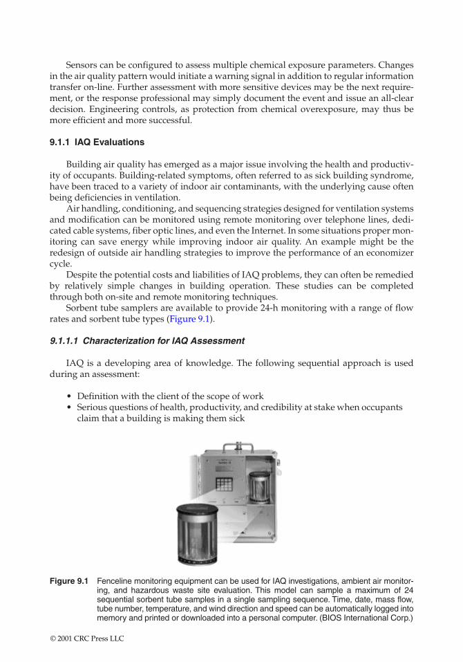
Figure 9.1 Fenceline monitoring equipment can be used for IAQ investigations, ambient air monitor-ing, and hazardous waste site evaluation. This model can sample a maximum of 24sequential sorbent tube samples in a single sampling sequence. Time, date, mass flow,tube number, temperature, and wind direction and speed can be automatically logged intomemory and printed or downloaded into a personal computer. (BIOS International Corp.)
Sensors can be configured to assess multiple chemical exposure parameters. Changesin the air quality pattern would initiate a warning signal in addition to regular informationtransfer on-line. Further assessment with more sensitive devices may be the next require-ment, or the response professional may simply document the event and issue an all-cleardecision. Engineering controls, as protection from chemical overexposure, may thus bemore efficient and more successful.
9.1.1 IAQ Evaluations
Building air quality has emerged as a major issue involving the health and productiv-ity of occupants. Building-related symptoms, often referred to as sick building syndrome,have been traced to a variety of indoor air contaminants, with the underlying cause oftenbeing deficiencies in ventilation.
Air handling, conditioning, and sequencing strategies designed for ventilation systemsand modification can be monitored using remote monitoring over telephone lines, dedi-cated cable systems, fiber optic lines, and even the Internet. In some situations proper mon-itoring can save energy while improving indoor air quality. An example might be theredesign of outside air handling strategies to improve the performance of an economizercycle.
Despite the potential costs and liabilities of IAQ problems, they can often be remediedby relatively simple changes in building operation. These studies can be completedthrough both on-site and remote monitoring techniques.
Sorbent tube samplers are available to provide 24-h monitoring with a range of flowrates and sorbent tube types (Figure 9.1).
9.1.1.1 Characterization for IAQ Assessment
IAQ is a developing area of knowledge. The following sequential approach is usedduring an assessment:
• Definition with the client of the scope of work• Serious questions of health, productivity, and credibility at stake when occupants
claim that a building is making them sick
© 2001 CRC Press LLC
• Discussion of various approaches to the investigation• Problems often classified as either ventilation related or source related for pur-
poses of implementing sensible corrective measures• Coordination of efforts among team members and current building occupants• Oversight of monitoring and diagnostic activities• Analysis of corrective actions• Generation of performance specifications
IAQ investigations are conducted as follows:
• Describe how to form and test explanations for the problem and its solution. Theproposed approach to the building investigation may involve moving suspectedcontaminant sources or manipulating HVAC controls to simulate conditions atthe time of complaints or to test possible corrective actions.
• IAQ measurement decision logic is developed.• A decision to obtain IAQ-related measurements follows logically from other
investigative activities.• Before starting to take measurements, investigators need a clear understanding
of how the results will be used. Without this understanding, it is impossible toplan appropriate sampling locations and times, instrumentation, and analysisprocedures.
• Nonroutine measurements (such as relatively expensive sampling for VOCs arenot to be conducted without site-specific justification.
• Concentrations low enough to comply with industrial occupational standards couldstill be harmful to children or other immune-compromised or sensitized occupants.
• Industrial IAQ problems tend to arise from high levels of individual chemical com-pounds, so standards set limits for individual contaminants or contaminant classes.
• Exposure workplace standards are rarely exceeded in residences and schools.Instead, IAQ investigators often find a large number of potential sources con-tributing low levels of many contaminants to the air.
The following information is presented for each IAQ phased evaluation:
• The basic goals, methodology, and sequence of the investigation, the informationto be obtained, and the process of hypothesis development and testing, includingcriteria for decision-making about further data-gathering
• Any elements of the work that will require a time commitment from staff or res-idents, including information to be collected by the facility
• The schedule, cost, and work products, such as a written report, specifications,and plans for mitigation work, supervision of mitigation work, and training pro-grams for staff
• Additional tasks (and costs) that may be part of solving the IAQ problem, butoutside the scope of the contract (examples include medical examination of com-plainants, laboratory fees, and contractor’s fees for mitigation work)
9.1.1.2 Source Assessment and Remediation
This IAQ phase includes either remote or on-site evaluation of known sources of air-borne contaminants. When required, the IAQ team may also oversee necessary correctivemeasures. Examples of such projects include modification of smoking areas, decontamina-tion of microbial growth surfaces, and response to pesticide spills.
© 2001 CRC Press LLC
The most efficient way to protect building air quality is through programs that preventproblems or address them in their earliest stages. In this regard IAQ aspects of facility designand property audits may be most effective if initiated during design and initial occupancy.Air quality precautions during facility design may include such steps as selecting and con-ditioning of materials to limit off-gassing, evaluation of proposed ventilation schemes,specifying remote sensing equipment, and preoccupancy testing of the building.
9.1.1.3 IAQ Risk Assessment
An investigation strategy based on evaluating building performance is used to solve aproblem without necessarily identifying a particular chemical compound as the cause. Theidea of testing the air to learn whether it is “safe’’ or “unsafe’’ is very appealing. However,most existing standards for airborne pollutants were developed for industrial settingswhere the majority of occupants are usually healthy adult men.
9.2 INDUSTRIAL/REMEDIATION PROCESS MONITORING
Through work efforts at industrial/remediation process sites, the basic precepts ofindustrial hygiene monitoring should be implemented from initial design through ongo-ing maintenance. The following is an example of an industrial hygiene scope of work toprovide answers in process safety management.
9.2.1 Process Safety Management Example Scope of Work
Process safety management (PSM) is a new strategy of management controls whereprocess limitations/hazards are identified and controlled so that injuries, spills, or hazardsare minimized. It is mandated in 29 CFR 1910.119 and applies to manufacturing plants andother industries that are involved with large quantity chemical usage. The principal com-ponents required for PSM compliance will benefit any industry trying to manage chemicaluse. PSM is a complex system of controls, and in order to be successful in the implementa-tion, upper management support and involvement is essential.
Standard operating procedures (SOPs) and O&M procedures must be reviewed. Thisreview will focus on processes that involve chemicals that are potential air contaminants orother environmental media contaminants to the extent that health risk management isrequired. The PSM standard mandates that the SOPs have provisions for every operatingphase, operating limitations, and safety and health considerations.
In general, the PSM requirements foroperating procedures include the following:
• Operating procedures that must address stepsfor each operating phase, operating limitsbetween various operations, safety and healthconsiderations
• Copy of procedures that are readily accessible toemployees
• Implementation of safe work practices
© 2001 CRC Press LLC
A review of spill containment capabilities must also occur to identify current spill con-tainment areas and any area limitations. Coordination of spill responses with regulatorymandates and facility siting requirements should be addressed.
All hazard communication documentation must be reviewed. Hazard communicationis a set of procedures to communicate the hazards potentially associated with storage, han-dling, shipping, or use of hazardous material. Communication is typically accomplishedthrough material safety data sheets (MSDS), shipping papers, emergency response proce-dures, labels on containers, and training for employees. There must be open communica-tion between all parties involved with hazardous material, including employer-employee,employee-employer, shipper-receiver, and the business-community. Specific proceduresmust be in place to facilitate this type of communication.
Past incidents will then be reviewed to determine any pattern or need for immediatechange. By looking at past events, safeguards can be identified to defray accidents andreleases in the future.
9.2.2 Provide List for Hazard and Operability Study
Current documents needed must be listed and acquired in order to complete a hazardand operability study (HAZOP). The current piping and instrumentation diagrams (P&ID)and other available design documents are a minimum requirement for review prior to ini-tiation of the HAZOP.
Superfund Amendments and Reauthorization Act (SARA) Title III requires companiesthat use a large amount of chemicals to provide information on their plants and to partici-pate in community emergency response plans. The SARA Title III reporting will bereviewed to identify any chemical uses that need to be addressed during the HAZOP study.
A process hazard analysis (PHA) provides employees and employers information toassist them in making good decisions about safety. The PHA focuses on the causes or con-tributing causes of potential accidents in the plant (fires, explosions, spills, releases, etc.).The PHA is directed toward the equipment, human actions, control panels, etc. that maycause failures in a system.
9.2.3 Process Hazard Analysis
Many variables must be considered when choosing the appropriate PHA technique touse, including the size of the plant, the number of processes, the types of processes, and thetypes of chemicals used. Many hazard analysis techniques can be used to determine theappropriate process safety aspects and physical distribution of a plant or facility. The fol-lowing techniques may be used in performing a PHA.
Hazard Analysis Techniques
• Checklist• “What if’’• HAZOP• Failure mode and effect analysis• Fault tree analysis• Event tree analysis• Distribution risk curves
© 2001 CRC Press LLC
9.2.3.1 Hazard and Operability Study
The HAZOP addresses each system and each element of a system that could deviatefrom normal operations and, thus, cause a hazard. A full assessment of each process is produced by looking at the hazards, consequences, causes, and personnel protectionneeded.
9.2.3.2 Failure Modes and Effects Analysis (FMEA)
FMEA involves the systematic rating of each process and the hazards involved. It ismost effective when analyzing an individual process. It starts with a diagram of the designof the processes and identifies all the possible components that could fail (i.e., valves,hoses, pumps).
9.2.3.3 Fault Tree Analysis
Fault tree analysis is a graphical representation of all possible events of a hazard or haz-ards that may occur if a fault/breach in a process occurs. This method centralizes on theevent that occurs, not so much the process. The graphical representation looks like a tree,and a probability is applied by the reviewer to each fault on the tree.
9.2.4 Design Analysis
Increasingly, designs must take into consideration safety and health requirements.These requirements include such topics as general safety, asbestos, lead, PCBs, volatilechemical/painting/other airborne chemical hazards, and hazardous waste generation.The following design documents should be prepared to provide the safety and healthdesign team information within engineering and construction documents.
9.2.4.1 Site Safety and Health Plans
For sites, including future building sites, requiring a phase I and/or phase II envi-ronmental site assessment (ESA), a site safety and health plan must be developed for theinvestigating team if hazardous wastes are still significantly present on-site. This plan will
Components are analyzed for the following:
• Potential mode of failure• Consequences of the failure• Hazard class (high, moderate, low)• Probability of failure• Detection methods• Compensating provisions/remarks
© 2001 CRC Press LLC
• Describe the minimum safety, health, and emergency response• List anticipated major site tasks and operations• Determine initial minimum levels of PPE
9.2.4.2 Health and Safety Design Analysis (HSDA)
During the design phase an HSDA is often developed. Site and/or hazard specificsafety and health considerations and protective measures are outlined in the HSDA. TheHSDA fully describes and justifies (using decision logic) the safety and health requirementsto be included in the contract specifications or work plans.
In the event that a site safety and health plan has been approved for prior on-site inves-tigative work, and the same contractor will be conducting the construction work, theHSDA only details the remaining construction work. If the remaining construction workdoes not pose additional hazards in excess of those discussed in the prior site safety andhealth plan, an HSDA will not be required.
9.2.4.3 Drawings
Drawings illustrate the following on an as-needed basis (i.e., either the drawings willcontain this information or will illustrate how the information will be presented during alater design phase):
• The basic site layout, including the location of all existing utilities (e.g., water,sewer, gas, electrical)
• All potential interferences with utility routings, including any existing infra-structure that may pose an obstacle
• Site work zones for hazardous waste site work, including the EZ, the CRZ, andthe SZ (When a work activity will be duplicated at varying locations on-site, anexample of the placement of each zone is provided.)
• Schematic of decontamination facilities for both personnel and heavy equipment(Ideally these facilities should be in separate locations.)
• Location of all emergency facilities: eyewash stations, drench showers, first aidstations
• Routes to medical facilities• Emergency and contingency plan staging areas• Air-monitoring stations for background, area, and perimeter monitoring (If air
monitoring is not required for any of these areas, the drawing notes must containa negative declaration to this effect.)
• Waste collection, transfer, and disposal locations
9.2.4.4 Specifications
The contract requirements are fully developed from the HSDA and are described in aspecification section. All minimum site-specific, task-specific, and hazard-specific proce-dures, precautions, and equipment determined necessary and described in the HSDA areclearly biddable and enforceable contractual requirements within the specification sec-tions.
For hazardous waste sites, the site description and contamination characterization por-tion of the HSDA may be incorporated for information as a specification appendix.
© 2001 CRC Press LLC
In the event that a site safety and health plan has been approved for prior on-site inves-tigative work, and the same contractor will be conducting the construction work:
• If the remaining remedial action construction work does not pose additional haz-ards in excess of those discussed in the prior approved plan, a safety and healthspecification section will not be required.
• If the remaining remedial action construction work does pose additional hazardsin excess of those discussed in the prior approved plan, but the additional haz-ards can be adequately discussed in an addendum to the prior approved plan, asafety and health specification section will not be required.
• In lieu of requiring that the contractor write a safety and health specification sec-tion, a safety and health work plan may be required.
• If the remaining construction work does pose additional hazards in excess ofthose discussed in the prior approved site safety and health plan, and the addi-tional hazards cannot be adequately discussed in an addendum to the priorapproved site safety and health plan, a safety and health specification section willbe required.
During any design analysis the chemical use and potential contaminant issues must beanalyzed.
9.2.4.5 Design Analysis Example—Wastewater Treatment
The following is an example of the type of design analysis required to determine whichchemicals could become air contaminants during process operations. This example is anexcerpt from a design analysis that illustrates how process stream chemical activities areanalyzed.
Wastewater Treatment
• Each reaction tank has a propeller mixer.• Detention time in each tank is from 15 to 45 min.• Reaction times for different wastes, reducing agents, temperatures, pH, and
chromium concentrations.
After the Hexavalent Chromium Has Been Reduced to Trivalent Chromium
• The waste stream can be combined with other wastestreams containing commonmetals. These combined waste streams can be treated by the hydroxide precipi-tation process to remove chromium and the other common metals.
• Optimum levels for your metal waste treatment facilities may be slightly differ-ent due to the “mix’’ of wastes being treated.
Cyanide Destruction by Oxidation
The cyanide ion (CN�) is extremely toxic and must be removed from metal wastesbefore discharge to sewers or the environment. Cyanide toxicity (poisoning) in humans iscaused by an irreversible reaction with the iron in hemoglobin that results in loss of theblood’s ability to transport oxygen.
© 2001 CRC Press LLC
If equipment failure occurs during the treatment of wastes containing cyanide,extremely toxic gases could be released. Therefore all tanks or pits used for cyanidedestruction must be properly located and ventilated so that any gases produced will neverenter an area occupied by people.
Cyanide Sources and Treatment
Cyanide compounds are used
• In plating solutions for copper, zinc, cadmium, silver, and gold• In the immersion stripping of various electrodeposits• In some activating solutions• Complexed with heavy metals such as zinc, cadmium, silver, gold, copper, nickel,
and iron
Flowing rinse waters after these production operations can become contaminated with cyanide. Cyanide may be present as the simple alkali cyanides of sodium or potassium.
For waste treatment control the two major groupings of cyanide compounds are seg-regated into
• Those that can be oxidized by chlorination (also known as cyanides amenable tochlorination)
• Those that resist oxidation by chlorination (also known as refracto-cyanides)
Both types are to toxic and must be removed or have their concentrations reduced belowtoxic levels prior to discharge of the rinse waters.
Those compounds that are readily oxidized by chlorination are cyanides of
• Sodium• Potassium• Cadmium• Zinc
The copper cyanide complex is also considered amenable to chlorination, although longer reaction times are required (also for silver and gold cyanide complexes). The nickelcyanide complex is more resistant to chlorination than the copper complex, yet it can be considered as amenable to chlorination under extreme oxidizing conditions. Iron complexes (most commonly the sodium ferrocyanide salt) are not readily oxidizable bychlorine.
Pretreatment permits prescribe maximum limits for cyanides oxidizable by chlo-rination and for total cyanide (the sum of those that can be chlorinated and those that cannot).
• The average limits for amenable cyanides are 0.05 mg/l and for total cyanide 0.28 mg/l.
• The maximum concentrations for amenable and total cyanide are 0.65 mg/l and 1.2 mg/l.
© 2001 CRC Press LLC
Chemistry Involved
Waste treatment systems are designed to oxidize cyanide compounds with sodiumhypochlorite (NaClO). The hypochlorite is purchased at a 14 to 15% by weight concentra-tion. This solution has been produced by the reaction between chlorine and sodiumhydroxide according to the reaction:
Cl2 � 2NaOH → NaClO � NaCl � H2O
Sodium cyanate (NaCNO) is formed by the reaction of hypochlorite and cyanide.
• This reaction is actually a simplification of the chlorination of cyanide; very rapidintermediate reactions take place.
• Chlorine is freed from the hypochlorite by disassociation (a reversal of the for-mation of hypochlorite shown above).
The chlorine actually reacts with the cyanide to form cyanogen chloride according to
NaCN � Cl2 → CNCl � NaCl
The cyanogen chloride then reacts with the sodium hydroxide to form the cyanate according to
CNCl � 2NaOH → NaCNO � NaCl � H2O
The cyanogen chloride is a gas that has limited solubility at neutral or low pH values.At pH values of 10 or higher the reaction producing the cyanate is quite rapid for cyanidesthat are not too tightly complexed with heavy metals. At lower pH values not only is thereaction too slow, but also there is a good probability of liberating the cyanogen chloridegas to the atmosphere. This gas is
• A lacrymator (produces tears)• Readily apparent to those nearby
Oxidation of cyanate is possible by chlorination where the reaction is
2NaCNO � 3NaOCl � H2O → 2CO2 � N2 � 3NaCl � 2NaOH
The carbon dioxide formed will react with alkali to produce carbonate. Any excess isliberated into the atmosphere.
• The nitrogen has a limited solubility and also escapes into the air.• This second stage oxidation reaction is faster at pH values slightly lower than the
initial reaction of cyanide to cyanate.
If the pH drops too low (below 7.0), then another reaction takes place with cyanate.This reaction will hydrolyze with water to produce ammonia compounds.
© 2001 CRC Press LLC
From this discussion pH as a critical factor must be defined. The rate of reaction, as wellas the end products, depend upon maintaining proper pH values. The escape of cyanogenchloride is inhibited by high pH values.
Another impact of the oxidizing potential of pH at 10.5 to 11.0 is the oxidizer millivoltspotential that results. Nitrogen chloride as an oxidizing gas essentially stops the reaction,so higher potentials of 650 mV do not solve the problem.
Operators must realize the extreme hazards that can develop and produce toxiccyanide gas whenever cyanide treatment processes are accidentally carried on at an acidic pH.
• Where significant levels of cyanides exist, extremely hazardous conditions candevelop very quickly.
• Also when treating cyanides be sure to determine the pH at the start of the treat-ment process. The adjustment of pH and the various set points for the treatmentsystem are to some extent dependent upon the concentration of cyanide andcyanate, and the initial pH of the wastestreams.
• Adjusting the pH downward to 9.0 for a treatment process when the initial pH of a cyanide solution is significantly higher could result in the evolution of toxic cya-nide gas.
Cyanides complexed with zinc and cadmium react with the same rate as the simplesodium and potassium cyanides. Because the various other metal complexes are moreresistant to oxidation by chlorination, long contact times are required.
In order to maintain a fast reaction rate, higher oxidizing potentials (additional excesschlorine) are employed. This method is most important for the complexes of silver andnickel.
When a cadmium cyanide complex is oxidized, the cadmium precipitates from solu-tion as cadmium oxide. When oxidized, these metals precipitate from solution as hydrox-ides of copper, nickel, and zinc.
However, the presence of silver cyanide presents an additional concern. The silvercyanide complex when oxidized can precipitate as
• Silver chloride (a white precipitate)• Silver oxide (a black precipitate)
Silver oxide is preferred; it is denser than silver chloride with the result that its removalfrom the wastewater is easier. Higher oxidizing conditions favor the oxide formation;lower oxidizing conditions favor the chloride formation.
The control devices are set to control the pH within the range of 10.5 to 11.5 for the first-stage reaction (cyanide to cyanate) and the second-stage reaction (cyanate to carbon dioxide and nitrogen). The control devices are set to maintain minimum oxidizingpotentials of
• �600 mV in the first stage and• �850 mV in the second stage
For the first stage reaction a minimum pH must be maintained. The top pH limit (11.5) isestablished.
© 2001 CRC Press LLC

Excessive alkali (as measured by pH) results in suppression of oxidation-reductionpotential (ORP) values. The ORP value selected considers the need to have excesshypochlorite present to dominate the reaction. Sodium hypochlorite always contains freesodium hydroxide.
When the ORP controller requests the addition of hypochlorite, the pH can rise becauseof this simultaneous addition of alkali. When the pH rises, the ORP value decreases, estab-lishing an out-of-control condition. Adding more hypochlorite results in the instrumenta-tion requesting still more hypochlorite even though there is no cyanide present. Thisphenomenon is eliminated by the addition of acid whenever the pH rises too high.
© 2001 CRC Press LLC
CHAPTER 10
Occupational Health—Air-Monitoring Strategies
This chapter discusses the current OSHA and NIOSH protocols and their applicability. Itincludes in tabular form the air-monitoring strategies that may be approved in the future.
Once substantial employee exposure is a potential concern, such exposure needs to bemeasured. The next step is to select a maximum-risk employee. When there are differentprocesses where employees may be exposed to the chemical of concern, a maximum-riskemployee should be selected for each work operation. The action level should usually bethe OSHA PEL.
Selection of the maximum-risk employee requires professional judgment. The best pro-cedure for selecting the maximum risk employee is to observe employees and select theperson closest to the chemical source. Employee mobility may affect this selection, e.g., ifthe closest employee task requires mobility, this worker may not be the maximum riskemployee. Air movement patterns and differences in work habits will also affect selectionof the maximum risk employee.
When many employees perform essentially the same task, a maximum-risk employeecannot be selected. In this circumstance it is necessary to resort to random sampling of thegroup of workers. The objective is to select a subgroup of adequate size so that there is ahigh probability that the random sample will contain at least one worker with high expo-sure. The number of persons in the group influences the number that needs to be sampledto ensure that at least one individual from the highest 10% exposure group is contained inthe sample. For example, to have 90% confidence in the results, if the group size is 10, 9 willbe sampled; for 50, only 18 need to be sampled.
If measurement shows exposure to the chemical at or above the action level or theSTEL, all other employees who may be exposed at or above the action level or STEL needto be identified. Measurement or otherwise accurate characterization of their exposuremust be accomplished.
Whether representative monitoring or random sampling is conducted, the purposeremains the same: to determine if the exposure of any employee is above the action level.If the exposure of the most exposed employee is less than the action level and the STEL,regardless of how the employee is identified, then it is reasonable to assume that measure-ments of exposure of the other employees in that operation would be below the action leveland the STEL.
© 2001 CRC Press LLC
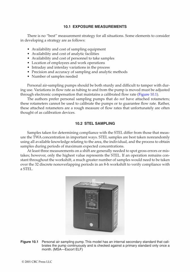
10.1 EXPOSURE MEASUREMENTS
There is no “best’’ measurement strategy for all situations. Some elements to considerin developing a strategy are as follows:
• Availability and cost of sampling equipment• Availability and cost of analytic facilities• Availability and cost of personnel to take samples• Location of employees and work operations• Intraday and interday variations in the process• Precision and accuracy of sampling and analytic methods• Number of samples needed
Personal air-sampling pumps should be both sturdy and difficult to tamper with dur-ing use. Variations in flow rate as tubing to and from the pump is moved must be adjustedthrough electronic compensation that maintains a calibrated flow rate (Figure 10.1).
The authors prefer personal sampling pumps that do not have attached rotameters;these rotameters cannot be used to calibrate the pumps or to guarantee flow rate. Rather,these attached rotameters are a rough measure of flow rates that unfortunately are oftenthought of as calibration devices.
10.2 STEL SAMPLING
Samples taken for determining compliance with the STEL differ from those that meas-ure the TWA concentration in important ways. STEL samples are best taken nonrandomlyusing all available knowledge relating to the area, the individual, and the process to obtainsamples during periods of maximum expected concentrations.
At least three measurements on a shift are generally needed to spot gross errors or mis-takes; however, only the highest value represents the STEL. If an operation remains con-stant throughout the workshift, a much greater number of samples would need to be takenover the 32 discrete nonoverlapping periods in an 8-h workshift to verify compliance witha STEL.
Figure 10.1 Personal air sampling pump. This model has an internal secondary standard that cali-brates the pump continuously and is checked against a primary standard only once amonth. (MSA—Escort ELF)
© 2001 CRC Press LLC
10.3 EXPOSURE FLUCTUATIONS
Interday and intraday fluctuations in employee exposure are mostly influenced by thephysical processes that generate formaldehyde and the work habits of the employee.Hence, in-plant process variations influence the determination of whether additional con-trols need to be imposed. Measurements in which employee exposure is low on a day thatis not representative of worst conditions may not provide sufficient information to deter-mine whether additional engineering controls will be installed to achieve the PELs.
The person responsible for sampling must be aware of systematic changes that willnegate the validity of the sampling results. Systematic changes in exposure concentrationfor an employee can occur due to
• The employee changing patterns of movement in the workplace• Closing plant doors and windows• Changes in ventilation from season to season• Decreases in ventilation efficiency or abrupt failure of engineering control
equipment• Changes in the production process or work habits of the employee
Any of these changes, if they may result in additional exposure that reaches the next level ofaction, requires the performance of additional monitoring to reassess employee exposure.
10.4 AIR-SAMPLING PUMP USER OPERATION
10.4.1 Pump Donning
• Attach the collection device (filter cassette, charcoal tube, etc.) to the shirt collaror as close as practical to the nose and mouth of the employee, i.e., in a hemi-sphere forward of the shoulders with a radius of approximately 6 to 9 in.
• The inlet should always be in a downward vertical position to avoid gross contam-ination. Position the excess tubing so that it does not interfere with normal activity.
• Turn on the pump and record the starting time.• Observe the pump operation for a short time after starting to make sure the pump
is operating correctly. Record the required information.
10.4.2 Pump Checking
• Check pump every 2 h.• More frequent checks may be necessary with heavy filter loading.• Ensure that the sampler is still assembled properly and that the hose has not
become pinched or detached from the cassette or the pump.• For filters observe for symmetrical deposition, fingerprints, large particles, etc.• Record the flow rate.• Periodically monitor the employee throughout the workday to ensure that sample
integrity is maintained and cyclical activities and work practices are identified.
10.4.3 Pump Doffing
• Before removing the pump at the end of the sample period, if there is a pumprotameter, check the flow rate to ensure that the rotameter ball is still at the
© 2001 CRC Press LLC
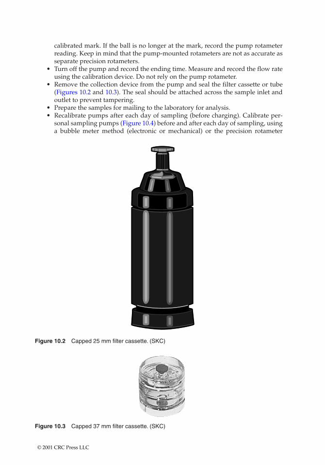
calibrated mark. If the ball is no longer at the mark, record the pump rotameterreading. Keep in mind that the pump-mounted rotameters are not as accurate asseparate precision rotameters.
• Turn off the pump and record the ending time. Measure and record the flow rateusing the calibration device. Do not rely on the pump rotameter.
• Remove the collection device from the pump and seal the filter cassette or tube(Figures 10.2 and 10.3). The seal should be attached across the sample inlet andoutlet to prevent tampering.
• Prepare the samples for mailing to the laboratory for analysis.• Recalibrate pumps after each day of sampling (before charging). Calibrate per-
sonal sampling pumps (Figure 10.4) before and after each day of sampling, usinga bubble meter method (electronic or mechanical) or the precision rotameter
Figure 10.2 Capped 25 mm filter cassette. (SKC)
Figure 10.3 Capped 37 mm filter cassette. (SKC)
© 2001 CRC Press LLC
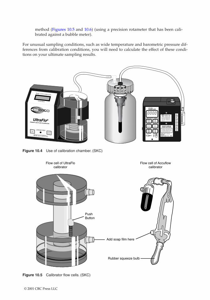
method (Figures 10.5 and 10.6) (using a precision rotameter that has been cali-brated against a bubble meter).
For unusual sampling conditions, such as wide temperature and barometric pressure dif-ferences from calibration conditions, you will need to calculate the effect of these condi-tions on your ultimate sampling results.
Figure 10.4 Use of calibration chamber. (SKC)
Figure 10.5 Calibrator flow cells. (SKC)
© 2001 CRC Press LLC
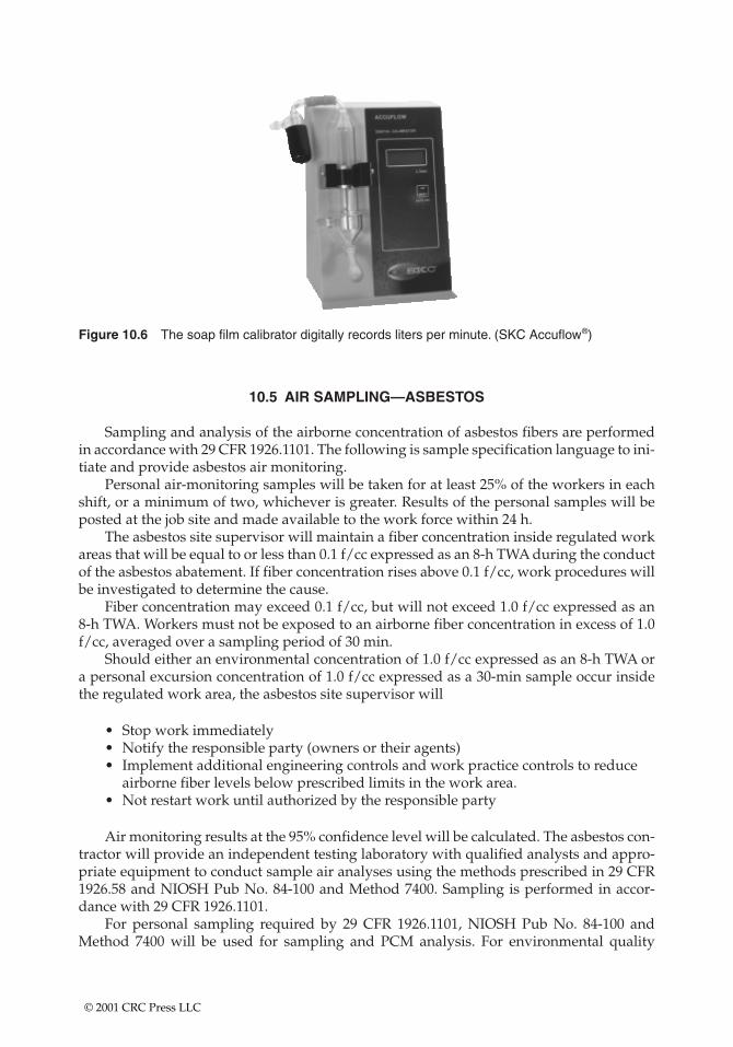
Figure 10.6 The soap film calibrator digitally records liters per minute. (SKC Accuflow®)
10.5 AIR SAMPLING—ASBESTOS
Sampling and analysis of the airborne concentration of asbestos fibers are performedin accordance with 29 CFR 1926.1101. The following is sample specification language to ini-tiate and provide asbestos air monitoring.
Personal air-monitoring samples will be taken for at least 25% of the workers in eachshift, or a minimum of two, whichever is greater. Results of the personal samples will beposted at the job site and made available to the work force within 24 h.
The asbestos site supervisor will maintain a fiber concentration inside regulated workareas that will be equal to or less than 0.1 f/cc expressed as an 8-h TWA during the conductof the asbestos abatement. If fiber concentration rises above 0.1 f/cc, work procedures willbe investigated to determine the cause.
Fiber concentration may exceed 0.1 f/cc, but will not exceed 1.0 f/cc expressed as an 8-h TWA. Workers must not be exposed to an airborne fiber concentration in excess of 1.0f/cc, averaged over a sampling period of 30 min.
Should either an environmental concentration of 1.0 f/cc expressed as an 8-h TWA ora personal excursion concentration of 1.0 f/cc expressed as a 30-min sample occur insidethe regulated work area, the asbestos site supervisor will
• Stop work immediately• Notify the responsible party (owners or their agents)• Implement additional engineering controls and work practice controls to reduce
airborne fiber levels below prescribed limits in the work area.• Not restart work until authorized by the responsible party
Air monitoring results at the 95% confidence level will be calculated. The asbestos con-tractor will provide an independent testing laboratory with qualified analysts and appro-priate equipment to conduct sample air analyses using the methods prescribed in 29 CFR1926.58 and NIOSH Pub No. 84-100 and Method 7400. Sampling is performed in accor-dance with 29 CFR 1926.1101.
For personal sampling required by 29 CFR 1926.1101, NIOSH Pub No. 84-100 andMethod 7400 will be used for sampling and PCM analysis. For environmental quality
© 2001 CRC Press LLC
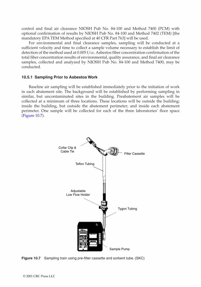
control and final air clearance NIOSH Pub No. 84-100 and Method 7400 (PCM) withoptional confirmation of results by NIOSH Pub No. 84-100 and Method 7402 (TEM) [themandatory EPA TEM Method specified at 40 CFR Part 763] will be used.
For environmental and final clearance samples, sampling will be conducted at asufficient velocity and time to collect a sample volume necessary to establish the limit ofdetection of the method used at 0.005 f/cc. Asbestos fiber concentration confirmation of thetotal fiber concentration results of environmental, quality assurance, and final air clearancesamples, collected and analyzed by NIOSH Pub No. 84-100 and Method 7400, may beconducted.
10.5.1 Sampling Prior to Asbestos Work
Baseline air sampling will be established immediately prior to the initiation of work in each abatement site. The background will be established by performing sampling in similar, but uncontaminated sites in the building. Preabatement air samples will be collected at a minimum of three locations. These locations will be outside the building;inside the building, but outside the abatement perimeter; and inside each abatementperimeter. One sample will be collected for each of the three laboratories’ floor space(Figure 10.7).
Figure 10.7 Sampling train using pre-filter cassette and sorbent tube. (SKC)
© 2001 CRC Press LLC
10.5.2 Sampling during Asbestos Abatement Work
The asbestos contractor and asbestos site supervisor will provide and/or oversee per-sonal air sampling as indicated in 29 CFR 1926.1101, State of New York and local require-ments, and in accordance with this plan.
Sampling will be conducted at least once each day in the laboratories where work isoccurring, close to the work in the asbestos-regulated space. If airborne fiber levels haveexceeded background or 0.01 f/cc, whichever is greater, all work will be stopped immedi-ately, and the responsible party notified. The condition causing the increase will be cor-rected. Work will not restart until authorized by the responsible party.
Where the construction of a containment is not required, after initial TWA airbornefiber concentrations are established, and provided the same type of work is being per-formed, PCM sampling will be conducted at the boundary of the asbestos-regulated work area in such locations and at such frequency as recommended by the on-site air-monitoring professional.
10.5.3 Sampling after Final Cleanup (Clearance Sampling)
Prior to conducting final air clearance monitoring, a final visual inspection of theasbestos contractor’s final cleanup of the abated asbestos-regulated work will occur. Finalclearance air monitoring will not begin until acceptance of this final cleaning by the respon-sible parties. Ongoing monitoring may also be used to prove that final clearance levelswere never exceeded.
Final clearance sampling of airborne fibers will be accomplished using aggressive airsampling techniques as defined in EPA 560/5-85-024 or as otherwise required by federal orstate requirements. The sampling and analytical method used will be mandatory [NIOSHPub No. 84-100 and Method 7400 (PCM)] with optional confirmation of results by NIOSHPub No. 84-100 and Method 7402 (TEM). [The mandatory EPA TEM method is specified at40 CFR Part 763.]
The final clearance air samples will be collected and analyzed as indicated by NIOSHPub No. 84-100 and Method 7400 (PCM) or the EPA mandatory method 40 CFR Part 763(TEM).
10.5.4 NIOSH Method
For PCM sampling and analysis using NIOSH Pub No. 84-100 and Method 7400, thefiber concentration inside the abated asbestos-regulated work area for each airborne sampleis less than 0.01 f/cc. Decontamination of the abated asbestos-regulated work area will beconsidered complete when every PCM final clearance sample is below the clearance limit.
• If any sample result is greater than 0.01 f/cc, the asbestos fiber concentration fromthat same filter will be reconfirmed using NIOSH Pub No. 84-100 and Method7402 (TEM).
• If any confirmation sample result is greater than 0.01 f/cc, then abatement isincomplete, and recleaning is required.
Upon completion of any required recleaning, resampling with results to meet the aboveclearance criteria is required.
© 2001 CRC Press LLC
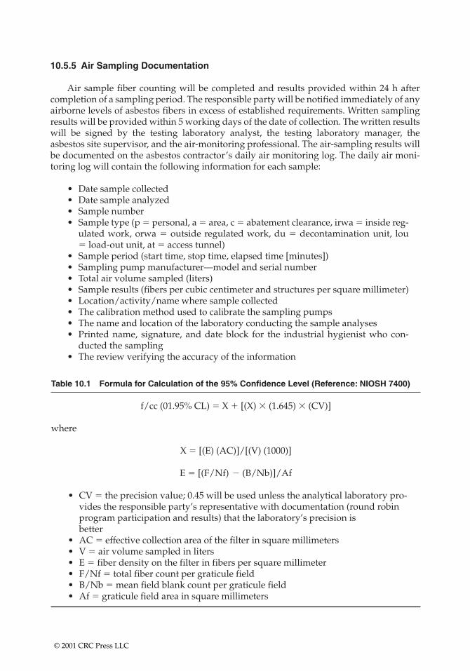
10.5.5 Air Sampling Documentation
Air sample fiber counting will be completed and results provided within 24 h aftercompletion of a sampling period. The responsible party will be notified immediately of anyairborne levels of asbestos fibers in excess of established requirements. Written samplingresults will be provided within 5 working days of the date of collection. The written resultswill be signed by the testing laboratory analyst, the testing laboratory manager, theasbestos site supervisor, and the air-monitoring professional. The air-sampling results willbe documented on the asbestos contractor’s daily air monitoring log. The daily air moni-toring log will contain the following information for each sample:
• Date sample collected• Date sample analyzed• Sample number• Sample type (p � personal, a � area, c � abatement clearance, irwa � inside reg-
ulated work, orwa � outside regulated work, du � decontamination unit, lou� load-out unit, at � access tunnel)
• Sample period (start time, stop time, elapsed time [minutes])• Sampling pump manufacturer—model and serial number• Total air volume sampled (liters)• Sample results (fibers per cubic centimeter and structures per square millimeter)• Location/activity/name where sample collected• The calibration method used to calibrate the sampling pumps• The name and location of the laboratory conducting the sample analyses• Printed name, signature, and date block for the industrial hygienist who con-
ducted the sampling• The review verifying the accuracy of the information
Table 10.1 Formula for Calculation of the 95% Confidence Level (Reference: NIOSH 7400)
f/cc (01.95% CL) � X � [(X) � (1.645) � (CV)]
where
X � [(E) (AC)]/[(V) (1000)]
E � [(F/Nf) � (B/Nb)]/Af
• CV � the precision value; 0.45 will be used unless the analytical laboratory pro-vides the responsible party’s representative with documentation (round robinprogram participation and results) that the laboratory’s precision is better
• AC � effective collection area of the filter in square millimeters• V � air volume sampled in liters• E � fiber density on the filter in fibers per square millimeter• F/Nf � total fiber count per graticule field• B/Nb � mean field blank count per graticule field• Af � graticule field area in square millimeters
© 2001 CRC Press LLC
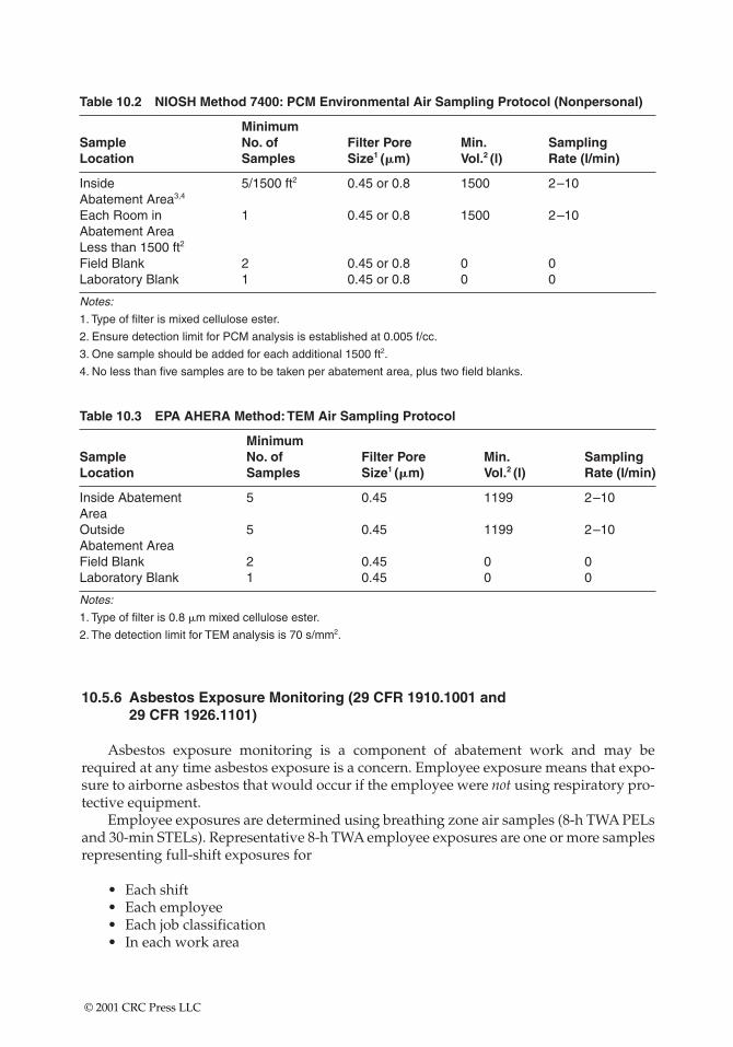
Table 10.3 EPA AHERA Method:TEM Air Sampling Protocol
MinimumSample No. of Filter Pore Min. SamplingLocation Samples Size1 (�m) Vol.2 (l) Rate (l/min)
Inside Abatement 5 0.45 1199 2–10AreaOutside 5 0.45 1199 2–10Abatement AreaField Blank 2 0.45 0 0Laboratory Blank 1 0.45 0 0
Notes:
1. Type of filter is 0.8 �m mixed cellulose ester.
2. The detection limit for TEM analysis is 70 s/mm2.
Table 10.2 NIOSH Method 7400: PCM Environmental Air Sampling Protocol (Nonpersonal)
MinimumSample No. of Filter Pore Min. SamplingLocation Samples Size1 (�m) Vol.2 (l) Rate (l/min)
Inside 5/1500 ft2 0.45 or 0.8 1500 2–10Abatement Area3,4
Each Room in 1 0.45 or 0.8 1500 2–10Abatement AreaLess than 1500 ft2
Field Blank 2 0.45 or 0.8 0 0Laboratory Blank 1 0.45 or 0.8 0 0
Notes:
1. Type of filter is mixed cellulose ester.
2. Ensure detection limit for PCM analysis is established at 0.005 f/cc.
3. One sample should be added for each additional 1500 ft2.
4. No less than five samples are to be taken per abatement area, plus two field blanks.
10.5.6 Asbestos Exposure Monitoring (29 CFR 1910.1001 and 29 CFR 1926.1101)
Asbestos exposure monitoring is a component of abatement work and may berequired at any time asbestos exposure is a concern. Employee exposure means that expo-sure to airborne asbestos that would occur if the employee were not using respiratory pro-tective equipment.
Employee exposures are determined using breathing zone air samples (8-h TWA PELsand 30-min STELs). Representative 8-h TWA employee exposures are one or more samplesrepresenting full-shift exposures for
• Each shift• Each employee• Each job classification• In each work area
© 2001 CRC Press LLC
Representative 30-min STELs are one or more samples representing 30-min exposures(operations that are most likely to produce exposures above the excursion limit) for
• Each shift• Each job classification• In each work area
10.5.7 Initial Monitoring
Begin initial monitoring immediately before/at the initiation of the operation(1926.1101):
• When employees may reasonably be expected to be exposed to airborne concentra-tions at or above the action level and/or excursion limit (1910.1001) made frombreathing zone air samples that are representative of the 8-h TWA and 30-minSTELs of each employee.
• Representative 8-h TWA employee exposures are determined on the basis of oneor more samples representing full-shift exposure for employees in each work area.
• Representative 30-min STELs are determined on the basis of one or more samplesrepresenting 30-min exposures associated with operations that are most likely toproduce exposures above the excursion limit for employees in each work area.
10.5.8 Historical Documentation for Initial Monitoring
Historical documentation for initial monitoring may be used when:
• Monitoring satisfies all the above requirements and the analytical requirementslisted in 29 CFR 1910.1001 and 1926.1101
• Documentation has occurred within the past calendar year (12 months)
10.5.9 Objective Data for Initial Monitoring
Objective data for initial monitoring may be used when asbestos is not capable of beingreleased in airborne concentrations at or above the action level and/or excursion limitunder the expected conditions of processing, use, or handling. No initial monitoring is thenrequired.
10.6 CRYSTALLINE SILICA SAMPLES ANALYZED BY X-RAY DIFFRACTION (XRD)
10.6.1 Air Samples
Respirable dust samples for quartz, cristobalite, and tridymite are analyzed by XRD.XRD is the preferred analytical method due to its sensitivity, its minimum requirements forsample preparation, and its ability to identify polymorphs (different crystalline forms) of free silica. For the analysis of crystalline free silica by XRD, the particle size distribution of
© 2001 CRC Press LLC
the samples must be matched as closely as possible to the standards, which is best accom-plished by collecting a respirable sample. Respirable dust samples are collected on a taredlow ash PVC filter using a 10-mm nylon cyclone at a flow rate of 1.5–1.9 l/min.
• A sample not collected in this manner is considered a total dust (or nonres-pirable) sample. Industrial hygienists are discouraged from submitting total dust samples because an accurate analysis cannot be provided by XRD for suchsamples.
• If the sample collected is nonrespirable, the laboratory must be advised on thechain-of-custody record.
Quartz (also cristobalite and tridymite) is initially identified by its major (primary)XRD peak. A few substances also have peaks near the same location, and it is necessary toconfirm quartz (also cristobalite or tridymite) using secondary and/or tertiary peaks. Toassist the analyst in identifying interference, the industrial hygienist should provide infor-mation concerning potential presence of other substances in the workplace. The followingsubstances should be noted:
• Aluminum phosphate• Feldspars (microcline, orthoclase, plagioclase)• Graphite• Iron carbide• Lead sulfate• Micas (biotite, muscovite)• Montmorillonite• Potash• Sillimanite• Silver chloride• Talc• Zircon (zirconium silicate)
A sample weight and total air volume should accompany all filter samples. Sampleweights of 0.5–3.0 mg are preferred. Do not submit samples unless their weight, or thecombined weights of all particulate filters representing an individual exposure, exceed 0.04 mg.
If heavy sample loading is noted during the sampling period, change the filter cassetteto avoid collecting a sample with a weight greater than 5.0 mg.
10.6.1.1 Laboratory Results for Air Samples
• Percent quartz (or cristobalite): Applicable for a respirable sample in which theamount of quartz (or cristobalite) in the sample was confirmed.
• Less than or equal to value in units of percent: Less than or equal to values areused when the adjusted 8-h exposure is found to be less than the PEL, based onthe sample’s primary diffraction peak.
• The value reported represents the maximum amount of quartz (or cristobalite)that could be present.
• The presence of quartz (or cristobalite) was not confirmed using secondaryand/or tertiary peaks in the sample because the sample could not be in violationof the PEL.
© 2001 CRC Press LLC
• Approximate values in units of percent: The particle size distribution in a totaldust sample is unknown and error in the XRD analysis may be greater than for res-pirable samples. Therefore, for total dust samples, an approximate result is given.
• Nondetected:—A sample reported as nondetected indicates that the quantity of quartz (or cristo-
balite) present in the sample is not greater than the detection limit of the instru-ment. The detection limit is usually 10 mg for quartz and 30 mg for cristobalite.
—If less than a full-shift sample was collected, the industrial hygienist should evaluate a nondetected result to determine whether adequate sampling wasperformed.
—If the presence of quartz (or cristobalite) is suspected in this case, the industrialhygienist may want to sample for a longer period of time to increase the sam-ple weights.
10.6.2 Bulk Samples
Bulk samples should be submitted for all silica analyses, if possible. Bulk samples havethe following purposes:
• To confirm the presence of quartz or cristobalite in respirable samples or to assessthe presence of other substances that may interfere in the analysis of respirablesamples
• To determine the approximate percentage of quartz (or cristobalite) in the bulksample
• To support hazard communication inspections
A bulk sample must be representative of the airborne free silica content of the workenvironment sampled; otherwise, it has no value.
The laboratory’s order of preference for bulk samples for an evaluation of personalexposure is as follows:
• A high-volume respirable area sample• A high-volume area sample• A representative settled-dust (rafter) sample (This is the most practical option. In
certain operations it may be very difficult to collect enough material using high-volume sampling to be used as a bulk sample.)
• A bulk sample of the raw material used in the manufacturing process (most prac-tical if used for hazard communication inspections)
The type of bulk sample submitted to the laboratory should be stated on the OSHA-91 formand cross-referenced to the appropriate air samples.
A reported bulk sample analysis for quartz (also cristobalite or tridymite) will be semi-quantitative because
• Errors are associated with bulk sampling.• The XRD analysis procedure requires a thin layer deposition for an accurate
analysis.• The error for bulk samples analyzed by XRD is unknown because the particle size
of nonrespirable bulk samples varies from sample to sample.
© 2001 CRC Press LLC
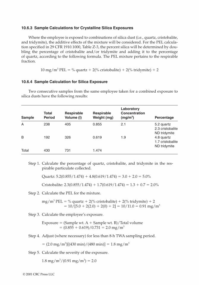
10.6.3 Sample Calculations for Crystalline Silica Exposures
Where the employee is exposed to combinations of silica dust (i.e., quartz, cristobalite,and tridymite), the additive effects of the mixture will be considered. For the PEL calcula-tion specified in 29 CFR 1910.1000, Table Z-3, the percent silica will be determined by dou-bling the percentage of cristobalite and/or tridymite and adding it to the percentage of quartz, according to the following formula. The PEL mixture pertains to the respirablefraction.
10 mg/m3 PEL � % quartz � 2(% cristobalite) � 2(% tridymite) � 2
10.6.4 Sample Calculation for Silica Exposure
Two consecutive samples from the same employee taken for a combined exposure tosilica dusts have the following results:
LaboratoryTotal Respirable Respirable Concentration
Sample Period Volume (l) Weight (mg) (mg/m3) Percentage
A 238 405 0.855 2.1 5.2 quartz2.3 cristobaliteND tridymite
B 192 326 0.619 1.9 4.8 quartz1.7 cristobaliteND tridymite
Total 430 731 1.474
Step 1. Calculate the percentage of quartz, cristobalite, and tridymite in the res-pirable particulate collected.
Quartz: 5.2(0.855/1.474) � 4.8(0.619/1.474) � 3.0 � 2.0 � 5.0%
Cristobalite: 2.3(0.855/1.474) � 1.7(0.619/1.474) � 1.3 � 0.7 � 2.0%
Step 2. Calculate the PEL for the mixture.
mg/m3 PEL � % quartz � 2(% cristobalite) � 2(% tridymite) � 2� 10/[5.0 � 2(2.0) � 2(0) � 2] � 10/11.0 � 0.91 mg/m3
Step 3. Calculate the employee’s exposure.
Exposure � (Sample wt. A � Sample wt. B)/Total volume� (0.855 � 0.619)/0.731 � 2.0 mg/m3
Step 4. Adjust (where necessary) for less than 8-h TWA sampling period.
� (2.0 mg/m3)[(430 min)/(480 min)] � 1.8 mg/m3
Step 5. Calculate the severity of the exposure.
1.8 mg/m3/(0.91 mg/m3) � 2.0
© 2001 CRC Press LLC
10.7 METALS—WELDING
Where two or more of the following analytes are requested on the same filter, an ICPanalysis may be conducted. However, the industrial hygienist should specify the metals ofinterest in the event samples cannot be analyzed by the Inductively Coupled Plasma (ICP)method. A computer printout of the following analytes may be reported:
• Antimony• Beryllium• Chromium• Cobalt• Copper• Iron• Lead• Manganese• Molybdenum• Nickel• Vanadium• Zinc
If requested, the laboratory can analyze for “solder-type’’ elements, such as
• Antimony• Beryllium• Cadmium• Copper• Lead• Silver• Tin• Zinc
Note: Samples taken during abrasive blasting operations are no longer analyzed by ICPbecause of difficulties with heavy loadings. These samples can be analyzed by atomicabsorption spectrometry (AAS) for specific metals (i.e., Pb, Cd, Cr, Fe).
10.8 GENERAL TECHNIQUE FOR WIPE SAMPLING
10.8.1 Filter Media and Solvents
Consult a CIH for appropriate filter media and solvents. Dry wipes may be used.Solvents are not always necessary, but may enhance removal.
Direct skin wipes should not be taken when high skin absorption of a substance isexpected. Under no conditions should any solvent other than distilled water be used on theskin, on personal protective gear that comes into direct contact with the skin, or on surfacesthat come into contact with food or tobacco products.
Generally, two types of filters are recommended for taking wipe samples:
1. Glass fiber filters (GFF) (37 mm) are usually used for materials that are analyzedby high performance liquid chromatography (HPLC) and often for substances
© 2001 CRC Press LLC
analyzed by gas chromatography (GC). The OCIS chemical sampling informa-tion specifies when GFFs are to be used.
2. Paper filters are generally used for metals. For convenience the Whatman smeartab (or its equivalent) or polyvinyl chloride filters for substances that are unsta-ble on paper-type filters are commonly used.
For some volatile organics, charcoal pads are used.
10.8.2 Wipe Sampling Procedures
Preloading a group of vials with appropriate filters is a convenient method. (TheWhatman smear tabs should be inserted with the tab end out.) Always wear clean plasticgloves when handling filters. Gloves should be disposable and should not be powdered.
Follow these procedures for taking wipe samples:
• If multiple samples are to be taken at the worksite, prepare a rough sketch of theareas or rooms to be wipe sampled.
• Use a new set of clean, impervious gloves for each sample to avoid contamina-tion of the filter by the hand (and the possibility of false positives) and to preventcontact with the substance.
• Withdraw the charcoal pad from the vial. If a damp wipe sample is desired, mois-ten the filter with distilled water or other solvent as recommended by the chosenanalytical laboratory.
• Caution: Skin, PPE, or surfaces that come into contact with food or tobacco prod-ucts must be wiped either dry or with distilled water, never with organic solvents.Skin wipes should not be done for materials with high skin absorption. It is rec-ommended that hands and fingers are the only skin surfaces wiped. Before anyskin wipe is taken, explain why you want the sample and ask the employee aboutpossible skin allergies to the chemicals in the sampling filter or medium. If theemployee refuses, do not force the issue.
• Wipe a section of the surface to be sampled using a template with an open area ofexactly 100 cm2.—For surfaces smaller than 100 cm2 use a template of the largest size possible. Be
sure to document the size of the area wiped. For curved surfaces the wiped areashould be estimated as accurately as possible and then documented.
—Maximum pressure should be applied when wiping.—To ensure that all of the partitioned area is wiped, start at the outside edge and
progress toward the center by wiping in concentric squares of decreasing size.—If the filter/pad dries out during the wiping procedure, rewet the filter (for
wetted filters only).• Without allowing the filter/pad to come into contact with any other surface, fold
the filter/pad with the exposed side in, then fold it over again.• Place the filter/pad in a sample vial.• Cap and number the vial.• Note the number at the sample location on the sketch. Include notes with the
sketch giving any further description of the sample.
At least one blank filter/pad treated in the same fashion, but without wiping, should besubmitted for each sampled area.
© 2001 CRC Press LLC
10.8.3 Special Technique for Wipe Sampling with Acids and Bases
When examining surfaces for contamination with strong acids or bases (e.g., hydrochlo-ric acid, sodium hydroxide), pH paper moistened with water may be used. However, resultsshould be viewed with caution due to potential interference.
10.8.4 Direct-Reading Instruments
For some types of surface contamination direct-reading instruments may be used (e.g.,mercury sniffer for mercury).
10.8.5 Aromatic Amines
Screening may determine the precise areas of carcinogenic aromatic amine contamina-tion. This is an optional procedure.
10.8.6 Special Considerations
Due to their volatility, most organic solvents are not suitable for wipes. Other sub-stances are not stable enough as samples to be wipe-sampled reliably. If necessary, judgesurface contamination by other means, (e.g., by use of detector tubes, photoionization ana-lyzers, or similar instruments).
Some substances should have solvent added to the vial as soon as the wipe sample isplaced in the vial (e.g., benzidine). These substances are indicated with an “X’’ next to thesolvent notation in the ACGIH biological exposure index (BEI).
Do not take surface wipe samples on skin if:
• OSHA or ACGIH shows a “skin’’ notation and the substance has—A skin LD50 of 200 mg/kg or less—An acute oral LD50 of 500 mg/kg or less
• The substance—Is an irritant,—Causes dermatitis or contact sensitization—Is termed corrosive
10.8.6.1 Fluorescent Screening for Carcinogenic Aromatic Amines
As in the case of routine wipe sampling, wear clean, disposable, impervious gloves.Wipe an area of exactly 100 cm2 with a sheet of filter paper moistened in the center with 5 drops of methanol.
• After wiping the sample area, apply 3 drops of fluorescamine (a visualization reagentsupplied by the laboratory upon request) to the contaminated area of the filter paper.
• Place a drop of the visualization reagent on an area of the filter paper that has notcome into contact with the surface. This step marks a nonsample area or blank onthe filter paper adjacent to the test area.
• After a reaction time of 6 min, irradiate the filter paper with 366-nm ultravioletlight.
© 2001 CRC Press LLC

• Compare the color development of the sample area with the nonsample or blankarea. A positive reaction shows yellow discoloration that is darker than the yel-low color of the fluorescamine blank.
• A discoloration indicates surface contamination—a possible aromatic amine car-cinogen. Repeat a wipe sampling of the contaminated areas using the regular sur-face contamination procedure.
The following compounds are some of the suspected carcinogenic agents that can bedetected by this screening procedure:
• 4,4’-Methylene bis(2-chloroaniline)• Benzidine• Alpha-napthylamine• Beta-napthylamine• 4-Aminobiphenyl
10.8.6.2 Alternate Screening Methods for Aromatic Amines
OSHA is testing commercially available kits with wipe pads that contain an aromaticamine indicator. Preliminary evaluations show them to be an adequate screening tool.Their detection limit is approximately 5.0 mg/100 cm2. These kits are more convenient than the fluorescent procedure outlined above, and they eliminate the added hazard ofhandling fluorescamine.
The following compounds are among the suspected agents that can be detectedthrough this screening procedure:
• Methylene dianiline (MDA)• 4,4’-Methylene bis(2-chloroaniline)• Benzidine• Alpha-napthylamine• Beta-napthylamine• 4-Aminobiphenyl• o-Toluidine• Aniline• 2,4-Toluenediamine• 1,3-Phenylenediamine• Napthylenediamine• 2,4-Xylidine• o-Chloroaniline• 3,4-Dichloroaniline• p-Nitroaniline
© 2001 CRC Press LLC
CHAPTER 11
Monitoring for Toxicological Risk
This chapter gives monitoring information when individuals are at greater risk from toxiceffects. These individuals may be immune compromised due to either disease or age (i.e., newborns,children to age three, adults approaching old age). Special emphasis is given to monitoring that canbe accomplished without emotional duress.
Exposure monitoring may be conducted for chemical/physical agents to determinetoxicological and carcinogenic chemical risk or other exposure parameters. The need formonitoring is based on the adequacy of the historical exposure data and the nature of thestress. Exposure monitoring is conducted to characterize personnel exposure where thereis little or no database information or when operation/process conditions have changed.The data are used to assess the need for engineering and/or administrative controls or theuse of protective equipment.
Employees should be notified of the results as soon as possible after the data have beencollected and evaluated. Industrial hygiene reports are issued after completion of the sam-ple collection and analysis portions of the monitoring surveys. Monitoring is performed asspecified in OSHA regulations 29 CFR 1910.1450 (laboratory), 29 CFR 1910.120 (hazardouswaste operations and emergency response), 29 CFR 1926.58 (asbestos, tremolite, antho-phylite, and actinolite), 29 CFR 1910.1028 (benzene), 29 CFR 1910.1027 (cadmium), and anyother situations deemed appropriate.
11.1 TYPES OF SAMPLING
Four types of samples are taken to determine potential or actual exposures to chemicalstresses within the workplace: long-term (8–12 h) TWA samples, short-term samples (5 to60 min), area samples, and wipe tests.
11.1.1 Long-Term Samples
Long-term samples are collected to determine average exposures throughout the typi-cal work shift. Usually four to six samples are sufficient to assess the exposure potential fora job classification.
© 2001 CRC Press LLC
11.1.2 Short-Term Samples
Short-term samples are collected to determine peak exposure potential during thework shift. When long-term samples are higher than expected, short-term samples can helpidentify the specific tasks that possibly produced the high long-term average. Short-termsamples are collected during an operation that lasts from 5 min to 1 h to determine the aver-age exposure potential for the task. Short-term samples are collected for tasks such asgroundwater/soil sampling, underground storage tank inspections, analytical laboratoryoperations, and asbestos sampling/inspections/abatement observation activities. Controlscan then be applied to the situation to reduce the exposure potential for the short-term taskas well as the long-term exposure.
11.1.3 Area Samples
Area samples are collected to identify background levels of airborne contaminants.They are useful in identifying contaminants from vents, open tanks, and other fugitiveemissions. From a practical standpoint they are not generally used to determine personalexposures for unusual circumstances.
For sites defined as hazardous waste sites, additional area monitoring may be required.Monitoring must be conducted before site entry at uncontrolled hazardous waste sites toidentify conditions immediately dangerous to life and health, such as oxygen-deficientatmospheres and areas where toxic substance exposures are above permissible limits.
Accurate information on the identification and quantification of airborne contami-nants is useful for
• Selecting PPE• Delineating areas where protection and controls are needed• Assessing the potential health effects of exposure• Determining the need for specific medical monitoring
After a hazardous waste cleanup operation begins, periodic monitoring of those per-sonnel who are likely to have higher exposures must be conducted to determine if theyhave been exposed to hazardous substances in excess of PELs. Monitoring must also beconducted for any potential condition that is immediately dangerous to life and health orfor higher exposures that may occur as a result of new work operations.
11.1.4 Wipe Samples
Wipe samples are collected to evaluate the tracking of chemicals. Office areas andequipment must be free of potentially harmful chemicals.
11.2 QUALITY CONTROL
Routine quality control procedures will be an integral part of the sampling and analy-sis procedures. Use of blanks, spikes, and routine calibration of equipment will be includedin the quality control of the data.
© 2001 CRC Press LLC
11.3 EXPOSURE EVALUATION CRITERIA
There are many sources for general exposure guidelines. The relevant evaluation crite-ria usually include the OSHA PELs, the recommended threshold limit values (TLVs) of theACGIH, and the NIOSH recommended exposure limits (RELs).
Occupational exposure values are concentrations of airborne substances to which it isbelieved nearly all employees may be exposed throughout their working lifetime withoutsuffering adverse health effects. These values are used as guidelines for evaluating expo-sures. Generally, safety factors are incorporated into the values, but values are not fine linesbetween safe and unsafe labels of exposure. Each individual exposure case must be evalu-ated based on several factors: the airborne concentration and its consistency, the material’swarning properties and its acute/chronic health implications, individual susceptibility,and the significance of other potential exposure routes.
Most values represent TWA airborne concentrations for an 8–12-h workday, 40-hworkweek. Limited exposures greater than the value are acceptable for most materials aslong as the 8-h TWA exposure does not exceed the value. For some materials excursion val-ues have also been established if the material could cause adverse effects from brief expo-sures to elevated concentrations. Frequency or duration limits are not established for theexcursion values; rather, professional judgment should be used to assess the health impli-cations of each individual exposure situation. A few materials have ceiling value limits,which indicate that the exposures should never exceed the ceiling value, even for brief peri-ods. A “C’’ notation next to the value indicates the ceiling value.
Occupational exposure values are usually expressed in parts per million, volume byvolume, or in milligrams of contaminant per cubic meter of air.
A designation of “A1’’ or “A2’’ indicates that the material is a confirmed human car-cinogen (A1) or suspected human carcinogen (A2). A “skin’’ or “S’’ notation next to thevalue indicates that the material may be absorbed through the skin and may cause effectsother than at the point of contact with the skin. For these materials skin contact may con-tribute to the overall exposure; therefore, inhalation exposure alone may not adequatelycharacterize total exposure.
11.4 EXAMPLES OF CHEMICALS THAT REQUIRE MONITORING
11.4.1 Carbon Monoxide (CO)
CO is a colorless, odorless gas generated by the combustion of common fuels with aninsufficient supply of air or where combustion is incomplete. It is often released by accidentor the improper maintenance or adjustment of burners or flues in confined spaces and byinternal combustion engines. Called “the silent killer,’’ CO poisoning may occur suddenly.
11.4.2 Hydrogen Sulfide (H2S)
H2S, a colorless gas, initially smells like rotten eggs. However, the odor cannot be takenas a warning because sensitivity to smell disappears quickly after breathing only a smallquantity of the gas. H2S is flammable and explosive in high concentrations.
Sudden poisoning may cause unconsciousness and respiratory arrest. In less suddenpoisoning symptoms are nausea, stomach distress, eye irritation, belching, coughing,headache, and blistering of lips.
© 2001 CRC Press LLC
11.4.3 Sulfur Dioxide (SO2)
The combustion of sulfur or compounds containing sulfur produces SO2, a pungent,irritating gas. Severe exposures may result from loading and unloading tank cars or cylin-ders, from rupturing or leaking pipes or tubing, and fumigation.
11.4.4 Ammonia (NH3)
NH3 is a strong irritant that can produce sudden death from bronchial spasms. Smallconcentrations that do not produce severe irritation are rapidly passed through the respi-ratory tract and metabolized so that they no longer act as ammonia. Ammonia can beexplosive if the contents of a tank or refrigeration system are exposed to an open flame.
11.4.5 Benzene
Often the contaminant of greatest concern on a petroleum spill or remediation site isbenzene with a PEL of 1 ppm. Benzene (C6H6) is a common component of gasoline andpetroleum products, especially the higher-octane gasolines. Benzene is a colorless to light-yellow liquid with an aromatic odor. Exposure can cause symptoms of dizziness, light-headedness, headaches, and vomiting. High exposures may cause convulsions and comaand irregular heartbeat. Repeated exposure can damage the blood-forming organs, caus-ing aplastic anemia. Long-term exposure can cause drying and scaling of the skin. Benzeneis an A1 carcinogen proven to cause leukemia in humans.
Benzene released into the soil is subject to rapid volatilization near the surface. Thebenzene that does not evaporate will be highly to very highly mobile in the soil and mayleach to groundwater. Benzene is uniformly distributed 1–10 cm through the soil and hasa half-life of 7.2 to 38.4 days. If benzene is released into water, rapid volatilization mayoccur. Benzene will not adsorb to particulates. Biodegradation may occur. Benzenereleased to the atmosphere will exist in the vapor phase. Benzene is fairly soluble in waterand is removed from the atmosphere by rain.
The first step if soil or water contamination by petroleum products is suspected is toassume that exposure during sampling will occur. Samplers will don HEPA-OV cartridge-equipped air-purifying respirators (APRs) and take soil samples. In lieu of laboratoryanalysis immunoassay field methods may be used.
When sustained benzene PID readings exceed 5 ppm, work must cease, and the EZallowed to ventilate. Retesting and assigning of respirator protection may commence aftera 30-min ventilation interval.
11.4.6 Hydrogen Cyanide or Hydrocyanic Acid (HCN)
HCN is an extremely rapid poison that interferes with the respiratory system andcauses chemical asphyxia. Liquid HCN is an eye and skin irritant.
11.4.7 Lead
Lead is a heavy, soft gray metal. Lead exposure can cause a variety of health problems.The earliest symptoms may be tiredness, trouble sleeping, stomach problems, constipation,headaches, irritability, and depression. Higher levels may cause aching and weakness in
© 2001 CRC Press LLC
the arms and legs, trouble concentrating and remembering things, and a low blood count(anemia). Lead exposure increases the risk of high blood pressure.
Repeated exposure can result in the buildup of lead in the body. This lead buildup ispartially deposited in the bones. When referring to the amount of lead in the bones, theterm body burden is often used. Body burden implies that the body is storing lead ratherthan excreting the lead through waste products or carrying the lead in the blood.
Because this lead is not being excreted in urine or carried in the blood, urine and bloodsamples will not reveal the total lead present in the body. Blood samples are an indicationof lead exposure for approximately 2–4 weeks after the exposure incident. Then, as thebody begins to deposit lead in the bone, blood samples become a less accurate indicationof lead exposure.
The lead in bone may be released from the bone tissue when certain processes withinthe body occur. One of these processes occurs when the body begins to use the calciumstored in bone as a substitute for calcium lacking in the diet. When calcium is removedfrom bone, the lead held in the bone tissue also begins to enter the bloodstream. Thisprocess is one of the reasons why women of childbearing age are cautioned to avoid expo-sure to lead. Lead is a probable terratogen, which means that a developing fetus can beseverely injured by exposure to lead.
Lead can cause serious permanent kidney or brain damage when exposures are high.Lead exposure can occur by inhalation or ingestion.
Lead if released or deposited in the soil will be retained in the upper 2–5 cm of soil,especially in soils with at least 5% organic matter or a pH of 5 or above. Leaching is not asignificant process under most circumstances. Lead enters water from runoff or waste-water. Lead is effectively removed from the water column to the sediment by adsorption toorganic matter and clay minerals. When released to the atmosphere, lead will generallyoccur as a dust or becomes adsorbed to particulate matter.
When lead dust levels reach 5 mg/m3 (100 times 0.05 mg/m3), air respirators must beworn. In all areas where visible dust is present and there is soil staining or other obvioussigns of contamination (drum fragments, intact drums, chemical containers, buried treatedwood), suspect lead contamination. Begin testing for both lead and PAH soil-adsorbedcomponents using 2 l/min flow rate through filter-loaded cassettes. Filter analyticals forboth lead and PAHs will be requested of the testing laboratory.
The OSHA PEL is 50 �g/m3 (0.050 mg/m3); the AL is 30 �g/m3 (0.030 mg/m3). On-sitework may expose workers above the PEL. Biological monitoring of exposure is necessaryif the airborne concentration exceeds 30 �g/m3 (0.030 mg/m3) for 30 days in 12 consecu-tive months.
On-site contaminant concentrations could exceed inhalation exposure maximumlimits for lead. Consequently, HEPA cartridge-equipped APRs will be required for all per-sonnel in any lead contaminant area during sampling activities. Air monitoring will beperformed to assess the degree of exposure to lead particulates during on-site investigativework and to confirm the adequacy of the level of PPE being used.
Employee exposure is the exposure that would occur if the employee was not using arespirator. Full shift (for at least 7 continuous hours) personal samples, including at leastone sample for each shift for each job classification in each work area, will be conducted inareas where lead contaminated soil is expected. Full shift personal samples will be repre-sentative of the monitored employee’s regular, daily exposure to lead. Monitoring for theinitial determination may be limited to a representative sample of the employees who theemployer reasonably believes are exposed to the greatest airborne concentrations of lead inthe workplace.
© 2001 CRC Press LLC
11.4.8 Flammable Chemicals
All flammable chemicals should be stored and used away from ignition sources suchas open flames, cigarettes, and sparking tools. All vessels containing flammable chemicalswill be grounded in accordance with OSHA and NFPA regulations and codes. Appropriatefire-extinguishing material will be kept available for fire emergencies. Flammable chemi-cals also pose a toxicological risk because the burn event may create new chemical formu-lations on a site. These chemicals may be spread either as out-gassing from the fire or viaadsorption to fire smoke particulates and subsequent dispersion.
Flammable and combustible chemicals are defined by NFPA as materials that will rap-idly or completely vaporize at atmospheric pressure and normal ambient temperature orthat are readily dispersed in air and burn readily.
This following chart describes the various levels of flammable materials:
4 GasesCryogenic materials
• Any liquid or gaseous material that is a liquid while under pressure and has aflash point below 73°F (22.8°C) and a boiling point below 100°F (37.8°C) (ClassIA flammable liquids)
• Materials that on account of their physical form or environmental conditions canform explosive mixtures with air and that are readily dispersed in air, such asdusts of combustible solids and mists of flammable or combustible liquid droplets
3 Liquids and solids can be ignited under almost all ambient temperature conditions.Materials in this classification produce hazardous atmospheres with air under almost allambient temperatures or, though unaffected by ambient temperatures, are readily ignitedunder almost all conditions. This classification should include the following:
• Liquids having a flash point below 73°F (22.8°C) and having a boiling point at orabove 100°F (37.8°C)
• Liquids having a flash point at or above 73°F (22.8°C) and below 100°F (37.8°C)(Class IB and Class IC flammable liquids)
• Solid materials in the form of coarse dusts that may burn rapidly, but generally donot form explosive atmospheres with air
• Solid materials in a fibrous or shredded form that may burn rapidly and createflash fire hazards, such as cotton, sisal, and hemp
• Materials that burn with extreme rapidity, usually by reason of self-containedoxygen (e.g., dry nitrocellulose and many organic peroxides)
• Materials that ignite spontaneously when exposed to air
2 Materials that must be moderately heated or exposed to relatively high ambienttemperatures before ignition can occur. Materials in this classification would not undernormal conditions form hazardous atmospheres with air, but under high ambienttemperatures or under moderate heating may release vapor in sufficient quantities toproduce hazardous atmospheres with air. This classification should include the following:
• Liquids having a flash point above 100°F (37.8°C), but not exceeding 200°F(93.4°F)
• Solids and semisolids that readily give off flammable vapors
1 Materials that must be preheated before ignition can occur. Materials in this classificationrequire considerable preheating, under all ambient temperature conditions, before ignitionand combustion can occur. This classification should include the following:
• Materials that will burn in air when exposed to a temperature of 1500°F(815.5°C) for a period of 5 min or less
© 2001 CRC Press LLC
• Liquids, solids, and semisolids having a flash point above 200°F (93.4°C)This classification includes most ordinary combustible materials.
0 Materials that will not burn. This classification should include any material that will not burnin air when exposed to a temperature of 1500°F (815.5°C) for a period of 5 min.
11.4.9 Reactive Hazards—Oxidizers
Oxidizers are chemicals that create a persistent fire when mixed with a flammable orcombustible material. All oxidizer chemicals should be segregated from all flammable and combustible materials, including solvents, cleaners, paints, rags, paper, and wood.Personnel handling oxidizers will wear proper PPE and equipment.
Acid gases may be oxidizers in some situations and should be treated as such duringmonitoring. Remember the term oxidation means a chemical’s ability to take electrons fromanother molecule. Acids, due to their positive valence potential, have the ability to takeelectrons from other chemicals. Thus the effects of oxidation may occur without what wetraditionally think of as oxygen-bearing compounds being present.
11.4.10 Paint
Paint and painting supplies often contain a variety of hazardous substances, such asflammable solvents and toxic ingredients. Organic paints and paint thinners often containflammable solvents that must be managed as other flammable chemicals. Aerosol spraysand epoxy resins sometimes contain toxic substances, including toluene diisocyanatates,and must therefore be scrutinized when the paint is initially purchased. Respiratory pro-tection and/or adequate ventilation must always be used when working with paints.
11.4.11 Cleaning Supplies
Everyday common cleaning supplies must not be overlooked in a “right-to-know’’compliance program. Corrosives and toxics are often used as ingredients in cleaningsupplies.
11.4.12 Compressed Gases
Compressed gases must be managed to prevent accidental damage to the cylinder orthe uncontrolled release of its gaseous contents.
• Damaged cylinders can become “unguided missiles.’’• Uncontrolled releases of compressed gases could lead to asphyxiation.• Stationary cylinders should be secured to walls or benches and should not be
moved without a valve protector in place.
11.5 CONFINED SPACE MONITORING
Entry into any confined space is prohibited until its atmosphere has been tested fromthe outside. If entry is authorized, entry conditions will be continuously monitored in theareas where authorized entrants are working. The atmosphere within the space will bemonitored using an O2/CGI monitor equipped with CO toxin sensors.
© 2001 CRC Press LLC
Assume that every confined space has an unknown, hazardous atmosphere. Under nocircumstances should anyone ever enter or even stick his or her head into a confined spacefor a “quick look.’’ Such an action constitutes entry into the confined space and can exposethe entrant to hazardous and possibly deadly atmospheres.
• The oxygen level must be determined first because most CGIs are oxygen depend-ent and will not provide reliable readings in an oxygen deficient atmosphere.
• Equipment for continuous monitoring of gases and vapors will be explosionproof and equipped with an audible alarm or danger-signaling device that willalert employees when a hazardous condition develops.
• Instruments used for testing the atmosphere in a confined space will be selectedfor their functional ability to measure hazardous concentrations.
• Instruments will be calibrated in accordance with the manufacturer’s instruc-tions. Each calibration will be recorded, filed, and available for inspection for 1 year after the last calibration date.
11.5.1 Entry Permits
Ongoing monitoring of the atmosphere will be performed in accordance with a con-fined space entry permit. When the atmospheric concentration of any substance cannot bekept within tolerance levels (i.e., PELs), then the employee will wear an approved respira-tor or leave the permit space.
The entry permit is revoked when the direct reading instrument being used or someother circumstance indicates that conditions in the space are no longer acceptable for entry.When an entry permit has been revoked because unacceptable conditions have arisen in apermit space, subsequent entry may not be made by special permit until the space is reeval-uated by the entry supervisor.
11.5.2 Bump Testing
Each day before monitoring a space, the instrument must be bump tested. The purposeof bump testing is to assure the readings on the instrument display are within the limitsstated on the calibration cylinder. Bump testing is accomplished by
• Turning the instrument on• Allowing the instrument to warm up for at least 10 min• Passing a known concentration of calibrated gas through the pump module
across the sensors
Instruments will only be used by employees who have been trained in the proper opera-tion, use, limitations, and calibration of the monitoring instrument.
11.5.3 Monitoring for LEL and O2 Levels
In any confined space classified as a class II or class III hazardous location according tothe National Electrical Code, Article 500, Sections 6 and 7, a fire watch will be establishedas part of the entry procedure. In such areas surface dust and fibers will be removed, and no work initiated until the airborne particulate level is below 10% of the LEL for thematerial.
© 2001 CRC Press LLC

When combustible dusts or ignitable fibers/filings are present, all equipment and ven-tilation systems used in the confined space will comply with Articles 502 and 503 of theNational Electrical Code.
11.5.4 Isolation
If isolation of the space is not feasible because the space is large or is part of a continu-ous system (such as a sewer), preentry testing will be performed to the extent possiblebefore entry is authorized. Any necessary additional tests will be selected and performedto the satisfaction of the entry supervisor (i.e., substance-specific detectors should be usedwhenever actual or potential contaminants have been identified).
11.5.5 Confined Space—Cautionary Statements
If possible, do not open the entry portal to the confined space and draw the samplethrough a small entry port leading into the confined space. Sudden changes in atmosphericcomposition within the confined space could cause violent reactions, or dilute the contam-inants in the confined space, giving a false low initial gas concentration.
Comprehensive testing should be conducted in various locations within the work area. It is important to understand that some gases or vapors are heavier than air (e.g.,hydrogen sulfide) and some gases (e.g., methane) are lighter than air. Therefore, all areas(top, middle, bottom) of a confined space must be tested with properly calibrated testinginstruments.
The results of atmospheric testing will have a direct impact on the selection of protec-tive equipment necessary for the tasks in the confined area. These results may also dictatethe duration of worker exposure to the environment of the space or whether an entry willbe made at all.
11.5.6 Stratified Atmospheres
When monitoring for entries involving a descent into atmosphere that may bestratified,
• The atmosphere envelope should be tested a distance of approximately 4 ft in thedirection of travel and to each side.
• The entrant’s rate of progress should be slowed to accommodate the samplingspeed and detector response of the sampling probe.
11.6 WELDING
The most significant hazard in the welding process is the generation of fumes andgases. The amount and type of fumes and gases involved will depend on the weldingprocess, the base material, the filler material, and the shielding gas. The toxicity of the con-taminants depends primarily on contaminant concentrations and the physiologicalresponses of the human body. A number of potentially hazardous materials are used influxes, coatings, coverings, and filler metals. Some of these include beryllium, cadmium,cleaning compounds, fluorine compounds, lead, mercury, stainless steels, and zinc. The
© 2001 CRC Press LLC
suppliers of these materials must determine if any hazard is associated with welding and cutting and provide warnings through tags, signs, etc. on boxes and containers.Employers also must follow the ventilation requirements specified in the standards forthese materials.
Mechanical ventilation must be provided when welding or cutting is done on othermetals. Mechanical local exhaust ventilation may be provided either by means of freelymovable hoods or fixed enclosures with tops to provide sufficient ventilation.
11.6.1 Effects of Toxic Gases
Exposure to various toxic gases generated during welding processes may produce oneor more of the following effects:
• Inflammation of the lungs (chemical pneumonitis)• Pulmonary edema (swelling and accumulation of fluids)• Emphysema (loss of elasticity of the lungs) (A very small percentage of emphy-
sema is caused by occupational exposure.)• Chronic bronchitis• Asphyxiation
The major toxic gases associated with welding are classified as primary pulmonaryand nonpulmonary. Cleaning compounds because of their properties often require specialventilation precautions following the manufacturer’s instructions. Degreasing operationsmay involve chlorinated hydrocarbons; these liquids or vapors should be kept away frommolten weld metal or the arc. Also keep them away from ultraviolet radiation from weld-ing operations.
11.6.2 Ventilation
Local exhaust or general ventilating systems must be provided and arranged to keepthe amount of toxic fumes, gases, or dust below the maximum allowable concentration asspecified in OSHA’s standard on air contaminants (29 CFR 1910.1000).
Natural ventilation is acceptable for welding, cutting, and related processes, where thenecessary precautions are taken to keep the welder’s breathing zone away from the plumeand where sampling of the atmosphere shows that concentrations of contaminants arebelow unsafe levels. Natural ventilation often meets the conditions, where the necessaryprecautions are taken to keep the welder’s breathing zone away from the plume and all ofthe following conditions are met:
• Space of more than 10,000 ft3 (284 m3) per welder is provided.• Ceiling height is more than 16 ft (5 m).• Welding is not done in a confined space.• Welding space does not contain partitions, balconies, or other structural barriers
that significantly obstruct cross-ventilation. Welding space refers to a building oran enclosed room in a building, not a welding booth or screened area that is usedto provide protection from welding radiation.
• Materials covered above are not present as deliberate constituents.
The only way to assure that airborne contaminant levels are within the allowablelimits, however, is to take air samples at the breathing zones of the personnel involved.
© 2001 CRC Press LLC
Mechanical ventilation includes local exhaust, local forced, and general area mechani-cal air movement. Local exhaust ventilation is preferred.
• Local exhaust ventilation means fixed or movable exhaust hoods placed as nearas practicable to the work area to maintain a capture velocity sufficient that keepsairborne contaminants below unsafe limits.
• Local forced ventilation means a local air-moving system (such as a fan) placedso that it moves the air at right angles (90°) to the welder (across the welder’sface). It should produce an approximate velocity of 100 ft/min (30 m/min) andbe maintained for a distance of approximately 2 ft (600 mm) directly above thework area. Precautions must be taken to insure that contaminants are not dis-persed to other work areas.
General mechanical ventilation may be necessary to maintain the general backgroundlevel of airborne contaminants below the levels referred to or to prevent the accumulationof explosive gas mixture. Examples of general mechanical ventilation are roof exhaust fans,wall exhaust fans, and similar large area air movers. General mechanical ventilation is notusually as satisfactory for health hazard control as local mechanical ventilation. It is oftenhelpful, however, when used in addition to local ventilation.
11.6.3 Ventilation in Confined Spaces during Welding
All welding and cutting operations carried out in confined spaces must be adequatelyventilated to prevent the accumulation of toxic materials or possible oxygen deficiency.Oxygen should never be used for ventilation. When it is impossible to provide adequateventilation, airline respirators or hose masks approved by the NIOSH must be used.
In areas immediately hazardous to life, hose masks with blowers or self-containedbreathing equipment that has been approved by the NIOSH must be used. Where weldingoperations are being carried out in a confined space, and welders and helpers are providedwith hose masks or hose masks with blowers or self-contained breathing equipment, anemployee must be stationed outside the space to insure the safety of those working within.
11.6.4 Fume Avoidance
Welders and cutters must take precautions to avoid breathing the fume plume directlyby adjusting the position of the work or the head or by ventilation that directs the plumeaway from the face.
11.6.5 Light Rays
Electric arcs and gas flames produce ultraviolet and infrared rays; continuous or repetitious ultraviolet exposure has a harmful effect on the eyes and skin. The usual ultra-violet effect is “sunburn’’ of the surface of the eye, which is painful and disabling, but tem-porary in most instances. However, permanent eye injury may result from looking directlyinto a very powerful arc without eye protection, due to the effect of visible and nearinfrared radiation. Ultraviolet radiation may also produce the same effects on the skin as asevere sunburn.
The production of ultraviolet radiation is high in gas-shielded arc welding. For exam-ple, a shield of argon gas around the arc doubles the intensity of the ultraviolet radiation,
© 2001 CRC Press LLC

and, with the greater current densities required (particularly with a consumable electrode),the intensity may be 5–30 times as great as with nonshielded welding, such as covered elec-trode or gas-shielded metal arc welding.
11.6.6 Infrared Rays
Infrared radiation has the effect only of heating the tissue with which it comes in con-tact. If the heat is not enough to cause an ordinary thermal burn, there is no harm.
Whenever possible, arc-welding operations should be isolated so that other workerswill not be exposed to either direct or reflected rays. Arc-welding stations for regular pro-duction work can be enclosed in booths if the size of the work area permits. The inside ofthe booth should be coated with a paint that is nonreflective to ultraviolet radiation andprovided with portable flameproof screens similarly painted or with flameproof curtains.Booths should be designed to permit air circulation at the floor level and adequate exhaustventilation.
11.6.7 Noise
In welding and cutting and the associated operation, noise levels may exceed the per-missible limits. Personal hearing protective devices may be needed.
11.6.8 Gas Welding and Cutting
Mixtures of fuel gases and air or oxygen in gas welding and cutting must not be per-mitted, except immediately prior to consumption, to guard against explosions. Acetylenemust not be generated, piped (except in approved cylinder manifolds), or used at a pres-sure higher than 15 lb/in.2 gauge or 30 lb/in.2 absolute. Only approved apparatus such astorches, regulators, or pressure-reducing valves, acetylene generators, and manifolds mustbe used. All portable cylinders used for storage and shipment of compressed gases must beconstructed and maintained according to Department of Transportation regulations.
© 2001 CRC Press LLC
CHAPTER 12
Risk Communication and Environmental Monitoring
When results must be communicated to the public, Chapter 12 provides proven methodologiesfor explaining the relevancy and adequacy of monitoring results.
This chapter includes regulations, responsibilities, and compliance requirements asso-ciated with air pollution emissions from stationary and mobile sources. The significanttypes and sources of air pollution emissions include the following:
• Particulates, SO2, NOx, CO, VOCs, and hazardous air pollutants from fuel burn-ing at steam and hot water generation plants and boilers
• Particulates and toxic air emissions from the operation of hazardous waste; gen-eral waste; classified material; and medical, pathological, and/or infectiouswaste incinerators
• Particulates, CO, metals, and toxic air pollutant emissions from open burning andopen detonation operations
• VOC vapor emissions from the operation of degreasers and other processes(paint stripping and metal finishing) that use solvents
• CO emissions from vehicles and equipment operated on the installation/instal-lation facility
• Fugitive particulate emissions from training activities and construction/demolition operations
Most facilities have air emissions sources in one or more of these categories.
12.1 FEDERAL LEGISLATION
12.1.1 The Clean Air Act Amendments of 1990 (CAAA90)
Public Law (PL) 101-549 (42 U.S. Code [USC] 7401-7671q), known as CAAA90, is thecurrent federal legislation regulating the prevention and control of air pollution. The acthas seven major titles that address various aspects of the national air pollution controlprogram:
© 2001 CRC Press LLC
• Title I describes air pollution control requirements for geographic areas in theU.S. with respect to the National Ambient Air Quality Standards (NAAQS).
• Title II deals mostly with revised tailpipe emission standards for motor vehicles.These requirements compel automobile manufacturers to improve design stand-ards to limit CO, hydrocarbon, and NOx emissions. Oxygenated gasoline is requiredin cities with the worst ozone and CO nonattainment. Reformulated gasoline andgasoline with reduced Reid vapor pressure is used in ozone non-attainment areas.
• Title III potentially contains the most costly requirement of CAAA90. Its majorelements deal with hazardous air pollutants through control of routine emissionsand contingency planning for accidental releases.
• Title IV addresses acid deposition control and applies only to commercial utilitiesthat produce electricity for sale.
• Title V outlines the requirement of having states issue federally enforceable oper-ating permits to major stationary sources. The permits are designed to enhancethe ability of the EPA, state regulatory agencies, and private citizens to enforcethe requirements of CAAA90. Permits will also be used to specify operation andcontrol requirements for stationary sources.
• Title VI limits the emissions of chlorofluorocarbons (CFCs), halons, and otherhalogenated chemicals that contribute to the destruction of stratospheric ozone.These requirements closely follow the control strategies recommended in June1990 by the second meeting of parties to the Montreal Protocol. Also, procure-ment of ozone-depleting substances is restricted by Department of Defenseacquisition policies.
• Title VII describes civil and criminal penalties that may be imposed for the viola-tion of new and existing air pollution control requirements. This title also givesauthority to the EPA to issue field citations for many types of violations.
12.1.2 The Federal Water Pollution Control Act
The Federal Water Pollution Control Act, commonly known as the Clean Water Act(CWA), governs the control of water pollution in the U.S. The objective of this act is torestore and maintain the chemical, physical, and biological integrity of the nation’s waters.
The CWA led to the promulgation of regulations concerning the incineration of sewagesludge. The implementing regulations for the control of emissions from the incineration ofsewage sludge are found in 40 CFR 503.40 through 503.48.
12.1.3 Resource Conservation and Recovery Act (RCRA) of 1976
The RCRA is the federal law that governs the disposal of solid waste. Subtitle D of theRCRA, as last amended in November 1984, PL 98-616, 42 USC 6941-6949a, establishes fed-eral standards and requirements for state and regional authorities respective to solid wastedisposal. The objectives of this subtitle are to assist in developing and encouragingmethods for the disposal of solid wastes that are environmentally sound and that maxi-mize the utilization of valuable resources recoverable from solid waste. The objectives areto be achieved through federal technical and financial assistance to states and regionalauthorities for comprehensive planning (42 USC 6941).
© 2001 CRC Press LLC
12.1.4 State/Local Regulations
The primary mechanisms regulating air pollutant emissions are state air quality regu-lations. These regulations will normally follow the federal guidelines for state programsand will have many similar features. However, depending on the type and degree of airpollutant problems within a state/region, the individual regulations will vary. As an exam-ple, ozone problems are widespread in California; therefore, various local authorities inthat state have stringent VOC emission requirements. The state of North Dakota has nosuch problem and, therefore, has fewer and less stringent VOC regulations.
A permit is normally required for new, expanded, or modified sources of air pollutants.There are federal, state, and local permits required for various sources. Large sources, andthe installation/CW facility as a whole, may require a permit to operate. States review per-mit applications for the construction or operation of many sources. Open burning permitsare typically handled locally.
Some state regulations apply directly to some installations/CW facilities and opera-tions without requiring a permit. At a minimum state regulations should be reviewed forthe following activities:
• Fugitive dust emissions• Control of particulate emissions from the transportation of refuse or materials in
open vehicles• Certification requirements for boiler operators• Emissions and emission control requirements for the operation of existing fossil
fuel-fired steam generators• Open burning• Vehicle exhaust emissions testing• Spray painting of vehicles, buildings, and/or furniture• Certification of vehicles transporting VOC liquids• Paving of roads and parking lots• Toxic air pollutants• Operation of cold cleaners, degreasers, and open-top vapor degreasers• Vapor control requirements for fuel pumps
12.2 KEY COMPLIANCE REQUIREMENTS
12.2.1 Steam-Generating Units [greater than 29 MW (100 MBtu/h)]
Steam-generating units (with a capacity � 29 MW) that started construction or modi-fication after June 19, 1984 are required to meet emissions limitations for particulates, SO2,and NOx. The limit that applies is dependent on the type of fuel being burned. Records ofthe amounts of fuel combusted each day are required (40 CFR 60.40b through 49b).
12.2.2 Steam-Generating Units [2.9 MW (10 MBtu/h) to 29 MW ]
Steam-generating units (with a maximum design heat input capacity � 2.9 MW but � 29 MW) that started construction, modification, or reconstruction after June 3, 1989are required to limit emissions of SO2 and particulates. Emission rates must be monitored.Installations/CW facilities are required to submit excess emission reports for any calendar
© 2001 CRC Press LLC
quarter in which the facility exceeds opacity limits. If an installation/CW facility does notexceed the limits in a given year, it is required to file semiannual reports affirming this fact.Installations/CW facilities required to meet SO2 emission limits are also required to submitquarterly reports (40 CFR 60.40c through 60.48c).
12.2.3 Fuel-Burning Facilities
Fuel-burning facilities (with heat input � 73 MW [250 BTU/h]) constructed or modi-fied after August 17, 1971 are required to limit emissions of particulates, SO2, and NOx.Monitoring of these pollutants and fuel analysis is also required (40 CFR 60.44 and 60.45).
12.2.4 Stationary Gas Turbines
Stationary gas turbines (with a heat input � 10.7 gJ/h [10 MBtu/h]) that were con-structed or modified after October 3, 1977 are required to limit the emissions of NOx andSO2. In addition to the emissions, the sulfur and nitrogen content of the fuel being firedmust also be monitored (40 CFR 60.330 through 60.335).
12.2.5 Municipal Waste Combustor
Municipal waste combustors (with a capacity � 225 metric tons [250 t] per day) thatstarted construction or modification after December 20, 1989 are required to limit theamounts of dioxin/furan, SO2, hydrogen chloride, CO, and NOx emitted. The chief munic-ipal waste combustor operator and shift supervisors are required to be certified to operatethe combustor, and there must be an operating manual that is updated yearly (40 CFR60.50a through 60.58a).
12.2.6 Incinerators
Incinerators (with a charging rate of � 45 metric tons/day [50 t/day]) that started con-struction or modification after August 17, 1971 are required to meet emissions limitationsfor particulates. Additionally, they must maintain records of daily charging rates and hoursof operation (40 CFR 60.50 through 60.54).
12.2.6.1 Sewage Sludge Incinerators
Sewage sludge incinerators (that combust � 1000 kg/day [2205 lb/day]) that wereconstructed or modified after June 11, 1973 are required to limit their emissions of par-ticulates. Monitoring devices are required, depending on what type of incinerator theinstallation/CW facility operates. Semiannual reports are required (40 CFR 60.150 through60.156).
12.2.6.2 Beryllium Incinerators
Incinerators for beryllium-containing waste, beryllium, beryllium oxide, or berylliumalloys cannot emit into the atmosphere more than 10 g (0.32 oz) of beryllium over a 24-hperiod. Records of emissions tests are to be kept for 2 years (40 CFR 61.30 through 61.34).
© 2001 CRC Press LLC
12.2.6.3 Incineration of Sewage Sludge
Installations/facilities with incinerators that fire sewage sludge must meet specificemissions standards for beryllium emissions, mercury emissions, and hydrocarbons. Theincinerators must have continuous monitoring devices for hydrocarbons and oxygen in theexit gas, with continuous monitoring for combustion temperature as specified by the per-mitting authority. Assorted reports must be submitted and records kept (40 CFR 503.40through 503.48).
12.2.7 Gasoline Dispensing
Leaded gasoline should not be introduced into any motor vehicle that is labeled“Unleaded gasoline only” or that is equipped with a gasoline tank filler inlet designed forunleaded gasoline. Fuel pumps are required to display signs stating the type of fuel in eachpump and that only unleaded gas can be introduced into labeled vehicles. The nozzles ofthe pumps must be properly sized. Depending on whether the oxygenated gas is still in thecontrol period, or the area has an oxygenated gasoline program with a credit program,pumps dispensing oxygenated gasoline must have required labels.
Since 1992, during high ozone seasons and regulatory control periods, gasoline cannotbe sold, offered for sale, imported, dispensed, supplied, or transported that exceeds theReid vapor pressure standards. No diesel fuel is to be distributed, transported, offered forsale, or dispensed for use in motor vehicles unless it is free of the dye 1,4-dialkylamino-antraquinone and has an octane index of at least 40 or a maximum aromatic content of 35 volume percent and a sulfur percentage of less than 0.05% [40 CFR 80.22(a), 80.22(d),80.22(e), 80.24(a)(1), 80.27(a)(2), 80.35, 80.80(d), and 80.29(a)].
12.2.8 Rotogravure Printing Presses
Rotogravure printing presses, except for proof presses, that started construction ormodification after October 28, 1980 are required to ensure that gases are not being dis-charged with VOCs equal to more than 16% of the total mass of VOC solvent and water usedat that press during any one performance averaging period (40 CFR 60.430 through 60.435).
12.2.9 Fugitive Emissions
The emission of volatile hazardous air pollutants (VHAPs), vinyl chloride, and ben-zene is to be managed, monitored, and controlled according to specific requirements. Theserequirements include taking certain actions when a leak is detected, ensuring that certainrecords are maintained, ensuring that pumps and compressors meet certain standards, andthat pressure relief devices in gas/vapor service have no detectable emissions except dur-ing pressure releases. Valves and lines in VHAP service must be monitored monthly andrepairs done within 15 days of leak detection. Systems and devices used to control VHAPemissions must recover vapors with a 95% efficiency or greater. Enclosed combustiondevices are to be designed and operated to reduce VHAP and benzene emissions, andclosed-vent systems will have no detectable emissions (40 CFR 61.240 through 61.242-10,61.246, and 61.247).
© 2001 CRC Press LLC
12.2.10 Sulfuric and Nitric Acid Plants
Sulfuric and nitric acid plants are required to limit their emissions and install continu-ous monitoring systems (40 CFR 60.70 through 60.85).
12.2.11 CFCs and Halons
To protect the ozone layer, no person repairing or servicing motor vehicles for paymentcan service a motor vehicle air-conditioner (MVAC) in any way that affects the refrigerantunless they have been trained and certified and are using approved equipment.Additionally, persons who maintain, service, or repair appliances, except MVACs, and per-sons who dispose of appliances, except for small appliances, room air conditioners,MVACs, and MVAC-like appliances are required to be certified through an approved tech-nician certification program.
As of November 15, 1992 no class I or class II substances suitable for use in motor vehi-cles as a refrigerant can be sold or distributed in any container that is less than 20 lb (9 kg) to any person unless that person is trained and certified. Installations/facilities thatsell class I or class II substances suitable for use as a refrigerant in containers of less than 20lb (9 kg) are required to display a sign couched in specific language. Servicing appliancescontaining CFCs and halons is required to be done in a manner to prevent emissions [40CFR 82.34(a), 82.34(b), 82.42(a) through 82.42(c), and 80.150 through 80.166].
12.2.12 Degreasing Operations
Batch cold-cleaning machines, batch vapor-cleaning machines, and in-line-cleaningmachines must have tightly fitting covers and assorted emission control devices to preventexcess emissions. Operators of these types of units are also required to submit notifications,operating reports, exceedance reports, and solvent use reports. These regulations specifi-cally apply to each individual batch vapor, in-line vapor, in-line cold, and batch coldsolvent cleaning machine that uses any solvent containing methylene chloride, per-chloroethylene, trichloroethylene, 1,1,1-trichloroethane, carbon tetrachloride, chloroform,or any combination of these halogenated Hazardous Air Pollutants (HAP) solvents, in totalconcentration greater than 5% by weight, as a cleaning and/or drying agent. Special sam-pling pumps are available to monitor grease dispersion (Figure 12.1).
12.3 KEY COMPLIANCE DEFINITIONS
(Note: The definitions provided are specific to the regulations cited above. Other reg-ulations may define the terms differently.)
Across Rod Solvent-Cleaning Machine: a batch solvent-cleaning machine in whichparts baskets are suspended from “cross-rods’’ as they are moved through themachine. Parts are loaded semicontinuously and enter and exit the machine froma single portal (40 CFR 63.431).
Air Blanket: the layer of air inside the solvent-cleaning machine freeboard locatedabove the solvent/air interface. The centerline of the air blanket is equidistantbetween the sides of the machine (40 CFR 63.461).
© 2001 CRC Press LLC
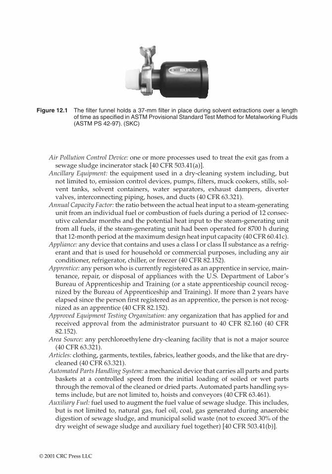
Figure 12.1 The filter funnel holds a 37-mm filter in place during solvent extractions over a lengthof time as specified in ASTM Provisional Standard Test Method for Metalworking Fluids(ASTM PS 42-97). (SKC)
Air Pollution Control Device: one or more processes used to treat the exit gas from asewage sludge incinerator stack [40 CFR 503.41(a)].
Ancillary Equipment: the equipment used in a dry-cleaning system including, butnot limited to, emission control devices, pumps, filters, muck cookers, stills, sol-vent tanks, solvent containers, water separators, exhaust dampers, divertervalves, interconnecting piping, hoses, and ducts (40 CFR 63.321).
Annual Capacity Factor: the ratio between the actual heat input to a steam-generatingunit from an individual fuel or combustion of fuels during a period of 12 consec-utive calendar months and the potential heat input to the steam-generating unitfrom all fuels, if the steam-generating unit had been operated for 8700 h duringthat 12-month period at the maximum design heat input capacity (40 CFR 60.41c).
Appliance: any device that contains and uses a class I or class II substance as a refrig-erant and that is used for household or commercial purposes, including any airconditioner, refrigerator, chiller, or freezer (40 CFR 82.152).
Apprentice: any person who is currently registered as an apprentice in service, main-tenance, repair, or disposal of appliances with the U.S. Department of Labor’sBureau of Apprenticeship and Training (or a state apprenticeship council recog-nized by the Bureau of Apprenticeship and Training). If more than 2 years haveelapsed since the person first registered as an apprentice, the person is not recog-nized as an apprentice (40 CFR 82.152).
Approved Equipment Testing Organization: any organization that has applied for andreceived approval from the administrator pursuant to 40 CFR 82.160 (40 CFR82.152).
Area Source: any perchloroethylene dry-cleaning facility that is not a major source(40 CFR 63.321).
Articles: clothing, garments, textiles, fabrics, leather goods, and the like that are dry-cleaned (40 CFR 63.321).
Automated Parts Handling System: a mechanical device that carries all parts and partsbaskets at a controlled speed from the initial loading of soiled or wet partsthrough the removal of the cleaned or dried parts. Automated parts handling sys-tems include, but are not limited to, hoists and conveyors (40 CFR 63.461).
Auxiliary Fuel: fuel used to augment the fuel value of sewage sludge. This includes,but is not limited to, natural gas, fuel oil, coal, gas generated during anaerobicdigestion of sewage sludge, and municipal solid waste (not to exceed 30% of thedry weight of sewage sludge and auxiliary fuel together) [40 CFR 503.41(b)].
© 2001 CRC Press LLC
Batch-Cleaning Machine: a solvent-cleaning machine in which individual parts or aset of parts move through the entire cleaning cycle before new parts are intro-duced into the machine. An open top, vapor-cleaning machine is a type of batch-cleaning machine. A solvent-cleaning machine, such as a ferris wheel or across-rod degreaser, that cleans multiple batch loads simultaneously and is man-ually loaded is a batch-cleaning machine (40 CFR 63.461).
Batch Municipal Waste Combustor: an incinerator that operates by forcefully project-ing a curtain of air across an open chamber or pit in which burning occurs.Incinerators of this type can be constructed above or below ground and with orwithout refractory walls and floor (40 CFR 60.51b).
Benzene Service: a piece of equipment that either contains or contacts a fluid (liquidor gas) that is at least 10% benzene by weight (40 CFR 61.111).
Bulk Gasoline Terminal: any gasoline facility that receives gasoline by pipeline, ship,or barge and has a throughput �75,000 l/day (19,998 gal/day) (40 CFR 60.501).
Carbon Adsorber: a bed of activated carbon into which an air–perchloroethylenegas–vapor stream is routed and which adsorbs the perchloroethylene on the car-bon (40 CFR 63.321). A bed of activated carbon into which an air solvent gas vapor stream is routed and that adsorbs the solvent on the carbon (40 CFR 63.461).
Cartridge Filter: a discrete filter unit containing both filter paper and activated car-bon that traps and removes contaminants from petroleum solvent, together withthe piping and ductwork used in installing this device (40 CFR 60.621).
Certified Refrigerant Recovery or Recycling Equipment: equipment certified by anapproved equipment testing organization to meet the standards in 40 CFR82.158(b) or (d), equipment certified pursuant to 40 CFR 82.36(a), or equipmentmanufactured before November 15, 1993 that meets the standards in 40 CFR82.158(c), (e), or (g) (40 CFR 82.152).
Clean Liquid Solvent: fresh, unused solvent, recycled solvent, or used solvent that hasbeen cleaned of soils (e.g., skimmed of oils or sludge and strained of metal chips)(40 CFR 63.461).
Cleaning Capacity: for a cleaning machine without a solvent/air interface, the maxi-mum volume of parts that can be cleaned at one time. In most cases the cleaningcapacity is equal to the volume (length times width times height) of the cleaningchamber (40 CFR 63.461).
Closed-Vent System: a system that is not open to the atmosphere and is composed ofpiping, connections, and, if necessary, flow-inducing devices that transport gas orvapor from a piece or pieces of equipment to a control device (40 CFR 61.241).
Coal Refuse: any waste products of coal mining, cleaning, and coal preparation oper-ations (e.g., cull, gob) containing coal, matrix material, clay, and other organic andinorganic material (40 CFR 60.41a).
Cofired Combustor: a unit combusting municipal solid waste with nonmunicipalsolid waste fuel (e.g., coal, industrial process waste) and subject to a federallyenforceable permit limiting the unit to combusting a fuel feed stream, 30% or lessof which is composed of municipal solid waste as measured on a calendar quar-ter basis (40 CFR 60.51a and 60.51b).
Cogeneration Steam-Generating Unit: a steam-generating unit that simultaneouslyproduces both electrical (or mechanical) and thermal energy from the same pri-mary energy source (40 CFR 60.41c).
Coin-Operated Dry-Cleaning Machine: a dry-cleaning machine that is operated by thecustomer (i.e., the customer places articles into the machine, turns the machineon, and removes articles from the machine) (40 CFR 63.321).
© 2001 CRC Press LLC

Cold-Cleaning Machine: any device or piece of equipment that contains and/or usesliquid solvent into which parts are placed to remove soils from the surface of theparts or to dry the parts. Cleaning machines that contain and use heated, non-boiling, solvent to clean the parts are classified as cold-cleaning machines (40 CFR63.461).
Colorimetric Detector Tube: a glass tube (sealed prior to use) containing materialimpregnated with a chemical that is sensitive to perchloroethylene and isdesigned to measure the concentration of perchloroethylene in the air (40 CFR63.321).
Combustion Research: the experimental firing of any fuel or combination of fuels in asteam-generating unit for the purpose of conducting research and developmentof more efficient combustion or more effective prevention or control of air pollu-tion emissions from combustion, provided that, during these periods of researchand development, the heat generated is not used for any purpose other than pre-heating combustion air for use by that steam-generating unit (i.e., the heat gen-erated is released to the atmosphere without being used for space heating,process heating, driving pumps, preheating combustion air for other units, gen-erating electricity, or any other purpose) (40 CFR 60.41c).
Commercial Refrigeration: refrigeration appliances utilized in the retail food and coldstorage warehouse sectors. Retail food appliances include the refrigeration equip-ment found in supermarkets, convenience stores, restaurants, and other food serv-ice establishments. Cold storage appliances include the equipment used to storemeat, produce, dairy products, and other perishable goods. All of the equipmentcontains large refrigerant charges, typically over 75 lb (34 kg) (40 CFR 82.152).
Commercial/Retail Waste: material discarded by stores, offices, restaurants, ware-houses, nonmanufacturing activities at industrial facilities, and other similarestablishments or facilities (40 CFR 60.51a).
Continuous Cleaning Machine: see in-line-cleaning machine.Continuous Emissions Monitoring System (CEMS): a monitoring system for continu-
ously measuring the emissions of a pollutant from an affected facility (40 CFR60.51a and 60.51b).
Control Efficiency: the mass of a pollutant in the sewage sludge fed to an incineratorminus the mass of that pollutant in the exit gas from the incinerator stack dividedby the mass of the pollutant in the sewage sludge fed to the incinerator [40 CFR503.41(c)].
Critical Component: a component without which industrial process refrigerationequipment will not function, will be unsafe in its intended environment, and/orwill be subject to failures that would render the industrial process served by therefrigeration appliance unsafe (40 CFR 82.152).
Custom-Built: specialized equipment or any of its critical components cannot bepurchased and/or installed without being uniquely designed, fabricated, and/orassembled to satisfy a specific set of industrial process conditions (40 CFR 82.152).
Designated Volatility Nonattainment Area: any area designated as being in nonattain-ment with the NAAQS for ozone pursuant to rule making under Section107(d)(4)(A)(ii) of CAAA90 (40 CFR 80.2).
Designated Volatility Attainment Area: an area not designated as being in nonattain-ment with the NAAQS for ozone (40 CFR 80.2).
Diesel Fuel: any fuel sold in any state and suitable for use in diesel motor vehiclesand diesel motor vehicle engines that is commonly or commercially known orsold as diesel fuel (40 CFR 80.2).
© 2001 CRC Press LLC
Dispersion Factor: the ratio of the increase in the ground level ambient air concen-trations for a pollutant at or beyond the property line of the site where the sewagesludge incinerator is located to the mass emission rate for the pollutant from theincinerator stack [40 CFR 503.41(d)].
Disposal: the process leading to and including the discharge, deposit, dumping, orplacing of any discarded appliance into or on any land or water; the disassemblyof any appliance for discharge, deposit, dumping, or placing of its discardedcomponent parts into or on any land or water; and the disassembly of an appli-ance for reuse of its component parts (40 CFR 82.152).
Diverter Valve: a flow control device that prevents room air from passing through a refrigerated condenser when the door of the dry-cleaning machine is open (40 CFR 63.321).
Dry-Cleaning Cycle: the washing and drying of articles in a dry-to-dry machine ortransfer machine system (40 CFR 63.321).
Dry-Cleaning Facility: an establishment with one or more dry-cleaning systems (40 CFR 63.321).
Dry-Cleaning Machine: a dry-to-dry machine or each machine of a transfer machinesystem (40 CFR 63.321).
Dry-Cleaning Machine Drum: the perforated container inside the dry-cleaningmachine that holds the articles during dry cleaning (40 CFR 63.321).
Dry-Cleaning System: a dry-to-dry machine and its ancillary equipment or a transfermachine system and its ancillary equipment (40 CFR 63.321).
Dryer: a machine used to remove petroleum solvent from articles of clothing orother textile or leather goods, after washing and removing excess petroleum sol-vent, and the piping and ductwork used in the installation of this device (40 CFR60.621). A machine used to remove perchloroethylene from articles by tumblingthem in a heated airstream (40 CFR 63.321).
Dry-to-Dry Machine: a one machine, dry-cleaning operation in which washing anddrying are performed in the same machine (40 CFR 63.321).
Duct Burner: a device that combusts fuel and is placed in the exhaust duct fromanother source (such as a stationary gas turbine, internal combustion engine, kiln,etc.) to allow the firing of additional fuel to heat the exhaust gases before theexhaust gases enter a steam-generating unit (40 CFR 60.41c).
Dwells: the technique of holding parts within the freeboard area, but above thevapor zone of the solvent-cleaning machine. Dwell occurs after cleaning to allowsolvent to drain from the parts or parts baskets back into the solvent-cleaningmachine (40 CFR 63.461).
Emerging Technology: any SO2 control system that is not defined as a conventionaltechnology and for which the owner or operator of the affected facility hasreceived approval from the administrator to operate as an emerging technology(40 CFR 60.41c).
Exhaust Damper: a flow control device that prevents the air–perchloroethylenegas–vapor stream from exiting the dry-cleaning machine into a carbon adsorberbefore room air is drawn into the dry-cleaning machine (40 CFR 63.321).
Existing: in relation to perchloroethylene dry cleaners, construction or reconstruc-tion commenced before December 9, 1991 (40 CFR 63.321). Any solvent-cleaningmachine whose construction or reconstruction commenced on or beforeNovember 29, 1993, but did not meet the definition of a solvent-cleaning machineon December 2, 1994 because it did not use halogenated HAP solvent liquid or
© 2001 CRC Press LLC
vapor covered under this subpart to remove soils, becomes an existing sourcewhen it commences to use such liquid or vapor. A solvent-cleaning machinemoved within a contiguous facility or to another facility under the same owner-ship constitutes an existing machine (40 CFR 63.461).
Federally Enforceable: all limitations and conditions enforceable by the administrator,including those requirements developed pursuant to 40 CFR 60 and 61, require-ments within any applicable state implementation plan, and any permit require-ments established pursuant to 40 CFR 52.21 or under 40 CFR 51.18 and 51.24 (40CFR 60.41b).
Fluidized Bed Incinerator: an enclosed device in which organic matter and inorganicmatter in sewage sludge are combusted in a bed of particles in the combustionchamber gas [40 CFR 503.41(e)].
Follow-up Verification Test: checking the repairs within 30 days of an appliance’sreturn to normal operating characteristics and conditions. Follow-up verificationtests for appliances from which the refrigerant charge has been evacuated meansa test conducted after the appliance or portion of the appliance has resumed oper-ating at normal operating characteristics and conditions of temperature and pres-sure, except in cases where sound professional judgment dictates that these testswill be more valid if they are performed prior to the return to normal operatingcharacteristics and conditions. A follow-up verification test with respect torepairs conducted without evacuation of the refrigerant charge means a reverifi-cation test conducted after the initial verification test and usually within 30 daysof the return to normal operating conditions. If an appliance is not evacuated, itis only necessary to conclude that any required changes in pressure, temperature,or other conditions returned the appliance to normal operating characteristicsand conditions (40 CFR 82.152).
Fossil Fuel: natural gas, petroleum, coal, and any form of solid, liquid, or gaseousfuel derived from such materials for the purpose of creating useful heat (40 CFR60.41a).
Freeboard Area: for a batch-cleaning machine this is the area within the solvent-cleaning machine that extends from the solvent/air interface to the top of themachine; for an in-line-cleaning machine, it is the area within the solvent-clean-ing machine that extends from the solvent/air interface to the bottom of theentrance or exit opening, whichever is lower (40 CFR 63.461).
Freeboard Ratio: the ratio of the solvent-cleaning machine freeboard height to thesmaller interior dimensions (length, width, or diameter) of the solvent-cleaningmachine (40 CFR 63.461).
Fuel Pretreatment: a process that removes a portion of the sulfur in a fuel before com-bustion in a steam-generating unit (40 CFR 60.41c).
Fugitive Emissions: air pollutants entering the atmosphere from other than a stack chimney, vent, or other functionally equivalent opening. Examplesinclude vapors, dust, and fumes (40 CFR 51.301j).
Full Charge: the amount of refrigerant required for normal operating characteristicsand conditions of the appliance as determined by using one of the following fourmethods or a combination of one of the following four methods (40 CFR 82.152):(1) the equipment manufacturers’ determination of the correct full charge for theequipment; (2) determining the full charge by appropriate calculations based oncomponent sizes, density of refrigerant, volume of piping, and all other relevantconsiderations; (3) the use of actual measurements of the amount of refrigerant
© 2001 CRC Press LLC
added or evacuated from the appliance; or (4) the use of an established rangebased on the best available data, regarding the normal operating characteristicsand conditions for the appliance, where the midpoint of the range will serve asthe full charge and where records are maintained in accordance with 82.166(q).
Gasoline Carrier: any distributor who transports, stores, or is responsible for thetransportation or storage of gasoline or diesel fuel without taking title to or otherwise having any ownership of the gasoline and without altering either thequality or quantity of the gasoline or diesel fuel (40 CFR 80.2).
Gasoline Distributor: any person who transports, stores, or is responsible for thetransportation or storage of gasoline or diesel fuel at any point between any gaso-line refinery or importer’s facility and any retail outlet or wholesale purchaserconsumer facility (40 CFR 80.2).
Halogenated Hazardous Air Pollutants Solvent (HAP): methylene chloride (CAS No.75-09-2), perchloroethylene (CAS No. 127-18-4), trichloroethylene (CAS No. 79-01-6), 1,1,1-trichloroethane (CAS No. 71-55-6), carbon tetrachloride (CAS No. 56-23-5), and chloroform (CAS 67-66-3) (40 CFR 63.461).
Heat Input: heat derived from the combustion of fuel in a steam-generating unit thatdoes not include the heat derived from preheated combustion air, recirculatedflue gases, or exhaust gases from other sources (40 CFR 60.41c).
High-Pressure Appliance: an appliance that uses a refrigerant with a boiling pointbetween �50 and 10°C (�58 and 50°F) at 29.9 in.Hg (76 cm) atmospheric pres-sure. This definition includes, but is not limited to, appliances using refrigerants-12, -22, -114, -500, or -502 (40 CFR 82.152).
Hourly Average: the arithmetic mean of all measurements taken during 1 h. At leasttwo measurements must be taken during the hour [40 CFR 503.41(f)].
Household Waste: includes material discarded by single and multiple residentialdwellings, hotels, motels, and other similar permanent or temporary housing (40 CFR 60.51a).
Idling Mode: the time period when a solvent-cleaning machine is not actively clean-ing parts, and the sump heating coils are turned on (40 CFR 63.461).
Idling Mode Cover: any cover or solvent-cleaning machine design that shields thecleaning machine openings during the idling mode. A cover that meets thisdefinition can also be used as a working mode cover if that definition is also met(40 CFR 63.461).
Immersion Cold-Cleaning Machine: a cold-cleaning machine in which the parts to becleaned are immersed in the solvent. A remote reservoir cold-cleaning machinethat is also an immersion cold-cleaning machine is considered an immersioncold-cleaning machine for the purposes of this subpart (40 CFR 63.461).
Incineration: in relation to sewage sludge, the combustion of organic matter andinorganic matter in sewage sludge by high temperatures in an enclosed device[40 CFR 503.41(g)].
Incinerator: any furnace used to burn solid waste for the purpose of reducing thevolume of the waste by removing combustible matter (40 CFR 60.51).
Industrial Process Refrigeration: complex customized appliances used in the chemi-cal, pharmaceutical, petrochemical, and manufacturing industries. This sectoralso includes industrial ice machines, appliances used directly in the generationof electricity, and ice rinks (40 CFR 82.152).
Industrial Process Shutdown: an industrial process or facility that temporarily ceases tooperate or manufacture whatever is being produced at that facility (40 CFR 82.152).
© 2001 CRC Press LLC
Initial Verification Test: leak tests that are conducted as soon as practicable after therepair is completed (40 CFR 82.152).
In-Line-Cleaning Machine or Continuous-Cleaning Machine: a solvent-cleaningmachine that uses an automated parts handling system, typically a conveyor, toautomatically provide a continuous supply of parts for cleaning. These units arefully enclosed except for the conveyor inlet and exit portals. In-line-cleaningmachines can be either cold- or vapor-cleaning machines (40 CFR 63.461).
Institutional Waste: materials discarded by hospitals, schools, nonmanufacturingactivities at prisons, and government facilities (40 CFR 60.51a).
Large Municipal Waste Combustor Plant: a municipal waste combustor plant with amunicipal waste combustor aggregate plant capacity for affected facilities that is�225 metric tons/day (250 t/day) of municipal solid waste (40 CFR 60.51a and60.51b).
Lignite: coal that is classified as lignite A or B according to the ASTM standards (40 CFR 60.41a).
Lip Exhaust: a device installed at the top of the opening of a solvent-cleaningmachine that draws in air and solvent vapor from the freeboard area and ductsthe air and vapor away from the solvent-cleaning area (40 CFR 63.461).
Low-Loss Fitting: any device intended to establish a connection between hoses, appli-ances, or recovery or recycling machines that is designed to close automatically orto be closed manually when disconnected, minimizing the release of refrigerantfrom hoses, appliances, and recovery or recycling machines (40 CFR 82.152).
Low-Pressure Appliance: an appliance that uses a refrigerant with a boiling point above10°C (50°F) at atmospheric pressure (29.9 in.Hg). This definition includes, but is notlimited to, equipment utilizing refrigerants -11, -113, and -123 (40 CFR 82.152).
Major Maintenance, Service, or Repair: any maintenance, service, or repair involvingthe removal of any or all of the following appliance components: compressor,condenser, evaporator, or auxiliary heat exchanger coil (40 CFR 82.152).
Major Source: in relation to dry-cleaning facilities, any facility that emits or has thepotential to emit more than 9.1 metric tons/year (10 t/year) of perchloroethyleneto the atmosphere. In lieu of measuring a facility’s potential to emit perchloro-ethylene emissions or determining a facility’s potential to emit perchloroethyleneemissions, a dry-cleaning facility is a major source if: it includes only dry-to-drymachines and has a total yearly perchloroethylene consumption �8000 l (2100gal) or it includes only transfer machine systems or both dry-to-dry and transfermachine systems and has a total yearly perchloroethylene consumption �6800 l(1800 gal) (40 CFR 63.321).
Management Practice (MP): practices that, although not mandated by law, areencouraged to promote safe operating procedures.
Mass Burn Refractory Municipal Waste Combustor: a field-erected combustor thatcombusts municipal solid waste in a refractory wall furnace. Unless otherwisespecified, this definition includes combustions with a cylindrical rotary refrac-tory wall furnace (40 CFR 60.51a and 60.51b).
Mass Burn Rotary Waterwall Municipal Waste Combustor: a field-erected combustorthat combusts municipal solid waste in a cylindrical rotary waterwall furnace (40CFR 60.51a and 60.51b).
Materials Separation Plan: a plan that identifies both a goal and an approach to sep-arate certain components of municipal solid waste for a given service area inorder to make the separated materials available for recycling (40 CFR 60.51b).
© 2001 CRC Press LLC
Maximum Heat Input Capacity of a Steam-Generating Unit: determined by operatingthe facility at maximum capacity for 24 h and using the heat loss methoddescribed in Sections 5 and 7.3 of the ASME Power Test Codes 4.1 [see 40 CFR60.17(h)] no later than 180 days after initial start-up of the facility and within 60 days after reaching the maximum production rate at which the facility will beoperated (40 CFR 60.51a).
Modification: according to new source performance standards (NSPSs), any physicalor operational change to an existing facility that results in an increase in the emis-sion rate to the atmosphere of any pollutant to which a standard applies except:(1) maintenance, repair, and replacement that the administrator determines to beroutine for a source category; (2) an increased production rate of an existing facility, if that increase can be accomplished without a capital expenditure on the facility; (3) an increase in the hours of operation; (4) use of an alternate fuel or raw material if, prior to the date any standard under this part becomes appli-cable to that source type, the existing facility was designed to accommodate thatalternate use (A facility will be designed to accommodate an alternative fuel orraw material if that use could be accomplished under the facility’s constructionspecifications as assessed prior to the change.); (5) the addition or use of any system or device whose primary function is the reduction of air pollutants, exceptwhen an emission control system is removed or replaced by a system that theadministrator determines to be less than environmentally beneficial; and (6) therelocation or change in ownership of an existing facility (40 CFR 60.14).
Motor Vehicle Air-Conditioner (MVAC): any appliance that is an MVAC as defined in40 CFR 82, subpart B (40 CFR 82.152).
Muck Cooker: a device for heating perchloroethylene-laden waste material tovolatilize and recover perchloroethylene (40 CFR 63.321).
Municipal Solid Waste or Municipal-Type Solid Waste: household, commercial/retail, and/or institutional waste. Household waste includes materials discardedby single and multiple residential dwellings, hotels, motels, and other similarpermanent or temporary housing establishments or facilities. Commercial/retailwaste includes materials discarded by stores, offices, restaurants, warehouses,nonmanufacturing activities at industrial facilities, and other similar establish-ments or facilities. Institutional waste includes material discarded by schools,nonmedical waste discarded by hospitals, material discarded by nonmanufac-turing activities at prisons and government facilities, and material discarded byother similar establishments. Household, commercial/retail, and institutionalwaste does not include used oil; sewage sludge; wood pallets; construction, ren-ovation, and demolition wastes (which includes, but is not limited to, railroad tiesand telephone poles); clean wood; industrial process or manufacturing wastes;medical waste; or motor vehicles. Household, commercial/retail, and institu-tional waste does include yard waste, refuse-derived fuel, and motor vehiclemaintenance materials limited to vehicle batteries and tires except as specified in40 CFR 60.50a(c) and 60.50b(g) (40 CFR 60.51a and 60.51b).
Municipal Waste Combustor Plant: one or more municipal waste combustor units atthe same location for which construction, modification, or reconstruction com-menced after December 20, 1989 and on or before September 20, 1994 (40 CFR60.51a). One or more municipal waste combustor units at the same location forwhich construction, modification, or reconstruction commenced after September20, 1994 (40 CFR 60.51b).
© 2001 CRC Press LLC
Municipal Waste Combustor Unit: any setting or equipment that combusts or gasifiesmunicipal solid waste including, but not limited to, field-erected incinerators(with or without heat recovery), modular incinerators (starved air or excess air),boilers (i.e., steam-generating units), furnaces (whether suspension fired, grate-fired, mass-fired, air curtain incinerators, or fluidized bed-fired), and pyrolysis/combustion units. Municipal waste combustors do not include pyrolysis/com-bustion units located at plastics/rubber recycling units, internal combustionengines, gas turbines, or other combustion devices that combust landfill gasescollected by landfill gas collection systems (40 CFR 60.51a and 60.51b).
MVAC-Like Appliance: mechanical vapor compression or open-drive compressorappliances used to cool the driver’s or passenger’s compartment of a nonroadmotor vehicle. This definition includes the air-conditioning equipment found onagricultural or construction vehicles, but is not intended to cover appliancesusing HCFC-22 refrigerant (40 CFR 82.152).
New: in relation to a perchloroethylene dry-cleaning facility, a facility in which con-struction or reconstruction commenced on or after December 9, 1991 (40 CFR63.321). In relation to solvent-cleaning machines, any machine whose construc-tion or reconstruction commenced after November 29, 1993 (40 CFR 63.461).
Nitric Acid Production Unit: any facility producing nitric acid, which is 30 to 70% in strength, by either the pressure or atmospheric pressure process (40 CFR 60.70).
Normal Operating Characteristics or Conditions: temperature, pressure, fluid flow,speed, and other characteristics that would normally be expected for a givenprocess load and ambient conditions during operation. Normal operating char-acteristics and conditions are marked by the absence of atypical conditions affect-ing the operation of the refrigeration appliance (40 CFR 82.152).
Normally Containing a Quantity of Refrigerant: containing the quantity of refrigerantwithin the appliance or appliance component when the appliance is operatingwith a full charge of refrigerant (40 CFR 82.152).
Opacity: the degree to which emissions reduce the transmission of light and obscureview of an object in the background (40 CFR 60.2).
Open Top, Vapor-Cleaning Machine: a batch solvent-cleaning machine that has itsupper surface open to the air and boils solvents to create solvent vapor used toclean and/or dry parts (40 CFR 63.461).
Opening an Appliance: any service, maintenance, or repair on an appliance that wouldrelease class I or class II refrigerant from the appliance to the atmosphere unlessthe refrigerant were previously recovered from the appliance (40 CFR 82.152).
Particulate Matter Emissions: any airborne finely divided solid or liquid material,except uncombined water, emitted to the ambient air (40 CFR 60.2).
Perceptible Leaks: any perchloroethylene vapor or liquid leaks that are obvious fromthe odor of perchloroethylene; visual observation, such as pools or droplets ofliquid; or the detection of gas flow by passing the fingers over the surface of theequipment (40 CFR 63.321).
Perchloroethylene Consumption: the total volume of perchloroethylene purchasedbased on purchase receipts or other reliable measures (40 CFR 63.321).
Petroleum Dry Cleaner: a dry-cleaning facility that uses petroleum solvent in a com-bination of washers, dryers, filters, stills, and settling tanks (40 CFR 60.621).
PM10: particulate matter with an aerodynamic diameter less than or equal to a nom-inal 10 �m (40 CFR 58.1).
© 2001 CRC Press LLC
Process Stub: a length of tubing that provides access to the refrigerant inside a smallappliance or room air-conditioner and can be resealed at the conclusion of repairor service (40 CFR 82.152).
Publication Rotogravure Printing: any number of rotogravure printing units capableof printing simultaneously on the same continuous web or substrate, and includ-ing any associated device for continuous cutting and folding the printed web,where the following sellable paper products are printed: catalogs; direct mailadvertisements; display advertisements; magazines; miscellaneous advertise-ments including brochures, pamphlets, catalog sheets, circular folders, andannouncements; newspapers; periodicals; and telephone and other directories(40 CFR 60.431).
Pyrolysis/Combustion Unit: a unit that produces gases, liquids, or solids through theheating of municipal solid waste. The gases, liquids, or solids produced are com-busted, and the emissions are vented to the atmosphere (40 CFR 60.51b).
Reclaim Refrigerant: to reprocess refrigerant to at least the purity specified in the Air-Conditioning and Refrigeration Institute (ARI) Standard 700-1988, Specifica-tions for Fluorocarbon Refrigerants (Appendix A to 40 CFR 82, subpart F), and toverify this purity using the analytical methodology prescribed in ARI Standard700-1988. In general reclamation involves the use of processes or proceduresavailable only at a reprocessing or manufacturing facility (40 CFR 82.152).
Reclaimer: a machine used to remove perchloroethylene from articles by tumblingthem in a heated airstream (40 CFR 63.321).
Reconstruction: in relation to perchloroethylene dry-cleaners, replacement of awasher, dryer, or reclaimer, or replacement of any components of a dry-cleaningsystem, to such an extent that the fixed capital cost of the new componentsexceeds 50% of the fixed capital cost that would be required to construct a com-parable new source (40 CFR 63.321).
Recover Refrigerant: to remove refrigerant in any condition from an appliance and tostore it in an external container without necessarily testing or processing it in anyway (40 CFR 82.152).
Recovery Efficiency: the percentage of refrigerant in an appliance that is recovered bya piece of recycling or recovery equipment (40 CFR 82.152).
Recycle Refrigerant: to extract refrigerant from an appliance and clean refrigerant forreuse without meeting all of the requirements for reclamation. In general recycledrefrigerant is refrigerant that is cleaned using oil separation and single or multi-ple passes through devices, such as replaceable core filter-dryers, that reducemoisture, acidity, and particulate matter. These procedures usually are imple-mented at the field job site (40 CFR 82.152).
Refrigerated Condenser: a vapor recovery system into which an air–perchloroethyl-ene gas–vapor stream is routed; the perchloroethylene is condensed by coolingthe gas–vapor stream (40 CFR 63.321).
Refuse-Derived Fuel: the combustible or organic portion of municipal waste that hasbeen separated out and processed for use as fuel (40 CFR 60.51a). A type ofmunicipal solid waste produced by processing municipal solid waste throughshredding and size classification, including all classes of refuse-derived fuelranging from low-density fluff through densified and pelletized refuse-derivedfuel (40 CFR 60.51b).
Remote Reservoir Cold-Cleaning Machine: any device in which liquid solvent ispumped to a sink-like work area that drains solvent back into an enclosed
© 2001 CRC Press LLC
container while parts are being cleaned, allowing no solvent to pool in the workarea (40 CFR 63.461).
Risk Specific Concentration: the allowable increase in the average daily ground levelambient air concentrations for a pollutant from the incineration of sewage sludgeat or beyond the property line of the site where the sewage sludge incinerator islocated [40 CFR 503.41(i)].
Room Enclosure: a stationary structure that encloses a transfer machine system andis vented to a carbon adsorber or an equivalent control device during operationof the transfer machine system (40 CFR 63.321).
Same Location: the same or contiguous property that is under common ownership orcontrol, including properties that are separated only by a street, road, highway,or other public right of way. Common ownership or control includes propertiesthat are owned, leased, or operated by the same entity, parent entity, subsidiary,subdivision, or any combination thereof, including any municipality or othergovernmental unit (40 CFR 60.51b).
Self-Contained Recovery Equipment: refrigerant recovery or recycling equipment thatis capable of removing the refrigerant from an appliance without the assistanceof components contained in the appliance (40 CFR 82.152).
Sewage Sludge Feed Rate: either the average daily amount of sewage sludge fired inall sewage sludge incinerators within the property line of the site, where thesewage sludge incinerators are located for the number of days in a 365-day periodthat each sewage sludge incinerator operates, or the average daily design capac-ity for all sewage sludge incinerators within the property line of the site wherethe sewage sludge incinerators are located [40 CFR 503.41(j)].
Sewage Sludge Incinerator: an enclosed device in which only sewage sludge and aux-iliary fuel are fired [40 CFR 503.41(k)].
Small Appliance: any of the following products that are fully manufactured, charged,and hermetically sealed in a factory with 5 lb or less of refrigerant: refrigeratorsdesigned for home use, freezers designed for home use, room air-conditioners(including window air-conditioners and packaged terminal air-conditioners),packaged terminal heat pumps, dehumidifiers, under-the-counter ice makers,vending machines, and drinking water coolers (40 CFR 82.152).
Small Municipal Waste Combustor Plant: a municipal waste combustor plant with acapacity for affected facilities that is �35 metric tons/day, but �225 metrictons/day of municipal solid waste (40 CFR 60.51b).
Solvent/Air Interface: the location of contact between the concentrated solvent vaporlayer and the air in a vapor-cleaning machine. This location of contact is definedas the in-line height of the primary condenser coils. For a cold-cleaning machinethe solvent/air interface is the location of contact between the liquid solvent andthe air (40 CFR 63.461).
Solvent-Cleaning Machine: any device or piece of equipment that uses halogenatedHAP solvent liquid or vapor to remove soils from the surface of materials. Thetypes of solvent-cleaning machines include, but are not limited to, batch vapor,in-line vapor, in-line cold, and batch cold solvent. Buckets, pails, and beakerswith capacities of 7.6 l (2 gal) or less are not considered solvent-cleaning machines(40 CFR 63.461).
Stationary Gas Turbines: any simple cycle gas turbine, regenerative cycle gas turbine, orany gas turbine portion of a combined cycle steam/electric-generating system thatis not self-propelled. It may be mounted on a vehicle for portability (40 CFR 60.331).
© 2001 CRC Press LLC
Steam-Generating Unit: any furnace, boiler, or other device used for combusting fuelfor the purpose of producing steam (including fossil fuel-fired steam generatorsassociated with combined cycle gas turbines); nuclear steam generators are notincluded (40 CFR 60.41a).
Suitable Replacement Refrigerant: for the purposes of 82.156(i)(7)(i), a refrigerant thatis acceptable under section 612(c) of CAAA90 and all regulations promulgatedunder that section, compatible with other materials with which it may come intocontact, and able to achieve the temperatures required for the affected industrialprocess in a technically feasible manner (40 CFR 82.152).
Sulfuric Acid Production Unit: any facility producing sulfuric acids by the contactprocess for burning elemental sulfur, alkylation acid, hydrogen sulfide, organicsulfides and mercaptans, or acid sludge, not including facilities where conversionto sulfuric acid is used primarily as a means of preventing emissions to the atmos-phere of SO2 or other sulfur compounds (40 CFR 60.81).
Superheated Vapor System: a system that heats the solvent vapor either passively oractively to a temperature above the solvent’s boiling point. Parts are held in thesuperheated vapor before exiting the machine to evaporate the liquid solvent onthem. Hot vapor recycle is an example of a superheated vapor system (40 CFR63.461).
System-Dependent Recovery Equipment: refrigerant recovery equipment that requiresthe assistance of components contained in an appliance to remove the refrigerantfrom the appliance (40 CFR 82.152).
System Mothballing: the intentional shutting down of a refrigeration applianceundertaken for an extended period of time by the owners or operators of the facility, where the refrigerant has been evacuated from the appliance or theaffected isolated section of the appliance, at least to atmospheric pressure (40 CFR82.152).
Technician: any person who performs maintenance, service, or repair that could rea-sonably be expected to release class I or class II refrigerants from appliances,except for MVACs, into the atmosphere. Any person who performs disposal ofappliances except for small appliances, MVAC, and MVAC-like equipment thatcould be reasonably expected to release class I or class II refrigerants from theappliances into the atmosphere. Technicians include, but are not limited to,installers, contractor employees, in-house service personnel, and owners (40 CFR82.152).
Transfer Machine System: a multiple machine dry-cleaning operation in which wash-ing and drying are performed in different machines. Examples include, but arenot limited to, a washer and dryer, a washer and reclaimer, and a dry-to-drymachine and reclaimer (40 CFR 63.321).
Very High-Pressure Appliance: an appliance that uses a refrigerant with a boilingpoint below �50°C (�58°F) at atmospheric pressure (29.9 in.Hg). This definitionincludes, but is not limited to, equipment utilizing refrigerants -13 and -503 (40 CFR 82.152).
Vapor-Cleaning Machine: a batch or in-line solvent-cleaning machine that boils liquid solvent, generating solvent vapor that is used as a part of the cleaning ordrying cycle (40 CFR 63.461).
Very Low Sulfur Oil: an oil that contains no more than 0.5 weight percent sulfur or that, when combusted without SO2 emission control, has an SO2 emission rate�215 ng/J (0.5 lb/MBtu) heat input (40 CFR 60.41b).
© 2001 CRC Press LLC
VHAP Service: a piece of equipment that either contains or contacts a fluid (liquidor gas) that is at least 10% by weight a VHAP (40 CFR 61.241).
VOC Service: in relationship to fugitive emissions, VOC service begins when a pieceof equipment contains or contacts a process fluid that is at least 10% VOC byweight (40 CFR 61.241).
Volatile Hazardous Air Pollutant (VHAP): a substance regulated under 40 CFR 61,subpart V, for which a standard for equipment leaks of the substance has beenproposed and promulgated. Benzene and vinyl chloride are VHAPs (40 CFR61.241).
Volatile Organic Compound (VOC): any compound of carbon, excluding CO, CO2,carbonic acid, metallic carbides, carbonates, and ammonium carbonate, that par-ticipates in atmospheric photochemical reactions (40 CFR 51.100).
Voluntary Certification Program: a technician-testing program operated by a personbefore that person obtained approval of a technician certification program (40 CFR 82.152).
Washer: a machine used to clean articles by immersing them in perchloroethylene,including a dry-to-dry machine used with a reclaimer (40 CFR 63.321).
Water Separator: any device used to recover perchloroethylene from a water-perchloroethylene mixture (40 CFR 63.321).
Waterfall Furnace: a combustion unit having energy (heat) recovery in the furnace(i.e., radiant heat transfer section of the combustor) (40 CFR 60.51b).
Wholesale Purchaser-Consumer: any organization that is an ultimate consumer ofgasoline or diesel fuel that purchases or obtains gasoline or diesel fuel from a sup-plier for use in motor vehicles and receives delivery of that product into a storagetank of at least 550 gal (2082 l) capacity substantially under the control of thatorganization (40 CFR 80.2).
Working Mode: the time period when the solvent-cleaning machine is actively clean-ing parts (40 CFR 63.461).
Working Mode Cover: any cover or solvent-cleaning machine design that shields thecleaning machine openings from outside air disturbances while parts are beingcleaned in the cleaning machine. A cover used during the working mode isopened only during parts entry and removal. A cover that meets this definitioncan also be used as an idling mode cover if that definition is also met (40 CFR63.461).
Yard Waste: grass, grass clippings, bushes, shrubs, and clippings from bushes and shrubs that are generated by residential, commercial/retail, institutional,and/or industrial sources as a part of maintenance activities associated with yards or other private or public lands. Yard waste does not include con-struction, renovation, and demolition wastes that are exempt from the definitionof municipal solid waste. Yard waste does not include clean wood (40 CFR60.51b).
12.4 COMMUNITY RELATIONS
If a facility is of interest to the local community, and especially if an incident/accidentoccurs, information about the air dispersion situation and risk management plan will nodoubt receive media coverage. Organizations will want to make sure that they have briefedlocal officials and other key stakeholders, such as neighbors, before this information
© 2001 CRC Press LLC

appears in the news or before the stakeholders are contacted by media people seeking their reactions.
Organization managers can ensure that they are providing complete information to com-munity leaders by briefing these people themselves. Community leaders may include localofficials and other key stakeholders, such as neighbors. Other members of the community arelikely to call community leaders for help in understanding the site’s activities. Organizationsshould give community leaders the information necessary to answer general questions andto encourage residents to call Risk Management Planning (RMP) reporting organizationsdirectly for more details.
A dialogue with the community will be most effective if it is started before an acci-dent/incident occurs. The activities conducted will depend on the level of communityinterest, the visibility of facility operations, and other factors (such as the safety record ofthe facility, community perceptions about the type of chemicals being handled, and thenumber of people potentially affected in a worst-case scenario.
12.4.1 Notification
Public notification procedures must be developed with local emergency responsegroups that accommodate community concerns. When these procedures are developed,documentation will help reduce or eliminate the sense of dread that may develop for thosepeople who may be potentially affected by an accident at the facility. Any special concernsgiven potential airborne or other environmental media contaminant release should beadded to these procedures. Separate notification for schools and senior citizen facilitiesmay ease community concerns for family and friends.
12.4.2 Fact Sheets
The preparation of consistently defined fact sheets of responses to the most likelyasked questions will help to eliminate confusion during community outreach. Mispercep-tions about facility operations may grow when information is lacking, unavailable, or dif-ficult for the community to interpret. Accidents, changes in the physical appearance of thefacility, and seemingly unrelated events such as a dispute with organized labor often resultin misinformation that spreads through the community that can either start or add to misperceptions. A short, preferably less than two pages, fact sheet that can be understoodby the community serves two functions: it fills an information gap and provides somethingin writing.
12.4.3 Explaining Air Monitoring to the General Public
Communication to the public should include factual information and explanations.Records to review include the following:
• State and local air pollution control regulations• Emissions inventory• All air pollution source permits• Plans and procedures applicable to air pollution control• Emission monitoring records• Opacity records
© 2001 CRC Press LLC

• Notices of violation (NOVs) from regulatory authorities• Instrument calibration and maintenance records• Reports/complaints concerning air quality• Air emergency episode plan• State and/or federal regulatory inspections• Regulatory inspection reports• Documentation of preventive measures or actions• Results of air sampling at the conclusion of the response action• Pollution prevention management plan• Ozone-depleting chemical (ODC) inventory• Training and certification records for employees who reclaim/recycle refrigerant
To the extent that off-site emissions are a concurrent issue, discussions should alsoinclude
• All air pollution sources (fuel burners, incinerators, VOC sources, etc.)• Air pollution monitoring and control devices• Air emission stacks• Air intake vents
12.4.4 Employee Education
Inform employees of the purpose, content, and answers to these most likely to be askedquestions about a facility or site. One of the primary sources of information about an organ-ization to the community is its employees. If they are properly informed, the chances ofmisinformation and rumors will decrease.
Select a spokesperson who understands emergency response procedures and who isavailable locally to handle questions from citizen groups and the news media. Thisspokesperson should also be the initial point of contact for emergency providers wheneverquestions arise.
12.4.5 Public Accessibility
For some organizations there will be a high level of public interest in their organizationand risk management plans. The level of public interest can depend on several factors,including your organization’s safety record, the types and quantities of materials used, andprior level of interest in the organization by the community. Organizations that have a highlevel of public interest should consider means to increase public accessibility to informa-tion about ongoing risk management efforts. Dual training sessions with emergencyproviders and discussions at that time as to air-monitoring protocols are recommended.
12.4.6 Repository
Create a file containing the risk management plan, environmental permits, emergencyresponse information, and general information about the organization. Select a location,preferably off-site, such as a library, where some information about the organization isavailable to the public.
© 2001 CRC Press LLC

12.4.7 Dialogue
For some organizations, setting up a citizens advisory panel (CAP) will be the best wayto identify the concerns of the community. CAPs are most often used in larger communi-ties where there are many different stakeholders and competing interests. CAPs can helporganizations by providing a forum for gathering public opinion, providing accurateinformation, and resolving differences. The panels are usually represented by individualsfrom many different segments of the community.
Who should be part of this dialogue? The individuals and groups that should be ini-tially contacted include the following:
• Adjacent property owners• Administrators of organizations within the worst-case scenario distance: schools,
nursing and senior citizen facilities, hospitals, day-care centers, and places ofworship
• County board members• Mayor and council members• Public health agencies• Civic and environmental groups• Media
CAPs are one of many management initiatives that can be used to establish and main-tain formal dialogue when
• A large number of residents are potentially affected by the operation• Multiple communities are involved• High interest in the facility is revealed through direct inquiries or news media
coverage• Misperceptions exist about risk posed to the community, site safety, operations,
or other key issues
© 2001 CRC Press LLC
Glossary of Terms
Acclimatization. The process of becoming accustomed to new environmental conditions.ACGIH. The American Conference of Governmental Industrial Hygienists is a profes-sional organization devoted to worker health protection. The organization publishesThreshold Limit Values for Chemical Substances in the Work Environment and the Documentationof TLVs. The TLV booklet is one source that may be used in hazard determination.Action Level. Term used by OSHA and NIOSH to express the level of toxicant thatrequires medical surveillance, usually one half the PEL.Acute. An adverse effect on the human body with symptoms of high severity comingquickly to a crisis. Acute effects are normally the result of short-term exposures and shortduration.Administrative Controls. Methods of controlling employee exposures by job rotation,work assignment, or time periods away from the hazard.AEC. Atomic Energy Commission. Now called the Nuclear Regulatory Commission inthe U.S. Department of Energy.Aerosols. Liquid droplets or solid particles dispersed in air with a fine enough particlesize (0.01 to 100 �m) to remain so dispersed for a period of time.AIHA. American Industrial Hygiene Association.Air Monitoring. Sampling for and measuring pollutants in the atmosphere.Air-Regulating Valve. An adjustable valve used to regulate airflow to the facepiece, hel-met, or hood of a respirator.Air-Purifying Respirator. Respirator that uses filters or sorbents to remove harmful sub-stances from the air.Air-Supplied Respirator. Respirator that provides a supply of breathable air from a cleansource outside the contaminated work area.Alpha-Emitter. A radioactive substance that gives off alpha particles.Alpha Particle (alpha ray, alpha radiation). A small electrically charged particle of veryhigh velocity thrown off by many radioactive materials, including uranium and radium. Itis made up of two neutrons and two protons. Its electric charge is positive.Annual Report on Carcinogens. A list of substances that are either known or anticipatedas carcinogens. It is published by the National Toxicology Program (NTP).ANSI. The American National Standards Institute is a voluntary membership organiza-tion (run with private funding) that develops consensus standards nationally for a widevariety of devices and procedures.Approved. Tested and listed as satisfactory by an authority having jurisdiction, suchas the U.S. Department of Health and Human Services, NIOSH-MSHA, or the U.S.Department of Agriculture.
© 2001 CRC Press LLC
Arc Welding. One form of electrical welding using either uncoated or coated rods.Arc-Welding Electrode. A component of the welding circuit through which current isconducted between the electrode holder and the arc.Asbestos. A hydrated magnesium silicate in fibrous form.Asbestosis. A disease of the lungs caused by the inhalation of fine airborne fibers ofasbestos.Asphyxia. Suffocation from a lack of oxygen. Chemical asphyxia is produced by a sub-stance, such as carbon monoxide, that combines with hemoglobin to reduce the blood’scapacity to transport oxygen. Simple asphyxia is the result of exposure to a substance, suchas methane, that displaces oxygen.Attenuate. To reduce in amount or intensity. Usually refers to noise or ionizing radiation.Attenuation. The reduction of the intensity at a designated first location as comparedwith intensity at a second location, which is farther from the source.Audiogram. A record of hearing loss or hearing level measured at several different fre-quencies—usually 500–6,000 Hz. The audiogram may be presented graphically or numer-ically. Hearing level is shown as a function of frequency.Audiologist. A person with graduate training in the specialized problems of hearing anddeafness.Audiometer. A signal generator or instrument for measuring objectively the sensitivityof hearing in decibels referred to as audiometric zero. Pure tone audiometers are standardinstruments for industrial use for audiometric testing.Audiometric Technician. A person who is trained and qualified to administer audio-metric examinations.Autoignition Temperature. The lowest temperature at which a flammable gas or vapor-air mixture will ignite from its own heat source or a contacted heated surface without aspark or flame. Vapors and gases will spontaneously ignite at a lower temperature in oxy-gen than in air, and their autoignition temperature may be influenced by the presence ofcatalytic substances.Beta particle (beta radiation). A small electrically charged particle thrown off by manyradioactive materials. It is identical with the electron. Beta particles emerge from radioac-tive material at high speeds.Boiling Point. The temperature at which the vapor pressure of a liquid equals atmos-pheric pressure.Breathing Zone. Imaginary globe of 2-ft radius surrounding the head.Cancer. A cellular tumor whose natural course is fatal that is usually associated with theformation of secondary tumors.Capture Velocity. Air velocity at any point in front of the exhaust hood necessary to over-come opposing air currents and to capture the contaminated air by forcing it to flow intothe exhaust hood.Carcinogen. A substance that causes cancer. Cancer is characterized by the proliferationof abnormal cells, sometimes in the form of a tumor.CAS Number. An identification number assigned by the Chemical Abstracts Service(CAS) of the American Chemical Society. The CAS Number is used in various databases,including Chemical Abstracts, for identification and information retrieval.Caustic. Something that strongly irritates, burns, corrodes, or destroys living tissue.Ceiling Limit (C). An airborne concentration of a toxic substance in the work environ-ment that should never be exceeded.CFR. Code of Federal Regulations—the collection of rules and regulations originallypublished in the Federal Register by various governmental departments and agencies.
© 2001 CRC Press LLC
OSHA regulations are found in 29 CFR; EPA regulations are in 40 CFR; and Department ofTransportation regulations are in 49 CFR.Combustible Liquids. Liquids having a flash point at or above 37.8°C (100°F).Comfort Ventilation. Airflow intended to maintain the comfort of room occupants (heat,humidity, and odor).Compressed Gas (OSHA). A gas or mixture of gases having, in a container, an absolutepressure exceeding 40 psi at 70°F (21.1°C). A gas or mixture of gases having, in a container,an absolute pressure exceeding 104 psi at 130°F (54.4°C) regardless of the pressure at 70°F(21.1°C). A liquid having a vapor pressure exceeding 40 psi at 100°F (37.8°C) as determinedby ASTM D-323-72.Confined Space. According to NIOSH’s Criteria for a Recommended Standard: Working inConfined Spaces, a space that by design has limited openings for entry and exit, unfavorablenatural ventilation that could contain or produce dangerous air contaminants, and notintended for continuous employee occupancy. Confined spaces include, but are not limitedto, storage tanks, compartments of ships, process vessels, pits, silos, vats, degreasers,reaction vessels, boilers, ventilation and exhaust ducts, sewers, tunnels, undergroundutility vaults, and pipelines. A confined space entry would be considered a nonroutinetask.Corrective Lens. A lens ground to the wearer’s individual optical prescription.Corrosion. A physical change, usually deterioration or destruction, caused by chemicalor electrochemical action as contrasted with erosion caused by mechanical action.Corrosive. A substance that causes visible destruction or permanent changes in humanskin tissue at the site of contact.Cryogenics. The field of science dealing with the behavior of matter at very low temper-atures.Daughter. As used in radioactivity, the product nucleus or atom resulting from the decayof the precursor or parent.dBA. Sound level in decibels read on the A-scale of a sound-level meter. The A-scale dis-criminates against very low frequencies (as does the human ear) and is, therefore, better formeasuring general sound levels.Decibel (dB). A unit used to express sound power level (Lw). Sound power is the totalacoustic output of a sound source in watts. Sound power level, in decibels, is Lw � 10 logW � Wo, where W is the sound power of the source and Wo is the reference sound power.Decontaminate. To make safe by eliminating poisonous or otherwise harmful sub-stances, such as noxious chemicals or radioactive material.Dermatitis. Inflammation of the skin from any cause.Differential Pressure. The difference in static pressure between two locations.Dilution. The process of increasing the proportion of solvent or diluent (liquid) to soluteor particulate matter (solid).DOP. Dioctyl phthalate, a powdered chemical that can be aerosolized to an extremelyuniform size, i.e., 0.3 �m, for a major portion of any sample.Dose. A term used to express the amount of a chemical or ionizing radiation energyabsorbed in a unit volume or an organ or individual. Dose rate is the dose delivered perunit of time (see also Roentgen, Rad, Rem). A term used to express the amount of exposureto a chemical substance.Dosimeter (dose meter). An instrument used to determine the full-shift exposure a per-son has received to a physical hazard.DOT. U.S. Department of Transportation.
© 2001 CRC Press LLC
Droplet. A liquid particle suspended in a gas. The liquid particle is generally of such sizeand density that it settles rapidly and only remains airborne for an appreciable length oftime in a turbulent atmosphere.Dry-Bulb Thermometer. An ordinary thermometer, especially one with an unmoistenedbulb not dependent on atmospheric humidity. The reading is the dry-bulb temperature.Duct. A conduit used for conveying air at low pressures.Dusts. Solid particles generated by handling, crushing, grinding, rapid impact, detona-tion, and decrepitation of organic or inorganic materials, such as rock, ore, metal, coal,wood, and grain. Dusts do not tend to flocculate, except under electrostatic forces; they donot diffuse in air, but settle under the influence of gravity.Engineering Controls. Methods of controlling employee exposures by modifying thesource or reducing the quantity of contaminants released into the workroom environment.EPA. U.S. Environmental Protection Agency.Epidermis. The superficial scarfskin or upper (outer) strata of skin.Exhalation valve. A device that allows exhaled air to leave a respirator and prevents out-side air from entering through the valve.Exhaust Ventilation. The removal of air usually by mechanical means from any space.The flow of air between two points is due to the occurrence of a pressure differencebetween the two points. This pressure difference will force air to flow from the high pres-sure zone to the low pressure zone.Exposure. Contact with a chemical, biological, or physical hazard.Eyepiece. Gas-tight, transparent window(s) in a full facepiece through which the wearermay see.Facepiece. That portion of a respirator that covers the wearer’s nose and mouth in a half-mask facepiece or nose, mouth, and eyes in a full facepiece. It is designed to make a gas-tight or dust-tight fit with the face and includes the headbands, exhalation valve(s), andconnections for the air-purifying device or respirable-gas source or both.Face Velocity. Average air velocity into the exhaust system measured at the opening intothe hood or booth.Federal Register. Publication of U.S. government documents officially promulgatedunder the law, documents whose validity depends on such publication. It is published oneach day following a government working day. It is, in effect, the daily supplement to theCode of Federal Regulations.Filter. (1) A device for separating components of a signal on the basis of its frequency. Itallow components in one or more frequency bands to pass relatively unattenuated, whileeffectively attenuating components in other frequency bands. (2) A fibrous medium usedin respirators to remove solid or liquid particles from the airstream entering the respirator.(3) A sheet of material that is interposed between a patient and the source of X-rays toabsorb a selective part of the X-rays. (4) A fibrous or membrane medium used to collectdust, fume, or mist air samples.Filter Efficiency. The efficiency of various filters can be established on the basis ofentrapped particles, i.e., collection efficiency, or on the basis of particles passed through thefilter, i.e., penetration efficiency.Flammable Aerosol. An aerosol that is required to be labeled as “Flammable’’ under theFederal Hazardous Substances Labeling Act (15 USC 1261).Flammable Limits. Flammables have a minimum concentration below which propaga-tion of flame does not occur on contact with a source of ignition. This point is known as theLEL. There is also a maximum concentration of vapor or gas in air above which propaga-tion of flame does not occur. This point is known as the UEL. These units are expressed inthe percent of gas or vapor in air by volume.Flammable Liquid. Any liquid having a flash point below 37.8°C (100°F).
© 2001 CRC Press LLC
Flammable Range. The difference between the LEL and the UEL, expressed in terms ofthe percentage of vapor or gas in air by volume, and often referred to as the “explosiverange.’’Frequency. Rate at which pressure oscillations are produced. A subjective characteristicof sound related to frequency is pitch.Fume. Airborne particulate formed by the evaporation of solid materials, e.g., metalfumes emitted during welding. Usually less than 1 �m in diameter.Gas Chromatography. A gaseous detection technique that involves the separation ofmixtures by passing them through a column that will enable the components to be sus-pended for varying periods of time before they are detected or recorded.Globe Thermometer. A thermometer set in the center of a metal sphere that has beenpainted black in order to measure radiant heat.Grab Sample. A sample that is taken within a very short time period. The sample is takento determine the constituents at a specific time.Gravimetric Method. A procedure dependent on the formation or use of a precipitate orresidue that is weighed to determine the concentration of a specific contaminant in a pre-viously collected sample.Hearing Conservation. The prevention or minimization of noise-induced deafnessthrough the use of hearing protection devices; the control of noise through engineeringmethods, annual audiometric tests, and employee training.Heat Cramps. Painful muscle spasms as a result of exposure to excess heat.Heat Exhaustion. A condition usually caused by loss of body water because of exposureto excess heat. Symptoms include headache, tiredness, nausea, and sometimes fainting.Heat Stress. Relative amount of thermal strain from the environment.Heat Stroke. A serious disorder resulting from exposure to excess heat. It results fromsweat suppression and increased storage of body heat. Symptoms include hot dry skin,high temperature, mental confusion, convulsions, and coma. It is fatal if not treatedpromptly.Helmet. A device that shields the eyes, face, neck, and other parts of the head.HEPA Filter. A disposable, extended medium, dry type filter with a particle removal effi-ciency of no less than 99.97% of 0.3 �m particles.Hertz. The frequency measured in cycles per second (1 cps � 1 Hz).Humidity. (1) Absolute humidity is the weight of water vapor per unit volume, poundsper cubic foot, or grams per cubic centimeter. (2) Relative humidity is the ratio of the actualpartial vapor pressure of the water vapor in a space to the saturation pressure of pure waterat the same temperature.IARC. International Agency for Research on Cancer.IDLH. Immediately dangerous to life or health.Inert (Chemical). Not having active properties.Inert Gas. A gas that does not normally combine chemically with the base metal or fillermetal.Infrared. Those wavelengths (10�4 to 10�1 cm) of the electromagnetic spectrum longerthan those of visible light and shorter than radio waves.Infrared Radiation. Electromagnetic energy with wavelengths from 770 nm to 12,000nm.Ionizing Radiation. Electrically charged or neutral particles or electromagnetic radiationthat will interact with gases, liquids, or solids to produce ions. There are five major types:alpha, beta, X-ray, gamma, and neutrons.LC50. Lethal concentration that will kill 50% of test animals within a specified time. See also LD50.
© 2001 CRC Press LLC
LD50. The dose required to produce death in 50% of the exposed species within a speci-fied time.Local Exhaust Ventilation. A ventilation system that captures and removes the contami-nants at the point they are being produced before they escape into the workroom air.Localized. Restricted to one spot or area in the body and not spread all through it (see alsosystemic).Lower Explosive Limit (LEL). The lower limit of flammability of a gas or vapor at ordi-nary ambient temperatures expressed in the percent of the gas or vapor in air by volume.This limit is assumed constant for temperatures up to 120°C (250°F). Above this tempera-ture it should be decreased by a factor of 0.7 because explosibility increases with highertemperatures.Makeup Air. Clean, tempered outdoor air supplied to a work space to replace airremoved by exhaust ventilation or some industrial process.Manometer. Instrument for measuring pressure; essentially a U-tube partially filled witha liquid (usually water, mercury, or a light oil) so constructed that the amount of displace-ment of the liquid indicates the pressure being exerted on the instrument.Maximum Use Concentration (MUC). The product of the protection factor of the respi-ratory protection equipment and the PEL.Medical Surveillance. Many OSHA-regulated chemicals have undesirable health-related effects; therefore OSHA requires that the employer conduct medical surveillance onemployees to maintain chemical exposure within acceptable limits.Mesothelioma. Cancer of the membranes that line the chest and abdomen.Micrometer (Micron). A unit of length equal to 10�4 cm, approximately 1/25,000 of aninch.Milligrams per Cubic Meter. Unit used to measure air concentrations of dusts, gases,mists, and fumes.Mists. Suspended liquid droplets generated by condensation from the gaseous to the liq-uid state or by breaking up a liquid into a dispersed state, such as by splashing, foaming,or atomizing. Mist is formed when a finely divided liquid is suspended in air.Mppcf. Million particles per cubic foot.MSHA. The Mine Safety and Health Administration is a federal agency that regulates thesafety and health of the mining industry.MSDS. Material safety data sheet.NFPA. The National Fire Protection Association is a voluntary membership organizationwhose aim is to promote and improve fire protection and prevention. The NFPA publishes16 volumes of codes known as the National Fire Codes.NIOSH. The National Institute for Occupational Safety and Health is a federal agencythat conducts research on health and safety concerns, tests and certifies respirators, andtrains occupational health and safety professionals.Noise-Induced Hearing Loss. The terminology used to refer to the slowly progressiveinner ear hearing loss that results from exposure to continuous noise over a long period oftime as contrasted to acoustic trauma or physical injury to the ear.NRC. Nuclear Regulatory Commission of the U.S. Department of Energy.NTP. National Toxicology Program.Nuisance Dust. Dusts that have a long history of little adverse effect on the lungs andthat do not produce significant organic disease or toxic effects when exposures are keptunder reasonable control.Odor. That property of a substance that affects the sense of smell.Odor Threshold. The minimum concentration of a substance at which a majority of testsubjects can detect and identify the characteristic odor of a substance.
© 2001 CRC Press LLC
Olfactory. Associated with the sense of smell.OSHA. U.S. Occupational Safety and Health Administration.Overexposure. Exposure beyond the specified limits.Oxidizing Agent. A chemical that gives off free oxygen in a chemical reaction.Particle. A small discrete mass of solid or liquid matter.Particulate. A particle of solid or liquid matter.Particulate Matter. A suspension of fine solid or liquid particles in air, such as dust, fog,fume, mist, smoke, or sprays. Particulate matter suspended in air is commonly known asan aerosol.Penetration. The passage of a chemical through an opening in a protective material.Holes and rips in protective clothing can allow penetration as can stitch holes, spacebetween zipper teeth, and open jacket and pant cuffs.Permeation. The passage of a chemical through a piece of clothing on a molecular level.If a piece of clothing is permeated, the chemical may collect on the inside, increasing thechance of skin contact with that chemical. Permeation is independent of degradation.Permeation may occur even though the clothing may show no signs of degradation.Permissible Exposure Limit (PEL). An exposure limit that is published and enforced byOSHA as a legal standard.Personal Protective Equipment (PPE). Devices worn by the worker to protect against haz-ards in the environment. Respirators, gloves, and hearing protectors are examples of PPE.ppb. Parts per billion.ppm. Parts of vapor, gas, or other contaminants per million parts of air by volume.Psychrometer. An instrument consisting of wet and dry bulb thermometers for measur-ing relative humidity.Pulmonary. Pertaining to the lungs.RAD. Radiation absorbed dose.Radioactive. The property of an isotope or element that is characterized by spontaneousdecay to emit radiation.Radioactivity. Emission of energy in the form of alpha, beta, or gamma radiation fromthe nucleus of an atom. Always involves the change of one kind of atom into a differentkind. A few elements, such as radium, are naturally radioactive. Other radioactive formsare induced.Reagent. Any substance used in a chemical reaction to produce, measure, examine, ordetect another substance.Respirator. A device to protect the wearer from inhalation of harmful contaminants.Respiratory System. Consists of (in descending order) the nose, mouth, nasal passages,nasal pharynx, pharynx, larynx, trachea, bronchi, bronchioles, air sacs (alveoli) of thelungs, and muscles of respiration.RTECS. Registry of Toxic Effects of Chemical Substances. This NIOSH publication is oneof the information sources OSHA recommends for hazard determination. RTECS providesdata on toxicity for over 50,000 different chemicals. It has an extensive cross-reference list-ing trade names and synonyms. It is available as hard copy, computer tape, microfiche, andon-line through the National Library of Medicine.Safety Can. An approved container, of not more than 19 l (5 gal) capacity, having aspring-closing lid and spout cover, and designed so that it will safely relieve internal pres-sure when subjected to fire exposure.Sampling. A process consisting of the withdrawal or isolation of a fractional part of awhole. In air analysis the separation of a portion of an ambient atmosphere with subse-quent analysis to determine concentration.
© 2001 CRC Press LLC
Sealed Source. A radioactive source sealed in a container or having a bonded cover,where the container or cover has sufficient mechanical strength to prevent contact with anddispersion of the radioactive material under the conditions of use and wear for which it isdesigned.SCBA. Self-contained breathing apparatus.Short-Term Exposure Limit (STEL). ACGIH-recommended exposure limit. Maximumconcentration to which workers can be exposed for a short period of time (15 min) for onlyfour times throughout the day with at least 1 h between exposures.Sound Level. A weighted sound pressure level, obtained by the use of metering charac-teristics and the weighting A, B, or C specified in ANSI S1.4.Sound Level Meter and Octave-Band Analyzer. Instruments for measuring sound pres-sure levels in decibels referenced to 0.0002 �bars. Readings can also be made in specificoctave bands, usually beginning at 75 Hz and continuing through 10,000 Hz.Sound Pressure Level (SPL). The level, in decibels, of a sound is 20 times the logarithmto the base 10 of the ratio of the pressure of this sound to the reference pressure. The refer-ence pressure must be explicitly stated.Specific Gravity. The ratio of the mass of a unit volume of a substance to the mass of thesame volume of a standard substance at a standard temperature. Water at 4°C (39.2°F) isthe standard usually referred to for liquids; dry air (at the same temperature and pressureas the gas) is often taken as the standard substance for gases.Spectrography (Spectral Emission). An instrumental method for detecting trace con-taminants utilizing the formation of a spectrum by exciting the contaminants under studyby various means, causing characteristic radiation to be formed, which is dispersed by agrating or a prism and photographed.Spectrophotometer. An instrument used for comparing the relative intensities of the cor-responding colors produced by chemical reactions.Stability. A measure of the ability of a substance to be handled and stored withoutundergoing unwanted chemical changes.Standard Industrial Classification (SIC) Code. Classification system for places ofemployment according to the major type of activity.Static Pressure. The potential pressure exerted in all directions by a fluid at rest. For afluid in motion, it is measured in a direction normal (at right angles) to the direction of flow,thus it shows the tendency to burst or collapse the pipe. When added to velocity pressure,it gives total pressure.Stressor. Any agent or thing causing a condition of stress.Suspected Carcinogen. A material that is believed to be capable of causing cancer, but forwhich there is limited empirical evidence.Symptom. Any bit of evidence from a patient indicating illness; the subjective feelings ofthe patient.Synergistic. Pertaining to an action of two or more substances, organs, or organisms toachieve an effect that is greater than the additive effects of each alone.Synonym. Another name by which the same chemical may be known.Systemic. Spread throughout the body, affecting all body systems and organs, not local-ized in one spot or area.Temperature. The condition of a body that determines the transfer of heat to or fromother bodies. Specifically, it is a manifestation of the average translational kinetic energy ofthe molecules of a substance due to heat agitation.Temperature, Dry-Bulb. The temperature of a gas or mixture of gases indicated by anaccurate thermometer after correction for radiation.
© 2001 CRC Press LLC
Temperature, Wet-Bulb. The temperature at which liquid or solid water, by evaporatinginto air, can bring the air to saturation adiabatically at the same temperature. Wet-bulb tem-perature (without qualification) is the temperature indicated by a wet-bulb psychrometer.Temporary Threshold Shift (TTS). The hearing loss suffered as the result of noise expo-sure, all or part of which is recovered during an arbitrary period of time when one isremoved from the noise. It accounts for the necessity of checking hearing acuity at least16 h after a noise exposure.Teratogen. An agent or substance that may cause physical defects in the developingembryo or fetus when a pregnant female is exposed to that substance.Threshold Limit Value (TLV). A TWA concentration under which most people can workconsistently for 8 h a day, day after day, with no harmful effects. A table of these values andaccompanying precautions is published annually by ACGIH.Toxicity. A relative property of a chemical agent that refers to a harmful effect on somebiologic mechanism and the condition under which this effect occurs.Toxin. A poisonous substance that is derived from an organism.TWA. Time-weighted average.Ultraviolet. Those wavelengths (10�5 to 10�6 cm) of the electromagnetic spectrum that areshorter than those of visible light and longer than X-rays.Unstable Radioactive Elements. The tendency of all radioactive elements is to emit par-ticles and decay to form other elements.Unstable (Reactive) Liquid. A liquid that in the pure state or as commercially producedor transported will vigorously polymerize, decompose, condense, or become self-reactiveunder conditions of shock, pressure, or temperature.Upper Explosive Limit (UEL). The highest concentration (expressed in percent vapor orgas in the air by volume) of a substance that will burn or explode when an ignition sourceis present.Vapor Pressure. Pressure (measured in pounds per square inch absolute [psia]) exertedby a vapor. If a vapor is kept in confinement over its liquid so that the vapor can accumu-late above the liquid (the temperature being held constant), the vapor pressure approachesa fixed limit called the maximum (or saturated) vapor pressure, dependent only on thetemperature and the liquid.Vapor. The gaseous form of a substance that is normally in the solid or liquid state (atroom temperature and pressure). A vapor can be changed back to the solid or liquid stateeither by increasing the pressure or decreasing the temperature. Vapors also diffuse.Evaporation is the process by which a liquid is changed into the vapor state and mixedwith surrounding air. Solvents with low boiling points will volatilize readily.Velocity, Face. The inward air velocity in the plane of opening into an enclosure.Velometer. A device for measuring air velocity.Ventilation. One of the principal methods to control health hazards—it causes fresh airto circulate to replace foul air simultaneously removed.Ventilation, Dilution. Airflow designed to dilute contaminants to acceptable levels.Ventilation, Mechanical. Air movement caused by a fan or other air moving device.Ventilation, Natural. Air movement caused by wind, temperature difference, or othernonmechanical factors.Volatility. The tendency or ability of a liquid to vaporize. Such liquids as alcohol andgasoline, because of their well-known tendency to evaporate rapidly, are called volatileliquids.Volume Flow Rate. The quantity (measured in units of volume) of a fluid flowing perunit of time, as cubic feet per minute, gallons per hour, or cubic meters per second.
© 2001 CRC Press LLC

Welding Types. The several types of welding are electric arc-welding, oxyacetylenewelding, spot welding, and inert or shielded gas welding utilizing helium or argon.Welding Rod. A rod or heavy wire that is melted and fused into metals in arc welding.Wet-Bulb Globe Temperature Index. An index of the heat stress in humans when workis being performed in a hot environment.Wet-Bulb Temperature. Temperature as determined by the wet-bulb thermometer or astandard sling psychrometer or its equivalent. This temperature is influenced by the evap-oration rate of water, which in turn depends on the humidity (amount of water vapor) inthe air.Wet-Bulb Thermometer. A thermometer whose bulb is covered with a cloth saturatedwith water.X-ray. Highly penetrating radiation similar to gamma rays. Unlike gamma rays X-rays donot come from the nucleus of the atom, but from the surrounding electrons. They are pro-duced by electron bombardment. When these rays pass through an object, they give ashadow picture of the denser portions.X-ray Diffraction. All crystals act as three-dimensional gratings for X-rays; the pattern ofdiffracted rays is characteristic for each crystalline material. This method is of particularvalue in determining the presence or absence of crystalline silica in an industrial dust.
© 2001 CRC Press LLC