sequence of operation - catering hygiene specialists
TRANSCRIPT
DFF
A
K
3
5
6
4
1
TEMPERATURE CONTROLS
Building the Finest in Commercial Refrigeration
SEQUENCEOF
OPERATION
TYPES OF TEMPERATURE CONTROLS
The cabinet’s General Sequence of Operation is determined by the temperature control.
What is a temperature control or thermostat?
A temperature control or thermostat is a device that is interposed in a cooling system
by which temperature is automatically maintained between certain levels.
TABLE OF CONTENTS
MECHANICAL TEMPERATURE CONTROLS 5
Mechanical Temperature Control General Sequence of Operation 6
How to Diagnose 10
Checking the Cut In and Cut Out of the Temperature Control 11
Conditions That Could Cause A Temperature Control Misdiagnosis 11
When to Make an Adjustment to a Mechanical Temperature Control 12
How to Adjust a Mechanical Temperature Control 12
ELECTRONIC TEMPERATURE CONTROLS 15
Dixell Electronic Temperature Control 17
Dixell Electronic Temperature Control General Sequence of Operation 18
Using the Dixell Electronic Control 19
LAE Electronic Temperature Control 29
LAE Electronic Temperature Control General Sequence of Operation 30
Using the LAE Electronic Control 34
Danfoss Electronic Temperature Control 51
Danfoss Electronic Temperature Control General Sequence of Operation 52
Using the Danfoss Electronic Control 56
Sollatek Electronic Temperature Control 61
Sollatek Electronic Temperature Control General Sequence of Operation 62
Using the Sollatek Electronic Control 63
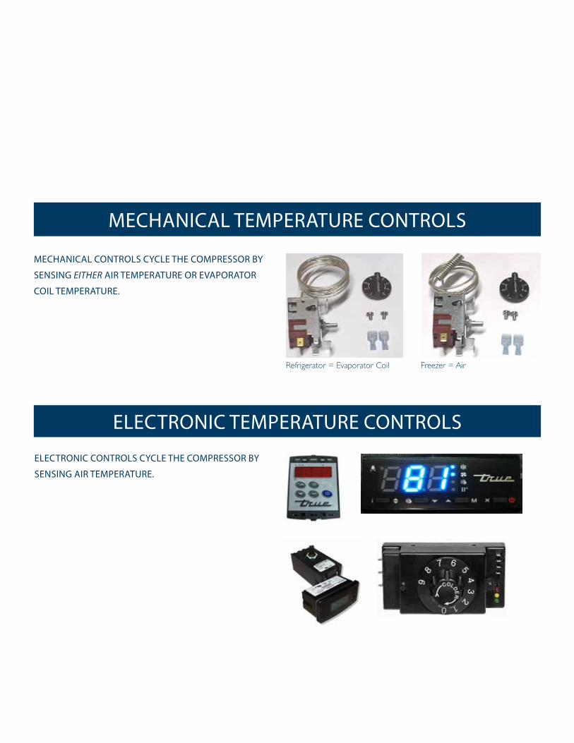
MECHANICAL TEMPERATURE CONTROLS
Refrigerator = Evaporator Coil Freezer = Air
ELECTRONIC CONTROLS CYCLE THE COMPRESSOR BY
SENSING AIR TEMPERATURE.
ELECTRONIC TEMPERATURE CONTROLS
MECHANICAL CONTROLS CYCLE THE COMPRESSOR BY
SENSING EITHER AIR TEMPERATURE OR EVAPORATOR
COIL TEMPERATURE.
4
TRUEtemperature controls sequence of operation www.truemfg.com
STARTUP A. Temperature controls are factory-set to give refrigerators an approximate temperature of 35°F (1.6°C) and freezers an
approximate temperature of -10°F (-23.3°C). Allow unit to function several hours, completely cooling cabinet before changing the control setting.
Temperature Control Location and Settings.
• Temperature control type will vary upon model and age of cabinet.
• Mechanical control or electronic control without display: - Inside cabinet - Behind cabinet - Behind front or rear access grill
• Electronic control with display: - In countertop - In top louvered panel - In or behind bottom louvered grill
B. Excessive tampering with the control could lead to service difficulties. Should it ever become necessary to replace temperature control, be sure it is ordered from your TRUE dealer or recommended service agent.
OPERATION
5
TRUEtemperature controls sequence of operation www.truemfg.com
MECHANICAL TEMPERATURE CONTROL GENERAL SEQUENCE OF OPERATION
HOW TO DIAGNOSE
CHECKING THE CUT IN AND CUT OUT OF THE TEMPERATURE CONTROL
CONDITIONS THAT COULD CAUSE A TEMPERATURE CONTROL MISDIAGNOSIS
CHANGING OUT AND INSTALLING A MECHANICAL TEMPERATURE CONTROL
WHEN TO MAKE AN ADJUSTMENT TO A MECHANICAL TEMPERATURE CONTROL
HOW TO ADJUST A MECHANICAL TEMPERATURE CONTROL
MECHANICAL TEMPERATURE CONTROLS
6
TRUEtemperature controls sequence of operation www.truemfg.com
MECHANICAL TEMPERATURE CONTROLS
MECHANICAL TEMPERATURE CONTROL GENERAL SEQUENCE OF OPERATION
MECHANICAL CONTROL REFRIGERATOR GENERAL SEQUENCE OF OPERATION
1. Cabinet is plugged in. a. Interior lights will illuminate on Glass Door Models only. If lights do not come on verify the light switch is in the “ON”
position. Solid door cabinets may or may not have lights that may be controlled by the door switch.
2. The compressor and evaporator fans will start if the temperature control is calling for cooling. (If the compressor does not start, verify that the temperature control is not in the “OFF” or “0” position.)
3. The temperature control may cycle the compressor and evaporator fan(s) on and off together. a. The temperature control is sensing the evaporator coil temperature. b. The temperature control should be set on the #4 or #5. c. The warmest setting is #1, the coldest is #9, and #0 is the off position. d. The thermometer is designed to read and display a cabinet temperature not a product temperature. The thermometer may reflect the refrigeration cycle swings of up and down temperatures. The most accurate temperature on a cabinet's operation is to verify the product temperature.
4. There is not a defrost timer as the temperature control will initiate the off-cycle defrost during each refrigeration cycle. a. At this time, the compressor will and the evaporator fan(s) may turn off. Defrost heaters are not installed on refrigerators
and therefore will not be energized. b. After the evaporator coil temperature has been reached, as determined by the temperature control, the compressor will
restart.5. There may be a timer located on the condensing unit base. This timer is not used for a defrost event. The timer will change
the rotation of the reversing condenser fan motor.
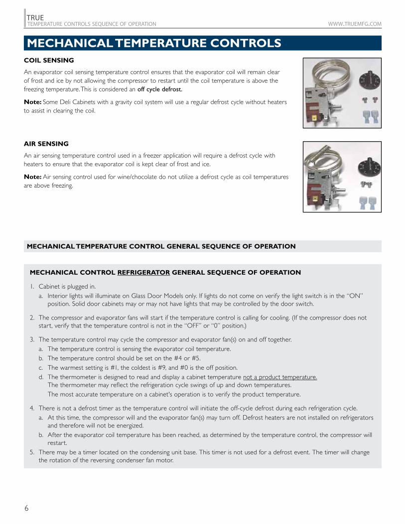
COIL SENSING
An evaporator coil sensing temperature control ensures that the evaporator coil will remain clear of frost and ice by not allowing the compressor to restart until the coil temperature is above the freezing temperature. This is considered an off cycle defrost.
Note: Some Deli Cabinets with a gravity coil system will use a regular defrost cycle without heaters to assist in clearing the coil.
AIR SENSING
An air sensing temperature control used in a freezer application will require a defrost cycle with heaters to ensure that the evaporator coil is kept clear of frost and ice.
Note: Air sensing control used for wine/chocolate do not utilize a defrost cycle as coil temperatures are above freezing.
7
TRUEtemperature controls sequence of operation www.truemfg.com
MECHANICAL TEMPERATURE CONTROLS
MECHANICAL CONTROL FREEZER GENERAL SEQUENCE OF OPERATION
1. Cabinet is plugged in. a. Interior lights will illuminate on glass door models only. If lights do not come on, verify the light switch is in
the “ON” position. Solid door cabinets may or may not have lights that may be controlled by the door switch.
2. The compressor only will start if the temperature control is calling for cooling. (If the compressor does not start, verify that the temperature control is not in the “OFF” or “0” position or the cabinet is not in a defrost event.)
a. The evaporator fan(s) will remain off until a specific temperature of the evaporator coil is reached.
3. The temperature control may cycle the compressor and evaporator fan(s) on and off together. a. The temperature control is sensing the air temperature. b. The temperature control should be set on the #4 or #5. c. The warmest setting is #1, the coldest is #9, and #0 is the off position. d. The thermometer is designed to read and display a cabinet temperature not a product temperature.
The thermometer may reflect the refrigeration cycle swings of up and down temperatures. The most accurate temperature on a cabinet's operation is to verify the product temperature.
4. The defrost timer will initiate defrost during specific times of day. a. At this time, the compressor and evaporator fan(s) will turn off and the evaporator coil heater and drain tube heater will
be energized. Some cabinets may also change the rotation of the reversing condenser fan motor. b. After the predetermined evaporator coil temperature has been reached or duration for defrost has expired, the
compressor will restart and the evaporator fan(s) will remain off until a specific temperature of the evaporator coil is reached.
MECHANICAL CONTROL DELI DISPLAY GENERAL SEQUENCE OF OPERATION
1. Cabinet is plugged in. a. Interior lights will illuminate. If lights do not come on verify the light switch is in the “ON” position.
2. a. The compressor and evaporator fans will start on a model TCGR if the temperature control is calling for cooling. (If the compressor does not start, verify that the temperature control is not in the “OFF” or “0” position.)
b. The compressor will start on models TSID, TDBD, and TCGG if the temperature control is calling for cooling. (The above 3 models are a gravity style coil design and do not have an evaporator fan motor.)
3. The temperature control may cycle the compressor and evaporator fan(s) on and off together. a. The temperature control is sensing the evaporator coil temperature. b. The temperature control should be set on the #4 or #5. c. The warmest setting is #1, the coldest is #9, and #0 is the off position. d. The thermometer is designed to read and display a cabinet temperature not a product temperature.
The thermometer may reflect the refrigeration cycle swings of up and down temperatures. The most accurate temperature on a cabinet's operation is to verify the product temperature.
4. There is not a defrost timer on a model TCGR as the temperature control will initiate the off-cycle defrost during each refrigeration cycle.
a. At this time, the compressor will turn off. Defrost heaters are not installed on refrigerators and therefore will not be energized.
b. After the evaporator coil temperature has been reached determined by the temperature control, the compressor will restart.
The defrost timer will initiate defrost on models TSID, TDBD, and TCGG during specific times of day. a. At this time, the compressor will turn off. No heaters will be energized. b. After the predetermined duration has expired, the compressor will restart.
8
TRUEtemperature controls sequence of operation www.truemfg.com
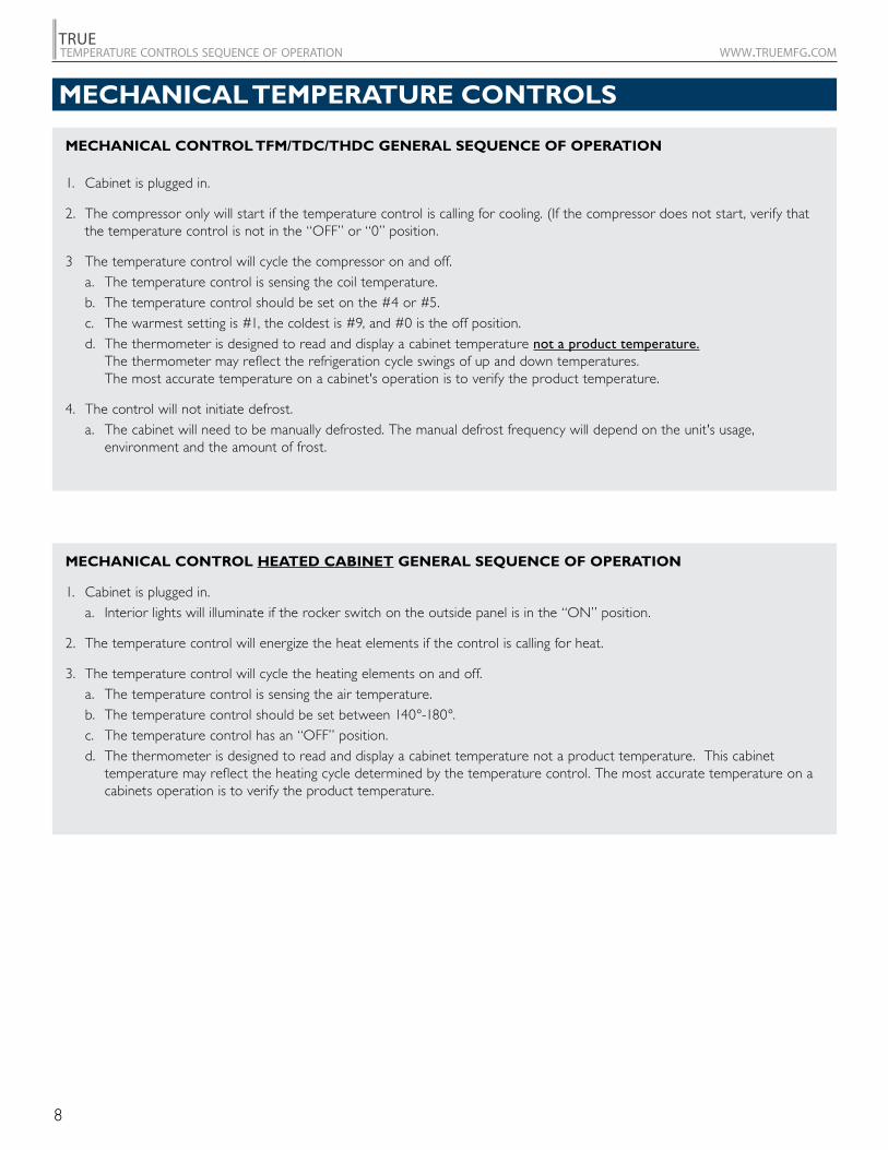
MECHANICAL CONTROL HEATED CABINET GENERAL SEQUENCE OF OPERATION
1. Cabinet is plugged in. a. Interior lights will illuminate if the rocker switch on the outside panel is in the “ON” position.
2. The temperature control will energize the heat elements if the control is calling for heat.
3. The temperature control will cycle the heating elements on and off. a. The temperature control is sensing the air temperature. b. The temperature control should be set between 140°-180°. c. The temperature control has an “OFF” position. d. The thermometer is designed to read and display a cabinet temperature not a product temperature. This cabinet
temperature may reflect the heating cycle determined by the temperature control. The most accurate temperature on a cabinets operation is to verify the product temperature.
MECHANICAL CONTROL TFM/TDC/THDC GENERAL SEQUENCE OF OPERATION
1. Cabinet is plugged in.
2. The compressor only will start if the temperature control is calling for cooling. (If the compressor does not start, verify that the temperature control is not in the “OFF” or “0” position.
3 The temperature control will cycle the compressor on and off. a. The temperature control is sensing the coil temperature. b. The temperature control should be set on the #4 or #5. c. The warmest setting is #1, the coldest is #9, and #0 is the off position. d. The thermometer is designed to read and display a cabinet temperature not a product temperature.
The thermometer may reflect the refrigeration cycle swings of up and down temperatures. The most accurate temperature on a cabinet's operation is to verify the product temperature.
4. The control will not initiate defrost. a. The cabinet will need to be manually defrosted. The manual defrost frequency will depend on the unit's usage,
environment and the amount of frost.
MECHANICAL TEMPERATURE CONTROLS
9
TRUEtemperature controls sequence of operation www.truemfg.com
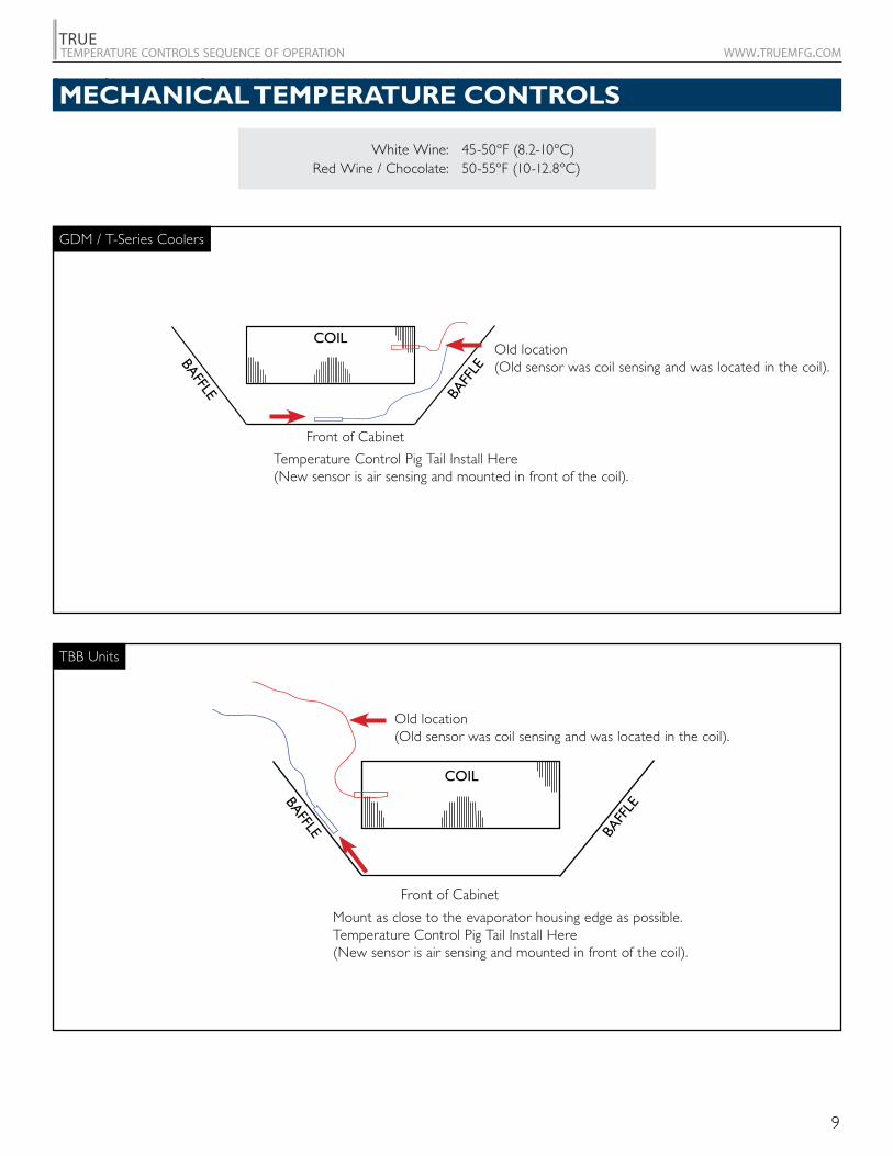
White Wine: 45-50ºF (8.2-10ºC) Red Wine / Chocolate: 50-55ºF (10-12.8ºC)
Some refrigerators used for special applications may have an air sensing control. These cabinets will run at a temperature where the evaporator coil never has the potential to freeze.
Front of Cabinet
Front of Cabinet
11
CONVERTED TO A WINE OR CHOCOLATE UNITSTANDARD TEMPERATURE CONTROL UNIT
GDM/T-SERIES COOLERS (TOP VIEW LOOKING DOWN)
Temperature Control Pig Tail Install Here (New sensor is air sensing and mounted in front of the coil).
Coil
BaffleBaffl
e
Old location (old sensor was coil sensing and was located in the coil).
FRONT VIEW OF CABINET
TBB UNITS
Mount as close to the evaporator housing edge as possible. Temperature Control Pig Tail Install Here (New sensor is air sensing and mounted in front of the coil).
Coil
BaffleBaffl
e
Old location (old sensor was coil sensing and was located in the coil).
Old location (Old sensor was coil sensing and was located in the coil).
Temperature Control Pig Tail Install Here (New sensor is air sensing and mounted in front of the coil).
Old location (Old sensor was coil sensing and was located in the coil).
Mount as close to the evaporator housing edge as possible. Temperature Control Pig Tail Install Here (New sensor is air sensing and mounted in front of the coil).
GDM / T-Series Coolers
TBB Units
MECHANICAL TEMPERATURE CONTROLS
10
TRUEtemperature controls sequence of operation www.truemfg.com
OLD TRUE P/N
NEW TRUE P/N (KIT) MFG P/N APPLICATION CUT-IN
ºF (C)CUT-OUT
ºF (C)800303 9531N376 35.0 (1.7) 14.5 (-9.7)
800304 9530N1490 -8.5 (-22.5) -14.5 (-25.8)
800306 9531N251 40.0 (4.4) 19.0 (-7.2)
800312 9530N1284 -8.5 (-22.5) -14.5 (-25.8)
800313 9531N335 36.5 (2.5) 16.0 (-8.9)
800320 9530N1185 32.5 (0.3) 26.5 (-3.1)
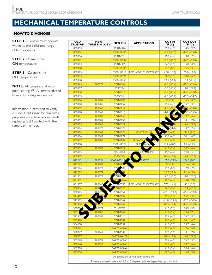
800325 9530N1318 RED WINE, CHOCOLATE 62.0 (16.7) 55.0 (12.8)
800335 9530N1376 38.0 (3.3) 20.0 (-6.7)
800340 9530N1155 26.1 (-3.3) 10.9 (-11.7)
800345 988271 077B1264 -2.6 (-19.4) -15.5 (-26.6)
800357 9530266 -3.0 (-19.4) -8.0 (-22.2)
800358 077B1214 -8.5 (-22.7) -14.4 (-26.0)
800363 9530C311 -2.6 (-19.2) -12.5 (-24.7)
800366 988282 077B6806 37 (2.8) 16.5 (-8.7)
800368 988285 077B6857 39.6 (4.3) 26.2 (-3.2)
800369 988266 077B1212 -2.6 (-19.4) -12.3 (-24.8)
800370 988267 077B1216 -4.0 (-20-2) -15.3 (-26.5)
800371 988286 077B6863 41.9 (5.5) 23.7 (-4.6)
800382 988284 077B6856 37.2 (2.9) 18.1 (-7.8)
800383 988268 077B1227 0.3 (-17.8) -5.6 (-21.1)
800384 988270 077B1229 24.8 (-4.0) 18.7 (-7.4)
800385 988269 077B1228 WHITE WINE 44.2 (6.8) 34.7 (1.5)
800386 988287 077B6871 43.2 (6.3) 20.1 (-6.7)
800387 988288 077B6887 FLOWER COOLER 39.2 (4.0) 21.2 (-6.0)
800390 9530N1329 SUPER NOVA 13.1 (-10.5) 8.1 (-13.3)
800393 988283 077B6827 41.7 (5.4) 20.5 (-6.4)
800395 931N370 HIGH ALTITUDE 40.0 (4.4) 22.8 (-5.1)
800399 9530C304 0.4 (-17.6) -5.4 (-20.8)
822212 988291 CAP-075-174R HEATED 165.0 (73.9) 174.0 (78.9)
822213 988289 077B6894 37 (2.8) 21.6 (-5.8)
822214 988273 077B1309 32.0 (0.0) 17.9 (-7.9)
822223 988274 077B1331 25.7 (-3.5) 8.6 (-13.0)
831931 988272 077B1277 -2.0 (-19.0) -9.0 (-23.0)
831932 3ART56VAA4 40.0 (4.4) 18.0 (-7.8)
831987 988265 077B0995 RED WINE, CHOCOLATE 57.2 (14.1) 49.6 (9.9)
908854 988290 077B6926 36.3 (2.4) 10.4 (-12.1)
908975 988275 077B1352 -12.1 (-24.7) -25.1 (-32.0)
911427 988276 077B1354 37.6 (3.1) 26.2 (-3.2)
913382 988277 077B1367 -11.0 (-24.1) -22.5 (-30.5)
917838 988278 077B1369 0.3 (-17.8) -14.1 (-25.8)
930794 988279 091X9775 41.5 (5.3) 24.9 (-3.9)
933190 988280 077B3264 41.7 (5.4) 19.4 (-7.1)
942659 988281 077B3315 39.6 (4.3) 26.2 (-3.2)
952478 077B3347 43.2 (6.3) 20.1 (-6.7)
954800 077B3531 41.9 (5.5) 23.7 (-4.6)
958745 3ART55VAA4 39.2 (4.0) 17.6 (-8.0)
958747 988264 077B3548 37.2 (2.9) 18.1 (-7.8)
958857 3ART5VAA198 8.0 (-13.3) -6.0 (-21.1)
959268 988294 3ART55VAA3 39.6 (4.2) 26.2 (-3.2)
960640 988296 3ART55VAA5 43.1 (6.2) 20.2 (-6.6)
962728 3ART55VAA6 41.8 (5.4) 20.4 (-6.4)
963056 3ART55VAA2 39.2 (4.0) 15.8 (-9.0)
All temps are at mid-point setting #5
All temps advised have a +/- 1.8 to 2 degree variance depending upon control
STEP 1 - Control must operate within its pre-calibrated range of temperatures. STEP 2 - Cut-in is the ON temperature. STEP 3 - Cut-out is the OFF temperature.
NOTE: All temps are at mid-point setting #5. All temps advised have a +/- 2 degree variance.
HOW TO DIAGNOSE
SUBJECT TO C
HANGEInformation is provided to verify cut-in/cut-out range for diagnostic purposes only. True recommends replacing OEM control with the same part number.
MECHANICAL TEMPERATURE CONTROLS
11
TRUEtemperature controls sequence of operation www.truemfg.com
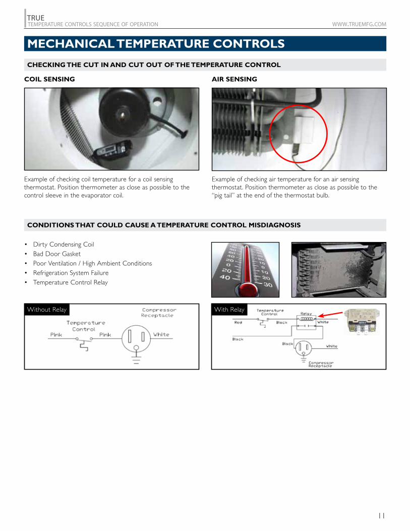
CONDITIONS THAT COULD CAUSE A TEMPERATURE CONTROL MISDIAGNOSIS
• Dirty Condensing Coil• Bad Door Gasket• Poor Ventilation / High Ambient Conditions• Refrigeration System Failure• Temperature Control Relay
COIL SENSING AIR SENSING
CHECKING THE CUT IN AND CUT OUT OF THE TEMPERATURE CONTROL
Without Relay With Relay
Example of checking coil temperature for a coil sensing thermostat. Position thermometer as close as possible to the control sleeve in the evaporator coil.
Example of checking air temperature for an air sensing thermostat. Position thermometer as close as possible to the “pig tail” at the end of the thermostat bulb.
MECHANICAL TEMPERATURE CONTROLS
12
TRUEtemperature controls sequence of operation www.truemfg.com
WHEN TO MAKE AN ADJUSTMENT TO A MECHANICAL TEMPERATURE CONTROL
WARMER
COLDE R
60
30
45
40
35
50
55
15
20
25
10
5
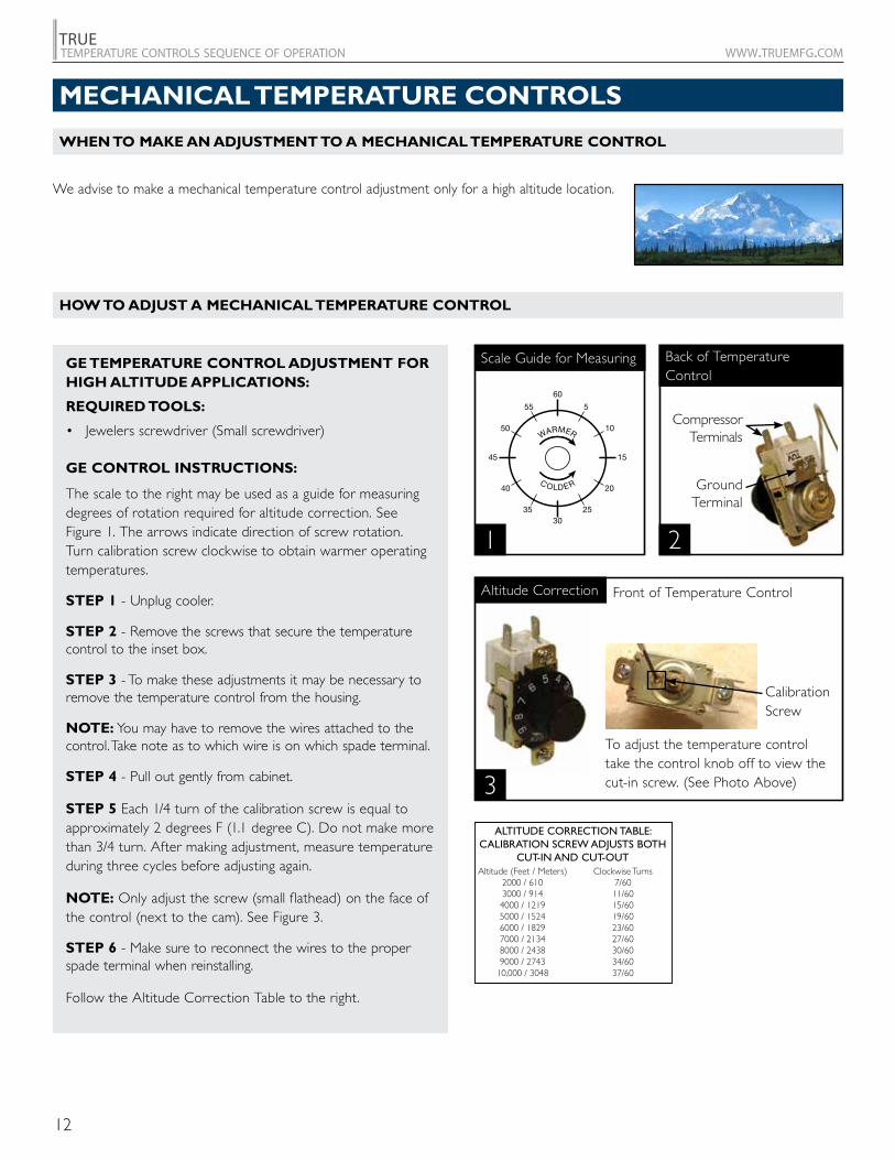
We advise to make a mechanical temperature control adjustment only for a high altitude location.
Compressor Terminals
GroundTerminal
To adjust the temperature control take the control knob off to view the cut-in screw. (See Photo Above)
Front of Temperature Control
Calibration Screw
1 2
3
ALTITUDE CORRECTION TABLE: CALIBRATION SCREW ADJUSTS BOTH
CUT-IN AND CUT-OUTAltitude (Feet / Meters)
2000 / 6103000 / 9144000 / 12195000 / 15246000 / 18297000 / 21348000 / 24389000 / 2743
10,000 / 3048
Clockwise Turns7/6011/6015/6019/6023/6027/6030/6034/6037/60
HOW TO ADJUST A MECHANICAL TEMPERATURE CONTROL
Altitude Correction
Scale Guide for Measuring Back of Temperature Control
GE TEMPERATURE CONTROL ADJUSTMENT FOR HIGH ALTITUDE APPLICATIONS:
REQUIRED TOOLS:
• Jewelers screwdriver (Small screwdriver)
GE CONTROL INSTRUCTIONS:
The scale to the right may be used as a guide for measuring degrees of rotation required for altitude correction. See Figure 1. The arrows indicate direction of screw rotation. Turn calibration screw clockwise to obtain warmer operating temperatures.
STEP 1 - Unplug cooler.
STEP 2 - Remove the screws that secure the temperature control to the inset box.
STEP 3 - To make these adjustments it may be necessary to remove the temperature control from the housing.
NOTE: You may have to remove the wires attached to the control. Take note as to which wire is on which spade terminal.
STEP 4 - Pull out gently from cabinet.
STEP 5 Each 1/4 turn of the calibration screw is equal to approximately 2 degrees F (1.1 degree C). Do not make more than 3/4 turn. After making adjustment, measure temperature during three cycles before adjusting again.
NOTE: Only adjust the screw (small flathead) on the face of the control (next to the cam). See Figure 3.
STEP 6 - Make sure to reconnect the wires to the proper spade terminal when reinstalling.
Follow the Altitude Correction Table to the right.
MECHANICAL TEMPERATURE CONTROLS
13
TRUEtemperature controls sequence of operation www.truemfg.com
1
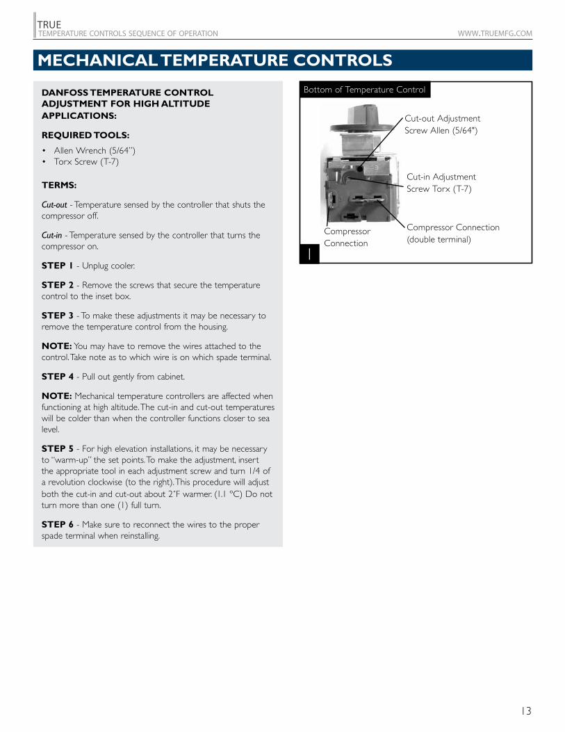
Cut-out AdjustmentScrew Allen (5/64")
Cut-in AdjustmentScrew Torx (T-7)
Compressor Connection
Compressor Connection (double terminal)
Bottom of Temperature ControlDANFOSS TEMPERATURE CONTROL ADJUSTMENT FOR HIGH ALTITUDE APPLICATIONS:
REQUIRED TOOLS:
• Allen Wrench (5/64”)• Torx Screw (T-7)
TERMS:
Cut-out - Temperature sensed by the controller that shuts the compressor off.
Cut-in - Temperature sensed by the controller that turns the compressor on.
STEP 1 - Unplug cooler.
STEP 2 - Remove the screws that secure the temperature control to the inset box.
STEP 3 - To make these adjustments it may be necessary to remove the temperature control from the housing.
NOTE: You may have to remove the wires attached to the control. Take note as to which wire is on which spade terminal.
STEP 4 - Pull out gently from cabinet.
NOTE: Mechanical temperature controllers are affected when functioning at high altitude. The cut-in and cut-out temperatures will be colder than when the controller functions closer to sea level.
STEP 5 - For high elevation installations, it may be necessary to “warm-up” the set points. To make the adjustment, insert the appropriate tool in each adjustment screw and turn 1/4 of a revolution clockwise (to the right). This procedure will adjust both the cut-in and cut-out about 2˚F warmer. (1.1 ºC) Do not turn more than one (1) full turn.
STEP 6 - Make sure to reconnect the wires to the proper spade terminal when reinstalling.
MECHANICAL TEMPERATURE CONTROLS

14
TRUEtemperature controls sequence of operation www.truemfg.com
15
TRUEtemperature controls sequence of operation www.truemfg.com
DIXELL
DIXELL ELECTRONIC TEMPERATURE CONTROL GENERAL SEQUENCE OF OPERATION
USING THE DIXELL ELECTRONIC CONTROL
LAE
LAE ELECTRONIC TEMPERATURE CONTROL GENERAL SEQUENCE OF OPERATION
USING THE LAE ELECTRONIC CONTROL
DANFOSS
DANFOSS ELECTRONIC TEMPERATURE CONTROL GENERAL SEQUENCE OF OPERATION
USING THE DANFOSS ELECTRONIC CONTROL
SOLLATEK
SOLLATEK ELECTRONIC TEMPERATURE CONTROL GENERAL SEQUENCE OF OPERATION
USING THE SOLLATEK ELECTRONIC CONTROL
ELECTRONIC TEMPERATURE CONTROLS

16
TRUEtemperature controls sequence of operation www.truemfg.com
17
TRUEtemperature controls sequence of operation www.truemfg.com
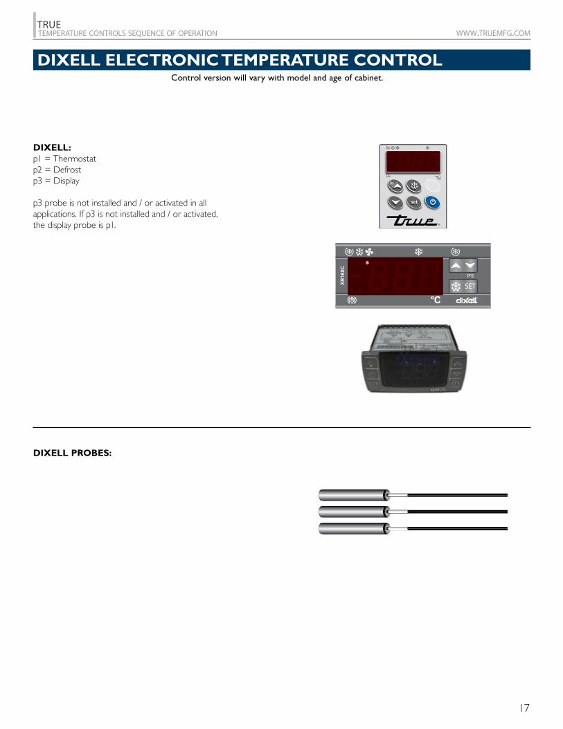
Control version will vary with model and age of cabinet.
DIXELL:p1 = Thermostat p2 = Defrostp3 = Display
p3 probe is not installed and / or activated in all applications. If p3 is not installed and / or activated, the display probe is p1.
SET
prg
XR160C
DIXELL ELECTRONIC TEMPERATURE CONTROL
DIXELL PROBES:
18
TRUEtemperature controls sequence of operation www.truemfg.com
DIXELL ELECTRONIC TEMPERATURE CONTROL
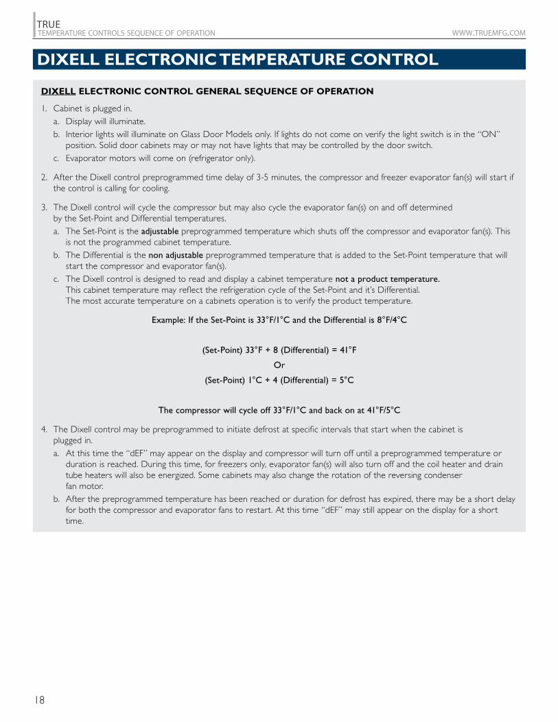
DIXELL ELECTRONIC CONTROL GENERAL SEQUENCE OF OPERATION
1. Cabinet is plugged in. a. Display will illuminate. b. Interior lights will illuminate on Glass Door Models only. If lights do not come on verify the light switch is in the “ON”
position. Solid door cabinets may or may not have lights that may be controlled by the door switch. c. Evaporator motors will come on (refrigerator only).
2. After the Dixell control preprogrammed time delay of 3-5 minutes, the compressor and freezer evaporator fan(s) will start if the control is calling for cooling.
3. The Dixell control will cycle the compressor but may also cycle the evaporator fan(s) on and off determined by the Set-Point and Differential temperatures.
a. The Set-Point is the adjustable preprogrammed temperature which shuts off the compressor and evaporator fan(s). This is not the programmed cabinet temperature.
b. The Differential is the non adjustable preprogrammed temperature that is added to the Set-Point temperature that will start the compressor and evaporator fan(s).
c. The Dixell control is designed to read and display a cabinet temperature not a product temperature. This cabinet temperature may reflect the refrigeration cycle of the Set-Point and it’s Differential. The most accurate temperature on a cabinets operation is to verify the product temperature.
Example: If the Set-Point is 33°F/1°C and the Differential is 8°F/4°C
(Set-Point) 33°F + 8 (Differential) = 41°F
Or
(Set-Point) 1°C + 4 (Differential) = 5°C
The compressor will cycle off 33°F/1°C and back on at 41°F/5°C
4. The Dixell control may be preprogrammed to initiate defrost at specific intervals that start when the cabinet is plugged in.
a. At this time the “dEF” may appear on the display and compressor will turn off until a preprogrammed temperature or duration is reached. During this time, for freezers only, evaporator fan(s) will also turn off and the coil heater and drain tube heaters will also be energized. Some cabinets may also change the rotation of the reversing condenser fan motor.
b. After the preprogrammed temperature has been reached or duration for defrost has expired, there may be a short delay for both the compressor and evaporator fans to restart. At this time “dEF” may still appear on the display for a short time.
19
TRUEtemperature controls sequence of operation www.truemfg.com
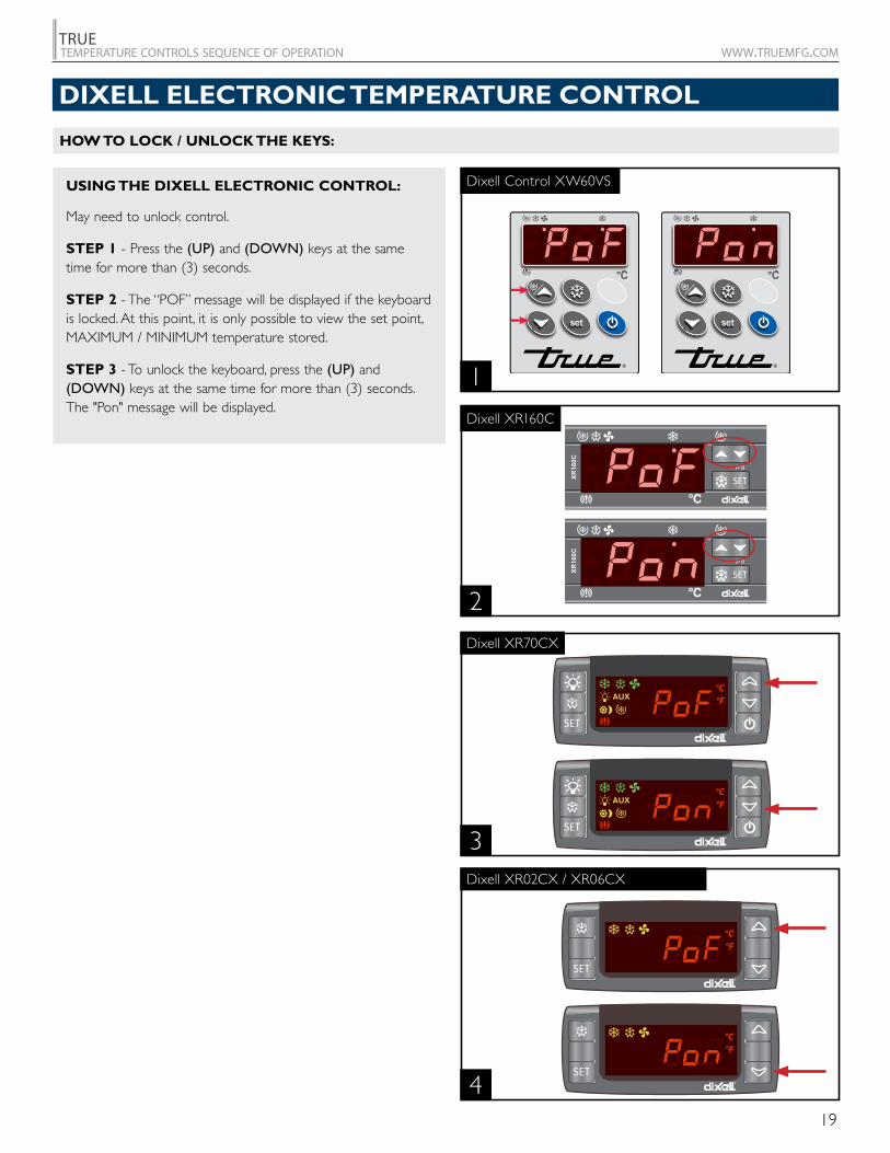
USING THE DIXELL ELECTRONIC CONTROL:
May need to unlock control.
STEP 1 - Press the (UP) and (DOWN) keys at the same time for more than (3) seconds.
STEP 2 - The “POF” message will be displayed if the keyboard is locked. At this point, it is only possible to view the set point, MAXIMUM / MINIMUM temperature stored.
STEP 3 - To unlock the keyboard, press the (UP) and (DOWN) keys at the same time for more than (3) seconds. The "Pon" message will be displayed.
HOW TO LOCK / UNLOCK THE KEYS:
3
4
2
Dixell XR160C
Dixell XR70CX
Dixell XR02CX / XR06CX
1
Dixell Control XW60VS
SET
°F°C
AUX
SET
°F°C
AUX
SET
°F°C
SET
°F°C
DIXELL ELECTRONIC TEMPERATURE CONTROL
SET
prg
XR160C
SET
prg
XR160C
20
TRUEtemperature controls sequence of operation www.truemfg.com
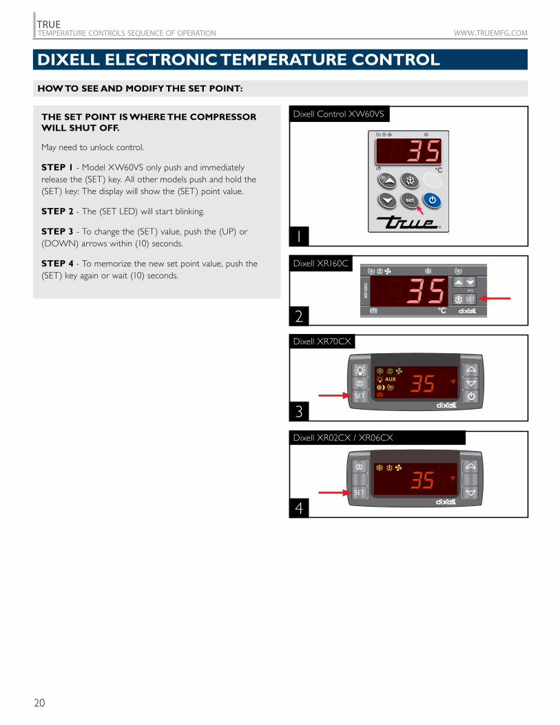
HOW TO SEE AND MODIFY THE SET POINT:
THE SET POINT IS WHERE THE COMPRESSOR WILL SHUT OFF.
May need to unlock control.
STEP 1 - Model XW60VS only push and immediately release the (SET) key. All other models push and hold the (SET) key: The display will show the (SET) point value.
STEP 2 - The (SET LED) will start blinking.
STEP 3 - To change the (SET) value, push the (UP) or (DOWN) arrows within (10) seconds.
STEP 4 - To memorize the new set point value, push the (SET) key again or wait (10) seconds.
SET
prg
XR160C
2
Dixell XR160C
1
Dixell Control XW60VS
DIXELL ELECTRONIC TEMPERATURE CONTROL
3
4
Dixell XR70CX
Dixell XR02CX / XR06CX
SET
°F°C
AUX
SET
°F°C
21
TRUEtemperature controls sequence of operation www.truemfg.com
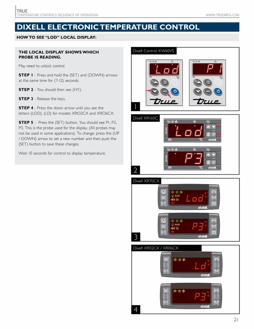
DIXELL ELECTRONIC TEMPERATURE CONTROLHOW TO SEE “LOD” LOCAL DISPLAY:
THE LOCAL DISPLAY SHOWS WHICH PROBE IS READING.
May need to unlock control.
STEP 1 - Press and hold the (SET) and (DOWN) arrows at the same time for (7-12) seconds.
STEP 2 - You should then see (HY).
STEP 3 - Release the keys.
STEP 4 - Press the down arrow until you see the letters (LOD), (LD) for models XRO2CX and XRO6CX.
STEP 5 - Press the (SET) button. You should see P1, P2, P3. This is the probe used for the display. (All probes may not be used in some applications). To change, press the (UP / DOWN) arrow to set a new number and then push the (SET) button to save these changes.
Wait 10 seconds for control to display temperature.
SET
prg
XR160C
SET
prg
XR160C
2
Dixell XR160C
1
Dixell Control XW60VS
3
4
Dixell XR70CX
Dixell XR02CX / XR06CX
SET
°F°C
AUX
SET
°F°C
AUX
SET
°F°C
SET
°F°C
22
TRUEtemperature controls sequence of operation www.truemfg.com
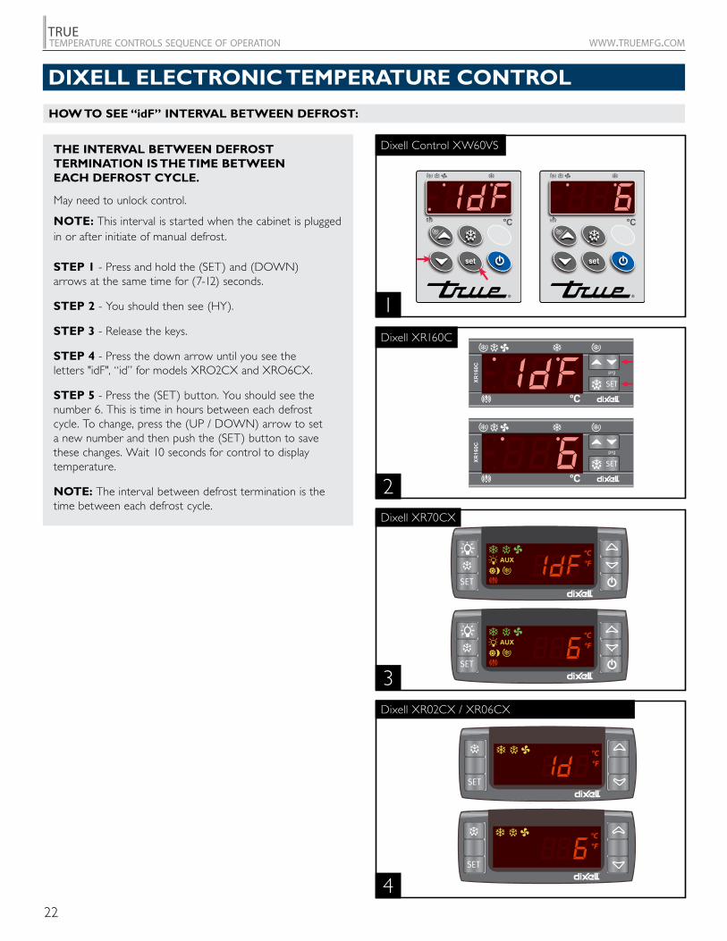
THE INTERVAL BETWEEN DEFROST TERMINATION IS THE TIME BETWEEN EACH DEFROST CYCLE.
May need to unlock control.
NOTE: This interval is started when the cabinet is plugged in or after initiate of manual defrost.
STEP 1 - Press and hold the (SET) and (DOWN) arrows at the same time for (7-12) seconds.
STEP 2 - You should then see (HY).
STEP 3 - Release the keys.
STEP 4 - Press the down arrow until you see the letters "idF", “id” for models XRO2CX and XRO6CX.
STEP 5 - Press the (SET) button. You should see the number 6. This is time in hours between each defrost cycle. To change, press the (UP / DOWN) arrow to set a new number and then push the (SET) button to save these changes. Wait 10 seconds for control to display temperature.
NOTE: The interval between defrost termination is the time between each defrost cycle.
SET
prg
XR160C
SET
prg
XR160C
2
Dixell XR160C
1
Dixell Control XW60VS
DIXELL ELECTRONIC TEMPERATURE CONTROL
HOW TO SEE “idF” INTERVAL BETWEEN DEFROST:
3
4
Dixell XR70CX
Dixell XR02CX / XR06CX
SET
°F°C
AUX
SET
°F°C
AUX
SET
°F°C
SET
°F°C
23
TRUEtemperature controls sequence of operation www.truemfg.com
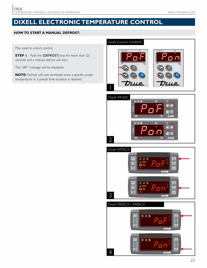
May need to unlock control.
STEP 1 - Push the (DEFROST) key for more than (2) seconds and a manual defrost will start.
The “dEF” message will be displayed.
NOTE: Defrost will only terminate once a specific preset temperature or a preset time duration is reached.
DIXELL ELECTRONIC TEMPERATURE CONTROL
HOW TO START A MANUAL DEFROST:
3
4
2
Dixell XR160C
Dixell XR70CX
Dixell XR02CX / XR06CX
1
Dixell Control XW60VS
SET
°F°C
AUX
SET
°F°C
AUX
SET
°F°C
SET
°F°C
SET
prg
XR160C
SET
prg
XR160C
24
TRUEtemperature controls sequence of operation www.truemfg.com
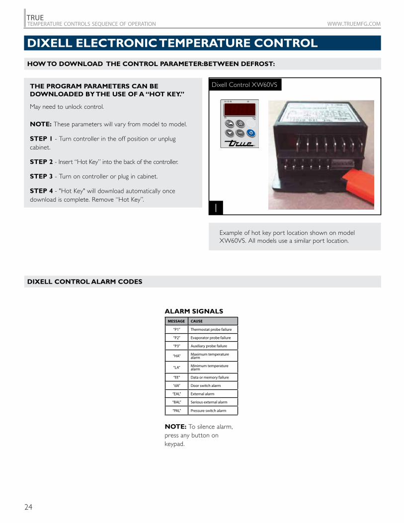
THE PROGRAM PARAMETERS CAN BE DOWNLOADED BY THE USE OF A “HOT KEY.”
May need to unlock control.
NOTE: These parameters will vary from model to model.
STEP 1 - Turn controller in the off position or unplug cabinet.
STEP 2 - Insert “Hot Key” into the back of the controller.
STEP 3 - Turn on controller or plug in cabinet.
STEP 4 - "Hot Key" will download automatically once download is complete. Remove “Hot Key”.
1
Dixell Control XW60VS
Example of hot key port location shown on model XW60VS. All models use a similar port location.
DIXELL ELECTRONIC TEMPERATURE CONTROL
ALARM SIGNALSMESSAGE CAUSE
“P1” Thermostat probe failure
“P2” Evaporator probe failure
“P3” Auxiliary probe failure
“HA” Maximum temperature alarm
“LA” Minimum temperature alarm
“EE” Data or memory failure
“dA” Door switch alarm
“EAL” External alarm
“BAL” Serious external alarm
“PAL” Pressure switch alarm
NOTE: To silence alarm, press any button on keypad.
HOW TO DOWNLOAD THE CONTROL PARAMETER:BETWEEN DEFROST:
DIXELL CONTROL ALARM CODES
25
TRUEtemperature controls sequence of operation www.truemfg.com
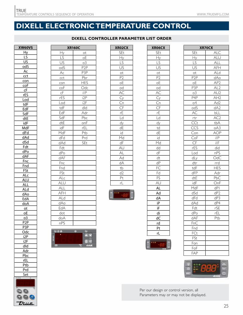
Per our design or control version, all Parameters may or may not be displayed.
SET
prg
XR160C
SET
°F°C
SET
°F°C
DIXELL ELECTRONIC TEMPERATURE CONTROL
DIXELL CONTROLLER PARAMETER LIST ORDER
XW60VSHyLSUS
odSAccctconcoFcFrESLodtdFEdFSdFdtEidF
MdFdFddAddSdFdtdPodAFFncFndFStALcALUALLALddAoEdAdoAotoEo3
P2PP3POdci2Pi2FdIdAdrPbcrELPtbPrdSet
XR02CXSEtHyLSUSotP2oEodACCyCnCFrELddydEid
MddFAUALAddAtbd2PtrL
XR06CXSEtHyLSUSotP2oEodACCyCnCFrELddytddEid
MddddFdtdPFCFdFSAUALAddAiPiFdidCrdPtrL
XR160CHy otLS oEUS o3odS P2PAc P3Pcct Pbrcon HEScoF OdccF i1PrES i2PLod i2FtdF dIdEdF AdrSdF PbcdtE onFidF rEL
MdF PtbdFd PrddAd SEtFdtdPodAFFncFndFStALcALUALLAFHALddAoEdAdotdoAnPS
XR70CXSEt ALCHy ALULS ALLUS AFHot ALd
P2P dAooE AP2P3P AL2o3 AU2P4P AH2o4 Ad2odS dA2AC bLLrtr AC2
CCt tbACCS oA3Con AOPCoF i1PCF i1FrES didLod nPSdLy OdCdtr rrdtdF HESdFP AdrdtE PbCidF OnF
MdF dP1dSd dP2dFd dP3dAd dP4Fdt rSEdPo rELdAF PtbFnCFndFCtFStFonFoFFAP
26
TRUEtemperature controls sequence of operation www.truemfg.com
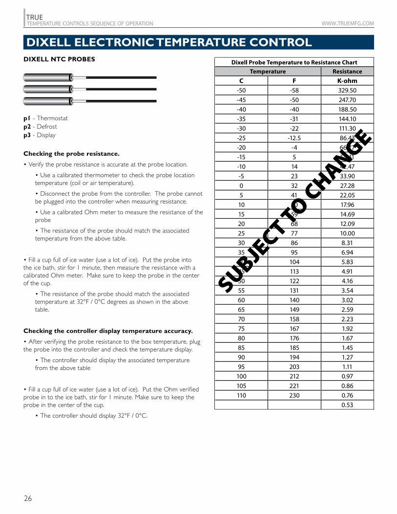
p1 - Thermostatp2 - Defrostp3 - Display
DIXELL NTC PROBES Dixell Probe Temperature to Resistance Chart
Temperature Resistance
C F K-ohm-50 -58 329.50-45 -50 247.70-40 -40 188.50-35 -31 144.10-30 -22 111.30-25 -12.5 86.43-20 -4 66.77-15 5 53.41-10 14 42.47-5 23 33.900 32 27.285 41 22.05
10 50 17.9615 59 14.6920 68 12.0925 77 10.0030 86 8.3135 95 6.9440 104 5.8345 113 4.9150 122 4.1655 131 3.5460 140 3.0265 149 2.5970 158 2.2375 167 1.9280 176 1.6785 185 1.4590 194 1.2795 203 1.11
100 212 0.97105 221 0.86110 230 0.76
0.53
SUBJECT TO C
HANGE
Checking the probe resistance.
• Verify the probe resistance is accurate at the probe location.
• Use a calibrated thermometer to check the probe location temperature (coil or air temperature).
• Disconnect the probe from the controller. The probe cannot be plugged into the controller when measuring resistance.
• Use a calibrated Ohm meter to measure the resistance of the probe
• The resistance of the probe should match the associated temperature from the above table.
• Fill a cup full of ice water (use a lot of ice). Put the probe into the ice bath, stir for 1 minute, then measure the resistance with a calibrated Ohm meter. Make sure to keep the probe in the center of the cup.
• The resistance of the probe should match the associated temperature at 32°F / 0°C degrees as shown in the above table.
Checking the controller display temperature accuracy.
• After verifying the probe resistance to the box temperature, plug the probe into the controller and check the temperature display.
• The controller should display the associated temperature from the above table
• Fill a cup full of ice water (use a lot of ice). Put the Ohm verified probe in to the ice bath, stir for 1 minute. Make sure to keep the probe in the center of the cup.
• The controller should display 32°F / 0°C.
DIXELL ELECTRONIC TEMPERATURE CONTROL
27
TRUEtemperature controls sequence of operation www.truemfg.com
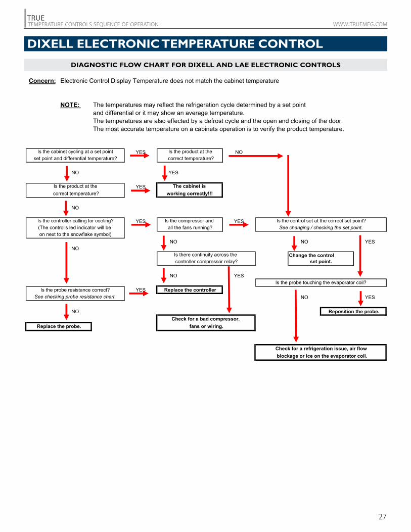
Diagnostic Flow Chart for Dixell and LAE electronic controls
Concern: Electronic Control Display Temperature does not match the cabinet temperature
NOTE: The temperatures may reflect the refrigeration cycle determined by a set point and differential or it may show an average temperature.The temperatures are also effected by a defrost cycle and the open and closing of the door.The most accurate temperature on a cabinets operation is to verify the product temperature.
YES NO
NO YES
YES
NO
YES YES
NO NO YESNO
Change the control
NO YES
YESNO YES
NO
Replace the probe.
set point.
Check for a refrigeration issue, air flow blockage or ice on the evaporator coil.
Reposition the probe.Check for a bad compressor,
fans or wiring.
Is the probe touching the evaporator coil?
Is the cabinet cycling at a set pointset point and differential temperature?
Is the product at the correct temperature?
Is the controller calling for cooling?(The control's led indicator will be on next to the snowflake symbol)
Is the probe resistance correct?See checking probe resistance chart.
Replace the controller
Is there continuity across the controller compressor relay?
all the fans running?
Is the product at the correct temperature?
Is the control set at the correct set point?See changing / checking the set point.
Is the compressor and
working correctly!!!The cabinet is
DIXELL ELECTRONIC TEMPERATURE CONTROL
DIAGNOSTIC FLOW CHART FOR DIXELL AND LAE ELECTRONIC CONTROLS

28
TRUEtemperature controls sequence of operation www.truemfg.com
29
TRUEtemperature controls sequence of operation www.truemfg.com
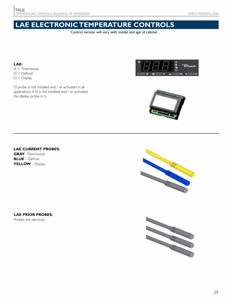
Control version will vary with model and age of cabinet.
LAE ELECTRONIC TEMPERATURE CONTROLS
LAE CURRENT PROBES:GRAY- ThermostatBLUE - DefrostYELLOW - Display
LAE PRIOR PROBES:Probes are identical.
LAE:t1 = Thermostatt2 = Defrostt3 = Display
t3 probe is not installed and / or activated in all applications if t3 is not installed and / or activated, the display probe is t1.
30
TRUEtemperature controls sequence of operation www.truemfg.com
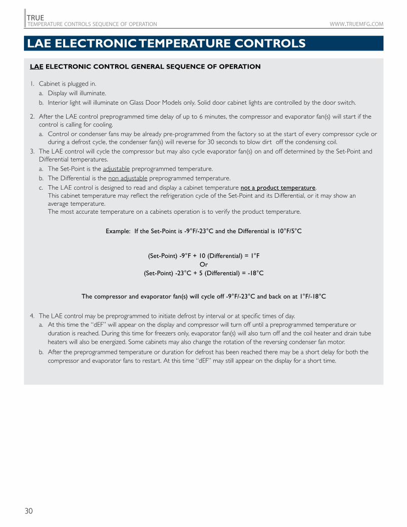
LAE ELECTRONIC CONTROL GENERAL SEQUENCE OF OPERATION
1. Cabinet is plugged in. a. Display will illuminate. b. Interior light will illuminate on Glass Door Models only. Solid door cabinet lights are controlled by the door switch.
2. After the LAE control preprogrammed time delay of up to 6 minutes, the compressor and evaporator fan(s) will start if the control is calling for cooling.
a. Control or condenser fans may be already pre-programmed from the factory so at the start of every compressor cycle or during a defrost cycle, the condenser fan(s) will reverse for 30 seconds to blow dirt off the condensing coil.
3. The LAE control will cycle the compressor but may also cycle evaporator fan(s) on and off determined by the Set-Point and Differential temperatures.
a. The Set-Point is the adjustable preprogrammed temperature. b. The Differential is the non adjustable preprogrammed temperature. c. The LAE control is designed to read and display a cabinet temperature not a product temperature.
This cabinet temperature may reflect the refrigeration cycle of the Set-Point and its Differential, or it may show an average temperature. The most accurate temperature on a cabinets operation is to verify the product temperature.
Example: If the Set-Point is -9°F/-23°C and the Differential is 10°F/5°C
(Set-Point) -9°F + 10 (Differential) = 1°F Or
(Set-Point) -23°C + 5 (Differential) = -18°C
The compressor and evaporator fan(s) will cycle off -9°F/-23°C and back on at 1°F/-18°C
4. The LAE control may be preprogrammed to initiate defrost by interval or at specific times of day. a. At this time the “dEF” will appear on the display and compressor will turn off until a preprogrammed temperature or
duration is reached. During this time for freezers only, evaporator fan(s) will also turn off and the coil heater and drain tube heaters will also be energized. Some cabinets may also change the rotation of the reversing condenser fan motor.
b. After the preprogrammed temperature or duration for defrost has been reached there may be a short delay for both the compressor and evaporator fans to restart. At this time “dEF” may still appear on the display for a short time.
LAE ELECTRONIC TEMPERATURE CONTROLS
31
TRUEtemperature controls sequence of operation www.truemfg.com
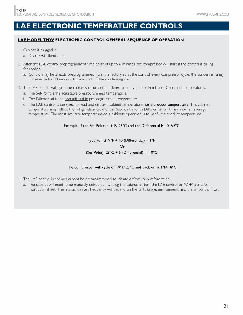
LAE MODEL TMW ELECTRONIC CONTROL GENERAL SEQUENCE OF OPERATION
1. Cabinet is plugged in. a. Display will illuminate.
2. After the LAE control preprogrammed time delay of up to 6 minutes, the compressor will start if the control is calling for cooling.
a. Control may be already preprogrammed from the factory so at the start of every compressor cycle, the condenser fan(s) will reverse for 30 seconds to blow dirt off the condensing coil.
3. The LAE control will cycle the compressor on and off determined by the Set-Point and Differential temperatures. a. The Set-Point is the adjustable preprogrammed temperature. b. The Differential is the non adjustable preprogrammed temperature. c. The LAE control is designed to read and display a cabinet temperature not a product temperature. This cabinet
temperature may reflect the refrigeration cycle of the Set-Point and it’s Differential, or it may show an average temperature. The most accurate temperature on a cabinets operation is to verify the product temperature.
Example: If the Set-Point is -9°F/-23°C and the Differential is 10°F/5°C
(Set-Point) -9°F + 10 (Differential) = 1°F
Or
(Set-Point) -23°C + 5 (Differential) = -18°C
The compressor will cycle off -9°F/-23°C and back on at 1°F/-18°C
4. The LAE control is not and cannot be preprogrammed to initiate defrost, only refrigeration. a. The cabinet will need to be manually defrosted. Unplug the cabinet or turn the LAE control to “OFF" per LAE
instruction sheet. The manual defrost frequency will depend on the units usage, environment, and the amount of frost.
LAE ELECTRONIC TEMPERATURE CONTROLS
32
TRUEtemperature controls sequence of operation www.truemfg.com
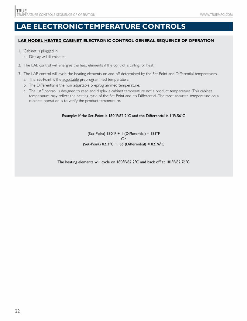
LAE MODEL HEATED CABINET ELECTRONIC CONTROL GENERAL SEQUENCE OF OPERATION
1. Cabinet is plugged in. a. Display will illuminate.
2. The LAE control will energize the heat elements if the control is calling for heat.
3. The LAE control will cycle the heating elements on and off determined by the Set-Point and Differential temperatures. a. The Set-Point is the adjustable preprogrammed temperature. b. The Differential is the non adjustable preprogrammed temperature. c. The LAE control is designed to read and display a cabinet temperature not a product temperature. This cabinet
temperature may reflect the heating cycle of the Set-Point and it’s Differential. The most accurate temperature on a cabinets operation is to verify the product temperature.
Example: If the Set-Point is 180°F/82.2°C and the Differential is 1°F/.56°C
(Set-Point) 180°F + 1 (Differential) = 181°F Or
(Set-Point) 82.2°C + .56 (Differential) = 82.76°C
The heating elements will cycle on 180°F/82.2°C and back off at 181°F/82.76°C
LAE ELECTRONIC TEMPERATURE CONTROLS
33
TRUEtemperature controls sequence of operation www.truemfg.com
PRODUCT ADVISEMENT
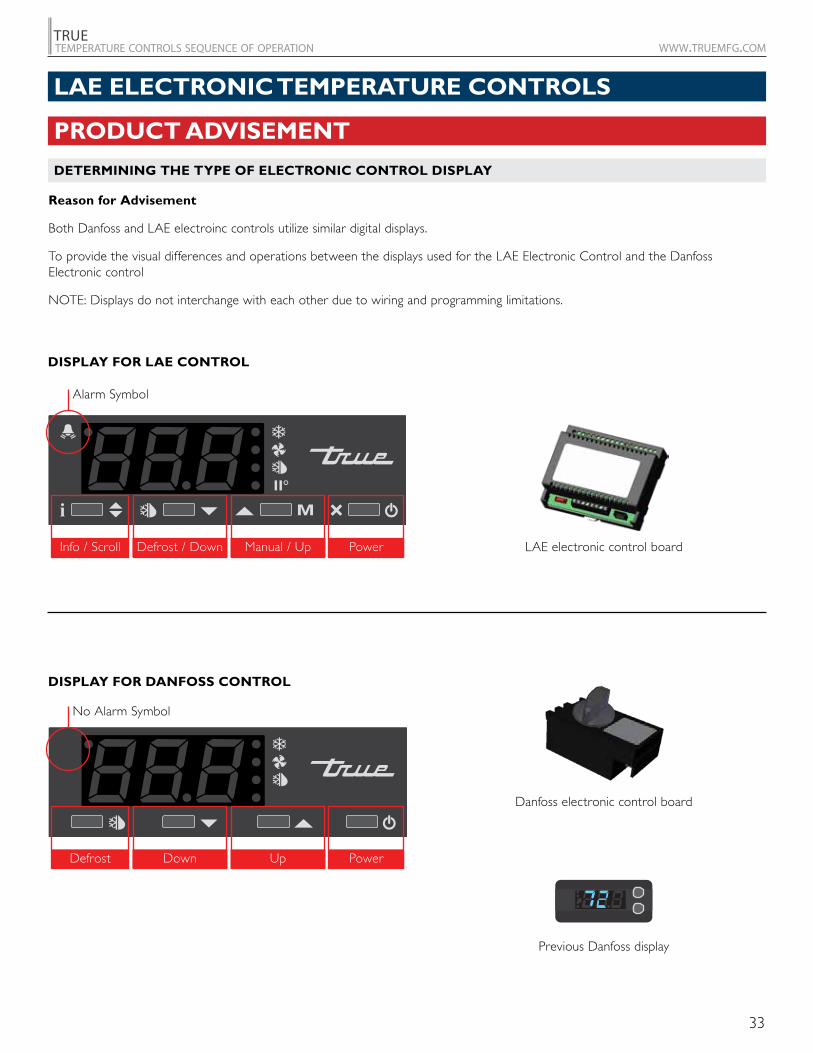
DETERMINING THE TYPE OF ELECTRONIC CONTROL DISPLAY
Reason for Advisement
Both Danfoss and LAE electroinc controls utilize similar digital displays.
To provide the visual differences and operations between the displays used for the LAE Electronic Control and the Danfoss Electronic control
NOTE: Displays do not interchange with each other due to wiring and programming limitations.
LAE electronic control board
Danfoss electronic control board
Previous Danfoss display
DISPLAY FOR LAE CONTROL
DISPLAY FOR DANFOSS CONTROL
Alarm Symbol
No Alarm Symbol
Info / Scroll
Defrost
Defrost / Down
Down
Manual / Up
Up
Power
Power
LAE ELECTRONIC TEMPERATURE CONTROLS
34
TRUEtemperature controls sequence of operation www.truemfg.com
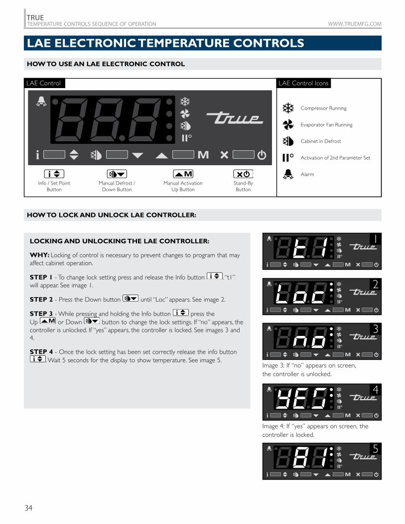
HOW TO USE AN LAE ELECTRONIC CONTROL
LOCKING AND UNLOCKING THE LAE CONTROLLER:
WHY: Locking of control is necessary to prevent changes to program that may affect cabinet operation.
STEP 1 - To change lock setting press and release the Info button . “t1” will appear. See image 1.
STEP 2 - Press the Down button until “Loc” appears. See image 2.
STEP 3 - While pressing and holding the Info button press the Up or Down button to change the lock settings. If “no” appears, the controller is unlocked. If “yes” appears, the controller is locked. See images 3 and 4.
STEP 4 - Once the lock setting has been set correctly release the info button . Wait 5 seconds for the display to show temperature. See image 5.
HOW TO LOCK AND UNLOCK LAE CONTROLLER:
Image 3: If “no” appears on screen, the controller is unlocked.
3
2
1
5
4
Image 4: If “yes” appears on screen, the controller is locked.
LAE Control
Info / Set PointButton
Manual Activation Up Button
Manual Defrost / Down Button
Stand-ByButton
LAE Control Icons
Compressor Running
Activation of 2nd Parameter Set
Alarm
Cabinet in Defrost
Evaporator Fan Running
LAE ELECTRONIC TEMPERATURE CONTROLS
35
TRUEtemperature controls sequence of operation www.truemfg.com
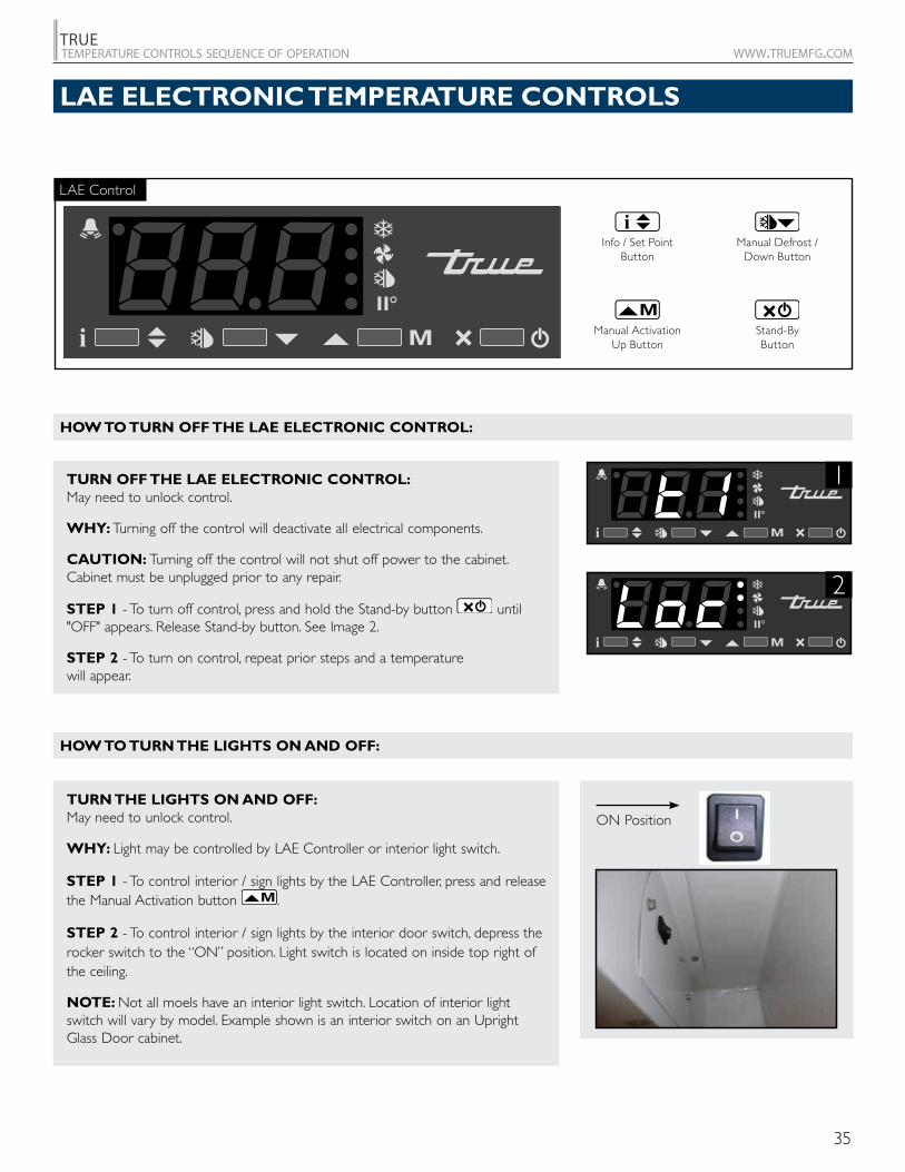
HOW TO TURN OFF THE LAE ELECTRONIC CONTROL:
HOW TO TURN THE LIGHTS ON AND OFF:
ON Position
TURN OFF THE LAE ELECTRONIC CONTROL: May need to unlock control.
WHY: Turning off the control will deactivate all electrical components.
CAUTION: Turning off the control will not shut off power to the cabinet. Cabinet must be unplugged prior to any repair.
STEP 1 - To turn off control, press and hold the Stand-by button until "OFF" appears. Release Stand-by button. See Image 2.
STEP 2 - To turn on control, repeat prior steps and a temperature will appear.
TURN THE LIGHTS ON AND OFF: May need to unlock control.
WHY: Light may be controlled by LAE Controller or interior light switch.
STEP 1 - To control interior / sign lights by the LAE Controller, press and release the Manual Activation button .
STEP 2 - To control interior / sign lights by the interior door switch, depress the rocker switch to the “ON” position. Light switch is located on inside top right of the ceiling.
NOTE: Not all moels have an interior light switch. Location of interior light switch will vary by model. Example shown is an interior switch on an Upright Glass Door cabinet.
1
2
LAE Control
Manual Activation Up Button
Info / Set PointButton
Stand-ByButton
Manual Defrost / Down Button
LAE ELECTRONIC TEMPERATURE CONTROLS
36
TRUEtemperature controls sequence of operation www.truemfg.com
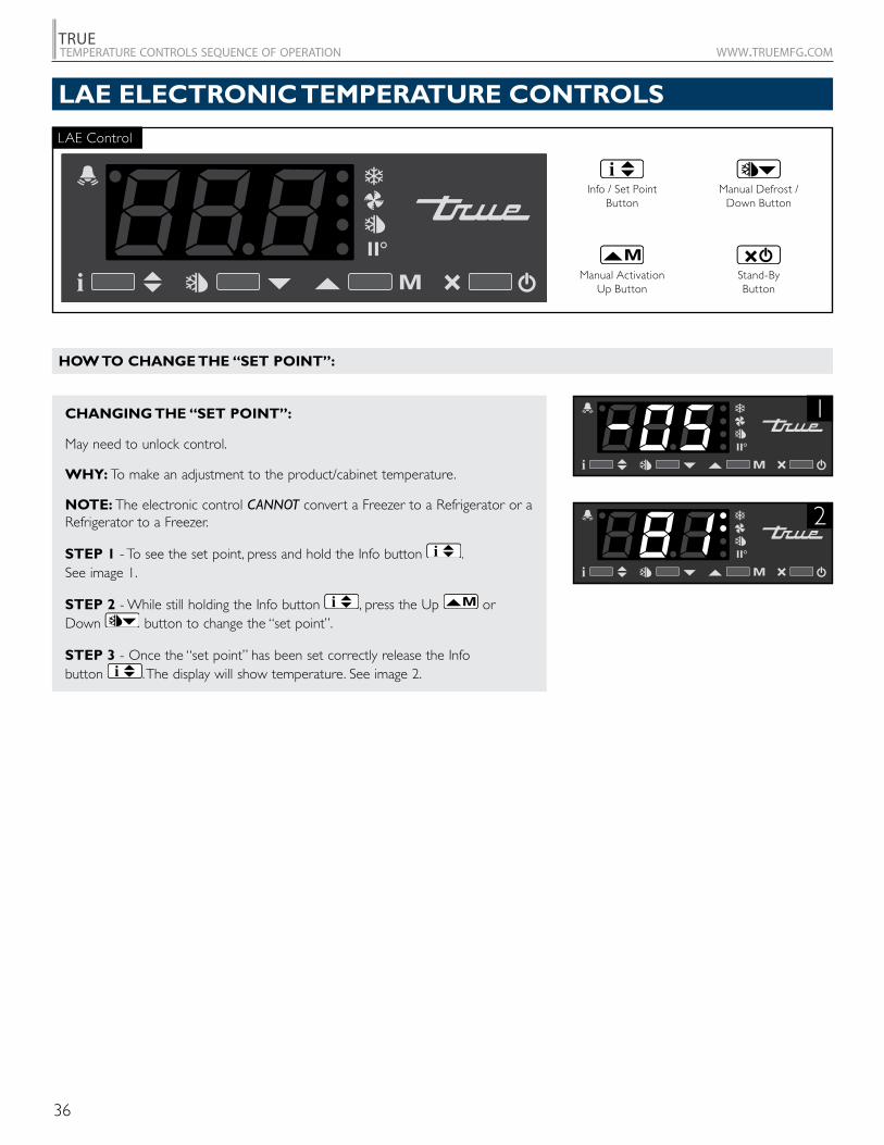
CHANGING THE “SET POINT”:
May need to unlock control.
WHY: To make an adjustment to the product/cabinet temperature.
NOTE: The electronic control CANNOT convert a Freezer to a Refrigerator or a Refrigerator to a Freezer.
STEP 1 - To see the set point, press and hold the Info button . See image 1.
STEP 2 - While still holding the Info button , press the Up or Down button to change the “set point”.
STEP 3 - Once the “set point” has been set correctly release the Info button . The display will show temperature. See image 2.
1
2
LAE Control
Manual Activation Up Button
Info / Set PointButton
Stand-ByButton
Manual Defrost / Down Button
LAE ELECTRONIC TEMPERATURE CONTROLS
HOW TO CHANGE THE “SET POINT”:
37
TRUEtemperature controls sequence of operation www.truemfg.com
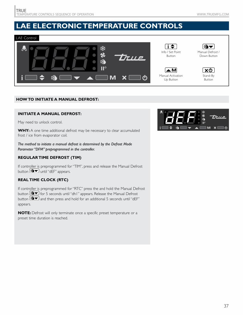
INITIATE A MANUAL DEFROST:
May need to unlock control.
WHY: A one time additional defrost may be necessary to clear accumulated frost / ice from evaporator coil.
The method to initiate a manual defrost is determined by the Defrost Mode Parameter “DFM” preprogrammed in the controller.
REGULAR TIME DEFROST (TIM)
If controller is preprogrammed for “TIM”, press and release the Manual Defrost button until “dEF” appears.
REAL TIME CLOCK (RTC)
If controller is preprogrammed for “RTC” press the and hold the Manual Defrost button for 5 seconds until “dh1” appears. Release the Manual Defrost button and then press and hold for an additional 5 seconds until “dEF” appears.
NOTE: Defrost will only terminate once a specific preset temperature or a preset time duration is reached.
LAE Control
Manual Activation Up Button
Info / Set PointButton
Stand-ByButton
Manual Defrost / Down Button
LAE ELECTRONIC TEMPERATURE CONTROLS
HOW TO INITIATE A MANUAL DEFROST:
38
TRUEtemperature controls sequence of operation www.truemfg.com
1a
1c
1b
2
3
4
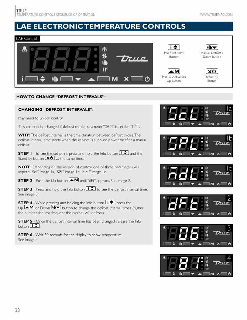
CHANGING “DEFROST INTERVALS”:
May need to unlock control.
This can only be changed if defrost mode parameter “DFM” is set for “TIM”.
WHY: The defrost interval is the time duration between defrost cycles. The defrost interval time starts when the cabinet is supplied power or after a manual defrost.
STEP 1 - To see the set point, press and hold the Info button and the Stand-by button at the same time.
NOTE: Depending on the version of control, one of three parameters will appear: “ScL” image 1a, “SPL” image 1b, “MdL” image 1c.
STEP 2 - Push the Up button until “dFt” appears. See image 2.
STEP 3 - Press and hold the Info button to see the defrost interval time. See image 3
STEP 4 - While pressing and holding the Info button , press the Up or Down button to change the defrost interval times (higher the number the less frequent the cabinet will defrost).
STEP 5 - Once the defrost interval time has been changed, release the Info button .
STEP 6 - Wait 30 seconds for the display to show temperature. See image 4.
LAE Control
Manual Activation Up Button
Info / Set PointButton
Stand-ByButton
Manual Defrost / Down Button
LAE ELECTRONIC TEMPERATURE CONTROLS
HOW TO CHANGE “DEFROST INTERVALS”:
39
TRUEtemperature controls sequence of operation www.truemfg.com
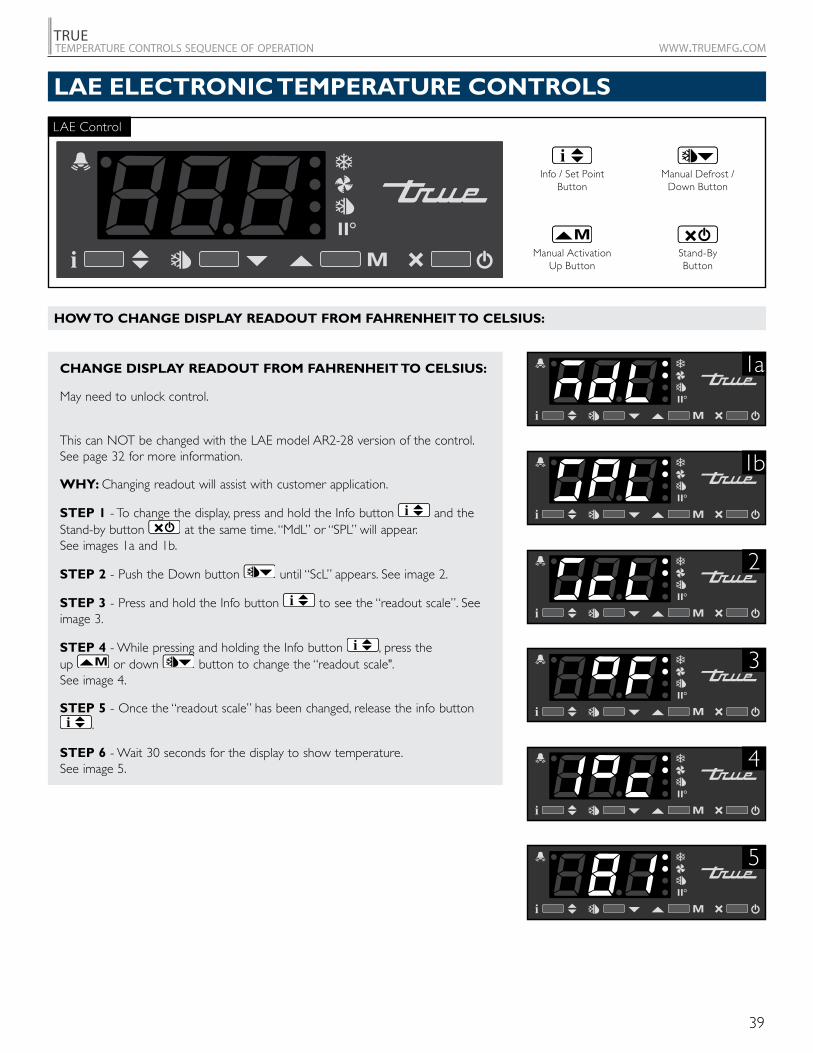
CHANGE DISPLAY READOUT FROM FAHRENHEIT TO CELSIUS:
May need to unlock control.
This can NOT be changed with the LAE model AR2-28 version of the control. See page 32 for more information.
WHY: Changing readout will assist with customer application.
STEP 1 - To change the display, press and hold the Info button and the Stand-by button at the same time. “MdL” or “SPL” will appear. See images 1a and 1b.
STEP 2 - Push the Down button until “ScL” appears. See image 2.
STEP 3 - Press and hold the Info button to see the “readout scale”. See image 3.
STEP 4 - While pressing and holding the Info button , press the up or down button to change the “readout scale". See image 4.
STEP 5 - Once the “readout scale” has been changed, release the info button .
STEP 6 - Wait 30 seconds for the display to show temperature. See image 5.
1a
1b
2
3
4
5
LAE Control
Manual Activation Up Button
Info / Set PointButton
Stand-ByButton
Manual Defrost / Down Button
LAE ELECTRONIC TEMPERATURE CONTROLS
HOW TO CHANGE DISPLAY READOUT FROM FAHRENHEIT TO CELSIUS:
40
TRUEtemperature controls sequence of operation www.truemfg.com
2
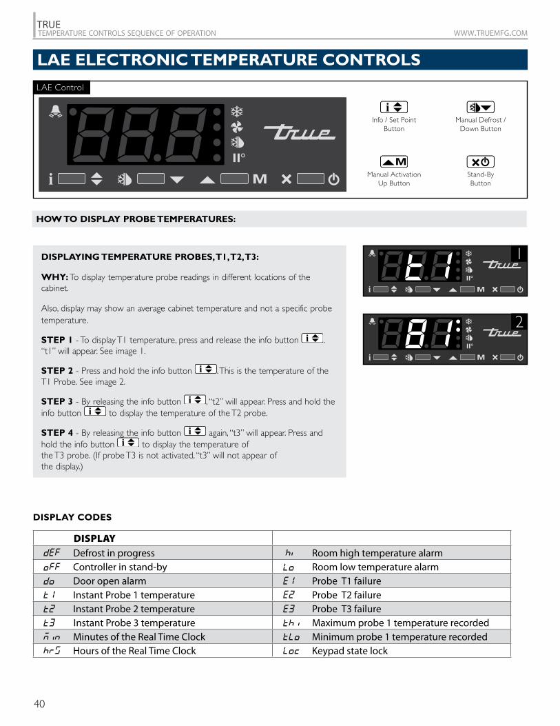
1DISPLAYING TEMPERATURE PROBES, T1, T2, T3:
WHY: To display temperature probe readings in different locations of the cabinet.
Also, display may show an average cabinet temperature and not a specific probe temperature.
STEP 1 - To display T1 temperature, press and release the info button . “t1” will appear. See image 1.
STEP 2 - Press and hold the info button . This is the temperature of the T1 Probe. See image 2.
STEP 3 - By releasing the info button , “t2” will appear. Press and hold the info button to display the temperature of the T2 probe.
STEP 4 - By releasing the info button again, “t3” will appear. Press and hold the info button to display the temperature of the T3 probe. (If probe T3 is not activated, “t3” will not appear of the display.)
DISPLAY CODES
DISPLAY Defrost in progress Room high temperature alarm Controller in stand-by Room low temperature alarm Door open alarm Probe T1 failure Instant Probe 1 temperature Probe T2 failure Instant Probe 2 temperature Probe T3 failure
Instant Probe 3 temperature Maximum probe 1 temperature recorded Minutes of the Real Time Clock Minimum probe 1 temperature recorded Hours of the Real Time Clock Keypad state lock
LAE Control
Manual Activation Up Button
Info / Set PointButton
Stand-ByButton
Manual Defrost / Down Button
LAE ELECTRONIC TEMPERATURE CONTROLS
HOW TO DISPLAY PROBE TEMPERATURES:
41
TRUEtemperature controls sequence of operation www.truemfg.com
984823
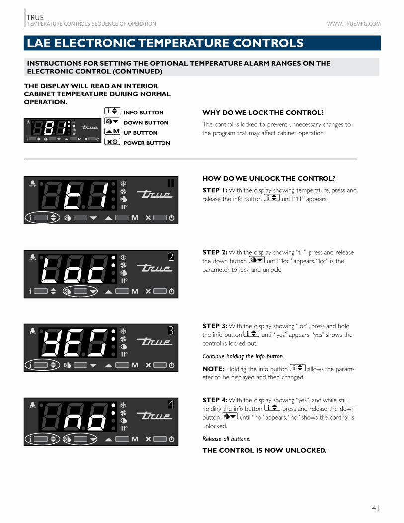
STEP 2: With the display showing “t1”, press and release the down button until “loc” appears. “loc” is the parameter to lock and unlock.
HOW DO WE UNLOCK THE CONTROL?
STEP 1: With the display showing temperature, press and release the info button until “t1” appears.
STEP 3: With the display showing “loc”, press and hold the info button until “yes” appears. “yes” shows the control is locked out.
Continue holding the info button.
NOTE: Holding the info button allows the param-eter to be displayed and then changed.
STEP 4: With the display showing “yes”, and while still holding the info button press and release the down button until “no” appears. “no” shows the control is unlocked.
Release all buttons.
THE CONTROL IS NOW UNLOCKED.
WHY DO WE LOCK THE CONTROL?
The control is locked to prevent unnecessary changes to the program that may affect cabinet operation.
THE DISPLAY WILL READ AN INTERIOR CABINET TEMPERATURE DURING NORMAL OPERATION.
INFO BUTTON
DOWN BUTTON
UP BUTTON
POWER BUTTON
2
3
4
1
LAE ELECTRONIC TEMPERATURE CONTROLS
INSTRUCTIONS FOR SETTING THE OPTIONAL TEMPERATURE ALARM RANGES ON THE ELECTRONIC CONTROL (CONTINUED)
42
TRUEtemperature controls sequence of operation www.truemfg.com
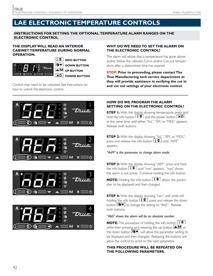
WHY DO WE NEED TO SET THE ALARM ON THE ELECTRONIC CONTROL?
The alarm will advise that a temperature has gone above and/or below the cabinets Cut-in and/or Cut-out temper-ature after a determined time has expired.
STOP: Prior to proceeding, please contact The True Manufacturing tech service department as they will provide assistance in verifying the cut in and cut out settings of your electronic control.Control may need to be unlocked. See instructions on
how to unlock the electronic control.
STEP 2: With the display showing “ScL”, “SPL’ or “MDL”, press and release the info button until “AtM” appears.
“AtM” is the parameter to change alarm mode.
STEP 3: With the display showing “AtM”, press and hold the info button until “non” appears. “non” shows the alarm is not active. Continue holding the info button.
NOTE: Holding the info button allows the param-eter to be displayed and then changed.
STEP 4: With the display showing “non”, and while still holding the info button , press and release the down button to change the setting to “AbS”. Release both buttons.
“AbS” shows the alarm will be an absolute number.
NOTE: The procedure of holding the info button while then pressing and releasing the up button or the down button will allow the parameter setting to be displayed and then changed. Releasing the buttons will allow the control to scroll to the next parameter.
THIS PROCEDURE WILL BE REPEATED ON THE FOLLOWING PARAMETERS.
HOW DO WE PROGRAM THE ALARM SETTING ON THE ELECTRONIC CONTROL?
STEP 1: With the display showing temperature, press and hold the info button and the power button at the same time until either “ScL”, “SPL’ or “MDL” appears. Release both buttons.
THE DISPLAY WILL READ AN INTERIOR CABINET TEMPERATURE DURING NORMAL OPERATION.
INFO BUTTON
DOWN BUTTON
UP BUTTON
POWER BUTTON
1
2
3
4
LAE ELECTRONIC TEMPERATURE CONTROLS
INSTRUCTIONS FOR SETTING THE OPTIONAL TEMPERATURE ALARM RANGES ON THE ELECTRONIC CONTROL
43
TRUEtemperature controls sequence of operation www.truemfg.com
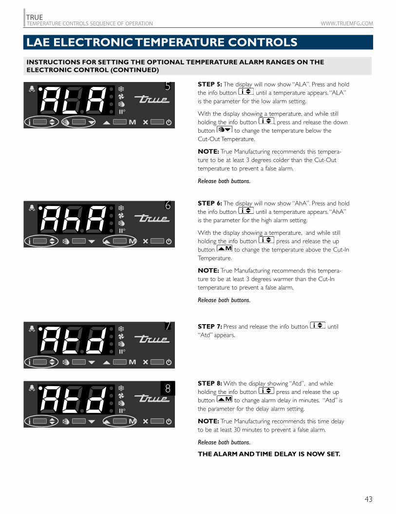
STEP 5: The display will now show “ALA”. Press and hold the info button until a temperature appears. “ALA” is the parameter for the low alarm setting.
With the display showing a temperature, and while still holding the info button , press and release the down button to change the temperature below the Cut-Out Temperature.
NOTE: True Manufacturing recommends this tempera-ture to be at least 3 degrees colder than the Cut-Out temperature to prevent a false alarm.
Release both buttons.
STEP 7: Press and release the info button until “Atd” appears.
STEP 8: With the display showing “Atd”, and while holding the info button press and release the up button to change alarm delay in minutes. “Atd” is the parameter for the delay alarm setting.
NOTE: True Manufacturing recommends this time delay to be at least 30 minutes to prevent a false alarm.
Release both buttons.
THE ALARM AND TIME DELAY IS NOW SET.
STEP 6: The display will now show “AhA”. Press and hold the info button until a temperature appears. “AhA” is the parameter for the high alarm setting.
With the display showing a temperature, and while still holding the info button press and release the up button to change the temperature above the Cut-In Temperature.
NOTE: True Manufacturing recommends this tempera-ture to be at least 3 degrees warmer than the Cut-In temperature to prevent a false alarm.
Release both buttons.
7
8
5
6
LAE ELECTRONIC TEMPERATURE CONTROLS
INSTRUCTIONS FOR SETTING THE OPTIONAL TEMPERATURE ALARM RANGES ON THE ELECTRONIC CONTROL (CONTINUED)
44
TRUEtemperature controls sequence of operation www.truemfg.com
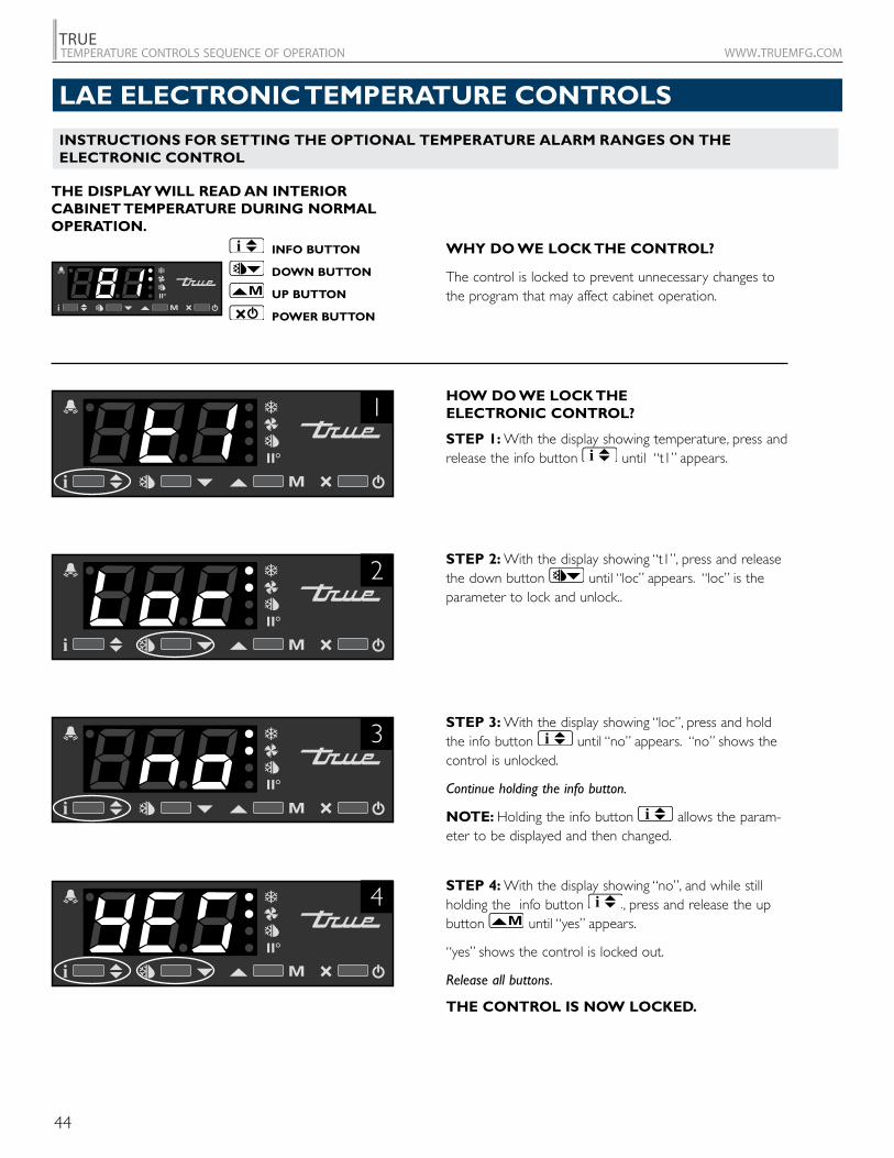
WHY DO WE LOCK THE CONTROL?
The control is locked to prevent unnecessary changes to the program that may affect cabinet operation.
STEP 2: With the display showing “t1”, press and release the down button until “loc” appears. “loc” is the parameter to lock and unlock..
HOW DO WE LOCK THE ELECTRONIC CONTROL?
STEP 1: With the display showing temperature, press and release the info button until “t1” appears.
STEP 3: With the display showing “loc”, press and hold the info button until “no” appears. “no” shows the control is unlocked.
Continue holding the info button.
NOTE: Holding the info button allows the param-eter to be displayed and then changed.
STEP 4: With the display showing “no”, and while still holding the info button , press and release the up button until “yes” appears.
“yes” shows the control is locked out.
Release all buttons.
THE CONTROL IS NOW LOCKED.
THE DISPLAY WILL READ AN INTERIOR CABINET TEMPERATURE DURING NORMAL OPERATION.
INFO BUTTON
DOWN BUTTON
UP BUTTON
POWER BUTTON
2
1
4
3
LAE ELECTRONIC TEMPERATURE CONTROLS
INSTRUCTIONS FOR SETTING THE OPTIONAL TEMPERATURE ALARM RANGES ON THE ELECTRONIC CONTROL
45
TRUEtemperature controls sequence of operation www.truemfg.com
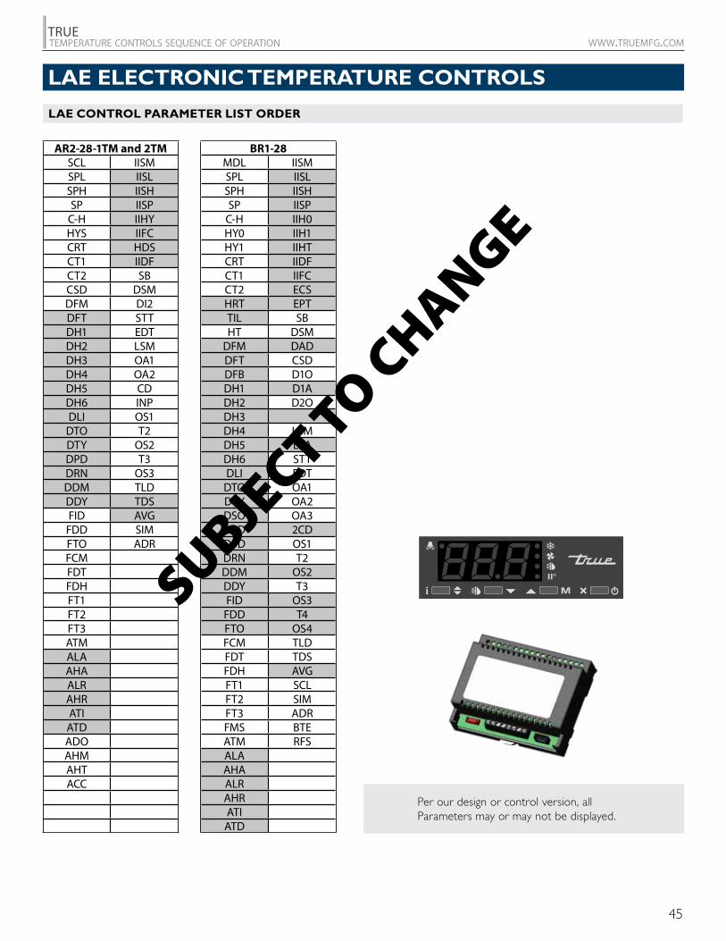
LAE CONTROL PARAMETER LIST ORDER
AR2-28-1TM and 2TMSCL IISMSPL IISLSPH IISHSP IISP
C-H IIHYHYS IIFCCRT HDSCT1 IIDFCT2 SBCSD DSMDFM DI2DFT STTDH1 EDTDH2 LSMDH3 OA1DH4 OA2DH5 CDDH6 INPDLI OS1
DTO T2DTY OS2DPD T3DRN OS3DDM TLDDDY TDSFID AVG
FDD SIMFTO ADRFCMFDTFDHFT1FT2FT3ATMALAAHAALRAHRATI
ATDADOAHMAHTACC
BR1-28MDL IISMSPL IISLSPH IISHSP IISP
C-H IIH0HY0 IIH1HY1 IIHTCRT IIDFCT1 IIFCCT2 ECSHRT EPTTIL SBHT DSM
DFM DADDFT CSDDFB D1ODH1 D1ADH2 D2ODH3 D2ADH4 LSMDH5 LSADH6 STTDLI EDT
DTO OA1DTY OA2DSO OA3SOD 2CD DPD OS1DRN T2DDM OS2DDY T3FID OS3
FDD T4FTO OS4FCM TLDFDT TDSFDH AVGFT1 SCLFT2 SIMFT3 ADRFMS BTEATM RFSALAAHAALRAHRATI
ATD
Per our design or control version, all Parameters may or may not be displayed.
SUBJECT TO C
HANGE
LAE ELECTRONIC TEMPERATURE CONTROLS
46
TRUEtemperature controls sequence of operation www.truemfg.com
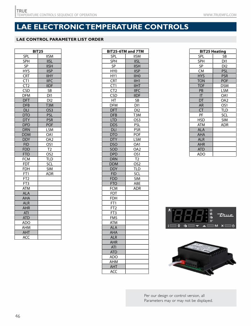
Per our design or control version, all Parameters may or may not be displayed.
LAE CONTROL PARAMETER LIST ORDER
BIT25SPL IISMSPH IISLSP IISH
HYS IISPCRT IIHYCT1 IIFCCT2 IIDFCSD SBDFM DI1DFT DI2DFB T3MDLI OS3
DTO PSLDTY PSRDPD POFDRN LSMDDM OA1DDY OA2FID OS1
FDD T2FTO OS2FCM TLDFDT SCLFDH SIMFT1 ADRFT2FT3ATMALAAHAALRAHRATI
ATDADOAHMAHTACC
BIT25-6TM and 7TMSPL IISMSPH IISLSP IISH
HY0 IISPHY1 IIH0CRT IIH1CT1 IIHTCT2 IIFCCSD IIDFHT SB
DFM DI1DFT DI2DFB T3MLTD OS3DDS PSLDLI PSR
DTO POFDTY LSMDSO OA1SOD OA2DPD OS1DRN T2DDM OS2DDY TLDFID SCL
FDD SIMFTO ABEFCM ADRFDTFDHFT1FT2FT3FMSATMALAAHAALRAHRATI
ATDADOAHMAHTACC
BIT25 HeatingSPL SBSPH DI1SP DI2CM PSLHYS PSRTON POFTOF DSMPB LSMIT OA1DT OA2AR OS1CT TLDPF SCL
HSD SIMATM ADRALAAHAALRAHRATDADO
LAE ELECTRONIC TEMPERATURE CONTROLS
47
TRUEtemperature controls sequence of operation www.truemfg.com
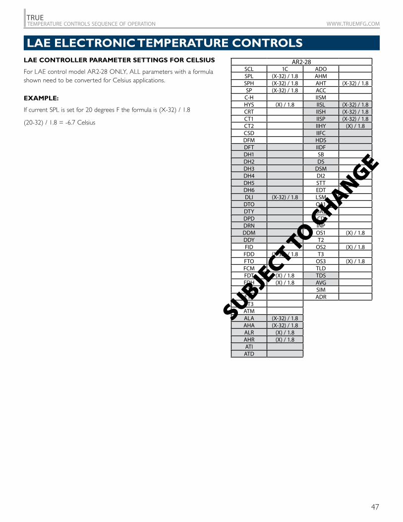
LAE CONTROLLER PARAMETER SETTINGS FOR CELSIUS
For LAE control model AR2-28 ONLY, ALL parameters with a formula shown need to be converted for Celsius applications.
EXAMPLE:
If current SPL is set for 20 degrees F the formula is (X-32) / 1.8
(20-32) / 1.8 = -6.7 Celsius
AR2-28SCL 1C ADOSPL (X-32) / 1.8 AHMSPH (X-32) / 1.8 AHT (X-32) / 1.8SP (X-32) / 1.8 ACC
C-H IISMHYS (X) / 1.8 IISL (X-32) / 1.8CRT IISH (X-32) / 1.8CT1 IISP (X-32) / 1.8CT2 IIHY (X) / 1.8CSD IIFCDFM HDSDFT IIDFDH1 SBDH2 DSDH3 DSMDH4 DI2DH5 STTDH6 EDTDLI (X-32) / 1.8 LSM
DTO OA1DTY OA2DPD CDDRN INPDDM OS1 (X) / 1.8DDY T2FID OS2 (X) / 1.8
FDD (X-32) / 1.8 T3FTO OS3 (X) / 1.8FCM TLDFDT (X) / 1.8 TDSFDH (X) / 1.8 AVGFT1 SIMFT2 ADRFT3ATMALA (X-32) / 1.8AHA (X-32) / 1.8ALR (X) / 1.8AHR (X) / 1.8ATI
ATD
SUBJECT TO C
HANGE
LAE ELECTRONIC TEMPERATURE CONTROLS
48
TRUEtemperature controls sequence of operation www.truemfg.com
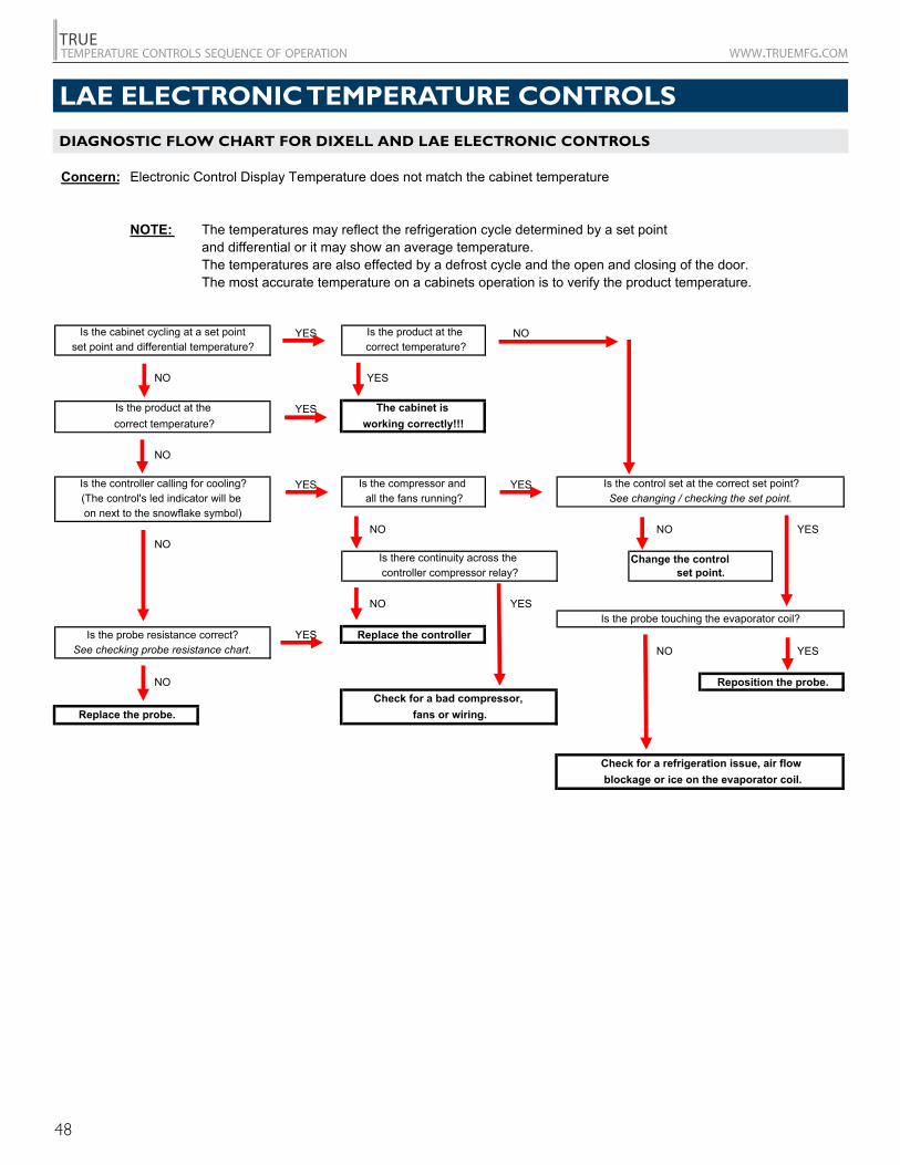
DIAGNOSTIC FLOW CHART FOR DIXELL AND LAE ELECTRONIC CONTROLSDiagnostic Flow Chart for Dixell and LAE electronic controls
Concern: Electronic Control Display Temperature does not match the cabinet temperature
NOTE: The temperatures may reflect the refrigeration cycle determined by a set point and differential or it may show an average temperature.The temperatures are also effected by a defrost cycle and the open and closing of the door.The most accurate temperature on a cabinets operation is to verify the product temperature.
YES NO
NO YES
YES
NO
YES YES
NO NO YESNO
Change the control
NO YES
YESNO YES
NO
Replace the probe.
set point.
Check for a refrigeration issue, air flow blockage or ice on the evaporator coil.
Reposition the probe.Check for a bad compressor,
fans or wiring.
Is the probe touching the evaporator coil?
Is the cabinet cycling at a set pointset point and differential temperature?
Is the product at the correct temperature?
Is the controller calling for cooling?(The control's led indicator will be on next to the snowflake symbol)
Is the probe resistance correct?See checking probe resistance chart.
Replace the controller
Is there continuity across the controller compressor relay?
all the fans running?
Is the product at the correct temperature?
Is the control set at the correct set point?See changing / checking the set point.
Is the compressor and
working correctly!!!The cabinet is
LAE ELECTRONIC TEMPERATURE CONTROLS
49
TRUEtemperature controls sequence of operation www.truemfg.com
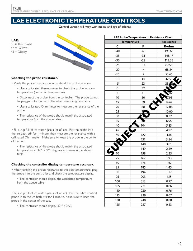
LAE ELECTRONIC TEMPERATURE CONTROLS
LAE Probe Temperature to Resistance Chart
Temperature Resistance
C F K-ohm-40 -40 195.65-35 -31 148.17-30 -22 113.35-25 -13 87.56-20 -4 68.24-15 5 53.65-10 14 42.51-5 23 33.890 32 27.225 41 22.02
10 50 17.9315 59 14.6720 68 12.0825 77 10.0030 86 8.3235 95 6.9540 104 5.8345 113 4.9250 122 4.1655 131 3.5460 140 3.0165 149 2.5970 158 2.2375 167 1.9380 176 1.6785 185 1.4590 194 1.2795 203 1.15
100 212 0.97105 221 0.86110 230 0.76115 239 0.67120 248 0.60125 257 0.53
SUBJECT TO C
HANGEChecking the probe resistance.
• Verify the probe resistance is accurate at the probe location.
• Use a calibrated thermometer to check the probe location temperature (coil or air temperature).
• Disconnect the probe from the controller. The probe cannot be plugged into the controller when measuring resistance.
• Use a calibrated Ohm meter to measure the resistance of the probe
• The resistance of the probe should match the associated temperature from the above table.
• Fill a cup full of ice water (use a lot of ice). Put the probe into the ice bath, stir for 1 minute, then measure the resistance with a calibrated Ohm meter. Make sure to keep the probe in the center of the cup.
• The resistance of the probe should match the associated temperature at 32°F / 0°C degrees as shown in the above table.
Checking the controller display temperature accuracy.
• After verifying the probe resistance to the box temperature, plug the probe into the controller and check the temperature display.
• The controller should display the associated temperature from the above table
• Fill a cup full of ice water (use a lot of ice). Put the Ohm verified probe in to the ice bath, stir for 1 minute. Make sure to keep the probe in the center of the cup.
• The controller should display 32°F / 0°C.
Control version will vary with model and age of cabinet.
LAE:t1 = Thermostatt2 = Defrostt3 = Display
50
TRUEtemperature controls sequence of operation www.truemfg.com
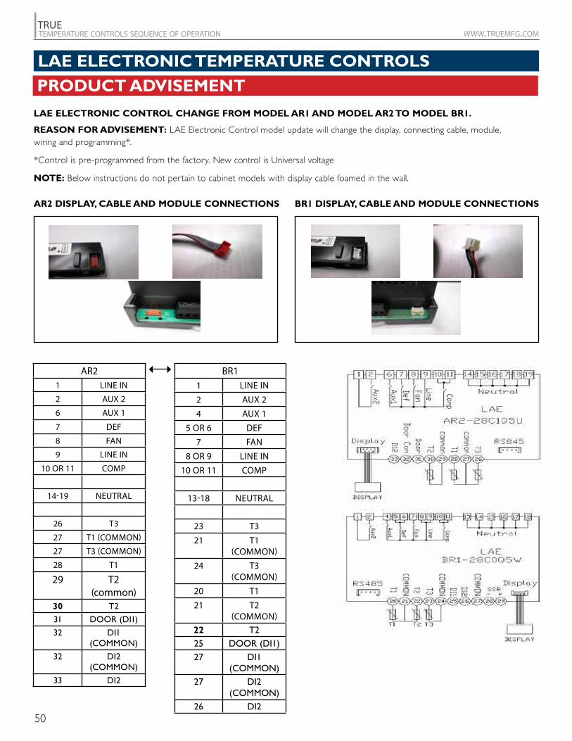
PRODUCT ADVISEMENT
LAE ELECTRONIC CONTROL CHANGE FROM MODEL AR1 AND MODEL AR2 TO MODEL BR1.
REASON FOR ADVISEMENT: LAE Electronic Control model update will change the display, connecting cable, module, wiring and programming*.
*Control is pre-programmed from the factory. New control is Universal voltage
NOTE: Below instructions do not pertain to cabinet models with display cable foamed in the wall.
BR1 DISPLAY, CABLE AND MODULE CONNECTIONSAR2 DISPLAY, CABLE AND MODULE CONNECTIONS
AR21 LINE IN
2 AUX 2
6 AUX 1
7 DEF
8 FAN
9 LINE IN
10 OR 11 COMP
14-19 NEUTRAL
26 T3
27 T1 (COMMON)
27 T3 (COMMON)
28 T1
29 T2 (common)
30 T2
31 DOOR (DI1)
32 DI1 (COMMON)
32 DI2 (COMMON)
33 DI2
BR11 LINE IN
2 AUX 2
4 AUX 1
5 OR 6 DEF
7 FAN
8 OR 9 LINE IN
10 OR 11 COMP
13-18 NEUTRAL
23 T3
21 T1 (COMMON)
24 T3 (COMMON)
20 T1
21 T2 (COMMON)
22 T225 DOOR (DI1)27 DI1
(COMMON)27 DI2
(COMMON)26 DI2
LAE ELECTRONIC TEMPERATURE CONTROLS
51
TRUEtemperature controls sequence of operation www.truemfg.com
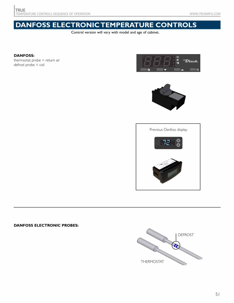
Control version will vary with model and age of cabinet.
DANFOSS ELECTRONIC TEMPERATURE CONTROLS
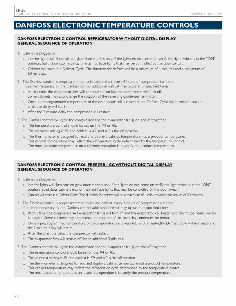
DANFOSS:thermostat probe = return air defrost probe = coil
DANFOSS ELECTRONIC PROBES:
THERMOSTAT
DEFROST
Previous Danfoss display
52
TRUEtemperature controls sequence of operation www.truemfg.com
DANFOSS ELECTRONIC CONTROL REFRIGERATOR WITH DIGITAL DISPLAY GENERAL SEQUENCE OF OPERATION
1. Cabinet is plugged in. a. Interior lights will illuminate on glass door models only. If the lights do not come on verify the light switch is in the “ON”
position. Solid door cabinets may or may not have lights that may be controlled by the door switch. b. Cabinet will start in a Defrost Cycle. The duration for defrost will be a minimum of 4 minutes and a maximum
of 60 minutes. c. The Danfoss Control Display will illuminate showing “deF”.
2. The Danfoss control is preprogrammed to initiate defrost every 4 hours of compressor run time. If deemed necessary by the Danfoss control additional defrost may occur at unspecified times.
a. At this time the, evaporator fans will continue to run but the compressor will turn off. Some cabinets may also change the rotation of the reversing condenser fan motor.
b. Once a preprogrammed temperature of the evaporator coil is reached, the Defrost Cycle will terminate and the 2 minute delay will start.
c. After the 2 minute delay the compressor will restart. d. The Danfoss Control Display will continue to show “deF” for an additional 30 minutes.
3. The Danfoss control will cycle the compressor and the evaporator fan(s) on and off determined by the Set-Point and Differential temperatures.
a. The Set-Point is the adjustable preprogrammed temperature which shuts off the compressor and evaporator fan(s). This is not the programmed cabinet temperature.
b. The Differential is the non adjustable preprogrammed temperature that is added to the Set-Point temperature that will start the compressor and evaporator fan(s).
c. The Danfoss control is designed to read and display a cabinet temperature not a product temperature. This cabinet temperature may reflect the refrigeration cycle of the Set-Point and its Differential. The most accurate temperature on a cabinets operation is to verify the product temperature.
Example: If the Set-Point is 34°F/1.1°C and the Differential is 6°F/3.3°C
(Set-Point) 34°F + 6 (Differential) = 40°F Or
(Set-Point) 1.1°C + 3.3 (Differential) = 4.4°C
The compressor will cycle off 34°F/1.1°C and back on at 40°F/4.4°C
DANFOSS ELECTRONIC TEMPERATURE CONTROLS
53
TRUEtemperature controls sequence of operation www.truemfg.com
DANFOSS ELECTRONIC CONTROL FREEZER WITH DIGITAL DISPLAY GENERAL SEQUENCE OF OPERATION
1. Cabinet is plugged in. a. Interior lights will illuminate on glass door models only. If the lights do not come on verify the light switch is in the “ON”
position. Solid door cabinets may or may not have lights that may be controlled by the door switch. b. Cabinet will start in a Defrost Cycle. The duration for defrost will be a minimum of 4 minutes and a maximum of
30 minutes. c. The Danfoss Control Display will illuminate showing “deF”.
2. The Danfoss control is preprogrammed to initiate defrost every 4 hours of compressor run time. If deemed necessary by the Danfoss control additional defrost may occur at unspecified times.
a. At this time, the compressor and evaporator fan(s) will turn off and the evaporator coil heater and drain tube heater will be energized. Some cabinets may also change the rotation of the reversing condenser fan motor.
b. Once a preprogrammed temperature of the evaporator coil is reached, or 30 minutes, the Defrost Cycle will terminate and the 2 minute delay will occur.
c. After the 2 minute delay the compressor will restart. d. The evaporator fans will remain off for an additional 3 minutes. e. The Danfoss Control Display will continue to show “deF” for an additional 30 minutes.
3. The Danfoss control will cycle the compressor and the evaporator fan(s) on and off determined by the Set-Point and Differential Temperatures.
a. The Set-Point is the adjustable preprogrammed temperature which shuts off the compressor and evaporator fan(s). This is not the programmed cabinet temperature.
b. The Differential is the non adjustable preprogrammed temperature that is added to the Set-Point temperature that will start the compressor and evaporator fan(s).
c. The Danfoss control is designed to read and display a cabinet temperature not a product temperature. This cabinet temperature may reflect the refrigeration cycle of the Set-Point and it’s Differential. The most accurate temperature on a cabinets operation is to verify the product temperature.
Example: If the Set-Point is -6°F/1°C and the Differential is 6°F/4°C
(Set-Point) -6°F + 6 (Differential) = 0°F
Or (Set-Point) -21.4°C + 3.3 (Differential) = -18.1°C
The compressor will cycle off -6°F/-21.4°C and back on at 0°F/-18.1°C
DANFOSS ELECTRONIC TEMPERATURE CONTROLS
54
TRUEtemperature controls sequence of operation www.truemfg.com
DANFOSS ELECTRONIC CONTROL REFRIGERATOR WITHOUT DIGITAL DISPLAY GENERAL SEQUENCE OF OPERATION
1. Cabinet is plugged in. a. Interior lights will illuminate on glass door models only. If the lights do not come on verify the light switch is in the “ON”
position. Solid door cabinets may or may not have lights that may be controlled by the door switch. b. Cabinet will start in a Defrost Cycle. The duration for defrost will be a minimum of 4 minutes and a maximum of
60 minutes.
2. The Danfoss control is preprogrammed to initiate defrost every 4 hours of compressor run time. If deemed necessary by the Danfoss control additional defrost may occur at unspecified times.
a. At this time, the evaporator fans will continue to run but the compressor will turn off. Some cabinets may also change the rotation of the reversing condenser fan motor.
b. Once a preprogrammed temperature of the evaporator coil is reached, the Defrost Cycle will terminate and the 2 minute delay will start.
c. After the 2 minute delay the compressor will restart.
3. The Danfoss control will cycle the compressor and the evaporator fan(s) on and off together. a. The temperature control should be set on the #4 or #5. b. The warmest setting is #1, the coldest is #9, and #0 is the off position. c. The thermometer is designed to read and display a cabinet temperature not a product temperature.
This cabinet temperature may reflect the refrigeration cycle determined by the temperature control. The most accurate temperature on a cabinets operation is to verify the product temperature.
DANFOSS ELECTRONIC CONTROL FREEZER / GC WITHOUT DIGITAL DISPLAY GENERAL SEQUENCE OF OPERATION
1. Cabinet is plugged in. a. Interior lights will illuminate on glass door models only. If the lights do not come on verify the light switch is in the “ON”
position. Solid door cabinets may or may not have lights that may be controlled by the door switch. b. Cabinet will start in a Defrost Cycle. The duration for defrost will be a minimum of 4 minutes and a maximum of 30 minutes.
2. The Danfoss control is preprogrammed to initiate defrost every 4 hours of compressor run time. If deemed necessary by the Danfoss control additional defrost may occur at unspecified times.
a. At this time, the compressor and evaporator fan(s) will turn off and the evaporator coil heater and drain tube heater will be energized. Some cabinets may also change the rotation of the reversing condenser fan motor.
b. Once a preprogrammed temperature of the evaporator coil is reached, or 30 minutes,the Defrost Cycle will terminate and the 2 minute delay will occur.
c. After the 2 minute delay the compressor will restart. d. The evaporator fans will remain off for an additional 3 minutes.
3. The Danfoss control will cycle the compressor and the evaporator fan(s) on and off together. a. The temperature control should be set on the #4 or #5. b. The warmest setting is #1, the coldest is #9, and #0 is the off position. c. The thermometer is designed to read and display a cabinet temperature not a product temperature.
This cabinet temperature may reflect the refrigeration cycle determined by the temperature control. The most accurate temperature on a cabinets operation is to verify the product temperature.
DANFOSS ELECTRONIC TEMPERATURE CONTROLS
55
TRUEtemperature controls sequence of operation www.truemfg.com
DANFOSS ELECTRONIC TEMPERATURE CONTROLS
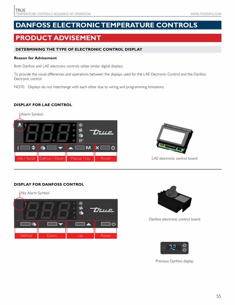
PRODUCT ADVISEMENT
DETERMINING THE TYPE OF ELECTRONIC CONTROL DISPLAY
Reason for Advisement
Both Danfoss and LAE electroinc controls utilize similar digital displays.
To provide the visual differences and operations between the displays used for the LAE Electronic Control and the Danfoss Electronic control
NOTE: Displays do not interchange with each other due to wiring and programming limitations.
LAE electronic control board
Danfoss electronic control board
Previous Danfoss display
DISPLAY FOR LAE CONTROL
DISPLAY FOR DANFOSS CONTROL
Alarm Symbol
No Alarm Symbol
Info / Scroll
Defrost
Defrost / Down
Down
Manual / Up
Up
Power
Power
56
TRUEtemperature controls sequence of operation www.truemfg.com
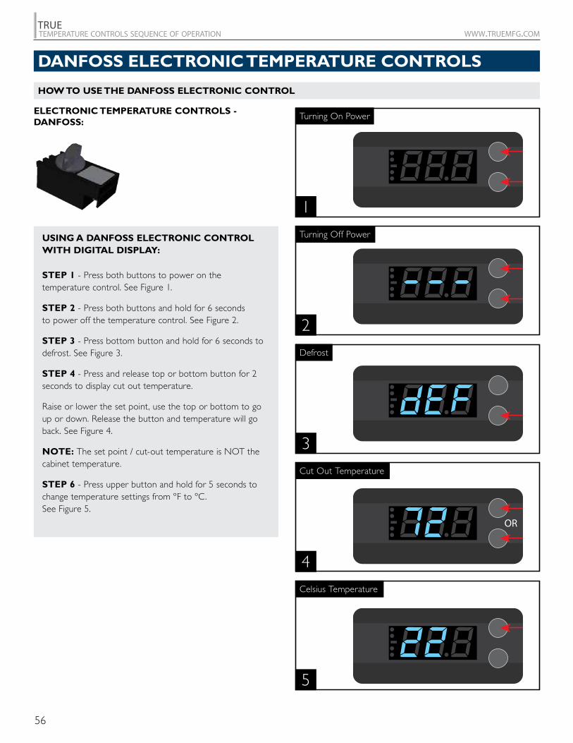
ELECTRONIC TEMPERATURE CONTROLS - DANFOSS:
1
Turning On Power
2
Turning Off PowerUSING A DANFOSS ELECTRONIC CONTROL WITH DIGITAL DISPLAY:
STEP 1 - Press both buttons to power on the temperature control. See Figure 1.
STEP 2 - Press both buttons and hold for 6 seconds to power off the temperature control. See Figure 2.
STEP 3 - Press bottom button and hold for 6 seconds to defrost. See Figure 3.
STEP 4 - Press and release top or bottom button for 2 seconds to display cut out temperature.
Raise or lower the set point, use the top or bottom to go up or down. Release the button and temperature will go back. See Figure 4.
NOTE: The set point / cut-out temperature is NOT the cabinet temperature.
STEP 6 - Press upper button and hold for 5 seconds to change temperature settings from ºF to ºC. See Figure 5.
Defrost
3
Cut Out Temperature
4
Celsius Temperature
5
HOW TO USE THE DANFOSS ELECTRONIC CONTROL
DANFOSS ELECTRONIC TEMPERATURE CONTROLS
57
TRUEtemperature controls sequence of operation www.truemfg.com
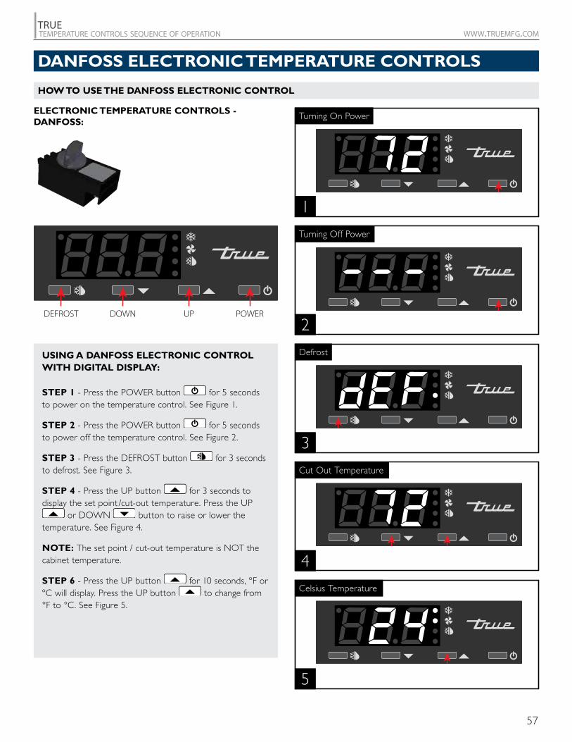
ELECTRONIC TEMPERATURE CONTROLS - DANFOSS:
1
Turning On Power
2
Turning Off Power
USING A DANFOSS ELECTRONIC CONTROL WITH DIGITAL DISPLAY:
STEP 1 - Press the POWER button for 5 seconds to power on the temperature control. See Figure 1.
STEP 2 - Press the POWER button for 5 seconds to power off the temperature control. See Figure 2.
STEP 3 - Press the DEFROST button for 3 seconds to defrost. See Figure 3.
STEP 4 - Press the UP button for 3 seconds to display the set point /cut-out temperature. Press the UP
or DOWN button to raise or lower the temperature. See Figure 4.
NOTE: The set point / cut-out temperature is NOT the cabinet temperature.
STEP 6 - Press the UP button for 10 seconds, ºF or ºC will display. Press the UP button to change from °F to °C. See Figure 5.
Defrost
3
Cut Out Temperature
4
Celsius Temperature
5
HOW TO USE THE DANFOSS ELECTRONIC CONTROL
DEFROST DOWN UP POWER
DANFOSS ELECTRONIC TEMPERATURE CONTROLS
58
TRUEtemperature controls sequence of operation www.truemfg.com
ALARMS ALARM TYPE CODE SHOWN VALUESensor 1 defect E1 –Sensor 2 defect E2 –Compressor fault E4 –Heater fault E5 –Pot fault E6 –Supply voltage low ULo –Supply voltage high UHi –High temperature alarm Hi TemperatureLow temperature alarm Lo TemperatureCommunication error E13 –
DANFOSS CONTROLS*
PART NUMBER
MARKING 5 CUT-IN/CUT-OUT
TEMPERATURE C (F)
DEFROST END TEMPERATURE
C (F)
9450584.41/1.1115 (39.94/34)
5 (41)
945059-18.1/-21.4
(-0.58/-6.52)5 (41)
9479814.41 /1.1115 (39.94/34)
5 (41)
9480723.69 /0.39
(38.64/32.7)5 (41)
9671952.22/0.555
(36/33)5 (41)
970719 (230V)4.41/1.1115 (39.94/34)
5 (41)
9707274.41/1.1115 (39.94/34)
5 (41)
9707284.41/1.1115 (39.94/34)
5 (41)
981945 (230V)4.41/1.1115 (39.94/34)
5 (41)
981946 (230V)-18.1/-21.4
(-0.58/-6.52)5 (41)
981947 (230V)4.41/1.1115 (39.94/34)
5 (41)
* Information is provided to verify cut-in/cut-out range for diagnostic purposes only. True recommends replacing OEM control with the same part number.
SUBJECT TO C
HANGE
DANFOSS ELECTRONIC TEMPERATURE CONTROLS
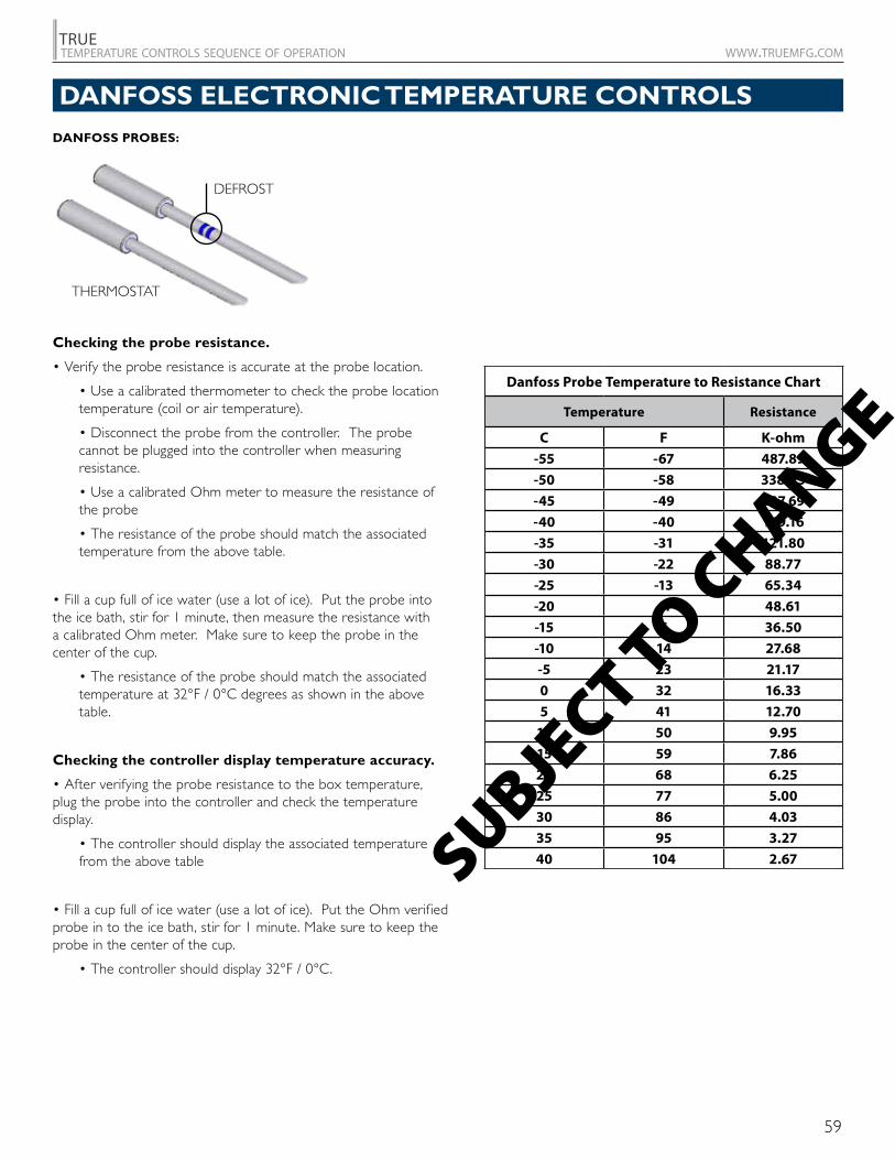
59
TRUEtemperature controls sequence of operation www.truemfg.com
Checking the probe resistance.
• Verify the probe resistance is accurate at the probe location.
• Use a calibrated thermometer to check the probe location temperature (coil or air temperature).
• Disconnect the probe from the controller. The probe cannot be plugged into the controller when measuring resistance.
• Use a calibrated Ohm meter to measure the resistance of the probe
• The resistance of the probe should match the associated temperature from the above table.
• Fill a cup full of ice water (use a lot of ice). Put the probe into the ice bath, stir for 1 minute, then measure the resistance with a calibrated Ohm meter. Make sure to keep the probe in the center of the cup.
• The resistance of the probe should match the associated temperature at 32°F / 0°C degrees as shown in the above table.
Checking the controller display temperature accuracy.
• After verifying the probe resistance to the box temperature, plug the probe into the controller and check the temperature display.
• The controller should display the associated temperature from the above table
• Fill a cup full of ice water (use a lot of ice). Put the Ohm verified probe in to the ice bath, stir for 1 minute. Make sure to keep the probe in the center of the cup.
• The controller should display 32°F / 0°C.
DANFOSS ELECTRONIC TEMPERATURE CONTROLS
Danfoss Probe Temperature to Resistance Chart
Temperature Resistance
C F K-ohm
-55 -67 487.89
-50 -58 338.25
-45 -49 237.69
-40 -40 169.16
-35 -31 121.80
-30 -22 88.77
-25 -13 65.34
-20 -4 48.61
-15 5 36.50
-10 14 27.68
-5 23 21.17
0 32 16.33
5 41 12.70
10 50 9.95
15 59 7.86
20 68 6.25
25 77 5.00
30 86 4.03
35 95 3.27
40 104 2.67SUBJECT TO C
HANGE
DANFOSS PROBES:
THERMOSTAT
DEFROST

60
TRUEtemperature controls sequence of operation www.truemfg.com
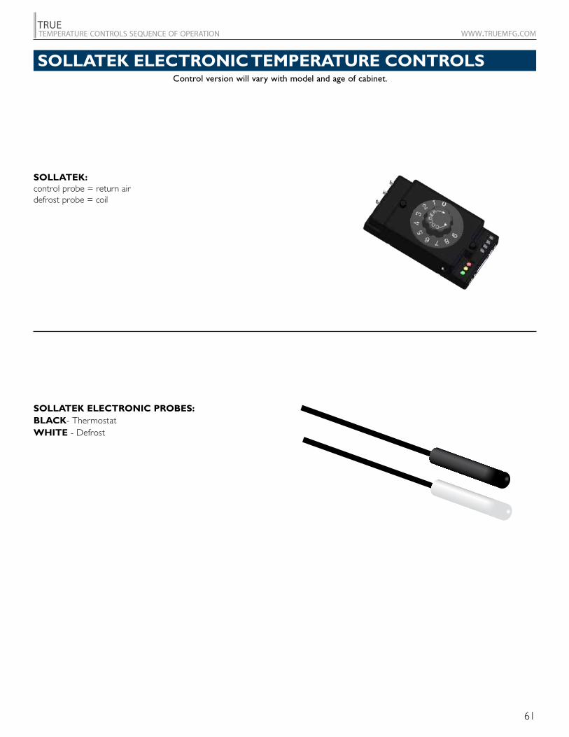
61
TRUEtemperature controls sequence of operation www.truemfg.com
Control version will vary with model and age of cabinet.
SOLLATEK ELECTRONIC TEMPERATURE CONTROLS
SOLLATEK:control probe = return air defrost probe = coil
SOLLATEK ELECTRONIC PROBES:BLACK- ThermostatWHITE - Defrost
62
TRUEtemperature controls sequence of operation www.truemfg.com
SOLLATEK ELECTRONIC CONTROL REFRIGERATOR GENERAL SEQUENCE OF OPERATION
1. Cabinet is plugged in. a. Interior lights will illuminate on Glass Door Models only. If the lights do not come on verify the light switch is in the “ON”
position. Solid door cabinets may or may not have lights that may be controlled by the door switch.
2. The compressor and evaporator fans will start if the temperature control is calling for cooling. (If the compressor does not start verify that the temperature control is not in the “off” or “0” position.)
a. Control or condenser fan(s) may be already preprogrammed from the factory so at the start of every compressor cycle, the condenser fan(s) will reverse for 30 seconds to blow dirt off the condensing coil.
3. The Sollatek temperature control may cycle the compressor and evaporator fan(s) on and off together. a. The temperature control should be set on the #4 or #5. b. The warmest setting is #1, the coldest is #9, and #0 is the off position. c. The thermometer is designed to read and display a cabinet temperature not a product temperature. This cabinet
temperature may reflect the refrigeration cycle determined by the temperature control. The most accurate temperature on a cabinets operation is to verify the product temperature.
4. The Sollatek control is preprogrammed to initiate defrost every 4 hours of compressor run time. If deemed necessary by the Sollatek control, additional defrost may occur at unspecified times.
a. At this time the evaporator fans will continue to run, but the compressor will turn off. Some cabinets may also change the rotation of the reversing condenser fan motor.
b. Once a preprogrammed temperature of the evaporator coil is reached, the Defrost Cycle will terminate and the 2 minute delay will start.
c. After the 2 minute delay the compressor will restart.
SOLLATEK ELECTRONIC TEMPERATURE CONTROLS
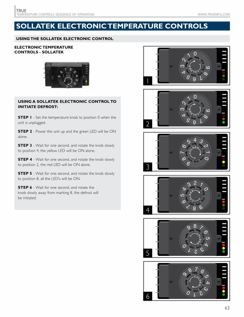
63
TRUEtemperature controls sequence of operation www.truemfg.com
ELECTRONIC TEMPERATURE CONTROLS - SOLLATEK
1
2
3
4
5
6
USING A SOLLATEK ELECTRONIC CONTROL TO INITIATE DEFROST:
STEP 1 - Set the temperature knob to position 0 when the unit is unplugged.
STEP 2 - Power the unit up and the green LED will be ON alone.
STEP 3 - Wait for one second, and rotate the knob slowly to position 4, the yellow LED will be ON alone.
STEP 4 - Wait for one second, and rotate the knob slowly to position 2, the red LED will be ON alone.
STEP 5 - Wait for one second, and rotate the knob slowly to position 8, all the LED’s will be ON.
STEP 6 - Wait for one second, and rotate the knob slowly away from marking 8, the defrost will be initiated.
USING THE SOLLATEK ELECTRONIC CONTROL
SOLLATEK ELECTRONIC TEMPERATURE CONTROLS
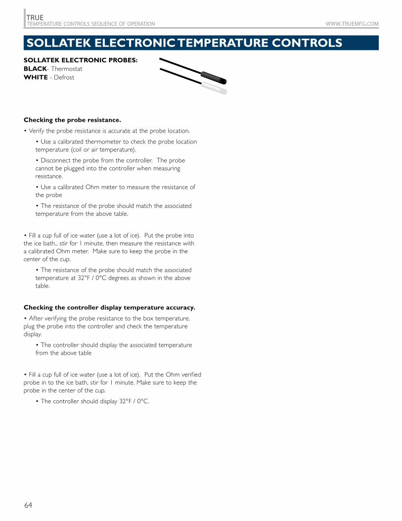
64
TRUEtemperature controls sequence of operation www.truemfg.com
SOLLATEK ELECTRONIC PROBES:BLACK- ThermostatWHITE - Defrost
Checking the probe resistance.
• Verify the probe resistance is accurate at the probe location.
• Use a calibrated thermometer to check the probe location temperature (coil or air temperature).
• Disconnect the probe from the controller. The probe cannot be plugged into the controller when measuring resistance.
• Use a calibrated Ohm meter to measure the resistance of the probe
• The resistance of the probe should match the associated temperature from the above table.
• Fill a cup full of ice water (use a lot of ice). Put the probe into the ice bath., stir for 1 minute, then measure the resistance with a calibrated Ohm meter. Make sure to keep the probe in the center of the cup.
• The resistance of the probe should match the associated temperature at 32°F / 0°C degrees as shown in the above table.
Checking the controller display temperature accuracy.
• After verifying the probe resistance to the box temperature, plug the probe into the controller and check the temperature display.
• The controller should display the associated temperature from the above table
• Fill a cup full of ice water (use a lot of ice). Put the Ohm verified probe in to the ice bath, stir for 1 minute. Make sure to keep the probe in the center of the cup.
• The controller should display 32°F / 0°C.
SOLLATEK ELECTRONIC TEMPERATURE CONTROLS
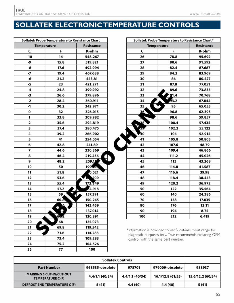
65
TRUEtemperature controls sequence of operation www.truemfg.com
Sollatek Controls
Part Number 968535-obsolete 978701 979009-obsolete 988937
MARKING 5 CUT-IN/CUT-OUT TEMPERATURE C (F) 4.4/1.1 (40/34) 4.4/1.1 (40/34) 16.1/12.8 (61/55) 15.6/12.2 (60/54)
DEFROST END TEMPERATURE C (F) 5 (41) 4.4 (40) 4.4 (40) 5 (41)
Sollatek Probe Temperature to Resistance Chart
Temperature Resistance
C F K-ohm-10 14 548.267
-9 15.8 519.821
-8 17.6 492.994
-7 19.4 467.688
-6 21.2 443.81
-5 23 421.271
-4 24.8 399.992
-3 26.6 379.896
-2 28.4 360.911
-1 30.2 342.971
0 32 326.015
1 33.8 309.982
2 35.6 294.819
3 37.4 280.475
4 39.2 266.902
5 41 254.054
6 42.8 241.89
7 44.6 230.369
8 46.4 219.456
9 48.2 209.115
10 50 199.314
11 51.8 190.021
12 53.6 181.209
13 55.4 172.849
14 57.2 164.918
15 59 157.391
16 60.8 150.245
17 62.6 143.459
18 64.4 137.014
19 66.2 130.891
20 68 125.073
21 69.8 119.542
22 71.6 114.283
23 73.4 109.283
24 75.2 104.526
25 77 100
Sollatek Probe Temperature to Resistance Chart*Temperature Resistance
C F K-ohm26 78.8 95.692
27 80.6 91.592
28 82.4 87.687
29 84.2 83.969
30 86 80.427
31 87.8 77.051
32 89.6 73.835
33 91.4 70.768
34 93.2 67.844
35 95 65.055
36 96.8 62.395
37 98.6 59.857
38 100.4 57.434
39 102.2 55.122
40 104 52.914
41 105.8 50.805
42 107.6 48.79
43 109.4 46.866
44 111.2 45.026
45 113 43.268
46 114.8 41.587
47 116.6 39.98
48 118.4 38.443
49 120.2 36.972
50 122 35.564
60 140 24.386
70 158 17.035
80 176 12.11
90 194 8.75
100 212 6.419
SUBJECT TO C
HANGE
* Information is provided to verify cut-in/cut-out range for diagnostic purposes only. True recommends replacing OEM control with the same part number.
SOLLATEK ELECTRONIC TEMPERATURE CONTROLS
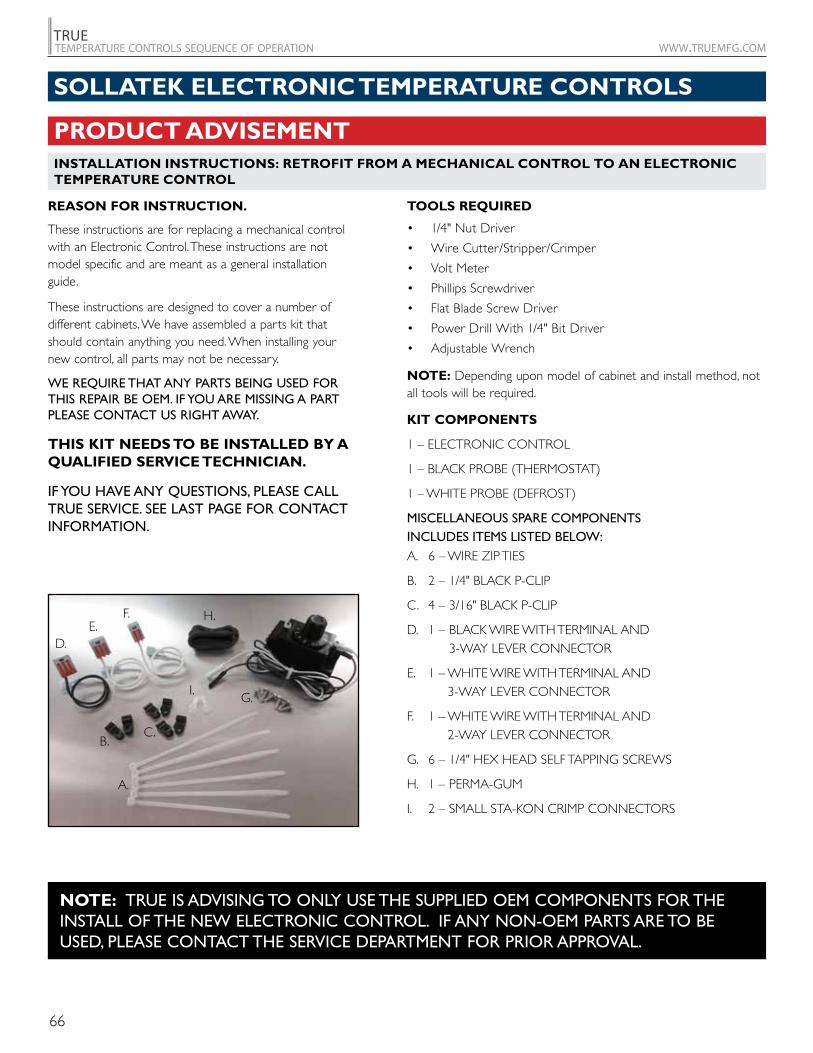
66
TRUEtemperature controls sequence of operation www.truemfg.com
PRODUCT ADVISEMENTINSTALLATION INSTRUCTIONS: RETROFIT FROM A MECHANICAL CONTROL TO AN ELECTRONIC TEMPERATURE CONTROL
SOLLATEK ELECTRONIC TEMPERATURE CONTROLS
TOOLS REQUIRED
• 1/4" Nut Driver
• Wire Cutter/Stripper/Crimper
• Volt Meter
• Phillips Screwdriver
• Flat Blade Screw Driver
• Power Drill With 1/4" Bit Driver
• Adjustable Wrench
NOTE: Depending upon model of cabinet and install method, not all tools will be required.
KIT COMPONENTS
1 – ELECTRONIC CONTROL
1 – BLACK PROBE (THERMOSTAT)
1 – WHITE PROBE (DEFROST)
MISCELLANEOUS SPARE COMPONENTS INCLUDES ITEMS LISTED BELOW:A. 6 – WIRE ZIP TIES
B. 2 – 1/4" BLACK P-CLIP
C. 4 – 3/16" BLACK P-CLIP
D. 1 – BLACK WIRE WITH TERMINAL AND 3-WAY LEVER CONNECTOR
E. 1 – WHITE WIRE WITH TERMINAL AND 3-WAY LEVER CONNECTOR
F. 1 – WHITE WIRE WITH TERMINAL AND 2-WAY LEVER CONNECTOR
G. 6 – 1/4" HEX HEAD SELF TAPPING SCREWS
H. 1 – PERMA-GUM
I. 2 – SMALL STA-KON CRIMP CONNECTORS
REASON FOR INSTRUCTION.
These instructions are for replacing a mechanical control with an Electronic Control. These instructions are not model specific and are meant as a general installation guide.
These instructions are designed to cover a number of different cabinets. We have assembled a parts kit that should contain anything you need. When installing your new control, all parts may not be necessary.
WE REQUIRE THAT ANY PARTS BEING USED FOR THIS REPAIR BE OEM. IF YOU ARE MISSING A PART PLEASE CONTACT US RIGHT AWAY.
THIS KIT NEEDS TO BE INSTALLED BY A QUALIFIED SERVICE TECHNICIAN.
IF YOU HAVE ANY QUESTIONS, PLEASE CALL TRUE SERVICE. SEE LAST PAGE FOR CONTACT INFORMATION.
NOTE: TRUE IS ADVISING TO ONLY USE THE SUPPLIED OEM COMPONENTS FOR THE INSTALL OF THE NEW ELECTRONIC CONTROL. IF ANY NON-OEM PARTS ARE TO BE USED, PLEASE CONTACT THE SERVICE DEPARTMENT FOR PRIOR APPROVAL.
A.
B.C.
D.E.
F.
G.
H.
I.
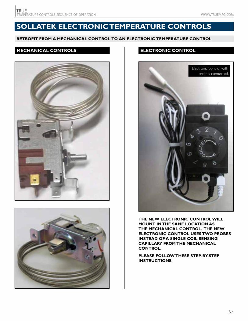
67
TRUEtemperature controls sequence of operation www.truemfg.com
SOLLATEK ELECTRONIC TEMPERATURE CONTROLS
MECHANICAL CONTROLS ELECTRONIC CONTROL
Electronic control with probes connected.
THE NEW ELECTRONIC CONTROL WILL MOUNT IN THE SAME LOCATION AS THE MECHANICAL CONTROL. THE NEW ELECTRONIC CONTROL USES TWO PROBES INSTEAD OF A SINGLE COIL SENSING CAPILLARY FROM THE MECHANICAL CONTROL.
PLEASE FOLLOW THESE STEP-BY-STEP INSTRUCTIONS.
RETROFIT FROM A MECHANICAL CONTROL TO AN ELECTRONIC TEMPERATURE CONTROL
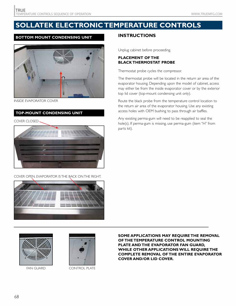
68
TRUEtemperature controls sequence of operation www.truemfg.com
INSTRUCTIONS
Unplug cabinet before proceeding.
PLACEMENT OF THE BLACK THERMOSTAT PROBE
Thermostat probe cycles the compressor.
The thermostat probe will be located in the return air area of the evaporator housing. Depending upon the model of cabinet, access may either be from the inside evaporator cover or by the exterior top lid cover (top- mount condensing unit only).
Route the black probe from the temperature control location to the return air area of the evaporator housing. Use any existing access holes with OEM bushing to pass through air baffles.
Any existing perma- gum will need to be reapplied to seal the hole(s). If perma-gum is missing, use perma-gum (item “H” from parts kit).
SOME APPLICATIONS MAY REQUIRE THE REMOVAL OF THE TEMPERATURE CONTROL MOUNTING PLATE AND THE EVAPORATOR FAN GUARD, WHILE OTHER APPLICATIONS WILL REQUIRE THE COMPLETE REMOVAL OF THE ENTIRE EVAPORATOR COVER AND/OR LID COVER.
FAN GUARD CONTROL PLATE
INSIDE EVAPORATOR COVER
BOTTOM MOUNT CONDENSING UNIT
COVER CLOSED
COVER OPEN. EVAPORATOR IS THE BACK ON THE RIGHT.
TOP-MOUNT CONDENSING UNIT
SOLLATEK ELECTRONIC TEMPERATURE CONTROLS
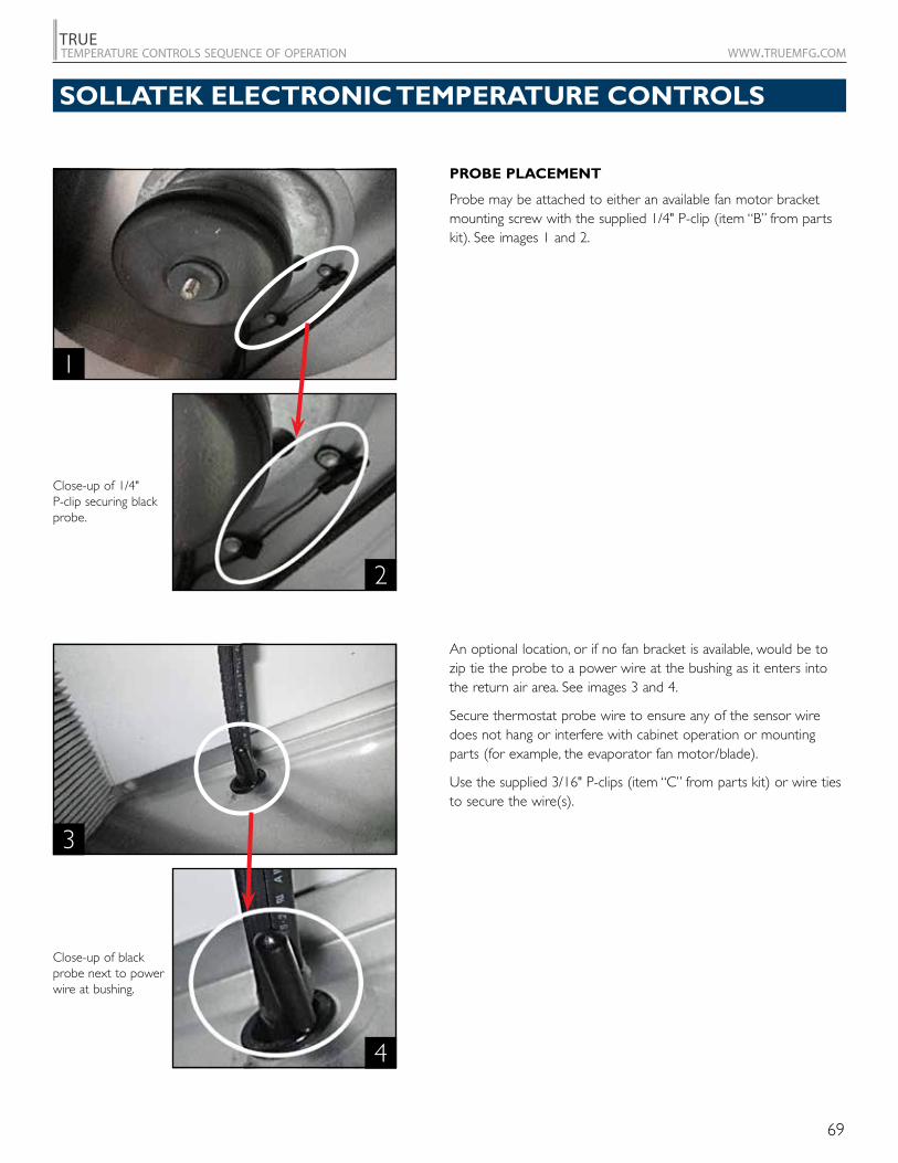
69
TRUEtemperature controls sequence of operation www.truemfg.com
PROBE PLACEMENT
Probe may be attached to either an available fan motor bracket mounting screw with the supplied 1/4" P- clip (item “B” from parts kit). See images 1 and 2.
An optional location, or if no fan bracket is available, would be to zip tie the probe to a power wire at the bushing as it enters into the return air area. See images 3 and 4.
Secure thermostat probe wire to ensure any of the sensor wire does not hang or interfere with cabinet operation or mounting parts (for example, the evaporator fan motor/blade).
Use the supplied 3/16" P- clips (item “C” from parts kit) or wire ties to secure the wire(s).
2
1
4
3
Close-up of 1/4" P- clip securing black probe.
Close-up of black probe next to power wire at bushing.
SOLLATEK ELECTRONIC TEMPERATURE CONTROLS
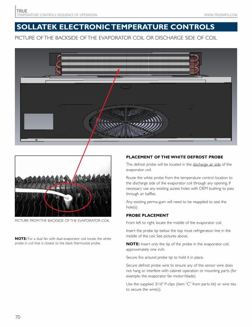
70
TRUEtemperature controls sequence of operation www.truemfg.com
PICTURE FROM THE BACKSIDE OF THE EVAPORATOR COIL
NOTE: For a dual fan with dual evaporator coil, locate the white probe in coil that is closest to the black thermostat probe.
PICTURE OF THE BACKSIDE OF THE EVAPORATOR COIL OR DISCHARGE SIDE OF COIL
PLACEMENT OF THE WHITE DEFROST PROBE
The defrost probe will be located in the discharge air side of the evaporator coil.
Route the white probe from the temperature control location to the discharge side of the evaporator coil through any opening. If necessary use any existing access holes with OEM bushing to pass through air baffles.
Any existing perma- gum will need to be reapplied to seal the hole(s).
PROBE PLACEMENT
From left to right, locate the middle of the evaporator coil.
Insert the probe tip below the top most refrigeration line in the middle of the coil. See pictures above.
NOTE: Insert only the tip of the probe in the evaporator coil, approximately one inch.
Secure fins around probe tip to hold it in place.
Secure defrost probe wire to ensure any of the sensor wire does not hang or interfere with cabinet operation or mounting parts (for example, the evaporator fan motor/blade).
Use the supplied 3/16" P- clips (item “C” from parts kit) or wire ties to secure the wire(s).
SOLLATEK ELECTRONIC TEMPERATURE CONTROLS
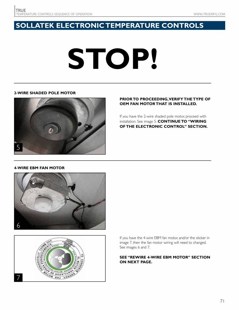
71
TRUEtemperature controls sequence of operation www.truemfg.com
PRIOR TO PROCEEDING, VERIFY THE TYPE OF OEM FAN MOTOR THAT IS INSTALLED.
If you have the 2-wire shaded pole motor, proceed with installation. See image 5. CONTINUE TO “WIRING OF THE ELECTRONIC CONTROL” SECTION.
If you have the 4-wire EBM fan motor, and/or the sticker in image 7, then the fan motor wiring will need to changed. See images 6 and 7.
SEE “REWIRE 4-WIRE EBM MOTOR” SECTION ON NEXT PAGE.
2- WIRE SHADED POLE MOTOR
4-WIRE EBM FAN MOTOR
5
6
7
STOP!SOLLATEK ELECTRONIC TEMPERATURE CONTROLS
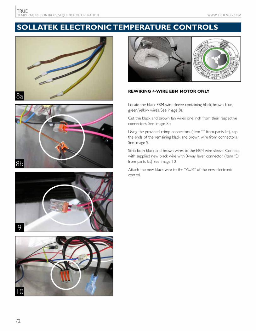
72
TRUEtemperature controls sequence of operation www.truemfg.com
REWIRING 4-WIRE EBM MOTOR ONLY
Locate the black EBM wire sleeve containing black, brown, blue, green/yellow wires. See image 8a.
Cut the black and brown fan wires one inch from their respective connectors. See image 8b.
Using the provided crimp connectors (item “I” from parts kit), cap the ends of the remaining black and brown wire from connectors. See image 9.
Strip both black and brown wires to the EBM wire sleeve. Connect with supplied new black wire with 3- way lever connector. (Item “D” from parts kit) See image 10.
Attach the new black wire to the “AUX” of the new electronic control.
8b
8a
9
10
SOLLATEK ELECTRONIC TEMPERATURE CONTROLS
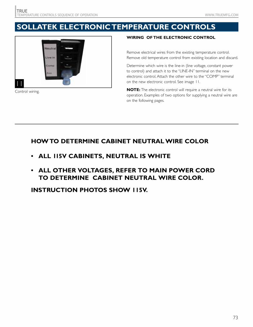
73
TRUEtemperature controls sequence of operation www.truemfg.com
WIRING OF THE ELECTRONIC CONTROL
Remove electrical wires from the existing temperature control. Remove old temperature control from existing location and discard.
Determine which wire is the line- in (line voltage, constant power to control) and attach it to the “LINE- IN” terminal on the new electronic control. Attach the other wire to the “COMP” terminal on the new electronic control. See image 11.
NOTE: The electronic control will require a neutral wire for its operation. Examples of two options for supplying a neutral wire are on the following pages.
HOW TO DETERMINE CABINET NEUTRAL WIRE COLOR
• ALL 115V CABINETS, NEUTRAL IS WHITE
• ALL OTHER VOLTAGES, REFER TO MAIN POWER CORD TO DETERMINE CABINET NEUTRAL WIRE COLOR.
INSTRUCTION PHOTOS SHOW 115V.
11Control wiring.
SOLLATEK ELECTRONIC TEMPERATURE CONTROLS
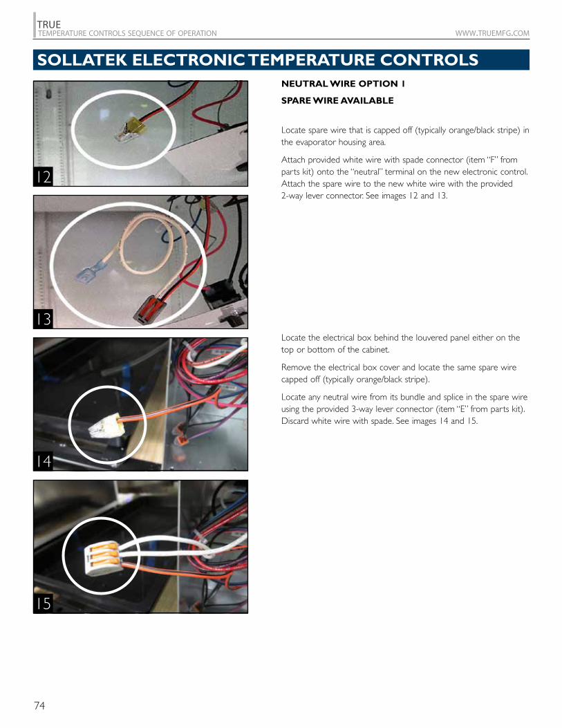
74
TRUEtemperature controls sequence of operation www.truemfg.com
NEUTRAL WIRE OPTION 1
SPARE WIRE AVAILABLE
Locate spare wire that is capped off (typically orange/black stripe) in the evaporator housing area.
Attach provided white wire with spade connector (item “F” from parts kit) onto the “neutral” terminal on the new electronic control. Attach the spare wire to the new white wire with the provided 2- way lever connector. See images 12 and 13.
Locate the electrical box behind the louvered panel either on the top or bottom of the cabinet.
Remove the electrical box cover and locate the same spare wire capped off (typically orange/black stripe).
Locate any neutral wire from its bundle and splice in the spare wire using the provided 3- way lever connector (item “E” from parts kit). Discard white wire with spade. See images 14 and 15.
12
13
14
15
SOLLATEK ELECTRONIC TEMPERATURE CONTROLS
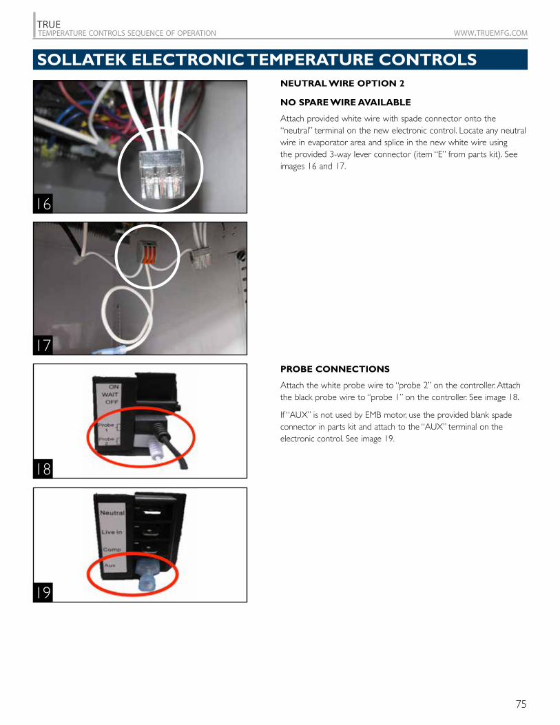
75
TRUEtemperature controls sequence of operation www.truemfg.com
NEUTRAL WIRE OPTION 2
NO SPARE WIRE AVAILABLE
Attach provided white wire with spade connector onto the “neutral” terminal on the new electronic control. Locate any neutral wire in evaporator area and splice in the new white wire using the provided 3-way lever connector (item “E” from parts kit). See images 16 and 17.
PROBE CONNECTIONS
Attach the white probe wire to “probe 2” on the controller. Attach the black probe wire to “probe 1” on the controller. See image 18.
If “AUX” is not used by EMB motor, use the provided blank spade connector in parts kit and attach to the “AUX” terminal on the electronic control. See image 19.
16
17
18
19
SOLLATEK ELECTRONIC TEMPERATURE CONTROLS
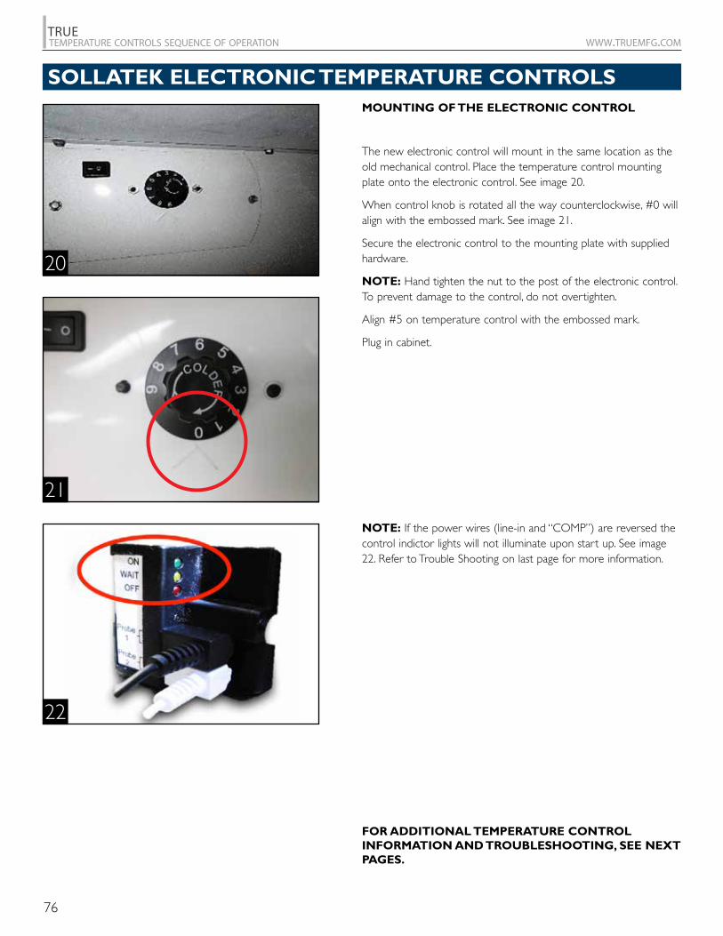
76
TRUEtemperature controls sequence of operation www.truemfg.com
MOUNTING OF THE ELECTRONIC CONTROL
The new electronic control will mount in the same location as the old mechanical control. Place the temperature control mounting plate onto the electronic control. See image 20.
When control knob is rotated all the way counterclockwise, #0 will align with the embossed mark. See image 21.
Secure the electronic control to the mounting plate with supplied hardware.
NOTE: Hand tighten the nut to the post of the electronic control. To prevent damage to the control, do not overtighten.
Align #5 on temperature control with the embossed mark.
Plug in cabinet.
NOTE: If the power wires (line- in and “COMP”) are reversed the control indictor lights will not illuminate upon start up. See image 22. Refer to Trouble Shooting on last page for more information.
FOR ADDITIONAL TEMPERATURE CONTROL INFORMATION AND TROUBLESHOOTING, SEE NEXT PAGES.
20
21
22
SOLLATEK ELECTRONIC TEMPERATURE CONTROLS
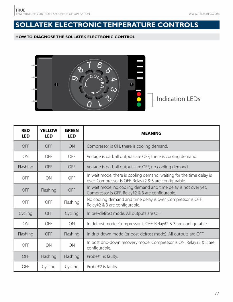
77
TRUEtemperature controls sequence of operation www.truemfg.com
COLDER
9 8
7 6 5 4 3
2 1 0 Indication LEDs
RED LED
YELLOW LED
GREEN LED
MEANING
OFF OFF ON Compressor is ON, there is cooling demand.
ON OFF OFF Voltage is bad, all outputs are OFF, there is cooling demand.
Flashing OFF OFF Voltage is bad, all outputs are OFF, no cooling demand.
OFF ON OFFIn wait mode, there is cooling demand, waiting for the time delay is over. Compressor is OFF. Relay#2 & 3 are configurable.
OFF Flashing OFFIn wait mode, no cooling demand and time delay is not over yet. Compressor is OFF. Relay#2 & 3 are configurable.
OFF OFF FlashingNo cooling demand and time delay is over. Compressor is OFF. Relay#2 & 3 are configurable.
Cycling OFF Cycling In pre-defrost mode. All outputs are OFF
ON OFF ON In defrost mode. Compressor is OFF. Relay#2 & 3 are configurable.
Flashing OFF Flashing In drip-down mode (or post-defrost mode). All outputs are OFF
OFF ON ONIn post drip-down recovery mode. Compressor is ON. Relay#2 & 3 are configurable.
OFF Flashing Flashing Probe#1 is faulty.
OFF Cycling Cycling Probe#2 is faulty.
HOW TO DIAGNOSE THE SOLLATEK ELECTRONIC CONTROL
SOLLATEK ELECTRONIC TEMPERATURE CONTROLS
78
TRUEtemperature controls sequence of operation www.truemfg.com
NOTES
79
TRUEtemperature controls sequence of operation www.truemfg.com
NOTES
80
TRUEtemperature controls sequence of operation www.truemfg.com
NOTES
DFF
A
K
3
5
6
4
1
USA Service Department Hours
(Central Standard Time Zone)
Monday - Thursday: 7:00 a.m.- 7:00 p.m.
Friday: 7:00 a.m.- 6:00 p.m.
Saturday: 8:00 a.m.- 12:00 p.m.
UK Service Department Hours
Monday - Friday: 8.30 a.m.- 5.00 p.m.
United Kingdom
phone: +44 (0) 1709.888080
freephone: 0800.783.2049
U.K. freephone to U.S.: 0800.894.928
fax: +44 (0) 1709.880838
USA & Canada
phone: 636.240.2400
toll free: 855.372.1368 (direct to Service Department)
toll free: 800.325.6152
fax: 636.980.8350
2001 East Terra LaneO’Fallon, Missouri 63366-4434
www.truemfg.com
1/16 • AN