air-conditioning high performance
TRANSCRIPT
Safety Precautions
Before starting use
Air-conditioner usage targetThe air-conditioner described in this catalog is a dedicated cooling/heating device for human use. Do not use it for special applications such as the storage of foodstuffs, animals or plants, precision devices or valuable art, etc. This could cause the quality of the items to drop, etc. Do not use this for cooling vehicles or ships. Water leakage or current leaks could occur.
Before useAlways read the "User,s Manual" thoroughly before starting use.
InstallationAlways commission the installation to a dealer or specialist. Improper installation will lead to water leakage, electric shocks and fires. Make sure that the outdoor unit is stable in installation. Fix the unit to stable base.
Usage placeDo not install in places where combustible gas could leak or where there are sparks. Installation in a place where combustible gas could be generated, flow or accumulate, or places containing carbon fibers could lead to fires.
Refrigerant leakageThe refrigerant (R410A) used for Air conditioner is non-toxic and inflammable in its original state. However, in consideration of a state where the refrigerant leaks into the room, measures against refrigerant leaks must be taken in small rooms where the tolerable level could be exceeded. Take measures by installing ventilation devices, etc.
Use in snowy areasTake the following measures when installing the outdoor unit in snowy areas.
·Snow preventionInstall a snow-prevention hood so that the snow does not obstruct the air intake port or enter and freeze in the outdoor unit.
·Snow pilingIn areas with heavy snow fall, the piled snow could block the air intake port. In this case, a frame that is 50cm or higher than the estimated snow fall must be installed underneath the outdoor unit.
Automatic defrosting deviceIf the temperature is low, and the humidity is high, frost will stick to the heat exchanger of the outdoor unit. If use is continued, the heating performance will drop. The "Automatic defrosting device" will function to remove this frost. After heating for approx, three to ten minutes, it will stop, and the frost will be removed. After defrosting, hot air will be blown again.
Servicing the air-conditionerAfter the air-conditioner is used for several seasons, dirt will build up in the air-conditioner causing the performance to drop. In addition to regular servicing, we recommend the maintenance contract (charged for) by a specialist.
Heating performanceThe heating performance values (kW) described in catalogue are the values obtained by operating at an outdoor temperature of 7 C and indoor temperature of 20 C as set forth in the ISO Standards. As the heating performance decreases as the outdoor temperature drops, if the outdoor temperature is too low and the heating performance is insufficient, use other heating appliances as well.
Indication of sound valuesThe sound values are the values (A scale) measured in a chamber such as an anechoic chamber following the ISO Standards. In the actual installation state, the value is normally larger than the values given in the catalog due to the effect of surrounding noise and echo. Take this into consideration when installing.
Use in oil atmosphereAvoid installing this unit in as atmosphere where oil scatters or builds up, such as in a kitchen or machine factory. If the oil adheres to the heat exchanger, the heat exchanging performance will drop, mist may be generated, and the synthetic resin parts may deform and break.
Use in acidic or alkaline atmosphereIf this unit is used in acidic atmosphere such as hot spring areas having high level of sulfuric gases or in alkaline atmosphere including ammonia or calcium chloride, places where the exhaust of the heat exchanger is sucked in, or at coastal areas where the unit is subject to salt breezes, the outer plate or heat exchanger, etc., will corrode. Please ask a dealer or specialist when you use an air conditioner in places differing from a general atmosphere. Use in places with high ceilingsIf the ceiling is high, install a circulator to improve the heat and air flow distribution when heating.
Mitsubishi Heavy Industries, Ltd.Air-Conditioning & Refrigeration DivisionMachinery Equipment & Infrastructure16-5, Konan 2-chome, Minato-ku, Tokyo, 108-8215 Japanhttp://www.mhi.co.jp
January 2016 F16P01E
Our factories are ISO9001 and ISO14001 certified.
Mitsubishi HeavyIndustries-Haier (Quingdao)
Air-conditioners Co.,Ltd.Certificate number : 01-1998-083
Certified ISO 9001
Because of our policy of continuous improvement, we reserve the right to make changes in all specifications without notice.
Edited in Japan
(COMPANY) participates in the ECC programme for (PROGRAMME).Check ongoing validity of certificate:www.eurovent-certification.com or www.certiflash.com
Certified ISO 14001
Air-Conditioning
High Performance
50/60Hz16P01E Inverter Packaged Air-Conditioners
2016
MITSUBISHI HEAVY INDUSTRIES-MAHAJAK AIR CONDITIONERS CO.,LTD.
ISO 14001Certificate 04104 1998 0813 E5
BIWAJIMA PLANT Mitsubishi Heavy Industries, Ltd.
Air-conditioning & Refrigeration Systems Headquarters
Mitsubishi HeavyIndustries-Haier (Quingdao)
Air-conditioners Co.,Ltd.Certificate Number : 5170-1996-AQ-RCG-RvA
Certificate Number : YKA4003622
BIWAJIMA PLANT Mitsubishi Heavy Industries, Ltd.
Air-conditioning & Refrigeration Systems HeadquartersCertified ISO 9001
Certificate Number : JQA-0709
MITSUBISHI HEAVY INDUSTRIES-MAHAJAK AIR CONDITIONERS CO., LTD.
Certified ISO 9001Certificate Number : 04100 1998 0813
Certificate Number : 04104 1998 0813 E5
M fin
-15˚C +43˚C
-20˚C +20˚C
50403020100-10-20-30
Heating
Cooling
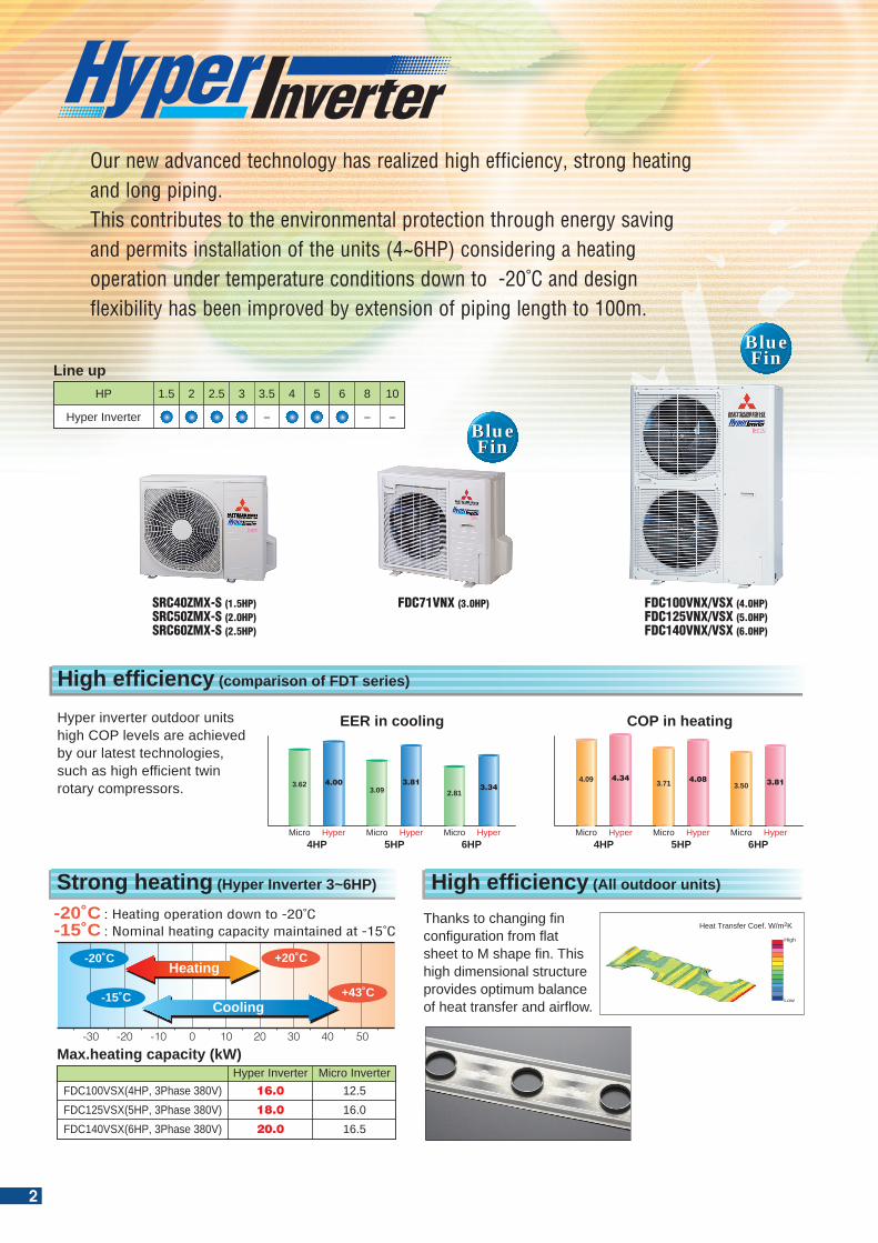
: Heating operation down to -20˚C: Nominal heating capacity maintained at -15˚C
-20˚C-15˚C
FDC100VSX(4HP, 3Phase 380V)FDC125VSX(5HP, 3Phase 380V)FDC140VSX(6HP, 3Phase 380V)
Micro InverterHyper Inverter12.516.016.5
16.0
18.0
20.0
Max.heating capacity (kW)
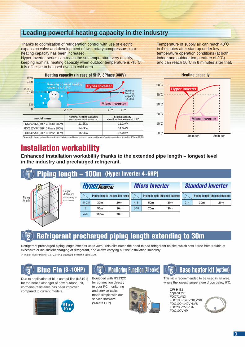
Thanks to optimization of refrigeration control with use of electric expansion valve and development of twin rotary compressors, max heating capacity has been increased.Hyper Inverter series can reach the set temperature very quickly, keeping nominal heating capacity when outdoor temperature is -15˚C. It is effective to be used even in cold area.
Temperature of supply air can reach 40˚C in 4 minutes after start up under low temperature operation conditions (at both indoor and outdoor temperature of 2˚C) and can reach 50˚C in 8 minutes after that.
FDC100VSX(4HP, 3Phase 380V)FDC125VSX(5HP, 3Phase 380V)FDC140VSX(6HP, 3Phase 380V)
11.2kW14.0kW16.0kW
nominal heating capacity(kW at outdoor temperature of 7˚C)model name
11.2kW14.0kW16.0kW
heating capacity at outdoor temperature of -15˚C
Heating capacity (in case of 5HP, 3Phase 380V)
nominalheatingcapacity14.0kW
Keeping nominal heating capacity at -15˚C
(kW)18.0
14.514.0
8.80 -15˚C 2˚C 7˚C
Hyper Inverter
Micro Inverter
Heating capacity
50˚C
40˚C
30˚C
20˚C
10˚C
0˚C4minutes 8minutes
Hyper Inverter
Micro Inverter
Please refer to our technical manual for installation conditions, operation range and heating/cooling capacities. (including 1Phase 220V)
Leading powerful heating capacity in the industry
Our new advanced technology has realized high efficiency, strong heating and long piping. This contributes to the environmental protection through energy saving and permits installation of the units (4~6HP) considering a heating operation under temperature conditions down to -20˚C and design flexibility has been improved by extension of piping length to 100m.
Hyper Inverter
HP 8
-
10
-
5 63 3.5
-
42 2.51.5
Line up
BlueFin
BlueFin
BlueFin
BlueFin
Strong heating (Hyper Inverter 3~6HP)
SRC40ZMX-S (1.5HP)SRC50ZMX-S (2.0HP)SRC60ZMX-S (2.5HP)
FDC71VNX (3.0HP) FDC100VNX/VSX (4.0HP)FDC125VNX/VSX (5.0HP)FDC140VNX/VSX (6.0HP)
High efficiency (comparison of FDT series)
Hyper inverter outdoor units high COP levels are achieved by our latest technologies, such as high efficient twin rotary compressors.
EER in cooling COP in heating
Micro Hyper MicroMicro Hyper Hyper5HP4HP 6HP
3.623.09 2.81
4.00 3.813.34
Micro Hyper MicroMicro Hyper Hyper5HP4HP 6HP
4.09 3.71 3.504.34 4.08 3.81
Thanks to changing fin configuration from flat sheet to M shape fin. This high dimensional structure provides optimum balance of heat transfer and airflow.
High
Low
Heat Transfer Coef. W/m2K
Enhanced installation workability thanks to the extended pipe length – longest levelin the industry and precharged refrigerant.
Refrigerant precharged piping length extends up to 30m. This eliminates the need to add refrigerant on site, which sets it free from trouble of excessive or insufficient charging of refrigerant, and allows carrying out the installation smoothly.
That of Hyper inverter 1.5~2.5HP & Standard inverter is up to 15m.
Point
1 Piping length – 100m (Hyper Inverter 4~6HP)
Point
3 Blue Fin (3~10HP) Point
4 Monitoring Function (All series) Point
5 Base heater kit (option)
Point
2 Refrigerant precharged piping length extending to 30m
Height difference(Outdoor higher than Indoor)
Piping length
Micro Inverter Standard Inverter
HP
1.5~2.5
3
4~6
30m
50m
100m
20m
30m
30m
Piping length Height difference
50m
70m
30m
30m
Piping length Height differenceHP
4~6
8.10
30m 20m
Piping length Height difference
3~4
HP
Due to application of blue coated fins (KS101) for the heat exchanger of new outdoor unit, corrosion resistance has been improved compared to current models.
BlueFin
BlueFin
This kit is recommended to be used in an area where the lowest temperature drops below 0˚C.
CW-H-E1applied forFDC71VNXFDC100~140VNX,VSXFDC100~140VN,VSFDC200/250VSAFDC100VNP
Equipped with RS232C for connection directly to your PC monitoring and service tasks made simple with our service software (“Mente PC”).
Installation workability
High efficiency (All outdoor units)
2
M fin
-15˚C +43˚C
-20˚C +20˚C
50403020100-10-20-30
Heating
Cooling
: Heating operation down to -20˚C: Nominal heating capacity maintained at -15˚C
-20˚C-15˚C
FDC100VSX(4HP, 3Phase 380V)FDC125VSX(5HP, 3Phase 380V)FDC140VSX(6HP, 3Phase 380V)
Micro InverterHyper Inverter12.516.016.5
16.0
18.0
20.0
Max.heating capacity (kW)
Thanks to optimization of refrigeration control with use of electric expansion valve and development of twin rotary compressors, max heating capacity has been increased.Hyper Inverter series can reach the set temperature very quickly, keeping nominal heating capacity when outdoor temperature is -15˚C. It is effective to be used even in cold area.
Temperature of supply air can reach 40˚C in 4 minutes after start up under low temperature operation conditions (at both indoor and outdoor temperature of 2˚C) and can reach 50˚C in 8 minutes after that.
FDC100VSX(4HP, 3Phase 380V)FDC125VSX(5HP, 3Phase 380V)FDC140VSX(6HP, 3Phase 380V)
11.2kW14.0kW16.0kW
nominal heating capacity(kW at outdoor temperature of 7˚C)model name
11.2kW14.0kW16.0kW
heating capacity at outdoor temperature of -15˚C
Heating capacity (in case of 5HP, 3Phase 380V)
nominalheatingcapacity14.0kW
Keeping nominal heating capacity at -15˚C
(kW)18.0
14.514.0
8.80 -15˚C 2˚C 7˚C
Hyper Inverter
Micro Inverter
Heating capacity
50˚C
40˚C
30˚C
20˚C
10˚C
0˚C4minutes 8minutes
Hyper Inverter
Micro Inverter
Please refer to our technical manual for installation conditions, operation range and heating/cooling capacities. (including 1Phase 220V)
Leading powerful heating capacity in the industry
Our new advanced technology has realized high efficiency, strong heating and long piping. This contributes to the environmental protection through energy saving and permits installation of the units (4~6HP) considering a heating operation under temperature conditions down to -20˚C and design flexibility has been improved by extension of piping length to 100m.
Hyper Inverter
HP 8
-
10
-
5 63 3.5
-
42 2.51.5
Line up
BlueFin
BlueFin
BlueFin
BlueFin
Strong heating (Hyper Inverter 3~6HP)
SRC40ZMX-S (1.5HP)SRC50ZMX-S (2.0HP)SRC60ZMX-S (2.5HP)
FDC71VNX (3.0HP) FDC100VNX/VSX (4.0HP)FDC125VNX/VSX (5.0HP)FDC140VNX/VSX (6.0HP)
High efficiency (comparison of FDT series)
Hyper inverter outdoor units high COP levels are achieved by our latest technologies, such as high efficient twin rotary compressors.
EER in cooling COP in heating
Micro Hyper MicroMicro Hyper Hyper5HP4HP 6HP
3.623.09 2.81
4.00 3.813.34
Micro Hyper MicroMicro Hyper Hyper5HP4HP 6HP
4.09 3.71 3.504.34 4.08 3.81
Thanks to changing fin configuration from flat sheet to M shape fin. This high dimensional structure provides optimum balance of heat transfer and airflow.
High
Low
Heat Transfer Coef. W/m2K
Enhanced installation workability thanks to the extended pipe length – longest levelin the industry and precharged refrigerant.
Refrigerant precharged piping length extends up to 30m. This eliminates the need to add refrigerant on site, which sets it free from trouble of excessive or insufficient charging of refrigerant, and allows carrying out the installation smoothly.
That of Hyper inverter 1.5~2.5HP & Standard inverter is up to 15m.
Point
1 Piping length – 100m (Hyper Inverter 4~6HP)
Point
3 Blue Fin (3~10HP) Point
4 Monitoring Function (All series) Point
5 Base heater kit (option)
Point
2 Refrigerant precharged piping length extending to 30m
Height difference(Outdoor higher than Indoor)
Piping length
Micro Inverter Standard Inverter
HP
1.5~2.5
3
4~6
30m
50m
100m
20m
30m
30m
Piping length Height difference
50m
70m
30m
30m
Piping length Height differenceHP
4~6
8.10
30m 20m
Piping length Height difference
3~4
HP
Due to application of blue coated fins (KS101) for the heat exchanger of new outdoor unit, corrosion resistance has been improved compared to current models.
BlueFin
BlueFin
This kit is recommended to be used in an area where the lowest temperature drops below 0˚C.
CW-H-E1applied forFDC71VNXFDC100~140VNX,VSXFDC100~140VN,VSFDC200/250VSAFDC100VNP
Equipped with RS232C for connection directly to your PC monitoring and service tasks made simple with our service software (“Mente PC”).
Installation workability
High efficiency (All outdoor units)
3
BlueFin
BlueFin
BlueFin
BlueFin
BlueFin
BlueFin
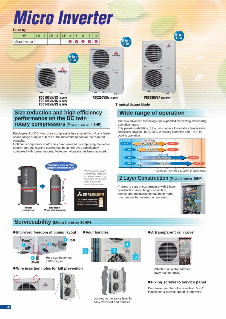
2 Layer Construction (Micro Inverter 10HP)
Thanks to control box structure with 2 layer construction using hinge connection, service and maintenance has been made much easier for inverter components.
Wide range of operationOur new advanced technology has expanded the heating and cooling operation range.This permits installation of the units under a low outdoor temperature conditions down to -15˚C/-20˚C In heating operation and -15˚C in cooling operation.
* Vector control means a. technique to realize an optimum control by converting the current wave to a smooth sinusoidal waveform
Employment of DC twin rotary compressor has enabled to utilize a high-speed range of up to 120 rps at the maximum to secure the required capacity.Optimum compressor control has been realized by employing the vector control* and the starting current has been improved significantly compared with former models. Moreover, vibration has been reduced.
Formercompressor
New modelDC twin rotary compressor
Heigh
t at 4
40 m
m
Outside diameter of shellø185mm
Heigh
t at 3
42m
m
Reduction in height by 22.3%Reduction in volume by 44.1%
ø133mm
Micro Inverter
Size reduction and high efficiencyperformance on the DC twin rotary compressors (Micro Inverter 4-6HP)
Micro Inverter
HP 1.5
-
2
-
2.5
-
3
-
3.5
-
4 5 6 8 10
Line up
FDC100VN/VS (4.0HP)FDC125VN/VS (5.0HP)FDC140VN/VS (6.0HP)
FDC200VSA (8.0HP) FDC250VSA (10.0HP)
Heating
Cooling+43ºC
+20ºC
+20ºC
-15ºC
+50ºC*-15ºC
-20ºC
-15ºC
50403020100-10-20* FDC200/250 : extended to 50˚CDB in the cooling mode.
Tropical Usage Mode
Wire insertion holes for fall prevention
2
3
4
1
Front
Down
RightRear
Improved freedom of piping layout
Hole size becomes 120% bigger.
FDC100/125/140FDC100/125/140
FDC200/250FDC200/250
FDC100/125/140FDC100/125/140
FDC200/250FDC200/250
M fin
2 1
4
3
Four handles A transparent rain cover
All outdoor units (Hyper, Micro,Standard)
Located at the same level for easy transport and transfer.
Decreasing number of screws from 5 to 2, installation & service speed is improved.
Attached as a standard for easy maintenance.
Fixing screws to service panel
BlueFin
BlueFin
BlueFin
BlueFin
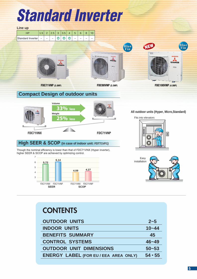
Though the nominal efficiency is lower than that of FDC71VNX (Hyper inverter), higher SEER & SCOP are achieved by optimizing control.
Compact Design of outdoor units
High SEER & SCOP (in case of indoor unit: FDT71VF1)
Standard Inverter 3
Standard Inverter
HP 1.5 2 2.5 3.5
- -
4 5 6 8 10
- - ---
Line up
Easy installation
FDC71VNX FDC71VNP
Volume
33% lessWeight
25% less
SCOP
6
7
5
4
3
4.09 4.27
SEER
5.726.14
FDC71VNX FDC71VNP FDC71VNX FDC71VNP
FDC100VNP (4.0HP)FDC71VNP (3.0HP) FDC90VNP (3.5HP)
NEW
Serviceability (Micro Inverter 10HP)
Fits into elevators
CONTENTSOUTDOOR UNITS 2~5INDOOR UNITS 10~44BENEFITS SUMMARY 45CONTROL SYSTEMS 46~49OUTDOOR UNIT DIMENSIONS 50~53ENERGY LABEL (FOR EU / EEA AREA ONLY) 54 • 55
4
BlueFin
BlueFin
BlueFin
BlueFin
BlueFin
BlueFin
2 Layer Construction (Micro Inverter 10HP)
Thanks to control box structure with 2 layer construction using hinge connection, service and maintenance has been made much easier for inverter components.
Wide range of operationOur new advanced technology has expanded the heating and cooling operation range.This permits installation of the units under a low outdoor temperature conditions down to -15˚C/-20˚C In heating operation and -15˚C in cooling operation.
* Vector control means a. technique to realize an optimum control by converting the current wave to a smooth sinusoidal waveform
Employment of DC twin rotary compressor has enabled to utilize a high-speed range of up to 120 rps at the maximum to secure the required capacity.Optimum compressor control has been realized by employing the vector control* and the starting current has been improved significantly compared with former models. Moreover, vibration has been reduced.
Formercompressor
New modelDC twin rotary compressor
Heigh
t at 4
40 m
m
Outside diameter of shellø185mm
Heigh
t at 3
42m
m
Reduction in height by 22.3%Reduction in volume by 44.1%
ø133mm
Micro Inverter
Size reduction and high efficiencyperformance on the DC twin rotary compressors (Micro Inverter 4-6HP)
Micro Inverter
HP 1.5
-
2
-
2.5
-
3
-
3.5
-
4 5 6 8 10
Line up
FDC100VN/VS (4.0HP)FDC125VN/VS (5.0HP)FDC140VN/VS (6.0HP)
FDC200VSA (8.0HP) FDC250VSA (10.0HP)
Heating
Cooling+43ºC
+20ºC
+20ºC
-15ºC
+50ºC*-15ºC
-20ºC
-15ºC
50403020100-10-20* FDC200/250 : extended to 50˚CDB in the cooling mode.
Tropical Usage Mode
Wire insertion holes for fall prevention
2
3
4
1
Front
Down
RightRear
Improved freedom of piping layout
Hole size becomes 120% bigger.
FDC100/125/140FDC100/125/140
FDC200/250FDC200/250
FDC100/125/140FDC100/125/140
FDC200/250FDC200/250
M fin
2 1
4
3
Four handles A transparent rain cover
All outdoor units (Hyper, Micro,Standard)
Located at the same level for easy transport and transfer.
Decreasing number of screws from 5 to 2, installation & service speed is improved.
Attached as a standard for easy maintenance.
Fixing screws to service panel
BlueFin
BlueFin
BlueFin
BlueFin
Though the nominal efficiency is lower than that of FDC71VNX (Hyper inverter), higher SEER & SCOP are achieved by optimizing control.
Compact Design of outdoor units
High SEER & SCOP (in case of indoor unit: FDT71VF1)
Standard Inverter 3
Standard Inverter
HP 1.5 2 2.5 3.5
- -
4 5 6 8 10
- - ---
Line up
Easy installation
FDC71VNX FDC71VNP
Volume
33% lessWeight
25% less
SCOP
6
7
5
4
3
4.09 4.27
SEER
5.726.14
FDC71VNX FDC71VNP FDC71VNX FDC71VNP
FDC100VNP (4.0HP)FDC71VNP (3.0HP) FDC90VNP (3.5HP)
NEW
Serviceability (Micro Inverter 10HP)
Fits into elevators
CONTENTSOUTDOOR UNITS 2~5INDOOR UNITS 10~44BENEFITS SUMMARY 45CONTROL SYSTEMS 46~49OUTDOOR UNIT DIMENSIONS 50~53ENERGY LABEL (FOR EU / EEA AREA ONLY) 54 • 55
5
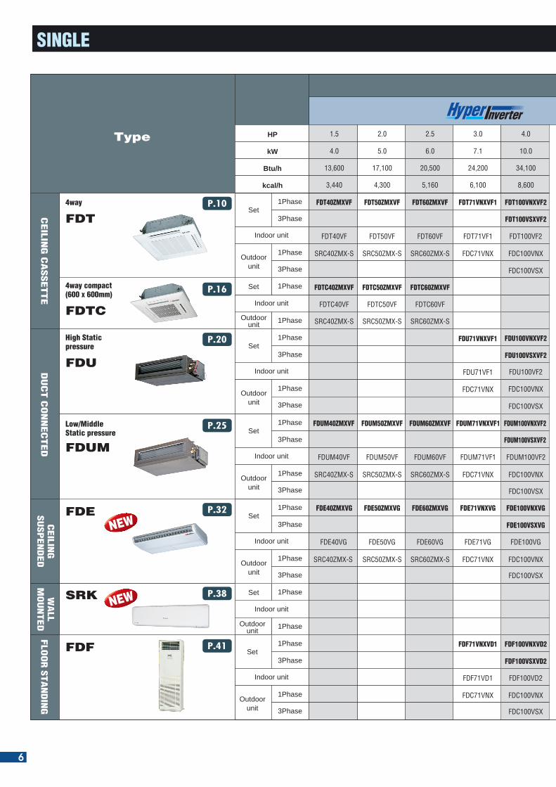
SINGLE
CEILIN
GS
USP
EN
DE
DW
ALL
MO
UN
TE
D
Type
4way
FDTP.10
P.16
P.20
P.25
P.32
P.38
P.41
4way compact (600 x 600mm)
FDTC
Low/Middle Static pressure
FDUM
High Static pressure
FDU
FDE
SRK
CEILIN
G C
ASSETTE
DU
CT C
ON
NEC
TED
FDTC40ZMXVF FDTC50ZMXVF FDTC60ZMXVF
FDTC40VF FDTC50VF FDTC60VF
SRC40ZMX-S SRC50ZMX-S SRC60ZMX-S
HP
kW
Btu/h
kcal/h
1.5
4.0
13,600
3,440
2.0
5.0
17,100
4,300
5.0
12.5
42,700
10,750
6.0
14.0
47,800
12,040
2.5
6.0
20,500
5,160
3.0
7.1
24,200
6,100
4.0
10.0
34,100
8,600
5.0
12.5
42,700
10,750
6.0
14.0
47,800
12,040
8.0
20.0
68,200
17,200
10.0
24.0
81,300
20,640
3.0
7.1
24,200
6,100
3.5
9.0
30,700
7,740
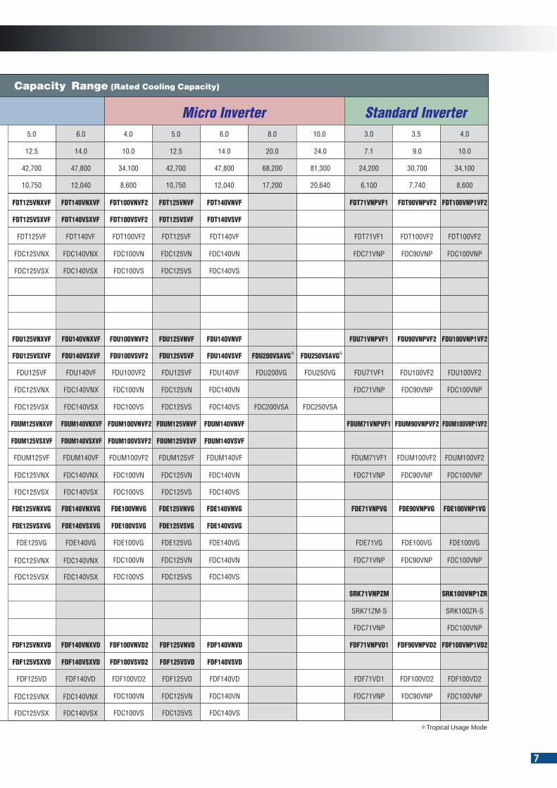
Capacity Range (Rated Cooling Capacity)
FDT40ZMXVF FDT50ZMXVF FDT60ZMXVF FDT71VNXVF1 FDT100VNVF2 FDT125VNVF FDT140VNVFFDT125VNXVF FDT140VNXVF FDT71VNPVF1 FDT90VNPVF2 FDT100VNP1VF2FDT100VNXVF2
FDT100VSVF2FDT125VSXVF FDT140VSXVF FDT125VSVF FDT140VSVFFDT100VSXVF2
FDT40VF FDT50VF FDT60VF FDT71VF1 FDT100VF2 FDT125VF FDT140VFFDT125VF FDT140VF FDT71VF1 FDT100VF2FDT100VF2
FDUM50ZMXVFFDUM40ZMXVF FDUM60ZMXVF FDUM71VNXVF1 FDUM100VNVF2 FDUM125VNVF FDUM140VNVFFDUM125VNXVF FDUM140VNXVF FDUM71VNPVF1 FDUM90VNPVF2 FDUM100VNP1VF2FDUM100VNXVF2
FDUM100VSVF2 FDUM125VSVF FDUM140VSVFFDUM125VSXVF FDUM140VSXVFFDUM100VSXVF2
FDUM50VFFDUM40VF FDUM60VF FDUM71VF1 FDUM100VF2 FDUM125VF FDUM140VFFDUM125VF FDUM140VF FDUM71VF1 FDUM100VF2FDUM100VF2
FDE40ZMXVG FDE50ZMXVG FDE60ZMXVG FDE71VNXVG FDE100VNVG FDE125VNVG FDE140VNVGFDE125VNXVG FDE140VNXVG FDE71VNPVG FDE90VNPVG FDE100VNP1VGFDE100VNXVG
SRC40ZMX-S SRC50ZMX-S SRC60ZMX-S FDC71VNX FDC100VN FDC125VN FDC140VNFDC125VNX FDC140VNX FDC71VNP FDC90VNPFDC100VNX
FDC100VS FDC125VS FDC140VSFDC125VSX FDC140VSXFDC100VSX
FDU100VSVF2 FDU125VSVF FDU140VSVF FDU200VSAVG FDU250VSAVGFDU125VSXVF FDU140VSXVFFDU100VSXVF2
FDU71VF1 FDU125VF FDU140VF FDU100VF2 FDU125VF FDU140VF FDU200VG FDU250VG FDU71VF1 FDU100VF2FDU100VF2
FDC100VSFDC125VSX FDC140VSX FDC125VS FDC140VS FDC200VSA FDC250VSAFDC100VSX
FDC125VNX FDC140VNXSRC50ZMX-SSRC40ZMX-S SRC60ZMX-S FDC71VNX FDC100VN FDC125VN FDC140VN FDC71VNP FDC90VNPFDC100VNX
FDC125VSX FDC140VSX FDC100VS FDC125VS FDC140VSFDC100VSX
FDC125VNX FDC140VNXSRC40ZMX-S SRC50ZMX-S SRC60ZMX-S FDC71VNX FDC100VN FDC125VN FDC140VN FDC71VNP FDC90VNPFDC100VNX
FDE100VSVGFDE125VSXVG FDE140VSXVG FDE125VSVG FDE140VSVGFDE100VSXVG
FDC125VSX FDC140VSX FDC100VS FDC125VS FDC140VSFDC100VSX
FDE40VG FDE125VG FDE140VGFDE50VG FDE60VG FDE71VG FDE100VG FDE125VG FDE140VG FDE71VG FDE100VGFDE100VG
4.0
10.0
34,100
8,600
FDC71VNX FDC125VNX FDC140VNX FDC100VN FDC125VN FDC140VNFDC100VNX FDC71VNP FDC90VNP
FDU71VNXVF1 FDU100VNXVF2 FDU100VNVF2 FDU125VNVF FDU140VNVF FDU71VNPVF1 FDU90VNPVF2 FDU100VNP1VF2FDU125VNXVF FDU140VNXVF
Micro Inverter Standard Inverter
Indoor unit
1Phase
3Phase
Indoor unit
1Phase
1Phase
1Phase
3PhaseSet
Set
Outdoorunit
Indoor unit
1Phase
3Phase
1Phase
3PhaseSet
Outdoorunit
Indoor unit
1Phase
3Phase
1Phase
3PhaseSet
Outdoorunit
Indoor unit
1Phase
3Phase
1Phase
3PhaseSet
Outdoorunit
Indoor unit
1Phase
3Phase
1Phase
3PhaseSet
Outdoorunit
Outdoorunit
Indoor unit
1Phase
1PhaseSet
Outdoorunit
FLO
OR
STA
ND
ING
FDF
SRK71VNPZM SRK100VNP1ZR
FDF71VNXVD1 FDF100VNVD2 FDF125VNVD FDF140VNVDFDF125VNXVD FDF140VNXVD FDF71VNPVD1 FDF90VNPVD2 FDF100VNP1VD2FDF100VNXVD2
FDC125VNX FDC140VNXFDC71VNX FDC100VN FDC125VN FDC140VN FDC71VNP FDC90VNPFDC100VNX
FDF100VSVD2FDF125VSXVD FDF140VSXVD FDF125VSVD FDF140VSVDFDF100VSXVD2
FDC125VSX FDC140VSX FDC100VS FDC125VS FDC140VSFDC100VSX
FDC71VNP FDC100VNP
SRK71ZM-S SRK100ZR-S
FDF125VD FDF140VDFDF71VD1 FDF100VD2 FDF125VD FDF140VD FDF71VD1 FDF100VD2
4.0
10.0
34,100
8,600
FDT100VF2
FDUM100VF2
FDC100VNP
FDU100VF2
FDC100VNP
FDC100VNP
FDE100VG
FDC100VNP
FDC100VNP
FDF100VD2FDF100VD2
Tropical Usage Mode
NEW
NEW
6
SINGLE
CEILIN
GS
USP
EN
DE
DW
ALL
MO
UN
TE
D
Type
4way
FDTP.10
P.16
P.20
P.25
P.32
P.38
P.41
4way compact (600 x 600mm)
FDTC
Low/Middle Static pressure
FDUM
High Static pressure
FDU
FDE
SRK
CEILIN
G C
ASSETTE
DU
CT C
ON
NEC
TED
FDTC40ZMXVF FDTC50ZMXVF FDTC60ZMXVF
FDTC40VF FDTC50VF FDTC60VF
SRC40ZMX-S SRC50ZMX-S SRC60ZMX-S
HP
kW
Btu/h
kcal/h
1.5
4.0
13,600
3,440
2.0
5.0
17,100
4,300
5.0
12.5
42,700
10,750
6.0
14.0
47,800
12,040
2.5
6.0
20,500
5,160
3.0
7.1
24,200
6,100
4.0
10.0
34,100
8,600
5.0
12.5
42,700
10,750
6.0
14.0
47,800
12,040
8.0
20.0
68,200
17,200
10.0
24.0
81,300
20,640
3.0
7.1
24,200
6,100
3.5
9.0
30,700
7,740
Capacity Range (Rated Cooling Capacity)
FDT40ZMXVF FDT50ZMXVF FDT60ZMXVF FDT71VNXVF1 FDT100VNVF2 FDT125VNVF FDT140VNVFFDT125VNXVF FDT140VNXVF FDT71VNPVF1 FDT90VNPVF2 FDT100VNP1VF2FDT100VNXVF2
FDT100VSVF2FDT125VSXVF FDT140VSXVF FDT125VSVF FDT140VSVFFDT100VSXVF2
FDT40VF FDT50VF FDT60VF FDT71VF1 FDT100VF2 FDT125VF FDT140VFFDT125VF FDT140VF FDT71VF1 FDT100VF2FDT100VF2
FDUM50ZMXVFFDUM40ZMXVF FDUM60ZMXVF FDUM71VNXVF1 FDUM100VNVF2 FDUM125VNVF FDUM140VNVFFDUM125VNXVF FDUM140VNXVF FDUM71VNPVF1 FDUM90VNPVF2 FDUM100VNP1VF2FDUM100VNXVF2
FDUM100VSVF2 FDUM125VSVF FDUM140VSVFFDUM125VSXVF FDUM140VSXVFFDUM100VSXVF2
FDUM50VFFDUM40VF FDUM60VF FDUM71VF1 FDUM100VF2 FDUM125VF FDUM140VFFDUM125VF FDUM140VF FDUM71VF1 FDUM100VF2FDUM100VF2
FDE40ZMXVG FDE50ZMXVG FDE60ZMXVG FDE71VNXVG FDE100VNVG FDE125VNVG FDE140VNVGFDE125VNXVG FDE140VNXVG FDE71VNPVG FDE90VNPVG FDE100VNP1VGFDE100VNXVG
SRC40ZMX-S SRC50ZMX-S SRC60ZMX-S FDC71VNX FDC100VN FDC125VN FDC140VNFDC125VNX FDC140VNX FDC71VNP FDC90VNPFDC100VNX
FDC100VS FDC125VS FDC140VSFDC125VSX FDC140VSXFDC100VSX
FDU100VSVF2 FDU125VSVF FDU140VSVF FDU200VSAVG FDU250VSAVGFDU125VSXVF FDU140VSXVFFDU100VSXVF2
FDU71VF1 FDU125VF FDU140VF FDU100VF2 FDU125VF FDU140VF FDU200VG FDU250VG FDU71VF1 FDU100VF2FDU100VF2
FDC100VSFDC125VSX FDC140VSX FDC125VS FDC140VS FDC200VSA FDC250VSAFDC100VSX
FDC125VNX FDC140VNXSRC50ZMX-SSRC40ZMX-S SRC60ZMX-S FDC71VNX FDC100VN FDC125VN FDC140VN FDC71VNP FDC90VNPFDC100VNX
FDC125VSX FDC140VSX FDC100VS FDC125VS FDC140VSFDC100VSX
FDC125VNX FDC140VNXSRC40ZMX-S SRC50ZMX-S SRC60ZMX-S FDC71VNX FDC100VN FDC125VN FDC140VN FDC71VNP FDC90VNPFDC100VNX
FDE100VSVGFDE125VSXVG FDE140VSXVG FDE125VSVG FDE140VSVGFDE100VSXVG
FDC125VSX FDC140VSX FDC100VS FDC125VS FDC140VSFDC100VSX
FDE40VG FDE125VG FDE140VGFDE50VG FDE60VG FDE71VG FDE100VG FDE125VG FDE140VG FDE71VG FDE100VGFDE100VG
4.0
10.0
34,100
8,600
FDC71VNX FDC125VNX FDC140VNX FDC100VN FDC125VN FDC140VNFDC100VNX FDC71VNP FDC90VNP
FDU71VNXVF1 FDU100VNXVF2 FDU100VNVF2 FDU125VNVF FDU140VNVF FDU71VNPVF1 FDU90VNPVF2 FDU100VNP1VF2FDU125VNXVF FDU140VNXVF
Micro Inverter Standard Inverter
Indoor unit
1Phase
3Phase
Indoor unit
1Phase
1Phase
1Phase
3PhaseSet
Set
Outdoorunit
Indoor unit
1Phase
3Phase
1Phase
3PhaseSet
Outdoorunit
Indoor unit
1Phase
3Phase
1Phase
3PhaseSet
Outdoorunit
Indoor unit
1Phase
3Phase
1Phase
3PhaseSet
Outdoorunit
Indoor unit
1Phase
3Phase
1Phase
3PhaseSet
Outdoorunit
Outdoorunit
Indoor unit
1Phase
1PhaseSet
Outdoorunit
FLO
OR
STA
ND
ING
FDF
SRK71VNPZM SRK100VNP1ZR
FDF71VNXVD1 FDF100VNVD2 FDF125VNVD FDF140VNVDFDF125VNXVD FDF140VNXVD FDF71VNPVD1 FDF90VNPVD2 FDF100VNP1VD2FDF100VNXVD2
FDC125VNX FDC140VNXFDC71VNX FDC100VN FDC125VN FDC140VN FDC71VNP FDC90VNPFDC100VNX
FDF100VSVD2FDF125VSXVD FDF140VSXVD FDF125VSVD FDF140VSVDFDF100VSXVD2
FDC125VSX FDC140VSX FDC100VS FDC125VS FDC140VSFDC100VSX
FDC71VNP FDC100VNP
SRK71ZM-S SRK100ZR-S
FDF125VD FDF140VDFDF71VD1 FDF100VD2 FDF125VD FDF140VD FDF71VD1 FDF100VD2
4.0
10.0
34,100
8,600
FDT100VF2
FDUM100VF2
FDC100VNP
FDU100VF2
FDC100VNP
FDC100VNP
FDE100VG
FDC100VNP
FDC100VNP
FDF100VD2FDF100VD2
Tropical Usage Mode
NEW
NEW
7
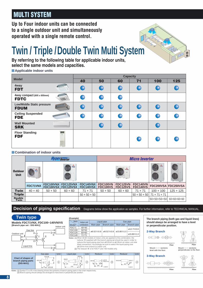
MULTI SYSTEM
Outdoor unit
Indoor unit
L
Liquid line
Gas line
1 23
3
4
4
40 + 40 50 + 50 60 + 6050 + 71
60 + 6050 + 7171 + 71
50 + 50 + 50
4wayFDT
Ceiling SuspendedFDE
24
11ID15.88
ID15.88
ID15.88
11
48
210
8ID9.52
ID9.52
ID9.52
180
8
8
105
50ID9.52 ø6.35
flared nut
2 piece
OD15.88
2 piece
ID12.7
8010
100 80 80
10300
ID15.88
ID12.7x3
10 100 ID9.52
ID9.52x3100
14˚
8
2378
3030
8105
50ID9.52
ø6.35 flarednut
50 + 50 71 + 71 100 + 10071 + 125 125 + 125
50 + 50 + 50 71 + 71 + 71
50+50+50+50 60+60+60+60
60+60+12571+71+100
Decision of piping specification
FDC71FDC100FDC125FDC140
40+4050+5060+6071+71
(Example)
Models FDC71VNX, FDC100~140VN/VS[Branch pipe set : DIS-WA1]
When 40-60 models of indoor units are applied to this combination, the reducer 3 supplied with the branch piping set should be used in order to reduce the liquid piping size from ø9.52mm to ø6.35mm at indoor unit side (flare connection). Accordingly be sure to select the liquid piping size ø9.52mm from branch to indoor unit.The reducer 4 is for FDC71 and 100 models only.
Item Liquid pipeMain pipeModel
Indoor unitcombinations
Gas pipe Symbol
1
Liquid pipe Reducer Symbol
3
ReducerSymbol
2
Symbol
4
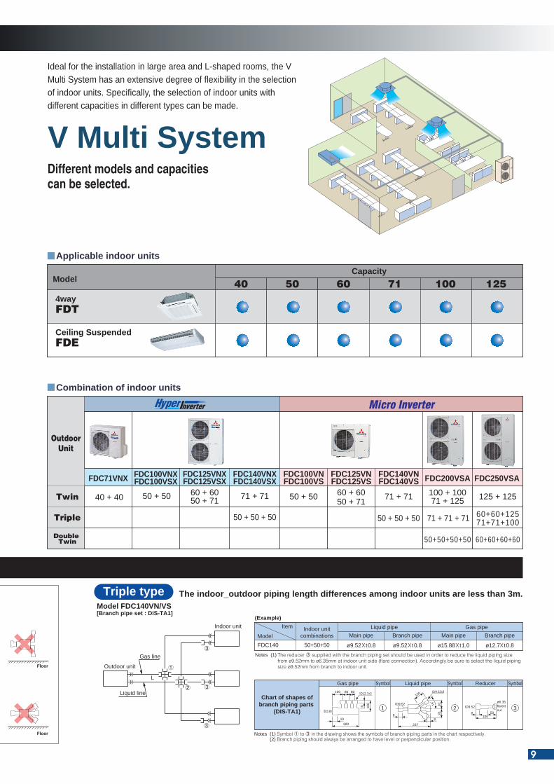
Symbol 1 to 4 in the drawing shows the symbols of branch piping parts in the chart respectively.Branch piping should always be arranged to have level or perpendicular position.
Notes (1)(2)
Branch pipeGas pipe
Main pipe Branch pipe
Notes (1)
(2)
ø9.52X t0.8 ø9.52X t0.8ø12.7X t0.8
ø15.88X t1.0ø15.88X t1.0 2-Way Branch
FloorFloor
Mount sectionslevel with the floor.
Floor
Mount sections perpendicular to the floor.
Floor
3-Way Branch
Floor Floor
Up to Four indoor units can be connectedto a single outdoor unit and simultaneouslyoperated with a single remote control.
By referring to the following table for applicable indoor units,select the same models and capacities.
Twin / Triple / Double Twin Multi SystemDifferent models and capacitiescan be selected.
V Multi System
Twin type The indoor_outdoor piping length differences among indoor units are less than 3m.
Applicable indoor units
Combination of indoor units
Applicable indoor units
Combination of indoor units
Ideal for the installation in large area and L-shaped rooms, the V Multi System has an extensive degree of flexibility in the selection of indoor units. Specifically, the selection of indoor units with different capacities in different types can be made.
Outdoor unit
Indoor unit
1
3
2Liquid line
L
Gas line
3
3
Chart of shapes ofbranch piping parts
(DIS-WA1)
Model FDC140VN/VS[Branch pipe set : DIS-TA1]
Gas pipe Symbol
1
Liquid pipe Reducer Symbol
3
Symbol
2
Symbol 1 to 3 in the drawing shows the symbols of branch piping parts in the chart respectively.Branch piping should always be arranged to have level or perpendicular position.
Notes (1)(2)
Triple type
Chart of shapes ofbranch piping parts
(DIS-TA1)
FDC140 50+50+50
(Example)
The reducer 3 supplied with the branch piping set should be used in order to reduce the liquid piping size from ø9.52mm to ø6.35mm at indoor unit side (flare connection). Accordingly be sure to select the liquid piping size ø9.52mm from branch to indoor unit.
Item Liquid pipeMain pipeModel
Indoor unitcombinations
Gas pipe
Notes (1)
ø9.52X t0.8Branch pipeø9.52X t0.8
Branch pipeø12.7X t0.8
Main pipeø15.88X t1.0
The branch piping (both gas and liquid lines) should always be arranged to have a levelor perpendicular position.
Diagrams below show the application as samples. For further information, refer to TECHNICAL MANUAL.
40 50 60 71 100 125Capacity
Model
4wayFDT4way compact (600 x 600mm)
FDTCLow/Middle Static pressureFDUMCeiling SuspendedFDEWall MountedSRKFloor StandingFDF
FDC71VNX
OutdoorUnit
TwinTriple
FDC100VNFDC100VS
FDC125VNFDC125VS
FDC140VNFDC140VS FDC200VSA FDC250VSA
40 + 40
FDC100VNXFDC100VSX
50 + 50
FDC140VNXFDC140VSX
71 + 71
FDC125VNXFDC125VSX
FDC71VNX FDC100VNFDC100VS
FDC125VNFDC125VS
FDC140VNFDC140VS FDC200VSA FDC250VSAFDC100VNX
FDC100VSXFDC140VNXFDC140VSX
FDC125VNXFDC125VSX
60 + 60 50 + 50 60 + 60 71 + 71 100 + 100 125 + 12550 + 50 + 5050 + 50 + 50 71 + 71 + 71
Double Twin 50+50+50+50 60+60+60+60
40 50 60 71 100 125Capacity
Model
Micro Inverter OutdoorUnit
Twin
Triple
Double Twin
Micro Inverter
8
MULTI SYSTEM
Outdoor unit
Indoor unit
L
Liquid line
Gas line
1 23
3
4
4
40 + 40 50 + 50 60 + 6050 + 71
60 + 6050 + 7171 + 71
50 + 50 + 50
4wayFDT
Ceiling SuspendedFDE
24
11ID15.88
ID15.88
ID15.88
11
48
210
8ID9.52
ID9.52
ID9.52
180
8
8
105
50ID9.52 ø6.35
flared nut
2 piece
OD15.88
2 piece
ID12.7
8010
100 80 80
10300
ID15.88
ID12.7x3
10 100 ID9.52
ID9.52x3100
14˚
8
2378
3030
8105
50ID9.52
ø6.35 flarednut
50 + 50 71 + 71 100 + 10071 + 125 125 + 125
50 + 50 + 50 71 + 71 + 71
50+50+50+50 60+60+60+60
60+60+12571+71+100
Decision of piping specification
FDC71FDC100FDC125FDC140
40+4050+5060+6071+71
(Example)
Models FDC71VNX, FDC100~140VN/VS[Branch pipe set : DIS-WA1]
When 40-60 models of indoor units are applied to this combination, the reducer 3 supplied with the branch piping set should be used in order to reduce the liquid piping size from ø9.52mm to ø6.35mm at indoor unit side (flare connection). Accordingly be sure to select the liquid piping size ø9.52mm from branch to indoor unit.The reducer 4 is for FDC71 and 100 models only.
Item Liquid pipeMain pipeModel
Indoor unitcombinations
Gas pipe Symbol
1
Liquid pipe Reducer Symbol
3
ReducerSymbol
2
Symbol
4
Symbol 1 to 4 in the drawing shows the symbols of branch piping parts in the chart respectively.Branch piping should always be arranged to have level or perpendicular position.
Notes (1)(2)
Branch pipeGas pipe
Main pipe Branch pipe
Notes (1)
(2)
ø9.52X t0.8 ø9.52X t0.8ø12.7X t0.8
ø15.88X t1.0ø15.88X t1.0 2-Way Branch
FloorFloor
Mount sectionslevel with the floor.
Floor
Mount sections perpendicular to the floor.
Floor
3-Way Branch
Floor Floor
Up to Four indoor units can be connectedto a single outdoor unit and simultaneouslyoperated with a single remote control.
By referring to the following table for applicable indoor units,select the same models and capacities.
Twin / Triple / Double Twin Multi SystemDifferent models and capacitiescan be selected.
V Multi System
Twin type The indoor_outdoor piping length differences among indoor units are less than 3m.
Applicable indoor units
Combination of indoor units
Applicable indoor units
Combination of indoor units
Ideal for the installation in large area and L-shaped rooms, the V Multi System has an extensive degree of flexibility in the selection of indoor units. Specifically, the selection of indoor units with different capacities in different types can be made.
Outdoor unit
Indoor unit
1
3
2Liquid line
L
Gas line
3
3
Chart of shapes ofbranch piping parts
(DIS-WA1)
Model FDC140VN/VS[Branch pipe set : DIS-TA1]
Gas pipe Symbol
1
Liquid pipe Reducer Symbol
3
Symbol
2
Symbol 1 to 3 in the drawing shows the symbols of branch piping parts in the chart respectively.Branch piping should always be arranged to have level or perpendicular position.
Notes (1)(2)
Triple type
Chart of shapes ofbranch piping parts
(DIS-TA1)
FDC140 50+50+50
(Example)
The reducer 3 supplied with the branch piping set should be used in order to reduce the liquid piping size from ø9.52mm to ø6.35mm at indoor unit side (flare connection). Accordingly be sure to select the liquid piping size ø9.52mm from branch to indoor unit.
Item Liquid pipeMain pipeModel
Indoor unitcombinations
Gas pipe
Notes (1)
ø9.52X t0.8Branch pipeø9.52X t0.8
Branch pipeø12.7X t0.8
Main pipeø15.88X t1.0
The branch piping (both gas and liquid lines) should always be arranged to have a levelor perpendicular position.
Diagrams below show the application as samples. For further information, refer to TECHNICAL MANUAL.
40 50 60 71 100 125Capacity
Model
4wayFDT4way compact (600 x 600mm)
FDTCLow/Middle Static pressureFDUMCeiling SuspendedFDEWall MountedSRKFloor StandingFDF
FDC71VNX
OutdoorUnit
TwinTriple
FDC100VNFDC100VS
FDC125VNFDC125VS
FDC140VNFDC140VS FDC200VSA FDC250VSA
40 + 40
FDC100VNXFDC100VSX
50 + 50
FDC140VNXFDC140VSX
71 + 71
FDC125VNXFDC125VSX
FDC71VNX FDC100VNFDC100VS
FDC125VNFDC125VS
FDC140VNFDC140VS FDC200VSA FDC250VSAFDC100VNX
FDC100VSXFDC140VNXFDC140VSX
FDC125VNXFDC125VSX
60 + 60 50 + 50 60 + 60 71 + 71 100 + 100 125 + 12550 + 50 + 5050 + 50 + 50 71 + 71 + 71
Double Twin 50+50+50+50 60+60+60+60
40 50 60 71 100 125Capacity
Model
Micro Inverter OutdoorUnit
Twin
Triple
Double Twin
Micro Inverter
9
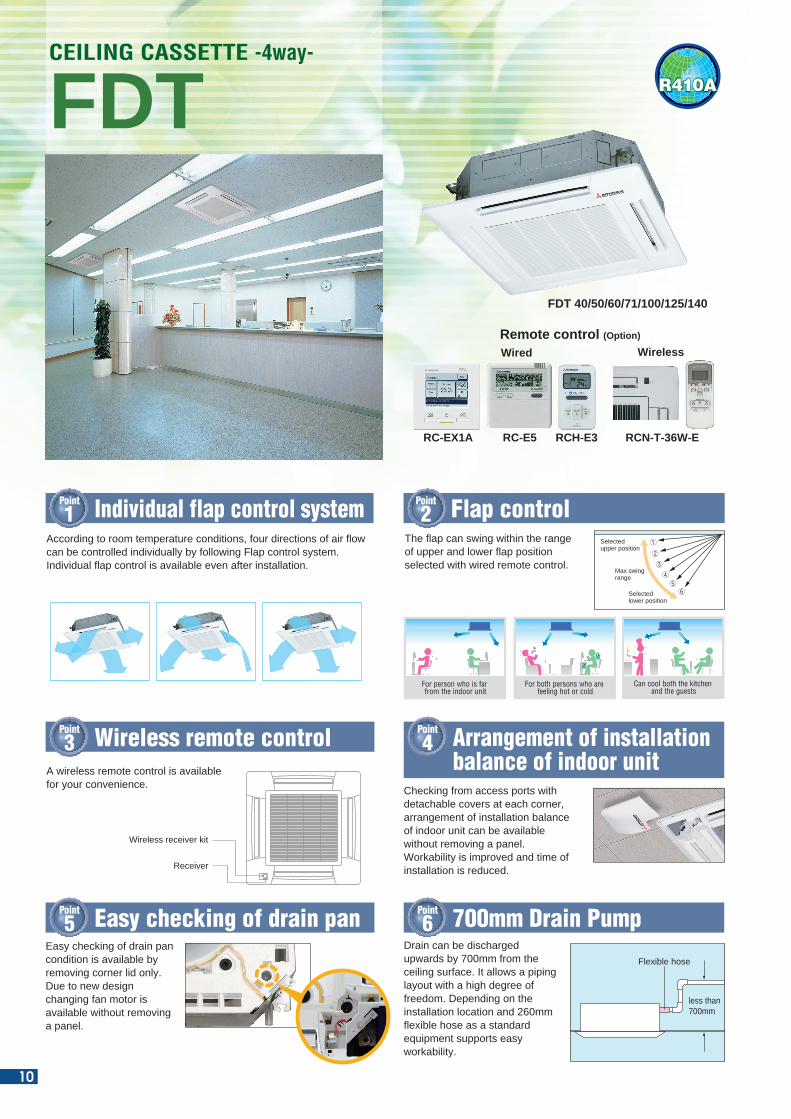
Easy checking of drain pan condition is available by removing corner lid only. Due to new design changing fan motor is available without removing a panel.
Point
5 Easy checking of drain pan
Point
3
Point
1 Individual flap control system
Wireless remote control
Point
2 Flap control
Drain can be discharged upwards by 700mm from the ceiling surface. It allows a piping layout with a high degree of freedom. Depending on the installation location and 260mm flexible hose as a standard equipment supports easy workability.
Point
6 700mm Drain Pump
Flexible hose
less than 700mm
Point
4 Arrangement of installation balance of indoor unit
Checking from access ports with detachable covers at each corner, arrangement of installation balance of indoor unit can be available without removing a panel. Workability is improved and time of installation is reduced.
FDT CEILING CASSETTE -4way-
R410A
RC-E5RC-EX1A
Wired
RCH-E3 RCN-T-36W-E
Wireless
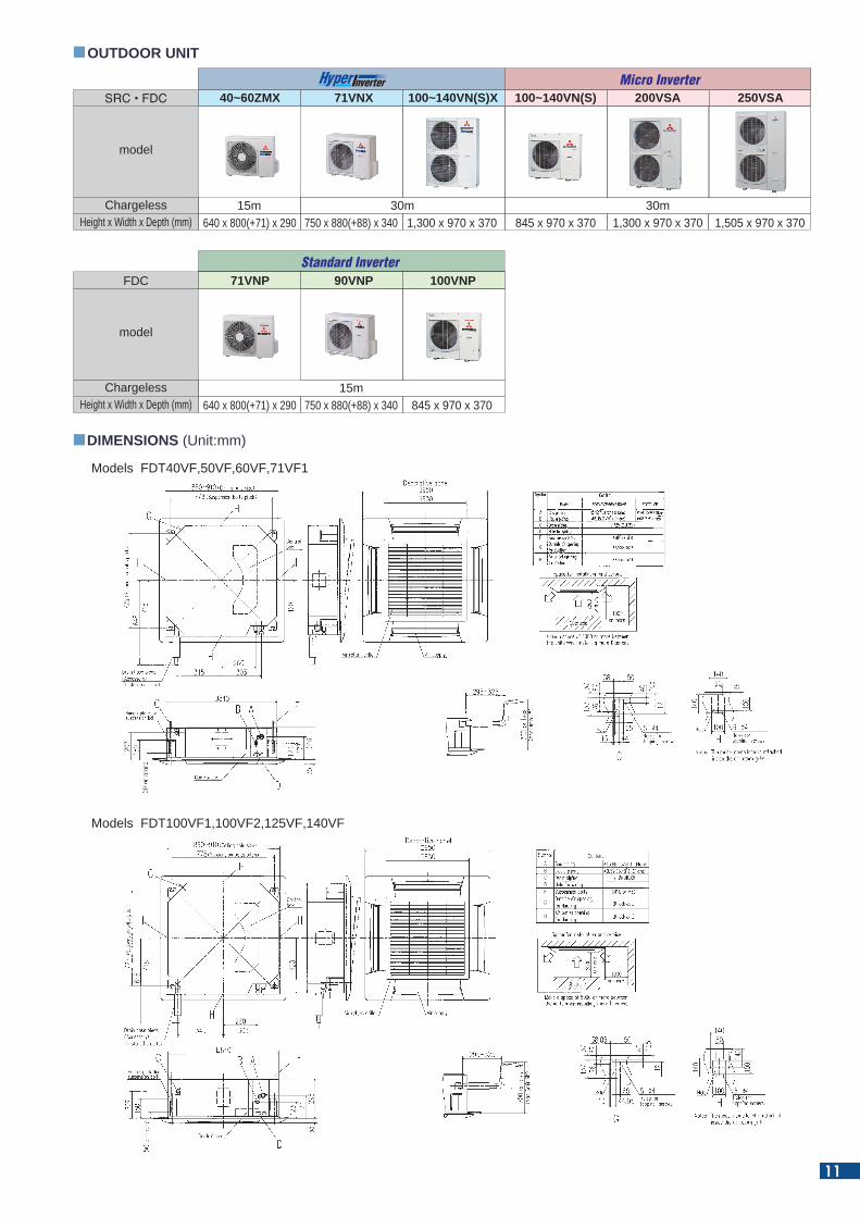
DIMENSIONS (Unit:mm)
OUTDOOR UNIT
Remote control (Option)
According to room temperature conditions, four directions of air flow can be controlled individually by following Flap control system. Individual flap control is available even after installation.
A wireless remote control is available for your convenience.
Selected upper position
Max swing range
Selected lower position
The flap can swing within the range of upper and lower flap position selected with wired remote control.
For person who is far from the indoor unit
For both persons who are feeling hot or cold
Can cool both the kitchen and the guests
FDT 40/50/60/71/100/125/140
SRC • FDC
Height x Width x Depth (mm) 640 x 800(+71) x 290 750 x 880(+88) x 340 1,300 x 970 x 370 1,300 x 970 x 370 1,505 x 970 x 370845 x 970 x 370
model
Chargeless
40~60ZMX 71VNX 100~140VN(S)X 250VSA100~140VN(S) 200VSA
15m 30m 30m
640 x 800(+71) x 290 750 x 880(+88) x 340 845 x 970 x 370
Micro Inverter
FDC
Height x Width x Depth (mm)
model
Chargeless
71VNP 90VNP 100VNP
15m
Standard Inverter
Models FDT40VF,50VF,60VF,71VF1
Wireless receiver kit
Receiver
Models FDT100VF1,100VF2,125VF,140VF
10
Easy checking of drain pan condition is available by removing corner lid only. Due to new design changing fan motor is available without removing a panel.
Point
5 Easy checking of drain pan
Point
3
Point
1 Individual flap control system
Wireless remote control
Point
2 Flap control
Drain can be discharged upwards by 700mm from the ceiling surface. It allows a piping layout with a high degree of freedom. Depending on the installation location and 260mm flexible hose as a standard equipment supports easy workability.
Point
6 700mm Drain Pump
Flexible hose
less than 700mm
Point
4 Arrangement of installation balance of indoor unit
Checking from access ports with detachable covers at each corner, arrangement of installation balance of indoor unit can be available without removing a panel. Workability is improved and time of installation is reduced.
FDT CEILING CASSETTE -4way-
R410A
RC-E5RC-EX1A
Wired
RCH-E3 RCN-T-36W-E
Wireless
DIMENSIONS (Unit:mm)
OUTDOOR UNIT
Remote control (Option)
According to room temperature conditions, four directions of air flow can be controlled individually by following Flap control system. Individual flap control is available even after installation.
A wireless remote control is available for your convenience.
Selected upper position
Max swing range
Selected lower position
The flap can swing within the range of upper and lower flap position selected with wired remote control.
For person who is far from the indoor unit
For both persons who are feeling hot or cold
Can cool both the kitchen and the guests
FDT 40/50/60/71/100/125/140
SRC • FDC
Height x Width x Depth (mm) 640 x 800(+71) x 290 750 x 880(+88) x 340 1,300 x 970 x 370 1,300 x 970 x 370 1,505 x 970 x 370845 x 970 x 370
model
Chargeless
40~60ZMX 71VNX 100~140VN(S)X 250VSA100~140VN(S) 200VSA
15m 30m 30m
640 x 800(+71) x 290 750 x 880(+88) x 340 845 x 970 x 370
Micro Inverter
FDC
Height x Width x Depth (mm)
model
Chargeless
71VNP 90VNP 100VNP
15m
Standard Inverter
Models FDT40VF,50VF,60VF,71VF1
Wireless receiver kit
Receiver
Models FDT100VF1,100VF2,125VF,140VF
11
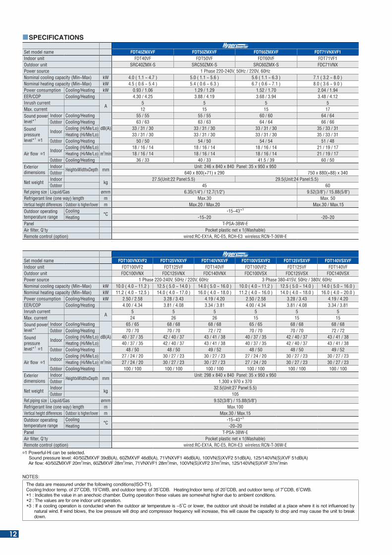
Set model name FDT40ZMXVF FDT50ZMXVF FDT60ZMXVF FDT71VNXVF1Indoor unit FDT40VF FDT50VF FDT60VF FDT71VF1Outdoor unit SRC40ZMX-S SRC50ZMX-S SRC60ZMX-S FDC71VNXPower source 1 Phase 220-240V, 50Hz / 220V, 60HzNominal cooling capacity (Min~Max) kW 4.0 ( 1.1 ~ 4.7 ) 5.0 ( 1.1 ~ 5.6 ) 5.6 ( 1.1 ~ 6.3 ) 7.1 ( 3.2 ~ 8.0 )Nominal heating capacity (Min~Max) kW 4.5 ( 0.6 ~ 5.4 ) 5.4 ( 0.6 ~ 6.3 ) 6.7 ( 0.6 ~ 7.1 ) 8.0 ( 3.6 ~ 9.0 ) Power consumption Cooling/Heating kW 0.93 / 1.06 1.29 / 1.29 1.52 / 1.70 2.04 / 1.94EER/COP Cooling/Heating 4.30 / 4.25 3.88 / 4.19 3.68 / 3.94 3.48 / 4.12Inrush current
A5 5 5 5
Max. current 12 15 15 17Sound power level*1
Indoor Cooling/Heating
dB(A)
55 / 55 55 / 55 60 / 60 64 / 64Outdoor Cooling/Heating 63 / 63 63 / 63 64 / 64 66 / 66
Sound pressure level*1 1
IndoorCooling (Hi/Me/Lo) 33 / 31 / 30 33 / 31 / 30 33 / 31 / 30 35 / 33 / 31Heating (Hi/Me/Lo) 33 / 31 / 30 33 / 31 / 30 33 / 31 / 30 35 / 33 / 31
Outdoor Cooling/Heating 50 / 50 54 / 50 54 / 54 51 / 48
Air flow 1Indoor
Cooling (Hi/Me/Lo)m3/min
18 / 16 / 14 18 / 16 / 14 18 / 16 / 14 21 / 19 / 17Heating (Hi/Me/Lo) 18 / 16 / 14 18 / 16 / 14 18 / 16 / 14 21 / 19 / 17
Outdoor Cooling/Heating 36 / 33 40 / 33 41.5 / 39 60 / 50Exterior dimensions
IndoorHeightxWidthxDepth mm
Unit: 246 x 840 x 840 Panel: 35 x 950 x 950Outdoor 640 x 800(+71) x 290 750 x 880(+88) x 340
Net weightIndoor
kg27.5(Unit:22 Panel:5.5) 29.5(Unit:24 Panel:5.5)
Outdoor 45 60Ref.piping size Liquid/Gas ømm 6.35(1/4") / 12.7(1/2") 9.52(3/8") / 15.88(5/8")Refrigerant line (one way) length m Max.30 Max. 50Vertical height differences Outdoor is higher/lower m Max.20 / Max.20 Max.30 / Max.15Outdoor operating temperature range
Cooling°C
-15~43*3
Heating -15~20 -20~20Panel T-PSA-3BW-EAir filter, Q'ty Pocket plastic net x 1(Washable)Remote control (option) wired:RC-EX1A, RC-E5, RCH-E3 wireless:RCN-T-36W-E
Set model name FDT100VNXVF2 FDT125VNXVF FDT140VNXVF FDT100VSXVF2 FDT125VSXVF FDT140VSXVFIndoor unit FDT100VF2 FDT125VF FDT140VF FDT100VF2 FDT125VF FDT140VFOutdoor unit FDC100VNX FDC125VNX FDC140VNX FDC100VSX FDC125VSX FDC140VSXPower source 1 Phase 220-240V, 50Hz / 220V, 60Hz 3 Phase 380-415V, 50Hz / 380V, 60HzNominal cooling capacity (Min~Max) kW 10.0 ( 4.0 ~ 11.2 ) 12.5 ( 5.0 ~ 14.0 ) 14.0 ( 5.0 ~ 16.0 ) 10.0 ( 4.0 ~ 11.2 ) 12.5 ( 5.0 ~ 14.0 ) 14.0 ( 5.0 ~ 16.0 )Nominal heating capacity (Min~Max) kW 11.2 ( 4.0 ~ 12.5 ) 14.0 ( 4.0 ~ 17.0 ) 16.0 ( 4.0 ~ 18.0 ) 11.2 ( 4.0 ~ 16.0 ) 14.0 ( 4.0 ~ 18.0 ) 16.0 ( 4.0 ~ 20.0 ) Power consumption Cooling/Heating kW 2.50 / 2.58 3.28 / 3.43 4.19 / 4.20 2.50 / 2.58 3.28 / 3.43 4.19 / 4.20EER/COP Cooling/Heating 4.00 / 4.34 3.81 / 4.08 3.34 / 3.81 4.00 / 4.34 3.81 / 4.08 3.34 / 3.81Inrush current
A5 5 5 5 5 5
Max. current 24 26 26 15 15 15Sound power level*1
Indoor Cooling/Heating
dB(A)
65 / 65 68 / 68 68 / 68 65 / 65 68 / 68 68 / 68Outdoor Cooling/Heating 70 / 70 70 / 70 72 / 72 70 / 70 70 / 70 72 / 72
Sound pressure level*1 1
IndoorCooling (Hi/Me/Lo) 40 / 37 / 35 42 / 40 / 37 43 / 41 / 38 40 / 37 / 35 42 / 40 / 37 43 / 41 / 38Heating (Hi/Me/Lo) 40 / 37 / 35 42 / 40 / 37 43 / 41 / 38 40 / 37 / 35 42 / 40 / 37 43 / 41 / 38
Outdoor Cooling/Heating 48 / 50 48 / 50 49 / 52 48 / 50 48 / 50 49 / 52
Air flow 1Indoor
Cooling (Hi/Me/Lo)m3/min
27 / 24 / 20 30 / 27 / 23 30 / 27 / 23 27 / 24 / 20 30 / 27 / 23 30 / 27 / 23Heating (Hi/Me/Lo) 27 / 24 / 20 30 / 27 / 23 30 / 27 / 23 27 / 24 / 20 30 / 27 / 23 30 / 27 / 23
Outdoor Cooling/Heating 100 / 100 100 / 100 100 / 100 100 / 100 100 / 100 100 / 100Exterior dimensions
IndoorHeightxWidthxDepth mm
Unit: 298 x 840 x 840 Panel: 35 x 950 x 950Outdoor 1,300 x 970 x 370
Net weightIndoor
kg32.5(Unit:27 Panel:5.5)
Outdoor 105Ref.piping size Liquid/Gas ømm 9.52(3/8") / 15.88(5/8")Refrigerant line (one way) length m Max.100Vertical height differences Outdoor is higher/lower m Max.30 / Max.15Outdoor operating temperature range
Cooling°C
-15~43*3
Heating -20~20Panel T-PSA-3BW-EAir filter, Q'ty Pocket plastic net x 1(Washable)Remote control (option) wired:RC-EX1A, RC-E5, RCH-E3 wireless:RCN-T-36W-E
1 Powerful-Hi can be selected. Sound pressure level: 40/50ZMXVF 39dB(A), 60ZMXVF 46dB(A), 71VNXVF1 46dB(A), 100VN(S)XVF2 51dB(A), 125/140VN(S)XVF 51dB(A) Air ow: M m3 min M m3 min N m3 min N( ) m3 min N( ) m3 min
SPECIFICATIONS
NOTES:he data are measured under the following conditions( O- ).
Cooling: ndoor temp. of C C and outdoor temp. of C . eating: ndoor temp. of C and outdoor temp. of C C .* : ndicates the value in an anechoic cham er. uring operation these values are somewhat higher due to am ient conditions.*2 : The values are for one indoor unit operation.* : f a cooling operation is conducted when the outdoor air temperature is C or lower the outdoor unit should e installed at a place where it is not in uenced y
natural wind. f wind lows the low pressure will drop and compressor fre uency will increase this will cause the capacity to drop and may cause the unit to reak down.
12
SPECIFICATIONS
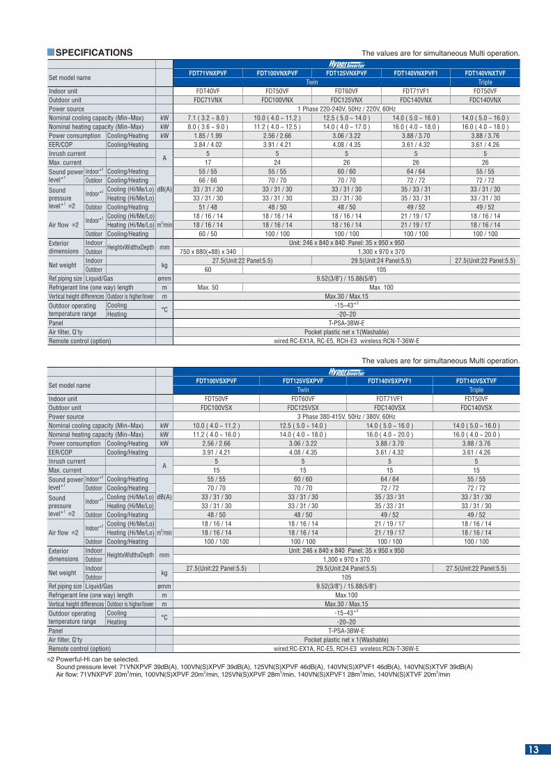
Set model nameFDT71VNXPVF FDT100VNXPVF FDT125VNXPVF FDT140VNXPVF1 FDT140VNXTVF
Twin TripleIndoor unit FDT40VF FDT50VF FDT60VF FDT71VF1 FDT50VFOutdoor unit FDC71VNX FDC100VNX FDC125VNX FDC140VNX FDC140VNXPower source 1 Phase 220-240V, 50Hz / 220V, 60HzNominal cooling capacity (Min~Max) kW 7.1 ( 3.2 ~ 8.0 ) 10.0 ( 4.0 ~ 11.2 ) 12.5 ( 5.0 ~ 14.0 ) 14.0 ( 5.0 ~ 16.0 ) 14.0 ( 5.0 ~ 16.0 )Nominal heating capacity (Min~Max) kW 8.0 ( 3.6 ~ 9.0 ) 11.2 ( 4.0 ~ 12.5 ) 14.0 ( 4.0 ~ 17.0 ) 16.0 ( 4.0 ~ 18.0 ) 16.0 ( 4.0 ~ 18.0 ) Power consumption Cooling/Heating kW 1.85 / 1.99 2.56 / 2.66 3.06 / 3.22 3.88 / 3.70 3.88 / 3.76EER/COP Cooling/Heating 3.84 / 4.02 3.91 / 4.21 4.08 / 4.35 3.61 / 4.32 3.61 / 4.26Inrush current
A5 5 5 5 5
Max. current 17 24 26 26 26Sound power level*1
Indoor*2 Cooling/Heating
dB(A)
55 / 55 55 / 55 60 / 60 64 / 64 55 / 55Outdoor Cooling/Heating 66 / 66 70 / 70 70 / 70 72 / 72 72 / 72
Sound pressure level*1 2
Indoor*2 Cooling (Hi/Me/Lo) 33 / 31 / 30 33 / 31 / 30 33 / 31 / 30 35 / 33 / 31 33 / 31 / 30Heating (Hi/Me/Lo) 33 / 31 / 30 33 / 31 / 30 33 / 31 / 30 35 / 33 / 31 33 / 31 / 30
Outdoor Cooling/Heating 51 / 48 48 / 50 48 / 50 49 / 52 49 / 52
Air flow 2Indoor*2 Cooling (Hi/Me/Lo)
m3/min18 / 16 / 14 18 / 16 / 14 18 / 16 / 14 21 / 19 / 17 18 / 16 / 14
Heating (Hi/Me/Lo) 18 / 16 / 14 18 / 16 / 14 18 / 16 / 14 21 / 19 / 17 18 / 16 / 14Outdoor Cooling/Heating 60 / 50 100 / 100 100 / 100 100 / 100 100 / 100
Exterior dimensions
IndoorHeightxWidthxDepth mm
Unit: 246 x 840 x 840 Panel: 35 x 950 x 950Outdoor 750 x 880(+88) x 340 1,300 x 970 x 370
Net weightIndoor
kg27.5(Unit:22 Panel:5.5) 29.5(Unit:24 Panel:5.5) 27.5(Unit:22 Panel:5.5)
Outdoor 60 105Ref.piping size Liquid/Gas ømm 9.52(3/8") / 15.88(5/8")Refrigerant line (one way) length m Max. 50 Max. 100Vertical height differences Outdoor is higher/lower m Max.30 / Max.15Outdoor operating temperature range
Cooling°C
-15~43*3
Heating -20~20Panel T-PSA-3BW-EAir filter, Q'ty Pocket plastic net x 1(Washable)Remote control (option) wired:RC-EX1A, RC-E5, RCH-E3 wireless:RCN-T-36W-E
he values are for simultaneous Multi operation.
Set model nameFDT100VSXPVF FDT125VSXPVF FDT140VSXPVF1 FDT140VSXTVF
Twin TripleIndoor unit FDT50VF FDT60VF FDT71VF1 FDT50VFOutdoor unit FDC100VSX FDC125VSX FDC140VSX FDC140VSXPower source 3 Phase 380-415V, 50Hz / 380V, 60HzNominal cooling capacity (Min~Max) kW 10.0 ( 4.0 ~ 11.2 ) 12.5 ( 5.0 ~ 14.0 ) 14.0 ( 5.0 ~ 16.0 ) 14.0 ( 5.0 ~ 16.0 )Nominal heating capacity (Min~Max) kW 11.2 ( 4.0 ~ 16.0 ) 14.0 ( 4.0 ~ 18.0 ) 16.0 ( 4.0 ~ 20.0 ) 16.0 ( 4.0 ~ 20.0 ) Power consumption Cooling/Heating kW 2.56 / 2.66 3.06 / 3.22 3.88 / 3.70 3.88 / 3.76EER/COP Cooling/Heating 3.91 / 4.21 4.08 / 4.35 3.61 / 4.32 3.61 / 4.26Inrush current
A5 5 5 5
Max. current 15 15 15 15Sound power level*1
Indoor*2 Cooling/Heating
dB(A)
55 / 55 60 / 60 64 / 64 55 / 55Outdoor Cooling/Heating 70 / 70 70 / 70 72 / 72 72 / 72
Sound pressure level*1 2
Indoor*2 Cooling (Hi/Me/Lo) 33 / 31 / 30 33 / 31 / 30 35 / 33 / 31 33 / 31 / 30Heating (Hi/Me/Lo) 33 / 31 / 30 33 / 31 / 30 35 / 33 / 31 33 / 31 / 30
Outdoor Cooling/Heating 48 / 50 48 / 50 49 / 52 49 / 52
Air flow 2Indoor*2 Cooling (Hi/Me/Lo)
m3/min18 / 16 / 14 18 / 16 / 14 21 / 19 / 17 18 / 16 / 14
Heating (Hi/Me/Lo) 18 / 16 / 14 18 / 16 / 14 21 / 19 / 17 18 / 16 / 14Outdoor Cooling/Heating 100 / 100 100 / 100 100 / 100 100 / 100
Exterior dimensions
IndoorHeightxWidthxDepth mm
Unit: 246 x 840 x 840 Panel: 35 x 950 x 950Outdoor 1,300 x 970 x 370
Net weightIndoor
kg27.5(Unit:22 Panel:5.5) 29.5(Unit:24 Panel:5.5) 27.5(Unit:22 Panel:5.5)
Outdoor 105Ref.piping size Liquid/Gas ømm 9.52(3/8") / 15.88(5/8")Refrigerant line (one way) length m Max.100Vertical height differences Outdoor is higher/lower m Max.30 / Max.15Outdoor operating temperature range
Cooling°C
-15~43*3
Heating -20~20Panel T-PSA-3BW-EAir filter, Q'ty Pocket plastic net x 1(Washable)Remote control (option) wired:RC-EX1A, RC-E5, RCH-E3 wireless:RCN-T-36W-E
2 Powerful-Hi can be selected. Sound pressure level: 71VNXPVF 39dB(A), 100VN(S)XPVF 39dB(A), 125VN(S)XPVF 46dB(A), 140VN(S)XPVF1 46dB(A), 140VN(S)XTVF 39dB(A) Air ow: N P m3 min N( ) P m3 min N( ) P m3 min N( ) P m3 min N( ) m3 min
he values are for simultaneous Multi operation.
13
SPECIFICATIONS
he values are for simultaneous Multi operation.
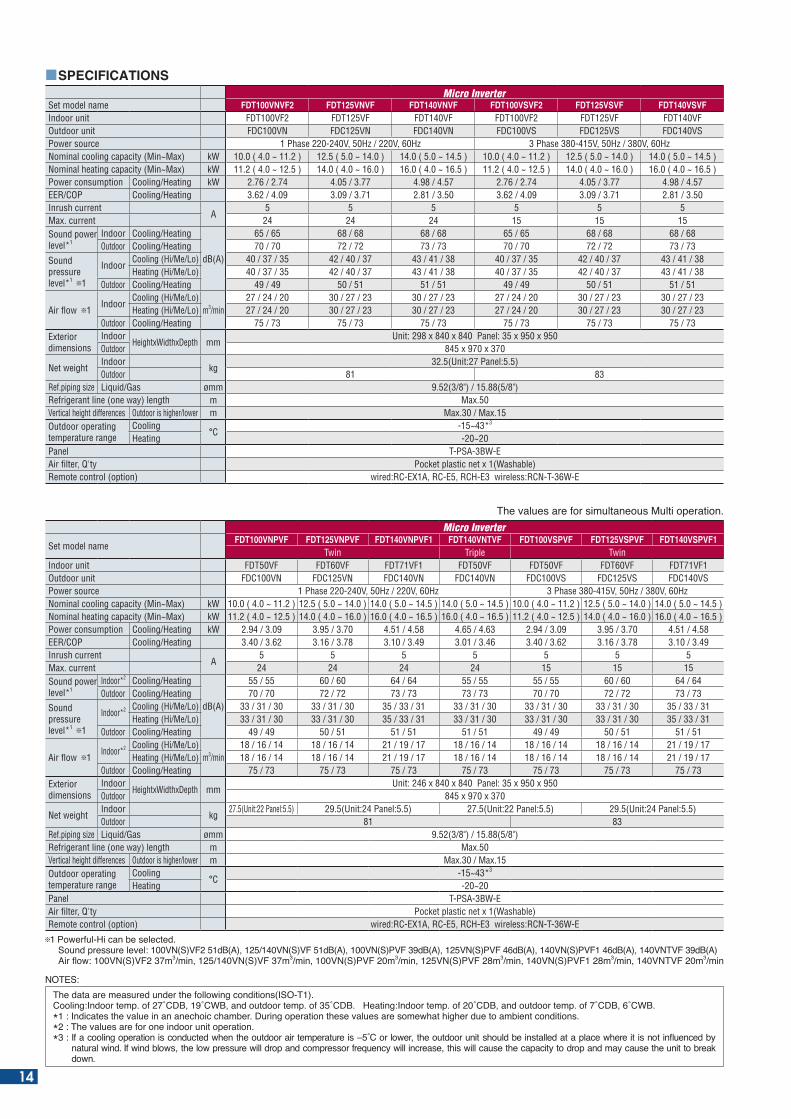
Set model nameFDT100VNPVF FDT125VNPVF FDT140VNPVF1 FDT140VNTVF FDT100VSPVF FDT125VSPVF FDT140VSPVF1
Twin Triple TwinIndoor unit FDT50VF FDT60VF FDT71VF1 FDT50VF FDT50VF FDT60VF FDT71VF1Outdoor unit FDC100VN FDC125VN FDC140VN FDC140VN FDC100VS FDC125VS FDC140VSPower source 1 Phase 220-240V, 50Hz / 220V, 60Hz 3 Phase 380-415V, 50Hz / 380V, 60HzNominal cooling capacity (Min~Max) kW 10.0 ( 4.0 ~ 11.2 ) 12.5 ( 5.0 ~ 14.0 ) 14.0 ( 5.0 ~ 14.5 ) 14.0 ( 5.0 ~ 14.5 ) 10.0 ( 4.0 ~ 11.2 ) 12.5 ( 5.0 ~ 14.0 ) 14.0 ( 5.0 ~ 14.5 )Nominal heating capacity (Min~Max) kW 11.2 ( 4.0 ~ 12.5 ) 14.0 ( 4.0 ~ 16.0 ) 16.0 ( 4.0 ~ 16.5 ) 16.0 ( 4.0 ~ 16.5 ) 11.2 ( 4.0 ~ 12.5 ) 14.0 ( 4.0 ~ 16.0 ) 16.0 ( 4.0 ~ 16.5 ) Power consumption Cooling/Heating kW 2.94 / 3.09 3.95 / 3.70 4.51 / 4.58 4.65 / 4.63 2.94 / 3.09 3.95 / 3.70 4.51 / 4.58EER/COP Cooling/Heating 3.40 / 3.62 3.16 / 3.78 3.10 / 3.49 3.01 / 3.46 3.40 / 3.62 3.16 / 3.78 3.10 / 3.49Inrush current
A5 5 5 5 5 5 5
Max. current 24 24 24 24 15 15 15Sound power level*1
Indoor*2 Cooling/Heating
dB(A)
55 / 55 60 / 60 64 / 64 55 / 55 55 / 55 60 / 60 64 / 64Outdoor Cooling/Heating 70 / 70 72 / 72 73 / 73 73 / 73 70 / 70 72 / 72 73 / 73
Sound pressure level*1 1
Indoor*2 Cooling (Hi/Me/Lo) 33 / 31 / 30 33 / 31 / 30 35 / 33 / 31 33 / 31 / 30 33 / 31 / 30 33 / 31 / 30 35 / 33 / 31Heating (Hi/Me/Lo) 33 / 31 / 30 33 / 31 / 30 35 / 33 / 31 33 / 31 / 30 33 / 31 / 30 33 / 31 / 30 35 / 33 / 31
Outdoor Cooling/Heating 49 / 49 50 / 51 51 / 51 51 / 51 49 / 49 50 / 51 51 / 51
Air flow 1Indoor*2 Cooling (Hi/Me/Lo)
m3/min18 / 16 / 14 18 / 16 / 14 21 / 19 / 17 18 / 16 / 14 18 / 16 / 14 18 / 16 / 14 21 / 19 / 17
Heating (Hi/Me/Lo) 18 / 16 / 14 18 / 16 / 14 21 / 19 / 17 18 / 16 / 14 18 / 16 / 14 18 / 16 / 14 21 / 19 / 17Outdoor Cooling/Heating 75 / 73 75 / 73 75 / 73 75 / 73 75 / 73 75 / 73 75 / 73
Exterior dimensions
IndoorHeightxWidthxDepth mm
Unit: 246 x 840 x 840 Panel: 35 x 950 x 950Outdoor 845 x 970 x 370
Net weightIndoor
kg27.5(Unit:22 Panel:5.5) 29.5(Unit:24 Panel:5.5) 27.5(Unit:22 Panel:5.5) 29.5(Unit:24 Panel:5.5)
Outdoor 81 83Ref.piping size Liquid/Gas ømm 9.52(3/8") / 15.88(5/8")Refrigerant line (one way) length m Max.50Vertical height differences Outdoor is higher/lower m Max.30 / Max.15Outdoor operating temperature range
Cooling°C
-15~43*3
Heating -20~20Panel T-PSA-3BW-EAir filter, Q'ty Pocket plastic net x 1(Washable)Remote control (option) wired:RC-EX1A, RC-E5, RCH-E3 wireless:RCN-T-36W-E
1 Powerful-Hi can be selected. Sound pressure level: 100VN(S)VF2 51dB(A), 125/140VN(S)VF 51dB(A), 100VN(S)PVF 39dB(A), 125VN(S)PVF 46dB(A), 140VN(S)PVF1 46dB(A), 140VNTVF 39dB(A) Air ow: N( ) m3 min N( ) m3 min N( )P m3 min N( )P m3 min N( )P m3 min N m3 min
Set model name FDT100VNVF2 FDT125VNVF FDT140VNVF FDT100VSVF2 FDT125VSVF FDT140VSVFIndoor unit FDT100VF2 FDT125VF FDT140VF FDT100VF2 FDT125VF FDT140VFOutdoor unit FDC100VN FDC125VN FDC140VN FDC100VS FDC125VS FDC140VSPower source 1 Phase 220-240V, 50Hz / 220V, 60Hz 3 Phase 380-415V, 50Hz / 380V, 60HzNominal cooling capacity (Min~Max) kW 10.0 ( 4.0 ~ 11.2 ) 12.5 ( 5.0 ~ 14.0 ) 14.0 ( 5.0 ~ 14.5 ) 10.0 ( 4.0 ~ 11.2 ) 12.5 ( 5.0 ~ 14.0 ) 14.0 ( 5.0 ~ 14.5 )Nominal heating capacity (Min~Max) kW 11.2 ( 4.0 ~ 12.5 ) 14.0 ( 4.0 ~ 16.0 ) 16.0 ( 4.0 ~ 16.5 ) 11.2 ( 4.0 ~ 12.5 ) 14.0 ( 4.0 ~ 16.0 ) 16.0 ( 4.0 ~ 16.5 ) Power consumption Cooling/Heating kW 2.76 / 2.74 4.05 / 3.77 4.98 / 4.57 2.76 / 2.74 4.05 / 3.77 4.98 / 4.57EER/COP Cooling/Heating 3.62 / 4.09 3.09 / 3.71 2.81 / 3.50 3.62 / 4.09 3.09 / 3.71 2.81 / 3.50Inrush current
A5 5 5 5 5 5
Max. current 24 24 24 15 15 15Sound power level*1
Indoor Cooling/Heating
dB(A)
65 / 65 68 / 68 68 / 68 65 / 65 68 / 68 68 / 68Outdoor Cooling/Heating 70 / 70 72 / 72 73 / 73 70 / 70 72 / 72 73 / 73
Sound pressure level*1 1
IndoorCooling (Hi/Me/Lo) 40 / 37 / 35 42 / 40 / 37 43 / 41 / 38 40 / 37 / 35 42 / 40 / 37 43 / 41 / 38Heating (Hi/Me/Lo) 40 / 37 / 35 42 / 40 / 37 43 / 41 / 38 40 / 37 / 35 42 / 40 / 37 43 / 41 / 38
Outdoor Cooling/Heating 49 / 49 50 / 51 51 / 51 49 / 49 50 / 51 51 / 51
Air flow 1Indoor
Cooling (Hi/Me/Lo)m3/min
27 / 24 / 20 30 / 27 / 23 30 / 27 / 23 27 / 24 / 20 30 / 27 / 23 30 / 27 / 23Heating (Hi/Me/Lo) 27 / 24 / 20 30 / 27 / 23 30 / 27 / 23 27 / 24 / 20 30 / 27 / 23 30 / 27 / 23
Outdoor Cooling/Heating 75 / 73 75 / 73 75 / 73 75 / 73 75 / 73 75 / 73Exterior dimensions
IndoorHeightxWidthxDepth mm
Unit: 298 x 840 x 840 Panel: 35 x 950 x 950Outdoor 845 x 970 x 370
Net weightIndoor
kg32.5(Unit:27 Panel:5.5)
Outdoor 81 83Ref.piping size Liquid/Gas ømm 9.52(3/8") / 15.88(5/8")Refrigerant line (one way) length m Max.50Vertical height differences Outdoor is higher/lower m Max.30 / Max.15Outdoor operating temperature range
Cooling°C
-15~43*3
Heating -20~20Panel T-PSA-3BW-EAir filter, Q'ty Pocket plastic net x 1(Washable)Remote control (option) wired:RC-EX1A, RC-E5, RCH-E3 wireless:RCN-T-36W-E
NOTES:he data are measured under the following conditions( O- ).
Cooling: ndoor temp. of C C and outdoor temp. of C . eating: ndoor temp. of C and outdoor temp. of C C .* : ndicates the value in an anechoic cham er. uring operation these values are somewhat higher due to am ient conditions.*2 : The values are for one indoor unit operation.* : f a cooling operation is conducted when the outdoor air temperature is C or lower the outdoor unit should e installed at a place where it is not in uenced y
natural wind. f wind lows the low pressure will drop and compressor fre uency will increase this will cause the capacity to drop and may cause the unit to reak down.
14
SPECIFICATIONS
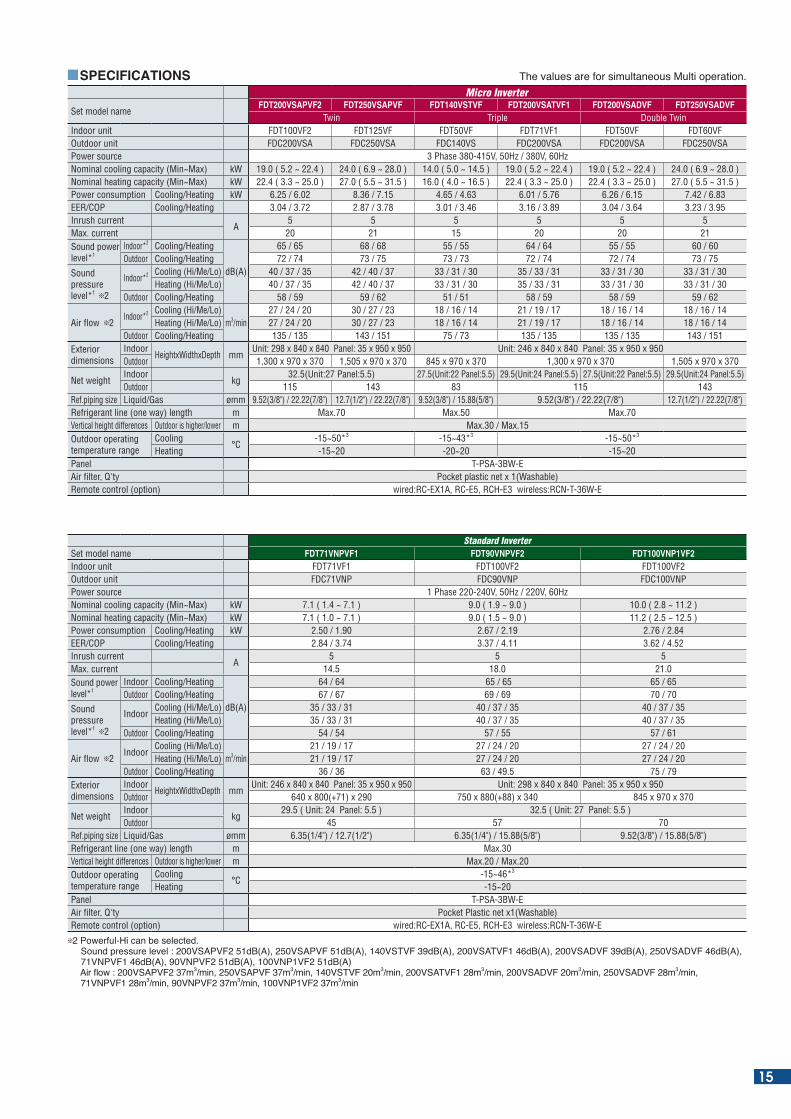
Set model nameFDT200VSAPVF2 FDT250VSAPVF FDT140VSTVF FDT200VSATVF1 FDT200VSADVF FDT250VSADVF
Twin Triple Double TwinIndoor unit FDT100VF2 FDT125VF FDT50VF FDT71VF1 FDT50VF FDT60VFOutdoor unit FDC200VSA FDC250VSA FDC140VS FDC200VSA FDC200VSA FDC250VSAPower source 3 Phase 380-415V, 50Hz / 380V, 60HzNominal cooling capacity (Min~Max) kW 19.0 ( 5.2 ~ 22.4 ) 24.0 ( 6.9 ~ 28.0 ) 14.0 ( 5.0 ~ 14.5 ) 19.0 ( 5.2 ~ 22.4 ) 19.0 ( 5.2 ~ 22.4 ) 24.0 ( 6.9 ~ 28.0 )Nominal heating capacity (Min~Max) kW 22.4 ( 3.3 ~ 25.0 ) 27.0 ( 5.5 ~ 31.5 ) 16.0 ( 4.0 ~ 16.5 ) 22.4 ( 3.3 ~ 25.0 ) 22.4 ( 3.3 ~ 25.0 ) 27.0 ( 5.5 ~ 31.5 ) Power consumption Cooling/Heating kW 6.25 / 6.02 8.36 / 7.15 4.65 / 4.63 6.01 / 5.76 6.26 / 6.15 7.42 / 6.83EER/COP Cooling/Heating 3.04 / 3.72 2.87 / 3.78 3.01 / 3.46 3.16 / 3.89 3.04 / 3.64 3.23 / 3.95Inrush current
A5 5 5 5 5 5
Max. current 20 21 15 20 20 21Sound power level*1
Indoor*2 Cooling/Heating
dB(A)
65 / 65 68 / 68 55 / 55 64 / 64 55 / 55 60 / 60Outdoor Cooling/Heating 72 / 74 73 / 75 73 / 73 72 / 74 72 / 74 73 / 75
Sound pressure level*1 2
Indoor*2 Cooling (Hi/Me/Lo) 40 / 37 / 35 42 / 40 / 37 33 / 31 / 30 35 / 33 / 31 33 / 31 / 30 33 / 31 / 30Heating (Hi/Me/Lo) 40 / 37 / 35 42 / 40 / 37 33 / 31 / 30 35 / 33 / 31 33 / 31 / 30 33 / 31 / 30
Outdoor Cooling/Heating 58 / 59 59 / 62 51 / 51 58 / 59 58 / 59 59 / 62
Air flow 2Indoor*2 Cooling (Hi/Me/Lo)
m3/min27 / 24 / 20 30 / 27 / 23 18 / 16 / 14 21 / 19 / 17 18 / 16 / 14 18 / 16 / 14
Heating (Hi/Me/Lo) 27 / 24 / 20 30 / 27 / 23 18 / 16 / 14 21 / 19 / 17 18 / 16 / 14 18 / 16 / 14Outdoor Cooling/Heating 135 / 135 143 / 151 75 / 73 135 / 135 135 / 135 143 / 151
Exterior dimensions
IndoorHeightxWidthxDepth mm
Unit: 298 x 840 x 840 Panel: 35 x 950 x 950 Unit: 246 x 840 x 840 Panel: 35 x 950 x 950Outdoor 1,300 x 970 x 370 1,505 x 970 x 370 845 x 970 x 370 1,300 x 970 x 370 1,505 x 970 x 370
Net weightIndoor
kg32.5(Unit:27 Panel:5.5) 27.5(Unit:22 Panel:5.5) 29.5(Unit:24 Panel:5.5) 27.5(Unit:22 Panel:5.5) 29.5(Unit:24 Panel:5.5)
Outdoor 115 143 83 115 143Ref.piping size Liquid/Gas ømm 9.52(3/8") / 22.22(7/8") 12.7(1/2") / 22.22(7/8") 9.52(3/8") / 15.88(5/8") 9.52(3/8") / 22.22(7/8") 12.7(1/2") / 22.22(7/8")Refrigerant line (one way) length m Max.70 Max.50 Max.70Vertical height differences Outdoor is higher/lower m Max.30 / Max.15Outdoor operating temperature range
Cooling°C
-15~50*3 -15~43*3 -15~50*3
Heating -15~20 -20~20 -15~20Panel T-PSA-3BW-EAir filter, Q'ty Pocket plastic net x 1(Washable)Remote control (option) wired:RC-EX1A, RC-E5, RCH-E3 wireless:RCN-T-36W-E
he values are for simultaneous Multi operation.
Standard InverterSet model name FDT71VNPVF1 FDT90VNPVF2 FDT100VNP1VF2Indoor unit FDT71VF1 FDT100VF2 FDT100VF2Outdoor unit FDC71VNP FDC90VNP FDC100VNPPower source 1 Phase 220-240V, 50Hz / 220V, 60HzNominal cooling capacity (Min~Max) kW 7.1 ( 1.4 ~ 7.1 ) 9.0 ( 1.9 ~ 9.0 ) 10.0 ( 2.8 ~ 11.2 )Nominal heating capacity (Min~Max) kW 7.1 ( 1.0 ~ 7.1 ) 9.0 ( 1.5 ~ 9.0 ) 11.2 ( 2.5 ~ 12.5 )Power consumption Cooling/Heating kW 2.50 / 1.90 2.67 / 2.19 2.76 / 2.84EER/COP Cooling/Heating 2.84 / 3.74 3.37 / 4.11 3.62 / 4.52Inrush current
A5 5 5
Max. current 14.5 18.0 21.0Sound power level*1
Indoor Cooling/Heating
dB(A)
64 / 64 65 / 65 65 / 65Outdoor Cooling/Heating 67 / 67 69 / 69 70 / 70
Sound pressure level*1 2
IndoorCooling (Hi/Me/Lo) 35 / 33 / 31 40 / 37 / 35 40 / 37 / 35Heating (Hi/Me/Lo) 35 / 33 / 31 40 / 37 / 35 40 / 37 / 35
Outdoor Cooling/Heating 54 / 54 57 / 55 57 / 61
Air flow 2Indoor
Cooling (Hi/Me/Lo)m3/min
21 / 19 / 17 27 / 24 / 20 27 / 24 / 20Heating (Hi/Me/Lo) 21 / 19 / 17 27 / 24 / 20 27 / 24 / 20
Outdoor Cooling/Heating 36 / 36 63 / 49.5 75 / 79Exterior dimensions
IndoorHeightxWidthxDepth mm
Unit: 246 x 840 x 840 Panel: 35 x 950 x 950 Unit: 298 x 840 x 840 Panel: 35 x 950 x 950Outdoor 640 x 800(+71) x 290 750 x 880(+88) x 340 845 x 970 x 370
Net weightIndoor
kg29.5 ( Unit: 24 Panel: 5.5 ) 32.5 ( Unit: 27 Panel: 5.5 )
Outdoor 45 57 70Ref.piping size Liquid/Gas ømm 6.35(1/4") / 12.7(1/2") 6.35(1/4") / 15.88(5/8") 9.52(3/8") / 15.88(5/8")Refrigerant line (one way) length m Max.30Vertical height differences Outdoor is higher/lower m Max.20 / Max.20Outdoor operating temperature range
Cooling°C
-15~46*3
Heating -15~20Panel T-PSA-3BW-EAir filter, Q'ty Pocket Plastic net x1(Washable)Remote control (option) wired:RC-EX1A, RC-E5, RCH-E3 wireless:RCN-T-36W-E
2 Powerful-Hi can be selected. ound pressure level : AP d (A) AP d (A) d (A) A d (A) A d (A) A d (A) 71VNPVF1 46dB(A), 90VNPVF2 51dB(A), 100VNP1VF2 51dB(A) Air ow : AP m3 min AP m3 min m3 min A m3 min A m3 min A m3 min NP m3 min NP m3 min NP m3 min
15
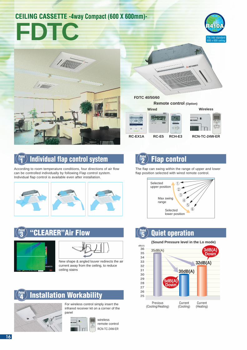
R410AFDTCCEILING CASSETTE -4way Compact (600 X 600mm)-
Point
3 “CLEARER”Air Flow
Point
4 Installation Workability
RCN-TC-24W-ER
New shape & angled louver redirects the air current away from the ceiling, to reduce ceiling stains
For wireless control simply insert the infrared receiver kit on a corner of the panel
wirelessremote control
Point
2 Flap control
Fits into standard 600 x 600 ceiling
Point
1 Individual flap control system
Point
5 Quiet operation(Sound Pressure level in the Lo mode)
Previous(Cooling/Heating)
Current(Cooling)
Current(Heating)
363534333231302928272625
dB(A)
35dB(A)
5dB(A)Down
3dB(A)Down
30dB(A)
32dB(A)
DIMENSIONS (Unit:mm)
Point
8 Arrangement of installation balance of indoor unit
Point
7 600mm Drain PumpPoint
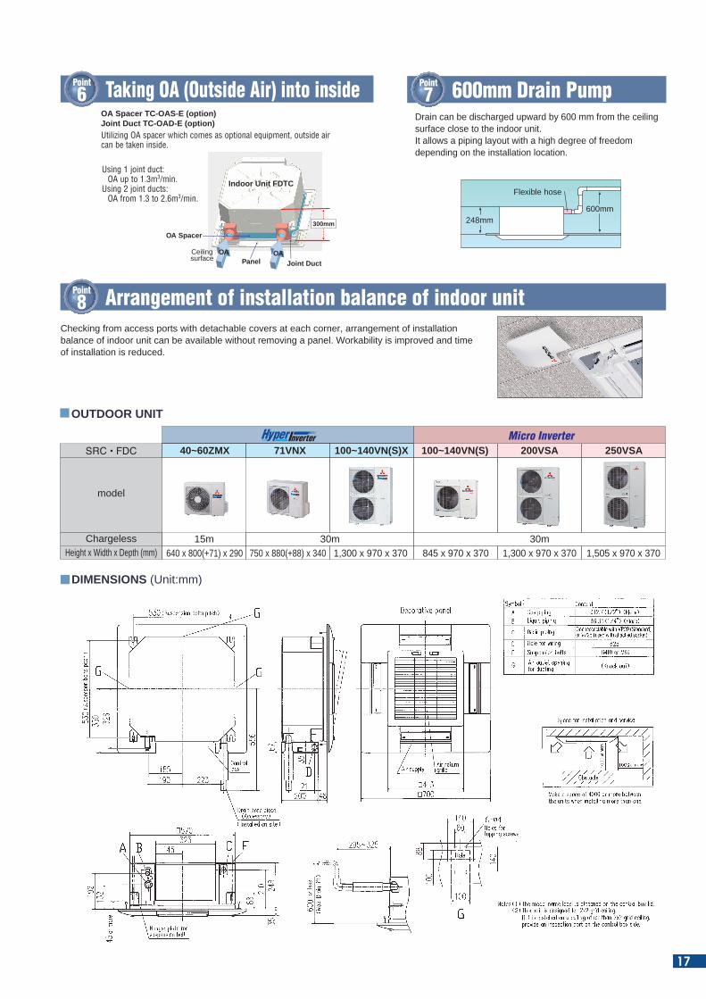
6 Taking OA (Outside Air) into insideDrain can be discharged upward by 600 mm from the ceiling surface close to the indoor unit.It allows a piping layout with a high degree of freedom depending on the installation location.
Flexible hose
248mm600mm
FDTC 40/50/60
RCN-TC-24W-ERRC-E5RC-EX1A
WirelessWired
RCH-E3
Remote control (Option)
According to room temperature conditions, four directions of air flow can be controlled individually by following Flap control system. Individual flap control is available even after installation.
Selected upper position
Max swing range
Selected lower position
The flap can swing within the range of upper and lower flap position selected with wired remote control.
Checking from access ports with detachable covers at each corner, arrangement of installation balance of indoor unit can be available without removing a panel. Workability is improved and time of installation is reduced.
OUTDOOR UNIT
SRC • FDC
Height x Width x Depth (mm) 640 x 800(+71) x 290 750 x 880(+88) x 340 1,300 x 970 x 370 1,300 x 970 x 370 1,505 x 970 x 370845 x 970 x 370
model
Chargeless
40~60ZMX 71VNX 100~140VN(S)X 100~140VN(S) 200VSA 250VSA
30m 30m15m
Micro Inverter
OA Spacer TC-OAS-E (option)Joint Duct TC-OAD-E (option)Utilizing OA spacer which comes as optional equipment, outside air can be taken inside.
OA OAPanel
300mm
Ceilingsurface
Indoor Unit FDTC
OA Spacer
Joint Duct
Using 1 joint duct: OA up to 1.3m3/min.
Using 2 joint ducts: OA from 1.3 to 2.6m3/min.
16
R410AFDTCCEILING CASSETTE -4way Compact (600 X 600mm)-
Point
3 “CLEARER”Air Flow
Point
4 Installation Workability
RCN-TC-24W-ER
New shape & angled louver redirects the air current away from the ceiling, to reduce ceiling stains
For wireless control simply insert the infrared receiver kit on a corner of the panel
wirelessremote control
Point
2 Flap control
Fits into standard 600 x 600 ceiling
Point
1 Individual flap control system
Point
5 Quiet operation(Sound Pressure level in the Lo mode)
Previous(Cooling/Heating)
Current(Cooling)
Current(Heating)
363534333231302928272625
dB(A)
35dB(A)
5dB(A)Down
3dB(A)Down
30dB(A)
32dB(A)
DIMENSIONS (Unit:mm)
Point
8 Arrangement of installation balance of indoor unit
Point
7 600mm Drain PumpPoint
6 Taking OA (Outside Air) into insideDrain can be discharged upward by 600 mm from the ceiling surface close to the indoor unit.It allows a piping layout with a high degree of freedom depending on the installation location.
Flexible hose
248mm600mm
FDTC 40/50/60
RCN-TC-24W-ERRC-E5RC-EX1A
WirelessWired
RCH-E3
Remote control (Option)
According to room temperature conditions, four directions of air flow can be controlled individually by following Flap control system. Individual flap control is available even after installation.
Selected upper position
Max swing range
Selected lower position
The flap can swing within the range of upper and lower flap position selected with wired remote control.
Checking from access ports with detachable covers at each corner, arrangement of installation balance of indoor unit can be available without removing a panel. Workability is improved and time of installation is reduced.
OUTDOOR UNIT
SRC • FDC
Height x Width x Depth (mm) 640 x 800(+71) x 290 750 x 880(+88) x 340 1,300 x 970 x 370 1,300 x 970 x 370 1,505 x 970 x 370845 x 970 x 370
model
Chargeless
40~60ZMX 71VNX 100~140VN(S)X 100~140VN(S) 200VSA 250VSA
30m 30m15m
Micro Inverter
OA Spacer TC-OAS-E (option)Joint Duct TC-OAD-E (option)Utilizing OA spacer which comes as optional equipment, outside air can be taken inside.
OA OAPanel
300mm
Ceilingsurface
Indoor Unit FDTC
OA Spacer
Joint Duct
Using 1 joint duct: OA up to 1.3m3/min.
Using 2 joint ducts: OA from 1.3 to 2.6m3/min.
17
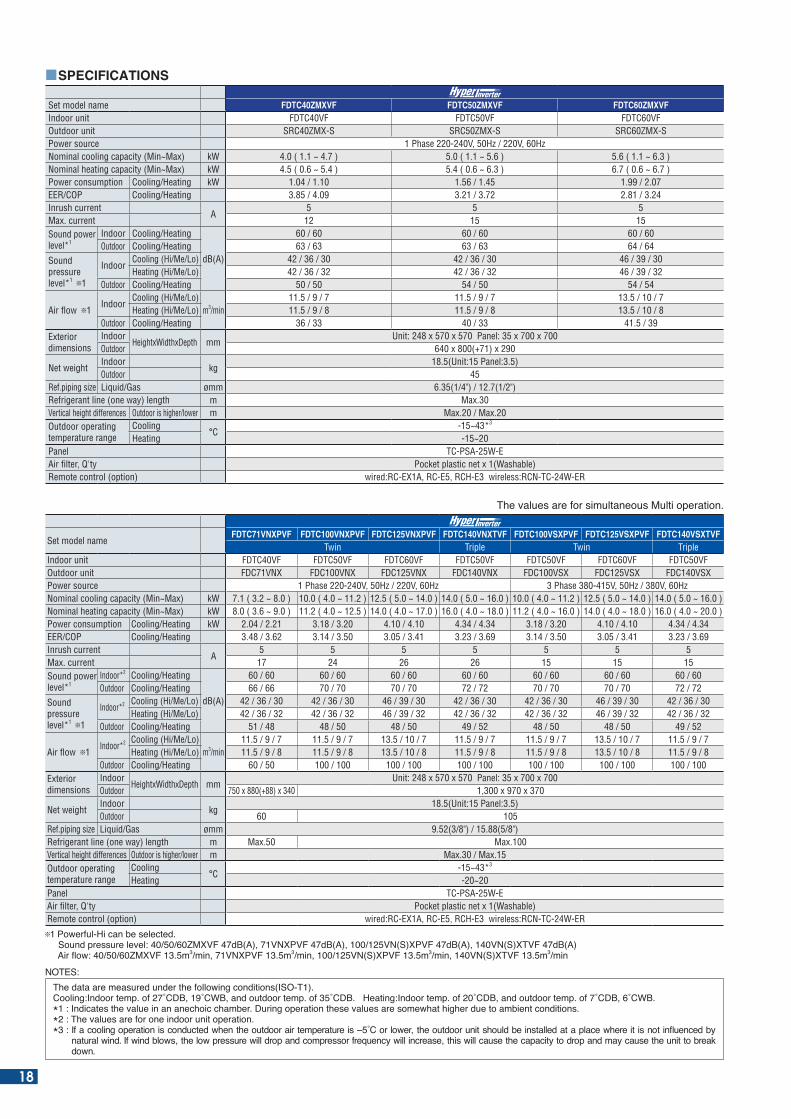
Set model name FDTC40ZMXVF FDTC50ZMXVF FDTC60ZMXVFIndoor unit FDTC40VF FDTC50VF FDTC60VFOutdoor unit SRC40ZMX-S SRC50ZMX-S SRC60ZMX-SPower source 1 Phase 220-240V, 50Hz / 220V, 60HzNominal cooling capacity (Min~Max) kW 4.0 ( 1.1 ~ 4.7 ) 5.0 ( 1.1 ~ 5.6 ) 5.6 ( 1.1 ~ 6.3 )Nominal heating capacity (Min~Max) kW 4.5 ( 0.6 ~ 5.4 ) 5.4 ( 0.6 ~ 6.3 ) 6.7 ( 0.6 ~ 6.7 ) Power consumption Cooling/Heating kW 1.04 / 1.10 1.56 / 1.45 1.99 / 2.07EER/COP Cooling/Heating 3.85 / 4.09 3.21 / 3.72 2.81 / 3.24Inrush current
A5 5 5
Max. current 12 15 15Sound power level*1
Indoor Cooling/Heating
dB(A)
60 / 60 60 / 60 60 / 60Outdoor Cooling/Heating 63 / 63 63 / 63 64 / 64
Sound pressure level*1 1
IndoorCooling (Hi/Me/Lo) 42 / 36 / 30 42 / 36 / 30 46 / 39 / 30Heating (Hi/Me/Lo) 42 / 36 / 32 42 / 36 / 32 46 / 39 / 32
Outdoor Cooling/Heating 50 / 50 54 / 50 54 / 54
Air flow 1Indoor
Cooling (Hi/Me/Lo)m3/min
11.5 / 9 / 7 11.5 / 9 / 7 13.5 / 10 / 7Heating (Hi/Me/Lo) 11.5 / 9 / 8 11.5 / 9 / 8 13.5 / 10 / 8
Outdoor Cooling/Heating 36 / 33 40 / 33 41.5 / 39Exterior dimensions
IndoorHeightxWidthxDepth mm
Unit: 248 x 570 x 570 Panel: 35 x 700 x 700Outdoor 640 x 800(+71) x 290
Net weightIndoor
kg18.5(Unit:15 Panel:3.5)
Outdoor 45Ref.piping size Liquid/Gas ømm 6.35(1/4") / 12.7(1/2")Refrigerant line (one way) length m Max.30Vertical height differences Outdoor is higher/lower m Max.20 / Max.20 Outdoor operating temperature range
Cooling°C
-15~43*3
Heating -15~20Panel TC-PSA-25W-EAir filter, Q'ty Pocket plastic net x 1(Washable)Remote control (option) wired:RC-EX1A, RC-E5, RCH-E3 wireless:RCN-TC-24W-ER
SPECIFICATIONS
he values are for simultaneous Multi operation.
Set model nameFDTC71VNXPVF FDTC100VNXPVF FDTC125VNXPVF FDTC140VNXTVF FDTC100VSXPVF FDTC125VSXPVF FDTC140VSXTVF
Twin Triple Twin TripleIndoor unit FDTC40VF FDTC50VF FDTC60VF FDTC50VF FDTC50VF FDTC60VF FDTC50VFOutdoor unit FDC71VNX FDC100VNX FDC125VNX FDC140VNX FDC100VSX FDC125VSX FDC140VSXPower source 1 Phase 220-240V, 50Hz / 220V, 60Hz 3 Phase 380-415V, 50Hz / 380V, 60HzNominal cooling capacity (Min~Max) kW 7.1 ( 3.2 ~ 8.0 ) 10.0 ( 4.0 ~ 11.2 ) 12.5 ( 5.0 ~ 14.0 ) 14.0 ( 5.0 ~ 16.0 ) 10.0 ( 4.0 ~ 11.2 ) 12.5 ( 5.0 ~ 14.0 ) 14.0 ( 5.0 ~ 16.0 )Nominal heating capacity (Min~Max) kW 8.0 ( 3.6 ~ 9.0 ) 11.2 ( 4.0 ~ 12.5 ) 14.0 ( 4.0 ~ 17.0 ) 16.0 ( 4.0 ~ 18.0 ) 11.2 ( 4.0 ~ 16.0 ) 14.0 ( 4.0 ~ 18.0 ) 16.0 ( 4.0 ~ 20.0 )Power consumption Cooling/Heating kW 2.04 / 2.21 3.18 / 3.20 4.10 / 4.10 4.34 / 4.34 3.18 / 3.20 4.10 / 4.10 4.34 / 4.34EER/COP Cooling/Heating 3.48 / 3.62 3.14 / 3.50 3.05 / 3.41 3.23 / 3.69 3.14 / 3.50 3.05 / 3.41 3.23 / 3.69Inrush current
A5 5 5 5 5 5 5
Max. current 17 24 26 26 15 15 15Sound power level*1
Indoor*2 Cooling/Heating
dB(A)
60 / 60 60 / 60 60 / 60 60 / 60 60 / 60 60 / 60 60 / 60Outdoor Cooling/Heating 66 / 66 70 / 70 70 / 70 72 / 72 70 / 70 70 / 70 72 / 72
Sound pressure level*1 1
Indoor*2 Cooling (Hi/Me/Lo) 42 / 36 / 30 42 / 36 / 30 46 / 39 / 30 42 / 36 / 30 42 / 36 / 30 46 / 39 / 30 42 / 36 / 30Heating (Hi/Me/Lo) 42 / 36 / 32 42 / 36 / 32 46 / 39 / 32 42 / 36 / 32 42 / 36 / 32 46 / 39 / 32 42 / 36 / 32
Outdoor Cooling/Heating 51 / 48 48 / 50 48 / 50 49 / 52 48 / 50 48 / 50 49 / 52
Air flow 1Indoor*2 Cooling (Hi/Me/Lo)
m3/min11.5 / 9 / 7 11.5 / 9 / 7 13.5 / 10 / 7 11.5 / 9 / 7 11.5 / 9 / 7 13.5 / 10 / 7 11.5 / 9 / 7
Heating (Hi/Me/Lo) 11.5 / 9 / 8 11.5 / 9 / 8 13.5 / 10 / 8 11.5 / 9 / 8 11.5 / 9 / 8 13.5 / 10 / 8 11.5 / 9 / 8Outdoor Cooling/Heating 60 / 50 100 / 100 100 / 100 100 / 100 100 / 100 100 / 100 100 / 100
Exterior dimensions
IndoorHeightxWidthxDepth mm
Unit: 248 x 570 x 570 Panel: 35 x 700 x 700Outdoor 750 x 880(+88) x 340 1,300 x 970 x 370
Net weightIndoor
kg18.5(Unit:15 Panel:3.5)
Outdoor 60 105Ref.piping size Liquid/Gas ømm 9.52(3/8") / 15.88(5/8")Refrigerant line (one way) length m Max.50 Max.100Vertical height differences Outdoor is higher/lower m Max.30 / Max.15Outdoor operating temperature range
Cooling°C
-15~43*3
Heating -20~20Panel TC-PSA-25W-EAir filter, Q'ty Pocket plastic net x 1(Washable)Remote control (option) wired:RC-EX1A, RC-E5, RCH-E3 wireless:RCN-TC-24W-ER
1 Powerful-Hi can be selected. Sound pressure level: 40/50/60ZMXVF 47dB(A), 71VNXPVF 47dB(A), 100/125VN(S)XPVF 47dB(A), 140VN(S)XTVF 47dB(A) Air ow: M . m3 min N P . m3 min N( ) P . m3 min N( ) . m3 min
NOTES:he data are measured under the following conditions( O- ).
Cooling: ndoor temp. of C C and outdoor temp. of C . eating: ndoor temp. of C and outdoor temp. of C C .* : ndicates the value in an anechoic cham er. uring operation these values are somewhat higher due to am ient conditions.*2 : The values are for one indoor unit operation.* : f a cooling operation is conducted when the outdoor air temperature is C or lower the outdoor unit should e installed at a place where it is not in uenced y
natural wind. f wind lows the low pressure will drop and compressor fre uency will increase this will cause the capacity to drop and may cause the unit to reak down.
18
SPECIFICATIONS
Set model nameFDTC100VNPVF FDTC125VNPVF FDTC140VNTVF
Twin TripleIndoor unit FDTC50VF FDTC60VF FDTC50VFOutdoor unit FDC100VN FDC125VN FDC140VNPower source 1 Phase 220-240V, 50Hz / 220V, 60HzNominal cooling capacity (Min~Max) kW 10.0 ( 4.0 ~ 11.2 ) 12.5 ( 5.0 ~ 14.0 ) 14.0 ( 5.0 ~ 14.5 )Nominal heating capacity (Min~Max) kW 11.2 ( 4.0 ~ 12.5 ) 14.0 ( 4.0 ~ 16.0 ) 16.0 ( 4.0 ~ 16.5 )Power consumption Cooling/Heating kW 3.25 / 3.26 5.35 / 4.62 4.64 / 4.52EER/COP Cooling/Heating 3.08 / 3.44 2.34 / 3.03 3.02 / 3.54Inrush current
A5 5 5
Max. current 24 24 24Sound power level*1
Indoor*2 Cooling/Heating
dB(A)
60 / 60 60 / 60 60 / 60Outdoor Cooling/Heating 70 / 70 72 / 72 73 / 73
Sound pressure level*1 2
Indoor*2 Cooling (Hi/Me/Lo) 42 / 36 / 30 46 / 39 / 30 42 / 36 / 30Heating (Hi/Me/Lo) 42 / 36 / 32 46 / 39 / 32 42 / 36 / 32
Outdoor Cooling/Heating 49 / 49 50 / 51 51 / 51
Air flow 2Indoor*2 Cooling (Hi/Me/Lo)
m3/min11.5 / 9 / 7 13.5 / 10 / 7 11.5 / 9 / 7
Heating (Hi/Me/Lo) 11.5 / 9 / 8 13.5 / 10 / 8 11.5 / 9 / 8Outdoor Cooling/Heating 75 / 73 75 / 73 75 / 73
Exterior dimensions
IndoorHeightxWidthxDepth mm
Unit: 248 x 570 x 570 Panel: 35 x 700 x 700Outdoor 845 x 970 x 370
Net weightIndoor
kg18.5(Unit:15 Panel:3.5)
Outdoor 81Ref.piping size Liquid/Gas ømm 9.52(3/8") / 15.88(5/8")Refrigerant line (one way) length m Max.50Vertical height differences Outdoor is higher/lower m Max.30 / Max.15Outdoor operating temperature range
Cooling°C
-15~43*3
Heating -20~20Panel TC-PSA-25W-EAir filter, Q'ty Pocket plastic net x 1(Washable)Remote control (option) wired:RC-EX1A, RC-E5, RCH-E3 wireless:RCN-TC-24W-ER
he values are for simultaneous Multi operation.
Set model nameFDTC100VSPVF FDTC125VSPVF FDTC140VSTVF FDTC200VSADVF FDTC250VSADVF
Twin Triple Double TwinIndoor unit FDTC50VF FDTC60VF FDTC50VF FDTC50VF FDTC60VFOutdoor unit FDC100VS FDC125VS FDC140VS FDC200VSA FDC250VSAPower source 3 Phase 380-415V, 50Hz / 380V, 60HzNominal cooling capacity (Min~Max) kW 10.0 ( 4.0 ~ 11.2 ) 12.5 ( 5.0 ~ 14.0 ) 14.0 ( 5.0 ~ 14.5 ) 19.0 ( 5.2 ~ 22.4 ) 24.0 ( 6.9 ~ 28.0 )Nominal heating capacity (Min~Max) kW 11.2 ( 4.0 ~ 12.5 ) 14.0 ( 4.0 ~ 16.0 ) 16.0 ( 4.0 ~ 16.5 ) 22.4 ( 3.3 ~ 25.0 ) 27.0 ( 5.5 ~ 31.5 )Power consumption Cooling/Heating kW 3.25 / 3.26 5.35 / 4.62 4.64 / 4.52 6.95 / 6.98 11.10 / 9.66EER/COP Cooling/Heating 3.08 / 3.44 2.34 / 3.03 3.02 / 3.54 2.73 / 3.21 2.16 / 2.80Inrush current
A5 5 5 5 5
Max. current 15 15 15 20 21Sound power level*1
Indoor*2 Cooling/Heating
dB(A)
60 / 60 60 / 60 60 / 60 60 / 60 60 / 60Outdoor Cooling/Heating 70 / 70 72 / 72 73 / 73 72 / 74 75 / 75
Sound pressure level*1 2
Indoor*2 Cooling (Hi/Me/Lo) 42 / 36 / 30 46 / 39 / 30 42 / 36 / 30 42 / 36 / 30 46 / 39 / 30Heating (Hi/Me/Lo) 42 / 36 / 32 46 / 39 / 32 42 / 36 / 32 42 / 36 / 32 46 / 39 / 32
Outdoor Cooling/Heating 49 / 49 50 / 51 51 / 51 58 / 59 61 / 62
Air flow 2Indoor*2 Cooling (Hi/Me/Lo)
m3/min11.5 / 9 / 7 13.5 / 10 / 7 11.5 / 9 / 7 11.5 / 9 / 7 13.5 / 10 / 7
Heating (Hi/Me/Lo) 11.5 / 9 / 8 13.5 / 10 / 8 11.5 / 9 / 8 11.5 / 9 / 8 13.5 / 10 / 8Outdoor Cooling/Heating 75 / 73 75 / 73 75 / 73 135 / 135 143 / 151
Exterior dimensions
IndoorHeightxWidthxDepth mm
Unit: 248 x 570 x 570 Panel: 35 x 700 x 700Outdoor 845 x 970 x 370 1,300 x 970 x 370 1,505 x 970 x 370
Net weightIndoor
kg18.5(Unit:15 Panel:3.5)
Outdoor 83 115 143Ref.piping size Liquid/Gas ømm 9.52(3/8") / 15.88(5/8") 9.52(3/8") / 22.22(7/8") 12.7(1/2") / 22.22(7/8")Refrigerant line (one way) length m Max.50 Max.70Vertical height differences Outdoor is higher/lower m Max.30 / Max.15Outdoor operating temperature range
Cooling°C
-15~43*3 -15~50*3
Heating -20~20 -15~20Panel TC-PSA-25W-EAir filter, Q'ty Pocket plastic net x 1(Washable)Remote control (option) wired:RC-EX1A, RC-E5, RCH-E3 wireless:RCN-TC-24W-ER
2 Powerful-Hi can be selected. ound pressure level: N( )P d (A) N( ) d (A) A d (A) Air ow: N( )P . m3 min N( ) . m3 min A . m3 min
he values are for simultaneous Multi operation.
19
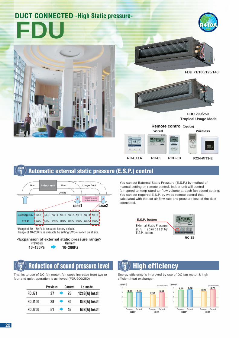
600mm Drain Pump is mounted in FDU71/100/125/140.The indoor unit is completely hidden in the ceiling, so this is suitable for spaces with classy interior decoration.
R410A
FDU 71/100/125/140
FDUDUCT CONNECTED -High Static pressure-
RC-E5RC-EX1A
Wired
RCH-E3 RCN-KIT3-E
Wireless
600mm
Remote control (Option)
FDU71 37 25 12dB(A) less!!Current Lo modePrevious
FDU100 38 30 8dB(A) less!!
FDU200 51 45 6dB(A) less!!
Point
2 Reduction of sound pressure level
Point
6 Enhanced installation workability
Point
1 Automatic external static pressure (E.S.P.) control
FDU 200/250Tropical Usage Mode
External Static Pressure (E.S.P.) can be set by E.S.P. button.
E.S.P. button
RC-E5
Keep the same air flow volume
Longer DuctDuct
Ceiling
Indoor unitDuct
*Range of 80~150 Pa is set at ex-factory default. Range of 10~200 Pa is available by setting SW8-4 switch on at site.
Setting No.
E.S.P.
No.8
80Pa
No.9
90Pa
No.10
100Pa
No.11
110Pa
No.12
120Pa
No.13
130Pa
No.14
140Pa
No.15
150Pa
case1 case2
<Expansion of external static pressure range>Previous
10~130PaCurrent
10~200Pa
Pipe
Fan unit
Point
5 Improvement of the serviceabilityPoint
4 Transparent inspection windowFan unit (impeller and motor) can be pulled out from the right side of the unit. Maintenance can be available from the right side or the bottom side.
Thanks to use of DC fan motor, fan steps increase from two to four and quiet operation is achieved.(FDU200/250)
Dirt condition of the bottom of a drain pan can be checked through this transparent inspection window without removing drain pan.
Cleaningnot required
A cross is visible
An outercircle is visible
Cleaningrequired
invisible
invisible
Round duct adapterIn case of requirements of round duct adapter, please access the followings for details.
Companye-mail
tel
: AIRZONE: [email protected] : +34-902-400-445
OUTDOOR UNIT
SRC•FDC
Height x Width x Depth (mm) 640 x 800(+71) x 290 750 x 880(+88) x 340 1,300 x 970 x 370 1,300 x 970 x 370 1,505 x 970 x 370845 x 970 x 370
model
Chargeless
40~60ZMX 71VNX 100~140VN(S)X 250VSA100~140VN(S) 200VSA
30m 30m15m
640 x 800(+71) x 290 750 x 880(+88) x 340 845 x 970 x 370
Micro Inverter
FDC
Height x Width x Depth (mm)
model
Chargeless
71VNP 90VNP 100VNP
15m
Standard Inverter
Point
3 High efficiencyEnergy efficiency is improved by use of DC fan motor & high efficient heat exchanger.
EER
4
3
2
1
2.523.01
COP
3.03 3.09
Previous Current Previous
(in case of 50Hz)
Current
8HP
EER
4
3
2
1
3.293.75
COP
3.68 3.72
Previous Current Previous
(in case of 50Hz)
Current
10HP
You can set External Static Pressure (E.S.P.) by method of manual setting on remote control. Indoor unit will control fan-speed to keep rated air flow volume at each fan speed setting. You can set required E.S.P. by wired remote control that calculated with the set air flow rate and pressure loss of the duct connected.
20
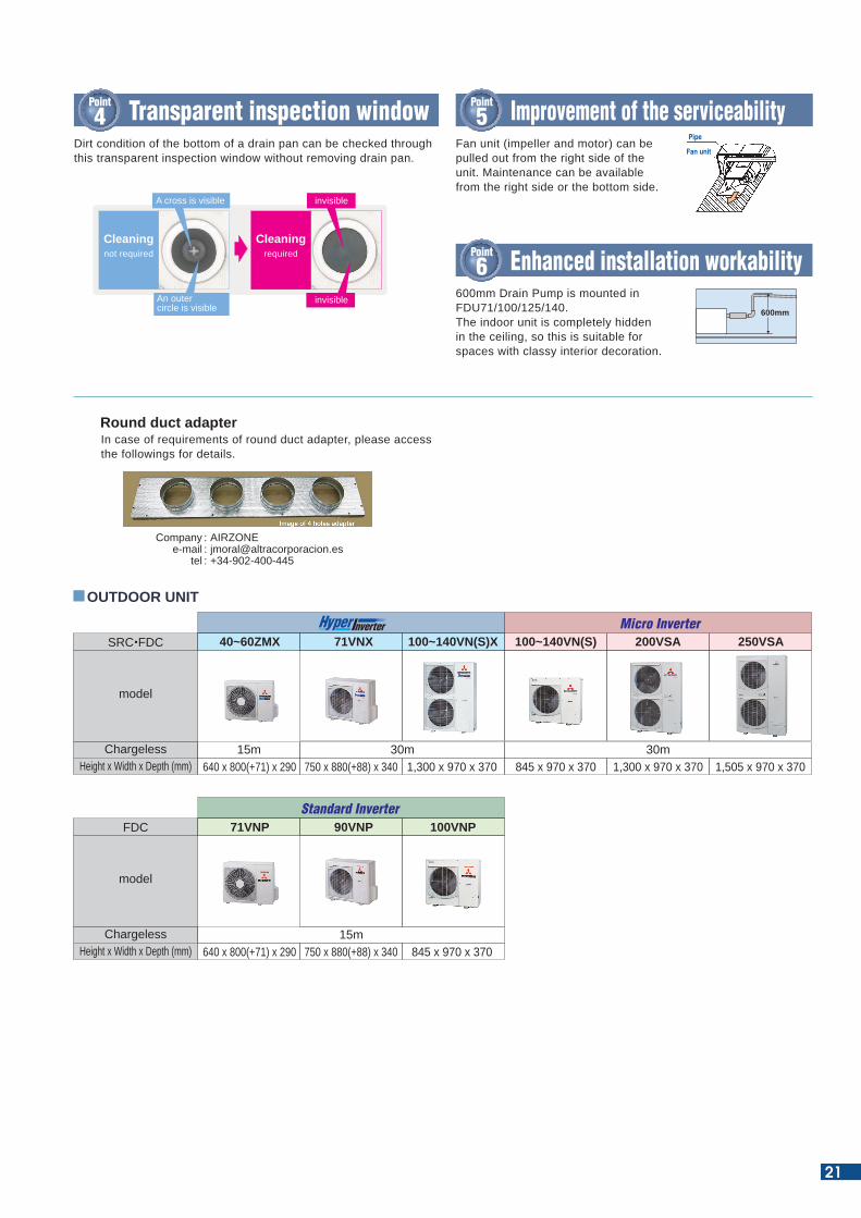
600mm Drain Pump is mounted in FDU71/100/125/140.The indoor unit is completely hidden in the ceiling, so this is suitable for spaces with classy interior decoration.
R410A
FDU 71/100/125/140
FDUDUCT CONNECTED -High Static pressure-
RC-E5RC-EX1A
Wired
RCH-E3 RCN-KIT3-E
Wireless
600mm
Remote control (Option)
FDU71 37 25 12dB(A) less!!Current Lo modePrevious
FDU100 38 30 8dB(A) less!!
FDU200 51 45 6dB(A) less!!
Point
2 Reduction of sound pressure level
Point
6 Enhanced installation workability
Point
1 Automatic external static pressure (E.S.P.) control
FDU 200/250Tropical Usage Mode
External Static Pressure (E.S.P.) can be set by E.S.P. button.
E.S.P. button
RC-E5
Keep the same air flow volume
Longer DuctDuct
Ceiling
Indoor unitDuct
*Range of 80~150 Pa is set at ex-factory default. Range of 10~200 Pa is available by setting SW8-4 switch on at site.
Setting No.
E.S.P.
No.8
80Pa
No.9
90Pa
No.10
100Pa
No.11
110Pa
No.12
120Pa
No.13
130Pa
No.14
140Pa
No.15
150Pa
case1 case2
<Expansion of external static pressure range>Previous
10~130PaCurrent
10~200Pa
Pipe
Fan unit
Point
5 Improvement of the serviceabilityPoint
4 Transparent inspection windowFan unit (impeller and motor) can be pulled out from the right side of the unit. Maintenance can be available from the right side or the bottom side.
Thanks to use of DC fan motor, fan steps increase from two to four and quiet operation is achieved.(FDU200/250)
Dirt condition of the bottom of a drain pan can be checked through this transparent inspection window without removing drain pan.
Cleaningnot required
A cross is visible
An outercircle is visible
Cleaningrequired
invisible
invisible
Round duct adapterIn case of requirements of round duct adapter, please access the followings for details.
Companye-mail
tel
: AIRZONE: [email protected] : +34-902-400-445
OUTDOOR UNIT
SRC•FDC
Height x Width x Depth (mm) 640 x 800(+71) x 290 750 x 880(+88) x 340 1,300 x 970 x 370 1,300 x 970 x 370 1,505 x 970 x 370845 x 970 x 370
model
Chargeless
40~60ZMX 71VNX 100~140VN(S)X 250VSA100~140VN(S) 200VSA
30m 30m15m
640 x 800(+71) x 290 750 x 880(+88) x 340 845 x 970 x 370
Micro Inverter
FDC
Height x Width x Depth (mm)
model
Chargeless
71VNP 90VNP 100VNP
15m
Standard Inverter
Point
3 High efficiencyEnergy efficiency is improved by use of DC fan motor & high efficient heat exchanger.
EER
4
3
2
1
2.523.01
COP
3.03 3.09
Previous Current Previous
(in case of 50Hz)
Current
8HP
EER
4
3
2
1
3.293.75
COP
3.68 3.72
Previous Current Previous
(in case of 50Hz)
Current
10HP
You can set External Static Pressure (E.S.P.) by method of manual setting on remote control. Indoor unit will control fan-speed to keep rated air flow volume at each fan speed setting. You can set required E.S.P. by wired remote control that calculated with the set air flow rate and pressure loss of the duct connected.
21
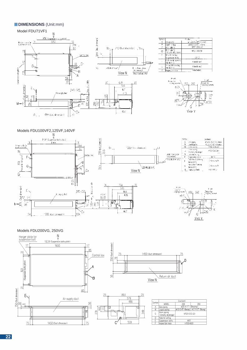
DIMENSIONS (Unit:mm)Model FDU71VF1
Models FDU100VF2,125VF,140VF
Models FDU200VG, 250VG
View N
N
View N
N
View N
N
22
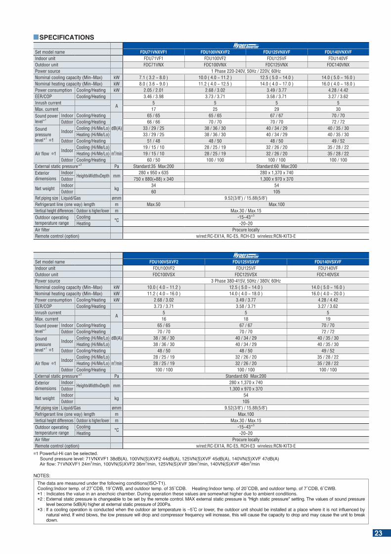
Set model name FDU100VSXVF2 FDU125VSXVF FDU140VSXVFIndoor unit FDU100VF2 FDU125VF FDU140VFOutdoor unit FDC100VSX FDC125VSX FDC140VSXPower source 3 Phase 380-415V, 50Hz / 380V, 60HzNominal cooling capacity (Min~Max) kW 10.0 ( 4.0 ~ 11.2 ) 12.5 ( 5.0 ~ 14.0 ) 14.0 ( 5.0 ~ 16.0 )Nominal heating capacity (Min~Max) kW 11.2 ( 4.0 ~ 16.0 ) 14.0 ( 4.0 ~ 18.0 ) 16.0 ( 4.0 ~ 20.0 ) Power consumption Cooling/Heating kW 2.68 / 3.02 3.49 / 3.77 4.28 / 4.42EER/COP Cooling/Heating 3.73 / 3.71 3.58 / 3.71 3.27 / 3.62Inrush current
A5 5 5
Max. current 16 18 19Sound power level*1
Indoor Cooling/Heating
dB(A)
65 / 65 67 / 67 70 / 70Outdoor Cooling/Heating 70 / 70 70 / 70 72 / 72
Sound pressure level*1 1
IndoorCooling (Hi/Me/Lo) 38 / 36 / 30 40 / 34 / 29 40 / 35 / 30Heating (Hi/Me/Lo) 38 / 36 / 30 40 / 34 / 29 40 / 35 / 30
Outdoor Cooling/Heating 48 / 50 48 / 50 49 / 52
Air flow 1Indoor
Cooling (Hi/Me/Lo)m3/min
28 / 25 / 19 32 / 26 / 20 35 / 28 / 22Heating (Hi/Me/Lo) 28 / 25 / 19 32 / 26 / 20 35 / 28 / 22
Outdoor Cooling/Heating 100 / 100 100 / 100 100 / 100External static pressure*2 Pa Standard:60 Max:200Exterior dimensions
IndoorHeightxWidthxDepth mm
280 x 1,370 x 740Outdoor 1,300 x 970 x 370
Net weightIndoor
kg54
Outdoor 105Ref.piping size Liquid/Gas ømm 9.52(3/8") / 15.88(5/8")Refrigerant line (one way) length m Max.100Vertical height differences Outdoor is higher/lower m Max.30 / Max.15Outdoor operating temperature range
Cooling°C
-15~43*3
Heating -20~20Air filter Procure locallyRemote control (option) wired:RC-EX1A, RC-E5, RCH-E3 wireless:RCN-KIT3-E
1 Powerful-Hi can be selected. ound pressure level: N d (A) N( ) d (A) N( ) d (A) N( ) d (A) Air ow: N m3 min N( ) m3 min N( ) m3 min N( ) m3 min
Set model name FDU71VNXVF1 FDU100VNXVF2 FDU125VNXVF FDU140VNXVFIndoor unit FDU71VF1 FDU100VF2 FDU125VF FDU140VFOutdoor unit FDC71VNX FDC100VNX FDC125VNX FDC140VNXPower source 1 Phase 220-240V, 50Hz / 220V, 60HzNominal cooling capacity (Min~Max) kW 7.1 ( 3.2 ~ 8.0 ) 10.0 ( 4.0 ~ 11.2 ) 12.5 ( 5.0 ~ 14.0 ) 14.0 ( 5.0 ~ 16.0 )Nominal heating capacity (Min~Max) kW 8.0 ( 3.6 ~ 9.0 ) 11.2 ( 4.0 ~ 12.5 ) 14.0 ( 4.0 ~ 17.0 ) 16.0 ( 4.0 ~ 18.0 ) Power consumption Cooling/Heating kW 2.05 / 2.01 2.68 / 3.02 3.49 / 3.77 4.28 / 4.42EER/COP Cooling/Heating 3.46 / 3.98 3.73 / 3.71 3.58 / 3.71 3.27 / 3.62Inrush current
A5 5 5 5
Max. current 17 25 29 30Sound power level*1
Indoor Cooling/Heating
dB(A)
65 / 65 65 / 65 67 / 67 70 / 70Outdoor Cooling/Heating 66 / 66 70 / 70 70 / 70 72 / 72
Sound pressure level*1 1
IndoorCooling (Hi/Me/Lo) 33 / 29 / 25 38 / 36 / 30 40 / 34 / 29 40 / 35 / 30Heating (Hi/Me/Lo) 33 / 29 / 25 38 / 36 / 30 40 / 34 / 29 40 / 35 / 30
Outdoor Cooling/Heating 51 / 48 48 / 50 48 / 50 49 / 52
Air flow 1Indoor
Cooling (Hi/Me/Lo)m3/min
19 / 15 / 10 28 / 25 / 19 32 / 26 / 20 35 / 28 / 22Heating (Hi/Me/Lo) 19 / 15 / 10 28 / 25 / 19 32 / 26 / 20 35 / 28 / 22
Outdoor Cooling/Heating 60 / 50 100 / 100 100 / 100 100 / 100External static pressure*2 Pa Standard:35 Max:200 Standard:60 Max:200Exterior dimensions
IndoorHeightxWidthxDepth mm
280 x 950 x 635 280 x 1,370 x 740Outdoor 750 x 880(+88) x 340 1,300 x 970 x 370
Net weightIndoor
kg34 54
Outdoor 60 105Ref.piping size Liquid/Gas ømm 9.52(3/8") / 15.88(5/8")Refrigerant line (one way) length m Max.50 Max.100Vertical height differences Outdoor is higher/lower m Max.30 / Max.15Outdoor operating temperature range
Cooling°C
-15~43*3
Heating -20~20Air filter Procure locallyRemote control (option) wired:RC-EX1A, RC-E5, RCH-E3 wireless:RCN-KIT3-E
SPECIFICATIONS
NOTES:he data are measured under the following conditions( O- ).
Cooling: ndoor temp. of C C and outdoor temp. of C . eating: ndoor temp. of C and outdoor temp. of C C . * : ndicates the value in an anechoic cham er. uring operation these values are somewhat higher due to am ient conditions.* : E ternal static pressure is changea le to e set y the remote control. MA e ternal static pressure is igh static pressure setting. he values of sound pressure
level ecome d (A) higher at e ternal static pressure of Pa. * : f a cooling operation is conducted when the outdoor air temperature is C or lower the outdoor unit should e installed at a place where it is not in uenced y
natural wind. f wind lows the low pressure will drop and compressor fre uency will increase this will cause the capacity to drop and may cause the unit to reak down.
23
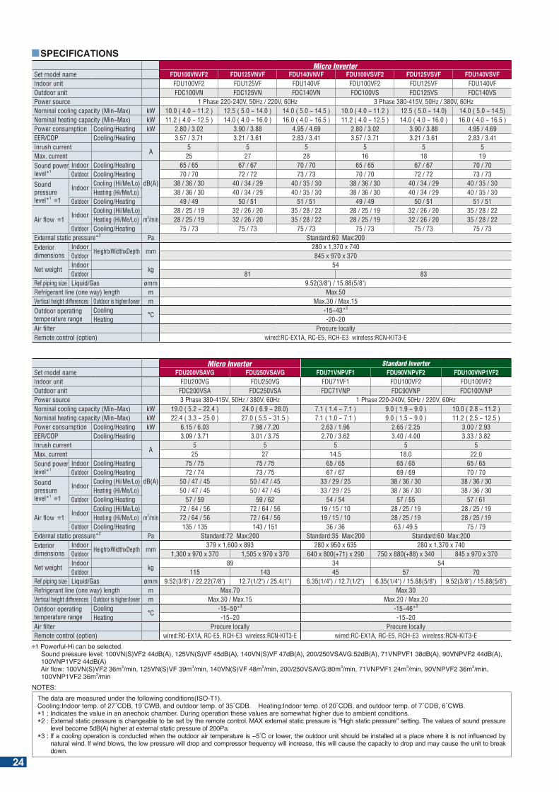
Set model name FDU100VNVF2 FDU125VNVF FDU140VNVF FDU100VSVF2 FDU125VSVF FDU140VSVFIndoor unit FDU100VF2 FDU125VF FDU140VF FDU100VF2 FDU125VF FDU140VFOutdoor unit FDC100VN FDC125VN FDC140VN FDC100VS FDC125VS FDC140VSPower source 1 Phase 220-240V, 50Hz / 220V, 60Hz 3 Phase 380-415V, 50Hz / 380V, 60HzNominal cooling capacity (Min~Max) kW 10.0 ( 4.0 ~ 11.2 ) 12.5 ( 5.0 ~ 14.0 ) 14.0 ( 5.0 ~ 14.5 ) 10.0 ( 4.0 ~ 11.2 ) 12.5 ( 5.0 ~ 14.0) 14.0 ( 5.0 ~ 14.5)Nominal heating capacity (Min~Max) kW 11.2 ( 4.0 ~ 12.5 ) 14.0 ( 4.0 ~ 16.0 ) 16.0 ( 4.0 ~ 16.5 ) 11.2 ( 4.0 ~ 12.5 ) 14.0 ( 4.0 ~ 16.0 ) 16.0 ( 4.0 ~ 16.5 ) Power consumption Cooling/Heating kW 2.80 / 3.02 3.90 / 3.88 4.95 / 4.69 2.80 / 3.02 3.90 / 3.88 4.95 / 4.69EER/COP Cooling/Heating 3.57 / 3.71 3.21 / 3.61 2.83 / 3.41 3.57 / 3.71 3.21 / 3.61 2.83 / 3.41Inrush current
A5 5 5 5 5 5
Max. current 25 27 28 16 18 19Sound power level*1
Indoor Cooling/Heating
dB(A)
65 / 65 67 / 67 70 / 70 65 / 65 67 / 67 70 / 70Outdoor Cooling/Heating 70 / 70 72 / 72 73 / 73 70 / 70 72 / 72 73 / 73
Sound pressure level*1 1
IndoorCooling (Hi/Me/Lo) 38 / 36 / 30 40 / 34 / 29 40 / 35 / 30 38 / 36 / 30 40 / 34 / 29 40 / 35 / 30Heating (Hi/Me/Lo) 38 / 36 / 30 40 / 34 / 29 40 / 35 / 30 38 / 36 / 30 40 / 34 / 29 40 / 35 / 30
Outdoor Cooling/Heating 49 / 49 50 / 51 51 / 51 49 / 49 50 / 51 51 / 51
Air flow 1Indoor
Cooling (Hi/Me/Lo)m3/min
28 / 25 / 19 32 / 26 / 20 35 / 28 / 22 28 / 25 / 19 32 / 26 / 20 35 / 28 / 22Heating (Hi/Me/Lo) 28 / 25 / 19 32 / 26 / 20 35 / 28 / 22 28 / 25 / 19 32 / 26 / 20 35 / 28 / 22
Outdoor Cooling/Heating 75 / 73 75 / 73 75 / 73 75 / 73 75 / 73 75 / 73External static pressure*2 Pa Standard:60 Max:200Exterior dimensions
IndoorHeightxWidthxDepth mm
280 x 1,370 x 740Outdoor 845 x 970 x 370
Net weightIndoor
kg54
Outdoor 81 83Ref.piping size Liquid/Gas ømm 9.52(3/8") / 15.88(5/8")Refrigerant line (one way) length m Max.50Vertical height differences Outdoor is higher/lower m Max.30 / Max.15Outdoor operating temperature range
Cooling°C
-15~43*3
Heating -20~20Air filter Procure locallyRemote control (option) wired:RC-EX1A, RC-E5, RCH-E3 wireless:RCN-KIT3-E
SPECIFICATIONS
Standard InverterSet model name FDU200VSAVG FDU250VSAVG FDU71VNPVF1 FDU90VNPVF2 FDU100VNP1VF2Indoor unit FDU200VG FDU250VG FDU71VF1 FDU100VF2 FDU100VF2Outdoor unit FDC200VSA FDC250VSA FDC71VNP FDC90VNP FDC100VNPPower source 3 Phase 380-415V, 50Hz / 380V, 60Hz 1 Phase 220-240V, 50Hz / 220V, 60HzNominal cooling capacity (Min~Max) kW 19.0 ( 5.2 ~ 22.4 ) 24.0 ( 6.9 ~ 28.0) 7.1 ( 1.4 ~ 7.1 ) 9.0 ( 1.9 ~ 9.0 ) 10.0 ( 2.8 ~ 11.2 )Nominal heating capacity (Min~Max) kW 22.4 ( 3.3 ~ 25.0 ) 27.0 ( 5.5 ~ 31.5 ) 7.1 ( 1.0 ~ 7.1 ) 9.0 ( 1.5 ~ 9.0 ) 11.2 ( 2.5 ~ 12.5 )Power consumption Cooling/Heating kW 6.15 / 6.03 7.98 / 7.20 2.63 / 1.96 2.65 / 2.25 3.00 / 2.93EER/COP Cooling/Heating 3.09 / 3.71 3.01 / 3.75 2.70 / 3.62 3.40 / 4.00 3.33 / 3.82Inrush current
A5 5 5 5 5
Max. current 25 27 14.5 18.0 22.0Sound power level*1
Indoor Cooling/Heating
dB(A)
75 / 75 75 / 75 65 / 65 65 / 65 65 / 65Outdoor Cooling/Heating 72 / 74 73 / 75 67 / 67 69 / 69 70 / 70
Sound pressure level*1 1
IndoorCooling (Hi/Me/Lo) 50 / 47 / 45 50 / 47 / 45 33 / 29 / 25 38 / 36 / 30 38 / 36 / 30Heating (Hi/Me/Lo) 50 / 47 / 45 50 / 47 / 45 33 / 29 / 25 38 / 36 / 30 38 / 36 / 30
Outdoor Cooling/Heating 57 / 59 59 / 62 54 / 54 57 / 55 57 / 61
Air flow 1Indoor
Cooling (Hi/Me/Lo)m3/min
72 / 64 / 56 72 / 64 / 56 19 / 15 / 10 28 / 25 / 19 28 / 25 / 19Heating (Hi/Me/Lo) 72 / 64 / 56 72 / 64 / 56 19 / 15 / 10 28 / 25 / 19 28 / 25 / 19
Outdoor Cooling/Heating 135 / 135 143 / 151 36 / 36 63 / 49.5 75 / 79External static pressure*2 Pa Standard:72 Max:200 Standard:35 Max:200 Standard:60 Max:200Exterior dimensions
IndoorHeightxWidthxDepth mm
379 x 1,600 x 893 280 x 950 x 635 280 x 1,370 x 740Outdoor 1,300 x 970 x 370 1,505 x 970 x 370 640 x 800(+71) x 290 750 x 880(+88) x 340 845 x 970 x 370
Net weightIndoor
kg89 34 54
Outdoor 115 143 45 57 70Ref.piping size Liquid/Gas ømm 9.52(3/8") / 22.22(7/8") 12.7(1/2") / 25.4(1") 6.35(1/4") / 12.7(1/2") 6.35(1/4") / 15.88(5/8") 9.52(3/8") / 15.88(5/8")Refrigerant line (one way) length m Max.70 Max.30Vertical height differences Outdoor is higher/lower m Max.30 / Max.15 Max.20 / Max.20Outdoor operating temperature range
Cooling°C
-15~50*3 -15~46*3
Heating -15~20 -15~20Air filter Procure locally Procure locallyRemote control (option) wired:RC-EX1A, RC-E5, RCH-E3 wireless:RCN-KIT3-E wired:RC-EX1A, RC-E5, RCH-E3 wireless:RCN-KIT3-E
1 Powerful-Hi can be selected. ound pressure level: N( ) d (A) N( ) d (A) N( ) d (A) A G: d (A) NP d (A) NP d (A) 100VNP1VF2 44dB(A) Air ow: N( ) m3 min N( ) m3 min N( ) m3 min A G: m3 min NP m3 min NP m3 min NP m3 minNOTES:
he data are measured under the following conditions( O- ).Cooling: ndoor temp. of C C and outdoor temp. of C . eating: ndoor temp. of C and outdoor temp. of C C . * : ndicates the value in an anechoic cham er. uring operation these values are somewhat higher due to am ient conditions.* : E ternal static pressure is changea le to e set y the remote control. MA e ternal static pressure is igh static pressure setting. he values of sound pressure
level ecome d (A) higher at e ternal static pressure of Pa. * : f a cooling operation is conducted when the outdoor air temperature is C or lower the outdoor unit should e installed at a place where it is not in uenced y
natural wind. f wind lows the low pressure will drop and compressor fre uency will increase this will cause the capacity to drop and may cause the unit to reak down.
24
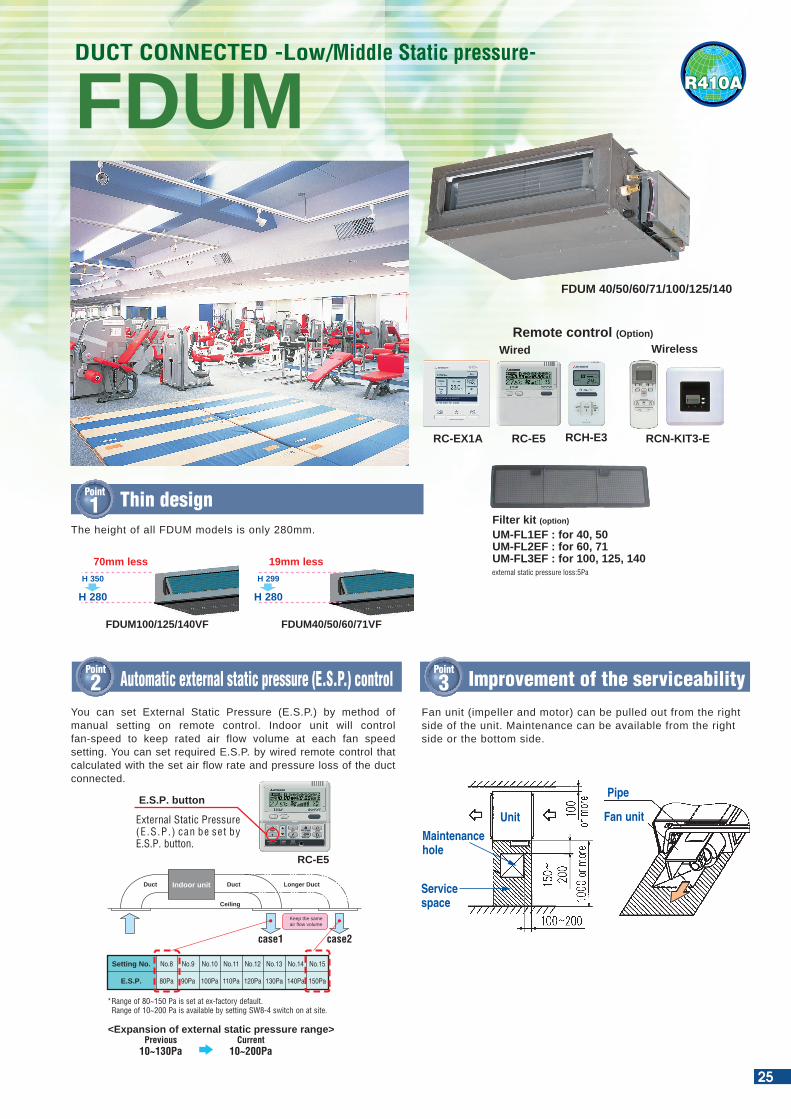
R410AFDUMDUCT CONNECTED -Low/Middle Static pressure-
Filter kit (option)
UM-FL1EF : for 40, 50UM-FL2EF : for 60, 71UM-FL3EF : for 100, 125, 140external static pressure loss:5Pa
RCN-KIT3-E
Wireless
FDUM 40/50/60/71/100/125/140
RC-E5RC-EX1A
Wired
RCH-E3
Remote control (Option)
H 350
H 280
Point
1 Thin design
FDUM100/125/140VF
H 299
H 280
FDUM40/50/60/71VF
70mm less 19mm less
The height of all FDUM models is only 280mm.
Point
2 Automatic external static pressure (E.S.P.) controlPoint
3 Improvement of the serviceability
External Static Pressure (E.S.P.) can be set by E.S.P. button.
E.S.P. button
RC-E5
Keep the same air flow volume
Longer DuctDuct
Ceiling
Indoor unitDuct
*Range of 80~150 Pa is set at ex-factory default. Range of 10~200 Pa is available by setting SW8-4 switch on at site.
Setting No.
E.S.P.
No.8
80Pa
No.9
90Pa
No.10
100Pa
No.11
110Pa
No.12
120Pa
No.13
130Pa
No.14
140Pa
No.15
150Pa
case1 case2
<Expansion of external static pressure range>Previous
10~130PaCurrent
10~200Pa
You can set External Static Pressure (E.S.P.) by method of manual setting on remote control. Indoor unit will control fan-speed to keep rated air flow volume at each fan speed setting. You can set required E.S.P. by wired remote control that calculated with the set air flow rate and pressure loss of the duct connected.
Fan unit (impeller and motor) can be pulled out from the right side of the unit. Maintenance can be available from the right side or the bottom side.
Maintenance hole
Pipe
Fan unitUnit
Service space
25
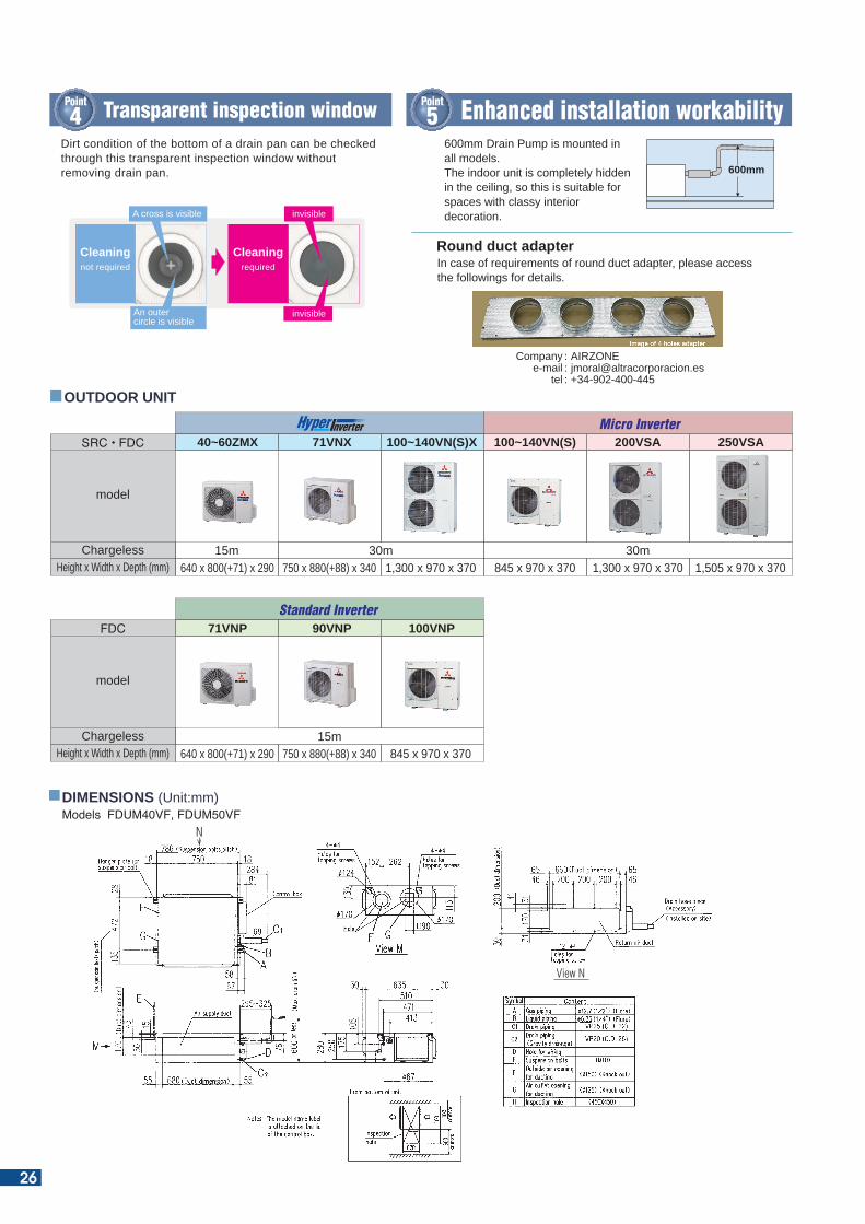
Point
4 Transparent inspection window600mm Drain Pump is mounted in all models.The indoor unit is completely hidden in the ceiling, so this is suitable for spaces with classy interior decoration.
600mm
Point
5 Enhanced installation workabilityDirt condition of the bottom of a drain pan can be checked through this transparent inspection window without removing drain pan.
Cleaningnot required
A cross is visible
An outercircle is visible
Cleaningrequired
invisible
invisible
Round duct adapterIn case of requirements of round duct adapter, please access the followings for details.
Companye-mail
tel
: AIRZONE: [email protected] : +34-902-400-445
OUTDOOR UNIT
SRC • FDC
Height x Width x Depth (mm) 640 x 800(+71) x 290 750 x 880(+88) x 340 1,300 x 970 x 370 1,300 x 970 x 370 1,505 x 970 x 370845 x 970 x 370
model
Chargeless
40~60ZMX 71VNX 100~140VN(S)X 250VSA100~140VN(S) 200VSA
15m 30m 30m
640 x 800(+71) x 290 750 x 880(+88) x 340 845 x 970 x 370
Micro Inverter
FDC
Height x Width x Depth (mm)
model
Chargeless
71VNP 90VNP 100VNP
15m
Standard Inverter
DIMENSIONS (Unit:mm)Models FDUM40VF, FDUM50VF
View N
N
26
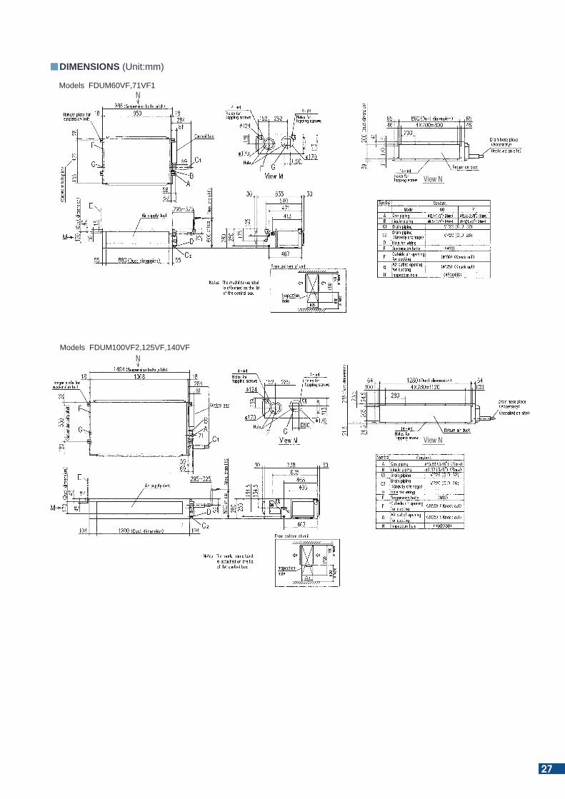
DIMENSIONS (Unit:mm)
Models FDUM100VF2,125VF,140VF
Models FDUM60VF,71VF1
View N
N
View N
N
27
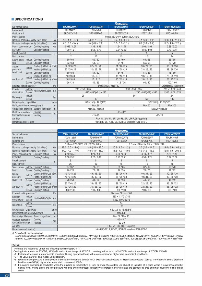
Set model name FDUM40ZMXVF FDUM50ZMXVF FDUM60ZMXVF FDUM71VNXVF1 FDUM100VNXVF2Indoor unit FDUM40VF FDUM50VF FDUM60VF FDUM71VF1 FDUM100VF2Outdoor unit SRC40ZMX-S SRC50ZMX-S SRC60ZMX-S FDC71VNX FDC100VNXPower source 1 Phase 220-240V, 50Hz / 220V, 60HzNominal cooling capacity (Min~Max) kW 4.0 ( 1.1 ~ 4.7 ) 5.0 ( 1.1 ~ 5.6 ) 5.6 ( 1.1 ~ 6.3 ) 7.1 ( 3.2 ~ 8.0 ) 10.0 ( 4.0 ~ 11.2 )Nominal heating capacity (Min~Max) kW 4.5 ( 0.6 ~ 5.4 ) 5.4 ( 0.6 ~ 6.3 ) 6.7 ( 0.6 ~ 7.1 ) 8.0 ( 3.6 ~ 9.0 ) 11.2 ( 4.0 ~ 12.5 )Power consumption Cooling/Heating kW 0.952 / 1.07 1.38 / 1.45 1.54 / 1.75 2.03 / 1.99 2.68 / 3.02EER/COP Cooling/Heating 4.20 / 4.21 3.62 / 3.72 3.64 / 3.83 3.50 / 4.02 3.73 / 3.71Inrush current
A5 5 5 5 5
Max. current 12 15 15 17 24Sound power level*1
Indoor Cooling/Heating
dB(A)
60 / 60 60 / 60 60 / 60 65 / 65 65 / 65Outdoor Cooling/Heating 63 / 63 63 / 63 64 / 64 66 / 66 70 / 70
Sound pressure level*1 1
IndoorCooling (Hi/Me/Lo) 32 / 29 / 26 32 / 29 / 26 31 / 28 / 25 33 / 29 / 25 38 / 36 / 30Heating (Hi/Me/Lo) 32 / 29 / 26 32 / 29 / 26 31 / 28 / 25 33 / 29 / 25 38 / 36 / 30
Outdoor Cooling/Heating 50 / 50 54 / 50 54 / 54 51 / 48 48 / 50
Air flow 1Indoor
Cooling (Hi/Me/Lo)m3/min
10 / 9 / 8 10 / 9 / 8 15 / 13 / 10 19 / 15 / 10 28 / 25 / 19Heating (Hi/Me/Lo) 10 / 9 / 8 10 / 9 / 8 15 / 13 / 10 19 / 15 / 10 28 / 25 / 19
Outdoor Cooling/Heating 36 / 33 40 / 33 41.5 / 39 60 / 50 100 / 100External static pressure*3 Pa Standard:35 Max:100 Standard:60 Max:100Exterior dimensions
IndoorHeightxWidthxDepth mm
280 x 750 x 635 280 x 950 x 635 280 x 1,370 x 740Outdoor 640 x 800(+71) x 290 750 x 880(+88) x 340 1,300 x 970 x 370
Net weightIndoor
kg29 34 54
Outdoor 45 60 105Ref.piping size Liquid/Gas ømm 6.35(1/4") / 12.7(1/2") 9.52(3/8") / 15.88(5/8")Refrigerant line (one way) length m Max.30 Max.50 Max.100Vertical height differences Outdoor is higher/lower m Max.20 / Max.20 Max.30 / Max.15Outdoor operating temperature range
Cooling°C
-15~43*4
Heating -15~20 -20~20Air filter Filter kit : UM-FL1EF / UM-FL2EF / UM-FL3EF (option)Remote control (option) wired:RC-EX1A, RC-E5, RCH-E3 wireless:RCN-KIT3-E
Set model name FDUM125VNXVF FDUM140VNXVF FDUM100VSXVF2 FDUM125VSXVF FDUM140VSXVFIndoor unit FDUM125VF FDUM140VF FDUM100VF2 FDUM125VF FDUM140VFOutdoor unit FDC125VNX FDC140VNX FDC100VSX FDC125VSX FDC140VSXPower source 1 Phase 220-240V, 50Hz / 220V, 60Hz 3 Phase 380-415V, 50Hz / 380V, 60HzNominal cooling capacity (Min~Max) kW 12.5 ( 5.0 ~ 14.0 ) 14.0 ( 5.0 ~ 16.0 ) 10.0 ( 4.0 ~ 11.2 ) 12.5 ( 5.0 ~ 14.0 ) 14.0 ( 5.0 ~ 16.0 )Nominal heating capacity (Min~Max) kW 14.0 ( 4.0 ~ 17.0 ) 16.0 ( 4.0 ~ 18.0 ) 11.2 ( 4.0 ~ 16.0 ) 14.0 ( 4.0 ~ 18.0 ) 16.0 ( 4.0 ~ 20.0 ) Power consumption Cooling/Heating kW 3.49 / 3.77 4.28 / 4.42 2.68 / 3.02 3.49 / 3.77 4.28 / 4.42EER/COP Cooling/Heating 3.58 / 3.71 3.27 / 3.62 3.73 / 3.71 3.58 / 3.71 3.27 / 3.62Inrush current
A5 5 5 5 5
Max. current 26 26 15 15 15Sound power level*1
Indoor Cooling/Heating
dB(A)
67 / 67 70 / 70 65 / 65 67 / 67 70 / 70Outdoor Cooling/Heating 70 / 70 72 / 72 70 / 70 70 / 70 72 / 72
Sound pressure level*1 1
IndoorCooling (Hi/Me/Lo) 40 / 34 / 29 40 / 35 / 30 38 / 36 / 30 40 / 34 / 29 40 / 35 / 30Heating (Hi/Me/Lo) 40 / 34 / 29 40 / 35 / 30 38 / 36 / 30 40 / 34 / 29 40 / 35 / 30
Outdoor Cooling/Heating 48 / 50 49 / 52 48 / 50 48 / 50 49 / 52
Air flow 1Indoor
Cooling (Hi/Me/Lo)m3/min
32 / 26 / 20 35 / 28 / 22 28 / 25 / 19 32 / 26 / 20 35 / 28 / 22Heating (Hi/Me/Lo) 32 / 26 / 20 35 / 28 / 22 28 / 25 / 19 32 / 26 / 20 35 / 28 / 22
Outdoor Cooling/Heating 100 / 100 100 / 100 100 / 100 100 / 100 100 / 100External static pressure*3 Pa Standard:60 Max:100Exterior dimensions
IndoorHeightxWidthxDepth mm
280 x 1,370 x 740Outdoor 1,300 x 970 x 370
Net weightIndoor
kg54
Outdoor 105Ref.piping size Liquid/Gas ømm 9.52(3/8") / 15.88(5/8")Refrigerant line (one way) length m Max.100Vertical height differences Outdoor is higher/lower m Max.30 / Max.15Outdoor operating temperature range
Cooling°C
-15~43*4
Heating -20~20Air filter Filter kit : UM-FL3EF (option)Remote control (option) wired:RC-EX1A, RC-E5, RCH-E3 wireless:RCN-KIT3-E
1 Powerful-Hi can be selected. ound pressure level: M M d (A) M d (A) N d (A) N( ) d (A) N( ) d (A) N( ) d (A) Air ow: M M m3 min M m3 min N m3 min N( ) m3 min N( ) m3 min N( ) m3 min
SPECIFICATIONS
NOTES:he data are measured under the following conditions( O- ).
Cooling: ndoor temp. of C C and outdoor temp. of C . eating: ndoor temp. of C and outdoor temp. of C C .* : ndicates the value in an anechoic cham er. uring operation these values are somewhat higher due to am ient conditions.*2 : The values are for one indoor unit operation.* : E ternal static pressure is changea le to e set y the remote control. MA e ternal static pressure is igh static pressure setting. he values of sound pressure
level ecome d (A) higher at e ternal static pressure of Pa. * : f a cooling operation is conducted when the outdoor air temperature is C or lower the outdoor unit should e installed at a place where it is not in uenced y
natural wind. f wind lows the low pressure will drop and compressor fre uency will increase this will cause the capacity to drop and may cause the unit to reak down.
28
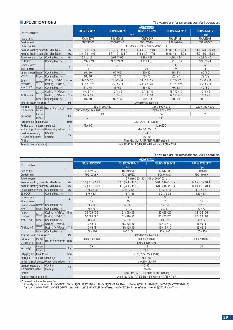
SPECIFICATIONS
Set model nameFDUM71VNXPVF FDUM100VNXPVF FDUM125VNXPVF FDUM140VNXPVF1 FDUM140VNXTVF
Twin TripleIndoor unit FDUM40VF FDUM50VF FDUM60VF FDUM71VF1 FDUM50VFOutdoor unit FDC71VNX FDC100VNX FDC125VNX FDC140VNX FDC140VNXPower source 1 Phase 220-240V, 50Hz / 220V, 60HzNominal cooling capacity (Min~Max) kW 7.1 ( 3.2 ~ 8.0 ) 10.0 ( 4.0 ~ 11.2 ) 12.5 ( 5.0 ~ 14.0 ) 14.0 ( 5.0 ~ 16.0 ) 14.0 ( 5.0 ~ 16.0 )Nominal heating capacity (Min~Max) kW 8.0 ( 3.6 ~ 9.0 ) 11.2 ( 4.0 ~ 12.5 ) 14.0 ( 4.0 ~ 17.0 ) 16.0 ( 4.0 ~ 18.0 ) 16.0 ( 4.0 ~ 18.0 ) Power consumption Cooling/Heating kW 2.01 / 1.91 2.66 / 3.02 3.26 / 3.66 4.36 / 4.35 4.21 / 4.69EER/COP Cooling/Heating 3.53 / 4.19 3.76 / 3.71 3.83 / 3.83 3.21 / 3.68 3.33 / 3.41Inrush current
A5 5 5 5 5
Max. current 17 24 26 26 26Sound power level*1
Indoor*2 Cooling/Heating
dB(A)
60 / 60 60 / 60 60 / 60 65 / 65 60 / 60Outdoor Cooling/Heating 66 / 66 70 / 70 70 / 70 72 / 72 72 / 72
Sound pressure level*1 2
Indoor*2 Cooling (Hi/Me/Lo) 39 / 29 / 26 32 / 29 / 26 31 / 28 / 25 33 / 29 / 25 32 / 29 / 26Heating (Hi/Me/Lo) 39 / 29 / 26 32 / 29 / 26 31 / 28 / 25 33 / 29 / 25 32 / 29 / 26
Outdoor Cooling/Heating 51 / 48 48 / 50 48 / 50 49 / 52 49 / 52
Air flow 2Indoor*2 Cooling (Hi/Me/Lo)
m3/min10 / 9 / 8 10 / 9 / 8 15 / 13 / 10 19 / 15 / 10 10 / 9 / 8
Heating (Hi/Me/Lo) 10 / 9 / 8 10 / 9 / 8 15 / 13 / 10 19 / 15 / 10 10 / 9 / 8Outdoor Cooling/Heating 60 / 50 100 / 100 100 / 100 100 / 100 100 / 100
External static pressure*3 Pa Standard:35 Max:100Exterior dimensions
IndoorHeightxWidthxDepth mm
280 x 750 x 635 280 x 950 x 635 280 x 750 x 635Outdoor 750 x 880(+88) x 340 1,300 x 970 x 370
Net weightIndoor
kg29 34 29
Outdoor 60 105Ref.piping size Liquid/Gas ømm 9.52(3/8") / 15.88(5/8")Refrigerant line (one way) length m Max.50 Max.100Vertical height differences Outdoor is higher/lower m Max.30 / Max.15 Outdoor operating temperature range
Cooling°C
-15~43*4
Heating -20~20Air filter Filter kit : UM-FL1EF / UM-FL2EF (option)Remote control (option) wired:RC-EX1A, RC-E5, RCH-E3 wireless:RCN-KIT3-E
he values are for simultaneous Multi operation.
Set model nameFDUM100VSXPVF FDUM125VSXPVF FDUM140VSXPVF1 FDUM140VSXTVF
Twin TripleIndoor unit FDUM50VF FDUM60VF FDUM71VF1 FDUM50VFOutdoor unit FDC100VSX FDC125VSX FDC140VSX FDC140VSXPower source 3 Phase 380-415V, 50Hz / 380V, 60HzNominal cooling capacity (Min~Max) kW 10.0 ( 4.0 ~ 11.2 ) 12.5 ( 5.0 ~ 14.0 ) 14.0 ( 5.0 ~ 16.0 ) 14.0 ( 5.0 ~ 16.0 )Nominal heating capacity (Min~Max) kW 11.2 ( 4.0 ~ 16.0 ) 14.0 ( 4.0 ~ 18.0 ) 16.0 ( 4.0 ~ 20.0 ) 16.0 ( 4.0 ~ 20.0 ) Power consumption Cooling/Heating kW 2.66 / 3.02 3.26 / 3.66 4.36 / 4.35 4.21 / 4.69EER/COP Cooling/Heating 3.76 / 3.71 3.83 / 3.83 3.21 / 3.68 3.33 / 3.41Inrush current
A5 5 5 5
Max. current 15 15 15 15Sound power level*1
Indoor*2 Cooling/Heating
dB(A)
60 / 60 60 / 60 65 / 65 60 / 60Outdoor Cooling/Heating 70 / 70 70 / 70 72 / 72 72 / 72
Sound pressure level*1 2
Indoor*2 Cooling (Hi/Me/Lo) 32 / 29 / 26 31 / 28 / 25 33 / 29 / 25 32 / 29 / 26Heating (Hi/Me/Lo) 32 / 29 / 26 31 / 28 / 25 33 / 29 / 25 32 / 29 / 26
Outdoor Cooling/Heating 48 / 50 48 / 50 49 / 52 49 / 52
Air flow 2Indoor*2 Cooling (Hi/Me/Lo)
m3/min10 / 9 / 8 15 / 13 / 10 19 / 15 / 10 10 / 9 / 8
Heating (Hi/Me/Lo) 10 / 9 / 8 15 / 13 / 10 19 / 15 / 10 10 / 9 / 8Outdoor Cooling/Heating 100 / 100 100 / 100 100 / 100 100 / 100
External static pressure*3 Pa Standard:35 Max:100Exterior dimensions
IndoorHeightxWidthxDepth mm
280 x 750 x 635 280 x 950 x 635 280 x 750 x 635Outdoor 1,300 x 970 x 370
Net weightIndoor
kg29 34 29
Outdoor 105Ref.piping size Liquid/Gas ømm 9.52(3/8") / 15.88(5/8")Refrigerant line (one way) length m Max.100Vertical height differences Outdoor is higher/lower m Max.30 / Max.15Outdoor operating temperature range
Cooling°C
-15~43*4
Heating -20~20Air filter Filter kit : UM-FL1EF / UM-FL2EF (option)Remote control (option) wired:RC-EX1A, RC-E5, RCH-E3 wireless:RCN-KIT3-E
2 Powerful-Hi can be selected. ound pressure level: N P N( ) P d (A) N( ) P d (A) N( ) P d (A) N( ) d (A) Air ow: N P N( ) P m3 min N( ) P m3 min N( ) P m3 min N( ) m3 min
he values are for simultaneous Multi operation.
29
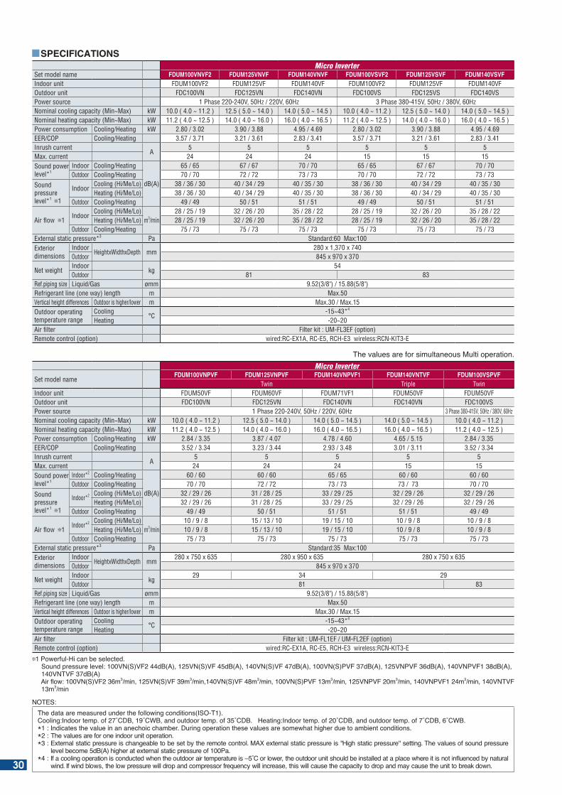
he values are for simultaneous Multi operation.
Set model nameFDUM100VNPVF FDUM125VNPVF FDUM140VNPVF1 FDUM140VNTVF FDUM100VSPVF
Twin Triple TwinIndoor unit FDUM50VF FDUM60VF FDUM71VF1 FDUM50VF FDUM50VFOutdoor unit FDC100VN FDC125VN FDC140VN FDC140VN FDC100VSPower source 1 Phase 220-240V, 50Hz / 220V, 60Hz 3 Phase 380-415V, 50Hz / 380V, 60HzNominal cooling capacity (Min~Max) kW 10.0 ( 4.0 ~ 11.2 ) 12.5 ( 5.0 ~ 14.0 ) 14.0 ( 5.0 ~ 14.5 ) 14.0 ( 5.0 ~ 14.5 ) 10.0 ( 4.0 ~ 11.2 )Nominal heating capacity (Min~Max) kW 11.2 ( 4.0 ~ 12.5 ) 14.0 ( 4.0 ~ 16.0 ) 16.0 ( 4.0 ~ 16.5 ) 16.0 ( 4.0 ~ 16.5 ) 11.2 ( 4.0 ~ 12.5 )Power consumption Cooling/Heating kW 2.84 / 3.35 3.87 / 4.07 4.78 / 4.60 4.65 / 5.15 2.84 / 3.35EER/COP Cooling/Heating 3.52 / 3.34 3.23 / 3.44 2.93 / 3.48 3.01 / 3.11 3.52 / 3.34Inrush current
A5 5 5 5 5
Max. current 24 24 24 15 15Sound power level*1
Indoor*2 Cooling/Heating
dB(A)
60 / 60 60 / 60 65 / 65 60 / 60 60 / 60Outdoor Cooling/Heating 70 / 70 72 / 72 73 / 73 73 / 73 70 / 70
Sound pressure level*1 1
Indoor*2 Cooling (Hi/Me/Lo) 32 / 29 / 26 31 / 28 / 25 33 / 29 / 25 32 / 29 / 26 32 / 29 / 26Heating (Hi/Me/Lo) 32 / 29 / 26 31 / 28 / 25 33 / 29 / 25 32 / 29 / 26 32 / 29 / 26
Outdoor Cooling/Heating 49 / 49 50 / 51 51 / 51 51 / 51 49 / 49
Air flow 1Indoor*2 Cooling (Hi/Me/Lo)
m3/min10 / 9 / 8 15 / 13 / 10 19 / 15 / 10 10 / 9 / 8 10 / 9 / 8
Heating (Hi/Me/Lo) 10 / 9 / 8 15 / 13 / 10 19 / 15 / 10 10 / 9 / 8 10 / 9 / 8Outdoor Cooling/Heating 75 / 73 75 / 73 75 / 73 75 / 73 75 / 73
External static pressure*3 Pa Standard:35 Max:100Exterior dimensions
IndoorHeightxWidthxDepth mm
280 x 750 x 635 280 x 950 x 635 280 x 750 x 635Outdoor 845 x 970 x 370
Net weightIndoor
kg29 34 29
Outdoor 81 83Ref.piping size Liquid/Gas ømm 9.52(3/8") / 15.88(5/8")Refrigerant line (one way) length m Max.50Vertical height differences Outdoor is higher/lower m Max.30 / Max.15Outdoor operating temperature range
Cooling°C
-15~43*4
Heating -20~20Air filter Filter kit : UM-FL1EF / UM-FL2EF (option)Remote control (option) wired:RC-EX1A, RC-E5, RCH-E3 wireless:RCN-KIT3-E
1 Powerful-Hi can be selected. ound pressure level: N( ) d (A) N( ) d (A) N( ) d (A) N( )P d (A) NP d (A) NP d (A) 140VNTVF 37dB(A) Air ow: N( ) m3 min N( ) m3 min N( ) m3 min N( )P m3 min NP m3 min NP m3 min N m3 min
SPECIFICATIONS
Set model name FDUM100VNVF2 FDUM125VNVF FDUM140VNVF FDUM100VSVF2 FDUM125VSVF FDUM140VSVFIndoor unit FDUM100VF2 FDUM125VF FDUM140VF FDUM100VF2 FDUM125VF FDUM140VFOutdoor unit FDC100VN FDC125VN FDC140VN FDC100VS FDC125VS FDC140VSPower source 1 Phase 220-240V, 50Hz / 220V, 60Hz 3 Phase 380-415V, 50Hz / 380V, 60HzNominal cooling capacity (Min~Max) kW 10.0 ( 4.0 ~ 11.2 ) 12.5 ( 5.0 ~ 14.0 ) 14.0 ( 5.0 ~ 14.5 ) 10.0 ( 4.0 ~ 11.2 ) 12.5 ( 5.0 ~ 14.0 ) 14.0 ( 5.0 ~ 14.5 )Nominal heating capacity (Min~Max) kW 11.2 ( 4.0 ~ 12.5 ) 14.0 ( 4.0 ~ 16.0 ) 16.0 ( 4.0 ~ 16.5 ) 11.2 ( 4.0 ~ 12.5 ) 14.0 ( 4.0 ~ 16.0 ) 16.0 ( 4.0 ~ 16.5 ) Power consumption Cooling/Heating kW 2.80 / 3.02 3.90 / 3.88 4.95 / 4.69 2.80 / 3.02 3.90 / 3.88 4.95 / 4.69EER/COP Cooling/Heating 3.57 / 3.71 3.21 / 3.61 2.83 / 3.41 3.57 / 3.71 3.21 / 3.61 2.83 / 3.41Inrush current
A5 5 5 5 5 5
Max. current 24 24 24 15 15 15Sound power level*1
Indoor Cooling/Heating
dB(A)
65 / 65 67 / 67 70 / 70 65 / 65 67 / 67 70 / 70Outdoor Cooling/Heating 70 / 70 72 / 72 73 / 73 70 / 70 72 / 72 73 / 73
Sound pressure level*1 1
IndoorCooling (Hi/Me/Lo) 38 / 36 / 30 40 / 34 / 29 40 / 35 / 30 38 / 36 / 30 40 / 34 / 29 40 / 35 / 30Heating (Hi/Me/Lo) 38 / 36 / 30 40 / 34 / 29 40 / 35 / 30 38 / 36 / 30 40 / 34 / 29 40 / 35 / 30
Outdoor Cooling/Heating 49 / 49 50 / 51 51 / 51 49 / 49 50 / 51 51 / 51
Air flow 1Indoor
Cooling (Hi/Me/Lo)m3/min
28 / 25 / 19 32 / 26 / 20 35 / 28 / 22 28 / 25 / 19 32 / 26 / 20 35 / 28 / 22Heating (Hi/Me/Lo) 28 / 25 / 19 32 / 26 / 20 35 / 28 / 22 28 / 25 / 19 32 / 26 / 20 35 / 28 / 22
Outdoor Cooling/Heating 75 / 73 75 / 73 75 / 73 75 / 73 75 / 73 75 / 73External static pressure*3 Pa Standard:60 Max:100Exterior dimensions
IndoorHeightxWidthxDepth mm
280 x 1,370 x 740Outdoor 845 x 970 x 370
Net weightIndoor
kg54
Outdoor 81 83Ref.piping size Liquid/Gas ømm 9.52(3/8") / 15.88(5/8")Refrigerant line (one way) length m Max.50Vertical height differences Outdoor is higher/lower m Max.30 / Max.15Outdoor operating temperature range
Cooling°C
-15~43*4
Heating -20~20Air filter Filter kit : UM-FL3EF (option)Remote control (option) wired:RC-EX1A, RC-E5, RCH-E3 wireless:RCN-KIT3-E
NOTES:he data are measured under the following conditions( O- ).
Cooling: ndoor temp. of C C and outdoor temp. of C . eating: ndoor temp. of C and outdoor temp. of C C . * : ndicates the value in an anechoic cham er. uring operation these values are somewhat higher due to am ient conditions.*2 : The values are for one indoor unit operation. * : E ternal static pressure is changea le to e set y the remote control. MA e ternal static pressure is igh static pressure setting. he values of sound pressure
level ecome d (A) higher at e ternal static pressure of Pa. * : f a cooling operation is conducted when the outdoor air temperature is C or lower the outdoor unit should e installed at a place where it is not in uenced y natural
wind. f wind lows the low pressure will drop and compressor fre uency will increase this will cause the capacity to drop and may cause the unit to reak down.30
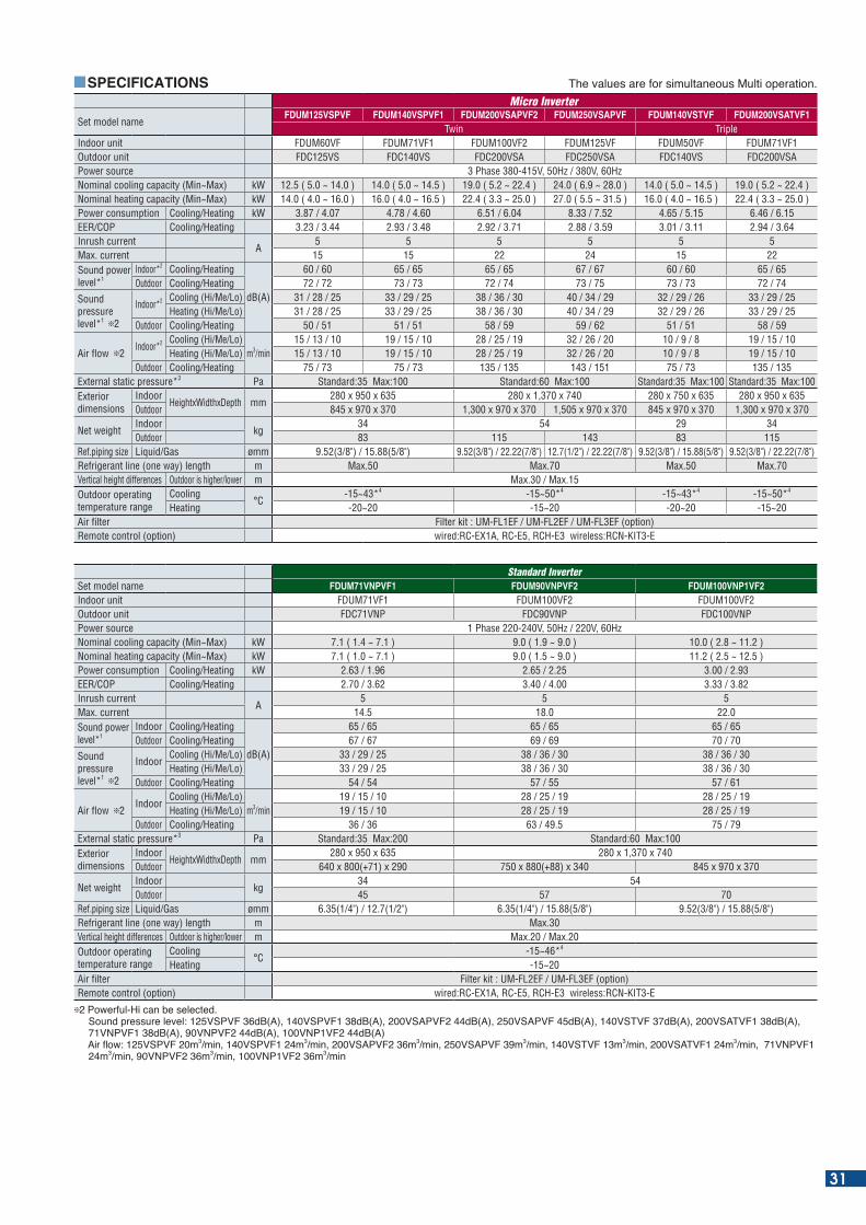
SPECIFICATIONS he values are for simultaneous Multi operation.
Set model nameFDUM125VSPVF FDUM140VSPVF1 FDUM200VSAPVF2 FDUM250VSAPVF FDUM140VSTVF FDUM200VSATVF1
Twin TripleIndoor unit FDUM60VF FDUM71VF1 FDUM100VF2 FDUM125VF FDUM50VF FDUM71VF1Outdoor unit FDC125VS FDC140VS FDC200VSA FDC250VSA FDC140VS FDC200VSAPower source 3 Phase 380-415V, 50Hz / 380V, 60HzNominal cooling capacity (Min~Max) kW 12.5 ( 5.0 ~ 14.0 ) 14.0 ( 5.0 ~ 14.5 ) 19.0 ( 5.2 ~ 22.4 ) 24.0 ( 6.9 ~ 28.0 ) 14.0 ( 5.0 ~ 14.5 ) 19.0 ( 5.2 ~ 22.4 )Nominal heating capacity (Min~Max) kW 14.0 ( 4.0 ~ 16.0 ) 16.0 ( 4.0 ~ 16.5 ) 22.4 ( 3.3 ~ 25.0 ) 27.0 ( 5.5 ~ 31.5 ) 16.0 ( 4.0 ~ 16.5 ) 22.4 ( 3.3 ~ 25.0 )Power consumption Cooling/Heating kW 3.87 / 4.07 4.78 / 4.60 6.51 / 6.04 8.33 / 7.52 4.65 / 5.15 6.46 / 6.15EER/COP Cooling/Heating 3.23 / 3.44 2.93 / 3.48 2.92 / 3.71 2.88 / 3.59 3.01 / 3.11 2.94 / 3.64Inrush current
A5 5 5 5 5 5
Max. current 15 15 22 24 15 22Sound power level*1
Indoor*2 Cooling/Heating
dB(A)
60 / 60 65 / 65 65 / 65 67 / 67 60 / 60 65 / 65Outdoor Cooling/Heating 72 / 72 73 / 73 72 / 74 73 / 75 73 / 73 72 / 74
Sound pressure level*1 2
Indoor*2 Cooling (Hi/Me/Lo) 31 / 28 / 25 33 / 29 / 25 38 / 36 / 30 40 / 34 / 29 32 / 29 / 26 33 / 29 / 25Heating (Hi/Me/Lo) 31 / 28 / 25 33 / 29 / 25 38 / 36 / 30 40 / 34 / 29 32 / 29 / 26 33 / 29 / 25
Outdoor Cooling/Heating 50 / 51 51 / 51 58 / 59 59 / 62 51 / 51 58 / 59
Air flow 2Indoor*2 Cooling (Hi/Me/Lo)
m3/min15 / 13 / 10 19 / 15 / 10 28 / 25 / 19 32 / 26 / 20 10 / 9 / 8 19 / 15 / 10
Heating (Hi/Me/Lo) 15 / 13 / 10 19 / 15 / 10 28 / 25 / 19 32 / 26 / 20 10 / 9 / 8 19 / 15 / 10Outdoor Cooling/Heating 75 / 73 75 / 73 135 / 135 143 / 151 75 / 73 135 / 135
External static pressure*3 Pa Standard:35 Max:100 Standard:60 Max:100 Standard:35 Max:100 Standard:35 Max:100Exterior dimensions
IndoorHeightxWidthxDepth mm
280 x 950 x 635 280 x 1,370 x 740 280 x 750 x 635 280 x 950 x 635Outdoor 845 x 970 x 370 1,300 x 970 x 370 1,505 x 970 x 370 845 x 970 x 370 1,300 x 970 x 370
Net weightIndoor
kg34 54 29 34
Outdoor 83 115 143 83 115Ref.piping size Liquid/Gas ømm 9.52(3/8") / 15.88(5/8") 9.52(3/8") / 22.22(7/8") 12.7(1/2") / 22.22(7/8") 9.52(3/8") / 15.88(5/8") 9.52(3/8") / 22.22(7/8")Refrigerant line (one way) length m Max.50 Max.70 Max.50 Max.70Vertical height differences Outdoor is higher/lower m Max.30 / Max.15Outdoor operating temperature range
Cooling°C
-15~43*4 -15~50*4 -15~43*4 -15~50*4
Heating -20~20 -15~20 -20~20 -15~20Air filter Filter kit : UM-FL1EF / UM-FL2EF / UM-FL3EF (option)Remote control (option) wired:RC-EX1A, RC-E5, RCH-E3 wireless:RCN-KIT3-E
Standard InverterSet model name FDUM71VNPVF1 FDUM90VNPVF2 FDUM100VNP1VF2Indoor unit FDUM71VF1 FDUM100VF2 FDUM100VF2Outdoor unit FDC71VNP FDC90VNP FDC100VNPPower source 1 Phase 220-240V, 50Hz / 220V, 60HzNominal cooling capacity (Min~Max) kW 7.1 ( 1.4 ~ 7.1 ) 9.0 ( 1.9 ~ 9.0 ) 10.0 ( 2.8 ~ 11.2 )Nominal heating capacity (Min~Max) kW 7.1 ( 1.0 ~ 7.1 ) 9.0 ( 1.5 ~ 9.0 ) 11.2 ( 2.5 ~ 12.5 )Power consumption Cooling/Heating kW 2.63 / 1.96 2.65 / 2.25 3.00 / 2.93EER/COP Cooling/Heating 2.70 / 3.62 3.40 / 4.00 3.33 / 3.82Inrush current
A5 5 5
Max. current 14.5 18.0 22.0Sound power level*1
Indoor Cooling/Heating
dB(A)
65 / 65 65 / 65 65 / 65Outdoor Cooling/Heating 67 / 67 69 / 69 70 / 70
Sound pressure level*1 2
IndoorCooling (Hi/Me/Lo) 33 / 29 / 25 38 / 36 / 30 38 / 36 / 30Heating (Hi/Me/Lo) 33 / 29 / 25 38 / 36 / 30 38 / 36 / 30
Outdoor Cooling/Heating 54 / 54 57 / 55 57 / 61
Air flow 2Indoor
Cooling (Hi/Me/Lo)m3/min
19 / 15 / 10 28 / 25 / 19 28 / 25 / 19Heating (Hi/Me/Lo) 19 / 15 / 10 28 / 25 / 19 28 / 25 / 19
Outdoor Cooling/Heating 36 / 36 63 / 49.5 75 / 79External static pressure*3 Pa Standard:35 Max:200 Standard:60 Max:100Exterior dimensions
IndoorHeightxWidthxDepth mm
280 x 950 x 635 280 x 1,370 x 740Outdoor 640 x 800(+71) x 290 750 x 880(+88) x 340 845 x 970 x 370
Net weightIndoor
kg34 54
Outdoor 45 57 70Ref.piping size Liquid/Gas ømm 6.35(1/4") / 12.7(1/2") 6.35(1/4") / 15.88(5/8") 9.52(3/8") / 15.88(5/8")Refrigerant line (one way) length m Max.30Vertical height differences Outdoor is higher/lower m Max.20 / Max.20Outdoor operating temperature range
Cooling°C
-15~46*4
Heating -15~20Air filter Filter kit : UM-FL2EF / UM-FL3EF (option)Remote control (option) wired:RC-EX1A, RC-E5, RCH-E3 wireless:RCN-KIT3-E
2 Powerful-Hi can be selected. ound pressure level: P d (A) P d (A) AP d (A) AP d (A) d (A) A d (A) NP d (A) NP d (A) NP d (A) Air ow: P m3 min P m3 min AP m3 min AP m3 min m3 min A m3 min NP m3 min NP m3 min NP m3 min
31
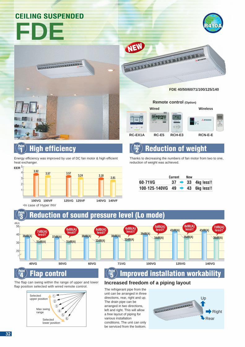
R410A
Energy efficiency was improved by use of DC fan motor & high efficient heat exchanger.
Thanks to decreasing the numbers of fan motor from two to one, reduction of weight was achieved.
Point
1 High efficiency
Point
3 Reduction of sound pressure level (Lo mode)
Point
2 Reduction of weight
FDECEILING SUSPENDED
Wireless
RC-E5RC-EX1A
Wired
RCH-E3
Remote control (Option)
50
40
30
20
dB(A)
40VG
7dB(A)less!!38dB(A)
31dB(A)
50VG
6dB(A)less!!
37dB(A)
31dB(A)
60VG
6dB(A)less!!
38dB(A)32dB(A)
71VG
6dB(A)less!!
38dB(A)32dB(A)
100VG
5dB(A)less!!
39dB(A)34dB(A)
125VG
8dB(A)less!!43dB(A)
35dB(A)
140VG
7dB(A)less!!43dB(A)
36dB(A)
5
4
3
2
1
100VG 100VF
3.923.57
125VG 125VF
3.573.24
140VG 140VF
3.182.81
FDE 40/50/60/71/100/125/140
60·71VG 37 33 4kg less!!NewCurrent
100·125·140VG 49 43 6kg less!!
Point
4 Flap control
Selected upper position
Max swing range
Selected lower position
The flap can swing within the range of upper and lower flap position selected with wired remote control.
OUTDOOR UNIT
SRC • FDC
Height x Width x Depth (mm) 640 x 800(+71) x 290 750 x 880(+88) x 340 1,300 x 970 x 370 1,300 x 970 x 370 1,505 x 970 x 370845 x 970 x 370
model
Chargeless
40~60ZMX 71VNX 100~140VN(S)X 250VSA100~140VN(S) 200VSA
15m 30m 30m
640 x 800(+71) x 290 750 x 880(+88) x 340 845 x 970 x 370
Micro Inverter
FDC
Height x Width x Depth (mm)
model
Chargeless
71VNP 90VNP 100VNP
15m
Standard Inverter
DIMENSIONS (Unit:mm)
model
FDE40,50
FDE60,71
FDE100~140
[ a ]
1022
1272
1572
[ b ]
990
1240
1540
[ c ]
1070
1320
1620
[ d ]
215
215
255
[ e ]
210
210
250
[ f ]
4000
4500
5000
DIMENSIONS TABLE
[ b ]
[ e ]
[ d ]
[ c ]
12.7(1/2”)(Flare)6.35(1/4”)(Flare)
40·50·60VG 71·100·125·140VG15.88(5/8”)(Flare)9.52(3/8”)(Flare)
VP20(M10 or M8)
PE coverPlate cover(Knock out)
[ f ]
[ a ]
EER
NEW
The refrigerant pipe from the unit can be arranged in three directions, rear, right and up. The drain pipe can be arranged in two directions, left and right. This will allow a free layout of piping for various installation conditions. The unit can only be serviced from the bottom.
Increased freedom of a piping layout
Point
5 Improved installation workability
RearRight
Up
RCN-E-E
•In case of Hyper INV
32
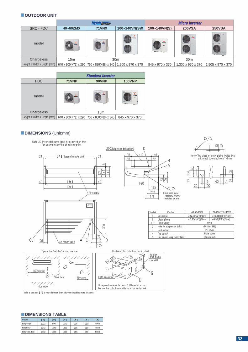
R410A
Energy efficiency was improved by use of DC fan motor & high efficient heat exchanger.
Thanks to decreasing the numbers of fan motor from two to one, reduction of weight was achieved.
Point
1 High efficiency
Point
3 Reduction of sound pressure level (Lo mode)
Point
2 Reduction of weight
FDECEILING SUSPENDED
Wireless
RC-E5RC-EX1A
Wired
RCH-E3
Remote control (Option)
50
40
30
20
dB(A)
40VG
7dB(A)less!!38dB(A)
31dB(A)
50VG
6dB(A)less!!
37dB(A)
31dB(A)
60VG
6dB(A)less!!
38dB(A)32dB(A)
71VG
6dB(A)less!!
38dB(A)32dB(A)
100VG
5dB(A)less!!
39dB(A)34dB(A)
125VG
8dB(A)less!!43dB(A)
35dB(A)
140VG
7dB(A)less!!43dB(A)
36dB(A)
5
4
3
2
1
100VG 100VF
3.923.57
125VG 125VF
3.573.24
140VG 140VF
3.182.81
FDE 40/50/60/71/100/125/140
60·71VG 37 33 4kg less!!NewCurrent
100·125·140VG 49 43 6kg less!!
Point
4 Flap control
Selected upper position
Max swing range
Selected lower position
The flap can swing within the range of upper and lower flap position selected with wired remote control.
OUTDOOR UNIT
SRC • FDC
Height x Width x Depth (mm) 640 x 800(+71) x 290 750 x 880(+88) x 340 1,300 x 970 x 370 1,300 x 970 x 370 1,505 x 970 x 370845 x 970 x 370
model
Chargeless
40~60ZMX 71VNX 100~140VN(S)X 250VSA100~140VN(S) 200VSA
15m 30m 30m
640 x 800(+71) x 290 750 x 880(+88) x 340 845 x 970 x 370
Micro Inverter
FDC
Height x Width x Depth (mm)
model
Chargeless
71VNP 90VNP 100VNP
15m
Standard Inverter
DIMENSIONS (Unit:mm)
model
FDE40,50
FDE60,71
FDE100~140
[ a ]
1022
1272
1572
[ b ]
990
1240
1540
[ c ]
1070
1320
1620
[ d ]
215
215
255
[ e ]
210
210
250
[ f ]
4000
4500
5000
DIMENSIONS TABLE
[ b ]
[ e ]
[ d ]
[ c ]
12.7(1/2”)(Flare)6.35(1/4”)(Flare)
40·50·60VG 71·100·125·140VG15.88(5/8”)(Flare)9.52(3/8”)(Flare)
VP20(M10 or M8)
PE coverPlate cover(Knock out)
[ f ]
[ a ]
EER
NEW
The refrigerant pipe from the unit can be arranged in three directions, rear, right and up. The drain pipe can be arranged in two directions, left and right. This will allow a free layout of piping for various installation conditions. The unit can only be serviced from the bottom.
Increased freedom of a piping layout
Point
5 Improved installation workability
RearRight
Up
RCN-E-E
•In case of Hyper INV
33
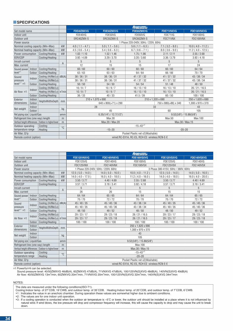
Set model name FDE40ZMXVG FDE50ZMXVG FDE60ZMXVG FDE71VNXVG FDE100VNXVGIndoor unit FDE40VG FDE50VG FDE60VG FDE71VG FDE100VGOutdoor unit SRC40ZMX-S SRC50ZMX-S SRC60ZMX-S FDC71VNX FDC100VNXPower source 1 Phase 220-240V, 50Hz / 220V, 60HzNominal cooling capacity (Min~Max) kW 4.0 ( 1.1 ~ 4.7 ) 5.0 ( 1.1 ~ 5.6 ) 5.6 ( 1.1 ~ 6.3 ) 7.1 ( 3.2 ~ 8.0 ) 10.0 ( 4.0 ~ 11.2 )Nominal heating capacity (Min~Max) kW 4.5 ( 0.6 ~ 5.4 ) 5.4 ( 0.6 ~ 6.3 ) 6.7 ( 0.6 ~ 7.1 ) 8.0 ( 3.6 ~ 9.0 ) 11.2 ( 4.0 ~ 12.5 )Power consumption Cooling/Heating kW 1.02 / 1.10 1.52 / 1.46 1.75 / 1.86 2.11 / 2.11 2.55 / 2.68EER/COP Cooling/Heating 3.92 / 4.09 3.29 / 3.70 3.20 / 3.60 3.36 / 3.79 3.92 / 4.18Inrush current
A5 5 5 5 5
Max. current 12 15 15 17 24Sound power level*1
Indoor Cooling/Heating
dB(A)
60 / 60 60 / 60 60 / 60 60 / 60 64 / 64Outdoor Cooling/Heating 63 / 63 63 / 63 64 / 64 66 / 66 70 / 70
Sound pressure level*1 1
IndoorCooling (Hi/Me/Lo) 38 / 36 / 31 38 / 36 / 31 41 / 37 / 32 41 / 37 / 32 43 / 38 / 34Heating (Hi/Me/Lo) 38 / 36 / 31 38 / 36 / 31 41 / 37 / 32 41 / 37 / 32 43 / 38 / 34
Outdoor Cooling/Heating 50 / 50 54 / 50 54 / 54 51 / 48 48 / 50
Air flow 1Indoor
Cooling (Hi/Me/Lo)m3/min
10 / 9 / 7 10 / 9 / 7 16 / 13 / 10 16 / 13 / 10 26 / 21 / 16.5Heating (Hi/Me/Lo) 10 / 9 / 7 10 / 9 / 7 16 / 13 / 10 16 / 13 / 10 26 / 21 / 16.5
Outdoor Cooling/Heating 36 / 33 40 / 33 41.5 / 39 60 / 50 100 / 100Exterior dimensions
IndoorHeightxWidthxDepth mm
210 x 1,070 x 690 210 x 1,320 x 690 250 x 1,620 x 690Outdoor 640 x 800(+71) x 290 750 x 880(+88) x 340 1,300 x 970 x 370
Net weightIndoor
kg28 33 43
Outdoor 45 60 105Ref.piping size Liquid/Gas ømm 6.35(1/4") / 12.7(1/2") 9.52(3/8") / 15.88(5/8")Refrigerant line (one way) length m Max.30 Max.50 Max.100Vertical height differences Outdoor is higher/lower m Max.20 / Max.20 Max.30 / Max.15Outdoor operating temperature range
Cooling°C
-15~43*3
Heating -15~20 -20~20Air filter, Q'ty Pocket Plastic net x2(Washable)Remote control (option) wired:RC-EX1A, RC-E5, RCH-E3 wireless:RCN-E-E
Set model name FDE125VNXVG FDE140VNXVG FDE100VSXVG FDE125VSXVG FDE140VSXVGIndoor unit FDE125VG FDE140VG FDE100VG FDE125VG FDE140VGOutdoor unit FDC125VNX FDC140VNX FDC100VSX FDC125VSX FDC140VSXPower source 1 Phase 220-240V, 50Hz / 220V, 60Hz 3 Phase 380-415V, 50Hz / 380V, 60HzNominal cooling capacity (Min~Max) kW 12.5 ( 5.0 ~ 14.0 ) 14.0 ( 5.0 ~ 16.0 ) 10.0 ( 4.0 ~ 11.2 ) 12.5 ( 5.0 ~ 14.0 ) 14.0 ( 5.0 ~ 16.0 )Nominal heating capacity (Min~Max) kW 14.0 ( 4.0 ~ 17.0 ) 16.0 ( 4.0 ~ 18.0 ) 11.2 ( 4.0 ~ 16.0 ) 14.0 ( 4.0 ~ 18.0 ) 16.0 ( 4.0 ~ 20.0 ) Power consumption Cooling/Heating kW 3.50 / 3.77 4.40 / 4.69 2.55 / 2.68 3.50 / 3.77 4.40 / 4.69EER/COP Cooling/Heating 3.57 / 3.71 3.18 / 3.41 3.92 / 4.18 3.57 / 3.71 3.18 / 3.41Inrush current
A5 5 5 5 5
Max. current 26 26 15 15 15Sound power level*1
Indoor Cooling/Heating
dB(A)
64 / 64 65 / 65 64 / 64 64 / 64 65 / 65Outdoor Cooling/Heating 70 / 70 72 / 72 70 / 70 70 / 70 72 / 72
Sound pressure level*1 1
IndoorCooling (Hi/Me/Lo) 45 / 40 / 35 45 / 40 / 36 43 / 38 / 34 45 / 40 / 35 45 / 40 / 36Heating (Hi/Me/Lo) 45 / 40 / 35 45 / 40 / 36 43 / 38 / 34 45 / 40 / 35 45 / 40 / 36
Outdoor Cooling/Heating 48 / 50 49 / 52 48 / 50 48 / 50 49 / 52
Air flow 1Indoor
Cooling (Hi/Me/Lo)m3/min
29 / 23 / 17 29 / 23 / 18 26 / 21 / 16.5 29 / 23 / 17 29 / 23 / 18Heating (Hi/Me/Lo) 29 / 23 / 17 29 / 23 / 18 26 / 21 / 16.5 29 / 23 / 17 29 / 23 / 18
Outdoor Cooling/Heating 100 / 100 100 / 100 100 / 100 100 / 100 100 / 100Exterior dimensions
IndoorHeightxWidthxDepth mm
250 x 1,620 x 690Outdoor 1,300 x 970 x 370
Net weightIndoor
kg43
Outdoor 105Ref.piping size Liquid/Gas ømm 9.52(3/8") / 15.88(5/8")Refrigerant line (one way) length m Max.100Vertical height differences Outdoor is higher/lower m Max.30 / Max.15Outdoor operating temperature range
Cooling°C
-15~43*3
Heating -20~20Air filter, Q'ty Pocket Plastic net x2(Washable)Remote control (option) wired:RC-EX1A, RC-E5, RCH-E3 wireless:RCN-E-E
1 Powerful-Hi can be selected. ound pressure level: M G d (A) M G d (A) N G d (A) N( ) G d (A) N( ) G d (A) Air ow: M G m3 min M G m3 min N G m3 min N( ) G m3 min N( ) G m3 min
SPECIFICATIONS
NOTES:he data are measured under the following conditions( O- ).
Cooling: ndoor temp. of C C and outdoor temp. of C . eating: ndoor temp. of C and outdoor temp. of C C .* : ndicates the value in an anechoic cham er. uring operation these values are somewhat higher due to am ient conditions.*2 : The values are for one indoor unit operation.* : f a cooling operation is conducted when the outdoor air temperature is C or lower the outdoor unit should e installed at a place where it is not in uenced y
natural wind. f wind lows the low pressure will drop and compressor fre uency will increase this will cause the capacity to drop and may cause the unit to reak down.
34
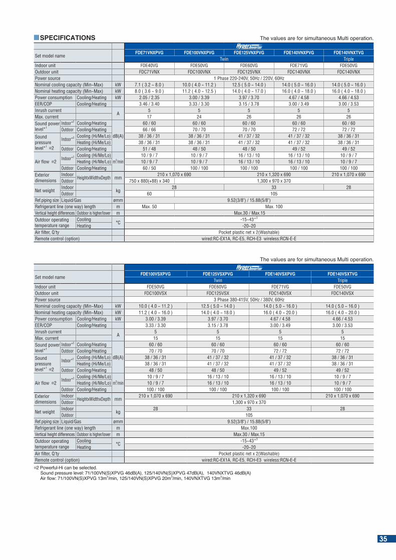
SPECIFICATIONS
Set model nameFDE71VNXPVG FDE100VNXPVG FDE125VNXPVG FDE140VNXPVG FDE140VNXTVG
Twin TripleIndoor unit FDE40VG FDE50VG FDE60VG FDE71VG FDE50VGOutdoor unit FDC71VNX FDC100VNX FDC125VNX FDC140VNX FDC140VNXPower source 1 Phase 220-240V, 50Hz / 220V, 60HzNominal cooling capacity (Min~Max) kW 7.1 ( 3.2 ~ 8.0 ) 10.0 ( 4.0 ~ 11.2 ) 12.5 ( 5.0 ~ 14.0 ) 14.0 ( 5.0 ~ 16.0 ) 14.0 ( 5.0 ~ 16.0 )Nominal heating capacity (Min~Max) kW 8.0 ( 3.6 ~ 9.0 ) 11.2 ( 4.0 ~ 12.5 ) 14.0 ( 4.0 ~ 17.0 ) 16.0 ( 4.0 ~ 18.0 ) 16.0 ( 4.0 ~ 18.0 )Power consumption Cooling/Heating kW 2.05 / 2.35 3.00 / 3.39 3.97 / 3.70 4.67 / 4.58 4.66 / 4.53EER/COP Cooling/Heating 3.46 / 3.40 3.33 / 3.30 3.15 / 3.78 3.00 / 3.49 3.00 / 3.53Inrush current
A5 5 5 5 5
Max. current 17 24 26 26 26Sound power level*1
Indoor*2 Cooling/Heating
dB(A)
60 / 60 60 / 60 60 / 60 60 / 60 60 / 60Outdoor Cooling/Heating 66 / 66 70 / 70 70 / 70 72 / 72 72 / 72
Sound pressure level*1 2
Indoor*2 Cooling (Hi/Me/Lo) 38 / 36 / 31 38 / 36 / 31 41 / 37 / 32 41 / 37 / 32 38 / 36 / 31Heating (Hi/Me/Lo) 38 / 36 / 31 38 / 36 / 31 41 / 37 / 32 41 / 37 / 32 38 / 36 / 31
Outdoor Cooling/Heating 51 / 48 48 / 50 48 / 50 49 / 52 49 / 52
Air flow 2Indoor*2 Cooling (Hi/Me/Lo)
m3/min10 / 9 / 7 10 / 9 / 7 16 / 13 / 10 16 / 13 / 10 10 / 9 / 7
Heating (Hi/Me/Lo) 10 / 9 / 7 10 / 9 / 7 16 / 13 / 10 16 / 13 / 10 10 / 9 / 7Outdoor Cooling/Heating 60 / 50 100 / 100 100 / 100 100 / 100 100 / 100
Exterior dimensions
IndoorHeightxWidthxDepth mm
210 x 1,070 x 690 210 x 1,320 x 690 210 x 1,070 x 690Outdoor 750 x 880(+88) x 340 1,300 x 970 x 370
Net weightIndoor
kg28 33 28
Outdoor 60 105Ref.piping size Liquid/Gas ømm 9.52(3/8") / 15.88(5/8")Refrigerant line (one way) length m Max. 50 Max. 100Vertical height differences Outdoor is higher/lower m Max.30 / Max.15 Outdoor operating temperature range
Cooling°C
-15~43*3
Heating -20~20Air filter, Q'ty Pocket plastic net x 2(Washable)Remote control (option) wired:RC-EX1A, RC-E5, RCH-E3 wireless:RCN-E-E
he values are for simultaneous Multi operation.
Set model nameFDE100VSXPVG FDE125VSXPVG FDE140VSXPVG FDE140VSXTVG
Twin TripleIndoor unit FDE50VG FDE60VG FDE71VG FDE50VGOutdoor unit FDC100VSX FDC125VSX FDC140VSX FDC140VSXPower source 3 Phase 380-415V, 50Hz / 380V, 60HzNominal cooling capacity (Min~Max) kW 10.0 ( 4.0 ~ 11.2 ) 12.5 ( 5.0 ~ 14.0 ) 14.0 ( 5.0 ~ 16.0 ) 14.0 ( 5.0 ~ 16.0 )Nominal heating capacity (Min~Max) kW 11.2 ( 4.0 ~ 16.0 ) 14.0 ( 4.0 ~ 18.0 ) 16.0 ( 4.0 ~ 20.0 ) 16.0 ( 4.0 ~ 20.0 )Power consumption Cooling/Heating kW 3.00 / 3.39 3.97 / 3.70 4.67 / 4.58 4.66 / 4.53EER/COP Cooling/Heating 3.33 / 3.30 3.15 / 3.78 3.00 / 3.49 3.00 / 3.53Inrush current
A5 5 5 5
Max. current 15 15 15 15Sound power level*1
Indoor*2 Cooling/Heating
dB(A)
60 / 60 60 / 60 60 / 60 60 / 60Outdoor Cooling/Heating 70 / 70 70 / 70 72 / 72 72 / 72
Sound pressure level*1 2
Indoor*2 Cooling (Hi/Me/Lo) 38 / 36 / 31 41 / 37 / 32 41 / 37 / 32 38 / 36 / 31Heating (Hi/Me/Lo) 38 / 36 / 31 41 / 37 / 32 41 / 37 / 32 38 / 36 / 31
Outdoor Cooling/Heating 48 / 50 48 / 50 49 / 52 49 / 52
Air flow 2Indoor*2 Cooling (Hi/Me/Lo)
m3/min10 / 9 / 7 16 / 13 / 10 16 / 13 / 10 10 / 9 / 7
Heating (Hi/Me/Lo) 10 / 9 / 7 16 / 13 / 10 16 / 13 / 10 10 / 9 / 7Outdoor Cooling/Heating 100 / 100 100 / 100 100 / 100 100 / 100
Exterior dimensions
IndoorHeightxWidthxDepth mm
210 x 1,070 x 690 210 x 1,320 x 690 210 x 1,070 x 690Outdoor 1,300 x 970 x 370
Net weightIndoor
kg28 33 28
Outdoor 105Ref.piping size Liquid/Gas ømm 9.52(3/8") / 15.88(5/8")Refrigerant line (one way) length m Max.100Vertical height differences Outdoor is higher/lower m Max.30 / Max.15Outdoor operating temperature range
Cooling°C
-15~43*3
Heating -20~20Air filter, Q'ty Pocket plastic net x 2(Washable)Remote control (option) wired:RC-EX1A, RC-E5, RCH-E3 wireless:RCN-E-E
2 Powerful-Hi can be selected. Sound pressure level: 71/100VN(S)XPVG 46dB(A), 125/140VN(S)XPVG 47dB(A), 140VNXTVG 46dB(A) Air ow: N( ) P G m3 min N( ) P G m3 min N G m3 min
he values are for simultaneous Multi operation.
35
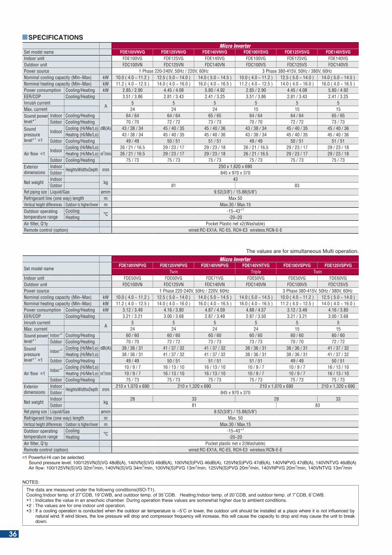
Set model name FDE100VNVG FDE125VNVG FDE140VNVG FDE100VSVG FDE125VSVG FDE140VSVGIndoor unit FDE100VG FDE125VG FDE140VG FDE100VG FDE125VG FDE140VGOutdoor unit FDC100VN FDC125VN FDC140VN FDC100VS FDC125VS FDC140VSPower source 1 Phase 220-240V, 50Hz / 220V, 60Hz 3 Phase 380-415V, 50Hz / 380V, 60HzNominal cooling capacity (Min~Max) kW 10.0 ( 4.0 ~ 11.2 ) 12.5 ( 5.0 ~ 14.0 ) 14.0 ( 5.0 ~ 14.5 ) 10.0 ( 4.0 ~ 11.2 ) 12.5 ( 5.0 ~ 14.0 ) 14.0 ( 5.0 ~ 14.5 )Nominal heating capacity (Min~Max) kW 11.2 ( 4.0 ~ 12.5 ) 14.0 ( 4.0 ~ 16.0 ) 16.0 ( 4.0 ~ 16.5 ) 11.2 ( 4.0 ~ 12.5 ) 14.0 ( 4.0 ~ 16.0 ) 16.0 ( 4.0 ~ 16.5 ) Power consumption Cooling/Heating kW 2.85 / 2.90 4.45 / 4.08 5.80 / 4.92 2.85 / 2.90 4.45 / 4.08 5.80 / 4.92EER/COP Cooling/Heating 3.51 / 3.86 2.81 / 3.43 2.41 / 3.25 3.51 / 3.86 2.81 / 3.43 2.41 / 3.25Inrush current
A5 5 5 5 5 5
Max. current 24 24 24 15 15 15Sound power level*1
Indoor Cooling/Heating
dB(A)
64 / 64 64 / 64 65 / 65 64 / 64 64 / 64 65 / 65Outdoor Cooling/Heating 70 / 70 72 / 72 73 / 73 70 / 70 72 / 72 73 / 73
Sound pressure level*1 1
IndoorCooling (Hi/Me/Lo) 43 / 38 / 34 45 / 40 / 35 45 / 40 / 36 43 / 38 / 34 45 / 40 / 35 45 / 40 / 36Heating (Hi/Me/Lo) 43 / 38 / 34 45 / 40 / 35 45 / 40 / 36 43 / 38 / 34 45 / 40 / 35 45 / 40 / 36
Outdoor Cooling/Heating 49 / 49 50 / 51 51 / 51 49 / 49 50 / 51 51 / 51
Air flow 1Indoor
Cooling (Hi/Me/Lo)m3/min
26 / 21 / 16.5 29 / 23 / 17 29 / 23 / 18 26 / 21 / 16.5 29 / 23 / 17 29 / 23 / 18Heating (Hi/Me/Lo) 26 / 21 / 16.5 29 / 23 / 17 29 / 23 / 18 26 / 21 / 16.5 29 / 23 / 17 29 / 23 / 18
Outdoor Cooling/Heating 75 / 73 75 / 73 75 / 73 75 / 73 75 / 73 75 / 73Exterior dimensions
IndoorHeightxWidthxDepth mm
250 x 1,620 x 690Outdoor 845 x 970 x 370
Net weightIndoor
kg43
Outdoor 81 83Ref.piping size Liquid/Gas ømm 9.52(3/8") / 15.88(5/8")Refrigerant line (one way) length m Max.50Vertical height differences Outdoor is higher/lower m Max.30 / Max.15Outdoor operating temperature range
Cooling°C
-15~43*3
Heating -20~20Air filter, Q'ty Pocket Plastic net x2(Washable)Remote control (option) wired:RC-EX1A, RC-E5, RCH-E3 wireless:RCN-E-E
SPECIFICATIONS
he values are for simultaneous Multi operation.
Set model nameFDE100VNPVG FDE125VNPVG FDE140VNPVG FDE140VNTVG FDE100VSPVG FDE125VSPVG
Twin Triple TwinIndoor unit FDE50VG FDE60VG FDE71VG FDE50VG FDE50VG FDE60VGOutdoor unit FDC100VN FDC125VN FDC140VN FDC140VN FDC100VS FDC125VSPower source 1 Phase 220-240V, 50Hz / 220V, 60Hz 3 Phase 380-415V, 50Hz / 380V, 60HzNominal cooling capacity (Min~Max) kW 10.0 ( 4.0 ~ 11.2 ) 12.5 ( 5.0 ~ 14.0 ) 14.0 ( 5.0 ~ 14.5 ) 14.0 ( 5.0 ~ 14.5 ) 10.0 ( 4.0 ~ 11.2 ) 12.5 ( 5.0 ~ 14.0 )Nominal heating capacity (Min~Max) kW 11.2 ( 4.0 ~ 12.5 ) 14.0 ( 4.0 ~ 16.0 ) 16.0 ( 4.0 ~ 16.5 ) 16.0 ( 4.0 ~ 16.5 ) 11.2 ( 4.0 ~ 12.5 ) 14.0 ( 4.0 ~ 16.0 ) Power consumption Cooling/Heating kW 3.12 / 3.49 4.16 / 3.80 4.87 / 4.59 4.88 / 4.57 3.12 / 3.49 4.16 / 3.80EER/COP Cooling/Heating 3.21 / 3.21 3.00 / 3.68 2.87 / 3.49 2.87 / 3.50 3.21 / 3.21 3.00 / 3.68Inrush current
A5 5 5 5 5 5
Max. current 24 24 24 24 15 15Sound power level*1
Indoor*2 Cooling/Heating
dB(A)
60 / 60 60 / 60 60 / 60 60 / 60 60 / 60 60 / 60Outdoor Cooling/Heating 70 / 70 72 / 72 73 / 73 73 / 73 70 / 70 72 / 72
Sound pressure level*1 1
Indoor*2 Cooling (Hi/Me/Lo) 38 / 36 / 31 41 / 37 / 32 41 / 37 / 32 38 / 36 / 31 38 / 36 / 31 41 / 37 / 32Heating (Hi/Me/Lo) 38 / 36 / 31 41 / 37 / 32 41 / 37 / 32 38 / 36 / 31 38 / 36 / 31 41 / 37 / 32
Outdoor Cooling/Heating 49 / 49 50 / 51 51 / 51 51 / 51 49 / 49 50 / 51
Air flow 1Indoor*2 Cooling (Hi/Me/Lo)
m3/min10 / 9 / 7 16 / 13 / 10 16 / 13 / 10 10 / 9 / 7 10 / 9 / 7 16 / 13 / 10
Heating (Hi/Me/Lo) 10 / 9 / 7 16 / 13 / 10 16 / 13 / 10 10 / 9 / 7 10 / 9 / 7 16 / 13 / 10Outdoor Cooling/Heating 75 / 73 75 / 73 75 / 73 75 / 73 75 / 73 75 / 73
Exterior dimensions
IndoorHeightxWidthxDepth mm
210 x 1,070 x 690 210 x 1,320 x 690 210 x 1,070 x 690 210 x 1,320 x 690Outdoor 845 x 970 x 370
Net weightIndoor
kg28 33 28 33
Outdoor 81 83Ref.piping size Liquid/Gas ømm 9.52(3/8") / 15.88(5/8")Refrigerant line (one way) length m Max. 50Vertical height differences Outdoor is higher/lower m Max.30 / Max.15Outdoor operating temperature range
Cooling°C
-15~43*3
Heating -20~20Air filter, Q'ty Pocket plastic net x 2(Washable)Remote control (option) wired:RC-EX1A, RC-E5, RCH-E3 wireless:RCN-E-E
1 Powerful-Hi can be selected. ound pressure level: N( ) G d (A) N( ) G d (A) N( )P G d (A) N( )P G d (A) NP G d (A) N G d (A) Air ow: N( ) G m3 min N( ) G m3 min N( )P G m3 min N( )P G m3 min NP G m3 min N G m3 min
NOTES:he data are measured under the following conditions( O- ).
Cooling: ndoor temp. of C C and outdoor temp. of C . eating: ndoor temp. of C and outdoor temp. of C C .* : ndicates the value in an anechoic cham er. uring operation these values are somewhat higher due to am ient conditions.*2 : The values are for one indoor unit operation.* : f a cooling operation is conducted when the outdoor air temperature is C or lower the outdoor unit should e installed at a place where it is not in uenced y
natural wind. f wind lows the low pressure will drop and compressor fre uency will increase this will cause the capacity to drop and may cause the unit to reak down.
36
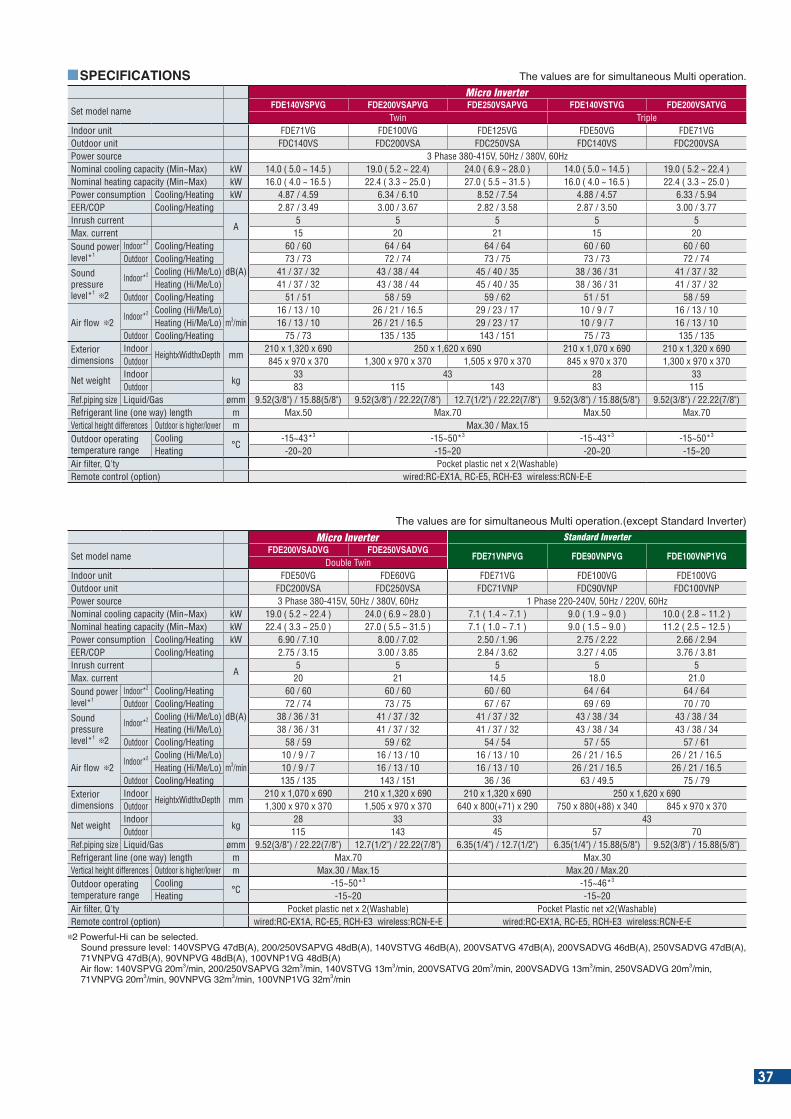
SPECIFICATIONS
Set model nameFDE140VSPVG FDE200VSAPVG FDE250VSAPVG FDE140VSTVG FDE200VSATVG
Twin TripleIndoor unit FDE71VG FDE100VG FDE125VG FDE50VG FDE71VGOutdoor unit FDC140VS FDC200VSA FDC250VSA FDC140VS FDC200VSAPower source 3 Phase 380-415V, 50Hz / 380V, 60HzNominal cooling capacity (Min~Max) kW 14.0 ( 5.0 ~ 14.5 ) 19.0 ( 5.2 ~ 22.4) 24.0 ( 6.9 ~ 28.0 ) 14.0 ( 5.0 ~ 14.5 ) 19.0 ( 5.2 ~ 22.4 )Nominal heating capacity (Min~Max) kW 16.0 ( 4.0 ~ 16.5 ) 22.4 ( 3.3 ~ 25.0 ) 27.0 ( 5.5 ~ 31.5 ) 16.0 ( 4.0 ~ 16.5 ) 22.4 ( 3.3 ~ 25.0 ) Power consumption Cooling/Heating kW 4.87 / 4.59 6.34 / 6.10 8.52 / 7.54 4.88 / 4.57 6.33 / 5.94EER/COP Cooling/Heating 2.87 / 3.49 3.00 / 3.67 2.82 / 3.58 2.87 / 3.50 3.00 / 3.77Inrush current
A5 5 5 5 5
Max. current 15 20 21 15 20Sound power level*1
Indoor*2 Cooling/Heating
dB(A)
60 / 60 64 / 64 64 / 64 60 / 60 60 / 60Outdoor Cooling/Heating 73 / 73 72 / 74 73 / 75 73 / 73 72 / 74
Sound pressure level*1 2
Indoor*2 Cooling (Hi/Me/Lo) 41 / 37 / 32 43 / 38 / 44 45 / 40 / 35 38 / 36 / 31 41 / 37 / 32Heating (Hi/Me/Lo) 41 / 37 / 32 43 / 38 / 44 45 / 40 / 35 38 / 36 / 31 41 / 37 / 32
Outdoor Cooling/Heating 51 / 51 58 / 59 59 / 62 51 / 51 58 / 59
Air flow 2Indoor*2 Cooling (Hi/Me/Lo)
m3/min16 / 13 / 10 26 / 21 / 16.5 29 / 23 / 17 10 / 9 / 7 16 / 13 / 10
Heating (Hi/Me/Lo) 16 / 13 / 10 26 / 21 / 16.5 29 / 23 / 17 10 / 9 / 7 16 / 13 / 10Outdoor Cooling/Heating 75 / 73 135 / 135 143 / 151 75 / 73 135 / 135
Exterior dimensions
IndoorHeightxWidthxDepth mm
210 x 1,320 x 690 250 x 1,620 x 690 210 x 1,070 x 690 210 x 1,320 x 690Outdoor 845 x 970 x 370 1,300 x 970 x 370 1,505 x 970 x 370 845 x 970 x 370 1,300 x 970 x 370
Net weightIndoor
kg33 43 28 33
Outdoor 83 115 143 83 115Ref.piping size Liquid/Gas ømm 9.52(3/8") / 15.88(5/8") 9.52(3/8") / 22.22(7/8") 12.7(1/2") / 22.22(7/8") 9.52(3/8") / 15.88(5/8") 9.52(3/8") / 22.22(7/8")Refrigerant line (one way) length m Max.50 Max.70 Max.50 Max.70Vertical height differences Outdoor is higher/lower m Max.30 / Max.15Outdoor operating temperature range
Cooling°C
-15~43*3 -15~50*3 -15~43*3 -15~50*3
Heating -20~20 -15~20 -20~20 -15~20Air filter, Q'ty Pocket plastic net x 2(Washable)Remote control (option) wired:RC-EX1A, RC-E5, RCH-E3 wireless:RCN-E-E
he values are for simultaneous Multi operation.
he values are for simultaneous Multi operation.(e cept tandard nverter)Standard Inverter
Set model nameFDE200VSADVG FDE250VSADVG
FDE71VNPVG FDE90VNPVG FDE100VNP1VGDouble Twin
Indoor unit FDE50VG FDE60VG FDE71VG FDE100VG FDE100VGOutdoor unit FDC200VSA FDC250VSA FDC71VNP FDC90VNP FDC100VNPPower source 3 Phase 380-415V, 50Hz / 380V, 60Hz 1 Phase 220-240V, 50Hz / 220V, 60HzNominal cooling capacity (Min~Max) kW 19.0 ( 5.2 ~ 22.4 ) 24.0 ( 6.9 ~ 28.0 ) 7.1 ( 1.4 ~ 7.1 ) 9.0 ( 1.9 ~ 9.0 ) 10.0 ( 2.8 ~ 11.2 )Nominal heating capacity (Min~Max) kW 22.4 ( 3.3 ~ 25.0 ) 27.0 ( 5.5 ~ 31.5 ) 7.1 ( 1.0 ~ 7.1 ) 9.0 ( 1.5 ~ 9.0 ) 11.2 ( 2.5 ~ 12.5 )Power consumption Cooling/Heating kW 6.90 / 7.10 8.00 / 7.02 2.50 / 1.96 2.75 / 2.22 2.66 / 2.94EER/COP Cooling/Heating 2.75 / 3.15 3.00 / 3.85 2.84 / 3.62 3.27 / 4.05 3.76 / 3.81Inrush current
A5 5 5 5 5
Max. current 20 21 14.5 18.0 21.0Sound power level*1
Indoor*2 Cooling/Heating
dB(A)
60 / 60 60 / 60 60 / 60 64 / 64 64 / 64Outdoor Cooling/Heating 72 / 74 73 / 75 67 / 67 69 / 69 70 / 70
Sound pressure level*1 2
Indoor*2 Cooling (Hi/Me/Lo) 38 / 36 / 31 41 / 37 / 32 41 / 37 / 32 43 / 38 / 34 43 / 38 / 34Heating (Hi/Me/Lo) 38 / 36 / 31 41 / 37 / 32 41 / 37 / 32 43 / 38 / 34 43 / 38 / 34
Outdoor Cooling/Heating 58 / 59 59 / 62 54 / 54 57 / 55 57 / 61
Air flow 2Indoor*2 Cooling (Hi/Me/Lo)
m3/min10 / 9 / 7 16 / 13 / 10 16 / 13 / 10 26 / 21 / 16.5 26 / 21 / 16.5
Heating (Hi/Me/Lo) 10 / 9 / 7 16 / 13 / 10 16 / 13 / 10 26 / 21 / 16.5 26 / 21 / 16.5Outdoor Cooling/Heating 135 / 135 143 / 151 36 / 36 63 / 49.5 75 / 79
Exterior dimensions
IndoorHeightxWidthxDepth mm
210 x 1,070 x 690 210 x 1,320 x 690 210 x 1,320 x 690 250 x 1,620 x 690Outdoor 1,300 x 970 x 370 1,505 x 970 x 370 640 x 800(+71) x 290 750 x 880(+88) x 340 845 x 970 x 370
Net weightIndoor
kg28 33 33 43
Outdoor 115 143 45 57 70Ref.piping size Liquid/Gas ømm 9.52(3/8") / 22.22(7/8") 12.7(1/2") / 22.22(7/8") 6.35(1/4") / 12.7(1/2") 6.35(1/4") / 15.88(5/8") 9.52(3/8") / 15.88(5/8")Refrigerant line (one way) length m Max.70 Max.30Vertical height differences Outdoor is higher/lower m Max.30 / Max.15 Max.20 / Max.20Outdoor operating temperature range
Cooling°C
-15~50*3 -15~46*3
Heating -15~20 -15~20Air filter, Q'ty Pocket plastic net x 2(Washable) Pocket Plastic net x2(Washable)Remote control (option) wired:RC-EX1A, RC-E5, RCH-E3 wireless:RCN-E-E wired:RC-EX1A, RC-E5, RCH-E3 wireless:RCN-E-E
2 Powerful-Hi can be selected. ound pressure level: P G d (A) AP G d (A) G d (A) A G d (A) A G d (A) A G d (A) NP G d (A) NP G d (A) NP G d (A) Air ow: P G m3 min AP G m3 min G m3 min A G m3 min A G m3 min A G m3 min NP G m3 min NP G m3 min NP G m3 min
37
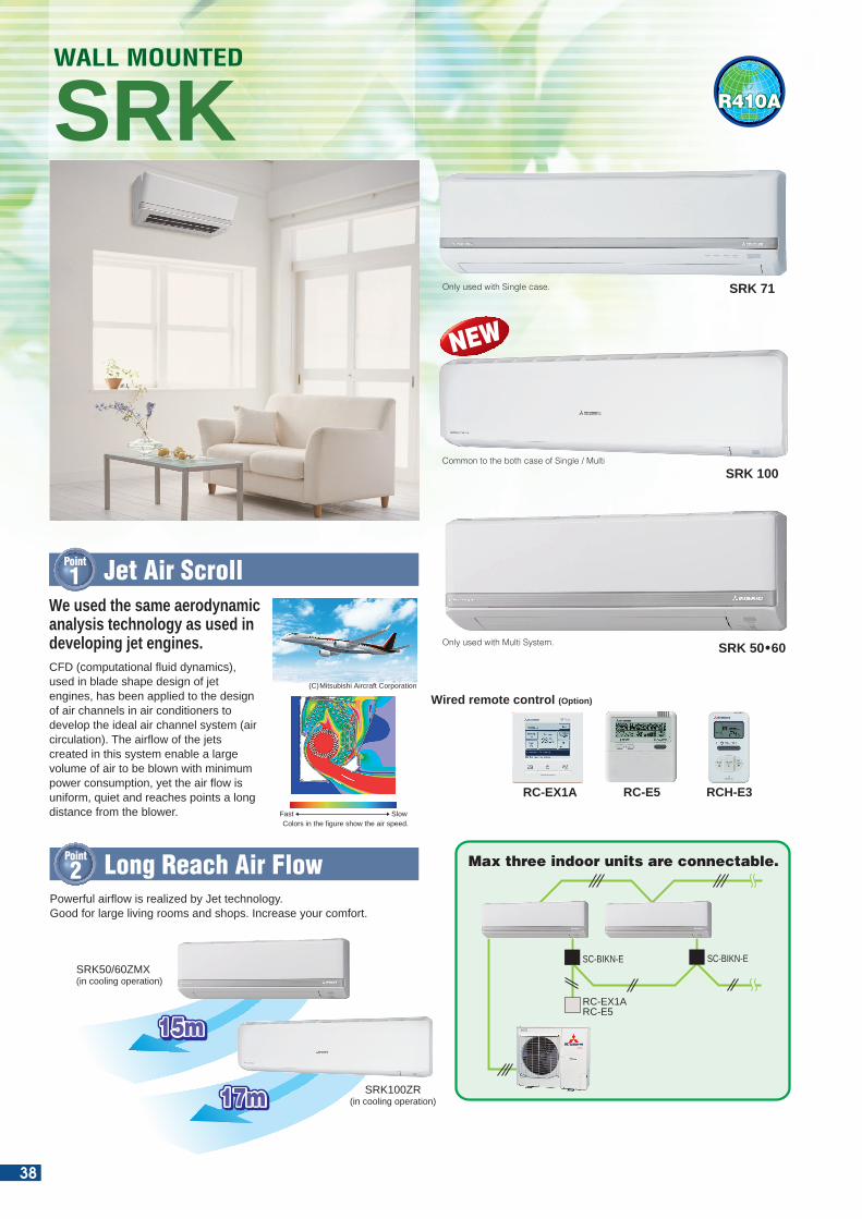
39
38
SRK 50•60
SRK 100
SRK 71
R410A
We used the same aerodynamicanalysis technology as used indeveloping jet engines.
Point
1 Jet Air Scroll
SRKWALL MOUNTED
CFD (computational fluid dynamics), used in blade shape design of jet engines, has been applied to the design of air channels in air conditioners to develop the ideal air channel system (air circulation). The airflow of the jets created in this system enable a large volume of air to be blown with minimum power consumption, yet the air flow is uniform, quiet and reaches points a long distance from the blower.
Powerful airflow is realized by Jet technology.Good for large living rooms and shops. Increase your comfort.
Point
2 Long Reach Air Flow
15m15m15m15m
17m17m17m17m
SRK50/60ZMX(in cooling operation)
SRK100ZR(in cooling operation)
Fast SlowColors in the figure show the air speed.
Max three indoor units are connectable.
SC-BIKN-E
RC-EX1ARC-E5
SC-BIKN-E
890
309
60 21881.9
6026
46.5
61.5
46.5
61.5
220
122.1
3
9
3.1
Piping holeright
(righ
t, le
ft)61
.5
Terminal block
RC-E5
Wired remote control (Option)
RCH-E3RC-EX1A
(C)Mitsubishi Aircraft Corporation
DIMENSIONS (Unit:mm)
OUTDOOR UNIT
FDC
Height x Width x Depth (mm)
model
Chargeless1,300 x 970 x 370 845 x 970 x 370
100~125VN(S)X 100~140VN(S)
30m 30m
Micro Inverter
15m640 x 800(+71) x 290 845 x 970 x 370
71VNP 100VNPStandard Inverter
Outlet for wiring
Outlet for piping
Outlet for piping Outlet for piping
Only used with Single case.
Common to the both case of Single / Multi
Only used with Multi System.
SRK50ZMX-S, 60ZMX-S SRK71ZM-S
SRK100ZR-S
Outlet for wiring
Outlet for piping
NEW
38
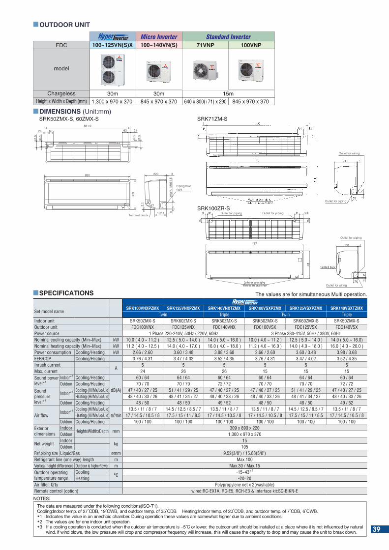
39
38
SRK 50•60
SRK 100
SRK 71
R410A
We used the same aerodynamicanalysis technology as used indeveloping jet engines.
Point
1 Jet Air Scroll
SRKWALL MOUNTED
CFD (computational fluid dynamics), used in blade shape design of jet engines, has been applied to the design of air channels in air conditioners to develop the ideal air channel system (air circulation). The airflow of the jets created in this system enable a large volume of air to be blown with minimum power consumption, yet the air flow is uniform, quiet and reaches points a long distance from the blower.
Powerful airflow is realized by Jet technology.Good for large living rooms and shops. Increase your comfort.
Point
2 Long Reach Air Flow
15m15m15m15m
17m17m17m17m
SRK50/60ZMX(in cooling operation)
SRK100ZR(in cooling operation)
Fast SlowColors in the figure show the air speed.
Max three indoor units are connectable.
SC-BIKN-E
RC-EX1ARC-E5
SC-BIKN-E
890
309
60 21881.9
6026
46.5
61.5
46.5
61.5
220
122.1
39
3.1
Piping holeright
(righ
t, le
ft)61
.5
Terminal block
RC-E5
Wired remote control (Option)
RCH-E3RC-EX1A
(C)Mitsubishi Aircraft Corporation
DIMENSIONS (Unit:mm)
OUTDOOR UNIT
FDC
Height x Width x Depth (mm)
model
Chargeless1,300 x 970 x 370 845 x 970 x 370
100~125VN(S)X 100~140VN(S)
30m 30m
Micro Inverter
15m640 x 800(+71) x 290 845 x 970 x 370
71VNP 100VNPStandard Inverter
Outlet for wiring
Outlet for piping
Outlet for piping Outlet for piping
Only used with Single case.
Common to the both case of Single / Multi
Only used with Multi System.
SRK50ZMX-S, 60ZMX-S SRK71ZM-S
SRK100ZR-S
Outlet for wiring
Outlet for piping
NEW
SPECIFICATIONS
Set model nameSRK100VNXPZMX SRK125VNXPZMX SRK140VNXTZMX SRK100VSXPZMX SRK125VSXPZMX SRK140VSXTZMX
Twin Triple Twin TripleIndoor unit SRK50ZMX-S SRK60ZMX-S SRK50ZMX-S SRK50ZMX-S SRK60ZMX-S SRK50ZMX-SOutdoor unit FDC100VNX FDC125VNX FDC140VNX FDC100VSX FDC125VSX FDC140VSXPower source 1 Phase 220-240V, 50Hz / 220V, 60Hz 3 Phase 380-415V, 50Hz / 380V, 60HzNominal cooling capacity (Min~Max) kW 10.0 ( 4.0 ~ 11.2 ) 12.5 ( 5.0 ~ 14.0 ) 14.0 ( 5.0 ~ 16.0 ) 10.0 ( 4.0 ~ 11.2 ) 12.5 ( 5.0 ~ 14.0 ) 14.0 ( 5.0 ~ 16.0)Nominal heating capacity (Min~Max) kW 11.2 ( 4.0 ~ 12.5 ) 14.0 ( 4.0 ~ 17.0 ) 16.0 ( 4.0 ~ 18.0 ) 11.2 ( 4.0 ~ 16.0 ) 14.0 ( 4.0 ~ 18.0 ) 16.0 ( 4.0 ~ 20.0 ) Power consumption Cooling/Heating kW 2.66 / 2.60 3.60 / 3.48 3.98 / 3.68 2.66 / 2.60 3.60 / 3.48 3.98 / 3.68EER/COP Cooling/Heating 3.76 / 4.31 3.47 / 4.02 3.52 / 4.35 3.76 / 4.31 3.47 / 4.02 3.52 / 4.35Inrush current
A5 5 5 5 5 5
Max. current 24 26 26 15 15 15Sound power level*1
Indoor*2 Cooling/Heating
dB(A)
60 / 64 64 / 64 60 / 64 60 / 64 64 / 64 60 / 64Outdoor Cooling/Heating 70 / 70 70 / 70 72 / 72 70 / 70 70 / 70 72 / 72
Sound pressure level*1
Indoor*2 Cooling (Hi/Me/Lo/Ulo) 47 / 40 / 27 / 25 51 / 41 / 29 / 25 47 / 40 / 27 / 25 47 / 40 / 27 / 25 51 / 41 / 29 / 25 47 / 40 / 27 / 25Heating (Hi/Me/Lo/Ulo) 48 / 40 / 33 / 26 48 / 41 / 34 / 27 48 / 40 / 33 / 26 48 / 40 / 33 / 26 48 / 41 / 34 / 27 48 / 40 / 33 / 26
Outdoor Cooling/Heating 48 / 50 48 / 50 49 / 52 48 / 50 48 / 50 49 / 52
Air flow Indoor*2 Cooling (Hi/Me/Lo/Ulo)
m3/min13.5 / 11 / 8 / 7 14.5 / 12.5 / 8.5 / 7 13.5 / 11 / 8 / 7 13.5 / 11 / 8 / 7 14.5 / 12.5 / 8.5 / 7 13.5 / 11 / 8 / 7
Heating (Hi/Me/Lo/Ulo) 17 / 14.5 / 10.5 / 8 17.5 / 15 / 11 / 8.5 17 / 14.5 / 10.5 / 8 17 / 14.5 / 10.5 / 8 17.5 / 15 / 11 / 8.5 17 / 14.5 / 10.5 / 8Outdoor Cooling/Heating 100 / 100 100 / 100 100 / 100 100 / 100 100 / 100 100 / 100
Exterior dimensions
IndoorHeightxWidthxDepth mm
309 x 890 x 220Outdoor 1,300 x 970 x 370
Net weightIndoor
kg15
Outdoor 105Ref.piping size Liquid/Gas ømm 9.52(3/8") / 15.88(5/8")Refrigerant line (one way) length m Max.100Vertical height differences Outdoor is higher/lower m Max.30 / Max.15Outdoor operating temperature range
Cooling°C
-15~43*3
Heating -20~20Air filter, Q'ty Polypropylene net x 2(washable)Remote control (option) wired:RC-EX1A, RC-E5, RCH-E3 & Interface kit:SC-BIKN-E
he values are for simultaneous Multi operation.
NOTES:he data are measured under the following conditions( O- ).
Cooling: ndoor temp. of C C and outdoor temp. of C . eating: ndoor temp. of C and outdoor temp. of C C . * : ndicates the value in an anechoic cham er. uring operation these values are somewhat higher due to am ient conditions.*2 : The values are for one indoor unit operation.* : f a cooling operation is conducted when the outdoor air temperature is C or lower the outdoor unit should e installed at a place where it is not in uenced y natural
wind. f wind lows the low pressure will drop and compressor fre uency will increase this will cause the capacity to drop and may cause the unit to reak down. 39
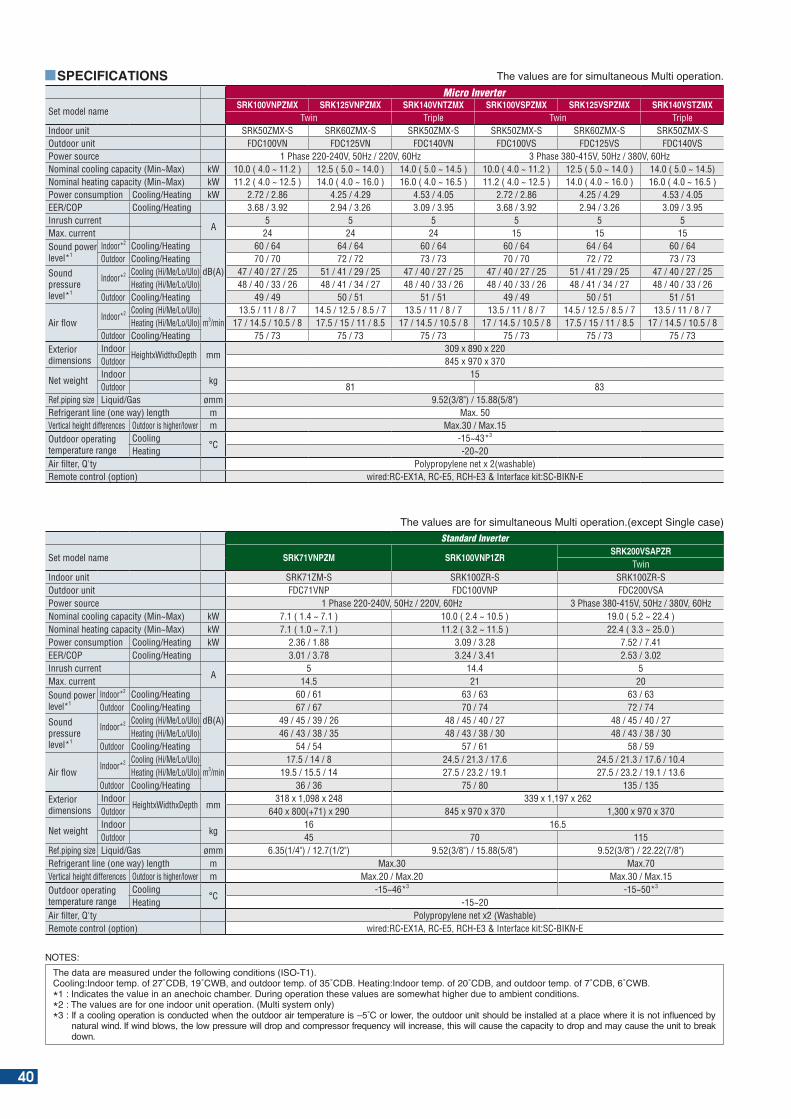
he values are for simultaneous Multi operation.
Set model nameSRK100VNPZMX SRK125VNPZMX SRK140VNTZMX SRK100VSPZMX SRK125VSPZMX SRK140VSTZMX
Twin Triple Twin TripleIndoor unit SRK50ZMX-S SRK60ZMX-S SRK50ZMX-S SRK50ZMX-S SRK60ZMX-S SRK50ZMX-SOutdoor unit FDC100VN FDC125VN FDC140VN FDC100VS FDC125VS FDC140VSPower source 1 Phase 220-240V, 50Hz / 220V, 60Hz 3 Phase 380-415V, 50Hz / 380V, 60HzNominal cooling capacity (Min~Max) kW 10.0 ( 4.0 ~ 11.2 ) 12.5 ( 5.0 ~ 14.0 ) 14.0 ( 5.0 ~ 14.5 ) 10.0 ( 4.0 ~ 11.2 ) 12.5 ( 5.0 ~ 14.0 ) 14.0 ( 5.0 ~ 14.5)Nominal heating capacity (Min~Max) kW 11.2 ( 4.0 ~ 12.5 ) 14.0 ( 4.0 ~ 16.0 ) 16.0 ( 4.0 ~ 16.5 ) 11.2 ( 4.0 ~ 12.5 ) 14.0 ( 4.0 ~ 16.0 ) 16.0 ( 4.0 ~ 16.5 ) Power consumption Cooling/Heating kW 2.72 / 2.86 4.25 / 4.29 4.53 / 4.05 2.72 / 2.86 4.25 / 4.29 4.53 / 4.05EER/COP Cooling/Heating 3.68 / 3.92 2.94 / 3.26 3.09 / 3.95 3.68 / 3.92 2.94 / 3.26 3.09 / 3.95Inrush current
A5 5 5 5 5 5
Max. current 24 24 24 15 15 15Sound power level*1
Indoor*2 Cooling/Heating
dB(A)
60 / 64 64 / 64 60 / 64 60 / 64 64 / 64 60 / 64Outdoor Cooling/Heating 70 / 70 72 / 72 73 / 73 70 / 70 72 / 72 73 / 73
Sound pressure level*1
Indoor*2 Cooling (Hi/Me/Lo/Ulo) 47 / 40 / 27 / 25 51 / 41 / 29 / 25 47 / 40 / 27 / 25 47 / 40 / 27 / 25 51 / 41 / 29 / 25 47 / 40 / 27 / 25Heating (Hi/Me/Lo/Ulo) 48 / 40 / 33 / 26 48 / 41 / 34 / 27 48 / 40 / 33 / 26 48 / 40 / 33 / 26 48 / 41 / 34 / 27 48 / 40 / 33 / 26
Outdoor Cooling/Heating 49 / 49 50 / 51 51 / 51 49 / 49 50 / 51 51 / 51
Air flow Indoor*2 Cooling (Hi/Me/Lo/Ulo)
m3/min13.5 / 11 / 8 / 7 14.5 / 12.5 / 8.5 / 7 13.5 / 11 / 8 / 7 13.5 / 11 / 8 / 7 14.5 / 12.5 / 8.5 / 7 13.5 / 11 / 8 / 7
Heating (Hi/Me/Lo/Ulo) 17 / 14.5 / 10.5 / 8 17.5 / 15 / 11 / 8.5 17 / 14.5 / 10.5 / 8 17 / 14.5 / 10.5 / 8 17.5 / 15 / 11 / 8.5 17 / 14.5 / 10.5 / 8Outdoor Cooling/Heating 75 / 73 75 / 73 75 / 73 75 / 73 75 / 73 75 / 73
Exterior dimensions
IndoorHeightxWidthxDepth mm
309 x 890 x 220Outdoor 845 x 970 x 370
Net weightIndoor
kg15
Outdoor 81 83Ref.piping size Liquid/Gas ømm 9.52(3/8") / 15.88(5/8")Refrigerant line (one way) length m Max. 50Vertical height differences Outdoor is higher/lower m Max.30 / Max.15Outdoor operating temperature range
Cooling°C
-15~43*3
Heating -20~20Air filter, Q'ty Polypropylene net x 2(washable)Remote control (option) wired:RC-EX1A, RC-E5, RCH-E3 & Interface kit:SC-BIKN-E
NOTES:he data are measured under the following conditions ( O- ).
Cooling: ndoor temp. of C C and outdoor temp. of C . eating: ndoor temp. of C and outdoor temp. of C C .* : ndicates the value in an anechoic cham er. uring operation these values are somewhat higher due to am ient conditions.* : he values are for one indoor unit operation. (Multi system only)* : f a cooling operation is conducted when the outdoor air temperature is C or lower the outdoor unit should e installed at a place where it is not in uenced y
natural wind. f wind lows the low pressure will drop and compressor fre uency will increase this will cause the capacity to drop and may cause the unit to reak down.
SPECIFICATIONS
he values are for simultaneous Multi operation.(e cept ingle case)Standard Inverter
Set model name SRK71VNPZM SRK100VNP1ZRSRK200VSAPZR
TwinIndoor unit SRK71ZM-S SRK100ZR-S SRK100ZR-SOutdoor unit FDC71VNP FDC100VNP FDC200VSAPower source 1 Phase 220-240V, 50Hz / 220V, 60Hz 3 Phase 380-415V, 50Hz / 380V, 60HzNominal cooling capacity (Min~Max) kW 7.1 ( 1.4 ~ 7.1 ) 10.0 ( 2.4 ~ 10.5 ) 19.0 ( 5.2 ~ 22.4 )Nominal heating capacity (Min~Max) kW 7.1 ( 1.0 ~ 7.1 ) 11.2 ( 3.2 ~ 11.5 ) 22.4 ( 3.3 ~ 25.0 )Power consumption Cooling/Heating kW 2.36 / 1.88 3.09 / 3.28 7.52 / 7.41EER/COP Cooling/Heating 3.01 / 3.78 3.24 / 3.41 2.53 / 3.02Inrush current
A5 14.4 5
Max. current 14.5 21 20Sound power level*1
Indoor*2 Cooling/Heating
dB(A)
60 / 61 63 / 63 63 / 63Outdoor Cooling/Heating 67 / 67 70 / 74 72 / 74
Sound pressure level*1
Indoor*2 Cooling (Hi/Me/Lo/Ulo) 49 / 45 / 39 / 26 48 / 45 / 40 / 27 48 / 45 / 40 / 27Heating (Hi/Me/Lo/Ulo) 46 / 43 / 38 / 35 48 / 43 / 38 / 30 48 / 43 / 38 / 30
Outdoor Cooling/Heating 54 / 54 57 / 61 58 / 59
Air flow Indoor*2 Cooling (Hi/Me/Lo/Ulo)
m3/min17.5 / 14 / 8 24.5 / 21.3 / 17.6 24.5 / 21.3 / 17.6 / 10.4
Heating (Hi/Me/Lo/Ulo) 19.5 / 15.5 / 14 27.5 / 23.2 / 19.1 27.5 / 23.2 / 19.1 / 13.6Outdoor Cooling/Heating 36 / 36 75 / 80 135 / 135
Exterior dimensions
IndoorHeightxWidthxDepth mm
318 x 1,098 x 248 339 x 1,197 x 262Outdoor 640 x 800(+71) x 290 845 x 970 x 370 1,300 x 970 x 370
Net weightIndoor
kg16 16.5
Outdoor 45 70 115Ref.piping size Liquid/Gas ømm 6.35(1/4") / 12.7(1/2") 9.52(3/8") / 15.88(5/8") 9.52(3/8") / 22.22(7/8")Refrigerant line (one way) length m Max.30 Max.70Vertical height differences Outdoor is higher/lower m Max.20 / Max.20 Max.30 / Max.15Outdoor operating temperature range
Cooling°C
-15~46*3 -15~50*3
Heating -15~20Air filter, Q'ty Polypropylene net x2 (Washable)Remote control (option) wired:RC-EX1A, RC-E5, RCH-E3 & Interface kit:SC-BIKN-E
40
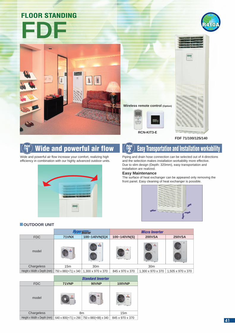
R410A
Piping and drain hose connection can be selected out of 4-directions and the selection makes installation workability more effective.Due to slim design (Depth: 320mm), easy transportation and installation are realized.Easy Maintenance The surface of heat exchanger can be appeared only removing the front panel. Easy cleaning of heat exchanger is possible.
Point
1 Wide and powerful air flow Point
2 Easy Transportation and Installation workability
FDFFLOOR STANDING
Wide and powerful air flow increase your comfort, realizing high efficiency in combination with our highly advanced outdoor units.
RCN-KIT3-E
Wireless remote control (Option)
FDF 71/100/125/140
OUTDOOR UNIT
FDC
Height x Width x Depth (mm) 750 x 880(+71) x 340 1,300 x 970 x 370 1,300 x 970 x 370 1,505 x 970 x 370845 x 970 x 370
model
Chargeless
71VNX 100~140VN(S)X 250VSA100~140VN(S) 200VSA
15m 30m 30m
640 x 800(+71) x 290 750 x 880(+88) x 340 845 x 970 x 370
Micro Inverter
FDC
Height x Width x Depth (mm)
model
Chargeless
71VNP 90VNP 100VNP
8m 15m
Standard Inverter
41
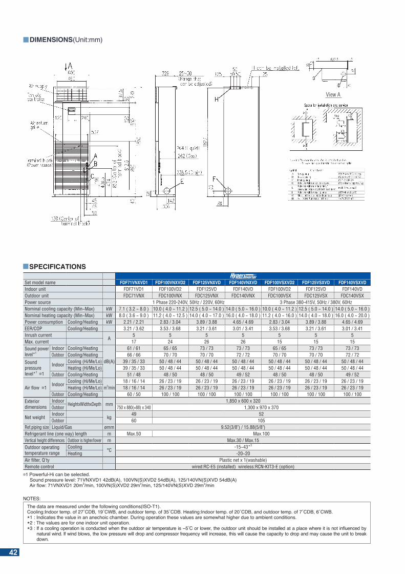
View A
DIMENSIONS(Unit:mm)
Set model name FDF71VNXVD1 FDF100VNXVD2 FDF125VNXVD FDF140VNXVD FDF100VSXVD2 FDF125VSXVD FDF140VSXVDIndoor unit FDF71VD1 FDF100VD2 FDF125VD FDF140VD FDF100VD2 FDF125VD FDF140VDOutdoor unit FDC71VNX FDC100VNX FDC125VNX FDC140VNX FDC100VSX FDC125VSX FDC140VSXPower source 1 Phase 220-240V, 50Hz / 220V, 60Hz 3 Phase 380-415V, 50Hz / 380V, 60HzNominal cooling capacity (Min~Max) kW 7.1 ( 3.2 ~ 8.0 ) 10.0 ( 4.0 ~ 11.2 ) 12.5 ( 5.0 ~ 14.0 ) 14.0 ( 5.0 ~ 16.0 ) 10.0 ( 4.0 ~ 11.2 ) 12.5 ( 5.0 ~ 14.0 ) 14.0 ( 5.0 ~ 16.0 )Nominal heating capacity (Min~Max) kW 8.0 ( 3.6 ~ 9.0 ) 11.2 ( 4.0 ~ 12.5 ) 14.0 ( 4.0 ~ 17.0 ) 16.0 ( 4.0 ~ 18.0 ) 11.2 ( 4.0 ~ 16.0 ) 14.0 ( 4.0 ~ 18.0 ) 16.0 ( 4.0 ~ 20.0 ) Power consumption Cooling/Heating kW 2.21 / 2.21 2.83 / 3.04 3.89 / 3.88 4.65 / 4.69 2.83 / 3.04 3.89 / 3.88 4.65 / 4.69EER/COP Cooling/Heating 3.21 / 3.62 3.53 / 3.68 3.21 / 3.61 3.01 / 3.41 3.53 / 3.68 3.21 / 3.61 3.01 / 3.41Inrush current
A5 5 5 5 5 5 5
Max. current 17 24 26 26 15 15 15Sound power level*1
Indoor Cooling/Heating
dB(A)
61 / 61 65 / 65 73 / 73 73 / 73 65 / 65 73 / 73 73 / 73Outdoor Cooling/Heating 66 / 66 70 / 70 70 / 70 72 / 72 70 / 70 70 / 70 72 / 72
Sound pressure level*1 1
IndoorCooling (Hi/Me/Lo) 39 / 35 / 33 50 / 48 / 44 50 / 48 / 44 50 / 48 / 44 50 / 48 / 44 50 / 48 / 44 50 / 48 / 44Heating (Hi/Me/Lo) 39 / 35 / 33 50 / 48 / 44 50 / 48 / 44 50 / 48 / 44 50 / 48 / 44 50 / 48 / 44 50 / 48 / 44
Outdoor Cooling/Heating 51 / 48 48 / 50 48 / 50 49 / 52 48 / 50 48 / 50 49 / 52
Air flow 1Indoor
Cooling (Hi/Me/Lo)m3/min
18 / 16 / 14 26 / 23 / 19 26 / 23 / 19 26 / 23 / 19 26 / 23 / 19 26 / 23 / 19 26 / 23 / 19Heating (Hi/Me/Lo) 18 / 16 / 14 26 / 23 / 19 26 / 23 / 19 26 / 23 / 19 26 / 23 / 19 26 / 23 / 19 26 / 23 / 19
Outdoor Cooling/Heating 60 / 50 100 / 100 100 / 100 100 / 100 100 / 100 100 / 100 100 / 100Exterior dimensions
IndoorHeightxWidthxDepth mm
1,850 x 600 x 320Outdoor 750 x 880(+88) x 340 1,300 x 970 x 370
Net weightIndoor
kg49 52
Outdoor 60 105Ref.piping size Liquid/Gas ømm 9.52(3/8") / 15.88(5/8")Refrigerant line (one way) length m Max.50 Max.100Vertical height differences Outdoor is higher/lower m Max.30 / Max.15Outdoor operating temperature range
Cooling°C
-15~43*3
Heating -20~20Air filter, Q'ty Plastic net x 1(washable)Remote control wired:RC-E5 (installed) wireless:RCN-KIT3-E (option)
1 Powerful-Hi can be selected. ound pressure level: N d (A) N( ) d (A) N( ) d (A) Air ow: N m3 min N( ) m3 min N( ) m3 min
SPECIFICATIONS
NOTES:he data are measured under the following conditions( O- ).
Cooling: ndoor temp. of C C and outdoor temp. of C . eating: ndoor temp. of C and outdoor temp. of C C .* : ndicates the value in an anechoic cham er. uring operation these values are somewhat higher due to am ient conditions.*2 : The values are for one indoor unit operation.* : f a cooling operation is conducted when the outdoor air temperature is C or lower the outdoor unit should e installed at a place where it is not in uenced y
natural wind. f wind lows the low pressure will drop and compressor fre uency will increase this will cause the capacity to drop and may cause the unit to reak down.
42
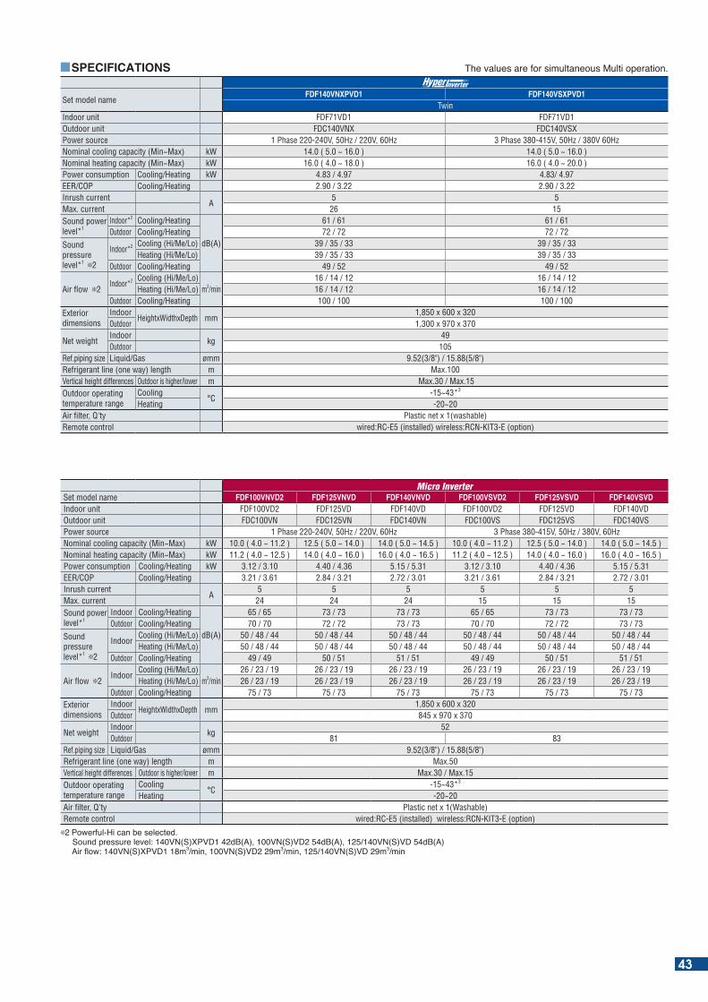
Set model nameFDF140VNXPVD1 FDF140VSXPVD1
TwinIndoor unit FDF71VD1 FDF71VD1Outdoor unit FDC140VNX FDC140VSXPower source 1 Phase 220-240V, 50Hz / 220V, 60Hz 3 Phase 380-415V, 50Hz / 380V 60HzNominal cooling capacity (Min~Max) kW 14.0 ( 5.0 ~ 16.0 ) 14.0 ( 5.0 ~ 16.0 )Nominal heating capacity (Min~Max) kW 16.0 ( 4.0 ~ 18.0 ) 16.0 ( 4.0 ~ 20.0 ) Power consumption Cooling/Heating kW 4.83 / 4.97 4.83/ 4.97EER/COP Cooling/Heating 2.90 / 3.22 2.90 / 3.22Inrush current
A5 5
Max. current 26 15Sound power level*1
Indoor*2 Cooling/Heating
dB(A)
61 / 61 61 / 61Outdoor Cooling/Heating 72 / 72 72 / 72
Sound pressure level*1 2
Indoor*2 Cooling (Hi/Me/Lo) 39 / 35 / 33 39 / 35 / 33Heating (Hi/Me/Lo) 39 / 35 / 33 39 / 35 / 33
Outdoor Cooling/Heating 49 / 52 49 / 52
Air flow 2Indoor*2 Cooling (Hi/Me/Lo)
m3/min16 / 14 / 12 16 / 14 / 12
Heating (Hi/Me/Lo) 16 / 14 / 12 16 / 14 / 12Outdoor Cooling/Heating 100 / 100 100 / 100
Exterior dimensions
IndoorHeightxWidthxDepth mm
1,850 x 600 x 320Outdoor 1,300 x 970 x 370
Net weightIndoor
kg49
Outdoor 105Ref.piping size Liquid/Gas ømm 9.52(3/8") / 15.88(5/8")Refrigerant line (one way) length m Max.100Vertical height differences Outdoor is higher/lower m Max.30 / Max.15 Outdoor operating temperature range
Cooling°C
-15~43*3
Heating -20~20Air filter, Q'ty Plastic net x 1(washable)Remote control wired:RC-E5 (installed) wireless:RCN-KIT3-E (option)
SPECIFICATIONS he values are for simultaneous Multi operation.
Set model name FDF100VNVD2 FDF125VNVD FDF140VNVD FDF100VSVD2 FDF125VSVD FDF140VSVDIndoor unit FDF100VD2 FDF125VD FDF140VD FDF100VD2 FDF125VD FDF140VDOutdoor unit FDC100VN FDC125VN FDC140VN FDC100VS FDC125VS FDC140VSPower source 1 Phase 220-240V, 50Hz / 220V, 60Hz 3 Phase 380-415V, 50Hz / 380V, 60HzNominal cooling capacity (Min~Max) kW 10.0 ( 4.0 ~ 11.2 ) 12.5 ( 5.0 ~ 14.0 ) 14.0 ( 5.0 ~ 14.5 ) 10.0 ( 4.0 ~ 11.2 ) 12.5 ( 5.0 ~ 14.0 ) 14.0 ( 5.0 ~ 14.5 )Nominal heating capacity (Min~Max) kW 11.2 ( 4.0 ~ 12.5 ) 14.0 ( 4.0 ~ 16.0 ) 16.0 ( 4.0 ~ 16.5 ) 11.2 ( 4.0 ~ 12.5 ) 14.0 ( 4.0 ~ 16.0 ) 16.0 ( 4.0 ~ 16.5 ) Power consumption Cooling/Heating kW 3.12 / 3.10 4.40 / 4.36 5.15 / 5.31 3.12 / 3.10 4.40 / 4.36 5.15 / 5.31EER/COP Cooling/Heating 3.21 / 3.61 2.84 / 3.21 2.72 / 3.01 3.21 / 3.61 2.84 / 3.21 2.72 / 3.01Inrush current
A5 5 5 5 5 5
Max. current 24 24 24 15 15 15Sound power level*1
Indoor Cooling/Heating
dB(A)
65 / 65 73 / 73 73 / 73 65 / 65 73 / 73 73 / 73Outdoor Cooling/Heating 70 / 70 72 / 72 73 / 73 70 / 70 72 / 72 73 / 73
Sound pressure level*1 2
IndoorCooling (Hi/Me/Lo) 50 / 48 / 44 50 / 48 / 44 50 / 48 / 44 50 / 48 / 44 50 / 48 / 44 50 / 48 / 44Heating (Hi/Me/Lo) 50 / 48 / 44 50 / 48 / 44 50 / 48 / 44 50 / 48 / 44 50 / 48 / 44 50 / 48 / 44
Outdoor Cooling/Heating 49 / 49 50 / 51 51 / 51 49 / 49 50 / 51 51 / 51
Air flow 2Indoor
Cooling (Hi/Me/Lo)m3/min
26 / 23 / 19 26 / 23 / 19 26 / 23 / 19 26 / 23 / 19 26 / 23 / 19 26 / 23 / 19Heating (Hi/Me/Lo) 26 / 23 / 19 26 / 23 / 19 26 / 23 / 19 26 / 23 / 19 26 / 23 / 19 26 / 23 / 19
Outdoor Cooling/Heating 75 / 73 75 / 73 75 / 73 75 / 73 75 / 73 75 / 73Exterior dimensions
IndoorHeightxWidthxDepth mm
1,850 x 600 x 320Outdoor 845 x 970 x 370
Net weightIndoor
kg52
Outdoor 81 83Ref.piping size Liquid/Gas ømm 9.52(3/8") / 15.88(5/8")Refrigerant line (one way) length m Max.50Vertical height differences Outdoor is higher/lower m Max.30 / Max.15Outdoor operating temperature range
Cooling°C
-15~43*3
Heating -20~20Air filter, Q'ty Plastic net x 1(Washable)Remote control wired:RC-E5 (installed) wireless:RCN-KIT3-E (option)
2 Powerful-Hi can be selected. ound pressure level: N( ) P d (A) N( ) d (A) N( ) d (A) Air ow: N( ) P m3 min N( ) m3 min N( ) m3 min
43
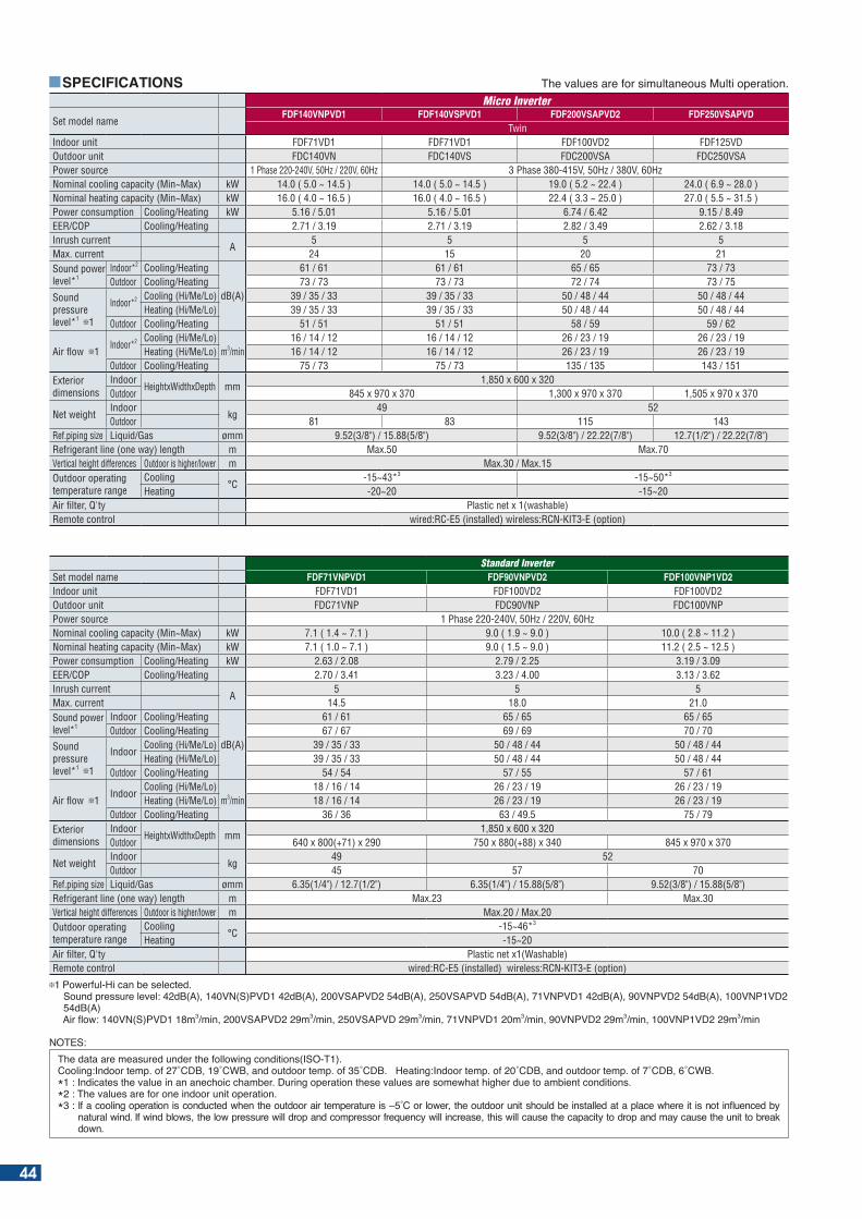
Set model nameFDF140VNPVD1 FDF140VSPVD1 FDF200VSAPVD2 FDF250VSAPVD
TwinIndoor unit FDF71VD1 FDF71VD1 FDF100VD2 FDF125VDOutdoor unit FDC140VN FDC140VS FDC200VSA FDC250VSAPower source 1 Phase 220-240V, 50Hz / 220V, 60Hz 3 Phase 380-415V, 50Hz / 380V, 60HzNominal cooling capacity (Min~Max) kW 14.0 ( 5.0 ~ 14.5 ) 14.0 ( 5.0 ~ 14.5 ) 19.0 ( 5.2 ~ 22.4 ) 24.0 ( 6.9 ~ 28.0 )Nominal heating capacity (Min~Max) kW 16.0 ( 4.0 ~ 16.5 ) 16.0 ( 4.0 ~ 16.5 ) 22.4 ( 3.3 ~ 25.0 ) 27.0 ( 5.5 ~ 31.5 ) Power consumption Cooling/Heating kW 5.16 / 5.01 5.16 / 5.01 6.74 / 6.42 9.15 / 8.49EER/COP Cooling/Heating 2.71 / 3.19 2.71 / 3.19 2.82 / 3.49 2.62 / 3.18Inrush current
A5 5 5 5
Max. current 24 15 20 21Sound power level*1
Indoor*2 Cooling/Heating
dB(A)
61 / 61 61 / 61 65 / 65 73 / 73Outdoor Cooling/Heating 73 / 73 73 / 73 72 / 74 73 / 75
Sound pressure level*1 1
Indoor*2 Cooling (Hi/Me/Lo) 39 / 35 / 33 39 / 35 / 33 50 / 48 / 44 50 / 48 / 44Heating (Hi/Me/Lo) 39 / 35 / 33 39 / 35 / 33 50 / 48 / 44 50 / 48 / 44
Outdoor Cooling/Heating 51 / 51 51 / 51 58 / 59 59 / 62
Air flow 1Indoor*2 Cooling (Hi/Me/Lo)
m3/min16 / 14 / 12 16 / 14 / 12 26 / 23 / 19 26 / 23 / 19
Heating (Hi/Me/Lo) 16 / 14 / 12 16 / 14 / 12 26 / 23 / 19 26 / 23 / 19Outdoor Cooling/Heating 75 / 73 75 / 73 135 / 135 143 / 151
Exterior dimensions
IndoorHeightxWidthxDepth mm
1,850 x 600 x 320Outdoor 845 x 970 x 370 1,300 x 970 x 370 1,505 x 970 x 370
Net weightIndoor
kg49 52
Outdoor 81 83 115 143Ref.piping size Liquid/Gas ømm 9.52(3/8") / 15.88(5/8") 9.52(3/8") / 22.22(7/8") 12.7(1/2") / 22.22(7/8")Refrigerant line (one way) length m Max.50 Max.70Vertical height differences Outdoor is higher/lower m Max.30 / Max.15Outdoor operating temperature range
Cooling°C
-15~43*3 -15~50*3
Heating -20~20 -15~20Air filter, Q'ty Plastic net x 1(washable)Remote control wired:RC-E5 (installed) wireless:RCN-KIT3-E (option)
SPECIFICATIONS he values are for simultaneous Multi operation.
Standard InverterSet model name FDF71VNPVD1 FDF90VNPVD2 FDF100VNP1VD2Indoor unit FDF71VD1 FDF100VD2 FDF100VD2Outdoor unit FDC71VNP FDC90VNP FDC100VNPPower source 1 Phase 220-240V, 50Hz / 220V, 60HzNominal cooling capacity (Min~Max) kW 7.1 ( 1.4 ~ 7.1 ) 9.0 ( 1.9 ~ 9.0 ) 10.0 ( 2.8 ~ 11.2 )Nominal heating capacity (Min~Max) kW 7.1 ( 1.0 ~ 7.1 ) 9.0 ( 1.5 ~ 9.0 ) 11.2 ( 2.5 ~ 12.5 )Power consumption Cooling/Heating kW 2.63 / 2.08 2.79 / 2.25 3.19 / 3.09EER/COP Cooling/Heating 2.70 / 3.41 3.23 / 4.00 3.13 / 3.62Inrush current
A5 5 5
Max. current 14.5 18.0 21.0Sound power level*1
Indoor Cooling/Heating
dB(A)
61 / 61 65 / 65 65 / 65Outdoor Cooling/Heating 67 / 67 69 / 69 70 / 70
Sound pressure level*1 1
IndoorCooling (Hi/Me/Lo) 39 / 35 / 33 50 / 48 / 44 50 / 48 / 44Heating (Hi/Me/Lo) 39 / 35 / 33 50 / 48 / 44 50 / 48 / 44
Outdoor Cooling/Heating 54 / 54 57 / 55 57 / 61
Air flow 1Indoor
Cooling (Hi/Me/Lo)m3/min
18 / 16 / 14 26 / 23 / 19 26 / 23 / 19Heating (Hi/Me/Lo) 18 / 16 / 14 26 / 23 / 19 26 / 23 / 19
Outdoor Cooling/Heating 36 / 36 63 / 49.5 75 / 79Exterior dimensions
IndoorHeightxWidthxDepth mm
1,850 x 600 x 320Outdoor 640 x 800(+71) x 290 750 x 880(+88) x 340 845 x 970 x 370
Net weightIndoor
kg49 52
Outdoor 45 57 70Ref.piping size Liquid/Gas ømm 6.35(1/4") / 12.7(1/2") 6.35(1/4") / 15.88(5/8") 9.52(3/8") / 15.88(5/8")Refrigerant line (one way) length m Max.23 Max.30Vertical height differences Outdoor is higher/lower m Max.20 / Max.20Outdoor operating temperature range
Cooling°C
-15~46*3
Heating -15~20Air filter, Q'ty Plastic net x1(Washable)Remote control wired:RC-E5 (installed) wireless:RCN-KIT3-E (option)
1 Powerful-Hi can be selected. ound pressure level: d (A) N( )P d (A) AP d (A) AP d (A) NP d (A) NP d (A) NP 54dB(A) Air ow: N( )P m3 min AP m3 min AP m3 min NP m3 min NP m3 min NP m3 min
NOTES:he data are measured under the following conditions( O- ).
Cooling: ndoor temp. of C C and outdoor temp. of C . eating: ndoor temp. of C and outdoor temp. of C C .* : ndicates the value in an anechoic cham er. uring operation these values are somewhat higher due to am ient conditions.*2 : The values are for one indoor unit operation.* : f a cooling operation is conducted when the outdoor air temperature is C or lower the outdoor unit should e installed at a place where it is not in uenced y
natural wind. f wind lows the low pressure will drop and compressor fre uency will increase this will cause the capacity to drop and may cause the unit to reak down.
44
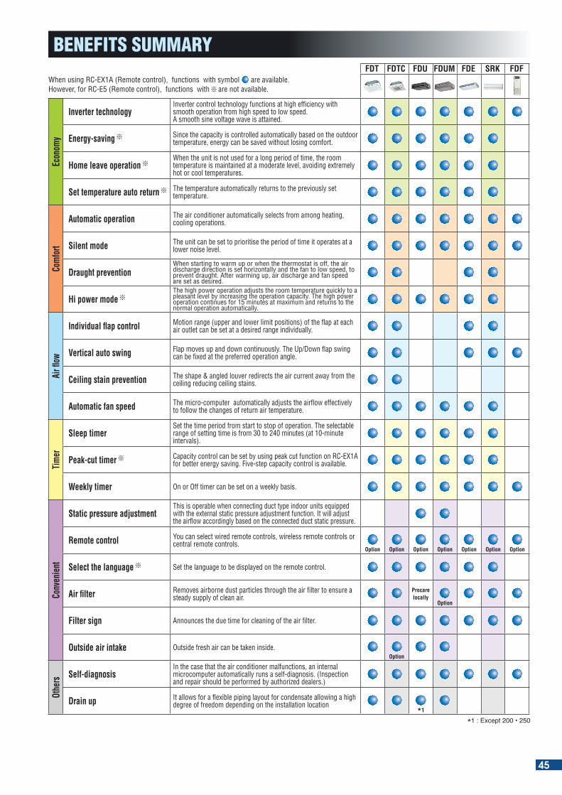
When using RC-EX1A (Remote control), functions with symbol are available.However, for RC-E5 (Remote control), functions with are not available.
FDT FDTC FDU FDUM FDE SRK FDF
Econ
omy
Inverter technologyInverter control technology functions at high efficiency with smooth operation from high speed to low speed. A smooth sine voltage wave is attained.
Energy-saving Since the capacity is controlled automatically based on the outdoor temperature, energy can be saved without losing comfort.
Home leave operation When the unit is not used for a long period of time, the room temperature is maintained at a moderate level, avoiding extremely hot or cool temperatures.
Set temperature auto return The temperature automatically returns to the previously set temperature.
Com
fort
Automatic operation The air conditioner automatically selects from among heating, cooling operations.
Silent mode The unit can be set to prioritise the period of time it operates at a lower noise level.
Draught preventionWhen starting to warm up or when the thermostat is off, the air discharge direction is set horizontally and the fan to low speed, to prevent draught. After warming up, air discharge and fan speed are set as desired.
Hi power mode The high power operation adjusts the room temperature quickly to a pleasant level by increasing the operation capacity. The high power operation continues for 15 minutes at maximum and returns to the normal operation automatically.
Air fl
ow
Individual flap control Motion range (upper and lower limit positions) of the flap at each air outlet can be set at a desired range individually.
Vertical auto swing Flap moves up and down continuously. The Up/Down flap swing can be fixed at the preferred operation angle.
Ceiling stain prevention The shape & angled louver redirects the air current away from the ceiling reducing ceiling stains.
Automatic fan speed The micro-computer automatically adjusts the airflow effectively to follow the changes of return air temperature.
Tim
er
Sleep timerSet the time period from start to stop of operation. The selectable range of setting time is from 30 to 240 minutes (at 10-minute intervals).
Peak-cut timer Capacity control can be set by using peak cut function on RC-EX1A for better energy saving. Five-step capacity control is available.
Weekly timer On or Off timer can be set on a weekly basis.
Conv
enie
nt
Static pressure adjustmentThis is operable when connecting duct type indoor units equipped with the external static pressure adjustment function. It will adjust the airflow accordingly based on the connected duct static pressure.
Remote control You can select wired remote controls, wireless remote controls or central remote controls.
Option Option Option Option Option Option Option
Select the language Set the language to be displayed on the remote control.
Air filter Removes airborne dust particles through the air filter to ensure a steady supply of clean air.
Procare locally
Option
Filter sign Announces the due time for cleaning of the air filter.
Outside air intake Outside fresh air can be taken inside.Option
Othe
rs Self-diagnosisIn the case that the air conditioner malfunctions, an internal microcomputer automatically runs a self-diagnosis. (Inspection and repair should be performed by authorized dealers.)
Drain up It allows for a flexible piping layout for condensate allowing a high degree of freedom depending on the installation location
*1
* : E cept
BENEFITS SUMMARY
45
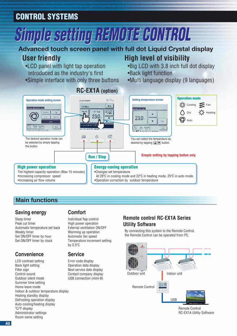
Simple setting by tapping button only
Operation mode setting screen
The desired operation mode can be selected by simply tapping this button.
Setting temperature screen
Sleep timerPeak cut timerAutomatic temperature set backWeekly timerSet ON/OFF timer by hourSet ON/OFF timer by clock
Saving energyIndividual flap controlHigh power operationExternal ventilation ON/OFFWarming up operationAutomatic fan speed Temperature increment setting by 0.5ºC
Comfort
By connecting this system to the Remote Control, the Remote Control can be operated from PC.
Remote control RC-EX1A Series Utility Software
LCD contrast settingBack light settingFilter signControl soundOutdoor silent modeSummer time settingHome leave modeIndoor & outdoor temperature displayHeating standby displayDefrosting operation displayAuto cooling/heating displayºC/ºF displayAdministrator settingsRoom name setting
ConvenienceError code displayOperation data displayNext service date displayContact company displayUSB connection (mini-B)
Service
Operation mode
Cooling
Dry
Auto
Fan
Heating
The highest capacity operation (Max 15 minutes)•Increasing compressor� speed •Increasing air flow volume
High power operation
Run / Stop
•Changes set temperature. At 28ºC in cooling mode and 22ºC in heating mode, 25ºC in auto mode. •Operation correction by outdoor temperature
Energy-saving operation
You can select the temperature as desired by tapping button.
Outdoor unit
Remote Control
Indoor unit
USB
Remote Control RC-EX1A Utility Software
Main functions
Simple setting REMOTE CONTROL Simple setting REMOTE CONTROL Advanced touch screen panel with full dot Liquid Crystal display
User friendly
RC-EX1A (option)
•LCD panel with light tap operation introduced as the industry's first•Simple interface with only three buttons
High level of visibility•Big LCD with 3.8 inch full dot display•Back light function•Multi language display (9 languages)
CONTROL SYSTEMS
46
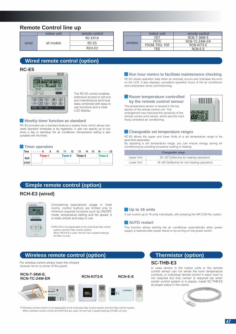
indoor unit remote control
wired all models RC-E5RCH-E3
RC-EX1A
Wired remote control (option)
RC-E5 stores operation data when an anomaly occurs and indicates the error on the LCD. It also displays cumulative operation hours of the air conditioner and compressor since commissioning.
Run hour meters to facilitate maintenance checking
RC-E5 provides (as a standard feature) a weekly timer, which allows one-week operation schedules to be registered. A user can specify up to four times a day to start/stop the air conditioner. (Temperature setting is also possible with the timer).
Weekly timer function as standard
Room temperature controlled by the remote control sensor
RC-E5
Simple remote control (option)
It can control up to 16 units individually, with pressing the AIR CON No. button.Up to 16 units
This function allows starting the air conditioner automatically when power supply is restored after power failure or by turning on the power switch.
AUTO restart
RCH-E3 (wired)
Considering specialized usage in hotel rooms, control buttons are limited only to minimum required functions such as ON/OFF, mode, temperature setting and fan speed. It is really simple and easy to use.
RCH-E3 is not applicable to the Individual flap control system and the Flap control system. When RCH-E3 is used, the fan has 3 speed settings (Hi-Me-Lo) only.
Wireless remote control is not applicable to the Individual flap control system and the Flap control system. When wireless remote control and RCH-E3 are used, the fan has 3 speed settings (Hi-Me-Lo) only.
RCN-T-36W-E,RCN-TC-24W-ER RCN-KIT3-E
For wireless control simply insert the infraredreceiver kit on a corner of the panel.
SC-THB-E3In case sensor in the indoor units or the remotecontrol sensor can not sense the room temperaturecorrectly, or individual remote control in each room is not required but only censor is required (as when center control system is in place), install SC-THB-E3 at proper place in the rooms.
The RC-E5 control enables extensive access to service and maintenance technical data combined with easy to use functions and a clear LCD display.
Remote Control line upindoor unit remote control
wireless RCN-TC-24W-ERRCN-T-36W-E
FDTCFDT
RCN-KIT3-EFDUM, FDU, FDFRCN-E-EFDE
The temperature sensor is housed in the top section of the remote control unit. This arrangement has improved the sensitivity of the remote control unit’s sensor, which permits more finely controlled air conditioning.
Changeable range
Upper limit 20~30˚C(effective for heating operation)
Lower limit 18~26˚C(effective for non-heating operation)
RC-E5 allows the upper and lower limits of a set temperature range to be specified separately.By adjusting a set temperature range, you can ensure energy saving air conditioning by avoiding excessive cooling or heating.
Changeable set temperature ranges
Timer operation
Wireless remote control (option) Thermistor (option)
RCN-E-E
47
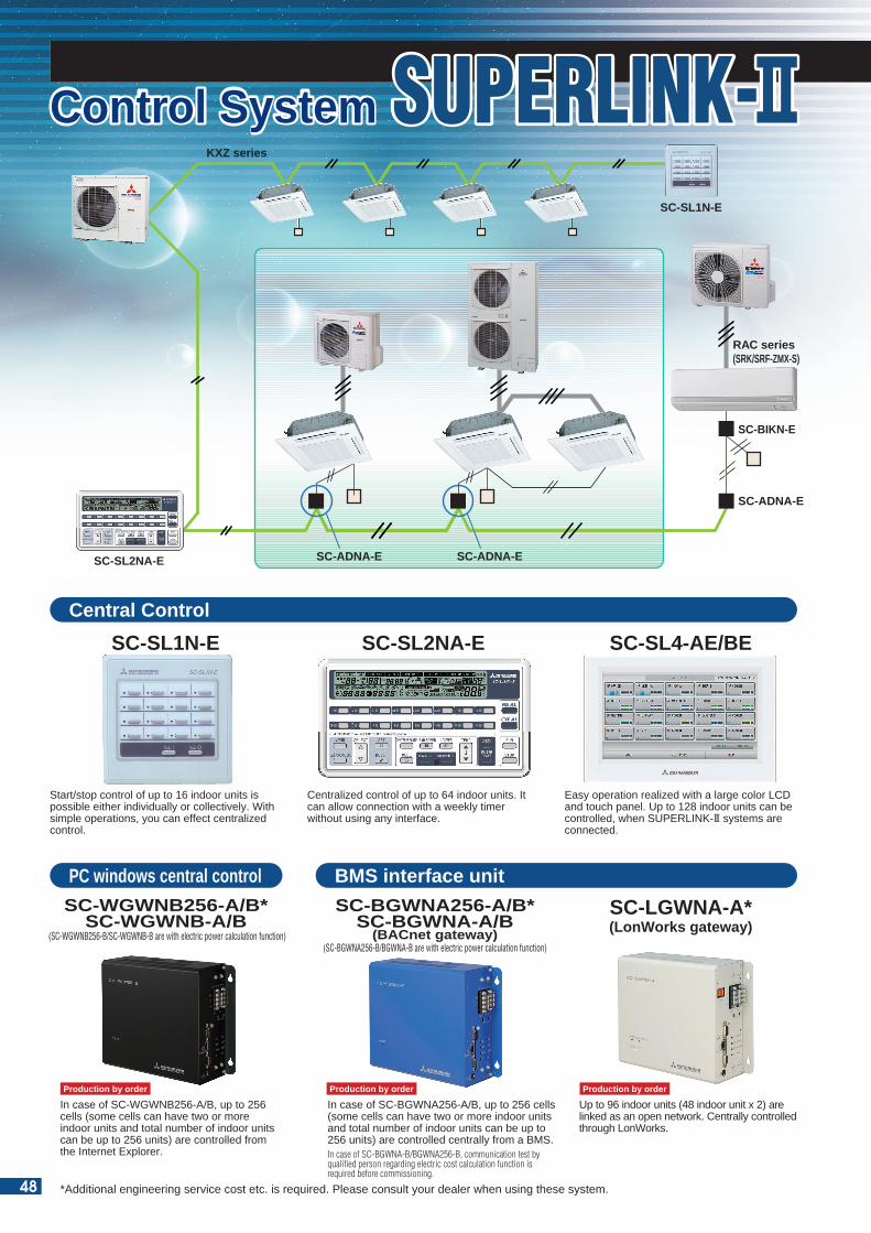
In case of SC-WGWNB256-A/B, up to 256 cells (some cells can have two or more indoor units and total number of indoor units can be up to 256 units) are controlled from the Internet Explorer.
In case of SC-BGWNA256-A/B, up to 256 cells (some cells can have two or more indoor units and total number of indoor units can be up to 256 units) are controlled centrally from a BMS.In case of SC-BGWNA-B/BGWNA256-B, communication test by qualified person regarding electric cost calculation function is required before commissioning.
Up to 96 indoor units (48 indoor unit x 2) are linked as an open network. Centrally controlled through LonWorks.
Outdoor unit
Internal/external CrossingIndoor unit
Remote controlSL E Board
Networkoptions
X Y
X Y X YA B
A B
Outdoor unitInternal/external Crossing
Inside Inside Inside Inside
R RSL EBoard
Networkoptions
Outdoor unitInternal/external Crossing
Inside Inside Inside Inside
R RSL EBoard
Outdoor unitInternal/external Crossing
Inside Inside Inside
R RSL EBoard
Networkoptions
Outdoor unitInternal/external Crossing
Inside Inside
SL EBoard
Networkoptions
Outdoor unitInternal/external Crossing
Inside Inside
SL EBoard
Networkoptions
Wireless Kit
Wirelessremote control
Basic Connections Plural Controls by Multiple Remote Controls. Mixture of Multiple Units
Plural Controls by Multiple Remote Controls. Mixture of Multiple Units Without Remote Control Wireless Kit
(3) Metal box dimension (unit:mm)
85
40
35
30
905
100
70
22.5
2-ø6
SUPERLINK E BOARD (SC-ADNA-E)This board is used when conducting control of the single package (wired remote control unit) 1-type series using a network option (SC-SL1N-E, SC-SL2NA-E, etc).
(1) Functions (a) Transmits the settings from the network option to the indoor units. (b) Returns the priority indoor unit data in response to a data request from the network option. (c) Inspects the error status of connected indoor units and transmits the inspection codes to the network option. (d) A maximum of 16 units can be controlled (if in the same operation mode).
(2) Wiring connection diagram
Set up “000” to “127” using address switch on the SL E board.
• Transmit the information of plural “Master” units to the network.• Transmit the abnormalities of the “Slave” units to the network. Setting the plural “Master/Slave” units with the dip SW of the printed circuit board. Setting the “Master/Slave” remote controls with the dip SW of the remote control board.
Set the SL E board dip SW to “Master” SW3-1 ON.The network option SL1N-E is not allowed (This will disturb switching of the operation mode)
SC-SL1N-E
SC-ADNA-E
KXZ series
Start/stop control of up to 16 indoor units is possible either individually or collectively. With simple operations, you can effect centralized control.
Centralized control of up to 64 indoor units. It can allow connection with a weekly timer without using any interface.
Easy operation realized with a large color LCD and touch panel. Up to 128 indoor units can be controlled, when SUPERLINK-II systems are connected.
SC-SL1N-E
SC-WGWNB256-A/B*SC-WGWNB-A/B
(SC-WGWNB256-B/SC-WGWNB-B are with electric power calculation function)
SC-BGWNA256-A/B*SC-BGWNA-A/B
(BACnet gateway)(SC-BGWNA256-B/BGWNA-B are with electric power calculation function)
SC-LGWNA-A*(LonWorks gateway)
SC-SL2NA-E SC-SL4-AE/BE
Control SystemControl System
SC-ADNA-E
RAC series(SRK/SRF-ZMX-S)
SC-ADNA-E
SC-BIKN-E
Connected to the terminals forSuperlink signal linesMVVS 0.75 - 1.25mm2
SL E board
OFF SW3 SW1
LED2
Run
Abnormal LED
3
SW2
ON
AB
XY
XY
AB
BlueBlue
Black
White
Master/Subaddress
Network address setting switches [000]-(127)
Connected to the remote control terminals (no polarity) (the length should be 600 m or shorter)
200 m or shorter300 m or shorter400 m or shorter600 m or shorter
0.5 mm2 x 2 cores0.75 mm2 x 2 cores1.25 mm2 x 2 cores2.0 mm2 x 2 cores
SC-SL2NA-E
SUPERLINK-SUPERLINK-
*Additional engineering service cost etc. is required. Please consult your dealer when using these system.
Production by order Production by orderProduction by order
External switch connection CnT
Remote surveillance system Card key on-off
HOTEL
HO
TE
L
All indoor units are equipped with an additional connection point-CnT-to connect indoor units to an external ON/OFF switch; e.g. time clock, fire alarm, etc.
Central Control
PC windows central control BMS interface unit
48
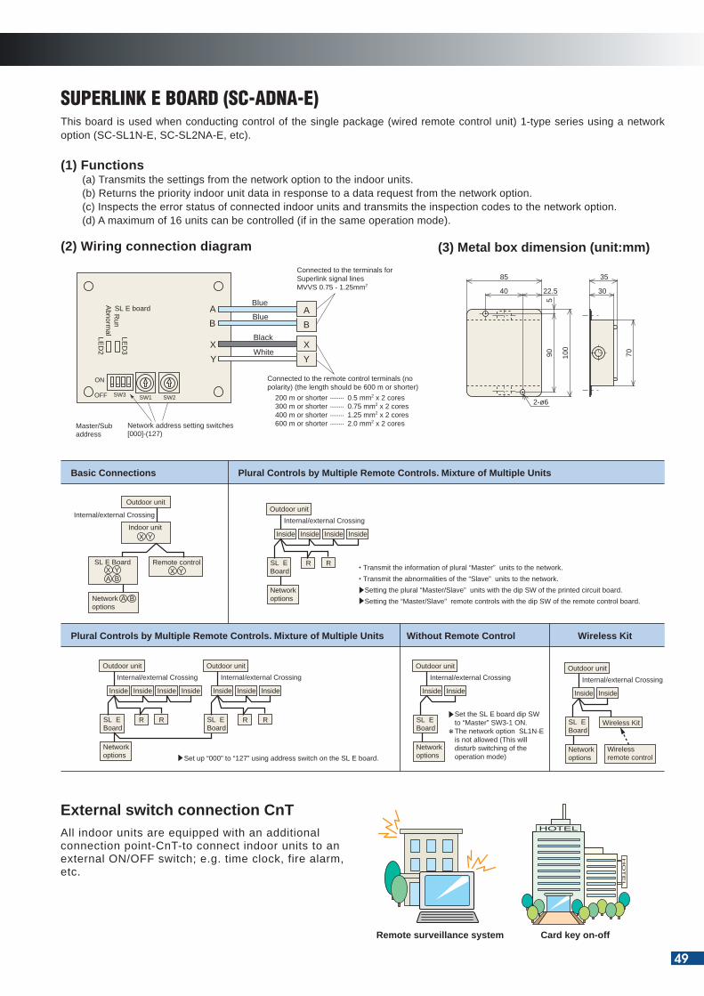
In case of SC-WGWNB256-A/B, up to 256 cells (some cells can have two or more indoor units and total number of indoor units can be up to 256 units) are controlled from the Internet Explorer.
In case of SC-BGWNA256-A/B, up to 256 cells (some cells can have two or more indoor units and total number of indoor units can be up to 256 units) are controlled centrally from a BMS.In case of SC-BGWNA-B/BGWNA256-B, communication test by qualified person regarding electric cost calculation function is required before commissioning.
Up to 96 indoor units (48 indoor unit x 2) are linked as an open network. Centrally controlled through LonWorks.
Outdoor unit
Internal/external CrossingIndoor unit
Remote controlSL E Board
Networkoptions
X Y
X Y X YA B
A B
Outdoor unitInternal/external Crossing
Inside Inside Inside Inside
R RSL EBoard
Networkoptions
Outdoor unitInternal/external Crossing
Inside Inside Inside Inside
R RSL EBoard
Outdoor unitInternal/external Crossing
Inside Inside Inside
R RSL EBoard
Networkoptions
Outdoor unitInternal/external Crossing
Inside Inside
SL EBoard
Networkoptions
Outdoor unitInternal/external Crossing
Inside Inside
SL EBoard
Networkoptions
Wireless Kit
Wirelessremote control
Basic Connections Plural Controls by Multiple Remote Controls. Mixture of Multiple Units
Plural Controls by Multiple Remote Controls. Mixture of Multiple Units Without Remote Control Wireless Kit
(3) Metal box dimension (unit:mm)
85
40
35
30
905
100
70
22.5
2-ø6
SUPERLINK E BOARD (SC-ADNA-E)This board is used when conducting control of the single package (wired remote control unit) 1-type series using a network option (SC-SL1N-E, SC-SL2NA-E, etc).
(1) Functions (a) Transmits the settings from the network option to the indoor units. (b) Returns the priority indoor unit data in response to a data request from the network option. (c) Inspects the error status of connected indoor units and transmits the inspection codes to the network option. (d) A maximum of 16 units can be controlled (if in the same operation mode).
(2) Wiring connection diagram
Set up “000” to “127” using address switch on the SL E board.
• Transmit the information of plural “Master” units to the network.• Transmit the abnormalities of the “Slave” units to the network. Setting the plural “Master/Slave” units with the dip SW of the printed circuit board. Setting the “Master/Slave” remote controls with the dip SW of the remote control board.
Set the SL E board dip SW to “Master” SW3-1 ON.The network option SL1N-E is not allowed (This will disturb switching of the operation mode)
SC-SL1N-E
SC-ADNA-E
KXZ series
Start/stop control of up to 16 indoor units is possible either individually or collectively. With simple operations, you can effect centralized control.
Centralized control of up to 64 indoor units. It can allow connection with a weekly timer without using any interface.
Easy operation realized with a large color LCD and touch panel. Up to 128 indoor units can be controlled, when SUPERLINK-II systems are connected.
SC-SL1N-E
SC-WGWNB256-A/B*SC-WGWNB-A/B
(SC-WGWNB256-B/SC-WGWNB-B are with electric power calculation function)
SC-BGWNA256-A/B*SC-BGWNA-A/B
(BACnet gateway)(SC-BGWNA256-B/BGWNA-B are with electric power calculation function)
SC-LGWNA-A*(LonWorks gateway)
SC-SL2NA-E SC-SL4-AE/BE
Control SystemControl System
SC-ADNA-E
RAC series(SRK/SRF-ZMX-S)
SC-ADNA-E
SC-BIKN-E
Connected to the terminals forSuperlink signal linesMVVS 0.75 - 1.25mm2
SL E board
OFF SW3 SW1
LED2
Run
Abnormal LED
3
SW2
ON
AB
XY
XY
AB
BlueBlue
Black
White
Master/Subaddress
Network address setting switches [000]-(127)
Connected to the remote control terminals (no polarity) (the length should be 600 m or shorter)
200 m or shorter300 m or shorter400 m or shorter600 m or shorter
0.5 mm2 x 2 cores0.75 mm2 x 2 cores1.25 mm2 x 2 cores2.0 mm2 x 2 cores
SC-SL2NA-E
SUPERLINK-SUPERLINK-
*Additional engineering service cost etc. is required. Please consult your dealer when using these system.
Production by order Production by orderProduction by order
External switch connection CnT
Remote surveillance system Card key on-off
HOTEL
HO
TE
L
All indoor units are equipped with an additional connection point-CnT-to connect indoor units to an external ON/OFF switch; e.g. time clock, fire alarm, etc.
Central Control
PC windows central control BMS interface unit
49
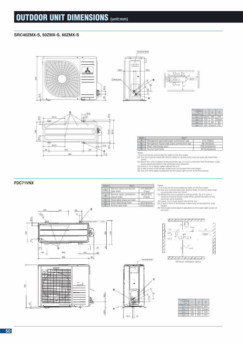
OUTDOOR UNIT DIMENSIONS (unit:mm)
FDC100VN, 125VN, 140VNFDC100VS, 125VS, 140VS
FDC71VNX
500Open100250
Open250150250
Open300100250
321L1L2L3L4
Dimensions
Examples of installation
MarkA
BCDE
ItemService valve connection (gas side)Service valve connection (liquid side)Pipe/cable draw-out holeDrain discharge holeAnchor bolt hole
ø15.88(5/8")(Flare)
M10x4placesø20x3places
ø9.52(3/8")(Flare)
Notes:(1) It must not be surrounded by walls on the four sides.(2) The unit must be fixed with anchor bolts. An anchor bolt must
not protrude more the 15mm.(3) Where the unit is subject to strong winds, lay it in such a
direction that the blower outlet faces perpendicularly to the dominant wind direction.
(4) Leave 1m or more space above the unit.(5) A wall in front of the blower outlet must not exceed the units
height.(6) The model name label is attached on the lower right corner of
the front.
165.5 25
Terminal block
B
A
C
30
3048.5
103.
5
750
24
Minimum installation space
Intake
outlet
Intake
Servicespace
L1
L2
L3
L4
D
E
2-R7.5
27
32
88880
150580150
61
310223 60
15
340
6147
.5
1938
0
418
SRC40ZMX-S, 50ZMX-S, 60ZMX-S
MarkABDE
ItemRefrigerant gas side pipe connection tapRefrigerant liquid side pipe connection tapDrain discharge portAnchor bolt hole
ø12.7(flare)ø6.35(flare)
ø20.5x5places M10x4places
Notes:(1) It must not be surrounded by walls on the four sides.(2) The unit must be fixed with anchor bolts.An anchor bolt must not protrude more than
15mm.(3) Where the unit is subject to strong winds, lay it in such a direction that the blower outlet
faces perpendicularly to the dominant wind direction.(4) Leave a 1m or larger space above the unit.(5) A wall in front of the blower outlet must not exceed the units height.(6) The unit name plate is attached on the lower right corner of the front panel.
280Open
80250
2807580
Open
Open100100250
321L1L2L3L4
Dimensions
Examples of installation
327.3
43.5
290
83.5
24.3
312.
514
.8
351.
6
327.3
89 510
800
201
17.9
71.2E
D 50.612
640
12.4
9342
.5
148.4 33.5
4040
Check joint
Terminal block
B
A
L2 L3
outlet L1
L4
IntakeServicespace
Intake
FDC100VNX, 100VSX, 125VNX, 125VSX, 140VNX, 140VSX
500Open150
5
Open5
3005
Open300150
5
321L1L2L3L4
Dimensions
Examples of installation
46
1300
110
50
20 40
20 40
38
410
370
103
15
55
195
612
624
110
70
150
50
195
50
10
5146
113
55
970
190
262 325
580 200
60
60 60 15
1527
50
15
40
A
B
A
F F
FC C
C
E
C
D
B
Terminal block
L1
L3
Intake
Outlet
Intake
Servicespace
L2L4
Minimum installation space
Notes:(1) It must not be surrounded by walls on the four
sides.(2) The unit must be fixed with anchor bolts. An
anchor bolt must not protrude more than 15mm.(3) Where the unit is subject to strong winds, lay it in
such a direction that the blower outlet faces perpendicularly to the dominant wind direction.
(4) Leave 1m or more space above the unit.(5) A wall in front of the blower outlet must not
exceed the units height.(6) The model name label is attached on the lower
right corner of the front panel. (7) Connect the Service valve with local pipe by
using the pipe of the attachment. (Gas side only)
Item
Service valve connection(liquid side)Pipe/cable draw-out holeDrain discharge holeAnchor bolt hole
Cable draw-out hole
ø15.88(5/8")(Flare)
ø9.52(3/8")(Flare)
ø20x3placesM10x4places
ø30(front)ø45(side)ø50(back)
Mark
A
BCDE
F
Service valve connection of the attached connecting pipe(gasside)
50
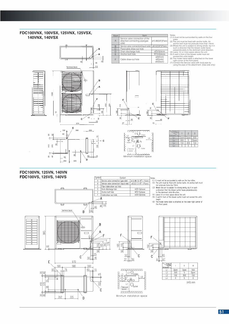
OUTDOOR UNIT DIMENSIONS (unit:mm)
FDC100VN, 125VN, 140VNFDC100VS, 125VS, 140VS
FDC71VNX
500Open100250
Open250150250
Open300100250
321L1L2L3L4
Dimensions
Examples of installation
MarkA
BCDE
ItemService valve connection (gas side)Service valve connection (liquid side)Pipe/cable draw-out holeDrain discharge holeAnchor bolt hole
ø15.88(5/8")(Flare)
M10x4placesø20x3places
ø9.52(3/8")(Flare)
Notes:(1) It must not be surrounded by walls on the four sides.(2) The unit must be fixed with anchor bolts. An anchor bolt must
not protrude more the 15mm.(3) Where the unit is subject to strong winds, lay it in such a
direction that the blower outlet faces perpendicularly to the dominant wind direction.
(4) Leave 1m or more space above the unit.(5) A wall in front of the blower outlet must not exceed the units
height.(6) The model name label is attached on the lower right corner of
the front.
165.5 25
Terminal block
B
A
C
30
3048.5
103.
5
750
24
Minimum installation space
Intake
outlet
Intake
Servicespace
L1
L2
L3
L4
D
E
2-R7.5
27
32
88880
150580150
61
310223 60
15
340
6147
.5
1938
0
418
SRC40ZMX-S, 50ZMX-S, 60ZMX-S
MarkABDE
ItemRefrigerant gas side pipe connection tapRefrigerant liquid side pipe connection tapDrain discharge portAnchor bolt hole
ø12.7(flare)ø6.35(flare)
ø20.5x5places M10x4places
Notes:(1) It must not be surrounded by walls on the four sides.(2) The unit must be fixed with anchor bolts.An anchor bolt must not protrude more than
15mm.(3) Where the unit is subject to strong winds, lay it in such a direction that the blower outlet
faces perpendicularly to the dominant wind direction.(4) Leave a 1m or larger space above the unit.(5) A wall in front of the blower outlet must not exceed the units height.(6) The unit name plate is attached on the lower right corner of the front panel.
280Open
80250
2807580
Open
Open100100250
321L1L2L3L4
Dimensions
Examples of installation
327.3
43.5
290
83.5
24.3
312.
514
.8
351.
6
327.3
89 510
800
201
17.9
71.2E
D 50.612
640
12.4
9342
.5
148.4 33.5
4040
Check joint
Terminal block
B
A
L2 L3
outlet L1
L4
IntakeServicespace
Intake
FDC100VNX, 100VSX, 125VNX, 125VSX, 140VNX, 140VSX
500Open150
5
Open5
3005
Open300150
5
321L1L2L3L4
Dimensions
Examples of installation
46
1300
110
50
20 40
20 40
38
410
370
103
15
55
195
612
624
110
70
150
50
195
50
10
5146
113
55
970
190
262 325
580 200
60
60 60 15
1527
50
15
40
A
B
A
F F
FC C
C
E
C
D
B
Terminal block
L1
L3
Intake
Outlet
Intake
Servicespace
L2L4
Minimum installation space
Notes:(1) It must not be surrounded by walls on the four
sides.(2) The unit must be fixed with anchor bolts. An
anchor bolt must not protrude more than 15mm.(3) Where the unit is subject to strong winds, lay it in
such a direction that the blower outlet faces perpendicularly to the dominant wind direction.
(4) Leave 1m or more space above the unit.(5) A wall in front of the blower outlet must not
exceed the units height.(6) The model name label is attached on the lower
right corner of the front panel. (7) Connect the Service valve with local pipe by
using the pipe of the attachment. (Gas side only)
Item
Service valve connection(liquid side)Pipe/cable draw-out holeDrain discharge holeAnchor bolt hole
Cable draw-out hole
ø15.88(5/8")(Flare)
ø9.52(3/8")(Flare)
ø20x3placesM10x4places
ø30(front)ø45(side)ø50(back)
Mark
A
BCDE
F
Service valve connection of the attached connecting pipe(gasside)
51
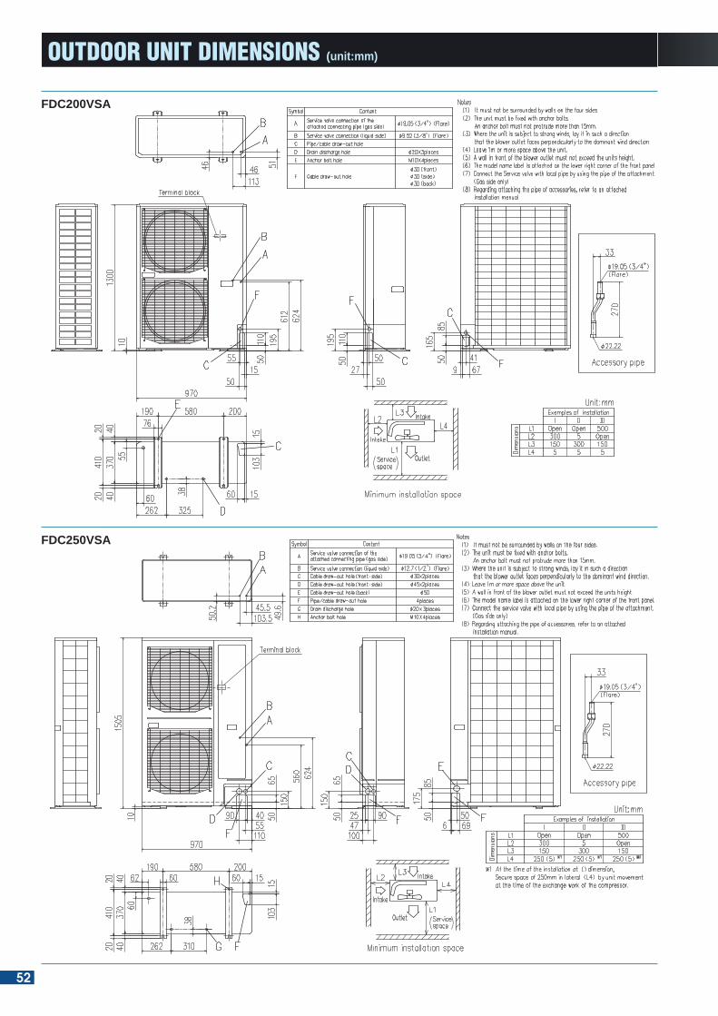
OUTDOOR UNIT DIMENSIONS (unit:mm)
FDC90VNP
FDC100VNP
FDC71VNP
FDC250VSA
FDC200VSA
52
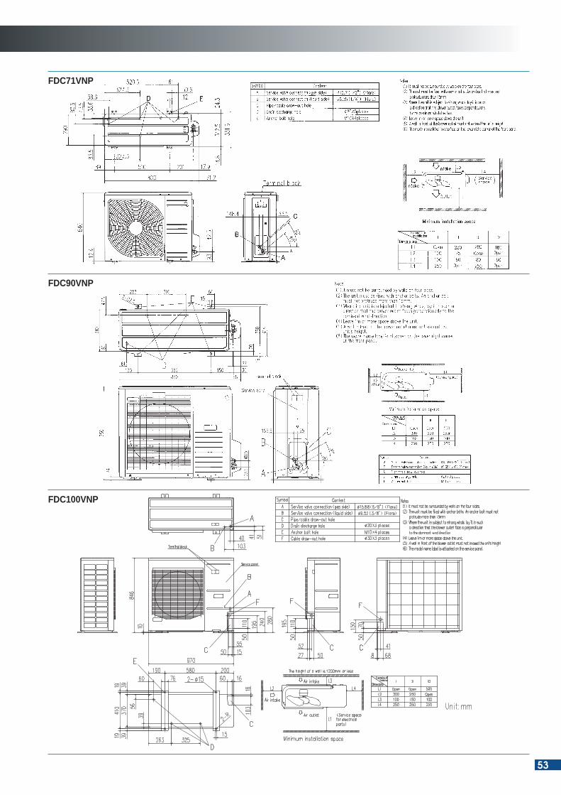
OUTDOOR UNIT DIMENSIONS (unit:mm)
FDC90VNP
FDC100VNP
FDC71VNP
FDC250VSA
FDC200VSA
53
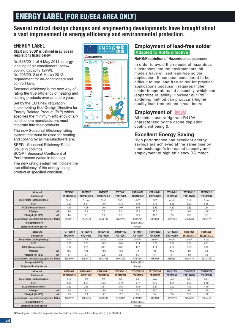
Indoor unit FDT40VF FDT50VF FDT60VF FDT71VF1 FDT100VF2 FDT100VF2 FDT40VFx2 FDT50VFx2 FDT50VFx2
Outdoor unit SRC40ZMX-S SRC50ZMX-S SRC60ZMX-S FDC71VNX FDC100VNX FDC100VSX FDC71VNX FDC100VNX FDC100VSX
Energy class (cooling/heating) A++/A+ A++/A+ A++/A A+/A+ A+/A A+/A A+/A+ A+/A A+/A
SEER 7.57 6.91 7.69 5.72 5.84 5.79 5.68 5.92 5.88
SCOP (Average climate) 4.16 4.09 3.86 4.09 3.96 3.95 4.10 3.85 3.84
Pdesignc kW 4.0 5.0 5.6 7.1 10.0 10.0 7.1 10.0 10.0
Pdesignh (@-10°C) kW 4.8 5.1 5.9 6.5 13.5 13.5 7.3 13.1 13.1
Annual electricity consumption (cooling/heating) kWh/a 185/1617 254/1748 255/2139 435/2226 600/4778 605/4782 438/2494 592/4768 596/4772
Refrigerant (GWP) R410A (1975)
Designated heating season Average
Indoor unit FDT100VF2 FDT100VF2 FDT50VFx2 FDT50VFx2 FDT71VF1 FDT100VF2 FDT100VF2 FDTC40VF FDTC50VF
Outdoor unit FDC100VN FDC100VS FDC100VN FDC100VS FDC71VNP FDC90VNP FDC100VNP SRC40ZMX-S SRC50ZMX-S
Energy class (cooling/heating) A+/A A/A A+/A A+/A A++/A+ A++/A+ A++/A+ A++/A A+/A
SEER 5.61 5.57 5.89 5.85 6.14 6.73 6.78 6.53 6.01
SCOP (Average climate) 3.92 3.91 3.81 3.81 4.27 4.11 4.52 3.96 3.85
Pdesignc kW 10.0 10.0 10.0 10.0 7.1 9.0 10.0 4.0 5.0
Pdesignh (@-10°C) kW 9.7 9.7 9.5 9.5 5.7 8.1 8.1 4.0 4.8
Annual electricity consumption (cooling/heating) kWh/a 625/3466 629/3470 595/3488 599/3492 405/1871 468/2756 516/2507 215/1416 291/1745
Refrigerant (GWP) R410A (1975)
Designated heating season Average
Indoor unit FDTC60VF FDTC40VFx2 FDTC50VFx2 FDTC50VFx2 FDTC50VFx2 FDTC50VFx2 FDU71VF1 FDU100VF2 FDU100VF2
Outdoor unit SRC60ZMX-S FDC71VNX FDC100VNX FDC100VSX FDC100VN FDC100VS FDC71VNX FDC100VNX FDC100VSX
Energy class (cooling/heating) A+/A A/A A/A A/A A/A A/A A/A A/A+ A/A+
SEER 5.76 5.31 5.23 5.19 5.17 5.13 5.24 5.22 5.19
SCOP (Average climate) 3.80 3.88 3.87 3.86 3.84 3.84 3.90 4.10 4.10
Pdesignc kW 5.6 7.1 10.0 10.0 10.0 10.0 7.1 10.0 10.0
Pdesignh (@-10°C) kW 5.9 6.8 10.2 10.2 9.4 9.4 7.0 13.0 13.0
Annual electricity consumption (cooling/heating) kWh/a 341/2172 468/2455 670/3692 674/3695 678/3424 682/3428 475/2513 670/4437 675/4441
Refrigerant (GWP) R410A (1975)
Designated heating season Average
R410A refrigerant contained in the products is a fluorinated greenhouse gas listed in Regulation (EU) No 517/2014.
Several radical design changes and engineering developments have brought about a vast improvement in energy efficiency and environmental protection.
All models use refrigerant R410A characterized by the ozone depletion coefficient being 0.
In order to avoid the release of hazardous substances into the environments, all models have utilized lead-free solder application. It has been considered to be difficult to use lead-free solder for practical applications because it requires higher solder temperatures at assembly, which can jeopardize reliability. However our PbF soldering method can produce a higher quality lead-free printed circuit board.
Employment of lead-free solder
Employment of
High performance and excellent energy savings are achieved at the same time by heat exchanger's increased capacity and employment of high efficiency DC motor.
Excellent Energy Saving
Adapted to RoHS directive
RoHS:Restriction of Hazardous substances
ENERGY LABEL
No.626/2011 of 4 May 2011: energy labeling of air-conditioners (below cooling capacity 12kW).No.206/2012 of 6 March 2012: requirement for air-conditioners and comfort fans.Seasonal efficiency is the new way of rating the true efficiency of heating and cooling products over an entire year.Set by the EU's new regulation implementing Eco-Design Directive for Energy Related Product (ErP) which specifies the minimum efficiency of air-conditioners manufacturers must integrate into their products.The new Seasonal Efficiency rating system that must be used for heating and cooling by all manufacturers are;SEER - Seasonal Efficiency Ratio (value in cooling)SCOP - Seasonal Coefficient of Performance (value in heating)The new rating system will indicate the true efficiency of the energy using product at specified condition.
SEER and SCOP is defined in European regulations listed below.
ENERGY LABEL [FOR EU/EEA AREA ONLY]
54
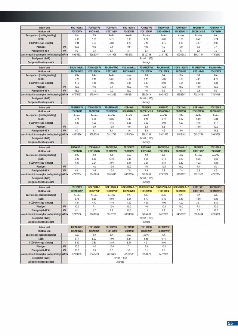
Indoor unit FDU100VF2 FDU100VF2 FDU71VF1 FDU100VF2 FDU100VF2 FDUM40VF FDUM50VF FDUM60VF FDUM71VF1
Outdoor unit FDC100VN FDC100VS FDC71VNP FDC90VNP FDC100VNP SRC40ZMX-S SRC50ZMX-S SRC60ZMX-S FDC71VNX
Energy class (cooling/heating) B/A B/A A+/A+ A++/A+ A++/A+ A+/A+ A+/A+ A++/A+ A/A
SEER 5.06 5.03 5.71 6.86 6.36 6.01 5.68 6.42 5.24
SCOP (Average climate) 3.94 3.94 4.00 4.20 4.13 4.15 4.36 4.37 3.90
Pdesignc kW 10.0 10.0 7.1 9.0 10.0 4.0 5.0 5.6 7.1
Pdesignh (@-10°C) kW 9.3 9.3 5.7 8.1 8.1 3.5 4.3 5.4 7.0
Annual electricity consumption (cooling/heating) kWh/a 692/3303 696/3307 436/1996 459/2703 551/2746 233/1182 309/1382 306/1731 475/2513
Refrigerant (GWP) R410A (1975)
Designated heating season Average
Indoor unit FDUM100VF2 FDUM100VF2 FDUM40VFx2 FDUM50VFx2 FDUM50VFx2 FDUM100VF2 FDUM100VF2 FDUM50VFx2 FDUM50VFx2
Outdoor unit FDC100VNX FDC100VSX FDC71VNX FDC100VNX FDC100VSX FDC100VN FDC100VS FDC100VN FDC100VS
Energy class (cooling/heating) A/A+ A/A+ A+/A+ A/A A/A B/A B/A B/A B/A
SEER 5.22 5.19 5.61 5.14 5.11 5.06 5.03 4.81 4.78
SCOP (Average climate) 4.10 4.10 4.05 3.88 3.87 3.94 3.94 3.82 3.81
Pdesignc kW 10.0 10.0 7.1 10.0 10.0 10.0 10.0 10.0 10.0
Pdesignh (@-10°C) kW 13.0 13.0 7.0 10.0 10.0 9.3 9.3 9.3 9.3
Annual electricity consumption (cooling/heating) kWh/a 670/4437 675/4441 444/2422 681/3611 685/3614 692/3303 696/3307 728/3413 732/3416
Refrigerant (GWP) R410A (1975)
Designated heating season Average
Indoor unit FDUM71VF1 FDUM100VF2 FDUM100VF2 FDE40VG FDE50VG FDE60VG FDE71VG FDE100VG FDE100VG
Outdoor unit FDC71VNP FDC90VNP FDC100VNP SRC40ZMX-S SRC50ZMX-S SRC60ZMX-S FDC71VNX FDC100VNX FDC100VSX
Energy class (cooling/heating) A+/A+ A++/A+ A++/A+ A++/A A++/A A++/A+ B/A+ A+/A+ A+/A+
SEER 5.71 6.86 6.36 6.46 6.10 6.72 4.87 5.89 5.84
SCOP (Average climate) 4.00 4.20 4.13 3.93 3.92 4.08 4.00 4.18 4.17
Pdesignc kW 7.1 9.0 10.0 4.0 5.0 5.6 7.1 10.0 10.0
Pdesignh (@-10°C) kW 5.7 8.1 8.1 3.0 3.8 4.3 6.0 11.2 11.2
Annual electricity consumption (cooling/heating) kWh/a 436/1996 459/2703 551/2746 217/1069 288/1358 292/1475 511/2102 595/3754 599/3758
Refrigerant (GWP) R410A (1975)
Designated heating season Average
Indoor unit FDE40VGx2 FDE50VGx2 FDE50VGx2 FDE100VG FDE100VG FDE50VGx2 FDE50VGx2 FDE71VG FDE100VG
Outdoor unit FDC71VNX FDC100VNX FDC100VSX FDC100VN FDC100VS FDC100VN FDC100VS FDC71VNP FDC90VNP
Energy class (cooling/heating) A/A+ A/A A/A A/A A/A A/A A/A A++/A+ A++/A+
SEER 5.26 5.53 5.49 5.43 5.39 5.16 5.13 6.35 6.63
SCOP (Average climate) 4.09 3.94 3.94 3.91 3.90 3.81 3.80 4.22 4.25
Pdesignc kW 7.1 10.0 10.0 10.0 10.0 10.0 10.0 7.1 9.0
Pdesignh (@-10°C) kW 6.0 10.8 10.8 7.9 7.9 7.8 7.8 5.8 8.2
Annual electricity consumption (cooling/heating) kWh/a 473/2054 634/3836 638/3840 645/2830 649/2833 679/2868 683/2872 392/1925 475/2704
Refrigerant (GWP) R410A (1975)
Designated heating season Average
Indoor unit FDE100VG SRK71ZM-S SRK100ZR-S SRK50ZMX-Sx2 SRK50ZMX-Sx2 SRK50ZMX-Sx2 SRK50ZMX-Sx2 FDF71VD1 FDF100VD2
Outdoor unit FDC100VNP FDC71VNP FDC100VNP FDC100VNX FDC100VSX FDC100VN FDC100VS FDC71VNX FDC100VNX
Energy class (cooling/heating) A++/A+ A++/A+ A++/A+ A/A+ A/A+ A/A+ A/A+ B/A A/A
SEER 6.73 6.60 6.60 5.51 5.47 5.46 5.47 4.80 5.20
SCOP (Average climate) 4.44 4.47 4.40 4.00 4.00 4.00 4.00 3.81 3.80
Pdesignc kW 10.0 7.1 10.0 10.0 10.0 10.0 10.0 7.1 10.0
Pdesignh (@-10°C) kW 8.1 5.7 7.2 11.6 11.6 8.2 8.2 6.7 13.0
Annual electricity consumption (cooling/heating) kWh/a 521/2556 377/1786 531/2289 636/4060 640/4063 642/2869 646/2872 518/2464 673/4792
Refrigerant (GWP) R410A (1975)
Designated heating season Average
Indoor unit FDF100VD2 FDF100VD2 FDF100VD2 FDF71VD1 FDF100VD2 FDF100VD2
Outdoor unit FDC100VSX FDC100VN FDC100VS FDC71VNP FDC90VNP FDC100VNP
Energy class (cooling/heating) A/A B/A B/A A/A A+/A+ A/A
SEER 5.17 5.02 4.99 5.24 5.69 5.41
SCOP (Average climate) 3.80 3.80 3.80 3.91 4.01 3.94
Pdesignc kW 10.0 10.0 10.0 7.1 9.0 10.0
Pdesignh (@-10°C) kW 13.0 9.3 9.3 5.5 8.1 8.1
Annual electricity consumption (cooling/heating) kWh/a 678/4795 697/3423 701/3427 475/1972 555/2826 647/2875
Refrigerant (GWP) R410A (1975)
Designated heating season Average
55
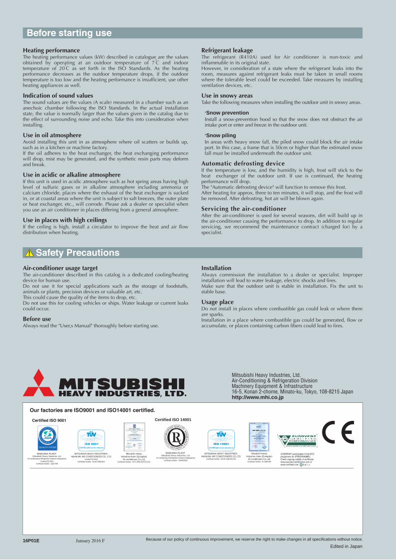
Safety Precautions
Before starting use
Air-conditioner usage targetThe air-conditioner described in this catalog is a dedicated cooling/heating device for human use. Do not use it for special applications such as the storage of foodstuffs, animals or plants, precision devices or valuable art, etc. This could cause the quality of the items to drop, etc. Do not use this for cooling vehicles or ships. Water leakage or current leaks could occur.
Before useAlways read the "User,s Manual" thoroughly before starting use.
InstallationAlways commission the installation to a dealer or specialist. Improper installation will lead to water leakage, electric shocks and fires. Make sure that the outdoor unit is stable in installation. Fix the unit to stable base.
Usage placeDo not install in places where combustible gas could leak or where there are sparks. Installation in a place where combustible gas could be generated, flow or accumulate, or places containing carbon fibers could lead to fires.
Refrigerant leakageThe refrigerant (R410A) used for Air conditioner is non-toxic and inflammable in its original state. However, in consideration of a state where the refrigerant leaks into the room, measures against refrigerant leaks must be taken in small rooms where the tolerable level could be exceeded. Take measures by installing ventilation devices, etc.
Use in snowy areasTake the following measures when installing the outdoor unit in snowy areas.
·Snow preventionInstall a snow-prevention hood so that the snow does not obstruct the air intake port or enter and freeze in the outdoor unit.
·Snow pilingIn areas with heavy snow fall, the piled snow could block the air intake port. In this case, a frame that is 50cm or higher than the estimated snow fall must be installed underneath the outdoor unit.
Automatic defrosting deviceIf the temperature is low, and the humidity is high, frost will stick to the heat exchanger of the outdoor unit. If use is continued, the heating performance will drop. The "Automatic defrosting device" will function to remove this frost. After heating for approx, three to ten minutes, it will stop, and the frost will be removed. After defrosting, hot air will be blown again.
Servicing the air-conditionerAfter the air-conditioner is used for several seasons, dirt will build up in the air-conditioner causing the performance to drop. In addition to regular servicing, we recommend the maintenance contract (charged for) by a specialist.
Heating performanceThe heating performance values (kW) described in catalogue are the values obtained by operating at an outdoor temperature of 7 C and indoor temperature of 20 C as set forth in the ISO Standards. As the heating performance decreases as the outdoor temperature drops, if the outdoor temperature is too low and the heating performance is insufficient, use other heating appliances as well.
Indication of sound valuesThe sound values are the values (A scale) measured in a chamber such as an anechoic chamber following the ISO Standards. In the actual installation state, the value is normally larger than the values given in the catalog due to the effect of surrounding noise and echo. Take this into consideration when installing.
Use in oil atmosphereAvoid installing this unit in as atmosphere where oil scatters or builds up, such as in a kitchen or machine factory. If the oil adheres to the heat exchanger, the heat exchanging performance will drop, mist may be generated, and the synthetic resin parts may deform and break.
Use in acidic or alkaline atmosphereIf this unit is used in acidic atmosphere such as hot spring areas having high level of sulfuric gases or in alkaline atmosphere including ammonia or calcium chloride, places where the exhaust of the heat exchanger is sucked in, or at coastal areas where the unit is subject to salt breezes, the outer plate or heat exchanger, etc., will corrode. Please ask a dealer or specialist when you use an air conditioner in places differing from a general atmosphere. Use in places with high ceilingsIf the ceiling is high, install a circulator to improve the heat and air flow distribution when heating.
Mitsubishi Heavy Industries, Ltd.Air-Conditioning & Refrigeration DivisionMachinery Equipment & Infrastructure16-5, Konan 2-chome, Minato-ku, Tokyo, 108-8215 Japanhttp://www.mhi.co.jp
January 2016 F16P01E
Our factories are ISO9001 and ISO14001 certified.
Mitsubishi HeavyIndustries-Haier (Quingdao)
Air-conditioners Co.,Ltd.Certificate number : 01-1998-083
Certified ISO 9001
Because of our policy of continuous improvement, we reserve the right to make changes in all specifications without notice.
Edited in Japan
(COMPANY) participates in the ECC programme for (PROGRAMME).Check ongoing validity of certificate:www.eurovent-certification.com or www.certiflash.com
Certified ISO 14001
Air-Conditioning
High Performance
50/60Hz16P01E Inverter Packaged Air-Conditioners
2016
MITSUBISHI HEAVY INDUSTRIES-MAHAJAK AIR CONDITIONERS CO.,LTD.
ISO 14001Certificate 04104 1998 0813 E5
BIWAJIMA PLANT Mitsubishi Heavy Industries, Ltd.
Air-conditioning & Refrigeration Systems Headquarters
Mitsubishi HeavyIndustries-Haier (Quingdao)
Air-conditioners Co.,Ltd.Certificate Number : 5170-1996-AQ-RCG-RvA
Certificate Number : YKA4003622
BIWAJIMA PLANT Mitsubishi Heavy Industries, Ltd.
Air-conditioning & Refrigeration Systems HeadquartersCertified ISO 9001
Certificate Number : JQA-0709
MITSUBISHI HEAVY INDUSTRIES-MAHAJAK AIR CONDITIONERS CO., LTD.
Certified ISO 9001Certificate Number : 04100 1998 0813
Certificate Number : 04104 1998 0813 E5