aeromorph as a morphing design tool in an educational environment
TRANSCRIPT

American Institute of Aeronautics and Astronautics
1
AeroMorph as a Morphing Design Tool in an Educational Environment
Cody Lafountain1, Kelly Cohen2 and Shaaban Abdallah3
University of Cincinnati, Cincinnati, OH, 45221
The standard curriculum at for Aerospace Engineering students the University of Cincinnati includes AEEM361 Integrated Aircraft Engineering. The goal of this course is to instruct students in the tools and methodology of aircraft design. The integrated aspects of aircraft design are underscored by introducing pre-junior students to the state-of-the-art Morphing technology, inspired by bat and bird flight, which can enable an aircraft to adapt its shape to best suit the flight condition thereby enhancing mission performance. In this paper, we present the development of unique software tools which allow undergraduates an opportunity to design airfoils for morphing aircraft. Morphing is introduced in the form of “on demand” camber as well as sweep change with the aim of improving aerodynamic efficiency for a multi-objective (several design points) mission profile. The Global Hawk UAV mission in general and its LRN1015 airfoil in particular is in focus due to the relative long mission times spent at the two different flight conditions, namely high-speed dash and low speed loiter. We are using several tools to virtually simulate a morphing wing including XFOIL to perform fast and relatively accurate two-dimensional steady-flow simulations of different morphed configurations using a camber controlled morphed wing to maneuver. In this paper we detail AEROMORPH, the educational MATLAB based tool developed and discuss the feedback of students who have taken above class and the lessons learned.
Nomenclature Cl = lift coefficient Cd = drag coefficient Cp = pressure coefficient FEM = finite element model
c = chord M = Mach number Re = Reynolds number CFD = computational fluid dynamics
I. Introduction INCE the early nineties, the Department of Aerospace Engineering (AsE/EM) and Engineering Mechanics at the University of Cincinnati (UC) has pursued an effort to redesign its undergraduate Aerospace Engineering
Curriculum with an emphasis on teaching increased design principles and multi-disciplinary content as described by Walker et al.1. As a result of this effort, the Integrated Engineering/Integrated Aircraft Engineering/ Integrated Spacecraft Engineering sequence (9 credit hours in all) was developed and over the past ten years this approach has been implemented successfully. During the last two academic years, one of the co-authors of this paper, Dr. Cohen, serving as instructor for the Integrated Aircraft Engineering class, introduced a project involving a morphing UAV program inspired by the bat. The main idea was to design an original airfoil which alters its geometry at different flight conditions. Furthermore, an assessment was made as to the impact of this technology on the overall mission performance and cost of the UAV. The main observations which emerged from this effort are as following:
• Students get very excited when challenged with a state-of-the-art research problem. “This is a new concept, which I totally had fun working on. I think including such new real world concepts in a class
1 Undergraduate Student, Dept. of Aerospace Engineering, Student Member, AIAA 2 Associate Professor, Dept. of Aerospace Engineering, Associate Fellow, AIAA 3 Professor, Dept. of Aerospace Engineering, Member , AIAA
S
48th AIAA Aerospace Sciences Meeting Including the New Horizons Forum and Aerospace Exposition4 - 7 January 2010, Orlando, Florida
AIAA 2010-1204
Copyright © 2010 by the American Institute of Aeronautics and Astronautics, Inc. All rights reserved.
Dow
nloa
ded
by U
NIV
ER
SIT
Y O
F C
INC
INN
AT
I on
Dec
embe
r 3,
201
4 | h
ttp://
arc.
aiaa
.org
| D
OI:
10.
2514
/6.2
010-
1204

American Institute of Aeronautics and Astronautics
2
project was awesome”; “It was very interesting. Had the opportunity to put in our thoughts on airfoil design to see whether it works or not. Got to play with new software, XFOIL. Should have more on Morphing Airfoil Design. I learned a lot and it is very exciting”;
• Students want to acquire tools which they perceive as being relevant for engineers “This is a good idea. It is a project/problem that could be used in the work force”.
• Students want to create that which never was. “First, I was very interested in the project itself. I was also pleased with how it was split into 3 milestones. But instead of just blending two airfoils together, I wanted to create my own morphing airfoil with whatever angle sweep producing the most L/D”.
• Students in their pre-junior year have a better feel for their major. “I feel that I have a better understanding of conceptual design. Somewhat more motivated to continue on with my major”.
(Note: citations in Italics are based on written feedback provided by the students taking the Spring 2008 Integrated Aircraft Engineering class at UC) From a pedagogical perspective, Booth2 states that learning is changing one’s way of experiencing some phenomena and teaching is creating such situations where such change is fostered. Based on the above experience with the Integrated Aircraft Engineering class, teaching conceptual design mission/performance analysis using Excel and airfoil design using XFOIL3 coupled with inspiration from Bats4 allow students to experience the phenomena of morphing and its intricacies in a unique manner within the framework of the class project. Given these positive trends, the UC AsE/EM team wishes to further enhance the multi-disciplinary aspects of their curriculum.
II. Background In the pioneering years of aeronautics, at the dawn of the 20th century, von Kármán5 reflects that upon the important innovation which took place i.e. the marriage of science and engineering for up until then invention was not part of a university education. About, five decades later, at Cal Tech, von Kármán5 noted that the “pendulum seems to have swung the other way” as engineering education became indiscernible from science education. In present time, there is a need to swing the pendulum once again, only this time in the direction of engineering with an emphasis on multi-disciplinary education. The question is how to devise an effective pedagogical methodology to achieve the above goal. Marzano, Pickering and Pollock6 suggest that effective pedagogy involves three related areas as illustrated in Figure 1.
Figure 1: Three Elements of Effective Pedagogy
Dow
nloa
ded
by U
NIV
ER
SIT
Y O
F C
INC
INN
AT
I on
Dec
embe
r 3,
201
4 | h
ttp://
arc.
aiaa
.org
| D
OI:
10.
2514
/6.2
010-
1204

American Institute of Aeronautics and Astronautics
3
Going back to Booth2, ideally speaking, teaching would then be about creating such situations where the desired change to be fostered would reflect what an engineer does. Figure 2 presents the categories of the taxonomy of engineering educational objectives as reproduced from Besterfield Sacre et al7.
Figure 2: The categories of the taxonomy of engineering educational objectives (reproduced from Besterfield Sacre et al7)
Given our objective of multi-disciplinary education, we need to reflect upon the taxonomy categories in Figure 2 and devise a curriculum for the Integrate Aircraft Engineering class which will equip the future engineer to be excited, comfortable and positive in his approach to multi-disciplinary engineering. In the following sections we describe the computational tools used in the above class.
III. XFOIL XFOIL is a Fortran CFD code originally written by Mark Drela at MIT in 1986. It has been updated many times since its initial release. It is now on version 6.96 for the windows platform. It combines high-order panel methods and the fully-coupled inviscid/viscous interaction method first used in ISES. XFOIL uses a text x- and y-coordinate file to model two-dimensional airfoils. The user may input an airfoil from a file or select a NACA 4- or 5- series airfoil and XFOIL will build the appropriate coordinate file. The user may then make changes to inviscid/viscous properties such as Mach number and Reynolds number (Re). Xfoil will then use the user data to simulate flight at many angles of attack and return lift coefficient (Cl), drag coefficient (Cd), and moment coefficient (Cm) in the form of a saved polar file and generate Cl vs. α and Cl vs. Cd plots. The main advantage of using XFOIL over more advanced CFD programs is that XFOIL can simulate an airfoil at one flight condition at a variety of angles of attack in a few minutes, as opposed to the hours that many other CFD codes require. This is a good trait when pinpoint accuracy is less important that the ability to explore design factors in a reasonable time period. XFOIL also is run from a command-line interface which does not require the user to develop his or her own grid. The simplicity is key when students are required to use the software as part of a project. If the software is too difficult to use, the students will spend their time learning to use the software as opposed to accomplishing the goals of the project.
One concern that needed to be addressed was the accuracy of XFOIL results. In order to ensure that the results we are obtaining from XFOIL are accurate when compared to industry accepted data, we acquired wind tunnel data from NASA on the LRN1015 airfoil. We chose the LRN1015 because it is an ideal morphing candidate used on the Global Hawk UAV and it has readily available wind tunnel data. We compared data from a NASA technical memorandum8 regarding Cl vs. α, Cl vs. Cd, and Cl vs. Cm to data generated by XFOIL. In their report, NASA compared wind tunnel data and data generated by two computer simulations, ISES and LBAUER. To this we added
Taxonomy Category Knowledge Comprehension Application Analysis Synthesis Evaluation
Command Words and Question Type
Arrange, define, describe, match, order, memorize, name, note, order, repeat. Who? What? When? Where? Questions
Alter, change, classify define in your own words, discuss, explain, extend. Give Examples, Translate
Apply, calculate, compute, construct, operate, practice. How many? Which? Write an example question.
Analyze, appraise, categorize, compare, conclude, contrast, criticize, diagnose, differentiate, etc. Why? Questions.
Assemble, compile, compose, create, improve synthesize. What if ? How can we improve? What would happen if? How can we solve? Questions.
Appraise, argue, choose, certify, criticize, decide, deduce, defend, discriminate, estimate, evaluate, recommend, etc.
Dow
nloa
ded
by U
NIV
ER
SIT
Y O
F C
INC
INN
AT
I on
Dec
embe
r 3,
201
4 | h
ttp://
arc.
aiaa
.org
| D
OI:
10.
2514
/6.2
010-
1204

American Institute of Aeronautics and Astronautics
4
the XFOIL data. We used XFOIL to calculate the lift coefficient at an interval of one degree over the interval [-3, 6]. This is a similar interval to the ISES and LBAUER data. For this comparison the Mach number was set at 0.2 and the Reynolds number was set at 500,000 to match the data recorded by NASA. The students participating in the Integrated Aircraft Engineering class perform this same validation as the first milestone of their project.
Figure 3 shows the results from all four sources compared on the same plot. XFOIL compares adequately to
ISES and LBAUER in predicting lift coefficient over the linear part of the Cl vs. α plot. XFOIL follows the wind tunnel data well, better than ISES, at positive angles of attack. The Cl vs. Cd plot shows similar results. The drag predictions from XFOIL, presented in Figure 4, show good correlation with both the wind tunnel data and ISES and LBAUER. This shows that XFOIL is predicting both lift and drag coefficients within an acceptable range or accuracy.
Figure 4. Drag Coefficient Comparison. LRN1015, Mach number 0.2, Reynolds number 500,000.
Figure 3. Lift Coefficient Comparison. LRN1015, Mach number 0.2, Reynolds number 500,000.
Dow
nloa
ded
by U
NIV
ER
SIT
Y O
F C
INC
INN
AT
I on
Dec
embe
r 3,
201
4 | h
ttp://
arc.
aiaa
.org
| D
OI:
10.
2514
/6.2
010-
1204
American Institute of Aeronautics and Astronautics
5
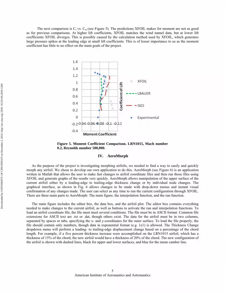
The next comparison is Cl vs. Cm (see Figure 5). The predictions XFOIL makes for moment are not as good as for previous comparisons. At higher lift coefficients, XFOIL matches the wind tunnel data, but at lower lift coefficients XFOIL diverges. This is possibly caused by the calculation method used by XFOIL, which generates large pressure spikes at the leading edge at small lift coefficients. This is of lesser importance to us as the moment coefficient has little to no effect on the main goals of the project.
IV. AeroMorph
As the purpose of the project is investigating morphing airfoils, we needed to find a way to easily and quickly morph any airfoil. We chose to develop our own application to do this. AeroMorph (see Figure 6) is an application written in Matlab that allows the user to make fast changes to airfoil coordinate files and then run those files using XFOIL and generate graphs of the results very quickly. AeroMorph allows manipulation of the upper surface of the current airfoil either by a leading-edge to trailing-edge thickness change or by individual node changes. The graphical interface, as shown in Fig. 6 allows changes to be made with drop-down menus and instant visual confirmation of any changes made. The user can select as any time to run the current configuration through XFOIL. There are three main parts to AeroMorph: The main figure, the interpolation function, and the run function.
The main figure includes the editor box, the data box, and the airfoil plot. The editor box contains everything needed to make changes to the current airfoil, as well as buttons to activate the run and interpolation functions. To load an airfoil coordinate file, the file must meet several conditions. The file must be in ASCII format. Common file extensions for ASCII text are .txt or .dat, though others exist. The data for the airfoil must be in two columns, separated by spaces or tabs, specifying the x- and y-coordinates for the outer surface. To load the file properly, the file should contain only numbers, though data in exponential format (e.g. 1e1) is allowed. The Thickness Change dropdown menu will perform a leading- to trailing-edge displacement change based on a percentage of the chord length. For example, if a five percent thickness increase were accomplished on the LRN1015 airfoil, which has a thickness of 15% of the chord, the new airfoil would have a thickness of 20% of the chord. The new configuration of the airfoil is shown with dashed lines, black for upper and lower surfaces, and blue for the mean camber line.
Figure 5. Moment Coefficient Comparison. LRN1015, Mach number 0.2, Reynolds number 500,000.
Dow
nloa
ded
by U
NIV
ER
SIT
Y O
F C
INC
INN
AT
I on
Dec
embe
r 3,
201
4 | h
ttp://
arc.
aiaa
.org
| D
OI:
10.
2514
/6.2
010-
1204

American Institute of Aeronautics and Astronautics
6
Figure 6. The Main AeroMorph figure, containing the editor box, data box, and airfoil plot.
Figure 7. LRN1015 with a +4% thickness change.
Dow
nloa
ded
by U
NIV
ER
SIT
Y O
F C
INC
INN
AT
I on
Dec
embe
r 3,
201
4 | h
ttp://
arc.
aiaa
.org
| D
OI:
10.
2514
/6.2
010-
1204

American Institute of Aeronautics and Astronautics
7
The Sweep Angle box allows the user to change the profile of the airfoil by changing the sweep angle. It performs this calculation by increasing the length of the airfoil by dividing by the cosine of the sweep angle specified, then multiplying the x- and y-coordinates by the cosine of the sweep angle to normalize the chord length to one. This method is accurate for most sweep angles, though at very high sweep angles (higher than 70 degrees) there are distortions at the leading and trailing edges caused by the geometry involved.
In order to make changes to an individual node, the node must first be selected in the Select Node dropdown. The nodes are shown as black circles. Choosing a node will also refresh the Data box to show information on the selected node. Note that the leading-edge and trailing-edge nodes (1 and 8) are not moveable. Once a node has been selected, its vertical displacement can be modified using the Raise/Lower Node dropdown. Nodes can be moved up or down. In order to maintain a smooth surface the panels between the nodes are able to rotate. When a node is raised or lowered, the panels to the right and left of the selected node rotate about the adjacent nodes. The Smooth Surface button uses the “polyfit” function in Matlab to generate an 18th order polynomial describing the upper surface of the current airfoil. It then uses that polynomial to remap the upper surface. This has the effect of smoothing the distortions caused by manipulating the airfoil, especially individual node changes. This should be used only as needed because it can cause distortion at the leading- and trailing-edges of the airfoil. The Smooth Surface button has very little effect on airfoils that contain more that 150 coordinates, such as those output by XFOIL. The Reset Airfoil button returns the current airfoil to its original configuration, deleting any unsaved changes. The data box displays information about the current airfoil. The data will automatically refresh whenever the airfoil is changed. Under Thickness %, it displays the thickness of the current airfoil in percentage of the thickness of the original airfoil. This will change whenever a thickness change is performed using the Thickness Change dropdown. Under Max Camber it displays the value corresponding to the maximum displacement of the mean camber line from the chord of the airfoil. Under Node Y value it displays the overall displacement of the currently
Figure 9. LRN1015 with node 4 raised 0.025 and node 5 lowered 0.025.
Figure 8. LRN1015 with a sweep angle of 45 degrees.
Dow
nloa
ded
by U
NIV
ER
SIT
Y O
F C
INC
INN
AT
I on
Dec
embe
r 3,
201
4 | h
ttp://
arc.
aiaa
.org
| D
OI:
10.
2514
/6.2
010-
1204

American Institute of Aeronautics and Astronautics
8
selected node from the chord line. Under Node Displacement it displays the relative displacement of the currently selected node from its original position. The airfoil plot displays the current airfoil as well as the original airfoil. The original airfoil is displayed with a grey fill, a solid black border, and a solid blue mean camber line. The current airfoil is displayed with a dashed line. The individually moveable nodes on the airfoil are displayed as black rings along the upper surface of the airfoil.
The interpolation function is activated by clicking the “Merge With…” button. This function is a graphical front-end for the interpolation function in XFOIL. It allows two airfoils to be mixed to create a new airfoil. The user selects two airfoils, which can include the current working airfoil or any from file. Then the user selects the ratio of interpolation by using a slider. This information in converted into the correct format for XFOIL, then the program activates XFOIL’s “inte” function to accomplish the interpolation. It then loads the interpolated airfoil back into AeroMorph.
The run function is activated by clicking the “Generate Run” button. It brings up a window in which the user may select parameters for the sequence of XFOIL commands desired. Its interface is designed to be more user-friendly than the command-line interface of XFOIL, saving the user time and effort, while accomplishing the same results. This is possible because AeroMorph automates the commands so that a run may be accomplished in seconds rather than minutes. To save further time, AeroMorph can understand when a particular permutation has already been run and will read the saved polar instead of re-running XFOIL. There are six parameters currently available to the user. The user may choose to vary the Reynolds number, the Mach number, the angle of attack (Alpha), the thickness, and/or the sweep angle. The user may also compare the
Figure 10. Blending of Airfoils
Figure 11. Selection of the Test Matrix
Dow
nloa
ded
by U
NIV
ER
SIT
Y O
F C
INC
INN
AT
I on
Dec
embe
r 3,
201
4 | h
ttp://
arc.
aiaa
.org
| D
OI:
10.
2514
/6.2
010-
1204

American Institute of Aeronautics and Astronautics
9
current airfoil to another airfoil from file. The user chooses by selecting or deselecting toggle buttons. If the toggle button for a parameter is selected, AeroMorph will use the first (left) column as the start value, the middle column as the step value, and the third (right) column as the end value. If the button for a parameter is deselected, AeroMorph will use only the value in the first (left) column. When the user clicks the “Run” button, AeroMorph builds a run matrix using the parameters selected, then runs XFOIL for each permutation required. Each run polar is saved in the “\polars” subdirectory for easy access with a filename describing all relevant permutation data (i.e. airfoil name, thickness, sweep angle, Angle of Attack range and step, Reynolds number, and Mach number). In the event that the airfoil itself is being modified, as is the case when thickness or sweep angle are modified, the airfoil coordinates are saved with each permutation. When a run has completed, AeroMorph reads Cl, Cd, and Cm data from the XFOIL polars, and builds a matrix containing the combined data from each run for each variable, as well as a legend entry for each run. When all runs have completed, AeroMorph plots Cl vs. α, Cd vs. α, Cm vs. α, and Cl/Cd vs. α. It uses a color spectrum based on the number of runs to differentiate between different runs. The plot can be saved as an image file.
Figure 12 shows the results of a run matrix varying the thickness of the LRN1015 airfoil from negative five percent to positive five percent. This equates to max thicknesses from ten percent of the chord to twenty percent of the chord. It took less than one minute to get the results for the eleven distinct airfoils being tested. The data is plotted on the same plot to make it very easy for students to directly compare the performances of different airfoils or different flight conditions. The next figure (Figure 13) shows data for the LRN1015 with varying sweep and Reynolds number. AeroMorph can vary any or all parameters of the run matrix at the user’s discretion.
Figure 12 with Varying Thickness
Dow
nloa
ded
by U
NIV
ER
SIT
Y O
F C
INC
INN
AT
I on
Dec
embe
r 3,
201
4 | h
ttp://
arc.
aiaa
.org
| D
OI:
10.
2514
/6.2
010-
1204

American Institute of Aeronautics and Astronautics
10
V. Student Feedback One advantage of developing a software package at an active university is the ability to receive feedback from
students using the software to accomplish real work. It is an important part of the development process to receive feedback, both positive and negative, on the use of the software. Students, as part of their final report for the morphing project, were given the option to review the AeroMorph software package and give feedback on their experience using it. Upon review of the student feedback, several main points appeared in more than one review.
• Students liked the intuitive design of the interface, and considered it an improvement over XFOIL that
saved them time, effort, and frustration. • Students disliked the naming convention and mechanism for saving output data. Several wanted the
option to choose their own naming convention. Students also wanted the option to view the results without saving the output to files.
• Students liked the additional features that AeroMorph offered over XFOIL, such as sweep morphing and the ability to batch runs varying different flight characteristics.
• Several students had issues with opening airfoils from a third-party online database. Some were the wrong format and others were missing points.
As we had no access to the third-party online airfoil database, we were unable to make changes to improve users’ experiences with it. The issue that students had with the naming convention was tackled in two ways. A
Figure 13 Results for LRN1015 with Varying Sweep Angle
Dow
nloa
ded
by U
NIV
ER
SIT
Y O
F C
INC
INN
AT
I on
Dec
embe
r 3,
201
4 | h
ttp://
arc.
aiaa
.org
| D
OI:
10.
2514
/6.2
010-
1204

American Institute of Aeronautics and Astronautics
11
checkbox was added that will give users the choice as to whether or not they want to keep the output files. The issue of letting users choose their own naming conventions is a much more difficult problem due to the construction of the program. This feature is currently being added, and will be present in the next version on AeroMorph. Another feature that will be added in the next version of AeroMorph is a progress bar that will progress during batch operations.
VI. Conclusions and Recommendations We currently have several big goals for the future development of AeroMorph. The first goal is to implement a
basic reverse solver into AeroMorph. This will be done simply by solving for the Lift over Drag efficiency for each configuration in the run matrix at a specific lift coefficient and determining the highest value. The second goal is a real-time solver implementation. In this case the user specifies a flight condition and flight performance is displayed almost instantly as changes are made to the airfoil. The loftiest goal is a genetic algorithm solver, implemented through the use of the genetic algorithm toolbox in Matlab. The genetic algorithm has potential to solve very quickly and efficiently for the best airfoil design for not just one flight condition, but for multiple flight conditions. This is a dramatic shift from previous design tools, which can only optimize an airfoil for one flight condition. Along the way, several smaller features will be added, including lower surface morphing, pure camber morphing with no thickness change, and the ability to vary the number of nodes on the surface. We will also continue to take into account comments and suggestions from the students of the Integrated Aircraft Engineering class.
The integration of AeroMorph into the curriculum at the University of Cincinnati will expand in the Integrated Aircraft Engineering class. As it gains features it will be used more as a tool for morphing airfoil design. It will also be made available to the seniors taking the senior aircraft design course. It is our hope that it can be made available to aerospace students and professors all over as an easy-to-use educational tool.
Acknowledgments The authors thank Ms. Jill Collet, Division of Professional Practice, University of Cincinnati, for her guidance and support of the Co-op research program. The authors acknowledge the assistance of Ms. Leva Wilson and Ms. Brenda Smith for their support and assistance.
References 1Walker, B.K., Wade, J.E, Orkwis, P.D., Jeng, A.-M, Khosla, P.K., and Slater, G.L., “Development of a Proposed
Aerospace Engineering Curriculum for the Twenty-first Century”, 35th AIAA Aerospace Sciences Meeting & Exhibit, Reno, NV, Jan 6-9, 1997, AIAA Paper 97-0737.
2Booth, S., “Engineering Education and the Pedagogy of Awareness”, Chapter 1, Effective Learning and Teaching in Engineering, Editors, Baillie C., and Moore, I., RoutledgeFalmer, New York, NY, 2004, pp. 9-24.
3Drela, M., “XFOIL: An Analysis and Design System for Low Reynolds Number Airfoils, Conference on Low Reynolds Number Airfoil Aerodynamics, University of Notre Dame, June 1989.
4Altringham, J.D., Bats – Biology and Behavior, Oxford University Press Inc, New York, NY, 1996. 5Von Kármán, T. with Lee Edson, The Wind and Beyond, Little Brown and Co., USA, 1967. 6Marzano, R.J., Pickering, D.J., and Pollock, J. E., “Classroom Instruction that Works – Research Based Strategies for Increasing Student Achievement”, Association for Supervision and Curriculum Development, Alexandria, VA, 2001. 7Besterfield-Sacre, M. et al., “Defining the outcomes, A framework for EC2000”, IEEE Transactions on Education,
Vol. 43, No. 2, 2000, pp.100-110 8Donovan, M.S. and Bransford, J.D., Editors, How Students Learn – History, Mathematics, and Science in the
Classroom, Committee on How People Learn, A Targeted Report for Teachers, Division of Behavioral and Social Sciences and Education, , National Research Council, National Academy Press, Washington, DC, 2005.
9Heywood J., “Interdisciplinary and Integrated Studies”, Chapter 8, Engineering Education – Research and Development in Curriculum and Instruction, IEEE Press, Wiley-Interscience, John Wiley and Sons, Inc., Hoboken, NJ, 2005, pp.199-220, 2005.
10XFOIL, Software Package, Ver. 6.96, MIT, Cambridge, MA, 2005. 11Matlab, Software Package, Ver. 7.4.0.287, The Mathworks, Inc., Natick, MA, 2007.
Dow
nloa
ded
by U
NIV
ER
SIT
Y O
F C
INC
INN
AT
I on
Dec
embe
r 3,
201
4 | h
ttp://
arc.
aiaa
.org
| D
OI:
10.
2514
/6.2
010-
1204

American Institute of Aeronautics and Astronautics
12
12Drela, M., and Youngren, H., “XFOIL 6.9 User Primer,” November 30, 2001 URL: http://web.mit.edu/drela/Public/web/xfoil/xfoil_doc.txt
Dow
nloa
ded
by U
NIV
ER
SIT
Y O
F C
INC
INN
AT
I on
Dec
embe
r 3,
201
4 | h
ttp://
arc.
aiaa
.org
| D
OI:
10.
2514
/6.2
010-
1204