aerodynamic analysis of hyplane in supersonic, rarefied flow
TRANSCRIPT

Acta Astronautica 123 (2016) 229–238
Contents lists available at ScienceDirect
Acta Astronautica
http://d0094-57
n CorrE-m
journal homepage: www.elsevier.com/locate/aa
Aerodynamic analysis of the aerospaceplane HyPlanein supersonic rarefied flow
Gennaro Zuppardi a,n, Raffaele Savino a, Gennaro Russo b,c, Luca Spano’ Cuomo a,Eliano Petrosino a
a Department of Industrial Engineering, Aerospace Division, University of Naples “Federico II”, Piazzale Tecchio 80, 80125 Naples, Italyb Trans-Tech Srl, Via Palizzi 107, 80127 Naples, Italyc Near Space of the Italian Institute for the Future, Via Guido de Ruggiero 52, 80128 Naples, Italy
a r t i c l e i n f o
Article history:Received 13 November 2015Received in revised form4 March 2016Accepted 24 March 2016Available online 28 March 2016
Keywords:Aerospaceplane aerodynamicsSupersonic flowAerodynamic surface attitude controlRarefied gas dynamicsDirect Simulation Monte Carlo method
x.doi.org/10.1016/j.actaastro.2016.03.02565/& 2016 IAA. Published by Elsevier Ltd. All
esponding author.ail address: [email protected] (G. Zuppardi).
a b s t r a c t
HyPlane is the Italian aerospaceplane proposal targeting, at the same time, both the space tourism andpoint-to-point intercontinental hypersonic flights. Unlike other aerospaceplane projects, relying onboosters or mother airplanes that bring the vehicle to high altitude, HyPlane will take off and landhorizontally from common runways. According to the current project, HyPlane will fly sub-orbital tra-jectories under high-supersonic/low-hypersonic continuum flow regimes. It can go beyond the vonKarman line at 100 km altitude for a short time, then starting the descending leg of the trajectory. Itsaerodynamic behavior up to 70 km have already been studied and the results published in previousworks. In the present paper some aspects of the aerodynamic behavior of HyPlane have been analyzed at80, 90 and 100 km. Computer tests, calculating the aerodynamic parameters, have been carried out by aDirect Simulation Monte Carlo code. The effects of the Knudsen, Mach and Reynolds numbers have beenevaluated in clean configuration. The effects of the aerodynamic surfaces on the rolling, pitching andyawing moments, and therefore on the capability to control attitude, have been analyzed at 100 kmaltitude. The aerodynamic behavior has been compared also with that of another aerospaceplane at100 km both in clean and flapped configuration.
& 2016 IAA. Published by Elsevier Ltd. All rights reserved.
1. Introduction
HyPlane [1–4] is a small, six seats, hypersonic aerospaceplane.Its dimensions are similar to those of a business jet and, just likean usual airplane, it is able to perform Horizontal Take-off andHorizontal Landing (HTHL) on common runways. For this reason,according to the logic “a closer space and aeronautics” [5], thisvehicle can be considered as the “natural” transition of the spacevehicles concept toward the future civil aviation or toward thedevelopment of trans-atmospheric, totally re-usable vehicle. Inother words, it moves toward much lower costs than other aero-spaceplane concepts relying on boosters, as per Space Shuttle [6]and SpaceLiner [7–9], or mother ship carrier as per SpaceShipTwo[10].
Architecture of HyPlane is similar to that of Concorde [11] butits dimensions are much smaller; the linear dimensions are re-duced of about 50%. HyPlane is powered by Turbine Based Com-bined Cycle (TBCC) turbo-ramjet engines plus a throtteable rocket,
rights reserved.
consuming less fuel than that of the engine of the Blackbird SR-71Lockheed aircraft. Current studies are based on the use of ad-vanced and green fuels (JP7, JP10, biofuel).
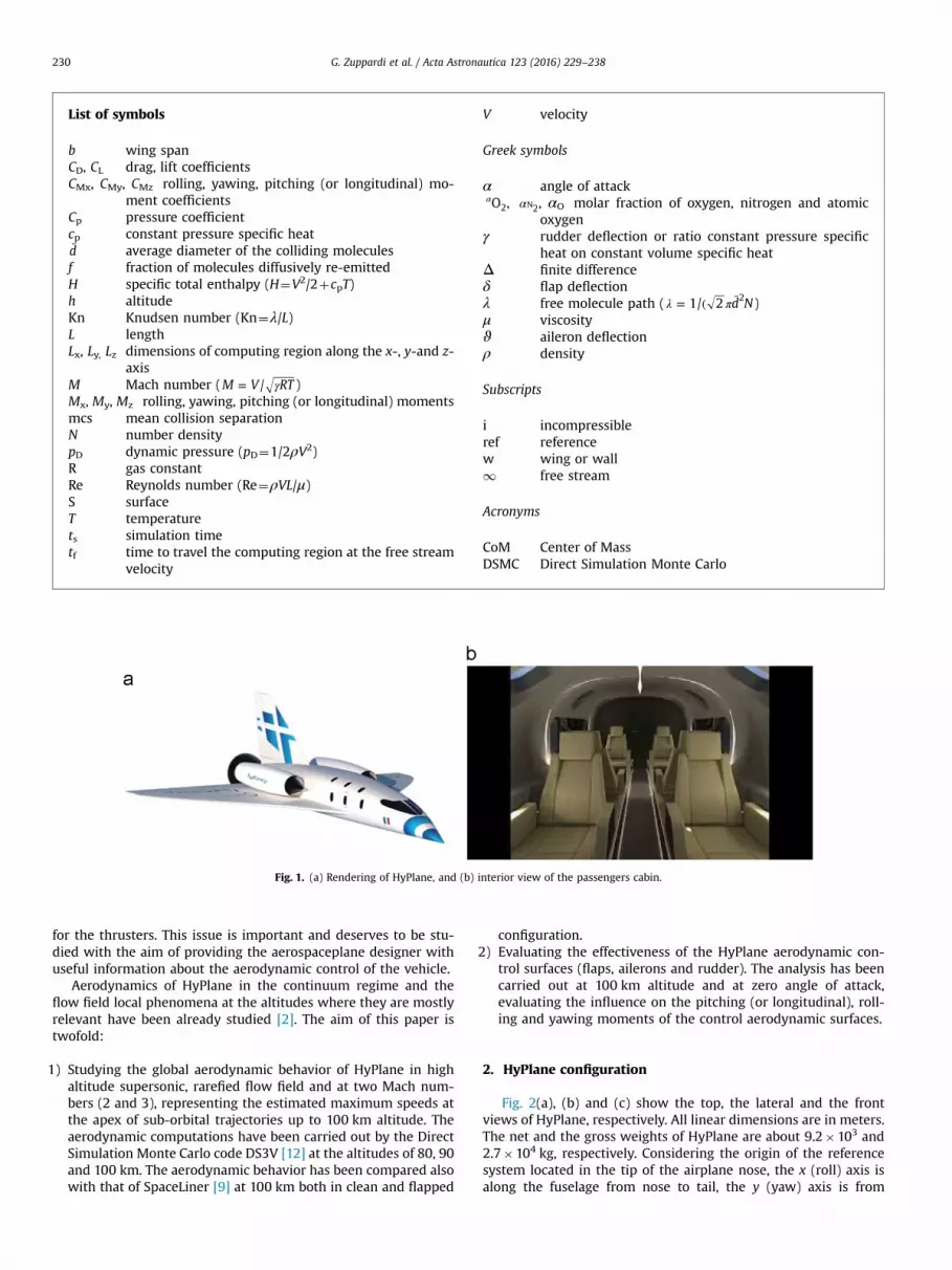
HyPlane has been designed to fly in stratosphere (at 30 kmaltitude) and at cruising speed of about 5000 km/h (Mach numberabout 4.6), covering distances like Rome–New York in less than2 h. Turbojet mode will be used for take-off and for reaching su-personic velocity, while ramjet mode will allow reaching hy-personic velocity at high altitude. HyPlane has been also designedas a space tourism vehicle; thanks to the boosting function of therocket motor, it can reach altitudes of at least 70 km twice or threetimes per flight in order to provide the passengers with anamazing view of Earth while they are floating in low gravity. Fig. 1(a) and (b) show rendering of HyPlane aeroshape and of the pas-sengers cabin respectively. Three large portholes on the top of thepassengers cabin are indicative of its tourism vocation.
It is well known that the success of the aerodynamic design ofan aerospaceplane is linked to its capability of controlling attitudeand restoring equilibrium in rarefied flow. These functions, for allspace vehicles, are undertaken by thrusters. Controlling attitudealso by means of aerodynamic surfaces simplifies this task. Inaddition, an aerospaceplane should carry a lower amount of fuel
1
2
List of symbols
b wing spanCD, CL drag, lift coefficientsCMx, CMy, CMz rolling, yawing, pitching (or longitudinal) mo-
ment coefficientsCp pressure coefficientcp constant pressure specific heatd̄ average diameter of the colliding moleculesf fraction of molecules diffusively re-emittedH specific total enthalpy (H¼V2/2þcpT)h altitudeKn Knudsen number (Kn¼λ/L)L lengthLx, Ly, Lz dimensions of computing region along the x-, y-and z-
axisM Mach number ( γ=M V RT/ )Mx, My, Mz rolling, yawing, pitching (or longitudinal) momentsmcs mean collision separationN number densitypD dynamic pressure (pD¼1/2ρV2)R gas constantRe Reynolds number (Re¼ρVL/μ)S surfaceT temperaturets simulation timetf time to travel the computing region at the free stream
velocity
V velocity
Greek symbols
α angle of attackαO2, α 2N , αO molar fraction of oxygen, nitrogen and atomic
oxygenγ rudder deflection or ratio constant pressure specific
heat on constant volume specific heatΔ finite differenceδ flap deflectionλ free molecule path ( λ π= ( d̄ N1/ 2 2 )μ viscosityϑ aileron deflectionρ density
Subscripts
i incompressibleref referencew wing or wall1 free stream
Acronyms
CoM Center of MassDSMC Direct Simulation Monte Carlo
Fig. 1. (a) Rendering of HyPlane, and (b) interior view of the passengers cabin.
G. Zuppardi et al. / Acta Astronautica 123 (2016) 229–238230
for the thrusters. This issue is important and deserves to be stu-died with the aim of providing the aerospaceplane designer withuseful information about the aerodynamic control of the vehicle.
Aerodynamics of HyPlane in the continuum regime and theflow field local phenomena at the altitudes where they are mostlyrelevant have been already studied [2]. The aim of this paper istwofold:
) Studying the global aerodynamic behavior of HyPlane in highaltitude supersonic, rarefied flow field and at two Mach num-bers (2 and 3), representing the estimated maximum speeds atthe apex of sub-orbital trajectories up to 100 km altitude. Theaerodynamic computations have been carried out by the DirectSimulation Monte Carlo code DS3V [12] at the altitudes of 80, 90and 100 km. The aerodynamic behavior has been compared alsowith that of SpaceLiner [9] at 100 km both in clean and flapped
configuration.) Evaluating the effectiveness of the HyPlane aerodynamic con-trol surfaces (flaps, ailerons and rudder). The analysis has beencarried out at 100 km altitude and at zero angle of attack,evaluating the influence on the pitching (or longitudinal), roll-ing and yawing moments of the control aerodynamic surfaces.
2. HyPlane configuration
Fig. 2(a), (b) and (c) show the top, the lateral and the frontviews of HyPlane, respectively. All linear dimensions are in meters.The net and the gross weights of HyPlane are about 9.2�103 and2.7�104 kg, respectively. Considering the origin of the referencesystem located in the tip of the airplane nose, the x (roll) axis isalong the fuselage from nose to tail, the y (yaw) axis is from
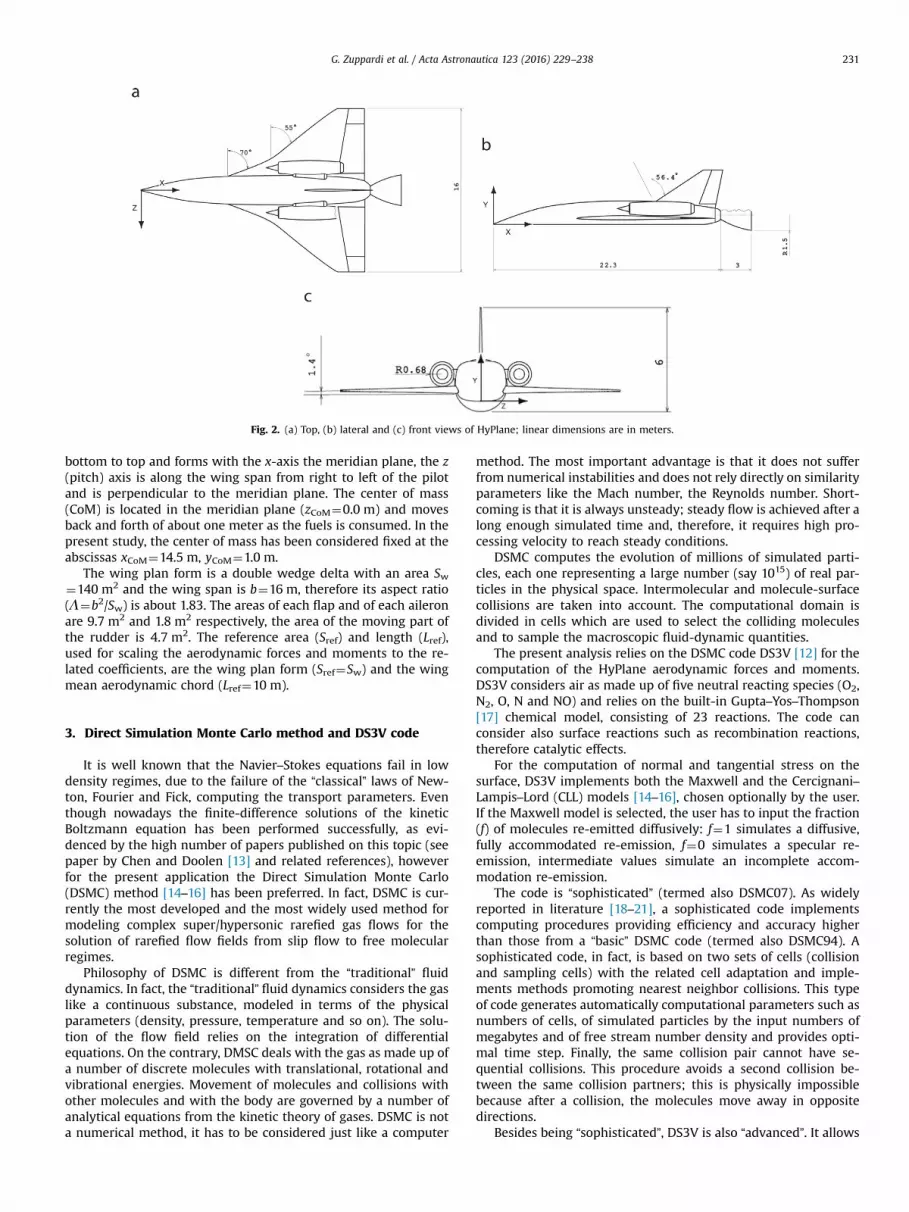
Fig. 2. (a) Top, (b) lateral and (c) front views of HyPlane; linear dimensions are in meters.
G. Zuppardi et al. / Acta Astronautica 123 (2016) 229–238 231
bottom to top and forms with the x-axis the meridian plane, the z(pitch) axis is along the wing span from right to left of the pilotand is perpendicular to the meridian plane. The center of mass(CoM) is located in the meridian plane (zCoM¼0.0 m) and movesback and forth of about one meter as the fuels is consumed. In thepresent study, the center of mass has been considered fixed at theabscissas xCoM¼14.5 m, yCoM¼1.0 m.
The wing plan form is a double wedge delta with an area Sw¼140 m2 and the wing span is b¼16 m, therefore its aspect ratio(Λ¼b2/Sw) is about 1.83. The areas of each flap and of each aileronare 9.7 m2 and 1.8 m2 respectively, the area of the moving part ofthe rudder is 4.7 m2. The reference area (Sref) and length (Lref),used for scaling the aerodynamic forces and moments to the re-lated coefficients, are the wing plan form (Sref¼Sw) and the wingmean aerodynamic chord (Lref¼10 m).
3. Direct Simulation Monte Carlo method and DS3V code
It is well known that the Navier–Stokes equations fail in lowdensity regimes, due to the failure of the “classical” laws of New-ton, Fourier and Fick, computing the transport parameters. Eventhough nowadays the finite-difference solutions of the kineticBoltzmann equation has been performed successfully, as evi-denced by the high number of papers published on this topic (seepaper by Chen and Doolen [13] and related references), howeverfor the present application the Direct Simulation Monte Carlo(DSMC) method [14–16] has been preferred. In fact, DSMC is cur-rently the most developed and the most widely used method formodeling complex super/hypersonic rarefied gas flows for thesolution of rarefied flow fields from slip flow to free molecularregimes.
Philosophy of DSMC is different from the “traditional” fluiddynamics. In fact, the “traditional” fluid dynamics considers the gaslike a continuous substance, modeled in terms of the physicalparameters (density, pressure, temperature and so on). The solu-tion of the flow field relies on the integration of differentialequations. On the contrary, DMSC deals with the gas as made up ofa number of discrete molecules with translational, rotational andvibrational energies. Movement of molecules and collisions withother molecules and with the body are governed by a number ofanalytical equations from the kinetic theory of gases. DSMC is nota numerical method, it has to be considered just like a computer
method. The most important advantage is that it does not sufferfrom numerical instabilities and does not rely directly on similarityparameters like the Mach number, the Reynolds number. Short-coming is that it is always unsteady; steady flow is achieved after along enough simulated time and, therefore, it requires high pro-cessing velocity to reach steady conditions.
DSMC computes the evolution of millions of simulated parti-cles, each one representing a large number (say 1015) of real par-ticles in the physical space. Intermolecular and molecule-surfacecollisions are taken into account. The computational domain isdivided in cells which are used to select the colliding moleculesand to sample the macroscopic fluid-dynamic quantities.
The present analysis relies on the DSMC code DS3V [12] for thecomputation of the HyPlane aerodynamic forces and moments.DS3V considers air as made up of five neutral reacting species (O2,N2, O, N and NO) and relies on the built-in Gupta–Yos–Thompson[17] chemical model, consisting of 23 reactions. The code canconsider also surface reactions such as recombination reactions,therefore catalytic effects.
For the computation of normal and tangential stress on thesurface, DS3V implements both the Maxwell and the Cercignani–Lampis–Lord (CLL) models [14–16], chosen optionally by the user.If the Maxwell model is selected, the user has to input the fraction(f) of molecules re-emitted diffusively: f¼1 simulates a diffusive,fully accommodated re-emission, f¼0 simulates a specular re-emission, intermediate values simulate an incomplete accom-modation re-emission.
The code is “sophisticated” (termed also DSMC07). As widelyreported in literature [18–21], a sophisticated code implementscomputing procedures providing efficiency and accuracy higherthan those from a “basic” DSMC code (termed also DSMC94). Asophisticated code, in fact, is based on two sets of cells (collisionand sampling cells) with the related cell adaptation and imple-ments methods promoting nearest neighbor collisions. This typeof code generates automatically computational parameters such asnumbers of cells, of simulated particles by the input numbers ofmegabytes and of free stream number density and provides opti-mal time step. Finally, the same collision pair cannot have se-quential collisions. This procedure avoids a second collision be-tween the same collision partners; this is physically impossiblebecause after a collision, the molecules move away in oppositedirections.
Besides being “sophisticated”, DS3V is also “advanced”. It allows

Table 1Input data to DS3V and overall Knudsen numbers.
h [km] ρ1 [kg/m3] N1 [m�3] T1 [K] α ∞O2 α ∞N2 αO1 Kn1L
100 5.59�10�7 1.19�1019 196 0.1798 0.7750 0.0452 5.59�10�3
90 3.39�10�6 7.12�1019 187 0.2075 0.7792 0.0133 9.37�10�4
80 1.83�10�5 3.84�1020 199 0.2095 0.7808 0.0097 1.74�10�4
Table 2Free stream velocity, dynamic pressure, total enthalpy, Mach and Reynoldsnumbers.
h [km] V1 [m/s] pD1 [N/m2] H1 [MJ/kg] M1 Re1L
100 570 9.08�10�2 3.59�10�1 2 6.08�102
100 855 2.04�10�1 5.63�10�1 3 9.11�102
90 542 4.98�10�1 3.35�10�1 2 3.74�102
90 827 1.16�10�0 5.30�10�1 3 5.61�102
80 568 2.95�10�0 3.61�10�1 2 1.98�104
80 852 6.64�10�0 5.63�10�1 3 2.97�104
G. Zuppardi et al. / Acta Astronautica 123 (2016) 229–238232
the user to evaluate the quality of a simulation. The user can verifythat the number of simulated particles and collision cells areadequate; this task is fulfilled by the on line visualization of theratio between the molecule mean collision separation (mcs) andthe mean free path (λ) in each computational cell. In addition, thecodes allow the user to change, during a run, the number of si-mulated particles. The ratio mcs/λ has to be less than unity ev-erywhere in the computational domain; more specifically, Bird[12,18–21] suggests 0.2 as a limit value for an optimal quality ofthe run. In addition, the code gives the user information about thestabilization of the runs by means of the profile of the number ofsimulated particles as a function of the simulated time. The sta-bilization of a DSMC calculation is achieved when this profile be-comes jagged and included within a band defined by the standarddeviation of the number of simulated particles.
4. Test conditions
Table 1 reports some free stream input data to DS3V andphysical parameters at the altitudes (h) of 80, 90 and 100 km fromthe US Standard Atmosphere 1976. The free stream velocities, re-ported in Table 2, were such that, at the same altitudes, Machnumbers 2 and 3 are fulfilled. The Reynolds and the Knudsennumbers, based on the overall length of the vehicle (L¼25.3 m)are also reported. The overall Knudsen numbers verify that theflow fields practically are in continuum low density regime or inslip flow. In fact, according to Moss [22], the transitional regime isdefined by:
10�3oKn1Lo50.In this application, the diffusive, fully accommodated Maxwell
model (f¼1) has been used. The wall temperature (Tw¼300 K)was supposed constant and uniform along the whole vehicle. Dueto the low value of velocity therefore of the free stream energylevel (H1) of the flow (see Table 2), dissociation of Oxygen andNitrogen is negligible (the dissociation energy of Oxygen and Ni-trogen are 15.4 and 33.6 MJ/kg, respectively) therefore no wallreaction was implemented.
Tests were carried out in the range of angles of attack (α) �5°to 30°with a step of 5°, considering HyPlane in clean configuration(δ¼ϑ¼γ¼0°). Tests, evaluating the effectiveness of the HyPlaneflaps, were carried out at h¼100 km (M1¼2), at zero angle ofattack and in the range of the flaps deflection angle (δ) �25° to25°. The computations in symmetric flight, i.e. with no aileron(ϑ¼0°) and with no rudder (γ¼0°), took advantage of the sym-metry of the flow field. Computations were, in fact, carried out onhalf body; the plane of symmetry of the vehicle lies on the x–yplane. The computing region was a parallelepiped: Lx¼30 m, Ly¼19 m and Lz¼11 m. The computations in not-symmetric flight(i.e. with ϑ≠0 or γ≠0) were carried out in a double sized paralle-lepiped Lx¼30 m, Ly¼19 m and Lz¼22 m and at h¼100 km andM1¼2. Tests evaluating efficiency of the aileron (ϑ) and therudder (γ) were carried out in the range of 0–25° at h¼100 km.Also for these cases, the step of the deflection angle was 5°.
5. Accuracy of the computations
The input number of megabytes, used for the present tests,ranged in the interval 150–200. Unfortunately, the user can onlyroughly control the number of cells by setting the input number ofdivisions and elements in each division; the higher the number ofelements the higher the number of the cells after the adaptationprocess. DS3V suggests an optimal number of molecules/cell foradapting both collision and sampling cells. An increment of thenumber of cells can be achieved also by inputting a smallernumber of molecules/cell. All runs relied on a number of simulatedmolecules of about 5.5�106. As the cell adaptation process wasfulfilled by means of 6 molecules for collision cell and 20 mole-cules for sampling cell, the number of collision and sampling cellswere about 106 and 2.7�105. According to the logic of the DSMCadaptation process, the cells are not of the same size neither areuniformly distributed in the flow field. The cells are smaller andtheir number is higher where there is a higher number of mole-cules and thus where there is an higher density.
In addition to the mcs/λ parameter (as said before, a correctDSMC simulation is achieved when mcs/λo1 everywhere in thecomputing dominion or in each collision cell), the quality of aDSMC run was evaluated also in terms of simulation time (ts). Infact, the longer the simulation time the larger the sample sizeduring a run and therefore the time averaging the fluid-dynamicquantities during the evolution toward the steady state conditions.The average of the molecular properties is equivalent to makingthe calculation with a larger number of molecules. It could then bepossible to achieve a one to one correspondence between real andsimulated molecules so that the fluctuations match those in realgas. A rule of thumb suggests to consider a run stabilized, from afluid-dynamic point of view, when ts/tf≅10; tf is the time to travelthe computing region at the free stream velocity. Finally, DS3V hasa function to evaluate the stabilization of a run by means of thecondition that the profile of the “molecule number history” getsjagged.
Even though the ratio mcs/λ is a local parameter, computed ineach collision cell, Table 3 reports values of mcs/λ, averaged in theflow field, obtainable by the 2-D plot shown during the DS3V run.Table 3 reports also the ratio ts/tf. To be conservative both mcs/λand ts/tf reported in the table are those obtained at the most se-vere test conditions:
� α¼30° in clean configuration.� α¼0° with the control surfaces deflected at maximum angles:

G. Zuppardi et al. / Acta Astronautica 123 (2016) 229–238 233
δ¼�25°, δ¼25°, ϑ¼725° and γ¼25°.
It is shown that all computations at h¼100 km satisfy the re-quirements of accurate computations from both DSMC and aero-dynamic points of view. Even though the values of mcs/λ do notsatisfy the optimal limit value of 0.2 by Bird, they are alwayssmaller than one in each run, as required by the method.
As reported in Table 4, the same remark about the ratio mcs/λcan be made for the tests at h¼90 km. On the contrary, ath¼80 km the DSMC calculation accuracy requirements is not sa-tisfied and, by the way, DS3V runs are more demanding. This iscoherent with the intrinsic DSMC formulation as reported by Bird[15], because the duration of the physical flow time increases withdecreasing rarefaction. Thus, considering that, at around 80 kmaltitude, the rarefaction level makes problematic the solution of aflow field by both DSMC and Navier–Stokes solvers as well, theresults obtained in the present work can be accepted as pre-liminary and only qualitatively indicative of the aerodynamic be-havior of HyPlane. On the other hand, an improvement of theDSMC results in terms of reducing mcs/λ is technically feasible byusing a larger number of simulated molecules and collision cells,implying more powerful computer both in terms of core storageand processing velocity. The current trend is using versions ofDSMC code operating on multi-processors computers.
Table 3Quality of computation at h¼100 km.
α¼30° δ¼�25° δ¼25° ϑ¼725° γ¼25°
mcs/λ 0.7 0.6 0.6 0.4 0.5ts/tf 12 9 19 59 106
Table 4Quality of computation at h¼90 and h¼80 km.
h¼90 km, α¼30° h¼80 km, α¼30°
mcs/λ 0.9 2ts/tf 6 9
Fig. 3. 3-D maps of pressure on the top (a) and on the bottom surfa
6. Analysis of results
Fig. 3(a) and (b) show the 3-D maps of the pressure distributionon the top (a) and on the bottom (b) surface of HyPlane ath¼100 km, α¼20°, δ¼25°, ϑ¼710° and γ¼0°. Due to the lowvalues of both free stream velocity and density, the total pressureis very low; the full scale of the graphics is about 8�10�2 Pa, freestream static pressure at h¼100 km is 3.22�10�2 Pa and pressureon the lower surface is about 4 times that on the upper surface.
Fig. 4(a)–(d) show the profiles of the lift (CL (a)) and drag (CD(b)) coefficients, aerodynamic efficiency (CL/CD (c)) and pitchingmoment coefficient (CMZ (d)); the reduction pole is the center ofmass. The computations were carried out in clean configuration(δ¼ϑ¼γ¼0°) as functions of the angle of attack (α) at h¼80, 90and 100 km and at the free stream Mach numbers 2 and 3 with nothrust by both the engines and the rocket.
In agreement with the well known supersonic similarity rule
( = −∞C C M/ 1p pi2 where Cp is the pressure coefficient and “i” is for
incompressible flow [23]), the lift, drag and moment coefficients atM1¼3 are smaller than those at M1¼2, being these aerodynamiccoefficients integrals of the pressure coefficients along the bodysurface.
Tables 5 and 6 make possible the quantification of the effects ofthe Mach, Reynolds and Knudsen numbers by means of importantaerodynamic parameters such as the slopes of the lift and of thepitching moment coefficients versus the angle of attack, theminimum drag coefficient and the maximum aerodynamic effi-ciency. Being the lift and moment curves pretty linear, the slopes(dCL/dα and dCMz/dα) have been computed on the whole intervalof angles of attack by the ratios of finite differences ΔCL/Δα andΔCMz/Δα.
The lift curve slope decreases with both the free stream Machand Knudsen numbers while the influence of both numbers on thepitching moment coefficient slope appears to be secondary. Theminimum drag coefficient is influenced both by the Knudsen andthe Reynolds numbers; it increases with the Knudsen number anddecreases with the Reynolds number. The minimum drag coeffi-cients are met at α¼0° at all analyzed conditions. The maximumefficiency is influenced in opposite direction of the drag coefficientby the Knudsen and Reynolds numbers. The angle of maximumefficiency is 20° at all analyzed conditions.
Fig. 4(d) verifies that, at each altitude and Mach number, thelongitudinal equilibrium (CMz¼0) is achieved at an angle of attackof α≅�5°. A positive flap deflection (i.e. anti-clock-wise or
ce of HyPlane: h¼100 km, α¼20°, δ¼25°, ϑ¼710°, and γ¼0°.

-5 0 5 10 15 20 25 30 [deg]
-0.2
0
0.2
0.4
0.6
0.8C
Lh=100 km, M =2h=100 km, M =3h=90 km, M =2h=90 km, M =3h=80 km, M =2h=80 km, M =3
-5 0 5 10 15 20 25 30
-0.2
0
0.2
0.4
0.6
0.8
-5 0 5 10 15 20 25 30[deg]
0.1
0.2
0.3
0.4
0.5
0.6
0.7
CD
0 5 10 15 20 25 30
h=100 km, M =2h=100 km, M =3h=90 km, M =2h=90 km, M =3h=80 km, M =2h=80 km, M =3
0.1
0.2
0.3
0.4
0.5
0.6
0.7
-5 0 5 10 15 20 25 30 [deg]
-1
-0.5
0
0.5
1
1.5
CL/
CD
0 5 10 15 20 25 30
h=100 km, M =2h=100 km, M =3h=90 km, M =2h=90 km, M =3h=80 km, M =2h=80 km, M =3
-1
-0.5
0
0.5
1
1.5
-5 0 5 10 15 20 25 30[deg]
-0.16
-0.12
-0.08
-0.04
0C
Mz
h=100 km, M =2h=100 km, M =3h=90 km, M =2h=90 km, M =3h=80 km, M =2h=80 km, M =3
-5 0 5 10 15 20 25 30
-0.16
-0.12
-0.08
-0.04
0
Fig. 4. (a) Lift coefficient, (b) drag coefficient, (c) aerodynamic efficiency and (d) pitching moment coefficient in clean configuration as function of the angle of attack.
Table 5Aerodynamic parameters at M1¼2.
h [km] ΔCL/Δα [deg.�1] ΔCMz/Δα [deg.�1] CDmin (CL/CD)max
100 0.0246 �0.0040 0.2745 1.106090 0.0249 �0.0040 0.2142 1.271980 0.0258 �0.0037 0.2378 1.1442
Table 6Aerodynamic parameters at M1¼3.
h [km] ΔCL/Δα [deg.�1] ΔCMz/Δα [deg.�1] CDmin (CL/CD)max
100 0.0208 �0.0036 0.2147 1.093390 0.0210 �0.0036 0.1752 1.191280 0.0219 �0.0035 0.2044 1.1659
G. Zuppardi et al. / Acta Astronautica 123 (2016) 229–238234
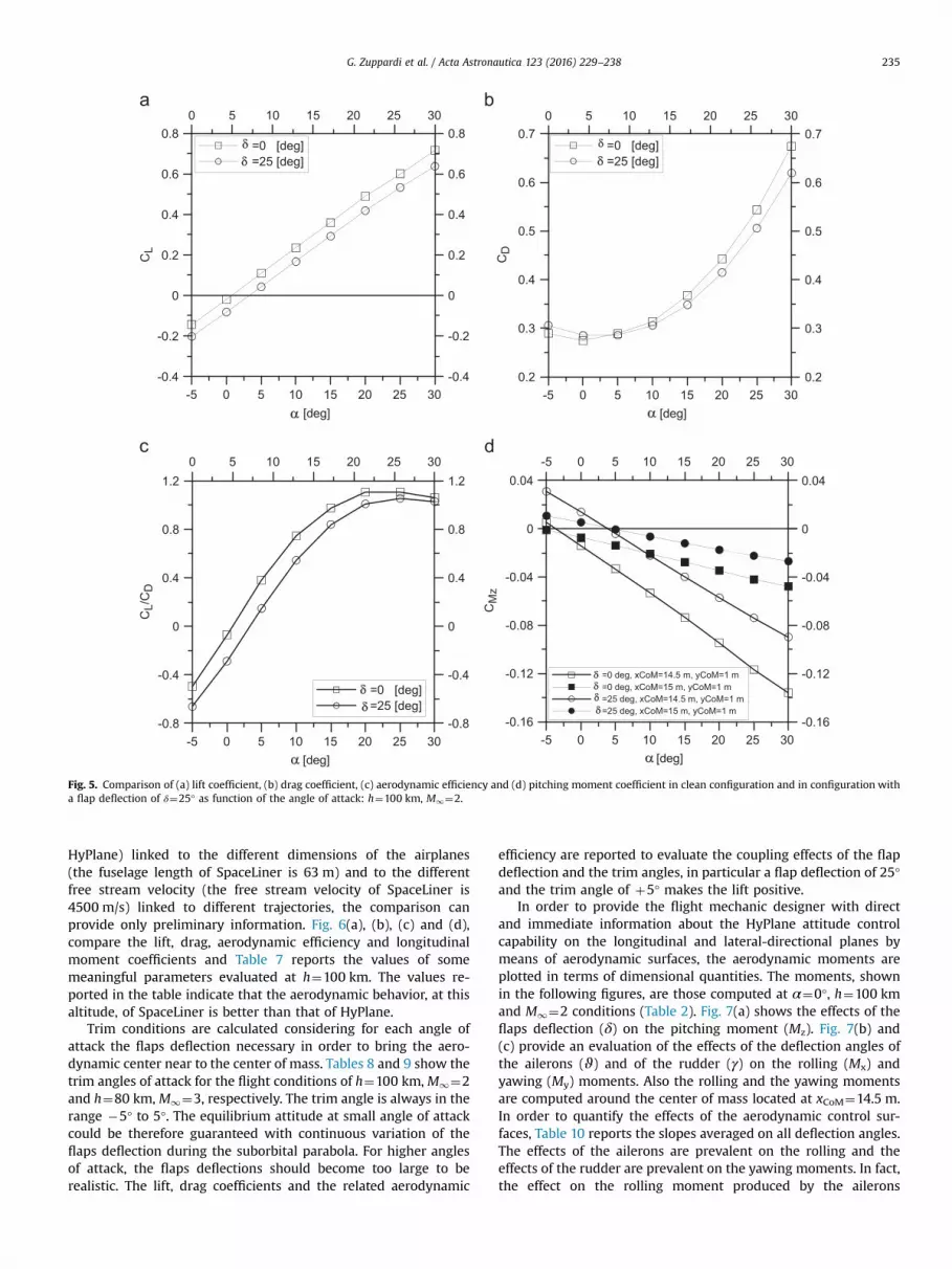
upward) of δ¼25° involves a shift of the equilibrium angle of at-tack to about 5°. As shown in Fig. 5, this deflection of the flapproduces a different aerodynamic behavior of the vehicle. Morespecifically, at h¼100 km and M1¼2, the effects of a flap deflec-tion of δ¼25° are:
i. The zero lift angle of attack moves from 0 to 5°.ii. CDmin (at α¼0°) increases from 0.2745 to 0.2851, the percentage
variation is about 4%.iii. ΔCL/Δα decreases from 0.0246 to 0.0240 [deg.�1], the per-
centage variation is �2%.iv. (CL/CD)max decreases from 1.1060 to 1.054, the percentage var-
iation is �4%.v. ΔCMz/Δα increases from �0.0040 to �0.0035 [deg.�1], the
percentage variation is �13%.
As reported in Fig. 5(d), the displacement of the center of massstrongly reduces the pitching moment slopes. For example, if xCoM¼15.0 m is assumed as reduction pole, the values of ΔCMz/Δα are�0.0013 and �0.0001 [deg.�1] in clean and flapped configuration,respectively. If xCoM¼14.5 m is assumed as reduction pole, thesevalues are �0.0041 and �0.0034, respectively.
In order to enhance the aerodynamic analysis of HyPlane, inrarefied flow, its global aerodynamic coefficients, are comparedwith those of SpaceLiner computed by Zuppardi et al. [9] by meansof the same DSMC code. Considering the different aerodynamictest conditions or Knudsen, Mach and Reynolds numbers(KnL1¼2.16�10�3, Ma1¼12 and ReL1¼8.04�103 for Space-Liner) and (KnL1¼5.59�10�3, Ma1¼3 and ReL1¼9.11�102 for
-5 0 5 10 15 20 25 30 [deg]
-0.4
-0.2
0
0.2
0.4
0.6
0.8C
L
0 5 10 15 20 25 30
=0 [deg] =25 [deg]
-0.4
-0.2
0
0.2
0.4
0.6
0.8
-5 0 5 10 15 20 25 30[deg]
0.2
0.3
0.4
0.5
0.6
0.7
CD
0 5 10 15 20 25 30
=0 [deg] =25 [deg]
0.2
0.3
0.4
0.5
0.6
0.7
-5 0 5 10 15 20 25 30 [deg]
-0.8
-0.4
0
0.4
0.8
1.2
CL/
CD
0 5 10 15 20 25 30
=0 [deg] =25 [deg]
-0.8
-0.4
0
0.4
0.8
1.2
-5 0 5 10 15 20 25 30[deg]
-0.16
-0.12
-0.08
-0.04
0
0.04C
Mz
=0 deg, xCoM=14.5 m, yCoM=1 m =0 deg, xCoM=15 m, yCoM=1 m =25 deg, xCoM=14.5 m, yCoM=1 m =25 deg, xCoM=15 m, yCoM=1 m
-5 0 5 10 15 20 25 30
-0.16
-0.12
-0.08
-0.04
0
0.04
Fig. 5. Comparison of (a) lift coefficient, (b) drag coefficient, (c) aerodynamic efficiency and (d) pitching moment coefficient in clean configuration and in configuration witha flap deflection of δ¼25° as function of the angle of attack: h¼100 km, M1¼2.
G. Zuppardi et al. / Acta Astronautica 123 (2016) 229–238 235
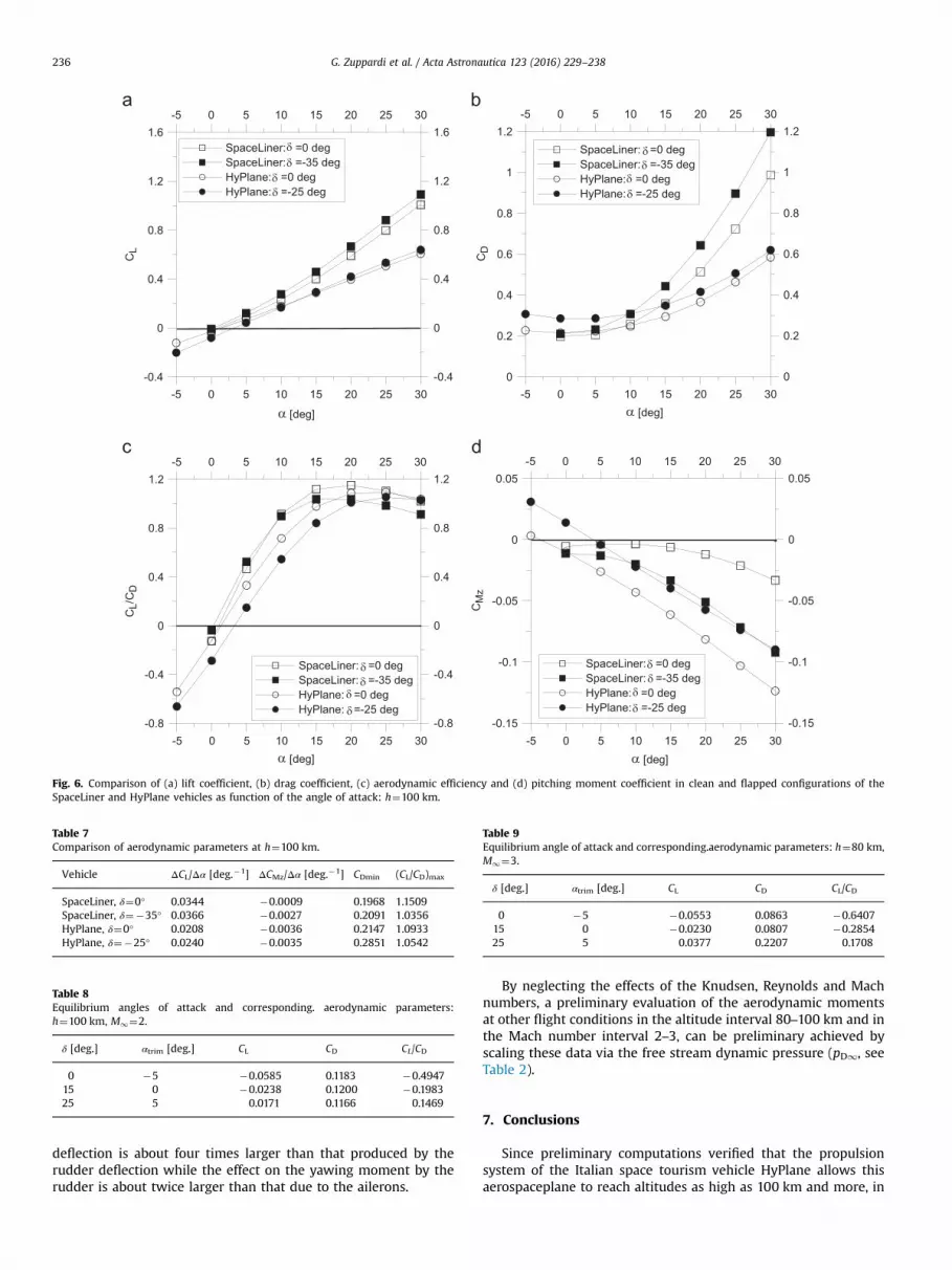
HyPlane) linked to the different dimensions of the airplanes(the fuselage length of SpaceLiner is 63 m) and to the differentfree stream velocity (the free stream velocity of SpaceLiner is4500 m/s) linked to different trajectories, the comparison canprovide only preliminary information. Fig. 6(a), (b), (c) and (d),compare the lift, drag, aerodynamic efficiency and longitudinalmoment coefficients and Table 7 reports the values of somemeaningful parameters evaluated at h¼100 km. The values re-ported in the table indicate that the aerodynamic behavior, at thisaltitude, of SpaceLiner is better than that of HyPlane.
Trim conditions are calculated considering for each angle ofattack the flaps deflection necessary in order to bring the aero-dynamic center near to the center of mass. Tables 8 and 9 show thetrim angles of attack for the flight conditions of h¼100 km, M1¼2and h¼80 km, M1¼3, respectively. The trim angle is always in therange �5° to 5°. The equilibrium attitude at small angle of attackcould be therefore guaranteed with continuous variation of theflaps deflection during the suborbital parabola. For higher anglesof attack, the flaps deflections should become too large to berealistic. The lift, drag coefficients and the related aerodynamic
efficiency are reported to evaluate the coupling effects of the flapdeflection and the trim angles, in particular a flap deflection of 25°and the trim angle of þ5° makes the lift positive.
In order to provide the flight mechanic designer with directand immediate information about the HyPlane attitude controlcapability on the longitudinal and lateral-directional planes bymeans of aerodynamic surfaces, the aerodynamic moments areplotted in terms of dimensional quantities. The moments, shownin the following figures, are those computed at α¼0°, h¼100 kmand M1¼2 conditions (Table 2). Fig. 7(a) shows the effects of theflaps deflection (δ) on the pitching moment (Mz). Fig. 7(b) and(c) provide an evaluation of the effects of the deflection angles ofthe ailerons (ϑ) and of the rudder (γ) on the rolling (Mx) andyawing (My) moments. Also the rolling and the yawing momentsare computed around the center of mass located at xCoM¼14.5 m.In order to quantify the effects of the aerodynamic control sur-faces, Table 10 reports the slopes averaged on all deflection angles.The effects of the ailerons are prevalent on the rolling and theeffects of the rudder are prevalent on the yawing moments. In fact,the effect on the rolling moment produced by the ailerons
-5 0 5 10 15 20 25 30
[deg]
-0.4
0
0.4
0.8
1.2
1.6C
LSpaceLiner: =0 degSpaceLiner: =-35 degHyPlane: =0 degHyPlane: =-25 deg
-0.4
0
0.4
0.8
1.2
1.6-5 0 5 10 15 20 25 30
α -5 0 5 10 15 20 25 30
[deg]
0
0.2
0.4
0.6
0.8
1
1.2
CD
SpaceLiner: =0 degSpaceLiner: =-35 degHyPlane: =0 degHyPlane: =-25 deg
-5 0 5 10 15 20 25 30
0
0.2
0.4
0.6
0.8
1
1.2
α
-5 0 5 10 15 20 25 30 [deg]
-0.8
-0.4
0
0.4
0.8
1.2
CL/
CD
SpaceLiner: =0 degSpaceLiner: =-35 degHyPlane: =0 degHyPlane: =-25 deg
-0.8
-0.4
0
0.4
0.8
1.2-5 0 5 10 15 20 25 30
α-5 0 5 10 15 20 25 30
[deg]
-0.15
-0.1
-0.05
0
0.05C
Mz
SpaceLiner: =0 degSpaceLiner: =-35 degHyPlane: =0 degHyPlane: =-25 deg
-5 0 5 10 15 20 25 30
-0.15
-0.1
-0.05
0
0.05
α
Fig. 6. Comparison of (a) lift coefficient, (b) drag coefficient, (c) aerodynamic efficiency and (d) pitching moment coefficient in clean and flapped configurations of theSpaceLiner and HyPlane vehicles as function of the angle of attack: h¼100 km.
Table 7Comparison of aerodynamic parameters at h¼100 km.
Vehicle ΔCL/Δα [deg.�1] ΔCMz/Δα [deg.�1] CDmin (CL/CD)max
SpaceLiner, δ¼0° 0.0344 �0.0009 0.1968 1.1509SpaceLiner, δ¼�35° 0.0366 �0.0027 0.2091 1.0356HyPlane, δ¼0° 0.0208 �0.0036 0.2147 1.0933HyPlane, δ¼�25° 0.0240 �0.0035 0.2851 1.0542
Table 8Equilibrium angles of attack and corresponding. aerodynamic parameters:h¼100 km, M1¼2.
δ [deg.] αtrim [deg.] CL CD CL/CD
0 �5 �0.0585 0.1183 �0.494715 0 �0.0238 0.1200 �0.198325 5 0.0171 0.1166 0.1469
Table 9Equilibrium angle of attack and corresponding.aerodynamic parameters: h¼80 km,M1¼3.
δ [deg.] αtrim [deg.] CL CD CL/CD
0 �5 �0.0553 0.0863 �0.640715 0 �0.0230 0.0807 �0.285425 5 0.0377 0.2207 0.1708
G. Zuppardi et al. / Acta Astronautica 123 (2016) 229–238236
deflection is about four times larger than that produced by therudder deflection while the effect on the yawing moment by therudder is about twice larger than that due to the ailerons.
By neglecting the effects of the Knudsen, Reynolds and Machnumbers, a preliminary evaluation of the aerodynamic momentsat other flight conditions in the altitude interval 80–100 km and inthe Mach number interval 2–3, can be preliminary achieved byscaling these data via the free stream dynamic pressure (pD1, seeTable 2).
7. Conclusions
Since preliminary computations verified that the propulsionsystem of the Italian space tourism vehicle HyPlane allows thisaerospaceplane to reach altitudes as high as 100 km and more, in

-25 -20 -15 -10 -5 0 5 10 15 20 25 [deg]
-8
-6
-4
-2
0
2
4M
zcg [
Nm
]
-25 -20 -15 -10 -5 0 5 10 15 20 25
-8
-6
-4
-2
0
2
4
0 5 10 15 20 25 , [deg]
0
0.25
0.5
0.75
1
1.25
1.5
Mxc
g [N
m]
AileronRudder
0 5 10 15 20 25
0
0.25
0.5
0.75
1
1.25
1.5
0 5 10 15 20 25 , [deg]
0
0.05
0.1
0.15
0.2
0.25
0.3
Myc
g [N
m]
AileronRudder
0 5 10 15 20 25
0
0.05
0.1
0.15
0.2
0.25
0.3
Fig. 7. Influence of the deflection angle of the flaps on the pitching moment (a) and of ailerons and rudder on the rolling (b) and yawing (c) moments.
Table 10Slopes of moments versus the deflection angle of the control surfaces.
dMz/dδ [Nm/deg.]
dMx/dϑ [Nm/deg.]
dMx/dγ [Nm/deg.]
dMy/dϑ [Nm/deg.]
dMy/dγ [Nm/deg.]
0.1800 0.0493 0.0206 0.0041 0.0154
G. Zuppardi et al. / Acta Astronautica 123 (2016) 229–238 237
the present paper some aspects of the aerodynamic behavior ofthe vehicle have been analyzed in rarefied (continuum low den-sity) regime. Computations by the DSMC code DS3V have beencarried out at the altitudes of 80, 90 and 100 km and at Machnumber of 2 and 3. The aerodynamic behavior, in terms of globalcoefficients, has been compared also with that of SpaceLiner at100 km both in clean and flapped configuration.
Computations showed that, in clean configuration and at highaltitude, the trim angle of attack is about �5° and that thanks tothe flap deflection of þ25° the trim angle of attack shifts to 5°,verifying the longitudinal attitude control capability. Other atti-tude control capabilities related to ailerons and rudder have beenalso evaluated. Tests have been carried out at zero angle of attack
and 100 km altitude, in the �25° to 25° flaps deflection anglerange and in the 0–25° ailerons and rudder deflection angle range.An evaluation of the aerodynamic moments at other analyzed testconditions can be preliminary fulfilled by scaling these data withthe dynamic pressure.
The verified HyPlane attitude control capability by means ofaerodynamic surfaces is very useful because allows HyPlane toreduce the amount of fuel for the thrusters.
References
[1] V. Carandente, V. D’Oriano, A. Gallina, G. Russo, R. Savino, Aerothermodynamicand system analysis of a small hypersonic airplane (HyPlane), in: Proceedingsof the 64th International Astronautical Congress, Beijing, China, 2013.
[2] R. Savino, G. Russo, V. D’Oriano, M. Visone, M. Battipede, P. Gili. Performancesof a small hypersonic airplane (HyPplane), in: Proceedings of the 65th Inter-national Astronautical Congress, Toronto, Canada, Acta Astronautica, 2014, 115,2015, pp. 338–348.
[3] R. Savino, G. Russo, V. Carandente, V. D’Oriano, HyPlane: challenges for spacetourism and business transportation, J. Aeronaut. Aerosp. Eng. 2 (2013) 1–8.
[4] R. Savino, G. Russo, V. Carandente, V. D’Oriano, HyPlane for space tourism andbusiness transportation, JBIS 67 (2014) 82–89.
[5] G. Russo, PRORA-USV: Closer Space and Aeronautics, West-East High Speed
G. Zuppardi et al. / Acta Astronautica 123 (2016) 229–238238
Flow Field (WEHSFF-2007) Conference, Moscow, Russia, 2007.[6] ⟨https://it.wikipedia.org/wiki/Space_Shuttle⟩.[7] M. Sippel, A. van Foreest, C. Bauer, F. Cremaschi, System Investigation of the
SpaceLiner Concept in FAST20XX, 2011, AIAA Paper, pp. 2011–2294.[8] M. Sippel et al., Technical maturation of the spaceliner concept, in: Proceed-
ings of the 18th AIAA/3AF International Space Planes and Hypersonic Systemsand Technologies Conference, Tours, France, 2012.
[9] G. Zuppardi, L. Morsa, M. Sippel, T. Schwanekamp, Aero-thermo-dynamicanalysis of the spaceLiner-7.1 vehicle in high altitude flight, in: Proceedings ofthe 29th International Symposium on Rarefied Gas Dynamics, Xi’an, China,2014.
[10] ⟨https://en.wikipedia.org/wiki/SpaceShipTwo⟩.[11] ⟨https://it.wikipedia.org/wiki/Concorde⟩.[12] G.A. Bird, The DS3V Program User's Guide Ver. 2.5, G.A.B. Consulting Pty. Ltd.
Sydney, Australia, 2006.[13] S. Chen, G.D. Doolen, Lattice Boltzmann method for fluid flows, Annu. Rev.
Fluid Mech. 30 (1998) 329–364.[14] G.A. Bird, Molecular Gas Dynamics and Direct Simulation Monte Carlo, Clar-
endon Press, Oxford, Great Britain, 1998.[15] G.A. Bird, The DSMC Method, Version 1.1, Amazon, ISBS 9781492112907,
Charleston, USA, 2013.[16] C. Shen, Rarefied Gas Dynamic: Fundamentals, Simulations and Micro Flows,
Springer-Verlag, Berlin, Germany, 2005.[17] R.N. Gupta, J.M. Yos, R.A. Thompson, A Review of Reaction Rates and Ther-
modynamic Transport Properties for an 11-Species Air Model for Chemical andThermal Non-Equilibrium Calculations to 30,000 K, NASA TM 101528, 1989.
[18] G.A. Bird, Sophisticated versus simple DSMC, in: Proceedings of the 25th In-ternational Symposium on Rarefied Gas Dynamics, Saint Petersburg, Russia,2006.
[19] G.A. Bird, M.A. Gallis, J.R. Torczynski, D.J. Rader, Accuracy and efficiency of thesophisticated Direct Simulation Monte Carlo algorithm for simulating non-continuum gas flows, Phys. Fluids 21 (2009) 017103.
[20] M.A. Gallis, J.R. Torczynski, D.J. Rader, G.A. Bird, Convergence behavior of anew DSMC algorithm, J. Comput. Phys. 228 (2009) 4532–4548.
[21] G.A. Bird, The DS2V/3V program suite for dsmc calculations, in: Proceedings ofthe 24th International Symposium on Rarafied Gas Dynamics Monopoli, Italy,2004.
[22] J.N. Moss, Rarefied Flows of Planetary Entry Capsules, Special course onCapsule Aerothermodynamics, Rhode-St.-Genèse, Belgium, AGARD-R 808,1995, pp. 95–129.
[23] A. Shapiro, The Dynamics and Thermodynamics of Compressible Fluid Flow,John Wiley & Sons Inc, New York, USA, 1953.
Gennaro Zuppardi got a Laurea degree in AeronauticalEngineering in July 1976 (score: 110/110) at the Uni-versity of Naples “Federico II”. He has been a lecturer in:1) Fluid-dynamics at the University of Basilicata (a.y.1993/94), 2) Experimental Fluid-dynamics at the Uni-versity of Naples “Federico II” (a.y. 1994/95), 3) Hy-personic Aerodynamics at the University of Naples“Federico II”, since a.y. 1997/98 up today. Research ac-tivities: 1) Boundary layer diagnostics by non-intrusivetechnique (thermography), 2) Adaptive walls windtunnel. 3) Aero-thermo-chemistry. 4) Rarefied Gas-Dynamics and DSMC, this subject is his current mayor.
He is author or co-author of 90 scientific papers and ofa book in Hypersonic Aerodynamics.
Raffaele Savino, Ph.D., is professor of Aerodynamics atthe University of Naples Federico II. He was responsibleas of several research programs in collaboration withResearch Centers and Space Agencies (ASI, CIRA, ESA,NASA). His memberships include the InternationalAcademy of Astronautics (IAA), the International As-tronautical Federation (IAF), the Italian Association ofAeronautics and Astronautics (AIDAA), the AmericanInstitute of Aeronautics and Astronautics (AIAA). He isauthor of over 200 publications in the fields of FluidDynamics, Microgravity and Space Experimentation,Physics of Fluids, Hypersonic Aerodynamics, Heat
transfer, Aerospace Propulsion Recent researchactivities include hypersonic numerical and experimental aerodynamics, aero-thermochemistry, innovative heat pipes for ground and space applications, hybridrocket propulsion.
Gennaro Russo, Co-founder and President of TRANS-TECH, an SME devoted to technology transfer and hightech projects. Co-conceiver and project manager of theHyPlane project. For 25 years he managed space relatedprograms, projects and facilities devoted to spacetransportation and reentry at the Italian AerospaceResearch Center. He was designer of the 70 MW SCIR-OCCO Plasma Wind Tunnel for reentry aero-thermodynamics simulation. At the beginning of hiscareer, he worked for about ten years with the Micro-gravity Research Team of University of Naples, design-ing, preparing and analyzing some experiments exe-
cuted on board the ESA Spacelab. He is vice-presidentof the Italian Institute for the Future and DG of its Center for Near Space devoted toSpace Tourism.
Luca Spano' Cuomo is a student in Aerospace En-gineering at the University of Naples “Federico II”. He iscurrently involved in the study of Aerodynamics ofaero-space-planes in rarefied flow by means of DirectSimulation Monte Carlo codes. More specifically, duringhis Laurea Thesis, he developed several RhinocerosCADs of HyPlane for running the DSMC code DS3V.
Eliano Petrosino got a Master degree in AerospaceEngineering In July 2015 (score 104/110) at the Uni-versity of Naples “Federico II”. The title of the thesis was“Influence of gas-surface interaction models on theaerodynamic parameters of an airfoil in hypersonic,rarefied flow”. He has been collaborating with the re-search group of the projects “HyPlane” and “MISTRAL”at the University of Naples “Federico II”. Since October2015 he has been working at CGM Italia s.r.l. as tech-nical office manager.