advanced automation light grids - sick germany
TRANSCRIPT

Advanced Automation Light Grids
For demanding requirements
Pr
od
uc
t in
fo
rm
Ati
on
A d v A n c e d A u t o m At i o n L i G h t G r i d s | s i c K 8014656/2011-09-01Subject to change without notice
Advanced automation light grids
2
technology
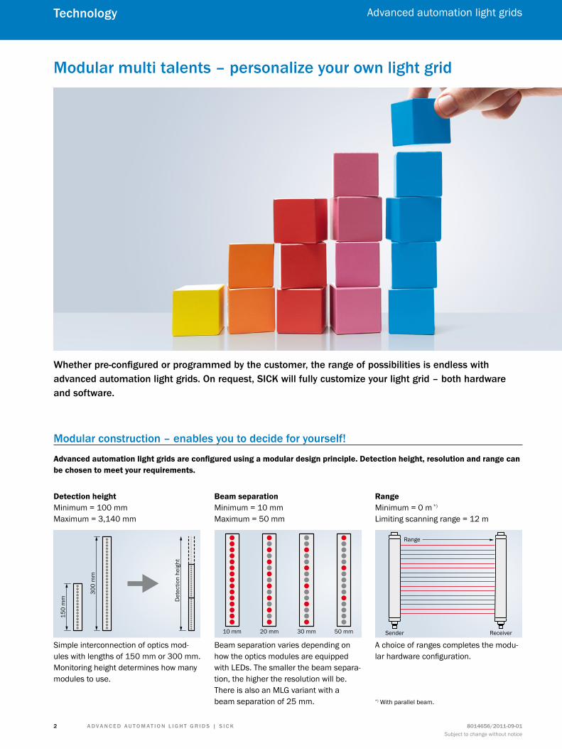
modular multi talents – personalize your own light grid
Whether pre-configured or programmed by the customer, the range of possibilities is endless with advanced auto mation light grids. on request, sicK will fully customize your light grid – both hardware and software.
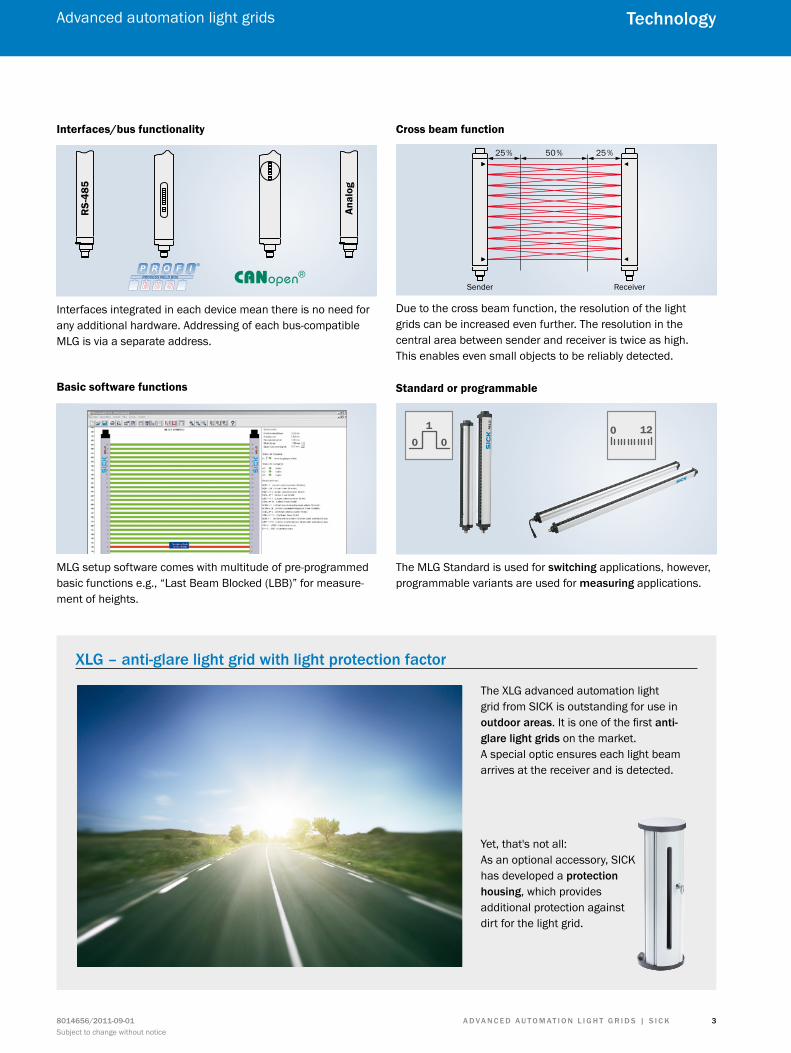
Advanced automation light grids are configured using a modular design principle. Detection height, resolution and range can be chosen to meet your requirements.
modular construction – enables you to decide for yourself!
Simple interconnection of optics mod-ules with lengths of 150 mm or 300 mm. Monitoring height determines how many modules to use.
Detection heightMinimum = 100 mm Maximum = 3,140 mm
Beam separationMinimum = 10 mm Maximum = 50 mm
RangeMinimum = 0 m *)
Limiting scanning range = 12 m
Beam separation varies depending on how the optics modules are equipped with LEDs. The smaller the beam separa-tion, the higher the resolution will be. There is also an MLG variant with a beam separation of 25 mm.
A choice of ranges completes the modu-lar hardware configuration.
150
mm Det
ectio
n he
ight
300
mm
10 mm 20 mm 30 mm 50 mm
Range
Sender Receiver
*) With parallel beam.
A d v A n c e d A u t o m At i o n L i G h t G r i d s | s i c K8014656/2011-09-01Subject to change without notice
Advanced automation light grids
3
technology
RS-
485
Anal
og
2 5% 50% 25%
Sender Receiver
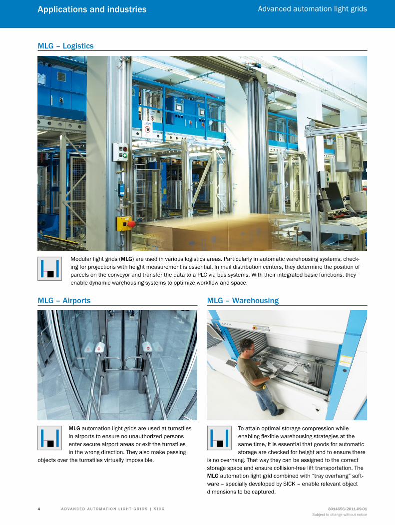
XLG – anti-glare light grid with light protection factor
The XLG advanced automation light grid from SICK is outstanding for use in outdoor areas. It is one of the first anti-glare light grids on the market. A special optic ensures each light beam arrives at the receiver and is detected.
Interfaces integrated in each device mean there is no need for any additional hardware. Addressing of each bus-compatible MLG is via a separate address.
Due to the cross beam function, the resolution of the light grids can be increased even further. The resolution in the central area between sender and receiver is twice as high. This enables even small objects to be reliably detected.
The MLG Standard is used for switching applications, however, programmable variants are used for measuring applications.
Interfaces/bus functionality Cross beam function
Standard or programmableBasic software functions
MLG setup software comes with multitude of pre-programmed basic functions e.g., “Last Beam Blocked (LBB)” for measure-ment of heights.
0 01 120
Yet, that's not all: As an optional accessory, SICK has developed a pro tection housing, which provides additional protection against dirt for the light grid.
A d v A n c e d A u t o m At i o n L i G h t G r i d s | s i c K 8014656/2011-09-01Subject to change without notice
Advanced automation light grids
4
Applications and industries
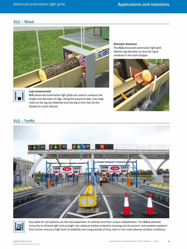
mLG – Logistics
mLG – Airports mLG – Warehousing
Modular light grids (mLG) are used in various logistics areas. Particularly in automatic warehousing systems, check-ing for projections with height measurement is essential. In mail distribution centers, they determine the position of parcels on the conveyor and transfer the data to a PLC via bus systems. With their integrated basic functions, they enable dynamic warehousing systems to optimize workflow and space.
To attain optimal storage compression while enabling flexible warehousing strategies at the same time, it is essential that goods for automatic storage are checked for height and to ensure there
is no overhang. That way they can be assigned to the correct storage space and ensure collision-free lift transportation. The mLG automation light grid combined with “tray overhang” soft-ware – specially developed by SICK – enable relevant object dimensions to be captured.
mLG automation light grids are used at turnstiles in airports to ensure no unauthorized persons enter secure airport areas or exit the turnstiles in the wrong direction. They also make passing
objects over the turnstiles virtually impossible.
A d v A n c e d A u t o m At i o n L i G h t G r i d s | s i c K8014656/2011-09-01Subject to change without notice
Advanced automation light grids
5
Applications and industries
XLG – traffic
Key tasks for toll systems are the fast separation of vehicles and their unique classification. The XLG’s absolute immunity to infrared light and sunlight, the optional heated protective housing and its scratch- and weather-resistant front screen ensure a high level of reliability over long periods of time, even in the most adverse outdoor conditions.
XLG – Wood
Log measurementXLG advanced automation light grids are used to measure the length and diameter of logs. Using the acquired data, any large roots on the log are detected and the log is then fed via the bypass to a butt reducer.
diameter detectionThe XLG advanced automation light grid detects log diameter so that the log is centered in the bark stripper.
A d v A n c e d A u t o m At i o n L i G h t G r i d s | s i c K 8014656/2011-09-01Subject to change without notice
Advanced automation light grids
6
Product family overview
Product family overview
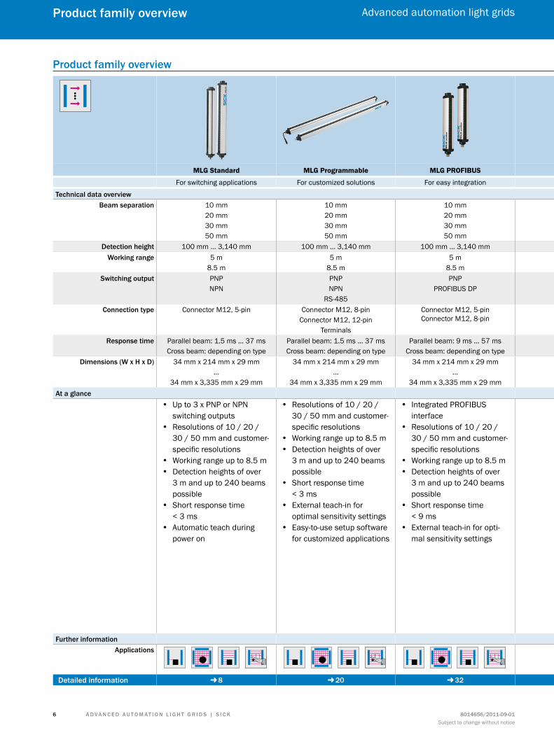
MLG Standard MLG Programmable MLG PROFIBUS MLG CANopen MLG Analog Output XLG Programmable
For switching applications For customized solutions For easy integration For fast integration Easy measuring with analog outputs Reliable measurement even in sunlight
technical data overviewBeam separation 10 mm
20 mm30 mm50 mm
10 mm20 mm30 mm50 mm
10 mm20 mm30 mm50 mm
10 mm20 mm30 mm50 mm
10 mm20 mm30 mm50 mm
10 mm20 mm30 mm50 mm
detection height 100 mm ... 3,140 mm 100 mm ... 3,140 mm 100 mm ... 3,140 mm 100 mm ... 3,140 mm 100 mm ... 3,140 mm 100 mm ... 1,990 mmWorking range 5 m
8.5 m 5 m
8.5 m 5 m
8.5 m5 m
8.5 m 5 m
8.5 m 5 m
switching output PNPNPN
PNPNPN
RS-485
PNPPROFIBUS DP
PNPCANopen
PNPNPN
2 x analog outputs
PNPNPN
RS-485connection type Connector M12, 5-pin Connector M12, 8-pin
Connector M12, 12-pinTerminals
Connector M12, 5-pin Connector M12, 8-pin
Connector M12, 8-pin Connector M12, 8-pinConnector M12, 12-pin
Terminals
Connector M12, 8-pinTerminals
response time Parallel beam: 1.5 ms ... 37 msCross beam: depending on type
Parallel beam: 1.5 ms ... 37 msCross beam: depending on type
Parallel beam: 9 ms ... 57 msCross beam: depending on type
Parallel beam: 9 ms ... 57 msCross beam: depending on type
Parallel beam: 1.5 ms ... 37 msCross beam: depending on type
Parallel beam: 1.5 ms ... 24 msCross beam: depending on type
dimensions (W x h x d) 34 mm x 214 mm x 29 mm...
34 mm x 3,335 mm x 29 mm
34 mm x 214 mm x 29 mm...
34 mm x 3,335 mm x 29 mm
34 mm x 214 mm x 29 mm...
34 mm x 3,335 mm x 29 mm
34 mm x 214 mm x 29 mm...
34 mm x 3,335 mm x 29 mm
34 mm x 214 mm x 29 mm...
34 mm x 3,335 mm x 29 mm
34 mm x 214 mm x 29 mm...
34 mm x 2,125 mm x 29 mmAt a glance
• Up to 3 x PNP or NPN switching outputs
• Resolutions of 10 / 20 / 30 / 50 mm and customer-specific resolutions
• Working range up to 8.5 m • Detection heights of over
3 m and up to 240 beams possible
• Short response time < 3 ms
• Automatic teach during power on
• Resolutions of 10 / 20 / 30 / 50 mm and customer-specific resolutions
• Working range up to 8.5 m • Detection heights of over
3 m and up to 240 beams possible
• Short response time < 3 ms
• External teach-in for optimal sensitivity settings
• Easy-to-use setup software for customized applications
• Integrated PROFIBUS interface
• Resolutions of 10 / 20 / 30 / 50 mm and customer-specific resolutions
• Working range up to 8.5 m • Detection heights of over
3 m and up to 240 beams possible
• Short response time < 9 ms
• External teach-in for opti-mal sensitivity settings
• Integrated CANopen interface • Resolutions of 10 / 20 / 30 / 50 mm
and customer-specific resolutions • Working range up to 8.5 m • Detection heights of over 3 m and up
to 240 beams possible • Short response time of < 9 ms • Teach algorithm for optimal
sensitivity settings in difficult applications
• Two analog outputs: voltage to current
• Resolutions of 10 / 20 / 30 / 50 mm and customer-specific resolutions
• Working range up to 8.5 m • Detection heights of over 3 m and up
to 240 beams possible • Short response time of < 3 ms
possible • Teach algorithm for optimal
sensitivity settings in difficult applications, such as measuring translucent objects
• Easy-to-use setup software for customized applications with new features
• Software tools, such as height mea-surement, zoning, hole detection, and presence control make implementation of complex solutions achievable
• Up to 6 x PNP or NPN switching out-puts and two switching inputs
• Resolutions of 10 / 20 / 30 / 50 mm and customer-specific resolutions
• Working range up to 5 m • Detection heights of over 3 m and up
to 150 beams possible • Short response time < 3 ms • External teach-in for optimal
sensitivity settings • Highest immunity to sunlight • Scratch-resistant front lens
further informationApplications
detailed information -- 8 -- 20 -- 32 -- 44 -- 54 -- 64
A d v A n c e d A u t o m At i o n L i G h t G r i d s | s i c K8014656/2011-09-01Subject to change without notice
Advanced automation light grids
7
Product family overview
Product family overview
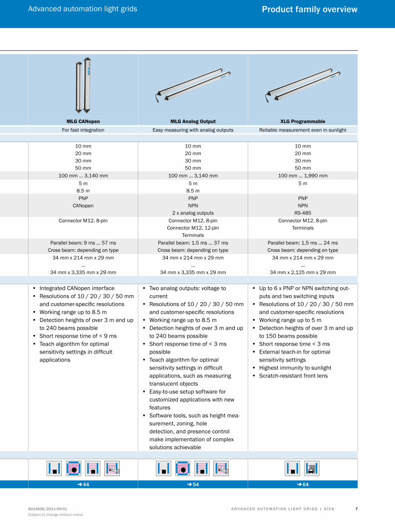
MLG Standard MLG Programmable MLG PROFIBUS MLG CANopen MLG Analog Output XLG Programmable
For switching applications For customized solutions For easy integration For fast integration Easy measuring with analog outputs Reliable measurement even in sunlight
technical data overviewBeam separation 10 mm
20 mm30 mm50 mm
10 mm20 mm30 mm50 mm
10 mm20 mm30 mm50 mm
10 mm20 mm30 mm50 mm
10 mm20 mm30 mm50 mm
10 mm20 mm30 mm50 mm
detection height 100 mm ... 3,140 mm 100 mm ... 3,140 mm 100 mm ... 3,140 mm 100 mm ... 3,140 mm 100 mm ... 3,140 mm 100 mm ... 1,990 mmWorking range 5 m
8.5 m 5 m
8.5 m 5 m
8.5 m5 m
8.5 m 5 m
8.5 m 5 m
switching output PNPNPN
PNPNPN
RS-485
PNPPROFIBUS DP
PNPCANopen
PNPNPN
2 x analog outputs
PNPNPN
RS-485connection type Connector M12, 5-pin Connector M12, 8-pin
Connector M12, 12-pinTerminals
Connector M12, 5-pin Connector M12, 8-pin
Connector M12, 8-pin Connector M12, 8-pinConnector M12, 12-pin
Terminals
Connector M12, 8-pinTerminals
response time Parallel beam: 1.5 ms ... 37 msCross beam: depending on type
Parallel beam: 1.5 ms ... 37 msCross beam: depending on type
Parallel beam: 9 ms ... 57 msCross beam: depending on type
Parallel beam: 9 ms ... 57 msCross beam: depending on type
Parallel beam: 1.5 ms ... 37 msCross beam: depending on type
Parallel beam: 1.5 ms ... 24 msCross beam: depending on type
dimensions (W x h x d) 34 mm x 214 mm x 29 mm...
34 mm x 3,335 mm x 29 mm
34 mm x 214 mm x 29 mm...
34 mm x 3,335 mm x 29 mm
34 mm x 214 mm x 29 mm...
34 mm x 3,335 mm x 29 mm
34 mm x 214 mm x 29 mm...
34 mm x 3,335 mm x 29 mm
34 mm x 214 mm x 29 mm...
34 mm x 3,335 mm x 29 mm
34 mm x 214 mm x 29 mm...
34 mm x 2,125 mm x 29 mmAt a glance
• Up to 3 x PNP or NPN switching outputs
• Resolutions of 10 / 20 / 30 / 50 mm and customer-specific resolutions
• Working range up to 8.5 m • Detection heights of over
3 m and up to 240 beams possible
• Short response time < 3 ms
• Automatic teach during power on
• Resolutions of 10 / 20 / 30 / 50 mm and customer-specific resolutions
• Working range up to 8.5 m • Detection heights of over
3 m and up to 240 beams possible
• Short response time < 3 ms
• External teach-in for optimal sensitivity settings
• Easy-to-use setup software for customized applications
• Integrated PROFIBUS interface
• Resolutions of 10 / 20 / 30 / 50 mm and customer-specific resolutions
• Working range up to 8.5 m • Detection heights of over
3 m and up to 240 beams possible
• Short response time < 9 ms
• External teach-in for opti-mal sensitivity settings
• Integrated CANopen interface • Resolutions of 10 / 20 / 30 / 50 mm
and customer-specific resolutions • Working range up to 8.5 m • Detection heights of over 3 m and up
to 240 beams possible • Short response time of < 9 ms • Teach algorithm for optimal
sensitivity settings in difficult applications
• Two analog outputs: voltage to current
• Resolutions of 10 / 20 / 30 / 50 mm and customer-specific resolutions
• Working range up to 8.5 m • Detection heights of over 3 m and up
to 240 beams possible • Short response time of < 3 ms
possible • Teach algorithm for optimal
sensitivity settings in difficult applications, such as measuring translucent objects
• Easy-to-use setup software for customized applications with new features
• Software tools, such as height mea-surement, zoning, hole detection, and presence control make implementation of complex solutions achievable
• Up to 6 x PNP or NPN switching out-puts and two switching inputs
• Resolutions of 10 / 20 / 30 / 50 mm and customer-specific resolutions
• Working range up to 5 m • Detection heights of over 3 m and up
to 150 beams possible • Short response time < 3 ms • External teach-in for optimal
sensitivity settings • Highest immunity to sunlight • Scratch-resistant front lens
further informationApplications
detailed information -- 8 -- 20 -- 32 -- 44 -- 54 -- 64
A d v A n c e d A u t o m At i o n L i G h t G r i d s | s i c K 8014656/2011-09-01Subject to change without notice
Advanced automation light grids
8
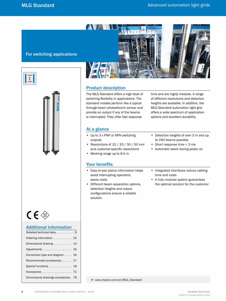
mLG standard
Product descriptionThe MLG Standard offers a high level of switching flexibility in applications. The standard models perform like a typical through-beam photoelectric sensor and provide an output if any of the beams is interrupted. They offer fast response
time and are highly modular. A range of different resolutions and detection heights are available. In addition, the MLG Standard automation light grid offers a wide spectrum of application options and excellent durability.
At a glance • Up to 3 x PNP or NPN switching
outputs • Resolutions of 10 / 20 / 30 / 50 mm
and customer-specific resolutions • Working range up to 8.5 m
• Detection heights of over 3 m and up to 240 beams possible
• Short response time < 3 ms • Automatic teach during power on
Your benefits • Easy-to-see status information helps
avoid interrupting operation, saves costs
• Different beam separation options, detection heights and output configurations ensure a reliable solution
• Integrated interfaces reduce cabling time and costs
• A fully modular system guarantees the optimal solution for the customer
for switching applications
Additional informationDetailed technical data. . . . . . . . . . . . .9
Ordering information. . . . . . . . . . . . . 10
Dimensional drawing . . . . . . . . . . . . 14
Adjustments . . . . . . . . . . . . . . . . . . . 16
Connection type and diagram . . . . . 16
Recommended accessories . . . . . . . 17
Special functions. . . . . . . . . . . . . . . . 18
Accessories . . . . . . . . . . . . . . . . . . . . 72
Dimensional drawings accessories . 78 - www.mysick.com/en/MLG_Standard
A d v A n c e d A u t o m At i o n L i G h t G r i d s | s i c K8014656/2011-09-01Subject to change without notice
Advanced automation light grids
9
mLG standard
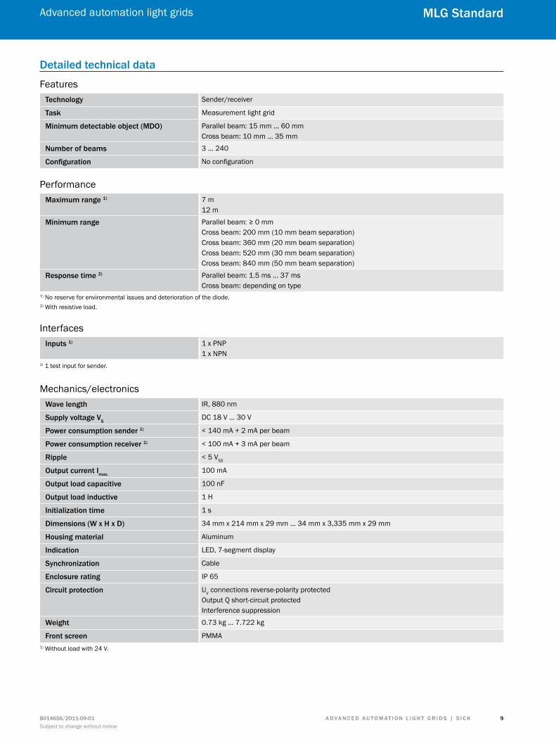
detailed technical data
Featurestechnology Sender/receiver
task Measurement light grid
minimum detectable object (mdo) Parallel beam: 15 mm ... 60 mmCross beam: 10 mm ... 35 mm
number of beams 3 ... 240
configuration No configuration
Performancemaximum range 1) 7 m
12 m
minimum range Parallel beam: ≥ 0 mmCross beam: 200 mm (10 mm beam separation)Cross beam: 360 mm (20 mm beam separation)Cross beam: 520 mm (30 mm beam separation)Cross beam: 840 mm (50 mm beam separation)
response time 2) Parallel beam: 1.5 ms ... 37 msCross beam: depending on type
1) No reserve for environmental issues and deterioration of the diode.2) With resistive load.
Interfacesinputs 1) 1 x PNP
1 x NPN1) 1 test input for sender.
Mechanics/electronicsWave length IR, 880 nm
supply voltage vsDC 18 V ... 30 V
Power consumption sender 1) < 140 mA + 2 mA per beam
Power consumption receiver 1) < 100 mA + 3 mA per beam
ripple < 5 VSS
output current imax.100 mA
output load capacitive 100 nF
output load inductive 1 H
initialization time 1 s
dimensions (W x h x d) 34 mm x 214 mm x 29 mm ... 34 mm x 3,335 mm x 29 mm
housing material Aluminum
indication LED, 7-segment display
synchronization Cable
enclosure rating IP 65
circuit protection UV connections reverse-polarity protectedOutput Q short-circuit protectedInterference suppression
Weight 0.73 kg ... 7.722 kg
front screen PMMA1) Without load with 24 V.
A d v A n c e d A u t o m At i o n L i G h t G r i d s | s i c K 8014656/2011-09-01Subject to change without notice
Advanced automation light grids
1 0
mLG standard
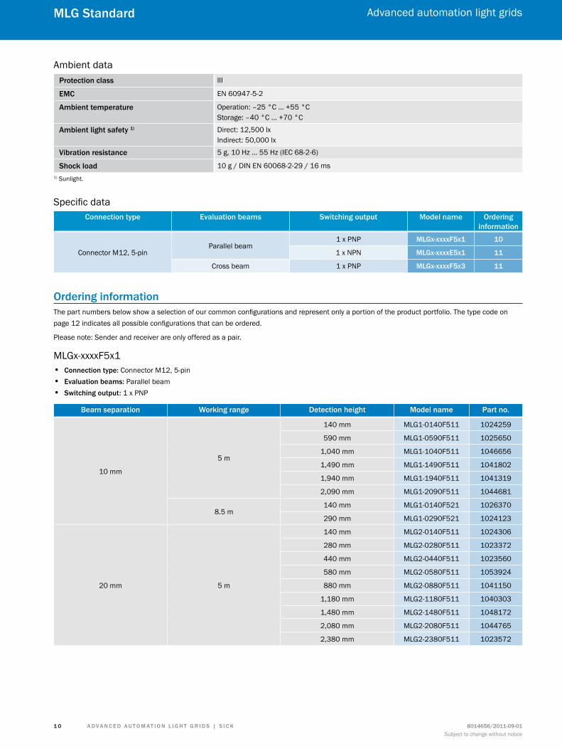
Ambient dataProtection class III
emc EN 60947-5-2
Ambient temperature Operation: –25 °C ... +55 °CStorage: –40 °C ... +70 °C
Ambient light safety 1) Direct: 12,500 lxIndirect: 50,000 lx
vibration resistance 5 g, 10 Hz ... 55 Hz (IEC 68-2-6)
shock load 10 g / DIN EN 60068-2-29 / 16 ms1) Sunlight.
Specific dataconnection type evaluation beams switching output model name ordering
information
Connector M12, 5-pinParallel beam
1 x PNP mLGx-xxxxf5x1 10
1 x NPN mLGx-xxxxe5x1 11
Cross beam 1 x PNP mLGx-xxxxf5x3 11
ordering informationThe part numbers below show a selection of our common configurations and represent only a portion of the product portfolio. The type code on page 12 indicates all possible configurations that can be ordered.
Please note: Sender and receiver are only offered as a pair.
MLGx-xxxxF5x1 • connection type: Connector M12, 5-pin • evaluation beams: Parallel beam • switching output: 1 x PNP
Beam separation Working range detection height model name Part no.
10 mm
5 m
140 mm MLG1-0140F511 1024259
590 mm MLG1-0590F511 1025650
1,040 mm MLG1-1040F511 1046656
1,490 mm MLG1-1490F511 1041802
1,940 mm MLG1-1940F511 1041319
2,090 mm MLG1-2090F511 1044681
8.5 m140 mm MLG1-0140F521 1026370
290 mm MLG1-0290F521 1024123
20 mm 5 m
140 mm MLG2-0140F511 1024306
280 mm MLG2-0280F511 1023372
440 mm MLG2-0440F511 1023560
580 mm MLG2-0580F511 1053924
880 mm MLG2-0880F511 1041150
1,180 mm MLG2-1180F511 1040303
1,480 mm MLG2-1480F511 1048172
2,080 mm MLG2-2080F511 1044765
2,380 mm MLG2-2380F511 1023572
A d v A n c e d A u t o m At i o n L i G h t G r i d s | s i c K8014656/2011-09-01Subject to change without notice
Advanced automation light grids
1 1
mLG standard
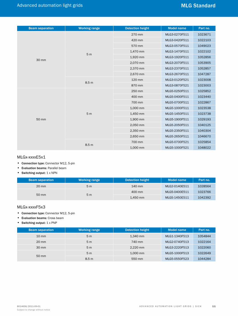
Beam separation Working range detection height model name Part no.
30 mm
5 m
270 mm MLG3-0270F511 1023671
420 mm MLG3-0420F511 1022103
570 mm MLG3-0570F511 1049023
1,470 mm MLG3-1470F511 1022102
1,920 mm MLG3-1920F511 1052856
2,070 mm MLG3-2070F511 1053905
2,370 mm MLG3-2370F511 1052857
2,670 mm MLG3-2670F511 1047287
8.5 m120 mm MLG3-0120F521 1023008
870 mm MLG3-0870F521 1023003
50 mm
5 m
250 mm MLG5-0250F511 1025852
400 mm MLG5-0400F511 1023440
700 mm MLG5-0700F511 1022867
1,000 mm MLG5-1000F511 1023538
1,450 mm MLG5-1450F511 1023738
1,900 mm MLG5-1900F511 1029193
2,050 mm MLG5-2050F511 1040125
2,350 mm MLG5-2350F511 1040304
2,650 mm MLG5-2650F511 1046670
8.5 m700 mm MLG5-0700F521 1025854
1,000 mm MLG5-1000F521 1048022
MLGx-xxxxE5x1 • connection type: Connector M12, 5-pin • evaluation beams: Parallel beam • switching output: 1 x NPN
Beam separation Working range detection height model name Part no.
20 mm 5 m 140 mm MLG2-0140E511 1028564
50 mm 5 m400 mm MLG5-0400E511 1023766
1,450 mm MLG5-1450E511 1042392
MLGx-xxxxF5x3 • connection type: Connector M12, 5-pin • evaluation beams: Cross beam • switching output: 1 x PNP
Beam separation Working range detection height model name Part no.
10 mm 5 m 1,340 mm MLG1-1340F513 1054844
20 mm 5 m 740 mm MLG2-0740F513 1022164
30 mm 5 m 2,220 mm MLG3-2220F513 1022060
50 mm5 m 1,000 mm MLG5-1000F513 1022649
8.5 m 550 mm MLG5-0550F523 1044284
A d v A n c e d A u t o m At i o n L i G h t G r i d s | s i c K 8014656/2011-09-01Subject to change without notice
Advanced automation light grids
1 2
mLG standard
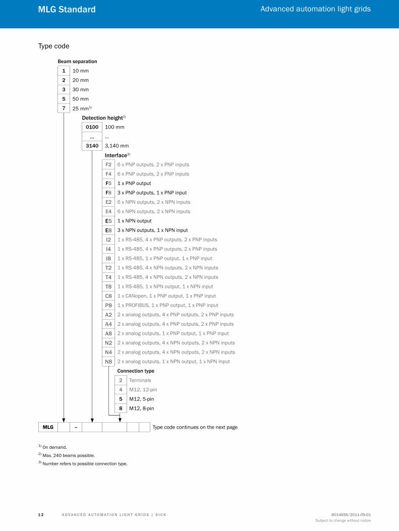
Type code
Beam separation
1 10 mm
2 20 mm
3 30 mm
5 50 mm
7 25 mm1)
detection height2)
0100 100 mm
… …
3140 3,140 mm
interface3)
f2 6 x PNP outputs, 2 x PNP inputs
f4 6 x PNP outputs, 2 x PNP inputs
f5 1 x PNP output
f8 3 x PNP outputs, 1 x PNP input
e2 6 x NPN outputs, 2 x NPN inputs
e4 6 x NPN outputs, 2 x NPN inputs
e5 1 x NPN output
e8 3 x NPN outputs, 1 x NPN input
i2 1 x RS-485, 4 x PNP outputs, 2 x PNP inputs
i4 1 x RS-485, 4 x PNP outputs, 2 x PNP inputs
i8 1 x RS-485, 1 x PNP output, 1 x PNP input
t2 1 x RS-485, 4 x NPN outputs, 2 x NPN inputs
t4 1 x RS-485, 4 x NPN outputs, 2 x NPN inputs
t8 1 x RS-485, 1 x NPN output, 1 x NPN input
c8 1 x CANopen, 1 x PNP output, 1 x PNP input
P8 1 x PROFIBUS, 1 x PNP output, 1 x PNP input
A2 2 x analog outputs, 4 x PNP outputs, 2 x PNP inputs
A4 2 x analog outputs, 4 x PNP outputs, 2 x PNP inputs
A8 2 x analog outputs, 1 x PNP output, 1 x PNP input
n2 2 x analog outputs, 4 x NPN outputs, 2 x NPN inputs
n4 2 x analog outputs, 4 x NPN outputs, 2 x NPN inputs
n8 2 x analog outputs, 1 x NPN output, 1 x NPN input
connection type
2 Terminals
4 M12, 12-pin
5 M12, 5-pin
8 M12, 8-pin
MLG – Type code continues on the next page
1) On demand.2) Max. 240 beams possible.3) Number refers to possible connection type.
A d v A n c e d A u t o m At i o n L i G h t G r i d s | s i c K8014656/2011-09-01Subject to change without notice
Advanced automation light grids
1 3
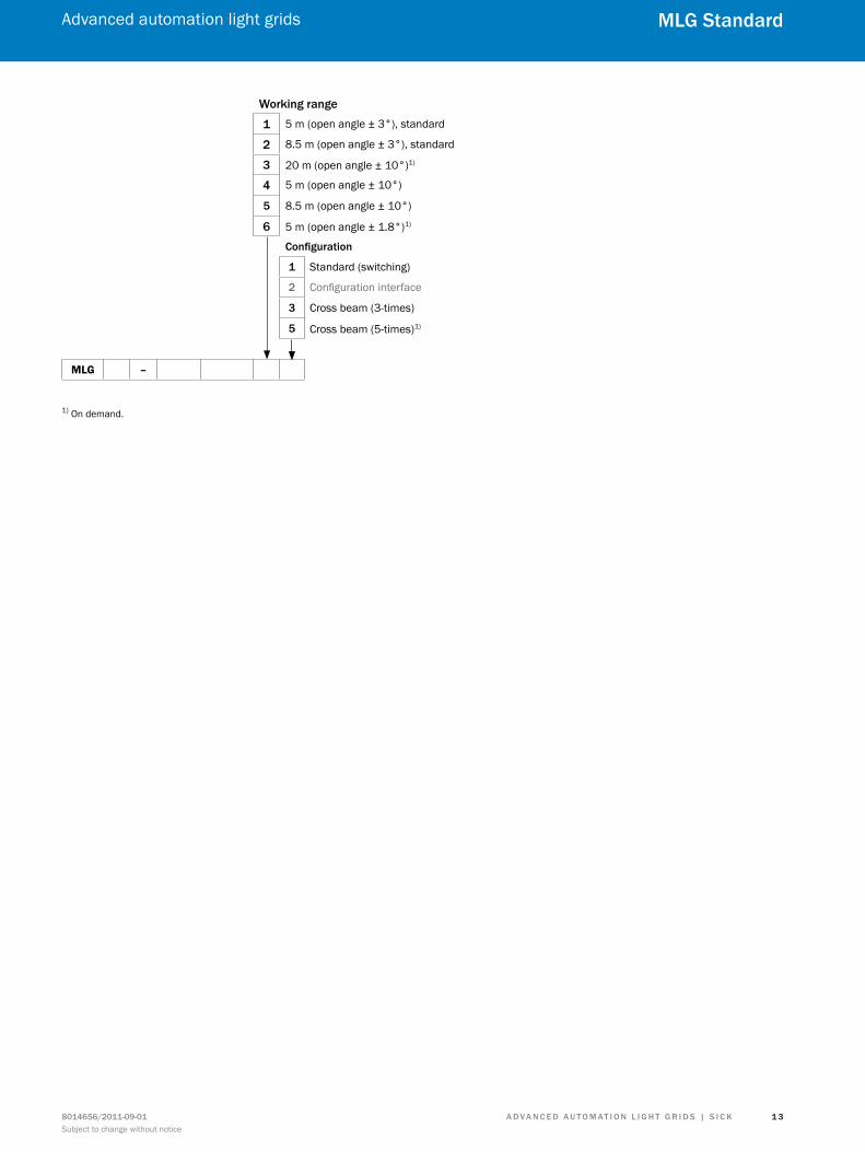
mLG standard
Working range
1 5 m (open angle ± 3°), standard
2 8.5 m (open angle ± 3°), standard
3 20 m (open angle ± 10°)1)
4 5 m (open angle ± 10°)
5 8.5 m (open angle ± 10°)
6 5 m (open angle ± 1.8°)1) configuration
1 Standard (switching)
2 Configuration interface
3 Cross beam (3-times)
5 Cross beam (5-times)1)
MLG –
1) On demand.
A d v A n c e d A u t o m At i o n L i G h t G r i d s | s i c K 8014656/2011-09-01Subject to change without notice
Advanced automation light grids
1 4
mLG standard
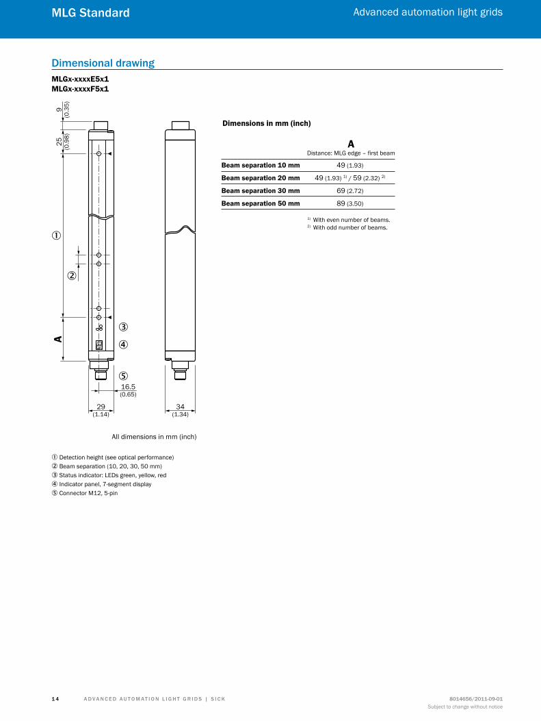
dimensional drawingMLGx-xxxxE5x1 MLGx-xxxxF5x1
A9
(0.3
5)25 (0.9
8)
�
�
�
�
�16.5(0.65)
29(1.14)
34(1.34)
All dimensions in mm (inch)
Dimensions in mm (inch)
ADistance: MLG edge – first beam
Beam separation 10 mm 49 (1.93)
Beam separation 20 mm 49 (1.93) 1) / 59 (2.32) 2)
Beam separation 30 mm 69 (2.72)
Beam separation 50 mm 89 (3.50)
1) With even number of beams.2) With odd number of beams.
1 Detection height (see optical performance)2 Beam separation (10, 20, 30, 50 mm)3 Status indicator: LEDs green, yellow, red4 Indicator panel, 7-segment display5 Connector M12, 5-pin
A d v A n c e d A u t o m At i o n L i G h t G r i d s | s i c K8014656/2011-09-01Subject to change without notice
Advanced automation light grids
1 5
mLG standard
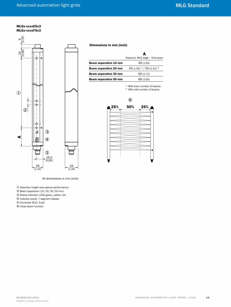
MLGx-xxxxE5x3 MLGx-xxxxF5x3
A9
(0.3
5)25 (0.9
8)
�
�
�
�
�16.5(0.65)
29(1.14)
34(1.34)
All dimensions in mm (inch)
�2 5% 50% 25%
Dimensions in mm (inch)
ADistance: MLG edge – first beam
Beam separation 10 mm 49 (1.93)
Beam separation 20 mm 49 (1.93) 1) / 59 (2.32) 2)
Beam separation 30 mm 69 (2.72)
Beam separation 50 mm 89 (3.50)
1) With even number of beams.2) With odd number of beams.
1 Detection height (see optical performance)2 Beam separation (10, 20, 30, 50 mm)3 Status indicator: LEDs green, yellow, red4 Indicator panel, 7-segment display5 Connector M12, 5-pin6 Cross beam function
A d v A n c e d A u t o m At i o n L i G h t G r i d s | s i c K 8014656/2011-09-01Subject to change without notice
Advanced automation light grids
1 6
mLG standard
Adjustments
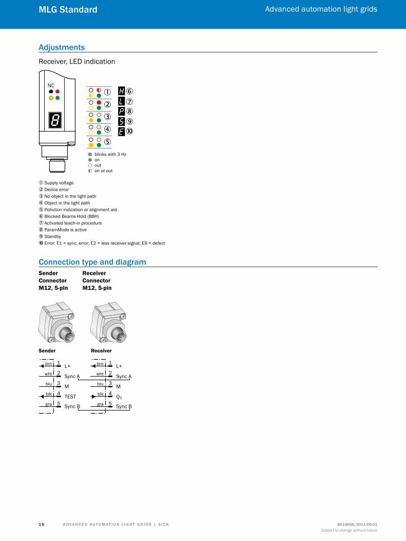
Receiver, LED indication
NC
blinks with 3 Hzonouton or out
�
� �����
��
�
1 Supply voltage2 Device error3 No object in the light path4 Object in the light path5 Pollution indication or alignment aid6 Blocked Beams Hold (BBH)7 Activated teach-in procedure8 ParamMode is active9 Standbyß Error: E1 = sync. error; E2 = less receiver signal; E9 = defect
connection type and diagramSender Connector M12, 5-pin
Receiver Connector M12, 5-pin
L+
Sync A
M
Sync B
TEST
brn
wht
blu
blk
gra
1
2
3
4
5
L+
Sync A
M
Sync B
Q1
brn
wht
blu
blk
gra
1
2
3
4
5
Sender Receiver
A d v A n c e d A u t o m At i o n L i G h t G r i d s | s i c K8014656/2011-09-01Subject to change without notice
Advanced automation light grids
1 7
mLG standard
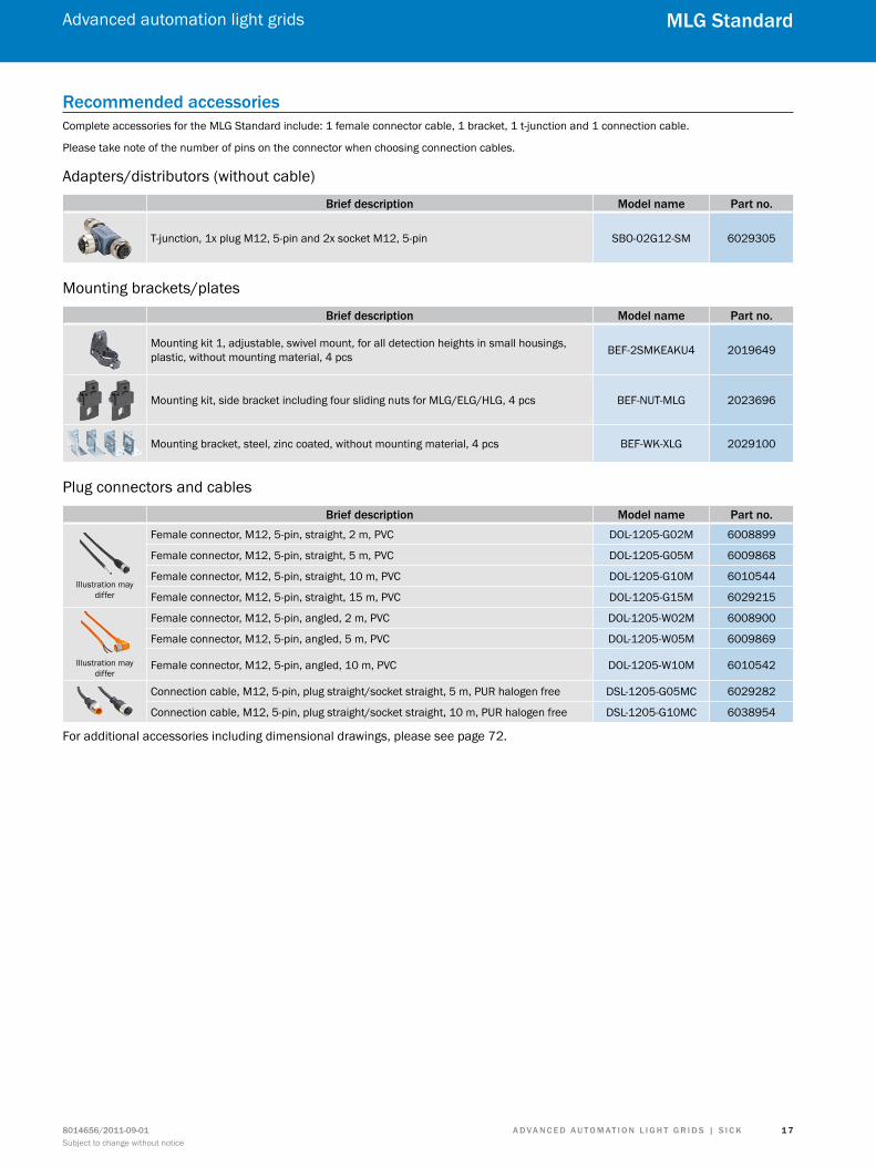
recommended accessoriesComplete accessories for the MLG Standard include: 1 female connector cable, 1 bracket, 1 t-junction and 1 connection cable.
Please take note of the number of pins on the connector when choosing connection cables.
Adapters/distributors (without cable)
Brief description model name Part no.
T-junction, 1x plug M12, 5-pin and 2x socket M12, 5-pin SBO-02G12-SM 6029305
Mounting brackets/plates
Brief description model name Part no.
Mounting kit 1, adjustable, swivel mount, for all detection heights in small housings, plastic, without mounting material, 4 pcs BEF-2SMKEAKU4 2019649
Mounting kit, side bracket including four sliding nuts for MLG/ELG/HLG, 4 pcs BEF-NUT-MLG 2023696
Mounting bracket, steel, zinc coated, without mounting material, 4 pcs BEF-WK-XLG 2029100
Plug connectors and cables
Brief description model name Part no.
Illustration may differ
Female connector, M12, 5-pin, straight, 2 m, PVC DOL-1205-G02M 6008899
Female connector, M12, 5-pin, straight, 5 m, PVC DOL-1205-G05M 6009868
Female connector, M12, 5-pin, straight, 10 m, PVC DOL-1205-G10M 6010544
Female connector, M12, 5-pin, straight, 15 m, PVC DOL-1205-G15M 6029215
Illustration may differ
Female connector, M12, 5-pin, angled, 2 m, PVC DOL-1205-W02M 6008900
Female connector, M12, 5-pin, angled, 5 m, PVC DOL-1205-W05M 6009869
Female connector, M12, 5-pin, angled, 10 m, PVC DOL-1205-W10M 6010542
Connection cable, M12, 5-pin, plug straight/socket straight, 5 m, PUR halogen free DSL-1205-G05MC 6029282
Connection cable, M12, 5-pin, plug straight/socket straight, 10 m, PUR halogen free DSL-1205-G10MC 6038954
For additional accessories including dimensional drawings, please see page 72.
A d v A n c e d A u t o m At i o n L i G h t G r i d s | s i c K 8014656/2011-09-01Subject to change without notice
Advanced automation light grids
1 8
mLG standard
special functions
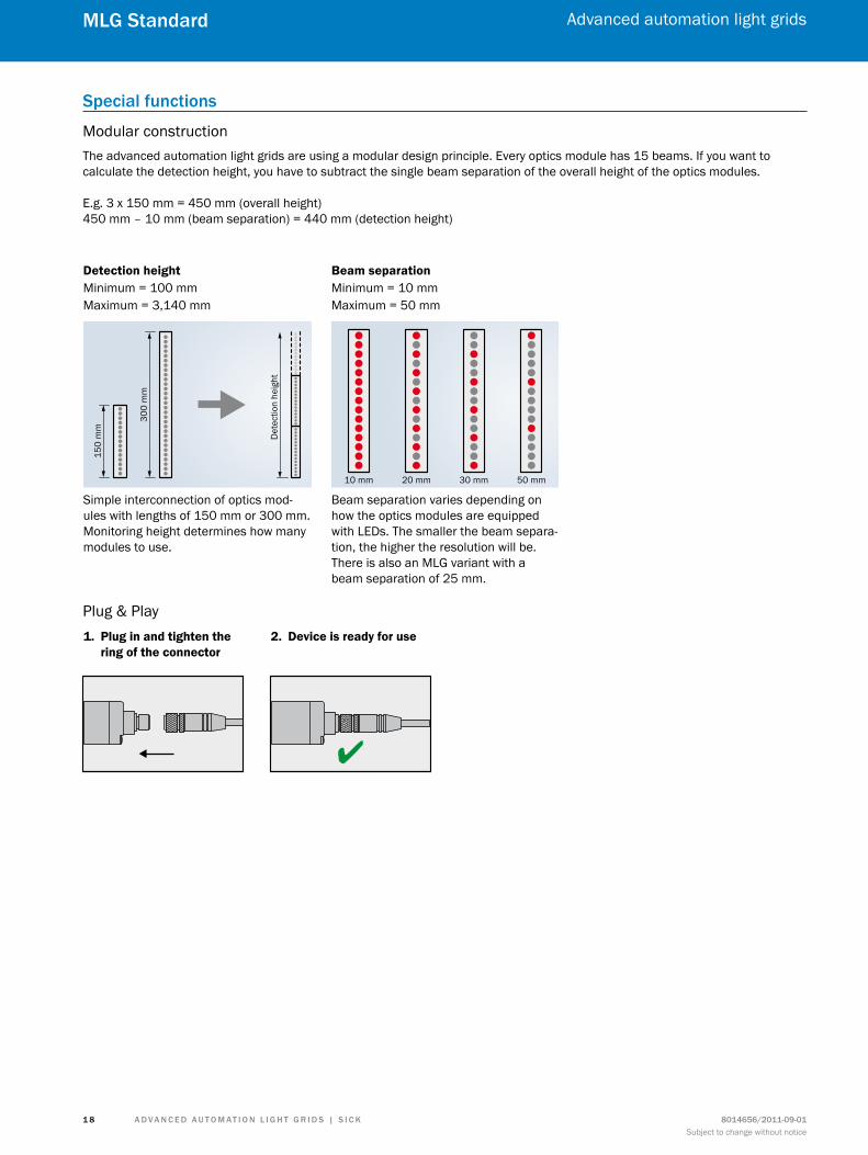
Modular constructionThe advanced automation light grids are using a modular design principle. Every optics module has 15 beams. If you want to calculate the detection height, you have to subtract the single beam separation of the overall height of the optics modules.
E.g. 3 x 150 mm = 450 mm (overall height)450 mm – 10 mm (beam separation) = 440 mm (detection height)
Simple interconnection of optics mod-ules with lengths of 150 mm or 300 mm. Monitoring height determines how many modules to use.
Detection height Beam separationMinimum = 100 mmMaximum = 3,140 mm
Minimum = 10 mmMaximum = 50 mm
Beam separation varies depending on how the optics modules are equipped with LEDs. The smaller the beam separa-tion, the higher the resolution will be. There is also an MLG variant with a beam separation of 25 mm.
150
mm
Det
ectio
n he
ight
300
mm
10 mm 20 mm 30 mm 50 mm
Plug & Play1. Plug in and tighten the ring of the connector
2. Device is ready for use
l

A d v A n c e d A u t o m At i o n L i G h t G r i d s | s i c K8014656/2011-09-01Subject to change without notice
Advanced automation light grids
1 9
mLG standard
A d v A n c e d A u t o m At i o n L i G h t G r i d s | s i c K 8014656/2011-09-01Subject to change without notice
Advanced automation light grids
2 0
mLG Programmable
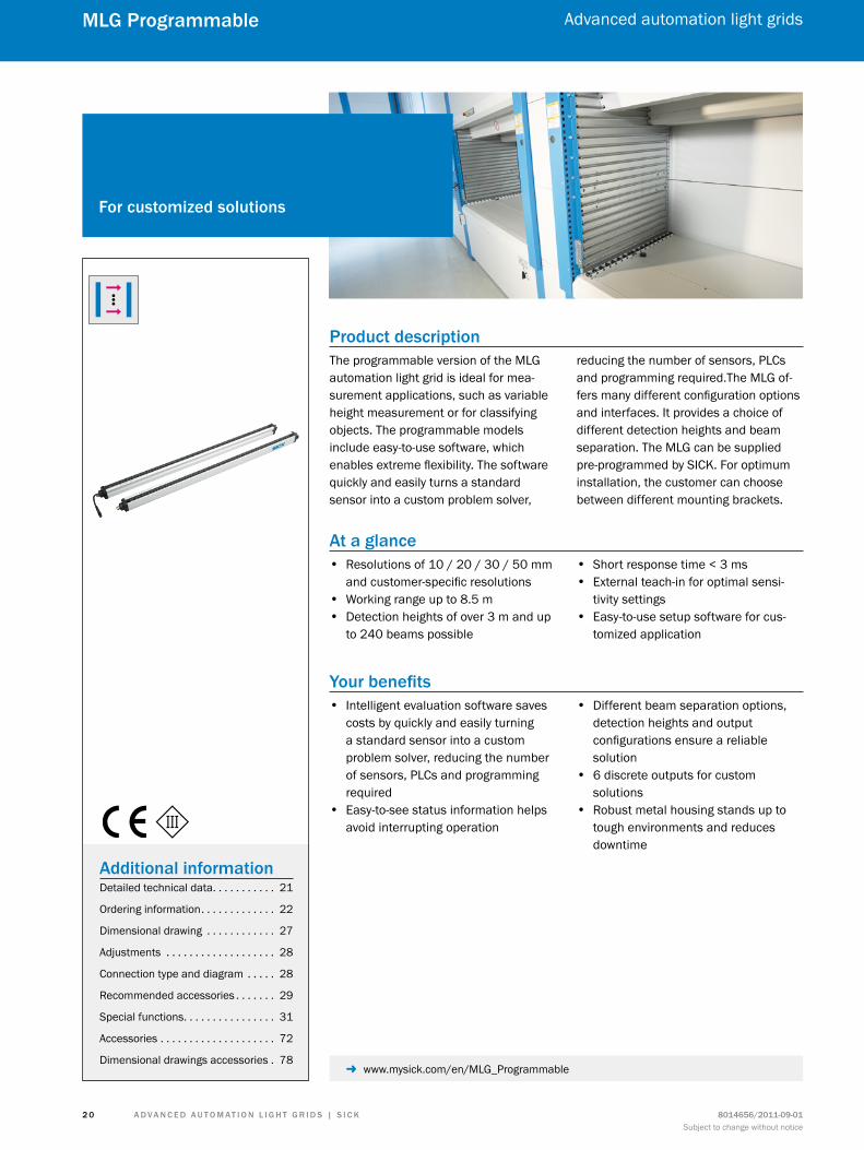
Product descriptionThe programmable version of the MLG automation light grid is ideal for mea-surement applications, such as variable height measurement or for classifying objects. The programmable models include easy-to-use software, which enables extreme flexibility. The software quickly and easily turns a standard sensor into a custom problem solver,
reducing the number of sensors, PLCs and programming required.The MLG of-fers many different configuration options and interfaces. It provides a choice of different detection heights and beam separation. The MLG can be supplied pre-programmed by SICK. For optimum installation, the customer can choose between different mounting brackets.
At a glance • Resolutions of 10 / 20 / 30 / 50 mm
and customer-specific resolutions • Working range up to 8.5 m • Detection heights of over 3 m and up
to 240 beams possible
• Short response time < 3 ms • External teach-in for optimal sensi-
tivity settings • Easy-to-use setup software for cus-
tomized application
Your benefits • Intelligent evaluation software saves
costs by quickly and easily turning a standard sensor into a custom problem solver, reducing the number of sensors, PLCs and programming required
• Easy-to-see status information helps avoid interrupting operation
• Different beam separation options, detection heights and output configurations ensure a reliable solution
• 6 discrete outputs for custom solutions
• Robust metal housing stands up to tough environments and reduces downtime
for customized solutions
Additional informationDetailed technical data. . . . . . . . . . . 21
Ordering information. . . . . . . . . . . . . 22
Dimensional drawing . . . . . . . . . . . . 27
Adjustments . . . . . . . . . . . . . . . . . . . 28
Connection type and diagram . . . . . 28
Recommended accessories . . . . . . . 29
Special functions. . . . . . . . . . . . . . . . 31
Accessories . . . . . . . . . . . . . . . . . . . . 72
Dimensional drawings accessories . 78 - www.mysick.com/en/MLG_Programmable
A d v A n c e d A u t o m At i o n L i G h t G r i d s | s i c K8014656/2011-09-01Subject to change without notice
Advanced automation light grids
2 1
mLG Programmable
detailed technical data
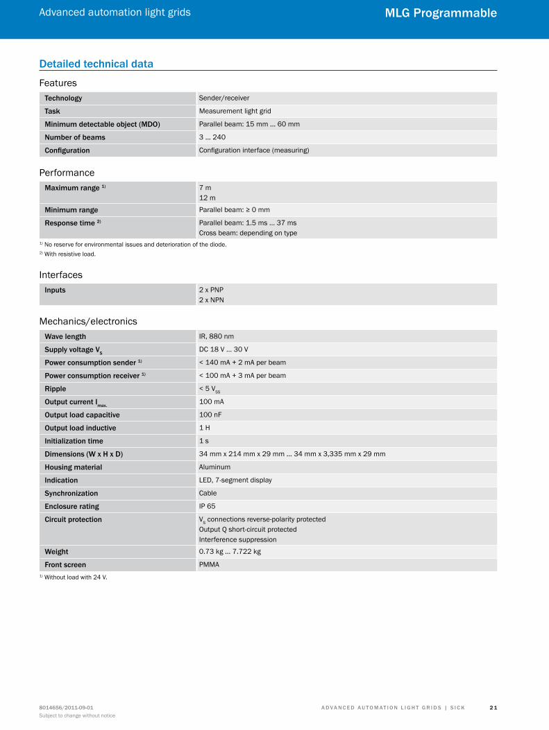
Featurestechnology Sender/receiver
task Measurement light grid
minimum detectable object (mdo) Parallel beam: 15 mm ... 60 mm
number of beams 3 ... 240
configuration Configuration interface (measuring)
Performancemaximum range 1) 7 m
12 m
minimum range Parallel beam: ≥ 0 mm
response time 2) Parallel beam: 1.5 ms ... 37 msCross beam: depending on type
1) No reserve for environmental issues and deterioration of the diode.2) With resistive load.
Interfacesinputs 2 x PNP
2 x NPN
Mechanics/electronicsWave length IR, 880 nm
supply voltage vsDC 18 V ... 30 V
Power consumption sender 1) < 140 mA + 2 mA per beam
Power consumption receiver 1) < 100 mA + 3 mA per beam
ripple < 5 VSS
output current imax.100 mA
output load capacitive 100 nF
output load inductive 1 H
initialization time 1 s
dimensions (W x h x d) 34 mm x 214 mm x 29 mm ... 34 mm x 3,335 mm x 29 mm
housing material Aluminum
indication LED, 7-segment display
synchronization Cable
enclosure rating IP 65
circuit protection VS connections reverse-polarity protectedOutput Q short-circuit protectedInterference suppression
Weight 0.73 kg ... 7.722 kg
front screen PMMA1) Without load with 24 V.
A d v A n c e d A u t o m At i o n L i G h t G r i d s | s i c K 8014656/2011-09-01Subject to change without notice
Advanced automation light grids
2 2
mLG Programmable
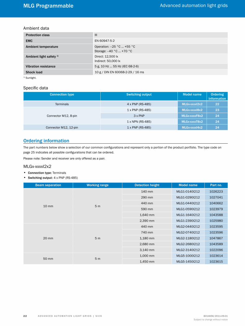
Ambient dataProtection class III
emc EN 60947-5-2
Ambient temperature Operation: –25 °C ... +55 °CStorage: –40 °C ... +70 °C
Ambient light safety 1) Direct: 12,500 lxIndirect: 50,000 lx
vibration resistance 5 g, 10 Hz ... 55 Hz (IEC 68-2-6)
shock load 10 g / DIN EN 60068-2-29 / 16 ms1) Sunlight.
Specific dataconnection type switching output model name ordering
informationTerminals 4 x PNP (RS-485) mLGx-xxxxi2x2 22
Connector M12, 8-pin
1 x PNP (RS-485) mLGx-xxxxi8x2 23
3 x PNP mLGx-xxxxf8x2 24
1 x NPN (RS-485) mLGx-xxxxt8x2 24
Connector M12, 12-pin 1 x PNP (RS-485) mLGx-xxxxi4x2 24
ordering informationThe part numbers below show a selection of our common configurations and represent only a portion of the product portfolio. The type code on page 25 indicates all possible configurations that can be ordered.
Please note: Sender and receiver are only offered as a pair.
MLGx-xxxxI2x2 • connection type: Terminals • switching output: 4 x PNP (RS-485)
Beam separation Working range detection height model name Part no.
10 mm 5 m
140 mm MLG1-0140I212 1026223
290 mm MLG1-0290I212 1027041
440 mm MLG1-0440I212 1040662
590 mm MLG1-0590I212 1023979
1,640 mm MLG1-1640I212 1043588
2,390 mm MLG1-2390I212 1025980
20 mm 5 m
440 mm MLG2-0440I212 1023595
740 mm MLG2-0740I212 1023596
1,180 mm MLG2-1180I212 1047867
2,680 mm MLG2-2680I212 1043589
3,140 mm MLG2-3140I212 1022096
50 mm 5 m1,000 mm MLG5-1000I212 1023614
1,450 mm MLG5-1450I212 1023615
A d v A n c e d A u t o m At i o n L i G h t G r i d s | s i c K8014656/2011-09-01Subject to change without notice
Advanced automation light grids
2 3
mLG Programmable
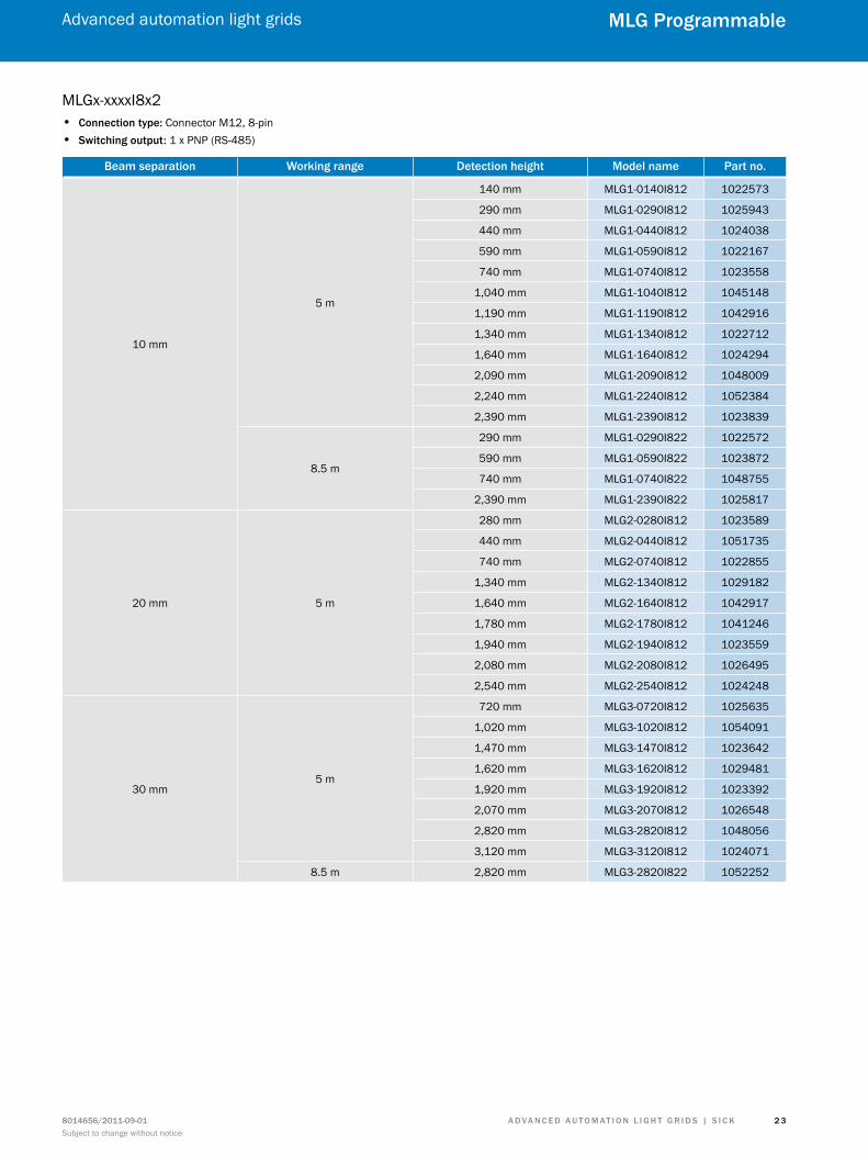
MLGx-xxxxI8x2 • connection type: Connector M12, 8-pin • switching output: 1 x PNP (RS-485)
Beam separation Working range detection height model name Part no.
10 mm
5 m
140 mm MLG1-0140I812 1022573
290 mm MLG1-0290I812 1025943
440 mm MLG1-0440I812 1024038
590 mm MLG1-0590I812 1022167
740 mm MLG1-0740I812 1023558
1,040 mm MLG1-1040I812 1045148
1,190 mm MLG1-1190I812 1042916
1,340 mm MLG1-1340I812 1022712
1,640 mm MLG1-1640I812 1024294
2,090 mm MLG1-2090I812 1048009
2,240 mm MLG1-2240I812 1052384
2,390 mm MLG1-2390I812 1023839
8.5 m
290 mm MLG1-0290I822 1022572
590 mm MLG1-0590I822 1023872
740 mm MLG1-0740I822 1048755
2,390 mm MLG1-2390I822 1025817
20 mm 5 m
280 mm MLG2-0280I812 1023589
440 mm MLG2-0440I812 1051735
740 mm MLG2-0740I812 1022855
1,340 mm MLG2-1340I812 1029182
1,640 mm MLG2-1640I812 1042917
1,780 mm MLG2-1780I812 1041246
1,940 mm MLG2-1940I812 1023559
2,080 mm MLG2-2080I812 1026495
2,540 mm MLG2-2540I812 1024248
30 mm5 m
720 mm MLG3-0720I812 1025635
1,020 mm MLG3-1020I812 1054091
1,470 mm MLG3-1470I812 1023642
1,620 mm MLG3-1620I812 1029481
1,920 mm MLG3-1920I812 1023392
2,070 mm MLG3-2070I812 1026548
2,820 mm MLG3-2820I812 1048056
3,120 mm MLG3-3120I812 1024071
8.5 m 2,820 mm MLG3-2820I822 1052252
A d v A n c e d A u t o m At i o n L i G h t G r i d s | s i c K 8014656/2011-09-01Subject to change without notice
Advanced automation light grids
2 4
mLG Programmable
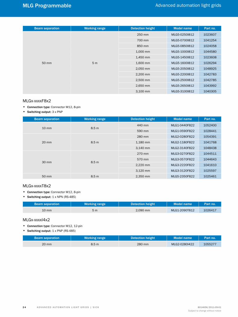
Beam separation Working range detection height model name Part no.
50 mm 5 m
250 mm MLG5-0250I812 1023607
700 mm MLG5-0700I812 1041254
850 mm MLG5-0850I812 1024058
1,000 mm MLG5-1000I812 1044580
1,450 mm MLG5-1450I812 1023608
1,600 mm MLG5-1600I812 1026294
2,050 mm MLG5-2050I812 1048925
2,200 mm MLG5-2200I812 1042783
2,500 mm MLG5-2500I812 1042785
2,650 mm MLG5-2650I812 1043992
3,100 mm MLG5-3100I812 1040305
MLGx-xxxxF8x2 • connection type: Connector M12, 8-pin • switching output: 3 x PNP
Beam separation Working range detection height model name Part no.
10 mm 8.5 m440 mm MLG1-0440F822 1052400
590 mm MLG1-0590F822 1028441
20 mm 8.5 m
280 mm MLG2-0280F822 1054391
1,180 mm MLG2-1180F822 1041768
3,140 mm MLG2-3140F822 1048438
30 mm 8.5 m
270 mm MLG3-0270F822 1044511
570 mm MLG3-0570F822 1044643
2,220 mm MLG3-2220F822 1041610
3,120 mm MLG3-3120F822 1025597
50 mm 8.5 m 2,350 mm MLG5-2350F822 1025461
MLGx-xxxxT8x2 • connection type: Connector M12, 8-pin • switching output: 1 x NPN (RS-485)
Beam separation Working range detection height model name Part no.
10 mm 5 m 2,090 mm MLG1-2090T812 1026417
MLGx-xxxxI4x2 • connection type: Connector M12, 12-pin • switching output: 1 x PNP (RS-485)
Beam separation Working range detection height model name Part no.
20 mm 8.5 m 280 mm MLG2-0280I422 1055277
A d v A n c e d A u t o m At i o n L i G h t G r i d s | s i c K8014656/2011-09-01Subject to change without notice
Advanced automation light grids
2 5
mLG Programmable
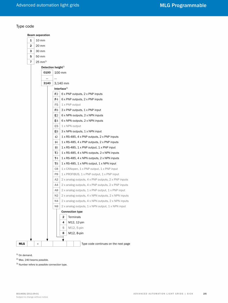
Type code
Beam separation
1 10 mm
2 20 mm
3 30 mm
5 50 mm
7 25 mm1)
detection height2)
0100 100 mm… …
3140 3,140 mm
interface3)
f2 6 x PNP outputs, 2 x PNP inputs
f4 6 x PNP outputs, 2 x PNP inputs
f5 1 x PNP output
f8 3 x PNP outputs, 1 x PNP input
e2 6 x NPN outputs, 2 x NPN inputs
e4 6 x NPN outputs, 2 x NPN inputs
e5 1 x NPN output
e8 3 x NPN outputs, 1 x NPN input
i2 1 x RS-485, 4 x PNP outputs, 2 x PNP inputs
i4 1 x RS-485, 4 x PNP outputs, 2 x PNP inputs
i8 1 x RS-485, 1 x PNP output, 1 x PNP input
t2 1 x RS-485, 4 x NPN outputs, 2 x NPN inputs
t4 1 x RS-485, 4 x NPN outputs, 2 x NPN inputs
t8 1 x RS-485, 1 x NPN output, 1 x NPN input
c8 1 x CANopen, 1 x PNP output, 1 x PNP input
P8 1 x PROFIBUS, 1 x PNP output, 1 x PNP input
A2 2 x analog outputs, 4 x PNP outputs, 2 x PNP inputs
A4 2 x analog outputs, 4 x PNP outputs, 2 x PNP inputs
A8 2 x analog outputs, 1 x PNP output, 1 x PNP input
n2 2 x analog outputs, 4 x NPN outputs, 2 x NPN inputs
n4 2 x analog outputs, 4 x NPN outputs, 2 x NPN inputs
n8 2 x analog outputs, 1 x NPN output, 1 x NPN input
connection type
2 Terminals
4 M12, 12-pin
5 M12, 5-pin8 M12, 8-pin
MLG – Type code continues on the next page
1) On demand.2) Max. 240 beams possible.3) Number refers to possible connection type.
A d v A n c e d A u t o m At i o n L i G h t G r i d s | s i c K 8014656/2011-09-01Subject to change without notice
Advanced automation light grids
2 6
mLG Programmable
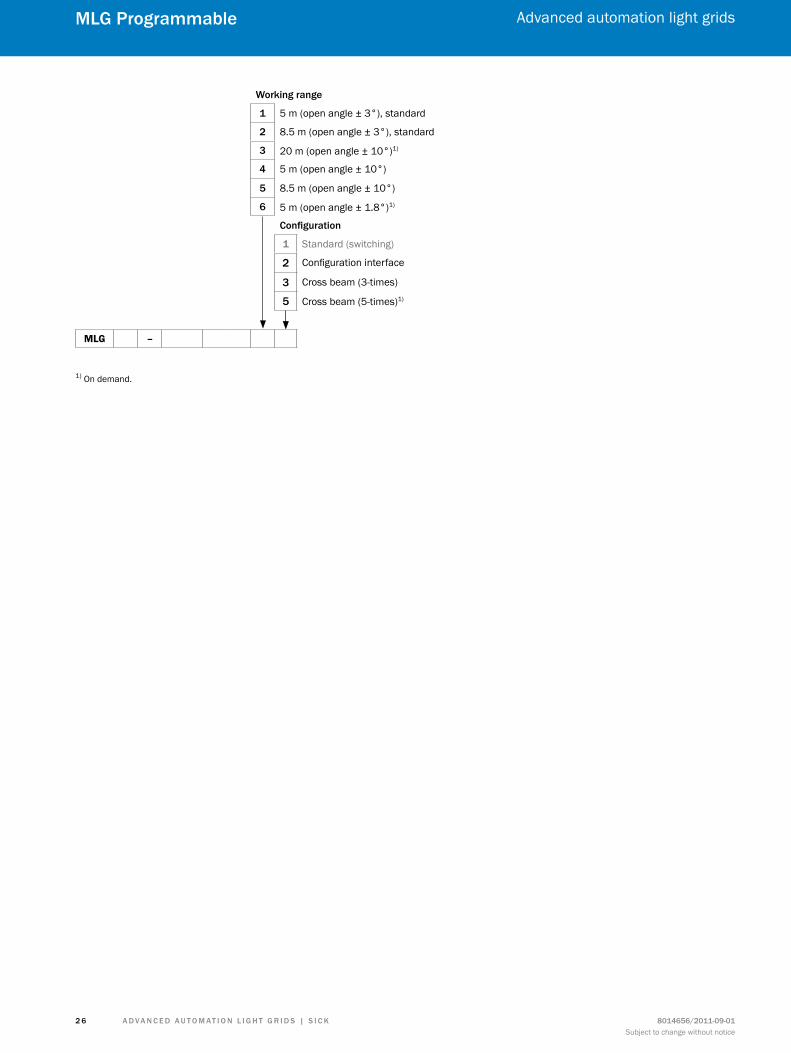
Working range
1 5 m (open angle ± 3°), standard
2 8.5 m (open angle ± 3°), standard
3 20 m (open angle ± 10°)1)
4 5 m (open angle ± 10°)
5 8.5 m (open angle ± 10°)
6 5 m (open angle ± 1.8°)1) configuration
1 Standard (switching)
2 Configuration interface
3 Cross beam (3-times)
5 Cross beam (5-times)1)
MLG –
1) On demand.
A d v A n c e d A u t o m At i o n L i G h t G r i d s | s i c K8014656/2011-09-01Subject to change without notice
Advanced automation light grids
2 7
mLG Programmable
dimensional drawing
A9
(0.3
5)25 (0.9
8)
�
�
�
�
� �16.5(0.65)
29(1.14)
34(1.34)
All dimensions in mm (inch)
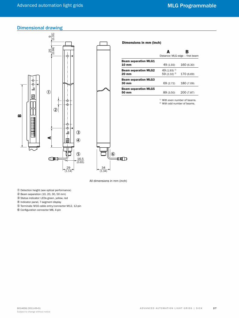
Dimensions in mm (inch)
A BDistance: MLG edge – first beam
Beam separation MLG110 mm 49 (1.93) 160 (6.30)
Beam separation MLG2 49 (1.93) 1)
20 mm 59 (2.32) 2) 170 (6.69)
Beam separation MLG330 mm 69 (2.72) 180 (7.09)
Beam separation MLG550 mm 89 (3.50) 200 (7.87)
B
1) With even number of beams.2) With odd number of beams.
1 Detection height (see optical performance)2 Beam separation (10, 20, 30, 50 mm)3 Status indicator: LEDs green, yellow, red4 Indicator panel, 7-segment display5 Terminals: M16 cable entry/connector M12, 12-pin6 Configuration connector M8, 4-pin
A d v A n c e d A u t o m At i o n L i G h t G r i d s | s i c K 8014656/2011-09-01Subject to change without notice
Advanced automation light grids
2 8
mLG Programmable
Adjustments
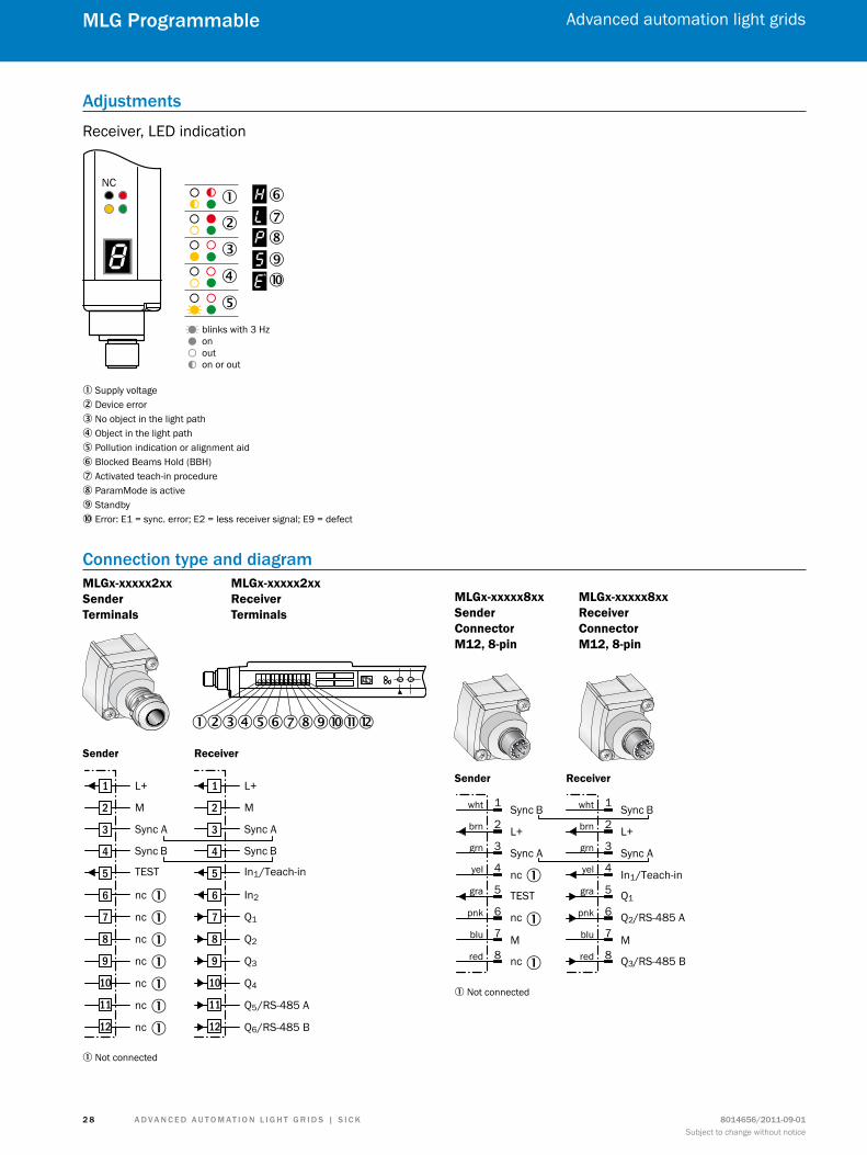
Receiver, LED indication
NC
blinks with 3 Hzonouton or out
�
� �����
��
�
1 Supply voltage2 Device error3 No object in the light path4 Object in the light path5 Pollution indication or alignment aid6 Blocked Beams Hold (BBH)7 Activated teach-in procedure8 ParamMode is active9 Standbyß Error: E1 = sync. error; E2 = less receiver signal; E9 = defect
connection type and diagramMLGx-xxxxx2xx Sender Terminals
MLGx-xxxxx2xx Receiver Terminals
123456789ßàá
Sender Receiver
L+
M
Sync A
In1/Teach-in
Sync B
In2
Q1
Q2
Q3
Q4
Q5/RS-485 A
Q6/RS-485 B
1
2
3
4
5
6
7
8
9
10
11
12
L+
M
Sync A
TEST
Sync B
nc
nc
nc
nc
nc
nc
nc
1
2
3
4
5
6
7
8
9
10
11
12
1
1
1
1
1
1
1
1 Not connected
MLGx-xxxxx8xx Sender Connector M12, 8-pin
MLGx-xxxxx8xx Receiver Connector M12, 8-pin
Sync B
L+
Sync A
Q1
In1/Teach-in
M
Q2/RS-485 A
Q3/RS-485 B
wht
brn
grn
yel
gra
pnk
blu
red
1
2
3
4
5
6
7
8
Sync B
L+
Sync A
TEST
nc
M
nc
nc
wht
brn
grn
yel
gra
pnk
blu
red
1
2
3
4
5
6
7
8
Sender Receiver
1
1
1
1 Not connected
A d v A n c e d A u t o m At i o n L i G h t G r i d s | s i c K8014656/2011-09-01Subject to change without notice
Advanced automation light grids
2 9
mLG Programmable
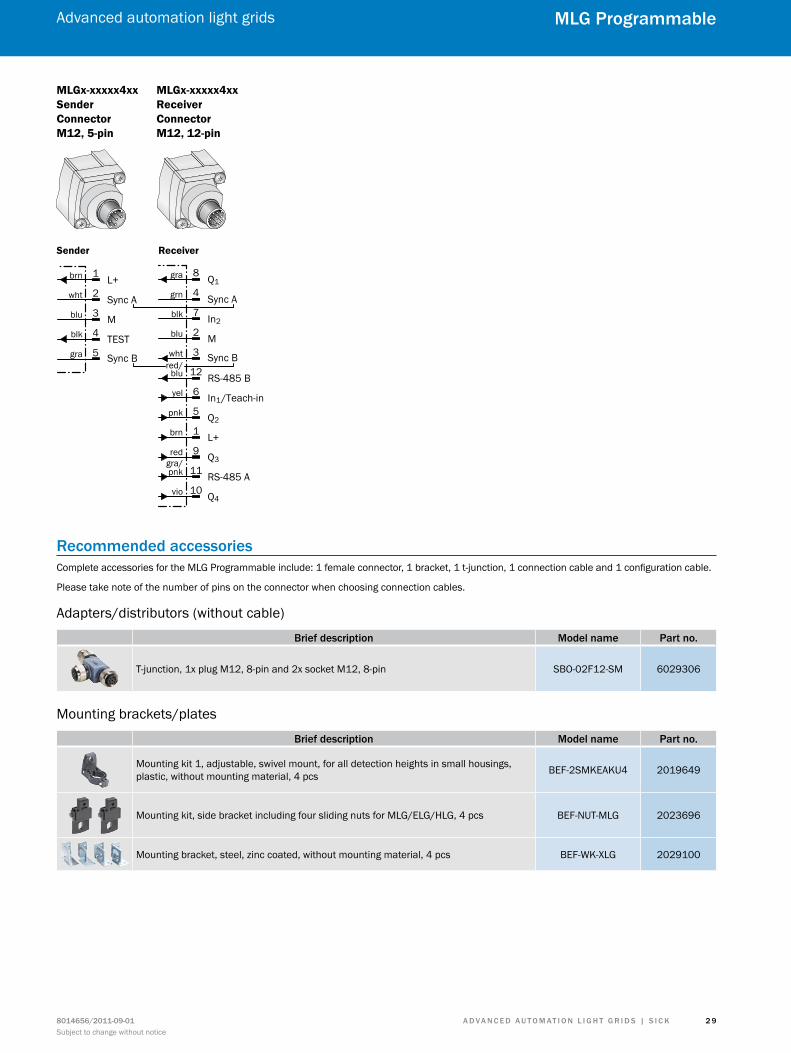
MLGx-xxxxx4xx Sender Connector M12, 5-pin
MLGx-xxxxx4xx Receiver Connector M12, 12-pin
Sender Receiver
Q1
Sync A
In2
Sync B
gra
grn
blk
wht
8
4
7
3Mblu 2
RS-485 Bred/
blu 12
In1/Teach-inyel 6
Q2pnk 5
L+brn 1
Q3red 9
RS-485 Agra/pnk 11
Q4vio 10
L+
Sync A
M
Sync B
TEST
brn
wht
blu
blk
gra
1
2
3
4
5
recommended accessoriesComplete accessories for the MLG Programmable include: 1 female connector, 1 bracket, 1 t-junction, 1 connection cable and 1 configuration cable.
Please take note of the number of pins on the connector when choosing connection cables.
Adapters/distributors (without cable)
Brief description model name Part no.
T-junction, 1x plug M12, 8-pin and 2x socket M12, 8-pin SBO-02F12-SM 6029306
Mounting brackets/plates
Brief description model name Part no.
Mounting kit 1, adjustable, swivel mount, for all detection heights in small housings, plastic, without mounting material, 4 pcs BEF-2SMKEAKU4 2019649
Mounting kit, side bracket including four sliding nuts for MLG/ELG/HLG, 4 pcs BEF-NUT-MLG 2023696
Mounting bracket, steel, zinc coated, without mounting material, 4 pcs BEF-WK-XLG 2029100
A d v A n c e d A u t o m At i o n L i G h t G r i d s | s i c K 8014656/2011-09-01Subject to change without notice
Advanced automation light grids
3 0
mLG Programmable
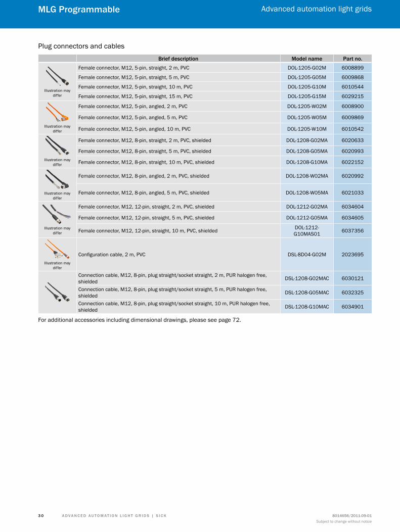
Plug connectors and cables
Brief description model name Part no.
Illustration may differ
Female connector, M12, 5-pin, straight, 2 m, PVC DOL-1205-G02M 6008899
Female connector, M12, 5-pin, straight, 5 m, PVC DOL-1205-G05M 6009868
Female connector, M12, 5-pin, straight, 10 m, PVC DOL-1205-G10M 6010544
Female connector, M12, 5-pin, straight, 15 m, PVC DOL-1205-G15M 6029215
Illustration may differ
Female connector, M12, 5-pin, angled, 2 m, PVC DOL-1205-W02M 6008900
Female connector, M12, 5-pin, angled, 5 m, PVC DOL-1205-W05M 6009869
Female connector, M12, 5-pin, angled, 10 m, PVC DOL-1205-W10M 6010542
Illustration may differ
Female connector, M12, 8-pin, straight, 2 m, PVC, shielded DOL-1208-G02MA 6020633
Female connector, M12, 8-pin, straight, 5 m, PVC, shielded DOL-1208-G05MA 6020993
Female connector, M12, 8-pin, straight, 10 m, PVC, shielded DOL-1208-G10MA 6022152
Illustration may differ
Female connector, M12, 8-pin, angled, 2 m, PVC, shielded DOL-1208-W02MA 6020992
Female connector, M12, 8-pin, angled, 5 m, PVC, shielded DOL-1208-W05MA 6021033
Illustration may differ
Female connector, M12, 12-pin, straight, 2 m, PVC, shielded DOL-1212-G02MA 6034604
Female connector, M12, 12-pin, straight, 5 m, PVC, shielded DOL-1212-G05MA 6034605
Female connector, M12, 12-pin, straight, 10 m, PVC, shielded DOL-1212-G10MAS01 6037356
Illustration may differ
Configuration cable, 2 m, PVC DSL-8D04-G02M 2023695
Connection cable, M12, 8-pin, plug straight/socket straight, 2 m, PUR halogen free, shielded DSL-1208-G02MAC 6030121
Connection cable, M12, 8-pin, plug straight/socket straight, 5 m, PUR halogen free, shielded DSL-1208-G05MAC 6032325
Connection cable, M12, 8-pin, plug straight/socket straight, 10 m, PUR halogen free, shielded DSL-1208-G10MAC 6034901
For additional accessories including dimensional drawings, please see page 72.
A d v A n c e d A u t o m At i o n L i G h t G r i d s | s i c K8014656/2011-09-01Subject to change without notice
Advanced automation light grids
3 1
mLG Programmable
special functions
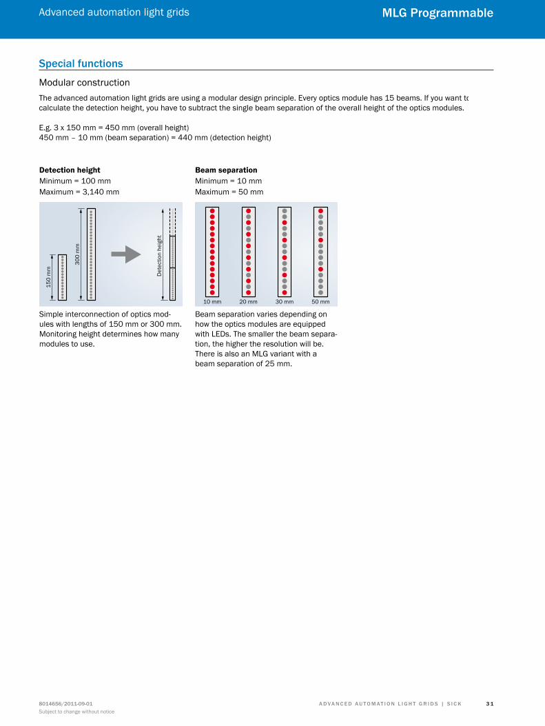
Modular constructionThe advanced automation light grids are using a modular design principle. Every optics module has 15 beams. If you want to calculate the detection height, you have to subtract the single beam separation of the overall height of the optics modules.
E.g. 3 x 150 mm = 450 mm (overall height)450 mm – 10 mm (beam separation) = 440 mm (detection height)
Simple interconnection of optics mod-ules with lengths of 150 mm or 300 mm. Monitoring height determines how many modules to use.
Detection height Beam separationMinimum = 100 mmMaximum = 3,140 mm
Minimum = 10 mmMaximum = 50 mm
Beam separation varies depending on how the optics modules are equipped with LEDs. The smaller the beam separa-tion, the higher the resolution will be. There is also an MLG variant with a beam separation of 25 mm.
150
mm
Det
ectio
n he
ight
300
mm
10 mm 20 mm 30 mm 50 mm
A d v A n c e d A u t o m At i o n L i G h t G r i d s | s i c K 8014656/2011-09-01Subject to change without notice
Advanced automation light grids
3 2
mLG ProfiBus
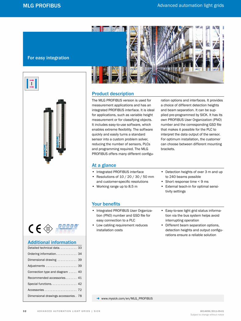
Product descriptionThe MLG PROFIBUS version is used for measurement applications and has an integrated PROFIBUS interface. It is ideal for applications, such as variable height measurement or for classifying objects. It includes easy-to-use software, which enables extreme flexibility. The software quickly and easily turns a standard sensor into a custom problem solver, reducing the number of sensors, PLCs and programming required. The MLG PROFIBUS offers many different configu-
ration options and interfaces. It provides a choice of different detection heights and beam separation. It can be sup-plied pre-programmed by SICK. It has its own PROFIBUS User Organization (PNO) number and the corresponding GSD file that makes it possible for the PLC to interpret the data output of the sensor. For optimum installation, the customer can choose between different mounting brackets.
At a glance • Integrated PROFIBUS interface • Resolutions of 10 / 20 / 30 / 50 mm
and customer-specific resolutions • Working range up to 8.5 m
• Detection heights of over 3 m and up to 240 beams possible
• Short response time < 9 ms • External teach-in for optimal sensi-
tivity settings
Your benefits • Integrated PROFIBUS User Organiza-
tion (PNO) number and GSD file for easy connection to a PLC
• Low cabling requirement reduces installation costs
• Easy-to-see light grid status informa-tion via the bus system helps avoid interrupting operation
• Different beam separation options, detection heights and output configu-rations ensure a reliable solution
for easy integration
Additional informationDetailed technical data. . . . . . . . . . . 33
Ordering information. . . . . . . . . . . . . 34
Dimensional drawing . . . . . . . . . . . . 39
Adjustments . . . . . . . . . . . . . . . . . . . 39
Connection type and diagram . . . . . 40
Recommended accessories . . . . . . . 41
Special functions. . . . . . . . . . . . . . . . 42
Accessories . . . . . . . . . . . . . . . . . . . . 72
Dimensional drawings accessories . 78 - www.mysick.com/en/MLG_PROFIBUS

A d v A n c e d A u t o m At i o n L i G h t G r i d s | s i c K8014656/2011-09-01Subject to change without notice
Advanced automation light grids
3 3
mLG ProfiBus
detailed technical data
Featurestechnology Sender/receiver
task Measurement light grid
minimum detectable object (mdo) Parallel beam: 15 mm ... 60 mm
number of beams 3 ... 240
configuration GSD file
Performancemaximum range 1) 7 m
12 m
minimum range Parallel beam: ≥ 0 mm
response time 2) Parallel beam: 9 ms ... 57 msCross beam: depending on type
1) No reserve for environmental issues and deterioration of the diode.2) With resistive load.
Interfacesinputs 1) 1 x PNP
1) 1 x test input for sender.
Mechanics/electronicsWave length IR, 880 nm
supply voltage vsDC 18 V ... 30 V
Power consumption sender 1) < 140 mA + 2 mA per beam
Power consumption receiver 1) < 100 mA + 3 mA per beam
ripple < 5 VSS
output current imax.100 mA
output load capacitive 100 nF
output load inductive 1 H
initialization time 1 s
dimensions (W x h x d) 34 mm x 214 mm x 29 mm ... 34 mm x 3,335 mm x 29 mm
housing material Aluminum
indication LED, 7-segment display
synchronization Cable
enclosure rating IP 65
circuit protection VS connections reverse-polarity protectedOutput Q short-circuit protectedInterference suppression
Weight 0.73 kg ... 7.722 kg
front screen PMMA1) Without load with 24 V.
A d v A n c e d A u t o m At i o n L i G h t G r i d s | s i c K 8014656/2011-09-01Subject to change without notice
Advanced automation light grids
3 4
mLG ProfiBus
Ambient dataProtection class III
emc EN 60947-5-2
Ambient temperature Operation: –25 °C ... +55 °CStorage: –40 °C ... +70 °C
Ambient light safety 1) Direct: 12,500 lxIndirect: 50,000 lx
vibration resistance 5 g, 10 Hz ... 55 Hz (IEC 68-2-6)
shock load 10 g / DIN EN 60068-2-29 / 16 ms1) Sunlight.
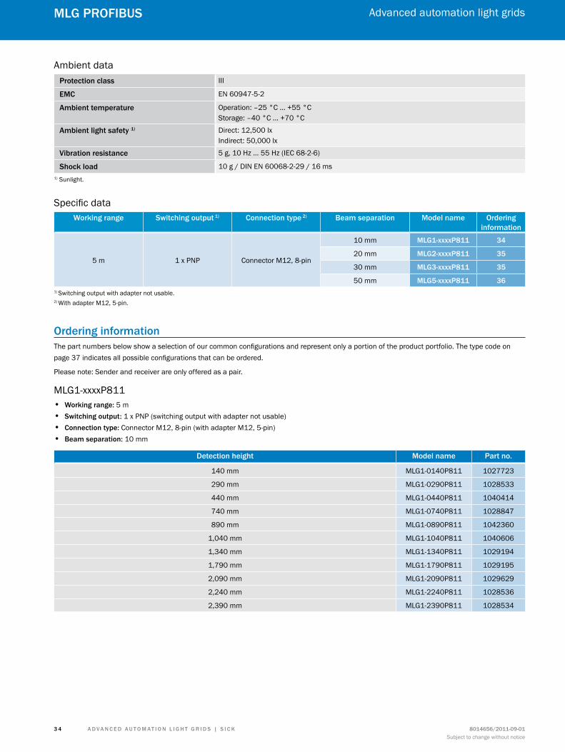
Specific dataWorking range switching output 1) connection type 2) Beam separation model name ordering
information
5 m 1 x PNP Connector M12, 8-pin
10 mm mLG1-xxxxP811 34
20 mm mLG2-xxxxP811 35
30 mm mLG3-xxxxP811 35
50 mm mLG5-xxxxP811 361) Switching output with adapter not usable.2) With adapter M12, 5-pin.
ordering informationThe part numbers below show a selection of our common configurations and represent only a portion of the product portfolio. The type code on page 37 indicates all possible configurations that can be ordered.
Please note: Sender and receiver are only offered as a pair.
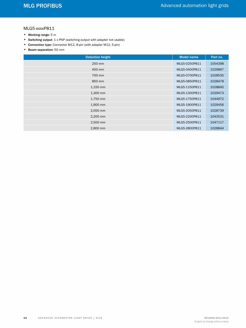
MLG1-xxxxP811 • Working range: 5 m • switching output: 1 x PNP (switching output with adapter not usable) • connection type: Connector M12, 8-pin (with adapter M12, 5-pin) • Beam separation: 10 mm
detection height model name Part no.
140 mm MLG1-0140P811 1027723
290 mm MLG1-0290P811 1028533
440 mm MLG1-0440P811 1040414
740 mm MLG1-0740P811 1028847
890 mm MLG1-0890P811 1042360
1,040 mm MLG1-1040P811 1040606
1,340 mm MLG1-1340P811 1029194
1,790 mm MLG1-1790P811 1029195
2,090 mm MLG1-2090P811 1029629
2,240 mm MLG1-2240P811 1028536
2,390 mm MLG1-2390P811 1028534
A d v A n c e d A u t o m At i o n L i G h t G r i d s | s i c K8014656/2011-09-01Subject to change without notice
Advanced automation light grids
3 5
mLG ProfiBus
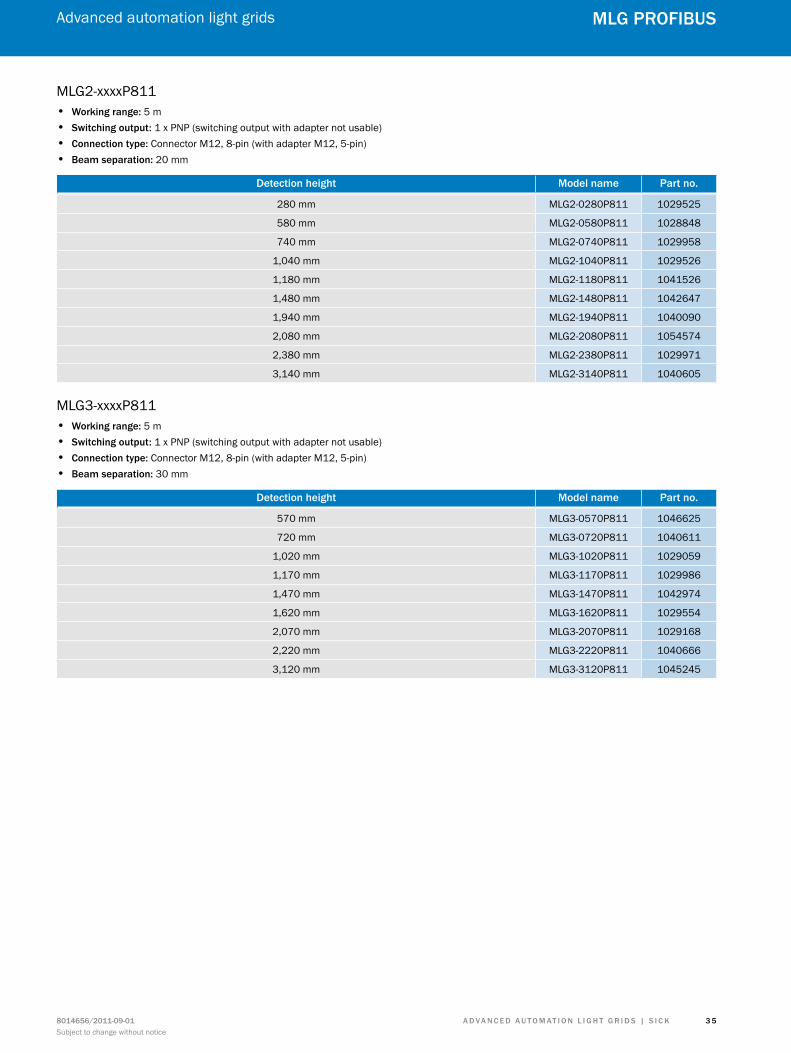
MLG2-xxxxP811 • Working range: 5 m • switching output: 1 x PNP (switching output with adapter not usable) • connection type: Connector M12, 8-pin (with adapter M12, 5-pin) • Beam separation: 20 mm
detection height model name Part no.
280 mm MLG2-0280P811 1029525
580 mm MLG2-0580P811 1028848
740 mm MLG2-0740P811 1029958
1,040 mm MLG2-1040P811 1029526
1,180 mm MLG2-1180P811 1041526
1,480 mm MLG2-1480P811 1042647
1,940 mm MLG2-1940P811 1040090
2,080 mm MLG2-2080P811 1054574
2,380 mm MLG2-2380P811 1029971
3,140 mm MLG2-3140P811 1040605
MLG3-xxxxP811 • Working range: 5 m • switching output: 1 x PNP (switching output with adapter not usable) • connection type: Connector M12, 8-pin (with adapter M12, 5-pin) • Beam separation: 30 mm
detection height model name Part no.
570 mm MLG3-0570P811 1046625
720 mm MLG3-0720P811 1040611
1,020 mm MLG3-1020P811 1029059
1,170 mm MLG3-1170P811 1029986
1,470 mm MLG3-1470P811 1042974
1,620 mm MLG3-1620P811 1029554
2,070 mm MLG3-2070P811 1029168
2,220 mm MLG3-2220P811 1040666
3,120 mm MLG3-3120P811 1045245
A d v A n c e d A u t o m At i o n L i G h t G r i d s | s i c K 8014656/2011-09-01Subject to change without notice
Advanced automation light grids
3 6
mLG ProfiBus
MLG5-xxxxP811 • Working range: 5 m • switching output: 1 x PNP (switching output with adapter not usable) • connection type: Connector M12, 8-pin (with adapter M12, 5-pin) • Beam separation: 50 mm
detection height model name Part no.
250 mm MLG5-0250P811 1054398
400 mm MLG5-0400P811 1029867
700 mm MLG5-0700P811 1028535
850 mm MLG5-0850P811 1028478
1,150 mm MLG5-1150P811 1028845
1,300 mm MLG5-1300P811 1029473
1,750 mm MLG5-1750P811 1044972
1,900 mm MLG5-1900P811 1029456
2,050 mm MLG5-2050P811 1028739
2,200 mm MLG5-2200P811 1043531
2,500 mm MLG5-2500P811 1047117
2,800 mm MLG5-2800P811 1028844
A d v A n c e d A u t o m At i o n L i G h t G r i d s | s i c K8014656/2011-09-01Subject to change without notice
Advanced automation light grids
3 7
mLG ProfiBus
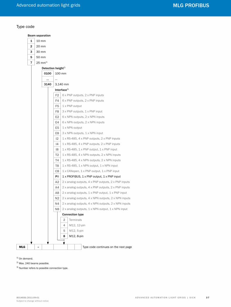
Type code
Beam separation
1 10 mm
2 20 mm
3 30 mm
5 50 mm
7 25 mm1)
detection height2)
0100 100 mm
… …
3140 3,140 mm
interface3)
f2 6 x PNP outputs, 2 x PNP inputs
f4 6 x PNP outputs, 2 x PNP inputs
f5 1 x PNP output
f8 3 x PNP outputs, 1 x PNP input
e2 6 x NPN outputs, 2 x NPN inputs
e4 6 x NPN outputs, 2 x NPN inputs
e5 1 x NPN output
e8 3 x NPN outputs, 1 x NPN input
i2 1 x RS-485, 4 x PNP outputs, 2 x PNP inputs
i4 1 x RS-485, 4 x PNP outputs, 2 x PNP inputs
i8 1 x RS-485, 1 x PNP output, 1 x PNP input
t2 1 x RS-485, 4 x NPN outputs, 2 x NPN inputs
t4 1 x RS-485, 4 x NPN outputs, 2 x NPN inputs
t8 1 x RS-485, 1 x NPN output, 1 x NPN input
c8 1 x CANopen, 1 x PNP output, 1 x PNP input
P8 1 x PROFIBUS, 1 x PNP output, 1 x PNP input
A2 2 x analog outputs, 4 x PNP outputs, 2 x PNP inputs
A4 2 x analog outputs, 4 x PNP outputs, 2 x PNP inputs
A8 2 x analog outputs, 1 x PNP output, 1 x PNP input
n2 2 x analog outputs, 4 x NPN outputs, 2 x NPN inputs
n4 2 x analog outputs, 4 x NPN outputs, 2 x NPN inputs
n8 2 x analog outputs, 1 x NPN output, 1 x NPN input
connection type
2 Terminals
4 M12, 12-pin
5 M12, 5-pin
8 M12, 8-pin
MLG – Type code continues on the next page
1) On demand.2) Max. 240 beams possible.3) Number refers to possible connection type.
A d v A n c e d A u t o m At i o n L i G h t G r i d s | s i c K 8014656/2011-09-01Subject to change without notice
Advanced automation light grids
3 8
mLG ProfiBus
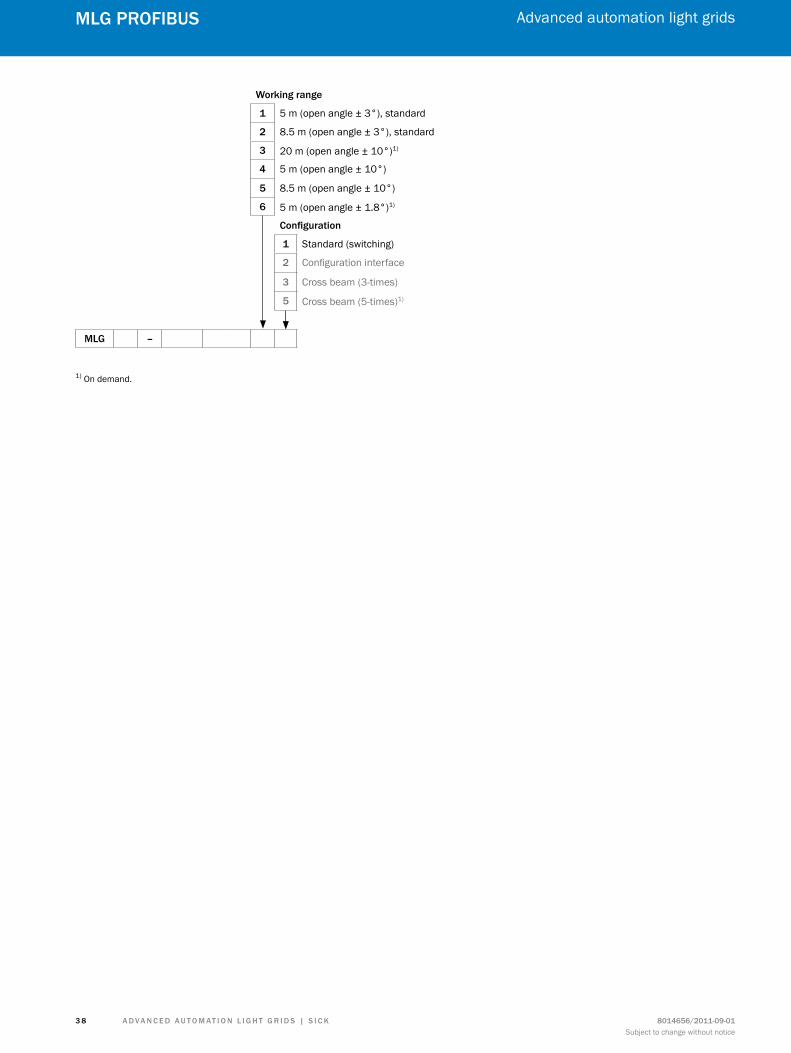
Working range
1 5 m (open angle ± 3°), standard
2 8.5 m (open angle ± 3°), standard
3 20 m (open angle ± 10°)1)
4 5 m (open angle ± 10°)
5 8.5 m (open angle ± 10°)
6 5 m (open angle ± 1.8°)1) configuration
1 Standard (switching)
2 Configuration interface
3 Cross beam (3-times)
5 Cross beam (5-times)1)
mLG –
1) On demand.
A d v A n c e d A u t o m At i o n L i G h t G r i d s | s i c K8014656/2011-09-01Subject to change without notice
Advanced automation light grids
3 9
mLG ProfiBus
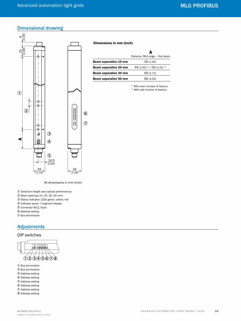
dimensional drawing
A9
(0.3
5)25 (0.9
8)
�
�
�
�
�
�
�
29(1.14)
34(1.34)
All dimensions in mm (inch)
Dimensions in mm (inch)
ADistance: MLG edge – first beam
Beam separation 10 mm 49 (1.93)
Beam separation 20 mm 49 (1.93) 1) / 59 (2.32) 2)
Beam separation 30 mm 69 (2.72)
Beam separation 50 mm 89 (3.50)
16.5(0.65)
1) With even number of beams.2) With odd number of beams.
1 Detection height (see optical performance)2 Beam spacing (10, 20, 30, 50 mm)3 Status indicator: LEDs green, yellow, red4 Indicator panel, 7-segment display5 Connector M12, 8-pin6 Address setting7 Bus termination
Adjustments
DIP switches
12345678
1 Bus termination2 Bus termination3 Address setting4 Address setting5 Address setting6 Address setting7 Address setting8 Address setting
A d v A n c e d A u t o m At i o n L i G h t G r i d s | s i c K 8014656/2011-09-01Subject to change without notice
Advanced automation light grids
4 0
mLG ProfiBus
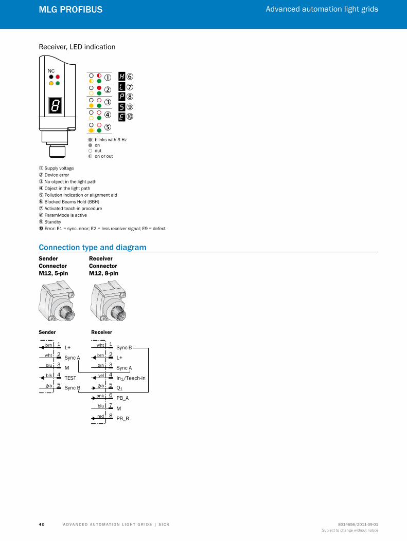
Receiver, LED indication
NC
blinks with 3 Hzonouton or out
�
� �����
��
�
1 Supply voltage2 Device error3 No object in the light path4 Object in the light path5 Pollution indication or alignment aid6 Blocked Beams Hold (BBH)7 Activated teach-in procedure8 ParamMode is active9 Standbyß Error: E1 = sync. error; E2 = less receiver signal; E9 = defect
connection type and diagramSender Connector M12, 5-pin
Receiver Connector M12, 8-pin
Sync B
L+
Sync A
Q1
In1/Teach-in
M
PB_A
PB_B
wht
brn
grn
yel
gra
pnk
blu
red
1
2
3
4
5
6
7
8
L+
Sync A
M
Sync B
TEST
brn
wht
blu
blk
gra
1
2
3
4
5
Sender Receiver
A d v A n c e d A u t o m At i o n L i G h t G r i d s | s i c K8014656/2011-09-01Subject to change without notice
Advanced automation light grids
4 1
mLG ProfiBus
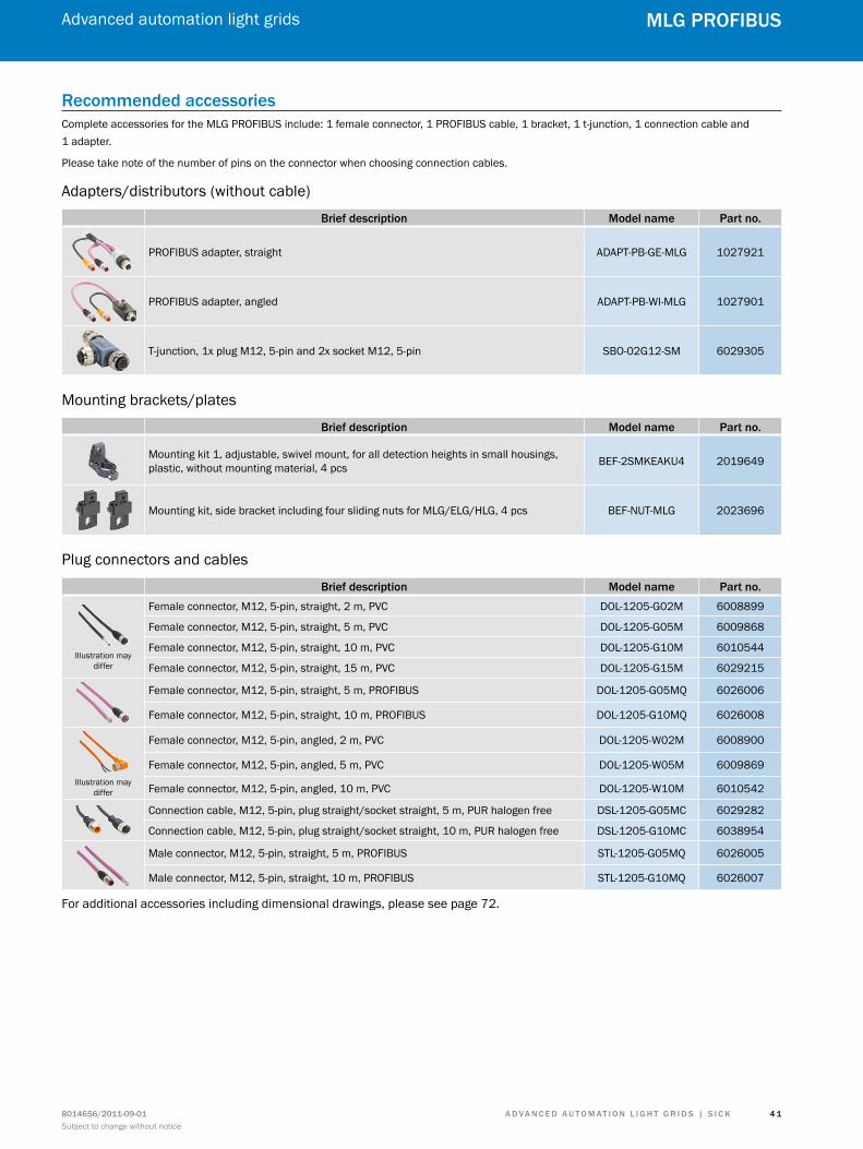
recommended accessoriesComplete accessories for the MLG PROFIBUS include: 1 female connector, 1 PROFIBUS cable, 1 bracket, 1 t-junction, 1 connection cable and 1 adapter.
Please take note of the number of pins on the connector when choosing connection cables.
Adapters/distributors (without cable)
Brief description model name Part no.
PROFIBUS adapter, straight ADAPT-PB-GE-MLG 1027921
PROFIBUS adapter, angled ADAPT-PB-WI-MLG 1027901
T-junction, 1x plug M12, 5-pin and 2x socket M12, 5-pin SBO-02G12-SM 6029305
Mounting brackets/plates
Brief description model name Part no.
Mounting kit 1, adjustable, swivel mount, for all detection heights in small housings, plastic, without mounting material, 4 pcs BEF-2SMKEAKU4 2019649
Mounting kit, side bracket including four sliding nuts for MLG/ELG/HLG, 4 pcs BEF-NUT-MLG 2023696
Plug connectors and cables
Brief description model name Part no.
Illustration may differ
Female connector, M12, 5-pin, straight, 2 m, PVC DOL-1205-G02M 6008899
Female connector, M12, 5-pin, straight, 5 m, PVC DOL-1205-G05M 6009868
Female connector, M12, 5-pin, straight, 10 m, PVC DOL-1205-G10M 6010544
Female connector, M12, 5-pin, straight, 15 m, PVC DOL-1205-G15M 6029215
Female connector, M12, 5-pin, straight, 5 m, PROFIBUS DOL-1205-G05MQ 6026006
Female connector, M12, 5-pin, straight, 10 m, PROFIBUS DOL-1205-G10MQ 6026008
Illustration may differ
Female connector, M12, 5-pin, angled, 2 m, PVC DOL-1205-W02M 6008900
Female connector, M12, 5-pin, angled, 5 m, PVC DOL-1205-W05M 6009869
Female connector, M12, 5-pin, angled, 10 m, PVC DOL-1205-W10M 6010542
Connection cable, M12, 5-pin, plug straight/socket straight, 5 m, PUR halogen free DSL-1205-G05MC 6029282
Connection cable, M12, 5-pin, plug straight/socket straight, 10 m, PUR halogen free DSL-1205-G10MC 6038954
Male connector, M12, 5-pin, straight, 5 m, PROFIBUS STL-1205-G05MQ 6026005
Male connector, M12, 5-pin, straight, 10 m, PROFIBUS STL-1205-G10MQ 6026007
For additional accessories including dimensional drawings, please see page 72.
A d v A n c e d A u t o m At i o n L i G h t G r i d s | s i c K 8014656/2011-09-01Subject to change without notice
Advanced automation light grids
4 2
mLG ProfiBus
special functions
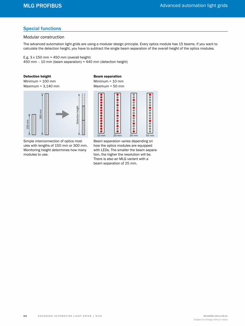
Modular constructionThe advanced automation light grids are using a modular design principle. Every optics module has 15 beams. If you want to calculate the detection height, you have to subtract the single beam separation of the overall height of the optics modules.
E.g. 3 x 150 mm = 450 mm (overall height)450 mm – 10 mm (beam separation) = 440 mm (detection height)
Simple interconnection of optics mod-ules with lengths of 150 mm or 300 mm. Monitoring height determines how many modules to use.
Detection height Beam separationMinimum = 100 mmMaximum = 3,140 mm
Minimum = 10 mmMaximum = 50 mm
Beam separation varies depending on how the optics modules are equipped with LEDs. The smaller the beam separa-tion, the higher the resolution will be. There is also an MLG variant with a beam separation of 25 mm.
150
mm
Det
ectio
n he
ight
300
mm
10 mm 20 mm 30 mm 50 mm

A d v A n c e d A u t o m At i o n L i G h t G r i d s | s i c K8014656/2011-09-01Subject to change without notice
Advanced automation light grids
4 3
mLG ProfiBus
A d v A n c e d A u t o m At i o n L i G h t G r i d s | s i c K 8014656/2011-09-01Subject to change without notice
Advanced automation light grids
4 4
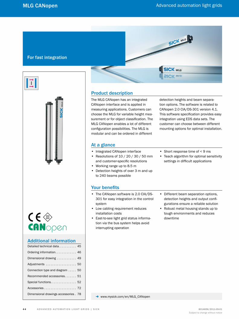
mLG cAnopen
Product descriptionThe MLG CANopen has an integrated CANopen interface and is applied in measuring applications. Customers can choose the MLG for variable height mea-surement or for object classification. The MLG CANopen enables a lot of different configuration possibilities. The MLG is modular and can be ordered in different
detection heights and beam separa-tion options. The software is related to CANopen 2.0 CIA/DS-301 version 4.1. This software specification provides easy integration using EDS data sets. The customer can choose between different mounting options for optimal installation.
At a glance • Integrated CANopen interface • Resolutions of 10 / 20 / 30 / 50 mm
and customer-specific resolutions • Working range up to 8.5 m • Detection heights of over 3 m and up
to 240 beams possible
• Short response time of < 9 ms • Teach algorithm for optimal sensitivity
settings in difficult applications
Your benefits • The CANopen software is 2.0 CIA/DS-
301 for easy integration in the control system
• Low cabling requirement reduces installation costs
• East-to-see light grid status informa-tion via the bus system helps avoid interrupting operation
• Different beam separation options, detection heights and output confi-gurations ensure a reliable solution
• Robust metal housing stands up to tough environments and reduces downtime
for fast integration
Additional informationDetailed technical data. . . . . . . . . . . 45
Ordering information. . . . . . . . . . . . . 46
Dimensional drawing . . . . . . . . . . . . 49
Adjustments . . . . . . . . . . . . . . . . . . . 50
Connection type and diagram . . . . . 50
Recommended accessories . . . . . . . 51
Special functions. . . . . . . . . . . . . . . . 52
Accessories . . . . . . . . . . . . . . . . . . . . 72
Dimensional drawings accessories . 78 - www.mysick.com/en/MLG_CANopen
A d v A n c e d A u t o m At i o n L i G h t G r i d s | s i c K8014656/2011-09-01Subject to change without notice
Advanced automation light grids
4 5
mLG cAnopen
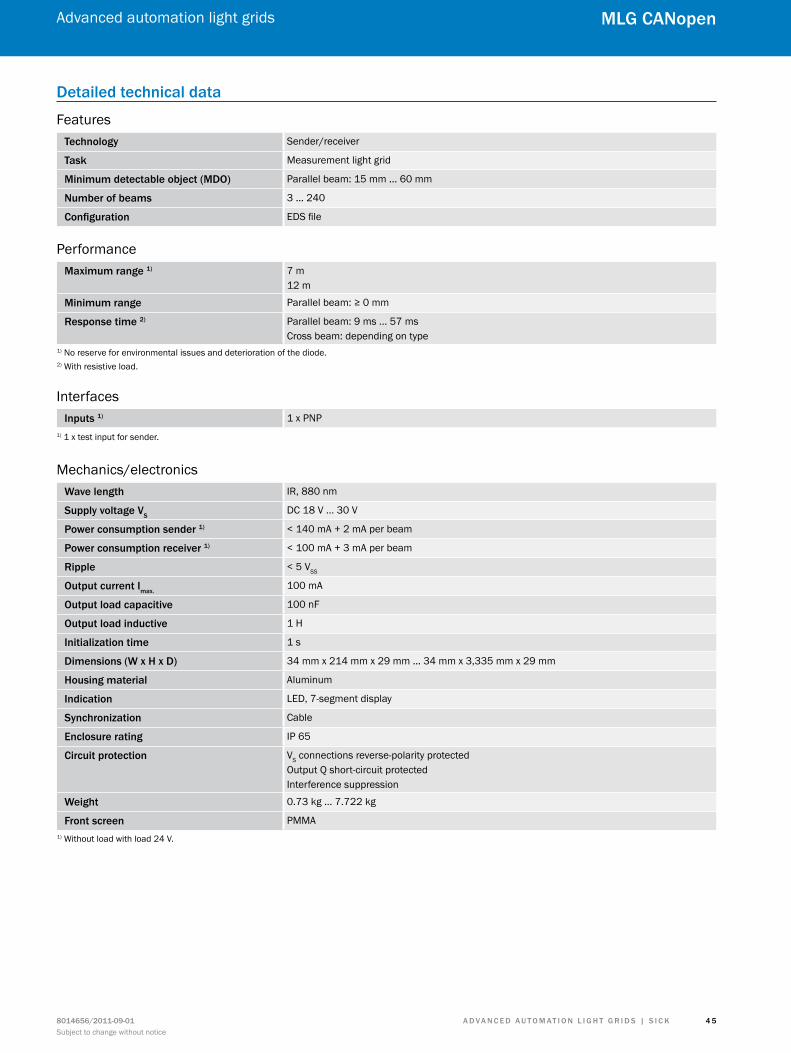
detailed technical data
Featurestechnology Sender/receiver
task Measurement light grid
minimum detectable object (mdo) Parallel beam: 15 mm ... 60 mm
number of beams 3 ... 240
configuration EDS file
Performancemaximum range 1) 7 m
12 m
minimum range Parallel beam: ≥ 0 mm
response time 2) Parallel beam: 9 ms ... 57 msCross beam: depending on type
1) No reserve for environmental issues and deterioration of the diode.2) With resistive load.
Interfacesinputs 1) 1 x PNP
1) 1 x test input for sender.
Mechanics/electronicsWave length IR, 880 nm
supply voltage vsDC 18 V ... 30 V
Power consumption sender 1) < 140 mA + 2 mA per beam
Power consumption receiver 1) < 100 mA + 3 mA per beam
ripple < 5 VSS
output current imax.100 mA
output load capacitive 100 nF
output load inductive 1 H
initialization time 1 s
dimensions (W x h x d) 34 mm x 214 mm x 29 mm ... 34 mm x 3,335 mm x 29 mm
housing material Aluminum
indication LED, 7-segment display
synchronization Cable
enclosure rating IP 65
circuit protection VS connections reverse-polarity protectedOutput Q short-circuit protectedInterference suppression
Weight 0.73 kg ... 7.722 kg
front screen PMMA1) Without load with load 24 V.
A d v A n c e d A u t o m At i o n L i G h t G r i d s | s i c K 8014656/2011-09-01Subject to change without notice
Advanced automation light grids
4 6
mLG cAnopen
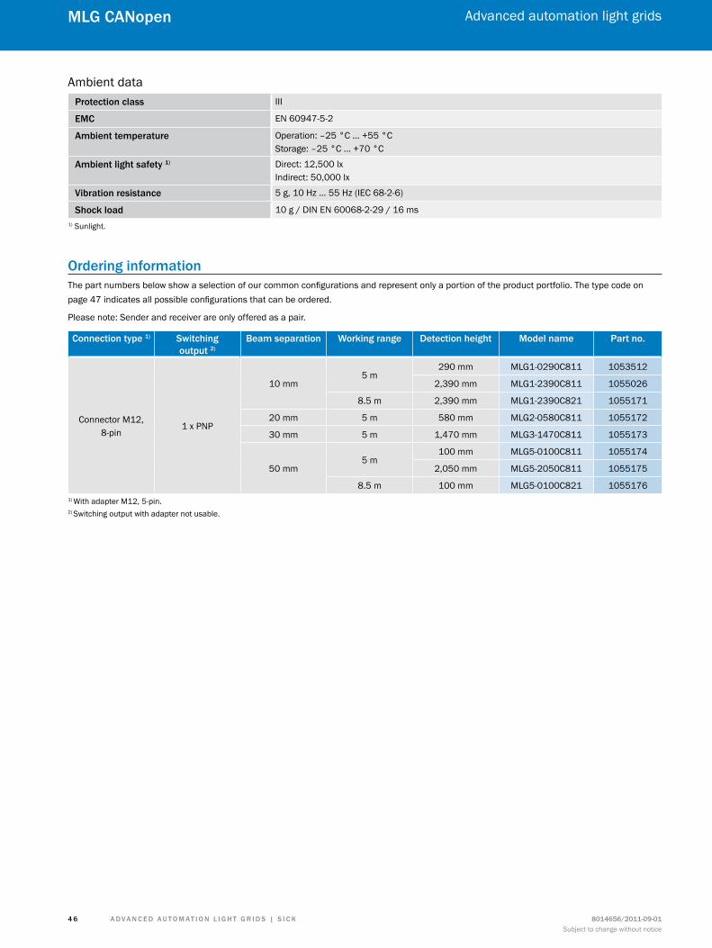
Ambient dataProtection class III
emc EN 60947-5-2
Ambient temperature Operation: –25 °C ... +55 °CStorage: –25 °C ... +70 °C
Ambient light safety 1) Direct: 12,500 lxIndirect: 50,000 lx
vibration resistance 5 g, 10 Hz ... 55 Hz (IEC 68-2-6)
shock load 10 g / DIN EN 60068-2-29 / 16 ms1) Sunlight.
ordering informationThe part numbers below show a selection of our common configurations and represent only a portion of the product portfolio. The type code on page 47 indicates all possible configurations that can be ordered.
Please note: Sender and receiver are only offered as a pair.
connection type 1) switching output 2)
Beam separation Working range detection height model name Part no.
Connector M12,8-pin
1 x PNP
10 mm5 m
290 mm MLG1-0290C811 1053512
2,390 mm MLG1-2390C811 1055026
8.5 m 2,390 mm MLG1-2390C821 1055171
20 mm 5 m 580 mm MLG2-0580C811 1055172
30 mm 5 m 1,470 mm MLG3-1470C811 1055173
50 mm5 m
100 mm MLG5-0100C811 1055174
2,050 mm MLG5-2050C811 1055175
8.5 m 100 mm MLG5-0100C821 10551761) With adapter M12, 5-pin.2) Switching output with adapter not usable.
A d v A n c e d A u t o m At i o n L i G h t G r i d s | s i c K8014656/2011-09-01Subject to change without notice
Advanced automation light grids
4 7
mLG cAnopen
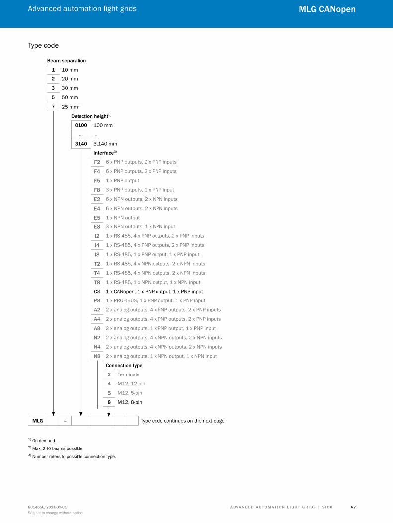
Type code
Beam separation
1 10 mm
2 20 mm
3 30 mm
5 50 mm
7 25 mm1)
detection height2)
0100 100 mm
… …
3140 3,140 mm
interface3)
f2 6 x PNP outputs, 2 x PNP inputs
f4 6 x PNP outputs, 2 x PNP inputs
f5 1 x PNP output
f8 3 x PNP outputs, 1 x PNP input
e2 6 x NPN outputs, 2 x NPN inputs
e4 6 x NPN outputs, 2 x NPN inputs
e5 1 x NPN output
e8 3 x NPN outputs, 1 x NPN input
i2 1 x RS-485, 4 x PNP outputs, 2 x PNP inputs
i4 1 x RS-485, 4 x PNP outputs, 2 x PNP inputs
i8 1 x RS-485, 1 x PNP output, 1 x PNP input
t2 1 x RS-485, 4 x NPN outputs, 2 x NPN inputs
t4 1 x RS-485, 4 x NPN outputs, 2 x NPN inputs
t8 1 x RS-485, 1 x NPN output, 1 x NPN input
c8 1 x CANopen, 1 x PNP output, 1 x PNP input
P8 1 x PROFIBUS, 1 x PNP output, 1 x PNP input
A2 2 x analog outputs, 4 x PNP outputs, 2 x PNP inputs
A4 2 x analog outputs, 4 x PNP outputs, 2 x PNP inputs
A8 2 x analog outputs, 1 x PNP output, 1 x PNP input
n2 2 x analog outputs, 4 x NPN outputs, 2 x NPN inputs
n4 2 x analog outputs, 4 x NPN outputs, 2 x NPN inputs
n8 2 x analog outputs, 1 x NPN output, 1 x NPN input
connection type
2 Terminals
4 M12, 12-pin
5 M12, 5-pin
8 M12, 8-pin
MLG – Type code continues on the next page
1) On demand.2) Max. 240 beams possible.3) Number refers to possible connection type.
A d v A n c e d A u t o m At i o n L i G h t G r i d s | s i c K 8014656/2011-09-01Subject to change without notice
Advanced automation light grids
4 8
mLG cAnopen
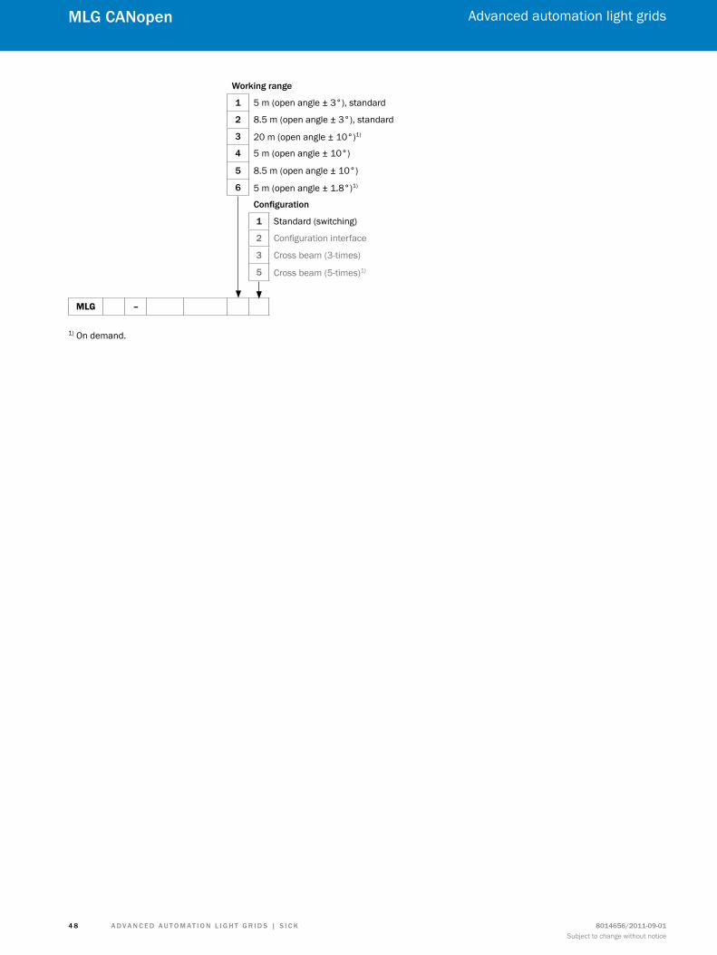
Working range
1 5 m (open angle ± 3°), standard
2 8.5 m (open angle ± 3°), standard
3 20 m (open angle ± 10°)1)
4 5 m (open angle ± 10°)
5 8.5 m (open angle ± 10°)
6 5 m (open angle ± 1.8°)1) configuration
1 Standard (switching)
2 Configuration interface
3 Cross beam (3-times)
5 Cross beam (5-times)1)
MLG –
1) On demand.
A d v A n c e d A u t o m At i o n L i G h t G r i d s | s i c K8014656/2011-09-01Subject to change without notice
Advanced automation light grids
4 9
mLG cAnopen
dimensional drawing
A9
(0.3
5)25 (0.9
8)
�
�
�
�
��
29(1.14)
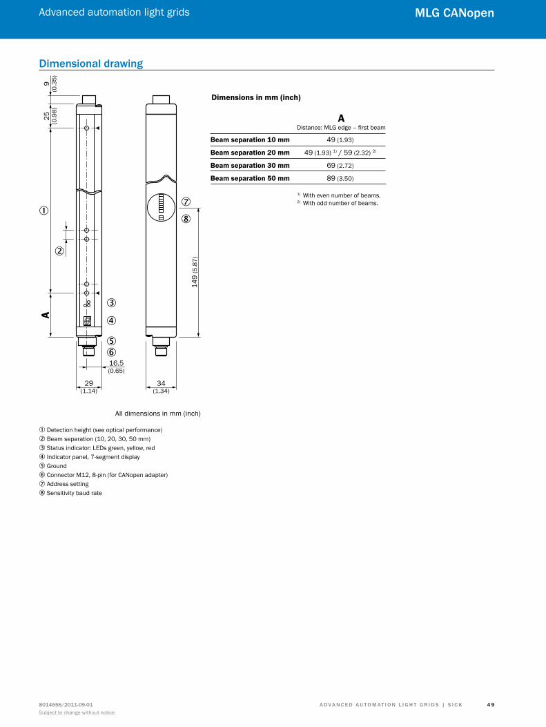
Dimensions in mm (inch)
ADistance: MLG edge – first beam
Beam separation 10 mm 49 (1.93)
Beam separation 20 mm 49 (1.93) 1) / 59 (2.32) 2)
Beam separation 30 mm 69 (2.72)
Beam separation 50 mm 89 (3.50)
16.5(0.65)
34(1.34)
All dimensions in mm (inch)
149
(5.8
7)��
1) With even number of beams.2) With odd number of beams.
1 Detection height (see optical performance)2 Beam separation (10, 20, 30, 50 mm)3 Status indicator: LEDs green, yellow, red4 Indicator panel, 7-segment display5 Ground6 Connector M12, 8-pin (for CANopen adapter)7 Address setting8 Sensitivity baud rate
A d v A n c e d A u t o m At i o n L i G h t G r i d s | s i c K 8014656/2011-09-01Subject to change without notice
Advanced automation light grids
5 0
mLG cAnopen
Adjustments
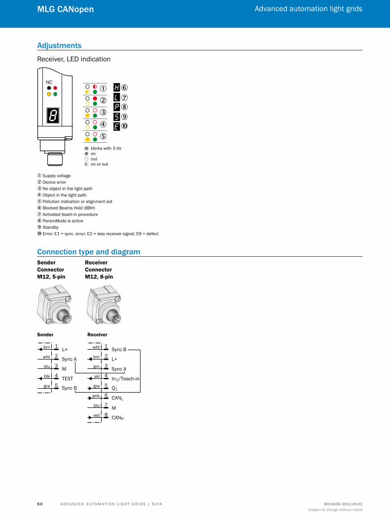
Receiver, LED indication
NC
blinks with 3 Hzonouton or out
�
� �����
��
�
1 Supply voltage2 Device error3 No object in the light path4 Object in the light path5 Pollution indication or alignment aid6 Blocked Beams Hold (BBH)7 Activated teach-in procedure8 ParamMode is active9 Standbyß Error: E1 = sync. error; E2 = less receiver signal; E9 = defect
connection type and diagramSender Connector M12, 5-pin
Receiver Connector M12, 8-pin
Sync B
L+
Sync A
Q1
In1/Teach-in
M
CANL
CANH
wht
brn
grn
yel
gra
pnk
blu
red
1
2
3
4
5
6
7
8
L+
Sync A
M
Sync B
TEST
brn
wht
blu
blk
gra
1
2
3
4
5
Sender Receiver
A d v A n c e d A u t o m At i o n L i G h t G r i d s | s i c K8014656/2011-09-01Subject to change without notice
Advanced automation light grids
5 1
mLG cAnopen
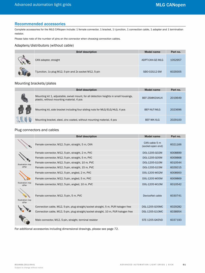
recommended accessoriesComplete accessories for the MLG CANopen include: 1 female connector, 1 bracket, 1 t-junction, 1 connection cable, 1 adapter and 1 termination resistor.
Please take note of the number of pins on the connector when choosing connection cables.
Adapters/distributors (without cable)
Brief description model name Part no.
CAN adapter, straight ADPT-CAN-GE-MLG 1052957
T-junction, 1x plug M12, 5-pin and 2x socket M12, 5-pin SBO-02G12-SM 6029305
Mounting brackets/plates
Brief description model name Part no.
Mounting kit 1, adjustable, swivel mount, for all detection heights in small housings, plastic, without mounting material, 4 pcs BEF-2SMKEAKU4 2019649
Mounting kit, side bracket including four sliding nuts for MLG/ELG/HLG, 4 pcs BEF-NUT-MLG 2023696
Mounting bracket, steel, zinc coated, without mounting material, 4 pcs BEF-WK-XLG 2029100
Plug connectors and cables
Brief description model name Part no.
Female connector, M12, 5-pin, straight, 5 m, CAN CAN cable 5 m (socket-open end) 6021166
Illustration may differ
Female connector, M12, 5-pin, straight, 2 m, PVC DOL-1205-G02M 6008899
Female connector, M12, 5-pin, straight, 5 m, PVC DOL-1205-G05M 6009868
Female connector, M12, 5-pin, straight, 10 m, PVC DOL-1205-G10M 6010544
Female connector, M12, 5-pin, straight, 15 m, PVC DOL-1205-G15M 6029215
Illustration may differ
Female connector, M12, 5-pin, angled, 2 m, PVC DOL-1205-W02M 6008900
Female connector, M12, 5-pin, angled, 5 m, PVC DOL-1205-W05M 6009869
Female connector, M12, 5-pin, angled, 10 m, PVC DOL-1205-W10M 6010542
Illustration may differ
Female connector, M12, 5-pin, 5 m, PVC DeviceNet cable 6030741
Connection cable, M12, 5-pin, plug straight/socket straight, 5 m, PUR halogen free DSL-1205-G05MC 6029282
Connection cable, M12, 5-pin, plug straight/socket straight, 10 m, PUR halogen free DSL-1205-G10MC 6038954
Male connector, M12, 5-pin, straight, terminal resistor STE-1205-GKEND 6037193
For additional accessories including dimensional drawings, please see page 72.
A d v A n c e d A u t o m At i o n L i G h t G r i d s | s i c K 8014656/2011-09-01Subject to change without notice
Advanced automation light grids
5 2
mLG cAnopen
special functions
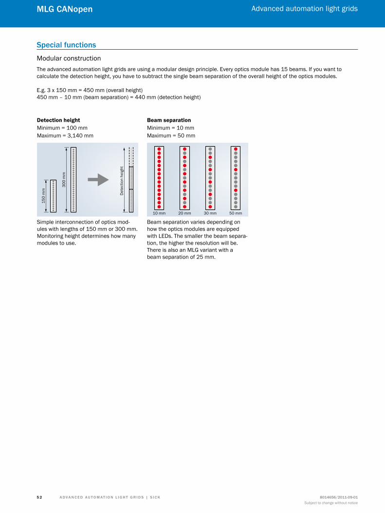
Modular constructionThe advanced automation light grids are using a modular design principle. Every optics module has 15 beams. If you want to calculate the detection height, you have to subtract the single beam separation of the overall height of the optics modules.
E.g. 3 x 150 mm = 450 mm (overall height)450 mm – 10 mm (beam separation) = 440 mm (detection height)
Simple interconnection of optics mod-ules with lengths of 150 mm or 300 mm. Monitoring height determines how many modules to use.
Detection height Beam separationMinimum = 100 mmMaximum = 3,140 mm
Minimum = 10 mmMaximum = 50 mm
Beam separation varies depending on how the optics modules are equipped with LEDs. The smaller the beam separa-tion, the higher the resolution will be. There is also an MLG variant with a beam separation of 25 mm.
150
mm
Det
ectio
n he
ight
300
mm
10 mm 20 mm 30 mm 50 mm

A d v A n c e d A u t o m At i o n L i G h t G r i d s | s i c K8014656/2011-09-01Subject to change without notice
Advanced automation light grids
5 3
mLG cAnopen
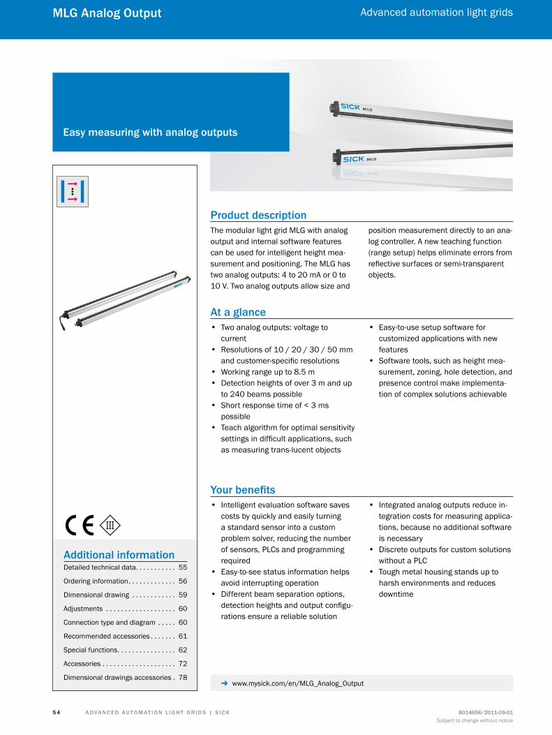
A d v A n c e d A u t o m At i o n L i G h t G r i d s | s i c K 8014656/2011-09-01Subject to change without notice
Advanced automation light grids
5 4
mLG Analog output
Product descriptionThe modular light grid MLG with analog output and internal software features can be used for intelligent height mea-surement and positioning. The MLG has two analog outputs: 4 to 20 mA or 0 to 10 V. Two analog outputs allow size and
position measurement directly to an ana-log controller. A new teaching function (range setup) helps eliminate errors from reflective surfaces or semi-transparent objects.
At a glance • Two analog outputs: voltage to
current • Resolutions of 10 / 20 / 30 / 50 mm
and customer-specific resolutions • Working range up to 8.5 m • Detection heights of over 3 m and up
to 240 beams possible • Short response time of < 3 ms
possible • Teach algorithm for optimal sensitivity
settings in difficult applications, such as measuring trans-lucent objects
• Easy-to-use setup software for customized applications with new features
• Software tools, such as height mea-surement, zoning, hole detection, and presence control make implementa-tion of complex solutions achievable
Your benefits • Intelligent evaluation software saves
costs by quickly and easily turning a standard sensor into a custom problem solver, reducing the number of sensors, PLCs and programming required
• Easy-to-see status information helps avoid interrupting operation
• Different beam separation options, detection heights and output configu-rations ensure a reliable solution
• Integrated analog outputs reduce in-tegration costs for measuring applica-tions, because no additional software is necessary
• Discrete outputs for custom solutions without a PLC
• Tough metal housing stands up to harsh environments and reduces downtime
easy measuring with analog outputs
Additional informationDetailed technical data. . . . . . . . . . . 55
Ordering information. . . . . . . . . . . . . 56
Dimensional drawing . . . . . . . . . . . . 59
Adjustments . . . . . . . . . . . . . . . . . . . 60
Connection type and diagram . . . . . 60
Recommended accessories . . . . . . . 61
Special functions. . . . . . . . . . . . . . . . 62
Accessories . . . . . . . . . . . . . . . . . . . . 72
Dimensional drawings accessories . 78 - www.mysick.com/en/MLG_Analog_Output
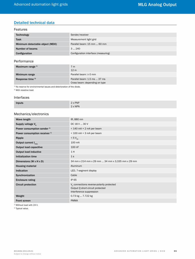
A d v A n c e d A u t o m At i o n L i G h t G r i d s | s i c K8014656/2011-09-01Subject to change without notice
Advanced automation light grids
5 5
mLG Analog output
detailed technical data
Featurestechnology Sender/receiver
task Measurement light grid
minimum detectable object (mdo) Parallel beam: 15 mm ... 60 mm
number of beams 3 ... 240
configuration Configuration interface (measuring)
Performancemaximum range 1) 7 m
12 m
minimum range Parallel beam: ≥ 0 mm
response time 2) Parallel beam: 1.5 ms ... 37 msCross beam: depending on type
1) No reserve for environmental issues and deterioration of the diode.2) With resistive load.
Interfacesinputs 2 x PNP
2 x NPN
Mechanics/electronicsWave length IR, 880 nm
supply voltage vsDC 18 V ... 30 V
Power consumption sender 1) < 140 mA + 2 mA per beam
Power consumption receiver 1) < 100 mA + 3 mA per beam
ripple < 5 VSS
output current imax.100 mA
output load capacitive 100 nF
output load inductive 1 H
initialization time 1 s
dimensions (W x h x d) 34 mm x 214 mm x 29 mm ... 34 mm x 3,335 mm x 29 mm
housing material Aluminum
indication LED, 7-segment display
synchronization Cable
enclosure rating IP 65
circuit protection VS connections reverse-polarity protectedOutput Q short-circuit protectedInterference suppression
Weight 0.73 kg ... 7.722 kg
front screen PMMA1) Without load with 24 V.2) Typical value.
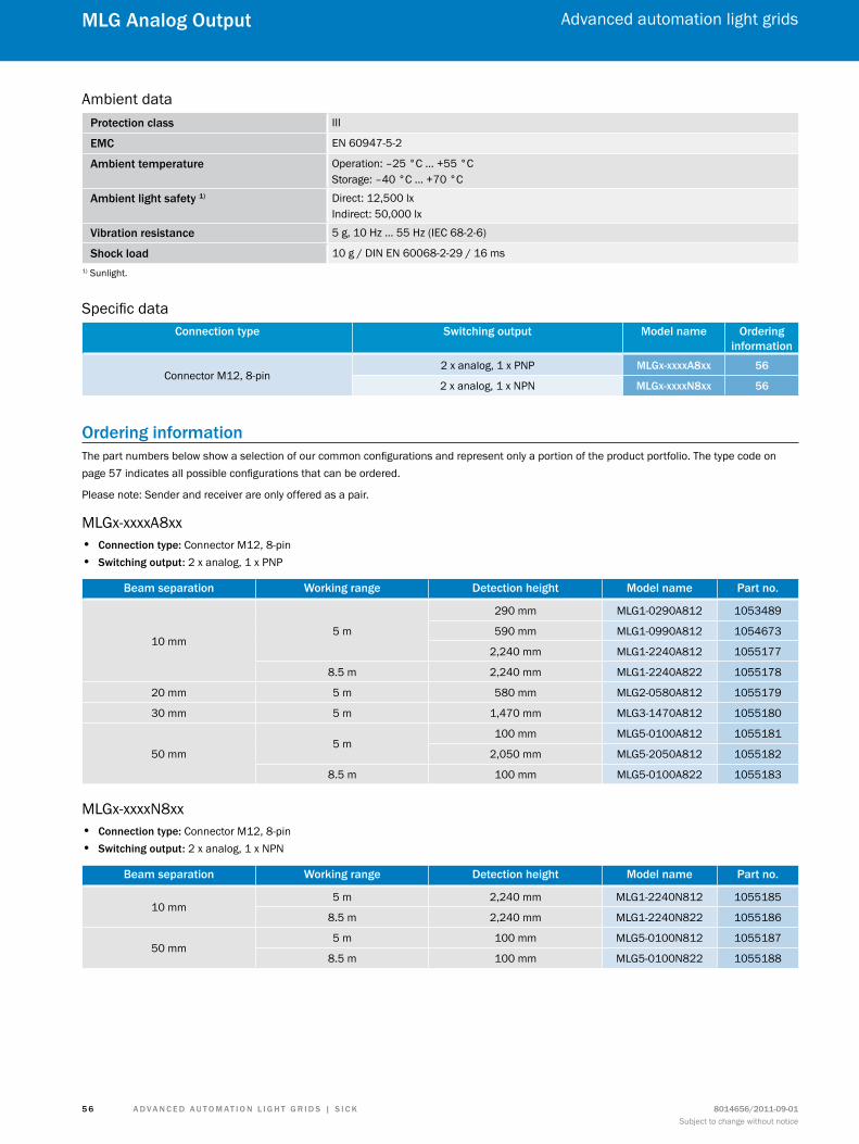
A d v A n c e d A u t o m At i o n L i G h t G r i d s | s i c K 8014656/2011-09-01Subject to change without notice
Advanced automation light grids
5 6
mLG Analog output
Ambient dataProtection class III
emc EN 60947-5-2
Ambient temperature Operation: –25 °C ... +55 °CStorage: –40 °C ... +70 °C
Ambient light safety 1) Direct: 12,500 lxIndirect: 50,000 lx
vibration resistance 5 g, 10 Hz ... 55 Hz (IEC 68-2-6)
shock load 10 g / DIN EN 60068-2-29 / 16 ms1) Sunlight.
Specific dataconnection type switching output model name ordering
information
Connector M12, 8-pin2 x analog, 1 x PNP mLGx-xxxxA8xx 56
2 x analog, 1 x NPN mLGx-xxxxn8xx 56
ordering informationThe part numbers below show a selection of our common configurations and represent only a portion of the product portfolio. The type code on page 57 indicates all possible configurations that can be ordered.
Please note: Sender and receiver are only offered as a pair.
MLGx-xxxxA8xx • connection type: Connector M12, 8-pin • switching output: 2 x analog, 1 x PNP
Beam separation Working range detection height model name Part no.
10 mm5 m
290 mm MLG1-0290A812 1053489
590 mm MLG1-0990A812 1054673
2,240 mm MLG1-2240A812 1055177
8.5 m 2,240 mm MLG1-2240A822 1055178
20 mm 5 m 580 mm MLG2-0580A812 1055179
30 mm 5 m 1,470 mm MLG3-1470A812 1055180
50 mm5 m
100 mm MLG5-0100A812 1055181
2,050 mm MLG5-2050A812 1055182
8.5 m 100 mm MLG5-0100A822 1055183
MLGx-xxxxN8xx • connection type: Connector M12, 8-pin • switching output: 2 x analog, 1 x NPN
Beam separation Working range detection height model name Part no.
10 mm5 m 2,240 mm MLG1-2240N812 1055185
8.5 m 2,240 mm MLG1-2240N822 1055186
50 mm5 m 100 mm MLG5-0100N812 1055187
8.5 m 100 mm MLG5-0100N822 1055188
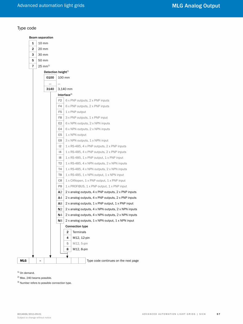
A d v A n c e d A u t o m At i o n L i G h t G r i d s | s i c K8014656/2011-09-01Subject to change without notice
Advanced automation light grids
5 7
mLG Analog output
Type code
Beam separation
1 10 mm
2 20 mm
3 30 mm
5 50 mm
7 25 mm1)
detection height2)
0100 100 mm
… …
3140 3,140 mm
interface3)
f2 6 x PNP outputs, 2 x PNP inputs
f4 6 x PNP outputs, 2 x PNP inputs
f5 1 x PNP output
f8 3 x PNP outputs, 1 x PNP input
e2 6 x NPN outputs, 2 x NPN inputs
e4 6 x NPN outputs, 2 x NPN inputs
e5 1 x NPN output
e8 3 x NPN outputs, 1 x NPN input
i2 1 x RS-485, 4 x PNP outputs, 2 x PNP inputs
i4 1 x RS-485, 4 x PNP outputs, 2 x PNP inputs
i8 1 x RS-485, 1 x PNP output, 1 x PNP input
t2 1 x RS-485, 4 x NPN outputs, 2 x NPN inputs
t4 1 x RS-485, 4 x NPN outputs, 2 x NPN inputs
t8 1 x RS-485, 1 x NPN output, 1 x NPN input
c8 1 x CANopen, 1 x PNP output, 1 x PNP input
P8 1 x PROFIBUS, 1 x PNP output, 1 x PNP input
A2 2 x analog outputs, 4 x PNP outputs, 2 x PNP inputs
A4 2 x analog outputs, 4 x PNP outputs, 2 x PNP inputs
A8 2 x analog outputs, 1 x PNP output, 1 x PNP input
n2 2 x analog outputs, 4 x NPN outputs, 2 x NPN inputs
n4 2 x analog outputs, 4 x NPN outputs, 2 x NPN inputs
n8 2 x analog outputs, 1 x NPN output, 1 x NPN input
connection type
2 Terminals
4 M12, 12-pin
5 M12, 5-pin
8 M12, 8-pin
MLG – Type code continues on the next page
1) On demand.2) Max. 240 beams possible.3) Number refers to possible connection type.
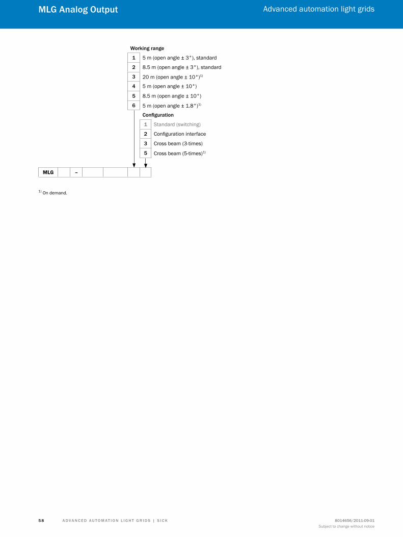
A d v A n c e d A u t o m At i o n L i G h t G r i d s | s i c K 8014656/2011-09-01Subject to change without notice
Advanced automation light grids
5 8
mLG Analog output
Working range
1 5 m (open angle ± 3°), standard
2 8.5 m (open angle ± 3°), standard
3 20 m (open angle ± 10°)1)
4 5 m (open angle ± 10°)
5 8.5 m (open angle ± 10°)
6 5 m (open angle ± 1.8°)1) configuration
1 Standard (switching)
2 Configuration interface
3 Cross beam (3-times)
5 Cross beam (5-times)1)
MLG –
1) On demand.
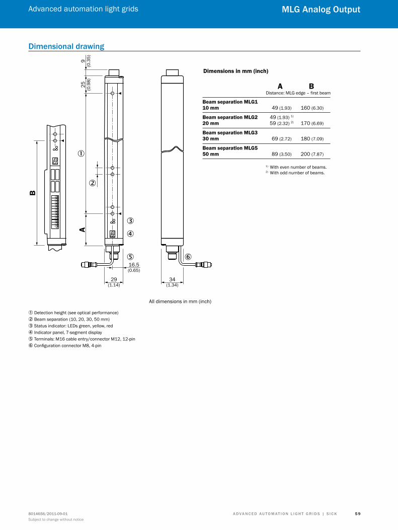
A d v A n c e d A u t o m At i o n L i G h t G r i d s | s i c K8014656/2011-09-01Subject to change without notice
Advanced automation light grids
5 9
mLG Analog output
dimensional drawing
A9
(0.3
5)25 (0.9
8)
�
�
�
�
� �16.5(0.65)
29(1.14)
34(1.34)
All dimensions in mm (inch)
Dimensions in mm (inch)
A BDistance: MLG edge – first beam
Beam separation MLG110 mm 49 (1.93) 160 (6.30)
Beam separation MLG2 49 (1.93) 1)
20 mm 59 (2.32) 2) 170 (6.69)
Beam separation MLG330 mm 69 (2.72) 180 (7.09)
Beam separation MLG550 mm 89 (3.50) 200 (7.87)
B
1) With even number of beams.2) With odd number of beams.
1 Detection height (see optical performance)2 Beam separation (10, 20, 30, 50 mm)3 Status indicator: LEDs green, yellow, red4 Indicator panel, 7-segment display5 Terminals: M16 cable entry/connector M12, 12-pin6 Configuration connector M8, 4-pin
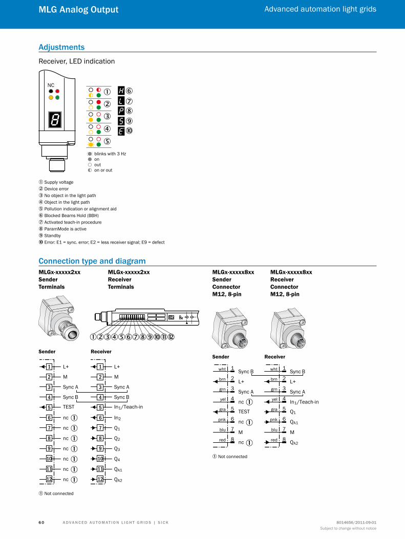
A d v A n c e d A u t o m At i o n L i G h t G r i d s | s i c K 8014656/2011-09-01Subject to change without notice
Advanced automation light grids
6 0
mLG Analog output
Adjustments
Receiver, LED indication
NC
blinks with 3 Hzonouton or out
�
� �����
��
�
1 Supply voltage2 Device error3 No object in the light path4 Object in the light path5 Pollution indication or alignment aid6 Blocked Beams Hold (BBH)7 Activated teach-in procedure8 ParamMode is active9 Standbyß Error: E1 = sync. error; E2 = less receiver signal; E9 = defect
connection type and diagramMLGx-xxxxx2xx Sender Terminals
MLGx-xxxxx2xx Receiver Terminals
123456789ßàá
Sender Receiver
L+
M
Sync A
In1/Teach-in
Sync B
In2
Q1
Q2
Q3
Q4
QA1
QA2
1
2
3
4
5
6
7
8
9
10
11
12
L+
M
Sync A
TEST
Sync B
nc
nc
nc
nc
nc
nc
nc
1
2
3
4
5
6
7
8
9
10
11
12
1
1
1
1
1
1
1
1 Not connected
MLGx-xxxxx8xx Sender Connector M12, 8-pin
MLGx-xxxxx8xx Receiver Connector M12, 8-pin
Sync B
L+
Sync A
Q1
In1/Teach-in
M
QA1
QA2
wht
brn
grn
yel
gra
pnk
blu
red
1
2
3
4
5
6
7
8
Sync B
L+
Sync A
TEST
nc
M
nc
nc
wht
brn
grn
yel
gra
pnk
blu
red
1
2
3
4
5
6
7
8
Sender Receiver
1
1
1
1 Not connected

A d v A n c e d A u t o m At i o n L i G h t G r i d s | s i c K8014656/2011-09-01Subject to change without notice
Advanced automation light grids
6 1
mLG Analog output
MLGx-xxxxx4xx Sender Connector M12, 5-pin
MLGx-xxxxx4xx Receiver Connector M12, 12-pin
Sender Receiver
Q1
Sync A
In2
Sync B
gra
grn
blk
wht
8
4
7
3Mblu 2
QA2
red/blu 12
In1/Teach-inyel 6
Q2pnk 5
L+brn 1
Q3red 9
QA1
gra/pnk 11
Q4vio 10
L+
Sync A
M
Sync B
TEST
brn
wht
blu
blk
gra
1
2
3
4
5
recommended accessoriesComplete accessories for the MLG Analog Output include: 1 female connector, 1 bracket, 1 t-junction and 1 connection cable.
Please take note of the number of pins on the connector when choosing connection cables.
Adapters/distributors (without cable)
Brief description model name Part no.
T-junction, 1x plug M12, 8-pin and 2x socket M12, 8-pin SBO-02F12-SM 6029306
Mounting brackets/plates
Brief description model name Part no.
Mounting kit 1, adjustable, swivel mount, for all detection heights in small housings, plastic, without mounting material, 4 pcs BEF-2SMKEAKU4 2019649
Mounting kit, side bracket including four sliding nuts for MLG/ELG/HLG, 4 pcs BEF-NUT-MLG 2023696
Mounting bracket, steel, zinc coated, without mounting material, 4 pcs BEF-WK-XLG 2029100
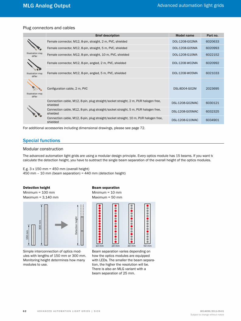
A d v A n c e d A u t o m At i o n L i G h t G r i d s | s i c K 8014656/2011-09-01Subject to change without notice
Advanced automation light grids
6 2
mLG Analog output
Plug connectors and cables
Brief description model name Part no.
Illustration may differ
Female connector, M12, 8-pin, straight, 2 m, PVC, shielded DOL-1208-G02MA 6020633
Female connector, M12, 8-pin, straight, 5 m, PVC, shielded DOL-1208-G05MA 6020993
Female connector, M12, 8-pin, straight, 10 m, PVC, shielded DOL-1208-G10MA 6022152
Illustration may differ
Female connector, M12, 8-pin, angled, 2 m, PVC, shielded DOL-1208-W02MA 6020992
Female connector, M12, 8-pin, angled, 5 m, PVC, shielded DOL-1208-W05MA 6021033
Illustration may differ
Configuration cable, 2 m, PVC DSL-8D04-G02M 2023695
Connection cable, M12, 8-pin, plug straight/socket straight, 2 m, PUR halogen free, shielded DSL-1208-G02MAC 6030121
Connection cable, M12, 8-pin, plug straight/socket straight, 5 m, PUR halogen free, shielded DSL-1208-G05MAC 6032325
Connection cable, M12, 8-pin, plug straight/socket straight, 10 m, PUR halogen free, shielded DSL-1208-G10MAC 6034901
For additional accessories including dimensional drawings, please see page 72.
special functions
Modular constructionThe advanced automation light grids are using a modular design principle. Every optics module has 15 beams. If you want to calculate the detection height, you have to subtract the single beam separation of the overall height of the optics modules.
E.g. 3 x 150 mm = 450 mm (overall height)450 mm – 10 mm (beam separation) = 440 mm (detection height)
Simple interconnection of optics mod-ules with lengths of 150 mm or 300 mm. Monitoring height determines how many modules to use.
Detection height Beam separationMinimum = 100 mmMaximum = 3,140 mm
Minimum = 10 mmMaximum = 50 mm
Beam separation varies depending on how the optics modules are equipped with LEDs. The smaller the beam separa-tion, the higher the resolution will be. There is also an MLG variant with a beam separation of 25 mm.
150
mm
Det
ectio
n he
ight
300
mm
10 mm 20 mm 30 mm 50 mm

A d v A n c e d A u t o m At i o n L i G h t G r i d s | s i c K8014656/2011-09-01Subject to change without notice
Advanced automation light grids
6 3
mLG Analog output
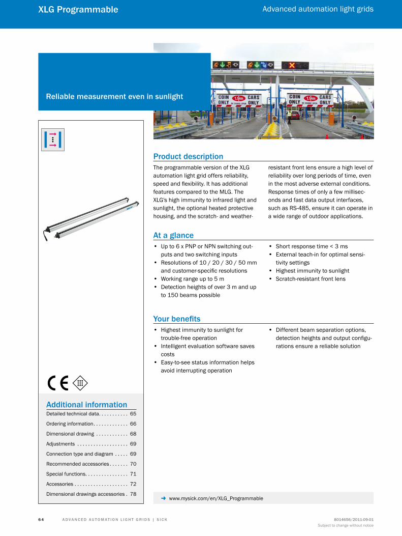
A d v A n c e d A u t o m At i o n L i G h t G r i d s | s i c K 8014656/2011-09-01Subject to change without notice
Advanced automation light grids
6 4
XLG Programmable
Product descriptionThe programmable version of the XLG automation light grid offers reliability, speed and flexibility. It has additional features compared to the MLG. The XLG's high immunity to infrared light and sunlight, the optional heated protective housing, and the scratch- and weather-
resistant front lens ensure a high level of reliability over long periods of time, even in the most adverse external conditions. Response times of only a few millisec-onds and fast data output interfaces, such as RS-485, ensure it can operate in a wide range of outdoor applications.
At a glance • Up to 6 x PNP or NPN switching out-
puts and two switching inputs • Resolutions of 10 / 20 / 30 / 50 mm
and customer-specific resolutions • Working range up to 5 m • Detection heights of over 3 m and up
to 150 beams possible
• Short response time < 3 ms • External teach-in for optimal sensi-
tivity settings • Highest immunity to sunlight • Scratch-resistant front lens
Your benefits • Highest immunity to sunlight for
trouble-free operation • Intelligent evaluation software saves
costs • Easy-to-see status information helps
avoid interrupting operation
• Different beam separation options, detection heights and output configu-rations ensure a reliable solution
reliable measurement even in sunlight
Additional informationDetailed technical data. . . . . . . . . . . 65
Ordering information. . . . . . . . . . . . . 66
Dimensional drawing . . . . . . . . . . . . 68
Adjustments . . . . . . . . . . . . . . . . . . . 69
Connection type and diagram . . . . . 69
Recommended accessories . . . . . . . 70
Special functions. . . . . . . . . . . . . . . . 71
Accessories . . . . . . . . . . . . . . . . . . . . 72
Dimensional drawings accessories . 78 - www.mysick.com/en/XLG_Programmable
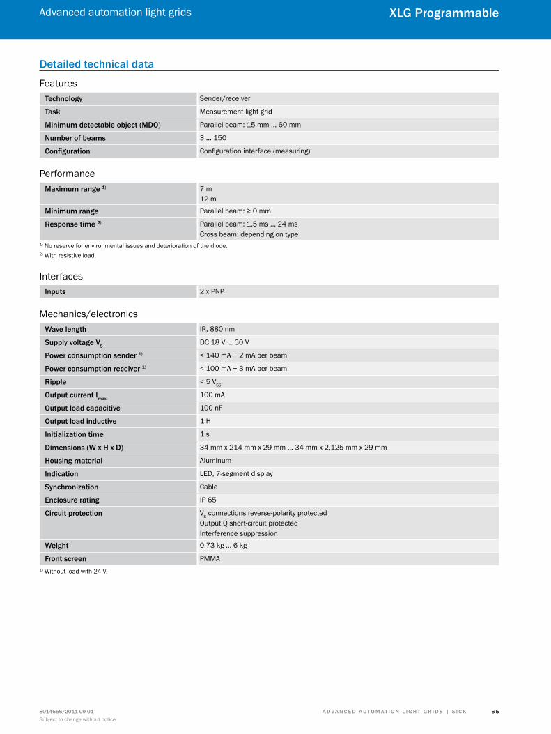
A d v A n c e d A u t o m At i o n L i G h t G r i d s | s i c K8014656/2011-09-01Subject to change without notice
Advanced automation light grids
6 5
XLG Programmable
detailed technical data
Featurestechnology Sender/receiver
task Measurement light grid
minimum detectable object (mdo) Parallel beam: 15 mm ... 60 mm
number of beams 3 ... 150
configuration Configuration interface (measuring)
Performancemaximum range 1) 7 m
12 m
minimum range Parallel beam: ≥ 0 mm
response time 2) Parallel beam: 1.5 ms ... 24 msCross beam: depending on type
1) No reserve for environmental issues and deterioration of the diode.2) With resistive load.
Interfacesinputs 2 x PNP
Mechanics/electronicsWave length IR, 880 nm
supply voltage vsDC 18 V ... 30 V
Power consumption sender 1) < 140 mA + 2 mA per beam
Power consumption receiver 1) < 100 mA + 3 mA per beam
ripple < 5 VSS
output current imax.100 mA
output load capacitive 100 nF
output load inductive 1 H
initialization time 1 s
dimensions (W x h x d) 34 mm x 214 mm x 29 mm ... 34 mm x 2,125 mm x 29 mm
housing material Aluminum
indication LED, 7-segment display
synchronization Cable
enclosure rating IP 65
circuit protection VS connections reverse-polarity protectedOutput Q short-circuit protectedInterference suppression
Weight 0.73 kg ... 6 kg
front screen PMMA1) Without load with 24 V.
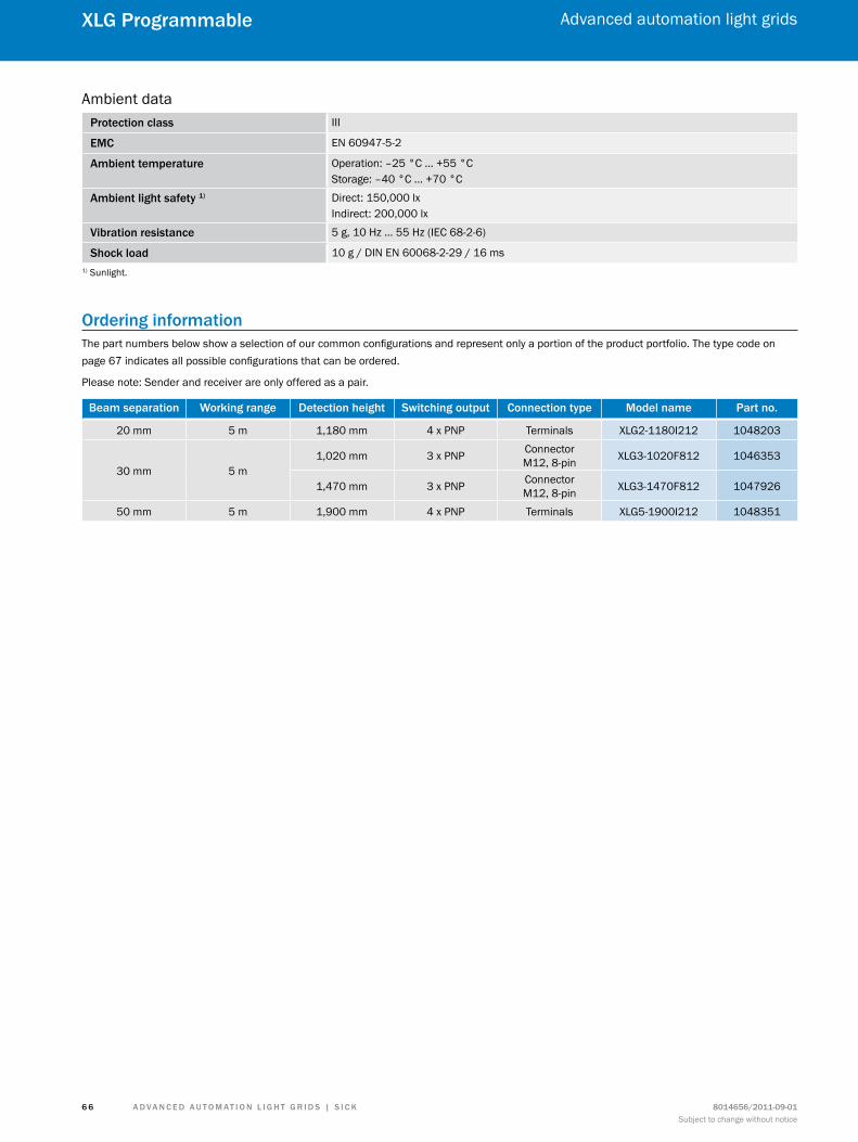
A d v A n c e d A u t o m At i o n L i G h t G r i d s | s i c K 8014656/2011-09-01Subject to change without notice
Advanced automation light grids
6 6
XLG Programmable
Ambient dataProtection class III
emc EN 60947-5-2
Ambient temperature Operation: –25 °C ... +55 °CStorage: –40 °C ... +70 °C
Ambient light safety 1) Direct: 150,000 lxIndirect: 200,000 lx
vibration resistance 5 g, 10 Hz ... 55 Hz (IEC 68-2-6)
shock load 10 g / DIN EN 60068-2-29 / 16 ms1) Sunlight.
ordering informationThe part numbers below show a selection of our common configurations and represent only a portion of the product portfolio. The type code on page 67 indicates all possible configurations that can be ordered.
Please note: Sender and receiver are only offered as a pair.
Beam separation Working range detection height switching output connection type model name Part no.
20 mm 5 m 1,180 mm 4 x PNP Terminals XLG2-1180I212 1048203
30 mm 5 m1,020 mm 3 x PNP Connector
M12, 8-pin XLG3-1020F812 1046353
1,470 mm 3 x PNP Connector M12, 8-pin XLG3-1470F812 1047926
50 mm 5 m 1,900 mm 4 x PNP Terminals XLG5-1900I212 1048351
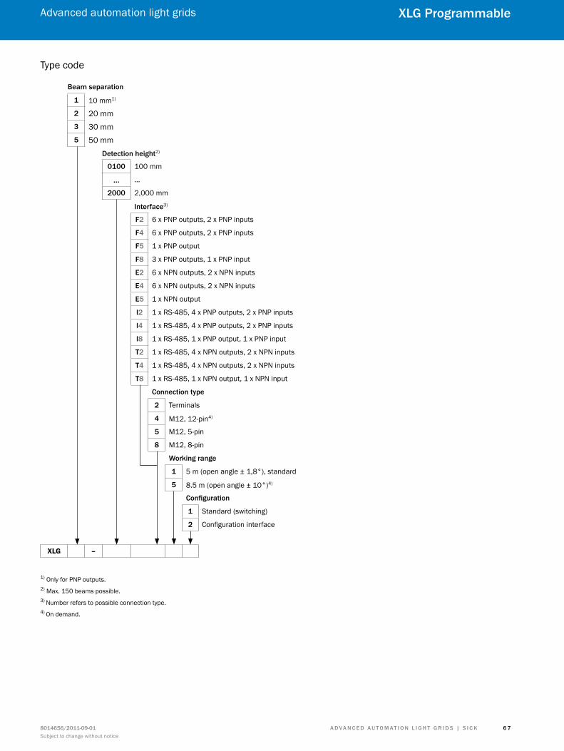
A d v A n c e d A u t o m At i o n L i G h t G r i d s | s i c K8014656/2011-09-01Subject to change without notice
Advanced automation light grids
6 7
XLG Programmable
Type code
Beam separation
1 10 mm1)
2 20 mm3 30 mm5 50 mm
detection height2)
0100 100 mm
… …
2000 2,000 mm
interface3)
f2 6 x PNP outputs, 2 x PNP inputs
f4 6 x PNP outputs, 2 x PNP inputs
f5 1 x PNP output
f8 3 x PNP outputs, 1 x PNP input
e2 6 x NPN outputs, 2 x NPN inputs
e4 6 x NPN outputs, 2 x NPN inputs
e5 1 x NPN output
i2 1 x RS-485, 4 x PNP outputs, 2 x PNP inputs
i4 1 x RS-485, 4 x PNP outputs, 2 x PNP inputs
i8 1 x RS-485, 1 x PNP output, 1 x PNP input
t2 1 x RS-485, 4 x NPN outputs, 2 x NPN inputs
t4 1 x RS-485, 4 x NPN outputs, 2 x NPN inputs
t8 1 x RS-485, 1 x NPN output, 1 x NPN input
connection type
2 Terminals
4 M12, 12-pin4)
5 M12, 5-pin
8 M12, 8-pin
Working range
1 5 m (open angle ± 1,8°), standard
5 8.5 m (open angle ± 10°)4)
configuration
1 Standard (switching)
2 Configuration interface
XLG –
1) Only for PNP outputs.2) Max. 150 beams possible.3) Number refers to possible connection type.4) On demand.
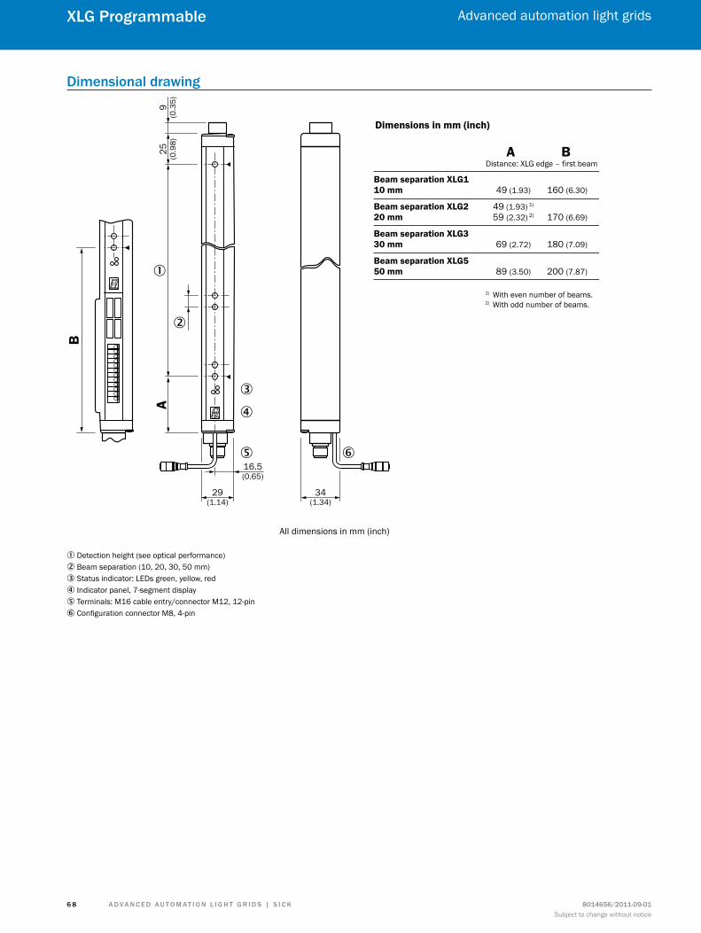
A d v A n c e d A u t o m At i o n L i G h t G r i d s | s i c K 8014656/2011-09-01Subject to change without notice
Advanced automation light grids
6 8
XLG Programmable
dimensional drawing
A9
(0.3
5)25 (0.9
8)
�
�
�
�
� �16.5(0.65)
29(1.14)
34(1.34)
All dimensions in mm (inch)
Dimensions in mm (inch)
A BDistance: XLG edge – first beam
Beam separation XLG110 mm 49 (1.93) 160 (6.30)
Beam separation XLG2 49 (1.93) 1)
20 mm 59 (2.32) 2) 170 (6.69)
Beam separation XLG330 mm 69 (2.72) 180 (7.09)
Beam separation XLG550 mm 89 (3.50) 200 (7.87)
B
1) With even number of beams.2) With odd number of beams.
1 Detection height (see optical performance)2 Beam separation (10, 20, 30, 50 mm)3 Status indicator: LEDs green, yellow, red4 Indicator panel, 7-segment display5 Terminals: M16 cable entry/connector M12, 12-pin6 Configuration connector M8, 4-pin
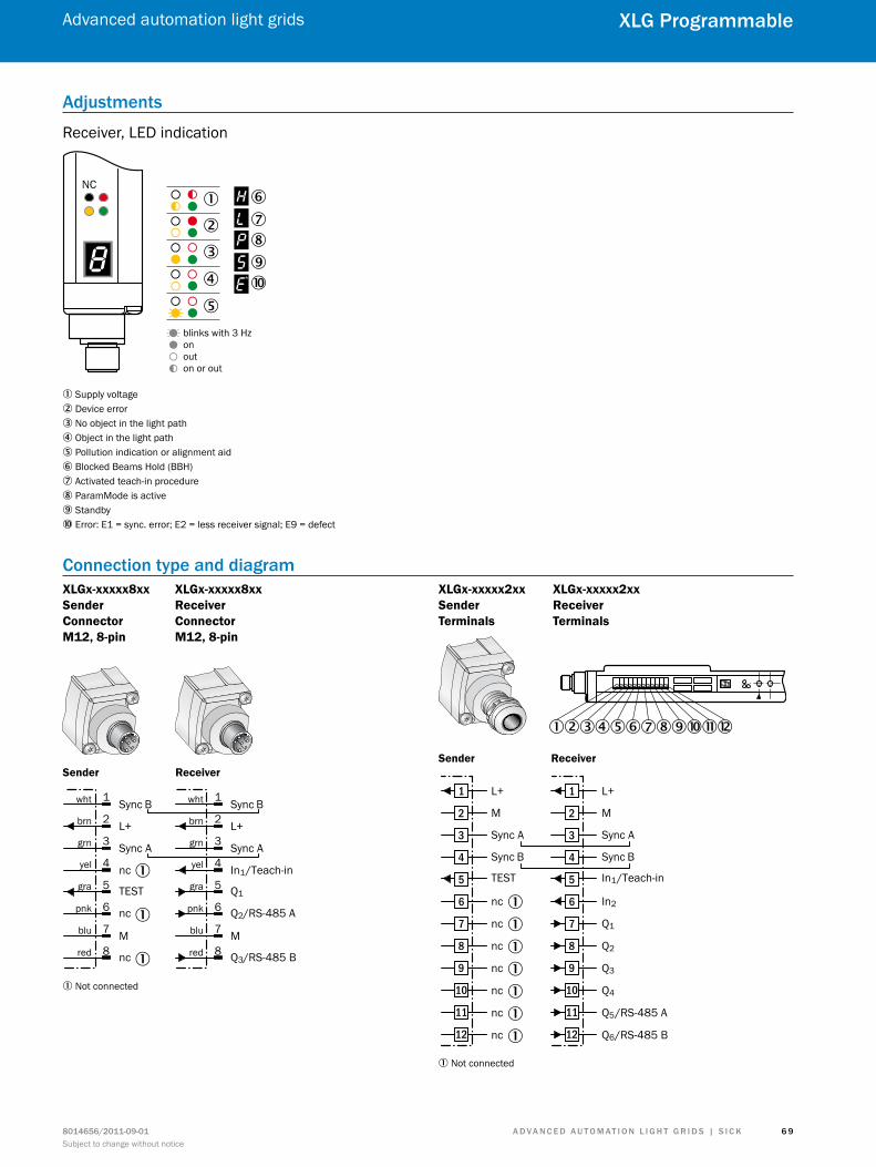
A d v A n c e d A u t o m At i o n L i G h t G r i d s | s i c K8014656/2011-09-01Subject to change without notice
Advanced automation light grids
6 9
XLG Programmable
Adjustments
Receiver, LED indication
NC
blinks with 3 Hzonouton or out
�
� �����
��
�
1 Supply voltage2 Device error3 No object in the light path4 Object in the light path5 Pollution indication or alignment aid6 Blocked Beams Hold (BBH)7 Activated teach-in procedure8 ParamMode is active9 Standbyß Error: E1 = sync. error; E2 = less receiver signal; E9 = defect
connection type and diagramXLGx-xxxxx8xx Sender Connector M12, 8-pin
XLGx-xxxxx8xx Receiver Connector M12, 8-pin
Sync B
L+
Sync A
Q1
In1/Teach-in
M
Q2/RS-485 A
Q3/RS-485 B
wht
brn
grn
yel
gra
pnk
blu
red
1
2
3
4
5
6
7
8
Sync B
L+
Sync A
TEST
nc
M
nc
nc
wht
brn
grn
yel
gra
pnk
blu
red
1
2
3
4
5
6
7
8
Sender Receiver
1
1
1
1 Not connected
XLGx-xxxxx2xx Sender Terminals
XLGx-xxxxx2xx Receiver Terminals
123456789ßàá
Sender Receiver
L+
M
Sync A
In1/Teach-in
Sync B
In2
Q1
Q2
Q3
Q4
Q5/RS-485 A
Q6/RS-485 B
1
2
3
4
5
6
7
8
9
10
11
12
L+
M
Sync A
TEST
Sync B
nc
nc
nc
nc
nc
nc
nc
1
2
3
4
5
6
7
8
9
10
11
12
1
1
1
1
1
1
1
1 Not connected
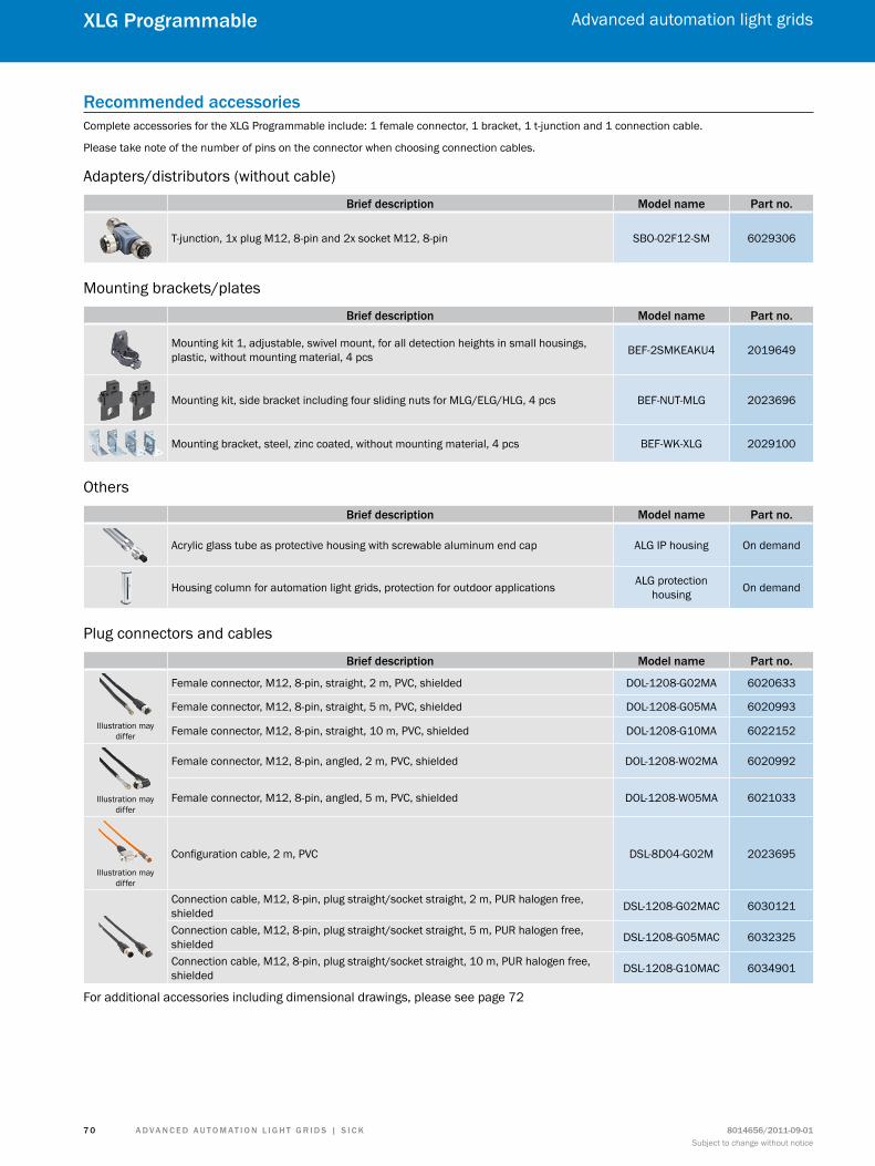
A d v A n c e d A u t o m At i o n L i G h t G r i d s | s i c K 8014656/2011-09-01Subject to change without notice
Advanced automation light grids
7 0
XLG Programmable
recommended accessoriesComplete accessories for the XLG Programmable include: 1 female connector, 1 bracket, 1 t-junction and 1 connection cable.
Please take note of the number of pins on the connector when choosing connection cables.
Adapters/distributors (without cable)
Brief description model name Part no.
T-junction, 1x plug M12, 8-pin and 2x socket M12, 8-pin SBO-02F12-SM 6029306
Mounting brackets/plates
Brief description model name Part no.
Mounting kit 1, adjustable, swivel mount, for all detection heights in small housings, plastic, without mounting material, 4 pcs BEF-2SMKEAKU4 2019649
Mounting kit, side bracket including four sliding nuts for MLG/ELG/HLG, 4 pcs BEF-NUT-MLG 2023696
Mounting bracket, steel, zinc coated, without mounting material, 4 pcs BEF-WK-XLG 2029100
Others
Brief description model name Part no.
Acrylic glass tube as protective housing with screwable aluminum end cap ALG IP housing On demand
Housing column for automation light grids, protection for outdoor applications ALG protection housing On demand
Plug connectors and cables
Brief description model name Part no.
Illustration may differ
Female connector, M12, 8-pin, straight, 2 m, PVC, shielded DOL-1208-G02MA 6020633
Female connector, M12, 8-pin, straight, 5 m, PVC, shielded DOL-1208-G05MA 6020993
Female connector, M12, 8-pin, straight, 10 m, PVC, shielded DOL-1208-G10MA 6022152
Illustration may differ
Female connector, M12, 8-pin, angled, 2 m, PVC, shielded DOL-1208-W02MA 6020992
Female connector, M12, 8-pin, angled, 5 m, PVC, shielded DOL-1208-W05MA 6021033
Illustration may differ
Configuration cable, 2 m, PVC DSL-8D04-G02M 2023695
Connection cable, M12, 8-pin, plug straight/socket straight, 2 m, PUR halogen free, shielded DSL-1208-G02MAC 6030121
Connection cable, M12, 8-pin, plug straight/socket straight, 5 m, PUR halogen free, shielded DSL-1208-G05MAC 6032325
Connection cable, M12, 8-pin, plug straight/socket straight, 10 m, PUR halogen free, shielded DSL-1208-G10MAC 6034901
For additional accessories including dimensional drawings, please see page 72

A d v A n c e d A u t o m At i o n L i G h t G r i d s | s i c K8014656/2011-09-01Subject to change without notice
Advanced automation light grids
7 1
XLG Programmable
special functions
Modular constructionThe advanced automation light grids are using a modular design principle. Every optics module has 15 beams. If you want to calculate the detection height, you have to subtract the single beam separation of the overall height of the optics modules.
E.g. 3 x 150 mm = 450 mm (overall height)450 mm – 10 mm (beam separation) = 440 mm (detection height)
Simple interconnection of optics mod-ules with lengths of 150 mm or 300 mm. Monitoring height determines how many modules to use.
Detection height Beam separationMinimum = 100 mmMaximum = 3,140 mm
Minimum = 10 mmMaximum = 50 mm
Beam separation varies depending on how the optics modules are equipped with LEDs. The smaller the beam separa-tion, the higher the resolution will be. There is also an MLG variant with a beam separation of 25 mm.
150
mm
Det
ectio
n he
ight
300
mm
10 mm 20 mm 30 mm 50 mm
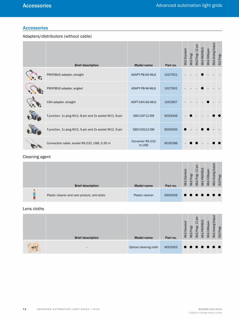
A d v A n c e d A u t o m At i o n L i G h t G r i d s | s i c K 8014656/2011-09-01Subject to change without notice
Advanced automation light grids
7 2
Accessories
Accessories
Adapters/distributors (without cable)
Brief description model name Part no. MLG
Sta
ndar
d
MLG
Pro
gr.
MLG
Pro
gr. 1
2-pi
n
MLG
PRO
FIBUS
MLG
CAN
open
MLG
Ana
log O
utpu
t
XLG
Prog
r.
PROFIBUS adapter, straight ADAPT-PB-GE-MLG 1027921 – – – O – – –
PROFIBUS adapter, angled ADAPT-PB-WI-MLG 1027901 – – – O – – –
CAN adapter, straight ADPT-CAN-GE-MLG 1052957 – – – – O – –
T-junction, 1x plug M12, 8-pin and 2x socket M12, 8-pin SBO-02F12-SM 6029306 – O – – – O O
T-junction, 1x plug M12, 5-pin and 2x socket M12, 5-pin SBO-02G12-SM 6029305 O – – O O – –
Connection cable, socket RS-232, USB, 0.35 m Converter RS-232 to USB 6035396 – O O – – O O
Cleaning agent
Brief description model name Part no. MLG
Sta
ndar
d
MLG
Pro
gr.
MLG
Pro
gr. 1
2-pi
n
MLG
PRO
FIBUS
MLG
CAN
open
MLG
Ana
log O
utpu
t
XLG
Prog
r.
Plastic cleaner and care product, anti-static Plastic cleaner 5600006 O O O O O O O
Lens cloths
Brief description model name Part no. MLG
Sta
ndar
d
MLG
Pro
gr.
MLG
Pro
gr. 1
2-pi
n
MLG
PRO
FIBUS
MLG
CAN
open
MLG
Ana
log O
utpu
t
XLG
Prog
r.
– Optical cleaning cloth 4003353 O O O O O O O
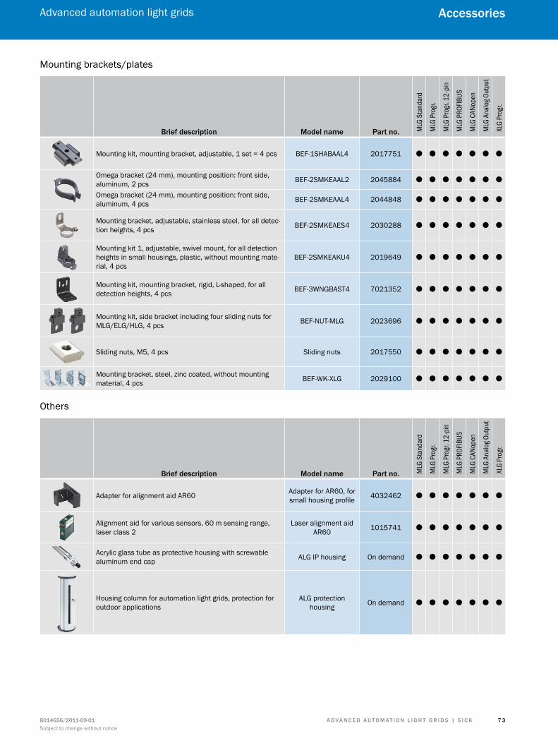
A d v A n c e d A u t o m At i o n L i G h t G r i d s | s i c K8014656/2011-09-01Subject to change without notice
Advanced automation light grids
7 3
Accessories
Mounting brackets/plates
Brief description model name Part no. MLG
Sta
ndar
d
MLG
Pro
gr.
MLG
Pro
gr. 1
2-pi
n
MLG
PRO
FIBUS
MLG
CAN
open
MLG
Ana
log O
utpu
t
XLG
Prog
r.
Mounting kit, mounting bracket, adjustable, 1 set = 4 pcs BEF-1SHABAAL4 2017751 O O O O O O O
Omega bracket (24 mm), mounting position: front side, aluminum, 2 pcs BEF-2SMKEAAL2 2045884 O O O O O O O
Omega bracket (24 mm), mounting position: front side, aluminum, 4 pcs BEF-2SMKEAAL4 2044848 O O O O O O O
Mounting bracket, adjustable, stainless steel, for all detec-tion heights, 4 pcs BEF-2SMKEAES4 2030288 O O O O O O O
Mounting kit 1, adjustable, swivel mount, for all detection heights in small housings, plastic, without mounting mate-rial, 4 pcs
BEF-2SMKEAKU4 2019649 O O O O O O O
Mounting kit, mounting bracket, rigid, L-shaped, for all detection heights, 4 pcs BEF-3WNGBAST4 7021352 O O O O O O O
Mounting kit, side bracket including four sliding nuts for MLG/ELG/HLG, 4 pcs BEF-NUT-MLG 2023696 O O O O O O O
Sliding nuts, M5, 4 pcs Sliding nuts 2017550 O O O O O O O
Mounting bracket, steel, zinc coated, without mounting material, 4 pcs BEF-WK-XLG 2029100 O O O O O O O
Others
Brief description model name Part no. MLG
Sta
ndar
d
MLG
Pro
gr.
MLG
Pro
gr. 1
2-pi
n
MLG
PRO
FIBUS
MLG
CAN
open
MLG
Ana
log O
utpu
t
XLG
Prog
r.Adapter for alignment aid AR60 Adapter for AR60, for
small housing profile 4032462 O O O O O O O
Alignment aid for various sensors, 60 m sensing range, laser class 2
Laser alignment aid AR60 1015741 O O O O O O O
Acrylic glass tube as protective housing with screwable aluminum end cap ALG IP housing On demand O O O O O O O
Housing column for automation light grids, protection for outdoor applications
ALG protection housing On demand O O O O O O O
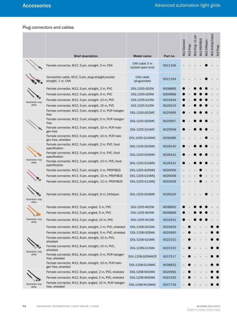
A d v A n c e d A u t o m At i o n L i G h t G r i d s | s i c K 8014656/2011-09-01Subject to change without notice
Advanced automation light grids
7 4
Accessories
Plug connectors and cables
Brief description model name Part no. MLG
Sta
ndar
d
MLG
Pro
gr.
MLG
Pro
gr. 1
2-pi
n
MLG
PRO
FIBUS
MLG
CAN
open
MLG
Ana
log O
utpu
t
XLG
Prog
r.
Female connector, M12, 5-pin, straight, 5 m, CAN CAN cable 5 m (socket-open end) 6021166 – – – – O – –
Connection cable, M12, 5-pin, plug straight/socket straight, 1 m, CAN
CAN cable (plug-socket) 6021164 – – – – O – –
Illustration may differ
Female connector, M12, 5-pin, straight, 2 m, PVC DOL-1205-G02M 6008899 O – O O O – –
Female connector, M12, 5-pin, straight, 5 m, PVC DOL-1205-G05M 6009868 O – O O O – –
Female connector, M12, 5-pin, straight, 10 m, PVC DOL-1205-G10M 6010544 O – O O O – –
Female connector, M12, 5-pin, straight, 15 m, PVC DOL-1205-G15M 6029215 O – O O O – –
Female connector, M12, 5-pin, straight, 2 m, PUR halogen free DOL-1205-G02MC 6025906 O – O O O – –
Female connector, M12, 5-pin, straight, 5 m, PUR halogen free DOL-1205-G05MC 6025907 O – O O O – –
Female connector, M12, 5-pin, straight, 10 m, PUR halo-gen free DOL-1205-G10MC 6025908 O – O O O – –
Female connector, M12, 5-pin, straight, 10 m, PUR halo-gen free, shielded DOL-1205-G10MAC 6036385 – – – – O – –
Illustration may differ
Female connector, M12, 5-pin, straight, 2 m, PVC, food specification DOL-1205-G02MN 6028140 O – O O O – –
Female connector, M12, 5-pin, straight, 5 m, PVC, food specification DOL-1205-G05MN 6028141 O – O O O – –
Female connector, M12, 5-pin, straight, 10 m, PVC, food specification DOL-1205-G10MN 6028142 O – O O O – –
Female connector, M12, 5-pin, straight, 5 m, PROFIBUS DOL-1205-G05MQ 6026006 – – – O – – –
Female connector, M12, 5-pin, straight, 10 m, PROFIBUS DOL-1205-G10MQ 6026008 – – – O – – –
Female connector, M12, 5-pin, straight, 12 m, PROFIBUS DOL-1205-G12MQ 6032636 – – – O – – –
Illustration may differ
Female connector, M12, 5-pin, straight, 6 m, CANopen DOL-1205-GO6MK 6028326 – – – – O – –
Illustration may differ
Female connector, M12, 5-pin, angled, 2 m, PVC DOL-1205-W02M 6008900 O – O O O – –
Female connector, M12, 5-pin, angled, 5 m, PVC DOL-1205-W05M 6009869 O – O O O – –
Female connector, M12, 5-pin, angled, 10 m, PVC DOL-1205-W10M 6010542 O – O O O – –
Illustration may differ
Female connector, M12, 8-pin, straight, 2 m, PVC, shielded DOL-1208-G02MA 6020633 – O – – – O O
Female connector, M12, 8-pin, straight, 5 m, PVC, shielded DOL-1208-G05MA 6020993 – O – – – O O
Female connector, M12, 8-pin, straight, 10 m, PVC, shielded DOL-1208-G10MA 6022152 – O – – – O O
Female connector, M12, 8-pin, straight, 15 m, PVC, shielded DOL-1208-G15MA 6022153 – O – – – O O
Female connector, M12, 8-pin, straight, 5 m, PUR halogen free, shielded DOL-1208-G05MACR 6037517 – O – – – O O
Female connector, M12, 8-pin, straight, 10 m, PUR halo-gen free, shielded DOL-1208-G10MAC 6038832 – O – – – O O
Illustration may differ
Female connector, M12, 8-pin, angled, 2 m, PVC, shielded DOL-1208-W02MA 6020992 – O – – – O O
Female connector, M12, 8-pin, angled, 5 m, PVC, shielded DOL-1208-W05MA 6021033 – O – – – O O
Female connector, M12, 8-pin, angled, 10 m, PUR halogen free, shielded DOL-1208-W10MAC 6037726 – O – – – O O
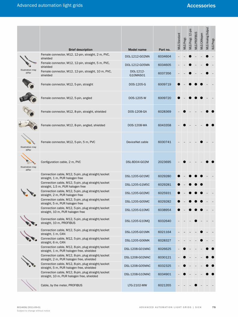
A d v A n c e d A u t o m At i o n L i G h t G r i d s | s i c K8014656/2011-09-01Subject to change without notice
Advanced automation light grids
7 5
Accessories
Brief description model name Part no. MLG
Sta
ndar
d
MLG
Pro
gr.
MLG
Pro
gr. 1
2-pi
n
MLG
PRO
FIBUS
MLG
CAN
open
MLG
Ana
log O
utpu
t
XLG
Prog
r.
Illustration may differ
Female connector, M12, 12-pin, straight, 2 m, PVC, shielded DOL-1212-G02MA 6034604 – – O – – O –
Female connector, M12, 12-pin, straight, 5 m, PVC, shielded DOL-1212-G05MA 6034605 – – O – – O –
Female connector, M12, 12-pin, straight, 10 m, PVC, shielded
DOL-1212-G10MAS01 6037356 – – O – – O –
Female connector, M12, 5-pin, straight DOS-1205-G 6009719 O – O O O – –
Female connector, M12, 5-pin, angled DOS-1205-W 6009720 O – O O O – –
Female connector, M12, 8-pin, straight, shielded DOS-1208-GA 6028369 – O – – – O O
Female connector, M12, 8-pin, angled, shielded DOS-1208-WA 6043358 – O – – – O O
Illustration may differ
Female connector, M12, 5-pin, 5 m, PVC DeviceNet cable 6030741 – – – – O – –
Illustration may differ
Configuration cable, 2 m, PVC DSL-8D04-G02M 2023695 – O – – – O O
Connection cable, M12, 5-pin, plug straight/socket straight, 1 m, PUR halogen free DSL-1205-G01MC 6029280 O – O O O – –
Connection cable, M12, 5-pin, plug straight/socket straight, 1.5 m, PUR halogen free DSL-1205-G1M5C 6029281 O – O O O
Connection cable, M12, 5-pin, plug straight/socket straight, 2 m, PUR halogen free DSL-1205-G02MC 6025931 O – O O O – –
Connection cable, M12, 5-pin, plug straight/socket straight, 5 m, PUR halogen free DSL-1205-G05MC 6029282 O – O O O – –
Connection cable, M12, 5-pin, plug straight/socket straight, 10 m, PUR halogen free DSL-1205-G10MC 6038954 O – O O O – –
Connection cable, M12, 5-pin, plug straight/socket straight, 10 m, PROFIBUS DSL-1205-G10MQ 6032640 – – – O – – –
Connection cable, M12, 5-pin, plug straight/socket straight, 1 m, CAN DSL-1205-G01MK 6021164 – – – – O – –
Connection cable, M12, 5-pin, plug straight/socket straight, 6 m, CAN DSL-1205-G06MK 6028327 – – – – O – –
Connection cable, M12, 8-pin, plug straight/socket straight, 1 m, PUR halogen free, shielded DSL-1208-G01MAC 6026625 – O – – – O O
Connection cable, M12, 8-pin, plug straight/socket straight, 2 m, PUR halogen free, shielded DSL-1208-G02MAC 6030121 – O – – – O O
Connection cable, M12, 8-pin, plug straight/socket straight, 5 m, PUR halogen free, shielded DSL-1208-G05MAC 6032325 – O – – – O O
Connection cable, M12, 8-pin, plug straight/socket straight, 10 m, PUR halogen free, shielded DSL-1208-G10MAC 6034901 – O – – – O O
Cable, by the meter, PROFIBUS LTG-2102-MW 6021355 – – – O – – –
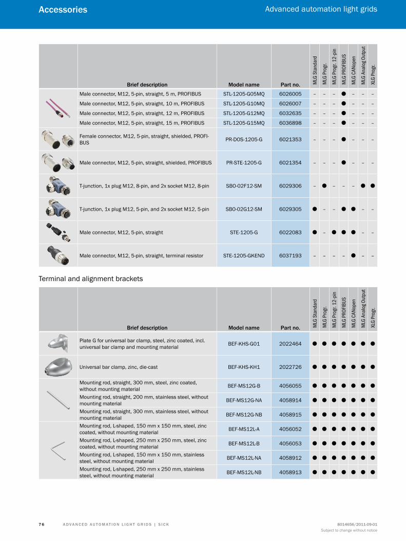
A d v A n c e d A u t o m At i o n L i G h t G r i d s | s i c K 8014656/2011-09-01Subject to change without notice
Advanced automation light grids
7 6
Accessories
Brief description model name Part no. MLG
Sta
ndar
d
MLG
Pro
gr.
MLG
Pro
gr. 1
2-pi
n
MLG
PRO
FIBUS
MLG
CAN
open
MLG
Ana
log O
utpu
t
XLG
Prog
r.
Male connector, M12, 5-pin, straight, 5 m, PROFIBUS STL-1205-G05MQ 6026005 – – – O – – –
Male connector, M12, 5-pin, straight, 10 m, PROFIBUS STL-1205-G10MQ 6026007 – – – O – – –
Male connector, M12, 5-pin, straight, 12 m, PROFIBUS STL-1205-G12MQ 6032635 – – – O – – –
Male connector, M12, 5-pin, straight, 15 m, PROFIBUS STL-1205-G15MQ 6036898 – – – O – – –
Female connector, M12, 5-pin, straight, shielded, PROFI-BUS PR-DOS-1205-G 6021353 – – – O – – –
Male connector, M12, 5-pin, straight, shielded, PROFIBUS PR-STE-1205-G 6021354 – – – O – – –
T-junction, 1x plug M12, 8-pin, and 2x socket M12, 8-pin SBO-02F12-SM 6029306 – O – – – O O
T-junction, 1x plug M12, 5-pin, and 2x socket M12, 5-pin SBO-02G12-SM 6029305 O – – O O – –
Male connector, M12, 5-pin, straight STE-1205-G 6022083 O – O O O – –
Male connector, M12, 5-pin, straight, terminal resistor STE-1205-GKEND 6037193 – – – – O – –
Terminal and alignment brackets
Brief description model name Part no. MLG
Sta
ndar
d
MLG
Pro
gr.
MLG
Pro
gr. 1
2-pi
n
MLG
PRO
FIBUS
MLG
CAN
open
MLG
Ana
log O
utpu
t
XLG
Prog
r.
Plate G for universal bar clamp, steel, zinc coated, incl. universal bar clamp and mounting material BEF-KHS-G01 2022464 O O O O O O O
Universal bar clamp, zinc, die-cast BEF-KHS-KH1 2022726 O O O O O O O
Mounting rod, straight, 300 mm, steel, zinc coated, without mounting material BEF-MS12G-B 4056055 O O O O O O O
Mounting rod, straight, 200 mm, stainless steel, without mounting material BEF-MS12G-NA 4058914 O O O O O O O
Mounting rod, straight, 300 mm, stainless steel, without mounting material BEF-MS12G-NB 4058915 O O O O O O O
Mounting rod, L-shaped, 150 mm x 150 mm, steel, zinc coated, without mounting material BEF-MS12L-A 4056052 O O O O O O O
Mounting rod, L-shaped, 250 mm x 250 mm, steel, zinc coated, without mounting material BEF-MS12L-B 4056053 O O O O O O O
Mounting rod, L-shaped, 150 mm x 150 mm, stainless steel, without mounting material BEF-MS12L-NA 4058912 O O O O O O O
Mounting rod, L-shaped, 250 mm x 250 mm, stainless steel, without mounting material BEF-MS12L-NB 4058913 O O O O O O O
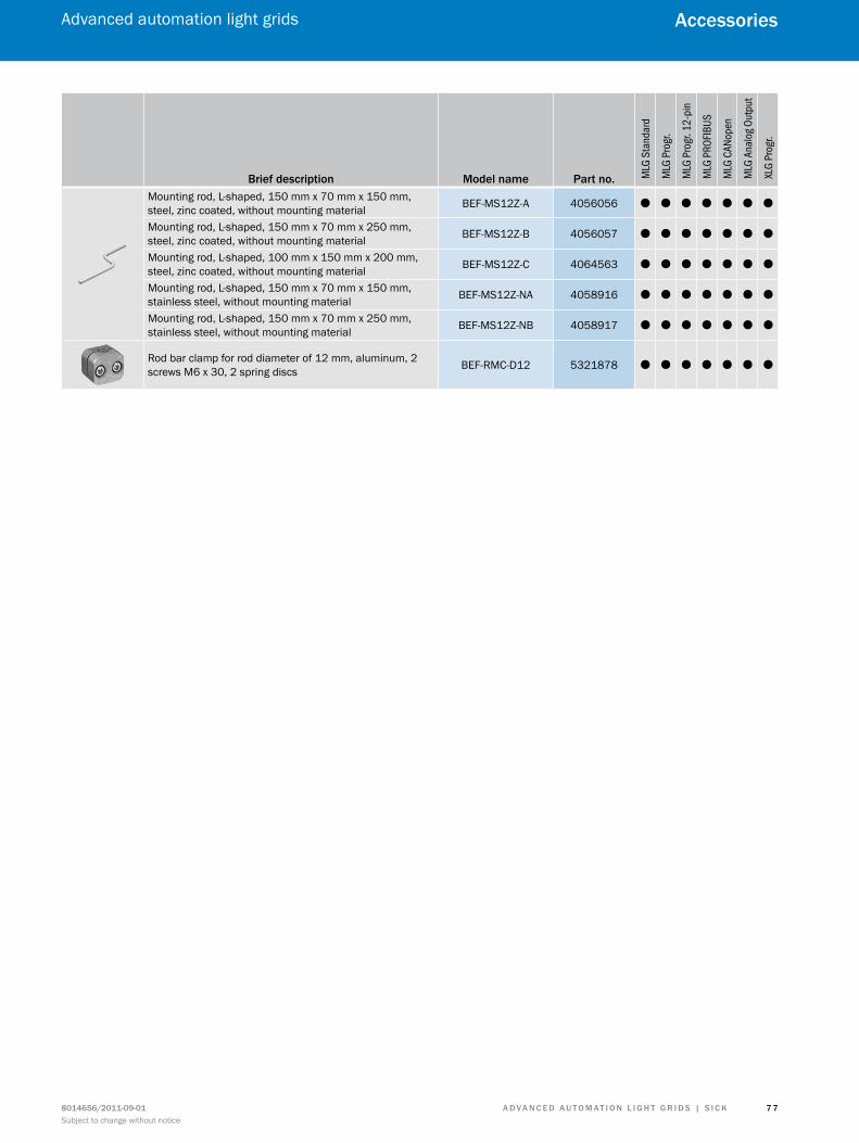
A d v A n c e d A u t o m At i o n L i G h t G r i d s | s i c K8014656/2011-09-01Subject to change without notice
Advanced automation light grids
7 7
Accessories
Brief description model name Part no. MLG
Sta
ndar
d
MLG
Pro
gr.
MLG
Pro
gr. 1
2-pi
n
MLG
PRO
FIBUS
MLG
CAN
open
MLG
Ana
log O
utpu
t
XLG
Prog
r.
Mounting rod, L-shaped, 150 mm x 70 mm x 150 mm, steel, zinc coated, without mounting material BEF-MS12Z-A 4056056 O O O O O O O
Mounting rod, L-shaped, 150 mm x 70 mm x 250 mm, steel, zinc coated, without mounting material BEF-MS12Z-B 4056057 O O O O O O O
Mounting rod, L-shaped, 100 mm x 150 mm x 200 mm, steel, zinc coated, without mounting material BEF-MS12Z-C 4064563 O O O O O O O
Mounting rod, L-shaped, 150 mm x 70 mm x 150 mm, stainless steel, without mounting material BEF-MS12Z-NA 4058916 O O O O O O O
Mounting rod, L-shaped, 150 mm x 70 mm x 250 mm, stainless steel, without mounting material BEF-MS12Z-NB 4058917 O O O O O O O
Rod bar clamp for rod diameter of 12 mm, aluminum, 2 screws M6 x 30, 2 spring discs BEF-RMC-D12 5321878 O O O O O O O
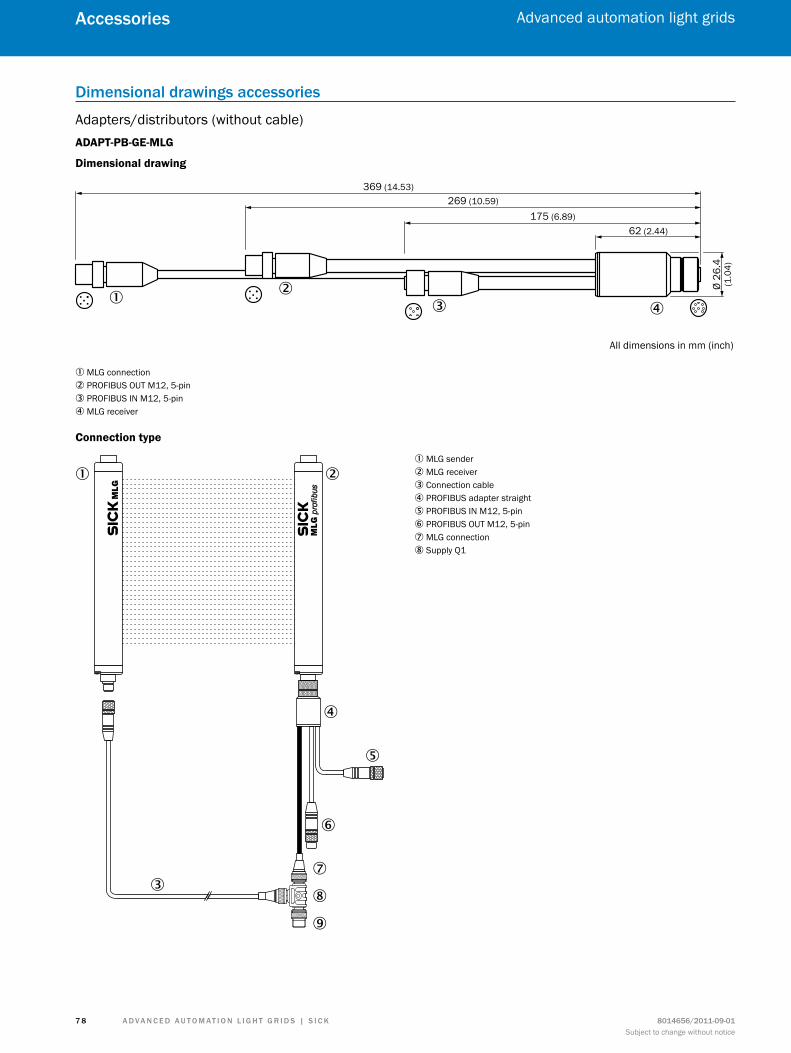
A d v A n c e d A u t o m At i o n L i G h t G r i d s | s i c K 8014656/2011-09-01Subject to change without notice
Advanced automation light grids
7 8
Accessories
dimensional drawings accessories
Adapters/distributors (without cable)ADAPT-PB-GE-MLG
Dimensional drawing
369 (14.53)269 (10.59)
175 (6.89)62 (2.44)
Ø 26
.4(1
.04)
All dimensions in mm (inch)
432
1
1 MLG connection2 PROFIBUS OUT M12, 5-pin3 PROFIBUS IN M12, 5-pin4 MLG receiver
Connection type
1 2
3
4
5
6
7
8
9
1 MLG sender2 MLG receiver3 Connection cable4 PROFIBUS adapter straight5 PROFIBUS IN M12, 5-pin6 PROFIBUS OUT M12, 5-pin7 MLG connection8 Supply Q1
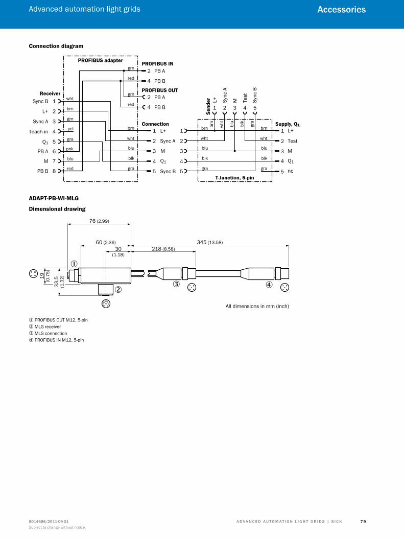
A d v A n c e d A u t o m At i o n L i G h t G r i d s | s i c K8014656/2011-09-01Subject to change without notice
Advanced automation light grids
7 9
Accessories
Connection diagram
PROFIBUS IN
L+
Test
M
nc
Q1
1
2
4
3
5
L+
Sync A
M
Sync B
Q1
1
2
4
3
5
PB A
PB B
2
4
1 2 43 5
L+ Sync
A
M Sync
B
Test
T-Junction, 5-pin
PROFIBUS adapter
Receiver
Send
erwht
brn
yel
grn
grn
red
PROFIBUS OUT
Connection Supply, Q1
PB A
PB B
2
4
grn
red
brn
wht
blu
blk
gra
1
2
4
3
5
brn
wht
blu
blk
gra
brn
wht
blu
blk
gra
gra
pnk
red
blu
Sync B
L+
Sync A
Q1
1
2
3
5
Teach-in 4
PB A 6
M 7
PB B 8
brn
wht blu
blk
gra
ADAPT-PB-WI-MLG
Dimensional drawing
2
1
3 4
76 (2.99)
60 (2.36)30
(1.18)
345 (13.58)218 (8.58)
19 (0.7
5)
33.5
(1.3
2)
All dimensions in mm (inch)
1 PROFIBUS OUT M12, 5-pin2 MLG receiver3 MLG connection4 PROFIBUS IN M12, 5-pin
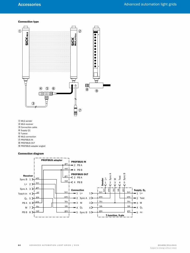
A d v A n c e d A u t o m At i o n L i G h t G r i d s | s i c K 8014656/2011-09-01Subject to change without notice
Advanced automation light grids
8 0
Accessories
Connection type
1 2
3
4 5 6
7
8 9
1 MLG sender2 MLG receiver3 Connection cable4 Supply Q15 T-piece6 MLG connection7 PROFIBUS IN8 PROFIBUS OUT9 PROFIBUS adapter angled
Connection diagram
PROFIBUS IN
L+
Test
M
nc
Q1
1
2
4
3
5
L+
Sync A
M
Sync B
Q1
1
2
4
3
5
PB A
PB B
2
4
1 2 43 5
L+ Sync
A
M Sync
B
Test
T-Junction, 5-pin
PROFIBUS adapter
Receiver
Send
erwht
brn
yel
grn
grn
red
PROFIBUS OUT
Connection Supply, Q1
PB A
PB B
2
4
grn
red
brn
wht
blu
blk
gra
1
2
4
3
5
brn
wht
blu
blk
gra
brn
wht
blu
blk
gra
gra
pnk
red
blu
Sync B
L+
Sync A
Q1
1
2
3
5
Teach-in 4
PB A 6
M 7
PB B 8
brn
wht blu
blk
gra
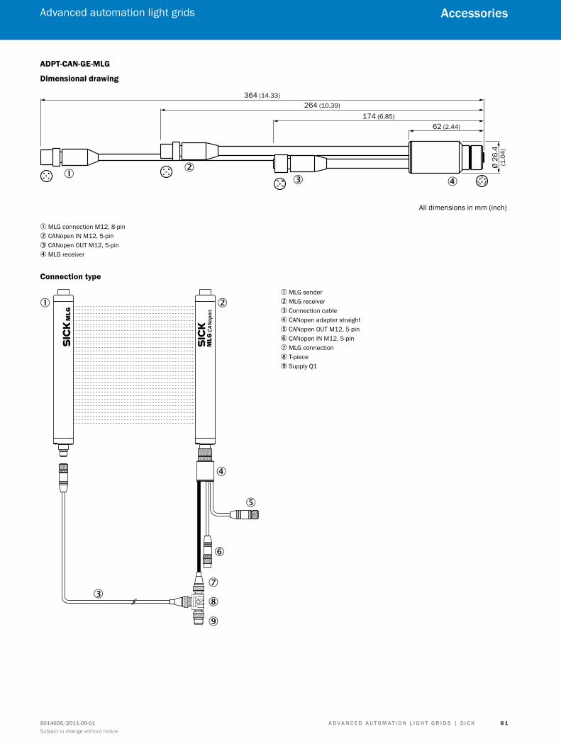
A d v A n c e d A u t o m At i o n L i G h t G r i d s | s i c K8014656/2011-09-01Subject to change without notice
Advanced automation light grids
8 1
Accessories
ADPT-CAN-GE-MLG
Dimensional drawing
364 (14.33)264 (10.39)
174 (6.85)62 (2.44)
Ø 26
.4(1
.04)
All dimensions in mm (inch)
432
1
1 MLG connection M12, 8-pin2 CANopen IN M12, 5-pin3 CANopen OUT M12, 5-pin4 MLG receiver
Connection type
1 2
3
4
5
6
7
8
9
CAN
open
1 MLG sender2 MLG receiver3 Connection cable4 CANopen adapter straight5 CANopen OUT M12, 5-pin6 CANopen IN M12, 5-pin7 MLG connection8 T-piece9 Supply Q1
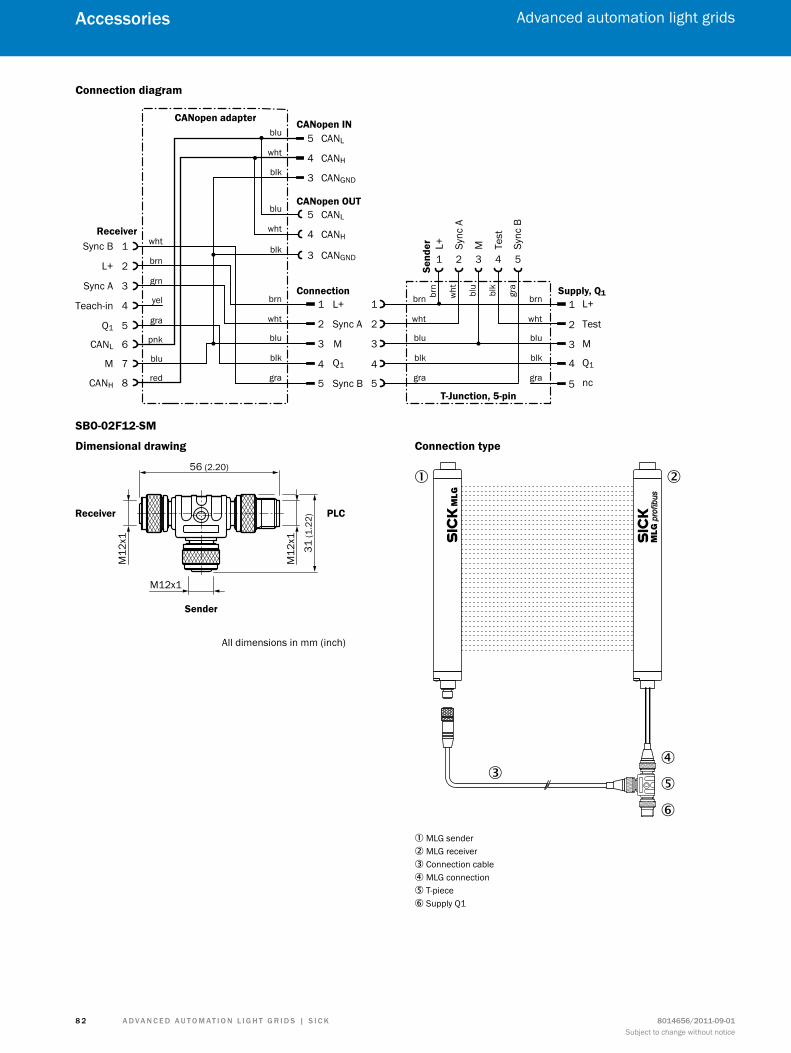
A d v A n c e d A u t o m At i o n L i G h t G r i d s | s i c K 8014656/2011-09-01Subject to change without notice
Advanced automation light grids
8 2
Accessories
Connection diagram
CANopen IN
L+
Test
M
nc
Q1
1
2
4
3
5
L+
Sync A
M
Sync B
Q1
1
2
4
3
5
CANL
CANH
5
4
1 2 43 5
L+ Sync
A
M Sync
B
Test
T-Junction, 5-pin
CANopen adapter
Receiver
Send
erwht
brn
yel
grn
blu
wht
CANGND3blk
CANopen OUT
Connection Supply, Q1
CANL
CANH
5
4
blu
wht
brn
wht
blu
blk
gra
1
2
4
3
5
brn
wht
blu
blk
gra
brn
wht
blu
blk
gra
gra
pnk
red
blu
Sync B
L+
Sync A
Q1
1
2
3
5
Teach-in 4
CANL 6
M 7
CANH 8
CANGND3blk
brn
wht blu
blk
gra
SBO-02F12-SM
Dimensional drawing
Receiver
Sender
PLC
M12
x1
M12x1
M12
x1
31 (1
.22)
56 (2.20)
All dimensions in mm (inch)
Connection type
1 2
34
5
6
1 MLG sender2 MLG receiver3 Connection cable4 MLG connection5 T-piece6 Supply Q1
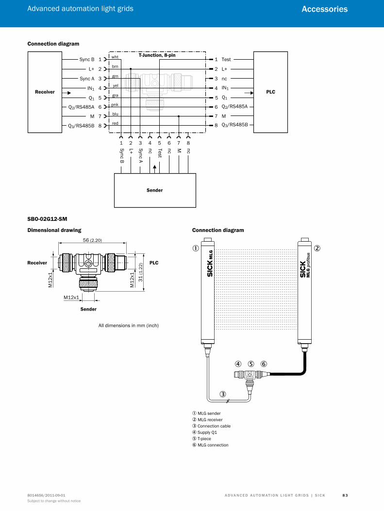
A d v A n c e d A u t o m At i o n L i G h t G r i d s | s i c K8014656/2011-09-01Subject to change without notice
Advanced automation light grids
8 3
Accessories
Connection diagram
Receiver
Sender
T-Junction, 8-pinTest
L+
nc
Q1
IN1
wht
brn
yel
grn
gra
pnk
blu
red
PLC
Sync B
L+
Sync A
Q1
1
2
3
5
1
2
4
3
5
IN1 4
Q2/RS485A 6
M 7
Q3/RS485B 8
Q2/RS485A6
M7
Q3/RS485B8
1 2 3 5
Test
4
nc
6
nc
7
M
8
ncSync A
Sync B
L+
SBO-02G12-SM
Dimensional drawing
Receiver
Sender
PLC
M12
x1
M12x1
M12
x1
31 (1
.22)
56 (2.20)
All dimensions in mm (inch)
Connection diagram
1 2
3
4 5 6
1 MLG sender2 MLG receiver3 Connection cable4 Supply Q15 T-piece6 MLG connection
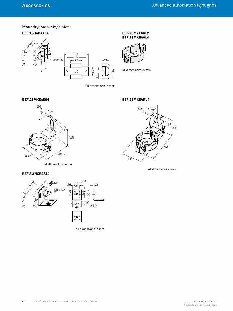
A d v A n c e d A u t o m At i o n L i G h t G r i d s | s i c K 8014656/2011-09-01Subject to change without notice
Advanced automation light grids
8 4
Accessories
Mounting brackets/platesBEF-1SHABAAL4
2
8065
23
5130
40
11
M5 x 18
All dimensions in mm
BEF-2SMKEAAL2 BEF-2SMKEAAL4
Ø 24
All dimensions in mm
BEF-2SMKEAES4
35
14.5
3.6
48.5
41.5
43.7
8.5
Ø 23.8
All dimensions in mm
BEF-2SMKEAKU4
36
62
8
3.8 34.3
Ø 24
4413
All dimensions in mmBEF-3WNGBAST4
5.3
12
2410
2244
1425
4.8
50
ø 8.3
5M5
M5 x 10
All dimensions in mm
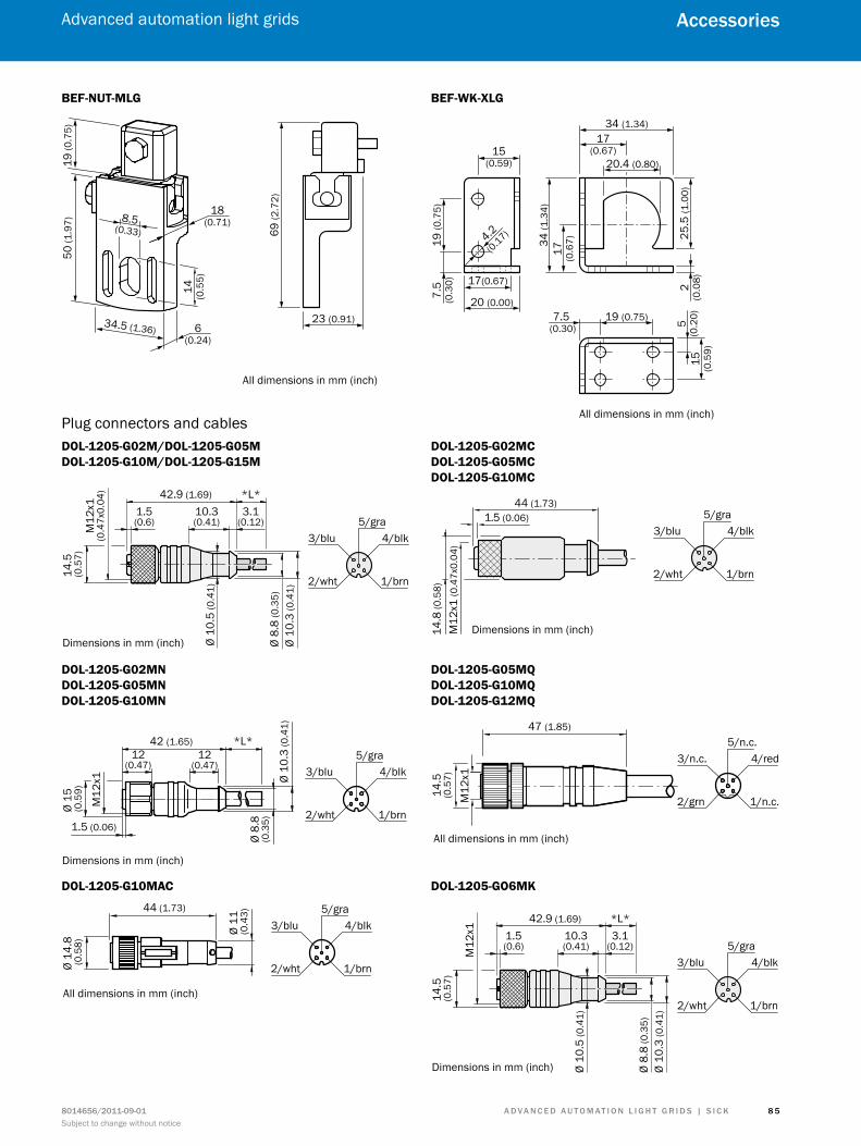
A d v A n c e d A u t o m At i o n L i G h t G r i d s | s i c K8014656/2011-09-01Subject to change without notice
Advanced automation light grids
8 5
Accessories
BEF-NUT-MLG
All dimensions in mm (inch)
69 (2
.72)
50 (1
.97)
19 (0
.75)
23 (0.91)
18(0.71)8.5
(0.33)
6(0.24)
34.5 (1.36)
14 (0.5
5)
BEF-WK-XLG
All dimensions in mm (inch)
20 (0.00)
17(0.67)
17(0.67)
34 (1
.34)
34 (1.34)
20.4 (0.80)
19 (0.75)
15 (0.5
9)
5(0
.20)7.5
(0.30)
25.5
(1.0
0)2
(0.0
8)
17 (0.6
7)
15(0.59)
7.5
(0.3
0)19
(0.7
5)
4.2
(0.17)
Plug connectors and cablesDOL-1205-G02M/DOL-1205-G05M DOL-1205-G10M/DOL-1205-G15M
*L*42.9 (1.69)
Ø 10
.3 (0
.41)
Ø 10
.5 (0
.41)
Ø 8.
8 (0
.35)
14.5
(0.5
7)
3.1(0.12)
10.3(0.41)
1.5(0.6) 5/gra
4/blk3/blu
2/wht 1/brn
Dimensions in mm (inch)
M12
x1(0
.47x
0.04
)
DOL-1205-G02MC DOL-1205-G05MC DOL-1205-G10MC
1.5 (0.06)
14.8
(0.5
8)
44 (1.73)5/gra
4/blk3/blu
2/wht 1/brn
Dimensions in mm (inch)M12
x1 (0
.47x
0.04
)
DOL-1205-G02MN DOL-1205-G05MN DOL-1205-G10MN
Ø 10
.3 (0
.41)
Ø 8.
8(0
.35)
M12
x1
*L*
Ø 15
(0
.59)
42 (1.65)
1.5 (0.06)
12(0.47)
5/gra4/blk3/blu
2/wht 1/brn
12(0.47)
Dimensions in mm (inch)
DOL-1205-G05MQ DOL-1205-G10MQ DOL-1205-G12MQ
M12
x1
5/n.c.4/red3/n.c.
2/grn 1/n.c.
47 (1.85)
14.5
(0.5
7)
All dimensions in mm (inch)
DOL-1205-G10MAC
5/gra4/blk3/blu
2/wht 1/brn
44 (1.73)
Ø 11
(0.4
3)
Ø 14
.8 (0
.58)
All dimensions in mm (inch)
DOL-1205-GO6MK
*L*42.9 (1.69)
Ø 10
.3 (0
.41)
Ø 10
.5 (0
.41)
Ø 8.
8 (0
.35)
14.5
(0.5
7)
3.1(0.12)
10.3(0.41)
1.5(0.6) 5/gra
4/blk3/blu
2/wht 1/brn
Dimensions in mm (inch)
M12
x1
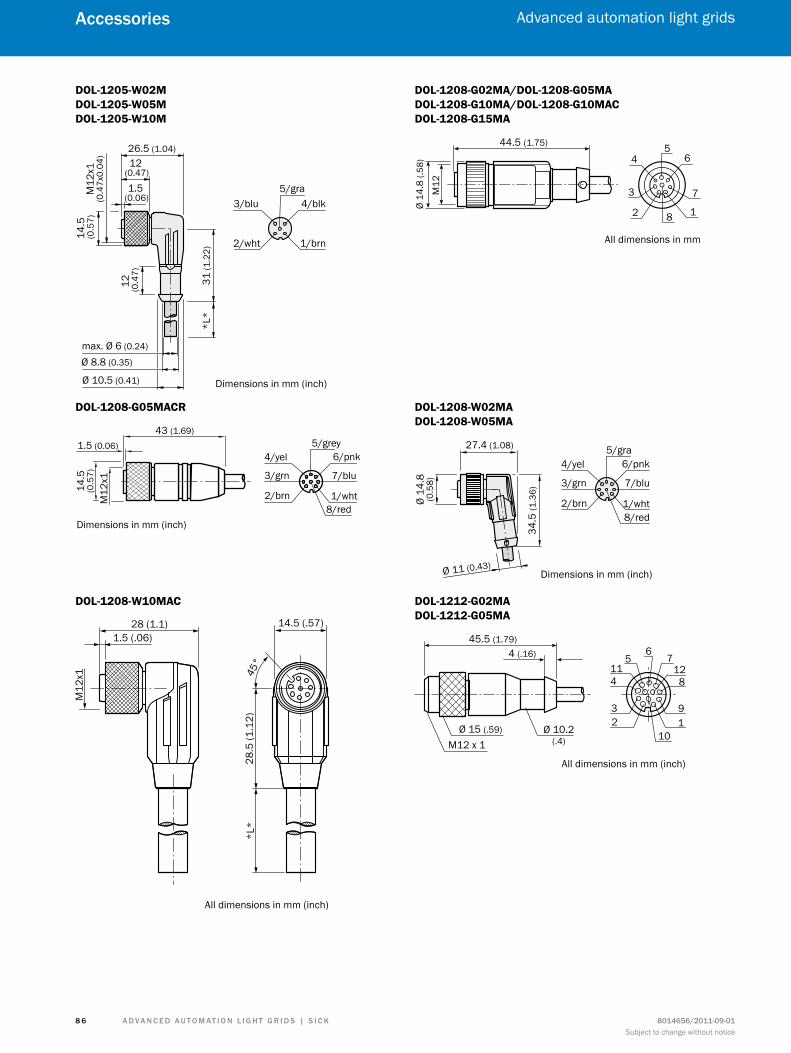
A d v A n c e d A u t o m At i o n L i G h t G r i d s | s i c K 8014656/2011-09-01Subject to change without notice
Advanced automation light grids
8 6
Accessories
DOL-1205-W02M DOL-1205-W05M DOL-1205-W10M
26.5 (1.04)
12 (0
.47)
12 (0.47)
1.5 (0.06)
max. Ø 6 (0.24)
14.5
(0.5
7)
Ø 8.8 (0.35)
Ø 10.5 (0.41)
31 (1
.22)
*L*
5/gra4/blk3/blu
2/wht 1/brn
Dimensions in mm (inch)
M12
x1(0
.47x
0.04
)DOL-1208-G02MA/DOL-1208-G05MA DOL-1208-G10MA/DOL-1208-G10MAC DOL-1208-G15MA
M12
Ø 14
.8 (.
58)
44.5 (1.75) 5
3
64
1
7
82
All dimensions in mm
DOL-1208-G05MACR
6/pnk
7/blu3/grn
8/red
4/yel
2/brn 1/wht
5/grey
14.5
(0.5
7)
1.5 (0.06)
43 (1.69)
M12
x1
Dimensions in mm (inch)
DOL-1208-W02MA DOL-1208-W05MA
6/pnk
7/blu3/grn
8/red
4/yel
2/brn 1/wht
5/gra27.4 (1.08)
Ø 14
.8(0
.58)
Ø 11 (0.43)
34.5
(1.3
6)
Dimensions in mm (inch)
DOL-1208-W10MAC
All dimensions in mm (inch)
DOL-1212-G02MA DOL-1212-G05MA
45.5 (1.79)4 (.16)
Ø 15 (.59) Ø 10.2(.4)M12 x 1
11 12
1012
3
4
56
7
9
8
All dimensions in mm (inch)
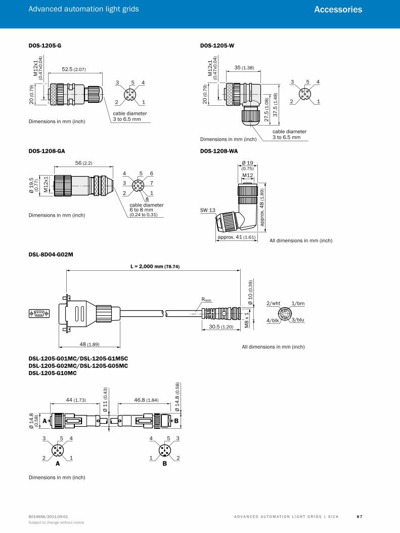
A d v A n c e d A u t o m At i o n L i G h t G r i d s | s i c K8014656/2011-09-01Subject to change without notice
Advanced automation light grids
8 7
Accessories
DOS-1205-G
20 (0
.79)
52.5 (2.07)
cable diameter3 to 6.5 mm
453
2 1
Dimensions in mm (inch)
M12
x1(0
.47x
0.04
)DOS-1205-W
37.5
(1.4
8)
27.5
(1.0
8)
35 (1.38)
453
2 1
cable diameter3 to 6.5 mmDimensions in mm (inch)
20 (0
.79)
M12
x1(0
.47x
0.04
)
DOS-1208-GA
56 (2.2)
M12
x1
Ø 19
.5(0
.77)
cable diameter6 to 8 mm(0.24 to 0.31)
6
73
5
8
4
2 1
Dimensions in mm (inch)
DOS-1208-WA
Ø 19(0.75)M12
appr
ox. 4
8 (1
.89)
approx. 41 (1.61)
SW 13
All dimensions in mm (inch)
DSL-8D04-G02M
All dimensions in mm (inch)
Ø 10
(0.3
9)
30.5 (1.20)
48 (1.89)
L = 2,000 mm (78.74)
Rmin
M8
x 1
2/wht 1/brn
4/blk 3/blu
DSL-1205-G01MC/DSL-1205-G1M5C DSL-1205-G02MC/DSL-1205-G05MC DSL-1205-G10MC
453
2 1
5 34
1 2A B
Ø 11
(0.4
3)
B
46.8 (1.84)
Ø 14
.8 (0
.58)
44 (1.73)
Ø 14
.8(0
.58) A
Dimensions in mm (inch)
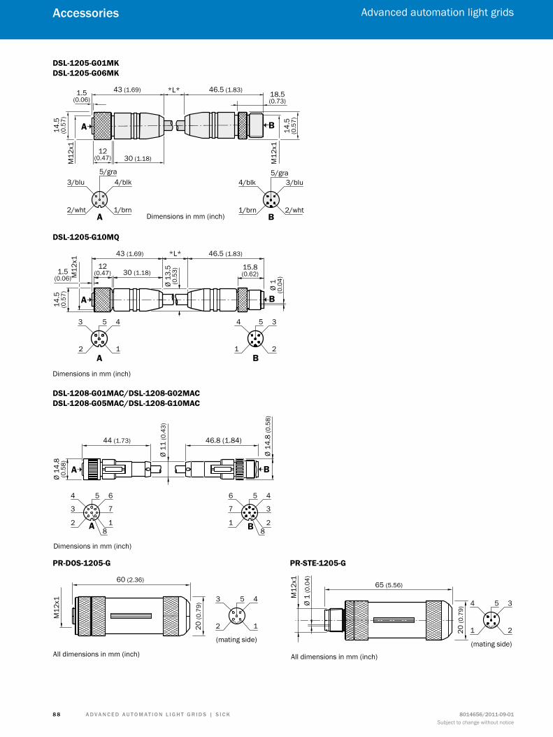
A d v A n c e d A u t o m At i o n L i G h t G r i d s | s i c K 8014656/2011-09-01Subject to change without notice
Advanced automation light grids
8 8
Accessories
DSL-1205-G01MK DSL-1205-G06MK
*L*
M12
x1
M12
x1
A B
5/gra
A
4/blk3/blu
2/wht 1/brnB
5/gra3/blu4/blk
1/brn 2/wht
43 (1.69)
30 (1.18)
1.5(0.06)
18.5(0.73)
14.5
(0.5
7)
14.5
(0.5
7)
12(0.47)
46.5 (1.83)
Dimensions in mm (inch)
DSL-1205-G10MQ
*L*
M12
x1
453
2 1
5 3 4
1 2A B
A B
43 (1.69)
30 (1.18)
46.5 (1.83)
Ø 13
.5(0
.53)
Ø 1
(0.0
4)
14.5
(0.5
7)
Dimensions in mm (inch)
12(0.47)1.5
(0.06)
15.8(0.62)
DSL-1208-G01MAC/DSL-1208-G02MAC DSL-1208-G05MAC/DSL-1208-G10MAC
44 (1.73)
Ø 14
.8(0
.58)
Ø 11
(0.4
3)
A B
A
6
73
5
8
4
2 1
4
37
5
8
6
1 2
B
46.8 (1.84)
Ø 14
.8 (0
.58)
Dimensions in mm (inch)
PR-DOS-1205-G
M12
x1
(mating side)
5 43
2 1
60 (2.36)
All dimensions in mm (inch)
20 (0
.79)
PR-STE-1205-G
5 34
1 2
M12
x1
(mating side)
65 (5.56)
Ø 1
(0.0
4)
20 (0
.79)
All dimensions in mm (inch)
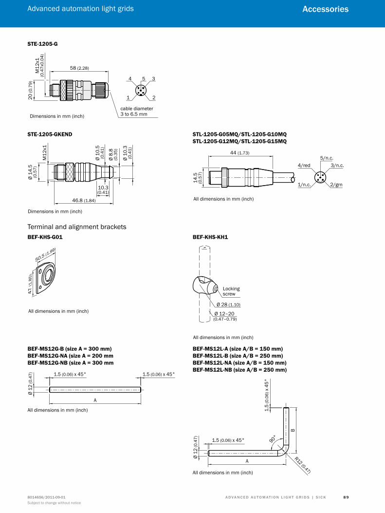
A d v A n c e d A u t o m At i o n L i G h t G r i d s | s i c K8014656/2011-09-01Subject to change without notice
Advanced automation light grids
8 9
Accessories
STE-1205-G
58 (2.28)
5 3 4
1 2
Dimensions in mm (inch)cable diameter3 to 6.5 mm
20 (0
.79)
M12
x1(0
.47x
0.04
)
STE-1205-GKEND
M12
x1
46.8 (1.84)
Ø 14
.5(0
.57)
Ø 10
.5(0
.41)
Ø 10
.3(0
.41)
Ø 8.
8(0
.35)
Dimensions in mm (inch)
10.3(0.41)
STL-1205-G05MQ/STL-1205-G10MQ STL-1205-G12MQ/STL-1205-G15MQ
5/n.c.3/n.c.4/red
1/n.c. 2/grn
44 (1.73)
14.5
(0.5
7)All dimensions in mm (inch)
Terminal and alignment bracketsBEF-KHS-G01
47 (1
.85)
50.5 (1.99)
All dimensions in mm (inch)
BEF-KHS-KH1
Ø 12–20 (0.47–0.79)
Ø 28 (1.10)
Lockingscrew
All dimensions in mm (inch)
BEF-MS12G-B (size A = 300 mm) BEF-MS12G-NA (size A = 200 mm BEF-MS12G-NB (size A = 300 mm
A
1.5 (0.06) x 45° 1.5 (0.06) x 45°
Ø 12
(0.4
7)
All dimensions in mm (inch)
BEF-MS12L-A (size A/B = 150 mm) BEF-MS12L-B (size A/B = 250 mm) BEF-MS12L-NA (size A/B = 150 mm) BEF-MS12L-NB (size A/B = 250 mm)
A
B
R12 (0.47)
1.5 (0.06) x 45°
1.5
(0.0
6) x
45°
90°
Ø 12
(0.4
7)
All dimensions in mm (inch)
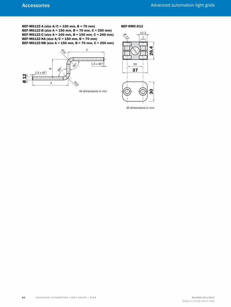
A d v A n c e d A u t o m At i o n L i G h t G r i d s | s i c K 8014656/2011-09-01Subject to change without notice
Advanced automation light grids
9 0
Accessories
BEF-MS12Z-A (size A/C = 150 mm, B = 70 mm) BEF-MS12Z-B (size A = 150 mm, B = 70 mm, C = 250 mm) BEF-MS12Z-C (size A = 100 mm, B = 150 mm, C = 200 mm) BEF-MS12Z-NA (size A/C = 150 mm, B = 70 mm) BEF-MS12Z-NB (size A = 150 mm, B = 70 mm, C = 250 mm)
A
BCR12
R12
1.5 x 45°
1.5 x 45°
90° 90°
Ø 12
All dimensions in mm
BEF-RMC-D12
37
26.4
30
20
Ø12
12.27
All dimensions in mm

A d v A n c e d A u t o m At i o n L i G h t G r i d s | s i c K8014656/2011-09-01Subject to change without notice
9 1
Singleturn/Multiturn HIPERFACE DSL®
www.mysick.com – Your quick access to maximum efficiency
search online quickly and safely with the sicK “finders”
efficiency – with sicK e-commerce tools
find out prices and availabilityDetermine the price and possible delivery date of your de-sired product simply and quickly.
request or view a quoteYou can have a quote generated online here.Every quote is confirmed to you via e-mail.
order onlineYou can go through the ordering process in just a few steps.
Product finder: We can help you to quickly target the product that best matches your application.
Applications finder: Select the application description on the basis of the challenge posed, industrial sector, or product group.
Literature finder: Go directly to the operating instructions, technical information, and other literature on all aspects of SICK products.
these and other finders at www.mysick.com
ProductApplicationsLiteratureServiceConnection diagramAccessoriesSpare part
clearly structured: You can find everything you need for your sensor planning under the menu items Pro-ducts, Information, and My Account.
Available 24 hours a day: Regard-less of where you are in the world or what you’d like to know – everything is just a click away at www.mysick.com.
safe: Your data is password-pro-tected and only visible to you. With the individual user management, you define who can see what data and who can execute what actions.

8014
656/
2011
-09-
01 ∙
SF (2
011-
09) ∙
WB
USm
od in
t37
SICK AG | Waldkirch | Germany | www.sick.com
Leading technologies
With a staff of more than 5,000 and over 50 subsidiaries and representa-tions worldwide, SICK is one of the leading and most successful manufac-turers of sensor technology. The power of innovation and solution competency have made SICK the global market leader. No matter what the project and industry may be, talking with an expert from SICK will provide you with an ideal basis for your plans – there is no need to settle for anything less than the best.
Unique product range
• Non-contact detecting, counting, classifying, positioning and measur-ing of any type of object or media
• Accident and operator protection with sensors, safety software and services
• Automatic identification with bar code and RFID readers
• Laser measurement technology for detecting the volume, position and contour of people and objects
• Complete system solutions for analy-sis and flow measurement of gases and liquids
Comprehensive services
• SICK LifeTime Services – for safety and productivity
• Application centers in Europe, Asia and North America for the develop-ment of system solutions under real-world conditions
• E-Business Partner Portal www.mysick.com – price and availabi-lity of products, requests for quotation and online orders
sicK at a glance
Worldwide presence with subsidiaries in the following countries:
Australia Belgium/Luxembourg Brasil ceská republika canada china danmark deutschland españa france Great Britain india israel italia Japan
méxico nederland norge Österreich Polska românia russia schweiz singapore slovenija south Africa south Korea suomi sverige taiwan türkiye united Arab emirates usA
Please find detailed addresses and additional representatives and agencies in all major industrial nations at www.sick.com