adaptive quality of service management for next generation residential gateways
TRANSCRIPT
Adaptive Quality of Service Management forNext Generation Residential Gateways
Ivan Vidal, Jaime Garcıa, Francisco Valera, Ignacio Soto, and Arturo Azcorra
Universidad Carlos III de MadridAvda. Universidad 30, 28911 Leganes - Madrid (Spain){ividal,jgr,fvalera,isoto,azcorra}@it.uc3m.es
Abstract. The TISPAN workgroup inside ETSI is currently working onaccommodating the IMS (IP Multimedia Subsystem) architecture, whichhas been created for the mobile world, to the fixed scenario where thereis a new important element to be taken into account: the ResidentialGateway (RGW). This element is typically considered as a customer de-vice where providers do not usually have anything to configure. However,in order to achieve real end-to-end Quality of Service (QoS) this cannotbe true anymore.This paper focuses on the way that a RGW is capable of configuring it-self (an interface with the providers is also available), regarding Qualityof Service parameters, into a Next Generation Network (NGN) scenario.The proposed RGW architecture is also flexible enough so as to adaptthe QoS management mechanism to different possible scenarios, e.g. con-figured by the provider, by the customer or even autoconfigured by theRGW itself. A specific scenario, where a RGW is deployed in the TISPANNGN architecture, will be explained and validated to proof the conceptof the RGW architecture.
1 Introduction
Nowadays a lot of work around Next Generation Networks (NGN) has beendone by the scientific community to achieve a real integration of every accesstechnology actually deployed to provide triple-play services (video, data andvoice). This work is still unfinished due to the high complexity of the problemand there are in fact many initiatives in progress. ETSI TISPAN is one of themand its philosophy is to try to conjugate different standards together and improvethem to be fully compatible with the NGN architecture. The TISPAN definedwhat a NGN is in [1]:
”A Next Generation Network is a packet-based network able to provideservices including Telecommunication Services and able to make use ofmultiple broadband, QoS-enabled transport technologies and in which ser-vice related functions are independent from underlying transport relatedtechnologies. It offers unrestricted access by users to different serviceproviders. It supports generalised mobility which will allow consistentand ubiquitous provision of services to users.”
As a result of the ongoing work, the first release for TISPAN Next GenerationNetwork (NGN) [2] was published at the beginning of 2006. The core network ofTISPAN NGN is based upon the IMS, as defined in 3GPP Release 6 and 3GPP2revision A for IP-based multimedia applications (although IMS is conceptuallydesigned to be independent from the technology used in the access network,the standards developed by the 3GPP from release 5 are mainly focused on theUMTS IP connectivity access network). Due to this decision, TISPAN archi-tecture obtains many advantages from merging both wireless and wired worldsbecause the only need fact is an IMS adaptation to the fixed world. But thiswork is not an easy task and a lot of discussions are still open. One of thesediscussions is related with the RGW configuration, because in the mobile worldthis entity does not exist. To date, there is no way to remotely configure theRGW QoS parameters by a NGN operator so there is still a gap in the architec-ture. Actually, the RGW is considered by the TISPAN as a customer equipmentwith no logical interfaces towards the network so as to be able to configure it.In this paper a flexible RGW architecture is proposed allowing the own gatewayto autoconfigure itself using the signalling interchanged by the customer devicesand the network. This architecture extends and demonstrate the concepts pub-lished in a previous work [3] where just the basic functionality was described, inorder to explain the work developed in the MUSE European Project [4] wherethe main goal is to research the European next generation network. In MUSEthe RGW is considered a key component and an entire Task Force is focused inits study and definition.
The rest of this article is organised as follows. The TISPAN NGN QoS man-agement architecture is reviewed in next Sect. 2. The complete RGW architectureis proposed in Sect. 3 while the particular part where the QoS autoconfigurationis extended is analysed in Sect. 4. Section 5 concludes the article with the maincontributions of this work.
2 TISPAN NGN QoS management overview
In this section, just a brief overview of TISPAN NGN QoS management is pre-sented. The functional architecture of TISPAN NGN in release 1 is describedin detail in [5] and the rest of the article follows the terminology defined byTISPAN. Figure 1 covers a simplified overview of this architecture to facilitatethe reading of this document.
2.1 Resource and admission control in TISPAN NGN
The Resource and Adsmission Control Subsystem (RACS) is the TISPAN NGNsubsystem that provides QoS reservation mechanisms over the transport layer.In this way, RACS provides the ASFs and the Service Control Subsystems withmeans to request and reserve resources from the transport networks which areunder its control.
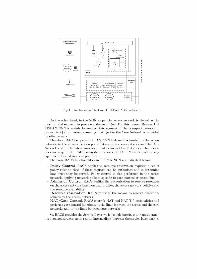
Fig. 1. Functional architecture of TISPAN NGN, release 1.
On the other hand, in the NGN scope, the access network is viewed as themost critical segment to provide end-to-end QoS. For this reason, Release 1 ofTISPAN NGN is mainly focused on this segment of the transport network inrespect to QoS provision, assuming that QoS in the Core Network is providedby other means.
Therefore, RACS scope in TISPAN NGN Release 1 is limited to the accessnetwork, to the interconnection point between the access network and the CoreNetwork and to the interconnection point between Core Networks. The releasedoes not require the RACS subsystem to cover the Core Network itself or anyequipment located in client premises.
The basic RACS functionalities in TISPAN NGN are indicated below:
– Policy Control. RACS applies to resource reservation requests a set ofpolicy rules to check if these requests can be authorised and to determinehow must they be served. Policy control is also performed in the accessnetwork, applying network policies specific to each particular access line.
– Admission Control. RACS verifies the authorisation to reserve resourceson the access network based on user profiles, the access network policies andthe resource availability.
– Resource reservation. RACS provides the means to reserve bearer re-sources on the access network.
– NAT/Gate Control. RACS controls NAT and NAT-T functionalities andperforms gate control functions, at the limit between the access and the corenetworks and in the limit between core networks.
So, RACS provides the Service Layer with a single interface to request trans-port control services, acting as an intermediary between the service layer entities
(ASFs and Service Control Subsystems) and the functional entities in the trans-fer sublayer. In this way, RACS ensures that service layer entities do not need tobe concerned with transport network details, like the topology and transmissiontechnologies.
In addition, the RACS subsystem supports a QoS Push Model for the trans-port control service requests, where the resource reservation requests are ”pushed”from ASFs and service control subsystems to RACS. If the requests can be satis-fied, RACS ”pushes” the requests to the transport layer to reserve the resources.
Finally, RACS supports several modes of operation in respect to resourcemanagement, two of which are explained below:
– A Reserve-commit resource management schema, where resources are re-served in a first phase and are finally made available after a commit proce-dure.
– A single-stage resource management schema, where reservation and commitprocedures are performed at the same time.
QoS control models. The RACS subsystem supports two different models forQoS control over the transport network. These models are the following:
– Guaranteed QoS. In this model the QoS is guaranteed with absolutebounds on some or all of its parameters, like throughput or jitter. GuaranteedQoS is configured on the access network with the application of techniquessuch as throughput control and traffic policing in the IP edge node. Thesetechniques may also be applied to the Access Node or to the equipments inthe client premises.
– Relative QoS. In this model the QoS is provided by class based differenti-ation. This QoS differentiation is configured in the IP edge node of the ac-cess network, where functionalities like packet marking are provided. RACSshould be aware that some equipment in the client premises may also pro-vide QoS differentiation, for example through packet marking. This markingshould only have effect if it is required by the operator.
RACS functional architecture. Figure 2 shows the functional architectureof the RACS subsystem.
The Application Function (AF) interacts with the RACS subsystem to re-quest transport-layer control services for QoS provisioning to services. This func-tion is implemented in some functional entities from the service layer, such asthe ASF and the P-CSCF of the Core IMS. The AF converts QoS informationfrom the application layer to QoS information which is suitable for the RACSsubsystem, and includes this information in a request message, which is sent tothe SPDF through the Gq’ interface. The details of the protocol used in theinterface Gq’ are specified in [6].
The Service Policy Decision Function (SPDF) authorises the request, check-ing the information contained on it against the local policy established for the
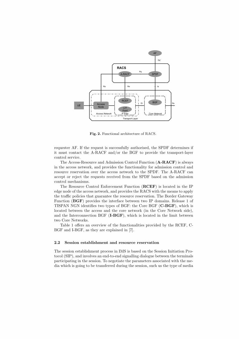
Fig. 2. Functional architecture of RACS.
requester AF. If the request is successfully authorised, the SPDF determines ifit must contact the A-RACF and/or the BGF to provide the transport-layercontrol service.
The Access-Resource and Admission Control Function (A-RACF) is alwaysin the access network, and provides the functionality for admission control andresource reservation over the access network to the SPDF. The A-RACF canaccept or reject the requests received from the SPDF based on the admissioncontrol mechanisms.
The Resource Control Enforcement Function (RCEF) is located in the IPedge node of the access network, and provides the RACS with the means to applythe traffic policies that guarantee the resource reservation. The Border GatewayFunction (BGF) provides the interface between two IP domains. Release 1 ofTISPAN NGN identifies two types of BGF: the Core BGF (C-BGF), which islocated between the access and the core network (in the Core Network side),and the Interconnection BGF (I-BGF), which is located in the limit betweentwo Core Networks.
Table 1 offers an overview of the functionalities provided by the RCEF, C-BGF and I-BGF, as they are explained in [7].
2.2 Session establishment and resource reservation
The session establishment process in IMS is based on the Session Initiation Pro-tocol (SIP), and involves an end-to-end signalling dialogue between the terminalsparticipating in the session. To negotiate the parameters associated with the me-dia which is going to be transferred during the session, such us the type of media
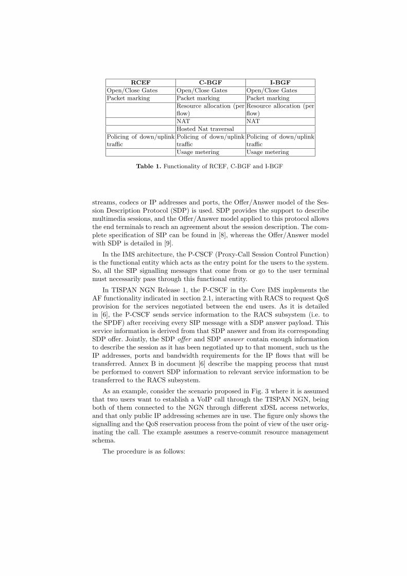
RCEF C-BGF I-BGF
Open/Close Gates Open/Close Gates Open/Close Gates
Packet marking Packet marking Packet marking
Resource allocation (perflow)
Resource allocation (perflow)
NAT NAT
Hosted Nat traversal
Policing of down/uplinktraffic
Policing of down/uplinktraffic
Policing of down/uplinktraffic
Usage metering Usage metering
Table 1. Functionality of RCEF, C-BGF and I-BGF
streams, codecs or IP addresses and ports, the Offer/Answer model of the Ses-sion Description Protocol (SDP) is used. SDP provides the support to describemultimedia sessions, and the Offer/Answer model applied to this protocol allowsthe end terminals to reach an agreement about the session description. The com-plete specification of SIP can be found in [8], whereas the Offer/Answer modelwith SDP is detailed in [9].
In the IMS architecture, the P-CSCF (Proxy-Call Session Control Function)is the functional entity which acts as the entry point for the users to the system.So, all the SIP signalling messages that come from or go to the user terminalmust necessarily pass through this functional entity.
In TISPAN NGN Release 1, the P-CSCF in the Core IMS implements theAF functionality indicated in section 2.1, interacting with RACS to request QoSprovision for the services negotiated between the end users. As it is detailedin [6], the P-CSCF sends service information to the RACS subsystem (i.e. tothe SPDF) after receiving every SIP message with a SDP answer payload. Thisservice information is derived from that SDP answer and from its correspondingSDP offer. Jointly, the SDP offer and SDP answer contain enough informationto describe the session as it has been negotiated up to that moment, such us theIP addresses, ports and bandwidth requirements for the IP flows that will betransferred. Annex B in document [6] describe the mapping process that mustbe performed to convert SDP information to relevant service information to betransferred to the RACS subsystem.
As an example, consider the scenario proposed in Fig. 3 where it is assumedthat two users want to establish a VoIP call through the TISPAN NGN, beingboth of them connected to the NGN through different xDSL access networks,and that only public IP addressing schemes are in use. The figure only shows thesignalling and the QoS reservation process from the point of view of the user orig-inating the call. The example assumes a reserve-commit resource managementschema.
The procedure is as follows:
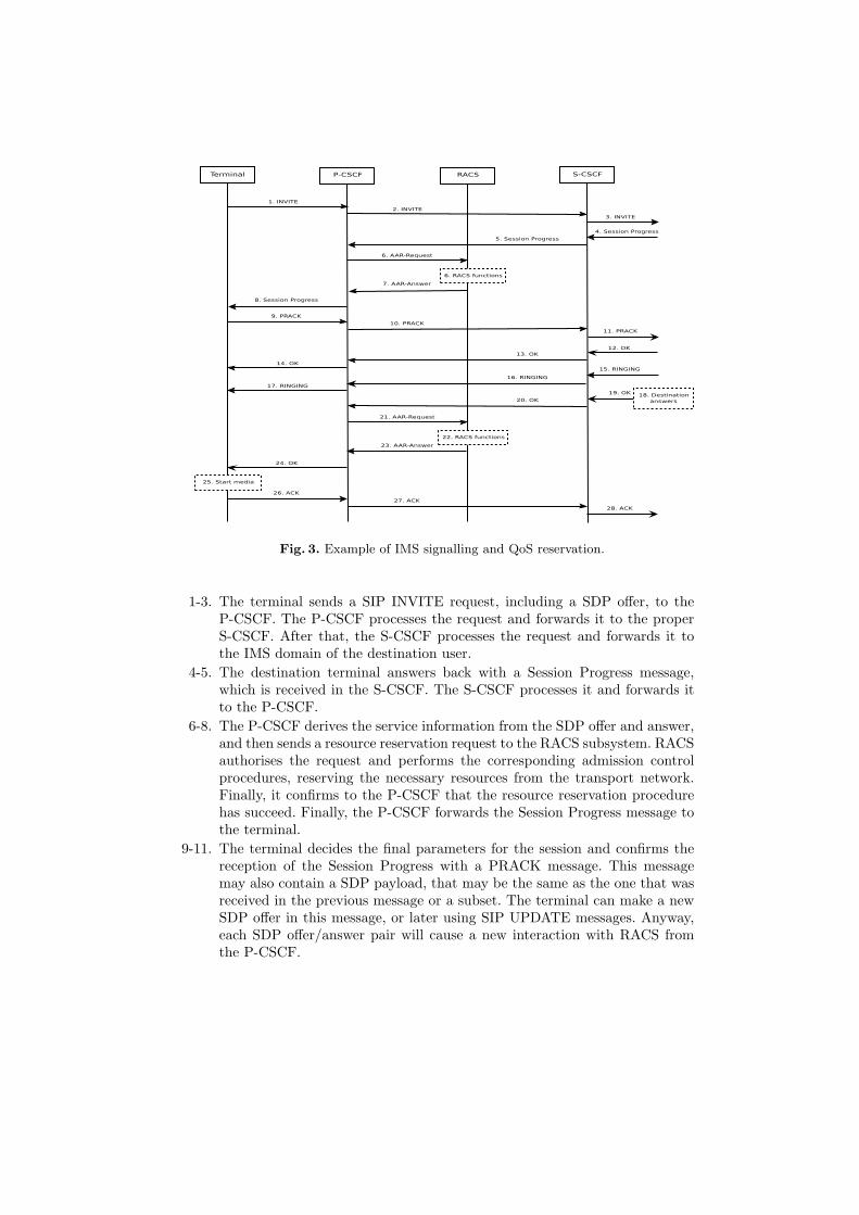
Fig. 3. Example of IMS signalling and QoS reservation.
1-3. The terminal sends a SIP INVITE request, including a SDP offer, to theP-CSCF. The P-CSCF processes the request and forwards it to the properS-CSCF. After that, the S-CSCF processes the request and forwards it tothe IMS domain of the destination user.
4-5. The destination terminal answers back with a Session Progress message,which is received in the S-CSCF. The S-CSCF processes it and forwards itto the P-CSCF.
6-8. The P-CSCF derives the service information from the SDP offer and answer,and then sends a resource reservation request to the RACS subsystem. RACSauthorises the request and performs the corresponding admission controlprocedures, reserving the necessary resources from the transport network.Finally, it confirms to the P-CSCF that the resource reservation procedurehas succeed. Finally, the P-CSCF forwards the Session Progress message tothe terminal.
9-11. The terminal decides the final parameters for the session and confirms thereception of the Session Progress with a PRACK message. This messagemay also contain a SDP payload, that may be the same as the one that wasreceived in the previous message or a subset. The terminal can make a newSDP offer in this message, or later using SIP UPDATE messages. Anyway,each SDP offer/answer pair will cause a new interaction with RACS fromthe P-CSCF.
12-14. The destination terminal acknowledges the PRACK with an OK messageand if the PRACK message included an SDP offer, the OK message willalso contain a SDP answer. If the session description has changed, a newinteraction with the RACS must be performed.
15-17. The destination terminal alerts the user about the incoming call and sendsa SIP RINGING message to the originator terminal.
18-20. When the destination user answers the phone, the destination terminal sendsa SIP OK message to the originator terminal, that arrives at the P-CSCF.
21-23. The P-CSCF interacts with the RACS subsystem to commit the previousresource reservations.
24-28. The SIP OK message arrives to the originator terminal, and the user canstart to send media. The terminal responds the SIP OK message with anACK message, which is sent to the IMS domain of the destination user.
3 RGW architecture
This section describes the architecture of the prototype already implementedfrom the point of view of the development environment and this description willbe classified using a bottom-up view starting at the data level and then definingthe configuration process.
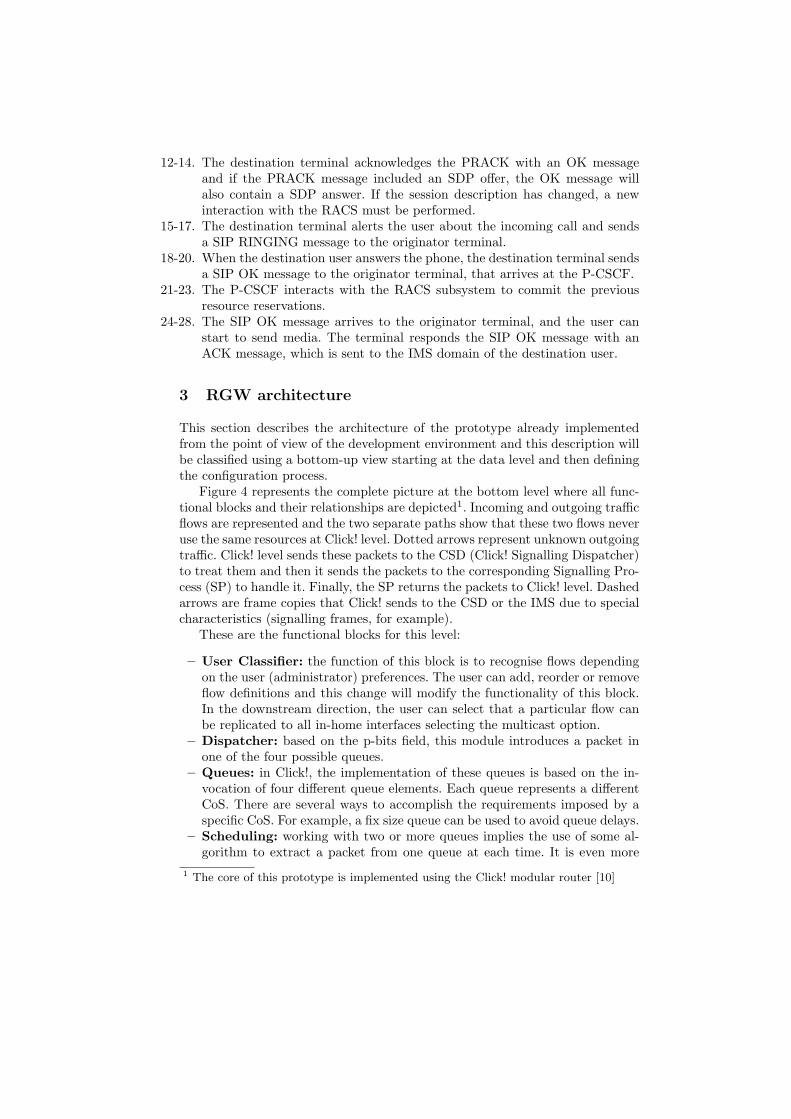
Figure 4 represents the complete picture at the bottom level where all func-tional blocks and their relationships are depicted1. Incoming and outgoing trafficflows are represented and the two separate paths show that these two flows neveruse the same resources at Click! level. Dotted arrows represent unknown outgoingtraffic. Click! level sends these packets to the CSD (Click! Signalling Dispatcher)to treat them and then it sends the packets to the corresponding Signalling Pro-cess (SP) to handle it. Finally, the SP returns the packets to Click! level. Dashedarrows are frame copies that Click! sends to the CSD or the IMS due to specialcharacteristics (signalling frames, for example).
These are the functional blocks for this level:
– User Classifier: the function of this block is to recognise flows dependingon the user (administrator) preferences. The user can add, reorder or removeflow definitions and this change will modify the functionality of this block.In the downstream direction, the user can select that a particular flow canbe replicated to all in-home interfaces selecting the multicast option.
– Dispatcher: based on the p-bits field, this module introduces a packet inone of the four possible queues.
– Queues: in Click!, the implementation of these queues is based on the in-vocation of four different queue elements. Each queue represents a differentCoS. There are several ways to accomplish the requirements imposed by aspecific CoS. For example, a fix size queue can be used to avoid queue delays.
– Scheduling: working with two or more queues implies the use of some al-gorithm to extract a packet from one queue at each time. It is even more
1 The core of this prototype is implemented using the Click! modular router [10]
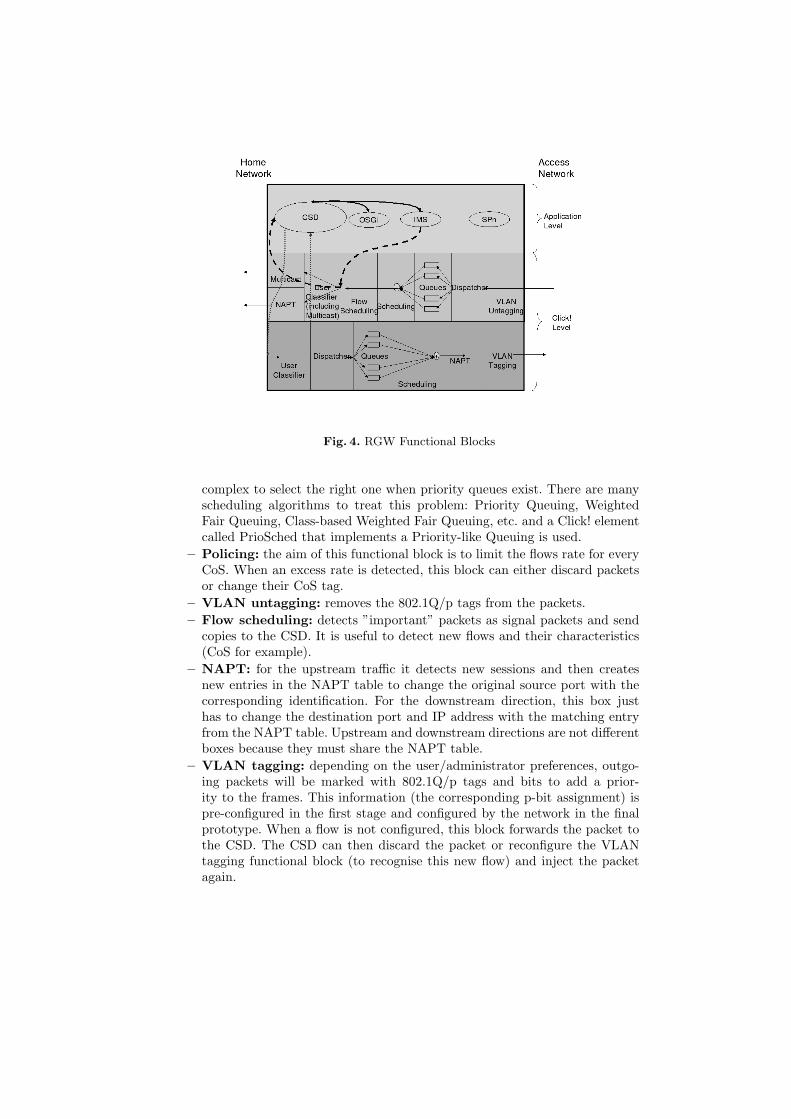
Fig. 4. RGW Functional Blocks
complex to select the right one when priority queues exist. There are manyscheduling algorithms to treat this problem: Priority Queuing, WeightedFair Queuing, Class-based Weighted Fair Queuing, etc. and a Click! elementcalled PrioSched that implements a Priority-like Queuing is used.
– Policing: the aim of this functional block is to limit the flows rate for everyCoS. When an excess rate is detected, this block can either discard packetsor change their CoS tag.
– VLAN untagging: removes the 802.1Q/p tags from the packets.– Flow scheduling: detects ”important” packets as signal packets and send
copies to the CSD. It is useful to detect new flows and their characteristics(CoS for example).
– NAPT: for the upstream traffic it detects new sessions and then createsnew entries in the NAPT table to change the original source port with thecorresponding identification. For the downstream direction, this box justhas to change the destination port and IP address with the matching entryfrom the NAPT table. Upstream and downstream directions are not differentboxes because they must share the NAPT table.
– VLAN tagging: depending on the user/administrator preferences, outgo-ing packets will be marked with 802.1Q/p tags and bits to add a prior-ity to the frames. This information (the corresponding p-bit assignment) ispre-configured in the first stage and configured by the network in the finalprototype. When a flow is not configured, this block forwards the packet tothe CSD. The CSD can then discard the packet or reconfigure the VLANtagging functional block (to recognise this new flow) and inject the packetagain.
– Multicast: this block copies all incoming frames to all in-home interfaces(like most Ethernet switches do).
– CSD: this software has been developed in Java to allow an easy and quickportability to other platforms. The CSD will configure and reconfigure theClick! level when signalling packets arrives. It is also possible to redirect thiskind of packets to the corresponding Signalling Process (SP).
– IMS: MUSE plans to adopt SIP, which is used as the prominent signallingprotocol in IMS, as its QoS signalling standard. Because the RGW is theaccess network and home network interconnection point, it must couple bothworlds and allow an end-to-end QoS. To accomplish this requirement, theRGW must be configured as any network node.
4 QoS management in the RGW
The specifications of TISPAN NGN Release 1 are mainly focused on the QoSprovision in the access network. Nevertheless, a complete service architecturewith QoS support will necessarily require to extend to QoS scope to the clientpremises, to provide end-to-end QoS. In this respect, this section describes anarchitecture which supports adaptive QoS management in a RGW connected toa NGN compliant with TISPAN NGN Release 1. The proposed architecture forthe RGW, from the point of view of QoS management, is shown in Fig. 5.
The NGN SP is the Signalling Process that will manage, in the RGW, theSIP signalling used to negotiate end-to-end services over the TISPAN NGN.It will process all the SIP signalling messages interchanged between the NGGcore IMS and the customer equipment. The NGN SP will provide the followingfunctionalities:
– P-CSCF functionality: after receiving every SIP message containing aSDP answer, it will derive the corresponding service information from theSDP offer and the SDP answer as it is specified in annex B of [6]. Thisinformation will be provided to the A-RACF functionality of the NGN SP.On the other hand, after receiving a SIP OK message corresponding to aSIP INVITE message, it will contact the A-RACF functionality of the NGNSP to start the commitment process for the reserved resources.
– A-RACF functionality: with the service information provided by the P-CSCF functionality, the A-RACF functionality will perform admission con-trol functions, verifying if the QoS demands can be satisfied in the RGW andthe home network with the available resources. The A-RACF functionalitywill support a reserve-commit resource management schema and the QoScontrol models defined for the RACS in [7], i.e. guaranteed QoS and relativeQoS.
– SIP signalling proxy: this functionality is necessary in the SignallingProxy Scenario (SPS) proposed in [3]. In this scenario the NGN SP wouldbehave as a signalling proxy on behalf of legacy terminals, by generating theSIP signalling associated with the upstream and the downstream traffic.
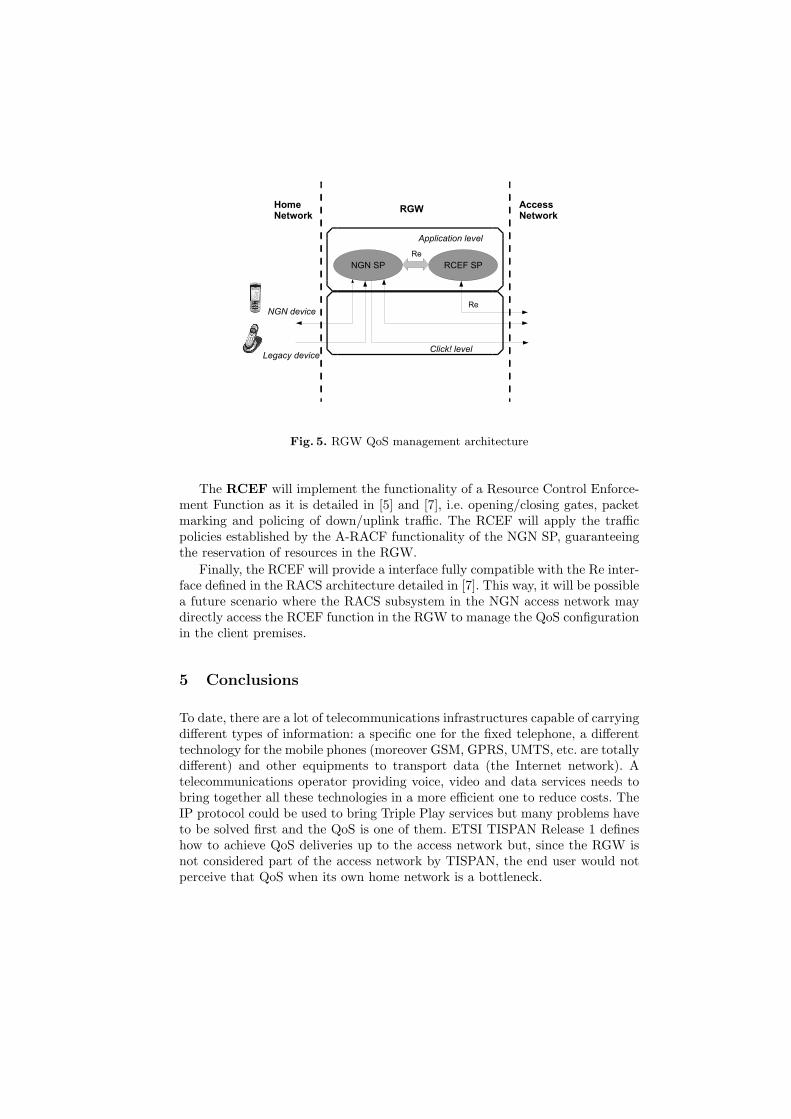
Fig. 5. RGW QoS management architecture
The RCEF will implement the functionality of a Resource Control Enforce-ment Function as it is detailed in [5] and [7], i.e. opening/closing gates, packetmarking and policing of down/uplink traffic. The RCEF will apply the trafficpolicies established by the A-RACF functionality of the NGN SP, guaranteeingthe reservation of resources in the RGW.
Finally, the RCEF will provide a interface fully compatible with the Re inter-face defined in the RACS architecture detailed in [7]. This way, it will be possiblea future scenario where the RACS subsystem in the NGN access network maydirectly access the RCEF function in the RGW to manage the QoS configurationin the client premises.
5 Conclusions
To date, there are a lot of telecommunications infrastructures capable of carryingdifferent types of information: a specific one for the fixed telephone, a differenttechnology for the mobile phones (moreover GSM, GPRS, UMTS, etc. are totallydifferent) and other equipments to transport data (the Internet network). Atelecommunications operator providing voice, video and data services needs tobring together all these technologies in a more efficient one to reduce costs. TheIP protocol could be used to bring Triple Play services but many problems haveto be solved first and the QoS is one of them. ETSI TISPAN Release 1 defineshow to achieve QoS deliveries up to the access network but, since the RGW isnot considered part of the access network by TISPAN, the end user would notperceive that QoS when its own home network is a bottleneck.

In this article we presented a flexible RGW architecture where both, theRGW resources and the home network available bandwidth are taken into ac-count to accept or not a given connection. The schema proposed is valid for aRGW aware NGN architecture, where the access and reservation systems con-figure the RGW and in a RGW unaware one. For the later, the RGW interceptsSIP requests and responses to perform some actions in the same way as in theTISPAN NGN devices (P-CSCF, A-RACF, etc.). How the RGW manages NAPTscenarios and updates the parameters of a certain established connection are letfor further study.
Acknowledgements
This article has been partially granted by the European Commission throughthe MUSE project.
References
1. TISPAN: ETSI TR 180 000 V1.1.1: ”Telecommunications and Internet convergedServices and Protocols for Advanced Networking (TISPAN); NGN Terminology.”(2006)
2. TISPAN: ETSI TR 180 001 V1.1.1: ”Telecommunications and Internet convergedServices and Protocols for Advanced Networking (TISPAN); NGN Release 1; Re-lease definition.” (2006)
3. Guerrero, C., Garcia-Reinoso, J., Valera, F., Azcorra, A.: Qos management in fixedbroadband residential gateways. LNCS 3754 (2005) 338–349 8th InternationalConference on Management of Multimedia Networks and Services (MMNS 2005).
4. MUSE: Multi Service Access Everywhere. Internet (2006) http://www.ist-muse.org/.
5. TISPAN: ETSI ES 282 001 V1.1.1: ”Telecommunications and Internet convergedServices and Protocols for Advanced Networking (TISPAN); NGN Functional Ar-chitecture Release 1” (2005)
6. TISPAN: ETSI TS 183 017 V1.1.1: ”Telecommunications and Internet convergedServices and Protocols for Advanced Networking (TISPAN); Resource and Ad-mission Control; DIAMETER protocol for session based policy set-up informationexchange between the Application Function (AF) and the Service Policy DecisionFunction (SPDF): Protocol specification.” (2006)
7. TISPAN: ETSI ES 282 003 V1.1.1: ”Telecommunications and Internet convergedServices and Protocols for Advanced Networking (TISPAN); Resource and Admis-sion Control Sub-system (RACS); Functional Architecture.” (2006)
8. Rosenberg, J., Schulzrinne, H., Camarillo, G., Johnston, A., Peterson, J., Sparks,R., Handley, M., Schooler, E.: SIP: Session Initiation Protocol. RFC 3261 (Pro-posed Standard) (2002) Updated by RFCs 3265, 3853, 4320.
9. Rosenberg, J., Schulzrinne, H.: An Offer/Answer Model with Session DescriptionProtocol (SDP). RFC 3264 (Proposed Standard) (2002)
10. Kohler, E., Morris, R., Chen, B., Jannotti, J., Kaashoek, M.F.: The Click ModularRouter Project. Internet (2006) http://www.read.cs.ucla.edu/click/.