ad a127105 - dtic
TRANSCRIPT
IEEE TRANSAPTIONS ON ANTENNAS AND PROPAGATION, VOL. AP-30, NO. l, JANUARY 1982 is
leesna Par
AD A127105 __- _
itri Dstribion/
A:' Availability Codes
~'i~TICELECTE
AR13 1983j
Diakoptic Theory for Multielement Antennas
GEORG GOUBAU, NARINDRA NATH PURl, SENIOR MEMBER, IEEE, AND FELIX K. SCHWERING, MEMBER, IEEE
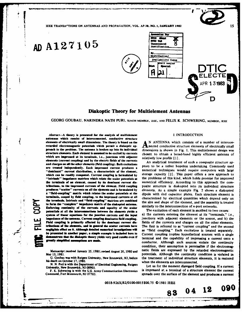
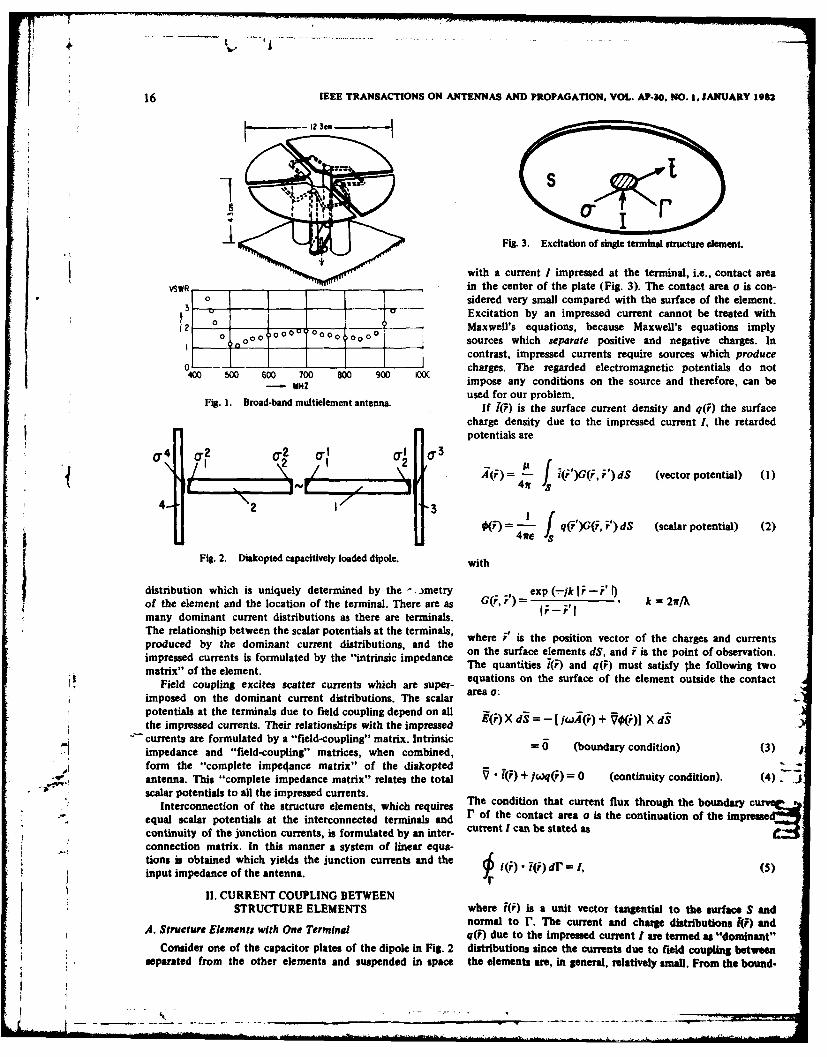
Abstrors-A theory is presented for the analysis of multielement I. INTRODUCTIONantennas which consist of interconected, conductive structureelements of electrically small dimensions. The theory is based on the N ANTENNA which consists of a number of intercon-retarded electromagnetic potentials which permit a diakoptic ap- 'nected conductive structure elements of electrically smallproach to the problem. The antenns Is broken up into its Individual dimensions is shown in Fig. 1. This multielement design wasstructure elements. Each element Is assumed to be excited by currents chosen to obtain a broad-band highly efficient antenna ofwhich are Impressed at its terminals, I.e., junctions with adjacent relatively low profile I l I.elements (current coupling) and by the electric fields of the currents An analytical treatment of such a composite structure ap-and charges on all the other elements (field coupling). Both excitationsare treated independently. Each Impressed current produces a pears to be a rather hopeless undertaking. Commonly used"dominant" current distribution, a characteristic of the element, numerical techniques would require computers with largewhich cun he readily computed. Current coupling Is formulated by storage capacity [2]. This paper offers a new approach to"intrinsic" impdance matrices whkh relate the scaler potentials at the problems of this kind, which holds promise for improvedthe terminals of an element, caused by Its dominant current dis- numerical efficiency. According to this approach the com-triibllo, to the Impressed currents of the element. Field coupling posite structure is diakopted into its individual structureproduces "scatter" currents on all the elements and is formulated by elements. As a simple example Fig. 2 shows a diakopteda "fleld-coupling" matrix which relates the scalar potentials at the dipole with 6nd capacitor plates. Each structure element isterminals, caused by field coupling, to the Impressed currents at all characterized by electrical quantities which depend only on
.o the terminals. intrinsic and "flald-couplng" matrices are combined the size and shape of the element, and the assembly is treated. to form the "complete" Impedance matrix of the diakopted antenna.,: similarly to the interconnection of n-port networks.
a Enforcing coutiNlty of the currents and equality of the scalarC > potentials at all the latereommectioa between the lemmnts yields a The excitation of each element is ascribed to two causes:
system of linear equations for the junction currents sad the input a) the currents entering the element at its "terminals," i.e.,-- i impedance of the mtenma. Current coupling dominates field coupling. junctions with adjacent elements or the source, and b) the
Fleld coupling is primarily affected by the dominant current die- fields of the currents and charges on all the other elements.trihutien of the elements, and in general the scatter currents have The first is referred to as "current coupling" and the second
LL negligible effect n it. Although detailed numerical Investigatiom will as "field coupling." Each excitation is treated separately.be presented in another pper, a simple example Is Included here to Current coupling implies hypothetical sources with a singledemomstrate that the dLkpti theory ylelds very good results even It terminal and the capability of impressing a current onto a
-eamdy mpwlledmamotl s are made, conductor. Although such sources violate the continuity
condition, their assumption is permissible if the electromag-Manuscript received January 25, 1980; revised August 20, 1980 and netic fields are expressed by the retarded electromagnetic
May 15, 1981. potentials. Although the continuity condition is violated inG. Goubau was with Rutgers Univesity, New Brunswick, NJ, before the treatment of individual structure elements, it is restored
his death on October 17, 1980. when the elements are interconnected.N. N. Purl is with the Department of Electrical Engineering, Rutgers Let us for the moment disregard field coupling. If a current
University, New Brunswick, NJ 08903.F. K. Schwering is with the U.S. Army Communication Electronics is impressed at. a terminal of a structure element the current
Command, Fort Monmouth, NJ 07703. spreads over the surface of the element and produces a current
0018-926X/82/0100-0015500.75 C 1981 IEEE
88 04 12 090.. _ - - - -, ,- -... . .. . .. . .. . . - . "- ...
16 IEEE TRANSACTIONS ON ANTENNAS AND PROPAGATION, VOL. AP-30, NO. 1, JANUARY 1982
Fig. 3. Excitation of single terminal structure element.
with a current I impressed at the terminal, i.e., contact area
VSWR in the center of the plate (Fig. 3). The contact area u is con-0 Isidered very small compared with the surface of the element.
, _,r_ Excitation by an impressed current cannot be treated with2 0 Maxwell's equations, because Maxwell's equations imply
00 O00 O0 0U 00 00 00O00
o sources which separate positive and negative charges. In
_1 1 contrast, impressed currents require sources which producecharges. The regarded electromagnetic potentials do not400 500 600 700 00 900 WOC
--- Mz impose any conditions on the source and therefore, can beused for our problem.
Figl. 1. Broad-band multielement antenna. If 1(F) is the surface current density and q(F) the surfacecharge density due to the impressed current I, the retardedpotentials are
2- 2 I 0J 2 2 (A (i) f J ')G(i, P) dS (vector potential) (1)
4rS
4 2 3 _= 4' f q(F')G(i, ,') dS (scalar potential) (2)
47re ,S
Fig. 2. Diakopted capacitively loaded dipole, with
distribution which is uniquely determined by the - .Jmetry exp (-1k 1i-F" )of the element and the location of the terminal. There are as G(, r') =-7 k = 2ff/>many dominant current distributions as there are terminals. - r'The relationship between the scalar potentials at the terminals, where F' is the position vector of the charges and currentsproduced by the dominant current distributions, and the on the surface elements dS, and F is the point of observation.impressed currents is formulated by the "intrinsic impedance The quantities 7() and q(F) must satisfy the following twomatrix" of the element. eq
Field coupling excites scatter currents which are super- aeuations on the surfae of the element outside the contact
imposed on the dominant current distributions. The scalar area a:
potentials at the terminals due to field coupling depend on all -
the impressed currents. Their relationships with the impressed EQ) X d9 = - (iA ) + 1(i)] X d§
currents are formulated by a "field-coupling" matrix. Intrinsic - 0 b condition) (3) jimpedance and "field-coupling" matrices, when combined,
form the "complete impeqance matrix" of the diakopted 7 +,.t-,~. antenna. This "complete impedance matrix" relates the total J •i(F) +/j0q(F) = 0 (continuity condition). (4)
scalar potentials to all the impressed currents.Interconnection of the structure elements, which requires The condition that current flux through the boundary curv"?*
equal scalar potentials at the interconnected terminals and C1 of the contact area is the continuation of the imprfse
continuity of the junction currents, is formulated by an inter- current I can be stated as
connection matrix. In this manner a system of linear equa-tions is obtained which yields the junction currents and the I (i) dl = !, (5)input impedance of the antenna. 0- () () r=1 5
11. CURRENT COUPLING BETWEENSTRUCTURE ELEMENTS where (F) is a unit vector tangential to the surface S and
normal to r. The current and charge distributions R(f) andA4. Structure Elements with One Terminal q(9) due to the impressed current I are termed as "dominant"
Consider one of the capacitor plates of the dipole in Fig. 2 distributions since the currents due to field coupling between!separated from the other elements and suspended in space the elements are, in general, relatively small. From the bound-
GOUBAU et aL: DIAKOPTIC THEORY FOR MULTIELEMENT ANTENNAS 17
ary condition (3) Both terms in (11) result from the second term (c rs bam)in the integrand of (10). The first term in the latepuad
JE() L +) (current term) yields a lowest arder coatribution --W ad,).()dS=- Iyto(r)+ q )l)J ~dS= 0. therefore, vanithes for t - 0. The first term IjjwC in (11) i
the one to be expected. The second term represents a neptive
(6) resistance of -30 fi for a conductor in free space (q = 120w)and is not quite obvious. It is brought about by the fact that
The surface of integration S is the surface of the element with an impressed current produces a charge on the element with-the exclusion of the contact area. Using the relations out a countercharge, in contrast to a Maxwell source. If the
scalar potential is expanded in a power series in w one obtains.~ ~ V -i(o = v()!(F)) - oov / - 7o
= V* (¢(0F0k)) + IO4q() (7) 0(0= - fj G(, )q( ') dS'
and applying Gauss's theorem one obtains from (6)
j / [i). 71;) + 0(o)q( l] ds= 4- S--teTdS+..
The first term of this expansion is the static potential of the=- "(-( ()d5 charges. The second term which is independent of i repre-
sents a potential, termed "background" potential 00, which
is uniform in space and has no gradient. This means that 0o
-__ (i) i(i) ) dr. (8) does not produce a field. It is this background potential which
r produces the -30 fl term in (11). When the element whichwe assumed to be suspended in space is within the antenna
If the contact area o is sufficiently small 0 can be considered structure, the background potential is compensated becauseconstant within the contact area and on r. Thus with (5), the total of the combined charges on all the other elements is(8) reduces to equal, but opposite in sign, to the charge of the considered
element. The background potential can be avoided if the re-S i=tarded scalar potential is redefined as a modified potential 4:jt,. [IF)- a(F) +I Q()q(i)] dS = 41 (9)
S- 0 (,)qr)dS (12)where 0 is the scalar potential at the contact area. 4 - 4ire
The ratio between b and I can be used to define an im-pedance which shall be termed "intrinsic impedance." If A whereand 40 are expressed by the current and charge distribution,the intrinsic impedance of the element is e 1(13
G( , ik= : # . (13)
This modified scalar potential will be used throughout the* / fpaper. It is preferred over the conventional potential 0 since it
f [A(i) "(F) + 0()q(i)] dS will lead to expressions for the intrinsic impedance which are2 $ closer to physical expectation.
Use of is legitimate as it does not conflict with Maxwell'sj)W5 (j ., theory. Since V4 = 74, the boundary condition (3) and the
- . 4 fr dominant current distribution derived from it remain un-changed if 0 is replaced by 4. For a Maxwell system, 0 and
r [; • ) I ( are identical since fq dS extended over the surface of thek " _ I q2 o2 d$'dS (10) entire structure is zero. The intrinsic impedance of a structure
L 12 k2 Q2 Jelement with one terminal becomes
where Q = Ifiw is the total charge on the element. The current Z ;( )qQ)J dSand charge dirtribution functions Ti! and q/Q are solely deter-mined by the geometry of the element and the location of thecoupling area. I(4 .,. 1(ir)
When the intrinsic impedance is computed with (10) for -- G(i, ')0
a conductor of any shape, for extremely low frequencies it Or S Stakes the form I ,. q)q( )
= I I114, ) oS s. (14)
* w- 0 wC 4;14Equation (14) represents a stationary formulation of the
where C is the static capacitance of the element. intrinsic impedance. This means small errors in the dominant
18 IEEE TRANSACTIONS ON ANTENNAS AND PROPAGATION. VOL. AP.1,. 1O. I,JANUARY IM95
current distribution have only a second-order effect on theintrinsic impedance (see Appendix 1).
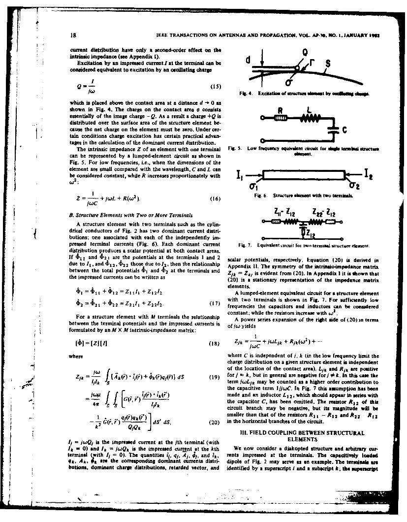
Excitation by an impressed current I at the terminal can be dconsidered equivalent to excitation by an oscillating charge
Fi. 4. Excitation of stuctuse msat by oNh sdks
which is placed above the contact area at a distance d - 0 asshown in Fig. 4. The charge on the contact are a consists R Lessentially of the image charge --Q. As a result a charge +Q isdistributed over the surface area of the structure element be-
* cause the net charge on the element must be zero. Under cer- C* tain conditions charge excitation has certain practical advan-
tages in the calculation of the dominant current distribution. _ _,,The intrinsic impedance Z of an element with one terminal Fig. 5. Low frequency equvala circuit for s temMad IMMctsu
can be represented by a lumped-element circuit as shown in dit.Fig. 5. For low frequencies, i.e., when the dimensions of theelement are small compared with the wavelength, C and L canTbe considered constant, while R increases proportionately with --' E E.--- t
be.
(6Fig. 6. Smtuctureermet with two termials.Z = + jW L + R(W2). (16)
B. Structure Elements with Two or More Terminals lI" 112 ZW" 112
A structure element with two terminals such as the cylin- ....... .drical conductors of Fig. 2 has two dominant current distri- Tz"butions; one associated with each of the independently im- TZ12pressed terminal currents (Fig. 6). Each dominant current Fig. 7. Equivalent circuit for iw,-terminal structure element.distribution produces a scalar potential at both contact areas.If 411 and 421 aresthe potentials at the terminals I and 2 calar potentials, respectively. Equation (20) is derived indue to I,, and $12, 4122 those due to/.2, then the relationship Appendix 11. The symmetry of the intrinsic-impedance matrixbetween the total potentials $1 and $2 at the terminals and Zik = Zk, is evident from (20). In Appendix I it is shown thatthe impressed currents can be written as (20) is a stationary representation of the impedance matrix
elements.$1 = $11 + $l 2 = ZI tI + ZI 212 A lumped-element equivalent circuit for a structure element
with two terminals is shown in Fig. 7. For sufficiently low2 = $2 1 + $ 2 2 = Z 2 III + Z2 212
• (17) frequencies the capacitors and inductors can be consideredconstant; while the resistors increase with w2.
For a structure element with M terminals the relationship A power series expansion of the right side of(20) in termsbetween the terminal potentials and the impressed currents is of jw yieldsformulated by an M X M intrinsic-impedance matrix:
4€1 =Z 111U (18) Z/k -jcC + Lik + Rjk(Q2 + "'
where where C is independent of j, k (in the low frequency limit thecharge distribution on a given structure element is independent
(of the location of the contact area). Lik and Ri, are positiveZik l (i() + ()qj(F)J dS (19) for j - k, but in general are negative for/ * k. In this case the
.lk S term jwoL/k may be counted as a higher order contribution tothe capacitive term I /jC. In Fig. 7 this assumption has been
________ - kv made and an inductor L 12 , which should appear in series with.- 4[ I l the capacitor C, has been omitted. The resistor R I 2 of this
kcircuit branch may be negative, but its magnitude will be
q()q( ') . smaller than that of the resistors Rt I - R 1 2 andR2 2 - R 2. ( dS' dS, (20) in the horizontal branches of the circuit.
2 1III. FIELD COUPLING BETWEEN STRUCTURAL
11 jwQ is the impressed current at the jth terminal (with ELEMENTSI= 0) and Ik = wQk is the impressed current at the kth We now consider a diakopted structure and arbitrary cur-terminal (with 1, = 0). The quantities 41, qj, AI, 41, and 1k, rents impressed at the terminals. The capacitively loadedqk, A,, 4, are the corresponding dominant currents distri- dipole of Fig. 2 may serve as an example. The terminals arbutions, dominant charge distributions, retarded vector, and identified by a superscript i and a subscript k; the superahpt
I I i I I ............GOURAU et at: DIAKOPTIC THEORY FOR MULTIELEMENT ANTENNAS 19
refenig to the number of the element and the subscript re- Furthermore, from the boundary conditions (21), using the
ferring to the number of the terminal on the element. If there relations (7) and Gauss's theorem, follows
were no field coupling between the elements, the current dis- r i i (
tributions on all the elements would be the dominant disti- Wit ( (24) an (25 o obtin bc at
but on associated with the impressed currents. are 1awlin sinc impednces6
The field of dominant current distribution is non- for every n including i. (25)Maxwellian ince the associated net charge is nonzero. If a
current r is impresred at the terminal the non-Maxweian The right side of (25) is zero since for scatter currents thefield of the dominant current and lharge distribution ik , rim integral of Gauss's theorem in (5) is zero (see AppendixlIV).
q*1 induces currents on all the other elements. The scatter With (23), (i4), and (25) one obtains the "backscatter"
fiel. t excited by thewe induced currents are Maxwellian, since impedances!. induced current distributions have no net charge. These
"'lirtorder'" scatter fields excite second-order scatter fields 1.1 $kid(F)
and so on; each higher order having a greatly reduced ampli- Zk,k (F) = '
tude. All these scatter fields when summed up form a multiple- 1k
scatter field which is Maxweilian. The currents and charges ''.2 N
associated with the multiple-scatter field are distributed over = J (6A,/ 64"'
all the surfaces S" (including S) and shall be denoted S' i n , "= Ii
Sqk in ; the superscripts and subscripts indicate that they are =
produced by the impressed current iki and located on the + 60k Sqk n)dSn , (26)
element n. In calculating 61it and Sqki" the structure ele-
ments are assumed open-circuited at their terminals. Hence which has to be added to the diagonal terms of the intrinsic-
the total flux of the scatter currents through the rim of the impedance matrix Zk ,k', using the notation of this section.
contact areas is zero. Scatter currents do not contribute to the Generalization of (26) to obtain the scatter field contributions
junction currents. to the off-diagonal terms is straightforward and yields
The total field generated by Ik5 (all other terminals open- ,
circuited) satisfies on every element the boundary conditions: Zk,/' I(F) = I(
-I ~In = 1,..--, ,....,N (21) 1_ 1_ .8-i+ ,4~ +- + kik))X dS" =0,
where Aa, 0 are the retarded potentials of the dominant 'k'j n=i Sn
current and charge distribution lk , qk ; and SAk , 60k_ are + 6k'6q/n) dSn . (27)
those of the scatter current and charge distributions 61k'in ,
bq51i combined. N is the number of elements. For k =(27) transforms into (26).
Since the electric field of i,, qki satisfies the boundary Let us now determine the potential 4)k,m '(F) produced
condition on S, it follows from (21 ) for n i that at the terminal (I) by the current fmie impressed at the terminal
OiiAk + 8 ) X dS =O (01). From the boundary condition (21)
Thus, j[ ( i' + Sm) + (m +,4'). 1'i dS' o,
J I(, wb ' + V 6k) I k dS 0, (2(28)
= N; k 1, "-',Mi. (22) and
Using the relations (7) and Gauss's theorem one obtains the
"backacatter" potential due to the field interaction of the L iW(Ai ' + Ak') + V( k + 6 4k)] I n dS- 0,
excited element with the other elements: Sn
" = kqk) (23)(29)
where the second equation holds for every n including i. The
The letter F indicates field coupling the first pair of indices potentials 6A' i and 6k' characterize the scatter field which
(ik) refers to the terminal at which 0 is determined, and the would be excited by I 1.second pair to the terminal of the impressed current which As before, we apply relations (7) and Gauss's theorem, and
products this potential. obtain from (28)As shown in Appendix Ill
(6,,. ik0 + 6,%'qkd') 4
&,m4 ')l" = 1WF !A+ i q k )d $'
( . + S . (24) •(81' 7k' + 6mqh)dS] (30)(li + $k81"d(4
20 IEEE TRANSACTIONS ON ANTENNAS AND PROPAGATION. VOL. AP-30, NO. 1, JANUARY 1982
and from (29) of the diakopted Istem and relates the terminal potentials
Mgi
0 J (Ai'',." + j,,'Sq"')dS" *$'(C = ZaI"(C)I
due to current coupling to the M, impressed currents of the+ (6Aa i • 6 + 5$6qma")dS". (31) elementi.
The sum of the matrices [Z(C)] and [Z(F)], i.e.,
The first term in (30) represents the contribution to the ter-minal potential $ k,m '(F) from the non-Maxwellian field of [ = IZ(C)] + [Z(F)] (36)
the dominant current and charge distribution im1, qm1 , and thesecond term that from the scatter current and charge distri- forms the "complete impedance matrix" of the diakopted
butions aim'", 6qmn . antenna, which represents the relationship between the total
As shown in Appendix III terminal potentials
M MI
sfSm ' 7k + S = l1 m1I
N f' produced by current and field coupling to all impressed cur-
= J (At'a4,,"+ k2 6qr ")dS". (32) rents. In matrix form
14] -- [Z][I. (37)
Expressing $k "(F) in terms of an impedance
If the matrix elements Zk"',(C) (20) and Zkj (F) (27) are$A.,m"(F) = Zk m"(F)Jm', (33)added, the resulting elements Zk/ have the same form as
those which pertain to field coupling between different struc-
and using (30), (31), and (32), the field-coupling impedance ture elements (34). In other words (34) can be used as generalbetween the terminals (') and (,) becomes formulation for all elements of the complete impedance ma-
trix of the diakopted system, and the condition i * I can be
I1 I dropped.
Z 1A1 Sm j t(m l +" mWlqk)dS' The symmetry of the [Z] matrix, i.e.,
N Zk,m,,' = m"' (38)
- n mfl A m + klqml)dsJ. can be easily verified, by expressing in (34) the vector and
scalar potentials by the current and charge distributions ac-
i * 1. (34) cording to (I) and (12).Equation (34) represents a stationary formulation of the
Equations (27) and (34) yield the elements of the field-cou- matrix elements of [Z]. This means first-order errors in the
* pling impedance matrix (Z(F)], which relates the scalar poten- current and charge distributions lead to only second-order
tials 4k (F) at the terminals, caused by field coupling, to the errors in the impedances (Appendix 1).impressed currents: Calculation of the radiation-coupling impedances according
to (27) and (34) requires, in principle, computation of the[$(F)] =I Z(F)1i, scatter current and charge distributions. However numerical
N NMI results obtained with this theory indicate that coupling by theF M! V scatter currents is a negligible effect. It has been found that
W T = WPk~ml' l(
F) coupling by the junction currents prevails over field coupling,
and field coupling by the non-Maxwellian fields (radiated bythe dominant current distribution) dominates over that by
N MI the Maxwellian fields (generated by the scatter currents). In
= Z d Za,mi'l(F)Im " (35) principle field coupling effects by the scatter currents can berIobtained with an iterative procedure, which is not discussed
here.IV. COMPLETE IMPEDANCE MATRIX OF THE If coupling by the Maxwellian scatter fields is neglected,
DIAKOPTED ANTENNA the formula for the elements of the complete-impedance
The intrinsic-impedance matrices of the individual struc- matrix for the diakopted system reduces to
ture elements can be combined into a diagonal block imped-ance matrix (Z(C)] by writing the matrix elements Zkj (20) Zk.m*. --- (d
in the form Ztj" (C). The superscripts I identify the terminals -lm' - 'T d' (39)
k and J as belonging to the element i; the letter C indicatescurrent coupling. The block matrix (Z(C)j, whose elements This means all the matrix elements can be computed from the
4 40 are zero for i I, is the "current-coupling matrix" dnminant current distribution. It is worth mentioning that
-| I II m m k ,, . .. .. - - . . . . ... . . . . .- * -
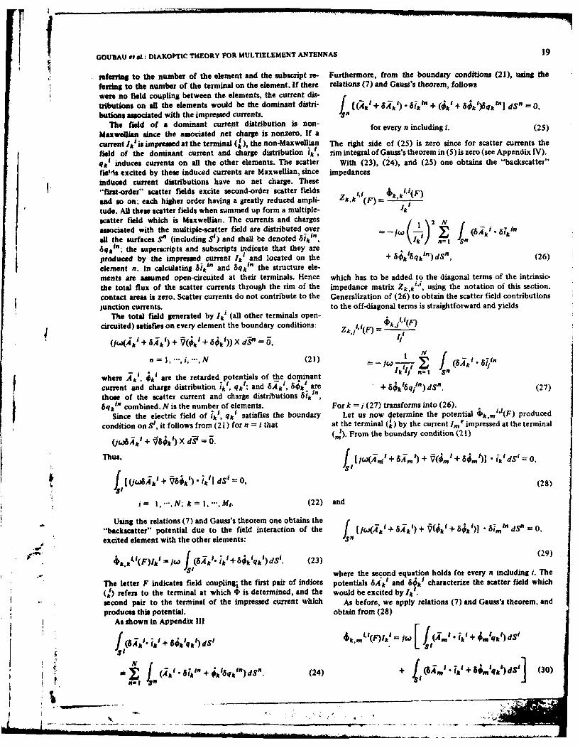
GOUDAU eta.: DIAKOPTIC THEORY FOR MULTIELEMENT ANTENNAS 21
formulation of the antenna problem in terIs of this approx- 2Limate impedance matrix can also be dei in a more con- 4 2 2 ventional manner by an application of the m thod of moments ift(31, [41. For this purpose one would fon ate the electric Z''1-"field integral equation of the entire (interconnected) antenna -4 11structure and reduce this equation to a linear system by em- 2 1 , i ,ploying the Galerkin version of the method of moments,while choosing the dominant current distributions of the vari- Fg. 8. Thin who dipole treated as diskopted four-element system.ous structure elements as (subsectional) basis and weight func-tions. After transformation of the linear system, by applica- relationships aretion of (7), into a matrix equation between the potentials andcurrents at the contact areas, the matrix coefficients are found (4J = [ZJ (11 [diakopted antenna] (40)to be identical with (39). The choice of the dominant currentdistributions as basis functions will alleviate the necessity for J =JZ 'li' [assembled actual antenna (41)subdividing a given antenna into many small segments. Sinceeach of these current distributions satisfies the conditioning at variousZion = 0 at its self-element (and since current coupling domi- Priterconnetins f t acu an Rqrents a) bronates) it can be expected that structure elements of compara- interconnections of the actual forei Requirements a), b),tively large size will already yield accurate results. In other and c) represent Kirchoff's structureswords the accent of the problem is shifted from solving an and can be written as
integral equation for the entire antenna to determination ofthe dominant current distributions of its structure elements (11 = [C] (11' (42)which, in many cases, can be reduced to canonical problems.Moreover, because of the stationary properties of the matrix (4,1' = I C1 t[4'] (43)coefficients (39), the dominant current distributions have tobe known only approximately in order to obtain impedance [I' = PiitUJ. (44)values of good accuracy. The numerical example discussed inSection VI confirms these predictions. [C) t represents the transpose of [C]. Note that V" denotes
potential differences, i.e., voltages.V. INTERCONNECTION OF THE STRUCTURE ELEMENTS From (42), (43), and (44) the impedance of the actual
AND INTERCONNECTION MATRIX interconnected structure can be written as
The requirement for the diakopted structure with im- IZV=IC)AzI C). (45)I pressed currents to be identical in performance with theassembled antenna are as follows. The following example shows how ICJ and [Z]' are obtained.
a) The sum of the impressed currents is zero at every junc- V EXAMPLEtion between the structure elements. This requirementassures that the Kirchoff condition of current continuity As an example we apply the diakoptic theory to an ordi-is satisfied and that the field of the assembled antenna nary thin-wire dipole antenna and compare the results with theis Maxwellian. data available in the literature. To obtain a multielement
b) The scalar potentials at interconnected terminals are structure we cut each wire in half, as shown in Fig. 8, and con-equal. sider each half as a structure element. The diakopted dipole is
c) The potential difference between the input terminals is thus modeled by two structure elements with one terminal andequated with the driving voltage of the antenna, two structure elements with two terminals, so that the total
It should be emphasized that the continuity of current at number of terminals is six. The complete impedance matrixjunction needs to be imposed only on the impressed cur- of the diakopted structure [Z] is therefore a 6 X 6 matrix.rents which are in turn e ly o the dominant current However there are only eight different impedances because the
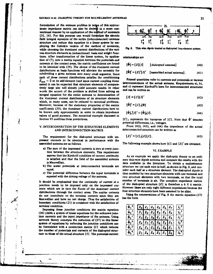
rentsu whichur areent inv turn theme flxe of thadmiankcrrndistributions through the contact areas. The scatter currents four structure elements have been assumed to be alike.do not contribute to the terminal currents since they are Using the enumerations of Fig. 8 the matrix equation (37)Maiwellian and have no net charge. Thus the satisfaction of has the formboundary conditions (2 1) is consistent with the satisfaction ofterminal condition. $13 3 Z
Imposing these junction conditions the matrix equation
(36) yields a system of linear equations for the unknown junc- fi21 Z I Z° Z 2 Z3 ZS Z6 12tion currents and the input impedance of the antenna. Usingnetwork theory concepts the reduction of (37) to this linear 2 Z
system of equations by enforcing the junction conditions can "2 Z 4 Z 3 Z1 Zo Z 2 Z3 2* r be formulated with a connection matrix ICI which reduces $12 Z6 ZS Z 3 Z2 , Z 1 , 2
the number of potentials and currents of the diakopted Ztru
ture to those of the actual structure [5 .The potentil-current :2 Z7 Z6 Z4 Z3 Z 0o
$
22 IEEE TRANSACTIONS ON ANTENNAS AND PROPAGATION, VOL. AP-30, NO. !, JANUARY 19S2
with
Zo =Zl133 =2Z211 =,11 =Z2222 =2122 =Z2244
=Z Z12331 =Z2113 =Z 1 212 =-Z2121 =Z1224 =Z 2 1
4 2
Z2 =Z211 =Z,211
=Z 2 12 2 =Z12
2 2
31=Z 13 =Z112 = I121 12 1 24 2
Z3 -ZI 1 - 12 = Z21 1 1 =Z2212 =222 Z2 2 =Z 2 24 2
Z 4 Z1 23 2
- 2 12 3 =z 1 2
1 4 =Z2Z241
Z5 = Z2112 =Z1221
Z6 = Z I 13 2
=Z1t23 =Z2214 =Z2241
Z7 =Z1234--Z2143
The darkened portion of the impedance matrix Z is the ample are the same for all the elements, can be approx-current-coupling matrix Z(C). imated by linear current distributions (uniform charge
The interconnection conditions require distribution).
i 3 = -21 = 1 $13 $ 2 1 = 01 Although the latter approximation is rather crude, oneshould expect reasonable results if the wire sections are short
122 =-III = -! $1' 422= VO compared with the wavelength because all the impedanceformulas are stationary expressions. Linear current distribu-
124 _--- 2 = 12 2 4 =$12 = 4 2 tion permits analytic formulations of all the impedancesZO, Z1, Z2, etc., and numerical calculations with a pocket
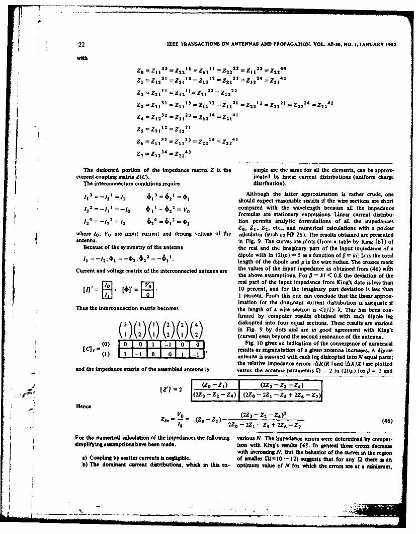
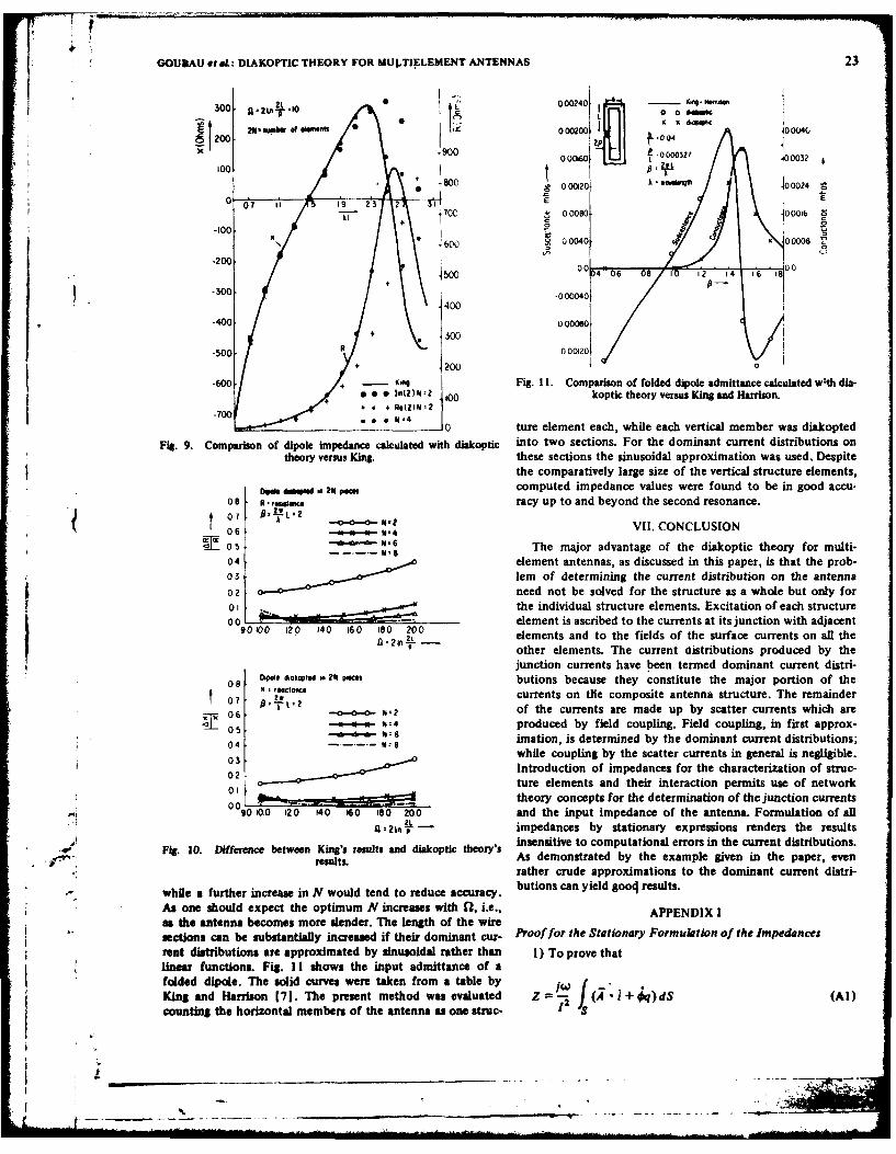
where 0, Vo are input current and driving voltage of the calculator (such as HP 25). The results obtained are presentedantenna, in Fig. 9. The curves are plots (from a table by King [61) of
Because of the symmetry of the antenna the real and the imaginary part of the input impedance of a
1- 2;$2 2 - 1. dipole with In (21/p) 5 ass function oftP= ki; 21is the total2 2length of the dipole and p is the wire radius. The crosses mark
Current and voltage matrix of the interconnected antenna are the values of the input impedance as obtained from (46) withthe above assumptions. For 0 = ki < 0.8 the deviation of the
I,- real part of the input impedance from King's data is less than[A]' 0 , ]' = . 10 percent, and for' the imaginary part deviation is less than
0 11 percent. From this one can conclude that the linear approx-imation for the dominant current distribution is adequate if
Thus the interconnection matrix becomes the length of a wire section is <1/15 X. This has been con-firmed by computer results obtained with each dipole leg
1(2 ) ( 4 diakopted into four equal sections. These results are markedin Fig. 9 by dots and are in good agreement with King's
12 1 2) (curves) even beyond the second resonance of the antenna.
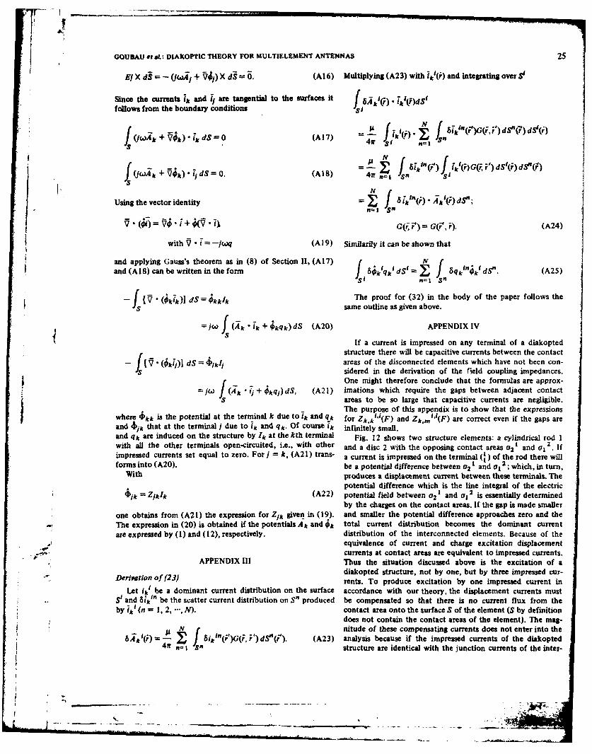
_ (0) 1 0 1 o I 0 1 1- I o 0 Fig. l0 gives an indication of the convergence of numerical( l -,1 - 1 0 1 -1 results as segmentation of a given antenna increases. A dipoleantenna is assumed with each leg diakopted into N equal parts;the relative impedance errors I ARIR land IAX/X I are plotted
and the impedance matrix of the assembled antenna is versus the antenna parameters 1 = 2 In (2l/p) for = 2 and
[Z'] 2 (Zo'2i) j (2Z3 -22-2Z4)(223 '- Z2 -2Z4) (2ZO - 221 -Z5 + 2Z6 -27)
Hencei =Vo (2Z3 - Z2 - Z4)2 - (Z,-Za)--(=2(-O 2-- 4 )) (46)
1 0o 2Z, - 2 I -Zs + 2Z 6 -27
* For the numerical calculation of the Impedances the following various N. The impedance errors were determined by compar-aimplifying assumptions have been made. ison with King's results [61. In general these errors decrease
with increasing N. But the behavior of the curves in the regiona) Coupling by scatter currents is negligible, of smaller X(=10 "" 12) suggests that for any 1. there is anb) The dominant current distributions, which in this ex- optimum value of N for which the errors are at a minimum,
GOUBAU eI &L: DIAKOPTIC THEORY FOR MULTIELEMENT ANTENNAS 23
300 . g2u.2t. 0024 1 - oW4 -N&eT • 000 2 4
oo200oo 000200 k J0 0 Eoo G
_ 07 1n 19- 23 2 ! C
00ki + 700000001ol z : o 'o J11
.200.
-300 .00004
400 oooo oooo04 j300
\0000 0oo o o o , . .-5o0 R+ 20000
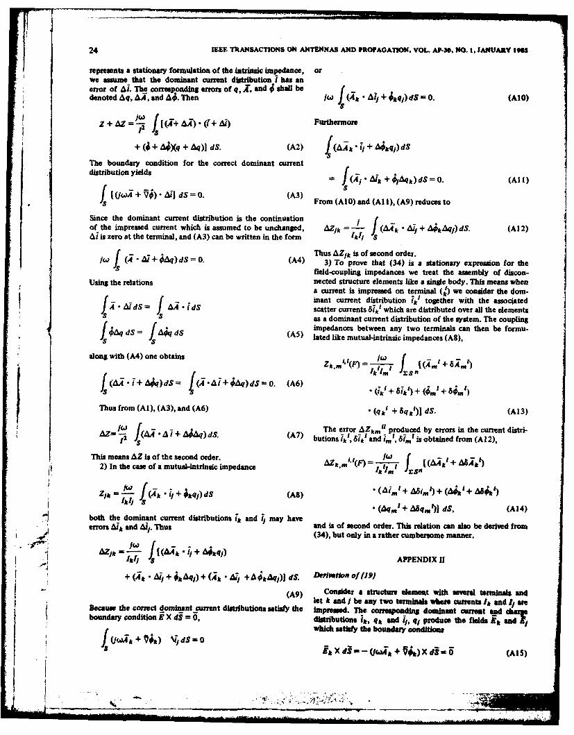
.60 + - mq Fig. 11. Comparison of folded dipole admittance calculated wth dia-*(Z) N-Z .10 koptic theory versus King and Harrison.
-700 4 +Q();
0. .. ture element each, while each vertical member was diakopted
Fig. 9. Comparison of dipole impedance calculated with diakoptic into two sections. For the dominant current distributions ontheory versus King. these sections the sinusoidal approximation was used. Despite
the comparatively large size of the vertical structure elements,
Do* d a 2N pm computed impedance values were found to be in good accu-os R:,*1%, racy up to and beyond the second resonance.
M--0--a- 9.2 VII. CONCLUSION06 -46- 4406 N-, The major advantage of the diakoptic theory for multi-04 element antennas, as discussed in this paper, is that the prob-03 lem of determining the current distribution on the antenna
02 need not be solved for the structure as a whole but only for01 the individual structure elements. Excitation of each structure0 10 0 - 140 1 - 80 200 element is ascribed to the currents at its junction with adjacent
1=20 elements and to the fields of the surface currents on all theother elements. The current distributions produced by thejunction currents have been termed dominant current distri-
08 Dwe dm, tsd 2 24 .eet butions because they constitute the major portion of the
07 reactofte currents on ile composite antenna structure. The remainder
06 -L-:2 -- 14 2 of the currents are made up by scatter currents which areo w -N4 produced by field coupling. Field coupling, in first approx-
0-, - 6: imation, is determined by the dominant current distributions;04 1#- while coupling by the scatter currents in general is negligible.
i 0303 Introduction of impedances for the characterization of struc-020 -ture elements and their interaction permits use of network
_0_--...-__ _ _._.._____ theory concepts for the determination of the junction currents
090100 120 140 60 1s. 200 and the input impedance of the antenna. Formulation of alla 2th impedances by stationary expressions renders the results
Fig. 10. Difference between Xings reults and dtskoptic theory's insensitive to computational errors in the current distributions.
results. As demonstrated by the example given in the paper, evenrather crude approximations to the dominant current distri-
while a further increase in N would tend to reduce accuracy. butions can yield gooc results.
As one should expect the optimum N increases with 1, i.e., APPENDIX Ias the antenna becomes more slender. The length of the wiresections can be substantlly increased if their dominant cur- Proof for the Stationary Formulation of the Impedancesrent distributions are approximated by sinusoidal rather than 1) To prove thatlinear functions. Fig. I I shows the input admittance of afolded dipole. The solid curves were taken from a table by / j(, )King and Harrison (7]. The present method was evaluated Z + )dS (Al)countinS the horizontal members of the antenna as one struc-
, - ,,__ __"_... .. .. ...... ..__ _ _ _ _ _ _=
24 IEEE TRANSACTIONS ON ANTENNAS AND PROPAGATION. VOL. AP-30. NO. I, JANUARY 1963
represents a stationary formulation of the intrinsic Impedance, orwe assume that the dominant current distribution 1 has anerror of A!. The corresponding erros of q, Z, and 4 shall bedenoted Aq, A4, and A. Then 64 Ali + kqi) dSO. (AIo)
= AZ4 L I[ 9+)(i + A4 Furthermore12
+ (j + A Xq + q)1 dS. (A2) 1(4A k + A;q,)dS
The boundary condition for the correct dominant currentdistribution yields =f(yils= j(Aj" A,-a+ j )ds =0. (Al l)
ts [(WX + Vj) - 9] ds=. (M)$f + AFrom (AIO) and (Al I), (A9) reduces to
Since the dominant current distribution is the continuation j ( -
of the impressed current which is assumed to be unchanged, AZ/k =- J (a4,k • A, + at Aqj) dS. (A! 2)A is zero at the terminal, and (A3) can be written in the form 4k1 S
f +4 Thus AZik is of second order.
(4 + il)d$ = 0. (M) 3) To prove that (34) is a stationary expression for theS ifield-coupling impedances we treat the assembly of discon-
Using the relations nected structure elements like a single body. This means whena current is impressed on terminal (bi ) we consider the dom-inant current distribution 7k' together with the associated
ad• idS scatter currents 6i* which are distributed over all the elementsSas a dominant current distribution of the system. The couplingF f8 impedances between any two terminals can then be formu-
f4AqdS= JAjqdS (A5) lated like mutual-intrinsic impedances (A8),S S
along with (A4) one obtains Z, (F) = i-777 f vi.m' +A'
Ikl' ES"I
f .+ 4) dS ~ A + Aq) dSz 0. (A6)+ ')+(,'+
Thus from (AI), (A3), and (A6) • (qk' + 6q k)] dS. (A13)
Z i + A q)d. ( The error AZkmi produced by errors in the current distri-
AZZC I butions 1k' and 81. ~~' is obtained from (Al 12),This means AZ is of the second order.
2) In the case of a mutual-intrinsic impedance AZk,. r#in t + 8
Ik1 (Aq. + Uqm )] ds, (A14)
both the dominant current distributions s' and 1 may haveerrors Ak and Al . Thus and is of second order. This relation can also be derived from
(34), but only in a rather cumbersome manner.
AZj +(~ jA~kqi)'k 3i APPENDIX II
+ Ail + kkq,) + (ik AT/ +4jtAq,)j dS. Deintkfl' of (J9)(A9) Consider a structure lemesit with several terminals and
let k and j be any two terminals where currents Ik and IareBecause the correct dominant cumnt distributions satisfy the impressed. The corresponding dominant current and caayboundary condition EX di = 0, distributions 1k, qk and 11, q1 produce the fields El andwhich satisfy the boundary conditions
j 4Xd!i) +ii)d in0 (AtS)
GOU BAU et &L: DIAKOPTIC THEORY FOR MULTIELEMENT ANTENNAS 25
El X d3 = - (JcQXA + Vii) X dS -. (Al 6) Multiplying (A23) with ik(i) and integrating over S1
Since the currents lt and 1, are tangential to the surfaces it f r)follows from the boundary conditions f t
Qwlt+ Vet)" -dS = 0 (A17) Jl(f "
]A (k()GFV d~)dnl(•,1 +] N i dS 0. (AI 8) 47 = 8414'k(r1 1
f S0n ad-.0N
Using the vector identity = J ' "i )A'(i) dS";
nwith ( oiftoioq (A9) Similarly it can be shown that
; ~and applying Gauss's theorem as in (8) of Section 11, (A17) f f
and (A18) can be written in the form f dkSqk'd$ - f 6qki idS~n . (A25)i n=l "
-f [" ( ki'] d$ = kk The proof for (32) in the body of the paper follows the
s same outline as given above.
=jw (Akti k+kqk)dS (A20) APPENDIX IV
If a current is impressed on any terminal of a diakopted
structure there will be capacitive currents between the contact-f ki])] dS = bkI/ areas of the disconnected elements which have not been con-
:s sidered in the derivation of the field coupling impedances.f One might therefore conclude that the formulas are approx-
=w J ( jk 1 + 4 q) dS, (A21 ) imations which require the gaps between adjacent contactS areas to be so large that capacitive currents are negligible.
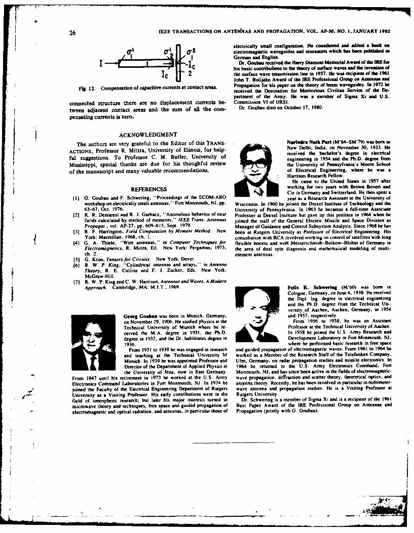
The purpose of this appendix is to show that the expressionswhere 'lkk is the potential at the terminal k due to ik and qk for Zkk"'(F) and Zk,m"'(F) are correct even if the gaps areand $/k that at the terminal j due to 1k and qk. Of course ik infinitely small.and qk are induced on the structure by Ik at the kth terminal Fig. 12 shows two structure elements: a cylindrical rod Iwith all the other terminals open-circuited, i.e., with other and a disc 2 with the opposing contact areas o2 t and a, 2 Ifimpressed currents set equal to zero. For I k, (A2 1) trans- a current is impressed on the terminal (,) of the rod there willforms into (A20). be a potential difference between 02 I and a, 2 ; which, in turn,
With produces a displacement current between these terminals. The
potential difference which is the line integral of the electric
*ik = Z/kit (A22) potential field between U21 and o12 is essentially determinedby the charges on the contact areas. If the gap is made smaller
one obtains from (A21) the expression for Zik given in (19). and smaller the potential difference approaches zero and the- The expression in (20) is obtained if the potentials A& and 4 total current distribution becomes the dominant current
are expressed by (1) and (12), respectively, distribution of the interconnected elements. Because of theequivalence of current and charge excitation displacementcurrents at contact areas are equivalent to impressed currents.
APPENDIX III Thus the situation discussed above is the excitation of adiakopted structure, not by one, but by three impressed cur-
Deriation of (23) rents. To produce excitation by one impressed current in
Let ik' be a dominant current distribution on the surface accordance with our theory, the displacement currents mustSt and 6ikt" be the scatter current distribution on S" produced be compensated so that there is no current flux from theby ik (n = 1, 2, ,N). contact area onto the surface S of the element (S by definition
does not contain the contact areas of the element). The mag-f~nnitude of these compensating currents does not enter into the
) jiik'nQr)GQ, r')dS"(r). (A23) analysis because if the impressed currents of the eintopte4r I n structure are identical with the junction currents of the inter-
26 IEEE TRANSACTIONS ON ANTENNAS AND PROPAGATION, VOL. AP-30, NO. I, JANUARY 1982
1 l electrically small configuration. lie coauthored and edited a book 0.0' 01 01electromagnetic waveguides and resonators which baa been publishied in
,4...............-..-~, IGerman and English.L-'L..,.........L...... .4Dr. Uoubeu received the Harry Diamont Memorial Award of the IRE for
IjJ C his basic contributions to the theory of surface waves and the invention ofIC 2 the surface wave transmission line in 1957. He was recipient of the 1961
John T. Bolljahn Award of the IRE Professional Group on Antennas and
Fig. 12. Compensation of capacitive currents at contact areas. Propagation for his paper on the theory of beam waveguides. Is 1972 bereceived the Decoration for Meritorious Civilian Service of the De-partment of the Army. He was a member of Sigma Xi and U.S.
connected structure there are no displacement currents be- Commission VI of URSI.
tween adjacent contact areas and the sum of all the corn- Dr. Goubu died on October 17, 1980.
pensating currents is zero.
ACKNOWLEDGMENT
The authors are very grateful to the Editor of this TRANS- Narhaira Natb Pirl (M'64-SM'79) was born inACTIONS, Professor R. Mittra, University of llinois, for help- € i New Delhi, India, on November 30. 1933. He
oo received the bachelor's degree in electricalful suggestions. To Professor C. M. Butler, University of engineering in 1954 and the Ph.D. degree from
Mississippi, special thanks are due for his thoughful review the University of Pennsylvania's Moore School
of the manuscript and many valuable recommendations. of Electrical Engineering, where he was aHarrison Research Fellow.
He came to the United States in 1957 afterREFERENCES working for two years with Brown Boveri and
Cie in Germany and Switzerland. He then spent a
(I1 G. Goubau and F. Schwering, "Proceedings of the ECOM-ARO year as a Research Assistant at the University of
workshop on electrically small antennas." Fort Monmouth, NJ. pp. Wisconsin. In 1960 he joined the Drexel Institute of Technology and the
63-67, Oct. 1976. University of Pennsylvania. In 1963 he becamse a full-time Associate121 K. R. Demarest and R. J. Garbacz. "Anomalous behavior of near Professor at Drexel Institute but gave up this position in 1964 when he
fields calculated by method of moments," IEEE Trans. Antennas joined the staff of the General Electric Missile and Space Division as
Propagat., vol. AP-27. pp. 609-615, Sept. 1979. Manager of Guidance and Control Subsystem Analysis. Since 1968 he has
131 R. F. Harrington, Field Computation by Moment Method. New been at Rutgers University as Professor of Electrical Engineering. HisYork: Macmillan. 1968. ch. I. consultation with RCA involved working on control of satellites with long
141 G. A. Thiele, "Wire antennas," in Computer Techniques for flexible booms and with Messerschmidt-Bolkow-Blohm of Germany inFlectromagnetics. R. Mittra, Ed. New York: Pergamon, 1973. the area of dual spin diagnosis and mathematical modeling of multi-
ch. 2. element antennas.(51 G. Kron, Tensorsfor Circuits. New York: Dover.161 R. W. P. King, "Cylindrical 3anennas and arrays," in Antenna
Theory, R. E. Collins and F. J. Zucker, Eds. New York:McGraw-Hill.
171 R. W. P. KingandC. W. Harrison, Antennas and Waves, A ModernApproach. Cambridge, MA: M.I.T.. 1969. Felix K. Schwertall (M'60) was born in
Cologne, Germany, on June 4. 1930. He receivedthe DipL. Ing. degree in electrical engineeringand the Ph.D. degree from the Technical Uni-versityof Aachen, Aachen. Germany. in 1954
Georg Gaubam was born in Munich, Germany. ' and 1957. respectively.on November 29. 1906. He studied physics at the " From 1956 to 1958. he was an Assistant
Technical University of Munich where he re- Professor at the Technical University of Aachen.
ceived the M.A. degree in 1931, the Ph.D. In 1958 he joined the U.S. Army Research and
degree in 1932, and the Dr. habilitatus degree in Development Laboratory in Fort Monmouth, NJ.
1936. where he performed basic research in free space
From 1931 to 1939 he was engaged in research and guided propagation of electromagnetic waves. From 1961 to 1964 he
and teaching at the Technical University bf worked as a Member of the Research Staff of the Telefunken Company.
Munich. In 1939 he was appointed Professor and Ulm. Germany. on radar propagation studies and missile electronics. In
Director ot the Department of Applied Physics at 1964 he returned to the U.S. Army Electronics Command. Fort
the University of Jena. now in East Germany. Monmouth. NJ. and has since been active in the fields of electromagnetic-
From 1947 until his retirement in 1973 he worked at the U.S. Army wave propagation. diftraction and scatter theory, theoretical optics. and
Electronics Command Laboratories in Fort Monmouth. NJ. In 1974 he antenna theory. Recently, he has been involved in particular in millimeter-
joined the Faculty of the Electrical Engineering Department of Rutgers wave antenna and propagation studies. He is a Visiting Professor at
University as a Visiting Professor. His early contributions were in the Rutgers University.field of ionospheric research; but later his major interests turned to Dr. Schwering is a member of Sigma Xi and is a recipient of the 1961
microwave theory and techniques. free space and guided propagation of Best Paper Award of the IRE Professional Group on Antennas andelectromagnetic and optical radiation, and antennas, in particular those of Propagation (jointly with G. Goubau).