acuvim-l multifunction power and energy meter - user's manual
TRANSCRIPT
Acuvim-L Multifunction Power and Energy MeterUser's Manual
www.accuenergy.com
V: 3.05 Revised: Feb 2022II
Copyright © 2022 V3.05
This manual may not be altered or reproduced in whole or in part by any means without the expressed written consent of Accuenergy.
The information contained in this document is believed to be accurate at the time of publication, however, Accuenergy assumes no responsibility for any errors which may appear here and reserves the right to make changes without notice. Please ask the local representative for latest product specifications before ordering.
Please read this manual carefully before installation, operation, and maintenance of Acuvim-L power meter.
The following symbols in this manual and on Acuvim-L series meters are used to provide warning of danger or risk during the installation and operation of the meters.
Electric Shock Symbol: Carries information about procedures which must be followed to reduce the risk of electric shock and danger to personal health.
Safety Alert Symbol: Carries information about circumstances which if not considered may result in injury or death.
This mark indicates that this product is UL Listed.
Installation and maintenance of the Acuvim-L power meter should only be performed by qualified, competent professionals who have received training and experience with high voltage and current devices.
Accuenergy shall not be responsible or liable for any damages caused by improper meter installation and/or operation.
www.accuenergy.com
V: 3.05 Revised: Feb 2022 1
Congratulations!
You have purchased an advanced, versatile, multifunction power meter. This meter can work as a remote terminal unit (RTU) that contributes to your system’s stability and reliability by providing real-time power quality monitoring and analysis. When you open the package, you will find the following items:
1. Acuvim-L power meter qty: 1
2. Terminal Blocks qty: 3 (2 for basic model)
3. Installation Clips qty: 4
4. Additional documentation: qty: 2 a. Quick Setup Guide, b. Calibration Certificate
To avoid complications, please read this manual carefully before installation and operation of the Acuvim L series meter.
www.accuenergy.com
V: 3.05 Revised: Feb 20222
Table of Contents
Chapter 1: Introduction ...........................................................................................................................................4
1.1 Functionality ..............................................................................................................................................................................4
1.2 Application Area ........................................................................................................................................................................4
1.3 Meter Overview.........................................................................................................................................................................5
Chapter 2: Installation ..............................................................................................................................................7
2.1 Appearance and Dimensions ..................................................................................................................................................8
2.2 Installation Methods ..............................................................................................................................................................10
2.3 Wiring .......................................................................................................................................................................................13
2.3.1 Terminal Strips .............................................................................................................................................................13
2.3.2 Power Requirement ....................................................................................................................................................14
2.3.3 Voltage Input Wiring ....................................................................................................................................................16
2.3.4 Current Input Wiring ...................................................................................................................................................18
2.3.5 Frequently Used Wiring Method................................................................................................................................20
2.3.6 Digital Output (DO) ......................................................................................................................................................23
2.3.7 Digital Input (DI) ...........................................................................................................................................................24
2.3.8 Communication ...........................................................................................................................................................24
Chapter 3: Basic Operations and Applications ...................................................................................................26
3.1 Display Panel and Keys ..........................................................................................................................................................26
3.2 Metering Data .........................................................................................................................................................................28
3.2.1 Voltage and Current Display ......................................................................................................................................29
3.2.2 Power Display ..............................................................................................................................................................30
3.2.3 Real-Time Energy Display ...........................................................................................................................................30
3.2.4 Phase Angle and Unbalance Display .........................................................................................................................31
3.2.5 TOU Energy Display .....................................................................................................................................................31
3.3 Statistics Display .....................................................................................................................................................................32
3.3.1 They Keys Operation of Voltage/Current the Most Value Module ........................................................................32
3.3.2 The Max Value of Power Display ...............................................................................................................................33
3.3.3 The Max Harmonic Distortion Display ......................................................................................................................33
3.4 Demand Display......................................................................................................................................................................34
3.4.1 Demand Display Module Key Operation ..................................................................................................................34
3.4.2 TOU Maximum Demand .............................................................................................................................................35
3.5 Harmonics Data Display ........................................................................................................................................................35
3.5.1 Basic Parameters Key Operation ...............................................................................................................................36
3.5.2 Harmonic Ratio Data Display .....................................................................................................................................37
3.6 Parameter Setting Mode ........................................................................................................................................................37
3.6.1 Key Operation Setting Module ...................................................................................................................................41
3.6.2 System Basic Setting Module .....................................................................................................................................42
3.6.3 I/O Interface Settings and Key Operations ...............................................................................................................44
3.6.4 Power Quality Settings Button and Page Display ....................................................................................................44
www.accuenergy.com
V: 3.05 Revised: Feb 2022 3
3.7 System Information Interface ...............................................................................................................................................45
3.7.1 Result of Wiring Check ................................................................................................................................................47
3.7.2 System Information .....................................................................................................................................................48
3.7.3 DI Count/State Display ................................................................................................................................................49
3.8 Page Recovery Function .........................................................................................................................................................49
Chapter 4: Function and Software Tools .............................................................................................................50
4.1 Basic Analog Measurements .................................................................................................................................................50
4.2 Max/Min ...................................................................................................................................................................................52
4.3 Harmonics and Power Quality Analysis ...............................................................................................................................53
4.4 Extended I/O Module .............................................................................................................................................................54
4.5 Extended Communication Block ..........................................................................................................................................55
4.6 TOU Block ................................................................................................................................................................................55
4.7 Daily Energy .............................................................................................................................................................................58
4.8 Power Quality Eventlog ..........................................................................................................................................................58
4.9 Over-Range Alarming .............................................................................................................................................................59
4.10 Seal .........................................................................................................................................................................................61
Chapter 5: Communications ..................................................................................................................................66
5.1 Modbus Protocol Introduction ..............................................................................................................................................66
5.1.1 Framing .........................................................................................................................................................................66
5.1.2 Address Field ................................................................................................................................................................66
5.1.3 Function Field ...............................................................................................................................................................67
5.1.4 Data Field ......................................................................................................................................................................67
5.1.5 Error Check Field .........................................................................................................................................................67
5.1.6 Error Checking .............................................................................................................................................................67
5.2 Communication Format .........................................................................................................................................................68
5.3 Data Address Table ................................................................................................................................................................71
Appendix: ...............................................................................................................................................................124
Appendix A: Technical Data and Specification ....................................................................................................................... 124
Appendix B: Ordering Information ......................................................................................................................................... 127
Appendix C: Revision History ................................................................................................................................................... 128

V: 3.05 Revised: Feb 20224
Acuvim-L Multifunction Power and Energy Meter
www.accuenergy.com
Chapter 1: Introduction
1.1 Functionality
Multifunction, High Accuracy MeasurementsAcuvim-L series three-phase, multifunction power meter built on the advanced microprocessor and high-precision ADC technology platform that uses with digital signal processing to measure and analyze voltage, current, active, reactive, apparent power, and energy. Extended digital outputs and an RS485 communication interface can output pulse energy, event alarms, remote data collection values, and control functions. The Acuvim-L series meter combines superior performance and high accuracy measurements with an affordable price point.
Compact and Easy to InstallAcuvim-L series meter can be installed into a standard ANSI C39.1 (4” round) or an IEC 92mm DIN (square) slot. With the 51mm depth, the meter can be installed in a small cabinet or enclosure. Installation clips are provided for easy installation and removal.
Easy to UseThe Acuvim-L features a large LCD screen with a bright backlight ideal for low lighting conditions. The interface permits easy access to measured data and meter settings by using the front panel keys or communication port. All settings are stored in non-volatile, EEPROM memory and are saved even when the meter is powered down.
Meets all Safety and Reliability StandardsAcuvim-L series meter was designed according to industrial standards. It can reliably run under high power disturbance conditions and, additionally, it has been fully tested for EMC and safety compliance in accordance with UL and IEC standards.
1.2 Application Area
Acuvim-L series can be used as front-end power automation system Acquisition Terminal (RTU) for remote data acquisition and control. It can also be used as a multifunction power measuring instrument in a power distribution system or a wide range of other applications. The Acuvim-L uses advanced true RMS measuring and digital signal processing technology for accurate monitoring of the power quality of non-linear loads, even in harsh environments.
• Power distribution automation
• Industrial automation
• Energy management systems
• Electric switch gear and control panels
• Building automation
• Marine applications
V: 3.05 Revised: Feb 2022 5www.accuenergy.com
1.3 Meter Overview
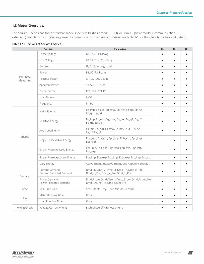
The Acuvim-L series has three standard models: Acuvim-BL (basic model + DO), Acuvim-CL (basic model + communication + extension), and Acuvim- EL (sharing power + communication + extension). Please see table 1-1 for their functionalities and details.
Table 1-1 Functions of Acuvim-L Series
Function Parameters BL CL EL
Real Time Measuring
Phase Voltage U1, U2, U3, UInavg
Line Voltage U12, U23, U31, UIIavg
Current I1, I2, I3, In, Iavg, Itotal
Power P1, P2, P3, Psum
Reactive Power Q1, Q2, Q3, Qsum
Apparent Power S1, S2, S3, Ssum
Power Factor PF1, PF2, PF3, PF
Load Nature L/C/R
Frequency F Hz
Energy
Active Energy Ep_imp, Ep_exp, Ep_total, Ep_net, Ep_q1, Ep_q2, Ep_q3, Ep_q4
Reactive Energy Eq_imp, Eq_exp, Eq_total, Eq_net, Eq_q1, Eq_q2, Eq_q3, Eq_q4
Apparent Energy Es_imp, Es_exp, Es_total, Es_net, Es_q1, Es_q2, Es_q3, Es_q4
Single-Phase Active Energy Epa_imp, Epa_exp, Epb_imp, Epb_exp, Epc_imp, Epc_exp
Single-Phase Reactive Energy Eqa_imp, Eqa_exp, Eqb_imp, Eqb_exp, Eqc_imp, Eqc_exp
Single-Phase Apparent Energy Esa_imp, Esa_exp, Esb_imp, Esb_ exp, Esc_imp, Esc_exp
Daily Energy Active Energy, Reactive Energy and Apparent Energy
Demand
Current Demand, Current Predicted Demand
Dmd_I1, Dmd_I2, Dmd_I3, Dmd_ In, Dmd_Ia_Pre, Dmd_Ib_Pre, Dmd_Ic_Pre, Dmd_In_Pre
Power Demand, Power Predicted Demand
Dmd_Psum, Dmd_Qsum, Dmd_ Ssum, Dmd_Psum_Pre, Dmd_ Qsum_Pre, Dmd_Ssum_Pre
Time Real Time Clock Year, Month, Day, Hour, Minute, Second
HourMeter Running Time Hour
Load Running Time Hour
Wiring Check Voltage/Current Wiring Each phase of V & I loss or error
Chapter 1: Introduction
V: 3.05 Revised: Feb 20226
Acuvim-L Multifunction Power and Energy Meter
www.accuenergy.com
Function Parameters BL CL EL
Power Quality
Voltage Unbalance U_unbl
Current Unbalance I_unbl
Voltage THD THD_V1, THD_V2, THD_V3
Current THD THD_I1, THD_I2, THD_I3, THD_IN
Individual HarmonicsHarmonics 2nd to 31st
Harmonics 2nd to 63rd
Voltage Crest Factor Crest Factor
TIF THFF
Current K Factor K Factor
Sequence Voltage/Current Sequence Positive Sequence, Negative Sequence, Zero Sequence
Phase Angles Voltage/Current Phase Angles Voltage Phase Angle, Current Phase Angle
Statistics
MAX with Time Stamp, MIN with Time Stamp
Each phase of V & I; Total of P, Q, S, PF & F; Demand of I1, I2, I3, IN,
P, Q&S; Each phase THD of V & I;
Unbalance factor of V & I
AlarmOver/Under Limit Alarm
V, I, P, Q, S, PF, V_THD & I_THD
Each Phase and Total or Average; Unbalance Factor of V& I; Load Type; Demand of I1, I2, I3, P, Q & S;
Reverse phase sequence;
Power Quality Event Logging
Power Quality Event with Time Stamp
Voltage SAG and fail, Current overflow, Phase Sequence error
Time of Use
Energy/Max Demand TOU, 4 Tariffs, 12 Seasons, 14 Schedules
Daylight Saving Time Two Adjustable Formats
Holiday Holiday setting up to 10 years
I/O
Energy Pulse Output 2 DO, configured as pulse output for kWh and kVArh, the pulse rate and width can be set
IO Module 4DI, 2DO/2RO, SOE, Pulse Counter, Pulse output, Alarm output
Communication
RS-485 Modbus®-RTU Protocol
Ethernet Modbus®-TCP, HTTP, SMTP, SNTP
RS-485 Module Modbus®-RTU Protocol
PROFIBUS PROFIBUS-DP/V0 Protocol
Display LCD or DIN Rail
Dimensions 96×96×64.3mm (Opening Size: 92 × 92mm)
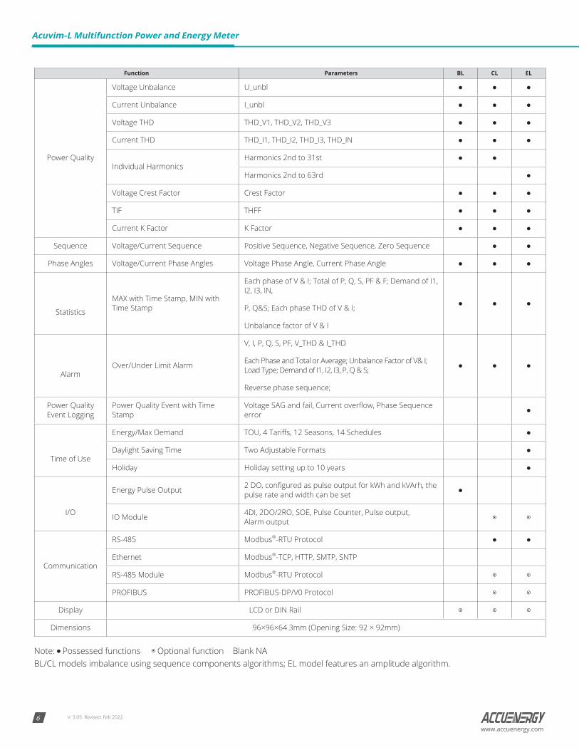
Note: Possessed functions Optional function Blank NA BL/CL models imbalance using sequence components algorithms; EL model features an amplitude algorithm.
V: 3.05 Revised: Feb 2022 7www.accuenergy.com
Chapter 2: Installation
Considerations When Installing Meters
• Installation of the meter must only be performed by qualified personnel who follow standard safety precautions throughout the installation procedure. Those personnel should have appropriate training and experience with high voltage devices. Appropriate safety gloves, safety glasses, and protective clothing are recommended.
• During normal operation, dangerous voltage may flow through many parts of the meter, including terminals, any connected CTs (Current Transformers) or PTs (Potential Transformers), and all I/O (Inputs and Outputs) modules and their circuits. All primary and secondary circuits can, at times, produce lethal voltages and currents. AVOID contact with any current-carrying surfaces.
• The meter and its I/O output channels are NOT designed as primary protection devices and shall NOT be used as primary circuit protection or in an energy-limiting capacity. The meter and its I/O output channels can only be used as secondary protection. AVOID using the meter under situations where failure of the meter may cause injury or death. AVOID using the meter for any application where risk of fire may occur.
• All meter terminals should be inaccessible after installation.
• Do NOT perform Dielectric (HIPOT) test to any inputs, outputs, or communication terminals. High voltage testing may damage the electronic components of the meter.
• Applying more than the maximum voltage the meter and/or its modules can withstand will permanently damage the meter and/or its modules. Please refer to the specifications for all devices before applying voltages.
• When removing meter for service, use shorting blocks and fuses for the voltage leads and the power supply to prevent hazardous voltage conditions or damage to CTs. CT grounding is optional.
• Accuenergy recommends using a dry cloth to wipe the meter.
NOTE: IF THE EQUIPMENT IS USED IN A MANNER NOT SPECIFIED BY THE MANUFACTURER, THE PROTECTION PROVIDED BY THE EQUIPMENT MAY BE IMPAIRED.
NOTE: THERE IS NO REQUIRED PREVENTIVE MAINTENANCE OR INSPECTION NECESSARY FOR SAFETY. HOWEVER, ANY REPAIR OR MAINTENANCE SHOULD BE PERFORMED BY THE FACTORY.
DISCONNECT DEVICE: The following part is considered the equipment disconnect device.
A Switch Or Circuit-Breaker Shall Be Included In The Installation. The Switch Shall Be In Close Proximity To The Equipment And Within Easy Reach Of The Operator. The Switch Shall Be Marked As The Disconnecting Device For The Equipment.
The installation method is introduced in this chapter. Please read this chapter carefully before beginning the installation process.
Chapter 2: Installation
V: 3.05 Revised: Feb 20228
Acuvim-L Multifunction Power and Energy Meter
www.accuenergy.com
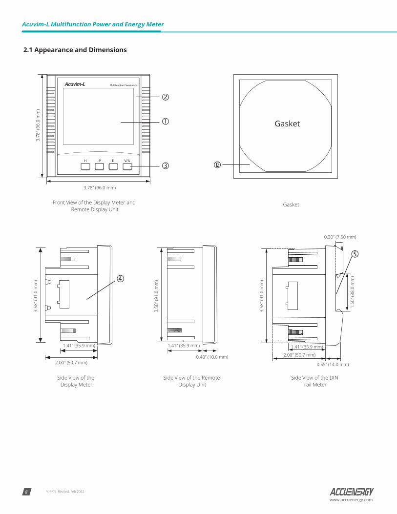
2.1 Appearance and Dimensions
Gasket
Side View of the
Front View of the Display Meter and Remote Display Unit
Display MeterSide View of the DIN Side View of the Remote
Display Unit rail Meter
Gasket
3.78” (96.0 mm)
2.00” (50.7 mm)0.40” (10.0 mm) 2.00” (50.7 mm)
0.55” (14.0 mm)
0.30” (7.60 mm)
1.41” (35.9 mm) 1.41” (35.9 mm) 1.41” (35.9 mm)
3.78
” (96
.0 m
m)
3.58
” (91
.0 m
m)
3.58
” (91
.0 m
m)
3.58
” (91
.0 m
m)
1.50
” (38
.0 m
m)
V: 3.05 Revised: Feb 2022 9www.accuenergy.com
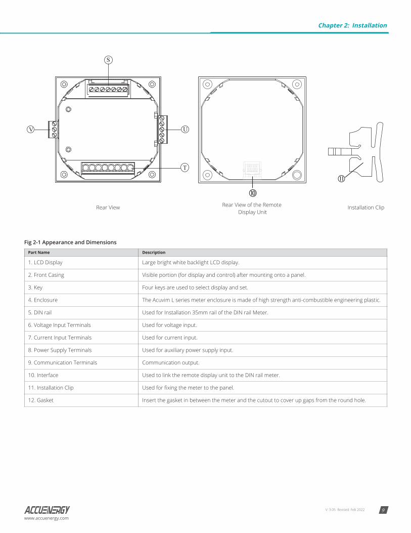
Rear View Installation ClipRear View of the Remote Display Unit
V
S
T
U
Fig 2-1 Appearance and Dimensions
Part Name Description
1. LCD Display Large bright white backlight LCD display.
2. Front Casing Visible portion (for display and control) after mounting onto a panel.
3. Key Four keys are used to select display and set.
4. Enclosure The Acuvim L series meter enclosure is made of high strength anti-combustible engineering plastic.
5. DIN rail Used for Installation 35mm rail of the DIN rail Meter.
6. Voltage Input Terminals Used for voltage input.
7. Current Input Terminals Used for current input.
8. Power Supply Terminals Used for auxiliary power supply input.
9. Communication Terminals Communication output.
10. Interface Used to link the remote display unit to the DIN rail meter.
11. Installation Clip Used for fixing the meter to the panel.
12. Gasket Insert the gasket in between the meter and the cutout to cover up gaps from the round hole.
Chapter 2: Installation
V: 3.05 Revised: Feb 202210
Acuvim-L Multifunction Power and Energy Meter
www.accuenergy.com
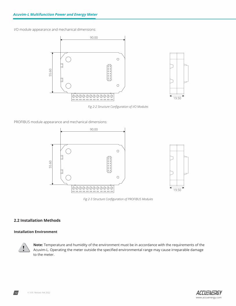
I/O module appearance and mechanical dimensions:
90.00
55.6
0
19.50
Fig 2-2 Structure Configuration of I/O Modules
PROFIBUS module appearance and mechanical dimensions:
90.00
55.6
0
19.50
Fig 2-3 Structure Configuration of PROFIBUS Modules
2.2 Installation Methods
Installation Environment
Note: Temperature and humidity of the environment must be in accordance with the requirements of the Acuvim-L. Operating the meter outside the specified environmental range may cause irreparable damage to the meter.
V: 3.05 Revised: Feb 2022 11www.accuenergy.com
Please check the environmental temperature and humidity according to Acuvim-L’s specifications to ensure the power meter will properly operate.
1. Temperature Range:
• Operation: -25°C to 70°C
• Storage: -40°C to 85°C
2. Humidity: 5% to 95% non-condensing
3. Location: Acuvim-L power meter should be installed in a dry and dust-free environment. Avoid exposing the meter to excessive heat, radiation, or sources of electrical noise.
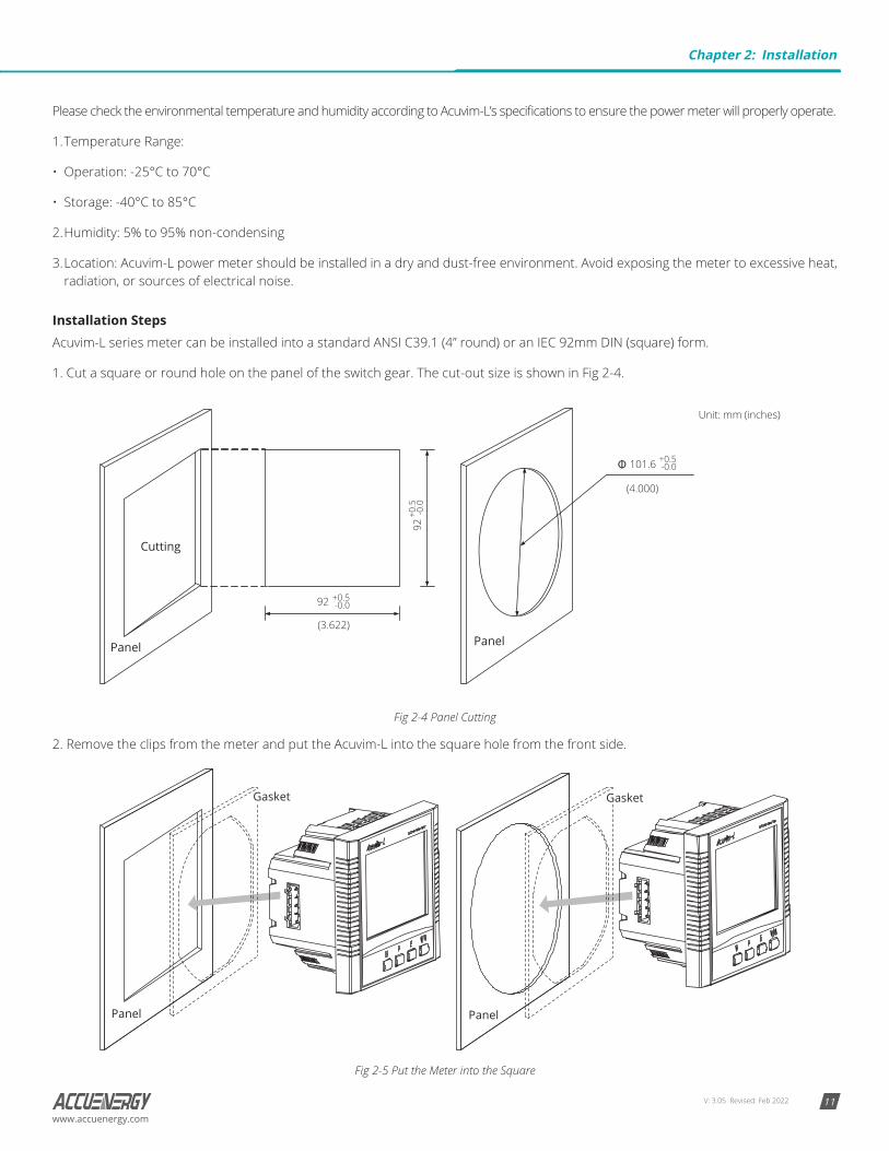
Installation StepsAcuvim-L series meter can be installed into a standard ANSI C39.1 (4” round) or an IEC 92mm DIN (square) form.
1. Cut a square or round hole on the panel of the switch gear. The cut-out size is shown in Fig 2-4.
Unit: mm (inches)
92
92
Cutting
Panel
101.6 +0.5-0.0
+0.5-0.0
+0.5
-0.0
Panel (3.622)
(4.000)
Fig 2-4 Panel Cutting
2. Remove the clips from the meter and put the Acuvim-L into the square hole from the front side.
Panel
Gasket
Panel
Gasket
Fig 2-5 Put the Meter into the Square
Chapter 2: Installation
V: 3.05 Revised: Feb 202212
Acuvim-L Multifunction Power and Energy Meter
www.accuenergy.com
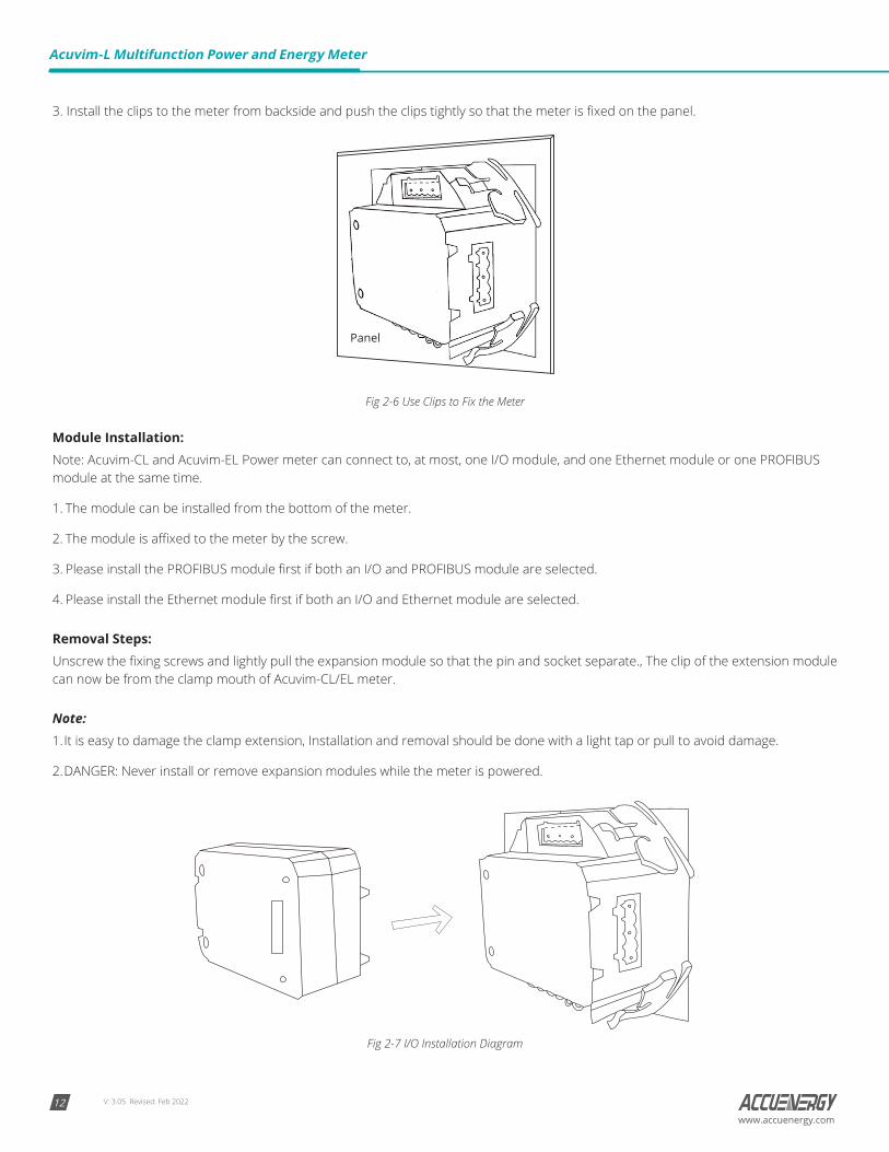
3. Install the clips to the meter from backside and push the clips tightly so that the meter is fixed on the panel.
Panel
Fig 2-6 Use Clips to Fix the Meter
Module Installation:Note: Acuvim-CL and Acuvim-EL Power meter can connect to, at most, one I/O module, and one Ethernet module or one PROFIBUS module at the same time.
1. The module can be installed from the bottom of the meter.
2. The module is affixed to the meter by the screw.
3. Please install the PROFIBUS module first if both an I/O and PROFIBUS module are selected.
4. Please install the Ethernet module first if both an I/O and Ethernet module are selected.
Removal Steps:Unscrew the fixing screws and lightly pull the expansion module so that the pin and socket separate., The clip of the extension module can now be from the clamp mouth of Acuvim-CL/EL meter.
Note:1. It is easy to damage the clamp extension, Installation and removal should be done with a light tap or pull to avoid damage.
2. DANGER: Never install or remove expansion modules while the meter is powered.
Fig 2-7 I/O Installation Diagram
V: 3.05 Revised: Feb 2022 13www.accuenergy.com
2.3 Wiring
2.3.1 Terminal Strips
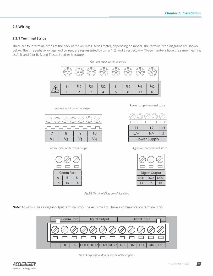
There are four terminal strips at the back of the Acuvim-L series meter, depending on model. The terminal strip diagrams are shown below. The three-phase voltage and current are represented by using 1, 2, and 3 respectively. These numbers have the same meaning as A, B, and C or R, S, and T used in other literature.
Voltage input terminal stripsPower supply terminal strips
Current input terminal strips
Communication terminal strips Digital output terminal strips
Fig 2-8 Terminal Diagram of Acuvim-L
Note: Acuvim-BL has a digital output terminal strip. The Acuvim-CL/EL have a communication terminal strip.
Fig 2-9 Expansion Module Terminal Description
Chapter 2: Installation
V: 3.05 Revised: Feb 202214
Acuvim-L Multifunction Power and Energy Meter
www.accuenergy.com
Danger! Only qualified personnel should perform wiring connections. Make sure the power supply is disconnected. Failure to follow these instructions may result in severe injury or death.
Safety Earth Connection
Before setting up the meter’s wiring, please make sure that the switch gear has an earth ground terminal. Connect both the meter and the switch gear ground terminals together. The following ground terminal symbol is used in this user’s manual.
Fig 2-10 Safety Earth Symbol
2.3.2 Power Requirement
Note: Make sure the power supply voltage is within the required auxiliary power supply range.
Auxiliary PowerThere are two Auxiliary Power Supply options for the Acuvim-L series meter:
1. Standard: 100~415Vac (50/60Hz) or 100~300Vdc
2. Low Voltage DC Option: 20~60Vdc
Choose the option according to the application.
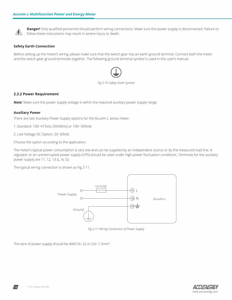
The meter’s typical power consumption is very low and can be supplied by an independent source or by the measured load line. A regulator or an uninterrupted power supply (UPS) should be used under high power fluctuation conditions. Terminals for the auxiliary power supply are 11, 12, 13 (L, N, G).
The typical wiring connection is shown as Fig 2-11.
L
N Acuvim-L
1A FUSE
Power Supply
Ground
11
12
13
Fig 2-11 Wiring Connection of Power Supply
The wire of power supply should be AWG16~22 or 0.6~1.5mm2.
V: 3.05 Revised: Feb 2022 15www.accuenergy.com
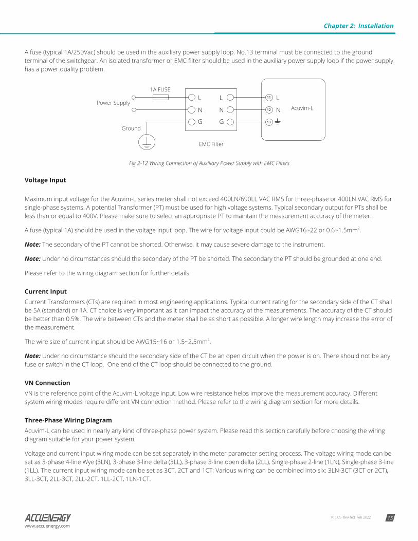
A fuse (typical 1A/250Vac) should be used in the auxiliary power supply loop. No.13 terminal must be connected to the ground terminal of the switchgear. An isolated transformer or EMC filter should be used in the auxiliary power supply loop if the power supply has a power quality problem.
1A FUSE
Power Supply
Ground
Acuvim-L
EMC Filter
L
N
G
L
N
G
L
N
Fig 2-12 Wiring Connection of Auxiliary Power Supply with EMC Filters
Voltage Input Maximum input voltage for the Acuvim-L series meter shall not exceed 400LN/690LL VAC RMS for three-phase or 400LN VAC RMS for single-phase systems. A potential Transformer (PT) must be used for high voltage systems. Typical secondary output for PTs shall be less than or equal to 400V. Please make sure to select an appropriate PT to maintain the measurement accuracy of the meter.
A fuse (typical 1A) should be used in the voltage input loop. The wire for voltage input could be AWG16~22 or 0.6~1.5mm2.
Note: The secondary of the PT cannot be shorted. Otherwise, it may cause severe damage to the instrument.
Note: Under no circumstances should the secondary of the PT be shorted. The secondary the PT should be grounded at one end.
Please refer to the wiring diagram section for further details.
Current InputCurrent Transformers (CTs) are required in most engineering applications. Typical current rating for the secondary side of the CT shall be 5A (standard) or 1A. CT choice is very important as it can impact the accuracy of the measurements. The accuracy of the CT should be better than 0.5%. The wire between CTs and the meter shall be as short as possible. A longer wire length may increase the error of the measurement.
The wire size of current input should be AWG15~16 or 1.5~2.5mm2.
Note: Under no circumstance should the secondary side of the CT be an open circuit when the power is on. There should not be any fuse or switch in the CT loop. One end of the CT loop should be connected to the ground.
VN ConnectionVN is the reference point of the Acuvim-L voltage input. Low wire resistance helps improve the measurement accuracy. Different system wiring modes require different VN connection method. Please refer to the wiring diagram section for more details.
Three-Phase Wiring DiagramAcuvim-L can be used in nearly any kind of three-phase power system. Please read this section carefully before choosing the wiring diagram suitable for your power system.
Voltage and current input wiring mode can be set separately in the meter parameter setting process. The voltage wiring mode can be set as 3-phase 4-line Wye (3LN), 3-phase 3-line delta (3LL), 3-phase 3-line open delta (2LL), Single-phase 2-line (1LN), Single-phase 3-line (1LL). The current input wiring mode can be set as 3CT, 2CT and 1CT; Various wiring can be combined into six: 3LN-3CT (3CT or 2CT), 3LL-3CT, 2LL-3CT, 2LL-2CT, 1LL-2CT, 1LN-1CT.
Chapter 2: Installation
V: 3.05 Revised: Feb 202216
Acuvim-L Multifunction Power and Energy Meter
www.accuenergy.com
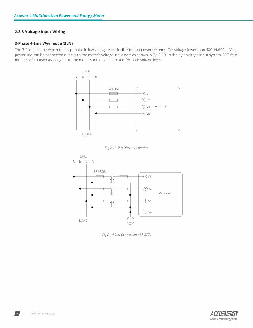
2.3.3 Voltage Input Wiring
3-Phase 4-Line Wye mode (3LN)The 3-Phase 4-Line Wye mode is popular in low voltage electric distribution power systems. For voltage lower than 400LN/690LL Vac, power line can be connected directly to the meter’s voltage input port as shown in Fig 2-13. In the high voltage input system, 3PT Wye mode is often used as in Fig 2-14. The meter should be set to 3LN for both voltage levels.
1A FUSEV1
V2
V3
VN
7
8
9
10
A B C N
LINE
LOAD
Acuvim-L
Fig 2-13 3LN Direct Connection
1A FUSEV1
V2
V3
7
8
9
A B C N
10 VN
LINE
LOAD
Acuvim-L
Fig 2-14 3LN Connection with 3PTs
V: 3.05 Revised: Feb 2022 17www.accuenergy.com
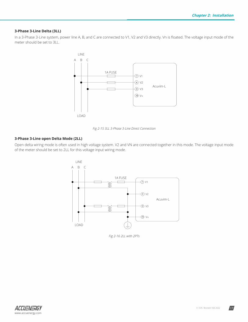
3-Phase 3-Line Delta (3LL)In a 3-Phase 3-Line system, power line A, B, and C are connected to V1, V2 and V3 directly. Vn is floated. The voltage input mode of the meter should be set to 3LL.
LINE
LOAD
V1
V2
V3
VN
7
8
9
10
A B C
1A FUSE
Acuvim-L
Fig 2-15 3LL 3-Phase 3-Line Direct Connection
3-Phase 3-Line open Delta Mode (2LL)Open delta wiring mode is often used in high voltage system. V2 and VN are connected together in this mode. The voltage input mode of the meter should be set to 2LL for this voltage input wiring mode.
1A FUSE
A B C
LINE
LOAD
V1
V2
V3
7
8
9
10 VN
Acuvim-L
Fig 2-16 2LL with 2PTs
Chapter 2: Installation
V: 3.05 Revised: Feb 202218
Acuvim-L Multifunction Power and Energy Meter
www.accuenergy.com
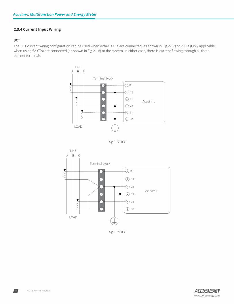
2.3.4 Current Input Wiring
3CTThe 3CT current wiring configuration can be used when either 3 CTs are connected (as shown in Fig 2-17) or 2 CTs (Only applicable when using 5A CTs) are connected (as shown in Fig 2-18) to the system. In either case, there is current flowing through all three current terminals.
I11
I32
I12
I21
I22
I31
A B C
3
5
4
2
6
Terminal block
1
LINE
LOAD
Acuvim-L
Fig 2-17 3CT
A B C
I11
I32
I12
I21
I22
I31
Terminal block
LINE
LOAD
3
5
4
2
6
1
Acuvim-L
Fig 2-18 3CT
V: 3.05 Revised: Feb 2022 19www.accuenergy.com
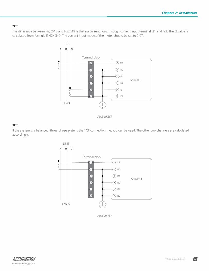
2CTThe difference between Fig. 2-18 and Fig 2-19 is that no current flows through current input terminal I21 and I22. The I2 value is calculated from formula i1+i2+i3=0. The current input mode of the meter should be set to 2 CT.
A B C
Terminal block
LINE
LOAD
I11
I32
I12
I21
I22
I31
3
5
4
2
6
1
Acuvim-L
Fig 2-19 2CT
1CTIf the system is a balanced, three-phase system, the 1CT connection method can be used. The other two channels are calculated accordingly.
A B C
Terminal block
LINE
LOAD
I11
I32
I12
I21
I22
I31
3
5
4
2
6
1
Acuvim-L
Fig 2-20 1CT
Chapter 2: Installation

V: 3.05 Revised: Feb 202220
Acuvim-L Multifunction Power and Energy Meter
www.accuenergy.com
2.3.5 Frequently Used Wiring Method
In this section, the most common voltage and current wiring connection combinations are put together into different diagrams. In order to display measurement readings correctly, please select the wiring diagram appropriate to your setup and application.
The meter supports seven kinds of wiring: 3LN-3CT (3CT and 2CT two ways), 3LL-3CT, 2LL-3CT, 2LL- 2CT, 1LL-2CT, and 1LN-1CT.
1. 3LN, 3CT with 3CTs (Wiring mode: 3LN, 3CT)
I42
I41
I32
I31
I22
I21
I12
I11
Acuvim-L
LINE
LOAD
LINE
LOAD
Terminal blockTerminal block
1A FUSE 1A FUSEA B C NA B C N
VN V3 V2 V11
2
3
4
5
6
17
18
12 11 10 9
I42
I41
I32
I31
I22
I21
I12
I11
Acuvim-L
VN V3 V2 V11
2
3
4
5
6
17
18
12 11 10 9
3LN, 3CT (IN Calculation)3LN, 3CT (IN Measurement)
Fig 2-21 3LN, 3CT with 3CTs
2. 3LN, 3CT with 2CTs (Wiring mode: 3LN,3CT)
1A FUSE
I42
I41
I32
I31
I22
I21
I12
I11
Acuvim-L
VN V3 V2 V11
2
3
4
5
6
17
18
12 11 10 9
I42
I41
I32
I31
I22
I21
I12
I11
Acuvim-L
VN V3 V2 V11
2
3
4
5
6
17
18
12 11 10 9
3LN, 3CT (2CT, IN Calculation)3LN, 3CT (2CT, IN Measurement)
LINELINE
LOADLOAD
Terminal blockTerminal block
1A FUSE A B C NA B C N
Fig 2-22 3LN, 3CT with 2CTs
V: 3.05 Revised: Feb 2022 21www.accuenergy.com
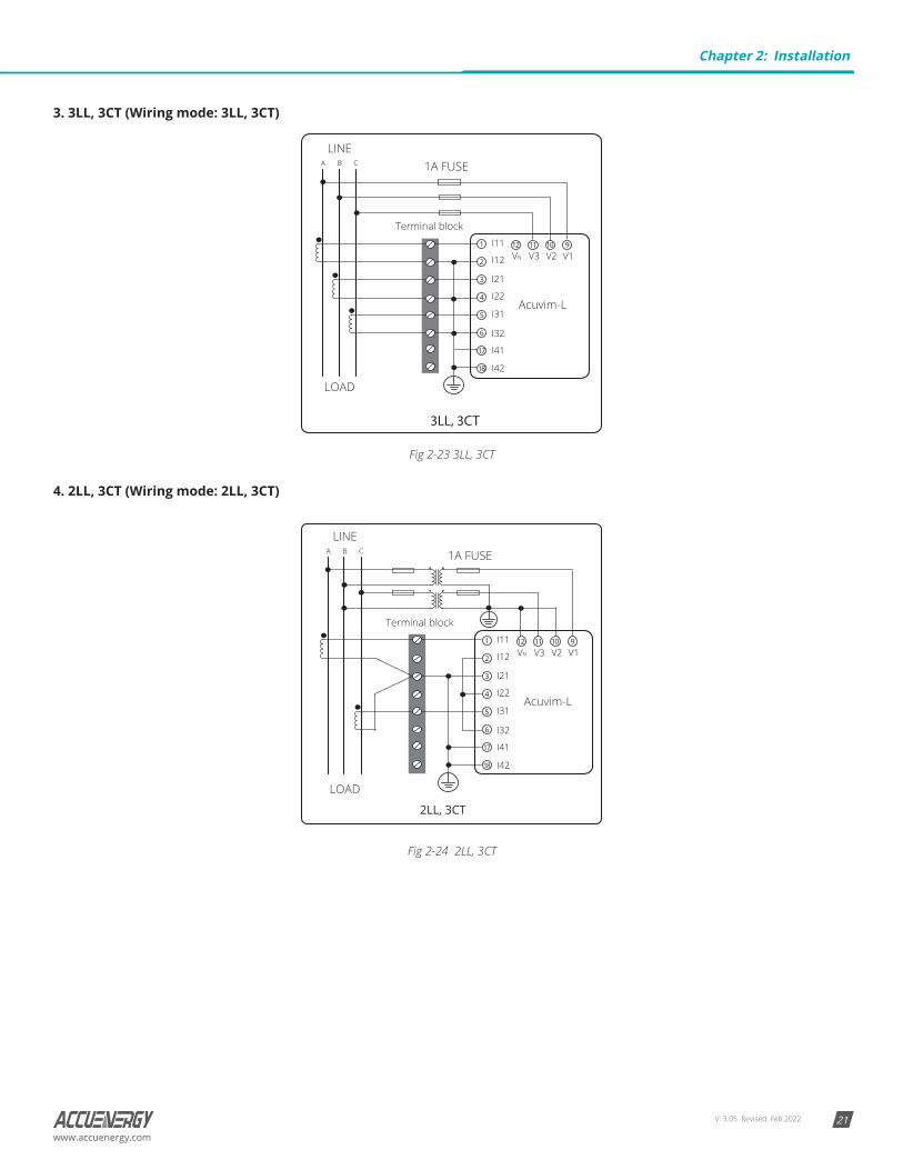
3. 3LL, 3CT (Wiring mode: 3LL, 3CT)
1A FUSEA B C
LINE
LOAD
Terminal block
I42
I41
I32
I31
I22
I21
I12
I11
Acuvim-L
VN V3 V2 V11
2
3
4
5
6
17
18
12 11 10 9
3LL, 3CT
Fig 2-23 3LL, 3CT
4. 2LL, 3CT (Wiring mode: 2LL, 3CT)
2LL, 3CT
A B C
LINE
LOAD
1A FUSE
Terminal block
I42
I41
I32
I31
I22
I21
I12
I11
Acuvim-L
VN V3 V2 V11
2
3
4
5
6
17
18
12 11 10 9
Fig 2-24 2LL, 3CT
Chapter 2: Installation
V: 3.05 Revised: Feb 202222
Acuvim-L Multifunction Power and Energy Meter
www.accuenergy.com
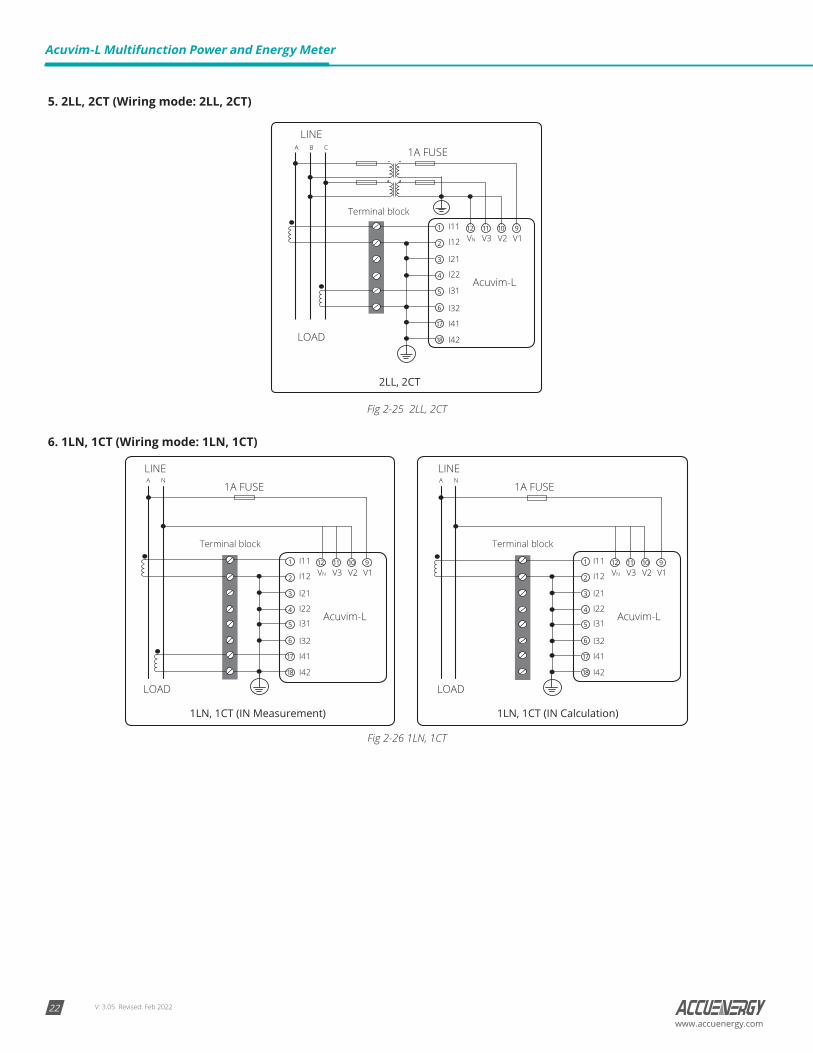
5. 2LL, 2CT (Wiring mode: 2LL, 2CT)
A B C
LINE
LOAD
1A FUSE
2LL, 2CT
I42
I41
I32
I31
I22
I21
I12
I11
Acuvim-L
VN V3 V2 V11
2
3
4
5
6
17
18
12 11 10 9
Terminal block
Fig 2-25 2LL, 2CT
6. 1LN, 1CT (Wiring mode: 1LN, 1CT)
1LN, 1CT (IN Calculation)1LN, 1CT (IN Measurement)
LINELINE
LOADLOAD
1A FUSE 1A FUSE
Terminal blockTerminal block
I42
I41
I32
I31
I22
I21
I12
I11
Acuvim-L
VN V3 V2 V11
2
3
4
5
6
17
18
12 11 10 9
I42
I41
I32
I31
I22
I21
I12
I11
Acuvim-L
VN V3 V2 V11
2
3
4
5
6
17
18
12 11 10 9
A N A N
Fig 2-26 1LN, 1CT
V: 3.05 Revised: Feb 2022 23www.accuenergy.com
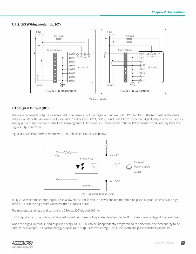
7. 1LL, 2CT (Wiring mode: 1LL, 2CT)
1A FUSE
1LL, 2CT (IN Calculation)1LL, 2CT (IN Measurement)
A N BA N BLINE
LOAD
LINE
LOAD
1A FUSE
Terminal blockTerminal block
I42
I41
I32
I31
I22
I21
I12
I11
Acuvim-L
VN V3 V2 V11
2
3
4
5
6
17
18
12 11 10 9
I42
I41
I32
I31
I22
I21
I12
I11
Acuvim-L
VN V3 V2 V11
2
3
4
5
6
17
18
12 11 10 9
Fig 2-27 1LL, 2CT
2.3.6 Digital Output (DO)
There are two digital outputs for Acuvim-BL. The terminals of the digital output are DO1, DO2 and DOC. The terminals of the digital output circuits of the Acuvim- EL/CL extension modules are DO11, DO12, DO21, and DO22. These two digital outputs can be used as energy pulse output or over/under limit alarming output. Acuvim-CL/ EL meters with optional I/O expansion modules only have the Digital Output function.
Digital output circuit form is Photo-MOS. The simplified circuit is as below:
DO1VCC
External
Power SupplyOUT
Photo-MOS
Acuvim-LDOC
AC/DCJ
Fig 2-28 Digital Output Circuit
In Fig 2-28, when the internal signal J is in a low state, OUT is also in a low state and therefore no pulse output. When J is in a high state, OUT is in the high state which will then output a pulse.
The max output voltage and current are 250Vac/300Vdc and 100mA.
For DC applications, the DO output terminal should be connected in parallel clamping diodes D to prevent over-voltage during switching.
When the digital output is used as pulse energy, DO1, DO2 can be independently programmed to select the electrical energy to be output; for example, DO1 active energy output, DO2 output reactive energy. The pulse width and pulse constant can be set.
Chapter 2: Installation
V: 3.05 Revised: Feb 202224
Acuvim-L Multifunction Power and Energy Meter
www.accuenergy.com
When the digital output is used as over/under limit alarming output, the upper and lower limit of the parameter, time interval, and output port can be set from the meter front for the Acuvim BL, and the Acuvim CL/EL can be programmed using the Acuview software or through the meter display.
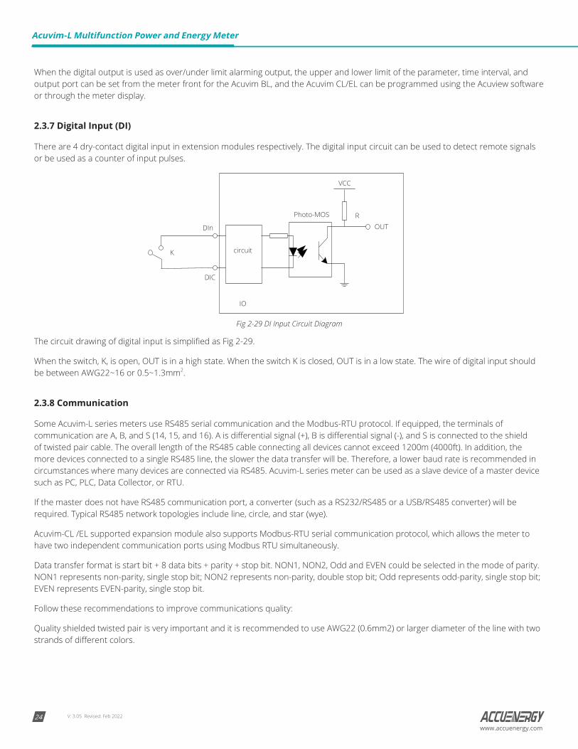
2.3.7 Digital Input (DI)
There are 4 dry-contact digital input in extension modules respectively. The digital input circuit can be used to detect remote signals or be used as a counter of input pulses.
DIn
Photo-MOS
circuit
IO
OUTR
VCC
DIC
K
Fig 2-29 DI Input Circuit Diagram
The circuit drawing of digital input is simplified as Fig 2-29.
When the switch, K, is open, OUT is in a high state. When the switch K is closed, OUT is in a low state. The wire of digital input should be between AWG22~16 or 0.5~1.3mm2.
2.3.8 Communication
Some Acuvim-L series meters use RS485 serial communication and the Modbus-RTU protocol. If equipped, the terminals of communication are A, B, and S (14, 15, and 16). A is differential signal (+), B is differential signal (-), and S is connected to the shield of twisted pair cable. The overall length of the RS485 cable connecting all devices cannot exceed 1200m (4000ft). In addition, the more devices connected to a single RS485 line, the slower the data transfer will be. Therefore, a lower baud rate is recommended in circumstances where many devices are connected via RS485. Acuvim-L series meter can be used as a slave device of a master device such as PC, PLC, Data Collector, or RTU.
If the master does not have RS485 communication port, a converter (such as a RS232/RS485 or a USB/RS485 converter) will be required. Typical RS485 network topologies include line, circle, and star (wye).
Acuvim-CL /EL supported expansion module also supports Modbus-RTU serial communication protocol, which allows the meter to have two independent communication ports using Modbus RTU simultaneously.
Data transfer format is start bit + 8 data bits + parity + stop bit. NON1, NON2, Odd and EVEN could be selected in the mode of parity. NON1 represents non-parity, single stop bit; NON2 represents non-parity, double stop bit; Odd represents odd-parity, single stop bit; EVEN represents EVEN-parity, single stop bit.
Follow these recommendations to improve communications quality:
Quality shielded twisted pair is very important and it is recommended to use AWG22 (0.6mm2) or larger diameter of the line with two strands of different colors.

V: 3.05 Revised: Feb 2022 25www.accuenergy.com
The shield of the RS485 cable must be connected to the ground at one end only. Every A (+) should be connected to A (+), B (-) to B (-), or it will influence the network or even damage the communication interface.
“T” type connection topology should be avoided. This means no new branches except from the starting point.
As much as possible, keep communication cables away from sources of electrical noise. When several devices are connected (daisy chain) along the same, long communication line, an anti-signal reflecting resistor (typical value 120Ω- 300Ω) is often used at the end of the circuit (the last meter of the chain) in cases where the communication quality is distorted.
Use RS232/RS485 or USB/RS485 converter with optically isolated output and surge protection.
Chapter 2: Installation
V: 3.05 Revised: Feb 202226
Acuvim-L Multifunction Power and Energy Meter
www.accuenergy.com
Chapter 3: Basic Operations and Applications
The detailed human-machine interface of the meter will be described in this chapter. This includes viewing real-time metering data and setting parameters using different key combination.
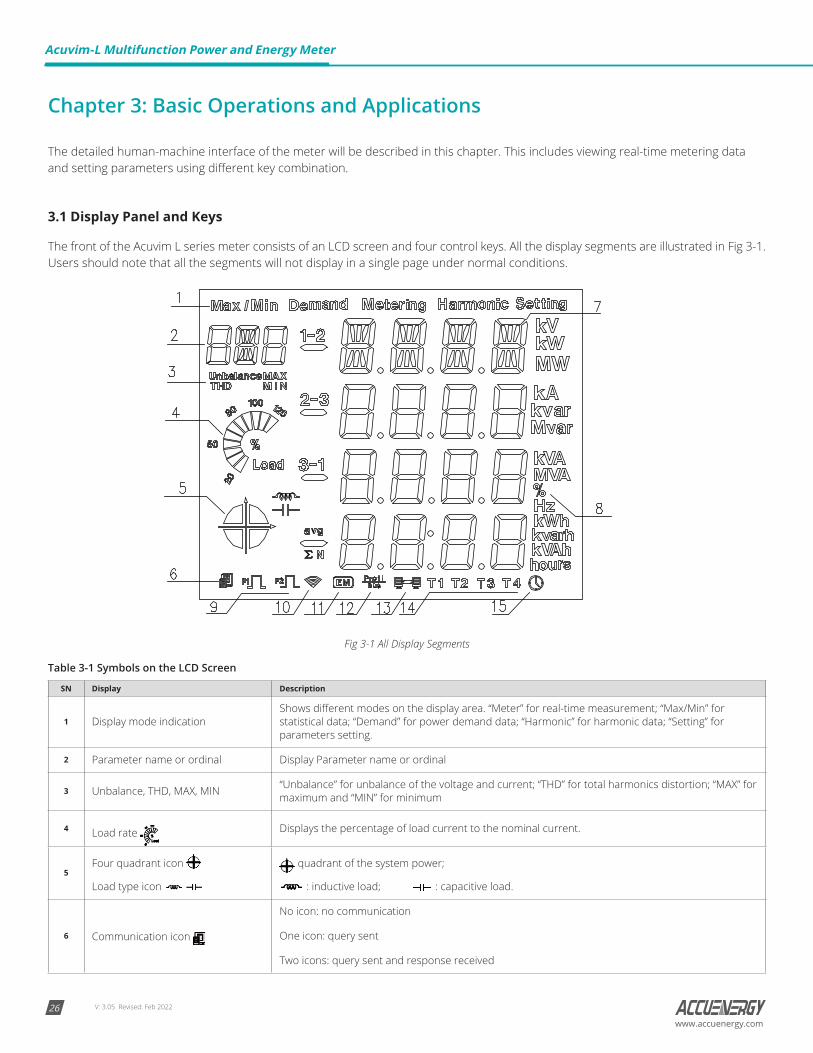
3.1 Display Panel and Keys
The front of the Acuvim L series meter consists of an LCD screen and four control keys. All the display segments are illustrated in Fig 3-1. Users should note that all the segments will not display in a single page under normal conditions.
Fig 3-1 All Display Segments
Table 3-1 Symbols on the LCD Screen
SN Display Description
1 Display mode indicationShows different modes on the display area. “Meter” for real-time measurement; “Max/Min” for statistical data; “Demand” for power demand data; “Harmonic” for harmonic data; “Setting” for parameters setting.
2 Parameter name or ordinal Display Parameter name or ordinal
3 Unbalance, THD, MAX, MIN “Unbalance” for unbalance of the voltage and current; “THD” for total harmonics distortion; “MAX” for maximum and “MIN” for minimum
4 Load rate Displays the percentage of load current to the nominal current.
5Four quadrant icon
Load type icon
quadrant of the system power;
: inductive load; : capacitive load.
6 Communication icon
No icon: no communication
One icon: query sent
Two icons: query sent and response received
V: 3.05 Revised: Feb 2022 27www.accuenergy.com
SN Display Description
7 Data Display area The contents of the display data in the region
8 Unit display area Display Data Unit
9 Pulse output status icon Display pulse output status
10 WIFI module icon This option not available on Acuvim-L.
11 Expansion Module icon Display expansion module status
12 PROFIBUS connection icon Icon: PROFIBUS modules
13 Ethernet connection icon Icon: Ethernet modules
14 Current rates icon T1, T2, T3, T4, respectively, sharp, peak, valley, and normal four season rates
15 Time icon Icon: Displays the current data region time value
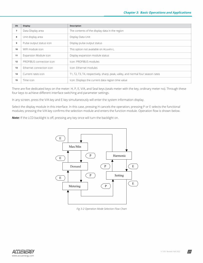
There are five dedicated keys on the meter: H, P, E, V/A, and Seal keys (seals meter with the key, ordinary meter no). Through these four keys to achieve different interface switching and parameter settings.
In any screen, press the V/A key and E key simultaneously will enter the system information display.
Select the display module in this interface. In this case, pressing H cancels the operation; pressing P or E selects the functional modules; pressing the V/A key confirms the selection module and enters the function module. Operation flow is shown below.
Note: If the LCD backlight is off, pressing any key once will turn the backlight on.
Demand
Fig 3-2 Operation Mode Selection Flow Chart
Chapter 3: Basic Operations and Applications
V: 3.05 Revised: Feb 202228
Acuvim-L Multifunction Power and Energy Meter
www.accuenergy.com
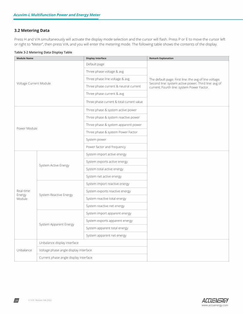
3.2 Metering Data
Press H and V/A simultaneously will activate the display mode selection and the cursor will flash. Press P or E to move the cursor left or right to “Meter”, then press V/A, and you will enter the metering mode. The following table shows the contents of the display.
Table 3-2 Metering Data Display Table
Module Name Display Interface Remark Explanation
Voltage Current Module
Default page
The default page: First line: the avg of line voltage; Second line: system active power; Third line: avg of current; Fourth line: system Power Factor.
Three phase voltage & avg
Three phase line voltage & avg
Three phase current & neutral current
Three phase current & avg
Three phase current & total current value
Power Module
Three phase & system active power
Three phase & system reactive power
Three phase & system apparent power
Three phase & system Power Factor
System power
Power factor and frequency
Real-time Energy Module
System Active Energy
System import active energy
System exports active energy
System total active energy
System net active energy
System Reactive Energy
System import reactive energy
System exports reactive energy
System reactive total energy
System reactive net energy
System Apparent Energy
System import apparent energy
System exports apparent energy
System apparent total energy
System apparent net energy
Unbalance
Unbalance display interface
Voltage phase angle display interface
Current phase angle display interface
V: 3.05 Revised: Feb 2022 29www.accuenergy.com
Module Name Display Interface Remark Explanation
Current month TOU energy (Accumulated)
Total
Active Energy
Import active energy
In this module, press the V/A key to switch to TOU demand interface.
Export active energy
Active total energy
Active net energy
Reactive Energy
Inductive reactive energy
Capacitive reactive energy
Reactive total energy
Reactive net energy
Apparent Energy
Import apparent energy
Export apparent energy
Apparent total energy
Apparent net energy
Shape Ditto Ditto
Peak Ditto Ditto
Normal Ditto Ditto
Valley Ditto Ditto
Prior month sharing time energy (Accumulated) Page structure of power sharing with the previous month
Current month TOU energy (Incremental) Page structure of power sharing with the previous month
Prior month TOU energy (Incremental) Page structure of power sharing with the previous month
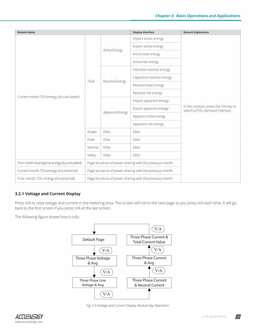
3.2.1 Voltage and Current Display
Press V/A to read voltage and current in the metering area. The screen will roll to the next page as you press V/A each time. It will go back to the first screen if you press V/A at the last screen.
The following figure shows how it rolls:
Fig 3-3 Voltage and Current Display Module Key Operation
Chapter 3: Basic Operations and Applications
V: 3.05 Revised: Feb 202230
Acuvim-L Multifunction Power and Energy Meter
www.accuenergy.com
Note: When the meter is set to “2LL” or “3LL”, there is no three-phase voltage & AVG and three-phase current & neutral current display; when the meter is set “1LN”, there is only A phase voltage and A phase current display; when the meter is set “1LL”, there is no C phase voltage and C phase current display.
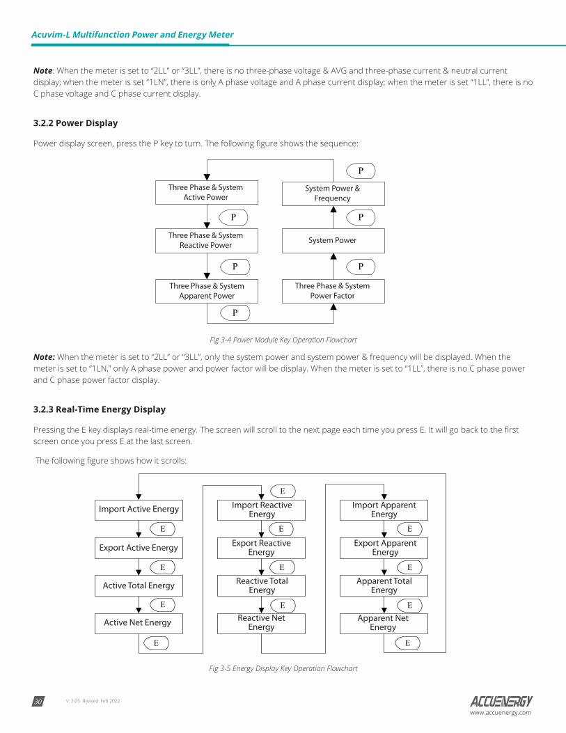
3.2.2 Power Display
Power display screen, press the P key to turn. The following figure shows the sequence:
Fig 3-4 Power Module Key Operation Flowchart
Note: When the meter is set to “2LL” or “3LL”, only the system power and system power & frequency will be displayed. When the meter is set to “1LN,” only A phase power and power factor will be display. When the meter is set to “1LL”, there is no C phase power and C phase power factor display.
3.2.3 Real-Time Energy Display
Pressing the E key displays real-time energy. The screen will scroll to the next page each time you press E. It will go back to the first screen once you press E at the last screen.
The following figure shows how it scrolls:
Fig 3-5 Energy Display Key Operation Flowchart

V: 3.05 Revised: Feb 2022 31www.accuenergy.com
3.2.4 Phase Angle and Unbalance Display
Pressing H displays phase angles and unbalance data. The screen will scroll to the next page each time you press H. It will go back to the first screen once you press H at the last screen.
The following figure shows how it scrolls:
Fig 3-6 Unbalance Key Operation
Voltage stands for line-to-line voltage when the wiring setting is “2LL” or “3LL” and for line-to-neutral voltage when other wiring settings. When the meter is set to “1LN”, there is only phase A current to phase A voltage angle display. When the meter is set to “1LL”, there is no phase C voltage or current to phase A voltage angle factor display. Rogowski coils do not support the phase angle or the unbalance functions.
3.2.5 TOU Energy Display
To display TOU energy parameters in the metering module, pressing the P key and V/A key simultaneously will enter the TOU energy display module. Key operations for this module are shown in Fig 3-7. TOU rates are divided into the total, sharp, peak, valley, and normal. H key: turn between total, sharp, peak, valley, and normal; P key: turn over the Current Month TOU (Accumulated energy), Current Month TOU (Incremental energy), Prior Month TOU (Accumulated energy) and Prior Month TOU (Incremental energy). V/A key: switch to the appropriate TOU demand maximum display interface. E key: flip over each module.
Fig 3-7 The Operation of TOU Energy
Chapter 3: Basic Operations and Applications
V: 3.05 Revised: Feb 202232
Acuvim-L Multifunction Power and Energy Meter
www.accuenergy.com
3.3 Statistics Display
See the contents of the Min/Max Statistics module in the table below.
Table 3-3 Max/Min Statistics Display Table
Module Name Display Interface
Max/Min of the Voltage and Current
Max value of Phase Voltage
Min value of Phase Voltage
Max value of Line Voltage
Min value of Line Voltage
Max value of Current
Min value of Current
Max/Min of the Power
Max value of System Power
Min value of System Power
Max value of Power Factor, Frequency
Min value of Power Factor, Frequency
Max value of Power Demand
Max value of Current Demand
Max/Min of the THD
Max value of Voltage Harmonic
Min value of Voltage Harmonic
Max value of Current Harmonic
Min value of Current Harmonic
Max value of Unbalance
Min value of Unbalance
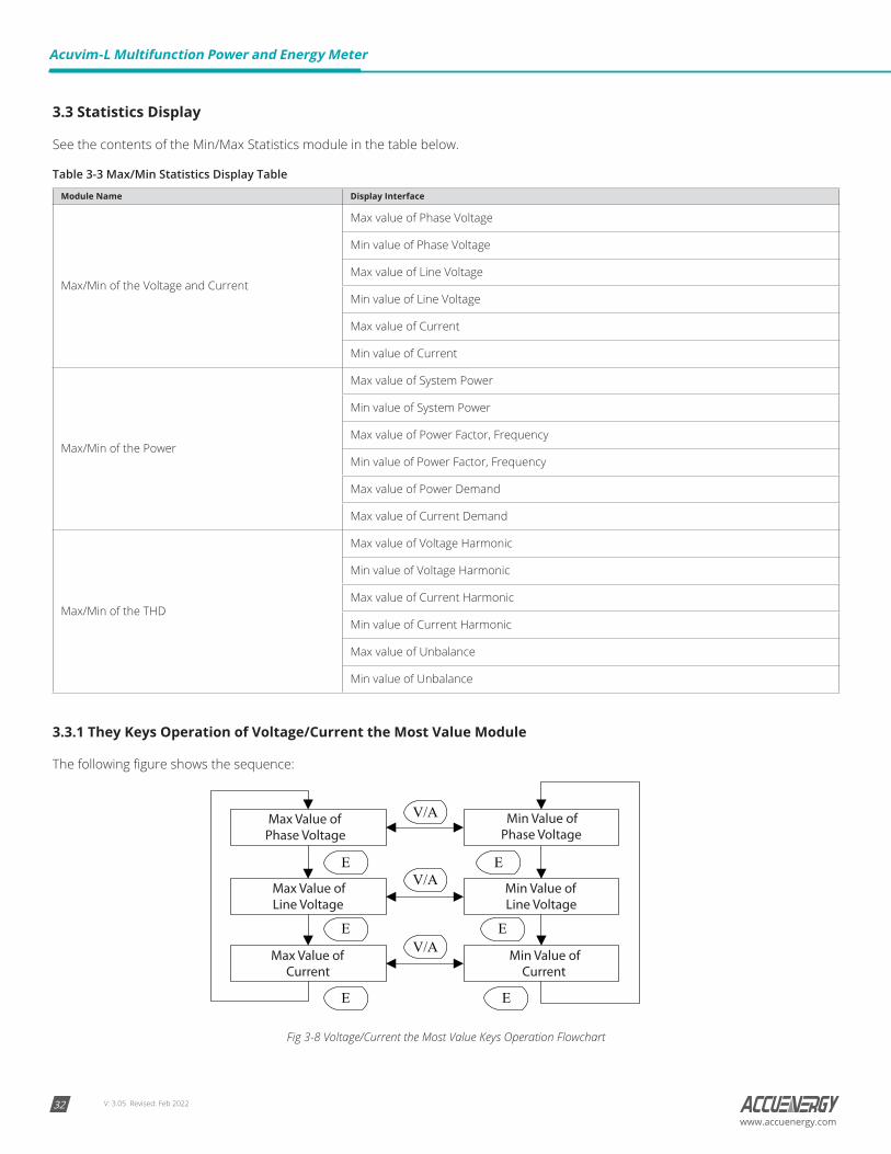
3.3.1 They Keys Operation of Voltage/Current the Most Value Module
The following figure shows the sequence:
Fig 3-8 Voltage/Current the Most Value Keys Operation Flowchart
V: 3.05 Revised: Feb 2022 33www.accuenergy.com
Note: For 2LL/3LL voltage wiring, there is no max/min value of phase voltage to display. When the voltage wiring is set to 1LL, phase voltage: No C-phase voltage; line voltage, no Ubc and Uca display; current: no C phase current; when the voltage wiring set 1LN, phase voltage: only A phase display, line voltage: no display, current: only A phase display.
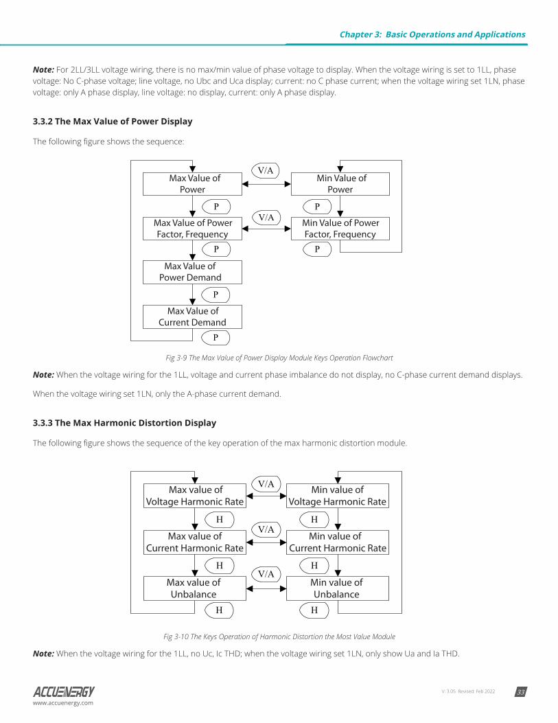
3.3.2 The Max Value of Power Display
The following figure shows the sequence:
Fig 3-9 The Max Value of Power Display Module Keys Operation Flowchart
Note: When the voltage wiring for the 1LL, voltage and current phase imbalance do not display, no C-phase current demand displays.
When the voltage wiring set 1LN, only the A-phase current demand.
3.3.3 The Max Harmonic Distortion Display
The following figure shows the sequence of the key operation of the max harmonic distortion module.
Fig 3-10 The Keys Operation of Harmonic Distortion the Most Value Module
Note: When the voltage wiring for the 1LL, no Uc, Ic THD; when the voltage wiring set 1LN, only show Ua and Ia THD.
Chapter 3: Basic Operations and Applications
V: 3.05 Revised: Feb 202234
Acuvim-L Multifunction Power and Energy Meter
www.accuenergy.com
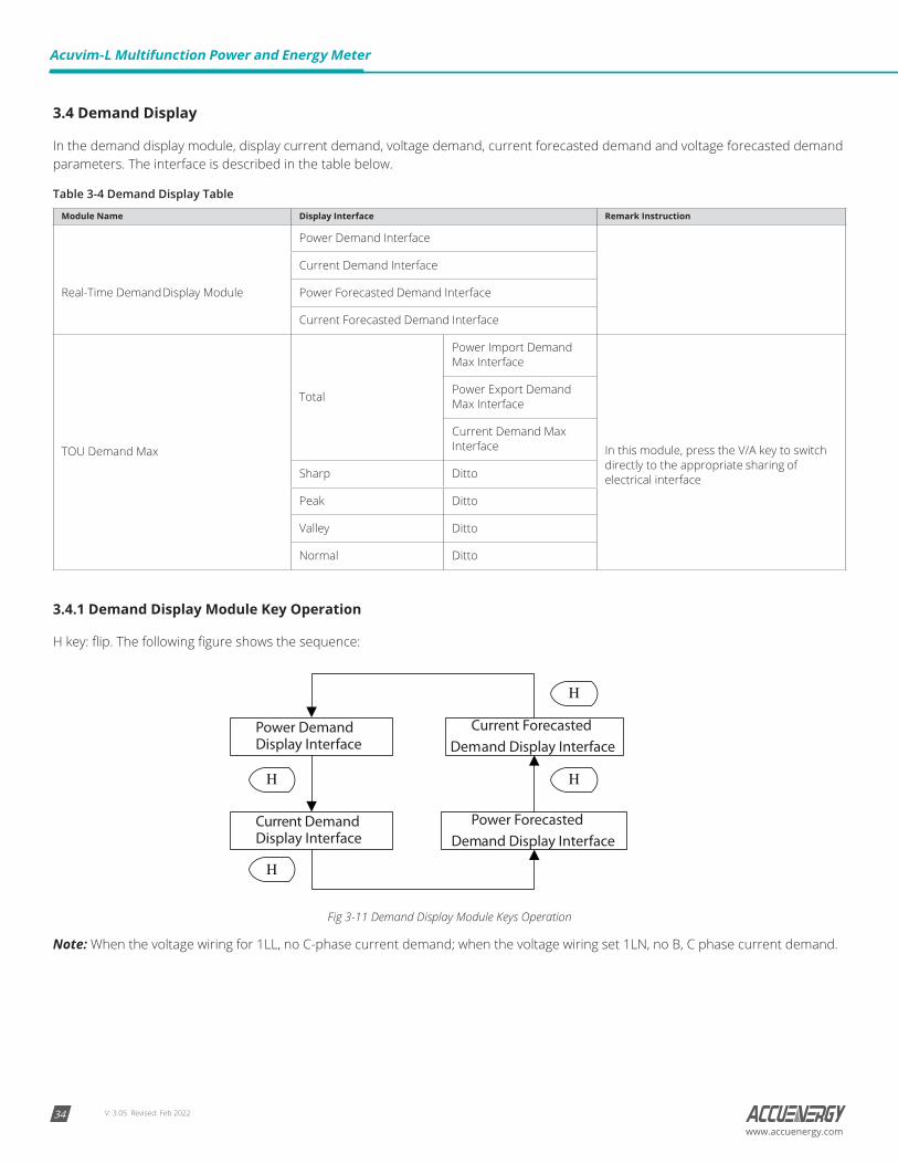
3.4 Demand Display
In the demand display module, display current demand, voltage demand, current forecasted demand and voltage forecasted demand parameters. The interface is described in the table below.
Table 3-4 Demand Display Table
Module Name Display Interface Remark Instruction
Real-Time Demand Display Module
Power Demand Interface
Current Demand Interface
Power Forecasted Demand Interface
Current Forecasted Demand Interface
TOU Demand Max
Total
Power Import Demand Max Interface
In this module, press the V/A key to switch directly to the appropriate sharing of electrical interface
Power Export Demand Max Interface
Current Demand Max Interface
Sharp Ditto
Peak Ditto
Valley Ditto
Normal Ditto
3.4.1 Demand Display Module Key Operation
H key: flip. The following figure shows the sequence:
Fig 3-11 Demand Display Module Keys Operation
Note: When the voltage wiring for 1LL, no C-phase current demand; when the voltage wiring set 1LN, no B, C phase current demand.
V: 3.05 Revised: Feb 2022 35www.accuenergy.com
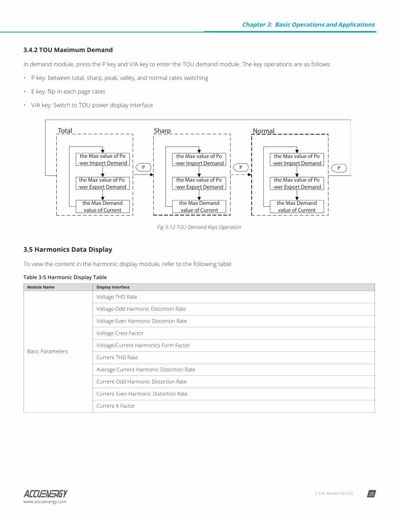
3.4.2 TOU Maximum Demand
In demand module, press the P key and V/A key to enter the TOU demand module. The key operations are as follows:
• P key: between total, sharp, peak, valley, and normal rates switching
• E key: flip In each page rates
• V/A key: Switch to TOU power display interface
Fig 3-12 TOU Demand Keys Operation
3.5 Harmonics Data Display
To view the content in the harmonic display module, refer to the following table:
Table 3-5 Harmonic Display Table
Module Name Display Interface
Basic Parameters
Voltage THD Rate
Voltage Odd Harmonic Distortion Rate
Voltage Even Harmonic Distortion Rate
Voltage Crest Factor
Voltage/Current Harmonics Form Factor
Current THD Rate
Average Current Harmonic Distortion Rate
Current Odd Harmonic Distortion Rate
Current Even Harmonic Distortion Rate
Current K Factor
Chapter 3: Basic Operations and Applications
V: 3.05 Revised: Feb 202236
Acuvim-L Multifunction Power and Energy Meter
www.accuenergy.com
Module Name Display Interface
Harmonic Ratio Data
Voltage Each Harmonic
Voltage 2nd Harmonic Ratio
......
Voltage 63rd Harmonic Ratio
Current Each Harmonic
Current 2nd Harmonic Ratio
......
Current 63rd Harmonic Ratio
Note:
1. BL and CL support 2nd~31st harmonics, EL supports 2nd~63rd harmonics.
2. Rogowski coils do not support harmonic function.
3. If the IN is calculated, the parameters related to the IN harmonic parameters are blocked.
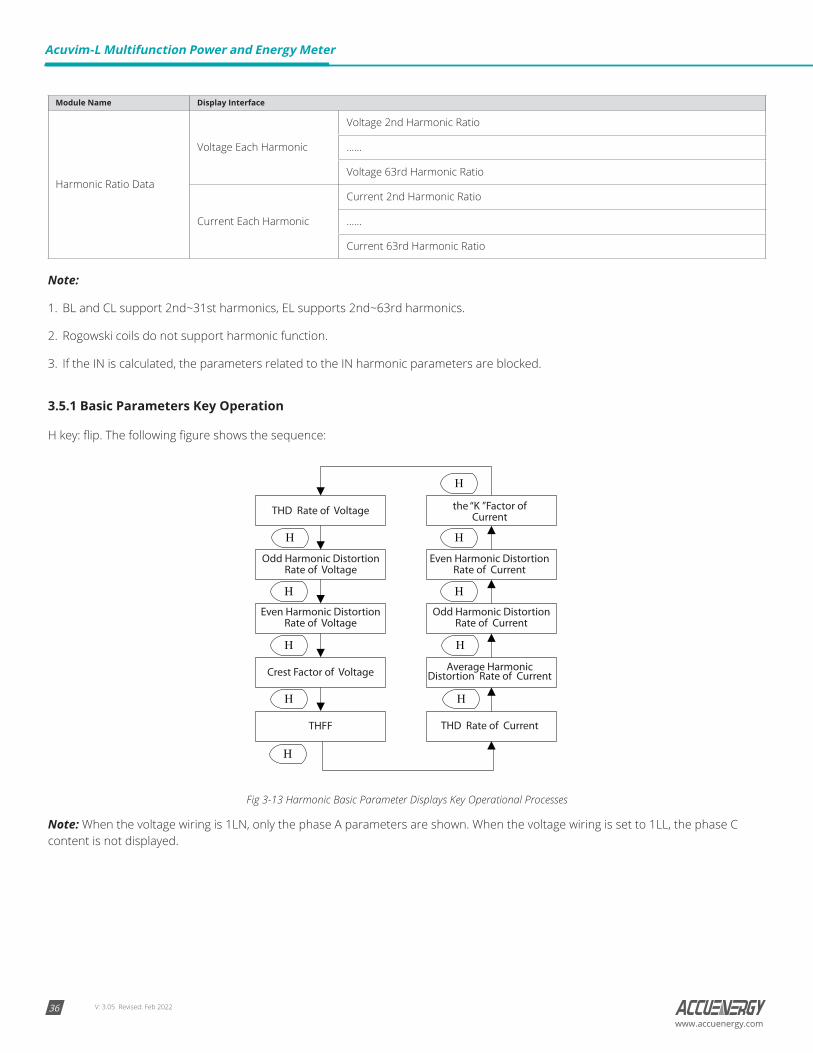
3.5.1 Basic Parameters Key Operation
H key: flip. The following figure shows the sequence:
Fig 3-13 Harmonic Basic Parameter Displays Key Operational Processes
Note: When the voltage wiring is 1LN, only the phase A parameters are shown. When the voltage wiring is set to 1LL, the phase C content is not displayed.
V: 3.05 Revised: Feb 2022 37www.accuenergy.com
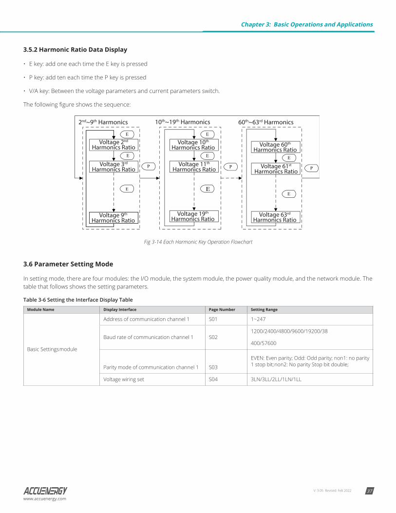
3.5.2 Harmonic Ratio Data Display
• E key: add one each time the E key is pressed
• P key: add ten each time the P key is pressed
• V/A key: Between the voltage parameters and current parameters switch.
The following figure shows the sequence:
10th~19th Harmonics2nd~9th Harmonics 60th~63rd Harmonics
Voltage 2nd Harmonics Ratio
Voltage 3rd Harmonics Ratio
Voltage 9th Harmonics Ratio
Voltage 10th Harmonics Ratio
Voltage 11th Harmonics Ratio
Voltage 19th Harmonics Ratio
Voltage 60th Harmonics Ratio
Voltage 61st Harmonics Ratio
Voltage 63rd Harmonics Ratio
Fig 3-14 Each Harmonic Key Operation Flowchart
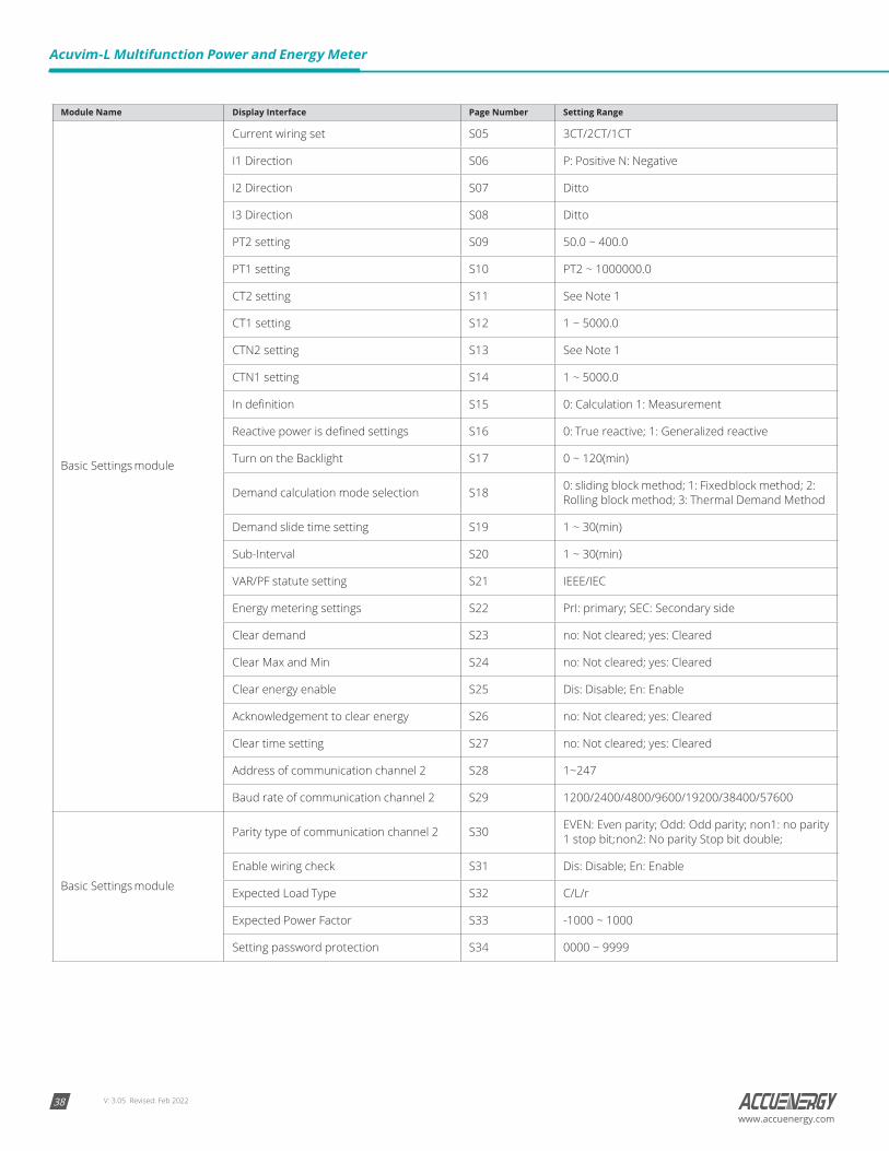
3.6 Parameter Setting Mode
In setting mode, there are four modules: the I/O module, the system module, the power quality module, and the network module. The table that follows shows the setting parameters.
Table 3-6 Setting the Interface Display Table
Module Name Display Interface Page Number Setting Range
Basic Settings module
Address of communication channel 1 S01 1~247
Baud rate of communication channel 1 S021200/2400/4800/9600/19200/38
400/57600
Parity mode of communication channel 1 S03
EVEN: Even parity; Odd: Odd parity; non1: no parity 1 stop bit; non2: No parity Stop bit double;
Voltage wiring set S04 3LN/3LL/2LL/1LN/1LL
Chapter 3: Basic Operations and Applications
V: 3.05 Revised: Feb 202238
Acuvim-L Multifunction Power and Energy Meter
www.accuenergy.com
Module Name Display Interface Page Number Setting Range
Basic Settings module
Current wiring set S05 3CT/2CT/1CT
I1 Direction S06 P: Positive N: Negative
I2 Direction S07 Ditto
I3 Direction S08 Ditto
PT2 setting S09 50.0 ~ 400.0
PT1 setting S10 PT2 ~ 1000000.0
CT2 setting S11 See Note 1
CT1 setting S12 1 ~ 5000.0
CTN2 setting S13 See Note 1
CTN1 setting S14 1 ~ 5000.0
In definition S15 0: Calculation 1: Measurement
Reactive power is defined settings S16 0: True reactive; 1: Generalized reactive
Turn on the Backlight S17 0 ~ 120(min)
Demand calculation mode selection S18 0: sliding block method; 1: Fixed block method; 2: Rolling block method; 3: Thermal Demand Method
Demand slide time setting S19 1 ~ 30(min)
Sub-Interval S20 1 ~ 30(min)
VAR/PF statute setting S21 IEEE/IEC
Energy metering settings S22 PrI: primary; SEC: Secondary side
Clear demand S23 no: Not cleared; yes: Cleared
Clear Max and Min S24 no: Not cleared; yes: Cleared
Clear energy enable S25 Dis: Disable; En: Enable
Acknowledgement to clear energy S26 no: Not cleared; yes: Cleared
Clear time setting S27 no: Not cleared; yes: Cleared
Address of communication channel 2 S28 1~247
Baud rate of communication channel 2 S29 1200/2400/4800/9600/19200/38400/57600
Basic Settings module
Parity type of communication channel 2 S30 EVEN: Even parity; Odd: Odd parity; non1: no parity 1 stop bit; non2: No parity Stop bit double;
Enable wiring check S31 Dis: Disable; En: Enable
Expected Load Type S32 C/L/r
Expected Power Factor S33 -1000 ~ 1000
Setting password protection S34 0000 ~ 9999
V: 3.05 Revised: Feb 2022 39www.accuenergy.com
Module Name Display Interface Page Number Setting Range
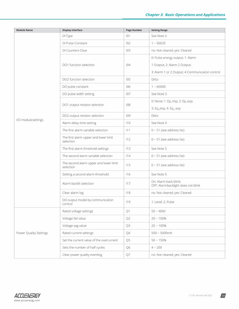
I/O module settings
DI Type I01 See Note 2
DI Pulse Constant I02 1 ~ 56635
DI Counters Clear I03 no: Not cleared; yes: Cleared
DO1 function selection I04
0: Pulse energy output; 1: Alarm
1 Output; 2: Alarm 2 Output;
3: Alarm 1 or 2 Output; 4: Communication control
DO2 function selection I05 Ditto
DO pulse constant I06 1 ~ 60000
DO pulse width setting I07 See Note 3
DO1 output resistor selection I080: None; 1: Ep_imp; 2: Ep_exp;
3: Eq_imp; 4: Eq_ exp
DO2 output resistor selection I09 Ditto
Alarm delay time setting I10 See Note 4
The first alarm variable selection I11 0 ~ 51 (see address list)
The first alarm upper and lower limit selection I12 0 ~ 51 (see address list)
The first alarm threshold settings I13 See Note 5
The second alarm variable selection I14 0 ~ 51 (see address list)
The second alarm upper and lower limit selection I15 0 ~ 51 (see address list)
Setting a second alarm threshold I16 See Note 5
Alarm backlit selection I17 On: Alarm back blink; OFF: Alarm backlight does not blink
Clear alarm log I18 no: Not cleared; yes: Cleared
DO output model by communication control I19 1: Level; 2: Pulse
Power Quality Settings
Rated voltage settings Q1 50 ~ 400V
Voltage fail value Q2 20 ~ 100%
Voltage sag value Q3 20 ~ 100%
Rated current settings Q4 500 ~ 5000mA
Set the current value of the overcurrent Q5 50 ~ 150%
Sets the number of half-cycles Q6 4 ~ 200
Clear power quality eventlog Q7 no: Not cleared; yes: Cleared
Chapter 3: Basic Operations and Applications
V: 3.05 Revised: Feb 202240
Acuvim-L Multifunction Power and Energy Meter
www.accuenergy.com
Module Name Display Interface Page Number Setting Range
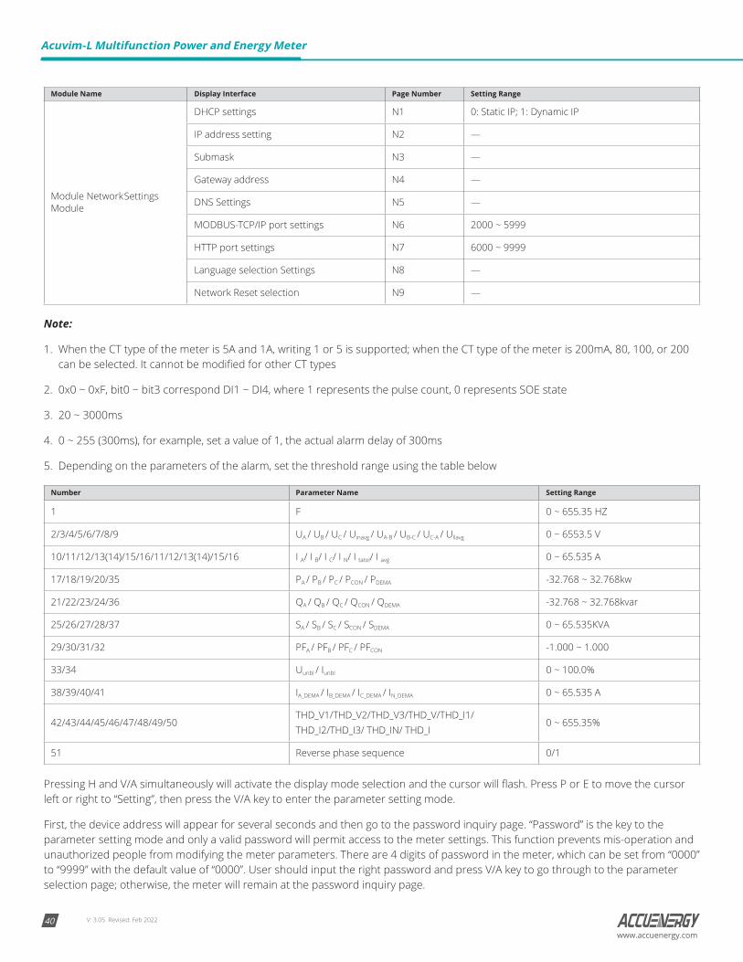
Module Network Settings Module
DHCP settings N1 0: Static IP; 1: Dynamic IP
IP address setting N2 —
Submask N3 —
Gateway address N4 —
DNS Settings N5 —
MODBUS-TCP/IP port settings N6 2000 ~ 5999
HTTP port settings N7 6000 ~ 9999
Language selection Settings N8 —
Network Reset selection N9 —
Note:
1. When the CT type of the meter is 5A and 1A, writing 1 or 5 is supported; when the CT type of the meter is 200mA, 80, 100, or 200 can be selected. It cannot be modified for other CT types
2. 0x0 ~ 0xF, bit0 ~ bit3 correspond DI1 ~ DI4, where 1 represents the pulse count, 0 represents SOE state
3. 20 ~ 3000ms
4. 0 ~ 255 (300ms), for example, set a value of 1, the actual alarm delay of 300ms
5. Depending on the parameters of the alarm, set the threshold range using the table below
Number Parameter Name Setting Range
1 F 0 ~ 655.35 HZ
2/3/4/5/6/7/8/9 UA / UB / UC / Uinavg / UA-B / UB-C / UC-A / Ullavg 0 ~ 6553.5 V
10/11/12/13(14)/15/16/11/12/13(14)/15/16 I A/ I B/ I C/ I N/ I tatol/ I avg 0 ~ 65.535 A
17/18/19/20/35 PA / PB / PC / PCON / PDEMA -32.768 ~ 32.768kw
21/22/23/24/36 QA / QB / QC / QCON / QDEMA -32.768 ~ 32.768kvar
25/26/27/28/37 SA / SB / SC / SCON / SDEMA 0 ~ 65.535KVA
29/30/31/32 PFA / PFB / PFC / PFCON -1.000 ~ 1.000
33/34 Uunbl / Iunbl 0 ~ 100.0%
38/39/40/41 IA_DEMA / IB_DEMA / IC_DEMA / IN_DEMA 0 ~ 65.535 A
42/43/44/45/46/47/48/49/50THD_V1/THD_V2/THD_V3/THD_V/THD_I1/THD_I2/THD_I3/ THD_IN/ THD_I
0 ~ 655.35%
51 Reverse phase sequence 0/1
Pressing H and V/A simultaneously will activate the display mode selection and the cursor will flash. Press P or E to move the cursor left or right to “Setting”, then press the V/A key to enter the parameter setting mode.
First, the device address will appear for several seconds and then go to the password inquiry page. “Password” is the key to the parameter setting mode and only a valid password will permit access to the meter settings. This function prevents mis-operation and unauthorized people from modifying the meter parameters. There are 4 digits of password in the meter, which can be set from “0000” to “9999” with the default value of “0000”. User should input the right password and press V/A key to go through to the parameter selection page; otherwise, the meter will remain at the password inquiry page.
V: 3.05 Revised: Feb 2022 41www.accuenergy.com
Key functions when inputting password:
• Press H, move the flashing cursor to the next position.
• Press P, the flashing number will add one.
• Press E, the flashing number will minus one.
• Press V/A, confirm the password.
In the parameter setting mode, parameters, such as system basic parameters, expanded I/O module parameters, power quality parameters and network module parameters can be read and modified.
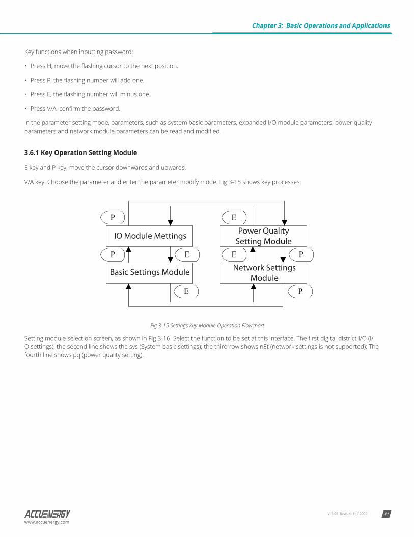
3.6.1 Key Operation Setting Module
E key and P key, move the cursor downwards and upwards.
V/A key: Choose the parameter and enter the parameter modify mode. Fig 3-15 shows key processes:
Fig 3-15 Settings Key Module Operation Flowchart
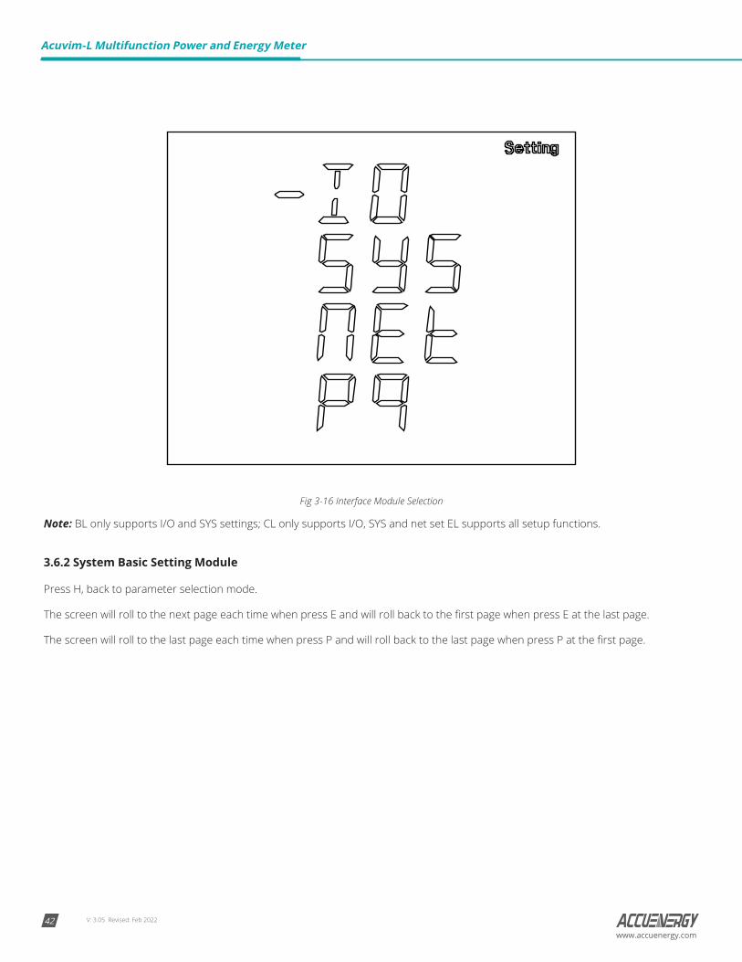
Setting module selection screen, as shown in Fig 3-16. Select the function to be set at this interface. The first digital district I/O (I/O settings); the second line shows the sys (System basic settings); the third row shows nEt (network settings is not supported); The fourth line shows pq (power quality setting).
Chapter 3: Basic Operations and Applications
V: 3.05 Revised: Feb 202242
Acuvim-L Multifunction Power and Energy Meter
www.accuenergy.com
Fig 3-16 Interface Module Selection
Note: BL only supports I/O and SYS settings; CL only supports I/O, SYS and net set EL supports all setup functions.
3.6.2 System Basic Setting Module
Press H, back to parameter selection mode.
The screen will roll to the next page each time when press E and will roll back to the first page when press E at the last page.
The screen will roll to the last page each time when press P and will roll back to the last page when press P at the first page.
V: 3.05 Revised: Feb 2022 43www.accuenergy.com
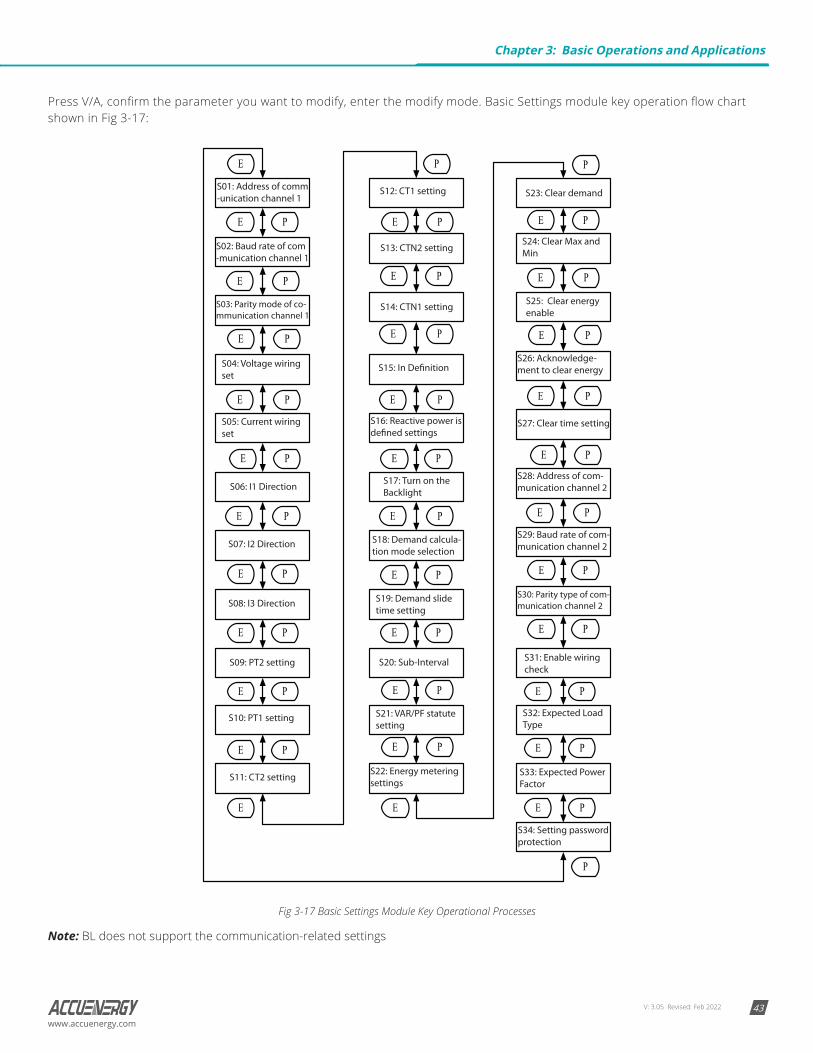
Press V/A, confirm the parameter you want to modify, enter the modify mode. Basic Settings module key operation flow chart shown in Fig 3-17:
Fig 3-17 Basic Settings Module Key Operational Processes
Note: BL does not support the communication-related settings
Chapter 3: Basic Operations and Applications
V: 3.05 Revised: Feb 202244
Acuvim-L Multifunction Power and Energy Meter
www.accuenergy.com
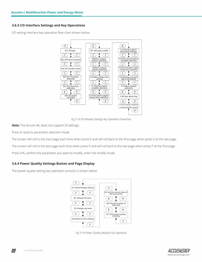
3.6.3 I/O Interface Settings and Key Operations
I/O setting interface key operation flow chart shown below.
Fig 3-18 I/O Module Settings Key Operation Flowchart
Note: The Acuvim-BL does not support DI settings.
Press H, back to parameter selection mode.
The screen will roll to the next page each time when press E and will roll back to the first page when press E at the last page.
The screen will roll to the last page each time when press P and will roll back to the last page when press P at the first page.
Press V/A, confirm the parameter you want to modify, enter the modify mode.
3.6.4 Power Quality Settings Button and Page Display
The power quality setting key operation process is shown below:
Fig 3-19 Power Quality Module Flip Operation
V: 3.05 Revised: Feb 2022 45www.accuenergy.com
Press H to go back to the parameter selection mode.
The screen will roll to the next page each time when press E and will scroll back to the first page when E is pressed at the last page.
The screen will scroll to the last page each time when P is pressed and will scroll back to the last page when P is pressed at the first page.
Press V/A to confirm the parameter you want to modify and to enter the modify mode.
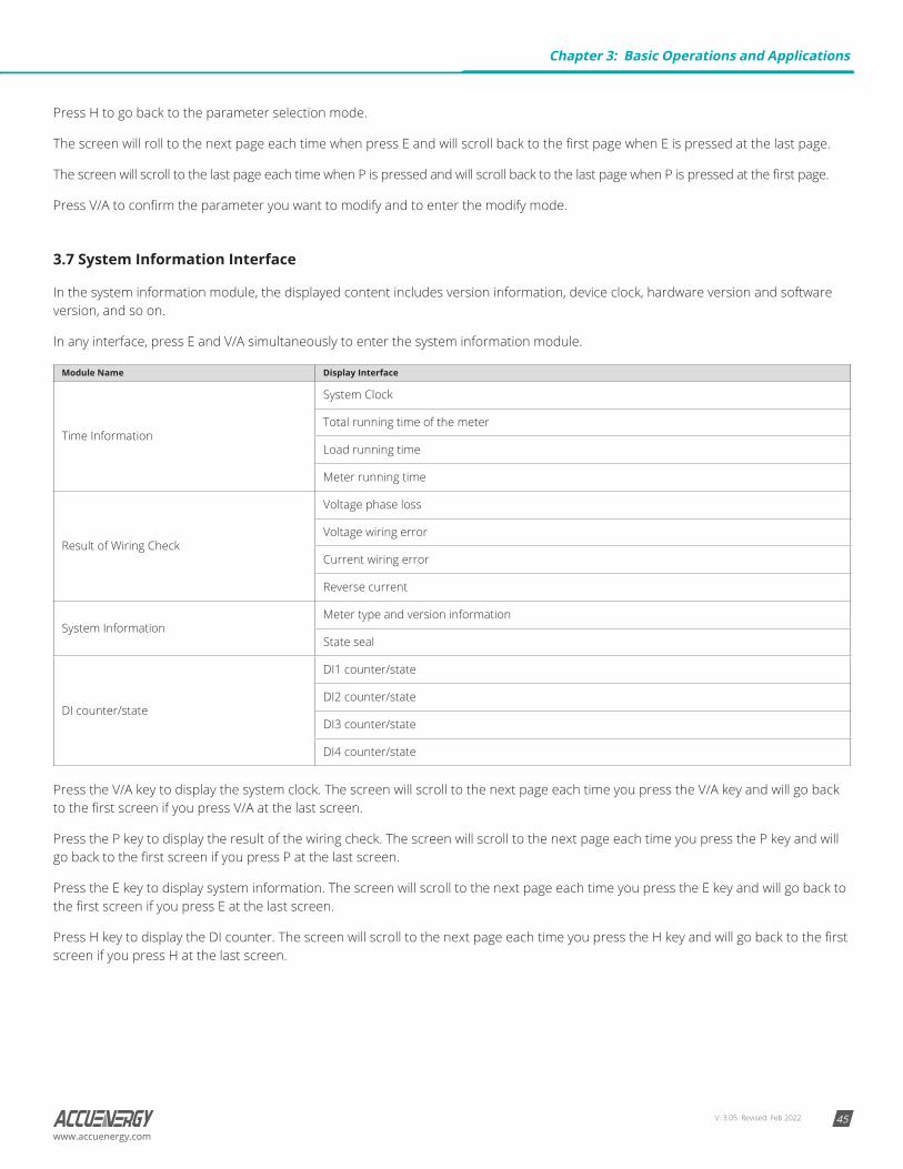
3.7 System Information Interface
In the system information module, the displayed content includes version information, device clock, hardware version and software version, and so on.
In any interface, press E and V/A simultaneously to enter the system information module.
Module Name Display Interface
Time Information
System Clock
Total running time of the meter
Load running time
Meter running time
Result of Wiring Check
Voltage phase loss
Voltage wiring error
Current wiring error
Reverse current
System InformationMeter type and version information
State seal
DI counter/state
DI1 counter/state
DI2 counter/state
DI3 counter/state
DI4 counter/state
Press the V/A key to display the system clock. The screen will scroll to the next page each time you press the V/A key and will go back to the first screen if you press V/A at the last screen.
Press the P key to display the result of the wiring check. The screen will scroll to the next page each time you press the P key and will go back to the first screen if you press P at the last screen.
Press the E key to display system information. The screen will scroll to the next page each time you press the E key and will go back to the first screen if you press E at the last screen.
Press H key to display the DI counter. The screen will scroll to the next page each time you press the H key and will go back to the first screen if you press H at the last screen.
Chapter 3: Basic Operations and Applications
V: 3.05 Revised: Feb 202246
Acuvim-L Multifunction Power and Energy Meter
www.accuenergy.com
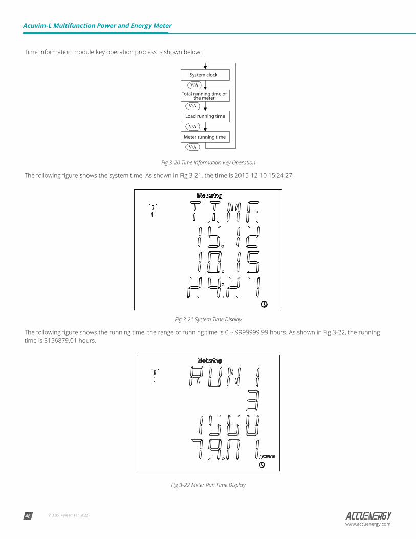
Time information module key operation process is shown below:
Fig 3-20 Time Information Key Operation
The following figure shows the system time. As shown in Fig 3-21, the time is 2015-12-10 15:24:27.
Fig 3-21 System Time Display
The following figure shows the running time, the range of running time is 0 ~ 9999999.99 hours. As shown in Fig 3-22, the running time is 3156879.01 hours.
Fig 3-22 Meter Run Time Display

V: 3.05 Revised: Feb 2022 47www.accuenergy.com
The following figure shows the load time where the range of load time is 0 ~ 9999999.99 hours. As shown in Fig 3-23, the displayed time is 1267834.87 hours.
Fig 3-23 Load Running Time Display
3.7.1 Result of Wiring Check
The following figure shows how it scrolls.
Fig 3-24 Wiring Judgment Result Shows the Key Processes
The following figure shows the result of wiring check about the phase voltage loss. As shown in Fig 3-25, B phase and C phase loss voltage.
Fig 3-25 B Phase and C Phase Loss
Chapter 3: Basic Operations and Applications
V: 3.05 Revised: Feb 202248
Acuvim-L Multifunction Power and Energy Meter
www.accuenergy.com
3.7.2 System Information
The version information module key operational processes is shown below.
Fig 3-26 System Information Key Operation
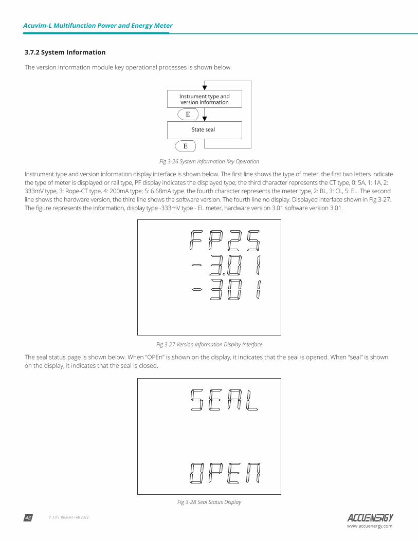
Instrument type and version information display interface is shown below. The first line shows the type of meter, the first two letters indicate the type of meter is displayed or rail type, PF display indicates the displayed type; the third character represents the CT type, 0: 5A, 1: 1A, 2: 333mV type, 3: Rope-CT type, 4: 200mA type; 5: 6.68mA type. the fourth character represents the meter type, 2: BL, 3: CL, 5: EL. The second line shows the hardware version, the third line shows the software version. The fourth line no display. Displayed interface shown in Fig 3-27. The figure represents the information, display type -333mV type - EL meter, hardware version 3.01 software version 3.01.
Fig 3-27 Version Information Display Interface
The seal status page is shown below. When “OPEn” is shown on the display, it indicates that the seal is opened. When “seal” is shown on the display, it indicates that the seal is closed.
Fig 3-28 Seal Status Display
V: 3.05 Revised: Feb 2022 49www.accuenergy.com
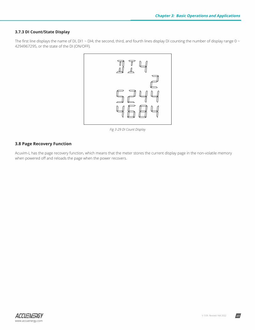
3.7.3 DI Count/State Display
The first line displays the name of DI, DI1 ~ DI4; the second, third, and fourth lines display DI counting the number of display range 0 ~ 4294967295, or the state of the DI (ON/OFF).
Fig 3-29 DI Count Display
3.8 Page Recovery Function
Acuvim-L has the page recovery function, which means that the meter stores the current display page in the non-volatile memory when powered off and reloads the page when the power recovers.
Chapter 3: Basic Operations and Applications
V: 3.05 Revised: Feb 202250
Acuvim-L Multifunction Power and Energy Meter
www.accuenergy.com
Chapter 4: Function and Software Tools
The Acuvim-L is a very powerful instrument that can measure almost all the parameters in the power system. Some of its advanced functionality cannot be controlled by simply pressing the keys, so we made this software to go with it. For clarity, we’ll introduce functions with the help of the software interface in this chapter. The version of the software you get may be more advanced or somewhat differ from what is shown in this manual. For best results, please refer to the specific manual that accompanied your instrument.
4.1 Basic Analog Measurements
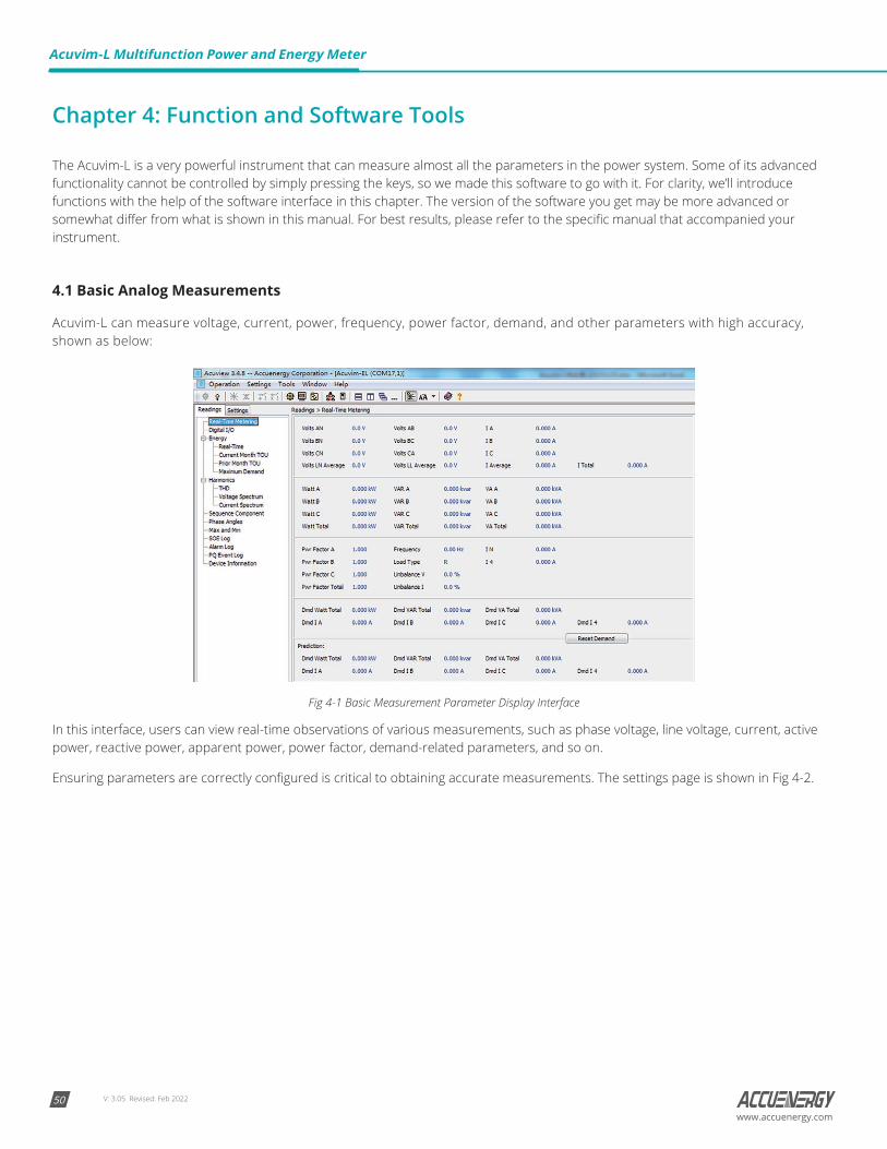
Acuvim-L can measure voltage, current, power, frequency, power factor, demand, and other parameters with high accuracy, shown as below:
Fig 4-1 Basic Measurement Parameter Display Interface
In this interface, users can view real-time observations of various measurements, such as phase voltage, line voltage, current, active power, reactive power, apparent power, power factor, demand-related parameters, and so on.
Ensuring parameters are correctly configured is critical to obtaining accurate measurements. The settings page is shown in Fig 4-2.
V: 3.05 Revised: Feb 2022 51www.accuenergy.com
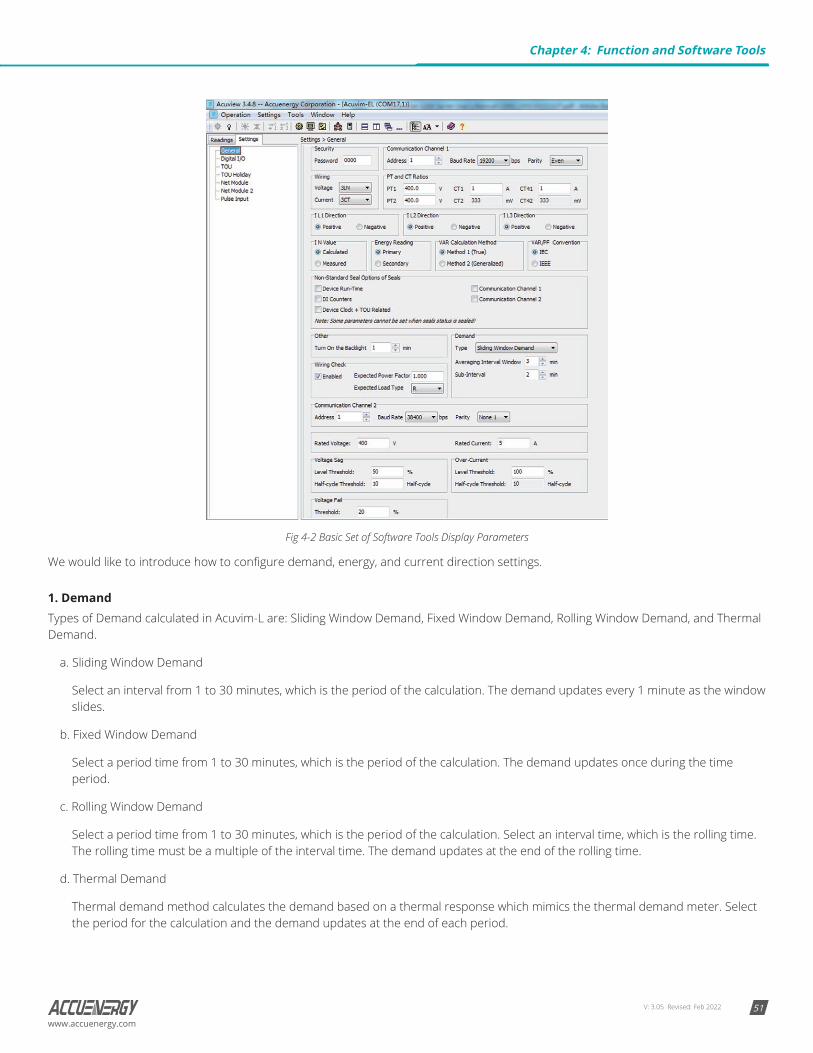
Fig 4-2 Basic Set of Software Tools Display Parameters
We would like to introduce how to configure demand, energy, and current direction settings.
1. DemandTypes of Demand calculated in Acuvim-L are: Sliding Window Demand, Fixed Window Demand, Rolling Window Demand, and Thermal Demand.
a. Sliding Window Demand
Select an interval from 1 to 30 minutes, which is the period of the calculation. The demand updates every 1 minute as the window slides.
b. Fixed Window Demand
Select a period time from 1 to 30 minutes, which is the period of the calculation. The demand updates once during the time period.
c. Rolling Window Demand
Select a period time from 1 to 30 minutes, which is the period of the calculation. Select an interval time, which is the rolling time. The rolling time must be a multiple of the interval time. The demand updates at the end of the rolling time.
d. Thermal Demand
Thermal demand method calculates the demand based on a thermal response which mimics the thermal demand meter. Select the period for the calculation and the demand updates at the end of each period.
Chapter 4: Function and Software Tools

V: 3.05 Revised: Feb 202252
Acuvim-L Multifunction Power and Energy Meter
www.accuenergy.com
2. EnergyVarious kinds of energy will accumulate in the Acuvim-L. Real time energy: the accumulation of energy for the kWh, kVArh and kVAh since the last time it was cleared.
a. There are two ways to calculate reactive energy (power):
Mode 0: real reactive energy:
Mode 1: General reactive energy:
b. User can choose primary energy or secondary energy by pressing a key or via communication.
Note:
1. The energy will be reset when user switches the mode of energy calculation (primary energy or second energy) and then start to accumulate the energy again.
2. Degree in electrical Acuvim-L series meter display is divided into primary energy or secondary energy, however, the degree of electrical pulses via I/O module output of only the secondary energy power pulse.
3. Current Direction Adjustment
The normal current direction is from port 1 to port 2, but sometimes a wiring error may occur. To adjust the direction of current, the three current directions can be set as “Negative,” which means reversing 180 degrees, and “Positive,” which means normal. It is easy to get the right data without changing the wiring.
4.2 Max/Min
Fig 4-3 Statistics Display
Acuvim-L can make statistics of the maximum and minimum values of phase/line voltage, currents, power, reactive power, apparent power, power factor, frequency, demand, unbalance factor, THD as well as the time they occur. All the data will be stored in non-volatile memory so that they will not be lost when the power supply is off. All the data can be accessed or be cleared via communication and by panel keys except for time stamps.
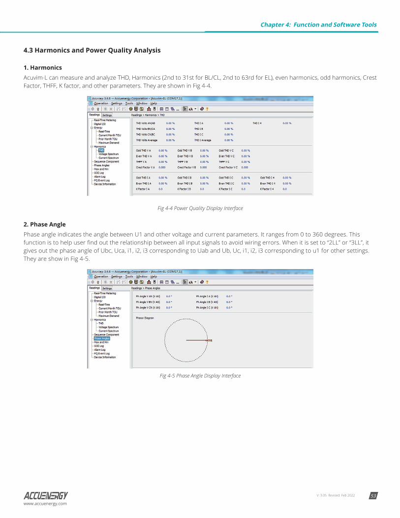
V: 3.05 Revised: Feb 2022 53www.accuenergy.com
4.3 Harmonics and Power Quality Analysis
1. HarmonicsAcuvim-L can measure and analyze THD, Harmonics (2nd to 31st for BL/CL, 2nd to 63rd for EL), even harmonics, odd harmonics, Crest Factor, THFF, K factor, and other parameters. They are shown in Fig 4-4.
Fig 4-4 Power Quality Display Interface
2. Phase AnglePhase angle indicates the angle between U1 and other voltage and current parameters. It ranges from 0 to 360 degrees. This function is to help user find out the relationship between all input signals to avoid wiring errors. When it is set to “2LL” or “3LL”, it gives out the phase angle of Ubc, Uca, i1, i2, i3 corresponding to Uab and Ub, Uc, i1, i2, i3 corresponding to u1 for other settings. They are show in Fig 4-5.
Fig 4-5 Phase Angle Display Interface
Chapter 4: Function and Software Tools
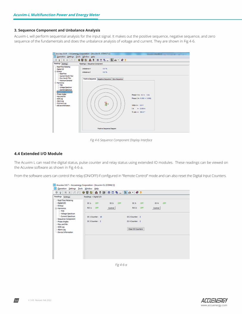
V: 3.05 Revised: Feb 202254
Acuvim-L Multifunction Power and Energy Meter
www.accuenergy.com
3. Sequence Component and Unbalance AnalysisAcuvim-L will perform sequential analysis for the input signal. It makes out the positive sequence, negative sequence, and zero sequence of the fundamentals and does the unbalance analysis of voltage and current. They are shown in Fig 4-6.
Fig 4-6 Sequence Component Display Interface
4.4 Extended I/O Module
The Acuvim L can read the digital status, pulse counter and relay status using extended IO modules. These readings can be viewed on the Acuview software as shown in Fig 4-6-a.
From the software users can control the relay (ON/OFF) if configured in “Remote Control” mode and can also reset the Digital Input Counters.
Fig 4-6-a
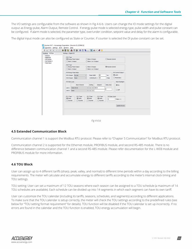
V: 3.05 Revised: Feb 2022 55www.accuenergy.com
The I/O settings are configurable from the software as shown in Fig 4-6-b. Users can change the IO mode settings for the digital output as Energy pulse, Alarm Output, Remote Control. If energy pulse mode is selected energy type, pulse width and pulse constant can be configured. If alarm mode is selected, the parameter type, over/under condition, setpoint value and delay for the alarm is configurable.
The digital input mode can also be configured as State or Counter, if counter is selected the DI pulse constant can be set.
Fig 4-6-b
4.5 Extended Communication Block
Communication channel 1 is support the Modbus RTU protocol. Please refer to “Chapter 5 Communication” for Modbus RTU protocol.
Communication channel 2 is supported for the Ethernet module, PROFIBUS module, and second RS-485 module. There is no difference between communication channel 1 and a second RS-485 module. Please refer documentation for the L-WEB module and PROFIBUS module for more information.
4.6 TOU Block
User can assign up to 4 different tariffs (sharp, peak, valley, and normal) to different time periods within a day according to the billing requirements. The meter will calculate and accumulate energy to different tariffs according to the meter’s internal clock timing and TOU settings.
TOU setting: User can set a maximum of 12 TOU seasons where each season can be assigned to a TOU schedule (a maximum of 14 TOU schedules are available). Each schedule can be divided up into 14 segments in which each segment can have its own tariff.
User can customize the TOU calendar (including its tariffs, seasons, schedules, and segments) according to different applications. To make sure that the TOU calendar is setup correctly, the meter will check the TOU settings according to the predefined rules (see below for “TOU setting format requirement” for details). TOU function will be disabled if the TOU calendar is set up incorrectly. If no errors are found in the calendar and the TOU function is enabled, TOU energy accumulation will begin.
Chapter 4: Function and Software Tools
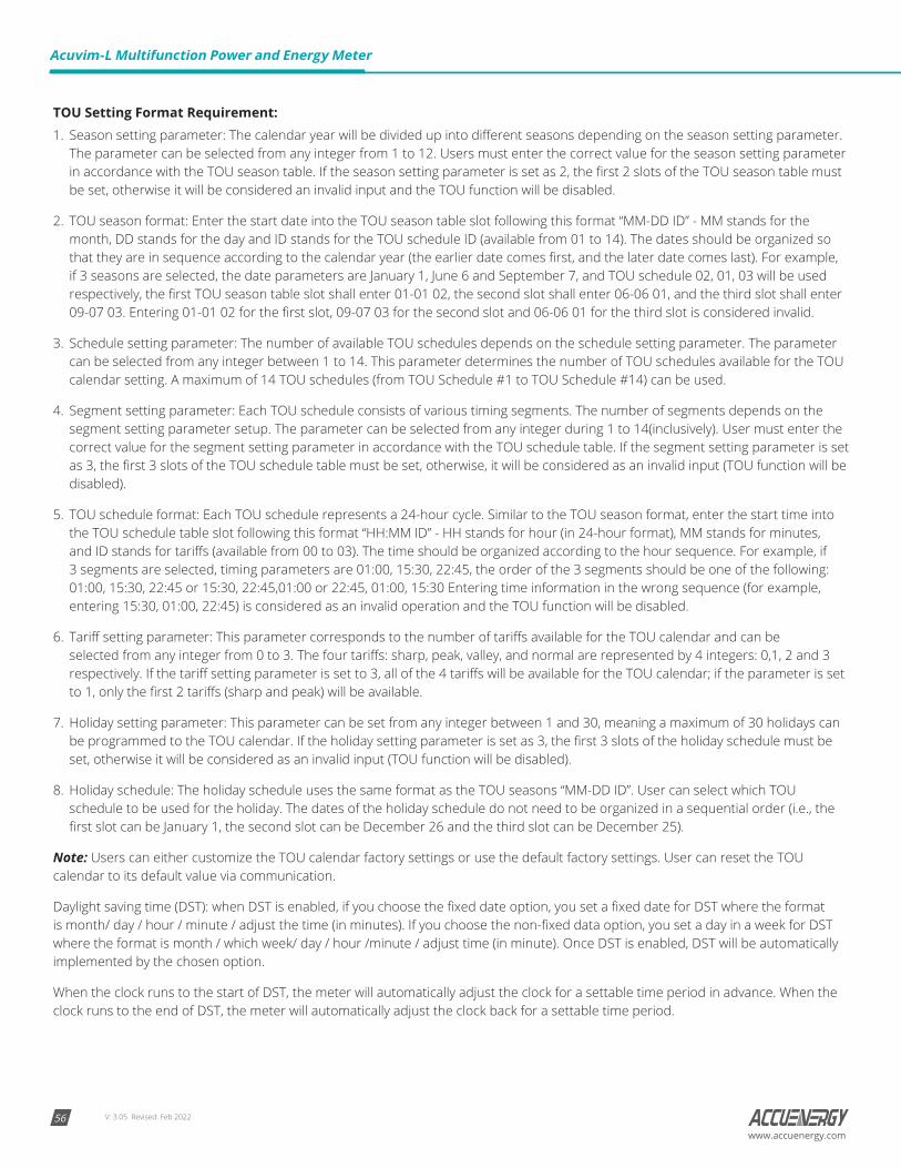
V: 3.05 Revised: Feb 202256
Acuvim-L Multifunction Power and Energy Meter
www.accuenergy.com
TOU Setting Format Requirement:1. Season setting parameter: The calendar year will be divided up into different seasons depending on the season setting parameter.
The parameter can be selected from any integer from 1 to 12. Users must enter the correct value for the season setting parameter in accordance with the TOU season table. If the season setting parameter is set as 2, the first 2 slots of the TOU season table must be set, otherwise it will be considered an invalid input and the TOU function will be disabled.
2. TOU season format: Enter the start date into the TOU season table slot following this format “MM-DD ID” - MM stands for the month, DD stands for the day and ID stands for the TOU schedule ID (available from 01 to 14). The dates should be organized so that they are in sequence according to the calendar year (the earlier date comes first, and the later date comes last). For example, if 3 seasons are selected, the date parameters are January 1, June 6 and September 7, and TOU schedule 02, 01, 03 will be used respectively, the first TOU season table slot shall enter 01-01 02, the second slot shall enter 06-06 01, and the third slot shall enter 09-07 03. Entering 01-01 02 for the first slot, 09-07 03 for the second slot and 06-06 01 for the third slot is considered invalid.
3. Schedule setting parameter: The number of available TOU schedules depends on the schedule setting parameter. The parameter can be selected from any integer between 1 to 14. This parameter determines the number of TOU schedules available for the TOU calendar setting. A maximum of 14 TOU schedules (from TOU Schedule #1 to TOU Schedule #14) can be used.
4. Segment setting parameter: Each TOU schedule consists of various timing segments. The number of segments depends on the segment setting parameter setup. The parameter can be selected from any integer during 1 to 14(inclusively). User must enter the correct value for the segment setting parameter in accordance with the TOU schedule table. If the segment setting parameter is set as 3, the first 3 slots of the TOU schedule table must be set, otherwise, it will be considered as an invalid input (TOU function will be disabled).
5. TOU schedule format: Each TOU schedule represents a 24-hour cycle. Similar to the TOU season format, enter the start time into the TOU schedule table slot following this format “HH:MM ID” - HH stands for hour (in 24-hour format), MM stands for minutes, and ID stands for tariffs (available from 00 to 03). The time should be organized according to the hour sequence. For example, if 3 segments are selected, timing parameters are 01:00, 15:30, 22:45, the order of the 3 segments should be one of the following: 01:00, 15:30, 22:45 or 15:30, 22:45,01:00 or 22:45, 01:00, 15:30 Entering time information in the wrong sequence (for example, entering 15:30, 01:00, 22:45) is considered as an invalid operation and the TOU function will be disabled.
6. Tariff setting parameter: This parameter corresponds to the number of tariffs available for the TOU calendar and can be selected from any integer from 0 to 3. The four tariffs: sharp, peak, valley, and normal are represented by 4 integers: 0,1, 2 and 3 respectively. If the tariff setting parameter is set to 3, all of the 4 tariffs will be available for the TOU calendar; if the parameter is set to 1, only the first 2 tariffs (sharp and peak) will be available.
7. Holiday setting parameter: This parameter can be set from any integer between 1 and 30, meaning a maximum of 30 holidays can be programmed to the TOU calendar. If the holiday setting parameter is set as 3, the first 3 slots of the holiday schedule must be set, otherwise it will be considered as an invalid input (TOU function will be disabled).
8. Holiday schedule: The holiday schedule uses the same format as the TOU seasons “MM-DD ID”. User can select which TOU schedule to be used for the holiday. The dates of the holiday schedule do not need to be organized in a sequential order (i.e., the first slot can be January 1, the second slot can be December 26 and the third slot can be December 25).
Note: Users can either customize the TOU calendar factory settings or use the default factory settings. User can reset the TOU calendar to its default value via communication.
Daylight saving time (DST): when DST is enabled, if you choose the fixed date option, you set a fixed date for DST where the format is month/ day / hour / minute / adjust the time (in minutes). If you choose the non-fixed data option, you set a day in a week for DST where the format is month / which week/ day / hour /minute / adjust time (in minute). Once DST is enabled, DST will be automatically implemented by the chosen option.
When the clock runs to the start of DST, the meter will automatically adjust the clock for a settable time period in advance. When the clock runs to the end of DST, the meter will automatically adjust the clock back for a settable time period.
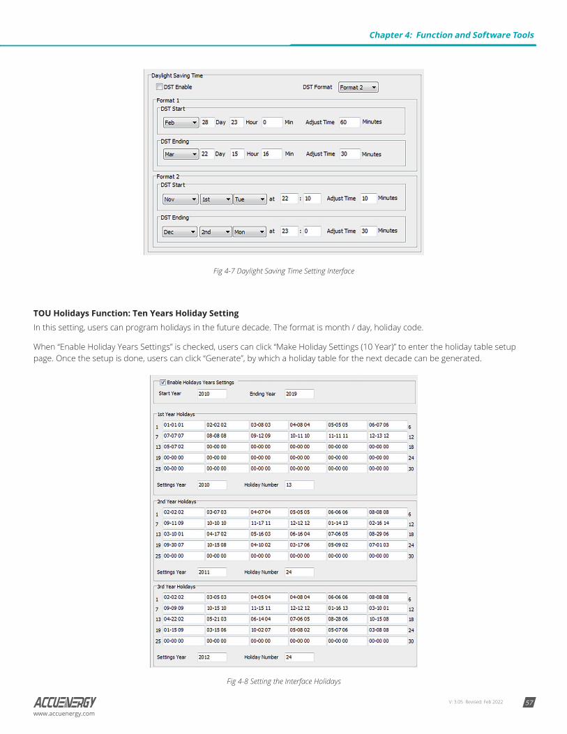
V: 3.05 Revised: Feb 2022 57www.accuenergy.com
Fig 4-7 Daylight Saving Time Setting Interface
TOU Holidays Function: Ten Years Holiday SettingIn this setting, users can program holidays in the future decade. The format is month / day, holiday code.
When “Enable Holiday Years Settings” is checked, users can click “Make Holiday Settings (10 Year)” to enter the holiday table setup page. Once the setup is done, users can click “Generate”, by which a holiday table for the next decade can be generated.
Fig 4-8 Setting the Interface Holidays
Chapter 4: Function and Software Tools
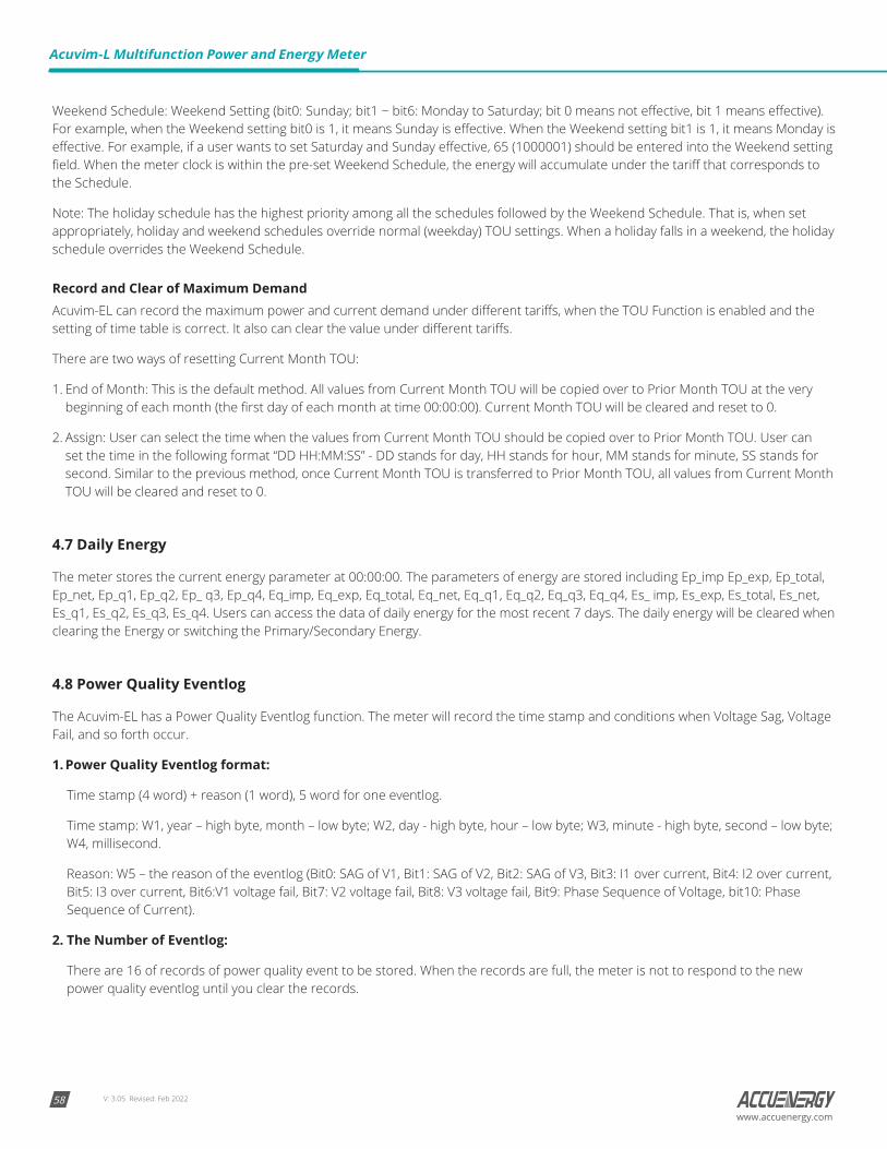
V: 3.05 Revised: Feb 202258
Acuvim-L Multifunction Power and Energy Meter
www.accuenergy.com
Weekend Schedule: Weekend Setting (bit0: Sunday; bit1 ~ bit6: Monday to Saturday; bit 0 means not effective, bit 1 means effective). For example, when the Weekend setting bit0 is 1, it means Sunday is effective. When the Weekend setting bit1 is 1, it means Monday is effective. For example, if a user wants to set Saturday and Sunday effective, 65 (1000001) should be entered into the Weekend setting field. When the meter clock is within the pre-set Weekend Schedule, the energy will accumulate under the tariff that corresponds to the Schedule.
Note: The holiday schedule has the highest priority among all the schedules followed by the Weekend Schedule. That is, when set appropriately, holiday and weekend schedules override normal (weekday) TOU settings. When a holiday falls in a weekend, the holiday schedule overrides the Weekend Schedule.
Record and Clear of Maximum DemandAcuvim-EL can record the maximum power and current demand under different tariffs, when the TOU Function is enabled and the setting of time table is correct. It also can clear the value under different tariffs.
There are two ways of resetting Current Month TOU:
1. End of Month: This is the default method. All values from Current Month TOU will be copied over to Prior Month TOU at the very beginning of each month (the first day of each month at time 00:00:00). Current Month TOU will be cleared and reset to 0.
2. Assign: User can select the time when the values from Current Month TOU should be copied over to Prior Month TOU. User can set the time in the following format “DD HH:MM:SS” - DD stands for day, HH stands for hour, MM stands for minute, SS stands for second. Similar to the previous method, once Current Month TOU is transferred to Prior Month TOU, all values from Current Month TOU will be cleared and reset to 0.
4.7 Daily Energy
The meter stores the current energy parameter at 00:00:00. The parameters of energy are stored including Ep_imp Ep_exp, Ep_total, Ep_net, Ep_q1, Ep_q2, Ep_ q3, Ep_q4, Eq_imp, Eq_exp, Eq_total, Eq_net, Eq_q1, Eq_q2, Eq_q3, Eq_q4, Es_ imp, Es_exp, Es_total, Es_net, Es_q1, Es_q2, Es_q3, Es_q4. Users can access the data of daily energy for the most recent 7 days. The daily energy will be cleared when clearing the Energy or switching the Primary/Secondary Energy.
4.8 Power Quality Eventlog
The Acuvim-EL has a Power Quality Eventlog function. The meter will record the time stamp and conditions when Voltage Sag, Voltage Fail, and so forth occur.
1. Power Quality Eventlog format:
Time stamp (4 word) + reason (1 word), 5 word for one eventlog.
Time stamp: W1, year – high byte, month – low byte; W2, day - high byte, hour – low byte; W3, minute - high byte, second – low byte; W4, millisecond.
Reason: W5 – the reason of the eventlog (Bit0: SAG of V1, Bit1: SAG of V2, Bit2: SAG of V3, Bit3: I1 over current, Bit4: I2 over current, Bit5: I3 over current, Bit6:V1 voltage fail, Bit7: V2 voltage fail, Bit8: V3 voltage fail, Bit9: Phase Sequence of Voltage, bit10: Phase Sequence of Current).
2. The Number of Eventlog:
There are 16 of records of power quality event to be stored. When the records are full, the meter is not to respond to the new power quality eventlog until you clear the records.
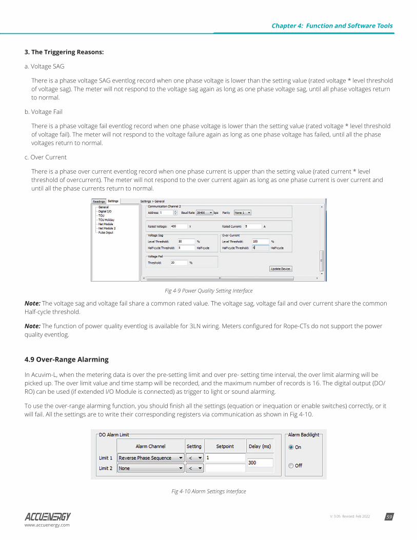
V: 3.05 Revised: Feb 2022 59www.accuenergy.com
3. The Triggering Reasons:
a. Voltage SAG
There is a phase voltage SAG eventlog record when one phase voltage is lower than the setting value (rated voltage * level threshold of voltage sag). The meter will not respond to the voltage sag again as long as one phase voltage sag, until all phase voltages return to normal.
b. Voltage Fail
There is a phase voltage fail eventlog record when one phase voltage is lower than the setting value (rated voltage * level threshold of voltage fail). The meter will not respond to the voltage failure again as long as one phase voltage has failed, until all the phase voltages return to normal.
c. Over Current
There is a phase over current eventlog record when one phase current is upper than the setting value (rated current * level threshold of overcurrent). The meter will not respond to the over current again as long as one phase current is over current and until all the phase currents return to normal.
Fig 4-9 Power Quality Setting Interface
Note: The voltage sag and voltage fail share a common rated value. The voltage sag, voltage fail and over current share the common Half-cycle threshold.
Note: The function of power quality eventlog is available for 3LN wiring. Meters configured for Rope-CTs do not support the power quality eventlog.
4.9 Over-Range Alarming
In Acuvim-L, when the metering data is over the pre-setting limit and over pre- setting time interval, the over limit alarming will be picked up. The over limit value and time stamp will be recorded, and the maximum number of records is 16. The digital output (DO/RO) can be used (if extended I/O Module is connected) as trigger to light or sound alarming.
To use the over-range alarming function, you should finish all the settings (equation or inequation or enable switches) correctly, or it will fail. All the settings are to write their corresponding registers via communication as shown in Fig 4-10.
Fig 4-10 Alarm Settings Interface
Chapter 4: Function and Software Tools
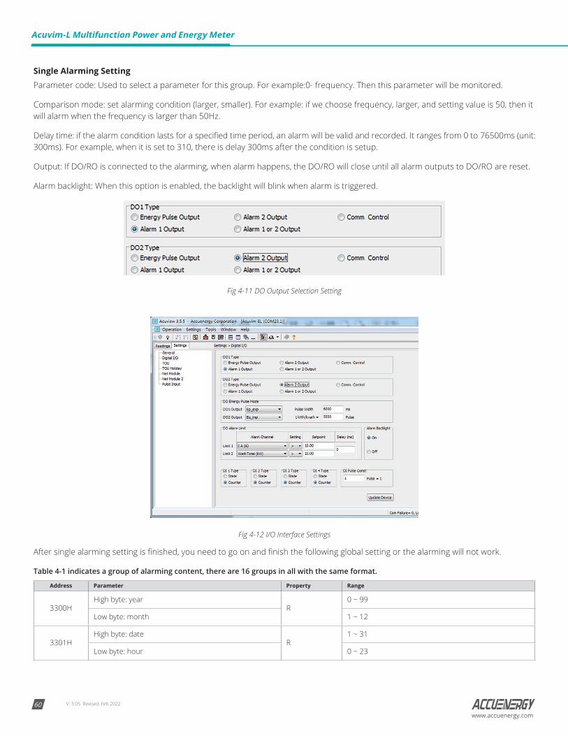
V: 3.05 Revised: Feb 202260
Acuvim-L Multifunction Power and Energy Meter
www.accuenergy.com
Single Alarming SettingParameter code: Used to select a parameter for this group. For example:0- frequency. Then this parameter will be monitored.
Comparison mode: set alarming condition (larger, smaller). For example: if we choose frequency, larger, and setting value is 50, then it will alarm when the frequency is larger than 50Hz.
Delay time: if the alarm condition lasts for a specified time period, an alarm will be valid and recorded. It ranges from 0 to 76500ms (unit: 300ms). For example, when it is set to 310, there is delay 300ms after the condition is setup.
Output: If DO/RO is connected to the alarming, when alarm happens, the DO/RO will close until all alarm outputs to DO/RO are reset.
Alarm backlight: When this option is enabled, the backlight will blink when alarm is triggered.
Fig 4-11 DO Output Selection Setting
Fig 4-12 I/O Interface Settings
After single alarming setting is finished, you need to go on and finish the following global setting or the alarming will not work.
Table 4-1 indicates a group of alarming content, there are 16 groups in all with the same format.
Address Parameter Property Range
3300HHigh byte: year
R0 ~ 99
Low byte: month 1 ~ 12
3301HHigh byte: date
R1 ~ 31
Low byte: hour 0 ~ 23
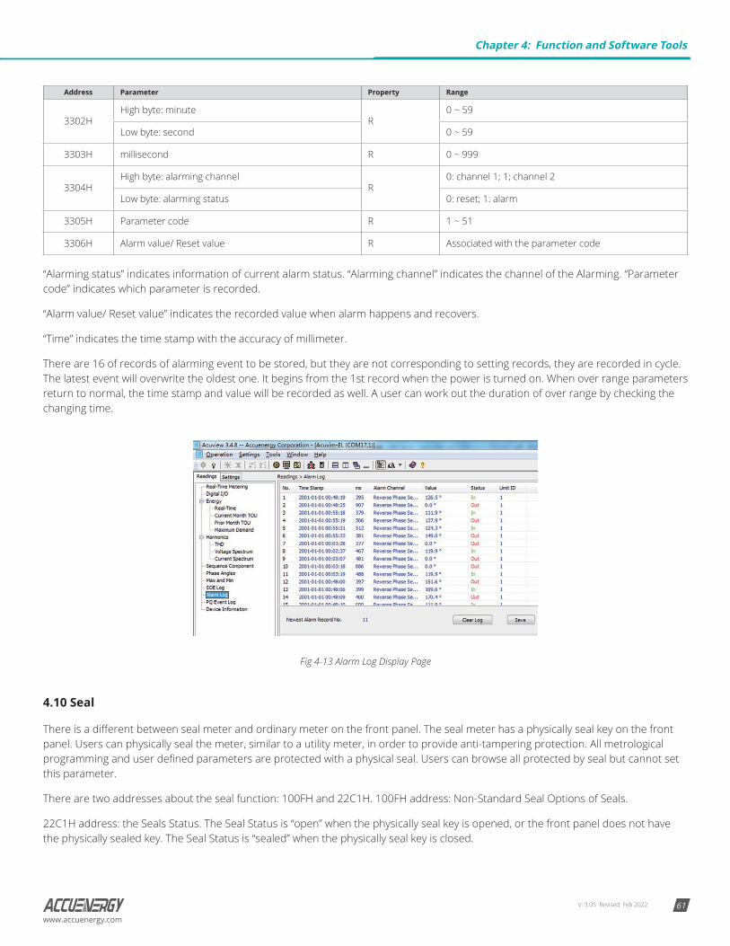
V: 3.05 Revised: Feb 2022 61www.accuenergy.com
Address Parameter Property Range
3302HHigh byte: minute
R0 ~ 59
Low byte: second 0 ~ 59
3303H millisecond R 0 ~ 999
3304HHigh byte: alarming channel
R0: channel 1; 1; channel 2
Low byte: alarming status 0: reset; 1: alarm
3305H Parameter code R 1 ~ 51
3306H Alarm value/ Reset value R Associated with the parameter code
“Alarming status” indicates information of current alarm status. “Alarming channel” indicates the channel of the Alarming. “Parameter code” indicates which parameter is recorded.
“Alarm value/ Reset value” indicates the recorded value when alarm happens and recovers.
“Time” indicates the time stamp with the accuracy of millimeter.
There are 16 of records of alarming event to be stored, but they are not corresponding to setting records, they are recorded in cycle. The latest event will overwrite the oldest one. It begins from the 1st record when the power is turned on. When over range parameters return to normal, the time stamp and value will be recorded as well. A user can work out the duration of over range by checking the changing time.
Fig 4-13 Alarm Log Display Page
4.10 Seal
There is a different between seal meter and ordinary meter on the front panel. The seal meter has a physically seal key on the front panel. Users can physically seal the meter, similar to a utility meter, in order to provide anti-tampering protection. All metrological programming and user defined parameters are protected with a physical seal. Users can browse all protected by seal but cannot set this parameter.
There are two addresses about the seal function: 100FH and 22C1H. 100FH address: Non-Standard Seal Options of Seals.
22C1H address: the Seals Status. The Seal Status is “open” when the physically seal key is opened, or the front panel does not have the physically sealed key. The Seal Status is “sealed” when the physically seal key is closed.
Chapter 4: Function and Software Tools
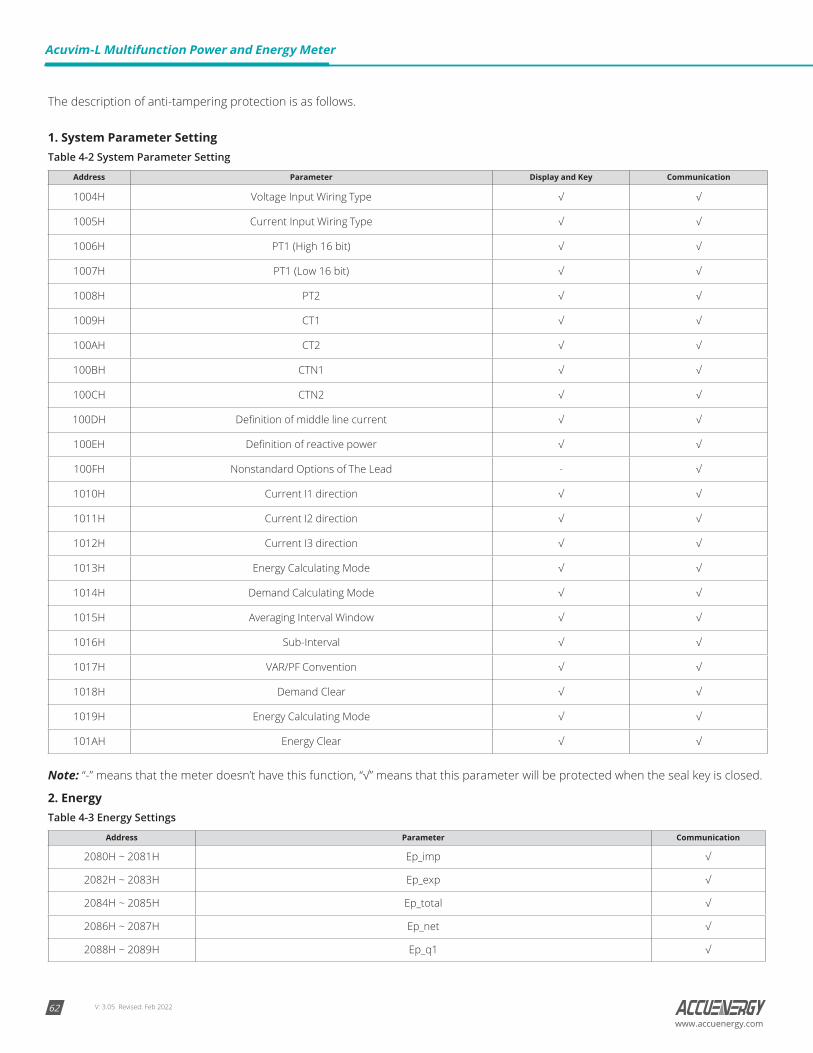
V: 3.05 Revised: Feb 202262
Acuvim-L Multifunction Power and Energy Meter
www.accuenergy.com
The description of anti-tampering protection is as follows.
1. System Parameter SettingTable 4-2 System Parameter Setting
Address Parameter Display and Key Communication
1004H Voltage Input Wiring Type √ √
1005H Current Input Wiring Type √ √
1006H PT1 (High 16 bit) √ √
1007H PT1 (Low 16 bit) √ √
1008H PT2 √ √
1009H CT1 √ √
100AH CT2 √ √
100BH CTN1 √ √
100CH CTN2 √ √
100DH Definition of middle line current √ √
100EH Definition of reactive power √ √
100FH Nonstandard Options of The Lead - √
1010H Current I1 direction √ √
1011H Current I2 direction √ √
1012H Current I3 direction √ √
1013H Energy Calculating Mode √ √
1014H Demand Calculating Mode √ √
1015H Averaging Interval Window √ √
1016H Sub-Interval √ √
1017H VAR/PF Convention √ √
1018H Demand Clear √ √
1019H Energy Calculating Mode √ √
101AH Energy Clear √ √
Note: “-” means that the meter doesn’t have this function, “√” means that this parameter will be protected when the seal key is closed.
2. EnergyTable 4-3 Energy Settings
Address Parameter Communication
2080H ~ 2081H Ep_imp √
2082H ~ 2083H Ep_exp √
2084H ~ 2085H Ep_total √
2086H ~ 2087H Ep_net √
2088H ~ 2089H Ep_q1 √
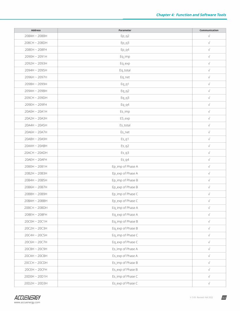
V: 3.05 Revised: Feb 2022 63www.accuenergy.com
Address Parameter Communication
208AH ~ 208BH Ep_q2 √
208CH ~ 208DH Ep_q3 √
208EH ~ 208FH Ep_q4 √
2090H ~ 2091H Eq_imp √
2092H ~ 2093H Eq_exp √
2094H ~ 2095H Eq_total √
2096H ~ 2097H Eq_net √
2098H ~ 2099H Eq_q1 √
209AH ~ 209BH Eq_q2 √
209CH ~ 209DH Eq_q3 √
209EH ~ 209FH Eq_q4 √
20A0H ~ 20A1H Es_imp √
20A2H ~ 20A3H ES_exp √
20A4H ~ 20A5H Es_total √
20A6H ~ 20A7H Es_net √
20A8H ~ 20A9H Es_q1 √
20AAH ~ 20ABH Es_q2 √
20ACH ~ 20ADH Es_q3 √
20AEH ~ 20AFH Es_q4 √
20B0H ~ 20B1H Ep_imp of Phase A √
20B2H ~ 20B3H Ep_exp of Phase A √
20B4H ~ 20B5H Ep_imp of Phase B √
20B6H ~ 20B7H Ep_exp of Phase B √
20B8H ~ 20B9H Ep_imp of Phase C √
20BAH ~ 20BBH Ep_exp of Phase C √
20BCH ~ 20BDH Eq_imp of Phase A √
20BEH ~ 20BFH Eq_exp of Phase A √
20C0H ~ 20C1H Eq_imp of Phase B √
20C2H ~ 20C3H Eq_exp of Phase B √
20C4H ~ 20C5H Eq_imp of Phase C √
20C6H ~ 20C7H Eq_exp of Phase C √
20C8H ~ 20C9H Es_imp of Phase A √
20CAH ~ 20CBH Es_exp of Phase A √
20CCH ~ 20CDH Es_imp of Phase B √
20CEH ~ 20CFH Es_exp of Phase B √
20D0H ~ 20D1H Es_imp of Phase C √
20D2H ~ 20D3H Es_exp of Phase C √
Chapter 4: Function and Software Tools

V: 3.05 Revised: Feb 202264
Acuvim-L Multifunction Power and Energy Meter
www.accuenergy.com
3. DITable 4-4 DI Settings
Address Parameter Display and Key Communication
1900H DI Type √ √
1901H DI Pulse Constant √ √
1902H Clear DI Counters √ √
1903H Work Mode of Do1 √ √
1904H Work Mode of Do2 √ √
1905H Pulse Constant √ √
1906H Do Pulse Width √ √
1907H Do1 Energy Output √ √
1908H Do2 Energy Output √ √
4. Non-Standard Seal Options of Seals:a. Communication channel 1, when the bit0 of Non-Standard Seal Options of Seals is valid, protected the content about the
communication channel 1 as follow.
Address Parameter Display and Key Communication
1000H Access code √ √
1001H Communication Address √ √
1002H Baud Rate √ √
1003H Parity Mode √ √
b. Communication channel 2, when the bit1 of Non-Standard Seal Options of Seals is valid, protected content about communication channel 2 is described in the following table.
Address Parameter Display and Key Communication
1024H Communication Address of Channel 2 √ √
1025H Baud Rate of Channel 2 √ √
1026H Parity Mode of Channel 2 √ √
Ethernet Module
1C03H DHCP √ √
1C04H IP Address First Byte (High) √ √
1C05H IP Address Second Byte (Low) √ √
1C06H IP Address Third Byte (High) √ √
1C07H IP Address Fourth Byte (Low) √ √
1C08H Subnet Mask First Byte (High) √ √
1C09H Subnet Mask Second Byte (Low) √ √
1C0AH Subnet Mask Third Byte (High) √ √
1C0BH Subnet Mask Fourth Byte (Low) √ √
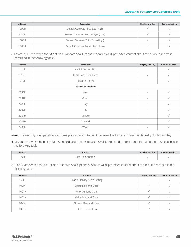
V: 3.05 Revised: Feb 2022 65www.accuenergy.com
Address Parameter Display and Key Communication
1C0CH Default Gateway First Byte (High) √ √
1C0DH Default Gateway Second Byte (Low) √ √
1C0EH Default Gateway Third Byte (High) √ √
1C0FH Default Gateway Fourth Byte (Low) √ √
c. Device Run-Time, when the bit2 of Non-Standard Seal Options of Seals is valid, protected content about the device run-time is described in the following table.
Address Parameter Display and Key Communication
101CH Reset Total Run Time
√
√
101DH Reset Load Time Clear √
101EH Reset Run Time √
Ethernet Module
2280H Year - √
2281H Month - √
2282H Day - √
2283H Hour - √
2284H Minute - √
2285H Second - √
2286H Week - √
Note: There is only one operation for three options (reset total run time, reset load time, and reset run time) by display and key.
d. DI Counters, when the bit3 of Non-Standard Seal Options of Seals is valid, protected content about the DI Counters is described in the following table.
Address Parameter Display and Key Communication
1902H Clear DI Counters √ √
e. TOU Related, when the bit4 of Non-Standard Seal Options of Seals is valid, protected content about the TOU is described in the following table.
Address Parameter Display and Key Communication
101FH Enable Holiday Years Setting - √
1020H Sharp Demand Clear √ √
1021H Peak Demand Clear √ √
1022H Valley Demand Clear √ √
1023H Normal Demand Clear √ √
1024H Total Demand Clear √ √
Chapter 4: Function and Software Tools
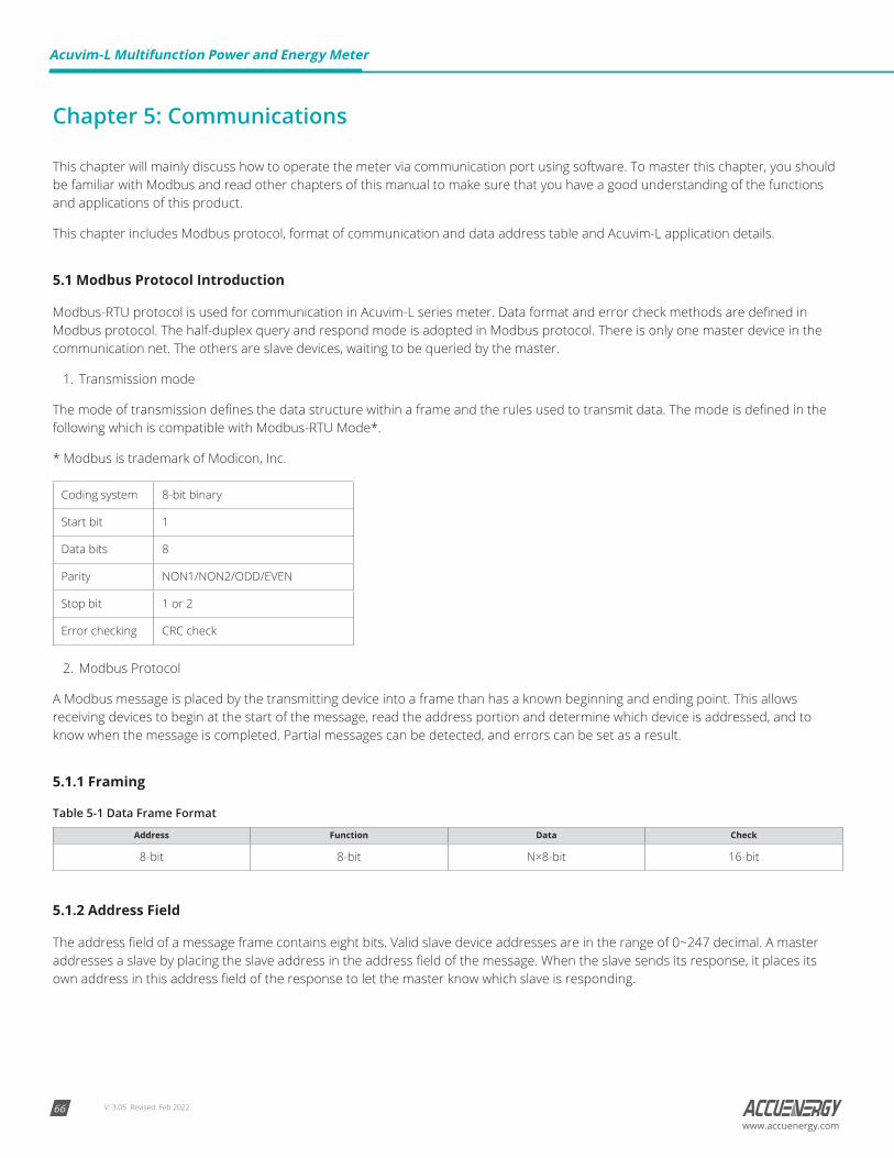
V: 3.05 Revised: Feb 202266
Acuvim-L Multifunction Power and Energy Meter
www.accuenergy.com
Chapter 5: Communications
This chapter will mainly discuss how to operate the meter via communication port using software. To master this chapter, you should be familiar with Modbus and read other chapters of this manual to make sure that you have a good understanding of the functions and applications of this product.
This chapter includes Modbus protocol, format of communication and data address table and Acuvim-L application details.
5.1 Modbus Protocol Introduction
Modbus-RTU protocol is used for communication in Acuvim-L series meter. Data format and error check methods are defined in Modbus protocol. The half-duplex query and respond mode is adopted in Modbus protocol. There is only one master device in the communication net. The others are slave devices, waiting to be queried by the master.
1. Transmission mode
The mode of transmission defines the data structure within a frame and the rules used to transmit data. The mode is defined in the following which is compatible with Modbus-RTU Mode*.
* Modbus is trademark of Modicon, Inc.
Coding system 8-bit binary
Start bit 1
Data bits 8
Parity NON1/NON2/ODD/EVEN
Stop bit 1 or 2
Error checking CRC check
2. Modbus Protocol
A Modbus message is placed by the transmitting device into a frame than has a known beginning and ending point. This allows receiving devices to begin at the start of the message, read the address portion and determine which device is addressed, and to know when the message is completed. Partial messages can be detected, and errors can be set as a result.
5.1.1 Framing
Table 5-1 Data Frame Format
Address Function Data Check
8-bit 8-bit N×8-bit 16-bit
5.1.2 Address Field
The address field of a message frame contains eight bits. Valid slave device addresses are in the range of 0~247 decimal. A master addresses a slave by placing the slave address in the address field of the message. When the slave sends its response, it places its own address in this address field of the response to let the master know which slave is responding.
V: 3.05 Revised: Feb 2022 67www.accuenergy.com
5.1.3 Function Field
The function code field of a message frame contains eight bits. Valid codes are in the range of 1~255 decimal. When a message is sent from a master to a slave device the function code field tells the slave what kind of action to perform.
Table 5-2 Function Code
Code Meaning Action
01 Read Relay Output Status Obtain current status of Relay Output
02 Read Digital Input (DI) Status Obtain current status of Digital Input
03 Read data Obtain current binary value from one or more registers
05 Write Relay Output Control the Relay
16 Preset multiple registers Place specific value into a series of consecutive multiple registers
5.1.4 Data Field
The data field is constructed using sets of two hexadecimal digits, in the range of 00 to FF hexadecimal. The data field of messages sent from a master to slave devices contains additional information which the slave must use to take the action defined by the function code. This can include items like discrete and register addresses, the quantity of items to be handled, and the count of actual data bytes in the field. For example, if the master requests a slave to read a group of holding registers (function code 03), the data field specifies the starting register and how many registers are to be read. If the master writes to a group of registers in the slave (function code 10 hexadecimal), the data field specifies the starting register, how many registers to write, the count of data bytes to follow in the data field, and the data to be written into the registers.
If no error occurs, the data field of a response from a slave to a master contains the data requested. If an error occurs, the field contains an exception code that the master application can use to determine the next action to be taken. The data field can be nonexistent (of zero length) in certain kinds of messages.
5.1.5 Error Check Field
Every message includes an error checking field which is based on the Cyclical Redundancy Check (CRC) method. The CRC field checks the contents of the entire message. It is applied regardless of any parity check method used for the individual characters of the message. The CRC field is two bytes long, containing a 16-bit binary value. The CRC value is calculated by the transmitting device and is appended to the message.
5.1.6 Error Checking
The receiving device recalculates the CRC value during reception of the message and compares the calculated value to the actual value it received in the CRC field. An error will be reported if the two values are not equal. CRC calculation is first started by preloading the whole 16-bit register to 1’s. The process begins by applying successive 8-bit bytes of the message to the current contents of the register. Only the eight bits of data in each character are used for generating the CRC. Start and stop bits, and the parity bit, do not apply to the CRC.
When generating the CRC, each 8-bit character is exclusive ORed with the register contents. The result is shifted towards the least significant bit (LSB), with a zero filled into the most significant bit (MSB) position. The LSB is extracted and examined, if the LSB equals to 1, the register is exclusive ORed with a preset, fixed value; if the LSB equals to 0, no action will be taken. This process is repeated until eight shifts have been performed. After the last (eighth) shift, the next 8-bitbyte is exclusive ORed with the register’s current value, and the process repeats for eight more shifts as described above. After all the bytes of the message have been applied, the final contents of the register, which should exchange the high-byte and the low-byte, is the CRC value. When the CRC is appended to the message, the low-order byte is appended first, followed by the high-order byte.
Chapter 5: Communications

V: 3.05 Revised: Feb 202268
Acuvim-L Multifunction Power and Energy Meter
www.accuenergy.com
A procedure for generating a CRC is:
1. Load a 16–bit register with FFFF hex (all 1’s). Call this the CRC register.
2. Exclusive OR the first 8–bit byte of the message with the low–order byte of the 16–bit CRC register, putting the result in the CRCregister.
3. Shift the CRC register one bit to the right (toward the LSB), zero–filling the MSB. Extract and examine the LSB.
a. (If the LSB was 0): Repeat Step 3 (another shift).
b. (If the LSB was 1): Exclusive OR the CRC register with the polynomial value A001 hex (1010 0000 0000 0001).
4. Repeat Steps 3 and 4 until 8 shifts have been performed. When this is done, a complete 8–bit byte will have been processed.
5. Repeat Steps 2 through 5 for the next 8–bit byte of the message. Continue doing this until all bytes have been processed.
6. The final content in the CRC register is the CRC value.
7. When the CRC is placed into the message, its upper and lower bytes must be swapped as described below.
5.2 Communication Format
Explanation of frame
Table 5-3 Explanation of a Frame
Addr Fun Data start reg hi Data start reg lo Data # of regs hi Data # of regs lo CRC16 hi CRC16 lo
06H 03H 00H 00H 00H 21H 84H 65H
As shown in table 4-3 the meaning of each abbreviated word is:
• Addr: Address of slave device
• Fun: Function code
• Data start reg HI: Start register address high byte
• Data start reg LO: Start register address low byte
• Data #of reg HI: Number of register high byte
• Data #of reg LO: Number of register low byte
• CRC16 HI: CRC high byte
• CRC16 LO: CRC low byte
1. Read Status of Relay (Function Code 01)This function code is used to read the statues in Acuvim-L.1=On, 0=Off; There are 2 Relays in Acuvim-L. The Address of each Relay is Relay1=0000Hand Relay2=0001H. The following query is to read Relay Status of Acuvim-L.
Query
Table 5-4 Read the Status of Relay1 and Relay2 Query Message
Addr Fun Relay start reg hi Relay start reg lo Relay # of reg hi Relay # of reg lo CRC16 Hi CRC16 lo
11H 01H 00H 00H 00H 02H BFH 5BH
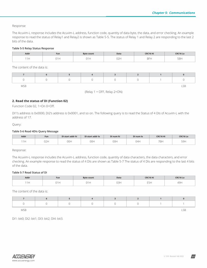
V: 3.05 Revised: Feb 2022 69www.accuenergy.com
Response
The Acuvim-L response includes the Acuvim-L address, function code, quantity of data byte, the data, and error checking. An example response to read the status of Relay1 and Relay2 is shown as Table 5-5. The status of Relay 1 and Relay 2 are responding to the last 2 bits of the data.
Table 5-5 Relay Status Response
Addr Fun Byte count Data CRC16 Hi CRC16 Lo
11H 01H 01H 02H BFH 5BH
The content of the data is:
7 6 5 4 3 2 1 0
0 0 0 0 0 0 1 0
MSB LSB
(Relay 1 = OFF, Relay 2=ON)
2. Read the status of DI (Function 02)Function Code 02, 1=On 0=Off.
DI1’s address is 0x0000, DI2’s address is 0x0001, and so on. The following query is to read the Status of 4 DIs of Acuvim-L with the address of 17.
Query:
Table 5-6 Read 4DIs Query Message
Addr Fun DI start addr hi DI start addr lo DI num hi DI num lo CRC16 Hi CRC16 Lo
11H 02H 00H 00H 00H 04H 7BH 59H
Response:
The Acuvim-L response includes the Acuvim-L address, function code, quantity of data characters, the data characters, and error checking. An example response to read the status of 4 DIs are shown as Table 5-7 The status of 4 DIs are responding to the last 4 bits of the data.
Table 5-7 Read Status of DI
Addr Fun Byte count Data CRC16 Hi CRC16 Lo
11H 01H 01H 03H E5H 49H
The content of the data is:
7 6 5 4 3 2 1 0
0 0 0 0 0 0 1 1
MSB LSB
DI1: bit0; DI2: bit1; DI3: bit2; DI4: bit3.
Chapter 5: Communications

V: 3.05 Revised: Feb 202270
Acuvim-L Multifunction Power and Energy Meter
www.accuenergy.com
3. Read Data (Function Code 03)This function allows the master to obtain the measurement results of Acuvim-L. There is an example to read the 3 measured data (F, U1 and U2) from slave device number 17, the data address of F is 0130H; U1 is 0131H, and V2 is 0132H.
Query:
Table 5-8 Read F, U1, U2 Query Message
Addr Fun Data start addr hi Data start addr lo Data #of regs hi Data #of regs lo CRC16 hi CRC16 lo
11H 03H 01H 30H 00H 03H 06H A8H
Response:
The Acuvim-L series meter response includes the address code, function code, quantity of data byte, data, and error checking. An example response to read F,V1 and V2 (F=1388H (50.00Hz), V1=03E7H (99.9V), V2=03E9H (100.1V) is shown as Table 5-9.
Table 5-9 Read F, V1 and V2 Message of Response
Addr Fun Byte count Data1 hi Data1 lo Data 2 hi Data2 lo Data3 hi Data3 lo CRC16 hi CRC16 lo
11H 03H 06H 13H 88H 03H E7H 03H E9H 7FH 04H
4. Write Relay OutputFunction 05 allows the user to control the Relay. The example below is a request to an Acuvim-L series meter with closing the RO1.
Query:
Table 5-10 Write DO Query Message
Addr Fun Data start reg hi Data start reg lo Data #of reg hi Data #of reg lo CRC16 hi CRC16 lo
11H 05H 00H 00H FFH 00H 8EH AAH
Response:
Table 5-11 Write DO Message of Response
Addr Fun Data start reg hi Data start reg lo Data #of reg hi Data #of reg lo CRC16 hi CRC16 lo
11H 05H 00H 00H FFH 00H 8EH AAH
5. Preset / Reset Multi-Register (Function Code 16)Function 16 allows the user to modify the contents of a multi-register. Any register that exists within the Acuvim-L series meter can have its contents changed by this message. The example below is a request to an Acuvim-L series meter with the address of 17 to Preset Ep_imp = (17807783.3KWH), while its HEX value is 0A9D4089H. Ep_imp data address is 0156H and 0157H.
Query:
Table 5-12 Preset KWH Query Message
Addr Fun Data start reg HI Data start reg LO Data #of reg HI Data #of reg LO Byte Count
11H 10H 01H 56H 00H 02H 04H
Value HI Value LO Value HI Value lO CRC 16 HI CRC 16 LO
0AH 9DH 40H 89H 4DH B9H
Response:
The normal response to a preset multi-register request includes the Acuvim-L series meter address, function code, data start register, the number of registers, and error checking.

V: 3.05 Revised: Feb 2022 71www.accuenergy.com
Table 5-13 Preset KWH Query Message of Response
Addr Fun Data start reg hi Data start reg lo Data #of reg hi Data #of Reg lo CRC16 hi CRC16 lo
11H 10H 01H 0CH 00H 02H A2H B4H
5.3 Data Address Table
Basic MeasurementsThe data address of basis measurements includes primary data address and secondary data address. Function code: 03 read.
Address Parameter Range Data type Type of access
2000H Frequency F 4500~6500 Word R
2001H A Phase voltage V1 0~65535 Word R
2002H B Phase voltage V2 0~65535 Word R
2003H C Phase voltage V3 0~65535 Word R
2004H Uinavg 0~65535 Word R
2005H Line voltage V12 0~65535 Word R
2006H Line voltage V23 0~65535 Word R
2007H Line voltage V31 0~65535 Word R
2008H UIIavg 0~65535 Word R
2009H current I1 0~65535 Word R
200AH current I2 0~65535 Word R
200BH current I3 0~65535 Word R
200CH Reserved 0~65535 Word R
200DH Neutral line current in 0~65535 Word R
200EH Itotal 0~65535 Word R
200FH Iavg 0~65535 Word R
2010H A Phase active power Pa -32768~32767 Word R
2011H B Phase active power Pb -32768~32767 Word R
2012H C Phase active power Pc -32768~32767 Word R
2013H System active power Pcon -32768~32767 Word R
2014H A Phase reactive power Qa -32768~32767 Word R
2015H B Phase reactive power Qb -32768~32767 Word R
2016H C Phase reactive power Qc -32768~32767 Word R
2017H System reactive power Qcon -32768~32767 Word R
2018H A Phase apparent power Sa 0~65535 Word R
2019H B Phase apparent power Sb 0~65535 Word R
201AH C Phase apparent power Sc 0~65535 Word R
Chapter 5: Communications

V: 3.05 Revised: Feb 202272
Acuvim-L Multifunction Power and Energy Meter
www.accuenergy.com
Address Parameter Range Data type Type of access
201BH System apparent power Scon 0~65535 Word R
201CH A Phase power factor PFa -1000~1000 Word R
201DH B Phase power factor PFb -1000~1000 Word R
201EH C Phase power factor PFc -1000~1000 Word R
201FH System power factor PFcon -1000~1000 Word R
2020H Voltage unbalance factor U_unbl 0~1000 Word R
2021H Current unbalance factor I_unbl 0~1000 Word R
2022H Load nature RT (L/C/R) 76/67/82 Word R
2023H Active power demand P_DEMA -32768~32767 Word R
2024H Reactive power demand Q_DEMA -32768~32767 Word R
2025H Apparent power demand S_DEMA 0~65535 Word R
2026H A Phase current demand Ia_DEMA 0~65535 Word R
2027H B Phase current demand Ib_DEMA 0~65535 Word R
2028H C Phase current demand Ic_DEMA 0~65535 Word R
2029H Neutral line Current demand IN_DEMA 0~65535 Word R
202AH Active Power Forecasting Demand P_DEMA -32768~32767 Word R
202BH Reactive Power Forecasting Demand Q_DEMA -32768~32767 Word R
202CH Apparent Power Forecasting Demand S_DEMA 0~65535 Word R
202DH A Phase current forecast demand Ia_DEMA 0~65535 Word R
202EH B Phase current forecast demand Ib_DEMA 0~65535 Word R
202FH C Phase current forecast demand Ic_DEMA 0~65535 Word R
2030H Neutral line current forecast demand IN_DEMA 0~65535 Word R
2031H - 207FH reserved Word R
The relationship between numerical value in register of the Acuvim-L series meter and the real physical value is shown in the following table. (Rx is numerical value in register of the Acuvim-L series meter.)
Table 5-15 Conversion Relationship of Basic Measurements
Parameter Relationship Unit
Voltage V1, V2, V3, V12, V23, V31 U=Rx × (PT1 / PT2) /10 Volt(V)
Current I1, I2, I3, In (Calculated) I=Rx ×(CT1/CT2) /1000 Amp(A)
In (Measured) I = Rx × (CTN1 / CTN2) / 1000 Amp(A)
Power Pa, Pb, Pc, Psum P=Rx × (PT1 / PT2) × (CT1/ CT2) Watt(W)
Reactive power Qa, Qb, Qc, Qsum Q=Rx × (PT1 / PT2) × (CT1/ CT2) var
Apparent power Sa,Sb,Sc,Ssum S=Rx × (PT1 / PT2) × (CT1/ CT2) VA
Power factor PFa, PFb, PFc, PFsum PF=Rx / 1000 NA
Frequency F=Rx / 100 Hz
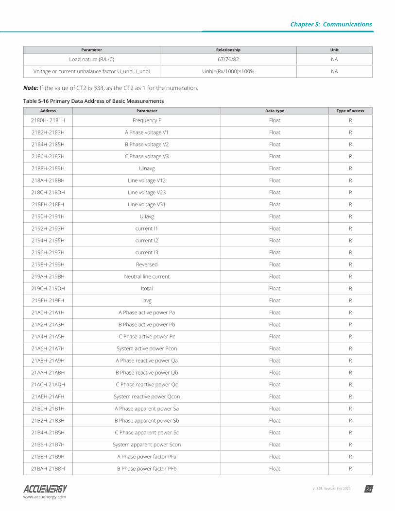
V: 3.05 Revised: Feb 2022 73www.accuenergy.com
Parameter Relationship Unit
Load nature (R/L/C) 67/76/82 NA
Voltage or current unbalance factor U_unbl, I_unbl Unbl=(Rx/1000)×100% NA
Note: If the value of CT2 is 333, as the CT2 as 1 for the numeration.
Table 5-16 Primary Data Address of Basic Measurements
Address Parameter Data type Type of access
2180H- 2181H Frequency F Float R
2182H-2183H A Phase voltage V1 Float R
2184H-2185H B Phase voltage V2 Float R
2186H-2187H C Phase voltage V3 Float R
2188H-2189H Uinavg Float R
218AH-218BH Line voltage V12 Float R
218CH-218DH Line voltage V23 Float R
218EH-218FH Line voltage V31 Float R
2190H-2191H UIIavg Float R
2192H-2193H current I1 Float R
2194H-2195H current I2 Float R
2196H-2197H current I3 Float R
2198H-2199H Reversed Float R
219AH-219BH Neutral line current Float R
219CH-219DH Itotal Float R
219EH-219FH Iavg Float R
21A0H-21A1H A Phase active power Pa Float R
21A2H-21A3H B Phase active power Pb Float R
21A4H-21A5H C Phase active power Pc Float R
21A6H-21A7H System active power Pcon Float R
21A8H-21A9H A Phase reactive power Qa Float R
21AAH-21ABH B Phase reactive power Qb Float R
21ACH-21ADH C Phase reactive power Qc Float R
21AEH-21AFH System reactive power Qcon Float R
21B0H-21B1H A Phase apparent power Sa Float R
21B2H-21B3H B Phase apparent power Sb Float R
21B4H-21B5H C Phase apparent power Sc Float R
21B6H-21B7H System apparent power Scon Float R
21B8H-21B9H A Phase power factor PFa Float R
21BAH-21BBH B Phase power factor PFb Float R
Chapter 5: Communications
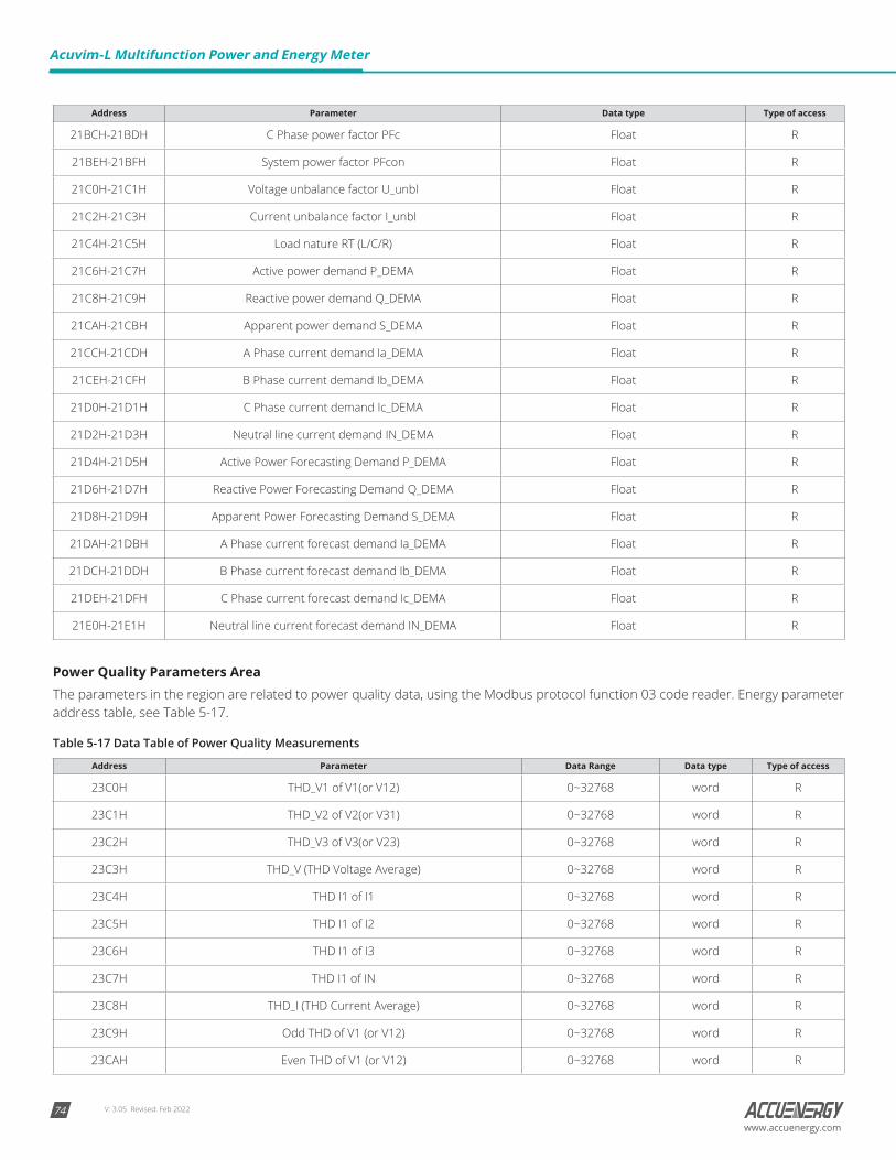
V: 3.05 Revised: Feb 202274
Acuvim-L Multifunction Power and Energy Meter
www.accuenergy.com
Address Parameter Data type Type of access
21BCH-21BDH C Phase power factor PFc Float R
21BEH-21BFH System power factor PFcon Float R
21C0H-21C1H Voltage unbalance factor U_unbl Float R
21C2H-21C3H Current unbalance factor I_unbl Float R
21C4H-21C5H Load nature RT (L/C/R) Float R
21C6H-21C7H Active power demand P_DEMA Float R
21C8H-21C9H Reactive power demand Q_DEMA Float R
21CAH-21CBH Apparent power demand S_DEMA Float R
21CCH-21CDH A Phase current demand Ia_DEMA Float R
21CEH-21CFH B Phase current demand Ib_DEMA Float R
21D0H-21D1H C Phase current demand Ic_DEMA Float R
21D2H-21D3H Neutral line current demand IN_DEMA Float R
21D4H-21D5H Active Power Forecasting Demand P_DEMA Float R
21D6H-21D7H Reactive Power Forecasting Demand Q_DEMA Float R
21D8H-21D9H Apparent Power Forecasting Demand S_DEMA Float R
21DAH-21DBH A Phase current forecast demand Ia_DEMA Float R
21DCH-21DDH B Phase current forecast demand Ib_DEMA Float R
21DEH-21DFH C Phase current forecast demand Ic_DEMA Float R
21E0H-21E1H Neutral line current forecast demand IN_DEMA Float R
Power Quality Parameters AreaThe parameters in the region are related to power quality data, using the Modbus protocol function 03 code reader. Energy parameter address table, see Table 5-17.
Table 5-17 Data Table of Power Quality Measurements
Address Parameter Data Range Data type Type of access
23C0H THD_V1 of V1(or V12) 0~32768 word R
23C1H THD_V2 of V2(or V31) 0~32768 word R
23C2H THD_V3 of V3(or V23) 0~32768 word R
23C3H THD_V (THD Voltage Average) 0~32768 word R
23C4H THD I1 of I1 0~32768 word R
23C5H THD I1 of I2 0~32768 word R
23C6H THD I1 of I3 0~32768 word R
23C7H THD I1 of IN 0~32768 word R
23C8H THD_I (THD Current Average) 0~32768 word R
23C9H Odd THD of V1 (or V12) 0~32768 word R
23CAH Even THD of V1 (or V12) 0~32768 word R
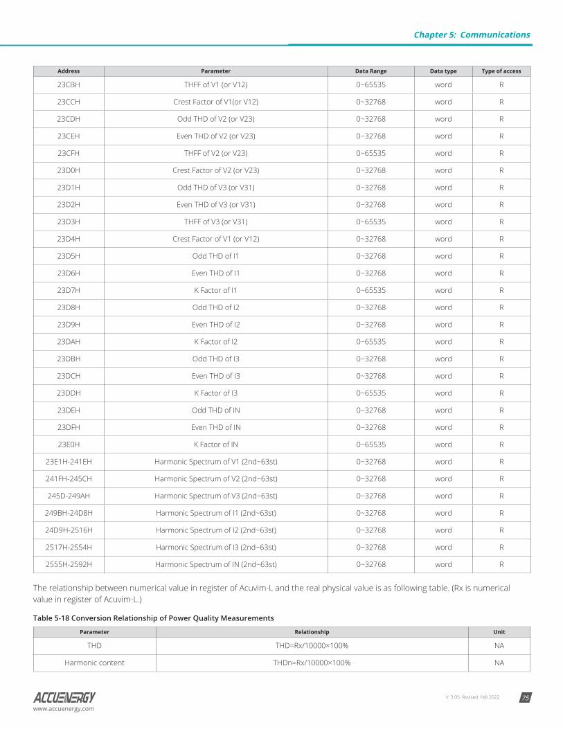
V: 3.05 Revised: Feb 2022 75www.accuenergy.com
Address Parameter Data Range Data type Type of access
23CBH THFF of V1 (or V12) 0~65535 word R
23CCH Crest Factor of V1(or V12) 0~32768 word R
23CDH Odd THD of V2 (or V23) 0~32768 word R
23CEH Even THD of V2 (or V23) 0~32768 word R
23CFH THFF of V2 (or V23) 0~65535 word R
23D0H Crest Factor of V2 (or V23) 0~32768 word R
23D1H Odd THD of V3 (or V31) 0~32768 word R
23D2H Even THD of V3 (or V31) 0~32768 word R
23D3H THFF of V3 (or V31) 0~65535 word R
23D4H Crest Factor of V1 (or V12) 0~32768 word R
23D5H Odd THD of I1 0~32768 word R
23D6H Even THD of I1 0~32768 word R
23D7H K Factor of I1 0~65535 word R
23D8H Odd THD of I2 0~32768 word R
23D9H Even THD of I2 0~32768 word R
23DAH K Factor of I2 0~65535 word R
23DBH Odd THD of I3 0~32768 word R
23DCH Even THD of I3 0~32768 word R
23DDH K Factor of I3 0~65535 word R
23DEH Odd THD of IN 0~32768 word R
23DFH Even THD of IN 0~32768 word R
23E0H K Factor of IN 0~65535 word R
23E1H-241EH Harmonic Spectrum of V1 (2nd~63st) 0~32768 word R
241FH-245CH Harmonic Spectrum of V2 (2nd~63st) 0~32768 word R
245D-249AH Harmonic Spectrum of V3 (2nd~63st) 0~32768 word R
249BH-24D8H Harmonic Spectrum of I1 (2nd~63st) 0~32768 word R
24D9H-2516H Harmonic Spectrum of I2 (2nd~63st) 0~32768 word R
2517H-2554H Harmonic Spectrum of I3 (2nd~63st) 0~32768 word R
2555H-2592H Harmonic Spectrum of IN (2nd~63st) 0~32768 word R
The relationship between numerical value in register of Acuvim-L and the real physical value is as following table. (Rx is numerical value in register of Acuvim-L.)
Table 5-18 Conversion Relationship of Power Quality Measurements
Parameter Relationship Unit
THD THD=Rx/10000×100% NA
Harmonic content THDn=Rx/10000×100% NA
Chapter 5: Communications
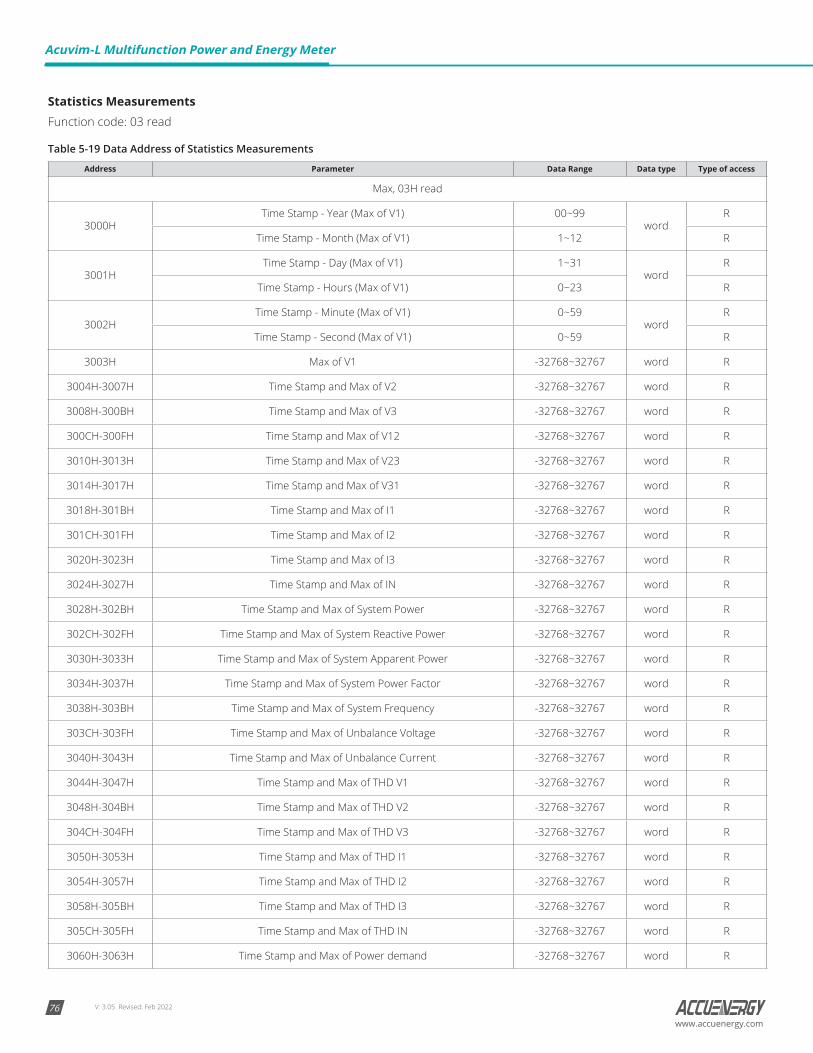
V: 3.05 Revised: Feb 202276
Acuvim-L Multifunction Power and Energy Meter
www.accuenergy.com
Statistics Measurements Function code: 03 read
Table 5-19 Data Address of Statistics Measurements
Address Parameter Data Range Data type Type of access
Max, 03H read
3000HTime Stamp - Year (Max of V1) 00~99
wordR
Time Stamp - Month (Max of V1) 1~12 R
3001HTime Stamp - Day (Max of V1) 1~31
wordR
Time Stamp - Hours (Max of V1) 0~23 R
3002HTime Stamp - Minute (Max of V1) 0~59
wordR
Time Stamp - Second (Max of V1) 0~59 R
3003H Max of V1 -32768~32767 word R
3004H-3007H Time Stamp and Max of V2 -32768~32767 word R
3008H-300BH Time Stamp and Max of V3 -32768~32767 word R
300CH-300FH Time Stamp and Max of V12 -32768~32767 word R
3010H-3013H Time Stamp and Max of V23 -32768~32767 word R
3014H-3017H Time Stamp and Max of V31 -32768~32767 word R
3018H-301BH Time Stamp and Max of I1 -32768~32767 word R
301CH-301FH Time Stamp and Max of I2 -32768~32767 word R
3020H-3023H Time Stamp and Max of I3 -32768~32767 word R
3024H-3027H Time Stamp and Max of IN -32768~32767 word R
3028H-302BH Time Stamp and Max of System Power -32768~32767 word R
302CH-302FH Time Stamp and Max of System Reactive Power -32768~32767 word R
3030H-3033H Time Stamp and Max of System Apparent Power -32768~32767 word R
3034H-3037H Time Stamp and Max of System Power Factor -32768~32767 word R
3038H-303BH Time Stamp and Max of System Frequency -32768~32767 word R
303CH-303FH Time Stamp and Max of Unbalance Voltage -32768~32767 word R
3040H-3043H Time Stamp and Max of Unbalance Current -32768~32767 word R
3044H-3047H Time Stamp and Max of THD V1 -32768~32767 word R
3048H-304BH Time Stamp and Max of THD V2 -32768~32767 word R
304CH-304FH Time Stamp and Max of THD V3 -32768~32767 word R
3050H-3053H Time Stamp and Max of THD I1 -32768~32767 word R
3054H-3057H Time Stamp and Max of THD I2 -32768~32767 word R
3058H-305BH Time Stamp and Max of THD I3 -32768~32767 word R
305CH-305FH Time Stamp and Max of THD IN -32768~32767 word R
3060H-3063H Time Stamp and Max of Power demand -32768~32767 word R

V: 3.05 Revised: Feb 2022 77www.accuenergy.com
3064H-3067H Time Stamp and Max of Reactive Power demand -32768~32767 word R
3068H-306BH Time Stamp and Max of Apparent Power demand -32768~32767 word R
306CH-306FH Time Stamp and Max of I1 Demand -32768~32767 word R
3070H-3073H Time Stamp and Max of I2 Demand -32768~32767 word R
3074H-3077H Time Stamp and Max of I3 Demand -32768~32767 word R
3078H-307B Time Stamp and Max of IN Demand -32768~32767 word R
Min, 03H read
307CH-307FH Time Stamp and Min of V1 -32768~32767 word R
3080H-3083H Time Stamp and Min of V2 -32768~32767 word R
3084H-3087H Time Stamp and Min of V3 -32768~32767 word R
3088H-308BH Time Stamp and Min of V12 -32768~32767 word R
308CH-308FH Time Stamp and Min of V23 -32768~32767 word R
3090H-3093H Time Stamp and Min of V31 -32768~32767 word R
3094H-3097H Time Stamp and Min of I1 -32768~32767 word R
3098H-309BH Time Stamp and Min of I2 -32768~32767 word R
309CH-309FH Time Stamp and Min of I3 -32768~32767 word R
30A0H-30A3H Time Stamp and Min of IN -32768~32767 word R
30A4H-30A7H Time Stamp and Min of System Power -32768~32767 word R
30A8H-30ABH Time Stamp and Min of System Reactive Power -32768~32767 word R
30ACH-30AFH Time Stamp and Min of System Apparent Power -32768~32767 word R
30B0H-30B3H Time Stamp and Min of System Power Factor -32768~32767 word R
30B4H-30B7H Time Stamp and Min of System Frequency -32768~32767 word R
30B8H-30BBH Time Stamp and Min of Unbalance Voltage -32768~32767 word R
30BCH-30BFH Time Stamp and Min of Unbalance Current -32768~32767 word R
30C0H-30C3H Time Stamp and Min of THD V1 -32768~32767 word R
30C4H-30C7H Time Stamp and Min of THD V2 -32768~32767 word R
30C8H-30CB Time Stamp and Min of THD V3 -32768~32767 word R
30CCH-30CFH Time Stamp and Min of THD I1 -32768~32767 word R
30D0-30D3H Time Stamp and Min of THD I2 -32768~32767 word R
30D4H-30D7H Time Stamp and Min of THD I3 -32768~32767 word R
30D8H-30DBH Time Stamp and Min of THD IN -32768~32767 word R
Chapter 5: Communications
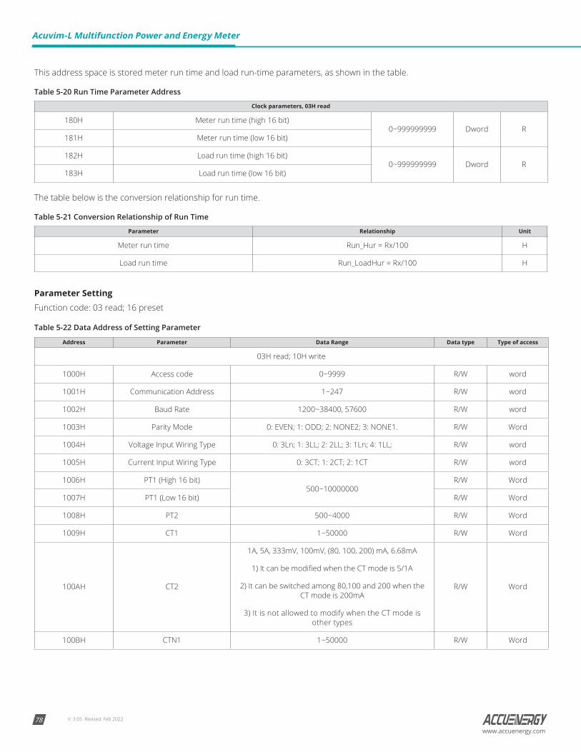
V: 3.05 Revised: Feb 202278
Acuvim-L Multifunction Power and Energy Meter
www.accuenergy.com
This address space is stored meter run time and load run-time parameters, as shown in the table.
Table 5-20 Run Time Parameter Address
Clock parameters, 03H read
180H Meter run time (high 16 bit)0~999999999 Dword R
181H Meter run time (low 16 bit)
182H Load run time (high 16 bit)0~999999999 Dword R
183H Load run time (low 16 bit)
The table below is the conversion relationship for run time.
Table 5-21 Conversion Relationship of Run Time
Parameter Relationship Unit
Meter run time Run_Hur = Rx/100 H
Load run time Run_LoadHur = Rx/100 H
Parameter SettingFunction code: 03 read; 16 preset
Table 5-22 Data Address of Setting Parameter
Address Parameter Data Range Data type Type of access
03H read; 10H write
1000H Access code 0~9999 R/W word
1001H Communication Address 1~247 R/W word
1002H Baud Rate 1200~38400, 57600 R/W word
1003H Parity Mode 0: EVEN; 1: ODD; 2: NONE2; 3: NONE1. R/W Word
1004H Voltage Input Wiring Type 0: 3Ln; 1: 3LL; 2: 2LL; 3: 1Ln; 4: 1LL; R/W word
1005H Current Input Wiring Type 0: 3CT; 1: 2CT; 2: 1CT R/W word
1006H PT1 (High 16 bit)500~10000000
R/W Word
1007H PT1 (Low 16 bit) R/W Word
1008H PT2 500~4000 R/W Word
1009H CT1 1~50000 R/W Word
100AH CT2
1A, 5A, 333mV, 100mV, (80, 100, 200) mA, 6.68mA
1) It can be modified when the CT mode is 5/1A
2) It can be switched among 80,100 and 200 when the CT mode is 200mA
3) It is not allowed to modify when the CT mode is other types
R/W Word
100BH CTN1 1~50000 R/W Word
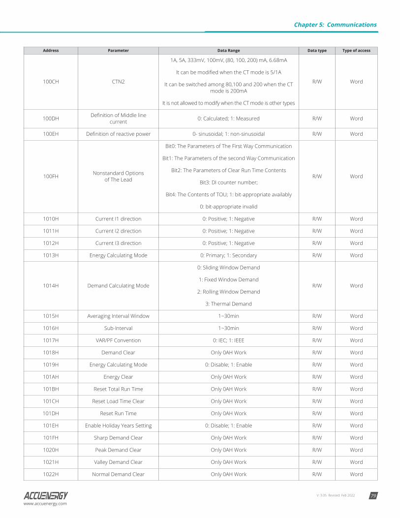
V: 3.05 Revised: Feb 2022 79www.accuenergy.com
Address Parameter Data Range Data type Type of access
100CH CTN2
1A, 5A, 333mV, 100mV, (80, 100, 200) mA, 6.68mA
It can be modified when the CT mode is 5/1A
It can be switched among 80,100 and 200 when the CT mode is 200mA
It is not allowed to modify when the CT mode is other types
R/W Word
100DH Definition of Middle line current 0: Calculated; 1: Measured R/W Word
100EH Definition of reactive power 0- sinusoidal; 1: non-sinusoidal R/W Word
100FH Nonstandard Options of The Lead
Bit0: The Parameters of The First Way Communication
Bit1: The Parameters of the second Way Communication
Bit2: The Parameters of Clear Run Time Contents
Bit3: DI counter number;
Bit4: The Contents of TOU; 1: bit-appropriate availably
0: bit-appropriate invalid
R/W Word
1010H Current I1 direction 0: Positive; 1: Negative R/W Word
1011H Current I2 direction 0: Positive; 1: Negative R/W Word
1012H Current I3 direction 0: Positive; 1: Negative R/W Word
1013H Energy Calculating Mode 0: Primary; 1: Secondary R/W Word
1014H Demand Calculating Mode
0: Sliding Window Demand
1: Fixed Window Demand
2: Rolling Window Demand
3: Thermal Demand
R/W Word
1015H Averaging Interval Window 1~30min R/W Word
1016H Sub-Interval 1~30min R/W Word
1017H VAR/PF Convention 0: IEC; 1: IEEE R/W Word
1018H Demand Clear Only 0AH Work R/W Word
1019H Energy Calculating Mode 0: Disable; 1: Enable R/W Word
101AH Energy Clear Only 0AH Work R/W Word
101BH Reset Total Run Time Only 0AH Work R/W Word
101CH Reset Load Time Clear Only 0AH Work R/W Word
101DH Reset Run Time Only 0AH Work R/W Word
101EH Enable Holiday Years Setting 0: Disable; 1: Enable R/W Word
101FH Sharp Demand Clear Only 0AH Work R/W Word
1020H Peak Demand Clear Only 0AH Work R/W Word
1021H Valley Demand Clear Only 0AH Work R/W Word
1022H Normal Demand Clear Only 0AH Work R/W Word
Chapter 5: Communications

V: 3.05 Revised: Feb 202280
Acuvim-L Multifunction Power and Energy Meter
www.accuenergy.com
Address Parameter Data Range Data type Type of access
1023H Total Demand Clear Only 0AH Work R/W Word
1024H Reset Max and Min Only 0AH Work R/W Word
1025H Turn On the Backlight 0~120(min) R/W Word
1026H Reverse 0: Modbus-RTU; 1: Profibus R/W Word
1027H Communication Address of Channel 2 1-247(MODBUS); 0~126: Profibus; R/W Word
1028H Baud Rate of Channel 2 1200-38400(DL\EL), 57600 R/W Word
1029H Parity Mode of Channel 2 0: EVEN ;1: ODD; 2: NONE2; 3: NONE1. R/W Word
102AH Enable Wiring Check Only 0AH Work R/W Word
102BH Expected Power FactorCapacitive: 67; Inductive: 76;
Resistive: 82;R/W Word
102CH Expected Load Type -1000~1000 R/W Integer
102DH Reverse R/W Word
Parameter of ClockFunction code:03 read,16: preset
Table 5-23 Data Address of Clock Parameter
Address Parameter Data Range Data type Type of access
03H read, 10H write
2280H Year 2000-2099 R/W Word
2281H Month 1-12 R/W Word
2282H Day 1-31 R/W Word
2283H Hour 0-23 R/W Word
2284H Minute 0-59 R/W Word
2285H Second 0-59 R/W Word
2286H Week 0-6 R/W Word
2287H Total Run Time (High)0~999999999 R Dword
2288H Total Run Time (Low)
2289H Load Run Time (High)0~999999999 R Dword
228AH Load Run Time (Low)
228BH Run Time (High)0~999999999 R Dword
228CH Run Time (Low)
228DH-22BFH Reverse R Word
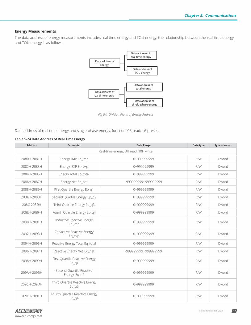
V: 3.05 Revised: Feb 2022 81www.accuenergy.com
Energy MeasurementsThe data address of energy measurements includes real time energy and TOU energy, the relationship between the real time energy and TOU energy is as follows:
Data address ofTOU energy
Data address ofenergy
Data address ofreal time energy
Data address of total energy
Data address of single-phase energy
Data address ofreal time energy
Fig 5-1 Division Plans of Energy Address
Data address of real time energy and single-phase energy, function: 03 read; 16 preset.
Table 5-24 Data Address of Real Time Energy
Address Parameter Data Range Data type Type of access
Real-time energy, 3H read, 10H write
2080H-2081H Energy IMP Ep_imp 0~999999999 R/W Dword
2082H-2083H Energy EXP Ep_exp 0~999999999 R/W Dword
2084H-2085H Energy Total Ep_total 0~999999999 R/W Dword
2086H-2087H Energy Net Ep_net -999999999~ 999999999 R/W Dword
2088H-2089H First Quartile Energy Ep_q1 0~999999999 R/W Dword
208AH-208BH Second Quartile Energy Ep_q2 0~999999999 R/W Dword
208C-208DH Third Quartile Energy Ep_q3 0~999999999 R/W Dword
208EH-208FH Fourth Quartile Energy Ep_q4 0~999999999 R/W Dword
2090H-2091H Inductive Reactive Energy Eq_imp 0~999999999 R/W Dword
2092H-2093H Capacitive Reactive Energy Eq_exp 0~999999999 R/W Dword
2094H-2095H Reactive Energy Total Eq_total 0~999999999 R/W Dword
2096H-2097H Reactive Energy Net Eq_net -999999999~ 999999999 R/W Dword
2098H-2099H First Quartile Reactive Energy Eq_q1 0~999999999 R/W Dword
209AH-209BH Second Quartile Reactive Energy Eq_q2 0~999999999 R/W Dword
209CH-209DH Third Quartile Reactive Energy Eq_q3 0~999999999 R/W Dword
209EH-209FH Fourth Quartile Reactive Energy Eq_q4 0~999999999 R/W Dword
Chapter 5: Communications
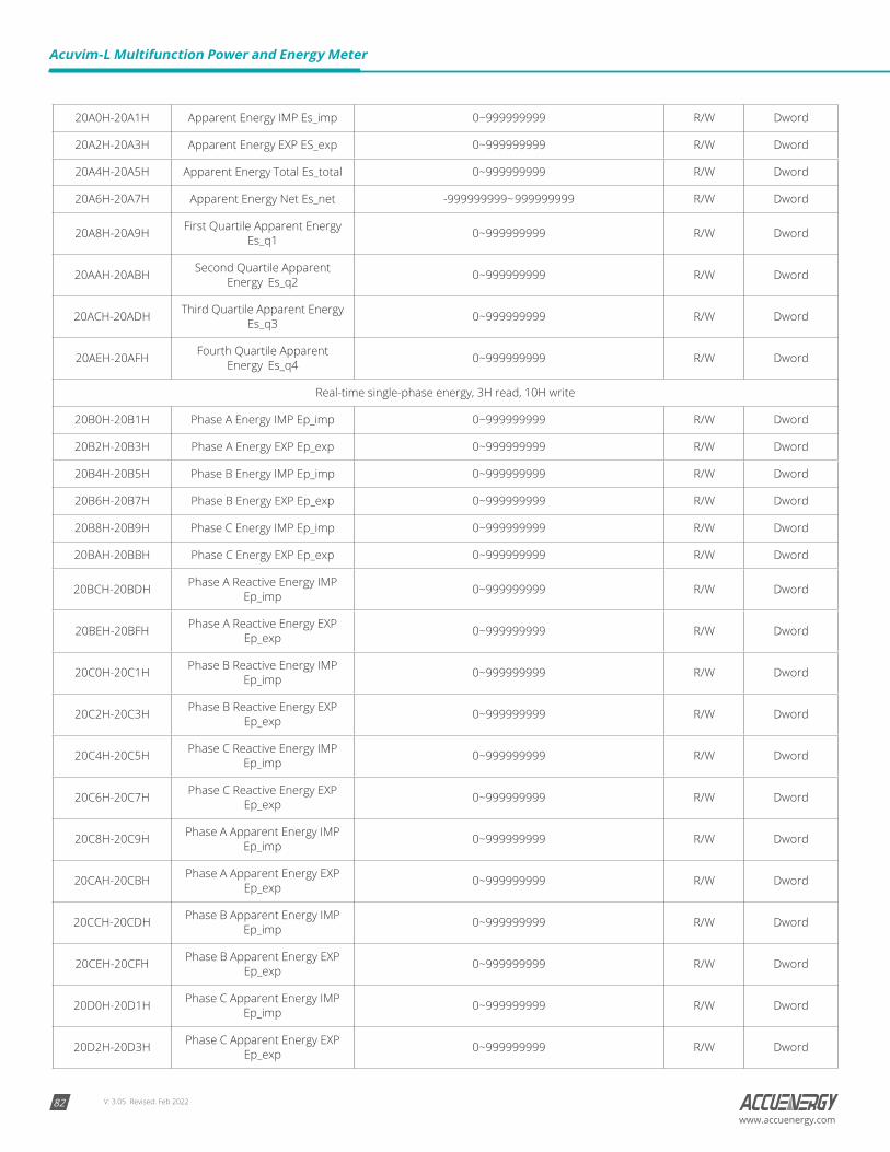
V: 3.05 Revised: Feb 202282
Acuvim-L Multifunction Power and Energy Meter
www.accuenergy.com
20A0H-20A1H Apparent Energy IMP Es_imp 0~999999999 R/W Dword
20A2H-20A3H Apparent Energy EXP ES_exp 0~999999999 R/W Dword
20A4H-20A5H Apparent Energy Total Es_total 0~999999999 R/W Dword
20A6H-20A7H Apparent Energy Net Es_net -999999999~ 999999999 R/W Dword
20A8H-20A9H First Quartile Apparent Energy Es_q1 0~999999999 R/W Dword
20AAH-20ABH Second Quartile Apparent Energy Es_q2 0~999999999 R/W Dword
20ACH-20ADH Third Quartile Apparent Energy Es_q3 0~999999999 R/W Dword
20AEH-20AFH Fourth Quartile Apparent Energy Es_q4 0~999999999 R/W Dword
Real-time single-phase energy, 3H read, 10H write
20B0H-20B1H Phase A Energy IMP Ep_imp 0~999999999 R/W Dword
20B2H-20B3H Phase A Energy EXP Ep_exp 0~999999999 R/W Dword
20B4H-20B5H Phase B Energy IMP Ep_imp 0~999999999 R/W Dword
20B6H-20B7H Phase B Energy EXP Ep_exp 0~999999999 R/W Dword
20B8H-20B9H Phase C Energy IMP Ep_imp 0~999999999 R/W Dword
20BAH-20BBH Phase C Energy EXP Ep_exp 0~999999999 R/W Dword
20BCH-20BDH Phase A Reactive Energy IMP Ep_imp 0~999999999 R/W Dword
20BEH-20BFH Phase A Reactive Energy EXP Ep_exp 0~999999999 R/W Dword
20C0H-20C1H Phase B Reactive Energy IMP Ep_imp 0~999999999 R/W Dword
20C2H-20C3H Phase B Reactive Energy EXP Ep_exp 0~999999999 R/W Dword
20C4H-20C5H Phase C Reactive Energy IMP Ep_imp 0~999999999 R/W Dword
20C6H-20C7H Phase C Reactive Energy EXP Ep_exp 0~999999999 R/W Dword
20C8H-20C9H Phase A Apparent Energy IMP Ep_imp 0~999999999 R/W Dword
20CAH-20CBH Phase A Apparent Energy EXP Ep_exp 0~999999999 R/W Dword
20CCH-20CDH Phase B Apparent Energy IMP Ep_imp 0~999999999 R/W Dword
20CEH-20CFH Phase B Apparent Energy EXP Ep_exp 0~999999999 R/W Dword
20D0H-20D1H Phase C Apparent Energy IMP Ep_imp 0~999999999 R/W Dword
20D2H-20D3H Phase C Apparent Energy EXP Ep_exp 0~999999999 R/W Dword
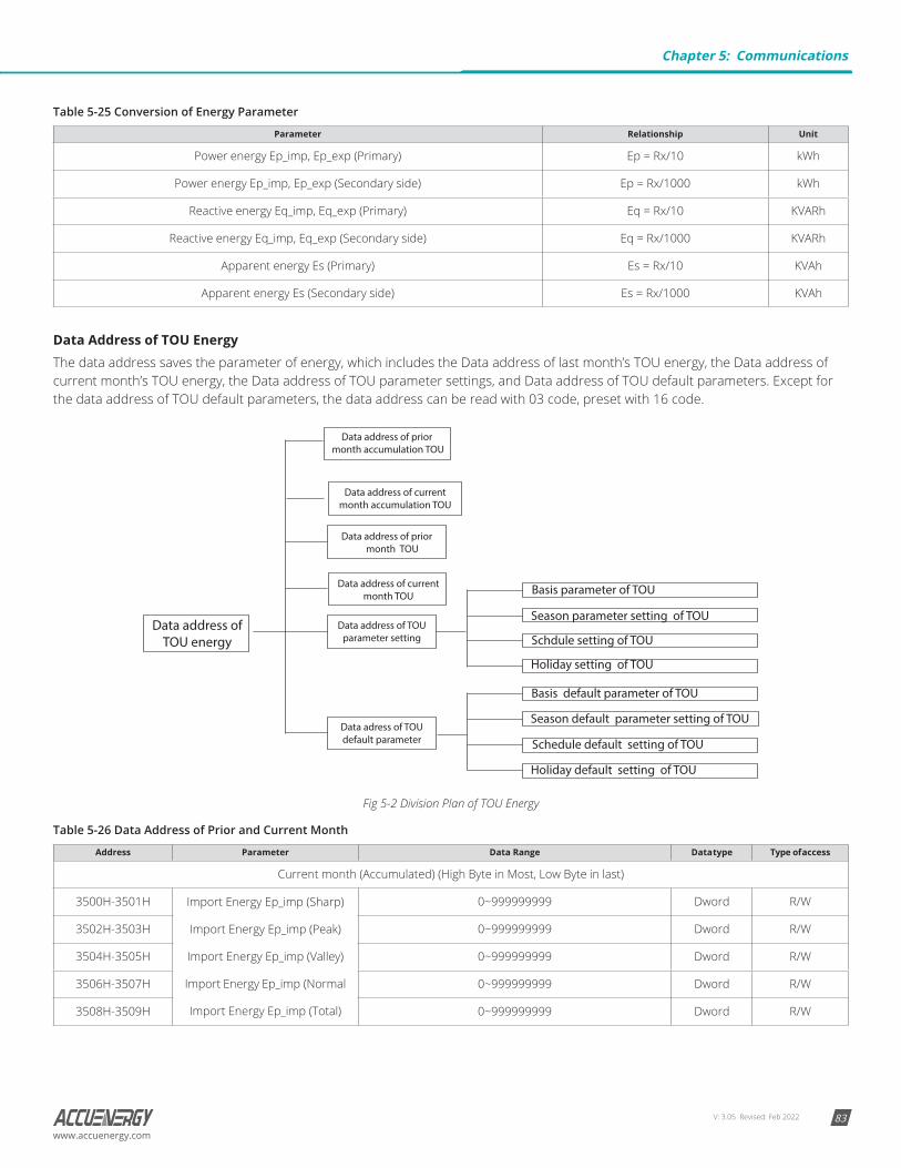
V: 3.05 Revised: Feb 2022 83www.accuenergy.com
Table 5-25 Conversion of Energy Parameter
Parameter Relationship Unit
Power energy Ep_imp, Ep_exp (Primary) Ep = Rx/10 kWh
Power energy Ep_imp, Ep_exp (Secondary side) Ep = Rx/1000 kWh
Reactive energy Eq_imp, Eq_exp (Primary) Eq = Rx/10 KVARh
Reactive energy Eq_imp, Eq_exp (Secondary side) Eq = Rx/1000 KVARh
Apparent energy Es (Primary) Es = Rx/10 KVAh
Apparent energy Es (Secondary side) Es = Rx/1000 KVAh
Data Address of TOU EnergyThe data address saves the parameter of energy, which includes the Data address of last month’s TOU energy, the Data address of current month’s TOU energy, the Data address of TOU parameter settings, and Data address of TOU default parameters. Except for the data address of TOU default parameters, the data address can be read with 03 code, preset with 16 code.
Data address ofTOU energy
Data address of currentmonth accumulation TOU
Data address of TOUparameter setting
Data adress of TOUdefault parameter
Basis parameter of TOU
Season parameter setting of TOU
Schdule setting of TOU
Holiday setting of TOU
Basis default parameter of TOU
Season default parameter setting of TOU
Schedule default setting of TOU
Holiday default setting of TOU
Data address of prior month accumulation TOU
Data address of prior month TOU
Data address of currentmonth TOU
Fig 5-2 Division Plan of TOU Energy
Table 5-26 Data Address of Prior and Current Month
Address Parameter Data Range Data type Type of access
Current month (Accumulated) (High Byte in Most, Low Byte in last)
3500H-3501H Import Energy Ep_imp (Sharp)
Import Energy Ep_imp (Peak)
Import Energy Ep_imp (Valley)
Import Energy Ep_imp (Normal
Import Energy Ep_imp (Total)
0~999999999 Dword R/W
3502H-3503H 0~999999999 Dword R/W
3504H-3505H 0~999999999 Dword R/W
3506H-3507H 0~999999999 Dword R/W
3508H-3509H 0~999999999 Dword R/W
Chapter 5: Communications
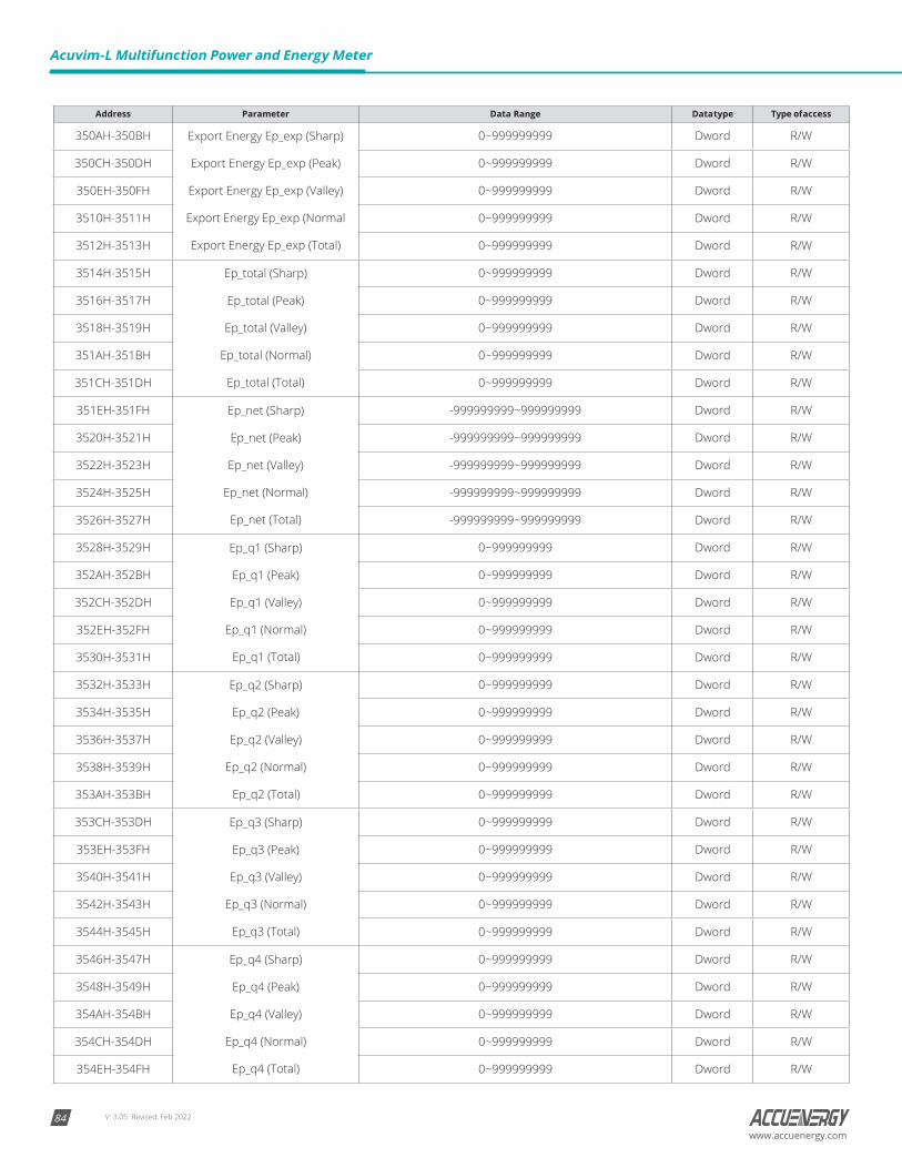
V: 3.05 Revised: Feb 202284
Acuvim-L Multifunction Power and Energy Meter
www.accuenergy.com
Address Parameter Data Range Data type Type of access
350AH-350BH Export Energy Ep_exp (Sharp)
Export Energy Ep_exp (Peak)
Export Energy Ep_exp (Valley)
Export Energy Ep_exp (Normal
Export Energy Ep_exp (Total)
0~999999999 Dword R/W
350CH-350DH 0~999999999 Dword R/W
350EH-350FH 0~999999999 Dword R/W
3510H-3511H 0~999999999 Dword R/W
3512H-3513H 0~999999999 Dword R/W
3514H-3515H Ep_total (Sharp)
Ep_total (Peak)
Ep_total (Valley)
Ep_total (Normal)
Ep_total (Total)
0~999999999 Dword R/W
3516H-3517H 0~999999999 Dword R/W
3518H-3519H 0~999999999 Dword R/W
351AH-351BH 0~999999999 Dword R/W
351CH-351DH 0~999999999 Dword R/W
351EH-351FH Ep_net (Sharp)
Ep_net (Peak)
Ep_net (Valley)
Ep_net (Normal)
Ep_net (Total)
-999999999~999999999 Dword R/W
3520H-3521H -999999999~999999999 Dword R/W
3522H-3523H -999999999~999999999 Dword R/W
3524H-3525H -999999999~999999999 Dword R/W
3526H-3527H -999999999~999999999 Dword R/W
3528H-3529H Ep_q1 (Sharp)
Ep_q1 (Peak)
Ep_q1 (Valley)
Ep_q1 (Normal)
Ep_q1 (Total)
0~999999999 Dword R/W
352AH-352BH 0~999999999 Dword R/W
352CH-352DH 0~999999999 Dword R/W
352EH-352FH 0~999999999 Dword R/W
3530H-3531H 0~999999999 Dword R/W
3532H-3533H Ep_q2 (Sharp)
Ep_q2 (Peak)
Ep_q2 (Valley)
Ep_q2 (Normal)
Ep_q2 (Total)
0~999999999 Dword R/W
3534H-3535H 0~999999999 Dword R/W
3536H-3537H 0~999999999 Dword R/W
3538H-3539H 0~999999999 Dword R/W
353AH-353BH 0~999999999 Dword R/W
353CH-353DH Ep_q3 (Sharp)
Ep_q3 (Peak)
Ep_q3 (Valley)
Ep_q3 (Normal)
Ep_q3 (Total)
0~999999999 Dword R/W
353EH-353FH 0~999999999 Dword R/W
3540H-3541H 0~999999999 Dword R/W
3542H-3543H 0~999999999 Dword R/W
3544H-3545H 0~999999999 Dword R/W
3546H-3547H Ep_q4 (Sharp)
Ep_q4 (Peak)
Ep_q4 (Valley)
Ep_q4 (Normal)
Ep_q4 (Total)
0~999999999 Dword R/W
3548H-3549H 0~999999999 Dword R/W
354AH-354BH 0~999999999 Dword R/W
354CH-354DH 0~999999999 Dword R/W
354EH-354FH 0~999999999 Dword R/W
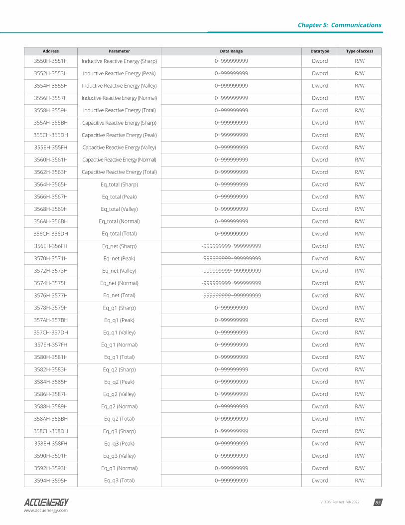
V: 3.05 Revised: Feb 2022 85www.accuenergy.com
Address Parameter Data Range Data type Type of access
3550H-3551H Inductive Reactive Energy (Sharp)
Inductive Reactive Energy (Peak)
Inductive Reactive Energy (Valley)
Inductive Reactive Energy (Normal)
Inductive Reactive Energy (Total)
0~999999999 Dword R/W
3552H-3553H 0~999999999 Dword R/W
3554H-3555H 0~999999999 Dword R/W
3556H-3557H 0~999999999 Dword R/W
3558H-3559H 0~999999999 Dword R/W
355AH-355BH Capacitive Reactive Energy (Sharp)
Capacitive Reactive Energy (Peak)
Capacitive Reactive Energy (Valley)
Capacitive Reactive Energy (Normal)
Capacitive Reactive Energy (Total)
0~999999999 Dword R/W
355CH-355DH 0~999999999 Dword R/W
355EH-355FH 0~999999999 Dword R/W
3560H-3561H 0~999999999 Dword R/W
3562H-3563H 0~999999999 Dword R/W
3564H-3565H Eq_total (Sharp)
Eq_total (Peak)
Eq_total (Valley)
Eq_total (Normal)
Eq_total (Total)
0~999999999 Dword R/W
3566H-3567H 0~999999999 Dword R/W
3568H-3569H 0~999999999 Dword R/W
356AH-356BH 0~999999999 Dword R/W
356CH-356DH 0~999999999 Dword R/W
356EH-356FH Eq_net (Sharp)
Eq_net (Peak)
Eq_net (Valley)
Eq_net (Normal)
Eq_net (Total)
-999999999~999999999 Dword R/W
3570H-3571H -999999999~999999999 Dword R/W
3572H-3573H -999999999~999999999 Dword R/W
3574H-3575H -999999999~999999999 Dword R/W
3576H-3577H -999999999~999999999 Dword R/W
3578H-3579H Eq_q1 (Sharp)
Eq_q1 (Peak)
Eq_q1 (Valley)
Eq_q1 (Normal)
Eq_q1 (Total)
0~999999999 Dword R/W
357AH-357BH 0~999999999 Dword R/W
357CH-357DH 0~999999999 Dword R/W
357EH-357FH 0~999999999 Dword R/W
3580H-3581H 0~999999999 Dword R/W
3582H-3583H Eq_q2 (Sharp)
Eq_q2 (Peak)
Eq_q2 (Valley)
Eq_q2 (Normal)
Eq_q2 (Total)
0~999999999 Dword R/W
3584H-3585H 0~999999999 Dword R/W
3586H-3587H 0~999999999 Dword R/W
3588H-3589H 0~999999999 Dword R/W
358AH-358BH 0~999999999 Dword R/W
358CH-358DH Eq_q3 (Sharp)
Eq_q3 (Peak)
Eq_q3 (Valley)
Eq_q3 (Normal)
Eq_q3 (Total)
0~999999999 Dword R/W
358EH-358FH 0~999999999 Dword R/W
3590H-3591H 0~999999999 Dword R/W
3592H-3593H 0~999999999 Dword R/W
3594H-3595H 0~999999999 Dword R/W
Chapter 5: Communications
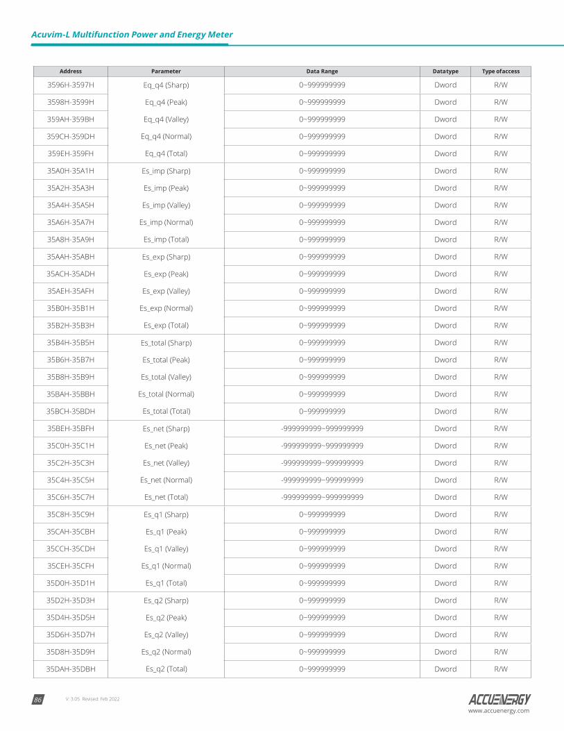
V: 3.05 Revised: Feb 202286
Acuvim-L Multifunction Power and Energy Meter
www.accuenergy.com
Address Parameter Data Range Data type Type of access
3596H-3597H Eq_q4 (Sharp)
Eq_q4 (Peak)
Eq_q4 (Valley)
Eq_q4 (Normal)
Eq_q4 (Total)
0~999999999 Dword R/W
3598H-3599H 0~999999999 Dword R/W
359AH-359BH 0~999999999 Dword R/W
359CH-359DH 0~999999999 Dword R/W
359EH-359FH 0~999999999 Dword R/W
35A0H-35A1H Es_imp (Sharp)
Es_imp (Peak)
Es_imp (Valley)
Es_imp (Normal)
Es_imp (Total)
0~999999999 Dword R/W
35A2H-35A3H 0~999999999 Dword R/W
35A4H-35A5H 0~999999999 Dword R/W
35A6H-35A7H 0~999999999 Dword R/W
35A8H-35A9H 0~999999999 Dword R/W
35AAH-35ABH Es_exp (Sharp)
Es_exp (Peak)
Es_exp (Valley)
Es_exp (Normal)
Es_exp (Total)
0~999999999 Dword R/W
35ACH-35ADH 0~999999999 Dword R/W
35AEH-35AFH 0~999999999 Dword R/W
35B0H-35B1H 0~999999999 Dword R/W
35B2H-35B3H 0~999999999 Dword R/W
35B4H-35B5H Es_total (Sharp)
Es_total (Peak)
Es_total (Valley)
Es_total (Normal)
Es_total (Total)
0~999999999 Dword R/W
35B6H-35B7H 0~999999999 Dword R/W
35B8H-35B9H 0~999999999 Dword R/W
35BAH-35BBH 0~999999999 Dword R/W
35BCH-35BDH 0~999999999 Dword R/W
35BEH-35BFH Es_net (Sharp)
Es_net (Peak)
Es_net (Valley)
Es_net (Normal)
Es_net (Total)
-999999999~999999999 Dword R/W
35C0H-35C1H -999999999~999999999 Dword R/W
35C2H-35C3H -999999999~999999999 Dword R/W
35C4H-35C5H -999999999~999999999 Dword R/W
35C6H-35C7H -999999999~999999999 Dword R/W
35C8H-35C9H Es_q1 (Sharp)
Es_q1 (Peak)
Es_q1 (Valley)
Es_q1 (Normal)
Es_q1 (Total)
0~999999999 Dword R/W
35CAH-35CBH 0~999999999 Dword R/W
35CCH-35CDH 0~999999999 Dword R/W
35CEH-35CFH 0~999999999 Dword R/W
35D0H-35D1H 0~999999999 Dword R/W
35D2H-35D3H Es_q2 (Sharp)
Es_q2 (Peak)
Es_q2 (Valley)
Es_q2 (Normal)
Es_q2 (Total)
0~999999999 Dword R/W
35D4H-35D5H 0~999999999 Dword R/W
35D6H-35D7H 0~999999999 Dword R/W
35D8H-35D9H 0~999999999 Dword R/W
35DAH-35DBH 0~999999999 Dword R/W
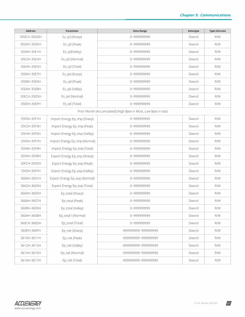
V: 3.05 Revised: Feb 2022 87www.accuenergy.com
Address Parameter Data Range Data type Type of access
35DCH-35DDH Es_q3 (Sharp)
Es_q3 (Peak)
Es_q3(Valley)
Es_q3 (Normal)
Es_q3 (Total)
0~999999999 Dword R/W
35DEH-35DFH 0~999999999 Dword R/W
35E0H-35E1H 0~999999999 Dword R/W
35E2H-35E3H 0~999999999 Dword R/W
35E4H-35E5H 0~999999999 Dword R/W
35E6H-35E7H Es_q4 (Sharp)
Es_q4 (Peak)
Es_q4 (Valley)
Es_q4 (Normal)
Es_q4 (Total)
0~999999999 Dword R/W
35E8H-35E9H 0~999999999 Dword R/W
35EAH-35EBH 0~999999999 Dword R/W
35ECH-35EDH 0~999999999 Dword R/W
35EEH-35EFH 0~999999999 Dword R/W
Prior Month (Accumulated) (High Byte in Most, Low Byte in last)
35F0H-35F1H Import Energy Ep_imp (Sharp)
Import Energy Ep_imp (Peak)
Import Energy Ep_imp (Valley)
Import Energy Ep_imp (Normal)
Import Energy Ep_imp (Total)
0~999999999 Dword R/W
35F2H-35F3H 0~999999999 Dword R/W
35F4H-35F5H 0~999999999 Dword R/W
35F6H-35F7H 0~999999999 Dword R/W
35F8H-35F9H 0~999999999 Dword R/W
35FAH-35FBH Export Energy Ep_exp (Sharp)
Export Energy Ep_exp (Peak)
Export Energy Ep_exp (Valley)
Export Energy Ep_exp (Normal)
Export Energy Ep_exp (Total)
0~999999999 Dword R/W
35FCH-35FDH 0~999999999 Dword R/W
35FEH-35FFH 0~999999999 Dword R/W
3600H-3501H 0~999999999 Dword R/W
3602H-3603H 0~999999999 Dword R/W
3604H-3605H Ep_total (Sharp)
Ep_total (Peak)
Ep_total (Valley)
Ep_total l (Normal)
Ep_total (Total)
0~999999999 Dword R/W
3606H-3607H 0~999999999 Dword R/W
3608H-3609H 0~999999999 Dword R/W
360AH-360BH 0~999999999 Dword R/W
360CH-360DH 0~999999999 Dword R/W
360EH-360FH Ep_net (Sharp)
Ep_net (Peak)
Ep_net (Valley)
Ep_net (Normal)
Ep_net (Total)
-999999999~999999999 Dword R/W
3610H-3611H -999999999~999999999 Dword R/W
3612H-3613H -999999999~999999999 Dword R/W
3614H-3615H -999999999~999999999 Dword R/W
3616H-3617H -999999999~999999999 Dword R/W
Chapter 5: Communications
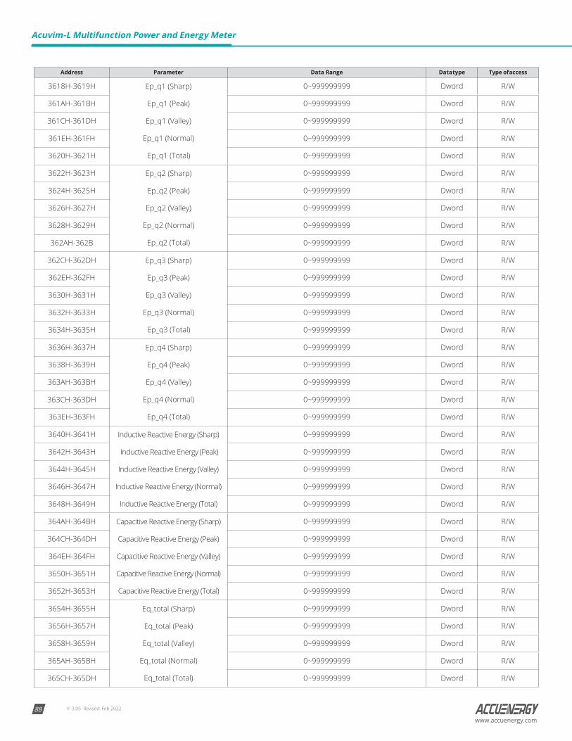
V: 3.05 Revised: Feb 202288
Acuvim-L Multifunction Power and Energy Meter
www.accuenergy.com
Address Parameter Data Range Data type Type of access
3618H-3619H Ep_q1 (Sharp)
Ep_q1 (Peak)
Ep_q1 (Valley)
Ep_q1 (Normal)
Ep_q1 (Total)
0~999999999 Dword R/W
361AH-361BH 0~999999999 Dword R/W
361CH-361DH 0~999999999 Dword R/W
361EH-361FH 0~999999999 Dword R/W
3620H-3621H 0~999999999 Dword R/W
3622H-3623H Ep_q2 (Sharp)
Ep_q2 (Peak)
Ep_q2 (Valley)
Ep_q2 (Normal)
Ep_q2 (Total)
0~999999999 Dword R/W
3624H-3625H 0~999999999 Dword R/W
3626H-3627H 0~999999999 Dword R/W
3628H-3629H 0~999999999 Dword R/W
362AH-362B 0~999999999 Dword R/W
362CH-362DH Ep_q3 (Sharp)
Ep_q3 (Peak)
Ep_q3 (Valley)
Ep_q3 (Normal)
Ep_q3 (Total)
0~999999999 Dword R/W
362EH-362FH 0~999999999 Dword R/W
3630H-3631H 0~999999999 Dword R/W
3632H-3633H 0~999999999 Dword R/W
3634H-3635H 0~999999999 Dword R/W
3636H-3637H Ep_q4 (Sharp)
Ep_q4 (Peak)
Ep_q4 (Valley)
Ep_q4 (Normal)
Ep_q4 (Total)
0~999999999 Dword R/W
3638H-3639H 0~999999999 Dword R/W
363AH-363BH 0~999999999 Dword R/W
363CH-363DH 0~999999999 Dword R/W
363EH-363FH 0~999999999 Dword R/W
3640H-3641H Inductive Reactive Energy (Sharp)
Inductive Reactive Energy (Peak)
Inductive Reactive Energy (Valley)
Inductive Reactive Energy (Normal)
Inductive Reactive Energy (Total)
0~999999999 Dword R/W
3642H-3643H 0~999999999 Dword R/W
3644H-3645H 0~999999999 Dword R/W
3646H-3647H 0~999999999 Dword R/W
3648H-3649H 0~999999999 Dword R/W
364AH-364BH Capacitive Reactive Energy (Sharp)
Capacitive Reactive Energy (Peak)
Capacitive Reactive Energy (Valley)
Capacitive Reactive Energy (Normal)
Capacitive Reactive Energy (Total)
0~999999999 Dword R/W
364CH-364DH 0~999999999 Dword R/W
364EH-364FH 0~999999999 Dword R/W
3650H-3651H 0~999999999 Dword R/W
3652H-3653H 0~999999999 Dword R/W
3654H-3655H Eq_total (Sharp)
Eq_total (Peak)
Eq_total (Valley)
Eq_total (Normal)
Eq_total (Total)
0~999999999 Dword R/W
3656H-3657H 0~999999999 Dword R/W
3658H-3659H 0~999999999 Dword R/W
365AH-365BH 0~999999999 Dword R/W
365CH-365DH 0~999999999 Dword R/W

V: 3.05 Revised: Feb 2022 89www.accuenergy.com
Address Parameter Data Range Data type Type of access
365EH-365FH Eq_net (Sharp)
Eq_net (Peak)
Eq_net (Valley)
Eq_net (Normal)
Eq_net (Total)
-999999999~999999999 Dword R/W
3660H-3661H -999999999~999999999 Dword R/W
3662H-3663H -999999999~999999999 Dword R/W
3664H-3665H -999999999~999999999 Dword R/W
3666H-3667H -999999999~999999999 Dword R/W
3668H-3669H Eq_q1 (Sharp)
Eq_q1 (Peak)
Eq_q1 (Valley)
Eq_q1 (Normal)
Eq_q1 (Total)
0~999999999 Dword R/W
366AH-366BH 0~999999999 Dword R/W
366CH-366DH 0~999999999 Dword R/W
366EH-366FH 0~999999999 Dword R/W
3670H-3671H 0~999999999 Dword R/W
3672H-3673H Eq_q2 (Sharp)
Eq_q2 (Peak)
Eq_q2 (Valley)
Eq_q2 (Normal)
Eq_q2 (Total)
0~999999999 Dword R/W
3674H-3675H 0~999999999 Dword R/W
3676H-3677H 0~999999999 Dword R/W
3678H-3679H 0~999999999 Dword R/W
367AH-367BH 0~999999999 Dword R/W
367CH-367DH Eq_q3 (Sharp)
Eq_q3 (Peak)
Eq_q3 (Valley)
Eq_q3 (Normal)
Eq_q3 (Total)
0~999999999 Dword R/W
367EH-367FH 0~999999999 Dword R/W
3680H-3681H 0~999999999 Dword R/W
3682H-3683H 0~999999999 Dword R/W
3684H-3685H 0~999999999 Dword R/W
3686H-3687H Eq_q4 (Sharp)
Eq_q4 (Peak)
Eq_q4 (Valley)
Eq_q4 (Normal)
Eq_q4 (Total)
0~999999999 Dword R/W
3688H-3689H 0~999999999 Dword R/W
368AH-368BH 0~999999999 Dword R/W
368CH-368DH 0~999999999 Dword R/W
368EH-368FH 0~999999999 Dword R/W
3690H-3691H Es_imp (Sharp)
Es_imp (Peak)
Es_imp (Valley)
Es_imp (Normal)
Es_imp (Total)
0~999999999 Dword R/W
3692H-3693H 0~999999999 Dword R/W
3694H-3695H 0~999999999 Dword R/W
3696H-3697H 0~999999999 Dword R/W
3698H-3699H 0~999999999 Dword R/W
369AH-369BH Es_exp (Sharp)
Es_exp (Peak)
Es_exp (Valley)
Es_exp (Normal)
Es_exp (Total)
0~999999999 Dword R/W
369CH-369DH 0~999999999 Dword R/W
369EH-369FH 0~999999999 Dword R/W
36A0H-36A1H 0~999999999 Dword R/W
36A2H-36A3H 0~999999999 Dword R/W
Chapter 5: Communications
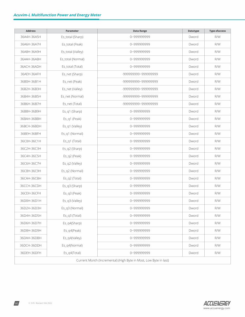
V: 3.05 Revised: Feb 202290
Acuvim-L Multifunction Power and Energy Meter
www.accuenergy.com
Address Parameter Data Range Data type Type of access
36A4H-36A5H Es_total (Sharp)
Es_total (Peak)
Es_total (Valley)
Es_total (Normal)
Es_total (Total)
0~999999999 Dword R/W
36A6H-36A7H 0~999999999 Dword R/W
36A8H-36A9H 0~999999999 Dword R/W
36AAH-36ABH 0~999999999 Dword R/W
36ACH-36ADH 0~999999999 Dword R/W
36AEH-36AFH Es_net (Sharp)
Es_net (Peak)
Es_net (Valley)
Es_net (Normal)
Es_net (Total)
-999999999~999999999 Dword R/W
36B0H-36B1H -999999999~999999999 Dword R/W
36B2H-36B3H -999999999~999999999 Dword R/W
36B4H-36B5H -999999999~999999999 Dword R/W
36B6H-36B7H -999999999~999999999 Dword R/W
36B8H-36B9H Es_q1 (Sharp)
Es_q1 (Peak)
Es_q1 (Valley)
Es_q1 (Normal)
Es_q1 (Total)
0~999999999 Dword R/W
36BAH-36BBH 0~999999999 Dword R/W
36BCH-36BDH 0~999999999 Dword R/W
36BEH-36BFH 0~999999999 Dword R/W
36C0H-36C1H 0~999999999 Dword R/W
36C2H-36C3H Es_q2 (Sharp)
Es_q2 (Peak)
Es_q2 (Valley)
Es_q2 (Normal)
Es_q2 (Total)
0~999999999 Dword R/W
36C4H-36C5H 0~999999999 Dword R/W
36C6H-36C7H 0~999999999 Dword R/W
36C8H-36C9H 0~999999999 Dword R/W
36CAH-36CBH 0~999999999 Dword R/W
36CCH-36CDH Es_q3 (Sharp)
Es_q3 (Peak)
Es_q3 (Valley)
Es_q3 (Normal)
Es_q3 (Total)
0~999999999 Dword R/W
36CEH-36CFH 0~999999999 Dword R/W
36D0H-36D1H 0~999999999 Dword R/W
36D2H-36D3H 0~999999999 Dword R/W
36D4H-36D5H 0~999999999 Dword R/W
36D6H-36D7H Es_q4(Sharp)
Es_q4(Peak)
Es_q4(Valley)
Es_q4(Normal)
Es_q4(Total)
0~999999999 Dword R/W
36D8H-36D9H 0~999999999 Dword R/W
36DAH-36DBH 0~999999999 Dword R/W
36DCH-36DDH 0~999999999 Dword R/W
36DEH-36DFH 0~999999999 Dword R/W
Current Month (Incremental) (High Byte in Most, Low Byte in last)
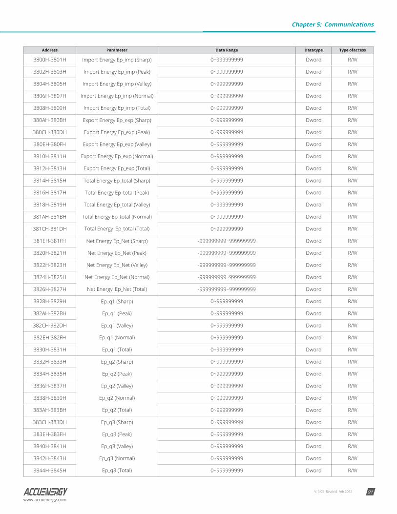
V: 3.05 Revised: Feb 2022 91www.accuenergy.com
Address Parameter Data Range Data type Type of access
3800H-3801H Import Energy Ep_imp (Sharp)
Import Energy Ep_imp (Peak)
Import Energy Ep_imp (Valley)
Import Energy Ep_imp (Normal)
Import Energy Ep_imp (Total)
0~999999999 Dword R/W
3802H-3803H 0~999999999 Dword R/W
3804H-3805H 0~999999999 Dword R/W
3806H-3807H 0~999999999 Dword R/W
3808H-3809H 0~999999999 Dword R/W
380AH-380BH Export Energy Ep_exp (Sharp)
Export Energy Ep_exp (Peak)
Export Energy Ep_exp (Valley)
Export Energy Ep_exp (Normal)
Export Energy Ep_exp (Total)
0~999999999 Dword R/W
380CH-380DH 0~999999999 Dword R/W
380EH-380FH 0~999999999 Dword R/W
3810H-3811H 0~999999999 Dword R/W
3812H-3813H 0~999999999 Dword R/W
3814H-3815H Total Energy Ep_total (Sharp)
Total Energy Ep_total (Peak)
Total Energy Ep_total (Valley)
Total Energy Ep_total (Normal)
Total Energy Ep_total (Total)
0~999999999 Dword R/W
3816H-3817H 0~999999999 Dword R/W
3818H-3819H 0~999999999 Dword R/W
381AH-381BH 0~999999999 Dword R/W
381CH-381DH 0~999999999 Dword R/W
381EH-381FH Net Energy Ep_Net (Sharp)
Net Energy Ep_Net (Peak)
Net Energy Ep_Net (Valley)
Net Energy Ep_Net (Normal)
Net Energy Ep_Net (Total)
-999999999~999999999 Dword R/W
3820H-3821H -999999999~999999999 Dword R/W
3822H-3823H -999999999~999999999 Dword R/W
3824H-3825H -999999999~999999999 Dword R/W
3826H-3827H -999999999~999999999 Dword R/W
3828H-3829H Ep_q1 (Sharp)
Ep_q1 (Peak)
Ep_q1 (Valley)
Ep_q1 (Normal)
Ep_q1 (Total)
0~999999999 Dword R/W
382AH-382BH 0~999999999 Dword R/W
382CH-382DH 0~999999999 Dword R/W
382EH-382FH 0~999999999 Dword R/W
3830H-3831H 0~999999999 Dword R/W
3832H-3833H Ep_q2 (Sharp)
Ep_q2 (Peak)
Ep_q2 (Valley)
Ep_q2 (Normal)
Ep_q2 (Total)
0~999999999 Dword R/W
3834H-3835H 0~999999999 Dword R/W
3836H-3837H 0~999999999 Dword R/W
3838H-3839H 0~999999999 Dword R/W
383AH-383BH 0~999999999 Dword R/W
383CH-383DH Ep_q3 (Sharp)
Ep_q3 (Peak)
Ep_q3 (Valley)
Ep_q3 (Normal)
Ep_q3 (Total)
0~999999999 Dword R/W
383EH-383FH 0~999999999 Dword R/W
3840H-3841H 0~999999999 Dword R/W
3842H-3843H 0~999999999 Dword R/W
3844H-3845H 0~999999999 Dword R/W
Chapter 5: Communications

V: 3.05 Revised: Feb 202292
Acuvim-L Multifunction Power and Energy Meter
www.accuenergy.com
Address Parameter Data Range Data type Type of access
3846H-3847H Ep_q4 (Sharp)
Ep_q4 (Peak)
Ep_q4 (Valley)
Ep_q4 (Normal)
Ep_q4 (Total)
0~999999999 Dword R/W
3848H-3849H 0~999999999 Dword R/W
384AH-384BH 0~999999999 Dword R/W
384CH-384DH 0~999999999 Dword R/W
384EH-384FH 0~999999999 Dword R/W
3850H-3851H Inductive Reactive Energy (Sharp)
Inductive Reactive Energy (Peak)
Inductive Reactive Energy (Valley)
Inductive Reactive Energy (Normal)
Inductive Reactive Energy (Total)
0~999999999 Dword R/W
3852H-3853H 0~999999999 Dword R/W
3854H-3855H 0~999999999 Dword R/W
3856H-3857H 0~999999999 Dword R/W
3858H-3859H 0~999999999 Dword R/W
385AH-385BH Capacitive Reactive Energy (Sharp)
Capacitive Reactive Energy (Peak)
Capacitive Reactive Energy (Valley)
Capacitive Reactive Energy (Normal)
Capacitive Reactive Energy (Total)
0~999999999 Dword R/W
385CH-385DH 0~999999999 Dword R/W
385EH-385FH 0~999999999 Dword R/W
3860H-3861H 0~999999999 Dword R/W
3862H-3863H 0~999999999 Dword R/W
3864H-3865H Total Reactive Energy Eq_total (Sharp)
Total Reactive Energy Eq_total (Peak)
Total Reactive Energy Eq_total (Valley)
Total Reactive Energy Eq_total (Normal)
Total Reactive Energy Eq_total (Total)
0~999999999 Dword R/W
3866H-3867H 0~999999999 Dword R/W
3868H-3869H 0~999999999 Dword R/W
386AH-386BH 0~999999999 Dword R/W
386CH-386DH 0~999999999 Dword R/W
386EH-386FH Net Reactive Energy Eq_net (Sharp)
Net Reactive Energy Eq_net (Peak)
Net Reactive Energy Eq_net (Valley)
Net Reactive Energy Eq_net (Normal)
Net Reactive Energy Eq_net (Total)
-999999999~999999999 Dword R/W
3870H-3871H -999999999~999999999 Dword R/W
3872H-3873H -999999999~999999999 Dword R/W
3874H-3875H -999999999~999999999 Dword R/W
3876H-3877H -999999999~999999999 Dword R/W
3878H-3879H Eq_q1 (Sharp)
Eq_q1 (Peak)
Eq_q1 (Valley)
Eq_q1 (Normal)
Eq_q1 (Total)
0~999999999 Dword R/W
387AH-387BH 0~999999999 Dword R/W
387CH-387DH 0~999999999 Dword R/W
387EH-387FH 0~999999999 Dword R/W
3880H-3881H 0~999999999 Dword R/W
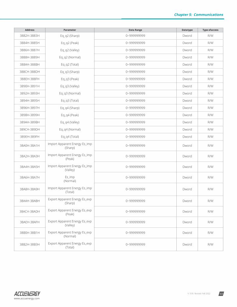
V: 3.05 Revised: Feb 2022 93www.accuenergy.com
Address Parameter Data Range Data type Type of access
3882H-3883H Eq_q2 (Sharp)
Eq_q2 (Peak)
Eq_q2 (Valley)
Eq_q2 (Normal)
Eq_q2 (Total)
0~999999999 Dword R/W
3884H-3885H 0~999999999 Dword R/W
3886H-3887H 0~999999999 Dword R/W
3888H-3889H 0~999999999 Dword R/W
388AH-388BH 0~999999999 Dword R/W
388CH-388DH Eq_q3 (Sharp)
Eq_q3 (Peak)
Eq_q3 (Valley)
Eq_q3 (Normal)
Eq_q3 (Total)
0~999999999 Dword R/W
388EH-388FH 0~999999999 Dword R/W
3890H-3891H 0~999999999 Dword R/W
3892H-3893H 0~999999999 Dword R/W
3894H-3895H 0~999999999 Dword R/W
3896H-3897H Eq_q4 (Sharp)
Eq_q4 (Peak)
Eq_q4 (Valley)
Eq_q4 (Normal)
Eq_q4 (Total)
0~999999999 Dword R/W
3898H-3899H 0~999999999 Dword R/W
389AH-389BH 0~999999999 Dword R/W
389CH-389DH 0~999999999 Dword R/W
389EH-389FH 0~999999999 Dword R/W
38A0H-38A1H Import Apparent Energy Es_imp (Sharp)
Import Apparent Energy Es_imp (Peak)
Import Apparent Energy Es_imp (Valley)
Es_imp (Normal)
Import Apparent Energy Es_imp (Total)
0~999999999 Dword R/W
38A2H-38A3H 0~999999999 Dword R/W
38A4H-38A5H 0~999999999 Dword R/W
38A6H-38A7H 0~999999999 Dword R/W
38A8H-38A9H 0~999999999 Dword R/W
38AAH-38ABH Export Apparent Energy Es_exp (Sharp)
Export Apparent Energy Es_exp (Peak)
Export Apparent Energy Es_exp (Valley)
Export Apparent Energy Es_exp (Normal)
Export Apparent Energy Es_exp (Total)
0~999999999 Dword R/W
38ACH-38ADH 0~999999999 Dword R/W
38AEH-38AFH 0~999999999 Dword R/W
38B0H-38B1H 0~999999999 Dword R/W
38B2H-38B3H 0~999999999 Dword R/W
Chapter 5: Communications
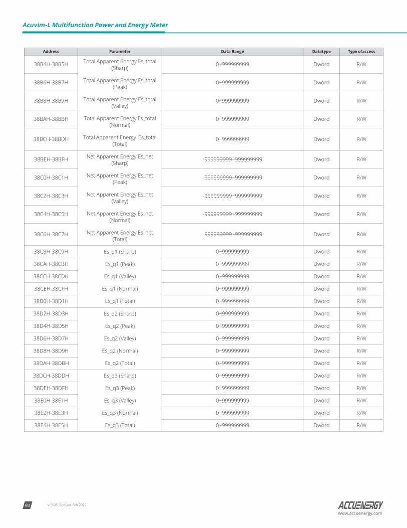
V: 3.05 Revised: Feb 202294
Acuvim-L Multifunction Power and Energy Meter
www.accuenergy.com
Address Parameter Data Range Data type Type of access
38B4H-38B5H Total Apparent Energy Es_total (Sharp)
Total Apparent Energy Es_total (Peak)
Total Apparent Energy Es_total (Valley)
Total Apparent Energy Es_total (Normal)
Total Apparent Energy Es_total (Total)
0~999999999 Dword R/W
38B6H-38B7H 0~999999999 Dword R/W
38B8H-38B9H 0~999999999 Dword R/W
38BAH-38BBH 0~999999999 Dword R/W
38BCH-38BDH 0~999999999 Dword R/W
38BEH-38BFH Net Apparent Energy Es_net (Sharp)
Net Apparent Energy Es_net (Peak)
Net Apparent Energy Es_net (Valley)
Net Apparent Energy Es_net (Normal)
Net Apparent Energy Es_net (Total)
-999999999~999999999 Dword R/W
38C0H-38C1H -999999999~999999999 Dword R/W
38C2H-38C3H -999999999~999999999 Dword R/W
38C4H-38C5H -999999999~999999999 Dword R/W
38C6H-38C7H -999999999~999999999 Dword R/W
38C8H-38C9H Es_q1 (Sharp)
Es_q1 (Peak)
Es_q1 (Valley)
Es_q1 (Normal)
Es_q1 (Total)
0~999999999 Dword R/W
38CAH-38CBH 0~999999999 Dword R/W
38CCH-38CDH 0~999999999 Dword R/W
38CEH-38CFH 0~999999999 Dword R/W
38D0H-38D1H 0~999999999 Dword R/W
38D2H-38D3H Es_q2 (Sharp)
Es_q2 (Peak)
Es_q2 (Valley)
Es_q2 (Normal)
Es_q2 (Total)
0~999999999 Dword R/W
38D4H-38D5H 0~999999999 Dword R/W
38D6H-38D7H 0~999999999 Dword R/W
38D8H-38D9H 0~999999999 Dword R/W
38DAH-38DBH 0~999999999 Dword R/W
38DCH-38DDH Es_q3 (Sharp)
Es_q3 (Peak)
Es_q3 (Valley)
Es_q3 (Normal)
Es_q3 (Total)
0~999999999 Dword R/W
38DEH-38DFH 0~999999999 Dword R/W
38E0H-38E1H 0~999999999 Dword R/W
38E2H-38E3H 0~999999999 Dword R/W
38E4H-38E5H 0~999999999 Dword R/W
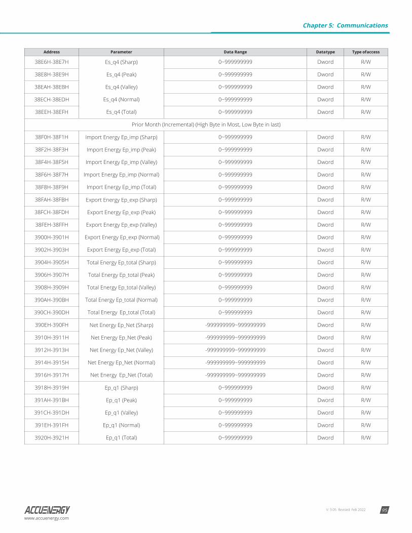
V: 3.05 Revised: Feb 2022 95www.accuenergy.com
Address Parameter Data Range Data type Type of access
38E6H-38E7H Es_q4 (Sharp)
Es_q4 (Peak)
Es_q4 (Valley)
Es_q4 (Normal)
Es_q4 (Total)
0~999999999 Dword R/W
38E8H-38E9H 0~999999999 Dword R/W
38EAH-38EBH 0~999999999 Dword R/W
38ECH-38EDH 0~999999999 Dword R/W
38EEH-38EFH 0~999999999 Dword R/W
Prior Month (Incremental) (High Byte in Most, Low Byte in last)
38F0H-38F1H Import Energy Ep_imp (Sharp)
Import Energy Ep_imp (Peak)
Import Energy Ep_imp (Valley)
Import Energy Ep_imp (Normal)
Import Energy Ep_imp (Total)
0~999999999 Dword R/W
38F2H-38F3H 0~999999999 Dword R/W
38F4H-38F5H 0~999999999 Dword R/W
38F6H-38F7H 0~999999999 Dword R/W
38F8H-38F9H 0~999999999 Dword R/W
38FAH-38FBH Export Energy Ep_exp (Sharp)
Export Energy Ep_exp (Peak)
Export Energy Ep_exp (Valley)
Export Energy Ep_exp (Normal)
Export Energy Ep_exp (Total)
0~999999999 Dword R/W
38FCH-38FDH 0~999999999 Dword R/W
38FEH-38FFH 0~999999999 Dword R/W
3900H-3901H 0~999999999 Dword R/W
3902H-3903H 0~999999999 Dword R/W
3904H-3905H Total Energy Ep_total (Sharp)
Total Energy Ep_total (Peak)
Total Energy Ep_total (Valley)
Total Energy Ep_total (Normal)
Total Energy Ep_total (Total)
0~999999999 Dword R/W
3906H-3907H 0~999999999 Dword R/W
3908H-3909H 0~999999999 Dword R/W
390AH-390BH 0~999999999 Dword R/W
390CH-390DH 0~999999999 Dword R/W
390EH-390FH Net Energy Ep_Net (Sharp)
Net Energy Ep_Net (Peak)
Net Energy Ep_Net (Valley)
Net Energy Ep_Net (Normal)
Net Energy Ep_Net (Total)
-999999999~999999999 Dword R/W
3910H-3911H -999999999~999999999 Dword R/W
3912H-3913H -999999999~999999999 Dword R/W
3914H-3915H -999999999~999999999 Dword R/W
3916H-3917H -999999999~999999999 Dword R/W
3918H-3919H Ep_q1 (Sharp)
Ep_q1 (Peak)
Ep_q1 (Valley)
Ep_q1 (Normal)
Ep_q1 (Total)
0~999999999 Dword R/W
391AH-391BH 0~999999999 Dword R/W
391CH-391DH 0~999999999 Dword R/W
391EH-391FH 0~999999999 Dword R/W
3920H-3921H 0~999999999 Dword R/W
Chapter 5: Communications
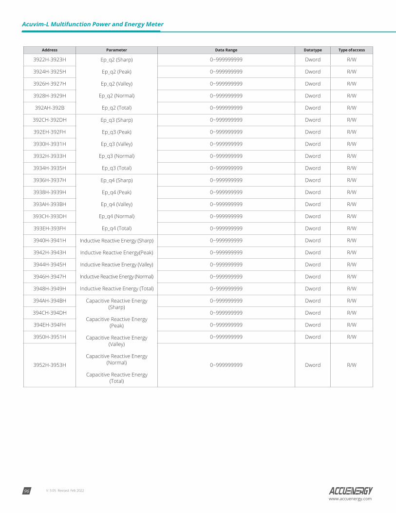
V: 3.05 Revised: Feb 202296
Acuvim-L Multifunction Power and Energy Meter
www.accuenergy.com
Address Parameter Data Range Data type Type of access
3922H-3923H Ep_q2 (Sharp)
Ep_q2 (Peak)
Ep_q2 (Valley)
Ep_q2 (Normal)
Ep_q2 (Total)
0~999999999 Dword R/W
3924H-3925H 0~999999999 Dword R/W
3926H-3927H 0~999999999 Dword R/W
3928H-3929H 0~999999999 Dword R/W
392AH-392B 0~999999999 Dword R/W
392CH-392DH Ep_q3 (Sharp)
Ep_q3 (Peak)
Ep_q3 (Valley)
Ep_q3 (Normal)
Ep_q3 (Total)
0~999999999 Dword R/W
392EH-392FH 0~999999999 Dword R/W
3930H-3931H 0~999999999 Dword R/W
3932H-3933H 0~999999999 Dword R/W
3934H-3935H 0~999999999 Dword R/W
3936H-3937H Ep_q4 (Sharp)
Ep_q4 (Peak)
Ep_q4 (Valley)
Ep_q4 (Normal)
Ep_q4 (Total)
0~999999999 Dword R/W
3938H-3939H 0~999999999 Dword R/W
393AH-393BH 0~999999999 Dword R/W
393CH-393DH 0~999999999 Dword R/W
393EH-393FH 0~999999999 Dword R/W
3940H-3941H Inductive Reactive Energy (Sharp)
Inductive Reactive Energy(Peak)
Inductive Reactive Energy (Valley)
Inductive Reactive Energy (Normal)
Inductive Reactive Energy (Total)
0~999999999 Dword R/W
3942H-3943H 0~999999999 Dword R/W
3944H-3945H 0~999999999 Dword R/W
3946H-3947H 0~999999999 Dword R/W
3948H-3949H 0~999999999 Dword R/W
394AH-394BH Capacitive Reactive Energy (Sharp)
Capacitive Reactive Energy (Peak)
Capacitive Reactive Energy (Valley)
Capacitive Reactive Energy (Normal)
Capacitive Reactive Energy (Total)
0~999999999 Dword R/W
394CH-394DH 0~999999999 Dword R/W
394EH-394FH 0~999999999 Dword R/W
3950H-3951H 0~999999999 Dword R/W
3952H-3953H 0~999999999 Dword R/W
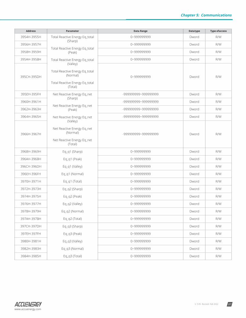
V: 3.05 Revised: Feb 2022 97www.accuenergy.com
Address Parameter Data Range Data type Type of access
3954H-3955H Total Reactive Energy Eq_total (Sharp)
Total Reactive Energy Eq_total (Peak)
Total Reactive Energy Eq_total (Valley)
Total Reactive Energy Eq_total (Normal)
Total Reactive Energy Eq_total (Total)
0~999999999 Dword R/W
3956H-3957H 0~999999999 Dword R/W
3958H-3959H 0~999999999 Dword R/W
395AH-395BH 0~999999999 Dword R/W
395CH-395DH 0~999999999 Dword R/W
395EH-395FH Net Reactive Energy Eq_net (Sharp)
Net Reactive Energy Eq_net (Peak)
Net Reactive Energy Eq_net (Valley)
Net Reactive Energy Eq_net (Normal)
Net Reactive Energy Eq_net (Total)
-999999999~999999999 Dword R/W
3960H-3961H -999999999~999999999 Dword R/W
3962H-3963H -999999999~999999999 Dword R/W
3964H-3965H -999999999~999999999 Dword R/W
3966H-3967H -999999999~999999999 Dword R/W
3968H-3969H Eq_q1 (Sharp)
Eq_q1 (Peak)
Eq_q1 (Valley)
Eq_q1 (Normal)
Eq_q1 (Total)
0~999999999 Dword R/W
396AH-396BH 0~999999999 Dword R/W
396CH-396DH 0~999999999 Dword R/W
396EH-396FH 0~999999999 Dword R/W
3970H-3971H 0~999999999 Dword R/W
3972H-3973H Eq_q2 (Sharp)
Eq_q2 (Peak)
Eq_q2 (Valley)
Eq_q2 (Normal)
Eq_q2 (Total)
0~999999999 Dword R/W
3974H-3975H 0~999999999 Dword R/W
3976H-3977H 0~999999999 Dword R/W
3978H-3979H 0~999999999 Dword R/W
397AH-397BH 0~999999999 Dword R/W
397CH-397DH Eq_q3 (Sharp)
Eq_q3 (Peak)
Eq_q3 (Valley)
Eq_q3 (Normal)
Eq_q3 (Total)
0~999999999 Dword R/W
397EH-397FH 0~999999999 Dword R/W
3980H-3981H 0~999999999 Dword R/W
3982H-3983H 0~999999999 Dword R/W
3984H-3985H 0~999999999 Dword R/W
Chapter 5: Communications
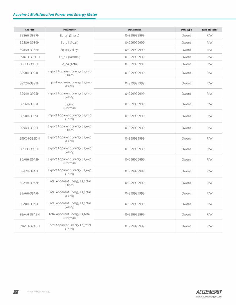
V: 3.05 Revised: Feb 202298
Acuvim-L Multifunction Power and Energy Meter
www.accuenergy.com
Address Parameter Data Range Data type Type of access
3986H-3987H Eq_q4 (Sharp)
Eq_q4 (Peak)
Eq_q4(Valley)
Eq_q4 (Normal)
Eq_q4 (Total)
0~999999999 Dword R/W
3988H-3989H 0~999999999 Dword R/W
398AH-398BH 0~999999999 Dword R/W
398CH-398DH 0~999999999 Dword R/W
398EH-398FH 0~999999999 Dword R/W
3990H-3991H Import Apparent Energy Es_imp (Sharp)
Import Apparent Energy Es_imp (Peak)
Import Apparent Energy Es_imp (Valley)
Es_imp (Normal)
Import Apparent Energy Es_imp (Total)
0~999999999 Dword R/W
3992H-3993H 0~999999999 Dword R/W
3994H-3995H 0~999999999 Dword R/W
3996H-3997H 0~999999999 Dword R/W
3998H-3999H 0~999999999 Dword R/W
399AH-399BH Export Apparent Energy Es_exp (Sharp)
Export Apparent Energy Es_exp (Peak)
Export Apparent Energy Es_exp (Valley)
Export Apparent Energy Es_exp (Normal)
Export Apparent Energy Es_exp (Total)
0~999999999 Dword R/W
399CH-399DH 0~999999999 Dword R/W
399EH-399FH 0~999999999 Dword R/W
39A0H-39A1H 0~999999999 Dword R/W
39A2H-39A3H 0~999999999 Dword R/W
39A4H-39A5H Total Apparent Energy Es_total (Sharp)
Total Apparent Energy Es_total (Peak)
Total Apparent Energy Es_total (Valley)
Total Apparent Energy Es_total (Normal)
Total Apparent Energy Es_total (Total)
0~999999999 Dword R/W
39A6H-39A7H 0~999999999 Dword R/W
39A8H-39A9H 0~999999999 Dword R/W
39AAH-39ABH 0~999999999 Dword R/W
39ACH-39ADH 0~999999999 Dword R/W

V: 3.05 Revised: Feb 2022 99www.accuenergy.com
Address Parameter Data Range Data type Type of access
39AEH-39AFH Net Apparent Energy Es_net (Sharp)
Net Apparent Energy Es_net (Peak)
Net Apparent Energy Es_net (Valley)
Net Apparent Energy Es_net (Normal)
Net Apparent Energy Es_net (Total)
-999999999~999999999 Dword R/W
39B0H-39B1H -999999999~999999999 Dword R/W
39B2H-39B3H -999999999~999999999 Dword R/W
39B4H-39B5H -999999999~999999999 Dword R/W
39B6H-39B7H -999999999~999999999 Dword R/W
39B8H-39B9H Es_q1 (Sharp)
Es_q1 (Peak)
Es_q1 (Valley)
Es_q1 (Normal)
Es_q1 (Total)
0~999999999 Dword R/W
39BAH-39BBH 0~999999999 Dword R/W
39BCH-39BDH 0~999999999 Dword R/W
39BEH-39BFH 0~999999999 Dword R/W
39C0H-39C1H 0~999999999 Dword R/W
39C2H-39C3H Es_q2 (Sharp)
Es_q2 (Peak)
Es_q2 (Valley)
Es_q2 (Normal)
Es_q2 (Total)
0~999999999 Dword R/W
39C4H-39C5H 0~999999999 Dword R/W
39C6H-39C7H 0~999999999 Dword R/W
39C8H-39C9H 0~999999999 Dword R/W
39CAH-39CBH 0~999999999 Dword R/W
39CCH-39CDH Es_q3 (Sharp)
Es_q3 (Peak)
Es_q3 (Valley)
Es_q3 (Normal)
Es_q3 (Total)
0~999999999 Dword R/W
39CEH-39CFH 0~999999999 Dword R/W
39D0H-39D1H 0~999999999 Dword R/W
39D2H-39D3H 0~999999999 Dword R/W
39D4H-39D5H 0~999999999 Dword R/W
39D6H-39D7H Es_q4 (Sharp)
Es_q4 (Peak)
Es_q4 (Valley)
Es_q4 (Normal)
Es_q4 (Total)
0~999999999 Dword R/W
39D8H-39D9H 0~999999999 Dword R/W
39DAH-39DBH 0~999999999 Dword R/W
39DCH-39DDH 0~999999999 Dword R/W
39DEH-39DFH 0~999999999 Dword R/W
The Daily EnergyFunction code: 03H for reading. The address table as below.
Table 5-27 Daily Energy
Address Parameter Data Range Data type Type of access
3C00H-3C01H Ep_imp (Yesterday) 0~999999999 Dword R/W
3C02H-3C03H Ep_exp (Yesterday) 0~999999999 Dword R/W
3C04H-3C05H Ep_total (Yesterday) 0~999999999 Dword R/W
Chapter 5: Communications
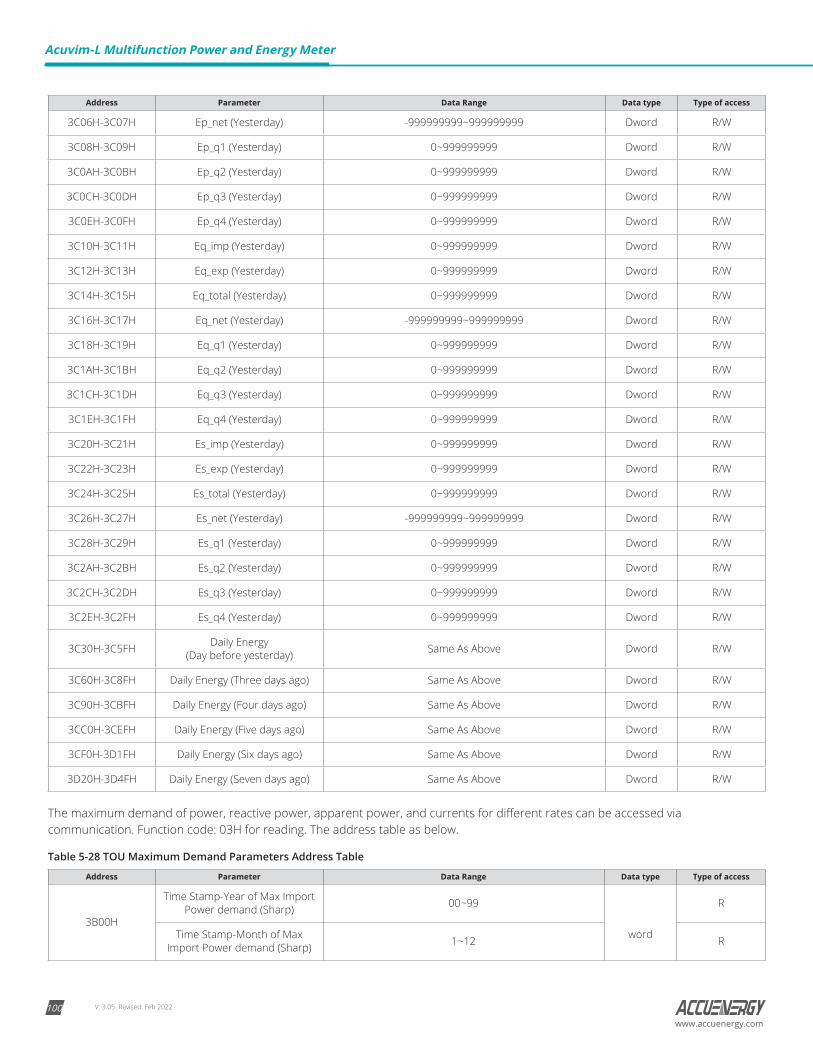
V: 3.05 Revised: Feb 2022100
Acuvim-L Multifunction Power and Energy Meter
www.accuenergy.com
Address Parameter Data Range Data type Type of access
3C06H-3C07H Ep_net (Yesterday) -999999999~999999999 Dword R/W
3C08H-3C09H Ep_q1 (Yesterday) 0~999999999 Dword R/W
3C0AH-3C0BH Ep_q2 (Yesterday) 0~999999999 Dword R/W
3C0CH-3C0DH Ep_q3 (Yesterday) 0~999999999 Dword R/W
3C0EH-3C0FH Ep_q4 (Yesterday) 0~999999999 Dword R/W
3C10H-3C11H Eq_imp (Yesterday) 0~999999999 Dword R/W
3C12H-3C13H Eq_exp (Yesterday) 0~999999999 Dword R/W
3C14H-3C15H Eq_total (Yesterday) 0~999999999 Dword R/W
3C16H-3C17H Eq_net (Yesterday) -999999999~999999999 Dword R/W
3C18H-3C19H Eq_q1 (Yesterday) 0~999999999 Dword R/W
3C1AH-3C1BH Eq_q2 (Yesterday) 0~999999999 Dword R/W
3C1CH-3C1DH Eq_q3 (Yesterday) 0~999999999 Dword R/W
3C1EH-3C1FH Eq_q4 (Yesterday) 0~999999999 Dword R/W
3C20H-3C21H Es_imp (Yesterday) 0~999999999 Dword R/W
3C22H-3C23H Es_exp (Yesterday) 0~999999999 Dword R/W
3C24H-3C25H Es_total (Yesterday) 0~999999999 Dword R/W
3C26H-3C27H Es_net (Yesterday) -999999999~999999999 Dword R/W
3C28H-3C29H Es_q1 (Yesterday) 0~999999999 Dword R/W
3C2AH-3C2BH Es_q2 (Yesterday) 0~999999999 Dword R/W
3C2CH-3C2DH Es_q3 (Yesterday) 0~999999999 Dword R/W
3C2EH-3C2FH Es_q4 (Yesterday) 0~999999999 Dword R/W
3C30H-3C5FH Daily Energy (Day before yesterday) Same As Above Dword R/W
3C60H-3C8FH Daily Energy (Three days ago) Same As Above Dword R/W
3C90H-3CBFH Daily Energy (Four days ago) Same As Above Dword R/W
3CC0H-3CEFH Daily Energy (Five days ago) Same As Above Dword R/W
3CF0H-3D1FH Daily Energy (Six days ago) Same As Above Dword R/W
3D20H-3D4FH Daily Energy (Seven days ago) Same As Above Dword R/W
The maximum demand of power, reactive power, apparent power, and currents for different rates can be accessed via communication. Function code: 03H for reading. The address table as below.
Table 5-28 TOU Maximum Demand Parameters Address Table
Address Parameter Data Range Data type Type of access
3B00H
Time Stamp-Year of Max Import Power demand (Sharp) 00~99
word
R
Time Stamp-Month of Max Import Power demand (Sharp) 1~12 R
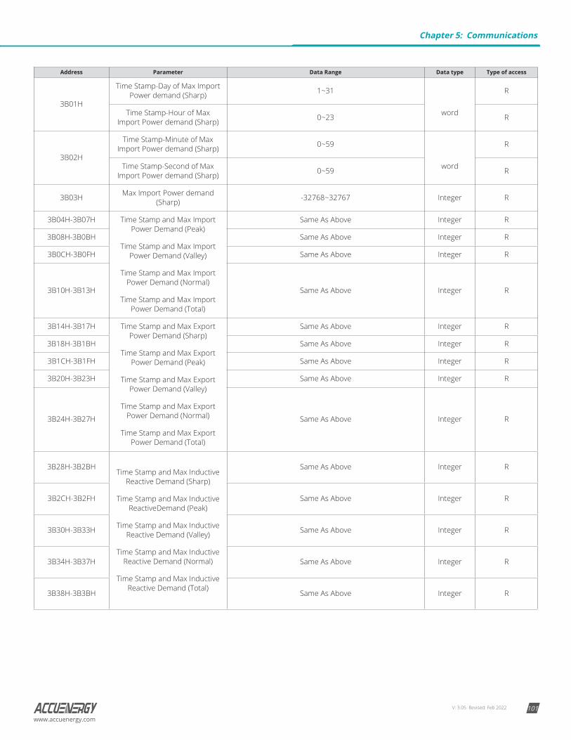
V: 3.05 Revised: Feb 2022 101www.accuenergy.com
Address Parameter Data Range Data type Type of access
3B01H
Time Stamp-Day of Max Import Power demand (Sharp) 1~31
word
R
Time Stamp-Hour of Max Import Power demand (Sharp) 0~23 R
3B02H
Time Stamp-Minute of Max Import Power demand (Sharp) 0~59
word
R
Time Stamp-Second of Max Import Power demand (Sharp) 0~59 R
3B03H Max Import Power demand (Sharp) -32768~32767 Integer R
3B04H-3B07H Time Stamp and Max Import Power Demand (Peak)
Time Stamp and Max Import Power Demand (Valley)
Time Stamp and Max Import Power Demand (Normal)
Time Stamp and Max Import Power Demand (Total)
Same As Above Integer R
3B08H-3B0BH Same As Above Integer R
3B0CH-3B0FH Same As Above Integer R
3B10H-3B13H Same As Above Integer R
3B14H-3B17H Time Stamp and Max Export Power Demand (Sharp)
Time Stamp and Max Export Power Demand (Peak)
Time Stamp and Max Export Power Demand (Valley)
Time Stamp and Max Export Power Demand (Normal)
Time Stamp and Max Export Power Demand (Total)
Same As Above Integer R
3B18H-3B1BH Same As Above Integer R
3B1CH-3B1FH Same As Above Integer R
3B20H-3B23H Same As Above Integer R
3B24H-3B27H Same As Above Integer R
3B28H-3B2BHTime Stamp and Max Inductive
Reactive Demand (Sharp)
Time Stamp and Max Inductive ReactiveDemand (Peak)
Time Stamp and Max Inductive Reactive Demand (Valley)
Time Stamp and Max Inductive Reactive Demand (Normal)
Time Stamp and Max Inductive Reactive Demand (Total)
Same As Above Integer R
3B2CH-3B2FH Same As Above Integer R
3B30H-3B33H Same As Above Integer R
3B34H-3B37H Same As Above Integer R
3B38H-3B3BH Same As Above Integer R
Chapter 5: Communications
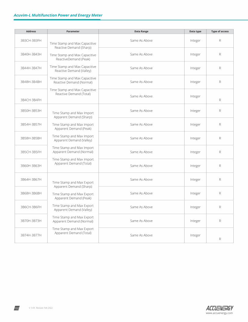
V: 3.05 Revised: Feb 2022102
Acuvim-L Multifunction Power and Energy Meter
www.accuenergy.com
Address Parameter Data Range Data type Type of access
3B3CH-3B3FHTime Stamp and Max Capacitive
Reactive Demand (Sharp)
Time Stamp and Max Capacitive ReactiveDemand (Peak)
Time Stamp and Max Capacitive Reactive Demand (Valley)
Time Stamp and Max Capacitive Reactive Demand (Normal)
Time Stamp and Max Capacitive Reactive Demand (Total)
Same As Above Integer R
3B40H-3B43H Same As Above Integer R
3B44H-3B47H Same As Above Integer R
3B48H-3B4BH Same As Above Integer R
3B4CH-3B4FHSame As Above Integer
R
3B50H-3B53HTime Stamp and Max Import Apparent Demand (Sharp)
Time Stamp and Max Import Apparent Demand (Peak)
Time Stamp and Max Import Apparent Demand (Valley)
Time Stamp and Max Import Apparent Demand (Normal)
Time Stamp and Max Import Apparent Demand (Total)
Same As Above Integer R
3B54H-3B57H Same As Above Integer R
3B58H-3B5BH Same As Above Integer R
3B5CH-3B5FH Same As Above Integer R
3B60H-3B63H Same As Above Integer R
3B64H-3B67HTime Stamp and Max Export Apparent Demand (Sharp)
Time Stamp and Max Export Apparent Demand (Peak)
Time Stamp and Max Export Apparent Demand (Valley)
Time Stamp and Max Export Apparent Demand (Normal)
Time Stamp and Max Export Apparent Demand (Total)
Same As Above Integer R
3B68H-3B6BH Same As Above Integer R
3B6CH-3B6FH Same As Above Integer R
3B70H-3B73H Same As Above Integer R
3B74H-3B77H Same As Above IntegerR
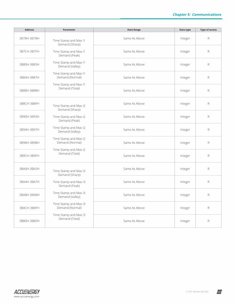
V: 3.05 Revised: Feb 2022 103www.accuenergy.com
Address Parameter Data Range Data type Type of access
3B78H-3B7BHTime Stamp and Max I1
Demand (Sharp)
Time Stamp and Max I1 Demand (Peak)
Time Stamp and Max I1 Demand (Valley)
Time Stamp and Max I1 Demand (Normal)
Time Stamp and Max I1 Demand (Total)
Same As Above Integer R
3B7CH-3B7FH Same As Above Integer R
3B80H-3B83H Same As Above Integer R
3B84H-3B87H Same As Above Integer R
3B88H-3B8BH Same As Above Integer R
3B8CH-3B8FHTime Stamp and Max I2
Demand (Sharp)
Time Stamp and Max I2 Demand (Peak)
Time Stamp and Max I2 Demand (Valley)
Time Stamp and Max I2 Demand (Normal)
Time Stamp and Max I2 Demand (Total)
Same As Above Integer R
3B90H-3B93H Same As Above Integer R
3B94H-3B97H Same As Above Integer R
3B98H-3B9BH Same As Above Integer R
3B9CH-3B9FH Same As Above Integer R
3BA0H-3BA3HTime Stamp and Max I3
Demand (Sharp)
Time Stamp and Max I3 Demand (Peak)
Time Stamp and Max I3 Demand (Valley)
Time Stamp and Max I3 Demand (Normal)
Time Stamp and Max I3 Demand (Total)
Same As Above Integer R
3BA4H-3BA7H Same As Above Integer R
3BA8H-3BABH Same As Above Integer R
3BACH-3BAFH Same As Above Integer R
3BB0H-3BB3H Same As Above Integer R
Chapter 5: Communications
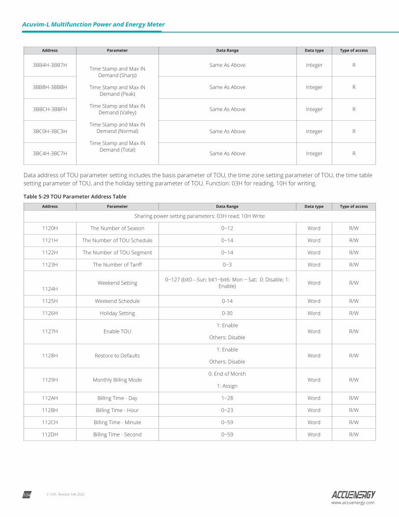
V: 3.05 Revised: Feb 2022104
Acuvim-L Multifunction Power and Energy Meter
www.accuenergy.com
Address Parameter Data Range Data type Type of access
3BB4H-3BB7HTime Stamp and Max IN
Demand (Sharp)
Time Stamp and Max IN Demand (Peak)
Time Stamp and Max IN Demand (Valley)
Time Stamp and Max IN Demand (Normal)
Time Stamp and Max IN Demand (Total)
Same As Above Integer R
3BB8H-3BBBH Same As Above Integer R
3BBCH-3BBFH Same As Above Integer R
3BC0H-3BC3H Same As Above Integer R
3BC4H-3BC7H Same As Above Integer R
Data address of TOU parameter setting includes the basis parameter of TOU, the time zone setting parameter of TOU, the time table setting parameter of TOU, and the holiday setting parameter of TOU. Function: 03H for reading, 10H for writing.
Table 5-29 TOU Parameter Address Table
Address Parameter Data Range Data type Type of access
Sharing power setting parameters: 03H read; 10H Write
1120H The Number of Season 0~12 Word R/W
1121H The Number of TOU Schedule 0~14 Word R/W
1122H The Number of TOU Segment 0~14 Word R/W
1123H The Number of Tariff 0~3 Word R/W
1124HWeekend Setting 0~127 (bit0---Sun: bit1~bit6: Mon ~ Sat; 0: Disable; 1:
Enable) Word R/W
1125H Weekend Schedule 0-14 Word R/W
1126H Holiday Setting 0-30 Word R/W
1127H Enable TOU1: Enable
Others: DisableWord R/W
1128H Restore to Defaults1: Enable
Others: DisableWord R/W
1129H Monthly Billing Mode0: End of Month
1: AssignWord R/W
112AH Billing Time - Day 1~28 Word R/W
112BH Billing Time - Hour 0~23 Word R/W
112CH Billing Time - Minute 0~59 Word R/W
112DH Billing Time - Second 0~59 Word R/W
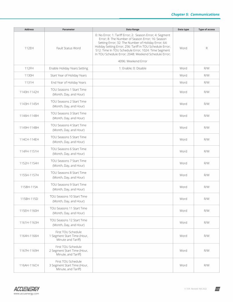
V: 3.05 Revised: Feb 2022 105www.accuenergy.com
Address Parameter Data Range Data type Type of access
112EH Fault Status Word
0: No Error; 1: Tariff Error; 2: Season Error; 4: Segment Error; 8: The Number of Season Error; 16: Season Setting Error; 32: The Number of Holiday Error; 64:
Holiday Setting Error; 256: Tariff in TOU Schedule Error; 512: Time In TOU Schedule Error; 1024: Time Segment In TOU Schedule Error; 2048: Weekend Schedule Error;
4096: Weekend Error
Word R
112FH Enable Holiday Years Setting 1: Enable; 0: Disable Word R/W
1130H Start Year of Holiday Years Word R/W
1131H End Year of Holiday Years Word R/W
1140H-1142HTOU Seasons 1 Start Time
(Month, Day, and Hour)Word R/W
1143H-1145HTOU Seasons 2 Start Time
(Month, Day, and Hour)Word R/W
1146H-1148HTOU Seasons 3 Start Time
(Month, Day, and Hour)Word R/W
1149H-114BHTOU Seasons 4 Start Time
(Month, Day, and Hour)Word R/W
114CH-114EHTOU Seasons 5 Start Time
(Month, Day, and Hour)Word R/W
114FH-1151HTOU Seasons 6 Start Time
(Month, Day, and Hour)Word R/W
1152H-1154HTOU Seasons 7 Start Time
(Month, Day, and Hour)Word R/W
1155H-1157HTOU Seasons 8 Start Time
(Month, Day, and Hour)Word R/W
1158H-115ATOU Seasons 9 Start Time
(Month, Day, and Hour)Word R/W
115BH-115DTOU Seasons 10 Start Time
(Month, Day, and Hour)Word R/W
115EH-1160HTOU Seasons 11 Start Time
(Month, Day, and Hour)Word R/W
1161H-1163HTOU Seasons 12 Start Time
(Month, Day, and Hour)Word R/W
1164H-1166HFirst TOU Schedule
1 Segment Start Time (Hour, Minute and Tariff)
Word R/W
1167H-1169HFirst TOU Schedule
2 Segment Start Time (Hour, Minute, and Tariff)
Word R/W
116AH-116CHFirst TOU Schedule
3 Segment Start Time (Hour, Minute, and Tariff)
Word R/W
Chapter 5: Communications
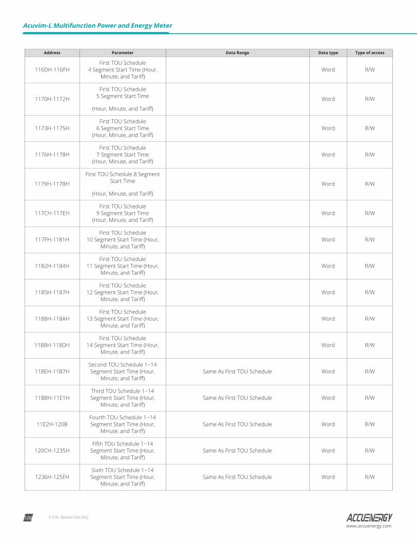
V: 3.05 Revised: Feb 2022106
Acuvim-L Multifunction Power and Energy Meter
www.accuenergy.com
Address Parameter Data Range Data type Type of access
116DH-116FHFirst TOU Schedule
4 Segment Start Time (Hour, Minute, and Tariff)
Word R/W
1170H-1172H
First TOU Schedule 5 Segment Start Time
(Hour, Minute, and Tariff)
Word R/W
1173H-1175HFirst TOU Schedule
6 Segment Start Time (Hour, Minute, and Tariff)
Word R/W
1176H-1178HFirst TOU Schedule
7 Segment Start Time (Hour, Minute, and Tariff)
Word R/W
1179H-117BH
First TOU Schedule 8 Segment Start Time
(Hour, Minute, and Tariff)
Word R/W
117CH-117EHFirst TOU Schedule
9 Segment Start Time (Hour, Minute, and Tariff)
Word R/W
117FH-1181HFirst TOU Schedule
10 Segment Start Time (Hour, Minute, and Tariff)
Word R/W
1182H-1184HFirst TOU Schedule
11 Segment Start Time (Hour, Minute, and Tariff)
Word R/W
1185H-1187HFirst TOU Schedule
12 Segment Start Time (Hour, Minute, and Tariff)
Word R/W
1188H-118AHFirst TOU Schedule
13 Segment Start Time (Hour, Minute, and Tariff)
Word R/W
118BH-118DHFirst TOU Schedule
14 Segment Start Time (Hour, Minute, and Tariff)
Word R/W
118EH-11B7HSecond TOU Schedule 1~14 Segment Start Time (Hour,
Minute, and Tariff)Same As First TOU Schedule Word R/W
11B8H-11E1HThird TOU Schedule 1~14 Segment Start Time (Hour,
Minute, and Tariff)Same As First TOU Schedule Word R/W
11E2H-120BFourth TOU Schedule 1~14 Segment Start Time (Hour,
Minute, and Tariff)Same As First TOU Schedule Word R/W
120CH-1235HFifth TOU Schedule 1~14
Segment Start Time (Hour, Minute, and Tariff)
Same As First TOU Schedule Word R/W
1236H-125FHSixth TOU Schedule 1~14 Segment Start Time (Hour,
Minute, and Tariff)Same As First TOU Schedule Word R/W
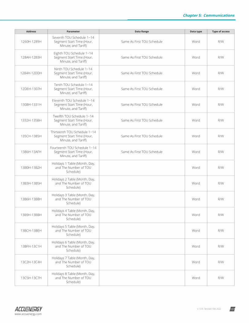
V: 3.05 Revised: Feb 2022 107www.accuenergy.com
Address Parameter Data Range Data type Type of access
1260H-1289HSeventh TOU Schedule 1~14 Segment Start Time (Hour,
Minute, and Tariff)Same As First TOU Schedule Word R/W
128AH-12B3HEighth TOU Schedule 1~14 Segment Start Time (Hour,
Minute, and Tariff)Same As First TOU Schedule Word R/W
12B4H-12DDHNinth TOU Schedule 1~14 Segment Start Time (Hour,
Minute, and Tariff)Same As First TOU Schedule Word R/W
12DEH-1307HTenth TOU Schedule 1~14 Segment Start Time (Hour,
Minute, and Tariff)Same As First TOU Schedule Word R/W
1308H-1331HEleventh TOU Schedule 1~14
Segment Start Time (Hour, Minute, and Tariff)
Same As First TOU Schedule Word R/W
1332H-135BHTwelfth TOU Schedule 1~14 Segment Start Time (Hour,
Minute, and Tariff)Same As First TOU Schedule Word R/W
135CH-1385HThirteenth TOU Schedule 1~14
Segment Start Time (Hour, Minute, and Tariff)
Same As First TOU Schedule Word R/W
1386H-13AFHFourteenth TOU Schedule 1~14
Segment Start Time (Hour, Minute, and Tariff)
Same As First TOU Schedule Word R/W
13B0H-13B2HHolidays 1 Table (Month, Day,
and The Number of TOU Schedule)
Word R/W
13B3H-13B5HHolidays 2 Table (Month, Day,
and The Number of TOU Schedule)
Word R/W
13B6H-13B8HHolidays 3 Table (Month, Day,
and The Number of TOU Schedule)
Word R/W
13B9H-13BBHHolidays 4 Table (Month, Day,
and The Number of TOU Schedule)
Word R/W
13BCH-13BEHHolidays 5 Table (Month, Day,
and The Number of TOU Schedule)
Word R/W
13BFH-13C1HHolidays 6 Table (Month, Day,
and The Number of TOU Schedule)
Word R/W
13C2H-13C4HHolidays 7 Table (Month, Day,
and The Number of TOU Schedule)
Word R/W
13C5H-13C7HHolidays 8 Table (Month, Day,
and The Number of TOU Schedule)
Word R/W
Chapter 5: Communications

V: 3.05 Revised: Feb 2022108
Acuvim-L Multifunction Power and Energy Meter
www.accuenergy.com
Address Parameter Data Range Data type Type of access
13C8H-13CAHHolidays 9 Table (Month, Day,
and The Number of TOU Schedule)
Word R/W
13CBH-13CDHHolidays 10 Table (Month,
Day, and The Number of TOU Schedule)
Word R/W
13CEH-13D0HHolidays 11 Table (Month,
Day, and The Number of TOU Schedule)
Word R/W
13D1H-13D3HHolidays 12 Table (Month,
Day, and The Number of TOU Schedule)
Word R/W
13D4H-13D6HHolidays 13 Table (Month,
Day, and The Number of TOU Schedule)
Word R/W
13D7H-13D9HHolidays 14 Table (Month,
Day, and The Number of TOU Schedule)
Word R/W
13DAH-13DCHHolidays 15 Table (Month,
Day, and The Number of TOU Schedule)
Word R/W
13DDH-13DFHHolidays 16 Table (Month,
Day, and The Number of TOU Schedule)
Word R/W
13E0H-13E2HHolidays 17 Table (Month,
Day, and The Number of TOU Schedule)
Word R/W
13E3H-13E5HHolidays 18 Table (Month,
Day, and The Number of TOU Schedule)
Word R/W
13E6H-13E8HHolidays 19 Table (Month,
Day, and The Number of TOU Schedule)
Word R/W
13E9H-13EBHHolidays 20 Table (Month,
Day, and The Number of TOU Schedule)
Word R/W
13ECH-13EEHHolidays 21 Table (Month,
Day, and The Number of TOU Schedule)
Word R/W
13EFH-13F1HHolidays 22 Table (Month,
Day, and The Number of TOU Schedule)
Word R/W
13F2H-13F4HHolidays 23 Table (Month,
Day, and The Number of TOU Schedule)
Word R/W
13F5H-13F7HHolidays 24 Table (Month,
Day, and The Number of TOU Schedule)
Word R/W
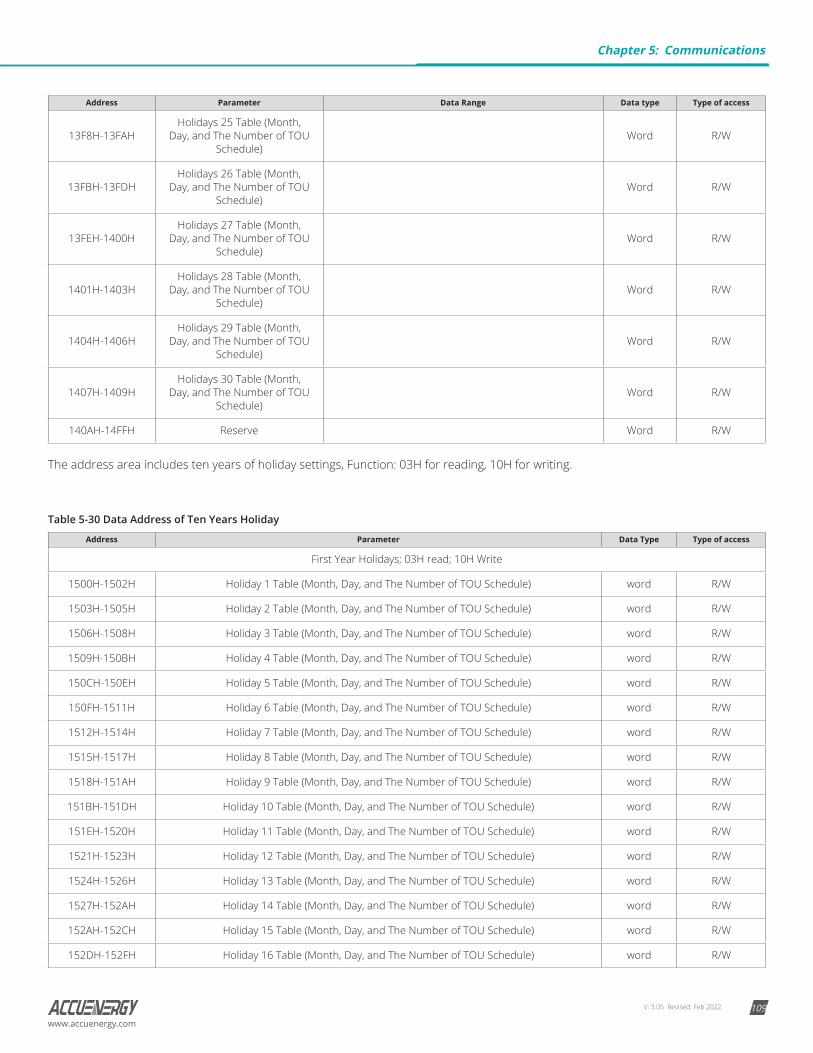
V: 3.05 Revised: Feb 2022 109www.accuenergy.com
Address Parameter Data Range Data type Type of access
13F8H-13FAHHolidays 25 Table (Month,
Day, and The Number of TOU Schedule)
Word R/W
13FBH-13FDHHolidays 26 Table (Month,
Day, and The Number of TOU Schedule)
Word R/W
13FEH-1400HHolidays 27 Table (Month,
Day, and The Number of TOU Schedule)
Word R/W
1401H-1403HHolidays 28 Table (Month,
Day, and The Number of TOU Schedule)
Word R/W
1404H-1406HHolidays 29 Table (Month,
Day, and The Number of TOU Schedule)
Word R/W
1407H-1409HHolidays 30 Table (Month,
Day, and The Number of TOU Schedule)
Word R/W
140AH-14FFH Reserve Word R/W
The address area includes ten years of holiday settings, Function: 03H for reading, 10H for writing.
Table 5-30 Data Address of Ten Years Holiday
Address Parameter Data Type Type of access
First Year Holidays; 03H read; 10H Write
1500H-1502H Holiday 1 Table (Month, Day, and The Number of TOU Schedule) word R/W
1503H-1505H Holiday 2 Table (Month, Day, and The Number of TOU Schedule) word R/W
1506H-1508H Holiday 3 Table (Month, Day, and The Number of TOU Schedule) word R/W
1509H-150BH Holiday 4 Table (Month, Day, and The Number of TOU Schedule) word R/W
150CH-150EH Holiday 5 Table (Month, Day, and The Number of TOU Schedule) word R/W
150FH-1511H Holiday 6 Table (Month, Day, and The Number of TOU Schedule) word R/W
1512H-1514H Holiday 7 Table (Month, Day, and The Number of TOU Schedule) word R/W
1515H-1517H Holiday 8 Table (Month, Day, and The Number of TOU Schedule) word R/W
1518H-151AH Holiday 9 Table (Month, Day, and The Number of TOU Schedule) word R/W
151BH-151DH Holiday 10 Table (Month, Day, and The Number of TOU Schedule) word R/W
151EH-1520H Holiday 11 Table (Month, Day, and The Number of TOU Schedule) word R/W
1521H-1523H Holiday 12 Table (Month, Day, and The Number of TOU Schedule) word R/W
1524H-1526H Holiday 13 Table (Month, Day, and The Number of TOU Schedule) word R/W
1527H-152AH Holiday 14 Table (Month, Day, and The Number of TOU Schedule) word R/W
152AH-152CH Holiday 15 Table (Month, Day, and The Number of TOU Schedule) word R/W
152DH-152FH Holiday 16 Table (Month, Day, and The Number of TOU Schedule) word R/W
Chapter 5: Communications
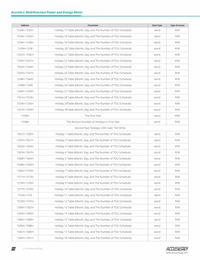
V: 3.05 Revised: Feb 2022110
Acuvim-L Multifunction Power and Energy Meter
www.accuenergy.com
Address Parameter Data Type Type of access
1530H-1532H Holiday 17 Table (Month, Day, and The Number of TOU Schedule) word R/W
1533H-1535H Holiday 18 Table (Month, Day, and The Number of TOU Schedule) word R/W
1536H-1538H Holiday 19 Table (Month, Day, and The Number of TOU Schedule) word R/W
1539H-153B Holiday 20 Table (Month, Day, and The Number of TOU Schedule) word R/W
153CH-153EH Holiday 21 Table (Month, Day, and The Number of TOU Schedule) word R/W
153FH-1541H Holiday 22 Table (Month, Day, and The Number of TOU Schedule) word R/W
1542H-1544H Holiday 23 Table (Month, Day, and The Number of TOU Schedule) word R/W
1545H-1547H Holiday 24 Table (Month, Day, and The Number of TOU Schedule) word R/W
1548H-154AH Holiday 25 Table (Month, Day, and The Number of TOU Schedule) word R/W
154BH-154D Holiday 26 Table (Month, Day, and The Number of TOU Schedule) word R/W
154EH-1550H Holiday 27 Table (Month, Day, and The Number of TOU Schedule) word R/W
1551H-1553H Holiday 28 Table (Month, Day, and The Number of TOU Schedule) word R/W
1554H-1556H Holiday 29Table (Month, Day, and The Number of TOU Schedule) word R/W
1557H-1559H Holiday 30Table (Month, Day, and The Number of TOU Schedule) word R/W
155AH The First Year word R/W
155BH The Amount Number of Holidays in First Year word R/W
Second Year Holidays; 03H read; 10H Write
155CH-155EH Holiday 1 Table (Month, Day, and The Number of TOU Schedule) word R/W
155FH-1561H Holiday 2 Table (Month, Day, and The Number of TOU Schedule) word R/W
1562H-1564H Holiday 3 Table (Month, Day, and The Number of TOU Schedule) word R/W
1565H-1567H Holiday 4 Table (Month, Day, and The Number of TOU Schedule) word R/W
1568H-156AH Holiday 5 Table (Month, Day, and The Number of TOU Schedule) word R/W
156BH-156DH Holiday 6 Table (Month, Day, and The Number of TOU Schedule) word R/W
156EH-1570H Holiday 7 Table (Month, Day, and The Number of TOU Schedule) word R/W
1571H-1573H Holiday 8 Table (Month, Day, and The Number of TOU Schedule) word R/W
1574H-1576H Holiday 9 Table (Month, Day, and The Number of TOU Schedule) word R/W
1577H-1579H Holiday 10 Table (Month, Day, and The Number of TOU Schedule) word R/W
157AH-157C Holiday 11 Table (Month, Day, and The Number of TOU Schedule) word R/W
157DH-157FH Holiday 12 Table (Month, Day, and The Number of TOU Schedule) word R/W
1580H-1582H Holiday 13 Table (Month, Day, and The Number of TOU Schedule) word R/W
1583H-1585H Holiday 14 Table (Month, Day, and The Number of TOU Schedule) word R/W
1586H-1588H Holiday 15 Table (Month, Day, and The Number of TOU Schedule) word R/W
1589H-158BH Holiday 16 Table (Month, Day, and The Number of TOU Schedule) word R/W
158CH-158EH Holiday 17 Table (Month, Day, and The Number of TOU Schedule) word R/W
158FH-1591H Holiday 18 Table (Month, Day, and The Number of TOU Schedule) word R/W
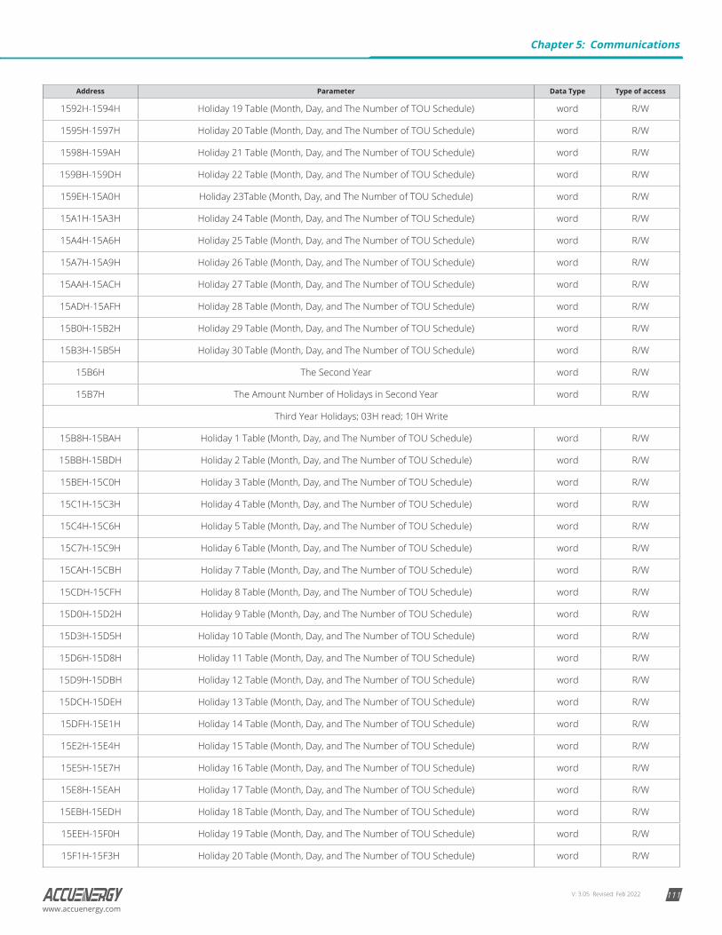
V: 3.05 Revised: Feb 2022 111www.accuenergy.com
Address Parameter Data Type Type of access
1592H-1594H Holiday 19 Table (Month, Day, and The Number of TOU Schedule) word R/W
1595H-1597H Holiday 20 Table (Month, Day, and The Number of TOU Schedule) word R/W
1598H-159AH Holiday 21 Table (Month, Day, and The Number of TOU Schedule) word R/W
159BH-159DH Holiday 22 Table (Month, Day, and The Number of TOU Schedule) word R/W
159EH-15A0H Holiday 23Table (Month, Day, and The Number of TOU Schedule) word R/W
15A1H-15A3H Holiday 24 Table (Month, Day, and The Number of TOU Schedule) word R/W
15A4H-15A6H Holiday 25 Table (Month, Day, and The Number of TOU Schedule) word R/W
15A7H-15A9H Holiday 26 Table (Month, Day, and The Number of TOU Schedule) word R/W
15AAH-15ACH Holiday 27 Table (Month, Day, and The Number of TOU Schedule) word R/W
15ADH-15AFH Holiday 28 Table (Month, Day, and The Number of TOU Schedule) word R/W
15B0H-15B2H Holiday 29 Table (Month, Day, and The Number of TOU Schedule) word R/W
15B3H-15B5H Holiday 30 Table (Month, Day, and The Number of TOU Schedule) word R/W
15B6H The Second Year word R/W
15B7H The Amount Number of Holidays in Second Year word R/W
Third Year Holidays; 03H read; 10H Write
15B8H-15BAH Holiday 1 Table (Month, Day, and The Number of TOU Schedule) word R/W
15BBH-15BDH Holiday 2 Table (Month, Day, and The Number of TOU Schedule) word R/W
15BEH-15C0H Holiday 3 Table (Month, Day, and The Number of TOU Schedule) word R/W
15C1H-15C3H Holiday 4 Table (Month, Day, and The Number of TOU Schedule) word R/W
15C4H-15C6H Holiday 5 Table (Month, Day, and The Number of TOU Schedule) word R/W
15C7H-15C9H Holiday 6 Table (Month, Day, and The Number of TOU Schedule) word R/W
15CAH-15CBH Holiday 7 Table (Month, Day, and The Number of TOU Schedule) word R/W
15CDH-15CFH Holiday 8 Table (Month, Day, and The Number of TOU Schedule) word R/W
15D0H-15D2H Holiday 9 Table (Month, Day, and The Number of TOU Schedule) word R/W
15D3H-15D5H Holiday 10 Table (Month, Day, and The Number of TOU Schedule) word R/W
15D6H-15D8H Holiday 11 Table (Month, Day, and The Number of TOU Schedule) word R/W
15D9H-15DBH Holiday 12 Table (Month, Day, and The Number of TOU Schedule) word R/W
15DCH-15DEH Holiday 13 Table (Month, Day, and The Number of TOU Schedule) word R/W
15DFH-15E1H Holiday 14 Table (Month, Day, and The Number of TOU Schedule) word R/W
15E2H-15E4H Holiday 15 Table (Month, Day, and The Number of TOU Schedule) word R/W
15E5H-15E7H Holiday 16 Table (Month, Day, and The Number of TOU Schedule) word R/W
15E8H-15EAH Holiday 17 Table (Month, Day, and The Number of TOU Schedule) word R/W
15EBH-15EDH Holiday 18 Table (Month, Day, and The Number of TOU Schedule) word R/W
15EEH-15F0H Holiday 19 Table (Month, Day, and The Number of TOU Schedule) word R/W
15F1H-15F3H Holiday 20 Table (Month, Day, and The Number of TOU Schedule) word R/W
Chapter 5: Communications

V: 3.05 Revised: Feb 2022112
Acuvim-L Multifunction Power and Energy Meter
www.accuenergy.com
Address Parameter Data Type Type of access
15F4H-15F6H Holiday 21 Table (Month, Day, and The Number of TOU Schedule) word R/W
15F7H-15F9H Holiday 22 Table (Month, Day, and The Number of TOU Schedule) word R/W
15FAH-15FCH Holiday 23 Table (Month, Day, and The Number of TOU Schedule) word R/W
15FDH-15FFH Holiday 24 Table (Month, Day, and The Number of TOU Schedule) word R/W
1600H-1602H Holiday 25 Table (Month, Day, and The Number of TOU Schedule) word R/W
1603H-1605H Holiday 26 Table (Month, Day, and The Number of TOU Schedule) word R/W
1606H-1608H Holiday 27 Table (Month, Day, and The Number of TOU Schedule) word R/W
1609H-160BH Holiday 28 Table (Month, Day, and The Number of TOU Schedule) word R/W
160CH-160EH Holiday 29 Table (Month, Day, and The Number of TOU Schedule) word R/W
160FH-1611H Holiday 30 Table (Month, Day, and The Number of TOU Schedule) word R/W
1612H The Third Year word R/W
1613H The Amount Number of Holidays in Third Year word R/W
Fourth Year Holidays; 03H read; 10H Write
1614H-1616H Holiday 1 Table (Month, Day, and The Number of TOU Schedule) word R/W
1617H-1619H Holiday 2 Table (Month, Day, and The Number of TOU Schedule) word R/W
161AH-161CH Holiday 3 Table (Month, Day, and The Number of TOU Schedule) word R/W
161DH-161FH Holiday 4 Table (Month, Day, and The Number of TOU Schedule) word R/W
1620H-1622H Holiday 5 Table (Month, Day, and The Number of TOU Schedule) word R/W
1623H-1625H Holiday 6 Table (Month, Day, and The Number of TOU Schedule) word R/W
1626H-1628H Holiday 7 Table (Month, Day, and The Number of TOU Schedule) word R/W
1629H-162B Holiday 8 Table (Month, Day, and The Number of TOU Schedule) word R/W
162CH-162EH Holiday 9 Table (Month, Day, and The Number of TOU Schedule) word R/W
162FH-1631H Holiday 10 Table (Month, Day, and The Number of TOU Schedule) word R/W
1632H-1634H Holiday 11 Table (Month, Day, and The Number of TOU Schedule) word R/W
1635H-1637H Holiday 12 Table (Month, Day, and The Number of TOU Schedule) word R/W
1638H-163AH Holiday 13 Table (Month, Day, and The Number of TOU Schedule) word R/W
163BH-163DH Holiday 14 Table (Month, Day, and The Number of TOU Schedule) word R/W
163EH-1640H Holiday 15 Table (Month, Day, and The Number of TOU Schedule) word R/W
1641H-1643H Holiday 16 Table (Month, Day, and The Number of TOU Schedule) word R/W
1644H-1646H Holiday 17 Table (Month, Day, and The Number of TOU Schedule) word R/W
1647H-1649H Holiday 18 Table (Month, Day, and The Number of TOU Schedule) word R/W
164AH-164CH Holiday 19 Table (Month, Day, and The Number of TOU Schedule) word R/W
164DH-164FH Holiday 20 Table (Month, Day, and The Number of TOU Schedule) word R/W
1650H-1652H Holiday 21 Table (Month, Day, and The Number of TOU Schedule) word R/W
1653H-1655H Holiday 22 Table (Month, Day, and The Number of TOU Schedule) word R/W

V: 3.05 Revised: Feb 2022 113www.accuenergy.com
Address Parameter Data Type Type of access
1656H-1658H Holiday 23 Table (Month, Day, and The Number of TOU Schedule) word R/W
1659H-165BH Holiday 24 Table (Month, Day, and The Number of TOU Schedule) word R/W
165CH-165EH Holiday 25 Table (Month, Day, and The Number of TOU Schedule) word R/W
165FH-1661H Holiday 26 Table (Month, Day, and The Number of TOU Schedule) word R/W
1662H-1664H Holiday 27 Table (Month, Day, and The Number of TOU Schedule) word R/W
1665H-1667H Holiday 28 Table (Month, Day, and The Number of TOU Schedule) word R/W
1668H-166AH Holiday 29 Table (Month, Day, and The Number of TOU Schedule) word R/W
166BH-166DH Holiday 30 Table (Month, Day, and The Number of TOU Schedule) word R/W
166EH The Fourth Year word R/W
166FH The Amount Number of Holidays in Fourth Year word R/W
Fifth Year Holidays; 03H read; 10H Write
1670H-1672H Holiday 1 Table (Month, Day, and The Number of TOU Schedule) word R/W
1673H-1675H Holiday 2 Table (Month, Day, and The Number of TOU Schedule) word R/W
1676H-1678H Holiday 3 Table (Month, Day, and The Number of TOU Schedule) word R/W
1679H-167BH Holiday 4 Table (Month, Day, and The Number of TOU Schedule) word R/W
167CH-167EH Holiday 5 Table (Month, Day, and The Number of TOU Schedule) word R/W
167FH-1681H Holiday 6 Table (Month, Day, and The Number of TOU Schedule) word R/W
1682H-1684H Holiday 7 Table (Month, Day, and The Number of TOU Schedule) word R/W
1685H-1687H Holiday 8 Table (Month, Day, and The Number of TOU Schedule) word R/W
1688H-168AH Holiday 9 Table (Month, Day, and The Number of TOU Schedule) word R/W
168BH-168DH Holiday 10 Table (Month, Day, and The Number of TOU Schedule) word R/W
168EH-1690H Holiday 11 Table (Month, Day, and The Number of TOU Schedule) word R/W
1691H-1693H Holiday 12 Table (Month, Day, and The Number of TOU Schedule) word R/W
1694H-1696H Holiday 13 Table (Month, Day, and The Number of TOU Schedule) word R/W
1697H-1699H Holiday 14 Table (Month, Day, and The Number of TOU Schedule) word R/W
169AH-169CH Holiday 15 Table (Month, Day, and The Number of TOU Schedule) word R/W
169DH-169FG Holiday 16 Table (Month, Day, and The Number of TOU Schedule) word R/W
16A0H-16A2H Holiday 17 Table (Month, Day, and The Number of TOU Schedule) word R/W
16A3H-16A5H Holiday 18 Table (Month, Day, and The Number of TOU Schedule) word R/W
16A6H-16A8H Holiday 19 Table (Month, Day, and The Number of TOU Schedule) word R/W
16A9H-16ABH Holiday 20 Table (Month, Day, and The Number of TOU Schedule) word R/W
16ACH-16AE Holiday 21 Table (Month, Day, and The Number of TOU Schedule) word R/W
16AFH-16B1H Holiday 22 Table (Month, Day, and The Number of TOU Schedule) word R/W
16B2H-16B4H Holiday 23 Table (Month, Day, and The Number of TOU Schedule) word R/W
16B5H-16B7H Holiday 24 Table (Month, Day, and The Number of TOU Schedule) word R/W
Chapter 5: Communications
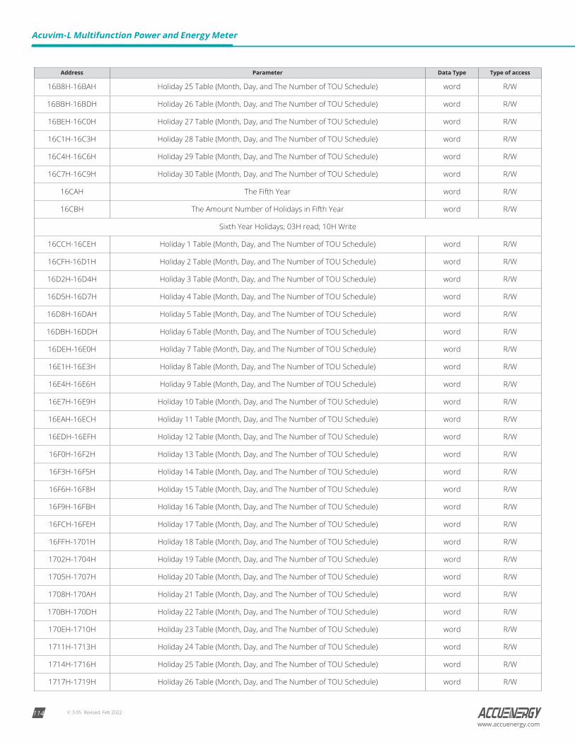
V: 3.05 Revised: Feb 2022114
Acuvim-L Multifunction Power and Energy Meter
www.accuenergy.com
Address Parameter Data Type Type of access
16B8H-16BAH Holiday 25 Table (Month, Day, and The Number of TOU Schedule) word R/W
16BBH-16BDH Holiday 26 Table (Month, Day, and The Number of TOU Schedule) word R/W
16BEH-16C0H Holiday 27 Table (Month, Day, and The Number of TOU Schedule) word R/W
16C1H-16C3H Holiday 28 Table (Month, Day, and The Number of TOU Schedule) word R/W
16C4H-16C6H Holiday 29 Table (Month, Day, and The Number of TOU Schedule) word R/W
16C7H-16C9H Holiday 30 Table (Month, Day, and The Number of TOU Schedule) word R/W
16CAH The Fifth Year word R/W
16CBH The Amount Number of Holidays in Fifth Year word R/W
Sixth Year Holidays; 03H read; 10H Write
16CCH-16CEH Holiday 1 Table (Month, Day, and The Number of TOU Schedule) word R/W
16CFH-16D1H Holiday 2 Table (Month, Day, and The Number of TOU Schedule) word R/W
16D2H-16D4H Holiday 3 Table (Month, Day, and The Number of TOU Schedule) word R/W
16D5H-16D7H Holiday 4 Table (Month, Day, and The Number of TOU Schedule) word R/W
16D8H-16DAH Holiday 5 Table (Month, Day, and The Number of TOU Schedule) word R/W
16DBH-16DDH Holiday 6 Table (Month, Day, and The Number of TOU Schedule) word R/W
16DEH-16E0H Holiday 7 Table (Month, Day, and The Number of TOU Schedule) word R/W
16E1H-16E3H Holiday 8 Table (Month, Day, and The Number of TOU Schedule) word R/W
16E4H-16E6H Holiday 9 Table (Month, Day, and The Number of TOU Schedule) word R/W
16E7H-16E9H Holiday 10 Table (Month, Day, and The Number of TOU Schedule) word R/W
16EAH-16ECH Holiday 11 Table (Month, Day, and The Number of TOU Schedule) word R/W
16EDH-16EFH Holiday 12 Table (Month, Day, and The Number of TOU Schedule) word R/W
16F0H-16F2H Holiday 13 Table (Month, Day, and The Number of TOU Schedule) word R/W
16F3H-16F5H Holiday 14 Table (Month, Day, and The Number of TOU Schedule) word R/W
16F6H-16F8H Holiday 15 Table (Month, Day, and The Number of TOU Schedule) word R/W
16F9H-16FBH Holiday 16 Table (Month, Day, and The Number of TOU Schedule) word R/W
16FCH-16FEH Holiday 17 Table (Month, Day, and The Number of TOU Schedule) word R/W
16FFH-1701H Holiday 18 Table (Month, Day, and The Number of TOU Schedule) word R/W
1702H-1704H Holiday 19 Table (Month, Day, and The Number of TOU Schedule) word R/W
1705H-1707H Holiday 20 Table (Month, Day, and The Number of TOU Schedule) word R/W
1708H-170AH Holiday 21 Table (Month, Day, and The Number of TOU Schedule) word R/W
170BH-170DH Holiday 22 Table (Month, Day, and The Number of TOU Schedule) word R/W
170EH-1710H Holiday 23 Table (Month, Day, and The Number of TOU Schedule) word R/W
1711H-1713H Holiday 24 Table (Month, Day, and The Number of TOU Schedule) word R/W
1714H-1716H Holiday 25 Table (Month, Day, and The Number of TOU Schedule) word R/W
1717H-1719H Holiday 26 Table (Month, Day, and The Number of TOU Schedule) word R/W
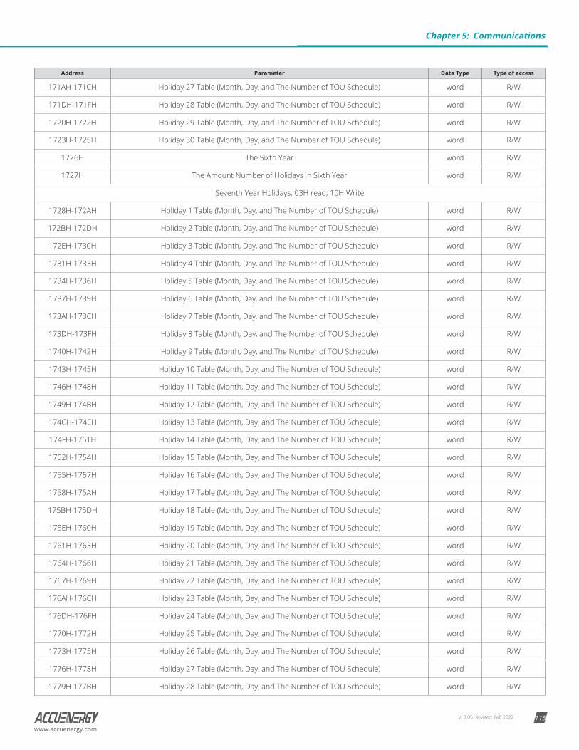
V: 3.05 Revised: Feb 2022 115www.accuenergy.com
Address Parameter Data Type Type of access
171AH-171CH Holiday 27 Table (Month, Day, and The Number of TOU Schedule) word R/W
171DH-171FH Holiday 28 Table (Month, Day, and The Number of TOU Schedule) word R/W
1720H-1722H Holiday 29 Table (Month, Day, and The Number of TOU Schedule) word R/W
1723H-1725H Holiday 30 Table (Month, Day, and The Number of TOU Schedule) word R/W
1726H The Sixth Year word R/W
1727H The Amount Number of Holidays in Sixth Year word R/W
Seventh Year Holidays; 03H read; 10H Write
1728H-172AH Holiday 1 Table (Month, Day, and The Number of TOU Schedule) word R/W
172BH-172DH Holiday 2 Table (Month, Day, and The Number of TOU Schedule) word R/W
172EH-1730H Holiday 3 Table (Month, Day, and The Number of TOU Schedule) word R/W
1731H-1733H Holiday 4 Table (Month, Day, and The Number of TOU Schedule) word R/W
1734H-1736H Holiday 5 Table (Month, Day, and The Number of TOU Schedule) word R/W
1737H-1739H Holiday 6 Table (Month, Day, and The Number of TOU Schedule) word R/W
173AH-173CH Holiday 7 Table (Month, Day, and The Number of TOU Schedule) word R/W
173DH-173FH Holiday 8 Table (Month, Day, and The Number of TOU Schedule) word R/W
1740H-1742H Holiday 9 Table (Month, Day, and The Number of TOU Schedule) word R/W
1743H-1745H Holiday 10 Table (Month, Day, and The Number of TOU Schedule) word R/W
1746H-1748H Holiday 11 Table (Month, Day, and The Number of TOU Schedule) word R/W
1749H-174BH Holiday 12 Table (Month, Day, and The Number of TOU Schedule) word R/W
174CH-174EH Holiday 13 Table (Month, Day, and The Number of TOU Schedule) word R/W
174FH-1751H Holiday 14 Table (Month, Day, and The Number of TOU Schedule) word R/W
1752H-1754H Holiday 15 Table (Month, Day, and The Number of TOU Schedule) word R/W
1755H-1757H Holiday 16 Table (Month, Day, and The Number of TOU Schedule) word R/W
1758H-175AH Holiday 17 Table (Month, Day, and The Number of TOU Schedule) word R/W
175BH-175DH Holiday 18 Table (Month, Day, and The Number of TOU Schedule) word R/W
175EH-1760H Holiday 19 Table (Month, Day, and The Number of TOU Schedule) word R/W
1761H-1763H Holiday 20 Table (Month, Day, and The Number of TOU Schedule) word R/W
1764H-1766H Holiday 21 Table (Month, Day, and The Number of TOU Schedule) word R/W
1767H-1769H Holiday 22 Table (Month, Day, and The Number of TOU Schedule) word R/W
176AH-176CH Holiday 23 Table (Month, Day, and The Number of TOU Schedule) word R/W
176DH-176FH Holiday 24 Table (Month, Day, and The Number of TOU Schedule) word R/W
1770H-1772H Holiday 25 Table (Month, Day, and The Number of TOU Schedule) word R/W
1773H-1775H Holiday 26 Table (Month, Day, and The Number of TOU Schedule) word R/W
1776H-1778H Holiday 27 Table (Month, Day, and The Number of TOU Schedule) word R/W
1779H-177BH Holiday 28 Table (Month, Day, and The Number of TOU Schedule) word R/W
Chapter 5: Communications
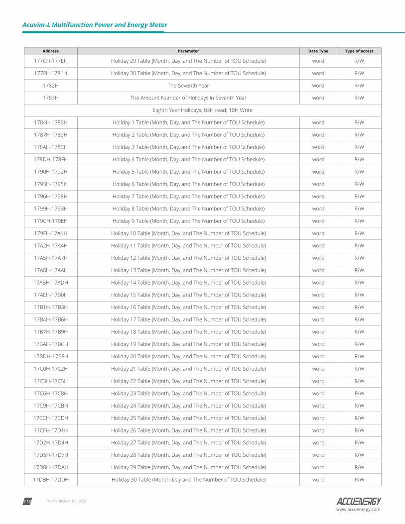
V: 3.05 Revised: Feb 2022116
Acuvim-L Multifunction Power and Energy Meter
www.accuenergy.com
Address Parameter Data Type Type of access
177CH-177EH Holiday 29 Table (Month, Day, and The Number of TOU Schedule) word R/W
177FH-1781H Holiday 30 Table (Month, Day, and The Number of TOU Schedule) word R/W
1782H The Seventh Year word R/W
1783H The Amount Number of Holidays in Seventh Year word R/W
Eighth Year Holidays; 03H read; 10H Write
1784H-1786H Holiday 1 Table (Month, Day, and The Number of TOU Schedule) word R/W
1787H-1789H Holiday 2 Table (Month, Day, and The Number of TOU Schedule) word R/W
178AH-178CH Holiday 3 Table (Month, Day, and The Number of TOU Schedule) word R/W
178DH-178FH Holiday 4 Table (Month, Day, and The Number of TOU Schedule) word R/W
1790H-1792H Holiday 5 Table (Month, Day, and The Number of TOU Schedule) word R/W
1793H-1795H Holiday 6 Table (Month, Day, and The Number of TOU Schedule) word R/W
1796H-1798H Holiday 7 Table (Month, Day, and The Number of TOU Schedule) word R/W
1799H-179BH Holiday 8 Table (Month, Day, and The Number of TOU Schedule) word R/W
179CH-179EH Holiday 9 Table (Month, Day, and The Number of TOU Schedule) word R/W
179FH-17A1H Holiday 10 Table (Month, Day, and The Number of TOU Schedule) word R/W
17A2H-17A4H Holiday 11 Table (Month, Day, and The Number of TOU Schedule) word R/W
17A5H-17A7H Holiday 12 Table (Month, Day, and The Number of TOU Schedule) word R/W
17A8H-17AAH Holiday 13 Table (Month, Day, and The Number of TOU Schedule) word R/W
17ABH-17ADH Holiday 14 Table (Month, Day, and The Number of TOU Schedule) word R/W
17AEH-17B0H Holiday 15 Table (Month, Day, and The Number of TOU Schedule) word R/W
17B1H-17B3H Holiday 16 Table (Month, Day, and The Number of TOU Schedule) word R/W
17B4H-17B6H Holiday 17 Table (Month, Day, and The Number of TOU Schedule) word R/W
17B7H-17B9H Holiday 18 Table (Month, Day, and The Number of TOU Schedule) word R/W
17BAH-17BCH Holiday 19 Table (Month, Day, and The Number of TOU Schedule) word R/W
17BDH-17BFH Holiday 20 Table (Month, Day, and The Number of TOU Schedule) word R/W
17C0H-17C2H Holiday 21 Table (Month, Day, and The Number of TOU Schedule) word R/W
17C3H-17C5H Holiday 22 Table (Month, Day, and The Number of TOU Schedule) word R/W
17C6H-17C8H Holiday 23 Table (Month, Day, and The Number of TOU Schedule) word R/W
17C9H-17CBH Holiday 24 Table (Month, Day, and The Number of TOU Schedule) word R/W
17CCH-17CDH Holiday 25 Table (Month, Day, and The Number of TOU Schedule) word R/W
17CFH-17D1H Holiday 26 Table (Month, Day, and The Number of TOU Schedule) word R/W
17D2H-17D4H Holiday 27 Table (Month, Day, and The Number of TOU Schedule) word R/W
17D5H-17D7H Holiday 28 Table (Month, Day, and The Number of TOU Schedule) word R/W
17D8H-17DAH Holiday 29 Table (Month, Day, and The Number of TOU Schedule) word R/W
17DBH-17DDH Holiday 30 Table (Month, Day and The Number of TOU Schedule) word R/W
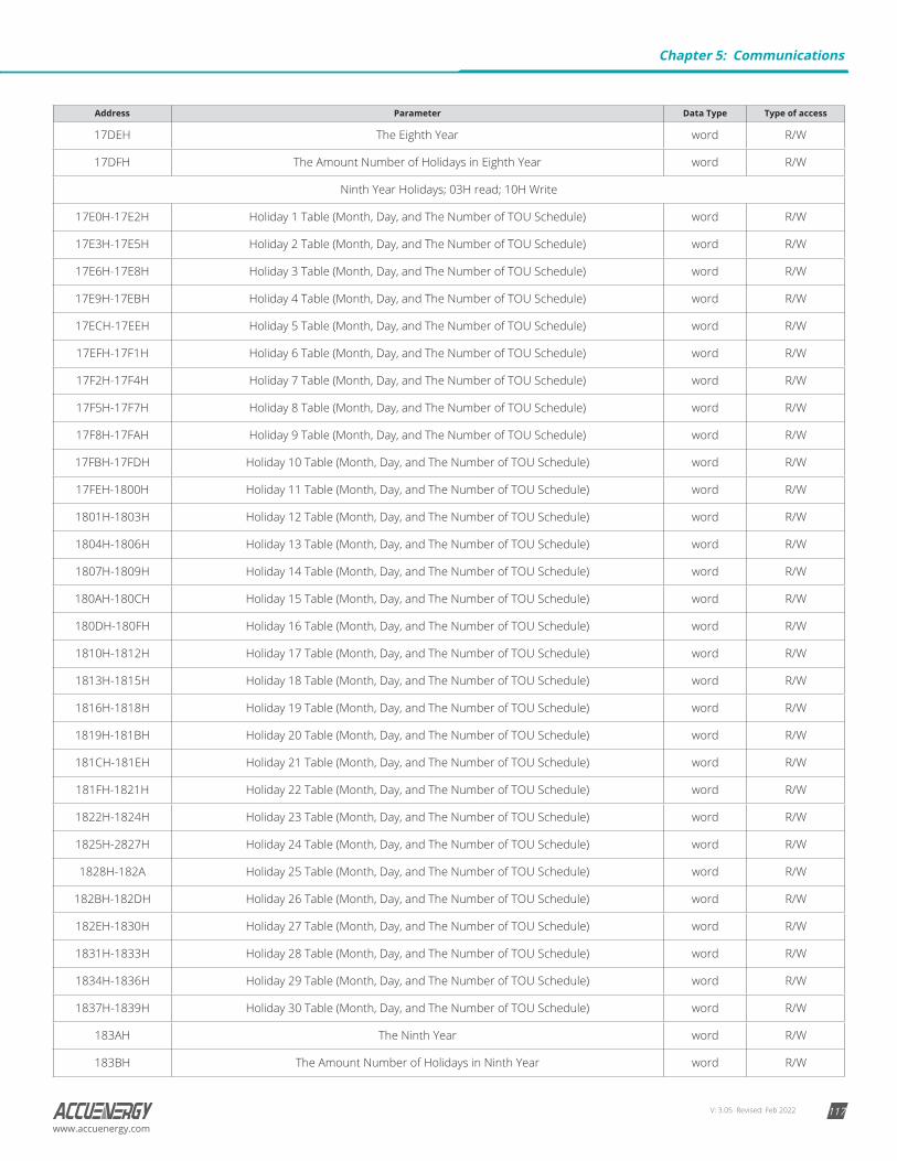
V: 3.05 Revised: Feb 2022 117www.accuenergy.com
Address Parameter Data Type Type of access
17DEH The Eighth Year word R/W
17DFH The Amount Number of Holidays in Eighth Year word R/W
Ninth Year Holidays; 03H read; 10H Write
17E0H-17E2H Holiday 1 Table (Month, Day, and The Number of TOU Schedule) word R/W
17E3H-17E5H Holiday 2 Table (Month, Day, and The Number of TOU Schedule) word R/W
17E6H-17E8H Holiday 3 Table (Month, Day, and The Number of TOU Schedule) word R/W
17E9H-17EBH Holiday 4 Table (Month, Day, and The Number of TOU Schedule) word R/W
17ECH-17EEH Holiday 5 Table (Month, Day, and The Number of TOU Schedule) word R/W
17EFH-17F1H Holiday 6 Table (Month, Day, and The Number of TOU Schedule) word R/W
17F2H-17F4H Holiday 7 Table (Month, Day, and The Number of TOU Schedule) word R/W
17F5H-17F7H Holiday 8 Table (Month, Day, and The Number of TOU Schedule) word R/W
17F8H-17FAH Holiday 9 Table (Month, Day, and The Number of TOU Schedule) word R/W
17FBH-17FDH Holiday 10 Table (Month, Day, and The Number of TOU Schedule) word R/W
17FEH-1800H Holiday 11 Table (Month, Day, and The Number of TOU Schedule) word R/W
1801H-1803H Holiday 12 Table (Month, Day, and The Number of TOU Schedule) word R/W
1804H-1806H Holiday 13 Table (Month, Day, and The Number of TOU Schedule) word R/W
1807H-1809H Holiday 14 Table (Month, Day, and The Number of TOU Schedule) word R/W
180AH-180CH Holiday 15 Table (Month, Day, and The Number of TOU Schedule) word R/W
180DH-180FH Holiday 16 Table (Month, Day, and The Number of TOU Schedule) word R/W
1810H-1812H Holiday 17 Table (Month, Day, and The Number of TOU Schedule) word R/W
1813H-1815H Holiday 18 Table (Month, Day, and The Number of TOU Schedule) word R/W
1816H-1818H Holiday 19 Table (Month, Day, and The Number of TOU Schedule) word R/W
1819H-181BH Holiday 20 Table (Month, Day, and The Number of TOU Schedule) word R/W
181CH-181EH Holiday 21 Table (Month, Day, and The Number of TOU Schedule) word R/W
181FH-1821H Holiday 22 Table (Month, Day, and The Number of TOU Schedule) word R/W
1822H-1824H Holiday 23 Table (Month, Day, and The Number of TOU Schedule) word R/W
1825H-2827H Holiday 24 Table (Month, Day, and The Number of TOU Schedule) word R/W
1828H-182A Holiday 25 Table (Month, Day, and The Number of TOU Schedule) word R/W
182BH-182DH Holiday 26 Table (Month, Day, and The Number of TOU Schedule) word R/W
182EH-1830H Holiday 27 Table (Month, Day, and The Number of TOU Schedule) word R/W
1831H-1833H Holiday 28 Table (Month, Day, and The Number of TOU Schedule) word R/W
1834H-1836H Holiday 29 Table (Month, Day, and The Number of TOU Schedule) word R/W
1837H-1839H Holiday 30 Table (Month, Day, and The Number of TOU Schedule) word R/W
183AH The Ninth Year word R/W
183BH The Amount Number of Holidays in Ninth Year word R/W
Chapter 5: Communications
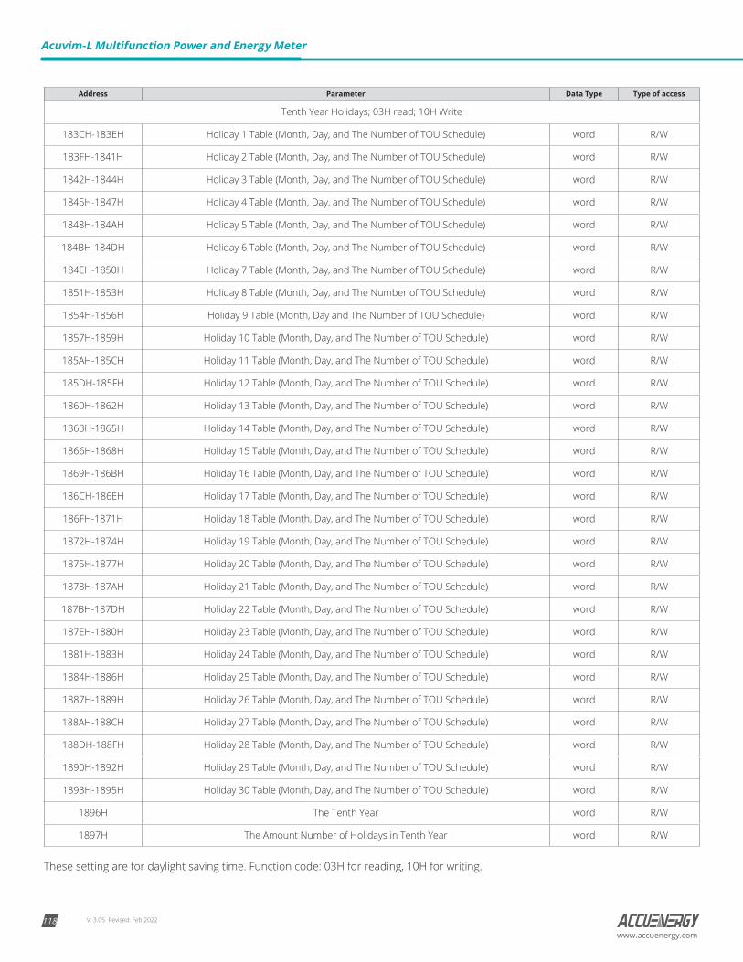
V: 3.05 Revised: Feb 2022118
Acuvim-L Multifunction Power and Energy Meter
www.accuenergy.com
Address Parameter Data Type Type of access
Tenth Year Holidays; 03H read; 10H Write
183CH-183EH Holiday 1 Table (Month, Day, and The Number of TOU Schedule) word R/W
183FH-1841H Holiday 2 Table (Month, Day, and The Number of TOU Schedule) word R/W
1842H-1844H Holiday 3 Table (Month, Day, and The Number of TOU Schedule) word R/W
1845H-1847H Holiday 4 Table (Month, Day, and The Number of TOU Schedule) word R/W
1848H-184AH Holiday 5 Table (Month, Day, and The Number of TOU Schedule) word R/W
184BH-184DH Holiday 6 Table (Month, Day, and The Number of TOU Schedule) word R/W
184EH-1850H Holiday 7 Table (Month, Day, and The Number of TOU Schedule) word R/W
1851H-1853H Holiday 8 Table (Month, Day, and The Number of TOU Schedule) word R/W
1854H-1856H Holiday 9 Table (Month, Day and The Number of TOU Schedule) word R/W
1857H-1859H Holiday 10 Table (Month, Day, and The Number of TOU Schedule) word R/W
185AH-185CH Holiday 11 Table (Month, Day, and The Number of TOU Schedule) word R/W
185DH-185FH Holiday 12 Table (Month, Day, and The Number of TOU Schedule) word R/W
1860H-1862H Holiday 13 Table (Month, Day, and The Number of TOU Schedule) word R/W
1863H-1865H Holiday 14 Table (Month, Day, and The Number of TOU Schedule) word R/W
1866H-1868H Holiday 15 Table (Month, Day, and The Number of TOU Schedule) word R/W
1869H-186BH Holiday 16 Table (Month, Day, and The Number of TOU Schedule) word R/W
186CH-186EH Holiday 17 Table (Month, Day, and The Number of TOU Schedule) word R/W
186FH-1871H Holiday 18 Table (Month, Day, and The Number of TOU Schedule) word R/W
1872H-1874H Holiday 19 Table (Month, Day, and The Number of TOU Schedule) word R/W
1875H-1877H Holiday 20 Table (Month, Day, and The Number of TOU Schedule) word R/W
1878H-187AH Holiday 21 Table (Month, Day, and The Number of TOU Schedule) word R/W
187BH-187DH Holiday 22 Table (Month, Day, and The Number of TOU Schedule) word R/W
187EH-1880H Holiday 23 Table (Month, Day, and The Number of TOU Schedule) word R/W
1881H-1883H Holiday 24 Table (Month, Day, and The Number of TOU Schedule) word R/W
1884H-1886H Holiday 25 Table (Month, Day, and The Number of TOU Schedule) word R/W
1887H-1889H Holiday 26 Table (Month, Day, and The Number of TOU Schedule) word R/W
188AH-188CH Holiday 27 Table (Month, Day, and The Number of TOU Schedule) word R/W
188DH-188FH Holiday 28 Table (Month, Day, and The Number of TOU Schedule) word R/W
1890H-1892H Holiday 29 Table (Month, Day, and The Number of TOU Schedule) word R/W
1893H-1895H Holiday 30 Table (Month, Day, and The Number of TOU Schedule) word R/W
1896H The Tenth Year word R/W
1897H The Amount Number of Holidays in Tenth Year word R/W
These setting are for daylight saving time. Function code: 03H for reading, 10H for writing.
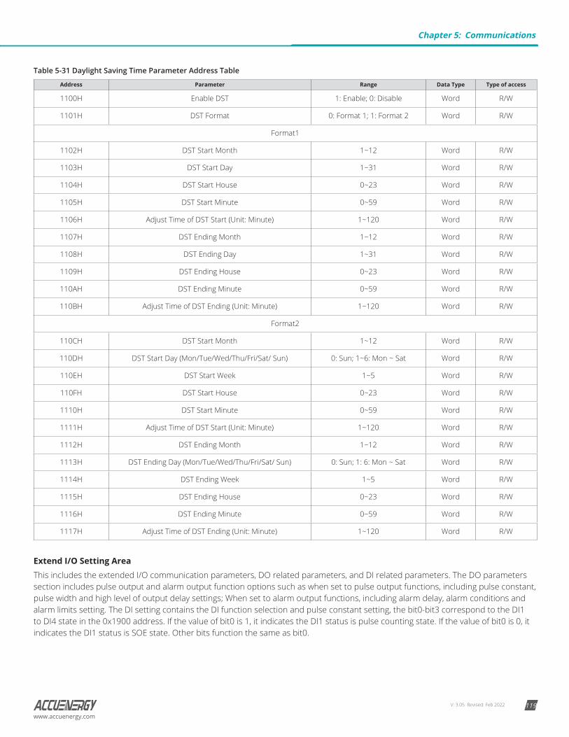
V: 3.05 Revised: Feb 2022 119www.accuenergy.com
Table 5-31 Daylight Saving Time Parameter Address Table
Address Parameter Range Data Type Type of access
1100H Enable DST 1: Enable; 0: Disable Word R/W
1101H DST Format 0: Format 1; 1: Format 2 Word R/W
Format1
1102H DST Start Month 1~12 Word R/W
1103H DST Start Day 1~31 Word R/W
1104H DST Start House 0~23 Word R/W
1105H DST Start Minute 0~59 Word R/W
1106H Adjust Time of DST Start (Unit: Minute) 1~120 Word R/W
1107H DST Ending Month 1~12 Word R/W
1108H DST Ending Day 1~31 Word R/W
1109H DST Ending House 0~23 Word R/W
110AH DST Ending Minute 0~59 Word R/W
110BH Adjust Time of DST Ending (Unit: Minute) 1~120 Word R/W
Format2
110CH DST Start Month 1~12 Word R/W
110DH DST Start Day (Mon/Tue/Wed/Thu/Fri/Sat/ Sun) 0: Sun; 1~6: Mon ~ Sat Word R/W
110EH DST Start Week 1~5 Word R/W
110FH DST Start House 0~23 Word R/W
1110H DST Start Minute 0~59 Word R/W
1111H Adjust Time of DST Start (Unit: Minute) 1~120 Word R/W
1112H DST Ending Month 1~12 Word R/W
1113H DST Ending Day (Mon/Tue/Wed/Thu/Fri/Sat/ Sun) 0: Sun; 1: 6: Mon ~ Sat Word R/W
1114H DST Ending Week 1~5 Word R/W
1115H DST Ending House 0~23 Word R/W
1116H DST Ending Minute 0~59 Word R/W
1117H Adjust Time of DST Ending (Unit: Minute) 1~120 Word R/W
Extend I/O Setting AreaThis includes the extended I/O communication parameters, DO related parameters, and DI related parameters. The DO parameters section includes pulse output and alarm output function options such as when set to pulse output functions, including pulse constant, pulse width and high level of output delay settings; When set to alarm output functions, including alarm delay, alarm conditions and alarm limits setting. The DI setting contains the DI function selection and pulse constant setting, the bit0-bit3 correspond to the DI1 to DI4 state in the 0x1900 address. If the value of bit0 is 1, it indicates the DI1 status is pulse counting state. If the value of bit0 is 0, it indicates the DI1 status is SOE state. Other bits function the same as bit0.
Chapter 5: Communications
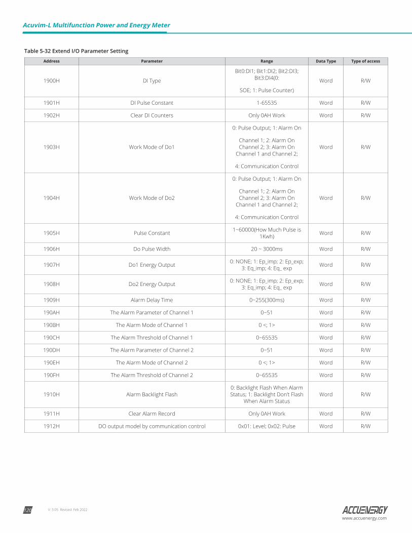
V: 3.05 Revised: Feb 2022120
Acuvim-L Multifunction Power and Energy Meter
www.accuenergy.com
Table 5-32 Extend I/O Parameter Setting
Address Parameter Range Data Type Type of access
1900H DI Type
Bit0:DI1; Bit1:DI2; Bit2:DI3; Bit3:DI4(0:
SOE; 1: Pulse Counter)
Word R/W
1901H DI Pulse Constant 1-65535 Word R/W
1902H Clear DI Counters Only 0AH Work Word R/W
1903H Work Mode of Do1
0: Pulse Output; 1: Alarm On
Channel 1; 2: Alarm On Channel 2; 3: Alarm On
Channel 1 and Channel 2;
4: Communication Control
Word R/W
1904H Work Mode of Do2
0: Pulse Output; 1: Alarm On
Channel 1; 2: Alarm On Channel 2; 3: Alarm On
Channel 1 and Channel 2;
4: Communication Control
Word R/W
1905H Pulse Constant 1~60000(How Much Pulse is 1Kwh) Word R/W
1906H Do Pulse Width 20 ~ 3000ms Word R/W
1907H Do1 Energy Output 0: NONE; 1: Ep_imp; 2: Ep_exp; 3: Eq_imp; 4: Eq_ exp Word R/W
1908H Do2 Energy Output 0: NONE; 1: Ep_imp; 2: Ep_exp; 3: Eq_imp; 4: Eq_ exp Word R/W
1909H Alarm Delay Time 0~255(300ms) Word R/W
190AH The Alarm Parameter of Channel 1 0~51 Word R/W
190BH The Alarm Mode of Channel 1 0 <; 1> Word R/W
190CH The Alarm Threshold of Channel 1 0~65535 Word R/W
190DH The Alarm Parameter of Channel 2 0~51 Word R/W
190EH The Alarm Mode of Channel 2 0 <; 1> Word R/W
190FH The Alarm Threshold of Channel 2 0~65535 Word R/W
1910H Alarm Backlight Flash0: Backlight Flash When Alarm Status; 1: Backlight Don’t Flash
When Alarm StatusWord R/W
1911H Clear Alarm Record Only 0AH Work Word R/W
1912H DO output model by communication control 0x01: Level; 0x02: Pulse Word R/W
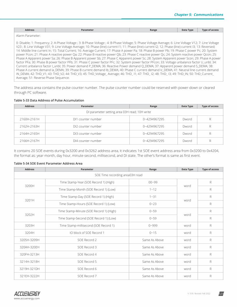
V: 3.05 Revised: Feb 2022 121www.accuenergy.com
Address Parameter Range Data Type Type of access
Alarm Parameter:
0: Disable; 1: Frequency; 2: A-Phase Voltage ; 3: B-Phase Voltage ; 4: B-Phase Voltage; 5: Phase Voltage Average; 6: Line Voltage V12; 7: Line Voltage V23 ; 8: Line Voltage V31; 9: Line Voltage Average; 10: Phase (line) current I1; 11: Phase (line) current I2; 12: Phase (line) current I3; 13: Reversed; 14: Middle line current In; 15: Total Current; 16: Average Current; 17: Phase A power Pa; 18: Phase B power Pb; 19: Phase C power Pc; 20: System power Pcon; 21: Phase A reactive power Qa; 22: Phase B reactive power Qb; 23: Phase C reactive power Qc; 24: System reactive power Qcon; 25: Phase A Apparent power Sa; 26: Phase B Apparent power Sb; 27: Phase C Apparent power Sc; 28: System Apparent power Scon; 29: Phase A power factor PFa; 30: Phase B power factor PFb; 31: Phase C power factor PFc; 32: System power factor PFcon; 33: Voltage unbalance factor U_unbl; 34: Current unbalance factor I_unbl; 35: Power demand P_DEMA; 36: Reactive Power demand Q_DEMA; 37: Apparent power demand S_DEMA; 38: Phase A current demand Ia_DEMA; 39: Phase B current demand Ib_DEMA; 40: Phase C current demand Ic_DEMA; 41: Neutral line current demand IN_DEMA; 42: THD_V1; 43: THD_V2; 44: THD_V3; 45: THD_Voltage_ Average; 46: THD_ I1; 47: THD_ I2; 48: THD_ I3; 49: THD_IN; 50: THD_Current_Average; 51: Reverse Phase Sequence.
The address area contains the pulse counter number. The pulse counter number could be reserved with power-down or cleared through PC software.
Table 5-33 Data Address of Pulse Accumulation
Address Parameter Range Data Type Type of access
DI parameter setting area 03H read; 10H write
2160H-2161H DI1 counter number 0~4294967295 Dword R
2162H-2163H DI2 counter number 0~4294967295 Dword R
2164H-2165H DI3 counter number 0~4294967295 Dword R
2166H-2167H DI4 counter number 0~4294967295 Dword R
It contains 20 SOE events during 0x3200 and 0x3262 address area, it indicates 1st SOE event address area from 0x3200 to 0x4204, the format as: year-month, day hour, minute-second, millisecond, and DI state. The other’s format is same as first event.
Table 5-34 SOE Event Parameter Address Area
Address Parameter Range Data Type Type of access
SOE Time recording area03H read
3200HTime Stamp-Year (SOE Record 1) (High) 00~99
wordR
Time Stamp-Month (SOE Record 1) (Low) 1~12 R
3201HTime Stamp-Day (SOE Record 1) (High) 1~31
wordR
Time Stamp-Hours (SOE Record 1) (Low) 0~23 R
3202HTime Stamp-Minute (SOE Record 1) (High) 0~59
wordR
Time Stamp-Second (SOE Record 1) (Low) 0~59 R
3203H Time Stamp-millisecond (SOE Record 1) 0~999 word R
3204H IO block of SOE Record 1 0~15 word R
3205H-3209H SOE Record 2 Same As Above word R
320AH-320EH SOE Record 3 Same As Above word R
320FH-3213H SOE Record 4 Same As Above word R
3214H-3218H SOE Record 5 Same As Above word R
3219H-321DH SOE Record 6 Same As Above word R
321EH-3222H SOE Record 7 Same As Above word R
Chapter 5: Communications
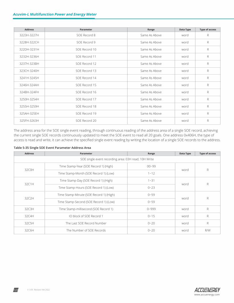
V: 3.05 Revised: Feb 2022122
Acuvim-L Multifunction Power and Energy Meter
www.accuenergy.com
Address Parameter Range Data Type Type of access
3223H-3227H SOE Record 8 Same As Above word R
3228H-322CH SOE Record 9 Same As Above word R
322DH-3231H SOE Record 10 Same As Above word R
3232H-3236H SOE Record 11 Same As Above word R
3237H-323BH SOE Record 12 Same As Above word R
323CH-3240H SOE Record 13 Same As Above word R
3241H-3245H SOE Record 14 Same As Above word R
3246H-324AH SOE Record 15 Same As Above word R
324BH-324FH SOE Record 16 Same As Above word R
3250H-3254H SOE Record 17 Same As Above word R
3255H-3259H SOE Record 18 Same As Above word R
325AH-325EH SOE Record 19 Same As Above word R
325FH-3263H SOE Record 20 Same As Above word R
The address area for the SOE single event reading, through continuous reading of the address area of a single SOE record, achieving the current single SOE records continuously updated to meet the SOE event to read all 20 goals. One address 0x406H, the type of access is read and write, it can achieve the specified single event reading by writing the location of a single SOE records to the address.
Table 5-35 Single SOE Event Parameter Address Area
Address Parameter Range Data Type Type of access
SOE single event recording area: 03H read; 10H Write
32C0HTime Stamp-Year (SOE Record 1) (High) 00~99
word RTime Stamp-Month (SOE Record 1) (Low) 1~12
32C1HTime Stamp-Day (SOE Record 1) (High) 1~31
word RTime Stamp-Hours (SOE Record 1) (Low) 0~23
32C2HTime Stamp-Minute (SOE Record 1) (High) 0~59
word RTime Stamp-Second (SOE Record 1) (Low) 0~59
32C3H Time Stamp-millisecond (SOE Record 1) 0~999 word R
32C4H IO block of SOE Record 1 0~15 word R
32C5H The Last SOE Record Number 0~20 word R
32C6H The Number of SOE Records 0~20 word R/W
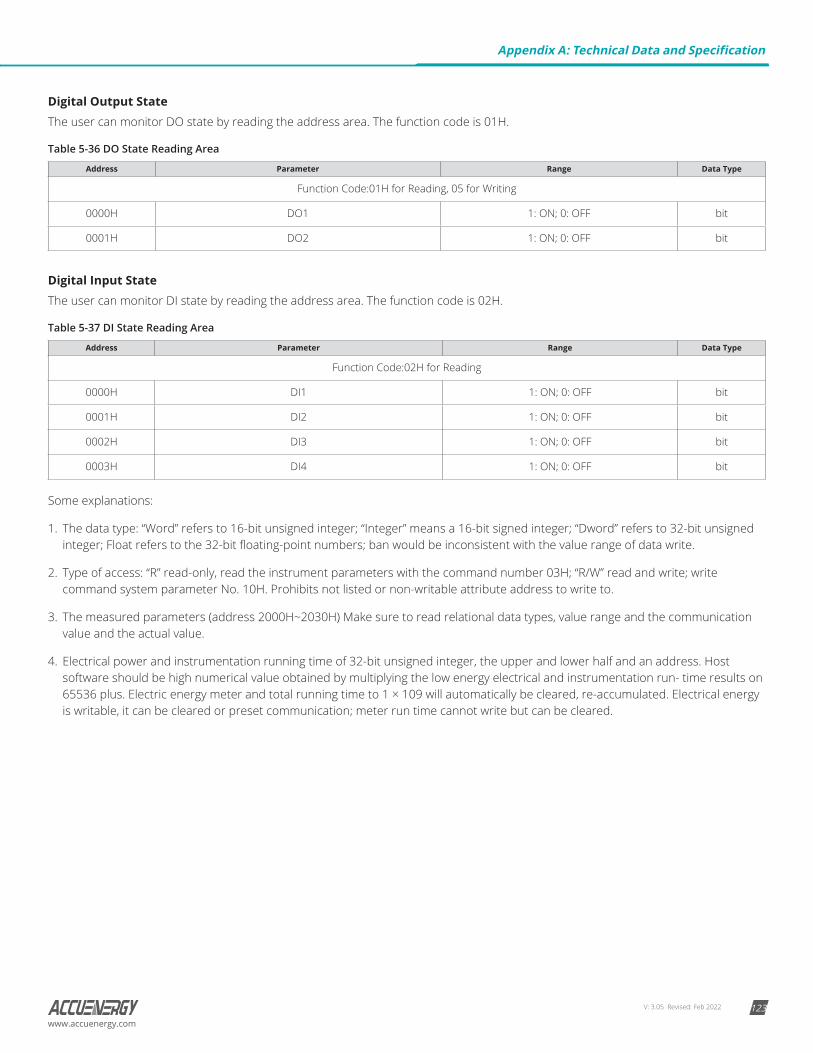
V: 3.05 Revised: Feb 2022 123www.accuenergy.com
Digital Output StateThe user can monitor DO state by reading the address area. The function code is 01H.
Table 5-36 DO State Reading Area
Address Parameter Range Data Type
Function Code:01H for Reading, 05 for Writing
0000H DO1 1: ON; 0: OFF bit
0001H DO2 1: ON; 0: OFF bit
Digital Input StateThe user can monitor DI state by reading the address area. The function code is 02H.
Table 5-37 DI State Reading Area
Address Parameter Range Data Type
Function Code:02H for Reading
0000H DI1 1: ON; 0: OFF bit
0001H DI2 1: ON; 0: OFF bit
0002H DI3 1: ON; 0: OFF bit
0003H DI4 1: ON; 0: OFF bit
Some explanations:
1. The data type: “Word” refers to 16-bit unsigned integer; “Integer” means a 16-bit signed integer; “Dword” refers to 32-bit unsigned integer; Float refers to the 32-bit floating-point numbers; ban would be inconsistent with the value range of data write.
2. Type of access: “R” read-only, read the instrument parameters with the command number 03H; “R/W” read and write; write command system parameter No. 10H. Prohibits not listed or non-writable attribute address to write to.
3. The measured parameters (address 2000H~2030H) Make sure to read relational data types, value range and the communication value and the actual value.
4. Electrical power and instrumentation running time of 32-bit unsigned integer, the upper and lower half and an address. Host software should be high numerical value obtained by multiplying the low energy electrical and instrumentation run- time results on 65536 plus. Electric energy meter and total running time to 1 × 10⁹ will automatically be cleared, re-accumulated. Electrical energy is writable, it can be cleared or preset communication; meter run time cannot write but can be cleared.
Appendix A: Technical Data and Specification
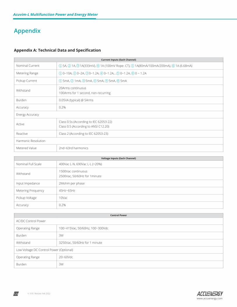
V: 3.05 Revised: Feb 2022124
Acuvim-L Multifunction Power and Energy Meter
www.accuenergy.com
Appendix
Appendix A: Technical Data and Specification
Current Inputs (Each Channel)
Nominal Current 5A, 1A, 1A(333mV), 1A (100mV Rope- CT), 1A(80mA/100mA/200mA), 1A (6.68mA)
Metering Range 0~10A, 0~2A, 0~1.2A, 0~1.2A,… 0~1.2A, 0 ~ 1.2A
Pickup Current 5mA, 1mA, 5mA, 5mA, 5mA, 5mA
Withstand20Arms continuous100Arms for 1 second, non-recurring
Burden 0.05VA (typical) @ 5Arms
Accuracy 0.2%
Energy Accuracy
ActiveClass 0.5s (According to IEC 62053-22) Class 0.5 (According to ANSI C12.20)
Reactive Class 2 (According to IEC 62053-23)
Harmonic Resolution
Metered Value 2nd~63rd harmonics
Voltage Inputs (Each Channel)
Nominal Full Scale 400Vac L-N, 690Vac L-L (+20%)
Withstand1500Vac continuous2500Vac, 50/60Hz for 1minute
Input Impedance 2Mohm per phase
Metering Frequency 45Hz~65Hz
Pickup Voltage 10Vac
Accuracy 0.2%
Control Power
AC/DC Control Power
Operating Range 100~415Vac, 50/60Hz, 100~300Vdc
Burden 3W
Withstand 3250Vac, 50/60Hz for 1 minute
Low Voltage DC Control Power (Optional)
Operating Range 20~60Vdc
Burden 3W

V: 3.05 Revised: Feb 2022 125www.accuenergy.com
AccuracyMetering
Parameters Accuracy Resolution Range
Voltage 0.2% 0.1V 20V~1000kV
Current 0.2% 0.001A 0~50000A
Current Demand 0.2% 0.001A 0~50000A
Power 0.5% 1W –9999~9999MW
Reactive Power 0.5% 1var –9999~9999Mvar
Apparent Power 0.5% 1VA 0~9999MVA
Power Demand 0.5% 1W –9999~9999MW
Reactive Power Demand 0.5% 1var –9999~9999Mvar
Apparent Power Demand 0.5% 1VA 0~9999MVA
Power Factor 0.5% 0.001 –1.0~1.0
Frequency 0.05% 0.01Hz 45.00~65.00Hz
Energy 0.5% 0.1kWh 0~99999999.9kWh
Reactive Energy 0.5% 0.1kvarh 0~99999999.9kvarh
Apparent Energy 0.5% 0.1VAh 0~99999999.9kVAh
Harmonics 1.0% 0.01%
Meter Running Time 0.1hrs 0~99999999.9hrs
Load Running Time 0.1hrs 0~99999999.9hrs
Standards
Measuring IEC 61036 Class 1, ANSI C12.16 Class 10
Environmental IEC 60068-2
Safety IEC 61010-1, UL 61010-1
EMC IEC 61000-4/2-3-4-5-6-8-11
Dimensions DIN 43700/ANSI C39.1
Digital input (DI)
Input Type Dry Contact
Input Resistance 4kΩ
Pulse Frequency (Max) 100Hz, 50% Duty Ratio
SOE Resolution 2ms
Digital output (DO)(Photo-MOS)
Voltage Range 0~250Vac/dc
Load Current 100mA (Max)
Output Frequency (Max) 25Hz, 50% Duty Ratio
Isolation Voltage 2500V
Appendix A: Technical Data and Specification
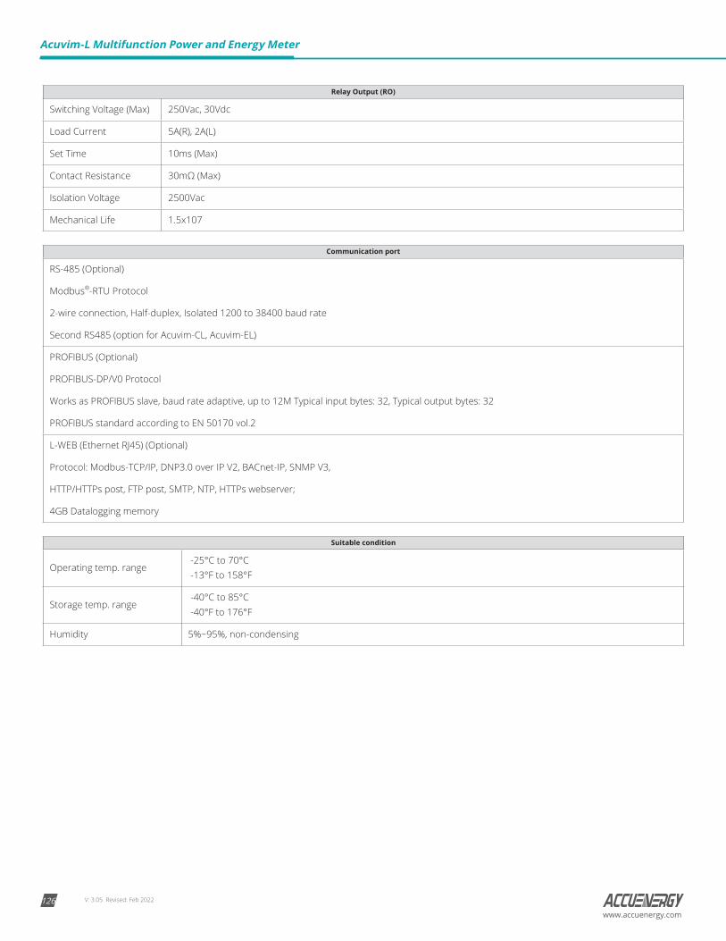
V: 3.05 Revised: Feb 2022126
Acuvim-L Multifunction Power and Energy Meter
www.accuenergy.com
Relay Output (RO)
Switching Voltage (Max) 250Vac, 30Vdc
Load Current 5A(R), 2A(L)
Set Time 10ms (Max)
Contact Resistance 30mΩ (Max)
Isolation Voltage 2500Vac
Mechanical Life 1.5x10⁷
Communication port
RS-485 (Optional)
Modbus®-RTU Protocol
2-wire connection, Half-duplex, Isolated 1200 to 38400 baud rate
Second RS485 (option for Acuvim-CL, Acuvim-EL)
PROFIBUS (Optional)
PROFIBUS-DP/V0 Protocol
Works as PROFIBUS slave, baud rate adaptive, up to 12M Typical input bytes: 32, Typical output bytes: 32
PROFIBUS standard according to EN 50170 vol.2
L-WEB (Ethernet RJ45) (Optional)
Protocol: Modbus-TCP/IP, DNP3.0 over IP V2, BACnet-IP, SNMP V3,
HTTP/HTTPs post, FTP post, SMTP, NTP, HTTPs webserver;
4GB Datalogging memory
Suitable condition
Operating temp. range -25°C to 70°C -13°F to 158°F
Storage temp. range -40°C to 85°C -40°F to 176°F
Humidity 5%~95%, non-condensing

V: 3.05 Revised: Feb 2022 127www.accuenergy.com
Appendix B: Ordering Information
Meter Model - Mounting Option - Current Input - Power SupplyAcuvim-BL: Basic Model + DO D: Standard with LCD Display 5A: 5A/1A
(Input Field Selectable)P1V3: 100~415Vac, 50~60Hz100~300Vdc
Acuvim-CL: Basic Model + Communication + Extension
M: DIN Rail Mount (Optional Remote Display to be added) RCT*: AcuCT-Flex Input P2V3: 20~60Vdc
Acuvim-EL: Sharing Power + Communication + Extension 333: 333mV Input
Ordering Example: Acuvim-CL-D-RCT-P2V3*Meters with RCT Current Input do not support I4, WIRING CHECK, POWER QUALITY, SEQUENCE, PHASE ANGLES, or POWER QUALITY EVENT LOGGING functions.
I/O Module (Optional) - Logic Module
L
WEB: Protocol: Modbus-TCP/IP, DNP 3.0 Over IP V2, BACnet-IP, SNMP V3, HTTP/HTTPs post, FTP post, SMTP, NTP, HTTPs webserver; 4GB Datalogging
Ordering Example: L-WEB
L X1: 4DI+2DO
X2: 4DI+2DO+Second RS485
X3: PROFIBUS
X4: 4DI+2DO+PROFIBUS
X5: 4DI+2RO
X6: 4DI+2RO+Second RS485
Ordering Example: L-X4
Accessories (Optional)
REM-DS1V3:Remote Display (Compatible with Acuvim-L Series “M”(DIN Mount) models only)
AXM-DIN: DIN Rail Adapter
96-IP66: Screen Protector for 96*96 meters
USB-RS485: USB-to-RS485 Converter
Ordering Example: AXM-DIN
ORDERING INFORMATION+
+ +
Notes: 1. Only the Acuvim-EL supports the use of expansion modules.
2. X4 and X6 two modules, respectively, by X1 + X3 and X1 and X5 composition and X3/X5 communication module shall be installed close to the body
Appendix B: Ordering Information
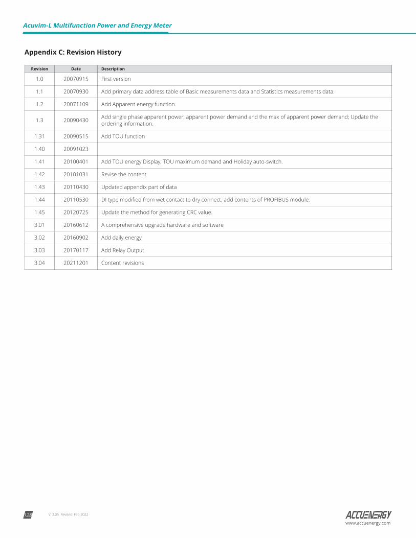
V: 3.05 Revised: Feb 2022128
Acuvim-L Multifunction Power and Energy Meter
www.accuenergy.com
Appendix C: Revision History
Revision Date Description
1.0 20070915 First version
1.1 20070930 Add primary data address table of Basic measurements data and Statistics measurements data.
1.2 20071109 Add Apparent energy function.
1.3 20090430 Add single phase apparent power, apparent power demand and the max of apparent power demand; Update the ordering information.
1.31 20090515 Add TOU function
1.40 20091023
1.41 20100401 Add TOU energy Display, TOU maximum demand and Holiday auto-switch.
1.42 20101031 Revise the content
1.43 20110430 Updated appendix part of data
1.44 20110530 DI type modified from wet contact to dry connect; add contents of PROFIBUS module.
1.45 20120725 Update the method for generating CRC value.
3.01 20160612 A comprehensive upgrade hardware and software
3.02 20160902 Add daily energy
3.03 20170117 Add Relay Output
3.04 20211201 Content revisions

MAKE ENERGY USAGE SMARTER
Accuenergy (Canada) Inc.Los Angeles - Toronto - Beijing - Pretoria
North America Toll Free: 1-877-721-8908Web: www.accuenergy.comEmail: [email protected]
Revision Date: Feb 2022 Version: 3.05Specs Subject To Change Without Notice.
ISO9001 Certified