power meter series - hioki
TRANSCRIPT
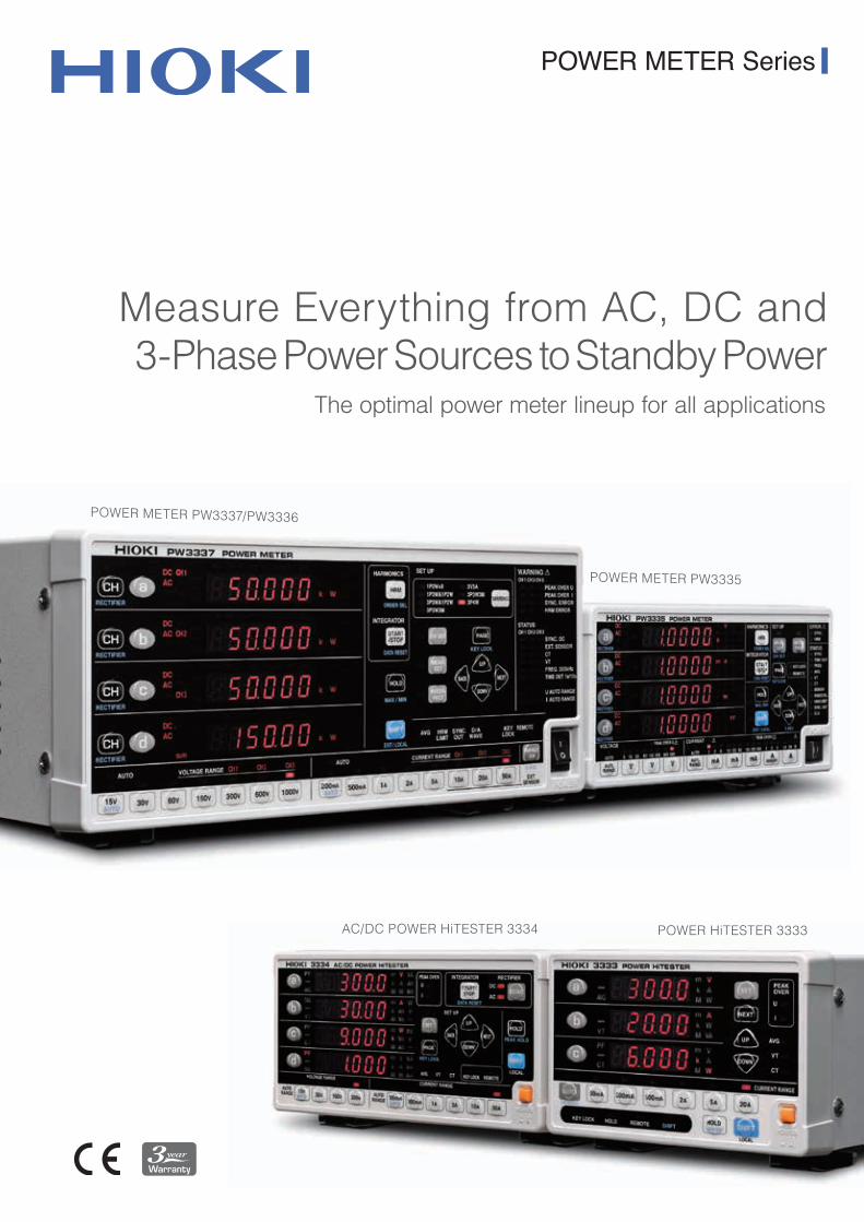
POWER METER Series
Measure Everything from AC, DC and 3-Phase Power Sources to Standby Power
The optimal power meter lineup for all applications
POWER METER PW3337/PW3336
POWER METER PW3335
AC/DC POWER HiTESTER 3334 POWER HiTESTER 3333
2
The best performing instruments for power measurement
on production lines, in laboratories, and in research facilities.
Hioki delivers the optimal power testing solutions
based on use case conditions, practical application, and accuracy.
Advancing the Standard forPower Measurement
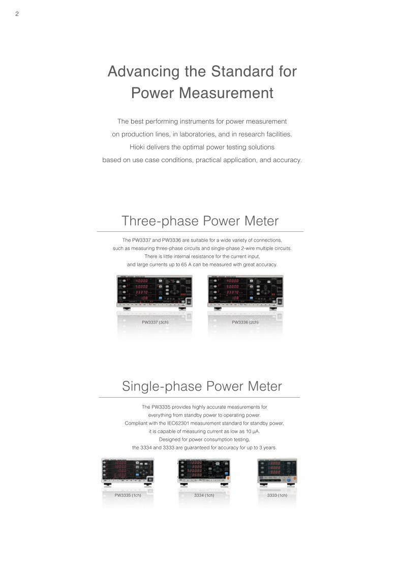
Single-phase Power MeterThe PW3335 provides highly accurate measurements for
everything from standby power to operating power.Compliant with the IEC62301 measurement standard for standby power,
it is capable of measuring current as low as 10 μA.Designed for power consumption testing,
the 3334 and 3333 are guaranteed for accuracy for up to 3 years.
3333 (1ch)PW3335 (1ch)
Three-phase Power MeterThe PW3337 and PW3336 are suitable for a wide variety of connections,
such as measuring three-phase circuits and single-phase 2-wire multiple circuits.There is little internal resistance for the current input,
and large currents up to 65 A can be measured with great accuracy.
PW3336 (2ch) PW3337 (3ch)
3334 (1ch)
3
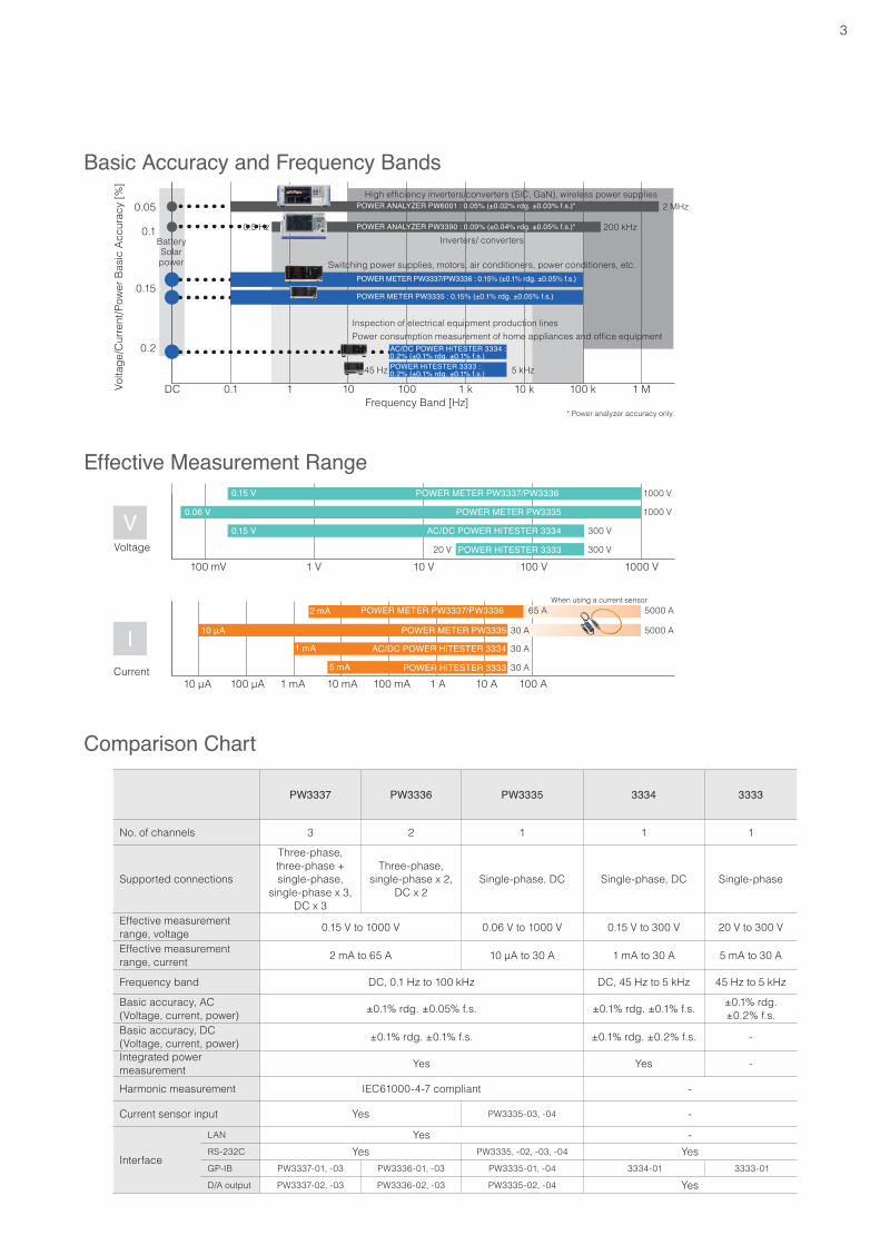
PW3337 PW3336 PW3335 3334 3333
No. of channels 3 2 1 1 1
Supported connections
Three-phase, three-phase + single-phase,
single-phase x 3, DC x 3
Three-phase, single-phase x 2,
DC x 2Single-phase, DC Single-phase, DC Single-phase
Effective measurement range, voltage 0.15 V to 1000 V 0.06 V to 1000 V 0.15 V to 300 V 20 V to 300 V
Effective measurement range, current 2 mA to 65 A 10 μA to 30 A 1 mA to 30 A 5 mA to 30 A
Frequency band DC, 0.1 Hz to 100 kHz DC, 45 Hz to 5 kHz 45 Hz to 5 kHz
Basic accuracy, AC(Voltage, current, power) ±0.1% rdg. ±0.05% f.s. ±0.1% rdg. ±0.1% f.s. ±0.1% rdg.
±0.2% f.s.Basic accuracy, DC(Voltage, current, power) ±0.1% rdg. ±0.1% f.s. ±0.1% rdg. ±0.2% f.s. -
Integrated power measurement Yes Yes -
Harmonic measurement IEC61000-4-7 compliant -
Current sensor input Yes PW3335-03, -04 -
Interface
LAN Yes -RS-232C Yes PW3335, -02, -03, -04 YesGP-IB PW3337-01, -03 PW3336-01, -03 PW3335-01, -04 3334-01 3333-01
D/A output PW3337-02, -03 PW3336-02, -03 PW3335-02, -04 Yes
Comparison Chart
Basic Accuracy and Frequency Bands
Frequency Band [Hz]DC 0.1 1 10 100 1 k 10 k 100 k 1 MVo
ltage
/Cur
rent
/Pow
er B
asic
Acc
urac
y [%
]
0.05
0.1
0.15
0.2
0.5 Hz 200 kHz
2 MHz
45 Hz 5 kHz
POWER ANALYZER PW6001 : 0.05% (±0.02% rdg. ±0.03% f.s.)*
* Power analyzer accuracy only.
POWER ANALYZER PW3390 : 0.09% (±0.04% rdg. ±0.05% f.s.)*
Inspection of electrical equipment production linesPower consumption measurement of home appliances and office equipment
POWER METER PW3337/PW3336 : 0.15% (±0.1% rdg. ±0.05% f.s.)
POWER METER PW3335 : 0.15% (±0.1% rdg. ±0.05% f.s.)
AC/DC POWER HiTESTER 3334 : 0.2% (±0.1% rdg. ±0.1% f.s.)POWER HiTESTER 3333 : 0.2% (±0.1% rdg. ±0.1% f.s.)
High efficiency inverters/converters (SiC, GaN), wireless power supplies
BatterySolar power
Inverters/ converters
Switching power supplies, motors, air conditioners, power conditioners, etc.
Effective Measurement Range0.15 V
0.06 V
0.15 V
20 V
300 V
300 V
POWER METER PW3337/PW3336
POWER METER PW3335
AC/DC POWER HiTESTER 3334
POWER HiTESTER 3333
100 mV 1 V 10 V 100 V 1000 V
1000 V
1000 V
2 mA
10 μA
1 mA
5 mA
30 A
30 A
30 A
65 A 5000 A
5000 A
POWER METER PW3337/PW3336
POWER METER PW3335
AC/DC POWER HiTESTER 3334
POWER HiTESTER 3333
10 μA 100 μA 10 mA 1 A1 mA 100 mA 10 A 100 ACurrent
Voltage
When using a current sensor
V
I
4
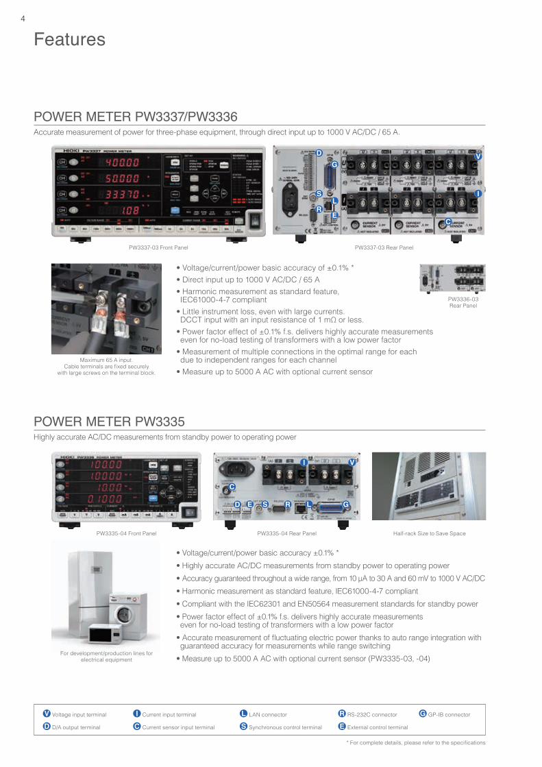
Accurate measurement of power for three-phase equipment, through direct input up to 1000 V AC/DC / 65 A.
Features
POWER METER PW3337/PW3336
PW3337-03 Front Panel PW3337-03 Rear Panel
PW3336-03Rear Panel
• Voltage/current/power basic accuracy of ±0.1% *• Direct input up to 1000 V AC/DC / 65 A• Harmonic measurement as standard feature, IEC61000-4-7 compliant
• Little instrument loss, even with large currents. DCCT input with an input resistance of 1 mΩ or less.
• Power factor effect of ±0.1% f.s. delivers highly accurate measurements even for no-load testing of transformers with a low power factor
• Measurement of multiple connections in the optimal range for each due to independent ranges for each channel
• Measure up to 5000 A AC with optional current sensor
Voltage input terminal Current input terminal LAN connector RS-232C connector GP-IB connector
D/A output terminal Current sensor input terminal Synchronous control terminal External control terminal
Maximum 65 A input.Cable terminals are fixed securely
with large screws on the terminal block.
• Voltage/current/power basic accuracy ±0.1% *• Highly accurate AC/DC measurements from standby power to operating power• Accuracy guaranteed throughout a wide range, from 10 μA to 30 A and 60 mV to 1000 V AC/DC• Harmonic measurement as standard feature, IEC61000-4-7 compliant• Compliant with the IEC62301 and EN50564 measurement standards for standby power• Power factor effect of ±0.1% f.s. delivers highly accurate measurements even for no-load testing of transformers with a low power factor
• Accurate measurement of fluctuating electric power thanks to auto range integration with guaranteed accuracy for measurements while range switching
• Measure up to 5000 A AC with optional current sensor (PW3335-03, -04)
Highly accurate AC/DC measurements from standby power to operating powerPOWER METER PW3335
PW3335-04 Front Panel PW3335-04 Rear Panel Half-rack Size to Save Space
For development/production lines for electrical equipment
* For complete details, please refer to the specifications
5
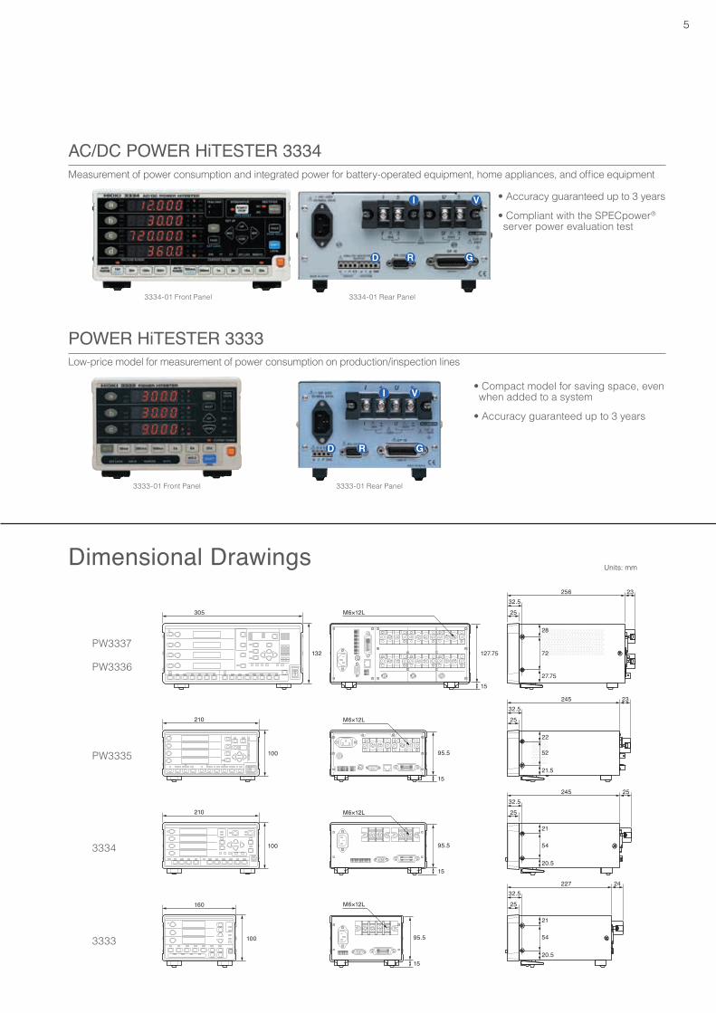
Measurement of power consumption and integrated power for battery-operated equipment, home appliances, and office equipment
Low-price model for measurement of power consumption on production/inspection lines
3334-01 Front Panel
3333-01 Front Panel
3334-01 Rear Panel
3333-01 Rear Panel
• Accuracy guaranteed up to 3 years
• Compliant with the SPECpower®
server power evaluation test
• Compact model for saving space, even when added to a system
• Accuracy guaranteed up to 3 years
PW3337
PW3336
PW3335
3334
3333
AC/DC POWER HiTESTER 3334
POWER HiTESTER 3333
Dimensional Drawings Units: mm
6
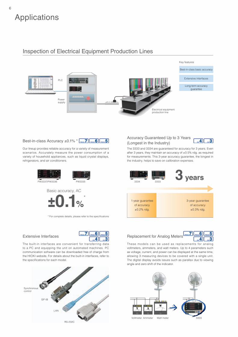
Inspection of Electrical Equipment Production Lines
Applications
Key features
Best-in-class basic accuracy
Extensive interfaces
Long-term accuracy guarantee
Electrical equipmentproduction line
PLC
Power supply
Best-in-class Accuracy ±0.1% *
Extensive Interfaces Replacement for Analog Meters
Accuracy Guaranteed Up to 3 Years (Longest in the Industry)
Our lineup provides reliable accuracy for a variety of measurement scenarios. Accurately measure the power consumption of a variety of household appliances, such as liquid crystal displays, refrigerators, and air conditioners.
The built-in interfaces are convenient for transferring data to a PC and equipping the unit on automated machines. PC communication software can be downloaded free of charge from the HIOKI website. For details about the built-in interfaces, refer to the specifications for each model.
These models can be used as replacements for analog voltmeters, ammeters, and watt meters. Up to 4 parameters such as voltage, current, and power can be displayed at the same time, allowing 3 measuring devices to be covered with a single unit. The digital display avoids issues such as parallax due to viewing angle and zero shift of the indicator.
Synchronous control
GP-IB
LAN
RS-232C
The 3333 and 3334 are guaranteed for accuracy for 3 years. Even after 3 years, they maintain an accuracy of ±0.5% rdg. as required for measurements. This 3-year accuracy guarantee, the longest in the industry, helps to save on calibration expenses.
Basic accuracy, AC
3334 33333 years
±0.1%*
3-year guarantee of accuracy±0.3% rdg.
1-year guarantee of accuracy±0.2% rdg.
Voltmeter Ammeter Watt meter 3333
PW3337/PW3336 PW3335
* For complete details, please refer to the specifications
7
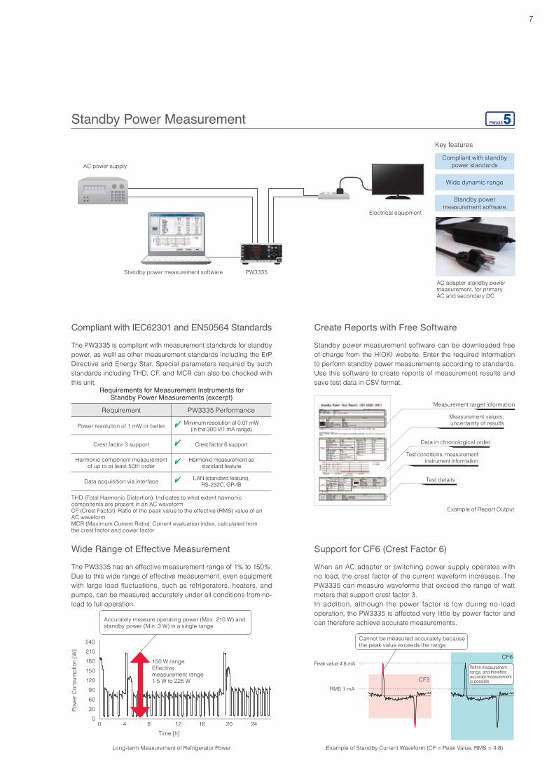
Standby Power MeasurementKey features
Compliant with standby power standards
Wide dynamic range
Standby power measurement software
AC power supply
Standby power measurement software
TV
PW3335
AC adapter standby power measurement, for primary AC and secondary DC
The PW3335 has an effective measurement range of 1% to 150%. Due to this wide range of effective measurement, even equipment with large load fluctuations, such as refrigerators, heaters, and pumps, can be measured accurately under all conditions from no-load to full operation.
When an AC adapter or switching power supply operates with no load, the crest factor of the current waveform increases. The PW3335 can measure waveforms that exceed the range of watt meters that support crest factor 3.In addition, although the power factor is low during no-load operation, the PW3335 is affected very little by power factor and can therefore achieve accurate measurements.
Peak value 4.8 mA
RMS 1 mA
Example of Standby Current Waveform (CF = Peak Value, RMS = 4.8)
CF3
CF6
Cannot be measured accurately because the peak value exceeds the range
THD (Total Harmonic Distortion): Indicates to what extent harmonic components are present in an AC waveformCF (Crest Factor): Ratio of the peak value to the effective (RMS) value of an AC waveformMCR (Maximum Current Ratio): Current evaluation index, calculated from the crest factor and power factor
Standby power measurement software can be downloaded free of charge from the HIOKI website. Enter the required information to perform standby power measurements according to standards. Use this software to create reports of measurement results and save test data in CSV format.
The PW3335 is compliant with measurement standards for standby power, as welll as other measurement standards including the ErP Directive and Energy Star. Special parameters required by such standards including THD, CF, and MCR can also be checked with this unit.
Requirements for Measurement Instruments for Standby Power Measurements (excerpt)
Requirement PW3335 Performance
Power resolution of 1 mW or better Minimum resolution of 0.01 mW(in the 300 V/1 mA range)
Crest factor 3 support Crest factor 6 support
Harmonic component measurement of up to at least 50th order
Harmonic measurement as standard feature
Data acquisition via interface LAN (standard feature),RS-232C, GP-IB
Compliant with IEC62301 and EN50564 Standards Create Reports with Free Software
Wide Range of Effective Measurement Support for CF6 (Crest Factor 6)
4
4
4
4
Within measurement range, and therefore accurate measurement is possible
Example of Report Output
Measurement target information
Measurement values, uncertainty of results
Data in chronological order
Test conditions, measurement instrument information
Test details
Long-term Measurement of Refrigerator Power
00 4 8 12 16 20 24
306090
120150180210240
Pow
er C
onsu
mpt
ion
[W]
Time [h]
Accurately measure operating power (Max. 210 W) and standby power (Min. 3 W) in a single range
150 W rangeEffective measurement range1.5 W to 225 W
Electrical equipment
8
Auto Range Integration with Guaranteed Accuracy when Switching Ranges
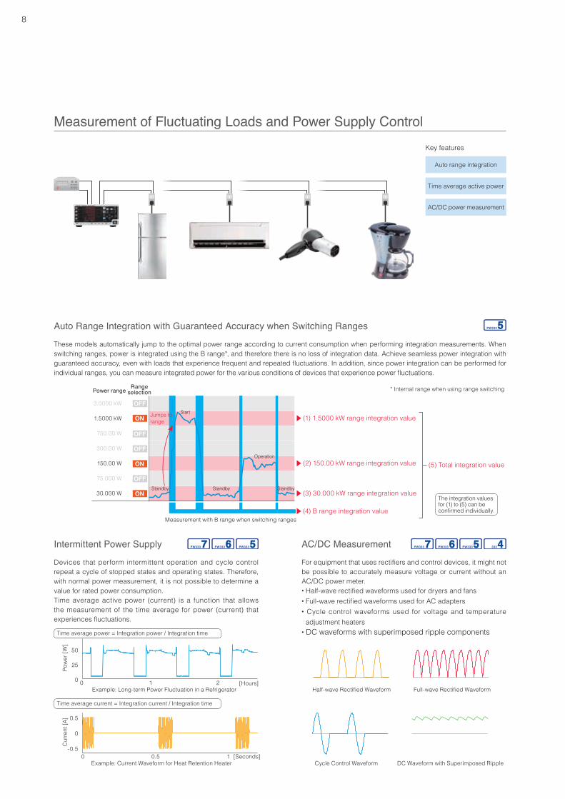
Measurement of Fluctuating Loads and Power Supply ControlKey features
Auto range integration
Time average active power
AC/DC power measurement
These models automatically jump to the optimal power range according to current consumption when performing integration measurements. When switching ranges, power is integrated using the B range*, and therefore there is no loss of integration data. Achieve seamless power integration with guaranteed accuracy, even with loads that experience frequent and repeated fluctuations. In addition, since power integration can be performed for individual ranges, you can measure integrated power for the various conditions of devices that experience power fluctuations.
(1) 1.5000 kW range integration value
(2) 150.00 kW range integration value (5) Total integration value
(3) 30.000 kW range integration value
(4) B range integration value
3.0000 kW
1.5000 kW
750.00 W
300.00 W
150.00 W
75.000 W
30.000 W
Power range Rangeselection
Standby Standby Standby
Measurement with B range when switching ranges
The integration values for (1) to (5) can be confirmed individually.
Time average power = Integration power / Integration time
Time average current = Integration current / Integration time
Operation
Start
For equipment that uses rectifiers and control devices, it might not be possible to accurately measure voltage or current without an AC/DC power meter.• Half-wave rectified waveforms used for dryers and fans• Full-wave rectified waveforms used for AC adapters• Cycle control waveforms used for voltage and temperature
adjustment heaters• DC waveforms with superimposed ripple components
Devices that perform intermittent operation and cycle control repeat a cycle of stopped states and operating states. Therefore, with normal power measurement, it is not possible to determine a value for rated power consumption.Time average active power (current) is a function that allows the measurement of the time average for power (current) that experiences fluctuations.
Half-wave Rectified Waveform Full-wave Rectified Waveform
Cycle Control Waveform DC Waveform with Superimposed Ripple
Intermittent Power Supply AC/DC Measurement
Jumps torange
* Internal range when using range switching
Cur
rent
[A]
Example: Current Waveform for Heat Retention Heater
0.5
0 0.5 1
0
-0.5[Seconds]
Example: Long-term Power Fluctuation in a Refrigerator
Pow
er [W
]
0
50
25
0 1 2 [Hours]
9
Inverter Efficiency Measurement
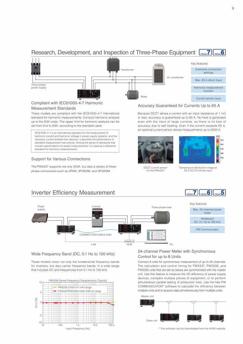
Research, Development, and Inspection of Three-Phase EquipmentKey features
Extensive connection settings
Max. 65 A direct input
Harmonic measurement function
Current sensor input
Three-phase power supply
Transformer
Motor
Air conditioner
Key features
Max. 24-channel power meter
WidebandDC, 0.1 Hz to 100 kHz
PW Communicator
Power supply
CONNECTION CABLE 9165
LAN HUB PC
Inverter Three-phase load
These models are compliant with the IEC61000-4-7 international standard for harmonic measurements. Conduct harmonic analysis up to the 50th order. The upper limit for harmonic analysis can be set from 2nd to 50th, according to the standard used.
The PW3337 supports not only 3V3A, but also a variety of three-phase connections such as 3P4W, 3P3W2M, and 3P3W3M.
IEC61000-4-7 is an international standard for the measurement of harmonic current and harmonic voltage in power supply systems, and the harmonic current emitted from devices. It specifies the performance of standard measurement instruments. Among the series of standards that include specifications for power measurements, it is used as a reference standard for harmonic measurements.
Temperature distribution image at 30 A DC/10-minute input
DCCT current sensor(in the PW3337)
Compliant with IEC61000-4-7 Harmonic Measurement Standards
Support for Various Connections
Connect 8 units for synchronous measurement of up to 24 channels. The calculation and control timing for PW3337, PW3336, and PW3335 units that are set as slaves are synchronized with the master unit. Use this feature to measure the I/O efficiency of power supply devices, compare multiple pieces of equipment, or to perform simultaneous parallel testing of production lines. Use the free PW COMMUNICATOR* software to calculate the efficiency between multiple units and to acquire data simultaneously from multiple units.
* This software can be downloaded from the HIOKI website.
Master unit
Slave unit
24-channel Power Meter with Synchronous Control for up to 8 UnitsWide Frequency Band (DC, 0.1 Hz to 100 kHz)
These models cover not only the fundamental frequency bands for inverters, but also carrier frequency bands, in a wide range that includes DC and frequencies from 0.1 Hz to 100 kHz.
Accuracy Guaranteed for Currents Up to 65 A
Because DCCT allows a current with an input resistance of 1 mΩ or less, accuracy is guaranteed up to 65 A. No heat is generated even with the input of large currents, so there is no loss of accuracy due to self heating. Even if the current exceeds 65 A, an optional current sensor allows measurements up to 5000 A.
Erro
r [%
]
Input Frequency [Hz]
PW3330 Series Frequency Characteristics (Typical)
100 k10 k1 k10010
0
5
10
-5
-10
PW3335 (1000 V/1 mA) rangePW3337/PW3336 (1000 V/50 A) range
10
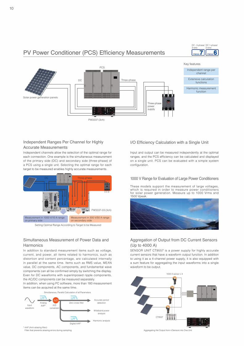
PV Power Conditioner (PCS) Efficiency Measurements
Accurate period detection
Simultaneous, Parallel Calculation of all Parameters
CT9557
Aggregating the Output from 4 Sensors into One Unit
1000 A sensor x 4
Wideband power analysis
Harmonic analysis
Zero-cross filter
Digital AAF*
Input waveform
A/Dconversion
AnalogAAF*
* AAF (Anti-aliasing filter): Filter that prevents aliasing errors during sampling
Key features
Independent range per channel
Extensive calculation functions
Harmonic measurement function
Solar power generation panels
DC Three-phase
PCS
Three-phase power supply
These models support the measurement of large voltages, which is required in order to measure power conditioners for solar power generation. Measure up to 1000 Vrms and 1500 Vpeak.
In addition to standard measurement items such as voltage, current, and power, all items related to harmonics, such as distortion and content percentage, are calculated internally in parallel at the same time. Items such as RMS value, MEAN value, DC components, AC components, and fundamental wave components can all be confirmed simply by switching the display. Even for DC waveforms with superimposed ripple components, the AC/DC components can be measured separately.In addition, when using PC software, more than 180 measurement items can be acquired at the same time.
Independent channels allow the selection of the optimal range for each connection. One example is the simultaneous measurement of the primary side (DC) and secondary side (three-phase) of a PCS using a single unit. Selecting the optimal range for each target to be measured enables highly accurate measurements.
Input and output can be measured independently at the optimal ranges, and the PCS efficiency can be calculated and displayed on a single unit. PCS can be evaluated with a simple system configuration.
Setting Optimal Range According to Target to be Measured
Independent Ranges Per Channel for Highly Accurate Measurements
Simultaneous Measurement of Power Data and Harmonics
I/O Efficiency Calculation with a Single Unit
1000 V Range for Evaluation of Large Power Conditioners
Measurement in 1000 V/10 A range on primary side
DC Three-phase
Measurement in 300 V/50 A range on secondary side
SENSOR UNIT CT9557 is a power supply for highly accurate current sensors that have a waveform output function. In addition to using it as a 4-channel power supply, it is also equipped with a sum feature for aggregating the input waveforms into a single waveform to be output.
Aggregation of Output from DC Current Sensors (Up to 4000 A)
PW3337-03 (3ch)
PW3337 (3ch)
DC - 3-phase/ 3-wire
DC 1-phase/ 2-wire
11
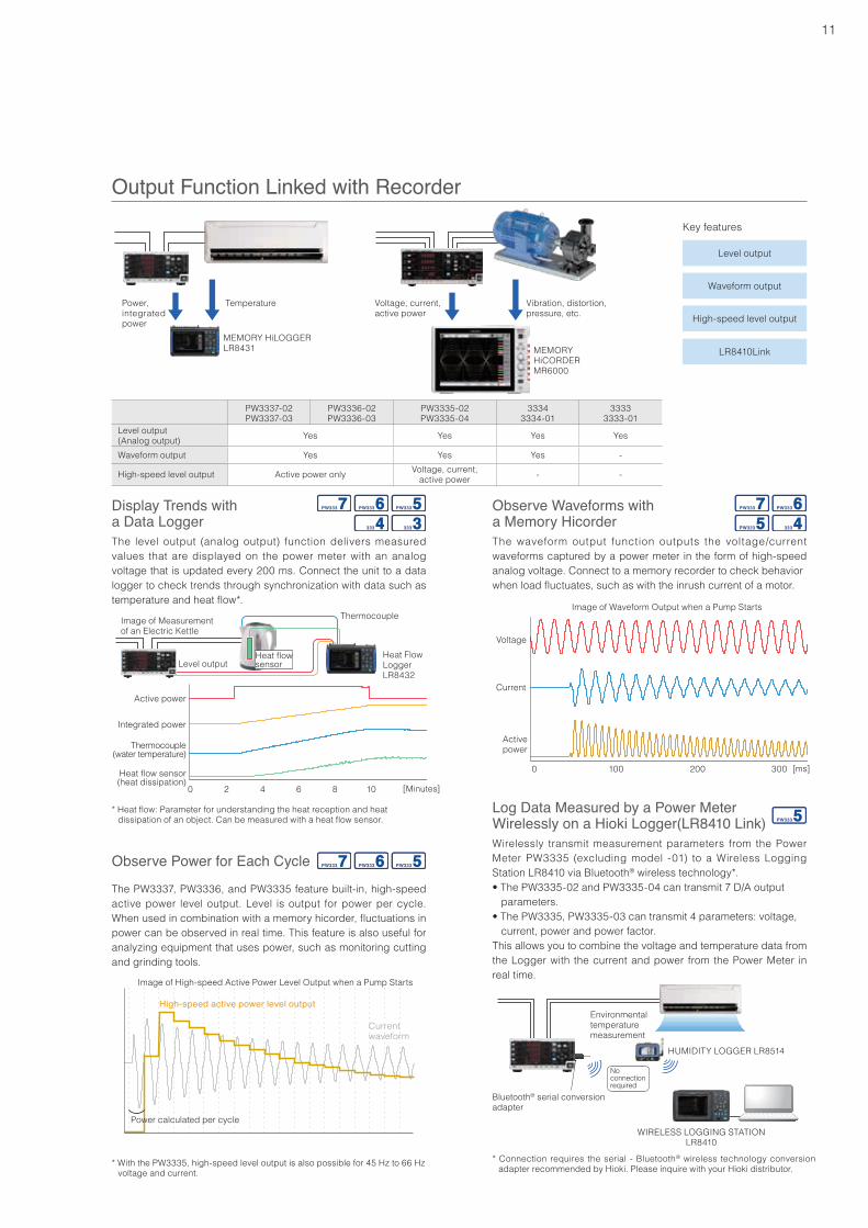
The level output (analog output) function delivers measured values that are displayed on the power meter with an analog voltage that is updated every 200 ms. Connect the unit to a data logger to check trends through synchronization with data such as temperature and heat flow*.
The waveform output function outputs the voltage/current waveforms captured by a power meter in the form of high-speed analog voltage. Connect to a memory recorder to check behaviorwhen load fluctuates, such as with the inrush current of a motor.
Output Function Linked with RecorderKey features
Level output
Waveform output
High-speed level output
LR8410Link
Image of High-speed Active Power Level Output when a Pump Starts
Power calculated per cycle
Current waveform
High-speed active power level output
The PW3337, PW3336, and PW3335 feature built-in, high-speed active power level output. Level is output for power per cycle. When used in combination with a memory hicorder, fluctuations in power can be observed in real time. This feature is also useful for analyzing equipment that uses power, such as monitoring cutting and grinding tools.
Display Trends with a Data Logger
Observe Power for Each Cycle
Observe Waveforms with a Memory Hicorder
Log Data Measured by a Power Meter Wirelessly on a Hioki Logger(LR8410 Link)Wirelessly transmit measurement parameters from the Power Meter PW3335 (excluding model -01) to a Wireless Logging Station LR8410 via Bluetooth® wireless technology*.• The PW3335-02 and PW3335-04 can transmit 7 D/A output parameters.• The PW3335, PW3335-03 can transmit 4 parameters: voltage, current, power and power factor.This allows you to combine the voltage and temperature data from the Logger with the current and power from the Power Meter in real time.
* Connection requires the serial - Bluetooth® wireless technology conversion adapter recommended by Hioki. Please inquire with your Hioki distributor.
No connection required
WIRELESS LOGGING STATIONLR8410
Bluetooth® serial conversion adapter
HUMIDITY LOGGER LR8514
Environmental temperature measurement
PW3337-02PW3337-03
PW3336-02PW3336-03
PW3335-02PW3335-04
33343334-01
33333333-01
Level output (Analog output) Yes Yes Yes Yes
Waveform output Yes Yes Yes -
High-speed level output Active power only Voltage, current, active power - -
Voltage, current,active power
Vibration, distortion,pressure, etc.
Power,integrated power
Temperature
MEMORY HiLOGGERLR8431 MEMORY
HiCORDER MR6000
* With the PW3335, high-speed level output is also possible for 45 Hz to 66 Hz voltage and current.
Voltage
Current
Active power
200 300 100 0
Image of Waveform Output when a Pump Starts
[ms]
Active power
Integrated power
Thermocouple (water temperature)
1086420
Heat flow sensor (heat dissipation)
[Minutes]
Image of Measurement of an Electric Kettle
Heat Flow LoggerLR8432
Thermocouple
* Heat flow: Parameter for understanding the heat reception and heat dissipation of an object. Can be measured with a heat flow sensor.
Heat flow sensorLevel output
12
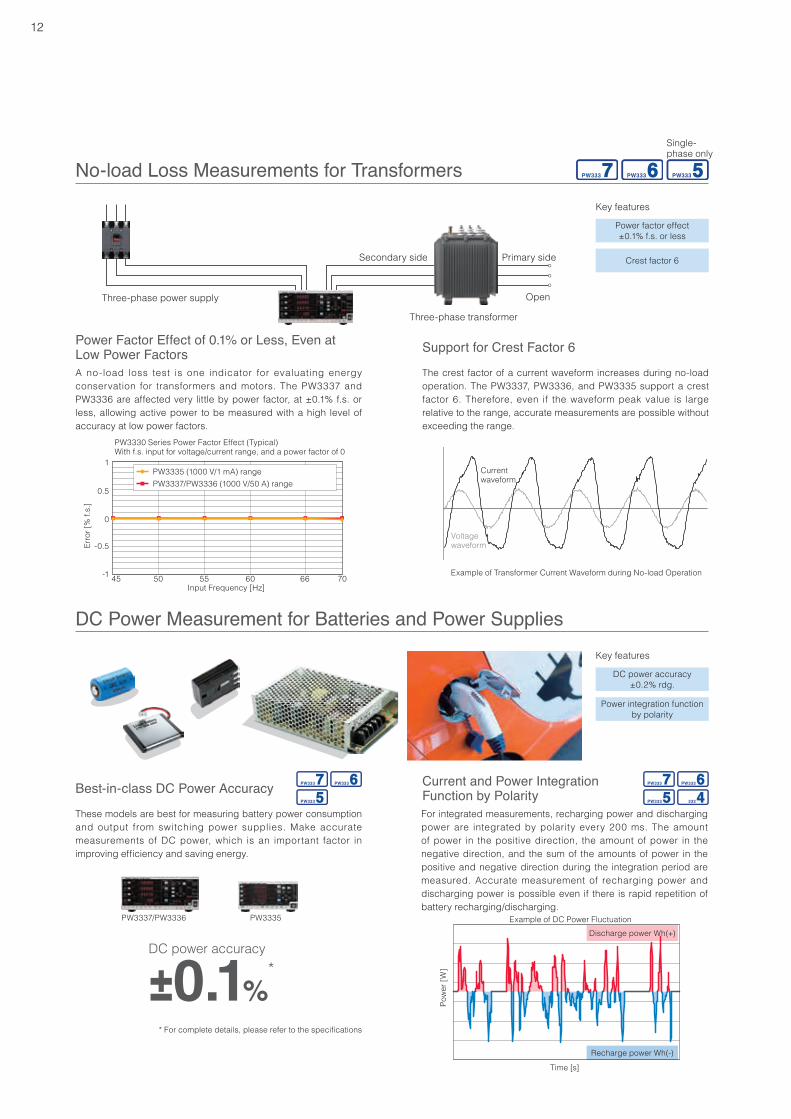
No-load Loss Measurements for TransformersKey features
Power factor effect±0.1% f.s. or less
Crest factor 6
Three-phase power supply
Three-phase transformer
Open
Primary sideSecondary side
A no-load loss test is one indicator for evaluating energy conservation for transformers and motors. The PW3337 and PW3336 are affected very little by power factor, at ±0.1% f.s. or less, allowing active power to be measured with a high level of accuracy at low power factors.
The crest factor of a current waveform increases during no-load operation. The PW3337, PW3336, and PW3335 support a crest factor 6. Therefore, even if the waveform peak value is large relative to the range, accurate measurements are possible without exceeding the range.
Example of Transformer Current Waveform during No-load Operation
Current waveform
Voltage waveform
These models are best for measuring battery power consumption and output from switching power supplies. Make accurate measurements of DC power, which is an important factor in improving efficiency and saving energy.
Power Factor Effect of 0.1% or Less, Even at Low Power Factors Support for Crest Factor 6
DC Power Measurement for Batteries and Power SuppliesKey features
DC power accuracy±0.2% rdg.
Power integration function by polarity
For integrated measurements, recharging power and discharging power are integrated by polarity every 200 ms. The amount of power in the positive direction, the amount of power in the negative direction, and the sum of the amounts of power in the positive and negative direction during the integration period are measured. Accurate measurement of recharging power and discharging power is possible even if there is rapid repetition of battery recharging/discharging.
Current and Power Integration Function by Polarity
Discharge power Wh(+)
Recharge power Wh(-)
Time [s]
Pow
er [W
]
Example of DC Power Fluctuation
PW3330 Series Power Factor Effect (Typical)With f.s. input for voltage/current range, and a power factor of 0
Erro
r [%
f.s.
]
Input Frequency [Hz]70666050 5545
0.5
1
0
-0.5
-1
PW3335 (1000 V/1 mA) rangePW3337/PW3336 (1000 V/50 A) range
Best-in-class DC Power Accuracy
DC power accuracy
Single-phase only
±0.1%*
PW3337/PW3336 PW3335
* For complete details, please refer to the specifications
13
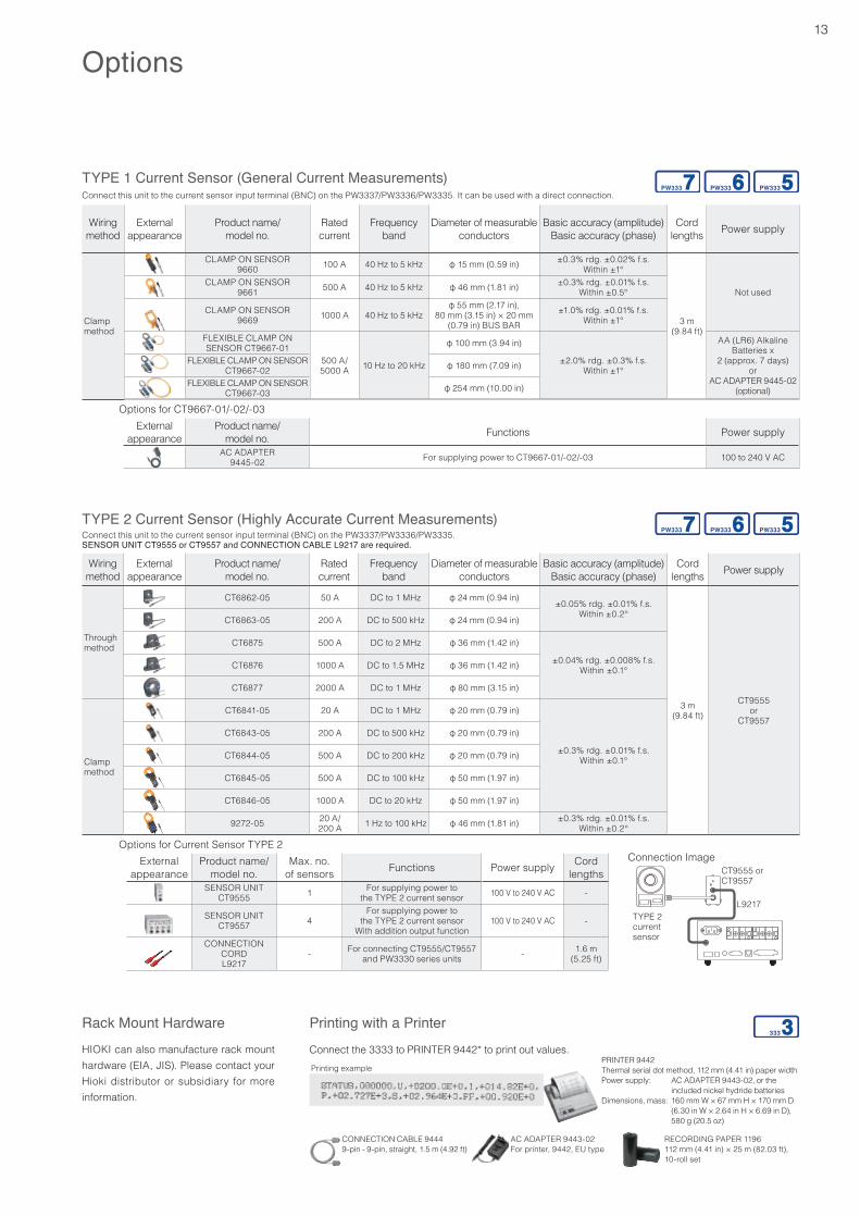
TYPE 2 Current Sensor (Highly Accurate Current Measurements)Connect this unit to the current sensor input terminal (BNC) on the PW3337/PW3336/PW3335.SENSOR UNIT CT9555 or CT9557 and CONNECTION CABLE L9217 are required.
Wiring method
External appearance
Product name/model no.
Rated current
Frequency band
Diameter of measurable conductors
Basic accuracy (amplitude)Basic accuracy (phase)
Cord lengths Power supply
Through method
CT6862-05 50 A DC to 1 MHz φ 24 mm (0.94 in) ±0.05% rdg. ±0.01% f.s.Within ±0.2°
3 m (9.84 ft)
CT9555 or
CT9557
CT6863-05 200 A DC to 500 kHz φ 24 mm (0.94 in)
CT6875 500 A DC to 2 MHz φ 36 mm (1.42 in)
±0.04% rdg. ±0.008% f.s.Within ±0.1°CT6876 1000 A DC to 1.5 MHz φ 36 mm (1.42 in)
CT6877 2000 A DC to 1 MHz φ 80 mm (3.15 in)
Clamp method
CT6841-05 20 A DC to 1 MHz φ 20 mm (0.79 in)
±0.3% rdg. ±0.01% f.s.Within ±0.1°
CT6843-05 200 A DC to 500 kHz φ 20 mm (0.79 in)
CT6844-05 500 A DC to 200 kHz φ 20 mm (0.79 in)
CT6845-05 500 A DC to 100 kHz φ 50 mm (1.97 in)
CT6846-05 1000 A DC to 20 kHz φ 50 mm (1.97 in)
9272-05 20 A/ 200 A 1 Hz to 100 kHz φ 46 mm (1.81 in) ±0.3% rdg. ±0.01% f.s.
Within ±0.2°
Options for Current Sensor TYPE 2External
appearanceProduct name/
model no.Max. no.
of sensors Functions Power supply Cord lengths
SENSOR UNITCT9555 1 For supplying power to
the TYPE 2 current sensor 100 V to 240 V AC -
SENSOR UNITCT9557 4
For supplying power to the TYPE 2 current sensor
With addition output function100 V to 240 V AC -
CONNECTION CORDL9217
- For connecting CT9555/CT9557 and PW3330 series units - 1.6 m
(5.25 ft)
Options
Rack Mount HardwareHIOKI can also manufacture rack mount hardware (EIA, JIS). Please contact your Hioki distributor or subsidiary for more information.
TYPE 1 Current Sensor (General Current Measurements)Connect this unit to the current sensor input terminal (BNC) on the PW3337/PW3336/PW3335. It can be used with a direct connection.
Wiring method
External appearance
Product name/model no.
Rated current
Frequency band
Diameter of measurable conductors
Basic accuracy (amplitude)Basic accuracy (phase)
Cord lengths Power supply
Clamp method
CLAMP ON SENSOR9660 100 A 40 Hz to 5 kHz φ 15 mm (0.59 in) ±0.3% rdg. ±0.02% f.s.
Within ±1°
3 m (9.84 ft)
Not usedCLAMP ON SENSOR
9661 500 A 40 Hz to 5 kHz φ 46 mm (1.81 in) ±0.3% rdg. ±0.01% f.s.Within ±0.5°
CLAMP ON SENSOR9669 1000 A 40 Hz to 5 kHz
φ 55 mm (2.17 in), 80 mm (3.15 in) × 20 mm
(0.79 in) BUS BAR±1.0% rdg. ±0.01% f.s.
Within ±1°
FLEXIBLE CLAMP ON SENSOR CT9667-01
500 A/ 5000 A 10 Hz to 20 kHz
φ 100 mm (3.94 in)
±2.0% rdg. ±0.3% f.s.Within ±1°
AA (LR6) Alkaline Batteries x
2 (approx. 7 days)or
AC ADAPTER 9445-02 (optional)
FLEXIBLE CLAMP ON SENSORCT9667-02 φ 180 mm (7.09 in)
FLEXIBLE CLAMP ON SENSORCT9667-03 φ 254 mm (10.00 in)
Options for CT9667-01/-02/-03External
appearanceProduct name/
model no. Functions Power supply
AC ADAPTER9445-02 For supplying power to CT9667-01/-02/-03 100 to 240 V AC
Connection Image
TYPE 2 current sensor
CT9555 or CT9557
L9217
Connect the 3333 to PRINTER 9442* to print out values.
Printing with a Printer
PRINTER 9442Thermal serial dot method, 112 mm (4.41 in) paper widthPower supply: AC ADAPTER 9443-02, or the
included nickel hydride batteriesDimensions, mass: 160 mm W × 67 mm H × 170 mm D
(6.30 in W × 2.64 in H × 6.69 in D), 580 g (20.5 oz)
Printing example
CONNECTION CABLE 94449-pin - 9-pin, straight, 1.5 m (4.92 ft)
AC ADAPTER 9443-02For printer, 9442, EU type
RECORDING PAPER 1196112 mm (4.41 in) × 25 m (82.03 ft), 10-roll set
14
Software
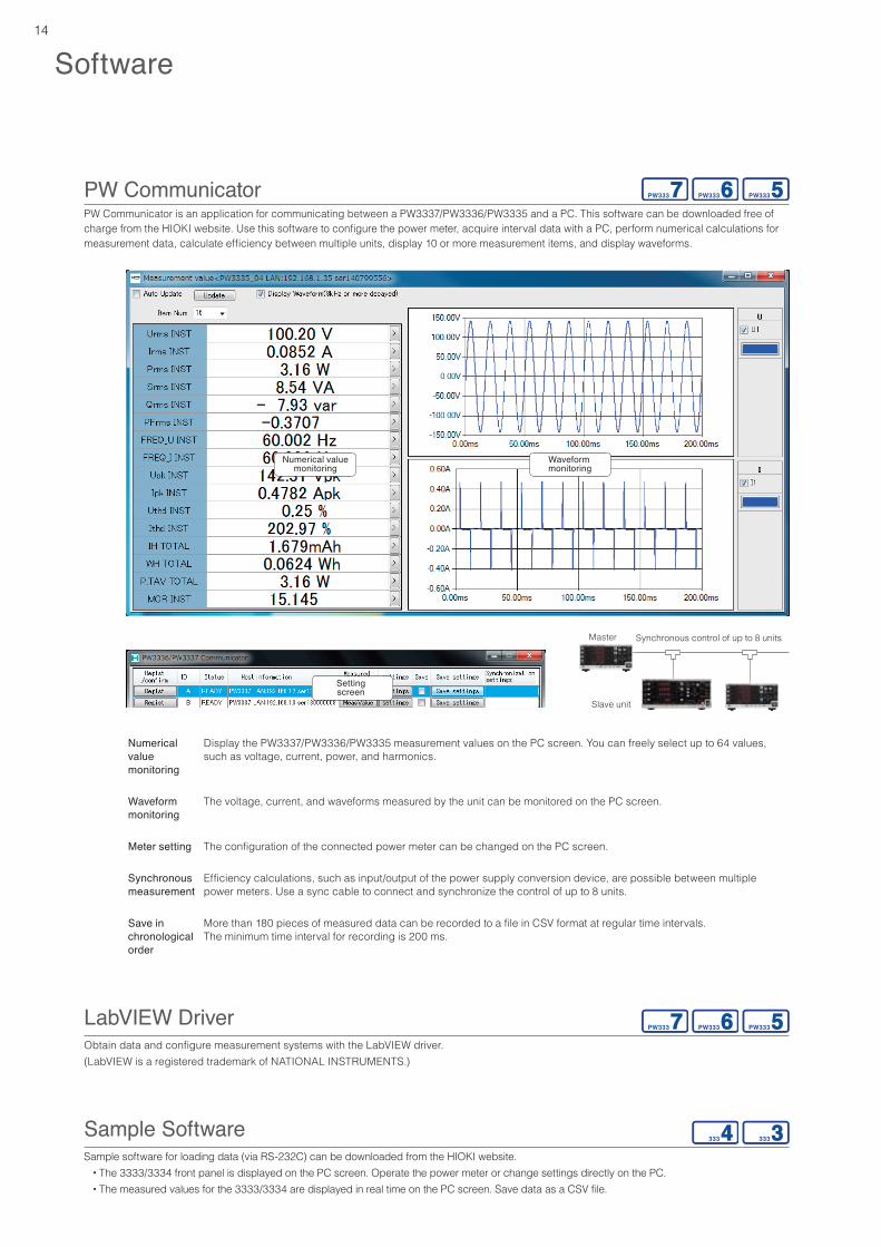
PW CommunicatorPW Communicator is an application for communicating between a PW3337/PW3336/PW3335 and a PC. This software can be downloaded free of charge from the HIOKI website. Use this software to configure the power meter, acquire interval data with a PC, perform numerical calculations for measurement data, calculate efficiency between multiple units, display 10 or more measurement items, and display waveforms.
Numerical value monitoring
Display the PW3337/PW3336/PW3335 measurement values on the PC screen. You can freely select up to 64 values,such as voltage, current, power, and harmonics.
Waveform monitoring
The voltage, current, and waveforms measured by the unit can be monitored on the PC screen.
Meter setting The configuration of the connected power meter can be changed on the PC screen.
Synchronous measurement
Efficiency calculations, such as input/output of the power supply conversion device, are possible between multiple power meters. Use a sync cable to connect and synchronize the control of up to 8 units.
Save in chronological order
More than 180 pieces of measured data can be recorded to a file in CSV format at regular time intervals.The minimum time interval for recording is 200 ms.
LabVIEW DriverObtain data and configure measurement systems with the LabVIEW driver.(LabVIEW is a registered trademark of NATIONAL INSTRUMENTS.)
Sample SoftwareSample software for loading data (via RS-232C) can be downloaded from the HIOKI website. • The 3333/3334 front panel is displayed on the PC screen. Operate the power meter or change settings directly on the PC. • The measured values for the 3333/3334 are displayed in real time on the PC screen. Save data as a CSV file.
Synchronous control of up to 8 units
Numerical value monitoring
Setting screen
Waveform monitoring
Master unit
Slave unit
15
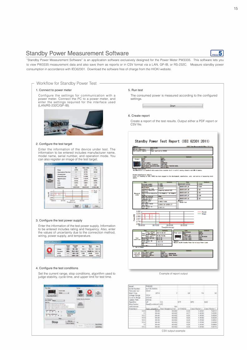
”Standby Power Measurement Software” is an application software exclusively designed for the Power Meter PW3335. This software lets you to view PW3335 measurement data and also save them as reports or in CSV format via a LAN, GP-IB, or RS-232C. Measure standby power consumption in accordance with IEC62301. Download the software free of charge from the HIOKI website.
6. Create report
Create a report of the test results. Output either a PDF report or CSV file.
2. Configure the test target
Enter the information of the device under test. The information to be entered includes manufacturer name, model name, serial number, and operation mode. You can also register an image of the test target.
Standby Power Measurement Software
1. Connect to power meter
Configure the set t ings for communication with a power meter. Connect the PC to a power meter, and enter the set tings required for the inter face used (LAN/RS-232C/GP-IB).
3. Configure the test power supply
Enter the information of the test power supply. Information to be entered includes rating and frequency. Also, enter the values of uncertainty due to the connection method, wiring, power supply, and temperature.
4. Configure the test conditions
Set the current range, stop conditions, algorithm used to judge stability, cycle time, and upper limit for test time.
Example of report output
CSV output example
5. Run test
The consumed power is measured according to the configured settings.
Workflow for Standby Power Test
16
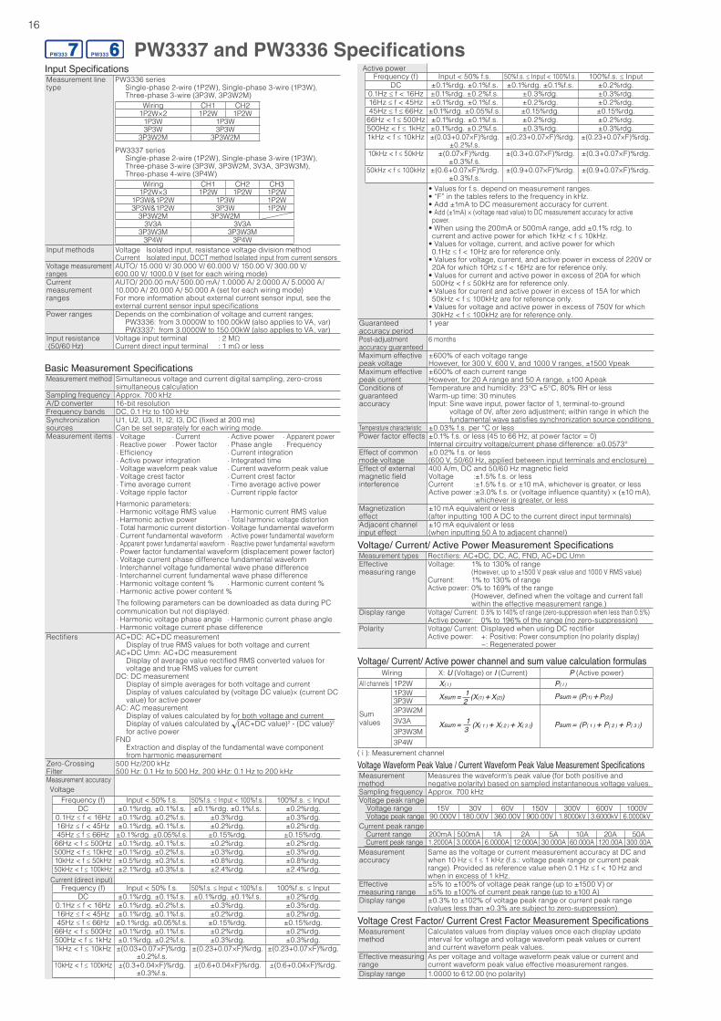
PW3337 and PW3336 SpecificationsInput SpecificationsMeasurement line type
PW3336 series Single-phase 2-wire (1P2W), Single-phase 3-wire (1P3W), Three-phase 3-wire (3P3W, 3P3W2M)
Wiring CH1 CH21P2W×2 1P2W 1P2W
1P3W 1P3W3P3W 3P3W
3P3W2M 3P3W2MPW3337 series Single-phase 2-wire (1P2W), Single-phase 3-wire (1P3W), Three-phase 3-wire (3P3W, 3P3W2M, 3V3A, 3P3W3M), Three-phase 4-wire (3P4W)
Wiring CH1 CH2 CH31P2W×3 1P2W 1P2W 1P2W
1P3W&1P2W 1P3W 1P2W3P3W&1P2W 3P3W 1P2W
3P3W2M 3P3W2M3V3A 3V3A
3P3W3M 3P3W3M3P4W 3P4W
Input methods Voltage Isolated input, resistance voltage division methodCurrent Isolated input, DCCT method Isolated input from current sensors
Voltage measurement ranges
AUTO/ 15.000 V/ 30.000 V/ 60.000 V/ 150.00 V/ 300.00 V/ 600.00 V/ 1000.0 V (set for each wiring mode)
Currentmeasurement ranges
AUTO/ 200.00 mA/ 500.00 mA/ 1.0000 A/ 2.0000 A/ 5.0000 A/ 10.000 A/ 20.000 A/ 50.000 A (set for each wiring mode)For more information about external current sensor input, see the external current sensor input specifications
Power ranges Depends on the combination of voltage and current ranges; PW3336: from 3.0000W to 100.00kW (also applies to VA, var) PW3337: from 3.0000W to 150.00kW (also applies to VA, var)
Input resistance (50/60 Hz)
Voltage input terminal : 2 MΩCurrent direct input terminal : 1 mΩ or less
Basic Measurement SpecificationsMeasurement method Simultaneous voltage and current digital sampling, zero-cross
simultaneous calculationSampling frequency Approx. 700 kHzA/D converter 16-bit resolutionFrequency bands DC, 0.1 Hz to 100 kHzSynchronizationsources
U1, U2, U3, I1, I2, I3, DC (fixed at 200 ms)Can be set separately for each wiring mode.
Measurement items · Voltage · Current · Active power · Apparent power · Reactive power · Power factor · Phase angle · Frequency · Efficiency · Current integration · Active power integration · Integrated time · Voltage waveform peak value · Current waveform peak value · Voltage crest factor · Current crest factor · Time average current · Time average active power · Voltage ripple factor · Current ripple factorHarmonic parameters: · Harmonic voltage RMS value · Harmonic current RMS value · Harmonic active power · Total harmonic voltage distortion · Total harmonic current distortion · Voltage fundamental waveform · Current fundamental waveform · Active power fundamental waveform · Apparent power fundamental waveform · Reactive power fundamental waveform · Power factor fundamental waveform (displacement power factor) · Voltage current phase difference fundamental waveform · Interchannel voltage fundamental wave phase difference · Interchannel current fundamental wave phase difference · Harmonic voltage content % · Harmonic current content % · Harmonic active power content %The following parameters can be downloaded as data during PC communication but not displayed: · Harmonic voltage phase angle · Harmonic current phase angle · Harmonic voltage current phase difference
Rectifiers AC+DC: AC+DC measurement Display of true RMS values for both voltage and currentAC+DC Umn: AC+DC measurement Display of average value rectified RMS converted values for
voltage and true RMS values for currentDC: DC measurement Display of simple averages for both voltage and current Display of values calculated by (voltage DC value)× (current DC
value) for active powerAC : AC measurement Display of values calculated by for both voltage and current Display of values calculated by (AC+DC value)2 - (DC value)2
for active power FND Extraction and display of the fundamental wave component
from harmonic measurementZero-Crossing Filter
500 Hz/200 kHz500 Hz: 0.1 Hz to 500 Hz, 200 kHz: 0.1 Hz to 200 kHz
Measurement accuracy Voltage
Frequency (f) Input < 50% f.s. 50%f.s. ≤ Input < 100%f.s. 100%f.s. ≤ InputDC ±0.1%rdg. ±0.1%f.s. ±0.1%rdg. ±0.1%f.s. ±0.2%rdg.
0.1Hz ≤ f < 16Hz ±0.1%rdg. ±0.2%f.s. ±0.3%rdg. ±0.3%rdg.16Hz ≤ f < 45Hz ±0.1%rdg. ±0.1%f.s. ±0.2%rdg. ±0.2%rdg.45Hz ≤ f ≤ 66Hz ±0.1%rdg. ±0.05%f.s. ±0.15%rdg. ±0.15%rdg.
66Hz < f ≤ 500Hz ±0.1%rdg. ±0.1%f.s. ±0.2%rdg. ±0.2%rdg.500Hz < f ≤ 10kHz ±0.1%rdg. ±0.2%f.s. ±0.3%rdg. ±0.3%rdg.10kHz < f ≤ 50kHz ±0.5%rdg. ±0.3%f.s. ±0.8%rdg. ±0.8%rdg.50kHz < f ≤ 100kHz ±2.1%rdg. ±0.3%f.s. ±2.4%rdg. ±2.4%rdg.
Current (direct input)Frequency (f) Input < 50% f.s. 50%f.s. ≤ Input < 100%f.s. 100%f.s. ≤ Input
DC ±0.1%rdg. ±0.1%f.s. ±0.1%rdg. ±0.1%f.s. ±0.2%rdg.0.1Hz ≤ f < 16Hz ±0.1%rdg. ±0.2%f.s. ±0.3%rdg. ±0.3%rdg.16Hz ≤ f < 45Hz ±0.1%rdg. ±0.1%f.s. ±0.2%rdg. ±0.2%rdg.45Hz ≤ f ≤ 66Hz ±0.1%rdg. ±0.05%f.s. ±0.15%rdg. ±0.15%rdg.
66Hz < f ≤ 500Hz ±0.1%rdg. ±0.1%f.s. ±0.2%rdg. ±0.2%rdg.500Hz < f ≤ 1kHz ±0.1%rdg. ±0.2%f.s. ±0.3%rdg. ±0.3%rdg.1kHz < f ≤ 10kHz ±(0.03+0.07×F)%rdg.
±0.2%f.s.±(0.23+0.07×F)%rdg. ±(0.23+0.07×F)%rdg.
10kHz < f ≤ 100kHz ±(0.3+0.04×F)%rdg.±0.3%f.s.
±(0.6+0.04×F)%rdg. ±(0.6+0.04×F)%rdg.
Voltage/ Current/ Active Power Measurement SpecificationsMeasurement types Rectifiers: AC+DC, DC, AC, FND, AC+DC UmnEffective measuring range
Voltage: 1% to 130% of range (However, up to ±1500 V peak value and 1000 V RMS value)
Current: 1% to 130% of rangeActive power: 0% to 169% of the range
(However, defined when the voltage and current fall within the effective measurement range.)
Display range Voltage/ Current: 0.5% to 140% of range (zero-suppression when less than 0.5%)Active power: 0% to 196% of the range (no zero-suppression)
Polarity Voltage/ Current: Displayed when using DC rectifierActive power: +: Positive: Power consumption (no polarity display) -: Regenerated power
Voltage/ Current/ Active power channel and sum value calculation formulasWiring X: U (Voltage) or I (Current) P (Active power)
All channels 1P2W
Sumvalues
1P3W3P3W3P3W2M3V3A3P3W3M3P4W
( i ): Measurement channel
X( i ) P( i )
21Xsum = (X(1) + X(2)) Psum = (P(1) + P(2))
31Xsum = (X( 1 ) + X( 2 ) + X( 3 )) Psum = (P( 1 ) + P( 2 ) + P( 3 ))
Voltage Crest Factor/ Current Crest Factor Measurement SpecificationsMeasurement method
Calculates values from display values once each display update interval for voltage and voltage waveform peak values or current and current waveform peak values.
Effective measuring range
As per voltage and voltage waveform peak value or current and current waveform peak value effective measurement ranges.
Display range 1.0000 to 612.00 (no polarity)
Voltage Waveform Peak Value / Current Waveform Peak Value Measurement SpecificationsMeasurementmethod
Measures the waveform’s peak value (for both positive and negative polarity) based on sampled instantaneous voltage values.
Sampling frequency Approx. 700 kHzVoltage peak range
Voltage range 15V 30V 60V 150V 300V 600V 1000VVoltage peak range 90.000V 180.00V 360.00V 900.00V 1.8000kV 3.6000kV 6.0000kV
Current peak rangeCurrent range 200mA 500mA 1A 2A 5A 10A 20A 50ACurrent peak range 1.2000A 3.0000A 6.0000A 12.000A 30.000A 60.000A 120.00A 300.00A
Measurementaccuracy
Same as the voltage or current measurement accuracy at DC and when 10 Hz ≤ f ≤ 1 kHz (f.s.: voltage peak range or current peak range). Provided as reference value when 0.1 Hz ≤ f < 10 Hz and when in excess of 1 kHz.
Effective measuring range
±5% to ±100% of voltage peak range (up to ±1500 V) or±5% to ±100% of current peak range (up to ±100 A)
Display range ±0.3% to ±102% of voltage peak range or current peak range (values less than ±0.3% are subject to zero-suppression)
Active powerFrequency (f) Input < 50% f.s. 50%f.s. ≤ Input < 100%f.s. 100%f.s. ≤ Input
DC ±0.1%rdg. ±0.1%f.s. ±0.1%rdg. ±0.1%f.s. ±0.2%rdg.0.1Hz ≤ f < 16Hz ±0.1%rdg. ±0.2%f.s. ±0.3%rdg. ±0.3%rdg.16Hz ≤ f < 45Hz ±0.1%rdg. ±0.1%f.s. ±0.2%rdg. ±0.2%rdg.45Hz ≤ f ≤ 66Hz ±0.1%rdg. ±0.05%f.s. ±0.15%rdg. ±0.15%rdg.
66Hz < f ≤ 500Hz ±0.1%rdg. ±0.1%f.s. ±0.2%rdg. ±0.2%rdg.500Hz < f ≤ 1kHz ±0.1%rdg. ±0.2%f.s. ±0.3%rdg. ±0.3%rdg.1kHz < f ≤ 10kHz ±(0.03+0.07×F)%rdg.
±0.2%f.s.±(0.23+0.07×F)%rdg. ±(0.23+0.07×F)%rdg.
10kHz < f ≤ 50kHz ±(0.07×F)%rdg. ±0.3%f.s.
±(0.3+0.07×F)%rdg. ±(0.3+0.07×F)%rdg.
50kHz < f ≤ 100kHz ±(0.6+0.07×F)%rdg.±0.3%f.s.
±(0.9+0.07×F)%rdg. ±(0.9+0.07×F)%rdg.
• Values for f.s. depend on measurement ranges.• “F” in the tables refers to the frequency in kHz.• Add ±1mA to DC measurement accuracy for current.• Add (±1mA) × (voltage read value) to DC measurement accuracy for active
power.• When using the 200mA or 500mA range, add ±0.1% rdg. to current and active power for which 1kHz < f ≤ 10kHz.
• Values for voltage, current, and active power for which 0.1Hz ≤ f < 10Hz are for reference only.• Values for voltage, current, and active power in excess of 220V or 20A for which 10Hz ≤ f < 16Hz are for reference only.
• Values for current and active power in excess of 20A for which 500Hz < f ≤ 50kHz are for reference only.• Values for current and active power in excess of 15A for which 50kHz < f ≤ 100kHz are for reference only.• Values for voltage and active power in excess of 750V for which 30kHz < f ≤ 100kHz are for reference only.
Guaranteed accuracy period
1 year
Post-adjustment accuracy guaranteed
6 months
Maximum effectivepeak voltage
±600% of each voltage rangeHowever, for 300 V, 600 V, and 1000 V ranges, ±1500 Vpeak
Maximum effectivepeak current
±600% of each current rangeHowever, for 20 A range and 50 A range, ±100 Apeak
Conditions of guaranteed accuracy
Temperature and humidity: 23°C ±5°C, 80% RH or lessWarm-up time: 30 minutesInput: Sine wave input, power factor of 1, terminal-to-ground
voltage of 0V, after zero adjustment; within range in which the fundamental wave satisfies synchronization source conditions
Temperature characteristic ±0.03% f.s. per °C or lessPower factor effects ±0.1% f.s. or less (45 to 66 Hz, at power factor = 0)
Internal circuitry voltage/current phase difference: ±0.0573°Effect of commonmode voltage
±0.02% f.s. or less (600 V, 50/60 Hz, applied between input terminals and enclosure)
Effect of external magnetic field interference
400 A/m, DC and 50/60 Hz magnetic fieldVoltage :±1.5% f.s. or lessCurrent :±1.5% f.s. or ±10 mA, whichever is greater, or lessActive power : ±3.0% f.s. or (voltage influence quantity) × (±10 mA),
whichever is greater, or lessMagnetization effect
±10 mA equivalent or less (after inputting 100 A DC to the current direct input terminals)
Adjacent channel input effect
±10 mA equivalent or less (when inputting 50 A to adjacent channel)
17
Wiring : Power factor : Phase angleAll channels 1P2W S( i )
P( i )si( i )( i ) = ( i ) = si( i ) cos-1| ( i )|
Sumvalues
1P3W
SsumPsumsisumsum =
sum = sisum cos-1| sum|(0º to ±90º)
When Psum ≥ 0
When Psum ≥ 0
(±90º to ±180º)sum = sisum |180 - cos-1| sum||
3P3W3P3W2M3V3A3P3W3M3P4W
( i ): Measurement channel ; The polarity symbol sisum is acquired from the Qsum symbol.
Power channel and sum value calculation formulasWiring S : Apparent power Q : Reactive power
All channels 1P2W S( i ) = U( i ) × I( i ) Q( i ) = si( i ) S( i )2 - P( i )2
Sumvalues
1P3W Ssum = S( 1 ) + S( 2 )
Qsum = Q( 1 ) + Q( 2 )3P3W Ssum = 2
3 (S( 1 ) + S( 2 ))3P3W2M Ssum = 3
3 (S( 1 ) + S( 2 ) + S( 3 ))3V3A3P3W3M Ssum = S( 1 ) + S( 2 ) + S( 3 ) Qsum = Q( 1 ) + Q( 2 ) + Q( 3 )3P4W
( i ): Measurement channel
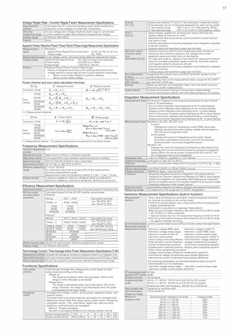
Voltage Ripple Rate / Current Ripple Factor Measurement SpecificationsMeasurementmethod
Calculates the AC component (peak to peak [peak width]) as a proportion of the voltage or current DC component
Effectivemeasuring range
As per voltage and voltage waveform peak value or current and current waveform peak value effective measurement ranges
Display range 0.00[%] to 500.00[%]Polarity None
Apparent Power/ Reactive Power/ Power Factor/ Phase Angle Measurement SpecificationsMeasurement types
Rectifiers Apparent Power/ Reactive Power/ Power Factor : AC+DC, AC, FND, AC+DC Umn Phase Angle : AC, FND
Effective measuring range As per voltage, current, and active power effective measurement ranges.Display range Apparent Power/ Reactive Power : 0% to 196% of the range (no zero-suppression)
Power Factor : ±0.0000 to ±1.0000Phase Angle : +180.00 to -180.00
Polarity Reactive Power/ Power Factor/ Phase Angle Polarity is assigned according to the lead/lag relationship of the
voltage waveform rising edge and the current waveform rising edge. + : When current lags voltage (no polarity display) - : When current leads voltage
Frequency Measurement SpecificationsNumber of measurement channels
3 ch
Measurement source Select from U (VHz) or I (AHz) by channelMeasurement method Calculated from input waveform period (reciprocal method)Measurement range 500 Hz/ 200 kHz (linked to zero-cross filter)Measurement accuracy ±0.1% rdg. ±1 dgt. (0°C to 40°C)Effective measuring range
0.1 Hz to 100 kHzFor sine wave input that is at least 20% of the measurement source’s measurement range.Measurement lower limit frequency setting: 0.1 sec. / 1 sec. / 10 sec.
Display format 0.1000 Hz to 9.9999 Hz, 9.900 Hz to 99.999 Hz, 99.00 Hz to 999.99 Hz, 9900 kHz to 9.9999 kHz, 9.900 kHz to 99.999 kHz, 99.00 kHz to 220.00 kHz
Efficiency Measurement SpecificationsMeasurement method Calculates the efficiency h [%] from the ratio of active power values for channels and wiresWiring modes and calculation equations
Calculated based on the AC+DC rectifier active powerPW3336Wiring CH1 CH2 Calculation formulas1P2W × 2 1P2W 1P2W h1=100×|P2| / |P1|
h2=100×|P1| / |P2|1P3W 1P3W3P3W 3P3W
3P3W2M 3P3W2MPW3337Wiring CH1 CH2 CH3 Calculation formulas1P2W × 3 1P2W 1P2W 1P2W h1=100×|P3| / |P1|
h2=100×|P1| / |P3|1P3W & 1P2W 1P3W 1P2W h1=100×|P3| / |Psum|
h2=100×|Psum| / |P3|3P3W & 1P2W 3P3W 1P2W3P3W2M 3P3W2M3V3A 3V3A3P3W3M 3P3W3M3P4W 3P4W
Effective measuring range As per the active power effective measurement range.Display range 0.00[%] to 200.00[%]
Time Average Current / Time Average Active Power Measurement Specifications (T.AV)Measurement method Calculates the average by dividing the integrated value by the integration timeMeasurement accuracy ±(Current or active power measurement accuracy) ±(±0.01%rdg. ±1dgt.)Effective measuring range As per the current or active power effective measurement range
Functional SpecificationsAuto-range(AUTO)
Automatically changes the voltage and current range for each wiring mode according to the input Range up: The range is increased when input exceeds 130% of the
range or when the peak is exceeded. Range down: The range is decreased when input falls below 15% of the
range. However, the range is not decreased when the peak is exceeded at the lower range.
Averaging(AVG)
· Averages the voltage, current, active power, apparent power, and reactive power. · The power factor and phase angle are calculated from averaged data. · Measured values other than peak values, power factor, frequency, integrated values, T.AV, crest factor, ripple rate, total harmonic distortion, and harmonics are averaged.
Method : Simple averaging Number of averaging iterations and display update intervalNumber of averaging iterations 1 (OFF) 2 5 10 25 50 100Display update interval 200ms 400ms 1s 2s 5s 10s 20s
Integration Measurement SpecificationsMeasurement items Simultaneous integration of the following 6 parameters for each channel
(total of 18 parameters):Sum of current integrated values (displayed as Ah on panel display)Positive current integrated value (displayed as Ah+ on panel display)Negative current integrated value (displayed as Ah- on panel display)Sum of active power integrated values (displayed as Wh on panel display)Positive active power integrated value (displayed as Wh+ on panel display)Negative active power integrated value (displayed as Wh- on panel display)
Measurement types Rectifiers: AC+DC, AC+DC Umn Current: Displays the result of integrating current RMS value data
(display values) once every display update interval (approx. 200 ms) as an integrated value.
Active power: Displays the result of integrating active power values
by polarity calculated once every cycle for the selected synchronization source as integrated values.
Rectifier: DC Displays the result of integrating instantaneous data obtained by
sampling both current and active power by polarity as integrated values (When the active power contains both AC and DC, the DC component will not be integrated)
Integration time 1 min. to 10000 hr., settable in 1 min. blocksIntegration time accuracy ±100 ppm ±1 dgt. (0°C to 40°C)Integration measurement accuracy
(Current or active power measurement accuracy) + (±0.01% rdg. ±1 dgt.)
Effective measuring range Until PEAK OVER U or PEAK OVER I occursDisplay resolution 999999 (6 digits + decimal point)Functions · Stopping integration based on integration time setting (timer)
· Displaying the integration elapsed time (displayed as TIME on panel display) · Additional integration by repeatedly starting/stopping integration · Backing up integrated values and the integration elapsed time during power outages · Stopping integration when power returns
External control Stopping/starting integration and resetting integrated values based on external controlMeasuring range Corresponds to the range set for START integretation
Harmonic Measurement Specifications (built-in function)Measurementmethod
· Zero-cross simultaneous calculation method (separate windows by channel according to the wiring mode) · Uniform thinning between zero-cross events after processing with a digital antialiasing filter · Interpolation calculations (Lagrange interpolation) · When the synchronization frequency falls within the 45 Hz to 66 Hz range
» IEC 61000-4-7:2002 compliant » Gaps and overlaps may occur if the measurement frequency is not 50 Hz or 60 Hz
· When the synchronization frequency falls outside the 45 Hz to 66 Hz range » No gaps or overlap will occur
Synchronization source Conforms to synchronization source (SYNC) for the basic measurement specificationsMeasurement channels 3Measurement items ·Harmonic voltage RMS value ·Harmonic voltage content %
·Harmonic voltage phase angle ·Harmonic current RMS value ·Harmonic current content % ·Harmonic current phase angle ·Harmonic active power ·Harmonic active power content % · Harmonic voltage current phase difference ·Total harmonic voltage distortion ·Total harmonic current distortion ·Voltage fundamental waveform ·Current fundamental waveform · Active power fundamental waveform ·Apparent power fundamental waveform ·Reactive power fundamental waveform ·Power factor fundamental waveform ·Voltage current phase difference fundamental waveform ·Interchannel voltage fundamental wave phase difference ·Interchannel current fundamental wave phase differenceThe following parameters can be downloaded as data during PC communication but not displayed: · Harmonic voltage phase angle · Harmonic current phase angle · Harmonic voltage current phase difference
FFT processing word length 32 bitsNumber of FFT points 4096Window function RectangularAnalysis window width
45 Hz ≤ f < 56 Hz: 178.57 ms to 222.22 ms (10 cycles)56 Hz ≤ f < 66 Hz: 181.82 ms to 214.29 ms (12 cycles)Frequencies other than the above: 185.92 ms to 214.08 ms
Data update rate Depends on window widthSynchronization frequency range
10 Hz to 640 Hz
Maximumanalysis order
Synchronization frequency (f) range Analysis order10 Hz ≤ f < 45 Hz 50th45 Hz ≤ f < 56 Hz 50th56 Hz ≤ f ≤ 66 Hz 50th
66 Hz < f ≤ 100 Hz 50th100 Hz < f ≤ 200 Hz 40th200 Hz < f ≤ 300 Hz 25th300 Hz < f ≤ 500 Hz 15th500 Hz < f ≤ 640 Hz 11th
Scaling(VT, CT)
Applies user-defined VT and CT ratio settings to measured values. These settings can be configured separately for each wiring mode.VT ratio setting range : OFF (1.0), 0.1 to 1000 (setting: 0000)CT ratio setting range : OFF (1.0), 0.001 to 1000 (setting: 0000)
HOLD(HOLD)
· Stops display updates for all measured values and fixes the display values at that point in time. · Measurement data acquired by communications is also fixed at that point in time. · Internal calculations (including integration and integration elapsed time) will continue. · Analog output and waveform output are not held.
Maximum value/minimum value hold(MAX/MIN HOLD)
· Detects maximum and minimum measured values as well as maximum and minimum values for the voltage and current waveform peak and holds them on the display. · For data with polarity, display of the maximum value and minimum value for the data’s absolute values is held (so that both positive and negative polarity values are shown). · Internal calculations (including integration and integration elapsed time) will continue. · Analog output and waveform output are not held.
Zero Adjustment (0 ADJ)
Degausses the current input unit DCCT and then zeroes out the current input offset.
Key-lock(KEY LOCK)
Disables key input in the measurement state, except for the SHIFT key and KEY LOCK key.
Backup Backs up settings and integration data if the instrument is turned off and if a power outage occurs.
System Reset Initializes the instrument’s settings. Communications-related settings (communications speed, address, and LAN-related settings) are not initialized.
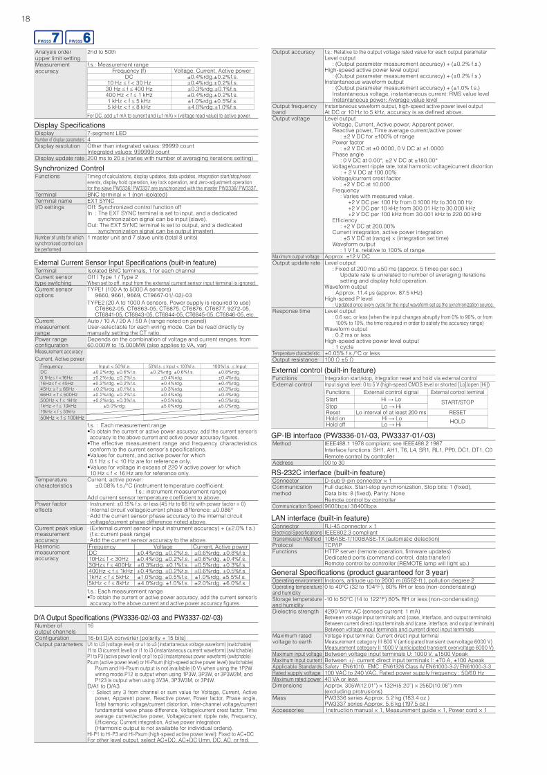
External Current Sensor Input Specifications (built-in feature)Terminal Isolated BNC terminals, 1 for each channelCurrent sensor type switching
Off / Type 1 / Type 2When set to off, input from the external current sensor input terminal is ignored.
Current sensor options
TYPE1 (100 A to 5000 A sensors) 9660, 9661, 9669, CT9667-01/-02/-03TYPE2 (20 A to 1000 A sensors, Power supply is required to use) CT6862-05, CT6863-05, CT6875, CT6876, CT6877, 9272-05,
CT6841-05, CT6843-05, CT6844-05, CT6845-05, CT6846-05, etc.Current measurementrange
Auto / 10 A / 20 A / 50 A (range noted on panel)User-selectable for each wiring mode. Can be read directly by manually setting the CT ratio.
Power rangeconfiguration
Depends on the combination of voltage and current ranges; from 60.000W to 15.000MW (also applies to VA, var)
Measurement accuracyCurrent, Active power
Frequency Input < 50%f.s. 50%f.s. ≤ Input < 100%f.s. 100%f.s. ≤ InputDC ±0.2%rdg. ±0.6%f.s. ±0.2%rdg. ±0.6%f.s. ±0.8%rdg. 0.1Hz≤ f <16Hz ±0.2%rdg. ±0.2%f.s. ±0.4%rdg. ±0.4%rdg. 16Hz≤ f < 45Hz ±0.2%rdg. ±0.2%f.s. ±0.4%rdg. ±0.4%rdg. 45Hz ≤ f ≤ 66Hz ±0.2%rdg. ±0.1%f.s. ±0.3%rdg. ±0.3%rdg. 66Hz < f ≤ 500Hz ±0.2%rdg. ±0.2%f.s. ±0.4%rdg. ±0.4%rdg. 500Hz < f ≤ 1kHz ±0.2%rdg. ±0.3%f.s. ±0.5%rdg. ±0.5%rdg. 1kHz < f ≤ 10kHz ±5.0%rdg. ±5.0%rdg. ±5.0%rdg. 10kHz < f ≤ 50kHz50kHz < f ≤ 100kHz
f.s. : Each measurement range•To obtain the current or active power accuracy, add the current sensor’s accuracy to the above current and active power accuracy figures.
•The effective measurement range and frequency characteristics conform to the current sensor’s specifications.
•Values for current, and active power for which 0.1 Hz ≤ f < 10 Hz are for reference only.
•Values for voltage in excess of 220 V active power for which 10 Hz ≤ f < 16 Hz are for reference only.
Temperaturecharacteristics
Current, active power: ±0.08% f.s./°C ( instrument temperature coefficient;
f.s.: instrument measurement range)Add current sensor temperature coefficient to above.
Power factor effects
· Instrument: ±0.15% f.s. or less (45 Hz to 66 Hz with power factor = 0) · Internal circuit voltage/current phase difference: ±0.086° · Add the current sensor phase accuracy to the internal circuit voltage/current phase difference noted above.
Current peak valuemeasurementaccuracy
· (External current sensor input instrument accuracy) + (±2.0% f.s.) (f.s.:current peak range) · Add the current sensor accuracy to the above.
Harmonic measurement accuracy
Frequency Voltage Current, Active powerDC ±0.4%rdg. ±0.2%f.s. ±0.6%rdg. ±0.8%f.s.10Hz≤ f < 30Hz ±0.4%rdg. ±0.2%f.s. ±0.6%rdg. ±0.4%f.s.30Hz≤ f ≤ 400Hz ±0.3%rdg. ±0.1%f.s. ±0.5%rdg. ±0.3%f.s.400Hz < f ≤ 1kHz ±0.4%rdg. ±0.2%f.s. ±0.6%rdg. ±0.5%f.s.1kHz < f ≤ 5kHz ±1.0%rdg. ±0.5%f.s. ±1.0%rdg. ±5.5%f.s.5kHz < f ≤ 8kHz ±4.0%rdg. ±1.0%f.s. ±2.0%rdg. ±6.0%f.s.f.s.: Each measurement range•To obtain the current or active power accuracy, add the current sensor’s accuracy to the above current and active power accuracy figures.
D/A Output Specifications (PW3336-02/-03 and PW3337-02/-03)Number ofoutput channels
16
Configuration 16-bit D/A converter (polarity + 15 bits)Output parameters U1 to U3 (voltage level) or u1 to u3 (instantaneous voltage waveform) (switchable)
I1 to I3 (current level) or i1 to i3 (instantaneous current waveform) (switchable)P1 to P3 (active power level) or p1 to p3 (instantaneous power waveform) (switchable)Psum (active power level) or Hi-Psum (high-speed active power level) (switchable)
Psum and Hi-Psum output is not available (0 V) when using the 1P2W wiring mode.P12 is output when using 1P3W, 3P3W, or 3P3W2M, and P123 is output when using 3V3A, 3P3W3M, or 3P4W.
D/A1 to D/A3: Select any 3 from channel or sum value for Voltage, Current, Active power, Apparent power, Reactive power, Power factor, Phase angle, Total harmonic voltage/current distortion, Inter-channel voltage/current fundamental wave phase difference, Voltage/current crest factor, Time average current/active power, Voltage/current ripple rate, Frequency, Efficiency, Current integration, Active power integration(Harmonic output is not available for individual orders).
Hi-P1 to Hi-P3 and Hi-Psum (high-speed active power level): Fixed to AC+DCFor other level output, select AC+DC, AC+DC Umn, DC, AC, or fnd.
General Specifications (product guaranteed for 3 year)Operating environment Indoors, altitude up to 2000 m (6562-ft.), pollution degree 2Operating temperature and humidity
0 to 40°C (32 to 104°F), 80% RH or less (non-condensating)
Storage temperature and humidity
-10 to 50°C (14 to 122°F) 80% RH or less (non-condensating)
Dielectric strength 4290 Vrms AC (sensed current: 1 mA)Between voltage input terminals and (case, interface, and output terminals)Between current direct input terminals and (case, interface, and output terminals)Between voltage input terminals and current direct input terminals
Maximum rated voltage to earth
Voltage input terminal, Current direct input terminalMeasurement category III 600 V (anticipated transient overvoltage 6000 V)Measurement category II 1000 V (anticipated transient overvoltage 6000 V)
Maximum input voltage Between voltage input terminals U: 1000 V, ±1500 VpeakMaximum input current Between +/- current direct input terminals I: ±70 A, ±100 ApeakApplicable Standards Safety : EN61010, EMC : EN61326 Class A/ EN61000-3-2/ EN61000-3-3Rated supply voltage 100 VAC to 240 VAC, Rated power supply frequency : 50/60 HzMaximum rated power 40 VA or lessDimensions Approx. 305W(12.01”) × 132H(5.20”) × 256D(10.08”) mm
(excluding protrusions)Mass PW3336 series Approx. 5.2 kg (183.4 oz.)
PW3337 series Approx. 5.6 kg (197.5 oz.)Accessories Instruction manual × 1, Measurement guide × 1, Power cord × 1
LAN interface (built-in feature)Connector RJ-45 connector × 1Electrical Specifications IEEE802.3 compliantTransmission Method 10BASE-T/100BASE-TX (automatic detection)Protocol TCP/IPFunctions HTTP server (remote operation, firmware updates)
Dedicated ports (command control, data transfer)Remote control by controller (REMOTE lamp will light up.)
RS-232C interface (built-in feature)Connector D-sub 9-pin connector × 1Communicationmethod
Full duplex, Start-stop synchronization, Stop bits: 1 (fixed),Data bits: 8 (fixed), Parity: NoneRemote control by controller
Communication Speed 9600bps/ 38400bps
GP-IB interface (PW3336-01/-03, PW3337-01/-03)Method IEEE488.1 1978 compliant; see IEEE488.2 1987
Interface functions: SH1, AH1, T6, L4, SR1, RL1, PP0, DC1, DT1, C0Remote control by controller
Address 00 to 30
External control (built-in feature)Functions Integration start/stop, integration reset and hold via external controlExternal control Input signal level: 0 to 5 V (high-speed CMOS level or shorted [Lo]/open [Hi])
Functions External control signal External control terminalStart Hi → Lo START/STOPStop Lo → HiReset Lo interval of at least 200 ms RESETHold on Hi → Lo HOLDHold off Lo → Hi
Output accuracy f.s.: Relative to the output voltage rated value for each output parameterLevel output : (Output parameter measurement accuracy) + (±0.2% f.s.)High-speed active power level output : (Output parameter measurement accuracy) + (±0.2% f.s.)Instantaneous waveform output : (Output parameter measurement accuracy) + (±1.0% f.s.) Instantaneous voltage, instantaneous current: RMS value level Instantaneous power: Average value level
Output frequency band
Instantaneous waveform output, high-speed active power level outputAt DC or 10 Hz to 5 kHz, accuracy is as defined above.
Output voltage Level output Voltage, Current, Active power, Apparent power,
Reactive power, Time average current/active power : ±2 V DC for ±100% of range Power factor : ±2 V DC at ±0.0000, 0 V DC at ±1.0000 Phase angle : 0 V DC at 0.00°, ±2 V DC at ±180.00° Voltage/current ripple rate, total harmonic voltage/current distortion : + 2 V DC at 100.00% Voltage/current crest factor : +2 V DC at 10.000 Frequency : Varies with measured value. +2 V DC per 100 Hz from 0.1000 Hz to 300.00 Hz +2 V DC per 10 kHz from 300.01 Hz to 30.000 kHz +2 V DC per 100 kHz from 30.001 kHz to 220.00 kHz Efficiency : +2 V DC at 200.00% Current integration, active power integration : ±5 V DC at (range) × (integration set time) Waveform output : 1 V f.s. relative to 100% of range
Maximum output voltage Approx. ±12 V DCOutput update rate Level output
: Fixed at 200 ms ±50 ms (approx. 5 times per sec.) Update rate is unrelated to number of averaging iterations
setting and display hold operation.Waveform output : Approx. 11.4 μs (approx. 87.5 kHz)High-speed P level : Updated once every cycle for the input waveform set as the synchronization source.
Response time Level output : 0.6 sec. or less (when the input changes abruptly from 0% to 90%, or from
100% to 10%, the time required in order to satisfy the accuracy range)Waveform output : 0.2 ms or lessHigh-speed active power level output : 1 cycle
Temperature characteristic ±0.05% f.s./°C or lessOutput resistance 100 Ω ±5 Ω
18
Synchronized ControlFunctions Timing of calculations, display updates, data updates, integration start/stop/reset
events, display hold operation, key lock operation, and zero-adjustment operation for the slave PW3336/ PW3337 are synchronized with the master PW3336/ PW3337.
Terminal BNC terminal × 1 (non-isolated)Terminal name EXT SYNCI/O settings Off: Synchronized control function off
In : The EXT SYNC terminal is set to input, and a dedicated synchronization signal can be input (slave). Out: The EXT SYNC terminal is set to output, and a dedicated synchronization signal can be output (master).
Number of units for which synchronized control can be performed
1 master unit and 7 slave units (total 8 units)
Display SpecificationsDisplay 7-segment LEDNumber of display parameters 4Display resolution Other than integrated values: 99999 count
Integrated values: 999999 countDisplay update rate 200 ms to 20 s (varies with number of averaging iterations setting)
Analysis order upper limit setting
2nd to 50th
Measurement accuracy
f.s.: Measurement range Frequency (f) Voltage, Current, Active power
DC ±0.4%rdg.±0.2%f.s.10 Hz ≤ f < 30 Hz ±0.4%rdg.±0.2%f.s.
30 Hz ≤ f ≤ 400 Hz ±0.3%rdg.±0.1%f.s.400 Hz < f ≤ 1 kHz ±0.4%rdg.±0.2%f.s.1 kHz < f ≤ 5 kHz ±1.0%rdg.±0.5%f.s.5 kHz < f ≤ 8 kHz ±4.0%rdg.±1.0%f.s.
For DC, add ±1 mA to current and (±1 mA) × (voltage read value) to active power.
19
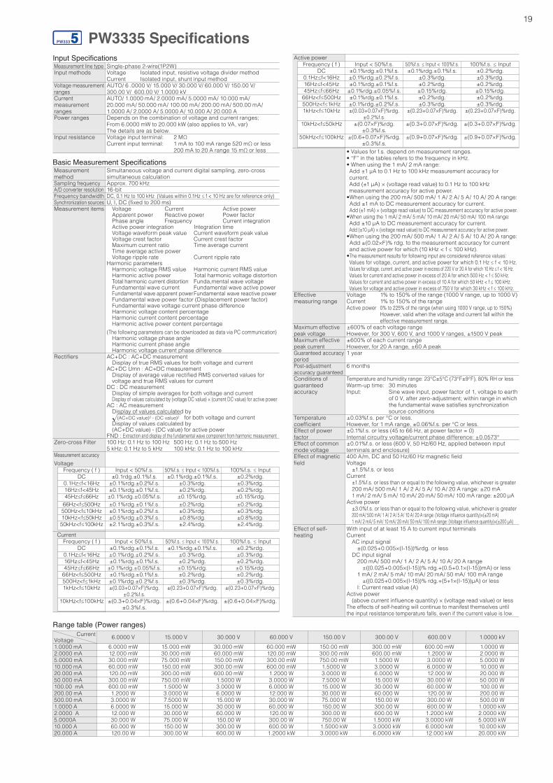
PW3335 SpecificationsInput SpecificationsMeasurement line type Single-phase 2-wire(1P2W)Input methods Voltage Isolated input, resistive voltage divider method
Current Isolated input, shunt input methodVoltage measurement ranges
AUTO/ 6 .0000 V/ 15.000 V/ 30.000 V/ 60.000 V/ 150.00 V/ 300.00 V/ 600.00 V/ 1.0000 kV
Current measurementranges
AUTO/ 1.0000 mA/ 2.0000 mA/ 5.0000 mA/ 10.000 mA/ 20.000 mA/ 50.000 mA/ 100.00 mA/ 200.00 mA/ 500.00 mA/ 1.0000 A/ 2.0000 A/ 5.0000 A/ 10.000 A/ 20.000 A
Power ranges Depends on the combination of voltage and current ranges;From 6.0000 mW to 20.000 kW (also applies to VA, var)The details are as below.
Input resistance Voltage input terminal: 2 MΩCurrent input terminal: 1 mA to 100 mA range 520 mΩ or less
200 mA to 20 A range 15 mΩ or less
Range table (Power ranges)Current
Voltage 6.0000 V 15.000 V 30.000 V 60.000 V 150.00 V 300.00 V 600.00 V 1.0000 kV1.0000 mA 6.0000 mW 15.000 mW 30.000 mW 60.000 mW 150.00 mW 300.00 mW 600.00 mW 1.0000 W2.0000 mA 12.000 mW 30.000 mW 60.000 mW 120.00 mW 300.00 mW 600.00 mW 1.2000 W 2.0000 W5.0000 mA 30.000 mW 75.000 mW 150.00 mW 300.00 mW 750.00 mW 1.5000 W 3.0000 W 5.0000 W10.000 mA 60.000 mW 150.00 mW 300.00 mW 600.00 mW 1.5000 W 3.0000 W 6.0000 W 10.000 W20.000 mA 120.00 mW 300.00 mW 600.00 mW 1.2000 W 3.0000 W 6.0000 W 12.000 W 20.000 W50.000 mA 300.00 mW 750.00 mW 1.5000 W 3.0000 W 7.5000 W 15.000 W 30.000 W 50.000 W100.00 mA 600.00 mW 1.5000 W 3.0000 W 6.0000 W 15.000 W 30.000 W 60.000 W 100.00 W200.00 mA 1.2000 W 3.0000 W 6.0000 W 12.000 W 30.000 W 60.000 W 120.00 W 200.00 W500.00 mA 3.0000 W 7.5000 W 15.000 W 30.000 W 75.000 W 150.00 W 300.00 W 500.00 W1.0000 A 6.0000 W 15.000 W 30.000 W 60.000 W 150.00 W 300.00 W 600.00 W 1.0000 kW2.0000 A 12.000 W 30.000 W 60.000 W 120.00 W 300.00 W 600.00 W 1.2000 kW 2.0000 kW5.0000A 30.000 W 75.000 W 150.00 W 300.00 W 750.00 W 1.5000 kW 3.0000 kW 5.0000 kW10.000 A 60.000 W 150.00 W 300.00 W 600.00 W 1.5000 kW 3.0000 kW 6.0000 kW 10.000 kW20.000 A 120.00 W 300.00 W 600.00 W 1.2000 kW 3.0000 kW 6.0000 kW 12.000 kW 20.000 kW
Basic Measurement SpecificationsMeasurement method
Simultaneous voltage and current digital sampling, zero-cross simultaneous calculation
Sampling frequency Approx. 700 kHzA/D converter resolution 16-bitFrequency bandwidth DC, 0.1 Hz to 100 kHz (Values within 0.1Hz ≤ f < 10 Hz are for reference only)Synchronization sources U, I, DC (fixed to 200 ms)Measurement items Voltage Current Active power
Apparent power Reactive power Power factor Phase angle Frequency Current integration Active power integration Integration time Voltage waveform peak value Current waveform peak value Voltage crest factor Current crest factor Maximum current ratio Time average current Time average active power Voltage ripple rate Current ripple rateHarmonic parameters Harmonic voltage RMS value Harmonic current RMS value Harmonic active power Total harmonic voltage distortion Total harmonic current distortion Funda,mental wave voltage Fundamental wave current Fundamental wave active power Fundamental wave apparent power Fundamental wave reactive power Fundamental wave power factor (Displacement power factor) Fundamental wave voltage current phase difference Harmonic voltage content percentage Harmonic current content percentage Harmonic active power content percentage(The following parameters can be downloaded as data via PC communication) Harmonic voltage phase angle Harmonic current phase angle Harmonic voltage current phase difference
Rectifiers AC+DC : AC+DC measurement Display of true RMS values for both voltage and currentAC+DC Umn : AC+DC measurement Display of average value rectified RMS converted values for voltage and true RMS values for currentDC : DC measurement Display of simple averages for both voltage and current Display of values calculated by (voltage DC value) × (current DC value) for active powerAC : AC measurement Display of values calculated by (AC+DC value)2 - (DC value)2 for both voltage and current Display of values calculated by (AC+DC value) - (DC value) for active powerFND : Extraction and display of the fundamental wave component from harmonic measurement
Zero-cross Filter 100 Hz: 0.1 Hz to 100 Hz 500 Hz: 0.1 Hz to 500 Hz5 kHz: 0.1 Hz to 5 kHz 100 kHz: 0.1 Hz to 100 kHz
Measurement accuracyVoltage
Frequency ( f ) Input < 50%f.s. 50%f.s. ≤ Input < 100%f.s. 100%f.s. ≤ InputDC ±0.1rdg.±0.1%f.s. ±0.1%rdg.±0.1%f.s. ±0.2%rdg.
0.1Hz≤f<16Hz ±0.1%rdg.±0.2%f.s. ±0.3%rdg. ±0.3%rdg.16Hz≤f<45Hz ±0.1%rdg.±0.1%f.s. ±0.2%rdg. ±0.2%rdg.45Hz≤f≤66Hz ±0.1%rdg.±0.05%f.s. ±0.15%rdg. ±0.15%rdg.
66Hz<f≤500Hz ±0.1%rdg.±0.1%f.s. ±0.2%rdg. ±0.2%rdg.500Hz<f≤10kHz ±0.1%rdg.±0.2%f.s. ±0.3%rdg. ±0.3%rdg.10kHz<f≤50kHz ±0.5%rdg.±0.3%f.s. ±0.8%rdg. ±0.8%rdg.50kHz<f≤100kHz ±2.1%rdg.±0.3%f.s. ±2.4%rdg. ±2.4%rdg.
CurrentFrequency ( f ) Input < 50%f.s. 50%f.s. ≤ Input < 100%f.s. 100%f.s. ≤ Input
DC ±0.1%rdg.±0.1%f.s. ±0.1%rdg.±0.1%f.s. ±0.2%rdg.0.1Hz≤f<16Hz ±0.1%rdg.±0.2%f.s. ±0.3%rdg. ±0.3%rdg.16Hz≤f<45Hz ±0.1%rdg.±0.1%f.s. ±0.2%rdg. ±0.2%rdg.45Hz≤f≤66Hz ±0.1%rdg.±0.05%f.s. ±0.15%rdg. ±0.15%rdg.
66Hz<f≤500Hz ±0.1%rdg.±0.1%f.s. ±0.2%rdg. ±0.2%rdg.500Hz<f≤1kHz ±0.1%rdg.±0.2%f.s. ±0.3%rdg. ±0.3%rdg.1kHz<f≤10kHz ±(0.03+0.07×F)%rdg.
±0.2%f.s.±(0.23+0.07×F)%rdg. ±(0.23+0.07×F)%rdg.
10kHz<f≤100kHz ±(0.3+0.04×F)%rdg.±0.3%f.s.
±(0.6+0.04×F)%rdg. ±(0.6+0.04×F)%rdg.
Active powerFrequency ( f ) Input < 50%f.s. 50%f.s. ≤ Input < 100%f.s. 100%f.s. ≤ Input
DC ±0.1%rdg.±0.1%f.s. ±0.1%rdg.±0.1%f.s. ±0.2%rdg.0.1Hz≤f<16Hz ±0.1%rdg.±0.2%f.s. ±0.3%rdg. ±0.3%rdg.16Hz≤f<45Hz ±0.1%rdg.±0.1%f.s. ±0.2%rdg. ±0.2%rdg.45Hz≤f≤66Hz ±0.1%rdg.±0.05%f.s. ±0.15%rdg. ±0.15%rdg.
66Hz<f≤500Hz ±0.1%rdg.±0.1%f.s. ±0.2%rdg. ±0.2%rdg.500Hz<f≤1kHz ±0.1%rdg.±0.2%f.s. ±0.3%rdg. ±0.3%rdg.1kHz<f≤10kHz ±(0.03+0.07×F)%rdg.
±0.2%f.s.±(0.23+0.07×F)%rdg. ±(0.23+0.07×F)%rdg.
10kHz<f≤50kHz ±(0.07×F)%rdg.±0.3%f.s.
±(0.3+0.07×F)%rdg. ±(0.3+0.07×F)%rdg.
50kHz<f≤100kHz ±(0.6+0.07×F)%rdg.±0.3%f.s.
±(0.9+0.07×F)%rdg. ±(0.9+0.07×F)%rdg.
• Values for f.s. depend on measurement ranges.• “F” in the tables refers to the frequency in kHz.• When using the 1 mA/ 2 mA range:Add ±1 μA to 0.1 Hz to 100 kHz measurement accuracy for current.Add (±1 μA) × (voltage read value) to 0.1 Hz to 100 kHz measurement accuracy for active power.
• When using the 200 mA/ 500 mA/ 1 A/ 2 A/ 5 A/ 10 A/ 20 A range: Add ±1 mA to DC measurement accuracy for current. Add (±1 mA) × (voltage read value) to DC measurement accuracy for active power.
• When using the 1 mA/ 2 mA/ 5 mA/ 10 mA/ 20 mA/ 50 mA/ 100 mA range:Add ±10 μA to DC measurement accuracy for current.Add (±10 μA) × (voltage read value) to DC measurement accuracy for active power.
• When using the 200 mA/ 500 mA/ 1 A/ 2 A/ 5 A/ 10 A/ 20 A range: Add ±(0.02×F)% rdg. to the measurement accuracy for current and active power for which (10 kHz < f ≤ 100 kHz).
• The measurement results for following input are considered reference values:Values for voltage, current, and active power for which 0.1 Hz ≤ f < 10 Hz.Values for voltage, current, and active power in excess of 220 V or 20 A for which 10 Hz ≤ f < 16 Hz.Values for current and active power in excess of 20 A for which 500 Hz < f ≤ 50 kHz.Values for current and active power in excess of 10 A for which 50 kHz < f ≤ 100 kHz.Values for voltage and active power in excess of 750 V for which 30 kHz < f ≤ 100 kHz.
Effective measuring range
Voltage 1% to 150% of the range (1000 V range, up to 1000 V)Current 1% to 150% of the rangeActive power 0% to 225% of the range (when using 1000 V range, up to 150%)
However, valid when the voltage and current fall within the effective measurement range.
Maximum effective peak voltage
±600% of each voltage rangeHowever, for 300 V, 600 V, and 1000 V ranges, ±1500 V peak
Maximum effective peak current
±600% of each current rangeHowever, for 20 A range, ±60 A peak
Guaranteed accuracyperiod
1 year
Post-adjustment accuracy guaranteed
6 months
Conditions of guaranteedaccuracy
Temperature and humidity range: 23°C±5°C (73°F±9°F), 80% RH or lessWarm-up time: 30 minutesInput: Sine wave input, power factor of 1, voltage to earth of 0 V, after zero-adjustment; within range in which the fundamental wave satisfies synchronization source conditions
Temperature coefficient
±0.03%f.s. per °C or less. However, for 1 mA range, ±0.06%f.s. per °C or less.
Effect of power factor
±0.1%f.s. or less (45 to 66 Hz, at power factor = 0)Internal circuitry voltage/current phase difference: ±0.0573°
Effect of common mode voltage
±0.01%f.s. or less (600 V, 50 Hz/60 Hz, applied between input terminals and enclosure)
Effect of magnetic field
400 A/m, DC and 50 Hz/60 Hz magnetic fieldVoltage ±1.5%f.s. or lessCurrent ±1.5%f.s. or less than or equal to the following value, whichever is greater 200 mA/ 500 mA/ 1 A/ 2 A/ 5 A/ 10 A/ 20 A range: ±20 mA 1 mA/ 2 mA/ 5 mA/ 10 mA/ 20 mA/ 50 mA/ 100 mA range: ±200 μAActive power ±3.0%f.s. or less than or equal to the following value, whichever is greater 200 mA/ 500 mA/ 1 A/ 2 A/ 5 A/ 10 A/ 20 A range: (Voltage influence quantity)×(±20 mA) 1 mA/ 2 mA/ 5 mA/ 10 mA/ 20 mA/ 50 mA/ 100 mA range: (Voltage influence quantity)×(±200 μA)
Effect of self-heating
With input of at least 15 A to current input terminalsCurrent AC input signal ±(0.025+0.005×(I-15))%rdg. or less DC input signal 200 mA/ 500 mA/ 1 A/ 2 A/ 5 A/ 10 A/ 20 A range ±((0.025+0.005×(I-15))% rdg.+(0.5+0.1×(I-15))mA) or less 1 mA/ 2 mA/ 5 mA/ 10 mA/ 20 mA/ 50 mA/ 100 mA range ±((0.025+0.005×(I-15))% rdg.+(5+1×(I-15))μA) or less I: Current read value (A)Active power (above current influence quantity) × (voltage read value) or lessThe effects of self-heating will continue to manifest themselves until the input resistance temperature falls, even if the current value is low.
20
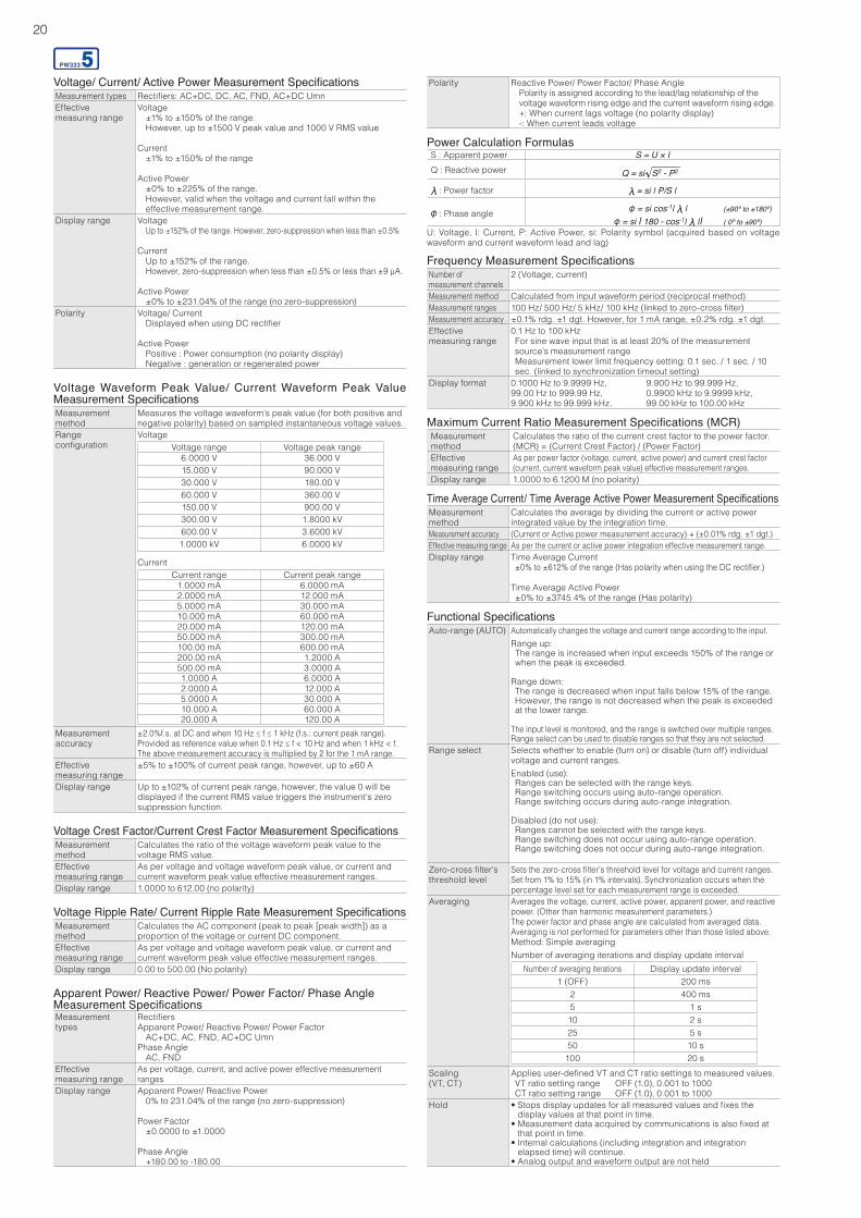
Voltage/ Current/ Active Power Measurement SpecificationsMeasurement types Rectifiers: AC+DC, DC, AC, FND, AC+DC UmnEffective measuring range
Voltage ±1% to ±150% of the range. However, up to ±1500 V peak value and 1000 V RMS value
Current ±1% to ±150% of the range
Active Power ±0% to ±225% of the range. However, valid when the voltage and current fall within the
effective measurement range.Display range Voltage
Up to ±152% of the range. However, zero-suppression when less than ±0.5%
Current Up to ±152% of the range. However, zero-suppression when less than ±0.5% or less than ±9 μA.
Active Power ±0% to ±231.04% of the range (no zero-suppression)
Polarity Voltage/ Current Displayed when using DC rectifier
Active Power Positive : Power consumption (no polarity display) Negative : generation or regenerated power
Voltage Crest Factor/Current Crest Factor Measurement SpecificationsMeasurement method
Calculates the ratio of the voltage waveform peak value to the voltage RMS value.
Effective measuring range
As per voltage and voltage waveform peak value, or current and current waveform peak value effective measurement ranges.
Display range 1.0000 to 612.00 (no polarity)
Voltage Waveform Peak Value/ Current Waveform Peak Value Measurement SpecificationsMeasurement method
Measures the voltage waveform’s peak value (for both positive and negative polarity) based on sampled instantaneous voltage values.
Range configuration
VoltageVoltage range Voltage peak range
6.0000 V 36.000 V15.000 V 90.000 V30.000 V 180.00 V60.000 V 360.00 V150.00 V 900.00 V300.00 V 1.8000 kV600.00 V 3.6000 kV1.0000 kV 6.0000 kV
CurrentCurrent range Current peak range
1.0000 mA 6.0000 mA2.0000 mA 12.000 mA5.0000 mA 30.000 mA10.000 mA 60.000 mA20.000 mA 120.00 mA50.000 mA 300.00 mA100.00 mA 600.00 mA200.00 mA 1.2000 A500.00 mA 3.0000 A1.0000 A 6.0000 A2.0000 A 12.000 A5.0000 A 30.000 A10.000 A 60.000 A20.000 A 120.00 A
Measurement accuracy
±2.0%f.s. at DC and when 10 Hz ≤ f ≤ 1 kHz (f.s.: current peak range).Provided as reference value when 0.1 Hz ≤ f < 10 Hz and when 1 kHz < f.The above measurement accuracy is multiplied by 2 for the 1 mA range.
Effective measuring range
±5% to ±100% of current peak range, however, up to ±60 A
Display range Up to ±102% of current peak range, however, the value 0 will be displayed if the current RMS value triggers the instrument's zero suppression function.
Voltage Ripple Rate/ Current Ripple Rate Measurement SpecificationsMeasurement method
Calculates the AC component (peak to peak [peak width]) as a proportion of the voltage or current DC component.
Effective measuring range
As per voltage and voltage waveform peak value, or current and current waveform peak value effective measurement ranges.
Display range 0.00 to 500.00 (No polarity)
Power Calculation FormulasS : Apparent power S = U × IQ : Reactive power Q = si S2 - P2
: Power factor = si | P/S |
: Phase angle = si cos-1| | (±90º to ±180º)
= si | 180 - cos-1| || ( 0º to ±90º)U: Voltage, I: Current, P: Active Power, si: Polarity symbol (acquired based on voltage waveform and current waveform lead and lag)
Apparent Power/ Reactive Power/ Power Factor/ Phase Angle Measurement SpecificationsMeasurement types
RectifiersApparent Power/ Reactive Power/ Power Factor AC+DC, AC, FND, AC+DC UmnPhase Angle AC, FND
Effective measuring range
As per voltage, current, and active power effective measurement ranges
Display range Apparent Power/ Reactive Power 0% to 231.04% of the range (no zero-suppression)
Power Factor ±0.0000 to ±1.0000
Phase Angle +180.00 to -180.00
Time Average Current/ Time Average Active Power Measurement SpecificationsMeasurement method
Calculates the average by dividing the current or active power integrated value by the integration time.
Measurement accuracy (Current or Active power measurement accuracy) + (±0.01% rdg. ±1 dgt.)Effective measuring range As per the current or active power integration effective measurement range.Display range Time Average Current
±0% to ±612% of the range (Has polarity when using the DC rectifier.)
Time Average Active Power±0% to ±3745.4% of the range (Has polarity)
Functional SpecificationsAuto-range (AUTO) Automatically changes the voltage and current range according to the input.
Range up: The range is increased when input exceeds 150% of the range or when the peak is exceeded.
Range down:The range is decreased when input falls below 15% of the range. However, the range is not decreased when the peak is exceeded at the lower range.
The input level is monitored, and the range is switched over multiple ranges. Range select can be used to disable ranges so that they are not selected.
Range select Selects whether to enable (turn on) or disable (turn off) individual voltage and current ranges.Enabled (use): Ranges can be selected with the range keys.Range switching occurs using auto-range operation.Range switching occurs during auto-range integration.
Disabled (do not use): Ranges cannot be selected with the range keys.Range switching does not occur using auto-range operation.Range switching does not occur during auto-range integration.
Zero-cross filter’sthreshold level
Sets the zero-cross filter’s threshold level for voltage and current ranges. Set from 1% to 15% (in 1% intervals). Synchronization occurs when the percentage level set for each measurement range is exceeded.
Averaging Averages the voltage, current, active power, apparent power, and reactive power. (Other than harmonic measurement parameters.)The power factor and phase angle are calculated from averaged data.Averaging is not performed for parameters other than those listed above.Method: Simple averagingNumber of averaging iterations and display update interval
Number of averaging iterations Display update interval1 (OFF) 200 ms
2 400 ms5 1 s10 2 s25 5 s50 10 s
100 20 sScaling (VT, CT)
Applies user-defined VT and CT ratio settings to measured values.VT ratio setting range OFF (1.0), 0.001 to 1000CT ratio setting range OFF (1.0), 0.001 to 1000
Hold • Stops display updates for all measured values and fixes the display values at that point in time.
• Measurement data acquired by communications is also fixed at that point in time.
• Internal calculations (including integration and integration elapsed time) will continue.
• Analog output and waveform output are not held
Frequency Measurement SpecificationsNumber of measurement channels
2 (Voltage, current)
Measurement method Calculated from input waveform period (reciprocal method)Measurement ranges 100 Hz/ 500 Hz/ 5 kHz/ 100 kHz (linked to zero-cross filter)Measurement accuracy ±0.1% rdg. ±1 dgt. However, for 1 mA range, ±0.2% rdg. ±1 dgt.Effective measuring range
0.1 Hz to 100 kHzFor sine wave input that is at least 20% of the measurement source’s measurement rangeMeasurement lower limit frequency setting: 0.1 sec. / 1 sec. / 10 sec. (linked to synchronization timeout setting)
Display format 0.1000 Hz to 9.9999 Hz, 9.900 Hz to 99.999 Hz,99.00 Hz to 999.99 Hz, 0.9900 kHz to 9.9999 kHz,9.900 kHz to 99.999 kHz, 99.00 kHz to 100.00 kHz
Maximum Current Ratio Measurement Specifications (MCR)Measurement method
Calculates the ratio of the current crest factor to the power factor.(MCR) = (Current Crest Factor) / (Power Factor)
Effective measuring range
As per power factor (voltage, current, active power) and current crest factor (current, current waveform peak value) effective measurement ranges.
Display range 1.0000 to 6.1200 M (no polarity)
Polarity Reactive Power/ Power Factor/ Phase AnglePolarity is assigned according to the lead/lag relationship of the voltage waveform rising edge and the current waveform rising edge.+: When current lags voltage (no polarity display)-: When current leads voltage
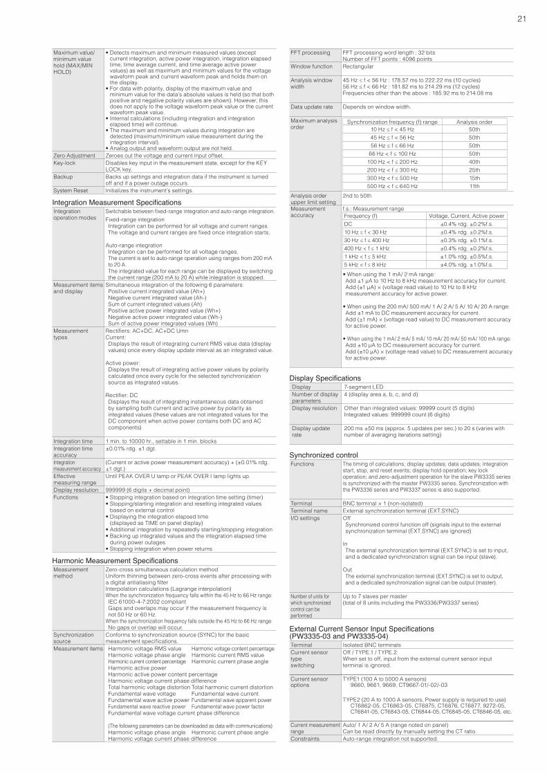
21
Integration Measurement SpecificationsIntegration operation modes
Switchable between fixed-range integration and auto-range integration.Fixed-range integrationIntegration can be performed for all voltage and current ranges.The voltage and current ranges are fixed once integration starts.
Auto-range integrationIntegration can be performed for all voltage ranges.The current is set to auto-range operation using ranges from 200 mA to 20 A.The integrated value for each range can be displayed by switching the current range (200 mA to 20 A) while integration is stopped.
Measurement items and display
Simultaneous integration of the following 6 parameters:Positive current integrated value (Ah+)Negative current integrated value (Ah-)Sum of current integrated values (Ah)Positive active power integrated value (Wh+)Negative active power integrated value (Wh-)Sum of active power integrated values (Wh)
Measurement types
Rectifiers: AC+DC, AC+DC UmnCurrent:Displays the result of integrating current RMS value data (display values) once every display update interval as an integrated value.
Active power: Displays the result of integrating active power values by polarity calculated once every cycle for the selected synchronization source as integrated values.
Rectifier: DCDisplays the result of integrating instantaneous data obtained by sampling both current and active power by polarity as integrated values (these values are not integrated values for the DC component when active power contains both DC and AC components)
Integration time 1 min. to 10000 hr., settable in 1 min. blocksIntegration time accuracy
±0.01% rdg. ±1 dgt.
Integration measurement accuracy
(Current or active power measurement accuracy) + (±0.01% rdg. ±1 dgt.)
Effective measuring range
Until PEAK OVER U lamp or PEAK OVER I lamp lights up.
Display resolution 999999 (6 digits + decimal point)Functions • Stopping integration based on integration time setting (timer)
• Stopping/starting integration and resetting integrated values based on external control
• Displaying the integration elapsed time (displayed as TIME on panel display)
• Additional integration by repeatedly starting/stopping integration• Backing up integrated values and the integration elapsed time
during power outages• Stopping integration when power returns
Maximum value/ minimum value hold (MAX/MIN HOLD)
• Detects maximum and minimum measured values (except current integration, active power integration, integration elapsed time, time average current, and time average active power values) as well as maximum and minimum values for the voltage waveform peak and current waveform peak and holds them on the display.
• For data with polarity, display of the maximum value and minimum value for the data’s absolute values is held (so that both positive and negative polarity values are shown). However, this does not apply to the voltage waveform peak value or the current waveform peak value.
• Internal calculations (including integration and integration elapsed time) will continue.
• The maximum and minimum values during integration are detected (maximum/minimum value measurement during the integration interval).
• Analog output and waveform output are not held.Zero Adjustment Zeroes out the voltage and current input offset.Key-lock Disables key input in the measurement state, except for the KEY
LOCK key.Backup Backs up settings and integration data if the instrument is turned
off and if a power outage occurs.System Reset Initializes the instrument’s settings.
Harmonic Measurement SpecificationsMeasurement method
Zero-cross simultaneous calculation methodUniform thinning between zero-cross events after processing with a digital antialiasing filterInterpolation calculations (Lagrange interpolation)When the synchronization frequency falls within the 45 Hz to 66 Hz range:IEC 61000-4-7:2002 compliantGaps and overlaps may occur if the measurement frequency is not 50 Hz or 60 Hz.
When the synchronization frequency falls outside the 45 Hz to 66 Hz range:No gaps or overlap will occur.
Synchronization source
Conforms to synchronization source (SYNC) for the basic measurement specifications.
Measurement items Harmonic voltage RMS value Harmonic voltage content percentageHarmonic voltage phase angle Harmonic current RMS valueHarmonic current content percentage Harmonic current phase angleHarmonic active power Harmonic active power content percentageHarmonic voltage current phase differenceTotal harmonic voltage distortion Total harmonic current distortion Fundamental wave voltage Fundamental wave currentFundamental wave active power Fundamental wave apparent powerFundamental wave reactive power Fundamental wave power factorFundamental wave voltage current phase difference
(The following parameters can be downloaded as data with communications)Harmonic voltage phase angle Harmonic current phase angle Harmonic voltage current phase difference
Display SpecificationsDisplay 7-segment LEDNumber of displayparameters
4 (display area a, b, c, and d)
Display resolution Other than integrated values: 99999 count (5 digits)Integrated values: 999999 count (6 digits)
Display update rate
200 ms ±50 ms (approx. 5 updates per sec.) to 20 s (varies with number of averaging iterations setting)
Synchronized controlFunctions The timing of calculations; display updates; data updates; integration
start, stop, and reset events; display hold operation; key lock operation; and zero-adjustment operation for the slave PW3335 series is synchronized with the master PW3335 series. Synchronization with the PW3336 series and PW3337 series is also supported.
Terminal BNC terminal × 1 (non-isolated)Terminal name External synchronization terminal (EXT.SYNC)I/O settings Off
Synchronized control function off (signals input to the external synchronization terminal (EXT.SYNC) are ignored)
InThe external synchronization terminal (EXT.SYNC) is set to input, and a dedicated synchronization signal can be input (slave).
OutThe external synchronization terminal (EXT.SYNC) is set to output, and a dedicated synchronization signal can be output (master).
Number of units for which synchronized control can be performed
Up to 7 slaves per master(total of 8 units including the PW3336/PW3337 series)
FFT processing FFT processing word length : 32 bitsNumber of FFT points : 4096 points
Window function Rectangular
Analysis window width
45 Hz ≤ f < 56 Hz : 178.57 ms to 222.22 ms (10 cycles)56 Hz ≤ f < 66 Hz : 181.82 ms to 214.29 ms (12 cycles)Frequencies other than the above : 185.92 ms to 214.08 ms
Data update rate Depends on window width.
Maximum analysis order
Synchronization frequency (f) range Analysis order10 Hz ≤ f < 45 Hz 50th45 Hz ≤ f < 56 Hz 50th56 Hz ≤ f ≤ 66 Hz 50th
66 Hz < f ≤ 100 Hz 50th100 Hz < f ≤ 200 Hz 40th200 Hz < f ≤ 300 Hz 25th300 Hz < f ≤ 500 Hz 15th500 Hz < f ≤ 640 Hz 11th
Analysis order upper limit setting
2nd to 50th
Measurement accuracy
f.s.: Measurement rangeFrequency (f) Voltage, Current, Active powerDC ±0.4% rdg. ±0.2%f.s.10 Hz ≤ f < 30 Hz ±0.4% rdg. ±0.2%f.s.30 Hz ≤ f ≤ 400 Hz ±0.3% rdg. ±0.1%f.s.400 Hz < f ≤ 1 kHz ±0.4% rdg. ±0.2%f.s.1 kHz < f ≤ 5 kHz ±1.0% rdg. ±0.5%f.s.5 kHz < f ≤ 8 kHz ±4.0% rdg. ±1.0%f.s.• When using the 1 mA/ 2 mA range:Add ±1 μA to 10 Hz to 8 kHz measurement accuracy for current.Add (±1 μA) × (voltage read value) to 10 Hz to 8 kHz measurement accuracy for active power.
• When using the 200 mA/ 500 mA/ 1 A/ 2 A/ 5 A/ 10 A/ 20 A range:Add ±1 mA to DC measurement accuracy for current.Add (±1 mA) × (voltage read value) to DC measurement accuracy for active power.
• When using the 1 mA/ 2 mA/ 5 mA/ 10 mA/ 20 mA/ 50 mA/ 100 mA range:Add ±10 μA to DC measurement accuracy for current.Add (±10 μA) × (voltage read value) to DC measurement accuracy for active power.
External Current Sensor Input Specifications (PW3335-03 and PW3335-04)Terminal Isolated BNC terminalsCurrent sensor typeswitching
Off / TYPE.1 / TYPE.2When set to off, input from the external current sensor input terminal is ignored.
Current sensor options
TYPE1 (100 A to 5000 A sensors) 9660, 9661, 9669, CT9667-01/-02/-03
TYPE2 (20 A to 1000 A sensors, Power supply is required to use) CT6862-05, CT6863-05, CT6875, CT6876, CT6877, 9272-05,
CT6841-05, CT6843-05, CT6844-05, CT6845-05, CT6846-05, etc.
Current measurementrange
Auto/ 1 A/ 2 A/ 5 A (range noted on panel)Can be read directly by manually setting the CT ratio.
Constraints Auto-range integration not supported.
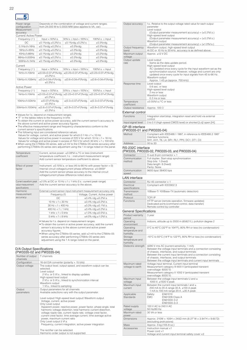
22
RS-232C interface(PW3335, PW3335-02, PW3335-03, and PW3335-04)Connector D-sub 9-pin connector × 1Communication method
Full duplex, Start-stop synchronizationStop bits: 1 (fixed)Data length: 8 (fixed)Parity: None
Communication speed
9600 bps/ 38400 bps
General SpecificationsProduct warranty period
3 year
Operating environment
Indoors, altitude up to 2000 m (6562 ft.), pollution degree 2
Operating temperature andhumidity
0°C to 40°C (32°F to 104°F), 80% RH or less (no condensation)
Storage temperature andhumidity
-10°C to 50°C (14°F to 122°F), 80% RH or less (no condensation)
Dielectric strength 4290 V rms AC (current sensitivity: 1 mA)Between the voltage input terminals and a connection consisting of chassis, interfaces, and output terminalsBetween the current input terminals and a connection consisting of chassis, interfaces, and output terminalsBetween the voltage input terminals and current input terminals
Maximum rated voltage to earth
Voltage input terminal, Current input terminalMeasurement category III 600 V (anticipated transient overvoltage: 6000 V)Measurement category II 1000 V (anticipated transient overvoltage: 6000 V)
Maximum input voltage
Between the voltage input terminals U and ±1000 V, ±1500 V peak
Maximum input current
Between the current input terminals I and ±200 mA to 20 A range 30 A, ±100 A peak1 mA to 100 mA range 20 A, ±30 A peak
Applicable Standards
Safety EN61010EMC EN61326 Class A EN61000-3-2 EN61000-3-3
Rated supply voltage
100 V AC to 240 V AC50 Hz/60 Hz
Maximum rated power
30 VA or less
Dimensions Approx. 210W × 100H × 245D mm (8.27”W × 3.94”H × 9.65”D) (excluding protrusions)
Mass Approx. 3 kg (105.8 oz.)Accessories Instruction manual ×1
Power cord ×1Voltage and current input terminal safety cover ×2
LAN interfaceConnector RJ-45 connector × 1Electrical specifications
Compliant with IEEE802.3
Transmission method
10Base-T/ 100Base-TX (automatic detection)
Protocol TCP/ IPFunctions HTTP server (remote operation, firmware updates)
Dedicated ports (command control, data transfer)Remote control by controller
GP-IB interface(PW3335-01 and PW3335-04)Method Compliant with IEEE488.1 1987, in reference to IEEE488.2 1987
Interface functionsSH1, AH1, T6, L4, SR1, RL1, PP0, DC1, DT1, C0
Address 00 to 30
D/A Output Specifications(PW3335-02 and PW3335-04)Number of output channels
7 channels
Configuration 16-bit D/A converter (polarity + 15 bits)Output voltage The output level, output speed, and waveform output can be
selected.Level output 2 Vf.s. or 5 Vf.s., linked to display updatesHigh-speed level output 2 Vf.s. or 5 Vf.s., linked to synchronization intervalWaveform output 1 Vf.s., linked to sampling
Output parameters
Output parameters for all channelsAvailable selections vary with the output parameter.
Level output/ High-speed level output/ Waveform outputVoltage, current, active power
Only Level outputApparent power, reactive power, power factor, phase angle, total harmonic voltage distortion, total harmonic current distortion, voltage ripple rate, current ripple rate, voltage crest factor, current crest factor, time average current, time average activepower, maximum current ratio
Only Level output 5 Vf.s.Frequency, current integration, active power integration
The rectifier can be selected.Harmonic-order output is not supported.
External controlFunctions Integration start/stop, integration reset and hold via external
controlInput signal level 0 to 5 V (high-speed CMOS level) or shorted [Lo]/ open [Hi]
Power range configuration
Depends on the combination of voltage and current ranges;from 24.000 W to 5.0000 MW (also applies to VA, var)
Measurement accuracyCurrent/ Active Power
Frequency ( f ) Input < 50%f.s. 50%f.s. ≤ Input < 100%f.s. 100%f.s. ≤ InputDC ±0.1%rdg.±0.2%f.s. ±0.1%rdg.±0.2%f.s. ±0.3%rdg.
0.1Hz≤f<16Hz ±0.1%rdg.±0.2%f.s. ±0.3%rdg. ±0.3%rdg.16Hz≤f<45Hz ±0.1%rdg.±0.2%f.s. ±0.3%rdg. ±0.3%rdg.45Hz≤f≤66Hz ±0.1%rdg.±0.1%f.s. ±0.2%rdg. ±0.2%rdg.
66Hz<f≤500Hz ±0.1%rdg.±0.2%f.s. ±0.3%rdg. ±0.3%rdg. 500Hz<f≤1kHz ±0.1%rdg.±0.2%f.s. ±0.3%rdg. ±0.3%rdg.
CurrentFrequency ( f ) Input < 50%f.s. 50%f.s. ≤ Input < 100%f.s. 100%f.s. ≤ Input1kHz<f≤10kHz ±(0.03+0.07×F)%rdg.
±0.2%f.s.±(0.23+0.07×F)%rdg. ±(0.23+0.07×F)%rdg.
10kHz<f≤100kHz ±(0.3+0.04×F)%rdg.±0.3%f.s.
±(0.6+0.04×F)%rdg. ±(0.6+0.04×F)%rdg.
Active PowerFrequency ( f ) Input < 50%f.s. 50%f.s. ≤ Input < 100%f.s. 100%f.s. ≤ Input1kHz<f≤10kHz ±(0.03+0.07×F)%rdg.
±0.2%f.s.±(0.23+0.07×F)%rdg. ±(0.23+0.07×F)%rdg.
10kHz<f≤50kHz ±(0.07×F)%rdg.±0.3%f.s.
±(0.3+0.07×F)%rdg. ±(0.3+0.07×F)%rdg.
50kHz<f≤100kHz ±(0.6+0.07×F)%rdg.±0.3%f.s.
±(0.9+0.07×F)%rdg. ±(0.9+0.07×F)%rdg.
• Values for f.s. depend on measurement ranges.• “F” in the tables refers to the frequency in kHz.• To obtain the current or active power accuracy, add the current sensor’s accuracy to
the above current and active power accuracy figures.• The effective measurement range and frequency characteristics conform to the
current sensor’s specifications.• The following input are considered reference values:
Values for voltage, current, and active power for which 0.1 Hz ≤ f < 10 Hz.Values for voltage and active power in excess of 220 V for which 10 Hz ≤ f < 16 Hz.Values for voltage and active power in excess of 750 V for which 30 kHz < f ≤ 100 kHz.
• When using the CT684x-05 series, add ±2 mV to the CT684x-05 series accuracy after performing CT684x-05 series zero adjustment using the 1 A range noted on the panel.
Temperature coefficient
Current, active power: ±0.08%f.s./°C or less (instrument temperature coefficient; f.s. : instrument measurement range)Add current sensor temperature coefficient to above.
Effect of power factor
Instrument: ±0.15%f.s. or less (45 to 66 Hz with power factor = 0)Internal circuit voltage/current phase difference: ±0.0859°Add the current sensor phase accuracy to the internal circuit voltage/current phase difference noted above.
Current waveform peak value measurement specifications
±2.0% at DC or 10 Hz ≤ f ≤ 1 kHz (f.s.: current peak range)Add the current sensor accuracy to the above.
Harmonic measurementaccuracy
External current sensor input instrument measurement accuracy onlyFrequency (f) Voltage, Current, Active power
DC ±0.4% rdg.±0.2%f.s.10 Hz ≤ f < 30 Hz ±0.4% rdg.±0.2%f.s.30 Hz ≤ f ≤ 400 Hz ±0.3% rdg.±0.1%f.s.400 Hz < f ≤ 1 kHz ±0.4% rdg.±0.2%f.s.1 kHz < f ≤ 5 kHz ±1.0% rdg.±0.5%f.s.5 kHz < f ≤ 8 kHz ±4.0% rdg.±1.0%f.s.
• Values for f.s. depend on measurement ranges.• To obtain the current or active power accuracy, add the current
sensor’s accuracy to the above current and active power accuracy figures.
• When using the CT684x-05 series, add ±2 mV to the CT684x-05 series accuracy after performing CT684x-05 series zero adjustment using the 1 A range noted on the panel.
Output accuracy f.s.: Relative to the output voltage rated value for each output parameterLevel output (Output parameter measurement accuracy) + (±0.2%f.s.)High-speed level output (Output parameter measurement accuracy) + (±0.2%f.s.)Waveform output (Output parameter measurement accuracy) + (±1.0%f.s.)
Output frequency band
Waveform output, high-speed level outputAt DC or 10 Hz to 30 kHz, accuracy is as defined above.
Maximum output voltage
Approx. ±12 V DC
Output update rate
Level output Same as the data update period.High-speed level output AC Updated once every cycle for the input waveform set as the
synchronization source. However, voltage and current are only updated once every cycle for input signals from 45 to 66 Hz.
Waveform output Approx. 1.43 μs (approx. 700 kHz)
Response time Level output 0.6 sec. or less High-speed level output 2 ms or lessWaveform output 0.2 ms or less
Temperature coefficient
±0.05%f.s./°C or less
Output resistance Approx. 100 Ω
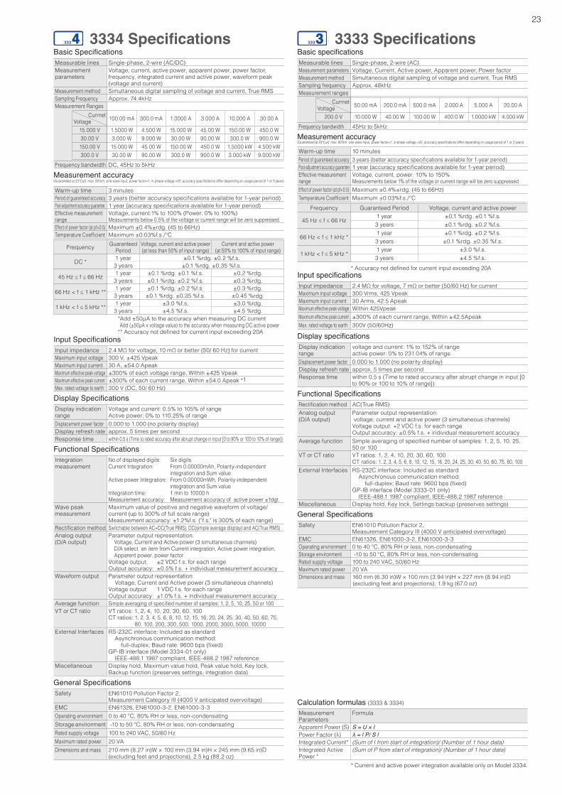
23
3334 SpecificationsBasic SpecificationsMeasurable lines Single-phase, 2-wire (AC/DC)Measurement parameters
Voltage, current, active power, apparent power, power factor, frequency, integrated current and active power, waveform peak (voltage and current)
Measurement method Simultaneous digital sampling of voltage and current, True RMSSampling Frequency Approx. 74.4kHzMeasurement Ranges
CurrnetVoltage 100.00 mA 300.0 mA 1.0000 A 3.000 A 10.000 A 30.00 A
15.000 V 1.5000 W 4.500 W 15.000 W 45.00 W 150.00 W 450.0 W30.00 V 3.000 W 9.000 W 30.00 W 90.00 W 300.0 W 900.0 W150.00 V 15.000 W 45.00 W 150.00 W 450.0 W 1.5000 kW 4.500 kW300.0 V 30.00 W 90.00 W 300.0 W 900.0 W 3.000 kW 9.000 kW
Frequency bandwidth DC, 45Hz to 5kHz
Measurement accuracy( Guaranteed at 23°C±5, max. 80%rh, sine wave input, power factor=1, in-phase voltage =0V, accuracy specifications differ depending on usage period of 1 or 3 years)
Warm-up time 3 minutesPeriod of guaranteed accuracy 3 years (better accuracy specifications available for 1-year period)Post-adjustment accuracy guarantee 1 year (accuracy specifications available for 1-year period)Effective measurement range
Voltage, current:1% to 100% (Power: 0% to 100%)Measurements below 0.5% of the voltage or current range will be zero suppressed.
Effect of power factor (at pf=0.5) Maximum ±0.4%±rdg. (45 to 66Hz)Temperature Coefficient Maximum ±0.03%f.s./ºC
Frequency Guaranteed Period
Voltage, current and active power(at less than 50% of input range)
Current and active power(at 50% to 100% of input range)
DC * 1 year ±0.1 %rdg. ±0.2 %f.s.3 years ±0.1 %rdg. ±0.35 %f.s.
45 Hz ≤ f ≤ 66 Hz 1 year ±0.1 %rdg. ±0.1 %f.s. ±0.2 %rdg.3 years ±0.1 %rdg. ±0.2 %f.s. ±0.3 %rdg.
66 Hz < f ≤ 1 kHz ** 1 year ±0.1 %rdg. ±0.2 %f.s. ±0.3 %rdg.3 years ±0.1 %rdg. ±0.35 %f.s. ±0.45 %rdg.
1 kHz < f ≤ 5 kHz ** 1 year ±3.0 %f.s. ±3.0 %rdg.3 years ±4.5 %f.s. ±4.5 %rdg.
* Add ±50μA to the accuracy when measuring DC current Add (±50μA x voltage value) to the accuracy when measuring DC active power
** Accuracy not defined for current input exceeding 20AInput SpecificationsInput impedance 2.4 MΩ for voltage, 10 mΩ or better (50/ 60 Hz) for currentMaximum input voltage 300 V, ±425 VpeakMaximum input current 30 A, ±54.0 ApeakMaximum effective peak voltage ±300% of each voltage range, Within ±425 VpeakMaximum effective peak current ±300% of each current range, Within ±54.0 Apeak *1Max. rated voltage to earth 300 V (DC, 50/ 60 Hz)
Display SpecificationsDisplay indication range
Voltage and current: 0.5% to 105% of rangeActive power: 0% to 110.25% of range
Displacement power factor 0.000 to 1.000 (no polarity display)Display refresh rate approx. 5 times per second Response time within 0.5 s (Time to rated accuracy after abrupt change in input [0 to 90% or 100 to 10% of range])
Functional SpecificationsIntegration measurement
No.of displayed digits: Six digitsCurrent Integration: From 0.00000mAh, Polarity-independent
integration and Sum valueActive power Integration: From 0.00000mWh, Polarity-independent
integration and Sum valueIntegration time: 1 min to 10000 h Measurement accuracy: Measurement accuracy of active power ±1dgt.
Wave peak measurement
Maximum value of positive and negative waveform of voltage/current (up to 300% of full scale range)Measurement accuracy: ±1.2%f.s. ("f.s." is 300% of each range)
Rectification method Switchable between AC+DC(True RMS), DC(simple average display) and AC(True RMS)Analog output(D/A output)
Parameter output representation: Voltage, Current and Active power (3 simultaneous channels)
D/A select an item from Current integration, Active power integration, Apparent power, power factor
Voltage output: ±2 VDC f.s. for each rangeOutput accuracy: ±0.5% f.s. + individual measurement accuracy
Waveform output Parameter output representation: Voltage, Current and Active power (3 simultaneous channels)Voltage output: 1 VDC f.s. for each rangeOutput accuracy: ±1.0% f.s. + individual measurement accuracy
Average function Simple averaging of specified number of samples: 1, 2, 5, 10, 25, 50 or 100VT or CT ratio VT ratios: 1, 2, 4, 10, 20, 30, 60, 100
CT ratios: 1, 2, 3, 4, 5, 6, 8, 10, 12, 15, 16, 20, 24, 25, 30, 40, 50, 60, 75, 80, 100, 200, 300, 500, 1000, 2000, 3000, 5000, 10000
External Interfaces RS-232C interface: Included as standard Asynchronous communication method: full-duplex; Baud rate: 9600 bps (fixed)GP-IB interface (Model 3334-01 only) IEEE-488.1 1987 compliant, IEEE-488.2 1987 reference
Miscellaneous Display hold, Maximum value hold, Peak value hold, Key lock, Backup function (preserves settings, integration data)
General SpecificationsSafety EN61010 Pollution Factor 2,
Measurement Category III (4000 V anticipated overvoltage)EMC EN61326, EN61000-3-2, EN61000-3-3 Operating environment 0 to 40 ºC, 80% RH or less, non-condensatingStorage environment -10 to 50 ºC, 80% RH or less, non-condensatingRated supply voltage 100 to 240 VAC, 50/60 HzMaximum rated power 20 VADimensions and mass 210 mm (8.27 in)W × 100 mm (3.94 in)H × 245 mm (9.65 in)D
(excluding feet and projections), 2.5 kg (88.2 oz)
3333 SpecificationsBasic specificationsMeasurable lines Single-phase, 2-wire (AC)Measurement parameters Voltage, Current, Active power, Apparent power, Power factorMeasurement method Simultaneous digital sampling of voltage and current, True RMSSampling frequency Approx. 48kHzMeasurement ranges
CurrnetVoltage 50.00 mA 200.0 mA 500.0 mA 2.000 A 5.000 A 20.00 A
200.0 V 10.000 W 40.00 W 100.00 W 400.0 W 1.0000 kW 4.000 kWFrequency bandwidth 45Hz to 5kHz
Measurement accuracy(Guaranteed at 23°C±5, max. 80%rh, sine wave input, power factor=1, in-phase voltage =0V, accuracy specifications differ depending on usage period of 1 or 3 years)
Warm-up time 10 minutesPeriod of guaranteed accuracy 3 years (better accuracy specifications available for 1-year period)Post-adjustment accuracy guarantee 1 year (accuracy specifications available for 1-year period)Effective measurement range
Voltage, current, power: 10% to 150%Measurements below 1% of the voltage or current range will be zero suppressed.
Effect of power factor (at pf=0.5) Maximum ±0.4%±rdg. (45 to 66Hz)Temperature Coefficient Maximum ±0.03%f.s./ºC
Frequency Guaranteed Period Voltage, current and active power
45 Hz ≤ f ≤ 66 Hz1 year ±0.1 %rdg. ±0.1 %f.s.3 years ±0.1 %rdg. ±0.2 %f.s.
66 Hz < f ≤ 1 kHz *1 year ±0.1 %rdg. ±0.2 %f.s.3 years ±0.1 %rdg. ±0.35 %f.s.
1 kHz < f ≤ 5 kHz *1 year ±3.0 %f.s.3 years ±4.5 %f.s.
* Accuracy not defined for current input exceeding 20AInput specificationsInput impedance 2.4 MΩ for voltage, 7 mΩ or better (50/60 Hz) for currentMaximum input voltage 300 Vrms, 425 VpeakMaximum input current 30 Arms, 42.5 ApeakMaximum effective peak voltage Within 425VpeakMaximum effective peak current ±300% of each current range, Within ±42.5ApeakMax. rated voltage to earth 300V (50/60Hz)
Display specificationsDisplay indication range
voltage and current: 1% to 152% of rangeactive power: 0% to 231.04% of range
Displacement power factor 0.000 to 1.000 (no polarity display)Display refresh rate approx. 5 times per second Response time within 0.5 s (Time to rated accuracy after abrupt change in input [0
to 90% or 100 to 10% of range])
Functional SpecificationsRectification method AC(True RMS)Analog output(D/A output)
Parameter output representation: voltage, current and active power (3 simultaneous channels)Voltage output: +2 VDC f.s. for each rangeOutput accuracy: ±0.5% f.s. + individual measurement accuracy
Average function Simple averaging of specified number of samples: 1, 2, 5, 10, 25, 50 or 100
VT or CT ratio VT ratios: 1, 2, 4, 10, 20, 30, 60, 100 CT ratios: 1, 2, 3, 4, 5, 6, 8, 10, 12, 15, 16, 20, 24, 25, 30, 40, 50, 60, 75, 80, 100
External Interfaces RS-232C interface: Included as standard Asynchronous communication method: full-duplex; Baud rate: 9600 bps (fixed)GP-IB interface (Model 3333-01 only) IEEE-488.1 1987 compliant, IEEE-488.2 1987 reference
Miscellaneous Display hold, Key lock, Settings backup (preserves settings)
General SpecificationsSafety EN61010 Pollution Factor 2,
Measurement Category III (4000 V anticipated overvoltage)EMC EN61326, EN61000-3-2, EN61000-3-3 Operating environment 0 to 40 ºC, 80% RH or less, non-condensatingStorage environment -10 to 50 ºC, 80% RH or less, non-condensatingRated supply voltage 100 to 240 VAC, 50/60 HzMaximum rated power 20 VADimensions and mass 160 mm (6.30 in)W × 100 mm (3.94 in)H × 227 mm (8.94 in)D
(excluding feet and projections), 1.9 kg (67.0 oz)
Calculation formulas (3333 & 3334)Measurement Parameters
Formula
Apparent Power (S) S = U × IPower Factor (λ) λ = | P/ S |Integrated Current* (Sum of I from start of integration)/ (Number of 1 hour data)Integrated Active Power *
(Sum of P from start of integration)/ (Number of 1 hour data)
* Current and active power integration available only on Model 3334.
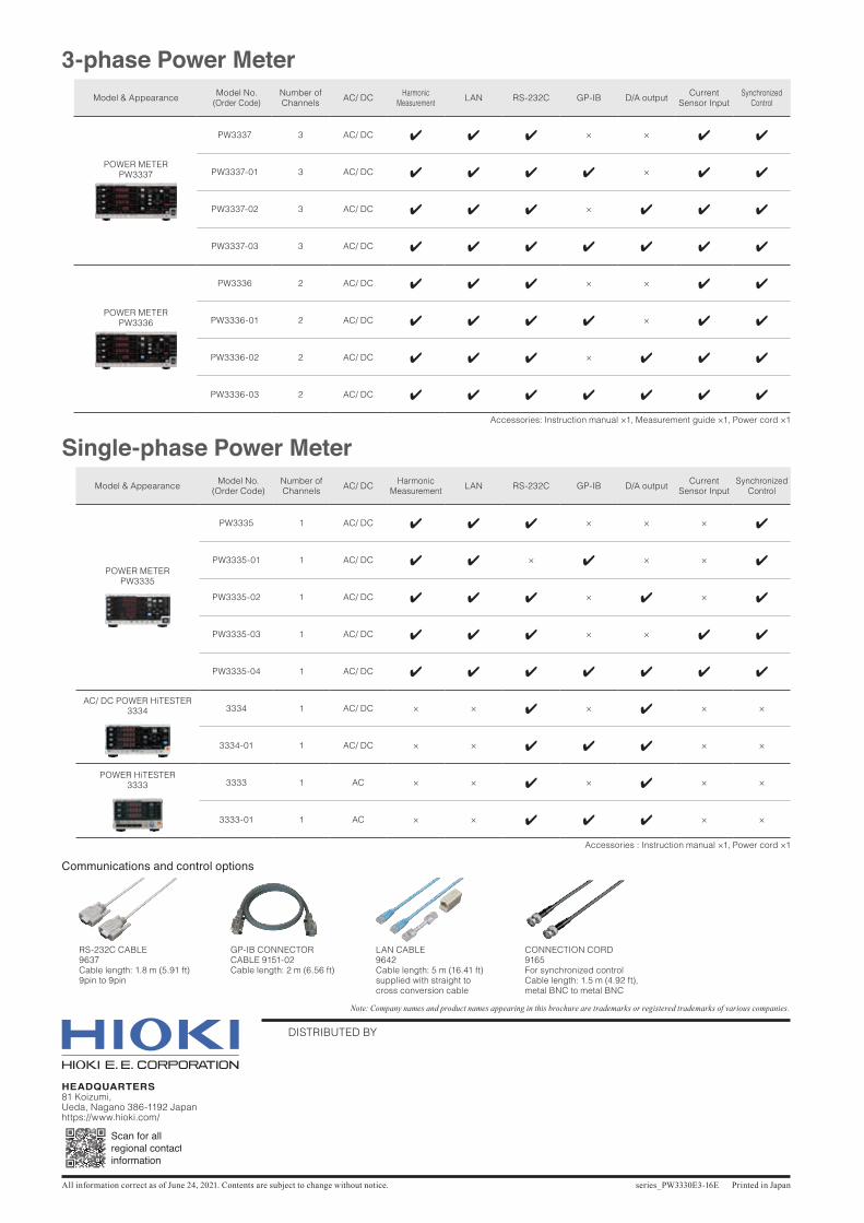
series_PW3330E3-16E Printed in Japan
DISTRIBUTED BY
HEADQUARTERS81 Koizumi, Ueda, Nagano 386-1192 Japanhttps://www.hioki.com/
All information correct as of June 24, 2021. Contents are subject to change without notice.
Note: Company names and product names appearing in this brochure are trademarks or registered trademarks of various companies.
3-phase Power MeterModel & Appearance Model No.
(Order Code)Number of Channels AC/ DC Harmonic
Measurement LAN RS-232C GP-IB D/A output Current Sensor Input
Synchronized Control
POWER METERPW3337
PW3337 3 AC/ DC 4 4 4 × × 4 4
PW3337-01 3 AC/ DC 4 4 4 4 × 4 4
PW3337-02 3 AC/ DC 4 4 4 × 4 4 4
PW3337-03 3 AC/ DC 4 4 4 4 4 4 4
POWER METERPW3336
PW3336 2 AC/ DC 4 4 4 × × 4 4
PW3336-01 2 AC/ DC 4 4 4 4 × 4 4
PW3336-02 2 AC/ DC 4 4 4 × 4 4 4
PW3336-03 2 AC/ DC 4 4 4 4 4 4 4
Accessories: Instruction manual ×1, Measurement guide ×1, Power cord ×1
Single-phase Power MeterModel & Appearance Model No.
(Order Code)Number of Channels AC/ DC Harmonic
Measurement LAN RS-232C GP-IB D/A output Current Sensor Input
Synchronized Control
POWER METERPW3335
PW3335 1 AC/ DC 4 4 4 × × × 4
PW3335-01 1 AC/ DC 4 4 × 4 × × 4
PW3335-02 1 AC/ DC 4 4 4 × 4 × 4
PW3335-03 1 AC/ DC 4 4 4 × × 4 4
PW3335-04 1 AC/ DC 4 4 4 4 4 4 4
AC/ DC POWER HiTESTER3334 3334 1 AC/ DC × × 4 × 4 × ×
3334-01 1 AC/ DC × × 4 4 4 × ×
POWER HiTESTER3333
3333 1 AC × × 4 × 4 × ×
3333-01 1 AC × × 4 4 4 × ×
Accessories : Instruction manual ×1, Power cord ×1
RS-232C CABLE9637Cable length: 1.8 m (5.91 ft)9pin to 9pin
GP-IB CONNECTORCABLE 9151-02Cable length: 2 m (6.56 ft)
LAN CABLE9642Cable length: 5 m (16.41 ft)supplied with straight to cross conversion cable
CONNECTION CORD9165For synchronized controlCable length: 1.5 m (4.92 ft),metal BNC to metal BNC
Communications and control options