accident identification with automatic ambulance rescue
TRANSCRIPT
18 Page 18-28 © MANTECH PUBLICATIONS 2020. All Rights Reserved
Journal of Advances in Communication Engineering and Its Innovations
Volume 5 Issue 1
Accident Identification with Automatic Ambulance Rescue System
V.Y.S.S. Sudir Patnaikuni*, Nirupam. G**, Niharika. B**, Chaitanya. A**, Poornima. G**
Assistant Professor*, Students**
Department of Electronics & Communication Engineering
Lendi Institute of Engineering & Technology, Jonnada
Corresponding Author’s email id: [email protected]*
DOI: http://doi.org/10.5281/zenodo.3745896
Abstract
Latterly, accidents are becoming one of the major dread for human beings. In
some accidents, victims are not saved by the response team, which may be
ambulance, police etc., due to lack of information about the location, severity
of the accident (or) some other issues.
Many technologies came into existence but they were unable to resolve the
problem. However this project will give the elucidation to overcome this
difficulty. In this project a central system is used where a vibrator sensor,
GSM (Global System for Mobiles communications), GPS modules are
connected to it. Multiple sensors are placed at different positions of the
vehicle to reduce the errors in detection. After the occurrence of the accident,
vibrator sensor comes into active state and with the help of the central system
GSM ((global System for mobiles), GPS (Global Positioning System) will be
activated. Immediately alert messages will be sent to the response teams,
where live location & severity of the accident will be shared.
Keywords: - Vibrator Sensor, GSM, GPS, Arduino.
Software: Arduino, Proteus.
INTRODUCTION
In day to day lives, the traffic crowd is
becoming much trouble. The main reason
notorious for traffic jams is rise in the
population and advancement of prudence.
So this is leading to the increase of
accidents. In order to control the riff to
prevent accidents on the road several
19 Page 18-28 © MANTECH PUBLICATIONS 2020. All Rights Reserved
Journal of Advances in Communication Engineering and Its Innovations
Volume 5 Issue 1
technologies came into existence like
embedded monitoring systems
implemented by using either
microcontrollers or Arduino and can be
extended by employing IOT. Various
sensors are available for the accident that
can be done by vibrator sensor. If one
sensor is placed in the vehicle, accuracy in
detection will not be upto the mark. So
multiple sensors will be placed at different
positions of the vehicle when at most
vibration is detected in the vehicle it is an
indication that an accident has occurred.
With the help of the central system GSM
and GPS comes into active state.
GSMsim900A is used to send alert
messages to the contacts saved in the sim
card. GPS is used for sharing the location
of the spot. Alert messages will be like the
vehicle number and location of the place
where the accident occurred. This project
consists of three different units.
Vehicle unit
Ambulance unit
Traffic unit
Ambulance and traffic units are the
existence of the project.
COMPONENTS
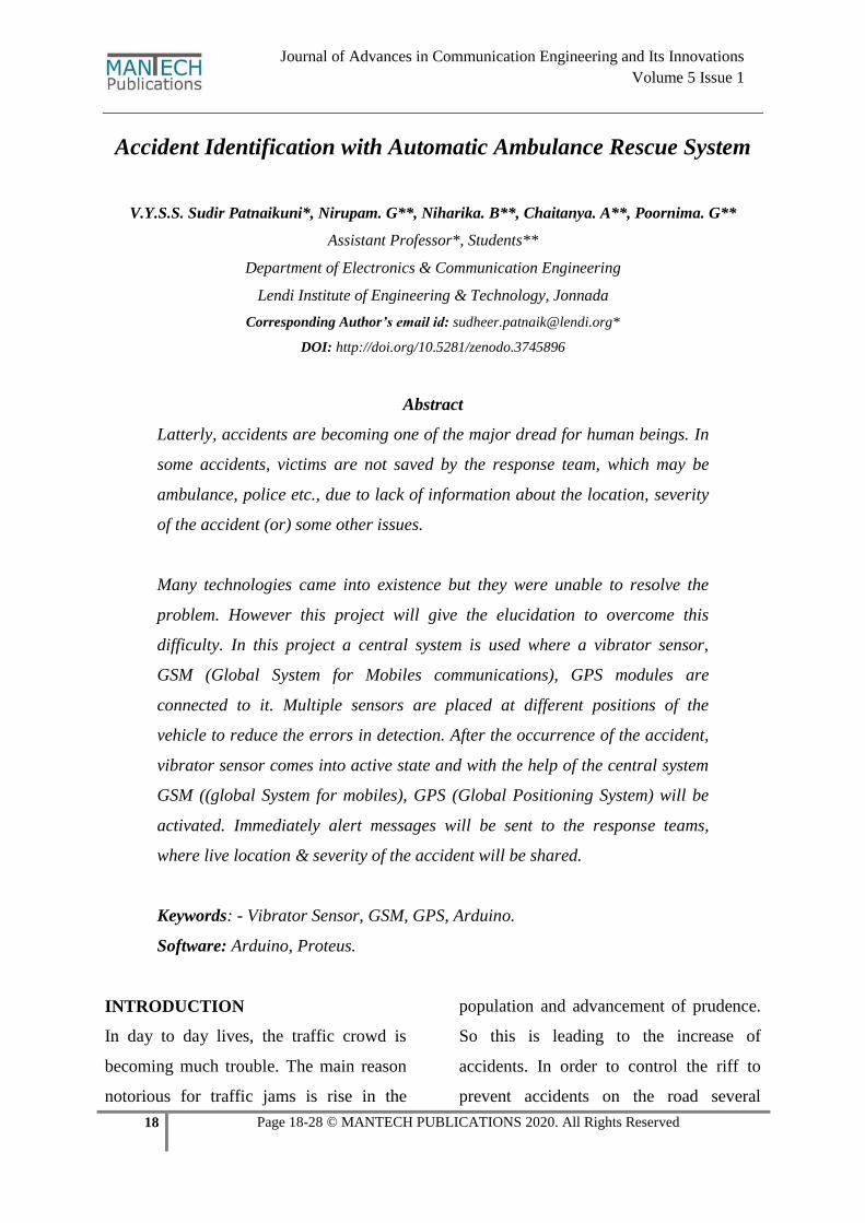
1) Arduino UNO:
“UNO” means “one” in Italian.
Arduino Uno belongs to the family of
microcontrollers which is open
sourced. THe board is assembled with
digital and analog, Input and output pins.
14digital I/O pins(0 to 13)
6 analog I/O pins(A0 to A15)
with the Arduino IDE(Integrated
Development Environment) the board can
be programmed. Power can be supplied by
USB cable or by external 9-volts battery.
Thyearduino board is more advantageous
because it can be programmed several
times when compared to a microcontroller
supplying voltage other than 5v or 3.3v
will detour the regulator and fully damage
the board. when 3v supply is given to the
board maximum current draw will be
50MA. To avoid any damage to the
arduino board, more than 40mA should not
be supplied to any I/o pin. Arduino board
provides the leaning for divulging with
another computer, arduino board or other
microcontrollers.
Arduino software (IDE) embodies a serial
monitor which concedes simple textual
20 Page 18-28 © MANTECH PUBLICATIONS 2020. All Rights Reserved
Journal of Advances in Communication Engineering and Its Innovations
Volume 5 Issue 1
data to and fro from the board. The
transmitter and receiver pins led’s will
spark when data is transmitted to the
board. Instead of physically pressing the
reset button before uploading the code to
the board, the arduino board has the
advantage that it allows it to reset by
software running on any connected
computer. See Figure: 1
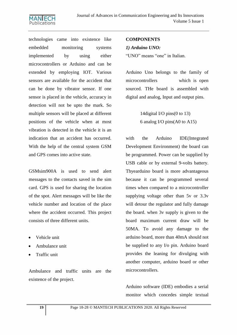
2) Vibrator Sensor:
Various types of sensor can be used for the
detection of the accident. However
vibrator sensor is used for detection
because of its accuracy. Other name of
vibrator sensor is piezoelectric sensor.
Vibrator sensor is capable of measuring
the process. This sensor uses the
piezoelectric effect that can measure
acceleration pressure, temperature, force
and electrical charge. This sensor is also
used for desisting fragrances within the air
and capacitance as well.
Fig:1 Arduino UNO
21 Page 18-28 © MANTECH PUBLICATIONS 2020. All Rights Reserved
Journal of Advances in Communication Engineering and Its Innovations
Volume 5 Issue 1
Fig: 2 Vibrator Sensor
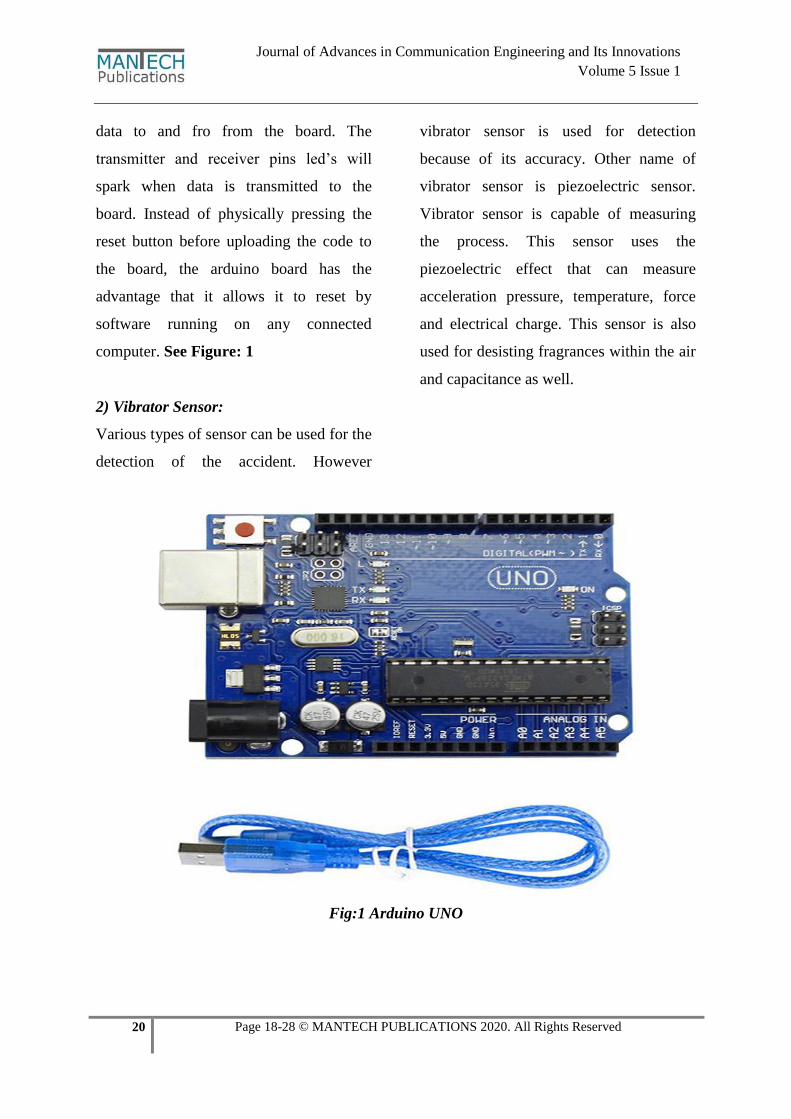
Working Principle:
It is based on mechanical principles for
disclosing observed system vibrations. The
Sensitivity range of these sensors is from
10mv/g to 100mv/g. The sensitivity can be
preferred based on the application. When
the accident ensues, immediately vibrator
sensor comes into the active state, and
when at most vibration is observed, It is a
portent that the accident is accursed.
The vibrator sensor will monotonously
sense for any at most vibration in the
vehicle. With the help of the central
system, the sensed data is given to
GSM,GPSmodules.Vibrator sensor is best
suitable for high frequency vibrations.
Fig:3 Vibrator peak voltage
3) GSM sim900A:
A GSM is a wireless modem that works
with a GSM wireless network. This
wireless modem acts like a dial-up
modem.GSM uses the GPRS(general
packet radio service) for data transmission
like browsing the web. The duct
contrariety between dialup modem and
GSM modem is that a dial-up modem send
22 Page 18-28 © MANTECH PUBLICATIONS 2020. All Rights Reserved
Journal of Advances in Communication Engineering and Its Innovations
Volume 5 Issue 1
and receives data through a fixed
telephone while a GSM modem send and
receives through radio waves.
Communication can be done through
wired or wireless. Wired is suited for only
short distance information can be sent.
When a USB cable is connected.wireless
communication is possible with the help of
GSM modem. Through GSM messages
can be sent, dialing phone is possible,
signal strength can be monitored, location
of the spot is sent to the contacts obtained
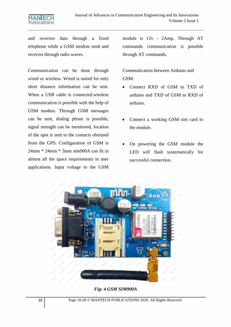
from the GPS. Configuration of GSM is
24mm * 24mm * 3mm sim900A can fit in
almost all the space requirements in user
applications. Input voltage to the GSM
module is 12v - 2Amp. Through AT
commands communication is possible
through AT commands.
Communication between Arduino and
GSM:
Connect RXD of GSM to TXD of
arduino and TXD of GSM to RXD of
arduino.
Connect a working GSM sim card to
the module.
On powering the GSM module the
LED will flash systematically for
successful connection.
Fig: 4 GSM SIM900A
23 Page 18-28 © MANTECH PUBLICATIONS 2020. All Rights Reserved
Journal of Advances in Communication Engineering and Its Innovations
Volume 5 Issue 1
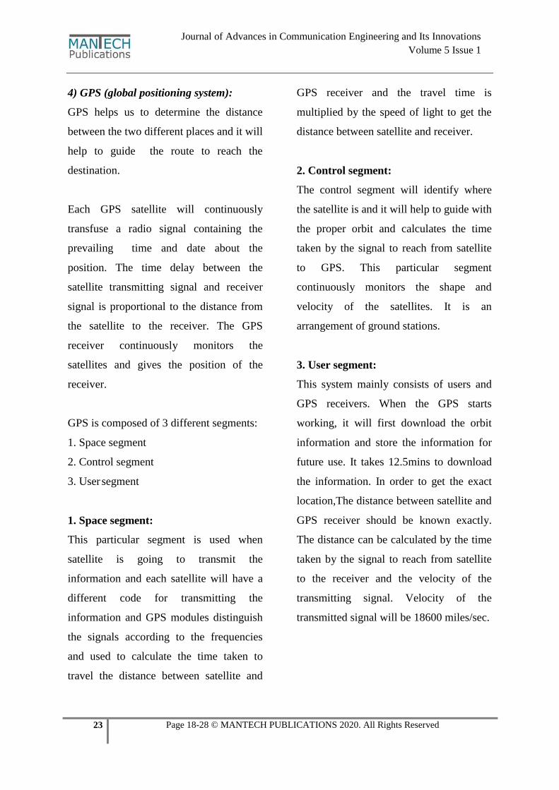
4) GPS (global positioning system):
GPS helps us to determine the distance
between the two different places and it will
help to guide the route to reach the
destination.
Each GPS satellite will continuously
transfuse a radio signal containing the
prevailing time and date about the
position. The time delay between the
satellite transmitting signal and receiver
signal is proportional to the distance from
the satellite to the receiver. The GPS
receiver continuously monitors the
satellites and gives the position of the
receiver.
GPS is composed of 3 different segments:
1. Space segment
2. Control segment
3. User segment
1. Space segment:
This particular segment is used when
satellite is going to transmit the
information and each satellite will have a
different code for transmitting the
information and GPS modules distinguish
the signals according to the frequencies
and used to calculate the time taken to
travel the distance between satellite and
GPS receiver and the travel time is
multiplied by the speed of light to get the
distance between satellite and receiver.
2. Control segment:
The control segment will identify where
the satellite is and it will help to guide with
the proper orbit and calculates the time
taken by the signal to reach from satellite
to GPS. This particular segment
continuously monitors the shape and
velocity of the satellites. It is an
arrangement of ground stations.
3. User segment:
This system mainly consists of users and
GPS receivers. When the GPS starts
working, it will first download the orbit
information and store the information for
future use. It takes 12.5mins to download
the information. In order to get the exact
location,The distance between satellite and
GPS receiver should be known exactly.
The distance can be calculated by the time
taken by the signal to reach from satellite
to the receiver and the velocity of the
transmitting signal. Velocity of the
transmitted signal will be 18600 miles/sec.
24 Page 18-28 © MANTECH PUBLICATIONS 2020. All Rights Reserved
Journal of Advances in Communication Engineering and Its Innovations
Volume 5 Issue 1
Fig:5 GPS Module
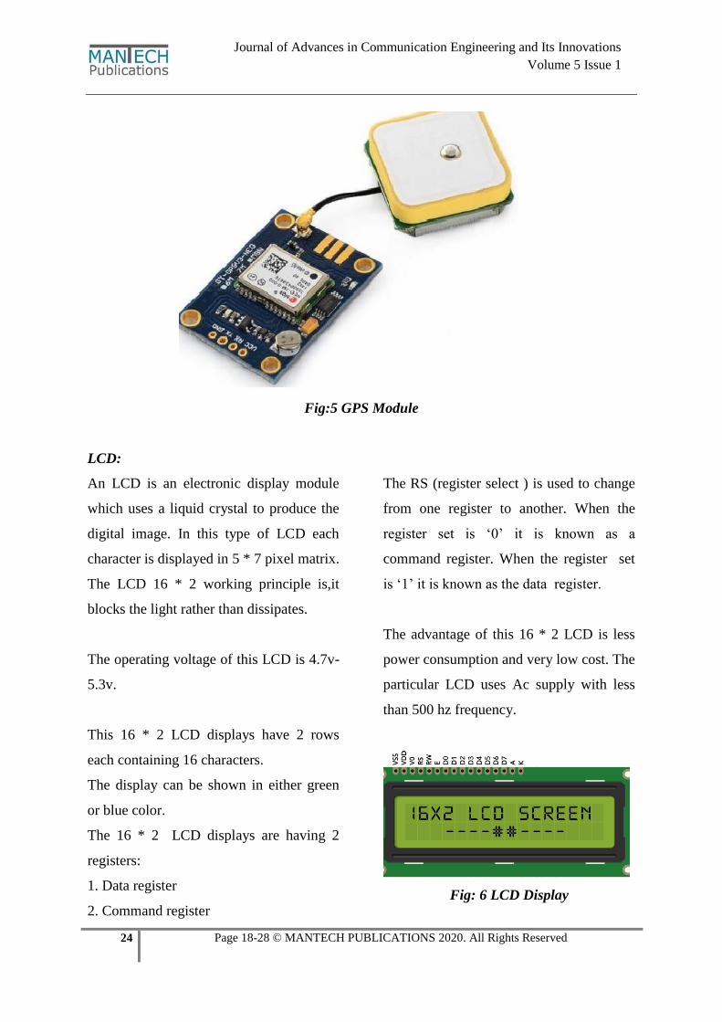
LCD:
An LCD is an electronic display module
which uses a liquid crystal to produce the
digital image. In this type of LCD each
character is displayed in 5 * 7 pixel matrix.
The LCD 16 * 2 working principle is,it
blocks the light rather than dissipates.
The operating voltage of this LCD is 4.7v-
5.3v.
This 16 * 2 LCD displays have 2 rows
each containing 16 characters.
The display can be shown in either green
or blue color.
The 16 * 2 LCD displays are having 2
registers:
1. Data register
2. Command register
The RS (register select ) is used to change
from one register to another. When the
register set is ‘0’ it is known as a
command register. When the register set
is ‘1’ it is known as the data register.
The advantage of this 16 * 2 LCD is less
power consumption and very low cost. The
particular LCD uses Ac supply with less
than 500 hz frequency.
Fig: 6 LCD Display
25 Page 18-28 © MANTECH PUBLICATIONS 2020. All Rights Reserved
Journal of Advances in Communication Engineering and Its Innovations
Volume 5 Issue 1
LED Indicator:
Light emitting diodeit emits light when the
current pases through it LED’s are more
advantageous. Because of their low power
consumption,low cost, switching is
fast,duration time is long. LED is used in
the project to indicate that vibrator sensor
starts working immediately after the
accident has occurred.
Fig:7 LED Light
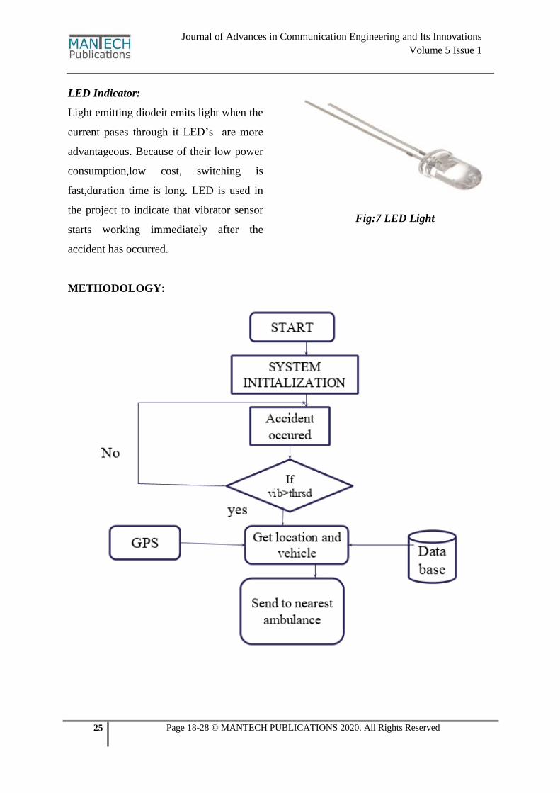
METHODOLOGY:
26 Page 18-28 © MANTECH PUBLICATIONS 2020. All Rights Reserved
Journal of Advances in Communication Engineering and Its Innovations
Volume 5 Issue 1
Algorithm:
Step 1: Start
Step 2: Accident occurred, Vibration
sensors will give respective value.
Step 3: Case 1: If vib val > threshold
value then the Central system gets
activated.
Case 2: If vib val < threshold value then
no change.
Step 4: If Case 1 occurred:
Central system will activate GPS,
GSM.
Message sent through GSM.
Location is shared to GSM with
help of GPS to the respective
contacts included in firmware.
Step 5: Based on GPS location, the
respective persons reach the location.
Step 6: Stop.
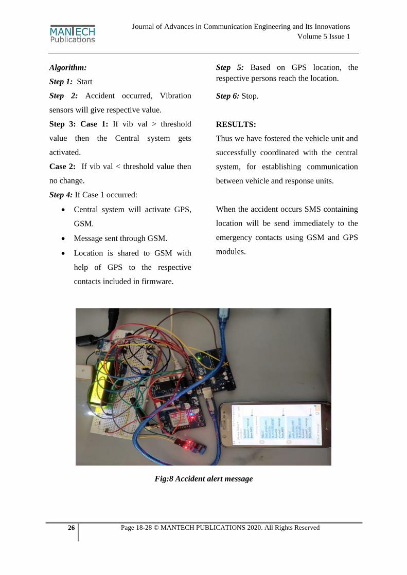
RESULTS:
Thus we have fostered the vehicle unit and
successfully coordinated with the central
system, for establishing communication
between vehicle and response units.
When the accident occurs SMS containing
location will be send immediately to the
emergency contacts using GSM and GPS
modules.
Fig:8 Accident alert message
27 Page 18-28 © MANTECH PUBLICATIONS 2020. All Rights Reserved
Journal of Advances in Communication Engineering and Its Innovations
Volume 5 Issue 1
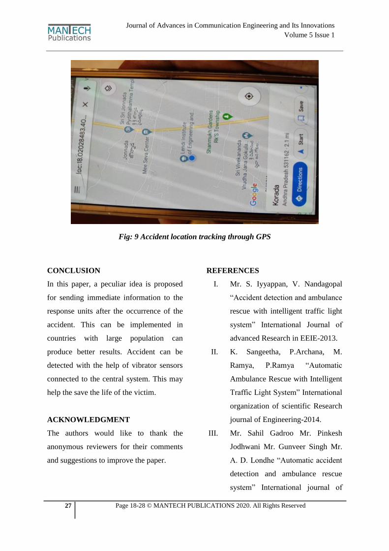
Fig: 9 Accident location tracking through GPS
CONCLUSION
In this paper, a peculiar idea is proposed
for sending immediate information to the
response units after the occurrence of the
accident. This can be implemented in
countries with large population can
produce better results. Accident can be
detected with the help of vibrator sensors
connected to the central system. This may
help the save the life of the victim.
ACKNOWLEDGMENT
The authors would like to thank the
anonymous reviewers for their comments
and suggestions to improve the paper.
REFERENCES
I. Mr. S. Iyyappan, V. Nandagopal
“Accident detection and ambulance
rescue with intelligent traffic light
system” International Journal of
advanced Research in EEIE-2013.
II. K. Sangeetha, P.Archana, M.
Ramya, P.Ramya “Automatic
Ambulance Rescue with Intelligent
Traffic Light System” International
organization of scientific Research
journal of Engineering-2014.
III. Mr. Sahil Gadroo Mr. Pinkesh
Jodhwani Mr. Gunveer Singh Mr.
A. D. Londhe “Automatic accident
detection and ambulance rescue
system” International journal of
28 Page 18-28 © MANTECH PUBLICATIONS 2020. All Rights Reserved
Journal of Advances in Communication Engineering and Its Innovations
Volume 5 Issue 1
scientific &engineering research-
2015.
IV. Hrishikesh Murkut, Fazal Patil,
Vishal Yadav, Meghana
Deshpande “Automatic accident
detection and rescue with
ambulance” SSRG International
journal of ECE-2015.
V. A. Hac, "Wireless Sensor Network
Designs”, John Wiley& Sons, Ltd,
2003.
VI. "Ultra-Low Energy Wireless
Sensor Networks in Practice
Theory", Realization and
Deployment, John Wiley & Sons,
Inc, 2007.
VII. N. Bulusu, "Wireless Sensor
Networks", Artech House, Inc,
2005
VIII. M. Lee, C. Yao, H. Liu,” Passive
Tag for Multi-carrier RFID
Systems”, IEEE 17th International
Conference on Parallel and
Distributed Systems, 2011.
IX. Y. Khalil, M. Al-kariki,
“Intelligent Traffic Light Flow
Control System using Wireless
Sensor Networks”, Journal of
Information Science and
Engineering, 26, 753-768 (2010).
X. R. Kannan, R. Nammily, S. Manoj
, A. Vishwa, ” Wireless Vehicular
Accident Detection and Reporting
System”, International Conference
on Mechanical and Electrical
Technology (ICMET 2010).
XI. T. Malik, S. Yi, S. Hongchi ,
“Adaptive Traffic light control
with Wireless Sensor Networks”,
(2007).
XII. C. Anuran, B. Saumya, C.
Anirudh, “An Intelligent Traffic
Control System using RFID”,
IEEE, 2009.
XIII. R. Kannan, V. Mohan, A.
Mohanan, P. Leons, R. Shooja, A
Vishwa, "Wireless Sensor Network
for Vehicle Speed Monitoring and
Traffic Routing System“,
International Conference on
Mechanical and Electrical
Technology (ICMET 2010).
Cite this Article as
V.Y.S.S. Sudir Patnaikuni, Nirupam. G,
Niharika. B, Chaitanya. A, Poornima.
G (2020) “Accident Identification with
Automatic Ambulance Rescue
System” Journal of Advances in
Communication Engineering and Its
Innovations, 5(1), 18- 28
http://doi.org/10.5281/zenodo.3745896