a150-metal-iom.pdf - psg dover
TRANSCRIPT
IOMINSTALLATION OPERATION & MAINTENANCE
A150METAL 1-1/2 INCH AIR-OPERATED DOUBLE-DIAPHRAGM PUMP
ALF-12060-E-02 All-Flo2
TABLE OF CONTENTSSECTION 1 WARNINGS, DANGERS AND CAUTIONS 3
SECTION 2 MODEL DESIGNATION MATRIX & REPAIR KITS 4-6
SECTION 3 PRINCIPLES OF OPERATION 7
SECTION 4 DIMENSIONAL DRAWINGS 8-9
SECTION 5 PERFORMANCE CURVES (RUBBER, TPE, & PTFE)
1-1/2” DISCHARGE PORTS ...................................10
1-1/4” TOP DISCHARGE PORT ........................... 11
SECTION 6 INSTALLATION, TROUBLESHOOTING AND MAINTENANCE
INSTALLATION................................................... 12-13
TROUBLESHOOTING .............................................. 14
OPERATION .................................................................15
MAINTENANCE ........................................................15
SECTION 7 REPAIR AND ASSEMBLY
PUMP WET END REMOVAL .........................16-17
AIR VALVE REMOVAL ..................................... 18-19
PILOT VALVE REMOVAL .............................. 20-21
TORQUE SPECIFICATION CHART ......................21
SECTION 8 EXPLODED VIEWS & PARTS LIST
THREADED ALUMINUM AND STAINLESS STEEL FULL STROKE .................................. 22-24
THREADED ALUMINUM AND STAINLESS STEEL PTFE SHORT STROKE ...................25-27
FLANGED STAINLESS STEEL FULL STROKE ..................................................................................28-30
FLANGED STAINLESS STEEL PTFE SHORT STROKE .................................................................31-33
SECTION 9 ELASTOMERS 34
SECTION 10 WARRANTY AND REGISTRATION 36
ALF-12060-E-02 All-Flo3
SECTION 1
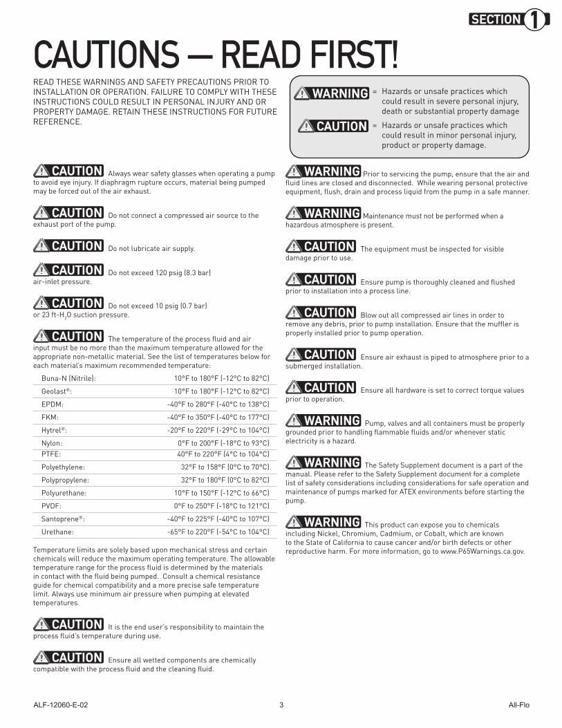
READ THESE WARNINGS AND SAFETY PRECAUTIONS PRIOR TO INSTALLATION OR OPERATION. FAILURE TO COMPLY WITH THESE INSTRUCTIONS COULD RESULT IN PERSONAL INJURY AND OR PROPERTY DAMAGE. RETAIN THESE INSTRUCTIONS FOR FUTURE REFERENCE.
CAUTION Always wear safety glasses when operating a pump to avoid eye injury. If diaphragm rupture occurs, material being pumped may be forced out of the air exhaust.
CAUTION Do not connect a compressed air source to the exhaust port of the pump.
CAUTION Do not lubricate air supply.
CAUTION Do not exceed 120 psig (8.3 bar) air-inlet pressure.
CAUTION Do not exceed 10 psig (0.7 bar) or 23 ft-H2O suction pressure.
CAUTION The temperature of the process fluid and air input must be no more than the maximum temperature allowed for the appropriate non-metallic material. See the list of temperatures below for each material’s maximum recommended temperature:
Buna-N (Nitrile): 10°F to 180°F (-12°C to 82°C)
Geolast®: 10°F to 180°F (-12°C to 82°C)
EPDM: -40°F to 280°F (-40°C to 138°C)
FKM: -40°F to 350°F (-40°C to 177°C)
Hytrel®: -20°F to 220°F (-29°C to 104°C)
Nylon: 0°F to 200°F (-18°C to 93°C)PTFE: 40°F to 220°F (4°C to 104°C)
Polyethylene: 32°F to 158°F (0°C to 70°C)
Polypropylene: 32°F to 180°F (0°C to 82°C)
Polyurethane: 10°F to 150°F (-12°C to 66°C)
PVDF: 0°F to 250°F (-18°C to 121°C)
Santoprene®: -40°F to 225°F (-40°C to 107°C)
Urethane: -65°F to 220°F (-54°C to 104°C)
Temperature limits are solely based upon mechanical stress and certain chemicals will reduce the maximum operating temperature. The allowable temperature range for the process fluid is determined by the materials in contact with the fluid being pumped. Consult a chemical resistance guide for chemical compatibility and a more precise safe temperature limit. Always use minimum air pressure when pumping at elevated temperatures.
CAUTION It is the end user’s responsibility to maintain the process fluid’s temperature during use.
CAUTION Ensure all wetted components are chemically compatible with the process fluid and the cleaning fluid.
CAUTIONS — READ FIRST!WARNING
CAUTION
= Hazards or unsafe practices which could result in severe personal injury, death or substantial property damage
= Hazards or unsafe practices which could result in minor personal injury, product or property damage.
WARNING Prior to servicing the pump, ensure that the air and fluid lines are closed and disconnected. While wearing personal protective equipment, flush, drain and process liquid from the pump in a safe manner.
WARNING Maintenance must not be performed when a hazardous atmosphere is present.
CAUTION The equipment must be inspected for visible damage prior to use.
CAUTION Ensure pump is thoroughly cleaned and flushed prior to installation into a process line.
CAUTION Blow out all compressed air lines in order to remove any debris, prior to pump installation. Ensure that the muffler is properly installed prior to pump operation.
CAUTION Ensure air exhaust is piped to atmosphere prior to a submerged installation.
CAUTION Ensure all hardware is set to correct torque values prior to operation.
WARNING Pump, valves and all containers must be properly grounded prior to handling flammable fluids and/or whenever static electricity is a hazard.
WARNING The Safety Supplement document is a part of the manual. Please refer to the Safety Supplement document for a complete list of safety considerations including considerations for safe operation and maintenance of pumps marked for ATEX environments before starting the pump.
WARNING This product can expose you to chemicals including Nickel, Chromium, Cadmium, or Cobalt, which are known to the State of California to cause cancer and/or birth defects or other reproductive harm. For more information, go to www.P65Warnings.ca.gov.
ALF-12060-E-02 All-Flo4
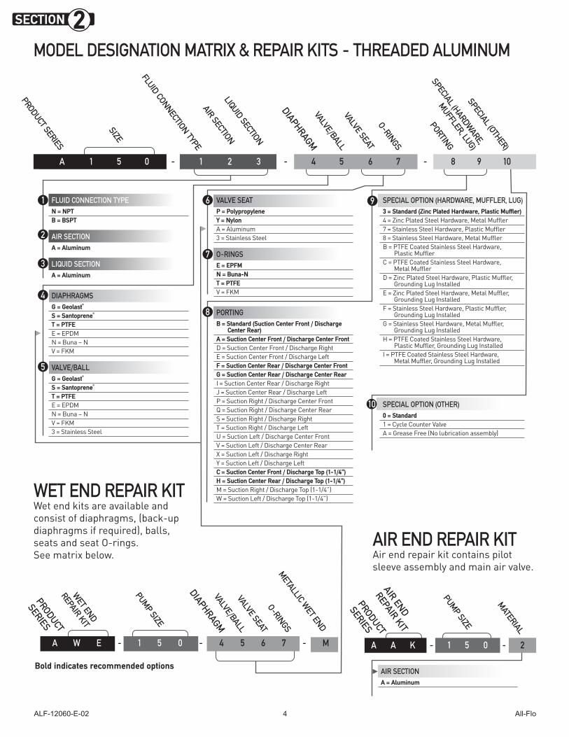
MODEL DESIGNATION MATRIX & REPAIR KITS - THREADED ALUMINUM
SECTION 2
PRODUCT SERIES
FLUID CONNECTION TYPE
LIQUID SECTION
DIAPHRAGMVALVE/BALLVALVE SEAT
O-RINGS
SPECIAL (OTHER)
PORTING
AIR SECTION
SPECIAL (HARDWARE,
MUFFLER, LUG)
A 1 5 0 - 1 2 3 - 4 5 6 7 - 8 9 10
FLUID CONNECTION TYPEN = NPTB = BSPT
AIR SECTIONA = Aluminum
LIQUID SECTIONA = Aluminum
DIAPHRAGMSG = Geolast®
S = Santoprene®
T = PTFEE = EPDM N = Buna – N V = FKM
VALVE/BALLG = Geolast®
S = Santoprene®
T = PTFEE = EPDM N = Buna – N V = FKM3 = Stainless Steel
VALVE SEATP = PolypropyleneY = NylonA = Aluminum3 = Stainless Steel
O-RINGSE = EPFMN = Buna-NT = PTFEV = FKM
PORTINGB = Standard (Suction Center Front / Discharge
Center Rear)A = Suction Center Front / Discharge Center FrontD = Suction Center Front / Discharge RightE = Suction Center Front / Discharge LeftF = Suction Center Rear / Discharge Center FrontG = Suction Center Rear / Discharge Center RearI = Suction Center Rear / Discharge RightJ = Suction Center Rear / Discharge LeftP = Suction Right / Discharge Center FrontQ = Suction Right / Discharge Center RearS = Suction Right / Discharge RightT = Suction Right / Discharge LeftU = Suction Left / Discharge Center FrontV = Suction Left / Discharge Center RearX = Suction Left / Discharge RightY = Suction Left / Discharge LeftC = Suction Center Front / Discharge Top (1-1/4”) H = Suction Center Rear / Discharge Top (1-1/4”)M = Suction Right / Discharge Top (1-1/4”)W = Suction Left / Discharge Top (1-1/4”)
SPECIAL OPTION (HARDWARE, MUFFLER, LUG)3 = Standard (Zinc Plated Hardware, Plastic Muffler)4 = Zinc Plated Steel Hardware, Metal Muffler7 = Stainless Steel Hardware, Plastic Muffler8 = Stainless Steel Hardware, Metal MufflerB = PTFE Coated Stainless Steel Hardware,
Plastic MufflerC = PTFE Coated Stainless Steel Hardware,
Metal MufflerD = Zinc Plated Steel Hardware, Plastic Muffler,
Grounding Lug InstalledE = Zinc Plated Steel Hardware, Metal Muffler,
Grounding Lug InstalledF = Stainless Steel Hardware, Plastic Muffler,
Grounding Lug InstalledG = Stainless Steel Hardware, Metal Muffler,
Grounding Lug InstalledH = PTFE Coated Stainless Steel Hardware,
Plastic Muffler, Grounding Lug InstalledI = PTFE Coated Stainless Steel Hardware,
Metal Muffler, Grounding Lug Installed
SPECIAL OPTION (OTHER)0 = Standard1 = Cycle Counter ValveA = Grease Free (No lubrication assembly)
SIZE
1
2
6
7
9
10
AIR SECTIONA = Aluminum
AIR END REPAIR KITAir end repair kit contains pilot sleeve assembly and main air valve.
MATERIAL
A A K - 1 5 0 - 2
PRODUCT
SERIES
PUMP SIZE
AIR END
REPAIR KIT
3
4
5
8
Bold indicates recommended options
WET END REPAIR KIT Wet end kits are available and consist of diaphragms, (back-up diaphragms if required), balls, seats and seat O-rings. See matrix below.
DIAPHRAGMVALVE/BALLVALVE SEAT
O-RINGS
PRODUCT
SERIES
WET END
REPAIR KIT
PUMP SIZE
METALLIC WET END
A W E - 1 5 0 - 4 5 6 7 - M
ALF-12060-E-02 All-Flo5
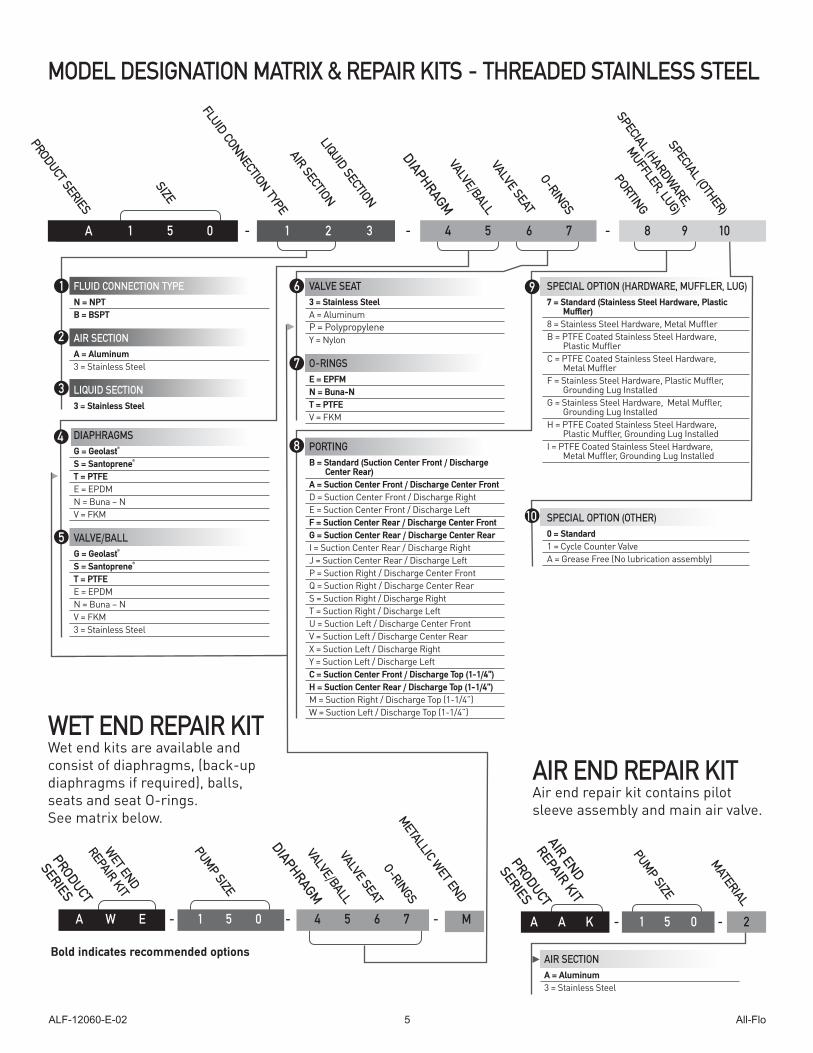
MODEL DESIGNATION MATRIX & REPAIR KITS - THREADED STAINLESS STEEL
PRODUCT SERIES
FLUID CONNECTION TYPE
LIQUID SECTION
DIAPHRAGMVALVE/BALLVALVE SEAT
O-RINGS
SPECIAL (OTHER)
PORTING
AIR SECTION
SPECIAL (HARDWARE,
MUFFLER, LUG)
A 1 5 0 - 1 2 3 - 4 5 6 7 - 8 9 10
FLUID CONNECTION TYPEN = NPTB = BSPT
AIR SECTIONA = Aluminum3 = Stainless Steel
LIQUID SECTION3 = Stainless Steel
DIAPHRAGMSG = Geolast®
S = Santoprene®
T = PTFEE = EPDM N = Buna – N V = FKM
VALVE/BALLG = Geolast®
S = Santoprene®
T = PTFEE = EPDM N = Buna – N V = FKM3 = Stainless Steel
VALVE SEAT3 = Stainless SteelA = AluminumP = PolypropyleneY = Nylon
O-RINGSE = EPFMN = Buna-NT = PTFEV = FKM
PORTINGB = Standard (Suction Center Front / Discharge
Center Rear)A = Suction Center Front / Discharge Center FrontD = Suction Center Front / Discharge RightE = Suction Center Front / Discharge LeftF = Suction Center Rear / Discharge Center FrontG = Suction Center Rear / Discharge Center RearI = Suction Center Rear / Discharge RightJ = Suction Center Rear / Discharge LeftP = Suction Right / Discharge Center FrontQ = Suction Right / Discharge Center RearS = Suction Right / Discharge RightT = Suction Right / Discharge LeftU = Suction Left / Discharge Center FrontV = Suction Left / Discharge Center RearX = Suction Left / Discharge RightY = Suction Left / Discharge LeftC = Suction Center Front / Discharge Top (1-1/4”) H = Suction Center Rear / Discharge Top (1-1/4”)M = Suction Right / Discharge Top (1-1/4”)W = Suction Left / Discharge Top (1-1/4”)
SPECIAL OPTION (HARDWARE, MUFFLER, LUG)7 = Standard (Stainless Steel Hardware, Plastic
Muffler)8 = Stainless Steel Hardware, Metal MufflerB = PTFE Coated Stainless Steel Hardware,
Plastic MufflerC = PTFE Coated Stainless Steel Hardware,
Metal MufflerF = Stainless Steel Hardware, Plastic Muffler,
Grounding Lug InstalledG = Stainless Steel Hardware, Metal Muffler,
Grounding Lug InstalledH = PTFE Coated Stainless Steel Hardware,
Plastic Muffler, Grounding Lug InstalledI = PTFE Coated Stainless Steel Hardware,
Metal Muffler, Grounding Lug Installed
SPECIAL OPTION (OTHER)0 = Standard1 = Cycle Counter ValveA = Grease Free (No lubrication assembly)
SIZE
1
2
6
7
9
10
AIR SECTIONA = Aluminum3 = Stainless Steel
AIR END REPAIR KITAir end repair kit contains pilot sleeve assembly and main air valve.
MATERIAL
A A K - 1 5 0 - 2
PRODUCT
SERIES
PUMP SIZE
AIR END
REPAIR KIT
3
4
5
8
WET END REPAIR KIT Wet end kits are available and consist of diaphragms, (back-up diaphragms if required), balls, seats and seat O-rings. See matrix below.
PRODUCT
SERIES
WET END
REPAIR KIT
METALLIC WET END
Bold indicates recommended options
DIAPHRAGMVALVE/BALLVALVE SEAT
O-RINGS
PUMP SIZE
A W E - 1 5 0 - 4 5 6 7 - M
ALF-12060-E-02 All-Flo6
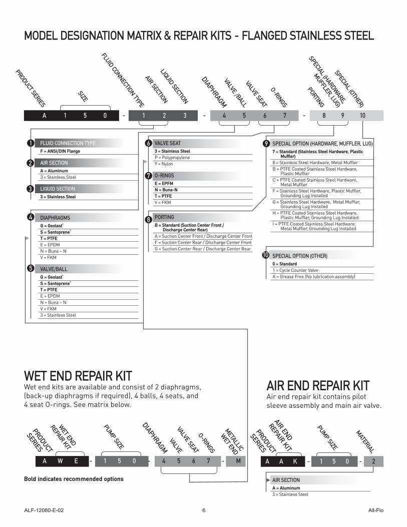
MODEL DESIGNATION MATRIX & REPAIR KITS - FLANGED STAINLESS STEEL
PRODUCT SERIES
FLUID CONNECTION TYPE
LIQUID SECTION
DIAPHRAGMVALVE /BALLVALVE SEAT
O-RINGS
SPECIAL (OTHER)
PORTING
AIR SECTION
SPECIAL (HARDWARE,
MUFFLER, LUG)
A 1 5 0 - 1 2 3 - 4 5 6 7 - 8 9 10
FLUID CONNECTION TYPEF = ANSI/DIN Flange
AIR SECTIONA = Aluminum3 = Stainless Steel
LIQUID SECTION3 = Stainless Steel
DIAPHRAGMSG = Geolast®
S = Santoprene®
T = PTFEE = EPDM N = Buna – N V = FKM
VALVE/BALLG = Geolast®
S = Santoprene®
T = PTFEE = EPDM N = Buna – N V = FKM3 = Stainless Steel
VALVE SEAT3 = Stainless SteelP = PolypropyleneY = Nylon
O-RINGSE = EPFMN = Buna-NT = PTFEV = FKM
PORTINGB = Standard (Suction Center Front /
Discharge Center Rear)A = Suction Center Front / Discharge Center FrontF = Suction Center Rear / Discharge Center FrontG = Suction Center Rear / Discharge Center Rear
SIZE
WET END REPAIR KIT Wet end kits are available and consist of 2 diaphragms, (back-up diaphragms if required), 4 balls, 4 seats, and 4 seat O-rings. See matrix below.
1
2
6
7
9
10
AIR SECTIONA = Aluminum3 = Stainless Steel
Bold indicates recommended options
AIR END REPAIR KITAir end repair kit contains pilot sleeve assembly and main air valve.
DIAPHRAGM
O-RINGS
PRODUCT
SERIES
WET END
REPAIR KIT
PUMP SIZE
MATERIAL
A A K - 1 5 0 - 2
PRODUCT
SERIES
PUMP SIZE
AIR END
REPAIR KIT
3
4
5
VALVEVALVE SEAT
8
SPECIAL OPTION (HARDWARE, MUFFLER, LUG)7 = Standard (Stainless Steel Hardware, Plastic
Muffler)8 = Stainless Steel Hardware, Metal MufflerB = PTFE Coated Stainless Steel Hardware,
Plastic MufflerC = PTFE Coated Stainless Steel Hardware,
Metal MufflerF = Stainless Steel Hardware, Plastic Muffler,
Grounding Lug InstalledG = Stainless Steel Hardware, Metal Muffler,
Grounding Lug InstalledH = PTFE Coated Stainless Steel Hardware,
Plastic Muffler, Grounding Lug InstalledI = PTFE Coated Stainless Steel Hardware,
Metal Muffler, Grounding Lug Installed
SPECIAL OPTION (OTHER)0 = Standard1 = Cycle Counter ValveA = Grease Free (No lubrication assembly)
METALLIC
WET END
A W E - 1 5 0 - 4 5 6 7 - M
ALF-12060-E-02 All-Flo7
SECTION 3
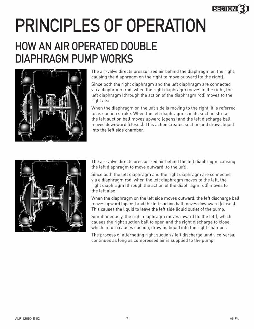
PRINCIPLES OF OPERATIONHOW AN AIR OPERATED DOUBLE DIAPHRAGM PUMP WORKS
The air-valve directs pressurized air behind the diaphragm on the right, causing the diaphragm on the right to move outward (to the right).
Since both the right diaphragm and the left diaphragm are connected via a diaphragm rod, when the right diaphragm moves to the right, the left diaphragm (through the action of the diaphragm rod) moves to the right also.
When the diaphragm on the left side is moving to the right, it is referred to as suction stroke. When the left diaphragm is in its suction stroke, the left suction ball moves upward (opens) and the left discharge ball moves downward (closes). This action creates suction and draws liquid into the left side chamber.
The air-valve directs pressurized air behind the left diaphragm, causing the left diaphragm to move outward (to the left).
Since both the left diaphragm and the right diaphragm are connected via a diaphragm rod, when the left diaphragm moves to the left, the right diaphragm (through the action of the diaphragm rod) moves to the left also.
When the diaphragm on the left side moves outward, the left discharge ball moves upward (opens) and the left suction ball moves downward (closes). This causes the liquid to leave the left side liquid outlet of the pump.
Simultaneously, the right diaphragm moves inward (to the left), which causes the right suction ball to open and the right discharge to close, which in turn causes suction, drawing liquid into the right chamber.
The process of alternating right suction / left discharge (and vice-versa) continues as long as compressed air is supplied to the pump.
ALF-12060-E-02 All-Flo8
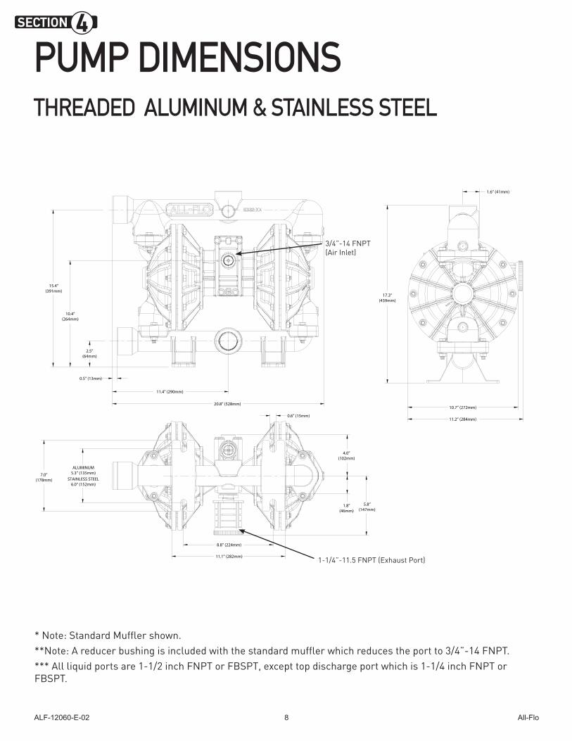
PUMP DIMENSIONS THREADED ALUMINUM & STAINLESS STEEL
* Note: Standard Muffler shown.**Note: A reducer bushing is included with the standard muffler which reduces the port to 3/4”-14 FNPT. *** All liquid ports are 1-1/2 inch FNPT or FBSPT, except top discharge port which is 1-1/4 inch FNPT or FBSPT.
20.8” (528mm)
2.5”(64mm)
10.4”(264mm)
15.4”(391mm)
0.6” (15mm)
7.0”(178mm)
11.1” (282mm)
8.8” (224mm)
ALUMINUM5.3” (135mm)
STAINLESS STEEL6.0” (152mm)
4.0”(102mm)
1.8”(46mm)
5.8”(147mm)
10.7” (272mm)
11.2” (284mm)
17.3”(439mm)
1.6” (41mm)
0.5” (13mm)
11.4” (290mm)
20.8” (528mm)
2.5”(64mm)
10.4”(264mm)
15.4”(391mm)
0.6” (15mm)
7.0”(178mm)
11.1” (282mm)
8.8” (224mm)
ALUMINUM5.3” (135mm)
STAINLESS STEEL6.0” (152mm)
4.0”(102mm)
1.8”(46mm)
5.8”(147mm)
10.7” (272mm)
11.2” (284mm)
17.3”(439mm)
1.6” (41mm)
0.5” (13mm)
11.4” (290mm)
SECTION 4
1-1/4”-11.5 FNPT (Exhaust Port)
3/4”-14 FNPT (Air Inlet)
ALF-12060-E-02 All-Flo9
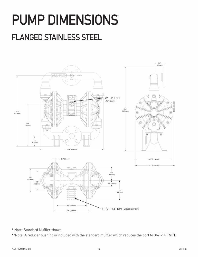
PUMP DIMENSIONS FLANGED STAINLESS STEEL
* Note: Standard Muffler shown. **Note: A reducer bushing is included with the standard muffler which reduces the port to 3/4”-14 FNPT.
8.8” (224mm)
6.0”(152mm)
7.0”(178mm)
10.6” (269mm)
3.1”(79mm)
12.6”(320mm)
20.9”(531mm)
18.8” (478mm)
3.2”(81mm)
23.9”(607mm)
10.7” (272mm)
11.2” (284mm)
1.8” (46mm)
5.8”(147mm)
4.0”(102mm)
0.6” (15mm)
8.8” (224mm)
6.0”(152mm)
7.0”(178mm)
10.6” (269mm)
3.1”(79mm)
12.6”(320mm)
20.9”(531mm)
18.8” (478mm)
3.2”(81mm)
23.9”(607mm)
10.7” (272mm)
11.2” (284mm)
1.8” (46mm)
5.8”(147mm)
4.0”(102mm)
0.6” (15mm)
1-1/4”-11.5 FNPT (Exhaust Port)
3/4”-14 FNPT (Air Inlet)
ALF-12060-E-02 All-Flo10
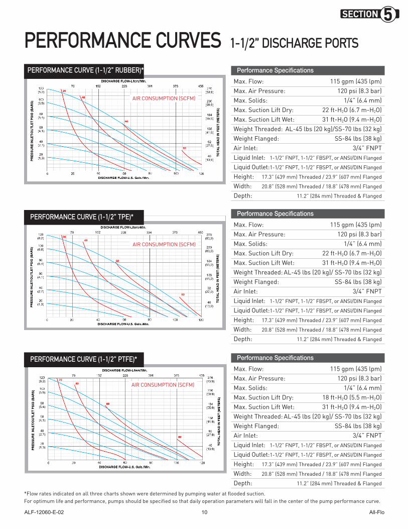
PERFORMANCE CURVES 1-1/2” DISCHARGE PORTS
PERFORMANCE CURVE (1-1/2” RUBBER)*
PERFORMANCE CURVE (1-1/2” TPE)*
PERFORMANCE CURVE (1-1/2” PTFE)*
*Flow rates indicated on all three charts shown were determined by pumping water at flooded suction.For optimum life and performance, pumps should be specified so that daily operation parameters will fall in the center of the pump performance curve.
Performance Specifications
Max. Flow: 115 gpm (435 lpm)Max. Air Pressure: 120 psi (8.3 bar)Max. Solids: 1/4” (6.4 mm)Max. Suction Lift Dry: 18 ft-H2O (5.5 m-H2O)Max. Suction Lift Wet: 31 ft-H2O (9.4 m-H2O)Weight Threaded: AL-45 lbs (20 kg)/ SS-70 lbs (32 kg)Weight Flanged: SS-84 lbs (38 kg)Air Inlet: 3/4” FNPTLiquid Inlet: 1-1/2” FNPT, 1-1/2” FBSPT, or ANSI/DIN Flanged
Liquid Outlet: 1-1/2” FNPT, 1-1/2” FBSPT, or ANSI/DIN Flanged
Height: 17.3” (439 mm) Threaded / 23.9” (607 mm) Flanged
Width: 20.8” (528 mm) Threaded / 18.8” (478 mm) Flanged
Depth: 11.2” (284 mm) Threaded & Flanged
Performance Specifications
Max. Flow: 115 gpm (435 lpm)Max. Air Pressure: 120 psi (8.3 bar)Max. Solids: 1/4” (6.4 mm)Max. Suction Lift Dry: 22 ft-H2O (6.7 m-H2O)Max. Suction Lift Wet: 31 ft-H2O (9.4 m-H2O)Weight Threaded: AL-45 lbs (20 kg)/SS-70 lbs (32 kg)Weight Flanged: SS-84 lbs (38 kg)Air Inlet: 3/4” FNPTLiquid Inlet: 1-1/2” FNPT, 1-1/2” FBSPT, or ANSI/DIN Flanged
Liquid Outlet: 1-1/2” FNPT, 1-1/2” FBSPT, or ANSI/DIN Flanged
Height: 17.3” (439 mm) Threaded / 23.9” (607 mm) Flanged
Width: 20.8” (528 mm) Threaded / 18.8” (478 mm) Flanged
Depth: 11.2” (284 mm) Threaded & Flanged
Performance Specifications
Max. Flow: 115 gpm (435 lpm)Max. Air Pressure: 120 psi (8.3 bar)Max. Solids: 1/4” (6.4 mm)Max. Suction Lift Dry: 22 ft-H2O (6.7 m-H2O)Max. Suction Lift Wet: 31 ft-H2O (9.4 m-H2O)Weight Threaded: AL-45 lbs (20 kg)/ SS-70 lbs (32 kg)Weight Flanged: SS-84 lbs (38 kg)Air Inlet: 3/4” FNPTLiquid Inlet: 1-1/2” FNPT, 1-1/2” FBSPT, or ANSI/DIN Flanged
Liquid Outlet: 1-1/2” FNPT, 1-1/2” FBSPT, or ANSI/DIN Flanged
Height: 17.3” (439 mm) Threaded / 23.9” (607 mm) Flanged
Width: 20.8” (528 mm) Threaded / 18.8” (478 mm) Flanged
Depth: 11.2” (284 mm) Threaded & Flanged
AIR CONSUMPTION (SCFM)
AIR CONSUMPTION (SCFM)
AIR CONSUMPTION (SCFM)
SECTION 5
ALF-12060-E-02 All-Flo11
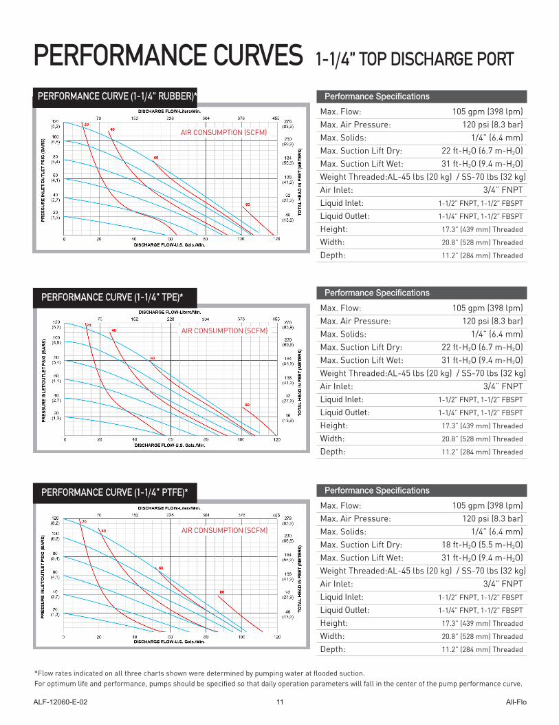
PERFORMANCE CURVES 1-1/4” TOP DISCHARGE PORT
PERFORMANCE CURVE (1-1/4” RUBBER)*
PERFORMANCE CURVE (1-1/4” TPE)*
PERFORMANCE CURVE (1-1/4” PTFE)*
*Flow rates indicated on all three charts shown were determined by pumping water at flooded suction.For optimum life and performance, pumps should be specified so that daily operation parameters will fall in the center of the pump performance curve.
Performance Specifications
Max. Flow: 105 gpm (398 lpm)Max. Air Pressure: 120 psi (8.3 bar)Max. Solids: 1/4” (6.4 mm)Max. Suction Lift Dry: 18 ft-H2O (5.5 m-H2O)Max. Suction Lift Wet: 31 ft-H2O (9.4 m-H2O)Weight Threaded: AL-45 lbs (20 kg) / SS-70 lbs (32 kg)Air Inlet: 3/4” FNPTLiquid Inlet: 1-1/2” FNPT, 1-1/2” FBSPT
Liquid Outlet: 1-1/4” FNPT, 1-1/2” FBSPT
Height: 17.3” (439 mm) Threaded
Width: 20.8” (528 mm) Threaded
Depth: 11.2” (284 mm) Threaded
Performance Specifications
Max. Flow: 105 gpm (398 lpm)Max. Air Pressure: 120 psi (8.3 bar)Max. Solids: 1/4” (6.4 mm)Max. Suction Lift Dry: 22 ft-H2O (6.7 m-H2O)Max. Suction Lift Wet: 31 ft-H2O (9.4 m-H2O)Weight Threaded: AL-45 lbs (20 kg) / SS-70 lbs (32 kg)Air Inlet: 3/4” FNPTLiquid Inlet: 1-1/2” FNPT, 1-1/2” FBSPT
Liquid Outlet: 1-1/4” FNPT, 1-1/2” FBSPT
Height: 17.3” (439 mm) Threaded
Width: 20.8” (528 mm) Threaded
Depth: 11.2” (284 mm) Threaded
AIR CONSUMPTION (SCFM)
AIR CONSUMPTION (SCFM)
AIR CONSUMPTION (SCFM)
ALF-12060-E-02 All-Flo12
SECTION 6
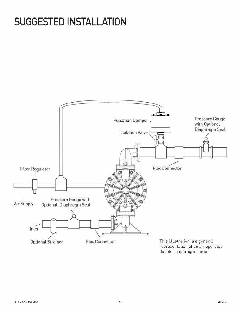
INSTALLATION, TROUBLESHOOTING AND MAINTENANCE INSTALLATIONPIPINGWhenever possible ensure the pump is installed using the shortest possible pipe lengths with the minimum amount of pipe fittings. Ensure all piping is supported independent of the pump.Suction and discharge piping should not be smaller than the connection size of the pump. When pumping liquids of high viscosity, larger piping may be used, in order to reduce frictional pipe loss.Employ flexible hoses in order to eliminate the vibration caused by the pump. Mounting feet can also be used to reduce vibration effects. All hoses should be reinforced, non-collapsible and be capable of high vacuum service. Ensure that all piping and hoses are chemically compatible with the process and cleaning fluid.For processes where pulsation effects should be reduced, employ a pulsation dampener on the discharge side of the pump. For self-priming applications, ensure all connections are airtight and the application is within the pumps dry-lift capability. Refer to product specifications for further details.For flooded suction applications, install a gate valve on the suction piping in order to facilitate service. For unattended flooded suction operation, it is recommended to pipe the exhaust air above the liquid source. In the event of a diaphragm failure this will reduce or eliminate the possibility of liquid discharging through the exhaust onto the ground.
LOCATIONEnsure that the pump is installed in an accessible location, in order to facilitate future service and maintenance.
AIREnsure that the air supply is sufficient for the volume of air required by the pump. Refer to product specifications for further details. For reliable operation, install a 5 micron air filter, air-valve and pressure regulator. Do not exceed the pumps maximum operating pressure of 120 psig.
REMOTE OPERATION Utilize a three way solenoid valve for remote operation. This ensures that air between the solenoid and the pump is allowed to “bleed off,” ensuring reliable operation. Liquid transfer volume is estimated by multiplying displacement per stroke times the number of strokes per minute
NOISECorrect installation of the muffler reduces sound levels. Refer to product specifications for further details.
SUBMERGED OPERATIONFor submersible operation, pipe the air exhaust to atmosphere
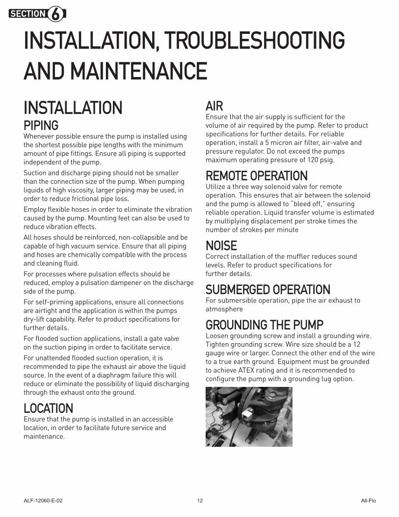
GROUNDING THE PUMPLoosen grounding screw and install a grounding wire. Tighten grounding screw. Wire size should be a 12 gauge wire or larger. Connect the other end of the wire to a true earth ground. Equipment must be grounded to achieve ATEX rating and it is recommended to configure the pump with a grounding lug option.
ALF-12060-E-02 All-Flo13
SUGGESTED INSTALLATION
This illustration is a generic representation of an air operated double-diaphragm pump.
ALF-12060-E-02 All-Flo14
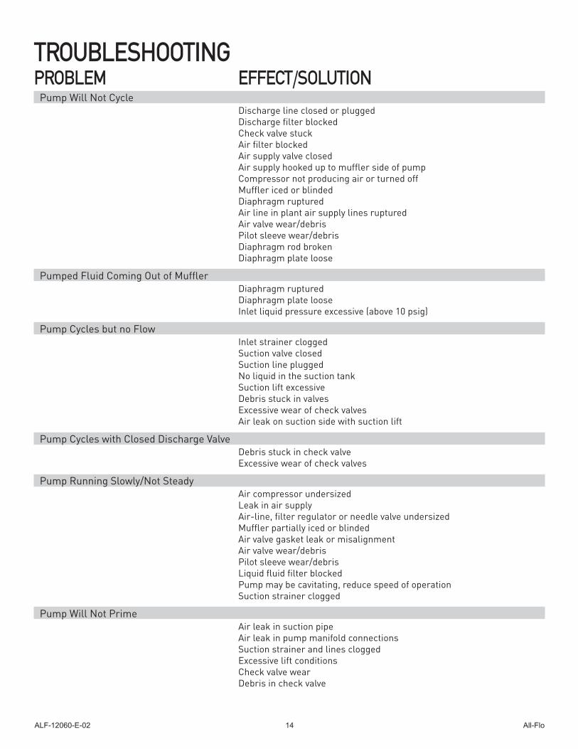
TROUBLESHOOTINGPROBLEM EFFECT/SOLUTION
Pump Will Not Cycle Discharge line closed or plugged Discharge filter blocked Check valve stuck Air filter blocked Air supply valve closed Air supply hooked up to muffler side of pump Compressor not producing air or turned off Muffler iced or blinded Diaphragm ruptured Air line in plant air supply lines ruptured Air valve wear/debris Pilot sleeve wear/debris Diaphragm rod broken Diaphragm plate loose
Pumped Fluid Coming Out of Muffler Diaphragm ruptured Diaphragm plate loose Inlet liquid pressure excessive (above 10 psig)
Pump Cycles but no Flow Inlet strainer clogged Suction valve closed Suction line plugged No liquid in the suction tank Suction lift excessive Debris stuck in valves Excessive wear of check valves Air leak on suction side with suction lift
Pump Cycles with Closed Discharge Valve Debris stuck in check valve Excessive wear of check valves
Pump Running Slowly/Not Steady Air compressor undersized Leak in air supply Air-line, filter regulator or needle valve undersized Muffler partially iced or blinded Air valve gasket leak or misalignment Air valve wear/debris Pilot sleeve wear/debris Liquid fluid filter blocked Pump may be cavitating, reduce speed of operation Suction strainer clogged
Pump Will Not Prime Air leak in suction pipe Air leak in pump manifold connections Suction strainer and lines clogged Excessive lift conditions Check valve wear Debris in check valve
ALF-12060-E-02 All-Flo15
OPERATION The Air-Operated Double Diaphragm Pump requires a minimum of 20 psig of air to operate, with some variation according to diaphragm material. Increasing the air pressure results in a more rapid cycling of the pump and thus a higher liquid flow rate. In order to not exceed 120 psig of inlet air pressure, and for accurate control of the pump, it is suggested to use a pressure regulator on the air inlet. An alternate means of controlling the flow-rate of the pump is to use an inlet air valve and partially open or close accordingly. When the air valve is completely in the closed position, the pump will cease to operate. A third method of controlling the flow rate of the pump is to use a liquid discharge valve. Closing the liquid discharge valve will cause a decrease in the flow rate since the pump will operate against a higher discharge pressure.Solenoid control of the inlet air may also be used in order to facilitate remote operation. A three way solenoid valve is recommended, in order to allow the air to “bleed off” between the solenoid and the pump. Do not use valves for flow control on the suction side of the pump. (Closing or partially closing a liquid suction valve restrict the suction line and may cause damage to the diaphragms.) Suction strainers may be employed to reduce or eliminate larger solids, but routine maintenance is necessary in order to prevent a restriction on the suction.
MAINTENANCEDue to the unique nature of each application, periodic inspection of the pump is the best method to determine a proper maintenance schedule. A record should be kept of all repairs made to an installed pump. This will serve as the best predictor of future maintenance.Typical maintenance involves replacing of “wear-parts” such as the diaphragms, balls, valve seats and O-rings. Proper maintenance can ensure trouble-free operation of the pump. Refer to repair and assembly instructions for further details.
WARNING Maintenance must not be performed when a hazardous atmosphere is present.
MAINTENANCE SCHEDULE WEEKLY (OR DAILY) Make a visual check of the pump. If pumped fluid is leaking out of the pump, pipe fittings or muffler turn off pump and schedule maintenance.
EVERY THREE MONTHSInspect fasteners and tighten any loose fasteners to recommended torque settings.Schedule pump service based on pump’s service history.
ALF-12060-E-02 All-Flo16
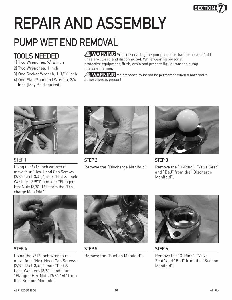
REPAIR AND ASSEMBLYPUMP WET END REMOVAL
STEP 1 Using the 9/16 inch wrench re-move four “Hex-Head Cap Screws (3/8”-16x1-3/4”)”, four “Flat & Lock Washers (3/8”)” and four “Flanged Hex Nuts (3/8”-16)” from the “Dis-charge Manifold”.
STEP 2 Remove the “Discharge Manifold”.
STEP 3 Remove the “O-Ring”, “Valve Seat” and “Ball” from the “Discharge Manifold”.
TOOLS NEEDED1) Two Wrenches, 9/16 Inch2) Two Wrenches, 1 Inch3) One Socket Wrench, 1-1/16 Inch4) One Flat (Spanner) Wrench, 3/4 Inch (May Be Required)
WARNING Prior to servicing the pump, ensure that the air and fluid lines are closed and disconnected. While wearing personal protective equipment, flush, drain and process liquid from the pump in a safe manner.
WARNING Maintenance must not be performed when a hazardous atmosphere is present.
STEP 4 Using the 9/16 inch wrench re-move four “Hex-Head Cap Screws (3/8”-16x1-3/4”)”, four “Flat & Lock Washers (3/8”)” and four “Flanged Hex Nuts (3/8”-16)” from the “Suction Manifold”.
STEP 5 Remove the “Suction Manifold”.
STEP 6 Remove the “O-Ring”, “Valve Seat” and “Ball” from the “Suction Manifold”.
SECTION 7
ALF-12060-E-02 All-Flo17
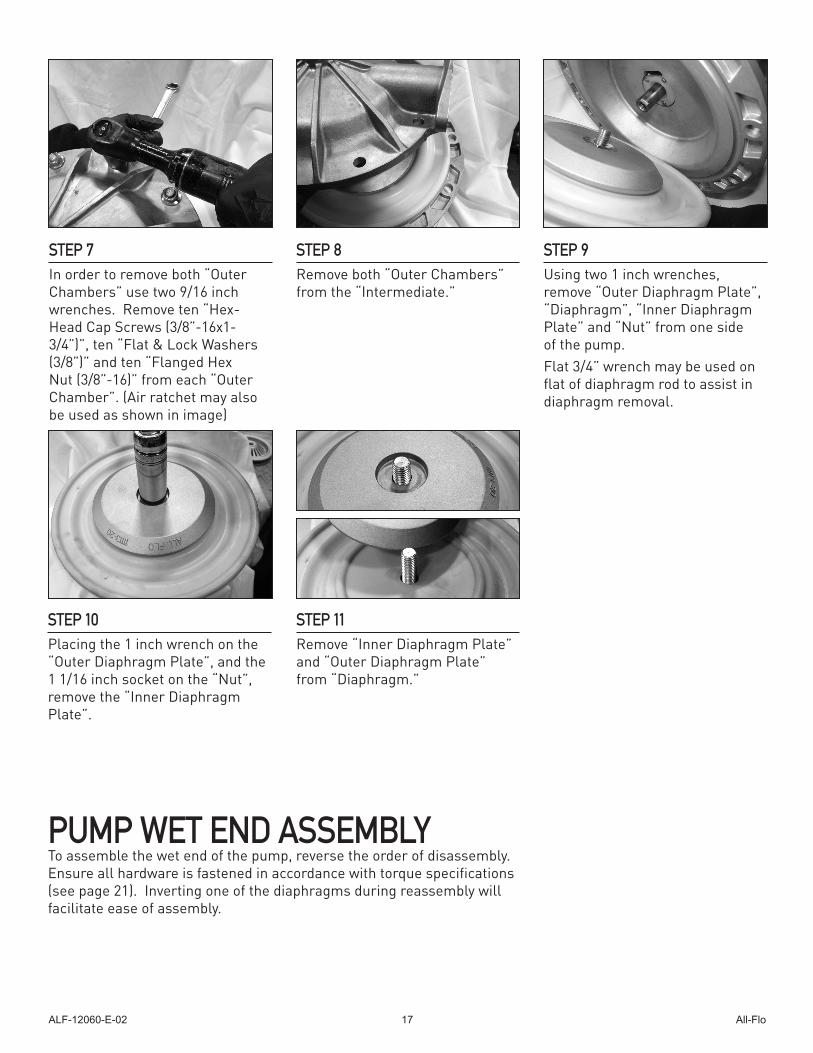
STEP 7In order to remove both “Outer Chambers” use two 9/16 inch wrenches. Remove ten “Hex-Head Cap Screws (3/8”-16x1-3/4”)”, ten “Flat & Lock Washers (3/8”)” and ten “Flanged Hex Nut (3/8”-16)” from each “Outer Chamber”. (Air ratchet may also be used as shown in image)
STEP 8 Remove both “Outer Chambers” from the “Intermediate.”
STEP 9 Using two 1 inch wrenches, remove “Outer Diaphragm Plate”, “Diaphragm”, “Inner Diaphragm Plate” and “Nut” from one side of the pump.Flat 3/4” wrench may be used on flat of diaphragm rod to assist in diaphragm removal.
STEP 10Placing the 1 inch wrench on the “Outer Diaphragm Plate”, and the 1 1/16 inch socket on the “Nut”, remove the “Inner Diaphragm Plate”.
STEP 11 Remove “Inner Diaphragm Plate” and “Outer Diaphragm Plate” from “Diaphragm.”
PUMP WET END ASSEMBLYTo assemble the wet end of the pump, reverse the order of disassembly. Ensure all hardware is fastened in accordance with torque specifications (see page 21). Inverting one of the diaphragms during reassembly will facilitate ease of assembly.
ALF-12060-E-02 All-Flo18
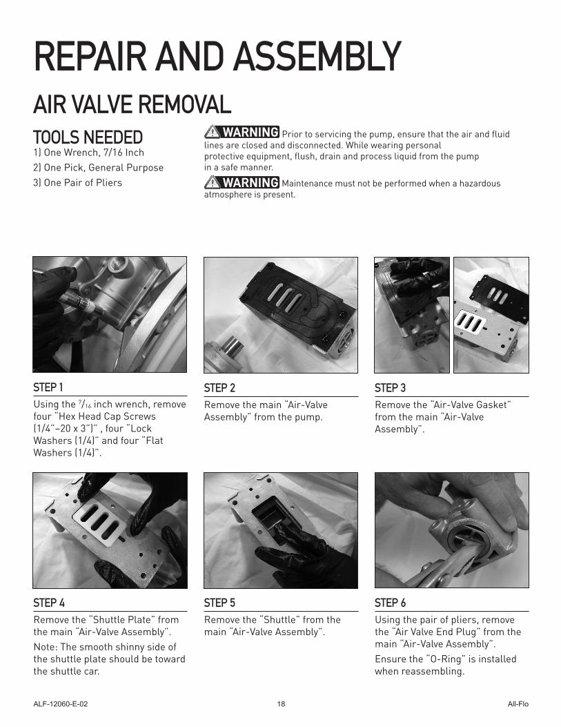
AIR VALVE REMOVAL
STEP 1 Using the 7/16 inch wrench, remove four “Hex Head Cap Screws (1/4”–20 x 3”)” , four “Lock Washers (1/4)” and four “Flat Washers (1/4)”.
STEP 2 Remove the main “Air-Valve Assembly” from the pump.
STEP 3 Remove the “Air-Valve Gasket” from the main “Air-Valve Assembly”.
TOOLS NEEDED1) One Wrench, 7/16 Inch2) One Pick, General Purpose3) One Pair of Pliers
WARNING Prior to servicing the pump, ensure that the air and fluid lines are closed and disconnected. While wearing personal protective equipment, flush, drain and process liquid from the pump in a safe manner.
WARNING Maintenance must not be performed when a hazardous atmosphere is present.
STEP 4 Remove the “Shuttle Plate” from the main “Air-Valve Assembly”.Note: The smooth shinny side of the shuttle plate should be toward the shuttle car.
STEP 5 Remove the “Shuttle” from the main “Air-Valve Assembly”.
STEP 6 Using the pair of pliers, remove the “Air Valve End Plug” from the main “Air-Valve Assembly”.Ensure the “O-Ring” is installed when reassembling.
REPAIR AND ASSEMBLY
ALF-12060-E-02 All-Flo19
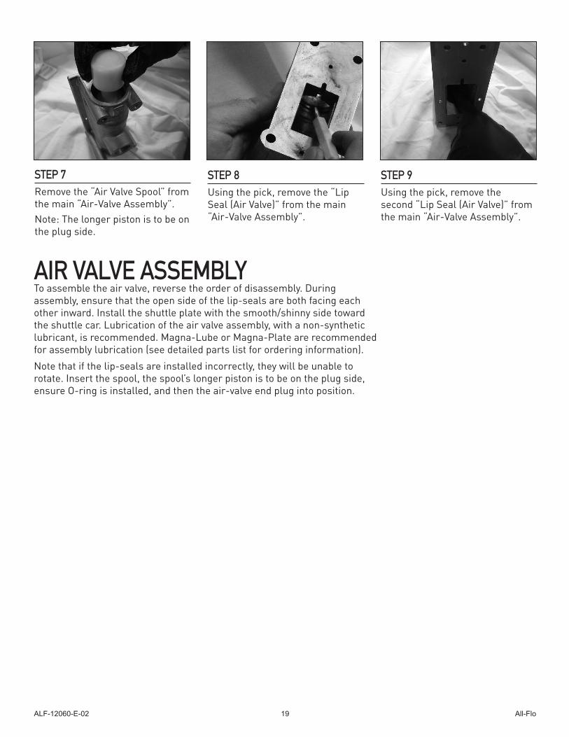
STEP 7 Remove the “Air Valve Spool” from the main “Air-Valve Assembly”.Note: The longer piston is to be on the plug side.
STEP 8 Using the pick, remove the “Lip Seal (Air Valve)” from the main “Air-Valve Assembly”.
STEP 9 Using the pick, remove the second “Lip Seal (Air Valve)” from the main “Air-Valve Assembly”.
AIR VALVE ASSEMBLYTo assemble the air valve, reverse the order of disassembly. During assembly, ensure that the open side of the lip-seals are both facing each other inward. Install the shuttle plate with the smooth/shinny side toward the shuttle car. Lubrication of the air valve assembly, with a non-synthetic lubricant, is recommended. Magna-Lube or Magna-Plate are recommended for assembly lubrication (see detailed parts list for ordering information).
Note that if the lip-seals are installed incorrectly, they will be unable to rotate. Insert the spool, the spool’s longer piston is to be on the plug side, ensure O-ring is installed, and then the air-valve end plug into position.
ALF-12060-E-02 All-Flo20
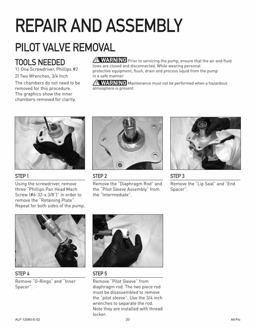
PILOT VALVE REMOVAL
STEP 1 Using the screwdriver, remove three “Phillips Pan Head Mach Screw (#6-32-x 3/8”)” in order to remove the “Retaining Plate”. Repeat for both sides of the pump.
STEP 2Remove the “Diaphragm Rod” and the “Pilot Sleeve Assembly” from the “Intermediate”.
TOOLS NEEDED1) One Screwdriver, Phillips #22) Two Wrenches, 3/4 InchThe chambers do not need to be removed for this procedure. The graphics show the inner chambers removed for clarity.
WARNING Prior to servicing the pump, ensure that the air and fluid lines are closed and disconnected. While wearing personal protective equipment, flush, drain and process liquid from the pump in a safe manner.
WARNING Maintenance must not be performed when a hazardous atmosphere is present.
STEP 3Remove the “Lip Seal” and “End Spacer”.
STEP 4Remove “O-Rings” and “Inner Spacer”.
REPAIR AND ASSEMBLY
STEP 5Remove “Pilot Sleeve” from diaphragm rod. The two piece rod must be disassembled to remove the “pilot sleeve”. Use the 3/4 inch wrenches to separate the rod. Note they are installed with thread locker.
ALF-12060-E-02 All-Flo21
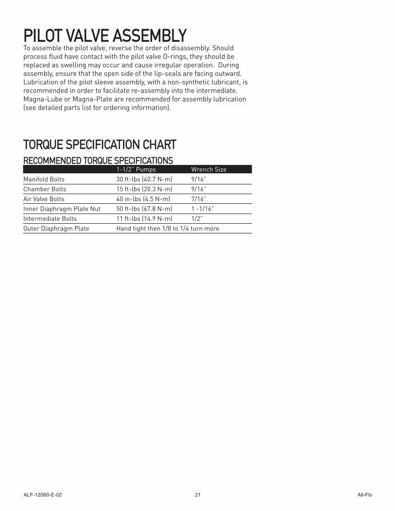
PILOT VALVE ASSEMBLYTo assemble the pilot valve, reverse the order of disassembly. Should process fluid have contact with the pilot valve O-rings, they should be replaced as swelling may occur and cause irregular operation. During assembly, ensure that the open side of the lip-seals are facing outward. Lubrication of the pilot sleeve assembly, with a non-synthetic lubricant, is recommended in order to facilitate re-assembly into the intermediate. Magna-Lube or Magna-Plate are recommended for assembly lubrication (see detailed parts list for ordering information).
TORQUE SPECIFICATION CHARTRECOMMENDED TORQUE SPECIFICATIONS 1-1/2” Pumps Wrench SizeManifold Bolts 30 ft-lbs (40.7 N-m) 9/16”Chamber Bolts 15 ft-lbs (20.3 N-m) 9/16”Air Valve Bolts 40 in-lbs (4.5 N-m) 7/16”Inner Diaphragm Plate Nut 50 ft-lbs (67.8 N-m) 1 -1/16”Intermediate Bolts 11 ft-lbs (14.9 N-m) 1/2”Outer Diaphragm Plate Hand tight then 1/8 to 1/4 turn more
ALF-12060-E-02 All-Flo22
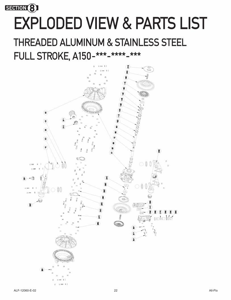
EXPLODED VIEW & PARTS LISTTHREADED ALUMINUM & STAINLESS STEEL FULL STROKE, A150-***-****-***
SECTION 8
ALF-12060-E-02 All-Flo23
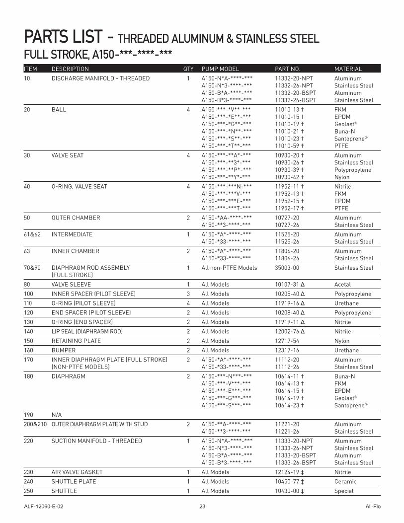
PARTS LIST - THREADED ALUMINUM & STAINLESS STEEL FULL STROKE, A150-***-****-***ITEM DESCRIPTION QTY PUMP MODEL PART NO. MATERIAL10 DISCHARGE MANIFOLD - THREADED 1 A150-N*A-****-*** 11332-20-NPT Aluminum A150-N*3-****-*** 11332-26-NPT Stainless Steel A150-B*A-****-*** 11332-20-BSPT Aluminum A150-B*3-****-*** 11332-26-BSPT Stainless Steel20 BALL 4 A150-***-*V**-*** 11010-13 † FKM A150-***-*E**-*** 11010-15 † EPDM A150-***-*G**-*** 11010-19 † Geolast®
A150-***-*N**-*** 11010-21 † Buna-N A150-***-*S**-*** 11010-23 † Santoprene® A150-***-*T**-*** 11010-59 † PTFE30 VALVE SEAT 4 A150-***-**A*-*** 10930-20 † Aluminum A150-***-**3*-*** 10930-26 † Stainless Steel A150-***-**P*-*** 10930-39 † Polypropylene A150-***-**Y*-*** 10930-42 † Nylon40 O-RING, VALVE SEAT 4 A150-***-***N-*** 11952-11 † Nitrile A150-***-***V-*** 11952-13 † FKM A150-***-***E-*** 11952-15 † EPDM A150-***-***T-*** 11952-17 † PTFE50 OUTER CHAMBER 2 A150-*AA-****-*** 10727-20 Aluminum A150-**3-****-*** 10727-26 Stainless Steel61&62 INTERMEDIATE 1 A150-*A*-****-*** 11525-20 Aluminum A150-*33-****-*** 11525-26 Stainless Steel63 INNER CHAMBER 2 A150-*A*-****-*** 11806-20 Aluminum A150-*33-****-*** 11806-26 Stainless Steel70&90 DIAPHRAGM ROD ASSEMBLY 1 All non-PTFE Models 35003-00 Stainless Steel (FULL STROKE)80 VALVE SLEEVE 1 All Models 10107-31 Δ Acetal100 INNER SPACER (PILOT SLEEVE) 3 All Models 10205-40 Δ Polypropylene110 O-RING (PILOT SLEEVE) 4 All Models 11919-16 Δ Urethane120 END SPACER (PILOT SLEEVE) 2 All Models 10208-40 Δ Polypropylene 130 O-RING (END SPACER) 2 All Models 11919-11 Δ Nitrile 140 LIP SEAL (DIAPHRAGM ROD) 2 All Models 12002-76 Δ Nitrile150 RETAINING PLATE 2 All Models 12717-54 Nylon 160 BUMPER 2 All Models 12317-16 Urethane170 INNER DIAPHRAGM PLATE (FULL STROKE) 2 A150-*A*-****-*** 11112-20 Aluminum (NON-PTFE MODELS) A150-*33-****-*** 11112-26 Stainless Steel180 DIAPHRAGM 2 A150-***-N***-*** 10614-11 † Buna-N A150-***-V***-*** 10614-13 † FKM A150-***-E***-*** 10614-15 † EPDM A150-***-G***-*** 10614-19 † Geolast® A150-***-S***-*** 10614-23 † Santoprene®
190 N/A200&210 OUTER DIAPHRAGM PLATE WITH STUD 2 A150-**A-****-*** 11221-20 Aluminum A150-**3-****-*** 11221-26 Stainless Steel220 SUCTION MANIFOLD - THREADED 1 A150-N*A-****-*** 11333-20-NPT Aluminum A150-N*3-****-*** 11333-26-NPT Stainless Steel A150-B*A-****-*** 11333-20-BSPT Aluminum A150-B*3-****-*** 11333-26-BSPT Stainless Steel230 AIR VALVE GASKET 1 All Models 12124-19 ‡ Nitrile240 SHUTTLE PLATE 1 All Models 10450-77 ‡ Ceramic 250 SHUTTLE 1 All Models 10430-00 ‡ Special
ALF-12060-E-02 All-Flo24
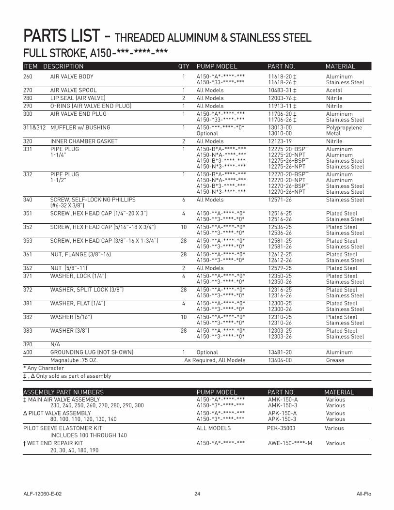
260 AIR VALVE BODY 1 A150-*A*-****-*** 11618-20 ‡ Aluminum A150-*33-****-*** 11618-26 ‡ Stainless Steel270 AIR VALVE SPOOL 1 All Models 10483-31 ‡ Acetal280 LIP SEAL (AIR VALVE) 2 All Models 12003-76 ‡ Nitrile290 O-RING (AIR VALVE END PLUG) 1 All Models 11913-11 ‡ Nitrile300 AIR VALVE END PLUG 1 A150-*A*-****-*** 11706-20 ‡ Aluminum A150-*33-****-*** 11706-26 ‡ Stainless Steel311&312 MUFFLER w/ BUSHING 1 A150-***-****-*0* 13013-00 Polypropylene Optional 13010-00 Metal320 INNER CHAMBER GASKET 2 All Models 12123-19 Nitrile331 PIPE PLUG 1 A150-B*A-****-*** 12275-20-BSPT Aluminum 1-1/4” A150-N*A-****-*** 12275-20-NPT Aluminum A150-B*3-****-*** 12275-26-BSPT Stainless Steel A150-N*3-****-*** 12275-26-NPT Stainless Steel332 PIPE PLUG 1 A150-B*A-****-*** 12270-20-BSPT Aluminum 1-1/2” A150-N*A-****-*** 12270-20-NPT Aluminum A150-B*3-****-*** 12270-26-BSPT Stainless Steel A150-N*3-****-*** 12270-26-NPT Stainless Steel 340 SCREW, SELF-LOCKING PHILLIPS 6 All Models 12571-26 Stainless Steel (#6-32 X 3/8”) 351 SCREW ,HEX HEAD CAP (1/4”-20 X 3”) 4 A150-**A-****-*0* 12516-25 Plated Steel A150-**3-****-*0* 12516-26 Stainless Steel352 SCREW, HEX HEAD CAP (5/16”-18 X 3/4”) 10 A150-**A-****-*0* 12536-25 Plated Steel A150-**3-****-*0* 12536-26 Stainless Steel353 SCREW, HEX HEAD CAP (3/8”-16 X 1-3/4”) 28 A150-**A-****-*0* 12581-25 Plated Steel A150-**3-****-*0* 12581-26 Stainless Steel361 NUT, FLANGE (3/8”-16) 28 A150-**A-****-*0* 12612-25 Plated Steel A150-**3-****-*0* 12612-26 Stainless Steel362 NUT (5/8”-11) 2 All Models 12579-25 Plated Steel371 WASHER, LOCK (1/4”) 4 A150-**A-****-*0* 12350-25 Plated Steel A150-**3-****-*0* 12350-26 Stainless Steel372 WASHER, SPLIT LOCK (3/8”) 28 A150-**A-****-*0* 12316-25 Plated Steel A150-**3-****-*0* 12316-26 Stainless Steel381 WASHER, FLAT (1/4”) 4 A150-**A-****-*0* 12300-25 Plated Steel A150-**3-****-*0* 12300-26 Stainless Steel382 WASHER (5/16”) 10 A150-**A-****-*0* 12310-25 Plated Steel A150-**3-****-*0* 12310-26 Stainless Steel383 WASHER (3/8”) 28 A150-**A-****-*0* 12303-25 Plated Steel A150-**3-****-*0* 12303-26 Stainless Steel390 N/A400 GROUNDING LUG (NOT SHOWN) 1 Optional 13481-20 Aluminum Magnalube .75 OZ. As Required, All Models 13404-00 Grease* Any Character‡ , Δ Only sold as part of assembly
‡ MAIN AIR VALVE ASSEMBLY A150-*A*-****-*** AMK-150-A Various 230, 240, 250, 260, 270, 280, 290, 300 A150-*3*-****-*** AMK-150-3 Various Δ PILOT VALVE ASSEMBLY A150-*A*-****-*** APK-150-A Various 80, 100, 110, 120, 130, 140 A150-*3*-****-*** APK-150-3 VariousPILOT SEEVE ELASTOMER KIT ALL MODELS PEK-35003 Various INCLUDES 100 THROUGH 140† WET END REPAIR KIT A150-*A*-****-*** AWE-150-****-M Various 20, 30, 40, 180, 190
ITEM DESCRIPTION QTY PUMP MODEL PART NO. MATERIAL
PARTS LIST - THREADED ALUMINUM & STAINLESS STEEL FULL STROKE, A150-***-****-***
ASSEMBLY PART NUMBERS PUMP MODEL PART NO. MATERIAL
ALF-12060-E-02 All-Flo25
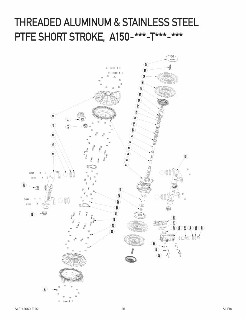
THREADED ALUMINUM & STAINLESS STEEL PTFE SHORT STROKE, A150-***-T***-***
ALF-12060-E-02 All-Flo26
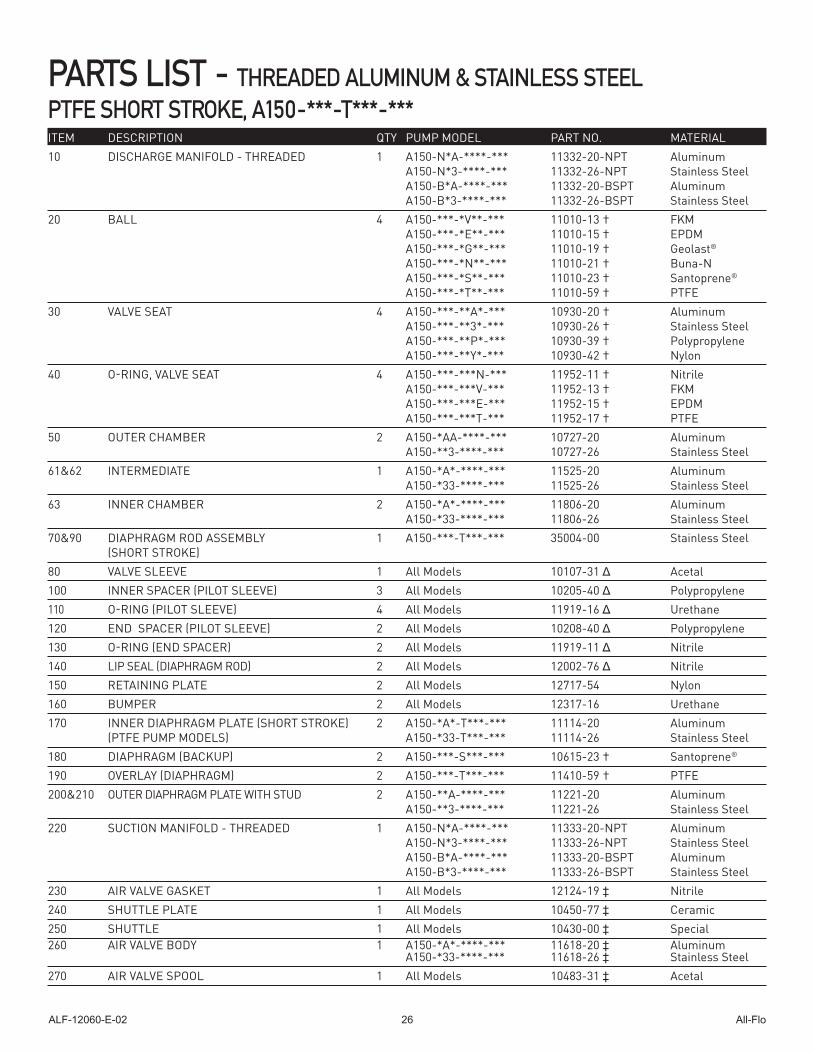
PARTS LIST - THREADED ALUMINUM & STAINLESS STEEL PTFE SHORT STROKE, A150-***-T***-***ITEM DESCRIPTION QTY PUMP MODEL PART NO. MATERIAL10 DISCHARGE MANIFOLD - THREADED 1 A150-N*A-****-*** 11332-20-NPT Aluminum A150-N*3-****-*** 11332-26-NPT Stainless Steel A150-B*A-****-*** 11332-20-BSPT Aluminum A150-B*3-****-*** 11332-26-BSPT Stainless Steel20 BALL 4 A150-***-*V**-*** 11010-13 † FKM A150-***-*E**-*** 11010-15 † EPDM A150-***-*G**-*** 11010-19 † Geolast® A150-***-*N**-*** 11010-21 † Buna-N A150-***-*S**-*** 11010-23 † Santoprene® A150-***-*T**-*** 11010-59 † PTFE30 VALVE SEAT 4 A150-***-**A*-*** 10930-20 † Aluminum A150-***-**3*-*** 10930-26 † Stainless Steel A150-***-**P*-*** 10930-39 † Polypropylene A150-***-**Y*-*** 10930-42 † Nylon40 O-RING, VALVE SEAT 4 A150-***-***N-*** 11952-11 † Nitrile A150-***-***V-*** 11952-13 † FKM A150-***-***E-*** 11952-15 † EPDM A150-***-***T-*** 11952-17 † PTFE50 OUTER CHAMBER 2 A150-*AA-****-*** 10727-20 Aluminum A150-**3-****-*** 10727-26 Stainless Steel61&62 INTERMEDIATE 1 A150-*A*-****-*** 11525-20 Aluminum A150-*33-****-*** 11525-26 Stainless Steel 63 INNER CHAMBER 2 A150-*A*-****-*** 11806-20 Aluminum A150-*33-****-*** 11806-26 Stainless Steel70&90 DIAPHRAGM ROD ASSEMBLY 1 A150-***-T***-*** 35004-00 Stainless Steel (SHORT STROKE)80 VALVE SLEEVE 1 All Models 10107-31 Δ Acetal100 INNER SPACER (PILOT SLEEVE) 3 All Models 10205-40 Δ Polypropylene110 O-RING (PILOT SLEEVE) 4 All Models 11919-16 Δ Urethane120 END SPACER (PILOT SLEEVE) 2 All Models 10208-40 Δ Polypropylene 130 O-RING (END SPACER) 2 All Models 11919-11 Δ Nitrile 140 LIP SEAL (DIAPHRAGM ROD) 2 All Models 12002-76 Δ Nitrile150 RETAINING PLATE 2 All Models 12717-54 Nylon 160 BUMPER 2 All Models 12317-16 Urethane170 INNER DIAPHRAGM PLATE (SHORT STROKE) 2 A150-*A*-T***-*** 11114-20 Aluminum (PTFE PUMP MODELS) A150-*33-T***-*** 11114-26 Stainless Steel180 DIAPHRAGM (BACKUP) 2 A150-***-S***-*** 10615-23 † Santoprene®
190 OVERLAY (DIAPHRAGM) 2 A150-***-T***-*** 11410-59 † PTFE200&210 OUTER DIAPHRAGM PLATE WITH STUD 2 A150-**A-****-*** 11221-20 Aluminum A150-**3-****-*** 11221-26 Stainless Steel220 SUCTION MANIFOLD - THREADED 1 A150-N*A-****-*** 11333-20-NPT Aluminum A150-N*3-****-*** 11333-26-NPT Stainless Steel A150-B*A-****-*** 11333-20-BSPT Aluminum A150-B*3-****-*** 11333-26-BSPT Stainless Steel230 AIR VALVE GASKET 1 All Models 12124-19 ‡ Nitrile240 SHUTTLE PLATE 1 All Models 10450-77 ‡ Ceramic 250 SHUTTLE 1 All Models 10430-00 ‡ Special260 AIR VALVE BODY 1 A150-*A*-****-*** 11618-20 ‡ Aluminum A150-*33-****-*** 11618-26 ‡ Stainless Steel270 AIR VALVE SPOOL 1 All Models 10483-31 ‡ Acetal
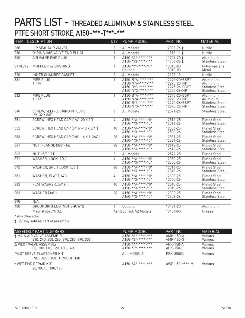
ALF-12060-E-02 All-Flo27
PARTS LIST - THREADED ALUMINUM & STAINLESS STEEL PTFE SHORT STROKE, A150-***-T***-***ITEM DESCRIPTION QTY PUMP MODEL PART NO. MATERIAL280 LIP SEAL (AIR VALVE) 2 All Models 12003-76 ‡ Nitrile290 O-RING (AIR VALVE END PLUG) 1 All Models 11913-11 ‡ Nitrile300 AIR VALVE END PLUG 1 A150-*A*-****-*** 11706-20 ‡ Aluminum A150-*33-****-*** 11706-26 ‡ Stainless Steel311&312 MUFFLER w/ BUSHING 1 A150-***-****-*0* 13013-00 Polypropylene Optional 13010-00 Metal320 INNER CHAMBER GASKET 2 All Models 12123-19 Nitrile331 PIPE PLUG 1 A150-B*A-****-*** 12275-20-BSPT Aluminum 1-1/4” A150-N*A-****-*** 12275-20-NPT Aluminum A150-B*3-****-*** 12275-26-BSPT Stainless Steel A150-N*3-****-*** 12275-26-NPT Stainless Steel332 PIPE PLUG 1 A150-B*A-****-*** 12270-20-BSPT Aluminum 1-1/2” A150-N*A-****-*** 12270-20-NPT Aluminum A150-B*3-****-*** 12270-26-BSPT Stainless Steel A150-N*3-****-*** 12270-26-NPT Stainless Steel 340 SCREW, SELF-LOCKING PHILLIPS 6 All Models 12571-26 Stainless Steel (#6-32 X 3/8”) 351 SCREW, HEX HEAD CAP (1/4”-20 X 3”) 4 A150-**A-****-*0* 12516-25 Plated Steel A150-**3-****-*0* 12516-26 Stainless Steel352 SCREW, HEX HEAD CAP (5/16”-18 X 3/4”) 10 A150-**A-****-*0* 12536-25 Plated Steel A150-**3-****-*0* 12536-26 Stainless Steel353 SCREW, HEX HEAD CAP (3/8”-16 X 1-3/4”) 28 A150-**A-****-*0* 12581-25 Plated Steel A150-**3-****-*0* 12581-26 Stainless Steel361 NUT, FLANGE (3/8”-16) 28 A150-**A-****-*0* 12612-25 Plated Steel A150-**3-****-*0* 12612-26 Stainless Steel362 NUT (5/8”-11) 2 All Models 12579-25 Plated Steel371 WASHER, LOCK (1/4”) 4 A150-**A-****-*0* 12350-25 Plated Steel A150-**3-****-*0* 12350-26 Stainless Steel372 WASHER, SPLIT LOCK (3/8”) 28 A150-**A-****-*0* 12316-25 Plated Steel A150-**3-****-*0* 12316-26 Stainless Steel381 WASHER, FLAT (1/4”) 4 A150-**A-****-*0* 12300-25 Plated Steel A150-**3-****-*0* 12300-26 Stainless Steel382 FLAT WASHER, (5/16”) 10 A150-**A-****-*0* 12310-25 Plated Steel A150-**3-****-*0* 12310-26 Stainless Steel383 WASHER (3/8”) 28 A150-**A-****-*0* 12303-25 Plated Steel A150-**3-****-*0* 12303-26 Stainless Steel390 N/A400 GROUNDING LUG (NOT SHOWN) 1 Optional 13481-20 Aluminum Magnalube .75 OZ. As Required, All Models 13404-00 Grease* Any Character‡ , Δ Only sold as part of assembly
‡ MAIN AIR VALVE ASSEMBLY A150-*A*-****-*** AMK-150-A Various 230, 240, 250, 260, 270, 280, 290, 300 A150-*3*-****-*** AMK-150-3 Various Δ PILOT VALVE ASSEMBLY A150-*A*-****-*** APK-150-A Various 80, 100, 110, 120, 130, 140 A150-*3*-****-*** APK-150-3 VariousPILOT SEEVE ELASTOMER KIT ALL MODELS PEK-35003 Various INCLUDES 100 THROUGH 140 † WET END REPAIR KIT A150-*A*-****-*** AWE-150-****-M Various 20, 30, 40, 180, 190
ASSEMBLY PART NUMBERS PUMP MODEL PART NO. MATERIAL
ALF-12060-E-02 All-Flo28
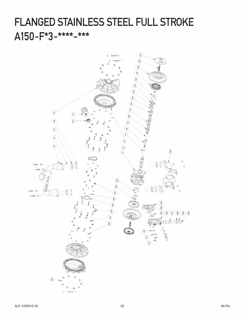
FLANGED STAINLESS STEEL FULL STROKE A150-F*3-****-***
FA
150-
FA3-
ASS
Y
100
1
20
70
250
2
40
270
180
50
170
210
260
300
290
230
381
3
71
351
340
200
362
361
353
150
280
110
1
30
140
220
40
20
10
80
311
3
12
30
160
90
63
320
383
382
372
352
61
62
ALF-12060-E-02 All-Flo29
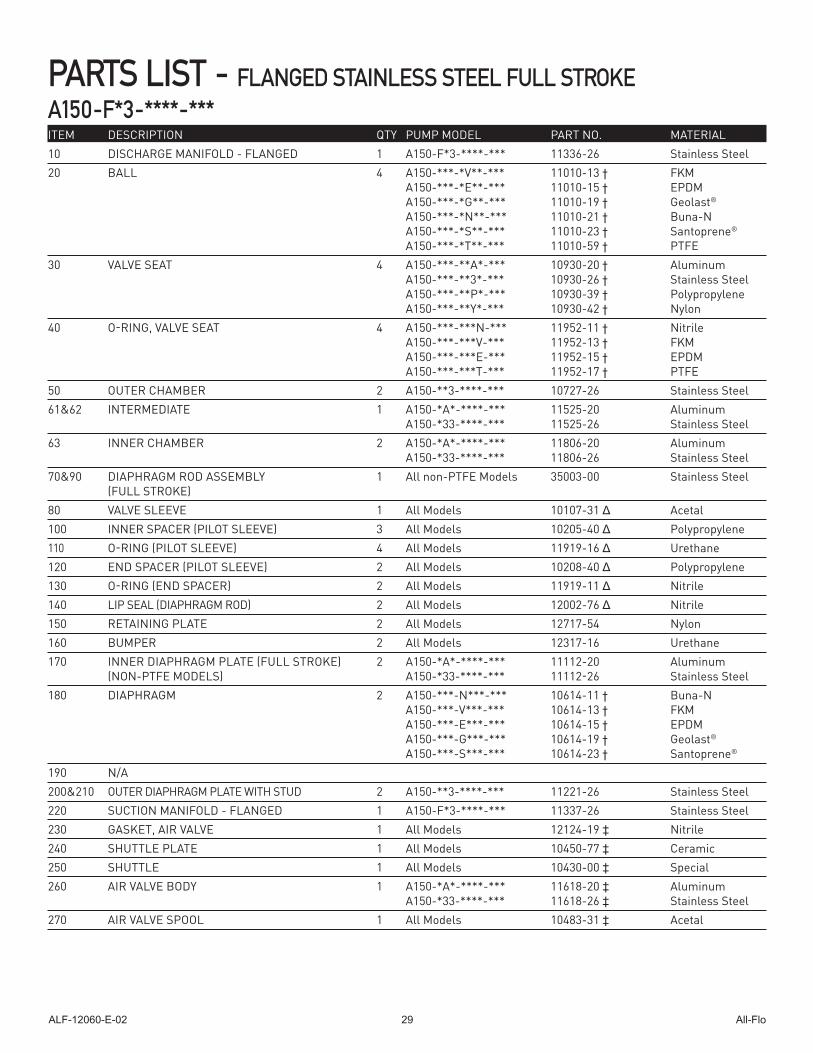
PARTS LIST - FLANGED STAINLESS STEEL FULL STROKEA150-F*3-****-***ITEM DESCRIPTION QTY PUMP MODEL PART NO. MATERIAL10 DISCHARGE MANIFOLD - FLANGED 1 A150-F*3-****-*** 11336-26 Stainless Steel20 BALL 4 A150-***-*V**-*** 11010-13 † FKM A150-***-*E**-*** 11010-15 † EPDM A150-***-*G**-*** 11010-19 † Geolast® A150-***-*N**-*** 11010-21 † Buna-N A150-***-*S**-*** 11010-23 † Santoprene® A150-***-*T**-*** 11010-59 † PTFE30 VALVE SEAT 4 A150-***-**A*-*** 10930-20 † Aluminum A150-***-**3*-*** 10930-26 † Stainless Steel A150-***-**P*-*** 10930-39 † Polypropylene A150-***-**Y*-*** 10930-42 † Nylon40 O-RING, VALVE SEAT 4 A150-***-***N-*** 11952-11 † Nitrile A150-***-***V-*** 11952-13 † FKM A150-***-***E-*** 11952-15 † EPDM A150-***-***T-*** 11952-17 † PTFE50 OUTER CHAMBER 2 A150-**3-****-*** 10727-26 Stainless Steel61&62 INTERMEDIATE 1 A150-*A*-****-*** 11525-20 Aluminum A150-*33-****-*** 11525-26 Stainless Steel 63 INNER CHAMBER 2 A150-*A*-****-*** 11806-20 Aluminum A150-*33-****-*** 11806-26 Stainless Steel70&90 DIAPHRAGM ROD ASSEMBLY 1 All non-PTFE Models 35003-00 Stainless Steel (FULL STROKE)80 VALVE SLEEVE 1 All Models 10107-31 Δ Acetal100 INNER SPACER (PILOT SLEEVE) 3 All Models 10205-40 Δ Polypropylene110 O-RING (PILOT SLEEVE) 4 All Models 11919-16 Δ Urethane120 END SPACER (PILOT SLEEVE) 2 All Models 10208-40 Δ Polypropylene 130 O-RING (END SPACER) 2 All Models 11919-11 Δ Nitrile 140 LIP SEAL (DIAPHRAGM ROD) 2 All Models 12002-76 Δ Nitrile150 RETAINING PLATE 2 All Models 12717-54 Nylon 160 BUMPER 2 All Models 12317-16 Urethane170 INNER DIAPHRAGM PLATE (FULL STROKE) 2 A150-*A*-****-*** 11112-20 Aluminum (NON-PTFE MODELS) A150-*33-****-*** 11112-26 Stainless Steel 180 DIAPHRAGM 2 A150-***-N***-*** 10614-11 † Buna-N A150-***-V***-*** 10614-13 † FKM A150-***-E***-*** 10614-15 † EPDM A150-***-G***-*** 10614-19 † Geolast® A150-***-S***-*** 10614-23 † Santoprene®
190 N/A200&210 OUTER DIAPHRAGM PLATE WITH STUD 2 A150-**3-****-*** 11221-26 Stainless Steel220 SUCTION MANIFOLD - FLANGED 1 A150-F*3-****-*** 11337-26 Stainless Steel230 GASKET, AIR VALVE 1 All Models 12124-19 ‡ Nitrile240 SHUTTLE PLATE 1 All Models 10450-77 ‡ Ceramic 250 SHUTTLE 1 All Models 10430-00 ‡ Special260 AIR VALVE BODY 1 A150-*A*-****-*** 11618-20 ‡ Aluminum A150-*33-****-*** 11618-26 ‡ Stainless Steel 270 AIR VALVE SPOOL 1 All Models 10483-31 ‡ Acetal
ALF-12060-E-02 All-Flo30
ITEM DESCRIPTION QTY PUMP MODEL PART NO. MATERIAL
PARTS LIST - FLANGED STAINLESS STEEL FULL STROKEA150-F*3-****-***
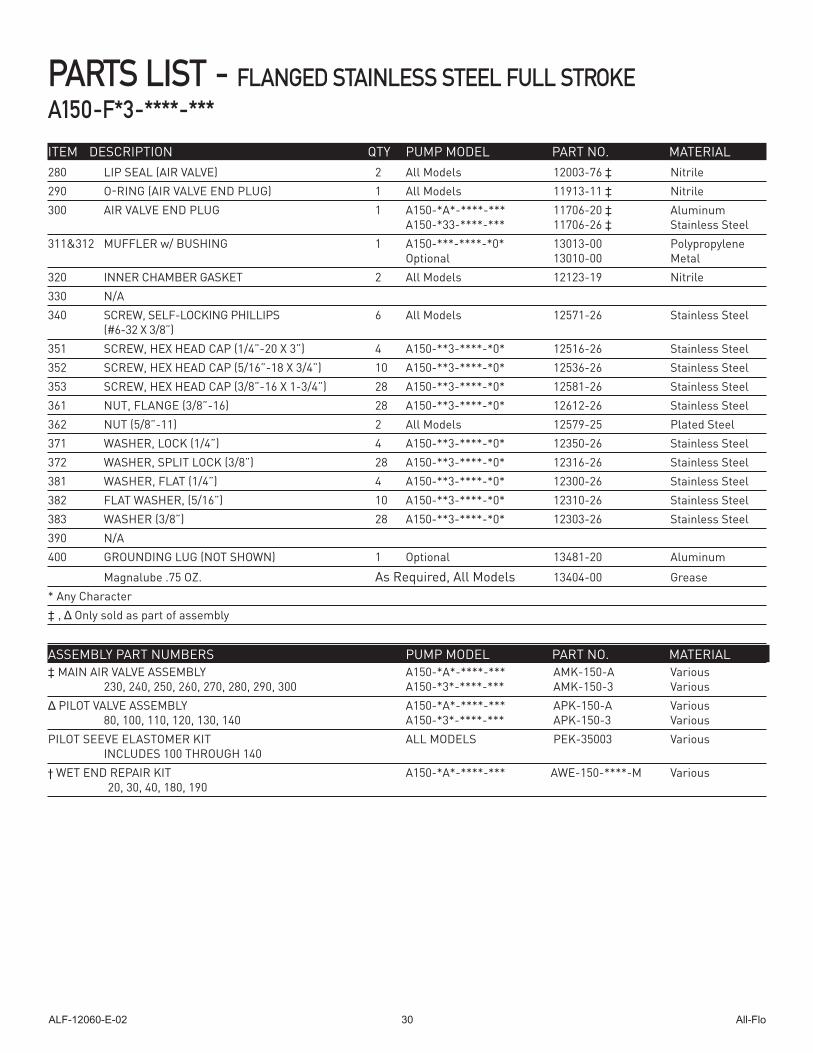
280 LIP SEAL (AIR VALVE) 2 All Models 12003-76 ‡ Nitrile 290 O-RING (AIR VALVE END PLUG) 1 All Models 11913-11 ‡ Nitrile300 AIR VALVE END PLUG 1 A150-*A*-****-*** 11706-20 ‡ Aluminum A150-*33-****-*** 11706-26 ‡ Stainless Steel311&312 MUFFLER w/ BUSHING 1 A150-***-****-*0* 13013-00 Polypropylene Optional 13010-00 Metal320 INNER CHAMBER GASKET 2 All Models 12123-19 Nitrile330 N/A 340 SCREW, SELF-LOCKING PHILLIPS 6 All Models 12571-26 Stainless Steel (#6-32 X 3/8”) 351 SCREW, HEX HEAD CAP (1/4”-20 X 3”) 4 A150-**3-****-*0* 12516-26 Stainless Steel352 SCREW, HEX HEAD CAP (5/16”-18 X 3/4”) 10 A150-**3-****-*0* 12536-26 Stainless Steel353 SCREW, HEX HEAD CAP (3/8”-16 X 1-3/4”) 28 A150-**3-****-*0* 12581-26 Stainless Steel361 NUT, FLANGE (3/8”-16) 28 A150-**3-****-*0* 12612-26 Stainless Steel362 NUT (5/8”-11) 2 All Models 12579-25 Plated Steel371 WASHER, LOCK (1/4”) 4 A150-**3-****-*0* 12350-26 Stainless Steel372 WASHER, SPLIT LOCK (3/8”) 28 A150-**3-****-*0* 12316-26 Stainless Steel381 WASHER, FLAT (1/4”) 4 A150-**3-****-*0* 12300-26 Stainless Steel382 FLAT WASHER, (5/16”) 10 A150-**3-****-*0* 12310-26 Stainless Steel383 WASHER (3/8”) 28 A150-**3-****-*0* 12303-26 Stainless Steel390 N/A400 GROUNDING LUG (NOT SHOWN) 1 Optional 13481-20 Aluminum
Magnalube .75 OZ. As Required, All Models 13404-00 Grease* Any Character‡ , Δ Only sold as part of assembly
‡ MAIN AIR VALVE ASSEMBLY A150-*A*-****-*** AMK-150-A Various 230, 240, 250, 260, 270, 280, 290, 300 A150-*3*-****-*** AMK-150-3 Various Δ PILOT VALVE ASSEMBLY A150-*A*-****-*** APK-150-A Various 80, 100, 110, 120, 130, 140 A150-*3*-****-*** APK-150-3 VariousPILOT SEEVE ELASTOMER KIT ALL MODELS PEK-35003 Various INCLUDES 100 THROUGH 140 † WET END REPAIR KIT A150-*A*-****-*** AWE-150-****-M Various 20, 30, 40, 180, 190
ASSEMBLY PART NUMBERS PUMP MODEL PART NO. MATERIAL
ALF-12060-E-02 All-Flo31
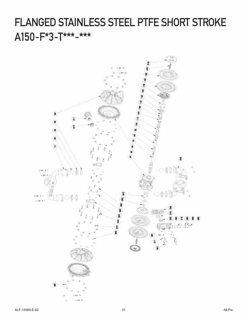
FLANGED STAINLESS STEEL PTFE SHORT STROKEA150-F*3-T***-***
ALF-12060-E-02 All-Flo32
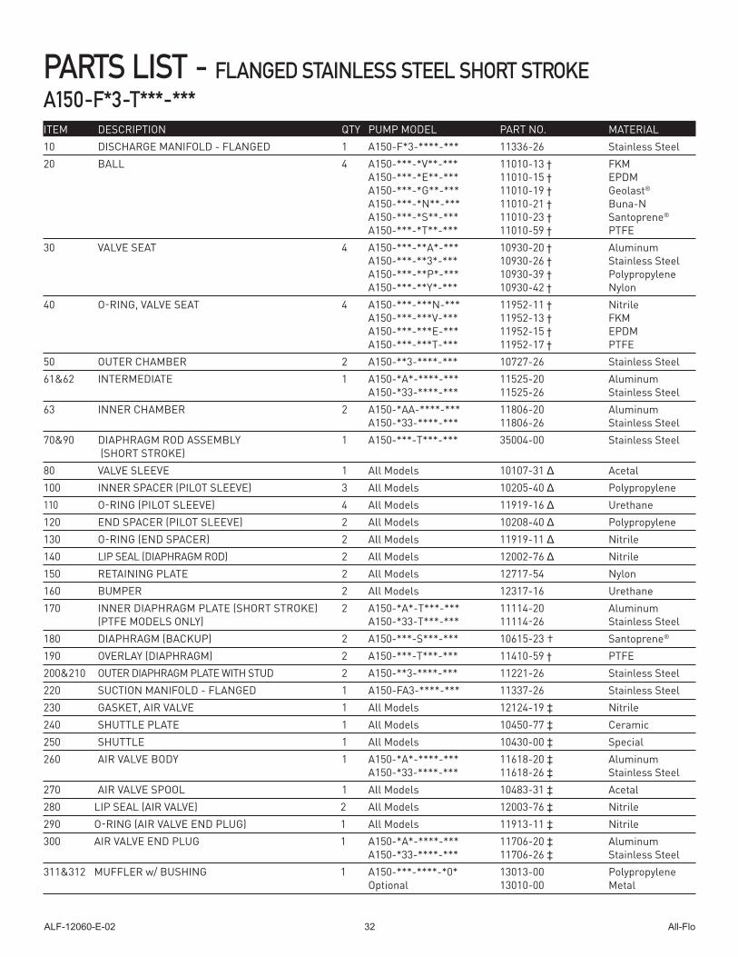
PARTS LIST - FLANGED STAINLESS STEEL SHORT STROKE A150-F*3-T***-***ITEM DESCRIPTION QTY PUMP MODEL PART NO. MATERIAL10 DISCHARGE MANIFOLD - FLANGED 1 A150-F*3-****-*** 11336-26 Stainless Steel20 BALL 4 A150-***-*V**-*** 11010-13 † FKM A150-***-*E**-*** 11010-15 † EPDM A150-***-*G**-*** 11010-19 † Geolast® A150-***-*N**-*** 11010-21 † Buna-N A150-***-*S**-*** 11010-23 † Santoprene® A150-***-*T**-*** 11010-59 † PTFE30 VALVE SEAT 4 A150-***-**A*-*** 10930-20 † Aluminum A150-***-**3*-*** 10930-26 † Stainless Steel A150-***-**P*-*** 10930-39 † Polypropylene A150-***-**Y*-*** 10930-42 † Nylon40 O-RING, VALVE SEAT 4 A150-***-***N-*** 11952-11 † Nitrile A150-***-***V-*** 11952-13 † FKM A150-***-***E-*** 11952-15 † EPDM A150-***-***T-*** 11952-17 † PTFE50 OUTER CHAMBER 2 A150-**3-****-*** 10727-26 Stainless Steel61&62 INTERMEDIATE 1 A150-*A*-****-*** 11525-20 Aluminum A150-*33-****-*** 11525-26 Stainless Steel63 INNER CHAMBER 2 A150-*AA-****-*** 11806-20 Aluminum A150-*33-****-*** 11806-26 Stainless Steel 70&90 DIAPHRAGM ROD ASSEMBLY 1 A150-***-T***-*** 35004-00 Stainless Steel (SHORT STROKE) 80 VALVE SLEEVE 1 All Models 10107-31 Δ Acetal100 INNER SPACER (PILOT SLEEVE) 3 All Models 10205-40 Δ Polypropylene110 O-RING (PILOT SLEEVE) 4 All Models 11919-16 Δ Urethane120 END SPACER (PILOT SLEEVE) 2 All Models 10208-40 Δ Polypropylene 130 O-RING (END SPACER) 2 All Models 11919-11 Δ Nitrile 140 LIP SEAL (DIAPHRAGM ROD) 2 All Models 12002-76 Δ Nitrile150 RETAINING PLATE 2 All Models 12717-54 Nylon 160 BUMPER 2 All Models 12317-16 Urethane170 INNER DIAPHRAGM PLATE (SHORT STROKE) 2 A150-*A*-T***-*** 11114-20 Aluminum (PTFE MODELS ONLY) A150-*33-T***-*** 11114-26 Stainless Steel180 DIAPHRAGM (BACKUP) 2 A150-***-S***-*** 10615-23 † Santoprene®
190 OVERLAY (DIAPHRAGM) 2 A150-***-T***-*** 11410-59 † PTFE200&210 OUTER DIAPHRAGM PLATE WITH STUD 2 A150-**3-****-*** 11221-26 Stainless Steel220 SUCTION MANIFOLD - FLANGED 1 A150-FA3-****-*** 11337-26 Stainless Steel230 GASKET, AIR VALVE 1 All Models 12124-19 ‡ Nitrile240 SHUTTLE PLATE 1 All Models 10450-77 ‡ Ceramic 250 SHUTTLE 1 All Models 10430-00 ‡ Special260 AIR VALVE BODY 1 A150-*A*-****-*** 11618-20 ‡ Aluminum A150-*33-****-*** 11618-26 ‡ Stainless Steel270 AIR VALVE SPOOL 1 All Models 10483-31 ‡ Acetal280 LIP SEAL (AIR VALVE) 2 All Models 12003-76 ‡ Nitrile 290 O-RING (AIR VALVE END PLUG) 1 All Models 11913-11 ‡ Nitrile300 AIR VALVE END PLUG 1 A150-*A*-****-*** 11706-20 ‡ Aluminum A150-*33-****-*** 11706-26 ‡ Stainless Steel311&312 MUFFLER w/ BUSHING 1 A150-***-****-*0* 13013-00 Polypropylene Optional 13010-00 Metal

ALF-12060-E-02 All-Flo33
ITEM DESCRIPTION QTY PUMP MODEL PART NO. MATERIAL
PARTS LIST - FLANGED STAINLESS STEEL SHORT STROKEA150-F*3-T***-***
320 INNER CHAMBER GASKET 2 All Models 12123-19 Nitrile330 N/A 340 SCREW, SELF-LOCKING PHILLIPS 6 All Models 12571-26 Stainless Steel (#6-32 X 3/8”) 351 SCREW, HEX HEAD CAP (1/4”-20 X 3”) 4 A150-**3-****-*0* 12516-26 Stainless Steel352 SCREW, HEX HEAD CAP (5/16”-18 X 3/4”) 10 A150-**3-****-*0* 12536-26 Stainless Steel353 SCREW, HEX HEAD CAP (3/8”-16 X 1-3/4”) 28 A150-**3-****-*0* 12581-26 Stainless Steel361 NUT, FLANGE (3/8”-16) 28 A150-**3-****-*0* 12612-26 Stainless Steel362 NUT (5/8”-11) 2 All Models 12579-25 Plated Steel371 WASHER, LOCK (1/4”) 4 A150-**3-****-*0* 12350-26 Stainless Steel372 WASHER, SPLIT LOCK (3/8”) 28 A150-**3-****-*0* 12316-26 Stainless Steel381 WASHER, FLAT (1/4”) 4 A150-**3-****-*0* 12300-26 Stainless Steel382 FLAT WASHER, (5/16”) 10 A150-**3-****-*0* 12310-26 Stainless Steel383 WASHER (3/8”) 28 A150-**3-****-*0* 12303-26 Stainless Steel390 N/A400 GROUNDING LUG (NOT SHOWN) 1 Optional 13481-20 Aluminum
Magnalube .75 OZ. As Required, All Models 13404-00 Grease* Any Character‡ , Δ Only sold as part of assembly
‡ MAIN AIR VALVE ASSEMBLY A150-*A*-****-*** AMK-150-A Various 230, 240, 250, 260, 270, 280, 290, 300 A150-*3*-****-*** AMK-150-3 Various Δ PILOT VALVE ASSEMBLY A150-*A*-****-*** APK-150-A Various 80, 100, 110, 120, 130, 140 A150-*3*-****-*** APK-150-3 VariousPILOT SEEVE ELASTOMER KIT ALL MODELS PEK-35003 Various INCLUDES 100 THROUGH 140 † WET END REPAIR KIT A150-*A*-****-*** AWE-150-****-M Various 20, 30, 40, 180, 190
ALF-12060-E-02 All-Flo34
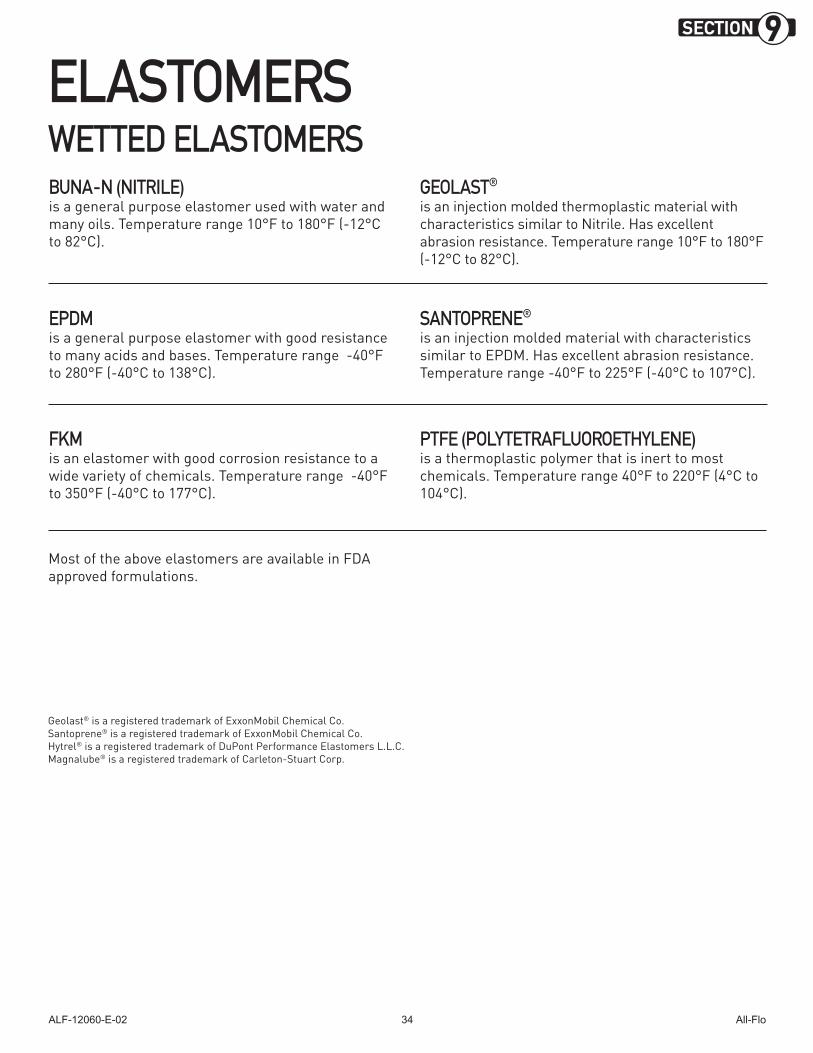
ELASTOMERS WETTED ELASTOMERS
FKM is an elastomer with good corrosion resistance to a wide variety of chemicals. Temperature range -40°F to 350°F (-40°C to 177°C).
Most of the above elastomers are available in FDA approved formulations.
BUNA-N (NITRILE)is a general purpose elastomer used with water and many oils. Temperature range 10°F to 180°F (-12°C to 82°C).
GEOLAST® is an injection molded thermoplastic material with characteristics similar to Nitrile. Has excellent abrasion resistance. Temperature range 10°F to 180°F (-12°C to 82°C).
EPDM is a general purpose elastomer with good resistance to many acids and bases. Temperature range -40°F to 280°F (-40°C to 138°C).
SANTOPRENE® is an injection molded material with characteristics similar to EPDM. Has excellent abrasion resistance. Temperature range -40°F to 225°F (-40°C to 107°C).
PTFE (POLYTETRAFLUOROETHYLENE)is a thermoplastic polymer that is inert to most chemicals. Temperature range 40°F to 220°F (4°C to 104°C).
Geolast® is a registered trademark of ExxonMobil Chemical Co.Santoprene® is a registered trademark of ExxonMobil Chemical Co.Hytrel® is a registered trademark of DuPont Performance Elastomers L.L.C.Magnalube® is a registered trademark of Carleton-Stuart Corp.
SECTION 9
ALF-12060-E-02 All-Flo35
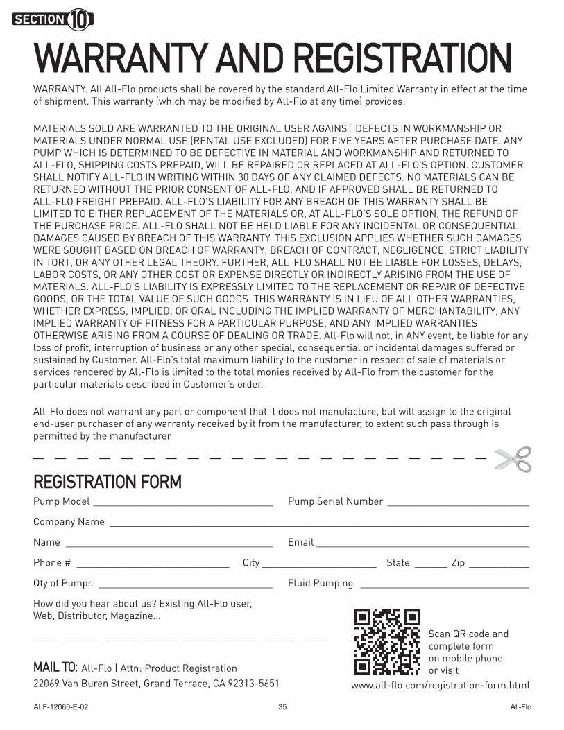
WARRANTY. All All-Flo products shall be covered by the standard All-Flo Limited Warranty in effect at the time of shipment. This warranty (which may be modified by All-Flo at any time) provides:
MATERIALS SOLD ARE WARRANTED TO THE ORIGINAL USER AGAINST DEFECTS IN WORKMANSHIP OR MATERIALS UNDER NORMAL USE (RENTAL USE EXCLUDED) FOR FIVE YEARS AFTER PURCHASE DATE. ANY PUMP WHICH IS DETERMINED TO BE DEFECTIVE IN MATERIAL AND WORKMANSHIP AND RETURNED TO ALL-FLO, SHIPPING COSTS PREPAID, WILL BE REPAIRED OR REPLACED AT ALL-FLO’S OPTION. CUSTOMER SHALL NOTIFY ALL-FLO IN WRITING WITHIN 30 DAYS OF ANY CLAIMED DEFECTS. NO MATERIALS CAN BE RETURNED WITHOUT THE PRIOR CONSENT OF ALL-FLO, AND IF APPROVED SHALL BE RETURNED TO ALL-FLO FREIGHT PREPAID. ALL-FLO’S LIABILITY FOR ANY BREACH OF THIS WARRANTY SHALL BE LIMITED TO EITHER REPLACEMENT OF THE MATERIALS OR, AT ALL-FLO’S SOLE OPTION, THE REFUND OF THE PURCHASE PRICE. ALL-FLO SHALL NOT BE HELD LIABLE FOR ANY INCIDENTAL OR CONSEQUENTIAL DAMAGES CAUSED BY BREACH OF THIS WARRANTY. THIS EXCLUSION APPLIES WHETHER SUCH DAMAGES WERE SOUGHT BASED ON BREACH OF WARRANTY, BREACH OF CONTRACT, NEGLIGENCE, STRICT LIABILITY IN TORT, OR ANY OTHER LEGAL THEORY. FURTHER, ALL-FLO SHALL NOT BE LIABLE FOR LOSSES, DELAYS, LABOR COSTS, OR ANY OTHER COST OR EXPENSE DIRECTLY OR INDIRECTLY ARISING FROM THE USE OF MATERIALS. ALL-FLO’S LIABILITY IS EXPRESSLY LIMITED TO THE REPLACEMENT OR REPAIR OF DEFECTIVE GOODS, OR THE TOTAL VALUE OF SUCH GOODS. THIS WARRANTY IS IN LIEU OF ALL OTHER WARRANTIES, WHETHER EXPRESS, IMPLIED, OR ORAL INCLUDING THE IMPLIED WARRANTY OF MERCHANTABILITY, ANY IMPLIED WARRANTY OF FITNESS FOR A PARTICULAR PURPOSE, AND ANY IMPLIED WARRANTIES OTHERWISE ARISING FROM A COURSE OF DEALING OR TRADE. All-Flo will not, in ANY event, be liable for any loss of profit, interruption of business or any other special, consequential or incidental damages suffered or sustained by Customer. All-Flo’s total maximum liability to the customer in respect of sale of materials or services rendered by All-Flo is limited to the total monies received by All-Flo from the customer for the particular materials described in Customer’s order.
All-Flo does not warrant any part or component that it does not manufacture, but will assign to the original end-user purchaser of any warranty received by it from the manufacturer, to extent such pass through is permitted by the manufacturer
REGISTRATION FORMPump Model _________________________________ Pump Serial Number __________________________
Company Name _____________________________________________________________________________
Name ______________________________________ Email _______________________________________
Phone # ____________________________ City _____________________ State ______ Zip ___________
Qty of Pumps ________________________________ Fluid Pumping _______________________________
How did you hear about us? Existing All-Flo user, Web, Distributor, Magazine…
______________________________________________________
www.all-flo.com/registration-form.html
WARRANTY AND REGISTRATION
Scan QR code and complete form on mobile phone or visitMAIL TO: All-Flo | Attn: Product Registration
22069 Van Buren Street, Grand Terrace, CA 92313-5651
SECTION 10
PSG® reserves the right to modify the information and illustrations contained in this document without prior notice. This is a non-contractual document.
PSG22069 Van Buren Street
Grand Terrace, CA 92313-5651 USAP: +1 (440) 354-1700 F: +1 (440) 354-9466
all-flo.com
All-Flo is committed to the pursuit of designing and manufacturing the
highest quality product available to industry. Since the beginning in
1986, All-Flo engineers have used their extensive knowledge of today’s
engineered materials, advanced air system logic and manufacturing
techniques to develop the superior group of lube-free, air-operated
diaphragm pumps found in this catalog. Every pump is performance
engineered and quality built to provide trouble-free service under the
toughest conditions.
Where Innovation Flows
ALF-12060-E-02