pro-flo r 260 - psg
TRANSCRIPT
EOM Engineering Operation & Maintenance
Pro-Flo® R 260 Bolted Metal Pump Integrated SD Series (ISD)
WIL-11710-E-01
WIL-11710-E-01 Wilden® 1
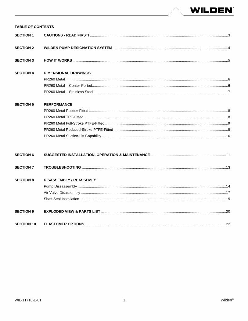
TABLE OF CONTENTS SECTION 1 CAUTIONS - READ FIRST! .......................................................................................................................................3
SECTION 2 WILDEN PUMP DESIGNATION SYSTEM .................................................................................................................4
SECTION 3 HOW IT WORKS ........................................................................................................................................................5
SECTION 4 DIMENSIONAL DRAWINGS
PR260 Metal ...............................................................................................................................................................6
PR260 Metal – Center-Ported .....................................................................................................................................6
PR260 Metal – Stainless Steel ...................................................................................................................................7
SECTION 5 PERFORMANCE
PR260 Metal Rubber-Fitted ........................................................................................................................................8
PR260 Metal TPE-Fitted .............................................................................................................................................8
PR260 Metal Full-Stroke PTFE-Fitted ........................................................................................................................9
PR260 Metal Reduced-Stroke PTFE-Fitted ................................................................................................................9
PR260 Metal Suction-Lift Capability ......................................................................................................................... 10
SECTION 6 SUGGESTED INSTALLATION, OPERATION & MAINTENANCE .......................................................................... 11
SECTION 7 TROUBLESHOOTING ............................................................................................................................................. 13
SECTION 8 DISASSEMBLY / REASSEMLY
Pump Dissassembly ................................................................................................................................................. 14
Air Valve Disassembly .............................................................................................................................................. 17
Shaft Seal Installation ............................................................................................................................................... 19
SECTION 9 EXPLODED VIEW & PARTS LIST .......................................................................................................................... 20
SECTION 10 ELASTOMER OPTIONS .......................................................................................................................................... 22
WIL-11710-E-01 Wilden® 2
Copyright Copyright 2018 PSG®, a Dover Company. All rights reserved. PSG reserves the right to modify the information and illustrations in this document without prior notice. The product described in this document is furnished under a license agreement or nondisclosure agreement. No part of this document may be reproduced, stored in a retrieval system, or transmitted in any form or any means electronic or mechanical, including photocopying and recording, without the written permission of PSG, a Dover Company, except as described by the terms of those agreements. This is a non-contractual document. 01-2019. Trademarks PSG and the PSG logo are registered trademarks of PSG. Wilden® is a registered trademark of PSG California LLC. Wil-FlexTM is a trademark of PSG California LLC. Saniflex™ is a trademark of PSG California LLC. All trademarks, names, logos and service marks (collectively "trademarks") in this document are registered and unregistered trademarks of their respective owners. Nothing contained in this document should be construed as granting any license or right to use any trademark without the prior written permission of the trademark owner. Warranty Each and every product manufactured by Wilden is built to meet the highest standards of quality. Every pump is functionally tested to insure integrity of operation. Wilden warrants that pumps, accessories and parts manufactured or supplied by it to be free from defects in material and workmanship for a period of five (5) years from date of installation or six (6) years from date of manufacture, whichever comes first. For more information, and to register your Wilden pump for warranty, please visit PSG official website. Certifications
WIL-11710-E-01 Wilden® 3
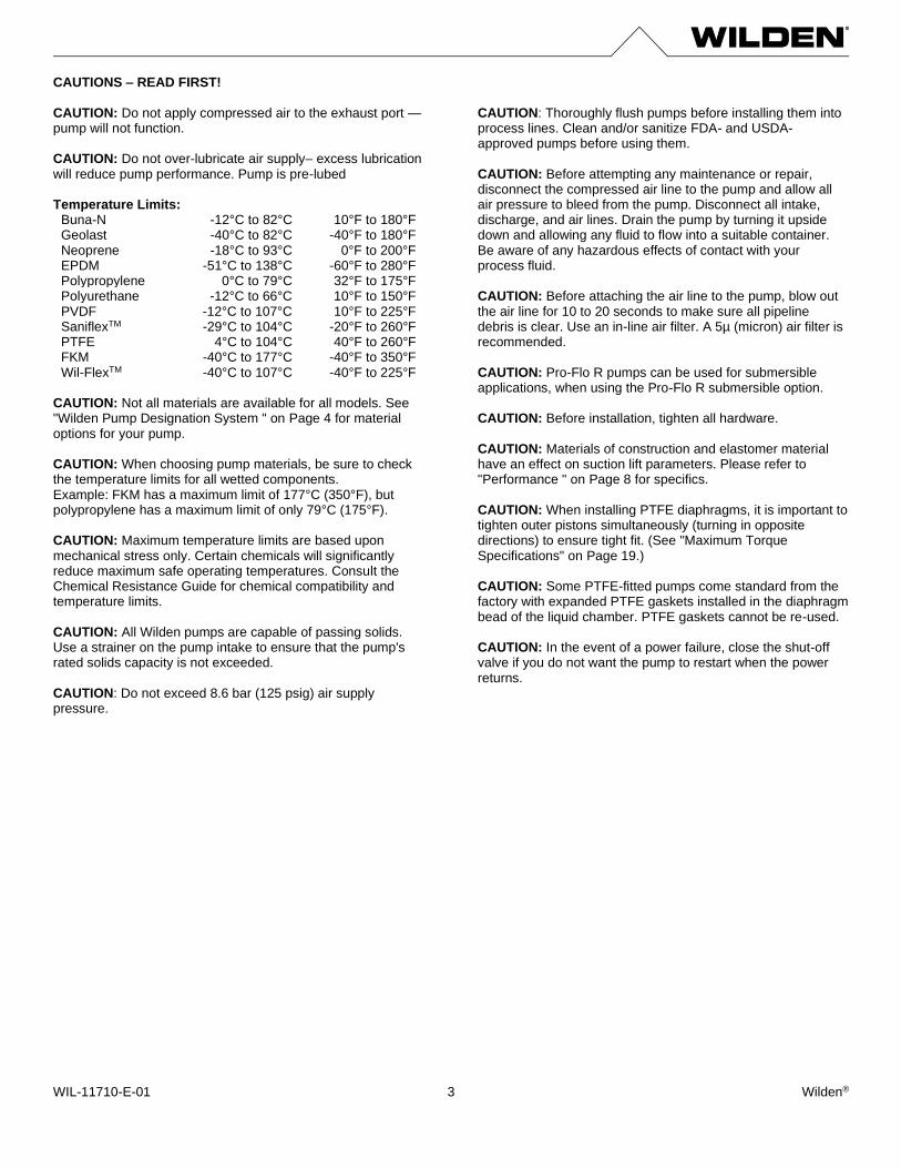
CAUTIONS – READ FIRST! CAUTION: Do not apply compressed air to the exhaust port — pump will not function. CAUTION: Do not over-lubricate air supply– excess lubrication will reduce pump performance. Pump is pre-lubed Temperature Limits:
Buna-N -12°C to 82°C 10°F to 180°F Geolast -40°C to 82°C -40°F to 180°F Neoprene -18°C to 93°C 0°F to 200°F EPDM -51°C to 138°C -60°F to 280°F Polypropylene 0°C to 79°C 32°F to 175°F Polyurethane -12°C to 66°C 10°F to 150°F PVDF -12°C to 107°C 10°F to 225°F SaniflexTM -29°C to 104°C -20°F to 260°F PTFE 4°C to 104°C 40°F to 260°F FKM -40°C to 177°C -40°F to 350°F Wil-FlexTM -40°C to 107°C -40°F to 225°F
CAUTION: Not all materials are available for all models. See "Wilden Pump Designation System " on Page 4 for material options for your pump. CAUTION: When choosing pump materials, be sure to check the temperature limits for all wetted components. Example: FKM has a maximum limit of 177°C (350°F), but polypropylene has a maximum limit of only 79°C (175°F). CAUTION: Maximum temperature limits are based upon mechanical stress only. Certain chemicals will significantly reduce maximum safe operating temperatures. Consult the Chemical Resistance Guide for chemical compatibility and temperature limits. CAUTION: All Wilden pumps are capable of passing solids. Use a strainer on the pump intake to ensure that the pump's rated solids capacity is not exceeded. CAUTION: Do not exceed 8.6 bar (125 psig) air supply pressure.
CAUTION: Thoroughly flush pumps before installing them into process lines. Clean and/or sanitize FDA- and USDA- approved pumps before using them. CAUTION: Before attempting any maintenance or repair, disconnect the compressed air line to the pump and allow all air pressure to bleed from the pump. Disconnect all intake, discharge, and air lines. Drain the pump by turning it upside down and allowing any fluid to flow into a suitable container. Be aware of any hazardous effects of contact with your process fluid. CAUTION: Before attaching the air line to the pump, blow out the air line for 10 to 20 seconds to make sure all pipeline debris is clear. Use an in-line air filter. A 5µ (micron) air filter is recommended. CAUTION: Pro-Flo R pumps can be used for submersible applications, when using the Pro-Flo R submersible option. CAUTION: Before installation, tighten all hardware. CAUTION: Materials of construction and elastomer material have an effect on suction lift parameters. Please refer to "Performance " on Page 8 for specifics. CAUTION: When installing PTFE diaphragms, it is important to tighten outer pistons simultaneously (turning in opposite directions) to ensure tight fit. (See "Maximum Torque Specifications" on Page 19.) CAUTION: Some PTFE-fitted pumps come standard from the factory with expanded PTFE gaskets installed in the diaphragm bead of the liquid chamber. PTFE gaskets cannot be re-used. CAUTION: In the event of a power failure, close the shut-off valve if you do not want the pump to restart when the power returns.
WIL-11710-E-01 Wilden® 4
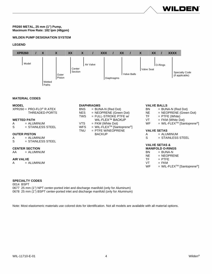
PR260 METAL, 25 mm (1") Pump, Maximum Flow Rate: 182 lpm (48gpm) WILDEN PUMP DESIGNATION SYSTEM LEGEND
MATERIAL CODES MODEL XPR260 = PRO-FLO® R ATEX THREADED-PORTS
WETTED PATH A = ALUMINUM S = STAINLESS STEEL OUTER PISTON A = ALUMINUM S = STAINLESS STEEL CENTER SECTION AA = ALUMINUM AIR VALVE A = ALUMINUM
DIAPHRAGMS BNS = BUNA-N (Red Dot) NES = NEOPRENE (Green Dot) TWS = FULL-STROKE PTFE w/ WIL-FLEX™ BACKUP VTS = FKM (White Dot) WFS = WIL-FLEXTM [Santoprene®] TNU = PTFE W/NEOPRENE BACKUP
VALVE BALLS BN = BUNA-N (Red Dot) NE = NEOPRENE (Green Dot) TF = PTFE (White) VT = FKM (White Dot) WF = WIL-FLEXTM [Santoprene®] VALVE SETAS A = ALUMINUM S = STAINLESS STEEL VALVE SETAS & MANIFOLD O-RINGS BN = BUNA-N NE = NEOPRENE TF = PTFE VT = FKM WF = WIL-FLEXTM [Santoprene®]
SPECIALTY CODES 0014 BSPT 0677 25 mm (1") NPT center-ported inlet and discharge manifold (only for Aluminum) 0678 25 mm (1") BSPT center-ported inlet and discharge manifold (only for Aluminum) Note: Most elastomeric materials use colored dots for identification. Not all models are available with all material options.
XPR260 / X X XX X / XXX / XX / X XX / XXXX
Model
Wetted Paths
Specialty Code (if applicable)
O-Rings
Valve Seat
Valve Balls
Diaphragms
Air Valve
Center Section
Outer Piston
WIL-11710-E-01 Wilden® 5
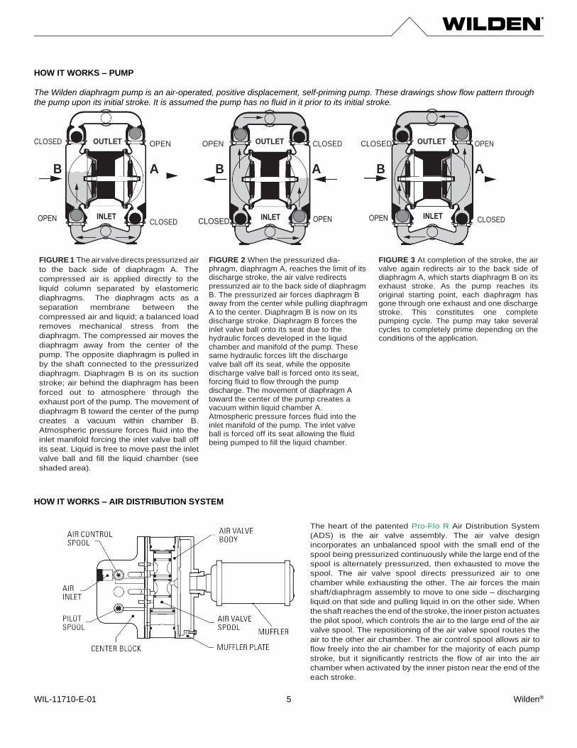
HOW IT WORKS – PUMP The Wilden diaphragm pump is an air-operated, positive displacement, self-priming pump. These drawings show flow pattern through the pump upon its initial stroke. It is assumed the pump has no fluid in it prior to its initial stroke. CLOSED OUTLET OPEN OPEN OUTLET CLOSED CLOSED OUTLET OPEN
B
A B
A B
A
FIGURE 1 The air valve directs pressurized air
to the back side of diaphragm A. The
compressed air is applied directly to the
liquid column separated by elastomeric
diaphragms. The diaphragm acts as a
separation membrane between the
compressed air and liquid; a balanced load
removes mechanical stress from the
diaphragm. The compressed air moves the
diaphragm away from the center of the
pump. The opposite diaphragm is pulled in
by the shaft connected to the pressurized
diaphragm. Diaphragm B is on its suction
stroke; air behind the diaphragm has been
forced out to atmosphere through the
exhaust port of the pump. The movement of
diaphragm B toward the center of the pump
creates a vacuum within chamber B.
Atmospheric pressure forces fluid into the
inlet manifold forcing the inlet valve ball off
its seat. Liquid is free to move past the inlet
valve ball and fill the liquid chamber (see
shaded area).
FIGURE 2 When the pressurized dia- phragm, diaphragm A, reaches the limit of its discharge stroke, the air valve redirects pressurized air to the back side of diaphragm B. The pressurized air forces diaphragm B away from the center while pulling diaphragm A to the center. Diaphragm B is now on its discharge stroke. Diaphragm B forces the inlet valve ball onto its seat due to the hydraulic forces developed in the liquid chamber and manifold of the pump. These same hydraulic forces lift the discharge valve ball off its seat, while the opposite discharge valve ball is forced onto its seat, forcing fluid to flow through the pump discharge. The movement of diaphragm A toward the center of the pump creates a vacuum within liquid chamber A. Atmospheric pressure forces fluid into the inlet manifold of the pump. The inlet valve ball is forced off its seat allowing the fluid being pumped to fill the liquid chamber.
FIGURE 3 At completion of the stroke, the air valve again redirects air to the back side of diaphragm A, which starts diaphragm B on its exhaust stroke. As the pump reaches its original starting point, each diaphragm has gone through one exhaust and one discharge stroke. This constitutes one complete pumping cycle. The pump may take several cycles to completely prime depending on the conditions of the application.
HOW IT WORKS – AIR DISTRIBUTION SYSTEM
The heart of the patented Pro-Flo R Air Distribution System
(ADS) is the air valve assembly. The air valve design
incorporates an unbalanced spool with the small end of the
spool being pressurized continuously while the large end of the
spool is alternately pressurized, then exhausted to move the
spool. The air valve spool directs pressurized air to one
chamber while exhausting the other. The air forces the main
shaft/diaphragm assembly to move to one side – discharging
liquid on that side and pulling liquid in on the other side. When
the shaft reaches the end of the stroke, the inner piston actuates
the pilot spool, which controls the air to the large end of the air
valve spool. The repositioning of the air valve spool routes the
air to the other air chamber. The air control spool allows air to
flow freely into the air chamber for the majority of each pump
stroke, but it significantly restricts the flow of air into the air
chamber when activated by the inner piston near the end of the
each stroke.
CLOSED CLOSED
WIL-11710-E-01 Wilden® 6
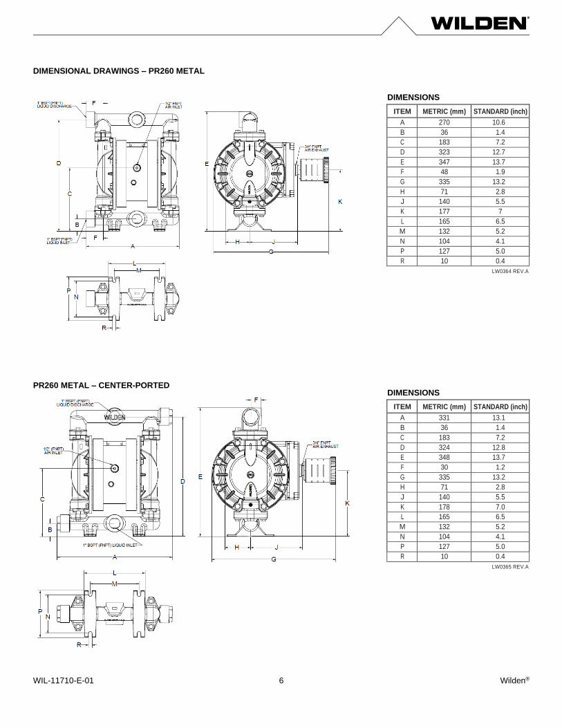
DIMENSIONAL DRAWINGS – PR260 METAL
ITEM METRIC (mm) STANDARD (inch)
A 270 10.6
B 36 1.4
C 183 7.2
D 323 12.7
E 347 13.7
F 48 1.9
G 335 13.2
H 71 2.8
J 140 5.5
K 177 7
L 165 6.5
M 132 5.2
N 104 4.1
P 127 5.0
R 10 0.4
LW0364 REV.A
PR260 METAL – CENTER-PORTED
ITEM METRIC (mm) STANDARD (inch)
A 331 13.1
B 36 1.4
C 183 7.2
D 324 12.8
E 348 13.7
F 30 1.2
G 335 13.2
H 71 2.8
J 140 5.5
K 178 7.0
L 165 6.5
M 132 5.2
N 104 4.1
P 127 5.0
R 10 0.4
LW0365 REV.A
DIMENSIONS
DIMENSIONS
WIL-11710-E-01 Wilden® 7
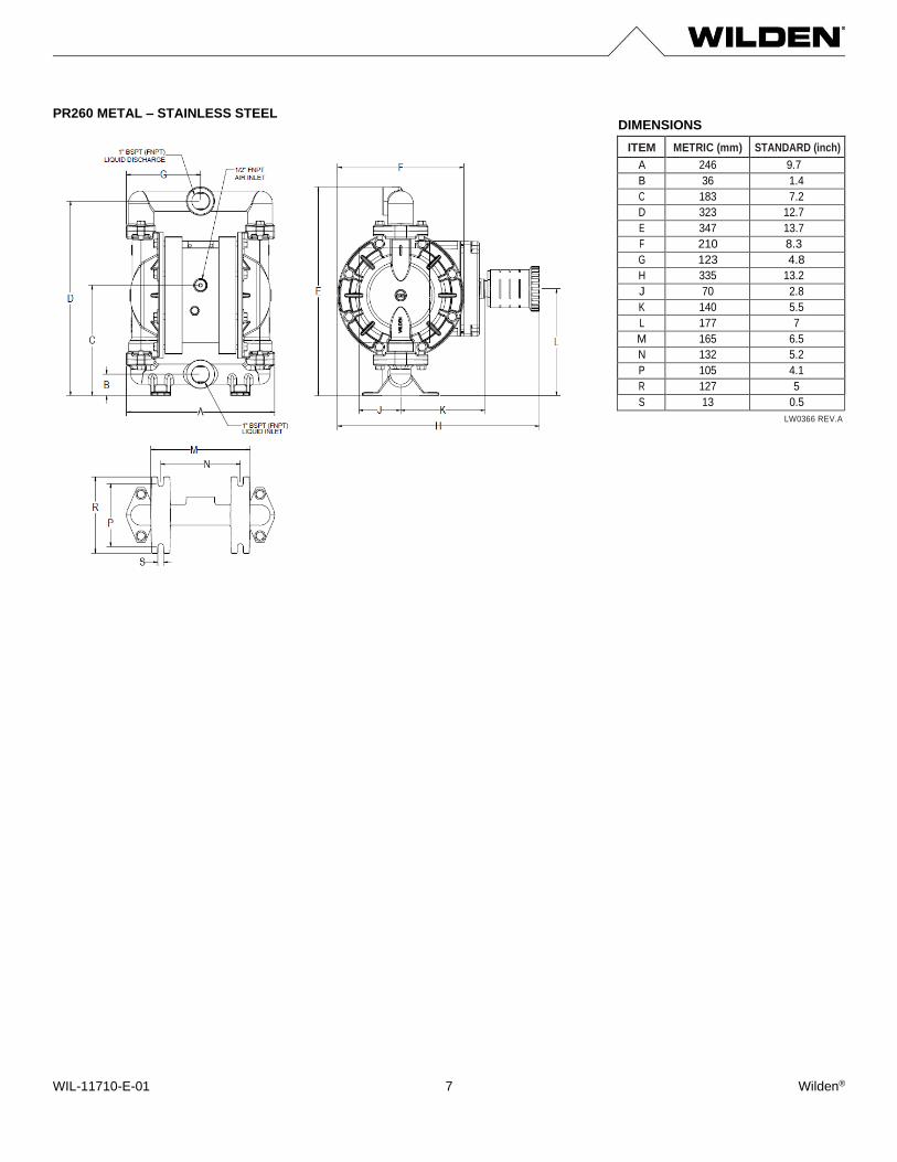
PR260 METAL – STAINLESS STEEL
ITEM METRIC (mm) STANDARD (inch)
A 246 9.7
B 36 1.4
C 183 7.2
D 323 12.7
E 347 13.7
F 210 8.3
G 123 4.8
H 335 13.2
J 70 2.8
K 140 5.5
L 177 7
M 165 6.5
N 132 5.2
P 105 4.1
R 127 5
S 13 0.5
LW0366 REV.A
DIMENSIONS
WIL-11710-E-01 Wilden® 8
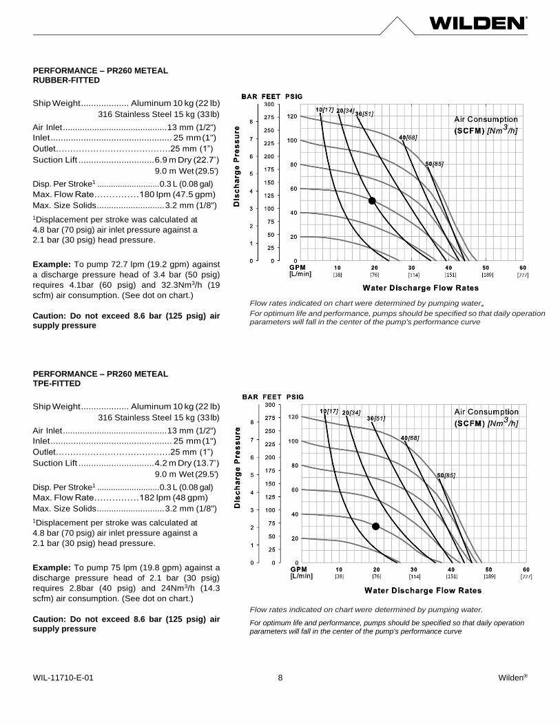
PERFORMANCE – PR260 METEAL RUBBER-FITTED PERFORMANCE – PR260 METEAL TPE-FITTED
Flow rates indicated on chart were determined by pumping water。 For optimum life and performance, pumps should be specified so that daily operation parameters will fall in the center of the pump's performance curve
Ship Weight ................... Aluminum 10 kg (22 lb)
316 Stainless Steel 15 kg (33 lb)
Air Inlet ........................................... 13 mm (1/2")
Inlet ................................................ 25 mm (1")
Outlet………………………………….25 mm (1”)
Suction Lift .............................. 6.9 m Dry (22.7’)
9.0 m Wet (29.5')
Disp. Per Stroke1 ........................... 0.3 L (0.08 gal)
Max. Flow Rate……………180 lpm (47.5 gpm)
Max. Size Solids ............................ 3.2 mm (1/8")
1Displacement per stroke was calculated at
4.8 bar (70 psig) air inlet pressure against a
2.1 bar (30 psig) head pressure.
Example: To pump 72.7 lpm (19.2 gpm) against
a discharge pressure head of 3.4 bar (50 psig)
requires 4.1bar (60 psig) and 32.3Nm3/h (19
scfm) air consumption. (See dot on chart.)
Caution: Do not exceed 8.6 bar (125 psig) air supply pressure
Flow rates indicated on chart were determined by pumping water.
For optimum life and performance, pumps should be specified so that daily operation parameters will fall in the center of the pump's performance curve
Ship Weight ................... Aluminum 10 kg (22 lb)
316 Stainless Steel 15 kg (33 lb)
Air Inlet ........................................... 13 mm (1/2")
Inlet ................................................ 25 mm (1")
Outlet………………………………….25 mm (1”)
Suction Lift .............................. 4.2 m Dry (13.7’)
9.0 m Wet (29.5')
Disp. Per Stroke1 ........................... 0.3 L (0.08 gal)
Max. Flow Rate……………182 lpm (48 gpm)
Max. Size Solids ............................ 3.2 mm (1/8")
1Displacement per stroke was calculated at
4.8 bar (70 psig) air inlet pressure against a
2.1 bar (30 psig) head pressure.
Example: To pump 75 lpm (19.8 gpm) against a
discharge pressure head of 2.1 bar (30 psig)
requires 2.8bar (40 psig) and 24Nm3/h (14.3
scfm) air consumption. (See dot on chart.)
Caution: Do not exceed 8.6 bar (125 psig) air supply pressure
WIL-11710-E-01 Wilden® 9
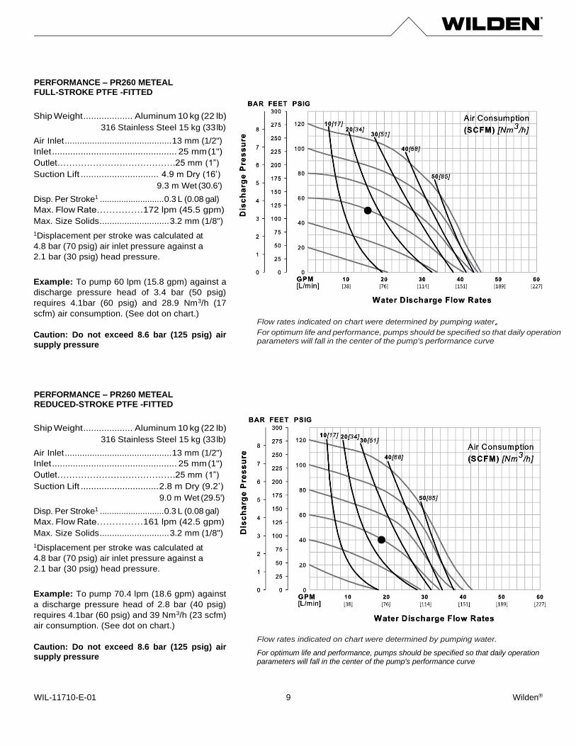
PERFORMANCE – PR260 METEAL FULL-STROKE PTFE -FITTED PERFORMANCE – PR260 METEAL REDUCED-STROKE PTFE -FITTED
Flow rates indicated on chart were determined by pumping water。 For optimum life and performance, pumps should be specified so that daily operation parameters will fall in the center of the pump's performance curve
Ship Weight ................... Aluminum 10 kg (22 lb)
316 Stainless Steel 15 kg (33 lb)
Air Inlet ........................................... 13 mm (1/2")
Inlet ................................................ 25 mm (1")
Outlet………………………………….25 mm (1”)
Suction Lift .............................. 4.9 m Dry (16’)
9.3 m Wet (30.6')
Disp. Per Stroke1 ........................... 0.3 L (0.08 gal)
Max. Flow Rate……………172 lpm (45.5 gpm)
Max. Size Solids ............................ 3.2 mm (1/8")
1Displacement per stroke was calculated at
4.8 bar (70 psig) air inlet pressure against a
2.1 bar (30 psig) head pressure.
Example: To pump 60 lpm (15.8 gpm) against a
discharge pressure head of 3.4 bar (50 psig)
requires 4.1bar (60 psig) and 28.9 Nm3/h (17
scfm) air consumption. (See dot on chart.)
Caution: Do not exceed 8.6 bar (125 psig) air
supply pressure
Flow rates indicated on chart were determined by pumping water.
For optimum life and performance, pumps should be specified so that daily operation parameters will fall in the center of the pump's performance curve
Ship Weight ................... Aluminum 10 kg (22 lb)
316 Stainless Steel 15 kg (33 lb)
Air Inlet ........................................... 13 mm (1/2")
Inlet ................................................ 25 mm (1")
Outlet………………………………….25 mm (1”)
Suction Lift .............................. 2.8 m Dry (9.2’)
9.0 m Wet (29.5')
Disp. Per Stroke1 ........................... 0.3 L (0.08 gal)
Max. Flow Rate……………161 lpm (42.5 gpm)
Max. Size Solids ............................ 3.2 mm (1/8")
1Displacement per stroke was calculated at
4.8 bar (70 psig) air inlet pressure against a
2.1 bar (30 psig) head pressure.
Example: To pump 70.4 lpm (18.6 gpm) against
a discharge pressure head of 2.8 bar (40 psig)
requires 4.1bar (60 psig) and 39 Nm3/h (23 scfm)
air consumption. (See dot on chart.)
Caution: Do not exceed 8.6 bar (125 psig) air supply pressure
WIL-11710-E-01 Wilden® 10
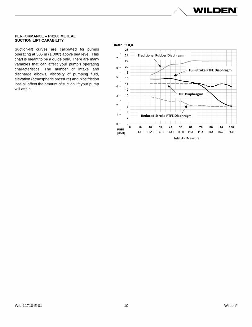
PERFORMANCE – PR260 METEAL SUCTION LIFT CAPABILITY
Suction-lift curves are calibrated for pumps
operating at 305 m (1,000') above sea level. This
chart is meant to be a guide only. There are many
variables that can affect your pump's operating
characteristics. The number of intake and
discharge elbows, viscosity of pumping fluid,
elevation (atmospheric pressure) and pipe friction
loss all affect the amount of suction lift your pump
will attain.
TPE Diaphragms
Traditional Rubber Diaphragm
Full-Stroke PTFE Diaphragm
Reduced-Stroke PTFE Diaphragm
WIL-11710-E-01 Wilden® 11
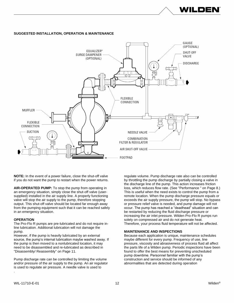
SUGGESTED INSTALLATION, OPERATION & MAINTENANCE Wilden pumps are designed to meet the performance requirements of even the most demanding pumping applications. They have been designed and manufactured to the highest standards and are available in a variety of liquid path materials to meet your chemical resistance needs. Refer to "Performance " on Page 8 for an in-depth analysis of the performance characteristics of your pump. Wilden offers the widest variety of elastomer options in the industry to satisfy temperature, chemical compatibility, abrasion resistance and flex concerns. The suction pipe size should be at least equal to or larger than the diameter size of the suction inlet on your Wilden pump. The suction hose must be a non-collapsible, reinforced type because these pumps are capable of pulling a high vacuum. Discharge piping should also be equal to or larger than the diameter of the pump discharge, which will help reduce friction losses. CAUTION: All fittings and connections must be airtight. Otherwise, pump suction capability will be reduced or lost. Months of careful planning, study and selection efforts can result in unsatisfactory pump performance if installation details are left to chance. You can avoid premature failure and long-term dissatisfaction by exercising reasonable care throughout the installation process. LOCATION Noise, safety and other logistical factors usually dictate where equipment will be situated on the production floor. Multiple installations with conflicting requirements can result in congestion of utility areas, leaving few choices for additional pumps. Within the framework of these and other existing conditions, locate every pump in such a way that the following six key factors are balanced against each other to maximum advantage:
• Access: First, the location should be accessible. If it’s easy to reach the pump, maintenance personnel will be able to perform routine inspections and adjustments more easily. If major repairs become necessary, ease of access can play a key role in speeding the repair process and reducing total downtime.
• Air Supply: Every pump location should have an air line large enough to supply the volume of air necessary to achieve the desired pumping rate. For best results, the pumps should use a 5μ (micron) air filter, needle valve and regulator. The use of an air filter before the pump will ensure that the majority of any pipeline contaminants will be eliminated.
• Solenoid Operation: When operation is controlled by a solenoid valve in the air line, three-way valves should be used. This valve allows trapped air between the valve and the pump to bleed off, which improves pump performance. You can estimate pumping volume by counting the number of strokes per minute, and then multiplying that figure by the displacement per stroke.
• Muffler: Using the standard Wilden muffler, sound levels are reduced below OSHA specifications. You can use other mufflers to reduce sound levels farther, but they usually reduce pump performance.
• Elevation: Selecting a site that is well within the pump’s dynamic lift capability will assure that loss-of-prime issues will be eliminated. In addition, pump efficiency can be adversely affected if proper attention is not given to site location.
• Piping: Final determination of the pump site should not be made until the piping challenges of each possible location have been evaluated. The impact of current and future installations should be considered ahead of time to make sure that inadvertent restrictions are not created for any remaining sites.
The best choice possible will be a site involving the shortest and straightest hook-up of suction and discharge piping. Unnecessary elbows, bends and fittings should be avoided. Pipe sizes should be selected to keep friction losses within practical limits. All piping should be supported independently of the pump. In addition, the piping should be aligned to avoid placing stress on the pump fittings. Flexible hose can be installed to aid in absorbing the forces created by the natural reciprocating action of the pump. If the pump is to be bolted down to a solid location, a mounting pad placed between the pump and the foundation will assist in minimizing pump vibration. Flexible connections between the pump and rigid piping will also assist in minimizing pump vibration. If quick-closing valves are installed at any point in the discharge system, or if pulsation within a system becomes a problem, a surge suppressor (SD Equalizer) should be installed to protect the pump, piping and gauges from surges and water hammer. If the pump is to be used in a self-priming application, make sure that all connections are airtight and that the suction lift is within the model’s ability. NOTE: Materials of construction and elastomer material have an effect on suction lift parameters. Please refer to "Performance " on Page 8 for specifics. When pumps are installed in applications involving flooded suction or suction head pressures, a gate valve should be installed in the suction line to permit closing of the line for pump service. Pumps in service with a positive suction head are most efficient when inlet pressure is limited to 0.5–0.7 bar (7–10 psig). Premature diaphragm failure may occur if positive suction is 0.7 bar (10 psig) and higher. Single-Point Exhaust Pro-Flo R pumps can be used for submersible applications when using the Pro-Flo R's single-point exhaust. CAUTION: All Wilden pumps are capable of passing solids. Use a strainer on the pump intake to ensure that the pump's rated solids capacity is not exceeded.
CAUTION: Do not exceed 8.6 bar (125 psig) air supply pressure.
WIL-11710-E-01 Wilden® 12
SUGGESTED INSTALLATION, OPERATION & MAINTENANCE NOTE: In the event of a power failure, close the shut-off valve if you do not want the pump to restart when the power returns. AIR-OPERATED PUMP: To stop the pump from operating in an emergency situation, simply close the shut-off valve (user-supplied) installed in the air supply line. A properly functioning valve will stop the air supply to the pump, therefore stopping output. This shut-off valve should be located far enough away from the pumping equipment such that it can be reached safely in an emergency situation. OPERATION The Pro-Flo R pumps are pre-lubricated and do not require in- line lubrication. Additional lubrication will not damage the pump. However, if the pump is heavily lubricated by an external source, the pump’s internal lubrication maybe washed away. If the pump is then moved to a nonlubricated location, it may need to be disassembled and re-lubricated as described in "Disassembly/ Reassembly" on Page 11. Pump discharge rate can be controlled by limiting the volume and/or pressure of the air supply to the pump. An air regulator is used to regulate air pressure. A needle valve is used to
regulate volume. Pump discharge rate also can be controlled by throttling the pump discharge by partially closing a valve in the discharge line of the pump. This action increases friction loss, which reduces flow rate. (See "Performance " on Page 8.) This is useful when the need exists to control the pump from a remote location. When the pump discharge pressure equals or exceeds the air supply pressure, the pump will stop. No bypass or pressure relief valve is needed, and pump damage will not occur. The pump has reached a “deadhead” situation and can be restarted by reducing the fluid discharge pressure or increasing the air inlet pressure. Wilden Pro-Flo R pumps run solely on compressed air and do not generate heat. Therefore, your process fluid temperature will not be affected. MAINTENANCE AND INSPECTIONS Because each application is unique, maintenance schedules maybe different for every pump. Frequency of use, line pressure, viscosity and abrasiveness of process fluid all affect the parts life of a Wilden pump. Periodic inspections have been found to offer the best means for preventing unscheduled pump downtime. Personnel familiar with the pump’s construction and service should be informed of any abnormalities that are detected during operation
.
WIL-11710-E-01 Wilden® 13
TROUBLESHOOTING
Pump will not run or runs slowly.
1. Remove plug from pilot spool exhaust. 2. Ensure that the air inlet pressure is at least 0.4 bar (5
psig) above startup pressure and that the differential pressure (the difference between air inlet and liquid discharge pressures) is not less than 0.7 bar (10 psig).
3. Check air inlet filter for debris (see "Suggested Installation, Operation, Maintenance and Troubleshooting" on Page 11).
4. Check for extreme air leakage (blow by) that would indicate worn seals/bores in the air valve, pilot spool and main shaft.
5. Disassemble the pump and check for obstructions in the air passageways or objects that would obstruct the movement of internal parts.
6. Check for sticking ball check valves. a. If material being pumped is not compatible with
pump elastomers, swelling may occur. Replace ball check valves and seals with proper elastomers.
b. Also, as the check valve balls wear out, they become smaller and can become stuck in the seats. In this case, replace balls and seats.
7. Check for any broken inner piston that would cause the air valve spool to be unable to shift.
Pump runs but little or no product flows.
1. Check for pump cavitation; slow pump speed down to allow thick material to flow into liquid chambers.
2. Verify that vacuum required to lift liquid is not greater than the vapor pressure of the material being pumped (cavitation).
3. Check for sticking ball check valves. a. If material being pumped is not compatible with
pump elastomers, swelling may occur. Replace ball check valves and seats with proper elastomers.
b. Also, as the check valve balls wear out, they become smaller and can become stuck in the seats. In this case, replace balls and seats.
Pump air valve freezes.
1. Check for excessive moisture in compressed air. a. Either install a dryer or hot air generator for
compressed air. b. Alternatively, a coalescing filter may be used to
remove the water from the compressed air in some applications.
Air bubbles in pump discharge.
1. Check for ruptured diaphragm.
2. Check tightness of outer pistons (see Disassembly/Reassembly on Page 14).
3. Check tightness of fasteners and integrity of O-rings and seals, especially at intake manifold.
4. Ensure pipe connections are airtight. Product comes out air exhaust.
1. Check for diaphragm rupture.
2. Check tightness of outer pistons to shaft.
WIL-11710-E-01 Wilden® 14
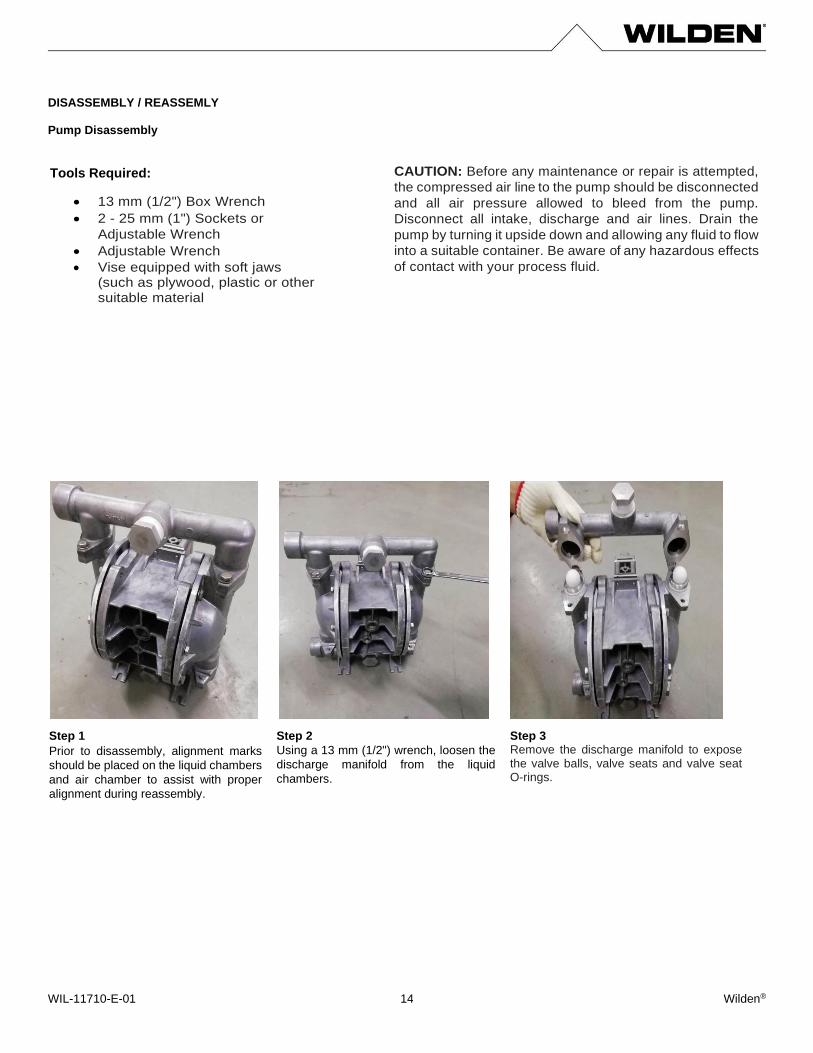
DISASSEMBLY / REASSEMLY Pump Disassembly
Step 1 Prior to disassembly, alignment marks
should be placed on the liquid chambers
and air chamber to assist with proper
alignment during reassembly.
Step 2
Using a 13 mm (1/2") wrench, loosen the
discharge manifold from the liquid
chambers.
Step 3 Remove the discharge manifold to expose the valve balls, valve seats and valve seat O-rings.
Tools Required:
• 13 mm (1/2") Box Wrench
• 2 - 25 mm (1") Sockets or
Adjustable Wrench
• Adjustable Wrench
• Vise equipped with soft jaws (such as plywood, plastic or other suitable material
CAUTION: Before any maintenance or repair is attempted,
the compressed air line to the pump should be disconnected
and all air pressure allowed to bleed from the pump.
Disconnect all intake, discharge and air lines. Drain the
pump by turning it upside down and allowing any fluid to flow
into a suitable container. Be aware of any hazardous effects
of contact with your process fluid.
WIL-11710-E-01 Wilden® 15
DISASSEMBLY / REASSEMLY
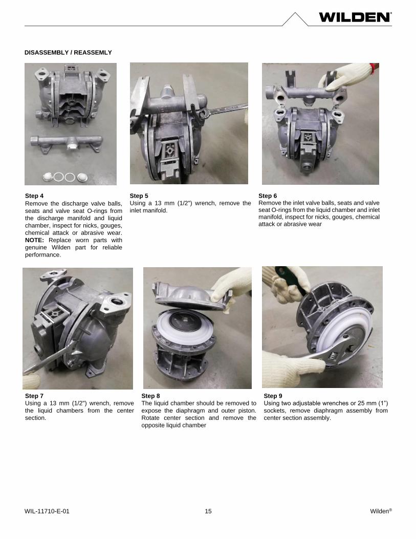
Step 4 Remove the discharge valve balls,
seats and valve seat O-rings from
the discharge manifold and liquid
chamber, inspect for nicks, gouges,
chemical attack or abrasive wear.
NOTE: Replace worn parts with
genuine Wilden part for reliable
performance.
Step 5
Using a 13 mm (1/2") wrench, remove the
inlet manifold.
Step 6 Remove the inlet valve balls, seats and valve seat O-rings from the liquid chamber and inlet manifold, inspect for nicks, gouges, chemical attack or abrasive wear
Step 7
Using a 13 mm (1/2") wrench, remove
the liquid chambers from the center
section.
Step 8
The liquid chamber should be removed to
expose the diaphragm and outer piston.
Rotate center section and remove the
opposite liquid chamber
Step 9
Using two adjustable wrenches or 25 mm (1”)
sockets, remove diaphragm assembly from
center section assembly.
WIL-11710-E-01 Wilden® 16
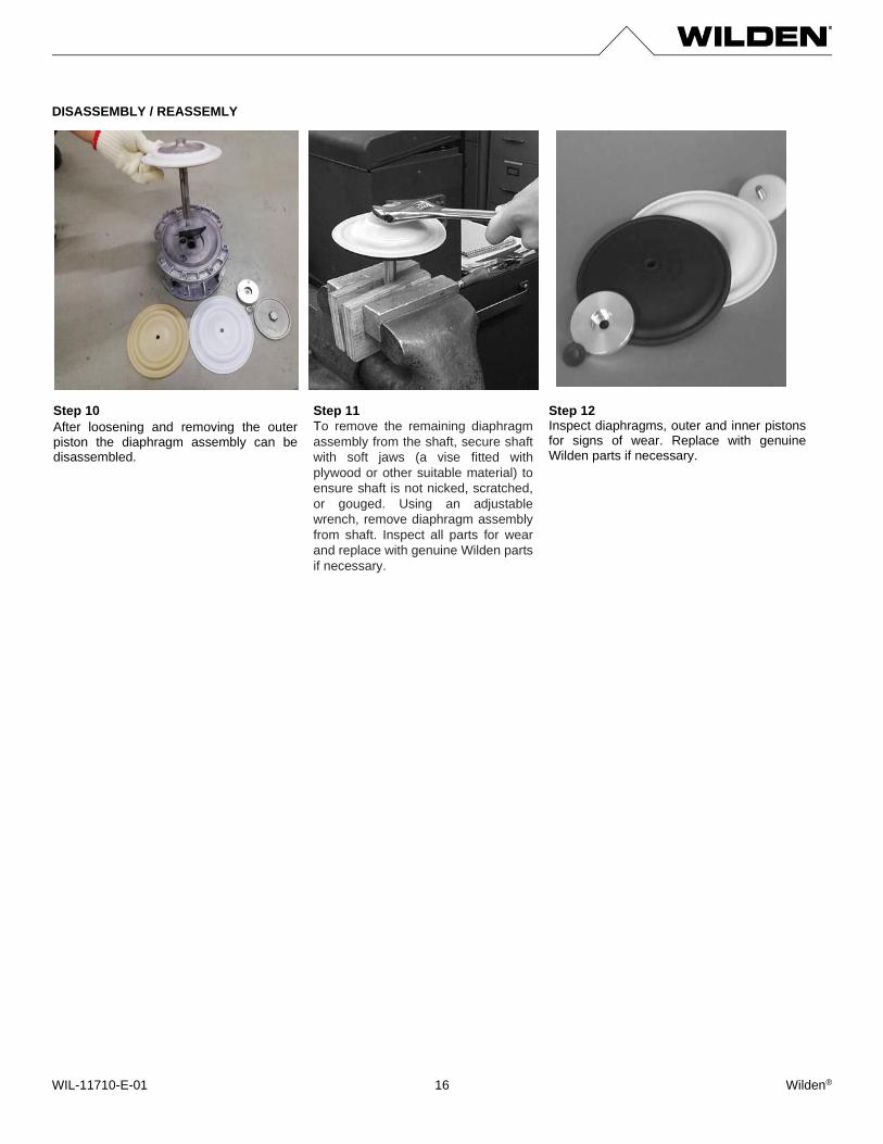
DISASSEMBLY / REASSEMLY Step 10 After loosening and removing the outer piston the diaphragm assembly can be disassembled.
Step 11
To remove the remaining diaphragm
assembly from the shaft, secure shaft
with soft jaws (a vise fitted with
plywood or other suitable material) to
ensure shaft is not nicked, scratched,
or gouged. Using an adjustable
wrench, remove diaphragm assembly
from shaft. Inspect all parts for wear
and replace with genuine Wilden parts
if necessary.
Step 12 Inspect diaphragms, outer and inner pistons for signs of wear. Replace with genuine Wilden parts if necessary.
WIL-11710-E-01 Wilden® 17
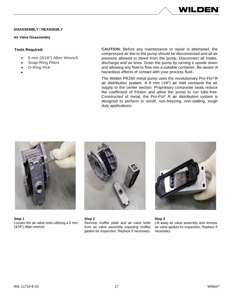
DISASSEMBLY / REASSEMLY Air Valve Disassembly
Step 1
Loosen the air valve bolts utilizing a 5 mm (3⁄16") Allen wrench.
Step 2
Remove muffler plate and air valve bolts
from air valve assembly exposing muffler
gasket for inspection. Replace if necessary.
Step 3
Lift away air valve assembly and remove
air valve gasket for inspection. Replace if
necessary.
Tools Required:
• 5 mm (3/16") Allen Wrench
• Snap-Ring Pliers
• O-Ring Pick
•
CAUTION: Before any maintenance or repair is attempted, the
compressed air line to the pump should be disconnected and all air
pressure allowed to bleed from the pump. Disconnect all intake,
discharge and air lines. Drain the pump by turning it upside down
and allowing any fluid to flow into a suitable container. Be aware of
hazardous effects of contact with your process fluid.
The Wilden PR260 metal pump uses the revolutionary Pro-Flo® R
air distribution system. A 6 mm (1⁄4") air inlet connects the air
supply to the center section. Proprietary composite seals reduce
the coefficient of friction and allow the pump to run lube-free.
Constructed of metal, the Pro-Flo® R air distribution system is
designed to perform in on/off, non-freezing, non-stalling, tough
duty applications.

WIL-11710-E-01 Wilden® 18
DISASSEMBLY / REASSEMLY
Step 4 Remove air valve end cap to expose air valve spool by simply lifting up on end cap once air valve bolts are removed.
Step 5
Remove air valve spool from air valve body by
threading one air valve bolt into the end of the
spool and gently sliding the spool out of the air
valve body. Inspect seals for signs of wear and
replace entire assembly if necessary. Use
caution when handling air valve spool to
prevent damaging seals.
NOTE: Seals should not be removed from assembly. Seals are not sold separately
Step 6 Remove pilot spool sleeve retaining snap ring on both sides of center section with snap ring pliers.
Step 7 Remove pilot spool sleeve from center section.
Step 8
With O-ring pick, gently remove the O-ring from the
opposite side of the center hole cut on the spool.
Gently remove the pilot spool from sleeve and inspect
for nicks, gouges or other signs of wear. Replace pilot
sleeve assembly or outer sleeve O-rings if necessary.
During reassembly never insert the pilot spool into the
sleeve with the center cut side first, this end
incorporates the urethane O-ring and will be damaged
as it slides over the ports cut in the sleeve.
NOTE: Seals should not be removed from pilot spool.
Seals are not sold separately.
Step 9
Check center section Glyd™ rings for signs of wear. If necessary, remove Glyd™ rings with O-ring pick and replace.
WIL-11710-E-01 Wilden® 19
DISASSEMBLY / REASSEMLY Shaft Seal Disassembly DISASSEMBLY / REASSEMLY
PRO-FLO R MAXIMUM TORQUE SPECIFICATIONS
Description of Part Torque
Air Valve 11.3 N•m (100 in-lb)
Dial Set Screw 11.3 N•m (100 in-lb)
Outer Pistons, All diaphragms 47.1 N•m (30 ft-lb)
Top and Bottom Manifold 8.5 N•m (75 in-lb)
Liquid Chamber to Center Section 8.5 N•m (75 in-lb)
Tools Required: The following tools can be used to aid in the installation of the new seals:
• Needle-Nose Pliers
• Phillips Screwdriver
• Electrical Tape
Figure A
Pre-Installation
After all of the old seals have been removed, the inside of the
bushing should be cleaned to ensure no debris is left that may cause
premature damage to the new seals.
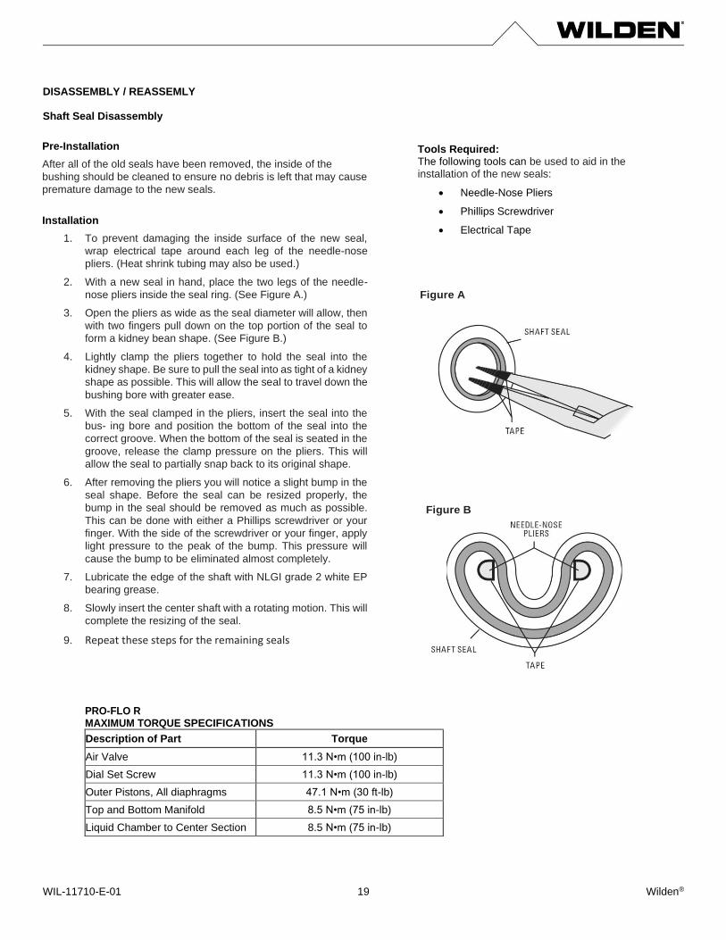
Installation
1. To prevent damaging the inside surface of the new seal,
wrap electrical tape around each leg of the needle-nose
pliers. (Heat shrink tubing may also be used.)
2. With a new seal in hand, place the two legs of the needle-
nose pliers inside the seal ring. (See Figure A.)
3. Open the pliers as wide as the seal diameter will allow, then
with two fingers pull down on the top portion of the seal to
form a kidney bean shape. (See Figure B.)
4. Lightly clamp the pliers together to hold the seal into the
kidney shape. Be sure to pull the seal into as tight of a kidney
shape as possible. This will allow the seal to travel down the
bushing bore with greater ease.
5. With the seal clamped in the pliers, insert the seal into the
bus- ing bore and position the bottom of the seal into the
correct groove. When the bottom of the seal is seated in the
groove, release the clamp pressure on the pliers. This will
allow the seal to partially snap back to its original shape.
6. After removing the pliers you will notice a slight bump in the
seal shape. Before the seal can be resized properly, the
bump in the seal should be removed as much as possible.
This can be done with either a Phillips screwdriver or your
finger. With the side of the screwdriver or your finger, apply
light pressure to the peak of the bump. This pressure will
cause the bump to be eliminated almost completely.
7. Lubricate the edge of the shaft with NLGI grade 2 white EP
bearing grease.
8. Slowly insert the center shaft with a rotating motion. This will
complete the resizing of the seal.
9. Repeat these steps for the remaining seals
Figure B
WIL-11710-E-01 Wilden® 20
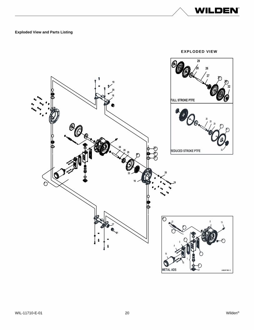
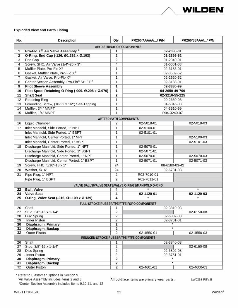
Exploded View and Parts Listing
17
1619
2032
25
242928
26
18
20
19
30
21
22
REDUCED STROKE PTFE
FULL STROKE PTFE
26
27
28
29
3130
32
METAL ADS LW0367 REV. C
EXPLODED VIEW
WIL-11710-E-01 Wilden® 21
Exploded View and Parts Listing
No. Description Qty. PR260/AAAAA/…/ P/N PR260/SSAAA/…/ P/N
AIR DISTRIBUTION COMPONENTS
1 Pro-Flo X® Air Valve Assembly 1 1 02-2030-01
2 O-Ring, End Cap (-126, Ø1.362 x Ø.103) 2 01-2395-52
3 End Cap 2 01-2340-01
4 Screw, SHC, Air Valve (1/4"-20 x 3") 4 01-6001-03
5 Muffler Plate, Pro-Flo X® 1 02-3185-01
6 Gasket, Muffler Plate, Pro-Flo X® 1 02-3502-52
7 Gasket, Air Valve, Pro-Flo X® 1 02-2620-52
8 Center Section Assembly, Pro-Flo® SHIFT 2 1 02-3138-01
9 Pilot Sleeve Assembly 1 02-3880-99
10 Pilot Spool Retaining O-Ring (-009. Ø.208 x Ø.070) 1 04-2650-49-700
11 Shaft Seal 2 02-3210-55-225
12 Retaining Ring 1 00-2650-03
13 Grounding Screw, (10-32 x 1/2") Self-Tapping 1 04-6345-08
14 Muffler, 3/4" MNPT 1 04-3510-99
15 Muffler, 1/4" MNPT 1 R04-3240-07
WETTED PATH COMPONENTS
16 Liquid Chamber 2 02-5018-01 02-5018-03
17 Inlet Manifold, Side Ported, 1" NPT 1 02-5100-01
Inlet Manifold, Side Ported, 1" BSPT 1 02-5101-01
Inlet Manifold, Center Ported, 1" NPT 1 02-5100-03
Inlet Manifold, Center Ported, 1" BSPT 1 02-5101-03
18 Discharge Manifold, Side Ported, 1" NPT 1 02-5070-01
Discharge Manifold, Side Ported, 1" BSPT 1 02-5071-01
Discharge Manifold, Center Ported, 1" NPT 1 02-5070-01 02-5070-03
Discharge Manifold, Center Ported, 1" BSPT 1 02-5071-01 02-5071-03
19 Screw, HHC, 5/16"-18 x 1" 24 08-6180-03-42
20 Washer, 5/16" 24 02-6731-03
21 Pipe Plug, 1" NPT 2 R02-7010-01
Pipe Plug, 1" BSPT 2 R02-7011-01
VALVE BALLS/VALVE SEATS/VALVE O-RINGS/MANIFOLD O-RING
22 Ball, Valve 4 * *
24 Valve Seat 4 02-1120-01 02-1120-03
25 O-ring, Valve Seat (-216, Ø1.109 x Ø.139) 4 * *
FULL-STROKE RUBBER/TPE/PTFE/FSIPD COMPONENTS
26 Shaft 1 02-3810-03
27 Stud, 3/8"-16 x 1-1/4" 2 02-6150-08
28 Disc Spring 2 02-6802-08
29 Inner Piston 2 02-3701-01
30 Diaphragm, Primary 2 *
31 Diaphragm, Backup 2 * 32 Outer Piston 2 02-4550-01 02-4550-03
REDUCED-STROKE RUBBER/TPE/PTFE COMPONENTS
26 Shaft 1 02-3840-03
27 Stud, 3/8"-16 x 1-1/4" 2 02-6150-08
28 Disc Spring 2 02-6802-08
29 Inner Piston 2 02-3751-01
30 Diaphragm, Primary 2 *
31 Diaphragm, Backup 2 * 32 Outer Piston 2 02-4601-01 02-4600-03
* Refer to Elastomer Options in Section 9 1Air Valve Assembly includes items 2 and 3 2Center Section Assembly includes items 9,10,11, and 12
All boldface items are primary wear parts. LW0368 REV.B
WIL-11710-E-01 Wilden® 22
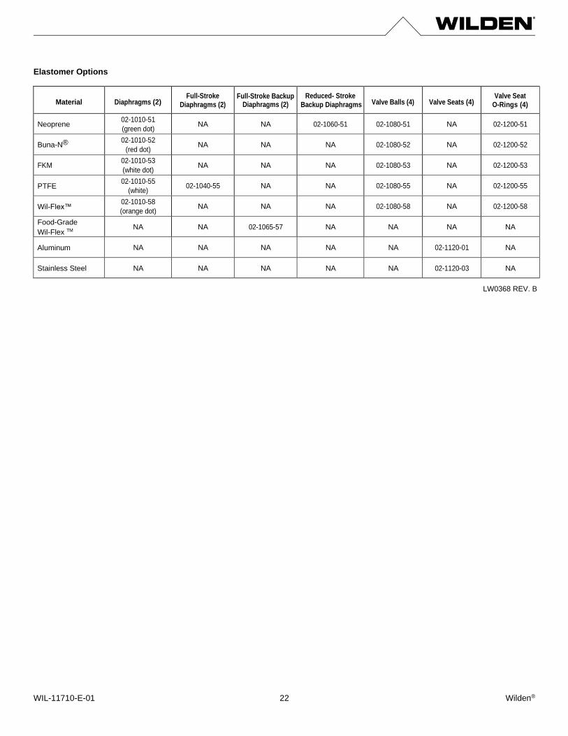
Elastomer Options
Material Diaphragms (2) Full-Stroke
Diaphragms (2) Full-Stroke Backup
Diaphragms (2) Reduced- Stroke
Backup Diaphragms Valve Balls (4) Valve Seats (4) Valve Seat
O-Rings (4)
Neoprene 02-1010-51
(green dot) NA NA 02-1060-51 02-1080-51 NA 02-1200-51
Buna-N® 02-1010-52
(red dot) NA NA NA 02-1080-52 NA 02-1200-52
FKM 02-1010-53
(white dot) NA NA NA 02-1080-53 NA 02-1200-53
PTFE 02-1010-55
(white) 02-1040-55 NA NA 02-1080-55 NA 02-1200-55
Wil-Flex™ 02-1010-58
(orange dot) NA NA NA 02-1080-58 NA 02-1200-58
Food-Grade
Wil-Flex TM NA NA 02-1065-57 NA NA NA NA
Aluminum NA NA NA NA NA 02-1120-01 NA
Stainless Steel NA NA NA NA NA 02-1120-03 NA
LW0368 REV. B
WIL-11500-E-09 Wilden® 23