a review of flotation physical froth flow modifiers - mdpi
TRANSCRIPT
minerals
Review
A Review of Flotation Physical Froth Flow Modifiers
Tawona M. Jera * and Clayton Bhondayi
�����������������
Citation: Jera, T.M.; Bhondayi, C. A
Review of Flotation Physical Froth
Flow Modifiers. Minerals 2021, 11, 864.
https://doi.org/10.3390/min1108
0864
Academic Editors:
Belinda Mcfadzean and
Kathryn Hadler
Received: 22 June 2021
Accepted: 19 July 2021
Published: 10 August 2021
Publisher’s Note: MDPI stays neutral
with regard to jurisdictional claims in
published maps and institutional affil-
iations.
Copyright: © 2021 by the authors.
Licensee MDPI, Basel, Switzerland.
This article is an open access article
distributed under the terms and
conditions of the Creative Commons
Attribution (CC BY) license (https://
creativecommons.org/licenses/by/
4.0/).
Institute for the Development of Energy for African Sustainability, University of South Africa, Florida Campus,Johannesburg 1709, South Africa; [email protected]* Correspondence: [email protected]; Tel.: +27-71-043-2128
Abstract: Over the past few decades, the need to process more minerals while lowering capital costshas led to an increase in the size of flotation cells, e.g., 0.03 m3 to 1000 m3. However, this increasehas created new challenges in the operation and design of industrial flotation cells, particularlyin terms of froth removal, because the distance the froth must travel increases with an increase inthe flotation cell diameter. This has a negative impact on recovery. Physical froth flow modifierscan be used to improve froth removal. Their major functions are to modify and optimise the flowof the froth, improve froth drainage, reduce dead zones, and improve froth flow and removaldynamics. Therefore, physical froth flow modifiers are discussed, evaluated, and compared in thispaper. The literature indicates that physical froth flow modifiers such as crowders and launders areused extensively as industrial solutions to enhance froth transport and recovery in large flotationcells. Other modifiers (including froth baffles and froth scrapers) have been found to have a profoundeffect on local froth phase sub-processes, including drainage and bubble coalescence. However,industrial uptake is either dwindling or limited to small-volume rectangular/U-shaped cells in thecase of scrapers, or, there is no uptake at all in the case of froth baffles. Further research on how someof the physical modifiers (e.g., baffles and launders) impact the selectivity of particles is required.
Keywords: froth stability; froth phase sub-processes; froth retention time; physical froth flow modifiers;froth carry rate; froth crowders; launders
1. Introduction
Froth flotation is a traditional mineral beneficiation technique. The process involvesadding chemicals to a slurry that alters the surfaces of milled particles so that they becomehydrophobic. Air in the form of bubbles picks up the hydrophobic particles as they rise tothe top of the pulp and form a froth. This layer of froth increases in height as more bubblesimpinge at the base of the froth and the bubbles become larger due to coalescence [1].The froth phase is very important in mineral froth flotation. Its functions include thefurther concentration of values by allowing the drainage of gangue minerals [2] to holdand transport particles to the concentrate launder [3].
The performance of the froth is known to be governed by the so-called froth phasesub-processes, i.e., bubble coalescence, liquid drainage, particles detachment and particlereattachment. It is measured in terms of froth recovery [4]. Froth recovery represents thefraction of the particles attached to the bubbles that enter the froth phase and survive itscleaning action and are recovered as concentrate [5].
The extent of the froth phase sub-processes is dependent on two crucial froth proper-ties: viz. froth stability and froth mobility. While it is known that froth stability depends ongas dispersion conditions, chemical conditions, and particle properties, it is also knownthat properties such as froth mobility can be increased by manipulating the froth zone(the compartment of the flotation cell that contains the froth). For instance, Cole et al. [6]reported that decreasing the cross-sectional area at the top of the froth increases frothmobility. Moys [7] and Bhondayi [8] found that manipulation of the froth zone can alsobe used to modify froth residence time distribution, i.e., froth mobility. Consequently,
Minerals 2021, 11, 864. https://doi.org/10.3390/min11080864 https://www.mdpi.com/journal/minerals
Minerals 2021, 11, 864 2 of 29
through practice and iterative research, several techniques to modify froth mobility andimprove froth performance have been developed. These include froth launders [9–16];froth crowders [14,17–22]; froth baffles [7,8,23]; and froth scrapers/froth paddles [24,25].The major functions of these techniques are to modify and optimise the flow of the froth,reduce dead zones, and improve froth flow and removal dynamics [2,18,26].
The purpose of this review is to provide a critical discussion of the available physicalfroth flow modifiers. The discussion of the physical froth flow modifiers focuses ontheir functions, how they influence froth performance, and where in a flotation circuitthey are most suitable, as well as their advantages and disadvantages. Comments onindustrial uptake are also included. The aim of the study is to show the extent of theknowledge regarding the subject of flow modifiers and their industrial uptake. This reviewis important to researchers in this field, as well as to practicing metallurgists who seek toimprove flotation cell froth performance and ultimately improve the flotation performanceof their operations. Researchers and designers in the field of froth flotation can identifygaps that require research, to improve the industrial application of flow modifiers. Theknowledge could also help practicing engineers who want to apply physical froth flowmodifiers in a new way, or engineers who need to retrofit a flow modifier at an existingfroth flotation facility.
2. The Flow of Froth in the Froth Zone
To discuss the concept of physical froth flow modification, we refer to the froth trans-port models that are available in the literature. These models depict how the froth is trans-ported from the pulp–froth interface to the concentrate launder. We base our discussion ontwo froth models that were considered by Moys [7] as being capable of describing the flowof the froth; these are: (i) solution for the 2D stream function equation/Laplace equation;and (ii) the two-stage tractable model. Application of the 2D stream function (Equation (1))to describe the flow of froth was found to be adequate by several researchers [8,27–29]. Ofimportance in the current work is that process parameters such as froth residence time dis-tribution, bubble streamline profiles and bubble velocity distribution can be obtained usingthis model. When using this modelling method, Moys [7], and later Bhondayi [8], foundthat bubbles close to the concentrate weir had a very short residence time compared tobubbles that enter the froth close to the back of the flotation cell. This has two implicationsthat are detrimental to flotation performance, viz., short froth residence time compromisesconcentrate grade, while a longer residence time reduces recovery. These findings arecritical when designing froth zones and froth removal methods or when modifying theflow of the froth.
∂2 Ø∂x2 +
∂2Ø∂z2 = 0 (1)
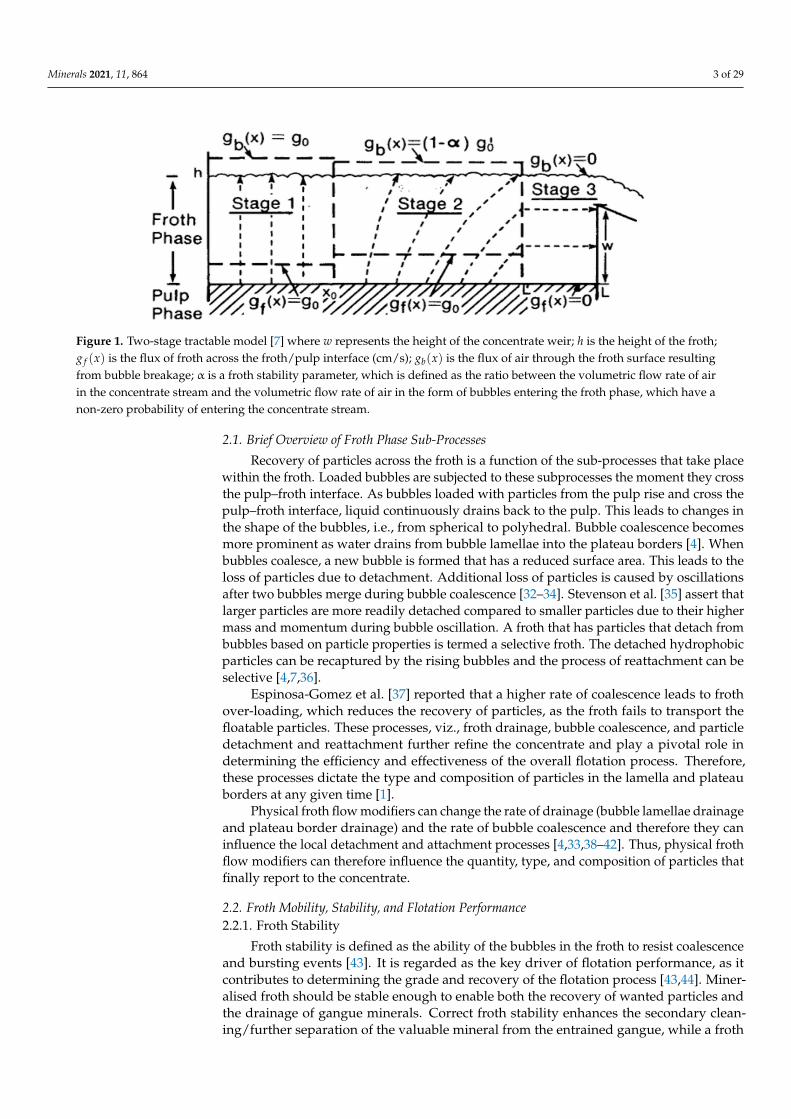
The two-stage tractable model (Figure 1) also presents a clear insight into the flowof the froth and hence has important implications for froth zone design and froth flowmodifying techniques. The model posits that the froth zone can be divided into zones orstages. In each stage, a certain type of flow occurs. For instance, in stage 1, all bubblesbreak up upon reaching the surface of the froth and do not contribute to concentrate flow.This stage is termed a dead zone. In stage 2, only a fraction of the bubbles entering thisstage break on the surface, with the balance reporting to the concentrate. In stage 3, allbubbles that enter the froth report to the concentrate. This model was further developedby [3,30,31] and its import in froth zone design and optimisation is that froth stability iscritical to efficient froth removal, and particular attention must be paid to activating stage1 and improving drainage in stage 3. Physical froth flow modification must then includereducing dead zones (stage 1) and improving drainage in stage 3 of flotation froth zone.
Minerals 2021, 11, 864 3 of 29
Figure 1. Two-stage tractable model [7] where w represents the height of the concentrate weir; h is the height of the froth;g f (x) is the flux of froth across the froth/pulp interface (cm/s); gb(x) is the flux of air through the froth surface resultingfrom bubble breakage; α is a froth stability parameter, which is defined as the ratio between the volumetric flow rate of airin the concentrate stream and the volumetric flow rate of air in the form of bubbles entering the froth phase, which have anon-zero probability of entering the concentrate stream.
2.1. Brief Overview of Froth Phase Sub-Processes
Recovery of particles across the froth is a function of the sub-processes that take placewithin the froth. Loaded bubbles are subjected to these subprocesses the moment they crossthe pulp–froth interface. As bubbles loaded with particles from the pulp rise and cross thepulp–froth interface, liquid continuously drains back to the pulp. This leads to changes inthe shape of the bubbles, i.e., from spherical to polyhedral. Bubble coalescence becomesmore prominent as water drains from bubble lamellae into the plateau borders [4]. Whenbubbles coalesce, a new bubble is formed that has a reduced surface area. This leads to theloss of particles due to detachment. Additional loss of particles is caused by oscillationsafter two bubbles merge during bubble coalescence [32–34]. Stevenson et al. [35] assert thatlarger particles are more readily detached compared to smaller particles due to their highermass and momentum during bubble oscillation. A froth that has particles that detach frombubbles based on particle properties is termed a selective froth. The detached hydrophobicparticles can be recaptured by the rising bubbles and the process of reattachment can beselective [4,7,36].
Espinosa-Gomez et al. [37] reported that a higher rate of coalescence leads to frothover-loading, which reduces the recovery of particles, as the froth fails to transport thefloatable particles. These processes, viz., froth drainage, bubble coalescence, and particledetachment and reattachment further refine the concentrate and play a pivotal role indetermining the efficiency and effectiveness of the overall flotation process. Therefore,these processes dictate the type and composition of particles in the lamella and plateauborders at any given time [1].
Physical froth flow modifiers can change the rate of drainage (bubble lamellae drainageand plateau border drainage) and the rate of bubble coalescence and therefore they caninfluence the local detachment and attachment processes [4,33,38–42]. Thus, physical frothflow modifiers can therefore influence the quantity, type, and composition of particles thatfinally report to the concentrate.
2.2. Froth Mobility, Stability, and Flotation Performance2.2.1. Froth Stability
Froth stability is defined as the ability of the bubbles in the froth to resist coalescenceand bursting events [43]. It is regarded as the key driver of flotation performance, as itcontributes to determining the grade and recovery of the flotation process [43,44]. Miner-alised froth should be stable enough to enable both the recovery of wanted particles andthe drainage of gangue minerals. Correct froth stability enhances the secondary clean-ing/further separation of the valuable mineral from the entrained gangue, while a froth
Minerals 2021, 11, 864 4 of 29
that is too stable is difficult to handle. If the froth is unstable (breaks continuously), itresults in the mineral-laden bubbles collapsing before they are carried over the concentrateweir which reduces recovery. An excessively stable froth (metastable froth) might entrain alarge number of gangue particles, which results in a poor grade of concentrate [45].
Several factors influence froth stability, including particle size and hydrophobicity [4]quality of process water, gas dispersion characteristics, and particle contact angle [43].The design of the froth zone has also been found to influence froth stability. For instance,Moys [7] concluded that air recovery can be changed by reducing the distance travelled bythe froth before it enters the concentrate launder. If air recovery is taken to be an indicatorof froth stability, as alluded to by several researchers, e.g., Moys [7], Barbian et al. [46] andHadler and Cilliers, [47], then physical froth flow modifiers can change the stability of thefroth. Froth surface velocity and froth rise velocity which can be changed by a physicalfroth flow modifier and can also be used as a measure of froth stability [48,49]. Otherindicators of froth stability are discussed in a review paper written by Farrokhpay [43].
2.2.2. Froth Mobility
According to Cutting et al. [24] and Farrokhpay [43], froth mobility describes the flowstreamlines that occur in the froth between the pulp–froth interface and the froth discharge.It is linked to the distribution of froth residence time [24] and depends on the distancethat the froth must travel before recovery [14]. The mobility of the froth is influenced byseveral factors, including froth stability, bubble loading [50], and froth rheology [43], etc.Moolman et al. [51] used the concept of froth mobility and stability to classify froths. Theydescribed an ideal froth as one that is not too runny nor too viscous. A runny froth is toowatery, has low mineralisation and is excessively mobile, while a sticky froth is highlyviscous with lower mobility than that of an ideal froth. A sticky froth contains largeelliptical bubbles with a high froth loading and is excessively stable [45].
Some of the challenges associated with froth mobility in large flotation cells aregenerally dealt with by inserting an external implement [14], which is referred to hereas a froth flow modifier. These inserts can modulate froth residence time; therefore, thepresence of a froth flow modifier plays a significant role in altering froth mobility. Forinstance, Bhondayi et al. [52] found that the presence of a baffle drastically changes thestreamlines followed by the bubbles as they rise from the pulp–froth interface to the surfaceof the froth. The results of their simulations (using the 2D stream function equation) alsopoint to changes in the distribution of froth residence time [52]. Cole [17] also found thatfroth crowders improve froth mobility by reducing the cross-sectional area available for thefroth. Cutting et al. [24] found that paddles assist in froth removal dynamics and thereforechange froth mobility.
2.3. Performance Measures in the Froth Zone2.3.1. Froth Recovery
Typically, the performance of the froth zone is measured in terms of froth recovery.Froth recovery is defined as the fraction of material that enters the froth, that survivesthe cleaning action in the froth zone and is recovered as concentrate. Froth recovery isknown to account for froth-phase sub-processes [53] and is related to froth retention time(FRT). FRT is a measure of the average froth residence time; it is calculated as the ratio offroth volume to the concentrate volumetric flow rate. Gorain et al. [54] related FRT to frothrecovery (R f ), as shown by Equation (2). Equation (2) shows that froth recovery dependson average froth residence time for given physical and chemical properties of the froth (β).Zanin et al. [55] added the impact of froth stability into Equation (2) through the parameterhalf-life time (t 1
2), which is defined as the time needed for the froth to collapse to 50% of its
initial equilibrium. The resulting model for froth recovery is given by Equation (3).
R f = e−β.FRT (2)
Minerals 2021, 11, 864 5 of 29
R f = e−β( FRT
t 12)
(3)
The model produced by Zanin et al. [55] shows the importance of both froth residencetime and froth stability in terms of froth recovery. Therefore, optimisation of froth recoveryusing physical froth flow modifiers must necessarily target froth residence time (mobility)and froth stability.
2.3.2. Froth Carry Rate and Lip Loading
The froth carry rate (FCR) is another measure of the performance of the froth zone [9,19,56].FCR measures the mass of concentrate (dry) that is removed from the flotation cell, pergiven area of froth per time (see Equation (4)). Lip length (LL) measures the amount of dryconcentrate solids that are recovered per given length (see Equation (5)). These froth zoneperformance measures emphasise the importance of the available froth surface area and thelength of the concentrate launder, in addition to the parameters that affect froth recovery.Consequently, changing the froth zone configuration in a manner that changes the frothsurface area and the concentrate launder lip changes FCR and LL, respectively [9,19,56].
FCR =Solids (tonnes per hour) in product
Froth surface area (m2)(4)
LL =Solids (tonnes per hour) in product
Lip length (m)(5)
Using Equations (4) and (5), flotation cell designers can determine the correct FCRand LL, and therefore can optimise froth transport in the flotation cells at any stage. Theflotation cell’s froth surface area and LL must complement the particle size, froth stabilityand concentration flow rate properties [56]. A high concentrate flow rate and steadilyflowing froth will need a large froth surface area and LL to control the high flows, which istypically the case in rougher and cleaner cells [11]. Conversely, for low concentrate flowand delicate froths, i.e., in scavenger cells, less froth surface area and LL are required, toensure that the froth makes it to the launder [11,57]. Once the FCR is considered acceptable,the lip loading is then calculated and should be kept below 1.5 t/m/h for mechanicalflotation cells [9,56,57]. Different launder configurations will have different LLs.
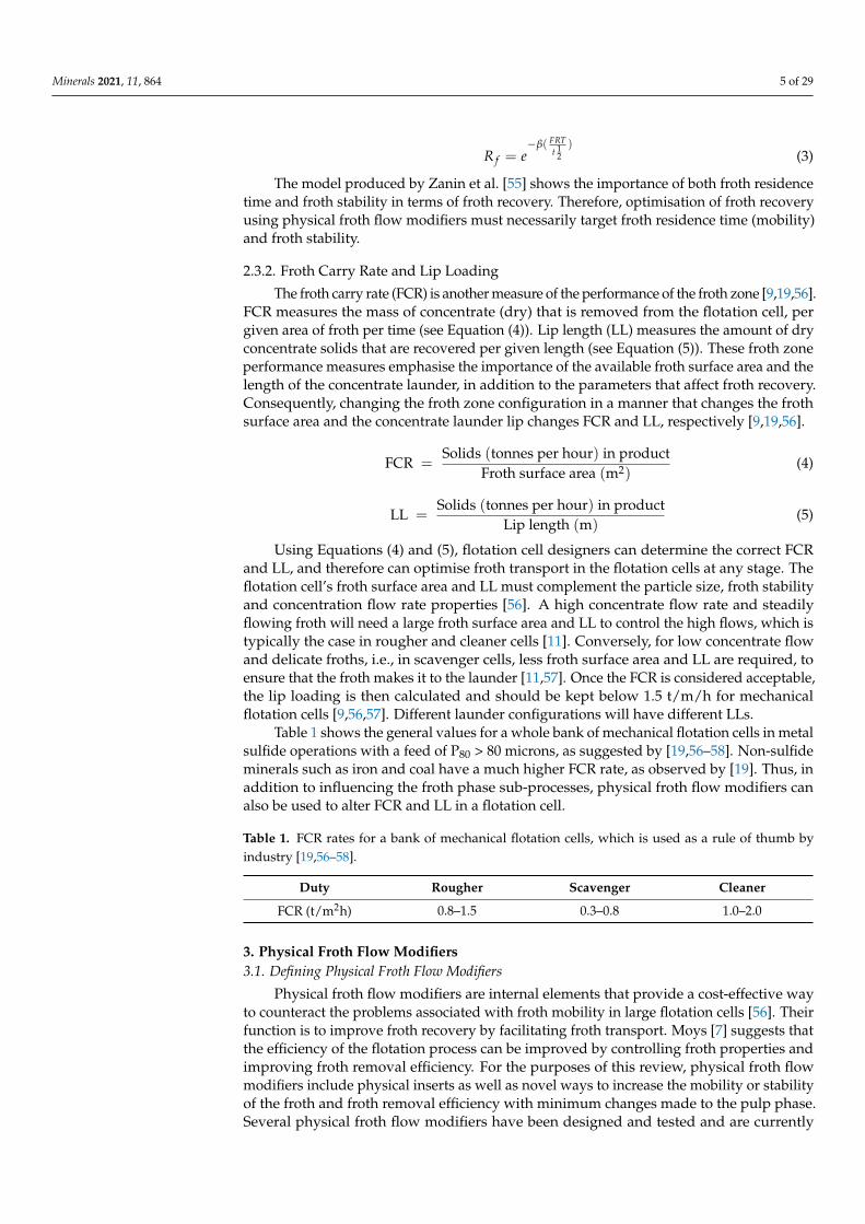
Table 1 shows the general values for a whole bank of mechanical flotation cells in metalsulfide operations with a feed of P80 > 80 microns, as suggested by [19,56–58]. Non-sulfideminerals such as iron and coal have a much higher FCR rate, as observed by [19]. Thus, inaddition to influencing the froth phase sub-processes, physical froth flow modifiers canalso be used to alter FCR and LL in a flotation cell.
Table 1. FCR rates for a bank of mechanical flotation cells, which is used as a rule of thumb byindustry [19,56–58].
Duty Rougher Scavenger Cleaner
FCR (t/m2h) 0.8–1.5 0.3–0.8 1.0–2.0
3. Physical Froth Flow Modifiers3.1. Defining Physical Froth Flow Modifiers
Physical froth flow modifiers are internal elements that provide a cost-effective wayto counteract the problems associated with froth mobility in large flotation cells [56]. Theirfunction is to improve froth recovery by facilitating froth transport. Moys [7] suggests thatthe efficiency of the flotation process can be improved by controlling froth properties andimproving froth removal efficiency. For the purposes of this review, physical froth flowmodifiers include physical inserts as well as novel ways to increase the mobility or stabilityof the froth and froth removal efficiency with minimum changes made to the pulp phase.Several physical froth flow modifiers have been designed and tested and are currently
Minerals 2021, 11, 864 6 of 29
being used in the mining industry. Table 2 provides a summary of these modifiers and therelevant associated research.
Table 2. Types of physical froth flow modifiers.
Type of Flow Modifier Literature and Scholars
Launders [9,11–16,56–58]Froth discharge pedals [24,25,59–61]
Froth crowders [6,14,18–20,22,56,62]Baffles [7,8,23,52]
3.2. Launders
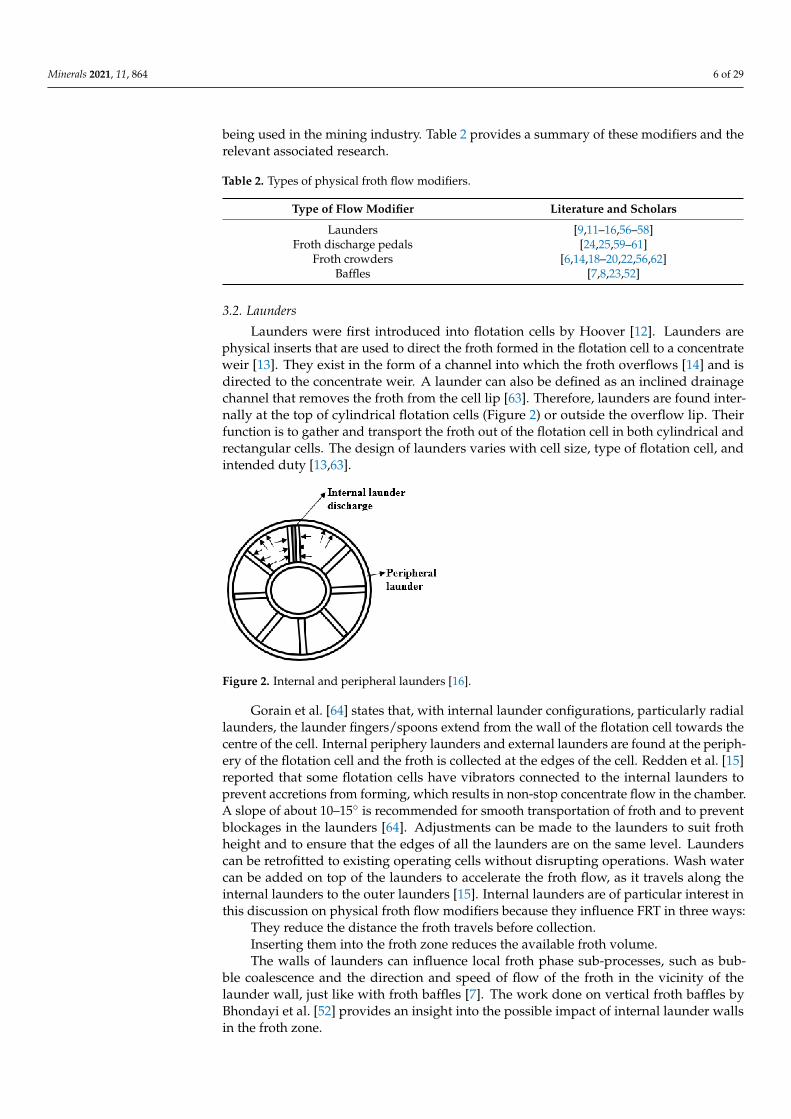
Launders were first introduced into flotation cells by Hoover [12]. Launders arephysical inserts that are used to direct the froth formed in the flotation cell to a concentrateweir [13]. They exist in the form of a channel into which the froth overflows [14] and isdirected to the concentrate weir. A launder can also be defined as an inclined drainagechannel that removes the froth from the cell lip [63]. Therefore, launders are found inter-nally at the top of cylindrical flotation cells (Figure 2) or outside the overflow lip. Theirfunction is to gather and transport the froth out of the flotation cell in both cylindrical andrectangular cells. The design of launders varies with cell size, type of flotation cell, andintended duty [13,63].
Figure 2. Internal and peripheral launders [16].
Gorain et al. [64] states that, with internal launder configurations, particularly radiallaunders, the launder fingers/spoons extend from the wall of the flotation cell towards thecentre of the cell. Internal periphery launders and external launders are found at the periph-ery of the flotation cell and the froth is collected at the edges of the cell. Redden et al. [15]reported that some flotation cells have vibrators connected to the internal launders toprevent accretions from forming, which results in non-stop concentrate flow in the chamber.A slope of about 10–15◦ is recommended for smooth transportation of froth and to preventblockages in the launders [64]. Adjustments can be made to the launders to suit frothheight and to ensure that the edges of all the launders are on the same level. Launderscan be retrofitted to existing operating cells without disrupting operations. Wash watercan be added on top of the launders to accelerate the froth flow, as it travels along theinternal launders to the outer launders [15]. Internal launders are of particular interest inthis discussion on physical froth flow modifiers because they influence FRT in three ways:
They reduce the distance the froth travels before collection.Inserting them into the froth zone reduces the available froth volume.The walls of launders can influence local froth phase sub-processes, such as bub-
ble coalescence and the direction and speed of flow of the froth in the vicinity of thelaunder wall, just like with froth baffles [7]. The work done on vertical froth baffles byBhondayi et al. [52] provides an insight into the possible impact of internal launder wallsin the froth zone.
Minerals 2021, 11, 864 7 of 29
External peripheral launders have a limited influence on froth recovery and FCR;however, they do affect lip loading.
3.2.1. Types of Launders
With cylindrical cells, launders can be concentric and either internal or external,depending on the capacity of the launder used for froth removal. Gorain et al. [64] re-ported that in rectangular cells, launders are located on the opposite side, adjacent to thefeed/discharge boxes or both sides if required by the generated froth. Rectangular cells setin series have launders on three sides.
Transverse launders are also used in rectangular cells, e.g., in OK-R and OK-Utypes [11]. Coleman [9] states that there are different launder types, which complementthe processing demands of roughers, cleaners, and scavenging circuits, i.e., radial, donut,transverse, hexagonal, and peripheral. It is the drive to increase the collection surface areafor froth removal in all stages of flotation that led to different launder configurations thatare classified as internal double launder, internal-peripheral, external-peripheral, double-external, radial, hexagonal, central donut, and transverse launders depending on theirdesign and position in the flotation cell. In a bank of cells, each cell has a launder thatis specifically designed to suit the expected mass recovery. Additional launders can beretrofitted to reduce the froth surface area and increase the FCR and/or to reduce the frothtransport distance (FTD), defined as the distance that a particle has to travel from the frothsurface area to the nearest launder lip [11,56,57]. Launder configurations have a stronginfluence on the FTD [65].
Internal Launders
Internal launders are sub-classified into radial launders, donut launders, transverselaunders, and internal peripheral launders, depending on their orientation [9,11,19]. Frothis collected in the internal launders and then discharged into the peripheral launders, asindicated by the arrows in Figure 2. Unlike external peripheral launders, internal peripherallaunders are located on the inside of the flotation cell to increase the froth-collecting surfacearea, while reducing the effective cell volume, which decreases the froth residence time andFTD [19,56,57,65]. Internal launders are easily modified when the feed grade changes, tochange the froth collection rate. The design allows for repair, inspection, and modificationsif a launder is damaged. Internal double launders are used for high-grade ores whenrecovery has to be done quickly and efficiently [11].
Radial Launders
Radial launders are another type of internal launder. Each launder finger/spoonextends at least halfway from the wall of the flotation cell towards the centre, as shownin Figure 2. Radial launders are equispaced to the circumference of the cell [13]. In caseswhere more LL is needed to handle a high concentrate mass recovery, radial launders canbe added to internal or external periphery launders, as shown in Figure 2 [9,13–15,65].Radial launders can be added to donut launder designs [9]. Yianatos and Diaz [66] reportedthat radial launders decrease the horizontal transport distance of the froth, especially inlarge flotation cells. Contreras et al. [67] observed that by shortening the average distancefrom the froth crowder to the overflow launder, the recovery of valuable minerals (trueflotation) increases considerably compared to the recovery of water and fine gangue.
Central Donut Launders
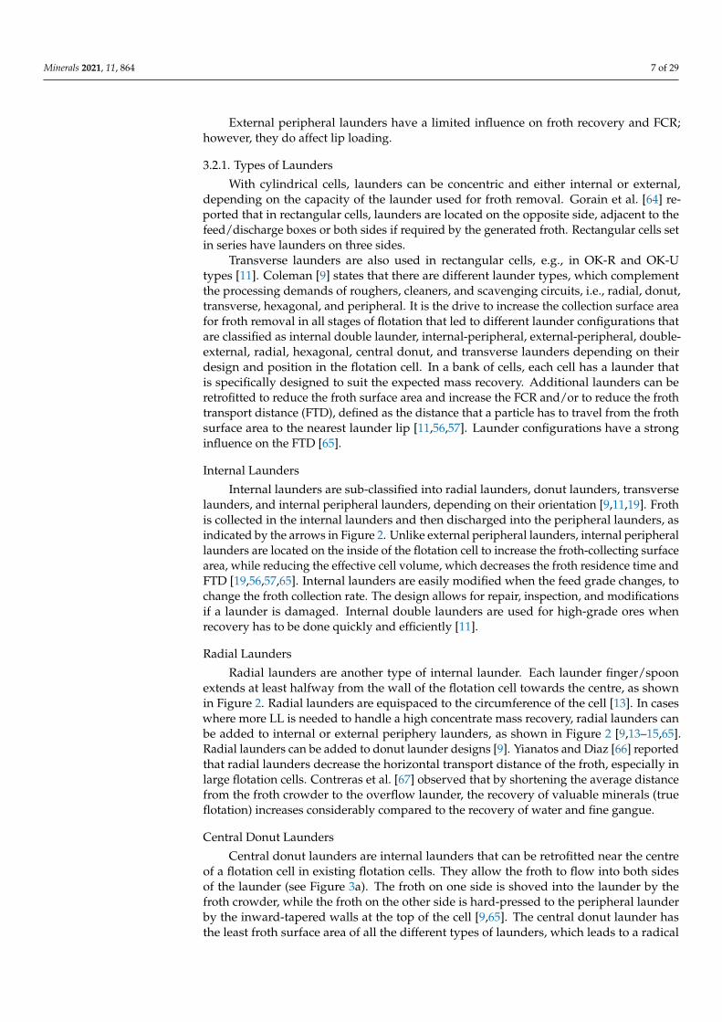
Central donut launders are internal launders that can be retrofitted near the centreof a flotation cell in existing flotation cells. They allow the froth to flow into both sidesof the launder (see Figure 3a). The froth on one side is shoved into the launder by thefroth crowder, while the froth on the other side is hard-pressed to the peripheral launderby the inward-tapered walls at the top of the cell [9,65]. The central donut launder hasthe least froth surface area of all the different types of launders, which leads to a radical
Minerals 2021, 11, 864 8 of 29
reduction in the FTD, which maximises mass pull and recovery in the cell. Retrofit centraldonut launders allow for robust and flexible adaptation to be made in response to feedgrade changes. Central launders are suitable for use in scavenger cells, where the froth isdelicate with a low concentrate flow and where less froth surface area and LL are requiredto recover the froth [11].
Figure 3. (a) Donut launder [14]; (b) Transverse launder [11].
Transverse Launders
Transverse launders (Figure 3b) are double internal crossflow launders that dischargefroth into the peripheral launders or at the edges on the same side of the cell to allow foreasy froth handling if they are installed without periphery launders [68]. Installation oftransverse launders provides the advantage of reducing the FTD and thereby ensuringeffective froth removal. Transverse launders reduce froth residence time, which facilitatesimprovement in the recovery of coarse particles and scavenger recovery [11,60]. A combi-nation of transverse launders added to external peripheral or internal launders is shownin Figure 3. This combination increases LL, and it is sometimes referred to as a doubleexternal launder or a double internal launder. Both donut and transverse launders dividethe froth layer into segments that tend to pull unevenly, which triggers uneven loading ofthe launders [11]. Additional internal support structures are needed for the installation ofboth types of launders, which is a disadvantage of transverse and donut launders that wasnoted by Heath and Runge [11].
External Peripheral Launder
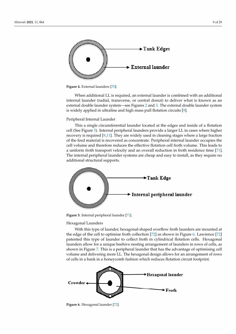
This is a single unit/launder located outside of the flotation cell, as shown in Figure 4.It results in the froth at the centre of the flotation cell having to travel a longer distanceto reach the weir [9]. Froth is pushed outwards by a crowder into the launders, whichhas certain advantages, i.e., it provides the froth with a greater surface area and it doesnot consume flotation cell volume. It is used in smaller diameter flotation cells, whichare typically less than 100 m3 [9]. This launder configuration is easy to design and installand is used extensively in ultrafine and high mass pull applications [9]. Other commonapplications include a high concentrate flow rate and stable flowing froths, which needsmore froth surface area and LL to handle the high flows [11].
The external peripheral launder provides more LL because it does not decrease theeffective flotation cell volume compared to internal peripheral launders and all the othertypes of launders. External launders increase the FTD, which increases the probability ofstagnant zones and the chance of lower recovery, as documented by [3,16,69]. Experimentaland numerical results obtained by Brito-Parada and Cilliers [63] show that a low liquidoverflow rate and a low air recovery rate are associated with launder configurations wherestagnant zones occur. External launders require that a bank of cells be spaced widely apart,which increases the overall footprint of the flotation circuit.
Minerals 2021, 11, 864 9 of 29
Figure 4. External launders [70].
When additional LL is required, an external launder is combined with an additionalinternal launder (radial, transverse, or central donut) to deliver what is known as anexternal double launder system—see Figures 2 and 3. The external double launder systemis widely applied in ultrafine and high mass pull flotation circuits [9].
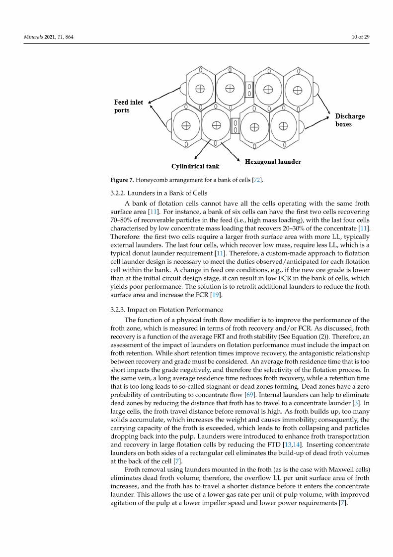
Peripheral Internal Launder
This a single circumferential launder located at the edges and inside of a flotationcell (See Figure 5). Internal peripheral launders provide a larger LL in cases where higherrecovery is required [9,11]. They are widely used in cleaning stages where a large fractionof the feed material is recovered as concentrate. Peripheral internal launder occupies thecell volume and therefore reduces the effective flotation cell froth volume. This leads toa uniform froth transport velocity and an overall reduction in froth residence time [71].The internal peripheral launder systems are cheap and easy to install, as they require noadditional structural supports.
Figure 5. Internal peripheral launder [71].
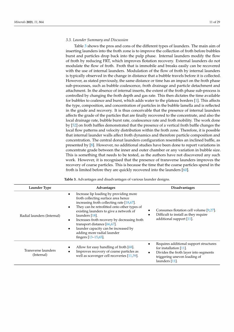
Hexagonal Launders
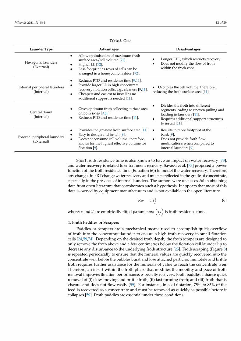
With this type of launder, hexagonal-shaped overflow froth launders are mounted atthe edge of the cell to optimise froth collection [72] as shown in Figure 6. Lawrence [72]patented this type of launder to collect froth in cylindrical flotation cells. Hexagonallaunders allow for a unique beehive nesting arrangement of launders in rows of cells, asshown in Figure 7. This is a peripheral launder that has the advantage of optimising cellvolume and delivering more LL. The hexagonal design allows for an arrangement of rowsof cells in a bank in a honeycomb fashion which reduces flotation circuit footprint.
Figure 6. Hexagonal launder [72].
Minerals 2021, 11, 864 10 of 29
Figure 7. Honeycomb arrangement for a bank of cells [72].
3.2.2. Launders in a Bank of Cells
A bank of flotation cells cannot have all the cells operating with the same frothsurface area [11]. For instance, a bank of six cells can have the first two cells recovering70–80% of recoverable particles in the feed (i.e., high mass loading), with the last four cellscharacterised by low concentrate mass loading that recovers 20–30% of the concentrate [11].Therefore: the first two cells require a larger froth surface area with more LL, typicallyexternal launders. The last four cells, which recover low mass, require less LL, which is atypical donut launder requirement [11]. Therefore, a custom-made approach to flotationcell launder design is necessary to meet the duties observed/anticipated for each flotationcell within the bank. A change in feed ore conditions, e.g., if the new ore grade is lowerthan at the initial circuit design stage, it can result in low FCR in the bank of cells, whichyields poor performance. The solution is to retrofit additional launders to reduce the frothsurface area and increase the FCR [19].
3.2.3. Impact on Flotation Performance
The function of a physical froth flow modifier is to improve the performance of thefroth zone, which is measured in terms of froth recovery and/or FCR. As discussed, frothrecovery is a function of the average FRT and froth stability (See Equation (2)). Therefore, anassessment of the impact of launders on flotation performance must include the impact onfroth retention. While short retention times improve recovery, the antagonistic relationshipbetween recovery and grade must be considered. An average froth residence time that is tooshort impacts the grade negatively, and therefore the selectivity of the flotation process. Inthe same vein, a long average residence time reduces froth recovery, while a retention timethat is too long leads to so-called stagnant or dead zones forming. Dead zones have a zeroprobability of contributing to concentrate flow [69]. Internal launders can help to eliminatedead zones by reducing the distance that froth has to travel to a concentrate launder [3]. Inlarge cells, the froth travel distance before removal is high. As froth builds up, too manysolids accumulate, which increases the weight and causes immobility; consequently, thecarrying capacity of the froth is exceeded, which leads to froth collapsing and particlesdropping back into the pulp. Launders were introduced to enhance froth transportationand recovery in large flotation cells by reducing the FTD [13,14]. Inserting concentratelaunders on both sides of a rectangular cell eliminates the build-up of dead froth volumesat the back of the cell [7].
Froth removal using launders mounted in the froth (as is the case with Maxwell cells)eliminates dead froth volume; therefore, the overflow LL per unit surface area of frothincreases, and the froth has to travel a shorter distance before it enters the concentratelaunder. This allows the use of a lower gas rate per unit of pulp volume, with improvedagitation of the pulp at a lower impeller speed and lower power requirements [7].
Minerals 2021, 11, 864 11 of 29
3.3. Launder Summary and Discussion
Table 3 shows the pros and cons of the different types of launders. The main aim ofinserting launders into the froth zone is to improve the collection of froth before bubblesburst and particles drop back into the pulp phase. Internal launders modify the flowof froth by reducing FRT, which improves flotation recovery. External launders do notmodulate the flow of froth. Froth that is immobile and breaks easily can be recoveredwith the use of internal launders. Modulation of the flow of froth by internal laundersis typically observed in the change in distance that a bubble travels before it is collected.However, as stated previously, the same distance or time has an impact on the froth phasesub-processes, such as bubble coalescence, froth drainage and particle detachment andattachment. In the absence of internal inserts, the extent of the froth phase sub-process iscontrolled by changing the froth depth and gas rate. This then dictates the time availablefor bubbles to coalesce and burst, which adds water to the plateau borders [1]. This affectsthe type, composition, and concentration of particles in the bubble lamella and is reflectedin the grade and recovery. It is thus conceivable that the presence of internal laundersaffects the grade of the particles that are finally recovered to the concentrate, and also thelocal drainage rate, bubble burst rate, coalescence rate and froth mobility. The work doneby [52] on froth baffles demonstrated that the presence of a vertical froth baffle changes thelocal flow patterns and velocity distribution within the froth zone. Therefore, it is possiblethat internal launder walls affect froth dynamics and therefore particle composition andconcentration. The central donut launders configuration resembles an inclined baffle, aspresented by [8]. However, no additional studies have been done to report variations inconcentrate grade between the inner and outer chamber or any variation in bubble size.This is something that needs to be tested, as the authors have not discovered any suchwork. However, it is recognised that the presence of transverse launders improves therecovery of coarse particles. This is because the time that the coarse particles spend in thefroth is limited before they are quickly recovered into the launders [60].
Table 3. Advantages and disadvantages of various launder designs.
Launder Type Advantages Disadvantages
Radial launders (Internal)
• Increase lip loading by providing morefroth collecting surface area henceincreasing froth collecting rate [18,67].
• They can be retrofitted onto other types ofexisting launders to give a network oflaunders [18].
• Increases froth recovery by decreasing frothtransport distance [66,67].
• launder capacity can be increased byadding more radial launderfingers [13–15,65].
• Consumes flotation cell volume [9,27].• Difficult to install as they require
additional support [11].
Transverse launders(Internal)
• Allow for easy handling of froth [68].• Improves recovery of coarse particles as
well as scavenger cell recoveries [11,59].
• Requires additional support structuresfor installation [11].
• Divides the froth layer into segmentstriggering uneven loading oflaunders [11].
Minerals 2021, 11, 864 12 of 29
Table 3. Cont.
Launder Type Advantages Disadvantages
Hexagonal launders(External)
• Allow optimisation of maximum frothsurface area/cell volume [72].
• Higher LL [72].• Less footprint as rows of cells can be
arranged in a honeycomb fashion [72].
• Longer FTD, which restricts recovery.• Does not modify the flow of froth
within the froth zone.
Internal peripheral launders(Internal)
• Reduces FTD and residence time [9,11].• Provide larger LL in high concentrate
recovery flotation cells, e.g., cleaners [9,11].• Cheapest and easiest to install as no
additional support is needed [11].
• Occupies the cell volume, therefore,reducing the froth surface area [11].
Central donut(Internal)
• Gives optimum froth collecting surface areaon both sides [9,65].
• Reduces FTD and residence time [11].
• Divides the froth into differentsegments leading to uneven pulling andloading in launders [11].
• Requires additional support structuresto install [11].
External peripheral launders(External)
• Provides the greatest froth surface area [11].• Easy to design and install [9].• Does not consume cell volume, therefore,
allows for the highest effective volume forflotation [9].
• Results in more footprint of thebank [9].
• Does not provide froth flowmodifications when compared tointernal launders [9].
Short froth residence time is also known to have an impact on water recovery [73],and water recovery is related to entrainment recovery. Savassi et al. [73] proposed a powerfunction of the froth residence time (Equation (6)) to model the water recovery. Therefore,any changes in FRT change water recovery and must be reflected in the grade of concentrate,especially in the presence of internal launders. The authors were unsuccessful in obtainingdata from open literature that corroborates such a hypothesis. It appears that most of thisdata is owned by equipment manufacturers and is not available in the open literature.
RW = c.τdf (6)
where: c and d are empirically fitted parameters;(
τf
)is froth residence time.
4. Froth Paddles or Scrapers
Paddles or scrapers are a mechanical means used to accomplish quick overflowof froth into the concentrate launder to ensure a high froth recovery in small flotationcells [24,59,74]. Depending on the desired froth depth, the froth scrapers are designed toonly remove the froth above and a few centimetres below the flotation cell launder lip todecrease any disturbance to the underlying froth structure [25]. Froth scraping (Figure 8)is repeated periodically to ensure that the mineral values are quickly recovered into theconcentrate weir before the bubbles burst and lose attached particles. Immobile and brittlefroth requires further assistance for the minerals of value to reach the concentrate weir.Therefore, an insert within the froth phase that modifies the mobility and pace of frothremoval improves flotation performance, especially recovery. Froth paddles enhance quickremoval of (i) slow-moving and brittle froth; (ii) fast forming froth; and (iii) froth that isviscous and does not flow easily [59]. For instance, in coal flotation, 75% to 85% of thefeed is recovered as a concentrate and must be removed as quickly as possible before itcollapses [59]. Froth paddles are essential under these conditions.
Minerals 2021, 11, 864 13 of 29
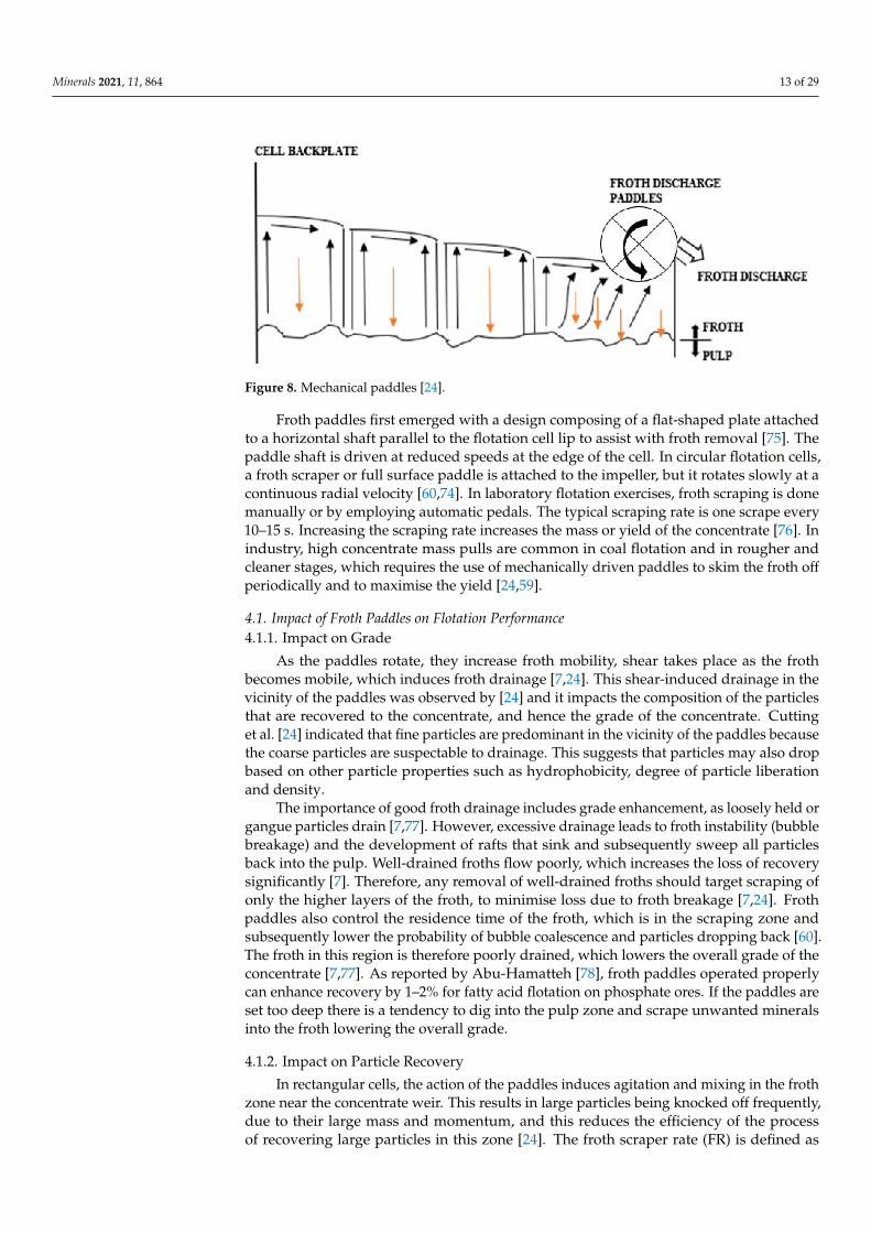
Figure 8. Mechanical paddles [24].
Froth paddles first emerged with a design composing of a flat-shaped plate attachedto a horizontal shaft parallel to the flotation cell lip to assist with froth removal [75]. Thepaddle shaft is driven at reduced speeds at the edge of the cell. In circular flotation cells,a froth scraper or full surface paddle is attached to the impeller, but it rotates slowly at acontinuous radial velocity [60,74]. In laboratory flotation exercises, froth scraping is donemanually or by employing automatic pedals. The typical scraping rate is one scrape every10–15 s. Increasing the scraping rate increases the mass or yield of the concentrate [76]. Inindustry, high concentrate mass pulls are common in coal flotation and in rougher andcleaner stages, which requires the use of mechanically driven paddles to skim the froth offperiodically and to maximise the yield [24,59].
4.1. Impact of Froth Paddles on Flotation Performance4.1.1. Impact on Grade
As the paddles rotate, they increase froth mobility, shear takes place as the frothbecomes mobile, which induces froth drainage [7,24]. This shear-induced drainage in thevicinity of the paddles was observed by [24] and it impacts the composition of the particlesthat are recovered to the concentrate, and hence the grade of the concentrate. Cuttinget al. [24] indicated that fine particles are predominant in the vicinity of the paddles becausethe coarse particles are suspectable to drainage. This suggests that particles may also dropbased on other particle properties such as hydrophobicity, degree of particle liberationand density.
The importance of good froth drainage includes grade enhancement, as loosely held organgue particles drain [7,77]. However, excessive drainage leads to froth instability (bubblebreakage) and the development of rafts that sink and subsequently sweep all particlesback into the pulp. Well-drained froths flow poorly, which increases the loss of recoverysignificantly [7]. Therefore, any removal of well-drained froths should target scraping ofonly the higher layers of the froth, to minimise loss due to froth breakage [7,24]. Frothpaddles also control the residence time of the froth, which is in the scraping zone andsubsequently lower the probability of bubble coalescence and particles dropping back [60].The froth in this region is therefore poorly drained, which lowers the overall grade of theconcentrate [7,77]. As reported by Abu-Hamatteh [78], froth paddles operated properlycan enhance recovery by 1–2% for fatty acid flotation on phosphate ores. If the paddles areset too deep there is a tendency to dig into the pulp zone and scrape unwanted mineralsinto the froth lowering the overall grade.
4.1.2. Impact on Particle Recovery
In rectangular cells, the action of the paddles induces agitation and mixing in the frothzone near the concentrate weir. This results in large particles being knocked off frequently,due to their large mass and momentum, and this reduces the efficiency of the processof recovering large particles in this zone [24]. The froth scraper rate (FR) is defined as
Minerals 2021, 11, 864 14 of 29
the rate at which the flotation cell scraper revolves and sweeps the froth over the lip ofthe flotation cell into the collecting launder. A rate that is too high will lead to splashingand froth breakage, while a slower rate will fail to recover enough particles in a givenperiod [24]. The froth removal rate can be a limiting factor on froth recovery, particularlyin the cleaner stages and with coal flotation [79]. Deep-set paddles also tend to block afree-flowing froth and slow down its travel to the lip of the cell, lowering the froth removalefficiency and recovery [78]. In the laboratory, fast scraping rates result in high water andentrainment recovery [80]. However, a standard 10–15 s laboratory scraping rate producesfroth recovery and entrainment recovery approximately equal to that of industrial rougherflotation cells, which, therefore, provides a reliable scale-up method [81,82].
4.2. Types of Froth Paddles
Froth paddles are used in flotation plants that utilise rectangular cells during roughingand cleaning stages]. The paddles are located at the front of the cell, where the frothis skimmed off into a concentrate weir for recovery. Flat paddles are generally used inthese flotation cells; however, some researchers [59] used helical blades and provided acomparison of the results seen when using the two types. Circular flotation cells use fullsurface scrapers to skim the froth off into internal launders [60,74,83].
4.2.1. Flat Paddles
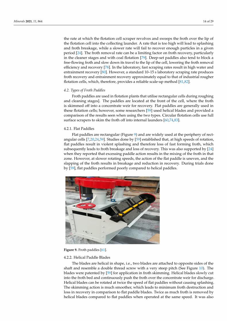
Flat paddles are rectangular (Figure 9) and are widely used at the periphery of rect-angular cells [7,20,24,59]. Studies done by [59] established that, at high speeds of rotation,flat paddles result in violent splashing and therefore loss of fast forming froth, whichsubsequently leads to froth breakage and loss of recovery. This was also supported by [24]when they reported that excessing paddle action results in the mixing of the froth in thatzone. However, at slower rotating speeds, the action of the flat paddle is uneven, and theslapping of the froth results in breakage and reduction in recovery. During trials doneby [59], flat paddles performed poorly compared to helical paddles.
Figure 9. Froth paddles [61].
4.2.2. Helical Paddle Blades
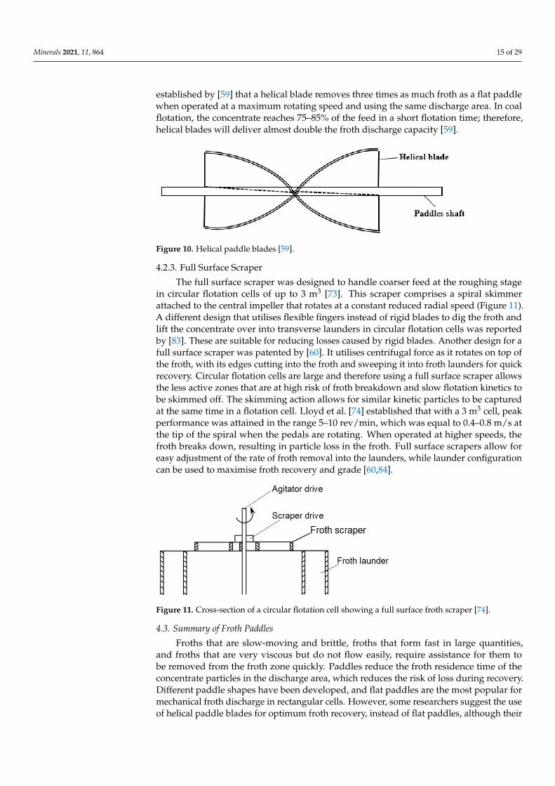
The blades are helical in shape, i.e., two blades are attached to opposite sides of theshaft and resemble a double thread screw with a very steep pitch (See Figure 10). Theblades were patented by [59] for application in froth skimming. Helical blades slowly cutinto the froth bed and continuously push the froth over the concentrate weir for discharge.Helical blades can be rotated at twice the speed of flat paddles without causing splashing.The skimming action is much smoother, which leads to minimum froth destruction andloss in recovery in comparison to flat paddle blades. Twice as much froth is removed byhelical blades compared to flat paddles when operated at the same speed. It was also
Minerals 2021, 11, 864 15 of 29
established by [59] that a helical blade removes three times as much froth as a flat paddlewhen operated at a maximum rotating speed and using the same discharge area. In coalflotation, the concentrate reaches 75–85% of the feed in a short flotation time; therefore,helical blades will deliver almost double the froth discharge capacity [59].
Figure 10. Helical paddle blades [59].
4.2.3. Full Surface Scraper
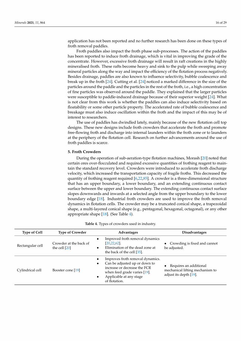
The full surface scraper was designed to handle coarser feed at the roughing stagein circular flotation cells of up to 3 m3 [73]. This scraper comprises a spiral skimmerattached to the central impeller that rotates at a constant reduced radial speed (Figure 11).A different design that utilises flexible fingers instead of rigid blades to dig the froth andlift the concentrate over into transverse launders in circular flotation cells was reportedby [83]. These are suitable for reducing losses caused by rigid blades. Another design for afull surface scraper was patented by [60]. It utilises centrifugal force as it rotates on top ofthe froth, with its edges cutting into the froth and sweeping it into froth launders for quickrecovery. Circular flotation cells are large and therefore using a full surface scraper allowsthe less active zones that are at high risk of froth breakdown and slow flotation kinetics tobe skimmed off. The skimming action allows for similar kinetic particles to be capturedat the same time in a flotation cell. Lloyd et al. [74] established that with a 3 m3 cell, peakperformance was attained in the range 5–10 rev/min, which was equal to 0.4–0.8 m/s atthe tip of the spiral when the pedals are rotating. When operated at higher speeds, thefroth breaks down, resulting in particle loss in the froth. Full surface scrapers allow foreasy adjustment of the rate of froth removal into the launders, while launder configurationcan be used to maximise froth recovery and grade [60,84].
Figure 11. Cross-section of a circular flotation cell showing a full surface froth scraper [74].
4.3. Summary of Froth Paddles
Froths that are slow-moving and brittle, froths that form fast in large quantities,and froths that are very viscous but do not flow easily, require assistance for them tobe removed from the froth zone quickly. Paddles reduce the froth residence time of theconcentrate particles in the discharge area, which reduces the risk of loss during recovery.Different paddle shapes have been developed, and flat paddles are the most popular formechanical froth discharge in rectangular cells. However, some researchers suggest the useof helical paddle blades for optimum froth recovery, instead of flat paddles, although their
Minerals 2021, 11, 864 16 of 29
application has not been reported and no further research has been done on these types offroth removal paddles.
Froth paddles also impact the froth phase sub-processes. The action of the paddleshas been reported to induce froth drainage, which is vital in improving the grade of theconcentrate. However, excessive froth drainage will result in raft creations in the highlymineralised froth. These rafts become heavy and sink to the pulp while sweeping awaymineral particles along the way and impact the efficiency of the flotation process negatively.Besides drainage, paddles are also known to influence selectivity, bubble coalescence andbreak up in the froth [24]. Cutting et al. [24] noticed a marked difference in the size of theparticles around the paddle and the particles in the rest of the froth, i.e., a high concentrationof fine particles was observed around the paddle. They explained that the larger particleswere susceptible to paddle-induced drainage because of their superior weight [24]. Whatis not clear from this work is whether the paddles can also induce selectivity based onfloatability or some other particle property. The accelerated rate of bubble coalescence andbreakage must also induce oscillation within the froth and the impact of this may be ofinterest to researchers.
The use of paddles has dwindled lately, mainly because of the new flotation cell topdesigns. These new designs include froth crowders that accelerate the froth and promotefree-flowing froth and discharge into internal launders within the froth zone or to laundersat the periphery of the flotation cell. Research on further advancements around the use offroth paddles is scarce.
5. Froth Crowders
During the operation of sub-aeration-type flotation machines, Morash [20] noted thatcertain ores over-flocculated and required excessive quantities of frothing reagent to main-tain the standard recovery level. Crowders were introduced to accelerate froth dischargevelocity, which increased the transportation capacity of fragile froths. This decreased thequantity of frothing reagent required [6,22,85]. A crowder is a three-dimensional structurethat has an upper boundary, a lower boundary, and an extending continuous contactsurface between the upper and lower boundary. The extending continuous contact surfaceslopes downwards and inwards at a selected angle from the upper boundary to the lowerboundary edge [18]. Industrial froth crowders are used to improve the froth removaldynamics in flotation cells. The crowder may be a truncated conical shape, a trapezoidalshape, a multi-layered conical shape (e.g., pentagonal, hexagonal, octagonal), or any otherappropriate shape [18]. (See Table 4).
Table 4. Types of crowders used in industry.
Type of Cell Type of Crowder Advantages Disadvantages
Rectangular cell Crowder at the back ofthe cell [20]
• Improved froth removal dynamics[20,22,62].
• Elimination of the dead zone atthe back of the cell [35].
• Crowding is fixed and cannotbe adjusted.
Cylindrical cell Booster cone [19]
• Improves froth removal dynamics.• Can be adjusted up or down to
increase or decrease the FCRwhen feed grade varies [19].
• Applicable at any stageof flotation.
• Requires an additionalmechanical lifting mechanism toadjust its depth [19].
Minerals 2021, 11, 864 17 of 29
Table 4. Cont.
Type of Cell Type of Crowder Advantages Disadvantages
Cylindrical cell Freely rotating cone [20]
• Froth crowding and frothskimming into the launders at thesame time [20].
• Cheap to install, with no need forcomplex rotor designs [20].
• Requires frequent cleaning if thefroth sticks onto the fins [20].
Cylindrical cell Built-in crowders [20] • Improved froth removal dynamics.
• Crowder is built into the rotorsystem, which complicates rotordesigns [85].
• Fixed froth crowding poses achallenge when feed gradechanges after varying the FCR,which ultimately affects theflotation performance [19].
Cylindrical cell Adjustable radial frothcrowders [85].
• Improved froth removal dynamicsin flotation cells with fixed centralcrowding when deep froth isemployed [86].
• Higher grade and higher recovery.
• Highly automated, which can beexpensive at initial installation [85].
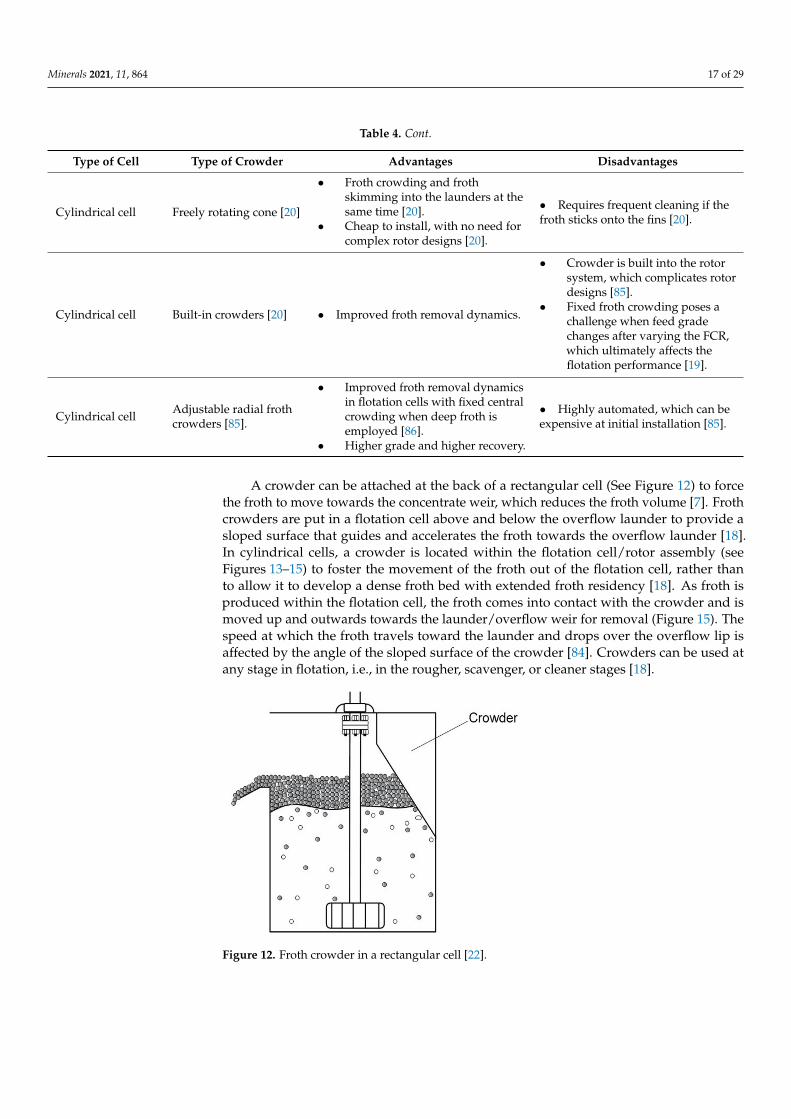
A crowder can be attached at the back of a rectangular cell (See Figure 12) to forcethe froth to move towards the concentrate weir, which reduces the froth volume [7]. Frothcrowders are put in a flotation cell above and below the overflow launder to provide asloped surface that guides and accelerates the froth towards the overflow launder [18].In cylindrical cells, a crowder is located within the flotation cell/rotor assembly (seeFigures 13–15) to foster the movement of the froth out of the flotation cell, rather thanto allow it to develop a dense froth bed with extended froth residency [18]. As froth isproduced within the flotation cell, the froth comes into contact with the crowder and ismoved up and outwards towards the launder/overflow weir for removal (Figure 15). Thespeed at which the froth travels toward the launder and drops over the overflow lip isaffected by the angle of the sloped surface of the crowder [84]. Crowders can be used atany stage in flotation, i.e., in the rougher, scavenger, or cleaner stages [18].
Figure 12. Froth crowder in a rectangular cell [22].
Minerals 2021, 11, 864 18 of 29
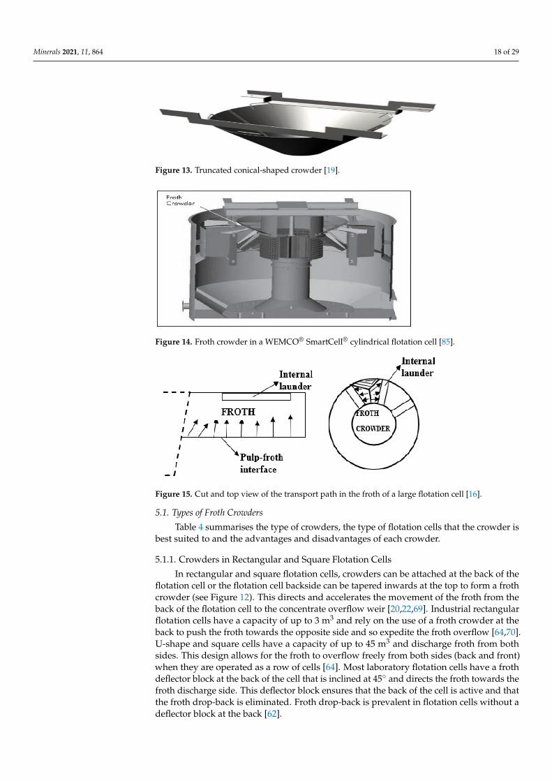
Figure 13. Truncated conical-shaped crowder [19].
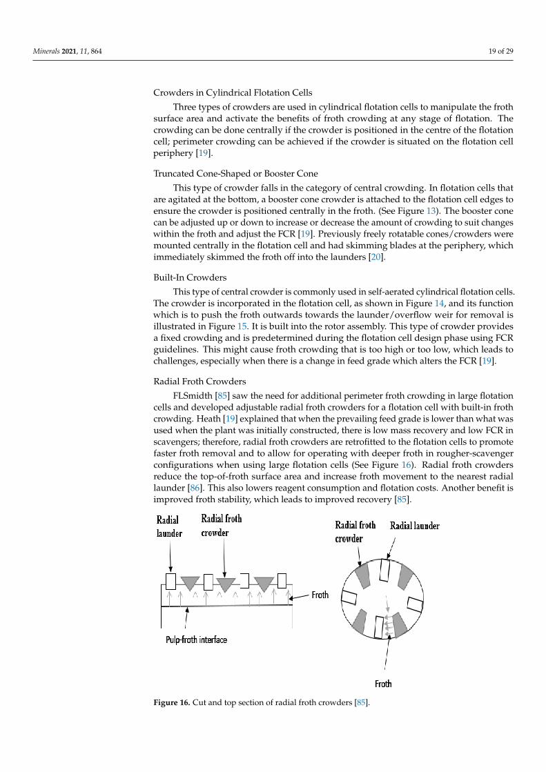
Figure 14. Froth crowder in a WEMCO® SmartCell® cylindrical flotation cell [85].
Figure 15. Cut and top view of the transport path in the froth of a large flotation cell [16].
5.1. Types of Froth Crowders
Table 4 summarises the type of crowders, the type of flotation cells that the crowder isbest suited to and the advantages and disadvantages of each crowder.
5.1.1. Crowders in Rectangular and Square Flotation Cells
In rectangular and square flotation cells, crowders can be attached at the back of theflotation cell or the flotation cell backside can be tapered inwards at the top to form a frothcrowder (see Figure 12). This directs and accelerates the movement of the froth from theback of the flotation cell to the concentrate overflow weir [20,22,69]. Industrial rectangularflotation cells have a capacity of up to 3 m3 and rely on the use of a froth crowder at theback to push the froth towards the opposite side and so expedite the froth overflow [64,70].U-shape and square cells have a capacity of up to 45 m3 and discharge froth from bothsides. This design allows for the froth to overflow freely from both sides (back and front)when they are operated as a row of cells [64]. Most laboratory flotation cells have a frothdeflector block at the back of the cell that is inclined at 45◦ and directs the froth towards thefroth discharge side. This deflector block ensures that the back of the cell is active and thatthe froth drop-back is eliminated. Froth drop-back is prevalent in flotation cells without adeflector block at the back [62].
Minerals 2021, 11, 864 19 of 29
Crowders in Cylindrical Flotation Cells
Three types of crowders are used in cylindrical flotation cells to manipulate the frothsurface area and activate the benefits of froth crowding at any stage of flotation. Thecrowding can be done centrally if the crowder is positioned in the centre of the flotationcell; perimeter crowding can be achieved if the crowder is situated on the flotation cellperiphery [19].
Truncated Cone-Shaped or Booster Cone
This type of crowder falls in the category of central crowding. In flotation cells thatare agitated at the bottom, a booster cone crowder is attached to the flotation cell edges toensure the crowder is positioned centrally in the froth. (See Figure 13). The booster conecan be adjusted up or down to increase or decrease the amount of crowding to suit changeswithin the froth and adjust the FCR [19]. Previously freely rotatable cones/crowders weremounted centrally in the flotation cell and had skimming blades at the periphery, whichimmediately skimmed the froth off into the launders [20].
Built-In Crowders
This type of central crowder is commonly used in self-aerated cylindrical flotation cells.The crowder is incorporated in the flotation cell, as shown in Figure 14, and its functionwhich is to push the froth outwards towards the launder/overflow weir for removal isillustrated in Figure 15. It is built into the rotor assembly. This type of crowder providesa fixed crowding and is predetermined during the flotation cell design phase using FCRguidelines. This might cause froth crowding that is too high or too low, which leads tochallenges, especially when there is a change in feed grade which alters the FCR [19].
Radial Froth Crowders
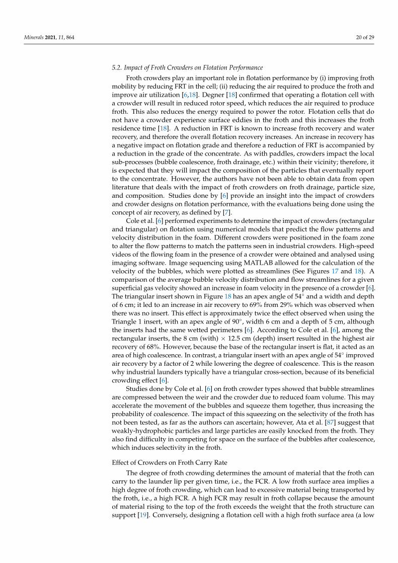
FLSmidth [85] saw the need for additional perimeter froth crowding in large flotationcells and developed adjustable radial froth crowders for a flotation cell with built-in frothcrowding. Heath [19] explained that when the prevailing feed grade is lower than what wasused when the plant was initially constructed, there is low mass recovery and low FCR inscavengers; therefore, radial froth crowders are retrofitted to the flotation cells to promotefaster froth removal and to allow for operating with deeper froth in rougher-scavengerconfigurations when using large flotation cells (See Figure 16). Radial froth crowdersreduce the top-of-froth surface area and increase froth movement to the nearest radiallaunder [86]. This also lowers reagent consumption and flotation costs. Another benefit isimproved froth stability, which leads to improved recovery [85].
Figure 16. Cut and top section of radial froth crowders [85].
Minerals 2021, 11, 864 20 of 29
5.2. Impact of Froth Crowders on Flotation Performance
Froth crowders play an important role in flotation performance by (i) improving frothmobility by reducing FRT in the cell; (ii) reducing the air required to produce the froth andimprove air utilization [6,18]. Degner [18] confirmed that operating a flotation cell witha crowder will result in reduced rotor speed, which reduces the air required to producefroth. This also reduces the energy required to power the rotor. Flotation cells that donot have a crowder experience surface eddies in the froth and this increases the frothresidence time [18]. A reduction in FRT is known to increase froth recovery and waterrecovery, and therefore the overall flotation recovery increases. An increase in recovery hasa negative impact on flotation grade and therefore a reduction of FRT is accompanied bya reduction in the grade of the concentrate. As with paddles, crowders impact the localsub-processes (bubble coalescence, froth drainage, etc.) within their vicinity; therefore, itis expected that they will impact the composition of the particles that eventually reportto the concentrate. However, the authors have not been able to obtain data from openliterature that deals with the impact of froth crowders on froth drainage, particle size,and composition. Studies done by [6] provide an insight into the impact of crowdersand crowder designs on flotation performance, with the evaluations being done using theconcept of air recovery, as defined by [7].
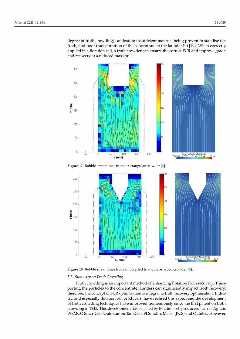
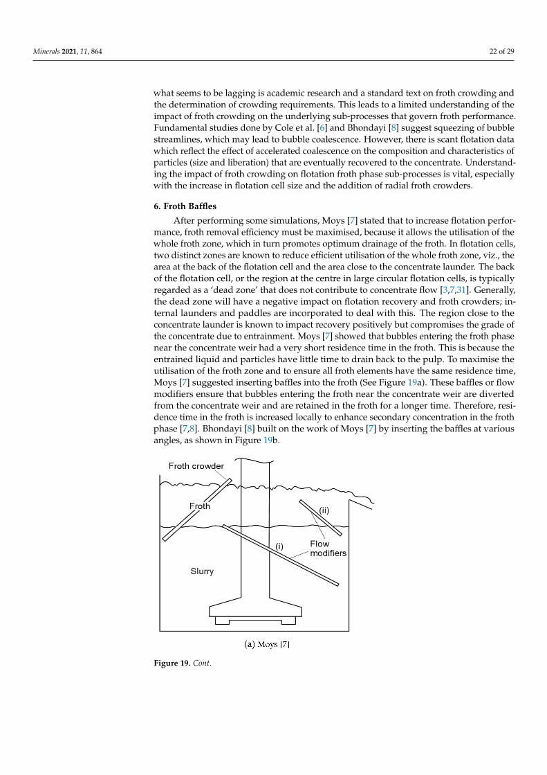
Cole et al. [6] performed experiments to determine the impact of crowders (rectangularand triangular) on flotation using numerical models that predict the flow patterns andvelocity distribution in the foam. Different crowders were positioned in the foam zoneto alter the flow patterns to match the patterns seen in industrial crowders. High-speedvideos of the flowing foam in the presence of a crowder were obtained and analysed usingimaging software. Image sequencing using MATLAB allowed for the calculation of thevelocity of the bubbles, which were plotted as streamlines (See Figures 17 and 18). Acomparison of the average bubble velocity distribution and flow streamlines for a givensuperficial gas velocity showed an increase in foam velocity in the presence of a crowder [6].The triangular insert shown in Figure 18 has an apex angle of 54◦ and a width and depthof 6 cm; it led to an increase in air recovery to 69% from 29% which was observed whenthere was no insert. This effect is approximately twice the effect observed when using theTriangle 1 insert, with an apex angle of 90◦, width 6 cm and a depth of 5 cm, althoughthe inserts had the same wetted perimeters [6]. According to Cole et al. [6], among therectangular inserts, the 8 cm (with) × 12.5 cm (depth) insert resulted in the highest airrecovery of 68%. However, because the base of the rectangular insert is flat, it acted as anarea of high coalescence. In contrast, a triangular insert with an apex angle of 54◦ improvedair recovery by a factor of 2 while lowering the degree of coalescence. This is the reasonwhy industrial launders typically have a triangular cross-section, because of its beneficialcrowding effect [6].
Studies done by Cole et al. [6] on froth crowder types showed that bubble streamlinesare compressed between the weir and the crowder due to reduced foam volume. This mayaccelerate the movement of the bubbles and squeeze them together, thus increasing theprobability of coalescence. The impact of this squeezing on the selectivity of the froth hasnot been tested, as far as the authors can ascertain; however, Ata et al. [87] suggest thatweakly-hydrophobic particles and large particles are easily knocked from the froth. Theyalso find difficulty in competing for space on the surface of the bubbles after coalescence,which induces selectivity in the froth.
Effect of Crowders on Froth Carry Rate
The degree of froth crowding determines the amount of material that the froth cancarry to the launder lip per given time, i.e., the FCR. A low froth surface area implies ahigh degree of froth crowding, which can lead to excessive material being transported bythe froth, i.e., a high FCR. A high FCR may result in froth collapse because the amountof material rising to the top of the froth exceeds the weight that the froth structure cansupport [19]. Conversely, designing a flotation cell with a high froth surface area (a low
Minerals 2021, 11, 864 21 of 29
degree of froth crowding) can lead to insufficient material being present to stabilise thefroth, and poor transportation of the concentrate to the launder lip [19]. When correctlyapplied in a flotation cell, a froth crowder can ensure the correct FCR and improve gradeand recovery at a reduced mass pull.
Figure 17. Bubble streamlines from a rectangular crowder [6].
Figure 18. Bubble streamlines from an inverted triangular-shaped crowder [6].
5.3. Summary on Froth Crowding
Froth crowding is an important method of enhancing flotation froth recovery. Trans-porting the particles to the concentrate launders can significantly impact froth recovery;therefore, the concept of FCR optimisation is integral to froth recovery optimisation. Indus-try, and especially flotation cell producers, have realised this aspect and the developmentof froth crowding techniques have improved tremendously since the first patent on frothcrowding in 1945. This development has been led by flotation cell producers such as Agitair,WEMCO SmartCell, Outokumpu TankCell, FLSmidth, Metso (RCS) and Outotec. However,
Minerals 2021, 11, 864 22 of 29
what seems to be lagging is academic research and a standard text on froth crowding andthe determination of crowding requirements. This leads to a limited understanding of theimpact of froth crowding on the underlying sub-processes that govern froth performance.Fundamental studies done by Cole et al. [6] and Bhondayi [8] suggest squeezing of bubblestreamlines, which may lead to bubble coalescence. However, there is scant flotation datawhich reflect the effect of accelerated coalescence on the composition and characteristics ofparticles (size and liberation) that are eventually recovered to the concentrate. Understand-ing the impact of froth crowding on flotation froth phase sub-processes is vital, especiallywith the increase in flotation cell size and the addition of radial froth crowders.
6. Froth Baffles
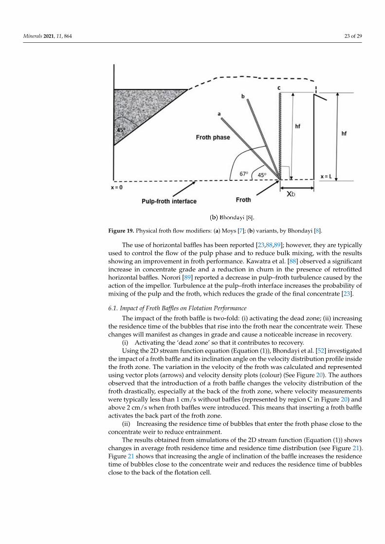
After performing some simulations, Moys [7] stated that to increase flotation perfor-mance, froth removal efficiency must be maximised, because it allows the utilisation of thewhole froth zone, which in turn promotes optimum drainage of the froth. In flotation cells,two distinct zones are known to reduce efficient utilisation of the whole froth zone, viz., thearea at the back of the flotation cell and the area close to the concentrate launder. The backof the flotation cell, or the region at the centre in large circular flotation cells, is typicallyregarded as a ‘dead zone’ that does not contribute to concentrate flow [3,7,31]. Generally,the dead zone will have a negative impact on flotation recovery and froth crowders; in-ternal launders and paddles are incorporated to deal with this. The region close to theconcentrate launder is known to impact recovery positively but compromises the grade ofthe concentrate due to entrainment. Moys [7] showed that bubbles entering the froth phasenear the concentrate weir had a very short residence time in the froth. This is because theentrained liquid and particles have little time to drain back to the pulp. To maximise theutilisation of the froth zone and to ensure all froth elements have the same residence time,Moys [7] suggested inserting baffles into the froth (See Figure 19a). These baffles or flowmodifiers ensure that bubbles entering the froth near the concentrate weir are divertedfrom the concentrate weir and are retained in the froth for a longer time. Therefore, resi-dence time in the froth is increased locally to enhance secondary concentration in the frothphase [7,8]. Bhondayi [8] built on the work of Moys [7] by inserting the baffles at variousangles, as shown in Figure 19b.
Figure 19. Cont.
Minerals 2021, 11, 864 23 of 29
Figure 19. Physical froth flow modifiers: (a) Moys [7]; (b) variants, by Bhondayi [8].
The use of horizontal baffles has been reported [23,88,89]; however, they are typicallyused to control the flow of the pulp phase and to reduce bulk mixing, with the resultsshowing an improvement in froth performance. Kawatra et al. [88] observed a significantincrease in concentrate grade and a reduction in churn in the presence of retrofittedhorizontal baffles. Norori [89] reported a decrease in pulp–froth turbulence caused by theaction of the impellor. Turbulence at the pulp–froth interface increases the probability ofmixing of the pulp and the froth, which reduces the grade of the final concentrate [23].
6.1. Impact of Froth Baffles on Flotation Performance
The impact of the froth baffle is two-fold: (i) activating the dead zone; (ii) increasingthe residence time of the bubbles that rise into the froth near the concentrate weir. Thesechanges will manifest as changes in grade and cause a noticeable increase in recovery.
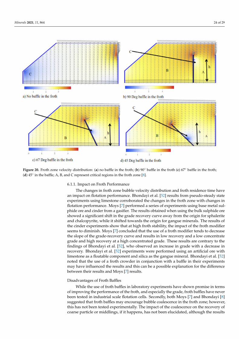
(i) Activating the ‘dead zone’ so that it contributes to recovery.Using the 2D stream function equation (Equation (1)), Bhondayi et al. [52] investigated
the impact of a froth baffle and its inclination angle on the velocity distribution profile insidethe froth zone. The variation in the velocity of the froth was calculated and representedusing vector plots (arrows) and velocity density plots (colour) (See Figure 20). The authorsobserved that the introduction of a froth baffle changes the velocity distribution of thefroth drastically, especially at the back of the froth zone, where velocity measurementswere typically less than 1 cm/s without baffles (represented by region C in Figure 20) andabove 2 cm/s when froth baffles were introduced. This means that inserting a froth baffleactivates the back part of the froth zone.
(ii) Increasing the residence time of bubbles that enter the froth phase close to theconcentrate weir to reduce entrainment.
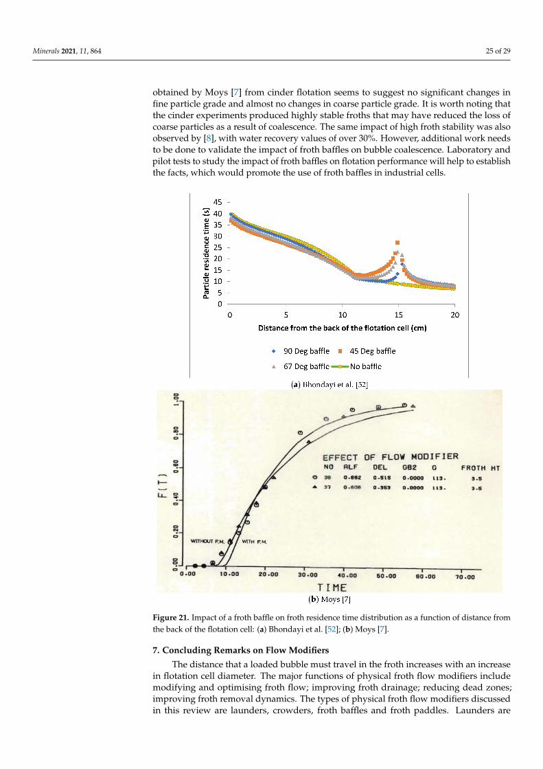
The results obtained from simulations of the 2D stream function (Equation (1)) showschanges in average froth residence time and residence time distribution (see Figure 21).Figure 21 shows that increasing the angle of inclination of the baffle increases the residencetime of bubbles close to the concentrate weir and reduces the residence time of bubblesclose to the back of the flotation cell.
Minerals 2021, 11, 864 24 of 29
Figure 20. Froth zone velocity distribution: (a) no baffle in the froth; (b) 90◦ baffle in the froth (c) 67◦ baffle in the froth;(d) 45◦ in the baffle; A, B, and C represent critical regions in the froth zone [8].
6.1.1. Impact on Froth Performance
The changes in froth zone bubble velocity distribution and froth residence time havean impact on flotation performance. Bhondayi et al. [52] results from pseudo-steady stateexperiments using limestone corroborated the changes in the froth zone with changes inflotation performance. Moys [7] performed a series of experiments using base metal sul-phide ore and cinder from a gasifier. The results obtained when using the bulk sulphide oreshowed a significant shift in the grade recovery curve away from the origin for sphaleriteand chalcopyrite, while it shifted towards the origin for gangue minerals. The results ofthe cinder experiments show that at high froth stability, the impact of the froth modifierseems to diminish. Moys [7] concluded that the use of a froth modifier tends to decreasethe slope of the grade-recovery curve and results in low recovery and a low concentrategrade and high recovery at a high concentrated grade. These results are contrary to thefindings of Bhondayi et al. [52], who observed an increase in grade with a decrease inrecovery. Bhondayi et al. [52] experiments were performed using an artificial ore withlimestone as a floatable component and silica as the gangue mineral. Bhondayi et al. [52]noted that the use of a froth crowder in conjunction with a baffle in their experimentsmay have influenced the results and this can be a possible explanation for the differencebetween their results and Moys [7] results.
Disadvantages of Froth Baffles
While the use of froth baffles in laboratory experiments have shown promise in termsof improving the performance of the froth, and especially the grade, froth baffles have neverbeen tested in industrial scale flotation cells. Secondly, both Moys [7] and Bhondayi [8]suggested that froth baffles may encourage bubble coalescence in the froth zone; however,this has not been tested experimentally. The impact of the coalescence on the recovery ofcoarse particle or middlings, if it happens, has not been elucidated, although the results
Minerals 2021, 11, 864 25 of 29
obtained by Moys [7] from cinder flotation seems to suggest no significant changes infine particle grade and almost no changes in coarse particle grade. It is worth noting thatthe cinder experiments produced highly stable froths that may have reduced the loss ofcoarse particles as a result of coalescence. The same impact of high froth stability was alsoobserved by [8], with water recovery values of over 30%. However, additional work needsto be done to validate the impact of froth baffles on bubble coalescence. Laboratory andpilot tests to study the impact of froth baffles on flotation performance will help to establishthe facts, which would promote the use of froth baffles in industrial cells.
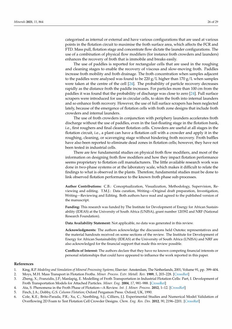
Figure 21. Impact of a froth baffle on froth residence time distribution as a function of distance fromthe back of the flotation cell: (a) Bhondayi et al. [52]; (b) Moys [7].
7. Concluding Remarks on Flow Modifiers
The distance that a loaded bubble must travel in the froth increases with an increasein flotation cell diameter. The major functions of physical froth flow modifiers includemodifying and optimising froth flow; improving froth drainage; reducing dead zones;improving froth removal dynamics. The types of physical froth flow modifiers discussedin this review are launders, crowders, froth baffles and froth paddles. Launders are
Minerals 2021, 11, 864 26 of 29
categorised as internal or external and have various configurations that are used at variouspoints in the flotation circuit to maximise the froth surface area, which affects the FCR andFTD. Mass pull, flotation stage and concentrate flow dictate the launder configurations. Theuse of a combination of physical flow modifiers (for instance froth crowders and launders)enhances the recovery of froth that is immobile and breaks easily.
The use of paddles is reported for rectangular cells that are used in the roughingand cleaning stages to enable the recovery of viscous and slow-moving froth. Paddlesincrease froth mobility and froth drainage. The froth concentration when samples adjacentto the paddles were analysed was found to be 220 g/L higher than 170 g/L when sampleswere taken at the centre of the cell [24]. The probability of particle recovery decreasesrapidly as the distance froth the paddle increases. For particles more than 100 cm from thepaddles it was found that the probability of discharge was close to zero [24]. Full surfacescrapers were introduced for use in circular cells, to skim the froth into internal laundersand so enhance froth recovery. However, the use of full surface scrapers has been neglectedlately, because of the emergence of flotation cells with froth zone designs that include frothcrowders and internal launders.
The use of froth crowders in conjunction with periphery launders accelerates frothdischarge without the use of paddles, even in the fast-floating stage in the flotation bank,i.e., first roughers and final cleaner flotation cells. Crowders are useful at all stages in theflotation circuit, i.e., a plant can have a flotation cell with a crowder and apply it in theroughing, cleaning, or scavenging stage without hindering froth recovery. Froth baffleshave also been reported to eliminate dead zones in flotation cells; however, they have notbeen tested in industrial cells.
There are few fundamental studies on physical froth flow modifiers, and most of theinformation on designing froth flow modifiers and how they impact flotation performanceseems proprietary to flotation cell manufacturers. The little available research work wasdone in two-phase systems or at the laboratory scale, which makes it difficult to relate thefindings to what is observed in the plants. Therefore, fundamental studies must be done tolink observed flotation performance to the known froth phase sub-processes.
Author Contributions: C.B.: Conceptualization, Visualization, Methodology, Supervision, Re-viewing and editing. T.M.J.: Data curation, Writing—Original draft preparation, Investigation,Writing—Reviewing and Editing. Both authors have read and agreed to the published version ofthe manuscript.
Funding: This research was funded by The Institute for Development of Energy for African Sustain-ability (IDEAS) at the University of South Africa (UNISA), grant number 120392 and NRF (NationalResearch Foundation).
Data Availability Statement: Not applicable, no data was generated in this review.
Acknowledgments: The authors acknowledge the discussions held Outotec representatives andthe material handouts received on some sections of the review. The Institute for Development ofEnergy for African Sustainability (IDEAS) at the University of South Africa (UNISA) and NRF arealso acknowledged for the financial support that made this review possible.
Conflicts of Interest: The authors declare that they have no known competing financial interests orpersonal relationships that could have appeared to influence the work reported in this paper.
References1. King, R.P. Modeling and Simulation of Mineral Processing Systems; Elsevier: Amsterdam, The Netherlands, 2001; Volume 91, pp. 399–404.2. Moys, M.H. Mass Transport in Flotation Froths. Miner. Process. Extr. Metall. Rev. 1989, 5, 203–228. [CrossRef]3. Zheng, X.; Franzidis, J.P.; Manlapig, E. Modelling of Froth Transportation in Industrial Flotation Cells: Part, I. Development of
Froth Transportation Models for Attached Particles. Miner. Eng. 2004, 17, 981–988. [CrossRef]4. Ata, S. Phenomena in the Froth Phase of Flotation—A Review. Int. J. Miner. Process. 2012, 1–12. [CrossRef]5. Finch, J.A.; Dobby, G.S. Column Flotation; Oxford Pergamon Press: Oxford, UK, 1990.6. Cole, K.E.; Brito-Parada, P.R.; Xu, C.; Neethling, S.J.; Cilliers, J.J. Experimental Studies and Numerical Model Validation of
Overflowing 2D Foam to Test Flotation Cell Crowder Designs. Chem. Eng. Res. Des. 2012, 90, 2196–2201. [CrossRef]
Minerals 2021, 11, 864 27 of 29
7. Moys, M.H. A Study of Processes Occurring in Flotation Froths. Ph.D. Thesis, University of Natal, Durban, South Africa, 1979.8. Bhondayi, C. A Study of Flotation Froth Phase Behaviour. Ph.D. Thesis, University of the Witwatersrand, Johannesburg, South
Africa, November 2014.9. Coleman, R. Flotation Cells: Selecting the Correct Concentrate Launder Design. Filtr. Sep. 2009, 46, 36–37. [CrossRef]10. Yianatos, J.B.; Henríquez, F.; Tapia, L. Evaluation of the largest flotation cells at Minera Los Pelambres. Miner. Eng. 2008,
21, 841–845. [CrossRef]11. Heath, J.; Runge, K. Froth Management. In SME Mineral Processing and Extractive Metallurgy, Handbook; Dunne, R.C., Kawatra,
S.K., Young, C.A., Eds.; Society for Mining, Metallurgy and Exploration: Englewood, CO, USA, 2019; pp. 959–966.12. Hoover, T.J. Apparatus for Ore Concentration. U.S. Patent 953,746, 5 April 1910.13. Kivisto, V.J.T.; Fallenius, B.K.; Niitti, U.T. Apparatus for Leading off Froth from the Tank of a Flotation Cell. U.S. Patent 4,566,968,
28 January 1986.14. Mesa, D.; Brito-Parada, P.R. Scale-Up in Froth Flotation: A State-of-the-Art Review. Separation and Purification Technology; Elsevier:
Amsterdam, The Netherlands, 2019; pp. 950–962. [CrossRef]15. Redden, L.; Foot, D.G., Jr.; Hunt, J.W. Flotation Cell with Radial Launders for Enhancing Froth Removal. U.S. Patent 6,095,336, 1
August 2000.16. Yianatos, J.; Bergh, L.; Tello, K.; Díaz, F.; Villanueva, A. Froth Mean Residence Time Measurement in Industrial Flotation Cells.
Miner. Eng. 2008, 21, 982–988. [CrossRef]17. Cole, K.E. Bubble Size, Coalescence and Particle Motion in Flowing Foams. Ph.D. Thesis, Imperial College London, London,
UK, 2010.18. Degner, V.R. Flotation Cell Crowder Device. U.S. Patent 5,611,917, 18 March 1997.19. Heath, J. Optimizing Froth Area of the Flotation Cell. Available online: https://www.brighttalk.com/webcast/13517/193793.2016
(accessed on 5 January 2020).20. Morash, N. Froth Skimming and Crowding Device for Flotation Machines. U.S. Patent 2369401, 13 February 1945.21. Moys, M.H. A Study of a Plug-Flow Model for Flotation Froth Behaviour. Int. J. Miner. Process. 1978, 5, 21–38. [CrossRef]22. Sayers, M.J. Froth Crowding Flotation Machine Method. U.S. Patent 2,756,877, 31 July 1956.23. Morrison, A.; Brito-Parada, P.; Cilliers, J. Developing a Design Modification for Improved Froth Flotation Performance through Min-
imising Turbulence at the Pulp-Froth Interface; Canadian Institute of Mining, Metallurgy and Petroleum: Montreal, QC, Canada,2019; pp. 1739–1747.
24. Cutting, G.W.; Barber, S.P.; Newton, S. Effects of Froth Structure and Mobility on the Performance and Simulation of ContinuouslyOperated Flotation Cells. Int. J. Miner. Process. 1986, 16, 43–61. [CrossRef]
25. Luttrell, G.H.; Yoon, R.H. Automation of a laboratory flotation machine for improved performance. Int. J. Miner. Process. 1983,10, 165–172. [CrossRef]
26. Degner, V.R.; Treweek, H.B. Large Flotation Cell Design and Development. In Flotation; Gaudin, A.M., Fuerstenau, M.C., Eds.;AIME: New York, NY, USA, 1976; Volume 2, pp. 816–837.
27. Brito-Parada, P.R.; Kramer, S.C.; Wilson, C.R.; Pain, C.C.; Neethling, S.J.; Cilliers, J.J. A Finite Element Formulation to Model theFlow of Foams. Chem. Eng. Sci. 2012, 69, 279–286. [CrossRef]
28. Murphy, D.G.; Zimmermann, W.; Woodburn, E.T. Kinematic Model of Bubble Motion in a Flotation Froth. Powder Technol. 1996,78, 3–12. [CrossRef]
29. Neethling, S.J.; Cilliers, J.J. The Effect of Weir Angle on Bubble Motion in a Flotation Froth: Visual Modelling and Verification.Miner. Eng. 1998, 11, 1035–1046. [CrossRef]
30. Neethling, S.J. A Mathematical Model of Flowing Foams and Froths. Ph.D. Thesis, University of Manchester UMIST, Manchester,UK, 1999.
31. Ross, V.E. A Study of the Froth Phase in Large-Scale Pyrite Flotation Cells. Int. J. Miner. Process. 1990, 30, 143–157. [CrossRef]32. Ata, S.; Ahmed, N.; Jameson, G.J. A Study of Bubble Coalescence in Flotation Froths. Int. J. Miner. Process. 2003, 72, 255–266.
[CrossRef]33. Ata, S. The Detachment of Particles from Coalescing Bubble Pairs. J. Colloid Interface Sci. 2009, 338, 558–565. [CrossRef] [PubMed]34. Moreno, Y.S.; Ata, S. On the Detachment of Hydrophobic Particles from the Froth Phase. Miner. Eng. 2016, 95, 113–115. [CrossRef]35. Stevenson, P.; Ata, S.; Evans, G.M. The Behavior of an Oscillating Particle Attached to a Gas-Liquid Surface. Ind. Eng. Chem. Res.
2009, 48, 8024–8029. [CrossRef]36. Seaman, D.R.; Manlapig, E.V.; Franzidis, J.P. Selective Transport of Attached Particles across the Pulp-Froth Interface. Miner. Eng.
2006, 19, 841–851. [CrossRef]37. Espinosa-Gomez, R.; Finch, J.A.; Yianatos, J.B.; Dobby, G.S. Flotation column carrying capacity: Particle size and density effects.
Miner. Eng. 1988, 1, 77–79. [CrossRef]38. Gautam, S.; Jameson, G.J. The detachment of particles from bubbles at various locations in a turbulent flotation cell. Miner. Eng.
2019, 132, 316–325. [CrossRef]39. Safari, M.; Deglon, D. Evaluation of an Attachment–Detachment Kinetic Model for Flotation. Minerals 2020, 10, 978. [CrossRef]40. Testa, F.G.; Safari, M.; Deglon, D.; Leal, L.D. Influence of agitation intensity on flotation rate of apatite particles. REM Int. Eng. J.
2017, 70, 491–495. [CrossRef]
Minerals 2021, 11, 864 28 of 29
41. Li, M.; Xia, Y.; Zhang, Y.; Ding, S.; Rong, G.; Cao, Y.; Xing, Y.; Gui, X. Mechanism of shale oil as an effective collector for oxidizedcoal flotation: From bubble–particle attachment and detachment point of view. Fuel 2019, 255, 115885. [CrossRef]
42. Hassanzadeh, A.; Safari, M.; Hoang, D.H. Fine, Coarse and Fine-Coarse Particle Flotation in Mineral Processing with A ParticularFocus on The Technological Assessments. In Proceedings of the 2nd International Conference on Mineral Science, Online, 1–15March 2021. [CrossRef]
43. Farrokhpay, S. The Significance of Froth Stability in Mineral Flotation—A Review. Adv. Colloid Interface Sci. 2011, 166, 1–7.[CrossRef]
44. Neethling, S.J.; Brito-Parada, P.R. Predicting Flotation Behaviour—The Interaction between Froth Stability and Performance.Miner. Eng. 2018, 120, 60–65. [CrossRef]
45. Moolman, D.W.; Eksteen, J.J.; Aldrich, C.; van Deventer, J.S.J. The Significance of Flotation Froth Appearance for Machine VisionControl. Int. J. Miner. Process. 1996, 48, 135–158. [CrossRef]
46. Barbian, N.; Hadler, K.; Cilliers, J.J. The Froth Stability Column: Measuring Froth Stability at an Industrial Scale. Miner. Eng. 2006,19, 713–718. [CrossRef]
47. Hadler, K.; Cilliers, J.J. The Relationship between the Peak in Air Recovery and Flotation Bank Performance. Miner. Eng. 2009,22, 451–455. [CrossRef]
48. Ventura-Medina, E.; Cilliers, J.J. A Model to Describe Flotation Performance Based on Physics of Foams and Froth Image Analysis.Int. J. Miner. Process. 2002, 67, 79–99. [CrossRef]
49. Zanin, M.; Wightman, E.; Grano, S.; Franzidis, J.-P. Quantifying Contributions to Froth Stability in Porphyry Copper Plants. Int. J.Miner. Process. 2009, 91, 19–27. [CrossRef]
50. Moudgil, B.M. Correlation between froth viscosity and flotation efficiency. Min. Metall. Explor. 1993, 10, 100–101. [CrossRef]51. Moolman, D.W.; Aldrich, C.; Van Deventer, J.S.J. The Monitoring of Froth Surfaces on Industrial Flotation Plants Using Connec-
tionist Image Processing Techniques. Miner. Eng. 1995, 8, 23–30. [CrossRef]52. Bhondayi, C.; Moys, M.H.; Fanucchi, D.; Danha, G. Numerical and Experimental Study of the Effect of a Froth Baffle on Flotation
Cell Performance. Miner. Eng. 2015, 77, 107–116. [CrossRef]53. Rahman, R.M.; Ata, S.; Jameson, G.J. Froth Recovery Measurements in an Industrial Flotation Cell. Miner. Eng. 2013, 53, 193–202.
[CrossRef]54. Gorain, B.K.; Harris, M.C.; Franzidis, J.-P.; Manlapig, E.V. The effect of froth residence time on the kinetics of flotation. Miner. Eng.
1998, 11, 627–638. [CrossRef]55. Zanin, M.; Grano, S.R.; Gredelj, S. Factors Affecting Froth Stability in Mineral Flotation and Implications on Minerals Recovery: A
Case Study. In Proceedings of the Procemin, Santiago, Chile, 22–24 October 2008; p. 1.56. Bermudez, G. Solutions to Manage Concentrate Froth WEBINAR. Finland: Outotec. 2020. Available online: https://www.outotec.
com/company/about-outotec/webinars/ (accessed on 13 January 2020).57. Morgan, S. Flotation Launder Design, Does it Matter? Available online: https://www.outotec.com/globalassets/newsletters/
output/2018-3/3.-flotation-launder-design.pdf.2018 (accessed on 3 April 2020).58. Coleman, R. Eliminate Flotation Bottlenecks Expert Advice in the Simplest Form: Best Practices = Best Profits. Eng. Min. J. 2016,
217, 52–54.59. Frantz, P.M.; Bertholf, W.M. Flotation. U.S. Patent 2,311,527, 16 February 1943.60. Bourke, P.; Taylor, D. Flotation Machine (Froth Removal Device). U.S. Patent 2,431,438, 26 April 2011.61. Michaud, D. Flotation Equipment; 911metallurgist: Langley, BC, Canada, 2016.62. Roberts, T.; Firth, B.A.; Nicol, S.K. A modified laboratory cell for the flotation of coal. Int. J. Miner. Process. 1982, 9, 191–200.
[CrossRef]63. Brito-Parada, P.R.; Cilliers, J.J. Experimental and numerical studies of launder configurations in a two-phase flotation system.
Miner. Eng. 2012, 36, 119–125. [CrossRef]64. Gorain, B.K.; Franzidis, J.P.; Manlapig, E.V. Flotation Cell Design: Application of Fundamental Principles. In Encyclopedia of
Separation Science; Elsevier: Amsterdam, The Netherlands, 2000; pp. 1502–1512. [CrossRef]65. Yanez, A.; Grau, R. A Froth Flotation Arrangement and a Froth Flotation Method. U.S. Patent 11,033,909, 15 June 2020.66. Yianatos, J.; Díaz, F. Hydrodynamic Characterization of Industrial Flotation Machines Using Radioisotopes; InTech: Shanghai,
China, 2011.67. Contreras, F.; Yianatos, J.; Vinnett, L. On the Froth Transport Modelling in Industrial Flotation Cells. Miner. Eng. 2013, 41, 17–24.
[CrossRef]68. Metso. Flotation Machines RCS: Maximum Flotation Recover. Available online: https://www.mogroup.com/globalassets/
product-pages/flotation-machines/rcs-brochure.pdf (accessed on 12 December 2020).69. Moys, M.H. Residence Time Distributions and Mass Transport in the Froth Phase of the Flotation Process. Int. J. Miner. Process.
1984, 13, 117–142. [CrossRef]70. Corby, G.A. Flotation Equipment and Process; Kroll Institute for Extractive Metallurgy Colorado School of Mines: Golden, CO,
USA, 2020.71. Boeree, C.R. Up-Scaling of Froth Flotation Equipment. Ph. D. Thesis, Delft University of Technology, Delft, The Netherlands, 2014.72. Lawrence, G.A. Froth Flotation Machine: Dorr-Oliver Inc. U.S. Patent 5,205,926, 27 April 1993.
Minerals 2021, 11, 864 29 of 29
73. Savassi, O.N.; Alexander, D.J.; Franzidis, J.-P.; Manlapig, E.V. An Empirical Model for Entrainment in Industrial Flotation Plants.Miner. Eng. 1998, 11, 243–256. [CrossRef]
74. Lloyd, P.J.D.; Hindet, A.L.; Hebden, D. The Design and Scale-up of a New Flotation Cell. J. S. Afr. Inst. Min. Metall. 1984,84, 33–44.
75. Daman, A.C.; Englewood, J.; William, T. Aerating Assembly for Froth Flotation Cells. U.S. Patent 3,393,803, 23 July 1968.76. Runge, K. How-To-Analyse-Flotation-Test-Results. Flotat. Plant Optim. 2016, 16, 55–173.77. Subrahmanyam, T.V.; Forssberg, E. Froth Stability, Particle Entrainment and Drainage in Flotation. A Review. Int. J. Miner. Process.
1988, 23, 33–53. [CrossRef]78. Abu-Hamatteh, Z.S.H. Froth Flotation Techniques of Eshidiya Phosphate Mines, Jordan. In Dead Sea Water Characterization and Its
Level Fluctuations View Project Statistical Analysis of Groundwater Quality Parameters for Harrana and Azraq Basins View Project FrothFlotation Techniques of Eshidiya Phosphate Mines; Al-Balqa’ Applied University: Al-Salt, Jordan, 2007.
79. Fuerstenau, M.C.; Jameson, G.; Yoon, R.-H. Froth Flotation: A Century of Innovation, 2007th ed.; And, M.C.F.G.J., Yoon, R.-H., Eds.;Society for Mining, Metallurgy, and Exploration: Englewood, CO, USA, 2007.
80. Sandoval, G.; Amelunxen, R.; Barriga, D.; Berrios, P.; Amelunxen, P. Review of Flotation Batch Test Procedures and Scale-up. InImplications for Entrainment; IMPC: Santiago, Chile, 2014.
81. Amelunxen, P.; LaDouceur, R.; Amelunxen, R.; Young, C. A Phenomenological Model of Entrainment and Froth Recovery forInterpreting Laboratory Flotation Kinetics Tests. Miner. Eng. 2018, 125, 60–65. [CrossRef]
82. Amelunxen, P.; Sandoval, G.; Barriga, D.; Amelunxen, R. The Implications of the Froth Recovery at the Laboratory Scale. Miner.Eng. 2014, 66, 54–61. [CrossRef]
83. Van der Spuy, R.C.M.; Ross, V.E. The Recovery of Coarse Minerals by Agglomeration and Flotation. Miner. Eng. 1991, 4, 1153–1166.[CrossRef]
84. Leiva, J.; Vinnett, L.; Yianatos, J. Estimation of Air Recovery by Measuring Froth Transport over the Lip in a Bi-DimensionalFlotation Cell. Miner. Eng. 2012, 36–38, 303–308. [CrossRef]
85. Smidth, F.L. Improve Metallurgical Performance with Advanced Froth Phase Control. Available online: https://www.flsmidth.com/en-gb/products/flotation-and-attrition/froth-recovery-upgrade-package (accessed on 12 October 2020).
86. Grau, R.; Davoise, D.; Yáñez, A.; López, Á. Optimizing the Froth Area of Large Mechanical Flotation Cells. In Procemin Geomet;Gecamin: Santiago, Chile, 2019.
87. Ata, S.; Ahmed, N.; Jameson, G.J. Collection of Hydrophobic Particles in the Froth Phase. Int. J. Miner. Process. 2002, 64, 101–122.[CrossRef]
88. Kawatra, S.; Eisele, T. Flotation Column with Adjustable Supported Baffles. U.S. Patent 5,335,785, 9 August 1994.89. Norori-McCormac, A. The Relationship between Particle Size, Cell Design and Air Recovery: The Effect on Flotation Performance.
Ph.D. Thesis, Imperial College London, London, UK, 2015. [CrossRef]