a proposed program to predict the performance of steam power plants
TRANSCRIPT
1
ABSTRACT The objective of this paper is to simulate the operation
of steam power plants by considering a typical example of a working power plant. The input data depends on the performance tests that were performed during the process of the delivery of the power plant by the contractor to the Egyptian Electrical Authority. The performance tests were carried out at the loads of (100%, 103% and 109% Load) as a check for the validity of the functionality of the program. It was found that the results of the program are in a good agreement with the test data. KEYWORDS
Steam power plant, Operating performance, Heaters, Thermodynamics.
I. INTRODUCTION Based on field experience, it was found that it is vital to
search for a quick and reliable methodology to estimate the operating performance of steam power plants. The actual performance may differ from the design performance due to many reasons such as aging, delayed maintenance, etc. It is interesting to predict this off-design performance. Thus, the idea of design and construction of the proposed program comes up. The program can be used by power plant engineers to determine operating condition of the plant and whether the plant is operating efficiently or not. This task is carried out by feeding the program with field readings and measurements of the plant. Then, the program helps the engineers to identify the needed corrective actions in order that the plant works efficiently. Moreover, the program may be used by under-graduate engineering students to solve problems that are related to steam power plants in appropriate courses. Generally, the program offers the following functions: 1. Prediction of the performance of the plant and its
components.
2. Diagnosing the deterioration in performance of the plant components.
3. Specifying the best working conditions for the operating variables of the power plant.
4. Evaluating performance of suggested modifications.
The steam power plant has been analyzed from the thermodynamic point of view. A mathematical model was constructed based on the thermodynamic formulation of the different components in the cycle. A computer code was developed in accordance to the mathematical model using "Visual Basic". The considered plant is "Abu Sultan Steam Power Plant, 4 × 150 MW".
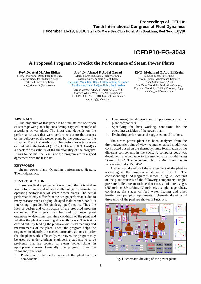
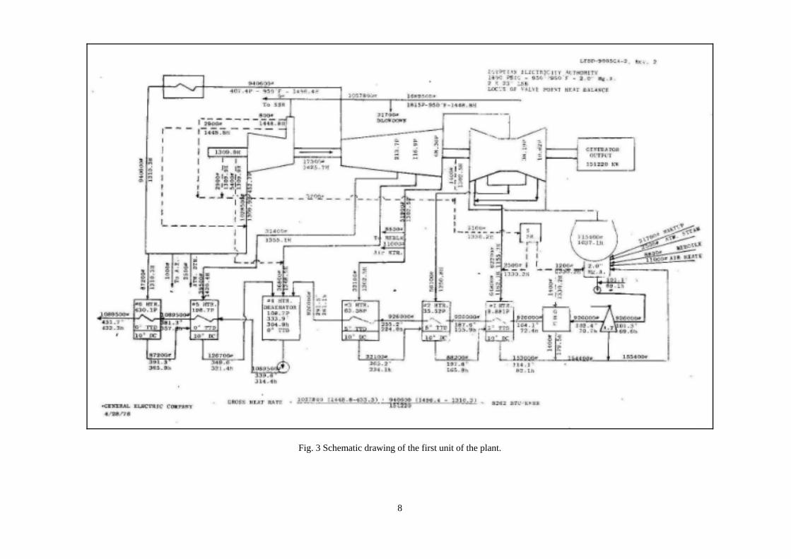
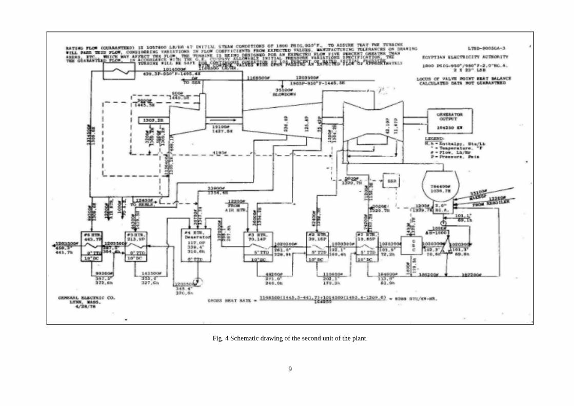
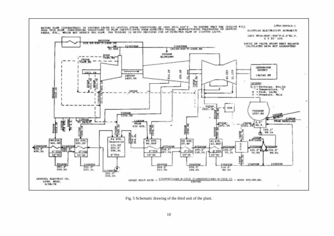
A schematic drawing of the arrangement of the plant as appearing in the program is shown in Fig. 1. The corresponding (T-S) diagram is shown in Fig. 2. Each unit of the plant consists of the following components: single-pressure boiler, steam turbine that consists of three stages (HP-turbine, LP turbine, LP turbine), a single-stage reheat, condenser, six stages of feed water heating and other heating and pumping equipments. Schematic drawings of three units of the pant are shown in Figs. 3-5.
Fig. 1 Schematic drawing of the power plant.
Proceedings of ICFD10: Tenth International Congress of Fluid Dynamics
December 16-19, 2010, Stella Di Mare Sea Club Hotel, Ain Soukhna, Red Sea, Egypt
ICFDP10-EG-3043
A Proposed Program to Predict the Performance of Steam Power Plants
Prof. Dr. Atef M. Alm-Eldien Mech. Power Eng. Dept., Faculty of Eng.
Vice-president for Students Affairs Port-Said University, Egypt [email protected]
Prof. Dr. Ahmed F. Abdel Gawad Mech. Power Eng. Dept., Faculty of Eng.,
Zagazig Univ., Zagazig 44519, Egypt Currently: Mech. Eng. Dept., College of Eng. & Islamic
Architecture, Umm Al-Qura Univ., Saudi Arabia
Senior Member AIAA, Member ASME, ACS Marquis Who is Who, IBC, ABI Biographee
ICFDP8, ICFDP9, ICFD10 General Coordinator [email protected]
ENG. Mohamed G. Abd El Kreim M.Sc. in Mech. Power Eng.
Steam Turbine Maintenance Engineer Abou Sultan Power Plant
East Delta Electricity Production Company Egyptian Electricity Holding Company, Egypt

2
Fig. 2 (T-S) diagram.
II. ANALYSIS The analysis is based on a mathematical model that
consists of governing equations of the operating parameters [1-7]. For the thermal calculation of the steam path in the plant, it is essential to know the steam flow rates through all turbine stages. Therefore, before starting the thermal calculation of the steam path, it is required to consider the regenerative system of the turbine to define the flow rate of steam through each section of the steam path. The heat cycle of the plant has the following data at rated load: main steam flow through the cycle is (1 kg/s), main steam parameters P = 129 bar, T = 510oC; the steam after expanding in the high-pressure turbine is taken for reheating (cold reheat pressure) P = 30.8 bar and that of reheated steam on entry to the intermediate turbine (hot reheat pressure) P = 27.71 bar; temperature of reheated steam T = 510oC, and condenser pressure is 0.067 bar. The turbine has six steam extractions for preheating of condensate and feed water to 233oC (Fig. 1). Condensate is preheated in three low-pressure heaters and de-aerator. Feed water is preheated in two high-pressure heaters. The condensate of heating steam in the 1st, 2nd and 3rd extraction lines is cascaded into the condenser, while condensate of the 5th and 6th extraction lines is cascaded into de-aerator. The pressures of extraction lines are as follows:
Extraction 1 2 3 4 5 6
P (bar) 0.72 2.59 4.65 7.95 14.5 30.8
For the thermal calculation of the steam path of a turbine, it is essential to know the steam flow rates through all turbine stages. A heat balance for heater (6) is applied as follows:
hhmhhm 191461846 11 ×+×=×+× (1) ( )( )hh
hhm1819
1446
−−
= (2)
Where, m6 is the fraction of steam extracted for heating of 1 kg of feed water in heater (6), h4 is the enthalpy of steam in the 1st extraction line (kJ/kg); h14 is the enthalpy of
heating steam condensate of the 1st extraction line; and hh 1819 , are the enthalpies of feed water at the exit from and
the entry to heater (6), respectively (kJ/kg). Adopting the same procedure for heater (5), we have
hmhhmhhmhm 156181551714655 11 ×+×+×=×+×+× (3) ( ) ( )( )
( )hhhhmhhm
155
1415617185
−−−−
= (4)
Where, m5 is the fraction of steam extracted for heating of 1 kg of feed water in heater (5), h5 is the enthalpy of steam in the 2st extraction line, kJ/kg; h14 , h15 are the enthalpies of heating steam condensate of the 1st and 2st extraction lines, respectively; and hh 1817 , are the enthalpies of feed water at the exit from and the entry to heater (5), respectively.
For heater (4): ( ) ( ) hhmmmhmmhm 2625456156564 11 ×=×−−−+×++× (5) ( ) ( )( )
( )hhhhmmhhm
256
15256525264 −
−++−= (6)
Where, m4 is the fraction of steam extracted for heating of 1 kg of feed water in heater (4), h6 is the enthalpy of steam in the 3rd extraction line (kJ/kg); h26 is the enthalpy of heating steam condensate of the 3rd extraction line; and
hh 2625 , are the enthalpy of feed water at the exit from and the entry to heater (4), respectively.
For heater (3): ( )( )hmmmhXm
hmmmhXm25456203
2445683
11
−−−+=−−−+
(7)
( )( )( )hh
hhmmmm208
24254563
1−
−−−−= (8)
Where, m3 is the fraction of steam extracted for heating of 1 kg of feed water in heater (4), h8 is the enthalpy of steam in the 4th extraction line, kJ/kg; h20 is the enthalpy of heating steam condensate of the 4th extraction line; and
hh 2425 , are the enthalpy of feed water at the exit from and the entry to heater (3), respectively.
For heater (2): ( )
( ) ( )hmmhmmmhmmmhmhm
213224456
2345620392
11
++−−−=−−−+×+×
(9)
( )( ) ( )( )hh
hhmhhmmmm219
2021323244562
1−
−+−−−−= (10)
Where, m2 is the fraction of steam extracted for heating of 1 kg of feed water in heater (2), h9 is the enthalpy of steam in the 5th extraction line (kJ/kg); hh 2021, are the enthalpies of heating steam condensate of the 5th and 4th extraction lines, respectively; and hh 2324 , are the enthalpies of feed water at the exit from and the entry to heater (2), respectively.
For heater (1): ( ) ( )
( ) ( ) hmmmhmmmhmmmhmmhm
2232123456
134562123101
11
×+++−−−=−−−+++×
(11)
( )( ) ( )( )( )hh
hhmmhhmmmm2210
21222313234561
1−
−++−−−−= (12)
Where, m1 is the fraction of steam extracted for heating of 1 kg of feed water in heater (2), h10 is the enthalpy of steam in the 6th extraction line (kJ/kg); hh 2221, are the
3
enthalpies of heating steam condensate of the 6th and 5th extraction lines, respectively; and hh 2313 , are the enthalpies of feed water at the exit from and the entry to heater (1), respectively.
The quantity of heat Q spent in the boiler to generate 1 kg of steam is given by:
( )( )hhmhhQ 436191 1 −−+−= (13) Where, h1 is the enthalpy of steam leaving boiler and
entering steam turbine, h19 is the enthalpy of feed water entering the boiler, ( )m61− is the quantity of steam flow through the re-heater, h4 is the enthalpy of steam entering re-heater and h3 is the enthalpy of steam leaving re-heater .
The turbine work ( wt ) is given by ( ) ( )( ) ( )( ) ( )( )( )( )( )( )( )( )⎪
⎪⎪
⎭
⎪⎪⎪
⎬
⎫
⎪⎪⎪
⎩
⎪⎪⎪
⎨
⎧
−−−−−−−+−−−−−−
+−−−−−−−−−+−
−−+−−+−
=
hhmmmmmmhhmmmmm
hhmmmmhhmmmhh
mmhhmhh
w mt
109123456
9823456
873456
7645665
5653641
111
111
η (14)
The pump work ( wp ) is given by ( )( ) ( )
ηm
phhhhmmmw 261712134561 −+−−−−
= (15)
Where, ηm is the mechanical efficiency. The net work ( wnet ) is given by ( )η gptnet www −= (16)
Where, η g is generator efficiency. The thermal efficiency (η tr ) of the plant is given by:
Qwnet
tr =η (17)
Heat rate is given as η tr
1 .
III. Case when Feed Water Heater is Out of Service
If a heater is removed from service, the steam flow is adjusted so that the turbine output does not exceed the maximum guarantied output. We will discus the effect of removing every one of the heaters from service and determine its effect on the cycle taking into account that the turbine output does not exceed the maximum guarantied output. The analysis will be made under the case of full (100%) load.
III.1 Removing Heater (6) from Service
At full (100%) load, the amount of steam extracted to the heaters are as follows : m6 = 8.213×10⁻² kg/s, m5 = 3.243×10⁻² kg/s, m4 = 3.391×10⁻² kg/s, m3 =2.977×10⁻² kg/s, m2 = 5.163×10⁻² kg/s, m1 =6.045×10⁻² kg/s. The amount of steam flow through the cycle will be (1 -0.213×10⁻²). Where, 8.213×10⁻² is the mass of extracted steam to heater (6) at full (100%) load. In this case, the amount of heat added will be
( )( )hhhhQ 432
181 10213.81 −×−+−= − (18) Where, h1 is the enthalpy of steam leaving boiler and
entering steam turbine, h18 is the enthalpy of feed water leaving heater (5) and entering the boiler, ( )10213.81 2−×− is the quantity of steam flow through the re-heater, h4 is
the enthalpy of steam entering re-heater, h3 is the enthalpy of steam leaving re-heater, and the turbine work is given by
( ) ( )( ) ( )( ) ( )( )( )( )( )( )( )( ) ⎪
⎪⎪
⎭
⎪⎪⎪
⎬
⎫
⎪⎪⎪
⎩
⎪⎪⎪
⎨
⎧
−−−−−−×−+−−−−−×−
+−−−−×−−−−×−+−
−×−+−×−+−
=
−
−
−
−
−−
hhmmmmmhhmmmm
hhmmmhhmmhh
mhhhh
w mt
109123452
9823452
873452
76452
65
52
532
41
10213.8110213.8110213.81
10213.8110213.8110213.81
η(19)
The pump work ( wp ) is given by ( )( ) ( )
ηm
phhhhmw 261712134
210213.81 −+−−×−=
−
(20)
Where, ηm is the mechanical efficiency.
III.2 Removing Heater (5) from Service In this case, it is required to determine the temperature
of feed water outlet from heater (6). By determining the enthalpy of feed water at the exit from heater (6) taking into account removal of heater (5) from cycle, we get
( ) hmhhmh 17144619 ×+−×= (21) Where, h19 is the enthalpy of feed water at exit from
heater (6), h4 is the enthalpy of extracted steam to heater (6), h14 is the enthalpy of heating steam condensate extracted to heater (6), m is the mass of steam flow rate through the cycle which equals to (1-3.243×10⁻²) kg/s, h17 is the enthalpy of feed water at the exit from heater (4). The temperature of feed water at the exit from heater (6) is determined by interpolation in terms of enthalpies and temperatures of heaters (6) and (4) as follows:
( ) ( )[ ]( ) 2.233
5.734100510059.1702.233 19
19 +−
−×−= hT (22)
Where, 233.2 and 170.9 are the temperatures of feed water at exit from heaters (6) and (4) when heater (5) is not removed from service, 1005 is the enthalpy of feed water at exit from heater (6) when heater (5) is not removed from service corresponding to the temperature 233.2, h19 is the enthalpy of feed water at exit from heater (6) when heater (5) is removed from service. We get the corresponding enthalpy according to calculated T 19 . Then by setting m5 to zero and setting h5, which is the enthalpy of extracted steam to heater (5), to zero in the equation of "turbine work, heat added and pump work", we can find the effect of removing heater (5) from service. III.3 Removing Heater (3) from Service
In this case, it is required to determine the temperature of feed water outlet from heaters (4), (5) & (6). By determining the enthalpy of feed water at the exit from heaters (4), (5) & (6) taking into account removal of heater (5) from cycle, we get
( ) ( )m
hmhmhhmmh 642424156526
×+×+−×+= (23)
Where, h26 is the enthalpy of feed water at exit from heater (4), h15 is the enthalpy of heating steam condensate extracted to heater (5), h24 is the enthalpy of feed water at the exit from heater (2), h6 is the enthalpy of extracted steam to heater (4), m is the mass flow rate of steam through the cycle and equals to (1-2.977×10⁻²) kg/s,
mm 65 & are the mass of extracted steam to heaters (5) and
4
(6), respectively. The enthalpy of feed water at exit from feed water pump is calculated as follows:
( )( )η p
ppvhh 1026171626
17×−×+
= (24)
Where, h17 is the enthalpy of feed water at exit from feed-water pump, v16 is the specific volume of feed water corresponding to the temperature of feed water at exit from heater (4), p17 is the feed-water pump pressure, p6 is the extraction pressure of heater (4), η p is the polytropic efficiency of the pump. The temperature of feed water at exit from heater (4) is calculated by interpolation as follows:
( ) ( )[ ]( ) 7.167
6.5205.7341249.170 2617
26 +−
−×−−= hhT (25)
Where, T 26 is the temperature of feed water at exit from heater (4), 170.9 is the temperature of feed water at exit from feed-water pump when heater (3) is not removed, 124 is the temperature of feed water at exit from heater (2), h17 is the enthalpy of feed water at exit from feed-water pump when heater (3) is removed from service, h26 is the enthalpy of feed water at exit from heater (4), 734.5 is the enthalpy of feed water at exit from feed-water pump when heater (3) is not removed from service, 520.6 is the enthalpy of feed water at exit from heater (2), 167.7 is the temperature of feed water at exit from heater (4) when heater (3) is not removed from service. The enthalpy of feed water at exit from heater (4) corresponding to T 26 can now be obtained and the enthalpy of feed water at exit from feed-water pump is also obtained. The enthalpy of feed water at exit from heater (5) can be calculated as follows:
( )( ) ( )[ ]m
hmhhmhhmh 1715146155518
×+−×+−×= (26)
Where, h18 is the enthalpy of feed water at exit from heater (5), m5 is the mass of extracted steam to heater (5), h5 is the enthalpy of extracted steam to heater (4), h15 is the enthalpy of heating steam condensate extracted to heater (5), m6 is the mass of extracted steam to heaters (6), h15 and h14 are the enthalpy of heating steam condensate extracted to heaters (5) and (6), h17 is the enthalpy of feed water at exit from feed-water pump, m is the mass flow rate of steam through the cycle and equals to (1-2.977×10⁻²) kg/s. The temperature of feed water at exit from heater (5) due to removal of heater (3) from service is calculated as:
( ) ( )[ ]( ) 1.194
5.7345.8259.1701.1945.825 18
18 +−
−×−−= hT (27)
Where, 825.5 is the value of enthalpy of feed water at exit from heater (5) when heater (3) is not removed from service, h18 is the enthalpy of feed water at exit from heater (5) when heater (3) is removed from service, 194.1 is the value of temperature of feed water at exit from heater (5) when heater (3) is not removed from service, 170.9 is the value of temperature of feed water at exit from feed-water pump when heater (3) is not removed from service, 734.5 is the value of enthalpy of feed water at exit from feed-water pump when heater (3) is not removed from service. Then, enthalpy of feed water at exit from heater (5), corresponding toT 18 , can be calculated. The enthalpy of
feed water at exit from heater (6) corresponding to removal of heater (3) from service can be calculated as:
( )( )[ ]m
hmhhmh 18144619
×+−×= (28)
Where, m6 is the mass of steam extracted to heater (6), h4 is the enthalpy of extracted steam to heater (6), h14 is the enthalpy of heating steam condensate extracted to heater (6), h18 is the enthalpy of feed water at exit from heater (5) when heater (3) is removed from service, m is the mass flow rate of steam through the cycle and equals to (1-2.977×10⁻²) kg/s. The temperature of feed water at exit from heater (6) is calculated by interpolation as follows:
( ) ( )[ ]( ) 2.233
5.825100510051.1942.233 19
19 +−
−×−−= hT (29)
Where, 233.2oC and 194.1oC are the temperatures of feed water at exit from heaters (6) and (5) when heater (3) is not removed from service, 1005 is the enthalpy of feed water at exit from heater (6) when heater (3) is not removed from service corresponding to the temperature 233.2oC, h19 is the enthalpy of feed water at exit from heater (6) when heater (3) is removed from service. We get the corresponding enthalpy according to the calculated T 19 .Then, by setting m5 to zero and setting h5, which is the enthalpy of extracted steam to heater (5) to zero in the equation of "turbine work, heat added and pump work", we can find the effect of removing heater (5) from service.
III.4 Removing Heaters (2) and (1) from Service
The process is the same as in case of removal of heater (3).
IV. RESULTS AND DISCUSSIONS
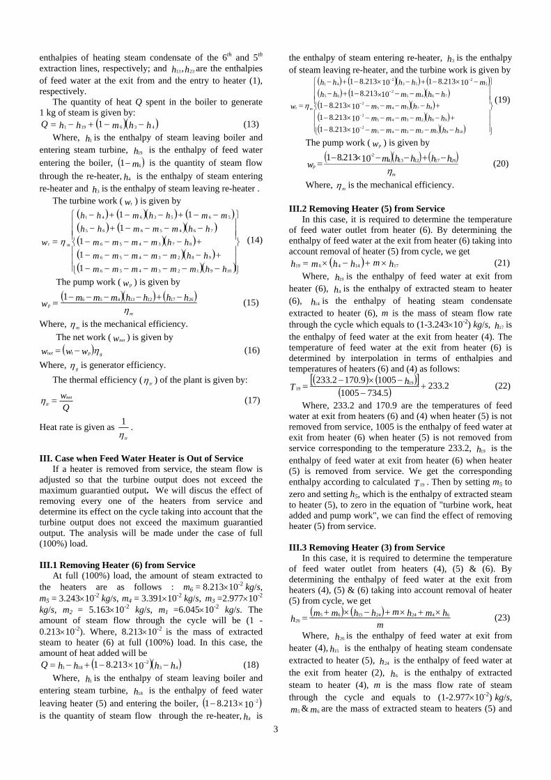
The steam plant has been analyzed from the thermodynamic point of view. A computer code was developed to simulate the operation of the plant and carried out at the loads of (131, 118 and 105 MW) as check points for the validity of the functionality of the program. The results also discuss the effect of removing the heaters from the cycle on the cycle performance. The cycle parameters for the three considered cases are shown in Figs. 3, 4 and 5. Fig. 6 shows the change of the net work with the change in load. As shown in Fig. 6, the net work increases with the increase in load although main steam temperature is the same for the three cases. However, mass flow rate increases with the increase in load.
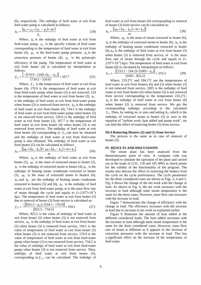
Figure 7 demonstrates the change of efficiency with the change in load. The efficiency increases with the increase in load due to increase in net work as explained earlier.
Figure 8 illustrates the amount of heat added at the different considered loads. The heat added increases with the increase in load although main steam temperature is the same for the three considered cases. However, mass flow rate of steam is different as it appears in the increase of extraction pressures with the increase in load. This has a significant effect on the increase of the temperature of feed water.
5
Fig. 6 Change of net work with change in load.
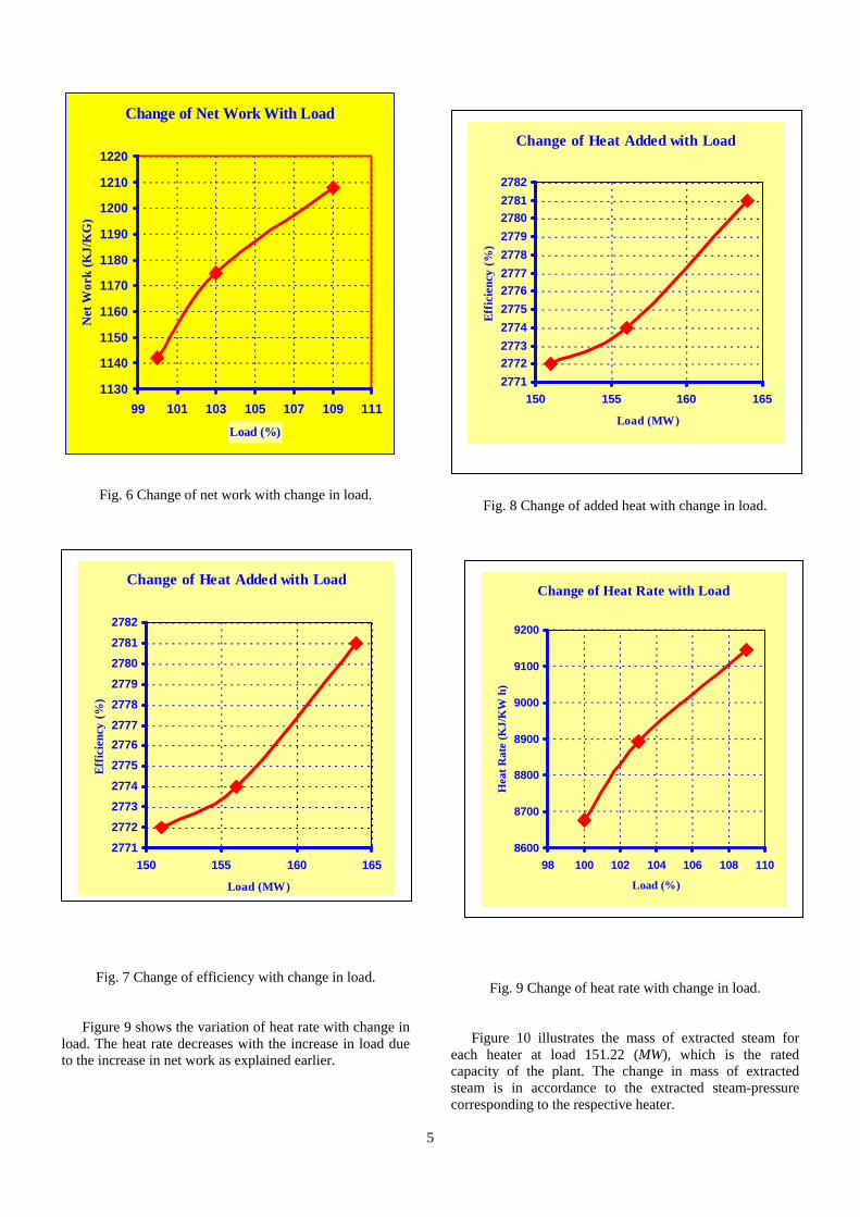
Fig. 7 Change of efficiency with change in load. Figure 9 shows the variation of heat rate with change in
load. The heat rate decreases with the increase in load due to the increase in net work as explained earlier.
Fig. 8 Change of added heat with change in load.
Fig. 9 Change of heat rate with change in load.
Figure 10 illustrates the mass of extracted steam for
each heater at load 151.22 (MW), which is the rated capacity of the plant. The change in mass of extracted steam is in accordance to the extracted steam-pressure corresponding to the respective heater.
Change of Net Work With Load
1130
1140
1150
1160
1170
1180
1190
1200
1210
1220
99 101 103 105 107 109 111
Load (%)
Net
Wor
k (K
J/K
G)
Change of Heat Added with Load
277127722773277427752776277727782779278027812782
150 155 160 165
Load (MW)
Effic
ienc
y (%
)
Change of Heat Added with Load
277127722773277427752776277727782779278027812782
150 155 160 165
Load (MW)
Effic
ienc
y (%
)
Change of Heat Rate with Load
8600
8700
8800
8900
9000
9100
9200
98 100 102 104 106 108 110
Load (%)
Hea
t Rat
e (K
J/K
W h
)
6
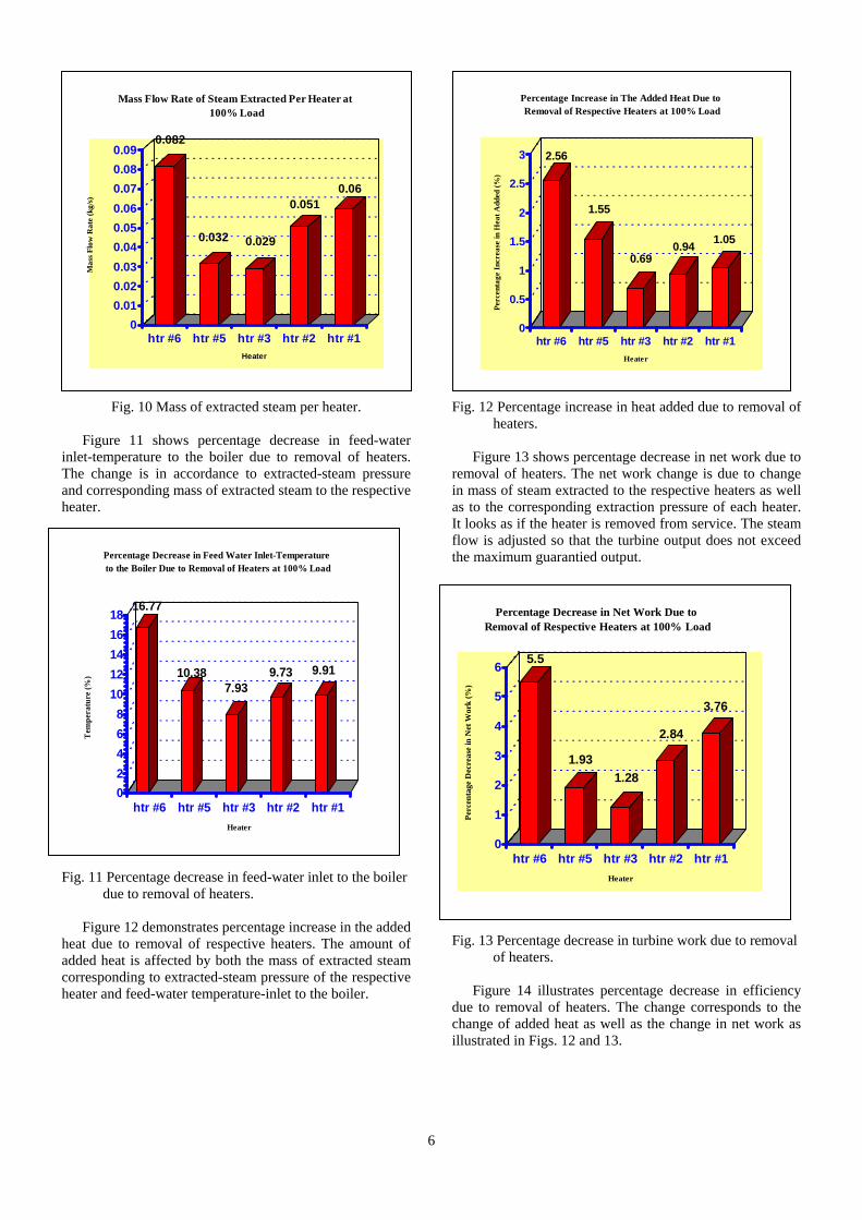
Fig. 10 Mass of extracted steam per heater.
Figure 11 shows percentage decrease in feed-water inlet-temperature to the boiler due to removal of heaters. The change is in accordance to extracted-steam pressure and corresponding mass of extracted steam to the respective heater.
Fig. 11 Percentage decrease in feed-water inlet to the boiler due to removal of heaters.
Figure 12 demonstrates percentage increase in the added
heat due to removal of respective heaters. The amount of added heat is affected by both the mass of extracted steam corresponding to extracted-steam pressure of the respective heater and feed-water temperature-inlet to the boiler.
Fig. 12 Percentage increase in heat added due to removal of heaters.
Figure 13 shows percentage decrease in net work due to
removal of heaters. The net work change is due to change in mass of steam extracted to the respective heaters as well as to the corresponding extraction pressure of each heater. It looks as if the heater is removed from service. The steam flow is adjusted so that the turbine output does not exceed the maximum guarantied output.
Fig. 13 Percentage decrease in turbine work due to removal
of heaters.
Figure 14 illustrates percentage decrease in efficiency due to removal of heaters. The change corresponds to the change of added heat as well as the change in net work as illustrated in Figs. 12 and 13.
0.082
0.032 0.029
0.0510.06
00.010.020.030.040.050.060.070.080.09
Mas
s Fl
ow R
ate
(kg/
s)
htr #6 htr #5 htr #3 htr #2 htr #1Heater
Mass Flow Rate of Steam Extracted Per Heater at 100% Load
16.77
10.387.93
9.73 9.91
02468
1012141618
Tem
pera
ture
(%)
htr #6 htr #5 htr #3 htr #2 htr #1Heater
Percentage Decrease in Feed Water Inlet-Temperature to the Boiler Due to Removal of Heaters at 100% Load
2.56
1.55
0.690.94 1.05
0
0.5
1
1.5
2
2.5
3
Perc
enta
ge I
ncre
ase
in H
eat A
dded
(%)
htr #6 htr #5 htr #3 htr #2 htr #1Heater
Percentage Increase in The Added Heat Due to Removal of Respective Heaters at 100% Load
5.5
1.931.28
2.84
3.76
0
1
2
3
4
5
6
Perc
enta
ge D
ecre
ase
in N
et W
ork
(%)
htr #6 htr #5 htr #3 htr #2 htr #1Heater
Percentage Decrease in Net Work Due to Removal of Respective Heaters at 100% Load
7
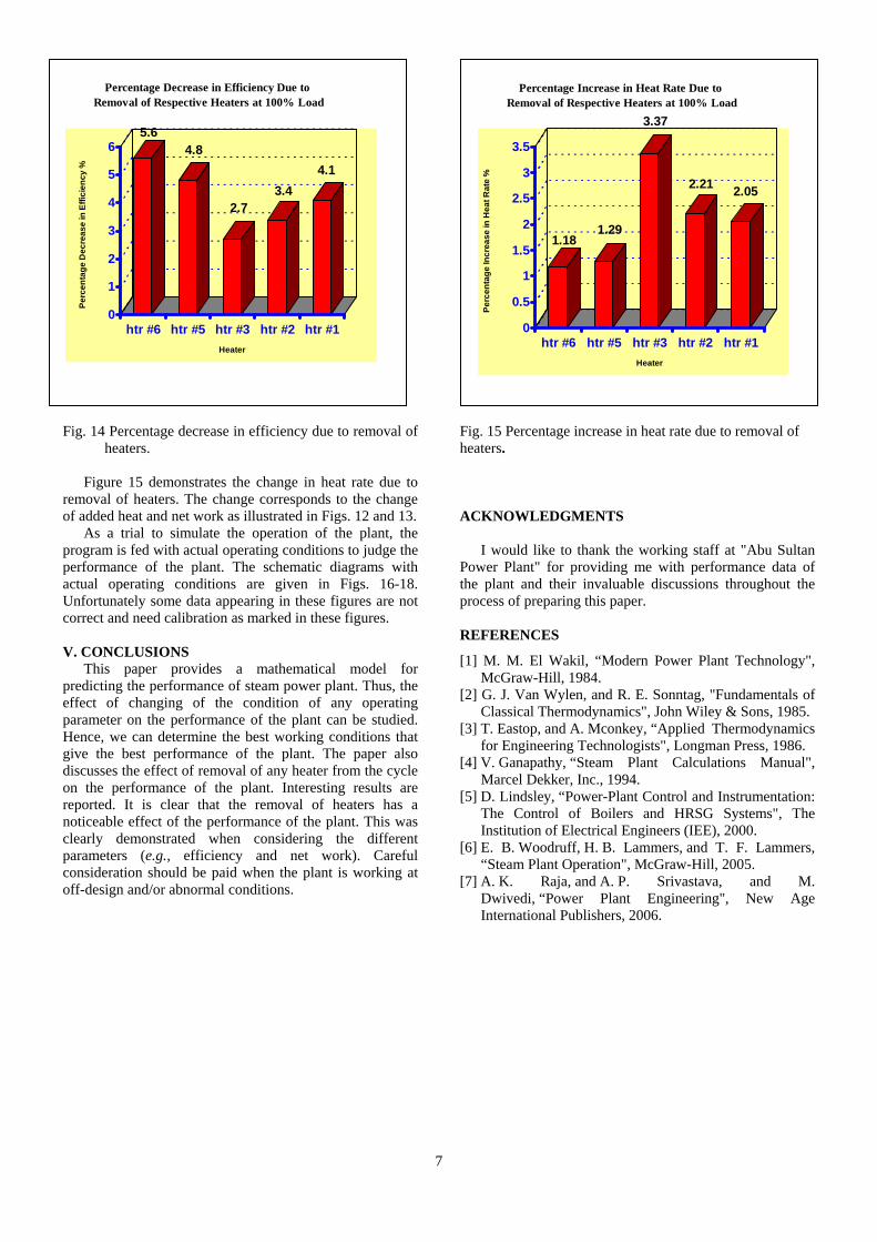
Fig. 14 Percentage decrease in efficiency due to removal of heaters.
Figure 15 demonstrates the change in heat rate due to
removal of heaters. The change corresponds to the change of added heat and net work as illustrated in Figs. 12 and 13.
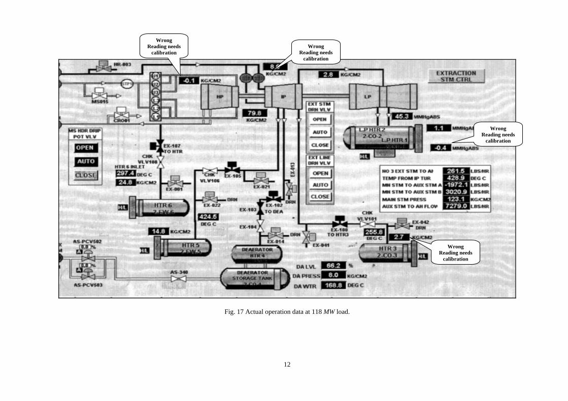
As a trial to simulate the operation of the plant, the program is fed with actual operating conditions to judge the performance of the plant. The schematic diagrams with actual operating conditions are given in Figs. 16-18. Unfortunately some data appearing in these figures are not correct and need calibration as marked in these figures. V. CONCLUSIONS
This paper provides a mathematical model for predicting the performance of steam power plant. Thus, the effect of changing of the condition of any operating parameter on the performance of the plant can be studied. Hence, we can determine the best working conditions that give the best performance of the plant. The paper also discusses the effect of removal of any heater from the cycle on the performance of the plant. Interesting results are reported. It is clear that the removal of heaters has a noticeable effect of the performance of the plant. This was clearly demonstrated when considering the different parameters (e.g., efficiency and net work). Careful consideration should be paid when the plant is working at off-design and/or abnormal conditions.
Fig. 15 Percentage increase in heat rate due to removal of heaters. ACKNOWLEDGMENTS
I would like to thank the working staff at "Abu Sultan Power Plant" for providing me with performance data of the plant and their invaluable discussions throughout the process of preparing this paper. REFERENCES
[1] M. M. El Wakil, “Modern Power Plant Technology", McGraw-Hill, 1984.
[2] G. J. Van Wylen, and R. E. Sonntag, "Fundamentals of Classical Thermodynamics", John Wiley & Sons, 1985.
[3] T. Eastop, and A. Mconkey, “Applied Thermodynamics for Engineering Technologists", Longman Press, 1986.
[4] V. Ganapathy, “Steam Plant Calculations Manual", Marcel Dekker, Inc., 1994.
[5] D. Lindsley, “Power-Plant Control and Instrumentation: The Control of Boilers and HRSG Systems", The Institution of Electrical Engineers (IEE), 2000.
[6] E. B. Woodruff, H. B. Lammers, and T. F. Lammers, “Steam Plant Operation", McGraw-Hill, 2005.
[7] A. K. Raja, and A. P. Srivastava, and M. Dwivedi, “Power Plant Engineering", New Age International Publishers, 2006.
5.64.8
2.73.4
4.1
0
1
2
3
4
5
6
Perc
enta
ge D
ecre
ase
in E
ffici
ency
%
htr #6 htr #5 htr #3 htr #2 htr #1Heater
Percentage Decrease in Efficiency Due to Removal of Respective Heaters at 100% Load
1.181.29
3.37
2.21 2.05
0
0.5
1
1.5
2
2.5
3
3.5
Perc
enta
ge In
crea
se in
Hea
t Rat
e %
htr #6 htr #5 htr #3 htr #2 htr #1Heater
Percentage Increase in Heat Rate Due to Removal of Respective Heaters at 100% Load
8
Fig. 3 Schematic drawing of the first unit of the plant.
9
Fig. 4 Schematic drawing of the second unit of the plant.
10
Fig. 5 Schematic drawing of the third unit of the plant.

11
Fig. 16 Actual operation data at 131 MW load.
Wrong Reading needs
calibration
Wrong Reading needs
calibration
12
Fig. 17 Actual operation data at 118 MW load.
Wrong Reading needs
calibration Wrong
Reading needs calibration
Wrong Reading needs
calibration
Wrong Reading needs
calibration
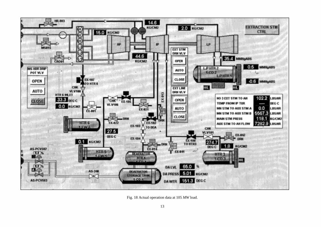
13
Fig. 18 Actual operation data at 105 MW load.