a novel fault-location algorithm for double-circuit transmission lines without utilizing line...
TRANSCRIPT
This article has been accepted for inclusion in a future issue of this journal. Content is final as presented, with the exception of pagination.
IEEE TRANSACTIONS ON POWER DELIVERY 1
A Novel Fault-Location Algorithmfor Double-Circuit Transmission Lines
Without Utilizing Line ParametersChristos A. Apostolopoulos and George N. Korres, Senior Member, IEEE
Abstract—This paper puts forward a novel algorithm for lo-cating faults on double-circuit transmission lines using two-endunsynchronized current measurements. The algorithm does notrequire line parameters, which is a radical step forward comparedto existing approaches, which require this information, so it can beconsidered as a settings-free algorithm. Only the positive-sequencecurrent phasors during the fault are processed for determining thesought distance to fault and the synchronization angle, limitingthus the amount of data needed to be transferred from each lineterminal. The proposed algorithm is derived by applying theKirchhoff’s voltage law around the parallel circuits loops duringthe fault. The algorithm is applicable for both transposed anduntransposed double-circuit lines and is independent of the faulttype. Evaluation studies using reliable Alternative Transients Pro-gram-Electromagnetic Transients Program simulation data verifythat the accuracy of the proposed algorithm is very high undervarious fault resistances, fault locations, and source impedances.
Index Terms—Double-circuit transmission lines, fault location,settings-free method, unsynchronized current measurements.
I. INTRODUCTION
D OUBLE-CIRCUIT transmission lines have been ex-tensively utilized in modern power systems to enhance
the reliability and security for the transmission of electricalenergy. The different possible configurations of double-circuitlines, combined with the effect of mutual coupling, makes theirprotection and fault-location estimation a very challengingproblem.
Many fault-location algorithms for double-circuit lines havebeen proposed in recent years [1]–[14]. These algorithmsare based either on one-terminal [1]–[8] or two-terminal data[9]–[14]. Although less precise than two-terminal algorithms,one-terminal algorithms appear more attractive since theyrely only on voltage and current measurements captured atone common terminal and, hence, no communication linkshave to be provided between both terminals of the line. Whiledifferent in their considered assumptions and implementationissues, these algorithms attempt to estimate the fault currentcontribution from the other terminal by solving the Kirchhoff’sVoltage Law (KVL) equations around parallel lines loops.
Manuscript received January 07, 2010; revised May 11, 2010; accepted De-cember 19, 2010. Paper no. TPWRD-00015-2010.
The authors are with the Electrical and Computer Engineering Department,National Technical University of Athens, Athens GR-15780, Greece (e-mail:[email protected]; [email protected]).
Color versions of one or more of the figures in this paper are available onlineat http://ieeexplore.ieee.org.
Digital Object Identifier 10.1109/TPWRD.2010.2102777
However, their accuracy is dependent on the fault type and lineparameters uncertainty, although it is not highly influenced bythe fault resistance and source impedances. Moreover, most ofthese algorithms cannot deal effectively with intercircuit faultswhich are more likely to occur on double-circuit lines sharingthe same tower structure.
Contrary to one-terminal algorithms, there are few two-ter-minal algorithms for double-circuit lines reported in the litera-ture [9]–[14]. These algorithms employ measurements at bothterminals of a double-circuit line and, thus, a larger amount ofinformation is available, which makes their performance supe-rior in comparison to one-terminal algorithms. Based on how thedigital measurements at the line ends are acquired, two-terminalalgorithms are divided into two categories: 1) those using syn-chronized measurements, if the global positioning system (GPS)is available and 2) those using unsynchronized measurements,if the signal from the GPS gets lost and there is no common timereference between measurements. In order to make the unsyn-chronized measurements useful for fault-location estimation,analytical synchronization must be achieved. This involves theintroduction of the synchronization angle as an additional un-known to the sought distance to fault. Then, the two unknownscan be solved by performing iterative [15]–[17] or noniterativecalculations [18].
References [9]–[11] present methods that employ unsynchro-nized measurements for estimating the distance to fault andthe synchronization angle between measurements from differentterminals of a double-circuit line. They can be classified intotwo groups: 1) phasor-based methods [9] and 2) time-domainmethods [10], [11]. Algorithms based on synchronized mea-surements have been discussed in [12]–[14]. Some of these al-gorithms require determination of the fault type [13], [14], whileothers make use of both prefault and postfault data [12], [13].Moreover, two-terminal algorithms can be further separated intothose using two-end voltages [13] or currents only [10], [11], orboth of them [9], [12], [14].
Based on the length of the double-circuit transmission line,short line [1]–[5], [8], [13] and long line [6], [7], [9]–[12], [14]algorithms have been developed using lumpled RL line parame-ters and distributed RLC line parameters, respectively. Most ofthese algorithms [1]–[6], [11], [13], [14] have focused on trans-posed transmission lines. Therefore, symmetrical componentsare used to determine the fault location. However, technical,economical and ecological aspects lead to untransposed trans-mission lines. Full transposition schemes are often too expen-
0885-8977/$26.00 © 2011 IEEE
This article has been accepted for inclusion in a future issue of this journal. Content is final as presented, with the exception of pagination.
2 IEEE TRANSACTIONS ON POWER DELIVERY
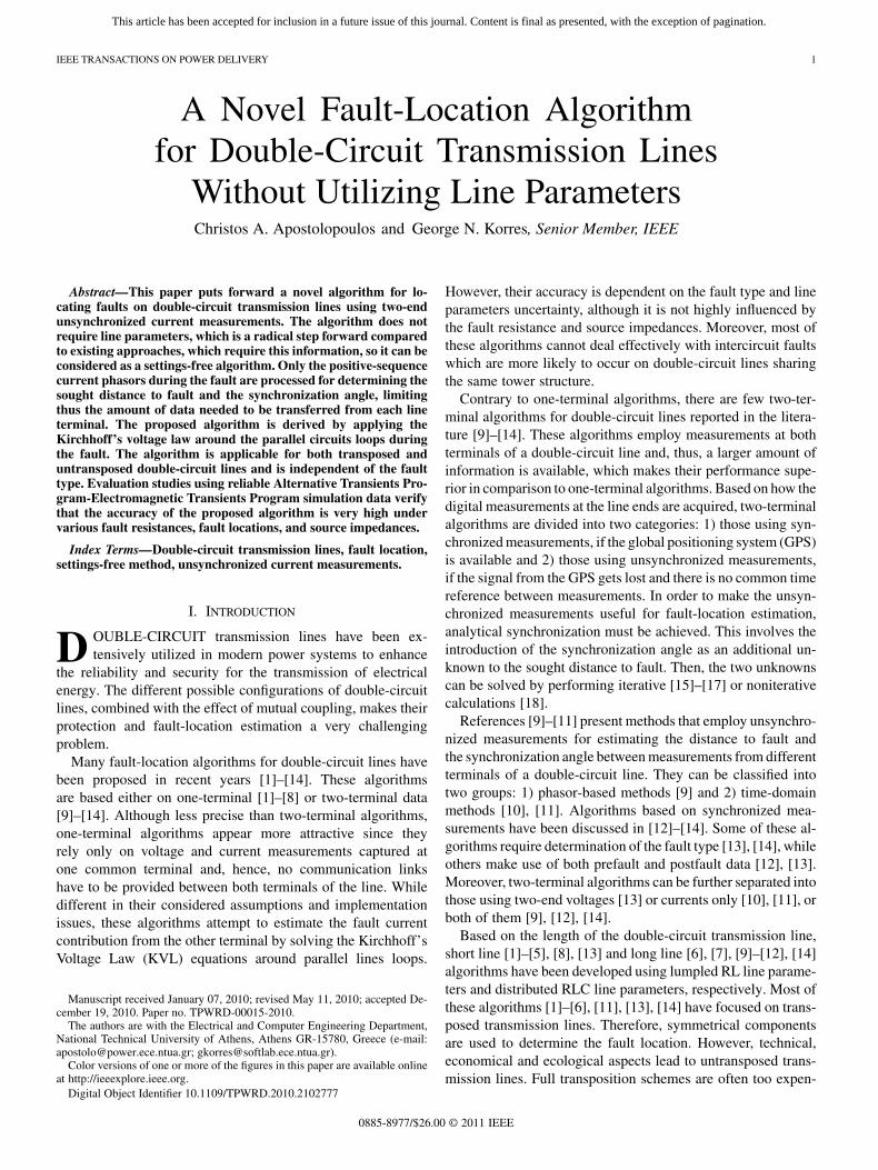
Fig. 1. Proposed measurement arrangement for fault location on double-circuittransmission lines.
sive and not applicable to short- and medium-length double-cir-cuit lines [19]. Although some fault-location methods [7]–[10],[12] have been proposed for untransposed double-circuit lines,most of them require the line parameters to be known exactly.
The authors of [12] describe a method for estimating lineparameters, but this method needs continuously monitoring ofthe double-circuit line during normal operations and demandsphasor measurement units (PMUs) for data synchronization.Recent methods that obviate the need for knowing the line pa-rameters to locate the fault have been presented in [20]–[23]. Al-though very instructive and innovative, these methods are onlyapplicable to fully transposed single-circuit transmission linesand do not consider the effect of mutual coupling in double-cir-cuit lines.
This paper puts forward a novel fault-location algorithmwhich is independent of line parameters and can be applied forboth transposed and untransposed double-circuit transmissionlines. The algorithm utilizes two-end unsynchronized currentmeasurements during the fault and the only assumption madefor its successful implementation is the unchangeability of lineparameters after the fault inception, regardless of the tempera-ture rise in conductors, which is a common assumption madeby the majority of the reported fault-location algorithms.
The mathematical derivation of the proposed algorithm isbased on the nominal- line model, providing thus charging cur-rent compensation in case of long lines also. The algorithm em-ploys the Kirchhoff’s voltage law around the parallel circuitsloops during the fault to derive a complex equation which con-tains the sought distance to fault and the corresponding synchro-nization angle. Then, the two unknowns are calculated by usinga noniterative process, which is also one step beyond the ex-isting methods. Only the positive-sequence current phasors areutilized, limiting thus the amount of data needed to be trans-ferred from each terminal of the double-circuit line. Moreover,classification of the fault type and selection of the faulted phaseare generally not required.
In the rest of this paper, Section II presents the proposed fault-location algorithm. Section III describes the evaluation studies,followed by the conclusion.
II. BASICS OF THE FAULT-LOCATION ALGORITHM
The proposed fault-location scheme on double-circuit two-terminal transmission line SR is shown schematically in Fig. 1.At both line ends (S,R), there are current transformers (CTs)which provide the transformed current signals to the measure-ment units (MUs). Digital measurements are performed in theseunits for determining the fundamental frequency phasors of thethree-phase currents. Then, the well-known symmetrical com-ponent transformation is applied to obtain the positive-sequencecurrent phasors. The measurement data are transmitted to thefault locator (FL), which is regarded as a stand-alone device,via communication links upon occurrence of a fault. It is to benoted that there is no GPS control of the digital measurementsperformed at the two line ends and, thus, a more general case ofunsynchronized measurements is considered.
The star of fault resistances shown in Fig. 1 enables repre-senting any type of fault on double-circuit lines, even intercir-cuit faults, eliminating, when necessary, those legs that are notpresent in the type of fault considered. For instance, the IAIIBGfault is reflected when the legs containing the resistances ,
, and are maintained and the rest are eliminated. Usingthis generic circuit model for fault representation, the math-ematical formulation of the proposed algorithm is derived inthe following paragraphs for both transposed and untransposeddouble-circuit lines.
A. Transposed Double-Circuit Transmission Line
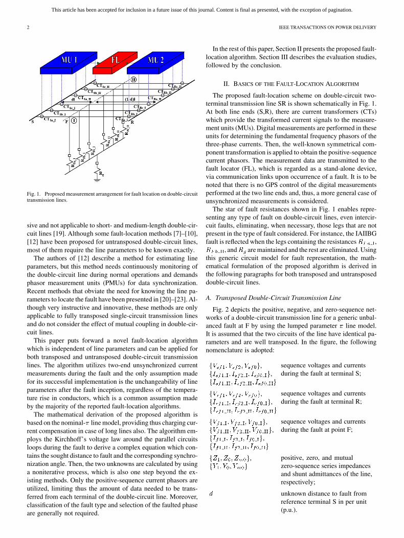
Fig. 2 depicts the positive, negative, and zero-sequence net-works of a double-circuit transmission line for a generic unbal-anced fault at F by using the lumped parameter line model.It is assumed that the two circuits of the line have identical pa-rameters and are well transposed. In the figure, the followingnomenclature is adopted:
,,
sequence voltages and currentsduring the fault at terminal S;
,,
sequence voltages and currentsduring the fault at terminal R;
,,
,
sequence voltages and currentsduring the fault at point F;
, positive, zero, and mutualzero-sequence series impedancesand shunt admittances of the line,respectively;
unknown distance to fault fromreference terminal S in per unit(p.u.).
This article has been accepted for inclusion in a future issue of this journal. Content is final as presented, with the exception of pagination.
APOSTOLOPOULOS AND KORRES: NOVEL FAULT-LOCATION ALGORITHM FOR DOUBLE-CIRCUIT TRANSMISSION LINES 3
Based on Fig. 2(a), we can derive the following equations forthe positive-sequence voltage at terminal R:
(1)
(2)
where is the synchronization angle between measurements atS and R, representing any possible synchronization error.
Rewriting (1) and (2), we have
(3)
(4)
Subtracting (4) from (3), we obtain
(5)or
(6)
Fig. 2. (a) Positive, (b) negative, and (c) zero-sequence networks of a trans-posed double-circuit transmission line during the fault.
Based on Fig. 2(b) and following a similar procedure as be-fore, we can derive an equation analogous to (6) relating thenegative-sequence currents between the line terminals:
(7)
(8)
(9)
This article has been accepted for inclusion in a future issue of this journal. Content is final as presented, with the exception of pagination.
4 IEEE TRANSACTIONS ON POWER DELIVERY
In case of the zero-sequence network, it follows from Fig. 2(c)that the zero-sequence voltage at R satisfies [24]: See (8) and (9)at the bottom of the previous page.
Equations (8) and (9) can be expressed as
(10)
(11)
Subtracting (11) from (10), we obtain
(12)
or
(13)
Equations (6), (7), and (13) form the basis for determining thesought synchronization angle and the corresponding distanceto fault, without requiring line parameters, by employing eitherthe positive, negative, or zero-sequence currents at the oppositeends of a transposed double-circuit transmission line. It followsfrom (6), (7), and (13) that
(14)
where and are constants defined in the Appendix. Sinceis a real number, the imaginary part of (14) should be zero,
i.e.,
(15)
where the bar over a variable designates the complex conjugate.Simplifying (15) leads to
(16)
where and are defined in the Appendix. Finally, the syn-chronization angle can be determined as follows:
(17)
After the synchronization angle is obtained, the fault locationis calculated by taking the real part of (14)
(18)
Limiting the synchronization angle range to , two so-lutions generally exist for in (17). One solution lies in theinterval while the other one lies in the interval
and the difference between them is radians. Todecide which solution is the correct one, we can check their cor-responding fault locations calculated by (18). If one obtainedper-unit fault location is in the boundary and the otherone is out of the boundary , the solution for the synchro-nization angle that corresponds to the former is the correct one,while the other one can be rejected or characterized as unreal-istic [15]–[17], [25].
In case of transposed double-circuit lines, the positive-se-quence quantities exist in all possible fault types encountered,while the negative-sequence quantities appear only in the occur-rence of unbalanced faults and the zero quantities in case of un-balanced faults involving ground. Thus, if we want to avoid theuse of a fault-type selection algorithm, we must apply (14) forfault-location estimation by employing the positive-sequencecurrents at the opposite line ends.
B. Untransposed Double-Circuit Transmission Line
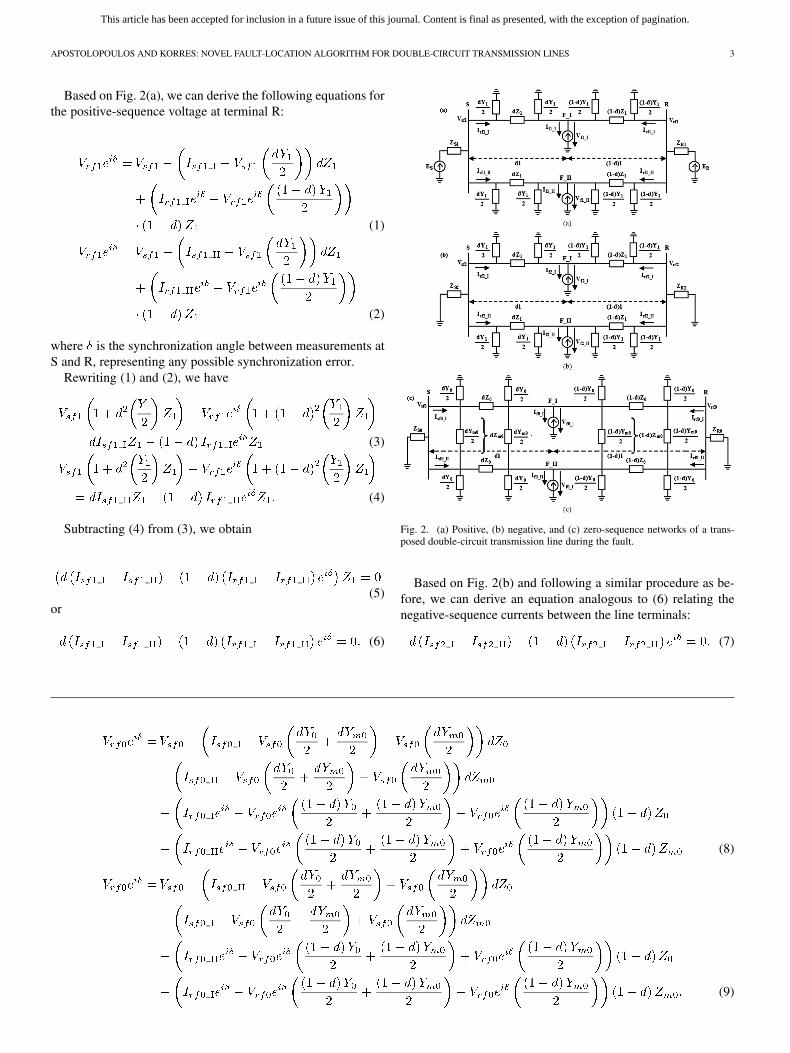
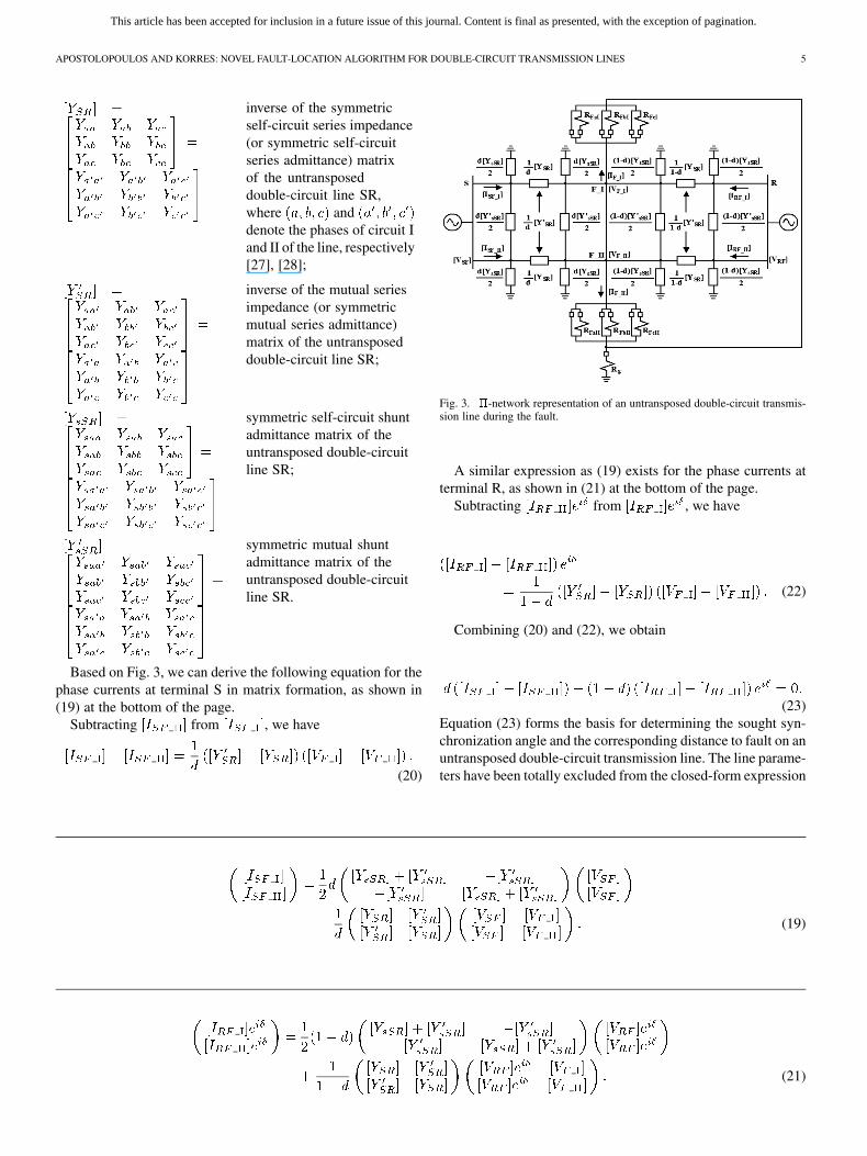
Fig. 3 shows the -network representation of an untransposeddouble-circuit line during a generic unbalanced fault at point F[26]. In the figure, the following notations are adopted:
,
,
vectors of phase voltagesand currents during the faultat terminal S;
,
,
vectors of phase voltagesand currents during the faultat terminal R;
,
,
,
vectors of phase voltagesand currents during the faultat point F;
, , ,, , ,
uknown fault and groundresistances involved in thefault;
This article has been accepted for inclusion in a future issue of this journal. Content is final as presented, with the exception of pagination.
APOSTOLOPOULOS AND KORRES: NOVEL FAULT-LOCATION ALGORITHM FOR DOUBLE-CIRCUIT TRANSMISSION LINES 5
inverse of the symmetricself-circuit series impedance(or symmetric self-circuitseries admittance) matrixof the untransposeddouble-circuit line SR,where anddenote the phases of circuit Iand II of the line, respectively[27], [28];
inverse of the mutual seriesimpedance (or symmetricmutual series admittance)matrix of the untransposeddouble-circuit line SR;
symmetric self-circuit shuntadmittance matrix of theuntransposed double-circuitline SR;
symmetric mutual shuntadmittance matrix of theuntransposed double-circuitline SR.
Based on Fig. 3, we can derive the following equation for thephase currents at terminal S in matrix formation, as shown in(19) at the bottom of the page.
Subtracting from , we have
(20)
Fig. 3. �-network representation of an untransposed double-circuit transmis-sion line during the fault.
A similar expression as (19) exists for the phase currents atterminal R, as shown in (21) at the bottom of the page.
Subtracting from , we have
(22)
Combining (20) and (22), we obtain
(23)Equation (23) forms the basis for determining the sought syn-chronization angle and the corresponding distance to fault on anuntransposed double-circuit transmission line. The line parame-ters have been totally excluded from the closed-form expression
(19)
(21)
This article has been accepted for inclusion in a future issue of this journal. Content is final as presented, with the exception of pagination.
6 IEEE TRANSACTIONS ON POWER DELIVERY
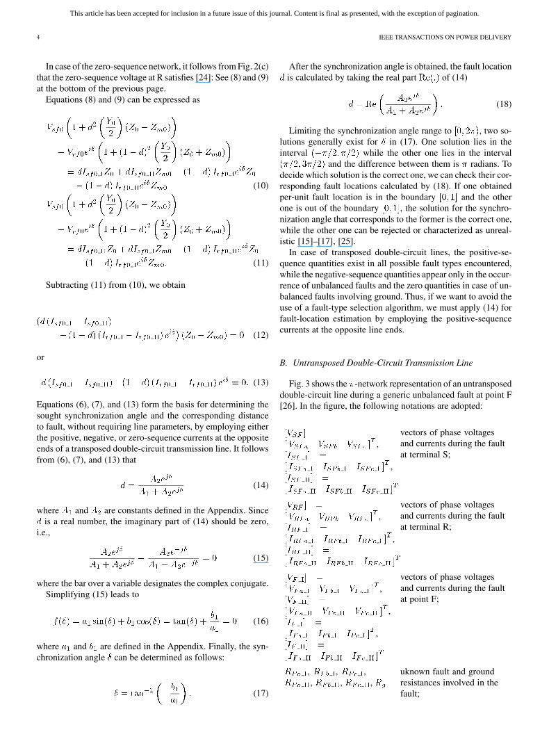
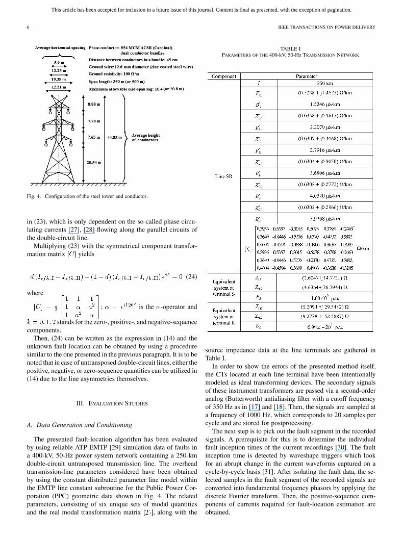
Fig. 4. Configuration of the steel tower and conductor.
in (23), which is only dependent on the so-called phase circu-lating currents [27], [28] flowing along the parallel circuits ofthe double-circuit line.
Multiplying (23) with the symmetrical component transfor-mation matrix yields
(24)
where
; is the -operator and
stands for the zero-, positive-, and negative-sequencecomponents.
Then, (24) can be written as the expression in (14) and theunknown fault location can be obtained by using a proceduresimilar to the one presented in the previous paragraph. It is to benoted that in case of untransposed double-circuit lines, either thepositive, negative, or zero-sequence quantities can be utilized in(14) due to the line asymmetries themselves.
III. EVALUATION STUDIES
A. Data Generation and Conditioning
The presented fault-location algorithm has been evaluatedby using reliable ATP-EMTP [29] simulation data of faults ina 400-kV, 50-Hz power system network containing a 250-kmdouble-circuit untransposed transmission line. The overheadtransmission-line parameters considered have been obtainedby using the constant distributed parameter line model withinthe EMTP line constant subroutine for the Public Power Cor-poration (PPC) geometric data shown in Fig. 4. The relatedparameters, consisting of six unique sets of modal quantitiesand the real modal transformation matrix , along with the
TABLE IPARAMETERS OF THE 400-kV, 50-Hz TRANSMISSION NETWORK
source impedance data at the line terminals are gathered inTable I.
In order to show the errors of the presented method itself,the CTs located at each line terminal have been intentionallymodeled as ideal transforming devices. The secondary signalsof these instrument transformers are passed via a second-orderanalog (Butterworth) antialiasing filter with a cutoff frequencyof 350 Hz as in [17] and [18]. Then, the signals are sampled ata frequency of 1000 Hz, which corresponds to 20 samples percycle and are stored for postprocessing.
The next step is to pick out the fault segment in the recordedsignals. A prerequisite for this is to determine the individualfault inception times of the current recordings [30]. The faultinception time is detected by waveshape triggers which lookfor an abrupt change in the current waveforms captured on acycle-by-cycle basis [31]. After isolating the fault data, the se-lected samples in the fault segment of the recorded signals areconverted into fundamental frequency phasors by applying thediscrete Fourier transform. Then, the positive-sequence com-ponents of currents required for fault-location estimation areobtained.
This article has been accepted for inclusion in a future issue of this journal. Content is final as presented, with the exception of pagination.
APOSTOLOPOULOS AND KORRES: NOVEL FAULT-LOCATION ALGORITHM FOR DOUBLE-CIRCUIT TRANSMISSION LINES 7
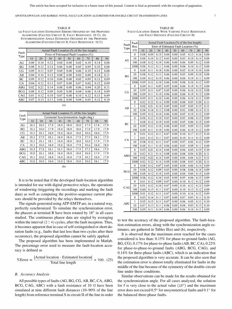
TABLE II(a) FAULT-LOCATION ESTIMATION ERRORS OBTAINED BY THE PROPOSED
ALGORITHM (FAULTED CIRCUIT II, FAULT RESISTANCE: 10 �). (b)SYNCHRONIZATION ANGLE ESTIMATES OBTAINED BY THE PROPOSED
ALGORITHM (FAULTED CIRCUIT II, FAULT RESISTANCE: 10 �)
(a)
(b)
It is to be noted that if the developed fault-location algorithmis intended for use with digital protective relays, the operationsof windowing (triggering the recordings and marking the faultdata) as well as computing the positive-sequence current pha-sors should be provided by the relays themselves.
The signals generated using ATP-EMTP are, in a natural way,perfectly synchronized. To simulate the synchronization error,the phasors at terminal R have been rotated by 18 in all casesstudied. The continuous phasor data are singled by averagingwithin the interval cycles, after the fault inception. Thus,it becomes apparent that in case of self-extinguished or short du-ration faults (e.g., faults that last less than two cycles after theiroccurence), the proposed algorithm cannot be safely applied.
The proposed algorithm has been implemented in Matlab.The percentage error used to measure the fault-location accu-racy is defined as
ErrorActual location - Estimated location
Total line length(25)
B. Accuracy Analysis
All possible types of faults (AG, BG, CG, AB, BC, CA, ABG,BCG, CAG, ABC) with a fault resistance of 10 have beensimulated at nine different fault distances (10–90% of the linelength) from reference terminal S in circuit II of the line in order
TABLE IIIFAULT-LOCATION ERROR WITH VARYING FAULT RESISTANCE
AND FAULT DISTANCE (FAULTED CIRCUIT II)
to test the accuracy of the proposed algorithm. The fault-loca-tion estimation errors, along with the synchronization angle es-timates, are gathered in Tables II(a) and (b), respectively.
It is observed that the maximum error reached for the casesconsidered is less than: 0.15% for phase-to-ground faults (AG,BG, CG), 0.17% for phase-to-phase faults (AB, BC, CA), 0.22%for phase-to-phase-to-ground faults (ABG, BCG, CAG), and0.14% for three-phase faults (ABC), which is an indication thatthe proposed algorithm is very accurate. It can be also seen thatthe estimation error is almost totally eliminated for faults in themiddle of the line because of the symmetry of the double-circuitline under these conditions.
Similar observations can be made for the results obtained forthe synchronization angle. For all cases analyzed, the solutionfor is very close to the actual value and the maximumerror does not exceed 0.5 for unsymmetrical faults and 0.1 forthe balanced three-phase faults.
This article has been accepted for inclusion in a future issue of this journal. Content is final as presented, with the exception of pagination.
8 IEEE TRANSACTIONS ON POWER DELIVERY
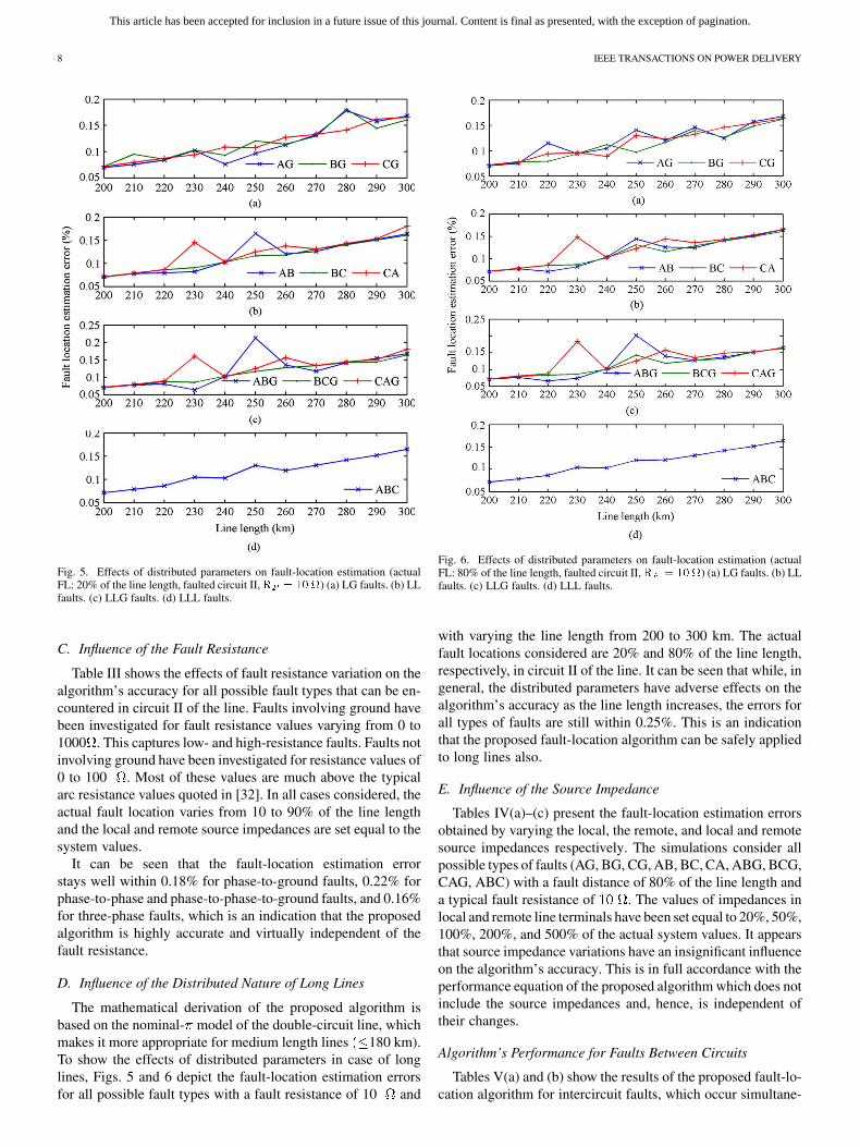
Fig. 5. Effects of distributed parameters on fault-location estimation (actualFL: 20% of the line length, faulted circuit II,� � �� �) (a) LG faults. (b) LLfaults. (c) LLG faults. (d) LLL faults.
C. Influence of the Fault Resistance
Table III shows the effects of fault resistance variation on thealgorithm’s accuracy for all possible fault types that can be en-countered in circuit II of the line. Faults involving ground havebeen investigated for fault resistance values varying from 0 to1000 . This captures low- and high-resistance faults. Faults notinvolving ground have been investigated for resistance values of0 to 100 . Most of these values are much above the typicalarc resistance values quoted in [32]. In all cases considered, theactual fault location varies from 10 to 90% of the line lengthand the local and remote source impedances are set equal to thesystem values.
It can be seen that the fault-location estimation errorstays well within 0.18% for phase-to-ground faults, 0.22% forphase-to-phase and phase-to-phase-to-ground faults, and 0.16%for three-phase faults, which is an indication that the proposedalgorithm is highly accurate and virtually independent of thefault resistance.
D. Influence of the Distributed Nature of Long Lines
The mathematical derivation of the proposed algorithm isbased on the nominal- model of the double-circuit line, whichmakes it more appropriate for medium length lines 180 km).To show the effects of distributed parameters in case of longlines, Figs. 5 and 6 depict the fault-location estimation errorsfor all possible fault types with a fault resistance of 10 and
Fig. 6. Effects of distributed parameters on fault-location estimation (actualFL: 80% of the line length, faulted circuit II,� � ���) (a) LG faults. (b) LLfaults. (c) LLG faults. (d) LLL faults.
with varying the line length from 200 to 300 km. The actualfault locations considered are 20% and 80% of the line length,respectively, in circuit II of the line. It can be seen that while, ingeneral, the distributed parameters have adverse effects on thealgorithm’s accuracy as the line length increases, the errors forall types of faults are still within 0.25%. This is an indicationthat the proposed fault-location algorithm can be safely appliedto long lines also.
E. Influence of the Source Impedance
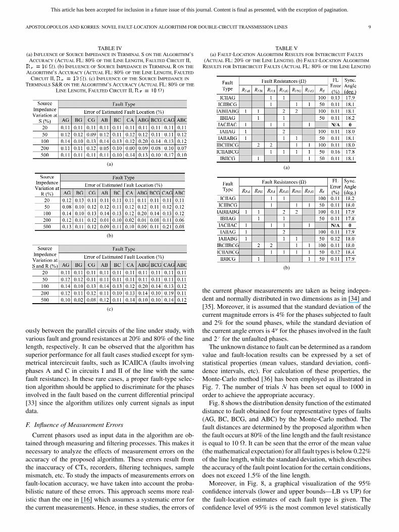
Tables IV(a)–(c) present the fault-location estimation errorsobtained by varying the local, the remote, and local and remotesource impedances respectively. The simulations consider allpossible types of faults (AG, BG, CG, AB, BC, CA, ABG, BCG,CAG, ABC) with a fault distance of 80% of the line length anda typical fault resistance of . The values of impedances inlocal and remote line terminals have been set equal to 20%, 50%,100%, 200%, and 500% of the actual system values. It appearsthat source impedance variations have an insignificant influenceon the algorithm’s accuracy. This is in full accordance with theperformance equation of the proposed algorithm which does notinclude the source impedances and, hence, is independent oftheir changes.
Algorithm’s Performance for Faults Between Circuits
Tables V(a) and (b) show the results of the proposed fault-lo-cation algorithm for intercircuit faults, which occur simultane-
This article has been accepted for inclusion in a future issue of this journal. Content is final as presented, with the exception of pagination.
APOSTOLOPOULOS AND KORRES: NOVEL FAULT-LOCATION ALGORITHM FOR DOUBLE-CIRCUIT TRANSMISSION LINES 9
TABLE IV(a) INFLUENCE OF SOURCE IMPEDANCE IN TERMINAL S ON THE ALGORITHM’S
ACCURACY (ACTUAL FL: 80% OF THE LINE LENGTH, FAULTED CIRCUIT II,� � �� �). (b) INFLUENCE OF SOURCE IMPEDANCE IN TERMINAL R ON THE
ALGORITHM’S ACCURACY (ACTUAL FL: 80% OF THE LINE LENGTH, FAULTED
CIRCUIT II, � � �� �). (c) INFLUENCE OF THE SOURCE IMPEDANCE IN
TERMINALS S&R ON THE ALGORITHM’S ACCURACY (ACTUAL FL: 80% OF THE
LINE LENGTH, FAULTED CIRCUIT II, � � �� �)
(a)
(b)
(c)
ously between the parallel circuits of the line under study, withvarious fault and ground resistances at 20% and 80% of the linelength, respectively. It can be observed that the algorithm hassuperior performance for all fault cases studied except for sym-metrical intercircuit faults, such as ICAIICA (faults involvingphases A and C in circuits I and II of the line with the samefault resistance). In these rare cases, a proper fault-type selec-tion algorithm should be applied to discriminate for the phasesinvolved in the fault based on the current differential principal[33] since the algorithm utilizes only current signals as inputdata.
F. Influence of Measurement Errors
Current phasors used as input data in the algorithm are ob-tained through measuring and filtering processes. This makes itnecessary to analyze the effects of measurement errors on theaccuracy of the proposed algorithm. These errors result fromthe inaccuracy of CTs, recorders, filtering techniques, samplemismatch, etc. To study the impacts of measurements errors onfault-location accuracy, we have taken into account the proba-bilistic nature of these errors. This approach seems more real-istic than the one in [16] which assumes a systematic error forthe current measurements. Hence, in these studies, the errors of
TABLE V(a) FAULT-LOCATION ALGORITHM RESULTS FOR INTERCIRCUIT FAULTS
(ACTUAL FL: 20% OF THE LINE LENGTH). (b) FAULT-LOCATION ALGORITHM
RESULTS FOR INTERCIRCUIT FAULTS (ACTUAL FL: 80% OF THE LINE LENGTH)
(a)
(b)
the current phasor measurements are taken as being indepen-dent and normally distributed in two dimensions as in [34] and[35]. Moreover, it is assumed that the standard deviation of thecurrent magnitude errors is 4% for the phases subjected to faultand 2% for the sound phases, while the standard deviation ofthe current angle errors is 4 for the phases involved in the faultand 2 for the unfaulted phases.
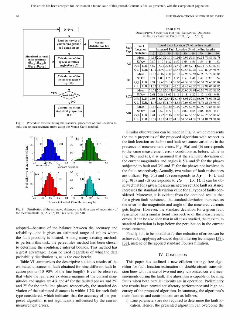
The unknown distance to fault can be determined as a randomvalue and fault-location results can be expressed by a set ofstatistical properties (mean values, standard deviation, confi-dence intervals, etc). For calculation of these properties, theMonte-Carlo method [36] has been employed as illustrated inFig. 7. The number of trials has been set equal to 1000 inorder to achieve the appropriate accuracy.
Fig. 8 shows the distribution density function of the estimateddistance to fault obtained for four representative types of faults(AG, BC, BCG, and ABC) by the Monte-Carlo method. Thefault distances are determined by the proposed algorithm whenthe fault occurs at 80% of the line length and the fault resistanceis equal to 10 . It can be seen that the error of the mean value(the mathematical expectation) for all fault types is below 0.22%of the line length, while the standard deviation, which describesthe accuracy of the fault point location for the certain conditions,does not exceed 1.5% of the line length.
Moreover, in Fig. 8, a graphical visualization of the 95%confidence intervals (lower and upper bounds—LB vs UP) forthe fault-location estimates of each fault type is given. Theconfidence level of 95% is the most common level statistically
This article has been accepted for inclusion in a future issue of this journal. Content is final as presented, with the exception of pagination.
10 IEEE TRANSACTIONS ON POWER DELIVERY
Fig. 7. Procedure for calculating the statistical properties of fault-location re-sults due to measurement errors using the Monte-Carlo method.
Fig. 8. Distribution of the estimated distances to fault in case of uncertainty ofthe measurements. (a) AG. (b) BC. (c) BCG. (d) ABC.
adopted—because of the balance between the accuracy andreliability—and it gives an estimated range of values wherethe fault probably is located. Among many existing methodsto perform this task, the percentiles method has been chosento determine the confidence interval bounds. This method hasa great advantage: it can be used regardless of what the dataprobability distribution is, as is the case herein.
Table VI summarizes the descriptive statistics results of theestimated distances to fault obtained for nine different fault lo-cation points (10–90% of the line length). It can be observedthat while the real error existence margins of the current mag-nitudes and angles are 4% and 4 for the faulted phases and 2%and 2 for the unfaulted phases, respectively, the standard de-viation of the estimated distances is within 1.7% for each faulttype considered, which indicates that the accuracy of the pro-posed algorithm is not significantly influenced by the currentmeasurement errors.
TABLE VIDESCRIPTIVE STATISTICS FOR THE ESTIMATED DISTANCE
TO FAULT (FAULTED CIRCUIT II, � � �� �)
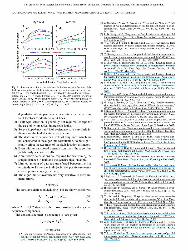
Similar observations can be made in Fig. 9, which representsthe main properties of the proposed algorithm with respect tothe fault location on the line and fault resistance variations in thepresence of measurement errors. Fig. 9(a) and (b) correspondsto the same measurement errors conditions as before, while inFig. 9(c) and (d), it is assumed that the standard deviation ofthe current magnitudes and angles is 5% and 5 for the phasessubjected to fault and 3% and 3 for the phases not involved inthe fault, respectively. Actually, two values of fault resistancesare utilized. Fig. 9(a) and (c) corresponds to andFig. 9(b) and (d) corresponds to . It can be ob-served that for a given measurement error set, the fault resistanceincreases the standard deviation value for all types of faults con-sidered. Moreover, it is evident from the obtained results thatfor a given fault resistance, the standard deviation increases asthe error in the magnitude and angle of the measured currentsgets higher. However, the standard deviation for a given faultresistance has a similar trend irrespective of the measurementerrors. It can be also seen that in all cases studied, the maximumstandard deviation is kept below the pertubation in the currentmeasurements.
Finally, it is to be noted that further reduction of errors can beachieved by applying advanced digital filtering techniques [37],[38], instead of the applied standard Fourier filtration.
IV. CONCLUSION
This paper has outlined a new efficient settings-free algo-rithm for fault-location estimation on double-circuit transmis-sion lines with the use of two-end unsynchronized current mea-surements during the fault. The algorithm is capable of locatingfaults when both parallel circuits are in operation. Preliminarytest results have proved satisfactory performance and high ac-curacy of the proposed algorithm. In summary, the algorithm’smain features and contributions are as follows.
1) Line parameters are not required to determine the fault lo-cation. Hence, the presented algorithm can overcome the
This article has been accepted for inclusion in a future issue of this journal. Content is final as presented, with the exception of pagination.
APOSTOLOPOULOS AND KORRES: NOVEL FAULT-LOCATION ALGORITHM FOR DOUBLE-CIRCUIT TRANSMISSION LINES 11
Fig. 9. Standard deviation of the estimated fault distances as a function of thefault-location point and fault resistance values at various measurement errors(a), (b) � �4% (faulted phases), � � 2% (healthy phases) for current mag-nitude, and � � � (faulted phases), � � � (healthy phases) for currentangle. (c) and (d) � � 5% (faulted phases), � � 3% (healthy phases) forcurrent magnitude and � � � (faulted phases), � � � (healthy phases) forcurrent angle (a), (c) � � �� (b), (d) � � ��� .
degradation of line parameters uncertainty on the existingfault locators for double-circuit lines.
2) Fault-type selection is generally not required, except forthe case of symmetrical intercircuit faults.
3) Source impedances and fault resistance have very little in-fluence on the fault-location calculation.
4) The distributed parameter effects of long lines, which arenot considered in the algorithm formulation, do not signif-icantly affect the accuracy of the fault-location estimates.
5) Even with untransposed transmission lines, the algorithmyields fairly accurate results.
6) Noniterative calculations are required for determining thesought distance to fault and the synchronization angle.
7) Limited amount of data are transferred between the lineterminals to locate the fault (only the positive-sequencecurrent phasors during the fault).
8) The algorithm is favorably not very sensitive to measure-ment errors.
APPENDIX
The constants defined in deducing (14) are shown as follows:
(A1)
(A2)
where 0,1,2 stands for the zero-, positive-, and negative-sequence components.
The constants defined in deducing (16) are given
(A3)
REFERENCES
[1] Y. Liao and S. Elangovan, “Digital distance relaying algorithm for first-zone protection for parallel transmission lines,” Proc. Inst. Elect. Eng.,Gen. Transm. Distrib., vol. 145, no. 6, pp. 531–536, Sep. 1998.
[2] Z. Qingchao, Z. Yao, S. Wennan, Y. Yixin, and W. Zhigang, “Faultlocation of two-parallel transmission line for nonearth fault using one-terminal data,” IEEE Trans. Power Del., vol. 14, no. 3, pp. 863–867,Jul. 1999.
[3] L. B. Sheng and S. Elangovan, “A fault location method for paralleltransmission lines,” Int. J. Elect. Power Energy Syst., vol. 21, no. 4, pp.253–259, May 1999.
[4] Y. J. Ahn, M. S. Choi, S. H. Kang, and S. J. Lee, “An accurate faultlocation algorithm for double-circuit transmission systems,” in Proc.IEEE Power Eng. Soc. Summer Meeting, Seattle, WA, Jul. 2000, pp.1344–1349.
[5] T. Kawady and J. Stenzel, “A practical fault location approach fordouble circuit transmission lines using single end data,” IEEE Trans.Power Del., vol. 18, no. 4, pp. 1166–1173, Oct. 2003.
[6] J. Izykowski, E. Rosolowski, and M. M. Saha, “Locating faults inpower transmission lines under availability of complete measurementsat one end,” Proc. Inst. Elect. Eng., Gen. Transm. Distrib., vol. 151,no. 2, pp. 268–273, Mar. 2004.
[7] G. Song, J. Suonan, and Y. Ge, “An accurate fault location algorithmfor parallel transmission lines using one-terminal data,” Elect. PowerEnergy Syst., vol. 31, no. 2–3, pp. 124–129, Feb./Mar. 2009.
[8] S. H. Kang, Y. J. Ahn, Y. C. Kang, and S. R. Nam, “A fault locationalgorithm based on circuit analysis for untransposed parallel transmis-sion lines,” IEEE Trans. Power Del., vol. 24, no. 4, pp. 1850–1856, Oct.2009.
[9] A. T. Johns and S. Jamali, “Accurate fault location technique for powertransmission lines,” Proc. Inst. Elect. Eng., Gen., Transm. Distrib., vol.137, no. 6, pp. 395–402, Nov. 1990.
[10] G. Song, J. Suonan, Q. Xu, P. Chen, and Y. Ge, “Parallel transmis-sion lines fault location algorithm based on differential component net,”IEEE Trans. Power Del., vol. 20, no. 4, pp. 2396–2406, Oct. 2005.
[11] J. Suonan, G. Song, Q. Xu, and Q. Chao, “Time-domain fault locationfor parallel transmission lines using unsynchronized currents,” Elect.Power Energy Syst., vol. 28, no. 4, pp. 253–260, May 2006.
[12] C. S. Chen, C. W. Liu, and J. A. Jiang, “A new adaptive PMU basedprotection shceme for transposed/untransposed parallel transmissionlines,” IEEE Trans. Power Del., vol. 17, no. 2, pp. 395–404, Apr. 2002.
[13] N. Kang and Y. Liao, “Fault location for double-circuit lines utilizingsparse voltage measurements,” presented at the IEEE Power Eng. Soc.Gen. Meeting, Calgary, AB, Canada, Jul. 2009.
[14] E. Rosolowski, J. Izykowski, and M. M. Saha, “Fault location algo-rithm for use with current differential protective relays of double-circuitline,” presented at the IEEE Bucharest Power Tech Conf., Bucharest,Romania, Jul. 2, 2009.
[15] D. Novosel, D. G. Hart, E. Udren, and J. Garitty, “Unsynchronizedtwo-terminal fault location estimation,” IEEE Trans. Power Del., vol.11, no. 1, pp. 130–138, Jan. 1996.
[16] Y. Liao, “Unsynchronized fault location based on distributed parameterline model,” Elect. Power Compon. Syst., vol. 35, no. 9, pp. 1061–1077,2007.
[17] J. Izykowski, R. Molag, E. Rosolowski, and M. Saha, “Accurate loca-tion of faults on power transmission lines with use of two-end unsyn-chronized measurements,” IEEE Trans. Power Del., vol. 21, no. 2, pp.627–633, Apr. 2006.
[18] J. Izykowski, E. Rosolowski, P. Balcerek, M. Fulczyk, and M. M. Saha,“Accurate noniterative fault-location algorithm utilizing two-end un-synchronized measurements,” IEEE Trans. Power Del., vol. 25, no. 1,pp. 72–80, Jan. 2010.
[19] H. Hupfauer, P. Schegner, and R. Simon, “Distance protection of un-symmetrical lines,” Eur. Trans. Elect. Power, vol. 6, no. 2, pp. 91–96,Mar./Apr. 1996.
[20] Y. Liao and S. Elangovan, “Unsynchronized two-terminal transmis-sion line fault location without using line parameters,” Proc. Inst. Elect.Eng., Gen. Transm. Distrib., vol. 153, no. 6, pp. 639–643, Nov. 2006.
[21] Y. Liao, “Transmission line fault location algorithms without requiringline parameters,” Elect. Power Compon. Syst., vol. 36, no. 11, pp.1218–1225, 2008.
[22] Y. Liao and N. Kang, “Fault-location algorithms without utilizing lineparameters based on the distributed parameter line model,” IEEE Trans.Power Del., vol. 24, no. 2, pp. 579–584, Apr. 2009.
[23] Z. M. Radojevic, C. H. Kim, M. Popov, G. Preston, and V. Terzija,“New approach for fault location on transmission lines not requiringline parameters,” presented at the Int. Power Syst. Transients, Kyoto,Japan, Jun. 2–6, 2009.
[24] Y. Liao, “Equivalent PI circuit for zero-sequence networks of paralleltransmission lines,” Elect. Power Compon. Syst., vol. 37, no. 7, pp.787–797, 2009.
This article has been accepted for inclusion in a future issue of this journal. Content is final as presented, with the exception of pagination.
12 IEEE TRANSACTIONS ON POWER DELIVERY
[25] C.-S. Yu, “An unsynchronized measurements correction method fortwo-terminal fault-location problems,” IEEE Trans. Power Del., vol.25, no. 3, pp. 1325–1333, Jul. 2010.
[26] M. H. Hesse and J. Sabath, “EHV double-circuit untransposed trans-mission line-analysis and tests,” IEEE Trans. Power App. Syst., vol.PAS-90, no. 3, pp. 984–992, May 1971.
[27] M. H. Hesse, “Circulating currents in parallel untransposed multicir-cuit lines: I-Numerical evaluations,” IEEE Trans. Power App. Sys., vol.PAS-85, no. 7, pp. 802–811, Jul. 1966.
[28] M. H. Hesse, “Circulating currents in parallel untransposed multicir-cuit lines: II-Methods for estimating current unbalance,” IEEE Trans.Power App. Syst., vol. PAS-85, no. 7, pp. 812–820, Jul. 1966.
[29] H. W. Dommel, Electromagnetic Transients Program. Portland, OR:BPA, 1986.
[30] M. Moreto and J. G. Rolim, “Automated analysis of digital faultrecorder data in power generating plants,” presented at the Power Syst.Comput. Conf., Glasgow, Scotland, Jul. 14–18, 2008.
[31] “User Manual,” 2005, PowerXplorer PX5, Dranetz-BMI, Tech. Doc-umentation, Rev. G.
[32] J. L. Blackburn, Symmetrical Components For Power System Engi-neering. New York: Marcel Dekker, 1993, pp. 98–99.
[33] B. Kasztenny, B. Campbell, and J. Mazereeuw, “Phase selection forsingle-pole tripping: Weak infeed conditions and cross-country faults,”presented at the 27th Annu. Western Protective Relay Conf., Spokane,WA, Oct. 2000.
[34] M. Bockarjova, G. Andersson, and A. Sauhats, “Statistical algorithmfor power transmission lines distance protection,” presented at the Int.Conf. Probabilistic Methods Appl. Power Syst., Stockholm, Sweden,Jun. 11–15, 2006.
[35] A. Sauhats and M. Danilova, “Fault location algorithms for super highvoltage power transmission lines,” presented at the IEEE Power TechConf., Bologna, Italy, Jun. 26, 2003.
[36] G. S. Fishman, Monte Carlo: Concepts, Algorithms and Applica-tions. New York: Springer-Verlag, 1995.
[37] S. R. Nam, S. H. Kang, and J. K. Park, “An analytic method formeasuring accurate fundamental frequency components,” IEEE Trans.Power Del., vol. 17, no. 2, pp. 405–411, Apr. 2002.
[38] C.-S. Yu, “A discrete fourier transform-based adaptive mimic phasorestimator for distance relaying applications,” IEEE Trans. Power Del.,vol. 21, no. 4, pp. 1836–1846, Oct. 2006.
Christos A. Apostolopoulos was born in Larisa, Greece, in 1981. He receivedthe Diploma in Electrical and Computer Engineering from the National Tech-nical University of Athens, Athens, Greece, in 2004, where he is currently pur-suing the Ph.D. degree.
Since 2005, he has been a Protection Engineer with PROT.A.S.I.S. S.A.,Athens. His main research interests are in power system protection, computerrelaying, and fault location.
George N. Korres (SM’05) received the Diploma and Ph.D. degree in electricaland computer engineering from the National Technical University of Athens,Athens, Greece, in 1984 and 1988, respectively.
Currently, he is Associate Professor in the School of Electrical and ComputerEngineering, National Technical University of Athens. His research interests arepower system state estimation, power system protection, and industrial automa-tion. He is a member of CIGRE.