circuit protection solutions
TRANSCRIPT
Circuit Protection SolutionsFull Line Catalog
Low-Peak® Fuses
For product data sheets, visit www.cooper.bussmann.com/products/datasheet.asp
Table of contents
Cooper Bussmann circuit protection solutions comply with major industrial standards and agency requirements such as: BS, IEC, DIN, UL, NEMA, CSA, CE, C-UL, etc. and are manufactured at facilities that are ISO 9000 certified.
This catalog is intended to present product data and provide technical information that will help the end user with design application. Cooper Bussmann reserves the right, without notice, to change design or construction or anyproducts and to discontinue or limit distribution of any products. Cooper Bussmann also reserves the right to change or update, without notice, any technical information contained in this catalog. Once a product has been select-ed, it should be tested by the user in all possible applications. Further, Cooper Bussmann takes no responsibility for errors or omissions contained in this catalog, or for mis-application of any Cooper Bussmann product. Extensiveproduct information is available in the Bussmann product data sheets available on line at www.cooperbussmann.com/products/datasheet.asp. ©2005 Cooper Bussmann
RED indicates NEW information
Selecting Circuit Protection . . . . . . . . . . . . . . . . . . . . . 22005 NEC® guide to fuse selection for various applications . . . . . . . . . . 2-6
Low Voltage, Branch Circuit Rated Fuses . . . . . . . . . . . . 7Holders & blocks for branch circuit rated fuses . . . . . . . . . . . . . . . . . . 8-10Dimensions data for branch circuit rated fuses . . . . . . . . . . . . . . . . . 11-12CUBEFuse™ Class J fuse & holder system . . . . . . . . . . . . . . . . . . . . 13-14Low-Peak LPJ_SP Class J fuses . . . . . . . . . . . . . . . . . . . . . . . . . . . . . . .15Low-Peak LPN-RK_SP & LPS-RK_SP Class RK1 fuses . . . . . . . . . . . 16-18Low-Peak LP-CC Class CC fuses . . . . . . . . . . . . . . . . . . . . . . . . . . . . . . .19Low-Peak KRP-C_SP & KRP-CL Class L fuses . . . . . . . . . . . . . . . . . . 20-21Fusetron FRN-R (250V) & FRS-R (600V) Class RK5 fuses . . . . . . . . . 22-23Limitron JKS Class J fuses . . . . . . . . . . . . . . . . . . . . . . . . . . . . . . . . . . . 25Limitron KTN-R (250V) & KTS-R (600V) Class RK1 fuses . . . . . . . . . 26-27Limitron KTK-R Class CC fuses . . . . . . . . . . . . . . . . . . . . . . . . . . . . . . . .28Limitron KTU & KLU Class L Fuses . . . . . . . . . . . . . . . . . . . . . . . . . . . . .29Dura-Lag DLN-R (250V) & DLS-R (600V) Class RK5 fuses . . . . . . . . . . .30CC-Tron FNQ-R Class CC fuses . . . . . . . . . . . . . . . . . . . . . . . . . . . . . . . .31T-Tron JNN (300V) & JJS (600V) Class T fuses . . . . . . . . . . . . . . . . . 32-33SC Class G fuses . . . . . . . . . . . . . . . . . . . . . . . . . . . . . . . . . . . . . . . . . .34NON (250V) & NOS (600V) general purpose Class K5 & H fuses . . . . . . .35Plug fuses (S, T, W, SL and TL), Fusestat fuse adapters . . . . . . . . . . . 36-37
Low Voltage Supplementary Fuses . . . . . . . . . . . . . . . . 39Holders & blocks for supplementary fuses . . . . . . . . . . . . . . . . . . . . 40-41Cable (K Series) & Welder (64000/68000 Series) Limiters . . . . . . . . . . . .4213⁄32" x 1 1⁄2" (BAF, BAN, KTK & KLM, DCM, FNM & FNQ) fuses . . . . . . . 43-4513⁄32" x 1 3⁄8" (BBS & KTQ) fuses . . . . . . . . . . . . . . . . . . . . . . . . . . . . . . . . .46GBA/GLD, MIC & MIN. FNA, MIS & KAZ pin indication fuses . . . . . . . 47-48ANN & ANL Limiters . . . . . . . . . . . . . . . . . . . . . . . . . . . . . . . . . . . . . . . .48ATC, ATM & MAX automotive blade-type fuses & holders . . . . . . . . . 49-50GLQ & GMQ In-line size rejecting fuses & holders . . . . . . . . . . . . . . . . . .51GLR & GMF/GRF In-line non- rejecting fuses & holders . . . . . . . . . . . . . .52
Electronic - PCB & Small Dimension fuses . . . . . . . . . . .535 x 15mm ferrule fuses . . . . . . . . . . . . . . . . . . . . . . . . . . . . . . . . . . . . . 545 x 20mm European (IEC) ferrule fuses . . . . . . . . . . . . . . . . . . . . . . . . . 555 x 20mm North American (UL) ferrule fuses . . . . . . . . . . . . . . . . . . . . . 561⁄4" Diameter x 5⁄8" to 1" length ferrule fuses . . . . . . . . . . . . . . . . . . . . . . 571⁄4" Diameter x 1 1⁄4" length fast-acting ferrule fuses . . . . . . . . . . . . . . . . . . 581⁄4" Diameter x 1 1⁄4" length time-delay ferrule fuses . . . . . . . . . . . . . . . . . . 59PC board mount fuse holders . . . . . . . . . . . . . . . . . . . . . . . . . . . . . . 60-61PC board fuseclips for 5mm diameter fuses . . . . . . . . . . . . . . . . . . . 62-65
Medium Voltage Fuses . . . . . . . . . . . . . . . . . . . . . . . .67Introduction . . . . . . . . . . . . . . . . . . . . . . . . . . . . . . . . . . . . . . . . . . . . . 68BBU boric acid fuses . . . . . . . . . . . . . . . . . . . . . . . . . . . . . . . . . . . . . 69-70E-rated fuses: CL-14 & bolt-in . . . . . . . . . . . . . . . . . . . . . . . . . . . . . . 71-72E-rated fuses for transformers & feeders . . . . . . . . . . . . . . . . . . . . . . 73-76R-Rated fuses for motor circuit protection . . . . . . . . . . . . . . . . . . . . . 77-79British Standard IEC fuses for motor circuit protection . . . . . . . . . . . . . . 80DIN IEC fuses for transformers . . . . . . . . . . . . . . . . . . . . . . . . . . . . . . . .81Potential transformer fuses . . . . . . . . . . . . . . . . . . . . . . . . . . . . . . . . . . .82Fast-acting fuses . . . . . . . . . . . . . . . . . . . . . . . . . . . . . . . . . . . . . . . . . . 83British Standard IEC fuses for oil filled switchgear . . . . . . . . . . . . . . . . . 84EEI-NEMA Type K & T, and Type H & N fuses . . . . . . . . . . . . . . . . . . . . . 85Fuse clips for medium voltage fuses . . . . . . . . . . . . . . . . . . . . . . . . . . . 86
High Speed Fuses . . . . . . . . . . . . . . . . . . . . . . . . . . . 87General Applications . . . . . . . . . . . . . . . . . . . . . . . . . . . . . . . . . . . . . 88-89North American fuses & accessories . . . . . . . . . . . . . . . . . . . . . . . . 90-106Square body fuses & accessories . . . . . . . . . . . . . . . . . . . . . . . . . 107-180British BS 88 fuses & accessories . . . . . . . . . . . . . . . . . . . . . . . . . 181-190Ferrule fuses & accessories . . . . . . . . . . . . . . . . . . . . . . . . . . . . . . 191-212
IEC & British Standard Fuses . . . . . . . . . . . . . . . . . . . 213Application Data . . . . . . . . . . . . . . . . . . . . . . . . . . . . . . . . . . . . . . 213-214CSA Type P & Type D fuses . . . . . . . . . . . . . . . . . . . . . . . . . . . . . . . . . 215Tron HRC Form II Class C fuses . . . . . . . . . . . . . . . . . . . . . . . . . . . . . . 216HRCI industrial ceramic body fuses . . . . . . . . . . . . . . . . . . . . . . . . . . . 217HRCI-J fast-acting fuses . . . . . . . . . . . . . . . . . . . . . . . . . . . . . . . . . . . 218HRCI-miscellaneous Type K fuses . . . . . . . . . . . . . . . . . . . . . . . . . . . . 219HRC Form II current-limiting fuses . . . . . . . . . . . . . . . . . . . . . . . . . . . . 220BS 88 British Standard low voltage fuses . . . . . . . . . . . . . . . . . . . 221-222DIN Type D & Neozed low voltage fuses . . . . . . . . . . . . . . . . . . . . . . . 223NH HRC fuses . . . . . . . . . . . . . . . . . . . . . . . . . . . . . . . . . . . . . . . . 224-225NH low voltage fuses . . . . . . . . . . . . . . . . . . . . . . . . . . . . . . . . . . . . . . 226Class gG/gL & aM IEC industrial ferrule fuses . . . . . . . . . . . . . . . . 227-228Class aM & gG/gL IEC industrial ferrule fuses with striker . . . . . . . . . . 229HRC fuse holders . . . . . . . . . . . . . . . . . . . . . . . . . . . . . . . . . . . . . . . . 230
Fuse Holders and Blocks . . . . . . . . . . . . . . . . . . . . . 231Optima fuse holder modules . . . . . . . . . . . . . . . . . . . . . . . . . . . . . 232-233Optima 3-pole overcurrent protection modules . . . . . . . . . . . . . . . 234-235Class J modular fuse holders . . . . . . . . . . . . . . . . . . . . . . . . . . . . . . . 236Safety J™ Class J (finger-safe) fuse holders . . . . . . . . . . . . . . . . . 237-238Global modular fuse holders . . . . . . . . . . . . . . . . . . . . . . . . . . . . . 239-240SAMI™ fuse covers . . . . . . . . . . . . . . . . . . . . . . . . . . . . . . . . . . . . . . . 241Class H(K) & R 250V & 600V fuse blocks . . . . . . . . . . . . . . . . . . . 242-247Class J fuse blocks . . . . . . . . . . . . . . . . . . . . . . . . . . . . . . . . . . . . 248-250Class T 300V & 600V fuse blocks . . . . . . . . . . . . . . . . . . . . . . . . . 251-254Add-a-pole Class CC & 13⁄32" x 1 1⁄2" fuse blocks . . . . . . . . . . . . . . . . . . . . 255Class CC, Type M & Class G fuse blocks . . . . . . . . . . . . . . . . . . . . . . . . 256Modular fuse blocks . . . . . . . . . . . . . . . . . . . . . . . . . . . . . . . . . . . . . . . 257Box cover units for plug fuses . . . . . . . . . . . . . . . . . . . . . . . . . . . . . . . 258In-line fuse holders . . . . . . . . . . . . . . . . . . . . . . . . . . . . . . . . . . . 259-260Tron in-line fuse holders . . . . . . . . . . . . . . . . . . . . . . . . . . . . . . . . 261-262Panel mounted fuse holders (including indicating) . . . . . . . . . . . . . 263-269Fuse blocks for 1⁄4" x 1 1⁄4" & 1⁄4" x 1" and fuses . . . . . . . . . . . . . . . . . 270-271Fuse blocks for 13⁄32" x 1 1⁄2" fuses . . . . . . . . . . . . . . . . . . . . . . . . . . . . . .272Rail mount fuse holders . . . . . . . . . . . . . . . . . . . . . . . . . . . . . . . . . . . .273
Power Distribution Blocks . . . . . . . . . . . . . . . . . . . 275163 Series . . . . . . . . . . . . . . . . . . . . . . . . . . . . . . . . . . . . . . . . . . 276-277Series 11675 & 11725 . . . . . . . . . . . . . . . . . . . . . . . . . . . . . . . . . . . . 278Series 160, 162, 163 & 165 distribution blocks . . . . . . . . . . . . . . . . . . 278Series 162, 163 & 165 power stud blocks . . . . . . . . . . . . . . . . . . . . . . 279Series 160, 162, 163 & 165 power splicer blocks . . . . . . . . . . . . . . . . 279Series 14002 & 14004 terminal blocks . . . . . . . . . . . . . . . . . . . . . . . . 280
Wire Connection Products . . . . . . . . . . . . . . . . . . . . . 281Rail mount terminal & disconnect terminal blocks . . . . . . . . . . . . . 282-286Sectional terminal blocks . . . . . . . . . . . . . . . . . . . . . . . . . . . . . . . 287-288Quick connect terminal blocks . . . . . . . . . . . . . . . . . . . . . . . . . . . . . . . 289Series TB (100, 200 & 300) double row terminal blocks . . . . . . . . 290-295Marking options & covers for double row terminal blocks . . . . . . . 296-297Series TB 400 & KU double row terminal blocks . . . . . . . . . . . . . . 298-299Series TS standard, flat & raised base terminal blocks . . . . . . . . . 300-302
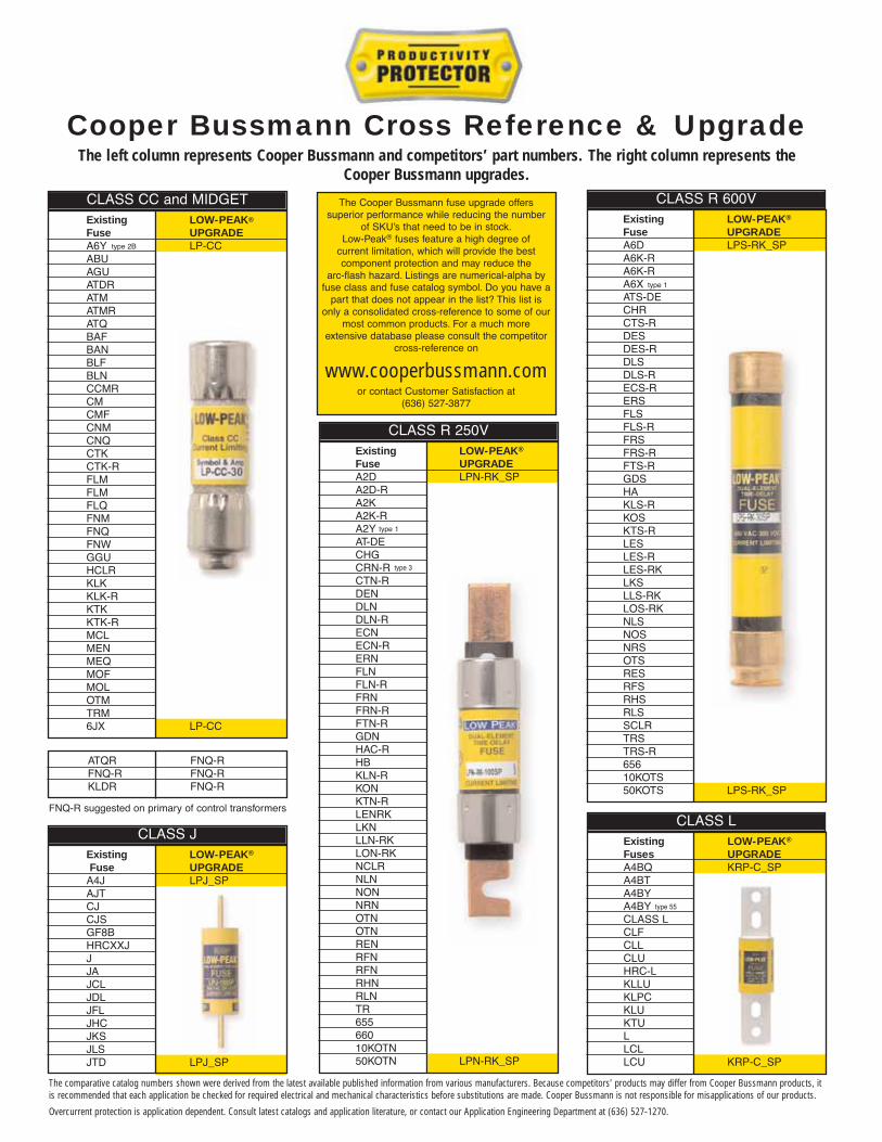
Cooper Bussmann Cross Reference & Upgrade
Existing LOW-PEAK®
Fuse UPGRADEA6Y LP-CCABUAGUATDRATMATMRATQBAFBANBLFBLNCCMRCMCMFCNMCNQCTKCTK-RFLMFLMFLQFNMFNQFNWGGUHCLRKLKKLK-RKTKKTK-RMCLMENMEQMOFMOLOTMTRM6JX LP-CC
type 2B
type 1
CLASS CC and MIDGET
Existing LOW-PEAK®
Fuse UPGRADEA4J LPJ_SPAJTCJCJSGF8BHRCXXJJJAJCLJDLJFLJHCJKSJLSJTD LPJ_SP
CLASS J
The Cooper Bussmann fuse upgrade offers superior performance while reducing the number
of SKU’s that need to be in stock.Low-Peak® fuses feature a high degree of
current limitation, which will provide the best component protection and may reduce the
arc-flash hazard. Listings are numerical-alpha byfuse class and fuse catalog symbol. Do you have a
part that does not appear in the list? This list isonly a consolidated cross-reference to some of our
most common products. For a much more extensive database please consult the competitor
cross-reference on
www.cooperbussmann.comor contact Customer Satisfaction at
(636) 527-3877
Existing LOW-PEAK®
Fuses UPGRADEA4BQ KRP-C_SPA4BTA4BYA4BYCLASS LCLFCLLCLUHRC-LKLLUKLPCKLUKTULLCLLCU KRP-C_SP
CLASS L
ATQR FNQ-RFNQ-R FNQ-RKLDR FNQ-R
Existing LOW-PEAK®
Fuse UPGRADEA2D LPN-RK_SPA2D-RA2KA2K-RA2YAT-DECHGCRN-RCTN-RDENDLNDLN-RECNECN-RERNFLNFLN-RFRNFRN-RFTN-RGDNHAC-RHBKLN-RKONKTN-RLENRKLKNLLN-RKLON-RKNCLRNLNNONNRNOTNOTNRENRFNRFNRHNRLNTR65566010KOTN50KOTN LPN-RK_SP
type 3
type 1
CLASS R 250V
Existing LOW-PEAK®
Fuse UPGRADEA6D LPS-RK_SPA6K-RA6K-RA6XATS-DECHRCTS-RDESDES-RDLSDLS-RECS-RERSFLSFLS-RFRSFRS-RFTS-RGDSHAKLS-RKOSKTS-RLESLES-RLES-RKLKSLLS-RKLOS-RKNLSNOSNRSOTSRESRFSRHSRLSSCLRTRSTRS-R65610KOTS50KOTS LPS-RK_SP
CLASS R 600V
The left column represents Cooper Bussmann and competitors’ part numbers. The right column represents theCooper Bussmann upgrades.
FNQ-R suggested on primary of control transformers
type 55
The comparative catalog numbers shown were derived from the latest available published information from various manufacturers. Because competitors’ products may differ from Cooper Bussmann products, itis recommended that each application be checked for required electrical and mechanical characteristics before substitutions are made. Cooper Bussmann is not responsible for misapplications of our products.
Overcurrent protection is application dependent. Consult latest catalogs and application literature, or contact our Application Engineering Department at (636) 527-1270.

Cooper Bussmann Products And Technical Support Delivered Worldwide
Customer Assistance
Customer Satisfaction Team
The Cooper Bussmann Customer Satisfaction Team isavailable to answers questions regarding CooperBussmann products and services. Calls should be madebetween 8:00 a.m. – 4:30 p.m. Central Time for all US time zones.
The Customer Satisfaction Team can be reached via:• Phone: 636-527-3877• Toll-free fax: 800-544-2570• E-mail: [email protected]
Emergency and After-Hours OrdersTo accommodate time-critical needs, Cooper Bussmannoffers emergency and after-hours service for next flightout or will call. Customers pay only standard price forthe circuit protection device, rush freight charges and amodest emergency fee for this service. Emergency andafter-hours orders should be placed through theCustomer Satisfaction Team. Call:
• 8:00 a.m.-4:30 p.m. Central Time 636-527-3877• After hours 314-995-1342
Application EngineeringApplication Engineering assistance is available to allcustomers. The Application Engineering team is staffedby degreed electrical engineers and available by phonewith technical and application support Monday – Friday,8:00 a.m. – 5:00 p.m. Central Time.
Application Engineering can be reached via phone, faxor email:• Phone: 636-527-1270• E-mail: [email protected]
Your Authorized Bussmann Distributor is:
©2005 Cooper Bussmann • St . Louis, MO 63178636-394-2877 • www.cooperbussmann.com
Printed in USA Reorder #1007 7-05-30M
For product Data Sheets, visit www.cooperbussmann.com/products/datasheet.asp 1
Table of contents
Disconnects . . . . . . . . . . . . . . . . . . . . . . . . . . . . . . 303Safety Module™ fused disconnect switch . . . . . . . . . . . . . . . . . . . . . . . 304Coordination Module™ fused panelboard . . . . . . . . . . . . . . . . . . . . . . . 305Power Module™ elevator disconnects . . . . . . . . . . . . . . . . . . . . . . . . . 306Overview for fusible disconnects . . . . . . . . . . . . . . . . . . . . . . . . . . . . . 30730A Base & rail mount fusible disconnects . . . . . . . . . . . . . . . . . . 308-30960-100A Base & rail mount fusible disconnects . . . . . . . . . . . . . . 310-311200-800A Base & rail mount fusible disconnects . . . . . . . . . . . . . 312-31330-800A 2-, 3-, 4- & 6-Pole enclosed fusible disconnects . . . . . . . 314-317Overview for non-fusible disconnects . . . . . . . . . . . . . . . . . . . . . . 318-31916-100A Base & rail mount non-fusible disconnects . . . . . . . . . . . 320-32116-100A door mounted non-fusible disconnects . . . . . . . . . . . . . . . . . . 322400-800A Non-fusible disconnects & accessories . . . . . . . . . . . . . 323-32416-80A 3-Pole enclosed non-fusible disconnects . . . . . . . . . . . . . . . . . 32516-3150A 3-Pole enclosed non-fusible disconnects . . . . . . . . . . . . . . . 32616-400A 2-, 4- & 6-Pole enclosed non-fusible disconnects . . . . . . 327-328A/C disconnects - fused and non-fused . . . . . . . . . . . . . . . . . . . . . . . . 329Fused, dead front disconnect switches . . . . . . . . . . . . . . . . . . . . . . . . . 330
Telecom Protection Devices . . . . . . . . . . . . . . . . . . 331Telpower TPC & TPCDS compact fused disconnect switches . . . . . . . . 332Telpower TPM & TPMDS miniature fused disconnect switches . . . . . . . 333Fused disconnect switches for TPA fuses . . . . . . . . . . . . . . . . . . . 334-335Fused disconnect switches for TPS fuses . . . . . . . . . . . . . . . . . . . . . . 336Fused disconnect switches . . . . . . . . . . . . . . . . . . . . . . . . . . . . . . 337-338Telpower high-current switch . . . . . . . . . . . . . . . . . . . . . . . . . . . . . . . 339Telpower 70-600A: 170Vdc fuses . . . . . . . . . . . . . . . . . . . . . . . . . . . . 340Telpower 1-600A: 170Vdc fuses . . . . . . . . . . . . . . . . . . . . . . . . . . . . . 341Indicating fuses & holders . . . . . . . . . . . . . . . . . . . . . . . . . . . . . . 342-343Telpower specialty fuses . . . . . . . . . . . . . . . . . . . . . . . . . . . . . . . . 344-345F38, FE2475 & F7036 Series filtered terminal blocks . . . . . . . . . . . 346-348Series C7021 & C7024 power feed thru terminal blocks . . . . . . . . 349-350
Surge Suppression Devices . . . . . . . . . . . . . . . . . . . . 351TVS transient voltage surge suppressors . . . . . . . . . . . . . . . . . . . . . . . 352TVSS transient surge suppression limiters . . . . . . . . . . . . . . . . . . . . . 353
Accessories . . . . . . . . . . . . . . . . . . . . . . . . . . . . . .354Fuse service kits & assortments . . . . . . . . . . . . . . . . . . . . . . . . . . 355-357Clip clamps & rail adapters (DIN & American) . . . . . . . . . . . . . . . . . . 358Spare fuse holders, pullers, testers & cabinets . . . . . . . . . . . . . . . . . . 359Fuse reducers & dummy "neutrals" . . . . . . . . . . . . . . . . . . . . . . . . . . . 360
Application Guide . . . . . . . . . . . . . . . . . . . . . . . . . . 361Cooper Bussmann Electrical Safety Services . . . . . . . . . . . . . . . . . . . . . 262Fuse technology . . . . . . . . . . . . . . . . . . . . . . . . . . . . . . . . . . . . . . 363-369Motor circuit branch circuit protection . . . . . . . . . . . . . . . . . . . . . . . . . 370Conductor & termination considerations . . . . . . . . . . . . . . . . . . . . 371-373Glossary . . . . . . . . . . . . . . . . . . . . . . . . . . . . . . . . . . . . . . . . . . . 374-376Out-of-stock substitution/upgrades . . . . . . . . . . . . . . . . . . . . . . . . . . . . 376Cooper Bussmann electrical trademarks . . . . . . . . . . . . . . . . . . . . . . . . 376Industrial & commercial fuse applications . . . . . . . . . . . . . . . . . . .377-378
Catalog Number Index . . . . . . . . . . . . . . . . . . . . 379-383
Sales support & manufacturing facilities . . . . . . . . . . . 384
Cross reference and Low-Peak® Fuse Stock ConsolidationInside back cover
Low Voltage
BranchCircuit
Low Voltage
Supplementary
Fuses
ElectronicFuses
Medium
VoltageFuses
High SpeedFuses
IEC&
BritishFuses
FuseHolders
& Blocks
Power
DistributionBlocks
Wire
ConnectionProducts
DisconnectsTelcom
ProtectionDevices
SurgeSuppression
DevicesAccessories
ApplicationGuide
Index
Catalog Sections Page
Low Voltage, Branch Circuit Rated Fuses . . . . . 7
Low Voltage Supplementary Fuses . . . . . . . . . . 39
Electronic - PC Board and Small . . . . . . . . . . . 53
Medium Voltage Fuses and Fuse Links . . . . . . . 67
High Speed Fuses . . . . . . . . . . . . . . . . . . . . . 87
IEC & British Standard Fuses . . . . . . . . . . . . . 213
Fuse Holders and Blocks . . . . . . . . . . . . . . . . 231
Power Distribution Blocks . . . . . . . . . . . . . . . 275
Wire Connection Products . . . . . . . . . . . . . . . 281
Disconnects . . . . . . . . . . . . . . . . . . . . . . . . 303
Telecom Protection Devices . . . . . . . . . . . . . 331
Surge Suppression Devices . . . . . . . . . . . . . . 351
Accessories . . . . . . . . . . . . . . . . . . . . . . . . 255
Application Guide . . . . . . . . . . . . . . . . . . . . . 361
Index by Part Number . . . . . . . . . . . . . . . . . .379
RED indicates NEW information
Electronic - PC Board andSmall Dimension Fuses . . . . . . . . . . . . . . . . .
For product Data Sheets, visit www.cooperbussmann.com/products/datasheet.asp2
Selecting circuit protection
Low Voltage, Branch Circuit Rated Fuses
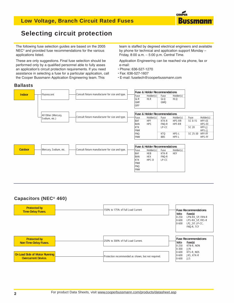
The following fuse selection guides are based on the 2005NEC® and provided fuse recommendations for the variousapplications listed.
These are only suggestions. Final fuse selection should beperformed only by a qualified personnel able to fully assesan application’s circuit protection requirements. If you needassistance in selecting a fuse for a particular application, callthe Cooper Bussmann Application Engineering team. This
team is staffed by degreed electrical engineers and availableby phone for technical and application support Monday –Friday, 8:00 a.m. – 5:00 p.m. Central Time.
Application Engineering can be reached via phone, fax or e-mail:
• Phone: 636-527-1270• Fax: 636-527-1607• E-mail: [email protected]
Fuse & Holder RecommendationsFuse Holder(s) Fuse Holder(s)BAF HEB KTK-R HEYBAN HEX FNQ-RKTK HPC-D LP-CCFNMFNQFNW
Mercury, Sodium, etc.
Fluorescent
All Other (Mercury,Sodium, etc.)
Indoor
Outdoor
Consult fixture manufacturer for size and type.
Consult fixture manufacturer for size and type.
Consult fixture manufacturer for size and type.
Fuse & Holder RecommendationsFuse Holder(s) Fuse Holder(s)GLR HLR GLQ HLQGMF GMQGRF
Ballasts
Fuse & Holder RecommendationsFuse Holder(s) Fuse Holder(s) Fuse Holder(s)BAF HPF KTK-R HPS-RR SC 0-15 HPF-EEBAN HPS FNQ-R HPF-RR HPS-EEKTK LP-CC SC 20 HPF-JJFNM HPS-JJFNQ KTQ HPS-L SC 25-30 HPF-FFFNW BBS HPF-L HPS-FF
Capacitors (NEC® 460)
Protected byTime-Delay Fuses.
150% to 175% of Full Load Current
On Load Side of Motor RunningOvercurrent Device.
Protection recommended as shown, but not required.
Protected byNon-Time-Delay Fuses.
250% to 300% of Full Load Current.
Fuse RecommendationsVolts Fuse(s)0-250 LPN-RK_SP, FRN-R0-600 LPS-RK_SP, FRS-R0-600 LPJ_SP, LP-CC,
FNQ-R, TCF
Fuse RecommendationsVolts Fuse(s)0-250 KTN-R, NON0-300 JJN0-600 KTS-R, NOS0-600 JKS, KTK-R0-600 JJS
For product Data Sheets, visit www.bussmann.com/products/datasheet.asp 3
Selecting circuit protection
Low Voltage, Branch Circuit Rated Fuses
Mains, Feeders, Branches
Feeder Circuits(600A & Less)
Fuse RecommendationsVolts Fuse(s)0-25O LPN-RK_SP, FRN-R0-600 LPS-RK_SP, FRS-R0-600 LPJ- SP, LP-CCMotor Loads
No Motor Load
Combination MotorLoads and Other Loads
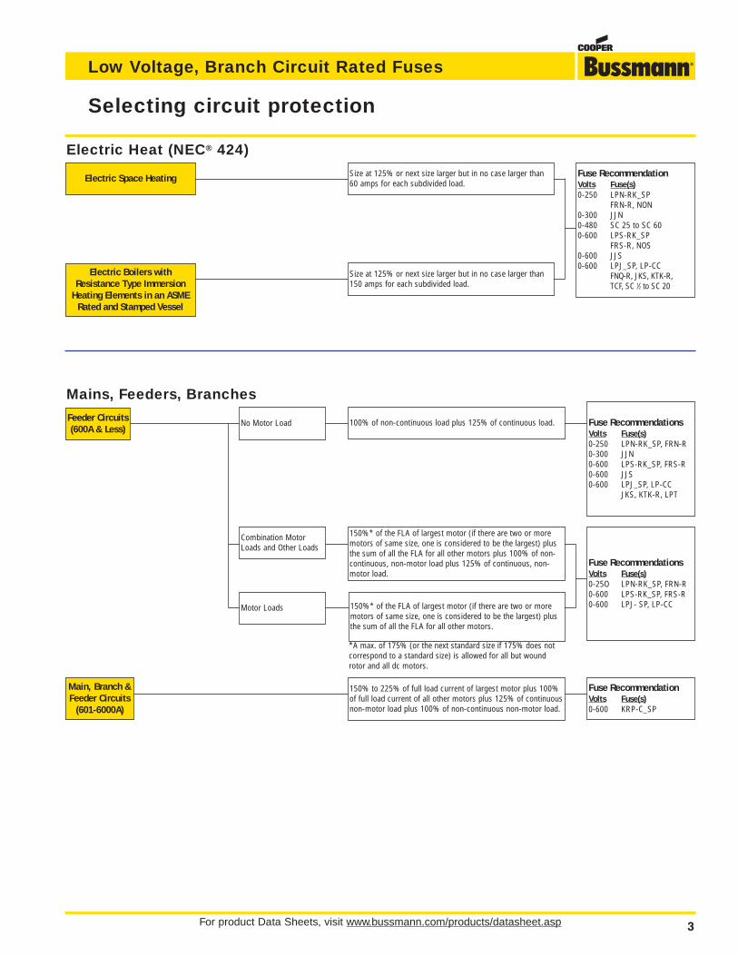
100% of non-continuous load plus 125% of continuous load.
150%* of the FLA of largest motor (if there are two or moremotors of same size, one is considered to be the largest) plusthe sum of all the FLA for all other motors plus 100% of non-continuous, non-motor load plus 125% of continuous, non-motor load.
150%* of the FLA of largest motor (if there are two or moremotors of same size, one is considered to be the largest) plusthe sum of all the FLA for all other motors.
*A max. of 175% (or the next standard size if 175% does notcorrespond to a standard size) is allowed for all but woundrotor and all dc motors.
Fuse RecommendationsVolts Fuse(s)0-250 LPN-RK_SP, FRN-R0-300 JJN0-600 LPS-RK_SP, FRS-R0-600 JJS0-600 LPJ_SP, LP-CC
JKS, KTK-R, LPT
Main, Branch &Feeder Circuits
(601-6000A)
150% to 225% of full load current of largest motor plus 100%of full load current of all other motors plus 125% of continuousnon-motor load plus 100% of non-continuous non-motor load.
Fuse RecommendationVolts Fuse(s)0-600 KRP-C_SP
Electric Heat (NEC® 424)
Electric Space Heating Size at 125% or next size larger but in no case larger than60 amps for each subdivided load.
Electric Boilers withResistance Type Immersion
Heating Elements in an ASMERated and Stamped Vessel
Size at 125% or next size larger but in no case larger than150 amps for each subdivided load.
Fuse RecommendationVolts Fuse(s)0-250 LPN-RK_SP
FRN-R, NON0-300 JJN0-480 SC 25 to SC 600-600 LPS-RK_SP
FRS-R, NOS0-600 JJS0-600 LPJ_SP, LP-CC
FNQ-R, JKS, KTK-R,TCF, SC 1⁄2 to SC 20
For product Data Sheets, visit www.cooperbussmann.com/products/datasheet.asp4
Selecting circuit protection
Low Voltage, Branch Circuit Rated Fuses
Above 600V
600V & Less
Fuse RecommendationsVolts Fuse(s)0-250 LPN-RK_SP, FRN-R0-600 LPS-RK_SP, FRS-R0-600 LPJ_SP, TCF
Fuse RecommendationsVolts Fuse(s)0-250 KTN-R, NON0-300 JJN0-600 KTS-R, NOS0-600 JJS0-600 LP-CC, JKS, KTK-R,
LPT
Short-Circuit Only
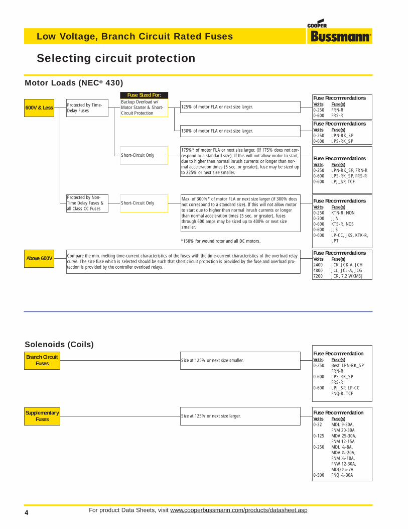
Backup Overload w/Motor Starter & Short-Circuit Protection
Short-Circuit Only
Protected by Time-Delay Fuses
Protected by Non-Time Delay Fuses &all Class CC Fuses
Compare the min. melting time-current characteristics of the fuses with the time-current characteristics of the overload relaycurve. The size fuse which is selected should be such that short.circuit protection is provided by the fuse and overload pro-tection is provided by the controller overload relays.
Fuse RecommendationsVolts Fuse(s)2400 JCK, JCK-A, JCH4800 JCL, JCL-A, JCG7200 JCR, 7.2 WKMSJ
Motor Loads (NEC® 430)
125% of motor FLA or next size larger.
130% of motor FLA or next size larger.
175%* of motor FLA or next size larger. (If 175% does not cor-respond to a standard size). If this will not allow motor to start,due to higher than normal inrush currents or longer than nor-mal acceleration times (5 sec. or greater), fuse may be sized upto 225% or next size smaller.
Max. of 300%* of motor FLA or next size larger (if 300% doesnot correspond to a standard size). If this will not allow motorto start due to higher than normal inrush currents or longerthan normal acceleration times (5 sec. or greater), fusesthrough 600 amps may be sized up to 400% or next sizesmaller.
Fuse Sized For:
*150% for wound rotor and all DC motors.
Fuse RecommendationsVolts Fuse(s)0-250 FRN-R0-600 FRS-R
Fuse RecommendationsVolts Fuse(s)0-250 LPN-RK_SP0-600 LPS-RK_SP
Solenoids (Coils)Branch Circuit
FusesSize at 125% or next size smaller.
Fuse RecommendationVolts Fuse(s)0-250 Best: LPN-RK_SP
FRN-R0-600 LPS-RK_SP
FRS-R0-600 LPJ_SP, LP-CC
FNQ-R, TCF
SupplementaryFuses
Size at 125% or next size larger.Fuse RecommendationVolts Fuse(s)0-32 MDL 9-30A,
FNM 20-30A0-125 MDA 25-30A,
FNM 12-15A0-250 MDL 1⁄16-8A,
MDA 2⁄10-20A,FNM 1⁄10-10A,FNW 12-30A,MDQ 1⁄100-7A
0-500 FNQ 1⁄10-30A
For product Data Sheets, visit www.bussmann.com/products/datasheet.asp 5
Selecting circuit protection
Low Voltage, Branch Circuit Rated Fuses
PrimaryProtection
Only
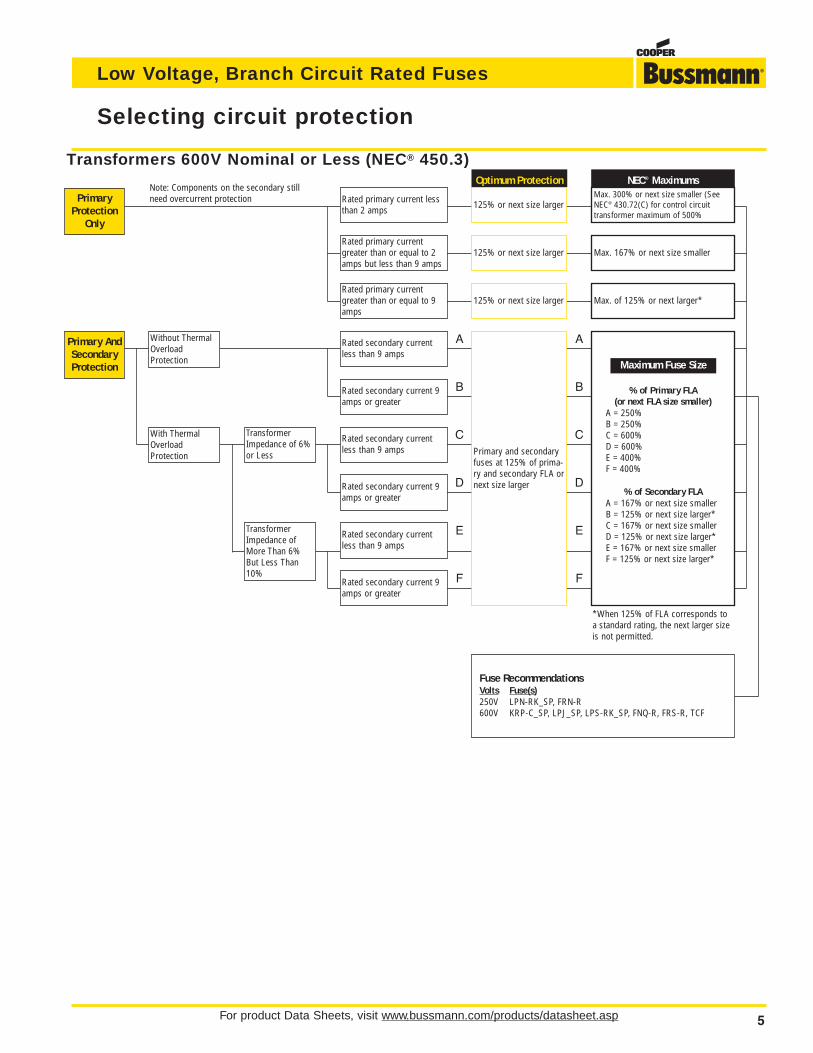
*When 125% of FLA corresponds toa standard rating, the next larger sizeis not permitted.
Primary AndSecondaryProtection
Optimum Protection
125% or next size larger
125% or next size larger
125% or next size larger Max. of 125% or next larger*
NEC® MaximumsMax. 300% or next size smaller (SeeNEC® 430.72(C) for control circuittransformer maximum of 500%
Max. 167% or next size smaller
Maximum Fuse Size
% of Primary FLA(or next FLA size smaller)
A = 250%B = 250%C = 600%D = 600%E = 400%F = 400%
% of Secondary FLAA = 167% or next size smallerB = 125% or next size larger*C = 167% or next size smallerD = 125% or next size larger*E = 167% or next size smallerF = 125% or next size larger*
Rated secondary current 9amps or greater
Rated secondary currentless than 9 amps
TransformerImpedance of 6%or Less
Rated secondary current 9amps or greater
Rated secondary currentless than 9 amps
TransformerImpedance ofMore Than 6%But Less Than10%
Rated secondary currentless than 9 amps
Rated secondary current 9amps or greater
Without ThermalOverloadProtection
With ThermalOverloadProtection
Note: Components on the secondary stillneed overcurrent protection Rated primary current less
than 2 amps
Rated primary currentgreater than or equal to 9amps
Rated primary currentgreater than or equal to 2amps but less than 9 amps
Transformers 600V Nominal or Less (NEC® 450.3)
Fuse RecommendationsVolts Fuse(s)250V LPN-RK_SP, FRN-R600V KRP-C_SP, LPJ_SP, LPS-RK_SP, FNQ-R, FRS-R, TCF
A A
B
C
D
E
F
B
C
D
E
F
Primary and secondaryfuses at 125% of prima-ry and secondary FLA ornext size larger
Maximum Fuse Size
For product Data Sheets, visit www.cooperbussmann.com/products/datasheet.asp6
Selecting circuit protection
Low Voltage, Branch Circuit Rated Fuses
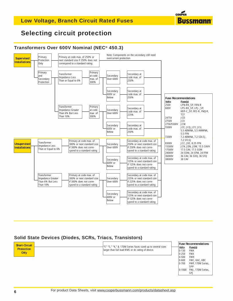
Solid State Devices (Diodes, SCRs, Triacs, Transistors)
Short-CircuitProtection
Only
“F,” “S,” “K,” & 170M Series fuses sized up to several sizeslarger than full load RMS or dc rating of device.
Fuse RecommendationsVolts Fuse(s)0-130 FWA0-250 FWX0-500 FWH0-600 FWC, KAC, KBC0-700 FWP, 170M Series,
SPP0-1000 FWJ, 170M Series,
SPJ
SupervisedInstallations
UnsupervisedInstallations
Transformers Over 600V Nominal (NEC® 450.3)
Fuse RecommendationsVolts Fuse(s)250V LPN-RK_SP, FRN-R600V LPS-RK_SP, LPJ-_SP,
KRP-C_SP, FRS-R, FNQ-R,TCF
2475V JCD2750V JCX2750/5500V JCW5500V JCE, JCQ, JCY, JCU,
5.5 ABWNA, 5.5 AMWNA,5.5 FFN
7200V 7.2 ABWNA, 7.2 SDLSJ, 7.2 SFLSJ
8300V JCZ, JDZ, 8.25 FFN15500V JCN, JDN, JDM, 15.5 CAVH17500V 17.5 CAV, 17.5 SDM24000V 24 SDM, 24 SFM, 24 FFM36000V 36 CAV, 36 SDQ, 36 SFQ38000V 38 CAV
Note: Components on the secondary still needovercurrent protectionPrimary at code max. of 250% or
next standard size if 250% does notcorrespond to a standard rating
PrimaryProtectionOnly
TransformerImpedance LessThan or Equal to 6%
Primaryat codemax. of300%
SecondaryOver 600V
Secondary atcode max. of250%
Secondary atcode max. of250%
Secondary atcode max. of225%
SecondaryOver 600V
Primaryat codemax. of300%
Secondary atcode max. of250%
SecondaryOver 600V
Primary at code max. of300% or next standard sizeif 300% does not corre-spond to a standard rating
TransformerImpedance LessThan or Equal to 6%
Primary at code max. of300% or next standard sizeif 300% does not corre-spond to a standard rating
SecondaryOver 600V
Secondary at code max. of125% or next standard sizeif 125% does not corre-spond to a standard rating
Secondary at code max. of225% or next standard sizeif 225% does not corre-spond to a standard rating
Secondary at code max. of125% or next standard sizeif 125% does not corre-spond to a standard rating
Secondary at code max. of250% or next standard sizeif 250% does not corre-spond to a standard rating
TransformerImpedance GreaterThan 6% But LessThan 10%
Secondary600V orBelow
Secondary600V orBelow
PrimaryandSecondaryProtection
TransformerImpedance GreaterThan 6% But LessThan 10%
Secondary600V orBelow
Secondary600V orBelow
7
Low Voltage
BranchCircuitFuses
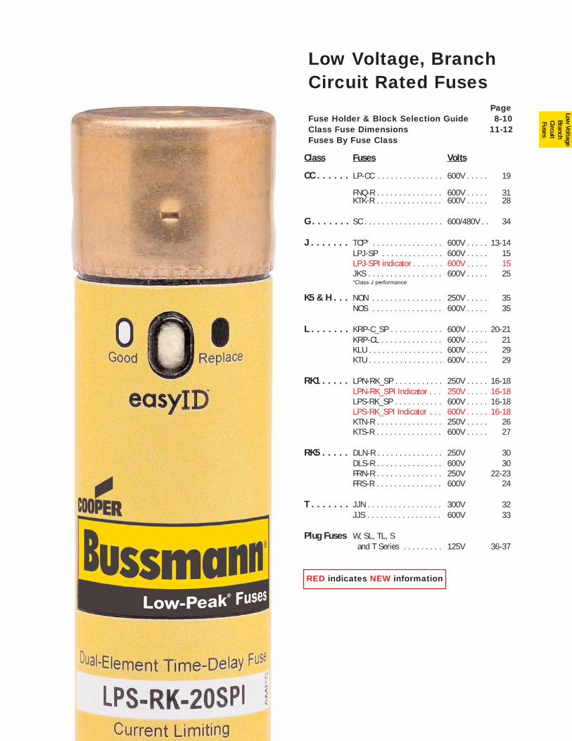
PageFuse Holder & Block Selection Guide 8-10Class Fuse Dimensions 11-12Fuses By Fuse Class
Class Fuses Volts
CC . . . . . . LP-CC . . . . . . . . . . . . . . . 600V . . . . . 19
FNQ-R . . . . . . . . . . . . . . . 600V . . . . . 31KTK-R . . . . . . . . . . . . . . . 600V . . . . . 28
G . . . . . . . SC . . . . . . . . . . . . . . . . . . 600/480V . . 34
J . . . . . . . TCF* . . . . . . . . . . . . . . . . 600V . . . . . 13-14LPJ-SP . . . . . . . . . . . . . . 600V . . . . . 15LPJ-SPI indicator . . . . . . . 600V . . . . . 15JKS . . . . . . . . . . . . . . . . . 600V . . . . . 25*Class J performance
K5 & H . . . NON . . . . . . . . . . . . . . . . 250V . . . . . 35NOS . . . . . . . . . . . . . . . . 600V . . . . . 35
L . . . . . . . KRP-C_SP . . . . . . . . . . . . 600V . . . . . 20-21KRP-CL . . . . . . . . . . . . . . 600V . . . . . 21KLU . . . . . . . . . . . . . . . . . 600V . . . . . 29KTU . . . . . . . . . . . . . . . . . 600V . . . . . 29
RK1 . . . . . LPN-RK_SP . . . . . . . . . . . 250V . . . . . 16-18LPN-RK_SPI Indicator . . . 250V . . . . . 16-18LPS-RK_SP . . . . . . . . . . . 600V . . . . . 16-18LPS-RK_SPI Indicator . . . 600V . . . . . 16-18KTN-R . . . . . . . . . . . . . . . 250V . . . . . 26KTS-R . . . . . . . . . . . . . . . 600V . . . . . 27
RK5 . . . . . DLN-R . . . . . . . . . . . . . . . 250V 30DLS-R . . . . . . . . . . . . . . . 600V 30FRN-R . . . . . . . . . . . . . . . 250V 22-23FRS-R . . . . . . . . . . . . . . . 600V 24
T . . . . . . . JJN . . . . . . . . . . . . . . . . . 300V 32JJS . . . . . . . . . . . . . . . . . 600V 33
Plug Fuses W, SL, TL, S and T Series . . . . . . . . . 125V 36-37
Low Voltage, BranchCircuit Rated Fuses
RED indicates NEW information
For product data sheets, visit www.cooperbussmann.com/products/datasheet.asp8
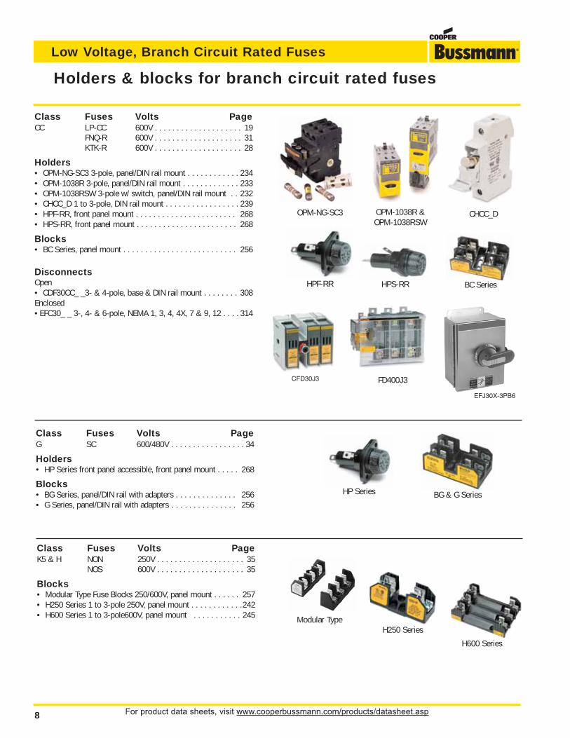
Low Voltage, Branch Circuit Rated Fuses
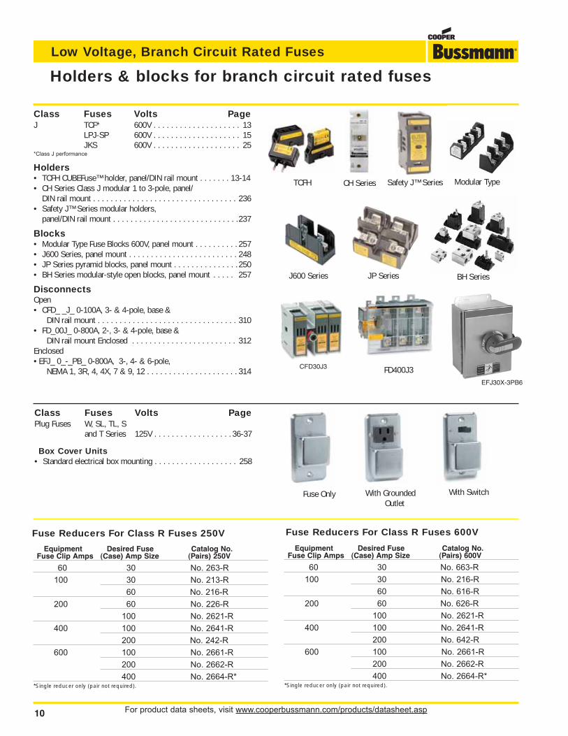
Holders & blocks for branch circuit rated fuses
Class Fuses Volts PageCC LP-CC 600V . . . . . . . . . . . . . . . . . . . . 19
FNQ-R 600V . . . . . . . . . . . . . . . . . . . . 31KTK-R 600V . . . . . . . . . . . . . . . . . . . . 28
Holders• OPM-NG-SC3 3-pole, panel/DIN rail mount . . . . . . . . . . . . 234• OPM-1038R 3-pole, panel/DIN rail mount . . . . . . . . . . . . . 233• OPM-1038RSW 3-pole w/ switch, panel/DIN rail mount . . 232• CHCC_D 1 to 3-pole, DIN rail mount . . . . . . . . . . . . . . . . . 239• HPF-RR, front panel mount . . . . . . . . . . . . . . . . . . . . . . . 268• HPS-RR, front panel mount . . . . . . . . . . . . . . . . . . . . . . . 268
Blocks• BC Series, panel mount . . . . . . . . . . . . . . . . . . . . . . . . . . 256
DisconnectsOpen• CDF30CC_ _3- & 4-pole, base & DIN rail mount . . . . . . . . 308Enclosed• EFC30_ _ 3-, 4- & 6-pole, NEMA 1, 3, 4, 4X, 7 & 9, 12 . . . . 314
Class Fuses Volts PageG SC 600/480V . . . . . . . . . . . . . . . . . 34
Holders• HP Series front panel accessible, front panel mount . . . . . 268
Blocks• BG Series, panel/DIN rail with adapters . . . . . . . . . . . . . . 256• G Series, panel/DIN rail with adapters . . . . . . . . . . . . . . . 256
Class Fuses Volts PageK5 & H NON 250V . . . . . . . . . . . . . . . . . . . . 35
NOS 600V . . . . . . . . . . . . . . . . . . . . 35
Blocks• Modular Type Fuse Blocks 250/600V, panel mount . . . . . . 257• H250 Series 1 to 3-pole 250V, panel mount . . . . . . . . . . . .242• H600 Series 1 to 3-pole600V, panel mount . . . . . . . . . . . 245
OPM-NG-SC3 CHCC_D
HPF-RR HPS-RR BC Series
HP Series BG & G Series
Modular TypeH250 Series
H600 Series
OPM-1038R & OPM-1038RSW
CFD30J3
EFJ30X-3PB6
FD400J3
For product data sheets, visit www.cooperbussmann.com/products/datasheet.asp 9
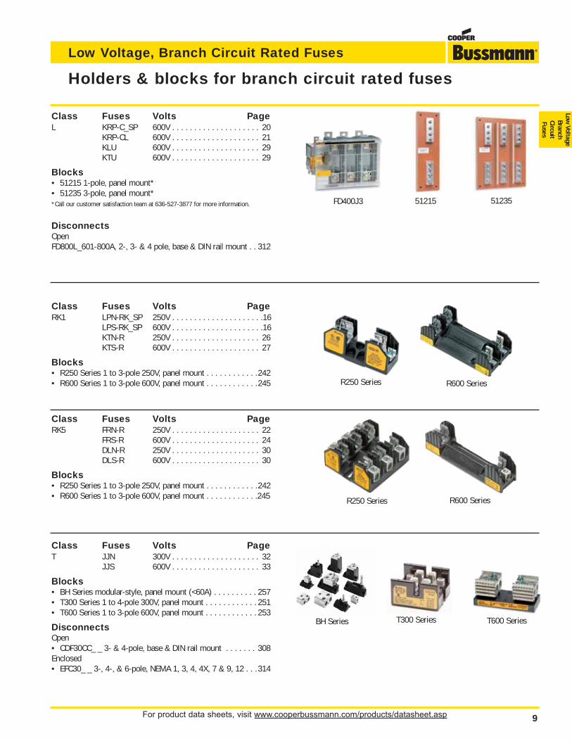
Low Voltage, Branch Circuit Rated Fuses
Low Voltage
BranchCircuitFuses
Holders & blocks for branch circuit rated fuses
Class Fuses Volts PageRK1 LPN-RK_SP 250V . . . . . . . . . . . . . . . . . . . . .16
LPS-RK_SP 600V . . . . . . . . . . . . . . . . . . . . .16KTN-R 250V . . . . . . . . . . . . . . . . . . . . 26KTS-R 600V . . . . . . . . . . . . . . . . . . . . 27
Blocks• R250 Series 1 to 3-pole 250V, panel mount . . . . . . . . . . . .242• R600 Series 1 to 3-pole 600V, panel mount . . . . . . . . . . . .245
Class Fuses Volts PageRK5 FRN-R 250V . . . . . . . . . . . . . . . . . . . . 22
FRS-R 600V . . . . . . . . . . . . . . . . . . . . 24DLN-R 250V . . . . . . . . . . . . . . . . . . . . 30DLS-R 600V . . . . . . . . . . . . . . . . . . . . 30
Blocks• R250 Series 1 to 3-pole 250V, panel mount . . . . . . . . . . . .242• R600 Series 1 to 3-pole 600V, panel mount . . . . . . . . . . . .245
51215 51235
R250 Series
R250 Series
R600 Series
R600 Series
BH Series T600 SeriesT300 Series
FD400J3
Class Fuses Volts PageL KRP-C_SP 600V . . . . . . . . . . . . . . . . . . . . 20
KRP-CL 600V . . . . . . . . . . . . . . . . . . . . 21KLU 600V . . . . . . . . . . . . . . . . . . . . 29KTU 600V . . . . . . . . . . . . . . . . . . . . 29
Blocks• 51215 1-pole, panel mount*• 51235 3-pole, panel mount**Call our customer satisfaction team at 636-527-3877 for more information.
DisconnectsOpenFD800L_601-800A, 2-, 3- & 4 pole, base & DIN rail mount . . 312
Class Fuses Volts PageT JJN 300V . . . . . . . . . . . . . . . . . . . . 32
JJS 600V . . . . . . . . . . . . . . . . . . . . 33
Blocks• BH Series modular-style, panel mount (<60A) . . . . . . . . . . 257• T300 Series 1 to 4-pole 300V, panel mount . . . . . . . . . . . . 251• T600 Series 1 to 3-pole 600V, panel mount . . . . . . . . . . . . 253
DisconnectsOpen• CDF30CC_ _ 3- & 4-pole, base & DIN rail mount . . . . . . . 308Enclosed• EFC30_ _ 3-, 4-, & 6-pole, NEMA 1, 3, 4, 4X, 7 & 9, 12 . . .314
For product data sheets, visit www.cooperbussmann.com/products/datasheet.asp10
Low Voltage, Branch Circuit Rated Fuses
Class Fuses Volts PagePlug Fuses W, SL, TL, S
and T Series 125V . . . . . . . . . . . . . . . . . . 36-37
Box Cover Units• Standard electrical box mounting . . . . . . . . . . . . . . . . . . . 258
Fuse Only With GroundedOutlet
With Switch
Class Fuses Volts PageJ TCF* 600V . . . . . . . . . . . . . . . . . . . . 13
LPJ-SP 600V . . . . . . . . . . . . . . . . . . . . 15JKS 600V . . . . . . . . . . . . . . . . . . . . 25
*Class J performance
Holders• TCFH CUBEFuse™ holder, panel/DIN rail mount . . . . . . . 13-14• CH Series Class J modular 1 to 3-pole, panel/
DIN rail mount . . . . . . . . . . . . . . . . . . . . . . . . . . . . . . . . . 236• Safety J™ Series modular holders,
panel/DIN rail mount . . . . . . . . . . . . . . . . . . . . . . . . . . . . .237
Blocks• Modular Type Fuse Blocks 600V, panel mount . . . . . . . . . . 257• J600 Series, panel mount . . . . . . . . . . . . . . . . . . . . . . . . . 248• JP Series pyramid blocks, panel mount . . . . . . . . . . . . . . . 250• BH Series modular-style open blocks, panel mount . . . . . 257
DisconnectsOpen• CFD_ _J_ 0-100A, 3- & 4-pole, base &
DIN rail mount . . . . . . . . . . . . . . . . . . . . . . . . . . . . . . . . 310• FD_00J_ 0-800A, 2-, 3- & 4-pole, base &
DIN rail mount Enclosed . . . . . . . . . . . . . . . . . . . . . . . . 312Enclosed• EFJ_ 0_-_PB_ 0-800A, 3-, 4- & 6-pole,
NEMA 1, 3R, 4, 4X, 7 & 9, 12 . . . . . . . . . . . . . . . . . . . . . 314
TCFH CH Series
J600 Series JP Series BH Series
Safety J™ Series Modular Type
CFD30J3
EFJ30X-3PB6
FD400J3
Holders & blocks for branch circuit rated fuses
Equipment Desired Fuse Catalog No.Fuse Clip Amps (Case) Amp Size (Pairs) 250V
60 30 No. 263-R
100 30 No. 213-R
60 No. 216-R
200 60 No. 226-R
100 No. 2621-R
400 100 No. 2641-R
200 No. 242-R
600 100 No. 2661-R
200 No. 2662-R
400 No. 2664-R**Single reducer only (pair not required).
Equipment Desired Fuse Catalog No.Fuse Clip Amps (Case) Amp Size (Pairs) 600V
60 30 No. 663-R
100 30 No. 216-R
60 No. 616-R
200 60 No. 626-R
100 No. 2621-R
400 100 No. 2641-R
200 No. 642-R
600 100 No. 2661-R
200 No. 2662-R
400 No. 2664-R**Single reducer only (pair not required).
Fuse Reducers For Class R Fuses 250V Fuse Reducers For Class R Fuses 600V
For product data sheets, visit www.cooperbussmann.com/products/datasheet.asp 11
Low Voltage, Branch Circuit Rated Fuses
Low Voltage
BranchCircuitFuses
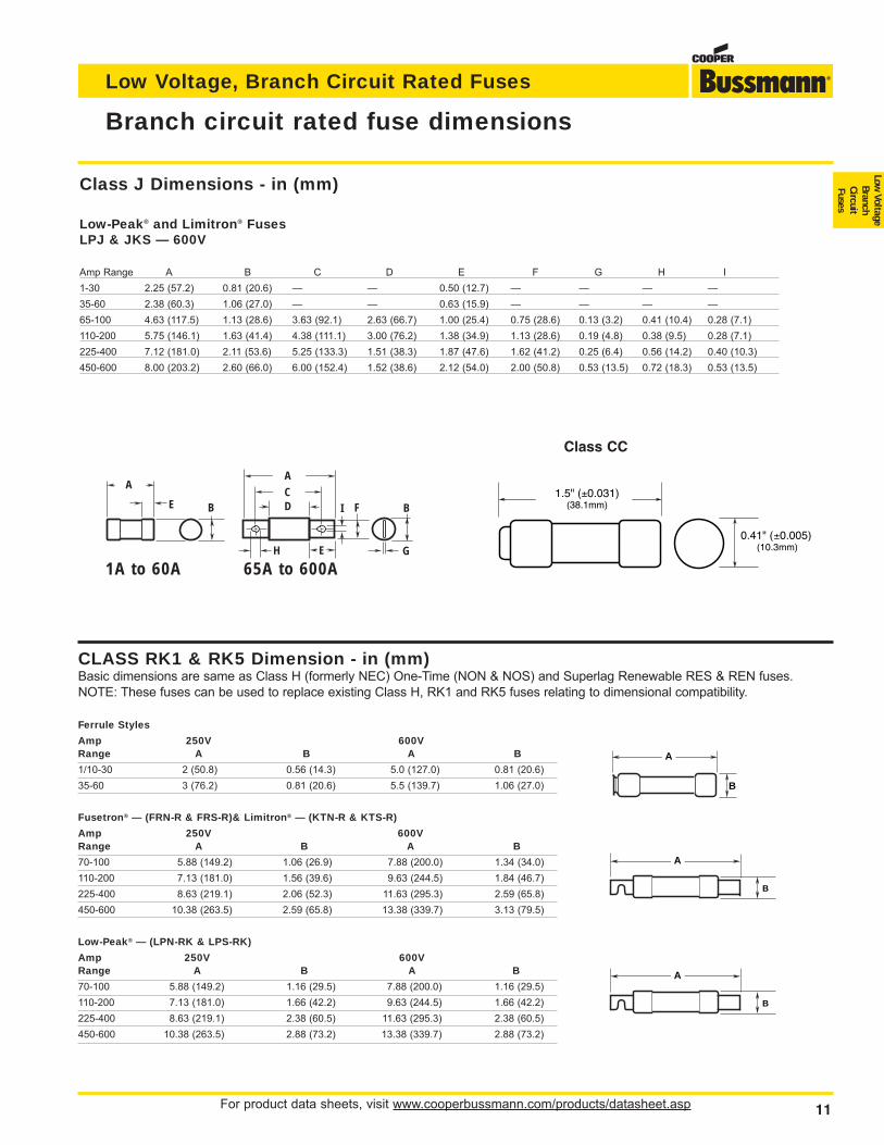
Class J Dimensions - in (mm)
Low-Peak® and Limitron® FusesLPJ & JKS — 600V
Amp Range A B C D E F G H I
1-30 2.25 (57.2) 0.81 (20.6) — — 0.50 (12.7) — — — —
35-60 2.38 (60.3) 1.06 (27.0) — — 0.63 (15.9) — — — —
65-100 4.63 (117.5) 1.13 (28.6) 3.63 (92.1) 2.63 (66.7) 1.00 (25.4) 0.75 (28.6) 0.13 (3.2) 0.41 (10.4) 0.28 (7.1)
110-200 5.75 (146.1) 1.63 (41.4) 4.38 (111.1) 3.00 (76.2) 1.38 (34.9) 1.13 (28.6) 0.19 (4.8) 0.38 (9.5) 0.28 (7.1)
225-400 7.12 (181.0) 2.11 (53.6) 5.25 (133.3) 1.51 (38.3) 1.87 (47.6) 1.62 (41.2) 0.25 (6.4) 0.56 (14.2) 0.40 (10.3)
450-600 8.00 (203.2) 2.60 (66.0) 6.00 (152.4) 1.52 (38.6) 2.12 (54.0) 2.00 (50.8) 0.53 (13.5) 0.72 (18.3) 0.53 (13.5)
11
Branch circuit rated fuse dimensions
CLASS RK1 & RK5 Dimension - in (mm)Basic dimensions are same as Class H (formerly NEC) One-Time (NON & NOS) and Superlag Renewable RES & REN fuses.NOTE: These fuses can be used to replace existing Class H, RK1 and RK5 fuses relating to dimensional compatibility.
Ferrule Styles
Amp 250V 600VRange A B A B
1/10-30 2 (50.8) 0.56 (14.3) 5.0 (127.0) 0.81 (20.6)
35-60 3 (76.2) 0.81 (20.6) 5.5 (139.7) 1.06 (27.0)
Fusetron® — (FRN-R & FRS-R)& Limitron® — (KTN-R & KTS-R)
Amp 250V 600VRange A B A B
70-100 5.88 (149.2) 1.06 (26.9) 7.88 (200.0) 1.34 (34.0)
110-200 7.13 (181.0) 1.56 (39.6) 9.63 (244.5) 1.84 (46.7)
225-400 8.63 (219.1) 2.06 (52.3) 11.63 (295.3) 2.59 (65.8)
450-600 10.38 (263.5) 2.59 (65.8) 13.38 (339.7) 3.13 (79.5)
Low-Peak® — (LPN-RK & LPS-RK)
Amp 250V 600VRange A B A B
70-100 5.88 (149.2) 1.16 (29.5) 7.88 (200.0) 1.16 (29.5)
110-200 7.13 (181.0) 1.66 (42.2) 9.63 (244.5) 1.66 (42.2)
225-400 8.63 (219.1) 2.38 (60.5) 11.63 (295.3) 2.38 (60.5)
450-600 10.38 (263.5) 2.88 (73.2) 13.38 (339.7) 2.88 (73.2)
A
B
A
B
A
B
A
B B
ACD
E
F
G
E
H
I
1A to 60A 65A to 600A
1.5" (±0.031)(38.1mm)
0.41" (±0.005)(10.3mm)
Class CC
For product data sheets, visit www.cooperbussmann.com/products/datasheet.asp12
Low Voltage, Branch Circuit Rated Fuses
12
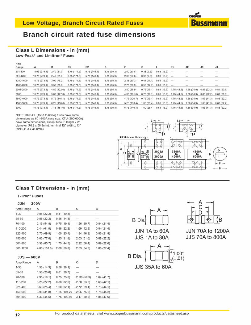
Branch circuit rated fuse dimensions
Class T Dimensions - in (mm)
T-Tron® Fuses
JJN — 300VAmp Range A B C D
1-30 0.88 (22.2) 0.41 (10.3) — —
35-60 0.88 (22.2) 0.56 (14.3) — —
70-100 2.16 (54.8) 0.75 (19.1) 1.56 (39.7) 0.84 (21.4)
110-200 2.44 (61.9) 0.88 (22.2) 1.69 (42.9) 0.84( 21.4)
225-400 2.75 (69.9) 1.00 (25.4) 1.84 (46.8) 0.86 (21.8)
450-600 3.06 (77.8) 1.25 (31.8) 2.03 (51.6) 0.88 (22.2)
601-800 3.38 (85.7) 1.75 (44.5) 2.22 (56.4) 0.89 (22.6)
801-1200 4.00 (101.6) 2.00 (50.8) 2.53 (64.3) 1.08 (27.4)
JJS — 600VAmp Range A B C D
1-30 1.50 (14.3) 0.56 (38.1) — —
35-60 1.56 (20.6) 0.81 (39.7) — —
70-100 2.95 (19.1) 0.75 (75.0) 2..36 (59.9) 1.64 (41.7)
110-200 3.25 (22.2) 0.88 (82.6) 2.50 (63.5) 1.66 (42.1)
225-400 3.63 (25.4) 1.00 (92.1) 2.72 (69.1) 1.73 (44.1)
450-600 3.98 (31.8) 1.25 (101.2) 2.96 (75.0) 1.78 (45.2)
601-800 4.33 (44.5) 1.75 (109.9) 3.17 (80.6) 1.88 (47.6)
A
A
B
F
G
DC1 C2
J1 J1J2 J2
J3 J3
J4 J4All Slots and Holes I
801A to
2000
A
601A to
800A 2001A
to3000A
3500Ato
4000A
4500Ato
6000A
Class L Dimensions - in (mm)Low-Peak® and Limitron® Fuses
AmpRange A B C1 C2 D F G I J1 J2 J3 J4
601-800 8.63 (219.1) 2.40 (61.0) 6.75 (171.5) 5.75 (146.1) 3.75 (95.3) 2.00 (50.8) 0.38 (9.5) 0.63 (15.9) — — — —
801-1200 10.75 (273.1) 2.40 (61.0) 6.75 (171.5) 5.75 (146.1) 3.75 (95.3) 2.00 (50.8) 0.38 (9.5) 0.63 (15.9) — — — —
1350-1600 10.75 (273.1) 3.00 (76.2) 6.75 (171.5) 5.75 (146.1) 3.75 (95.3) 2.38 (60.3) 0.44 (11.1) 0.63 (15.9) — — — —
1800-2000 10.75 (273.1) 3.50 (88.9) 6.75 (171.5) 5.75 (146.1) 3.75 (95.3) 2.75 (69.9) 0.50 (12.7) 0.63 (15.9) — — — —
2001-2500 10.75 (273.1) 4.80 (122.0) 6.75 (171.5) 5.75 (146.1) 3.75 (95.3) 3.50 (88.9) 0.75 (19.1) 0.63 (15.9) 1.75 (44.5) 1.38 (34.9) 0.88 (22.2) 0.81 (20.6)
3000 10.75 (273.1) 5.00 (127.0) 6.75 (171.5) 5.75 (146.1) 3.75 (95.3) 4.00 (101.6) 0.75 (19.1) 0.63 (15.9) 1.75 (44.5) 1.38 (34.9) 0.88 (22.2) 0.81 (20.6)
3500-4000 10.75 (273.1) 5.75 (146.1) 6.75 (171.5) 5.75 (146.1) 3.75 (95.3) 4.75 (120.7) 0.75 (19.1) 0.63 (15.9) 1.75 (44.5) 1.38 (34.9) 1.63 (41.3) 0.88 (22.2)
4500-5000 10.75 (273.1) 6.25 (158.8) 6.75 (171.5) 5.75 (146.1) 3.75 (95.3) 5.25 (133.4) 1.00 (25.4) 0.63 (15.9) 1.75 (44.5) 1.38 (34.9) 1.63 (41.3) 0.88 (22.2)
6000 10.75 (273.1) 7.13 (181.0) 6.75 (171.5) 5.75 (146.1) 3.75 (95.3) 5.75 (146.1) 1.00 (25.4) 0.63 (15.9) 1.75 (44.5) 1.38 (34.9) 1.63 (41.3) 0.88 (22.2)
NOTE: KRP-CL (150A to 600A) fuses have samedimensions as 601-800A case size. KTU (200-600A)have same dimensions, except tube 3” length x 2”diameter (76.2 x 50.8mm); terminal 15⁄8” width x 11⁄4”thick (41.3 x 31.8mm).
JJN 70A to 1200A
JJS 70A to 800A
JJS 35A to 60A
For product data sheets, visit www.cooperbussmann.com/products/datasheet.asp 13
Low Voltage, Branch Circuit Rated Fuses
Low Voltage
BranchCircuitFuses
13
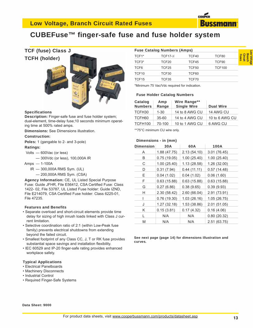
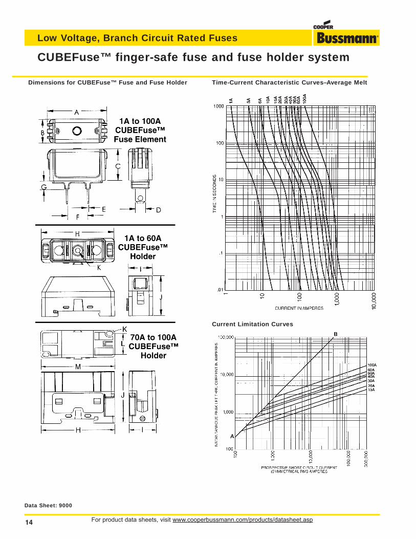
CUBEFuse™ finger-safe fuse and fuse holder system
Data Sheet: 9000
Fuse Catalog Numbers (Amps)
TCF1* TCF17-1⁄2 TCF40 TCF80
TCF3* TCF20 TCF45 TCF90
TCF6 TCF25 TCF50 TCF100
TCF10 TCF30 TCF60
TCF15 TCF35 TCF70
*Minimum 75 Vac/Vdc required for indication.
Fuse Holder Catalog Numbers
Catalog Amp Wire Range**Numbers Range Single Wire Dual Wire
TCFH30 1-30 14 to 8 AWG CU 14 AWG CU
TCFH60 35-60 14 to 4 AWG CU 10 to 6 AWG CU
TCFH100 70-100 10 to 1 AWG CU 6 AWG CU
**75°C minimum CU wire only.
Dimensions - in (mm)
Dimension 30A 60A 100A
A 1.88 (47.75) 2.13 (54.10) 3.01 (76.45)
B 0.75 (19.05) 1.00 (25.40) 1.00 (25.40)
C 1.00 (25.40) 1.13 (28.58) 1.26 (32.00)
D 0.31 (7.94) 0.44 (11.11) 0.57 (14.48)
E 0.04 (1.02) 0.04 (1.02) 0.06 (1.60)
F 0.63 (15.88) 0.63 (15.88) 0.63 (15.88)
G 0.27 (6.86) 0.38 (9.65) 0.39 (9.93)
H 2.30 (58.42) 2.60 (66.04) 2.91 (73.91)
I 0.76 (19.30) 1.03 (26.16) 1.05 (26.75)
J 1.27 (32.18) 1.53 (38.86) 2.01 (51.05)
K 0.15 (3.81) 0.17 (4.32) 0.16 (4.06)
L N/A N/A 0.80 (20.32)
M N/A N/A 2.51 (63.75)
TCF (fuse) Class J
TCFH (holder)
SpecificationsDescription: Finger-safe fuse and fuse holder system;dual-element, time-delay fuse;10 seconds minimum operat-ing time at 500% rated amps.
Dimensions: See Dimensions illustration.
Construction:Poles: 1 (gangable to 2- and 3-pole)
Ratings:Volts — 600Vac (or less)
— 300Vdc (or less), 100,000A IR
Amps — 1-100A
IR — 300,000A RMS Sym. (UL)
— 200,000A RMS Sym. (CSA)
Agency Information: CE, UL Listed Special PurposeFuse: Guide JFHR, File E56412, CSA Certified Fuse: Class1422- 02, File 53787, UL Listed Fuse holder: Guide IZND,File E214079, CSA Certified Fuse holder: Class 6225-01,File 47235.
Features and Benefits• Separate overload and short-circuit elements provide time
delay for sizing of high inrush loads linked with Class J cur-rent limitation.
• Selective coordination ratio of 2:1 (within Low-Peak fusefamily) prevents electrical shutdowns from extendingbeyond the failed circuit.
• Smallest footprint of any Class CC, J, T or RK fuse providessubstantial space savings and installation flexibility.
• IEC 60529 and IP-20 finger-safe rating provides enhancedworkplace safety.
Typical Applications• Electrical Panelboards• Machinery Disconnects• Industrial Control• Required Finger-Safe Systems
See next page (page 14) for dimensions illustration andcurves.
For product data sheets, visit www.cooperbussmann.com/products/datasheet.asp14
Low Voltage, Branch Circuit Rated Fuses
14
CUBEFuse™ finger-safe fuse and fuse holder system
Dimensions for CUBEFuse™ Fuse and Fuse Holder
Current Limitation Curves
Time-Current Characteristic Curves–Average Melt
Data Sheet: 9000
For product data sheets, visit www.cooperbussmann.com/products/datasheet.asp 15
Low Voltage, Branch Circuit Rated Fuses
Low Voltage
BranchCircuitFuses
15
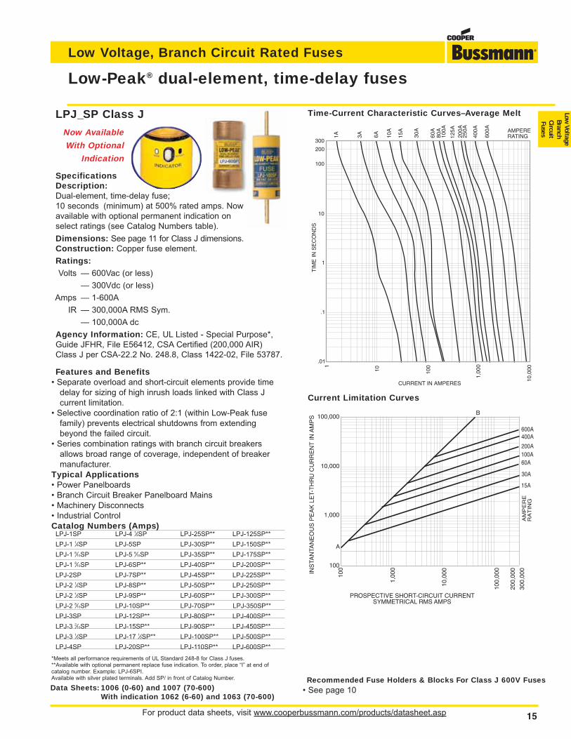
Low-Peak® dual-element, time-delay fuses
LPJ_SP Class J
Now Available
With Optional
Indication
SpecificationsDescription:Dual-element, time-delay fuse; 10 seconds (minimum) at 500% rated amps. Nowavailable with optional permanent indication on select ratings (see Catalog Numbers table).
Dimensions: See page 11 for Class J dimensions.Construction: Copper fuse element.
Ratings:Volts — 600Vac (or less)
— 300Vdc (or less)
Amps — 1-600A
IR — 300,000A RMS Sym.
— 100,000A dc
Agency Information: CE, UL Listed - Special Purpose*,Guide JFHR, File E56412, CSA Certified (200,000 AIR)Class J per CSA-22.2 No. 248.8, Class 1422-02, File 53787.
Features and Benefits• Separate overload and short-circuit elements provide time
delay for sizing of high inrush loads linked with Class J current limitation.
• Selective coordination ratio of 2:1 (within Low-Peak fusefamily) prevents electrical shutdowns from extendingbeyond the failed circuit.
• Series combination ratings with branch circuit breakersallows broad range of coverage, independent of breakermanufacturer.
Typical Applications• Power Panelboards• Branch Circuit Breaker Panelboard Mains• Machinery Disconnects• Industrial ControlCatalog Numbers (Amps)
LPJ-1SP LPJ-4 1⁄2SP LPJ-25SP** LPJ-125SP**
LPJ-1 1⁄4SP LPJ-5SP LPJ-30SP** LPJ-150SP**
LPJ-1 6⁄10SP LPJ-5 6⁄10SP LPJ-35SP** LPJ-175SP**
LPJ-1 8⁄10SP LPJ-6SP** LPJ-40SP** LPJ-200SP**
LPJ-2SP LPJ-7SP** LPJ-45SP** LPJ-225SP**
LPJ-2 1⁄4SP LPJ-8SP** LPJ-50SP** LPJ-250SP**
LPJ-2 1⁄2SP LPJ-9SP** LPJ-60SP** LPJ-300SP**
LPJ-2 8⁄10SP LPJ-10SP** LPJ-70SP** LPJ-350SP**
LPJ-3SP LPJ-12SP** LPJ-80SP** LPJ-400SP**
LPJ-3 2⁄10SP LPJ-15SP** LPJ-90SP** LPJ-450SP**
LPJ-3 1⁄2SP LPJ-17 1⁄2SP** LPJ-100SP** LPJ-500SP**
LPJ-4SP LPJ-20SP** LPJ-110SP** LPJ-600SP**
*Meets all performance requirements of UL Standard 248-8 for Class J fuses.**Available with optional permanent replace fuse indication. To order, place “I” at end ofcatalog number. Example: LPJ-6SPI.Available with silver plated terminals. Add SP/ in front of Catalog Number.
AMPERERATING1A 3A 6A
300
100
10
1
.1
.01
TIM
E IN
SE
CO
ND
S
10A
15A
30A
60A
100A
400A
1,00
0
100
CURRENT IN AMPERES
600A
125A
250A
200A
80A
200
10
10,0
00
1
Recommended Fuse Holders & Blocks For Class J 600V Fuses• See page 10
Time-Current Characteristic Curves–Average Melt
Current Limitation Curves
INS
TAN
TAN
EO
US
PE
AK
LE
T-T
HR
U C
UR
RE
NT
IN A
MP
S 100,000
10,000
1,000
100
B
A
PROSPECTIVE SHORT-CIRCUIT CURRENTSYMMETRICAL RMS AMPS
100
1,00
0
10,0
00
100,
000
200,
000
600A400A
200A100A60A
30A
15A
RA
AM
PE
RE
TIN
G30
0,00
0
Data Sheets: 1006 (0-60) and 1007 (70-600)With indication 1062 (6-60) and 1063 (70-600)
For product data sheets, visit www.cooperbussmann.com/products/datasheet.asp16
Low Voltage, Branch Circuit Rated Fuses
16
Typical Applications• Large Distribution Switchboards• Power Panelboards• Motor Control Centers• Machinery Disconnect SwitchesLPN Catalog Numbers (Amps) (250Vac/125Vdc)
LPN-RK-1⁄10SP LPN-RK-3 1⁄2SP LPN-RK-60SP**
LPN-RK-15⁄100SP LPN-RK-4SP LPN-RK-70SP****
LPN-RK-2⁄10SP LPN-RK-4 1⁄2SP LPN-RK-80SP**
LPN-RK-3⁄10SP LPN-RK-5SP LPN-RK-90SP**
LPN-RK-4⁄10SP LPN-RK-5 6⁄10SP LPN-RK-100SP**
LPN-RK-1⁄2SP LPN-RK-6SP LPN-RK-110SP**
LPN-RK-6⁄10SP LPN-RK-6 1⁄4SP LPN-RK-125SP**
LPN-RK-8⁄10SP LPN-RK-8SP LPN-RK-150SP**
LPN-RK-1SP LPN-RK-9SP LPN-RK-175SP**
LPN-RK-1 1⁄8SP LPN-RK-10SP LPN-RK-200SP**
LPN-RK-1 1⁄4SP LPN-RK-12SP LPN-RK-225SP**
LPN-RK-1 4⁄10SP LPN-RK-15SP LPN-RK-250SP**
LPN-RK-1 6⁄10SP LPN-RK-17 1⁄2SP LPN-RK-300SP**
LPN-RK-1 8⁄10SP LPN-RK-20SP LPN-RK-350SP**
LPN-RK-2SP LPN-RK-25SP LPN-RK-400SP**
LPN-RK-2 1⁄4SP LPN-RK-30SP LPN-RK-450SP**
LPN-RK-2 1⁄2SP LPN-RK-35SP** LPN-RK-500SP**
LPN-RK-2 8⁄10SP LPN-RK-40SP** LPN-RK-600SP**
LPN-RK-3SP LPN-RK-45SP**
LPN-RK-3 2⁄10SP LPN-RK-50SP***Meets all performance requirements of UL Standard 248-12 for Class RK1 fuses.**Available with optional permanent indication. To order, place “I” at end of Catalog Number.
Example: LPN-RK-35SPI.0-60A fuses available with Nickel plate option. (Ex: LPS-RK30SPNP) 70-600A fuses availablewith Tin plate option. Example: LPS-RK-100SP-TP.
LPS Catalog Numbers - (Amps) (600Vac/300Vdc)LPS-RK-1⁄10SP LPS-RK-2 1⁄2SP LPS-RK-12SP** LPS-RK-110SP**
LPS-RK-2⁄10SP LPS-RK-2 8⁄10SP LPS-RK-15SP** LPS-RK-125SP**
LPS-RK-3⁄10SP LPS-RK-3SP LPS-RK-17 1⁄2SP** LPS-RK-150SP**
LPS-RK-4⁄10SP LPS-RK-3 2⁄10SP LPS-RK-20SP** LPS-RK-175SP**
LPS-RK-1⁄2SP LPS-RK-3 1⁄2SP LPS-RK-25SP** LPS-RK-200SP**
LPS-RK-6⁄10SP LPS-RK-4SP LPS-RK-30SP** LPS-RK-225SP**
LPS-RK-8⁄10SP LPS-RK-4 1⁄2SP LPS-RK-35SP** LPS-RK-250SP**
LPS-RK-1SP LPS-RK-5SP LPS-RK-40SP** LPS-RK-300SP**
LPS-RK-1 1⁄8SP LPS-RK-5 6⁄10SP LPS-RK-45SP** LPS-RK-350SP**
LPS-RK-1 1⁄4SP LPS-RK-6SP** LPS-RK-50SP** LPS-RK-400SP**
LPS-RK-1 4⁄10SP LPS-RK-6 1⁄4SP** LPS-RK-60SP** LPS-RK-450SP**
LPS-RK-1 1⁄2SP LPS-RK-7SP** LPS-RK-70SP** LPS-RK-500SP**
LPS-RK-1 6⁄10SP LPS-RK-8SP** LPS-RK-80SP** LPS-RK-600SP**
LPS-RK-1 8⁄10SP LPS-RK-9SP** LPS-RK-90SP**
LPS-RK-2 1⁄4SP LPS-RK-10SP** LPS-RK-100SP***Meets all performance requirements of UL Standard 248-12 for Class RK1 fuses.**Available with optional permanent replace fuse indication. To order, place “I” at end ofCatalog Number. Example: LPS-RK-15SPI.
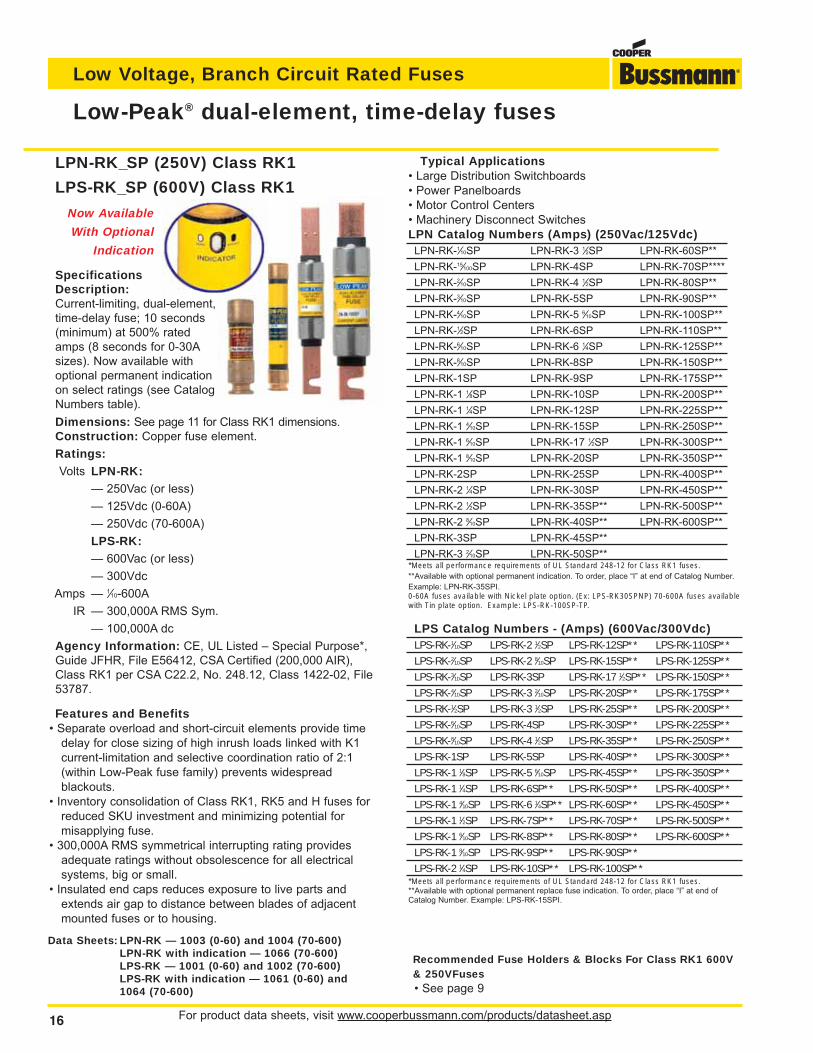
Low-Peak® dual-element, time-delay fuses
LPN-RK_SP (250V) Class RK1
LPS-RK_SP (600V) Class RK1
Now Available
With Optional
Indication
SpecificationsDescription:Current-limiting, dual-element,time-delay fuse; 10 seconds(minimum) at 500% ratedamps (8 seconds for 0-30Asizes). Now available withoptional permanent indicationon select ratings (see CatalogNumbers table).
Dimensions: See page 11 for Class RK1 dimensions.Construction: Copper fuse element.
Ratings:Volts LPN-RK:
— 250Vac (or less)
— 125Vdc (0-60A)
— 250Vdc (70-600A)
LPS-RK:— 600Vac (or less)
— 300Vdc
Amps — 1⁄10-600A
IR — 300,000A RMS Sym.
— 100,000A dc
Agency Information: CE, UL Listed – Special Purpose*,Guide JFHR, File E56412, CSA Certified (200,000 AIR),Class RK1 per CSA C22.2, No. 248.12, Class 1422-02, File53787.
Features and Benefits• Separate overload and short-circuit elements provide time
delay for close sizing of high inrush loads linked with K1current-limitation and selective coordination ratio of 2:1(within Low-Peak fuse family) prevents widespreadblackouts.
• Inventory consolidation of Class RK1, RK5 and H fuses forreduced SKU investment and minimizing potential formisapplying fuse.
• 300,000A RMS symmetrical interrupting rating providesadequate ratings without obsolescence for all electricalsystems, big or small.
• Insulated end caps reduces exposure to live parts andextends air gap to distance between blades of adjacentmounted fuses or to housing.
Data Sheets: LPN-RK — 1003 (0-60) and 1004 (70-600)LPN-RK with indication — 1066 (70-600)LPS-RK — 1001 (0-60) and 1002 (70-600)LPS-RK with indication — 1061 (0-60) and1064 (70-600)
Recommended Fuse Holders & Blocks For Class RK1 600V& 250VFuses• See page 9
For product data sheets, visit www.cooperbussmann.com/products/datasheet.asp 17
Low Voltage, Branch Circuit Rated Fuses
Low Voltage
BranchCircuitFuses
17
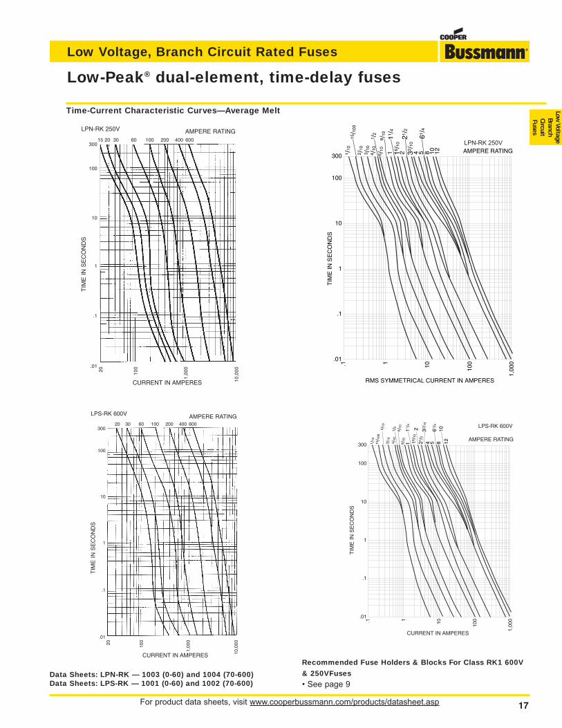
Low-Peak® dual-element, time-delay fuses
Time-Current Characteristic Curves—Average Melt
TIM
E I
N S
EC
ON
DS
CURRENT IN AMPERES
AMPERE RATING
300
100
10
1
.1
.01
20 100
1,00
0
10,0
00
15 20 30 60 100 200 400 600
LPN-RK 250V
TIM
E I
N S
EC
ON
DS
CURRENT IN AMPERES
AMPERE RATING
300
100
10
1
.1
.01
20 100
1,00
0
10,0
00
20 30 60 100 200 400 600
LPS-RK 600V
1 2 4 5 8 10 12 AMPERE RATING300
100
10
1
.1
.01
.1 1 10 100
1,00
0
TIM
E IN
SE
CO
ND
S
RMS SYMMETRICAL CURRENT IN AMPERES
1 /10
15/1
002 /
103 /
104 /
101 /
26 /
108 /
10 11/4
16/1
0
21/2
32/1
0
61/4
LPN-RK 250V
1 /10
15/1
002 /
10
4 /10
6 /10
16/1
0
8 /10
1
2
4 5 8 121011
/4
21/2
32/1
0
61/4
1 /2
3 /10
LPS-RK 600V
TIM
E I
N S
EC
ON
DS
CURRENT IN AMPERES
AMPERE RATING
Data Sheets: LPN-RK — 1003 (0-60) and 1004 (70-600)Data Sheets: LPS-RK — 1001 (0-60) and 1002 (70-600)
Recommended Fuse Holders & Blocks For Class RK1 600V
& 250VFuses
• See page 9
For product data sheets, visit www.cooperbussmann.com/products/datasheet.asp18
Low Voltage, Branch Circuit Rated Fuses
A
B
600400
200
100A
MP
ER
ER
AT
ING
400,000
100,000
10,000
1,000
1,00
0
10,0
00
100,
000
200,
000
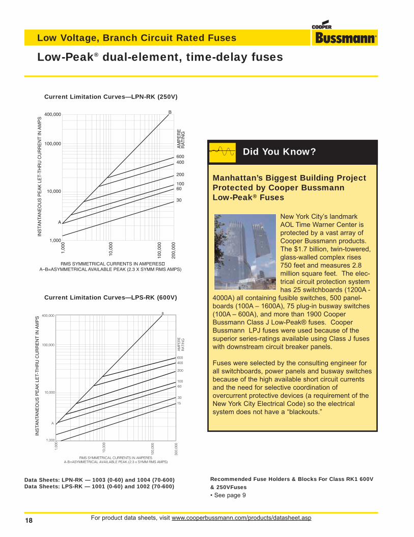
RMS SYMMETRICAL CURRENTS IN AMPERESA–B=ASYMMETRICAL AVAILABLE PEAK (2.3 X SYMM RMS AMPS)
INS
TAN
TAN
EO
US
PE
AK
LE
T-T
HR
U C
UR
RE
NT
IN A
MP
S
60
30
Current Limitation Curves—LPN-RK (250V)
B
INS
TAN
TAN
EO
US
PE
AK
LE
T-T
HR
U C
UR
RE
NT
IN A
MP
S
Current Limitation Curves—LPS-RK (600V)
Data Sheets: LPN-RK — 1003 (0-60) and 1004 (70-600)Data Sheets: LPS-RK — 1001 (0-60) and 1002 (70-600)
Recommended Fuse Holders & Blocks For Class RK1 600V
& 250VFuses
• See page 9
Low-Peak® dual-element, time-delay fuses
Manhattan’s Biggest Building ProjectProtected by Cooper BussmannLow-Peak® Fuses
New York City’s landmarkAOL Time Warner Center isprotected by a vast array ofCooper Bussmann products.The $1.7 billion, twin-towered,glass-walled complex rises750 feet and measures 2.8 million square feet. The elec-trical circuit protection systemhas 25 switchboards (1200A -
4000A) all containing fusible switches, 500 panel-boards (100A – 1600A), 75 plug-in busway switches(100A – 600A), and more than 1900 CooperBussmann Class J Low-Peak® fuses. CooperBussmann LPJ fuses were used because of thesuperior series-ratings available using Class J fuseswith downstream circuit breaker panels.
Fuses were selected by the consulting engineer forall switchboards, power panels and busway switchesbecause of the high available short circuit currentsand the need for selective coordination of overcurrent protective devices (a requirement of theNew York City Electrical Code) so the electrical system does not have a “blackouts.”
Did You Know?
For product data sheets, visit www.cooperbussmann.com/products/datasheet.asp 19
Low Voltage, Branch Circuit Rated Fuses
Low Voltage
BranchCircuitFuses
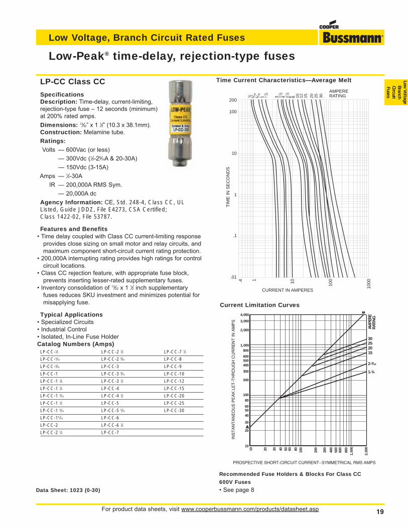
LP-CC Class CC
SpecificationsDescription: Time-delay, current-limiting,rejection-type fuse – 12 seconds (minimum)at 200% rated amps.
Dimensions: 13⁄32” x 1 1⁄2” (10.3 x 38.1mm).Construction: Melamine tube.
Ratings:Volts — 600Vac (or less)
— 300Vdc (1⁄2-28⁄10A & 20-30A)
— 150Vdc (3-15A)
Amps — 1⁄2-30A
IR — 200,000A RMS Sym.
— 20,000A dc
Agency Information: CE, Std. 248-4, Class CC, ULListed, Guide JDDZ, File E4273, CSA Certified;Class 1422-02, File 53787.
Features and Benefits• Time delay coupled with Class CC current-limiting response
provides close sizing on small motor and relay circuits, andmaximum component short-circuit current rating protection.
• 200,000A interrupting rating provides high ratings for controlcircuit locations.
• Class CC rejection feature, with appropriate fuse block,prevents inserting lesser-rated supplementary fuses.
• Inventory consolidation of 13⁄32 x 1 1⁄2 inch supplementaryfuses reduces SKU investment and minimizes potential formisapplying fuse.
Typical Applications• Specialized Circuits• Industrial Control• Isolated, In-Line Fuse HolderCatalog Numbers (Amps)
LP-CC-1⁄2 LP-CC-2 1⁄2 LP-CC-7 1⁄2
LP-CC-6⁄10 LP-CC-2 8⁄10 LP-CC-8
LP-CC-8⁄10 LP-CC-3 LP-CC-9
LP-CC-1 LP-CC-3 8⁄10 LP-CC-10
LP-CC-1 1⁄8 LP-CC-3 1⁄2 LP-CC-12
LP-CC-1 1⁄4 LP-CC-4 LP-CC-15
LP-CC-1 4⁄10 LP-CC-4 1⁄2 LP-CC-20
LP-CC-1 1⁄2 LP-CC-5 LP-CC-25
LP-CC-1 6⁄10 LP-CC-5 6⁄10 LP-CC-30
LP-CC-18 ⁄10 LP-CC-6
LP-CC-2 LP-CC-6 1⁄4
LP-CC-2 1⁄4 LP-CC-7
Low-Peak® time-delay, rejection-type fuses
200
100
10
TIM
E IN
SE
CO
ND
S
1
.1
.01
⁄Ω™ flΩ¡º
°Ω¡º
1 1⁄Ω¢
3 3⁄Ω™
4 4⁄Ω™
6 8 10 12 15 20 25 30
AMPERERATING
.4 1 10 100
1000
CURRENT IN AMPERES
Time Current Characteristics—Average Melt
Data Sheet: 1023 (0-30)
Recommended Fuse Holders & Blocks For Class CC
600V Fuses
• See page 8
10 20 30 40 50 60 80 100
200
300
400
500
600
800
1,00
0
2,00
0
4,000
3,000
2,000
1,000800
600
400
300
200
10080
60
40
30
20
10
50
500
3025
AMPE
RERA
TING
2015
2-8/10
1-1/4
PROSPECTIVE SHORT-CIRCUIT CURRENT–SYMMETRICAL RMS AMPS
INS
TA
NT
AN
EO
US
PE
AK
LE
T-T
HR
OU
GH
CU
RR
EN
T IN
AM
PS
Current Limitation Curves
For product data sheets, visit www.cooperbussmann.com/products/datasheet.asp20
Low Voltage, Branch Circuit Rated Fuses
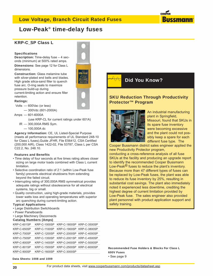
Low-Peak® time-delay fuses
SpecificationsDescription: Time-delay fuse – 4 sec-onds (minimum) at 500% rated amps.
Dimensions: See page 12 for Class Ldimensions.
Construction: Glass melamine tubewith silver-plated end bells and blades.High grade silica-sand filler to quenchfuse arc. O-ring seals to maximize pressure build-up duringcurrent-limiting action and ensure fillerretention.
Ratings:Volts — 600Vac (or less)
— 300Vdc (601-2000A)
Amps — 601-6000A
(use KRP-CL for current ratings under 601A)
IR — 300,000A RMS Sym.
— 100,000A dc
Agency Information: CE, UL Listed-Special Purpose(meets all performance requirements of UL Standard 248-10for Class L fuses),Guide JFHR, File E56412, CSA Certified(200,000 AIR), Class 1422-02, File 53787, Class L per CSAC22.2, No. 248.10.
Features and Benefits• Time delay of four seconds at five times rating allows closer
sizing on large motor loads combined with Class L currentlimitation.
• Selective coordination ratio of 2:1 (within Low-Peak fusefamily) prevents electrical shutdowns from extendingbeyond the failed circuit.
• Interrupting rating of 300,000A RMS symmetrical providesadequate ratings without obsolescence for all electrical systems, big or small.
• Quality construction, using high-grade materials, provideslower watts loss and operating temperatures with superiorarc quenching during current-limiting action.
Typical Applications• Large Distribution Switchboards• Power Panelboards• Large Machinery DisconnectsCatalog Numbers (Amps)KRP-C-601SP KRP-C-1000SP KRP-C-1800SP KRP-C-3500SP
KRP-C-650SP KRP-C-1100SP KRP-C-1900SP KRP-C-3800SP
KRP-C-700SP KRP-C-1200SP KRP-C-2000SP KRP-C-4000SP
KRP-C-750SP KRP-C-1350SP KRP-C-2001SP KRP-C-4500SP
KRP-C-800SP KRP-C-1400SP KRP-C-2400SP KRP-C-5000SP
KRP-C-801SP KRP-C-1500SP KRP-C-2500SP KRP-C-6000SP
KRP-C-900SP KRP-C-1600SP KRP-C-3000SP
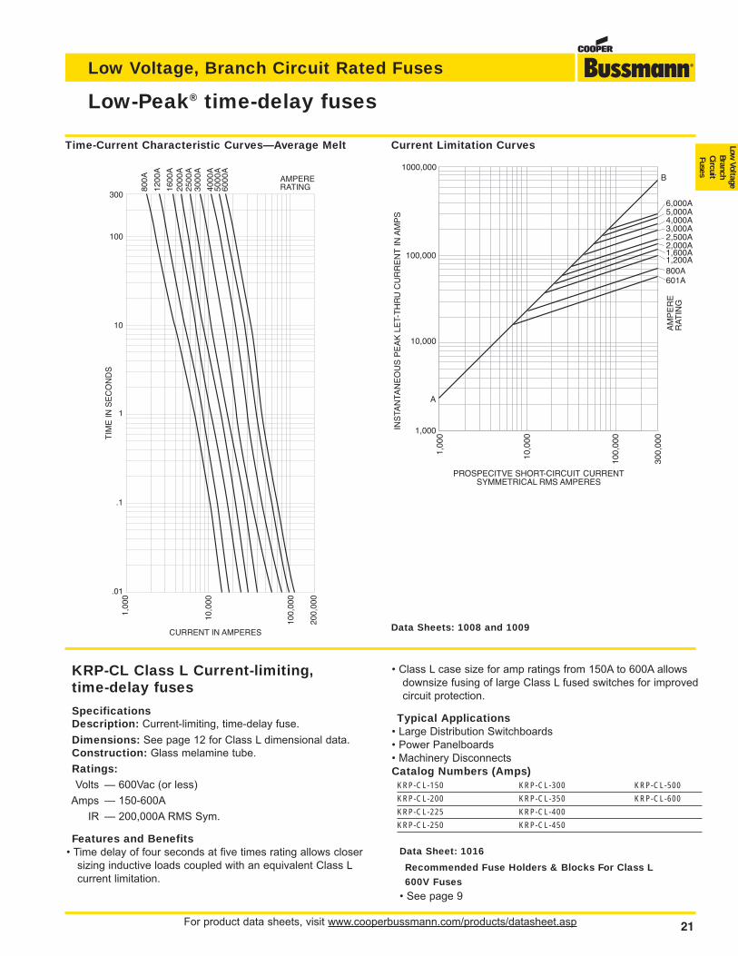
Data Sheets: 1008 and 1009
KRP-C_SP Class L
Recommended Fuse Holders & Blocks For Class L
600V Fuses
• See page 9
SKU Reduction Through ProductivityProtector™ Program
An industrial manufacturingplant in Springfield,Missouri, found that SKUs inits spare fuse inventorywere becoming excessiveand the plant could not pos-sibly keep a spare for eachdifferent fuse type. The
Cooper Bussmann district sales engineer applied thenew Productivity Protector program, conducting a cross-reference analysis of all fuseSKUs at the facility and producing an upgrade reportto identify the recommended Cooper BussmannLow-Peak® fuses to reduce the plant’s inventory.Because more than 47 different types of fuses canbe replaced by Low-Peak fuses, the plant was ableto reduce its fuse inventory by 25%, resulting in substantial cost savings. The plant also immediatelynoted it experienced less downtime, crediting thehighest degree of current limitation provided by Low-Peak fuse. The sales engineer also providedplant personnel with product application support andsafety training.
Did You Know?
For product data sheets, visit www.cooperbussmann.com/products/datasheet.asp 21
Low Voltage, Branch Circuit Rated Fuses
Low Voltage
BranchCircuitFuses
Low-Peak® time-delay fuses
1000,000
10,000
1,000
10,0
00
300,
000
INS
TAN
TAN
EO
US
PE
AK
LE
T-T
HR
U C
UR
RE
NT
IN A
MP
S
PROSPECITVE SHORT-CIRCUIT CURRENTSYMMETRICAL RMS AMPERES
100,
000
100,000
6,000A5,000A4,000A3,000A2,500A2,000A1,600A1,200A800A601A
A
AM
PE
RE
RA
TIN
G
B
1,00
0
300
100
10
1
.1
.01
1,00
0
10,0
00
100,
000
200,
000
CURRENT IN AMPERES
TIM
E IN
SE
CO
ND
S
800A
1200
A
1600
A20
00A
2500
A30
00A
4000
A50
00A
6000
A
AMPERERATING
Current Limitation CurvesTime-Current Characteristic Curves—Average Melt
KRP-CL Class L Current-limiting,time-delay fuses
SpecificationsDescription: Current-limiting, time-delay fuse.
Dimensions: See page 12 for Class L dimensional data.Construction: Glass melamine tube.
Ratings:Volts — 600Vac (or less)
Amps — 150-600A
IR — 200,000A RMS Sym.
Features and Benefits• Time delay of four seconds at five times rating allows closer
sizing inductive loads coupled with an equivalent Class Lcurrent limitation.
• Class L case size for amp ratings from 150A to 600A allowsdownsize fusing of large Class L fused switches for improvedcircuit protection.
Typical Applications• Large Distribution Switchboards• Power Panelboards• Machinery DisconnectsCatalog Numbers (Amps)
KRP-CL-150 KRP-CL-300 KRP-CL-500
KRP-CL-200 KRP-CL-350 KRP-CL-600
KRP-CL-225 KRP-CL-400
KRP-CL-250 KRP-CL-450
Data Sheets: 1008 and 1009
Data Sheet: 1016
Recommended Fuse Holders & Blocks For Class L
600V Fuses
• See page 9
For product data sheets, visit www.cooperbussmann.com/products/datasheet.asp22
Low Voltage, Branch Circuit Rated Fuses
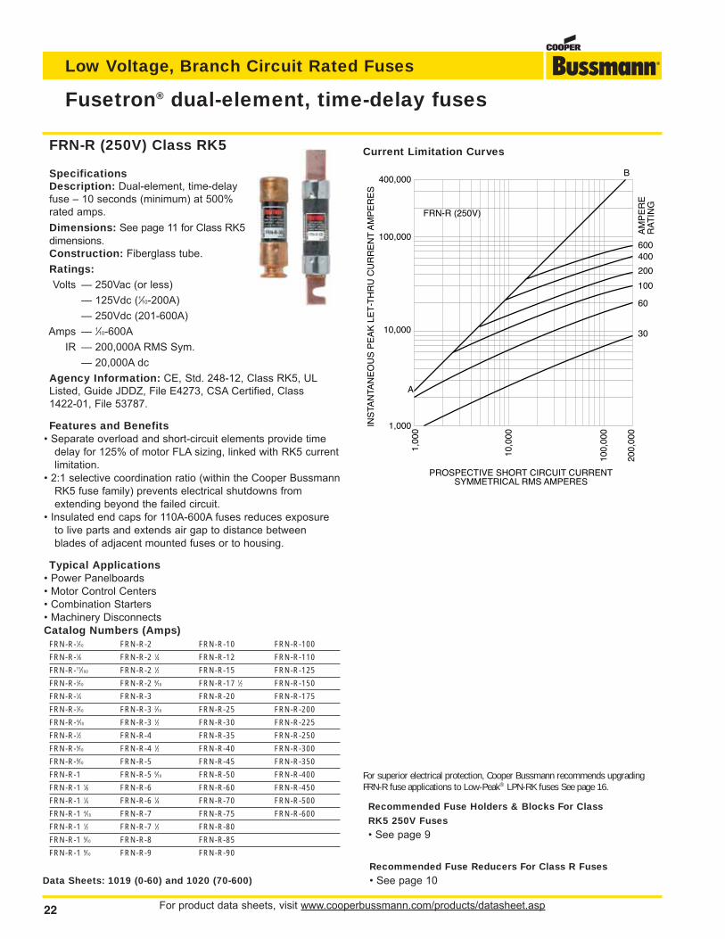
Fusetron® dual-element, time-delay fuses
SpecificationsDescription: Dual-element, time-delayfuse – 10 seconds (minimum) at 500%rated amps.
Dimensions: See page 11 for Class RK5dimensions.Construction: Fiberglass tube.
Ratings:Volts — 250Vac (or less)
— 125Vdc (1⁄10-200A)
— 250Vdc (201-600A)
Amps — 1⁄10-600A
IR — 200,000A RMS Sym.
— 20,000A dc
Agency Information: CE, Std. 248-12, Class RK5, ULListed, Guide JDDZ, File E4273, CSA Certified, Class1422-01, File 53787.
Features and Benefits• Separate overload and short-circuit elements provide time
delay for 125% of motor FLA sizing, linked with RK5 currentlimitation.
• 2:1 selective coordination ratio (within the Cooper BussmannRK5 fuse family) prevents electrical shutdowns fromextending beyond the failed circuit.
• Insulated end caps for 110A-600A fuses reduces exposureto live parts and extends air gap to distance betweenblades of adjacent mounted fuses or to housing.
Typical Applications• Power Panelboards• Motor Control Centers• Combination Starters• Machinery DisconnectsCatalog Numbers (Amps)
FRN-R-1⁄10 FRN-R-2 FRN-R-10 FRN-R-100
FRN-R-1⁄8 FRN-R-2 1⁄4 FRN-R-12 FRN-R-110
FRN-R-15⁄100 FRN-R-2 1⁄2 FRN-R-15 FRN-R-125
FRN-R-2⁄10 FRN-R-2 8⁄10 FRN-R-17 1⁄2 FRN-R-150
FRN-R-1⁄4 FRN-R-3 FRN-R-20 FRN-R-175
FRN-R-3⁄10 FRN-R-3 2⁄10 FRN-R-25 FRN-R-200
FRN-R-4⁄10 FRN-R-3 1⁄2 FRN-R-30 FRN-R-225
FRN-R-1⁄2 FRN-R-4 FRN-R-35 FRN-R-250
FRN-R-6⁄10 FRN-R-4 1⁄2 FRN-R-40 FRN-R-300
FRN-R-8⁄10 FRN-R-5 FRN-R-45 FRN-R-350
FRN-R-1 FRN-R-5 6⁄10 FRN-R-50 FRN-R-400
FRN-R-1 1⁄8 FRN-R-6 FRN-R-60 FRN-R-450
FRN-R-1 1⁄4 FRN-R-6 1⁄4 FRN-R-70 FRN-R-500
FRN-R-1 4⁄10 FRN-R-7 FRN-R-75 FRN-R-600
FRN-R-1 1⁄2 FRN-R-7 1⁄2 FRN-R-80
FRN-R-1 6⁄10 FRN-R-8 FRN-R-85
FRN-R-1 8⁄10 FRN-R-9 FRN-R-90
Data Sheets: 1019 (0-60) and 1020 (70-600)
INS
TAN
TAN
EO
US
PE
AK
LE
T-T
HR
U C
UR
RE
NT
AM
PE
RE
S
PROSPECTIVE SHORT CIRCUIT CURRENTSYMMETRICAL RMS AMPERES
400,000
100,000
10,000
1,0001,
000
10,0
00
100,
000
200,
000
60
600
100
AM
PE
RE
RA
TIN
G
400
200
B
A
30
FRN-R (250V)
Current Limitation CurvesFRN-R (250V) Class RK5
For superior electrical protection, Cooper Bussmann recommends upgradingFRN-R fuse applications to Low-Peak® LPN-RK fuses See page 16.
Recommended Fuse Holders & Blocks For Class
RK5 250V Fuses
• See page 9
Recommended Fuse Reducers For Class R Fuses
• See page 10
For product data sheets, visit www.cooperbussmann.com/products/datasheet.asp 23
Low Voltage, Branch Circuit Rated Fuses
Low Voltage
BranchCircuitFuses
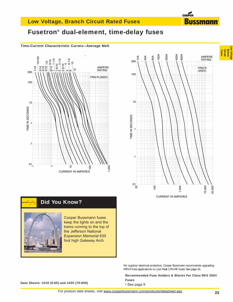
Fusetron® dual-element, time-delay fuses
Data Sheets: 1019 (0-60) and 1020 (70-600)
FRN-R (250V)
g
1/10
2/10
15/1
00
3/10
4/10
6/10
1/2
8/10
11-
1/4
1-6/
102
2-1/
23-
2/10
45
6-1/
48
1012
AMPERERATING
300
100
10
1
.1
.01
TIM
E IN
SE
CO
ND
S
.1 1 10 100
1,00
0
CURRENT IN AMPERES
20 100
1,00
0
10,0
00
20,0
00
10
1
.1
.01
TIM
E IN
SE
CO
ND
S
CURRENT IN AMPERES
FRN-R(250V)
60A
100A
200A
30A
400A AMPERE
RATING600A
15A
300
100
Time-Current Characteristic Curves—Average Melt
For superior electrical protection, Cooper Bussmann recommends upgradingFRN-R fuse applications to Low-Peak LPN-RK fuses See page 16.
Recommended Fuse Holders & Blocks For Class RK5 250V
Fuses
• See page 9
Cooper Bussmann fuseskeep the lights on and thetrams running to the top ofthe Jefferson NationalExpansion Memorial 630foot high Gateway Arch.
Did You Know?
For product data sheets, visit www.cooperbussmann.com/products/datasheet.asp24
Low Voltage, Branch Circuit Rated Fuses
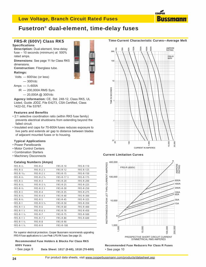
Fusetron® dual-element, time-delay fuses
600A
100A
AM
PE
RE
RA
TIN
G
400A
200A
60A
INS
TAN
TAN
EO
US
PE
AK
LE
T T
HR
U C
UR
RE
NT
AM
PE
RE
S
PROSPECTIVE SHORT CIRCUIT CURRENTSYMMETRICAL RMS AMPERES
B
A
400,000
100,000
10,000
1,000
1,00
0
10,0
00
100,
000
FRS-R (600V)
30A
200,
000
15A
Time-Current Characteristic Curves—Average Melt
Current Limitation Curves
FRS-R (600V) Class RK5SpecificationsDescription: Dual-element, time-delayfuse – 10 seconds (minimum) at 500%rated amps.
Dimensions: See page 11 for Class RK5dimensions.Construction: Fiberglass tube.
Ratings:Volts — 600Vac (or less)
— 300Vdc
Amps — 1⁄10-600A
IR — 200,000A RMS Sym.
— 20,000A @ 300Vdc
Agency Information: CE, Std. 248-12, Class RK5, ULListed, Guide JDDZ, File E4273, CSA Certified, Class1422-02, File 53787.
Features and Benefits• 2:1 selective coordination ratio (within RK5 fuse family)
prevents electrical shutdowns from extending beyond thefailed circuit.
• Insulated end caps for 70-600A fuses reduces exposure tolive parts and extends air gap to distance between bladesof adjacent mounted fuses or to housing.
Typical Applications• Power Panelboards• Motor Control Centers• Combination Starters• Machinery Disconnects
Catalog Numbers (Amps)FRS-R-1⁄10 FRS-R-2 FRS-R-10 FRS-R-110
FRS-R-1⁄8 FRS-R-2 1⁄4 FRS-R-12 FRS-R-125
FRS-R-15⁄100 FRS-R-2 1⁄2 FRS-R-15 FRS-R-150
FRS-R-2⁄10 FRS-R-2 8⁄10 FRS-R-17 1⁄2 FRS-R-175
FRS-R-1⁄4 FRS-R-3 FRS-R-20 FRS-R-200
FRS-R-3⁄10 FRS-R-3 2⁄10 FRS-R-25 FRS-R-225
FRS-R-4⁄10 FRS-R-3 1⁄2 FRS-R-30 FRS-R-250
FRS-R-1⁄2 FRS-R-4 FRS-R-35 FRS-R-275
FRS-R-6⁄10 FRS-R-4 1⁄2 FRS-R-40 FRS-R-300
FRS-R-8⁄10 FRS-R-5 FRS-R-45 FRS-R-325
FRS-R-1 FRS-R-5 6⁄10 FRS-R-50 FRS-R-350
FRS-R-1 1⁄8 FRS-R-6 FRS-R-60 FRS-R-400
FRS-R-1 1⁄4 FRS-R-6 1⁄4 FRS-R-70 FRS-R-450
FRS-R-1 4⁄10 FRS-R-7 FRS-R-75 FRS-R-500
FRS-R-1 1⁄2 FRS-R-7 1⁄2 FRS-R-80 FRS-R-600
FRS-R-1 6⁄10 FRS-R-8 FRS-R-90
FRS-R-1 8⁄10 FRS-R-9 FRS-R-100
Data Sheet: 1017 (0-60), 1018 (70-600)
For superior electrical protection, Cooper Bussmann recommends upgradingFRS-R fuse applications to Low-Peak LPS-RK fuses See page 16.
Recommended Fuse Holders & Blocks For Class RK5
600V Fuses
• See page 9
Recommended Fuse Reducers For Class R Fuses
• See page 10
For product data sheets, visit www.cooperbussmann.com/products/datasheet.asp 25
Low Voltage, Branch Circuit Rated Fuses
Low Voltage
BranchCircuitFuses
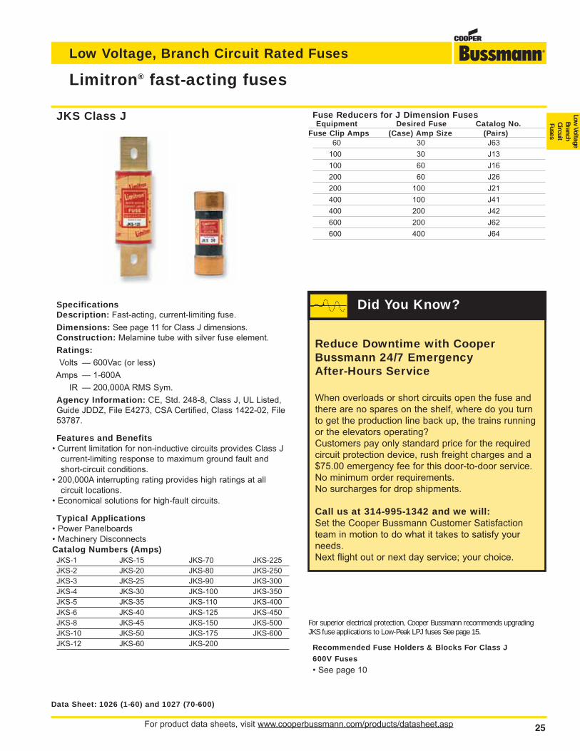
Limitron® fast-acting fuses
SpecificationsDescription: Fast-acting, current-limiting fuse.
Dimensions: See page 11 for Class J dimensions.Construction: Melamine tube with silver fuse element.
Ratings:Volts — 600Vac (or less)
Amps — 1-600A
IR — 200,000A RMS Sym.
Agency Information: CE, Std. 248-8, Class J, UL Listed,Guide JDDZ, File E4273, CSA Certified, Class 1422-02, File53787.
Features and Benefits• Current limitation for non-inductive circuits provides Class J
current-limiting response to maximum ground fault andshort-circuit conditions.
• 200,000A interrupting rating provides high ratings at all circuit locations.
• Economical solutions for high-fault circuits.
Typical Applications• Power Panelboards• Machinery DisconnectsCatalog Numbers (Amps)
JKS-1 JKS-15 JKS-70 JKS-225
JKS-2 JKS-20 JKS-80 JKS-250
JKS-3 JKS-25 JKS-90 JKS-300
JKS-4 JKS-30 JKS-100 JKS-350
JKS-5 JKS-35 JKS-110 JKS-400
JKS-6 JKS-40 JKS-125 JKS-450
JKS-8 JKS-45 JKS-150 JKS-500
JKS-10 JKS-50 JKS-175 JKS-600
JKS-12 JKS-60 JKS-200
For superior electrical protection, Cooper Bussmann recommends upgradingJKS fuse applications to Low-Peak LPJ fuses See page 15.
Recommended Fuse Holders & Blocks For Class J
600V Fuses
• See page 10
Fuse Reducers for J Dimension FusesEquipment Desired Fuse Catalog No.
Fuse Clip Amps (Case) Amp Size (Pairs)60 30 J63
100 30 J13
100 60 J16
200 60 J26
200 100 J21
400 100 J41
400 200 J42
600 200 J62
600 400 J64
Data Sheet: 1026 (1-60) and 1027 (70-600)
JKS Class J
Reduce Downtime with CooperBussmann 24/7 Emergency After-Hours Service
When overloads or short circuits open the fuse andthere are no spares on the shelf, where do you turnto get the production line back up, the trains runningor the elevators operating?Customers pay only standard price for the requiredcircuit protection device, rush freight charges and a$75.00 emergency fee for this door-to-door service. No minimum order requirements.No surcharges for drop shipments.
Call us at 314-995-1342 and we will:Set the Cooper Bussmann Customer Satisfactionteam in motion to do what it takes to satisfy yourneeds.Next flight out or next day service; your choice.
Did You Know?
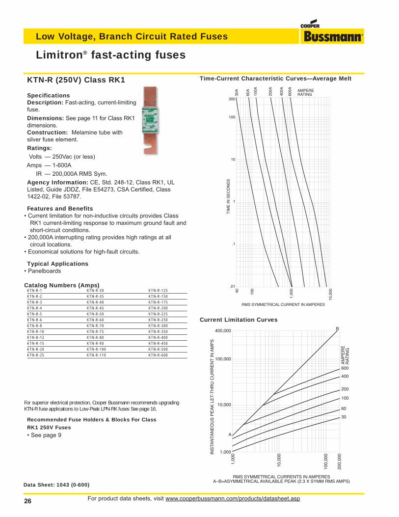
For product data sheets, visit www.cooperbussmann.com/products/datasheet.asp26
Low Voltage, Branch Circuit Rated Fuses
Limitron® fast-acting fuses
Data Sheet: 1043 (0-600)
SpecificationsDescription: Fast-acting, current-limitingfuse.
Dimensions: See page 11 for Class RK1dimensions.Construction: Melamine tube with silver fuse element.
Ratings:Volts — 250Vac (or less)
Amps — 1-600A
IR — 200,000A RMS Sym.
Agency Information: CE, Std. 248-12, Class RK1, ULListed, Guide JDDZ, File E54273, CSA Certified, Class1422-02, File 53787.
Features and Benefits• Current limitation for non-inductive circuits provides Class
RK1 current-limiting response to maximum ground fault andshort-circuit conditions.
• 200,000A interrupting rating provides high ratings at allcircuit locations.
• Economical solutions for high-fault circuits.
Typical Applications• Panelboards
Catalog Numbers (Amps)KTN-R-1 KTN-R-30 KTN-R-125
KTN-R-2 KTN-R-35 KTN-R-150
KTN-R-3 KTN-R-40 KTN-R-175
KTN-R-4 KTN-R-45 KTN-R-200
KTN-R-5 KTN-R-50 KTN-R-225
KTN-R-6 KTN-R-60 KTN-R-250
KTN-R-8 KTN-R-70 KTN-R-300
KTN-R-10 KTN-R-75 KTN-R-350
KTN-R-12 KTN-R-80 KTN-R-400
KTN-R-15 KTN-R-90 KTN-R-450
KTN-R-20 KTN-R-100 KTN-R-500
KTN-R-25 KTN-R-110 KTN-R-600
RMS SYMMETRICAL CURRENT IN AMPERES
TIM
E IN
SE
CO
ND
S
300
100
10
1
.1
.01
40 100
1,00
0
10,0
00
30A
60A
100A
200A
400A
600A AMPERE
RATING
600
100
60
AM
PE
RE
RA
TIN
G
30
400
200
INS
TAN
TAN
EO
US
PE
AK
LE
T-T
HR
U C
UR
RE
NT
IN A
MP
S
400,000
100,000
10,000
1,000
1,00
0
10,0
00
100,
000
200,
000
RMS SYMMETRICAL CURRENTS IN AMPERESA–B=ASYMMETRICAL AVAILABLE PEAK (2.3 X SYMM RMS AMPS)
A
B
Time-Current Characteristic Curves—Average Melt
Current Limitation Curves
KTN-R (250V) Class RK1
For superior electrical protection, Cooper Bussmann recommends upgradingKTN-R fuse applications to Low-Peak LPN-RK fuses See page 16.
Recommended Fuse Holders & Blocks For Class
RK1 250V Fuses
• See page 9
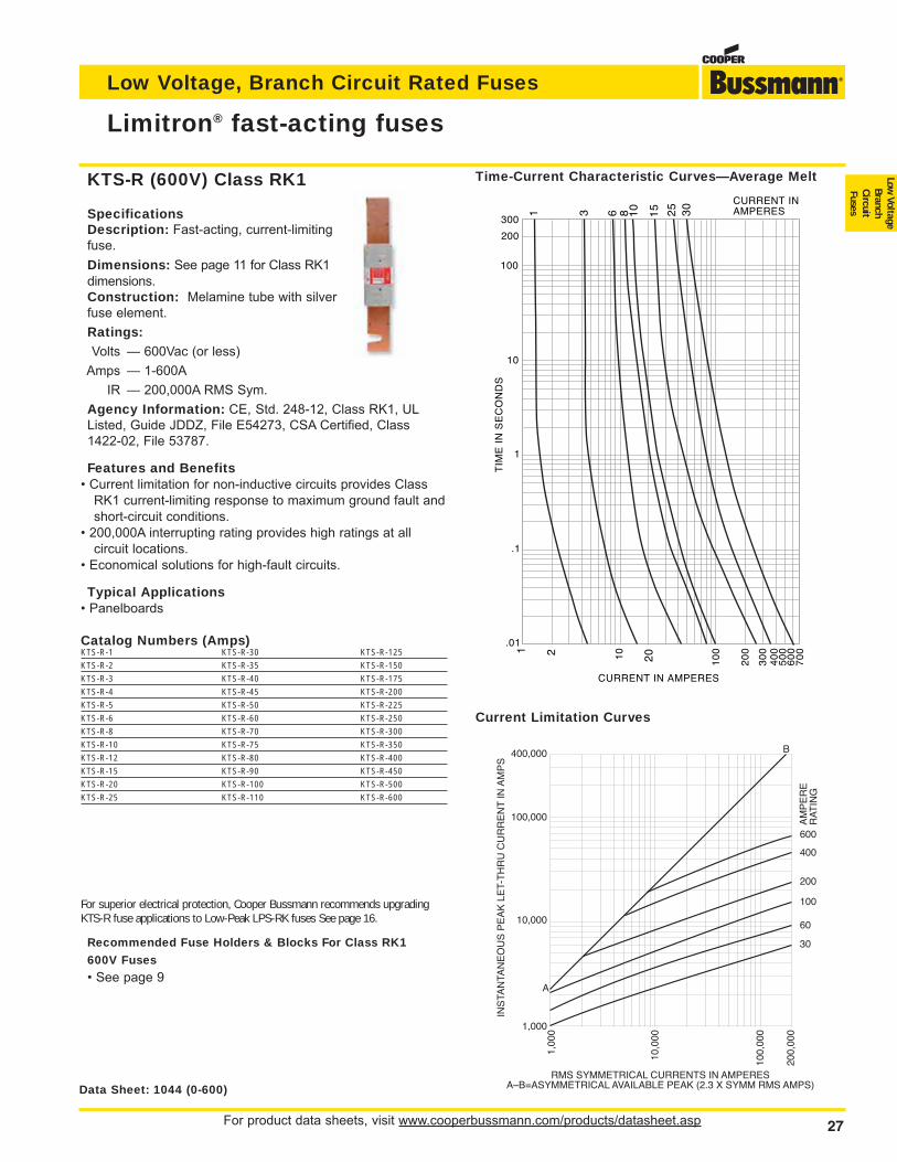
For product data sheets, visit www.cooperbussmann.com/products/datasheet.asp 27
Low Voltage, Branch Circuit Rated Fuses
Low Voltage
BranchCircuitFuses
Limitron® fast-acting fuses
Data Sheet: 1044 (0-600)
SpecificationsDescription: Fast-acting, current-limitingfuse.
Dimensions: See page 11 for Class RK1dimensions.Construction: Melamine tube with silverfuse element.
Ratings:Volts — 600Vac (or less)
Amps — 1-600A
IR — 200,000A RMS Sym.
Agency Information: CE, Std. 248-12, Class RK1, ULListed, Guide JDDZ, File E54273, CSA Certified, Class1422-02, File 53787.
Features and Benefits• Current limitation for non-inductive circuits provides Class
RK1 current-limiting response to maximum ground fault andshort-circuit conditions.
• 200,000A interrupting rating provides high ratings at allcircuit locations.
• Economical solutions for high-fault circuits.
Typical Applications• Panelboards
Catalog Numbers (Amps)KTS-R-1 KTS-R-30 KTS-R-125
KTS-R-2 KTS-R-35 KTS-R-150
KTS-R-3 KTS-R-40 KTS-R-175
KTS-R-4 KTS-R-45 KTS-R-200
KTS-R-5 KTS-R-50 KTS-R-225
KTS-R-6 KTS-R-60 KTS-R-250
KTS-R-8 KTS-R-70 KTS-R-300
KTS-R-10 KTS-R-75 KTS-R-350
KTS-R-12 KTS-R-80 KTS-R-400
KTS-R-15 KTS-R-90 KTS-R-450
KTS-R-20 KTS-R-100 KTS-R-500
KTS-R-25 KTS-R-110 KTS-R-600
1
100
10
1
.1
.01
10
10
0
20
0
TIM
E I
N S
EC
ON
DS
CURRENT IN AMPERES
30
0
200
40
05
002 20
60
07
00
300
1 3 6 8 10
15 25 30 CURRENT IN
AMPERES
600
100
60
AM
PE
RE
RA
TIN
G
30
400
200
200,
000
100,
000
10,0
00
1,00
0
1,000
INS
TAN
TAN
EO
US
PE
AK
LE
T-T
HR
U C
UR
RE
NT
IN A
MP
S
400,000
100,000
10,000
RMS SYMMETRICAL CURRENTS IN AMPERESA–B=ASYMMETRICAL AVAILABLE PEAK (2.3 X SYMM RMS AMPS)
B
A
Time-Current Characteristic Curves—Average Melt
Current Limitation Curves
KTS-R (600V) Class RK1
For superior electrical protection, Cooper Bussmann recommends upgradingKTS-R fuse applications to Low-Peak LPS-RK fuses See page 16.
Recommended Fuse Holders & Blocks For Class RK1
600V Fuses
• See page 9
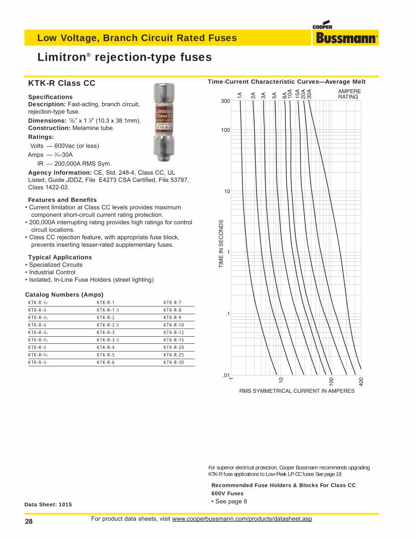
For product data sheets, visit www.cooperbussmann.com/products/datasheet.asp28
Low Voltage, Branch Circuit Rated Fuses
Limitron® rejection-type fuses
Data Sheet: 1015
SpecificationsDescription: Fast-acting, branch circuit,rejection-type fuse.
Dimensions: 13⁄32” x 1 1⁄2” (10.3 x 38.1mm).Construction: Melamine tube.
Ratings:Volts — 600Vac (or less)
Amps — 1⁄10-30A
IR — 200,000A RMS Sym.
Agency Information: CE, Std. 248-4, Class CC, ULListed, Guide JDDZ, File E4273 CSA Certified, File 53787,Class 1422-02.
Features and Benefits• Current limitation at Class CC levels provides maximum
component short-circuit current rating protection.• 200,000A interrupting rating provides high ratings for control
circuit locations.• Class CC rejection feature, with appropriate fuse block,
prevents inserting lesser-rated supplementary fuses.
Typical Applications• Specialized Circuits• Industrial Control• Isolated, In-Line Fuse Holders (street lighting)
Catalog Numbers (Amps)KTK-R-1⁄10 KTK-R-1 KTK-R-7
KTK-R-1⁄8 KTK-R-1 1⁄2 KTK-R-8
KTK-R-2⁄10 KTK-R-2 KTK-R-9
KTK-R-1⁄4 KTK-R-2 1⁄2 KTK-R-10
KTK-R-3⁄10 KTK-R-3 KTK-R-12
KTK-R-4⁄10 KTK-R-3 1⁄2 KTK-R-15
KTK-R-1⁄2 KTK-R-4 KTK-R-20
KTK-R-6⁄10 KTK-R-5 KTK-R-25
KTK-R-3⁄4 KTK-R-6 KTK-R-30
RMS SYMMETRICAL CURRENT IN AMPERES
TIM
E IN
SE
CO
ND
S
10 100
4001
10A
20A
3A
AMPERERATING2A1A 5A 8A 15
A
30A
300
100
10
1
.1
.01
Time-Current Characteristic Curves—Average MeltKTK-R Class CC
For superior electrical protection, Cooper Bussmann recommends upgradingKTK-R fuse applications to Low-Peak LP-CC fuses See page 19.
Recommended Fuse Holders & Blocks For Class CC
600V Fuses
• See page 8
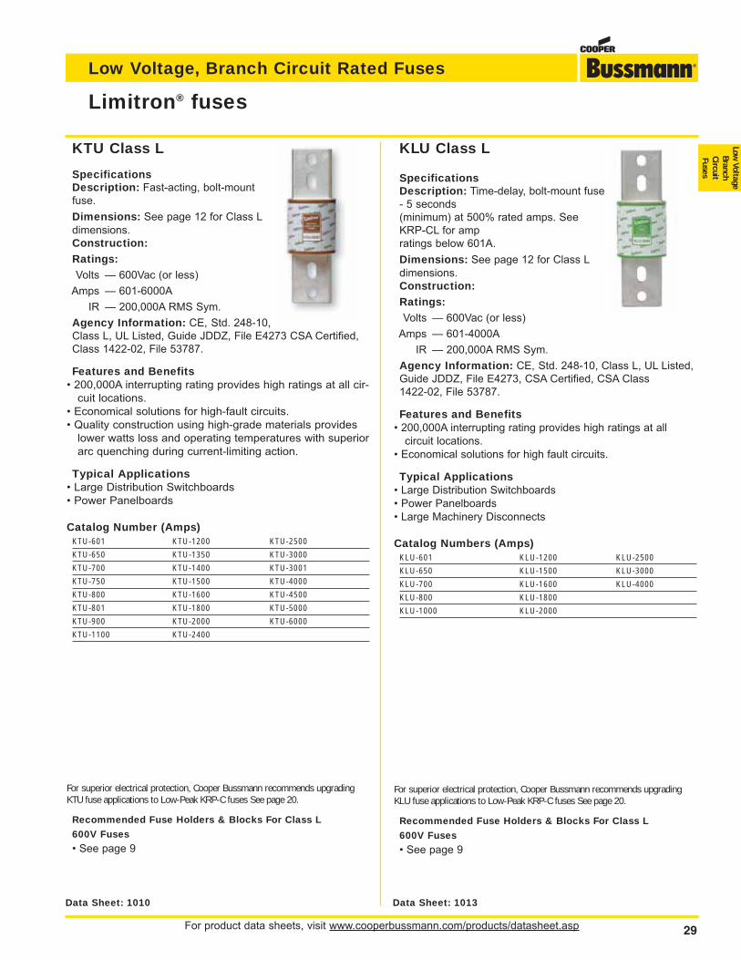
For product data sheets, visit www.cooperbussmann.com/products/datasheet.asp 29
Low Voltage, Branch Circuit Rated Fuses
Low Voltage
BranchCircuitFuses
Limitron® fuses
SpecificationsDescription: Fast-acting, bolt-mountfuse.
Dimensions: See page 12 for Class Ldimensions.Construction:Ratings:Volts — 600Vac (or less)
Amps — 601-6000A
IR — 200,000A RMS Sym.
Agency Information: CE, Std. 248-10,Class L, UL Listed, Guide JDDZ, File E4273 CSA Certified,Class 1422-02, File 53787.
Features and Benefits• 200,000A interrupting rating provides high ratings at all cir-
cuit locations.• Economical solutions for high-fault circuits.• Quality construction using high-grade materials provides
lower watts loss and operating temperatures with superiorarc quenching during current-limiting action.
Typical Applications• Large Distribution Switchboards• Power Panelboards
Catalog Number (Amps)KTU-601 KTU-1200 KTU-2500
KTU-650 KTU-1350 KTU-3000
KTU-700 KTU-1400 KTU-3001
KTU-750 KTU-1500 KTU-4000
KTU-800 KTU-1600 KTU-4500
KTU-801 KTU-1800 KTU-5000
KTU-900 KTU-2000 KTU-6000
KTU-1100 KTU-2400
SpecificationsDescription: Time-delay, bolt-mount fuse- 5 seconds(minimum) at 500% rated amps. SeeKRP-CL for ampratings below 601A.
Dimensions: See page 12 for Class Ldimensions.Construction:Ratings:Volts — 600Vac (or less)
Amps — 601-4000A
IR — 200,000A RMS Sym.
Agency Information: CE, Std. 248-10, Class L, UL Listed,Guide JDDZ, File E4273, CSA Certified, CSA Class 1422-02, File 53787.
Features and Benefits• 200,000A interrupting rating provides high ratings at all
circuit locations.• Economical solutions for high fault circuits.
Typical Applications• Large Distribution Switchboards• Power Panelboards• Large Machinery Disconnects
Catalog Numbers (Amps)KLU-601 KLU-1200 KLU-2500
KLU-650 KLU-1500 KLU-3000
KLU-700 KLU-1600 KLU-4000
KLU-800 KLU-1800
KLU-1000 KLU-2000
Data Sheet: 1010 Data Sheet: 1013
KTU Class L KLU Class L
For superior electrical protection, Cooper Bussmann recommends upgradingKLU fuse applications to Low-Peak KRP-C fuses See page 20.
Recommended Fuse Holders & Blocks For Class L
600V Fuses
• See page 9
For superior electrical protection, Cooper Bussmann recommends upgradingKTU fuse applications to Low-Peak KRP-C fuses See page 20.
Recommended Fuse Holders & Blocks For Class L
600V Fuses
• See page 9
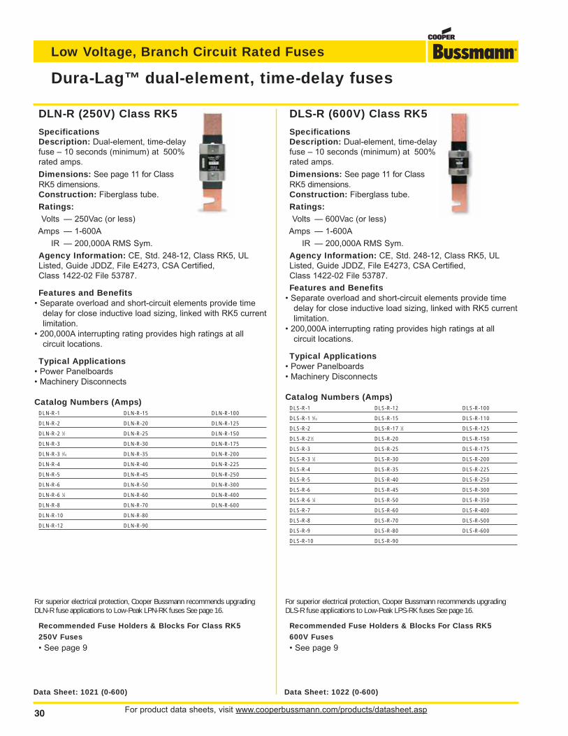
For product data sheets, visit www.cooperbussmann.com/products/datasheet.asp30
Low Voltage, Branch Circuit Rated Fuses
DLS-R (600V) Class RK5
SpecificationsDescription: Dual-element, time-delayfuse – 10 seconds (minimum) at 500%rated amps.
Dimensions: See page 11 for ClassRK5 dimensions.Construction: Fiberglass tube.
Ratings:Volts — 600Vac (or less)
Amps — 1-600A
IR — 200,000A RMS Sym.
Agency Information: CE, Std. 248-12, Class RK5, ULListed, Guide JDDZ, File E4273, CSA Certified, Class 1422-02 File 53787.
Features and Benefits• Separate overload and short-circuit elements provide time
delay for close inductive load sizing, linked with RK5 currentlimitation.
• 200,000A interrupting rating provides high ratings at all circuit locations.
Typical Applications• Power Panelboards• Machinery Disconnects
Catalog Numbers (Amps)DLS-R-1 DLS-R-12 DLS-R-100
DLS-R-1 6⁄10 DLS-R-15 DLS-R-110
DLS-R-2 DLS-R-17 1⁄2 DLS-R-125
DLS-R-21⁄2 DLS-R-20 DLS-R-150
DLS-R-3 DLS-R-25 DLS-R-175
DLS-R-3 1⁄2 DLS-R-30 DLS-R-200
DLS-R-4 DLS-R-35 DLS-R-225
DLS-R-5 DLS-R-40 DLS-R-250
DLS-R-6 DLS-R-45 DLS-R-300
DLS-R-6 1⁄4 DLS-R-50 DLS-R-350
DLS-R-7 DLS-R-60 DLS-R-400
DLS-R-8 DLS-R-70 DLS-R-500
DLS-R-9 DLS-R-80 DLS-R-600
DLS-R-10 DLS-R-90
DLN-R (250V) Class RK5
SpecificationsDescription: Dual-element, time-delayfuse – 10 seconds (minimum) at 500%rated amps.
Dimensions: See page 11 for ClassRK5 dimensions.Construction: Fiberglass tube.
Ratings:Volts — 250Vac (or less)
Amps — 1-600A
IR — 200,000A RMS Sym.
Agency Information: CE, Std. 248-12, Class RK5, ULListed, Guide JDDZ, File E4273, CSA Certified, Class 1422-02 File 53787.
Features and Benefits• Separate overload and short-circuit elements provide time
delay for close inductive load sizing, linked with RK5 currentlimitation.
• 200,000A interrupting rating provides high ratings at allcircuit locations.
Typical Applications• Power Panelboards• Machinery Disconnects
Catalog Numbers (Amps)DLN-R-1 DLN-R-15 DLN-R-100
DLN-R-2 DLN-R-20 DLN-R-125
DLN-R-2 1⁄2 DLN-R-25 DLN-R-150
DLN-R-3 DLN-R-30 DLN-R-175
DLN-R-3 2⁄10 DLN-R-35 DLN-R-200
DLN-R-4 DLN-R-40 DLN-R-225
DLN-R-5 DLN-R-45 DLN-R-250
DLN-R-6 DLN-R-50 DLN-R-300
DLN-R-6 1⁄4 DLN-R-60 DLN-R-400
DLN-R-8 DLN-R-70 DLN-R-600
DLN-R-10 DLN-R-80
DLN-R-12 DLN-R-90
Dura-Lag™ dual-element, time-delay fuses
Data Sheet: 1021 (0-600) Data Sheet: 1022 (0-600)
For superior electrical protection, Cooper Bussmann recommends upgradingDLS-R fuse applications to Low-Peak LPS-RK fuses See page 16.
Recommended Fuse Holders & Blocks For Class RK5
600V Fuses
• See page 9
For superior electrical protection, Cooper Bussmann recommends upgradingDLN-R fuse applications to Low-Peak LPN-RK fuses See page 16.
Recommended Fuse Holders & Blocks For Class RK5
250V Fuses
• See page 9
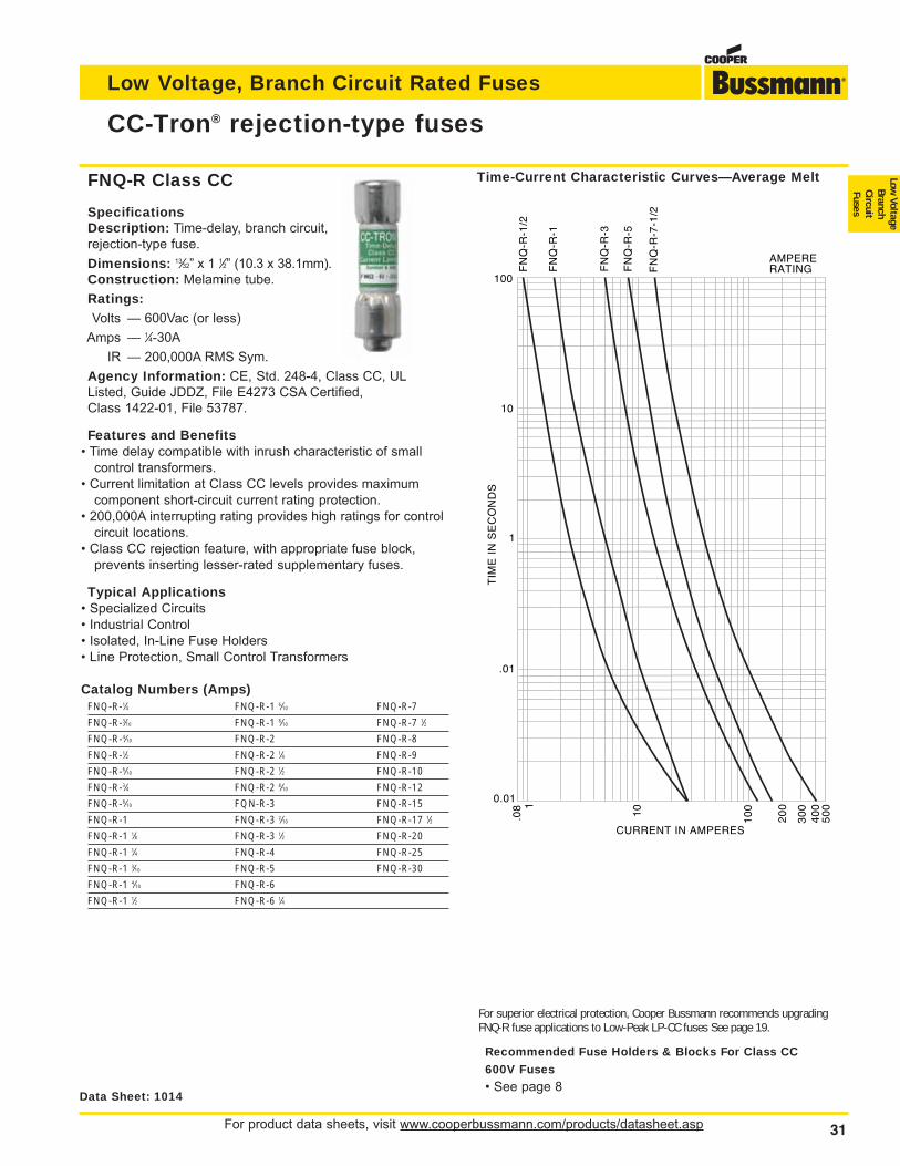
For product data sheets, visit www.cooperbussmann.com/products/datasheet.asp 31
Low Voltage, Branch Circuit Rated Fuses
Low Voltage
BranchCircuitFuses
CC-Tron® rejection-type fuses
Data Sheet: 1014
SpecificationsDescription: Time-delay, branch circuit,rejection-type fuse.
Dimensions: 13⁄32” x 1 1⁄2” (10.3 x 38.1mm).Construction: Melamine tube.
Ratings:Volts — 600Vac (or less)
Amps — 1⁄4-30A
IR — 200,000A RMS Sym.
Agency Information: CE, Std. 248-4, Class CC, ULListed, Guide JDDZ, File E4273 CSA Certified,Class 1422-01, File 53787.
Features and Benefits• Time delay compatible with inrush characteristic of small
control transformers.• Current limitation at Class CC levels provides maximum
component short-circuit current rating protection.• 200,000A interrupting rating provides high ratings for control
circuit locations.• Class CC rejection feature, with appropriate fuse block,
prevents inserting lesser-rated supplementary fuses.
Typical Applications• Specialized Circuits• Industrial Control• Isolated, In-Line Fuse Holders• Line Protection, Small Control Transformers
Catalog Numbers (Amps)FNQ-R-1⁄4 FNQ-R-1 6⁄10 FNQ-R-7
FNQ-R-3⁄10 FNQ-R-1 8⁄10 FNQ-R-7 1⁄2
FNQ-R-4⁄10 FNQ-R-2 FNQ-R-8
FNQ-R-1⁄2 FNQ-R-2 1⁄4 FNQ-R-9
FNQ-R-6⁄10 FNQ-R-2 1⁄2 FNQ-R-10
FNQ-R-3⁄4 FNQ-R-2 8⁄10 FNQ-R-12
FNQ-R-8⁄10 FQN-R-3 FNQ-R-15
FNQ-R-1 FNQ-R-3 2⁄10 FNQ-R-17 1⁄2
FNQ-R-1 1⁄8 FNQ-R-3 1⁄2 FNQ-R-20
FNQ-R-1 1⁄4 FNQ-R-4 FNQ-R-25
FNQ-R-1 3⁄10 FNQ-R-5 FNQ-R-30
FNQ-R-1 4⁄10 FNQ-R-6
FNQ-R-1 1⁄2 FNQ-R-6 1⁄4
AMPERERATING
100
10
1
.01
.08 1
10
10
0
20
0
CURRENT IN AMPERES
30
04
00
50
0
TIM
E I
N S
EC
ON
DS
FN
Q-R
-1/2
FN
Q-R
-1
FN
Q-R
-3
FN
Q-R
-5
FN
Q-R
-7-1
/2
0.01
Time-Current Characteristic Curves—Average MeltFNQ-R Class CC
For superior electrical protection, Cooper Bussmann recommends upgradingFNQ-R fuse applications to Low-Peak LP-CC fuses See page 19.
Recommended Fuse Holders & Blocks For Class CC
600V Fuses
• See page 8
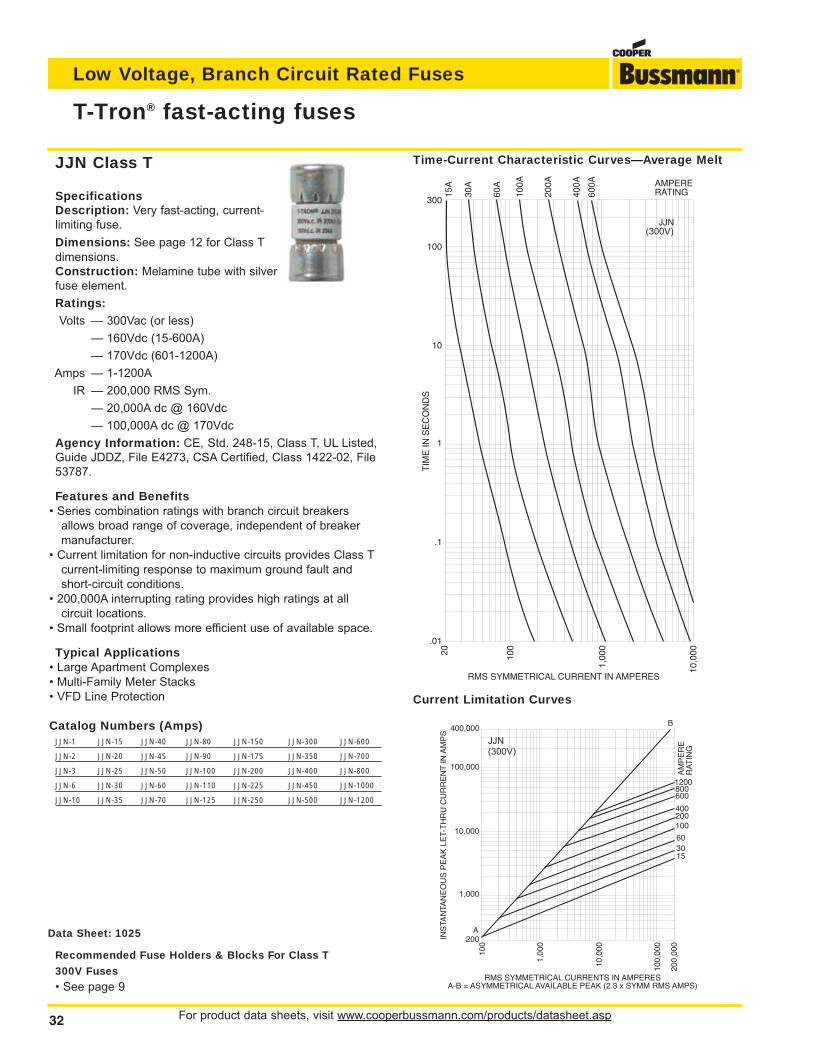
For product data sheets, visit www.cooperbussmann.com/products/datasheet.asp32
Low Voltage, Branch Circuit Rated Fuses
T-Tron® fast-acting fuses
Data Sheet: 1025
SpecificationsDescription: Very fast-acting, current-limiting fuse.
Dimensions: See page 12 for Class Tdimensions.Construction: Melamine tube with silverfuse element.
Ratings:Volts — 300Vac (or less)
— 160Vdc (15-600A)
— 170Vdc (601-1200A)
Amps — 1-1200A
IR — 200,000 RMS Sym.
— 20,000A dc @ 160Vdc
— 100,000A dc @ 170Vdc
Agency Information: CE, Std. 248-15, Class T, UL Listed,Guide JDDZ, File E4273, CSA Certified, Class 1422-02, File53787.
Features and Benefits• Series combination ratings with branch circuit breakers
allows broad range of coverage, independent of breakermanufacturer.
• Current limitation for non-inductive circuits provides Class Tcurrent-limiting response to maximum ground fault andshort-circuit conditions.
• 200,000A interrupting rating provides high ratings at allcircuit locations.
• Small footprint allows more efficient use of available space.
Typical Applications• Large Apartment Complexes• Multi-Family Meter Stacks• VFD Line Protection
Catalog Numbers (Amps)JJN-1 JJN-15 JJN-40 JJN-80 JJN-150 JJN-300 JJN-600
JJN-2 JJN-20 JJN-45 JJN-90 JJN-175 JJN-350 JJN-700
JJN-3 JJN-25 JJN-50 JJN-100 JJN-200 JJN-400 JJN-800
JJN-6 JJN-30 JJN-60 JJN-110 JJN-225 JJN-450 JJN-1000
JJN-10 JJN-35 JJN-70 JJN-125 JJN-250 JJN-500 JJN-1200
JJN Class T
Current Limitation Curves
600
400200100
603015
AM
PE
RE
RA
TIN
G
8001200
INS
TAN
TAN
EO
US
PE
AK
LE
T-T
HR
U C
UR
RE
NT
IN A
MP
S
RMS SYMMETRICAL CURRENTS IN AMPERESA-B = ASYMMETRICAL AVAILABLE PEAK (2.3 x SYMM RMS AMPS)
100,000
10,000
1,000
200
100
1,00
0
10,0
00
100,
000
200,
000
400,000B
A
RMS SYMMETRICAL CURRENT IN AMPERES
TIM
E IN
SE
CO
ND
S
20 100
1,00
0
10,0
00
300
100
10
1
.1
.01
60A
100A
200A
30A
400A AMPERE
RATING600A
15A
JJN(300V)
JJN(300V)
Time-Current Characteristic Curves—Average Melt
Recommended Fuse Holders & Blocks For Class T
300V Fuses
• See page 9
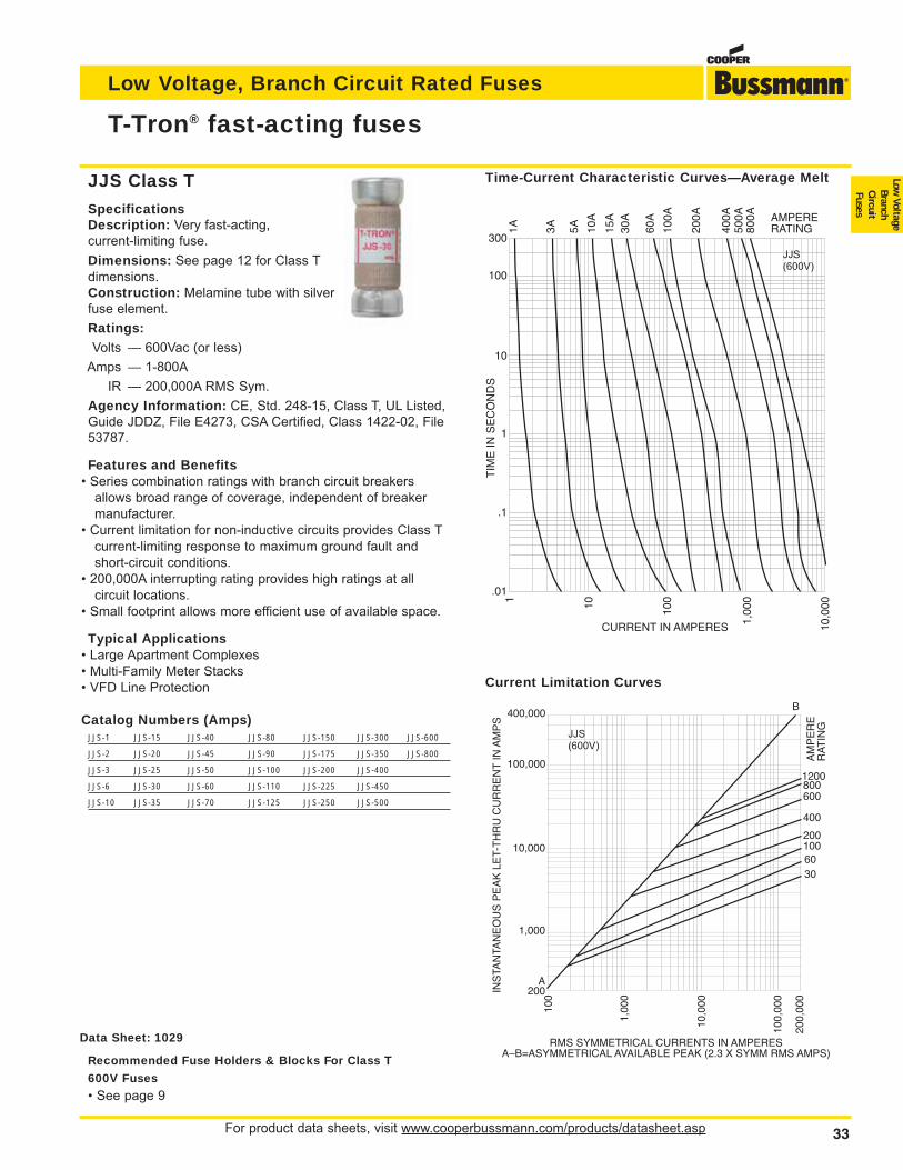
For product data sheets, visit www.cooperbussmann.com/products/datasheet.asp 33
Low Voltage, Branch Circuit Rated Fuses
Low Voltage
BranchCircuitFusesSpecifications
Description: Very fast-acting, current-limiting fuse.
Dimensions: See page 12 for Class Tdimensions.Construction: Melamine tube with silverfuse element.
Ratings:Volts — 600Vac (or less)
Amps — 1-800A
IR — 200,000A RMS Sym.
Agency Information: CE, Std. 248-15, Class T, UL Listed,Guide JDDZ, File E4273, CSA Certified, Class 1422-02, File53787.
Features and Benefits• Series combination ratings with branch circuit breakers
allows broad range of coverage, independent of breakermanufacturer.
• Current limitation for non-inductive circuits provides Class Tcurrent-limiting response to maximum ground fault andshort-circuit conditions.
• 200,000A interrupting rating provides high ratings at allcircuit locations.
• Small footprint allows more efficient use of available space.
Typical Applications• Large Apartment Complexes• Multi-Family Meter Stacks• VFD Line Protection
Catalog Numbers (Amps)JJS-1 JJS-15 JJS-40 JJS-80 JJS-150 JJS-300 JJS-600
JJS-2 JJS-20 JJS-45 JJS-90 JJS-175 JJS-350 JJS-800
JJS-3 JJS-25 JJS-50 JJS-100 JJS-200 JJS-400
JJS-6 JJS-30 JJS-60 JJS-110 JJS-225 JJS-450
JJS-10 JJS-35 JJS-70 JJS-125 JJS-250 JJS-500
Data Sheet: 1029
JJS Class T
T-Tron® fast-acting fuses
600
400
2001006030
AM
PE
RE
RA
TIN
G
8001200
INS
TAN
TAN
EO
US
PE
AK
LE
T-T
HR
U C
UR
RE
NT
IN A
MP
S
100,000
10,000
1,000
200
100
1,00
0
10,0
00
100,
000
200,
000
400,000B
A
RMS SYMMETRICAL CURRENTS IN AMPERESA–B=ASYMMETRICAL AVAILABLE PEAK (2.3 X SYMM RMS AMPS)
1A 3A 5A 10A
30A
15A
60A
200A
400A
500A
100A
800A AMPERE
RATING
10,0
00
1,00
0
100101
300
100
10
1
.1
.01
CURRENT IN AMPERES
TIM
E IN
SE
CO
ND
S
JJS(600V)
JJS(600V)
Time-Current Characteristic Curves—Average Melt
Recommended Fuse Holders & Blocks For Class T
600V Fuses
• See page 9
Current Limitation Curves
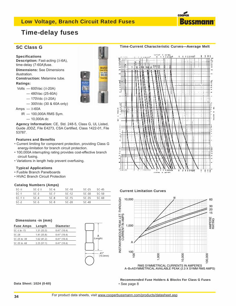
For product data sheets, visit www.cooperbussmann.com/products/datasheet.asp34
Low Voltage, Branch Circuit Rated Fuses
Time-delay fuses
Data Sheet: 1024 (0-60)
SpecificationsDescription: Fast-acting (1⁄2-6A), time-delay (7-60A)fuse.
Dimensions: See Dimensions illustration.Construction: Melamine tube.
Ratings:Volts — 600Vac (1⁄2-20A)
— 480Vac (25-60A)
— 170Vdc (1⁄2-20A)
— 300Vdc (30 & 60A only)
Amps — 1⁄2-60A
IR — 100,000A RMS Sym.
— 10,000A dc
Agency Information: CE, Std. 248-5, Class G, UL Listed,Guide JDDZ, File E4273, CSA Certified, Class 1422-01, File53787.
Features and Benefits• Current limiting for component protection, providing Class G
energy-limitation for branch circuit protection.• 100,000A interrupting rating provides cost-effective branch
circuit fusing.• Variations in length help prevent overfusing.
Typical Applications• Fusible Branch Panelboards• HVAC Branch Circuit Protection
Catalog Numbers (Amps)SC-1⁄2 SC-2 1⁄2 SC-6 SC-10 SC-25 SC-45
SC-1 SC-3 SC-7 SC-12 SC-30 SC-50
SC-1 1⁄2 SC-4 SC-8 SC-15 SC-35 SC-60
SC-2 SC-5 SC-9 SC-20 SC-40
SC Class G
Recommended Fuse Holders & Blocks For Class G Fuses• See page 8
Dimensions -in (mm)
Fuse Amps Length DiameterSC-1⁄2 to -15 1.31 (33.3) 0.41” (10.4)
SC-20 1.41 (35.8) 0.41” (10.4)
SC-25 to -30 1.62 (41.2) 0.41” (10.4)
SC-35 to -60 2.25 (57.1) 0.41” (10.4)
A(Length)
.41"(10.3mm)
Current Limitation Curves
Time-Current Characteristic Curves—Average Melt
B60
302015
AM
PE
RE
RA
TIN
G
A
10,000
1,000
100
100
1,00
0
10,0
00
100,
000
INS
TAN
TAN
EO
US
PE
AK
LE
T-T
HR
OU
GH
C
UR
RE
NT
IN A
MP
S
RMS SYMMETRICAL CURRENTS IN AMPERESA–B=ASYMMETRICAL AVAILABLE PEAK (2.3 X SYMM RMS AMPS)
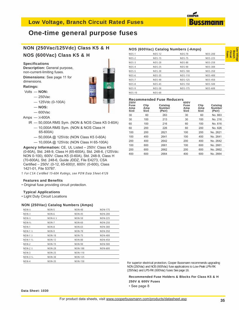
For product data sheets, visit www.cooperbussmann.com/products/datasheet.asp 35
Low Voltage, Branch Circuit Rated Fuses
Low Voltage
BranchCircuitFuses
One-time general purpose fuses
SpecificationsDescription: General purpose, non-current-limiting fuses.
Dimensions: See page 11 for dimensions.
Ratings:Volts — NON:
— 250Vac
— 125Vdc (0-100A)
— NOS:— 600Vac
Amps — 1⁄8-600A
IR — 50,000A RMS Sym. (NON & NOS Class K5 0-60A)
— 10,000A RMS Sym. (NON & NOS Class H65-600A)
— 50,000A @ 125Vdc (NON Class K5 0-60A)
— 10,000A @ 125Vdc (NON Class H 65-100A)
Agency Information: CE, UL Listed – 250V: Class K5(0-60A), Std. 248-9, Class H (65-600A), Std. 248-6, (125Vdc:NON 0-100), 600V: Class K5 (0-60A), Std. 248-9, Class H(70-600A), Std. 248-6, Guide JDDZ, File E4273, CSACertified – 250V: (0-12, 65-600)†, 600V: (0-600), Class1421-01, File 53787.
† For CSA Certified 15-60A Ratings, see PON Data Sheet 4126
Features and Benefits• Original fuse providing circuit protection.
Typical Applications• Light Duty Circuit Locations
NON (250Vac) Catalog Numbers (Amps)NON-1⁄8 NON-5 NON-40 NON-175
NON-1⁄2 NON-6 NON-45 NON-200
NON-3⁄4 NON-6 1⁄4 NON-50 NON-225
NON-8⁄10 NON-7 NON-60 NON-250
NON-1 NON-8 NON-65 NON-300
NON-1 1⁄4 NON-9 NON-70 NON-350
NON-1 1⁄2 NON-10 NON-75 NON-400
NON-1 6⁄10 NON-12 NON-80 NON-450
NON-2 NON-15 NON-90 NON-500
NON-2 1⁄2 NON-20 NON-100 NON-600
NON-3 NON-25 NON-110
NON-3 2⁄10 NON-30 NON-125
NON-4 NON-35 NON-150
NOS (600Vac) Catalog Numbers (-Amps)NOS-1 NOS-12 NOS-70 NOS-200
NOS-2 NOS-15 NOS-75 NOS-225
NOS-3 NOS-20 NOS-80 NOS-250
NOS-4 NOS-25 NOS-90 NOS-300
NOS-5 NOS-30 NOS-100 NOS-350
NOS-6 NOS-35 NOS-110 NOS-400
NOS-7 NOS-40 NOS-125 NOS-450
NOS-8 NOS-45 NOS-150 NOS-500
NOS-9 NOS-50 NOS-175 NOS-600
NOS-10 NOS-60
Recommended Fuse Reducers250V 600VFuse Clip Catalog Fuse Clip CatalogAmp Amp Number Amp Amp NumberSize Size (Pair) Size Size (Pair)
30 60 263 30 60 No. 663
30 100 213 30 100 No. 216
60 100 216 60 100 No. 616
60 200 226 60 200 No. 626
100 200 2621 100 200 No. 2621
100 400 2641 100 400 No. 2641
200 400 2642 200 400 No. 2642
100 600 2661 100 600 No. 2661
200 600 2662 200 600 No. 2662
400 600 2664 400 600 No. 2664
Data Sheet: 1030
NON (250Vac/125Vdc) Class K5 & H
NOS (600Vac) Class K5 & H
For superior electrical protection, Cooper Bussmann recommends upgradingNON (250Vac) and NOS (600Vac) fuse applications to Low-Peak LPN-RK(250Vac) and LPS-RK (600Vac) fuses See page 16.
Recommended Fuse Holders & Blocks For Class K5 & H
250V & 600V Fuses
• See page 8
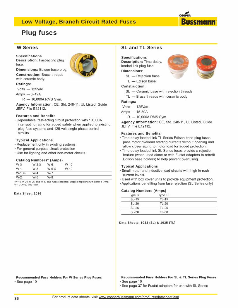
For product data sheets, visit www.cooperbussmann.com/products/datasheet.asp36
Low Voltage, Branch Circuit Rated Fuses
Plug fuses
Data Sheets: 1033 (SL) & 1035 (TL)
SpecificationsDescription: Fast-acting plugfuse.
Dimensions: Edison base plug.
Construction: Brass threadswith ceramic body.
Ratings:Volts — 125Vac
Amps — 1⁄2-12A
IR — 10,000A RMS Sym.
Agency Information: CE, Std. 248-11, UL Listed, GuideJEFV, File E12112.
Features and Benefits• Dependable, fast-acting circuit protection with 10,000A
interrupting rating for added safety when applied to existingplug fuse systems and 125-volt single-phase controlcircuits.
Typical Applications• Replacement only in existing systems.• For general purpose circuit protection• Use for lighting and other non-motor circuits
Catalog Numbers* (Amps)W-1⁄2 W-2 1⁄2 W-6 W-10
W-1 W-3 W-6 1⁄2 W-12
W-1 8⁄10 W-4 W-7
W-2 W-5 W-8
*W-15, W-20, W-25, and W-30 plug fuses obsoleted. Suggest replacing with either T-(Amp)or TL-(Amp) plug fuses.
SpecificationsDescription: Time-delay,loaded link plug fuse.
Dimensions:SL — Rejection base
TL — Edison base
Construction:SL — Ceramic base with rejection threads
TL — Brass threads with ceramic body
Ratings:Volts — 125Vac
Amps — 15-30A
IR — 10,000A RMS Sym.
Agency Information: CE, Std. 248-11, UL Listed, GuideJEFV, File E12112.
Features and Benefits• Time-delay loaded link TL Series Edison base plug fuses
pass motor overload starting currents without opening andallow closer sizing to motor load for added protection.
• Time-delay loaded link SL Series fuses provide a rejectionfeature (when used alone or with Fustat adapters to retrofitEdison base holders) to help prevent overfusing.
Typical Applications• Small motor and inductive load circuits with high in-rush
current levels.• Used with box cover units to provide equipment protection.• Applications benefiting from fuse rejection (SL Series only)
Catalog Numbers (Amps)Type SL Type TL
SL-15 TL-15
SL-20 TL-20
SL-25 TL-25
SL-30 TL-30
W Series SL and TL Series
Recommended Fuse Holders For W Series Plug Fuses• See page 10
Recommended Fuse Holders For SL & TL Series Plug Fuses• See page 10• See page 37 for Fustat adapters for use with SL Series
Data Sheet: 1036
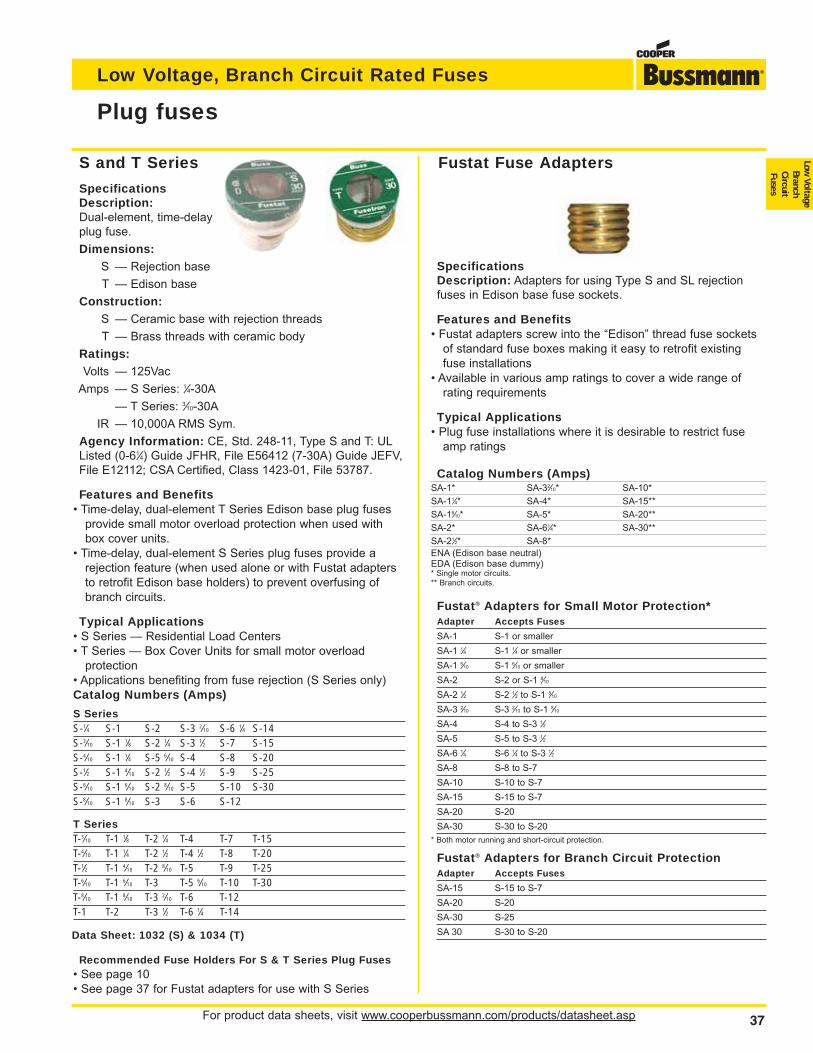
For product data sheets, visit www.cooperbussmann.com/products/datasheet.asp 37
Low Voltage, Branch Circuit Rated Fuses
Low Voltage
BranchCircuitFuses
S and T Series
SpecificationsDescription:Dual-element, time-delayplug fuse.
Dimensions:S — Rejection base
T — Edison base
Construction:S — Ceramic base with rejection threads
T — Brass threads with ceramic body
Ratings:Volts — 125Vac
Amps — S Series: 1⁄4-30A
— T Series: 3⁄10-30A
IR — 10,000A RMS Sym.
Agency Information: CE, Std. 248-11, Type S and T: ULListed (0-61⁄4) Guide JFHR, File E56412 (7-30A) Guide JEFV,File E12112; CSA Certified, Class 1423-01, File 53787.
Features and Benefits• Time-delay, dual-element T Series Edison base plug fuses
provide small motor overload protection when used withbox cover units.
• Time-delay, dual-element S Series plug fuses provide arejection feature (when used alone or with Fustat adaptersto retrofit Edison base holders) to prevent overfusing ofbranch circuits.
Typical Applications• S Series — Residential Load Centers• T Series — Box Cover Units for small motor overload
protection• Applications benefiting from fuse rejection (S Series only)Catalog Numbers (Amps)
S SeriesS-1⁄4 S-1 S-2 S-3 2⁄10 S-6 1⁄4 S-14S-3⁄10 S-1 1⁄8 S-2 1⁄4 S-3 1⁄2 S-7 S-15S-4⁄10 S-1 1⁄4 S-5 6⁄10 S-4 S-8 S-20S-1⁄2 S-1 4⁄10 S-2 1⁄2 S-4 1⁄2 S-9 S-25S-6⁄10 S-1 6⁄10 S-2 8⁄10 S-5 S-10 S-30S-8⁄10 S-1 8⁄10 S-3 S-6 S-12
T SeriesT-3⁄10 T-1 1⁄8 T-2 1⁄4 T-4 T-7 T-15T-4⁄10 T-1 1⁄4 T-2 1⁄2 T-4 1⁄2 T-8 T-20T-1⁄2 T-1 4⁄10 T-2 8⁄10 T-5 T-9 T-25T-6⁄10 T-1 6⁄10 T-3 T-5 6⁄10 T-10 T-30T-8⁄10 T-1 8⁄10 T-3 2⁄10 T-6 T-12T-1 T-2 T-3 1⁄2 T-6 1⁄4 T-14
Plug fuses
SpecificationsDescription: Adapters for using Type S and SL rejectionfuses in Edison base fuse sockets.
Features and Benefits• Fustat adapters screw into the “Edison” thread fuse sockets
of standard fuse boxes making it easy to retrofit existingfuse installations
• Available in various amp ratings to cover a wide range ofrating requirements
Typical Applications• Plug fuse installations where it is desirable to restrict fuse
amp ratings
Catalog Numbers (Amps)SA-1* SA-32⁄10* SA-10*
SA-11⁄4* SA-4* SA-15**
SA-16⁄10* SA-5* SA-20**
SA-2* SA-61⁄4* SA-30**
SA-21⁄2* SA-8*
ENA (Edison base neutral)EDA (Edison base dummy)* Single motor circuits.** Branch circuits.
Fustat® Adapters for Small Motor Protection*Adapter Accepts Fuses
SA-1 S-1 or smaller
SA-1 1⁄4 S-1 1⁄4 or smaller
SA-1 6⁄10 S-1 6⁄10 or smaller
SA-2 S-2 or S-1 8⁄10
SA-2 1⁄2 S-2 1⁄2 to S-1 8⁄10
SA-3 2⁄10 S-3 2⁄10 to S-1 8⁄10
SA-4 S-4 to S-3 1⁄2
SA-5 S-5 to S-3 1⁄2
SA-6 1⁄4 S-6 1⁄4 to S-3 1⁄2
SA-8 S-8 to S-7
SA-10 S-10 to S-7
SA-15 S-15 to S-7
SA-20 S-20
SA-30 S-30 to S-20
* Both motor running and short-circuit protection.
Fustat® Adapters for Branch Circuit ProtectionAdapter Accepts Fuses
SA-15 S-15 to S-7
SA-20 S-20
SA-30 S-25
SA 30 S-30 to S-20Data Sheet: 1032 (S) & 1034 (T)
Fustat Fuse Adapters
Recommended Fuse Holders For S & T Series Plug Fuses• See page 10• See page 37 for Fustat adapters for use with S Series
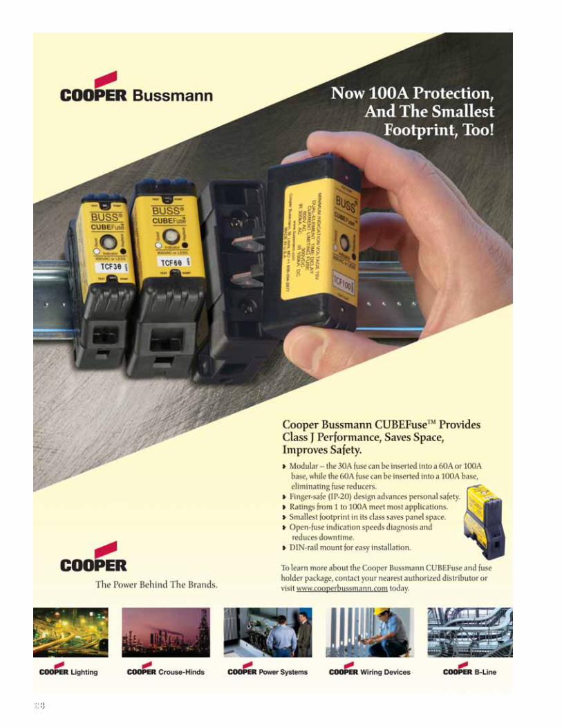
3838
39
Low Voltage
Supplementary
Fuses
Low VoltageSupplementary Fuses
Section ContentsPage
Fuse Holder & Block Selection Guide . . . . . 40-41
Cable limiters & welder limitersK Series cable limiters . . . . . . . . . 600V . . . . . . . . . . 42
64000 & 68000 welder limiters . . . 600V . . . . . . . . . . 42
13⁄32” x 11⁄2” fast acting supplementary fusesBAF . . . . . . . . . . . . . . . . . . . . . . 250V . . . . . . . . . . 43
BAN . . . . . . . . . . . . . . . . . . . . . . 250V . . . . . . . . . . 43
KTK . . . . . . . . . . . . . . . . . . . . . . 600V . . . . . . . . . . 43
KLM . . . . . . . . . . . . . . . . . . . . . . 500V . . . . . . . . . . 43
DCM . . . . . . . . . . . . . . . . . . 600Vac/dc . . . . . . . . . . 44
13⁄32” x 11⁄2” time-delay supplementary fusesFNM . . . . . . . . . . . . . . . . . . . . . . 250V . . . . . . . . . . 45
FNQ . . . . . . . . . . . . . . . . . . . . . . 500V . . . . . . . . . . 45
13⁄32” x 13⁄8” fast acting supplementary fusesBBS . . . . . . . . . . . . . . . . . . . . . . 600V . . . . . . . . . . 46
KTQ . . . . . . . . . . . . . . . . . . . . . . 600V . . . . . . . . . . 46
Pin indication fuses and actuatorGBA . . . . . . . . . . . . . . . . . . . . . . 125V . . . . . . . . . . 47
GLD . . . . . . . . . . . . . . . . . . . . . . 125V . . . . . . . . . . 47
MIC . . . . . . . . . . . . . . 250V fast acting . . . . . . . . . . . 47
MIN . . . . . . . . . . . . . . 250V fast acting . . . . . . . . . . . 47
FNA . . . . . . . . . . . . . . 250V time-delay . . . . . . . . . . 47
MIS . . . . . . . . . . . . . . . . . . . . . . . 600V . . . . . . . . . . 48
KAZ . . . . . . . . . . . . . . . . . . . . . . . 600V . . . . . . . . . . 48
LimitersANN . . . . . . . . . . . . . . 125V fast acting . . . . . . . . . 48
ANL . . . . . . . . . . . . . . 80Vdc time-delay . . . . . . . . . 48
Automotive blade-type fusesATC . . . . . . . . . . . . . . . . . . . . . . . 32Vdc . . . . . . . . . 49
ATM . . . . . . . . . . . . . . . . . . . . . . . 32Vdc . . . . . . . . 49
MAX . . . . . . . . . . . . . . . . . . . . . . 32Vdc . . . . . . . . 49
Automotive blade-type fuse holdersHHC, HHD, HHF, HHG for ATC fuses . . . . . . . . . . . . 50
HHL, HHM for ATM fuses . . . . . . . . . . . . . . . . . . . . . 50
HHX for MAX fuses . . . . . . . . . . . . . . . . . . . . . . . . . . 50
In-line size rejecting fuses and fuse holdersGLQ . . . . . . . . . . . . . . . . . . . . . . 300V . . . . . . . . . . 51
GMQ . . . . . . . . . . . . . . . . . . . . . . 300V . . . . . . . . . . 51
In-line non-rejecting fuses and fuse holdersGLR . . . . . . . . . . . . . . . . . . . . . . 300V . . . . . . . . . . 52
GMF . . . . . . . . . . . . . . . . . . . . . . 300V . . . . . . . . . . 52
GRF . . . . . . . . . . . . . . . . . . . . . . 300V . . . . . . . . . . 52
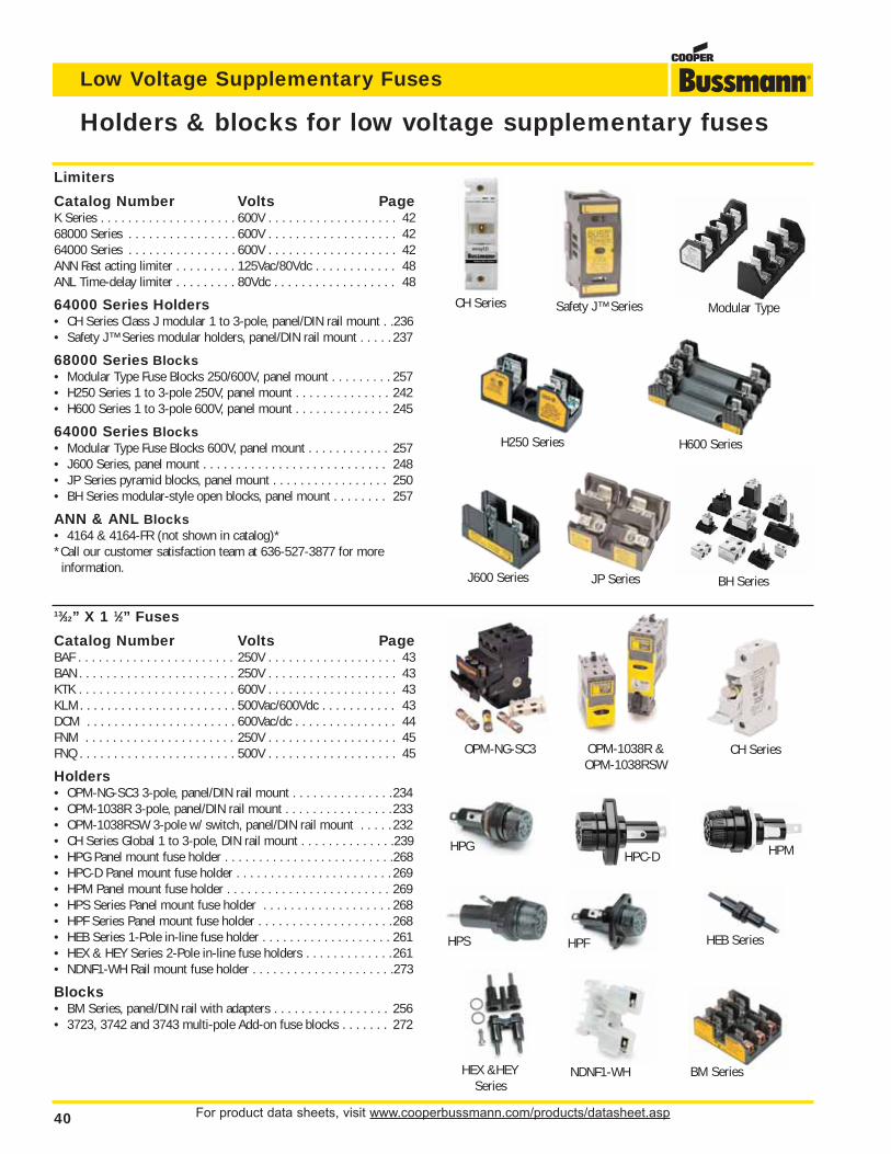
For product data sheets, visit www.cooperbussmann.com/products/datasheet.asp40
Low Voltage Supplementary Fuses
13⁄32” X 1 1⁄2” Fuses
Catalog Number Volts PageBAF . . . . . . . . . . . . . . . . . . . . . . . 250V . . . . . . . . . . . . . . . . . . . 43BAN . . . . . . . . . . . . . . . . . . . . . . . 250V . . . . . . . . . . . . . . . . . . . 43KTK . . . . . . . . . . . . . . . . . . . . . . . 600V . . . . . . . . . . . . . . . . . . . 43KLM . . . . . . . . . . . . . . . . . . . . . . . 500Vac/600Vdc . . . . . . . . . . . 43DCM . . . . . . . . . . . . . . . . . . . . . . 600Vac/dc . . . . . . . . . . . . . . . 44FNM . . . . . . . . . . . . . . . . . . . . . . 250V . . . . . . . . . . . . . . . . . . . 45FNQ . . . . . . . . . . . . . . . . . . . . . . . 500V . . . . . . . . . . . . . . . . . . . 45
Holders• OPM-NG-SC3 3-pole, panel/DIN rail mount . . . . . . . . . . . . . . .234• OPM-1038R 3-pole, panel/DIN rail mount . . . . . . . . . . . . . . . .233• OPM-1038RSW 3-pole w/ switch, panel/DIN rail mount . . . . . 232• CH Series Global 1 to 3-pole, DIN rail mount . . . . . . . . . . . . . .239• HPG Panel mount fuse holder . . . . . . . . . . . . . . . . . . . . . . . . .268• HPC-D Panel mount fuse holder . . . . . . . . . . . . . . . . . . . . . . . 269• HPM Panel mount fuse holder . . . . . . . . . . . . . . . . . . . . . . . . 269• HPS Series Panel mount fuse holder . . . . . . . . . . . . . . . . . . . 268• HPF Series Panel mount fuse holder . . . . . . . . . . . . . . . . . . . .268• HEB Series 1-Pole in-line fuse holder . . . . . . . . . . . . . . . . . . . 261• HEX & HEY Series 2-Pole in-line fuse holders . . . . . . . . . . . . .261• NDNF1-WH Rail mount fuse holder . . . . . . . . . . . . . . . . . . . . .273
Blocks• BM Series, panel/DIN rail with adapters . . . . . . . . . . . . . . . . . 256• 3723, 3742 and 3743 multi-pole Add-on fuse blocks . . . . . . . 272
OPM-NG-SC3 CH Series
CH Series
J600 Series JP Series BH Series
Safety J™ Series Modular Type
H250 Series H600 Series
OPM-1038R & OPM-1038RSW
Holders & blocks for low voltage supplementary fuses
Limiters
Catalog Number Volts PageK Series . . . . . . . . . . . . . . . . . . . . 600V . . . . . . . . . . . . . . . . . . . 4268000 Series . . . . . . . . . . . . . . . . 600V . . . . . . . . . . . . . . . . . . . 4264000 Series . . . . . . . . . . . . . . . . 600V . . . . . . . . . . . . . . . . . . . 42ANN Fast acting limiter . . . . . . . . . 125Vac/80Vdc . . . . . . . . . . . . 48ANL Time-delay limiter . . . . . . . . . 80Vdc . . . . . . . . . . . . . . . . . . 48
64000 Series Holders• CH Series Class J modular 1 to 3-pole, panel/DIN rail mount . .236• Safety J™ Series modular holders, panel/DIN rail mount . . . . . 237
68000 Series Blocks• Modular Type Fuse Blocks 250/600V, panel mount . . . . . . . . . 257• H250 Series 1 to 3-pole 250V, panel mount . . . . . . . . . . . . . . 242• H600 Series 1 to 3-pole 600V, panel mount . . . . . . . . . . . . . . 245
64000 Series Blocks• Modular Type Fuse Blocks 600V, panel mount . . . . . . . . . . . . 257• J600 Series, panel mount . . . . . . . . . . . . . . . . . . . . . . . . . . . 248• JP Series pyramid blocks, panel mount . . . . . . . . . . . . . . . . . 250• BH Series modular-style open blocks, panel mount . . . . . . . . 257
ANN & ANL Blocks• 4164 & 4164-FR (not shown in catalog)**Call our customer satisfaction team at 636-527-3877 for more
information.
HPGHPC-D HPM
HPS HPF HEB Series
HEX &HEYSeries
NDNF1-WH BM Series
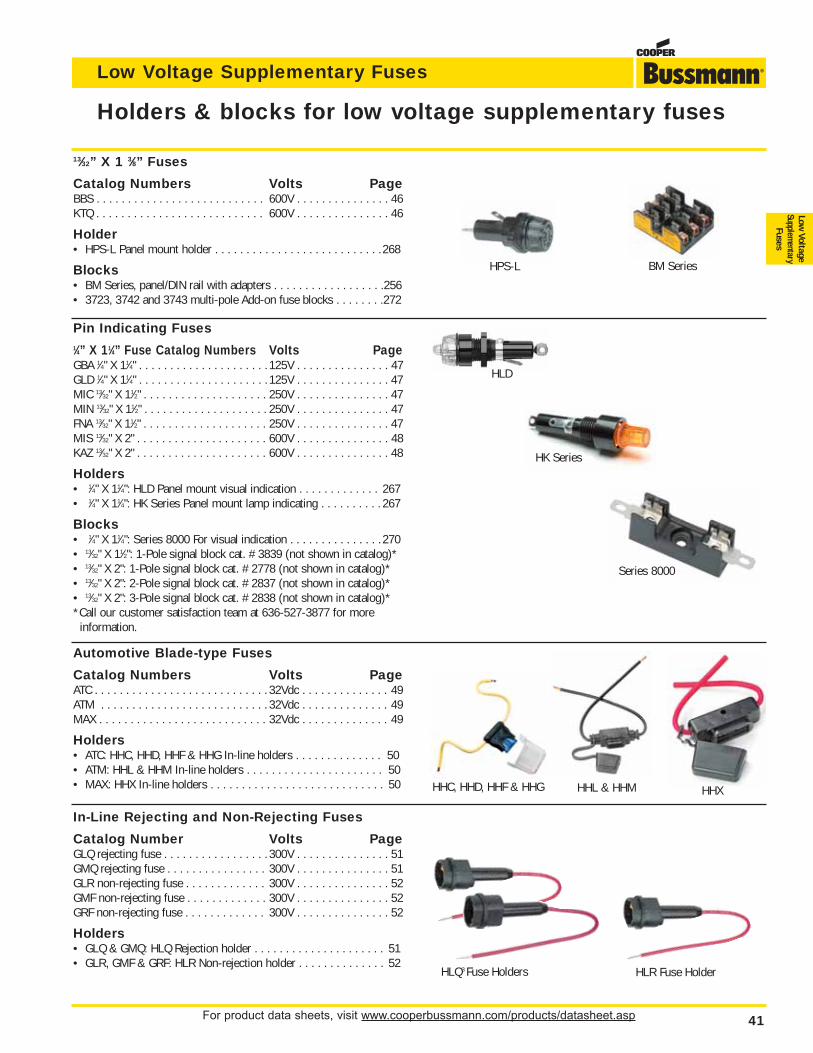
For product data sheets, visit www.cooperbussmann.com/products/datasheet.asp 41
Low Voltage Supplementary Fuses
Low Voltage
Supplementary
Fuses
Holders & blocks for low voltage supplementary fuses
In-Line Rejecting and Non-Rejecting Fuses
Catalog Number Volts PageGLQ rejecting fuse . . . . . . . . . . . . . . . . . 300V . . . . . . . . . . . . . . . 51GMQ rejecting fuse . . . . . . . . . . . . . . . . 300V . . . . . . . . . . . . . . . 51GLR non-rejecting fuse . . . . . . . . . . . . . 300V . . . . . . . . . . . . . . . 52GMF non-rejecting fuse . . . . . . . . . . . . . 300V . . . . . . . . . . . . . . . 52GRF non-rejecting fuse . . . . . . . . . . . . . 300V . . . . . . . . . . . . . . . 52
Holders• GLQ & GMQ: HLQ Rejection holder . . . . . . . . . . . . . . . . . . . . . 51• GLR, GMF & GRF: HLR Non-rejection holder . . . . . . . . . . . . . . 52
13⁄32” X 1 3⁄8” Fuses
Catalog Numbers Volts PageBBS . . . . . . . . . . . . . . . . . . . . . . . . . . . 600V . . . . . . . . . . . . . . . 46KTQ . . . . . . . . . . . . . . . . . . . . . . . . . . . 600V . . . . . . . . . . . . . . . 46
Holder• HPS-L Panel mount holder . . . . . . . . . . . . . . . . . . . . . . . . . . .268
Blocks• BM Series, panel/DIN rail with adapters . . . . . . . . . . . . . . . . . .256• 3723, 3742 and 3743 multi-pole Add-on fuse blocks . . . . . . . .272
Automotive Blade-type Fuses
Catalog Numbers Volts PageATC . . . . . . . . . . . . . . . . . . . . . . . . . . . . 32Vdc . . . . . . . . . . . . . . 49ATM . . . . . . . . . . . . . . . . . . . . . . . . . . . 32Vdc . . . . . . . . . . . . . . 49MAX . . . . . . . . . . . . . . . . . . . . . . . . . . . 32Vdc . . . . . . . . . . . . . . 49
Holders• ATC: HHC, HHD, HHF & HHG In-line holders . . . . . . . . . . . . . . 50• ATM: HHL & HHM In-line holders . . . . . . . . . . . . . . . . . . . . . . 50• MAX: HHX In-line holders . . . . . . . . . . . . . . . . . . . . . . . . . . . . 50
Pin Indicating Fuses1⁄4” X 11⁄4” Fuse Catalog Numbers Volts PageGBA 1⁄4" X 11⁄4" . . . . . . . . . . . . . . . . . . . . . 125V . . . . . . . . . . . . . . . 47GLD 1⁄4" X 11⁄4" . . . . . . . . . . . . . . . . . . . . . 125V . . . . . . . . . . . . . . . 47MIC 13⁄32" X 11⁄2" . . . . . . . . . . . . . . . . . . . . 250V . . . . . . . . . . . . . . . 47MIN 13⁄32" X 11⁄2" . . . . . . . . . . . . . . . . . . . . 250V . . . . . . . . . . . . . . . 47FNA 13⁄32" X 11⁄2" . . . . . . . . . . . . . . . . . . . . 250V . . . . . . . . . . . . . . . 47MIS 13⁄32" X 2" . . . . . . . . . . . . . . . . . . . . . 600V . . . . . . . . . . . . . . . 48KAZ 13⁄32" X 2" . . . . . . . . . . . . . . . . . . . . . 600V . . . . . . . . . . . . . . . 48
Holders• 1⁄4" X 11⁄4": HLD Panel mount visual indication . . . . . . . . . . . . . 267• 1⁄4" X 11⁄4": HK Series Panel mount lamp indicating . . . . . . . . . . 267
Blocks• 1⁄4" X 11⁄4": Series 8000 For visual indication . . . . . . . . . . . . . . . 270• 13⁄32" X 11⁄2": 1-Pole signal block cat. # 3839 (not shown in catalog)*• 13⁄32" X 2": 1-Pole signal block cat. # 2778 (not shown in catalog)*• 13⁄32" X 2": 2-Pole signal block cat. # 2837 (not shown in catalog)*• 13⁄32" X 2": 3-Pole signal block cat. # 2838 (not shown in catalog)**Call our customer satisfaction team at 636-527-3877 for more
information.
HPS-L BM Series
HLD
HK Series
Series 8000
HHC, HHD, HHF & HHG HHXHHL & HHM
HLQ3 Fuse Holders HLR Fuse Holder
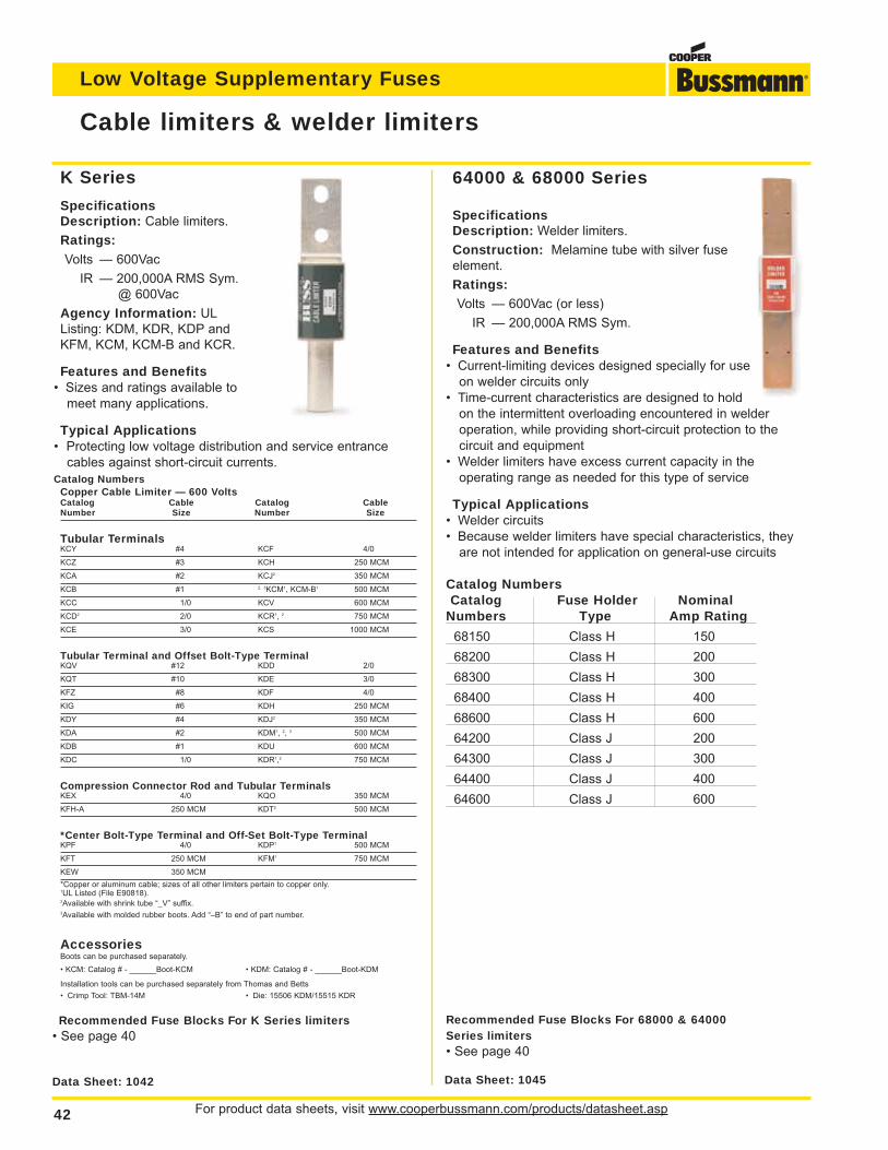
For product data sheets, visit www.cooperbussmann.com/products/datasheet.asp42
Low Voltage Supplementary Fuses
K Series
SpecificationsDescription: Cable limiters.
Ratings:
Volts — 600Vac
IR — 200,000A RMS Sym.
@ 600Vac
Agency Information: UL
Listing: KDM, KDR, KDP and
KFM, KCM, KCM-B and KCR.
Features and Benefits• Sizes and ratings available to
meet many applications.
Typical Applications• Protecting low voltage distribution and service entrance
cables against short-circuit currents.
Catalog NumbersCopper Cable Limiter — 600 VoltsCatalog Cable Catalog CableNumber Size Number Size
Tubular TerminalsKCY #4 KCF 4/0
KCZ #3 KCH 250 MCM
KCA #2 KCJ2 350 MCM
KCB #1 2, 3KCM1, KCM-B1 500 MCM
KCC 1/0 KCV 600 MCM
KCD2 2/0 KCR1, 2 750 MCM
KCE 3/0 KCS 1000 MCM
Tubular Terminal and Offset Bolt-Type TerminalKQV #12 KDD 2/0
KQT #10 KDE 3/0
KFZ #8 KDF 4/0
KIG #6 KDH 250 MCM
KDY #4 KDJ2 350 MCM
KDA #2 KDM1, 2, 3 500 MCM
KDB #1 KDU 600 MCM
KDC 1/0 KDR1,2 750 MCM
Compression Connector Rod and Tubular TerminalsKEX 4/0 KQO 350 MCM
KFH-A 250 MCM KDT2 500 MCM
*Center Bolt-Type Terminal and Off-Set Bolt-Type TerminalKPF 4/0 KDP1 500 MCM
KFT 250 MCM KFM1 750 MCM
KEW 350 MCM
*Copper or aluminum cable; sizes of all other limiters pertain to copper only.1UL Listed (File E90818).2Available with shrink tube “_V” suffix.3Available with molded rubber boots. Add “–B” to end of part number.
AccessoriesBoots can be purchased separately.
• KCM: Catalog # - ______Boot-KCM • KDM: Catalog # - ______Boot-KDM
Installation tools can be purchased separately from Thomas and Betts
• Crimp Tool: TBM-14M • Die: 15506 KDM/15515 KDR
SpecificationsDescription: Welder limiters.
Construction: Melamine tube with silver fuse
element.
Ratings:Volts — 600Vac (or less)
IR — 200,000A RMS Sym.
Features and Benefits• Current-limiting devices designed specially for use
on welder circuits only
• Time-current characteristics are designed to hold
on the intermittent overloading encountered in welder
operation, while providing short-circuit protection to the
circuit and equipment
• Welder limiters have excess current capacity in the
operating range as needed for this type of service
Typical Applications• Welder circuits
• Because welder limiters have special characteristics, they
are not intended for application on general-use circuits
Catalog NumbersCatalog Fuse Holder Nominal
Numbers Type Amp Rating
68150 Class H 150
68200 Class H 200
68300 Class H 300
68400 Class H 400
68600 Class H 600
64200 Class J 200
64300 Class J 300
64400 Class J 400
64600 Class J 600
Cable limiters & welder limiters
Data Sheet: 1042 Data Sheet: 1045
64000 & 68000 Series
Recommended Fuse Blocks For K Series limiters• See page 40
Recommended Fuse Blocks For 68000 & 64000Series limiters• See page 40
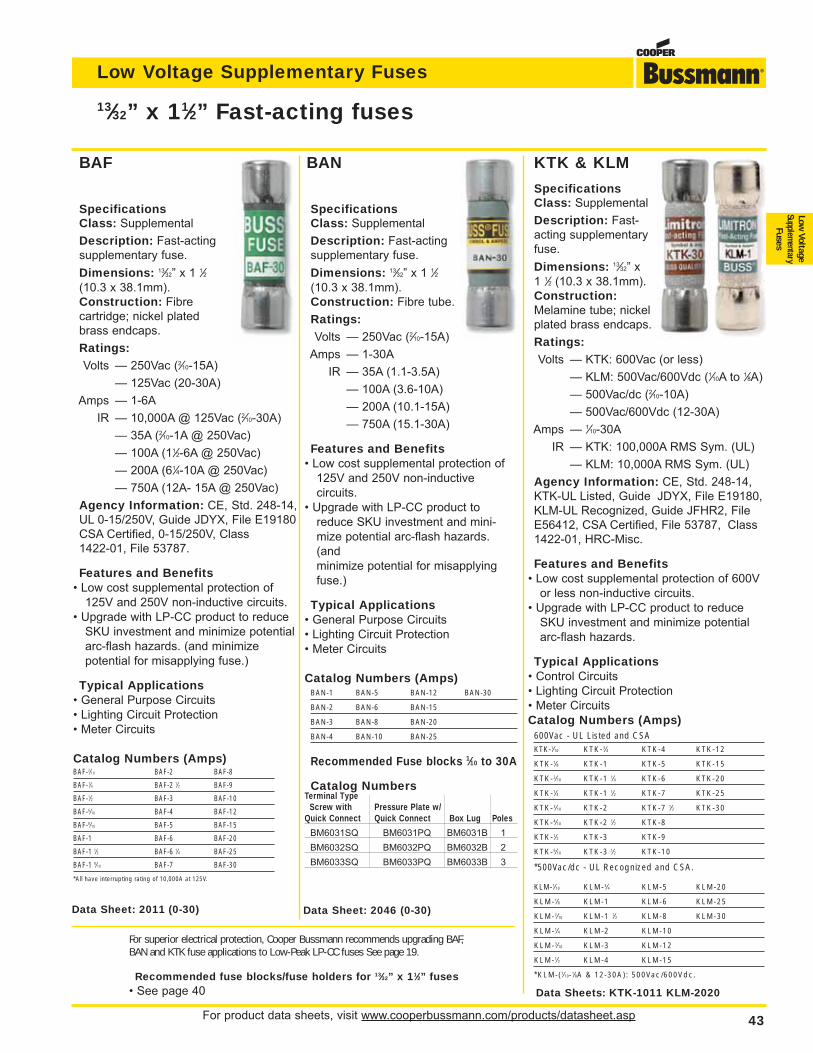
For product data sheets, visit www.cooperbussmann.com/products/datasheet.asp 43
Low Voltage Supplementary Fuses
Low Voltage
Supplementary
Fuses
For superior electrical protection, Cooper Bussmann recommends upgrading BAF,BAN and KTK fuse applications to Low-Peak LP-CC fuses See page 19.
Recommended fuse blocks/fuse holders for 13⁄32” x 11⁄2” fuses• See page 40 Data Sheets: KTK-1011 KLM-2020
Data Sheet: 2046 (0-30) Data Sheet: 2011 (0-30)
SpecificationsClass: Supplemental
Description: Fast-acting
supplementary fuse.
Dimensions: 13⁄32” x 1 1⁄2
(10.3 x 38.1mm).
Construction: Fibre
cartridge; nickel plated
brass endcaps.
Ratings:Volts — 250Vac (2⁄10-15A)
— 125Vac (20-30A)
Amps — 1-6A
IR — 10,000A @ 125Vac (2⁄10-30A)
— 35A (2⁄10-1A @ 250Vac)
— 100A (11⁄2-6A @ 250Vac)
— 200A (61⁄4-10A @ 250Vac)
— 750A (12A- 15A @ 250Vac)
Agency Information: CE, Std. 248-14,
UL 0-15/250V, Guide JDYX, File E19180
CSA Certified, 0-15/250V, Class
1422-01, File 53787.
Features and Benefits• Low cost supplemental protection of
125V and 250V non-inductive circuits.
• Upgrade with LP-CC product to reduce
SKU investment and minimize potential
arc-flash hazards. (and minimize
potential for misapplying fuse.)
Typical Applications• General Purpose Circuits
• Lighting Circuit Protection
• Meter Circuits
Catalog Numbers (Amps)BAF-2⁄10 BAF-2 BAF-8
BAF-1⁄4 BAF-2 1⁄2 BAF-9
BAF-1⁄2 BAF-3 BAF-10
BAF-6⁄10 BAF-4 BAF-12
BAF-8⁄10 BAF-5 BAF-15
BAF-1 BAF-6 BAF-20
BAF-1 1⁄2 BAF-6 1⁄4 BAF-25
BAF-1 8⁄10 BAF-7 BAF-30
*All have interrupting rating of 10,000A at 125V.
SpecificationsClass: Supplemental
Description: Fast-acting
supplementary fuse.
Dimensions: 13⁄32” x 1 1⁄2
(10.3 x 38.1mm).
Construction: Fibre tube.
Ratings:Volts — 250Vac (2⁄10-15A)
Amps — 1-30A
IR — 35A (1.1-3.5A)
— 100A (3.6-10A)
— 200A (10.1-15A)
— 750A (15.1-30A)
Features and Benefits• Low cost supplemental protection of
125V and 250V non-inductive
circuits.
• Upgrade with LP-CC product to
reduce SKU investment and mini-
mize potential arc-flash hazards.
(and
minimize potential for misapplying
fuse.)
Typical Applications• General Purpose Circuits
• Lighting Circuit Protection
• Meter Circuits
Catalog Numbers (Amps)BAN-1 BAN-5 BAN-12 BAN-30
BAN-2 BAN-6 BAN-15
BAN-3 BAN-8 BAN-20
BAN-4 BAN-10 BAN-25
Recommended Fuse blocks 1⁄10 to 30A
Catalog NumbersTerminal Type
Screw with Pressure Plate w/Quick Connect Quick Connect Box Lug Poles
BM6031SQ BM6031PQ BM6031B 1
BM6032SQ BM6032PQ BM6032B 2
BM6033SQ BM6033PQ BM6033B 3
KTK & KLM
SpecificationsClass: Supplemental
Description: Fast-
acting supplementary
fuse.
Dimensions: 13⁄32” x
1 1⁄2 (10.3 x 38.1mm).
Construction:Melamine tube; nickel
plated brass endcaps.
Ratings:Volts — KTK: 600Vac (or less)
— KLM: 500Vac/600Vdc (1⁄10A to 1⁄8A)
— 500Vac/dc (2⁄10-10A)
— 500Vac/600Vdc (12-30A)
Amps — 1⁄10-30A
IR — KTK: 100,000A RMS Sym. (UL)
— KLM: 10,000A RMS Sym. (UL)
Agency Information: CE, Std. 248-14,
KTK-UL Listed, Guide JDYX, File E19180,
KLM-UL Recognized, Guide JFHR2, File
E56412, CSA Certified, File 53787, Class
1422-01, HRC-Misc.
Features and Benefits• Low cost supplemental protection of 600V
or less non-inductive circuits.
• Upgrade with LP-CC product to reduce
SKU investment and minimize potential
arc-flash hazards.
Typical Applications• Control Circuits
• Lighting Circuit Protection
• Meter Circuits
Catalog Numbers (Amps)600Vac - UL Listed and CSAKTK-1⁄10 KTK-3⁄4 KTK-4 KTK-12
KTK-1⁄8 KTK-1 KTK-5 KTK-15
KTK-2⁄10 KTK-1 1⁄4 KTK-6 KTK-20
KTK-1⁄4 KTK-1 1⁄2 KTK-7 KTK-25
KTK-3⁄10 KTK-2 KTK-7 1⁄2 KTK-30
KTK-4⁄10 KTK-2 1⁄2 KTK-8
KTK-1⁄2 KTK-3 KTK-9
KTK-6⁄10 KTK-3 1⁄2 KTK-10
*500Vac/dc - UL Recognized and CSA.
KLM-1⁄10 KLM-3⁄4 KLM-5 KLM-20
KLM-1⁄8 KLM-1 KLM-6 KLM-25
KLM-2⁄10 KLM-1 1⁄2 KLM-8 KLM-30
KLM-1⁄4 KLM-2 KLM-10
KLM-3⁄10 KLM-3 KLM-12
KLM-1⁄2 KLM-4 KLM-15
*KLM-(1⁄10-1⁄8A & 12-30A): 500Vac/600Vdc.
13⁄32” x 11⁄2” Fast-acting fuses
BAF BAN
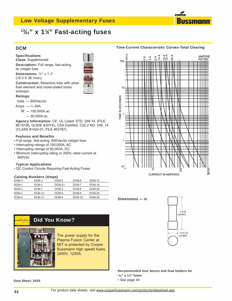
For product data sheets, visit www.cooperbussmann.com/products/datasheet.asp44
Low Voltage Supplementary Fuses
13⁄32” x 11⁄2” Fast-acting fuses
Data Sheet: 2020
1.59(±0.031)
0.419(±0.004)
Dimensions — in
1 10
100
CURRENT IN AMPERES
100
10
1
.1
.01
TIM
E IN
SE
CO
ND
S
AMPERERATING3/
4 A
15 A
10 A
20 A
30 A
8 A
5 A
3 A
1,00
0
Time-Current Characteristic Curves–Total ClearingDCM
SpecificationsClass: Supplemental
Description: Full range, fast-acting,
dc midget fuse.
Dimensions: 13⁄32” x 1 1⁄2”
(10.3 X 38.1mm).
Construction: Melamine tube with silver
fuse element and nickel-plated brass
endcaps.
Ratings:Volts — 600Vac/dc
Amps — 1⁄10-30A
IR — 100,000A ac
— 50,000A dc
Agency Information: CE, UL Listed: STD. 248-14, (FILE
#E19180, GUIDE #JDYX), CSA Certified, C22.2 NO. 248. 14
(CLASS #1422-01, FILE #53787).
Features and Benefits• Full range, fast-acting, 600Vac/dc midget fuse.
• Interrupting ratings of 100,000A, AC.
• Interrupting ratings of 50,000A, DC.
• Minimum interrupting rating or 200% rated current at
600Vdc.
Typical Applications• DC Control Circuits Requiring Fast-Acting Fuses.
Catalog Numbers (Amps)DCM-1⁄10 DCM-1⁄2 DCM-2 DCM-6 DCM-12
DCM-1⁄8 DCM-3⁄4 DCM-21⁄2 DCM-7 DCM-15
DCM-2⁄10 DCM-1 DCM-3 DCM-8 DCM-20
DCM-1⁄4 DCM-11⁄4 DCM-4 DCM-9 DCM-25
DCM-3⁄10 DCM-11⁄2 DCM-5 DCM-10 DCM-30
Recommended fuse blocks and fuse holders for 13⁄32” x 11⁄2” fuses
• See page 40
The power supply for the
Plasma Fusion Center at
MIT is protected by Cooper
Bussmann high speed fuses,
2500V, 1200A.
Did You Know?
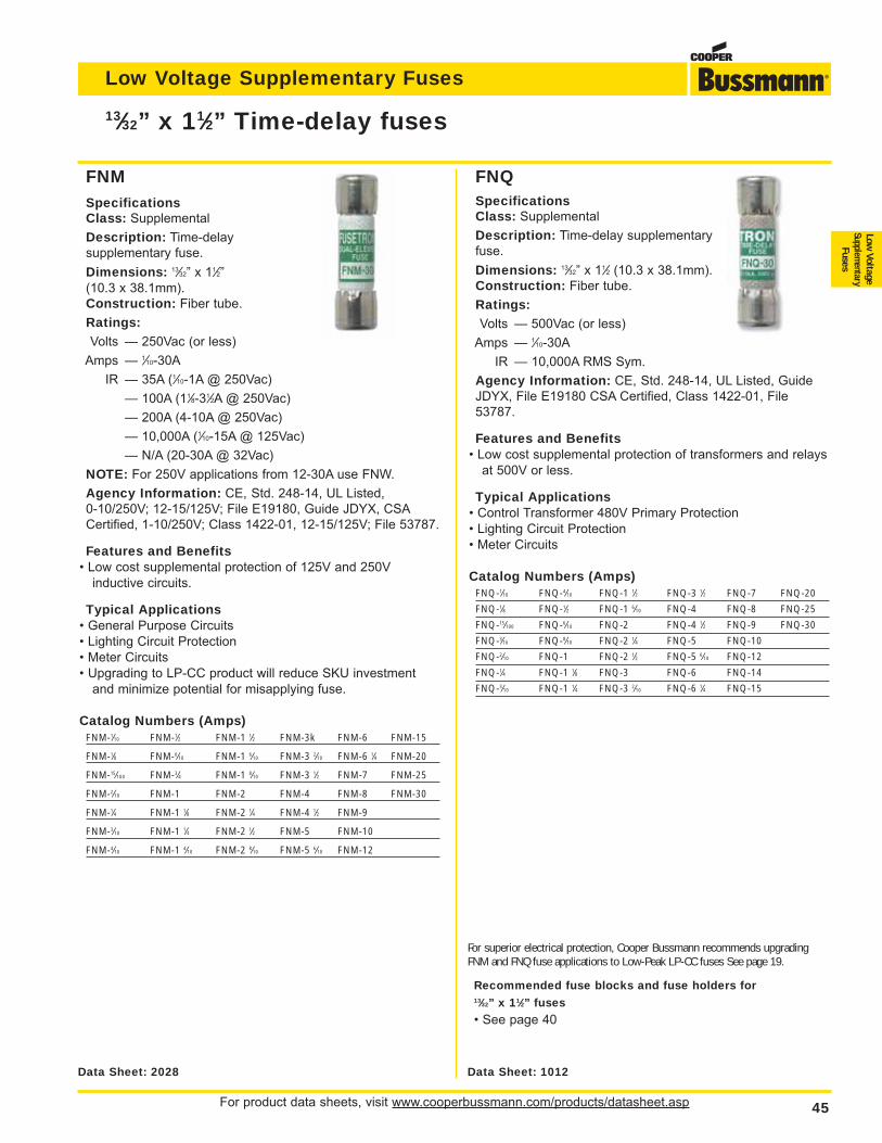
For product data sheets, visit www.cooperbussmann.com/products/datasheet.asp 45
Low Voltage Supplementary Fuses
Low Voltage
Supplementary
Fuses
SpecificationsClass: Supplemental
Description: Time-delay
supplementary fuse.
Dimensions: 13⁄32” x 11⁄2”
(10.3 x 38.1mm).
Construction: Fiber tube.
Ratings:Volts — 250Vac (or less)
Amps — 1⁄10-30A
IR — 35A (1⁄10-1A @ 250Vac)
— 100A (11⁄8-31⁄2A @ 250Vac)
— 200A (4-10A @ 250Vac)
— 10,000A (1⁄10-15A @ 125Vac)
— N/A (20-30A @ 32Vac)
NOTE: For 250V applications from 12-30A use FNW.
Agency Information: CE, Std. 248-14, UL Listed,
0-10/250V; 12-15/125V; File E19180, Guide JDYX, CSA
Certified, 1-10/250V; Class 1422-01, 12-15/125V; File 53787.
Features and Benefits• Low cost supplemental protection of 125V and 250V
inductive circuits.
Typical Applications• General Purpose Circuits
• Lighting Circuit Protection
• Meter Circuits
• Upgrading to LP-CC product will reduce SKU investment
and minimize potential for misapplying fuse.
Catalog Numbers (Amps)FNM-1⁄10 FNM-1⁄2 FNM-1 1⁄2 FNM-3k FNM-6 FNM-15
FNM-1⁄8 FNM-6⁄10 FNM-1 6⁄10 FNM-3 2⁄10 FNM-6 1⁄4 FNM-20
FNM-15⁄100 FNM-3⁄4 FNM-1 8⁄10 FNM-3 1⁄2 FNM-7 FNM-25
FNM-2⁄10 FNM-1 FNM-2 FNM-4 FNM-8 FNM-30
FNM-1⁄4 FNM-1 1⁄8 FNM-2 1⁄4 FNM-4 1⁄2 FNM-9
FNM-3⁄10 FNM-1 1⁄4 FNM-2 1⁄2 FNM-5 FNM-10
FNM-4⁄10 FNM-1 4⁄10 FNM-2 8⁄10 FNM-5 6⁄10 FNM-12
SpecificationsClass: Supplemental
Description: Time-delay supplementary
fuse.
Dimensions: 13⁄32” x 11⁄2 (10.3 x 38.1mm).
Construction: Fiber tube.
Ratings:Volts — 500Vac (or less)
Amps — 1⁄10-30A
IR — 10,000A RMS Sym.
Agency Information: CE, Std. 248-14, UL Listed, Guide
JDYX, File E19180 CSA Certified, Class 1422-01, File
53787.
Features and Benefits• Low cost supplemental protection of transformers and relays
at 500V or less.
Typical Applications• Control Transformer 480V Primary Protection
• Lighting Circuit Protection
• Meter Circuits
Catalog Numbers (Amps)FNQ-1⁄10 FNQ-4⁄10 FNQ-1 1⁄2 FNQ-3 1⁄2 FNQ-7 FNQ-20
FNQ-1⁄8 FNQ-1⁄2 FNQ-1 6⁄10 FNQ-4 FNQ-8 FNQ-25
FNQ-15⁄100 FNQ-6⁄10 FNQ-2 FNQ-4 1⁄2 FNQ-9 FNQ-30
FNQ-3⁄16 FNQ-8⁄10 FNQ-2 1⁄4 FNQ-5 FNQ-10
FNQ-2⁄10 FNQ-1 FNQ-2 1⁄2 FNQ-5 6⁄10 FNQ-12
FNQ-1⁄4 FNQ-1 1⁄8 FNQ-3 FNQ-6 FNQ-14
FNQ-3⁄10 FNQ-1 1⁄4 FNQ-3 2⁄10 FNQ-6 1⁄4 FNQ-15
13⁄32” x 11⁄2” Time-delay fuses
Data Sheet: 2028 Data Sheet: 1012
For superior electrical protection, Cooper Bussmann recommends upgradingFNM and FNQ fuse applications to Low-Peak LP-CC fuses See page 19.
Recommended fuse blocks and fuse holders for 13⁄32” x 11⁄2” fuses
• See page 40
FNM FNQ
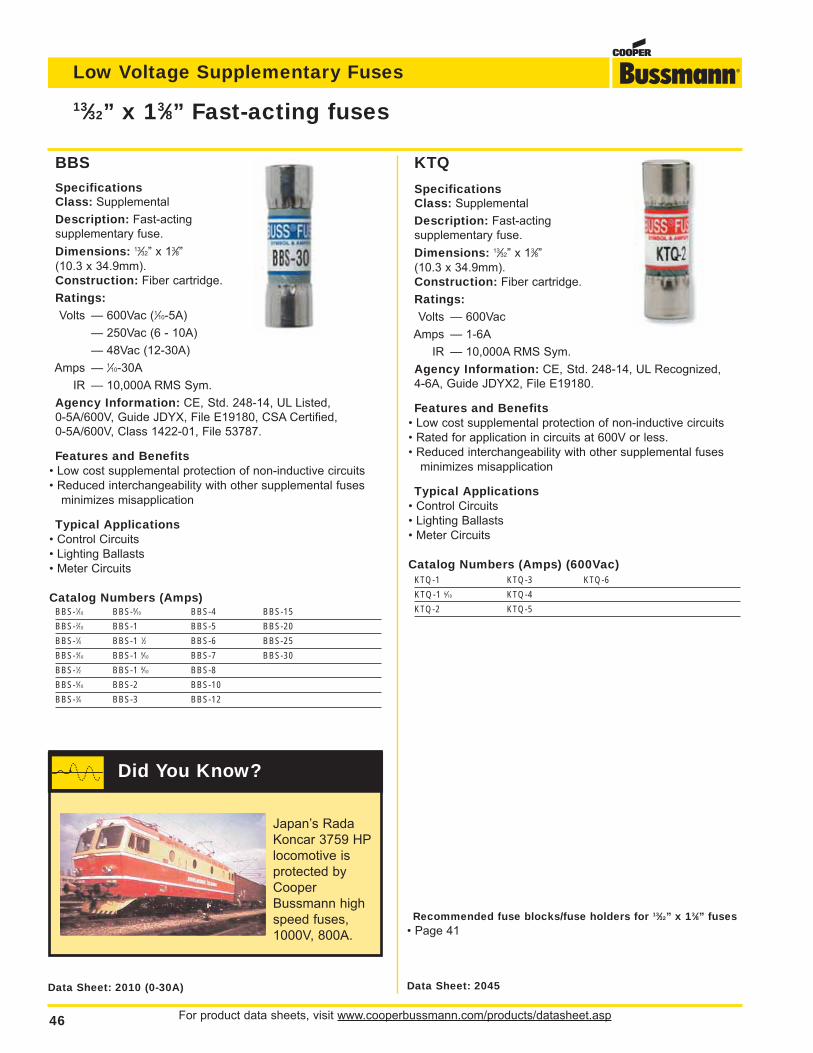
For product data sheets, visit www.cooperbussmann.com/products/datasheet.asp46
Low Voltage Supplementary Fuses
SpecificationsClass: Supplemental
Description: Fast-acting
supplementary fuse.
Dimensions: 13⁄32” x 13⁄8”
(10.3 x 34.9mm).
Construction: Fiber cartridge.
Ratings:Volts — 600Vac
Amps — 1-6A
IR — 10,000A RMS Sym.
Agency Information: CE, Std. 248-14, UL Recognized,
4-6A, Guide JDYX2, File E19180.
Features and Benefits• Low cost supplemental protection of non-inductive circuits
• Rated for application in circuits at 600V or less.
• Reduced interchangeability with other supplemental fuses
minimizes misapplication
Typical Applications• Control Circuits
• Lighting Ballasts
• Meter Circuits
Catalog Numbers (Amps) (600Vac)KTQ-1 KTQ-3 KTQ-6
KTQ-1 6⁄10 KTQ-4
KTQ-2 KTQ-5
SpecificationsClass: Supplemental
Description: Fast-acting
supplementary fuse.
Dimensions: 13⁄32” x 13⁄8”
(10.3 x 34.9mm).
Construction: Fiber cartridge.
Ratings:Volts — 600Vac (1⁄10-5A)
— 250Vac (6 - 10A)
— 48Vac (12-30A)
Amps — 1⁄10-30A
IR — 10,000A RMS Sym.
Agency Information: CE, Std. 248-14, UL Listed,
0-5A/600V, Guide JDYX, File E19180, CSA Certified,
0-5A/600V, Class 1422-01, File 53787.
Features and Benefits• Low cost supplemental protection of non-inductive circuits
• Reduced interchangeability with other supplemental fuses
minimizes misapplication
Typical Applications• Control Circuits
• Lighting Ballasts
• Meter Circuits
Catalog Numbers (Amps)BBS-1⁄10 BBS-8⁄10 BBS-4 BBS-15
BBS-2⁄10 BBS-1 BBS-5 BBS-20
BBS-1⁄4 BBS-1 1⁄2 BBS-6 BBS-25
BBS-4⁄10 BBS-1 6⁄10 BBS-7 BBS-30
BBS-1⁄2 BBS-1 8⁄10 BBS-8
BBS-6⁄10 BBS-2 BBS-10
BBS-3⁄4 BBS-3 BBS-12
13⁄32” x 13⁄8” Fast-acting fuses
Data Sheet: 2010 (0-30A) Data Sheet: 2045
Recommended fuse blocks/fuse holders for 13⁄32” x 13⁄8” fuses• Page 41
BBS KTQ
Japan’s Rada
Koncar 3759 HP
locomotive is
protected by
Cooper
Bussmann high
speed fuses,
1000V, 800A.
Did You Know?
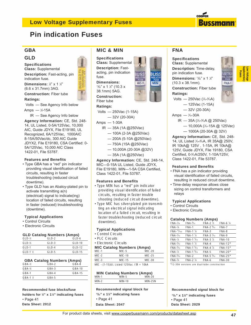
For product data sheets, visit www.cooperbussmann.com/products/datasheet.asp 47
Low Voltage Supplementary Fuses
Low Voltage
Supplementary
Fuses
SpecificationsClass: Supplemental
Description: Time-delay,
pin indication fuse.
Dimensions: 13⁄32” x 1 1⁄2”
(10.3 x 38.1mm).
Construction: Fiber tube
Ratings:Volts — 250Vac (1⁄10-8⁄10A)
— 125Vac (1-15A)
— 32V (20-30A)
Amps — 1⁄10-30A
IR — 35A (1⁄10-8⁄10A @ 250Vac)
— 10,000A (1⁄10-15A @ 125Vac)
— 1000A (20-30A @ 32V)
Agency Information: CE, Std. 248-
14, UL Listed 1⁄10-8⁄10A, IR 35A@ 250V,
IR 10kA@ 125V , 1-15A, IR 10kA@
125V, Guide JDYX, File 19180, CSA
Certified, 0-8⁄10A/250V, 1-10A/125V,
Class 1422-01, File 53787.
Features and Benefits• FNA has a pin indicator providing
visual identification of failed circuits,
resulting in reduced circuit downtime.
• Time-delay response allows close
sizing on control transformers and
relays
Typical Applications• Control Circuits
• Electronic Circuits
Catalog Numbers (Amps)FNA-1⁄10 FNA-8⁄10 FNA-2 1⁄2 FNA-6 1⁄4FNA-1⁄8 FNA-1 FNA-2 8⁄10 FNA-7FNA-15⁄100 FNA-1 1⁄8 FNA-3 FNA-8FNA-2⁄10 FNA-1 1⁄4 FNA-3 2⁄10 FNA-9FNA-1⁄4 FNA-1 4⁄10 FNA-3 1⁄2 FNA-10FNA-3⁄10 FNA-1 1⁄2 FNA-4 FNA-12*FNA-4⁄10 FNA-1 6⁄10 FNA-4 1⁄2 FNA-15*FNA-1⁄2 FNA-1 8⁄10 FNA-5 FNA-20*FNA-6⁄10 FNA-2 FNA-5 6⁄10 FNA-25*FNA-3⁄4 FNA-2 1⁄4 FNA-6 FNA-30*12-30A versions are dual-tube construction
MIC & MIN
SpecificationsClass: Supplemental
Description: Fast-
acting, pin indication
fuse.
Dimensions:13⁄32” x 1 1⁄2” (10.3 x
38.1mm) 5AG.
Construction:Fiber tube
Ratings:Volts — 250Vac (1-15A)
— 32V (20-30A)
Amps — 1-30A
IR — 35A (1A @250Vac)
— 100A (2-3A @250Vac)
— 200A (5-10A @250Vac)
— 750A (15A @250Vac)
— 10,000A (20-30A @32V)
— 35A (1A @250Vac)
Agency Information: CE, Std. 248-14,
MIC—0-15A UL Listed, Guide JDYX,
File E19180, MIN—1-5A CSA Certified,
Class 1422-01, File 53787.
Features and Benefits• Type MIN has a “red” pin indicator
providing visual identification of failedcircuits, resulting in faster troubleshooting (reduced circuit downtime).
• Type MIC has silver-plated pin transmit-ting an electrical signal indicatinglocation of a failed circuit, resulting infaster troubleshooting (reduced circuitdowntime).
Typical Applications• Control Circuits• PLC Circuits• Electronic CircuitsMIC Catalog Numbers (Amps)MIC-1 MIC-5 MIC-20
MIC-2 MIC-10 MIC-25
MIC-3 MIC-15 MIC-30
MIC - (1-15)UL Listed 125Vac / IR = 10kA
MIN Catalog Numbers (Amps)MIN-1 MIN-5 MIN-20
MIN-2 MIN-10 MIN-25N
SpecificationsClass: Supplemental
Description: Fast-acting, pin
indication fuse.
Dimensions: 1⁄4” x 1 1⁄4”
(6.6 x 31.7mm) 3AG.
Construction: Fiber tube
Ratings:Volts — See Agency Info below
Amps — 1⁄2-15A
IR — See Agency Info below
Agency Information: CE, Std. 248-
14, UL Listed, 0-5A/125Vac, 10,000
AIC, Guide JDYX, File E19180, UL
Recognized, 6A/125Vac, 1000AIC
8-15A/50Vac/dc, 300 AIC Guide
JDYX2, File E19180, CSA Certified: 0-
5A/125Vac, 10,000 AIC Class
1422-01, File 53787.
Features and Benefits• Type GBA has a “red” pin indicator
providing visual identification of failed
circuits, resulting in faster
troubleshooting (reduced circuit
downtime).
• Type GLD has an Abaloy-plated pin to
activate transmitting a(n)
(electrical) signal to indicate(ing)
location of failed circuits, resulting
in faster (reduced) troubleshooting
(downtime).
Typical Applications• Control Circuits
• Electronic Circuits
GLD Catalog Numbers (Amps)GLD-1⁄2 GLD-2 GLD-6
GLD-3⁄4 GLD-3 GLD-10
GLD-1 GLD-4 GLD-12
GLD-1 1⁄2 GLD-5 GLD-15
GBA Catalog Numbers (Amps)GBA-1⁄2 GBA-2 GBA-8
GBA-3⁄4 GBA-3 GBA-10
GBA-1 GBA-4 GBA-15
GBA-1 1⁄2 GBA-5
Pin indication Fuses
Data Sheet: 2029Data Sheet: 2047Data Sheet: 2012
GBA
GLD
FNA
Recommended fuse blocks/fuse
holders for 1⁄4” x 11⁄4” indicating fuses
• Page 41
Recommended signal block for13⁄32” x 11⁄2” indicating fuses
• Page 41
Recommended signal block for13⁄32” x 11⁄2” indicating fuses• Page 41
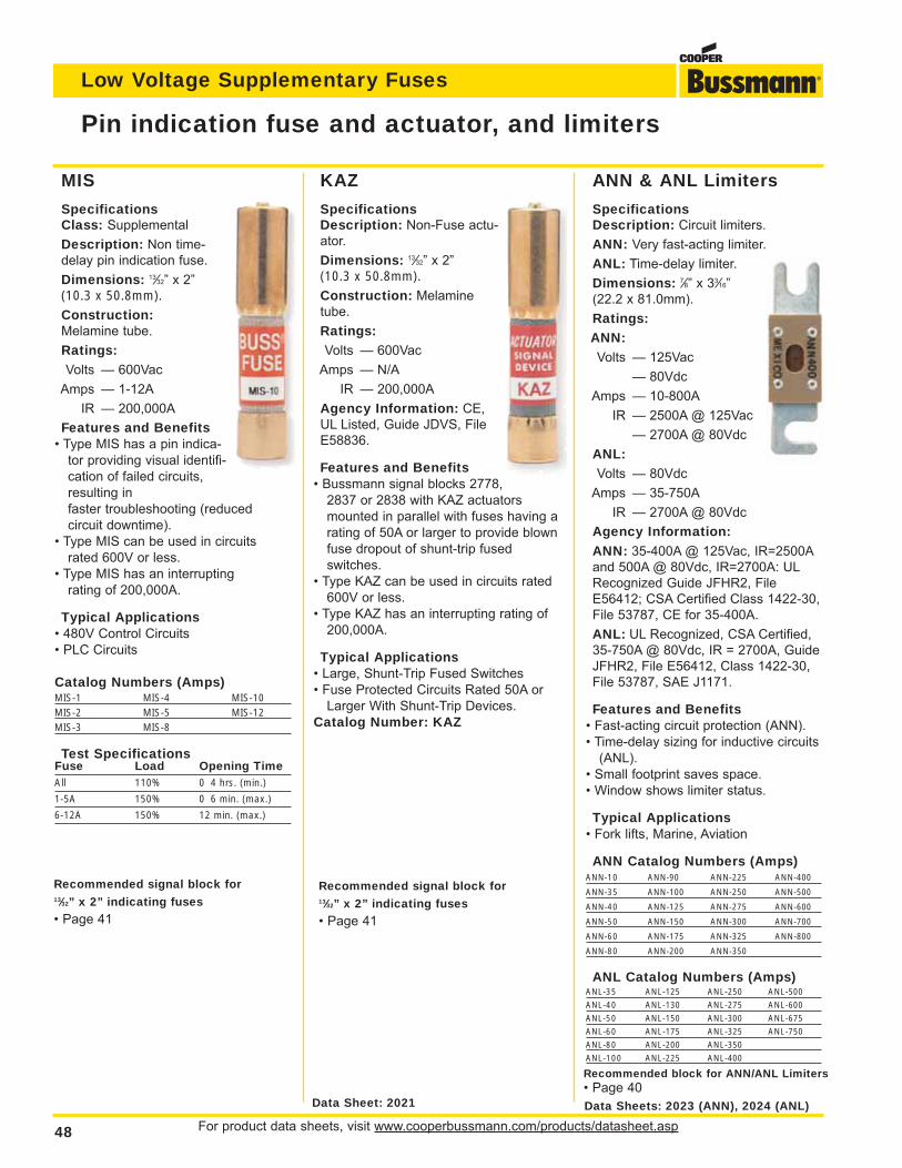
For product data sheets, visit www.cooperbussmann.com/products/datasheet.asp48
Low Voltage Supplementary Fuses
ANN & ANL Limiters
SpecificationsDescription: Circuit limiters.
ANN: Very fast-acting limiter.
ANL: Time-delay limiter.
Dimensions: 7⁄8” x 33⁄16”
(22.2 x 81.0mm).
Ratings:ANN:Volts — 125Vac
— 80Vdc
Amps — 10-800A
IR — 2500A @ 125Vac
— 2700A @ 80Vdc
ANL:Volts — 80Vdc
Amps — 35-750A
IR — 2700A @ 80Vdc
Agency Information:
ANN: 35-400A @ 125Vac, IR=2500A
and 500A @ 80Vdc, IR=2700A: UL
Recognized Guide JFHR2, File
E56412; CSA Certified Class 1422-30,
File 53787, CE for 35-400A.
ANL: UL Recognized, CSA Certified,
35-750A @ 80Vdc, IR = 2700A, Guide
JFHR2, File E56412, Class 1422-30,
File 53787, SAE J1171.
Features and Benefits• Fast-acting circuit protection (ANN).
• Time-delay sizing for inductive circuits
(ANL).
• Small footprint saves space.
• Window shows limiter status.
Typical Applications• Fork lifts, Marine, Aviation
ANN Catalog Numbers (Amps)ANN-10 ANN-90 ANN-225 ANN-400
ANN-35 ANN-100 ANN-250 ANN-500
ANN-40 ANN-125 ANN-275 ANN-600
ANN-50 ANN-150 ANN-300 ANN-700
ANN-60 ANN-175 ANN-325 ANN-800
ANN-80 ANN-200 ANN-350
ANL Catalog Numbers (Amps)ANL-35 ANL-125 ANL-250 ANL-500
ANL-40 ANL-130 ANL-275 ANL-600
ANL-50 ANL-150 ANL-300 ANL-675
ANL-60 ANL-175 ANL-325 ANL-750
ANL-80 ANL-200 ANL-350
ANL-100 ANL-225 ANL-400
KAZ
SpecificationsDescription: Non-Fuse actu-
ator.
Dimensions: 13⁄32” x 2”
(10.3 x 50.8mm).Construction: Melamine
tube.
Ratings:Volts — 600Vac
Amps — N/A
IR — 200,000A
Agency Information: CE,
UL Listed, Guide JDVS, File
E58836.
Features and Benefits• Bussmann signal blocks 2778,
2837 or 2838 with KAZ actuators
mounted in parallel with fuses having a
rating of 50A or larger to provide blown
fuse dropout of shunt-trip fused
switches.
• Type KAZ can be used in circuits rated
600V or less.
• Type KAZ has an interrupting rating of
200,000A.
Typical Applications• Large, Shunt-Trip Fused Switches
• Fuse Protected Circuits Rated 50A or
Larger With Shunt-Trip Devices.
Catalog Number: KAZ
MIS
SpecificationsClass: Supplemental
Description: Non time-
delay pin indication fuse.
Dimensions: 13⁄32” x 2”
(10.3 x 50.8mm).Construction:Melamine tube.
Ratings:Volts — 600Vac
Amps — 1-12A
IR — 200,000A
Features and Benefits• Type MIS has a pin indica-
tor providing visual identifi-
cation of failed circuits,
resulting in
faster troubleshooting (reduced
circuit downtime).
• Type MIS can be used in circuits
rated 600V or less.
• Type MIS has an interrupting
rating of 200,000A.
Typical Applications• 480V Control Circuits
• PLC Circuits
Catalog Numbers (Amps)MIS-1 MIS-4 MIS-10MIS-2 MIS-5 MIS-12MIS-3 MIS-8
Test SpecificationsFuse Load Opening TimeAll 110% 0 4 hrs. (min.)
1-5A 150% 0 6 min. (max.)
6-12A 150% 12 min. (max.)
Pin indication fuse and actuator, and limiters
Data Sheet: 2021 Data Sheets: 2023 (ANN), 2024 (ANL)
Recommended signal block for13⁄32” x 2” indicating fuses
• Page 41
Recommended signal block for 13⁄32” x 2” indicating fuses
• Page 41
Recommended block for ANN/ANL Limiters• Page 40
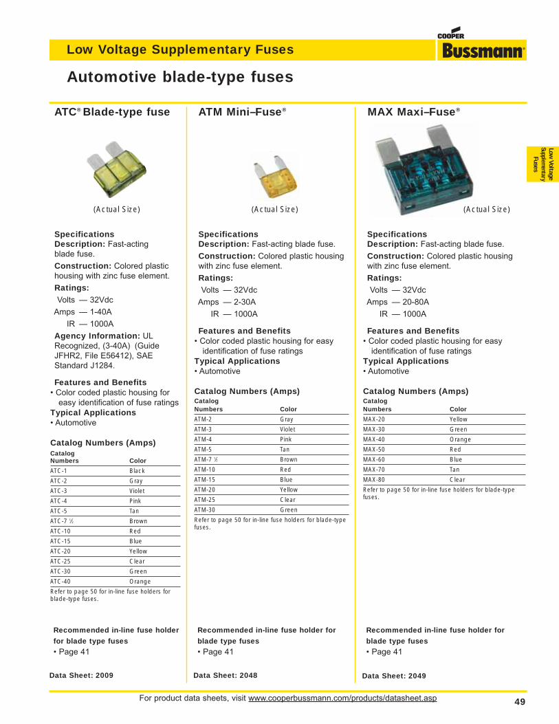
For product data sheets, visit www.cooperbussmann.com/products/datasheet.asp 49
Low Voltage Supplementary Fuses
Low Voltage
Supplementary
Fuses
SpecificationsDescription: Fast-acting
blade fuse.
Construction: Colored plastic
housing with zinc fuse element.
Ratings:Volts — 32Vdc
Amps — 1-40A
IR — 1000A
Agency Information: UL
Recognized, (3-40A) (Guide
JFHR2, File E56412), SAE
Standard J1284.
Features and Benefits• Color coded plastic housing for
easy identification of fuse ratings
Typical Applications• Automotive
Catalog Numbers (Amps)CatalogNumbers Color
ATC-1 Black
ATC-2 Gray
ATC-3 Violet
ATC-4 Pink
ATC-5 Tan
ATC-7 1⁄2 Brown
ATC-10 Red
ATC-15 Blue
ATC-20 Yellow
ATC-25 Clear
ATC-30 Green
ATC-40 Orange
Refer to page 50 for in-line fuse holders forblade-type fuses.
Automotive blade-type fuses
Data Sheet: 2049Data Sheet: 2048Data Sheet: 2009
(Actual Size) (Actual Size)
ATC® Blade-type fuse ATM Mini–Fuse® MAX Maxi–Fuse®
SpecificationsDescription: Fast-acting blade fuse.
Construction: Colored plastic housing
with zinc fuse element.
Ratings:Volts — 32Vdc
Amps — 2-30A
IR — 1000A
Features and Benefits• Color coded plastic housing for easy
identification of fuse ratings
Typical Applications• Automotive
Catalog Numbers (Amps)CatalogNumbers Color
ATM-2 Gray
ATM-3 Violet
ATM-4 Pink
ATM-5 Tan
ATM-7 1⁄2 Brown
ATM-10 Red
ATM-15 Blue
ATM-20 Yellow
ATM-25 Clear
ATM-30 Green
Refer to page 50 for in-line fuse holders for blade-typefuses.
(Actual Size)
SpecificationsDescription: Fast-acting blade fuse.
Construction: Colored plastic housing
with zinc fuse element.
Ratings:Volts — 32Vdc
Amps — 20-80A
IR — 1000A
Features and Benefits• Color coded plastic housing for easy
identification of fuse ratings
Typical Applications• Automotive
Catalog Numbers (Amps)CatalogNumbers Color
MAX-20 Yellow
MAX-30 Green
MAX-40 Orange
MAX-50 Red
MAX-60 Blue
MAX-70 Tan
MAX-80 Clear
Refer to page 50 for in-line fuse holders for blade-typefuses.
Recommended in-line fuse holder
for blade type fuses
• Page 41
Recommended in-line fuse holder for
blade type fuses
• Page 41
Recommended in-line fuse holder for
blade type fuses
• Page 41
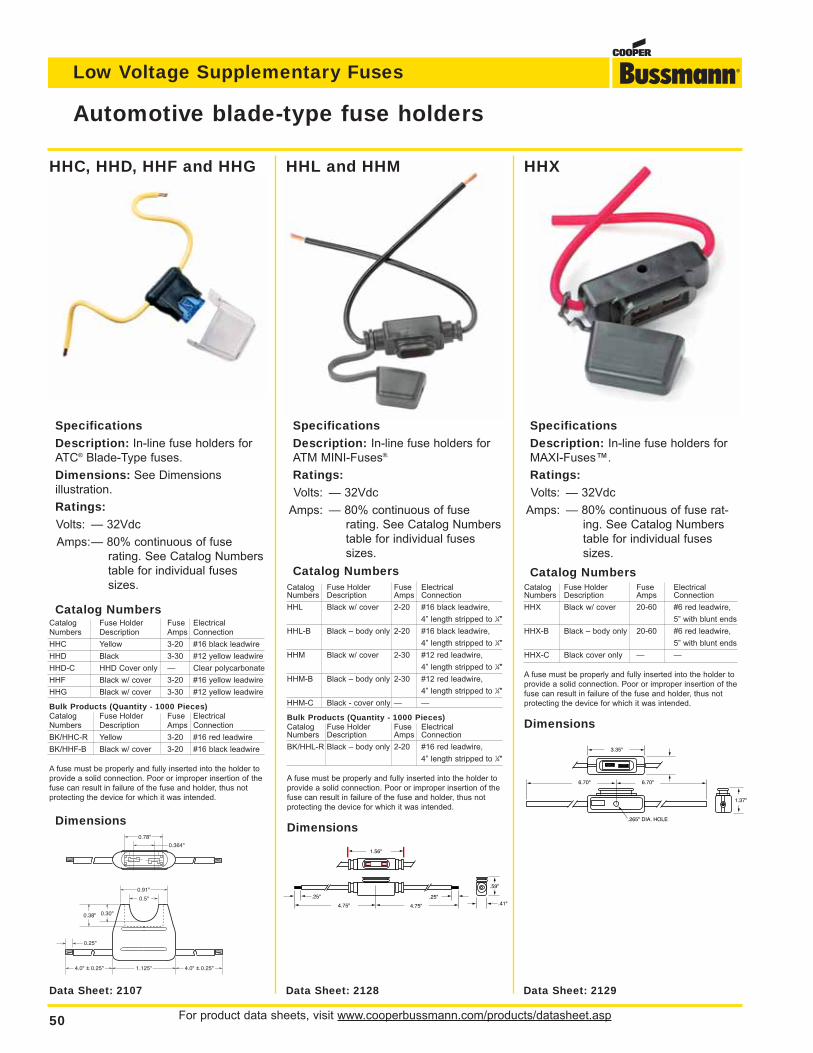
For product data sheets, visit www.cooperbussmann.com/products/datasheet.asp50
Low Voltage Supplementary Fuses
Automotive blade-type fuse holders
0.78"
0.91"
0.5"
0.38" 0.30"
4.0" + 0.25" 4.0" + 0.25"1.125"
0.364"
0.25"
Data Sheet: 2107 Data Sheet: 2129Data Sheet: 2128
Specifications
Description: In-line fuse holders for
ATC® Blade-Type fuses.
Dimensions: See Dimensions
illustration.
Ratings:
Volts: — 32Vdc
Amps:— 80% continuous of fuse
rating. See Catalog Numbers
table for individual fuses
sizes.
Catalog NumbersCatalog Fuse Holder Fuse ElectricalNumbers Description Amps Connection
HHC Yellow 3-20 #16 black leadwire
HHD Black 3-30 #12 yellow leadwire
HHD-C HHD Cover only — Clear polycarbonate
HHF Black w/ cover 3-20 #16 yellow leadwire
HHG Black w/ cover 3-30 #12 yellow leadwire
Bulk Products (Quantity - 1000 Pieces)Catalog Fuse Holder Fuse ElectricalNumbers Description Amps Connection
BK/HHC-R Yellow 3-20 #16 red leadwire
BK/HHF-B Black w/ cover 3-20 #16 black leadwire
A fuse must be properly and fully inserted into the holder to
provide a solid connection. Poor or improper insertion of the
fuse can result in failure of the fuse and holder, thus not
protecting the device for which it was intended.
Dimensions
Specifications
Description: In-line fuse holders for
ATM MINI-Fuses®.
Ratings:
Volts: — 32Vdc
Amps: — 80% continuous of fuse
rating. See Catalog Numbers
table for individual fuses
sizes.
Catalog NumbersCatalog Fuse Holder Fuse ElectricalNumbers Description Amps Connection
HHL Black w/ cover 2-20 #16 black leadwire,
4” length stripped to 1⁄4"
HHL-B Black – body only 2-20 #16 black leadwire,
4” length stripped to 1⁄4"
HHM Black w/ cover 2-30 #12 red leadwire,
4” length stripped to 1⁄4"
HHM-B Black – body only 2-30 #12 red leadwire,
4” length stripped to 1⁄4"
HHM-C Black - cover only — —
Bulk Products (Quantity - 1000 Pieces)Catalog Fuse Holder Fuse ElectricalNumbers Description Amps Connection
BK/HHL-R Black – body only 2-20 #16 red leadwire,
4” length stripped to 1⁄4"
A fuse must be properly and fully inserted into the holder to
provide a solid connection. Poor or improper insertion of the
fuse can result in failure of the fuse and holder, thus not
protecting the device for which it was intended.
Dimensions
Specifications
Description: In-line fuse holders for
MAXI-Fuses™.
Ratings:
Volts: — 32Vdc
Amps: — 80% continuous of fuse rat-
ing. See Catalog Numbers
table for individual fuses
sizes.
Catalog NumbersCatalog Fuse Holder Fuse ElectricalNumbers Description Amps Connection
HHX Black w/ cover 20-60 #6 red leadwire,
5” with blunt ends
HHX-B Black – body only 20-60 #6 red leadwire,
5” with blunt ends
HHX-C Black cover only — —
A fuse must be properly and fully inserted into the holder to
provide a solid connection. Poor or improper insertion of the
fuse can result in failure of the fuse and holder, thus not
protecting the device for which it was intended.
Dimensions
HHC, HHD, HHF and HHG HHXHHL and HHM
1.56"
4.75" 4.75"
.25" .25"
.59"
.41"
3.35"
6.70" 6.70"
1.37"
.265" DIA. HOLE
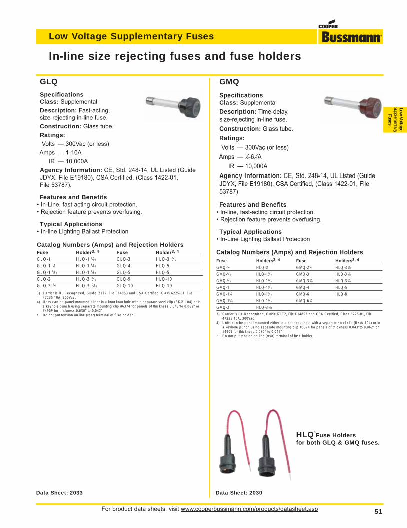
For product data sheets, visit www.cooperbussmann.com/products/datasheet.asp 51
Low Voltage Supplementary Fuses
Low Voltage
Supplementary
Fuses
In-line size rejecting fuses and fuse holders
Data Sheet: 2030Data Sheet: 2033
HLQ3Fuse Holders
for both GLQ & GMQ fuses.
GLQ
SpecificationsClass: Supplemental
Description: Fast-acting,
size-rejecting in-line fuse.
Construction: Glass tube.
Ratings:Volts — 300Vac (or less)
Amps — 1-10A
IR — 10,000A
Agency Information: CE, Std. 248-14, UL Listed (Guide
JDYX, File E19180), CSA Certified, (Class 1422-01,
File 53787).
Features and Benefits• In-Line, fast acting circuit protection.
• Rejection feature prevents overfusing.
Typical Applications• In-line Lighting Ballast Protection
Catalog Numbers (Amps) and Rejection HoldersFuse Holder3, 4 Fuse Holder3, 4
GLQ-1 HLQ-1 6⁄10 GLQ-3 HLQ-3 2⁄10
GLQ-1 1⁄2 HLQ-1 6⁄10 GLQ-4 HLQ-5GLQ-1 6⁄10 HLQ-1 6⁄10 GLQ-5 HLQ-5GLQ-2 HLQ-3 2⁄10 GLQ-9 HLQ-10GLQ-2 1⁄2 HLQ-3 2⁄10 GLQ-10 HLQ-10
3) Carrier is UL Recognized, Guide IZLT2, File E14853 and CSA Certified, Class 6225-01, File47235 10A, 300Vac.
4) Units can be panel-mounted either in a knockout hole with a separate steel clip (BK/A-104) or ina keyhole punch using separate mounting clip #6374 for panels of thickness 0.043”to 0.062” or#4909 for thickness 0.030” to 0.042”.
• Do not put tension on line (rear) terminal of fuse holder.
GMQ
SpecificationsClass: Supplemental
Description: Time-delay,
size-rejecting in-line fuse.
Construction: Glass tube.
Ratings:Volts — 300Vac (or less)
Amps — 1⁄2-61⁄4A
IR — 10,000A
Agency Information: CE, Std. 248-14, UL Listed (Guide
JDYX, File E19180), CSA Certified, (Class 1422-01, File
53787)
Features and Benefits• In-line, fast-acting circuit protection.
• Rejection feature prevents overfusing.
Typical Applications• In-Line Lighting Ballast Protection
Catalog Numbers (Amps) and Rejection HoldersFuse Holders3, 4 Fuse Holders3, 4
GMQ-1⁄2 HLQ-1⁄2 GMQ-21⁄2 HLQ-3 2⁄10
GMQ-6⁄10 HLQ-16⁄10 GMQ-3 HLQ-3 2⁄10
GMQ-8⁄10 HLQ-16⁄10 GMQ-3 2⁄10 HLQ-3 2⁄10
GMQ-1 HLQ-16⁄10 GMQ-4 HLQ-5
GMQ-11⁄4 HLQ-16⁄10 GMQ-6 HLQ-8
GMQ-16⁄10 HLQ-16⁄10 GMQ-6 1⁄4
GMQ-2 HLQ-3 2⁄10
3) Carrier is UL Recognized, Guide IZLT2, File E14853 and CSA Certified, Class 6225-01, File47235 10A, 300Vac.
4) Units can be panel-mounted either in a knockout hole with a separate steel clip (BK/A-104) or ina keyhole punch using separate mounting clip #6374 for panels of thickness 0.043”to 0.062” or#4909 for thickness 0.030” to 0.042”
• Do not put tension on line (rear) terminal of fuse holder.
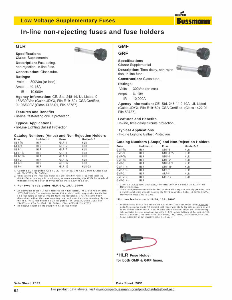
For product data sheets, visit www.cooperbussmann.com/products/datasheet.asp52
Low Voltage Supplementary Fuses
GLR
SpecificationsClass: Supplemental
Description: Fast-acting,
non-rejection, in-line fuse.
Construction: Glass tube.
Ratings:Volts — 300Vac (or less)
Amps — 3⁄16-15A
IR — 10,000A
Agency Information: CE, Std. 248-14, UL Listed, 0-
15A/300Vac (Guide JDYX, File E19180), CSA Certified,
0-10A/300V (Class 1422-01, File 53787).
Features and Benefits• In-line, fast-acting circuit protection.
Typical Applications• In-Line Lighting Ballast Protection
Catalog Numbers (Amps) and Non-Rejection HoldersFuse Holder1, 2 Fuse Holder1, 2
GLR-3⁄16 HLR GLR-5 HLRGLR-1⁄2 HLR GLR-6 HLRGLR-1 HLR GLR-7 HLRGLR-1 1⁄2 HLR GLR-8 HLRGLR-1 6⁄10 HLR GLR-9 HLRGLR-2 HLR GLR-10 HLRGLR-3 HLR GLR-12 HLRGLR-4 HLR GLR-15 HLR-2A
1) Carrier is UL Recognized, Guide IZLT2, File E14853 and CSA Certified, Class 6225-01, File 47235 12A, 300Vac.
2) Units can be panel-mounted either in a knockout hole with a separate steel clip(BK/A-104) or in a keyhole punch using separate mounting clip #6374 for panels ofthickness 0.043”to 0.062” or #4909 for thickness 0.030” to 0.042”.
* For two leads order HLR-2A, 15A, 300V
• An alternative to the HLR fuse holder is the A fuse holder. The A fuse holder comesWITHOUT leads. The customer inserts #18 insulated solid copper wire into the lineside receptacle as well as into the load side receptacle. It has the same bodydimensions, utilizes the same mounting hole, and takes the same mounting clips asthe HLR. The A fuse holder is UL Recognized, 10A, 300Vac, Guide IZLT2, FileE14853 and CSA Certified, 10A, 300Vac, Class 6225-01, File 47235.
• Do not put tension on line (rear) terminal of fuse holder.
GMF
GRF
SpecificationsClass: Supplemental
Description: Time-delay, non-rejec-
tion, in-line fuse.
Construction: Glass tube.
Ratings:Volts — 300Vac (or less)
Amps — 3⁄10-10A
IR — 10,000A
Agency Information: CE, Std. 248-14 0-10A, UL Listed
(Guide JDYX, File E19180), CSA Certified, (Class 1422-01,
File 53787).
Features and Benefits• In-line, time-delay circuits protection.
Typical Applications• In-Line Lighting Ballast Protection
Catalog Numbers (-Amps) and Non-Rejection HoldersFuse Holder1, 2 Fuse Holder1, 2
GMF-3⁄10 HLR GMF-3 HLRGMF-1⁄2 HLR GMF-3 2⁄10 HLRGMF-6⁄10 HLR GMF-4 HLRGMF-8⁄10 HLR GMF-5* HLRGMF-1 HLR GMF-6 1⁄4 HLRGMF-1 1⁄4 HLR GMF-10 HLRGMF-1 6⁄10 HLR GRF-7 HLRGMF-2 HLR GRF-8 HLRGMF-2 1⁄2 HLR GRF-10 HLRGMF-2 8⁄10 HLR
1) Carrier is UL Recognized, Guide IZLT2, File E14853 and CSA Certified, Class 6225-01, File47235 12A, 300Vac.
2) Units can be panel-mounted either in a knockout hole with a separate steel clip (BK/A-104) or ina keyhole punch using separate mounting clip #6374 for panels of thickness 0.043”to 0.062” or#4909 for thickness 0.030” to 0.042”.
*For two leads order HLR-2A, 15A, 300V
• An alternative to the HLR fuse holder is the A fuse holder. The A fuse holder comes WITHOUTleads. The customer inserts #18 insulated solid copper wire into the line side receptacle as wellas into the load side receptacle. It has the same body dimensions, utilizes the same mountinghole, and takes the same mounting clips as the HLR. The A fuse holder is UL Recognized, 10A,300Vac, Guide IZLT2, File E14853 and CSA Certified, 10A, 300Vac, Class 6225-01, File 47235.
• Do not put tension on line (rear) terminal of fuse holder.
In-line non-rejecting fuses and fuse holders
Data Sheet: 2032 Data Sheet: 2031
*HLR Fuse Holderfor both GMF & GRF fuses.
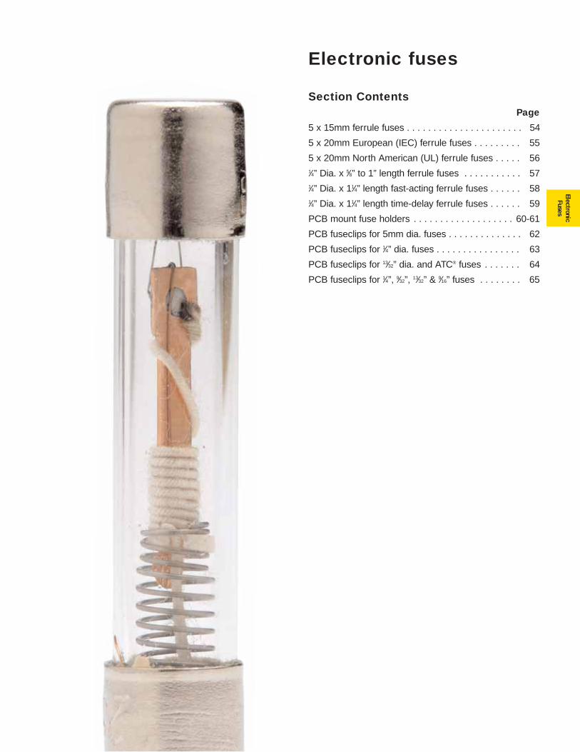
53
ElectronicFuses
Electronic fuses
Section ContentsPage
5 x 15mm ferrule fuses . . . . . . . . . . . . . . . . . . . . . . 54
5 x 20mm European (IEC) ferrule fuses . . . . . . . . . 55
5 x 20mm North American (UL) ferrule fuses . . . . . 561⁄4” Dia. x 5⁄8” to 1” length ferrule fuses . . . . . . . . . . . 571⁄4” Dia. x 11⁄4” length fast-acting ferrule fuses . . . . . . 581⁄4” Dia. x 11⁄4” length time-delay ferrule fuses . . . . . . 59
PCB mount fuse holders . . . . . . . . . . . . . . . . . . . 60-61
PCB fuseclips for 5mm dia. fuses . . . . . . . . . . . . . . 62
PCB fuseclips for 1⁄4” dia. fuses . . . . . . . . . . . . . . . . 63
PCB fuseclips for 13⁄32” dia. and ATC® fuses . . . . . . . 64
PCB fuseclips for 1⁄4”, 9⁄32”, 13⁄32” & 9⁄16” fuses . . . . . . . . 65
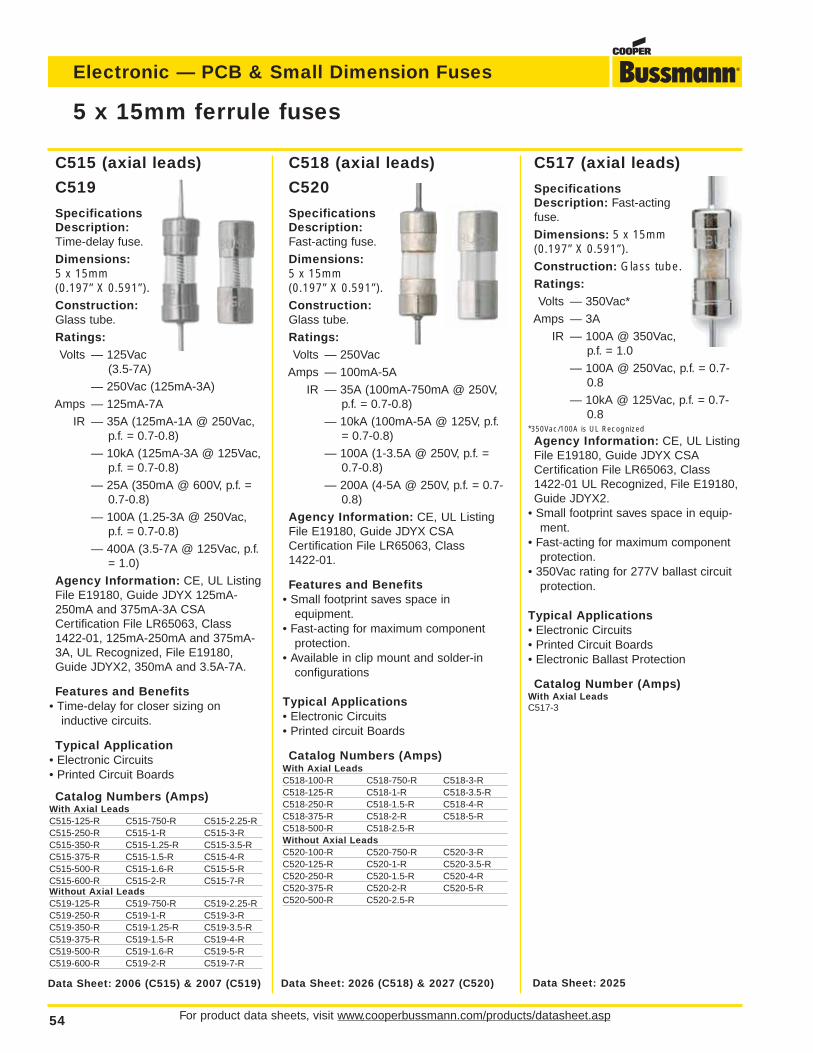
C517 (axial leads)
SpecificationsDescription: Fast-actingfuse.
Dimensions: 5 x 15mm(0.197” X 0.591”).Construction: Glass tube.Ratings:Volts — 350Vac*
Amps — 3A
IR — 100A @ 350Vac,p.f. = 1.0
— 100A @ 250Vac, p.f. = 0.7-0.8
— 10kA @ 125Vac, p.f. = 0.7-0.8
*350Vac/100A is UL Recognized
Agency Information: CE, UL ListingFile E19180, Guide JDYX CSACertification File LR65063, Class1422-01 UL Recognized, File E19180,Guide JDYX2.
• Small footprint saves space in equip-ment.
• Fast-acting for maximum componentprotection.
• 350Vac rating for 277V ballast circuitprotection.
Typical Applications• Electronic Circuits• Printed Circuit Boards• Electronic Ballast Protection
Catalog Number (Amps)With Axial LeadsC517-3
C518 (axial leads)
C520
SpecificationsDescription:Fast-acting fuse.
Dimensions:5 x 15mm (0.197” X 0.591”).Construction:Glass tube.
Ratings:Volts — 250Vac
Amps — 100mA-5A
IR — 35A (100mA-750mA @ 250V,p.f. = 0.7-0.8)
— 10kA (100mA-5A @ 125V, p.f.= 0.7-0.8)
— 100A (1-3.5A @ 250V, p.f. =0.7-0.8)
— 200A (4-5A @ 250V, p.f. = 0.7-0.8)
Agency Information: CE, UL ListingFile E19180, Guide JDYX CSACertification File LR65063, Class1422-01.
Features and Benefits• Small footprint saves space in
equipment.• Fast-acting for maximum component
protection.• Available in clip mount and solder-in
configurations
Typical Applications• Electronic Circuits• Printed circuit Boards
Catalog Numbers (Amps)With Axial LeadsC518-100-R C518-750-R C518-3-RC518-125-R C518-1-R C518-3.5-RC518-250-R C518-1.5-R C518-4-RC518-375-R C518-2-R C518-5-RC518-500-R C518-2.5-RWithout Axial LeadsC520-100-R C520-750-R C520-3-RC520-125-R C520-1-R C520-3.5-RC520-250-R C520-1.5-R C520-4-RC520-375-R C520-2-R C520-5-RC520-500-R C520-2.5-R
C515 (axial leads)
C519
SpecificationsDescription:Time-delay fuse.
Dimensions:5 x 15mm (0.197” X 0.591”).Construction:Glass tube.
Ratings:Volts — 125Vac
(3.5-7A)
— 250Vac (125mA-3A)
Amps — 125mA-7A
IR — 35A (125mA-1A @ 250Vac,p.f. = 0.7-0.8)
— 10kA (125mA-3A @ 125Vac,p.f. = 0.7-0.8)
— 25A (350mA @ 600V, p.f. =0.7-0.8)
— 100A (1.25-3A @ 250Vac,p.f. = 0.7-0.8)
— 400A (3.5-7A @ 125Vac, p.f.= 1.0)
Agency Information: CE, UL ListingFile E19180, Guide JDYX 125mA-250mA and 375mA-3A CSACertification File LR65063, Class1422-01, 125mA-250mA and 375mA-3A, UL Recognized, File E19180,Guide JDYX2, 350mA and 3.5A-7A.
Features and Benefits• Time-delay for closer sizing on
inductive circuits.
Typical Application• Electronic Circuits• Printed Circuit Boards
Catalog Numbers (Amps)With Axial LeadsC515-125-R C515-750-R C515-2.25-RC515-250-R C515-1-R C515-3-RC515-350-R C515-1.25-R C515-3.5-RC515-375-R C515-1.5-R C515-4-RC515-500-R C515-1.6-R C515-5-RC515-600-R C515-2-R C515-7-RWithout Axial LeadsC519-125-R C519-750-R C519-2.25-RC519-250-R C519-1-R C519-3-RC519-350-R C519-1.25-R C519-3.5-RC519-375-R C519-1.5-R C519-4-RC519-500-R C519-1.6-R C519-5-RC519-600-R C519-2-R C519-7-R
For product data sheets, visit www.cooperbussmann.com/products/datasheet.asp54
Electronic — PCB & Small Dimension Fuses
5 x 15mm ferrule fuses
Data Sheet: 2025Data Sheet: 2026 (C518) & 2027 (C520)Data Sheet: 2006 (C515) & 2007 (C519)
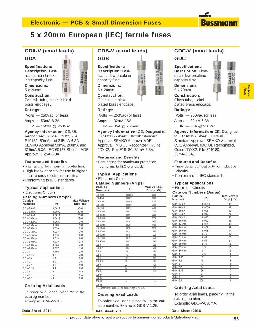
For product data sheets, visit www.cooperbussmann.com/products/datasheet.asp 55
Electronic — PCB & Small Dimension Fuses
ElectronicFuses
GDC-V (axial leads)
GDC
SpecificationsDescription: Time-delay, low-breakingcapacity fuse.
Dimensions:5 x 20mm.
Construction:Glass tube, nickel-plated brass endcaps.
Ratings:Volts — 250Vac (or less)
Amps — 32mA-6.3A
IR — 35A @ 250Vac
Agency Information: CE, Designedto IEC 60127-Sheet III BritishStandard Approval SEMKO ApprovalVDE Approval, IMQ UL Recognized,Guide JDYX2, File E19180,32mA-6.3A.
Features and Benefits• Time-delay compatibility for inductive
circuits.• Conforming to IEC standards.
Typical Applications• Electronic CircuitsCatalog Numbers (Amps)Catalog Max VoltageNumbers I2t Drop (mV)
GDC-32mA 0.0014 1050GDC-40mA 0.0034 920GDC-50mA 0.006 800GDC-63mA 0.012 760GDC-80mA 0.015 580GDC-100mA 0.022 490GDC-125mA 0.034 390GDC-160mA 0.052 320GDC-200mA 0.078 340GDC-250mA 0.17 270GDC-315mA 0.41 250GDC-400mA 0.61 210GDC-500mA 0.75 168GDC-630mA 1.3 158GDC-800mA 3.1 132GDC-1 3.6 85GDC-1.25 7 80GDC-1.6 10 80GDC-2 17 80GDC-2.5 34 80GDC-3.15 56 75GDC-4 91 75GDC-5 133 75GDC-6.3 270 65
Ordering Axial Leads
To order axial leads, place “V” in thecatalog number.Example: GDC-V-630mA.
GDB-V (axial leads)
GDB
SpecificationsDescription: Fast-acting, low-breakingcapacity fuse.
Dimensions:5 x 20mm.
Construction:Glass tube, nickel-plated brass endcaps.
Ratings:Volts — 250Vac (or less)
Amps — 32mA-16A
IR — 35A @ 250Vac
Agency Information: CE, Designed toIEC 60127-Sheet II British StandardApproval SEMKO Approval VDEApproval, IMQ UL Recognized, GuideJDYX2, File E19180, 32mA-6.3A.
Features and Benefits• Fast-acting for maximum protection,
conforms to IEC standards.
Typical Applications• Electronic CircuitsCatalog Numbers (Amps)Catalog Max VoltageNumbers I2t Drop (mV)
GDB-32mA 0.000047 10000GDB-40mA 0.00011 8000GDB-50mA 0.00020 3200GDB-63mA 0.00057 2500GDB-80mA 0.0012 2200GDB-100mA 0.003 2100GDB-125mA 0.005 2000GDB-160mA 0.008 1950GDB-200mA 0.016 1600GDB-250mA 0.028 1400GDB-315mA 0.058 1150GDB-400mA 0.018 950GDB-500mA 0.018 220GDB-630mA 0.035 220GDB-800mA 0.067 180GDB-1 0.60 200GDB-1.25 0.84 200GDB-1.6 1.6 190GDB-2 4.2 160GDB-2.5 6.1 145GDB-3.15 13 130GDB-4 22 120GDB-5 42 115GDB-6.3 69 110GDB-8* — —GDB-10* — —GDB-12* — —GDB-16* — —*IEC Standard 127 Sheet II does not include ratings above 6.3A.
Ordering Axial Leads
To order axial leads, place “V” in the cat-alog number. Example: GDB-V-1.25.
GDA-V (axial leads)
GDA
SpecificationsDescription: Fast-acting, high-break-ing capacity fuse.
Dimensions:5 x 20mm.
Construction:Ceramic tube, nickel-platedbrass endcaps.Ratings:Volts — 250Vac (or less)
Amps — 50mA-6.3A
IR — 1500A @ 250Vac
Agency Information: CE, ULRecognized, Guide JDYX2, FileE19180, 50mA and 315mA-6.3ASEMKO Approval 50mA, 200mA and315mA-6.3A, IEC 60127-Sheet I, VDEApproval 1.25A-6.3A.
Features and Benefits• Fast-acting for maximum protection.• High break capacity for use in higher
fault energy electronic circuitry.• Conforming to IEC standards.
Typical Applications• Electronic CircuitsCatalog Numbers (Amps)Catalog Max VoltageNumbers I2t Drop (mV)
GDA-50mA 0.0017 9000GDA-63mA 0.0005 3300GDA-80mA 0.0011 2600GDA-100mA 0.0018 2300GDA-125mA 0.0037 1900GDA-160mA 0.008 1600GDA-200mA 0.020 1350GDA-250mA 0.027 1300GDA-315mA 0.010 1400GDA-400mA 0.018 1200GDA-500mA 0.038 1050GDA-630mA 0.064 1200GDA-800mA 0.097 490GDA-1 0.480 230GDA-1.25 0.9 200GDA-1.6 1.9 180GDA-2 2.0 205GDA-2.5 3.9 190GDA-3.15 8.1 160GDA-4 14 160GDA-5 25 155GDA-6.3 48 150
Ordering Axial Leads
To order axial leads, place “V” in thecatalog number.Example: GDA-V-3.15.
5 x 20mm European (IEC) ferrule fuses
Data Sheet: 2016Data Sheet: 2015Data Sheet: 2014
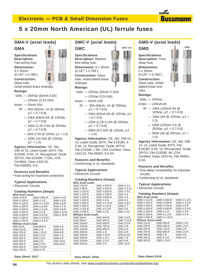
For product data sheets, visit www.cooperbussmann.com/products/datasheet.asp56
Electronic — PCB & Small Dimension Fuses
GMD-V (axial leads)
GMD
SpecificationsDescription: Time-delay fuse.
Dimensions:5 x 20mm (0.197” x 0.788”).
Construction:Glass tube, nickel-plated brass end-caps.
Ratings:Volts — 250Vac
Amps — 125mA-4A
IR — 10kA (125mA-3A @125Vac, p.f. = 0.7-0.8)
— 10kA (4A @ 125Vac, p.f. =1.0)
— 100A (125mA-3.A @250Vac, p.f. = 0.7-0.8)
— 200A (4A @ 250Vac, p.f. =1.0)
Agency Information: CE, Std. 248-14, UL Listed Guide JDYX, FileE19180, 0-3A, UL Recognized, GuideJDYX2, File E19180, 4A, CSACertified, Class 1422-01, File 65063,0-3A.
Features and Benefits• Time-delay compatibility for inductive
circuits.• Conforming to UL standards.
Typical Applications• Electronic Circuits
Catalog Numbers (Amps)With Axial LeadsGMD-V-125-R GMD-V-500-R GMD-V-1.5-RGMD-V-150-R GMD-V-630-R GMD-V-1.6-RGMD-V-200-R GMD-V-750-R GMD-V-2-RGMD-V-250-R GMD-V-800-R GMD-V-2.5-RGMD-V-300-R GMD-V-1-R GMD-V-3-RGMD-V-315-R GMD-V-1.2-R GMD-V-4-RGMD-V-400-R GMD-V-1.25-RWithout Axial LeadsGMD-125-R GMD-500-R GMD-1.5-RGMD-150-R GMD-630-R GMD-1.6-RGMD-200-R GMD-750-R GMD-2-RGMD-250-R GMD-800-R GMD-2.5-RGMD-300-R GMD-1-R GMD-3-RGMD-315-R GMD-1.2-R GMD-4-RGMD-400-R GMD-1.25-R
GMC-V (axial leads)
GMC
SpecificationsDescription: Mediumtime-delay fuse.
Dimensions: 5 x 20mm(0.197” x 0.788”).
Construction: Glasstube, nickel-plated brassendcaps.
Ratings:Volts — 250Vac (63mA-3.15A)
— 125Vac (3.5-10A)
Amps — 63mA-10A
IR — 35A (63mA- 1A @ 250Vac,p.f. = 0.7-0.8)
— 10kA (63mA-6A @ 125Vac, p.f.= 0.7-0.8)
— 100A (1.25-3.15A @ 250Vac,p.f. = 0.7-0.8)
— 200A (6.3-10A @ 125Vac, p.f.= 1.0)
Agency Information: CE, Std. 248-14,UL Listed Guide JDYX, File E19180, 0-6.3A, UL Recognized, Guide JDYX2,File E19180, 7-8A, CSA Certified, Class1422-01, File 65063, 0-6.3A.
Features and Benefits• Conforming to UL standards.
Typical Applications• Electronic Circuits
Catalog Numbers (Amps)With Axial LeadsGMC-V-63-R GMC-V-500-R GMC-V-2.5GMC-V-80-R GMC-V-600-R GMC-V-3.15GMC-V-100-R GMC-V-630-R GMC-V-3.5GMC-V-125-R GMC-V-750-R GMC-V-4GMC-V-150-R GMC-V-800-R GMC-V-5GMC-V-200-R GMC-V-1-R GMC-V-6GMC-V-250-R GMC-V-1.25-R GMC-V-6.3GMC-V-300-R GMC-V-1.5-R GMC-V-7GMC-V-315-R GMC-V-1.6-R GMC-V-8GMC-V-400-R GMC-V-2-R GMC-V-10Without Axial LeadsGMC-63mA GMC-500-R GMC-2.5-RGMC-80mA GMC-600-R GMC-3.15-RGMC-100mA GMC-630-R GMC-3.5-RGMC-125mA GMC-750-R GMC-4-RGMC-150mA GMC-800-R GMC-5-RGMC-200mA GMC-1-R GMC-6-RGMC-250mA GMC-1.25-R GMC-6.3-RGMC-300mA GMC-1.5-R GMC-7-RGMC-315mA GMC-1.6-R GMC-8-RGMC-400mA GMC-2-R GMC-10-R
GMA-V (axial leads)
GMA
SpecificationsDescription:Fast-acting fuse.
Dimensions:5 x 20mm(0.197” x 0.788”).
Construction:Glass tube,nickel-plated brass endcaps.
Ratings:Volts — 250Vac (63mA-2.5A)
— 125Vac (3.15-15A)
Amps — 63mA-15A
IR — 35A (63mA- 1A @ 250Vac,p.f. = 0.7-0.8)
— 10kA (63mA-6A @ 125Vac,p.f. = 0.7-0.8)
— 100A (1.25-2.5A @ 250Vac,p.f. = 0.7-0.8)
— 200A (7-8A @ 125Vac, p.f. = 1.0)
— 150A (10-15A @ 125Vac,p.f. = 1.0)
Agency Information: CE, Std.248-14 UL Listed Guide JDYX, FileE19180, 0-6A, UL Recognized, GuideJDYX2, File E19180, 7-15A, CSACertified, Class 1422-01,File E65063, 0-6.
Features and Benefits• Fast-acting for maximum protection.
Typical Applications• Electronic Circuits
Catalog Numbers (Amps)With Axial LeadsGMA-V-63-R GMA-V-800-R GMA-V-4-RGMA-V-100-R GMA-V-1-R GMA-V-5-RGMA-V-125-R GMA-V-1.25-R GMA-V-6-RGMA-V-200-R GMA-V-1.5-R GMA-V-7-RGMA-V-250-R GMA-V-1.6-R GMA-V-8-RGMA-V-300-R GMA-V-2-R GMA-V-10-RGMA-V-500-R GMA-V-2.5-R GMA-V-15-RGMA-V-600-R GMA-V-3.15-RGMA-V-750-R GMA-V-3.5-RWithout Axial LeadsGMA-63-R GMA-800-R GMA-4-RGMA-100-R GMA-1-R GMA-5-RGMA-125-R GMA-1.25-R GMA-6-RGMA-200-R GMA-1.5-R GMA-7-RGMA-250-R GMA-1.6-R GMA-8-RGMA-300-R GMA-2-R GMA-10-RGMA-500-R GMA-2.5-R GMA-15-RGMA-600-R GMA-3.15-RGMA-750-R GMA-3.5-R
5 x 20mm North American (UL) ferrule fuses
Data Sheet:2019Data Sheet: 2018Data Sheet: 2017
GMC-10A GMD
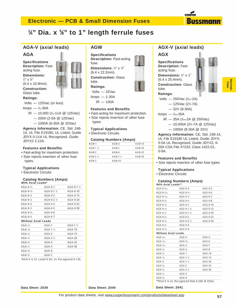
For product data sheets, visit www.cooperbussmann.com/products/datasheet.asp 57
Electronic — PCB & Small Dimension Fuses
ElectronicFuses
1⁄4” Dia. x 5⁄8” to 1” length ferrule fuses
AGX-V (axial leads)
AGX
SpecificationsDescription: Fast-acting fuse.
Dimensions: 1⁄4” x 1”(6.4 x 25.4mm).
Construction: Glasstube.
Ratings:Volts — 250Vac (1⁄500-2A)
— 125Vac (21⁄2-7A)
— 32V (8-30A)
Amps — 1⁄500-30A
IR — 35A (1⁄500-2A @ 250Vac)
— 10,000A (21⁄2-7A @ 125Vac)
— 1000A (8-30A @ 32V)
Agency Information: CE, Std. 248-14,UL File E19180 UL Listed, Guide JDYX,0-5A UL Recognized, Guide JDYX2, 6-20A CSA File 47233; Class 1422-01,0-5A.
Features and Benefits• Size rejects insertion of other fuse types.
Typical Applications• Electronic Circuits
Catalog Numbers (Amps)With Axial Leads**
AGX-V-1⁄500 AGX-V-3⁄8 AGX-V-5
AGX-V-1⁄200 AGX-V-4⁄10 AGX-V-6
AGX-V-1⁄100 AGX-V-1⁄2 AGX-V-7
AGX-V-1⁄32 AGX-V-3⁄4 AGX-V-8
AGX-V-1⁄16 AGX-V-1 AGX-V-10
AGX-V-1⁄10 AGX-V-1 1⁄4 AGX-V-15
AGX-V-1⁄8 AGX-V-1 1⁄2 AGX-V-20
AGX-V-3⁄16 AGX-V-2 AGX-V-25
AGX-V-2⁄10 AGX-V-2 1⁄2 AGX-V-30
AGX-V-1⁄4 AGX-V-3
AGX-V-3⁄10 AGX-V-4
Without Axial Leads
AGX-1⁄500 AGX-3⁄8 AGX-5
AGX-1⁄200 AGX-4⁄10 AGX-6
AGX-1⁄100 AGX-1⁄2 AGX-7
AGX-1⁄32 AGX-3⁄4 AGX-8
AGX-1⁄16 AGX-1 AGX-10
AGX-1⁄10 AGX-1 1⁄4 AGX-15
AGX-1⁄8 AGX-1 1⁄2 AGX-20
AGX-3⁄16 AGX-2 AGX-25
AGX-2⁄10 AGX-2 1⁄2 AGX-30
AGX-1⁄4 AGX-3
AGX-3⁄10 AGX-4**AGX-V is UL Recognized from 6-20A @ 32Vac
AGA-V (axial leads)
AGA
SpecificationsDescription: Fast-acting fuse.
Dimensions:1⁄4” x 5⁄8”(6.4 x 15.9mm).
Construction:Glass tube.
Ratings:Volts — 125Vac (or less)
Amps — 1⁄16-30A
IR — 10,000 (1⁄16-11⁄2A @ 125Vac)
— 200A (2-5A @ 125Vac)
— 1000A (6-30A @ 32Vac)
Agency Information: CE, Std. 248-14, UL File E19180, UL Listed, GuideJDYX 0-11⁄2A UL Recognized, GuideJDYX2 2-12A.
Features and Benefits• Fast-acting for maximum protection.• Size rejects insertion of other fuse
types.
Typical Applications• Electronic Circuits
Catalog Numbers (Amps)With Axial Leads*
AGA-V-1⁄16 AGA-V-1 AGA-V-7 1⁄2
AGA-V-1⁄10 AGA-V-1 1⁄2 AGA-V-10
AGA-V-1⁄8 AGA-V-2 AGA-V-15
AGA-V-1⁄4 AGA-V-2 1⁄2 AGA-V-20
AGA-V-3⁄8 AGA-V-3 AGA-V-25
AGA-V-1⁄2 AGA-V-5 AGA-V-30
AGA-V-6⁄10 AGA-V-6
AGA-V-3⁄4 AGA-V-7
Without Axial Leads
AGA-1⁄16 AGA-1 AGA-7 1⁄2
AGA-1⁄10 AGA-1 1⁄2 AGA-10
AGA-1⁄8 AGA-2 AGA-15
AGA-1⁄4 AGA-2 1⁄2 AGA-20
AGA-3⁄8 AGA-3 AGA-25
AGA-1⁄2 AGA-5 AGA-30
AGA-6⁄10 AGA-6
AGA-3⁄4 AGA-7
*AGA-V is UL Listed 0-5A, UL Recognized 6-12A.
AGW
SpecificationsDescription: Fast-actingfuse.
Dimensions: 1⁄4” x 7⁄8”(6.4 x 22.2mm).
Construction: Glasstube.
Ratings:Volts — 32Vac
Amps — 1-30A
IR — 100A
Features and Benefits• Fast-acting for maximum protection.• Size rejects insertion of other fuse
types.
Typical Applications• Electronic Circuits
Catalog Numbers (Amps)AGW-1 AGW-4 AGW-15
AGW-1 1⁄2 AGW-5 AGW-20
AGW-2 AGW-6 AGW-25
AGW-2 1⁄2 AGW-7 1⁄2 AGW-30
AGW-3 AGW-10
Data Sheet: 2040Data Sheet: 2039 Data Sheet: 2041
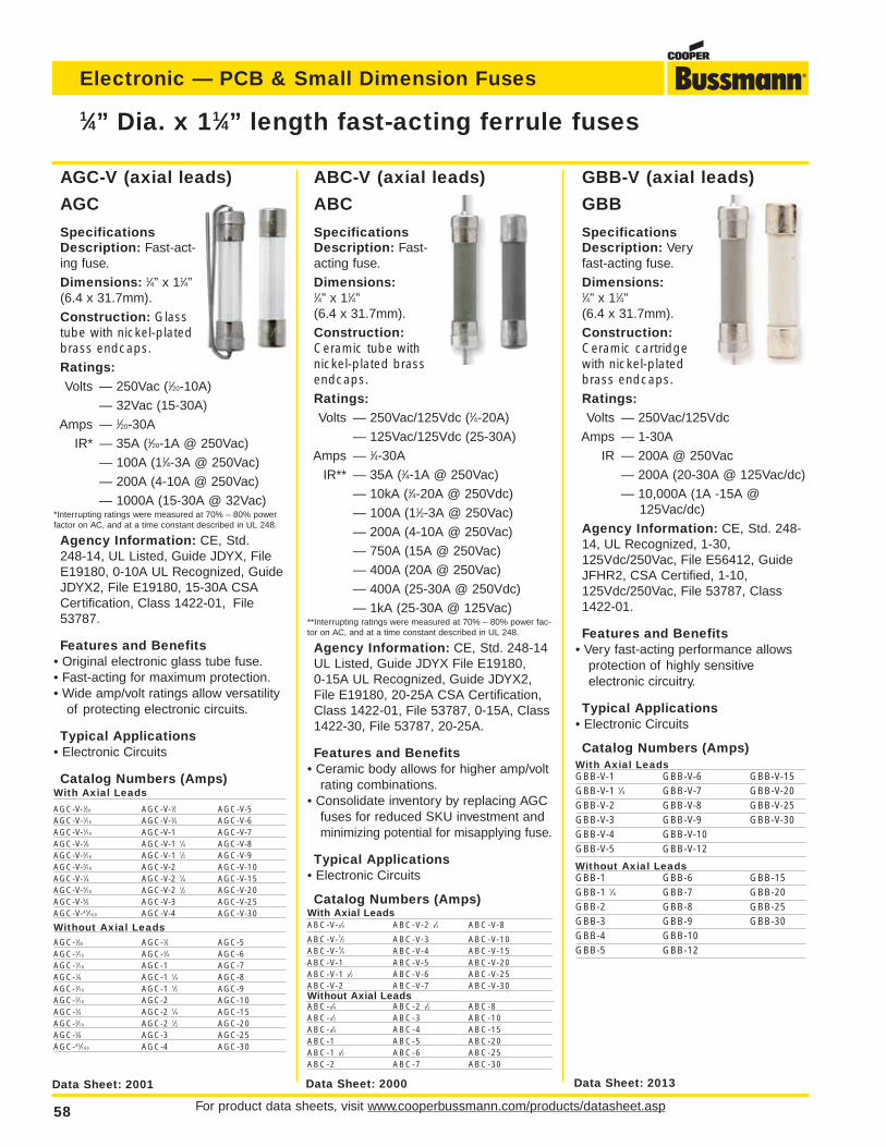
For product data sheets, visit www.cooperbussmann.com/products/datasheet.asp58
Electronic — PCB & Small Dimension Fuses
GBB-V (axial leads)
GBB
SpecificationsDescription: Veryfast-acting fuse.
Dimensions:1⁄4” x 11⁄4”(6.4 x 31.7mm).
Construction:Ceramic cartridgewith nickel-platedbrass endcaps.Ratings:Volts — 250Vac/125Vdc
Amps — 1-30A
IR — 200A @ 250Vac
— 200A (20-30A @ 125Vac/dc)
— 10,000A (1A -15A @125Vac/dc)
Agency Information: CE, Std. 248-14, UL Recognized, 1-30,125Vdc/250Vac, File E56412, GuideJFHR2, CSA Certified, 1-10,125Vdc/250Vac, File 53787, Class1422-01.
Features and Benefits• Very fast-acting performance allows
protection of highly sensitive electronic circuitry.
Typical Applications• Electronic Circuits
Catalog Numbers (Amps)With Axial LeadsGBB-V-1 GBB-V-6 GBB-V-15GBB-V-1 1⁄4 GBB-V-7 GBB-V-20GBB-V-2 GBB-V-8 GBB-V-25GBB-V-3 GBB-V-9 GBB-V-30GBB-V-4 GBB-V-10GBB-V-5 GBB-V-12
Without Axial LeadsGBB-1 GBB-6 GBB-15GBB-1 1⁄4 GBB-7 GBB-20GBB-2 GBB-8 GBB-25GBB-3 GBB-9 GBB-30GBB-4 GBB-10GBB-5 GBB-12
Data Sheet: 2013
ABC-V (axial leads)
ABC
SpecificationsDescription: Fast-acting fuse.
Dimensions:1⁄4” x 11⁄4”(6.4 x 31.7mm).
Construction:Ceramic tube withnickel-plated brassendcaps.Ratings:Volts — 250Vac/125Vdc (1⁄4-20A)
— 125Vac/125Vdc (25-30A)
Amps — 1⁄4-30A
IR** — 35A (1⁄4-1A @ 250Vac)
— 10kA (1⁄4-20A @ 250Vdc)
— 100A (11⁄2-3A @ 250Vac)
— 200A (4-10A @ 250Vac)
— 750A (15A @ 250Vac)
— 400A (20A @ 250Vac)
— 400A (25-30A @ 250Vdc)
— 1kA (25-30A @ 125Vac)**Interrupting ratings were measured at 70% – 80% power fac-tor on AC, and at a time constant described in UL 248.
Agency Information: CE, Std. 248-14UL Listed, Guide JDYX File E19180,0-15A UL Recognized, Guide JDYX2,File E19180, 20-25A CSA Certification,Class 1422-01, File 53787, 0-15A, Class1422-30, File 53787, 20-25A.
Features and Benefits• Ceramic body allows for higher amp/volt
rating combinations.• Consolidate inventory by replacing AGC
fuses for reduced SKU investment andminimizing potential for misapplying fuse.
Typical Applications• Electronic Circuits
Catalog Numbers (Amps)With Axial LeadsABC-V-1⁄4 ABC-V-2 1⁄2 ABC-V-8
ABC-V-1⁄2 ABC-V-3 ABC-V-10ABC-V-3⁄4 ABC-V-4 ABC-V-15ABC-V-1 ABC-V-5 ABC-V-20ABC-V-1 1⁄2 ABC-V-6 ABC-V-25ABC-V-2 ABC-V-7 ABC-V-30Without Axial LeadsABC-1⁄4 ABC-2 1⁄2 ABC-8ABC-1⁄2 ABC-3 ABC-10ABC-3⁄4 ABC-4 ABC-15ABC-1 ABC-5 ABC-20ABC-1 1⁄2 ABC-6 ABC-25ABC-2 ABC-7 ABC-30
AGC-V (axial leads)
AGC
SpecificationsDescription: Fast-act-ing fuse.
Dimensions: 1⁄4” x 11⁄4”(6.4 x 31.7mm).
Construction: Glasstube with nickel-platedbrass endcaps.Ratings:Volts — 250Vac (1⁄20-10A)
— 32Vac (15-30A)
Amps — 1⁄20-30A
IR* — 35A (1⁄20-1A @ 250Vac)
— 100A (11⁄4-3A @ 250Vac)
— 200A (4-10A @ 250Vac)
— 1000A (15-30A @ 32Vac)*Interrupting ratings were measured at 70% – 80% powerfactor on AC, and at a time constant described in UL 248.
Agency Information: CE, Std.248-14, UL Listed, Guide JDYX, FileE19180, 0-10A UL Recognized, GuideJDYX2, File E19180, 15-30A CSACertification, Class 1422-01, File53787.
Features and Benefits• Original electronic glass tube fuse.• Fast-acting for maximum protection.• Wide amp/volt ratings allow versatility
of protecting electronic circuits.
Typical Applications• Electronic Circuits
Catalog Numbers (Amps)With Axial Leads
AGC-V-1⁄20 AGC-V-1⁄2 AGC-V-5AGC-V-1⁄16 AGC-V-3⁄4 AGC-V-6AGC-V-1⁄10 AGC-V-1 AGC-V-7AGC-V-1⁄8 AGC-V-1 1⁄4 AGC-V-8AGC-V-3⁄16 AGC-V-1 1⁄2 AGC-V-9AGC-V-2⁄10 AGC-V-2 AGC-V-10AGC-V-1⁄4 AGC-V-2 1⁄4 AGC-V-15AGC-V-3⁄10 AGC-V-2 1⁄2 AGC-V-20AGC-V-3⁄8 AGC-V-3 AGC-V-25AGC-V-45⁄100 AGC-V-4 AGC-V-30
Without Axial LeadsAGC-1⁄20 AGC-1⁄2 AGC-5AGC-1⁄16 AGC-3⁄4 AGC-6AGC-1⁄10 AGC-1 AGC-7AGC-1⁄8 AGC-1 1⁄4 AGC-8AGC-3⁄16 AGC-1 1⁄2 AGC-9AGC-2⁄10 AGC-2 AGC-10AGC-1⁄4 AGC-2 1⁄4 AGC-15AGC-3⁄10 AGC-2 1⁄2 AGC-20AGC-3⁄8 AGC-3 AGC-25AGC-45⁄100 AGC-4 AGC-30
1⁄4” Dia. x 11⁄4” length fast-acting ferrule fuses
Data Sheet: 2000Data Sheet: 2001
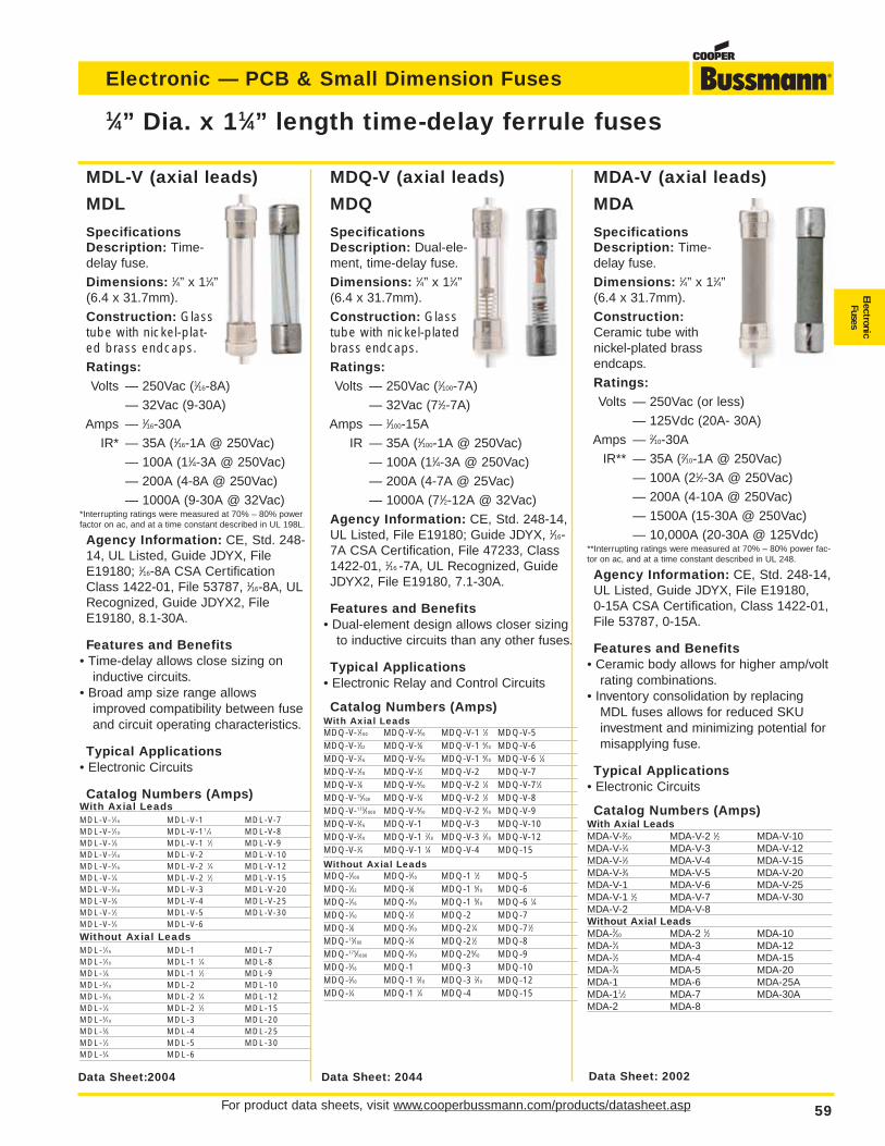
For product data sheets, visit www.cooperbussmann.com/products/datasheet.asp 59
Electronic — PCB & Small Dimension Fuses
ElectronicFuses
MDL-V (axial leads)
MDL
SpecificationsDescription: Time-delay fuse.
Dimensions: 1⁄4” x 11⁄4”(6.4 x 31.7mm).
Construction: Glasstube with nickel-plat-ed brass endcaps.Ratings:Volts — 250Vac (1⁄16-8A)
— 32Vac (9-30A)
Amps — 1⁄16-30A
IR* — 35A (1⁄16-1A @ 250Vac)
— 100A (11⁄4-3A @ 250Vac)
— 200A (4-8A @ 250Vac)
— 1000A (9-30A @ 32Vac)*Interrupting ratings were measured at 70% – 80% powerfactor on ac, and at a time constant described in UL 198L.
Agency Information: CE, Std. 248-14, UL Listed, Guide JDYX, FileE19180; 1⁄16-8A CSA CertificationClass 1422-01, File 53787, 1⁄16-8A, ULRecognized, Guide JDYX2, FileE19180, 8.1-30A.
Features and Benefits• Time-delay allows close sizing on
inductive circuits.• Broad amp size range allows
improved compatibility between fuseand circuit operating characteristics.
Typical Applications• Electronic Circuits
Catalog Numbers (Amps)With Axial LeadsMDL-V-1⁄16 MDL-V-1 MDL-V-7MDL-V-1⁄10 MDL-V-11 ⁄4 MDL-V-8MDL-V-1⁄8 MDL-V-1 1⁄2 MDL-V-9MDL-V-2⁄10 MDL-V-2 MDL-V-10MDL-V-3⁄16 MDL-V-2 1⁄4 MDL-V-12MDL-V-1⁄4 MDL-V-2 1⁄2 MDL-V-15MDL-V-3⁄10 MDL-V-3 MDL-V-20MDL-V-3⁄8 MDL-V-4 MDL-V-25MDL-V-1⁄2 MDL-V-5 MDL-V-30MDL-V-3⁄4 MDL-V-6
Without Axial LeadsMDL-1⁄16 MDL-1 MDL-7MDL-1⁄10 MDL-1 1⁄4 MDL-8MDL-1⁄8 MDL-1 1⁄2 MDL-9MDL-2⁄10 MDL-2 MDL-10MDL-3⁄16 MDL-2 1⁄4 MDL-12MDL-1⁄4 MDL-2 1⁄2 MDL-15MDL-3⁄10 MDL-3 MDL-20MDL-3⁄8 MDL-4 MDL-25MDL-1⁄2 MDL-5 MDL-30MDL-3⁄4 MDL-6
1⁄4” Dia. x 11⁄4” length time-delay ferrule fuses
Data Sheet:2004
MDA-V (axial leads)
MDA
SpecificationsDescription: Time-delay fuse.
Dimensions: 1⁄4” x 11⁄4”(6.4 x 31.7mm).
Construction:Ceramic tube with nickel-plated brassendcaps.
Ratings:Volts — 250Vac (or less)
— 125Vdc (20A- 30A)
Amps — 2⁄10-30A
IR** — 35A (2⁄10-1A @ 250Vac)
— 100A (21⁄2-3A @ 250Vac)
— 200A (4-10A @ 250Vac)
— 1500A (15-30A @ 250Vac)
— 10,000A (20-30A @ 125Vdc)**Interrupting ratings were measured at 70% – 80% power fac-tor on ac, and at a time constant described in UL 248.
Agency Information: CE, Std. 248-14,UL Listed, Guide JDYX, File E19180,0-15A CSA Certification, Class 1422-01,File 53787, 0-15A.
Features and Benefits• Ceramic body allows for higher amp/volt
rating combinations.• Inventory consolidation by replacing
MDL fuses allows for reduced SKUinvestment and minimizing potential formisapplying fuse.
Typical Applications• Electronic Circuits
Catalog Numbers (Amps)With Axial LeadsMDA-V-2⁄10 MDA-V-2 1⁄2 MDA-V-10MDA-V-1⁄4 MDA-V-3 MDA-V-12MDA-V-1⁄2 MDA-V-4 MDA-V-15MDA-V-3⁄4 MDA-V-5 MDA-V-20MDA-V-1 MDA-V-6 MDA-V-25MDA-V-1 1⁄2 MDA-V-7 MDA-V-30MDA-V-2 MDA-V-8Without Axial LeadsMDA-2⁄10 MDA-2 1⁄2 MDA-10MDA-1⁄4 MDA-3 MDA-12MDA-1⁄2 MDA-4 MDA-15MDA-3⁄4 MDA-5 MDA-20MDA-1 MDA-6 MDA-25AMDA-11 ⁄2 MDA-7 MDA-30AMDA-2 MDA-8
MDQ-V (axial leads)
MDQ
SpecificationsDescription: Dual-ele-ment, time-delay fuse.
Dimensions: 1⁄4” x 11⁄4”(6.4 x 31.7mm).
Construction: Glasstube with nickel-platedbrass endcaps.Ratings:Volts — 250Vac (1⁄100-7A)
— 32Vac (71⁄2-7A)
Amps — 1⁄100-15A
IR — 35A (1⁄100-1A @ 250Vac)
— 100A (11⁄4-3A @ 250Vac)
— 200A (4-7A @ 25Vac)
— 1000A (71⁄2-12A @ 32Vac)
Agency Information: CE, Std. 248-14,UL Listed, File E19180; Guide JDYX, 1⁄16-7A CSA Certification, File 47233, Class1422-01, 1⁄16 -7A, UL Recognized, GuideJDYX2, File E19180, 7.1-30A.
Features and Benefits• Dual-element design allows closer sizing
to inductive circuits than any other fuses.
Typical Applications• Electronic Relay and Control Circuits
Catalog Numbers (Amps)With Axial LeadsMDQ-V-1⁄100 MDQ-V-3⁄10 MDQ-V-1 1⁄2 MDQ-V-5MDQ-V-1⁄32 MDQ-V-3⁄8 MDQ-V-1 6⁄10 MDQ-V-6MDQ-V-1⁄16 MDQ-V-4⁄10 MDQ-V-1 8⁄10 MDQ-V-6 1⁄4MDQ-V-1⁄10 MDQ-V-1⁄2 MDQ-V-2 MDQ-V-7MDQ-V-1⁄8 MDQ-V-6⁄10 MDQ-V-2 1⁄4 MDQ-V-71⁄2MDQ-V-15⁄100 MDQ-V-3⁄4 MDQ-V-2 1⁄2 MDQ-V-8MDQ-V-175⁄1000 MDQ-V-8⁄10 MDQ-V-2 8⁄10 MDQ-V-9MDQ-V-3⁄16 MDQ-V-1 MDQ-V-3 MDQ-V-10MDQ-V-2⁄10 MDQ-V-1 2⁄10 MDQ-V-3 2⁄10 MDQ-V-12MDQ-V-1⁄4 MDQ-V-1 1⁄4 MDQ-V-4 MDQ-15
Without Axial LeadsMDQ-1⁄100 MDQ-3⁄10 MDQ-1 1⁄2 MDQ-5MDQ-1⁄32 MDQ-3⁄8 MDQ-1 6⁄10 MDQ-6MDQ-1⁄16 MDQ-4⁄10 MDQ-1 8⁄10 MDQ-6 1⁄4MDQ-1⁄10 MDQ-1⁄2 MDQ-2 MDQ-7MDQ-1⁄8 MDQ-6⁄10 MDQ-21⁄4 MDQ-71⁄2MDQ-15⁄100 MDQ-3⁄4 MDQ-21⁄2 MDQ-8MDQ-175⁄1000 MDQ-8⁄10 MDQ-28⁄10 MDQ-9MDQ-3⁄16 MDQ-1 MDQ-3 MDQ-10MDQ-2⁄10 MDQ-1 2⁄10 MDQ-3 2⁄10 MDQ-12MDQ-1⁄4 MDQ-1 1⁄4 MDQ-4 MDQ-15
Data Sheet: 2002Data Sheet: 2044
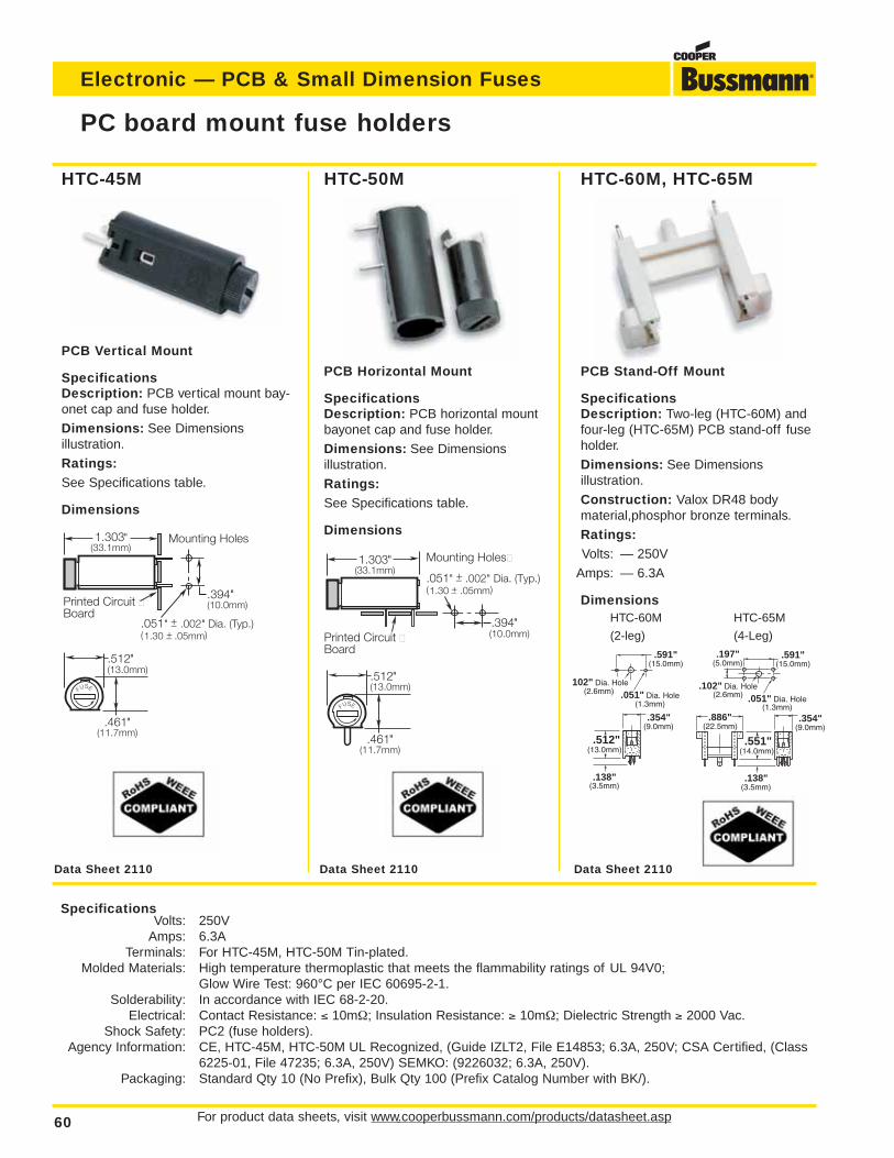
For product data sheets, visit www.cooperbussmann.com/products/datasheet.asp60
Electronic — PCB & Small Dimension Fuses
HTC-60M, HTC-65M
PCB Stand-Off Mount
SpecificationsDescription: Two-leg (HTC-60M) andfour-leg (HTC-65M) PCB stand-off fuseholder.
Dimensions: See Dimensions illustration.
Construction: Valox DR48 bodymaterial,phosphor bronze terminals.
Ratings:Volts: — 250V
Amps: — 6.3A
Dimensions
HTC-50M
PCB Horizontal Mount
SpecificationsDescription: PCB horizontal mountbayonet cap and fuse holder.
Dimensions: See Dimensions illustration.
Ratings:See Specifications table.
Dimensions
HTC-45M
PCB Vertical Mount
SpecificationsDescription: PCB vertical mount bay-onet cap and fuse holder.
Dimensions: See Dimensions illustration.
Ratings:See Specifications table.
Dimensions
PC board mount fuse holders
FUSE
.461"(11.7mm)
1.303"(33.1mm)
.512"(13.0mm)
Printed Circuit Board
.051" + .002" Dia. (Typ.) _ (1.30 + .05mm)_
.394"(10.0mm)
Mounting Holes
FUSE
.461"(11.7mm)
1.303"(33.1mm)
.512"(13.0mm)
Printed Circuit Board
.394"(10.0mm)
Mounting Holes
.051" + .002" Dia. (Typ.) _ (1.30 + .05mm)
_
.197"(5.0mm)
.102" Dia. Hole(2.6mm) .051" Dia. Hole
(1.3mm)
.591"(15.0mm)
.886"(22.5mm)
.138"(3.5mm)
.354"(9.0mm)
.551"(14.0mm)
102" Dia. Hole(2.6mm) .051" Dia. Hole
(1.3mm)
.591"(15.0mm)
.138"(3.5mm)
.354"(9.0mm)
.512"(13.0mm)
Data Sheet 2110 Data Sheet 2110 Data Sheet 2110
SpecificationsVolts: 250V
Amps: 6.3ATerminals: For HTC-45M, HTC-50M Tin-plated.
Molded Materials: High temperature thermoplastic that meets the flammability ratings of UL 94V0;Glow Wire Test: 960°C per IEC 60695-2-1.
Solderability: In accordance with IEC 68-2-20.Electrical: Contact Resistance: ≤ 10mΩ; Insulation Resistance: ≥ 10mΩ; Dielectric Strength ≥ 2000 Vac.
Shock Safety: PC2 (fuse holders).Agency Information: CE, HTC-45M, HTC-50M UL Recognized, (Guide IZLT2, File E14853; 6.3A, 250V; CSA Certified, (Class
6225-01, File 47235; 6.3A, 250V) SEMKO: (9226032; 6.3A, 250V).Packaging: Standard Qty 10 (No Prefix), Bulk Qty 100 (Prefix Catalog Number with BK/).
HTC-60M HTC-65M
(2-leg) (4-Leg)
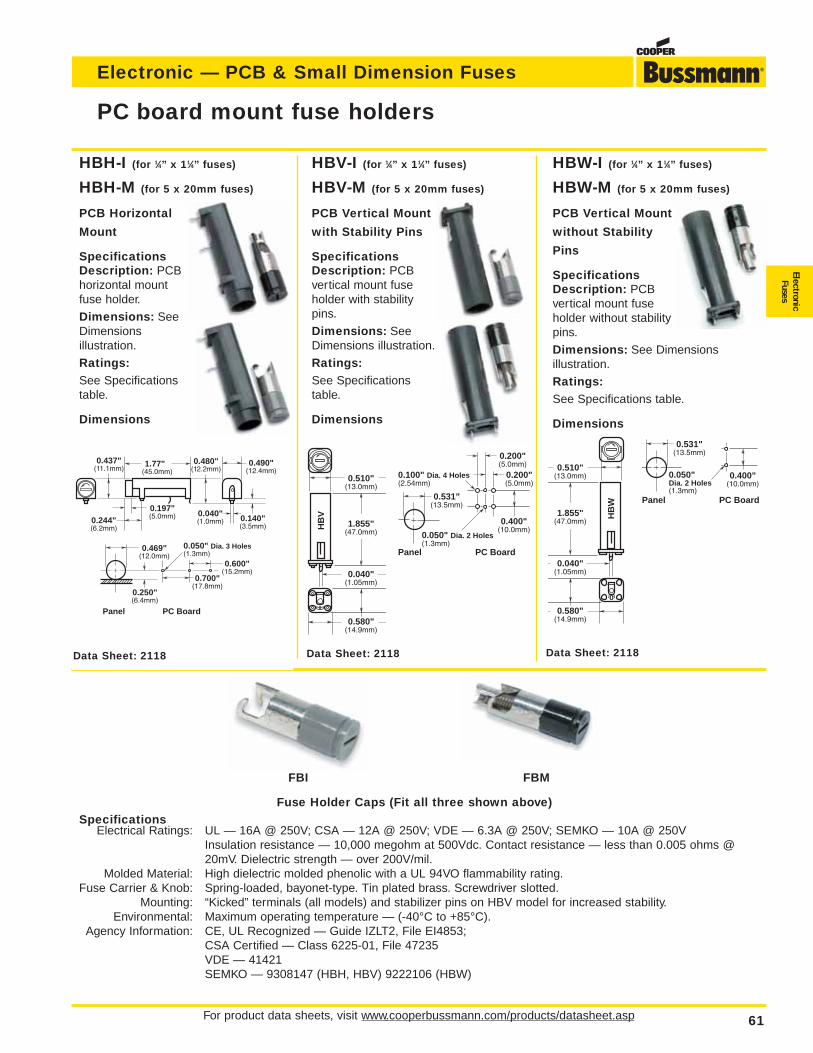
For product data sheets, visit www.cooperbussmann.com/products/datasheet.asp 61
Electronic — PCB & Small Dimension Fuses
ElectronicFuses
HBH-I (for 1⁄4” x 11⁄4” fuses)
HBH-M (for 5 x 20mm fuses)
PCB Horizontal
Mount
SpecificationsDescription: PCBhorizontal mountfuse holder.
Dimensions: SeeDimensions illustration.
Ratings:See Specificationstable.
Dimensions
HBV-I (for 1⁄4” x 11⁄4” fuses)
HBV-M (for 5 x 20mm fuses)
PCB Vertical Mount
with Stability Pins
SpecificationsDescription: PCBvertical mount fuseholder with stabilitypins.
Dimensions: SeeDimensions illustration.
Ratings:See Specificationstable.
Dimensions
HBW-I (for 1⁄4” x 11⁄4” fuses)
HBW-M (for 5 x 20mm fuses)
PCB Vertical Mount
without Stability
Pins
SpecificationsDescription: PCBvertical mount fuseholder without stabilitypins.
Dimensions: See Dimensions illustration.
Ratings:See Specifications table.
Dimensions
PC board mount fuse holders
0.437"(11.1mm)
0.197"(5.0mm)0.244"
(6.2mm)
1.77"(45.0mm)
0.480"(12.2mm)
0.490"(12.4mm)
0.040"(1.0mm) 0.140"
(3.5mm)
0.469"(12.0mm)
0.250"(6.4mm)
Panel
0.700"(17.8mm)
0.600"(15.2mm)
0.050" Dia. 3 Holes(1.3mm)
PC Board
HB
V
0.510"(13.0mm)
1.855"(47.0mm)
0.040"(1.05mm)
0.580"(14.9mm)
0.200"(5.0mm)
0.200"(5.0mm)
0.100" Dia. 4 Holes(2.54mm)
Panel PC Board
0.531"(13.5mm)
0.400"(10.0mm)
0.050" Dia. 2 Holes(1.3mm)
HB
W
0.510"(13.0mm)
1.855"(47.0mm)
0.040"(1.05mm)
0.580"(14.9mm)
Panel PC Board
0.531"(13.5mm)
0.400"(10.0mm)
0.050" Dia. 2 Holes(1.3mm)
Data Sheet: 2118 Data Sheet: 2118 Data Sheet: 2118
FBI FBM
Fuse Holder Caps (Fit all three shown above)Specifications
Electrical Ratings: UL — 16A @ 250V; CSA — 12A @ 250V; VDE — 6.3A @ 250V; SEMKO — 10A @ 250VInsulation resistance — 10,000 megohm at 500Vdc. Contact resistance — less than 0.005 ohms @20mV. Dielectric strength — over 200V/mil.
Molded Material: High dielectric molded phenolic with a UL 94VO flammability rating.Fuse Carrier & Knob: Spring-loaded, bayonet-type. Tin plated brass. Screwdriver slotted.
Mounting: “Kicked” terminals (all models) and stabilizer pins on HBV model for increased stability.Environmental: Maximum operating temperature — (-40°C to +85°C).
Agency Information: CE, UL Recognized — Guide IZLT2, File EI4853;CSA Certified — Class 6225-01, File 47235VDE — 41421SEMKO — 9308147 (HBH, HBV) 9222106 (HBW)
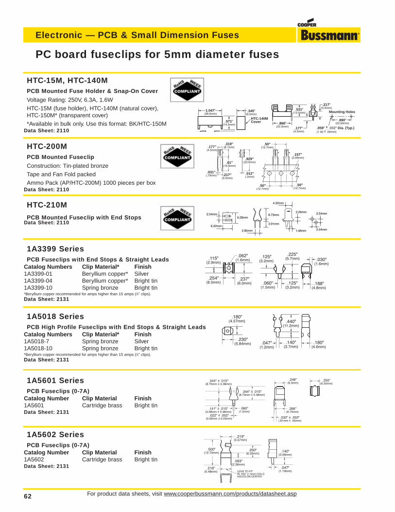
For product data sheets, visit www.cooperbussmann.com/products/datasheet.asp62
Electronic — PCB & Small Dimension Fuses
PC board fuseclips for 5mm diameter fuses
.031"(.79mm) .217"
(5.5mm)
.012"(.3mm)
.177"(4.5mm)
.319"(8.1mm)
BUSS
.61"(15.5mm)
.929"(23.6mm)
BUSS
BUSS
.50"(12.7mm)
.50"(12.7mm)
.50"(12.7mm)
.157"(3.99mm)
2.54mm1.46mm
2.29mm
4.32mm
8.73mm
3.91mm
2.85mm
6.26mm
6.22mm
2.54mm 2.54mm
.180"(4.57mm)
.230"(5.84mm)
HTC-210M
PCB Mounted Fuseclip with End StopsData Sheet: 2110
HTC-15M, HTC-140MPCB Mounted Fuse Holder & Snap-On Cover
Voltage Rating: 250V, 6.3A, 1.6W
HTC-15M (fuse holder), HTC-140M (natural cover),HTC-150M* (transparent cover)
*Available in bulk only. Use this format: BK/HTC-150MData Sheet: 2110
HTC-200MPCB Mounted Fuseclip
Construction: Tin-plated bronze
Tape and Fan Fold packed
Ammo Pack (AP/HTC-200M) 1000 pieces per boxData Sheet: 2110
1A3399 SeriesPCB Fuseclips with End Stops & Straight Leads
Catalog Numbers Clip Material* Finish1A3399-01 Beryllium copper* Silver1A3399-04 Beryllium copper* Bright tin1A3399-10 Spring bronze Bright tin*Beryllium copper recommended for amps higher than 15 amps (1⁄4” clips).
Data Sheet: 2131
1A5601 SeriesPCB Fuseclips (0-7A)
Catalog Number Clip Material Finish1A5601 Cartridge brass Bright tinData Sheet: 2131
1A5602 SeriesPCB Fuseclips (0-7A)
Catalog Number Clip Material Finish1A5602 Cartridge brass Bright tinData Sheet: 2131
1A5018 SeriesPCB High Profile Fuseclips with End Stops & Straight Leads
Catalog Numbers Clip Material* Finish1A5018-7 Spring bronze Silver1A5018-10 Spring bronze Bright tin*Beryllium copper recommended for amps higher than 15 amps (1⁄4” clips).
Data Sheet: 2131
.115"(2.9mm)
.062"(1.6mm)
.254"(6.5mm)
.237"(6.0mm)
.125"(3.2mm)
.225"(5.7mm)
.125"(3.2mm)
.060"(1.5mm)
.188"(4.8mm)
.030"(1.6mm)
.440"(11.2mm)
.140"(3.7mm)
.047"(1.2mm)
.180"(4.6mm)
.250"(6.35mm)
.060"(1.5mm)
.246"(6.3mm)
.344" + .015"(8.73mm + 0.38mm)
.266"(6.75mm)
.344" + .015"(8.73mm + 0.38mm)
.141" + .015"(3.58mm + 0.38mm)
.022" + .002"(0.56mm + 0.05mm) .032" + .002"
(.81mm + .05mm)
.216"(5.48mm) LEGS TO FIT
IN .052" (1.3mm) DIA.HOLES ON CENTER
.219"(5.57mm)
.047"(1.19mm)
.093"(2.36mm)
.500" (12.70mm)
.250"(6.35mm)
.140"(3.56mm)
HTC-140M Cover
1.047"(26.6mm)
217"
.345"(9.0mm)
.571"(14.5mm) .866"
(22.0mm)
.217"(5.5mm)
.177"(4.5mm)
.890"(22.60mm)
Mounting Holes
.059" + .002" Dia. (Typ.)
_ (1.50 + .05mm)
_
.531"(13.5mm)
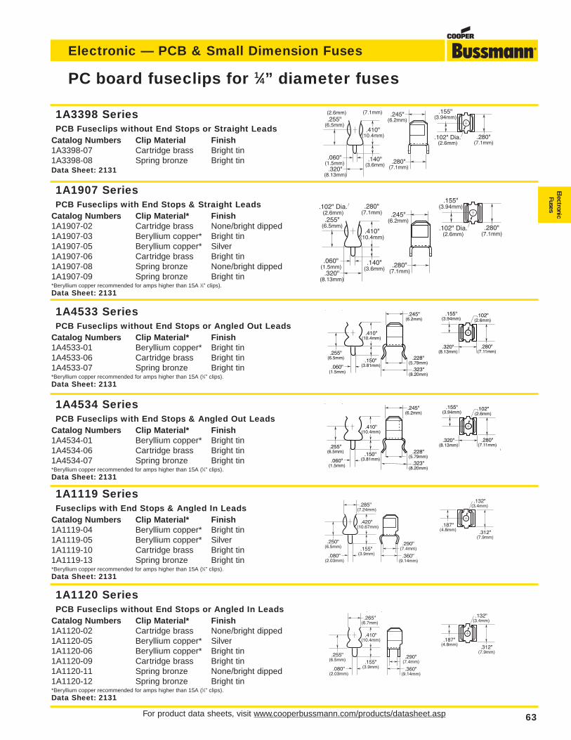
For product data sheets, visit www.cooperbussmann.com/products/datasheet.asp 63
Electronic — PCB & Small Dimension Fuses
ElectronicFuses
PC board fuseclips for 1⁄4” diameter fuses
.245"(6.2mm)
.280"(7.1mm)
(7.1mm)
.410"(10.4mm)
.140"(3.6mm)
.060"(1.5mm)
.320"(8.13mm)
(2.6mm).255"
(6.5mm)
.280"(7.1mm)
.155"(3.94mm)
.102" Dia.(2.6mm)
.245"(6.2mm)
.280"(7.1mm)
.280"(7.1mm)
.410"(10.4mm)
.140"(3.6mm)
.060"(1.5mm)
.320"(8.13mm)
.102" Dia.(2.6mm).255"
(6.5mm) .280"(7.1mm)
.155"(3.94mm)
.102" Dia.(2.6mm)
.255"(6.5mm)
.410"(10.4mm)
.060"(1.5mm)
.150"(3.81mm)
( )
.245"(6.2mm)
.228"(5.79mm)
.323"(8.20mm)
.280"(7.11mm)
.102"(2.6mm)
.155"(3.94mm)
.320"(8.13mm)
( )
.255"(6.5mm)
.410"(10.4mm)
.080"(2.03mm)
.265"(6.7mm)
.155"(3.9mm)
.290"(7.4mm)
.360"(9.14mm)
.312"(7.9mm)
.132"(3.4mm)
.187"(4.8mm)
.312"(7.9mm)
.132"(3.4mm)
.187"(4.8mm)
.250"(6.5mm)
.420"(10.67mm)
.080"(2.03mm)
.285"(7.24mm)
.155"(3.9mm)
.290"(7.4mm)
.360"(9.14mm)
1A3398 SeriesPCB Fuseclips without End Stops or Straight Leads
Catalog Numbers Clip Material Finish1A3398-07 Cartridge brass Bright tin1A3398-08 Spring bronze Bright tinData Sheet: 2131
1A1907 SeriesPCB Fuseclips with End Stops & Straight Leads
Catalog Numbers Clip Material* Finish1A1907-02 Cartridge brass None/bright dipped1A1907-03 Beryllium copper* Bright tin1A1907-05 Beryllium copper* Silver1A1907-06 Cartridge brass Bright tin1A1907-08 Spring bronze None/bright dipped1A1907-09 Spring bronze Bright tin*Beryllium copper recommended for amps higher than 15A 1⁄4” clips).
Data Sheet: 2131
1A1120 SeriesPCB Fuseclips without End Stops or Angled In Leads
Catalog Numbers Clip Material* Finish1A1120-02 Cartridge brass None/bright dipped1A1120-05 Beryllium copper* Silver1A1120-06 Beryllium copper* Bright tin1A1120-09 Cartridge brass Bright tin1A1120-11 Spring bronze None/bright dipped1A1120-12 Spring bronze Bright tin*Beryllium copper recommended for amps higher than 15A (1⁄4” clips).
Data Sheet: 2131
1A1119 SeriesFuseclips with End Stops & Angled In Leads
Catalog Numbers Clip Material* Finish1A1119-04 Beryllium copper* Bright tin1A1119-05 Beryllium copper* Silver1A1119-10 Cartridge brass Bright tin1A1119-13 Spring bronze Bright tin*Beryllium copper recommended for amps higher than 15A (1⁄4” clips).
Data Sheet: 2131
1A4534 SeriesPCB Fuseclips with End Stops & Angled Out Leads
Catalog Numbers Clip Material* Finish1A4534-01 Beryllium copper* Bright tin1A4534-06 Cartridge brass Bright tin1A4534-07 Spring bronze Bright tin*Beryllium copper recommended for amps higher than 15A (1⁄4” clips).
Data Sheet: 2131
1A4533 SeriesPCB Fuseclips without End Stops or Angled Out Leads
Catalog Numbers Clip Material* Finish1A4533-01 Beryllium copper* Bright tin1A4533-06 Cartridge brass Bright tin1A4533-07 Spring bronze Bright tin*Beryllium copper recommended for amps higher than 15A (1⁄4” clips).
Data Sheet: 2131
.255"(6.5mm)
.410"(10.4mm)
.060"(1.5mm)
.150"(3.81mm)
( )
.245"(6.2mm)
.228"(5.79mm)
.323"(8.20mm)
.280"(7.11mm)
.102"(2.6mm)
.155"(3.94mm)
.320"(8.13mm)
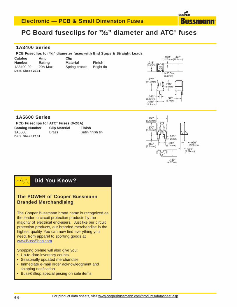
For product data sheets, visit www.cooperbussmann.com/products/datasheet.asp64
Electronic — PCB & Small Dimension Fuses
PC Board fuseclips for 13⁄32” diameter and ATC® fuses
1A5600 SeriesPCB Fuseclips for ATC® Fuses (0-20A)
Catalog Number Clip Material Finish1A5600 Brass Satin finish tinData Sheet 2131
.218"(5.5mm)
.710"(18.0mm)
.080"(2.0mm).470"
(11.9mm)
.142" Dia.(3.6mm)
.050"(1.27mm)
.437"(11.1mm)
.470"(11.9mm)
.380"(9.7mm)
.150"(3.81mm)
.330"(8.38mm)
.295"(7.49mm)
.180"(4.57mm)
.200"(5.08mm)
.053"(1.35mm)
.090"(2.29mm)
.090"(2.29mm)
1A3400 SeriesPCB Fuseclips for 13⁄32” diameter fuses with End Stops & Straight Leads
Catalog Amp ClipNumber Rating Material Finish1A3400-09 20A Max. Spring bronze Bright tinData Sheet 2131
The POWER of Cooper BussmannBranded Merchandising
The Cooper Bussmann brand name is recognized asthe leader in circuit protection products by the majority of electrical end-users. Just like our circuitprotection products, our branded merchandise is thehighest quality. You can now find everything youneed, from apparel to sporting goods atwww.BussShop.com.
Shopping on-line will also give you:• Up-to-date inventory counts• Seasonally updated merchandise• Immediate e-mail order acknowledgment and
shipping notification• Buss®Shop special pricing on sale items
Did You Know?
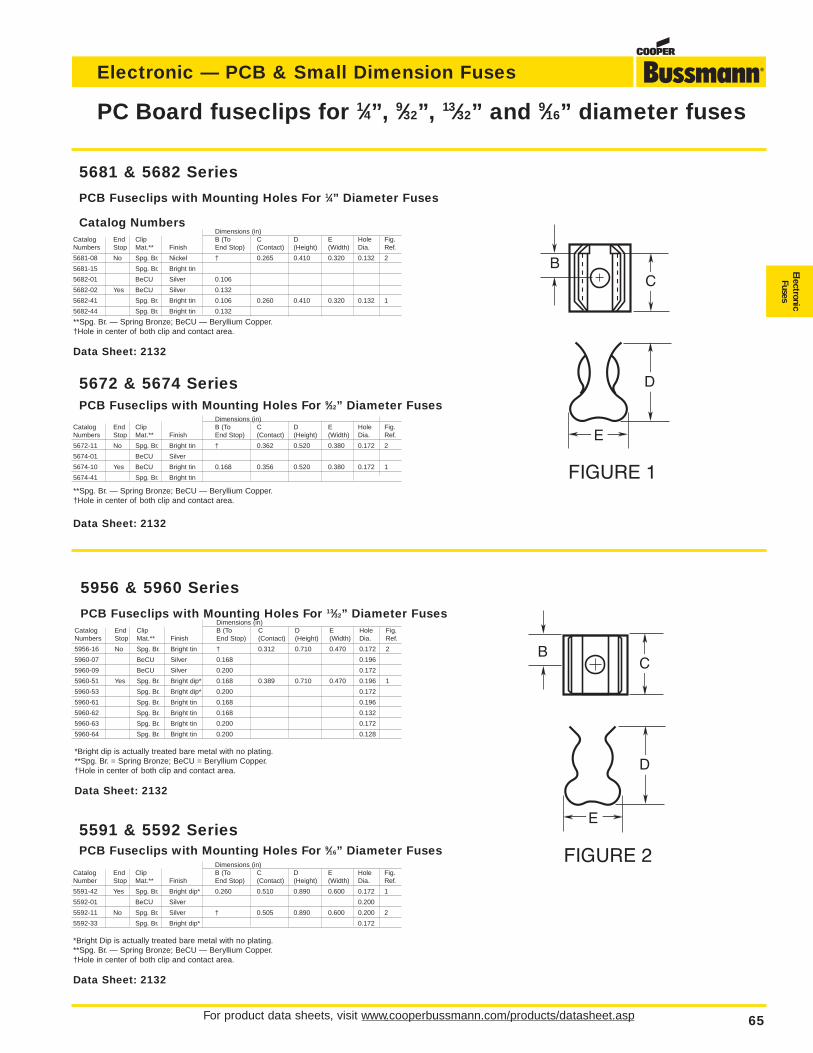
For product data sheets, visit www.cooperbussmann.com/products/datasheet.asp 65
Electronic — PCB & Small Dimension Fuses
ElectronicFuses
PC Board fuseclips for 1⁄4”, 9⁄32”, 13⁄32” and 9⁄16” diameter fuses
BC
D
E
FIGURE 1
C
D
E
FIGURE 2
B
5591 & 5592 SeriesPCB Fuseclips with Mounting Holes For 9⁄16” Diameter Fuses
Dimensions (in)Catalog End Clip B (To C D E Hole Fig.Number Stop Mat.** Finish End Stop) (Contact) (Height) (Width) Dia. Ref.
5591-42 Yes Spg. Br. Bright dip* 0.260 0.510 0.890 0.600 0.172 1
5592-01 BeCU Silver 0.200
5592-11 No Spg. Br. Silver † 0.505 0.890 0.600 0.200 2
5592-33 Spg. Br. Bright dip* 0.172
*Bright Dip is actually treated bare metal with no plating.**Spg. Br. — Spring Bronze; BeCU — Beryllium Copper.†Hole in center of both clip and contact area.
Data Sheet: 2132
5681 & 5682 Series
PCB Fuseclips with Mounting Holes For 1⁄4” Diameter Fuses
Catalog NumbersDimensions (in)
Catalog End Clip B (To C D E Hole Fig.Numbers Stop Mat.** Finish End Stop) (Contact) (Height) (Width) Dia. Ref.
5681-08 No Spg. Br. Nickel † 0.265 0.410 0.320 0.132 2
5681-15 Spg. Br. Bright tin
5682-01 BeCU Silver 0.106
5682-02 Yes BeCU Silver 0.132
5682-41 Spg. Br. Bright tin 0.106 0.260 0.410 0.320 0.132 1
5682-44 Spg. Br. Bright tin 0.132
**Spg. Br. — Spring Bronze; BeCU — Beryllium Copper.†Hole in center of both clip and contact area.
Data Sheet: 2132
5672 & 5674 SeriesPCB Fuseclips with Mounting Holes For 9⁄32” Diameter Fuses
Dimensions (in)Catalog End Clip B (To C D E Hole Fig.Numbers Stop Mat.** Finish End Stop) (Contact) (Height) (Width) Dia. Ref.
5672-11 No Spg. Br. Bright tin † 0.362 0.520 0.380 0.172 2
5674-01 BeCU Silver
5674-10 Yes BeCU Bright tin 0.168 0.356 0.520 0.380 0.172 1
5674-41 Spg. Br. Bright tin
**Spg. Br. — Spring Bronze; BeCU — Beryllium Copper.†Hole in center of both clip and contact area.
Data Sheet: 2132
5956 & 5960 Series
PCB Fuseclips with Mounting Holes For 13⁄32” Diameter Fuses Dimensions (in)
Catalog End Clip B (To C D E Hole Fig.Numbers Stop Mat.** Finish End Stop) (Contact) (Height) (Width) Dia. Ref.
5956-16 No Spg. Br. Bright tin † 0.312 0.710 0.470 0.172 2
5960-07 BeCU Silver 0.168 0.196
5960-09 BeCU Silver 0.200 0.172
5960-51 Yes Spg. Br. Bright dip* 0.168 0.389 0.710 0.470 0.196 1
5960-53 Spg. Br. Bright dip* 0.200 0.172
5960-61 Spg. Br. Bright tin 0.168 0.196
5960-62 Spg. Br. Bright tin 0.168 0.132
5960-63 Spg. Br. Bright tin 0.200 0.172
5960-64 Spg. Br. Bright tin 0.200 0.128
*Bright dip is actually treated bare metal with no plating.**Spg. Br. = Spring Bronze; BeCU = Beryllium Copper.†Hole in center of both clip and contact area.
Data Sheet: 2132

66
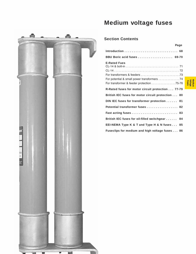
67
Medium
VoltageFuses
Section Contents
Page
Introduction . . . . . . . . . . . . . . . . . . . . . . . . . . . . . 68
BBU Boric acid fuses . . . . . . . . . . . . . . . . . . . 69-70
E-Rated FuesCL-14 & bolt-in . . . . . . . . . . . . . . . . . . . . . . . . . . . . . . . . . . . 71
CL-14 . . . . . . . . . . . . . . . . . . . . . . . . . . . . . . . . . . . . . . . . . . . 72
For transformers & feeders . . . . . . . . . . . . . . . . . . . . . . . . . .73
For potential & small power transformers . . . . . . . . . . . . . . 74
For transformer & feeder protection . . . . . . . . . . . . . . . .75-76
R-Rated fuses for motor circuit protection . . . 77-79
British IEC fuses for motor circuit protection . . . 80
DIN IEC fuses for transformer protection . . . . . . 81
Potential transformer fuses . . . . . . . . . . . . . . . . . 82
Fast acting fuses . . . . . . . . . . . . . . . . . . . . . . . . . 83
British IEC fuses for oil-filled switchgear . . . . . . 84
EEI-NEMA Type K & T and Type H & N fuses . . . 85
Fuseclips for medium and high voltage fuses . . . 86
Medium voltage fuses
For product Data Sheets, visit www.cooperbussmann.com/products/datasheet.asp68
Medium Voltage Fuses
Medium voltage fuses
Worldwide Circuit Protection SolutionsCopper Bussmann is a world-leading supplier of fuses andfusible protection systems. Each product is backed by an efficient worldwide distribution network with unrivaled serviceand technical support. Cooper Bussmann circuit protectionsolutions comply with major international standards: BS, IEC,DIN and UL.
Cooper Bussmann medium voltage fuses have absorbed andembodied the expertise and experience of the thirteen mostprestigious manufacturers and offer an unbeatable range ofproducts in terms of technical excellence, performance andquality.
Cooper Bussmann offers a wider range of medium voltagefuses than any other manufacturer, with types available tomeet most service applications. With over 50 years experience in design and manufacture, Cooper Bussmannhas supplied fuses to more than 90 countries worldwide.
Cooper Bussmann medium voltage fuses are extremelyeffective in preventing damage to a system in the event of afault, due to considerable limitation of let-through current inDIN and British Standard designs to the latest IEC requirements.
Cooper Bussmann was a pioneer in the development of full-range medium and high voltage fuses and is consequentlythe market leader in this field offering genuine full-rangecharacteristics.
The Cooper Bussmann team of specialist engineers plays aleading role in international standardization of medium voltage fuses, offering a comprehensive service of advice onapplication and selection of medium voltage fuses.
With a continual commitment to meet our customers' needs,with innovative, high quality products with ISO 9001, ISO9002 and ISO 14000 "approved systems," CooperBussmann is the supplier of choice for medium voltage circuit protection solutions.
Features and Benefits• Cool Running: A small mass of special low melting point
alloy called M-effect applied on each fuse element has theeffect of drastically reducing the temperature of the fuseduring operation. The larger cross section of the fuse elements made possible by use of M-effect ensures coolerrunning and lower power dissipation under normal serviceconditions.
• Cool Operation: When a Cooper Bussmann fuse operatesunder low fault conditions, the maximum temperature rise ofthe fuse is held well within the no damage temperature limits for all insulated fuse switchgear typically about 160ºC.The fuse carrier contacts remain unimpaired.
• Non-Deterioration: High purity silver is used as elementmaterial and the use of M-effect ensures against the possibility of long term grain growth by keeping the runningtemperature of the element material well within safe limits.
• Surge Current Withstand: The use of M-effect allows use ofa somewhat larger element cross section for a given currentrating. This improves withstand capability against transientover currents such as those due to transformer magnetizinginrush current or lightning surge.
• Short Circuit Interrupting Performance: Cooper Bussmannfuses are tested to IEC standards and are designed to limitpeak let-through current and energy to exceptionally lowvalues; thus ensuring maximum protection to associatedtransformer, cables or switchgear.
• Construction: The mechanical construction ensures againstdamage or deterioration in normal service. All electricalconnections within the fuse are made by welded or brazedjoints thus avoiding any risk of long term poor or intermittentinternal contact.
• Quality: Cooper Bussmann operates a rigorous and intensive quality control system. All fuses are X-rayed,examined and electrically tested prior to packing and amanufacturing date number allocated to aid identification inthe unlikely event of a subsequent query.
Medium Voltage Fuse Construction• Silver Elements: High purity silver is used to make the
conducting elements. The high conductivity of silver alongwith a larger element cross section is used in conjunctionwith the M-effect to provide low power dissipation and non-deterioration for the life time of the fuse. Most mediumvoltage fuses have elements connected in parallel woundaround a star shape ceramic core, but for motor fuses theelements are passed straight through allowing up to 24 elements in one fuse.
• Striker Mechanism: The striker can provide the user withvisual indication that the fuse has operated. However, it ismost commonly used to trip associated switchgear to allow3-phase disconnection, whatever the fault condition.
• Oil Seals: The Cooper Bussmann range of oil tight fuses aredesigned for use in oil-filled switchgear. A unique triple sealensures against long-term deterioration.
• Fixing Arrangement: Cooper Bussmann fuses come with avariety of tags, studs and collars, which provide the userwith easy installation. Higher current ratings can beobtained by bolting two or more fuses together and specialfixing arrangements are available for this purpose.
• Granular Quartz Filler: All Cooper Bussmann current-limitingfuses are filled with "sand" where the quality, grain size andcompaction are all critical in providing a filler which acts asan arc-quenching medium during fuse operation.
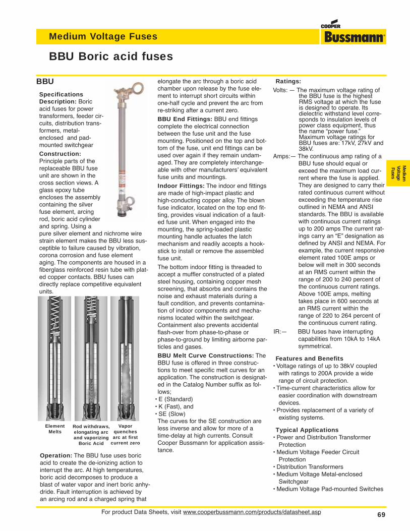
For product Data Sheets, visit www.cooperbussmann.com/products/datasheet.asp 69
Medium Voltage Fuses
Medium
VoltageFuses
BBU Boric acid fuses
Element Melts
Rod withdraws,elongating arcand vaporizing
Boric Acid
Vapor quenches arc at first
current zero
BBU
SpecificationsDescription: Boricacid fuses for powertransformers, feeder cir-cuits, distribution trans-formers, metal-enclosed and pad-mounted switchgear
Construction:Principle parts of thereplaceable BBU fuseunit are shown in thecross section views. Aglass epoxy tubeencloses the assemblycontaining the silverfuse element, arcingrod, boric acid cylinderand spring. Using apure silver element and nichrome wirestrain element makes the BBU less sus-ceptible to failure caused by vibration,corona corrosion and fuse elementaging. The components are housed in afiberglass reinforced resin tube with plat-ed copper contacts. BBU fuses candirectly replace competitive equivalentunits.
Operation: The BBU fuse uses boricacid to create the de-ionizing action tointerrupt the arc. At high temperatures,boric acid decomposes to produce ablast of water vapor and inert boric anhy-dride. Fault interruption is achieved byan arcing rod and a charged spring that
elongate the arc through a boric acidchamber upon release by the fuse ele-ment to interrupt short circuits withinone-half cycle and prevent the arc fromre-striking after a current zero.
BBU End Fittings: BBU end fittingscomplete the electrical connectionbetween the fuse unit and the fusemounting. Positioned on the top and bot-tom of the fuse, unit end fittings can beused over again if they remain undam-aged. They are completely interchange-able with other manufacturers’ equivalentfuse units and mountings.
Indoor Fittings: The indoor end fittingsare made of high-impact plastic andhigh-conducting copper alloy. The blownfuse indicator, located on the top end fit-ting, provides visual indication of a fault-ed fuse unit. When engaged into themounting, the spring-loaded plasticmounting handle actuates the latchmechanism and readily accepts a hook-stick to install or remove the assembledfuse unit.
The bottom indoor fitting is threaded toaccept a muffler constructed of a platedsteel housing, containing copper meshscreening, that absorbs and contains thenoise and exhaust materials during afault condition, and prevents contamina-tion of indoor components and mecha-nisms located within the switchgear.Containment also prevents accidentalflash-over from phase-to-phase orphase-to-ground by limiting airborne par-ticles and gases.
BBU Melt Curve Constructions: TheBBU fuse is offered in three construc-tions to meet specific melt curves for anapplication. The construction is designat-ed in the Catalog Number suffix as fol-lows;
• E (Standard)• K (Fast), and• SE (Slow)The curves for the SE construction areless inverse and allow for more of atime-delay at high currents. ConsultCooper Bussmann for application assis-tance.
Ratings:Volts: — The maximum voltage rating of
the BBU fuse is the highestRMS voltage at which the fuseis designed to operate. Itsdielectric withstand level corre-sponds to insulation levels ofpower class equipment, thusthe name “power fuse.”Maximum voltage ratings forBBU fuses are: 17kV, 27kV and38kV.
Amps:— The continuous amp rating of aBBU fuse should equal orexceed the maximum load cur-rent where the fuse is applied.They are designed to carry theirrated continuous current withoutexceeding the temperature riseoutlined in NEMA and ANSIstandards. The BBU is availablewith continuous current ratingsup to 200 amps The current rat-ings carry an “E” designation asdefined by ANSI and NEMA. Forexample, the current responsiveelement rated 100E amps orbelow will melt in 300 secondsat an RMS current within therange of 200 to 240 percent ofthe continuous current ratings.Above 100E amps, meltingtakes place in 600 seconds atan RMS current within therange of 220 to 264 percent ofthe continuous current rating.
IR:— BBU fuses have interruptingcapabilities from 10kA to 14kAsymmetrical.
Features and Benefits• Voltage ratings of up to 38kV coupled
with ratings to 200A provide a widerange of circuit protection.
• Time-current characteristics allow foreasier coordination with downstreamdevices.
• Provides replacement of a variety ofexisting systems.
Typical Applications• Power and Distribution Transformer
Protection• Medium Voltage Feeder Circuit
Protection• Distribution Transformers• Medium Voltage Metal-enclosed
Switchgear• Medium Voltage Pad-mounted Switches
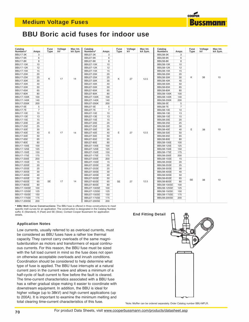
For product Data Sheets, visit www.cooperbussmann.com/products/datasheet.asp70
Medium Voltage Fuses
Catalog Fuse Voltage Max Int.Numbers Amps Type kV kA Sym.BBU38-3K 3 K 38 10BBU38-6K 6BBU38-8K 8BBU38-10K 10BBU38-12K 12BBU38-15K 15BBU38-20K 20BBU38-30K 30BBU38-40K 40BBU38-50K 50BBU38-65K 65BBU38-80K 80BBU38-100K 100BBU38-140K 140BBU38-200K 200BBU38-5E 5 E 38 10BBU38-7E 7BBU38-10E 10BBU38-13E 13BBU38-15E 15BBU38-20E 20BBU38-25E 25BBU38-30E 30BBU38-40E 40BBU38-50E 50BBU38-65E 65BBU38-80E 80BBU38-100E 100BBU38-125E 125BBU38-150E 150BBU38-175E 175BBU38-200E 200BBU38-15SE 15 SE 38 10BBU38-20SE 20BBU38-25SE 25BBU38-30SE 30BBU38-40SE 40BBU38-50SE 50BBU38-65SE 65BBU38-80SE 80BBU38-100SE 100BBU38-125SE 125BBU38-150SE 150BBU38-175SE 175BBU38-200SE 200
Catalog Fuse Voltage Max Int.Numbers* Amps Type kV kA Sym.BBU27-3K 3 K 27 12.5BBU27-6K 6BBU27-8K 8BBU27-10K 10BBU27-12K 12BBU27-15K 15BBU27-20K 20BBU27-25K 25BBU27-30K 30BBU27-40K 40BBU27-50K 50BBU27-65K 65BBU27-80K 80BBU27-100K 100BBU27-140K 140BBU27-200K 200BBU27-5E 5 E 27 12.5BBU27-7E 7BBU27-10E 10BBU27-13E 13BBU27-15E 15BBU27-20E 20BBU27-25E 25BBU27-30E 30BBU27-40E 40BBU27-50E 50BBU27-65E 65BBU27-80E 80BBU27-100E 100BBU27-125E 125BBU27-150E 150BBU27-175E 175BBU27-200E 200BBU27-15SE 15 SE 27 12.5BBU27-20SE 20BBU27-25SE 25BBU27-30SE 30BBU27-40SE 40BBU27-50SE 50BBU27-65SE 65BBU27-80SE 80BBU27-100SE 100BBU27-125SE 125BBU27-150SE 150BBU27-175SE 175BBU27-200SE 200
Catalog Fuse Voltage Max Int.Numbers* Amps Type kV kA SymBBU17-3K 3 K 17 14BBU17-6K 6BBU17-8K 8BBU17-10K 10BBU17-12K 12BBU17-15K 15BBU17-20K 20BBU17-25K 25BBU17-30K 30BBU17-40K 40BBU17-50K 50BBU17-65K 65BBU17-80K 80BBU17-100K 100BBU17-140K 140BBU17-200K 200BBU17-5E 5 E 17 14BBU17-7E 7BBU17-10E 10BBU17-13E 13BBU17-15E 15BBU17-20E 20BBU17-25E 25BBU17-30E 30BBU17-40E 40BBU17-50E 50BBU17-65E 65BBU17-80E 80BBU17-100E 100BBU17-125E 125BBU17-150E 150BBU17-175E 175BBU17-200E 200BBU17-15SE 15 SE 17 14BBU17-20SE 20BBU17-25SE 25BBU17-30SE 30BBU17-40SE 40BBU17-50SE 50BBU17-65SE 65BBU17-80SE 80BBU17-100SE 100BBU17-125SE 125BBU17-150SE 150BBU17-175SE 175BBU17-200SE 200
BBU Boric acid fuses for indoor use
*Note: Muffler can be ordered separately. Order Catalog number BBU-MFLR.
Application Notes
Low currents, usually referred to as overload currents, mustbe considered as BBU fuses have a rather low thermalcapacity. They cannot carry overloads of the same magni-tude/duration as motors and transformers of equal continu-ous currents. For this reason, the BBU fuse must be sizedwith the full load current in mind so the fuse does not openon otherwise acceptable overloads and inrush conditions.Coordination should be considered to help determine whattype of fuse is applied. The BBU fuse interrupts at a naturalcurrent zero in the current wave and allows a minimum of ahalf-cycle of fault current to flow before the fault is cleared.The time-current characteristics associated with a BBU fusehas a rather gradual slope making it easier to coordinate withdownstream equipment. In addition, the BBU is ideal forhigher voltage (up to 38kV) and high current applications (upto 200A). It is important to examine the minimum melting andtotal clearing time-current characteristics of this fuse.
* BBU Melt Curve Constructions: The BBU fuse is offered in three constructions to meetspecific melt curves for an application. The construction is designated in the Catalog Numbersuffix: E (Standard), K (Fast) and SE (Slow). Contact Cooper Bussmann for applicationdetails. End Fitting Detail
K 27 12.5
12.5
12.5
27
27
E
SE
K 17 14
14
14
17
17
E
SE
K 38 10
10
10
38
38
E
SE
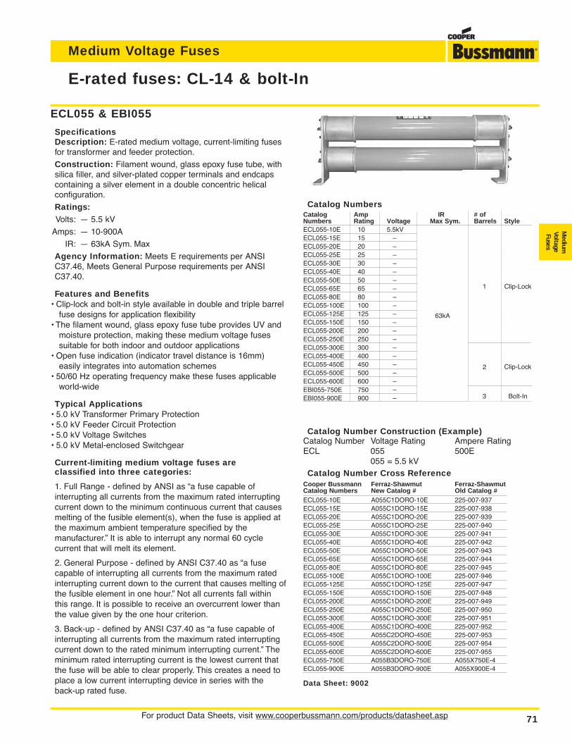
For product Data Sheets, visit www.cooperbussmann.com/products/datasheet.asp 71
Medium Voltage Fuses
Medium
VoltageFuses
E-rated fuses: CL-14 & bolt-In
Data Sheet: 9002
Catalog Number Cross ReferenceCooper Bussmann Ferraz-Shawmut Ferraz-ShawmutCatalog Numbers New Catalog # Old Catalog #ECL055-10E A055C1DORO-10E 225-007-937ECL055-15E A055C1DORO-15E 225-007-938ECL055-20E A055C1DORO-20E 225-007-939ECL055-25E A055C1DORO-25E 225-007-940ECL055-30E A055C1DORO-30E 225-007-941ECL055-40E A055C1DORO-40E 225-007-942ECL055-50E A055C1DORO-50E 225-007-943ECL055-65E A055C1DORO-65E 225-007-944ECL055-80E A055C1DORO-80E 225-007-945ECL055-100E A055C1DORO-100E 225-007-946ECL055-125E A055C1DORO-125E 225-007-947ECL055-150E A055C1DORO-150E 225-007-948ECL055-200E A055C1DORO-200E 225-007-949ECL055-250E A055C1DORO-250E 225-007-950ECL055-300E A055C1DORO-300E 225-007-951ECL055-400E A055C1DORO-400E 225-007-952ECL055-450E A055C2DORO-450E 225-007-953ECL055-500E A055C2DORO-500E 225-007-954ECL055-600E A055C2DORO-600E 225-007-955ECL055-750E A055B3DORO-750E A055X750E-4ECL055-900E A055B3DORO-900E A055X900E-4
ECL055 & EBI055
SpecificationsDescription: E-rated medium voltage, current-limiting fusesfor transformer and feeder protection.
Construction: Filament wound, glass epoxy fuse tube, withsilica filler, and silver-plated copper terminals and endcapscontaining a silver element in a double concentric helicalconfiguration.
Ratings:Volts: — 5.5 kV
Amps: — 10-900A
IR: — 63kA Sym. Max
Agency Information: Meets E requirements per ANSIC37.46, Meets General Purpose requirements per ANSIC37.40.
Features and Benefits• Clip-lock and bolt-in style available in double and triple barrel
fuse designs for application flexibility• The filament wound, glass epoxy fuse tube provides UV and
moisture protection, making these medium voltage fusessuitable for both indoor and outdoor applications
• Open fuse indication (indicator travel distance is 16mm)easily integrates into automation schemes
• 50/60 Hz operating frequency make these fuses applicableworld-wide
Typical Applications• 5.0 kV Transformer Primary Protection• 5.0 kV Feeder Circuit Protection• 5.0 kV Voltage Switches• 5.0 kV Metal-enclosed Switchgear
Current-limiting medium voltage fuses are classified into three categories:
1. Full Range - defined by ANSI as “a fuse capable ofinterrupting all currents from the maximum rated interruptingcurrent down to the minimum continuous current that causesmelting of the fusible element(s), when the fuse is applied atthe maximum ambient temperature specified by themanufacturer.” It is able to interrupt any normal 60 cyclecurrent that will melt its element.
2. General Purpose - defined by ANSI C37.40 as “a fusecapable of interrupting all currents from the maximum ratedinterrupting current down to the current that causes melting ofthe fusible element in one hour.” Not all currents fall withinthis range. It is possible to receive an overcurrent lower thanthe value given by the one hour criterion.
3. Back-up - defined by ANSI C37.40 as “a fuse capable ofinterrupting all currents from the maximum rated interruptingcurrent down to the rated minimum interrupting current.” Theminimum rated interrupting current is the lowest current thatthe fuse will be able to clear properly. This creates a need toplace a low current interrupting device in series with theback-up rated fuse.
Catalog Number Construction (Example)Catalog Number Voltage Rating Ampere RatingECL 055 500E
055 = 5.5 kV
Catalog NumbersCatalog Amp IR # ofNumbers Rating Voltage Max Sym. Barrels StyleECL055-10E 10 5.5kV 63kA 1 Clip-LockECL055-15E 15 –ECL055-20E 20 –ECL055-25E 25 –ECL055-30E 30 –ECL055-40E 40 –ECL055-50E 50 –ECL055-65E 65 –ECL055-80E 80 –ECL055-100E 100 –ECL055-125E 125 –ECL055-150E 150 –ECL055-200E 200 –ECL055-250E 250 –ECL055-300E 300 – 2ECL055-400E 400 –ECL055-450E 450 –ECL055-500E 500 –ECL055-600E 600 –EBI055-750E 750 – 3 Bolt-InEBI055-900E 900 –
1 Clip-Lock
Clip-Lock
Bolt-In
2
3
63kA
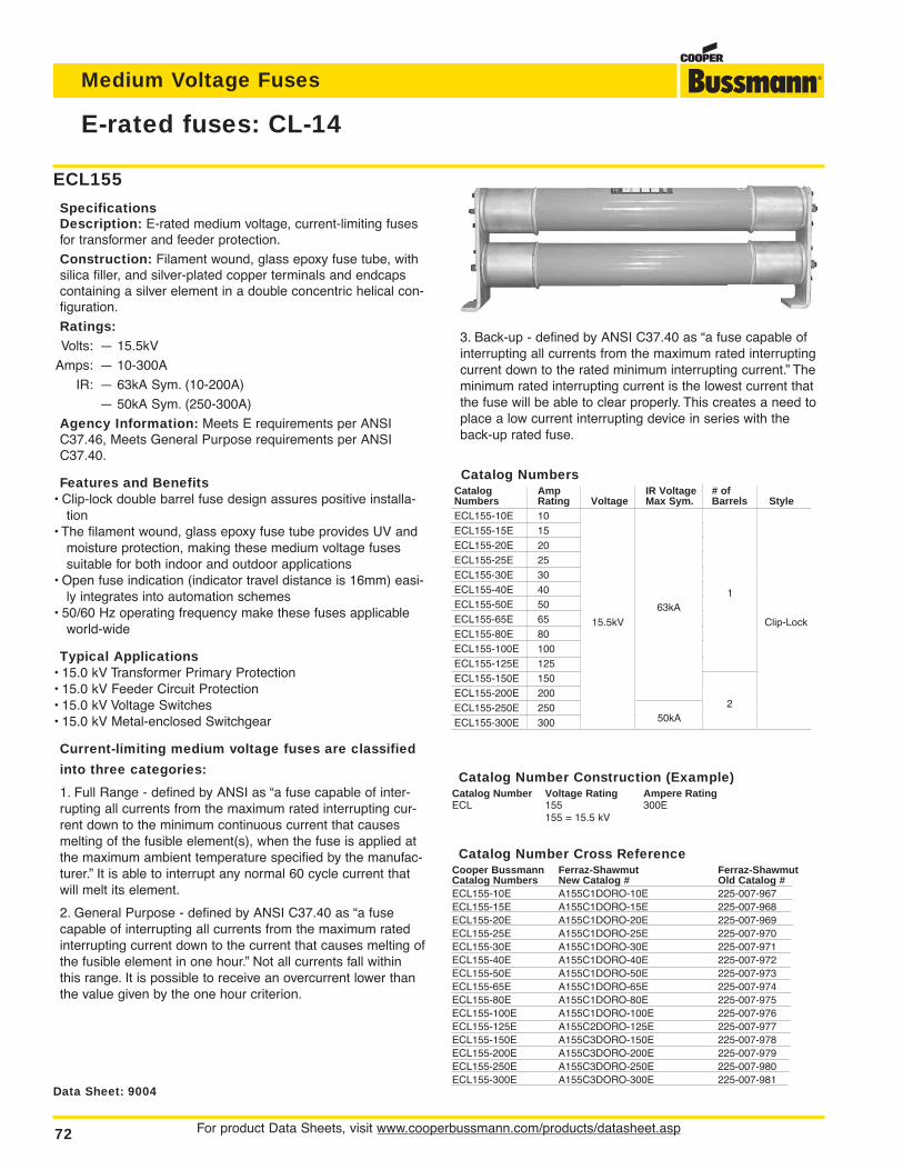
For product Data Sheets, visit www.cooperbussmann.com/products/datasheet.asp72
Medium Voltage Fuses
E-rated fuses: CL-14
Catalog Number Cross ReferenceCooper Bussmann Ferraz-Shawmut Ferraz-ShawmutCatalog Numbers New Catalog # Old Catalog #ECL155-10E A155C1DORO-10E 225-007-967ECL155-15E A155C1DORO-15E 225-007-968ECL155-20E A155C1DORO-20E 225-007-969ECL155-25E A155C1DORO-25E 225-007-970ECL155-30E A155C1DORO-30E 225-007-971ECL155-40E A155C1DORO-40E 225-007-972ECL155-50E A155C1DORO-50E 225-007-973ECL155-65E A155C1DORO-65E 225-007-974ECL155-80E A155C1DORO-80E 225-007-975ECL155-100E A155C1DORO-100E 225-007-976ECL155-125E A155C2DORO-125E 225-007-977ECL155-150E A155C3DORO-150E 225-007-978ECL155-200E A155C3DORO-200E 225-007-979ECL155-250E A155C3DORO-250E 225-007-980ECL155-300E A155C3DORO-300E 225-007-981
Data Sheet: 9004
Catalog NumbersCatalog Amp IR Voltage # ofNumbers Rating Voltage Max Sym. Barrels StyleECL155-10E 10 15.5kV 63KA 1 Clip-LockECL155-15E 15ECL155-20E 20ECL155-25E 25ECL155-30E 30ECL155-40E 40ECL155-50E 50ECL155-65E 65ECL155-80E 80ECL155-100E 100ECL155-125E 125ECL155-150E 150 2ECL155-200E 200ECL155-250E 250 50kAECL155-300E 300
Catalog Number Construction (Example)Catalog Number Voltage Rating Ampere RatingECL 155 300E
155 = 15.5 kV
ECL155
SpecificationsDescription: E-rated medium voltage, current-limiting fusesfor transformer and feeder protection.
Construction: Filament wound, glass epoxy fuse tube, withsilica filler, and silver-plated copper terminals and endcapscontaining a silver element in a double concentric helical con-figuration.
Ratings:Volts: — 15.5kV
Amps: — 10-300A
IR: — 63kA Sym. (10-200A)
— 50kA Sym. (250-300A)
Agency Information: Meets E requirements per ANSIC37.46, Meets General Purpose requirements per ANSIC37.40.
Features and Benefits• Clip-lock double barrel fuse design assures positive installa-
tion• The filament wound, glass epoxy fuse tube provides UV and
moisture protection, making these medium voltage fusessuitable for both indoor and outdoor applications
• Open fuse indication (indicator travel distance is 16mm) easi-ly integrates into automation schemes
• 50/60 Hz operating frequency make these fuses applicableworld-wide
Typical Applications• 15.0 kV Transformer Primary Protection• 15.0 kV Feeder Circuit Protection• 15.0 kV Voltage Switches• 15.0 kV Metal-enclosed Switchgear
Current-limiting medium voltage fuses are classified
into three categories:
1. Full Range - defined by ANSI as “a fuse capable of inter-rupting all currents from the maximum rated interrupting cur-rent down to the minimum continuous current that causesmelting of the fusible element(s), when the fuse is applied atthe maximum ambient temperature specified by the manufac-turer.” It is able to interrupt any normal 60 cycle current thatwill melt its element.
2. General Purpose - defined by ANSI C37.40 as “a fusecapable of interrupting all currents from the maximum ratedinterrupting current down to the current that causes melting ofthe fusible element in one hour.” Not all currents fall withinthis range. It is possible to receive an overcurrent lower thanthe value given by the one hour criterion.
3. Back-up - defined by ANSI C37.40 as “a fuse capable ofinterrupting all currents from the maximum rated interruptingcurrent down to the rated minimum interrupting current.” Theminimum rated interrupting current is the lowest current thatthe fuse will be able to clear properly. This creates a need toplace a low current interrupting device in series with theback-up rated fuse.
15.5kV63kA
1
Clip-Lock
250kA
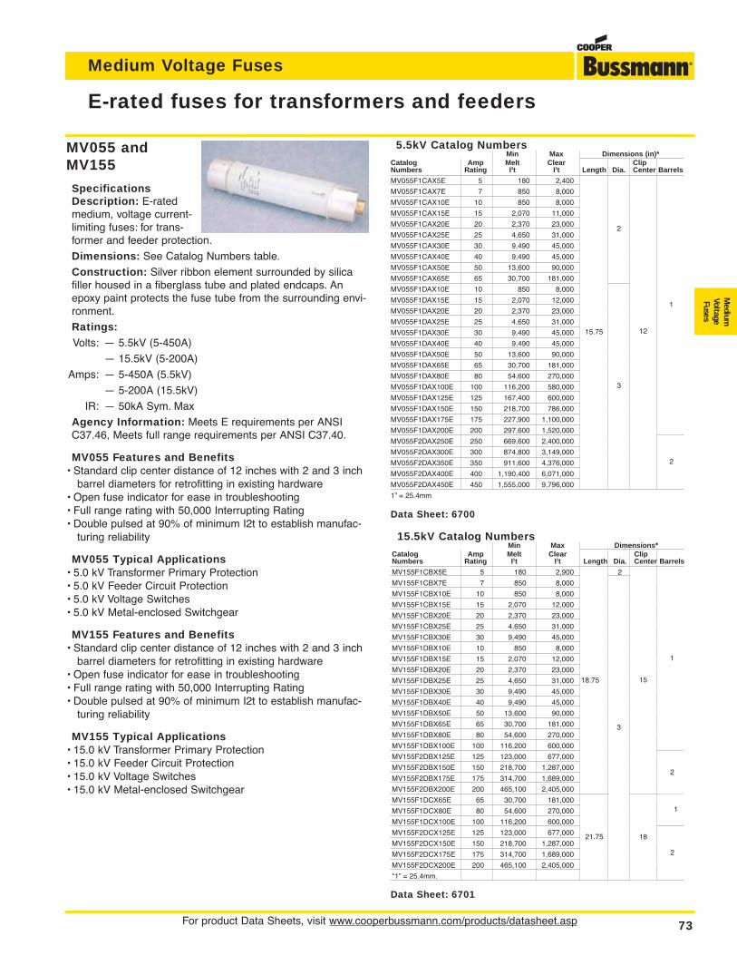
For product Data Sheets, visit www.cooperbussmann.com/products/datasheet.asp 73
Medium Voltage Fuses
Medium
VoltageFuses
MV055 andMV155
SpecificationsDescription: E-ratedmedium, voltage current-limiting fuses: for trans-former and feeder protection.
Dimensions: See Catalog Numbers table.
Construction: Silver ribbon element surrounded by silicafiller housed in a fiberglass tube and plated endcaps. Anepoxy paint protects the fuse tube from the surrounding envi-ronment.
Ratings:Volts: — 5.5kV (5-450A)
— 15.5kV (5-200A)
Amps: — 5-450A (5.5kV)
— 5-200A (15.5kV)
IR: — 50kA Sym. Max
Agency Information: Meets E requirements per ANSIC37.46, Meets full range requirements per ANSI C37.40.
MV055 Features and Benefits• Standard clip center distance of 12 inches with 2 and 3 inch
barrel diameters for retrofitting in existing hardware• Open fuse indicator for ease in troubleshooting• Full range rating with 50,000 Interrupting Rating• Double pulsed at 90% of minimum I2t to establish manufac-
turing reliability
MV055 Typical Applications• 5.0 kV Transformer Primary Protection• 5.0 kV Feeder Circuit Protection• 5.0 kV Voltage Switches• 5.0 kV Metal-enclosed Switchgear
MV155 Features and Benefits• Standard clip center distance of 12 inches with 2 and 3 inch
barrel diameters for retrofitting in existing hardware• Open fuse indicator for ease in troubleshooting• Full range rating with 50,000 Interrupting Rating• Double pulsed at 90% of minimum I2t to establish manufac-
turing reliability
MV155 Typical Applications• 15.0 kV Transformer Primary Protection• 15.0 kV Feeder Circuit Protection• 15.0 kV Voltage Switches• 15.0 kV Metal-enclosed Switchgear
E-rated fuses for transformers and feeders
15.5kV Catalog NumbersMin Max Dimensions*
Catalog Amp Melt Clear ClipNumbers Rating I2t I2t Length Dia. Center Barrels
MV155F1CBX5E 5 180 2,900 18.75 2 15 1
MV155F1CBX7E 7 850 8,000
MV155F1CBX10E 10 850 8,000
MV155F1CBX15E 15 2,070 12,000
MV155F1CBX20E 20 2,370 23,000
MV155F1CBX25E 25 4,650 31,000
MV155F1CBX30E 30 9,490 45,000
MV155F1DBX10E 10 850 8,000 18.75 3 15 1
MV155F1DBX15E 15 2,070 12,000
MV155F1DBX20E 20 2,370 23,000
MV155F1DBX25E 25 4,650 31,000
MV155F1DBX30E 30 9,490 45,000
MV155F1DBX40E 40 9,490 45,000
MV155F1DBX50E 50 13,600 90,000
MV155F1DBX65E 65 30,700 181,000
MV155F1DBX80E 80 54,600 270,000
MV155F1DBX100E 100 116,200 600,000
MV155F2DBX125E 125 123,000 677,000 18.75 3 15 2
MV155F2DBX150E 150 218,700 1,287,000
MV155F2DBX175E 175 314,700 1,689,000
MV155F2DBX200E 200 465,100 2,405,000
MV155F1DCX65E 65 30,700 181,000 21.75 3 18 1
MV155F1DCX80E 80 54,600 270,000
MV155F1DCX100E 100 116,200 600,000
MV155F2DCX125E 125 123,000 677,000 21.75 3 18 2
MV155F2DCX150E 150 218,700 1,287,000
MV155F2DCX175E 175 314,700 1,689,000
MV155F2DCX200E 200 465,100 2,405,000
*1” = 25.4mm.
Data Sheet: 6700
Data Sheet: 6701
5.5kV Catalog NumbersMin Max Dimensions (in)*
Catalog Amp Melt Clear ClipNumbers Rating I2t I2t Length Dia. Center Barrels
MV055F1CAX5E 5 180 2,400 15.75 2 12 1
MV055F1CAX7E 7 850 8,000
MV055F1CAX10E 10 850 8,000
MV055F1CAX15E 15 2,070 11,000
MV055F1CAX20E 20 2,370 23,000
MV055F1CAX25E 25 4,650 31,000
MV055F1CAX30E 30 9,490 45,000
MV055F1CAX40E 40 9,490 45,000
MV055F1CAX50E 50 13,600 90,000
MV055F1CAX65E 65 30,700 181,000
MV055F1DAX10E 10 850 8,000 15.75 3 12 1
MV055F1DAX15E 15 2,070 12,000
MV055F1DAX20E 20 2,370 23,000
MV055F1DAX25E 25 4,650 31,000
MV055F1DAX30E 30 9,490 45,000
MV055F1DAX40E 40 9,490 45,000
MV055F1DAX50E 50 13,600 90,000
MV055F1DAX65E 65 30,700 181,000
MV055F1DAX80E 80 54,600 270,000
MV055F1DAX100E 100 116,200 580,000
MV055F1DAX125E 125 167,400 600,000 15.75 3 12 1
MV055F1DAX150E 150 218,700 786,000
MV055F1DAX175E 175 227,900 1,100,000
MV055F1DAX200E 200 297,600 1,520,000
MV055F2DAX250E 250 669,600 2,400,000 15.75 3 12 2
MV055F2DAX300E 300 874,800 3,149,000
MV055F2DAX350E 350 911,600 4,376,000
MV055F2DAX400E 400 1,190,400 6,071,000
MV055F2DAX450E 450 1,555,000 9,796,000
1” = 25.4mm
15.75 12
2
1
2
3
18.75
3
15
1
2
2
1
1821.75
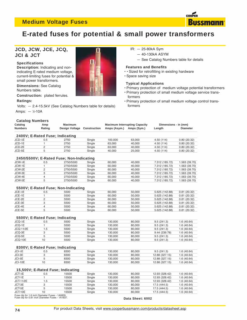
For product Data Sheets, visit www.cooperbussmann.com/products/datasheet.asp74
Medium Voltage Fuses
E-rated fuses for potential & small power transformers
Data Sheet: 6002
Catalog NumbersCatalog Amp Maximum Maximum Interrupting Capacity Dimensions - in (mm)Numbers Rating Design Voltage Construction Amps (Asym.) Amps (Sym.) Length Diameter
2400V; E-Rated Fuse; IndicatingJCD-1⁄2E 0.5 2750 Single 100,000 63,000 4.50 (114) 0.80 (20.32)JCD-1E 1 2750 Single 63,000 40,000 4.50 (114) 0.80 (20.32)JCD-2E 2 2750 Single 63,000 40,000 4.50 (114) 0.80 (20.32)JCD-5E 5 2750 Single 40,000 25,000 4.50 (114) 0.80 (20.32)
2450/5500V; E-Rated Fuse; Non-IndicatingJCW-1⁄2E 0.5 2750/5500 Single 60,000 40,000 7.312 (185.72) 1.563 (39.70)JCW-1E 1 2750/5500 Single 60,000 40,000 7.312 (185.72) 1.563 (39.70)JCW-2E 2 2750/5500 Single 60,000 40,000 7.312 (185.72) 1.563 (39.70)JCW-3E 3 2750/5500 Single 60,000 40,000 7.312 (185.72) 1.563 (39.70)JCW-4E 4 2750/5500 Single 60,000 40,000 7.312 (185.72) 1.563 (39.70)JCW-5E 5 2750/5500 Single 60,000 40,000 7.312 (185.72) 1.563 (39.70)
5500V; E-Rated Fuse; Non-IndicatingJCE-1⁄2E 0.5 5500 Single 60,000 50,000 5.625 (142.88) 0.81 (20.32)JCE-1E 1 5500 Single 60,000 50,000 5.625 (142.88) 0.81 (20.32)JCE-2E 2 5500 Single 60,000 50,000 5.625 (142.88) 0.81 (20.32)JCE-3E 3 5500 Single 60,000 50,000 5.625 (142.88) 0.81 (20.32)JCE-4E 4 5500 Single 60,000 50,000 5.625 (142.88) 0.81 (20.32)JCE-5E 5 5500 Single 60,000 50,000 5.625 (142.88) 0.81 (20.32)
5500V; E-Rated Fuse; IndicatingJCQ-1⁄2E 0.5 5500 Single 130,000 80,000 9.5 (241.3) 1.6 (40.64)JCQ-1E 1 5500 Single 130,000 80,000 9.5 (241.3) 1.6 (40.64)JCQ-11⁄2E 1.5 5500 Single 130,000 80,000 9.5 (241.3) 1.6 (40.64)JCQ-3E 3 5500 Single 130,000 80,000 9.44 (239.78) 1.6 (40.64)JCQ-5E 5 5500 Single 130,000 80,000 9.5 (241.3) 1.6 (40.64)JCQ-10E 10 5500 Single 130,000 80,000 9.5 (241.3) 1.6 (40.64)
8300V; E-Rated Fuse; IndicatingJCI-1⁄2E 0.5 8300 Single 130,000 80,000 9.5 (241.3) 1.6 (40.64)JCI-3E 3 8300 Single 130,000 80,000 12.88 (327.15) 1.6 (40.64)JCI-5E 5 8300 Single 130,000 80,000 12.88 (327.15) 1.6 (40.64)JCI-10E 10 8300 Single 130,000 80,000 12.88 (327.15) 1.6 (40.64)
15,500V; E-Rated Fuse; IndicatingJCT-1⁄2E 0.5 15500 Single 130,000 80,000 12.93 (328.42) 1.6 (40.64)JCT-1E 1 15500 Single 130,000 80,000 12.93 (328.42) 1.6 (40.64)JCT-11⁄2E 1.5 15500 Single 130,000 80,000 12.93 (328.42) 1.6 (40.64)JCT-3E 3 15500 Single 130,000 80,000 17.5 (444.5) 1.6 (40.64)JCT-5E 5 15500 Single 130,000 80,000 17.5 (444.5) 1.6 (40.64)JCT-10E 10 15500 Single 130,000 80,000 17.5 (444.5) 1.6 (40.64)Fuse clip for 1.6 inch Diameter Fuses - 1A0835.Fuse clip for 0.81 inch Diameter Fuses - 1A1837.
JCD, JCW, JCE, JCQ,JCI & JCT
SpecificationsDescription: Indicating and non-indicating E-rated medium voltage,current-limiting fuses for potential &small power transformers.
Dimensions: See CatalogNumbers table.
Construction: plated ferrules.
Ratings:Volts: — 2.4-15.5kV (See Catalog Numbers table for details)
Amps: — 1⁄2-10A
IR: — 25-80kA Sym
— 40-130kA ASYM
— See Catalog Numbers table for details
Features and Benefits• • Sized for retrofitting in existing hardware• Space saving size
Typical Applications• Primary protection of medium voltage potential transformers• Primary protection of small medium voltage service trans-
formers• Primary protection of small medium voltage control trans-
formers
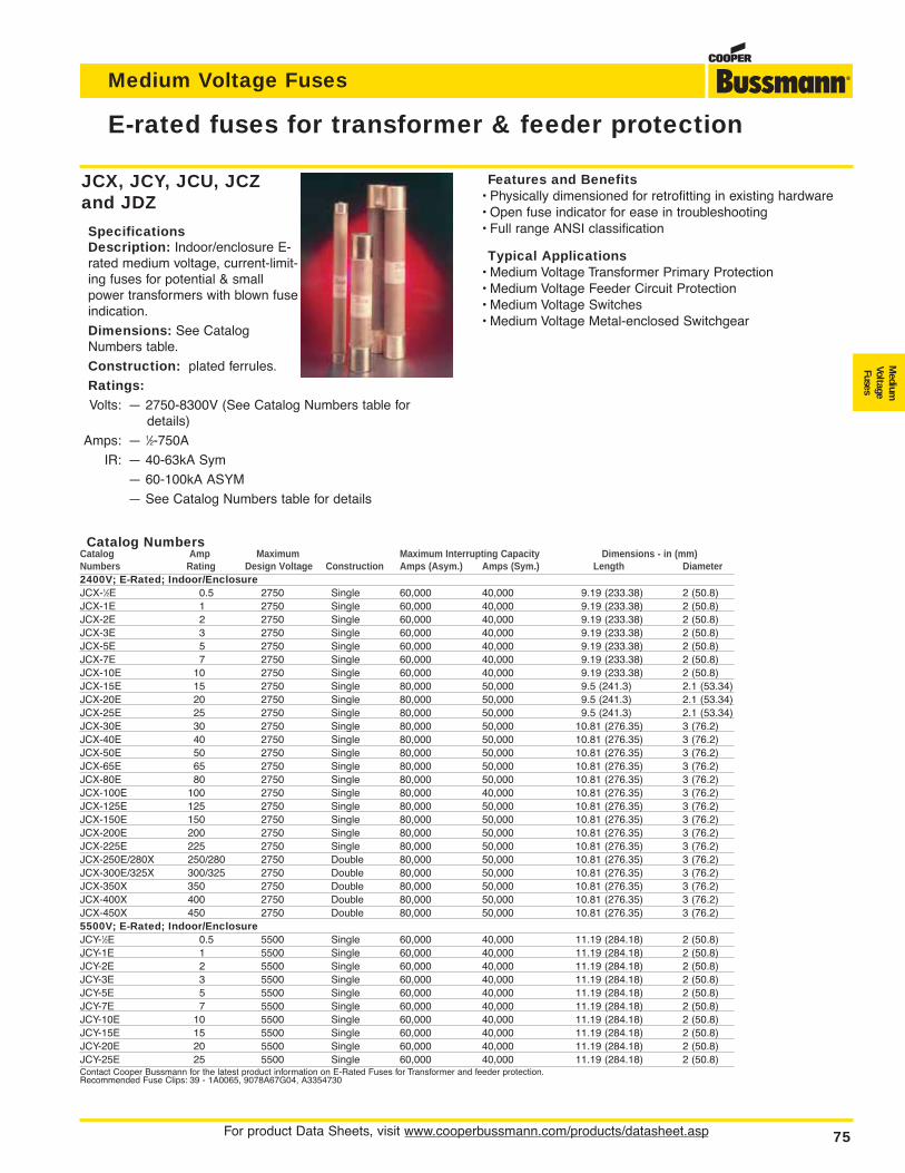
For product Data Sheets, visit www.cooperbussmann.com/products/datasheet.asp 75
Medium Voltage Fuses
Medium
VoltageFuses
JCX, JCY, JCU, JCZand JDZ
SpecificationsDescription: Indoor/enclosure E-rated medium voltage, current-limit-ing fuses for potential & smallpower transformers with blown fuseindication.
Dimensions: See CatalogNumbers table.
Construction: plated ferrules.
Ratings:Volts: — 2750-8300V (See Catalog Numbers table for
details)
Amps: — 1⁄2-750A
IR: — 40-63kA Sym
— 60-100kA ASYM
— See Catalog Numbers table for details
E-rated fuses for transformer & feeder protection
Catalog NumbersCatalog Amp Maximum Maximum Interrupting Capacity Dimensions - in (mm)Numbers Rating Design Voltage Construction Amps (Asym.) Amps (Sym.) Length Diameter2400V; E-Rated; Indoor/EnclosureJCX-1⁄2E 0.5 2750 Single 60,000 40,000 9.19 (233.38) 2 (50.8)JCX-1E 1 2750 Single 60,000 40,000 9.19 (233.38) 2 (50.8)JCX-2E 2 2750 Single 60,000 40,000 9.19 (233.38) 2 (50.8)JCX-3E 3 2750 Single 60,000 40,000 9.19 (233.38) 2 (50.8)JCX-5E 5 2750 Single 60,000 40,000 9.19 (233.38) 2 (50.8)JCX-7E 7 2750 Single 60,000 40,000 9.19 (233.38) 2 (50.8)JCX-10E 10 2750 Single 60,000 40,000 9.19 (233.38) 2 (50.8)JCX-15E 15 2750 Single 80,000 50,000 9.5 (241.3) 2.1 (53.34)JCX-20E 20 2750 Single 80,000 50,000 9.5 (241.3) 2.1 (53.34)JCX-25E 25 2750 Single 80,000 50,000 9.5 (241.3) 2.1 (53.34)JCX-30E 30 2750 Single 80,000 50,000 10.81 (276.35) 3 (76.2)JCX-40E 40 2750 Single 80,000 50,000 10.81 (276.35) 3 (76.2)JCX-50E 50 2750 Single 80,000 50,000 10.81 (276.35) 3 (76.2)JCX-65E 65 2750 Single 80,000 50,000 10.81 (276.35) 3 (76.2)JCX-80E 80 2750 Single 80,000 50,000 10.81 (276.35) 3 (76.2)JCX-100E 100 2750 Single 80,000 40,000 10.81 (276.35) 3 (76.2)JCX-125E 125 2750 Single 80,000 50,000 10.81 (276.35) 3 (76.2)JCX-150E 150 2750 Single 80,000 50,000 10.81 (276.35) 3 (76.2)JCX-200E 200 2750 Single 80,000 50,000 10.81 (276.35) 3 (76.2)JCX-225E 225 2750 Single 80,000 50,000 10.81 (276.35) 3 (76.2)JCX-250E/280X 250/280 2750 Double 80,000 50,000 10.81 (276.35) 3 (76.2)JCX-300E/325X 300/325 2750 Double 80,000 50,000 10.81 (276.35) 3 (76.2)JCX-350X 350 2750 Double 80,000 50,000 10.81 (276.35) 3 (76.2)JCX-400X 400 2750 Double 80,000 50,000 10.81 (276.35) 3 (76.2)JCX-450X 450 2750 Double 80,000 50,000 10.81 (276.35) 3 (76.2)5500V; E-Rated; Indoor/EnclosureJCY-1⁄2E 0.5 5500 Single 60,000 40,000 11.19 (284.18) 2 (50.8)JCY-1E 1 5500 Single 60,000 40,000 11.19 (284.18) 2 (50.8)JCY-2E 2 5500 Single 60,000 40,000 11.19 (284.18) 2 (50.8)JCY-3E 3 5500 Single 60,000 40,000 11.19 (284.18) 2 (50.8)JCY-5E 5 5500 Single 60,000 40,000 11.19 (284.18) 2 (50.8)JCY-7E 7 5500 Single 60,000 40,000 11.19 (284.18) 2 (50.8)JCY-10E 10 5500 Single 60,000 40,000 11.19 (284.18) 2 (50.8)JCY-15E 15 5500 Single 60,000 40,000 11.19 (284.18) 2 (50.8)JCY-20E 20 5500 Single 60,000 40,000 11.19 (284.18) 2 (50.8)JCY-25E 25 5500 Single 60,000 40,000 11.19 (284.18) 2 (50.8)Contact Cooper Bussmann for the latest product information on E-Rated Fuses for Transformer and feeder protection.Recommended Fuse Clips: 39 - 1A0065, 9078A67G04, A3354730
Features and Benefits• Physically dimensioned for retrofitting in existing hardware• Open fuse indicator for ease in troubleshooting• Full range ANSI classification
Typical Applications• Medium Voltage Transformer Primary Protection• Medium Voltage Feeder Circuit Protection• Medium Voltage Switches• Medium Voltage Metal-enclosed Switchgear
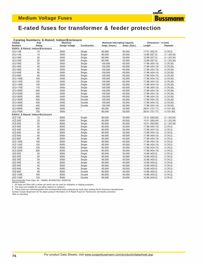
For product Data Sheets, visit www.cooperbussmann.com/products/datasheet.asp76
Medium Voltage Fuses
E-rated fuses for transformer & feeder protection
Catalog Numbers: E-Rated; Indoor/EnclosureCatalog Amp Maximum Maximum Interrupting Capacity Dimensions - in (mm)Numbers Rating Design Voltage Construction Amps. (Asym.) Amps. (Sym.) Length Diameter5500V; E-Rated; Indoor/EnclosureJCU-10E 10 5500 Single 80,000 50,000 17.81 (452.4) 3 (76.2)JCU-15E 15 5500 Single 80,000 50,000 12.88 (327.0) 2.1 (53.34)JCU-20E 20 5500 Single 80,000 50,000 12.88 (327.0) 2.1 (53.34)JCU-25E 25 5500 Single 80,000 50,000 12.88 (327.0) 2.1 (53.34)JCU-30E 30 5500 Single 100,000 63,000 17.88 (454.15) 3 (76.20)JCU-40E 40 5500 Single 100,000 63,000 17.88 (454.15) 3 (76.20)JCU-50E 50 5500 Single 100,000 63,000 17.88 (454.15) 3 (76.20)JCU-65E 60 5500 Single 100,000 63,000 17.88 (454.15) 3 (76.20)JCU-80E 80 5500 Single 100,000 63,000 17.88 (454.15) 3 (76.20)JCU-100E 100 5500 Single 100,000 63,000 17.88 (454.15) 3 (76.20)JCU-125E 125 5500 Single 100,000 63,000 17.88 (454.15) 3 (76.20)JCU-150E 150 5500 Single 100,000 63,000 17.88 (454.15) 3 (76.20)JCU-175E 175 5500 Single 100,000 63,000 17.88 (454.15) 3 (76.20)JCU-200E 200 5500 Single 100,000 63,000 17.88 (454.15) 3 (76.20)JCU-250E 250 5500 Single 100,000 63,000 17.88 (454.15) 3 (76.20)JCU-300E 300 5500 Double 100,000 63,000 17.88 (454.15) 3 (76.20)JCU-350E 350 5500 Double 100,000 63,000 17.88 (454.15) 3 (76.20)JCU-400E 400 5500 Double 100,000 63,000 17.88 (454.15) 3 (76.20)JCU-450E 450 5500 Double 100,000 63,000 17.88 (454.15) 3 (76.20)JCU-600E 600 5500 * 80,000 50,000 28.81 (731.77) 4 (101.60)JCU-750E 750 5500 * 80,000 50,000 28.81 (731.77) 4 (101.60)8300V; E-Rated; Indoor/EnclosureJCZ-15E 15 8300 Single 80,000 50,000 15.51 (393.95) 2.1 (53.34)JCZ-20E 20 8300 Single 80,000 50,000 15.51 (393.95) 2.1 (53.34)JCZ-25E 25 8300 Single 80,000 50,000 15.51 (393.95) 2.1 (53.34)JCZ-30E 30 8300 Single 80,000 50,000 17.88 (454.15) 3 (76.2)JCZ-40E 40 8300 Single 80,000 50,000 17.88 (454.15) 3 (76.2)JCZ-50E 50 8300 Single 80,000 50,000 17.88 (454.15) 3 (76.2)JCZ-65E 65 8300 Single 80,000 50,000 17.88 (454.15) 3 (76.2)JCZ-80E 80 8300 Single 80,000 50,000 17.88 (454.15) 3 (76.2)JCZ-100E 100 8300 Single 80,000 50,000 17.88 (454.15) 3 (76.2)JCZ-125E 125 8300 Single 80,000 50,000 17.88 (454.15) 3 (76.2)JCZ-150E 150 8300 Single 80,000 50,000 17.88 (454.15) 3 (76.2)JCZ-200E 200 8300 Double 80,000 50,000 17.88 (454.15) 3 (76.2)JDZ-20E 20 8300 Single 80,000 50,000 15.88 (403.2) 3 (76.2)JDZ-25E 25 8300 Single 80,000 50,000 15.88 (403.2) 3 (76.2)JDZ-30E 30 8300 Single 80,000 50,000 15.88 (403.2) 3 (76.2)JDZ-40E 40 8300 Single 80,000 50,000 15.88 (403.2) 3 (76.2)JDZ-50E 50 8300 Single 80,000 50,000 15.88 (403.2) 3 (76.2)JDZ-65E 65 8300 Single 80,000 50,000 15.88 (403.2) 3 (76.2)JDZ-80E 80 8300 Double 80,000 50,000 15.88 (403.2) 3 (76.2)JDZ-100E 100 8300 Double 80,000 50,000 15.88 (403.2) 3 (76.2)JDZ-125E 125 8300 Double 80,000 50,000 15.88 (403.2) 3 (76.2)Recommended Fuse Clips: 39 - 1A0065, 9078A67G04, A3354730General Notes:1. All fuses are fitted with a striker pin which can be used for indication or tripping purposes.2. The fuses are suitable for use either indoors or outdoors.3. These fuses are interchangeable with corresponding fuses produced by most other leading North American manufacturers.Contact Cooper Bussmann for the latest product information on E-Rated Fuses for Transformer and feeder protection.*Bolt on mounting
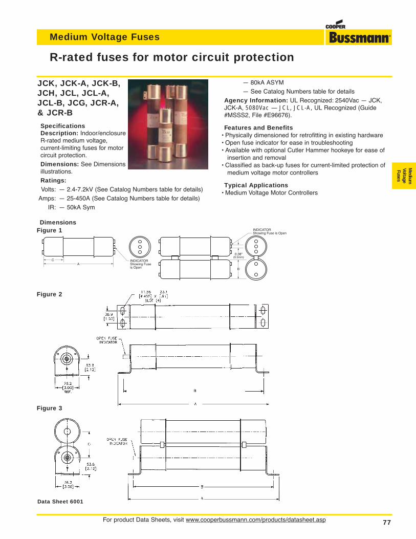
For product Data Sheets, visit www.cooperbussmann.com/products/datasheet.asp 77
Medium Voltage Fuses
Medium
VoltageFuses
JCK, JCK-A, JCK-B,JCH, JCL, JCL-A,JCL-B, JCG, JCR-A,& JCR-B
SpecificationsDescription: Indoor/enclosureR-rated medium voltage,current-limiting fuses for motorcircuit protection.
Dimensions: See Dimensionsillustrations.
Ratings:Volts: — 2.4-7.2kV (See Catalog Numbers table for details)
Amps: — 25-450A (See Catalog Numbers table for details)
IR: — 50kA Sym
R-rated fuses for motor circuit protection
0.38"(9.5mm)
B
INDICATORShowing Fuse is Open
INDICATORShowing Fuseis Open
AC
DimensionsFigure 1
Figure 2
Figure 3
Data Sheet 6001
— 80kA ASYM
— See Catalog Numbers table for details
Agency Information: UL Recognized: 2540Vac — JCK,JCK-A, 5080Vac — JCL, JCL-A, UL Recognized (Guide#MSSS2, File #E96676).
Features and Benefits• Physically dimensioned for retrofitting in existing hardware• Open fuse indicator for ease in troubleshooting• Available with optional Cutler Hammer hookeye for ease of
insertion and removal• Classified as back-up fuses for current-limited protection of
medium voltage motor controllers
Typical Applications• Medium Voltage Motor Controllers
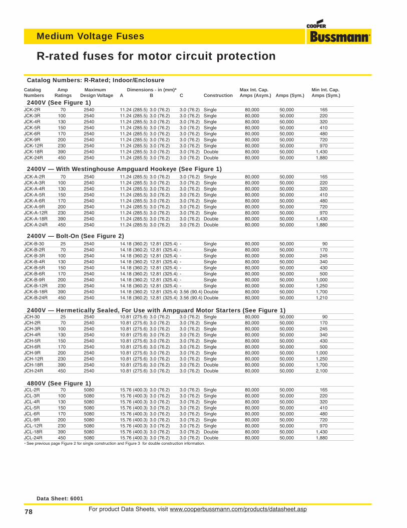
For product Data Sheets, visit www.cooperbussmann.com/products/datasheet.asp78
Medium Voltage Fuses
R-rated fuses for motor circuit protection
Catalog Numbers: R-Rated; Indoor/Enclosure
Catalog Amp Maximum Dimensions - in (mm)* Max Int. Cap. Min Int. Cap.Numbers Ratings Design Voltage A B C Construction Amps (Asym.) Amps (Sym.) Amps (Sym.)
2400V (See Figure 1)JCK-2R 70 2540 11.24 (285.5) 3.0 (76.2) 3.0 (76.2) Single 80,000 50,000 165JCK-3R 100 2540 11.24 (285.5) 3.0 (76.2) 3.0 (76.2) Single 80,000 50,000 220JCK-4R 130 2540 11.24 (285.5) 3.0 (76.2) 3.0 (76.2) Single 80,000 50,000 320JCK-5R 150 2540 11.24 (285.5) 3.0 (76.2) 3.0 (76.2) Single 80,000 50,000 410JCK-6R 170 2540 11.24 (285.5) 3.0 (76.2) 3.0 (76.2) Single 80,000 50,000 480JCK-9R 200 2540 11.24 (285.5) 3.0 (76.2) 3.0 (76.2) Single 80,000 50,000 720JCK-12R 230 2540 11.24 (285.5) 3.0 (76.2) 3.0 (76.2) Single 80,000 50,000 970JCK-18R 390 2540 11.24 (285.5) 3.0 (76.2) 3.0 (76.2) Double 80,000 50,000 1,430JCK-24R 450 2540 11.24 (285.5) 3.0 (76.2) 3.0 (76.2) Double 80,000 50,000 1,880
2400V — With Westinghouse Ampguard Hookeye (See Figure 1)JCK-A-2R 70 2540 11.24 (285.5) 3.0 (76.2) 3.0 (76.2) Single 80,000 50,000 165JCK-A-3R 100 2540 11.24 (285.5) 3.0 (76.2) 3.0 (76.2) Single 80,000 50,000 220JCK-A-4R 130 2540 11.24 (285.5) 3.0 (76.2) 3.0 (76.2) Single 80,000 50,000 320JCK-A-5R 150 2540 11.24 (285.5) 3.0 (76.2) 3.0 (76.2) Single 80,000 50,000 410JCK-A-6R 170 2540 11.24 (285.5) 3.0 (76.2) 3.0 (76.2) Single 80,000 50,000 480JCK-A-9R 200 2540 11.24 (285.5) 3.0 (76.2) 3.0 (76.2) Single 80,000 50,000 720JCK-A-12R 230 2540 11.24 (285.5) 3.0 (76.2) 3.0 (76.2) Single 80,000 50,000 970JCK-A-18R 390 2540 11.24 (285.5) 3.0 (76.2) 3.0 (76.2) Double 80,000 50,000 1,430JCK-A-24R 450 2540 11.24 (285.5) 3.0 (76.2) 3.0 (76.2) Double 80,000 50,000 1,880
2400V — Bolt-On (See Figure 2)JCK-B-30 25 2540 14.18 (360.2) 12.81 (325.4) - Single 80,000 50,000 90JCK-B-2R 70 2540 14.18 (360.2) 12.81 (325.4) - Single 80,000 50,000 170JCK-B-3R 100 2540 14.18 (360.2) 12.81 (325.4) - Single 80,000 50,000 245JCK-B-4R 130 2540 14.18 (360.2) 12.81 (325.4) - Single 80,000 50,000 340JCK-B-5R 150 2540 14.18 (360.2) 12.81 (325.4) - Single 80,000 50,000 430JCK-B-6R 170 2540 14.18 (360.2) 12.81 (325.4) - Single 80,000 50,000 500JCK-B-9R 200 2540 14.18 (360.2) 12.81 (325.4) - Single 80,000 50,000 1,000JCK-B-12R 230 2540 14.18 (360.2) 12.81 (325.4) - Single 80,000 50,000 1,250JCK-B-18R 390 2540 14.18 (360.2) 12.81 (325.4) 3.56 (90.4) Double 80,000 50,000 1,700JCK-B-24R 450 2540 14.18 (360.2) 12.81 (325.4) 3.56 (90.4) Double 80,000 50,000 1,210
2400V — Hermetically Sealed, For Use with Ampguard Motor Starters (See Figure 1)JCH-30 25 2540 10.81 (275.6) 3.0 (76.2) 3.0 (76.2) Single 80,000 50,000 90JCH-2R 70 2540 10.81 (275.6) 3.0 (76.2) 3.0 (76.2) Single 80,000 50,000 170JCH-3R 100 2540 10.81 (275.6) 3.0 (76.2) 3.0 (76.2) Single 80,000 50,000 245JCH-4R 130 2540 10.81 (275.6) 3.0 (76.2) 3.0 (76.2) Single 80,000 50,000 340JCH-5R 150 2540 10.81 (275.6) 3.0 (76.2) 3.0 (76.2) Single 80,000 50,000 430JCH-6R 170 2540 10.81 (275.6) 3.0 (76.2) 3.0 (76.2) Single 80,000 50,000 500JCH-9R 200 2540 10.81 (275.6) 3.0 (76.2) 3.0 (76.2) Single 80,000 50,000 1,000JCH-12R 230 2540 10.81 (275.6) 3.0 (76.2) 3.0 (76.2) Single 80,000 50,000 1,250JCH-18R 390 2540 10.81 (275.6) 3.0 (76.2) 3.0 (76.2) Double 80,000 50,000 1,700JCH-24R 450 2540 10.81 (275.6) 3.0 (76.2) 3.0 (76.2) Double 80,000 50,000 2,100
4800V (See Figure 1)JCL-2R 70 5080 15.76 (400.3) 3.0 (76.2) 3.0 (76.2) Single 80,000 50,000 165JCL-3R 100 5080 15.76 (400.3) 3.0 (76.2) 3.0 (76.2) Single 80,000 50,000 220JCL-4R 130 5080 15.76 (400.3) 3.0 (76.2) 3.0 (76.2) Single 80,000 50,000 320JCL-5R 150 5080 15.76 (400.3) 3.0 (76.2) 3.0 (76.2) Single 80,000 50,000 410JCL-6R 170 5080 15.76 (400.3) 3.0 (76.2) 3.0 (76.2) Single 80,000 50,000 480JCL-9R 200 5080 15.76 (400.3) 3.0 (76.2) 3.0 (76.2) Single 80,000 50,000 720JCL-12R 230 5080 15.76 (400.3) 3.0 (76.2) 3.0 (76.2) Single 80,000 50,000 970JCL-18R 390 5080 15.76 (400.3) 3.0 (76.2) 3.0 (76.2) Double 80,000 50,000 1,430JCL-24R 450 5080 15.76 (400.3) 3.0 (76.2) 3.0 (76.2) Double 80,000 50,000 1,880• See previous page Figure 2 for single construction and Figure 3 for double construction information.
Data Sheet: 6001
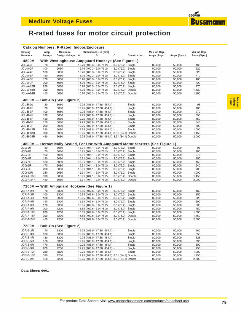
For product Data Sheets, visit www.cooperbussmann.com/products/datasheet.asp 79
Medium Voltage Fuses
Medium
VoltageFuses
R-rated fuses for motor circuit protection
Catalog Numbers: R-Rated; Indoor/EnclosureCatalog Amp Maximum Dimensions - in (mm) Max Int. Cap. Min Int. Cap.Numbers Ratings Design Voltage A B C Construction Amps (Asym. Amps (Sym.) Amps (Sym.)
4800V — With Westinghouse Ampguard Hookeye (See Figure 1)JCL-A-2R 70 5080 15.76 (400.3) 3.0 (76.2) 3.0 (76.2) Single 80,000 50,000 165JCL-A-3R 100 5080 15.76 (400.3) 3.0 (76.2) 3.0 (76.2) Single 80,000 50,000 220JCL-A-4R 130 5080 15.76 (400.3) 3.0 (76.2) 3.0 (76.2) Single 80,000 50,000 320JCL-A-5R 150 5080 15.76 (400.3) 3.0 (76.2) 3.0 (76.2) Single 80,000 50,000 410JCL-A-6R 170 5080 15.76 (400.3) 3.0 (76.2) 3.0 (76.2) Single 80,000 50,000 480JCL-A-9R 200 5080 15.76 (400.3) 3.0 (76.2) 3.0 (76.2) Single 80,000 50,000 720JCL-A-12R 230 5080 15.76 (400.3) 3.0 (76.2) 3.0 (76.2) Single 80,000 50,000 970JCL-A-18R 390 5080 15.76 (400.3) 3.0 (76.2) 3.0 (76.2) Double 80,000 50,000 1,430JCL-A-24R 450 5080 15.76 (400.3) 3.0 (76.2) 3.0 (76.2) Double 80,000 50,000 1,880
4800V — Bolt-On (See Figure 2)JCL-B-30 30 5080 19.25 (488.9) 17.88 (454.1) - Single 80,000 50,000 95JCL-B-2R 70 5080 19.25 (488.9) 17.88 (454.1) - Single 80,000 50,000 180JCL-B-3R 100 5080 19.25 (488.9) 17.88 (454.1) - Single 80,000 50,000 270JCL-B-4R 130 5080 19.25 (488.9) 17.88 (454.1) - Single 80,000 50,000 350JCL-B-5R 150 5080 19.25 (488.9) 17.88 (454.1) - Single 80,000 50,000 450JCL-B-6R 170 5080 19.25 (488.9) 17.88 (454.1) - Single 80,000 50,000 540JCL-B-9R 200 5080 19.25 (488.9) 17.88 (454.1) - Single 80,000 50,000 700JCL-B-12R 230 5080 19.25 (488.9) 17.88 (454.1) - Single 80,000 50,000 1,000JCL-B-18R 390 5080 19.25 (488.9) 17.88 (454.1) 3.31 (84.1) Double 80,000 50,000 1,450JCL-B-24R 450 5080 19.25 (488.9) 17.88 (454.1) 3.31 (84.1) Double 80,000 50,000 2,000
4800V — Hermetically Sealed, For Use with Ampguard Motor Starters (See Figure 1)JCG-30 30 5080 15.91 (404.1) 3.0 (76.2) 3.0 (76.2) Single 80,000 50,000 95JCG-2R 70 5080 15.91 (404.1) 3.0 (76.2) 3.0 (76.2) Single 80,000 50,000 180JCG-3R 100 5080 15.91 (404.1) 3.0 (76.2) 3.0 (76.2) Single 80,000 50,000 270JCG-4R 130 5080 15.91 (404.1) 3.0 (76.2) 3.0 (76.2) Single 80,000 50,000 350JCG-5R 150 5080 15.91 (404.1) 3.0 (76.2) 3.0 (76.2) Single 80,000 50,000 450JCG-6R 170 5080 15.91 (404.1) 3.0 (76.2) 3.0 (76.2) Single 80,000 50,000 540JCG-9R 200 5080 15.91 (404.1) 3.0 (76.2) 3.0 (76.2) Single 80,000 50,000 700JCG-12R 230 5080 15.91 (404.1) 3.0 (76.2) 3.0 (76.2) Single 80,000 50,000 1,000JCG-A-18R 390 5080 15.91 (404.1) 3.0 (76.2) 3.0 (76.2) Double 80,000 50,000 1,450JCG-A-24R 450 5080 15.91 (404.1) 3.0 (76.2) 3.0 (76.2) Double 80,000 50,000 2,000
7200V — With Ampguard Hookeye (See Figure 1)JCR-A-2R 70 8300 15.85 (402.6) 3.0 (76.2) 3.0 (76.2) Single 80,000 50,000 160JCR-A-3R 100 8300 15.85 (402.6) 3.0 (76.2) 3.0 (76.2) Single 80,000 50,000 250JCR-A-4R 130 8300 15.85 (402.6) 3.0 (76.2) 3.0 (76.2) Single 80,000 50,000 325JCR-A-5R 150 8300 15.85 (402.6) 3.0 (76.2) 3.0 (76.2) Single 80,000 50,000 390JCR-A-6R 170 8300 15.85 (402.6) 3.0 (76.2) 3.0 (76.2) Single 80,000 50,000 500JCR-A-9R 200 7200 15.85 (402.6) 3.0 (76.2) 3.0 (76.2) Single 80,000 50,000 750JCR-A-12R 230 7200 15.85 (402.6) 3.0 (76.2) 3.0 (76.2) Single 80,000 50,000 1,000JCR-A-18R 390 7200 15.85 (402.6) 3.0 (76.2) 3.0 (76.2) Double 80,000 50,000 1,450JCR-A-24R 450 7200 15.85 (402.6) 3.0 (76.2) 3.0 (76.2) Double 80,000 50,000 2,500
7200V — Bolt-On (See Figure 2)JCR-B-2R 70 8300 19.25 (488.9) 17.88 (454.1) - Single 80,000 50,000 160JCR-B-3R 100 8300 19.25 (488.9) 17.88 (454.1) - Single 80,000 50,000 250JCR-B-4R 130 8300 19.25 (488.9) 17.88 (454.1) - Single 80,000 50,000 325JCR-B-5R 150 8300 19.25 (488.9) 17.88 (454.1) - Single 80,000 50,000 390JCR-B-6R 170 8300 19.25 (488.9) 17.88 (454.1) - Single 80,000 50,000 500JCR-B-9R 200 7200 19.25 (488.9) 17.88 (454.1) - Single 80,000 50,000 750JCR-B-12R 230 7200 19.25 (488.9) 17.88 (454.1) - Single 80,000 50,000 1,000JCR-B-18R 390 7200 19.25 (488.9) 17.88 (454.1) 3.31 (84.1) Double 80,000 50,000 1,450JCR-B-24R 450 7200 19.25 (488.9) 17.88 (454.1) 3.31 (84.1) Double 80,000 50,000 2,500
Data Sheet: 6001
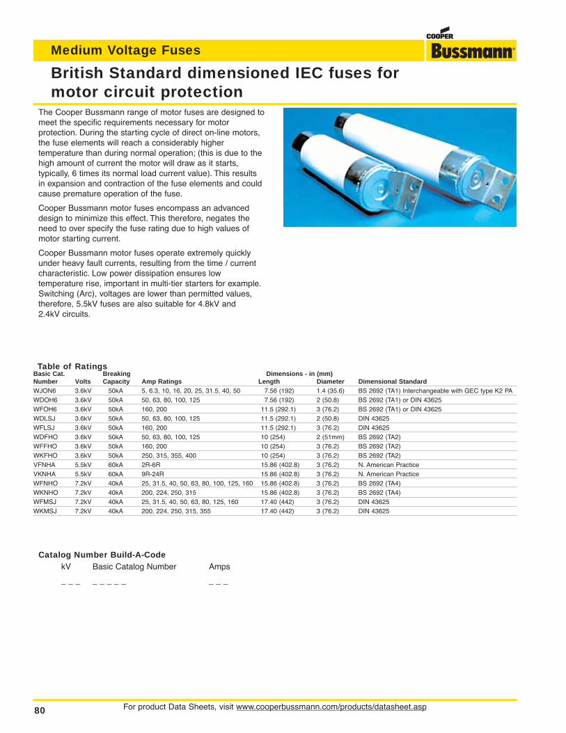
For product Data Sheets, visit www.cooperbussmann.com/products/datasheet.asp80
Medium Voltage Fuses
Table of RatingsBasic Cat. Breaking Dimensions - in (mm)Number Volts Capacity Amp Ratings Length Diameter Dimensional StandardWJON6 3.6kV 50kA 5, 6.3, 10, 16, 20, 25, 31.5, 40, 50 7.56 (192) 1.4 (35.6) BS 2692 (TA1) Interchangeable with GEC type K2 PAWDOH6 3.6kV 50kA 50, 63, 80, 100, 125 7.56 (192) 2 (50.8) BS 2692 (TA1) or DIN 43625WFOH6 3.6kV 50kA 160, 200 11.5 (292.1) 3 (76.2) BS 2692 (TA1) or DIN 43625WDLSJ 3.6kV 50kA 50, 63, 80, 100, 125 11.5 (292.1) 2 (50.8) DIN 43625WFLSJ 3.6kV 50kA 160, 200 11.5 (292.1) 3 (76.2) DIN 43625WDFHO 3.6kV 50kA 50, 63, 80, 100, 125 10 (254) 2 (51mm) BS 2692 (TA2)WFFHO 3.6kV 50kA 160, 200 10 (254) 3 (76.2) BS 2692 (TA2)WKFHO 3.6kV 50kA 250, 315, 355, 400 10 (254) 3 (76.2) BS 2692 (TA2)VFNHA 5.5kV 60kA 2R-6R 15.86 (402.8) 3 (76.2) N. American PracticeVKNHA 5.5kV 60kA 9R-24R 15.86 (402.8) 3 (76.2) N. American PracticeWFNHO 7.2kV 40kA 25, 31.5, 40, 50, 63, 80, 100, 125, 160 15.86 (402.8) 3 (76.2) BS 2692 (TA4)WKNHO 7.2kV 40kA 200, 224, 250, 315 15.86 (402.8) 3 (76.2) BS 2692 (TA4)WFMSJ 7.2kV 40kA 25, 31.5, 40, 50, 63, 80, 125, 160 17.40 (442) 3 (76.2) DIN 43625WKMSJ 7.2kV 40kA 200, 224, 250, 315, 355 17.40 (442) 3 (76.2) DIN 43625
British Standard dimensioned IEC fuses for motor circuit protection
Catalog Number Build-A-CodekV Basic Catalog Number Amps
_ _ _ _ _ _ _ _ _ _ _
The Cooper Bussmann range of motor fuses are designed tomeet the specific requirements necessary for motor protection. During the starting cycle of direct on-line motors,the fuse elements will reach a considerably higher temperature than during normal operation; (this is due to thehigh amount of current the motor will draw as it starts, typically, 6 times its normal load current value). This resultsin expansion and contraction of the fuse elements and couldcause premature operation of the fuse.
Cooper Bussmann motor fuses encompass an advanceddesign to minimize this effect. This therefore, negates theneed to over specify the fuse rating due to high values ofmotor starting current.
Cooper Bussmann motor fuses operate extremely quicklyunder heavy fault currents, resulting from the time / currentcharacteristic. Low power dissipation ensures low temperature rise, important in multi-tier starters for example.Switching (Arc), voltages are lower than permitted values,therefore, 5.5kV fuses are also suitable for 4.8kV and 2.4kV circuits.
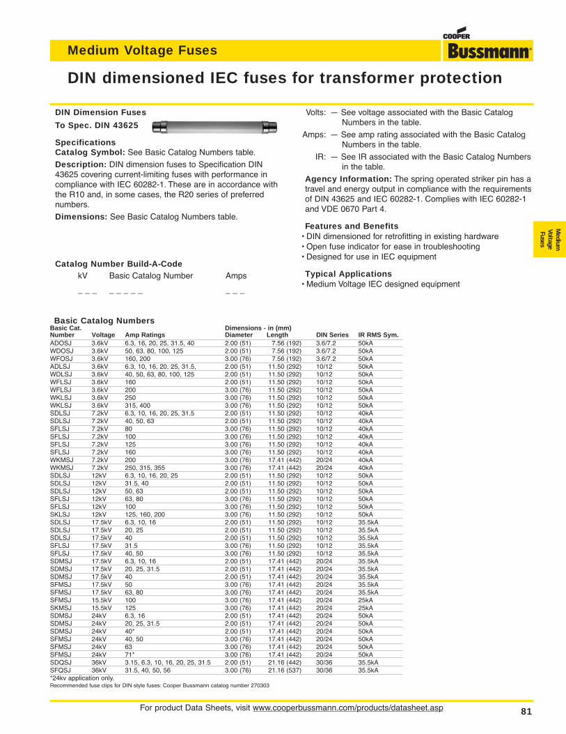
For product Data Sheets, visit www.cooperbussmann.com/products/datasheet.asp 81
Medium Voltage Fuses
Medium
VoltageFuses
DIN Dimension Fuses
To Spec. DIN 43625
SpecificationsCatalog Symbol: See Basic Catalog Numbers table.
Description: DIN dimension fuses to Specification DIN43625 covering current-limiting fuses with performance incompliance with IEC 60282-1. These are in accordance withthe R10 and, in some cases, the R20 series of preferrednumbers.
Dimensions: See Basic Catalog Numbers table.
Basic Catalog NumbersBasic Cat. Dimensions - in (mm)Number Voltage Amp Ratings Diameter Length DIN Series IR RMS Sym.ADOSJ 3.6kV 6.3, 16, 20, 25, 31.5, 40 2.00 (51) 7.56 (192) 3.6/7.2 50kAWDOSJ 3.6kV 50, 63, 80, 100, 125 2.00 (51) 7.56 (192) 3.6/7.2 50kAWFOSJ 3.6kV 160, 200 3.00 (76) 7.56 (192) 3.6/7.2 50kAADLSJ 3.6kV 6.3, 10, 16, 20, 25, 31.5, 2.00 (51) 11.50 (292) 10/12 50kAWDLSJ 3.6kV 40, 50, 63, 80, 100, 125 2.00 (51) 11.50 (292) 10/12 50kAWFLSJ 3.6kV 160 2.00 (51) 11.50 (292) 10/12 50kAWFLSJ 3.6kV 200 3.00 (76) 11.50 (292) 10/12 50kAWKLSJ 3.6kV 250 3.00 (76) 11.50 (292) 10/12 50kAWKLSJ 3.6kV 315, 400 3.00 (76) 11.50 (292) 10/12 50kASDLSJ 7.2kV 6.3, 10, 16, 20, 25, 31.5 2.00 (51) 11.50 (292) 10/12 40kASDLSJ 7.2kV 40, 50, 63 2.00 (51) 11.50 (292) 10/12 40kASFLSJ 7.2kV 80 3.00 (76) 11.50 (292) 10/12 40kASFLSJ 7.2kV 100 3.00 (76) 11.50 (292) 10/12 40kASFLSJ 7.2kV 125 3.00 (76) 11.50 (292) 10/12 40kASFLSJ 7.2kV 160 3.00 (76) 11.50 (292) 10/12 40kAWKMSJ 7.2kV 200 3.00 (76) 17.41 (442) 20/24 40kAWKMSJ 7.2kV 250, 315, 355 3.00 (76) 17.41 (442) 20/24 40kASDLSJ 12kV 6.3, 10, 16, 20, 25 2.00 (51) 11.50 (292) 10/12 50kASDLSJ 12kV 31.5, 40 2.00 (51) 11.50 (292) 10/12 50kASDLSJ 12kV 50, 63 2.00 (51) 11.50 (292) 10/12 50kASFLSJ 12kV 63, 80 3.00 (76) 11.50 (292) 10/12 50kASFLSJ 12kV 100 3.00 (76) 11.50 (292) 10/12 50kASKLSJ 12kV 125, 160, 200 3.00 (76) 11.50 (292) 10/12 50kASDLSJ 17.5kV 6.3, 10, 16 2.00 (51) 11.50 (292) 10/12 35.5kASDLSJ 17.5kV 20, 25 2.00 (51) 11.50 (292) 10/12 35.5kASDLSJ 17.5kV 40 2.00 (51) 11.50 (292) 10/12 35.5kASFLSJ 17.5kV 31.5 3.00 (76) 11.50 (292) 10/12 35.5kASFLSJ 17.5kV 40, 50 3.00 (76) 11.50 (292) 10/12 35.5kASDMSJ 17.5kV 6.3, 10, 16 2.00 (51) 17.41 (442) 20/24 35.5kASDMSJ 17.5kV 20, 25, 31.5 2.00 (51) 17.41 (442) 20/24 35.5kASDMSJ 17.5kV 40 2.00 (51) 17.41 (442) 20/24 35.5kASFMSJ 17.5kV 50 3.00 (76) 17.41 (442) 20/24 35.5kASFMSJ 17.5kV 63, 80 3.00 (76) 17.41 (442) 20/24 35.5kASFMSJ 15.5kV 100 3.00 (76) 17.41 (442) 20/24 25kASKMSJ 15.5kV 125 3.00 (76) 17.41 (442) 20/24 25kASDMSJ 24kV 6.3, 16 2.00 (51) 17.41 (442) 20/24 50kASDMSJ 24kV 20, 25, 31.5 2.00 (51) 17.41 (442) 20/24 50kASDMSJ 24kV 40* 2.00 (51) 17.41 (442) 20/24 50kASFMSJ 24kV 40, 50 3.00 (76) 17.41 (442) 20/24 50kASFMSJ 24kV 63 3.00 (76) 17.41 (442) 20/24 50kASFMSJ 24kV 71* 3.00 (76) 17.41 (442) 20/24 50kASDQSJ 36kV 3.15, 6.3, 10, 16, 20, 25, 31.5 2.00 (51) 21.16 (442) 30/36 35.5kASFQSJ 36kV 31.5, 40, 50, 56 3.00 (76) 21.16 (537) 30/36 35.5kA*24kv application only.Recommended fuse clips for DIN style fuses: Cooper Bussmann catalog number 270303
DIN dimensioned IEC fuses for transformer protection
Volts: — See voltage associated with the Basic CatalogNumbers in the table.
Amps: — See amp rating associated with the Basic CatalogNumbers in the table.
IR: — See IR associated with the Basic Catalog Numbersin the table.
Agency Information: The spring operated striker pin has atravel and energy output in compliance with the requirementsof DIN 43625 and IEC 60282-1. Complies with IEC 60282-1and VDE 0670 Part 4.
Features and Benefits• DIN dimensioned for retrofitting in existing hardware• Open fuse indicator for ease in troubleshooting• Designed for use in IEC equipment
Typical Applications• Medium Voltage IEC designed equipment
Catalog Number Build-A-CodekV Basic Catalog Number Amps
_ _ _ _ _ _ _ _ _ _ _
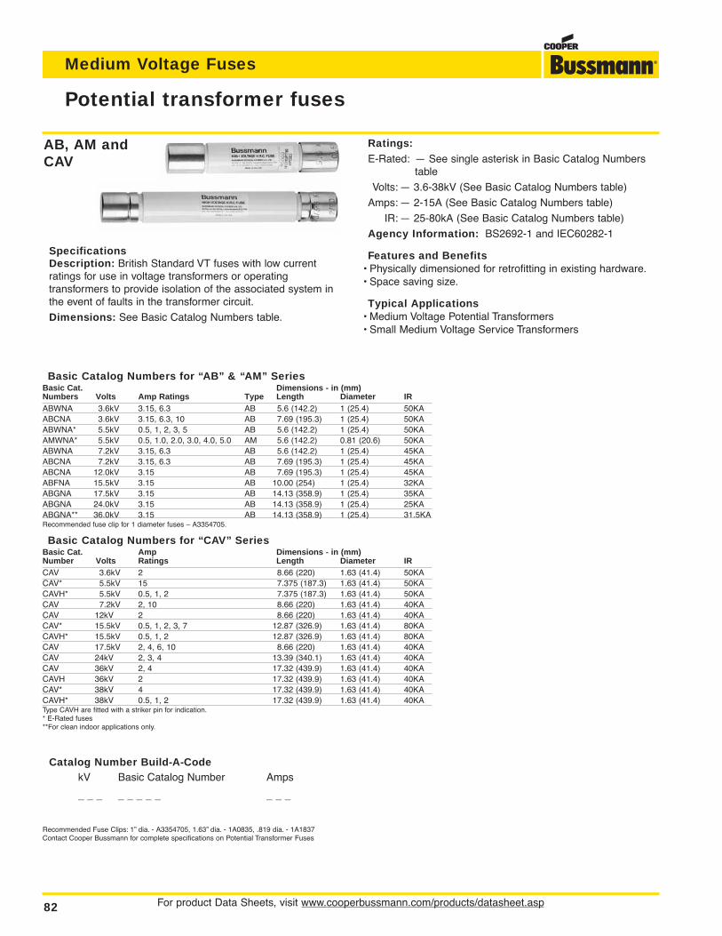
For product Data Sheets, visit www.cooperbussmann.com/products/datasheet.asp82
Medium Voltage Fuses
AB, AM andCAV
SpecificationsDescription: British Standard VT fuses with low current ratings for use in voltage transformers or operating transformers to provide isolation of the associated system inthe event of faults in the transformer circuit.
Dimensions: See Basic Catalog Numbers table.
Basic Catalog Numbers for “AB” & “AM” SeriesBasic Cat. Dimensions - in (mm)Numbers Volts Amp Ratings Type Length Diameter IRABWNA 3.6kV 3.15, 6.3 AB 5.6 (142.2) 1 (25.4) 50KAABCNA 3.6kV 3.15, 6.3, 10 AB 7.69 (195.3) 1 (25.4) 50KAABWNA* 5.5kV 0.5, 1, 2, 3, 5 AB 5.6 (142.2) 1 (25.4) 50KAAMWNA* 5.5kV 0.5, 1.0, 2.0, 3.0, 4.0, 5.0 AM 5.6 (142.2) 0.81 (20.6) 50KAABWNA 7.2kV 3.15, 6.3 AB 5.6 (142.2) 1 (25.4) 45KAABCNA 7.2kV 3.15, 6.3 AB 7.69 (195.3) 1 (25.4) 45KAABCNA 12.0kV 3.15 AB 7.69 (195.3) 1 (25.4) 45KAABFNA 15.5kV 3.15 AB 10.00 (254) 1 (25.4) 32KAABGNA 17.5kV 3.15 AB 14.13 (358.9) 1 (25.4) 35KAABGNA 24.0kV 3.15 AB 14.13 (358.9) 1 (25.4) 25KAABGNA** 36.0kV 3.15 AB 14.13 (358.9) 1 (25.4) 31.5KARecommended fuse clip for 1 diameter fuses – A3354705.
Basic Catalog Numbers for “CAV” SeriesBasic Cat. Amp Dimensions - in (mm)Number Volts Ratings Length Diameter IRCAV 3.6kV 2 8.66 (220) 1.63 (41.4) 50KACAV* 5.5kV 15 7.375 (187.3) 1.63 (41.4) 50KACAVH* 5.5kV 0.5, 1, 2 7.375 (187.3) 1.63 (41.4) 50KACAV 7.2kV 2, 10 8.66 (220) 1.63 (41.4) 40KACAV 12kV 2 8.66 (220) 1.63 (41.4) 40KACAV* 15.5kV 0.5, 1, 2, 3, 7 12.87 (326.9) 1.63 (41.4) 80KACAVH* 15.5kV 0.5, 1, 2 12.87 (326.9) 1.63 (41.4) 80KACAV 17.5kV 2, 4, 6, 10 8.66 (220) 1.63 (41.4) 40KACAV 24kV 2, 3, 4 13.39 (340.1) 1.63 (41.4) 40KACAV 36kV 2, 4 17.32 (439.9) 1.63 (41.4) 40KACAVH 36kV 2 17.32 (439.9) 1.63 (41.4) 40KACAV* 38kV 4 17.32 (439.9) 1.63 (41.4) 40KACAVH* 38kV 0.5, 1, 2 17.32 (439.9) 1.63 (41.4) 40KAType CAVH are fitted with a striker pin for indication.* E-Rated fuses**For clean indoor applications only.
Potential transformer fuses
Recommended Fuse Clips: 1” dia. - A3354705, 1.63” dia. - 1A0835, .819 dia. - 1A1837Contact Cooper Bussmann for complete specifications on Potential Transformer Fuses
Ratings:E-Rated: — See single asterisk in Basic Catalog Numbers
table
Volts: — 3.6-38kV (See Basic Catalog Numbers table)
Amps: — 2-15A (See Basic Catalog Numbers table)
IR: — 25-80kA (See Basic Catalog Numbers table)
Agency Information: BS2692-1 and IEC60282-1
Features and Benefits• Physically dimensioned for retrofitting in existing hardware.• Space saving size.
Typical Applications• Medium Voltage Potential Transformers• Small Medium Voltage Service Transformers
Catalog Number Build-A-CodekV Basic Catalog Number Amps
_ _ _ _ _ _ _ _ _ _ _
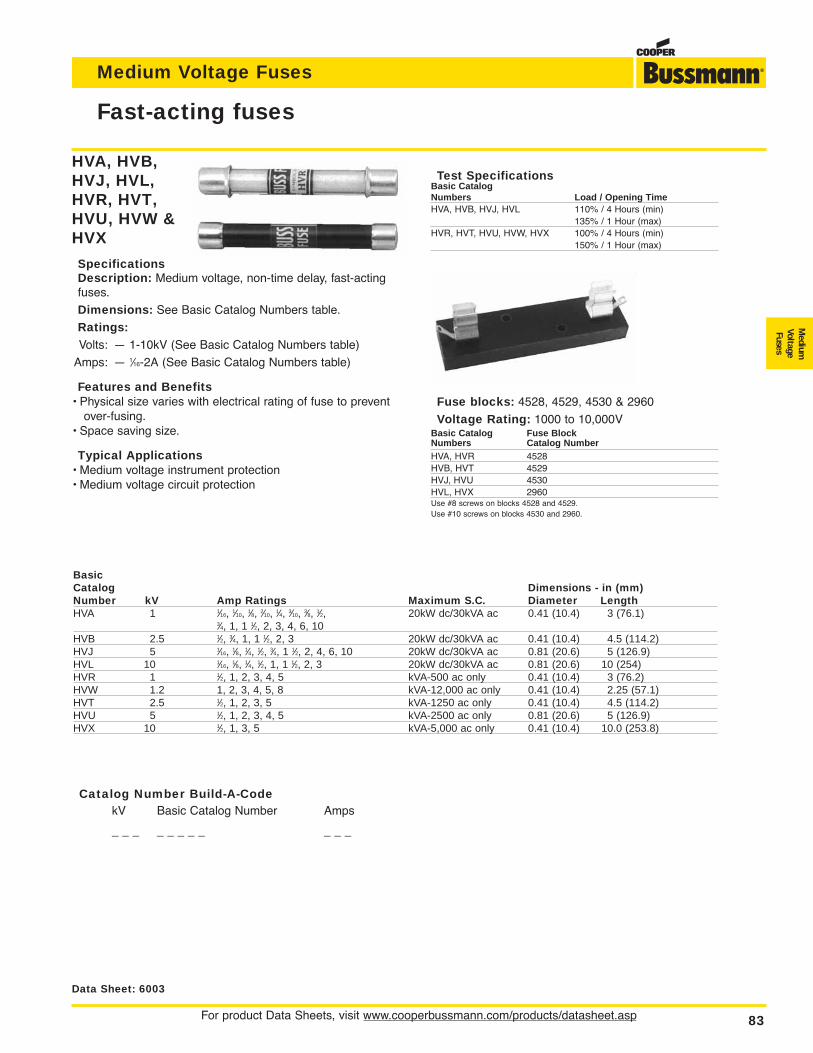
For product Data Sheets, visit www.cooperbussmann.com/products/datasheet.asp 83
Medium Voltage Fuses
Medium
VoltageFuses
Fast-acting fuses
Data Sheet: 6003
Fuse blocks: 4528, 4529, 4530 & 2960
Voltage Rating: 1000 to 10,000VBasic Catalog Fuse BlockNumbers Catalog NumberHVA, HVR 4528HVB, HVT 4529HVJ, HVU 4530HVL, HVX 2960Use #8 screws on blocks 4528 and 4529.Use #10 screws on blocks 4530 and 2960.
Test SpecificationsBasic CatalogNumbers Load / Opening TimeHVA, HVB, HVJ, HVL 110% / 4 Hours (min)
135% / 1 Hour (max)HVR, HVT, HVU, HVW, HVX 100% / 4 Hours (min)
150% / 1 Hour (max)
HVA, HVB,HVJ, HVL,HVR, HVT,HVU, HVW &HVX
SpecificationsDescription: Medium voltage, non-time delay, fast-actingfuses.
Dimensions: See Basic Catalog Numbers table.
Ratings:Volts: — 1-10kV (See Basic Catalog Numbers table)
Amps: — 1⁄16-2A (See Basic Catalog Numbers table)
Features and Benefits• Physical size varies with electrical rating of fuse to prevent
over-fusing.• Space saving size.
Typical Applications• Medium voltage instrument protection• Medium voltage circuit protection
BasicCatalog Dimensions - in (mm)Number kV Amp Ratings Maximum S.C. Diameter LengthHVA 1 1⁄16, 1⁄10, 1⁄8, 2⁄10, 1⁄4, 3⁄10, 3⁄8, 1⁄2, 20kW dc/30kVA ac 0.41 (10.4) 3 (76.1)
3⁄4, 1, 1 1⁄2, 2, 3, 4, 6, 10HVB 2.5 1⁄2, 3⁄4, 1, 1 1⁄2, 2, 3 20kW dc/30kVA ac 0.41 (10.4) 4.5 (114.2)HVJ 5 1⁄16, 1⁄8, 1⁄4, 1⁄2, 3⁄4, 1 1⁄2, 2, 4, 6, 10 20kW dc/30kVA ac 0.81 (20.6) 5 (126.9)HVL 10 1⁄16, 1⁄8, 1⁄4, 1⁄2, 1, 1 1⁄2, 2, 3 20kW dc/30kVA ac 0.81 (20.6) 10 (254)HVR 1 1⁄2, 1, 2, 3, 4, 5 kVA-500 ac only 0.41 (10.4) 3 (76.2)HVW 1.2 1, 2, 3, 4, 5, 8 kVA-12,000 ac only 0.41 (10.4) 2.25 (57.1)HVT 2.5 1⁄2, 1, 2, 3, 5 kVA-1250 ac only 0.41 (10.4) 4.5 (114.2)HVU 5 1⁄2, 1, 2, 3, 4, 5 kVA-2500 ac only 0.81 (20.6) 5 (126.9)HVX 10 1⁄2, 1, 3, 5 kVA-5,000 ac only 0.41 (10.4) 10.0 (253.8)
Catalog Number Build-A-CodekV Basic Catalog Number Amps
_ _ _ _ _ _ _ _ _ _ _
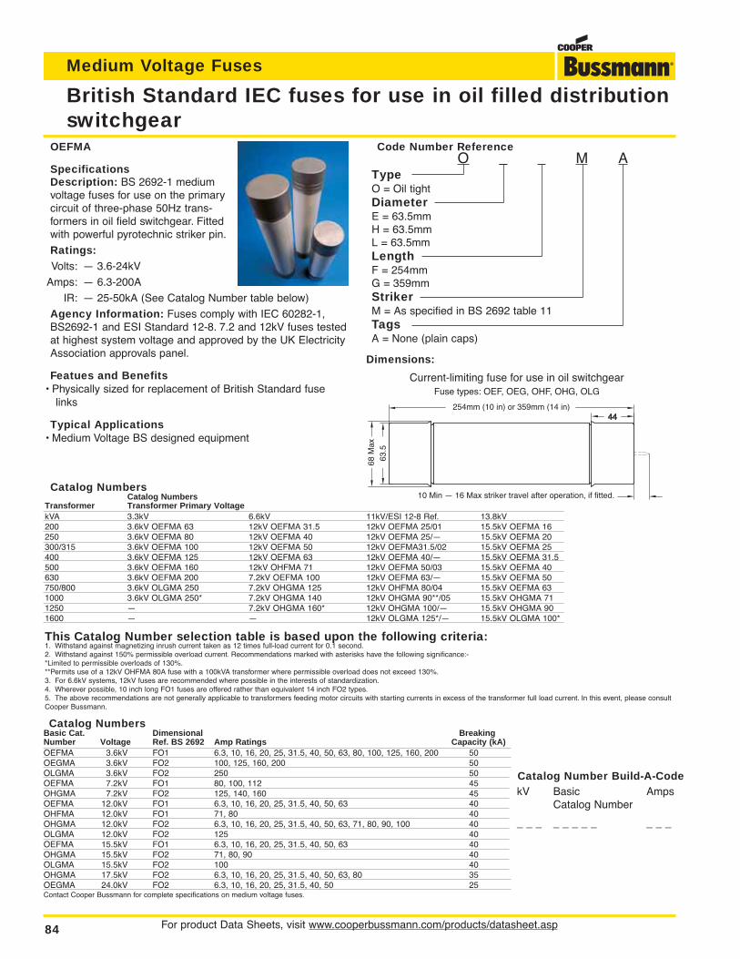
For product Data Sheets, visit www.cooperbussmann.com/products/datasheet.asp84
Medium Voltage Fuses
British Standard IEC fuses for use in oil filled distributionswitchgear
OEFMA
SpecificationsDescription: BS 2692-1 mediumvoltage fuses for use on the primarycircuit of three-phase 50Hz trans-formers in oil field switchgear. Fittedwith powerful pyrotechnic striker pin.
Ratings:Volts: — 3.6-24kV
Amps: — 6.3-200A
IR: — 25-50kA (See Catalog Number table below)
Agency Information: Fuses comply with IEC 60282-1,BS2692-1 and ESI Standard 12-8. 7.2 and 12kV fuses testedat highest system voltage and approved by the UK ElectricityAssociation approvals panel.
Featues and Benefits• Physically sized for replacement of British Standard fuse
links
Typical Applications• Medium Voltage BS designed equipment
Catalog NumbersCatalog Numbers
Transformer Transformer Primary VoltagekVA 3.3kV 6.6kV 11kV/ESI 12-8 Ref. 13.8kV200 3.6kV OEFMA 63 12kV OEFMA 31.5 12kV OEFMA 25/01 15.5kV OEFMA 16250 3.6kV OEFMA 80 12kV OEFMA 40 12kV OEFMA 25/— 15.5kV OEFMA 20300/315 3.6kV OEFMA 100 12kV OEFMA 50 12kV OEFMA31.5/02 15.5kV OEFMA 25400 3.6kV OEFMA 125 12kV OEFMA 63 12kV OEFMA 40/— 15.5kV OEFMA 31.5500 3.6kV OEFMA 160 12kV OHFMA 71 12kV OEFMA 50/03 15.5kV OEFMA 40630 3.6kV OEFMA 200 7.2kV OEFMA 100 12kV OEFMA 63/— 15.5kV OEFMA 50750/800 3.6kV OLGMA 250 7.2kV OHGMA 125 12kV OHFMA 80/04 15.5kV OEFMA 631000 3.6kV OLGMA 250* 7.2kV OHGMA 140 12kV OHGMA 90**/05 15.5kV OHGMA 711250 — 7.2kV OHGMA 160* 12kV OHGMA 100/— 15.5kV OHGMA 901600 — — 12kV OLGMA 125*/— 15.5kV OLGMA 100*
This Catalog Number selection table is based upon the following criteria:1. Withstand against magnetizing inrush current taken as 12 times full-load current for 0.1 second.2. Withstand against 150% permissible overload current. Recommendations marked with asterisks have the following significance:-*Limited to permissible overloads of 130%.**Permits use of a 12kV OHFMA 80A fuse with a 100kVA transformer where permissible overload does not exceed 130%.3. For 6.6kV systems, 12kV fuses are recommended where possible in the interests of standardization.4. Wherever possible, 10 inch long FO1 fuses are offered rather than equivalent 14 inch FO2 types.5. The above recommendations are not generally applicable to transformers feeding motor circuits with starting currents in excess of the transformer full load current. In this event, please consultCooper Bussmann.
Catalog NumbersBasic Cat. Dimensional BreakingNumber Voltage Ref. BS 2692 Amp Ratings Capacity (kA)OEFMA 3.6kV FO1 6.3, 10, 16, 20, 25, 31.5, 40, 50, 63, 80, 100, 125, 160, 200 50OEGMA 3.6kV FO2 100, 125, 160, 200 50OLGMA 3.6kV FO2 250 50OEFMA 7.2kV FO1 80, 100, 112 45OHGMA 7.2kV FO2 125, 140, 160 45OEFMA 12.0kV FO1 6.3, 10, 16, 20, 25, 31.5, 40, 50, 63 40OHFMA 12.0kV FO1 71, 80 40OHGMA 12.0kV FO2 6.3, 10, 16, 20, 25, 31.5, 40, 50, 63, 71, 80, 90, 100 40OLGMA 12.0kV FO2 125 40OEFMA 15.5kV FO1 6.3, 10, 16, 20, 25, 31.5, 40, 50, 63 40OHGMA 15.5kV FO2 71, 80, 90 40OLGMA 15.5kV FO2 100 40OHGMA 17.5kV FO2 6.3, 10, 16, 20, 25, 31.5, 40, 50, 63, 80 35OEGMA 24.0kV FO2 6.3, 10, 16, 20, 25, 31.5, 40, 50 25Contact Cooper Bussmann for complete specifications on medium voltage fuses.
Code Number ReferenceO _ _ M A
TypeO = Oil tightDiameterE = 63.5mmH = 63.5mmL = 63.5mmLengthF = 254mmG = 359mmStrikerM = As specified in BS 2692 table 11TagsA = None (plain caps)
Catalog Number Build-A-CodekV Basic Amps
Catalog Number
_ _ _ _ _ _ _ _ _ _ _
Current-limiting fuse for use in oil switchgearFuse types: OEF, OEG, OHF, OHG, OLG
10 Min — 16 Max striker travel after operation, if fitted.
63.5
68 M
ax
4444254mm (10 in) or 359mm (14 in)
Dimensions:
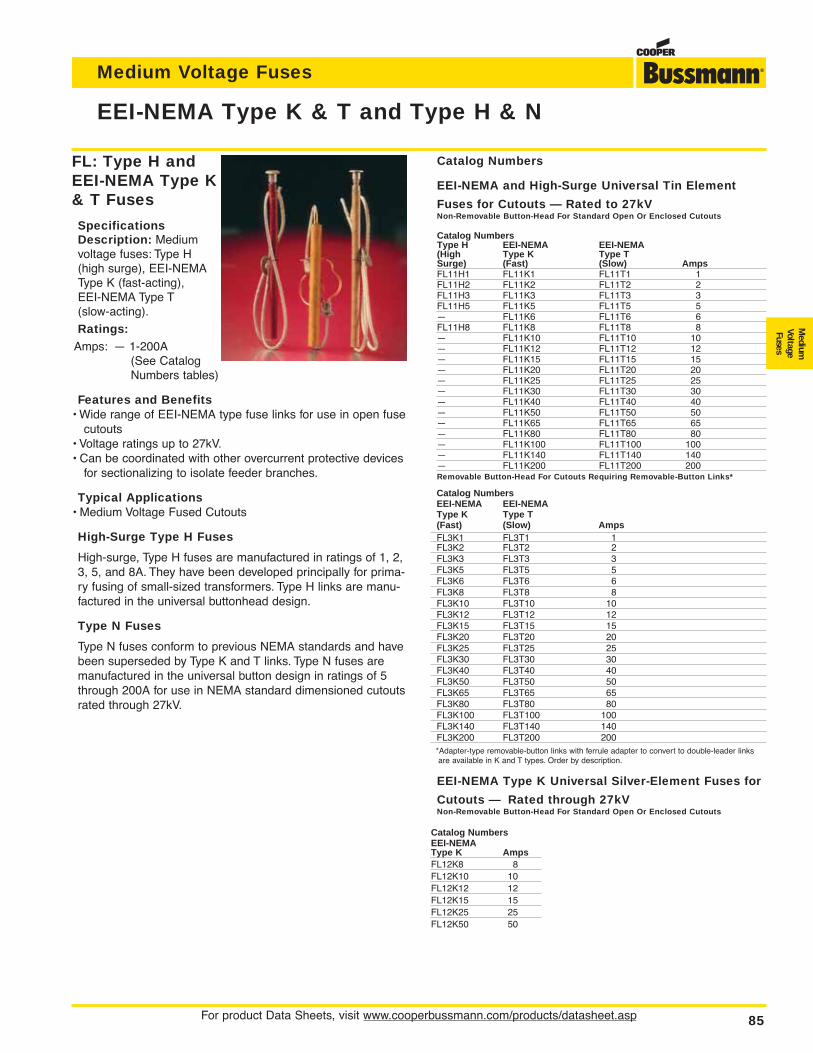
For product Data Sheets, visit www.cooperbussmann.com/products/datasheet.asp 85
Medium Voltage Fuses
Medium
VoltageFuses
EEI-NEMA Type K & T and Type H & N
Catalog Numbers
EEI-NEMA and High-Surge Universal Tin Element
Fuses for Cutouts — Rated to 27kVNon-Removable Button-Head For Standard Open Or Enclosed Cutouts
Catalog NumbersType H EEI-NEMA EEI-NEMA(High Type K Type TSurge) (Fast) (Slow) AmpsFL11H1 FL11K1 FL11T1 1FL11H2 FL11K2 FL11T2 2FL11H3 FL11K3 FL11T3 3FL11H5 FL11K5 FL11T5 5— FL11K6 FL11T6 6FL11H8 FL11K8 FL11T8 8— FL11K10 FL11T10 10— FL11K12 FL11T12 12— FL11K15 FL11T15 15— FL11K20 FL11T20 20— FL11K25 FL11T25 25— FL11K30 FL11T30 30— FL11K40 FL11T40 40— FL11K50 FL11T50 50— FL11K65 FL11T65 65— FL11K80 FL11T80 80— FL11K100 FL11T100 100— FL11K140 FL11T140 140— FL11K200 FL11T200 200Removable Button-Head For Cutouts Requiring Removable-Button Links*
Catalog NumbersEEI-NEMA EEI-NEMAType K Type T(Fast) (Slow) AmpsFL3K1 FL3T1 1FL3K2 FL3T2 2FL3K3 FL3T3 3FL3K5 FL3T5 5FL3K6 FL3T6 6FL3K8 FL3T8 8FL3K10 FL3T10 10FL3K12 FL3T12 12FL3K15 FL3T15 15FL3K20 FL3T20 20FL3K25 FL3T25 25FL3K30 FL3T30 30FL3K40 FL3T40 40FL3K50 FL3T50 50FL3K65 FL3T65 65FL3K80 FL3T80 80FL3K100 FL3T100 100FL3K140 FL3T140 140FL3K200 FL3T200 200*Adapter-type removable-button links with ferrule adapter to convert to double-leader linksare available in K and T types. Order by description.
EEI-NEMA Type K Universal Silver-Element Fuses for
Cutouts — Rated through 27kVNon-Removable Button-Head For Standard Open Or Enclosed Cutouts
Catalog NumbersEEI-NEMAType K AmpsFL12K8 8FL12K10 10FL12K12 12FL12K15 15FL12K25 25FL12K50 50
FL: Type H andEEI-NEMA Type K& T Fuses
SpecificationsDescription: Mediumvoltage fuses: Type H(high surge), EEI-NEMAType K (fast-acting), EEI-NEMA Type T (slow-acting).
Ratings:Amps: — 1-200A
(See CatalogNumbers tables)
Features and Benefits• Wide range of EEI-NEMA type fuse links for use in open fuse
cutouts• Voltage ratings up to 27kV.• Can be coordinated with other overcurrent protective devices
for sectionalizing to isolate feeder branches.
Typical Applications• Medium Voltage Fused Cutouts
High-Surge Type H Fuses
High-surge, Type H fuses are manufactured in ratings of 1, 2,3, 5, and 8A. They have been developed principally for prima-ry fusing of small-sized transformers. Type H links are manu-factured in the universal buttonhead design.
Type N Fuses
Type N fuses conform to previous NEMA standards and havebeen superseded by Type K and T links. Type N fuses aremanufactured in the universal button design in ratings of 5through 200A for use in NEMA standard dimensioned cutoutsrated through 27kV.
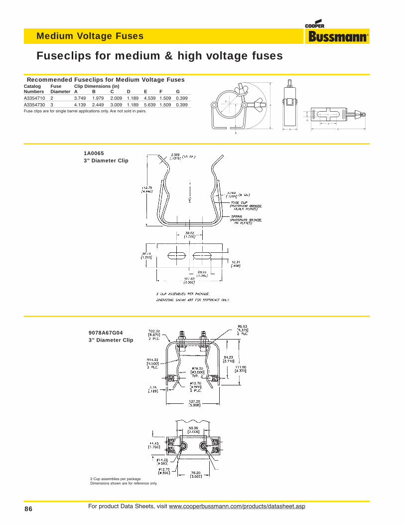
For product Data Sheets, visit www.cooperbussmann.com/products/datasheet.asp86
Medium Voltage Fuses
Fuseclips for medium & high voltage fuses
1A00653” Diameter Clip
C
B
A
G
E
F
D
9078A67G043” Diameter Clip
2 Cup assemblies per package.Dimensions shown are for reference only.
Recommended Fuseclips for Medium Voltage FusesCatalog Fuse Clip Dimensions (in)Numbers Diameter A B C D E F GA3354710 2 3.749 1.979 2.009 1.189 4.539 1.509 0.399A3354730 3 4.139 2.449 3.009 1.189 5.639 1.509 0.399Fuse clips are for single barrel applications only. Are not sold in pairs.
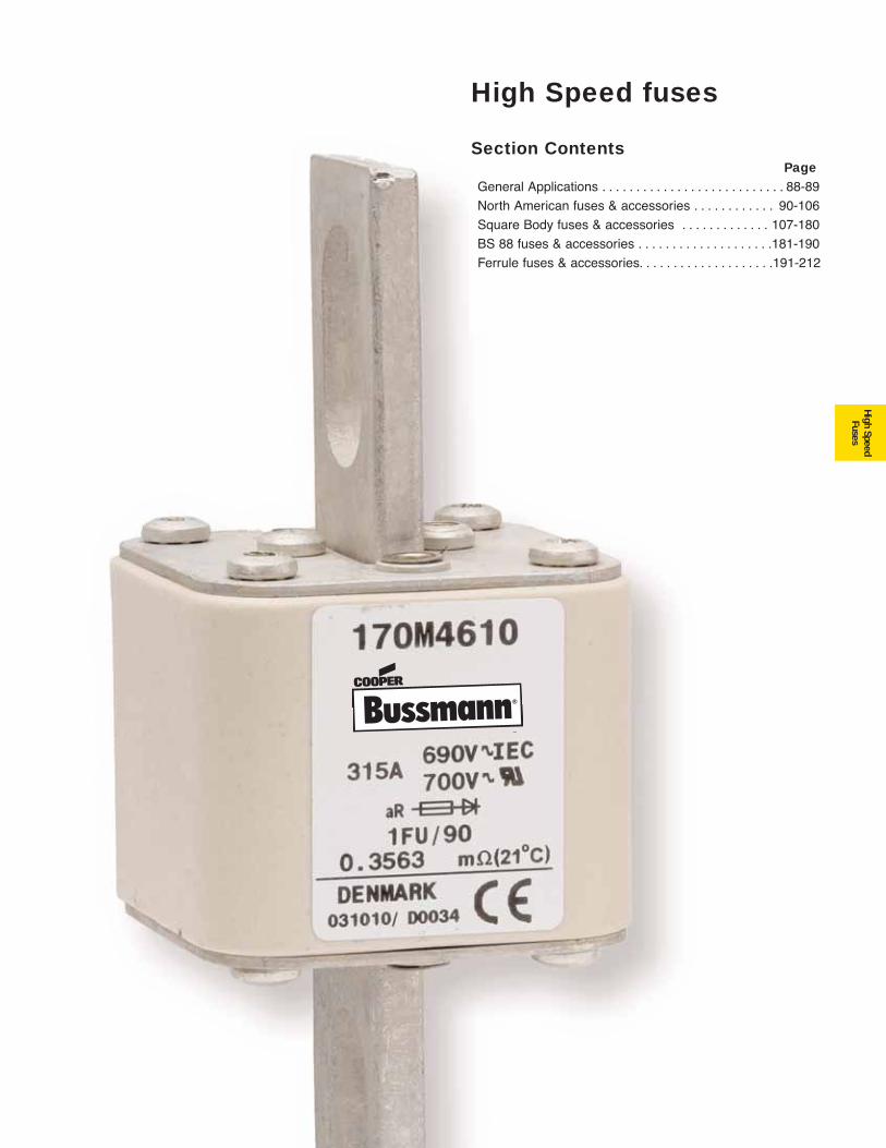
87
High Speed fuses
High SpeedFuses
Section ContentsPage
General Applications . . . . . . . . . . . . . . . . . . . . . . . . . . . 88-89
North American fuses & accessories . . . . . . . . . . . . 90-106
Square Body fuses & accessories . . . . . . . . . . . . . 107-180
BS 88 fuses & accessories . . . . . . . . . . . . . . . . . . . .181-190
Ferrule fuses & accessories. . . . . . . . . . . . . . . . . . . .191-212
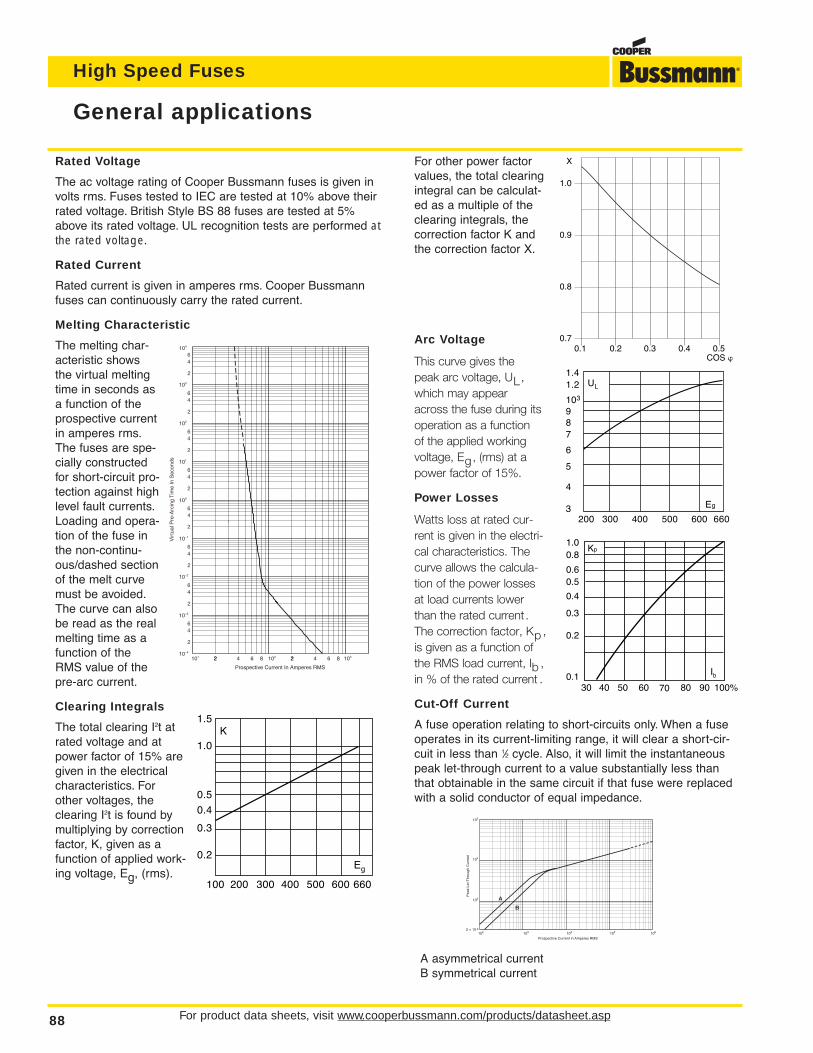
For other power factorvalues, the total clearingintegral can be calculat-ed as a multiple of theclearing integrals, thecorrection factor K andthe correction factor X.
Arc Voltage
This curve gives thepeak arc voltage, UL,which may appearacross the fuse during itsoperation as a functionof the applied workingvoltage, Eg, (rms) at apower factor of 15%.
Power Losses
Watts loss at rated cur-rent is given in the electri-cal characteristics. Thecurve allows the calcula-tion of the power lossesat load currents lowerthan the rated current.The correction factor, Kp ,is given as a function ofthe RMS load current, Ib ,in % of the rated current .
Cut-Off Current
A fuse operation relating to short-circuits only. When a fuseoperates in its current-limiting range, it will clear a short-cir-cuit in less than 1⁄2 cycle. Also, it will limit the instantaneouspeak let-through current to a value substantially less thanthat obtainable in the same circuit if that fuse were replacedwith a solid conductor of equal impedance.
A asymmetrical currentB symmetrical current
For product data sheets, visit www.cooperbussmann.com/products/datasheet.asp88
High Speed Fuses
Prospective Current in Amperes RMS
Pea
k Le
t-T
hrou
gh C
urre
nt
102 ≈ 10
22
103
104
105
103 104 105 106
A
B
General applications
Rated Voltage
The ac voltage rating of Cooper Bussmann fuses is given involts rms. Fuses tested to IEC are tested at 10% above theirrated voltage. British Style BS 88 fuses are tested at 5%above its rated voltage. UL recognition tests are performed atthe rated voltage.
Rated Current
Rated current is given in amperes rms. Cooper Bussmannfuses can continuously carry the rated current.
Melting Characteristic
The melting char-acteristic showsthe virtual meltingtime in seconds asa function of theprospective currentin amperes rms.The fuses are spe-cially constructedfor short-circuit pro-tection against highlevel fault currents.Loading and opera-tion of the fuse inthe non-continu-ous/dashed sectionof the melt curvemust be avoided.The curve can alsobe read as the realmelting time as afunction of theRMS value of thepre-arc current.
Clearing Integrals
The total clearing I2t atrated voltage and atpower factor of 15% aregiven in the electricalcharacteristics. Forother voltages, theclearing I2t is found bymultiplying by correctionfactor, K, given as afunction of applied work-ing voltage, Eg, (rms).
104
103
102
101 22 4 6 8 2102 2 4 6 8 103
2
46
2
64
100
2
64
101
2
64
2
64
2
64
64
2
6
2
4
Prospective Current In Amperes RMS
Vir
tual
Pre
-Arc
ing
Tim
e In
Sec
onds
10–4
10–3
10–2
10–1
K1.5
1.0
0.5
0.4
0.3
0.2
100 200 300 400 500 600 660
Eg
1.0
0.9
0.8
0.70.1 0.2 0.3 0.4 0.5
COS
X
UL
1.41.2
103
6
87
9
5
4
3200 300 400 500 600 660
Eg
Kp1.00.8
0.4
0.50.6
0.3
0.2
0.130 40 50 60 70 80 90 100%
Ib
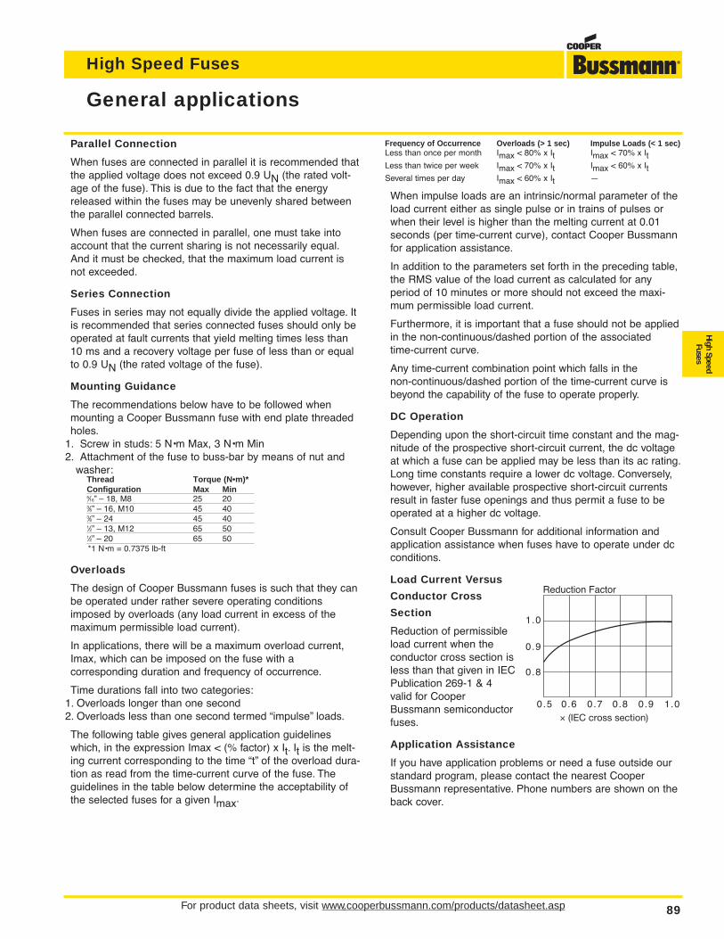
High Speed Fuses
For product data sheets, visit www.cooperbussmann.com/products/datasheet.asp 89
High SpeedFuses
General applications
Parallel Connection
When fuses are connected in parallel it is recommended thatthe applied voltage does not exceed 0.9 UN (the rated volt-age of the fuse). This is due to the fact that the energyreleased within the fuses may be unevenly shared betweenthe parallel connected barrels.
When fuses are connected in parallel, one must take intoaccount that the current sharing is not necessarily equal.And it must be checked, that the maximum load current isnot exceeded.
Series Connection
Fuses in series may not equally divide the applied voltage. Itis recommended that series connected fuses should only beoperated at fault currents that yield melting times less than10 ms and a recovery voltage per fuse of less than or equalto 0.9 UN (the rated voltage of the fuse).
Mounting Guidance
The recommendations below have to be followed whenmounting a Cooper Bussmann fuse with end plate threadedholes.
1. Screw in studs: 5 N•m Max, 3 N•m Min2. Attachment of the fuse to buss-bar by means of nut and
washer:Thread Torque (N•m)*Configuration Max Min5⁄16” – 18, M8 25 203⁄8” – 16, M10 45 403⁄8” – 24 45 401⁄2” – 13, M12 65 501⁄2” – 20 65 50*1 N•m = 0.7375 lb-ft
Overloads
The design of Cooper Bussmann fuses is such that they canbe operated under rather severe operating conditionsimposed by overloads (any load current in excess of themaximum permissible load current).
In applications, there will be a maximum overload current,Imax, which can be imposed on the fuse with a corresponding duration and frequency of occurrence.
Time durations fall into two categories:1. Overloads longer than one second2. Overloads less than one second termed “impulse” loads.
The following table gives general application guidelineswhich, in the expression Imax < (% factor) x It. It is the melt-ing current corresponding to the time “t” of the overload dura-tion as read from the time-current curve of the fuse. Theguidelines in the table below determine the acceptability ofthe selected fuses for a given Imax.
Frequency of Occurrence Overloads (> 1 sec) Impulse Loads (< 1 sec)Less than once per month Imax < 80% x It Imax < 70% x ItLess than twice per week Imax < 70% x It Imax < 60% x ItSeveral times per day Imax < 60% x It —
When impulse loads are an intrinsic/normal parameter of theload current either as single pulse or in trains of pulses orwhen their level is higher than the melting current at 0.01seconds (per time-current curve), contact Cooper Bussmannfor application assistance.
In addition to the parameters set forth in the preceding table,the RMS value of the load current as calculated for any period of 10 minutes or more should not exceed the maxi-mum permissible load current.
Furthermore, it is important that a fuse should not be appliedin the non-continuous/dashed portion of the associated time-current curve.
Any time-current combination point which falls in the non-continuous/dashed portion of the time-current curve isbeyond the capability of the fuse to operate properly.
DC Operation
Depending upon the short-circuit time constant and the mag-nitude of the prospective short-circuit current, the dc voltageat which a fuse can be applied may be less than its ac rating.Long time constants require a lower dc voltage. Conversely,however, higher available prospective short-circuit currentsresult in faster fuse openings and thus permit a fuse to beoperated at a higher dc voltage.
Consult Cooper Bussmann for additional information andapplication assistance when fuses have to operate under dcconditions.
Load Current Versus
Conductor Cross
Section
Reduction of permissibleload current when theconductor cross section isless than that given in IECPublication 269-1 & 4valid for CooperBussmann semiconductorfuses.
Application Assistance
If you have application problems or need a fuse outside ourstandard program, please contact the nearest CooperBussmann representative. Phone numbers are shown on theback cover.
1.0
0.9
0.8
0.5 0.6 0.7 0.8 0.9 1.0≈ (IEC cross section)
Reduction Factor
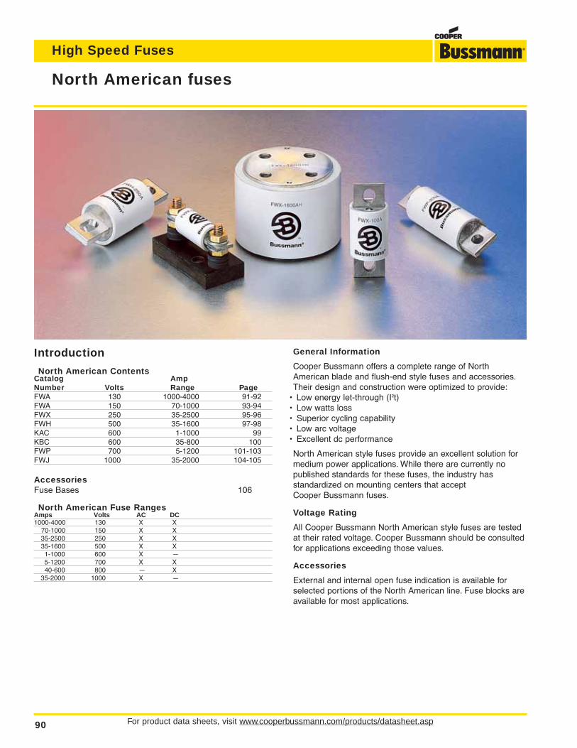
Introduction
North American ContentsCatalog AmpNumber Volts Range PageFWA 130 1000-4000 91-92FWA 150 70-1000 93-94FWX 250 35-2500 95-96FWH 500 35-1600 97-98KAC 600 1-1000 99KBC 600 35-800 100FWP 700 5-1200 101-103FWJ 1000 35-2000 104-105
AccessoriesFuse Bases 106
North American Fuse RangesAmps Volts AC DC1000-4000 130 X X
70-1000 150 X X35-2500 250 X X35-1600 500 X X1-1000 600 X —5-1200 700 X X40-600 800 — X
35-2000 1000 X —
For product data sheets, visit www.cooperbussmann.com/products/datasheet.asp90
High Speed Fuses
North American fuses
General Information
Cooper Bussmann offers a complete range of NorthAmerican blade and flush-end style fuses and accessories.Their design and construction were optimized to provide:
• Low energy let-through (I2t)• Low watts loss• Superior cycling capability• Low arc voltage• Excellent dc performance
North American style fuses provide an excellent solution formedium power applications. While there are currently nopublished standards for these fuses, the industry hasstandardized on mounting centers that accept Cooper Bussmann fuses.
Voltage Rating
All Cooper Bussmann North American style fuses are testedat their rated voltage. Cooper Bussmann should be consultedfor applications exceeding those values.
Accessories
External and internal open fuse indication is available forselected portions of the North American line. Fuse blocks areavailable for most applications.
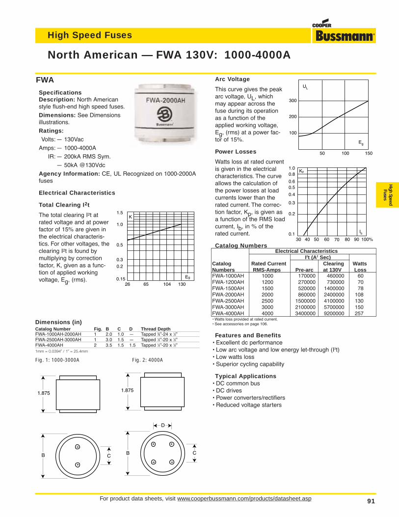
High Speed Fuses
For product data sheets, visit www.cooperbussmann.com/products/datasheet.asp 91
High SpeedFuses
Dimensions (in)Catalog Number Fig. B C D Thread DepthFWA-1000AH-2000AH 1 2.0 1.0 — Tapped 3⁄8”-24 x 1⁄2”FWA-2500AH-3000AH 1 3.0 1.5 — Tapped 1⁄2”-20 x 1⁄2”FWA-4000AH 2 3.5 1.5 1.5 Tapped 1⁄2”-20 x 1⁄2”1mm = 0.0394∑ / 1∑ = 25.4mm
Fig. 1: 1000-3000A Fig. 2: 4000A
1.875
B C
1.875
CB
D
Arc Voltage
This curve gives the peakarc voltage, UL, whichmay appear across thefuse during its operationas a function of theapplied working voltage,Eg, (rms) at a power fac-tor of 15%.
Power Losses
Watts loss at rated currentis given in the electricalcharacteristics. The curveallows the calculation ofthe power losses at loadcurrents lower than therated current. The correc-tion factor, Kp, is given asa function of the RMS loadcurrent, Ib, in % of therated current.
Catalog NumbersElectrical Characteristics
I2t (A2 Sec)Catalog Rated Current Clearing WattsNumbers RMS-Amps Pre-arc at 130V LossFWA-1000AH 1000 170000 460000 60FWA-1200AH 1200 270000 730000 70FWA-1500AH 1500 520000 1400000 78FWA-2000AH 2000 860000 2400000 108FWA-2500AH 2500 1500000 4100000 130FWA-3000AH 3000 2100000 5700000 150FWA-4000AH 4000 3400000 9200000 257• Watts loss provided at rated current.• See accessories on page 106.
Features and Benefits• Excellent dc performance• Low arc voltage and low energy let-through (I2t)• Low watts loss• Superior cycling capability
Typical Applications• DC common bus• DC drives• Power converters/rectifiers• Reduced voltage starters
North American — FWA 130V: 1000-4000A
FWA
SpecificationsDescription: North Americanstyle flush-end high speed fuses.
Dimensions: See Dimensionsillustrations.
Ratings:Volts: — 130Vac
Amps: — 1000-4000A
IR: — 200kA RMS Sym.
— 50kA @130Vdc
Agency Information: CE, UL Recognized on 1000-2000Afuses
Electrical Characteristics
Total Clearing I2t
The total clearing I2t atrated voltage and at powerfactor of 15% are given inthe electrical characteris-tics. For other voltages, theclearing I2t is found bymultiplying by correctionfactor, K, given as a func-tion of applied workingvoltage, Eg, (rms).
1301046526
1.5
1.0
0.5
0.3
0.2
0.15 Eg
K
UL
Eg
200
100
100 15050
300
Kp1.00.8
0.4
0.50.6
0.3
0.2
0.130 40 50 60 70 80 90 100%
Ib
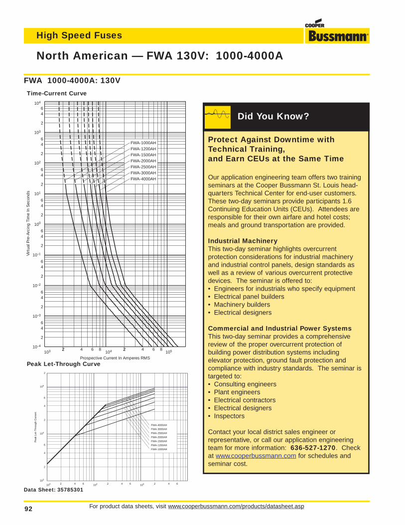
For product data sheets, visit www.cooperbussmann.com/products/datasheet.asp92
High Speed Fuses
North American — FWA 130V: 1000-4000A
FWA 1000-4000A: 130V
Time-Current Curve
103 22 4 6 8 2104 2 4 6 8
105
Prospective Current In Amperes RMS
2
46
2
64
100
2
64
101
2
64
2
64
2
64
Virt
ual P
re-A
rcin
g Ti
me
In S
econ
ds
64
2
6
2
4
10–1
10–2
10–3
10–4
102
103
104
FWA-4000AHFWA-3000AHFWA-2500AHFWA-2000AHFWA-1500AHFWA-1200AHFWA-1000AH
FWA-4000AH
FWA-3000AH
FWA-2500AH
FWA-2000AH
FWA-1500AH
FWA-1200AH
FWA-1000AH
Pea
k Le
t-Th
roug
h C
urre
nt
2
6
4
2
6
4
2
2 4 6 2 4 6 2 4 6104 105
103
104
105
103
Peak Let-Through Curve
Data Sheet: 35785301
Protect Against Downtime withTechnical Training,and Earn CEUs at the Same Time
Our application engineering team offers two trainingseminars at the Cooper Bussmann St. Louis head-quarters Technical Center for end-user customers.These two-day seminars provide participants 1.6Continuing Education Units (CEUs). Attendees areresponsible for their own airfare and hotel costs;meals and ground transportation are provided.
Industrial MachineryThis two-day seminar highlights overcurrent protection considerations for industrial machineryand industrial control panels, design standards aswell as a review of various overcurrent protectivedevices. The seminar is offered to:• Engineers for industrials who specify equipment• Electrical panel builders• Machinery builders• Electrical designers
Commercial and Industrial Power SystemsThis two-day seminar provides a comprehensivereview of the proper overcurrent protection ofbuilding power distribution systems including elevator protection, ground fault protection and compliance with industry standards. The seminar istargeted to:• Consulting engineers• Plant engineers• Electrical contractors• Electrical designers• Inspectors
Contact your local district sales engineer or representative, or call our application engineeringteam for more information: 636-527-1270. Checkat www.cooperbussmann.com for schedules and seminar cost.
Did You Know?
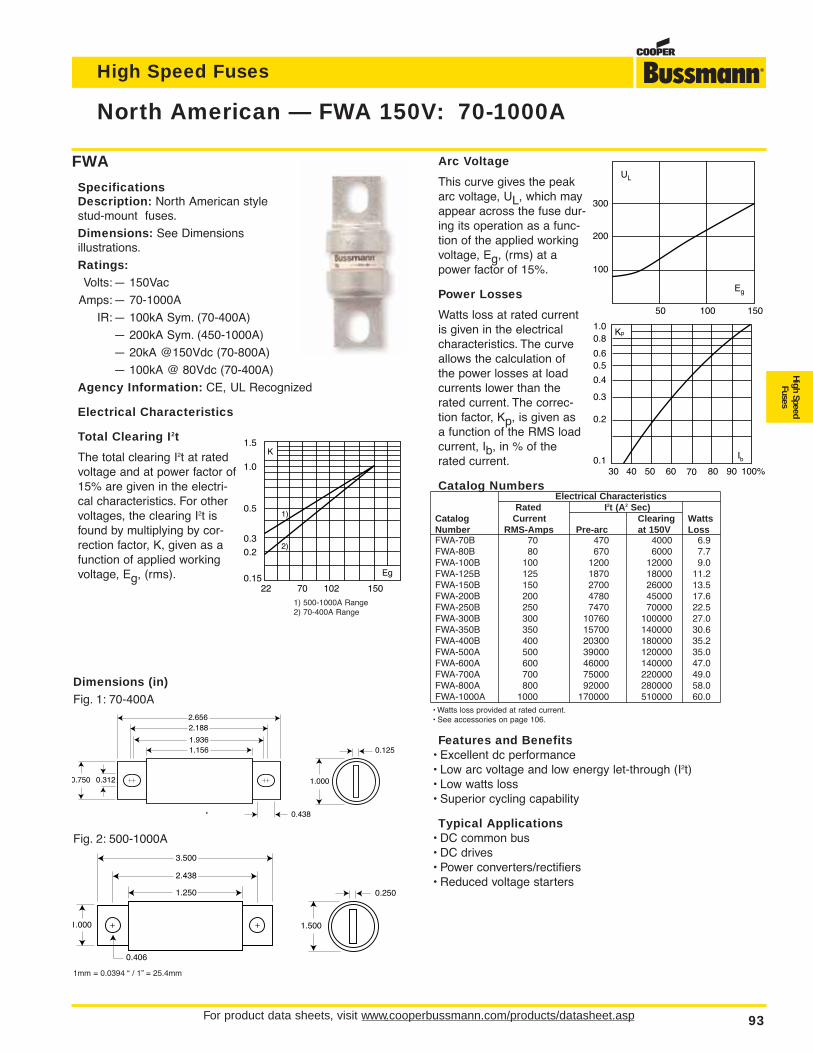
High Speed Fuses
For product data sheets, visit www.cooperbussmann.com/products/datasheet.asp 93
High SpeedFuses
2.656
1.936
2.188
1.156
0.312
0.438
0.750 1.000
0.125
Dimensions (in)Fig. 1: 70-400A
1.500
0.250
3.500
2.438
1.250
1.000
0.406
Fig. 2: 500-1000A
1mm = 0.0394 “ / 1” = 25.4mm
North American — FWA 150V: 70-1000A
FWA
SpecificationsDescription: North American stylestud-mount fuses.
Dimensions: See Dimensions illustrations.
Ratings:Volts:— 150Vac
Amps:— 70-1000A
IR:— 100kA Sym. (70-400A)
— 200kA Sym. (450-1000A)
— 20kA @150Vdc (70-800A)
— 100kA @ 80Vdc (70-400A)
Agency Information: CE, UL Recognized
Electrical Characteristics
Total Clearing I2t
The total clearing I2t at ratedvoltage and at power factor of15% are given in the electri-cal characteristics. For othervoltages, the clearing I2t isfound by multiplying by cor-rection factor, K, given as afunction of applied workingvoltage, Eg, (rms).
Arc Voltage
This curve gives the peakarc voltage, UL, which mayappear across the fuse dur-ing its operation as a func-tion of the applied workingvoltage, Eg, (rms) at apower factor of 15%.
Power Losses
Watts loss at rated currentis given in the electricalcharacteristics. The curveallows the calculation ofthe power losses at loadcurrents lower than therated current. The correc-tion factor, Kp, is given asa function of the RMS loadcurrent, Ib, in % of therated current.
Catalog NumbersElectrical Characteristics
Rated I2t (A2 Sec)Catalog Current Clearing WattsNumber RMS-Amps Pre-arc at 150V LossFWA-70B 70 470 4000 6.9FWA-80B 80 670 6000 7.7FWA-100B 100 1200 12000 9.0FWA-125B 125 1870 18000 11.2FWA-150B 150 2700 26000 13.5FWA-200B 200 4780 45000 17.6FWA-250B 250 7470 70000 22.5FWA-300B 300 10760 100000 27.0FWA-350B 350 15700 140000 30.6FWA-400B 400 20300 180000 35.2FWA-500A 500 39000 120000 35.0FWA-600A 600 46000 140000 47.0FWA-700A 700 75000 220000 49.0FWA-800A 800 92000 280000 58.0FWA-1000A 1000 170000 510000 60.0
• Watts loss provided at rated current.• See accessories on page 106.
Features and Benefits• Excellent dc performance• Low arc voltage and low energy let-through (I2t)• Low watts loss• Superior cycling capability
Typical Applications• DC common bus• DC drives• Power converters/rectifiers• Reduced voltage starters
1501027022
1.5
1.0
0.5
0.3
0.2
0.15Eg
K
1)
2)
Kp1.00.8
0.4
0.50.6
0.3
0.2
0.130 40 50 60 70 80 90 100%
Ib
UL
Eg
200
100
100 15050
300
1) 500-1000A Range2) 70-400A Range
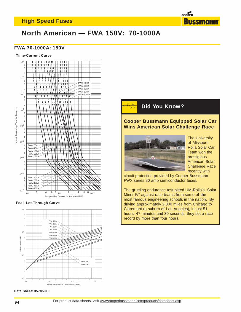
For product data sheets, visit www.cooperbussmann.com/products/datasheet.asp94
High Speed Fuses
North American — FWA 150V: 70-1000A
Prospective Current In Amperes RMS
Virt
ual P
re-A
rcin
g Ti
me
In S
econ
ds
102 2 4 6 8 103 2 4 6 8 104
2
46
2
64
100
2
64
101
2
64
2
64
2
64
64
2
6
2
4
10–1
10–2
10–3
10–4
102
103
104
FWA-1000AFWA-800AFWA-700AFWA-600AFWA-500A
FWA-200A
FWA-400AFWA-350AFWA-300AFWA-250A
FWA-150A
FWA-70AFWA-80AFWA-100AFWA-125A
FWA 70-1000A: 150V
Time-Current Curve
Prospective Short-Circuit Current Symmetrical RMS
Pea
k Le
t-Th
roug
h C
urre
nt
2
6
4
2
6
4
2
6
4
2 4 6 2 4 6 2 4 6102
103
104
106
102 103 104 1052
FWA-400A
FWA-350A
FWA-300A
FWA-250A
FWA-200A
FWA-150A
FWA-100A
FWA-80A
FWA-70A
Peak Let-Through Curve
Data Sheet: 35785310
Cooper Bussmann Equipped Solar CarWins American Solar Challenge Race
The Universityof Missouri-Rolla Solar CarTeam won theprestigiousAmerican SolarChallenge Racerecently with
circuit protection provided by Cooper BussmannFWX series 80 amp semiconductor fuses.
The grueling endurance test pitted UM-Rolla’s “SolarMiner IV” against race teams from some of the most famous engineering schools in the nation. Bydriving approximately 2,300 miles from Chicago toClaremont (a suburb of Los Angeles), in just 51hours, 47 minutes and 39 seconds, they set a racerecord by more than four hours.
Did You Know?
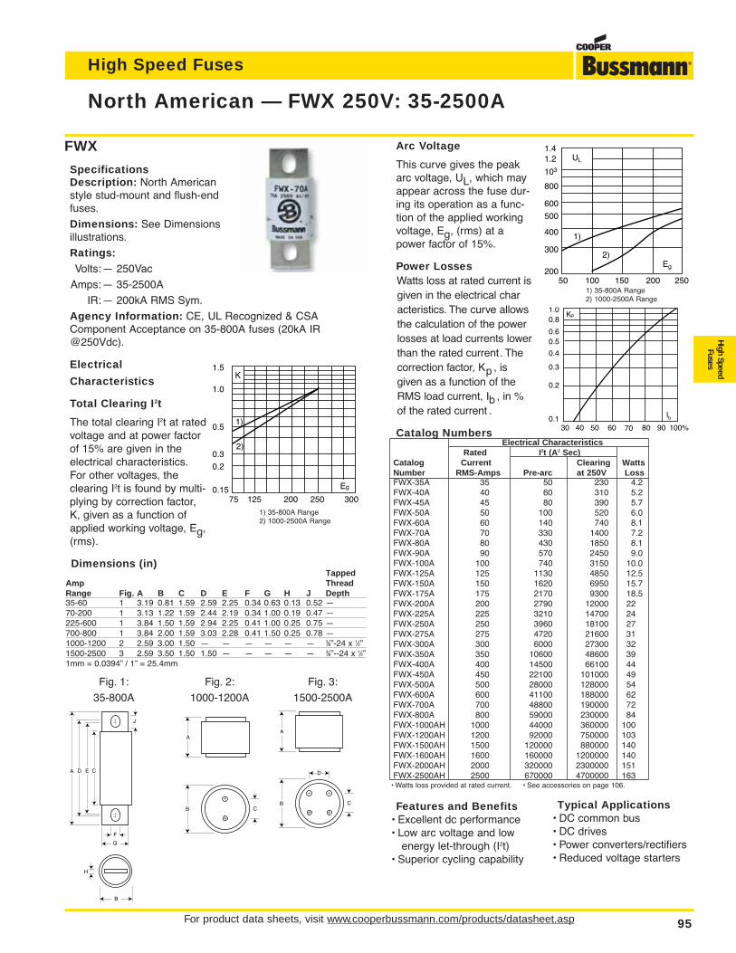
High Speed Fuses
For product data sheets, visit www.cooperbussmann.com/products/datasheet.asp 95
High SpeedFuses
North American — FWX 250V: 35-2500A
FWX
SpecificationsDescription: North Americanstyle stud-mount and flush-endfuses.
Dimensions: See Dimensionsillustrations.
Ratings:Volts:— 250Vac
Amps:— 35-2500A
IR:— 200kA RMS Sym.
Agency Information: CE, UL Recognized & CSAComponent Acceptance on 35-800A fuses (20kA IR@250Vdc).
Electrical
Characteristics
Total Clearing I2t
The total clearing I2t at ratedvoltage and at power factorof 15% are given in theelectrical characteristics.For other voltages, theclearing I2t is found by multi-plying by correction factor,K, given as a function ofapplied working voltage, Eg,(rms).
Arc Voltage
This curve gives the peakarc voltage, UL, which mayappear across the fuse dur-ing its operation as a func-tion of the applied workingvoltage, Eg, (rms) at apower factor of 15%.
Power LossesWatts loss at rated current isgiven in the electrical characteristics. The curve allows the calculation of the power losses at load currents lowerthan the rated current. Thecorrection factor, Kp , is given as a function of the RMS load current, Ib , in % of the rated current .
Catalog NumbersElectrical Characteristics
Rated I2t (A2 Sec)Catalog Current Clearing WattsNumber RMS-Amps Pre-arc at 250V LossFWX-35A 35 50 230 4.2FWX-40A 40 60 310 5.2FWX-45A 45 80 390 5.7FWX-50A 50 100 520 6.0FWX-60A 60 140 740 8.1FWX-70A 70 330 1400 7.2FWX-80A 80 430 1850 8.1FWX-90A 90 570 2450 9.0FWX-100A 100 740 3150 10.0FWX-125A 125 1130 4850 12.5FWX-150A 150 1620 6950 15.7FWX-175A 175 2170 9300 18.5FWX-200A 200 2790 12000 22FWX-225A 225 3210 14700 24FWX-250A 250 3960 18100 27FWX-275A 275 4720 21600 31FWX-300A 300 6000 27300 32FWX-350A 350 10600 48600 39FWX-400A 400 14500 66100 44FWX-450A 450 22100 101000 49FWX-500A 500 28000 128000 54FWX-600A 600 41100 188000 62FWX-700A 700 48800 190000 72FWX-800A 800 59000 230000 84FWX-1000AH 1000 44000 360000 100FWX-1200AH 1200 92000 750000 103FWX-1500AH 1500 120000 880000 140FWX-1600AH 1600 160000 1200000 140FWX-2000AH 2000 320000 2300000 151FWX-2500AH 2500 670000 4700000 163
• Watts loss provided at rated current. • See accessories on page 106.
Features and Benefits• Excellent dc performance• Low arc voltage and low
energy let-through (I2t)• Superior cycling capability
Kp1.00.8
0.4
0.50.6
0.3
0.2
0.130 40 50 60 70 80 90 100%
Ib
1.5
1.0
0.5
0.3
0.2
0.1575 125 300200 250
Eg
K
1)
2)
UL
1.41.2
103
800
600
500
400
300
20050 100 150 200 250
Eg
1)
2)
1) 35-800A Range2) 1000-2500A Range
1) 35-800A Range2) 1000-2500A Range
A ED C
F
J
G
B
H
A
B C
A
B C
D
Fig. 1:
35-800A
Fig. 2:
1000-1200A
Fig. 3:
1500-2500A
Dimensions (in)Tapped
Amp ThreadRange Fig. A B C D E F G H J Depth35-60 1 3.19 0.81 1.59 2.59 2.25 0.34 0.63 0.13 0.52 —70-200 1 3.13 1.22 1.59 2.44 2.19 0.34 1.00 0.19 0.47 —225-600 1 3.84 1.50 1.59 2.94 2.25 0.41 1.00 0.25 0.75 —700-800 1 3.84 2.00 1.59 3.03 2.28 0.41 1.50 0.25 0.78 —1000-1200 2 2.59 3.00 1.50 — — — — — — 3⁄8”-24 x 1⁄2”1500-2500 3 2.59 3.50 1.50 1.50 — — — — — 3⁄8”--24 x 1⁄2”1mm = 0.0394” / 1” = 25.4mm
Typical Applications• DC common bus• DC drives• Power converters/rectifiers• Reduced voltage starters
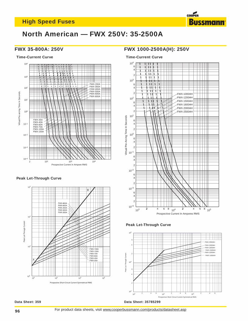
For product data sheets, visit www.cooperbussmann.com/products/datasheet.asp96
High Speed Fuses
North American — FWX 250V: 35-2500A
104
103
102
102 103 104
101
100
10–1
10–2
10–3
10–4
2Prospective Current In Ampere RMS
Virt
ual P
re-a
rcin
g Ti
me
In S
econ
ds
FWX-800AFWX-600AFWX-500AFXW-400AFWX-350AFWX-200A
FWX-150A
FWX-70AFWX-60AFWX-40AFWX-35A
FWX-100A
103 22 4 6 8 2104 2 4 6 8
105
2
46
2
64
100
2
64
2
64
2
64
2
64
64
2
6
2
4
10–1
10–2
10–3
10–4
102
101
103
104
FWX-2500AHFWX-2000AHFWX-1600AHFWX-1500AHFWX-1200AHFWX-1000AH
Prospective Current In Amperes RMS
Virt
ual P
re-A
rcin
g Ti
me
In S
econ
ds
FWX 1000-2500A(H): 250V
Time-Current Curve
FWX 35-800A: 250V
Time-Current Curve
FWX-150AFWX-100AFWX-70AFWX-60AFWX-45AFWX-35A
FWX-200AFWX-300AFWX-400AFWX-600AFWX-800A
102 103 104 105102
103
104
105
Prospective Short-Circuit Current Symmetrical RMS
Pea
k Le
t-T
hrou
gh C
urre
nt
A
B
Prospective Short-Circuit Current Symmetrical RMS
Pea
k Le
t-Th
roug
h C
urre
nt
2
6
4
2
6
4
2 4 6 2 4 6 2 4 6103
104
105
FWX-2000AH
FWX-1600AH
FWX-1500AHFWX-1200AH
FWX-1000AH
103 104 105
FWX-2500AH
Peak Let-Through Curve
Peak Let-Through Curve
Data Sheet: 359 Data Sheet: 35785299
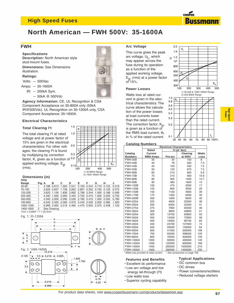
High Speed Fuses
For product data sheets, visit www.cooperbussmann.com/products/datasheet.asp 97
High SpeedFuses
North American — FWH 500V: 35-1600A
FWH
SpecificationsDescription: North American stylestud-mount fuses.
Dimensions: See Dimensions illustration.
Ratings:Volts: — 500Vac
Amps: — 35-1600A
IR: — 200kA Sym.
— 50kA @ 500Vdc
Agency Information: CE, UL Recognition & CSAComponent Acceptance on 35-800A only (50kAIR@500Vdc). UL Recognition on 35-1200A only, CSAComponent Acceptance: 35-1600A.
Electrical Characteristics
Total Clearing I2t
The total clearing I2t at ratedvoltage and at power factor of15% are given in the electricalcharacteristics. For other volt-ages, the clearing I2t is foundby multiplying by correctionfactor, K, given as a function ofapplied working voltage, Eg,(rms).
Arc Voltage
This curve gives the peakarc voltage, UL, whichmay appear across thefuse during its operationas a function of theapplied working voltage,Eg, (rms) at a power factorof 15%.
Power Losses
Watts loss at rated cur-rent is given in the elec-trical characteristics. Thecurve allows the calcula-tion of the power lossesat load currents lowerthan the rated current.The correction factor, Kp,is given as a function ofthe RMS load current, Ib,in % of the rated current.
Catalog NumbersElectrical Characteristics
Rated I2t (A2 Sec)Catalog Current Clearing WattsNumbers RMS-Amps Pre-arc at 500V LossFWH-35B 35 34 150 8FWH-40B 40 76 320 7.5FWH-45B 45 105 450 7.5FWH-50B 50 135 670 7.5FWH-60B 60 210 900 9.9FWH-70B 70 210 900 10.6FWH-80B 80 305 1400 12.7FWH-90B 90 360 1600 15FWH-100B 100 475 2000 17FWH-125B 125 800 3500 25FWH-150B 150 1100 4600 30FWH-175B 175 1450 6200 35FWH-200B 200 1900 8500 40FWH-225A 225 4600 23300 39FWH-250A 250 6300 32200 41FWH-275A 275 7900 40300 46FWH-300A 300 9800 49800 51FWH-325A 325 13700 63800 53FWH-350A 350 14500 72900 58FWH-400A 400 19200 96700 65FWH-450A 450 24700 127000 74FWH-500A 500 29200 149000 84FWH-600A 600 41300 206000 108FWH-700A 700 55000 298000 120FWH-800A 800 76200 409000 129FWH-1000A 1000 92000 450000 145FWH-1200A 1200 122000 600000 180FWH-1400A 1400 200000 1000000 210FWH-1600A 1600 290000 1400000 230
• Watts loss provided at rated current. • See accessories on page 106.
Features and Benefits• Excellent dc performance• Low arc voltage and low
energy let-through (I2t)• Low watts loss• Superior cycling capability
500400250100
1.5
1.0
0.5
0.3
0.2
0.15Eg
K
1)
2)
UL
2.0
1.6
1.2
103
800
600
500
400
300100 400300200 500
Eg
2)
1)
1) 35-200 & 1000-1600A Range2) 225-800A Range
A
E
D
C
F
J
G B
H
10.219
3.219 0.625
4.250.75
3.5
6.219
0.125 0.51.625
1.750
8.969
Fig. 1: 35-1200A
Fig. 2: 1400-1600A
Dimensions (in)AmpRange Fig. A B C D E F G H J35-60 1 3.188 0.813 1.593 2.541 2.193 0.344 0.719 0.125 0.51870-100 1 3.625 0.947 1.736 2.853 2.807 0.352 0.750 0.125 0.375125-200 1 3.625 1.156 1.836 2.892 2.768 0.344 1.000 0.188 0.406225-400 1 4.340 1.500 2.090 3.440 2.750 0.410 1.000 0.250 0.750450-600 1 4.340 2.000 2.090 3.530 2.780 0.410 1.500 0.250 0.780700-800 1 6.340 2.500 2.090 4.970 3.440 0.530 2.000 0.380 1.3001000-1200 1 6.969 3.000 3.219 5.465 4.475 0.625 2.375 0.438 1.1201400-1600 2 See Drawing1mm = 0.0394” / 1” = 25.4mm
Kp1.00.8
0.4
0.50.6
0.3
0.2
0.130 40 50 60 70 80 90 100%
Ib
1) 35-800A Range2) 1000-1600A Range
Typical Applications• DC common bus• DC drives• Power converters/rectifiers• Reduced voltage starters
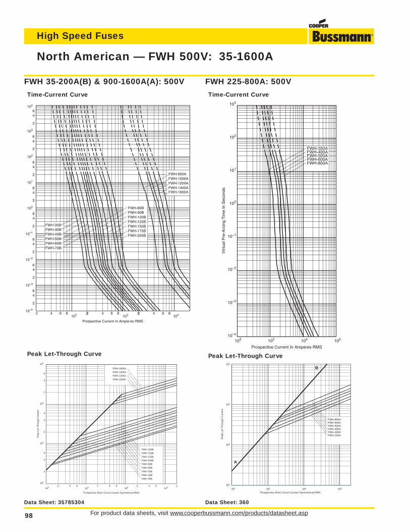
For product data sheets, visit www.cooperbussmann.com/products/datasheet.asp98
High Speed Fuses
North American — FWH 500V: 35-1600A
2 4 6 8102 22 4 6 8 2
103 2 4 6 8104
2
46
2
64
2
64
2
64
2
64
2
64
64
2
6
2
4
100
101
10–1
10–2
10–3
10–4
102
103
104
FWH-90BFWH-80B
FWH-125BFWH-100B
FWH-175BFWH-200B
FWH-150B
FWH-60BFWH-70B
FWH-50BFWH-45BFWH-40BFWH-35B
FWH-1200AFWH-1400A
FWH-900AFWH-1000A
FWH-1600A
Prospective Current In Amperes RMS
10–3
10–2
10–1
100
101
102
103
10–4
FWH-350AFWH-400AFWH-500AFWH-600AFWH-800A
Prospective Current In Amperes RMS
Vir
tual
Pre
-Arc
ing
Tim
e In
Sec
onds
102 103 104 105
FWH 225-800A: 500V
Time-Current Curve
FWH 35-200A(B) & 900-1600A(A): 500V
Time-Current Curve
FWH-200B
FWH-150B
FWH-125B
FWH-100B
FWH-80B
FWH-60B
FWH-50B
FWH-35B
FWH-40B
FWH-1000A
FWH-1200A
FWH-1400A
FWH-1600A
Prospective Short-Circuit Current Symmetrical RMS
Pea
k Le
t-Th
roug
h C
urre
nt
2
4
2
6
6
4
2
6
4
2 4 6 2 4 6 2 4 6 2102
103
104
105
102 103 104 105
FWH-800AFWH-600AFWH-500AFWH-400AFWH-300AFWH-250A
102
105
104
103
103 104 105
102
Prospective Short-Circuit Current Symmetrical RMS
Pea
k Le
t-Th
roug
h C
urre
nt
A
B
Peak Let-Through CurvePeak Let-Through Curve
Data Sheet: 35785304 Data Sheet: 360
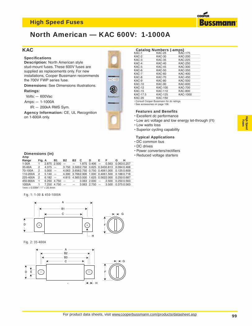
High Speed Fuses
For product data sheets, visit www.cooperbussmann.com/products/datasheet.asp 99
High SpeedFuses
North American — KAC 600V: 1-1000A
F
G
A
C
B1
H
D
Fig. 1: 1-30 & 450-1000A
A
B3
B2
C
ED F
H
G
Fig. 2: 35-400A
Dimensions (in)AmpRange Fig. A B1 B2 B3 C D E F G H1-30A 1 2.875 2.500 — — 1.875 0.406 — 0.563 0.063 0.25735-60A 2 4.375 — 3.750 3.5002.750 0.625 0.3430.813 0.094 0.46870-100A 2 5.000 — 4.063 3.6562.750 0.750 0.4061.000 0.125 0.609110-200A 2 5.140 — 4.390 3.7662.906 1.000 0.4061.500 0.188 0.718225-400A 2 6.182 — 4.815 4.5653.000 1.625 0.5622.000 0.250 0.687450-800A 1 6.250 4.750 — — 3.063 2.000 — 2.500 0.250 0.5631000A 1 7.250 4.750 — — 3.063 2.750 — 3.500 0.375 0.5631mm = 0.0394” / 1” = 25.4mm
KAC
SpecificationsDescription: North American style stud-mount fuses. These 600V fuses are supplied as replacements only. For newinstallations, Cooper Bussmann recommendsthe 700V FWP series fuse.
Dimensions: See Dimensions illustrations.
Ratings:Volts:— 600Vac
Amps:— 1-1000A
IR:— 200kA RMS Sym.
Agency Information: CE, UL Recognitionon 1-600A only.
Catalog Numbers (-amps)KAC-1 KAC-25 KAC-175KAC-2 KAC-30 KAC-200KAC-3 KAC-35 KAC-225KAC-4 KAC-40 KAC-250KAC-5 KAC-45 KAC-300KAC-6 KAC-50 KAC-350KAC-7 KAC-60 KAC-400KAC-8 KAC-70 KAC-450KAC-9 KAC-80 KAC-500KAC-10 KAC-90 KAC-600KAC-12 KAC-100 KAC-700KAC-15 KAC-110 KAC-800KAC-17.5 KAC-125 KAC-1000KAC-20 KAC-150• Consult Cooper Bussmann for dc ratings.• See accessories on page 106.
Features and Benefits• Excellent dc performance• Low arc voltage and low energy let-through (I2t)• Low watts loss• Superior cycling capability
Typical Applications• DC common bus• DC drives• Power converters/rectifiers• Reduced voltage starters
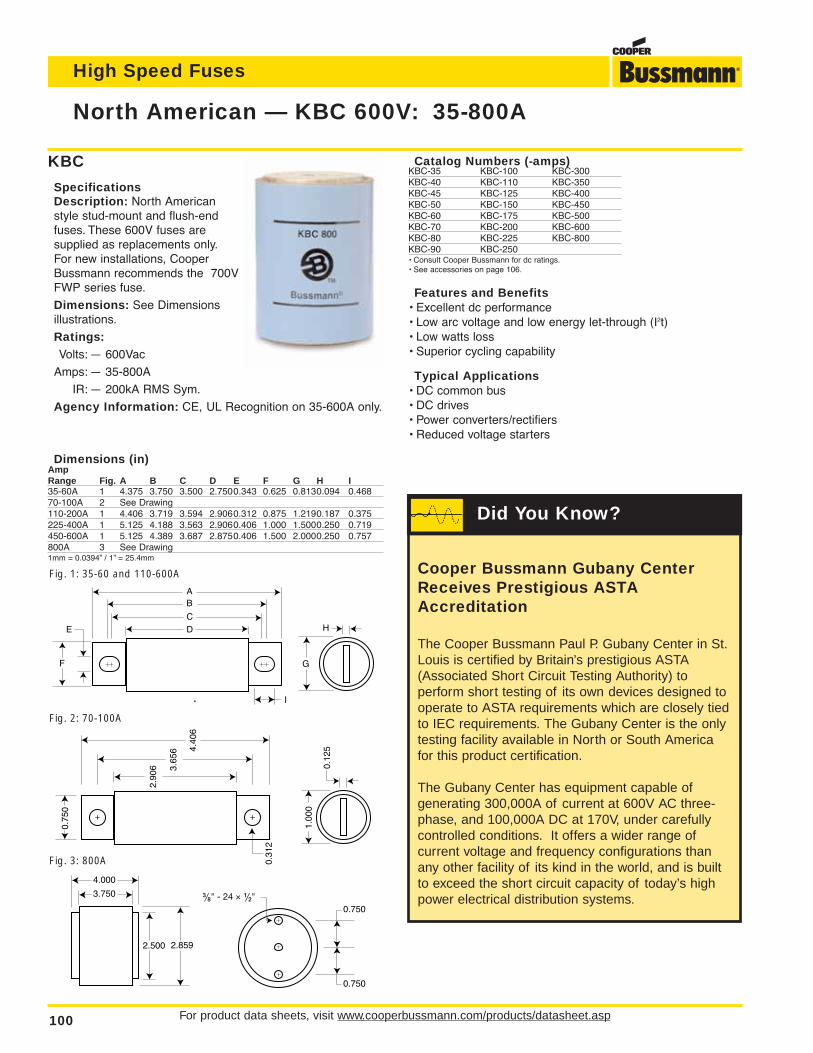
For product data sheets, visit www.cooperbussmann.com/products/datasheet.asp100
High Speed Fuses
North American — KBC 600V: 35-800A
Dimensions (in)AmpRange Fig. A B C D E F G H I35-60A 1 4.375 3.750 3.500 2.7500.343 0.625 0.8130.094 0.46870-100A 2 See Drawing110-200A 1 4.406 3.719 3.594 2.9060.312 0.875 1.2190.187 0.375225-400A 1 5.125 4.188 3.563 2.9060.406 1.000 1.5000.250 0.719450-600A 1 5.125 4.389 3.687 2.8750.406 1.500 2.0000.250 0.757800A 3 See Drawing1mm = 0.0394” / 1” = 25.4mm
KBC
SpecificationsDescription: North Americanstyle stud-mount and flush-endfuses. These 600V fuses are supplied as replacements only.For new installations, CooperBussmann recommends the 700VFWP series fuse.
Dimensions: See Dimensionsillustrations.
Ratings:Volts: — 600Vac
Amps: — 35-800A
IR: — 200kA RMS Sym.
Agency Information: CE, UL Recognition on 35-600A only.
A
C
B
DE
F G
I
H
Fig. 1: 35-60 and 110-600A
Fig. 2: 70-100A
4.000
3.750
2.8592.500
0.750
0.750
‹Ω•" - 24 ≈ ⁄Ω™"
Fig. 3: 800A
0.75
0
3.65
6 4.40
6
2.90
6
0.31
2
1.00
0
0.12
5
Catalog Numbers (-amps)KBC-35 KBC-100 KBC-300KBC-40 KBC-110 KBC-350KBC-45 KBC-125 KBC-400KBC-50 KBC-150 KBC-450KBC-60 KBC-175 KBC-500KBC-70 KBC-200 KBC-600KBC-80 KBC-225 KBC-800KBC-90 KBC-250• Consult Cooper Bussmann for dc ratings.• See accessories on page 106.
Features and Benefits• Excellent dc performance• Low arc voltage and low energy let-through (I2t)• Low watts loss• Superior cycling capability
Typical Applications• DC common bus• DC drives• Power converters/rectifiers• Reduced voltage starters
Cooper Bussmann Gubany CenterReceives Prestigious ASTAAccreditation
The Cooper Bussmann Paul P. Gubany Center in St.Louis is certified by Britain’s prestigious ASTA(Associated Short Circuit Testing Authority) to perform short testing of its own devices designed tooperate to ASTA requirements which are closely tiedto IEC requirements. The Gubany Center is the onlytesting facility available in North or South Americafor this product certification.
The Gubany Center has equipment capable ofgenerating 300,000A of current at 600V AC three-phase, and 100,000A DC at 170V, under carefullycontrolled conditions. It offers a wider range ofcurrent voltage and frequency configurations thanany other facility of its kind in the world, and is builtto exceed the short circuit capacity of today’s highpower electrical distribution systems.
Did You Know?
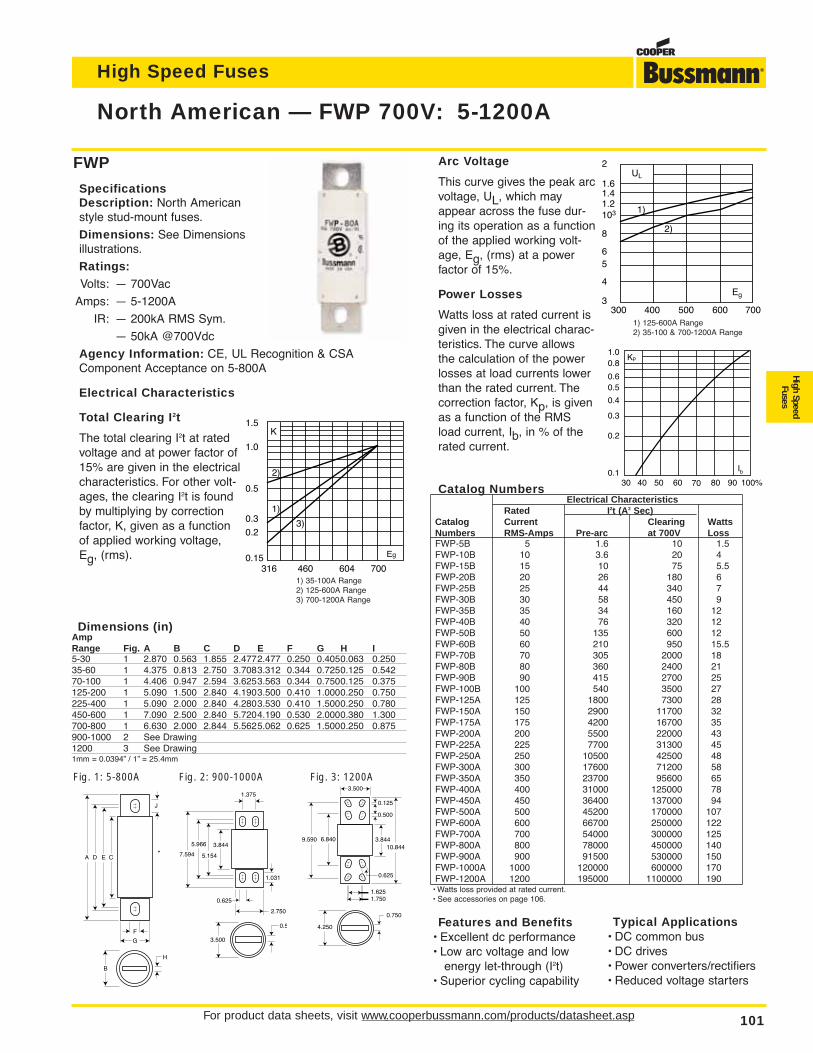
High Speed Fuses
For product data sheets, visit www.cooperbussmann.com/products/datasheet.asp 101
High SpeedFuses
North American — FWP 700V: 5-1200A
FWP
SpecificationsDescription: North Americanstyle stud-mount fuses.
Dimensions: See Dimensionsillustrations.
Ratings:Volts: — 700Vac
Amps: — 5-1200A
IR: — 200kA RMS Sym.
— 50kA @700Vdc
Agency Information: CE, UL Recognition & CSAComponent Acceptance on 5-800A
Electrical Characteristics
Total Clearing I2t
The total clearing I2t at ratedvoltage and at power factor of15% are given in the electricalcharacteristics. For other volt-ages, the clearing I2t is foundby multiplying by correctionfactor, K, given as a functionof applied working voltage,Eg, (rms).
Arc Voltage
This curve gives the peak arcvoltage, UL, which mayappear across the fuse dur-ing its operation as a functionof the applied working volt-age, Eg, (rms) at a powerfactor of 15%.
Power Losses
Watts loss at rated current isgiven in the electrical charac-teristics. The curve allowsthe calculation of the powerlosses at load currents lowerthan the rated current. Thecorrection factor, Kp, is givenas a function of the RMSload current, Ib, in % of therated current.
Catalog NumbersElectrical Characteristics
Rated I2t (A2 Sec)Catalog Current Clearing WattsNumbers RMS-Amps Pre-arc at 700V LossFWP-5B 5 1.6 10 1.5FWP-10B 10 3.6 20 4FWP-15B 15 10 75 5.5FWP-20B 20 26 180 6FWP-25B 25 44 340 7FWP-30B 30 58 450 9FWP-35B 35 34 160 12FWP-40B 40 76 320 12FWP-50B 50 135 600 12FWP-60B 60 210 950 15.5FWP-70B 70 305 2000 18FWP-80B 80 360 2400 21FWP-90B 90 415 2700 25FWP-100B 100 540 3500 27FWP-125A 125 1800 7300 28FWP-150A 150 2900 11700 32FWP-175A 175 4200 16700 35FWP-200A 200 5500 22000 43FWP-225A 225 7700 31300 45FWP-250A 250 10500 42500 48FWP-300A 300 17600 71200 58FWP-350A 350 23700 95600 65FWP-400A 400 31000 125000 78FWP-450A 450 36400 137000 94FWP-500A 500 45200 170000 107FWP-600A 600 66700 250000 122FWP-700A 700 54000 300000 125FWP-800A 800 78000 450000 140FWP-900A 900 91500 530000 150FWP-1000A 1000 120000 600000 170FWP-1200A 1200 195000 1100000 190
• Watts loss provided at rated current.• See accessories on page 106.
Features and Benefits• Excellent dc performance• Low arc voltage and low
energy let-through (I2t)• Superior cycling capability
700604460316
1.5
1.0
0.5
0.3
0.2
0.15 Eg
K
1)
3)
2)
UL
2
1.61.41.2103
8
65
4
3400300 500 600 700
Eg
1)
2)
Kp1.00.8
0.4
0.50.6
0.3
0.2
0.130 40 50 60 70 80 90 100%
Ib
1) 125-600A Range2) 35-100 & 700-1200A Range
1) 35-100A Range2) 125-600A Range3) 700-1200A Range
A ED C
F
J
G
B
H
Fig. 1: 5-800A
Dimensions (in)AmpRange Fig. A B C D E F G H I5-30 1 2.870 0.563 1.855 2.4772.477 0.250 0.4050.063 0.25035-60 1 4.375 0.813 2.750 3.7083.312 0.344 0.7250.125 0.54270-100 1 4.406 0.947 2.594 3.6253.563 0.344 0.7500.125 0.375125-200 1 5.090 1.500 2.840 4.1903.500 0.410 1.0000.250 0.750225-400 1 5.090 2.000 2.840 4.2803.530 0.410 1.5000.250 0.780450-600 1 7.090 2.500 2.840 5.7204.190 0.530 2.0000.380 1.300700-800 1 6.630 2.000 2.844 5.5625.062 0.625 1.5000.250 0.875900-1000 2 See Drawing1200 3 See Drawing1mm = 0.0394” / 1” = 25.4mm
7.594
0.5
3.500
3.844
1.031
0.625
2.750
5.966
5.154
1.375
Fig. 2: 900-1000A Fig. 3: 1200A
10.8443.844
0.625
4.250
0.750
3.500
6.840
0.125
0.500
1.6251.750
9.590
Typical Applications• DC common bus• DC drives• Power converters/rectifiers• Reduced voltage starters
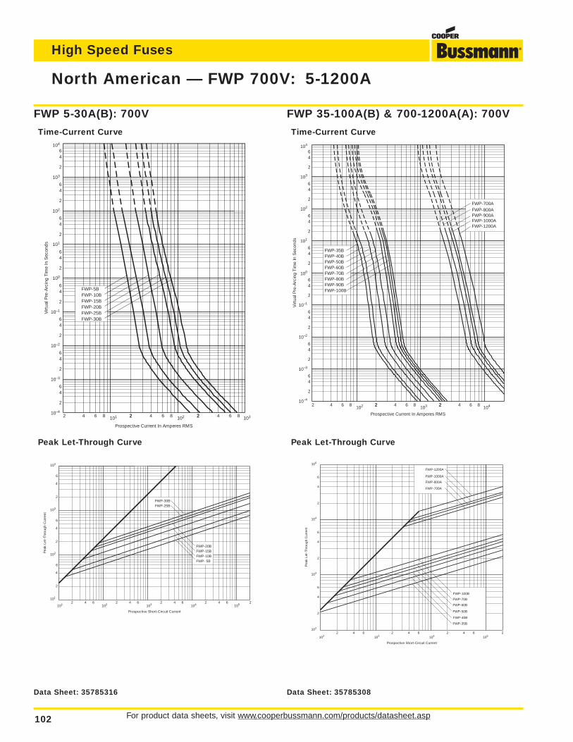
For product data sheets, visit www.cooperbussmann.com/products/datasheet.asp102
High Speed Fuses
North American — FWP 700V: 5-1200A
2 4 6 8102 22 4 6 8 2
103 2 4 6 8104
2
46
2
64
2
64
101
100
2
64
2
64
2
64
64
2
6
2
4
10–1
10–2
10–3
10–4
102
103
104
FWP-35B
FWP-80BFWP-90BFWP-100B
FWP-60BFWP-70B
FWP-40BFWP-50B
FWP-900A
FWP-1200AFWP-1000A
FWP-800AFWP-700A
Prospective Current In Amperes RMS
Virt
ual P
re-A
rcin
g Ti
me
In S
econ
ds
FWP 35-100A(B) & 700-1200A(A): 700V
Time-Current Curve
Prospective Short-Circuit Current
Pea
k Le
t-Th
roug
h C
urre
nt
2
6
4
2
6
4
2
6
4
2 4 6 2 4 6 2 4 6102
103
104
106
102 103 104 1052
FWP-700A
FWP-800A
FWP-1000A
FWP-100B
FWP-35B
FWP-70B
FWP-40B
FWP-50B
FWP-60B
FWP-1200A
Peak Let-Through Curve
2 4 6 8 101 22 4 6 8 2102 2 4 6 8 103
2
46
2
64
2
64
2
64
2
64
2
64
64
2
6
2
4
10–1
10–2
10–3
10–4
102
101
100
103
104
Prospective Current In Amperes RMS
Virt
ual P
re-A
rcin
g Ti
me
In S
econ
ds
FWP-10BFWP-15BFWP-20B
FWP-5B
FWP-30BFWP-25B
FWP 5-30A(B): 700V
Time-Current Curve
Prospective Short-Circuit Current
Pea
k Le
t-Th
roug
h C
urre
nt
2
4
2
6
6
4
2
6
4
2 4 6 2 4 6 2 4 6 2 4 6101
102
103
104
101 102 103 104 105
FWP- 5BFWP-10BFWP-15BFWP-20B
FWP-25BFWP-30B
2
Peak Let-Through Curve
Data Sheet: 35785308Data Sheet: 35785316
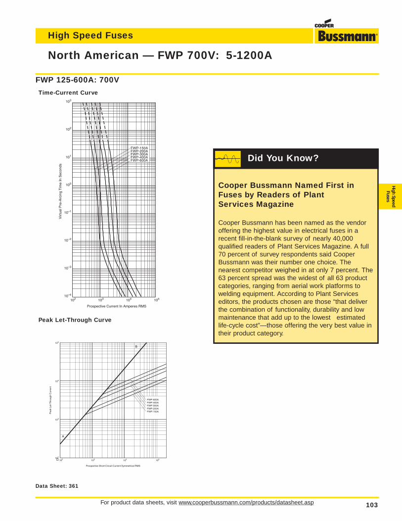
High Speed Fuses
For product data sheets, visit www.cooperbussmann.com/products/datasheet.asp 103
High SpeedFuses
North American — FWP 700V: 5-1200A
10–4
10–3
10–2
10–1
100
101
102
103
FWP-150AFWP-200AFWP-300AFWP-400AFWP-600A
Prospective Current In Amperes RMS
Vir
tual
Pre
-Arc
ing
Tim
e In
Sec
onds
102 103 104 105
FWP 125-600A: 700V
Time-Current Curve
FWP-600AFWP-400AFWP-300AFWP-200AFWP-150A
102 103 104 105102
103
104
105
Prospective Short-Circuit Current Symmetrical RMS
Pea
k Le
t-T
hrou
gh C
urre
nt
A
B
Peak Let-Through Curve
Data Sheet: 361
Cooper Bussmann Named First inFuses by Readers of Plant Services Magazine
Cooper Bussmann has been named as the vendoroffering the highest value in electrical fuses in arecent fill-in-the-blank survey of nearly 40,000qualified readers of Plant Services Magazine. A full70 percent of survey respondents said CooperBussmann was their number one choice. Thenearest competitor weighed in at only 7 percent. The63 percent spread was the widest of all 63 productcategories, ranging from aerial work platforms towelding equipment. According to Plant Serviceseditors, the products chosen are those “that deliverthe combination of functionality, durability and lowmaintenance that add up to the lowest estimatedlife-cycle cost”—those offering the very best value intheir product category.
Did You Know?
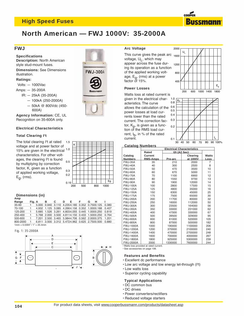
For product data sheets, visit www.cooperbussmann.com/products/datasheet.asp104
High Speed Fuses
North American — FWJ 1000V: 35-2000A
FWJ
SpecificationsDescription: North Americanstyle stud-mount fuses.
Dimensions: See Dimensionsillustration.
Ratings:Volts: — 1000Vac
Amps: — 35-200A
IR: — 25kA (35-200A)
— 100kA (250-2000A)
— 50kA @ 800Vdc (450-600A)
Agency Information: CE, ULRecognition on 35-600A only.
Electrical Characteristics
Total Clearing I2t
The total clearing I2t at ratedvoltage and at power factor of15% are given in the electricalcharacteristics. For other volt-ages, the clearing I2t is foundby multiplying by correctionfactor, K, given as a functionof applied working voltage,Eg, (rms).
Arc Voltage
This curve gives the peak arcvoltage, UL, which mayappear across the fuse dur-ing its operation as a functionof the applied working volt-age, Eg, (rms) at a powerfactor of 15%.
Power Losses
Watts loss at rated current isgiven in the electrical char-acteristics. The curveallows the calculation of thepower losses at load cur-rents lower than the ratedcurrent. The correction fac-tor, Kp, is given as a func-tion of the RMS load cur-rent, Ib, in % of the ratedcurrent.
Catalog NumbersElectrical Characteristics
Rated I2t (A2 Sec)Catalog Current Clearing WattsNumbers RMS-Amps Pre-arc at 1000V LossFWJ-35A 35 210 2000 7FWJ-40A 40 300 2500 8FWJ-50A 50 470 3500 10FWJ-60A 60 670 5000 11FWJ-70A 70 1100 6900 12FWJ-80A 80 1550 9700 13FWJ-90A 90 1900 12000 14FWJ-100A 100 2800 17500 15FWJ-125A 125 4800 35000 16FWJ-150A 150 6300 45000 25FWJ-175A 175 7500 65000 30FWJ-200A 200 11700 80000 32FWJ-250A 250 16000 112000 50FWJ-300A 300 23500 164000 56FWJ-350A 350 33000 231000 62FWJ-400A 400 47000 330000 67FWJ-500A 500 39500 329000 95FWJ-600A 600 61000 520000 105FWJ-800A 800 87000 500000 182FWJ-1000A 1000 190000 1100000 206FWJ-1200A 1200 370000 2100000 240FWJ-1400A 1400 470000 2700000 248FWJ-1600A 1600 700000 4000000 267FWJ-1800A 1800 925000 5300000 239FWJ-2000A 2000 1330000 7600000 244
• Watts loss provided at rated current.• See accessories on page 106.
Features and Benefits• Excellent dc performance• Low arc voltage and low energy let-through (I2t)• Low watts loss• Superior cycling capability
Typical Applications• DC common bus• DC drives• Power converters/rectifiers• Reduced voltage starters
2000
1600
1200
800
400
200 600 1000 1400 1800
UL
Eg
Kp1.00.8
0.4
0.50.6
0.3
0.2
0.130 40 50 60 70 80 90 100%
Ib
1000800500200
1.5
1.0
0.5
0.3
0.2
0.15Eg
K
A
E
D
C
F
J
G B
H
Fig. 1: 35-2000A
Dimensions (in)AmpRange Fig. A B C D E F G H I35-60 1 5.000 0.940 3.110 4.2354.180 0.352 0.7500.125 0.38070-100 1 4.932 1.125 3.085 4.2664.156 0.352 1.0000.188 0.407125-200 1 5.685 1.526 3.261 4.8034.055 0.445 1.0000.250 0.819250-400 1 5.768 2.000 3.500 4.8114.150 0.433 1.5000.250 0.764500-600 1 7.201 2.500 3.465 5.9844.706 0.562 2.0000.375 1.201800-2000 1 6.811 3.500 3.312 5.4724.962 0.625 2.7500.500 0.8801mm = 0.0394” / 1” = 25.4mm
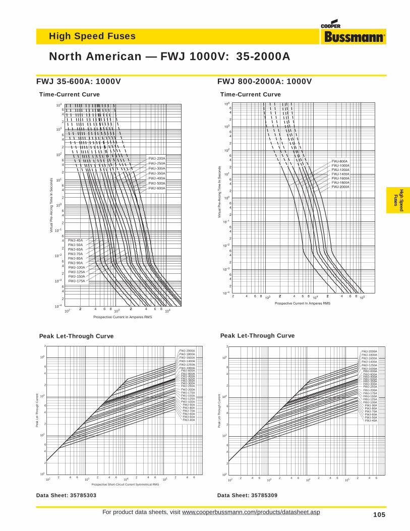
High Speed Fuses
For product data sheets, visit www.cooperbussmann.com/products/datasheet.asp 105
High SpeedFuses
North American — FWJ 1000V: 35-2000A
2 4 6 8 103 22 4 6 8 2104 2 4 6 8 105
2
46
2
64
100
2
64
101
2
64
2
64
2
64
64
2
6
2
4
10–1
10–2
10–3
10–4
102
103
104
FWJ-1800AFWJ-2000A
FWJ-800AFWJ-1000AFWJ-1200AFWJ-1400AFWJ-1600A
Prospective Current In Amperes RMS
Vir
tual
Pre
-Arc
ing
Tim
e In
Sec
onds
FWJ 800-2000A: 1000V
Time-Current Curve
Pea
k Le
t-Th
roug
h C
urre
nt
2
4
2
6
6
4
2
6
4
2
2 4 6 2 4 6 2 4 6 2 4 6102
103
104
105
102 103 104 105
FWJ-40AFWJ-50AFWJ-60AFWJ-70AFWJ-80AFWJ-90A
FWJ-100AFWJ-125AFWJ-150AFWJ-175AFWJ-200A
FWJ-500AFWJ-350AFWJ-300AFWJ-250A
FWJ-600AFWJ-800A
FWJ-2000AFWJ-1800AFWJ-1600AFWJ-1400AFWJ-1250AFWJ-1000A
FWJ-400A
Peak Let-Through Curve
Prospective Current In Amperes RMS
Virt
ual P
re-A
rcin
g Ti
me
In S
econ
ds
102 22 4 6 8 2103 2 4 6 8
104
2
46
2
64
100
2
64
2
64
2
64
2
64
64
2
6
2
4
10–1
10–2
10–3
10–4
102
103
104
FWJ-125AFWJ-150A
FWJ-60A
FWJ-100AFWJ-90AFWJ-80AFWJ-70A
FWJ-50AFWJ-40A
FWJ-600A
FWJ-200AFWJ-250AFWJ-300AFWJ-350AFWJ-400AFWJ-500A
FWJ-175A
101
FWJ 35-600A: 1000V
Time-Current Curve
Prospective Short-Circuit Current Symmetrical RMS
Pea
k Le
t-Th
roug
h C
urre
nt
2
4
2
6
6
4
2
6
4
2
2 4 6 2 4 6 2 4 6 2 4 6102
103
104
105
102 103 104 105
FWJ-40AFWJ-50AFWJ-60AFWJ-70AFWJ-80AFWJ-90A
FWJ-100AFWJ-125AFWJ-150AFWJ-175AFWJ-200A
FWJ-500AFWJ-350AFWJ-300AFWJ-250A
FWJ-600AFWJ-800A
FWJ-2000AFWJ-1800AFWJ-1600AFWJ-1400AFWJ-1250AFWJ-1000A
FWJ-400A
Peak Let-Through Curve
Data Sheet: 35785303 Data Sheet: 35785309
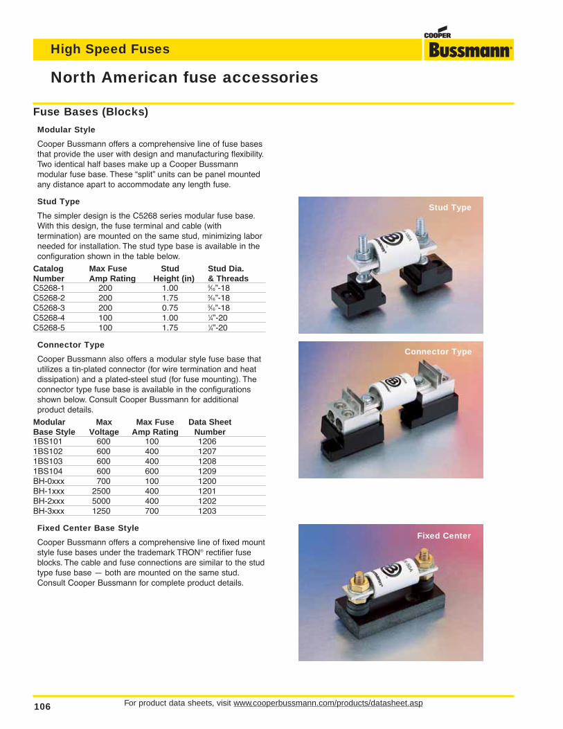
For product data sheets, visit www.cooperbussmann.com/products/datasheet.asp106
High Speed Fuses
North American fuse accessories
Stud Type
Connector Type
Fixed Center
Fuse Bases (Blocks)
Modular Style
Cooper Bussmann offers a comprehensive line of fuse basesthat provide the user with design and manufacturing flexibility.Two identical half bases make up a Cooper Bussmann modular fuse base. These “split” units can be panel mountedany distance apart to accommodate any length fuse.
Stud Type
The simpler design is the C5268 series modular fuse base.With this design, the fuse terminal and cable (with termination) are mounted on the same stud, minimizing laborneeded for installation. The stud type base is available in theconfiguration shown in the table below.
Catalog Max Fuse Stud Stud Dia.Number Amp Rating Height (in) & ThreadsC5268-1 200 1.00 5⁄16”-18C5268-2 200 1.75 5⁄16”-18C5268-3 200 0.75 5⁄16”-18C5268-4 100 1.00 1⁄4”-20C5268-5 100 1.75 1⁄4”-20
Connector Type
Cooper Bussmann also offers a modular style fuse base thatutilizes a tin-plated connector (for wire termination and heatdissipation) and a plated-steel stud (for fuse mounting). Theconnector type fuse base is available in the configurationsshown below. Consult Cooper Bussmann for additional product details.
Modular Max Max Fuse Data SheetBase Style Voltage Amp Rating Number1BS101 600 100 12061BS102 600 400 12071BS103 600 400 12081BS104 600 600 1209BH-0xxx 700 100 1200BH-1xxx 2500 400 1201BH-2xxx 5000 400 1202BH-3xxx 1250 700 1203
Fixed Center Base Style
Cooper Bussmann offers a comprehensive line of fixed mountstyle fuse bases under the trademark TRON® rectifier fuseblocks. The cable and fuse connections are similar to the studtype fuse base — both are mounted on the same stud.Consult Cooper Bussmann for complete product details.
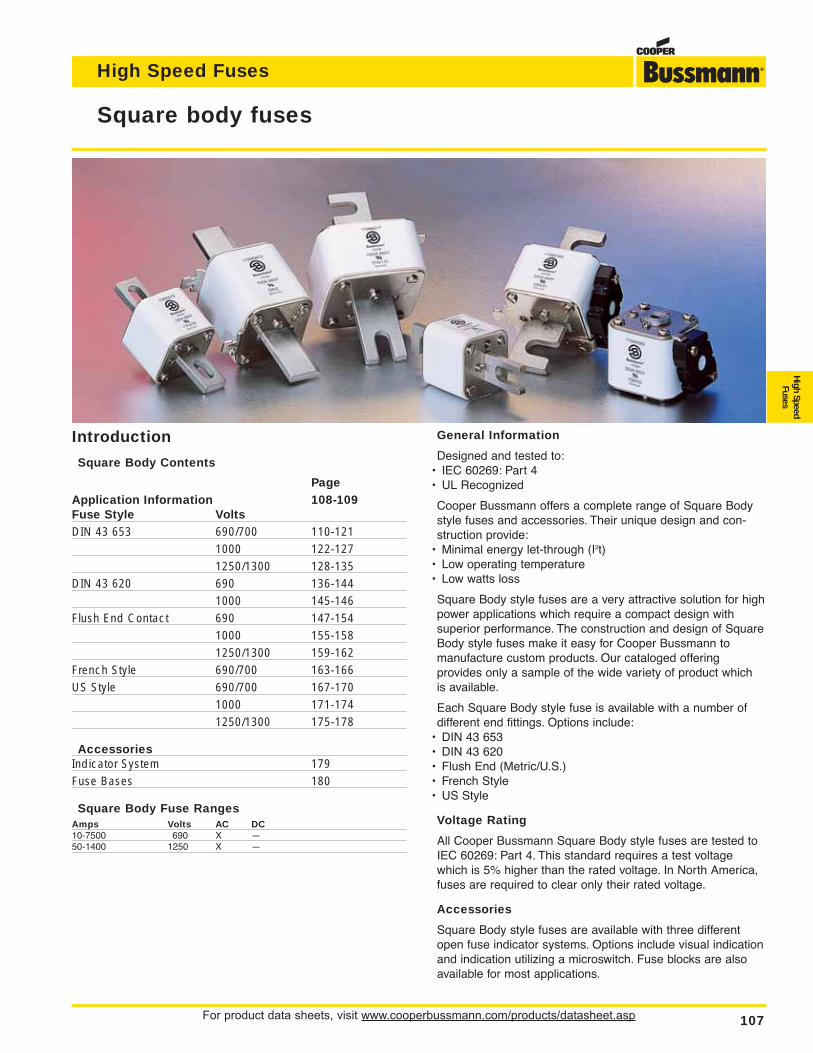
For product data sheets, visit www.cooperbussmann.com/products/datasheet.asp 107
Square body fuses
High Speed Fuses
High SpeedFuses
General Information
Designed and tested to:• IEC 60269: Part 4• UL Recognized
Cooper Bussmann offers a complete range of Square Bodystyle fuses and accessories. Their unique design and con-struction provide:
• Minimal energy let-through (I2t)• Low operating temperature• Low watts loss
Square Body style fuses are a very attractive solution for highpower applications which require a compact design withsuperior performance. The construction and design of SquareBody style fuses make it easy for Cooper Bussmann to manufacture custom products. Our cataloged offering provides only a sample of the wide variety of product which is available.
Each Square Body style fuse is available with a number ofdifferent end fittings. Options include:
• DIN 43 653• DIN 43 620• Flush End (Metric/U.S.)• French Style• US Style
Voltage Rating
All Cooper Bussmann Square Body style fuses are tested toIEC 60269: Part 4. This standard requires a test voltagewhich is 5% higher than the rated voltage. In North America,fuses are required to clear only their rated voltage.
Accessories
Square Body style fuses are available with three differentopen fuse indicator systems. Options include visual indicationand indication utilizing a microswitch. Fuse blocks are alsoavailable for most applications.
Introduction
Square Body Contents
PageApplication Information 108-109Fuse Style VoltsDIN 43 653 690/700 110-121
1000 122-1271250/1300 128-135
DIN 43 620 690 136-1441000 145-146
Flush End Contact 690 147-1541000 155-1581250/1300 159-162
French Style 690/700 163-166US Style 690/700 167-170
1000 171-1741250/1300 175-178
AccessoriesIndicator System 179Fuse Bases 180
Square Body Fuse RangesAmps Volts AC DC10-7500 690 X —50-1400 1250 X —
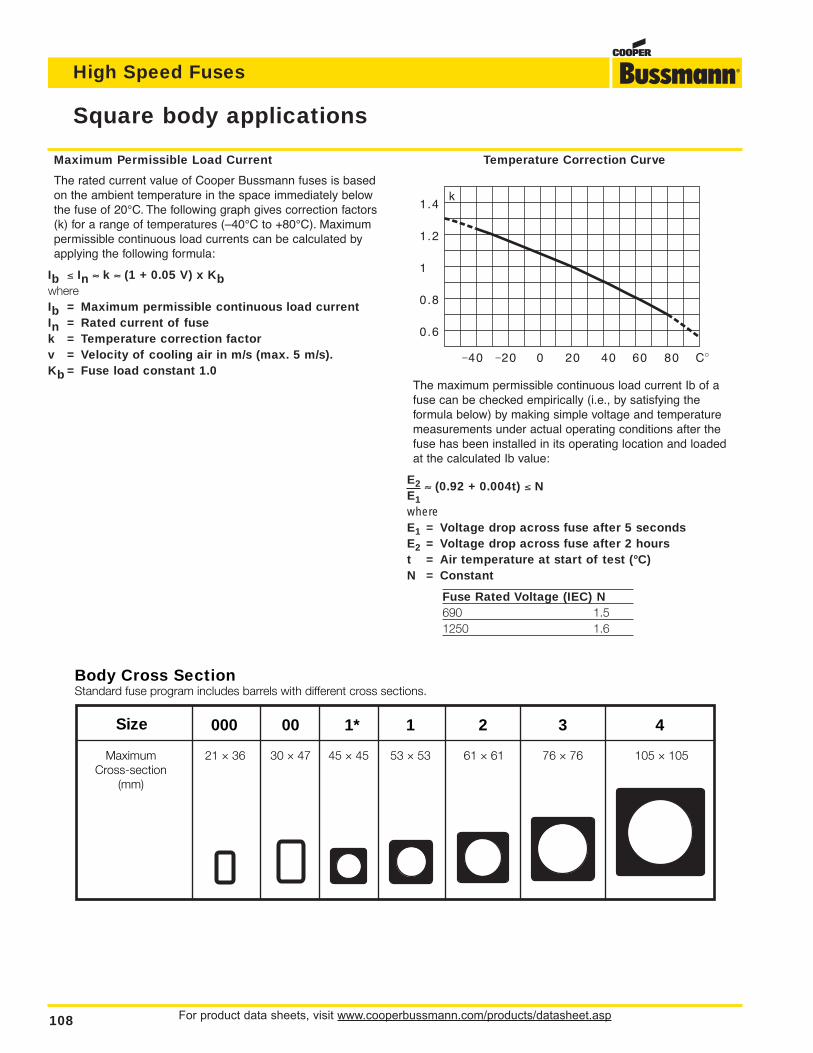
For product data sheets, visit www.cooperbussmann.com/products/datasheet.asp108
Square body applications
High Speed Fuses
Maximum Permissible Load Current
The rated current value of Cooper Bussmann fuses is basedon the ambient temperature in the space immediately belowthe fuse of 20°C. The following graph gives correction factors(k) for a range of temperatures (–40°C to +80°C). Maximumpermissible continuous load currents can be calculated byapplying the following formula:
Ib ≤ In ≈ k ≈ (1 + 0.05 V) x KbwhereIb = Maximum permissible continuous load currentIn = Rated current of fusek = Temperature correction factorv = Velocity of cooling air in m/s (max. 5 m/s).Kb = Fuse load constant 1.0
Temperature Correction Curve
The maximum permissible continuous load current Ib of afuse can be checked empirically (i.e., by satisfying the formula below) by making simple voltage and temperaturemeasurements under actual operating conditions after thefuse has been installed in its operating location and loaded at the calculated Ib value:
E2 ≈ (0.92 + 0.004t) ≤ NE1whereE1 = Voltage drop across fuse after 5 secondsE2 = Voltage drop across fuse after 2 hourst = Air temperature at start of test (°C)N = Constant
Fuse Rated Voltage (IEC) N690 1.51250 1.6
Body Cross SectionStandard fuse program includes barrels with different cross sections.
Size 000 00 1* 1 2 3 4
MaximumCross-section
(mm)
21 ≈ 36 30 ≈ 47 45 ≈ 45 53 ≈ 53 61 ≈ 61 76 ≈ 76 105 ≈ 105
1.4
1.2
1
0.8
0.6
k
–40 –20 0 4020 60 80 C
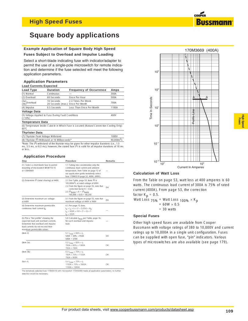
For product data sheets, visit www.cooperbussmann.com/products/datasheet.asp 109
Square body applications
High Speed Fuses
High SpeedFuses
Example Application of Square Body High Speed
Fuses Subject to Overload and Impulse Loading
Select a short-blade indicating fuse with indicator/adapter topermit the use of a single-pole microswitch for remote indica-tion and determine if the fuse selected will meet the followingapplication parameters.
Application ParametersLoad Currents ExpectedLoad Type Duration Frequency of Occurrence Amps(1) Normal Continuous — 300A
(2) Overload 60 Seconds Once Per Hour 500A
(3a) 10 Seconds 2-3 Times Per Week(3b)Overload 20 Seconds (max.) Once Per Month 700A
(4) Impulse 0.5 Seconds Less Than Once Per Month 1100A
Voltage Data(5) Voltage Applied to Fuse During Fault Conditions 400V(+10%)
Temperature Data(6) Temperature Inside Cubicle in Which Fuse is Located (Natural Convection Cooling Only)60°C
Thyrister Data(7) Thyrister Peak Voltage Withstand 1000V
(8) Thyrister I2t Withstand at 10 Milliseconds* 90,000A2s
*Note: The I2t withstand of the thyrister may be given for other impulse durations (i.e., 1.5ms, 3.5 ms, or 8.3 ms); however, the stated fuse I2t is valid for all impulse durations of 10 msor less.
Application ProcedureStep Procedure Remarks
(1) Select a short-blade fuse to permit 1.1 Taking into consideration only themounting of microswitch MSW710-1S continuous load current and ambientor 170H0069 temperature, from Table on page 12 of —
our application guide tentatively select fuse 170M3519 page 52, 400A, 690V).
(2) Determine I2 t (total clearing) at 440V. 2.1 See Table, page 53. Note I2t is105,000A2s at rated voltage of 690V.2.2 From the figure on page 55, note that
OKcorrection factor K = 0.65.
2.3 I2t660V ≈ K = I2t440V105,000 ≈ 0.65 = 68,250
(3) Determine maximum arc voltage 3.1 From the figure on page 53, note thatat 440V maximum voltage at 440V is 900V
OK
(4) Determine maximum permissible 4.1 Per page 15 data,continuous load current Ib. Ib = In ≈ k ≈ (1 + 0.05V) ≈ Kb
—Ib = 400A ≈ 0.8 ≈ (1 + 0) ≈ 1Ib = 320A
(5) Plot a “line profile” showing the 5.0 Calculate Imax per Table, page 16,expected load and overload currents. for each overload and impulse —Determine that overload and impulse load.load currents do not exceed theirmaximum permissible values.
(Item 2) 5.1 Imax < 60% ≈ It500A < 60% ≈ 950A OK500A < 570A
(Item 3a) 5.2 Imax < 60% ≈ It700A < 60% ≈ 1360A OK700A < 780A
(Item 3b) 5.3 Imax < 70% ≈ It700A < 70% ≈ 1150A OK700A < 805A
(Item 4) 5.4 Imax < 70% ≈ It1100A < 70% ≈ 1800A OK1100A < 1260A
The tentatively selected fuse 170M3519 with microswitch 170H0069 meets all application parameters; no furtherselection would be necessary.
102 10310–2
10–1
100
101
102
103
Current In Amperes
Tim
e In
Sec
onds A A
170M3669 (400A)
Pro
file
Line
Calculation of Watt Loss
From the Table on page 53, watt loss at 400 amperes is 60watts. The continuous load current of 300A is 75% of ratedcurrent (400A). From page 53, the correction factor Kp = 0.5.Watt Loss 75% = Watt Loss 100% ≈ Kp
= 60W ≈ 0.5= 30 watts
Special Fuses
Other high speed fuses are available from CooperBussmann with voltage ratings of 380 to 10,000V and currentratings up to 10,000A in a single unit configuration. Fusescan be supplied with open fuse, “pin” indicators. Varioustypes of microswitches are also available (see page 179).
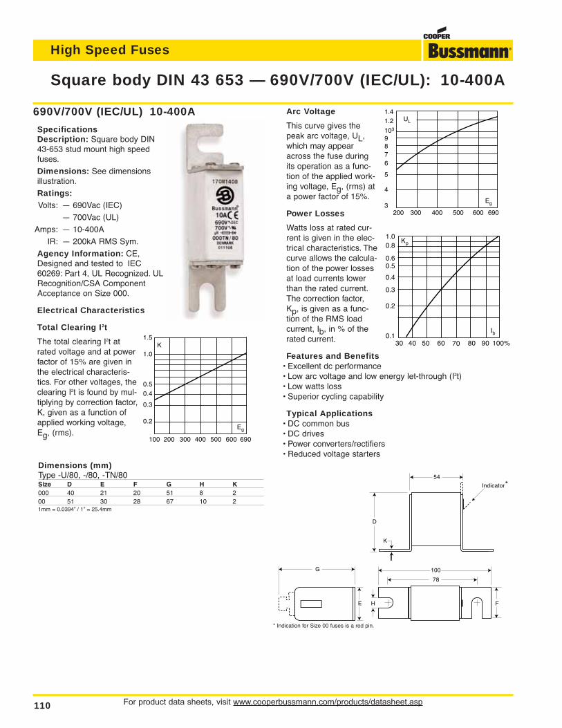
Arc Voltage
This curve gives thepeak arc voltage, UL,which may appearacross the fuse duringits operation as a func-tion of the applied work-ing voltage, Eg, (rms) ata power factor of 15%.
Power Losses
Watts loss at rated cur-rent is given in the elec-trical characteristics. Thecurve allows the calcula-tion of the power lossesat load currents lowerthan the rated current.The correction factor,Kp, is given as a func-tion of the RMS loadcurrent, Ib, in % of therated current.
Features and Benefits• Excellent dc performance• Low arc voltage and low energy let-through (I2t)• Low watts loss• Superior cycling capability
Typical Applications• DC common bus• DC drives• Power converters/rectifiers• Reduced voltage starters
For product data sheets, visit www.cooperbussmann.com/products/datasheet.asp110
Square body DIN 43 653 — 690V/700V (IEC/UL): 10-400A
High Speed Fuses
*
690V/700V (IEC/UL) 10-400A
SpecificationsDescription: Square body DIN43-653 stud mount high speedfuses.
Dimensions: See dimensions illustration.
Ratings:Volts: — 690Vac (IEC)
— 700Vac (UL)
Amps: — 10-400A
IR: — 200kA RMS Sym.
Agency Information: CE,Designed and tested to IEC60269: Part 4, UL Recognized. ULRecognition/CSA ComponentAcceptance on Size 000.
Electrical Characteristics
Total Clearing I2t
The total clearing I2t atrated voltage and at powerfactor of 15% are given inthe electrical characteris-tics. For other voltages, theclearing I2t is found by mul-tiplying by correction factor,K, given as a function ofapplied working voltage,Eg, (rms).
100 200 300 400 500 600
K1.5
1.0
0.5
0.4
0.3
0.2Eg
690
UL
1.41.2
103
6
87
9
5
4
3Eg
200 300 400 500 600 690
Kp
30 40 50 60 70 80 90 100%
Ib
1.00.8
0.4
0.50.6
0.3
0.2
0.1
F
100
78
D
E
G
H
K
54
Indicator
Dimensions (mm)Type -U/80, -/80, -TN/80Size D E F G H K000 40 21 20 51 8 200 51 30 28 67 10 21mm = 0.0394” / 1” = 25.4mm
* Indication for Size 00 fuses is a red pin.
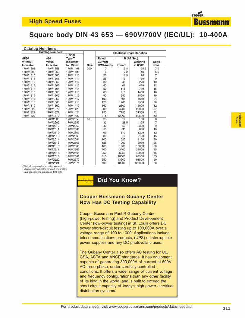
For product data sheets, visit www.cooperbussmann.com/products/datasheet.asp 111
Square body DIN 43 653 — 690V/700V (IEC/UL): 10-400A
High Speed Fuses
High SpeedFuses
Catalog NumbersCatalog Numbers
-TN/80Electrical Characteristics
-U/80 -/80 Type T Rated I2t (A2 Sec)Without Visual Indicator Current Clearing WattsIndicator Indicator for Micro Size RMS-Amps Pre-arc at 660V Loss170M1308 170M1358 170M1408 000 10 3.8 25.5 3.0170M1309 170M1359 170M1409 16 7.2 48 5.5170M1310 170M1360 170M1410 20 11.5 78 7170M1311 170M1361 170M1411 25 19 130 9170M1312 170M1362 170M1412 32 40 270 10170M1313 170M1363 170M1413 40 69 460 12170M1314 170M1364 170M1414 50 115 770 15170M1315 170M1365 170M1415 63 215 1450 16170M1316 170M1366 170M1416 80 380 2550 19170M1317 170M1367 170M1417 100 695 4650 24170M1318 170M1368 170M1418 125 1200 8500 28170M1319 170M1369 170M1419 160 2300 16000 32170M1320 170M1370 170M1420 200 4200 28000 37170M1321 170M1371 170M1421 250 7750 51500 42170M1322 170M1372 170M1422 315 12000 80500 52
170M2608 170M2658 00 25 19 130 6170M2609 170M2659 32 28.5 195 7170M2610 170M2660 40 50 360 9170M2611 170M2661 50 95 640 10170M2612 170M2662 63 170 1200 12170M2613 170M2663 80 310 2100 15170M2614 170M2664 100 620 4150 20170M2615 170M2665 125 1000 6950 25170M2616 170M2666 160 1900 13000 30170M2617 170M2667 200 3400 23000 35170M2618 170M2668 250 6250 42000 45170M2619 170M2669 315 10000 68500 55170M2620 170M2670 350 13500 91500 60170M2621 170M2671 400 18000 125000 70
• Watts loss provided at rated current.• Microswitch indicator ordered separately.• See accessories on pages 179-180.
Cooper Bussmann Gubany CenterNow Has DC Testing Capability
Cooper Bussmann Paul P. Gubany Center
(high-power testing) and Product Development
Center (low-power testing) in St. Louis offers DC
power short-circuit testing up to 100,000A over a
voltage range of 100 to 1000. Applications include
telecommunications products, (UPS) uninterruptible
power supplies and any DC photovoltaic uses.
The Gubany Center also offers AC testing for UL,
CSA, ASTA and ANCE standards. It has equipment
capable of generating 300,000A of current at 600V
AC three-phase, under carefully controlled
conditions. It offers a wider range of current voltage
and frequency configurations than any other facility
of its kind in the world, and is built to exceed the
short circuit capacity of today’s high power electrical
distribution systems.
Did You Know?
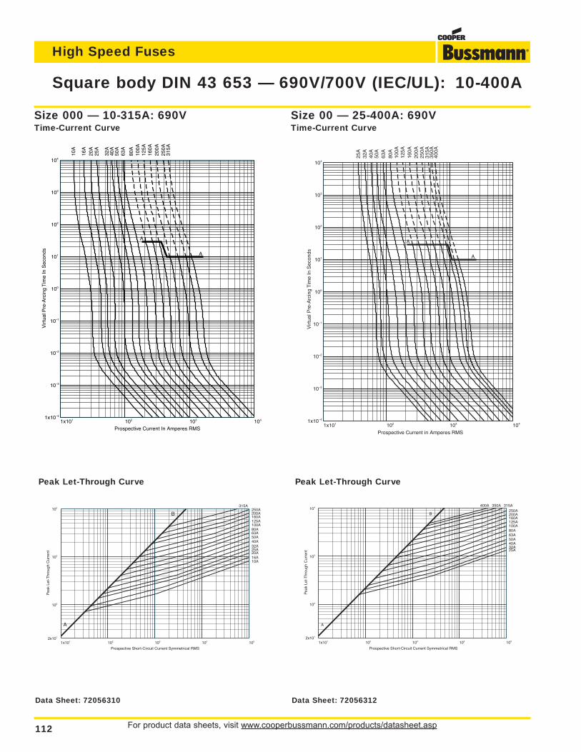
For product data sheets, visit www.cooperbussmann.com/products/datasheet.asp112
Square body DIN 43 653 — 690V/700V (IEC/UL): 10-400A
High Speed Fuses
1x101 102 103 1041x10–4
10–3
10–2
10–1
100
101
102
103
104
Prospective Current In Amperes RMS
Vir
tual
Pre
-Arc
ing
Tim
e In
Sec
onds
10A
16A
20A
25A
32A
40A
50A
63A
80A
100A
125A
160A
200A
250A
315A
A
A
1x101 102 103 1041x10–4
10–3
10–2
10–1
100
101
102
103
104
Prospective Current in Amperes RMS
Vir
tual
Pre
-Arc
ing
Tim
e In
Sec
onds
25A
32A
40A
50A
63A
80A
100A
125A
160A
200A
250A
315A
350A
400A
A
A
Size 00 — 25-400A: 690VTime-Current Curve
Size 000 — 10-315A: 690VTime-Current Curve
1x101 102 103 104 1052x101
102
103
104
Prospective Short-Circuit Current Symmetrical RMS
Pea
k Le
t-T
hrou
gh C
urre
nt
10A16A20A25A32A40A50A63A80A100A125A160A200A250A
A
B
315A
1x101 102 103 104 1052x101
102
103
104
Prospective Short-Circuit Current Symmetrical RMS
Pea
k Le
t-T
hrou
gh C
urre
nt 25A32A40A50A63A80A100A125A160A200A250A
315A350A400A
A
B
Peak Let-Through CurvePeak Let-Through Curve
Data Sheet: 72056310 Data Sheet: 72056312
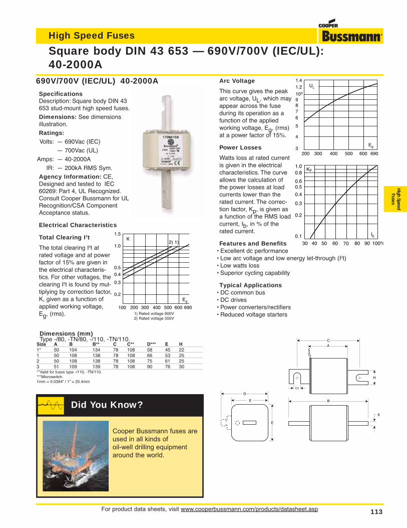
For product data sheets, visit www.cooperbussmann.com/products/datasheet.asp 113
Square body DIN 43 653 — 690V/700V (IEC/UL):40-2000A
High Speed Fuses
High SpeedFuses
690V/700V (IEC/UL) 40-2000A
SpecificationsDescription: Square body DIN 43653 stud-mount high speed fuses.
Dimensions: See dimensionsillustration.
Ratings:Volts: — 690Vac (IEC)
— 700Vac (UL)
Amps: — 40-2000A
IR: — 200kA RMS Sym.
Agency Information: CE,Designed and tested to IEC60269: Part 4, UL Recognized.Consult Cooper Bussmann for ULRecognition/CSA ComponentAcceptance status.
Electrical Characteristics
Total Clearing I2t
The total clearing I2t atrated voltage and at powerfactor of 15% are given inthe electrical characteris-tics. For other voltages, theclearing I2t is found by mul-tiplying by correction factor,K, given as a function ofapplied working voltage,Eg, (rms).
Arc Voltage
This curve gives the peakarc voltage, UL, which mayappear across the fuseduring its operation as afunction of the appliedworking voltage, Eg, (rms)at a power factor of 15%.
Power Losses
Watts loss at rated currentis given in the electricalcharacteristics. The curveallows the calculation ofthe power losses at loadcurrents lower than therated current. The correc-tion factor, Kp, is given asa function of the RMS loadcurrent, Ib, in % of therated current.
Features and Benefits• Excellent dc performance• Low arc voltage and low energy let-through (I2t)• Low watts loss• Superior cycling capability
Typical Applications• DC common bus• DC drives• Power converters/rectifiers• Reduced voltage starters
UL
1.41.2
103
6
87
9
5
4
3Eg
200 300 400 500 600 690
Kp1.00.8
0.4
0.50.6
0.3
0.2
0.1
30 40 50 60 70 80 90 100%
Ib
100 200 300 400 500 600 690
K1.5
1.0
0.5
0.4
0.3
0.2Eg
1)2)
1) Rated voltage 600V2) Rated voltage 550V
A
B
C
D
E
E
6
11
H
Dimensions (mm)Type -/80, -TN/80, -/110, -TN/110.
Size A B B** C C** D*** E H1* 50 104 134 78 108 58 45 221 50 108 138 78 108 66 53 252 50 108 138 78 108 75 61 253 51 109 139 78 108 90 76 30**Valid for fuses type -/110, -TN/110.***Microswitch.1mm = 0.0394” / 1” = 25.4mm
Cooper Bussmann fuses are
used in all kinds of
oil-well drilling equipment
around the world.
Did You Know?
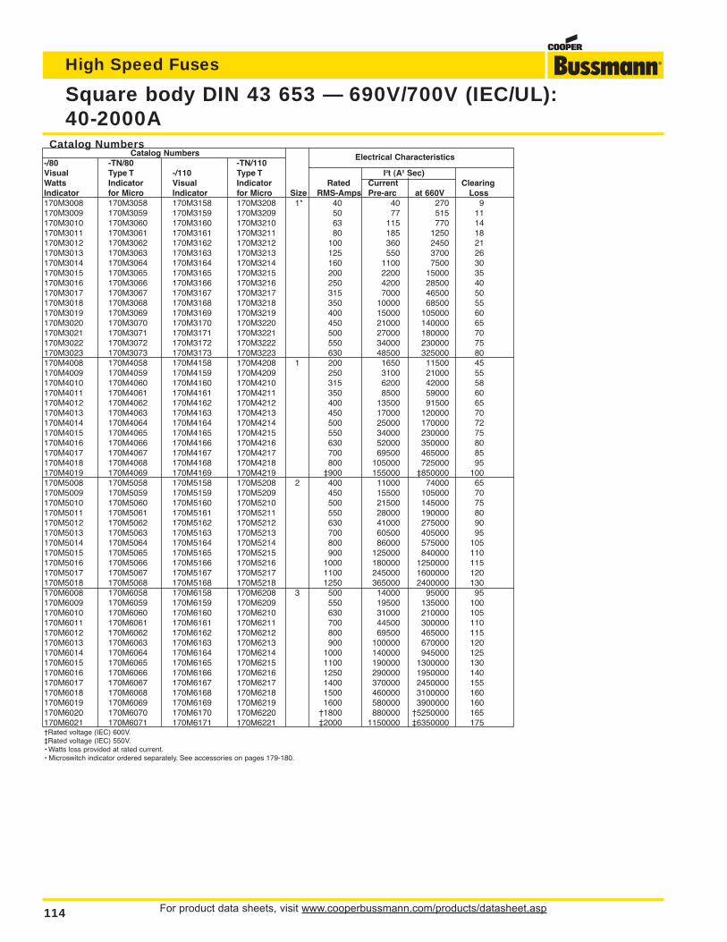
For product data sheets, visit www.cooperbussmann.com/products/datasheet.asp114
Square body DIN 43 653 — 690V/700V (IEC/UL):40-2000A
High Speed Fuses
Catalog NumbersCatalog Numbers
-/80 -TN/80 -TN/110Electrical Characteristics
Visual Type T -/110 Type T I2t (A2 Sec)Watts Indicator Visual Indicator Rated Current ClearingIndicator for Micro Indicator for Micro Size RMS-Amps Pre-arc at 660V Loss170M3008 170M3058 170M3158 170M3208 1* 40 40 270 9170M3009 170M3059 170M3159 170M3209 50 77 515 11170M3010 170M3060 170M3160 170M3210 63 115 770 14170M3011 170M3061 170M3161 170M3211 80 185 1250 18170M3012 170M3062 170M3162 170M3212 100 360 2450 21170M3013 170M3063 170M3163 170M3213 125 550 3700 26170M3014 170M3064 170M3164 170M3214 160 1100 7500 30170M3015 170M3065 170M3165 170M3215 200 2200 15000 35170M3016 170M3066 170M3166 170M3216 250 4200 28500 40170M3017 170M3067 170M3167 170M3217 315 7000 46500 50170M3018 170M3068 170M3168 170M3218 350 10000 68500 55170M3019 170M3069 170M3169 170M3219 400 15000 105000 60170M3020 170M3070 170M3170 170M3220 450 21000 140000 65170M3021 170M3071 170M3171 170M3221 500 27000 180000 70170M3022 170M3072 170M3172 170M3222 550 34000 230000 75170M3023 170M3073 170M3173 170M3223 630 48500 325000 80170M4008 170M4058 170M4158 170M4208 1 200 1650 11500 45170M4009 170M4059 170M4159 170M4209 250 3100 21000 55170M4010 170M4060 170M4160 170M4210 315 6200 42000 58170M4011 170M4061 170M4161 170M4211 350 8500 59000 60170M4012 170M4062 170M4162 170M4212 400 13500 91500 65170M4013 170M4063 170M4163 170M4213 450 17000 120000 70170M4014 170M4064 170M4164 170M4214 500 25000 170000 72170M4015 170M4065 170M4165 170M4215 550 34000 230000 75170M4016 170M4066 170M4166 170M4216 630 52000 350000 80170M4017 170M4067 170M4167 170M4217 700 69500 465000 85170M4018 170M4068 170M4168 170M4218 800 105000 725000 95170M4019 170M4069 170M4169 170M4219 ‡900 155000 ‡850000 100170M5008 170M5058 170M5158 170M5208 2 400 11000 74000 65170M5009 170M5059 170M5159 170M5209 450 15500 105000 70170M5010 170M5060 170M5160 170M5210 500 21500 145000 75170M5011 170M5061 170M5161 170M5211 550 28000 190000 80170M5012 170M5062 170M5162 170M5212 630 41000 275000 90170M5013 170M5063 170M5163 170M5213 700 60500 405000 95170M5014 170M5064 170M5164 170M5214 800 86000 575000 105170M5015 170M5065 170M5165 170M5215 900 125000 840000 110170M5016 170M5066 170M5166 170M5216 1000 180000 1250000 115170M5017 170M5067 170M5167 170M5217 1100 245000 1600000 120170M5018 170M5068 170M5168 170M5218 1250 365000 2400000 130170M6008 170M6058 170M6158 170M6208 3 500 14000 95000 95170M6009 170M6059 170M6159 170M6209 550 19500 135000 100170M6010 170M6060 170M6160 170M6210 630 31000 210000 105170M6011 170M6061 170M6161 170M6211 700 44500 300000 110170M6012 170M6062 170M6162 170M6212 800 69500 465000 115170M6013 170M6063 170M6163 170M6213 900 100000 670000 120170M6014 170M6064 170M6164 170M6214 1000 140000 945000 125170M6015 170M6065 170M6165 170M6215 1100 190000 1300000 130170M6016 170M6066 170M6166 170M6216 1250 290000 1950000 140170M6017 170M6067 170M6167 170M6217 1400 370000 2450000 155170M6018 170M6068 170M6168 170M6218 1500 460000 3100000 160170M6019 170M6069 170M6169 170M6219 1600 580000 3900000 160170M6020 170M6070 170M6170 170M6220 †1800 880000 †5250000 165170M6021 170M6071 170M6171 170M6221 ‡2000 1150000 ‡6350000 175†Rated voltage (IEC) 600V.‡Rated voltage (IEC) 550V.• Watts loss provided at rated current.• Microswitch indicator ordered separately. See accessories on pages 179-180.
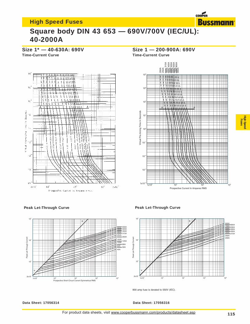
For product data sheets, visit www.cooperbussmann.com/products/datasheet.asp 115
Square body DIN 43 653 — 690V/700V (IEC/UL):40-2000A
High Speed Fuses
High SpeedFuses
1x10² 103 104 1051x10–4
10–3
10–2
10–1
100
101
102
103
104
Prospective Current In Amperes RMS
Vir
tual
Pre
-Arc
ing
Tim
e In
Sec
onds
200A
250A
315A
350A
400A
450A
500A
550A
630A
700A
800A
900A
A A
Size 1 — 200-900A: 690VTime-Current Curve
Size 1* — 40-630A: 690VTime-Current Curve
1x10² 103 104 105 1062x102
103
104
105
Prospective Short-Circuit Current Symmetrical RMS
Pea
k Le
t-T
hrou
gh C
urre
nt
50A40A
63A80A
100A125A
160A200A
250A315A
350A400A450A500A550A630A
A
B
1x10² 103 104 105 1062x102
103
104
105
Pea
k Le
t-T
hrou
gh C
urre
nt 200A250A
315A350A400A450A500A550A630A
700A800A
900A
A
B
Peak Let-Through CurvePeak Let-Through Curve
900 amp fuse is derated to 550V (IEC).
Data Sheet: 17056316Data Sheet: 17056314
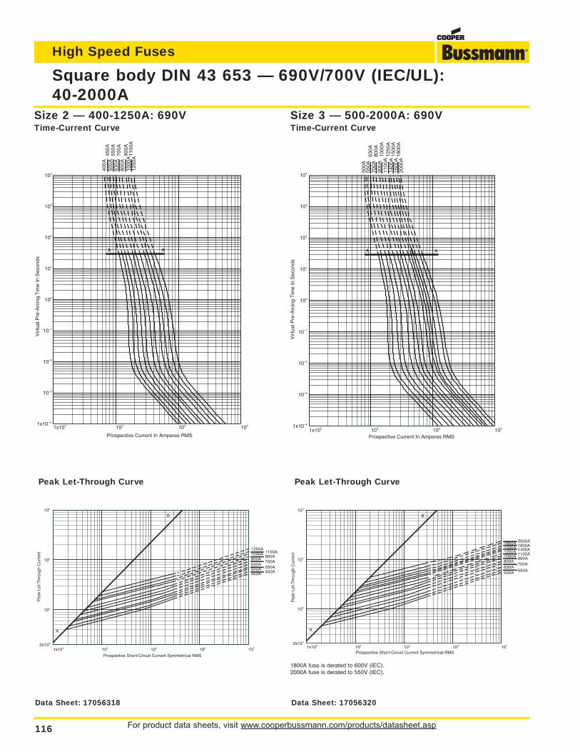
For product data sheets, visit www.cooperbussmann.com/products/datasheet.asp116
Square body DIN 43 653 — 690V/700V (IEC/UL):40-2000A
High Speed Fuses
1x10² 103 104 1051x10–4
10–3
10–2
10–1
100
101
102
103
104
Prospective Current In Amperes RMS
Vir
tual
Pre
-Arc
ing
Tim
e In
Sec
onds
400A
450A
500A
550A
630A
700A
800A
900A
1000
A11
00A
1250
A
A A
1x10² 103 104 1051x10–4
10–3
10–2
10–1
100
101
102
103
104
Prospective Current In Amperes RMS
Vir
tual
Pre
-Arc
ing
Tim
e In
Sec
onds
500A
550A
630A
700A
800A
900A
1000
A11
00A
1250
A14
00A
1500
A16
00A
1800
A20
00A
A A
Size 3 — 500-2000A: 690VTime-Current Curve
Size 2 — 400-1250A: 690VTime-Current Curve
1x10³ 104 105 106 1072x103
104
105
106
Prospective Short-Circuit Current Symmetrical RMS
Pea
k Le
t-T
hrou
gh C
urre
nt
400A 450A500A 550A630A
700A800A900A1000A 1100A
1250A
A
B
1x10³ 104 105 106 1072x103
104
105
106
Prospective Short-Circuit Current Symmetrical RMS
Pea
k Le
t-T
hrou
gh C
urre
nt
500A 550A630A
700A800A
900A1000A 1100A1250A 1400A1500A 1600A1800A 2000A
A
B
Peak Let-Through CurvePeak Let-Through Curve
1800A fuse is derated to 600V (IEC).2000A fuse is derated to 550V (IEC).
Data Sheet: 17056318 Data Sheet: 17056320
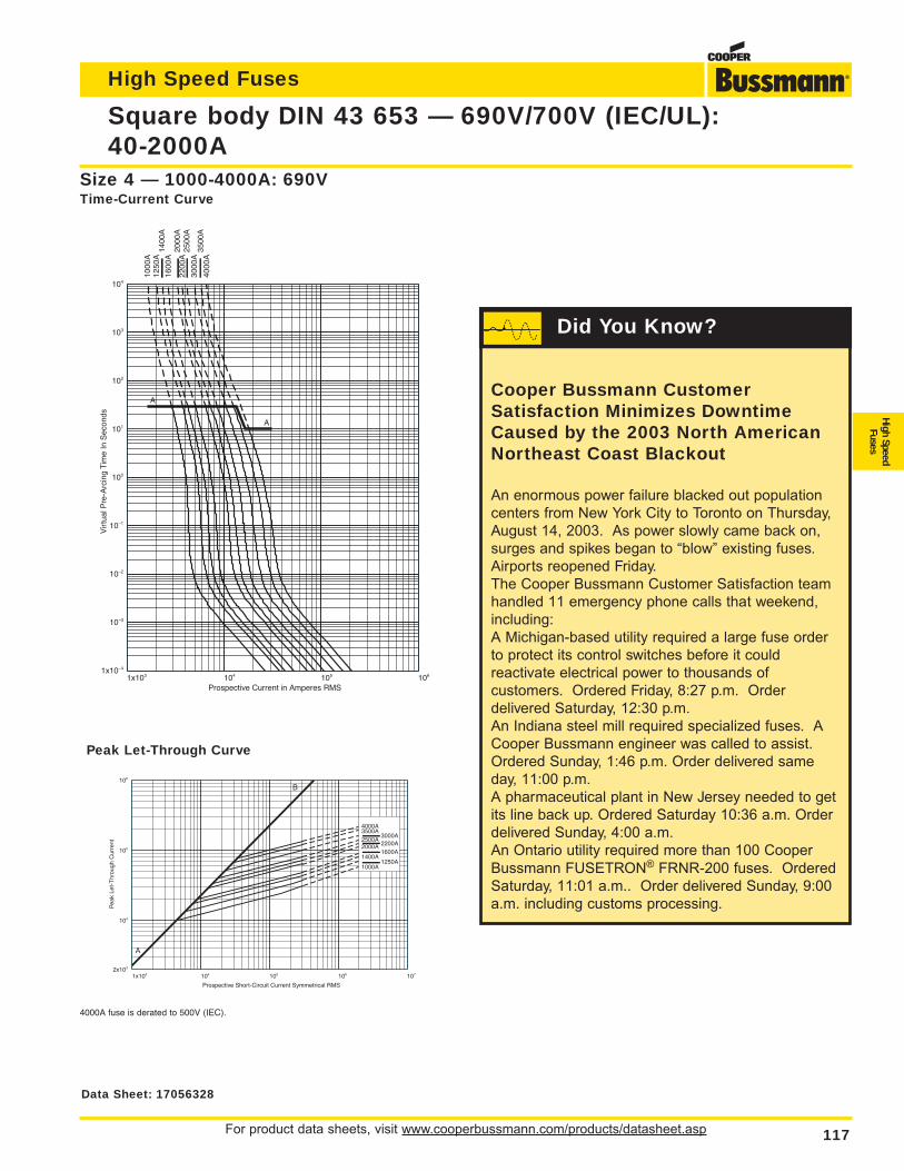
For product data sheets, visit www.cooperbussmann.com/products/datasheet.asp 117
Square body DIN 43 653 — 690V/700V (IEC/UL):40-2000A
High Speed Fuses
High SpeedFuses
1x10³ 104 105 1061x10–4
10–3
10–2
10–1
100
101
102
103
104
Prospective Current in Amperes RMS
Vir
tual
Pre
-Arc
ing
Tim
e In
Sec
onds
1000
A12
50A
1400
A16
00A
2000
A22
00A
2500
A30
00A
3500
A40
00A
A
A
Size 4 — 1000-4000A: 690VTime-Current Curve
1x10³ 104 105 106 1072x103
104
105
106
Prospective Short-Circuit Current Symmetrical RMS
Pea
k Le
t-T
hrou
gh C
urre
nt
1000A1250A
1400A1600A
2000A 2200A2500A
3000A3500A4000A
A
B
Peak Let-Through Curve
4000A fuse is derated to 500V (IEC).
Data Sheet: 17056328
Cooper Bussmann CustomerSatisfaction Minimizes DowntimeCaused by the 2003 North AmericanNortheast Coast Blackout
An enormous power failure blacked out population
centers from New York City to Toronto on Thursday,
August 14, 2003. As power slowly came back on,
surges and spikes began to “blow” existing fuses.
Airports reopened Friday.
The Cooper Bussmann Customer Satisfaction team
handled 11 emergency phone calls that weekend,
including:
A Michigan-based utility required a large fuse order
to protect its control switches before it could
reactivate electrical power to thousands of
customers. Ordered Friday, 8:27 p.m. Order
delivered Saturday, 12:30 p.m.
An Indiana steel mill required specialized fuses. A
Cooper Bussmann engineer was called to assist.
Ordered Sunday, 1:46 p.m. Order delivered same
day, 11:00 p.m.
A pharmaceutical plant in New Jersey needed to get
its line back up. Ordered Saturday 10:36 a.m. Order
delivered Sunday, 4:00 a.m.
An Ontario utility required more than 100 Cooper
Bussmann FUSETRON® FRNR-200 fuses. Ordered
Saturday, 11:01 a.m.. Order delivered Sunday, 9:00
a.m. including customs processing.
Did You Know?
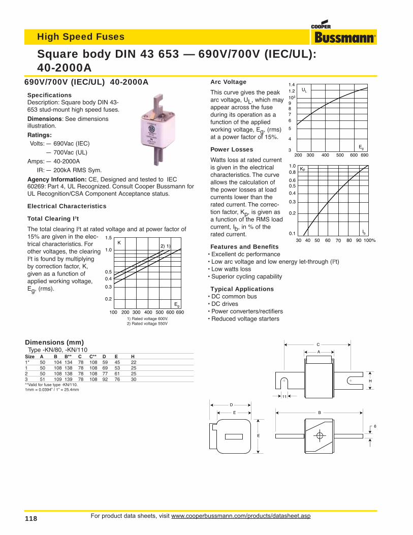
For product data sheets, visit www.cooperbussmann.com/products/datasheet.asp118
High Speed Fuses
Square body DIN 43 653 — 690V/700V (IEC/UL):40-2000A
690V/700V (IEC/UL) 40-2000A
SpecificationsDescription: Square body DIN 43-653 stud-mount high speed fuses.
Dimensions: See dimensions illustration.
Ratings:Volts: — 690Vac (IEC)
— 700Vac (UL)
Amps: — 40-2000A
IR: — 200kA RMS Sym.
Agency Information: CE, Designed and tested to IEC60269: Part 4, UL Recognized. Consult Cooper Bussmann forUL Recognition/CSA Component Acceptance status.
Electrical Characteristics
Total Clearing I2t
The total clearing I2t at rated voltage and at power factor of15% are given in the elec-trical characteristics. Forother voltages, the clearingI2t is found by multiplyingby correction factor, K,given as a function ofapplied working voltage,Eg, (rms).
C
B
A
H
11
6
E
E
D
Dimensions (mm)Type -KN/80, -KN/110
Size A B B** C C** D E H1* 50 104 134 78 108 59 45 221 50 108 138 78 108 69 53 252 50 108 138 78 108 77 61 253 51 109 139 78 108 92 76 30**Valid for fuse type -KN/110.1mm = 0.0394” / 1” = 25.4mm
Arc Voltage
This curve gives the peakarc voltage, UL, which mayappear across the fuseduring its operation as afunction of the appliedworking voltage, Eg, (rms)at a power factor of 15%.
Power Losses
Watts loss at rated currentis given in the electricalcharacteristics. The curveallows the calculation ofthe power losses at loadcurrents lower than therated current. The correc-tion factor, Kp, is given asa function of the RMS loadcurrent, Ib, in % of therated current.
Features and Benefits• Excellent dc performance• Low arc voltage and low energy let-through (I2t)• Low watts loss• Superior cycling capability
Typical Applications• DC common bus• DC drives• Power converters/rectifiers• Reduced voltage starters
Kp1.00.8
0.4
0.50.6
0.3
0.2
0.1
30 40 50 60 70 80 90 100%
Ib
UL
1.41.2
103
6
87
9
5
4
3Eg
200 300 400 500 600 690
100 200 300 400 500 600 690
K1.5
1.0
0.5
0.4
0.3
0.2Eg
1)2)
1) Rated voltage 600V.2) Rated voltage 550V
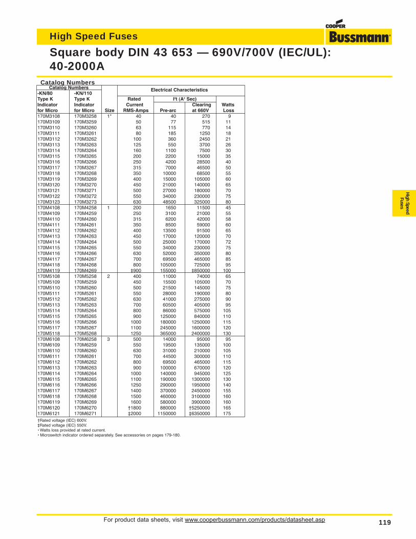
For product data sheets, visit www.cooperbussmann.com/products/datasheet.asp 119
High Speed Fuses
High SpeedFuses
Square body DIN 43 653 — 690V/700V (IEC/UL):40-2000A
Catalog NumbersCatalog Numbers
-KN/80 -KN/110Electrical Characteristics
Type K Type K Rated I2t (A2 Sec)Indicator Indicator Current Clearing Wattsfor Micro for Micro Size RMS-Amps Pre-arc at 660V Loss170M3108 170M3258 1* 40 40 270 9170M3109 170M3259 50 77 515 11170M3110 170M3260 63 115 770 14170M3111 170M3261 80 185 1250 18170M3112 170M3262 100 360 2450 21170M3113 170M3263 125 550 3700 26170M3114 170M3264 160 1100 7500 30170M3115 170M3265 200 2200 15000 35170M3116 170M3266 250 4200 28500 40170M3117 170M3267 315 7000 46500 50170M3118 170M3268 350 10000 68500 55170M3119 170M3269 400 15000 105000 60170M3120 170M3270 450 21000 140000 65170M3121 170M3271 500 27000 180000 70170M3122 170M3272 550 34000 230000 75170M3123 170M3273 630 48500 325000 80170M4108 170M4258 1 200 1650 11500 45170M4109 170M4259 250 3100 21000 55170M4110 170M4260 315 6200 42000 58170M4111 170M4261 350 8500 59000 60170M4112 170M4262 400 13500 91500 65170M4113 170M4263 450 17000 120000 70170M4114 170M4264 500 25000 170000 72170M4115 170M4265 550 34000 230000 75170M4116 170M4266 630 52000 350000 80170M4117 170M4267 700 69500 465000 85170M4118 170M4268 800 105000 725000 95170M4119 170M4269 ‡900 155000 ‡850000 100170M5108 170M5258 2 400 11000 74000 65170M5109 170M5259 450 15500 105000 70170M5110 170M5260 500 21500 145000 75170M5111 170M5261 550 28000 190000 80170M5112 170M5262 630 41000 275000 90170M5113 170M5263 700 60500 405000 95170M5114 170M5264 800 86000 575000 105170M5115 170M5265 900 125000 840000 110170M5116 170M5266 1000 180000 1250000 115170M5117 170M5267 1100 245000 1600000 120170M5118 170M5268 1250 365000 2400000 130170M6108 170M6258 3 500 14000 95000 95170M6109 170M6259 550 19500 135000 100170M6110 170M6260 630 31000 210000 105170M6111 170M6261 700 44500 300000 110170M6112 170M6262 800 69500 465000 115170M6113 170M6263 900 100000 670000 120170M6114 170M6264 1000 140000 945000 125170M6115 170M6265 1100 190000 1300000 130170M6116 170M6266 1250 290000 1950000 140170M6117 170M6267 1400 370000 2450000 155170M6118 170M6268 1500 460000 3100000 160170M6119 170M6269 1600 580000 3900000 160170M6120 170M6270 †1800 880000 †5250000 165170M6121 170M6271 ‡2000 1150000 ‡6350000 175†Rated voltage (IEC) 600V.‡Rated voltage (IEC) 550V.• Watts loss provided at rated current.• Microswitch indicator ordered separately. See accessories on pages 179-180.
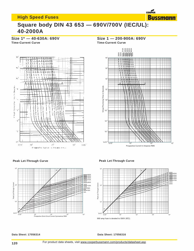
For product data sheets, visit www.cooperbussmann.com/products/datasheet.asp120
Square body DIN 43 653 — 690V/700V (IEC/UL):40-2000A
High Speed Fuses
1x10² 103 104 1051x10–4
10–3
10–2
10–1
100
101
102
103
104
Prospective Current In Amperes RMS
Vir
tual
Pre
-Arc
ing
Tim
e In
Sec
onds
200A
250A
315A
350A
400A
450A
500A
550A
630A
700A
800A
900A
A A
Size 1 — 200-900A: 690VTime-Current Curve
Size 1* — 40-630A: 690VTime-Current Curve
1x10² 103 104 105 1062x102
103
104
105
Prospective Short-Circuit Current Symmetrical RMS
Pea
k Le
t-T
hrou
gh C
urre
nt
50A40A
63A80A
100A125A
160A200A
250A315A
350A400A450A500A550A630A
A
B
1x10² 103 104 105 1062x102
103
104
105
Pea
k Le
t-T
hrou
gh C
urre
nt 200A250A
315A350A400A450A500A550A630A
700A800A
900A
A
B
Peak Let-Through CurvePeak Let-Through Curve
900 amp fuse is derated to 550V (IEC).
Data Sheet: 17056314 Data Sheet: 17056316
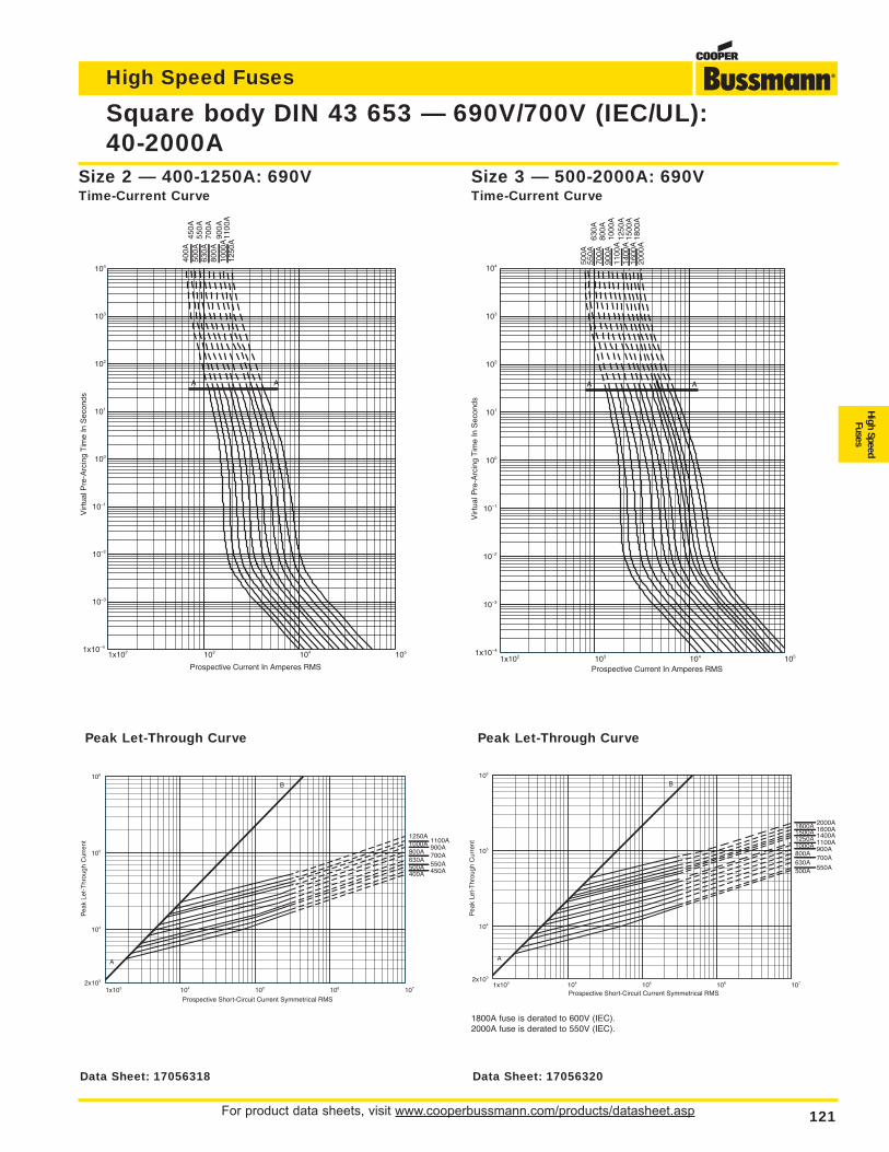
For product data sheets, visit www.cooperbussmann.com/products/datasheet.asp 121
Square body DIN 43 653 — 690V/700V (IEC/UL):40-2000A
High Speed Fuses
High SpeedFuses
1x10² 103 104 1051x10–4
10–3
10–2
10–1
100
101
102
103
104
Prospective Current In Amperes RMS
Vir
tual
Pre
-Arc
ing
Tim
e In
Sec
onds
400A
450A
500A
550A
630A
700A
800A
900A
1000
A11
00A
1250
A
A A
1x10² 103 104 1051x10–4
10–3
10–2
10–1
100
101
102
103
104
Prospective Current In Amperes RMS
Vir
tual
Pre
-Arc
ing
Tim
e In
Sec
onds
500A
550A
630A
700A
800A
900A
1000
A11
00A
1250
A14
00A
1500
A16
00A
1800
A20
00A
A A
Size 3 — 500-2000A: 690VTime-Current Curve
Size 2 — 400-1250A: 690VTime-Current Curve
1x10³ 104 105 106 1072x103
104
105
106
Prospective Short-Circuit Current Symmetrical RMS
Pea
k Le
t-T
hrou
gh C
urre
nt
400A 450A500A 550A630A
700A800A900A1000A 1100A
1250A
A
B
1x10³ 104 105 106 1072x103
104
105
106
Prospective Short-Circuit Current Symmetrical RMS
Pea
k Le
t-T
hrou
gh C
urre
nt
500A 550A630A
700A800A
900A1000A 1100A1250A 1400A1500A 1600A1800A 2000A
A
B
Peak Let-Through CurvePeak Let-Through Curve
1800A fuse is derated to 600V (IEC).2000A fuse is derated to 550V (IEC).
Data Sheet: 17056318 Data Sheet: 17056320
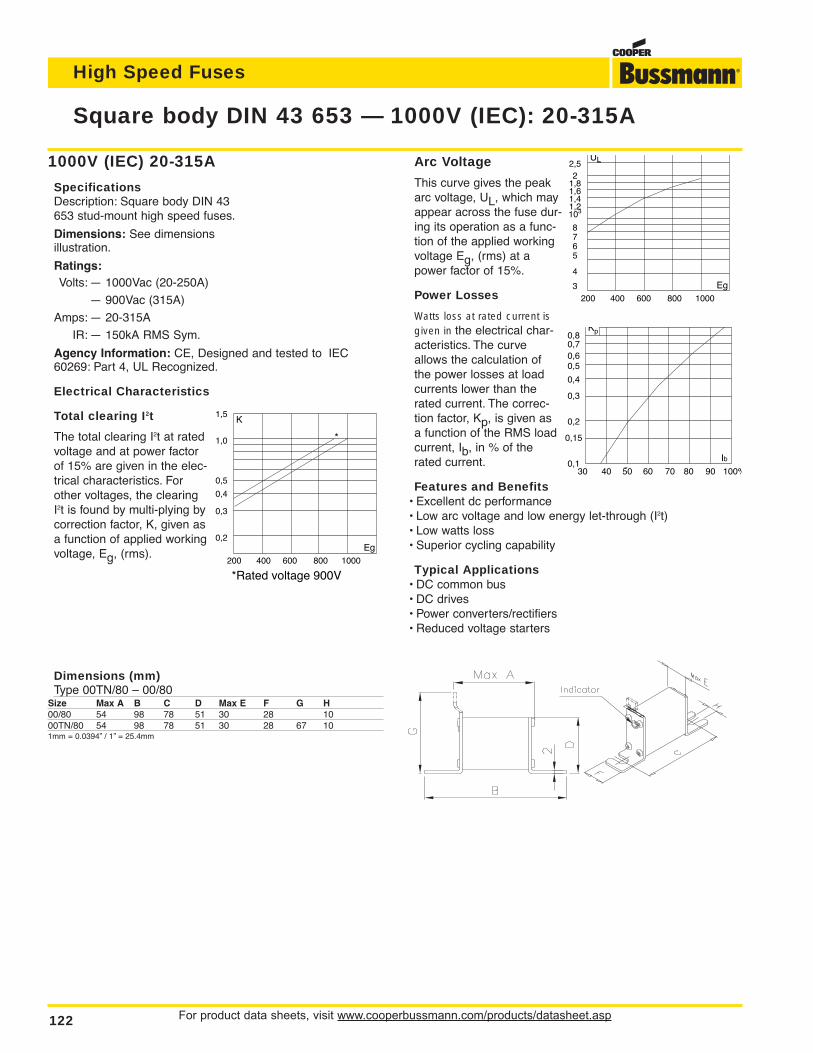
1000V (IEC) 20-315A
SpecificationsDescription: Square body DIN 43653 stud-mount high speed fuses.
Dimensions: See dimensionsillustration.
Ratings:Volts: — 1000Vac (20-250A)
— 900Vac (315A)
Amps: — 20-315A
IR: — 150kA RMS Sym.
Agency Information: CE, Designed and tested to IEC60269: Part 4, UL Recognized.
Electrical Characteristics
Total clearing I2t
The total clearing I2t at ratedvoltage and at power factorof 15% are given in the elec-trical characteristics. Forother voltages, the clearingI2t is found by multi-plying bycorrection factor, K, given asa function of applied workingvoltage, Eg, (rms).
For product data sheets, visit www.cooperbussmann.com/products/datasheet.asp122
Square body DIN 43 653 — 1000V (IEC): 20-315A
High Speed Fuses
1,5
1,0
0,5
0,4
0,3
0,2
K
Eg 200 400 600 800 1000
*Rated voltage 900V
*
Arc Voltage
This curve gives the peakarc voltage, UL, which mayappear across the fuse dur-ing its operation as a func-tion of the applied workingvoltage Eg, (rms) at apower factor of 15%.
Power Losses
Watts loss at rated current isgiven in the electrical char-acteristics. The curveallows the calculation ofthe power losses at loadcurrents lower than therated current. The correc-tion factor, Kp, is given asa function of the RMS loadcurrent, Ib, in % of therated current.
Features and Benefits• Excellent dc performance• Low arc voltage and low energy let-through (I2t)• Low watts loss• Superior cycling capability
Typical Applications• DC common bus• DC drives• Power converters/rectifiers• Reduced voltage starters
2,52
1,81,61,41,2103
8765
4
3
UL
Eg 200 400 600 800 1000
0,80,70,60,5
0,4
0,3
0,2
0,15
0,1
Kp
Ib30 40 50 60 70 80 90 100%
Dimensions (mm)Type 00TN/80 – 00/80
Size Max A B C D Max E F G H00/80 54 98 78 51 30 28 1000TN/80 54 98 78 51 30 28 67 101mm = 0.0394” / 1” = 25.4mm
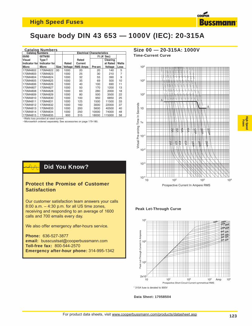
Catalog NumbersCatalog Numbers Electrical Characteristics
00/80 00TN/80 I2t (A2 Sec)Visual Type T Rated ClearingIndicator for Indicator for Rated Current at Rated WattsMicro Micro Size Voltage RMS Amps Pre-arc Voltage Loss170M4802 170M4822 00 1000 20 20 140 5170M4803 170M4823 1000 25 30 210 7170M4804 170M4824 1000 32 55 390 9170M4805 170M4825 1000 35 69 500 10170M4806 170M4826 1000 40 100 690 11170M4807 170M4827 1000 50 170 1200 13170M4808 170M4828 1000 63 280 2000 18170M4809 170M4829 1000 80 500 3500 22170M4810 170M4830 1000 100 950 6850 25170M4811 170M4831 1000 125 1500 11500 33170M4812 170M4832 1000 160 3000 22000 37170M4813 170M4833 1000 200 5600 40500 40170M4814 170M4834 1000 250 10000 74000 48170M4815 170M4835 900 315 18000 115000 58• Watts loss provided at rated current.• Microswitch ordered separately. See accessories on page 179-180.
For product data sheets, visit www.cooperbussmann.com/products/datasheet.asp 123
Square body DIN 43 653 — 1000V (IEC): 20-315A
High Speed Fuses
High SpeedFuses
104
103
102
10
1s
10-1
10-2
10-3
10-4
Virt
ual P
re-a
rcin
g Ti
me
In S
econ
ds
Prospective Current In Ampere RMS
10 102 103 104
25A
35A
50A
80A
125A
200A
315A*250A
63A
40A32A
20A
100A
160A
104
103
102
2x10
Pea
k Le
t-T
hrou
gh C
urre
nt In
Am
pere
s
Prospective Short-Circuit Current symmetrical RMS10 102 103 104 Amp 105
315A 250A200A
160A
125A100A
80A 63A
50A 40A35A 32A
25A 20A
Size 00 — 20-315A: 1000VTime-Current Curve
Peak Let-Through Curve
* 315A fuse is derated to 900V
Data Sheet: 17058504
Protect the Promise of CustomerSatisfaction
Our customer satisfaction team answers your calls
8:00 a.m. – 4:30 p.m. for all US time zones,
receiving and responding to an average of 1600
calls and 700 emails every day.
We also offer emergency after-hours service.
Phone: 636-527-3877
email: [email protected]
Toll-free fax: 800-544-2570
Emergency after-hour phone: 314-995-1342
Did You Know?
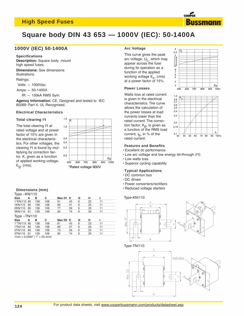
For product data sheets, visit www.cooperbussmann.com/products/datasheet.asp124
Square body DIN 43 653 — 1000V (IEC): 50-1400A
High Speed Fuses
1000V (IEC) 50-1400A
SpecificationsDescription: Square body mounthigh speed fuses.
Dimensions: See dimensionsillustrations.
Ratings:
Volts: — 1000Vac.
Amps:— 50-1400A
IR: — 150kA RMS Sym.
Agency Information: CE, Designed and tested to IEC60269: Part 4, UL Recognized.
Electrical Characteristics
Total clearing I2t
The total clearing I2t atrated voltage and at powerfactor of 15% are given inthe electrical characteris-tics. For other voltages, theclearing I2t is found by mul-tiplying by correction fac-tor, K, given as a functionof applied working voltage,Eg, (rms).
Arc Voltage
This curve gives the peakarc voltage, UL, which mayappear across the fuseduring its operation as afunction of the appliedworking voltage Eg, (rms)at a power factor of 15%.
Power Losses
Watts loss at rated currentis given in the electricalcharacteristics. The curveallows the calculation ofthe power losses at loadcurrents lower than therated current. The correc-tion factor, Kp, is given asa function of the RMS loadcurrent, Ib, in % of therated current.
Features and Benefits• Excellent dc performance• Low arc voltage and low energy let-through (I2t)• Low watts loss• Superior cycling capability
Typical Applications• DC common bus• DC drives• Power converters/rectifiers• Reduced voltage starters
1,5
1,0
0,5
0,4
0,3
0,2
K
Eg 500 600 700 800 900 1000
*Rated voltage 900V
*
32,52
1,81,61,41,2103
8765
4
3
UL
Eg 500 600 700 800 900 1000
1,0
0,80,70,60,5
0,4
0,3
0,2
0,15
0,1
Kp
Ib30 40 50 60 70 80 90 100%
Type-TN/110
Type-KN/110
Dimensions (mm)Type –KN/110Size A B C Max D1 E G H I.1*KN/110 80 138 108 61 43 6 22 111KN/110 80 138 108 69 51 6 25 112KN/110 80 138 108 77 59 6 25 113KN/110 81 139 108 92 74 6 30 11
Type –TN/110Size A B C Max D2 E G H I1*TN/110 80 138 108 61 43 6 22 111TN/110 80 138 108 69 51 6 25 112TN/110 80 138 108 75 59 6 25 113TN/110 81 139 108 90 74 6 30 111mm = 0.0394” / 1” = 25.4mm
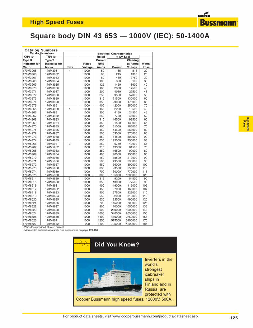
For product data sheets, visit www.cooperbussmann.com/products/datasheet.asp 125
Square body DIN 43 653 — 1000V (IEC): 50-1400A
High Speed Fuses
High SpeedFuses
Catalog NumbersCatalog Numbers Electrical Characteristics
-KN/110 -TN/110 Rated I2t (A2 Sec)Type K Type T Current ClearingIndicator for Indicator for Rated RMS at Rated WattsMicro Micro Size Voltage Amps Pre-arc Voltage Loss170M3965 170M3981 1* 1000 50 135 815 20170M3966 170M3982 1000 63 215 1300 25170M3967 170M3983 1000 80 460 2750 30170M3968 170M3984 1000 100 860 5100 35 170M3969 170M3985 1000 125 1450 8600 40170M3970 170M3986 1000 160 2850 17500 45170M3971 170M3987 1000 200 4950 29500 48170M3972 170M3988 1000 250 9550 57000 50170M3973 170M3989 1000 315 21500 130000 60170M3974 170M3990 1000 350 29000 175000 65170M3975 170M3991 1000 400 42000 250000 70170M4965 170M4980 1 1000 160 2200 13500 40170M4966 170M4981 1000 200 4150 24500 45170M4967 170M4982 1000 250 7750 46000 52170M4968 170M4983 1000 315 16500 98500 60170M4969 170M4984 1000 350 21500 130000 65170M4970 170M4985 1000 400 31000 185000 70170M4971 170M4986 1000 450 44500 265000 80170M4972 170M4987 1000 500 63000 375000 85170M4973 170M4988 1000 550 84500 500000 90170M4974 170M4989 1000 630 125000 755000 98170M5966 170M5981 2 1000 250 6750 40000 65170M5967 170M5982 1000 315 13500 81500 75170M5968 170M5983 1000 350 16500 99000 80170M5969 170M5984 1000 400 26000 155000 85170M5970 170M5985 1000 450 35500 210000 90170M5971 170M5986 1000 500 49500 295000 95170M5972 170M5987 1000 550 66000 390000 100170M5973 170M5988 1000 630 93500 555000 110170M5974 170M5989 1000 700 130000 770000 115170M5975 170M5990 1000 800 195000 1200000 125170M8614 170M8629 3 1000 315 9200 54500 90170M8615 170M8630 1000 350 13000 77500 95170M8616 170M8631 1000 400 19000 115000 105170M8617 170M8632 1000 450 27000 160000 107170M8618 170M8633 1000 500 37500 225000 110170M8619 170M8634 1000 550 52000 310000 115170M8620 170M8635 1000 630 82500 490000 120170M8621 170M8636 1000 700 115000 700000 125170M8622 170M8637 1000 800 170000 1050000 135170M8623 170M8638 1000 900 250000 1500000 145170M8624 170M8639 1000 1000 340000 2050000 150170M8625 170M8640 1000 1100 460000 2750000 155170M8626 170M8641 1000 1250 575000 3400000 175170M8627 170M8642 900 1400 795000 4200000 185• Watts loss provided at rated current.• Microswitch ordered separately. See accessories on page 179-180.
Inverters in the
world’s
strongest
icebreaker
ships in
Finland and in
Russia are
protected with
Cooper Bussmann high speed fuses, 12000V, 500A.
Did You Know?
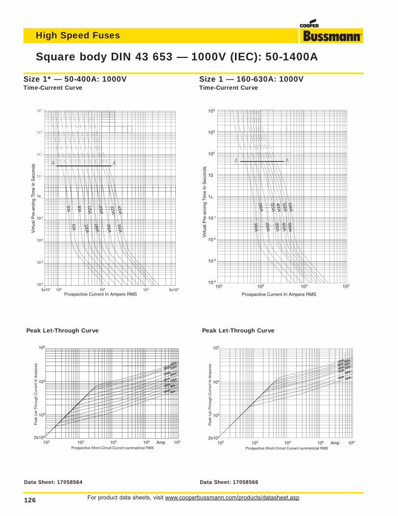
For product data sheets, visit www.cooperbussmann.com/products/datasheet.asp126
Square body DIN 43 653 — 1000V (IEC): 50-1400A
High Speed Fuses
1s
10-1
10-2
10-3
10-4
Virt
ual P
re-a
rcin
g Ti
me
In S
econ
ds
Prospective Current In Ampere RMS5x101 102 103 104 5x10⁴
50A
80A
125A
200A
315A400A
350A
63A
160A
250A
100A
105
104
103
2x10²
Pea
k Le
t-T
hrou
gh C
urre
nt In
Am
pere
s
Prospective Short-Circuit Current symmetrical RMS102 103 104 105 Amp 106
400A
350A 315A
250A200A
160A
50A630A80A100A125A
Size 1* — 50-400A: 1000VTime-Current Curve
Peak Let-Through Curve
104
103
102
10
1s
10-1
10-2
10-3
10-4
Virt
ual P
re-a
rcin
g Ti
me
In S
econ
ds
Prospective Current In Ampere RMS
102 103 104 105
200A
315A400A500A630A
160A
350A
250A
450A550A
105
104
103
2x10²
Pea
k Le
t-T
hrou
gh C
urre
nt In
Am
pere
s
Prospective Short-Circuit Current symmetrical RMS102 103 104 105 Amp 106
550A
500A 450A
400A 350A
315A
630A
160A200A250A
Size 1 — 160-630A: 1000VTime-Current Curve
Peak Let-Through Curve
Data Sheet: 17058564 Data Sheet: 17058566
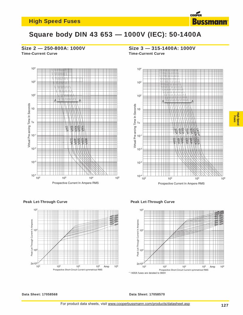
For product data sheets, visit www.cooperbussmann.com/products/datasheet.asp 127
Square body DIN 43 653 — 1000V (IEC): 50-1400A
High Speed Fuses
High SpeedFuses
Size 2 — 250-800A: 1000VTime-Current Curve
Peak Let-Through Curve
104
103
102
10
1s
10-1
10-2
10-3
10-4
Virt
ual P
re-a
rcin
g Ti
me
In S
econ
ds
Prospective Current In Ampere RMS
102 103 104 105 250A350A
550A700A
315A
500A400A
630A800A
450A
105
104
103
2x10²
Pea
k Le
t-T
hrou
gh C
urre
nt In
Am
pere
s
Prospective Short-Circuit Current symmetrical RMS102 103 104 105 Amp 106
700A800A
630A
500A550A
450A
250A315A350A
400A
104
103
102
10
1s
10-1
10-2
10-3
10-4
Virt
ual P
re-a
rcin
g Ti
me
In S
econ
ds
Prospective Current In Ampere RMS
102 103 104 105
350A450A
700A900A
315A
500A400A
630A800A
550A
1100A1400A*
1000A1250A
105
104
103
2x10²
Pea
k Le
t-T
hrou
gh C
urre
nt In
Am
pere
s
Prospective Short-Circuit Current symmetrical RMS102 103 104 105 Amp 106
1250A1400A*1100A
900A1000A
800A
500A550A
630A700A
450A 400A
350A 315A
Size 3 — 315-1400A: 1000VTime-Current Curve
Peak Let-Through Curve
* 1400A fuses are derated to 900V
Data Sheet: 17058568 Data Sheet: 17058570
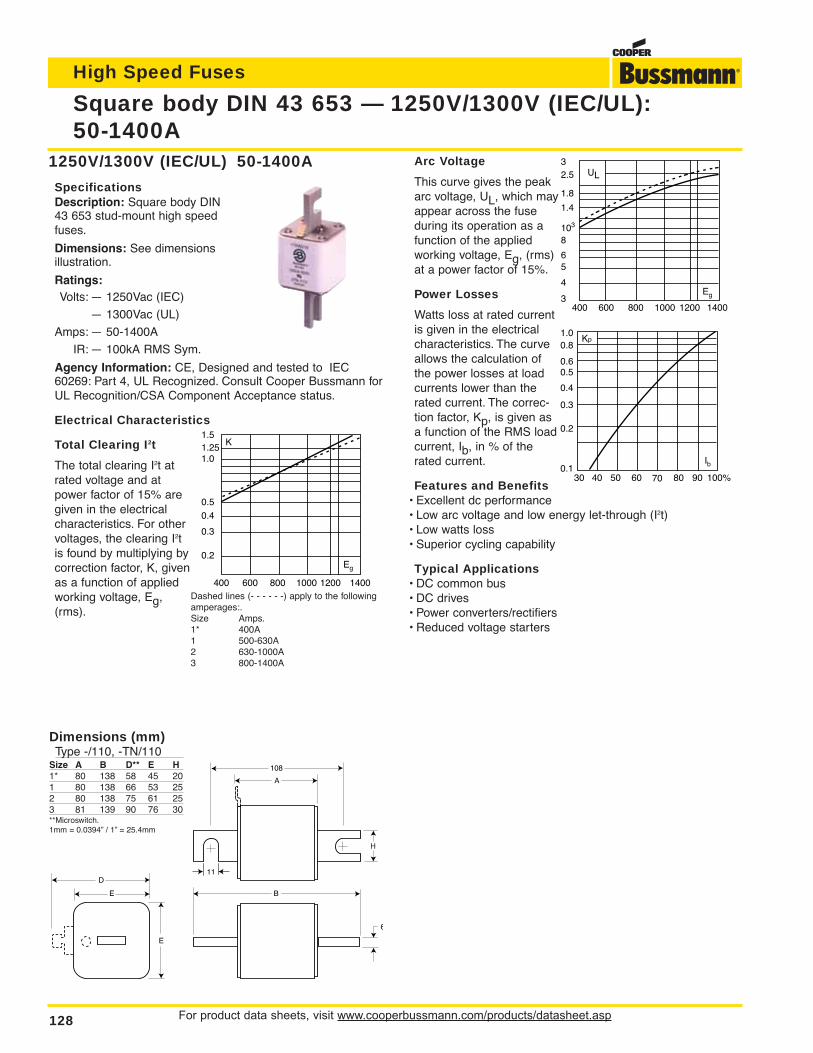
Arc Voltage
This curve gives the peakarc voltage, UL, which mayappear across the fuseduring its operation as afunction of the appliedworking voltage, Eg, (rms)at a power factor of 15%.
Power Losses
Watts loss at rated currentis given in the electricalcharacteristics. The curveallows the calculation ofthe power losses at loadcurrents lower than therated current. The correc-tion factor, Kp, is given asa function of the RMS loadcurrent, Ib, in % of therated current.
Features and Benefits• Excellent dc performance• Low arc voltage and low energy let-through (I2t)• Low watts loss• Superior cycling capability
Typical Applications• DC common bus• DC drives• Power converters/rectifiers• Reduced voltage starters
For product data sheets, visit www.cooperbussmann.com/products/datasheet.asp128
Square body DIN 43 653 — 1250V/1300V (IEC/UL):50-1400A
High Speed Fuses
1250V/1300V (IEC/UL) 50-1400A
SpecificationsDescription: Square body DIN43 653 stud-mount high speedfuses.
Dimensions: See dimensionsillustration.
Ratings:Volts: — 1250Vac (IEC)
— 1300Vac (UL)
Amps: — 50-1400A
IR: — 100kA RMS Sym.
Agency Information: CE, Designed and tested to IEC60269: Part 4, UL Recognized. Consult Cooper Bussmann forUL Recognition/CSA Component Acceptance status.
Electrical Characteristics
Total Clearing I2t
The total clearing I2t atrated voltage and atpower factor of 15% aregiven in the electricalcharacteristics. For othervoltages, the clearing I2tis found by multiplying bycorrection factor, K, givenas a function of appliedworking voltage, Eg,(rms).
UL32.5
8103
1.4
1.8
6
4
5
3400 600 800 1000 1200 1400
Eg
Dashed lines (- - - - - -) apply to the followingamperages:.Size Amps.1* 400A1 500-630A2 630-1000A3 800-1400A
K1.5
1.01.25
0.5
0.4
0.3
0.2
400 600 800 1000 1200 1400
Eg
Kp
30 40 50 60 70 80 90 100%
Ib
1.00.8
0.4
0.50.6
0.3
0.2
0.1
A
B
108
D
E
E
6
H
11
Dimensions (mm)Type -/110, -TN/110
Size A B D** E H1* 80 138 58 45 201 80 138 66 53 252 80 138 75 61 253 81 139 90 76 30**Microswitch.1mm = 0.0394” / 1” = 25.4mm
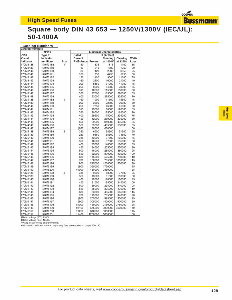
For product data sheets, visit www.cooperbussmann.com/products/datasheet.asp 129
Square body DIN 43 653 — 1250V/1300V (IEC/UL):50-1400A
High Speed Fuses
High SpeedFuses
Catalog NumbersCatalog Numbers
-TN/110 Electrical Characteristics-/110 Type T Rated I2t (A2 Sec)Visual Indicator Current Clearing Clearing WattsIndicator for Micro Size RMS-Amps Pre-arc at 1000V at 1250V Loss170M3138 170M3188 1* 50 135 815 1100 15170M3139 170M3189 63 215 1300 1750 20170M3140 170M3190 80 420 2500 3350 25170M3141 170M3191 100 750 4450 5950 30170M3142 170M3192 125 1450 9000 11500 35170M3143 170M3193 160 2600 16000 21000 40170M3144 170M3194 200 5150 31000 41000 45170M3145 170M3195 250 9200 54500 73000 55170M3146 170M3196 315 18500 115000 150000 60170M3147 170M3197 350 27000 165000 220000 65170M3148 170M3198 400 53000 265000 335000 70170M4138 170M4188 1 160 1900 11500 15500 45170M4139 170M4189 200 3800 22500 30000 50170M4140 170M4190 250 7750 46000 61500 60170M4141 170M4191 315 15000 90000 120000 65170M4142 170M4192 350 20000 125000 165000 70170M4143 170M4193 400 29500 175000 235000 75170M4144 170M4194 450 42000 250000 335000 80170M4145 170M4195 500 69500 340000 435000 85170M4146 170M4196 550 95000 465000 590000 95170M4147 170M4197 †630 130000 660000 100170M5138 170M5188 2 250 6500 38500 51500 65170M5139 170M5189 280 9350 55500 74500 70170M5140 170M5190 315 13000 77500 105000 75170M5141 170M5191 350 16500 97500 135000 80170M5142 170M5192 400 23000 140000 180000 85170M5143 170M5193 450 34000 205000 270000 90170M5144 170M5194 500 48000 285000 380000 95170M5145 170M5195 550 62000 370000 495000 100170M5146 170M5196 630 115000 575000 730000 110170M5147 170M5197 700 160000 795000 1050000 115170M5148 170M5198 800 245000 1200000 1550000 120170M5149 170M5199 †900 360000 1750000 125170M5150 170M5200 †1000 480000 2350000 135170M6138 170M6188 3 315 9500 58000 77500 85170M6139 170M6189 350 13500 81500 110000 90170M6140 170M6190 400 19500 120000 160000 95170M6141 170M6191 450 31000 185000 245000 100170M6142 170M6192 500 39000 235000 310000 105170M6143 170M6193 550 55000 325000 435000 110170M6144 170M6194 630 83500 495000 665000 115170M6145 170M6195 700 115000 705000 940000 120170M6146 170M6196 ‡800 205000 995000 1300000 125170M6147 170M6197 ‡900 305000 1500000 1900000 130170M6148 170M6198 ‡1000 450000 2150000 2750000 135170M6149 170M6199 ‡1100 575000 2800000 3600000 140170M6150 170M6200 †1250 810000 3950000 145170M6151 170M6201 †1400 1250000 6000000 150†Rated voltage (IEC) 1100V.‡Rated voltage (IEC) 1250V.• Watts loss provided at rated current.• Microswitch indicator ordered separately. See accessories on pages 179-180.
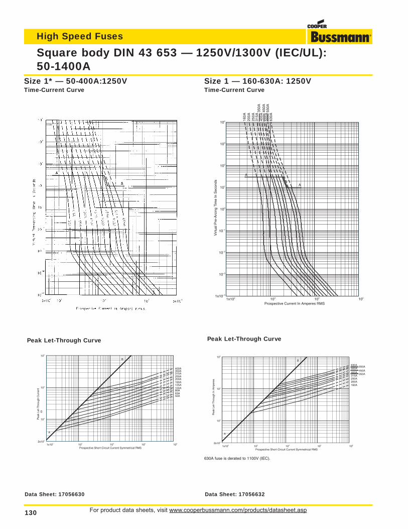
For product data sheets, visit www.cooperbussmann.com/products/datasheet.asp130
Square body DIN 43 653 — 1250V/1300V (IEC/UL):50-1400A
High Speed Fuses
Size 1* — 50-400A:1250VTime-Current Curve
1x10² 103 104 105 1062x102
103
104
105
Prospective Short-Circuit Current Symmetrical RMS
Pea
k Le
t-T
hrou
gh C
urre
nt
50A63A80A100A125A160A200A250A315A350A400A
A
B
Peak Let-Through Curve
1x10² 103 104 1051x10–4
10–3
10–2
10–1
100
101
102
103
104
Prospective Current In Amperes RMS
Virt
ual P
re-A
rcin
g Ti
me
In S
econ
ds
A
A
160A
200A
250A
315A
350A
400A
450A
500A
550A
630A
Size 1 — 160-630A: 1250VTime-Current Curve
1x10² 103 104 105 1062x102
103
104
105
Prospective Short-Circuit Current Symmetrical RMS
Pea
k Le
t-T
hrou
gh In
Am
pere
s
160A200A250A315A
350A400A
450A500A
550A630A
A
B
Peak Let-Through Curve
630A fuse is derated to 1100V (IEC).
Data Sheet: 17056630 Data Sheet: 17056632
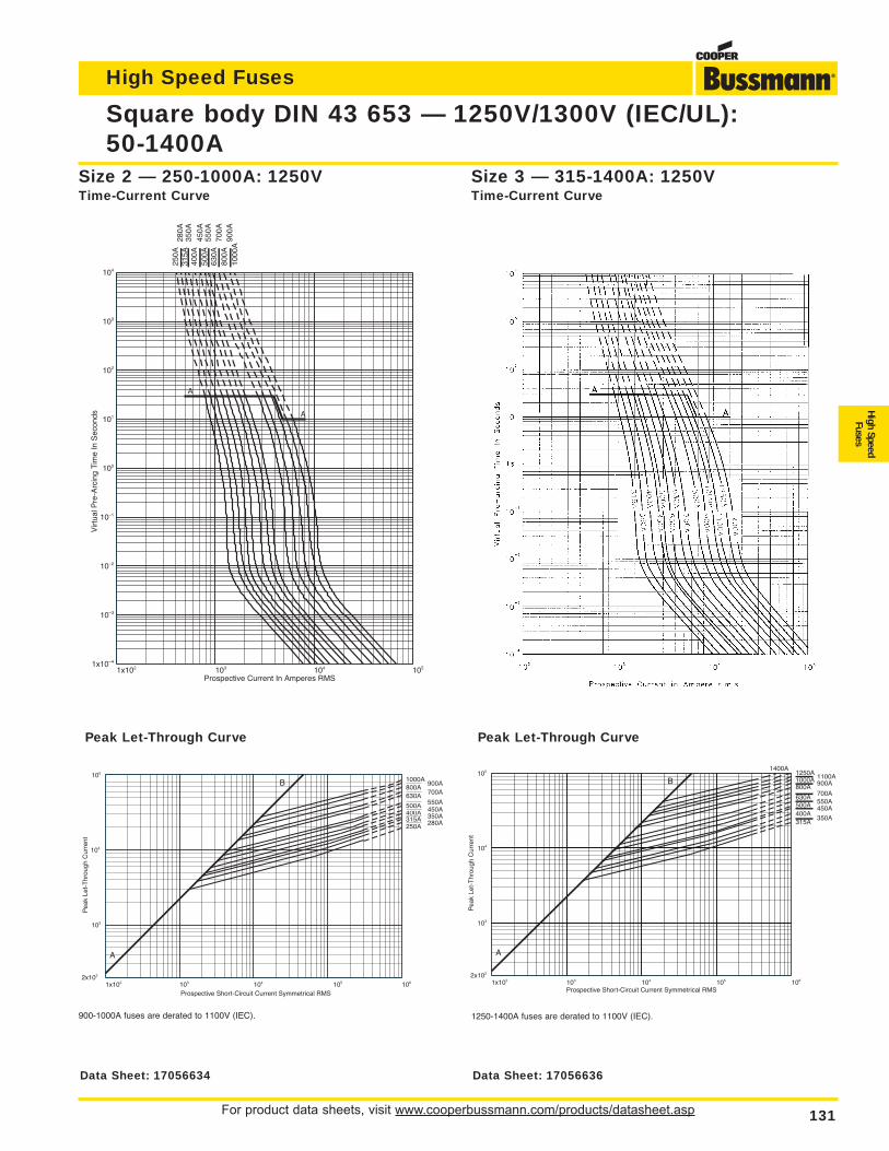
For product data sheets, visit www.cooperbussmann.com/products/datasheet.asp 131
Square body DIN 43 653 — 1250V/1300V (IEC/UL):50-1400A
High Speed Fuses
High SpeedFuses
1x10² 103 104 1051x10–4
10–3
10–2
10–1
100
101
102
103
104
Prospective Current In Amperes RMS
Virt
ual P
re-A
rcin
g Ti
me
In S
econ
ds
250A
280A
315A
350A
400A
450A
500A
550A
630A
700A
800A
900A
1000
A
A
A
Size 2 — 250-1000A: 1250VTime-Current Curve
1x10² 103 104 105 1062x102
103
104
105
Prospective Short-Circuit Current Symmetrical RMS
Pea
k Le
t-T
hrou
gh C
urre
nt
250A 280A315A 350A400A 450A500A 550A630A 700A800A
900A1000A
A
B
Peak Let-Through Curve
900-1000A fuses are derated to 1100V (IEC).
Size 3 — 315-1400A: 1250VTime-Current Curve
1x10² 103 104 105 1062x102
103
104
105
Prospective Short-Circuit Current Symmetrical RMS
Pea
k Le
t-T
hrou
gh C
urre
nt
315A350A
400A450A500A 550A
630A700A
800A 900A1000A 1100A1250A1400A
A
B
Peak Let-Through Curve
1250-1400A fuses are derated to 1100V (IEC).
Data Sheet: 17056634 Data Sheet: 17056636
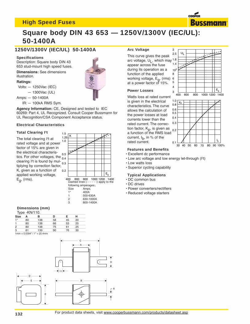
For product data sheets, visit www.cooperbussmann.com/products/datasheet.asp132
Square body DIN 43 653 — 1250V/1300V (IEC/UL):50-1400A
High Speed Fuses
1250V/1300V (IEC/UL) 50-1400A
SpecificationsDescription: Square body DIN 43653 stud-mount high speed fuses.
Dimensions: See dimensionsillustration.
Ratings:Volts: — 1250Vac (IEC)
— 1300Vac (UL)
Amps: — 50-1400A
IR: — 100kA RMS Sym.
Agency Information: CE, Designed and tested to IEC60269: Part 4, UL Recognized. Consult Cooper Bussmann forUL Recognition/CSA Component Acceptance status.
Electrical Characteristics
Total Clearing I2t
The total clearing I2t atrated voltage and at powerfactor of 15% are given inthe electrical characteris-tics. For other voltages, theclearing I2t is found by mul-tiplying by correction factor,K, given as a function ofapplied working voltage,Eg, (rms).
C
B
A
H
11
6
E
E
D
K1.5
1.01.25
0.5
0.4
0.3
0.2
400 600 800 1000 1200 1400
Eg
Arc Voltage
This curve gives the peakarc voltage, UL, which mayappear across the fuseduring its operation as afunction of the appliedworking voltage, Eg, (rms)at a power factor of 15%.
Power Losses
Watts loss at rated currentis given in the electricalcharacteristics. The curveallows the calculation ofthe power losses at loadcurrents lower than therated current. The correc-tion factor, Kp, is given asa function of the RMS loadcurrent, Ib, in % of therated current.
Features and Benefits• Excellent dc performance• Low arc voltage and low energy let-through (I2t)• Low watts loss• Superior cycling capability
Typical Applications• DC common bus• DC drives• Power converters/rectifiers• Reduced voltage starters
Dashed lines (- - - - - -) apply to thefollowing amperages:.Size Amps.1* 400A1 500-630A2 630-1000A3 800-1400A
UL32.5
8103
1.4
1.8
6
4
5
3400 600 800 1000 1200 1400
Eg
Kp
30 40 50 60 70 80 90 100%
Ib
1.00.8
0.4
0.50.6
0.3
0.2
0.1
Dimensions (mm)Type -KN/110.
Size A B D E H1* 80 138 58 45 201 80 138 66 53 252 80 138 75 61 253 81 139 90 76 301mm = 0.0394” / 1” = 25.4mm
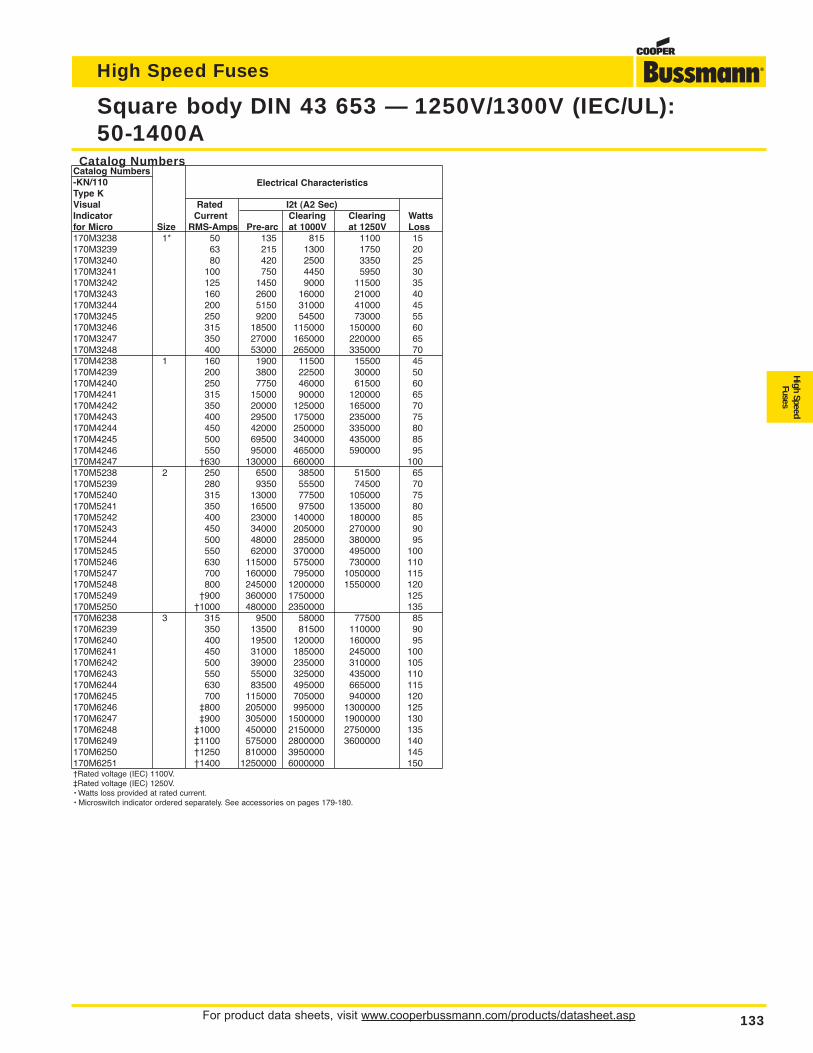
For product data sheets, visit www.cooperbussmann.com/products/datasheet.asp 133
Square body DIN 43 653 — 1250V/1300V (IEC/UL):50-1400A
High Speed Fuses
High SpeedFuses
Catalog NumbersCatalog Numbers-KN/110Type K
Electrical Characteristics
Visual Rated I2t (A2 Sec)Indicator Current Clearing Clearing Wattsfor Micro Size RMS-Amps Pre-arc at 1000V at 1250V Loss170M3238 1* 50 135 815 1100 15170M3239 63 215 1300 1750 20170M3240 80 420 2500 3350 25170M3241 100 750 4450 5950 30170M3242 125 1450 9000 11500 35170M3243 160 2600 16000 21000 40170M3244 200 5150 31000 41000 45170M3245 250 9200 54500 73000 55170M3246 315 18500 115000 150000 60170M3247 350 27000 165000 220000 65170M3248 400 53000 265000 335000 70170M4238 1 160 1900 11500 15500 45170M4239 200 3800 22500 30000 50170M4240 250 7750 46000 61500 60170M4241 315 15000 90000 120000 65170M4242 350 20000 125000 165000 70170M4243 400 29500 175000 235000 75170M4244 450 42000 250000 335000 80170M4245 500 69500 340000 435000 85170M4246 550 95000 465000 590000 95170M4247 †630 130000 660000 100170M5238 2 250 6500 38500 51500 65170M5239 280 9350 55500 74500 70170M5240 315 13000 77500 105000 75170M5241 350 16500 97500 135000 80170M5242 400 23000 140000 180000 85170M5243 450 34000 205000 270000 90170M5244 500 48000 285000 380000 95170M5245 550 62000 370000 495000 100170M5246 630 115000 575000 730000 110170M5247 700 160000 795000 1050000 115170M5248 800 245000 1200000 1550000 120170M5249 †900 360000 1750000 125170M5250 †1000 480000 2350000 135170M6238 3 315 9500 58000 77500 85170M6239 350 13500 81500 110000 90170M6240 400 19500 120000 160000 95170M6241 450 31000 185000 245000 100170M6242 500 39000 235000 310000 105170M6243 550 55000 325000 435000 110170M6244 630 83500 495000 665000 115170M6245 700 115000 705000 940000 120170M6246 ‡800 205000 995000 1300000 125170M6247 ‡900 305000 1500000 1900000 130170M6248 ‡1000 450000 2150000 2750000 135170M6249 ‡1100 575000 2800000 3600000 140170M6250 †1250 810000 3950000 145170M6251 †1400 1250000 6000000 150†Rated voltage (IEC) 1100V.‡Rated voltage (IEC) 1250V.• Watts loss provided at rated current.• Microswitch indicator ordered separately. See accessories on pages 179-180.
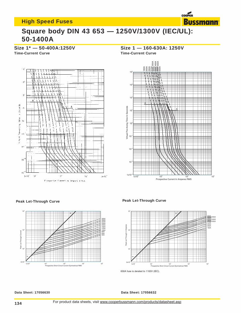
For product data sheets, visit www.cooperbussmann.com/products/datasheet.asp134
Square body DIN 43 653 — 1250V/1300V (IEC/UL):50-1400A
High Speed Fuses
Size 1* — 50-400A:1250VTime-Current Curve
1x10² 103 104 105 1062x102
103
104
105
Prospective Short-Circuit Current Symmetrical RMS
Pea
k Le
t-T
hrou
gh C
urre
nt
50A63A80A100A125A160A200A250A315A350A400A
A
B
Peak Let-Through Curve
1x10² 103 104 1051x10–4
10–3
10–2
10–1
100
101
102
103
104
Prospective Current In Amperes RMS
Virt
ual P
re-A
rcin
g Ti
me
In S
econ
ds
A
A
160A
200A
250A
315A
350A
400A
450A
500A
550A
630A
Size 1 — 160-630A: 1250VTime-Current Curve
1x10² 103 104 105 1062x102
103
104
105
Prospective Short-Circuit Current Symmetrical RMS
Pea
k Le
t-T
hrou
gh In
Am
pere
s
160A200A250A315A
350A400A
450A500A
550A630A
A
B
Peak Let-Through Curve
630A fuse is derated to 1100V (IEC).
Data Sheet: 17056630 Data Sheet: 17056632
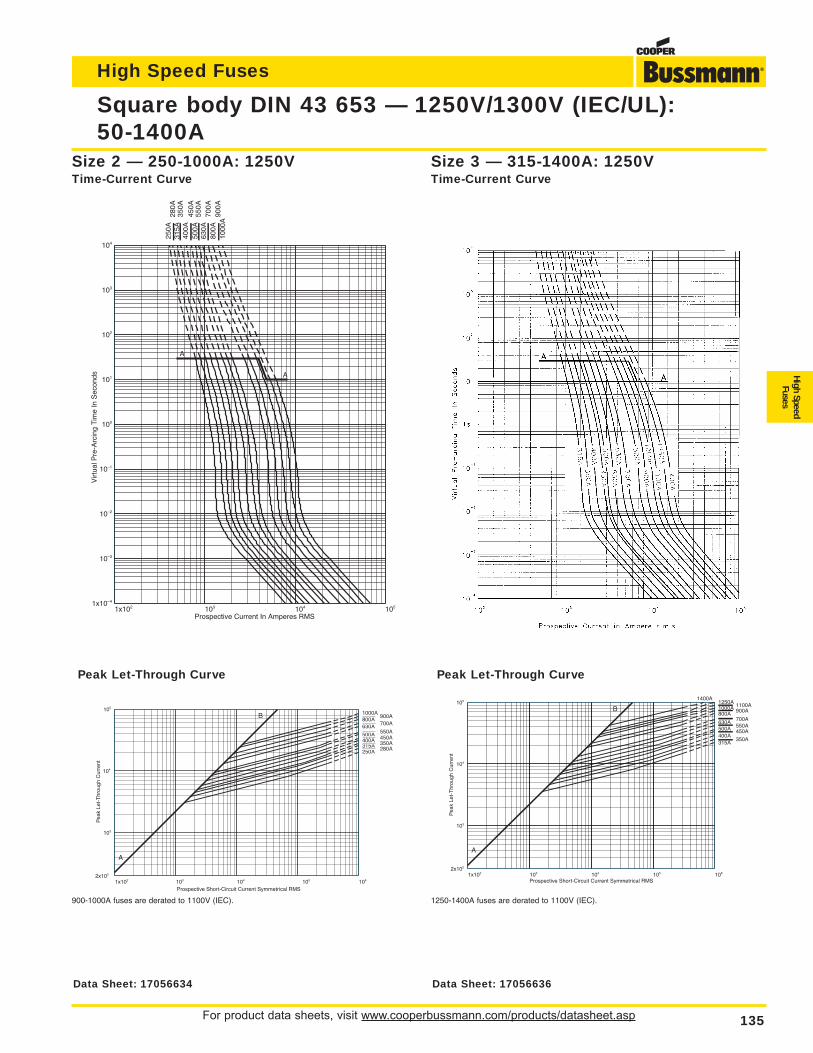
For product data sheets, visit www.cooperbussmann.com/products/datasheet.asp 135
Square body DIN 43 653 — 1250V/1300V (IEC/UL):50-1400A
High Speed Fuses
High SpeedFuses
1x10² 103 104 1051x10–4
10–3
10–2
10–1
100
101
102
103
104
Prospective Current In Amperes RMS
Virt
ual P
re-A
rcin
g Ti
me
In S
econ
ds
250A
280A
315A
350A
400A
450A
500A
550A
630A
700A
800A
900A
1000
A
A
A
Size 2 — 250-1000A: 1250VTime-Current Curve
1x10² 103 104 105 1062x102
103
104
105
Prospective Short-Circuit Current Symmetrical RMS
Pea
k Le
t-T
hrou
gh C
urre
nt
250A 280A315A 350A400A 450A500A 550A630A 700A800A
900A1000A
A
B
Peak Let-Through Curve
900-1000A fuses are derated to 1100V (IEC).
Size 3 — 315-1400A: 1250VTime-Current Curve
1x10² 103 104 105 1062x102
103
104
105
Prospective Short-Circuit Current Symmetrical RMS
Pea
k Le
t-T
hrou
gh C
urre
nt
315A350A
400A450A500A 550A
630A700A
800A 900A1000A 1100A1250A1400A
A
B
Peak Let-Through Curve
1250-1400A fuses are derated to 1100V (IEC).
Data Sheet: 17056634 Data Sheet: 17056636
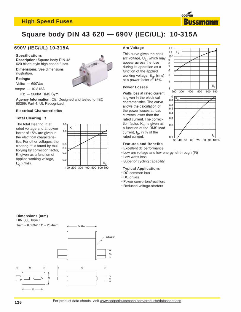
For product data sheets, visit www.cooperbussmann.com/products/datasheet.asp136
Square body DIN 43 620 — 690V (IEC/UL): 10-315A
High Speed Fuses
690V (IEC/UL) 10-315A
SpecificationsDescription: Square body DIN 43620 blade style high speed fuses.
Dimensions: See dimensionsillustration.
Ratings:Volts: — 690Vac
Amps: — 10-315A
IR: — 200kA RMS Sym.
Agency Information: CE, Designed and tested to IEC60269: Part 4, UL Recognized.
Electrical Characteristics
Total Clearing I2t
The total clearing I2t atrated voltage and at powerfactor of 15% are given inthe electrical characteris-tics. For other voltages, theclearing I2t is found by mul-tiplying by correction factor,K, given as a function ofapplied working voltage,Eg, (rms).
54 Max
7948
21 6
35
15
Indicator
Dimensions (mm)DIN 000 Type T1mm = 0.0394” / 1” = 25.4mm
K1.5
1.0
0.5
0.4
0.3
0.2Eg
100 200 300 400 500 600 690
Arc Voltage
This curve gives the peakarc voltage, UL, which mayappear across the fuseduring its operation as afunction of the appliedworking voltage, Eg, (rms)at a power factor of 15%.
Power Losses
Watts loss at rated currentis given in the electricalcharacteristics. The curveallows the calculation ofthe power losses at loadcurrents lower than therated current. The correc-tion factor, Kp, is given asa function of the RMS loadcurrent, Ib, in % of therated current.
Features and Benefits• Excellent dc performance• Low arc voltage and low energy let-through (I2t)• Low watts loss• Superior cycling capability
Typical Applications• DC common bus• DC drives• Power converters/rectifiers• Reduced voltage starters
UL
1.41.2
103
6
87
9
5
4
3Eg
200 300 400 500 600 690
Kp
30 40 50 60 70 80 90 100%
Ib
1.00.8
0.4
0.50.6
0.3
0.2
0.1
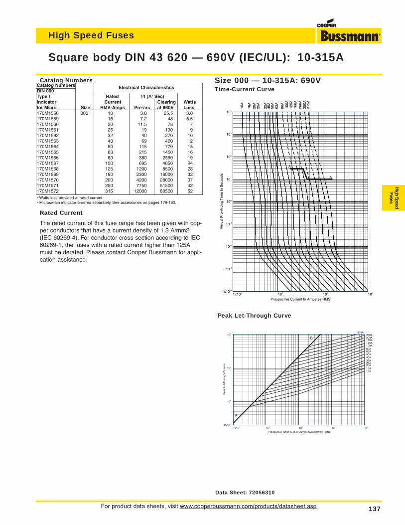
Catalog NumbersCatalog NumbersDIN 000
Electrical Characteristics
Type T Rated I2t (A2 Sec)Indicator Current Clearing Wattsfor Micro Size RMS-Amps Pre-arc at 660V Loss170M1558 000 10 3.8 25.5 3.0170M1559 16 7.2 48 5.5170M1560 20 11.5 78 7170M1561 25 19 130 9170M1562 32 40 270 10170M1563 40 69 460 12170M1564 50 115 770 15170M1565 63 215 1450 16170M1566 80 380 2550 19170M1567 100 695 4650 24170M1568 125 1200 8500 28170M1569 160 2300 16000 32170M1570 200 4200 28000 37170M1571 250 7750 51500 42170M1572 315 12000 80500 52• Watts loss provided at rated current.• Microswitch indicator ordered separately. See accessories on pages 179-180.
Rated Current
The rated current of this fuse range has been given with cop-per conductors that have a current density of 1.3 A/mm2(IEC 60269-4). For conductor cross section according to IEC60269-1, the fuses with a rated current higher than 125Amust be derated. Please contact Cooper Bussmann for appli-cation assistance.
For product data sheets, visit www.cooperbussmann.com/products/datasheet.asp 137
Square body DIN 43 620 — 690V (IEC/UL): 10-315A
High Speed Fuses
High SpeedFuses
1x101 102 103 1041x10–4
10–3
10–2
10–1
100
101
102
103
104
Prospective Current In Amperes RMS
Vir
tual
Pre
-Arc
ing
Tim
e In
Sec
onds
10A
16A
20A
25A
32A
40A
50A
63A
80A
100A
125A
160A
200A
250A
315A
A
A
Size 000 — 10-315A: 690VTime-Current Curve
1x101 102 103 104 1052x101
102
103
104
Prospective Short-Circuit Current Symmetrical RMS
Pea
k Le
t-T
hrou
gh C
urre
nt
10A16A20A25A32A40A50A63A80A100A125A160A200A250A
A
B
315A
Peak Let-Through Curve
Data Sheet: 72056310
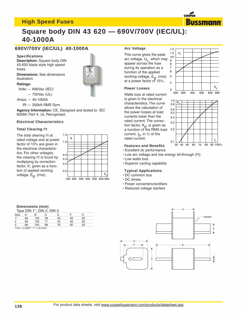
Arc Voltage
This curve gives the peakarc voltage, UL, which mayappear across the fuseduring its operation as afunction of the appliedworking voltage, Eg, (rms)at a power factor of 15%.
Power Losses
Watts loss at rated currentis given in the electricalcharacteristics. The curveallows the calculation ofthe power losses at loadcurrents lower than therated current. The correc-tion factor, Kp, is given asa function of the RMS loadcurrent, Ib, in % of therated current.
Features and Benefits• Excellent dc performance• Low arc voltage and low energy let-through (I2t)• Low watts loss• Superior cycling capability
Typical Applications• DC common bus• DC drives• Power converters/rectifiers• Reduced voltage starters
For product data sheets, visit www.cooperbussmann.com/products/datasheet.asp138
Square body DIN 43 620 — 690V/700V (IEC/UL):40-1000A
High Speed Fuses
690V/700V (IEC/UL) 40-1000A
SpecificationsDescription: Square body DIN43 620 blade style high speedfuses.
Dimensions: See dimensionsillustration.
Ratings:Volts:— 690Vac (IEC)
— 700Vac (UL)
Amps:— 40-1000A
IR:— 200kA RMS Sym.
Agency Information: CE, Designed and tested to IEC60269: Part 4, UL Recognized.
Electrical Characteristics
Total Clearing I2t
The total clearing I2t atrated voltage and at powerfactor of 15% are given inthe electrical characteris-tics. For other voltages,the clearing I2t is found bymultiplying by correctionfactor, K, given as a func-tion of applied workingvoltage, Eg, (rms).
K1.5
1.0
0.5
0.4
0.3
0.2Eg
100 200 300 400 500 600 690
UL
1.41.2
103
6
87
9
5
4
3Eg
200 300 400 500 600 690
Kp
30 40 50 60 70 80 90 100%
Ib
1.00.8
0.4
0.50.6
0.3
0.2
0.1
A
B
D
E
F
6
H
Indicator
Dimensions (mm)Type DIN 1*, DIN 2, DIN 3
Size A B D E F H1* 69 135 58 45 40 202 69 150 71 55 48 263 68 150 88 76 60 331mm = 0.0394” / 1” = 25.4mm
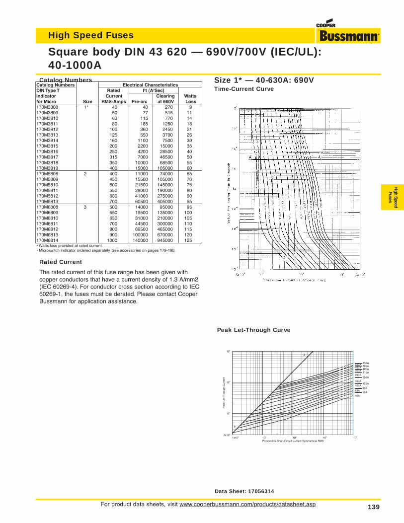
For product data sheets, visit www.cooperbussmann.com/products/datasheet.asp 139
Square body DIN 43 620 — 690V/700V (IEC/UL):40-1000A
High Speed Fuses
High SpeedFuses
Catalog NumbersCatalog Numbers Electrical CharacteristicsDIN Type T Rated I2t (A2Sec)Indicator Current Clearing Wattsfor Micro Size RMS-Amps Pre-arc at 660V Loss170M3808 1* 40 40 270 9170M3809 50 77 515 11170M3810 63 115 770 14170M3811 80 185 1250 18170M3812 100 360 2450 21170M3813 125 550 3700 26170M3814 160 1100 7500 30170M3815 200 2200 15000 35170M3816 250 4200 28500 40170M3817 315 7000 46500 50170M3818 350 10000 68500 55170M3819 400 15000 105000 60170M5808 2 400 11000 74000 65170M5809 450 15500 105000 70170M5810 500 21500 145000 75170M5811 550 28000 190000 80170M5812 630 41000 275000 90170M5813 700 60500 405000 95170M6808 3 500 14000 95000 95170M6809 550 19500 135000 100170M6810 630 31000 210000 105170M6811 700 44500 300000 110170M6812 800 69500 465000 115170M6813 900 100000 670000 120170M6814 1000 140000 945000 125• Watts loss provided at rated current.• Microswitch indicator ordered separately. See accessories on pages 179-180.
Rated Current
The rated current of this fuse range has been given with copper conductors that have a current density of 1.3 A/mm2(IEC 60269-4). For conductor cross section according to IEC60269-1, the fuses must be derated. Please contact CooperBussmann for application assistance.
Size 1* — 40-630A: 690VTime-Current Curve
1x10² 103 104 105 1062x102
103
104
105
Prospective Short-Circuit Current Symmetrical RMS
Pea
k Le
t-T
hrou
gh C
urre
nt
50A40A
63A80A
100A125A
160A200A
250A315A
350A400A450A500A550A630A
A
B
Peak Let-Through Curve
Data Sheet: 17056314
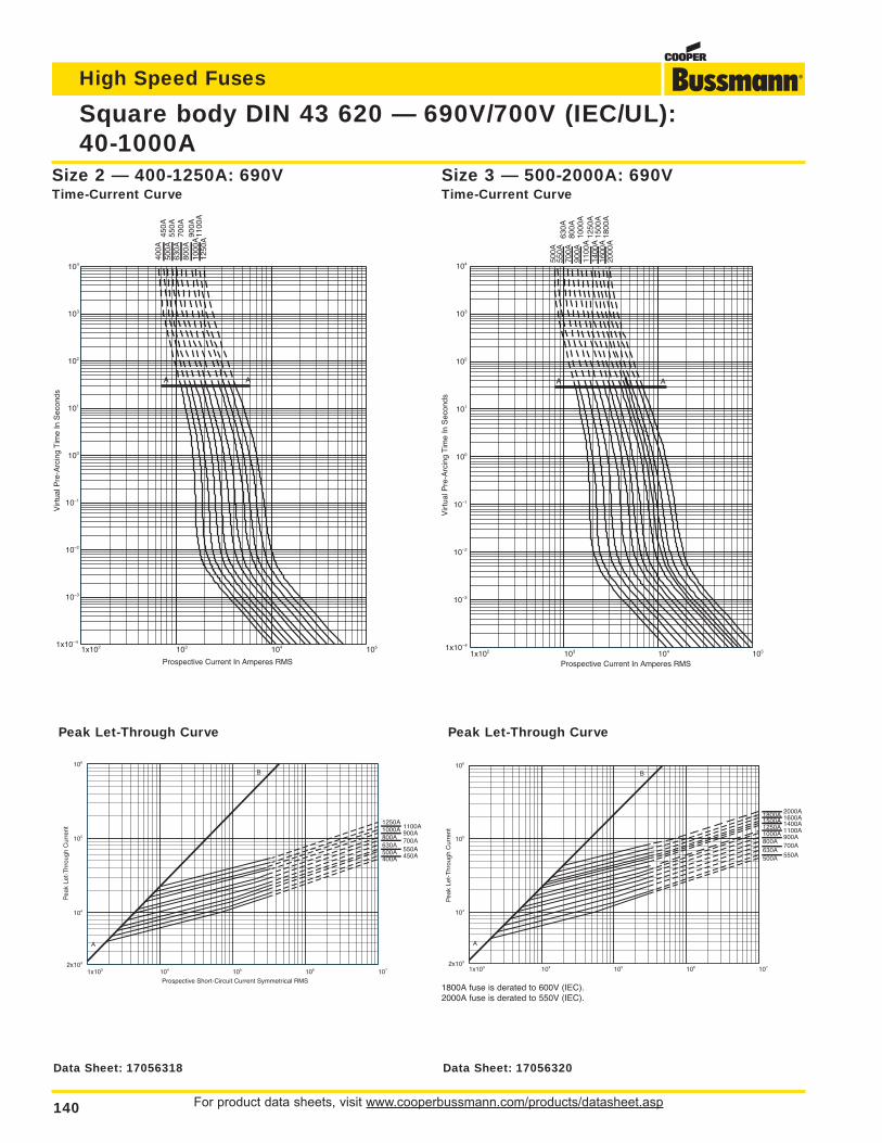
For product data sheets, visit www.cooperbussmann.com/products/datasheet.asp140
Square body DIN 43 620 — 690V/700V (IEC/UL):40-1000A
High Speed Fuses
1x10² 103 104 1051x10–4
10–3
10–2
10–1
100
101
102
103
104
Prospective Current In Amperes RMS
Vir
tual
Pre
-Arc
ing
Tim
e In
Sec
onds
500A
550A
630A
700A
800A
900A
1000
A11
00A
1250
A14
00A
1500
A16
00A
1800
A20
00A
A A
Size 3 — 500-2000A: 690VTime-Current Curve
1x10³ 104 105 106 1072x103
104
105
106
Pea
k Le
t-T
hrou
gh C
urre
nt
500A 550A630A
700A800A
900A1000A 1100A1250A 1400A1500A 1600A1800A 2000A
A
B
Peak Let-Through Curve
1800A fuse is derated to 600V (IEC).2000A fuse is derated to 550V (IEC).
1x10² 103 104 1051x10–4
10–3
10–2
10–1
100
101
102
103
104
Prospective Current In Amperes RMS
Vir
tual
Pre
-Arc
ing
Tim
e In
Sec
onds
400A
450A
500A
550A
630A
700A
800A
900A
1000
A11
00A
1250
A
A A
Size 2 — 400-1250A: 690VTime-Current Curve
1x10³ 104 105 106 1072x103
104
105
106
Prospective Short-Circuit Current Symmetrical RMS
Pea
k Le
t-T
hrou
gh C
urre
nt
400A 450A500A 550A630A
700A800A900A1000A 1100A
1250A
A
B
Peak Let-Through Curve
Data Sheet: 17056318 Data Sheet: 17056320
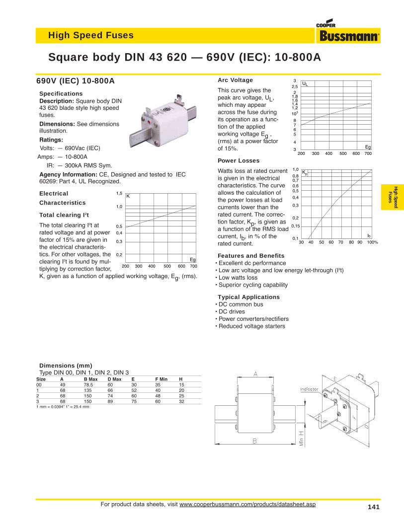
For product data sheets, visit www.cooperbussmann.com/products/datasheet.asp 141
Square body DIN 43 620 — 690V (IEC): 10-800A
High Speed Fuses
High SpeedFuses
690V (IEC) 10-800A
SpecificationsDescription: Square body DIN43 620 blade style high speedfuses.
Dimensions: See dimensionsillustration.
Ratings:Volts: — 690Vac (IEC)
Amps: — 10-800A
IR: — 300kA RMS Sym.
Agency Information: CE, Designed and tested to IEC60269: Part 4, UL Recognized.
Electrical
Characteristics
Total clearing I2t
The total clearing I2t atrated voltage and at powerfactor of 15% are given inthe electrical characteris-tics. For other voltages, theclearing I2t is found by mul-tiplying by correction factor,K, given as a function of applied working voltage, Eg, (rms).
Arc Voltage
This curve gives thepeak arc voltage, UL,which may appearacross the fuse duringits operation as a func-tion of the appliedworking voltage Eg ,(rms) at a power factorof 15%.
Power Losses
Watts loss at rated currentis given in the electricalcharacteristics. The curveallows the calculation ofthe power losses at loadcurrents lower than therated current. The correc-tion factor, Kp, is given asa function of the RMS loadcurrent, Ib, in % of therated current.
Features and Benefits• Excellent dc performance• Low arc voltage and low energy let-through (I2t)• Low watts loss• Superior cycling capability
Typical Applications• DC common bus• DC drives• Power converters/rectifiers• Reduced voltage starters
Dimensions (mm)Type DIN 00, DIN 1, DIN 2, DIN 3
Size A B Max D Max E F Min H00 49 78.5 60 30 35 151 68 135 66 52 40 202 68 150 74 60 48 253 68 150 89 75 60 321 mm = 0.0394” 1” = 25.4 mm
1,5
1,0
0,5
0,4
0,3
0,2
K
Eg 200 300 400 500 600 700
32,52
1,81,61,41,2103
8765
4
3
UL
Eg 200 300 400 500 600 700
1,0
0,80,70,60,5
0,4
0,3
0,2
0,15
0,1
Kp
Ib30 40 50 60 70 80 90 100%
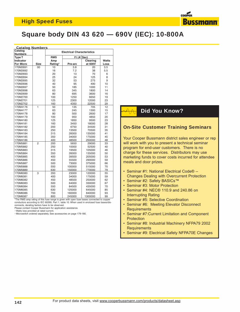
For product data sheets, visit www.cooperbussmann.com/products/datasheet.asp142
Square body DIN 43 620 — 690V (IEC): 10-800A
High Speed Fuses
Catalog NumbersCatalogNumbers
Electrical Characteristics
Type T RMS I2t (A2 Sec)Indicator Amp Clearing WattsFor Micro Size Rating* Pre-arc at 600V Loss170M2691 00 10 3.8 20 3.5170M2692 16 7.2 38 5.5170M2693 20 13 70 6170M2694 25 24 125 8170M2695 32 53 275 9170M2696 40 95 490 10170M2697 50 185 1000 11170M2698 63 345 1800 14170M2699 80 695 3600 16170M2700 100 1250 6650 19170M2701 125 2300 12000 23170M2702 160 4350 22500 29170M4176 1 50 135 705 12170M4177 63 245 1300 15170M4178 80 500 2600 17170M4179 100 950 4850 20170M4180 125 1850 9500 23170M4181 160 3450 18000 28170M4182 200 6750 34500 31170M4183 250 13500 70500 35170M4184 315 26000 135000 41170M4185 350 34000 175000 45170M4186 400 48500 250000 48170M5881 2 200 5650 29000 33170M5882 250 10000 52500 40170M5883 315 19500 105000 46170M5884 350 26000 135000 50170M5885 400 39500 205000 53170M5886 450 55500 290000 59170M5887 500 73000 375000 66170M5888 550 100000 515000 70170M5889 630 150000 770000 79170M6080 3 350 23000 120000 55170M6081 400 34000 175000 59170M6082 450 48500 250000 62170M6083 500 64000 330000 67170M6084 550 84500 435000 70170M6085 630 125000 645000 85170M6086 700 160000 840000 93170M6087 800 245000 1300000 99*The RMS amp rating of this fuse range is given with open fuse bases connected to copperconductors according to IEC 60269, Part 1, table 10. When used in enclosed fuse bases/dis-connects, derating factors have to be observed.Please contact Cooper Bussmann for application assistance.• Watts loss provided at rated current.• Microswitch ordered separately. See accessories on page 179-180.
On-Site Customer Training Seminars
Your Cooper Bussmann district sales engineer or rep
will work with you to present a technical seminar
program for end-user customers. There is no
charge for these services. Distributors may use
marketing funds to cover costs incurred for attendee
meals and door prizes.
• Seminar #1: National Electrical Code® --
Changes Dealing with Overcurrent Protection
• Seminar #2: Safety BASICs™
• Seminar #3: Motor Protection
• Seminar #4: NEC® 110.9 and 240.86 on
Interrupting Rating
• Seminar #5: Selective Coordination
• Seminar #6: Meeting Elevator Disconnect
Requirements
• Seminar #7:Current Limitation and Component
Protection
• Seminar #8: Industrial Machinery NFPA79 2002
Requirements
• Seminar #9: Electrical Safety NFPA70E Changes
Did You Know?
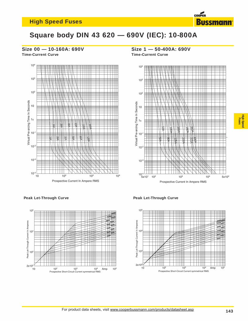
For product data sheets, visit www.cooperbussmann.com/products/datasheet.asp 143
Square body DIN 43 620 — 690V (IEC): 10-800A
High Speed Fuses
High SpeedFuses
104
103
102
10
1s
10-1
10-2
10-3
10-4
Vir
tual
Pre
-arc
ing
Tim
e In
Sec
onds
Prospective Current In Ampere RMS
10 102 103 104
16A
25A
40A
63A
100A
160A125A
20A
80A
10A
50A
32A
105
104
103
2x10²
Pea
k Le
t-T
hrou
gh C
urre
nt In
Am
pere
s
Prospective Short-Circuit Current symmetrical RMS10 102 103 104 Amp 105
160A
125A100A
80A63A
50A 40A
32A25A
20A 16A
10A
104
103
102
10
1s
10-1
10-2
10-3
10-4
Vir
tual
Pre
-arc
ing
Tim
e In
Sec
onds
Prospective Current In Ampere RMS
5x101 102 103 104 5x10⁴
63A
100A
160A
250A350A
400A
80A
315A
50A
200A
125A
105
104
103
2x10²
Pea
k Le
t-T
hrou
gh C
urre
nt In
Am
pere
s
Prospective Short-Circuit Current symmetrical RMS10 102 103 104 Amp 105
400A350A
315A250A
200A160A
125A100A
80A63A
50A
Size 00 — 10-160A: 690VTime-Current Curve
Size 1 — 50-400A: 690VTime-Current Curve
Peak Let-Through Curve Peak Let-Through Curve
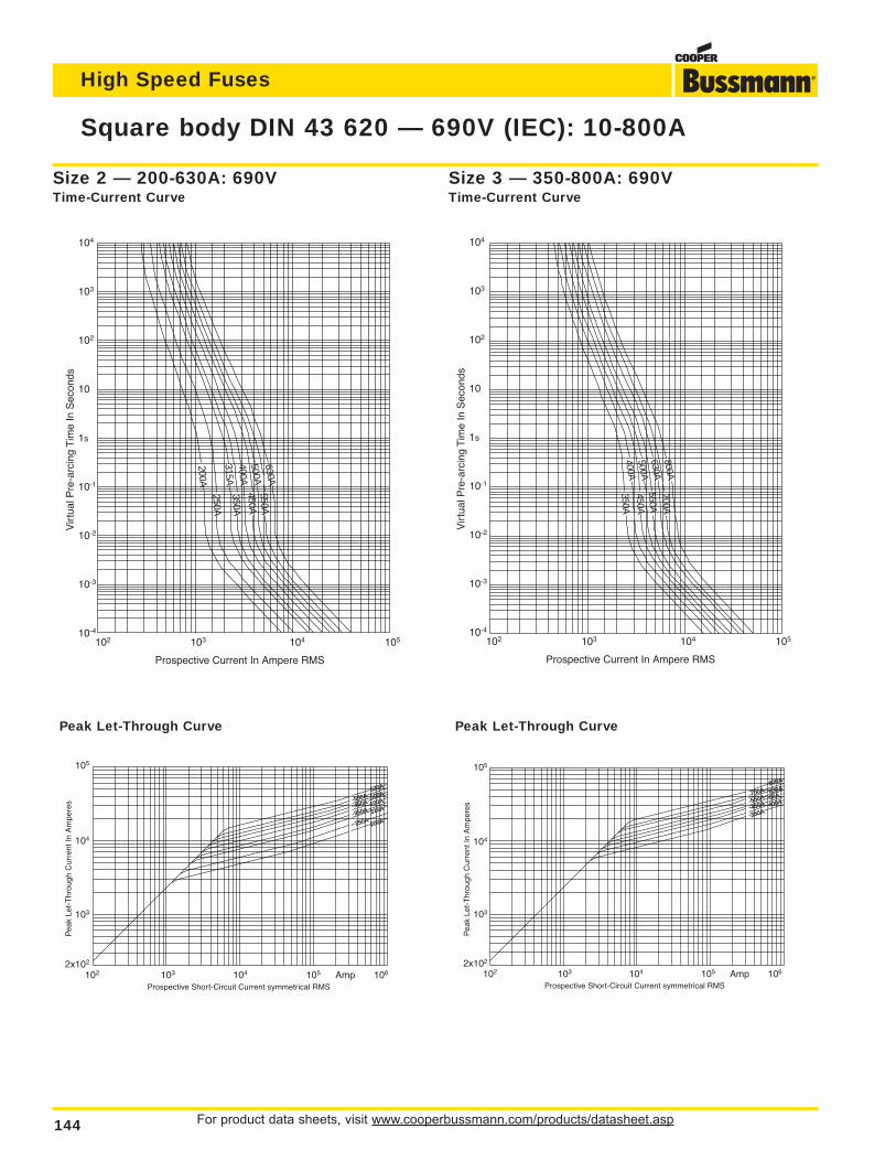
For product data sheets, visit www.cooperbussmann.com/products/datasheet.asp144
Square body DIN 43 620 — 690V (IEC): 10-800A
High Speed Fuses
104
103
102
10
1s
10-1
10-2
10-3
10-4
Vir
tual
Pre
-arc
ing
Tim
e In
Sec
onds
Prospective Current In Ampere RMS
102 103 104 105
200A
315A400A500A630A
350A
250A
550A450A
105
104
103
2x10²
Pea
k Le
t-T
hrou
gh C
urre
nt In
Am
pere
s
Prospective Short-Circuit Current symmetrical RMS102 103 104 105 Amp 106
630A
550A 500A
450A 100A
350A 315A
250A 200A
104
103
102
10
1s
10-1
10-2
10-3
10-4
Vir
tual
Pre
-arc
ing
Tim
e In
Sec
onds
Prospective Current In Ampere RMS
102 103 104 105
450A
350A
700A550A
800A
630A
500A
400A
105
104
103
2x10²
Pea
k Le
t-T
hrou
gh C
urre
nt In
Am
pere
s
Prospective Short-Circuit Current symmetrical RMS102 103 104 105 Amp 106
800A
700A 630A
550A 00A
450A 400A
350A
Size 2 — 200-630A: 690VTime-Current Curve
Size 3 — 350-800A: 690VTime-Current Curve
Peak Let-Through CurvePeak Let-Through Curve
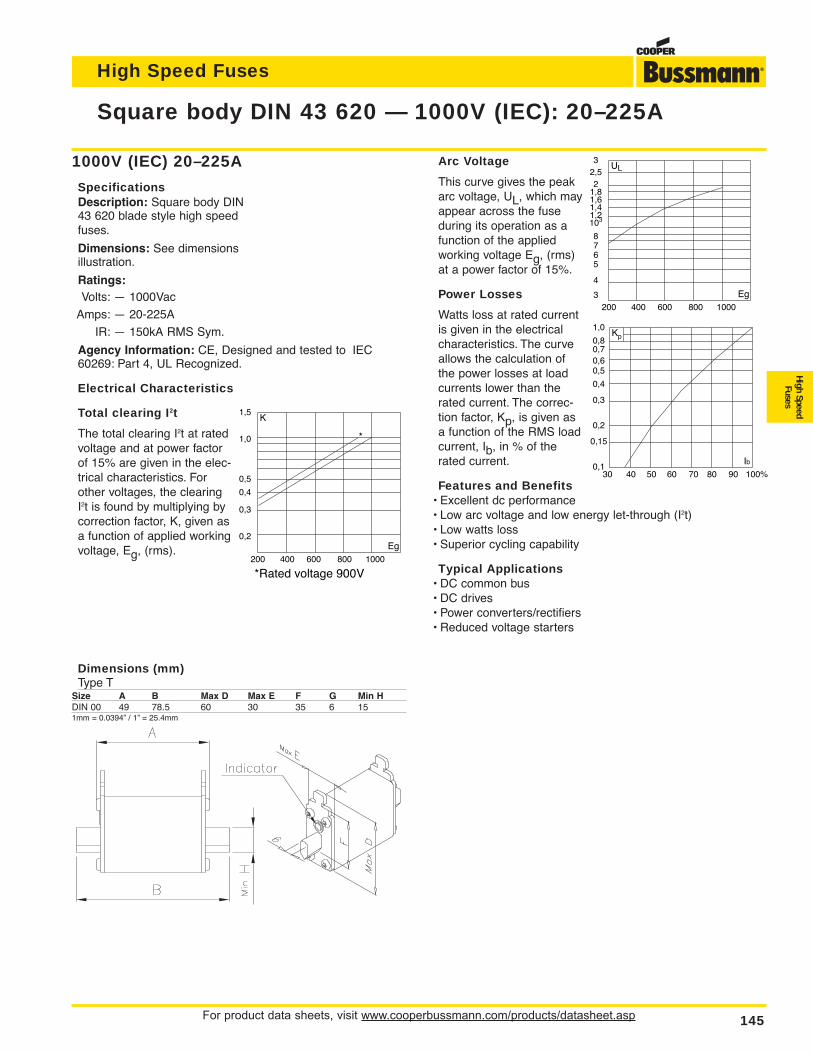
For product data sheets, visit www.cooperbussmann.com/products/datasheet.asp 145
High Speed Fuses
High SpeedFuses
Arc Voltage
This curve gives the peakarc voltage, UL, which mayappear across the fuseduring its operation as afunction of the appliedworking voltage Eg, (rms)at a power factor of 15%.
Power Losses
Watts loss at rated currentis given in the electricalcharacteristics. The curveallows the calculation ofthe power losses at loadcurrents lower than therated current. The correc-tion factor, Kp, is given asa function of the RMS loadcurrent, Ib, in % of therated current.
Features and Benefits• Excellent dc performance• Low arc voltage and low energy let-through (I2t)• Low watts loss• Superior cycling capability
Typical Applications• DC common bus• DC drives• Power converters/rectifiers• Reduced voltage starters
Square body DIN 43 620 — 1000V (IEC): 20–225A
1000V (IEC) 20–225A
SpecificationsDescription: Square body DIN43 620 blade style high speedfuses.
Dimensions: See dimensionsillustration.
Ratings:Volts: — 1000Vac
Amps: — 20-225A
IR: — 150kA RMS Sym.
Agency Information: CE, Designed and tested to IEC60269: Part 4, UL Recognized.
Electrical Characteristics
Total clearing I2t
The total clearing I2t at ratedvoltage and at power factorof 15% are given in the elec-trical characteristics. Forother voltages, the clearingI2t is found by multiplying bycorrection factor, K, given asa function of applied workingvoltage, Eg, (rms).
1,5
1,0
0,5
0,4
0,3
0,2
K
Eg 200 400 600 800 1000
*Rated voltage 900V
*
32,52
1,81,61,41,2103
8765
4
3
UL
Eg 200 400 600 800 1000
1,0
0,80,70,60,5
0,4
0,3
0,2
0,15
0,1
Kp
Ib30 40 50 60 70 80 90 100%
Dimensions (mm)Type T
Size A B Max D Max E F G Min HDIN 00 49 78.5 60 30 35 6 151mm = 0.0394” / 1” = 25.4mm
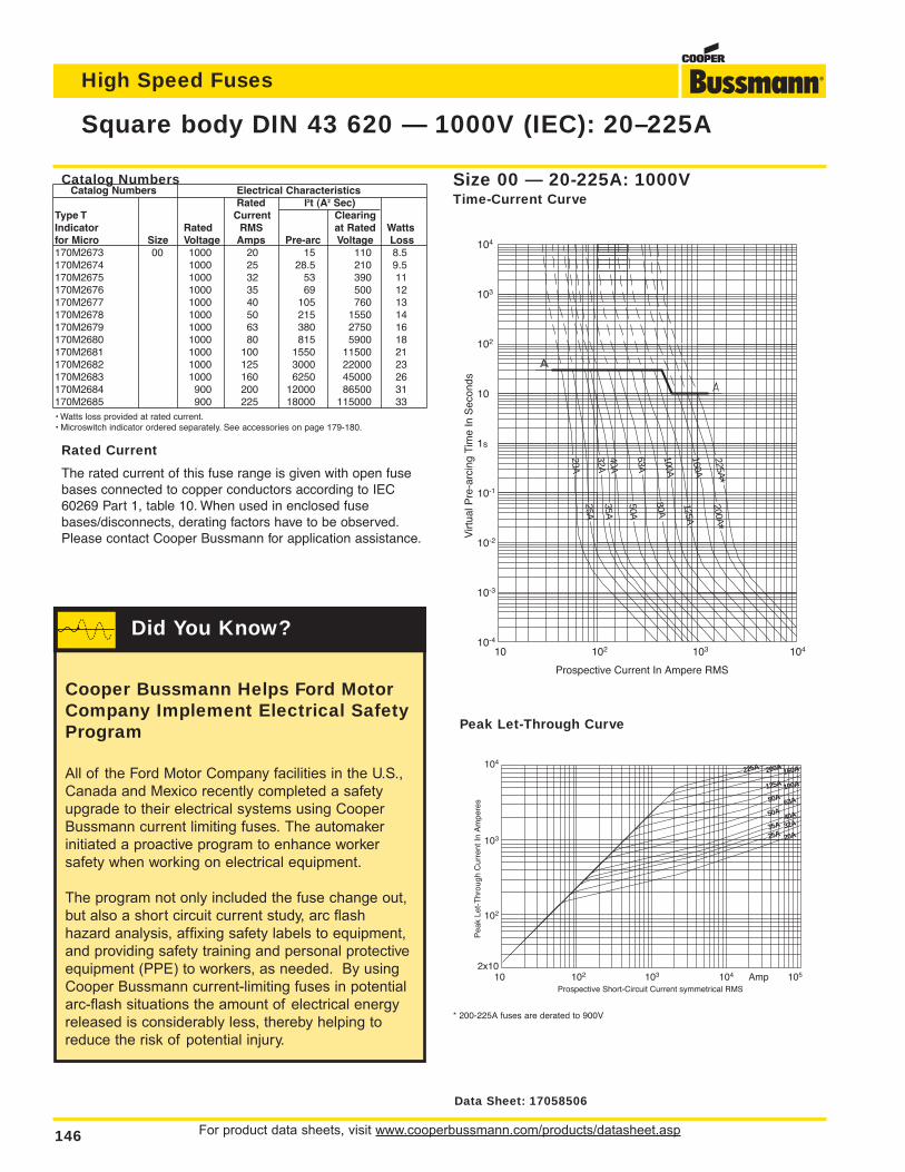
For product data sheets, visit www.cooperbussmann.com/products/datasheet.asp146
High Speed Fuses
Square body DIN 43 620 — 1000V (IEC): 20–225A
104
103
102
10
1s
10-1
10-2
10-3
10-4
Virt
ual P
re-a
rcin
g Ti
me
In S
econ
ds
Prospective Current In Ampere RMS
10 102 103 104
20A
32A40A
63A
100A
160A
225A*
50A
35A
25A
80A
125A
200A*
104
103
102
2x10
Pea
k Le
t-T
hrou
gh C
urre
nt In
Am
pere
s
Prospective Short-Circuit Current symmetrical RMS10 102 103 104 Amp 105
225A 200A160A
125A 100A
80A63A
50A40A
35A 32A
25A 20A
Size 00 — 20-225A: 1000VTime-Current Curve
Peak Let-Through Curve
* 200-225A fuses are derated to 900V
Catalog NumbersCatalog Numbers Electrical Characteristics
Rated I2t (A2 Sec)Type T Current ClearingIndicator Rated RMS at Rated Wattsfor Micro Size Voltage Amps Pre-arc Voltage Loss170M2673 00 1000 20 15 110 8.5170M2674 1000 25 28.5 210 9.5170M2675 1000 32 53 390 11170M2676 1000 35 69 500 12170M2677 1000 40 105 760 13170M2678 1000 50 215 1550 14170M2679 1000 63 380 2750 16170M2680 1000 80 815 5900 18170M2681 1000 100 1550 11500 21170M2682 1000 125 3000 22000 23170M2683 1000 160 6250 45000 26170M2684 900 200 12000 86500 31170M2685 900 225 18000 115000 33• Watts loss provided at rated current.• Microswitch indicator ordered separately. See accessories on page 179-180.
Rated Current
The rated current of this fuse range is given with open fusebases connected to copper conductors according to IEC60269 Part 1, table 10. When used in enclosed fusebases/disconnects, derating factors have to be observed.Please contact Cooper Bussmann for application assistance.
Data Sheet: 17058506
Cooper Bussmann Helps Ford MotorCompany Implement Electrical SafetyProgram
All of the Ford Motor Company facilities in the U.S.,
Canada and Mexico recently completed a safety
upgrade to their electrical systems using Cooper
Bussmann current limiting fuses. The automaker
initiated a proactive program to enhance worker
safety when working on electrical equipment.
The program not only included the fuse change out,
but also a short circuit current study, arc flash
hazard analysis, affixing safety labels to equipment,
and providing safety training and personal protective
equipment (PPE) to workers, as needed. By using
Cooper Bussmann current-limiting fuses in potential
arc-flash situations the amount of electrical energy
released is considerably less, thereby helping to
reduce the risk of potential injury.
Did You Know?
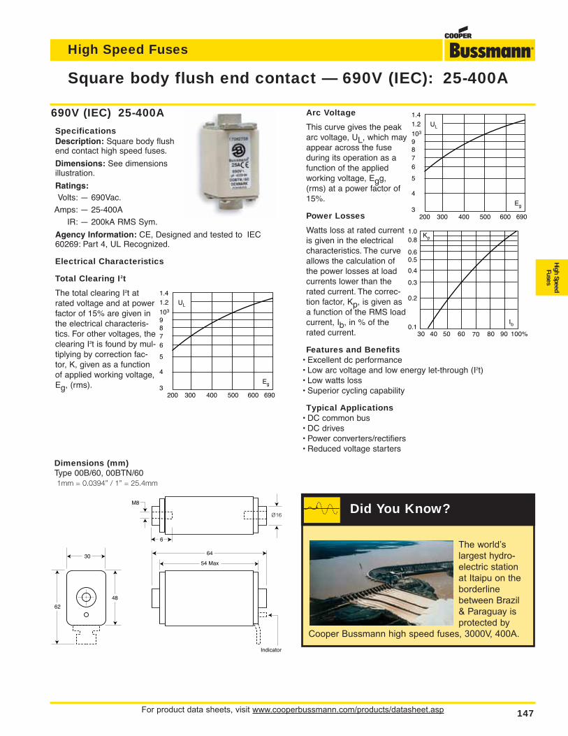
For product data sheets, visit www.cooperbussmann.com/products/datasheet.asp 147
High Speed Fuses
High SpeedFuses
Arc Voltage
This curve gives the peakarc voltage, UL, which mayappear across the fuseduring its operation as afunction of the appliedworking voltage, Egg,(rms) at a power factor of15%.
Power Losses
Watts loss at rated currentis given in the electricalcharacteristics. The curveallows the calculation ofthe power losses at loadcurrents lower than therated current. The correc-tion factor, Kp, is given asa function of the RMS loadcurrent, Ib, in % of therated current.
Features and Benefits• Excellent dc performance• Low arc voltage and low energy let-through (I2t)• Low watts loss• Superior cycling capability
Typical Applications• DC common bus• DC drives• Power converters/rectifiers• Reduced voltage starters
Square body flush end contact — 690V (IEC): 25-400A
690V (IEC) 25-400A
SpecificationsDescription: Square body flushend contact high speed fuses.
Dimensions: See dimensionsillustration.
Ratings:Volts: — 690Vac.
Amps: — 25-400A
IR: — 200kA RMS Sym.
Agency Information: CE, Designed and tested to IEC60269: Part 4, UL Recognized.
Electrical Characteristics
Total Clearing I2t
The total clearing I2t atrated voltage and at powerfactor of 15% are given inthe electrical characteris-tics. For other voltages, theclearing I2t is found by mul-tiplying by correction fac-tor, K, given as a functionof applied working voltage,Eg, (rms).
UL
1.41.2
103
6
87
9
5
4
3Eg
200 300 400 500 600 690
UL
1.41.2
103
6
87
9
5
4
3Eg
200 300 400 500 600 690
Kp
30 40 50 60 70 80 90 100%
Ib
1.00.8
0.4
0.50.6
0.3
0.2
0.1
54 Max
6430
48
62
M8
6
Indicator
Dimensions (mm)Type 00B/60, 00BTN/601mm = 0.0394” / 1” = 25.4mm
The world’s
largest hydro-
electric station
at Itaipu on the
borderline
between Brazil
& Paraguay is
protected by
Cooper Bussmann high speed fuses, 3000V, 400A.
Did You Know?
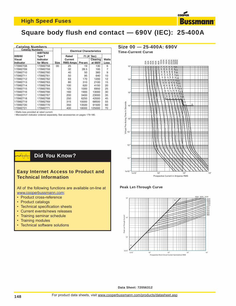
For product data sheets, visit www.cooperbussmann.com/products/datasheet.asp148
High Speed Fuses
Square body flush end contact — 690V (IEC): 25-400A
1x101 102 103 1041x10–4
10–3
10–2
10–1
100
101
102
103
104
Prospective Current in Amperes RMS
Vir
tual
Pre
-Arc
ing
Tim
e In
Sec
onds
25A
32A
40A
50A
63A
80A
100A
125A
160A
200A
250A
315A
350A
400A
A
A
Size 00 — 25-400A: 690VTime-Current Curve
1x101 102 103 104 1052x101
102
103
104
Prospective Short-Circuit Current Symmetrical RMS
Pea
k Le
t-T
hrou
gh C
urre
nt 25A32A40A50A63A80A100A125A160A200A250A
315A350A400A
A
B
Peak Let-Through Curve
Catalog NumbersCatalog Numbers
00BTN/60Electrical Characteristics
00B/60 Type T Rated I2t (A2 Sec)Visual Indicator Current Clearing WattsIndicator for Micro Size RMS-Amps Pre-arc at 660V Loss170M2708 170M2758 00 25 19 130 6170M2709 170M2759 32 28.5 195 7170M2710 170M2760 40 50 360 9170M2711 170M2761 50 95 640 10170M2712 170M2762 63 170 1200 12170M2713 170M2763 80 310 2100 15170M2714 170M2764 100 620 4150 20170M2715 170M2765 125 1000 6950 25170M2716 170M2766 160 1900 13000 30170M2717 170M2767 200 3400 23000 35170M2718 170M2768 250 6250 42000 45170M2719 170M2769 315 10000 68500 55170M2720 170M2770 350 13500 91500 60170M2721 170M2771 400 18000 125000 70• Watts loss provided at rated current.• Microswitch indicator ordered separately. See accessories on pages 179-180.
Data Sheet: 72056312
Easy Internet Access to Product andTechnical Information
All of the following functions are available on-line at
www.cooperbussmann.com:
• Product cross-reference
• Product catalogs
• Technical specification sheets
• Current events/news releases
• Training seminar schedule
• Training modules
• Technical software solutions
Did You Know?
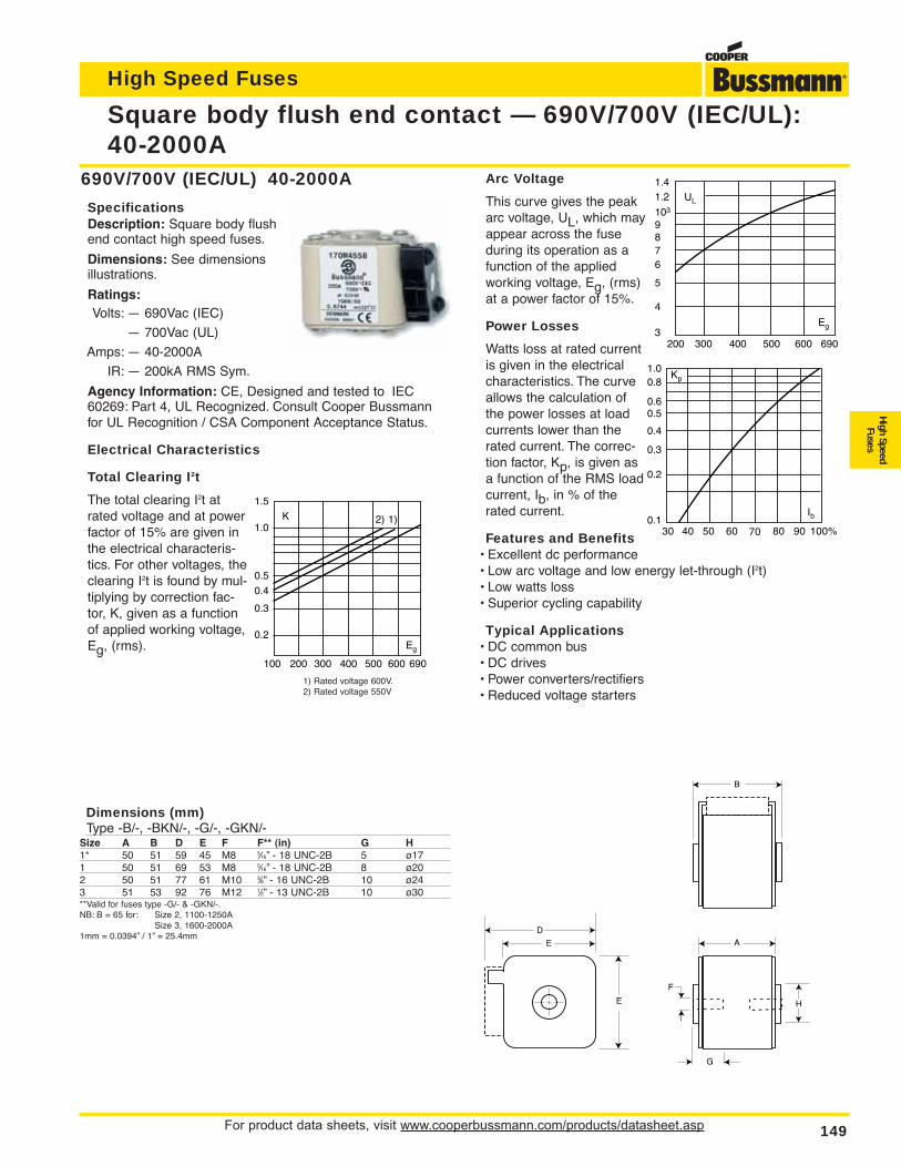
For product data sheets, visit www.cooperbussmann.com/products/datasheet.asp 149
High Speed Fuses
High SpeedFuses
Arc Voltage
This curve gives the peakarc voltage, UL, which mayappear across the fuseduring its operation as afunction of the appliedworking voltage, Eg, (rms)at a power factor of 15%.
Power Losses
Watts loss at rated currentis given in the electricalcharacteristics. The curveallows the calculation ofthe power losses at loadcurrents lower than therated current. The correc-tion factor, Kp, is given asa function of the RMS loadcurrent, Ib, in % of therated current.
Features and Benefits• Excellent dc performance• Low arc voltage and low energy let-through (I2t)• Low watts loss• Superior cycling capability
Typical Applications• DC common bus• DC drives• Power converters/rectifiers• Reduced voltage starters
Square body flush end contact — 690V/700V (IEC/UL):40-2000A
Kp
30 40 50 60 70 80 90 100%
Ib
1.00.8
0.4
0.50.6
0.3
0.2
0.1
690V/700V (IEC/UL) 40-2000A
SpecificationsDescription: Square body flushend contact high speed fuses.
Dimensions: See dimensionsillustrations.
Ratings:Volts: — 690Vac (IEC)
— 700Vac (UL)
Amps: — 40-2000A
IR: — 200kA RMS Sym.
Agency Information: CE, Designed and tested to IEC60269: Part 4, UL Recognized. Consult Cooper Bussmannfor UL Recognition / CSA Component Acceptance Status.
Electrical Characteristics
Total Clearing I2t
The total clearing I2t atrated voltage and at powerfactor of 15% are given inthe electrical characteris-tics. For other voltages, theclearing I2t is found by mul-tiplying by correction fac-tor, K, given as a functionof applied working voltage,Eg, (rms).
A
B
D
E
E H
G
F
Dimensions (mm)Type -B/-, -BKN/-, -G/-, -GKN/-
Size A B D E F F** (in) G H1* 50 51 59 45 M8 5⁄16” - 18 UNC-2B 5 ø171 50 51 69 53 M8 5⁄16” - 18 UNC-2B 8 ø202 50 51 77 61 M10 3⁄8” - 16 UNC-2B 10 ø243 51 53 92 76 M12 1⁄2” - 13 UNC-2B 10 ø30**Valid for fuses type -G/- & -GKN/-.NB: B = 65 for: Size 2, 1100-1250A
Size 3, 1600-2000A1mm = 0.0394” / 1” = 25.4mm
UL
1.41.2
103
6
87
9
5
4
3Eg
200 300 400 500 600 690
K
1.5
1.0
0.5
0.4
0.3
0.2Eg
1)2)
100 200 300 400 500 600 690
1) Rated voltage 600V.2) Rated voltage 550V
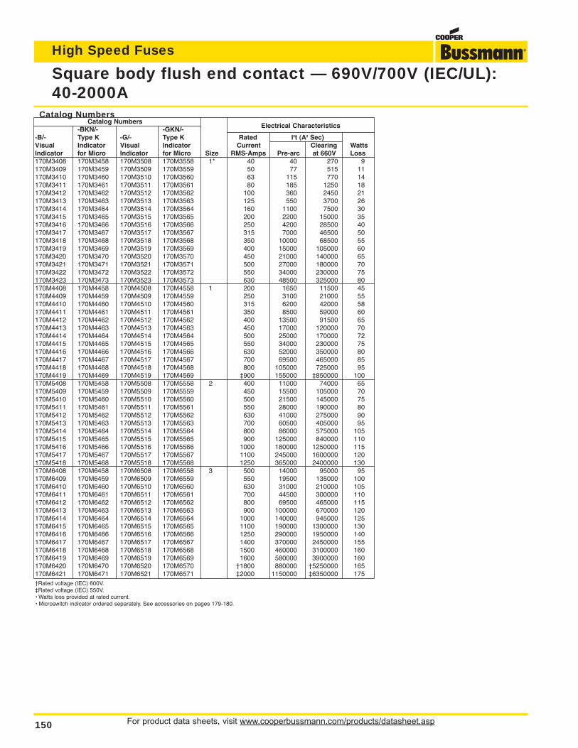
For product data sheets, visit www.cooperbussmann.com/products/datasheet.asp150
High Speed Fuses
Square body flush end contact — 690V/700V (IEC/UL):40-2000A
Catalog NumbersCatalog Numbers
-BKN/- -GKN/- Electrical Characteristics
-B/- Type K -G/- Type K Rated I2t (A2 Sec)Visual Indicator Visual Indicator Current Clearing WattsIndicator for Micro Indicator for Micro Size RMS-Amps Pre-arc at 660V Loss170M3408 170M3458 170M3508 170M3558 1* 40 40 270 9170M3409 170M3459 170M3509 170M3559 50 77 515 11170M3410 170M3460 170M3510 170M3560 63 115 770 14170M3411 170M3461 170M3511 170M3561 80 185 1250 18170M3412 170M3462 170M3512 170M3562 100 360 2450 21170M3413 170M3463 170M3513 170M3563 125 550 3700 26170M3414 170M3464 170M3514 170M3564 160 1100 7500 30170M3415 170M3465 170M3515 170M3565 200 2200 15000 35170M3416 170M3466 170M3516 170M3566 250 4200 28500 40170M3417 170M3467 170M3517 170M3567 315 7000 46500 50170M3418 170M3468 170M3518 170M3568 350 10000 68500 55170M3419 170M3469 170M3519 170M3569 400 15000 105000 60170M3420 170M3470 170M3520 170M3570 450 21000 140000 65170M3421 170M3471 170M3521 170M3571 500 27000 180000 70170M3422 170M3472 170M3522 170M3572 550 34000 230000 75170M3423 170M3473 170M3523 170M3573 630 48500 325000 80170M4408 170M4458 170M4508 170M4558 1 200 1650 11500 45170M4409 170M4459 170M4509 170M4559 250 3100 21000 55170M4410 170M4460 170M4510 170M4560 315 6200 42000 58170M4411 170M4461 170M4511 170M4561 350 8500 59000 60170M4412 170M4462 170M4512 170M4562 400 13500 91500 65170M4413 170M4463 170M4513 170M4563 450 17000 120000 70170M4414 170M4464 170M4514 170M4564 500 25000 170000 72170M4415 170M4465 170M4515 170M4565 550 34000 230000 75170M4416 170M4466 170M4516 170M4566 630 52000 350000 80170M4417 170M4467 170M4517 170M4567 700 69500 465000 85170M4418 170M4468 170M4518 170M4568 800 105000 725000 95170M4419 170M4469 170M4519 170M4569 ‡900 155000 ‡850000 100170M5408 170M5458 170M5508 170M5558 2 400 11000 74000 65170M5409 170M5459 170M5509 170M5559 450 15500 105000 70170M5410 170M5460 170M5510 170M5560 500 21500 145000 75170M5411 170M5461 170M5511 170M5561 550 28000 190000 80170M5412 170M5462 170M5512 170M5562 630 41000 275000 90170M5413 170M5463 170M5513 170M5563 700 60500 405000 95170M5414 170M5464 170M5514 170M5564 800 86000 575000 105170M5415 170M5465 170M5515 170M5565 900 125000 840000 110170M5416 170M5466 170M5516 170M5566 1000 180000 1250000 115170M5417 170M5467 170M5517 170M5567 1100 245000 1600000 120170M5418 170M5468 170M5518 170M5568 1250 365000 2400000 130170M6408 170M6458 170M6508 170M6558 3 500 14000 95000 95170M6409 170M6459 170M6509 170M6559 550 19500 135000 100170M6410 170M6460 170M6510 170M6560 630 31000 210000 105170M6411 170M6461 170M6511 170M6561 700 44500 300000 110170M6412 170M6462 170M6512 170M6562 800 69500 465000 115170M6413 170M6463 170M6513 170M6563 900 100000 670000 120170M6414 170M6464 170M6514 170M6564 1000 140000 945000 125170M6415 170M6465 170M6515 170M6565 1100 190000 1300000 130170M6416 170M6466 170M6516 170M6566 1250 290000 1950000 140170M6417 170M6467 170M6517 170M6567 1400 370000 2450000 155170M6418 170M6468 170M6518 170M6568 1500 460000 3100000 160170M6419 170M6469 170M6519 170M6569 1600 580000 3900000 160170M6420 170M6470 170M6520 170M6570 †1800 880000 †5250000 165170M6421 170M6471 170M6521 170M6571 ‡2000 1150000 ‡6350000 175†Rated voltage (IEC) 600V.‡Rated voltage (IEC) 550V.• Watts loss provided at rated current.• Microswitch indicator ordered separately. See accessories on pages 179-180.
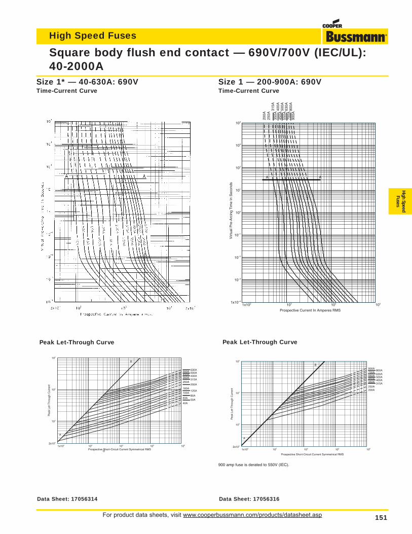
For product data sheets, visit www.cooperbussmann.com/products/datasheet.asp 151
High Speed Fuses
High SpeedFuses
Square body flush end contact — 690V/700V (IEC/UL):40-2000A
1x10² 103 104 1051x10–4
10–3
10–2
10–1
100
101
102
103
104
Prospective Current In Amperes RMS
Vir
tual
Pre
-Arc
ing
Tim
e In
Sec
onds
200A
250A
315A
350A
400A
450A
500A
550A
630A
700A
800A
900A
A A
Size 1 — 200-900A: 690VTime-Current Curve
Size 1* — 40-630A: 690VTime-Current Curve
1x10² 103 104 105 1062x102
103
104
105
Prospective Short-Circuit Current Symmetrical RMS
Pea
k Le
t-T
hrou
gh C
urre
nt
50A40A
63A80A
100A125A
160A200A
250A315A
350A400A450A500A550A630A
A
B
1x10² 103 104 105 1062x102
103
104
105
Prospective Short-Circuit Current Symmetrical RMS
Pea
k Le
t-T
hrou
gh C
urre
nt 200A250A
315A350A400A450A500A550A630A
700A800A
900A
A
B
Peak Let-Through CurvePeak Let-Through Curve
900 amp fuse is derated to 550V (IEC).
Data Sheet: 17056314 Data Sheet: 17056316
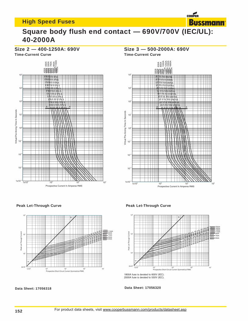
For product data sheets, visit www.cooperbussmann.com/products/datasheet.asp152
High Speed Fuses
Square body flush end contact — 690V/700V (IEC/UL):40-2000A
1x10² 103 104 1051x10–4
10–3
10–2
10–1
100
101
102
103
104
Prospective Current In Amperes RMS
Vir
tual
Pre
-Arc
ing
Tim
e In
Sec
onds
400A
450A
500A
550A
630A
700A
800A
900A
1000
A11
00A
1250
A
A A
1x10² 103 104 1051x10–4
10–3
10–2
10–1
100
101
102
103
104
Prospective Current In Amperes RMS
Vir
tual
Pre
-Arc
ing
Tim
e In
Sec
onds
500A
550A
630A
700A
800A
900A
1000
A11
00A
1250
A14
00A
1500
A16
00A
1800
A20
00A
A A
Size 3 — 500-2000A: 690VTime-Current Curve
Size 2 — 400-1250A: 690VTime-Current Curve
1x10³ 104 105 106 1072x103
104
105
106
Prospective Short-Circuit Current Symmetrical RMS
Pea
k Le
t-T
hrou
gh C
urre
nt
400A 450A500A 550A630A
700A800A900A1000A 1100A
1250A
A
B
1x10³ 104 105 106 1072x103
104
105
106
Prospective Short-Circuit Current Symmetrical RMS
Pea
k Le
t-T
hrou
gh C
urre
nt
500A 550A630A
700A800A
900A1000A 1100A1250A 1400A1500A 1600A1800A 2000A
A
B
Peak Let-Through CurvePeak Let-Through Curve
1800A fuse is derated to 600V (IEC).2000A fuse is derated to 550V (IEC).
Data Sheet: 17056318 Data Sheet: 17056320
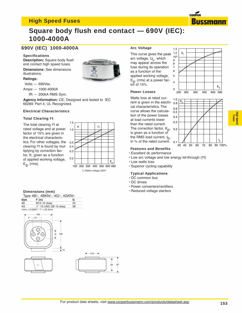
For product data sheets, visit www.cooperbussmann.com/products/datasheet.asp 153
High Speed Fuses
High SpeedFuses
Arc Voltage
This curve gives the peakarc voltage, UL, whichmay appear across thefuse during its operationas a function of theapplied working voltage,Eg, (rms) at a power fac-tor of 15%.
Power Losses
Watts loss at rated cur-rent is given in the electri-cal characteristics. Thecurve allows the calcula-tion of the power lossesat load currents lowerthan the rated current.The correction factor, Kp,is given as a function ofthe RMS load current, Ib,in % of the rated current.
Features and Benefits• Excellent dc performance• Low arc voltage and low energy let-through (I2t)• Low watts loss• Superior cycling capability
Typical Applications• DC common bus• DC drives• Power converters/rectifiers• Reduced voltage starters
Square body flush end contact — 690V (IEC):1000-4000A
690V (IEC) 1000-4000A
SpecificationsDescription: Square body flushend contact high speed fuses.
Dimensions: See dimensionsillustrations.
Ratings:Volts: — 690Vac
Amps: — 1000-4000A
IR: — 200kA RMS Sym.
Agency Information: CE, Designed and tested to IEC60269: Part 4, UL Recognized.
Electrical Characteristics
Total Clearing I2t
The total clearing I2t atrated voltage and at powerfactor of 15% are given inthe electrical characteris-tics. For other voltages, theclearing I2t is found by mul-tiplying by correction fac-tor, K, given as a functionof applied working voltage,Eg, (rms).
K
1.5
1.0
0.5
0.4
0.3
0.2Eg
1)
100 200 300 400 500 600 690
Kp
30 40 50 60 70 80 90 100%
Ib
1.00.8
0.4
0.50.6
0.3
0.2
0.1
1) Rated voltage 500V
UL
1.41.2
103
6
87
9
5
4
3Eg
200 300 400 500 600 690
53
105
67
15
F
G
105
Ø4
Ø56
Dimensions (mm)Type 4B/-, 4BKN/-, 4G/-, 4GKN/-
Size F (in) G4B M10 10 deep 334G 1⁄2” -13 UNC-2B 10 deep 381mm = 0.0394” / 1” = 25.4mm
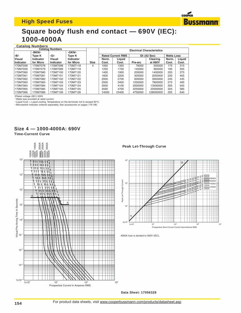
For product data sheets, visit www.cooperbussmann.com/products/datasheet.asp154
High Speed Fuses
Square body flush end contact — 690V (IEC):1000-4000A
1x10³ 104 105 1061x10–4
10–3
10–2
10–1
100
101
102
103
104
Prospective Current in Amperes RMS
Vir
tual
Pre
-Arc
ing
Tim
e In
Sec
onds
1000
A12
50A
1400
A16
00A
2000
A22
00A
2500
A30
00A
3500
A40
00A
A
A
Size 4 — 1000-4000A: 690VTime-Current Curve
1x10³ 104 105 106 1072x103
104
105
106
Prospective Short-Circuit Current Symmetrical RMS
Pea
k Le
t-T
hrou
gh C
urre
nt
1000A1250A
1400A1600A
2000A 2200A2500A
3000A3500A4000A
A
B
Peak Let-Through Curve
4000A fuse is derated to 500V (IEC).
Catalog NumbersCatalog Numbers
-BKN/- -GKN/-Electrical Characteristics
-B/- Type K -G/- Type K Rated Current RMS I2t (A2 Sec) Watts LossVisual Indicator Visual Indicator Norm. Liquid Clearing Norm. LiquidIndicator for Micro Indicator for Micro Size Cool. Cool. Pre-arc at 660V Cool. Cool.170M7058 170M7078 170M7098 170M7118 4 1000 1350 76000 505000 175 315170M7059 170M7079 170M7099 170M7119 1250 1700 145000 965000 195 355170M7060 170M7080 170M7100 170M7120 1400 1900 205000 1400000 205 375170M7061 170M7081 170M7101 170M7121 1600 2200 305000 2050000 220 405170M7062 170M7082 170M7102 170M7122 2000 2700 600000 3950000 245 445170M7063 170M7083 170M7103 170M7123 2500 3400 1200000 7800000 275 495170M7064 170M7084 170M7104 170M7124 3000 4100 2000000 13500000 305 555170M7065 170M7085 170M7105 170M7125 3500 4700 3250000 22000000 325 585170M7066 170M7086 170M7106 170M7126 †4000 †5400 4700000 †28000000 355 640†Rated voltage (IEC) 500V.• Watts loss provided at rated current.• Liquid Cool. = Liquid cooling. Temperature on the terminals not to exceed 60°C.• Microswitch indicator ordered separately. See accessories on pages 179-180.
Data Sheet: 17056328
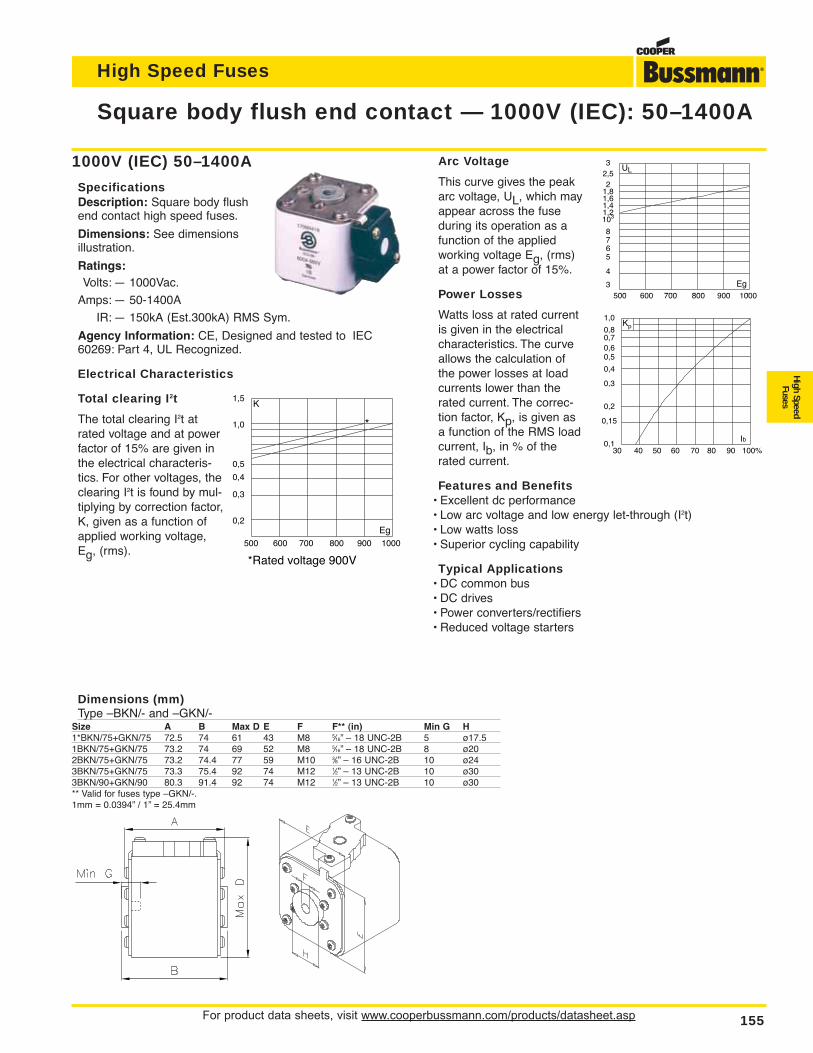
For product data sheets, visit www.cooperbussmann.com/products/datasheet.asp 155
High Speed Fuses
High SpeedFuses
Arc Voltage
This curve gives the peakarc voltage, UL, which mayappear across the fuseduring its operation as afunction of the appliedworking voltage Eg, (rms)at a power factor of 15%.
Power Losses
Watts loss at rated currentis given in the electricalcharacteristics. The curveallows the calculation ofthe power losses at loadcurrents lower than therated current. The correc-tion factor, Kp, is given asa function of the RMS loadcurrent, Ib, in % of therated current.
Features and Benefits• Excellent dc performance• Low arc voltage and low energy let-through (I2t)• Low watts loss• Superior cycling capability
Typical Applications• DC common bus• DC drives• Power converters/rectifiers• Reduced voltage starters
Square body flush end contact — 1000V (IEC): 50–1400A
1000V (IEC) 50–1400A
SpecificationsDescription: Square body flushend contact high speed fuses.
Dimensions: See dimensionsillustration.
Ratings:Volts: — 1000Vac.
Amps: — 50-1400A
IR: — 150kA (Est.300kA) RMS Sym.
Agency Information: CE, Designed and tested to IEC60269: Part 4, UL Recognized.
Electrical Characteristics
Total clearing I2t
The total clearing I2t atrated voltage and at powerfactor of 15% are given inthe electrical characteris-tics. For other voltages, theclearing I2t is found by mul-tiplying by correction factor,K, given as a function ofapplied working voltage,Eg, (rms).
1,5
1,0
0,5
0,4
0,3
0,2
K
Eg 500 600 700 800 900 1000
*Rated voltage 900V
*
32,52
1,81,61,41,2103
8765
4
3
UL
Eg 500 600 700 800 900 1000
Dimensions (mm)Type –BKN/- and –GKN/-
Size A B Max D E F F** (in) Min G H1*BKN/75+GKN/75 72.5 74 61 43 M8 5⁄16” – 18 UNC-2B 5 ø17.51BKN/75+GKN/75 73.2 74 69 52 M8 5⁄16” – 18 UNC-2B 8 ø202BKN/75+GKN/75 73.2 74.4 77 59 M10 3⁄8” – 16 UNC-2B 10 ø243BKN/75+GKN/75 73.3 75.4 92 74 M12 1⁄2” – 13 UNC-2B 10 ø303BKN/90+GKN/90 80.3 91.4 92 74 M12 1⁄2” – 13 UNC-2B 10 ø30** Valid for fuses type –GKN/-.1mm = 0.0394” / 1” = 25.4mm
1,0
0,80,70,60,5
0,4
0,3
0,2
0,15
0,1
Kp
Ib30 40 50 60 70 80 90 100%
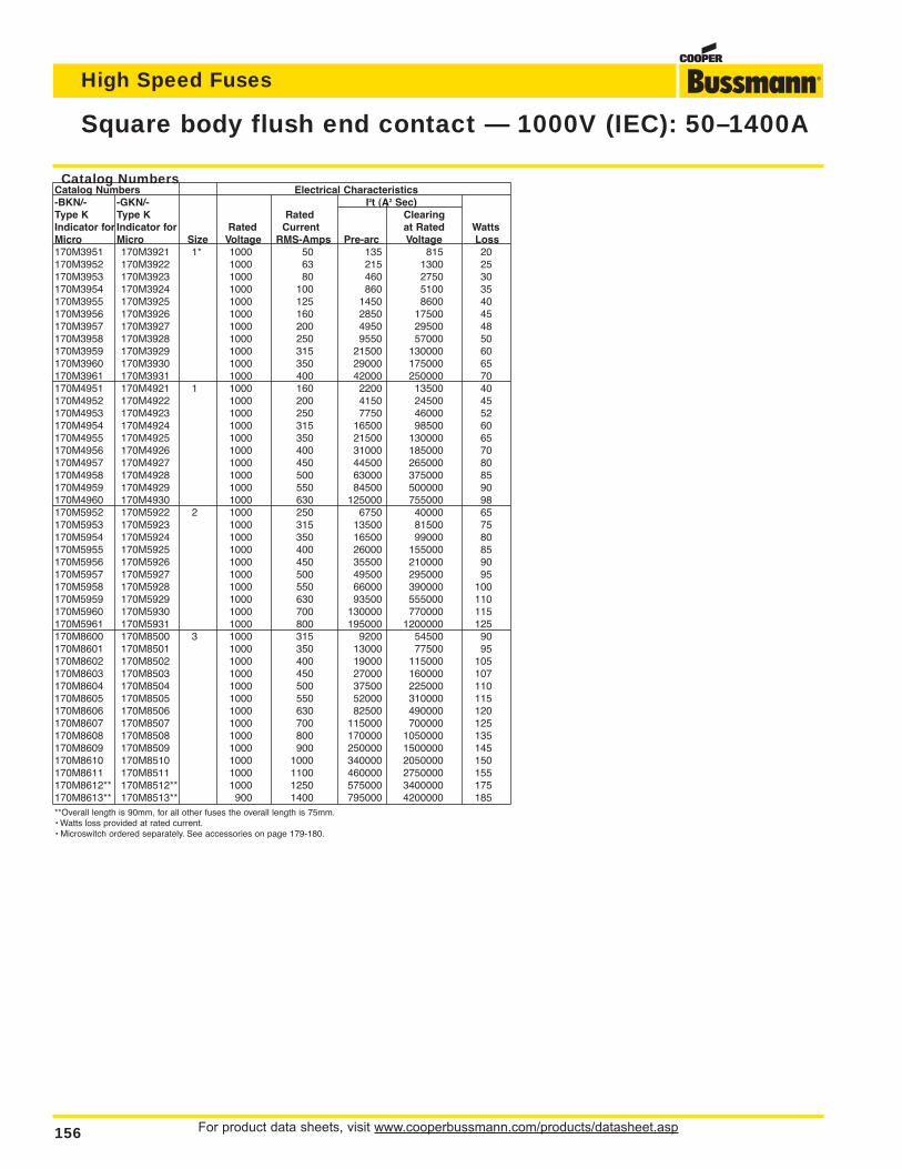
For product data sheets, visit www.cooperbussmann.com/products/datasheet.asp156
High Speed Fuses
Square body flush end contact — 1000V (IEC): 50–1400A
Catalog NumbersCatalog Numbers Electrical Characteristics-BKN/- -GKN/- I2t (A2 Sec)Type K Type K Rated ClearingIndicator for Indicator for Rated Current at Rated WattsMicro Micro Size Voltage RMS-Amps Pre-arc Voltage Loss170M3951 170M3921 1* 1000 50 135 815 20170M3952 170M3922 1000 63 215 1300 25170M3953 170M3923 1000 80 460 2750 30170M3954 170M3924 1000 100 860 5100 35170M3955 170M3925 1000 125 1450 8600 40170M3956 170M3926 1000 160 2850 17500 45170M3957 170M3927 1000 200 4950 29500 48170M3958 170M3928 1000 250 9550 57000 50170M3959 170M3929 1000 315 21500 130000 60170M3960 170M3930 1000 350 29000 175000 65170M3961 170M3931 1000 400 42000 250000 70170M4951 170M4921 1 1000 160 2200 13500 40170M4952 170M4922 1000 200 4150 24500 45170M4953 170M4923 1000 250 7750 46000 52170M4954 170M4924 1000 315 16500 98500 60170M4955 170M4925 1000 350 21500 130000 65170M4956 170M4926 1000 400 31000 185000 70170M4957 170M4927 1000 450 44500 265000 80170M4958 170M4928 1000 500 63000 375000 85170M4959 170M4929 1000 550 84500 500000 90170M4960 170M4930 1000 630 125000 755000 98170M5952 170M5922 2 1000 250 6750 40000 65170M5953 170M5923 1000 315 13500 81500 75170M5954 170M5924 1000 350 16500 99000 80170M5955 170M5925 1000 400 26000 155000 85170M5956 170M5926 1000 450 35500 210000 90170M5957 170M5927 1000 500 49500 295000 95170M5958 170M5928 1000 550 66000 390000 100170M5959 170M5929 1000 630 93500 555000 110170M5960 170M5930 1000 700 130000 770000 115170M5961 170M5931 1000 800 195000 1200000 125170M8600 170M8500 3 1000 315 9200 54500 90170M8601 170M8501 1000 350 13000 77500 95170M8602 170M8502 1000 400 19000 115000 105170M8603 170M8503 1000 450 27000 160000 107170M8604 170M8504 1000 500 37500 225000 110170M8605 170M8505 1000 550 52000 310000 115170M8606 170M8506 1000 630 82500 490000 120170M8607 170M8507 1000 700 115000 700000 125170M8608 170M8508 1000 800 170000 1050000 135170M8609 170M8509 1000 900 250000 1500000 145170M8610 170M8510 1000 1000 340000 2050000 150170M8611 170M8511 1000 1100 460000 2750000 155170M8612** 170M8512** 1000 1250 575000 3400000 175170M8613** 170M8513** 900 1400 795000 4200000 185**Overall length is 90mm, for all other fuses the overall length is 75mm.• Watts loss provided at rated current.• Microswitch ordered separately. See accessories on page 179-180.
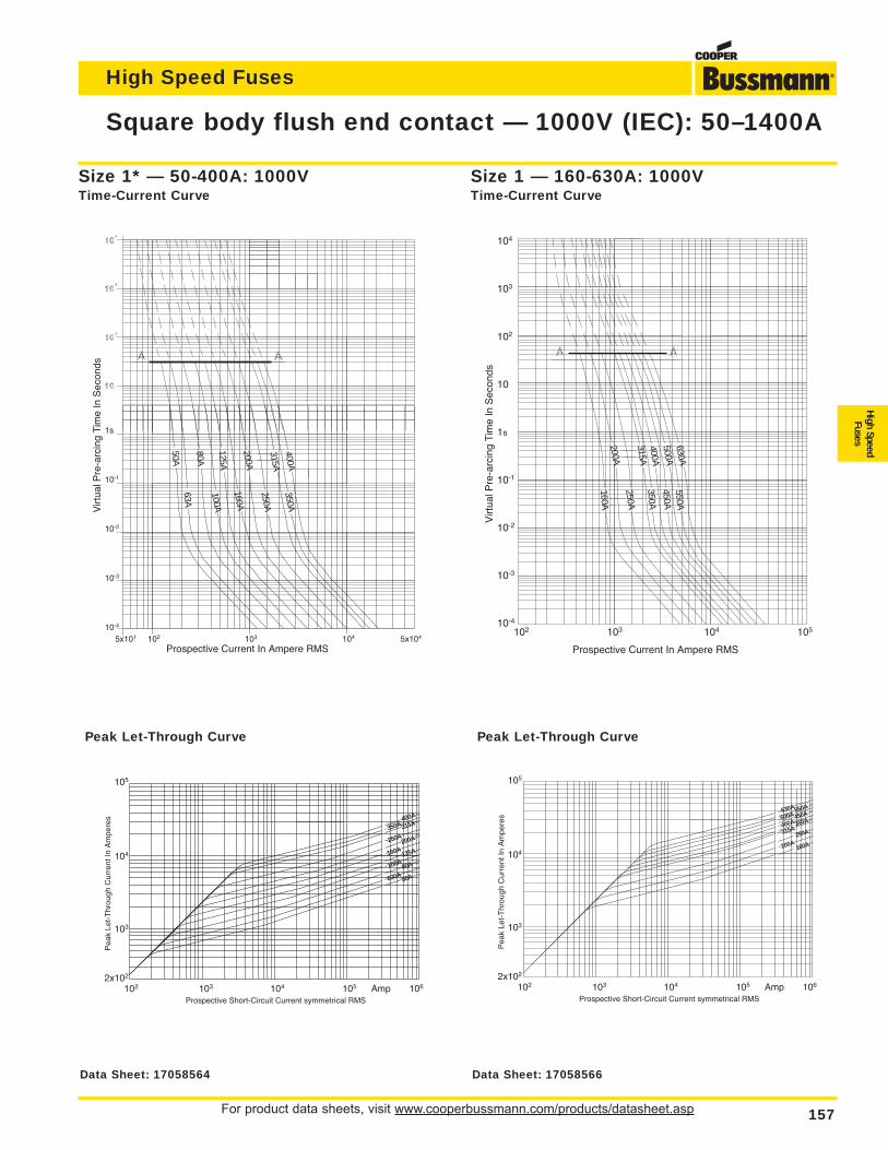
For product data sheets, visit www.cooperbussmann.com/products/datasheet.asp 157
High Speed Fuses
High SpeedFuses
Square body flush end contact — 1000V (IEC): 50–1400A
1s
10-1
10-2
10-3
10-4
Virt
ual P
re-a
rcin
g Ti
me
In S
econ
ds
Prospective Current In Ampere RMS5x101 102 103 104 5x10⁴
50A
80A
125A
200A
315A400A
350A
63A
160A
250A
100A
105
104
103
2x10²
Pea
k Le
t-T
hrou
gh C
urre
nt In
Am
pere
s
Prospective Short-Circuit Current symmetrical RMS102 103 104 105 Amp 106
400A
350A 315A
250A200A
160A
50A630A80A100A125A
Size 1* — 50-400A: 1000VTime-Current Curve
Peak Let-Through Curve
104
103
102
10
1s
10-1
10-2
10-3
10-4
Virt
ual P
re-a
rcin
g Ti
me
In S
econ
ds
Prospective Current In Ampere RMS
102 103 104 105
200A
315A400A500A630A
160A
350A
250A
450A550A
105
104
103
2x10²
Pea
k Le
t-T
hrou
gh C
urre
nt In
Am
pere
s
Prospective Short-Circuit Current symmetrical RMS102 103 104 105 Amp 106
550A
500A 450A
400A 350A
315A
630A
160A200A250A
Size 1 — 160-630A: 1000VTime-Current Curve
Peak Let-Through Curve
Data Sheet: 17058564 Data Sheet: 17058566
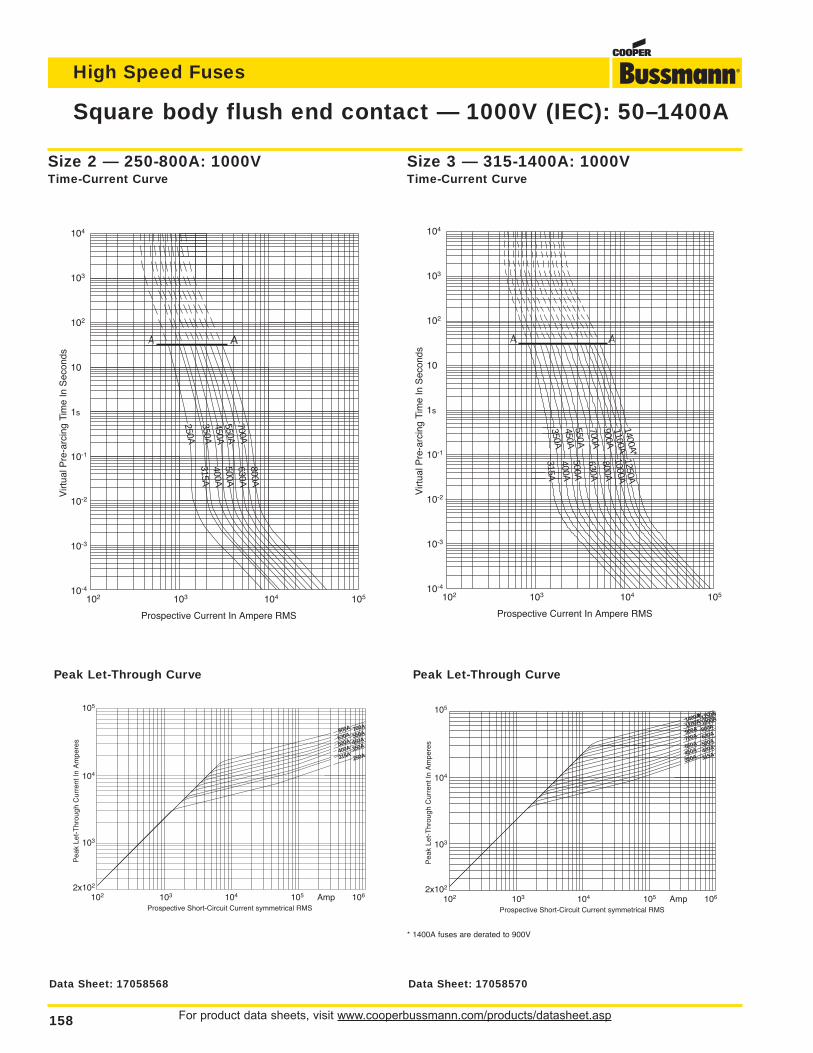
For product data sheets, visit www.cooperbussmann.com/products/datasheet.asp158
High Speed Fuses
Square body flush end contact — 1000V (IEC): 50–1400A
Size 2 — 250-800A: 1000VTime-Current Curve
Peak Let-Through Curve
104
103
102
10
1s
10-1
10-2
10-3
10-4
Virt
ual P
re-a
rcin
g Ti
me
In S
econ
ds
Prospective Current In Ampere RMS
102 103 104 105
250A350A
550A700A
315A
500A400A
630A800A
450A
105
104
103
2x10²
Pea
k Le
t-T
hrou
gh C
urre
nt In
Am
pere
s
Prospective Short-Circuit Current symmetrical RMS102 103 104 105 Amp 106
700A800A
630A
500A550A
450A
250A315A350A
400A
104
103
102
10
1s
10-1
10-2
10-3
10-4
Virt
ual P
re-a
rcin
g Ti
me
In S
econ
ds
Prospective Current In Ampere RMS
102 103 104 105
350A450A
700A900A
315A
500A400A
630A800A
550A
1100A1400A*
1000A1250A
105
104
103
2x10²
Pea
k Le
t-T
hrou
gh C
urre
nt In
Am
pere
s
Prospective Short-Circuit Current symmetrical RMS102 103 104 105 Amp 106
1250A1400A*1100A
900A1000A
800A
500A550A
630A700A
450A 400A
350A 315A
Size 3 — 315-1400A: 1000VTime-Current Curve
Peak Let-Through Curve
* 1400A fuses are derated to 900V
Data Sheet: 17058568 Data Sheet: 17058570
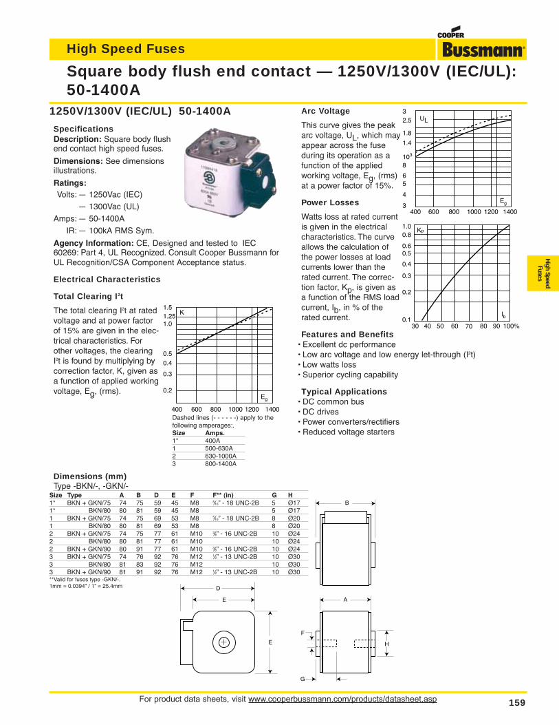
For product data sheets, visit www.cooperbussmann.com/products/datasheet.asp 159
High Speed Fuses
High SpeedFuses
Arc Voltage
This curve gives the peakarc voltage, UL, which mayappear across the fuseduring its operation as afunction of the appliedworking voltage, Eg, (rms)at a power factor of 15%.
Power Losses
Watts loss at rated currentis given in the electricalcharacteristics. The curveallows the calculation ofthe power losses at loadcurrents lower than therated current. The correc-tion factor, Kp, is given asa function of the RMS loadcurrent, Ib, in % of therated current.
Features and Benefits• Excellent dc performance• Low arc voltage and low energy let-through (I2t)• Low watts loss• Superior cycling capability
Typical Applications• DC common bus• DC drives• Power converters/rectifiers• Reduced voltage starters
Square body flush end contact — 1250V/1300V (IEC/UL):50-1400A
1250V/1300V (IEC/UL) 50-1400A
SpecificationsDescription: Square body flushend contact high speed fuses.
Dimensions: See dimensionsillustrations.
Ratings:Volts: — 1250Vac (IEC)
— 1300Vac (UL)
Amps: — 50-1400A
IR: — 100kA RMS Sym.
Agency Information: CE, Designed and tested to IEC60269: Part 4, UL Recognized. Consult Cooper Bussmann forUL Recognition/CSA Component Acceptance status.
Electrical Characteristics
Total Clearing I2t
The total clearing I2t at ratedvoltage and at power factorof 15% are given in the elec-trical characteristics. Forother voltages, the clearingI2t is found by multiplying bycorrection factor, K, given asa function of applied workingvoltage, Eg, (rms).
A
B
D
E
E H
G
F
Dimensions (mm)Type -BKN/-, -GKN/-
Size Type A B D E F F** (in) G H1* BKN + GKN/75 74 75 59 45 M8 5⁄16” - 18 UNC-2B 5 Ø171* BKN/80 80 81 59 45 M8 5 Ø171 BKN + GKN/75 74 75 69 53 M8 5⁄16” - 18 UNC-2B 8 Ø201 BKN/80 80 81 69 53 M8 8 Ø202 BKN + GKN/75 74 75 77 61 M10 3⁄8” - 16 UNC-2B 10 Ø242 BKN/80 80 81 77 61 M10 10 Ø242 BKN + GKN/90 80 91 77 61 M10 3⁄8” - 16 UNC-2B 10 Ø243 BKN + GKN/75 74 76 92 76 M12 1⁄2” - 13 UNC-2B 10 Ø303 BKN/80 81 83 92 76 M12 10 Ø303 BKN + GKN/90 81 91 92 76 M12 1⁄2” - 13 UNC-2B 10 Ø30**Valid for fuses type -GKN/-.1mm = 0.0394” / 1” = 25.4mm
K1.5
1.01.25
0.5
0.4
0.3
0.2
400 600 800 1000 1200 1400
Eg
UL32.5
8103
1.4
1.8
6
4
5
3400 600 800 1000 1200 1400
Eg
Kp
30 40 50 60 70 80 90 100%
Ib
1.00.8
0.4
0.50.6
0.3
0.2
0.1
Dashed lines (- - - - - -) apply to thefollowing amperages:.Size Amps.1* 400A1 500-630A2 630-1000A3 800-1400A
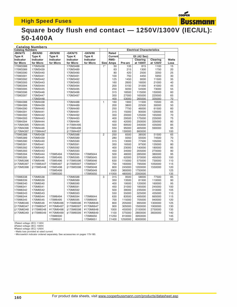
For product data sheets, visit www.cooperbussmann.com/products/datasheet.asp160
High Speed Fuses
Square body flush end contact — 1250V/1300V (IEC/UL):50-1400A
Catalog NumbersCatalog Numbers Electrical Characteristics-BKN/75 -BKN/80 -BKN/90 -GKN/75 -GKN/90 RatedType K Type K Type K Type K Type K Current I2t (A2 Sec)Indicator Indicator Indicator Indicator Indicator RMS- Clearing Clearing Wattsfor Micro for Micro for Micro for Micro for Micro Size Amps Pre-arc at 1000V at 1250V Loss170M3388 170M3438 170M3488 1* 50 135 815 1100 15170M3389 170M3439 170M3489 63 215 1300 1750 20170M3390 170M3440 170M3490 80 420 2500 3350 25170M3391 170M3441 170M3491 100 750 4450 5950 30170M3392 170M3442 170M3492 125 1450 9000 11500 35170M3393 170M3443 170M3493 160 2600 16000 21000 40170M3394 170M3444 170M3494 200 5150 31000 41000 45170M3395 170M3445 170M3495 250 9200 54500 73000 55170M3396 170M3446 170M3496 315 18500 115000 150000 60170M3397 170M3447 170M3497 350 27000 165000 220000 65
170M3448 400 53000 265000 335000 70170M4388 170M4438 170M4488 1 160 1900 11500 15500 45170M4389 170M4439 170M4489 200 3800 22500 30000 50170M4390 170M4440 170M4490 250 7750 46000 61500 60170M4391 170M4441 170M4491 315 15000 90000 120000 65170M4392 170M4442 170M4492 350 20000 125000 165000 70170M4393 170M4443 170M4493 400 29500 175000 235000 75170M4394 170M4444 170M4494 450 42000 250000 335000 80†170M4395 170M4445 †170M4495 500 69500 340000 435000 85‡170M4396 170M4446 ‡170M4496 550 95000 465000 590000 95‡170M4397 †170M4447 ‡170M4497 630 130000 660000 100170M5388 170M5438 170M5588 2 250 6500 38500 51500 65170M5389 170M5439 170M5589 280 9350 55500 74500 70170M5390 170M5440 170M5590 315 13000 77500 105000 75170M5391 170M5441 170M5591 350 16500 97500 135000 80170M5392 170M5442 170M5592 400 23000 140000 180000 85170M5393 170M5443 170M5593 450 34000 205000 270000 90170M5394 170M5444 170M5494 170M5594 170M5644 500 48000 285000 380000 95170M5395 170M5445 170M5495 170M5595 170M5645 550 62000 370000 495000 100†170M5396 170M5446 170M5496 †170M5596 170M5646 630 115000 575000 730000 110‡170M5397 †170M5447 170M5497 ‡170M5597 170M5647 700 160000 795000 1050000 115‡170M5398 ‡170M5448 170M5498 ‡170M5598 170M5648 800 245000 1200000 1550000 120
170M5499 170M5649 †900 360000 1750000 125170M5500 170M5650 †1000 480000 2350000 135
170M6338 170M6538 170M6588 3 315 9500 58000 77500 85170M6339 170M6539 170M6589 350 13500 81500 110000 90170M6340 170M6540 170M6590 400 19500 120000 160000 95170M6341 170M6541 170M6591 450 31000 185000 245000 100170M6342 170M6542 170M6592 500 39000 235000 310000 105170M6343 170M6543 170M6593 550 55000 325000 435000 110170M6344 170M6544 170M6494 170M6594 170M6644 630 83500 495000 665000 115170M6345 170M6545 170M6495 170M6595 170M6645 700 115000 705000 940000 120†170M6346 170M6546 ¥170M6496 †170M6596 ¥170M6646 800 205000 995000 1300000 125‡170M6347 †170M6547 ¥170M6497 ‡170M6597 ¥170M6647 900 305000 1500000 1900000 130‡170M6348 †170M6548 ¥170M6498 ‡170M6598 ¥170M6648 1000 450000 2150000 2750000 135‡170M6349 ‡170M6549 ¥170M6499 ‡170M6599 ¥170M6649 1100 575000 2800000 3600000 140
170M6500 170M6650 †1250 810000 3950000 145170M6501 170M6651 †1400 1250000 6000000 150
†Rated voltage (IEC) 1100V.‡Rated voltage (IEC) 1000V.¥Rated voltage (IEC) 1250V.• Watts loss provided at rated current.• Microswitch indicator ordered separately. See accessories on pages 179-180.
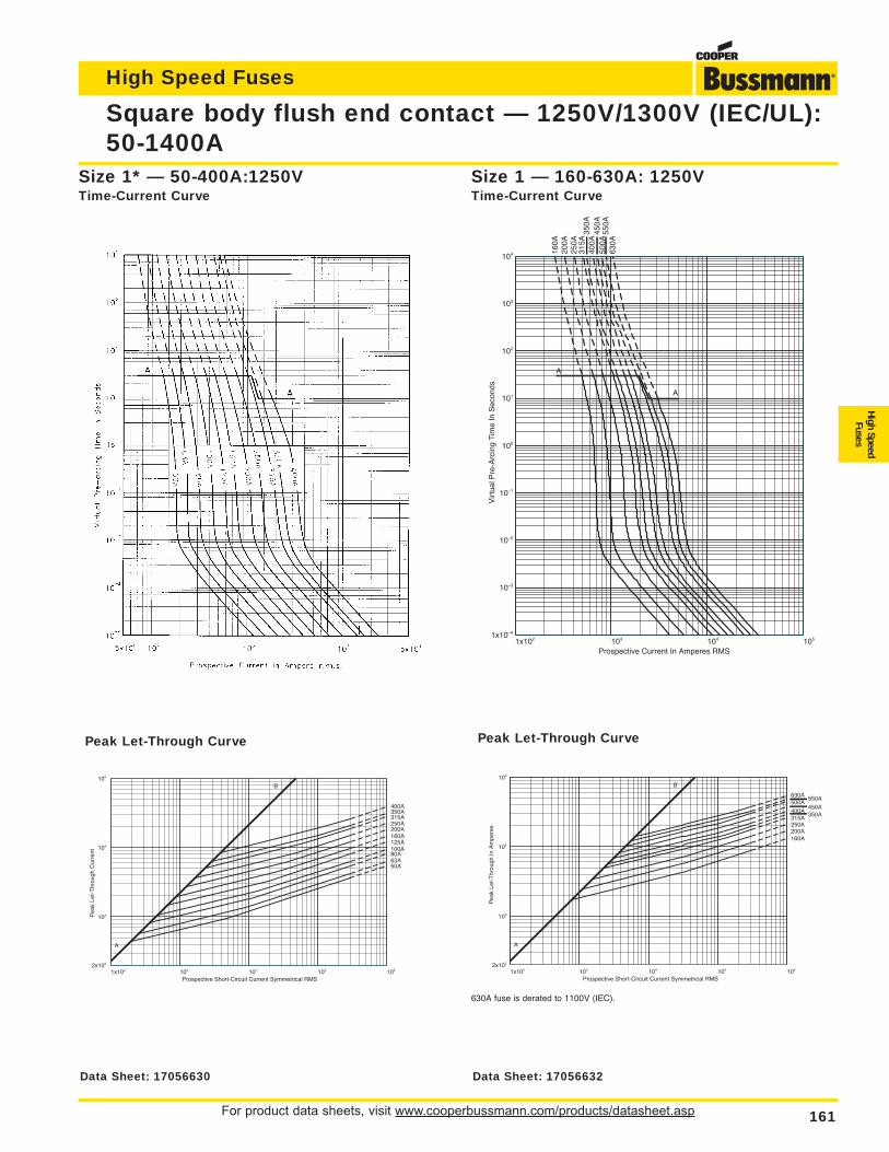
For product data sheets, visit www.cooperbussmann.com/products/datasheet.asp 161
High Speed Fuses
High SpeedFuses
Square body flush end contact — 1250V/1300V (IEC/UL):50-1400A
Size 1* — 50-400A:1250VTime-Current Curve
1x10² 103 104 105 1062x102
103
104
105
Prospective Short-Circuit Current Symmetrical RMS
Pea
k Le
t-T
hrou
gh C
urre
nt
50A63A80A100A125A160A200A250A315A350A400A
A
B
Peak Let-Through Curve
1x10² 103 104 1051x10–4
10–3
10–2
10–1
100
101
102
103
104
Prospective Current In Amperes RMS
Virt
ual P
re-A
rcin
g Ti
me
In S
econ
ds
A
A
160A
200A
250A
315A
350A
400A
450A
500A
550A
630A
Size 1 — 160-630A: 1250VTime-Current Curve
1x10² 103 104 105 1062x102
103
104
105
Prospective Short-Circuit Current Symmetrical RMS
Pea
k Le
t-T
hrou
gh In
Am
pere
s
160A200A250A315A
350A400A
450A500A
550A630A
A
B
Peak Let-Through Curve
630A fuse is derated to 1100V (IEC).
Data Sheet: 17056630 Data Sheet: 17056632
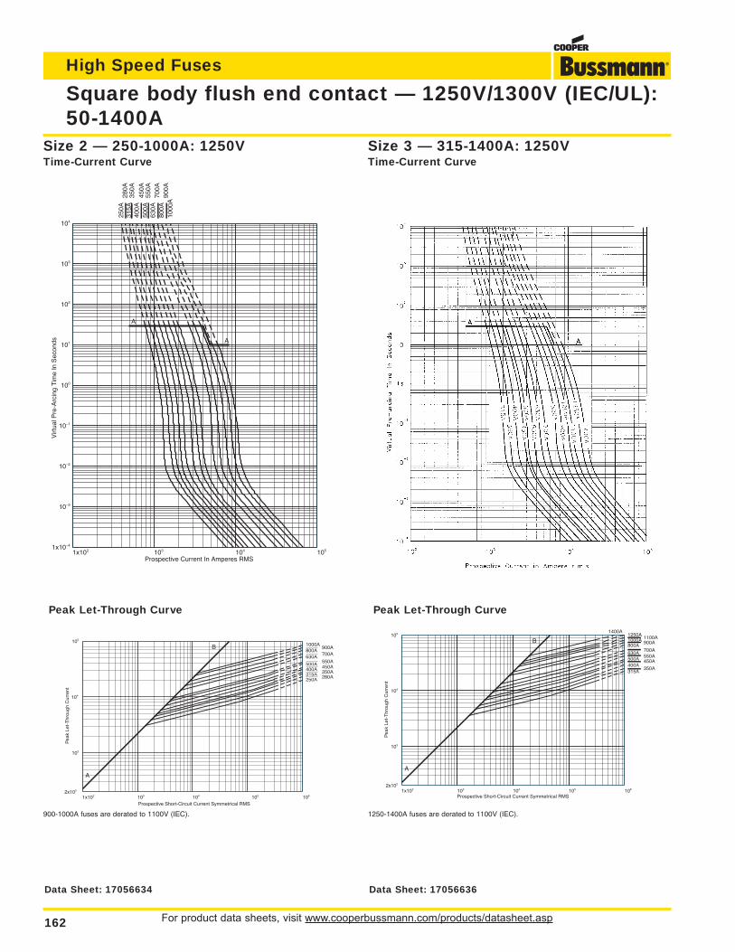
For product data sheets, visit www.cooperbussmann.com/products/datasheet.asp162
High Speed Fuses
Square body flush end contact — 1250V/1300V (IEC/UL):50-1400A
1x10² 103 104 1051x10–4
10–3
10–2
10–1
100
101
102
103
104
Prospective Current In Amperes RMS
Virt
ual P
re-A
rcin
g Ti
me
In S
econ
ds
250A
280A
315A
350A
400A
450A
500A
550A
630A
700A
800A
900A
1000
A
A
A
Size 2 — 250-1000A: 1250VTime-Current Curve
1x10² 103 104 105 1062x102
103
104
105
Prospective Short-Circuit Current Symmetrical RMS
Pea
k Le
t-T
hrou
gh C
urre
nt
250A 280A315A 350A400A 450A500A 550A630A 700A800A
900A1000A
A
B
Peak Let-Through Curve
900-1000A fuses are derated to 1100V (IEC).
Size 3 — 315-1400A: 1250VTime-Current Curve
1x10² 103 104 105 1062x102
103
104
105
Prospective Short-Circuit Current Symmetrical RMS
Pea
k Le
t-T
hrou
gh C
urre
nt
315A350A
400A450A500A 550A
630A700A
800A 900A1000A 1100A1250A1400A
A
B
Peak Let-Through Curve
1250-1400A fuses are derated to 1100V (IEC).
Data Sheet: 17056634 Data Sheet: 17056636
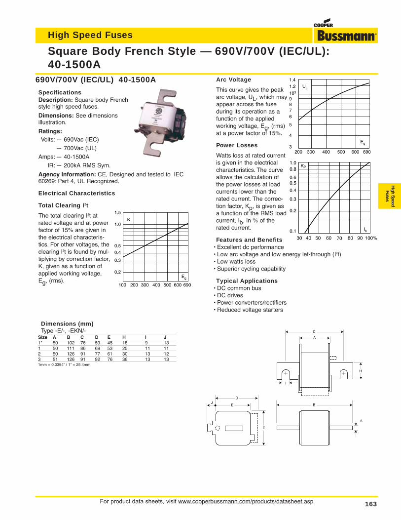
For product data sheets, visit www.cooperbussmann.com/products/datasheet.asp 163
High Speed Fuses
High SpeedFuses
Arc Voltage
This curve gives the peakarc voltage, UL, which mayappear across the fuseduring its operation as afunction of the appliedworking voltage, Eg, (rms)at a power factor of 15%.
Power Losses
Watts loss at rated currentis given in the electricalcharacteristics. The curveallows the calculation ofthe power losses at loadcurrents lower than therated current. The correc-tion factor, Kp, is given asa function of the RMS loadcurrent, Ib, in % of therated current.
Features and Benefits• Excellent dc performance• Low arc voltage and low energy let-through (I2t)• Low watts loss• Superior cycling capability
Typical Applications• DC common bus• DC drives• Power converters/rectifiers• Reduced voltage starters
Square Body French Style — 690V/700V (IEC/UL):40-1500A
690V/700V (IEC/UL) 40-1500A
SpecificationsDescription: Square body Frenchstyle high speed fuses.
Dimensions: See dimensionsillustration.
Ratings:Volts: — 690Vac (IEC)
— 700Vac (UL)
Amps: — 40-1500A
IR: — 200kA RMS Sym.
Agency Information: CE, Designed and tested to IEC60269: Part 4, UL Recognized.
Electrical Characteristics
Total Clearing I2t
The total clearing I2t atrated voltage and at powerfactor of 15% are given inthe electrical characteris-tics. For other voltages, theclearing I2t is found by mul-tiplying by correction factor,K, given as a function ofapplied working voltage,Eg, (rms).
A
B
C
D
EJ
E
6
H
I
Dimensions (mm)Type -E/-, -EKN/-
Size A B C D E H I J1* 50 102 76 59 45 18 9 131 50 111 86 69 53 25 11 112 50 126 91 77 61 30 13 123 51 126 91 92 76 36 13 131mm = 0.0394” / 1” = 25.4mm
K
1.5
1.0
0.5
0.4
0.3
0.2Eg
100 200 300 400 500 600 690
UL
1.41.2
103
6
87
9
5
4
3Eg
200 300 400 500 600 690
Kp1.00.8
0.4
0.50.6
0.3
0.2
0.1
30 40 50 60 70 80 90 100%
Ib
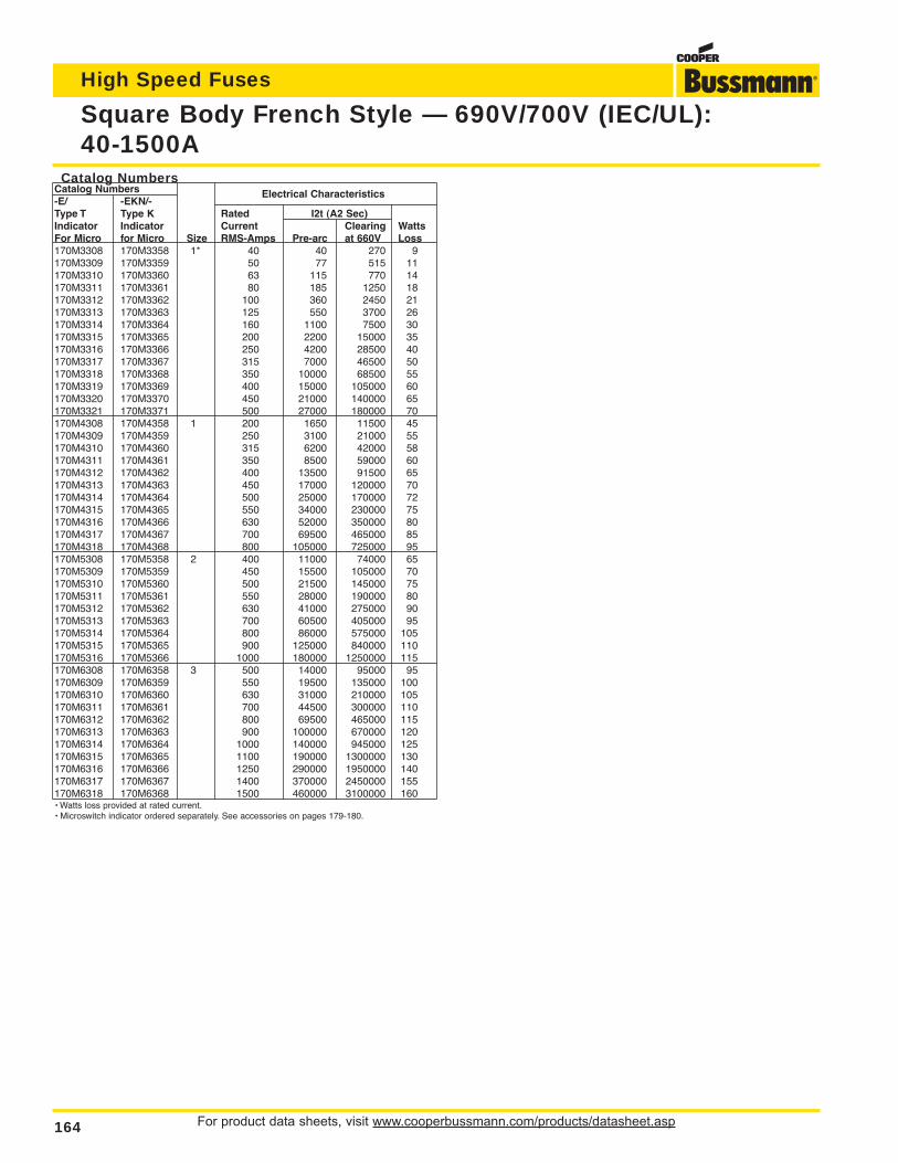
For product data sheets, visit www.cooperbussmann.com/products/datasheet.asp164
High Speed Fuses
Square Body French Style — 690V/700V (IEC/UL):40-1500A
Catalog NumbersCatalog Numbers-E/ -EKN/-
Electrical Characteristics
Type T Type K Rated I2t (A2 Sec)Indicator Indicator Current Clearing WattsFor Micro for Micro Size RMS-Amps Pre-arc at 660V Loss170M3308 170M3358 1* 40 40 270 9170M3309 170M3359 50 77 515 11170M3310 170M3360 63 115 770 14170M3311 170M3361 80 185 1250 18170M3312 170M3362 100 360 2450 21170M3313 170M3363 125 550 3700 26170M3314 170M3364 160 1100 7500 30170M3315 170M3365 200 2200 15000 35170M3316 170M3366 250 4200 28500 40170M3317 170M3367 315 7000 46500 50170M3318 170M3368 350 10000 68500 55170M3319 170M3369 400 15000 105000 60170M3320 170M3370 450 21000 140000 65170M3321 170M3371 500 27000 180000 70170M4308 170M4358 1 200 1650 11500 45170M4309 170M4359 250 3100 21000 55170M4310 170M4360 315 6200 42000 58170M4311 170M4361 350 8500 59000 60170M4312 170M4362 400 13500 91500 65170M4313 170M4363 450 17000 120000 70170M4314 170M4364 500 25000 170000 72170M4315 170M4365 550 34000 230000 75170M4316 170M4366 630 52000 350000 80170M4317 170M4367 700 69500 465000 85170M4318 170M4368 800 105000 725000 95170M5308 170M5358 2 400 11000 74000 65170M5309 170M5359 450 15500 105000 70170M5310 170M5360 500 21500 145000 75170M5311 170M5361 550 28000 190000 80170M5312 170M5362 630 41000 275000 90170M5313 170M5363 700 60500 405000 95170M5314 170M5364 800 86000 575000 105170M5315 170M5365 900 125000 840000 110170M5316 170M5366 1000 180000 1250000 115170M6308 170M6358 3 500 14000 95000 95170M6309 170M6359 550 19500 135000 100170M6310 170M6360 630 31000 210000 105170M6311 170M6361 700 44500 300000 110170M6312 170M6362 800 69500 465000 115170M6313 170M6363 900 100000 670000 120170M6314 170M6364 1000 140000 945000 125170M6315 170M6365 1100 190000 1300000 130170M6316 170M6366 1250 290000 1950000 140170M6317 170M6367 1400 370000 2450000 155170M6318 170M6368 1500 460000 3100000 160• Watts loss provided at rated current.• Microswitch indicator ordered separately. See accessories on pages 179-180.
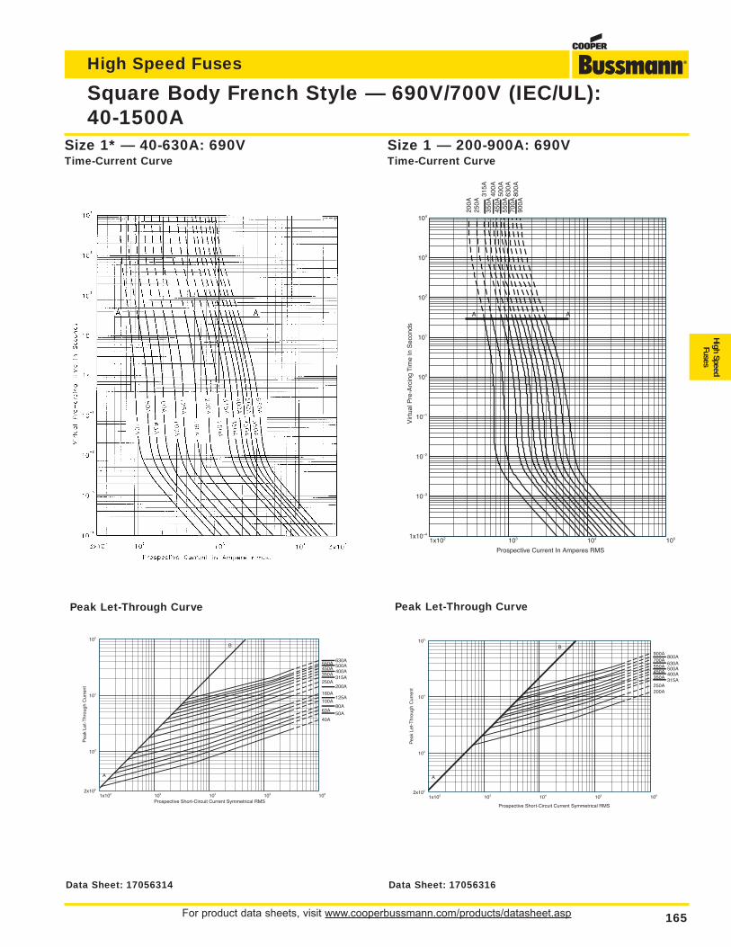
For product data sheets, visit www.cooperbussmann.com/products/datasheet.asp 165
High Speed Fuses
High SpeedFuses
Square Body French Style — 690V/700V (IEC/UL):40-1500A
1x10² 103 104 1051x10–4
10–3
10–2
10–1
100
101
102
103
104
Prospective Current In Amperes RMS
Vir
tual
Pre
-Arc
ing
Tim
e In
Sec
onds
200A
250A
315A
350A
400A
450A
500A
550A
630A
700A
800A
900A
A A
Size 1 — 200-900A: 690VTime-Current Curve
Size 1* — 40-630A: 690VTime-Current Curve
1x10² 103 104 105 1062x102
103
104
105
Prospective Short-Circuit Current Symmetrical RMS
Pea
k Le
t-T
hrou
gh C
urre
nt
50A40A
63A80A
100A125A
160A200A
250A315A
350A400A450A500A550A630A
A
B
1x10² 103 104 105 1062x102
103
104
105
Prospective Short-Circuit Current Symmetrical RMS
Pea
k Le
t-T
hrou
gh C
urre
nt 200A250A
315A350A400A450A500A550A630A
700A800A
900A
A
B
Peak Let-Through CurvePeak Let-Through Curve
Data Sheet: 17056314 Data Sheet: 17056316
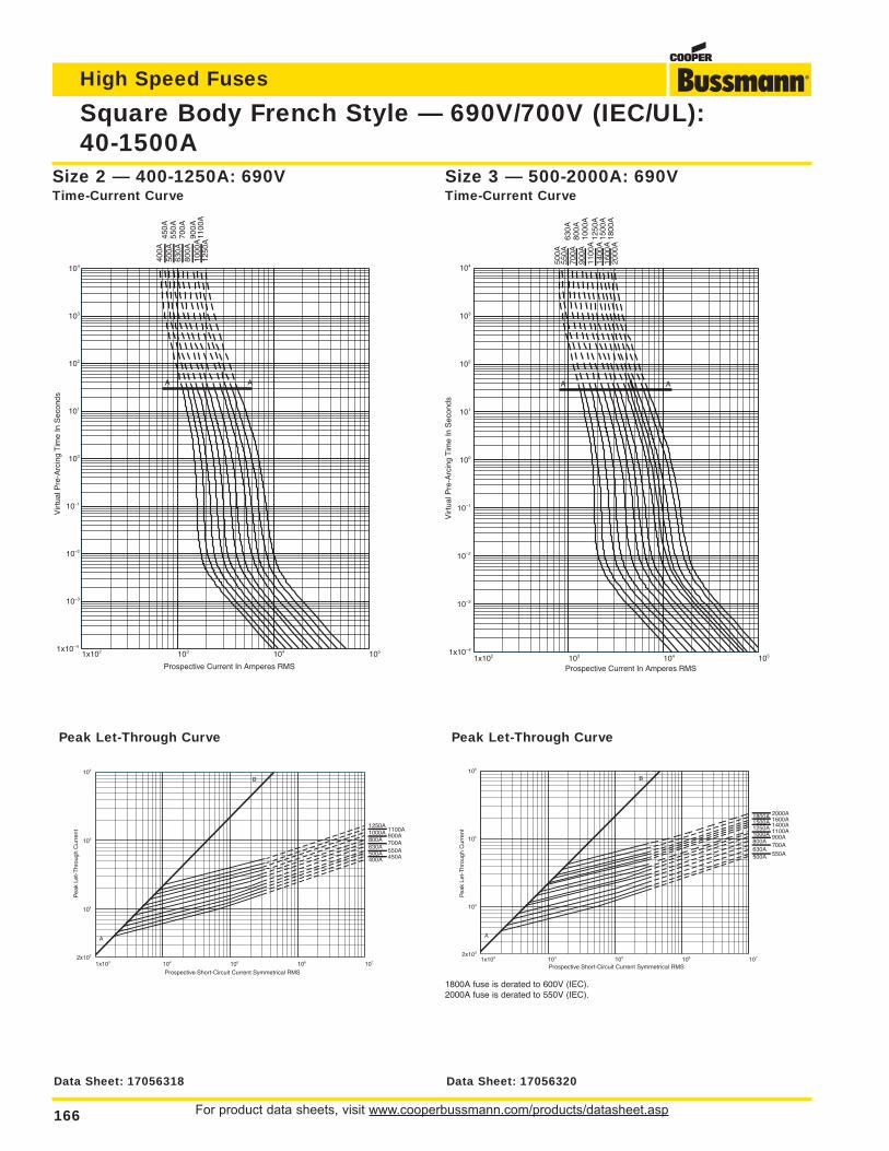
For product data sheets, visit www.cooperbussmann.com/products/datasheet.asp166
High Speed Fuses
Square Body French Style — 690V/700V (IEC/UL):40-1500A
1x10² 103 104 1051x10–4
10–3
10–2
10–1
100
101
102
103
104
Prospective Current In Amperes RMS
Vir
tual
Pre
-Arc
ing
Tim
e In
Sec
onds
400A
450A
500A
550A
630A
700A
800A
900A
1000
A11
00A
1250
A
A A
1x10² 103 104 1051x10–4
10–3
10–2
10–1
100
101
102
103
104
Prospective Current In Amperes RMS
Vir
tual
Pre
-Arc
ing
Tim
e In
Sec
onds
500A
550A
630A
700A
800A
900A
1000
A11
00A
1250
A14
00A
1500
A16
00A
1800
A20
00A
A A
Size 3 — 500-2000A: 690VTime-Current Curve
Size 2 — 400-1250A: 690VTime-Current Curve
1x10³ 104 105 106 1072x103
104
105
106
Prospective Short-Circuit Current Symmetrical RMS
Pea
k Le
t-T
hrou
gh C
urre
nt
400A 450A500A 550A630A
700A800A900A1000A 1100A
1250A
A
B
1x10³ 104 105 106 1072x103
104
105
106
Prospective Short-Circuit Current Symmetrical RMS
Pea
k Le
t-T
hrou
gh C
urre
nt
500A 550A630A
700A800A
900A1000A 1100A1250A 1400A1500A 1600A1800A 2000A
A
B
Peak Let-Through CurvePeak Let-Through Curve
1800A fuse is derated to 600V (IEC).2000A fuse is derated to 550V (IEC).
Data Sheet: 17056318 Data Sheet: 17056320
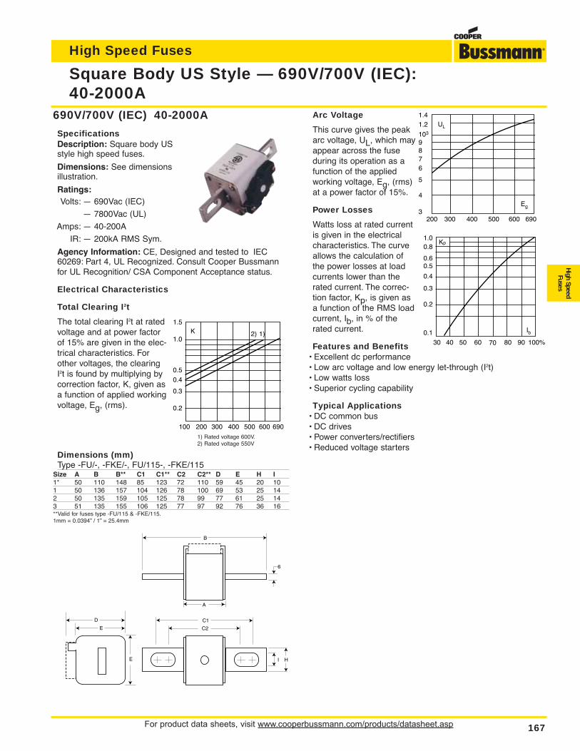
For product data sheets, visit www.cooperbussmann.com/products/datasheet.asp 167
High Speed Fuses
High SpeedFuses
Arc Voltage
This curve gives the peakarc voltage, UL, which mayappear across the fuseduring its operation as afunction of the appliedworking voltage, Eg, (rms)at a power factor of 15%.
Power Losses
Watts loss at rated currentis given in the electricalcharacteristics. The curveallows the calculation ofthe power losses at loadcurrents lower than therated current. The correc-tion factor, Kp, is given asa function of the RMS loadcurrent, Ib, in % of therated current.
Features and Benefits• Excellent dc performance• Low arc voltage and low energy let-through (I2t)• Low watts loss• Superior cycling capability
Typical Applications• DC common bus• DC drives• Power converters/rectifiers• Reduced voltage starters
Square Body US Style — 690V/700V (IEC):40-2000A
690V/700V (IEC) 40-2000A
SpecificationsDescription: Square body USstyle high speed fuses.
Dimensions: See dimensionsillustration.
Ratings:Volts: — 690Vac (IEC)
— 7800Vac (UL)
Amps: — 40-200A
IR: — 200kA RMS Sym.
Agency Information: CE, Designed and tested to IEC60269: Part 4, UL Recognized. Consult Cooper Bussmannfor UL Recognition/ CSA Component Acceptance status.
Electrical Characteristics
Total Clearing I2t
The total clearing I2t at ratedvoltage and at power factorof 15% are given in the elec-trical characteristics. Forother voltages, the clearingI2t is found by multiplying bycorrection factor, K, given asa function of applied workingvoltage, Eg, (rms).
B
C2
D
E
E
6
H I
C1
A
Dimensions (mm)Type -FU/-, -FKE/-, FU/115-, -FKE/115
Size A B B** C1 C1** C2 C2** D E H I1* 50 110 148 85 123 72 110 59 45 20 101 50 136 157 104 126 78 100 69 53 25 142 50 135 159 105 125 78 99 77 61 25 143 51 135 155 106 125 77 97 92 76 36 16**Valid for fuses type -FU/115 & -FKE/115.1mm = 0.0394” / 1” = 25.4mm
K1.5
1.0
0.5
0.4
0.3
0.2
1)2)
100 200 300 400 500 600 690
UL
1.41.2
103
6
87
9
5
4
3Eg
200 300 400 500 600 690
Kp1.00.8
0.4
0.50.6
0.3
0.2
0.1
30 40 50 60 70 80 90 100%
Ib
1) Rated voltage 600V.2) Rated voltage 550V
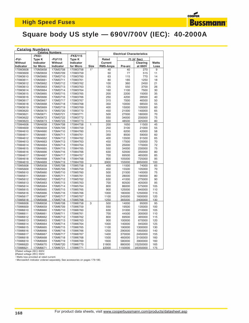
For product data sheets, visit www.cooperbussmann.com/products/datasheet.asp168
High Speed Fuses
Square body US style — 690V/700V (IEC): 40-2000A
Catalog NumbersCatalog Numbers
-FKE/- -FKE/115Electrical Characteristics
-FU/- Type K -FU/115 Type K Rated I2t (A2 Sec)Without Indicator Without Indicator Current Clearing WattsIndicator for Micro Indicator for Micro Size RMS-Amps Pre-arc at 660V Loss170M3608 170M3658 170M3708 170M3758 1* 40 40 270 9170M3609 170M3659 170M3709 170M3759 50 77 515 11170M3610 170M3660 170M3710 170M3760 63 115 770 14170M3611 170M3661 170M3711 170M3761 80 185 1250 18170M3612 170M3662 170M3712 170M3762 100 360 2450 21170M3613 170M3663 170M3713 170M3763 125 550 3700 26170M3614 170M3664 170M3714 170M3764 160 1100 7500 30170M3615 170M3665 170M3715 170M3765 200 2200 15000 35170M3616 170M3666 170M3716 170M3766 250 4200 28500 40170M3617 170M3667 170M3717 170M3767 315 7000 46500 50170M3618 170M3668 170M3718 170M3768 350 10000 68500 55170M3619 170M3669 170M3719 170M3769 400 15000 105000 60170M3620 170M3670 170M3720 170M3770 450 21000 140000 65170M3621 170M3671 170M3721 170M3771 500 27000 180000 70170M3622 170M3672 170M3722 170M3772 550 34000 230000 75170M3623 170M3673 170M3723 170M3773 630 48500 325000 80170M4608 170M4658 170M4708 170M4758 1 200 1650 11500 45170M4609 170M4659 170M4709 170M4759 250 3100 21000 55170M4610 170M4660 170M4710 170M4760 315 6200 42000 58170M4611 170M4661 170M4711 170M4761 350 8500 59000 60170M4612 170M4662 170M4712 170M4762 400 13500 91500 65170M4613 170M4663 170M4713 170M4763 450 17000 120000 70170M4614 170M4664 170M4714 170M4764 500 25000 170000 72170M4615 170M4665 170M4715 170M4765 550 34000 230000 75170M4616 170M4666 170M4716 170M4766 630 52000 350000 80170M4617 170M4667 170M4717 170M4767 700 69500 465000 85170M4618 170M4668 170M4718 170M4768 800 105000 725000 95170M4619 170M4669 170M4719 170M4769 ‡900 155000 ‡850000 100170M5608 170M5658 170M5708 170M5758 2 400 11000 74000 65170M5609 170M5659 170M5709 170M5759 450 15500 105000 70170M5610 170M5660 170M5710 170M5760 500 21500 145000 75170M5611 170M5661 170M5711 170M5761 550 28000 190000 80170M5612 170M5662 170M5712 170M5762 630 41000 275000 90170M5613 170M5663 170M5713 170M5763 700 60500 405000 95170M5614 170M5664 170M5714 170M5764 800 86000 575000 105170M5615 170M5665 170M5715 170M5765 900 125000 840000 110170M5616 170M5666 170M5716 170M5766 1000 180000 1250000 115170M5617 170M5667 170M5717 170M5767 1100 245000 1600000 120170M5618 170M5668 170M5718 170M5768 1250 365000 2400000 130170M6608 170M6658 170M6708 170M6758 3 500 14000 95000 95170M6609 170M6659 170M6709 170M6759 550 19500 135000 100170M6610 170M6660 170M6710 170M6760 630 31000 210000 105170M6611 170M6661 170M6711 170M6761 700 44500 300000 110170M6612 170M6662 170M6712 170M6762 800 69500 465000 115170M6613 170M6663 170M6713 170M6763 900 100000 670000 120170M6614 170M6664 170M6714 170M6764 1000 140000 945000 125170M6615 170M6665 170M6715 170M6765 1100 190000 1300000 130170M6616 170M6666 170M6716 170M6766 1250 290000 1950000 140170M6617 170M6667 170M6717 170M6767 1400 370000 2450000 155170M6618 170M6668 170M6718 170M6768 1500 460000 3100000 160170M6619 170M6669 170M6719 170M6769 1600 580000 3900000 160170M6620 170M6670 170M6720 170M6770 †1800 880000 †5250000 165170M6621 170M6671 170M6721 170M6771 ‡2000 1150000 ‡6350000 175†Rated voltage (IEC) 600V.‡Rated voltage (IEC) 550V.• Watts loss provided at rated current.• Microswitch indicator ordered separately. See accessories on pages 179-180.
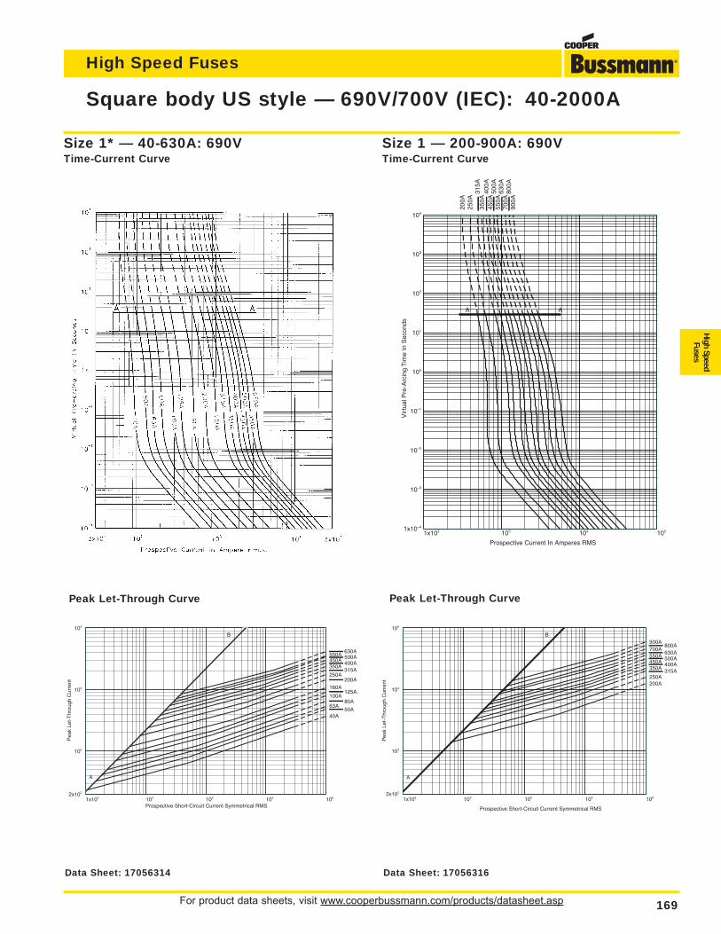
For product data sheets, visit www.cooperbussmann.com/products/datasheet.asp 169
High Speed Fuses
High SpeedFuses
Square body US style — 690V/700V (IEC): 40-2000A
1x10² 103 104 1051x10–4
10–3
10–2
10–1
100
101
102
103
104
Prospective Current In Amperes RMS
Vir
tual
Pre
-Arc
ing
Tim
e In
Sec
onds
200A
250A
315A
350A
400A
450A
500A
550A
630A
700A
800A
900A
A A
Size 1 — 200-900A: 690VTime-Current Curve
Size 1* — 40-630A: 690VTime-Current Curve
1x10² 103 104 105 1062x102
103
104
105
Prospective Short-Circuit Current Symmetrical RMS
Pea
k Le
t-T
hrou
gh C
urre
nt
50A40A
63A80A
100A125A
160A200A
250A315A
350A400A450A500A550A630A
A
B
1x10² 103 104 105 1062x102
103
104
105
Prospective Short-Circuit Current Symmetrical RMS
Pea
k Le
t-T
hrou
gh C
urre
nt 200A250A
315A350A400A450A500A550A630A
700A800A
900A
A
B
Peak Let-Through CurvePeak Let-Through Curve
Data Sheet: 17056314 Data Sheet: 17056316
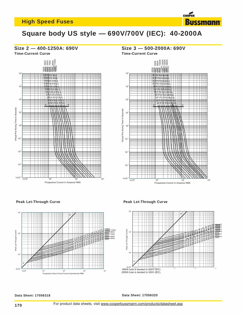
For product data sheets, visit www.cooperbussmann.com/products/datasheet.asp170
High Speed Fuses
Square body US style — 690V/700V (IEC): 40-2000A
1x10² 103 104 1051x10–4
10–3
10–2
10–1
100
101
102
103
104
Prospective Current In Amperes RMS
Vir
tual
Pre
-Arc
ing
Tim
e In
Sec
onds
400A
450A
500A
550A
630A
700A
800A
900A
1000
A11
00A
1250
A
A A
1x10² 103 104 1051x10–4
10–3
10–2
10–1
100
101
102
103
104
Prospective Current In Amperes RMS
Vir
tual
Pre
-Arc
ing
Tim
e In
Sec
onds
500A
550A
630A
700A
800A
900A
1000
A11
00A
1250
A14
00A
1500
A16
00A
1800
A20
00A
A A
Size 3 — 500-2000A: 690VTime-Current Curve
Size 2 — 400-1250A: 690VTime-Current Curve
1x10³ 104 105 106 1072x103
104
105
106
Prospective Short-Circuit Current Symmetrical RMS
Pea
k Le
t-T
hrou
gh C
urre
nt
400A 450A500A 550A630A
700A800A900A1000A 1100A
1250A
A
B
1x10³ 104 105 106 1072x103
104
105
106
Pea
k Le
t-T
hrou
gh C
urre
nt
500A 5630A
7800A
91000A 11250A 11500A 11800A 2
A
B
Peak Let-Through CurvePeak Let-Through Curve
1800A fuse is derated to 600V (IEC).2000A fuse is derated to 550V (IEC).
Data Sheet: 17056318 Data Sheet: 17056320
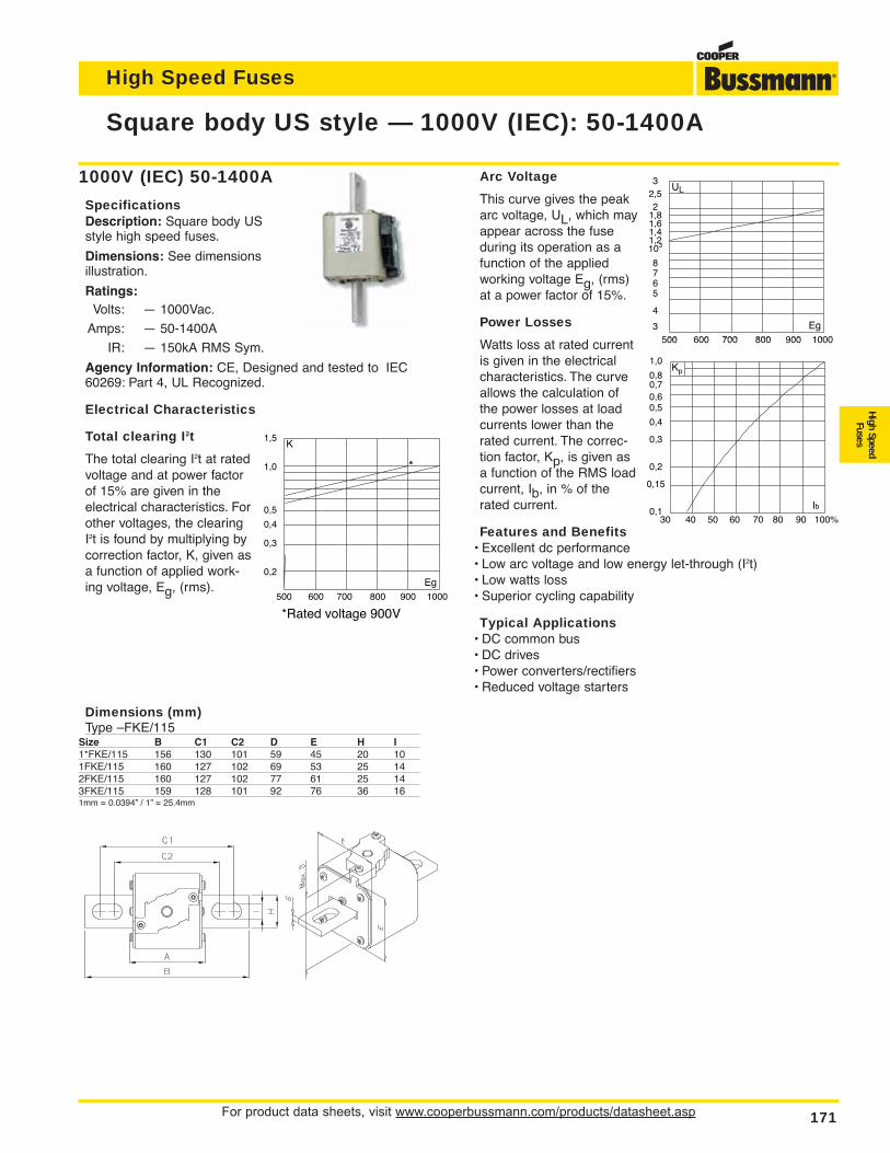
For product data sheets, visit www.cooperbussmann.com/products/datasheet.asp 171
High Speed Fuses
High SpeedFuses
Arc Voltage
This curve gives the peakarc voltage, UL, which mayappear across the fuseduring its operation as afunction of the appliedworking voltage Eg, (rms)at a power factor of 15%.
Power Losses
Watts loss at rated currentis given in the electricalcharacteristics. The curveallows the calculation ofthe power losses at loadcurrents lower than therated current. The correc-tion factor, Kp, is given asa function of the RMS loadcurrent, Ib, in % of therated current.
Features and Benefits• Excellent dc performance• Low arc voltage and low energy let-through (I2t)• Low watts loss• Superior cycling capability
Typical Applications• DC common bus• DC drives• Power converters/rectifiers• Reduced voltage starters
Square body US style — 1000V (IEC): 50-1400A
1000V (IEC) 50-1400A
SpecificationsDescription: Square body USstyle high speed fuses.
Dimensions: See dimensionsillustration.
Ratings:Volts: — 1000Vac.
Amps: — 50-1400A
IR: — 150kA RMS Sym.
Agency Information: CE, Designed and tested to IEC60269: Part 4, UL Recognized.
Electrical Characteristics
Total clearing I2t
The total clearing I2t at ratedvoltage and at power factorof 15% are given in theelectrical characteristics. Forother voltages, the clearingI2t is found by multiplying bycorrection factor, K, given asa function of applied work-ing voltage, Eg, (rms).
1,5
1,0
0,5
0,4
0,3
0,2
K
Eg 500 600 700 800 900 1000
*Rated voltage 900V
*
32,52
1,81,61,41,2103
8765
4
3
UL
Eg 500 600 700 800 900 1000
1,0
0,80,70,60,5
0,4
0,3
0,2
0,15
0,1
Kp
Ib30 40 50 60 70 80 90 100%
Dimensions (mm)Type –FKE/115
Size B C1 C2 D E H I1*FKE/115 156 130 101 59 45 20 101FKE/115 160 127 102 69 53 25 142FKE/115 160 127 102 77 61 25 143FKE/115 159 128 101 92 76 36 161mm = 0.0394” / 1” = 25.4mm
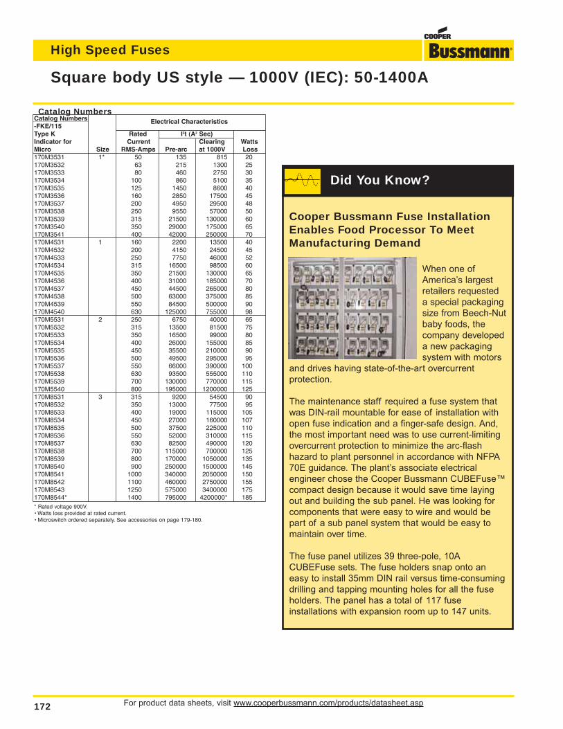
For product data sheets, visit www.cooperbussmann.com/products/datasheet.asp172
High Speed Fuses
Square body US style — 1000V (IEC): 50-1400A
Catalog NumbersCatalog Numbers-FKE/115
Electrical Characteristics
Type K Rated I2t (A2 Sec)Indicator for Current Clearing WattsMicro Size RMS-Amps Pre-arc at 1000V Loss170M3531 1* 50 135 815 20170M3532 63 215 1300 25170M3533 80 460 2750 30170M3534 100 860 5100 35170M3535 125 1450 8600 40170M3536 160 2850 17500 45170M3537 200 4950 29500 48170M3538 250 9550 57000 50170M3539 315 21500 130000 60170M3540 350 29000 175000 65170M3541 400 42000 250000 70170M4531 1 160 2200 13500 40170M4532 200 4150 24500 45170M4533 250 7750 46000 52170M4534 315 16500 98500 60170M4535 350 21500 130000 65170M4536 400 31000 185000 70170M4537 450 44500 265000 80170M4538 500 63000 375000 85170M4539 550 84500 500000 90170M4540 630 125000 755000 98170M5531 2 250 6750 40000 65170M5532 315 13500 81500 75170M5533 350 16500 99000 80170M5534 400 26000 155000 85170M5535 450 35500 210000 90170M5536 500 49500 295000 95170M5537 550 66000 390000 100170M5538 630 93500 555000 110170M5539 700 130000 770000 115170M5540 800 195000 1200000 125170M8531 3 315 9200 54500 90170M8532 350 13000 77500 95170M8533 400 19000 115000 105170M8534 450 27000 160000 107170M8535 500 37500 225000 110170M8536 550 52000 310000 115170M8537 630 82500 490000 120170M8538 700 115000 700000 125170M8539 800 170000 1050000 135170M8540 900 250000 1500000 145170M8541 1000 340000 2050000 150170M8542 1100 460000 2750000 155170M8543 1250 575000 3400000 175170M8544* 1400 795000 4200000* 185* Rated voltage 900V.• Watts loss provided at rated current.• Microswitch ordered separately. See accessories on page 179-180.
Cooper Bussmann Fuse InstallationEnables Food Processor To MeetManufacturing Demand
When one of
America’s largest
retailers requested
a special packaging
size from Beech-Nut
baby foods, the
company developed
a new packaging
system with motors
and drives having state-of-the-art overcurrent
protection.
The maintenance staff required a fuse system that
was DIN-rail mountable for ease of installation with
open fuse indication and a finger-safe design. And,
the most important need was to use current-limiting
overcurrent protection to minimize the arc-flash
hazard to plant personnel in accordance with NFPA
70E guidance. The plant’s associate electrical
engineer chose the Cooper Bussmann CUBEFuse™
compact design because it would save time laying
out and building the sub panel. He was looking for
components that were easy to wire and would be
part of a sub panel system that would be easy to
maintain over time.
The fuse panel utilizes 39 three-pole, 10A
CUBEFuse sets. The fuse holders snap onto an
easy to install 35mm DIN rail versus time-consuming
drilling and tapping mounting holes for all the fuse
holders. The panel has a total of 117 fuse
installations with expansion room up to 147 units.
Did You Know?
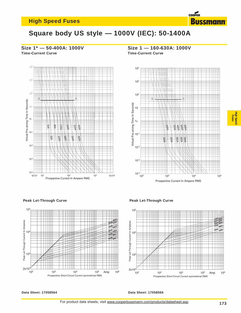
For product data sheets, visit www.cooperbussmann.com/products/datasheet.asp 173
High Speed Fuses
High SpeedFuses
Square body US style — 1000V (IEC): 50-1400A
1s
10-1
10-2
10-3
10-4
Virt
ual P
re-a
rcin
g Ti
me
In S
econ
ds
Prospective Current In Ampere RMS5x101 102 103 104 5x10⁴
50A
80A
125A
200A
315A400A
350A
63A
160A
250A
100A
105
104
103
2x10²
Pea
k Le
t-T
hrou
gh C
urre
nt In
Am
pere
s
Prospective Short-Circuit Current symmetrical RMS102 103 104 105 Amp 106
400A
350A 315A
250A200A
160A
50A630A80A100A125A
Size 1* — 50-400A: 1000VTime-Current Curve
Peak Let-Through Curve
104
103
102
10
1s
10-1
10-2
10-3
10-4
Virt
ual P
re-a
rcin
g Ti
me
In S
econ
ds
Prospective Current In Ampere RMS
102 103 104 105
200A
315A400A500A630A
160A
350A
250A
450A550A
105
104
103
2x10²
Pea
k Le
t-T
hrou
gh C
urre
nt In
Am
pere
s
Prospective Short-Circuit Current symmetrical RMS102 103 104 105 Amp 106
550A
500A 450A
400A 350A
315A
630A
160A200A250A
Size 1 — 160-630A: 1000VTime-Current Curve
Peak Let-Through Curve
Data Sheet: 17058564 Data Sheet: 17058566
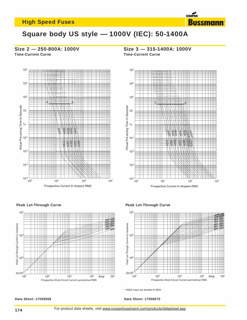
For product data sheets, visit www.cooperbussmann.com/products/datasheet.asp174
High Speed Fuses
Square body US style — 1000V (IEC): 50-1400A
Size 2 — 250-800A: 1000VTime-Current Curve
Peak Let-Through Curve
104
103
102
10
1s
10-1
10-2
10-3
10-4
Virt
ual P
re-a
rcin
g Ti
me
In S
econ
ds
Prospective Current In Ampere RMS
102 103 104 105
250A350A
550A700A
315A
500A400A
630A800A
450A
105
104
103
2x10²
Pea
k Le
t-T
hrou
gh C
urre
nt In
Am
pere
s
Prospective Short-Circuit Current symmetrical RMS102 103 104 105 Amp 106
700A800A
630A
500A550A
450A
250A315A350A
400A
104
103
102
10
1s
10-1
10-2
10-3
10-4
Virt
ual P
re-a
rcin
g Ti
me
In S
econ
ds
Prospective Current In Ampere RMS
102 103 104 105
350A450A
700A900A
315A
500A400A
630A800A
550A
1100A1400A*
1000A1250A
105
104
103
2x10²
Pea
k Le
t-T
hrou
gh C
urre
nt In
Am
pere
s
Prospective Short-Circuit Current symmetrical RMS102 103 104 105 Amp 106
1250A1400A*1100A
900A1000A
800A
500A550A
630A700A
450A 400A
350A 315A
Size 3 — 315-1400A: 1000VTime-Current Curve
Peak Let-Through Curve
* 1400A fuses are derated to 900V
Data Sheet: 17058568 Data Sheet: 17058570
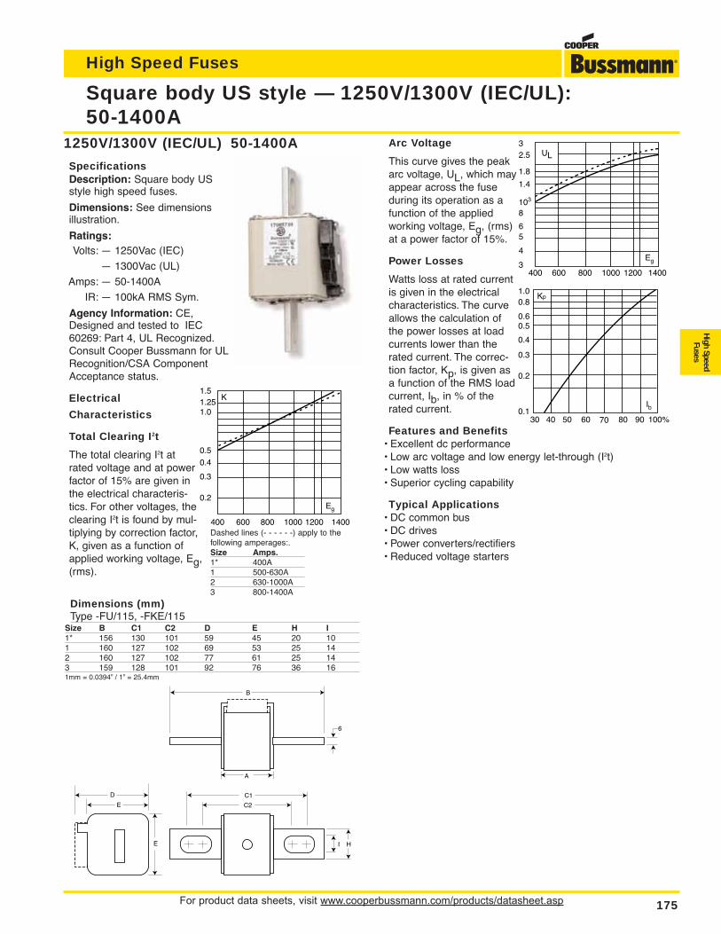
For product data sheets, visit www.cooperbussmann.com/products/datasheet.asp 175
High Speed Fuses
High SpeedFuses
Arc Voltage
This curve gives the peakarc voltage, UL, which mayappear across the fuseduring its operation as afunction of the appliedworking voltage, Eg, (rms)at a power factor of 15%.
Power Losses
Watts loss at rated currentis given in the electricalcharacteristics. The curveallows the calculation ofthe power losses at loadcurrents lower than therated current. The correc-tion factor, Kp, is given asa function of the RMS loadcurrent, Ib, in % of therated current.
Features and Benefits• Excellent dc performance• Low arc voltage and low energy let-through (I2t)• Low watts loss• Superior cycling capability
Typical Applications• DC common bus• DC drives• Power converters/rectifiers• Reduced voltage starters
Square body US style — 1250V/1300V (IEC/UL):50-1400A
1250V/1300V (IEC/UL) 50-1400A
SpecificationsDescription: Square body USstyle high speed fuses.
Dimensions: See dimensionsillustration.
Ratings:Volts: — 1250Vac (IEC)
— 1300Vac (UL)
Amps: — 50-1400A
IR: — 100kA RMS Sym.
Agency Information: CE,Designed and tested to IEC60269: Part 4, UL Recognized.Consult Cooper Bussmann for ULRecognition/CSA ComponentAcceptance status.
Electrical
Characteristics
Total Clearing I2t
The total clearing I2t atrated voltage and at powerfactor of 15% are given inthe electrical characteris-tics. For other voltages, theclearing I2t is found by mul-tiplying by correction factor,K, given as a function ofapplied working voltage, Eg,(rms).
B
C2
D
E
E
6
H I
C1
A
Dimensions (mm)Type -FU/115, -FKE/115
Size B C1 C2 D E H I1* 156 130 101 59 45 20 101 160 127 102 69 53 25 142 160 127 102 77 61 25 143 159 128 101 92 76 36 161mm = 0.0394” / 1” = 25.4mm
K1.5
1.01.25
0.5
0.4
0.3
0.2
400 600 800 1000 1200 1400
Eg
UL32.5
8103
1.4
1.8
6
4
5
3400 600 800 1000 1200 1400
Eg
Kp
30 40 50 60 70 80 90 100%
Ib
1.00.8
0.4
0.50.6
0.3
0.2
0.1
Dashed lines (- - - - - -) apply to thefollowing amperages:.Size Amps.1* 400A1 500-630A2 630-1000A3 800-1400A
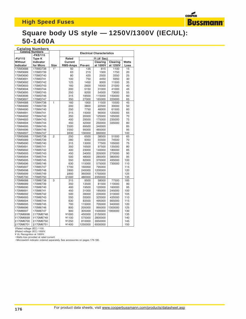
For product data sheets, visit www.cooperbussmann.com/products/datasheet.asp176
High Speed Fuses
Square body US style — 1250V/1300V (IEC/UL):50-1400A
Catalog NumbersCatalog Numbers
-FKE/115Electrical Characteristics
-FU/115 Type K Rated I2t (A2 Sec)Without Indicator Current Clearing Clearing WattsIndicator for Micro Size RMS-Amps Pre-arc at 1000V at 1250V Loss170M3688 170M3738 1* 50 135 815 1100 15170M3689 170M3739 63 215 1300 1750 20170M3690 170M3740 80 420 2500 3350 25170M3691 170M3741 100 750 4450 5950 30170M3692 170M3742 125 1450 9000 11500 35170M3693 170M3743 160 2600 16000 21000 40170M3694 170M3744 200 5150 31000 41000 45170M3695 170M3745 250 9200 54500 73000 55170M3696 170M3746 315 18500 115000 150000 60170M3697 170M3747 350 27000 165000 220000 65170M4688 170M4738 1 160 1900 11500 15500 45170M4689 170M4739 200 3800 22500 30000 50170M4690 170M4740 250 7750 46000 61500 60170M4691 170M4741 315 15000 90000 120000 65170M4692 170M4742 350 20000 125000 165000 70170M4693 170M4743 400 29500 175000 235000 75170M4694 170M4744 450 42000 250000 335000 80170M4695 170M4745 †500 69500 340000 85170M4696 170M4746 †550 95000 465000 95170M4697 170M4747 ‡630 130000 660000 100170M5688 170M5738 2 250 6500 38500 51500 65170M5689 170M5739 280 9350 55500 74500 70170M5690 170M5740 315 13000 77500 105000 75170M5691 170M5741 350 16500 97500 135000 80170M5692 170M5742 400 23000 140000 180000 85170M5693 170M5743 450 34000 205000 270000 90170M5694 170M5744 500 48000 285000 380000 95170M5695 170M5745 550 62000 370000 495000 100170M5696 170M5746 630 115000 575000 730000 110170M5697 170M5747 †700 160000 795000 115170M5698 170M5748 †800 245000 1200000 120170M5699 170M5749 ‡900 360000 1750000 125170M5700 170M5750 ‡1000 480000 2350000 135170M6688 170M6738 3 315 9500 58000 77500 185170M6689 170M6739 350 13500 81500 110000 90170M6690 170M6740 400 19500 120000 160000 95170M6691 170M6741 450 31000 185000 245000 100170M6692 170M6742 500 39000 235000 310000 105170M6693 170M6743 550 55000 325000 435000 110170M6694 170M6744 630 83500 495000 665000 115170M6695 170M6745 700 115000 705000 940000 120170M6696 170M6746 800 205000 995000 1300000 125170M6697 170M6747 900 305000 1500000 1900000 130†170M6698 †170M6748 ¥1000 450000 2150000 135†170M6699 †170M6749 ¥1100 575000 2800000 140‡170M6700 ‡170M6750 ¥1250 810000 3950000 145‡170M6701 ‡170M6751 ¥1400 1250000 6000000 150†Rated voltage (IEC) 1100.‡Rated voltage (IEC) 1000V.¥ UL Recognition at 1000V.• Watts loss provided at rated current.• Microswitch indicator ordered separately. See accessories on pages 179-180.
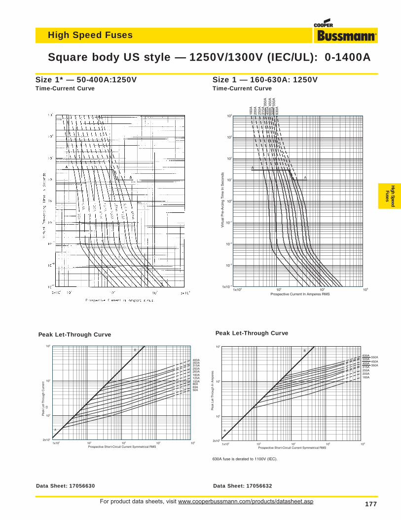
For product data sheets, visit www.cooperbussmann.com/products/datasheet.asp 177
High Speed Fuses
High SpeedFuses
Square body US style — 1250V/1300V (IEC/UL): 0-1400A
Size 1* — 50-400A:1250VTime-Current Curve
1x10² 103 104 105 1062x102
103
104
105
Prospective Short-Circuit Current Symmetrical RMS
Pea
k Le
t-T
hrou
gh C
urre
nt
50A63A80A100A125A160A200A250A315A350A400A
A
B
Peak Let-Through Curve
1x10² 103 104 1051x10–4
10–3
10–2
10–1
100
101
102
103
104
Prospective Current In Amperes RMS
Virt
ual P
re-A
rcin
g Ti
me
In S
econ
ds
A
A
160A
200A
250A
315A
350A
400A
450A
500A
550A
630A
Size 1 — 160-630A: 1250VTime-Current Curve
1x10² 103 104 105 1062x102
103
104
105
Prospective Short-Circuit Current Symmetrical RMS
Pea
k Le
t-T
hrou
gh In
Am
pere
s
160A200A250A315A
350A400A
450A500A
550A630A
A
B
Peak Let-Through Curve
630A fuse is derated to 1100V (IEC).
Data Sheet: 17056630 Data Sheet: 17056632
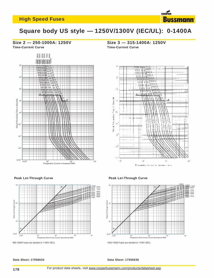
For product data sheets, visit www.cooperbussmann.com/products/datasheet.asp178
High Speed Fuses
Square body US style — 1250V/1300V (IEC/UL): 0-1400A
1x10² 103 104 1051x10–4
10–3
10–2
10–1
100
101
102
103
104
Prospective Current In Amperes RMS
Virt
ual P
re-A
rcin
g Ti
me
In S
econ
ds
250A
280A
315A
350A
400A
450A
500A
550A
630A
700A
800A
900A
1000
A
A
A
Size 2 — 250-1000A: 1250VTime-Current Curve
1x10² 103 104 105 1062x102
103
104
105
Prospective Short-Circuit Current Symmetrical RMS
Pea
k Le
t-T
hrou
gh C
urre
nt
250A 280A315A 350A400A 450A500A 550A630A 700A800A
900A1000A
A
B
Peak Let-Through Curve
900-1000A fuses are derated to 1100V (IEC).
Size 3 — 315-1400A: 1250VTime-Current Curve
1x10² 103 104 105 1062x102
103
104
105
Prospective Short-Circuit Current Symmetrical RMS
Pea
k Le
t-T
hrou
gh C
urre
nt
315A350A
400A450A500A 550A
630A700A
800A 900A1000A 1100A1250A1400A
A
B
Peak Let-Through Curve
1250-1400A fuses are derated to 1100V (IEC).
Data Sheet: 17056634 Data Sheet: 17056636
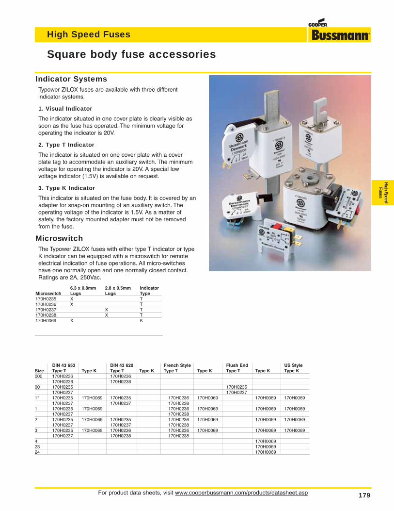
DIN 43 653 DIN 43 620 French Style Flush End US StyleSize Type T Type K Type T Type K Type T Type K Type T Type K Type K000 170H0236 170H0236
170H0238 170H023800 170H0235 170H0235
170H0237 170H02371* 170H0235 170H0069 170H0235 170H0236 170H0069 170H0069 170H0069
170H0237 170H0237 170H02381 170H0235 170H0069 170H0236 170H0069 170H0069 170H0069
170H0237 170H02382 170H0235 170H0069 170H0235 170H0236 170H0069 170H0069 170H0069
170H0237 170H0237 170H02383 170H0235 170H0069 170H0236 170H0236 170H0069 170H0069 170H0069
170H0237 170H0238 170H02384 170H006923 170H006924 170H0069
For product data sheets, visit www.cooperbussmann.com/products/datasheet.asp 179
High Speed Fuses
High SpeedFuses
Square body fuse accessories
Indicator SystemsTypower ZILOX fuses are available with three different indicator systems.
1. Visual Indicator
The indicator situated in one cover plate is clearly visible assoon as the fuse has operated. The minimum voltage foroperating the indicator is 20V.
2. Type T Indicator
The indicator is situated on one cover plate with a coverplate tag to accommodate an auxiliary switch. The minimumvoltage for operating the indicator is 20V. A special low voltage indicator (1.5V) is available on request.
3. Type K Indicator
This indicator is situated on the fuse body. It is covered by anadapter for snap-on mounting of an auxiliary switch. Theoperating voltage of the indicator is 1.5V. As a matter of safety, the factory mounted adapter must not be removedfrom the fuse.
MicroswitchThe Typower ZILOX fuses with either type T indicator or typeK indicator can be equipped with a microswitch for remoteelectrical indication of fuse operations. All micro-switcheshave one normally open and one normally closed contact.Ratings are 2A, 250Vac.
6.3 x 0.8mm 2.8 x 0.5mm IndicatorMicroswitch Lugs Lugs Type170H0235 X T170H0236 X T170H0237 X T170H0238 X T170H0069 X K
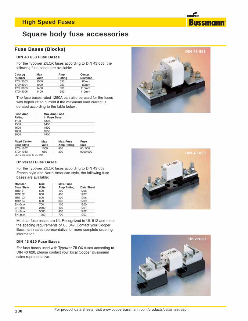
For product data sheets, visit www.cooperbussmann.com/products/datasheet.asp180
High Speed Fuses
Square body fuse accessories
Universal
DIN 43 653
DIN 43 653
Fuse Bases (Blocks)
DIN 43 653 Fuse Bases
For the Typower ZILOX fuses according to DIN 43 653, thefollowing fuse bases are available:
Catalog Max Amp CenterNumber Volts Rating Distance170H3003 1000 630 80mm170H3004 1000 1250 80mm170H3005 1400 630 110mm170H3006 1400 1250 110mm
The fuse bases rated 1250A can also be used for the fuseswith higher rated current if the maximum load current is derated according to the table below:
Fuse Amp Max Amp LoadRating In Fuse Base1400 13251500 14001600 15001800 16502000 1800
Fixed Center Max Max. Fuse FuseBase Style Volts Amp Rating Size170H1007 1000 400 00, 000170H1013 660 200 0000,000UL Recognized to UL 512.
Universal Fuse Bases
For the Typower ZILOX fuses according to DIN 43 653,French style and North American style, the following fusebases are available:
Modular Max Max. FuseBase Style Volts Amp Rating Data Sheet1BS101 600 100 12061BS102 600 400 12071BS103 600 400 12081BS104 600 600 1209BH-0xxx 700 100 1200BH-1xxx 2500 400 1201BH-2xxx 5000 400 1202BH-3xxx 1250 700 1203
Modular fuse bases are UL Recognized to UL 512 and meetthe spacing requirements of UL 347. Contact your CooperBussmann sales representative for more complete orderinginformation.
DIN 43 620 Fuse Bases
For fuse bases used with Typower ZILOX fuses according toDIN 43 620, please contact your local Cooper Bussmannsales representative.
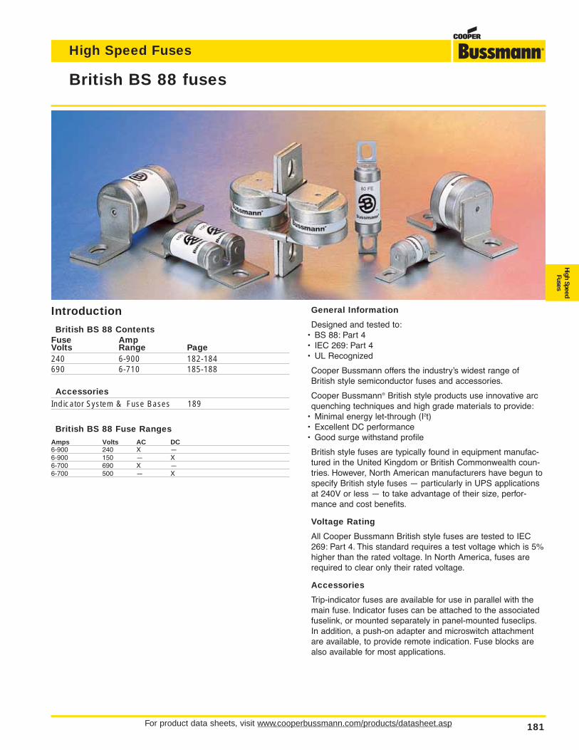
For product data sheets, visit www.cooperbussmann.com/products/datasheet.asp 181
High Speed Fuses
High SpeedFuses
British BS 88 fuses
General Information
Designed and tested to:• BS 88: Part 4• IEC 269: Part 4• UL Recognized
Cooper Bussmann offers the industry’s widest range ofBritish style semiconductor fuses and accessories.
Cooper Bussmann® British style products use innovative arcquenching techniques and high grade materials to provide:
• Minimal energy let-through (I2t)• Excellent DC performance• Good surge withstand profile
British style fuses are typically found in equipment manufac-tured in the United Kingdom or British Commonwealth coun-tries. However, North American manufacturers have begun tospecify British style fuses — particularly in UPS applicationsat 240V or less — to take advantage of their size, perfor-mance and cost benefits.
Voltage Rating
All Cooper Bussmann British style fuses are tested to IEC269: Part 4. This standard requires a test voltage which is 5%higher than the rated voltage. In North America, fuses arerequired to clear only their rated voltage.
Accessories
Trip-indicator fuses are available for use in parallel with themain fuse. Indicator fuses can be attached to the associatedfuselink, or mounted separately in panel-mounted fuseclips.In addition, a push-on adapter and microswitch attachmentare available, to provide remote indication. Fuse blocks arealso available for most applications.
Introduction
British BS 88 ContentsFuse AmpVolts Range Page240 6-900 182-184690 6-710 185-188
AccessoriesIndicator System & Fuse Bases 189
British BS 88 Fuse Ranges
Amps Volts AC DC6-900 240 X —6-900 150 — X6-700 690 X —6-700 500 — X
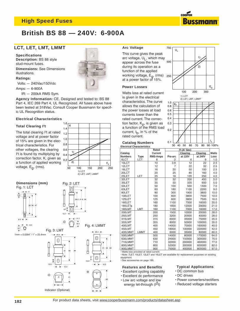
Arc Voltage
This curve gives the peakarc voltage, UL, which mayappear across the fuseduring its operation as afunction of the appliedworking voltage, Eg, (rms)at a power factor of 15%.
Power Losses
Watts loss at rated currentis given in the electricalcharacteristics. The curveallows the calculation ofthe power losses at loadcurrents lower than therated current. The correc-tion factor, Kp, is given asa function of the RMS loadcurrent, Ib, in % of therated current.
Catalog NumbersElectrical Characteristics
Rated I2t (A2 Sec)Catalog Current Clearing Clearing WattsNumbers Type RMS-Amps Pre-arc at 120V at 240V Loss6LCT LCT 6 2 6 9 1.010LCT 10 3.8 12 22 2.512LCT 12 7 22 32 2.516LCT 16 20 50 100 2.520LCT 20 25 80 160 4.025LET LET 25 18 120 250 4.032LET 32 32 200 450 5.035LET 35 50 320 600 5.050LET 50 100 500 1400 7.063LET 63 180 1100 2200 9.080LET 80 300 1900 3800 10.0100LET 100 600 3800 7500 10.0125LET 125 600 3800 7500 16.0160LET 160 1100 7000 16000 20.0180LETa 180 1600 12000 29000 21.0160LMT LMT 160 1100 7000 16000 17.0200LMT 200 1500 10000 20000 28.0250LMT 250 3200 20000 40000 28.0315LMT 315 6000 35000 75000 35.0355LMT 355 8000 50000 100000 35.0400LMT 400 14000 70000 160000 40.0450LMT 450 18000 100000 220000 42.0400LMMT LMMT 400 6000 35000 80000 60.0500LMMT 500 14000 80000 170000 64.0630LMMT 630 24000 150000 300000 75.0710LMMT 710 32000 200000 460000 77.0800LMMT 800 52000 300000 600000 82.0900LMMT 900 75000 400000 800000 97.0
• Watts loss provided at rated current.• Note: 7LET, 10LET, 12LET and 16LET are available for replacement purposes on existingequipment.• See accessories on page 189.
Features and Benefits• Excellent cycling capability• Excellent dc performance• Low arc voltage and low
energy let-through (I2t)
For product data sheets, visit www.cooperbussmann.com/products/datasheet.asp182
High Speed Fuses
British BS 88 — 240V: 6-900A
5641.826.2
17.7
19.1
12.7
7.1
9.7
Fig. 2: LET
473828
6.4
8.4
8.7
4
5.5
Dimensions (mm)Fig. 1: LCT
1mm = 0.0394” / 1” = 25.4mm
LCT, LET, LMT, LMMT
SpecificationsDescription: BS 88 style stud-mount fuses.
Dimensions: See Dimensionsillustrations.
Ratings:Volts: — 240Vac/150Vdc
Amps: — 6-900A
IR: — 200kA RMS Sym.
Agency Information: CE, Designed and tested to: BS 88Part 4, IEC 269 Part 4, UL Recognized. All fuses above havebeen tested at 318Vac. Consult Cooper Bussmann for specif-ic UL Recognition status.
Electrical Characteristics
Total Clearing I2t
The total clearing I2t at ratedvoltage and at power factorof 15% are given in the elec-trical characteristics. Forother voltages, the clearingI2t is found by multiplying bycorrection factor, K, given asa function of applied workingvoltage, Eg, (rms).
845931
83
38
25.4
13.5
10.3
0.2
0.4
0.6
0.8
1.0
1.2
1.4
1.6
10050 150 200 250
1)
2) Eg
K
845931
41
38.1
25.4
10.313.5
Fig. 3: LMTFig. 4: LMMT
Indicator (Optional)
1) LCT2) LET, LMT, LMMT
Kp1.00.8
0.4
0.50.6
0.3
0.2
0.130 40 50 60 70 80 90 100%
Ib
750
500
250
100 200 300
1)
2)
Eg
UL
1) LCT2) LET, LMT, LMMT
Typical Applications• DC common bus• DC drives• Power converters/rectifiers• Reduced voltage starters
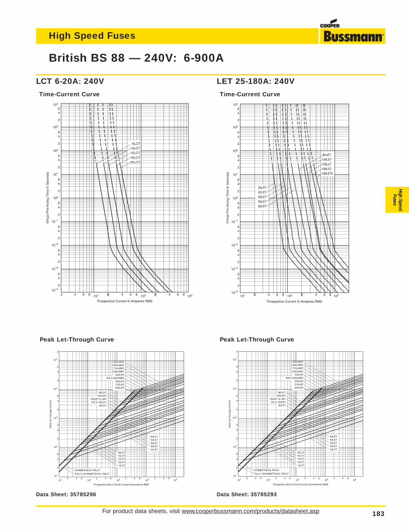
For product data sheets, visit www.cooperbussmann.com/products/datasheet.asp 183
British BS 88 — 240V: 6-900A
Peak Let-Through CurvePeak Let-Through Curve
LET 25-180A: 240V
Time-Current Curve
LCT 6-20A: 240V
Time-Current Curve
104
103
102
10–1
10–2
10–3
10–4
Prospective Current In Amperes RMS
Virt
ual P
re-A
rcin
g Ti
me
In S
econ
ds
2 4 6 8 101 22 4 6 8 2102 2 4 6 8 103
2
46
2
64
100
2
64
101
2
64
2
64
2
64
64
2
6
2
4
20LCT16LCT12LCT10LCT
6LCT
104
103
102
101 22 4 6 8 2102 2 4 6 8 103
2
46
2
64
100
2
64
101
2
64
2
64
2
64
64
2
6
2
4
Prospective Current In Amperes RMS
Virt
ual P
re-A
rcin
g Ti
me
In S
econ
ds
63LET50LET35LET32LET25LET
180LETa160LET125LET100LET 80LET
10–4
10–3
10–2
10–1
Prospective Short-Circuit Current Symmetrical RMS
101 1022 64 2 4 6103 2 4 6
104 2 4 6105
Pea
k Le
t-T
hrou
gh C
urre
nt
101
6
2
4
2
102
4
6
2
103
6
4
104
6
4
2
2
105
SYMMETRICAL FAULT
FULLY ASYMMETRICAL FAULT
20LCT16LCT12LCT10LCT 6LCT
25LET32LET35LET50LET63LET
80LET125 & 100LET
160LET & LMT200LMT180LET
250LMT315LMT355LMT
400 & 500LMMT450LMT
630LMMT710LMMT800LMMT900LMMT
High Speed Fuses
High SpeedFuses
Data Sheet: 35785293Data Sheet: 35785296
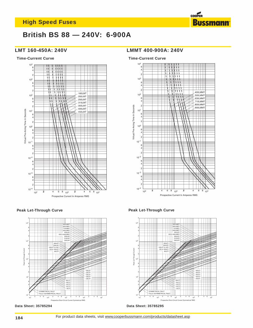
For product data sheets, visit www.cooperbussmann.com/products/datasheet.asp184
High Speed Fuses
British BS 88 — 240V: 6-900A
10–4
10–3
10–1
102
102 22 4 6 8 2103 2 4 6 8 104
2
46
2
64
100
2
64
101
2
64
2
64
2
64
64
2
6
2
4
104
315LMT
450LMT400LMT355LMT
250LMT200LMT160LMT
Prospective Current In Amperes RMS
Vir
tual
Pre
-Arc
ing
Tim
e In
Sec
onds
103
10–2
10–1
10–3
10–2
102
103
104
102 22 4 6 8 2103 2 4 6 8 104
2
46
2
64
100
2
64
101
2
64
2
64
2
64
64
2
6
2
4
Prospective Current In Amperes RMS
Vir
tual
Pre
-Arc
ing
Tim
e In
Sec
onds
10–4
710LMMT
900LMMT800LMMT
630LMMT500LMMT400LMMT
Prospective Short-Circuit Current Symmetrical RMS
101 1022 64 2 4 6103 2 4 6
104 2 4 6105
Pea
k Le
t-T
hrou
gh C
urre
nt
101
6
2
4
2
102
4
6
2
103
6
4
104
6
4
2
2
105
SYMMETRICAL FAULT
FULLY ASYMMETRICAL FAULT
20LCT16LCT12LCT10LCT 6LCT
25LET32LET35LET50LET63LET
80LET125 & 100LET
160LET & LMT200LMT180LET
250LMT315LMT355LMT
400 & 500LMMT450LMT
630LMMT710LMMT800LMMT900LMMT
Peak Let-Through CurvePeak Let-Through Curve
LMMT 400-900A: 240V
Time-Current Curve
LMT 160-450A: 240V
Time-Current Curve
Data Sheet: 35785294 Data Sheet: 35785295
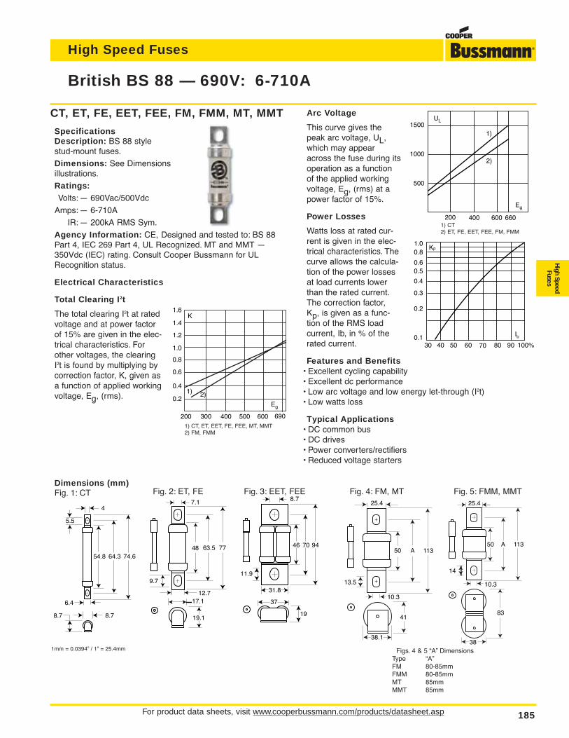
For product data sheets, visit www.cooperbussmann.com/products/datasheet.asp 185
British BS 88 — 690V: 6-710A
High Speed Fuses
High SpeedFuses
CT, ET, FE, EET, FEE, FM, FMM, MT, MMT
SpecificationsDescription: BS 88 style stud-mount fuses.
Dimensions: See Dimensionsillustrations.
Ratings:Volts: — 690Vac/500Vdc
Amps: — 6-710A
IR: — 200kA RMS Sym.
Agency Information: CE, Designed and tested to: BS 88Part 4, IEC 269 Part 4, UL Recognized. MT and MMT —350Vdc (IEC) rating. Consult Cooper Bussmann for ULRecognition status.
Electrical Characteristics
Total Clearing I2t
The total clearing I2t at ratedvoltage and at power factorof 15% are given in the elec-trical characteristics. Forother voltages, the clearingI2t is found by multiplying bycorrection factor, K, given asa function of applied workingvoltage, Eg, (rms).
Dimensions (mm)Fig. 1: CT
7763.548
17.1
19.1
12.7
7.1
9.7
947046
37
19
31.8
8.7
11.9
113A50
41
38.1
25.4
10.3
13.5
113A50
83
38
25.4
10.3
14
Fig. 2: ET, FE
74.664.354.8
6.4
8.78.7
4
5.5
Fig. 3: EET, FEE Fig. 4: FM, MT Fig. 5: FMM, MMT
1mm = 0.0394” / 1” = 25.4mm Figs. 4 & 5 “A” DimensionsType “A”FM 80-85mmFMM 80-85mmMT 85mmMMT 85mm
Arc Voltage
This curve gives thepeak arc voltage, UL,which may appearacross the fuse during itsoperation as a functionof the applied workingvoltage, Eg, (rms) at apower factor of 15%.
Power Losses
Watts loss at rated cur-rent is given in the elec-trical characteristics. Thecurve allows the calcula-tion of the power lossesat load currents lowerthan the rated current.The correction factor,Kp, is given as a func-tion of the RMS loadcurrent, Ib, in % of therated current.
Features and Benefits• Excellent cycling capability• Excellent dc performance• Low arc voltage and low energy let-through (I2t)• Low watts loss
Typical Applications• DC common bus• DC drives• Power converters/rectifiers• Reduced voltage starters
1500
1000
500
200 400 600 660
Eg
UL
1)
2)
1) CT2) ET, FE, EET, FEE, FM, FMM
200 300 400 500 600 690
0.2
0.4
0.6
0.8
1.0
1.2
1.4
1.6
1) 2)
Eg
K
1) CT, ET, EET, FE, FEE, MT, MMT2) FM, FMM
Kp1.00.8
0.4
0.50.6
0.3
0.2
0.130 40 50 60 70 80 90 100%
Ib
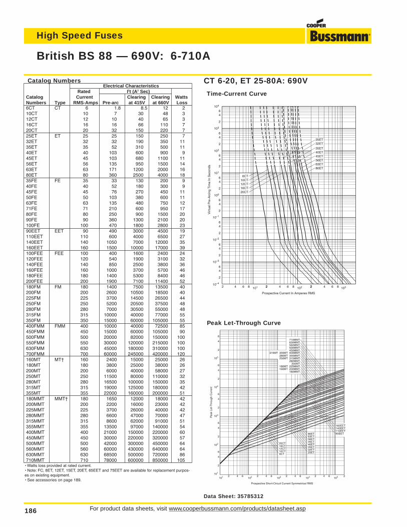
For product data sheets, visit www.cooperbussmann.com/products/datasheet.asp186
High Speed Fuses
British BS 88 — 690V: 6-710A
103
10–1
2 4 6 8 101 22 4 6 8 2102 2 4 6 8 103
2
46
2
64
100
2
64
101
2
64
2
64
2
64
64
2
6
2
4
10CT12CT16CT20CT
6CT
32ET25ET
Prospective Current In Amperes RMS
Vir
tual
Pre
-Arc
ing
Tim
e In
Sec
onds
56ET
80ET63ET
45ET40ET35ET
10–4
10–3
10–2
102
104
Prospective Short-Circuit Current Symmetrical RMS
Pea
k Le
t-T
hrou
gh C
urre
nt
2
4
2
6
6
4
2
4
6
4
2
6
4
2
6
2 4 6 2 4 6 2 4 6 2 4 6101
102
103
104
105
101 102 103 104 105 2
20CT16CT12CT10CT6CT
80ET63ET56ET45ET40ET35ET32ET25ET
710MMT630MMT560MMT500MMT450MMT
315MT 355MT 400MMT280MT 355MMT250MT 315MMT
280MMT 200MT
180MT 225MMT160MT 200MMT
180MMT
160EET140EET110EET90EET
Peak Let-Through Curve
CT 6-20, ET 25-80A: 690V
Time-Current Curve
Catalog NumbersElectrical Characteristics
Rated I2t (A2 Sec)Catalog Current Clearing Clearing WattsNumbers Type RMS-Amps Pre-arc at 415V at 660V Loss6CT CT 6 1.8 8.5 12 210CT 10 7 30 48 312CT 12 10 40 65 316CT 16 16 66 110 720CT 20 32 150 220 725ET ET 25 25 150 250 732ET 32 32 190 350 1135ET 35 52 310 500 1140ET 40 103 600 900 945ET 45 103 680 1100 1156ET 56 135 950 1500 1463ET 63 171 1200 2000 1680ET 80 360 2500 4000 1835FE FE 35 33 130 200 940FE 40 52 180 300 945FE 45 76 270 450 1150FE 50 103 380 600 1163FE 63 135 480 750 1271FE 71 210 600 950 1780FE 80 250 900 1500 2090FE 90 360 1300 2100 20100FE 100 470 1800 2800 2390EET EET 90 490 3000 4500 19110EET 110 600 4000 6500 27140EET 140 1050 7000 12000 35160EET 160 1500 10000 17000 39100FEE FEE 100 400 1600 2400 24120FEE 120 540 1900 3100 32140FEE 140 850 2500 3800 36160FEE 160 1000 3700 5700 46180FEE 180 1400 5300 8400 46200FEE 200 1900 7100 11400 52180FM FM 180 1400 7500 13500 40200FM 200 2600 10500 18500 40225FM 225 3700 14500 26500 44250FM 250 5200 20500 37500 48280FM 280 7000 30500 55000 48315FM 315 10000 40000 77000 55350FM 350 15000 60000 105000 55400FMM FMM 400 10000 40000 72500 85450FMM 450 15000 60000 105000 90500FMM 500 20000 82000 150000 100550FMM 550 30000 120000 215000 100630FMM 630 45000 180000 310000 100700FMM 700 60000 245000 420000 120160MT MT† 160 2400 15000 25000 26180MT 180 3800 25000 38000 26200MT 200 6000 40000 58000 27250MT 250 11500 80000 110000 32280MT 280 16500 100000 150000 35315MT 315 19000 125000 180000 42355MT 355 22000 160000 200000 51180MMT MMT† 180 1650 12000 18000 42200MMT 200 2200 16000 23000 42225MMT 225 3700 26000 40000 42280MMT 280 6600 47000 70000 47315MMT 315 8600 62000 91000 51355MMT 355 13500 97000 140000 54400MMT 400 21000 150000 220000 60450MMT 450 30000 220000 320000 57500MMT 500 42000 300000 450000 64560MMT 560 60000 430000 640000 64630MMT 630 68500 500000 720000 86710MMT 710 78000 600000 850000 105
• Watts loss provided at rated current.• Note: FC, 8ET, 12ET, 15ET, 20ET, 65EET and 75EET are available for replacement purpos-es on existing equipment.• See accessories on page 189.
Data Sheet: 35785312
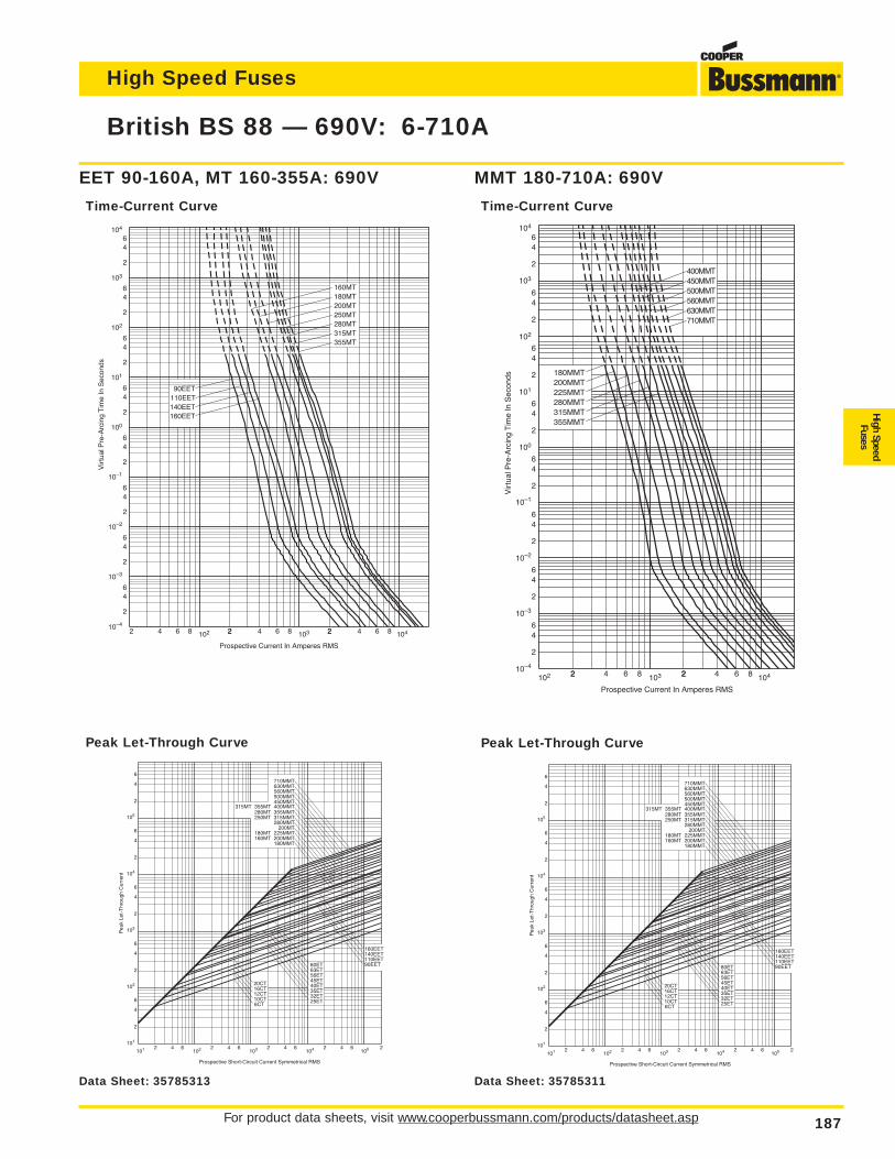
For product data sheets, visit www.cooperbussmann.com/products/datasheet.asp 187
British BS 88 — 690V: 6-710A
High Speed Fuses
High SpeedFuses
103
104
102
10–1
10–2
2 4 6 8 102 22 4 6 8 2103 2 4 6 8 104
2
46
2
64
100
2
64
101
2
64
2
64
2
64
64
2
6
2
4
Prospective Current In Amperes RMS
Vir
tual
Pre
-Arc
ing
Tim
e In
Sec
onds
160EET140EET110EET90EET
200MT
355MT315MT280MT250MT
180MT160MT
10–4
10–3
Prospective Short-Circuit Current Symmetrical RMS
Pea
k Le
t-T
hrou
gh C
urre
nt
2
4
2
6
6
4
2
4
6
4
2
6
4
2
6
2 4 6 2 4 6 2 4 6 2 4 6101
102
103
104
105
101 102 103 104 105 2
20CT16CT12CT10CT6CT
80ET63ET56ET45ET40ET35ET32ET25ET
710MMT630MMT560MMT500MMT450MMT
315MT 355MT 400MMT280MT 355MMT250MT 315MMT
280MMT 200MT
180MT 225MMT160MT 200MMT
180MMT
160EET140EET110EET90EET
Peak Let-Through Curve
EET 90-160A, MT 160-355A: 690V
Time-Current Curve
104
103
102
10–1
10–3
Prospective Current In Amperes RMS
Vir
tual
Pre
-Arc
ing
Tim
e In
Sec
onds
102 22 4 6 8 2103 2 4 6 8 104
2
46
2
64
100
2
64
101
2
64
2
64
2
64
64
2
6
2
4
280MMT
355MMT315MMT
225MMT200MMT180MMT
630MMT710MMT
560MMT500MMT450MMT400MMT
10–4
10–2
MMT 180-710A: 690V
Time-Current Curve
Prospective Short-Circuit Current Symmetrical RMS
Pea
k Le
t-T
hrou
gh C
urre
nt
2
4
2
6
6
4
2
4
6
4
2
6
4
2
6
2 4 6 2 4 6 2 4 6 2 4 6101
102
103
104
105
101 102 103 104 105 2
20CT16CT12CT10CT6CT
80ET63ET56ET45ET40ET35ET32ET25ET
710MMT630MMT560MMT500MMT450MMT
315MT 355MT 400MMT280MT 355MMT250MT 315MMT
280MMT 200MT
180MT 225MMT160MT 200MMT
180MMT
160EET140EET110EET90EET
Peak Let-Through Curve
Data Sheet: 35785313 Data Sheet: 35785311
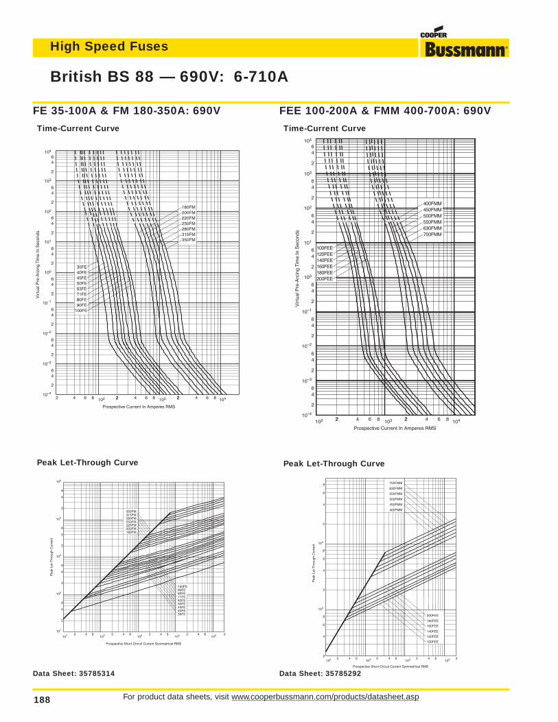
For product data sheets, visit www.cooperbussmann.com/products/datasheet.asp188
High Speed Fuses
British BS 88 — 690V: 6-710A
104
103
102
10–1
10–2
10–3
10–4
102 22 4 6 8 2103 2 4 6 8 104
2
46
2
64
100
2
64
101
2
64
2
64
2
64
64
2
6
2
4
120FEE140FEE160FEE180FEE200FEE
100FEE
550FMM
700FMM630FMM
500FMM450FMM400FMM
Prospective Current In Amperes RMS
Vir
tual
Pre
-Arc
ing
Tim
e In
Sec
onds
FEE 100-200A & FMM 400-700A: 690V
Time-Current Curve
Prospective Short-Circuit Current Symmetrical RMS
Pea
k Le
t-T
hrou
gh C
urre
nt
102 2 4 62
4
6
103
8
2
8
4
6
104
2
4
6
8
103 2 4 6104 2 4 6
105 2
180FEE
100FEE
120FEE
140FEE
160FEE
200FEE
400FMM
450FMM
500FMM
550FMM
630FMM
700FMM
Peak Let-Through Curve
103
102
10–1
10–2
10–4
2 4 6 8 102 22 4 6 8 2103 2 4 6 8 104
2
46
2
64
100
2
64
101
2
64
2
64
2
64
64
2
6
2
4
100FE
35FE40FE45FE50FE63FE71FE80FE90FE
350FM315FM280FM250FM220FM200FM180FM
Prospective Current In Amperes RMS
Vir
tual
Pre
-Arc
ing
Tim
e In
Sec
onds
10–3
104
FE 35-100A & FM 180-350A: 690V
Time-Current Curve
Prospective Short-Circuit Current Symmetrical RMS
Pea
k Le
t-T
hrou
gh C
urre
nt
2
4
2
6
6
4
2
6
4
2
6
4
2 4 6 2 4 6 2 4 6 2 4 6101
102
103
104
105
101 102 103 104 105 2
350FM315FM280FM250FM225FM200FM180FM
100FE90FE80FE71FE63FE50FE45FE40FE35FE
Peak Let-Through Curve
Data Sheet: 35785314 Data Sheet: 35785292
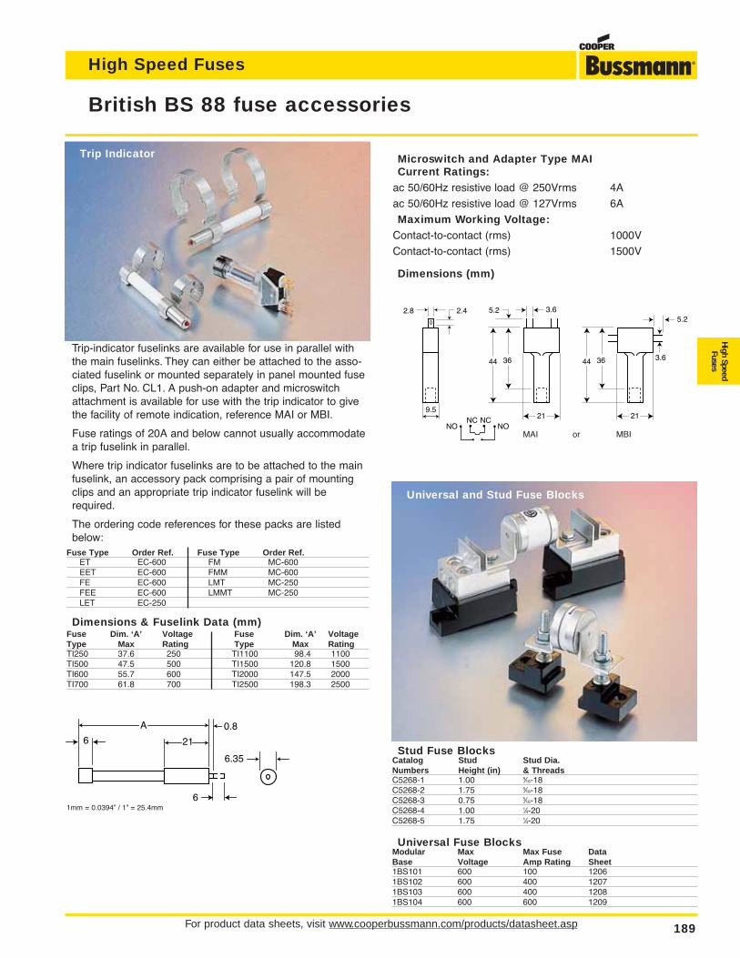
For product data sheets, visit www.cooperbussmann.com/products/datasheet.asp 189
British BS 88 fuse accessories
Trip-indicator fuselinks are available for use in parallel withthe main fuselinks. They can either be attached to the asso-ciated fuselink or mounted separately in panel mounted fuseclips, Part No. CL1. A push-on adapter and microswitchattachment is available for use with the trip indicator to givethe facility of remote indication, reference MAI or MBI.
Fuse ratings of 20A and below cannot usually accommodatea trip fuselink in parallel.
Where trip indicator fuselinks are to be attached to the mainfuselink, an accessory pack comprising a pair of mountingclips and an appropriate trip indicator fuselink will berequired.
The ordering code references for these packs are listedbelow:
Fuse Type Order Ref. Fuse Type Order Ref.ET EC-600 FM MC-600EET EC-600 FMM MC-600FE EC-600 LMT MC-250FEE EC-600 LMMT MC-250LET EC-250
Dimensions & Fuselink Data (mm)Fuse Dim. ‘A’ Voltage Fuse Dim. ‘A’ VoltageType Max Rating Type Max RatingTI250 37.6 250 TI1100 98.4 1100TI500 47.5 500 TI1500 120.8 1500TI600 55.7 600 TI2000 147.5 2000TI700 61.8 700 TI2500 198.3 2500
6 21
A 0.8
6.35
6
2.8 2.4 3.65.2
5.2
21
3644 3.6
21
3644
9.5NC NC
NONO
Microswitch and Adapter Type MAICurrent Ratings:
ac 50/60Hz resistive load @ 250Vrms 4A
ac 50/60Hz resistive load @ 127Vrms 6A
Maximum Working Voltage:Contact-to-contact (rms) 1000V
Contact-to-contact (rms) 1500V
Dimensions (mm)
Stud Fuse BlocksCatalog Stud Stud Dia.Numbers Height (in) & ThreadsC5268-1 1.00 5⁄16-18C5268-2 1.75 5⁄16-18C5268-3 0.75 5⁄16-18C5268-4 1.00 1⁄4-20C5268-5 1.75 1⁄4-20
Universal Fuse BlocksModular Max Max Fuse DataBase Voltage Amp Rating Sheet1BS101 600 100 12061BS102 600 400 12071BS103 600 400 12081BS104 600 600 1209
1mm = 0.0394” / 1” = 25.4mm
Trip Indicator
Universal and Stud Fuse Blocks
MAI or MBI
High Speed Fuses
High SpeedFuses

190
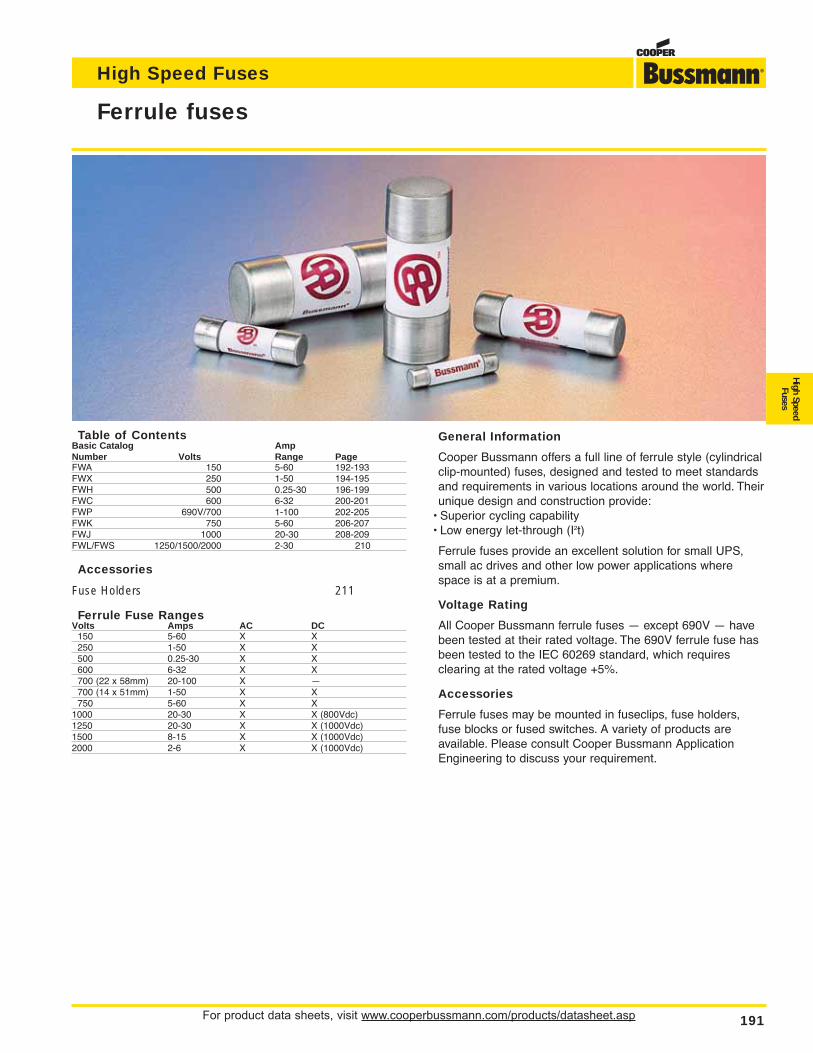
For product data sheets, visit www.cooperbussmann.com/products/datasheet.asp 191
High Speed Fuses
High SpeedFuses
Ferrule fuses
Table of ContentsBasic Catalog AmpNumber Volts Range PageFWA 150 5-60 192-193FWX 250 1-50 194-195FWH 500 0.25-30 196-199FWC 600 6-32 200-201FWP 690V/700 1-100 202-205FWK 750 5-60 206-207FWJ 1000 20-30 208-209FWL/FWS 1250/1500/2000 2-30 210
Accessories
Fuse Holders 211
Ferrule Fuse RangesVolts Amps AC DC
150 5-60 X X250 1-50 X X500 0.25-30 X X600 6-32 X X700 (22 x 58mm) 20-100 X —700 (14 x 51mm) 1-50 X X750 5-60 X X
1000 20-30 X X (800Vdc)1250 20-30 X X (1000Vdc)1500 8-15 X X (1000Vdc)2000 2-6 X X (1000Vdc)
General Information
Cooper Bussmann offers a full line of ferrule style (cylindricalclip-mounted) fuses, designed and tested to meet standardsand requirements in various locations around the world. Theirunique design and construction provide:
• Superior cycling capability• Low energy let-through (I2t)
Ferrule fuses provide an excellent solution for small UPS,small ac drives and other low power applications wherespace is at a premium.
Voltage Rating
All Cooper Bussmann ferrule fuses — except 690V — havebeen tested at their rated voltage. The 690V ferrule fuse hasbeen tested to the IEC 60269 standard, which requires clearing at the rated voltage +5%.
Accessories
Ferrule fuses may be mounted in fuseclips, fuse holders,fuse blocks or fused switches. A variety of products are available. Please consult Cooper Bussmann ApplicationEngineering to discuss your requirement.
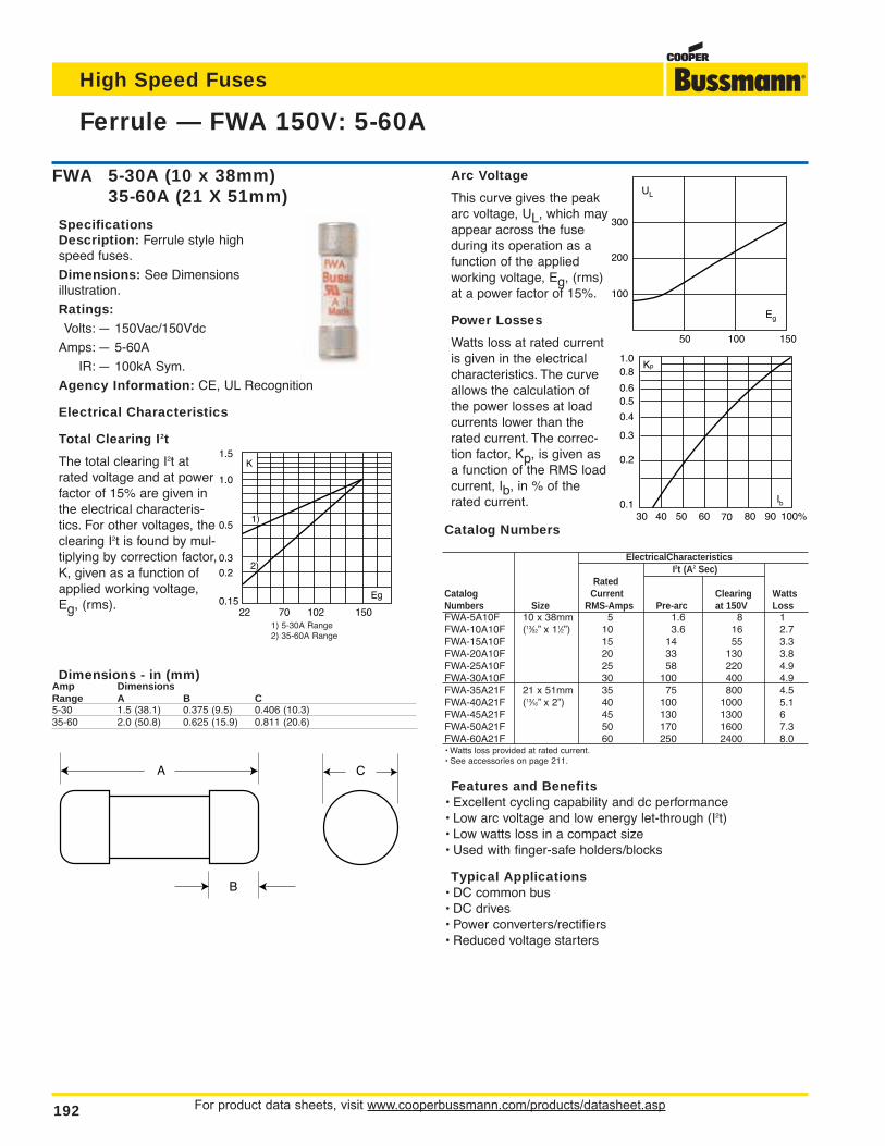
Arc Voltage
This curve gives the peakarc voltage, UL, which mayappear across the fuseduring its operation as afunction of the appliedworking voltage, Eg, (rms)at a power factor of 15%.
Power Losses
Watts loss at rated currentis given in the electricalcharacteristics. The curveallows the calculation ofthe power losses at loadcurrents lower than therated current. The correc-tion factor, Kp, is given asa function of the RMS loadcurrent, Ib, in % of therated current.
Catalog Numbers
ElectricalCharacteristicsI2t (A2 Sec)
RatedCatalog Current Clearing WattsNumbers Size RMS-Amps Pre-arc at 150V LossFWA-5A10F 10 x 38mm 5 1.6 8 1FWA-10A10F (13⁄32” x 11⁄2”) 10 3.6 16 2.7FWA-15A10F 15 14 55 3.3FWA-20A10F 20 33 130 3.8FWA-25A10F 25 58 220 4.9FWA-30A10F 30 100 400 4.9FWA-35A21F 21 x 51mm 35 75 800 4.5FWA-40A21F (13⁄16” x 2”) 40 100 1000 5.1FWA-45A21F 45 130 1300 6FWA-50A21F 50 170 1600 7.3FWA-60A21F 60 250 2400 8.0• Watts loss provided at rated current.• See accessories on page 211.
Features and Benefits• Excellent cycling capability and dc performance• Low arc voltage and low energy let-through (I2t)• Low watts loss in a compact size• Used with finger-safe holders/blocks
Typical Applications• DC common bus• DC drives• Power converters/rectifiers• Reduced voltage starters
Ferrule — FWA 150V: 5-60A
For product data sheets, visit www.cooperbussmann.com/products/datasheet.asp192
High Speed Fuses
Dimensions - in (mm)Amp DimensionsRange A B C5-30 1.5 (38.1) 0.375 (9.5) 0.406 (10.3)35-60 2.0 (50.8) 0.625 (15.9) 0.811 (20.6)
UL
Eg
200
100
100 15050
300
Kp1.00.8
0.4
0.50.6
0.3
0.2
0.130 40 50 60 70 80 90 100%
Ib
A
B
C
FWA 5-30A (10 x 38mm)35-60A (21 X 51mm)
SpecificationsDescription: Ferrule style highspeed fuses.
Dimensions: See Dimensions illustration.
Ratings:Volts: — 150Vac/150Vdc
Amps: — 5-60A
IR: — 100kA Sym.
Agency Information: CE, UL Recognition
Electrical Characteristics
Total Clearing I2t
The total clearing I2t atrated voltage and at powerfactor of 15% are given inthe electrical characteris-tics. For other voltages, theclearing I2t is found by mul-tiplying by correction factor,K, given as a function ofapplied working voltage,Eg, (rms).
1501027022
1.5
1.0
0.5
0.3
0.2
0.15Eg
K
1)
2)
1) 5-30A Range2) 35-60A Range
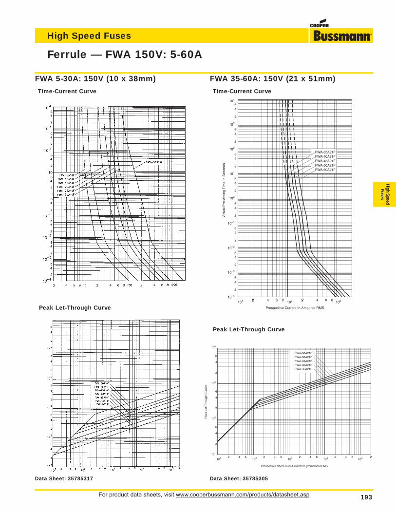
Ferrule — FWA 150V: 5-60A
For product data sheets, visit www.cooperbussmann.com/products/datasheet.asp 193
High Speed Fuses
High SpeedFuses
101 22 4 6 8 2102 2 4 6 8
103
2
46
2
64
100
2
64
101
2
64
2
64
2
64
64
2
6
2
4
10–1
10–2
10–3
10–4
102
103
104
FWA-45A21FFWA-50A21FFWA-60A21F
FWA-35A21FFWA-40A21F
Vir
tual
Pre
-Arc
ing
Tim
e In
Sec
onds
Prospective Current In Amperes RMS
Prospective Short-Circuit Current Symmetrical RMS
Pea
k Le
t-T
hrou
gh C
urre
nt
2
4
2
6
6
4
2
6
4
2 4 6 2 4 6 2 4 6 2 4 6101
102
103
104
101 102 103 104 105
FWA-35A21FFWA-40A21FFWA-45A21FFWA-50A21FFWA-60A21F
2
Peak Let-Through Curve
Peak Let-Through Curve
FWA 35-60A: 150V (21 x 51mm)
Time-Current Curve
FWA 5-30A: 150V (10 x 38mm)
Time-Current Curve
Data Sheet: 35785317 Data Sheet: 35785305
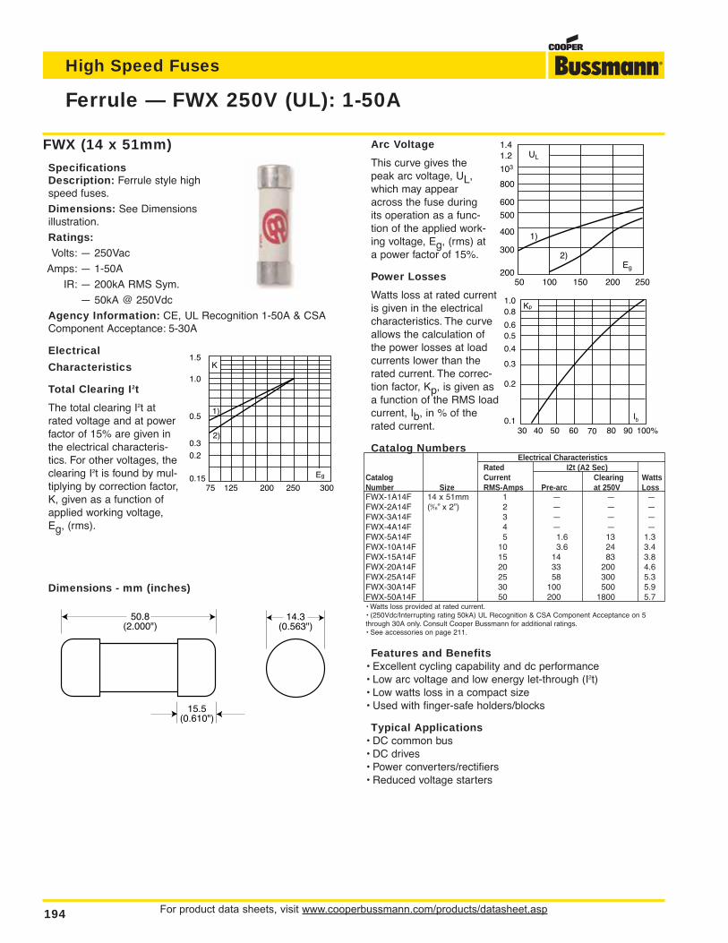
For product data sheets, visit www.cooperbussmann.com/products/datasheet.asp194
High Speed Fuses
Ferrule — FWX 250V (UL): 1-50A
FWX (14 x 51mm)
SpecificationsDescription: Ferrule style highspeed fuses.
Dimensions: See Dimensionsillustration.
Ratings:Volts: — 250Vac
Amps: — 1-50A
IR: — 200kA RMS Sym.
— 50kA @ 250Vdc
Agency Information: CE, UL Recognition 1-50A & CSAComponent Acceptance: 5-30A
Electrical
Characteristics
Total Clearing I2t
The total clearing I2t atrated voltage and at powerfactor of 15% are given inthe electrical characteris-tics. For other voltages, theclearing I2t is found by mul-tiplying by correction factor,K, given as a function ofapplied working voltage,Eg, (rms).
Dimensions - mm (inches)
50.8(2.000")
15.5(0.610")
14.3(0.563")
Arc Voltage
This curve gives thepeak arc voltage, UL,which may appearacross the fuse duringits operation as a func-tion of the applied work-ing voltage, Eg, (rms) ata power factor of 15%.
Power Losses
Watts loss at rated currentis given in the electricalcharacteristics. The curveallows the calculation ofthe power losses at loadcurrents lower than therated current. The correc-tion factor, Kp, is given asa function of the RMS loadcurrent, Ib, in % of therated current.
Catalog NumbersElectrical Characteristics
Rated I2t (A2 Sec)Catalog Current Clearing WattsNumber Size RMS-Amps Pre-arc at 250V LossFWX-1A14F 14 x 51mm 1 — — —FWX-2A14F (9⁄16” x 2”) 2 — — —FWX-3A14F 3 — — —FWX-4A14F 4 — — —FWX-5A14F 5 1.6 13 1.3FWX-10A14F 10 3.6 24 3.4FWX-15A14F 15 14 83 3.8FWX-20A14F 20 33 200 4.6FWX-25A14F 25 58 300 5.3FWX-30A14F 30 100 500 5.9FWX-50A14F 50 200 1800 5.7• Watts loss provided at rated current.• (250Vdc/Interrupting rating 50kA) UL Recognition & CSA Component Acceptance on 5through 30A only. Consult Cooper Bussmann for additional ratings.• See accessories on page 211.
Features and Benefits• Excellent cycling capability and dc performance• Low arc voltage and low energy let-through (I2t)• Low watts loss in a compact size• Used with finger-safe holders/blocks
Typical Applications• DC common bus• DC drives• Power converters/rectifiers• Reduced voltage starters
1.5
1.0
0.5
0.3
0.2
0.1575 125 300200 250
Eg
K
1)
2)
UL
1.41.2
103
800
600
500
400
300
20050 100 150 200 250
Eg
1)
2)
Kp1.00.8
0.4
0.50.6
0.3
0.2
0.130 40 50 60 70 80 90 100%
Ib
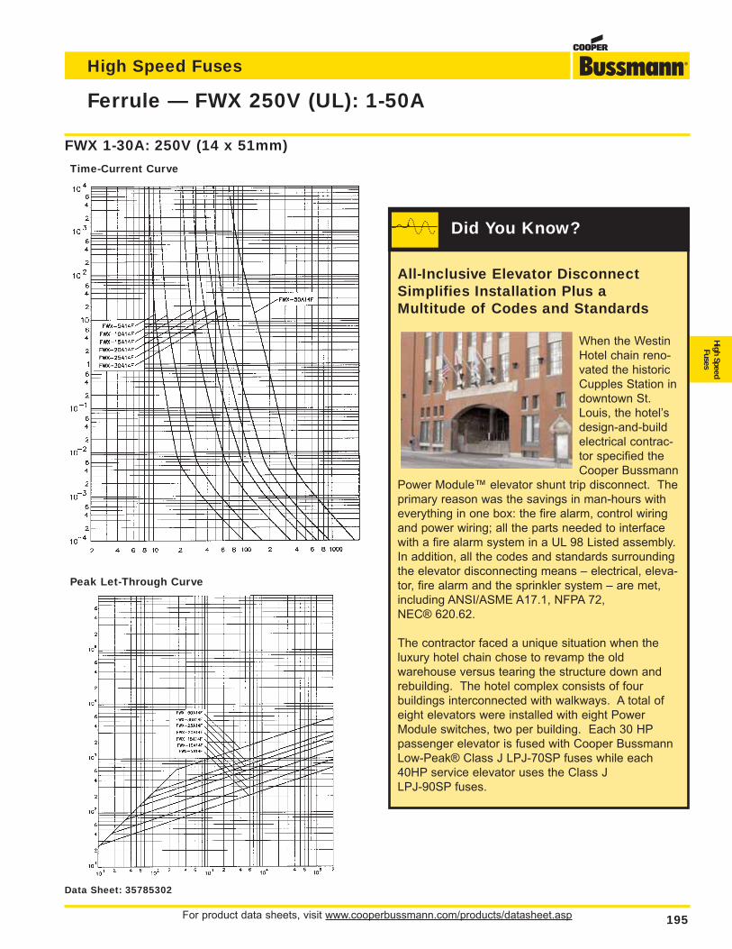
For product data sheets, visit www.cooperbussmann.com/products/datasheet.asp 195
Ferrule — FWX 250V (UL): 1-50A
High Speed Fuses
High SpeedFuses
Peak Let-Through Curve
FWX 1-30A: 250V (14 x 51mm)
Time-Current Curve
Data Sheet: 35785302
All-Inclusive Elevator DisconnectSimplifies Installation Plus aMultitude of Codes and Standards
When the WestinHotel chain reno-vated the historicCupples Station indowntown St.Louis, the hotel’sdesign-and-buildelectrical contrac-tor specified theCooper Bussmann
Power Module™ elevator shunt trip disconnect. Theprimary reason was the savings in man-hours witheverything in one box: the fire alarm, control wiringand power wiring; all the parts needed to interfacewith a fire alarm system in a UL 98 Listed assembly.In addition, all the codes and standards surroundingthe elevator disconnecting means – electrical, eleva-tor, fire alarm and the sprinkler system – are met,including ANSI/ASME A17.1, NFPA 72, NEC® 620.62.
The contractor faced a unique situation when theluxury hotel chain chose to revamp the old warehouse versus tearing the structure down andrebuilding. The hotel complex consists of four buildings interconnected with walkways. A total ofeight elevators were installed with eight PowerModule switches, two per building. Each 30 HPpassenger elevator is fused with Cooper BussmannLow-Peak® Class J LPJ-70SP fuses while each40HP service elevator uses the Class J LPJ-90SP fuses.
Did You Know?
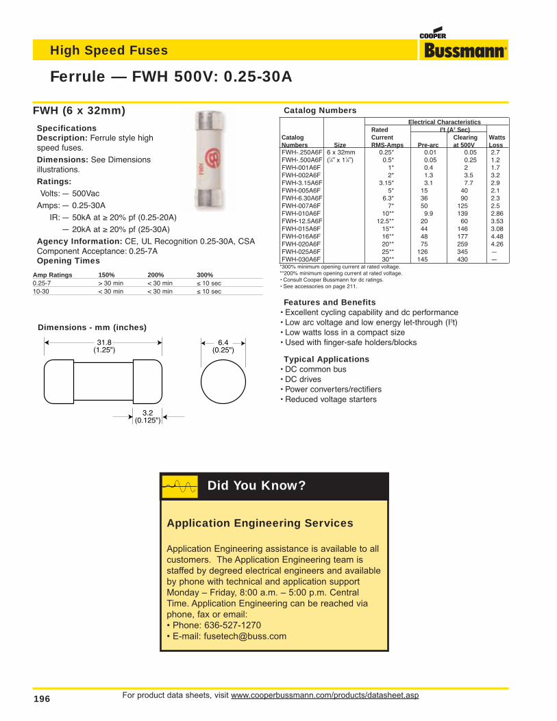
For product data sheets, visit www.cooperbussmann.com/products/datasheet.asp196
Ferrule — FWH 500V: 0.25-30A
High Speed Fuses
FWH (6 x 32mm)
SpecificationsDescription: Ferrule style highspeed fuses.
Dimensions: See Dimensionsillustrations.
Ratings:Volts: — 500Vac
Amps: — 0.25-30A
IR: — 50kA at ≥ 20% pf (0.25-20A)
— 20kA at ≥ 20% pf (25-30A)
Agency Information: CE, UL Recognition 0.25-30A, CSAComponent Acceptance: 0.25-7AOpening Times
Amp Ratings 150% 200% 300%0.25-7 > 30 min < 30 min ≤ 10 sec10-30 < 30 min < 30 min ≤ 10 sec
31.8(1.25")
3.2(0.125")
6.4(0.25")
Dimensions - mm (inches)
Catalog NumbersElectrical Characteristics
Rated I2t (A2 Sec)Catalog Current Clearing WattsNumbers Size RMS-Amps Pre-arc at 500V LossFWH-.250A6F 6 x 32mm 0.25* 0.01 0.05 2.7FWH-.500A6F (1⁄4” x 11⁄4”) 0.5* 0.05 0.25 1.2FWH-001A6F 1* 0.4 2 1.7FWH-002A6F 2* 1.3 3.5 3.2FWH-3.15A6F 3.15* 3.1 7.7 2.9FWH-005A6F 5* 15 40 2.1FWH-6.30A6F 6.3* 36 90 2.3FWH-007A6F 7* 50 125 2.5FWH-010A6F 10** 9.9 139 2.86 FWH-12.5A6F 12.5** 20 60 3.53FWH-015A6F 15** 44 146 3.08FWH-016A6F 16** 48 177 4.48FWH-020A6F 20** 75 259 4.26FWH-025A6F 25** 126 345 —FWH-030A6F 30** 145 430 —
*300% minimum opening current at rated voltage.**200% minimum opening current at rated voltage.• Consult Cooper Bussmann for dc ratings.• See accessories on page 211.
Features and Benefits• Excellent cycling capability and dc performance• Low arc voltage and low energy let-through (I2t)• Low watts loss in a compact size• Used with finger-safe holders/blocks
Typical Applications• DC common bus• DC drives• Power converters/rectifiers• Reduced voltage starters
Application Engineering Services
Application Engineering assistance is available to allcustomers. The Application Engineering team isstaffed by degreed electrical engineers and availableby phone with technical and application supportMonday – Friday, 8:00 a.m. – 5:00 p.m. CentralTime. Application Engineering can be reached viaphone, fax or email:• Phone: 636-527-1270• E-mail: [email protected]
Did You Know?
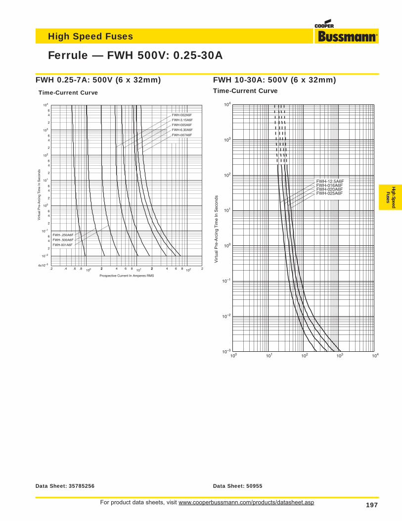
For product data sheets, visit www.cooperbussmann.com/products/datasheet.asp 197
Ferrule — FWH 500V: 0.25-30A
High Speed Fuses
High SpeedFuses
.2 .4 .6 .8 100 22 4 6 8 2101 2 4 6 8 2102
Prospective Current In Amperes RMS
2
46
2
64
2
64
2
64
2
64
2
64
10–1
10–2
4x10⁻³
100
101
102
103
104
Vir
tual
Pre
-Arc
ing
Tim
e In
Sec
onds
FWH-002A6F
FWH-3.15A6F
FWH-005A6F
FWH-6.30A6F
FWH-001A6F
FWH-.500A6F
FWH-.250A6F
FWH-007A6F
FWH 0.25-7A: 500V (6 x 32mm)
Time-Current Curve
Vir
tual
Pre
-Arc
ing
Tim
e In
Sec
onds
10–3
10–2
10–1
100
101
100
102
101
103
103 104102
104
FWH-12.5A6FFWH-016A6FFWH-020A6FFWH-025A6F
FWH 10-30A: 500V (6 x 32mm)Time-Current Curve
Data Sheet: 35785256 Data Sheet: 50955
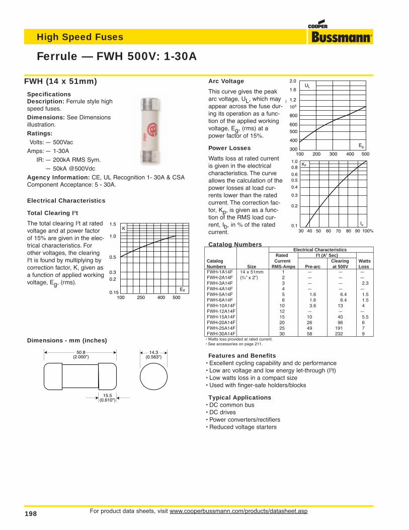
For product data sheets, visit www.cooperbussmann.com/products/datasheet.asp198
Ferrule — FWH 500V: 1-30A
High Speed Fuses
Dimensions - mm (inches)
50.8(2.000")
15.5(0.610")
14.3(0.563")
FWH (14 x 51mm)
SpecificationsDescription: Ferrule style highspeed fuses.
Dimensions: See Dimensionsillustration.
Ratings:Volts: — 500Vac
Amps: — 1-30A
IR: — 200kA RMS Sym.
— 50kA @500Vdc
Agency Information: CE, UL Recognition 1- 30A & CSAComponent Acceptance: 5 - 30A.
Electrical Characteristics
Total Clearing I2t
The total clearing I2t at ratedvoltage and at power factorof 15% are given in the elec-trical characteristics. Forother voltages, the clearingI2t is found by multiplying bycorrection factor, K, given asa function of applied workingvoltage, Eg, (rms).
500400250100
1.5
1.0
0.5
0.3
0.2
0.15Eg
K
Arc Voltage
This curve gives the peakarc voltage, UL, which mayappear across the fuse dur-ing its operation as a func-tion of the applied workingvoltage, Eg, (rms) at apower factor of 15%.
Power Losses
Watts loss at rated currentis given in the electricalcharacteristics. The curveallows the calculation of thepower losses at load cur-rents lower than the ratedcurrent. The correction fac-tor, Kp, is given as a func-tion of the RMS load cur-rent, Ib, in % of the ratedcurrent.
Catalog NumbersElectrical Characteristics
Rated I2t (A2 Sec)Catalog Current Clearing WattsNumbers Size RMS-Amps Pre-arc at 500V LossFWH-1A14F 14 x 51mm 1 — — —FWH-2A14F (9⁄16” x 2”) 2 — — —FWH-3A14F 3 — — 2.3FWH-4A14F 4 — — —FWH-5A14F 5 1.6 6.4 1.5FWH-6A14F 6 1.6 6.4 1.5FWH-10A14F 10 3.6 13 4FWH-12A14F 12 — — —FWH-15A14F 15 10 40 5.5FWH-20A14F 20 26 96 6FWH-25A14F 25 49 191 7FWH-30A14F 30 58 232 9
• Watts loss provided at rated current.• See accessories on page 211.
Features and Benefits• Excellent cycling capability and dc performance• Low arc voltage and low energy let-through (I2t)• Low watts loss in a compact size• Used with finger-safe holders/blocks
Typical Applications• DC common bus• DC drives• Power converters/rectifiers• Reduced voltage starters
UL
2.0
1.6
1.2
103
800
600
500
400
300100 400300200 500
Eg
Kp1.00.8
0.4
0.50.6
0.3
0.2
0.130 40 50 60 70 80 90 100%
Ib
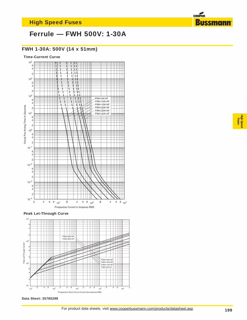
For product data sheets, visit www.cooperbussmann.com/products/datasheet.asp 199
Ferrule — FWH 500V: 1-30A
High Speed Fuses
High SpeedFuses
Peak Let-Through Curve
2 4 6 8 101 22 4 6 8 2102 2 4 6 8 103
2
46
2
64
2
64
2
64
2
64
2
64
64
2
6
2
4
FWH-5A14FFWH-10A14FFWH-15A14FFWH-20A14FFWH-25A14FFWH-30A14F
Vir
tual
Pre
-Arc
ing
Tim
e In
Sec
onds
Prospective Current In Amperes RMS
103
100
101
104
102
10–4
10–3
10–2
10–1
FWH 1-30A: 500V (14 x 51mm)
Time-Current Curve
Prospective Short-Circuit Current Symmetrical RMS
Pea
k Le
t-T
hrou
gh C
urre
nt
2
4
2
6
6
4
2
6
4
2 4 6 2 4 6 2 4 6 2 4 6101
102
103
104
101 102 103 104 105
FWH-5A14FFWH-10A14FFWH-15A14FFWH-20A14F
FWH-25A14FFWH-30A14F
2
Data Sheet: 35785298
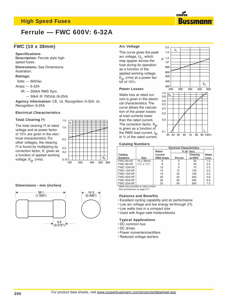
For product data sheets, visit www.cooperbussmann.com/products/datasheet.asp200
Ferrule — FWC 600V: 6-32A
High Speed Fuses
Dimensions - mm (inches)
38.1(1.500")
9.5(0.375")
10.3(0.406")
FWC (10 x 38mm)
SpecificationsDescription: Ferrule style highspeed fuses.
Dimensions: See Dimensionsillustration.
Ratings:Volts: — 600Vac
Amps: — 6-32A
IR: — 200kA RMS Sym.
— 50kA @ 700Vdc (6-25A)
Agency Information: CE, UL Recognition: 6-32A. ULRecognition: 6-25A
Electrical Characteristics
Total Clearing I2t
The total clearing I2t at ratedvoltage and at power factorof 15% are given in the elec-trical characteristics. Forother voltages, the clearingI2t is found by multiplying bycorrection factor, K, given asa function of applied workingvoltage, Eg, (rms).
Arc Voltage
This curve gives the peakarc voltage, UL, whichmay appear across thefuse during its operationas a function of theapplied working voltage,Eg, (rms) at a power fac-tor of 15%.
Power Losses
Watts loss at rated cur-rent is given in the electri-cal characteristics. Thecurve allows the calcula-tion of the power lossesat load currents lowerthan the rated current.The correction factor, Kp,is given as a function ofthe RMS load current, Ib,in % of the rated current.
Catalog NumbersElectrical Characteristics
Rated I2t (A2 Sec)Catalog Current Clearing WattsNumbers Size RMS-Amps Pre-arc at 600V LossFWC-6A10F 10 x 38mm 6 4 30 1.5FWC-8A10F (13⁄32” x 11⁄2”) 8 6 50 2.0FWC-10A10F 10 9 70 2.5FWC-12A10F 12 15 120 3.0FWC-16A10F 16 25 150 3.5FWC-20A10F 20 34 260 4.8FWC-25A10F 25 60 390 6.0FWC-32A10F 32 95 600 7.5
• Watts loss provided at rated current.• See accessories on page 211.
Features and Benefits• Excellent cycling capability and dc performance• Low arc voltage and low energy let-through (I2t)• Low watts loss in a compact size• Used with finger-safe holders/blocks
Typical Applications• DC common bus• DC drives• Power converters/rectifiers• Reduced voltage starters
500 600400250100
1.5
1.0
0.5
0.3
0.2
0.15Eg
K
UL
2.0
1.6
1.2
103
800
600
500
400
300400300200 500 600
Eg
Kp1.00.8
0.4
0.50.6
0.3
0.2
0.130 40 50 60 70 80 90 100%
Ib
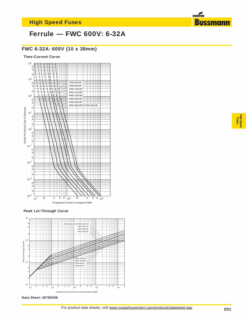
For product data sheets, visit www.cooperbussmann.com/products/datasheet.asp 201
Ferrule — FWC 600V: 6-32A
High Speed Fuses
High SpeedFuses
103
104
102
10–1
10–2
10–3
10–4
101 22 4 6 8 2102 2 4 6 8 103
2
46
2
64
100
2
64
101
2
64
2
64
2
64
64
2
6
2
4
Prospective Current In Amperes RMS
Vir
tual
Pre
-Arc
ing
Tim
e In
Sec
onds
FWC-10A10F
FWC-30A10F & FWC-32A10F
FWC-20A10FFWC-25A10F
FWC-12A10FFWC-16A10F
FWC-8A10F FWC-6A10F
Prospective Short-Circuit Current Symmetrical RMS
Pea
k Le
t-T
hrou
gh C
urre
nt
2
4
2
6
6
4
2
6
4
2 4 6 2 4 6 2 4 6 24 6101
102
103
104
101 102 103 104 105
FWC-6A10FFWC-8A10FFWC-10A10FFWC-12A10F
FWC-16A10FFWC-20A10FFWC-25A10F
FWC-30A10F & FWC-32A10F
Peak Let-Through Curve
FWC 6-32A: 600V (10 x 38mm)
Time-Current Curve
Data Sheet: 35785306
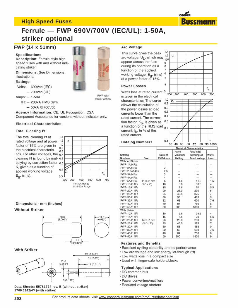
For product data sheets, visit www.cooperbussmann.com/products/datasheet.asp202
Ferrule — FWP 690V/700V (IEC/UL): 1-50A,striker optional
High Speed Fuses
Dimensions - mm (inches)
51 (2.00")
59 (2.323")
13 (0.511")
14.3(0.563")
5 (0.197")
FWP (14 x 51mm)
SpecificationsDescription: Ferrule style highspeed fuses with and without indi-cating striker.
Dimensions: See Dimensionsillustrations.
Ratings:Volts: — 690Vac (IEC)
— 700Vac (UL)
Amps: — 1-50A
IR: — 200kA RMS Sym.
— 50kA @700Vdc
Agency Information: CE, UL Recognition, CSAComponent Acceptance for versions without indicator only.
Electrical Characteristics
Total Clearing I2t
The total clearing I2t atrated voltage and at powerfactor of 15% are given inthe electrical characteris-tics. For other voltages, theclearing I2t is found by mul-tiplying by correction factor,K, given as a function ofapplied working voltage,Eg, (rms).
Arc Voltage
This curve gives the peakarc voltage, UL, which mayappear across the fuseduring its operation as afunction of the appliedworking voltage, Eg, (rms)at a power factor of 15%.
Power Losses
Watts loss at rated currentis given in the electricalcharacteristics. The curveallows the calculation ofthe power losses at loadcurrents lower than therated current. The correc-tion factor, Kp, is given asa function of the RMS loadcurrent, Ib, in % of therated current.
Catalog Numbers
Rated I2t (A2 Sec)Catalog Current Minimum Clearing At WattsNumbers Size RMS-Amps Melting Rated Voltage LossWithout StrikerFWP-1A14Fa 1 — — —FWP-2A14Fa 2 — — —FWP-2.5A14Fa 2.5 — — —FWP-3A14Fa 3 — — —FWP-4A14Fa 4 — — —FWP-5A14Fa 14 x 51mm 5 1.6 11.0 1.5FWP-10A14Fa (9⁄16" x 2") 10 3.6 38.5 4FWP-15A14Fa 15 8.6 70 5.5FWP-20A14Fa 20 26.0 230 6FWP-25A14Fa 25 46.5 375 7FWP-30A14Fa 30 58 485 9FWP-32A14Fa 32 68 600 7.6FWP-40A14Fa 40 84 750 8FWP-50A14Fa 50 200 1800 9With StrikerFWP-10A14FI 10 3.6 38.5 4FWP-15A14FI 15 8.6 70 5.5FWP-20A14FI 14 x 51mm 20 26.0 230 6FWP-25A14FI (9⁄16” x 2”) 25 46.5 375 7FWP-30A14FI 30 58 485 9FWP-32A14FI 32 68 600 7.6FWP-40A14FI 40 84 750 8FWP-50A14FI 50 200 1800 9
Features and Benefits• Excellent cycling capability and dc performance• Low arc voltage and low energy let-through (I2t)• Low watts loss in a compact size• Used with finger-safe holders/blocks
Typical Applications• DC common bus• DC drives• Power converters/rectifiers• Reduced voltage starters
UL
1.41.2
103
6
87
9
5
4
3200 300 400 500 600 700
Eg
Kp1.00.8
0.4
0.50.6
0.3
0.2
0.130 40 50 60 70 80 90 100%
Ib
Data Sheets: E5781724 rev. B (without striker) 170K5342/43 (with striker)
K
1.41.2
1.0
0.6
0.80.7
0.9
0.5
0.4
0.3200 300 400 500 600 700
Eg
1)
2)
1) 5-30A Range2) 32-50A Range
50.8(2.000")
15.5(0.610")
14.3(0.563")
With Striker
Without Striker
FWP withstriker option.
Electrical Characteristics
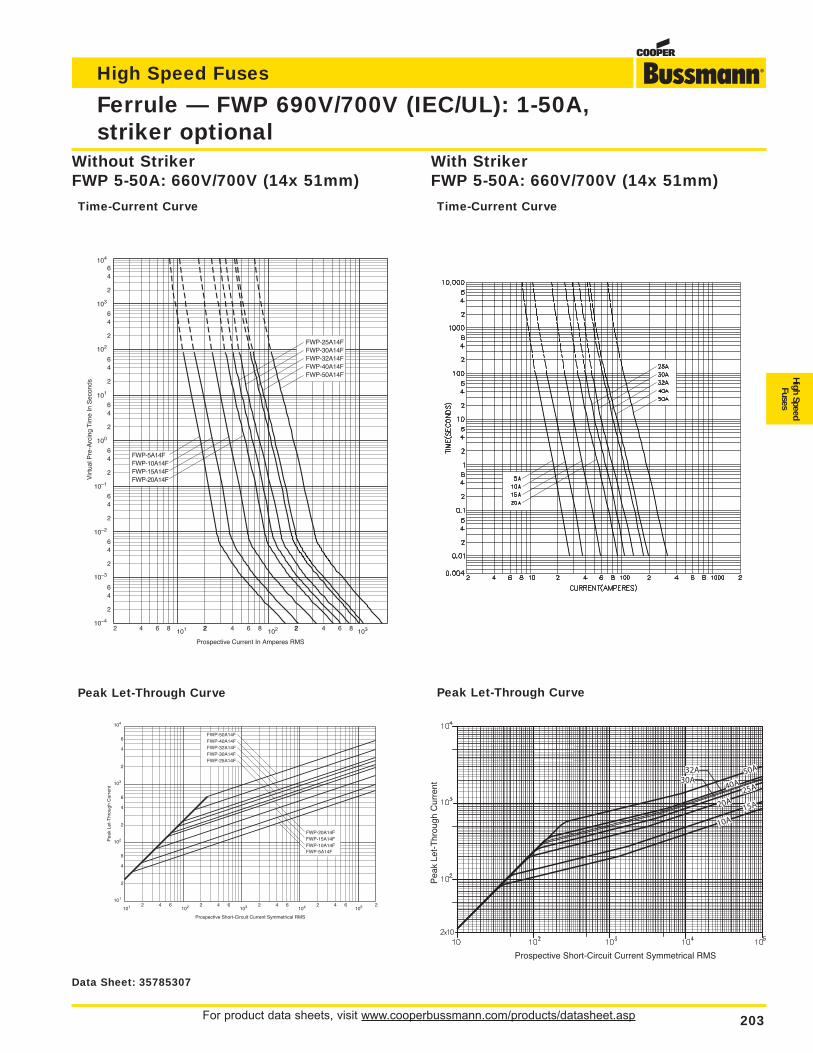
For product data sheets, visit www.cooperbussmann.com/products/datasheet.asp 203
Ferrule — FWP 690V/700V (IEC/UL): 1-50A,striker optional
High Speed Fuses
High SpeedFuses
103
102
10–1
10–2
10–3
10–4
FWP-10A14FFWP-15A14FFWP-20A14F
FWP-5A14F
FWP-50A14F
FWP-30A14FFWP-32A14FFWP-40A14F
FWP-25A14F
2 4 6 8 101 22 4 6 8 2102 2 4 6 8 103
2
46
2
64
100
2
64
101
2
64
2
64
2
64
64
2
6
2
4
Prospective Current In Amperes RMS
Vir
tual
Pre
-Arc
ing
Tim
e In
Sec
onds
104
Prospective Short-Circuit Current Symmetrical RMS
Pea
k Le
t-T
hrou
gh C
urre
nt
2
4
2
6
6
4
2
6
4
2 4 6 2 4 6 2 4 6 2 4 6101
102
103
104
101 102 103 104 105
FWP-5A14FFWP-10A14FFWP-15A14FFWP-20A14F
FWP-25A14FFWP-30A14FFWP-32A14FFWP-40A14FFWP-50A14F
2
Peak Let-Through Curve Peak Let-Through Curve
Without StrikerFWP 5-50A: 660V/700V (14x 51mm)
Time-Current Curve
With StrikerFWP 5-50A: 660V/700V (14x 51mm)
Time-Current Curve
Data Sheet: 35785307
20A
32A30A
40A
50A
25A
15A
10A
Pea
k Le
t-T
hrou
gh C
urre
nt
Prospective Short-Circuit Current Symmetrical RMS
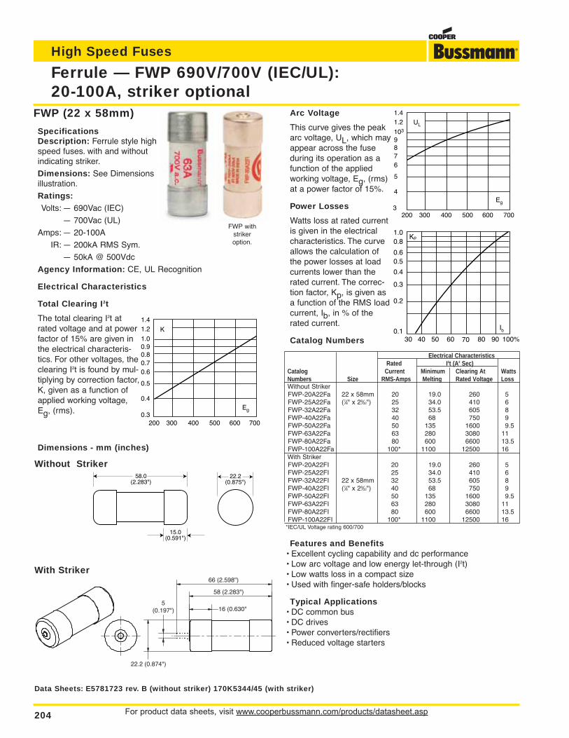
For product data sheets, visit www.cooperbussmann.com/products/datasheet.asp204
Ferrule — FWP 690V/700V (IEC/UL):20-100A, striker optional
High Speed Fuses
Dimensions - mm (inches)
66 (2.598")
58 (2.283")
16 (0.630"
22.2 (0.874")
5(0.197")
FWP (22 x 58mm)
SpecificationsDescription: Ferrule style highspeed fuses. with and withoutindicating striker.
Dimensions: See Dimensionsillustration.
Ratings:Volts: — 690Vac (IEC)
— 700Vac (UL)
Amps: — 20-100A
IR: — 200kA RMS Sym.
— 50kA @ 500Vdc
Agency Information: CE, UL Recognition
Electrical Characteristics
Total Clearing I2t
The total clearing I2t atrated voltage and at powerfactor of 15% are given inthe electrical characteris-tics. For other voltages, theclearing I2t is found by mul-tiplying by correction factor,K, given as a function ofapplied working voltage,Eg, (rms).
Arc Voltage
This curve gives the peakarc voltage, UL, which mayappear across the fuseduring its operation as afunction of the appliedworking voltage, Eg, (rms)at a power factor of 15%.
Power Losses
Watts loss at rated currentis given in the electricalcharacteristics. The curveallows the calculation ofthe power losses at loadcurrents lower than therated current. The correc-tion factor, Kp, is given asa function of the RMS loadcurrent, Ib, in % of therated current.
Catalog Numbers
Electrical CharacteristicsRated I2t (A2 Sec)
Catalog Current Minimum Clearing At WattsNumbers Size RMS-Amps Melting Rated Voltage LossWithout StrikerFWP-20A22Fa 22 x 58mm 20 19.0 260 5FWP-25A22Fa (7⁄8" x 29⁄32") 25 34.0 410 6FWP-32A22Fa 32 53.5 605 8FWP-40A22Fa 40 68 750 9FWP-50A22Fa 50 135 1600 9.5FWP-63A22Fa 63 280 3080 11FWP-80A22Fa 80 600 6600 13.5FWP-100A22Fa 100* 1100 12500 16With StrikerFWP-20A22FI 20 19.0 260 5FWP-25A22FI 25 34.0 410 6FWP-32A22FI 22 x 58mm 32 53.5 605 8FWP-40A22FI (7⁄8" x 29⁄32") 40 68 750 9FWP-50A22FI 50 135 1600 9.5FWP-63A22FI 63 280 3080 11FWP-80A22FI 80 600 6600 13.5FWP-100A22FI 100* 1100 12500 16
*IEC/UL Voltage rating 600/700
Features and Benefits• Excellent cycling capability and dc performance• Low arc voltage and low energy let-through (I2t)• Low watts loss in a compact size• Used with finger-safe holders/blocks
Typical Applications• DC common bus• DC drives• Power converters/rectifiers• Reduced voltage starters
K
1.41.2
1.0
0.6
0.80.7
0.9
0.5
0.4
0.3200 300 400 500 600 700
Eg
UL
1.41.2
103
6
87
9
5
4
3200 300 400 500 600 700
Eg
Kp1.00.8
0.4
0.50.6
0.3
0.2
0.130 40 50 60 70 80 90 100%
Ib
Data Sheets: E5781723 rev. B (without striker) 170K5344/45 (with striker)
58.0(2.283")
15.0(0.591")
22.2(0.875")
With Striker
Without Striker
FWP withstrikeroption.
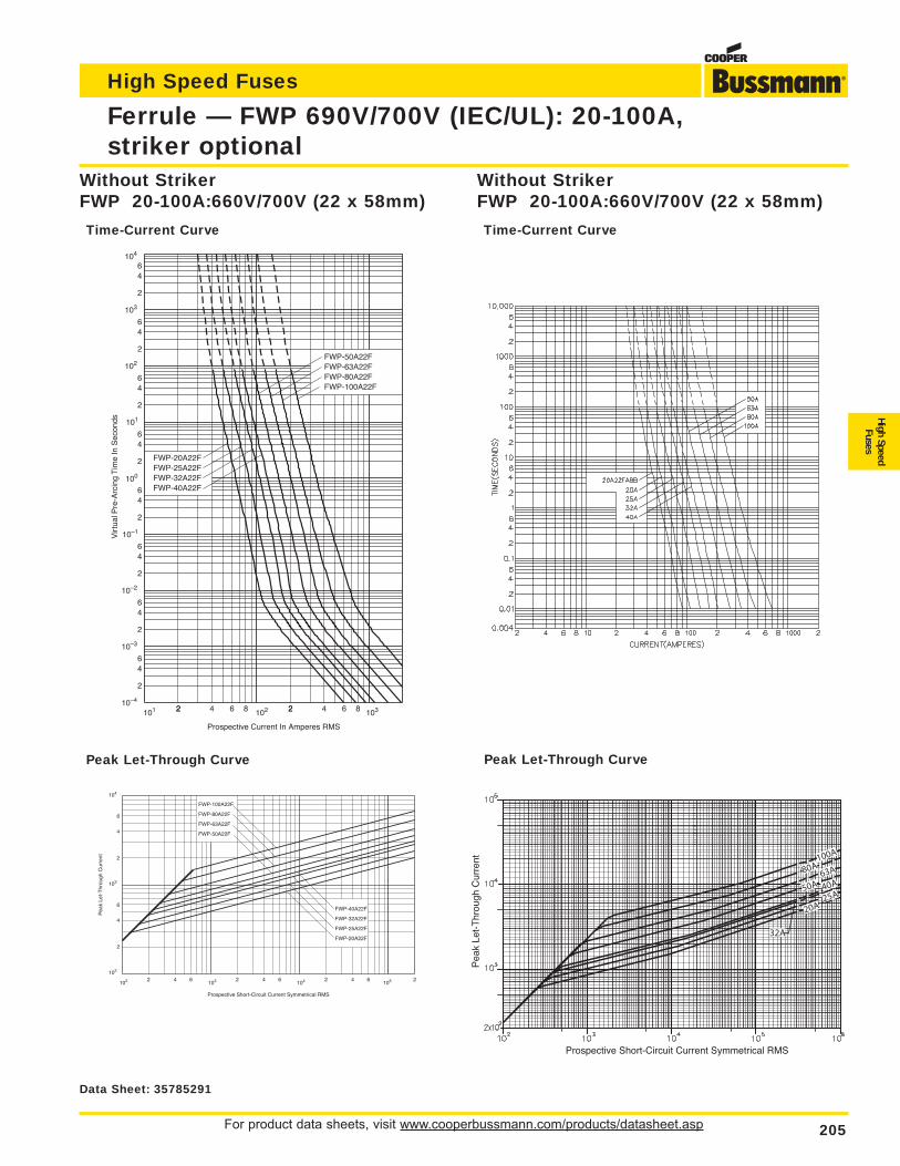
For product data sheets, visit www.cooperbussmann.com/products/datasheet.asp 205
Ferrule — FWP 690V/700V (IEC/UL): 20-100A,striker optional
High Speed Fuses
High SpeedFuses
101 22 4 6 8 2102 2 4 6 8 103
2
46
2
64
2
64
2
64
2
64
2
64
64
2
6
2
4
101
100
10–1
10–2
10–3
10–4
102
103
104
Prospective Current In Amperes RMS
Vir
tual
Pre
-Arc
ing
Tim
e In
Sec
onds
FWP-20A22FFWP-25A22FFWP-32A22FFWP-40A22F
FWP-50A22FFWP-63A22FFWP-80A22FFWP-100A22F
104
Prospective Short-Circuit Current Symmetrical RMS
Pea
k Le
t-T
hrou
gh C
urre
nt
2
6
4
2
6
4
2 4 6 2 4 6 24 6102
103
102 103 104 105
FWP-20A22F
FWP-25A22F
FWP-32A22F
FWP-40A22F
FWP-50A22F
FWP-63A22F
FWP-80A22F
FWP-100A22F
2
Peak Let-Through Curve Peak Let-Through Curve
Without StrikerFWP 20-100A:660V/700V (22 x 58mm)
Time-Current Curve
Without StrikerFWP 20-100A:660V/700V (22 x 58mm)
Time-Current Curve
Data Sheet: 35785291
20A25A
50A 40A63A80A
100A
32A
Prospective Short-Circuit Current Symmetrical RMS
Pea
k Le
t-T
hrou
gh C
urre
nt
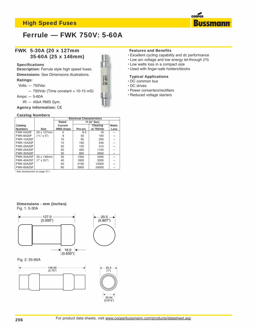
For product data sheets, visit www.cooperbussmann.com/products/datasheet.asp206
Ferrule — FWK 750V: 5-60A
High Speed Fuses
Dimensions - mm (inches)Fig. 1: 5-30A
146.05(5.75")
25.4(1")
20.64(0.813")
Fig. 2: 35-60A
127.0(5.000")
16.0(0.630")
20.5(0.807")
FWK 5-30A (20 x 127mm35-60A (25 x 146mm)
SpecificationsDescription: Ferrule style high speed fuses.
Dimensions: See Dimensions illustrations.
Ratings:Volts: — 750Vac
— 750Vdc (Time constant = 10-15 mS)
Amps: — 5-60A
IR: — 45kA RMS Sym.
Agency Information: CE
Catalog NumbersElectrical Characteristics
Rated I2t (A2 Sec)Catalog Current Clearing WattsNumbers Size RMS-Amps Pre-arc at 750Vdc LossFWK-5A20F 20 x 127mm 5 8.5 16 —FWK-8A20F (13⁄16” x 5”) 8 50 100 —FWK-10A20F 10 95 200 —FWK-15A20F 15 100 240 —FWK-20A20F 20 125 315 —FWK-25A20F 25 400 1100 —FWK-30A20F 30 800 2600 —FWK-35A25F 25 x 146mm 35 1300 4300 —FWK-40A25F (1” x 53⁄4”) 40 1600 5300 —FWK-50A25F 50 3100 12000 —FWK-60A25F 60 5900 24000 —
• See accessories on page 211.
Features and Benefits• Excellent cycling capability and dc performance• Low arc voltage and low energy let-through (I2t)• Low watts loss in a compact size• Used with finger-safe holders/blocks
Typical Applications• DC common bus• DC drives• Power converters/rectifiers• Reduced voltage starters
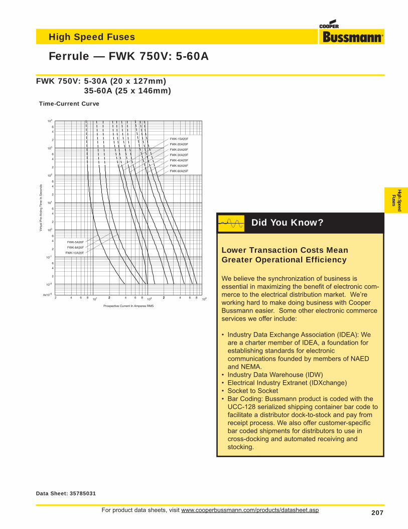
For product data sheets, visit www.cooperbussmann.com/products/datasheet.asp 207
Ferrule — FWK 750V: 5-60A
High Speed Fuses
High SpeedFuses
2 4 6 8 101 22 4 6 8 2102 2 4 6 8 103
2
4
6
2
6
4
2
6
4
2
6
4
2
6
4
2
6
4
10±1
10±2
4x10±3
100
101
102
103
104
FWK-15A20F
FWK-20A20F
FWK-25A20F
FWK-30A20F
FWK-40A25F
FWK-50A25F
FWK-60A25F
FWK-5A20F
FWK-8A20F
FWK-10A20F
Prospective Current In Amperes RMS
Vir
tual
Pre
-Arc
ing
Tim
e In
Sec
onds
FWK 750V: 5-30A (20 x 127mm)35-60A (25 x 146mm)
Time-Current Curve
Data Sheet: 35785031
Lower Transaction Costs MeanGreater Operational Efficiency
We believe the synchronization of business isessential in maximizing the benefit of electronic com-merce to the electrical distribution market. We’reworking hard to make doing business with CooperBussmann easier. Some other electronic commerceservices we offer include:
• Industry Data Exchange Association (IDEA): Weare a charter member of IDEA, a foundation for establishing standards for electronic communications founded by members of NAED and NEMA.
• Industry Data Warehouse (IDW)• Electrical Industry Extranet (IDXchange)• Socket to Socket• Bar Coding: Bussmann product is coded with the
UCC-128 serialized shipping container bar code to facilitate a distributor dock-to-stock and pay from receipt process. We also offer customer-specific bar coded shipments for distributors to use in cross-docking and automated receiving and stocking.
Did You Know?
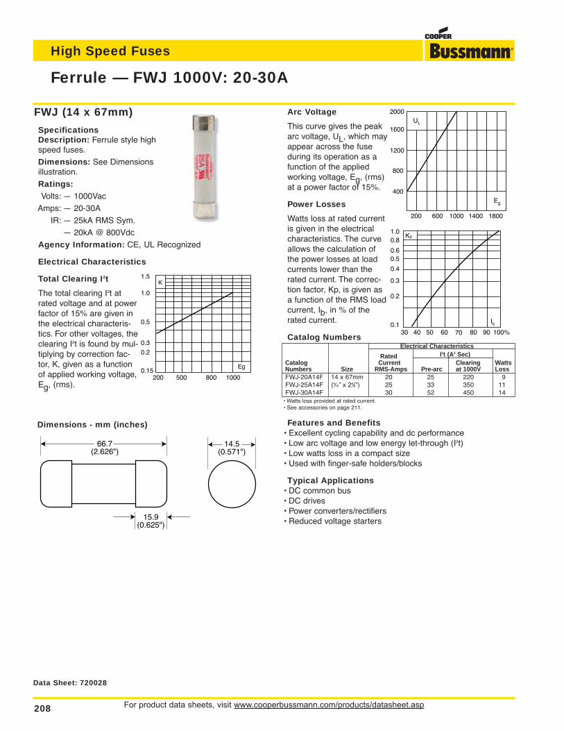
For product data sheets, visit www.cooperbussmann.com/products/datasheet.asp208
Ferrule — FWJ 1000V: 20-30A
High Speed Fuses
Dimensions - mm (inches)
66.7(2.626")
15.9(0.625")
14.5(0.571")
FWJ (14 x 67mm)
SpecificationsDescription: Ferrule style highspeed fuses.
Dimensions: See Dimensionsillustration.
Ratings:Volts: — 1000Vac
Amps: — 20-30A
IR: — 25kA RMS Sym.
— 20kA @ 800Vdc
Agency Information: CE, UL Recognized
Electrical Characteristics
Total Clearing I2t
The total clearing I2t atrated voltage and at powerfactor of 15% are given inthe electrical characteris-tics. For other voltages, theclearing I2t is found by mul-tiplying by correction fac-tor, K, given as a functionof applied working voltage,Eg, (rms).
Arc Voltage
This curve gives the peakarc voltage, UL, which mayappear across the fuseduring its operation as afunction of the appliedworking voltage, Eg, (rms)at a power factor of 15%.
Power Losses
Watts loss at rated currentis given in the electricalcharacteristics. The curveallows the calculation ofthe power losses at loadcurrents lower than therated current. The correc-tion factor, Kp, is given asa function of the RMS loadcurrent, Ib, in % of therated current.
Catalog NumbersElectrical Characteristics
Rated I2t (A2 Sec)Catalog Current Clearing WattsNumbers Size RMS-Amps Pre-arc at 1000V LossFWJ-20A14F 14 x 67mm 20 25 220 9FWJ-25A14F (9⁄16” x 25⁄8”) 25 33 350 11FWJ-30A14F 30 52 450 14
• Watts loss provided at rated current.• See accessories on page 211.
Features and Benefits• Excellent cycling capability and dc performance• Low arc voltage and low energy let-through (I2t)• Low watts loss in a compact size• Used with finger-safe holders/blocks
Typical Applications• DC common bus• DC drives• Power converters/rectifiers• Reduced voltage starters
1000800500200
1.5
1.0
0.5
0.3
0.2
0.15Eg
K
2000
1600
1200
800
400
200 600 1000 1400 1800
UL
Eg
Kp1.00.8
0.4
0.50.6
0.3
0.2
0.130 40 50 60 70 80 90 100%
Ib
Data Sheet: 720028
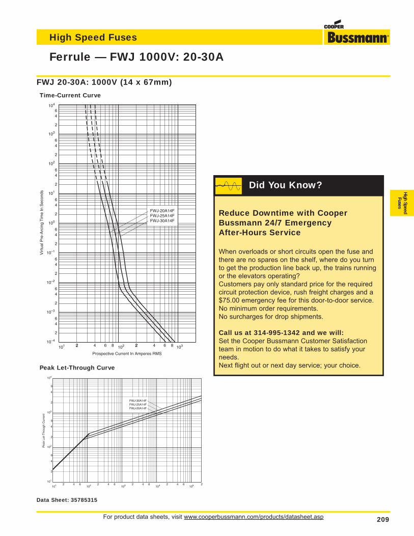
For product data sheets, visit www.cooperbussmann.com/products/datasheet.asp 209
Ferrule — FWJ 1000V: 20-30A
High Speed Fuses
High SpeedFuses
FWJ-20A14FFWJ-25A14FFWJ-30A14F
101 22 4 6 8 2102 2 4 6 8 103
2
46
2
64
2
64
2
64
2
64
2
64
64
2
6
2
4
10–4
100
101
10–1
10–2
10–3
102
103
104
Prospective Current In Amperes RMS
Vir
tual
Pre
-Arc
ing
Tim
e In
Sec
onds
FWJ 20-30A: 1000V (14 x 67mm)
Time-Current Curve
Pea
k Le
t-T
hrou
gh C
urre
nt
2
4
2
6
6
4
2
6
4
2 4 6 2 4 6 2 4 6 2 4 6101
102
103
104
101 102 103 104 105
FWJ-20A14FFWJ-25A14FFWJ-30A14F
2
Peak Let-Through Curve
Data Sheet: 35785315
Reduce Downtime with CooperBussmann 24/7 Emergency After-Hours Service
When overloads or short circuits open the fuse andthere are no spares on the shelf, where do you turnto get the production line back up, the trains runningor the elevators operating?Customers pay only standard price for the requiredcircuit protection device, rush freight charges and a$75.00 emergency fee for this door-to-door service. No minimum order requirements.No surcharges for drop shipments.
Call us at 314-995-1342 and we will:Set the Cooper Bussmann Customer Satisfactionteam in motion to do what it takes to satisfy yourneeds.Next flight out or next day service; your choice.
Did You Know?
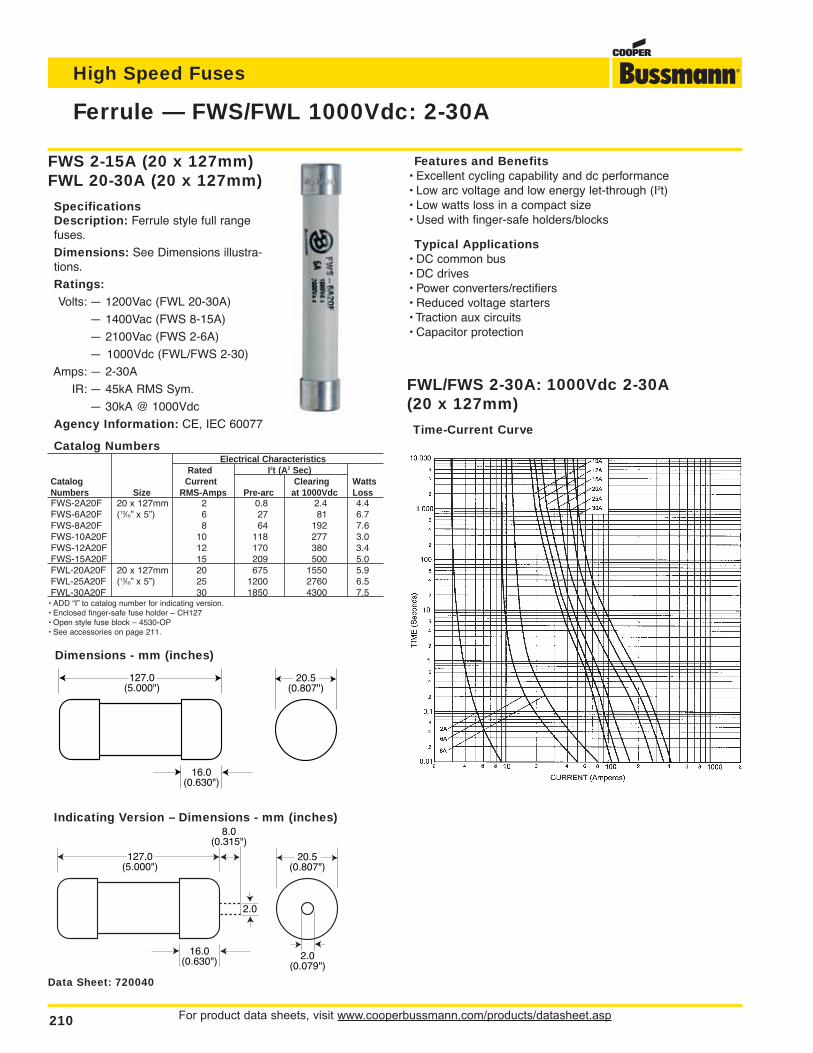
For product data sheets, visit www.cooperbussmann.com/products/datasheet.asp210
Ferrule — FWS/FWL 1000Vdc: 2-30A
High Speed Fuses
Dimensions - mm (inches)
127.0(5.000")
16.0(0.630")
20.5(0.807")
Indicating Version – Dimensions - mm (inches)
127.0(5.000")
16.0(0.630")
20.5(0.807")
2.0(0.079")
2.0
8.0(0.315")
FWL/FWS 2-30A: 1000Vdc 2-30A (20 x 127mm)
Time-Current Curve
FWS 2-15A (20 x 127mm)FWL 20-30A (20 x 127mm)
SpecificationsDescription: Ferrule style full rangefuses.
Dimensions: See Dimensions illustra-tions.
Ratings:Volts: — 1200Vac (FWL 20-30A)
— 1400Vac (FWS 8-15A)
— 2100Vac (FWS 2-6A)
— 1000Vdc (FWL/FWS 2-30)
Amps: — 2-30A
IR: — 45kA RMS Sym.
— 30kA @ 1000Vdc
Agency Information: CE, IEC 60077
Catalog NumbersElectrical Characteristics
Rated I2t (A2 Sec)Catalog Current Clearing WattsNumbers Size RMS-Amps Pre-arc at 1000Vdc LossFWS-2A20F 20 x 127mm 2 0.8 2.4 4.4FWS-6A20F (13⁄16” x 5”) 6 27 81 6.7FWS-8A20F 8 64 192 7.6FWS-10A20F 10 118 277 3.0FWS-12A20F 12 170 380 3.4FWS-15A20F 15 209 500 5.0FWL-20A20F 20 x 127mm 20 675 1550 5.9FWL-25A20F (13⁄16” x 5”) 25 1200 2760 6.5FWL-30A20F 30 1850 4300 7.5
• ADD “I” to catalog number for indicating version.• Enclosed finger-safe fuse holder – CH127• Open style fuse block – 4530-OP• See accessories on page 211.
Features and Benefits• Excellent cycling capability and dc performance• Low arc voltage and low energy let-through (I2t)• Low watts loss in a compact size• Used with finger-safe holders/blocks
Typical Applications• DC common bus• DC drives• Power converters/rectifiers• Reduced voltage starters• Traction aux circuits• Capacitor protection
Data Sheet: 720040
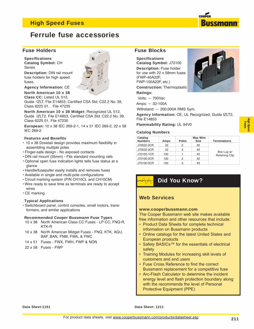
For product data sheets, visit www.cooperbussmann.com/products/datasheet.asp 211
High Speed Fuses
High SpeedFuses
Fuse Blocks
SpecificationsCatalog Symbol: J70100
Description: Fuse holder for use with 22 x 58mm fuses(FWP-40A22F, FWP-100A22F, etc.)
Construction: Thermoplastic
Ratings:Volts: — 700Vac
Amps: — 32-100A
Withstand: — 200,000A RMS Sym.
Agency Information: CE, UL Recognized, Guide IZLT2,File E14853
Flammability Rating: UL 94V0
Catalog NumbersCatalog Max WireNumbers Amps Poles Size TerminationsJ70032-2CR 32 2 #2 Box Lug w/
J70032-3CR 32 3 #2 Retaining Clip
J70100-1CR 100 1 #2
J70100-2CR 100 2 #2
J70100-3CR 100 3 #2
Ferrule fuse accessories
Data Sheet:1151
Fuse Holders
SpecificationsCatalog Symbol: CHSeries
Description: DIN rail mountfuse holders for high speedfuses.
Agency Information: CE
North American 10 x 38Class CC: Listed UL 512,Guide IZLT, File E14853, Certified CSA Std. C22.2 No. 39,Class 6225 01, File 47235
North American 10 x 38 Midget: Recognized UL 512,Guide IZLT2, File E14853, Certified CSA Std. C22.2 No. 39,Class 6225 01, File 47235
European: 10 x 38 IEC 269-2-1, 14 x 51 IEC 269-2, 22 x 58IEC 269-2
Features and Benefits• 10 x 38 Dovetail design provides maximum flexibility in
assembling multiple poles• Finger-safe design - No exposed contacts• DIN rail mount (35mm) - Fits standard mounting rails• Optional open fuse indication lights tells fuse status at a
glance• Handle/fusepuller easily installs and removes fuses• Available in single and multi-pole configurations• Circuit marking system (P/N CH10CL and CH10CM)• Wire ready to save time as terminals are ready to accept
wires• CE marking
Typical Applications• Switchboard panel, control consoles, small motors, trans-
formers, and similar applications
Recommended Cooper Bussmann Fuse Types10 x 38 North American Class CC Fuses - LP-CC, FNQ-R,
KTK-R
10 x 38 North American Midget Fuses - FNQ, KTK, AGU,BAF, BAN, FNM, FWA, & FWC
14 x 51 Fuses - FWX, FWH, FWP & NON
22 x 58 Fuses - FWP
Data Sheet: 1211
Box Lug w/Retaining Clip
Web Services
www.cooperbussmann.comThe Cooper Bussmann web site makes availablefree information and other resources that include:• Product Data Sheets for complete technical
information on Bussmann products• Online catalogs for the latest United States and
European products• Safety BASICs™ for the essentials of electrical
safety• Training Modules for increasing skill levels of
customers and end users• Fuse Cross Reference to find the correct
Bussmann replacement for a competitive fuse• Arc-Flash Calculator to determine the incident
energy level and flash protection boundary along with the recommends the level of Personal Protective Equipment (PPE)
Did You Know?
212
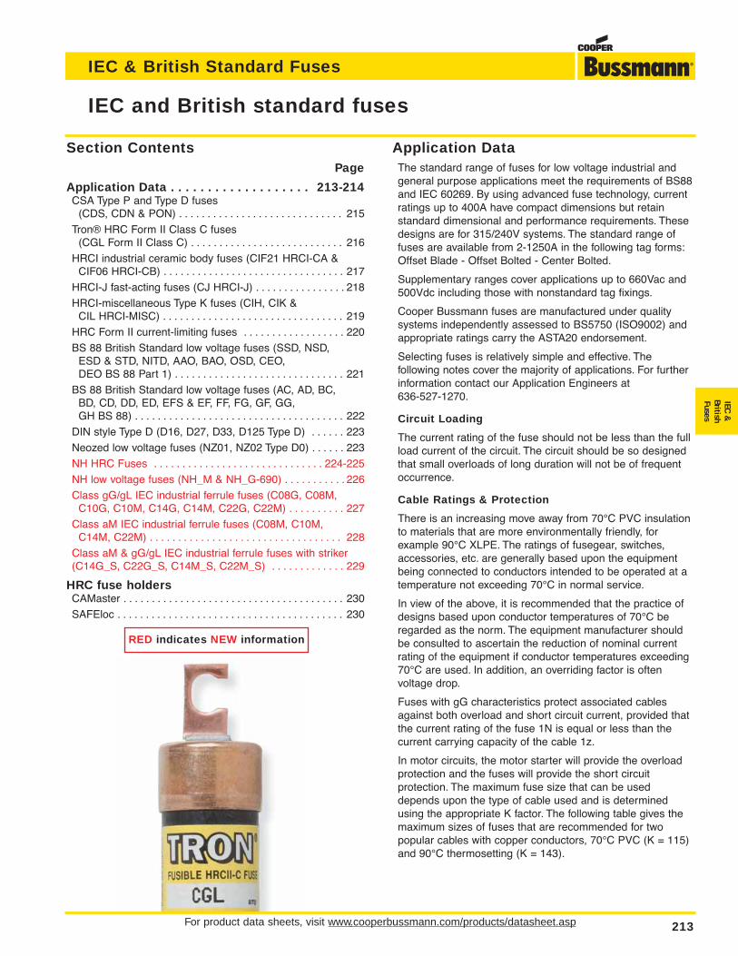
For product data sheets, visit www.cooperbussmann.com/products/datasheet.asp 213
IEC and British standard fuses
IEC & British Standard Fuses
IEC&
BritishFuses
Application DataThe standard range of fuses for low voltage industrial andgeneral purpose applications meet the requirements of BS88and IEC 60269. By using advanced fuse technology, currentratings up to 400A have compact dimensions but retainstandard dimensional and performance requirements. Thesedesigns are for 315/240V systems. The standard range offuses are available from 2-1250A in the following tag forms:Offset Blade - Offset Bolted - Center Bolted.
Supplementary ranges cover applications up to 660Vac and500Vdc including those with nonstandard tag fixings.
Cooper Bussmann fuses are manufactured under qualitysystems independently assessed to BS5750 (ISO9002) andappropriate ratings carry the ASTA20 endorsement.
Selecting fuses is relatively simple and effective. Thefollowing notes cover the majority of applications. For furtherinformation contact our Application Engineers at636-527-1270.
Circuit Loading
The current rating of the fuse should not be less than the fullload current of the circuit. The circuit should be so designedthat small overloads of long duration will not be of frequentoccurrence.
Cable Ratings & Protection
There is an increasing move away from 70°C PVC insulationto materials that are more environmentally friendly, forexample 90°C XLPE. The ratings of fusegear, switches,accessories, etc. are generally based upon the equipmentbeing connected to conductors intended to be operated at atemperature not exceeding 70°C in normal service.
In view of the above, it is recommended that the practice ofdesigns based upon conductor temperatures of 70°C beregarded as the norm. The equipment manufacturer shouldbe consulted to ascertain the reduction of nominal currentrating of the equipment if conductor temperatures exceeding70°C are used. In addition, an overriding factor is oftenvoltage drop.
Fuses with gG characteristics protect associated cablesagainst both overload and short circuit current, provided thatthe current rating of the fuse 1N is equal or less than thecurrent carrying capacity of the cable 1z.
In motor circuits, the motor starter will provide the overloadprotection and the fuses will provide the short circuitprotection. The maximum fuse size that can be useddepends upon the type of cable used and is determinedusing the appropriate K factor. The following table gives themaximum sizes of fuses that are recommended for twopopular cables with copper conductors, 70°C PVC (K = 115)and 90°C thermosetting (K = 143).
Section ContentsPage
Application Data . . . . . . . . . . . . . . . . . . . 213-214CSA Type P and Type D fuses
(CDS, CDN & PON) . . . . . . . . . . . . . . . . . . . . . . . . . . . . . 215
Tron® HRC Form II Class C fuses (CGL Form II Class C) . . . . . . . . . . . . . . . . . . . . . . . . . . . 216
HRCI industrial ceramic body fuses (CIF21 HRCI-CA &CIF06 HRCI-CB) . . . . . . . . . . . . . . . . . . . . . . . . . . . . . . . . 217
HRCI-J fast-acting fuses (CJ HRCI-J) . . . . . . . . . . . . . . . . 218
HRCI-miscellaneous Type K fuses (CIH, CIK & CIL HRCI-MISC) . . . . . . . . . . . . . . . . . . . . . . . . . . . . . . . . 219
HRC Form II current-limiting fuses . . . . . . . . . . . . . . . . . . 220
BS 88 British Standard low voltage fuses (SSD, NSD, ESD & STD, NITD, AAO, BAO, OSD, CEO, DEO BS 88 Part 1) . . . . . . . . . . . . . . . . . . . . . . . . . . . . . . 221
BS 88 British Standard low voltage fuses (AC, AD, BC, BD, CD, DD, ED, EFS & EF, FF, FG, GF, GG, GH BS 88) . . . . . . . . . . . . . . . . . . . . . . . . . . . . . . . . . . . . . 222
DIN style Type D (D16, D27, D33, D125 Type D) . . . . . . 223
Neozed low voltage fuses (NZ01, NZ02 Type D0) . . . . . . 223
NH HRC Fuses . . . . . . . . . . . . . . . . . . . . . . . . . . . . . . 224-225
NH low voltage fuses (NH_M & NH_G-690) . . . . . . . . . . . 226
Class gG/gL IEC industrial ferrule fuses (C08G, C08M,C10G, C10M, C14G, C14M, C22G, C22M) . . . . . . . . . . 227
Class aM IEC industrial ferrule fuses (C08M, C10M, C14M, C22M) . . . . . . . . . . . . . . . . . . . . . . . . . . . . . . . . . . 228
Class aM & gG/gL IEC industrial ferrule fuses with striker(C14G_S, C22G_S, C14M_S, C22M_S) . . . . . . . . . . . . . 229
HRC fuse holdersCAMaster . . . . . . . . . . . . . . . . . . . . . . . . . . . . . . . . . . . . . . . 230
SAFEloc . . . . . . . . . . . . . . . . . . . . . . . . . . . . . . . . . . . . . . . . 230
RED indicates NEW information
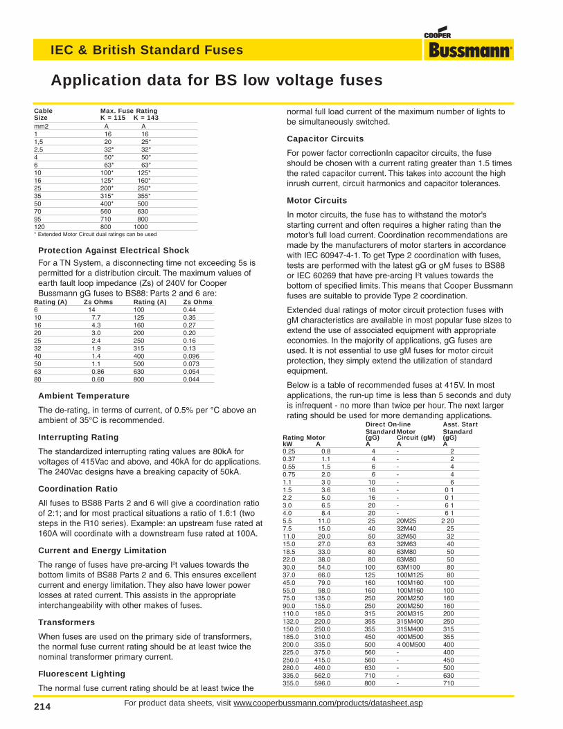
For product data sheets, visit www.cooperbussmann.com/products/datasheet.asp214
Application data for BS low voltage fuses
IEC & British Standard Fuses
Cable Max. Fuse RatingSize K = 115 K = 143mm2 A A1 16 161,5 20 25*2.5 32* 32*4 50* 50*6 63* 63*10 100* 125*16 125* 160*25 200* 250*35 315* 355*50 400* 50070 560 63095 710 800120 800 1000* Extended Motor Circuit dual ratings can be used
Protection Against Electrical Shock
For a TN System, a disconnecting time not exceeding 5s ispermitted for a distribution circuit. The maximum values ofearth fault loop impedance (Zs) of 240V for CooperBussmann gG fuses to BS88: Parts 2 and 6 are:
Rating (A) Zs Ohms Rating (A) Zs Ohms6 14 100 0.4410 7.7 125 0.3516 4.3 160 0.2720 3.0 200 0.2025 2.4 250 0.1632 1.9 315 0.1340 1.4 400 0.09650 1.1 500 0.07363 0.86 630 0.05480 0.60 800 0.044
Ambient Temperature
The de-rating, in terms of current, of 0.5% per °C above anambient of 35°C is recommended.
Interrupting Rating
The standardized interrupting rating values are 80kA forvoltages of 415Vac and above, and 40kA for dc applications.The 240Vac designs have a breaking capacity of 50kA.
Coordination Ratio
All fuses to BS88 Parts 2 and 6 will give a coordination ratioof 2:1; and for most practical situations a ratio of 1.6:1 (twosteps in the R10 series). Example: an upstream fuse rated at160A will coordinate with a downstream fuse rated at 100A.
Current and Energy Limitation
The range of fuses have pre-arcing I2t values towards thebottom limits of BS88 Parts 2 and 6. This ensures excellentcurrent and energy limitation. They also have lower powerlosses at rated current. This assists in the appropriateinterchangeability with other makes of fuses.
Transformers
When fuses are used on the primary side of transformers,the normal fuse current rating should be at least twice thenominal transformer primary current.
Fluorescent Lighting
The normal fuse current rating should be at least twice the
normal full load current of the maximum number of lights tobe simultaneously switched.
Capacitor Circuits
For power factor correctionIn capacitor circuits, the fuseshould be chosen with a current rating greater than 1.5 timesthe rated capacitor current. This takes into account the highinrush current, circuit harmonics and capacitor tolerances.
Motor Circuits
In motor circuits, the fuse has to withstand the motor'sstarting current and often requires a higher rating than themotor's full load current. Coordination recommendations aremade by the manufacturers of motor starters in accordancewith IEC 60947-4-1. To get Type 2 coordination with fuses,tests are performed with the latest gG or gM fuses to BS88or IEC 60269 that have pre-arcing I2t values towards the bottom of specified limits. This means that Cooper Bussmannfuses are suitable to provide Type 2 coordination.
Extended dual ratings of motor circuit protection fuses withgM characteristics are available in most popular fuse sizes toextend the use of associated equipment with appropriateeconomies. In the majority of applications, gG fuses areused. It is not essential to use gM fuses for motor circuitprotection, they simply extend the utilization of standardequipment.
Below is a table of recommended fuses at 415V. In mostapplications, the run-up time is less than 5 seconds and dutyis infrequent - no more than twice per hour. The next largerrating should be used for more demanding applications.
Direct On-line Asst. StartStandard Motor Standard
Rating Motor (gG) Circuit (gM) (gG)kW A A A A0.25 0.8 4 - 20.37 1.1 4 - 20.55 1.5 6 - 40.75 2.0 6 - 41.1 3 0 10 - 61.5 3.6 16 - 0 12.2 5.0 16 - 0 13.0 6.5 20 - 6 14.0 8.4 20 - 6 15.5 11.0 25 20M25 2 207.5 15.0 40 32M40 2511.0 20.0 50 32M50 3215.0 27.0 63 32M63 4018.5 33.0 80 63M80 5022.0 38.0 80 63M80 5030.0 54.0 100 63M100 8037.0 66.0 125 100M125 8045.0 79.0 160 100M160 10055.0 98.0 160 100M160 10075.0 135.0 250 200M250 16090.0 155.0 250 200M250 160110.0 185.0 315 200M315 200132.0 220.0 355 315M400 250150.0 250.0 355 315M400 315185.0 310.0 450 400M500 355200.0 335.0 500 4 00M500 400225.0 375.0 560 - 400250.0 415.0 560 - 450280.0 460.0 630 - 500335.0 562.0 710 - 630355.0 596.0 800 - 710
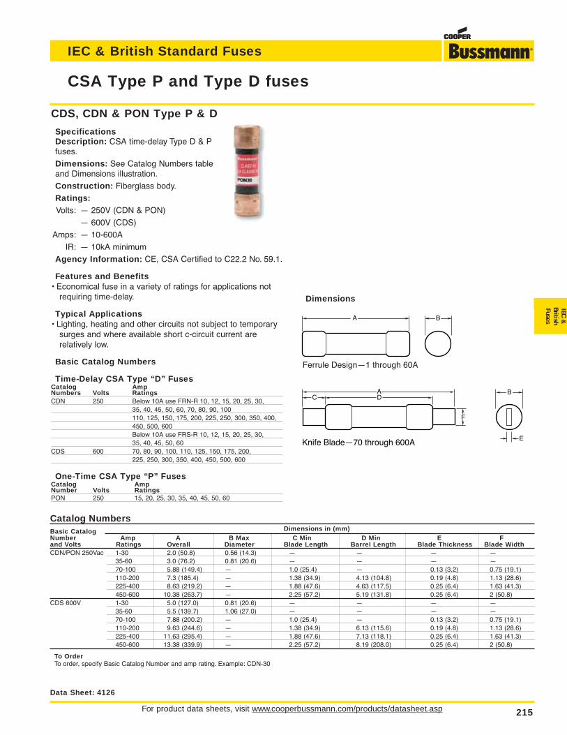
For product data sheets, visit www.cooperbussmann.com/products/datasheet.asp 215
CSA Type P and Type D fuses
IEC & British Standard Fuses
IEC&
BritishFuses
Catalog NumbersBasic Catalog Dimensions in (mm)Number Amp A B Max C Min D Min E F and Volts Ratings Overall Diameter Blade Length Barrel Length Blade Thickness Blade WidthCDN/PON 250Vac 1-30 2.0 (50.8) 0.56 (14.3) — — — —
35-60 3.0 (76.2) 0.81 (20.6) — — — —70-100 5.88 (149.4) — 1.0 (25.4) — 0.13 (3.2) 0.75 (19.1)110-200 7.3 (185.4) — 1.38 (34.9) 4.13 (104.8) 0.19 (4.8) 1.13 (28.6)225-400 8.63 (219.2) — 1.88 (47.6) 4.63 (117.5) 0.25 (6.4) 1.63 (41.3)450-600 10.38 (263.7) — 2.25 (57.2) 5.19 (131.8) 0.25 (6.4) 2 (50.8)
CDS 600V 1-30 5.0 (127.0) 0.81 (20.6) — — — —35-60 5.5 (139.7) 1.06 (27.0) — — — —70-100 7.88 (200.2) — 1.0 (25.4) — 0.13 (3.2) 0.75 (19.1)110-200 9.63 (244.6) — 1.38 (34.9) 6.13 (115.6) 0.19 (4.8) 1.13 (28.6)225-400 11.63 (295.4) — 1.88 (47.6) 7.13 (118.1) 0.25 (6.4) 1.63 (41.3)450-600 13.38 (339.9) — 2.25 (57.2) 8.19 (208.0) 0.25 (6.4) 2 (50.8)
To OrderTo order, specify Basic Catalog Number and amp rating. Example: CDN-30
E
B
F
ADC
Knife Blade—70 through 600A
A B
Ferrule Design—1 through 60A
Data Sheet: 4126
CDS, CDN & PON Type P & D
SpecificationsDescription: CSA time-delay Type D & Pfuses.
Dimensions: See Catalog Numbers tableand Dimensions illustration.
Construction: Fiberglass body.
Ratings:Volts: — 250V (CDN & PON)
— 600V (CDS)
Amps: — 10-600A
IR: — 10kA minimum
Agency Information: CE, CSA Certified to C22.2 No. 59.1.
Features and Benefits• Economical fuse in a variety of ratings for applications not
requiring time-delay.
Typical Applications• Lighting, heating and other circuits not subject to temporary
surges and where available short c-circuit current arerelatively low.
Basic Catalog Numbers
Time-Delay CSA Type “D” FusesCatalog AmpNumbers Volts RatingsCDN 250 Below 10A use FRN-R 10, 12, 15, 20, 25, 30,
35, 40, 45, 50, 60, 70, 80, 90, 100110, 125, 150, 175, 200, 225, 250, 300, 350, 400,450, 500, 600Below 10A use FRS-R 10, 12, 15, 20, 25, 30,35, 40, 45, 50, 60
CDS 600 70, 80, 90, 100, 110, 125, 150, 175, 200,225, 250, 300, 350, 400, 450, 500, 600
One-Time CSA Type “P” FusesCatalog AmpNumber Volts RatingsPON 250 15, 20, 25, 30, 35, 40, 45, 50, 60
Dimensions
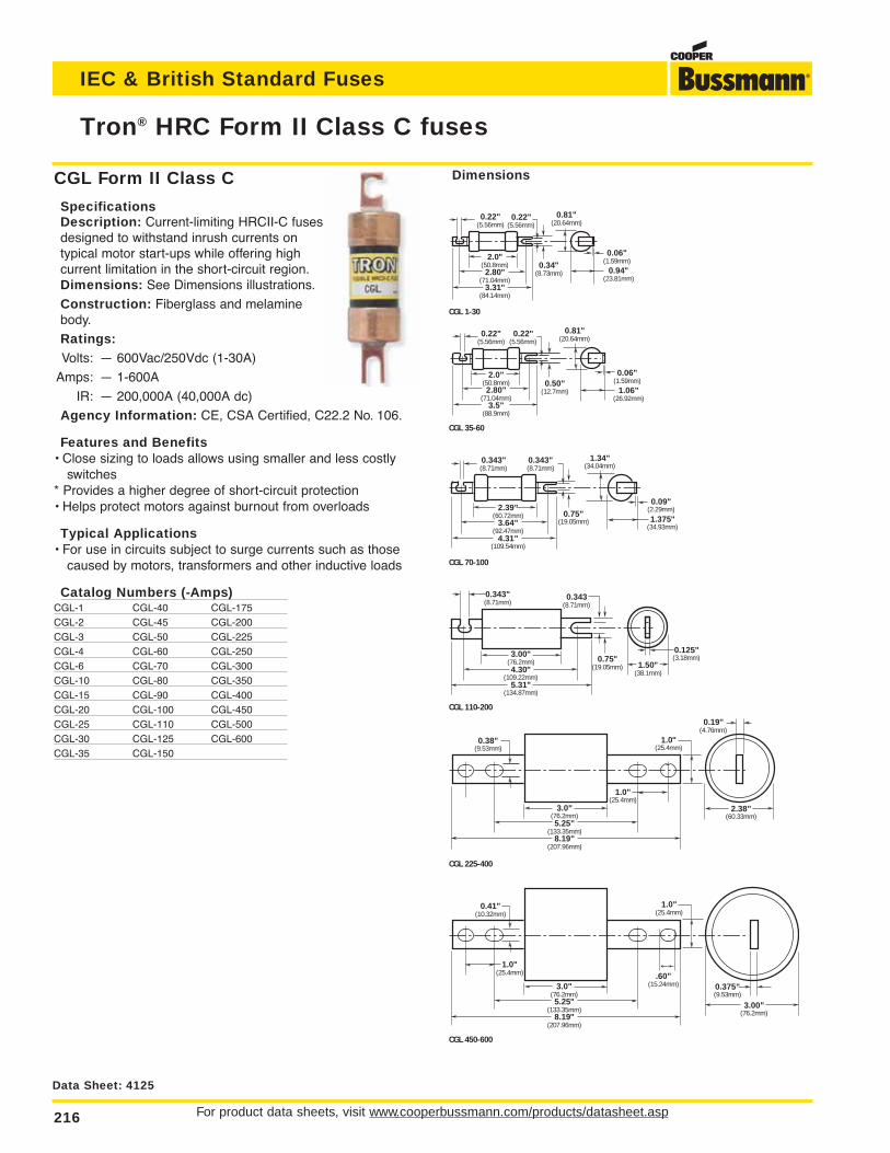
CGL Form II Class C
SpecificationsDescription: Current-limiting HRCII-C fusesdesigned to withstand inrush currents ontypical motor start-ups while offering highcurrent limitation in the short-circuit region.Dimensions: See Dimensions illustrations.
Construction: Fiberglass and melaminebody.
Ratings:Volts: — 600Vac/250Vdc (1-30A)
Amps: — 1-600A
IR: — 200,000A (40,000A dc)
Agency Information: CE, CSA Certified, C22.2 No. 106.
Features and Benefits• Close sizing to loads allows using smaller and less costly
switches* Provides a higher degree of short-circuit protection• Helps protect motors against burnout from overloads
Typical Applications• For use in circuits subject to surge currents such as those
caused by motors, transformers and other inductive loads
Catalog Numbers (-Amps)CGL-1 CGL-40 CGL-175CGL-2 CGL-45 CGL-200CGL-3 CGL-50 CGL-225CGL-4 CGL-60 CGL-250CGL-6 CGL-70 CGL-300CGL-10 CGL-80 CGL-350CGL-15 CGL-90 CGL-400CGL-20 CGL-100 CGL-450CGL-25 CGL-110 CGL-500CGL-30 CGL-125 CGL-600CGL-35 CGL-150
For product data sheets, visit www.cooperbussmann.com/products/datasheet.asp216
Tron® HRC Form II Class C fuses
IEC & British Standard Fuses
Data Sheet: 4125
2.0"(50.8mm)2.80"
(71.04mm)3.5"
(88.9mm)
0.94"(23.81mm)
0.06"(1.59mm)2.0"
(50.8mm)2.80"
(71.04mm)3.31"
(84.14mm)
0.81"(20.64mm)
0.22"(5.56mm)
0.22"(5.56mm)
0.34"(8.73mm)
CGL 1-30
CGL 35-60
0.50"(12.7mm)
0.81"(20.64mm)
0.22"(5.56mm)
0.22"(5.56mm)
1.06"(26.92mm)
0.06"(1.59mm)
CGL 70-100
0.75"(19.05mm)
1.34"(34.04mm)
0.343"(8.71mm)
0.343"(8.71mm)
2.39"(60.72mm)
3.64"(92.47mm)
4.31"(109.54mm)
1.375"(34.93mm)
0.09"(2.29mm)
CGL 110-200
0.75"(19.05mm)
0.343(8.71mm)
0.343"(8.71mm)
3.00"(76.2mm)4.30"
(109.22mm)5.31"
(134.87mm)
1.50"(38.1mm)
0.125"(3.18mm)
CGL 225-400
1.0"(25.4mm)
0.38"(9.53mm)
3.0"(76.2mm)5.25"
(133.35mm)8.19"
(207.96mm)
2.38"(60.33mm)
0.19"(4.76mm)
1.0"(25.4mm)
CGL 450-600
0.41"(10.32mm)
3.00"(76.2mm)
1.0"(25.4mm)
1.0"(25.4mm)
0.375"(9.53mm)
3.0"(76.2mm)5.25"
(133.35mm)8.19"
(207.96mm)
.60"(15.24mm)
Dimensions
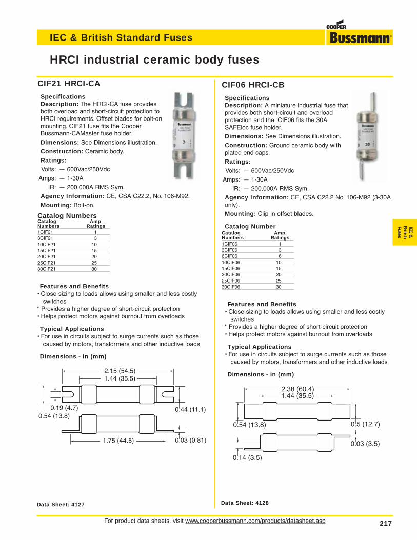
CIF21 HRCI-CA
SpecificationsDescription: The HRCI-CA fuse providesboth overload and short-circuit protection toHRCI requirements. Offset blades for bolt-onmounting. CIF21 fuse fits the CooperBussmann-CAMaster fuse holder.
Dimensions: See Dimensions illustration.
Construction: Ceramic body.
Ratings:Volts: — 600Vac/250Vdc
Amps: — 1-30A
IR: — 200,000A RMS Sym.
Agency Information: CE, CSA C22.2, No. 106-M92.
Mounting: Bolt-on.
Catalog NumbersCatalog AmpNumbers Ratings1CIF21 13CIF21 310CIF21 1015CIF21 1520CIF21 2025CIF21 2530CIF21 30
CIF06 HRCI-CB
SpecificationsDescription: A miniature industrial fuse thatprovides both short-circuit and overload protection and the CIF06 fits the 30ASAFEloc fuse holder.
Dimensions: See Dimensions illustration.
Construction: Ground ceramic body withplated end caps.
Ratings:Volts: — 600Vac/250Vdc
Amps: — 1-30A
IR: — 200,000A RMS Sym.
Agency Information: CE, CSA C22.2 No. 106-M92 (3-30Aonly).
Mounting: Clip-in offset blades.
Catalog NumberCatalog AmpNumbers Ratings1CIF06 13CIF06 36CIF06 610CIF06 1015CIF06 1520CIF06 2025CIF06 2530CIF06 30
For product data sheets, visit www.cooperbussmann.com/products/datasheet.asp 217
HRCI industrial ceramic body fuses
IEC & British Standard Fuses
IEC&
BritishFuses
Data Sheet: 4128Data Sheet: 4127
2.15 (54.5)1.44 (35.5)
1.75 (44.5)
0.19 (4.7)0.54 (13.8)
0.44 (11.1)
0.03 (0.81)
Features and Benefits• Close sizing to loads allows using smaller and less costly
switches* Provides a higher degree of short-circuit protection• Helps protect motors against burnout from overloads
Typical Applications• For use in circuits subject to surge currents such as those
caused by motors, transformers and other inductive loads
Dimensions - in (mm)
2.38 (60.4)1.44 (35.5)
0.54 (13.8)
0.14 (3.5)
0.5 (12.7)
0.03 (3.5)
Features and Benefits• Close sizing to loads allows using smaller and less costly
switches* Provides a higher degree of short-circuit protection• Helps protect motors against burnout from overloads
Typical Applications• For use in circuits subject to surge currents such as those
caused by motors, transformers and other inductive loads
Dimensions - in (mm)
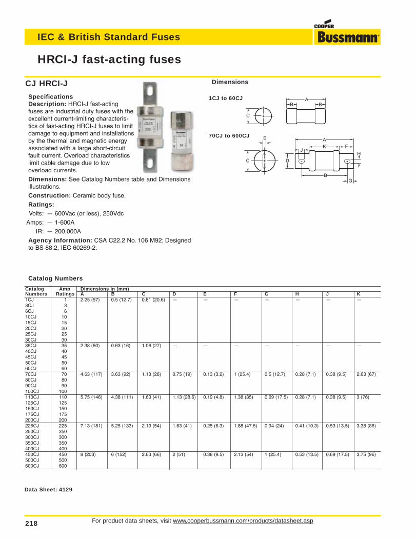
CJ HRCI-J
SpecificationsDescription: HRCI-J fast-actingfuses are industrial duty fuses with theexcellent current-limiting characteris-tics of fast-acting HRCI-J fuses to limitdamage to equipment and installationsby the thermal and magnetic energyassociated with a large short-circuitfault current. Overload characteristicslimit cable damage due to low overload currents.
Dimensions: See Catalog Numbers table and Dimensionsillustrations.
Construction: Ceramic body fuse.
Ratings:Volts: — 600Vac (or less), 250Vdc
Amps: — 1-600A
IR: — 200,000A
Agency Information: CSA C22.2 No. 106 M92; Designedto BS 88:2, IEC 60269-2.
For product data sheets, visit www.cooperbussmann.com/products/datasheet.asp218
HRCI-J fast-acting fuses
IEC & British Standard Fuses
Data Sheet: 4129
Catalog NumbersCatalog Amp Dimensions in (mm)Numbers Ratings A B C D E F G H J K1CJ 1 2.25 (57) 0.5 (12.7) 0.81 (20.6) — — — — — — —3CJ 36CJ 610CJ 1015CJ 1520CJ 2025CJ 2530CJ 3035CJ 35 2.38 (60) 0.63 (16) 1.06 (27) — — — — — — —40CJ 4045CJ 4550CJ 5060CJ 6070CJ 70 4.63 (117) 3.63 (92) 1.13 (28) 0.75 (19) 0.13 (3.2) 1 (25.4) 0.5 (12.7) 0.28 (7.1) 0.38 (9.5) 2.63 (67)80CJ 8090CJ 90100CJ 100110CJ 110 5.75 (146) 4.38 (111) 1.63 (41) 1.13 (28.6) 0.19 (4.8) 1.38 (35) 0.69 (17.5) 0.28 (7.1) 0.38 (9.5) 3 (76)125CJ 125150CJ 150175CJ 175200CJ 200225CJ 225 7.13 (181) 5.25 (133) 2.13 (54) 1.63 (41) 0.25 (6.3) 1.88 (47.6) 0.94 (24) 0.41 (10.3) 0.53 (13.5) 3.38 (86)250CJ 250300CJ 300350CJ 350400CJ 400450CJ 450 8 (203) 6 (152) 2.63 (66) 2 (51) 0.38 (9.5) 2.13 (54) 1 (25.4) 0.53 (13.5) 0.69 (17.5) 3.75 (96)500CJ 500600CJ 600
A
JFK
B
H
DC
E
G
AB B
C
Dimensions
1CJ to 60CJ
70CJ to 600CJ
Catalog Numbers
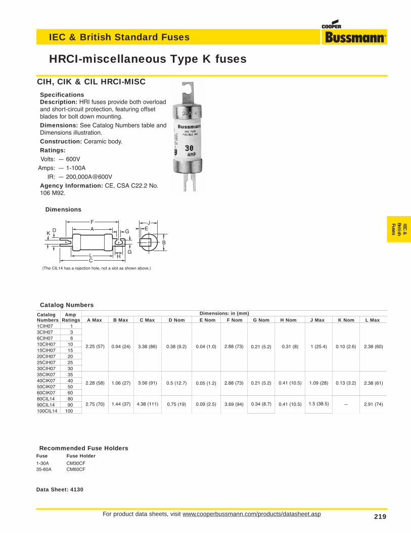
For product data sheets, visit www.cooperbussmann.com/products/datasheet.asp 219
HRCI-miscellaneous Type K fuses
IEC & British Standard Fuses
IEC&
BritishFuses
Dimensions
Data Sheet: 4130
CIH, CIK & CIL HRCI-MISC
SpecificationsDescription: HRI fuses provide both overloadand short-circuit protection, featuring offsetblades for bolt down mounting.
Dimensions: See Catalog Numbers table andDimensions illustration.
Construction: Ceramic body.
Ratings:Volts: — 600V
Amps: — 1-100A
IR: — 200,000A@600V
Agency Information: CE, CSA C22.2 No.106 M92.
E
G
G
H
DK
FA
LC
J
B
(The CIL14 has a rejection hole, not a slot as shown above.)
Recommended Fuse HoldersFuse Fuse Holder
1-30A CM30CF35-60A CM60CF
Catalog Numbers
Catalog Amp Dimensions: in (mm)Numbers Ratings A Max B Max C Max D Nom E Nom F Nom G Nom H Nom J Max K Nom L Max1CIH07 1 2.25 (57) 0.94 (24) 3.38 (86) 0.38 (9.2) 0.04 (1.0) 2.88 (73) 0.21 (5.2) 0.31 (8) 1 (25.4) 0.10 (2.6) 2.38 (60)3CIH07 36CIH07 610CIH07 1015CIH07 1520CIH07 2025CIH07 2530CIH07 3035CIK07 35 2.28 (58) 1.06 (27) 3.56 (91) 0.5 (12.7) 0.05 (1.2) 2.88 (73) 0.21 (5.2) 0.41 (10.5) 1.09 (28) 0.13 (3.2) 2.38 (61)40CIK07 4050CIK07 5060CIK07 6080CIL14 80 2.75 (70) 1.44 (37) 4.38 (111) 0.75 (19) 0.09 (2.5) 3.69 (94) 0.34 (8.7) 0.41 (10.5) 1.5 (38.5) — 2.91 (74)90CIL14 90100CIL14 100
2.25 (57) 0.94 (24) 3.38 (86) 0.38 (9.2) 0.04 (1.0) 2.88 (73) 0.21 (5.2) 0.31 (8) 1 (25.4) 0.10 (2.6) 2.38 (60)
2.38 (61)
2.91 (74)
0.13 (3.2)
—
1.09 (28)
1.5 (38.5)
0.41 (10.5)
0.41 (10.5)
0.21 (5.2)
0.34 (8.7)
2.88 (73)
3.69 (94)
0.05 (1.2)
0.09 (2.5)
0.5 (12.7)
0.75 (19)
3.56 (91)
4.38 (111)
1.06 (27)
1.44 (37)
2.28 (58)
2.75 (70)
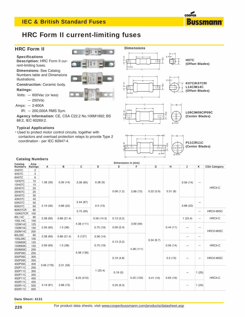
HRC Form II
SpecificationsDescription: HRC Form II cur-rent-limiting fuses.
Dimensions: See CatalogNumbers table and Dimensionsillustrations.
Construction: Ceramic body.
Ratings:Volts: — 600Vac (or less)
— 250Vdc
Amps: — 2-600A
IR: — 200,000A RMS Sym.
Agency Information: CE, CSA C22.2 No.106M1992; BS88:2, IEC 60269:2.
Typical Applications• Used to protect motor control circuits, together with
contactors and overload protection relays to provide Type 2coordination - per IEC 60947-4.
For product data sheets, visit www.cooperbussmann.com/products/datasheet.asp220
HRC Form II current-limiting fuses
IEC & British Standard Fuses
Data Sheet: 4131
Catalog NumbersCatalog Amp Dimensions in (mm)Numbers Ratings A B C D E F G H J K CSA Category2H07C 2 1.38 (35) 0.56 (14) 3.38 (85) 0.38 (9) 0.06 (1.2) 2.88 (73) 0.22 (5.6) 0.31 (8) 0.56 (14) — HRCII-C4H07C 46H07C 610H07C 1015H07C 1520H07C 2025H07C 2530H07C 3040K07C 40 2.19 (56) 0.88 (22) 3.44 (87) 0.5 (13) 0.06 (1.2) 2.88 (73) 0.22 (5.6) 0.31 (8) 0.88 (22) — HRCII-C50K07C 5060K07C 6080K07CR 80 2.19 (56) 0.88 (22) 3.75 (95) 0.5 (13) 0.06 (1.2) 2.88 (73) 0.22 (5.6) 0.31 (8) 0.88 (22) — HRCII-MISC100K07CR 10080L14C 80 2.38 (60) 0.88 (21.4) 4.38 (111) 0.56 (14.3) 0.13 (3.2) 3.69 (94) 0.34 (8.7) 0.44 (11) 1 (25.4) — HRCII-C100L14C 100125M14C 125 2.56 (65) 1.5 (38) 4.38 (111) 0.75 (19) 0.09 (2.4) 3.69 (94) 0.34 (8.7) 0.44 (11) — — HRCII-MISC150M14C 150200M14C 20080L09C 80 2.38 (60) 0.88 (21.4) 5 (127) 0.56 (14) 0.13 (3.2) 4.38 (111) 0.34 (8.7) 0.44 (11) — — HRCII-MISC100L09C 100125M09C 125 2.56 (65) 1.5 (38) 5.38 (136) 0.75 (19) 0.13 (3.2) 4.38 (111) 0.34 (8.7) 0.56 (14) — — HRCII-C150M09C 150200M09C 200250P09C 250 3.06 (178) 2.31 (59) 5.38 (136) 1 (25.4) 0.19 (4.8) 4.38 (111) 0.34 (8.7) 0.5 (13) — — HRCII-MISC300P09C 300350P09C 350400P09C 400250P11C 250 3.06 (178) 2.31 (59) 8.25 (210) 1 (25.4) 0.19 (5) 5.25 (133) 0.41 (10) 0.63 (16) — 1 (25) HRCII-C300P11C 300350P11C 350400P11C 400450R11C 450 3.19 (81) 2.88 (73) 8.25 (210) 1 (25.4) 0.25 (6.3) 5.25 (133) 0.41 (10) 0.63 (16) — 1 (25) HRCII-C500R11C 500600R11C 600
ED
G
F
A
HC
J
B
E
DG
F
A
H
C
J
B
DG
C
A
F
B
E
H
F B
E
G
C
A
K
D
K
H
H07C(Offset Blades)
K07C/K07CR/L14C/M14C (Offset Blades)
L09C/M09C/P09C(Center Blades)
P11C/R11C (Center Blades)
Dimensions
1.38 (35) 0.56 (14) 3.38 (85) 0.38 (9)
0.06 (1.2) 2.88 (73) 0.22 (5.6) 0.31 (8)
0.56 (14) —
HRCII-C
HRCII-MISC
HRCII-C
HRCII-C
HRCII-C
HRCII-MISC
HRCII-MISC
—
—
—
—
—
—
—
1 (25)
1 (25)
0.88 (22)
1 (25.4)
—
—
—
—
—
—
0.44 (11)
0.56 (14)
0.5 (13)
0.63 (16)
0.34 (8.7)
0.41 (10)
3.69 (94)
4.38 (111)
5.25 (133)
0.13 (3.2)
0.09 (2.4)
0.13 (3.2)
0.19 (4.8)
0.19 (5)
0.25 (6.3)
0.5 (13)
0.56 (14.3)
0.75 (19)
0.56 (14)
0.75 (19)
1 (25.4)
3.44 (87)
3.75 (95)
4.38 (111)
5 (127)
5.38 (136)
8.25 (210)
2.19 (56) 0.88 (22)
2.38 (60) 0.88 (21.4)
1.5 (38)
1.5 (38)
2.31 (59)
2.88 (73)
2.38 (60) 0.88 (21.4)
2.56 (65)
2.56 (65)
3.19 (81)
3.06 (178)
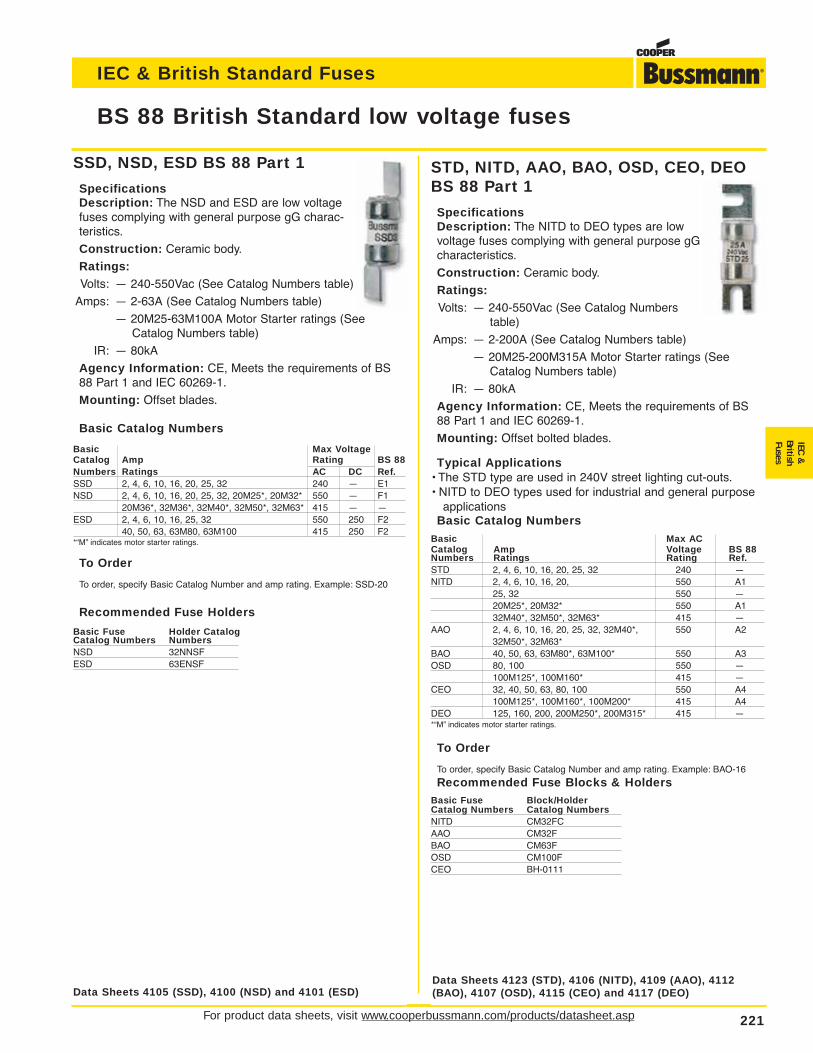
SSD, NSD, ESD BS 88 Part 1
SpecificationsDescription: The NSD and ESD are low voltagefuses complying with general purpose gG charac-teristics.
Construction: Ceramic body.
Ratings:Volts: — 240-550Vac (See Catalog Numbers table)
Amps: — 2-63A (See Catalog Numbers table)
— 20M25-63M100A Motor Starter ratings (SeeCatalog Numbers table)
IR: — 80kA
Agency Information: CE, Meets the requirements of BS88 Part 1 and IEC 60269-1.
Mounting: Offset blades.
Basic Catalog Numbers
Basic Max VoltageCatalog Amp Rating BS 88Numbers Ratings AC DC Ref.SSD 2, 4, 6, 10, 16, 20, 25, 32 240 — E1NSD 2, 4, 6, 10, 16, 20, 25, 32, 20M25*, 20M32* 550 — F1
20M36*, 32M36*, 32M40*, 32M50*, 32M63* 415 — —ESD 2, 4, 6, 10, 16, 25, 32 550 250 F2
40, 50, 63, 63M80, 63M100 415 250 F2*“M” indicates motor starter ratings.
To Order
To order, specify Basic Catalog Number and amp rating. Example: SSD-20
Recommended Fuse Holders
Basic Fuse Holder CatalogCatalog Numbers NumbersNSD 32NNSFESD 63ENSF
For product data sheets, visit www.cooperbussmann.com/products/datasheet.asp 221
BS 88 British Standard low voltage fuses
IEC & British Standard Fuses
IEC&
BritishFuses
STD, NITD, AAO, BAO, OSD, CEO, DEO BS 88 Part 1
SpecificationsDescription: The NITD to DEO types are lowvoltage fuses complying with general purpose gGcharacteristics.
Construction: Ceramic body.
Ratings:Volts: — 240-550Vac (See Catalog Numbers
table)
Amps: — 2-200A (See Catalog Numbers table)
— 20M25-200M315A Motor Starter ratings (SeeCatalog Numbers table)
IR: — 80kA
Agency Information: CE, Meets the requirements of BS88 Part 1 and IEC 60269-1.
Mounting: Offset bolted blades.
Typical Applications• The STD type are used in 240V street lighting cut-outs.• NITD to DEO types used for industrial and general purpose
applicationsBasic Catalog Numbers
Basic Max ACCatalog Amp Voltage BS 88Numbers Ratings Rating Ref.STD 2, 4, 6, 10, 16, 20, 25, 32 240 —NITD 2, 4, 6, 10, 16, 20, 550 A1
25, 32 550 —20M25*, 20M32* 550 A132M40*, 32M50*, 32M63* 415 —
AAO 2, 4, 6, 10, 16, 20, 25, 32, 32M40*, 550 A232M50*, 32M63*
BAO 40, 50, 63, 63M80*, 63M100* 550 A3OSD 80, 100 550 —
100M125*, 100M160* 415 —CEO 32, 40, 50, 63, 80, 100 550 A4
100M125*, 100M160*, 100M200* 415 A4DEO 125, 160, 200, 200M250*, 200M315* 415 —*“M” indicates motor starter ratings.
To Order
To order, specify Basic Catalog Number and amp rating. Example: BAO-16
Recommended Fuse Blocks & HoldersBasic Fuse Block/HolderCatalog Numbers Catalog NumbersNITD CM32FCAAO CM32FBAO CM63FOSD CM100FCEO BH-0111
Data Sheets 4105 (SSD), 4100 (NSD) and 4101 (ESD)Data Sheets 4123 (STD), 4106 (NITD), 4109 (AAO), 4112(BAO), 4107 (OSD), 4115 (CEO) and 4117 (DEO)
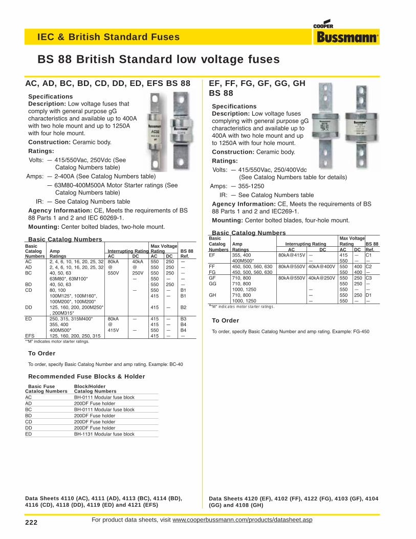
EF, FF, FG, GF, GG, GHBS 88
SpecificationsDescription: Low voltage fusescomplying with general purpose gGcharacteristics and available up to400A with two hole mount and upto 1250A with four hole mount.
Construction: Ceramic body.
Ratings:Volts: — 415/550Vac, 250/400Vdc
(See Catalog Numbers table for details)
Amps: — 355-1250
IR: — See Catalog Numbers table
Agency Information: CE, Meets the requirements of BS88 Parts 1 and 2 and IEC269-1.
Mounting: Center bolted blades, four-hole mount.
Basic Catalog NumbersBasic Max VoltageCatalog Amp Interrupting Rating Rating BS 88Numbers Ratings AC DC AC DC Ref.EF 355, 400 80kA@415V — 415 — C1
400M500* — 550 — —FF 450, 500, 560, 630 80kA@550V 40kA@400V 550 400 C2FG 450, 500, 560, 630 550 400 —GF 710, 800 80kA@550V 40kA@250V 550 250 C3GG 710, 800 550 250 —
1000, 1250 — 550 — —GH 710, 800 — 550 250 D1
1000, 1250 — 550 — —*“M” indicates motor starter ratings.
To Order
To order, specify Basic Catalog Number and amp rating. Example: FG-450
AC, AD, BC, BD, CD, DD, ED, EFS BS 88
SpecificationsDescription: Low voltage fuses thatcomply with general purpose gG characteristics and available up to 400Awith two hole mount and up to 1250Awith four hole mount.
Construction: Ceramic body.
Ratings:Volts: — 415/550Vac, 250Vdc (See
Catalog Numbers table)
Amps: — 2-400A (See Catalog Numbers table)
— 63M80-400M500A Motor Starter ratings (SeeCatalog Numbers table)
IR: — See Catalog Numbers table
Agency Information: CE, Meets the requirements of BS88 Parts 1 and 2 and IEC 60269-1.
Mounting: Center bolted blades, two-hole mount.
Basic Catalog NumbersBasic Max VoltageCatalog Amp Interrupting Rating Rating BS 88Numbers Ratings AC DC AC DC Ref.AC 2, 4, 6, 10, 16, 20, 25, 32 80kA 40kA 550 250 —AD 2, 4, 6, 10, 16, 20, 25, 32 @ @ 550 250 —BC 40, 50, 63 550V 250V 550 250 —
63M80*, 63M100* — 550 — —BD 40, 50, 63 550 250 —CD 80, 100 — 550 — B1
100M125*, 100M160*, 415 — B1100M200*, 100M200*
DD 125, 160, 200, 200M250* 415 — B2, 200M315*
ED 250, 315, 315M400* 80kA — 415 — B3355, 400 @ 415 — B4400M500* 415V — 550 — B4
EFS 125, 160, 200, 250, 315 415 — —*“M” indicates motor starter ratings.
To Order
To order, specify Basic Catalog Number and amp rating. Example: BC-40
Recommended Fuse Blocks & Holder
Basic Fuse Block/HolderCatalog Numbers Catalog NumbersAC BH-0111 Modular fuse blockAD 200DF Fuse holderBC BH-0111 Modular fuse blockBD 200DF Fuse holderCD 200DF Fuse holderDD 200DF Fuse holderED BH-1131 Modular fuse block
For product data sheets, visit www.cooperbussmann.com/products/datasheet.asp222
BS 88 British Standard low voltage fuses
IEC & British Standard Fuses
Data Sheets 4110 (AC), 4111 (AD), 4113 (BC), 4114 (BD),4116 (CD), 4118 (DD), 4119 (ED) and 4121 (EFS)
Data Sheets 4120 (EF), 4102 (FF), 4122 (FG), 4103 (GF), 4104(GG) and 4108 (GH)
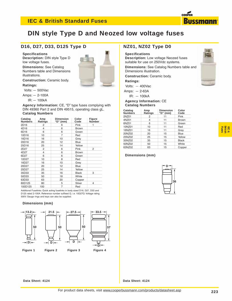
NZ01, NZ02 Type D0
SpecificationsDescription: Low voltage Neozed fuses suitable for use on 250Vdc systems.
Dimensions: See Catalog Numbers table andDimensions illustration.
Construction: Ceramic body.
Ratings:Volts: — 400Vac
Amps: — 2-63A
IR: — 100kA
Agency Information: CECatalog Numbers
Catalog Amp Dimension ColorNumbers Ratings “D” (mm) Code2NZ01 2 11 Pink4NZ01 4 11 Brown6NZ01 6 11 Green10NZ01 10 11 Red16NZ01 16 11 Grey20NZ02 20 15 Blue25NZ02 25 15 Yellow35NZ02 35 15 Black50NZ02 50 15 White63NZ02 63 15 Copper
Dimensions (mm)
D16, D27, D33, D125 Type D
SpecificationsDescription: DIN style Type Dlow voltage fuses.
Dimensions: See CatalogNumbers table and Dimensionsillustrations.
Construction: Ceramic body.
Ratings:Volts: — 500Vac
Amps: — 2-100A
IR: — 100kA
Agency Information: CE, “D” type fuses complying withDIN 49360 Part 2 and DIN 49515, operating class gL.Catalog Numbers
Catalog Amp Dimension Color FigureNumbers Ratings “D” (mm) Code Number2D16 2 6 Pink 14D16 4 6 Brown6D16 6 6 Green10D16 10 7 Red16D16 16 10 Grey20D16 20 12 Blue25D16 25 14 Yellow2D27 2 6 Pink 24D27 4 6 Brown6D27 6 6 Green10D27 10 8 Red16D27 16 10 Grey20D27 20 12 Blue25D27 25 14 Yellow35D33 35 16 Black 350D33 50 18 White63D33 63 20 Copper80D125 80 5 Silver 4100D125 100 7 RedAdditional Fuselinks: Quick acting fuselinks in body sized D16, D27, D33 and D125 rated 2-100A. Reference number suffixed Q, i.e. 10D27Q. Voltage rating 500V. Gauge rings and keys can also be supplied.
Dimensions (mm)
For product data sheets, visit www.cooperbussmann.com/products/datasheet.asp 223
DIN style Type D and Neozed low voltage fuses
IEC & British Standard Fuses
IEC&
BritishFuses
Data Sheet: 4124
D
36
Data Sheet: 4124
Figure 1 Figure 2 Figure 3 Figure 4
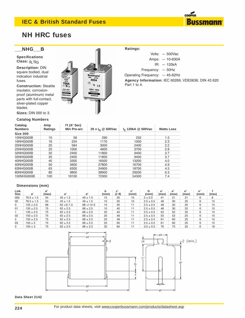
For product data sheets, visit www.cooperbussmann.com/products/datasheet.asp224
NH HRC fuses
IEC & British Standard Fuses
___NHG___B
SpecificationsClass: gL/gG
Description: DINsquare bodied, dualindication industrialfuses.
Construction: Steatiteinsulator, corrosion-proof (aluminum) metalparts with full-contact,silver-plated copperblades.
Sizes: DIN 000 to 3.
Catalog Numbers
Catalog Amp I2t (A2 Sec)Numbers Ratings Min Pre-arc 20 x In @ 500Vac I1 120kA @ 500Vac Watts LossSize 00010NHG000B 10 58 290 232 1.516NHG000B 16 234 1170 1000 2.320NHG000B 20 584 3000 2400 2.225NHG000B 25 1000 4600 3700 2.832NHG000B 32 2400 11800 9400 3.735NHG000B 35 2400 11800 9400 3.740NHG000B 40 3300 16500 13200 4.050NHG000B 50 5600 27800 16700 4.963NHG000B 63 6300 24900 18700 4.580NHG000B 80 9800 38900 29200 6.3100NHG000B 100 18100 72300 54300 7.4
Dimensions (mm)
Link a2 b c1 c2 D e1 e2 e3 e4 fSize a1 (max) a3 a4 (nom) (± 8) (nom) (nom) (max) (max) (max) (nom) (max)000 78.5 ± 1.5 54 45 ± 1.5 49 ± 1.5 15 35 10 2 ± 0.5 41 21 21 6 800 78.5 ± 1.5 54 45 ± 1.5 49 ± 1.5 15 35 10 2.5 ± 0.5 48 30 25 6 150 125 ± 2.5 68 62 +3/-1.5 68 +1.5/-3 15 35 11 2.5 ± 0.5 48 30 25 6 1501 135 ± 2.5 75 62 ± 2.5 68 ± 2.5 15 40 11 2.5 ± 0.5 48 30 25 6 151 135 ± 2.5 75 62 ± 2.5 68 ± 2.5 20 40 11 2.5 ± 0.5 53 52 25 6 1502 150 ± 2.5 75 62 ± 2.5 68 ± 2.5 20 48 11 2.5 ± 0.5 53 52 25 6 152 150 ± 2.5 75 62 ± 2.5 68 ± 2.5 25 48 11 2.5 ± 0.5 61 60 25 6 1503 150 ± 3 75 62 ± 2.5 68 ± 2.5 25 60 11 2.5 ± 0.5 61 60 25 6 153 150 ± 3 75 62 ± 2.5 68 ± 2.5 32 60 11 3.0 ± 0.5 76 75 25 6 18
Ratings:Volts: — 500Vac
Amps: — 10-630A
IR: — 120kA
Frequency: — 50Hz
Operating Frequency: — 45-62Hz
Agency Information: IEC 60269, VDE0636, DIN 43 620Part 1 to 4.
Data Sheet 2142
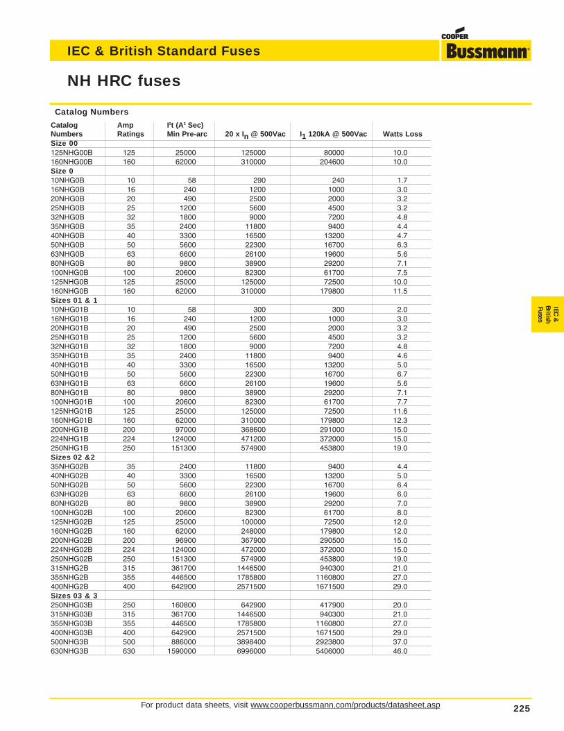
For product data sheets, visit www.cooperbussmann.com/products/datasheet.asp 225
NH HRC fuses
IEC & British Standard Fuses
IEC&
BritishFuses
Catalog Numbers
Catalog Amp I2t (A2 Sec)Numbers Ratings Min Pre-arc 20 x In @ 500Vac I1 120kA @ 500Vac Watts LossSize 00125NHG00B 125 25000 125000 80000 10.0160NHG00B 160 62000 310000 204600 10.0Size 010NHG0B 10 58 290 240 1.716NHG0B 16 240 1200 1000 3.020NHG0B 20 490 2500 2000 3.225NHG0B 25 1200 5600 4500 3.232NHG0B 32 1800 9000 7200 4.835NHG0B 35 2400 11800 9400 4.440NHG0B 40 3300 16500 13200 4.750NHG0B 50 5600 22300 16700 6.363NHG0B 63 6600 26100 19600 5.680NHG0B 80 9800 38900 29200 7.1100NHG0B 100 20600 82300 61700 7.5125NHG0B 125 25000 125000 72500 10.0160NHG0B 160 62000 310000 179800 11.5Sizes 01 & 110NHG01B 10 58 300 300 2.016NHG01B 16 240 1200 1000 3.020NHG01B 20 490 2500 2000 3.225NHG01B 25 1200 5600 4500 3.232NHG01B 32 1800 9000 7200 4.835NHG01B 35 2400 11800 9400 4.640NHG01B 40 3300 16500 13200 5.050NHG01B 50 5600 22300 16700 6.763NHG01B 63 6600 26100 19600 5.680NHG01B 80 9800 38900 29200 7.1100NHG01B 100 20600 82300 61700 7.7125NHG01B 125 25000 125000 72500 11.6160NHG01B 160 62000 310000 179800 12.3200NHG1B 200 97000 368600 291000 15.0224NHG1B 224 124000 471200 372000 15.0250NHG1B 250 151300 574900 453800 19.0Sizes 02 &235NHG02B 35 2400 11800 9400 4.440NHG02B 40 3300 16500 13200 5.050NHG02B 50 5600 22300 16700 6.463NHG02B 63 6600 26100 19600 6.080NHG02B 80 9800 38900 29200 7.0100NHG02B 100 20600 82300 61700 8.0125NHG02B 125 25000 100000 72500 12.0160NHG02B 160 62000 248000 179800 12.0200NHG02B 200 96900 367900 290500 15.0224NHG02B 224 124000 472000 372000 15.0250NHG02B 250 151300 574900 453800 19.0315NHG2B 315 361700 1446500 940300 21.0355NHG2B 355 446500 1785800 1160800 27.0400NHG2B 400 642900 2571500 1671500 29.0Sizes 03 & 3250NHG03B 250 160800 642900 417900 20.0315NHG03B 315 361700 1446500 940300 21.0355NHG03B 355 446500 1785800 1160800 27.0400NHG03B 400 642900 2571500 1671500 29.0500NHG3B 500 886000 3898400 2923800 37.0630NHG3B 630 1590000 6996000 5406000 46.0
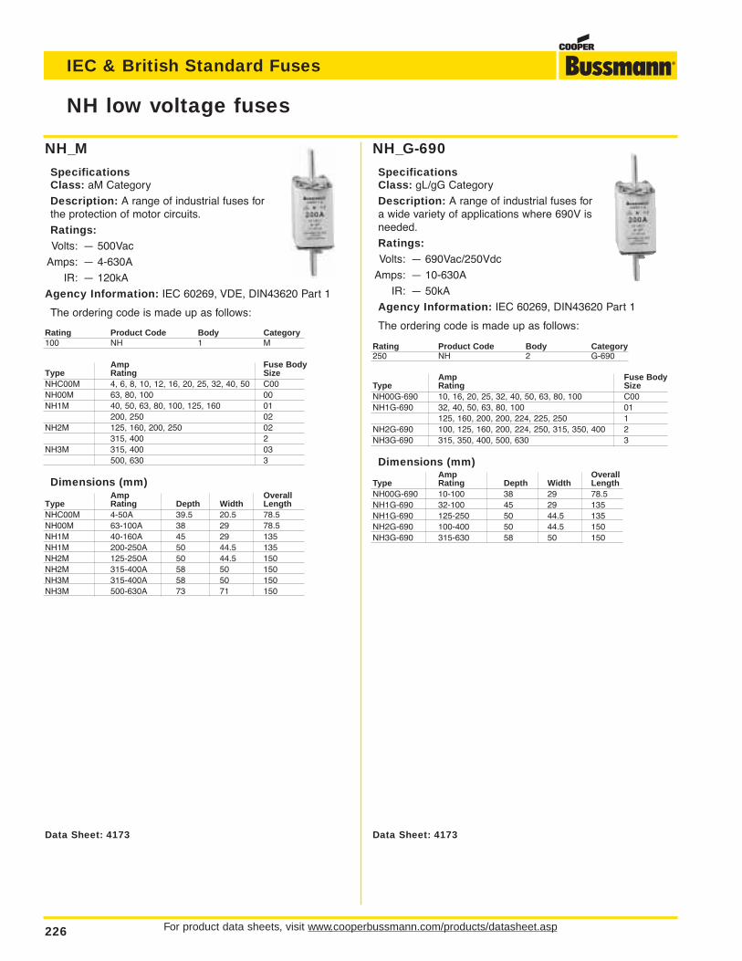
For product data sheets, visit www.cooperbussmann.com/products/datasheet.asp226
NH low voltage fuses
IEC & British Standard Fuses
NH_G-690
SpecificationsClass: gL/gG Category
Description: A range of industrial fuses fora wide variety of applications where 690V isneeded.
Ratings:Volts: — 690Vac/250Vdc
Amps: — 10-630A
IR: — 50kA
Agency Information: IEC 60269, DIN43620 Part 1
The ordering code is made up as follows:
Rating Product Code Body Category250 NH 2 G-690
Amp Fuse BodyType Rating SizeNH00G-690 10, 16, 20, 25, 32, 40, 50, 63, 80, 100 C00NH1G-690 32, 40, 50, 63, 80, 100 01
125, 160, 200, 200, 224, 225, 250 1NH2G-690 100, 125, 160, 200, 224, 250, 315, 350, 400 2NH3G-690 315, 350, 400, 500, 630 3
Dimensions (mm)Amp Overall
Type Rating Depth Width LengthNH00G-690 10-100 38 29 78.5NH1G-690 32-100 45 29 135NH1G-690 125-250 50 44.5 135NH2G-690 100-400 50 44.5 150NH3G-690 315-630 58 50 150
NH_M
SpecificationsClass: aM Category
Description: A range of industrial fuses forthe protection of motor circuits.
Ratings:Volts: — 500Vac
Amps: — 4-630A
IR: — 120kA
Agency Information: IEC 60269, VDE, DIN43620 Part 1
The ordering code is made up as follows:
Rating Product Code Body Category100 NH 1 M
Amp Fuse BodyType Rating SizeNHC00M 4, 6, 8, 10, 12, 16, 20, 25, 32, 40, 50 C00NH00M 63, 80, 100 00NH1M 40, 50, 63, 80, 100, 125, 160 01
200, 250 02NH2M 125, 160, 200, 250 02
315, 400 2NH3M 315, 400 03
500, 630 3
Dimensions (mm)Amp Overall
Type Rating Depth Width LengthNHC00M 4-50A 39.5 20.5 78.5NH00M 63-100A 38 29 78.5NH1M 40-160A 45 29 135NH1M 200-250A 50 44.5 135NH2M 125-250A 50 44.5 150NH2M 315-400A 58 50 150NH3M 315-400A 58 50 150NH3M 500-630A 73 71 150
Data Sheet: 4173 Data Sheet: 4173
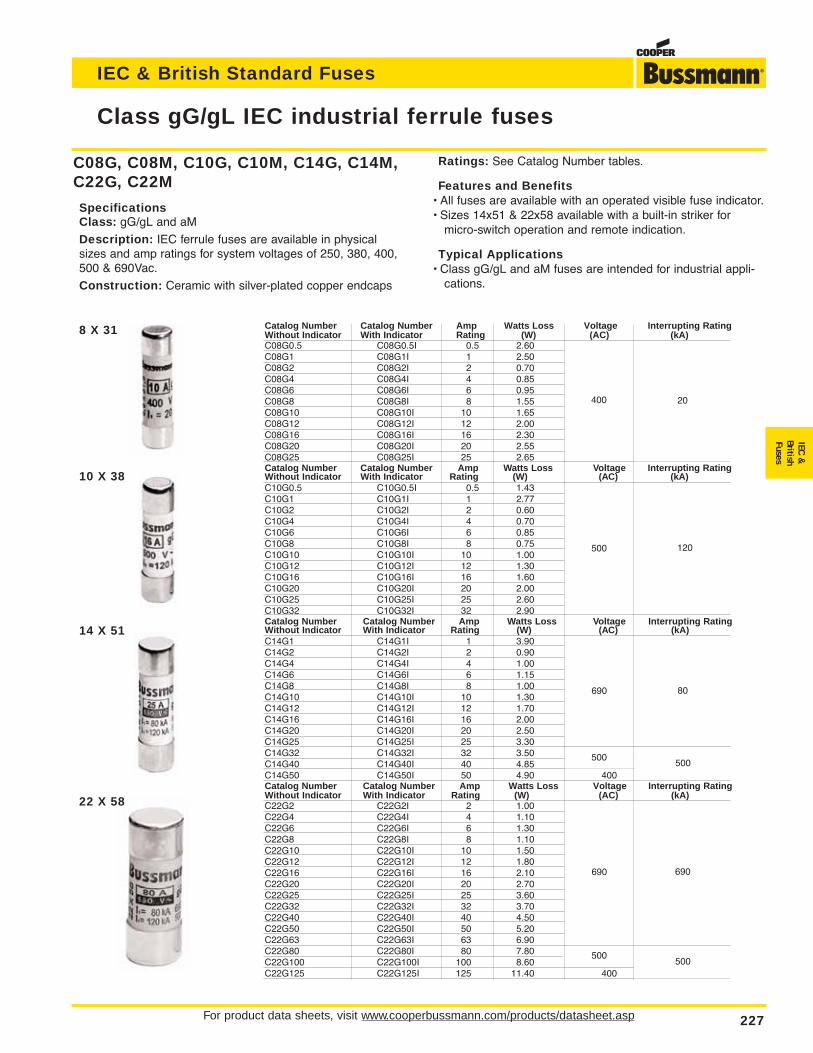
For product data sheets, visit www.cooperbussmann.com/products/datasheet.asp 227
Class gG/gL IEC industrial ferrule fuses
IEC & British Standard Fuses
IEC&
BritishFuses
Catalog Number Catalog Number Amp Watts Loss Voltage Interrupting RatingWithout Indicator With Indicator Rating (W) (AC) (kA)C08G0.5 C08G0.5I 0.5 2.60 400 20C08G1 C08G1I 1 2.50C08G2 C08G2I 2 0.70C08G4 C08G4I 4 0.85C08G6 C08G6I 6 0.95C08G8 C08G8I 8 1.55C08G10 C08G10I 10 1.65C08G12 C08G12I 12 2.00C08G16 C08G16I 16 2.30C08G20 C08G20I 20 2.55C08G25 C08G25I 25 2.65Catalog Number Catalog Number Amp Watts Loss Voltage Interrupting RatingWithout Indicator With Indicator Rating (W) (AC) (kA)C10G0.5 C10G0.5I 0.5 1.43 500 120C10G1 C10G1I 1 2.77C10G2 C10G2I 2 0.60C10G4 C10G4I 4 0.70C10G6 C10G6I 6 0.85C10G8 C10G8I 8 0.75C10G10 C10G10I 10 1.00C10G12 C10G12I 12 1.30C10G16 C10G16I 16 1.60C10G20 C10G20I 20 2.00C10G25 C10G25I 25 2.60C10G32 C10G32I 32 2.90 400Catalog Number Catalog Number Amp Watts Loss Voltage Interrupting RatingWithout Indicator With Indicator Rating (W) (AC) (kA)C14G1 C14G1I 1 3.90 690 80C14G2 C14G2I 2 0.90C14G4 C14G4I 4 1.00C14G6 C14G6I 6 1.15C14G8 C14G8I 8 1.00C14G10 C14G10I 10 1.30C14G12 C14G12I 12 1.70C14G16 C14G16I 16 2.00C14G20 C14G20I 20 2.50C14G25 C14G25I 25 3.30C14G32 C14G32I 32 3.50 500 120C14G40 C14G40I 40 4.85C14G50 C14G50I 50 4.90 400Catalog Number Catalog Number Amp Watts Loss Voltage Interrupting RatingWithout Indicator With Indicator Rating (W) (AC) (kA)C22G2 C22G2I 2 1.00 690 80C22G4 C22G4I 4 1.10C22G6 C22G6I 6 1.30C22G8 C22G8I 8 1.10C22G10 C22G10I 10 1.50C22G12 C22G12I 12 1.80C22G16 C22G16I 16 2.10C22G20 C22G20I 20 2.70C22G25 C22G25I 25 3.60C22G32 C22G32I 32 3.70C22G40 C22G40I 40 4.50C22G50 C22G50I 50 5.20C22G63 C22G63I 63 6.90C22G80 C22G80I 80 7.80 500 120C22G100 C22G100I 100 8.60C22G125 C22G125I 125 11.40 400
C08G, C08M, C10G, C10M, C14G, C14M,C22G, C22M
SpecificationsClass: gG/gL and aM
Description: IEC ferrule fuses are available in physicalsizes and amp ratings for system voltages of 250, 380, 400,500 & 690Vac.
Construction: Ceramic with silver-plated copper endcaps
Ratings: See Catalog Number tables.
Features and Benefits• All fuses are available with an operated visible fuse indicator.• Sizes 14x51 & 22x58 available with a built-in striker for
micro-switch operation and remote indication.
Typical Applications• Class gG/gL and aM fuses are intended for industrial appli-
cations.
8 X 31
10 X 38
14 X 51
22 X 58
400 20
500 120
690 80
500500
690 690
500500
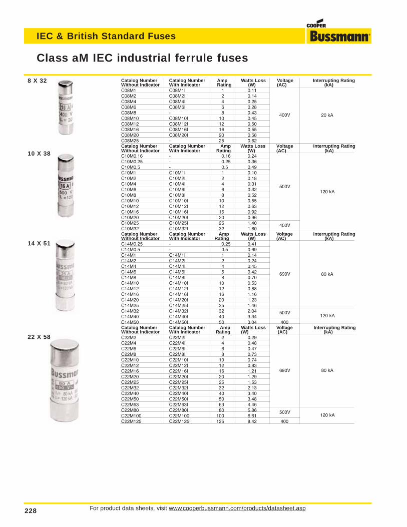
For product data sheets, visit www.cooperbussmann.com/products/datasheet.asp228
Class aM IEC industrial ferrule fuses
IEC & British Standard Fuses
Catalog Number Catalog Number Amp Watts Loss Voltage Interrupting RatingWithout Indicator With Indicator Rating (W) (AC) (kA)C08M1 C08M1I 1 0.11 400V 20 kAC08M2 C08M2I 2 0.14C08M4 C08M4I 4 0.25C08M6 C08M6I 6 0.28C08M8 - 8 0.43C08M10 C08M10I 10 0.45C08M12 C08M12I 12 0.50C08M16 C08M16I 16 0.55C08M20 C08M20I 20 0.58C08M25 - 25 0.62Catalog Number Catalog Number Amp Watts Loss Voltage Interrupting RatingWithout Indicator With Indicator Rating (W) (AC) (kA)C10M0.16 - 0.16 0.24 500 120C10M0.25 - 0.25 0.36C10M0.5 - 0.5 0.49C10M1 C10M1I 1 0.10C10M2 C10M2I 2 0.18C10M4 C10M4I 4 0.31C10M6 C10M6I 6 0.32C10M8 C10M8I 8 0.52C10M10 C10M10I 10 0.55C10M12 C10M12I 12 0.63C10M16 C10M16I 16 0.92C10M20 C10M20I 20 0.96C10M25 C10M25I 25 1.40 400C10M32 C10M32I 32 1.80Catalog Number Catalog Number Amp Watts Loss Voltage Interrupting RatingWithout Indicator With Indicator Rating (W) (AC) (kA)C14M0.25 - 0.25 0.41 690 80C14M0.5 - 0.5 0.69C14M1 C14M1I 1 0.14C14M2 C14M2I 2 0.24C14M4 C14M4I 4 0.45C14M6 C14M6I 6 0.42C14M8 C14M8I 8 0.70C14M10 C14M10I 10 0.53C14M12 C14M12I 12 0.88C14M16 C14M16I 16 1.16C14M20 C14M20I 20 1.23C14M25 C14M25I 25 1.46C14M32 C14M32I 32 2.04 500 120C14M40 C14M40I 40 3.34C14M50 C14M50I 50 3.04 400Catalog Number Catalog Number Amp Watts Loss Voltage Interrupting RatingWithout Indicator With Indicator Rating (W) (AC) (kA)C22M2 C22M2I 2 0.29 690 80C22M4 C22M4I 4 0.48C22M6 C22M6I 6 0.47C22M8 C22M8I 8 0.73C22M10 C22M10I 10 0.74C22M12 C22M12I 12 0.83C22M16 C22M16I 16 1.21C22M20 C22M20I 20 1.29C22M25 C22M25I 25 1.53C22M32 C22M32I 32 2.13C22M40 C22M40I 40 3.40C22M50 C22M50I 50 3.48C22M63 C22M63I 63 4.46C22M80 C22M80I 80 5.86 500 120C22M100 C22M100I 100 6.61C22M125 C22M125I 125 8.42 400
8 X 32
22 X 58
14 X 51
10 X 38
400V 20 kA
120 kA
80 kA
500V
400V
690V
500V120 kA
80 kA
120 kA
690V
500V
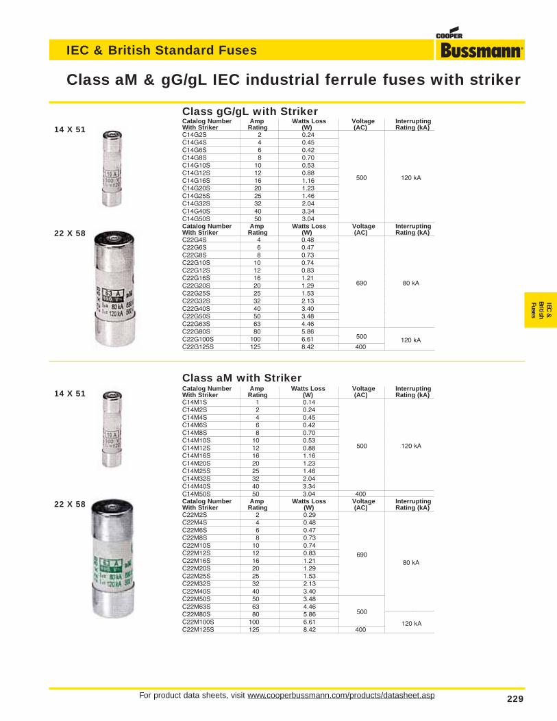
For product data sheets, visit www.cooperbussmann.com/products/datasheet.asp 229
Class aM & gG/gL IEC industrial ferrule fuses with striker
IEC & British Standard Fuses
IEC&
BritishFuses
Class gG/gL with StrikerCatalog Number Amp Watts Loss Voltage InterruptingWith Striker Rating (W) (AC) Rating (kA)C14G2S 2 0.24 500 120C14G4S 4 0.45C14G6S 6 0.42C14G8S 8 0.70C14G10S 10 0.53C14G12S 12 0.88C14G16S 16 1.16C14G20S 20 1.23C14G25S 25 1.46C14G32S 32 2.04C14G40S 40 3.34C14G50S 50 3.04 400Catalog Number Amp Watts Loss Voltage InterruptingWith Striker Rating (W) (AC) Rating (kA)C22G4S 4 0.48 690 80C22G6S 6 0.47C22G8S 8 0.73C22G10S 10 0.74C22G12S 12 0.83C22G16S 16 1.21C22G20S 20 1.29C22G25S 25 1.53C22G32S 32 2.13C22G40S 40 3.40C22G50S 50 3.48C22G63S 63 4.46C22G80S 80 5.86 500 120C22G100S 100 6.61C22G125S 125 8.42 400
Class aM with StrikerCatalog Number Amp Watts Loss Voltage InterruptingWith Striker Rating (W) (AC) Rating (kA)C14M1S 1 0.14 500 120C14M2S 2 0.24C14M4S 4 0.45C14M6S 6 0.42C14M8S 8 0.70C14M10S 10 0.53C14M12S 12 0.88C14M16S 16 1.16C14M20S 20 1.23C14M25S 25 1.46C14M32S 32 2.04C14M40S 40 3.34C14M50S 50 3.04 400Catalog Number Amp Watts Loss Voltage InterruptingWith Striker Rating (W) (AC) Rating (kA)C22M2S 2 0.29 690 80C22M4S 4 0.48C22M6S 6 0.47C22M8S 8 0.73C22M10S 10 0.74C22M12S 12 0.83C22M16S 16 1.21C22M20S 20 1.29C22M25S 25 1.53C22M32S 32 2.13C22M40S 40 3.40C22M50S 50 3.48C22M63S 63 4.46C22M80S 80 5.86 500 120C22M100S 100 6.61C22M125S 125 8.42 400
14 X 51
22 X 58
14 X 51
22 X 58
500 120 kA
80 kA
120 kA
690
500
500 120 kA
80 kA
120 kA
690
500
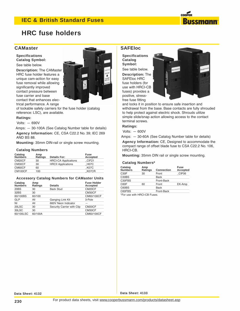
For product data sheets, visit www.cooperbussmann.com/products/datasheet.asp230
IEC & British Standard Fuses
SAFEloc
SpecificationsCatalogSymbol:See table below.
Description: TheSAFEloc HRCfuse holders (foruse with HRCI-CBfuses) provides apositive, stress-free fuse fittingand locks it in position to ensure safe insertion and withdrawal from the base. Base contacts are fully shroudedto help protect against electric shock. Shrouds utilize simple slide/snap action allowing access to the contact terminal screws.
Ratings:Volts: — 600V
Amps: — 30-60A (See Catalog Number table for details)
Agency Information: CE, Designed to accommodate thecompact range of offset blade fuse to CSA C22.2 No. 106,HRCI-CB.
Mounting: 35mm DIN rail or single screw mounting.
Catalog Numbers*Catalog Amp FuseNumbers Ratings Connection AcceptedC30F 30 Front _CIF06C30BS BackC30FBS Front-BackC60F 60 Front EK-AmpC60BS BackC60FBS Front-Back*For use with HRCI-CB Fuses.
CAMaster
SpecificationsCatalog Symbol:See table below.
Description: The CAMasterHRC fuse holder features aunique cam-action for easyfuse removal while allowingsignificantly improved contact pressure betweenfuse carrier and base contact that enhances elec-trical performance. A rangeof lockable safety carriers for the fuse holder (catalog reference: LSC), are available.
Ratings:Volts: — 690V
Amps: — 30-100A (See Catalog Number table for details)
Agency Information: CE, CSA C22.2 No. 39; IEC 269AND BS 88.
Mounting: 35mm DIN-rail or single screw mounting.
Catalog NumbersCatalog Amp FuseNumbers Ratings Details For: AcceptedCM20CF 30 HRCI-CA Applications _CIF21CM30CF 30 HRCII Applications _H07CCM60CF 60 _K07CCM100CF 100 _K07CR
Accessory Catalog Numbers for CAMaster UnitsCatalog Amp Fuse HolderNumbers Ratings Details Accepted20BS 30 Back Stud CM20CF32BS 30 CM30CF60/100BS 60/100 CM60/100CFGLP All Ganging Link Kit 3-PoleNI All 660V Neon Indicator —20LSC 30 Security Carrier with Clip CM20CF30LSC 30 CM30CF60/100LSC 60/100A CM60/100CF
HRC fuse holders
Data Sheet: 4132 Data Sheet: 4133
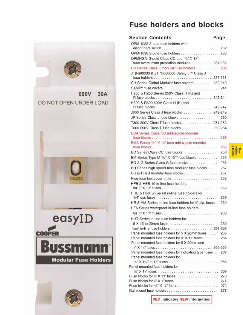
231
FuseHolders
& Blocks
Fuse holders and blocks
Section Contents PageOPM-1038 3-pole fuse holders with
disconnect switch . . . . . . . . . . . . . . . . . . . . . . . . . . . . . . 232
OPM-1038 3-pole fuse holders . . . . . . . . . . . . . . . . . . . . 233
OPMNGA- 3-pole Class CC and 13⁄32” X 11⁄2”fuse overcurrent protection modules . . . . . . . . . . . 234-235
CH Series Class J modular fuse holders . . . . . . . . . . . . 236
JT(N)60030 & JT(N)600600 Safety J™ Class J fuse holders . . . . . . . . . . . . . . . . . . . . . . . . . . . . . . . 237-238
CH Series Global Modular fuse holders . . . . . . . . . 239-240
SAMI™ fuse covers . . . . . . . . . . . . . . . . . . . . . . . . . . . . . 241
H250 & R250 Series 250V Class H (K) and R fuse blocks . . . . . . . . . . . . . . . . . . . . . . . . . . . . . . 242-244
H600 & R600 600V Class H (K) and R fuse blocks . . . . . . . . . . . . . . . . . . . . . . . . . . . . . . 245-247
J600 Series Class J fuse blocks . . . . . . . . . . . . . . . 248-249
JP Series Class J fuse blocks . . . . . . . . . . . . . . . . . 250
T300 300V Class T fuse blocks . . . . . . . . . . . . . . . . 251-252
T600 600V Class T fuse blocks . . . . . . . . . . . . . . . . 253-254
BCA Series Class CC add-a-pole modular fuse blocks . . . . . . . . . . . . . . . . . . . . . . . . . . . . . . . . . . . 255
BMA Series 13⁄32” X 11⁄2” fuse add-a-pole modular fuse blocks . . . . . . . . . . . . . . . . . . . . . . . . . . . . . . . . . . . 255
BC Series Class CC fuse blocks . . . . . . . . . . . . . . . . . . 256
BM Series Type M 13⁄32” X 11⁄2”” fuse blocks . . . . . . . . . . . 256
BG & G Series Class G fuse blocks . . . . . . . . . . . . . . . 256
BH Series high speed fuse modular fuse blocks . . . . . 257
Class H & J modular fuse blocks . . . . . . . . . . . . . . . . . . 257
Plug fuse box cover units . . . . . . . . . . . . . . . . . . . . . . . . 258
HFB & HEB-10 in-line fuse holders for 1⁄4” X 11⁄4” fuses . . . . . . . . . . . . . . . . . . . . . . . . . . . . . . 259
HHB & HRK universal in-line fuse holders for 1/4” dia. fuses . . . . . . . . . . . . . . . . . . . . . . . . . . . . . . . . . 259
HR & HM Series in-line fuse holders for 1⁄4” dia. fuses . . 260
HFA Series waterproof in-line fuse holders
for 1⁄4” X 11⁄4” fuses . . . . . . . . . . . . . . . . . . . . . . . . . . . . . . 260
HHT Series in-line fuse holders for 5 X 15 to 20mm fuses . . . . . . . . . . . . . . . . . . . . . . . . . . 260
Tron® in-line fuse holders . . . . . . . . . . . . . . . . . . . . . . . 261-262Panel mounted fuse holders for 5 X 20mm fuses . . . . . . 263Panel mounted fuse holders for 1⁄4” X 11⁄4” fuses . . . . . . . . 264Panel mounted fuse holders for 5 X 20mm and
1⁄4” X 11⁄4” fuses . . . . . . . . . . . . . . . . . . . . . . . . . . . . . . . 265-266Panel mounted fuse holders for indicating type fuses . . 267Panel mounted fuse holders for
13⁄32” X 15⁄16” to 11⁄2” fuses . . . . . . . . . . . . . . . . . . . . . . . . . . . . 268Panel mounted fuse holders for
13⁄32” X 11⁄2” fuses . . . . . . . . . . . . . . . . . . . . . . . . . . . . . . . . . . 269Fuse blocks for 1⁄4” X 11⁄4” fuses . . . . . . . . . . . . . . . . . . . . . . . 270Fuse blocks for 1⁄4” X 1” fuses . . . . . . . . . . . . . . . . . . . . . . . . 271Fuse blocks for 13⁄32” X 11⁄2” fuses . . . . . . . . . . . . . . . . . . . . . . . .272Rail mount fuse holders . . . . . . . . . . . . . . . . . . . . . . . . . . . . 273
RED indicates NEW information
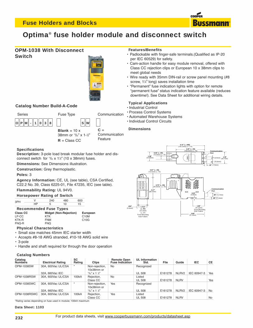
For product data sheets, visit www.cooperbussmann.com/products/datasheet.asp232
Fuse Holders and Blocks
Optima® fuse holder module and disconnect switch
4.25∑ (± .03)(108.0mm) (± .76)
(6.9mm)
(18.8mm)
(7.9mm)
BU
SS
5.72∑ (± .045)(145.3mm) (± 1.14)
0.43∑ (± .03)(10.9mm) (± .76)
1.38∑(35.0mm)
0.23∑
1.86∑
(5.8mm)
3.17∑(80.5mm)
1.312∑(± .01)
(33.3mm)(± .25)
Panel MountingHole Pattern
(47.2mm)Panel MountingHole Pattern
3.74∑ (± .03)(95.0mm) (± .76)
0.57∑ (± .03)(14.5mm) (± .76)
.27∑
.31∑
CommunicationPort
.74∑
.50∑ (12.7mm)
CommunicationPort
.44∑ (11.2mm)
2T1 1L1
3L2
5L3
4T 2
6T31.76∑
3.60∑(91.4mm)
(44.7mm)
.224∑(5.6mm)
Data Sheet: 1103
SpecificationsDescription: 3-pole load break modular fuse holder and dis-connect switch for 13⁄32 x 11⁄2” (10 x 38mm) fuses.
Dimensions: See Dimensions illustration.
Construction: Grey thermoplastic.
Poles: 3
Agency Information: CE, UL (see table), CSA Certified,C22.2 No. 39, Class 6225-01, File 47235, IEC (see table).
Flammability Rating: UL 94V0.
Horsepower Rating of SwitchV 240 480 6003PHHP 5 10 15
Recommended Fuse TypesClass CC Midget (Non-Rejection) EuropeanLP-CC KTK C10MKTK-R FNM C10GFNQ-R FNQ
Physical Characteristics• Small size matches 45mm IEC starter width• Accepts #8-18 AWG stranded, #10-18 AWG solid wire• 3-pole• Handle and shaft required for through the door operation
Features/Benefits• Padlockable with finger-safe terminals.(Qualified as IP-20
per IEC 60529) for safety.• Cam-action handle for easy module removal, offered with
Class CC rejection clips or European 10 x 38mm clips tomeet global needs
• Wire ready with 35mm DIN-rail or screw panel mounting (#8screw, 11⁄4” long) saves installation time
• “Permanent” fuse indication lights with option for remote“permanent fuse” status indication feature available (reducesdowntime!). See Data Sheet for additional wiring details.
Typical Applications• Industrial Control• Process Control Systems• Automated Warehouse Systems• Individual Control Circuits
Dimensions
Catalog NumbersCatalog SC Remote Open UL InformationNumbers Electrical Rating Rating Clips Fuse Indication Std. File Guide IEC CEOPM-1038SW 30A, 600Vac UL/CSA * Non-rejection, No Recognized
10x38mm or32A, 660Vac IEC 13⁄32” x 1 1⁄2” UL 508 E161278 NLRV2 IEC 60947-3 Yes
OPM-1038RSW 30A, 600Vac UL/CSA 100kA Rejection, No ListedClass CC UL 508 E161278 NLRV Yes
OPM-1038SWC 30A, 600Vac UL/CSA * Non-rejection, Yes Recognized10x38mm or
32A, 660Vac IEC 13⁄32” x 1 1⁄2” UL 508 E161278 NLRV2 IEC 60947-3 NoOPM-1038RSWC 30A, 600Vac UL/CSA 100kA Rejection, Yes Listed
Class CC UL 508 E161278 NLRV No*Rating varies depending on fuse used in module; 100kA maximum
O P M - 1 0 3 8 S W
Series Fuse Type Communication
C =CommunicationFeature
Catalog Number Build-A-Code
OPM-1038 With DisconnectSwitch
Blank = 10 x38mm or 13⁄32” x 1-1⁄2”
R = Class CC
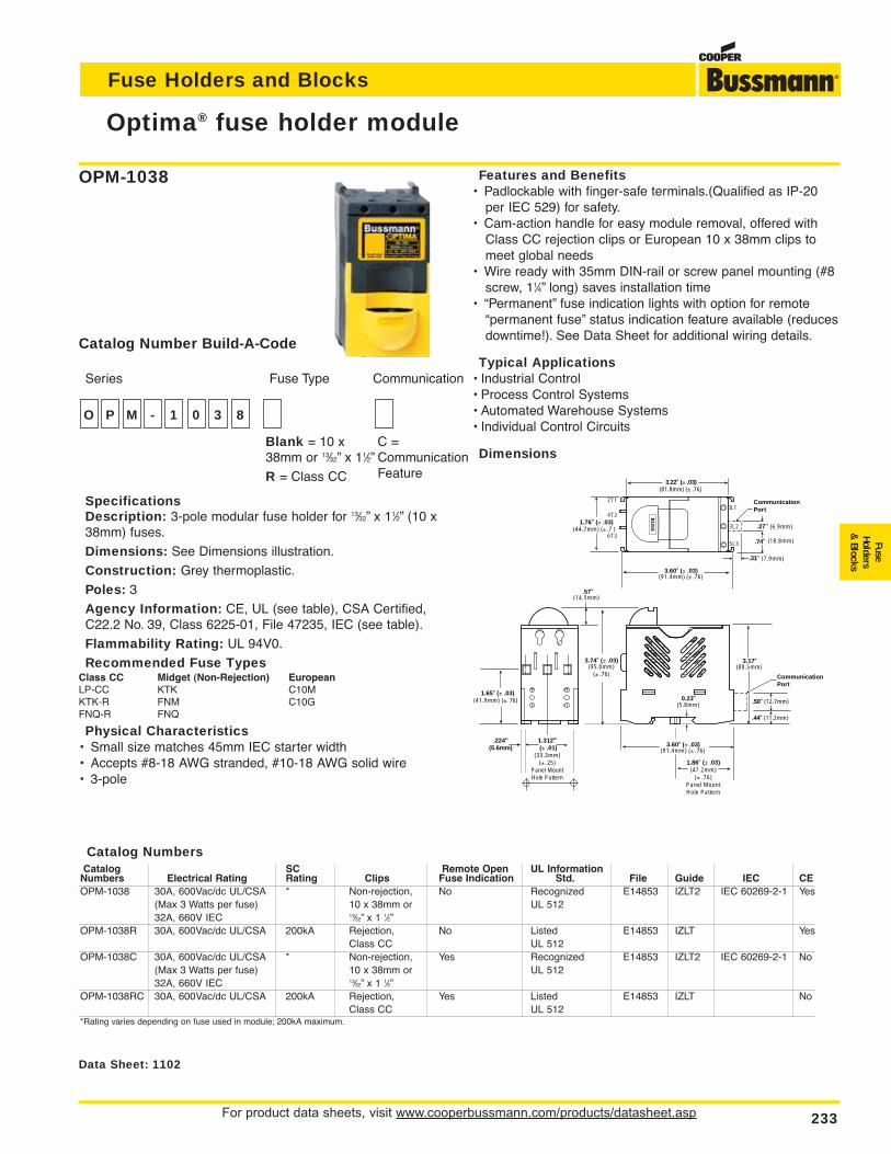
Fuse Holders and Blocks
Optima® fuse holder module
For product data sheets, visit www.cooperbussmann.com/products/datasheet.asp 233
FuseHolders
& Blocks
BU
SS
3.74∑ (± .03)(95.0mm)
(± .76)
.57∑(14.5mm)
0.23∑(5.8mm)
3.17∑(80.5mm)
3.22∑ (± .03)
.27∑
.31∑
(81.8mm) (± .76)
3.60∑ (± .03) (91.4mm) (± .76)
1.76∑ (± .03)(44.7mm) (± .7 )
1.65∑ (± .03)(41.9mm) (±. 76)
1.312∑ (± .01)
(33.3mm)(± .25)
Panel MountHole Pattern
1.86∑ (± .03)(47.2mm)
(± .76)Panel MountHole Pattern
3.60∑ (± .03)(91.4mm) (± .76)
CommunicationPort
.74∑
CommunicationPort
(6.9mm)
(18.8mm)
(7.9mm)
.50∑ (12.7mm)
.44∑ (11.2mm)
2T1
4T2
6T3
IL1
3L2
5L3
.224"(5.6mm)
Data Sheet: 1102
SpecificationsDescription: 3-pole modular fuse holder for 13⁄32” x 11⁄2” (10 x38mm) fuses.
Dimensions: See Dimensions illustration.
Construction: Grey thermoplastic.
Poles: 3
Agency Information: CE, UL (see table), CSA Certified,C22.2 No. 39, Class 6225-01, File 47235, IEC (see table).
Flammability Rating: UL 94V0.
Recommended Fuse TypesClass CC Midget (Non-Rejection) EuropeanLP-CC KTK C10MKTK-R FNM C10GFNQ-R FNQ
Physical Characteristics• Small size matches 45mm IEC starter width• Accepts #8-18 AWG stranded, #10-18 AWG solid wire• 3-pole
Features and Benefits• Padlockable with finger-safe terminals.(Qualified as IP-20
per IEC 529) for safety.• Cam-action handle for easy module removal, offered with
Class CC rejection clips or European 10 x 38mm clips tomeet global needs
• Wire ready with 35mm DIN-rail or screw panel mounting (#8screw, 11⁄4” long) saves installation time
• “Permanent” fuse indication lights with option for remote“permanent fuse” status indication feature available (reducesdowntime!). See Data Sheet for additional wiring details.
Typical Applications• Industrial Control• Process Control Systems• Automated Warehouse Systems• Individual Control Circuits
Dimensions
O P M - 1 0 3 8
Series Fuse Type Communication
C =CommunicationFeature
Blank = 10 x38mm or 13⁄32” x 11⁄2”
R = Class CC
Catalog Number Build-A-Code
OPM-1038
Catalog NumbersCatalog SC Remote Open UL Information
Numbers Electrical Rating Rating Clips Fuse Indication Std. File Guide IEC CEOPM-1038 30A, 600Vac/dc UL/CSA * Non-rejection, No Recognized E14853 IZLT2 IEC 60269-2-1 Yes
(Max 3 Watts per fuse) 10 x 38mm or UL 51232A, 660V IEC 13⁄32” x 1 1⁄2”
OPM-1038R 30A, 600Vac/dc UL/CSA 200kA Rejection, No Listed E14853 IZLT YesClass CC UL 512
OPM-1038C 30A, 600Vac/dc UL/CSA * Non-rejection, Yes Recognized E14853 IZLT2 IEC 60269-2-1 No(Max 3 Watts per fuse) 10 x 38mm or UL 51232A, 660V IEC 13⁄32” x 1 1⁄2”
OPM-1038RC 30A, 600Vac/dc UL/CSA 200kA Rejection, Yes Listed E14853 IZLT NoClass CC UL 512
*Rating varies depending on fuse used in module; 200kA maximum.
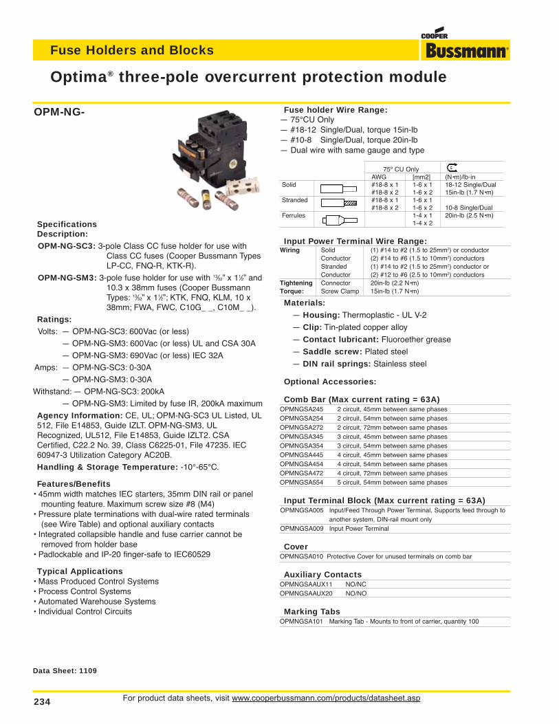
Fuse holder Wire Range:— 75°CU Only— #18-12 Single/Dual, torque 15in-lb— #10-8 Single/Dual, torque 20in-lb— Dual wire with same gauge and type
AWG [mm2] (N•m)/lb-in
Solid #18-8 x 1 1-6 x 1 18-12 Single/Dual#18-8 x 2 1-6 x 2 15in-lb (1.7 N•m)
Stranded #18-8 x 1 1-6 x 1#18-8 x 2 1-6 x 2 10-8 Single/Dual
Ferrules 1-4 x 1 20in-lb (2.5 N•m)1-4 x 2
Input Power Terminal Wire Range:Wiring Solid (1) #14 to #2 (1.5 to 25mm2) or conductor
Conductor (2) #14 to #6 (1.5 to 10mm2) conductorsStranded (1) #14 to #2 (1.5 to 25mm2) conductor orConductor (2) #12 to #6 (2.5 to 10mm2) conductors
Tightening Connector 20in-lb (2.2 N•m)Torque: Screw Clamp 15in-lb (1.7 N•m)
Materials:
— Housing: Thermoplastic - UL V-2
— Clip: Tin-plated copper alloy
— Contact lubricant: Fluoroether grease
— Saddle screw: Plated steel
— DIN rail springs: Stainless steel
Optional Accessories:
Comb Bar (Max current rating = 63A)OPMNGSA245 2 circuit, 45mm between same phasesOPMNGSA254 2 circuit, 54mm between same phasesOPMNGSA272 2 circuit, 72mm between same phasesOPMNGSA345 3 circuit, 45mm between same phasesOPMNGSA354 3 circuit, 54mm between same phasesOPMNGSA445 4 circuit, 45mm between same phasesOPMNGSA454 4 circuit, 54mm between same phasesOPMNGSA472 4 circuit, 72mm between same phasesOPMNGSA554 5 circuit, 54mm between same phases
Input Terminal Block (Max current rating = 63A)OPMNGSA005 Input/Feed Through Power Terminal, Supports feed through to
another system, DIN-rail mount onlyOPMNGSA009 Input Power Terminal
CoverOPMNGSA010 Protective Cover for unused terminals on comb bar
Auxiliary ContactsOPMNGSAAUX11 NO/NCOPMNGSAAUX20 NO/NO
Marking TabsOPMNGSA101 Marking Tab - Mounts to front of carrier, quantity 100
Fuse Holders and Blocks
For product data sheets, visit www.cooperbussmann.com/products/datasheet.asp234
Optima® three-pole overcurrent protection module
Data Sheet: 1109
SpecificationsDescription:OPM-NG-SC3: 3-pole Class CC fuse holder for use with
Class CC fuses (Cooper Bussmann TypesLP-CC, FNQ-R, KTK-R).
OPM-NG-SM3: 3-pole fuse holder for use with 13⁄32” x 11⁄2” and10.3 x 38mm fuses (Cooper BussmannTypes: 13⁄32” x 11⁄2”; KTK, FNQ, KLM, 10 x38mm; FWA, FWC, C10G_ _, C10M_ _).
Ratings:Volts: — OPM-NG-SC3: 600Vac (or less)
— OPM-NG-SM3: 600Vac (or less) UL and CSA 30A
— OPM-NG-SM3: 690Vac (or less) IEC 32A
Amps: — OPM-NG-SC3: 0-30A
— OPM-NG-SM3: 0-30A
Withstand: — OPM-NG-SC3: 200kA
— OPM-NG-SM3: Limited by fuse IR, 200kA maximum
Agency Information: CE, UL; OPM-NG-SC3 UL Listed, UL512, File E14853, Guide IZLT. OPM-NG-SM3, ULRecognized, UL512, File E14853, Guide IZLT2. CSACertified, C22.2 No. 39, Class C6225-01, File 47235. IEC60947-3 Utilization Category AC20B.
Handling & Storage Temperature: -10°-65°C.
Features/Benefits• 45mm width matches IEC starters, 35mm DIN rail or panel
mounting feature. Maximum screw size #8 (M4)• Pressure plate terminations with dual-wire rated terminals
(see Wire Table) and optional auxiliary contacts• Integrated collapsible handle and fuse carrier cannot be
removed from holder base• Padlockable and IP-20 finger-safe to IEC60529
Typical Applications• Mass Produced Control Systems• Process Control Systems• Automated Warehouse Systems• Individual Control Circuits
OPM-NG-
75º CU OnlyAWG [mm2] (N•m)/lb-in
Solid #18-8 x 1 1-6 x 1 18-12 Single/Dual#18-8 x 2 1-6 x 2 15in-lb (1.7 N•m)
Stranded #18-8 x 1 1-6 x 1#18-8 x 2 1-6 x 2 10-8 Single/Dual
Ferrules 1-4 x 1 20in-lb (2.5 N•m)1-4 x 2
Fuse Holders and Blocks
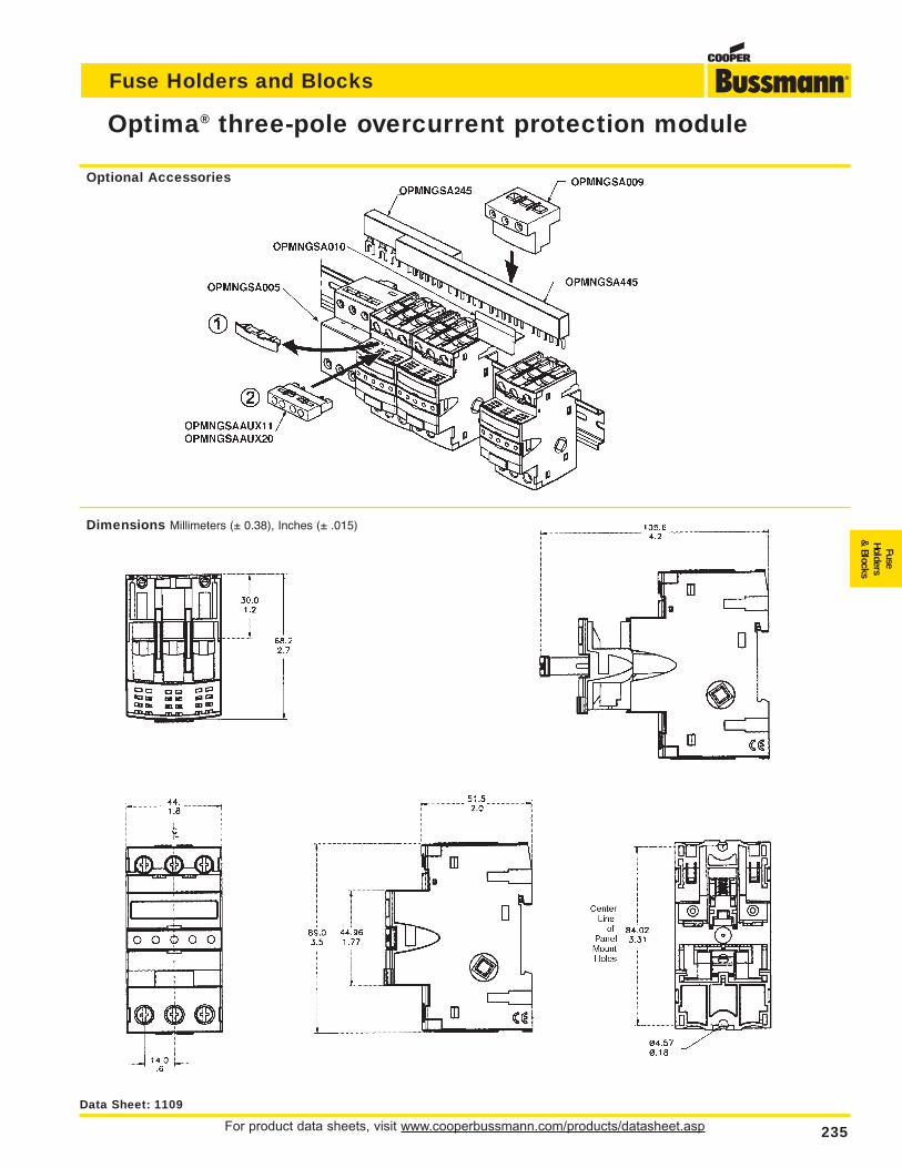
Fuse Holders and Blocks
For product data sheets, visit www.cooperbussmann.com/products/datasheet.asp 235
Optima® three-pole overcurrent protection module
FuseHolders
& Blocks
Data Sheet: 1109
Optional Accessories
Dimensions Millimeters (± 0.38), Inches (± .015)
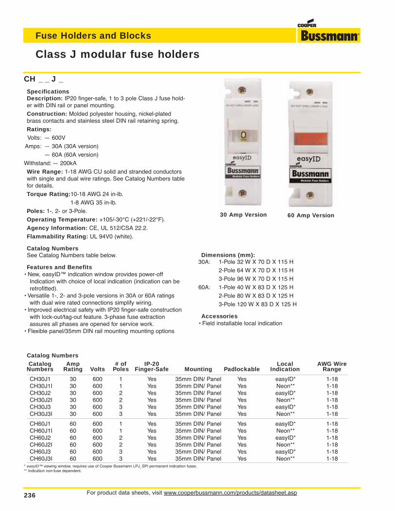
For product data sheets, visit www.cooperbussmann.com/products/datasheet.asp236
Fuse Holders and Blocks
Class J modular fuse holders
CH _ _ J _
SpecificationsDescription: IP20 finger-safe, 1 to 3 pole Class J fuse hold-er with DIN rail or panel mounting.
Construction: Molded polyester housing, nickel-platedbrass contacts and stainless steel DIN rail retaining spring.
Ratings:Volts: — 600V
Amps: — 30A (30A version)
— 60A (60A version)
Withstand: — 200kA
Wire Range: 1-18 AWG CU solid and stranded conductorswith single and dual wire ratings. See Catalog Numbers tablefor details.
Torque Rating:10-18 AWG 24 in-lb.
1-8 AWG 35 in-lb.
Poles: 1-, 2- or 3-Pole.
Operating Temperature: +105/-30°C (+221/-22°F).
Agency Information: CE, UL 512/CSA 22.2.
Flammability Rating: UL 94V0 (white).
Catalog NumbersSee Catalog Numbers table below.
Features and Benefits• New, easyID™ indication window provides power-off
Indication with choice of local indication (indication can beretrofitted).
• Versatile 1-, 2- and 3-pole versions in 30A or 60A ratingswith dual wire rated connections simplify wiring.
• Improved electrical safety with IP20 finger-safe constructionwith lock-out/tag-out feature. 3-phase fuse extractionassures all phases are opened for service work.
• Flexible panel/35mm DIN rail mounting mounting options
Catalog NumbersCatalog Amp # of IP-20 Local AWG Wire
Numbers Rating Volts Poles Finger-Safe Mounting Padlockable Indication Range
CH30J1 30 600 1 Yes 35mm DIN/ Panel Yes easyID* 1-18CH30J1I 30 600 1 Yes 35mm DIN/ Panel Yes Neon** 1-18CH30J2 30 600 2 Yes 35mm DIN/ Panel Yes easyID* 1-18CH30J2I 30 600 2 Yes 35mm DIN/ Panel Yes Neon** 1-18CH30J3 30 600 3 Yes 35mm DIN/ Panel Yes easyID* 1-18CH30J3I 30 600 3 Yes 35mm DIN/ Panel Yes Neon** 1-18
CH60J1 60 600 1 Yes 35mm DIN/ Panel Yes easyID* 1-18CH60J1I 60 600 1 Yes 35mm DIN/ Panel Yes Neon** 1-18CH60J2 60 600 2 Yes 35mm DIN/ Panel Yes easyID* 1-18CH60J2I 60 600 2 Yes 35mm DIN/ Panel Yes Neon** 1-18CH60J3 60 600 3 Yes 35mm DIN/ Panel Yes easyID* 1-18CH60J3I 60 600 3 Yes 35mm DIN/ Panel Yes Neon** 1-18
* easyID™ viewing window, requires use of Cooper Bussmann LPJ_SPI permanent indication fuses.** Indication non-fuse dependent.
Dimensions (mm):30A: 1-Pole 32 W X 70 D X 115 H
2-Pole 64 W X 70 D X 115 H
3-Pole 96 W X 70 D X 115 H
60A: 1-Pole 40 W X 83 D X 125 H
2-Pole 80 W X 83 D X 125 H
3-Pole 120 W X 83 D X 125 H
Accessories• Field installable local indication
30 Amp Version 60 Amp Version
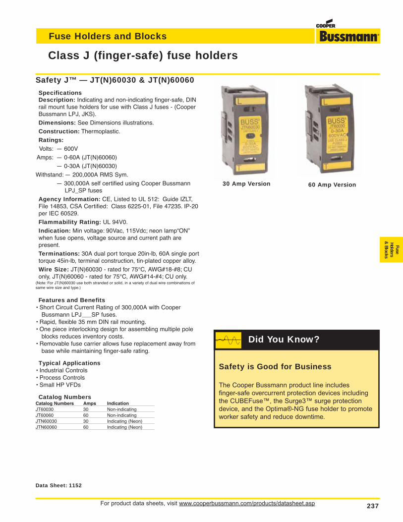
For product data sheets, visit www.cooperbussmann.com/products/datasheet.asp 237
Fuse Holders and Blocks
FuseHolders
& Blocks
Class J (finger-safe) fuse holders
Features and Benefits• Short Circuit Current Rating of 300,000A with Cooper
Bussmann LPJ___SP fuses.• Rapid, flexible 35 mm DIN rail mounting.• One piece interlocking design for assembling multiple pole
blocks reduces inventory costs.• Removable fuse carrier allows fuse replacement away from
base while maintaining finger-safe rating.
Typical Applications• Industrial Controls• Process Controls• Small HP VFDs
Catalog NumbersCatalog Numbers Amps IndicationJT60030 30 Non-indicatingJT60060 60 Non-indicatingJTN60030 30 Indicating (Neon)JTN60060 60 Indicating (Neon)
Data Sheet: 1152
Safety J™ — JT(N)60030 & JT(N)60060
SpecificationsDescription: Indicating and non-indicating finger-safe, DINrail mount fuse holders for use with Class J fuses - (CooperBussmann LPJ, JKS).
Dimensions: See Dimensions illustrations.
Construction: Thermoplastic.
Ratings:Volts: — 600V
Amps: — 0-60A (JT(N)60060)
— 0-30A (JT(N)60030)
Withstand: — 200,000A RMS Sym.
— 300,000A self certified using Cooper BussmannLPJ_SP fuses
Agency Information: CE, Listed to UL 512: Guide IZLT,File 14853, CSA Certified: Class 6225-01, File 47235. IP-20per IEC 60529.
Flammability Rating: UL 94V0.
Indication: Min voltage: 90Vac, 115Vdc; neon lamp“ON”when fuse opens, voltage source and current path are present.
Terminations: 30A dual port torque 20in-lb, 60A single porttorque 45in-lb, terminal construction, tin-plated copper alloy.
Wire Size: JT(N)60030 - rated for 75°C, AWG#18-#8; CUonly, JT(N)60060 - rated for 75°C, AWG#14-#4; CU only.
(Note: For JT(N)60030 use both stranded or solid, in a variety of dual wire combinations ofsame wire size and type.)
30 Amp Version 60 Amp Version
Safety is Good for Business
The Cooper Bussmann product line includes
finger-safe overcurrent protection devices including
the CUBEFuse™, the Surge3™ surge protection
device, and the Optima®-NG fuse holder to promote
worker safety and reduce downtime.
Did You Know?
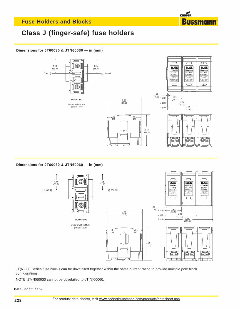
For product data sheets, visit www.cooperbussmann.com/products/datasheet.asp238
Fuse Holders and Blocks
Class J (finger-safe) fuse holders
JT(N)600 Series fuse blocks can be dovetailed together within the same current rating to provide multiple pole blockconfigurations.
NOTE: JT(N)60030 cannot be dovetailed to JT(N)60060.
3.10(78.7)
3.06(77.7)
1.31(33.3)
1.25(31.8)
Din-railSlot
MOUNTING
Shown without fusepullout cover
4.40(111.7)
2.96(75.2)
1.52(38.1)
.10(2.6)
BUSS
35 – 60A600VACUSE CLASS J
FUSESDO NOT REMOVE
UNDER LOAD
JT60060BUSS
35 – 60A600VACUSE CLASS J
FUSESDO NOT REMOVE
UNDER LOAD
JT60060BUSS
35 – 60A600VACUSE CLASS J
FUSESDO NOT REMOVE
UNDER LOAD
JT60060
1 pole
2 pole
3 pole
Data Sheet: 1152
Dimensions for JT60060 & JTN60060 — in (mm)
1.14(29.0)
1.05(26.7)
Slot
MOUNTING
Shown without fusepullout cover
BUSS
0 – 30A600VACUSE CLASS J
FUSESDO NOT REMOVE
UNDER LOAD
JT60030BUSS
0 – 30A600VACUSE CLASS J
FUSESDO NOT REMOVE
UNDER LOAD
JT60030BUSS
0 – 30A600VACUSE CLASS J
FUSESDO NOT REMOVE
UNDER LOAD
JT60030
3.60(91.4)
2.42(61.3)
1.23(31.2)
.07(1.8)
1 pole
2 pole
3 pole
2.75(69.9)
2.52(64.1)
Din-rail
Dimensions for JT60030 & JTN60030 — in (mm)
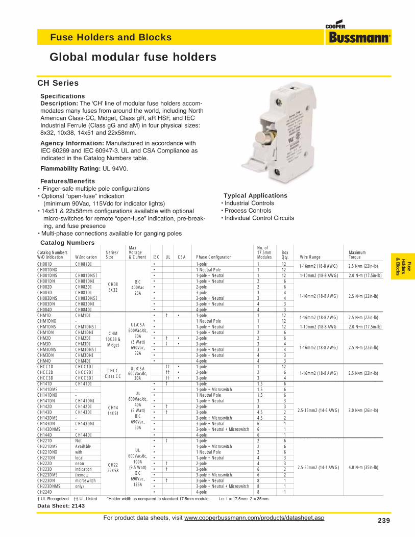
For product data sheets, visit www.cooperbussmann.com/products/datasheet.asp 239
Fuse Holders and Blocks
FuseHolders
& Blocks
Global modular fuse holders
Catalog NumbersMax No. of
Catalog Numbers Series/ Voltage 17.5mm Box MaximumW/O Indication W/Indication Size & Current IEC UL CSA Phase Configuration Modules Qty. Wire Range Torque
CH081D CH081DI CH08 IEC • 1-pole 1 12 1-16mm2 (18-8 AWG) 2.5 N•m (22in-lb)CH081DNX - 8X32 400Vac • 1 Neutral Pole 1 12CH081DNS CH081DNSI 25A • 1-pole + Neutral 1 12 1-10mm2 (18-8 AWG) 2.0 N•m (17.5in-lb)CH081DN CH081DNI • 1-pole + Neutral 2 6 1-16mm2 (18-8 AWG) 2.5 N•m (22in-lb)CH082D CH082DI • 2-pole 2 6CH083D CH083DI • 3-pole 3 4CH083DNS CH083DNSI • 3-pole + Neutral 3 4CH083DN CH083DNI • 3-pole + Neutral 4 3CH084D CH084DI UL/CSA • 4-pole 4 3CHM1D CHM1DI CHM 600Vac/dc, • † • 1-pole 1 12 1-16mm2 (18-8 AWG) 2.5 N•m (22in-lb)CHM1DNX - 10X38 & 30A • 1 Neutral Pole 1 12CHM1DNS CHM1DNSI Midget (3 Watt) • 1-pole + Neutral 1 12 1-10mm2 (18-8 AWG 2.0 N•m (17.5in-lb)CHM1DN CHM1DNI 690Vac, • 1-pole + Neutral 2 6 1-16mm2 (18-8 AWG) 2.5 N•m (22in-lb)CHM2D CHM2DI 32A • † • 2-pole 2 6CHM3D CHM3DI • † • 3-pole 3 4CHM3DNS CHM3DNSI UL/CSA • 3-pole + Neutral 3 4CHM3DN CHM3DNI 600Vac/dc, • 3-pole + Neutral 4 3CHM4D CHM4DI 30A • 4-pole 4 3CHCC1D CHCC1DI CHCC †† • 1-pole 1 12 1-16mm2 (18-8 AWG) 2.5 N•m (22in-lb)CHCC2D CHCC2DI Class CC UL †† • 2-pole 2 6CHCC3D CHCC3DI 600Vac/dc, †† • 3-pole 3 4CH141D CH141DI CH14 40A • † 1-pole 1.5 6 2.5-16mm2 (14-6 AWG) 3.0 N•m (26in-lb)CH141DMS - 14X51 (5 Watt) • 1-pole + Microswitch 1.5 6CH141DNX - IEC • 1 Neutral Pole 1.5 6CH141DN CH141DNI 690Vac, • 1-pole + Neutral 3 3CH142D CH142DI 50A • † 2-pole 3 3CH143D CH143DI • † 3-pole 4.5 2CH143DMS - • 3-pole + Microswitch 4.5 2CH143DN CH143DNI UL • 3-pole + Neutral 6 1CH143DNMS - 600Vac/dc, • 3-pole + Neutral + Microswitch 6 1CH144D CH144DI 100A • 4-pole 6 1CH221D Not CH22 (9.5 Watt) • † 1-pole 2 6 2.5-50mm2 (14-1 AWG) 4.0 N•m (35in-lb)CH221DMS Available 22X58 IEC • 1-pole + Microswitch 2 6CH221DNX with 690Vac, • 1 Neutral Pole 2 6CH221DN local 125A • 1-pole + Neutral 4 3CH222D neon • † 2-pole 4 3CH223D indication • † 3-pole 6 2CH223DMS (remote • 3-pole + Microswitch 6 2CH223DN microswitch • † 3-pole + Neutral 8 1CH223DNMS only) • 3-pole + Neutral + Microswitch 8 1CH224D • 4-pole 8 1† UL Recognized †† UL LIsted *Holder width as compared to standard 17.5mm module. i.e. 1 = 17.5mm 2 = 35mm.
Data Sheet: 2143
CH Series
SpecificationsDescription: The ‘CH’ line of modular fuse holders accom-modates many fuses from around the world, including NorthAmerican Class-CC, Midget, Class gR, aR HSF, and IECIndustrial Ferrule (Class gG and aM) in four physical sizes:8x32, 10x38, 14x51 and 22x58mm.
Agency Information: Manufactured in accordance withIEC 60269 and IEC 60947-3. UL and CSA Compliance asindicated in the Catalog Numbers table.
Flammability Rating: UL 94V0.
Features/Benefits• Finger-safe multiple pole configurations• Optional “open-fuse” indication
(minimum 90Vac, 115Vdc for indicator lights)• 14x51 & 22x58mm configurations available with optional
micro-switches for remote “open-fuse” indication, pre-break-ing, and fuse presence
• Multi-phase connections available for ganging poles
Typical Applications• Industrial Controls• Process Controls• Individual Control Circuits
CH088X32
CHM10X38 &Midget
CHCCClass CC
CH1414X51
CH2222X58
IEC400Vac
25A
UL/CSA600Vac/dc,
30A(3 Watt)690Vac,
32A
UL600Vac/dc,
40A(5 Watt)
IEC690Vac,
50A
UL600Vac/dc,
100A(9.5 Watt)
IEC690Vac,
125A
UL/CSA600Vac/dc,
30A
1-16mm2 (18-8 AWG) 2.5 N•m (22in-lb)
1-16mm2 (18-8 AWG) 2.5 N•m (22in-lb)
1-16mm2 (18-8 AWG) 2.5 N•m (22in-lb)
1-16mm2 (18-8 AWG) 2.5 N•m (22in-lb)
1-16mm2 (18-8 AWG) 2.5 N•m (22in-lb)
2.5-16mm2 (14-6 AWG) 3.0 N•m (26in-lb)
2.5-50mm2 (14-1 AWG) 4.0 N•m (35in-lb)
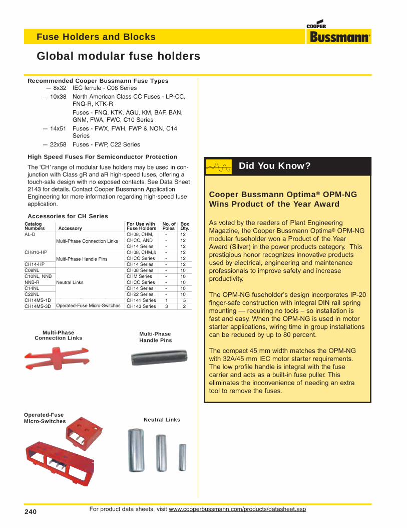
For product data sheets, visit www.cooperbussmann.com/products/datasheet.asp240
Fuse Holders and Blocks
Global modular fuse holders
Multi-PhaseConnection Links
Multi-PhaseHandle Pins
Neutral LinksOperated-FuseMicro-Switches
Recommended Cooper Bussmann Fuse Types— 8x32 IEC ferrule - C08 Series
— 10x38 North American Class CC Fuses - LP-CC,FNQ-R, KTK-R
Fuses - FNQ, KTK, AGU, KM, BAF, BAN,GNM, FWA, FWC, C10 Series
— 14x51 Fuses - FWX, FWH, FWP & NON, C14Series
— 22x58 Fuses - FWP, C22 Series
High Speed Fuses For Semiconductor Protection
The ‘CH’ range of modular fuse holders may be used in con-junction with Class gR and aR high-speed fuses, offering atouch-safe design with no exposed contacts. See Data Sheet2143 for details. Contact Cooper Bussmann ApplicationEngineering for more information regarding high-speed fuseapplication.
Accessories for CH SeriesCatalog For Use with No. of BoxNumbers Accessory Fuse Holders Poles Qty.AL-D Multi-Phase Connection Links CH08, CHM, - 12
CHCC, AND - 12CH14 Series - 12
CH810-HP Multi-Phase Handle Pins CH08, CHM,& - 12CHCC Series - 12
CH14-HP CH14 Series - 12C08NL Neutral Links CH08 Series - 10C10NL, NNB CHM Series - 10NNB-R CHCC Series - 10C14NL CH14 Series - 10C22NL CH22 Series - 10CH14MS-1D Operated-Fuse Micro-Switches CH141 Series 1 5CH14MS-3D CH143 Series 3 2
Cooper Bussmann Optima® OPM-NGWins Product of the Year Award
As voted by the readers of Plant Engineering
Magazine, the Cooper Bussmann Optima® OPM-NG
modular fuseholder won a Product of the Year
Award (Silver) in the power products category. This
prestigious honor recognizes innovative products
used by electrical, engineering and maintenance
professionals to improve safety and increase
productivity.
The OPM-NG fuseholder’s design incorporates IP-20
finger-safe construction with integral DIN rail spring
mounting — requiring no tools – so installation is
fast and easy. When the OPM-NG is used in motor
starter applications, wiring time in group installations
can be reduced by up to 80 percent.
The compact 45 mm width matches the OPM-NG
with 32A/45 mm IEC motor starter requirements.
The low profile handle is integral with the fuse
carrier and acts as a built-in fuse puller. This
eliminates the inconvenience of needing an extra
tool to remove the fuses.
Did You Know?
Multi-Phase Connection Links
Multi-Phase Handle Pins
Operated-Fuse Micro-Switches
Neutral Links
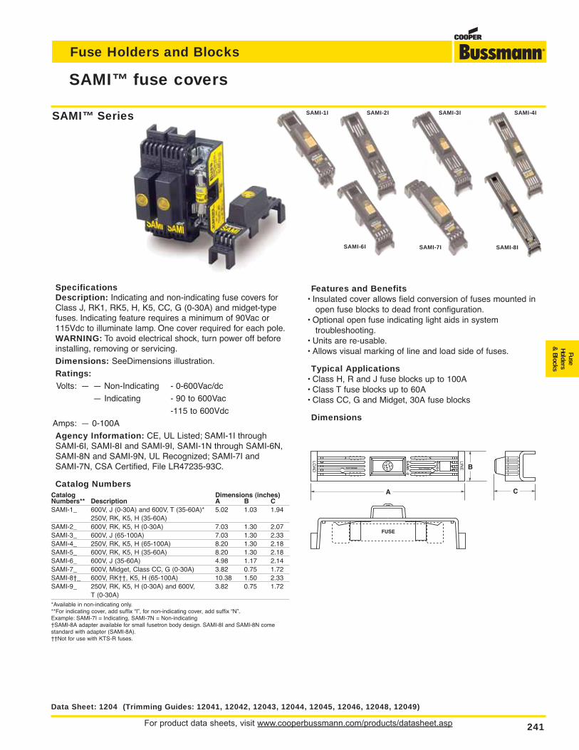
For product data sheets, visit www.cooperbussmann.com/products/datasheet.asp 241
Fuse Holders and Blocks
FuseHolders
& Blocks
SAMI™ fuse covers
SpecificationsDescription: Indicating and non-indicating fuse covers forClass J, RK1, RK5, H, K5, CC, G (0-30A) and midget-typefuses. Indicating feature requires a minimum of 90Vac or115Vdc to illuminate lamp. One cover required for each pole.WARNING: To avoid electrical shock, turn power off beforeinstalling, removing or servicing.
Dimensions: SeeDimensions illustration.
Ratings:Volts: — — Non-Indicating - 0-600Vac/dc
— Indicating - 90 to 600Vac
-115 to 600Vdc
Amps: — 0-100A
Agency Information: CE, UL Listed; SAMI-1I throughSAMI-6I, SAMI-8I and SAMI-9I, SAMI-1N through SAMI-6N,SAMI-8N and SAMI-9N, UL Recognized; SAMI-7I andSAMI-7N, CSA Certified, File LR47235-93C.
Catalog NumbersCatalog Dimensions (inches)Numbers** Description A B CSAMI-1_ 600V, J (0-30A) and 600V, T (35-60A)* 5.02 1.03 1.94
250V, RK, K5, H (35-60A)SAMI-2_ 600V, RK, K5, H (0-30A) 7.03 1.30 2.07SAMI-3_ 600V, J (65-100A) 7.03 1.30 2.33SAMI-4_ 250V, RK, K5, H (65-100A) 8.20 1.30 2.18SAMI-5_ 600V, RK, K5, H (35-60A) 8.20 1.30 2.18SAMI-6_ 600V, J (35-60A) 4.98 1.17 2.14SAMI-7_ 600V, Midget, Class CC, G (0-30A) 3.82 0.75 1.72SAMI-8†_ 600V, RK††, K5, H (65-100A) 10.38 1.50 2.33SAMI-9_ 250V, RK, K5, H (0-30A) and 600V, 3.82 0.75 1.72
T (0-30A)*Available in non-indicating only.**For indicating cover, add suffix “I”, for non-indicating cover, add suffix “N”.Example: SAMI-7I = Indicating, SAMI-7N = Non-indicating†SAMI-8A adapter available for small fusetron body design. SAMI-8I and SAMI-8N comestandard with adapter (SAMI-8A).††Not for use with KTS-R fuses.
Features and Benefits• Insulated cover allows field conversion of fuses mounted in
open fuse blocks to dead front configuration.• Optional open fuse indicating light aids in system
troubleshooting.• Units are re-usable.• Allows visual marking of line and load side of fuses.
Typical Applications• Class H, R and J fuse blocks up to 100A• Class T fuse blocks up to 60A• Class CC, G and Midget, 30A fuse blocks
Dimensions
LINE
Bu
ss
SA
MI -2
LOA
D TEST PROBE TEST PROBE
C
B
A
FUSE
Data Sheet: 1204 (Trimming Guides: 12041, 12042, 12043, 12044, 12045, 12046, 12048, 12049)
SAMI-1I SAMI-3I SAMI-4ISAMI-2I
SAMI-6I SAMI-8ISAMI-7I
SAMI™ Series
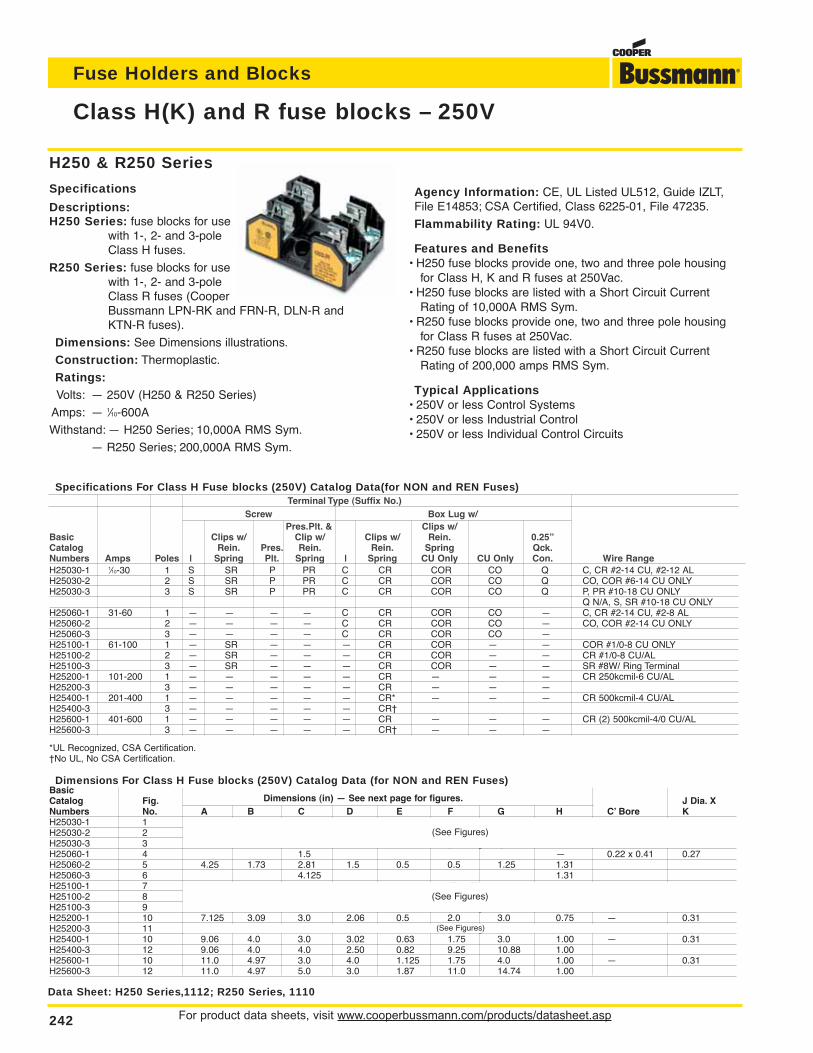
For product data sheets, visit www.cooperbussmann.com/products/datasheet.asp242
Fuse Holders and Blocks
Class H(K) and R fuse blocks – 250V
Data Sheet: H250 Series,1112; R250 Series, 1110
H250 & R250 Series
Specifications
Descriptions:H250 Series: fuse blocks for use
with 1-, 2- and 3-poleClass H fuses.
R250 Series: fuse blocks for usewith 1-, 2- and 3-poleClass R fuses (CooperBussmann LPN-RK and FRN-R, DLN-R and KTN-R fuses).
Dimensions: See Dimensions illustrations.
Construction: Thermoplastic.
Ratings:Volts: — 250V (H250 & R250 Series)
Amps: — 1⁄10-600A
Withstand: — H250 Series; 10,000A RMS Sym.
— R250 Series; 200,000A RMS Sym.
Dimensions For Class H Fuse blocks (250V) Catalog Data (for NON and REN Fuses)BasicCatalog Fig. Dimensions (in) — See next page for figures. J Dia. XNumbers No. A B C D E F G H C’ Bore KH25030-1 1 (See Figures)H25030-2 2 (See Figures)H25030-3 3 (See Figures)H25060-1 4 1.5 — 0.22 x 0.41 0.27H25060-2 5 4.25 1.73 2.81 1.5 0.5 0.5 1.25 1.31H25060-3 6 4.125 1.31H25100-1 7 (See Figures)H25100-2 8 (See Figures)H25100-3 9 (See Figures)H25200-1 10 7.125 3.09 3.0 2.06 0.5 2.0 3.0 0.75 — 0.31H25200-3 11 (See Figures)H25400-1 10 9.06 4.0 3.0 3.02 0.63 1.75 3.0 1.00 — 0.31H25400-3 12 9.06 4.0 4.0 2.50 0.82 9.25 10.88 1.00H25600-1 10 11.0 4.97 3.0 4.0 1.125 1.75 4.0 1.00 — 0.31H25600-3 12 11.0 4.97 5.0 3.0 1.87 11.0 14.74 1.00
Agency Information: CE, UL Listed UL512, Guide IZLT,File E14853; CSA Certified, Class 6225-01, File 47235.
Flammability Rating: UL 94V0.
Features and Benefits• H250 fuse blocks provide one, two and three pole housing
for Class H, K and R fuses at 250Vac.• H250 fuse blocks are listed with a Short Circuit Current
Rating of 10,000A RMS Sym.• R250 fuse blocks provide one, two and three pole housing
for Class R fuses at 250Vac.• R250 fuse blocks are listed with a Short Circuit Current
Rating of 200,000 amps RMS Sym.
Typical Applications• 250V or less Control Systems• 250V or less Industrial Control• 250V or less Individual Control Circuits
H25030-1 1⁄10-30 1 S SR P PR C CR COR CO Q C, CR #2-14 CU, #2-12 ALH25030-2 2 S SR P PR C CR COR CO Q CO, COR #6-14 CU ONLYH25030-3 3 S SR P PR C CR COR CO Q P, PR #10-18 CU ONLY
Q N/A, S, SR #10-18 CU ONLYH25060-1 31-60 1 — — — — C CR COR CO — C, CR #2-14 CU, #2-8 ALH25060-2 2 — — — — C CR COR CO — CO, COR #2-14 CU ONLYH25060-3 3 — — — — C CR COR CO —H25100-1 61-100 1 — SR — — — CR COR — — COR #1/0-8 CU ONLYH25100-2 2 — SR — — — CR COR — — CR #1/0-8 CU/ALH25100-3 3 — SR — — — CR COR — — SR #8W/ Ring TerminalH25200-1 101-200 1 — — — — — CR — — — CR 250kcmil-6 CU/ALH25200-3 3 — — — — — CR — — —H25400-1 201-400 1 — — — — — CR* — — — CR 500kcmil-4 CU/ALH25400-3 3 — — — — — CR†H25600-1 401-600 1 — — — — — CR — — — CR (2) 500kcmil-4/0 CU/ALH25600-3 3 — — — — — CR† — — —
*UL Recognized, CSA Certification.†No UL, No CSA Certification.
Pres.Plt. & Clips w/Basic Clips w/ Clip w/ Clips w/ Rein. 0.25”Catalog Rein. Pres. Rein. Rein. Spring Qck.Numbers Amps Poles | Spring Plt. Spring | Spring CU Only CU Only Con. Wire Range
Specifications For Class H Fuse blocks (250V) Catalog Data(for NON and REN Fuses)Terminal Type (Suffix No.)
Screw Box Lug w/
(See Figures)
(See Figures)
(See Figures)
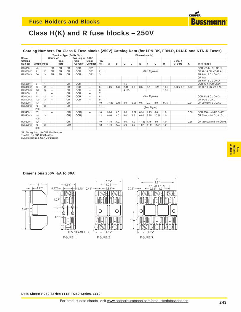
For product data sheets, visit www.cooperbussmann.com/products/datasheet.asp 243
Fuse Holders and Blocks
FuseHolders
& Blocks
Class H(K) and R fuse blocks – 250V
Catalog Numbers For Class R Fuse blocks (250V) Catalog Data (for LPN-RK, FRN-R, DLN-R and KTN-R Fuses)Terminal Type (Suffix No.) Dimensions (in)
Basic Screw w/ Box Lug w/ 0.25”Catalog Pres. Clip Quick- Fig. J Dia. XNumber Amps Poles — Plate — Cu Only Connect No. A B C D E F G H C’ Bore K Wire Range
R25030-1 1 SR PR CR COR QR* 1 (See Figures) COR #6-14 CU ONLYR25030-2 to 2 SR PR CR COR QR* 2 (See Figures) CR #2-14 CU, #2-12 ALR25030-3 30 3 SR PR CR COR QR* 3 (See Figures) PR #10-18 CU ONLY
QR N/ASR #10-18 CU ONLY
R25060-1 31 1 — CR COR — 4 1.5 — COR #2-14 CU ONLYR25060-2 to 2 — CR COR — 5 4.25 1.73 2.81 1.5 0.5 0.5 1.25 1.31 0.22 x 0.41 0.27 CR #2-14 CU, #2-8 ALR25060-3 60 3 — CR COR — 6 4.125 1.31R25100-1 61 1 — CR COR — 7 (See Figures)R25100-2 to 2 — CR COR — 8 (See Figures) COR 1/0-8 CU ONLYR25100-3 100 3 — CR COR — 9 (See Figures) CR 1/0-8 CU/ALR25200-1 101 1 — CR — — 10 7.125 3.15 3.0 2.06 0.5 2.0 3.0 0.75 — 0.31 CR 250kcmil-6 CU/ALR25200-3 to 3 CR — 11 (See Figure)
200R25400-1 201 1 — CR‡ COR‡ — 10 9.06 4.0 3.0 3.02 0.91 1.75 3.0 1.0 0.56 COR 500kcmil-4/0 ONLYR25400-3 to 3 CR† COR† 12 9.06 4.0 4.0 2.5 0.82 9.25 10.88 1.0 CR 500kcmil-4 CU/ALCU
400R25600-1 401 1 — CR — — 10 11.0 4.97 3.0 4.0 1.125 1.75 4.0 1.0 0.56 CR (2) 500kcmil-4/0 CU/ALR25600-3 to 3 — CR† — — 12 11.0 4.97 5.0 3.0 1.87 11.0 14.74 1.0
600
*UL Recognized, No CSA Certification.†No UL, No CSA Certification.‡UL Recognized, CSA Certification
1.41"0.22"
1.09"
3.03"
0.5"
0.17" 0.75" 0.25"1.25"0.95"
0.22" DIAMETER
0.41"
2.05"
2 SPACES AT0.95" - 1.91"
2.5"3"
0.55"
1.27"
1.52"
0.55"
Dimensions 250V 1⁄10A to 30A
FIGURE 1. FIGURE 2. FIGURE 3.
Data Sheet: H250 Series,1112; R250 Series, 1110
1⁄10
to30
31to6061to
100101to
200201to
400401to
600
(See Figures)
(See Figures)
(See Figure)
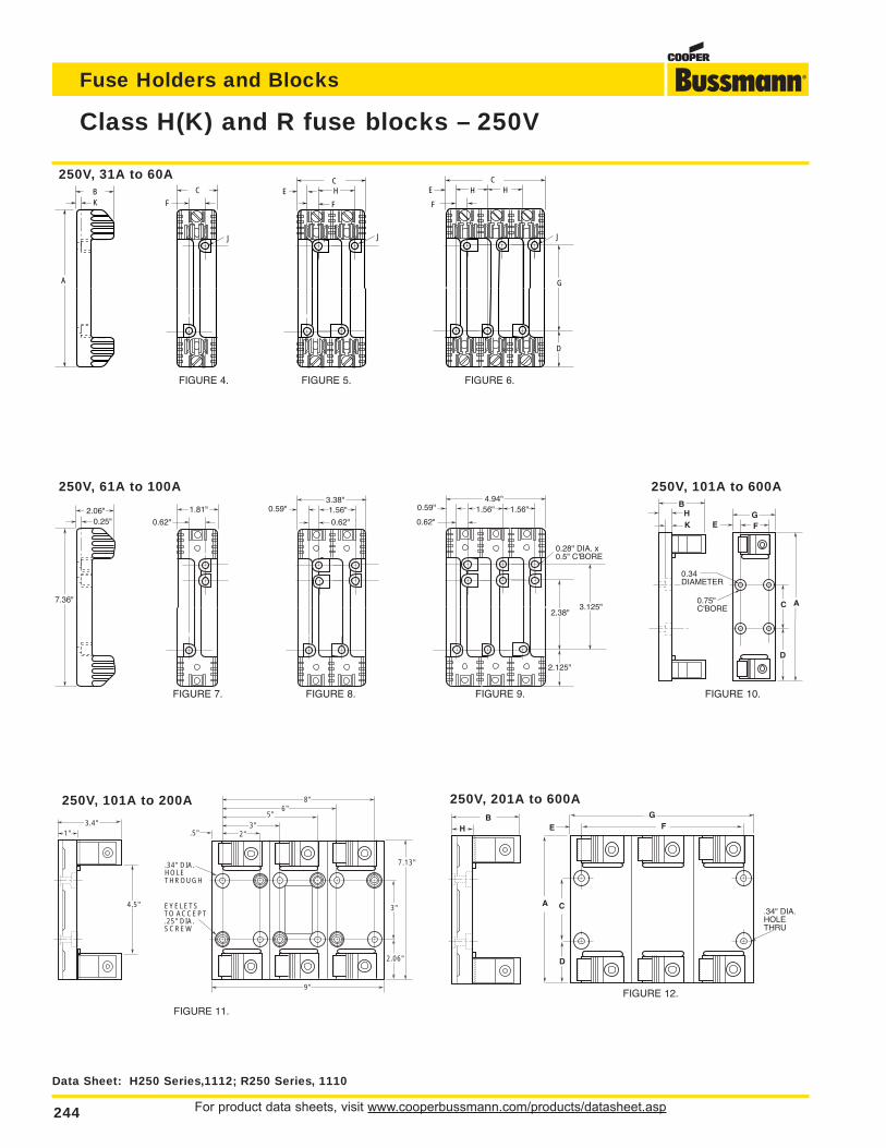
For product data sheets, visit www.cooperbussmann.com/products/datasheet.asp244
Fuse Holders and Blocks
7.36"
0.25"2.06" 1.81"
0.62"
3.38"0.59"
0.62"
4.94"
2.38"
2.125"
0.62"
0.28" DIA. x0.5" C'BORE
0.59"1.56" 1.56"1.56"
3.125"
Class H(K) and R fuse blocks – 250V
A
KB C
F
CE H
F
HC
G
D
F
HE
JJ J
250V, 31A to 60A
FIGURE 4. FIGURE 5. FIGURE 6.
250V, 61A to 100A
FIGURE 7. FIGURE 8. FIGURE 9.
250V, 101A to 600A
250V, 201A to 600A250V, 101A to 200A
BHK E F
0.75"C'BORE
0.34DIAMETER
G
C
D
A
FIGURE 10.
FIGURE 11.
FIGURE 12.
3.4"
4.5"
1" .5"
EYELETS TO ACCEPT.25" DIA. SCREW
.34" DIA. HOLE THROUGH
8"6"
5"3"
2"
3"
2.06"
7.13"
9"
C.34" DIA. HOLE THRU
A
BH
GFE
D
Data Sheet: H250 Series,1112; R250 Series, 1110
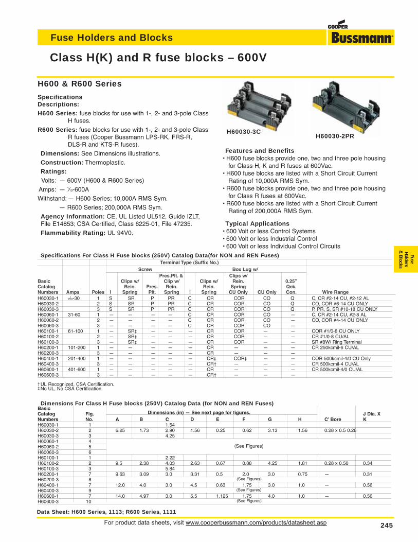
For product data sheets, visit www.cooperbussmann.com/products/datasheet.asp 245
Fuse Holders and Blocks
FuseHolders
& Blocks
Class H(K) and R fuse blocks – 600V
Data Sheet: H600 Series, 1113; R600 Series, 1111
H60030-2PRH60030-3C
H600 & R600 Series
SpecificationsDescriptions:H600 Series: fuse blocks for use with 1-, 2- and 3-pole Class
H fuses.
R600 Series: fuse blocks for use with 1-, 2- and 3-pole ClassR fuses (Cooper Bussmann LPS-RK, FRS-R, DLS-R and KTS-R fuses).
Dimensions: See Dimensions illustrations.
Construction: Thermoplastic.
Ratings:Volts: — 600V (H600 & R600 Series)
Amps: — 1⁄10-600A
Withstand: — H600 Series; 10,000A RMS Sym.
— R600 Series; 200,000A RMS Sym.
Agency Information: CE, UL Listed UL512, Guide IZLT,File E14853; CSA Certified, Class 6225-01, File 47235.
Flammability Rating: UL 94V0.
Features and Benefits• H600 fuse blocks provide one, two and three pole housing
for Class H, K and R fuses at 600Vac.• H600 fuse blocks are listed with a Short Circuit Current
Rating of 10,000A RMS Sym.• R600 fuse blocks provide one, two and three pole housing
for Class R fuses at 600Vac.• R600 fuse blocks are listed with a Short Circuit Current
Rating of 200,000A RMS Sym.
Typical Applications• 600 Volt or less Control Systems• 600 Volt or less Industrial Control• 600 Volt or less Individual Control Circuits
Dimensions For Class H Fuse blocks (250V) Catalog Data (for NON and REN Fuses)BasicCatalog Fig. Dimensions (in) — See next page for figures. J Dia. XNumbers No. A B C D E F G H C’ Bore KH60030-1 1 1.54H60030-2 2 6.25 1.73 2.90 1.56 0.25 0.62 3.13 1.56 0.28 x 0.5 0.26H60030-3 3 4.25H60060-1 4H60060-2 5H60060-3 6H60100-1 1 2.22H60100-2 2 9.5 2.38 4.03 2.63 0.67 0.88 4.25 1.81 0.28 x 0.50 0.34H60100-3 3 5.84H60200-1 7 9.63 3.09 3.0 3.31 0.5 2.0 3.0 0.75 — 0.31H60200-3 8 (See Figures)H60400-1 7 12.0 4.0 3.0 4.5 0.63 1.75 3.0 1.0 — 0.56H60400-3 9H60600-1 7 14.0 4.97 3.0 5.5 1.125 1.75 4.0 1.0 — 0.56H60600-3 10
H60030-1 1⁄10-30 1 S SR P PR C CR COR CO Q C, CR #2-14 CU, #2-12 ALH60030-2 2 S SR P PR C CR COR CO Q CO, COR #6-14 CU ONLYH60030-3 3 S SR P PR C CR COR CO Q P, PR, S, SR #10-18 CU ONLYH60060-1 31-60 1 — — — — C CR COR CO — C, CR #2-14 CU, #2-8 ALH60060-2 2 — — — — C CR COR CO — CO, COR #4-14 CU ONLYH60060-3 3 — — — — C CR COR CO —H60100-1 61-100 1 — SR‡ — — — CR COR — — COR #1/0-8 CU ONLYH60100-2 2 — SR‡ — — — CR COR — — CR #1/0-8 CU/ALH60100-3 3 — SR‡ — — — CR COR — — SR #8W/ Ring TerminalH60200-1 101-200 1 — — — — — CR — — — CR 250kcmil-6 CU/ALH60200-3 3 — — — — — CR — — —H60400-1 201-400 1 — — — — — CR‡ COR‡ — — COR 500kcmil-4/0 CU OnlyH60400-3 3 — — — — — CR† — — — CR 500kcmil-4 CU/ALH60600-1 401-600 1 — — — — — CR — — — CR 500kcmil-4/0 CU/ALH60600-3 3 — — — — — CR† — — —
UL Recognized, CSA Certification.No UL, No CSA Certification.
Pres.Plt. & Clips w/Basic Clips w/ Clip w/ Clips w/ Rein. 0.25”Catalog Rein. Pres. Rein. Rein. Spring Qck.Numbers Amps Poles | Spring Plt. Spring | Spring CU Only CU Only Con. Wire Range
Specifications For Class H Fuse blocks (250V) Catalog Data(for NON and REN Fuses)Terminal Type (Suffix No.)
Screw Box Lug w/
(See Figures)
(See Figures)
(See Figures)
(See Figures)
‡†
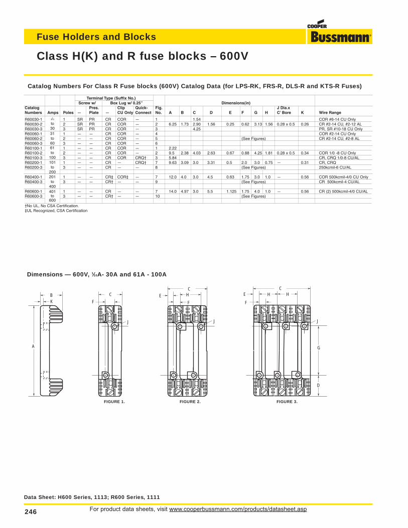
For product data sheets, visit www.cooperbussmann.com/products/datasheet.asp246
Fuse Holders and Blocks
Class H(K) and R fuse blocks – 600V
Data Sheet: H600 Series, 1113; R600 Series, 1111
A
KB C
F
CE H
F
HC
G
D
F
HE
JJ J
Dimensions — 600V, 1⁄10A- 30A and 61A - 100A
FIGURE 1. FIGURE 2. FIGURE 3.
Catalog Numbers For Class R Fuse blocks (600V) Catalog Data (for LPS-RK, FRS-R, DLS-R and KTS-R Fuses)
Terminal Type (Suffix No.)Screw w/ Box Lug w/ 0.25” Dimensions(in)
Catalog Pres. Clip Quick- Fig. J Dia.xNumbers Amps Poles — Plate — CU Only Connect No. A B C D E F G H C’ Bore K Wire Range
R60030-1 1/10 1 SR PR CR COR — 1 1.54 COR #6-14 CU OnlyR60030-2 to 2 SR PR CR COR — 2 6.25 1.73 2.90 1.56 0.25 0.62 3.13 1.56 0.28 x 0.5 0.26 CR #2-14 CU, #2-12 ALR60030-3 30 3 SR PR CR COR — 3 4.25 PR, SR #10-18 CU OnlyR60060-1 31 1 — — CR COR — 4 COR #2-14 CU OnlyR60060-2 to 2 — — CR COR — 5 (See Figures) CR #2-14 CU, #2-8 ALR60060-3 60 3 — — CR COR — 6R60100-1 61 1 — — CR COR — 1 2.22R60100-2 to 2 — — CR COR — 2 9.5 2.38 4.03 2.63 0.67 0.88 4.25 1.81 0.28 x 0.5 0.34 COR 1/0 -8 CU OnlyR60100-3 100 3 — — CR COR CRQ† 3 5.84 CR, CRQ 1/0-8 CU/ALR60200-1 101 1 — — CR — CRQ† 7 9.63 3.09 3.0 3.31 0.5 2.0 3.0 0.75 — 0.31 CR, CRQR60200-3 to 3 — — CR — — 8 (See Figures) 250kcmil-6 CU/AL
200R60400-1 201 1 — — CR‡ COR‡ — 7 12.0 4.0 3.0 4.5 0.63 1.75 3.0 1.0 — 0.56 COR 500kcmil-4/0 CU OnlyR60400-3 to 3 — — CR† — — 9 (See Figures) CR 500kcmil-4 CU/AL
400R60600-1 401 1 — — CR — — 7 14.0 4.97 3.0 5.5 1.125 1.75 4.0 1.0 — 0.56 CR (2) 500kcmil-4/0 CU/ALR60600-3 to 3 — — CR† — — 10 (See Figures)
600†No UL, No CSA Certification.‡UL Recognized, CSA Certification
1⁄10
to3031to6061to
100101to
200201to
400401to
600
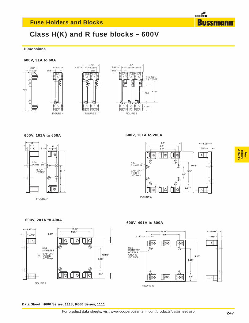
For product data sheets, visit www.cooperbussmann.com/products/datasheet.asp 247
Fuse Holders and Blocks
FuseHolders
& Blocks
Class H(K) and R fuse blocks – 600V
Data Sheet: H600 Series, 1113; R600 Series, 1111
7.36"
0.25"2.06" 1.81"
0.62"
3.38"0.59"
0.62"
4.94"
2.38"
2.125"
0.62"
0.28" DIA. x0.5" C'BORE
0.59"1.56" 1.56"1.56"
3.125"
Dimensions
600V, 31A to 60A
FIGURE 4 FIGURE 5 FIGURE 6
BHK E F
0.75"C'BORE
0.34DIAMETER
G
C
D
A
600V, 101A to 600A
6.5"8.0"
0.75" DIA.C'BORE.50" Deep
0.34DIAMETER
9.0"
5.5"
9.58"
3.0"
2.04"
3.15"
.75"
600V, 101A to 200A
11.0"
0.34DIAMETER0.75" DIA.C'BORE.67" Deep 14.00"
2.5"
4.987"
1.00"2.13"
15.26"
8.00"
9.25"
0.75" DIA.C'BORE.67" Deep
0.34DIAMETER
11.63"
7.00"
12.00"
2.5"
1.19"
0"
4.02"
1.00"
600V, 201A to 400A600V, 401A to 600A
FIGURE 7FIGURE 8
FIGURE 9FIGURE 10
4.02”
1.00”
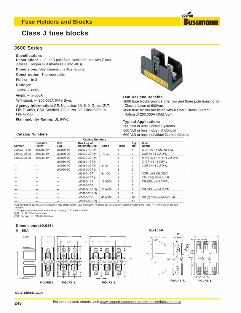
For product data sheets, visit www.cooperbussmann.com/products/datasheet.asp248
Fuse Holders and Blocks
J600 Series
SpecificationsDescription: 1-, 2- or 3-pole fuse blocks for use with ClassJ fuses (Cooper Bussmann LPJ and JKS).
Dimensions: See Dimensions illustrations.
Construction: Thermoplastic.
Poles: 1 to 3
Ratings:Volts: — 600V
Amps: — 1⁄2-600A
Withstand: — 200,000A RMS Sym.
Agency Information: CE, UL Listed, UL 512, Guide IZLT,File E14853, CSA Certified, C22.2 No. 39, Class 6225-01,File 47235.
Flammability Rating: UL 94V0.
Class J fuse blocks
Data Sheet: 1114
1⁄2 - 60A Dimensions (±0.015)
.30"2.28"
6.28"
.94"
.22"Dia.
.5"C'Bore
1.583"5"
3.14"
1.75" 1.5"
Catalog NumbersPressure Box Box Lug w/ Fig. Wire
Screw† Plate† Lug Retaining Clip Amps Poles No. RangeJ60030-1S(2) J60030-1P J60030-1C J60030-1CR†† 1 1 C, CR #2-14 CU, #2-8 ALJ60030-2S(2) J60030-2P J60030-2C J60030-2CR†† 1/2-30 2 2 COR #2-14 CU OnlyJ60030-3S(2) J60030-3P J60030-3C J60030-3CR†† 3 3 P, PR, S, SR #10-14 CU Only— — J60060-1C J60060-1CR†† 1 1 C, CR, #2-14 CU/AL— — J60060-2C J60060-2CR†† 31-60 2 2 COR #4-14 CU Only— — J60060-3C J60060-3CR†† 3 3— — — J60100-1CR 61-100 1 4 COR 1/0-8 CU ONLY— — — J60100-3CR†† 3 5 CR, CRQ 1/0-8 CU/AL— — — J60200-1CR 101-200 1 6 CR 250kcmil-6 CU/AL— — — J60200-3CR 3 7— — — J60400-1CR(3) 201-400 1 8 CR 500kcmil -4 CU/AL— — — J60400-3CR(3) 3 9— — — J60600-1CR 401-600 1 10 CR (2) 500kcmil-4/0 CU/AL— — — J60600-3CR(2) 3 11†Clip reinforcing springs are standard on fuse blocks rated 100A and above. Available on 30A and 60A blocks by adding the letter “R” to the end of the partnumber.
††Copper only connections available by changing “CR” suffix to “COR”.(2)No UL, No CSA Certification(3)UL Recognized, CSA Certification
2.250
3.202
.750
4.702
2.250
CLL
1.500
4.005
C
2.415"
.750
1.702
FIGURE 1. FIGURE 2. FIGURE 3.FIGURE 4. FIGURE 5.
Features and Benefits• J600 fuse blocks provide one, two and three pole housing for
Class J fuses at 600Vac.• J600 fuse blocks are listed with a Short Circuit Current
Rating of 200,000A RMS Sym.
Typical Applications• 600 Volt or less Control Systems• 600 Volt or less Industrial Control• 600 Volt or less Individual Control CircuitsCatalog Numbers
61-100A
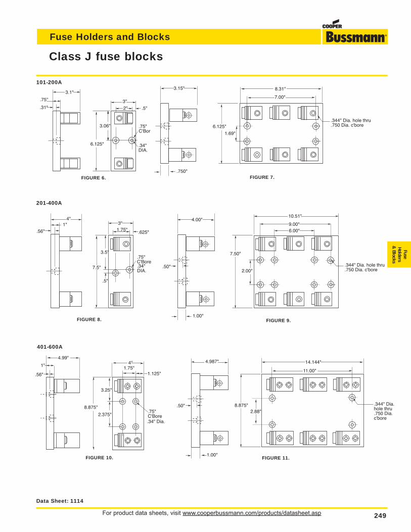
For product data sheets, visit www.cooperbussmann.com/products/datasheet.asp 249
Fuse Holders and Blocks
FuseHolders
& Blocks
Class J fuse blocks
Data Sheet: 1114
3.5"
1.75"3"
.625"
.75"C'Bore.34"DIA.
.5"
7.5"
1"4"
.56"
.75"
3.1"
.31"
6.125"
3.06"
2"3"
.5"
.75"C'Bor
.34"DIA.
FIGURE 6.
101-200A
201-400A
6.125"
7.00"
8.31"
1.69"
.344" Dia. hole thru
.750 Dia. c'bore
3.15"
.750"FIGURE 7.
9.00"
10.51"
7.50"
2.00".344" Dia. hole thru.750 Dia. c'bore
4.00"
1.00"
6.00"
.50"
FIGURE 8. FIGURE 9.
.56"
8.875"
3.25"
1.75"
.75"C'Bore.34" Dia.
4"
2.375"
1.125"
1"
4.99"
401-600A
FIGURE 10.
8.875"
11.00"
14.144"
.344" Dia. hole thru.750 Dia. c'bore
2.88"
4.987"
1.00"
.50"
FIGURE 11.
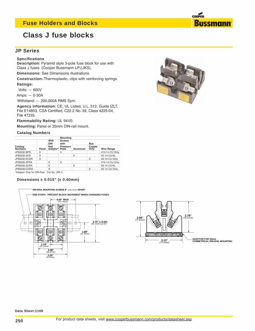
For product data sheets, visit www.cooperbussmann.com/products/datasheet.asp250
Fuse Holders and Blocks
Class J fuse blocks
Data Sheet:1108
ADAPTOR FOR 35mm SYMMETRICAL DIN-RAIL MOUNTING
2.78"(70.6mm)3.06"
(77.8mm)
3.13"(79.5mm)
JP Series
SpecificationsDescription: Pyramid style 3-pole fuse block for use withClass J fuses (Cooper Bussmann LPJ,JKS).
Dimensions: See Dimensions illustrations.
Construction: Thermoplastic, clips with reinforcing springs.
Ratings:Volts: — 600V
Amps: — 0-30A
Withstand: — 200,000A RMS Sym.
Agency Information: CE, UL Listed, U.L. 512, Guide IZLT,File E14853, CSA Certified, C22.2 No. 39, Class 4225-04,File 47235.
Flammability Rating: UL 94V0.
Mounting: Panel or 35mm DIN-rail mount.
Catalog NumbersMounting
With ScrewsDIN with Box
Catalog Rail Pressure CopperNumbers Panel Adapter* Plate Aluminum Only Wire RangeJP60030-3PR X X #10-14 CU OnlyJP60030-3CR X X #2-14 CU/ALJP60030-3COR X X #2-14 CU OnlyJP60030-3PRA X X #10-14 CU OnlyJP60030-3CRA X X #2-14 CU/ALJP60030-CORA X X #2-14 CU Only*Adapter Only for DIN-Rail - Cat No. JPA-3.
Dimensions ± 0.015” (± 0.40mm)
3.29"(83.6mm)
END STOPS - PREVENT BLOCK MOVEMENT WHEN CHANGING FUSES
DIN-RAIL MOUNTING SCREW 8" (203.2mm) APART
4.00" MAX.(101.6mm)
1.19"(30.2mm)
3.75" (±0.02)(95.3mm (±0.50)
1.88"(47.6mm)
2.38"(60.4mm)
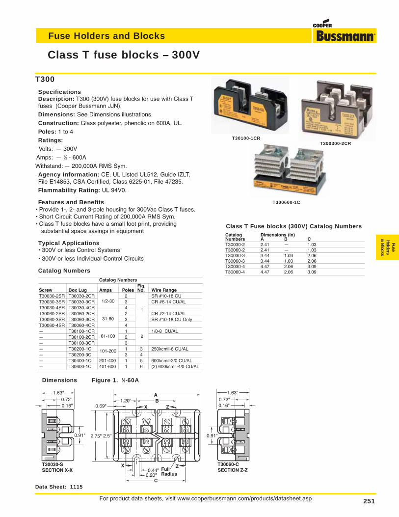
For product data sheets, visit www.cooperbussmann.com/products/datasheet.asp 251
Fuse Holders and Blocks
FuseHolders
& Blocks
Class T fuse blocks – 300V
Data Sheet: 1115
T30030-SSECTION X-X
0.91"
1.63"0.72"0.16"
ZXFullRadius
ZX
0.44"0.20"
C
B1.20"A
0.69"
2.5"2.75"
T30060-CSECTION Z-Z
0.91"
1.63"0.72"0.16"
Dimensions Figure 1. 1⁄2-60A
T300
SpecificationsDescription: T300 (300V) fuse blocks for use with Class Tfuses (Cooper Bussmann JJN).
Dimensions: See Dimensions illustrations.
Construction: Glass polyester, phenolic on 600A, UL.
Poles: 1 to 4
Ratings:Volts: — 300V
Amps: — 1⁄2 - 600A
Withstand: — 200,000A RMS Sym.
Agency Information: CE, UL Listed UL512, Guide IZLT,File E14853, CSA Certified, Class 6225-01, File 47235.
Flammability Rating: UL 94V0.
Features and Benefits• Provide 1-, 2- and 3-pole housing for 300Vac Class T fuses.• Short Circuit Current Rating of 200,000A RMS Sym.• Class T fuse blocks have a small foot print, providing
substantial space savings in equipment
Typical Applications• 300V or less Control Systems
• 300V or less Individual Control Circuits
Catalog Numbers
T30100-1CRT300300-2CR
T300600-1C
Catalog Dimensions (in)Numbers A B CT30030-2 2.41 — 1.03T30060-2 2.41 — 1.03T30030-3 3.44 1.03 2.06T30060-3 3.44 1.03 2.06T30030-4 4.47 2.06 3.09T30060-4 4.47 2.06 3.09
Catalog NumbersFig.
Screw Box Lug Amps Poles No. Wire RangeT30030-2SR T30030-2CR 1/2-30 2 1 SR #10-18 CUT30030-3SR T30030-3CR 3 CR #6-14 CU/ALT30030-4SR T30030-4CR 4T30060-2SR T30060-2CR 31-60 2 1 CR #2-14 CU/ALT30060-3SR T30060-3CR 3 SR #10-18 CU OnlyT30060-4SR T30060-4CR 4— T30100-1CR 61-100 1 2 1/0-8 CU/AL— T30100-2CR 2— T30100-3CR 3— T30200-1C 101-200 1 3 250kcmil-6 CU/AL— T30200-3C 3 4— T30400-1C 201-400 1 5 600kcmil-2/0 CU/AL— T30600-1C 401-600 1 6 (2) 600kcmil-4/0 CU/AL
Class T Fuse blocks (300V) Catalog Numbers
1/2-30
1
2
31-60
61-100
101-200
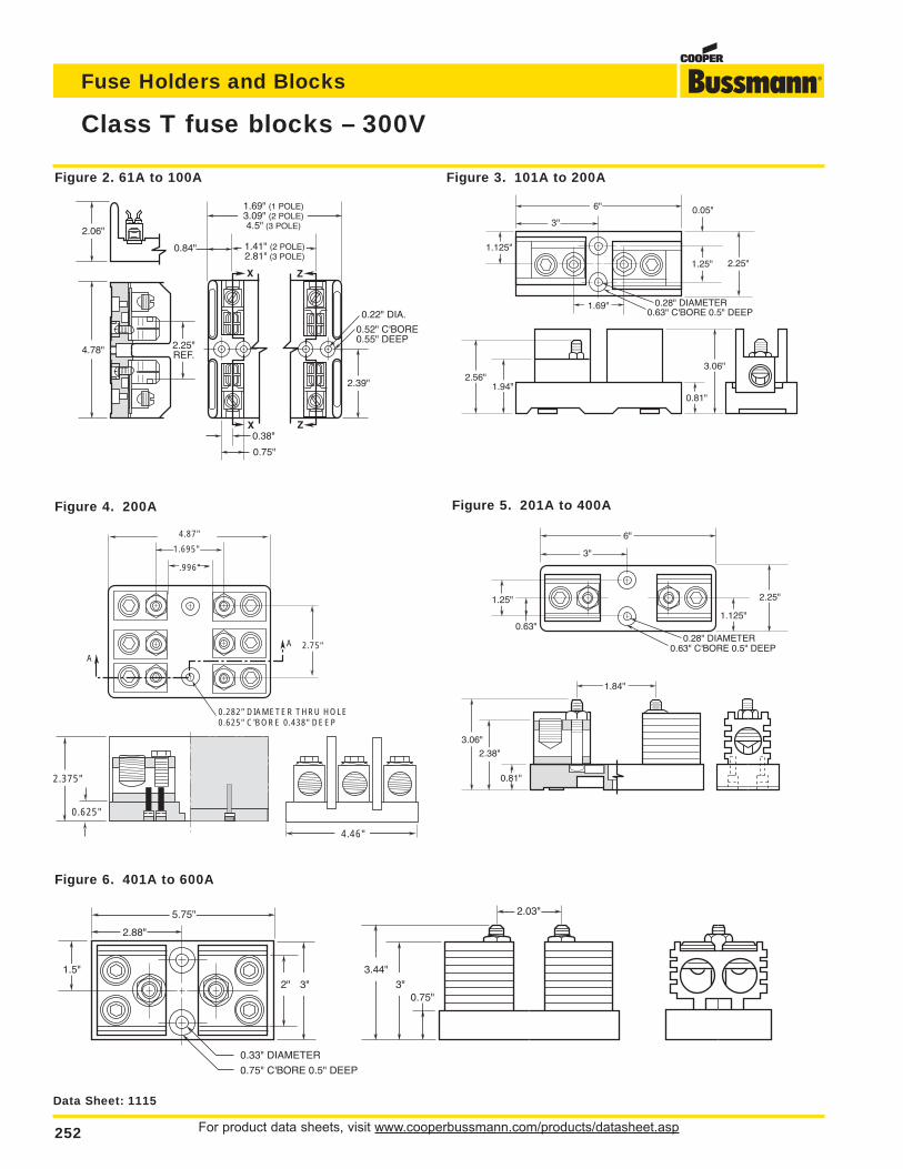
For product data sheets, visit www.cooperbussmann.com/products/datasheet.asp252
Fuse Holders and Blocks
Class T fuse blocks – 300V
Data Sheet: 1115
Z
Z
0.52" C'BORE0.55" DEEP
0.22" DIA.
X
X
2.39"
2.25"REF.4.78"
2.06"
1.69" (1 POLE)3.09" (2 POLE)4.5" (3 POLE)
1.41" (2 POLE)2.81" (3 POLE)
0.84"
0.38"
0.75"
0.625" C'BORE 0.438" DEEP0.282" DIAMETER THRU HOLE
.996"
A
A 2.75"
1.695"
4.87"
0.625"
2.375"
4.46"
Figure 2. 61A to 100A
3"
6"
0.28" DIAMETER0.63" C'BORE 0.5" DEEP
1.125"
2.56"1.94"
0.81"
3.06"
1.69"
0.05"
1.25" 2.25"
Figure 3. 101A to 200A
Figure 4. 200A
0.63" C'BORE 0.5" DEEP
6"
0.28" DIAMETER
1.125"
2.25"
0.63"
3"
1.25"
1.84"
0.81"
2.38"
3.06"
Figure 5. 201A to 400A
3.44"
0.75"3"
2.03"
3"2"
1.5"
5.75"
2.88"
0.33" DIAMETER
0.75" C'BORE 0.5" DEEP
Figure 6. 401A to 600A
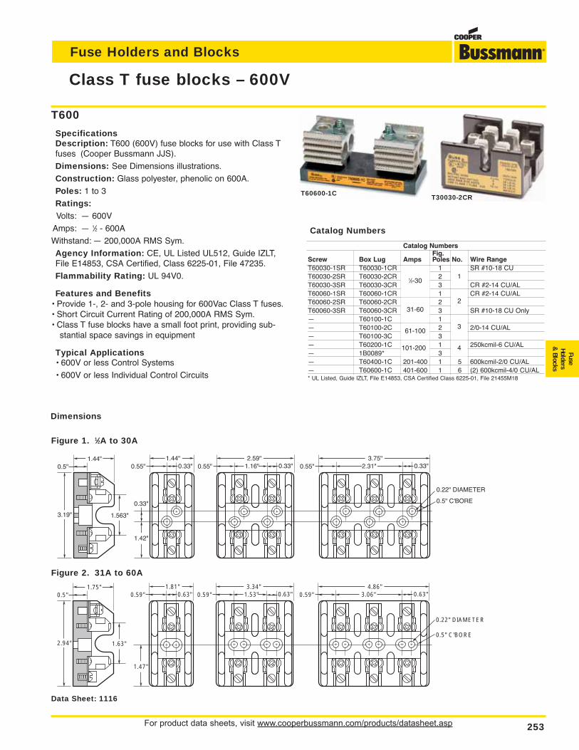
For product data sheets, visit www.cooperbussmann.com/products/datasheet.asp 253
Fuse Holders and Blocks
FuseHolders
& Blocks
Class T fuse blocks – 600V
Data Sheet: 1116
Figure 1. 1⁄2A to 30A
3.19"
1.44"
1.563"
0.33"
1.42"
0.5"1.44"
0.55" 0.33" 0.55"2.59"
1.16" 0.33" 0.55"3.75"
2.31" 0.33"
0.22" DIAMETER
0.5" C'BORE
2.94"
1.75"
1.63"
1.47"
0.5"1.81"
0.59" 0.63" 0.59"3.34"
1.53" 0.63" 0.59"4.86"
3.06" 0.63"
0.22" DIAMETER
0.5" C'BORE
Figure 2. 31A to 60A
T600
SpecificationsDescription: T600 (600V) fuse blocks for use with Class Tfuses (Cooper Bussmann JJS).
Dimensions: See Dimensions illustrations.
Construction: Glass polyester, phenolic on 600A.
Poles: 1 to 3
Ratings:Volts: — 600V
Amps: — 1⁄2 - 600A
Withstand: — 200,000A RMS Sym.
Agency Information: CE, UL Listed UL512, Guide IZLT,File E14853, CSA Certified, Class 6225-01, File 47235.
Flammability Rating: UL 94V0.
Features and Benefits• Provide 1-, 2- and 3-pole housing for 600Vac Class T fuses.• Short Circuit Current Rating of 200,000A RMS Sym.• Class T fuse blocks have a small foot print, providing sub-
stantial space savings in equipment
Typical Applications• 600V or less Control Systems
• 600V or less Individual Control Circuits
T30030-2CRT60600-1C
Catalog NumbersFig.
Screw Box Lug Amps Poles No. Wire RangeT60030-1SR T60030-1CR 1 1 SR #10-18 CUT60030-2SR T60030-2CR 1/2-30 2T60030-3SR T60030-3CR 3 CR #2-14 CU/ALT60060-1SR T60060-1CR 1 2 CR #2-14 CU/ALT60060-2SR T60060-2CR 31-60 2T60060-3SR T60060-3CR 3 SR #10-18 CU Only— T60100-1C 1 3— T60100-2C 61-100 2 2/0-14 CU/AL— T60100-3C 3— T60200-1C 101-200 1 4 250kcmil-6 CU/AL— 1B0089* 3— T60400-1C 201-400 1 5 600kcmil-2/0 CU/AL— T60600-1C 401-600 1 6 (2) 600kcmil-4/0 CU/AL* UL Listed, Guide IZLT, File E14853, CSA Certified Class 6225-01, File 21455M18
Catalog Numbers
1⁄2-301
2
3
4
31-60
61-100
101-200
Dimensions
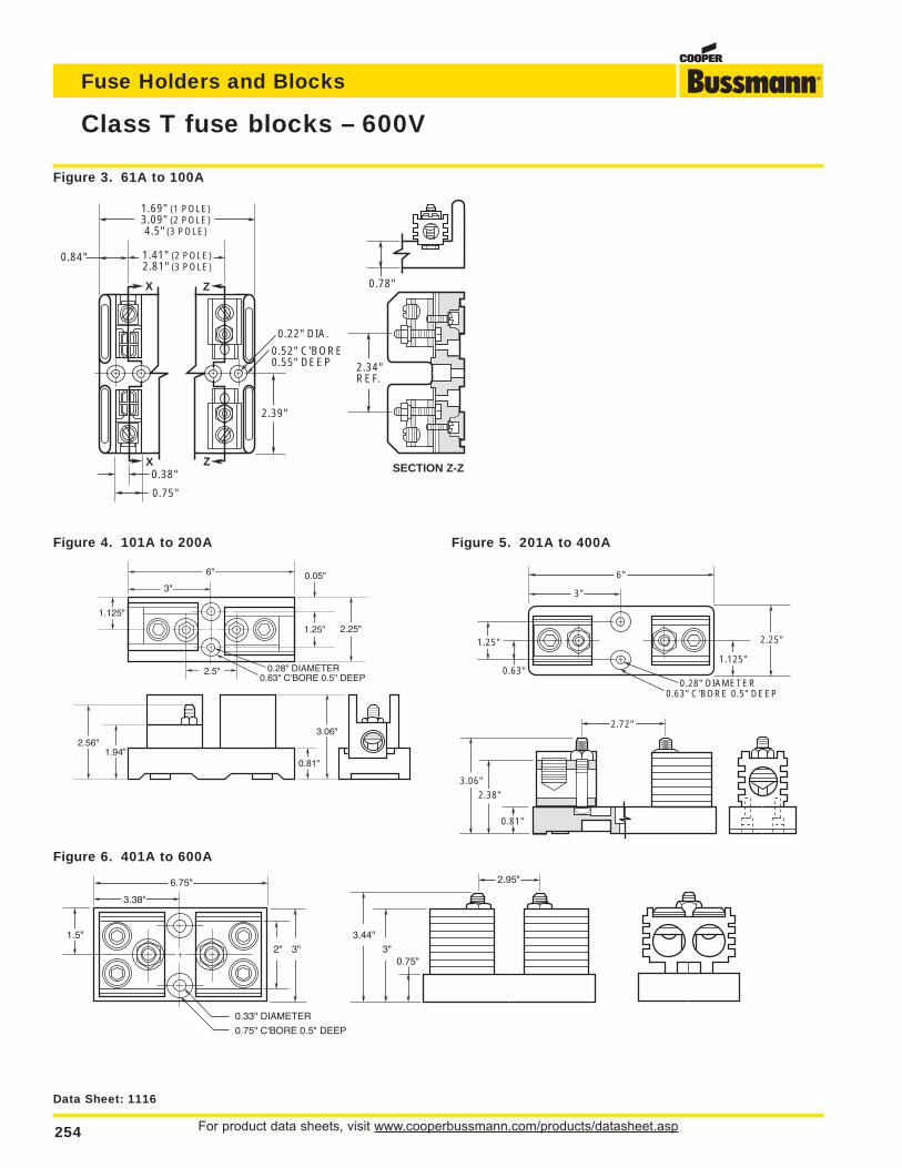
For product data sheets, visit www.cooperbussmann.com/products/datasheet.asp254
Fuse Holders and Blocks
Class T fuse blocks – 600V
Data Sheet: 1116
Figure 5. 201A to 400A
0.63" C'BORE 0.5" DEEP
6"
0.28" DIAMETER
1.125"
2.25"
0.63"
3"
1.25"
2.72"
0.81"
2.38"3.06"
Figure 4. 101A to 200A
3"
6"
0.28" DIAMETER0.63" C'BORE 0.5" DEEP
1.125"
2.56"1.94"
0.81"
3.06"
2.5"
0.05"
1.25" 2.25"
Figure 3. 61A to 100A
Z
Z
0.52" C'BORE0.55" DEEP
0.22" DIA.
X
X
2.39"
1.69" (1 POLE)3.09" (2 POLE)4.5" (3 POLE)
1.41" (2 POLE)2.81" (3 POLE)
0.84"
0.38" SECTION Z-Z
0.78"
2.34"REF.
0.75"
Figure 6. 401A to 600A
3.44"
0.75"3"
2.95"
3"2"
1.5"
6.75"
3.38"
0.33" DIAMETER
0.75" C'BORE 0.5" DEEP
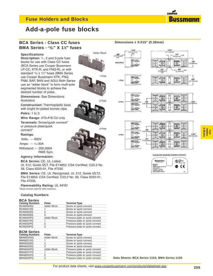
BCA Series - Class CC fusesBMA Series - 13⁄32" X 11⁄2" fuses
SpecificationsDescription: 1-, 2 and 3-pole fuseblocks for use with Class CC fuses(BCA Series use Cooper BussmannLP-CC, KTK-R, and FNQ-R), or withstandard 13⁄32 x 11⁄2" fuses (BMA Seriesuse Cooper Bussmann KTK, FNQ,FNM, BAF, BAN and AGU) Both Seriesuse an "adder block" to form multi-polesegmented blocks to achieve thedesired number of poles.
Dimensions: See Dimensions illustration.
Construction: Thermoplastic basewith bright tin-plated bronze clips.
Poles: 1 to 3.
Wire Range: #10-#18 CU only.
Terminals: Screw/quick connect*or pressure plate/quick connect*.
Ratings:Volts: — 600V
Amps: — 1⁄10-30A
Withstand: — 200,000A RMS Sym.
Agency Information:BCA Series: CE, UL Listed,UL 512, Guide IZLT, File E14853. CSA Certified, C22.2 No.39, Class 6225-01, File 47235.
BMA Series: CE, UL Recognized, UL 512, Guide IZLT2,File E14853. CSA Certified, C22.2 No. 39, Class 6225-01,File 47235.
Flammability Rating: UL 94VO*Quick connect rated for 20A maximum.
Catalog Numbers
BCA SeriesCatalog Numbers Poles Terminal TypeBCA603ASQ Adder Block Screw w/ quick connectBCA6031SQ 1 Screw w/ quick connectBCA6032SQ 2 Screw w/ quick connectBCA6033SQ 3 Screw w/ quick connectBCA603APQ Adder Block Pressure plate w/ quick connectBCA6031PQ 1 Pressure plate w/ quick connectBCA6032PQ 2 Pressure plate w/ quick connectBCA6033PQ 3 Pressure plate w/ quick connect
BCM SeriesCatalog Numbers Poles Terminal TypeBMA603ASQ Adder Block Screw w/ quick connectBMA6031SQ 1 Screw w/ quick connectBMA6032SQ 2 Screw w/ quick connectBMA6033SQ 3 Screw w/ quick connectBMA603APQ Adder Block Pressure plate w/ quick connectBMA6031PQ 1 Pressure plate w/ quick connectBMA6032PQ 2 Pressure plate w/ quick connectBMA6033PQ 3 Pressure plate w/ quick connect
For product data sheets, visit www.cooperbussmann.com/products/datasheet.asp 255
Fuse Holders and Blocks
FuseHolders
& Blocks
Add-a-pole fuse blocks
Data Sheets: BCA Series 1154, BMA Series 1155
Dimensions ± 0.015" (0.38mm)
Adder Block
1-Pole
2-Pole
3-Pole
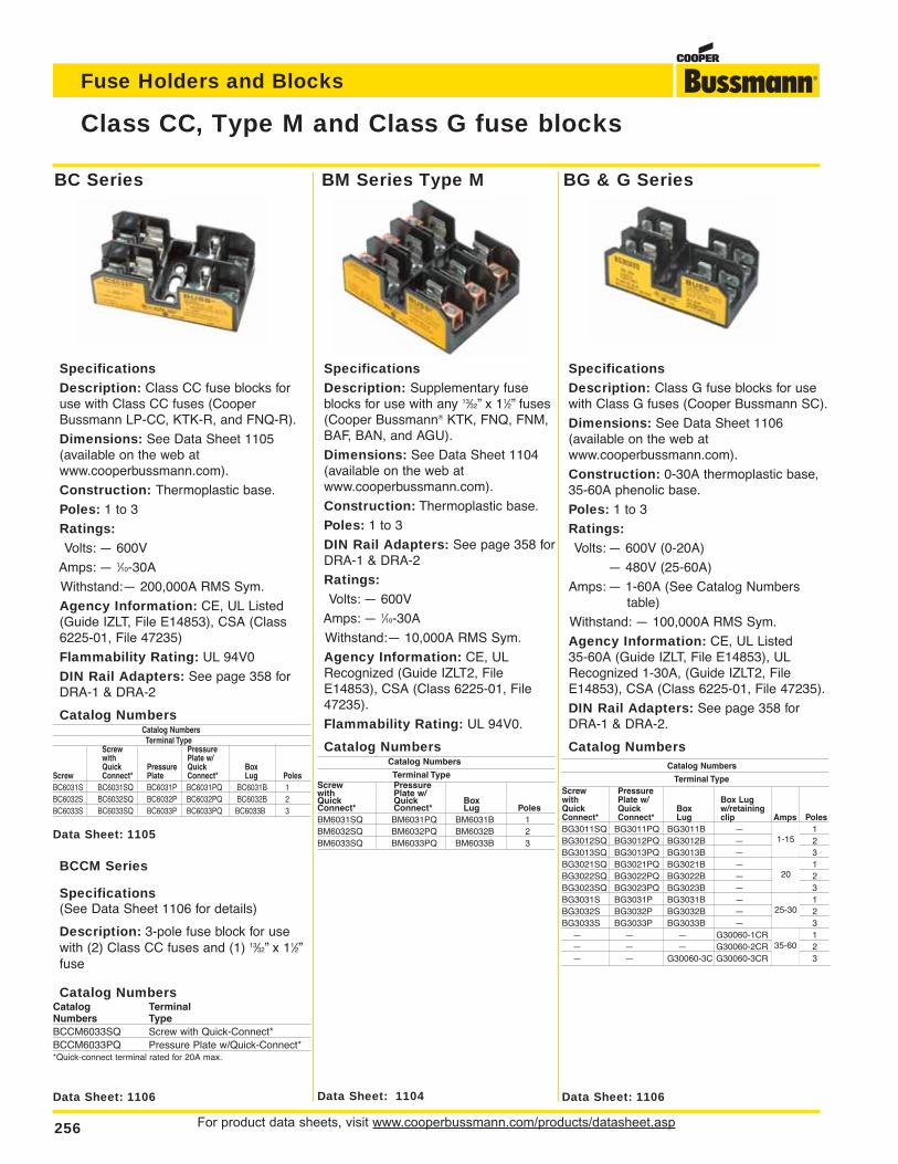
For product data sheets, visit www.cooperbussmann.com/products/datasheet.asp256
Fuse Holders and Blocks
Class CC, Type M and Class G fuse blocks
Data Sheet: 1106 Data Sheet: 1106Data Sheet: 1104
Data Sheet: 1105
SpecificationsDescription: Class CC fuse blocks foruse with Class CC fuses (CooperBussmann LP-CC, KTK-R, and FNQ-R).
Dimensions: See Data Sheet 1105(available on the web at www.cooperbussmann.com).
Construction: Thermoplastic base.
Poles: 1 to 3
Ratings:Volts: — 600V
Amps: — 1⁄10-30A
Withstand:— 200,000A RMS Sym.
Agency Information: CE, UL Listed(Guide IZLT, File E14853), CSA (Class6225-01, File 47235)
Flammability Rating: UL 94V0
DIN Rail Adapters: See page 358 forDRA-1 & DRA-2
Catalog NumbersCatalog NumbersTerminal Type
Screw Pressurewith Plate w/Quick Pressure Quick Box
Screw Connect* Plate Connect* Lug PolesBC6031S BC6031SQ BC6031P BC6031PQ BC6031B 1BC6032S BC6032SQ BC6032P BC6032PQ BC6032B 2BC6033S BC6033SQ BC6033P BC6033PQ BC6033B 3
BCCM Series
Specifications(See Data Sheet 1106 for details)
Description: 3-pole fuse block for usewith (2) Class CC fuses and (1) 13⁄32” x 11⁄2”fuse
Catalog NumbersCatalog TerminalNumbers TypeBCCM6033SQ Screw with Quick-Connect*BCCM6033PQ Pressure Plate w/Quick-Connect**Quick-connect terminal rated for 20A max.
SpecificationsDescription: Supplementary fuseblocks for use with any 13⁄32” x 11⁄2” fuses(Cooper Bussmann® KTK, FNQ, FNM,BAF, BAN, and AGU).
Dimensions: See Data Sheet 1104(available on the web at www.cooperbussmann.com).
Construction: Thermoplastic base.
Poles: 1 to 3
DIN Rail Adapters: See page 358 forDRA-1 & DRA-2
Ratings:Volts: — 600V
Amps: — 1⁄10-30A
Withstand:— 10,000A RMS Sym.
Agency Information: CE, ULRecognized (Guide IZLT2, FileE14853), CSA (Class 6225-01, File47235).
Flammability Rating: UL 94V0.
Catalog NumbersCatalog Numbers
Terminal TypeScrew Pressurewith Plate w/Quick Quick BoxConnect* Connect* Lug PolesBM6031SQ BM6031PQ BM6031B 1BM6032SQ BM6032PQ BM6032B 2BM6033SQ BM6033PQ BM6033B 3
SpecificationsDescription: Class G fuse blocks for usewith Class G fuses (Cooper Bussmann SC).
Dimensions: See Data Sheet 1106 (available on the web at www.cooperbussmann.com).
Construction: 0-30A thermoplastic base,35-60A phenolic base.
Poles: 1 to 3
Ratings:Volts: — 600V (0-20A)
— 480V (25-60A)
Amps: — 1-60A (See Catalog Numberstable)
Withstand: — 100,000A RMS Sym.
Agency Information: CE, UL Listed 35-60A (Guide IZLT, File E14853), ULRecognized 1-30A, (Guide IZLT2, FileE14853), CSA (Class 6225-01, File 47235).
DIN Rail Adapters: See page 358 forDRA-1 & DRA-2.
Catalog NumbersCatalog Numbers
Terminal TypeScrew Pressurewith Plate w/ Box LugQuick Quick Box w/retainingConnect* Connect* Lug clip Amps PolesBG3011SQ BG3011PQ BG3011B — 1 1BG3012SQ BG3012PQ BG3012B — to 2BG3013SQ BG3013PQ BG3013B — 15 3BG3021SQ BG3021PQ BG3021B — 20 1BG3022SQ BG3022PQ BG3022B — 2BG3023SQ BG3023PQ BG3023B — 3BG3031S BG3031P BG3031B — 25 1BG3032S BG3032P BG3032B — to 2BG3033S BG3033P BG3033B — 30 3
— — — G30060-1CR 35 1— — — G30060-2CR to 2— — G30060-3C G30060-3CR 60 3
BC Series BM Series Type M BG & G Series
1-15
20
25-30
35-60
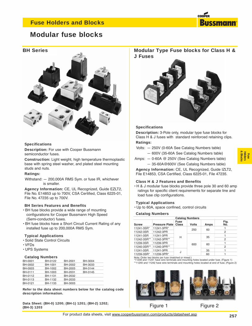
For product data sheets, visit www.cooperbussmann.com/products/datasheet.asp 257
Fuse Holders and Blocks
FuseHolders
& Blocks
Modular fuse blocks
SpecificationsDescription: For use with Cooper Bussmann semiconductor fuses.
Construction: Light weight, high temperature thermoplasticbase with spring steel washer, and plated steel mountingstuds and nuts.
Ratings:Withstand: — 200,000A RMS Sym. or fuse IR, whichever
is smaller.
Agency Information: CE, UL Recognized, Guide EZLT2,File No. E14853 up to 700V, CSA Certified, Class 6225-01,File No. 47235 up to 700V.
BH Series Features and Benefits• BH fuse blocks provide a wide range of mounting
configurations for Cooper Bussmann High Speed(Semi-conductor) fuses.
• BH fuse blocks have a Short Circuit Current Rating of anyinstalled fuse up to 200,000A RMS Sym.
Typical Applications• Solid State Control Circuits• VFDs• UPS Systems
Catalog NumbersBH-0001 BH-0122 BH-2001 BH-3004BH-0002 BH-1001 BH-2002 BH-3033BH-0003 BH-1002 BH-2003 BH-3144BH-0111 BH-1003 BH-2031 BH-3145BH-0112 BH-1131 BH-2032BH-0113 BH-1132 BH-2033BH-0121 BH-1133 BH-3003
Data Sheet: (BH-0) 1200; (BH-1) 1201; (BH-2) 1202;(BH-3) 1203
Refer to the data sheet numbers below for the catalog codedescription information.
Figure 1 Figure 2
BH Series Modular Type Fuse blocks for Class H &J Fuses
SpecificationsDescription: 3-Pole only, modular type fuse blocks forClass H & J fuses with standard reinforced retaining clips.
Ratings:Volts: — 250V (0-60A See Catalog Numbers table)
— 600V (35-60A See Catalog Numbers table)
Amps: — 0-60A @ 250V (See Catalog Numbers table)
— 35-60A@600V (See Catalog Numbers table)
Agency Information: CE, UL Recognized, Guide IZLT2,File E14853, CSA Certified, Class 6225-01, File 47235.
Class H & J Features and Benefits• H & J modular fuse blocks provide three pole 30 and 60 amp
ratings for specific client requirements for separate line andload fuse clip configurations.
Typical Applications• Up to 60A, space confined, control circuits
Catalog NumbersCatalog NumbersFuse Fig.
Screw Pressure Plate Class Volts Amps No.11241-3SR* 11241-3PR* H 250 60 111242-3SR 11242-3PR 211241-3SR 11241-3PR 600 35 111242-3SR** 11242-3PR** 211239-3SR 11239-3PR 60 111240-3SR** 11240-3PR** 211241-3SR 11241-3PR J 600 35 111239-3SR* 11239-3PR* 60 1Note: Order two blocks per fuse (matched or mixed.)*11239 and 11241 have wire terminals and mounting holes located under fuse. (Figure 1)**11240 and 11242 have wire terminals and mounting holes located at end of fuse. (Figure 2)
H
J
250 60
60
35
600
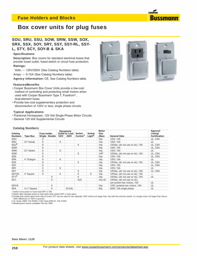
For product data sheets, visit www.cooperbussmann.com/products/datasheet.asp258
Fuse Holders and Blocks
SOU, SRU, SSU, SOW, SRW, SSW, SOX,SRX, SSX, SOY, SRY, SSY, SSY-RL, SSY-L, STY, SCY, SOY-B & SKASpecificationsDescription: Box covers for standard electrical boxes thatprovide fused outlet, fused switch or circuit fuse protection.
Ratings:Volts: — 125V/250V (See Catalog Numbers table)
Amps: — 0-15A (See Catalog Numbers table)
Agency Information: CE, See Catalog Numbers table.
Features/Benefits• Cooper Bussmann Box Cover Units provide a low-cost
method of controlling and protecting small motors whenused with Cooper Bussmann Type T, Fusetron® , dual-element fuses.
• Provide low-cost supplementary protection and disconnection of 125V or less, single phase circuits.
Typical Applications• Fractional Horsepower, 125 Volt Single-Phase Motor Circuits• General 125 Volt Supplemental Circuits
Box cover units for plug fuses
Data Sheet: 1129
Catalog NumbersReceptacle Motor Agency4
Catalog Fuse holder Outlet to Load Switch Switch Size Listing/Numbers Type Box Single Double 125V 250V Control1 Light2 (Max) General Data CertificationSOU X 3⁄4hp 125V, 15A UL, CSASRU 21⁄4" Handy X X 1⁄2hp 125V, 15A ULSSU5 X X 1⁄2hp 125Vac, (do not use on dc), 15A UL, CSASOW X 3⁄4hp 125V, 15A UL, CSASRW 23⁄4" Switch X X 1⁄2hp 125V, 15A ULSSW X X 1⁄2HP 125Vac, (do not use on dc), 15A UL, CSASOX X 3⁄4hp 125V, 15A UL, CSASRX 4" Octagon X X 1⁄2hp 125V, 15A ULSSX X X 1⁄2hp 125Vac, (do not use on dc), 15A UL, CSASOY X 3⁄4hp 125V, 15A UL, CSASRY X X 1⁄2hp 125V, 15A ULSSY X X 1⁄2hp 125Vac, (do not use on dc), 15A UL, CSASSY-RL 4" Square X X X X 1⁄2hp 125Vac, (do not use on dc), 15A —STY3 X X 1⁄2hp 125Vac, (do not use on dc), 15A ULSCY X X(2) 1⁄2hp (2) 125Vac, (do not use on dc),
can protect two motors, 15A ULSOY-B X 3⁄4hp 125V, protects two motors, 15A ULSKA 411⁄16" Square X X(15A) 2hp 250V, 15A single phase UL1 Switch turns power to fused load OFF or ON.2 Switch light indicates power to load (dark when switch OFF or fuse open).3 Double-pole switch opens both side of circuit. STY can be used for two separate 125V motors not larger than 1⁄2hp with the common switch, or a single motor not larger than 2hp at
250V (Maximum of 150V to ground).4 UL Guide JAMZ, File IE6491; CSA Class 6225-01, File 47235.5 Weatherproof version available, Part No. SSN.
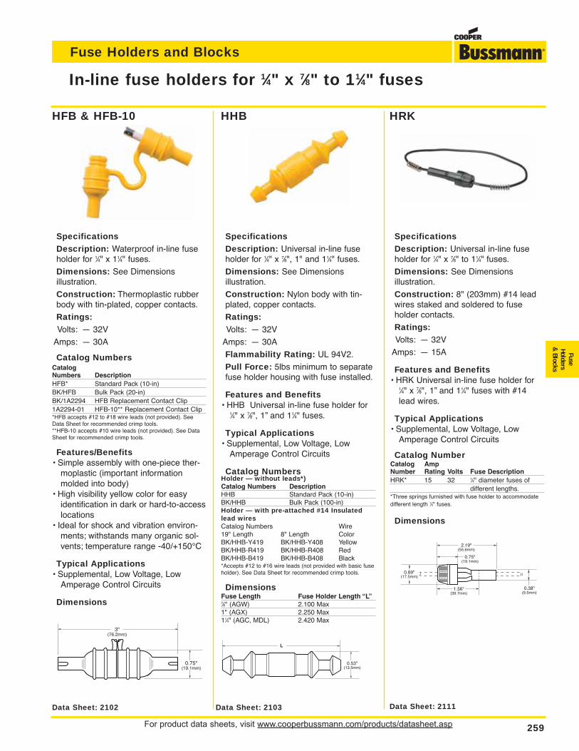
For product data sheets, visit www.cooperbussmann.com/products/datasheet.asp 259
Fuse Holders and Blocks
FuseHolders
& Blocks
SpecificationsDescription: Waterproof in-line fuseholder for 1⁄4" x 11⁄4" fuses.
Dimensions: See Dimensions illustration.
Construction: Thermoplastic rubberbody with tin-plated, copper contacts.
Ratings:Volts: — 32V
Amps: — 30A
Catalog NumbersCatalogNumbers DescriptionHFB* Standard Pack (10-in)BK/HFB Bulk Pack (20-in)BK/1A2294 HFB Replacement Contact Clip1A2294-01 HFB-10** Replacement Contact Clip*HFB accepts #12 to #18 wire leads (not provided). SeeData Sheet for recommended crimp tools.**HFB-10 accepts #10 wire leads (not provided). See DataSheet for recommended crimp tools.
Features/Benefits• Simple assembly with one-piece ther-
moplastic (important informationmolded into body)
• High visibility yellow color for easyidentification in dark or hard-to-accesslocations
• Ideal for shock and vibration environ-ments; withstands many organic sol-vents; temperature range -40/+150°C
Typical Applications• Supplemental, Low Voltage, Low
Amperage Control Circuits
Dimensions
In-line fuse holders for 1⁄4" x 7⁄8" to 11⁄4" fuses
0.75"(19.1mm)
3"(76.2mm)
Data Sheet: 2102 Data Sheet: 2111Data Sheet: 2103
SpecificationsDescription: Universal in-line fuseholder for 1⁄4" x 7⁄8" to 11⁄4" fuses.
Dimensions: See Dimensions illustration.
Construction: 8" (203mm) #14 leadwires staked and soldered to fuse holder contacts.
Ratings:Volts: — 32V
Amps: — 15A
Features and Benefits• HRK Universal in-line fuse holder for
1⁄4" x 7⁄8", 1” and 11⁄4" fuses with #14lead wires.
Typical Applications• Supplemental, Low Voltage, Low
Amperage Control Circuits
Catalog NumberCatalog AmpNumber Rating Volts Fuse DescriptionHRK* 15 32 1⁄4" diameter fuses of
different lengths.*Three springs furnished with fuse holder to accommodatedifferent length 1⁄4" fuses.
Dimensions
SpecificationsDescription: Universal in-line fuseholder for 1⁄4" x 7⁄8", 1" and 11⁄4" fuses.
Dimensions: See Dimensions illustration.
Construction: Nylon body with tin-plated, copper contacts.
Ratings:Volts: — 32V
Amps: — 30A
Flammability Rating: UL 94V2.
Pull Force: 5lbs minimum to separatefuse holder housing with fuse installed.
Features and Benefits• HHB Universal in-line fuse holder for
1⁄4" x 7⁄8", 1” and 11⁄4" fuses.
Typical Applications• Supplemental, Low Voltage, Low
Amperage Control Circuits
Catalog NumbersHolder — without leads*)Catalog Numbers DescriptionHHB Standard Pack (10-in)BK/HHB Bulk Pack (100-in)Holder — with pre-attached #14 Insulatedlead wiresCatalog Numbers Wire19" Length 8" Length ColorBK/HHB-Y419 BK/HHB-Y408 YellowBK/HHB-R419 BK/HHB-R408 RedBK/HHB-B419 BK/HHB-B408 Black*Accepts #12 to #16 wire leads (not provided with basic fuseholder). See Data Sheet for recommended crimp tools.
DimensionsFuse Length Fuse Holder Length “L”7⁄8" (AGW) 2.100 Max1" (AGX) 2.250 Max11⁄4" (AGC, MDL) 2.420 Max
L
0.53"(13.5mm)
0.75"(19.1mm)
2.19"(55.6mm)
1.56"(39.7mm)
0.69"(17.5mm)
0.38"(9.5mm)
HFB & HFB-10 HHB HRK
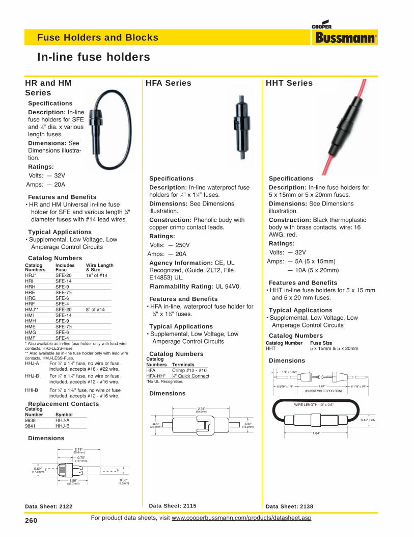
HR and HMSeriesSpecificationsDescription: In-linefuse holders for SFEand 1⁄4" dia. x variouslength fuses.
Dimensions: SeeDimensions illustra-tion.
Ratings:Volts: — 32V
Amps: — 20A
Features and Benefits• HR and HM Universal in-line fuse
holder for SFE and various length 1⁄4" diameter fuses with #14 lead wires.
Typical Applications• Supplemental, Low Voltage, Low
Amperage Control Circuits
Catalog NumbersCatalog Includes Wire LengthNumbers Fuse & SizeHRJ* SFE-20 19” of #14HRI SFE-14HRH SFE-9HRE SFE-71⁄2HRG SFE-6HRF SFE-4HMJ** SFE-20 8” of #14HMI SFE-14HMH SFE-9HME SFE-71⁄2HMG SFE-6HMF SFE-4* Also available as in-line fuse holder only with lead wirecontacts, HRJ-LESS-Fuse.** Also available as in-line fuse holder only with lead wirecontacts, HMJ-LESS-Fuse.HHJ-A For 1⁄4" x 11⁄4" fuse, no wire or fuse
included, accepts #18 - #22 wire.
HHJ-B For 1⁄4" x 11⁄4" fuse, no wire or fuse included, accepts #12 - #16 wire.
HHI-B For 1⁄4" x 11⁄16" fuse, no wire or fuse included, accepts #12 - #16 wire.
Replacement ContactsCatalogNumber Symbol9838 HHJ-A9841 HHJ-B
Dimensions
For product data sheets, visit www.cooperbussmann.com/products/datasheet.asp260
Fuse Holders and Blocks
In-line fuse holders
0.75"(19.1mm)
2.19"(55.6mm)
1.56"(39.7mm)
0.69"(17.5mm)
0.38"(9.5mm)
1.84"
0.42" DIA.
WIRE LENGTH: 13" ± 0.5"
Data Sheet: 2122 Data Sheet: 2115 Data Sheet: 2138
SpecificationsDescription: In-line waterproof fuseholders for 1⁄4" x 11⁄4" fuses.
Dimensions: See Dimensions illustration.
Construction: Phenolic body withcopper crimp contact leads.
Ratings:Volts: — 250V
Amps: — 20A
Agency Information: CE, ULRecognized, (Guide IZLT2, FileE14853) UL.
Flammability Rating: UL 94V0.
Features and Benefits• HFA in-line, waterproof fuse holder for
1⁄4" x 11⁄4" fuses.
Typical Applications• Supplemental, Low Voltage, Low
Amperage Control Circuits
Catalog NumbersCatalogNumbers TerminalsHFA Crimp #12 - #16HFA-HH* 1⁄4" Quick Connect*No UL Recognition.
Dimensions
SpecificationsDescription: In-line fuse holders for 5 x 15mm or 5 x 20mm fuses.
Dimensions: See Dimensions illustration.
Construction: Black thermoplasticbody with brass contacts, wire: 16AWG, red.
Ratings:Volts: — 32V
Amps: — 5A (5 x 15mm)
— 10A (5 x 20mm)
Features and Benefits• HHT in-line fuse holders for 5 x 15 mm
and 5 x 20 mm fuses.
Typical Applications• Supplemental, Low Voltage, Low
Amperage Control Circuits
Catalog NumbersCatalog Number Fuse SizeHHT 5 x 15mm & 5 x 20mm
Dimensions
2.34"(59.5mm)
.600"(15.2mm)
.800"(20.3mm)
HFA Series HHT Series
(IN ASSEMBLED POSITION)
1/4" ± 1/32"
1.84"6-3/16" ± 1/4" 6-1/16" ± 1/4"
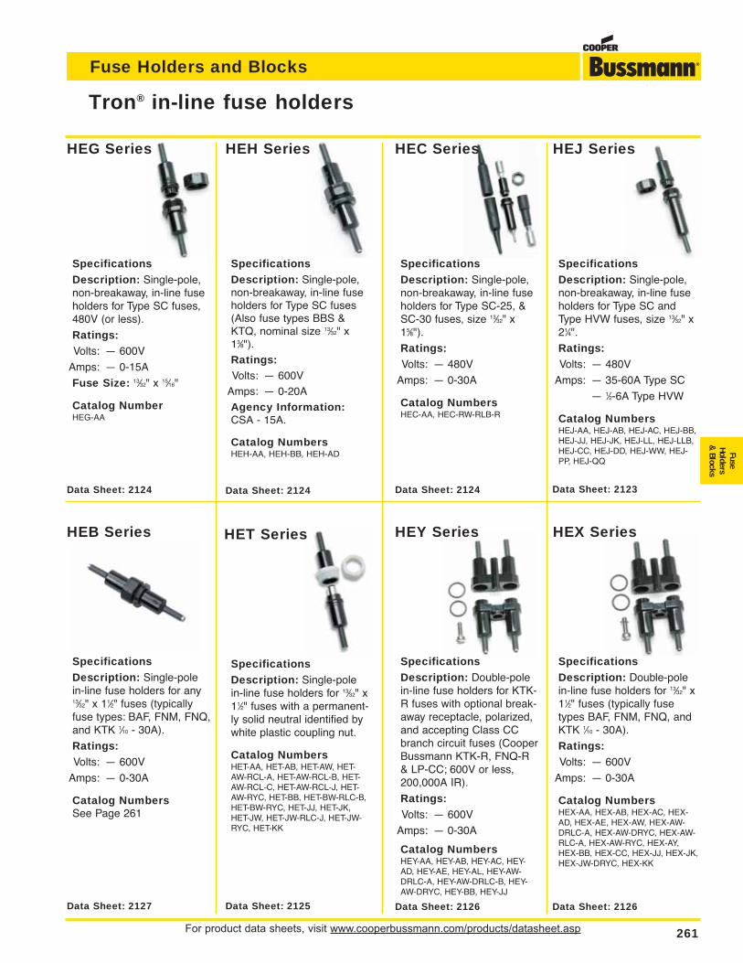
For product data sheets, visit www.cooperbussmann.com/products/datasheet.asp 261
Fuse Holders and Blocks
FuseHolders
& Blocks
Tron® in-line fuse holders
SpecificationsDescription: Single-pole,non-breakaway, in-line fuseholders for Type SC fuses,480V (or less).
Ratings:Volts: — 600V
Amps: — 0-15A
Fuse Size: 13⁄32" x 15⁄16"
Catalog NumberHEG-AA
SpecificationsDescription: Single-pole,non-breakaway, in-line fuseholders for Type SC fuses(Also fuse types BBS &KTQ, nominal size 13⁄32" x13⁄8").
Ratings:Volts: — 600V
Amps: — 0-20A
Agency Information:CSA - 15A.
Catalog NumbersHEH-AA, HEH-BB, HEH-AD
SpecificationsDescription: Single-pole,non-breakaway, in-line fuseholders for Type SC-25, &SC-30 fuses, size 13⁄32" x15⁄8").
Ratings:Volts: — 480V
Amps: — 0-30A
Catalog NumbersHEC-AA, HEC-RW-RLB-R
SpecificationsDescription: Single-pole,non-breakaway, in-line fuseholders for Type SC andType HVW fuses, size 13⁄32" x21⁄4".
Ratings:Volts: — 480V
Amps: — 35-60A Type SC
— 1⁄2-6A Type HVW
Catalog NumbersHEJ-AA, HEJ-AB, HEJ-AC, HEJ-BB,HEJ-JJ, HEJ-JK, HEJ-LL, HEJ-LLB,HEJ-CC, HEJ-DD, HEJ-WW, HEJ-PP, HEJ-QQ
SpecificationsDescription: Single-polein-line fuse holders for any13⁄32" x 11⁄2" fuses (typicallyfuse types: BAF, FNM, FNQ,and KTK 1⁄10 - 30A).
Ratings:Volts: — 600V
Amps: — 0-30A
Catalog NumbersSee Page 261
SpecificationsDescription: Single-polein-line fuse holders for 13⁄32" x11⁄2" fuses with a permanent-ly solid neutral identified bywhite plastic coupling nut.
Catalog NumbersHET-AA, HET-AB, HET-AW, HET-AW-RCL-A, HET-AW-RCL-B, HET-AW-RCL-C, HET-AW-RCL-J, HET-AW-RYC, HET-BB, HET-BW-RLC-B,HET-BW-RYC, HET-JJ, HET-JK,HET-JW, HET-JW-RLC-J, HET-JW-RYC, HET-KK
SpecificationsDescription: Double-polein-line fuse holders for KTK-R fuses with optional break-away receptacle, polarized,and accepting Class CCbranch circuit fuses (CooperBussmann KTK-R, FNQ-R& LP-CC; 600V or less,200,000A IR).
Ratings:Volts: — 600V
Amps: — 0-30A
Catalog NumbersHEY-AA, HEY-AB, HEY-AC, HEY-AD, HEY-AE, HEY-AL, HEY-AW-DRLC-A, HEY-AW-DRLC-B, HEY-AW-DRYC, HEY-BB, HEY-JJ
Data Sheet: 2126
SpecificationsDescription: Double-polein-line fuse holders for 13⁄32" x11⁄2" fuses (typically fusetypes BAF, FNM, FNQ, andKTK 1⁄10 - 30A).
Ratings:Volts: — 600V
Amps: — 0-30A
Catalog NumbersHEX-AA, HEX-AB, HEX-AC, HEX-AD, HEX-AE, HEX-AW, HEX-AW-DRLC-A, HEX-AW-DRYC, HEX-AW-RLC-A, HEX-AW-RYC, HEX-AY,HEX-BB, HEX-CC, HEX-JJ, HEX-JK,HEX-JW-DRYC, HEX-KK
HEG Series
HEB Series HET Series HEY Series HEX Series
HEH Series HEC Series HEJ Series
Data Sheet: 2127 Data Sheet: 2125 Data Sheet: 2126
Data Sheet: 2124 Data Sheet: 2124 Data Sheet: 2124 Data Sheet: 2123
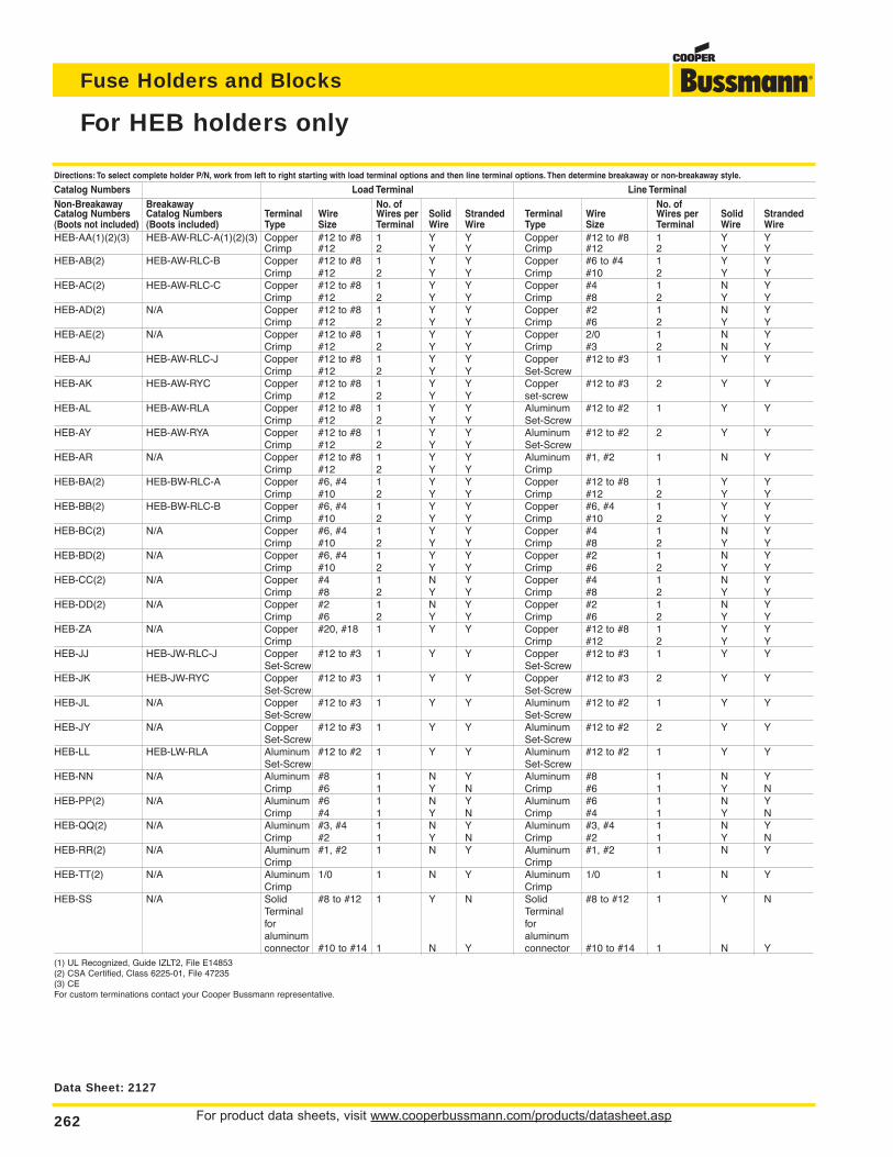
For product data sheets, visit www.cooperbussmann.com/products/datasheet.asp262
Fuse Holders and Blocks
For HEB holders only
Directions: To select complete holder P/N, work from left to right starting with load terminal options and then line terminal options. Then determine breakaway or non-breakaway style.
Catalog Numbers Load Terminal Line TerminalNon-Breakaway Breakaway No. of No. ofCatalog Numbers Catalog Numbers Terminal Wire Wires per Solid Stranded Terminal Wire Wires per Solid Stranded(Boots not included) (Boots included) Type Size Terminal Wire Wire Type Size Terminal Wire WireHEB-AA(1)(2)(3) HEB-AW-RLC-A(1)(2)(3) Copper #12 to #8 1 Y Y Copper #12 to #8 1 Y Y
Crimp #12 2 Y Y Crimp #12 2 Y YHEB-AB(2) HEB-AW-RLC-B Copper #12 to #8 1 Y Y Copper #6 to #4 1 Y Y
Crimp #12 2 Y Y Crimp #10 2 Y YHEB-AC(2) HEB-AW-RLC-C Copper #12 to #8 1 Y Y Copper #4 1 N Y
Crimp #12 2 Y Y Crimp #8 2 Y YHEB-AD(2) N/A Copper #12 to #8 1 Y Y Copper #2 1 N Y
Crimp #12 2 Y Y Crimp #6 2 Y YHEB-AE(2) N/A Copper #12 to #8 1 Y Y Copper 2/0 1 N Y
Crimp #12 2 Y Y Crimp #3 2 N YHEB-AJ HEB-AW-RLC-J Copper #12 to #8 1 Y Y Copper #12 to #3 1 Y Y
Crimp #12 2 Y Y Set-ScrewHEB-AK HEB-AW-RYC Copper #12 to #8 1 Y Y Copper #12 to #3 2 Y Y
Crimp #12 2 Y Y set-screwHEB-AL HEB-AW-RLA Copper #12 to #8 1 Y Y Aluminum #12 to #2 1 Y Y
Crimp #12 2 Y Y Set-ScrewHEB-AY HEB-AW-RYA Copper #12 to #8 1 Y Y Aluminum #12 to #2 2 Y Y
Crimp #12 2 Y Y Set-ScrewHEB-AR N/A Copper #12 to #8 1 Y Y Aluminum #1, #2 1 N Y
Crimp #12 2 Y Y CrimpHEB-BA(2) HEB-BW-RLC-A Copper #6, #4 1 Y Y Copper #12 to #8 1 Y Y
Crimp #10 2 Y Y Crimp #12 2 Y YHEB-BB(2) HEB-BW-RLC-B Copper #6, #4 1 Y Y Copper #6, #4 1 Y Y
Crimp #10 2 Y Y Crimp #10 2 Y YHEB-BC(2) N/A Copper #6, #4 1 Y Y Copper #4 1 N Y
Crimp #10 2 Y Y Crimp #8 2 Y YHEB-BD(2) N/A Copper #6, #4 1 Y Y Copper #2 1 N Y
Crimp #10 2 Y Y Crimp #6 2 Y YHEB-CC(2) N/A Copper #4 1 N Y Copper #4 1 N Y
Crimp #8 2 Y Y Crimp #8 2 Y YHEB-DD(2) N/A Copper #2 1 N Y Copper #2 1 N Y
Crimp #6 2 Y Y Crimp #6 2 Y YHEB-ZA N/A Copper #20, #18 1 Y Y Copper #12 to #8 1 Y Y
Crimp Crimp #12 2 Y YHEB-JJ HEB-JW-RLC-J Copper #12 to #3 1 Y Y Copper #12 to #3 1 Y Y
Set-Screw Set-ScrewHEB-JK HEB-JW-RYC Copper #12 to #3 1 Y Y Copper #12 to #3 2 Y Y
Set-Screw Set-ScrewHEB-JL N/A Copper #12 to #3 1 Y Y Aluminum #12 to #2 1 Y Y
Set-Screw Set-ScrewHEB-JY N/A Copper #12 to #3 1 Y Y Aluminum #12 to #2 2 Y Y
Set-Screw Set-ScrewHEB-LL HEB-LW-RLA Aluminum #12 to #2 1 Y Y Aluminum #12 to #2 1 Y Y
Set-Screw Set-ScrewHEB-NN N/A Aluminum #8 1 N Y Aluminum #8 1 N Y
Crimp #6 1 Y N Crimp #6 1 Y NHEB-PP(2) N/A Aluminum #6 1 N Y Aluminum #6 1 N Y
Crimp #4 1 Y N Crimp #4 1 Y NHEB-QQ(2) N/A Aluminum #3, #4 1 N Y Aluminum #3, #4 1 N Y
Crimp #2 1 Y N Crimp #2 1 Y NHEB-RR(2) N/A Aluminum #1, #2 1 N Y Aluminum #1, #2 1 N Y
Crimp CrimpHEB-TT(2) N/A Aluminum 1/0 1 N Y Aluminum 1/0 1 N Y
Crimp CrimpHEB-SS N/A Solid #8 to #12 1 Y N Solid #8 to #12 1 Y N
Terminal Terminalfor for aluminum aluminumconnector #10 to #14 1 N Y connector #10 to #14 1 N Y
(1) UL Recognized, Guide IZLT2, File E14853(2) CSA Certified, Class 6225-01, File 47235(3) CEFor custom terminations contact your Cooper Bussmann representative.
Data Sheet: 2127
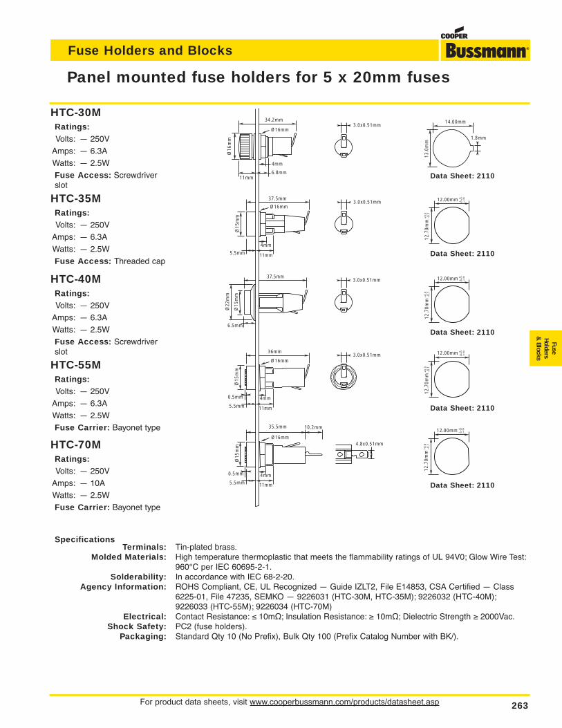
For product data sheets, visit www.cooperbussmann.com/products/datasheet.asp 263
Fuse Holders and Blocks
FuseHolders
& Blocks
Panel mounted fuse holders for 5 x 20mm fuses
SpecificationsTerminals: Tin-plated brass.
Molded Materials: High temperature thermoplastic that meets the flammability ratings of UL 94V0; Glow Wire Test:960°C per IEC 60695-2-1.
Solderability: In accordance with IEC 68-2-20.Agency Information: ROHS Compliant, CE, UL Recognized — Guide IZLT2, File E14853, CSA Certified — Class
6225-01, File 47235, SEMKO — 9226031 (HTC-30M, HTC-35M); 9226032 (HTC-40M);9226033 (HTC-55M); 9226034 (HTC-70M)
Electrical: Contact Resistance: ≤ 10mΩ; Insulation Resistance: ≥ 10mΩ; Dielectric Strength ≥ 2000Vac.Shock Safety: PC2 (fuse holders).
Packaging: Standard Qty 10 (No Prefix), Bulk Qty 100 (Prefix Catalog Number with BK/).
3.0x0.51mm
34.2mm
6.8mm
4mm
Ø16
mm
Ø16mm3.0x0.51mm
14.00mm
1.8mm
13.0
mm
12.00mm +0.0–0.1
12.7
0mm
+0.
0–0
.1
12.00mm +0.0–0.1
12.7
0mm
+0.
0–0
.1
12.00mm +0.0–0.1
12.7
0mm
+0.
0–0
.112.00mm +0.0
–0.1
12.7
0mm
+0.
0–0
.1
3.0x0.51mm
3.0x0.51mm
4.8x0.51mm
11mm
37.5mm
4mm
Ø15
mm
Ø16mm
11mm5.5mm
Ø22
mm
6.5mm
Ø15
mm
37.5mm
36mm
4mm
Ø15
mm
Ø16mm
11mm5.5mm
0.5mm
35.5mm
4mm
Ø15
mm
Ø16mm
11mm5.5mm
0.5mm
10.2mm
Data Sheet: 2110
Data Sheet: 2110
Data Sheet: 2110
Data Sheet: 2110
Data Sheet: 2110
HTC-35MRatings:Volts: — 250V
Amps: — 6.3A
Watts: — 2.5W
Fuse Access: Threaded cap
HTC-55MRatings:Volts: — 250V
Amps: — 6.3A
Watts: — 2.5W
Fuse Carrier: Bayonet type
HTC-40MRatings:Volts: — 250V
Amps: — 6.3A
Watts: — 2.5W
Fuse Access: Screwdriverslot
HTC-70MRatings:Volts: — 250V
Amps: — 10A
Watts: — 2.5W
Fuse Carrier: Bayonet type
HTC-30MRatings:Volts: — 250V
Amps: — 6.3A
Watts: — 2.5W
Fuse Access: Screwdriverslot
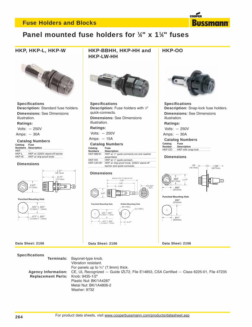
For product data sheets, visit www.cooperbussmann.com/products/datasheet.asp264
Fuse Holders and Blocks
Panel mounted fuse holders for 1⁄4" x 11⁄4" fuses
SpecificationsTerminals: Bayonet-type knob.
Vibration resistant.For panels up to 5⁄16" (7.9mm) thick.
Agency Information: CE, UL Recognized — Guide IZLT2, File E14853, CSA Certified — Class 6225-01, File 47235Replacement Parts: Knob: 9435-1/2"
Plastic Nut: BK/1A4287Metal Nut: BK/1A4806-2Washer: 9732
0.69"(17.5mm)
0.75"(19.1mm)
2.31"(58.7mm)
.473" + .005"(12.0mm + .13mm)
.505" + .005"(12.8mm + .13mm)
Punched Mounting Hole
FU
SE FUSE
FUSE
0.463"REF.
.473" + .005"(12.0mm + .13mm)
.505" + .005"(12.8mm + .13mm)
Punched Mounting Hole
0.27"
0.5" DRILL#41 DRILL
Drilled Mounting Hole
0.69"
2.64"
2.44"
WHEN FUSE IS INSERTED
0.69"
.800"(20.3mm)
Punched Mounting Hole
.811"(20.6mm)
.890"(22.6mm)
1.56"(39.7mm)
.75"(19.1mm)
.855"(21.7mm)
1.17"FU
SE FUS
E
FUSE
Data Sheet: 2106 Data Sheet: 2106Data Sheet: 2106
SpecificationsDescription: Standard fuse holders.
Dimensions: See Dimensions illustration.
Ratings:Volts: — 250V
Amps: — 30A
Catalog NumbersCatalog FuseNumbers DescriptionHKP —HKP-L HKP w/ 2250V stand-off barrierHKP-W HKP w/ drip-proof knob
Dimensions
SpecificationsDescription: Fuse holders with 1⁄4"quick-connects.
Dimensions: See Dimensions illustration.
Ratings:Volts: — 250V
Amps: — 15A
Catalog NumbersCatalog FuseNumbers DescriptionHKP-BBHH HKP w/ 1⁄4" quick-connects,nut and washer
assembled.HKP-HH HKP w/ 1⁄4" quick-connect.HKP-LW-HH HKP w/ drip-proof knob, 2250V stand-off
barrier and quick-connects.
Dimensions
SpecificationsDescription: Snap-lock fuse holders.
Dimensions: See Dimensions illustration.
Ratings:Volts: — 250V
Amps: — 30A
Catalog NumbersCatalog FuseNumber DescriptionHKP-OO HKP with snap-lock
Dimensions
HKP, HKP-L, HKP-W HKP-OOHKP-BBHH, HKP-HH andHKP-LW-HH
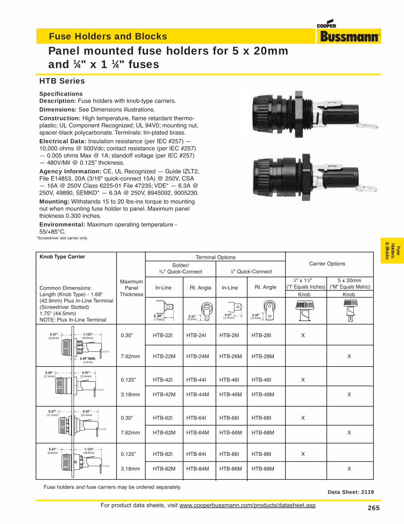
For product data sheets, visit www.cooperbussmann.com/products/datasheet.asp 265
Fuse Holders and Blocks
FuseHolders
& Blocks
Panel mounted fuse holders for 5 x 20mm and 1⁄4" x 1 1⁄4" fuses
HTB Series
SpecificationsDescription: Fuse holders with knob-type carriers.
Dimensions: See Dimensions illustrations.
Construction: High temperature, flame retardant thermo-plastic; UL Component Recognized; UL 94V0; mounting nut,spacer-black polycarbonate. Terminals: tin-plated brass.
Electrical Data: Insulation resistance (per IEC #257) —10,000 ohms @ 500Vdc; contact resistance (per IEC #257)— 0.005 ohms Max @ 1A; standoff voltage (per IEC #257)— 480V/Mil @ 0.125” thickness.
Agency Information: CE, UL Recognized — Guide IZLT2,File E14853, 20A (3/16" quick-connect 15A) @ 250V, CSA— 16A @ 250V Class 6225-01 File 47235; VDE* — 6.3A @250V, 49890, SEMKO* — 6.3A @ 250V, 8945092, 9005230.
Mounting: Withstands 15 to 20 lbs-ins torque to mountingnut when mounting fuse holder to panel. Maximum panelthickness 0.300 inches.
Environmental: Maximum operating temperature -55/+85°C.
*Screwdriver slot carrier only.
Data Sheet: 2119
0.30” HTB-22I HTB-24I HTB-26I HTB-28I X
7.62mm HTB-22M HTB-24M HTB-26M HTB-28M X
0.125” HTB-42I HTB-44I HTB-46I HTB-48I X
3.18mm HTB-42M HTB-44M HTB-46M HTB-48M X
0.30” HTB-62I HTB-64I HTB-66I HTB-68I X
7.62mm HTB-62M HTB-64M HTB-66M HTB-68M X
0.125” HTB-82I HTB-84I HTB-86I HTB-88I X
3.18mm HTB-82M HTB-84M HTB-86M HTB-88M X
Fuse holders and fuse carriers may be ordered separately.
1.125"(28.6mm)
0.47"(11.9mm)
0.09" NOM.(2.4mm)
1.125"(28.6mm)
0.47"(11.9mm)
0.92"(23.4mm)
0.67"(17.1mm)
0.91"(23.0mm)
0.69"(17.5mm)
Knob Type Carrier
Common Dimensions:Length (Knob Type) - 1.69"(42.9mm) Plus In-Line Terminal(Screwdriver Slotted)1.75" (44.5mm)NOTE: Plus In-Line Terminal
MaximumPanel
Thickness
Solder/3⁄16" Quick-Connect 1⁄4" Quick-Connect
Carrier Options
1⁄4" x 11⁄4" 5 x 20mm(“I” Equals Inches) (“M” Equals Metric)
Knob KnobIn-Line Rt. Angle In-Line Rt. Angle
0.34"8.7mm)
0.33"(8.3mm)
0.47"(11.9mm)
0.45"(11.5mm)
Terminal Options
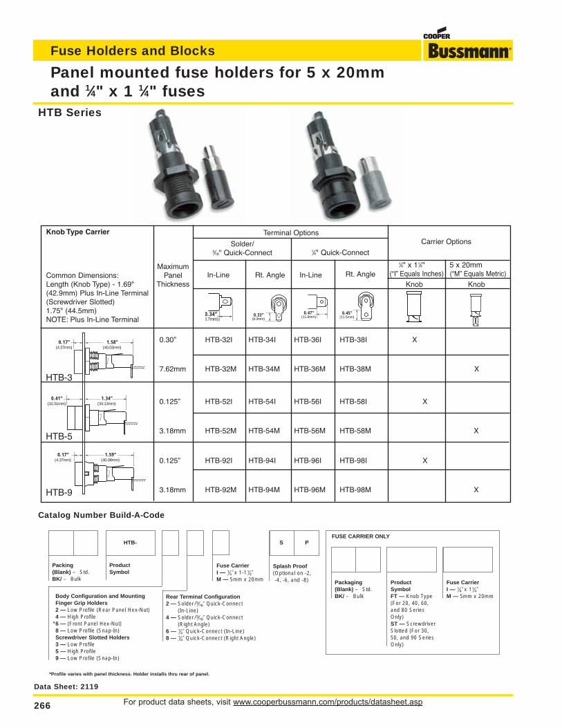
For product data sheets, visit www.cooperbussmann.com/products/datasheet.asp266
Fuse Holders and Blocks
Panel mounted fuse holders for 5 x 20mmand 1⁄4" x 1 1⁄4" fuses
0.30” HTB-32I HTB-34I HTB-36I HTB-38I X
7.62mm HTB-32M HTB-34M HTB-36M HTB-38M X
0.125” HTB-52I HTB-54I HTB-56I HTB-58I X
3.18mm HTB-52M HTB-54M HTB-56M HTB-58M X
0.125” HTB-92I HTB-94I HTB-96I HTB-98I X
3.18mm HTB-92M HTB-94M HTB-96M HTB-98M X
0.17"(4.37mm)
1.58"(40.03mm)
0.17"(4.37mm)
1.59"(40.08mm)
0.41"(10.31mm)
1.34"(34.13mm)
S
Packing (Blank) – Std.BK/ – Bulk
Rear Terminal Configuration2 — Solder / ‹Ω¡§∑ Quick-Connect
Solder / ‹Ω¡§∑ Quick-Connect(In-Line)
4 — (Right Angle)
6 — ⁄Ω¢∑ Quick-Connect (In-Line)8 — ⁄Ω¢∑ Quick-Connect (Right Angle)
Fuse CarrierI — ⁄Ω¢∑ x 1-1⁄Ω¢∑M — 5mm x 20mm
Splash Proof(Optional on -2,-4, -6, and -8)
Body Configuration and Mounting Finger Grip Holders2 — Low Profile (Rear Panel Hex-Nut)4 — High Profile
*6 — (Front Panel Hex-Nut)8 — Low Profile (Snap-In)Screwdriver Slotted Holders3 — Low Profile5 — High Profile9 — Low Profile (Snap-In)
ProductSymbol
HTB-
Packaging (Blank) – Std.BK/ – Bulk
Fuse CarrierI — ⁄Ω¢∑ x 1⁄Ω¢∑M — 5mm x 20mm
ProductSymbolFT — Knob Type (For 20, 40, 60,and 80 SeriesOnly)ST — ScrewdriverSlotted (For 30,50, and 90 SeriesOnly)
P
*Profile varies with panel thickness. Holder installs thru rear of panel.
FUSE CARRIER ONLY
Data Sheet: 2119
Catalog Number Build-A-Code
HTB Series
HTB-3
HTB-5
HTB-9
Knob Type Carrier
Common Dimensions:Length (Knob Type) - 1.69"(42.9mm) Plus In-Line Terminal(Screwdriver Slotted)1.75" (44.5mm)NOTE: Plus In-Line Terminal
MaximumPanel
Thickness
Solder/3⁄16" Quick-Connect 1⁄4" Quick-Connect
Carrier Options
1⁄4" x 11⁄4" 5 x 20mm(“I” Equals Inches) (“M” Equals Metric)
Knob KnobIn-Line Rt. Angle In-Line Rt. Angle
0.34"8.7mm)
0.33"(8.3mm)
0.47"(11.9mm)
0.45"(11.5mm)
Terminal Options
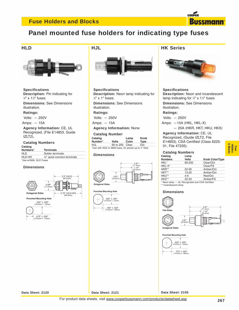
For product data sheets, visit www.cooperbussmann.com/products/datasheet.asp 267
Fuse Holders and Blocks
FuseHolders
& Blocks
Panel mounted fuse holders for indicating type fuses
.630" + .005"(16.0mm + .13mm)
.573" + .003"(14.6mm + .08mm)
Punched Mounting Hole
Octagonal Sides
0.81"(20.6mm)
1.19"(30.2mm)
2.81"(71.4mm)
Flat-Sides
Data Sheet: 2120 Data Sheet: 2121 Data Sheet: 2105
SpecificationsDescription: Pin indicating for 1⁄4" x 11⁄4" fuses.
Dimensions: See Dimensions illustration.
Ratings:Volts: — 250V
Amps: — 15A
Agency Information: CE, ULRecognized, (File E14853, GuideIZLT2).
Catalog NumbersCatalogNumbers* TerminalsHLD Solder terminalsHLD-HH 1⁄4" quick-connect terminals*Use w/GBA, GLD Fuses
Dimensions
SpecificationsDescription: Neon lamp indicating for1⁄4" x 1" fuses.
Dimensions: See Dimensions illustration.
Ratings:Volts: — 250V
Amps: — 15A
Agency Information: None
Catalog NumberCatalog Lamp KnobNumber* Volts Color TypeHJL 90 to 250 Clear Oct*Use with AGX or MKB fuses, for panels up to 1⁄8" thick.
Dimensions
SpecificationsDescription: Neon and incandescentlamp indicating for 1⁄4" x 11⁄4" fuses
Dimensions: See Dimensionsillustration.
Ratings:Volts: — 250V
Amps: —15A (HKL, HKL-X)
— 20A (HKR, HKT, HKU, HKX)
Agency Information: CE, ULRecognized, (Guide IZLT2, FileE14853), CSA Certified (Class 6225-01, File 47235).
Catalog NumbersCatalog LampNumbers Volts Knob Color/TypeHKL* 90-250 Clear/OctHKL-X* Clear/FSHKR** 22-30 Amber/OctHKT** 13-22 Amber/OctHKU** 4-6 Red/OctHKX** 22-33 Amber/FS* Neon lamp — UL Recognized and CSA Certified** Incandescent lamp
Dimensions
HLD HK SeriesHJL
Octagonal Sides
.505" + .005"(16.0mm + .13mm)
.473" + .005"(12.0mm + .13mm)
Punched Mounting Hole
0.69"(17.5mm)
2.5" (HLD)(63.5mm)
2.75" (HLD-HH)(69.9mm)
.630" + .005"(16.0mm + .13mm)
.590" + .003"(14.6mm + .08mm)
Punched Mounting Hole
Octagonal Sides
0.81"(20.6mm)
1.19"(30.2mm)
2.81"(71.4mm)
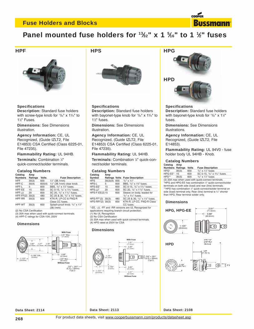
For product data sheets, visit www.cooperbussmann.com/products/datasheet.asp268
Fuse Holders and Blocks
Panel mounted fuse holders for 13⁄32" x 1 5⁄16" to 1 1⁄2" fuses
Data Sheet: 2114 Data Sheet: 2113 Data Sheet: 2108
0.180" DIA.(4.6mm)
1.125"(28.6mm)
1.00"(25.4mm)
Without Fuse
2.69" Max.(68.3mm)
0.88"(22.2mm)
1.78"(45.2mm)
1.31"(33.3mm)
2.81" Max.(71.4mm)
With Fuse
FUSE
FUS
EFU
SE
.250" ± .003" (6.35 ± .08mm) (Typ.2)
0.88"(22.2mm)
2.81"(71.4mm)
With Fuse
Without Fuse
2.41"(64.3mm)
0.80"(20.2mm)
1.78"(45.2mm)
0.180"(4.6mm)
1.125"(28.6mm)
.250" ± .003" (6.35 ± .08mm) (Typ.2)
1.125"(28.6mm)
0.88"(22.2mm)
2.81"(71.4mm)
SpecificationsDescription: Standard fuse holderswith screw-type knob for 13⁄32" x 15⁄16" to11⁄2" Fuses.
Dimensions: See Dimensions illustration.
Agency Information: CE, ULRecognized, (Guide IZLT2, FileE14853) CSA Certified (Class 6225-01,File 47235).
Flammability Rating: UL 94HB.
Terminals: Combination 1⁄4" quick-connect/solder terminals.
Catalog NumbersCatalog AmpNumbers Ratings Volts Fuse DescriptionHPF 30(3) 600 11⁄2" (38.1mm)HPF-C 30(4) 600(4) 11⁄2" (38.1mm) clear knob.HPF-L 5 600 BBS, 13⁄32" x 13⁄8" fuses.HPF-EE 15 600 SC 0-15, 13⁄32" x 15⁄16" fuses.HPF-JJ 20 600 SC 20, 13⁄32" x 113⁄32" fuses.HPF-FF(2) 30(3) 480 SC 25 & 30, 13⁄32" x 15⁄8" fuses.HPF-RR 30(3) 600 KTK-R, LP-CC & FNQ-R
Class CC fuses.HPF-WT 30(3) 600 Splash-proof knob. 13⁄32" x 11⁄2"
(38.1mm)(2) No CSA Certification(3) 20A max when used with quick-connect terminals.(4) HPF-C ratings for CSA-15A, 250V
Dimensions
SpecificationsDescription: Standard fuse holderswith bayonet-type knob for 13⁄32" x 15⁄16" to11⁄2" fuses.
Dimensions: See Dimensions illustration.
Agency Information: CE, ULRecognized, (Guide IZLT2, FileE14853) CSA Certified (Class 6225-01,File 47235).
Flammability Rating: UL 94HB.
Terminals: Combination 1⁄4" quick-con-nect/solder terminals.
Catalog NumbersCatalog AmpSymbol Ratings Volts Fuse DescriptionHPS 30(3)(4) 600 13⁄32" x 11⁄2"HPS-L 5 600 BBS, 13⁄32" x 13⁄8" fuses.HPS-EE* 15 600 SC 0-15, 13⁄32" x 15⁄16" fuses.HPS-JJ* 20 600 SC 20, 13⁄32" x 113⁄32" fuses.HPS-F-EE(2)15 600 Sleeve on body, leaded for
13⁄32" x 15⁄16" fuses.HPS-FF*(2) 30(3) 480 SC 25 & 30, 13⁄32" x 15⁄8" fuses.HPS-RR*(2) 30(3) 600 KTK-R, LP-CC, FNQ-R Class
CC fuses.*-EE, -JJ, -FF and -RR versions are UL Recognized forapplications requiring branch circuit protection.(1) No UL Recognition(2) No CSA Certification(3) 20A max when used with quick-connect terminals.(4) HPS rated at 250V for CSA
Dimensions
SpecificationsDescription: Standard fuse holderswith bayonet-type knob for 13⁄32" x 11⁄2"fuses.
Dimensions: See Dimensions illustrations.
Agency Information: CE, ULRecognized, (Guide IZLT2, FileE14853).
Flammability Rating: UL 94V0 - fuseholder body UL 94HB - Knob.
Catalog NumbersCatalog AmpNumbers Ratings Volts Fuse DescriptionHPG* 30(3) 600 13⁄32" x 11⁄2" fusesHPG-EE* 15 600 SC 0-15, 13⁄32" x 15⁄16" fuses.HPD** 30(3) 600 13⁄32" x 11⁄2" fuses(3) 20A max when used with quick-connect terminals.*HPG and HPG-EE has combination 1⁄4" quick-connect/solderterminals on both side (load) and rear (line) terminals.**HPD has combination 1⁄4" quick-connect/solder terminal onside (load) terminal only. Rear (line) terminal is 3⁄16" shorterthan HPG. Rear terminal solder only.
Dimensions
HPG, HPG-EE
HPD
HPF
HPD
HPGHPS
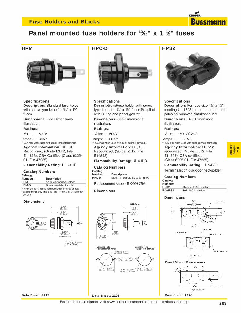
For product data sheets, visit www.cooperbussmann.com/products/datasheet.asp 269
Fuse Holders and Blocks
FuseHolders
& Blocks
Panel mounted fuse holders for 13⁄32" x 1 1⁄2" fuses
Data Sheet: 2112 Data Sheet: 2109 Data Sheet: 2140
Panel Mount Dimensions
1.41"(30.6mm)
0.94"(23.8mm)
With Fuse
Without Fuse
2.73"(69.5mm)
2.594"(65.89mm)
.250" ± .003" (6.35 ± .08mm)
1.031" + 0.003"(26.2mm + 0.08mm)
0.187" + 0.002"(4.75mm + 0.05mm)
Mounting HoleFlange Rear of Panel
Mounting HoleFlange Front of Panel
0.890" + 0.003"(22.6mm + 0.08mm)
1.312" + 0.003"(33.3mm + 0.08mm)
1.312" + 0.003"(33.3mm + 0.08mm)
1.775"(45.1mm)
0.180"(4.6mm)
1.120"(30.5mm)
0.88"(22.2mm)
2.48"(63.1mm)
With Fuse
SpecificationsDescription: Standard fuse holderwith screw-type knob for 13⁄32" x 11⁄2"fuses.
Dimensions: See Dimensions illustration.
Ratings:Volts: — 600V
Amps: — 30A(3)
(3) 20A max when used with quick-connect terminals.
Agency Information: CE, ULRecognized, (Guide IZLT2, FileE14853), CSA Certified (Class 6225-01, File 47235).
Flammability Rating: UL 94HB.
Catalog NumbersCatalogNumbers DescriptionHPM 1⁄4" quick-connect/solderHPM-D Splash-resistant knob(4)
(4) HPM-D has 1⁄4" quick-connect/solder terminal on rear(load) terminal only. The side (line) terminal is 1⁄4" quick-con-nect only.
Dimensions
SpecificationsDescription:Fuse holder with screw-type knob for 13⁄32" x 11⁄2" fuses.Suppliedwith O-ring and panel gasket.
Dimensions: See Dimensions illustration.
Ratings:Volts: — 600V
Amps: — 30A(3)
(3) 20A max when used with quick-connect terminals.
Agency Information: CE, ULRecognized, (Guide IZLT2, FileE14853).
Flammability Rating: UL 94HB.
Catalog NumbersCatalogNumber DescriptionHPC-D Mount in panels up to 1⁄4" thick.
Replacement knob - BK/9987SA
Dimensions
SpecificationsDescription: For fuse size 13⁄32" x 11⁄2",meeting UL 1598 requirement that bothpoles be removed simultaneously.
Dimensions: See Dimensions illustration.
Ratings:Volts: — 600V@30A
Amps: — 0-30A (3)
(3) 20A max when used with quick-connect terminals.
Agency Information: UL 512 recognized, (Guide IZLT2, FileE14853), CSA certified:(Class 6225-01, File 47235).
Flammability Rating: UL 94V0.
Terminals: 1⁄4” quick-connect/solder.
Catalog NumbersCatalogNumbersHPS2 Standard 10-in cartonBK/HPS2 Bulk 100-in carton
Dimensions
HPM HPC-D HPS2
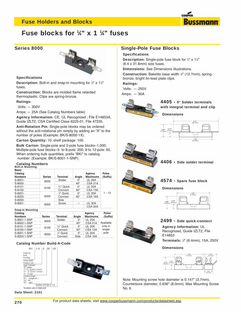
For product data sheets, visit www.cooperbussmann.com/products/datasheet.asp270
Fuse Holders and Blocks
Fuse blocks for 1⁄4" x 1 1⁄4" fuses
4405 - 0° Solder terminalswith integral terminal and clip
Dimensions
Note: Mounting screw hole diameter is 0.147" (3.7mm).Counterbore diameter, 0.636" (8.0mm). Max Mounting ScrewNo. 6.
SpecificationsDescription: Bolt-in and snap-in mounting for 1⁄4" x 11⁄4"fuses.
Construction: Blocks are molded flame retarded thermoplastic. Clips are spring-bronze.
Ratings:Volts: — 300V
Amps: — 25A (See Catalog Numbers table)
Agency Information: CE, UL Recognized ; File E14853A,Guide IZLT2, CSA Certified Class 6225-01, File 47235.
Anti-Rotation Pin: Single-pole blocks may be ordered without the anti-rotational pin simply by adding an “X” to thenumber of poles (Example: BK/S-8000-1X).
Carton Quantity: 10; shelf package: 100.
Bulk Carton: Single-pole and 2-pole fuse blocks–1,000;Multiple-pole fuse blocks–3- to 8-pole: 200; 9-to 12-pole: 50.When ordering bulk quantities, prefix “BK/” to catalognumber: (Example: BK/S-8001-1-SNP).
2.31"(58.7mm)
1.63"(41.3mm)
0.27"(6.7mm)0.69"
(17.5mm)
Catalog NumbersBolt-in MountingBasicCatalog Agency PolesNumbers Series Terminal Angle Maximums (Suffix)S-8001- 8000 Solder 0° UL 25A 1 - 12S-8002- 40° CSA 21AS-8101- 8100 3⁄16" Quick 0° UL 20AS-8102- Connect 40° CSA 13AS-8201- 8200 1⁄4" Quick 0° UL 20AS-8202- Connect 40° CSA 16AS-8203- SideS-8301- 8300 Screw — UL 30A
CSA 25ASnap-in MountingCatalog Agency PolesNumbers Series Terminal Angle Maximums (Suffix)S-8001-1-SNP 8000 Solder 0° UL 25A AvailableS-8002-1-SNP 40° CSA 21A only inS-8101-1-SNP 8100 3⁄16" Quick 0° UL 20A singleS-8102-1-SNP Connect 40° CSA 13A poleS-8201-1-SNP 8200 1⁄4" Quick 0° UL 20AS-8203-1-SNP Connect Side CSA 16A
Catalog Number Build-A-Code
4406 - Side solder terminal
4574 - Spare fuse block
Dimensions
2499 - Side quick-connect
Agency Information: ULRecognized, Guide IZLT2, FileE14853
Terminals: 1⁄4" (6.4mm); 15A, 250V
Dimensions
Series 8000
BK/ S-8 0 00 -00
Prefix forBulkPacking
Series 8000Product Line
Terminal Angle“01” - straight (0°,) “02”- 40°“03” - side*
Type Terminal“0”-Solder“1”-‹Ω¡§∑ Quick Connect “2” - ⁄Ω¢∑ Quick Connect “3” - Screw
Number of Poles (1-12)
*Available only in single pole
Data Sheet: 2101
1.63"(41.3mm)
0.27"(6.7mm)0.69"
(17.5mm)
0.27"(6.7mm)
0.75"(19.1mm)
0.5"(12.7mm)
0.72"(18.3mm)
1.63"(41.3mm)
Single-Pole Fuse BlocksSpecificationsDescription: Single-pole fuse block for 1⁄4" x 11⁄4" (6.4 x 31.8mm) size fuses.
Dimensions: See Dimensions illustrations.
Construction: Bakelite base width 1⁄2" (12.7mm); spring-bronze, bright tin-lead plate clips.
Ratings:Volts: — 250V
Amps: — 30A
8000
8000Availableonly insinglepole
1 - 12
8100
8100
8300
8200
8200
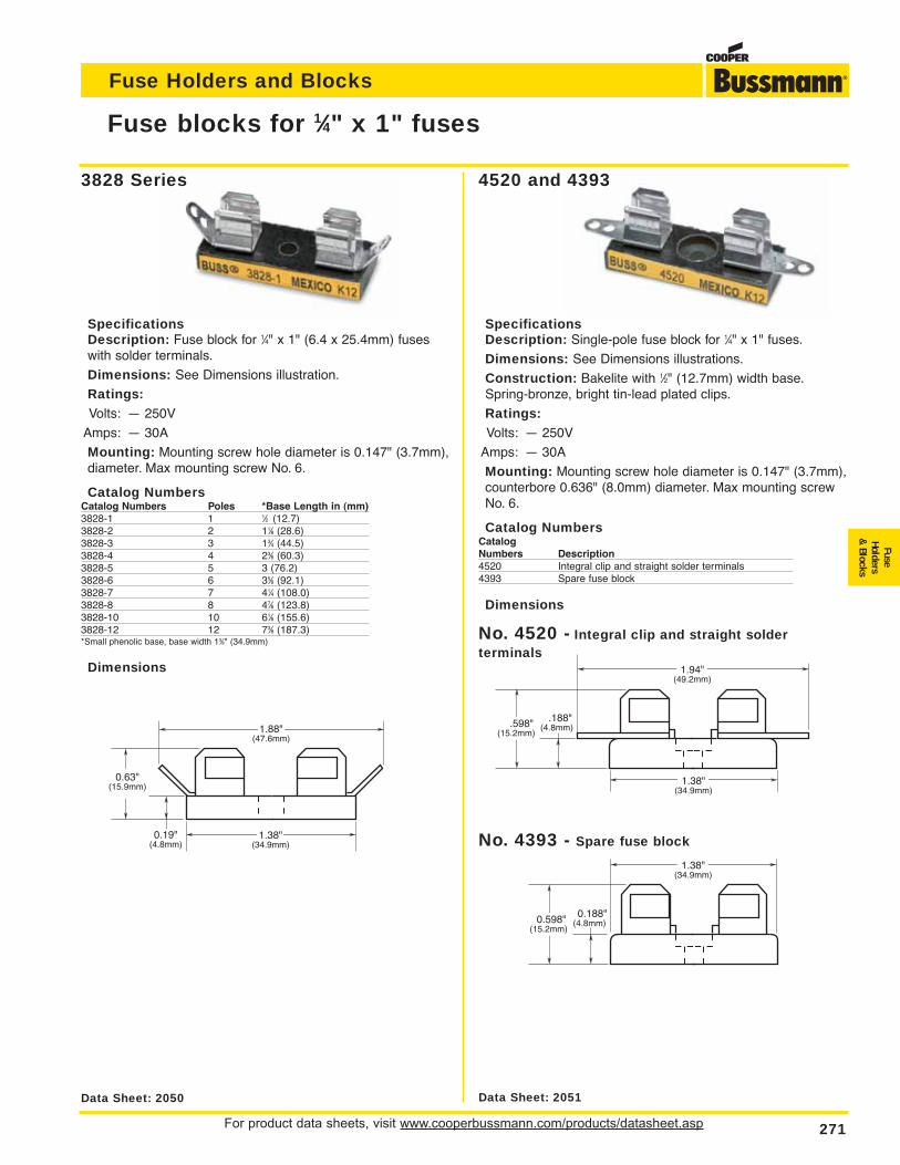
For product data sheets, visit www.cooperbussmann.com/products/datasheet.asp 271
Fuse Holders and Blocks
FuseHolders
& Blocks
No. 4520 - Integral clip and straight solder terminals
Fuse blocks for 1⁄4" x 1" fuses
0.19"(4.8mm)
0.63"(15.9mm)
1.88"(47.6mm)
1.38"(34.9mm)
1.94"(49.2mm)
1.38"(34.9mm)
.188"(4.8mm) .598"
(15.2mm)
1.38"(34.9mm)
0.188"(4.8mm)0.598"
(15.2mm)
No. 4393 - Spare fuse block
3828 Series 4520 and 4393
SpecificationsDescription: Fuse block for 1⁄4" x 1" (6.4 x 25.4mm) fuseswith solder terminals.
Dimensions: See Dimensions illustration.
Ratings:Volts: — 250V
Amps: — 30A
Mounting: Mounting screw hole diameter is 0.147" (3.7mm),diameter. Max mounting screw No. 6.
Catalog NumbersCatalog Numbers Poles *Base Length in (mm)3828-1 1 1⁄2 (12.7)3828-2 2 11⁄8 (28.6)3828-3 3 13⁄4 (44.5)3828-4 4 23⁄8 (60.3)3828-5 5 3 (76.2)3828-6 6 35⁄8 (92.1)3828-7 7 41⁄4 (108.0)3828-8 8 47⁄8 (123.8)3828-10 10 61⁄8 (155.6)3828-12 12 73⁄8 (187.3)*Small phenolic base, base width 13⁄8" (34.9mm)
Dimensions
SpecificationsDescription: Single-pole fuse block for 1⁄4" x 1" fuses.
Dimensions: See Dimensions illustrations.
Construction: Bakelite with 1⁄2" (12.7mm) width base.Spring-bronze, bright tin-lead plated clips.
Ratings:Volts: — 250V
Amps: — 30A
Mounting: Mounting screw hole diameter is 0.147" (3.7mm),counterbore 0.636" (8.0mm) diameter. Max mounting screwNo. 6.
Catalog NumbersCatalogNumbers Description4520 Integral clip and straight solder terminals4393 Spare fuse block
Dimensions
Data Sheet: 2050 Data Sheet: 2051
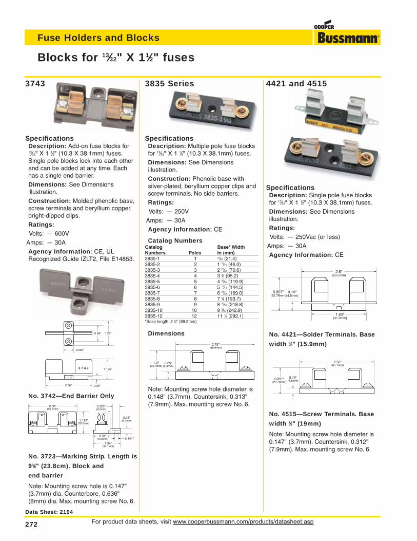
For product data sheets, visit www.cooperbussmann.com/products/datasheet.asp272
Fuse Holders and Blocks
Blocks for 13⁄32" X 11⁄2" fuses
SpecificationsDescription: Add-on fuse blocks for13⁄32" X 1 1⁄2" (10.3 X 38.1mm) fuses.Single pole blocks lock into each otherand can be added at any time. Eachhas a single end barrier.
Dimensions: See Dimensions illustration.
Construction: Molded phenolic base,screw terminals and beryllium copper,bright-dipped clips.
Ratings:Volts: — 600V
Amps: — 30A
Agency Information: CE, ULRecognized Guide IZLT2, File E14853.
No. 3742—End Barrier Only
No. 3723—Marking Strip. Length is
93⁄8" (23.8cm). Block and
end barrier
Note: Mounting screw hole is 0.147"(3.7mm) dia. Counterbore, 0.636"(8mm) dia. Max. mounting screw No. 6.
SpecificationsDescription: Single pole fuse blocksfor 13⁄32" X 1 1⁄2" (10.3 X 38.1mm) fuses.
Dimensions: See Dimensions illustration.
Ratings:Volts: — 250Vac (or less)
Amps: — 30A
Agency Information: CE
No. 4421—Solder Terminals. Base
width 5⁄8" (15.9mm)
No. 4515—Screw Terminals. Base
width 3⁄4" (19mm)
Note: Mounting screw hole diameter is0.147" (3.7mm). Countersink, 0.312"(7.9mm). Max. mounting screw No. 6.
SpecificationsDescription: Multiple pole fuse blocksfor 13⁄32" X 1 1⁄2" (10.3 X 38.1mm) fuses.
Dimensions: See Dimensions illustration.
Construction: Phenolic base with silver-plated, beryllium copper clips andscrew terminals. No side barriers.
Ratings:Volts: — 250V
Amps: — 30A
Agency Information: CE
Catalog NumbersCatalog Base* WidthNumbers Poles In (mm)3835-1 1 27⁄32 (21.4)3835-2 2 1 13⁄16 (46.0)3835-3 3 2 25⁄32 (70.6)3835-4 4 3 3⁄4 (95.2)3835-5 5 4 23⁄32 (119.9)3835-6 6 5 11⁄16 (144.5)3835-7 7 6 21⁄32 (169.0)3835-8 8 7 5⁄8 (193.7)3835-9 9 8 19⁄32 (218.8)3835-10 10 9 9⁄16 (242.9)3835-12 12 11 1⁄2 (292.1)*Base length: 2 3⁄4" (69.9mm)
Dimensions
Note: Mounting screw hole diameter is0.148" (3.7mm). Countersink, 0.313"(7.9mm). Max. mounting screw No. 6.
3 7 4 2
0.25"2.56"
1.125"
1.29"0.84"
0.500"
1.125"(28.6mm)
2.56"(65.1mm)
0.78"(19.8mm)
1.34"(34.1mm)
0.25"(6.4mm)
0.323"(8.2mm)
0.144"
0.19"(4.8mm)
0.897"(22.78mm)
2.5"(63.5mm)
1.63"(41.3mm)
2.56"(65.1mm)
0.19"(4.8mm) 0.897"
(22.78mm)
2.75"(69.9mm)
0.25"(6.4mm)
1.0"(25.4mm)
3743 4421 and 45153835 Series
Data Sheet: 2104
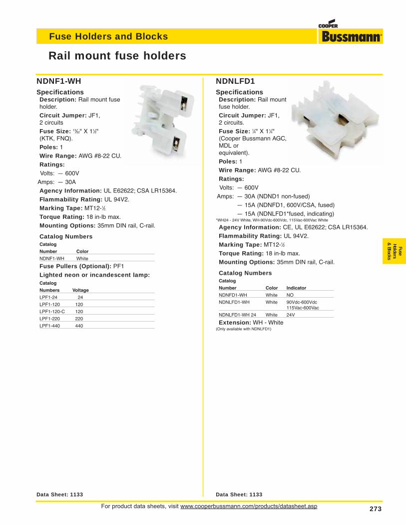
For product data sheets, visit www.cooperbussmann.com/products/datasheet.asp 273
Fuse Holders and Blocks
FuseHolders
& Blocks
NDNF1-WHSpecificationsDescription: Rail mount fuseholder.
Circuit Jumper: JF1, 2 circuits
Fuse Size: 13⁄32" X 11⁄2" (KTK, FNQ).
Poles: 1
Wire Range: AWG #8-22 CU.
Ratings:Volts: — 600V
Amps: — 30A
Agency Information: UL E62622; CSA LR15364.
Flammability Rating: UL 94V2.
Marking Tape: MT12-1⁄2.
Torque Rating: 18 in-lb max.
Mounting Options: 35mm DIN rail, C-rail.
Catalog NumbersCatalog
Number Color
NDNF1-WH White
Fuse Pullers (Optional): PF1
Lighted neon or incandescent lamp:Catalog
Numbers Voltage
LPF1-24 24
LPF1-120 120
LPF1-120-C 120
LPF1-220 220
LPF1-440 440
NDNLFD1SpecificationsDescription: Rail mountfuse holder.
Circuit Jumper: JF1, 2 circuits.
Fuse Size: 1⁄4" X 11⁄4"(Cooper Bussmann AGC,MDL or equivalent).
Poles: 1
Wire Range: AWG #8-22 CU.
Ratings:Volts: — 600V
Amps: — 30A (NDND1 non-fused)
— 15A (NDNFD1, 600V/CSA, fused)
— 15A (NDNLFD1*fused, indicating)*WH24 - 24V White, WH-90Vdc-600Vdc, 115Vac-600Vac White
Agency Information: CE, UL E62622; CSA LR15364.
Flammability Rating: UL 94V2.
Marking Tape: MT12-1⁄2
Torque Rating: 18 in-lb max.
Mounting Options: 35mm DIN rail, C-rail.
Catalog NumbersCatalog
Number Color Indicator
NDNFD1-WH White NO
NDNLFD1-WH White 90Vdc-600Vdc115Vac-600Vac
NDNLFD1-WH 24 White 24V
Extension: WH - White(Only available with NDNLFD1)
Rail mount fuse holders
Data Sheet: 1133 Data Sheet: 1133
274
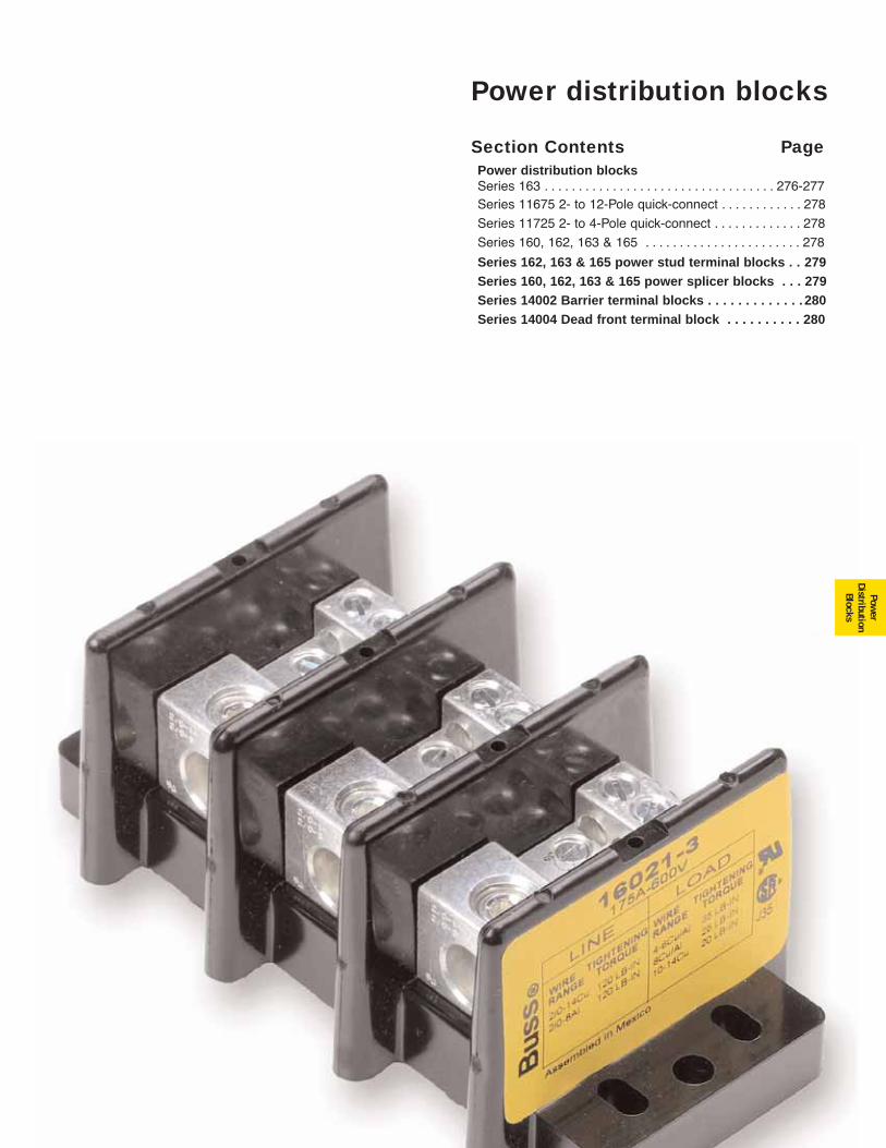
275
Power distribution blocks
Section Contents PagePower distribution blocks Series 163 . . . . . . . . . . . . . . . . . . . . . . . . . . . . . . . . . . 276-277Series 11675 2- to 12-Pole quick-connect . . . . . . . . . . . . 278
Series 11725 2- to 4-Pole quick-connect . . . . . . . . . . . . . 278
Series 160, 162, 163 & 165 . . . . . . . . . . . . . . . . . . . . . . . 278
Series 162, 163 & 165 power stud terminal blocks . . 279Series 160, 162, 163 & 165 power splicer blocks . . . 279Series 14002 Barrier terminal blocks . . . . . . . . . . . . . 280Series 14004 Dead front terminal block . . . . . . . . . . 280
Power
DistributionBlocks
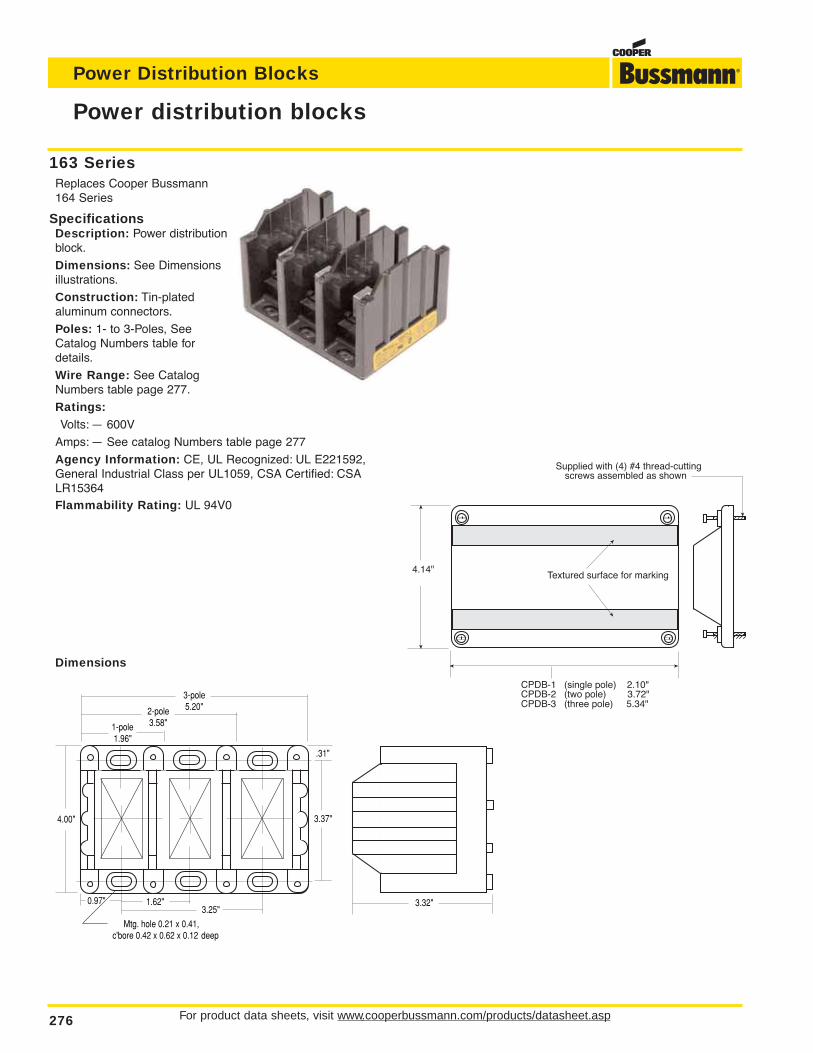
163 SeriesReplaces Cooper Bussmann164 Series
SpecificationsDescription: Power distributionblock.
Dimensions: See Dimensionsillustrations.
Construction: Tin-plated aluminum connectors.
Poles: 1- to 3-Poles, SeeCatalog Numbers table fordetails.
Wire Range: See CatalogNumbers table page 277.
Ratings:Volts: — 600V
Amps: — See catalog Numbers table page 277
Agency Information: CE, UL Recognized: UL E221592,General Industrial Class per UL1059, CSA Certified: CSALR15364Flammability Rating: UL 94V0
Dimensions
For product data sheets, visit www.cooperbussmann.com/products/datasheet.asp276
Power distribution blocks
Power Distribution Blocks
1-pole1.96"
2-pole3.58"
3-pole5.20"
.31"
1.62"3.25"
Mtg. hole 0.21 x 0.41,c'bore 0.42 x 0.62 x 0.12 deep
3.32"0.97"
4.00" 3.37"
Supplied with (4) #4 thread-cutting screws assembled as shown
Textured surface for marking
CPDB-1 (single pole) 2.10"CPDB-2 (two pole) 3.72"CPDB-3 (three pole) 5.34"
4.14"
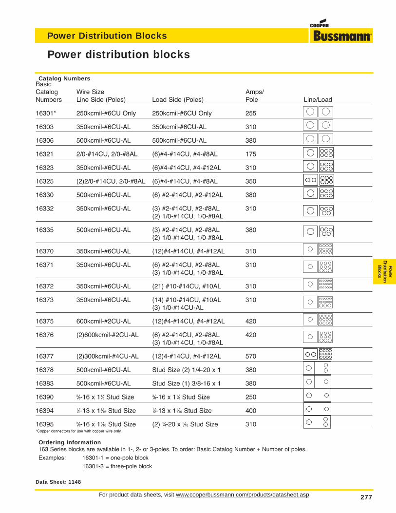
For product data sheets, visit www.cooperbussmann.com/products/datasheet.asp 277
Power distribution blocks
Power Distribution Blocks
Power
DistributionBlocks
Catalog NumbersBasicCatalog Wire Size Amps/Numbers Line Side (Poles) Load Side (Poles) Pole Line/Load
16301* 250kcmil-#6CU Only 250kcmil-#6CU Only 255
16303 350kcmil-#6CU-AL 350kcmil-#6CU-AL 310
16306 500kcmil-#6CU-AL 500kcmil-#6CU-AL 380
16321 2/0-#14CU, 2/0-#8AL (6)#4-#14CU, #4-#8AL 175
16323 350kcmil-#6CU-AL (6)#4-#14CU, #4-#12AL 310
16325 (2)2/0-#14CU, 2/0-#8AL (6)#4-#14CU, #4-#8AL 350
16330 500kcmil-#6CU-AL (6) #2-#14CU, #2-#12AL 380
16332 350kcmil-#6CU-AL (3) #2-#14CU, #2-#8AL 310(2) 1/0-#14CU, 1/0-#8AL
16335 500kcmil-#6CU-AL (3) #2-#14CU, #2-#8AL 380(2) 1/0-#14CU, 1/0-#8AL
16370 350kcmil-#6CU-AL (12)#4-#14CU, #4-#12AL 310
16371 350kcmil-#6CU-AL (6) #2-#14CU, #2-#8AL 310(3) 1/0-#14CU, 1/0-#8AL
16372 350kcmil-#6CU-AL (21) #10-#14CU, #10AL 310
16373 350kcmil-#6CU-AL (14) #10-#14CU, #10AL 310(3) 1/0-#14CU-AL
16375 600kcmil-#2CU-AL (12)#4-#14CU, #4-#12AL 420
16376 (2)600kcmil-#2CU-AL (6) #2-#14CU, #2-#8AL 420(3) 1/0-#14CU, 1/0-#8AL
16377 (2)300kcmil-#4CU-AL (12)4-#14CU, #4-#12AL 570
16378 500kcmil-#6CU-AL Stud Size (2) 1/4-20 x 1 380
16383 500kcmil-#6CU-AL Stud Size (1) 3/8-16 x 1 380
16390 3⁄8-16 x 11⁄8 Stud Size 3⁄8-16 x 11⁄8 Stud Size 250
16394 1⁄2-13 x 11⁄16 Stud Size 1⁄2-13 x 11⁄16 Stud Size 400
16395 3⁄8-16 x 17⁄16 Stud Size (2) 1⁄4-20 x 9⁄16 Stud Size 310*Copper connectors for use with copper wire only.
Ordering Information163 Series blocks are available in 1-, 2- or 3-poles. To order: Basic Catalog Number + Number of poles.
Examples: 16301-1 = one-pole block
16301-3 = three-pole block
Data Sheet: 1148
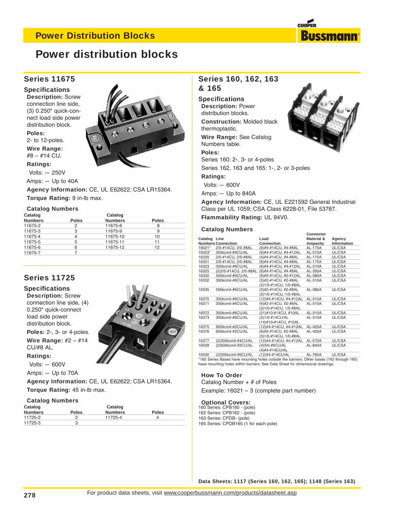
For product data sheets, visit www.cooperbussmann.com/products/datasheet.asp278
Power distribution blocks
Power Distribution Blocks
Series 11725SpecificationsDescription: Screwconnection line side, (4)0.250" quick-connectload side power distribution block.
Poles: 2-, 3- or 4-poles.
Wire Range: #2 – #14CU/#8 AL.
Ratings:Volts: — 600V
Amps: — Up to 70A
Agency Information: CE, UL E62622; CSA LR15364.
Torque Rating: 45 in-lb max.
Catalog NumbersCatalog CatalogNumbers Poles Numbers Poles11725-2 2 11725-4 411725-3 3
Series 11675SpecificationsDescription: Screwconnection line side,(3) 0.250" quick-con-nect load side powerdistribution block.
Poles:2- to 12-poles.
Wire Range:#8 – #14 CU.
Ratings:Volts: — 250V
Amps: — Up to 40A
Agency Information: CE, UL E62622; CSA LR15364.
Torque Rating: 9 in-lb max.
Catalog NumbersCatalog CatalogNumbers Poles Numbers Poles11675-2 2 11675-8 811675-3 3 11675-9 911675-4 4 11675-10 1011675-5 5 11675-11 1111675-6 6 11675-12 1211675-7 7
Data Sheets: 1117 (Series 160, 162, 165); 1148 (Series 163)
Series 160, 162, 163& 165SpecificationsDescription: Power distribution blocks.
Construction: Molded blackthermoplastic.
Wire Range: See CatalogNumbers table.
Poles:Series 160: 2-, 3- or 4-poles
Series 162, 163 and 165: 1-, 2- or 3-poles
Ratings:Volts: — 600V
Amps: — Up to 840A
Agency Information: CE, UL E221592 General IndustrialClass per UL 1059; CSA Class 6228-01, File 53787.
Flammability Rating: UL 94V0.
Catalog NumbersConnector
Catalog Line Load Material & AgencyNumbers Connection Connection Ampacity Information16021* 2/0-#14CU, 2/0-#8AL (6)#4-#14CU, #4-#8AL AL-175A UL/CSA16023* 350kcmil-#6CU/AL (6)#4-#14CU, #4-#12AL AL-310A UL/CSA16220 2/0-#14CU, 2/0-#8AL (4)#4-#14CU, #4-#8AL AL-175A UL/CSA16321 2/0-#14CU, 2/0-#8AL (6)#4-#14CU, #4-#8AL AL-175A UL/CSA16323 350kcmil-#6CU/AL (6)#4-#14CU, #4-#12AL AL-310A UL/CSA16325 (2)2/0-#14CU, 2/0-#8AL (6)#4-#14CU, #4-#8AL AL-350A UL/CSA16330 500kcmil-#6CU/AL (6)#2-#14CU, #2-#12AL AL-380A UL/CSA16332 350kcmil-#6CU/AL (3)#2-#14CU, #2-#8AL AL-310A UL/CSA
(2)1/0-#14CU, 1/0-#8AL16335 500kcmil-#6CU/AL (3)#2-#14CU, #2-#8AL AL-380A UL/CSA
(2)1/0-#14CU, 1/0-#8AL16370 350kcmil-#6CU/AL (12)#4-#14CU, #4-#12AL AL-310A UL/CSA16371 350kcmil-#6CU/AL (6)#2-#14CU, #2-#8AL AL-310A UL/CSA
(3)1/0-#14CU, 1/0-#8AL16372 350kcmil-#6CU/AL (21)#10-#14CU, #10AL AL-310A UL/CSA16373 350kcmil-#6CU/AL (3)1/0-#14CU/AL AL-310A UL/CSA
(14)#10-#14CU, #10AL16375 600kcmil-#2CU/AL (12)#4-#14CU, #4-#12AL AL-420A UL/CSA16376 600kcmil-#2CU/AL (6)#2-#14CU, #2-#8AL AL-420A UL/CSA
(3)1/0-#14CU, 1/0-#8AL16377 (2)300kcmil-#4CU/AL (12)#4-#14CU, #4-#12AL AL-570A UL/CSA16528 (2)600kcmil-#2CU/AL (4)3/0-#6CU/AL AL-840A UL/CSA
(4)#4-#14CU/AL16530 (2)500kcmil-#6CU/AL (12)#4-#14CU/AL AL-760A UL/CSA*160 Series Bases have mounting holes outside the barriers. Other bases (162 through 165)have mounting holes within barriers. See Data Sheet for dimensional drawings.
How To OrderCatalog Number + # of Poles
Example: 16021 – 3 (complete part number)
Optional Covers:160 Series: CPB160 - (pole)162 Series: CPB162 - (pole)163 Series: CPDB- (pole)165 Series: CPDB165 (1 for each pole)
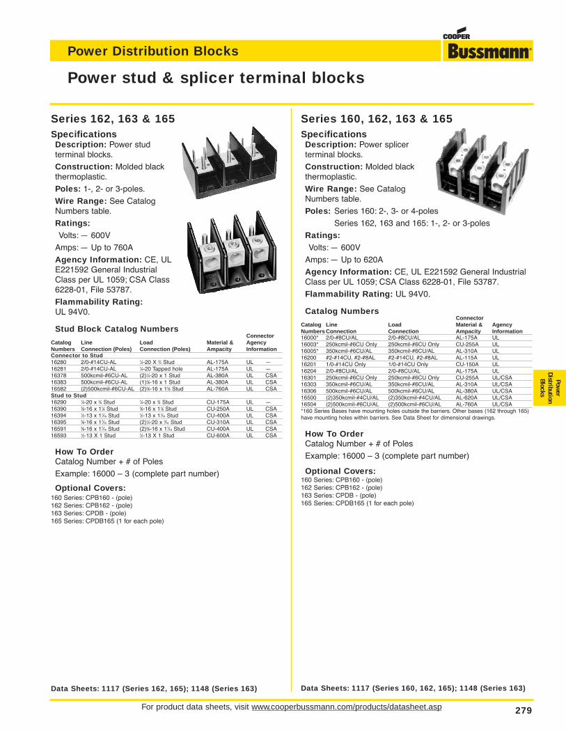
For product data sheets, visit www.cooperbussmann.com/products/datasheet.asp 279
Power Distribution Blocks
Power
DistributionBlocks
Power stud & splicer terminal blocks
Data Sheets: 1117 (Series 162, 165); 1148 (Series 163)
Series 162, 163 & 165SpecificationsDescription: Power stud terminal blocks.
Construction: Molded blackthermoplastic.
Poles: 1-, 2- or 3-poles.
Wire Range: See CatalogNumbers table.
Ratings:Volts: — 600V
Amps: — Up to 760A
Agency Information: CE, ULE221592 General IndustrialClass per UL 1059; CSA Class6228-01, File 53787.
Flammability Rating:UL 94V0.
Stud Block Catalog NumbersConnector
Catalog Line Load Material & AgencyNumbers Connection (Poles) Connection (Poles) Ampacity InformationConnector to Stud16280 2/0-#14CU-AL 1⁄4-20 X 3⁄4 Stud AL-175A UL —16281 2/0-#14CU-AL 1⁄4-20 Tapped hole AL-175A UL —16378 500kcmil-#6CU-AL (2)1⁄4-20 x 1 Stud AL-380A UL CSA16383 500kcmil-#6CU-AL (1)3⁄8-16 x 1 Stud AL-380A UL CSA16582 (2)500kcmil-#6CU-AL (2)3⁄8-16 x 15⁄8 Stud AL-760A UL CSAStud to Stud16290 1⁄4-20 x 3⁄4 Stud 1⁄4-20 x 3⁄4 Stud CU-175A UL —16390 3⁄8-16 x 11⁄8 Stud 3⁄8-16 x 11⁄8 Stud CU-250A UL CSA16394 1⁄2-13 x 11⁄16 Stud 1⁄2-13 x 11⁄16 Stud CU-400A UL CSA16395 3⁄8-16 x 17⁄16 Stud (2)1⁄4-20 x 9⁄16 Stud CU-310A UL CSA16591 3⁄8-16 x 17⁄16 Stud (2)3⁄8-16 x 17⁄16 Stud CU-400A UL CSA16593 1⁄2-13 X 1 Stud 1⁄2-13 X 1 Stud CU-600A UL CSA
How To OrderCatalog Number + # of Poles
Example: 16000 – 3 (complete part number)
Optional Covers:160 Series: CPB160 - (pole)162 Series: CPB162 - (pole)163 Series: CPDB - (pole)165 Series: CPDB165 (1 for each pole)
Series 160, 162, 163 & 165SpecificationsDescription: Power splicer terminal blocks.
Construction: Molded blackthermoplastic.
Wire Range: See CatalogNumbers table.
Poles: Series 160: 2-, 3- or 4-poles
Series 162, 163 and 165: 1-, 2- or 3-poles
Ratings:Volts: — 600V
Amps: — Up to 620A
Agency Information: CE, UL E221592 General IndustrialClass per UL 1059; CSA Class 6228-01, File 53787.
Flammability Rating: UL 94V0.
Catalog NumbersConnector
Catalog Line Load Material & AgencyNumbers Connection Connection Ampacity Information16000* 2/0-#8CU/AL 2/0-#8CU/AL AL-175A UL16003* 250kcmil-#6CU Only 250kcmil-#6CU Only CU-255A UL16005* 350kcmil-#6CU/AL 350kcmil-#6CU/AL AL-310A UL16200 #2-#14CU, #2-#8AL #2-#14CU, #2-#8AL AL-115A UL16201 1/0-#14CU Only 1/0-#14CU Only CU-150A UL16204 2/0-#8CU/AL 2/0-#8CU/AL AL-175A UL16301 250kcmil-#6CU Only 250kcmil-#6CU Only CU-255A UL/CSA16303 350kcmil-#6CU/AL 350kcmil-#6CU/AL AL-310A UL/CSA16306 500kcmil-#6CU/AL 500kcmil-#6CU/AL AL-380A UL/CSA16500 (2)350kcmil-#4CU/AL (2)350kcmil-#4CU/AL AL-620A UL/CSA16504 (2)500kcmil-#6CU/AL (2)500kcmil-#6CU/AL AL-760A UL/CSA*160 Series Bases have mounting holes outside the barriers. Other bases (162 through 165)have mounting holes within barriers. See Data Sheet for dimensional drawings.
How To OrderCatalog Number + # of Poles
Example: 16000 – 3 (complete part number)
Optional Covers:160 Series: CPB160 - (pole)162 Series: CPB162 - (pole)163 Series: CPDB - (pole)165 Series: CPDB165 (1 for each pole)
Data Sheets: 1117 (Series 160, 162, 165); 1148 (Series 163)
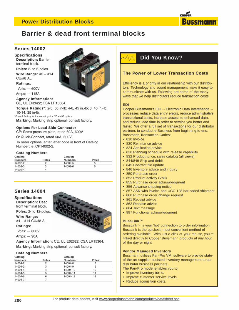
For product data sheets, visit www.cooperbussmann.com/products/datasheet.asp280
Power Distribution Blocks
Series 14004SpecificationsDescription: Deadfront terminal block.
Poles: 2- to 12-poles.
Wire Range:#4 – #14 CU/#8 AL.
Ratings:Volts: — 600V
Amps: — 90A
Agency Information: CE, UL E62622; CSA LR15364.
Marking: Marking strip optional, consult factory.
Catalog NumbersCatalog CatalogNumbers Poles Numbers Poles14004-2 2 14004-8 814004-3 3 14004-9 914004-4 4 14004-10 1014004-5 5 14004-11 1114004-6 6 14004-12 1214004-7 7
Series 14002SpecificationsDescription: Barrierterminal block.
Poles: 2- to 6-poles.
Wire Range: #2 – #14CU/#8 AL.
Ratings:Volts: — 600V
Amps: — 115A
Agency Information:CE, UL E62622; CSA LR15364.
Torque Ratings*: 2-3, 50 in-lb; 4-6, 45 in.-lb; 8, 40 in.-lb;10-14, 35 in-lb.
*Consult factory for torque ratings for CP and Q options.
Marking: Marking strip optional, consult factory.
Options For Load Side ConnectorCP: Sems pressure plate, rated 60A, 600V
Q: Quick-Connect, rated 50A, 600V
To order options, enter letter code in front of CatalogNumber: ie; CP14002-2.
Catalog NumbersCatalog CatalogNumbers Poles Numbers Poles14002-2 2 14002-5 514002-3 3 14002-6 614002-4 4
Barrier & dead front terminal blocks
The Power of Lower Transaction Costs
Efficiency is a priority in our relationship with our distribu-tors. Technology and sound management make it easy tocommunicate with us. Following are some of the manyways that we help distributors reduce transaction costs.
EDICooper Bussmann’s EDI -- Electronic Data Interchange --processes reduce data entry errors, reduce administrativetransactional costs, increase access to enhanced data,and reduce lead time in order to service you better andfaster. We offer a full set of transactions for our distributorpartners to conduct e-Business from beginning to end.Bussmann Transaction Codes:• 810 Invoice• 820 Remittance advice• 824 Application advice• 830 Planning schedule with release capability• 832 Product, price, sales catalog (all views)• 844/849 Ship and debit • 845 Contract file update • 846 Inventory advice and inquiry• 850 Purchase order• 852 Product activity (VMI)• 855 Purchase order acknowledgment• 856 Advance shipping notice• 857 ASN with invoice and UCC-128 bar coded shipment• 860 Purchase order change request• 861 Receipt advice• 862 Release advice• 864 Text message• 997 Functional acknowledgment
BussLink™BussLink™ is your ‘hot’ connection to order information.BussLink is the quickest, most convenient method ofordering available. With just a click of your mouse, you’relinked directly to Cooper Bussmann products at any hourof the day or night.
Vendor Managed InventoryBussmann utilizes Pan-Pro VMI software to provide state-of-the-art supplier assisted inventory management to ourdistributor business partners.The Pan-Pro model enables you to:• Improve inventory turns.• Improve customer service levels.• Reduce acquisition costs.
Did You Know?
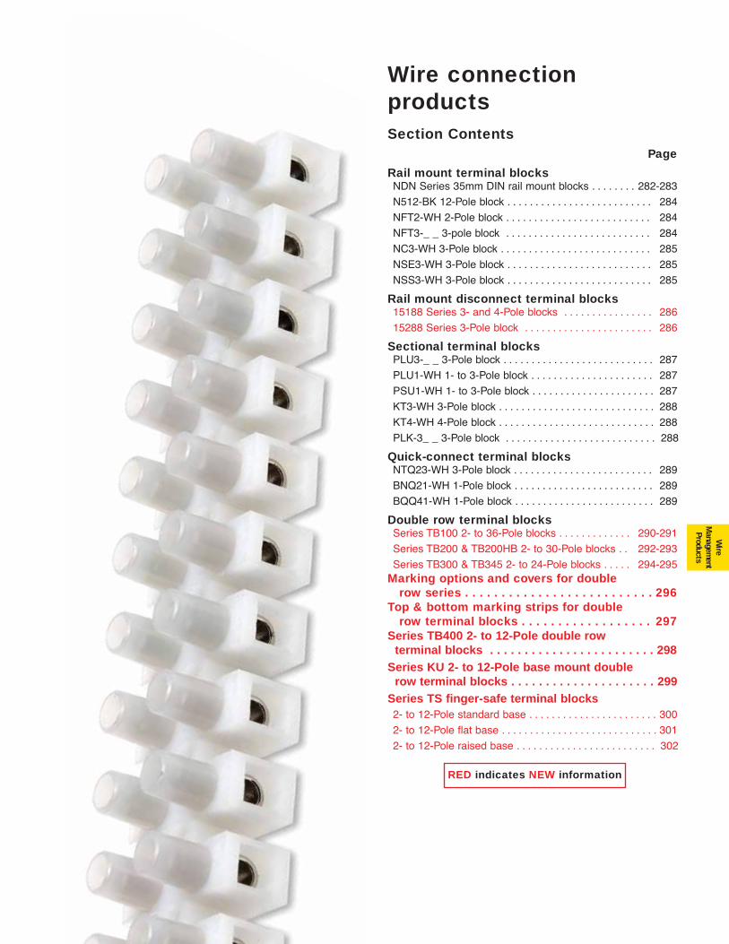
281
Wire
Managem
entProducts
Wire connectionproductsSection Contents
Page
Rail mount terminal blocksNDN Series 35mm DIN rail mount blocks . . . . . . . . 282-283
N512-BK 12-Pole block . . . . . . . . . . . . . . . . . . . . . . . . . . 284
NFT2-WH 2-Pole block . . . . . . . . . . . . . . . . . . . . . . . . . . 284
NFT3-_ _ 3-pole block . . . . . . . . . . . . . . . . . . . . . . . . . . 284
NC3-WH 3-Pole block . . . . . . . . . . . . . . . . . . . . . . . . . . . 285
NSE3-WH 3-Pole block . . . . . . . . . . . . . . . . . . . . . . . . . . 285
NSS3-WH 3-Pole block . . . . . . . . . . . . . . . . . . . . . . . . . . 285
Rail mount disconnect terminal blocks15188 Series 3- and 4-Pole blocks . . . . . . . . . . . . . . . . 286
15288 Series 3-Pole block . . . . . . . . . . . . . . . . . . . . . . . 286
Sectional terminal blocksPLU3-_ _ 3-Pole block . . . . . . . . . . . . . . . . . . . . . . . . . . . 287
PLU1-WH 1- to 3-Pole block . . . . . . . . . . . . . . . . . . . . . . 287
PSU1-WH 1- to 3-Pole block . . . . . . . . . . . . . . . . . . . . . . 287
KT3-WH 3-Pole block . . . . . . . . . . . . . . . . . . . . . . . . . . . . 288
KT4-WH 4-Pole block . . . . . . . . . . . . . . . . . . . . . . . . . . . . 288
PLK-3_ _ 3-Pole block . . . . . . . . . . . . . . . . . . . . . . . . . . . 288
Quick-connect terminal blocksNTQ23-WH 3-Pole block . . . . . . . . . . . . . . . . . . . . . . . . . 289
BNQ21-WH 1-Pole block . . . . . . . . . . . . . . . . . . . . . . . . . 289
BQQ41-WH 1-Pole block . . . . . . . . . . . . . . . . . . . . . . . . . 289
Double row terminal blocksSeries TB100 2- to 36-Pole blocks . . . . . . . . . . . . . 290-291
Series TB200 & TB200HB 2- to 30-Pole blocks . . 292-293
Series TB300 & TB345 2- to 24-Pole blocks . . . . . 294-295Marking options and covers for double
row series . . . . . . . . . . . . . . . . . . . . . . . . . . 296Top & bottom marking strips for double
row terminal blocks . . . . . . . . . . . . . . . . . . 297Series TB400 2- to 12-Pole double row
terminal blocks . . . . . . . . . . . . . . . . . . . . . . . . 298Series KU 2- to 12-Pole base mount double
row terminal blocks . . . . . . . . . . . . . . . . . . . . . 299Series TS finger-safe terminal blocks 2- to 12-Pole standard base . . . . . . . . . . . . . . . . . . . . . . . 300
2- to 12-Pole flat base . . . . . . . . . . . . . . . . . . . . . . . . . . . . 301
2- to 12-Pole raised base . . . . . . . . . . . . . . . . . . . . . . . . . 302
RED indicates NEW information
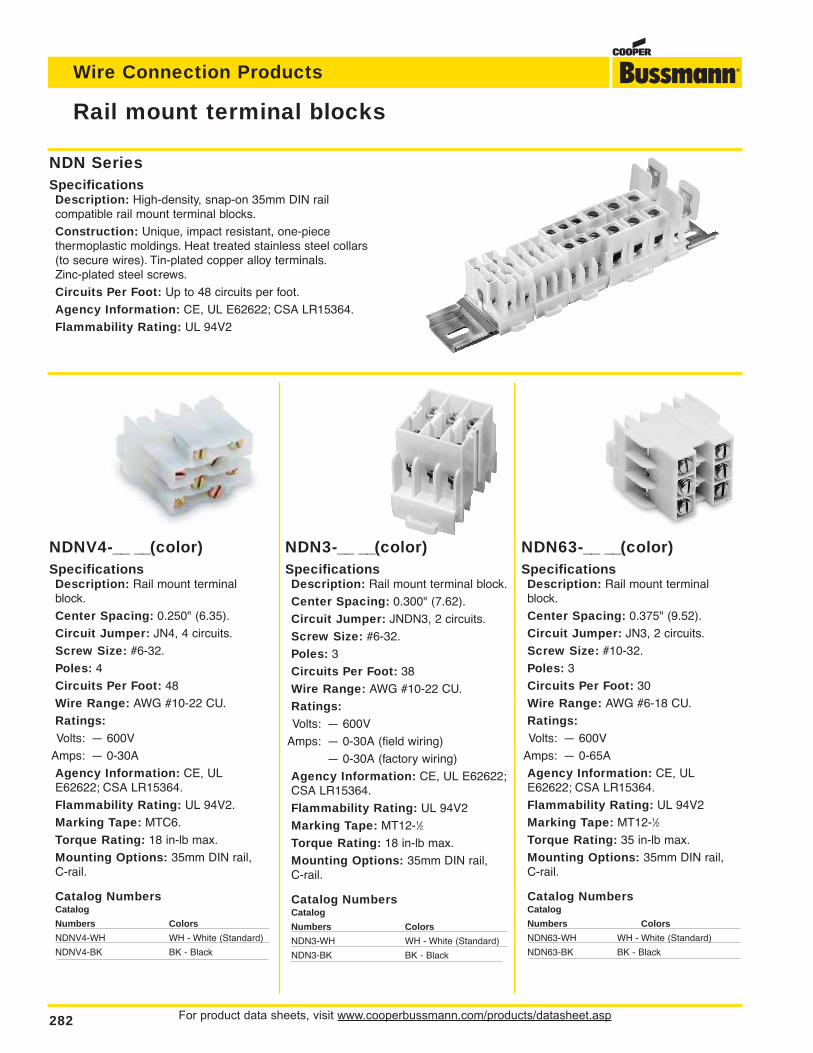
For product data sheets, visit www.cooperbussmann.com/products/datasheet.asp282
Wire Connection Products
Rail mount terminal blocks
NDN SeriesSpecificationsDescription: High-density, snap-on 35mm DIN rail compatible rail mount terminal blocks.
Construction: Unique, impact resistant, one-piece thermoplastic moldings. Heat treated stainless steel collars(to secure wires). Tin-plated copper alloy terminals.Zinc-plated steel screws.
Circuits Per Foot: Up to 48 circuits per foot.
Agency Information: CE, UL E62622; CSA LR15364.
Flammability Rating: UL 94V2
NDNV4-__ __(color)SpecificationsDescription: Rail mount terminalblock.
Center Spacing: 0.250" (6.35).
Circuit Jumper: JN4, 4 circuits.
Screw Size: #6-32.
Poles: 4
Circuits Per Foot: 48
Wire Range: AWG #10-22 CU.
Ratings:Volts: — 600V
Amps: — 0-30A
Agency Information: CE, ULE62622; CSA LR15364.
Flammability Rating: UL 94V2.
Marking Tape: MTC6.
Torque Rating: 18 in-lb max.
Mounting Options: 35mm DIN rail, C-rail.
Catalog NumbersCatalog
Numbers Colors
NDNV4-WH WH - White (Standard)
NDNV4-BK BK - Black
NDN3-__ __(color)SpecificationsDescription: Rail mount terminal block.
Center Spacing: 0.300" (7.62).
Circuit Jumper: JNDN3, 2 circuits.
Screw Size: #6-32.
Poles: 3
Circuits Per Foot: 38
Wire Range: AWG #10-22 CU.
Ratings:Volts: — 600V
Amps: — 0-30A (field wiring)
— 0-30A (factory wiring)
Agency Information: CE, UL E62622;CSA LR15364.
Flammability Rating: UL 94V2
Marking Tape: MT12-1⁄2.
Torque Rating: 18 in-lb max.
Mounting Options: 35mm DIN rail, C-rail.
Catalog NumbersCatalog
Numbers Colors
NDN3-WH WH - White (Standard)
NDN3-BK BK - Black
NDN63-__ __(color)SpecificationsDescription: Rail mount terminalblock.
Center Spacing: 0.375" (9.52).
Circuit Jumper: JN3, 2 circuits.
Screw Size: #10-32.
Poles: 3
Circuits Per Foot: 30
Wire Range: AWG #6-18 CU.
Ratings:Volts: — 600V
Amps: — 0-65A
Agency Information: CE, ULE62622; CSA LR15364.
Flammability Rating: UL 94V2
Marking Tape: MT12-1⁄2.
Torque Rating: 35 in-lb max.
Mounting Options: 35mm DIN rail, C-rail.
Catalog NumbersCatalog
Numbers Colors
NDN63-WH WH - White (Standard)
NDN63-BK BK - Black
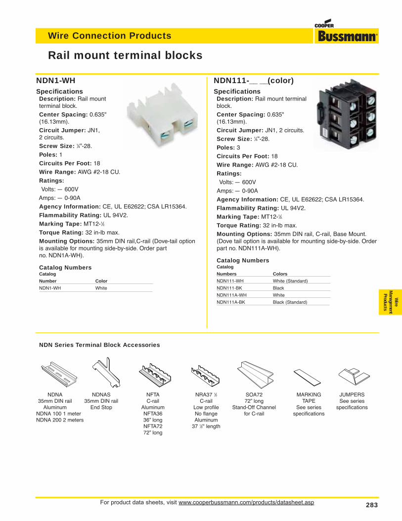
For product data sheets, visit www.cooperbussmann.com/products/datasheet.asp 283
Wire Connection Products
Wire
Managem
entProducts
NDN1-WHSpecificationsDescription: Rail mount terminal block.
Center Spacing: 0.635"(16.13mm).
Circuit Jumper: JN1, 2 circuits.
Screw Size: 1⁄4”-28.
Poles: 1
Circuits Per Foot: 18
Wire Range: AWG #2-18 CU.
Ratings:Volts: — 600V
Amps: — 0-90A
Agency Information: CE, UL E62622; CSA LR15364.
Flammability Rating: UL 94V2.
Marking Tape: MT12-1⁄2.
Torque Rating: 32 in-lb max.
Mounting Options: 35mm DIN rail,C-rail (Dove-tail optionis available for mounting side-by-side. Order part no. NDN1A-WH).
Catalog NumbersCatalog
Number Color
NDN1-WH White
NDN111-__ __(color)SpecificationsDescription: Rail mount terminalblock.
Center Spacing: 0.635"(16.13mm).
Circuit Jumper: JN1, 2 circuits.
Screw Size: 1⁄4”-28.
Poles: 3
Circuits Per Foot: 18
Wire Range: AWG #2-18 CU.
Ratings:Volts: — 600V
Amps: — 0-90A
Agency Information: CE, UL E62622; CSA LR15364.
Flammability Rating: UL 94V2.
Marking Tape: MT12-1⁄2.
Torque Rating: 32 in-lb max.
Mounting Options: 35mm DIN rail, C-rail, Base Mount.(Dove tail option is available for mounting side-by-side. Orderpart no. NDN111A-WH).
Catalog NumbersCatalog
Numbers Colors
NDN111-WH White (Standard)
NDN111-BK Black
NDN111A-WH White
NDN111A-BK Black (Standard)
Rail mount terminal blocks
NDNA NDNAS NFTA NRA37 1⁄2 SOA72 MARKING JUMPERS35mm DIN rail 35mm DIN rail C-rail C-rail 72” long TAPE See series
Aluminum End Stop Aluminum Low profile Stand-Off Channel See series specificationsNDNA 100 1 meter NFTA36 No flange for C-rail specificationsNDNA 200 2 meters 36” long Aluminum
NFTA72 37 1⁄2" length72” long
NDN Series Terminal Block Accessories
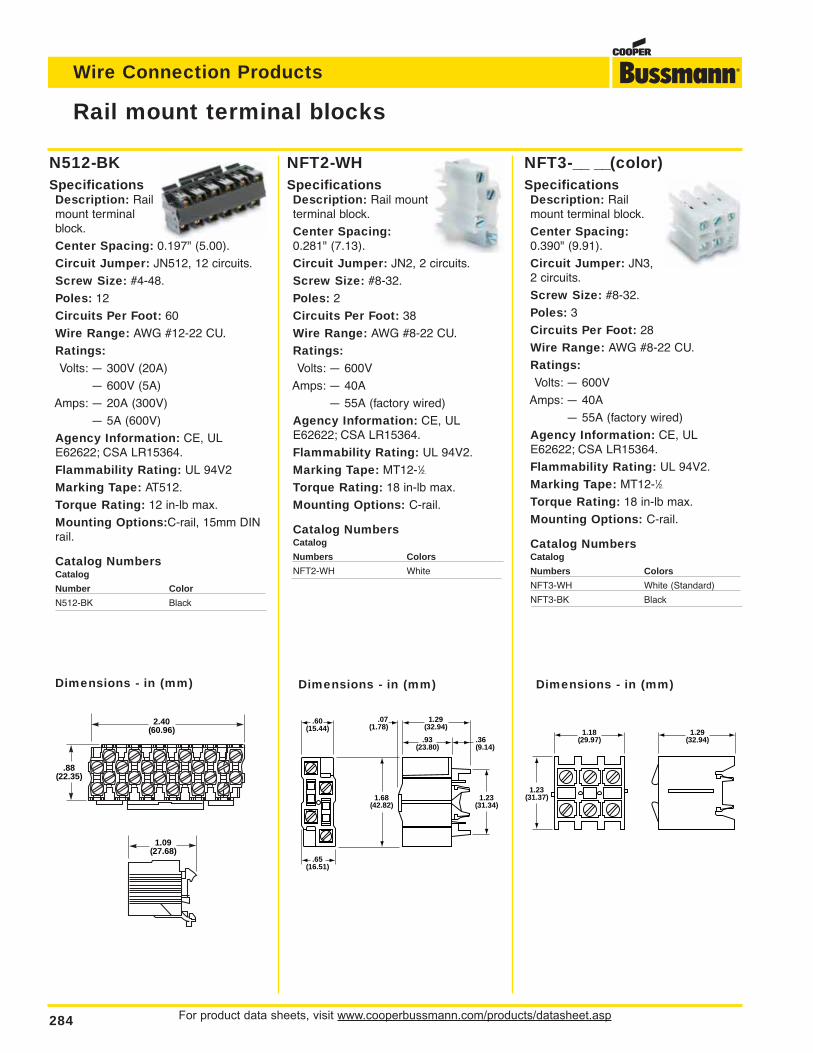
For product data sheets, visit www.cooperbussmann.com/products/datasheet.asp284
Wire Connection Products
NFT3-__ __(color)SpecificationsDescription: Railmount terminal block.
Center Spacing:0.390" (9.91).
Circuit Jumper: JN3,2 circuits.
Screw Size: #8-32.
Poles: 3
Circuits Per Foot: 28
Wire Range: AWG #8-22 CU.
Ratings:Volts: — 600V
Amps: — 40A
— 55A (factory wired)
Agency Information: CE, ULE62622; CSA LR15364.
Flammability Rating: UL 94V2.
Marking Tape: MT12-1⁄2.
Torque Rating: 18 in-lb max.
Mounting Options: C-rail.
Catalog NumbersCatalog
Numbers Colors
NFT3-WH White (Standard)
NFT3-BK Black
NFT2-WHSpecificationsDescription: Rail mountterminal block.
Center Spacing:0.281" (7.13).
Circuit Jumper: JN2, 2 circuits.
Screw Size: #8-32.
Poles: 2
Circuits Per Foot: 38
Wire Range: AWG #8-22 CU.
Ratings:Volts: — 600V
Amps: — 40A
— 55A (factory wired)
Agency Information: CE, ULE62622; CSA LR15364.
Flammability Rating: UL 94V2.
Marking Tape: MT12-1⁄2.
Torque Rating: 18 in-lb max.
Mounting Options: C-rail.
Catalog NumbersCatalog
Numbers Colors
NFT2-WH White
N512-BKSpecificationsDescription: Railmount terminalblock.
Center Spacing: 0.197" (5.00).
Circuit Jumper: JN512, 12 circuits.
Screw Size: #4-48.
Poles: 12
Circuits Per Foot: 60
Wire Range: AWG #12-22 CU.
Ratings:Volts: — 300V (20A)
— 600V (5A)
Amps: — 20A (300V)
— 5A (600V)
Agency Information: CE, ULE62622; CSA LR15364.
Flammability Rating: UL 94V2
Marking Tape: AT512.
Torque Rating: 12 in-lb max.
Mounting Options:C-rail, 15mm DINrail.
Catalog NumbersCatalog
Number Color
N512-BK Black
Rail mount terminal blocks
2.40(60.96)
.88(22.35)
1.09(27.68)
.60(15.44)
.65(16.51)
.07(1.78)
1.29(32.94)
.93(23.80)
1.68(42.82)
1.23(31.34)
.36(9.14)
1.18(29.97)
1.29(32.94)
1.23(31.37)
Dimensions - in (mm) Dimensions - in (mm) Dimensions - in (mm)
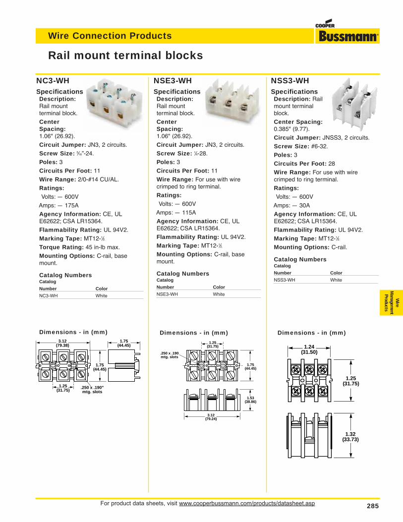
For product data sheets, visit www.cooperbussmann.com/products/datasheet.asp 285
Wire Connection Products
Wire
Managem
entProducts
NSS3-WHSpecificationsDescription: Railmount terminalblock.
Center Spacing:0.385" (9.77).
Circuit Jumper: JNSS3, 2 circuits.
Screw Size: #6-32.
Poles: 3
Circuits Per Foot: 28
Wire Range: For use with wirecrimped to ring terminal.
Ratings:Volts: — 600V
Amps: — 30A
Agency Information: CE, ULE62622; CSA LR15364.
Flammability Rating: UL 94V2.
Marking Tape: MT12-1⁄2.
Mounting Options: C-rail.
Catalog NumbersCatalog
Number Color
NSS3-WH White
NSE3-WHSpecificationsDescription:Rail mount terminal block.
CenterSpacing:1.06" (26.92).
Circuit Jumper: JN3, 2 circuits.
Screw Size: 1⁄4-28.
Poles: 3
Circuits Per Foot: 11
Wire Range: For use with wirecrimped to ring terminal.
Ratings:Volts: — 600V
Amps: — 115A
Agency Information: CE, ULE62622; CSA LR15364.
Flammability Rating: UL 94V2.
Marking Tape: MT12-1⁄2.
Mounting Options: C-rail, basemount.
Catalog NumbersCatalog
Number Color
NSE3-WH White
NC3-WHSpecificationsDescription:Rail mount terminal block.
CenterSpacing:1.06" (26.92).
Circuit Jumper: JN3, 2 circuits.
Screw Size: 5⁄16”-24.
Poles: 3
Circuits Per Foot: 11
Wire Range: 2/0-#14 CU/AL.
Ratings:Volts: — 600V
Amps: — 175A
Agency Information: CE, ULE62622; CSA LR15364.
Flammability Rating: UL 94V2.
Marking Tape: MT12-1⁄2.
Torque Rating: 45 in-lb max.
Mounting Options: C-rail, basemount.
Catalog NumbersCatalog
Number Color
NC3-WH White
Rail mount terminal blocks
3.12(79.38)
.250 x .190"mtg. slots
1.25(31.75)
1.75(44.45)
1.75(44.45)
1.75(44.45)
.250 x .190mtg. slots
1.53(38.86)
3.12(79.24)
1.25(31.75) 1.24
(31.50)
1.25(31.75)
1.32(33.73)
Dimensions - in (mm) Dimensions - in (mm) Dimensions - in (mm)
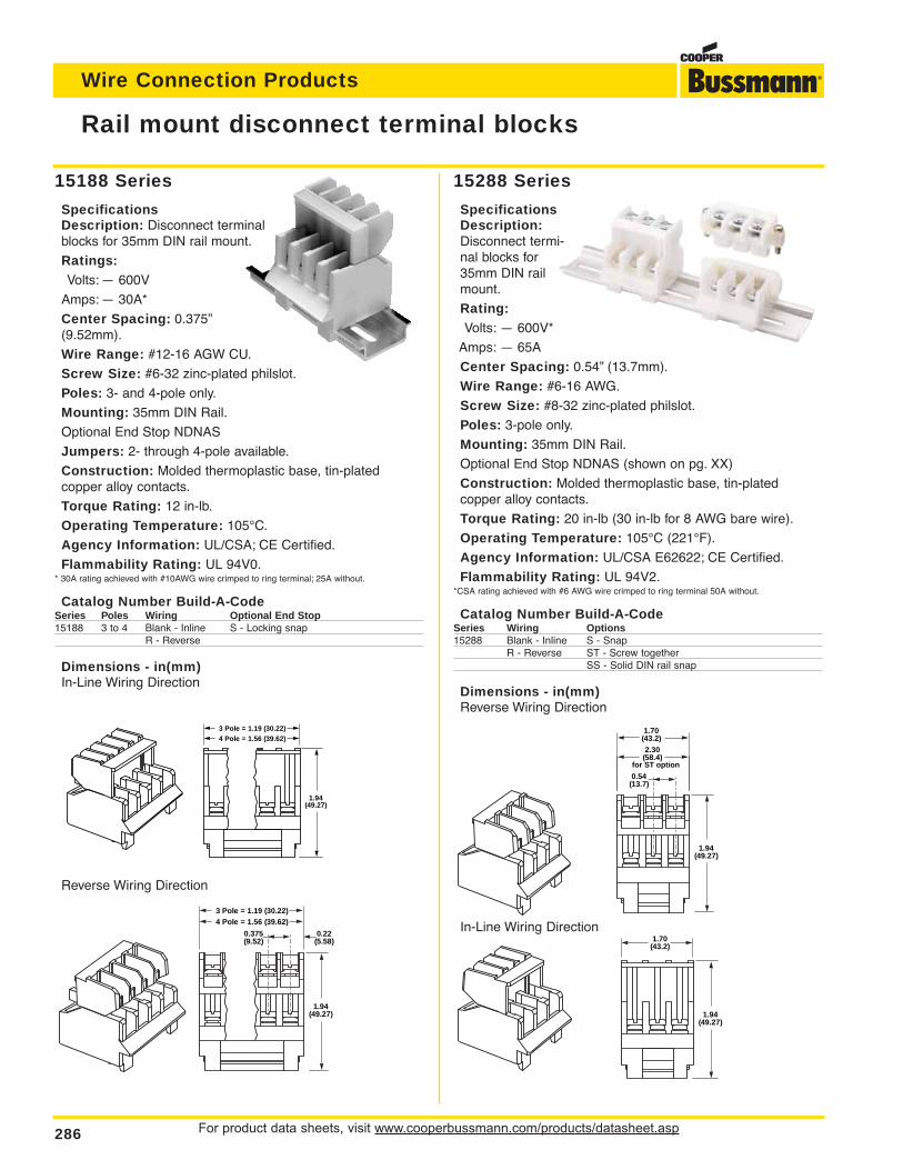
For product data sheets, visit www.cooperbussmann.com/products/datasheet.asp286
Wire Connection Products
15288 Series
SpecificationsDescription:Disconnect termi-nal blocks for35mm DIN railmount.
Rating:Volts: — 600V*
Amps: — 65A
Center Spacing: 0.54” (13.7mm).
Wire Range: #6-16 AWG.
Screw Size: #8-32 zinc-plated philslot.
Poles: 3-pole only.
Mounting: 35mm DIN Rail.
Optional End Stop NDNAS (shown on pg. XX)
Construction: Molded thermoplastic base, tin-plated copper alloy contacts.
Torque Rating: 20 in-lb (30 in-lb for 8 AWG bare wire).
Operating Temperature: 105°C (221°F).
Agency Information: UL/CSA E62622; CE Certified.
Flammability Rating: UL 94V2.*CSA rating achieved with #6 AWG wire crimped to ring terminal 50A without.
Catalog Number Build-A-CodeSeries Wiring Options15288 Blank - Inline S - Snap
R - Reverse ST - Screw togetherSS - Solid DIN rail snap
Dimensions - in(mm)Reverse Wiring Direction
1.94(49.27)
1.70(43.2)
1.94(49.27)
0.54(13.7)
2.30(58.4)
for ST option
1.70(43.2)
In-Line Wiring Direction
Rail mount disconnect terminal blocks
15188 Series
SpecificationsDescription: Disconnect terminalblocks for 35mm DIN rail mount.
Ratings:Volts: — 600V
Amps: — 30A*
Center Spacing: 0.375”(9.52mm).
Wire Range: #12-16 AGW CU.
Screw Size: #6-32 zinc-plated philslot.
Poles: 3- and 4-pole only.
Mounting: 35mm DIN Rail.
Optional End Stop NDNAS
Jumpers: 2- through 4-pole available.
Construction: Molded thermoplastic base, tin-plated copper alloy contacts.
Torque Rating: 12 in-lb.
Operating Temperature: 105°C.
Agency Information: UL/CSA; CE Certified.
Flammability Rating: UL 94V0.* 30A rating achieved with #10AWG wire crimped to ring terminal; 25A without.
Catalog Number Build-A-CodeSeries Poles Wiring Optional End Stop15188 3 to 4 Blank - Inline S - Locking snap
R - Reverse
Dimensions - in(mm)In-Line Wiring Direction
1.94(49.27)
3 Pole = 1.19 (30.22)4 Pole = 1.56 (39.62)
1.94(49.27)
0.375(9.52)
0.22(5.58)
3 Pole = 1.19 (30.22)4 Pole = 1.56 (39.62)
Reverse Wiring Direction
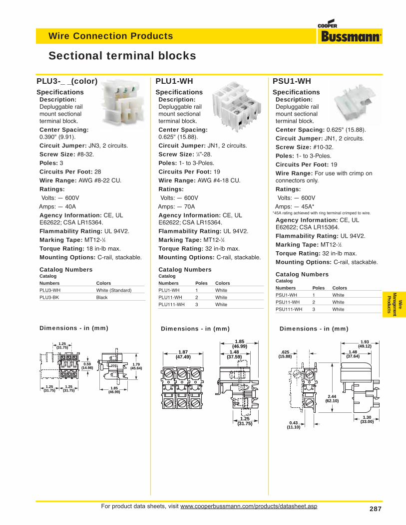
For product data sheets, visit www.cooperbussmann.com/products/datasheet.asp 287
Wire Connection Products
PLU1-WHSpecificationsDescription:Depluggable railmount sectionalterminal block.
Center Spacing:0.625" (15.88).
Circuit Jumper: JN1, 2 circuits.
Screw Size: 1⁄4”-28.
Poles: 1- to 3-Poles.
Circuits Per Foot: 19
Wire Range: AWG #4-18 CU.
Ratings:Volts: — 600V
Amps: — 70A
Agency Information: CE, ULE62622; CSA LR15364.
Flammability Rating: UL 94V2.
Marking Tape: MT12-1⁄2.
Torque Rating: 32 in-lb max.
Mounting Options: C-rail, stackable.
Catalog NumbersCatalog
Numbers Poles Colors
PLU1-WH 1 White
PLU11-WH 2 White
PLU111-WH 3 White
PSU1-WHSpecificationsDescription:Depluggable railmount sectional terminal block.
Center Spacing: 0.625" (15.88).
Circuit Jumper: JN1, 2 circuits.
Screw Size: #10-32.
Poles: 1- to 3-Poles.
Circuits Per Foot: 19
Wire Range: For use with crimp onconnectors only.
Ratings:Volts: — 600V
Amps: — 45A**45A rating achieved with ring terminal crimped to wire.
Agency Information: CE, ULE62622; CSA LR15364.
Flammability Rating: UL 94V2.
Marking Tape: MT12-1⁄2.
Torque Rating: 32 in-lb max.
Mounting Options: C-rail, stackable.
Catalog NumbersCatalog
Numbers Poles Colors
PSU1-WH 1 White
PSU11-WH 2 White
PSU111-WH 3 White
PLU3-_ _(color)SpecificationsDescription:Depluggable railmount sectional terminal block.
Center Spacing:0.390" (9.91).
Circuit Jumper: JN3, 2 circuits.
Screw Size: #8-32.
Poles: 3
Circuits Per Foot: 28
Wire Range: AWG #8-22 CU.
Ratings:Volts: — 600V
Amps: — 40A
Agency Information: CE, ULE62622; CSA LR15364.
Flammability Rating: UL 94V2.
Marking Tape: MT12-1⁄2.
Torque Rating: 18 in-lb max.
Mounting Options: C-rail, stackable.
Catalog NumbersCatalog
Numbers Colors
PLU3-WH White (Standard)
PLU3-BK Black
Sectional terminal blocks
Wire
Managem
entProducts
1.25(31.75)
0.59(14.98)
1.79(45.64)
1.85(46.99)
1.25(31.75)
1.25(31.75)
1.87(47.49)
1.85(46.99)
1.48(37.59)
1.25(31.75)
.625(15.88)
1.93(49.12)
2.44(62.10)
1.48(37.64)
1.30(33.00)0.43
(11.10)
Dimensions - in (mm) Dimensions - in (mm) Dimensions - in (mm)
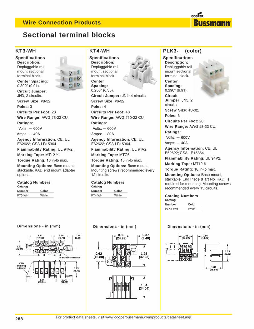
For product data sheets, visit www.cooperbussmann.com/products/datasheet.asp288
Wire Connection Products
KT3-WHSpecificationsDescription:Depluggable railmount sectional terminal block.
Center Spacing:0.390" (9.91).
Circuit Jumper:JN3, 2 circuits.
Screw Size: #8-32.
Poles: 3
Circuits Per Foot: 28
Wire Range: AWG #8-22 CU.
Ratings:Volts: — 600V
Amps: — 40A
Agency Information: CE, ULE62622; CSA LR15364.
Flammability Rating: UL 94V2.
Marking Tape: MT12-1⁄2.
Torque Rating: 18 in-lb max.
Mounting Options: Base mount,stackable. KAD end mount adapteroptional.
Catalog NumbersCatalog
Number Color
KT3-WH White
PLK3-_ _(color)SpecificationsDescription:Depluggable railmount sectionalterminal block.
CenterSpacing:0.390" (9.91).
CircuitJumper: JN3, 2circuits.
Screw Size: #8-32.
Poles: 3
Circuits Per Foot: 28
Wire Range: AWG #8-22 CU.
Ratings:Volts: — 600V
Amps: — 40A
Agency Information: CE, ULE62622; CSA LR15364.
Flammability Rating: UL 94V2.
Marking Tape: MT12-1⁄2.
Torque Rating: 18 in-lb max.
Mounting Options: Base mount,stackable. End Piece (Part No. KAD) isrequired for mounting. Mounting screwsrecommended every 15 circuits.
Catalog NumbersCatalog
Number Color
PLK3-WH White
Sectional terminal blocks
KT4-WHSpecificationsDescription:Depluggable railmount sectionalterminal block.
CenterSpacing:0.250" (6.35).
Circuit Jumper: JN4, 4 circuits.
Screw Size: #6-32.
Poles: 4
Circuits Per Foot: 48
Wire Range: AWG #10-22 CU.
Ratings:Volts: — 600V
Amps: — 30A
Agency Information: CE, ULE62622; CSA LR15364.
Flammability Rating: UL 94V2.
Marking Tape: MTC6.
Torque Rating: 18 in-lb max.
Mounting Options: Base mount.,Mounting screws recommended every12 circuits.
Catalog NumbersCatalog
Number Color
KT4-WH White
#8 screw clearance
KADend mtg.adapter
1.22(31.04)
1.25(31.75)
2.34(59.51)
1.25(31.75)
0.25(6.35)
1.25(31.75)
1.87(47.63)
1.34(34.04)
1.26(32.23)
0.62(15.88)
0.98(24.99)
0.37(9.40)
1.46(37.22)
0.56(14.22)
1.79(45.52)
1.84(46.86)
Dimensions - in (mm) Dimensions - in (mm) Dimensions - in (mm)
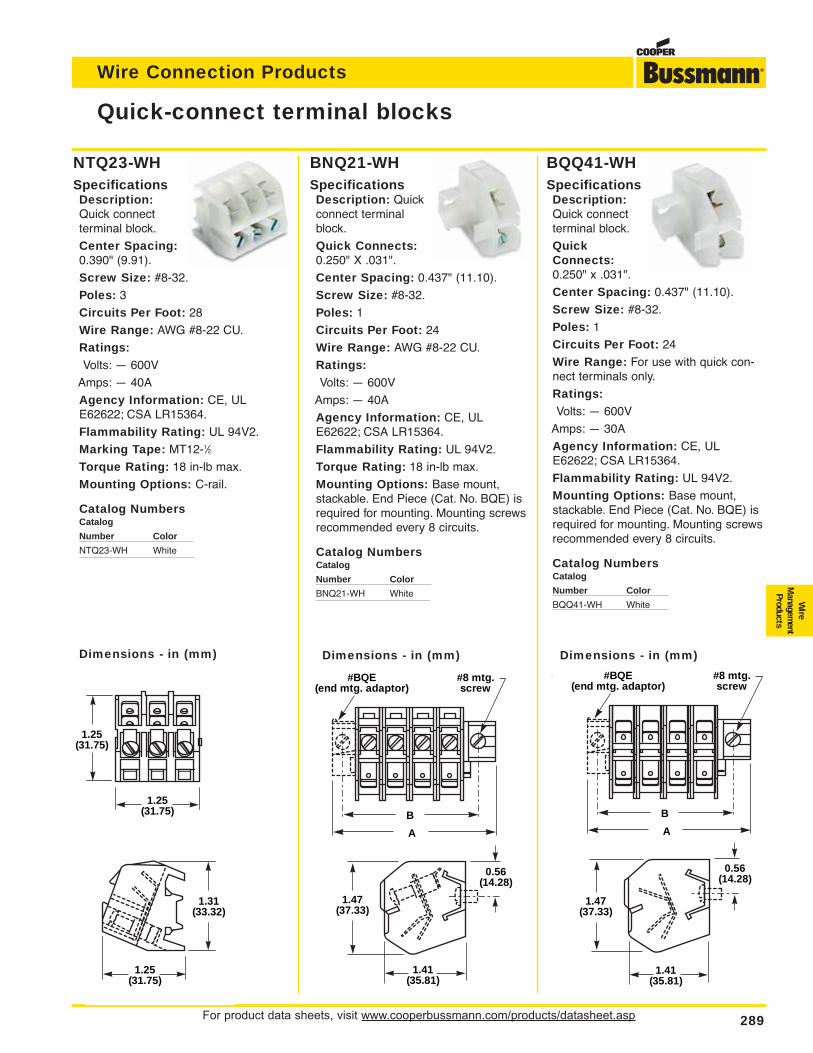
For product data sheets, visit www.cooperbussmann.com/products/datasheet.asp 289
Wire Connection Products
Wire
Managem
entProducts
BNQ21-WHSpecificationsDescription: Quickconnect terminalblock.
Quick Connects:0.250" X .031".
Center Spacing: 0.437" (11.10).
Screw Size: #8-32.
Poles: 1
Circuits Per Foot: 24
Wire Range: AWG #8-22 CU.
Ratings:Volts: — 600V
Amps: — 40A
Agency Information: CE, ULE62622; CSA LR15364.
Flammability Rating: UL 94V2.
Torque Rating: 18 in-lb max.
Mounting Options: Base mount,stackable. End Piece (Cat. No. BQE) isrequired for mounting. Mounting screwsrecommended every 8 circuits.
Catalog NumbersCatalog
Number Color
BNQ21-WH White
NTQ23-WHSpecificationsDescription:Quick connect terminal block.
Center Spacing:0.390" (9.91).
Screw Size: #8-32.
Poles: 3
Circuits Per Foot: 28
Wire Range: AWG #8-22 CU.
Ratings:Volts: — 600V
Amps: — 40A
Agency Information: CE, ULE62622; CSA LR15364.
Flammability Rating: UL 94V2.
Marking Tape: MT12-1⁄2.
Torque Rating: 18 in-lb max.
Mounting Options: C-rail.
Catalog NumbersCatalog
Number Color
NTQ23-WH White
Quick-connect terminal blocks
1.25(31.75)
1.25(31.75)
#8 mtg.screw
#BQE(end mtg. adaptor)
B
A
1.41(35.81)
0.56(14.28)
1.47(37.33)
(
B
A
#8 mtg.screw
#BQE(end mtg. adaptor)
1.41(35.81)
0.56(14.28)
1.47(37.33)
Dimensions - in (mm)
1.25(31.75)
1.31(33.32)
Dimensions - in (mm) Dimensions - in (mm)
BQQ41-WHSpecificationsDescription:Quick connectterminal block.
QuickConnects:0.250" x .031".
Center Spacing: 0.437" (11.10).
Screw Size: #8-32.
Poles: 1
Circuits Per Foot: 24
Wire Range: For use with quick con-nect terminals only.
Ratings:Volts: — 600V
Amps: — 30A
Agency Information: CE, ULE62622; CSA LR15364.
Flammability Rating: UL 94V2.
Mounting Options: Base mount,stackable. End Piece (Cat. No. BQE) isrequired for mounting. Mounting screwsrecommended every 8 circuits.
Catalog NumbersCatalog
Number Color
BQQ41-WH White
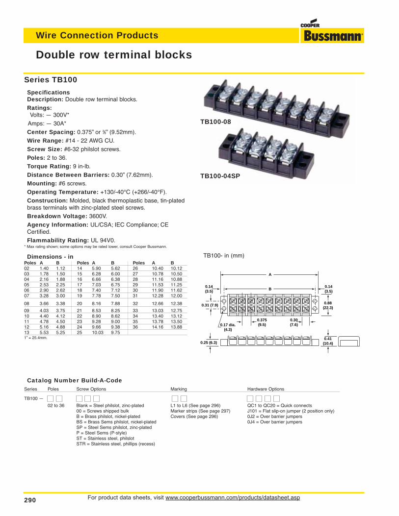
Catalog Number Build-A-CodeSeries Poles Screw Options Marking Hardware Options
TB100 —
02 to 36 Blank = Steel philslot, zinc-plated L1 to L6 (See page 296) QC1 to QC20 = Quick connects00 = Screws shipped bulk Marker strips (See page 297) J101 = Flat slip-on jumper (2 position only)B = Brass philslot, nickel-plated Covers (See page 296) 0J2 = Over barrier jumpersBS = Brass Sems philslot, nickel-plated 0J4 = Over barrier jumpersSP = Steel Sems philslot, zinc-platedP = Steel Sems (P-style)ST = Stainless steel, philslotSTR = Stainless steel, phillips (recess)
For product data sheets, visit www.cooperbussmann.com/products/datasheet.asp290
Wire Connection Products
Double row terminal blocks
0.14(3.5)
0.375(9.5)
0.30(7.6)0.17 dia.
(4.3)
0.14(3.5)
0.88(22.3)
0.41(10.4)
0.31 (7.9)
A
B
0.25 (6.3)
TB100- in (mm)
Series TB100
SpecificationsDescription: Double row terminal blocks.
Ratings:Volts: — 300V*
Amps: — 30A*
Center Spacing: 0.375” or 3⁄8” (9.52mm).
Wire Range: #14 - 22 AWG CU.
Screw Size: #6-32 philslot screws.
Poles: 2 to 36.
Torque Rating: 9 in-lb.
Distance Between Barriers: 0.30” (7.62mm).
Mounting: #6 screws.
Operating Temperature: +130/-40°C (+266/-40°F).
Construction: Molded, black thermoplastic base, tin-platedbrass terminals with zinc-plated steel screws.
Breakdown Voltage: 3600V.
Agency Information: UL/CSA; IEC Compliance; CECertified.
Flammability Rating: UL 94V0.* Max rating shown; some options may be rated lower, consult Cooper Bussmann.
Dimensions - inPoles A B Poles A B Poles A B02 1.40 1.12 14 5.90 5.62 26 10.40 10.1203 1.78 1.50 15 6.28 6.00 27 10.78 10.5004 2.16 1.88 16 6.66 6.38 28 11.16 10.8805 2.53 2.25 17 7.03 6.75 29 11.53 11.2506 2.90 2.62 18 7.40 7.12 30 11.90 11.6207 3.28 3.00 19 7.78 7.50 31 12.28 12.00
08 3.66 3.38 20 8.16 7.88 32 12.66 12.38
09 4.03 3.75 21 8.53 8.25 33 13.03 12.7510 4.40 4.12 22 8.90 8.62 34 13.40 13.1211 4.78 4.50 23 9.28 9.00 35 13.78 13.5012 5.16 4.88 24 9.66 9.38 36 14.16 13.8813 5.53 5.25 25 10.03 9.751” = 25.4mm.
TB100-08
TB100-04SP
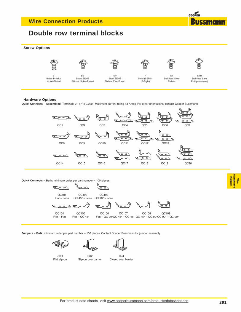
For product data sheets, visit www.cooperbussmann.com/products/datasheet.asp 291
Wire Connection Products
Wire
Managem
entProducts
Double row terminal blocks
B BS SP P ST STRBrass Philslot Brass SEMS Steel SEMS Steel (SEMS) Stainless Steel Stainless SteelNickel-Plated Philslot Nickel-Plated Philslot Zinc-Plated (P-Style) Philslot Phillips (recess)
Hardware OptionsQuick Connects – Assembled: Terminals 0.187” x 0.020”. Maximum current rating 13 Amps. For other orientations, contact Cooper Bussmann.
QC1 QC2 QC3 QC4 QC5 QC6 QC7
QC8 QC9 QC10 QC11 QC12 QC13
QC14 QC15 QC16 QC17 QC18 QC19 QC20
Quick Connects – Bulk: minimum order per part number – 100 pieces.
QC101 QC102 QC103Flat – none QC 45° – none QC 90° – none
QC104 QC105 QC106 QC107 QC108 QC109Flat – Flat Flat – QC 45° Flat – QC 90°QC 45° – QC 45° QC 45° – QC 90°QC 90° – QC 90°
Jumpers – Bulk: minimum order per part number – 100 pieces. Contact Cooper Bussmann for jumper assembly.
J101 OJ2 OJ4Flat slip-on Slip-on over barrier Closed over barrier
Screw Options
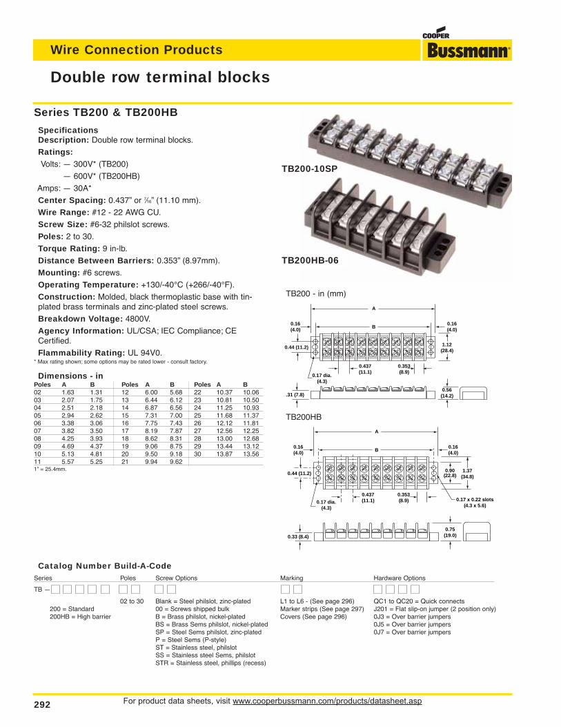
0.16(4.0)
0.437(11.1)
0.353(8.9)
0.17 dia.(4.3)
0.16(4.0)
1.12(28.4)
0.56(14.2)
0.44 (11.2)
A
B
.31 (7.8)
For product data sheets, visit www.cooperbussmann.com/products/datasheet.asp292
Wire Connection Products
Double row terminal blocks
Series TB200 & TB200HB
SpecificationsDescription: Double row terminal blocks.
Ratings:Volts: — 300V* (TB200)
— 600V* (TB200HB)
Amps: — 30A*
Center Spacing: 0.437” or 7⁄16” (11.10 mm).
Wire Range: #12 - 22 AWG CU.
Screw Size: #6-32 philslot screws.
Poles: 2 to 30.
Torque Rating: 9 in-lb.
Distance Between Barriers: 0.353” (8.97mm).
Mounting: #6 screws.
Operating Temperature: +130/-40°C (+266/-40°F).
Construction: Molded, black thermoplastic base with tin-plated brass terminals and zinc-plated steel screws.
Breakdown Voltage: 4800V.
Agency Information: UL/CSA; IEC Compliance; CECertified.
Flammability Rating: UL 94V0.* Max rating shown; some options may be rated lower - consult factory.
Dimensions - inPoles A B Poles A B Poles A B02 1.63 1.31 12 6.00 5.68 22 10.37 10.0603 2.07 1.75 13 6.44 6.12 23 10.81 10.5004 2.51 2.18 14 6.87 6.56 24 11.25 10.9305 2.94 2.62 15 7.31 7.00 25 11.68 11.3706 3.38 3.06 16 7.75 7.43 26 12.12 11.8107 3.82 3.50 17 8.19 7.87 27 12.56 12.2508 4.25 3.93 18 8.62 8.31 28 13.00 12.6809 4.69 4.37 19 9.06 8.75 29 13.44 13.1210 5.13 4.81 20 9.50 9.18 30 13.87 13.5611 5.57 5.25 21 9.94 9.621” = 25.4mm.
TB200 - in (mm)
TB200HB
TB200-10SP
TB200HB-06
0.16(4.0)
0.437(11.1)
0.353(8.9)0.17 dia.
(4.3)
0.17 x 0.22 slots(4.3 x 5.6)
0.16(4.0)
1.37(34.8)
0.90(22.8)
0.75(19.0)
0.44 (11.2)
A
B
0.33 (8.4)
Catalog Number Build-A-CodeSeries Poles Screw Options Marking Hardware Options
TB —
02 to 30 Blank = Steel philslot, zinc-plated L1 to L6 - (See page 296) QC1 to QC20 = Quick connects200 = Standard 00 = Screws shipped bulk Marker strips (See page 297) J201 = Flat slip-on jumper (2 position only)200HB = High barrier B = Brass philslot, nickel-plated Covers (See page 296) 0J3 = Over barrier jumpers
BS = Brass Sems philslot, nickel-plated 0J5 = Over barrier jumpersSP = Steel Sems philslot, zinc-plated 0J7 = Over barrier jumpersP = Steel Sems (P-style)ST = Stainless steel, philslotSS = Stainless steel Sems, philslotSTR = Stainless steel, phillips (recess)
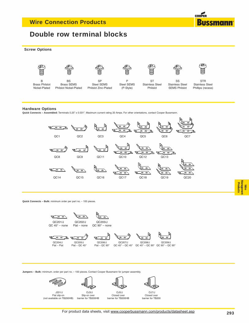
For product data sheets, visit www.cooperbussmann.com/products/datasheet.asp 293
Wire Connection Products
Wire
Managem
entProducts
Double row terminal blocks
Screw Options
B BS SP P ST SS STRBrass Philslot Brass SEMS Steel SEMS Steel SEMS Stainless Steel Stainless Steel Stainless SteelNickel-Plated Philslot Nickel-Plated Philslot Zinc-Plated (P-Style) Philslot SEMS Philslot Phillips (recess)
Hardware OptionsQuick Connects – Assembled: Terminals 0.25” x 0.031”. Maximum current rating 20 Amps. For other orientations, contact Cooper Bussmann.
QC1 QC2 QC3 QC4 QC5 QC6 QC7
QC8 QC9 QC11 QC10 QC12 QC13
QC14 QC15 QC16 QC17 QC18 QC19 QC20
Quick Connects – Bulk: minimum order per part no. – 100 pieces.
QC201/J QC202/J QC203/JQC 45° – none Flat – none QC 90° – none
QC204/J QC205/J QC206/J QC207/J QC208/J QC209/JFlat – Flat Flat – QC 45° Flat – QC 90° QC 45° – QC 45° QC 45° – QC 90° QC 90° – QC 90°
Jumpers – Bulk: minimum. order per part no. – 100 pieces. Contact Cooper Bussmann for jumper assembly.
J201/J OJ3/J OJ5/J OJ7/JFlat slip-on Slip-on over Closed over Closed over
(not available on TB200HB) barrier for TB200HB barrier for TB200HB barrier for TB200
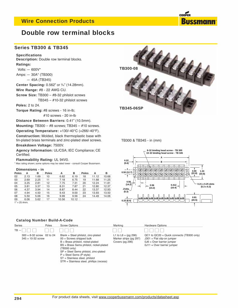
Catalog Number Build-A-CodeSeries Poles Screw Options Marking Hardware Options
TB —
300 = 8-32 screw 02 to 24 Blank = Steel philslot, zinc-plated L1 to L6 = (pg 296) QC1 to QC20 = Quick connects (TB300 only)345 = 10-32 screw 00 = Screws shipped bulk Marker strips (pg 297) J301 = Flat slip-on jumper
B = Brass philslot, nickel-plated Covers (pg 296) 0J6 = Over barrier jumperBS = Brass Sems philslot, nickel-plated 0J11 = Over barrier jumper(TB300 only)SP = Steel Sems philslot, zinc-platedP = Steel Sems (P-style)ST = Stainless steel, philslotSTR = Stainless steel, phillips (recess)
For product data sheets, visit www.cooperbussmann.com/products/datasheet.asp294
Wire Connection Products
Double row terminal blocks
0.22(5.6)
0.56(14.2) 0.56
(14.2)0.412(10.4).21dia.
(5.3)
0.21 x 0.25 slots(5.3 x 6.3)
1.33(33.8)
0.90(22.8)
0.81(20.5)
0.50 (12.7)
A
B
8-32 binding head screw - TB 30010-32 binding head screw - TB 345
0.33 (8.4)
TB300 & TB345 - in (mm)
Series TB300 & TB345
SpecificationsDescription: Double row terminal blocks.
Ratings:Volts: — 600V*
Amps: — 30A* (TB300)
— 45A (TB345)
Center Spacing: 0.562” or 9⁄16” (14.28mm).
Wire Range: #8 - 22 AWG CU.
Screw Size: TB300 – #8-32 philslot screws
TB345 – #10-32 philslot screws
Poles: 2 to 24.
Torque Rating: #8 screws - 16 in-lb;
#10 screws - 20 in-lb
Distance Between Barriers: 0.41” (10.5mm).
Mounting: TB300 – #8 screws; TB345 – #10 screws.
Operating Temperature: +130/-40°C (+266/-40°F).
Construction: Molded, black thermoplastic base with tin-plated brass terminals and zinc-plated steel screws.
Breakdown Voltage: 7500V.
Agency Information: UL/CSA; IEC Compliance; CECertified.
Flammability Rating: UL 94V0.* Max rating shown; some options may be rated lower - consult Cooper Bussmann.
Dimensions - inPoles A B Poles A B Poles A B02 2.13 1.69 10 6.62 6.19 18 11.12 10.6803 2.69 2.25 11 7.18 6.75 19 11.68 11.2504 3.25 2.81 12 7.75 7.31 20 12.24 11.8105 3.81 3.37 13 8.31 7.87 21 12.80 12.3706 4.37 3.94 14 8.87 8.44 22 13.37 12.9307 4.94 4.50 15 9.43 9.00 23 13.93 13.5008 5.50 5.06 16 9.99 9.56 24 14.49 14.0609 6.06 5.62 17 10.56 10.121” = 25.4mm.
TB300-08
TB345-06SP
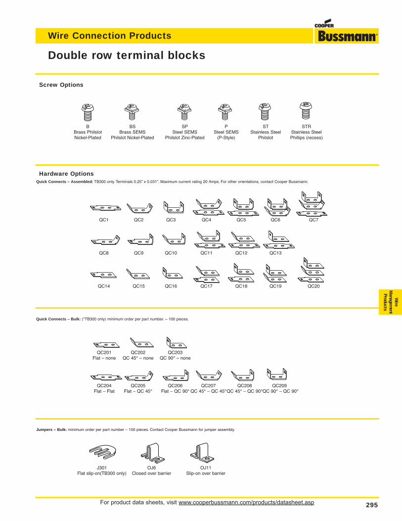
For product data sheets, visit www.cooperbussmann.com/products/datasheet.asp 295
Wire Connection Products
Wire
Managem
entProducts
Double row terminal blocks
Screw Options
B BS SP P ST STRBrass Philslot Brass SEMS Steel SEMS Steel SEMS Stainless Steel Stainless SteelNickel-Plated Philslot Nickel-Plated Philslot Zinc-Plated (P-Style) Philslot Phillips (recess)
Hardware OptionsQuick Connects – Assembled: TB300 only. Terminals 0.25” x 0.031”. Maximum current rating 20 Amps. For other orientations, contact Cooper Bussmann.
QC1 QC2 QC3 QC4 QC5 QC6 QC7
QC8 QC9 QC10 QC11 QC12 QC13
QC14 QC15 QC16 QC17 QC18 QC19 QC20
Quick Connects – Bulk: (*TB300 only) minimum order per part number. – 100 pieces.
QC201 QC202 QC203Flat – none QC 45° – none QC 90° – none
QC204 QC205 QC206 QC207 QC208 QC209Flat – Flat Flat – QC 45° Flat – QC 90° QC 45° – QC 45°QC 45° – QC 90°QC 90° – QC 90°
Jumpers – Bulk: minimum order per part number – 100 pieces. Contact Cooper Bussmann for jumper assembly.
J301 OJ6 OJ11Flat slip-on(TB300 only) Closed over barrier Slip-on over barrier
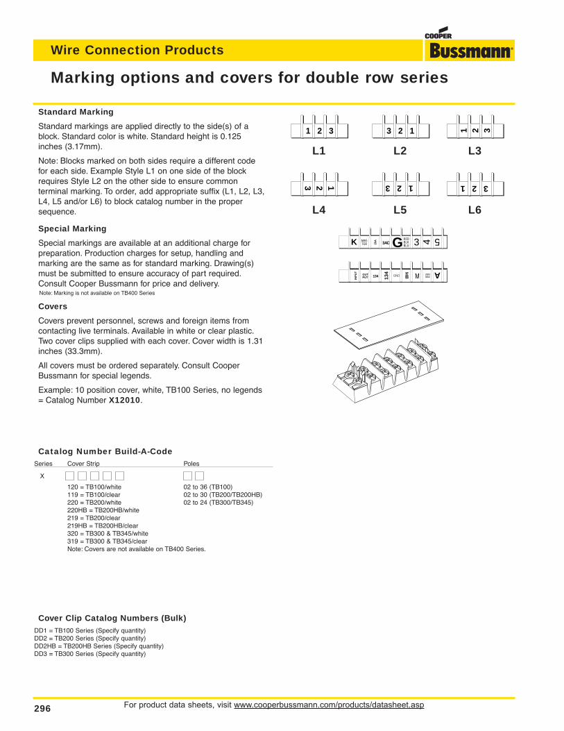
Catalog Number Build-A-CodeSeries Cover Strip Poles
X
120 = TB100/white 02 to 36 (TB100)119 = TB100/clear 02 to 30 (TB200/TB200HB)220 = TB200/white 02 to 24 (TB300/TB345)220HB = TB200HB/white219 = TB200/clear219HB = TB200HB/clear320 = TB300 & TB345/white319 = TB300 & TB345/clearNote: Covers are not available on TB400 Series.
For product data sheets, visit www.cooperbussmann.com/products/datasheet.asp296
Wire Connection Products
Marking options and covers for double row series
Cover Clip Catalog Numbers (Bulk)DD1 = TB100 Series (Specify quantity)DD2 = TB200 Series (Specify quantity)DD2HB = TB200HB Series (Specify quantity)DD3 = TB300 Series (Specify quantity)
Standard Marking
Standard markings are applied directly to the side(s) of ablock. Standard color is white. Standard height is 0.125 inches (3.17mm).
Note: Blocks marked on both sides require a different codefor each side. Example Style L1 on one side of the blockrequires Style L2 on the other side to ensure common terminal marking. To order, add appropriate suffix (L1, L2, L3,L4, L5 and/or L6) to block catalog number in the propersequence.
Special Marking
Special markings are available at an additional charge forpreparation. Production charges for setup, handling andmarking are the same as for standard marking. Drawing(s)must be submitted to ensure accuracy of part required.Consult Cooper Bussmann for price and delivery.Note: Marking is not available on TB400 Series
Covers
Covers prevent personnel, screws and foreign items fromcontacting live terminals. Available in white or clear plastic.Two cover clips supplied with each cover. Cover width is 1.31inches (33.3mm).
All covers must be ordered separately. Consult CooperBussmann for special legends.
Example: 10 position cover, white, TB100 Series, no legends= Catalog Number X12010.
1 2 3 3 2 1
3 2 11 2 3
1 2 3
123
L1 L2 L3
L4 L5 L6
K 3 4 5G3ACMASTER
300VMAX
20A
INP
UT
OUTPUT 134 13
4
GND
MB
REDBLKBLU
A
M
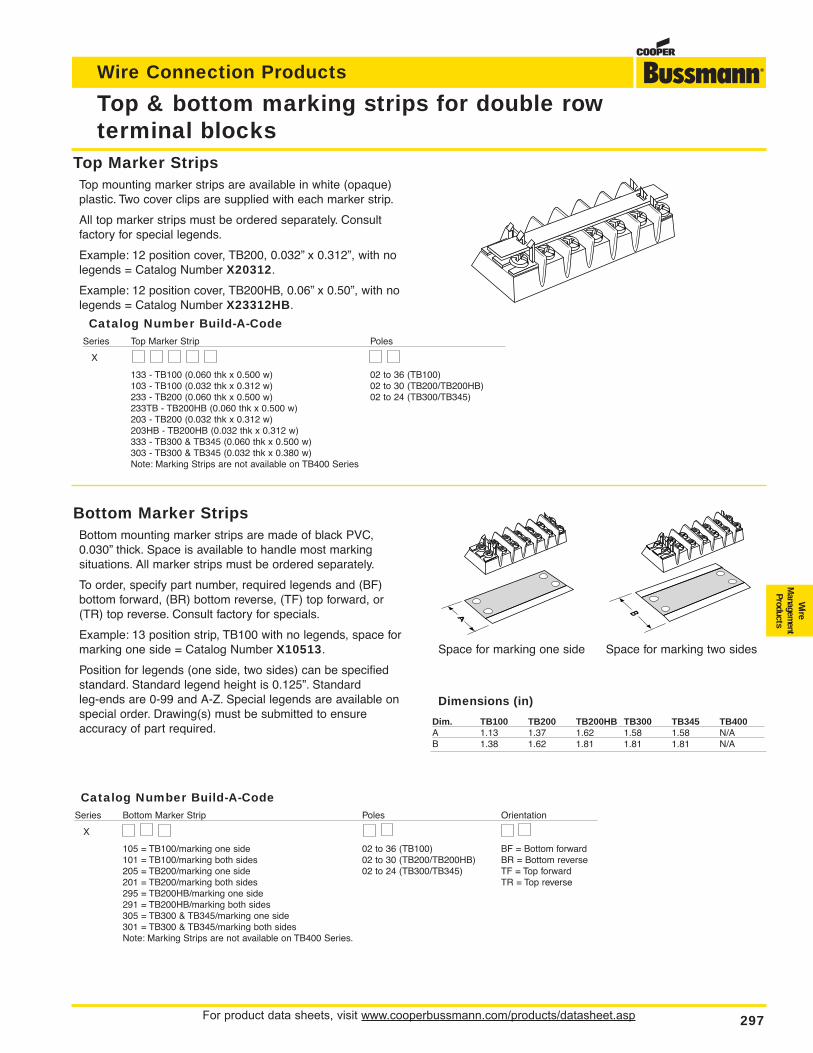
For product data sheets, visit www.cooperbussmann.com/products/datasheet.asp 297
Wire Connection Products
Top & bottom marking strips for double row terminal blocks
Top Marker StripsTop mounting marker strips are available in white (opaque)plastic. Two cover clips are supplied with each marker strip.
All top marker strips must be ordered separately. Consult factory for special legends.
Example: 12 position cover, TB200, 0.032” x 0.312”, with nolegends = Catalog Number X20312.
Example: 12 position cover, TB200HB, 0.06” x 0.50”, with nolegends = Catalog Number X23312HB.
Bottom Marker StripsBottom mounting marker strips are made of black PVC,0.030” thick. Space is available to handle most marking situations. All marker strips must be ordered separately.
To order, specify part number, required legends and (BF)bottom forward, (BR) bottom reverse, (TF) top forward, or(TR) top reverse. Consult factory for specials.
Example: 13 position strip, TB100 with no legends, space formarking one side = Catalog Number X10513.
Position for legends (one side, two sides) can be specifiedstandard. Standard legend height is 0.125”. Standard leg-ends are 0-99 and A-Z. Special legends are available onspecial order. Drawing(s) must be submitted to ensure accuracy of part required.
Dimensions (in)
Dim. TB100 TB200 TB200HB TB300 TB345 TB400A 1.13 1.37 1.62 1.58 1.58 N/AB 1.38 1.62 1.81 1.81 1.81 N/A
Wire
Managem
entProducts
Space for marking one side Space for marking two sides
Catalog Number Build-A-CodeSeries Top Marker Strip Poles
X
133 - TB100 (0.060 thk x 0.500 w) 02 to 36 (TB100)103 - TB100 (0.032 thk x 0.312 w) 02 to 30 (TB200/TB200HB)233 - TB200 (0.060 thk x 0.500 w) 02 to 24 (TB300/TB345)233TB - TB200HB (0.060 thk x 0.500 w)203 - TB200 (0.032 thk x 0.312 w)203HB - TB200HB (0.032 thk x 0.312 w)333 - TB300 & TB345 (0.060 thk x 0.500 w)303 - TB300 & TB345 (0.032 thk x 0.380 w)Note: Marking Strips are not available on TB400 Series
Catalog Number Build-A-CodeSeries Bottom Marker Strip Poles Orientation
X
105 = TB100/marking one side 02 to 36 (TB100) BF = Bottom forward101 = TB100/marking both sides 02 to 30 (TB200/TB200HB) BR = Bottom reverse205 = TB200/marking one side 02 to 24 (TB300/TB345) TF = Top forward201 = TB200/marking both sides TR = Top reverse295 = TB200HB/marking one side291 = TB200HB/marking both sides305 = TB300 & TB345/marking one side301 = TB300 & TB345/marking both sidesNote: Marking Strips are not available on TB400 Series.
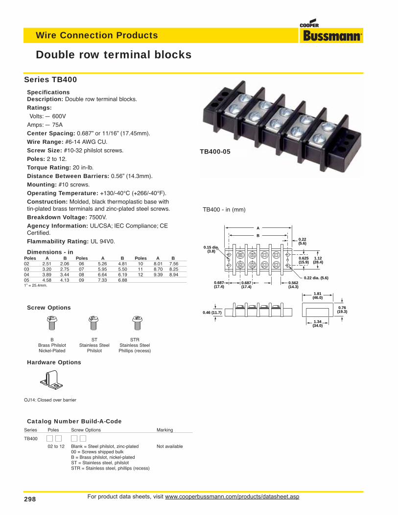
For product data sheets, visit www.cooperbussmann.com/products/datasheet.asp298
Wire Connection Products
Screw Options
B ST STRBrass Philslot Stainless Steel Stainless SteelNickel-Plated Philslot Phillips (recess)
Hardware Options
OJ14: Closed over barrier
Double row terminal blocks
Series TB400
SpecificationsDescription: Double row terminal blocks.
Ratings:Volts: — 600V
Amps: — 75A
Center Spacing: 0.687” or 11/16” (17.45mm).
Wire Range: #6-14 AWG CU.
Screw Size: #10-32 philslot screws.
Poles: 2 to 12.
Torque Rating: 20 in-lb.
Distance Between Barriers: 0.56” (14.3mm).
Mounting: #10 screws.
Operating Temperature: +130/-40°C (+266/-40°F).
Construction: Molded, black thermoplastic base with tin-plated brass terminals and zinc-plated steel screws.
Breakdown Voltage: 7500V.
Agency Information: UL/CSA; IEC Compliance; CECertified.
Flammability Rating: UL 94V0.
Dimensions - inPoles A B Poles A B Poles A B02 2.51 2.06 06 5.26 4.81 10 8.01 7.5603 3.20 2.75 07 5.95 5.50 11 8.70 8.2504 3.89 3.44 08 6.64 6.19 12 9.39 8.9405 4.58 4.13 09 7.33 6.881” = 25.4mm.
0.15 dia.(3.8)
0.687(17.4)
0.22(5.6)
A
B
0.625(15.9)
1.12(28.4)
0.687(17.4)
0.562(14.3)
1.81(46.0)
0.76(19.3)0.46 (11.7)
1.34(34.0)
0.22 dia. (5.6)
TB400 - in (mm)
TB400-05
Catalog Number Build-A-CodeSeries Poles Screw Options Marking
TB400
02 to 12 Blank = Steel philslot, zinc-plated Not available00 = Screws shipped bulkB = Brass philslot, nickel-platedST = Stainless steel, philslotSTR = Stainless steel, phillips (recess)
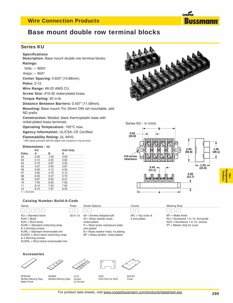
For product data sheets, visit www.cooperbussmann.com/products/datasheet.asp 299
Wire Connection Products
Wire
Managem
entProducts
Base mount double row terminal blocks
Series KU
SpecificationsDescription: Base mount double row terminal blocks.
Ratings:Volts:— 600V
Amps:— 60A*
Center Spacing: 0.625” (15.88mm).
Poles: 2-12.
Wire Range: #6-22 AWG CU.
Screw Size: #10-32 nickel-plated brass.
Torque Rating: 20 in-lb.
Distance Between Barriers: 0.437” (11.09mm).
Mounting: Base mount. For 35mm DIN rail mountable, addND prefix.
Construction: Molded, black thermoplastic base with nickel-plated brass terminals.
Operating Temperature: 105°C max.
Agency Information: UL/CSA; CE Certified.
Flammability Rating: UL 94V0.* 60A rating achieved with #6 copper wire crimped to ring terminal.
Dimensions - inKU KUX Only
Poles A B A02 2.50 1.62 2.0003 3.12 2.25 2.6204 3.75 2.87 3.2505 4.37 3.50 3.8706 5.00 4.12 4.5007 5.62 4.75 5.1208 6.25 5.37 5.7509 6.87 6.00 6.3710 7.50 6.62 7.0011 8.12 7.25 7.6212 8.75 7.87 8.251” = 25.4mm.
MTMU## NUM## JU12 NUE NUC##Molded Marking Tape Molded Marking Tape Jumper End Piece for NUC CoverMatte Finish 12 Circuits
1.25(31.8)
A
B
#10 screwclearance
0.62(15.9)
1.50(38.1)
2.00(50.8)
0.43(11.1)
0.50(12.7)
Accessories
Series KU - in (mm)
Catalog Number Build-A-CodeSeries Poles Screw Options Covers Marking Strip
KU = Standard block 02 to 12 00 = Screws shipped bulk WC = Top cover & MT = Matte finishKUH = Block W = Brass washer head, 2 end plates NU = Numbered 1 to 12, horizontalKUX = Short block nickel-plated NUV = Numbered 1 to 12, verticalKUSC = Standard w/shorting strap P = Steel screw w/pressure plate PT = Marker strip for cover& 4 shorting screws zinc-platedKURL = Standard w/removable link B = Brass washer head, no platingKUXSC = Short block w/shorting strap BP = Brass philslot, nickel-plated& 4 Shorting screwsKUXRL = Short block w/removable link
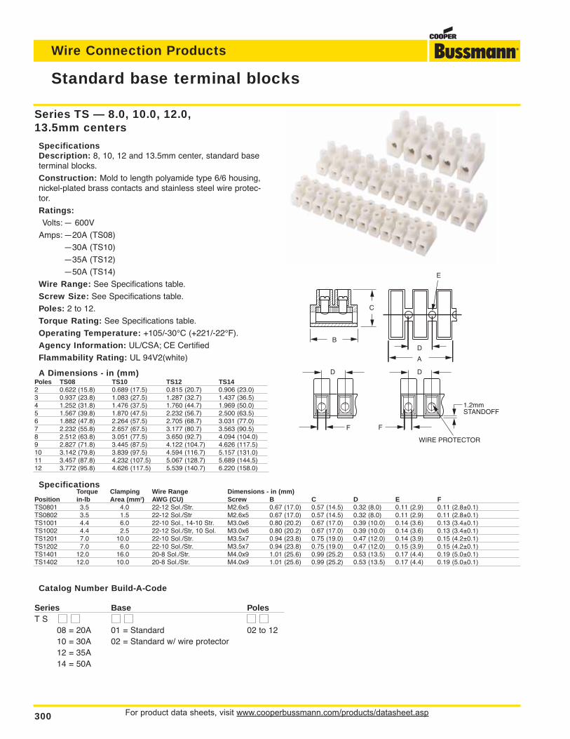
For product data sheets, visit www.cooperbussmann.com/products/datasheet.asp300
Wire Connection Products
Standard base terminal blocks
SpecificationsTorque Clamping Wire Range Dimensions - in (mm)
Position in-lb Area (mm2) AWG (CU) Screw B C D E FTS0801 3.5 4.0 22-12 Sol./Str. M2.6x5 0.67 (17.0) 0.57 (14.5) 0.32 (8.0) 0.11 (2.9) 0.11 (2.8±0.1)TS0802 3.5 1.5 22-12 Sol./Str M2.6x5 0.67 (17.0) 0.57 (14.5) 0.32 (8.0) 0.11 (2.9) 0.11 (2.8±0.1)TS1001 4.4 6.0 22-10 Sol., 14-10 Str. M3.0x6 0.80 (20.2) 0.67 (17.0) 0.39 (10.0) 0.14 (3.6) 0.13 (3.4±0.1)TS1002 4.4 2.5 22-12 Sol./Str, 10 Sol. M3.0x6 0.80 (20.2) 0.67 (17.0) 0.39 (10.0) 0.14 (3.6) 0.13 (3.4±0.1)TS1201 7.0 10.0 22-10 Sol./Str. M3.5x7 0.94 (23.8) 0.75 (19.0) 0.47 (12.0) 0.14 (3.9) 0.15 (4.2±0.1)TS1202 7.0 6.0 22-10 Sol./Str. M3.5x7 0.94 (23.8) 0.75 (19.0) 0.47 (12.0) 0.15 (3.9) 0.15 (4.2±0.1)TS1401 12.0 16.0 20-8 Sol./Str. M4.0x9 1.01 (25.6) 0.99 (25.2) 0.53 (13.5) 0.17 (4.4) 0.19 (5.0±0.1)TS1402 12.0 10.0 20-8 Sol./Str. M4.0x9 1.01 (25.6) 0.99 (25.2) 0.53 (13.5) 0.17 (4.4) 0.19 (5.0±0.1)
Catalog Number Build-A-Code
Series Base PolesT S
08 = 20A 01 = Standard 02 to 1210 = 30A 02 = Standard w/ wire protector12 = 35A14 = 50A
B
D
F F
1.2mm STANDOFF
D
D
A
E
C
WIRE PROTECTOR
Series TS — 8.0, 10.0, 12.0,13.5mm centers
SpecificationsDescription: 8, 10, 12 and 13.5mm center, standard baseterminal blocks.
Construction: Mold to length polyamide type 6/6 housing,nickel-plated brass contacts and stainless steel wire protec-tor.
Ratings:Volts: — 600V
Amps: —20A (TS08)
—30A (TS10)
—35A (TS12)
—50A (TS14)
Wire Range: See Specifications table.
Screw Size: See Specifications table.
Poles: 2 to 12.
Torque Rating: See Specifications table.
Operating Temperature: +105/-30°C (+221/-22°F).
Agency Information: UL/CSA; CE Certified
Flammability Rating: UL 94V2(white)
A Dimensions - in (mm)Poles TS08 TS10 TS12 TS142 0.622 (15.8) 0.689 (17.5) 0.815 (20.7) 0.906 (23.0)3 0.937 (23.8) 1.083 (27.5) 1.287 (32.7) 1.437 (36.5)4 1.252 (31.8) 1.476 (37.5) 1.760 (44.7) 1.969 (50.0)5 1.567 (39.8) 1.870 (47.5) 2.232 (56.7) 2.500 (63.5)6 1.882 (47.8) 2.264 (57.5) 2.705 (68.7) 3.031 (77.0)7 2.232 (55.8) 2.657 (67.5) 3.177 (80.7) 3.563 (90.5)8 2.512 (63.8) 3.051 (77.5) 3.650 (92.7) 4.094 (104.0)9 2.827 (71.8) 3.445 (87.5) 4.122 (104.7) 4.626 (117.5)10 3.142 (79.8) 3.839 (97.5) 4.594 (116.7) 5.157 (131.0)11 3.457 (87.8) 4.232 (107.5) 5.067 (128.7) 5.689 (144.5)12 3.772 (95.8) 4.626 (117.5) 5.539 (140.7) 6.220 (158.0)
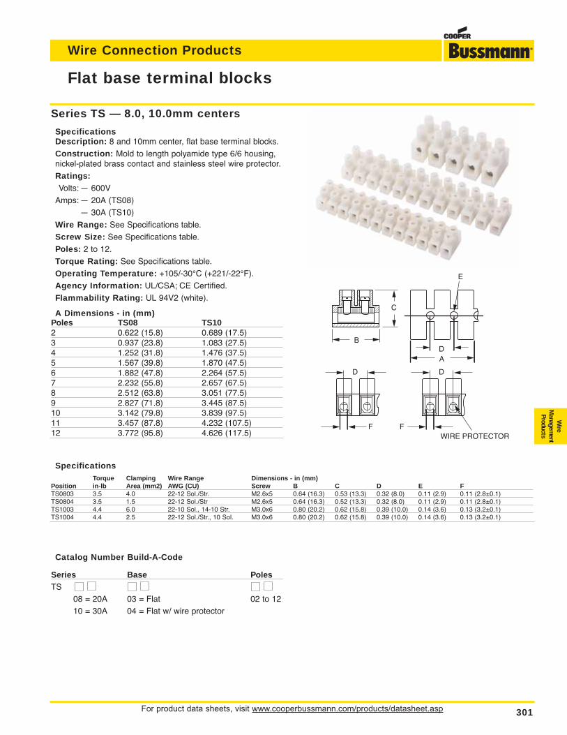
For product data sheets, visit www.cooperbussmann.com/products/datasheet.asp 301
Wire Connection Products
Flat base terminal blocks
SpecificationsTorque Clamping Wire Range Dimensions - in (mm)
Position in-lb Area (mm2) AWG (CU) Screw B C D E FTS0803 3.5 4.0 22-12 Sol./Str. M2.6x5 0.64 (16.3) 0.53 (13.3) 0.32 (8.0) 0.11 (2.9) 0.11 (2.8±0.1)TS0804 3.5 1.5 22-12 Sol./Str M2.6x5 0.64 (16.3) 0.52 (13.3) 0.32 (8.0) 0.11 (2.9) 0.11 (2.8±0.1)TS1003 4.4 6.0 22-10 Sol., 14-10 Str. M3.0x6 0.80 (20.2) 0.62 (15.8) 0.39 (10.0) 0.14 (3.6) 0.13 (3.2±0.1)TS1004 4.4 2.5 22-12 Sol./Str., 10 Sol. M3.0x6 0.80 (20.2) 0.62 (15.8) 0.39 (10.0) 0.14 (3.6) 0.13 (3.2±0.1)
Catalog Number Build-A-Code
Series Base PolesTS
08 = 20A 03 = Flat 02 to 1210 = 30A 04 = Flat w/ wire protector
B
D
F F
D
D
E
C
WIRE PROTECTOR
A
Series TS — 8.0, 10.0mm centers
SpecificationsDescription: 8 and 10mm center, flat base terminal blocks.
Construction: Mold to length polyamide type 6/6 housing,nickel-plated brass contact and stainless steel wire protector.
Ratings:Volts: — 600V
Amps: — 20A (TS08)
— 30A (TS10)
Wire Range: See Specifications table.
Screw Size: See Specifications table.
Poles: 2 to 12.
Torque Rating: See Specifications table.
Operating Temperature: +105/-30°C (+221/-22°F).
Agency Information: UL/CSA; CE Certified.
Flammability Rating: UL 94V2 (white).
A Dimensions - in (mm)Poles TS08 TS102 0.622 (15.8) 0.689 (17.5)3 0.937 (23.8) 1.083 (27.5)4 1.252 (31.8) 1.476 (37.5)5 1.567 (39.8) 1.870 (47.5)6 1.882 (47.8) 2.264 (57.5)7 2.232 (55.8) 2.657 (67.5)8 2.512 (63.8) 3.051 (77.5)9 2.827 (71.8) 3.445 (87.5)10 3.142 (79.8) 3.839 (97.5)11 3.457 (87.8) 4.232 (107.5)12 3.772 (95.8) 4.626 (117.5)
Wire
Managem
entProducts
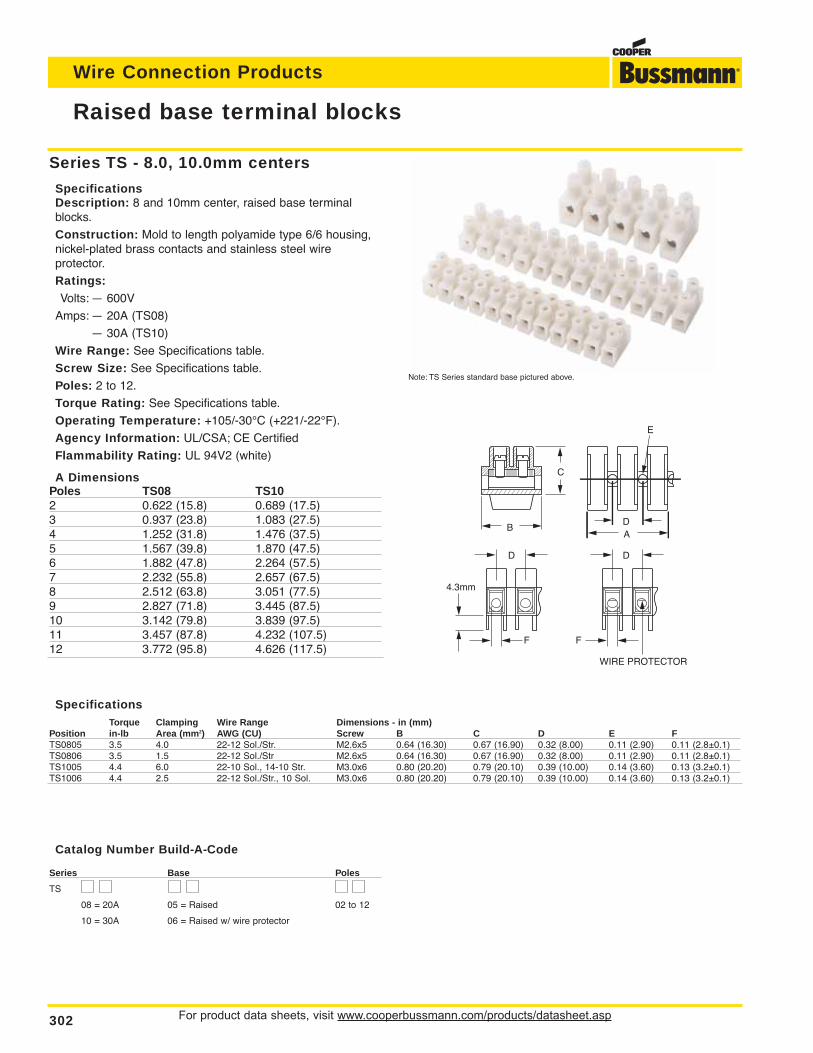
For product data sheets, visit www.cooperbussmann.com/products/datasheet.asp302
Wire Connection Products
Raised base terminal blocks
SpecificationsTorque Clamping Wire Range Dimensions - in (mm)
Position in-lb Area (mm2) AWG (CU) Screw B C D E FTS0805 3.5 4.0 22-12 Sol./Str. M2.6x5 0.64 (16.30) 0.67 (16.90) 0.32 (8.00) 0.11 (2.90) 0.11 (2.8±0.1)TS0806 3.5 1.5 22-12 Sol./Str M2.6x5 0.64 (16.30) 0.67 (16.90) 0.32 (8.00) 0.11 (2.90) 0.11 (2.8±0.1)TS1005 4.4 6.0 22-10 Sol., 14-10 Str. M3.0x6 0.80 (20.20) 0.79 (20.10) 0.39 (10.00) 0.14 (3.60) 0.13 (3.2±0.1)TS1006 4.4 2.5 22-12 Sol./Str., 10 Sol. M3.0x6 0.80 (20.20) 0.79 (20.10) 0.39 (10.00) 0.14 (3.60) 0.13 (3.2±0.1)
Catalog Number Build-A-Code
Series Base Poles
TS
08 = 20A 05 = Raised 02 to 12
10 = 30A 06 = Raised w/ wire protector
F F
D
D
E
B
C
D
WIRE PROTECTOR
4.3mm
A
Series TS - 8.0, 10.0mm centers
SpecificationsDescription: 8 and 10mm center, raised base terminalblocks.
Construction: Mold to length polyamide type 6/6 housing,nickel-plated brass contacts and stainless steel wire protector.
Ratings:Volts: — 600V
Amps: — 20A (TS08)
— 30A (TS10)
Wire Range: See Specifications table.
Screw Size: See Specifications table.
Poles: 2 to 12.
Torque Rating: See Specifications table.
Operating Temperature: +105/-30°C (+221/-22°F).
Agency Information: UL/CSA; CE Certified
Flammability Rating: UL 94V2 (white)
A DimensionsPoles TS08 TS102 0.622 (15.8) 0.689 (17.5)3 0.937 (23.8) 1.083 (27.5)4 1.252 (31.8) 1.476 (37.5)5 1.567 (39.8) 1.870 (47.5)6 1.882 (47.8) 2.264 (57.5)7 2.232 (55.8) 2.657 (67.5)8 2.512 (63.8) 3.051 (77.5)9 2.827 (71.8) 3.445 (87.5)10 3.142 (79.8) 3.839 (97.5)11 3.457 (87.8) 4.232 (107.5)12 3.772 (95.8) 4.626 (117.5)
Note: TS Series standard base pictured above.
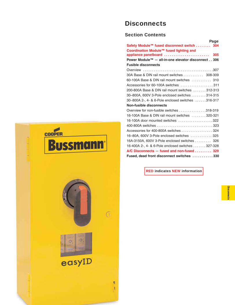
303
Disconnects
Disconnects
Section ContentsPage
Safety Module™ fused disconnect switch . . . . . . . . 304Coordination Module™ fused lighting and appliance panelboard . . . . . . . . . . . . . . . . . . . . . . . . 305Power Module™ — all-in-one elevator disconnect . . 306Fusible disconnects Overview . . . . . . . . . . . . . . . . . . . . . . . . . . . . . . . . . . . . . . .307
30A Base & DIN rail mount switches . . . . . . . . . . . 308-309
60-100A Base & DIN rail mount switches . . . . . . . . . . . 310
Accessories for 60-100A switches . . . . . . . . . . . . . . . . . . 311
200-800A Base & DIN rail mount switches . . . . . . . 312-313
30–800A, 600V 3-Pole enclosed switches . . . . . . . . 314-315
30–800A 2-, 4- & 6-Pole enclosed switches . . . . . . 316-317
Non-fusible disconnectsOverview for non-fusible switches . . . . . . . . . . . . . . .318-319
16-100A Base & DIN rail mount switches . . . . . . . . 320-321
16-100A door mounted switches . . . . . . . . . . . . . . . . . . . 322
400-800A switches . . . . . . . . . . . . . . . . . . . . . . . . . . . . . . . 323
Accessories for 400-800A switches . . . . . . . . . . . . . . . . . 324
16–80A, 600V 3-Pole enclosed switches . . . . . . . . . . . . 325
16A-3150A, 600V 3-Pole enclosed switches . . . . . . . . . 326
16-400A 2-, 4- & 6-Pole enclosed switches . . . . . . . 327-328
A/C Disconnects — fused and non-fused . . . . . . . . . 329Fused, dead front disconnect switches . . . . . . . . . . . 330
RED indicates NEW information
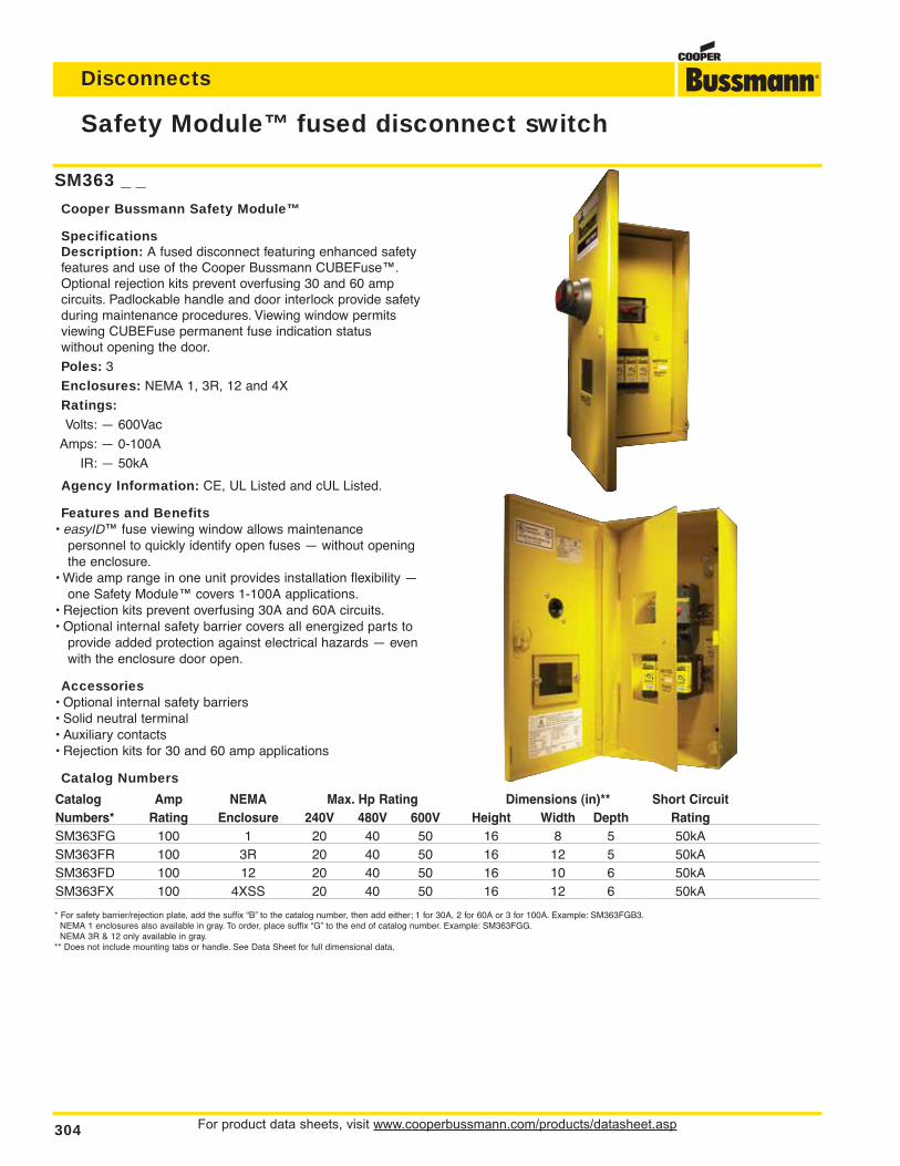
For product data sheets, visit www.cooperbussmann.com/products/datasheet.asp304
Disconnects
Safety Module™ fused disconnect switch
SM363 _ _
Cooper Bussmann Safety Module™
SpecificationsDescription: A fused disconnect featuring enhanced safetyfeatures and use of the Cooper Bussmann CUBEFuse™.Optional rejection kits prevent overfusing 30 and 60 amp circuits. Padlockable handle and door interlock provide safetyduring maintenance procedures. Viewing window permitsviewing CUBEFuse permanent fuse indication status without opening the door.
Poles: 3
Enclosures: NEMA 1, 3R, 12 and 4X
Ratings:Volts: — 600Vac
Amps: — 0-100A
IR: — 50kA
Agency Information: CE, UL Listed and cUL Listed.
Features and Benefits• easyID™ fuse viewing window allows maintenance
personnel to quickly identify open fuses — without openingthe enclosure.
• Wide amp range in one unit provides installation flexibility —one Safety Module™ covers 1-100A applications.
• Rejection kits prevent overfusing 30A and 60A circuits.• Optional internal safety barrier covers all energized parts to
provide added protection against electrical hazards — evenwith the enclosure door open.
Accessories• Optional internal safety barriers• Solid neutral terminal• Auxiliary contacts• Rejection kits for 30 and 60 amp applications
Catalog Numbers
Catalog Amp NEMA Max. Hp Rating Dimensions (in)** Short CircuitNumbers* Rating Enclosure 240V 480V 600V Height Width Depth RatingSM363FG 100 1 20 40 50 16 8 5 50kASM363FR 100 3R 20 40 50 16 12 5 50kASM363FD 100 12 20 40 50 16 10 6 50kASM363FX 100 4XSS 20 40 50 16 12 6 50kA
* For safety barrier/rejection plate, add the suffix “B” to the catalog number, then add either; 1 for 30A, 2 for 60A or 3 for 100A. Example: SM363FGB3.NEMA 1 enclosures also available in gray. To order, place suffix “G” to the end of catalog number. Example: SM363FGG.NEMA 3R & 12 only available in gray.
** Does not include mounting tabs or handle. See Data Sheet for full dimensional data.
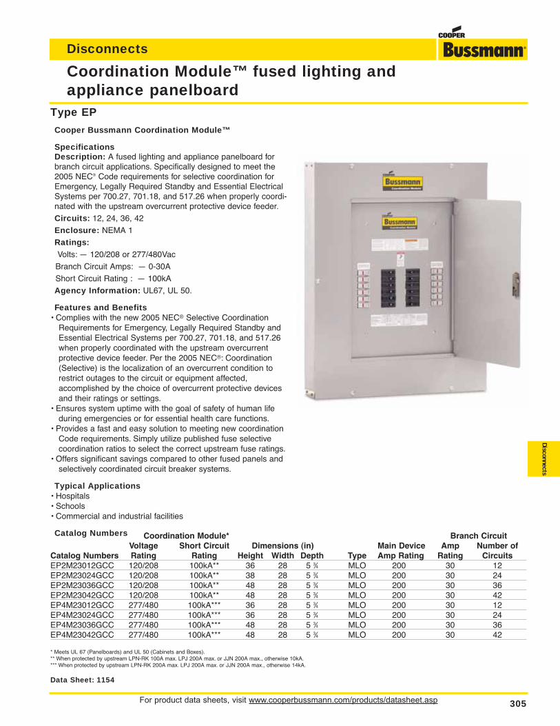
Coordination Module* Branch CircuitVoltage Short Circuit Dimensions (in) Main Device Amp Number of
Catalog Numbers Rating Rating Height Width Depth Type Amp Rating Rating CircuitsEP2M23012GCC 120/208 100kA** 36 28 5 3⁄4 MLO 200 30 12EP2M23024GCC 120/208 100kA** 38 28 5 3⁄4 MLO 200 30 24EP2M23036GCC 120/208 100kA** 48 28 5 3⁄4 MLO 200 30 36EP2M23042GCC 120/208 100kA** 48 28 5 3⁄4 MLO 200 30 42EP4M23012GCC 277/480 100kA*** 36 28 5 3⁄4 MLO 200 30 12EP4M23024GCC 277/480 100kA*** 36 28 5 3⁄4 MLO 200 30 24EP4M23036GCC 277/480 100kA*** 48 28 5 3⁄4 MLO 200 30 36EP4M23042GCC 277/480 100kA*** 48 28 5 3⁄4 MLO 200 30 42
* Meets UL 67 (Panelboards) and UL 50 (Cabinets and Boxes).** When protected by upstream LPN-RK 100A max. LPJ 200A max. or JJN 200A max., otherwise 10kA.*** When protected by upstream LPN-RK 200A max. LPJ 200A max. or JJN 200A max., otherwise 14kA.
For product data sheets, visit www.cooperbussmann.com/products/datasheet.asp 305
Coordination Module™ fused lighting and appliance panelboard
Disconnects
Disconnects
Data Sheet: 1154
Type EP
Cooper Bussmann Coordination Module™
SpecificationsDescription: A fused lighting and appliance panelboard forbranch circuit applications. Specifically designed to meet the2005 NEC® Code requirements for selective coordination forEmergency, Legally Required Standby and Essential ElectricalSystems per 700.27, 701.18, and 517.26 when properly coordi-nated with the upstream overcurrent protective device feeder.
Circuits: 12, 24, 36, 42
Enclosure: NEMA 1
Ratings:Volts: — 120/208 or 277/480Vac
Branch Circuit Amps: — 0-30A
Short Circuit Rating : — 100kA
Agency Information: UL67, UL 50.
Features and Benefits• Complies with the new 2005 NEC® Selective Coordination
Requirements for Emergency, Legally Required Standby andEssential Electrical Systems per 700.27, 701.18, and 517.26when properly coordinated with the upstream overcurrent protective device feeder. Per the 2005 NEC®: Coordination(Selective) is the localization of an overcurrent condition torestrict outages to the circuit or equipment affected, accomplished by the choice of overcurrent protective devicesand their ratings or settings.
• Ensures system uptime with the goal of safety of human life during emergencies or for essential health care functions.
• Provides a fast and easy solution to meeting new coordinationCode requirements. Simply utilize published fuse selective coordination ratios to select the correct upstream fuse ratings.
• Offers significant savings compared to other fused panels andselectively coordinated circuit breaker systems.
Typical Applications• Hospitals• Schools• Commercial and industrial facilities
Catalog Numbers
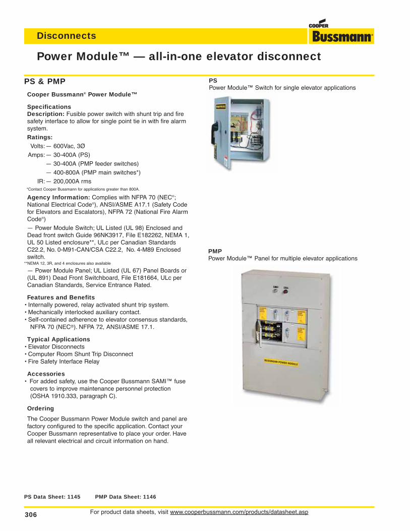
For product data sheets, visit www.cooperbussmann.com/products/datasheet.asp306
Disconnects
Power Module™ — all-in-one elevator disconnect
PS Data Sheet: 1145 PMP Data Sheet: 1146
PMPPower Module™ Panel for multiple elevator applications
PSPower Module™ Switch for single elevator applications
PS & PMP
Cooper Bussmann® Power Module™
SpecificationsDescription: Fusible power switch with shunt trip and firesafety interface to allow for single point tie in with fire alarmsystem.
Ratings:Volts:— 600Vac, 3Ø
Amps:— 30-400A (PS)
— 30-400A (PMP feeder switches)
— 400-800A (PMP main switches*)
IR:— 200,000A rms*Contact Cooper Bussmann for applications greater than 800A.
Agency Information: Complies with NFPA 70 (NEC®;National Electrical Code®), ANSI/ASME A17.1 (Safety Codefor Elevators and Escalators), NFPA 72 (National Fire AlarmCode®)
— Power Module Switch; UL Listed (UL 98) Enclosed andDead front switch Guide 96NK3917, File E182262, NEMA 1,UL 50 Listed enclosure**, ULc per Canadian StandardsC22.2, No. 0-M91-CAN/CSA C22.2, No. 4-M89 Enclosedswitch.
**NEMA 12, 3R, and 4 enclosures also available
— Power Module Panel; UL Listed (UL 67) Panel Boards or(UL 891) Dead Front Switchboard, File E181664, ULc perCanadian Standards, Service Entrance Rated.
Features and Benefits• Internally powered, relay activated shunt trip system.• Mechanically interlocked auxiliary contact.• Self-contained adherence to elevator consensus standards,
NFPA 70 (NEC®). NFPA 72, ANSI/ASME 17.1.
Typical Applications• Elevator Disconnects• Computer Room Shunt Trip Disconnect• Fire Safety Interface Relay
Accessories• For added safety, use the Cooper Bussmann SAMI™ fuse
covers to improve maintenance personnel protection (OSHA 1910.333, paragraph C).
Ordering
The Cooper Bussmann Power Module switch and panel arefactory configured to the specific application. Contact yourCooper Bussmann representative to place your order. Haveall relevant electrical and circuit information on hand.
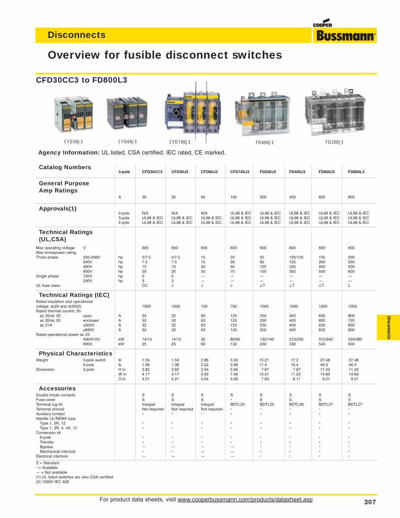
For product data sheets, visit www.cooperbussmann.com/products/datasheet.asp 307
Disconnects
Disconnects
Overview for fusible disconnect switches
CFD30J3 CFD60J3 FD200J3FD400J3
Agency Information: UL listed, CSA certified, IEC rated, CE marked.
Catalog Numbers3-pole CFD30CC3 CFD30J3 CFD60J3 CFD100J3 FD200J3 FD400J3 FD600J3 FD800L3
General Purpose Amp Ratings
A 30 30 60 100 200 400 600 800
Approvals(1)2-pole N/A N/A N/A UL98 & IEC UL98 & IEC UL98 & IEC UL98 & IEC UL98 & IEC3-pole UL98 & IEC UL98 & IEC UL98 & IEC UL98 & IEC UL98 & IEC UL98 & IEC UL98 & IEC UL98 & IEC4-pole UL98 & IEC UL98 & IEC UL98 & IEC UL98 & IEC UL98 & IEC UL98 & IEC UL98 & IEC UL98 & IEC
Technical Ratings (UL,CSA)
Max operating voltage V 600 600 600 600 600 600 600 600Max horsepower ratingThree phase 200-208V hp 5/7.5 5/7.5 15 25 50 100/125 150 200
240V hp 7.5 7.5 15 30 60 125 200 250480V hp 15 15 30 60 125 250 400 500600V hp 20 20 50 75 150 350 500 600
Single phase 120V hp 2 2 — — — — — —240V hp 3 3 — — — — — —
UL fuse class CC J J J J,T J,T J,T L
Technical Ratings (IEC)Rated insulation and operationalvoltage. ac20 and dc20(2) 1000 1000 750 750 1000 1000 1000 1000Rated thermal current, Ith
ac 20/dc 20 open A 32 32 63 125 250 400 630 800ac 20/dc 20 enclosed A 32 32 63 125 250 400 600 720ac 21A ≤500V A 32 32 63 125 250 400 630 800
≤690V A 32 32 63 125 250 400 630 800Rated operational power ac 23
400/415V kW 14/15 14/15 30 80/90 132/140 210/230 315/340 350/380690V kW 25 25 60 132 230 330 540 600
Physical CharacteristicsWeight 3-pole switch lb 1.54 1.54 2.86 3.30 15.21 17.2 37.48 37.48
4-pole lb 1.98 1.98 3.52 3.96 17.4 19.4 46.3 46.3Dimension 3-pole H in 3.82 3.82 3.94 5.66 7.87 7.87 11.42 11.42
W in 4.17 4.17 5.63 7.06 10.31 11.22 14.69 14.69D in 4.21 4.21 5.04 5.09 7.83 8.11 9.21 9.21
AccessoriesDouble break contacts S S S S S S S SFuse cover S S S • S S S STerminal lug kit Integral Integral Integral BDTL24 BDTL25 BDTL26 BDTL27 BDTL27Terminal shroud Not required Not required Not required • • • • •Auxiliary contact • • • • • • • •Handle UL/NEMA type
Type 1, 3R, 12 • • • • • • • •Type 1, 3R, 4, 4X, 12 • • • • • • • •
Conversion kit6-pole • • • • • • • •Transfer • • • • • • • •Bypass — — — — • • • •Mechanical interlock • • — — • • • •
Electrical interlock — — — — • • • •
S = Standard• = Available— = Not available(1) UL listed switches are also CSA certified(2) 1000V IEC 408
CFD30CC3 to FD800L3
CFD100J3
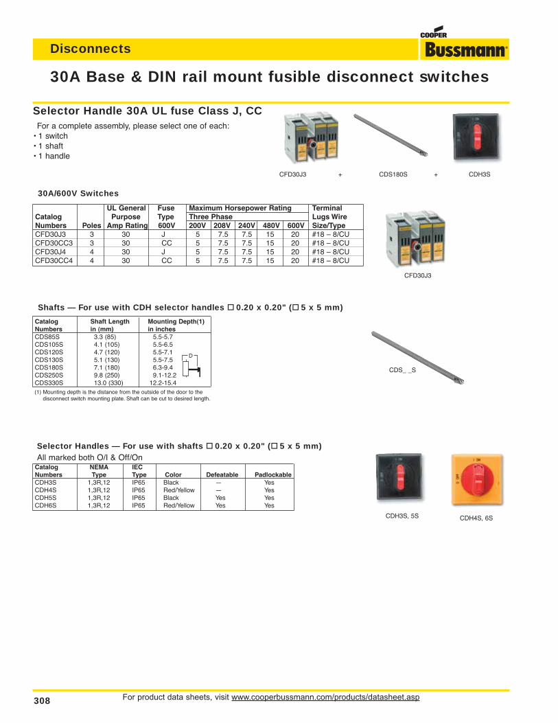
For product data sheets, visit www.cooperbussmann.com/products/datasheet.asp308
Disconnects
30A Base & DIN rail mount fusible disconnect switches
Catalog Shaft Length Mounting Depth(1)Numbers in (mm) in inchesCDS85S 3.3 (85) 5.5-5.7CDS105S 4.1 (105) 5.5-6.5CDS120S 4.7 (120) 5.5-7.1CDS130S 5.1 (130) 5.5-7.5CDS180S 7.1 (180) 6.3-9.4CDS250S 9.8 (250) 9.1-12.2CDS330S 13.0 (330) 12.2-15.4(1) Mounting depth is the distance from the outside of the door to the
disconnect switch mounting plate. Shaft can be cut to desired length.
Selector Handle 30A UL fuse Class J, CCFor a complete assembly, please select one of each:
• 1 switch• 1 shaft• 1 handle
CFD30J3 + CDS180S + CDH3S
CFD30J3
CDS_ _S
UL General Fuse Maximum Horsepower Rating TerminalCatalog Purpose Type Three Phase Lugs WireNumbers Poles Amp Rating 600V 200V 208V 240V 480V 600V Size/TypeCFD30J3 3 30 J 5 7.5 7.5 15 20 #18 – 8/CUCFD30CC3 3 30 CC 5 7.5 7.5 15 20 #18 – 8/CUCFD30J4 4 30 J 5 7.5 7.5 15 20 #18 – 8/CUCFD30CC4 4 30 CC 5 7.5 7.5 15 20 #18 – 8/CU
CDH3S, 5S CDH4S, 6S
Selector Handles — For use with shafts 0.20 x 0.20" ( 5 x 5 mm)All marked both O/I & Off/On
Catalog NEMA IECNumbers Type Type Color Defeatable PadlockableCDH3S 1,3R,12 IP65 Black — YesCDH4S 1,3R,12 IP65 Red/Yellow — YesCDH5S 1,3R,12 IP65 Black Yes YesCDH6S 1,3R,12 IP65 Red/Yellow Yes Yes
Shafts — For use with CDH selector handles 0.20 x 0.20" ( 5 x 5 mm)
30A/600V Switches
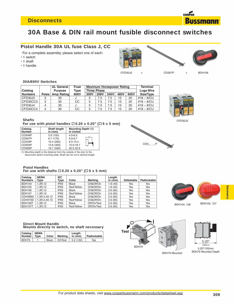
For product data sheets, visit www.cooperbussmann.com/products/datasheet.asp 309
Disconnects
Disconnects
30A Base & DIN rail mount fusible disconnect switches
Catalog Shaft length Mounting Depth (1)Number in (mm) in inchesCDS48P 5.9 (150) 4.9-8.9CDS67P 6.7 (170) 5.9-9.7CDS49P 10.4 (265) 9.5-13.4CDS50P 15.8 (400) 15.0-18.7CDS99P 19.7 (500) 20.5-22.6(1) Mounting depth is the distance from the outside of the door to the
disconnect switch mounting plate. Shaft can be cut to desired length.
Catalog NEMA IEC LengthNumbers Type Type Color Marking in (mm) Defeatable PadlockableBDH104 1,3R,12 IP65 Black O/I&Off/On 1.8 (45) Yes YesBDH105 1,3R,12 IP65 Red/Yellow O/I&Off/On 1.8 (45) Yes YesBDH106 1,3R,12 IP65 Black O/I&Off/On 2.6 (65) Yes YesBDH107 1,3R,12 IP65 Red/Yellow O/I&Off/On 2.6 (65) Yes YesCDHXB65 1,3R,4,4X,12 IP65 Black O/I&Off/On 2.6 (65) Yes YesCDHXY65 1,3R,4,4X,12 IP65 Red/Yellow O/I&Off/On 2.6 (65) Yes YesBDH106T 1,3R,12 IP65 Black Off/On/Test 2.6 (65) Yes YesBDH107T 1,3R,12 IP65 Red/Yellow Off/On/Test 2.6 (65) Yes Yes
Pistol Handle 30A UL fuse Class J, CCFor a complete assembly, please select one of each:
• 1 switch• 1 shaft• 1 handle
CDS__ __P
CFD30J3 + CDS67P + BDH106
BDH104, 106 BDH105, 107
5.20"132mm
Catalog NEMA LengthNumber Type Color Marking in (mm) PadlockableBDH79 1 Black O/I/Test 5.2 (132) Yes
BDH795.20"/132mm
BDH79 Mounted DepthBDH79 Mounted
CFD30J3
UL General Fuse Maximum Horsepower Rating TerminalCatalog Purpose Type Three Phase Lugs WireNumbers Poles Amp Rating 600V 200V 208V 240V 480V 600V Size/TypeCFD30J3 3 30 J 5 7.5 7.5 15 20 #18 – 8/CUCFD30CC3 3 30 CC 5 7.5 7.5 15 20 #18 – 8/CUCFD30J4 4 30 J 5 7.5 7.5 15 20 #18 – 8/CUCFD30CC4 4 30 CC 5 7.5 7.5 15 20 #18 – 8/CU
30A/600V Switches
ShaftsFor use with pistol handles 0.20 x 0.20" ( 5 x 5 mm)
Pistol HandlesFor use with shafts 0.20 x 0.20" ( 5 x 5 mm)
Direct Mount HandleMounts directly to switch, no shaft necessary
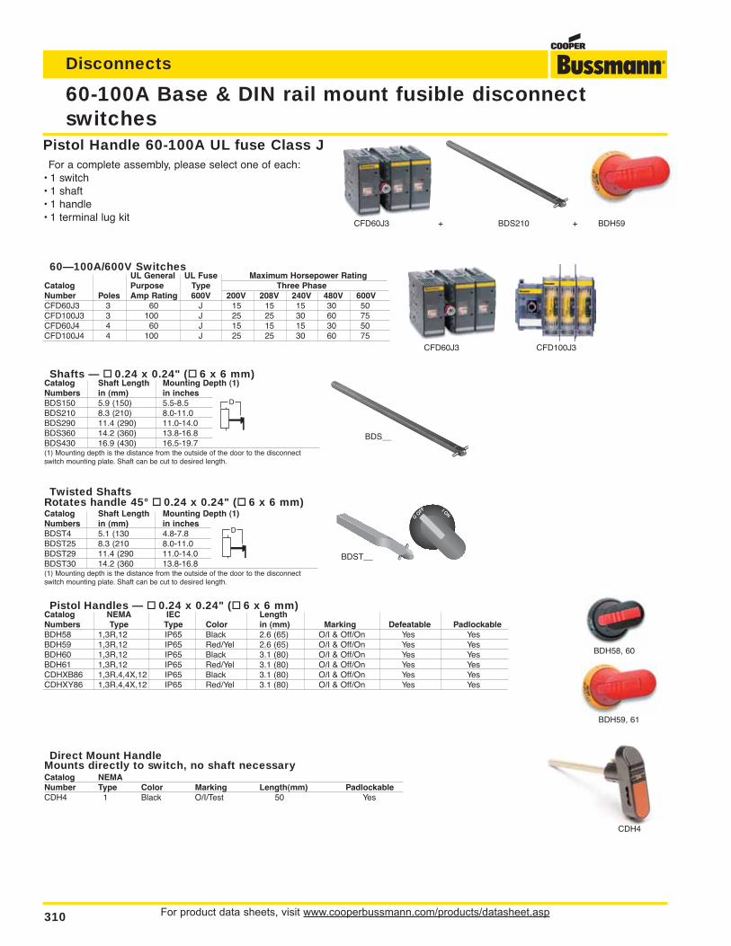
For product data sheets, visit www.cooperbussmann.com/products/datasheet.asp310
Disconnects
Twisted ShaftsRotates handle 45° 0.24 x 0.24" ( 6 x 6 mm)Catalog Shaft Length Mounting Depth (1)Numbers in (mm) in inchesBDST4 5.1 (130 4.8-7.8BDST25 8.3 (210 8.0-11.0BDST29 11.4 (290 11.0-14.0BDST30 14.2 (360 13.8-16.8(1) Mounting depth is the distance from the outside of the door to the disconnectswitch mounting plate. Shaft can be cut to desired length.
Shafts — 0.24 x 0.24" ( 6 x 6 mm)Catalog Shaft Length Mounting Depth (1)Numbers in (mm) in inchesBDS150 5.9 (150) 5.5-8.5BDS210 8.3 (210) 8.0-11.0BDS290 11.4 (290) 11.0-14.0BDS360 14.2 (360) 13.8-16.8BDS430 16.9 (430) 16.5-19.7(1) Mounting depth is the distance from the outside of the door to the disconnectswitch mounting plate. Shaft can be cut to desired length.
60-100A Base & DIN rail mount fusible disconnectswitches
BDH59, 61
BDH58, 60
Pistol Handle 60-100A UL fuse Class JFor a complete assembly, please select one of each:
• 1 switch• 1 shaft• 1 handle• 1 terminal lug kit
CFD60J3 CFD100J3
BDST__
BDS__
CFD60J3 + BDS210 + BDH59
60—100A/600V SwitchesUL General UL Fuse Maximum Horsepower Rating
Catalog Purpose Type Three PhaseNumber Poles Amp Rating 600V 200V 208V 240V 480V 600VCFD60J3 3 60 J 15 15 15 30 50CFD100J3 3 100 J 25 25 30 60 75CFD60J4 4 60 J 15 15 15 30 50CFD100J4 4 100 J 25 25 30 60 75
Pistol Handles — 0.24 x 0.24" ( 6 x 6 mm)Catalog NEMA IEC LengthNumbers Type Type Color in (mm) Marking Defeatable PadlockableBDH58 1,3R,12 IP65 Black 2.6 (65) O/I & Off/On Yes YesBDH59 1,3R,12 IP65 Red/Yel 2.6 (65) O/I & Off/On Yes YesBDH60 1,3R,12 IP65 Black 3.1 (80) O/I & Off/On Yes YesBDH61 1,3R,12 IP65 Red/Yel 3.1 (80) O/I & Off/On Yes YesCDHXB86 1,3R,4,4X,12 IP65 Black 3.1 (80) O/I & Off/On Yes YesCDHXY86 1,3R,4,4X,12 IP65 Red/Yel 3.1 (80) O/I & Off/On Yes Yes
Direct Mount HandleMounts directly to switch, no shaft necessaryCatalog NEMANumber Type Color Marking Length(mm) PadlockableCDH4 1 Black O/I/Test 50 Yes
CDH4
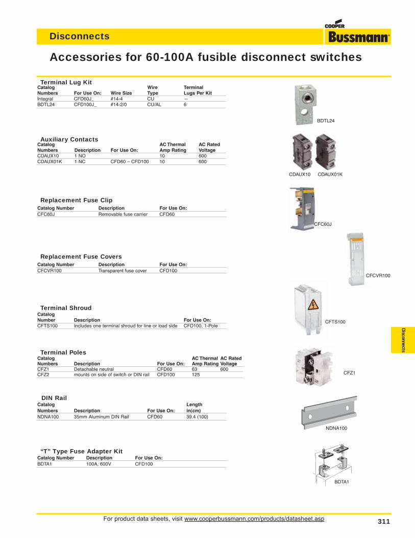
For product data sheets, visit www.cooperbussmann.com/products/datasheet.asp 311
Disconnects
Disconnects
Accessories for 60-100A fusible disconnect switches
NDNA100
CDAUX10 CDAUX01K
BDTL24
CFC60J
CFCVR100
CFTS100
CFZ1
Terminal Lug KitCatalog Wire TerminalNumbers For Use On: Wire Size Type Lugs Per KitIntegral CFD60J_ #14-4 CU —BDTL24 CFD100J_ #14-2/0 CU/AL 6
Auxiliary ContactsCatalog AC Thermal AC RatedNumbers Description For Use On: Amp Rating VoltageCDAUX10 1 NO 10 600CDAUX01K 1 NC CFD60 – CFD100 10 600
Replacement Fuse ClipCatalog Number Description For Use On:CFC60J Removable fuse carrier CFD60
Replacement Fuse CoversCatalog Number Description For Use On:CFCVR100 Transparent fuse cover CFD100
Terminal ShroudCatalogNumber Description For Use On:CFTS100 Includes one terminal shroud for line or load side CFD100, 1-Pole
Terminal PolesCatalog AC Thermal AC RatedNumbers Description For Use On: Amp Rating VoltageCFZ1 Detachable neutral CFD60 63 600CFZ2 mounts on side of switch or DIN rail CFD100 125
DIN RailCatalog LengthNumbers Description For Use On: in(cm)NDNA100 35mm Aluminum DIN Rail CFD60 39.4 (100)
“T” Type Fuse Adapter KitCatalog Number Description For Use On:BDTA1 100A, 600V CFD100
BDTA1
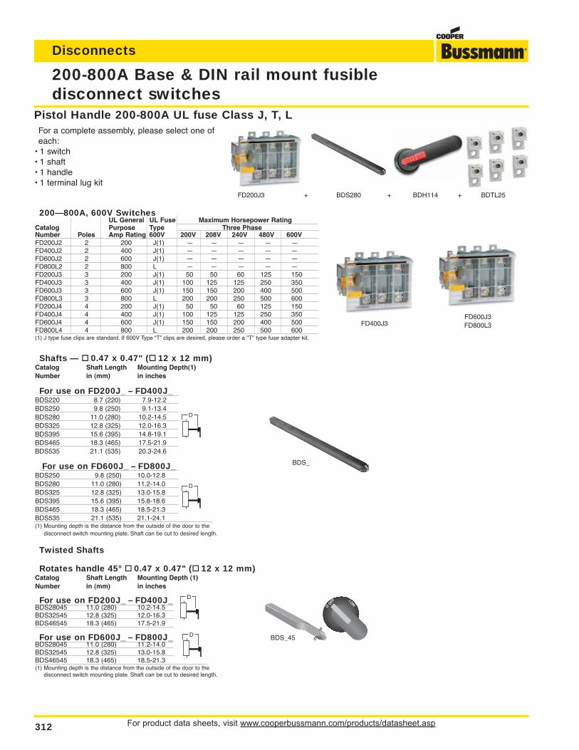
For product data sheets, visit www.cooperbussmann.com/products/datasheet.asp312
Disconnects
Twisted Shafts
Rotates handle 45° 0.47 x 0.47" ( 12 x 12 mm)Catalog Shaft Length Mounting Depth (1)Number in (mm) in inches
For use on FD200J_ – FD400J_BDS28045 11.0 (280) 10.2-14.5BDS32545 12.8 (325) 12.0-16.3BDS46545 18.3 (465) 17.5-21.9
For use on FD600J_ – FD800J_BDS28045 11.0 (280) 11.2-14.0BDS32545 12.8 (325) 13.0-15.8BDS46545 18.3 (465) 18.5-21.3(1) Mounting depth is the distance from the outside of the door to the
disconnect switch mounting plate. Shaft can be cut to desired length.
Shafts — 0.47 x 0.47" ( 12 x 12 mm)Catalog Shaft Length Mounting Depth(1)Number in (mm) in inches
For use on FD200J_ – FD400J_BDS220 8.7 (220) 7.9-12.2BDS250 9.8 (250) 9.1-13.4BDS280 11.0 (280) 10.2-14.5BDS325 12.8 (325) 12.0-16.3BDS395 15.6 (395) 14.8-19.1BDS465 18.3 (465) 17.5-21.9BDS535 21.1 (535) 20.3-24.6
For use on FD600J_ – FD800J_BDS250 9.8 (250) 10.0-12.8BDS280 11.0 (280) 11.2-14.0BDS325 12.8 (325) 13.0-15.8BDS395 15.6 (395) 15.8-18.6BDS465 18.3 (465) 18.5-21.3BDS535 21.1 (535) 21.1-24.1(1) Mounting depth is the distance from the outside of the door to the
disconnect switch mounting plate. Shaft can be cut to desired length.
200-800A Base & DIN rail mount fusible disconnect switches
Pistol Handle 200-800A UL fuse Class J, T, LFor a complete assembly, please select one ofeach:
• 1 switch• 1 shaft• 1 handle• 1 terminal lug kit
FD600J3FD800L3
FD200J3 + BDS280 + BDH114 + BDTL25
FD400J3
BDS_45
BDS_
200—800A, 600V SwitchesUL General UL Fuse Maximum Horsepower Rating
Catalog Purpose Type Three PhaseNumber Poles Amp Rating 600V 200V 208V 240V 480V 600VFD200J2 2 200 J(1) — — — — —FD400J2 2 400 J(1) — — — — —FD600J2 2 600 J(1) — — — — —FD800L2 2 800 L — — — — —FD200J3 3 200 J(1) 50 50 60 125 150FD400J3 3 400 J(1) 100 125 125 250 350FD600J3 3 600 J(1) 150 150 200 400 500FD800L3 3 800 L 200 200 250 500 600FD200J4 4 200 J(1) 50 50 60 125 150FD400J4 4 400 J(1) 100 125 125 250 350FD600J4 4 600 J(1) 150 150 200 400 500FD800L4 4 800 L 200 200 250 500 600(1) J type fuse clips are standard. If 600V Type “T” clips are desired, please order a "T" type fuse adapter kit.
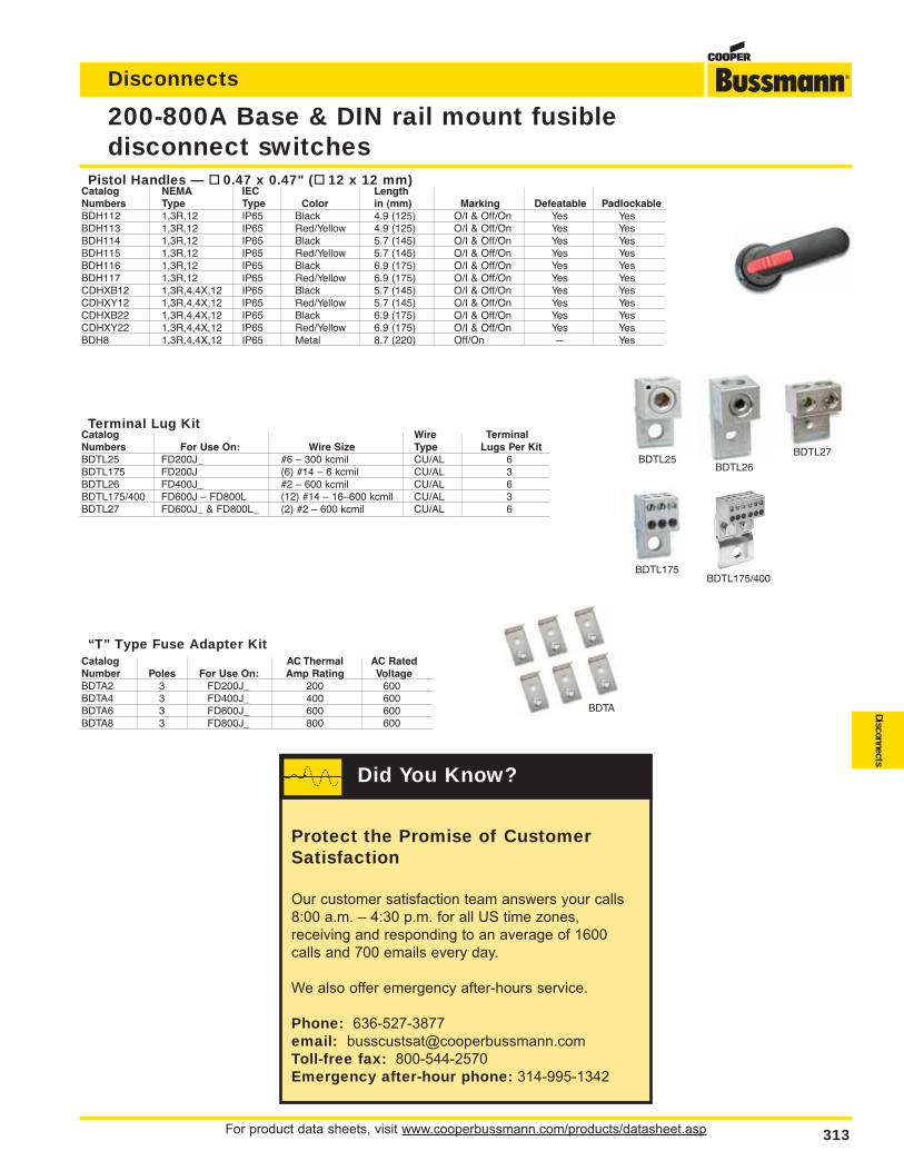
For product data sheets, visit www.cooperbussmann.com/products/datasheet.asp 313
Disconnects
Disconnects
200-800A Base & DIN rail mount fusible disconnect switches
BDTA
BDTL25
BDTL175BDTL175/400
BDTL26
BDTL27
Pistol Handles — 0.47 x 0.47" ( 12 x 12 mm)Catalog NEMA IEC LengthNumbers Type Type Color in (mm) Marking Defeatable PadlockableBDH112 1,3R,12 IP65 Black 4.9 (125) O/I & Off/On Yes YesBDH113 1,3R,12 IP65 Red/Yellow 4.9 (125) O/I & Off/On Yes YesBDH114 1,3R,12 IP65 Black 5.7 (145) O/I & Off/On Yes YesBDH115 1,3R,12 IP65 Red/Yellow 5.7 (145) O/I & Off/On Yes YesBDH116 1,3R,12 IP65 Black 6.9 (175) O/I & Off/On Yes YesBDH117 1,3R,12 IP65 Red/Yellow 6.9 (175) O/I & Off/On Yes YesCDHXB12 1,3R,4,4X,12 IP65 Black 5.7 (145) O/I & Off/On Yes YesCDHXY12 1,3R,4,4X,12 IP65 Red/Yellow 5.7 (145) O/I & Off/On Yes YesCDHXB22 1,3R,4,4X,12 IP65 Black 6.9 (175) O/I & Off/On Yes YesCDHXY22 1,3R,4,4X,12 IP65 Red/Yellow 6.9 (175) O/I & Off/On Yes YesBDH8 1,3R,4,4X,12 IP65 Metal 8.7 (220) Off/On — Yes
Terminal Lug KitCatalog Wire TerminalNumbers For Use On: Wire Size Type Lugs Per KitBDTL25 FD200J_ #6 – 300 kcmil CU/AL 6BDTL175 FD200J (6) #14 – 6 kcmil CU/AL 3BDTL26 FD400J_ #2 – 600 kcmil CU/AL 6BDTL175/400 FD600J – FD800L (12) #14 – 16–600 kcmil CU/AL 3BDTL27 FD600J_ & FD800L_ (2) #2 – 600 kcmil CU/AL 6
“T” Type Fuse Adapter KitCatalog AC Thermal AC RatedNumber Poles For Use On: Amp Rating VoltageBDTA2 3 FD200J_ 200 600BDTA4 3 FD400J_ 400 600BDTA6 3 FD600J_ 600 600BDTA8 3 FD800J_ 800 600
BDH112
Protect the Promise of CustomerSatisfaction
Our customer satisfaction team answers your calls
8:00 a.m. – 4:30 p.m. for all US time zones,
receiving and responding to an average of 1600
calls and 700 emails every day.
We also offer emergency after-hours service.
Phone: 636-527-3877
email: [email protected]
Toll-free fax: 800-544-2570
Emergency after-hour phone: 314-995-1342
Did You Know?
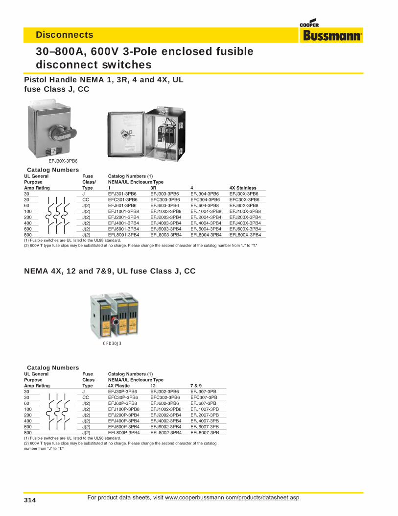
For product data sheets, visit www.cooperbussmann.com/products/datasheet.asp314
Disconnects
Catalog NumbersUL General Fuse Catalog Numbers (1)Purpose Class NEMA/UL Enclosure TypeAmp Rating Type 4X Plastic 12 7 & 930 J EFJ30P-3PB6 EFJ302-3PB6 EFJ307-3PB30 CC EFC30P-3PB6 EFC302-3PB6 EFC307-3PB60 J(2) EFJ60P-3PB8 EFJ602-3PB6 EFJ607-3PB100 J(2) EFJ100P-3PB8 EFJ1002-3PB8 EFJ1007-3PB200 J(2) EFJ200P-3PB4 EFJ2002-3PB4 EFJ2007-3PB400 J(2) EFJ400P-3PB4 EFJ4002-3PB4 EFJ4007-3PB600 J(2) EFJ600P-3PB4 EFJ6002-3PB4 EFJ6007-3PB800 J(2) EFL800P-3PB4 EFL8002-3PB4 EFL8007-3PB(1) Fusible switches are UL listed to the UL98 standard.(2) 600V T type fuse clips may be substituted at no charge. Please change the second character of the catalognumber from "J" to "T."
30–800A, 600V 3-Pole enclosed fusible disconnect switches
Catalog NumbersUL General Fuse Catalog Numbers (1)Purpose Class/ NEMA/UL Enclosure TypeAmp Rating Type 1 3R 4 4X Stainless30 J EFJ301-3PB6 EFJ303-3PB6 EFJ304-3PB6 EFJ30X-3PB630 CC EFC301-3PB6 EFC303-3PB6 EFC304-3PB6 EFC30X-3PB660 J(2) EFJ601-3PB6 EFJ603-3PB6 EFJ604-3PB8 EFJ60X-3PB8100 J(2) EFJ1001-3PB8 EFJ1003-3PB8 EFJ1004-3PB8 EFJ100X-3PB8200 J(2) EFJ2001-3PB4 EFJ2003-3PB4 EFJ2004-3PB4 EFJ200X-3PB4400 J(2) EFJ4001-3PB4 EFJ4003-3PB4 EFJ4004-3PB4 EFJ400X-3PB4600 J(2) EFJ6001-3PB4 EFJ6003-3PB4 EFJ6004-3PB4 EFJ600X-3PB4800 J(2) EFL8001-3PB4 EFL8003-3PB4 EFL8004-3PB4 EFL800X-3PB4(1) Fusible switches are UL listed to the UL98 standard.(2) 600V T type fuse clips may be substituted at no charge. Please change the second character of the catalog number from "J" to "T."
Pistol Handle NEMA 1, 3R, 4 and 4X, ULfuse Class J, CC
NEMA 4X, 12 and 7&9, UL fuse Class J, CC
EFJ30X-3PB6
CFD30J3
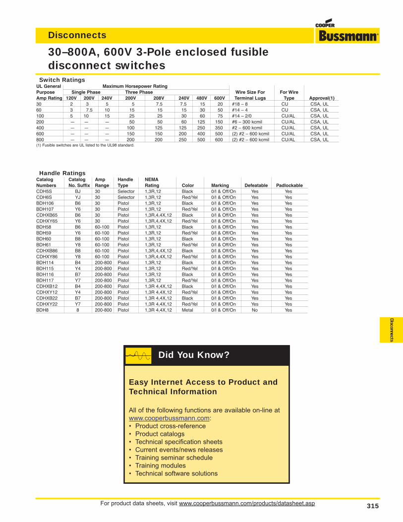
For product data sheets, visit www.cooperbussmann.com/products/datasheet.asp 315
Disconnects
Disconnects
30–800A, 600V 3-Pole enclosed fusible disconnect switches
Switch RatingsUL General Maximum Horsepower RatingPurpose Single Phase Three Phase Wire Size For For WireAmp Rating 120V 200V 240V 200V 208V 240V 480V 600V Terminal Lugs Type Approval(1)30 2 3 5 5 7.5 7.5 15 20 #18 – 8 CU CSA, UL60 3 7.5 10 15 15 15 30 50 #14 – 4 CU CSA, UL100 5 10 15 25 25 30 60 75 #14 – 2/0 CU/AL CSA, UL200 — — — 50 50 60 125 150 #6 – 300 kcmil CU/AL CSA, UL400 — — — 100 125 125 250 350 #2 – 600 kcmil CU/AL CSA, UL600 — — — 150 150 200 400 500 (2) #2 – 600 kcmil CU/AL CSA, UL800 — — — 200 200 250 500 600 (2) #2 – 600 kcmil CU/AL CSA, UL(1) Fusible switches are UL listed to the UL98 standard.
Handle RatingsCatalog Catalog Amp Handle NEMANumbers No. Suffix Range Type Rating Color Marking Defeatable PadlockableCDH5S BJ 30 Selector 1,3R,12 Black 0/I & Off/On Yes YesCDH6S YJ 30 Selector 1,3R,12 Red/Yel 0/I & Off/On Yes YesBDH106 B6 30 Pistol 1,3R,12 Black 0/I & Off/On Yes YesBDH107 Y6 30 Pistol 1,3R,12 Red/Yel 0/I & Off/On Yes YesCDHXB65 B6 30 Pistol 1,3R,4,4X,12 Black 0/I & Off/On Yes YesCDHXY65 Y6 30 Pistol 1,3R,4,4X,12 Red/Yel 0/I & Off/On Yes YesBDH58 B6 60-100 Pistol 1,3R,12 Black 0/I & Off/On Yes YesBDH59 Y6 60-100 Pistol 1,3R,12 Red/Yel 0/I & Off/On Yes YesBDH60 B8 60-100 Pistol 1,3R,12 Black 0/I & Off/On Yes YesBDH61 Y8 60-100 Pistol 1,3R,12 Red/Yel 0/I & Off/On Yes YesCDHXB86 B8 60-100 Pistol 1,3R,4,4X,12 Black 0/I & Off/On Yes YesCDHXY86 Y8 60-100 Pistol 1,3R,4,4X,12 Red/Yel 0/I & Off/On Yes YesBDH114 B4 200-800 Pistol 1,3R,12 Black 0/I & Off/On Yes YesBDH115 Y4 200-800 Pistol 1,3R,12 Red/Yel 0/I & Off/On Yes YesBDH116 B7 200-800 Pistol 1,3R,12 Black 0/I & Off/On Yes YesBDH117 Y7 200-800 Pistol 1,3R,12 Red/Yel 0/I & Off/On Yes YesCDHXB12 B4 200-800 Pistol 1,3R 4,4X,12 Black 0/I & Off/On Yes YesCDHXY12 Y4 200-800 Pistol 1,3R 4,4X,12 Red/Yel 0/I & Off/On Yes YesCDHXB22 B7 200-800 Pistol 1,3R 4,4X,12 Black 0/I & Off/On Yes YesCDHXY22 Y7 200-800 Pistol 1,3R 4,4X,12 Red/Yel 0/I & Off/On Yes YesBDH8 8 200-800 Pistol 1,3R 4,4X,12 Metal 0/I & Off/On No Yes
Easy Internet Access to Product andTechnical Information
All of the following functions are available on-line at
www.cooperbussmann.com:
• Product cross-reference
• Product catalogs
• Technical specification sheets
• Current events/news releases
• Training seminar schedule
• Training modules
• Technical software solutions
Did You Know?
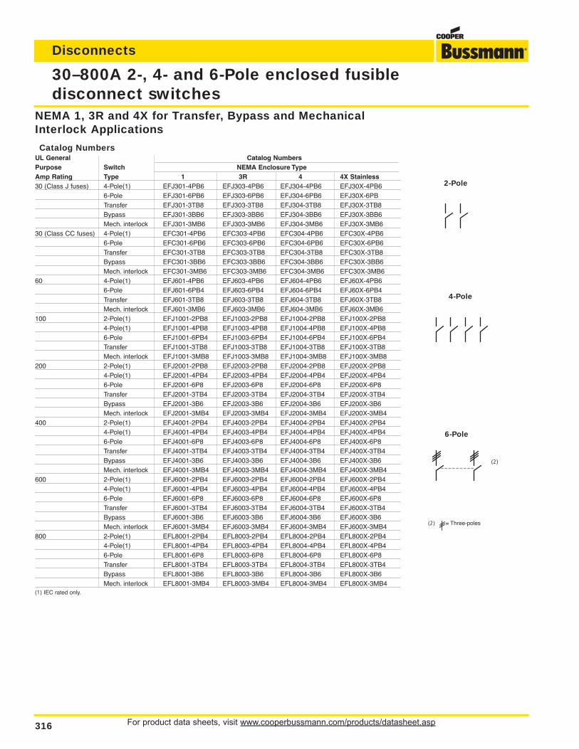
For product data sheets, visit www.cooperbussmann.com/products/datasheet.asp316
Disconnects
30–800A 2-, 4- and 6-Pole enclosed fusible disconnect switches
(2) = Three-poles
2-Pole
4-Pole
6-Pole
(2)
NEMA 1, 3R and 4X for Transfer, Bypass and MechanicalInterlock Applications
Catalog NumbersUL General Catalog NumbersPurpose Switch NEMA Enclosure TypeAmp Rating Type 1 3R 4 4X Stainless30 (Class J fuses) 4-Pole(1) EFJ301-4PB6 EFJ303-4PB6 EFJ304-4PB6 EFJ30X-4PB6
6-Pole EFJ301-6PB6 EFJ303-6PB6 EFJ304-6PB6 EFJ30X-6PBTransfer EFJ301-3TB8 EFJ303-3TB8 EFJ304-3TB8 EFJ30X-3TB8Bypass EFJ301-3BB6 EFJ303-3BB6 EFJ304-3BB6 EFJ30X-3BB6Mech. interlock EFJ301-3MB6 EFJ303-3MB6 EFJ304-3MB6 EFJ30X-3MB6
30 (Class CC fuses) 4-Pole(1) EFC301-4PB6 EFC303-4PB6 EFC304-4PB6 EFC30X-4PB66-Pole EFC301-6PB6 EFC303-6PB6 EFC304-6PB6 EFC30X-6PB6Transfer EFC301-3TB8 EFC303-3TB8 EFC304-3TB8 EFC30X-3TB8Bypass EFC301-3BB6 EFC303-3BB6 EFC304-3BB6 EFC30X-3BB6Mech. interlock EFC301-3MB6 EFC303-3MB6 EFC304-3MB6 EFC30X-3MB6
60 4-Pole(1) EFJ601-4PB6 EFJ603-4PB6 EFJ604-4PB6 EFJ60X-4PB66-Pole EFJ601-6PB4 EFJ603-6PB4 EFJ604-6PB4 EFJ60X-6PB4Transfer EFJ601-3TB8 EFJ603-3TB8 EFJ604-3TB8 EFJ60X-3TB8Mech. interlock EFJ601-3MB6 EFJ603-3MB6 EFJ604-3MB6 EFJ60X-3MB6
100 2-Pole(1) EFJ1001-2PB8 EFJ1003-2PB8 EFJ1004-2PB8 EFJ100X-2PB84-Pole(1) EFJ1001-4PB8 EFJ1003-4PB8 EFJ1004-4PB8 EFJ100X-4PB86-Pole EFJ1001-6PB4 EFJ1003-6PB4 EFJ1004-6PB4 EFJ100X-6PB4Transfer EFJ1001-3TB8 EFJ1003-3TB8 EFJ1004-3TB8 EFJ100X-3TB8Mech. interlock EFJ1001-3MB8 EFJ1003-3MB8 EFJ1004-3MB8 EFJ100X-3MB8
200 2-Pole(1) EFJ2001-2PB8 EFJ2003-2PB8 EFJ2004-2PB8 EFJ200X-2PB84-Pole(1) EFJ2001-4PB4 EFJ2003-4PB4 EFJ2004-4PB4 EFJ200X-4PB46-Pole EFJ2001-6P8 EFJ2003-6P8 EFJ2004-6P8 EFJ200X-6P8Transfer EFJ2001-3TB4 EFJ2003-3TB4 EFJ2004-3TB4 EFJ200X-3TB4Bypass EFJ2001-3B6 EFJ2003-3B6 EFJ2004-3B6 EFJ200X-3B6Mech. interlock EFJ2001-3MB4 EFJ2003-3MB4 EFJ2004-3MB4 EFJ200X-3MB4
400 2-Pole(1) EFJ4001-2PB4 EFJ4003-2PB4 EFJ4004-2PB4 EFJ400X-2PB44-Pole(1) EFJ4001-4PB4 EFJ4003-4PB4 EFJ4004-4PB4 EFJ400X-4PB46-Pole EFJ4001-6P8 EFJ4003-6P8 EFJ4004-6P8 EFJ400X-6P8Transfer EFJ4001-3TB4 EFJ4003-3TB4 EFJ4004-3TB4 EFJ400X-3TB4Bypass EFJ4001-3B6 EFJ4003-3B6 EFJ4004-3B6 EFJ400X-3B6Mech. interlock EFJ4001-3MB4 EFJ4003-3MB4 EFJ4004-3MB4 EFJ400X-3MB4
600 2-Pole(1) EFJ6001-2PB4 EFJ6003-2PB4 EFJ6004-2PB4 EFJ600X-2PB44-Pole(1) EFJ6001-4PB4 EFJ6003-4PB4 EFJ6004-4PB4 EFJ600X-4PB46-Pole EFJ6001-6P8 EFJ6003-6P8 EFJ6004-6P8 EFJ600X-6P8Transfer EFJ6001-3TB4 EFJ6003-3TB4 EFJ6004-3TB4 EFJ600X-3TB4Bypass EFJ6001-3B6 EFJ6003-3B6 EFJ6004-3B6 EFJ600X-3B6Mech. interlock EFJ6001-3MB4 EFJ6003-3MB4 EFJ6004-3MB4 EFJ600X-3MB4
800 2-Pole(1) EFL8001-2PB4 EFL8003-2PB4 EFL8004-2PB4 EFL800X-2PB44-Pole(1) EFL8001-4PB4 EFL8003-4PB4 EFL8004-4PB4 EFL800X-4PB46-Pole EFL8001-6P8 EFL8003-6P8 EFL8004-6P8 EFL800X-6P8Transfer EFL8001-3TB4 EFL8003-3TB4 EFL8004-3TB4 EFL800X-3TB4Bypass EFL8001-3B6 EFL8003-3B6 EFL8004-3B6 EFL800X-3B6Mech. interlock EFL8001-3MB4 EFL8003-3MB4 EFL8004-3MB4 EFL800X-3MB4
(1) IEC rated only.
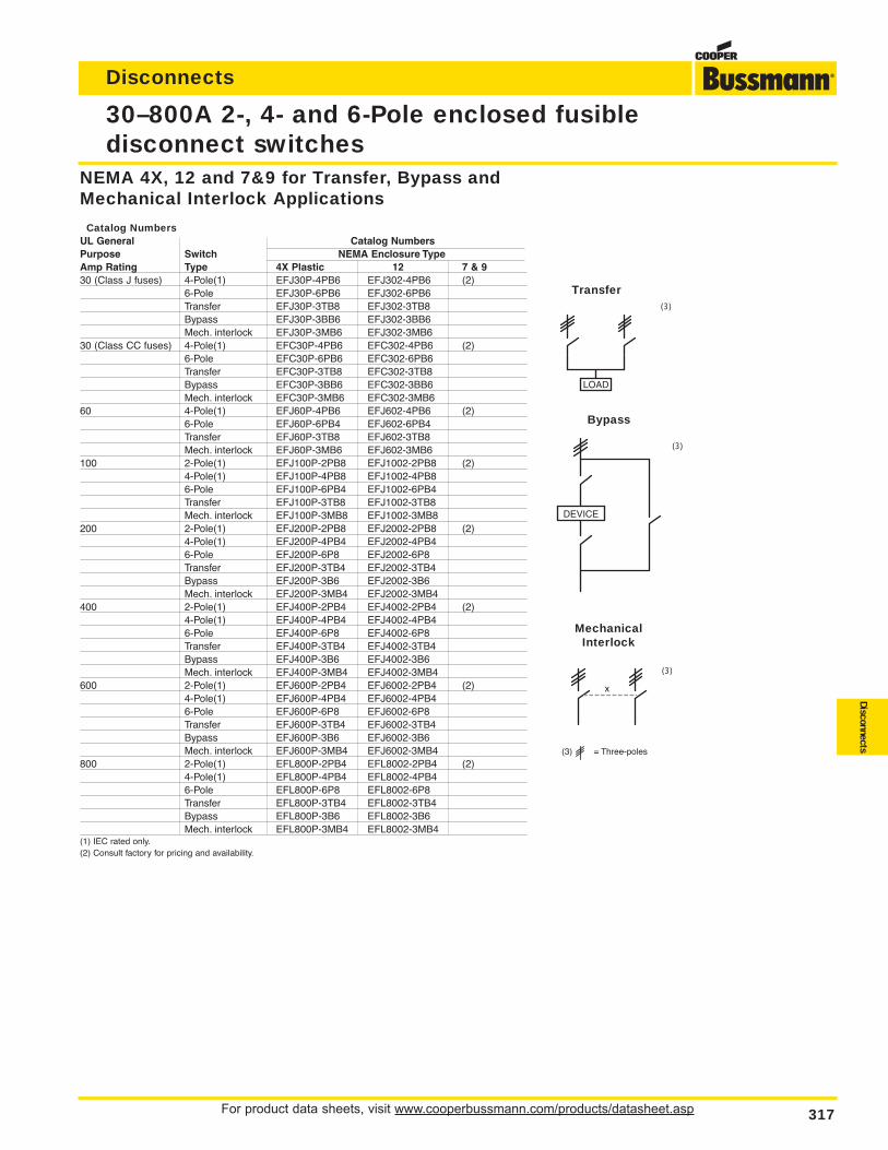
For product data sheets, visit www.cooperbussmann.com/products/datasheet.asp 317
Disconnects
Disconnects
NEMA 4X, 12 and 7&9 for Transfer, Bypass andMechanical Interlock Applications
Catalog NumbersUL General Catalog NumbersPurpose Switch NEMA Enclosure TypeAmp Rating Type 4X Plastic 12 7 & 930 (Class J fuses) 4-Pole(1) EFJ30P-4PB6 EFJ302-4PB6 (2)
6-Pole EFJ30P-6PB6 EFJ302-6PB6Transfer EFJ30P-3TB8 EFJ302-3TB8Bypass EFJ30P-3BB6 EFJ302-3BB6Mech. interlock EFJ30P-3MB6 EFJ302-3MB6
30 (Class CC fuses) 4-Pole(1) EFC30P-4PB6 EFC302-4PB6 (2)6-Pole EFC30P-6PB6 EFC302-6PB6Transfer EFC30P-3TB8 EFC302-3TB8Bypass EFC30P-3BB6 EFC302-3BB6Mech. interlock EFC30P-3MB6 EFC302-3MB6
60 4-Pole(1) EFJ60P-4PB6 EFJ602-4PB6 (2)6-Pole EFJ60P-6PB4 EFJ602-6PB4Transfer EFJ60P-3TB8 EFJ602-3TB8Mech. interlock EFJ60P-3MB6 EFJ602-3MB6
100 2-Pole(1) EFJ100P-2PB8 EFJ1002-2PB8 (2)4-Pole(1) EFJ100P-4PB8 EFJ1002-4PB86-Pole EFJ100P-6PB4 EFJ1002-6PB4Transfer EFJ100P-3TB8 EFJ1002-3TB8Mech. interlock EFJ100P-3MB8 EFJ1002-3MB8
200 2-Pole(1) EFJ200P-2PB8 EFJ2002-2PB8 (2)4-Pole(1) EFJ200P-4PB4 EFJ2002-4PB46-Pole EFJ200P-6P8 EFJ2002-6P8Transfer EFJ200P-3TB4 EFJ2002-3TB4Bypass EFJ200P-3B6 EFJ2002-3B6Mech. interlock EFJ200P-3MB4 EFJ2002-3MB4
400 2-Pole(1) EFJ400P-2PB4 EFJ4002-2PB4 (2)4-Pole(1) EFJ400P-4PB4 EFJ4002-4PB46-Pole EFJ400P-6P8 EFJ4002-6P8Transfer EFJ400P-3TB4 EFJ4002-3TB4Bypass EFJ400P-3B6 EFJ4002-3B6Mech. interlock EFJ400P-3MB4 EFJ4002-3MB4
600 2-Pole(1) EFJ600P-2PB4 EFJ6002-2PB4 (2)4-Pole(1) EFJ600P-4PB4 EFJ6002-4PB46-Pole EFJ600P-6P8 EFJ6002-6P8Transfer EFJ600P-3TB4 EFJ6002-3TB4Bypass EFJ600P-3B6 EFJ6002-3B6Mech. interlock EFJ600P-3MB4 EFJ6002-3MB4
800 2-Pole(1) EFL800P-2PB4 EFL8002-2PB4 (2)4-Pole(1) EFL800P-4PB4 EFL8002-4PB46-Pole EFL800P-6P8 EFL8002-6P8Transfer EFL800P-3TB4 EFL8002-3TB4Bypass EFL800P-3B6 EFL8002-3B6Mech. interlock EFL800P-3MB4 EFL8002-3MB4
(1) IEC rated only.(2) Consult factory for pricing and availability.
30–800A 2-, 4- and 6-Pole enclosed fusible disconnect switches
(3) = Three-poles
Transfer(3)
Bypass
(3)
MechanicalInterlock
(3)
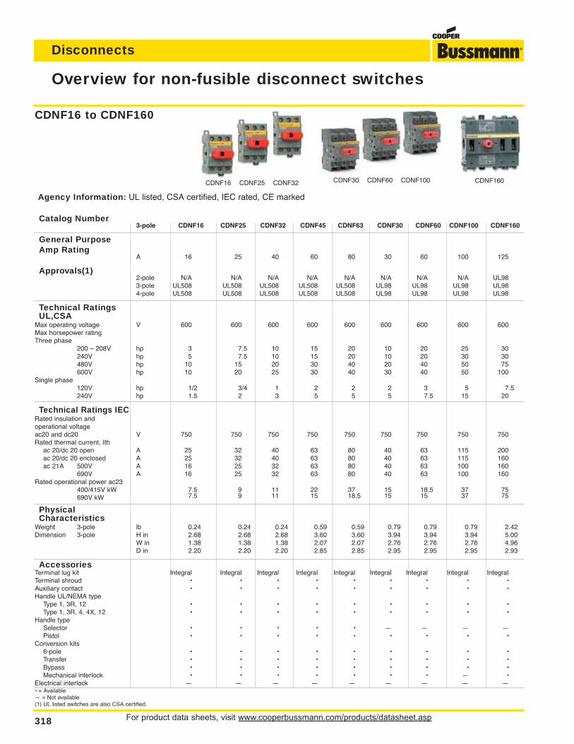
For product data sheets, visit www.cooperbussmann.com/products/datasheet.asp318
Disconnects
Overview for non-fusible disconnect switches
CDNF160CDNF30 CDNF60 CDNF100CDNF16 CDNF25 CDNF32
Catalog Number3-pole CDNF16 CDNF25 CDNF32 CDNF45 CDNF63 CDNF30 CDNF60 CDNF100 CDNF160
General Purpose Amp Rating
A 16 25 40 60 80 30 60 100 125
Approvals(1)2-pole N/A N/A N/A N/A N/A N/A N/A N/A UL983-pole UL508 UL508 UL508 UL508 UL508 UL98 UL98 UL98 UL984-pole UL508 UL508 UL508 UL508 UL508 UL98 UL98 UL98 UL98
Technical Ratings UL,CSA
Max operating voltage V 600 600 600 600 600 600 600 600 600Max horsepower ratingThree phase
200 – 208V hp 3 7.5 10 15 20 10 20 25 30240V hp 5 7.5 10 15 20 10 20 30 30480V hp 10 15 20 30 40 20 40 50 75600V hp 10 20 25 30 40 30 40 50 100
Single phase120V hp 1/2 3/4 1 2 2 2 3 5 7.5240V hp 1.5 2 3 5 5 5 7.5 15 20
Technical Ratings IECRated insulation andoperational voltageac20 and dc20 V 750 750 750 750 750 750 750 750 750Rated thermal current, Ith
ac 20/dc 20 open A 25 32 40 63 80 40 63 115 200ac 20/dc 20 enclosed A 25 32 40 63 80 40 63 115 160ac 21A 500V A 16 25 32 63 80 40 63 100 160
690V A 16 25 32 63 80 40 63 100 160Rated operational power ac23
400/415V kW 7.5 9 11 22 37 15 18.5 37 75690V kW 7.5 9 11 15 18.5 15 15 37 75
Physical Characteristics
Weight 3-pole lb 0.24 0.24 0.24 0.59 0.59 0.79 0.79 0.79 2.42Dimension 3-pole H in 2.68 2.68 2.68 3.60 3.60 3.94 3.94 3.94 5.00
W in 1.38 1.38 1.38 2.07 2.07 2.76 2.76 2.76 4.96D in 2.20 2.20 2.20 2.85 2.85 2.95 2.95 2.95 2.93
AccessoriesTerminal lug kit Integral Integral Integral Integral Integral Integral Integral Integral IntegralTerminal shroud • • • • • • • • •Auxiliary contact • • • • • • • • •Handle UL/NEMA type
Type 1, 3R, 12 • • • • • • • • •Type 1, 3R, 4, 4X, 12 • • • • • • • • •
Handle typeSelector • • • • • — — — —Pistol • • • • • • • • •
Conversion kits6-pole • • • • • • • • •Transfer • • • • • • • • •Bypass • • • • • • • • •Mechanical interlock • • • • • • • — •
Electrical interlock — — — — — — — — —• = Available— = Not available(1) UL listed switches are also CSA certified.
CDNF16 to CDNF160
Agency Information: UL listed, CSA certified, IEC rated, CE marked
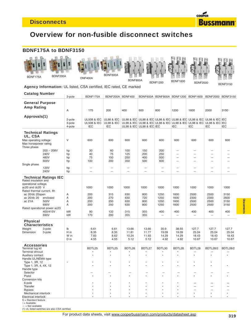
For product data sheets, visit www.cooperbussmann.com/products/datasheet.asp 319
Disconnects
Disconnects
Overview for non-fusible disconnect switches
Catalog Number3-pole BDNF175A BDNF200A BDNF400 BDNF600A BDNF800A BDNF1200 BDNF1600 BDNF2000 BDNF3150
General Purpose Amp Rating
A 175 200 400 600 800 1200 1600 2000 3150
Approvals(1)2-pole UL508 & IEC UL98 & IEC UL98 & IEC UL98 & IEC UL98 & IEC UL98 & IEC UL98 & IEC UL98 & IEC IEC3-pole UL508 & IEC UL98 & IEC UL98 & IEC UL98 & IEC UL98 & IEC UL98 & IEC UL98 & IEC UL98 & IEC IEC4-pole IEC IEC UL98 & IEC UL98 & IEC IEC IEC IEC IEC IEC
Technical Ratings UL, CSA
Max operating voltage V 600 600 600 600 600 600 600 600 600Max horsepower ratingThree phase
200 – 208V hp 30 60 100 150 200 — — — —240V hp 40 75 125 200 250 — — — —480V hp 75 150 250 400 500 — — — —600V hp 100 200 350 500 600 — — — —
Single phase120V hp — — — — — — — — —240V hp — — — — — — — — —
Technical Ratings IECRated insulation andoperational voltage.ac20 and dc20 V 1000 1000 1000 1000 1000 1000 1000 1000 1000Rated thermal current, Ith
ac 20/dc 20open A 200 315 630 800 1250 1600 2500 2500 3150ac 20/dc 20 enclosed A 200 270 630 720 1250 1600 2300 2300 2600ac 21A 500V A 200 250 630 800 1250 1600 2500 2500 3150
690V A 200 250 630 800 1250 1600 2500 2500 3150Rated operational power ac23
400/415V kW 90 132 315 355 400 400 400 400 400690V kW 170 200 355 355 — — — — —
Physical Characteristics
Weight 3-pole lb 6.61 6.61 13.66 13.66 35.9 38.55 127.7 127.7 127.7Dimension 3-pole H in 8.35 8.35 11.81 11.77 19.09 19.09 25.04 25.04 25.04
W in 7.83 8.62 10.24 11.93 14.29 14.29 18.43 18.43 18.43D in 4.55 4.55 5.12 5.12 4.92 4.92 10.67 10.67 10.67
AccessoriesTerminal lug kit BDTL25 BDTL25 BDTL26 BDTL27 BDTL30 BDTL28 BDTL28 BDTL28/2 BDTL28/2Terminal shroud • • • • • • — — —Auxiliary contact • • • • • • • • •Handle UL/NEMA type
Type 1, 3R, 12 • • • • • • • • •Type 1, 3R, 4, 4X, 12 • • • • • • • • •
Handle typeSelector — — — — — — — — —Pistol • • • • • • • • •
Conversion kits6-pole • • • • • • — — —Transfer • • • • • • — — —Bypass • • • • • • — — —Mechanical interlock • • • • • • • • •
Electrical interlock • • • • • • • • •S = Standard feature• = Available— = Not available(1) UL listed switches are also CSA certified.
BDNF200ADNF400A
BDNF600A
BDNF800ABDNF1200 BDNF1600 BDNF2000 BDNF3150
BDNF175A
BDNF175A to BDNF3150
Agency Information: UL listed, CSA certified, IEC rated, CE marked
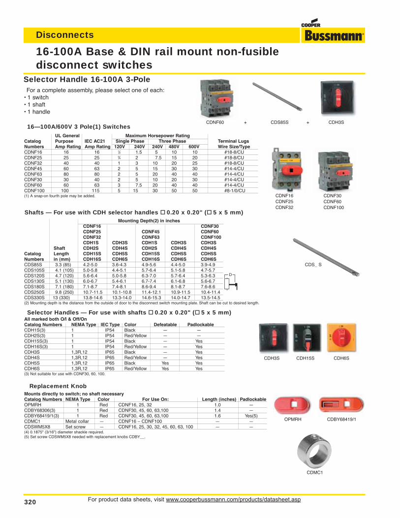
For product data sheets, visit www.cooperbussmann.com/products/datasheet.asp320
Disconnects
16-100A Base & DIN rail mount non-fusibledisconnect switches
Selector Handle 16-100A 3-PoleFor a complete assembly, please select one of each:
• 1 switch• 1 shaft• 1 handle
CDNF30CDNF60CDNF100
CDNF60 + CDS85S + CDH3S
CDNF16CDNF25CDNF32
CDS_ S
CDH15SCDH3S CDH6S
CDMC1
OPMRH CDBY68419/1
UL General Maximum Horsepower RatingCatalog Purpose IEC AC21 Single Phase Three Phase Terminal LugsNumbers Amp Rating Amp Rating 120V 240V 240V 480V 600V Wire Size/TypeCDNF16 16 16 1⁄2 1.5 5 10 10 #18-8/CUCDNF25 25 25 3⁄4 2 7.5 15 20 #18-8/CUCDNF32 40 40 1 3 10 20 25 #18-8/CUCDNF45 60 63 2 5 15 30 30 #14-4/CUCDNF63 80 80 2 5 20 40 40 #14-4/CUCDNF30 30 40 2 5 10 20 30 #14-4/CUCDNF60 60 63 3 7.5 20 40 40 #14-4/CUCDNF100 100 115 5 15 30 50 50 #8-1/0/CU(1) A snap-on fourth pole may be added.
All marked both O/I & Off/OnCatalog Numbers NEMA Type IEC Type Color Defeatable PadlockableCDH1S(3) 1 IP54 Black — —CDH2S(3) 1 IP54 Red/Yellow — —CDH15S(3) 1 IP54 Black — YesCDH16S(3) 1 IP54 Red/Yellow — YesCDH3S 1,3R,12 IP65 Black — YesCDH4S 1,3R,12 IP65 Red/Yellow — YesCDH5S 1,3R,12 IP65 Black Yes YesCDH6S 1,3R,12 IP65 Red/Yellow Yes Yes(3) Not suitable for use with CDNF30, 60, 100.
Mounting Depth(2) in inchesCDNF16 CDNF30CDNF25 CDNF45 CDNF60CDNF32 CDNF63 CDNF100CDH1S CDH3S CDH1S CDH3S CDH3S
Shaft CDH2S CDH4S CDH2S CDH4S CDH4SCatalog Length CDH15S CDH5S CDH15S CDH5S CDH5SNumbers in (mm) CDH16S CDH6S CDH16S CDH6S CDH6SCDS85S 3.3 (85) 4.2-5.0 3.6-4.3 4.9-5.6 4.4-5.0 3.9-4.9CDS105S 4.1 (105) 5.0-5.8 4.4-5.1 5.7-6.4 5.1-5.8 4.7-5.7CDS120S 4.7 (120) 5.6-6.4 5.0-5.8 6.3-7.0 5.7-6.4 5.3-6.3CDS130S 5.1 (130) 6.0-6.7 5.4-6.1 6.7-7.4 6.1-6.8 5.6-6.7CDS180S 7.1 (180) 7.1-8.7 7.4-8.1 8.6-9.4 8.1-8.7 7.6-8.6CDS250S 9.8 (250) 10.7-11.5 10.1-10.8 11.4-12.1 10.9-11.5 10.4-11.4CDS330S 13 (330) 13.8-14.6 13.3-14.0 14.6-15.3 14.0-14.7 13.5-14.5(2) Mounting depth is the distance from the outside of door to the disconnect switch mounting plate. Shaft can be cut to desired length.
Mounts directly to switch; no shaft necessaryCatalog Numbers NEMA Type Color For Use On: Length (inches) PadlockableOPMRH 1 Red CDNF16, 25, 32 1.0 —CDBY68306(3) 1 Red CDNF30, 45, 60, 63,100 1.4 —CDBY68419/1(3) 1 Red CDNF30, 45, 60, 63,100 1.6 Yes(5)CDMC1 Metal collar — CDNF16 – CDNF100 — —CDSWM5X8 Set screw — CDNF16, 25, 30, 32, 45, 60, 63, 100 — —(4) 0.1875" (3/16") diameter shackle required.(5) Set screw CDSWM5X8 needed with replacement knobs CDBY__.
16—100A/600V 3 Pole(1) Switches
Shafts — For use with CDH selector handles 0.20 x 0.20" ( 5 x 5 mm)
Selector Handles — For use with shafts 0.20 x 0.20" ( 5 x 5 mm)
Replacement Knob
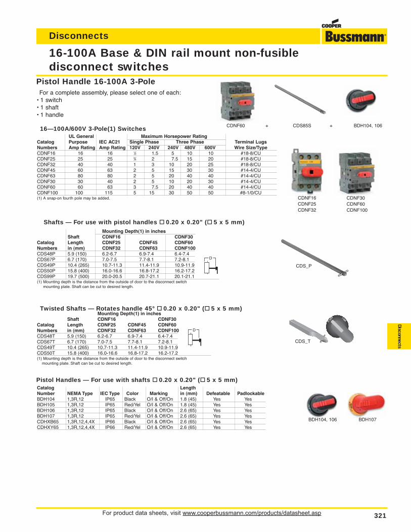
For product data sheets, visit www.cooperbussmann.com/products/datasheet.asp 321
Disconnects
Disconnects
Twisted Shafts — Rotates handle 45° 0.20 x 0.20" ( 5 x 5 mm)Mounting Depth(1) in inches
Shaft CDNF16 CDNF30Catalog Length CDNF25 CDNF45 CDNF60Numbers in (mm) CDNF32 CDNF63 CDNF100CDS48T 5.9 (150) 6.2-6.7 6.9-7.4 6.4-7.4CDS67T 6.7 (170) 7.0-7.5 7.7-8.1 7.2-8.1CDS49T 10.4 (265) 10.7-11.3 11.4-11.9 10.9-11.9CDS50T 15.8 (400) 16.0-16.6 16.8-17.2 16.2-17.2(1) Mounting depth is the distance from the outside of door to the disconnect switch
mounting plate. Shaft can be cut to desired length.
Mounting Depth(1) in inchesShaft CDNF16 CDNF30
Catalog Length CDNF25 CDNF45 CDNF60Numbers in (mm) CDNF32 CDNF63 CDNF100CDS48P 5.9 (150) 6.2-6.7 6.9-7.4 6.4-7.4CDS67P 6.7 (170) 7.0-7.5 7.7-8.1 7.2-8.1CDS49P 10.4 (265) 10.7-11.3 11.4-11.9 10.9-11.9CDS50P 15.8 (400) 16.0-16.6 16.8-17.2 16.2-17.2CDS99P 19.7 (500) 20.0-20.5 20.7-21.1 20.1-21.1(1) Mounting depth is the distance from the outside of door to the disconnect switch
mounting plate. Shaft can be cut to desired length.
16-100A Base & DIN rail mount non-fusibledisconnect switches
Pistol Handle 16-100A 3-PoleFor a complete assembly, please select one of each:
• 1 switch• 1 shaft• 1 handle
CDNF60 + CDS85S + BDH104, 106
CDS_P
BDH107BDH104, 106
CDS_T
CDNF30CDNF60CDNF100
CDNF16CDNF25CDNF32
UL General Maximum Horsepower RatingCatalog Purpose IEC AC21 Single Phase Three Phase Terminal LugsNumbers Amp Rating Amp Rating 120V 240V 240V 480V 600V Wire Size/TypeCDNF16 16 16 1⁄2 1.5 5 10 10 #18-8/CUCDNF25 25 25 3⁄4 2 7.5 15 20 #18-8/CUCDNF32 40 40 1 3 10 20 25 #18-8/CUCDNF45 60 63 2 5 15 30 30 #14-4/CUCDNF63 80 80 2 5 20 40 40 #14-4/CUCDNF30 30 40 2 5 10 20 30 #14-4/CUCDNF60 60 63 3 7.5 20 40 40 #14-4/CUCDNF100 100 115 5 15 30 50 50 #8-1/0/CU(1) A snap-on fourth pole may be added.
Catalog LengthNumber NEMA Type IEC Type Color Marking in (mm) Defeatable PadlockableBDH104 1,3R,12 IP65 Black O/I & Off/On 1.8 (45) Yes YesBDH105 1,3R,12 IP65 Red/Yel O/I & Off/On 1.8 (45) Yes YesBDH106 1,3R,12 IP65 Black O/I & Off/On 2.6 (65) Yes YesBDH107 1,3R,12 IP65 Red/Yel O/I & Off/On 2.6 (65) Yes YesCDHXB65 1,3R,12,4,4X IP66 Black O/I & Off/On 2.6 (65) Yes YesCDHXY65 1,3R,12,4,4X IP66 Red/Yel O/I & Off/On 2.6 (65) Yes Yes
16—100A/600V 3-Pole(1) Switches
Shafts — For use with pistol handles 0.20 x 0.20" ( 5 x 5 mm)
Pistol Handles — For use with shafts 0.20 x 0.20" ( 5 x 5 mm)
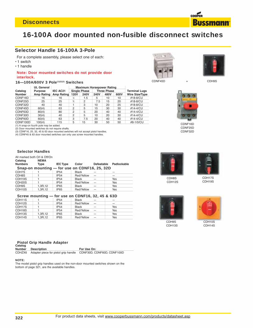
For product data sheets, visit www.cooperbussmann.com/products/datasheet.asp322
Disconnects
16-100A door mounted non-fusible disconnect switches
Selector Handle 16-100A 3-PoleFor a complete assembly, please select one of each:
• 1 switch• 1 handle
Note: Door mounted switches do not provide door interlock.
CDH8SCDH12S
CDNF45D + CDH9S
CDNF16DCDNF25DCDNF32D
CDH9SCDH13S
CDH17SCDH19S
CDH10SCDH14S
UL General Maximum Horsepower RatingCatalog Purpose IEC AC21 Single Phase Three Phase Terminal LugsNumber Amp Rating Amp Rating 120V 240V 240V 480V 600V Wire Size/TypeCDNF16D 16 16 1⁄2 1.5 5 10 10 #18-8/CUCDNF25D 25 25 3⁄4 2 7.5 15 20 #18-8/CUCDNF32D 40 40 1 3 10 20 25 #18-8/CUCDNF45D 60(4) 63 2 5 15 30 30 #14-4/CUCDNF63D 80(4) 80 2 5 20 40 40 #14-4/CUCDNF30D 30(4) 40 2 5 10 20 30 #14-4/CUCDNF60D 60(4) 63 3 7.5 20 40 40 #14-4/CUCDNF100D 100(4) 115 5 15 30 50 50 #8-1/0/CU(1) A snap-on fourth pole may be added.(2) Door mounted switches do not require shafts.(3) CDNF16, 25, 32, 45 & 63 door mounted switches will not accept pistol handles.(4) CDNF45 & 63 door mounted switches can only use screw mounted handles.
Selector HandlesAll marked both O/I & Off/OnCatalog NEMANumbers Type IEC Type Color Defeatable Padlockable
Snap-on mounting — for use on CDNF16, 25, 32DCDH7S 1 IP54 Black — —CDH8S 1 IP54 Red/Yellow — —CDH19S 1 IP54 Black — YesCDH20S 1 IP54 Red/Yellow — YesCDH9S 1,3R,12 IP65 Black — YesCDH10S 1,3R,12 IP65 Red/Yellow — Yes
Screw mounting — for use on CDNF16, 32, 45 & 63DCDH11S 1 IP54 Black — —CDH12S 1 IP54 Red/Yellow — —CDH17S 1 IP54 Black — YesCDH18S 1 IP54 Red/Yellow — YesCDH13S 1,3R,12 IP65 Black — YesCDH14S 1,3R,12 IP65 Red/Yellow — Yes
Pistol Grip Handle AdapterCatalogNumber Description For Use On:CDHZX6 Adapter piece for pistol grip handle CDNF30D, CDNF60D, CDNF100D
16—100A/600V 3 Pole(1)(2)(3) Switches
NOTE:The model pistol grip handles used on the non-door mounted switches shown on thebottom of page 321, are the available handles.
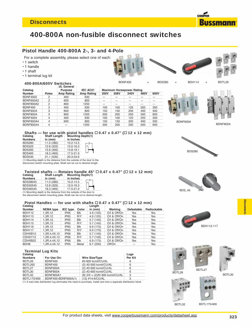
For product data sheets, visit www.cooperbussmann.com/products/datasheet.asp 323
Disconnects
Disconnects
400-800A non-fusible disconnect switches
Twisted shafts — Rotates handle 45° 0.47 x 0.47" ( 12 x 12 mm)Catalog Shaft Length Mounting Depth(1)Numbers in (mm) in InchesBDS28045 11.0 (280) 10.2-14.5BDS32545 12.8 (325) 12.0-16.3BDS46545 18.3 (465) 17.5-21.9(1) Mounting depth is the distance from the outside of the door to the disconnect switch mounting plate. Shaft can be cut to desired length.
Shafts — for use with pistol handles 0.47 x 0.47" ( 12 x 12 mm)Catalog Shaft Length Mounting Depth(1)Numbers in (mm) in InchesBDS280 11.0 (280) 10.2-14.5BDS325 12.8 (325) 12.0-16.3BDS395 15.6 (395) 14.8-19.1BDS465 18.3 (465) 17.5-21.9BDS535 21.1 (535) 20.3-24.6(1) Mounting depth is the distance from the outside of the door to the disconnect switch mounting plate. Shaft can be cut to desired length.
Pistol Handle 400-800A 2-, 3- and 4-PoleFor a complete assembly, please select one of each:
• 1 switch• 1 handle• 1 shaft• 1 terminal lug kit
400-800A/600V SwitchesUL General
Catalog Purpose IEC AC21 Maximum Horsepower RatingNumber Poles Amp Rating Amp Rating 200V 208V 240V 480V 600VBDNF4002 2 400 630 — — — — —BDNF600A2 2 600 800 — — — — —BDNF800A2 2 800 1250 — — — — —BDNF400 3 400 630 100 100 125 250 350BDNF600A 3 600 800 150 150 200 400 500BDNF800A 3 800 1250 200 200 250 500 600BDNF4004 4 400 630 100 100 125 250 350BDNF600A4 4 600 800 150 150 200 400 500BDNF800A4 4 — 1250 200 200 250 500 600
Pistol Handles — for use with shafts 0.47 x 0.47” ( 12 x 12 mm)Catalog LengthNumber NEMA type IEC type Color in (mm) Marking Defeatable PadlockableBDH112 1,3R,12 IP65 Blk 4.9 (125) O/I & Off/On Yes YesBDH113 1,3R,12 IP65 R/Y 4.9 (125) O/I & Off/On Yes YesBDH114 1,3R,12 IP65 Blk 5.7 (145) O/I & Off/On Yes YesBDH115 1,3R,12 IP65 R/Y 5.7 (145) O/I & Off/On Yes YesBDH116 1,3R,12 IP65 Blk 6.9 (175) O/I & Off/On Yes YesBDH117 1,3R,12 IP65 R/Y 6.9 (175) O/I & Off/On Yes YesCDHXB12 1,3R,4,4X,12 IP66 Blk 5.7 (145) O/I & Off/On Yes YesCDHXY12 1,3R,4,4X,12 IP66 R/Y 5.7 (145) O/I & Off/On Yes YesCDHXB22 1,3R,4,4X,12 IP66 Blk 6.9 (175) O/I & Off/On Yes YesBDH8 1,3R,4,4X,12 IP65 Metal 8.7 (220) Off/On — Yes
Terminal Lug KitsCatalog LugsNumbers For Use On: Wire Size/Type Per KitBDTL26 BDNF400 #2-600 kcmil/CU/AL 6BDTL262 BDNF400 (2) #2-500 kcmil/CU/AL 6BDTL27 BDNF600A (2) #2-600 kcmil/CU/AL 6BDTL30 BDNF800A (2) #2-600 kcmil/CU/AL 6BDTL32 BDNF800A1 (8) 2/0 + (2)#2 600 kcmil/CU/AL 3BDTL175/400 BDNF400-BDNF600A(1) (12) #14-6/CU/AL 3(1) A load side distribution lug eliminates the need to purchase, install and wire a separate distribution block.
BDS280
BDS_45
BDNF400 + BDS280 + BDH114 + BDTL26
BDNF600ABDNF800A
BDH112-117
BDTL26BDTL27
BDTL30
BDTL32 BDTL175/400
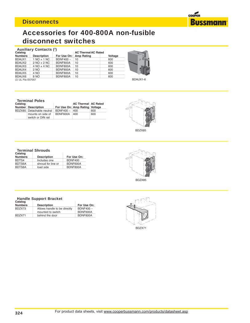
For product data sheets, visit www.cooperbussmann.com/products/datasheet.asp324
Disconnects
Accessories for 400-800A non-fusibledisconnect switches
Auxiliary Contacts (2)Catalog AC ThermalAC RatedNumbers Description For Use On: Amp Rating VoltageBDAUX1 1 NO + 1 NC BDNF400 – 10 600BDAUX2 2 NO + 2 NC BDNF800A 10 600BDAUX3 4 NO + 4 NC BDNF800A 10 600BDAUX4 2 NO BDNF800A 10 600BDAUX5 4 NO BDNF800A 10 600BDAUX6 8 NO BDNF800A 10 600(2) UL File E57057
Terminal PolesCatalog AC Thermal AC RatedNumber Description For Use On: Amp Rating VoltageBDZX85 Detachable neutral BDNF400 – 400 600
mounts on side of BDNF600A 400 600switch or DIN rail
Terminal ShroudsCatalogNumbers Description For Use On:BDTS4 Includes one BDNF400BDTS6A shroud for line or BDNF600ABDTS8A load side BDNF800A
Handle Support BracketCatalogNumbers Description For Use On:BDZX73 Allows handle to be directly BDNF400 –
mounted to switch BDNF600ABDZX71 behind the door BDNF800A
BDAUX1-6
BDZX85
BDZX85
BDZX71
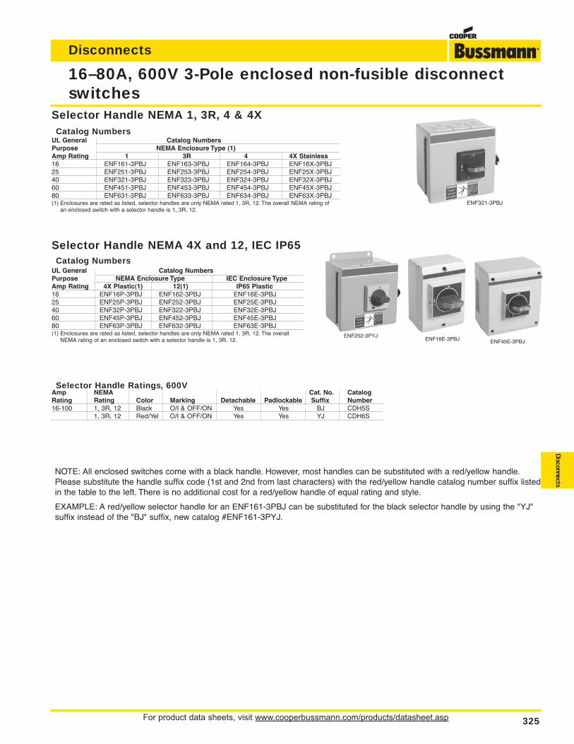
For product data sheets, visit www.cooperbussmann.com/products/datasheet.asp 325
Disconnects
Disconnects
16–80A, 600V 3-Pole enclosed non-fusible disconnectswitches
ENF321-3PBJ
Selector Handle NEMA 1, 3R, 4 & 4XCatalog Numbers
UL General Catalog NumbersPurpose NEMA Enclosure Type (1)Amp Rating 1 3R 4 4X Stainless16 ENF161-3PBJ ENF163-3PBJ ENF164-3PBJ ENF16X-3PBJ25 ENF251-3PBJ ENF253-3PBJ ENF254-3PBJ ENF25X-3PBJ40 ENF321-3PBJ ENF323-3PBJ ENF324-3PBJ ENF32X-3PBJ60 ENF451-3PBJ ENF453-3PBJ ENF454-3PBJ ENF45X-3PBJ80 ENF631-3PBJ ENF633-3PBJ ENF634-3PBJ ENF63X-3PBJ(1) Enclosures are rated as listed, selector handles are only NEMA rated 1, 3R, 12. The overall NEMA rating of
an enclosed switch with a selector handle is 1, 3R, 12.
Selector Handle NEMA 4X and 12, IEC IP65Catalog Numbers
UL General Catalog NumbersPurpose NEMA Enclosure Type IEC Enclosure TypeAmp Rating 4X Plastic(1) 12(1) IP65 Plastic16 ENF16P-3PBJ ENF162-3PBJ ENF16E-3PBJ25 ENF25P-3PBJ ENF252-3PBJ ENF25E-3PBJ40 ENF32P-3PBJ ENF322-3PBJ ENF32E-3PBJ60 ENF45P-3PBJ ENF452-3PBJ ENF45E-3PBJ80 ENF63P-3PBJ ENF632-3PBJ ENF63E-3PBJ(1) Enclosures are rated as listed, selector handles are only NEMA rated 1, 3R, 12. The overall
NEMA rating of an enclosed switch with a selector handle is 1, 3R, 12.ENF252-3PYJ
ENF16E-3PBJ ENF45E-3PBJ
Selector Handle Ratings, 600VAmp NEMA Cat. No. CatalogRating Rating Color Marking Detachable Padlockable Suffix Number16-100 1, 3R, 12 Black O/I & OFF/ON Yes Yes BJ CDH5S
1, 3R, 12 Red/Yel O/I & OFF/ON Yes Yes YJ CDH6S
NOTE: All enclosed switches come with a black handle. However, most handles can be substituted with a red/yellow handle.Please substitute the handle suffix code (1st and 2nd from last characters) with the red/yellow handle catalog number suffix listedin the table to the left. There is no additional cost for a red/yellow handle of equal rating and style.
EXAMPLE: A red/yellow selector handle for an ENF161-3PBJ can be substituted for the black selector handle by using the "YJ"suffix instead of the "BJ" suffix, new catalog #ENF161-3PYJ.
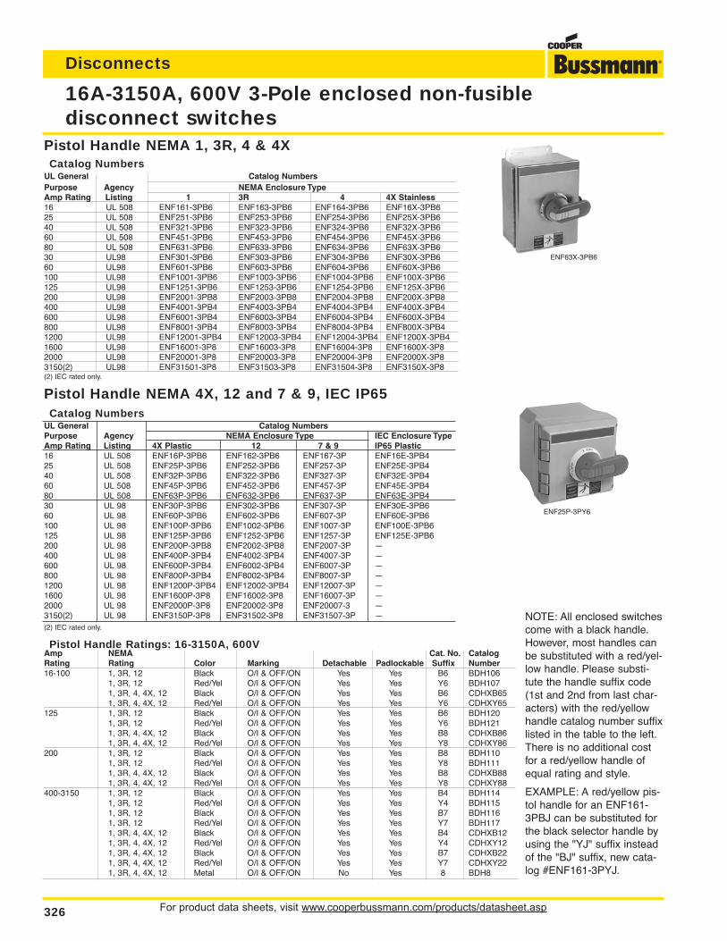
For product data sheets, visit www.cooperbussmann.com/products/datasheet.asp326
Disconnects
16A-3150A, 600V 3-Pole enclosed non-fusible disconnect switches
NOTE: All enclosed switchescome with a black handle.However, most handles canbe substituted with a red/yel-low handle. Please substi-tute the handle suffix code(1st and 2nd from last char-acters) with the red/yellowhandle catalog number suffixlisted in the table to the left.There is no additional costfor a red/yellow handle ofequal rating and style.
EXAMPLE: A red/yellow pis-tol handle for an ENF161-3PBJ can be substituted forthe black selector handle byusing the "YJ" suffix insteadof the "BJ" suffix, new cata-log #ENF161-3PYJ.
Pistol Handle NEMA 4X, 12 and 7 & 9, IEC IP65Catalog Numbers
UL General Catalog NumbersPurpose Agency NEMA Enclosure Type IEC Enclosure TypeAmp Rating Listing 4X Plastic 12 7 & 9 IP65 Plastic16 UL 508 ENF16P-3PB6 ENF162-3PB6 ENF167-3P ENF16E-3PB425 UL 508 ENF25P-3PB6 ENF252-3PB6 ENF257-3P ENF25E-3PB440 UL 508 ENF32P-3PB6 ENF322-3PB6 ENF327-3P ENF32E-3PB460 UL 508 ENF45P-3PB6 ENF452-3PB6 ENF457-3P ENF45E-3PB480 UL 508 ENF63P-3PB6 ENF632-3PB6 ENF637-3P ENF63E-3PB430 UL 98 ENF30P-3PB6 ENF302-3PB6 ENF307-3P ENF30E-3PB660 UL 98 ENF60P-3PB6 ENF602-3PB6 ENF607-3P ENF60E-3PB6100 UL 98 ENF100P-3PB6 ENF1002-3PB6 ENF1007-3P ENF100E-3PB6125 UL 98 ENF125P-3PB6 ENF1252-3PB6 ENF1257-3P ENF125E-3PB6200 UL 98 ENF200P-3PB8 ENF2002-3PB8 ENF2007-3P —400 UL 98 ENF400P-3PB4 ENF4002-3PB4 ENF4007-3P —600 UL 98 ENF600P-3PB4 ENF6002-3PB4 ENF6007-3P —800 UL 98 ENF800P-3PB4 ENF8002-3PB4 ENF8007-3P —1200 UL 98 ENF1200P-3PB4 ENF12002-3PB4 ENF12007-3P —1600 UL 98 ENF1600P-3P8 ENF16002-3P8 ENF16007-3P —2000 UL 98 ENF2000P-3P8 ENF20002-3P8 ENF20007-3 —3150(2) UL 98 ENF3150P-3P8 ENF31502-3P8 ENF31507-3P —(2) IEC rated only.
ENF25P-3PY6
ENF63X-3PB6
Pistol Handle NEMA 1, 3R, 4 & 4XCatalog Numbers
UL General Catalog NumbersPurpose Agency NEMA Enclosure TypeAmp Rating Listing 1 3R 4 4X Stainless16 UL 508 ENF161-3PB6 ENF163-3PB6 ENF164-3PB6 ENF16X-3PB625 UL 508 ENF251-3PB6 ENF253-3PB6 ENF254-3PB6 ENF25X-3PB640 UL 508 ENF321-3PB6 ENF323-3PB6 ENF324-3PB6 ENF32X-3PB660 UL 508 ENF451-3PB6 ENF453-3PB6 ENF454-3PB6 ENF45X-3PB680 UL 508 ENF631-3PB6 ENF633-3PB6 ENF634-3PB6 ENF63X-3PB630 UL98 ENF301-3PB6 ENF303-3PB6 ENF304-3PB6 ENF30X-3PB660 UL98 ENF601-3PB6 ENF603-3PB6 ENF604-3PB6 ENF60X-3PB6100 UL98 ENF1001-3PB6 ENF1003-3PB6 ENF1004-3PB6 ENF100X-3PB6125 UL98 ENF1251-3PB6 ENF1253-3PB6 ENF1254-3PB6 ENF125X-3PB6200 UL98 ENF2001-3PB8 ENF2003-3PB8 ENF2004-3PB8 ENF200X-3PB8400 UL98 ENF4001-3PB4 ENF4003-3PB4 ENF4004-3PB4 ENF400X-3PB4600 UL98 ENF6001-3PB4 ENF6003-3PB4 ENF6004-3PB4 ENF600X-3PB4800 UL98 ENF8001-3PB4 ENF8003-3PB4 ENF8004-3PB4 ENF800X-3PB41200 UL98 ENF12001-3PB4 ENF12003-3PB4 ENF12004-3PB4 ENF1200X-3PB41600 UL98 ENF16001-3P8 ENF16003-3P8 ENF16004-3P8 ENF1600X-3P82000 UL98 ENF20001-3P8 ENF20003-3P8 ENF20004-3P8 ENF2000X-3P83150(2) UL98 ENF31501-3P8 ENF31503-3P8 ENF31504-3P8 ENF3150X-3P8(2) IEC rated only.
Pistol Handle Ratings: 16-3150A, 600VAmp NEMA Cat. No. CatalogRating Rating Color Marking Detachable Padlockable Suffix Number16-100 1, 3R, 12 Black O/I & OFF/ON Yes Yes B6 BDH106
1, 3R, 12 Red/Yel O/I & OFF/ON Yes Yes Y6 BDH1071, 3R, 4, 4X, 12 Black O/I & OFF/ON Yes Yes B6 CDHXB651, 3R, 4, 4X, 12 Red/Yel O/I & OFF/ON Yes Yes Y6 CDHXY65
125 1, 3R, 12 Black O/I & OFF/ON Yes Yes B6 BDH1201, 3R, 12 Red/Yel O/I & OFF/ON Yes Yes Y6 BDH1211, 3R, 4, 4X, 12 Black O/I & OFF/ON Yes Yes B8 CDHXB861, 3R, 4, 4X, 12 Red/Yel O/I & OFF/ON Yes Yes Y8 CDHXY86
200 1, 3R, 12 Black O/I & OFF/ON Yes Yes B8 BDH1101, 3R, 12 Red/Yel O/I & OFF/ON Yes Yes Y8 BDH1111, 3R, 4, 4X, 12 Black O/I & OFF/ON Yes Yes B8 CDHXB881, 3R, 4, 4X, 12 Red/Yel O/I & OFF/ON Yes Yes Y8 CDHXY88
400-3150 1, 3R, 12 Black O/I & OFF/ON Yes Yes B4 BDH1141, 3R, 12 Red/Yel O/I & OFF/ON Yes Yes Y4 BDH1151, 3R, 12 Black O/I & OFF/ON Yes Yes B7 BDH1161, 3R, 12 Red/Yel O/I & OFF/ON Yes Yes Y7 BDH1171, 3R, 4, 4X, 12 Black O/I & OFF/ON Yes Yes B4 CDHXB121, 3R, 4, 4X, 12 Red/Yel O/I & OFF/ON Yes Yes Y4 CDHXY121, 3R, 4, 4X, 12 Black O/I & OFF/ON Yes Yes B7 CDHXB221, 3R, 4, 4X, 12 Red/Yel O/I & OFF/ON Yes Yes Y7 CDHXY221, 3R, 4, 4X, 12 Metal O/I & OFF/ON No Yes 8 BDH8
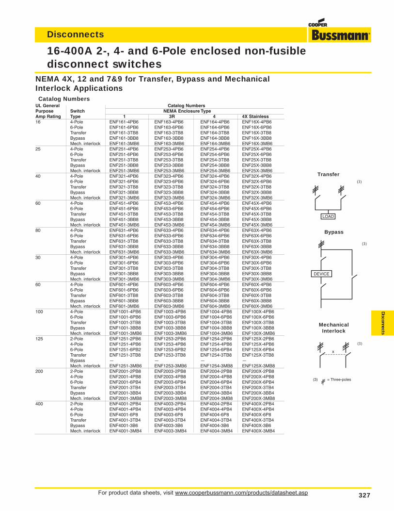
For product data sheets, visit www.cooperbussmann.com/products/datasheet.asp 327
Disconnects
Disconnects
16-400A 2-, 4- and 6-Pole enclosed non-fusible disconnect switches
NEMA 4X, 12 and 7&9 for Transfer, Bypass and MechanicalInterlock ApplicationsCatalog Numbers
UL General Catalog NumbersPurpose Switch NEMA Enclosure TypeAmp Rating Type 1 3R 4 4X Stainless16 4-Pole ENF161-4PB6 ENF163-4PB6 ENF164-4PB6 ENF16X-4PB6
6-Pole ENF161-6PB6 ENF163-6PB6 ENF164-6PB6 ENF16X-6PB6Transfer ENF161-3TB8 ENF163-3TB8 ENF164-3TB8 ENF16X-3TB8Bypass ENF161-3BB8 ENF163-3BB8 ENF164-3BB8 ENF16X-3BB8Mech. interlock ENF161-3MB6 ENF163-3MB6 ENF164-3MB6 ENF16X-3MB6
25 4-Pole ENF251-4PB6 ENF253-4PB6 ENF254-4PB6 ENF25X-4PB66-Pole ENF251-6PB6 ENF253-6PB6 ENF254-6PB6 ENF25X-6PB6Transfer ENF251-3TB8 ENF253-3TB8 ENF254-3TB8 ENF25X-3TB8Bypass ENF251-3BB8 ENF253-3BB8 ENF254-3BB8 ENF25X-3BB8Mech. interlock ENF251-3MB6 ENF253-3MB6 ENF254-3MB6 ENF25X-3MB6
40 4-Pole ENF321-4PB6 ENF323-4PB6 ENF324-4PB6 ENF32X-4PB66-Pole ENF321-6PB6 ENF323-6PB6 ENF324-6PB6 ENF32X-6PB6Transfer ENF321-3TB8 ENF323-3TB8 ENF324-3TB8 ENF32X-3TB8Bypass ENF321-3BB8 ENF323-3BB8 ENF324-3BB8 ENF32X-3BB8Mech. interlock ENF321-3MB6 ENF323-3MB6 ENF324-3MB6 ENF32X-3MB6
60 4-Pole ENF451-4PB6 ENF453-4PB6 ENF454-4PB6 ENF45X-4PB66-Pole ENF451-6PB6 ENF453-6PB6 ENF454-6PB6 ENF45X-6PB6Transfer ENF451-3TB8 ENF453-3TB8 ENF454-3TB8 ENF45X-3TB8Bypass ENF451-3BB8 ENF453-3BB8 ENF454-3BB8 ENF45X-3BB8Mech. interlock ENF451-3MB6 ENF453-3MB6 ENF454-3MB6 ENF45X-3MB6
80 4-Pole ENF631-4PB6 ENF633-4PB6 ENF634-4PB6 ENF63X-4PB66-Pole ENF631-6PB6 ENF633-6PB6 ENF634-6PB6 ENF63X-6PB6Transfer ENF631-3TB8 ENF633-3TB8 ENF634-3TB8 ENF63X-3TB8Bypass ENF631-3BB8 ENF633-3BB8 ENF634-3BB8 ENF63X-3BB8Mech. interlock ENF631-3MB6 ENF633-3MB6 ENF634-3MB6 ENF63X-3MB6
30 4-Pole ENF301-4PB6 ENF303-4PB6 ENF304-4PB6 ENF30X-4PB66-Pole ENF301-6PB6 ENF303-6PB6 ENF304-6PB6 ENF30X-6PB6Transfer ENF301-3TB8 ENF303-3TB8 ENF304-3TB8 ENF30X-3TB8Bypass ENF301-3BB8 ENF303-3BB8 ENF304-3BB8 ENF30X-3BB8Mech. interlock ENF301-3MB6 ENF303-3MB6 ENF304-3MB6 ENF30X-3MB6
60 4-Pole ENF601-4PB6 ENF603-4PB6 ENF604-4PB6 ENF60X-4PB66-Pole ENF601-6PB6 ENF603-6PB6 ENF604-6PB6 ENF60X-6PB6Transfer ENF601-3TB8 ENF603-3TB8 ENF604-3TB8 ENF60X-3TB8Bypass ENF601-3BB8 ENF603-3BB8 ENF604-3BB8 ENF60X-3BB8Mech. interlock ENF601-3MB6 ENF603-3MB6 ENF604-3MB6 ENF60X-3MB6
100 4-Pole ENF1001-4PB6 ENF1003-4PB6 ENF1004-4PB6 ENF100X-4PB66-Pole ENF1001-6PB6 ENF1003-6PB6 ENF1004-6PB6 ENF100X-6PB6Transfer ENF1001-3TB8 ENF1003-3TB8 ENF1004-3TB8 ENF100X-3TB8Bypass ENF1001-3BB8 ENF1003-3BB8 ENF1004-3BB8 ENF100X-3BB8Mech. interlock ENF1001-3MB6 ENF1003-3MB6 ENF1004-3MB6 ENF100X-3MB6
125 2-Pole ENF1251-2PB6 ENF1253-2PB6 ENF1254-2PB6 ENF125X-2PB64-Pole ENF1251-4PB6 ENF1253-4PB6 ENF1254-4PB6 ENF125X-4PB66-Pole ENF1251-6PB2 ENF1253-6PB2 ENF1254-6PB4 ENF125X-6PB4Transfer ENF1251-3TB8 ENF1253-3TB8 ENF1254-3TB8 ENF125X-3TB8Bypass — — — —Mech. interlock ENF1251-3MB6 ENF1253-3MB6 ENF1254-3MB8 ENF125X-3MB8
200 2-Pole ENF2001-2PB8 ENF2003-2PB8 ENF2004-2PB8 ENF200X-2PB84-Pole ENF2001-4PB8 ENF2003-4PB8 ENF2004-4PB8 ENF200X-4PB86-Pole ENF2001-6PB4 ENF2003-6PB4 ENF2004-6PB4 ENF200X-6PB4Transfer ENF2001-3TB4 ENF2003-3TB4 ENF2004-3TB4 ENF200X-3TB4Bypass ENF2001-3BB4 ENF2003-3BB4 ENF2004-3BB4 ENF200X-3BB4Mech. interlock ENF2001-3MB8 ENF2003-3MB8 ENF2004-3MB8 ENF200X-3MB8
400 2-Pole ENF4001-2PB4 ENF4003-2PB4 ENF4004-2PB4 ENF400X-2PB44-Pole ENF4001-4PB4 ENF4003-4PB4 ENF4004-4PB4 ENF400X-4PB46-Pole ENF4001-6P8 ENF4003-6P8 ENF4004-6P8 ENF400X-6P8Transfer ENF4001-3TB4 ENF4003-3TB4 ENF4004-3TB4 ENF400X-3TB4Bypass ENF4001-3B6 ENF4003-3B6 ENF4004-3B6 ENF400X-3B6Mech. interlock ENF4001-3MB4 ENF4003-3MB4 ENF4004-3MB4 ENF400X-3MB4
(3) = Three-poles
Transfer(3)
Bypass
(3)
MechanicalInterlock
(3)
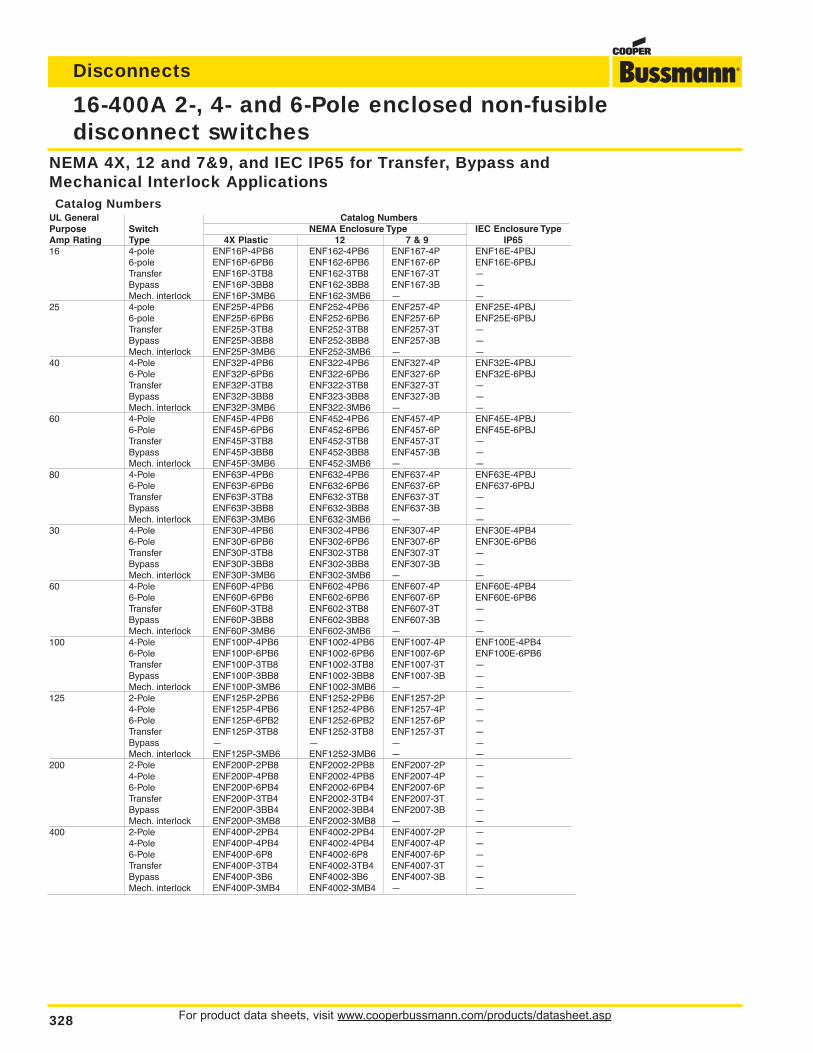
For product data sheets, visit www.cooperbussmann.com/products/datasheet.asp328
Disconnects
16-400A 2-, 4- and 6-Pole enclosed non-fusible disconnect switches
NEMA 4X, 12 and 7&9, and IEC IP65 for Transfer, Bypass andMechanical Interlock ApplicationsCatalog Numbers
UL General Catalog NumbersPurpose Switch NEMA Enclosure Type IEC Enclosure TypeAmp Rating Type 4X Plastic 12 7 & 9 IP6516 4-pole ENF16P-4PB6 ENF162-4PB6 ENF167-4P ENF16E-4PBJ
6-pole ENF16P-6PB6 ENF162-6PB6 ENF167-6P ENF16E-6PBJTransfer ENF16P-3TB8 ENF162-3TB8 ENF167-3T —Bypass ENF16P-3BB8 ENF162-3BB8 ENF167-3B —Mech. interlock ENF16P-3MB6 ENF162-3MB6 — —
25 4-pole ENF25P-4PB6 ENF252-4PB6 ENF257-4P ENF25E-4PBJ6-pole ENF25P-6PB6 ENF252-6PB6 ENF257-6P ENF25E-6PBJTransfer ENF25P-3TB8 ENF252-3TB8 ENF257-3T —Bypass ENF25P-3BB8 ENF252-3BB8 ENF257-3B —Mech. interlock ENF25P-3MB6 ENF252-3MB6 — —
40 4-Pole ENF32P-4PB6 ENF322-4PB6 ENF327-4P ENF32E-4PBJ6-Pole ENF32P-6PB6 ENF322-6PB6 ENF327-6P ENF32E-6PBJTransfer ENF32P-3TB8 ENF322-3TB8 ENF327-3T —Bypass ENF32P-3BB8 ENF323-3BB8 ENF327-3B —Mech. interlock ENF32P-3MB6 ENF322-3MB6 — —
60 4-Pole ENF45P-4PB6 ENF452-4PB6 ENF457-4P ENF45E-4PBJ6-Pole ENF45P-6PB6 ENF452-6PB6 ENF457-6P ENF45E-6PBJTransfer ENF45P-3TB8 ENF452-3TB8 ENF457-3T —Bypass ENF45P-3BB8 ENF452-3BB8 ENF457-3B —Mech. interlock ENF45P-3MB6 ENF452-3MB6 — —
80 4-Pole ENF63P-4PB6 ENF632-4PB6 ENF637-4P ENF63E-4PBJ6-Pole ENF63P-6PB6 ENF632-6PB6 ENF637-6P ENF637-6PBJTransfer ENF63P-3TB8 ENF632-3TB8 ENF637-3T —Bypass ENF63P-3BB8 ENF632-3BB8 ENF637-3B —Mech. interlock ENF63P-3MB6 ENF632-3MB6 — —
30 4-Pole ENF30P-4PB6 ENF302-4PB6 ENF307-4P ENF30E-4PB46-Pole ENF30P-6PB6 ENF302-6PB6 ENF307-6P ENF30E-6PB6Transfer ENF30P-3TB8 ENF302-3TB8 ENF307-3T —Bypass ENF30P-3BB8 ENF302-3BB8 ENF307-3B —Mech. interlock ENF30P-3MB6 ENF302-3MB6 — —
60 4-Pole ENF60P-4PB6 ENF602-4PB6 ENF607-4P ENF60E-4PB46-Pole ENF60P-6PB6 ENF602-6PB6 ENF607-6P ENF60E-6PB6Transfer ENF60P-3TB8 ENF602-3TB8 ENF607-3T —Bypass ENF60P-3BB8 ENF602-3BB8 ENF607-3B —Mech. interlock ENF60P-3MB6 ENF602-3MB6 — —
100 4-Pole ENF100P-4PB6 ENF1002-4PB6 ENF1007-4P ENF100E-4PB46-Pole ENF100P-6PB6 ENF1002-6PB6 ENF1007-6P ENF100E-6PB6Transfer ENF100P-3TB8 ENF1002-3TB8 ENF1007-3T —Bypass ENF100P-3BB8 ENF1002-3BB8 ENF1007-3B —Mech. interlock ENF100P-3MB6 ENF1002-3MB6 — —
125 2-Pole ENF125P-2PB6 ENF1252-2PB6 ENF1257-2P —4-Pole ENF125P-4PB6 ENF1252-4PB6 ENF1257-4P —6-Pole ENF125P-6PB2 ENF1252-6PB2 ENF1257-6P —Transfer ENF125P-3TB8 ENF1252-3TB8 ENF1257-3T —Bypass — — — —Mech. interlock ENF125P-3MB6 ENF1252-3MB6 — —
200 2-Pole ENF200P-2PB8 ENF2002-2PB8 ENF2007-2P —4-Pole ENF200P-4PB8 ENF2002-4PB8 ENF2007-4P —6-Pole ENF200P-6PB4 ENF2002-6PB4 ENF2007-6P —Transfer ENF200P-3TB4 ENF2002-3TB4 ENF2007-3T —Bypass ENF200P-3BB4 ENF2002-3BB4 ENF2007-3B —Mech. interlock ENF200P-3MB8 ENF2002-3MB8 — —
400 2-Pole ENF400P-2PB4 ENF4002-2PB4 ENF4007-2P —4-Pole ENF400P-4PB4 ENF4002-4PB4 ENF4007-4P —6-Pole ENF400P-6P8 ENF4002-6P8 ENF4007-6P —Transfer ENF400P-3TB4 ENF4002-3TB4 ENF4007-3T —Bypass ENF400P-3B6 ENF4002-3B6 ENF4007-3B —Mech. interlock ENF400P-3MB4 ENF4002-3MB4 — —
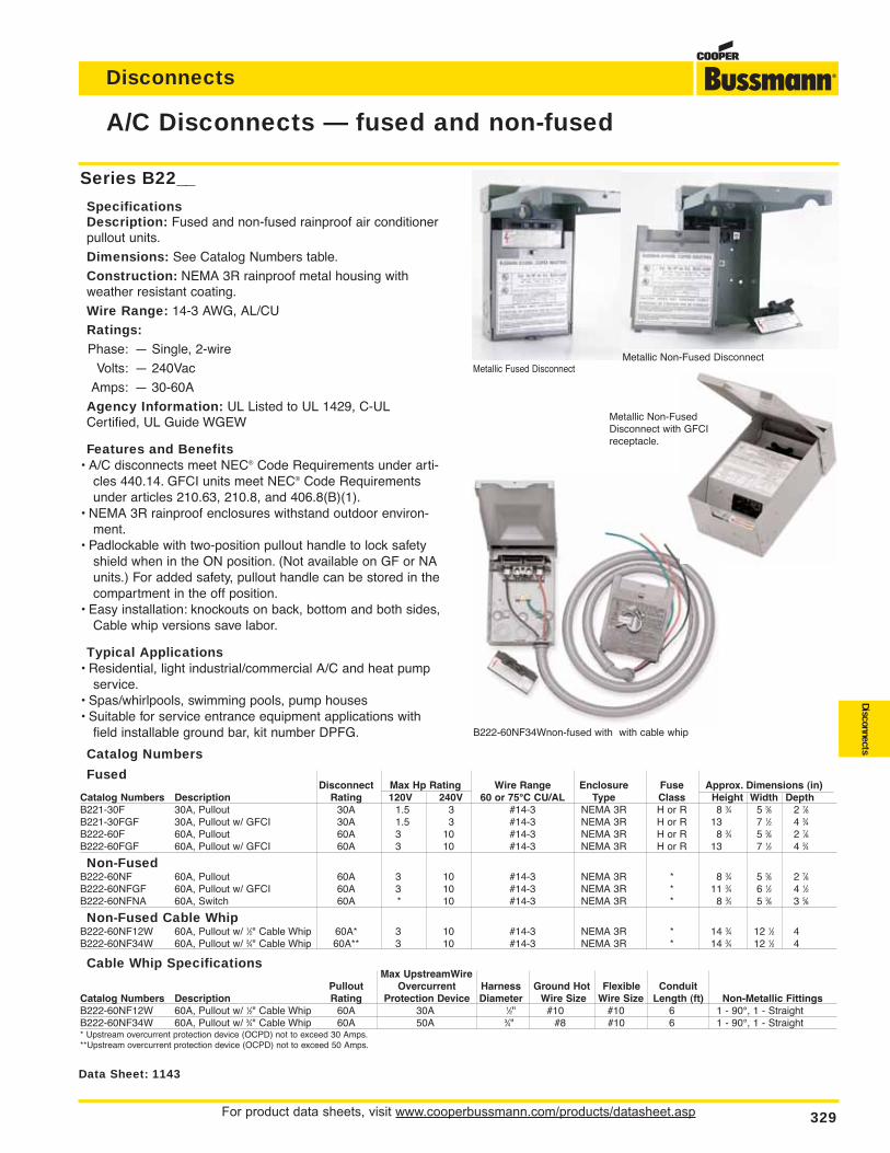
For product data sheets, visit www.cooperbussmann.com/products/datasheet.asp 329
Disconnects
Disconnects
A/C Disconnects — fused and non-fused
Data Sheet: 1143
Series B22__
SpecificationsDescription: Fused and non-fused rainproof air conditionerpullout units.
Dimensions: See Catalog Numbers table.
Construction: NEMA 3R rainproof metal housing withweather resistant coating.
Wire Range: 14-3 AWG, AL/CU
Ratings:Phase: — Single, 2-wire
Volts: — 240Vac
Amps: — 30-60A
Agency Information: UL Listed to UL 1429, C-ULCertified, UL Guide WGEW
Features and Benefits• A/C disconnects meet NEC® Code Requirements under arti-
cles 440.14. GFCI units meet NEC® Code Requirementsunder articles 210.63, 210.8, and 406.8(B)(1).
• NEMA 3R rainproof enclosures withstand outdoor environ-ment.
• Padlockable with two-position pullout handle to lock safetyshield when in the ON position. (Not available on GF or NAunits.) For added safety, pullout handle can be stored in thecompartment in the off position.
• Easy installation: knockouts on back, bottom and both sides,Cable whip versions save labor.
Typical Applications• Residential, light industrial/commercial A/C and heat pump
service.• Spas/whirlpools, swimming pools, pump houses• Suitable for service entrance equipment applications with
field installable ground bar, kit number DPFG.
Metallic Fused DisconnectMetallic Non-Fused Disconnect
Catalog Numbers
FusedDisconnect Max Hp Rating Wire Range Enclosure Fuse Approx. Dimensions (in)
Catalog Numbers Description Rating 120V 240V 60 or 75°C CU/AL Type Class Height Width DepthB221-30F 30A, Pullout 30A 1.5 3 #14-3 NEMA 3R H or R 8 3⁄4 5 3⁄8 2 7⁄8B221-30FGF 30A, Pullout w/ GFCI 30A 1.5 3 #14-3 NEMA 3R H or R 13 7 1⁄2 4 3⁄4B222-60F 60A, Pullout 60A 3 10 #14-3 NEMA 3R H or R 8 3⁄4 5 3⁄8 2 7⁄8B222-60FGF 60A, Pullout w/ GFCI 60A 3 10 #14-3 NEMA 3R H or R 13 7 1⁄2 4 3⁄4
Non-FusedB222-60NF 60A, Pullout 60A 3 10 #14-3 NEMA 3R * 8 3⁄4 5 3⁄8 2 7⁄8B222-60NFGF 60A, Pullout w/ GFCI 60A 3 10 #14-3 NEMA 3R * 11 3⁄4 6 1⁄2 4 1⁄2B222-60NFNA 60A, Switch 60A * 10 #14-3 NEMA 3R * 8 3⁄4 5 3⁄8 3 5⁄8
Non-Fused Cable WhipB222-60NF12W 60A, Pullout w/ 1⁄2" Cable Whip 60A* 3 10 #14-3 NEMA 3R * 14 3⁄4 12 1⁄2 4B222-60NF34W 60A, Pullout w/ 3⁄4" Cable Whip 60A** 3 10 #14-3 NEMA 3R * 14 3⁄4 12 1⁄2 4
Cable Whip SpecificationsMax UpstreamWire
Pullout Overcurrent Harness Ground Hot Flexible ConduitCatalog Numbers Description Rating Protection Device Diameter Wire Size Wire Size Length (ft) Non-Metallic FittingsB222-60NF12W 60A, Pullout w/ 1⁄2" Cable Whip 60A 30A 1⁄2" #10 #10 6 1 - 90°, 1 - StraightB222-60NF34W 60A, Pullout w/ 3⁄4" Cable Whip 60A 50A 3⁄4" #8 #10 6 1 - 90°, 1 - Straight* Upstream overcurrent protection device (OCPD) not to exceed 30 Amps.**Upstream overcurrent protection device (OCPD) not to exceed 50 Amps.
B222-60NF34Wnon-fused with with cable whip
Metallic Non-FusedDisconnect with GFCIreceptacle.
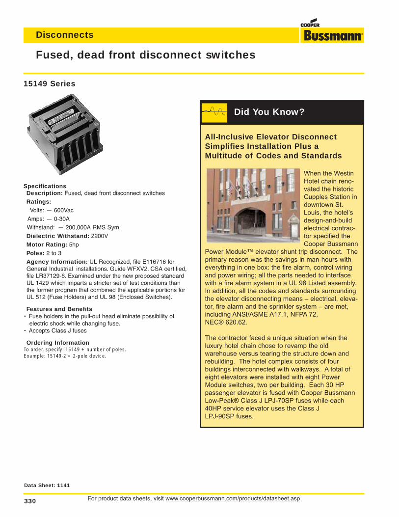
For product data sheets, visit www.cooperbussmann.com/products/datasheet.asp330
Disconnects
Fused, dead front disconnect switches
15149 Series
SpecificationsDescription: Fused, dead front disconnect switches
Ratings:Volts: — 600Vac
Amps: — 0-30A
Withstand: — 200,000A RMS Sym.
Dielectric Withstand: 2200V
Motor Rating: 5hp
Poles: 2 to 3
Agency Information: UL Recognized, file E116716 forGeneral Industrial installations. Guide WFXV2. CSA certified,file LR37129-6. Examined under the new proposed standardUL 1429 which imparts a stricter set of test conditions thanthe former program that combined the applicable portions forUL 512 (Fuse Holders) and UL 98 (Enclosed Switches).
Features and Benefits• Fuse holders in the pull-out head eliminate possibility of
electric shock while changing fuse.• Accepts Class J fuses
Ordering InformationTo order, specify: 15149 + number of poles.Example: 15149-2 = 2-pole device.
Data Sheet: 1141
All-Inclusive Elevator DisconnectSimplifies Installation Plus aMultitude of Codes and Standards
When the Westin
Hotel chain reno-
vated the historic
Cupples Station in
downtown St.
Louis, the hotel’s
design-and-build
electrical contrac-
tor specified the
Cooper Bussmann
Power Module™ elevator shunt trip disconnect. The
primary reason was the savings in man-hours with
everything in one box: the fire alarm, control wiring
and power wiring; all the parts needed to interface
with a fire alarm system in a UL 98 Listed assembly.
In addition, all the codes and standards surrounding
the elevator disconnecting means – electrical, eleva-
tor, fire alarm and the sprinkler system – are met,
including ANSI/ASME A17.1, NFPA 72,
NEC® 620.62.
The contractor faced a unique situation when the
luxury hotel chain chose to revamp the old
warehouse versus tearing the structure down and
rebuilding. The hotel complex consists of four
buildings interconnected with walkways. A total of
eight elevators were installed with eight Power
Module switches, two per building. Each 30 HP
passenger elevator is fused with Cooper Bussmann
Low-Peak® Class J LPJ-70SP fuses while each
40HP service elevator uses the Class J
LPJ-90SP fuses.
Did You Know?
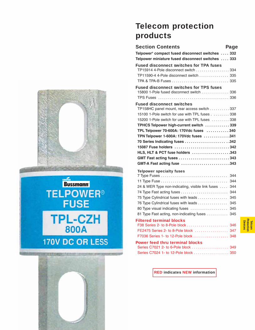
331
TelcomProtectionDevices
Section Contents PageTelpower® compact fused disconnect switches . . . . 332Telpower miniature fused disconnect switches . . . . 333
Fused disconnect switches for TPA fusesTP15914 4-Pole disconnect switch . . . . . . . . . . . . . . . . . 334
TP11590-4 4-Pole disconnect switch . . . . . . . . . . . . . . . 335
TPA & TPA-B Fuses . . . . . . . . . . . . . . . . . . . . . . . . . . . . . 335
Fused disconnect switches for TPS fuses15800 1-Pole fused disconnect switch . . . . . . . . . . . . . . 336
TPS Fuses . . . . . . . . . . . . . . . . . . . . . . . . . . . . . . . . . . . . 336
Fused disconnect switchesTP158HC panel mount, rear access switch . . . . . . . . . . 337
15100 1-Pole switch for use with TPL fuses . . . . . . . . . 338
15200 1-Pole switch for use with TPL fuses . . . . . . . . . 338
TPHCS Telpower high-current switch . . . . . . . . . . . . 339TPL Telpower 70-600A: 170Vdc fuses . . . . . . . . . . . 340TPN Telpower 1-600A: 170Vdc fuses . . . . . . . . . . . . .34170 Series Indicating fuses . . . . . . . . . . . . . . . . . . . . . .34215087 Fuse holders . . . . . . . . . . . . . . . . . . . . . . . . . . . 342HLS, HLT & PCT fuse holders . . . . . . . . . . . . . . . . . . .343GMT Fast acting fuses . . . . . . . . . . . . . . . . . . . . . . . . . 343GMT-A Fast acting fuse . . . . . . . . . . . . . . . . . . . . . . . .343
Telpower specialty fuses7 Type Fuses . . . . . . . . . . . . . . . . . . . . . . . . . . . . . . . . . . 344
11 Type Fuse . . . . . . . . . . . . . . . . . . . . . . . . . . . . . . . . . . 344
24 & WER Type non-indicating, visible link fuses . . . . 344
74 Type Fast acting fuses . . . . . . . . . . . . . . . . . . . . . . . . 344
75 Type Cylindrical fuses with leads . . . . . . . . . . . . . . . 345
76 Type Cylindrical fuses with leads . . . . . . . . . . . . . . . 345
80 Type visual indicating fuses . . . . . . . . . . . . . . . . . . . 345
81 Type Fast acting, non-indicating fuses . . . . . . . . . . . 345
Filtered terminal blocksF38 Series 2- to 8-Pole block . . . . . . . . . . . . . . . . . . . . . 346
FE2475 Series 2- to 8-Pole block . . . . . . . . . . . . . . . . . 347
F7036 Series 1- to 12-Pole block . . . . . . . . . . . . . . . . . . 348
Power feed thru terminal blocksSeries C7021 2- to 6-Pole block . . . . . . . . . . . . . . . . . . . 349
Series C7024 1- to 12-Pole block . . . . . . . . . . . . . . . . . . 350
Telecom protection products
RED indicates NEW information
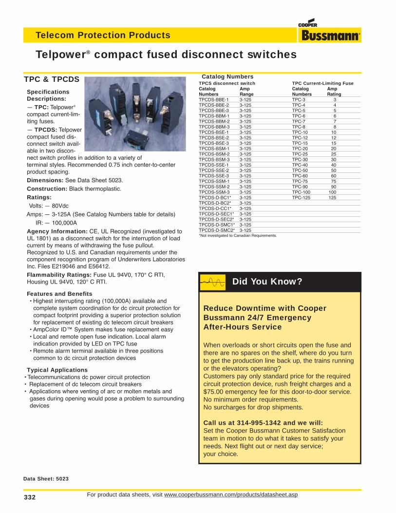
For product data sheets, visit www.cooperbussmann.com/products/datasheet.asp332
Telecom Protection Products
Telpower® compact fused disconnect switches
Data Sheet: 5023
TPC & TPCDS
SpecificationsDescriptions:— TPC: Telpower®
compact current-lim-iting fuses.
— TPCDS: Telpowercompact fused dis-connect switch avail-able in two discon-nect switch profiles in addition to a variety of terminal styles. Recommended 0.75 inch center-to-centerproduct spacing.
Dimensions: See Data Sheet 5023.
Construction: Black thermoplastic.
Ratings:Volts: — 80Vdc
Amps: — 3-125A (See Catalog Numbers table for details)
IR: — 100,000A
Agency Information: CE, UL Recognized (investigated toUL 1801) as a disconnect switch for the interruption of loadcurrent by means of withdrawing the fuse pullout.Recognized to U.S. and Canadian requirements under thecomponent recognition program of Underwriters LaboratoriesInc. Files E219046 and E56412.
Flammability Ratings: Fuse UL 94V0, 170° C RTI,Housing UL 94V0, 120° C RTI.
Features and Benefits• Highest interrupting rating (100,000A) available and
complete system coordination for dc circuit protection for compact footprint providing a superior protection solutionfor replacement of existing dc telecom circuit breakers
• AmpColor ID™ System makes fuse replacement easy• Local and remote open fuse indication. Local alarm
indication provided by LED on TPC fuse• Remote alarm terminal available in three positions
common to dc circuit protection devices
Typical Applications• Telecommunications dc power circuit protection• Replacement of dc telecom circuit breakers• Applications where venting of arc or molten metals and
gases during opening would pose a problem to surroundingdevices
Catalog NumbersTPCS disconnect switch TPC Current-Limiting FuseCatalog Amp Catalog AmpNumbers Range Numbers RatingTPCDS-BBE-1 3-125 TPC-3 3TPCDS-BBE-2 3-125 TPC-4 4TPCDS-BBE-3 3-125 TPC-5 5TPCDS-BBM-1 3-125 TPC-6 6TPCDS-BBM-2 3-125 TPC-7 7TPCDS-BBM-3 3-125 TPC-8 8TPCDS-BSE-1 3-125 TPC-10 10TPCDS-BSE-2 3-125 TPC-12 12TPCDS-BSE-3 3-125 TPC-15 15TPCDS-BSM-1 3-125 TPC-20 20TPCDS-BSM-2 3-125 TPC-25 25TPCDS-BSM-3 3-125 TPC-30 30TPCDS-SSE-1 3-125 TPC-40 40TPCDS-SSE-2 3-125 TPC-50 50TPCDS-SSE-3 3-125 TPC-60 60TPCDS-SSM-1 3-125 TPC-75 75TPCDS-SSM-2 3-125 TPC-90 90TPCDS-SSM-3 3-125 TPC-100 100TPCDS-D-BC1* 3-125 TPC-125 125TPCDS-D-BC2* 3-125TPCDS-D-CC1* 3-125TPCDS-D-SEC1* 3-125TPCDS-D-SEC2* 3-125TPCDS-D-SMC1* 3-125TPCDS-D-SMC2* 3-125*Not investigated to Canadian Requirements.
Reduce Downtime with CooperBussmann 24/7 Emergency After-Hours Service
When overloads or short circuits open the fuse andthere are no spares on the shelf, where do you turnto get the production line back up, the trains runningor the elevators operating?Customers pay only standard price for the requiredcircuit protection device, rush freight charges and a$75.00 emergency fee for this door-to-door service.No minimum order requirements.No surcharges for drop shipments.
Call us at 314-995-1342 and we will:Set the Cooper Bussmann Customer Satisfactionteam in motion to do what it takes to satisfy yourneeds. Next flight out or next day service;your choice.
Did You Know?
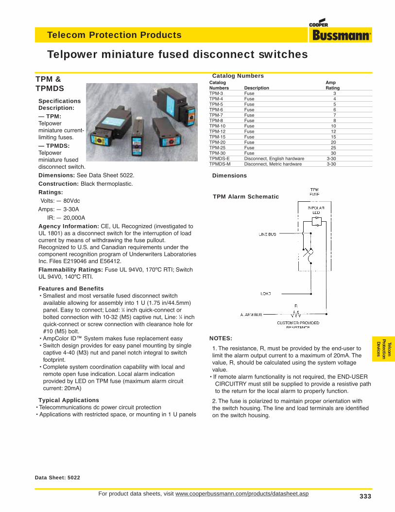
For product data sheets, visit www.cooperbussmann.com/products/datasheet.asp 333
Telecom Protection Products
Data Sheet: 5022
Telpower miniature fused disconnect switches
Catalog NumbersCatalog AmpNumbers Description RatingTPM-3 Fuse 3TPM-4 Fuse 4TPM-5 Fuse 5TPM-6 Fuse 6TPM-7 Fuse 7TPM-8 Fuse 8TPM-10 Fuse 10TPM-12 Fuse 12TPM-15 Fuse 15TPM-20 Fuse 20TPM-25 Fuse 25TPM-30 Fuse 30TPMDS-E Disconnect, English hardware 3-30TPMDS-M Disconnect, Metric hardware 3-30
Dimensions
NOTES:
1. The resistance, R, must be provided by the end-user tolimit the alarm output current to a maximum of 20mA. Thevalue, R, should be calculated using the system voltagevalue.
• If remote alarm functionality is not required, the END-USERCIRCUITRY must still be supplied to provide a resistive pathto the return for the local alarm to properly function.
2. The fuse is polarized to maintain proper orientation withthe switch housing. The line and load terminals are identifiedon the switch housing.
TPM &TPMDS
SpecificationsDescription:— TPM:Telpower miniature current-limiting fuses.
— TPMDS:Telpower miniature fuseddisconnect switch.
Dimensions: See Data Sheet 5022.
Construction: Black thermoplastic.
Ratings:Volts: — 80Vdc
Amps: — 3-30A
IR: — 20,000A
Agency Information: CE, UL Recognized (investigated toUL 1801) as a disconnect switch for the interruption of loadcurrent by means of withdrawing the fuse pullout.Recognized to U.S. and Canadian requirements under thecomponent recognition program of Underwriters LaboratoriesInc. Files E219046 and E56412.
Flammability Ratings: Fuse UL 94V0, 170ºC RTI; SwitchUL 94V0, 140ºC RTI.
Features and Benefits• Smallest and most versatile fused disconnect switch
available allowing for assembly into 1 U (1.75 in/44.5mm)panel. Easy to connect; Load: 1⁄4 inch quick-connect or bolted connection with 10-32 (M5) captive nut, Line: 1⁄4 inch quick-connect or screw connection with clearance hole for #10 (M5) bolt.
• AmpColor ID™ System makes fuse replacement easy• Switch design provides for easy panel mounting by single
captive 4-40 (M3) nut and panel notch integral to switch footprint.
• Complete system coordination capability with local and remote open fuse indication. Local alarm indication provided by LED on TPM fuse (maximum alarm circuit current: 20mA)
Typical Applications• Telecommunications dc power circuit protection• Applications with restricted space, or mounting in 1 U panels
TPM Alarm Schematic
TelcomProtectionDevices
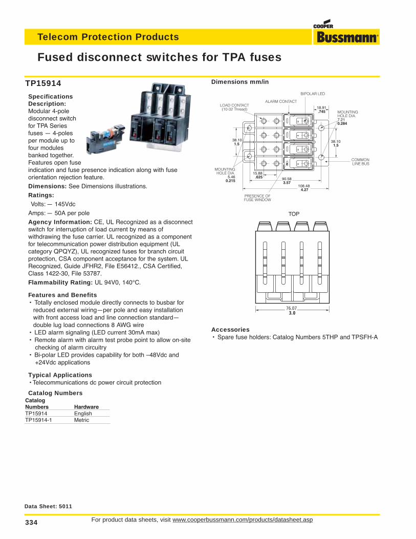
For product data sheets, visit www.cooperbussmann.com/products/datasheet.asp334
Telecom Protection Products
TP15914
SpecificationsDescription:Modular 4-pole disconnect switchfor TPA Seriesfuses — 4-polesper module up tofour modulesbanked together.Features open fuseindication and fuse presence indication along with fuse orientation rejection feature.
Dimensions: See Dimensions illustrations.
Ratings:Volts: — 145Vdc
Amps: — 50A per pole
Agency Information: CE, UL Recognized as a disconnectswitch for interruption of load current by means of withdrawing the fuse carrier. UL recognized as a componentfor telecommunication power distribution equipment (UL category QPQYZ), UL recognized fuses for branch circuitprotection, CSA component acceptance for the system. ULRecognized, Guide JFHR2, File E56412., CSA Certified,Class 1422-30, File 53787.
Flammability Rating: UL 94V0, 140°C.
Features and Benefits• Totally enclosed module directly connects to busbar for
reduced external wiring—per pole and easy installation with front access load and line connection standard—double lug load connections 8 AWG wire
• LED alarm signaling (LED current 30mA max)• Remote alarm with alarm test probe point to allow on-site
checking of alarm circuitry• Bi-polar LED provides capability for both –48Vdc and
+24Vdc applications
Typical Applications• Telecommunications dc power circuit protection
Catalog NumbersCatalogNumbers HardwareTP15914 EnglishTP15914-1 Metric
Fused disconnect switches for TPA fuses
Data Sheet: 5011
Dimensions mm/in
Accessories• Spare fuse holders: Catalog Numbers 5THP and TPSFH-A
TOP
76.073.0
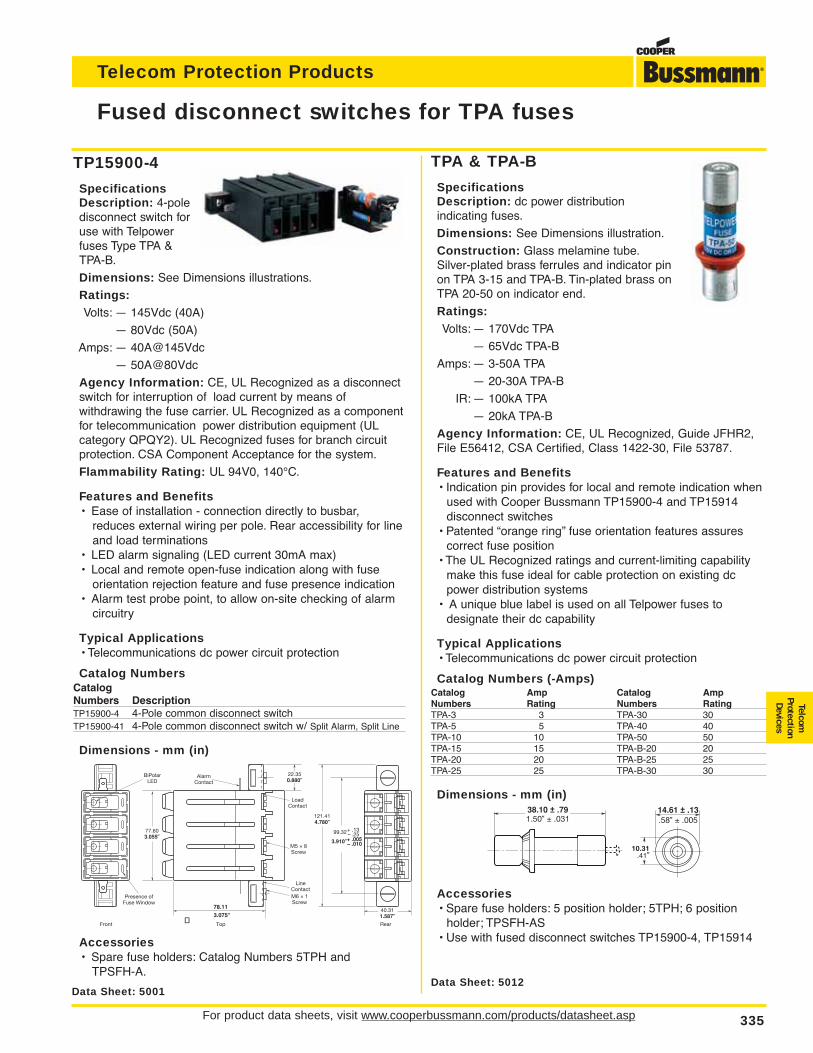
For product data sheets, visit www.cooperbussmann.com/products/datasheet.asp 335
Telecom Protection Products
TP15900-4
SpecificationsDescription: 4-poledisconnect switch foruse with Telpowerfuses Type TPA &TPA-B.
Dimensions: See Dimensions illustrations.
Ratings:Volts: — 145Vdc (40A)
— 80Vdc (50A)
Amps: — 40A@145Vdc
— 50A@80Vdc
Agency Information: CE, UL Recognized as a disconnectswitch for interruption of load current by means of withdrawing the fuse carrier. UL Recognized as a componentfor telecommunication power distribution equipment (UL category QPQY2). UL Recognized fuses for branch circuitprotection. CSA Component Acceptance for the system.
Flammability Rating: UL 94V0, 140°C.
Features and Benefits• Ease of installation - connection directly to busbar,
reduces external wiring per pole. Rear accessibility for line and load terminations
• LED alarm signaling (LED current 30mA max)• Local and remote open-fuse indication along with fuse
orientation rejection feature and fuse presence indication• Alarm test probe point, to allow on-site checking of alarm
circuitry
Typical Applications• Telecommunications dc power circuit protection
Catalog NumbersCatalogNumbers DescriptionTP15900-4 4-Pole common disconnect switchTP15900-41 4-Pole common disconnect switch w/ Split Alarm, Split Line
Dimensions - mm (in)
Accessories• Spare fuse holders: Catalog Numbers 5TPH and
TPSFH-A.
Fused disconnect switches for TPA fuses
Data Sheet: 5001
TelcomProtectionDevices
Data Sheet: 5012
TPA & TPA-B
SpecificationsDescription: dc power distribution indicating fuses.
Dimensions: See Dimensions illustration.
Construction: Glass melamine tube.Silver-plated brass ferrules and indicator pinon TPA 3-15 and TPA-B. Tin-plated brass onTPA 20-50 on indicator end.
Ratings:Volts: — 170Vdc TPA
— 65Vdc TPA-B
Amps: — 3-50A TPA
— 20-30A TPA-B
IR: — 100kA TPA
— 20kA TPA-B
Agency Information: CE, UL Recognized, Guide JFHR2,File E56412, CSA Certified, Class 1422-30, File 53787.
Features and Benefits• Indication pin provides for local and remote indication when
used with Cooper Bussmann TP15900-4 and TP15914 disconnect switches
• Patented “orange ring” fuse orientation features assures correct fuse position
• The UL Recognized ratings and current-limiting capability make this fuse ideal for cable protection on existing dc power distribution systems
• A unique blue label is used on all Telpower fuses to designate their dc capability
Typical Applications• Telecommunications dc power circuit protection
Catalog Numbers (-Amps)Catalog Amp Catalog AmpNumbers Rating Numbers RatingTPA-3 3 TPA-30 30TPA-5 5 TPA-40 40TPA-10 10 TPA-50 50TPA-15 15 TPA-B-20 20TPA-20 20 TPA-B-25 25TPA-25 25 TPA-B-30 30
Dimensions - mm (in)
Accessories• Spare fuse holders: 5 position holder; 5TPH; 6 position
holder; TPSFH-AS• Use with fused disconnect switches TP15900-4, TP15914
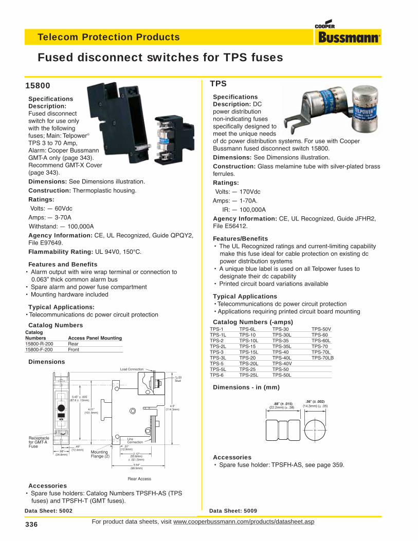
For product data sheets, visit www.cooperbussmann.com/products/datasheet.asp336
Telecom Protection Products
TPS
SpecificationsDescription: DCpower distribution non-indicating fusesspecifically designed tomeet the unique needsof dc power distribution systems. For use with CooperBussmann fused disconnect switch 15800.
Dimensions: See Dimensions illustration.
Construction: Glass melamine tube with silver-plated brassferrules.
Ratings:Volts: — 170Vdc
Amps: — 1-70A.
IR: — 100,000A
Agency Information: CE, UL Recognized, Guide JFHR2,File E56412.
Features/Benefits• The UL Recognized ratings and current-limiting capability
make this fuse ideal for cable protection on existing dc power distribution systems
• A unique blue label is used on all Telpower fuses to designate their dc capability
• Printed circuit board variations available
Typical Applications• Telecommunications dc power circuit protection• Applications requiring printed circuit board mounting
Catalog Numbers (-amps)TPS-1 TPS-6L TPS-30 TPS-50VTPS-1L TPS-10 TPS-30L TPS-60TPS-2 TPS-10L TPS-35 TPS-60LTPS-2L TPS-15 TPS-35L TPS-70TPS-3 TPS-15L TPS-40 TPS-70LTPS-3L TPS-20 TPS-40L TPS-70LBTPS-5 TPS-20L TPS-40VTPS-5L TPS-25 TPS-50TPS-6 TPS-25L TPS-50L
Dimensions - in (mm)
Accessories• Spare fuse holder: TPSFH-AS, see page 359.
Fused disconnect switches for TPS fuses
Data Sheet: 5009
15800
SpecificationsDescription:Fused disconnectswitch for use onlywith the following fuses; Main: Telpower®
TPS 3 to 70 Amp, Alarm: Cooper BussmannGMT-A only (page 343).Recommend GMT-X Cover (page 343).
Dimensions: See Dimensions illustration.
Construction: Thermoplastic housing.
Ratings:Volts: — 60Vdc
Amps: — 3-70A
Withstand: — 100,000A
Agency Information: CE, UL Recognized, Guide QPQY2,File E97649.
Flammability Rating: UL 94V0, 150°C.
Features and Benefits• Alarm output with wire wrap terminal or connection to
0.063” thick common alarm bus• Spare alarm and power fuse compartment• Mounting hardware included
Typical Applications:• Telecommunications dc power circuit protection
Catalog NumbersCatalogNumbers Access Panel Mounting15800-R-200 Rear15800-F-200 Front
Dimensions
Accessories• Spare fuse holders: Catalog Numbers TPSFH-AS (TPS
fuses) and TPSFH-T (GMT fuses).
Data Sheet: 5002
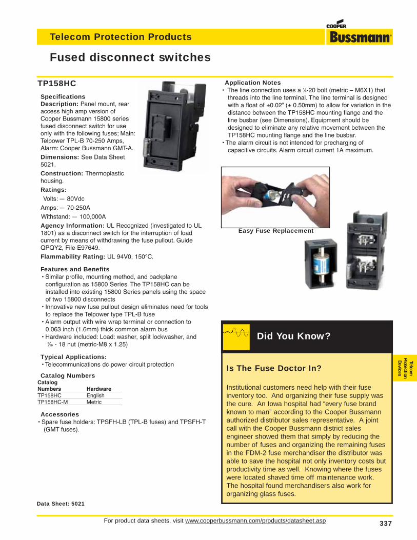
For product data sheets, visit www.cooperbussmann.com/products/datasheet.asp 337
Telecom Protection Products
TP158HC
SpecificationsDescription: Panel mount, rearaccess high amp version ofCooper Bussmann 15800 seriesfused disconnect switch for useonly with the following fuses; Main:Telpower TPL-B 70-250 Amps,Alarm: Cooper Bussmann GMT-A.
Dimensions: See Data Sheet5021.
Construction: Thermoplastichousing.
Ratings:Volts: — 80Vdc
Amps: — 70-250A
Withstand: — 100,000A
Agency Information: UL Recognized (investigated to UL1801) as a disconnect switch for the interruption of load current by means of withdrawing the fuse pullout. GuideQPQY2, File E97649.
Flammability Rating: UL 94V0, 150°C.
Features and Benefits• Similar profile, mounting method, and backplane
configuration as 15800 Series. The TP158HC can be installed into existing 15800 Series panels using the space of two 15800 disconnects
• Innovative new fuse pullout design eliminates need for toolsto replace the Telpower type TPL-B fuse
• Alarm output with wire wrap terminal or connection to 0.063 inch (1.6mm) thick common alarm bus
• Hardware included: Load: washer, split lockwasher, and 5⁄16 - 18 nut (metric-M8 x 1.25)
Typical Applications:• Telecommunications dc power circuit protection
Catalog NumbersCatalogNumbers HardwareTP158HC EnglishTP158HC-M Metric
Accessories• Spare fuse holders: TPSFH-LB (TPL-B fuses) and TPSFH-T
(GMT fuses).
Application Notes• The line connection uses a 1⁄4-20 bolt (metric – M6X1) that
threads into the line terminal. The line terminal is designedwith a float of ±0.02” (± 0.50mm) to allow for variation in thedistance between the TP158HC mounting flange and theline busbar (see Dimensions). Equipment should bedesigned to eliminate any relative movement between theTP158HC mounting flange and the line busbar.
• The alarm circuit is not intended for precharging of capacitive circuits. Alarm circuit current 1A maximum.
Fused disconnect switches
Data Sheet: 5021
Easy Fuse Replacement
TelcomProtectionDevicesIs The Fuse Doctor In?
Institutional customers need help with their fuseinventory too. And organizing their fuse supply wasthe cure. An Iowa hospital had “every fuse brandknown to man” according to the Cooper Bussmannauthorized distributor sales representative. A jointcall with the Cooper Bussmann district sales engineer showed them that simply by reducing thenumber of fuses and organizing the remaining fusesin the FDM-2 fuse merchandiser the distributor wasable to save the hospital not only inventory costs butproductivity time as well. Knowing where the fuseswere located shaved time off maintenance work.The hospital found merchandisers also work fororganizing glass fuses.
Did You Know?
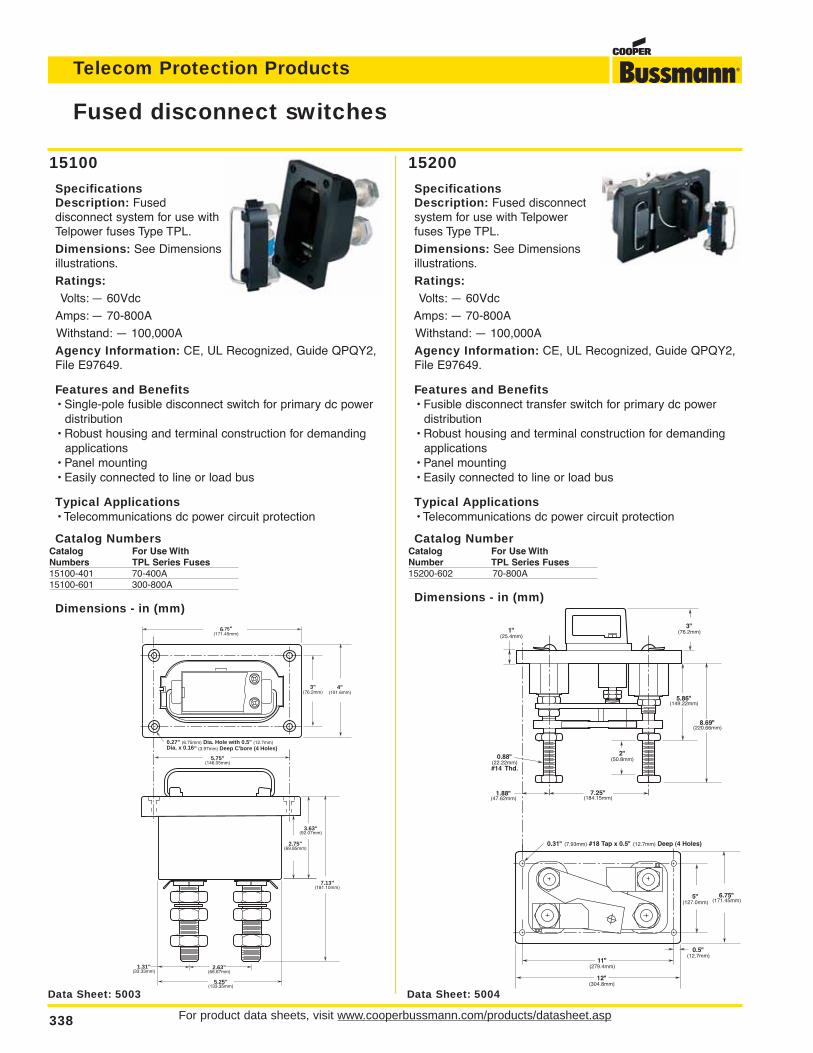
For product data sheets, visit www.cooperbussmann.com/products/datasheet.asp338
Telecom Protection Products
Fused disconnect switches
0.27" (6.75mm) Dia. Hole with 0.5" (12.7mm)Dia. x 0.16" (3.97mm) Deep C'bore (4 Holes)
2.63"(66.67mm)
1.31"(33.33mm)
4"(101.6mm)
3"(76.2mm)
5.25"(133.35mm)
7.13"(181.10mm)
3.63"(92.07mm)
2.75"(69.85mm)
6.75"(171.45mm)
5.75"(146.05mm)
15100
SpecificationsDescription: Fused disconnect system for use withTelpower fuses Type TPL.
Dimensions: See Dimensionsillustrations.
Ratings:Volts: — 60Vdc
Amps: — 70-800A
Withstand: — 100,000A
Agency Information: CE, UL Recognized, Guide QPQY2,File E97649.
Features and Benefits• Single-pole fusible disconnect switch for primary dc power
distribution• Robust housing and terminal construction for demanding
applications• Panel mounting• Easily connected to line or load bus
Typical Applications• Telecommunications dc power circuit protection
Catalog NumbersCatalog For Use WithNumbers TPL Series Fuses15100-401 70-400A15100-601 300-800A
Dimensions - in (mm)
15200
SpecificationsDescription: Fused disconnectsystem for use with Telpowerfuses Type TPL.
Dimensions: See Dimensionsillustrations.
Ratings:Volts: — 60Vdc
Amps: — 70-800A
Withstand: — 100,000A
Agency Information: CE, UL Recognized, Guide QPQY2,File E97649.
Features and Benefits• Fusible disconnect transfer switch for primary dc power
distribution• Robust housing and terminal construction for demanding
applications• Panel mounting• Easily connected to line or load bus
Typical Applications• Telecommunications dc power circuit protection
Catalog NumberCatalog For Use WithNumber TPL Series Fuses15200-602 70-800A
Dimensions - in (mm)
Data Sheet: 5003
7.25"(184.15mm)
0.88" (22.22mm)#14 Thd.
0.31" (7.93mm) #18 Tap x 0.5" (12.7mm) Deep (4 Holes)
11"(279.4mm)
0.5"(12.7mm)
12"(304.8mm)
1"(25.4mm)
8.69"(220.66mm)
5.86"(149.22mm)
3"(76.2mm)
2"(50.8mm)
1.88"(47.62mm)
6.75"(171.45mm)
5"(127.0mm)
Data Sheet: 5004
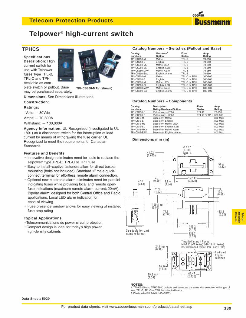
For product data sheets, visit www.cooperbussmann.com/products/datasheet.asp 339
Telecom Protection Products
TPHCS
SpecificationsDescription: Highcurrent switch foruse with Telpowerfuses Type TPL-B,TPL-C and TPH.Available as com-plete switch or pullout. Basemay be purchased separately.
Dimensions: See Dimensions illustrations.
Construction:Ratings:Volts:— 80Vdc
Amps:— 70-800A
Withstand: — 100,000A
Agency Information: UL Recognized (investigated to UL1801) as a disconnect switch for the interruption of load current by means of withdrawing the fuse carrier. ULRecognized to meet the requirements for CanadianStandards.
Features and Benefits• Innovative design eliminates need for tools to replace the
Telpower® type TPL-B, TPL-C or TPH fuse• Easy to install–captive fasteners allow for direct busbar
mounting (bolts not included). Standard 1⁄4” male quick-connect terminal for effortless remote alarm connection.
• Optional new electronic alarm eliminates need for parallel indicating fuses while providing local and remote open-fuse indications (maximum remote alarm current: 20mA);Bipolar alarm: designed for both Central Office and Radio applications, Local LED alarm indication for ease-of-viewing.
• Fuse presence window allows for easy viewing of installedfuse amp rating
Typical Applications• Telecommunications dc power circuit protection• Compact design is ideal for today’s high power,
high-density cabinets
Telpower® high-current switch
Data Sheet: 5020
Catalog Numbers – Switches (Pullout and Base)Catalog Hardware/ Fuse AmpNumbers Option Series RatingTPHCS250-M Metric TPL-B 70-250TPHCS250-E English TPL-B 70-250TPHCS250-ML Metric, LED TPL-B 70-250TPHCS250-EL English, LED TPL-B 70-250TPHCS250-MAV Metric, Alarm TPL-B 70-250TPHCS250-EAV English, Alarm TPL-B 70-250TPHCS800-M Metric TPL-C or TPH 300-800TPHCS800-E English TPL-C or TPH 300-800TPHCS800-ML Metric, LED TPL-C or TPH 300-800TPHCS800-EL English, LED TPL-C or TPH 300-800TPHCS800-MAV Metric, Alarm TPL-C or TPH 300-800TPHCS800-EA English, Alarm TPL-C or TPH 300-800
Catalog Numbers – ComponentsCatalog Description Fuse AmpNumbers Rating/Hardware/Option Series RatingTPHCS250-P Pullout only – 250A TPL-B 70-250TPHCS800-P Pullout only – 800A TPL-C or TPH 300-800TPHCS-B-M Base only, Metric — 800 MaxTPHCS-B-E Base only, English — 800 MaxTPHCS-B-ML Base only, Metric, LED — 800 MaxTPHCS-B-EL Base only, English, LED — 800 MaxTPHCS-B-MAV Base only, Metric, Alarm — 800 MaxTPHCS-B-EAV Base only, English, Alarm — 800 Max
Dimensions mm (in)
TPHCS800-MAV (shown)
NOTES:1. TPHCS250 and TPHCS800 pullouts and bases are the same with exception to the type offuse, TPL-B, TPL-C or TPH the pullout will carry.2. Plastic rated UL 94V0, 140∞C RTI.
41.02(1.615)
Ø 7.62(0.300)Type. 4
12.7(0.50)
74.6(2.94)
25.9(1.02)
122.43(4.820)8.8
(0.34)
s
s
s
s
s
s
s s
s
s
s
s
ss
100.5 REF(3.96)
s
s
s
s
s
s
s
66.4(2.62)
s
s
105.2(4.14)
s s
Threaded Insert, 4 PlacesM8x1.25 (-M Series) 5/16-18 (-E Series)Recommended Torque 15N • m (11 Ft-lb)
Tin-Plated CopperTerminals
s
s
ss
139.7(5.50)
24.8 REF(0.98)
39.2 REF(1.54)
16.76(0.660)
s s
13.2(0.52)
17.3(0.68)
ss
s
61.47(2.420)
s
22.2(0.88)
See table for partnumber format
s
s
TelcomProtectionDevices
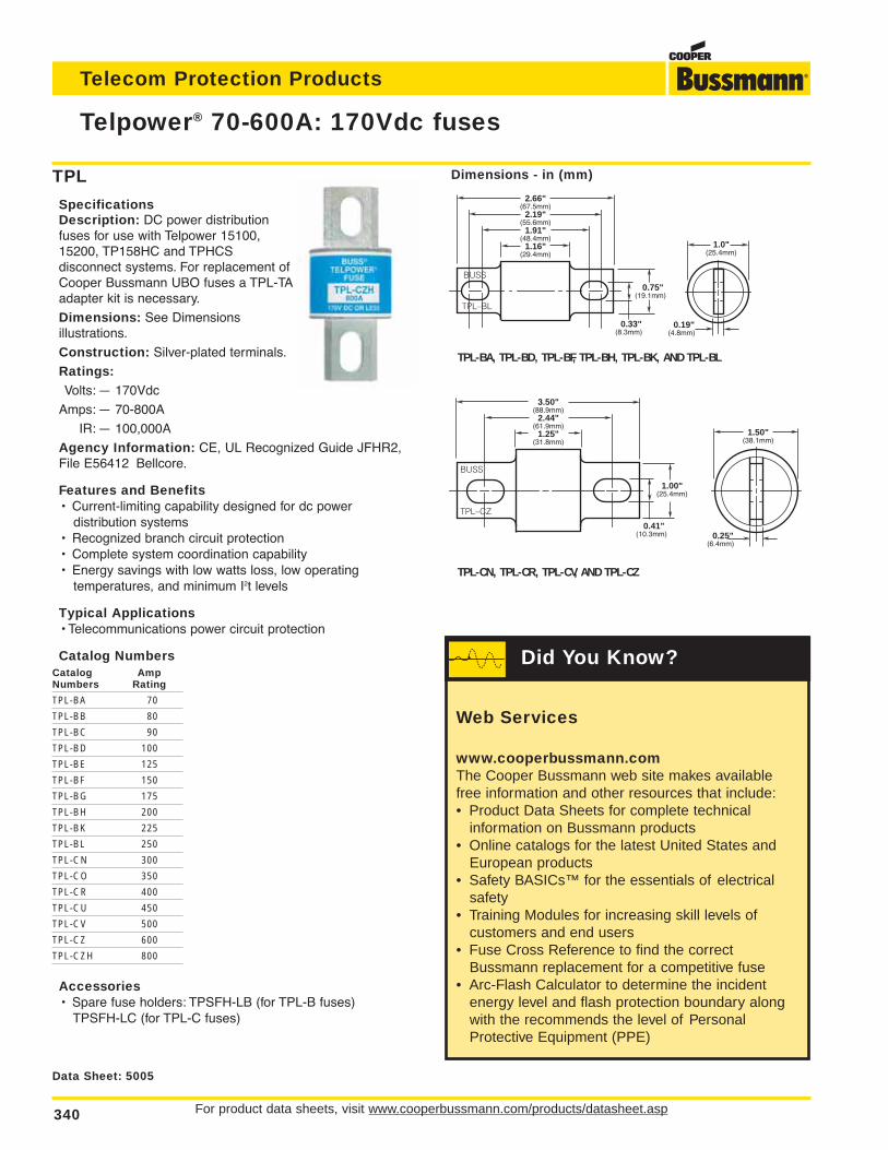
For product data sheets, visit www.cooperbussmann.com/products/datasheet.asp340
Telecom Protection Products
Telpower® 70-600A: 170Vdc fuses
Data Sheet: 5005
TPL
SpecificationsDescription: DC power distributionfuses for use with Telpower 15100,15200, TP158HC and TPHCS disconnect systems. For replacement ofCooper Bussmann UBO fuses a TPL-TAadapter kit is necessary.
Dimensions: See Dimensions illustrations.
Construction: Silver-plated terminals.
Ratings:Volts: — 170Vdc
Amps: — 70-800A
IR: — 100,000A
Agency Information: CE, UL Recognized Guide JFHR2,File E56412 Bellcore.
Features and Benefits• Current-limiting capability designed for dc power
distribution systems• Recognized branch circuit protection• Complete system coordination capability• Energy savings with low watts loss, low operating
temperatures, and minimum I2t levels
Typical Applications• Telecommunications power circuit protection
Catalog NumbersCatalog AmpNumbers Rating
TPL-BA 70
TPL-BB 80
TPL-BC 90
TPL-BD 100
TPL-BE 125
TPL-BF 150
TPL-BG 175
TPL-BH 200
TPL-BK 225
TPL-BL 250
TPL-CN 300
TPL-CO 350
TPL-CR 400
TPL-CU 450
TPL-CV 500
TPL-CZ 600
TPL-CZH 800
Accessories• Spare fuse holders: TPSFH-LB (for TPL-B fuses)
TPSFH-LC (for TPL-C fuses)
Dimensions - in (mm)
0.33"(8.3mm)
2.66"(67.5mm)
2.19"(55.6mm)
1.91"(48.4mm)
1.16"(29.4mm)
BUSS
TPL–BL
0.75"(19.1mm)
0.19"(4.8mm)
1.0"(25.4mm)
0.25"(6.4mm)
1.50"(38.1mm)
TPL-BA, TPL-BD, TPL-BF, TPL-BH, TPL-BK, AND TPL-BL
TPL-CN, TPL-CR, TPL-CV, AND TPL-CZ
3.50"(88.9mm)
2.44"(61.9mm)
1.25"(31.8mm)
1.00"(25.4mm)
0.41"(10.3mm)
BUSS
TPL–CZ
Web Services
www.cooperbussmann.comThe Cooper Bussmann web site makes availablefree information and other resources that include:• Product Data Sheets for complete technical
information on Bussmann products• Online catalogs for the latest United States and
European products• Safety BASICs™ for the essentials of electrical
safety• Training Modules for increasing skill levels of
customers and end users• Fuse Cross Reference to find the correct
Bussmann replacement for a competitive fuse• Arc-Flash Calculator to determine the incident
energy level and flash protection boundary along with the recommends the level of Personal Protective Equipment (PPE)
Did You Know?
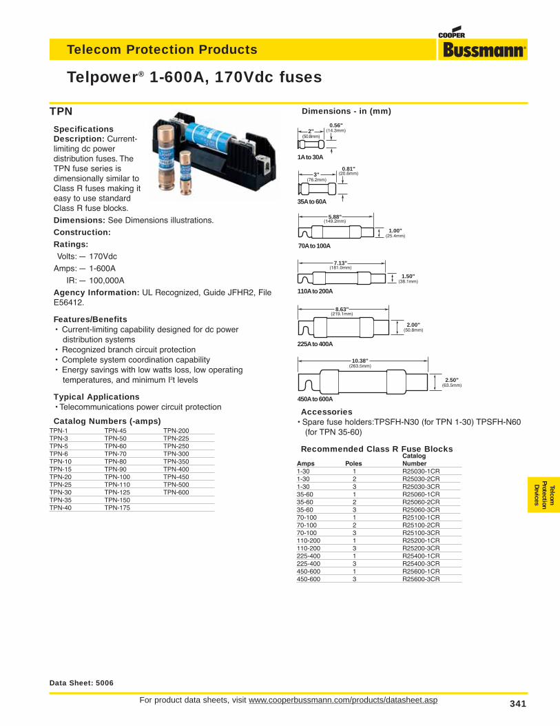
For product data sheets, visit www.cooperbussmann.com/products/datasheet.asp 341
Telecom Protection Products
Telpower® 1-600A, 170Vdc fuses
Data Sheet: 5006
TPN
SpecificationsDescription: Current-limiting dc power distribution fuses. TheTPN fuse series isdimensionally similar toClass R fuses making iteasy to use standardClass R fuse blocks.
Dimensions: See Dimensions illustrations.
Construction:Ratings:Volts: — 170Vdc
Amps: — 1-600A
IR: — 100,000A
Agency Information: UL Recognized, Guide JFHR2, FileE56412.
Features/Benefits• Current-limiting capability designed for dc power
distribution systems• Recognized branch circuit protection• Complete system coordination capability• Energy savings with low watts loss, low operating
temperatures, and minimum I2t levels
Typical Applications• Telecommunications power circuit protection
Catalog Numbers (-amps)TPN-1 TPN-45 TPN-200TPN-3 TPN-50 TPN-225TPN-5 TPN-60 TPN-250TPN-6 TPN-70 TPN-300TPN-10 TPN-80 TPN-350TPN-15 TPN-90 TPN-400TPN-20 TPN-100 TPN-450TPN-25 TPN-110 TPN-500TPN-30 TPN-125 TPN-600TPN-35 TPN-150TPN-40 TPN-175
Accessories• Spare fuse holders:TPSFH-N30 (for TPN 1-30) TPSFH-N60
(for TPN 35-60)
Recommended Class R Fuse BlocksCatalog
Amps Poles Number1-30 1 R25030-1CR1-30 2 R25030-2CR1-30 3 R25030-3CR35-60 1 R25060-1CR35-60 2 R25060-2CR35-60 3 R25060-3CR70-100 1 R25100-1CR70-100 2 R25100-2CR70-100 3 R25100-3CR110-200 1 R25200-1CR110-200 3 R25200-3CR225-400 1 R25400-1CR225-400 3 R25400-3CR450-600 1 R25600-1CR450-600 3 R25600-3CR
0.81"(20.6mm)3"
(76.2mm)
35A to 60A
2"(50.8mm)
0.56"(14.3mm)
1A to 30A
5.88"(149.2mm)
70A to 100A
7.13"(181.0mm)
110A to 200A
225A to 400A
8.63"(219.1mm)
450A to 600A
10.38"(263.5mm)
2.50"(63.5mm)
2.00"(50.8mm)
1.50"(38.1mm)
1.00"(25.4mm)
Dimensions - in (mm)
TelcomProtectionDevices
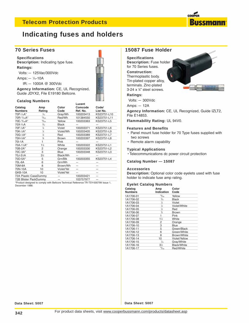
For product data sheets, visit www.cooperbussmann.com/products/datasheet.asp342
Telecom Protection Products
70 Series Fuses
SpecificationsDescription: Indicating type fuse.
Ratings:Volts:— 125Vac/300Vdc
Amps:— 1⁄10-10A
IR:— 1000A @ 300Vdc
Agency Information: CE, UL Recognized,Guide JDYX2, File E19180 Bellcore.
Catalog NumbersLucent
Catalog Amp Color Comcode Code/Numbers Rating Code Ref. No. List No.70P-1⁄10A* 1⁄10 Gray/Wh 100203413 KS23751-L1070R-15⁄100A* 15⁄100 Red/Wh 101384550 KS23751-L1170E-18⁄100A* 18⁄100 Yellow 100203363 KS23751-L570X-2⁄10A 2⁄10 Black — —70F-1⁄4A* 1⁄4 Violet 100203371 KS23751-L670K-1⁄4A* 1⁄4 Violet/Wh 100203405 KS23751-L970G-1⁄2A* 1⁄2 Red 100203389 KS23751-L770H-3⁄4A* 3⁄4 Brown 100203397 KS23751-L870I-1A 1 Pink — —70A-11⁄3A* 11⁄3 White 100203322 KS23751-L170B-2A* 2 Orange 100203330 KS23751-L270C-3A* 3 Blue 100203348 KS23751-L370J-31⁄2A 31⁄2 Black/Wh — —70D-5A* 5 Grn/Blk 100203355 KS23751-L470L-6A 6 Grn/Wh — —70M-8A 8 Brown/Wh — —70N-10A 10 Violet/Yel — —GKB-10A 10 Violet/Yel — —72A Plastic CaseDummy — 100203421 —72B Blister PackDummy — 103757977 —*Product designed to comply with Bellcore Technical Reference TR-TSY-000799 Issue 1,December 1988.
Indicating fuses and holders
Data Sheet: 5007 Data Sheet: 5007
15087 Fuse Holder
SpecificationsDescription: Fuse holderfor 70 Series fuses.
Construction:Thermoplastic body.Tin-plated copper alloy,terminals. Zinc-plated 3-24 x 3⁄8” steel screws.
Ratings:Volts: — 300Vdc
Amps: — 12A
Agency Information: CE, UL Recognized, Guide IZLT2,File E14853.
Flammability Rating: UL 94V0.
Features and Benefits• Panel mount fuse holder for 70 Type fuses supplied with
two screws• Remote alarm capability
Typical Applications• Telecommunications dc power circuit protection
Catalog Number — 15087
AccessoriesDescription: Optional color code eyelets used with fuseholder to indicate fuse amp rating.
Eyelet Catalog NumbersCatalog Amp ColorNumbers Indication Code1A1706-01 18⁄100 Yellow1A1706-02 2⁄10 Black1A1706-03 1⁄4 Violet1A1706-04 1⁄4 Violet/White1A1706-05 1⁄2 Red1A1706-06 3⁄4 Brown1A1706-07 1 Pink1A1706-08 11⁄3 White1A1706-09 2 Orange1A1706-10 3 Blue1A1706-11 5 Green/Black1A1706-12 6 Green/White1A1706-13 8 Brown/White1A1706-14 10 Violet/Yellow1A1706-15 1⁄10 Gray/White1A1706-16 31⁄2 Black/White1A1706-17 15⁄100 Red/White
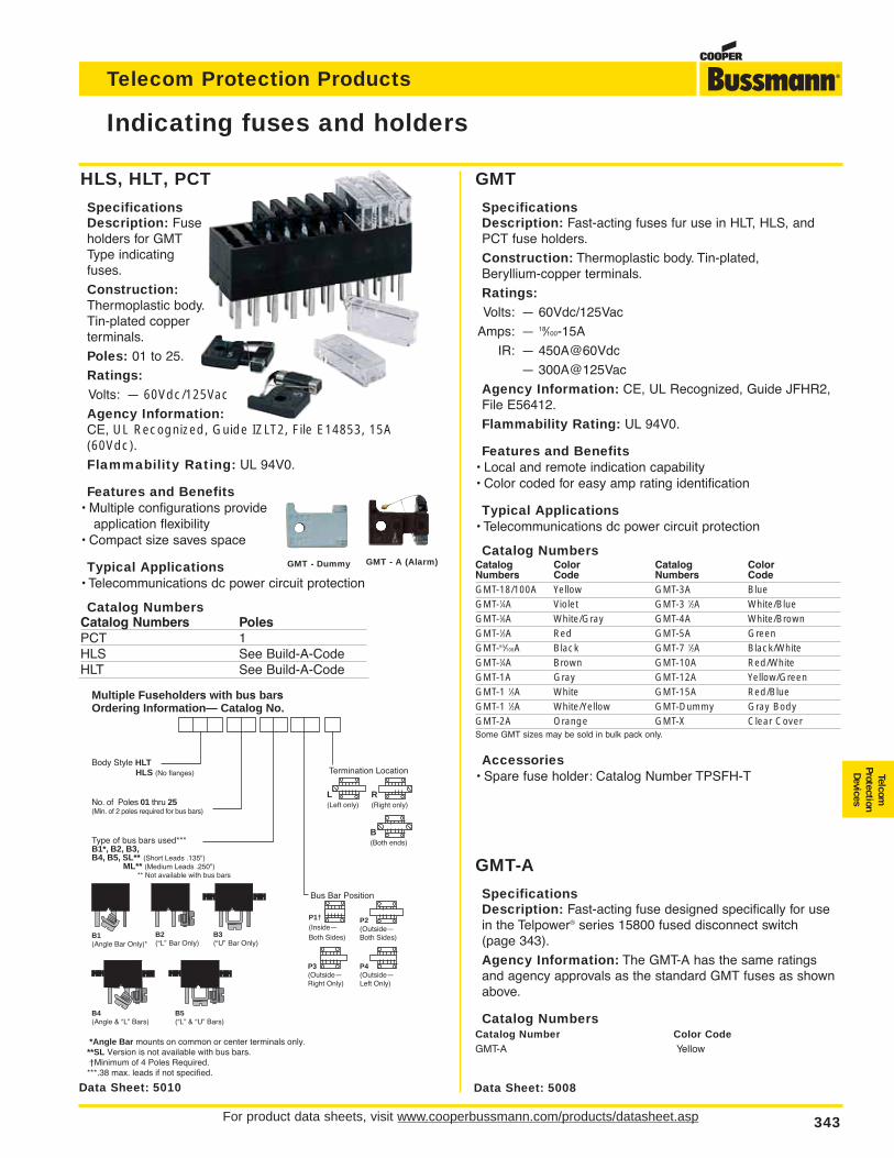
For product data sheets, visit www.cooperbussmann.com/products/datasheet.asp 343
Telecom Protection Products
HLS, HLT, PCT
SpecificationsDescription: Fuseholders for GMTType indicatingfuses.
Construction:Thermoplastic body.Tin-plated copperterminals.
Poles: 01 to 25.
Ratings:Volts: — 60Vdc/125Vac Agency Information:CE, UL Recognized, Guide IZLT2, File E14853, 15A(60Vdc).Flammability Rating: UL 94V0.
Features and Benefits• Multiple configurations provide
application flexibility• Compact size saves space
Typical Applications• Telecommunications dc power circuit protection
Catalog NumbersCatalog Numbers PolesPCT 1HLS See Build-A-CodeHLT See Build-A-Code
Indicating fuses and holders
Data Sheet: 5008Data Sheet: 5010
Multiple Fuseholders with bus barsOrdering Information— Catalog No.
Type of bus bars used***B1*, B2, B3,B4, B5, SL** (Short Leads .135") ML** (Medium Leads .250") ** Not available with bus bars
Bus Bar Position
P4(Outside—Left Only)
P3(Outside—Right Only)
P2(Outside—Both Sides)
P1†(Inside—Both Sides)B3
(“U” Bar Only)B2(“L” Bar Only)
B1(Angle Bar Only)*
B5(“L” & “U” Bars)
B4(Angle & “L” Bars)
Body Style HLT HLS (No flanges)
No. of Poles 01 thru 25(Min. of 2 poles required for bus bars)
Termination Location
B(Both ends)
L(Left only)
R(Right only)
*Angle Bar mounts on common or center terminals only.**SL Version is not available with bus bars.†Minimum of 4 Poles Required.***.38 max. leads if not specified.
GMT - Dummy GMT - A (Alarm)
GMT
SpecificationsDescription: Fast-acting fuses fur use in HLT, HLS, andPCT fuse holders.
Construction: Thermoplastic body. Tin-plated, Beryllium-copper terminals.
Ratings:Volts: — 60Vdc/125Vac
Amps: — 18⁄100-15A
IR: — 450A@60Vdc
— 300A@125Vac
Agency Information: CE, UL Recognized, Guide JFHR2,File E56412.
Flammability Rating: UL 94V0.
Features and Benefits• Local and remote indication capability• Color coded for easy amp rating identification
Typical Applications• Telecommunications dc power circuit protection
Catalog NumbersCatalog Color Catalog ColorNumbers Code Numbers CodeGMT-18/100A Yellow GMT-3A BlueGMT-1⁄4A Violet GMT-3 1⁄2A White/BlueGMT-3⁄8A White/Gray GMT-4A White/BrownGMT-1⁄2A Red GMT-5A GreenGMT-65⁄100A Black GMT-7 1⁄2A Black/WhiteGMT-3⁄4A Brown GMT-10A Red/WhiteGMT-1A Gray GMT-12A Yellow/GreenGMT-1 1⁄3A White GMT-15A Red/BlueGMT-1 1⁄2A White/Yellow GMT-Dummy Gray BodyGMT-2A Orange GMT-X Clear CoverSome GMT sizes may be sold in bulk pack only.
Accessories• Spare fuse holder: Catalog Number TPSFH-T
GMT-A
SpecificationsDescription: Fast-acting fuse designed specifically for usein the Telpower® series 15800 fused disconnect switch (page 343).
Agency Information: The GMT-A has the same ratingsand agency approvals as the standard GMT fuses as shownabove.
Catalog NumbersCatalog Number Color CodeGMT-A Yellow
TelcomProtectionDevices
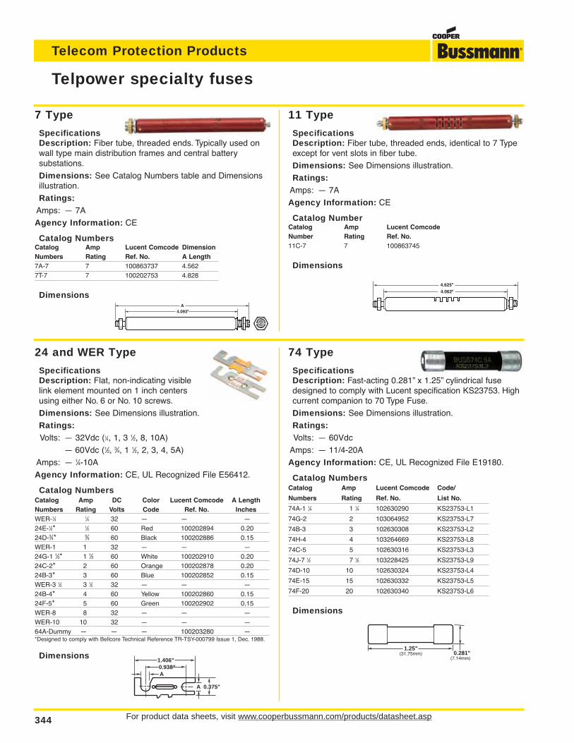
For product data sheets, visit www.cooperbussmann.com/products/datasheet.asp344
Telecom Protection Products
11 Type
SpecificationsDescription: Fiber tube, threaded ends, identical to 7 Typeexcept for vent slots in fiber tube.
Dimensions: See Dimensions illustration.
Ratings:Amps: — 7A
Agency Information: CE
Catalog NumberCatalog Amp Lucent ComcodeNumber Rating Ref. No.11C-7 7 100863745
Dimensions
7 Type
SpecificationsDescription: Fiber tube, threaded ends. Typically used onwall type main distribution frames and central battery substations.
Dimensions: See Catalog Numbers table and Dimensionsillustration.
Ratings:Amps: — 7A
Agency Information: CE
Catalog NumbersCatalog Amp Lucent Comcode DimensionNumbers Rating Ref. No. A Length7A-7 7 100863737 4.5627T-7 7 100202753 4.828
Dimensions
24 and WER Type
SpecificationsDescription: Flat, non-indicating visiblelink element mounted on 1 inch centersusing either No. 6 or No. 10 screws.
Dimensions: See Dimensions illustration.
Ratings:Volts: — 32Vdc (1⁄4, 1, 3 1⁄2, 8, 10A)
— 60Vdc (1⁄2, 3⁄4, 1 1⁄2, 2, 3, 4, 5A)
Amps: — 1⁄4-10A
Agency Information: CE, UL Recognized File E56412.
Catalog NumbersCatalog Amp DC Color Lucent Comcode A LengthNumbers Rating Volts Code Ref. No. InchesWER-1⁄4 1⁄4 32 — — —24E-1⁄2* 1⁄2 60 Red 100202894 0.2024D-3⁄4* 3⁄4 60 Black 100202886 0.15WER-1 1 32 — — —24G-1 1⁄3* 1 1⁄3 60 White 100202910 0.2024C-2* 2 60 Orange 100202878 0.2024B-3* 3 60 Blue 100202852 0.15WER-3 1⁄2 3 1⁄2 32 — — —24B-4* 4 60 Yellow 100202860 0.1524F-5* 5 60 Green 100202902 0.15WER-8 8 32 — — —WER-10 10 32 — — —64A-Dummy — — — 100203280 —*Designed to comply with Bellcore Technical Reference TR-TSY-000799 Issue 1, Dec. 1988.
Dimensions
Telpower specialty fuses
4.062"
4.625"
4.093"A
A 0.375"
A0.938"1.406"
74 Type
SpecificationsDescription: Fast-acting 0.281” x 1.25” cylindrical fusedesigned to comply with Lucent specification KS23753. Highcurrent companion to 70 Type Fuse.
Dimensions: See Dimensions illustration.
Ratings:Volts: — 60Vdc
Amps: — 11/4-20A
Agency Information: CE, UL Recognized File E19180.
Catalog NumbersCatalog Amp Lucent Comcode Code/
Numbers Rating Ref. No. List No.
74A-1 1⁄4 1 1⁄4 102630290 KS23753-L1
74G-2 2 103064952 KS23753-L7
74B-3 3 102630308 KS23753-L2
74H-4 4 103264669 KS23753-L8
74C-5 5 102630316 KS23753-L3
74J-7 1⁄2 7 1⁄2 103228425 KS23753-L9
74D-10 10 102630324 KS23753-L4
74E-15 15 102630332 KS23753-L5
74F-20 20 102630340 KS23753-L6
Dimensions
1.25"(31.75mm) 0.281"
(7.14mm)
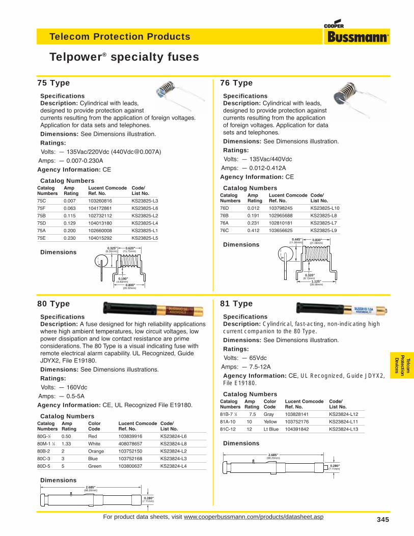
For product data sheets, visit www.cooperbussmann.com/products/datasheet.asp 345
Telecom Protection Products
TelcomProtectionDevices
80 Type
SpecificationsDescription: A fuse designed for high reliability applicationswhere high ambient temperatures, low circuit voltages, lowpower dissipation and low contact resistance are prime considerations. The 80 Type is a visual indicating fuse withremote electrical alarm capability. UL Recognized, GuideJDYX2, File E19180.
Dimensions: See Dimensions illustrations.
Ratings:Volts: — 160Vdc
Amps: — 0.5-5A
Agency Information: CE, UL Recognized File E19180.
Catalog NumbersCatalog Amp Color Lucent Comcode Code/Numbers Rating Code Ref. No. List No.
80G-1⁄2 0.50 Red 103839916 KS23824-L6
80M-1 1⁄3 1.33 White 408078657 KS23824-L8
80B-2 2 Orange 103752150 KS23824-L2
80C-3 3 Blue 103752168 KS23824-L3
80D-5 5 Green 103800637 KS23824-L4
Dimensions
75 Type
SpecificationsDescription: Cylindrical with leads,designed to provide protection againstcurrents resulting from the application of foreign voltages.Application for data sets and telephones.
Dimensions: See Dimensions illustration.
Ratings:Volts: — 135Vac/220Vdc ([email protected])
Amps: — 0.007-0.230A
Agency Information: CE
Catalog NumbersCatalog Amp Lucent Comcode Code/Numbers Rating Ref. No. List No.
75C 0.007 103260816 KS23825-L3
75F 0.063 104172861 KS23825-L6
75B 0.115 102732112 KS23825-L2
75D 0.129 104013180 KS23825-L4
75A 0.200 102660008 KS23825-L1
75E 0.230 104015292 KS23825-L5
Dimensions
76 Type
SpecificationsDescription: Cylindrical with leads,designed to provide protection againstcurrents resulting from the applicationof foreign voltages. Application for datasets and telephones.
Dimensions: See Dimensions illustration.
Ratings:Volts: — 135Vac/440Vdc
Amps: — 0.012-0.412A
Agency Information: CE
Catalog NumbersCatalog Amp Lucent Comcode Code/Numbers Rating Ref. No. List No.
76D 0.012 103798245 KS23825-L10
76B 0.191 102965688 KS23825-L8
76A 0.231 102810181 KS23825-L7
76C 0.412 103656625 KS23825-L9
Dimensions
Telpower® specialty fuses
——
A
0.445"(11.30mm)
0.320"(8.13mm)
1.125"(28.58mm)
0.830"(21.08mm)
0.280"(7.11mm)
2.685"(68.20mm)
0.190"(4.83mm)
0.325"(8.26mm)
0.620"(15.75mm)
0.800"(20.32mm)
——
A
81 Type
SpecificationsDescription: Cylindrical, fast-acting, non-indicating highcurrent companion to the 80 Type. Dimensions: See Dimensions illustration.
Ratings:Volts: — 65Vdc
Amps: — 7.5-12A
Agency Information: CE, UL Recognized, Guide JDYX2,File E19180.
Catalog NumbersCatalog Amp Color Lucent Comcode Code/Numbers Rating Code Ref. No. List No.
81B-7 1⁄2 7.5 Gray 103828141 KS23824-L12
81A-10 10 Yellow 103752176 KS23824-L11
81C-12 12 Lt Blue 104391842 KS23824-L13
Dimensions
0.280"(7.11mm)
2.685"(68.20mm)
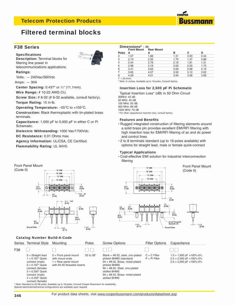
For product data sheets, visit www.cooperbussmann.com/products/datasheet.asp346
Telecom Protection Products
Filtered terminal blocks
F38 Series
SpecificationsDescription: Terminal blocks for filtering line power in telecommunications applications.
Ratings:Volts: — 240Vac/300Vdc
Amps: — 30A
Center Spacing: 0.437" or 7⁄16" (11.1mm).
Wire Range: # 10-22 AWG CU.
Screw Size: # 8-32 (# 6-32 available, consult factory).
Torque Rating: 15 in-lb.
Operating Temperature: –55°C to +105°C.
Construction: Black thermoplastic with tin-plated brass terminals.
Capacitance: 1,000 pF to 5,000 pF in either C or PiSchematic.
Dielectric Withstanding: 1000 Vac/1700Vdc.
DC Resistance: 0.01 Ohms max.
Agency Information: UL/CSA, CE Certified.
Flammability Rating: UL 94V0.
Dimensions* - inFront Mount Rear Mount
Poles A A B C D2 1.67 1.88 1.31 0.93 0.443 2.10 2.32 1.75 1.37 0.884 2.54 2.76 2.19 1.81 1.315 2.98 3.19 2.63 2.25 1.756 3.41 3.63 3.06 2.68 2.197 3.85 4.07 3.50 3.12 2.628 4.29 4.51 3.94 3.56 3.061” = 25.4mm.* Note: In inches. Available up to 16-poles. Consult factory.
Insertion Loss for 2,500 pF Pi Schematic
Typical Insertion Loss* (dB) in 50 Ohm Circuit30MHz: 42 dB50 MHz: 45 dB100 MHz: 50 dB300 MHz: 68 dB1000 MHz: 70 dB* For other capacitance insertion loss, consult factory.
Features and Benefits• Rugged integrated construction of filtering elements around
a solid brass pin provides excellent EMI/RFI filtering withhigh insertion loss for EMI/RFI filtering of ac and dc powerand control lines
• 2 to 8 terminals standard (up to 16-poles available) withoptions for straight lead, male or female quick-connect
Typical Applications• Cost-effective EMI solution for industrial interconnection
filteringFront Panel Mount (Code 0)
Front Panel Mount (Code 0)
Catalog Number Build-A-Code
Series Terminal Style Mounting Poles Screw Options Filter Options Capacitance
F38 _ _ _ _ _ _ _ _ . _
0 = Straight lead 0 = Front panel mount 02 to 08* Blank = #8-32, steel, zinc-plated C = C Filter 1.0 = 1,000 pF +100%-0%1 = 0.187" Quick with mount ends philslot BHMS (standard) P = Pi Filter 2.5 = 2,500 pF +100%-0%connect (male) 1 = Rear panel mount 04 = #8-32, Brass, nickel-plated 5.0 = 5,000 pF +100%-0%2 = 0.187" Quick with #4-40 threaded inserts philslot BHMSconnect (female) 92 = #8-32, Steel, zinc-plated3 = 0.250" Quick slotted BHMSconnect (male) 94 = #8-32, Brass, nickel-plated4 = 0.250" Quick slotted BHMSconnect (female)
* Note: Standard is 02-08 poles. Available up to 16-poles. Consult Cooper Bussmann for availability.Special electrical/mechanical configurations are available upon request.
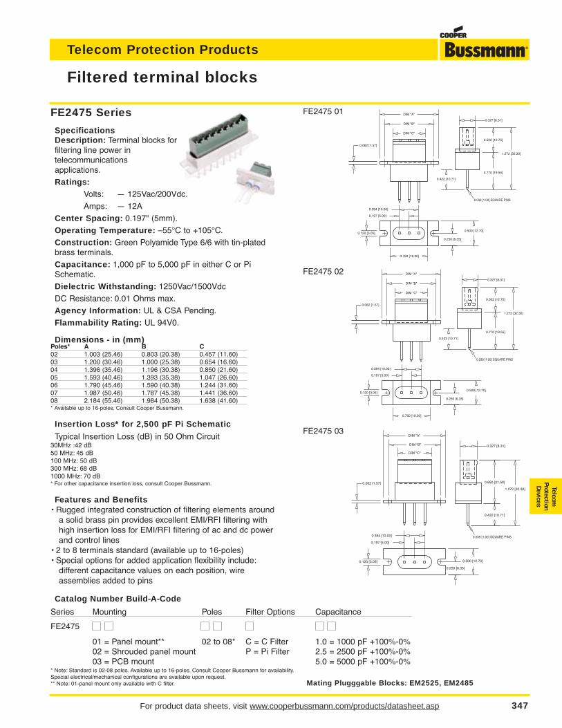
For product data sheets, visit www.cooperbussmann.com/products/datasheet.asp 347
Telecom Protection Products
TelcomProtectionDevices
FE2475 Series
SpecificationsDescription: Terminal blocks forfiltering line power in telecommunications applications.
Ratings:Volts: — 125Vac/200Vdc.
Amps: — 12A
Center Spacing: 0.197" (5mm).
Operating Temperature: –55°C to +105°C.
Construction: Green Polyamide Type 6/6 with tin-platedbrass terminals.
Capacitance: 1,000 pF to 5,000 pF in either C or PiSchematic.
Dielectric Withstanding: 1250Vac/1500Vdc
DC Resistance: 0.01 Ohms max.
Agency Information: UL & CSA Pending.
Flammability Rating: UL 94V0.
Dimensions - in (mm)Poles* A B C02 1.003 (25.46) 0.803 (20.38) 0.457 (11.60)03 1.200 (30.46) 1.000 (25.38) 0.654 (16.60)04 1.396 (35.46) 1.196 (30.38) 0.850 (21.60)05 1.593 (40.46) 1.393 (35.38) 1.047 (26.60)06 1.790 (45.46) 1.590 (40.38) 1.244 (31.60)07 1.987 (50.46) 1.787 (45.38) 1.441 (36.60)08 2.184 (55.46) 1.984 (50.38) 1.638 (41.60)* Available up to 16-poles. Consult Cooper Bussmann.
Insertion Loss* for 2,500 pF Pi Schematic
Typical Insertion Loss (dB) in 50 Ohm Circuit30MHz :42 dB50 MHz: 45 dB100 MHz: 50 dB300 MHz: 68 dB1000 MHz: 70 dB* For other capacitance insertion loss, consult Cooper Bussmann.
Features and Benefits• Rugged integrated construction of filtering elements around
a solid brass pin provides excellent EMI/RFI filtering withhigh insertion loss for EMI/RFI filtering of ac and dc powerand control lines
• 2 to 8 terminals standard (available up to 16-poles)• Special options for added application flexibility include:
different capacitance values on each position, wire assemblies added to pins
Filtered terminal blocks
FE2475 01
FE2475 02
FE2475 03
0.039 [1.00] SQUARE PINS
0.062 [1.57]
0.500 [12.70]
0.250 [6.35]
0.120 [3.05]
1.272 [32.30]
0.502 [12.75]
0.770 [19.55]
0.422 [10.71]
0.327 [8.31]
DIM "C"
DIM "B"
DIM "A"
0.760 [19.30]
0.197 [5.00]
0.394 [10.00]
0.062 [1.57]
0.120 [3.05] 0.500 [12.70]
0.250 [6.35]
1.272 [32.30]
0.850 [21.59]
0.422 [10.71]
0.327 [8.31]
DIM "C"
DIM "B"
DIM "A"
0.197 [5.00]
0.394 [10.00] 0.039 [1.00] SQUARE PINS
0.039 [1.00] SQUARE PINS
0.062 [1.57]
0.500 [12.70]
0.250 [6.35]
0.120 [3.05]
1.272 [32.30]
0.502 [12.75]
0.770 [19.55]
0.422 [10.71]
0.327 [8.31]
DIM "C"
DIM "B"
DIM "A"
0.760 [19.30]
0.197 [5.00]
0.394 [10.00]
Catalog Number Build-A-Code
Series Mounting Poles Filter Options Capacitance
FE2475
01 = Panel mount** 02 to 08* C = C Filter 1.0 = 1000 pF +100%-0%02 = Shrouded panel mount P = Pi Filter 2.5 = 2500 pF +100%-0%03 = PCB mount 5.0 = 5000 pF +100%-0%
* Note: Standard is 02-08 poles. Available up to 16-poles. Consult Cooper Bussmann for availability.Special electrical/mechanical configurations are available upon request.** Note: 01-panel mount only available with C filter. Mating Plugggable Blocks: EM2525, EM2485
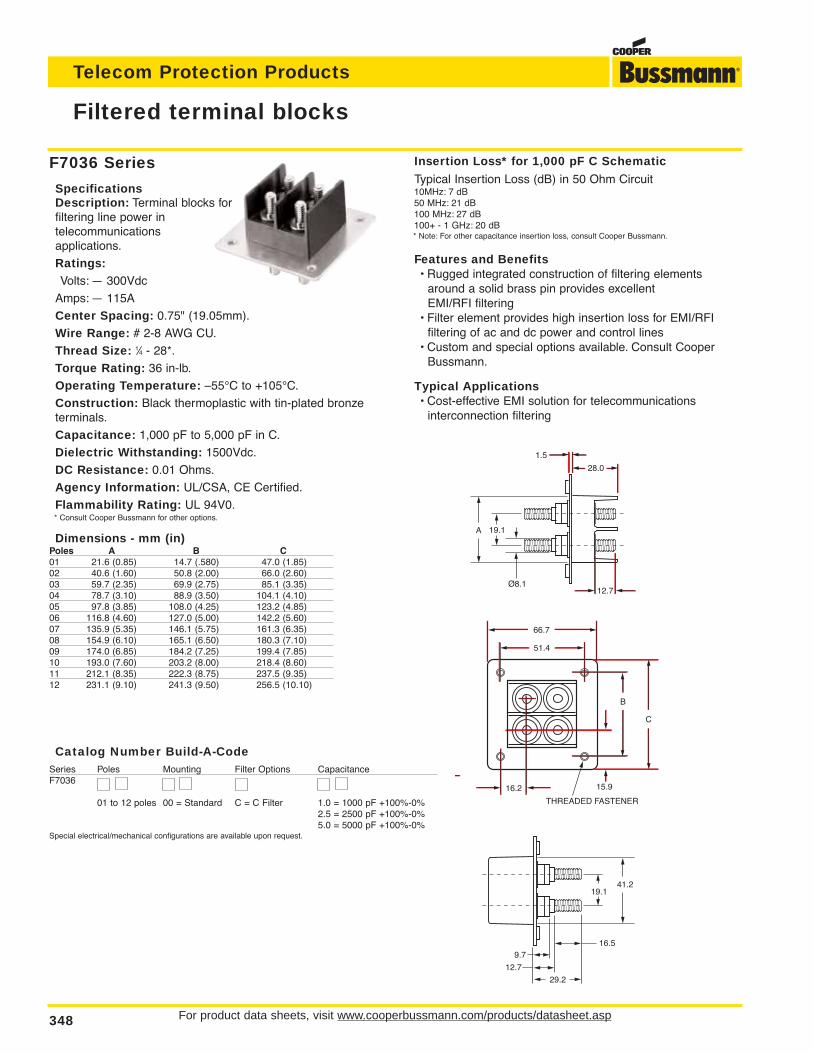
For product data sheets, visit www.cooperbussmann.com/products/datasheet.asp348
Telecom Protection Products
F7036 Series
SpecificationsDescription: Terminal blocks forfiltering line power in telecommunications applications.
Ratings:Volts: — 300Vdc
Amps: — 115A
Center Spacing: 0.75" (19.05mm).
Wire Range: # 2-8 AWG CU.
Thread Size: 1⁄4 - 28*.
Torque Rating: 36 in-lb.
Operating Temperature: –55°C to +105°C.
Construction: Black thermoplastic with tin-plated bronzeterminals.
Capacitance: 1,000 pF to 5,000 pF in C.
Dielectric Withstanding: 1500Vdc.
DC Resistance: 0.01 Ohms.
Agency Information: UL/CSA, CE Certified.
Flammability Rating: UL 94V0.* Consult Cooper Bussmann for other options.
Dimensions - mm (in)Poles A B C01 21.6 (0.85) 14.7 (.580) 47.0 (1.85)02 40.6 (1.60) 50.8 (2.00) 66.0 (2.60)03 59.7 (2.35) 69.9 (2.75) 85.1 (3.35)04 78.7 (3.10) 88.9 (3.50) 104.1 (4.10)05 97.8 (3.85) 108.0 (4.25) 123.2 (4.85)06 116.8 (4.60) 127.0 (5.00) 142.2 (5.60)07 135.9 (5.35) 146.1 (5.75) 161.3 (6.35)08 154.9 (6.10) 165.1 (6.50) 180.3 (7.10)09 174.0 (6.85) 184.2 (7.25) 199.4 (7.85)10 193.0 (7.60) 203.2 (8.00) 218.4 (8.60)11 212.1 (8.35) 222.3 (8.75) 237.5 (9.35)12 231.1 (9.10) 241.3 (9.50) 256.5 (10.10)
Filtered terminal blocks
19.141.2
16.5
29.2
9.7
12.7
16.2
51.4
15.9
THREADED FASTENER
B
C
66.7
Insertion Loss* for 1,000 pF C Schematic
Typical Insertion Loss (dB) in 50 Ohm Circuit10MHz: 7 dB50 MHz: 21 dB100 MHz: 27 dB100+ - 1 GHz: 20 dB* Note: For other capacitance insertion loss, consult Cooper Bussmann.
Features and Benefits• Rugged integrated construction of filtering elements
around a solid brass pin provides excellent EMI/RFI filtering
• Filter element provides high insertion loss for EMI/RFI filtering of ac and dc power and control lines
• Custom and special options available. Consult Cooper Bussmann.
Typical Applications• Cost-effective EMI solution for telecommunications
interconnection filtering
Catalog Number Build-A-CodeSeries Poles Mounting Filter Options CapacitanceF7036
01 to 12 poles 00 = Standard C = C Filter 1.0 = 1000 pF +100%-0%2.5 = 2500 pF +100%-0%5.0 = 5000 pF +100%-0%
Special electrical/mechanical configurations are available upon request.
A 19.1
Ø8.112.7
28.0
1.5
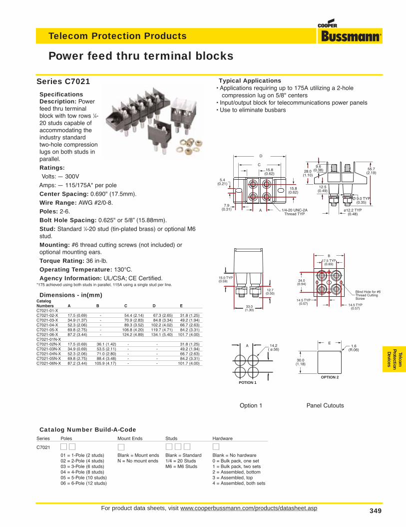
For product data sheets, visit www.cooperbussmann.com/products/datasheet.asp 349
Telecom Protection Products
TelcomProtectionDevices
Power feed thru terminal blocks
Series C7021
SpecificationsDescription: Powerfeed thru terminalblock with tow rows 1⁄4-20 studs capable ofaccommodating theindustry standard two-hole compressionlugs on both studs inparallel.
Ratings:Volts: — 300V
Amps: — 115/175A* per pole
Center Spacing: 0.690" (17.5mm).
Wire Range: AWG #2/0-8.
Poles: 2-6.
Bolt Hole Spacing: 0.625" or 5/8” (15.88mm).
Stud: Standard 1⁄4-20 stud (tin-plated brass) or optional M6stud.
Mounting: #6 thread cutting screws (not included) or optional mounting ears.
Torque Rating: 36 in-lb.
Operating Temperature: 130°C.
Agency Information: UL/CSA; CE Certified.*175 achieved using both studs in parallel, 115A using a single stud per line.
Dimensions - in(mm)CatalogNumbers A B C D EC7021-01-XC7021-02-X 17.5 (0.69) - 54.4 (2.14) 67.3 (2.65) 31.8 (1.25)C7021-03-X 34.9 (1.37) - 70.9 (2.83) 84.8 (3.34) 49.2 (1.94)C7021-04-X 52.3 (2.06) - 89.3 (3.52) 102.2 (4.02) 66.7 (2.63)C7021-05-X 69.8 (2.75) - 106.8 (4.20) 119.7 (4.71) 84.2 (3.31)C7021-06-X 87.2 (3.44) - 124.2 (4.89) 134.1 (5.40) 101.7 (4.00)C7021-01N-XC7021-02N-X 17.5 (0.69) 36.1 (1.42) - - 31.8 (1.25)C7021-03N-X 34.9 (0.69) 53.5 (2.11) - - 49.2 (1.94)C7021-04N-X 52.3 (2.06) 71.0 (2.80) - - 66.7 (2.63)C7021-05N-X 69.8 (2.75) 88.4 (3.48) - - 84.2 (3.31)C7021-06N-X 87.2 (3.44) 105.9 (4.17) - - 101.7 (4.00)
Option 1 Panel Cutouts
Typical Applications• Applications requiring up to 175A utilizing a 2-hole
compression lug on 5/8" centers• Input/output block for telecommunications power panels• Use to eliminate busbars
9.6(0.38)28.0
(1.10)
ø12.2 TYP(0.48)
55.7(2.19)
12.5(0.49)
Ø 9.0 TYP(0.35)
D
A
C15.8
(0.62)
5.4(0.21)
7.9(0.31) 1/4-20 UNC-2A
Thread TYP
15.8(0.62)
17.5 TYP(0.69)
24.0(0.94)
14.5 TYP(0.57) 14.5 TYP
(0.57)
Blind Hole for #6Thread CuttingScrew
15.0 TYP(0.59)
33.0(1.30)
12.7(0.50)
B
30.0(1.18)
1.6(R.06)
OPTION 2
14.2( ø.56)
POTION 1
EA
Catalog Number Build-A-CodeSeries Poles Mount Ends Studs Hardware
C7021
01 = 1-Pole (2 studs) Blank = Mount ends Blank = Standard Blank = No hardware02 = 2-Pole (4 studs) N = No mount ends 1/4 = 20 Studs 0 = Bulk pack, one set03 = 3-Pole (6 studs) M6 = M6 Studs 1 = Bulk pack, two sets04 = 4-Pole (8 studs) 2 = Assembled, bottom05 = 5-Pole (10 studs) 3 = Assembled, top06 = 6-Pole (12 studs) 4 = Assembled, both sets
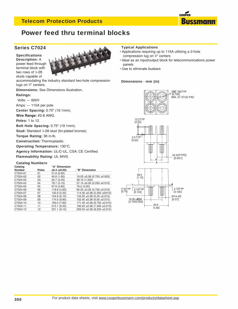
For product data sheets, visit www.cooperbussmann.com/products/datasheet.asp350
Telecom Protection Products
Power feed thru terminal blocks
Series C7024
SpecificationsDescription: Apower feed throughterminal block withtwo rows of 1⁄4-28studs capable ofaccommodating the industry standard two-hole compressionlugs on 3⁄4" centers.
Dimensions: See Dimensions illustration.
Ratings:Volts: — 600V
Amps: — 115A per pole
Center Spacing: 0.75" (19.1mm).
Wire Range: #2-8 AWG.
Poles: 1 to 12.
Bolt Hole Spacing: 0.75" (19.1mm).
Stud: Standard 1⁄4-28 stud (tin-plated bronze).
Torque Rating: 36 in-lb.
Construction: Thermoplastic.
Operating Temperature: 130°C.
Agency Information: UL/C-UL, CSA; CE Certified.
Flammability Rating: UL 94V0.
Catalog NumbersCatalog “A” DimensionNumber Poles ±0.4 (±0.02) “B” DimensionC7024-01 01 21.6 (0.85) -C7024-02 02 40.6 (1.60) 19.05 ±0.08 (0.750 ±0.003)C7024-03 03 59.7 (2.35) 38.10 (1.500)C7024-04 04 78.7 (3.10) 57.15 ±0.26 (2.250 ±0.010)C7024-05 05 97.8 (3.85) 76.2 (3.00)C7024-06 06 116.8 (4.60) 95.25 ±0.26 (3.750 ±0.010)C7024-07 07 135.9 (5.35) 114.30 ±0.38 (5.250 ±0/015)C7024-08 08 154.9 (6.10) 133.35 ±0.38 (5.25 ±0.015)C7024-09 09 174.0 (6.85) 152.40 ±0.38 (6.00 ±0.015)C7024-10 10 193.0 (7.60) 171.45 ±0.38 (6.750 ±0.015)C7024-11 11 212.1 (8.35) 190.50 ±0.38 (7.500 ±0.015)C7024-12 12 231.1 (9.10) 209.55 ±0.38 (8.250 ±0.015)
][0.1062.70TYP
][0.020.5 TYP
][0.5213.2TYP
B
][ 0.003±
0.7500.0819.06
][0.7017.8TYP
][0.1243.16TYP
16.53TYP[0.651]
A
][1.6040.6
][1.1028.0
][0.70017.780
MIN. AT STUD PAD
TYPØ
Ø14.4[0.57]
Typical Applications• Applications requiring up to 115A utilizing a 2-hole
compression lug on 3⁄4" centers• Ideal as an input/output block for telecommunications power
panels• Use to eliminate busbars
Dimensions - mm (in)
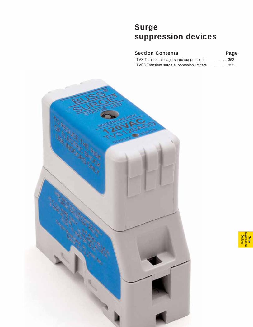
351
Surgesuppression devices
SurgeSuppression
Devices
Section Contents PageTVS Transient voltage surge suppressors . . . . . . . . . . . 352
TVSS Transient surge suppression limiters . . . . . . . . . . 353
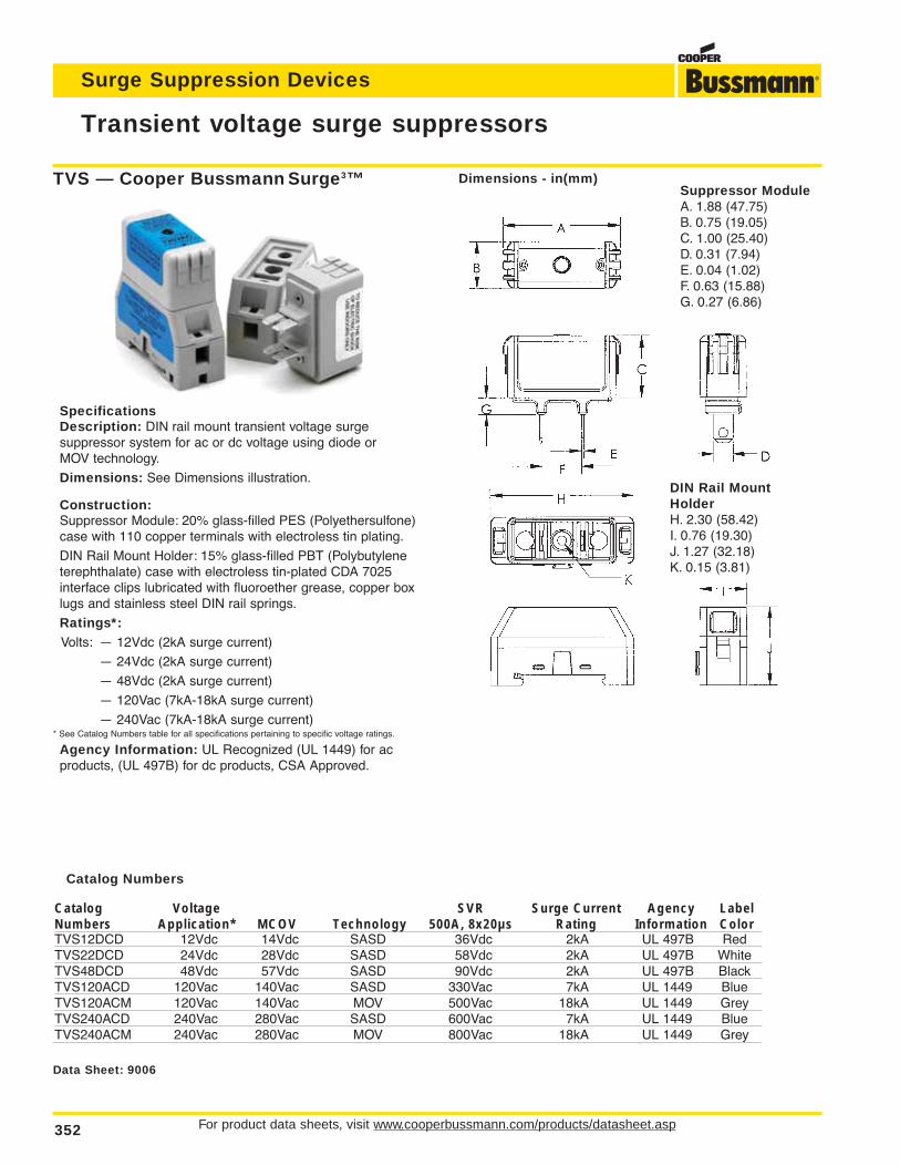
For product data sheets, visit www.cooperbussmann.com/products/datasheet.asp352
Transient voltage surge suppressors
Surge Suppression Devices
Data Sheet: 9006
SpecificationsDescription: DIN rail mount transient voltage surge suppressor system for ac or dc voltage using diode or MOV technology.
Dimensions: See Dimensions illustration.
Construction:Suppressor Module: 20% glass-filled PES (Polyethersulfone)case with 110 copper terminals with electroless tin plating.
DIN Rail Mount Holder: 15% glass-filled PBT (Polybutyleneterephthalate) case with electroless tin-plated CDA 7025interface clips lubricated with fluoroether grease, copper boxlugs and stainless steel DIN rail springs.
Ratings*:Volts: — 12Vdc (2kA surge current)
— 24Vdc (2kA surge current)
— 48Vdc (2kA surge current)
— 120Vac (7kA-18kA surge current)
— 240Vac (7kA-18kA surge current)* See Catalog Numbers table for all specifications pertaining to specific voltage ratings.
Agency Information: UL Recognized (UL 1449) for acproducts, (UL 497B) for dc products, CSA Approved.
Catalog Numbers
Catalog Voltage SVR Surge Current Agency LabelNumbers Application* MCOV Technology 500A, 8x20µs Rating Information ColorTVS12DCD 12Vdc 14Vdc SASD 36Vdc 2kA UL 497B RedTVS22DCD 24Vdc 28Vdc SASD 58Vdc 2kA UL 497B WhiteTVS48DCD 48Vdc 57Vdc SASD 90Vdc 2kA UL 497B BlackTVS120ACD 120Vac 140Vac SASD 330Vac 7kA UL 1449 BlueTVS120ACM 120Vac 140Vac MOV 500Vac 18kA UL 1449 GreyTVS240ACD 240Vac 280Vac SASD 600Vac 7kA UL 1449 BlueTVS240ACM 240Vac 280Vac MOV 800Vac 18kA UL 1449 Grey
TVS — Cooper Bussmann Surge3™ Dimensions - in(mm)Suppressor ModuleA. 1.88 (47.75)B. 0.75 (19.05)C. 1.00 (25.40)D. 0.31 (7.94)E. 0.04 (1.02)F. 0.63 (15.88)G. 0.27 (6.86)
DIN Rail MountHolderH. 2.30 (58.42)I. 0.76 (19.30)J. 1.27 (32.18)K. 0.15 (3.81)
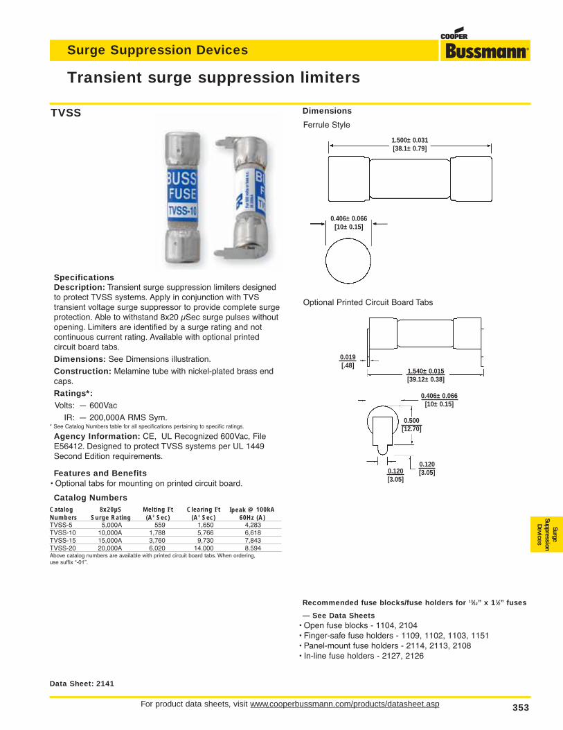
For product data sheets, visit www.cooperbussmann.com/products/datasheet.asp 353
Surge Suppression Devices
Transient surge suppression limiters
SurgeSuppression
Devices
Data Sheet: 2141
SpecificationsDescription: Transient surge suppression limiters designedto protect TVSS systems. Apply in conjunction with TVS transient voltage surge suppressor to provide complete surgeprotection. Able to withstand 8x20 µSec surge pulses withoutopening. Limiters are identified by a surge rating and not continuous current rating. Available with optional printed circuit board tabs.
Dimensions: See Dimensions illustration.
Construction: Melamine tube with nickel-plated brass endcaps.
Ratings*:Volts: — 600Vac
IR: — 200,000A RMS Sym.* See Catalog Numbers table for all specifications pertaining to specific ratings.
Agency Information: CE, UL Recognized 600Vac, FileE56412. Designed to protect TVSS systems per UL 1449Second Edition requirements.
Features and Benefits• Optional tabs for mounting on printed circuit board.
Catalog NumbersCatalog 8x20µS Melting I2t Clearing I2t Ipeak @ 100kANumbers Surge Rating (A2 Sec) (A2 Sec) 60Hz (A)TVSS-5 5,000A 559 1,650 4,283TVSS-10 10,000A 1,788 5,766 6,618TVSS-15 15,000A 3,760 9,730 7,843TVSS-20 20,000A 6,020 14.000 8.594Above catalog numbers are available with printed circuit board tabs. When ordering, use suffix “-01”.
Recommended fuse blocks/fuse holders for 13⁄32” x 11⁄2” fuses
— See Data Sheets• Open fuse blocks - 1104, 2104• Finger-safe fuse holders - 1109, 1102, 1103, 1151• Panel-mount fuse holders - 2114, 2113, 2108• In-line fuse holders - 2127, 2126
Dimensions
Ferrule Style
Optional Printed Circuit Board Tabs
TVSS
1.500± 0.031[38.1± 0.79]
0.406± 0.066[10± 0.15]
0.406± 0.066[10± 0.15]
0.500[12.70]
0.019[.48]
0.120[3.05]0.120
[3.05]
1.540± 0.015[39.12± 0.38]
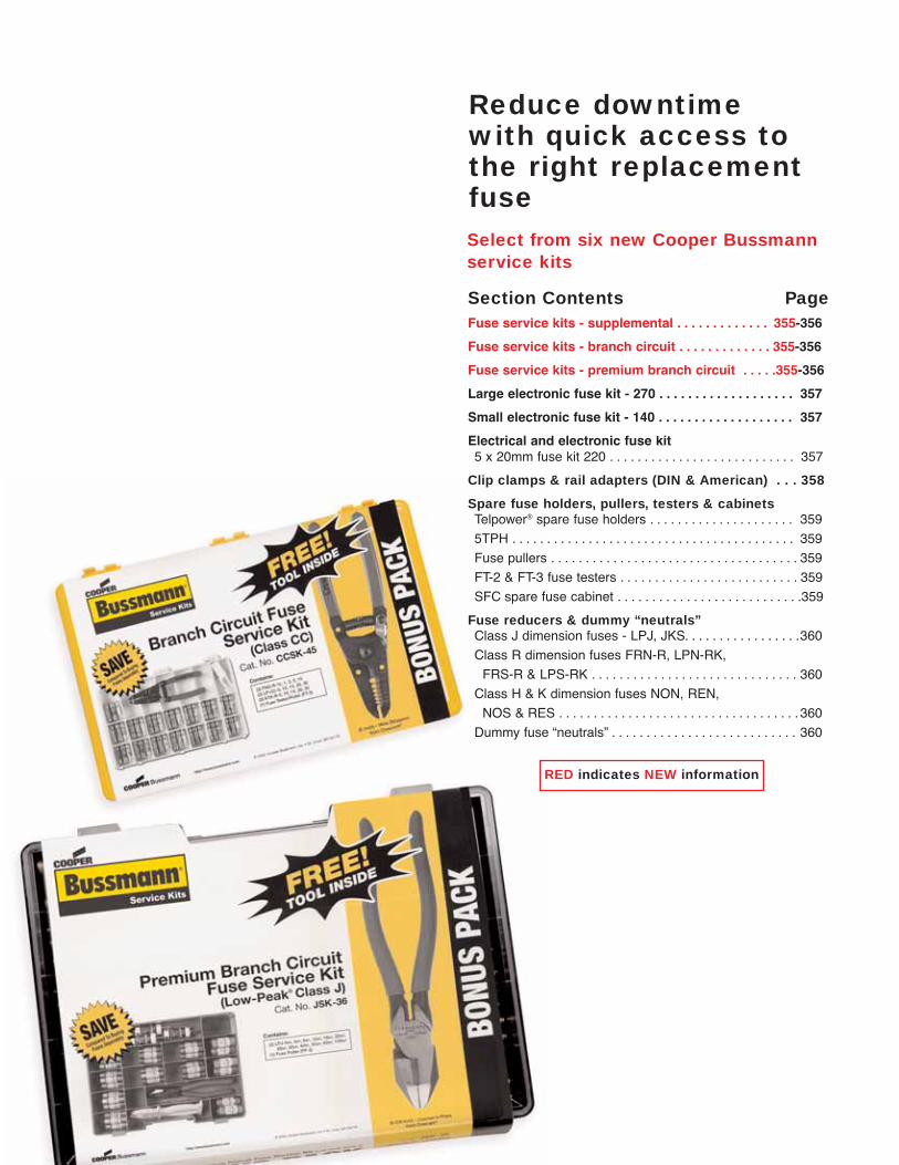
354
Select from six new Cooper Bussmann service kits
Reduce downtimewith quick access tothe right replacementfuse
Section Contents PageFuse service kits - supplemental . . . . . . . . . . . . . 355-356
Fuse service kits - branch circuit . . . . . . . . . . . . . 355-356
Fuse service kits - premium branch circuit . . . . .355-356
Large electronic fuse kit - 270 . . . . . . . . . . . . . . . . . . . 357
Small electronic fuse kit - 140 . . . . . . . . . . . . . . . . . . . 357
Electrical and electronic fuse kit5 x 20mm fuse kit 220 . . . . . . . . . . . . . . . . . . . . . . . . . . . 357
Clip clamps & rail adapters (DIN & American) . . . 358
Spare fuse holders, pullers, testers & cabinetsTelpower® spare fuse holders . . . . . . . . . . . . . . . . . . . . . 359
5TPH . . . . . . . . . . . . . . . . . . . . . . . . . . . . . . . . . . . . . . . . . 359
Fuse pullers . . . . . . . . . . . . . . . . . . . . . . . . . . . . . . . . . . . . 359
FT-2 & FT-3 fuse testers . . . . . . . . . . . . . . . . . . . . . . . . . . 359
SFC spare fuse cabinet . . . . . . . . . . . . . . . . . . . . . . . . . . .359
Fuse reducers & dummy “neutrals”Class J dimension fuses - LPJ, JKS. . . . . . . . . . . . . . . . .360
Class R dimension fuses FRN-R, LPN-RK,
FRS-R & LPS-RK . . . . . . . . . . . . . . . . . . . . . . . . . . . . . . 360
Class H & K dimension fuses NON, REN,
NOS & RES . . . . . . . . . . . . . . . . . . . . . . . . . . . . . . . . . . . 360
Dummy fuse “neutrals” . . . . . . . . . . . . . . . . . . . . . . . . . . . 360
RED indicates NEW information
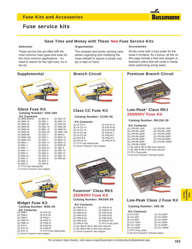
For product data sheets, visit www.cooperbussmann.com/products/datasheet.asp 355
Fuse service kits
Fuse Kits and Accessories
SurgeSuppression
Devices
Glass Fuse KitCatalog Number: GSK-260Kit Contents
(5) GMA-500mA (5) MDL-6 (5) AGC-10(5) GMA-1A (5) MDL-7 (5) AGC-15(5) GMA-2A (5) MDL-8 (5) AGC-20(5) GMA-3A (5) MDL-10 (5) GMC-2A(5) GMA-4A (5) MDL-15 (5) GMC-5A(5) GMA-5A (5) MDL-20 (5) GMC-10A(5) GMA-6A (5) AGC-1⁄4 (5) MDA-5(5) GMA-10A (5) AGC-1⁄2 (5) MDA-10(5) GMA-15A (5) AGC-1 (5) MDA-12(5) MDL-1⁄4 (5) AGC-11⁄2 (5) MDA-15(5) MDL-1⁄2 (5) AGC-2 (5) MDA-20(5) MDL-1 (5) AGC-21⁄2 (5) ABC-5(5) MDL-11⁄2 (5) AGC-3 (5) ABC-10(5) MDL-2 (5) AGC-4 (5) ABC-12(5) MDL-21⁄2 (5) AGC-5 (5) ABC-15(5) MDL-3 (5) AGC-6 (5) ABC-20(5) MDL-4 (5) AGC-7(5) MDL-5 (5) AGC-8(1) FT-3 Fuse tester/puller(1) 6-inch Crescent® wire stripper
Midget Fuse KitCatalog Number: MSK-45Kit Contents
(3) FNM-1 (3) KTK-20(3) FNM-2 (3) KTK-30(3) FNM-5 (3) FNQ-5(3) FNM-10 (3) FNQ-10(3) FNM-15 (3) FNQ-15(3) KTK-5 (3) FNQ-20(3) KTK-10 (3) FNQ-30(3) KTK-15 (1) FT-3 Fuse tester/puller(1) 6-inch Crescent® wire stripper
Class CC Fuse Kit
Catalog Number: CCSK-45
Kit Contents(3) LP-CC-5 (3) KTK-R-15(3) LP-CC-10 (3) KTK-R-20(3) LP-CC-15 (3) KTK-R-30(3) LP-CC-20 (3) FNQ-R-1⁄2(3) LP-CC-30 (3) FNQ-R-3(3) KTK-R-5 (3) FNQ-R-5(3) KTK-R-10 (3) FNQ-R-10(1) FT-3 Fuse tester/puller(1) 6-inch Crescent® wire stripper
Branch CircuitSupplemental
Fusetron® Class RK5250/600V Fuse KitCatalog Number: RK5SK-39
Kit Contents(3) FRN-R-10 (3) FRS-R-10(3) FRN-R-15 (3) FRS-R-15(3) FRN-R-20 (3) FRS-R-20(3) FRN-R-25 (3) FRS-R-30(3) FRN-R-30 (3) FRS-R-60(3) FRN-R-60 (3) FRS-R-100(3) FRN-R-100 (1) FP-2 Fuse puller(1) No. 263-R (60 to 30A fuse reducer)(1) No. 663-R (60 to 30A fuse reducer)(1) 6-inch Crescent® wire stripper
Low-Peak Class J Fuse Kit
Catalog Number: JSK-36
Kit Contents(3) LPJ-3SP (3) LPJ-25SP(3) LPJ-5SP (3) LPJ-30SP(3) LPJ-6SP (3) LPJ-40SP(3) LPJ-10SP (3) LPJ-50SP(3) LPJ-15SP (3) LPJ-60SP(3) LPJ-20SP (3) LPJ-100SP(1) FP-2 Fuse puller(1) 85⁄8-inch Crescent® lineman’s pliers
Premium Branch Circuit
Low-Peak® Class RK1250/600V Fuse Kit
Catalog Number: RK1SK-39
Kit Contents(3) LPN-RK-10SP (3) LPS-RK-10SP(3) LPN-RK-15SP (3) LPS-RK-15SP(3) LPN-RK-20SP (3) LPS-RK-20SP(3) LPN-RK-25SP (3) LPS-RK-30SP(3) LPN-RK-30SP (3) LPS-RK-60SP(3) LPN-RK-60SP (3) LPS-RK-100SP(3) LPN-RK-100SP(1) No. 263-R (60 to 30A fuse reducer)(1) No. 663-R (60 to 30A fuse reducer)(1) FP-2 Fuse puller(1) 85⁄8-inch Crescent® lineman’s pliers
Selection
These service kits are filled with themost common fuse types and sizes forthe most common applications – noneed to search for the right fuse, it’s inthe kit.
Organization
The compact and sturdy carrying caseallows organizing and modifying thefuses needed to assure a proper sup-ply is kept on hand.
Accessories
All kits come with a fuse puller for thefuses it contains. As a bonus, all kits onthis page include a free wire stripper orlineman’s pliers that will come in handywhen performing wiring tasks.
Save Time and Money with These New Fuse Service Kits
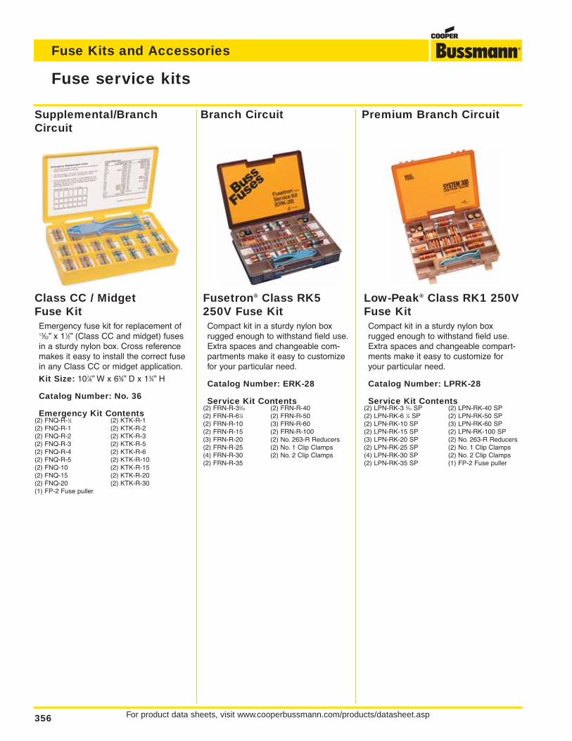
For product data sheets, visit www.cooperbussmann.com/products/datasheet.asp356
Fuse Kits and Accessories
Fuse service kits
Low-Peak® Class RK1 250VFuse KitCompact kit in a sturdy nylon boxrugged enough to withstand field use.Extra spaces and changeable compart-ments make it easy to customize foryour particular need.
Catalog Number: LPRK-28
Service Kit Contents(2) LPN-RK-3 2⁄10 SP (2) LPN-RK-40 SP(2) LPN-RK-6 1⁄4 SP (2) LPN-RK-50 SP(2) LPN-RK-10 SP (3) LPN-RK-60 SP(2) LPN-RK-15 SP (2) LPN-RK-100 SP(3) LPN-RK-20 SP (2) No. 263-R Reducers(2) LPN-RK-25 SP (2) No. 1 Clip Clamps(4) LPN-RK-30 SP (2) No. 2 Clip Clamps(2) LPN-RK-35 SP (1) FP-2 Fuse puller
Fusetron® Class RK5250V Fuse KitCompact kit in a sturdy nylon boxrugged enough to withstand field use.Extra spaces and changeable com-partments make it easy to customizefor your particular need.
Catalog Number: ERK-28
Service Kit Contents(2) FRN-R-32⁄10 (2) FRN-R-40(2) FRN-R-61⁄4 (2) FRN-R-50(2) FRN-R-10 (3) FRN-R-60(2) FRN-R-15 (2) FRN-R-100(3) FRN-R-20 (2) No. 263-R Reducers(2) FRN-R-25 (2) No. 1 Clip Clamps(4) FRN-R-30 (2) No. 2 Clip Clamps(2) FRN-R-35
Class CC / MidgetFuse KitEmergency fuse kit for replacement of13⁄32” x 11⁄2” (Class CC and midget) fusesin a sturdy nylon box. Cross referencemakes it easy to install the correct fusein any Class CC or midget application.
Kit Size: 107⁄8” W x 65⁄8” D x 13⁄4” H
Catalog Number: No. 36
Emergency Kit Contents(2) FNQ-R-1⁄2 (2) KTK-R-1(2) FNQ-R-1 (2) KTK-R-2(2) FNQ-R-2 (2) KTK-R-3(2) FNQ-R-3 (2) KTK-R-5(2) FNQ-R-4 (2) KTK-R-6(2) FNQ-R-5 (2) KTK-R-10(2) FNQ-10 (2) KTK-R-15(2) FNQ-15 (2) KTK-R-20(2) FNQ-20 (2) KTK-R-30(1) FP-2 Fuse puller
Supplemental/BranchCircuit
Branch Circuit Premium Branch Circuit
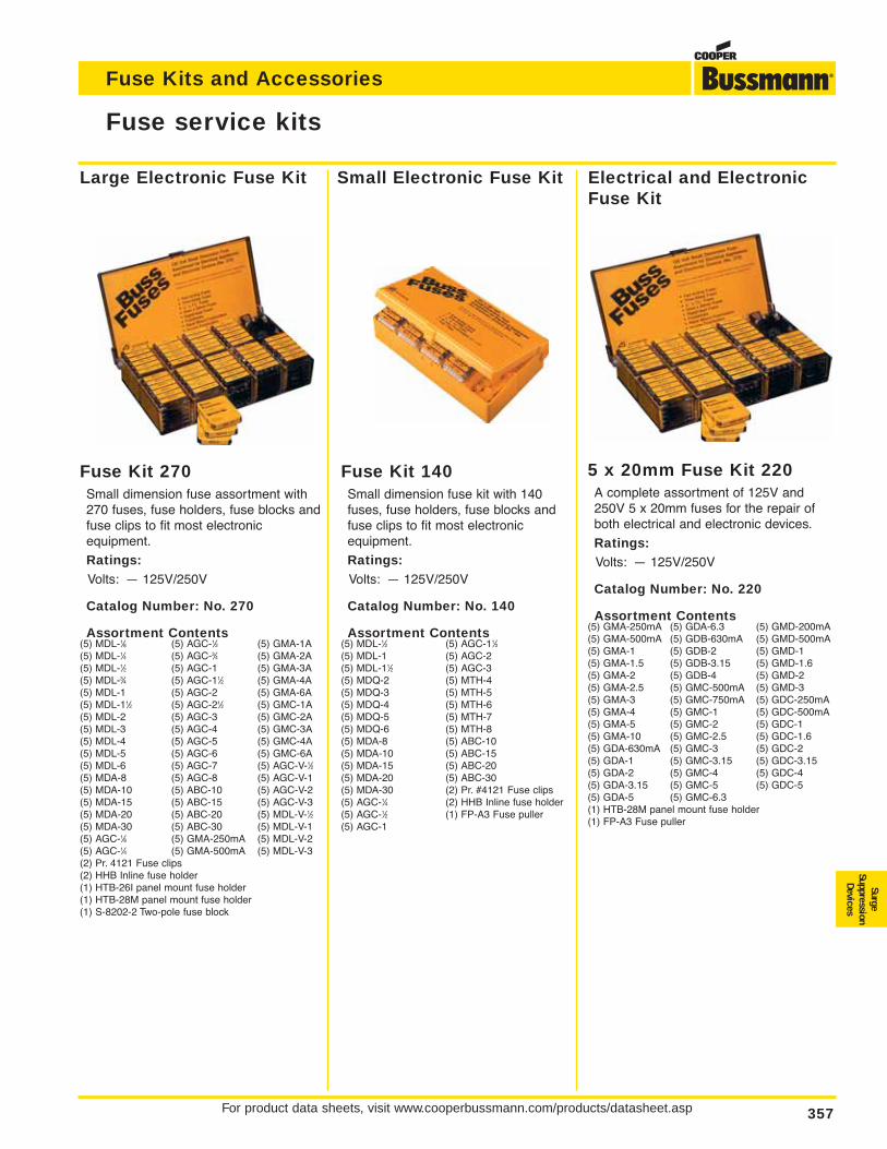
For product data sheets, visit www.cooperbussmann.com/products/datasheet.asp 357
Fuse Kits and Accessories
SurgeSuppression
Devices
Fuse service kits
Fuse Kit 270Small dimension fuse assortment with270 fuses, fuse holders, fuse blocks andfuse clips to fit most electronic equipment.
Ratings:Volts: — 125V/250V
Catalog Number: No. 270
Assortment Contents(5) MDL-1⁄8 (5) AGC-1⁄2 (5) GMA-1A(5) MDL-1⁄4 (5) AGC-3⁄4 (5) GMA-2A(5) MDL-1⁄2 (5) AGC-1 (5) GMA-3A(5) MDL-3⁄4 (5) AGC-11⁄2 (5) GMA-4A(5) MDL-1 (5) AGC-2 (5) GMA-6A(5) MDL-11⁄2 (5) AGC-21⁄2 (5) GMC-1A(5) MDL-2 (5) AGC-3 (5) GMC-2A(5) MDL-3 (5) AGC-4 (5) GMC-3A(5) MDL-4 (5) AGC-5 (5) GMC-4A(5) MDL-5 (5) AGC-6 (5) GMC-6A(5) MDL-6 (5) AGC-7 (5) AGC-V-1⁄2(5) MDA-8 (5) AGC-8 (5) AGC-V-1(5) MDA-10 (5) ABC-10 (5) AGC-V-2(5) MDA-15 (5) ABC-15 (5) AGC-V-3(5) MDA-20 (5) ABC-20 (5) MDL-V-1⁄2(5) MDA-30 (5) ABC-30 (5) MDL-V-1(5) AGC-1⁄8 (5) GMA-250mA (5) MDL-V-2(5) AGC-1⁄4 (5) GMA-500mA (5) MDL-V-3(2) Pr. 4121 Fuse clips(2) HHB Inline fuse holder(1) HTB-26I panel mount fuse holder(1) HTB-28M panel mount fuse holder(1) S-8202-2 Two-pole fuse block
Fuse Kit 140Small dimension fuse kit with 140fuses, fuse holders, fuse blocks andfuse clips to fit most electronic equipment.
Ratings:Volts: — 125V/250V
Catalog Number: No. 140
Assortment Contents(5) MDL-1⁄2 (5) AGC-11⁄2(5) MDL-1 (5) AGC-2(5) MDL-11⁄2 (5) AGC-3(5) MDQ-2 (5) MTH-4(5) MDQ-3 (5) MTH-5(5) MDQ-4 (5) MTH-6(5) MDQ-5 (5) MTH-7(5) MDQ-6 (5) MTH-8(5) MDA-8 (5) ABC-10(5) MDA-10 (5) ABC-15(5) MDA-15 (5) ABC-20(5) MDA-20 (5) ABC-30(5) MDA-30 (2) Pr. #4121 Fuse clips(5) AGC-1⁄4 (2) HHB Inline fuse holder(5) AGC-1⁄2 (1) FP-A3 Fuse puller(5) AGC-1
5 x 20mm Fuse Kit 220A complete assortment of 125V and250V 5 x 20mm fuses for the repair ofboth electrical and electronic devices.
Ratings:Volts: — 125V/250V
Catalog Number: No. 220
Assortment Contents(5) GMA-250mA (5) GDA-6.3 (5) GMD-200mA(5) GMA-500mA (5) GDB-630mA (5) GMD-500mA(5) GMA-1 (5) GDB-2 (5) GMD-1(5) GMA-1.5 (5) GDB-3.15 (5) GMD-1.6(5) GMA-2 (5) GDB-4 (5) GMD-2(5) GMA-2.5 (5) GMC-500mA (5) GMD-3(5) GMA-3 (5) GMC-750mA (5) GDC-250mA(5) GMA-4 (5) GMC-1 (5) GDC-500mA(5) GMA-5 (5) GMC-2 (5) GDC-1(5) GMA-10 (5) GMC-2.5 (5) GDC-1.6(5) GDA-630mA (5) GMC-3 (5) GDC-2(5) GDA-1 (5) GMC-3.15 (5) GDC-3.15(5) GDA-2 (5) GMC-4 (5) GDC-4(5) GDA-3.15 (5) GMC-5 (5) GDC-5(5) GDA-5 (5) GMC-6.3(1) HTB-28M panel mount fuse holder(1) FP-A3 Fuse puller
Large Electronic Fuse Kit Small Electronic Fuse Kit Electrical and ElectronicFuse Kit
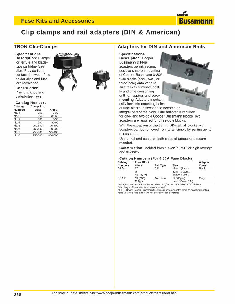
For product data sheets, visit www.cooperbussmann.com/products/datasheet.asp358
Fuse Kits and Accessories
Adapters for DIN and American Rails
SpecificationsDescription: CooperBussmann DIN-railadapters permit secure,positive snap-on mountingof Cooper Bussmann 0-30Afuse blocks (one-, two-, orthree-pole) onto varioussize rails to eliminate cost-ly and time consumingdrilling, tapping, and screwmounting. Adapters mechani-cally lock into mounting holesof fuse blocks in seconds to become anintegral part of the block. One adapter is requiredfor one- and two-pole Cooper Bussmann blocks. Twoadapters are required for three-pole blocks.
With the exception of the 32mm DIN-rail, all blocks withadapters can be removed from a rail simply by pulling up itsrelease tab.
Use of rail end-stops on both sides of adapters is recom-mended.
Construction: Molded from “Lexan™ 241” for high strengthand flexibility.
Catalog Numbers (For 0-30A Fuse Blocks)Catalog Fuse Block AdapterNumbers Class Rail Type Size ColorDRA-1 CC DIN 15mm (Sym.) Black
G 32mm (Asym.)*H (250V) 35mm (Sym.)
DRA-2 *R (250) American 17⁄64” (Sym.) GrayM Type (also 35mm DIN)
Package Quantities: standard—10; bulk—100 (Cat. No. BK/DRA-1 or BK/DRA-2.)*Mounting on 15mm rails is not recommended.NOTE—Newer Cooper Bussmann fuse blocks have elongated block-to-adapter mountingholes (old style fuse blocks will not accept the rail adapters).
Clip clamps and rail adapters (DIN & American)
TRON Clip-Clamps
SpecificationsDescription: Clampsfor ferrule and blade-type cartridge fuseclips. Provide tightcontacts between fuseholder clips and fuseferrules/blades.
Construction:Phenolic knob andplated-steel jaws.
Catalog NumbersCatalog Clamp SizeNumbers Volts AmpsNo. 1 250 0-30No. 2 250 35-60No. 2 600 0-30No. 4 600 35-60No. 5 250/600 70-100No. 6 250/600 110-200No. 7 250/600 225-400No. 8 250/600 450-600
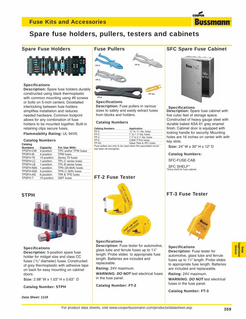
For product data sheets, visit www.cooperbussmann.com/products/datasheet.asp 359
Fuse Kits and Accessories
Fuse Pullers
SpecificationsDescription: Fuse pullers in varioussizes to safely and easily extract fusesfrom blocks and holders.
Catalog Numbers
Catalog Numbers ApplicationFP-2 13⁄32” to 13⁄16” dia. fusesFP-3 1” to 1 3⁄4” dia. fusesFP-4 1 3⁄4” to 2 1⁄2” dia. fusesFP-6 0-60A T-Tron fusesFP-A3 Glass Tube & ATC fusesFuse pullers are only to be used when the associated circuithas been de-energized.
Spare Fuse Holders
SpecificationsDescription: Spare fuse holders durablyconstructed using black thermoplasticwith common mounting using #6 screwsor bolts on 5-inch centers. Dovetailedinterlocking between fuse holders simplifies installation and reduces needed hardware. Common footprintallows for any combination of fuse holders to be mounted together. Built-inretaining clips secure fuses.
Flammability Rating: UL 94V0.
Catalog NumbersCatalogNumbers Capacity For Use With:TPSFH-CW 4-position TPC and/or TPW fusesTPSFH-M 4-position TPM fusesTPSFH-70 12-position Series 70 fusesTPSFH-LC 1-position TPL-C series fusesTPSFH-LB 1-position TPL-B series fusesTPSFH-N60 1-position TPN (35-60A) fusesTPSFH-N30 4-position TPN (1-30A) fusesTPSFH-AS 6-position TPA & TPS fusesTPSFH-T 10-position GMT fuses
Spare fuse holders, pullers, testers and cabinets
Data Sheet: 1119
SFC Spare Fuse Cabinet
SpecificationsDescription: Spare fuse cabinet withfive cubic feet of storage space.Constructed of heavy gauge steel withdurable baked ASA 61 grey enamel finish. Cabinet door is equipped withlocking handle for security. Mountingholes are 16 inches on center with withkey slots.
Size: 24” W x 30” H x 12” D
Catalog Numbers:
SFC-FUSE-CAB
SFC SHELF**Extra shelf for fuse cabinet.
5TPH
SpecificationsDescription: 5-position spare fuse holder for midget size and class CCfuses (13⁄32” diameter) fuses. Constructedof grey thermoplastic with adhesive tapeon back for easy mounting on cabinetdoors.
Size: 2.98” W x 1.03” H x 0.63” D
Catalog Number: 5TPH
FT-2 Fuse Tester
SpecificationsDescription: Fuse tester for automotive,glass tube and ferrule fuses up to 17⁄8”length. Probe slides to appropriate fuselength. Batteries are included andreplaceable.
Rating: 24V maximum.
WARNING: DO NOT test electrical fusesin the fuse panel.
Catalog Number: FT-2
FT-3 Fuse Tester
SpecificationsDescription: Fuse tester for automotive, glass tube and ferrulefuses up to 11⁄4” length. Probe slides to appropriate fuse length. Batteriesare included and replaceable.
Rating: 24V maximum.
WARNING: DO NOT test electricalfuses in the fuse panel.
Catalog Number: FT-3
FP-4
FP-A3
FP-6
FP-3
FP-2
SurgeSuppression
Devices
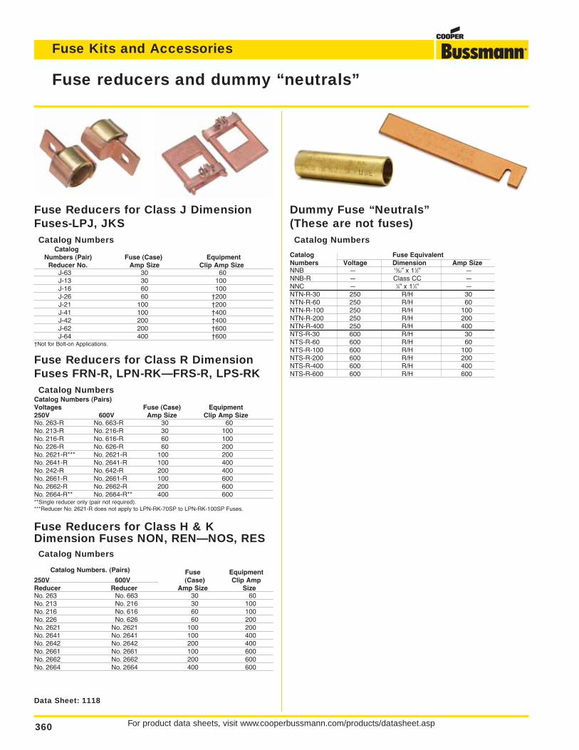
For product data sheets, visit www.cooperbussmann.com/products/datasheet.asp360
Fuse Kits and Accessories
Fuse reducers and dummy “neutrals”
Data Sheet: 1118
Fuse Reducers for Class J DimensionFuses-LPJ, JKSCatalog Numbers
CatalogNumbers (Pair) Fuse (Case) Equipment
Reducer No. Amp Size Clip Amp SizeJ-63 30 60J-13 30 100J-16 60 100J-26 60 †200J-21 100 †200J-41 100 †400J-42 200 †400J-62 200 †600J-64 400 †600
†Not for Bolt-on Applications.
Fuse Reducers for Class R DimensionFuses FRN-R, LPN-RK—FRS-R, LPS-RKCatalog Numbers
Catalog Numbers (Pairs)Voltages Fuse (Case) Equipment250V 600V Amp Size Clip Amp SizeNo. 263-R No. 663-R 30 60No. 213-R No. 216-R 30 100No. 216-R No. 616-R 60 100No. 226-R No. 626-R 60 200No. 2621-R*** No. 2621-R 100 200No. 2641-R No. 2641-R 100 400No. 242-R No. 642-R 200 400No. 2661-R No. 2661-R 100 600No. 2662-R No. 2662-R 200 600No. 2664-R** No. 2664-R** 400 600**Single reducer only (pair not required).***Reducer No. 2621-R does not apply to LPN-RK-70SP to LPN-RK-100SP Fuses.
Fuse Reducers for Class H & KDimension Fuses NON, REN—NOS, RESCatalog Numbers
Catalog Numbers. (Pairs) Fuse Equipment250V 600V (Case) Clip AmpReducer Reducer Amp Size SizeNo. 263 No. 663 30 60No. 213 No. 216 30 100No. 216 No. 616 60 100No. 226 No. 626 60 200No. 2621 No. 2621 100 200No. 2641 No. 2641 100 400No. 2642 No. 2642 200 400No. 2661 No. 2661 100 600No. 2662 No. 2662 200 600No. 2664 No. 2664 400 600
Dummy Fuse “Neutrals”(These are not fuses)Catalog Numbers
Catalog Fuse EquivalentNumbers Voltage Dimension Amp SizeNNB — 13⁄32” x 11⁄2” —NNB-R — Class CC —NNC — 1⁄4” x 11⁄4” —NTN-R-30 250 R/H 30NTN-R-60 250 R/H 60NTN-R-100 250 R/H 100NTN-R-200 250 R/H 200NTN-R-400 250 R/H 400NTS-R-30 600 R/H 30NTS-R-60 600 R/H 60NTS-R-100 600 R/H 100NTS-R-200 600 R/H 200NTS-R-400 600 R/H 400NTS-R-600 600 R/H 600
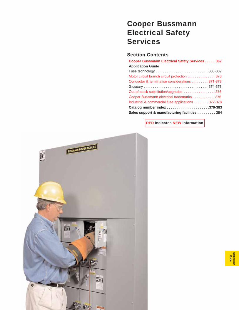
361
ApplicationGuide
RED indicates NEW information
Cooper BussmannElectrical SafetyServices
Section ContentsCooper Bussmann Electrical Safety Services . . . . . 362Application Guide Fuse technology . . . . . . . . . . . . . . . . . . . . . . . . . . . . 363-369
Motor circuit branch circuit protection . . . . . . . . . . . . . . . 370
Conductor & termination considerations . . . . . . . . . 371-373
Glossary . . . . . . . . . . . . . . . . . . . . . . . . . . . . . . . . . . . 374-376
Out-of-stock substitution/upgrades . . . . . . . . . . . . . . . . . 376
Cooper Bussmann electrical trademarks . . . . . . . . . . . . 376
Industrial & commercial fuse applications . . . . . . . . 377-378
Catalog number index . . . . . . . . . . . . . . . . . . . . .379-383Sales support & manufacturing facilities . . . . . . . . . 384

For product data sheets, visit www.cooperbussmann.com/products/datasheet.asp362
Application Guide
ImproveElectrical
Safetyand
ReduceLiability
Improving Safety, Reducing Liability
A Safe Working Environment
Complete electrical safety involves a total approach to theselection, installation and continued maintenance of all electrical system components.
Keeping on top of all facets of any power distribution systemcan become a complex task involving ever-evolving codeschanges, changes made by electrical utilities and governmentregulations that affect what goes on inside any commercial,industrial or institutional facility.
While this Application Guide is intended to provide a generalunderstanding, its depth of coverage is limited. For moredetailed information, we recommend reviewing the CooperBussmann SPD (Selecting Protective Devices — Reorder# 3002).
Electrical Safety Services
To help you be sure your power distribution system is up tocode, and providing maximum safety and reduced liability,Cooper Bussmann offers Electrical Safety Services.
Our professional staff of degreed Electrical Engineers is available to assist in assessing your current electrical system;analyzing it for areas of weakness and making recommendations for improvements that will help assure itssafety and integrity.
Cooper Bussmann Electrical Safety Services
Employee Training
At Cooper Bussmann we recognize any electrical system isn'ta "get it and forget it" affair. It's vital that your employees areproperly trained to perform the tasks they're called upon foroperating and maintaining your electrical power distributionsystem.
We have developed comprehensive training programs that canbe modified to meet your specific needs so that your maintenance staff is qualified to perform their duties.
Contact Cooper Bussmann
To learn more about our comprehensive approach to enhancing electrical safety in facilities like yours, contact yourlocal Cooper Bussmann representative, or call 636-207-3294.
For product data sheets, visit www.cooperbussmann.com/products/datasheet.asp 363
Application Guide
ApplicationGuide
Fuse technology
Circuit Protection
Electrical distribution systems are often quite complicated.They cannot be absolutely fail-safe. Circuits are subject todestructive overcurrents. Harsh environments, general deterioration, accidental damage, damage from natural causes,excessive expansion, and/or overloading of the electrical distribution system are factors which contribute to the occurrence of such overcurrents. Reliable protective devicesprevent or minimize costly damage to transformers, conductors, motors, and the other many components andloads that make up the complete distribution system. Reliablecircuit protection is essential to avoid the severe monetarylosses which can result from power blackouts and prolongeddowntime of facilities. It is the need for reliable protection, safety, and freedom from fire hazards that has made the fuse awidely used protective device.
Overcurrents
An overcurrent is either an overload current or a short-circuitcurrent. The overload current is an excessive current relative tonormal operating current, but one which is confined to the normal conductive paths provided by the conductors and othercomponents and loads of the distribution system. As the nameimplies, a short-circuit current is one which flows outside thenormal conducting paths.
Overloads
Overloads are most often between one and six times the normal current level. Usually, they are caused by harmlesstemporary surge currents that occur when motors are started-up or transformers are energized. Such overload currents, or transients, are normal occurrences. Since they areof brief duration, any temperature rise is trivial and has noharmful effect on the circuit components. (It is important thatprotective devices do not react to them.)
Continuous overloads can result from defective motors (suchas worn motor bearings), overloaded equipment, or too manyloads on one circuit. Such sustained overloads are destructiveand must be cut off by protective devices before they damagethe distribution system or system loads. However, since theyare of relatively low magnitude compared to short-circuit currents, removal of the overload current within minutes willgenerally prevent equipment damage. A sustained overloadcurrent results in overheating of conductors and other components and will cause deterioration of insulation, whichmay eventually result in severe damage and short-circuits if notinterrupted.
Short-Circuits
Whereas overload currents occur at rather modest levels, theshort-circuit or fault current can be many hundred times largerthan the normal operating current. A high level fault may be50,000A (or larger). If not cut off within a matter of a few thousandths of a second, damage and destruction canbecome rampant—there can be severe insulation damage,melting of conductors, vaporization of metal, ionization ofgases, arcing, and fires.
Simultaneously, high level short-circuit currents can develophuge magnetic-field stresses. The magnetic forces betweenbus bars and other conductors can be many hundreds ofpounds per linear foot; even heavy bracing may not be adequate to keep them from being warped or distorted beyond repair.
Fuses
The fuse is a reliable overcurrent protective device. A “fusible”link or links encapsulated in a tube and connected to contactterminals comprise the fundamental elements of the basicfuse. Electrical resistance of the link is so low that it simply actsas a conductor. However, when destructive currents occur, thelink very quickly melts and opens the circuit to protect conductors and other circuit components and loads. Fuse characteristics are stable. Fuses do not require periodic maintenance or testing. Fuses have three unique performancecharacteristics:
1. Modern fuses have an extremely “high interrupting rating”—can with-stand very high fault currents without rupturing.
2. Properly applied, fuses prevent “blackouts.” Only the fuse nearest a faultopens without upstream fuses (feeders or mains) being affected—fusesthus provide “selective coordination.” (These terms are precisely definedin subsequent pages.)
3. Fuses provide optimum component protection by keeping fault currentsto a low value…They are said to be “current limiting.”
Voltage Rating
The voltage rating of a fuse must be at least equal to or greaterthan the circuit voltage. It can be higher but never lower. Forinstance, a 600V fuse can be used in a 208V circuit.
The voltage rating of a fuse is a function of its capability toopen a circuit under an overcurrent condition. Specifically, thevoltage rating determines the ability of the fuse to suppress theinternal arcing that occurs after a fuse link melts and an arc isproduced. If a fuse is used with a voltage rating lower than thecircuit voltage, arc suppression will be impaired and, undersome fault current conditions, the fuse may not clear the overcurrent safely. Special consideration is necessary for semiconductor fuse and medium voltage fuse applications,where a fuse of a certain voltage rating is used on a lower voltage circuit.
Ampere Rating
Every fuse has a specific amp rating. In selecting the amp rating of a fuse, consideration must be given to the type of loadand code requirements. The amp rating of a fuse normallyshould not exceed the current carrying capacity of the circuit.For instance, if a conductor is rated to carry 20A, a 20A fuse isthe largest that should be used. However, there are some specific circumstances in which the amp rating is permitted tobe greater than the current carrying capacity of the circuit.
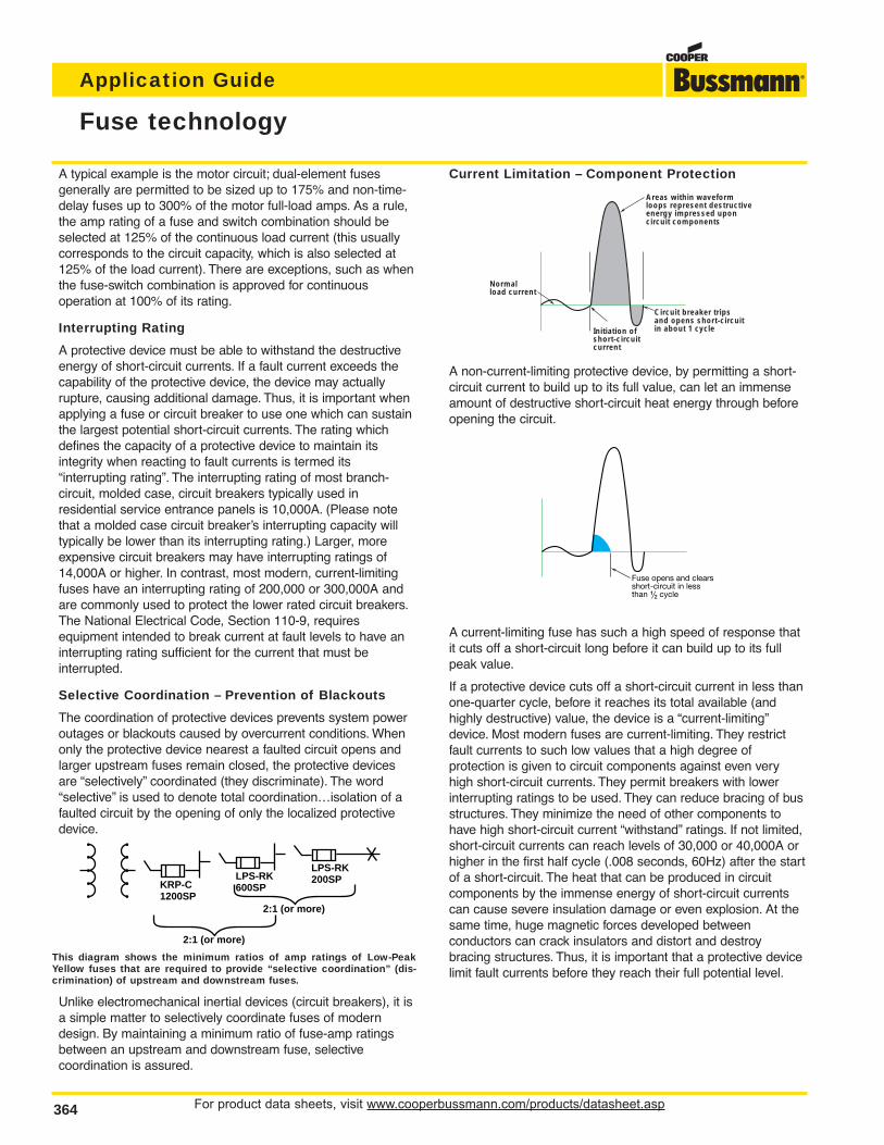
For product data sheets, visit www.cooperbussmann.com/products/datasheet.asp364
Application Guide
Fuse technology
A typical example is the motor circuit; dual-element fuses generally are permitted to be sized up to 175% and non-time-delay fuses up to 300% of the motor full-load amps. As a rule,the amp rating of a fuse and switch combination should beselected at 125% of the continuous load current (this usuallycorresponds to the circuit capacity, which is also selected at125% of the load current). There are exceptions, such as whenthe fuse-switch combination is approved for continuous operation at 100% of its rating.
Interrupting Rating
A protective device must be able to withstand the destructiveenergy of short-circuit currents. If a fault current exceeds thecapability of the protective device, the device may actually rupture, causing additional damage. Thus, it is important whenapplying a fuse or circuit breaker to use one which can sustainthe largest potential short-circuit currents. The rating whichdefines the capacity of a protective device to maintain itsintegrity when reacting to fault currents is termed its “interrupting rating”. The interrupting rating of most branch-circuit, molded case, circuit breakers typically used in residential service entrance panels is 10,000A. (Please notethat a molded case circuit breaker’s interrupting capacity willtypically be lower than its interrupting rating.) Larger, moreexpensive circuit breakers may have interrupting ratings of14,000A or higher. In contrast, most modern, current-limitingfuses have an interrupting rating of 200,000 or 300,000A andare commonly used to protect the lower rated circuit breakers.The National Electrical Code, Section 110-9, requires equipment intended to break current at fault levels to have aninterrupting rating sufficient for the current that must be interrupted.
Selective Coordination – Prevention of Blackouts
The coordination of protective devices prevents system poweroutages or blackouts caused by overcurrent conditions. Whenonly the protective device nearest a faulted circuit opens andlarger upstream fuses remain closed, the protective devicesare “selectively” coordinated (they discriminate). The word“selective” is used to denote total coordination…isolation of afaulted circuit by the opening of only the localized protectivedevice.
This diagram shows the minimum ratios of amp ratings of Low-PeakYellow fuses that are required to provide “selective coordination” (dis-crimination) of upstream and downstream fuses.
Unlike electromechanical inertial devices (circuit breakers), it isa simple matter to selectively coordinate fuses of moderndesign. By maintaining a minimum ratio of fuse-amp ratingsbetween an upstream and downstream fuse, selective coordination is assured.
Current Limitation – Component Protection
A non-current-limiting protective device, by permitting a short-circuit current to build up to its full value, can let an immenseamount of destructive short-circuit heat energy through beforeopening the circuit.
A current-limiting fuse has such a high speed of response thatit cuts off a short-circuit long before it can build up to its fullpeak value.
If a protective device cuts off a short-circuit current in less thanone-quarter cycle, before it reaches its total available (andhighly destructive) value, the device is a “current-limiting”device. Most modern fuses are current-limiting. They restrictfault currents to such low values that a high degree of protection is given to circuit components against even veryhigh short-circuit currents. They permit breakers with lowerinterrupting ratings to be used. They can reduce bracing of busstructures. They minimize the need of other components tohave high short-circuit current “withstand” ratings. If not limited,short-circuit currents can reach levels of 30,000 or 40,000A orhigher in the first half cycle (.008 seconds, 60Hz) after the startof a short-circuit. The heat that can be produced in circuit components by the immense energy of short-circuit currentscan cause severe insulation damage or even explosion. At thesame time, huge magnetic forces developed between conductors can crack insulators and distort and destroy bracing structures. Thus, it is important that a protective devicelimit fault currents before they reach their full potential level.
KRP-C1200SP
2:1 (or more)
LPS-RK600SP
LPS-RK200SP
2:1 (or more)
Initiation ofshort-circuit current
Normalload current
Areas within waveformloops represent destructiveenergy impressed uponcircuit components
Circuit breaker tripsand opens short-circuitin about 1 cycle
Fuse opens and clearsshort-circuit in lessthan ⁄Ω™ cycle
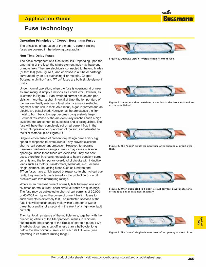
For product data sheets, visit www.cooperbussmann.com/products/datasheet.asp 365
Application Guide
ApplicationGuide
Fuse technology
Operating Principles of Cooper Bussmann Fuses
The principles of operation of the modern, current-limitingfuses are covered in the following paragraphs.
Non-Time-Delay Fuses
The basic component of a fuse is the link. Depending upon theamp rating of the fuse, the single-element fuse may have oneor more links. They are electrically connected to the end blades(or ferrules) (see Figure 1) and enclosed in a tube or cartridgesurrounded by an arc quenching filler material. CooperBussmann Limitron® and T-Tron® fuses are both single-elementfuses.
Under normal operation, when the fuse is operating at or nearits amp rating, it simply functions as a conductor. However, asillustrated in Figure 2, if an overload current occurs and per-sists for more than a short interval of time, the temperature ofthe link eventually reaches a level which causes a restrictedsegment of the link to melt. As a result, a gap is formed and anelectric arc established. However, as the arc causes the linkmetal to burn back, the gap becomes progressively larger.Electrical resistance of the arc eventually reaches such a highlevel that the arc cannot be sustained and is extinguished. Thefuse will have then completely cut off all current flow in the circuit. Suppression or quenching of the arc is accelerated bythe filler material. (See Figure 3.)
Single-element fuses of present day design have a very highspeed of response to overcurrents. They provide excellentshort-circuit component protection. However, temporary, harmless overloads or surge currents may cause nuisanceopenings unless these fuses are oversized. They are bestused, therefore, in circuits not subject to heavy transient surgecurrents and the temporary over-load of circuits with inductiveloads such as motors, transformers, solenoids, etc. Becausesingle-element, fast-acting fuses such as Limitron and T-Tron fuses have a high speed of response to short-circuit cur-rents, they are particularly suited for the protection of circuitbreakers with low interrupting ratings.
Whereas an overload current normally falls between one andsix times normal current, short-circuit currents are quite high.The fuse may be subjected to short-circuit currents of 30,000or 40,000A or higher. Response of current limiting fuses tosuch currents is extremely fast. The restricted sections of thefuse link will simultaneously melt (within a matter of two orthree-thousandths of a second in the event of a high-level faultcurrent).
The high total resistance of the multiple arcs, together with thequenching effects of the filler particles, results in rapid arc suppression and clearing of the circuit. (Refer to Figures 4 & 5)Short-circuit current is cut off in less than a half-cycle, longbefore the short-circuit current can reach its full value (fuseoperating in its current limiting range).
Figure 2. Under sustained overload, a section of the link melts and anarc is established.
Figure 3. The “open” single-element fuse after opening a circuit over-load.
Figure 4. When subjected to a short-circuit current, several sectionsof the fuse link melt almost instantly.
Figure 5. The “open” single-element fuse after opening a short circuit.
Figure 1. Cutaway view of typical single-element fuse.
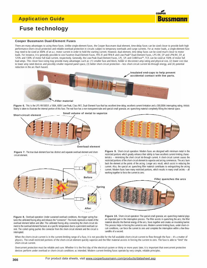
For product data sheets, visit www.cooperbussmann.com/products/datasheet.asp366
Application Guide
Fuse technology
Cooper Bussmann Dual-Element Fuses
There are many advantages to using these fuses. Unlike single-element fuses, the Cooper Bussmann dual-element, time-delay fuses can be sized closer to provide both highperformance short-circuit protection and reliable overload protection in circuits subject to temporary overloads and surge currents. For ac motor loads, a single-element fusemay need to be sized at 300% of an a.c. motor current in order to hold the starting current. However, dual-element, time delay fuses can be sized much closer to motorloads. For instance, it is generally possible to size Fusetron Dual-Element Fuses, FRS-R and FRN-R and Low-Peak® Dual-Element Fuses, LPS-RK_SP and LPN-RK_SP, at125% and 130% of motor full load current, respectively. Generally, the Low-Peak Dual-Element Fuses, LPJ_SP, and CUBEFuse™, TCF, can be sized at 150% of motor fullload amps. This closer fuse sizing may provide many advantages such as: (1) smaller fuse and block, holder or disconnect amp rating and physical size, (2) lower cost dueto lower amp rated devices and possibly smaller required panel space, (3) better short-circuit protection – less short-circuit current let-through energy, and (4) potentialreduction in the arc-flash hazard.
Figure 6. This is the LPS-RK100SP, a 100A, 600V Low-Peak, Class RK1, Dual-Element Fuse that has excellent time-delay, excellent current-limitation and a 300,000A interrupting rating. Artisticliberty is taken to illustrate the internal portion of this fuse. The real fuse has a non-transparent tube and special small granular, arc-quenching material completely filling the internal space.
Figure 7. The true dual-element fuse has distinct and separate overload element and short-circuit element.
Short-circuit element
Overload element
Spring
Filler quenches the arcs
Small volume of metal to vaporize
Filler material
Insulated end-caps to help preventaccidental contact with live parts.
Figure 8. Overload operation: Under sustained overload conditions, the trigger spring frac-tures the calibrated fusing alloy and releases the “connector”. The insets represent a model of theoverload element before and after. The calibrated fusing alloy connecting the short-circuit ele-ment to the overload element fractures at a specific temperature due to a persistent overload cur-rent. The coiled spring pushes the connector from the short-circuit element and the circuit isinterrupted.
Figure 9. Short-circuit operation: Modern fuses are designed with minimum metal in therestricted portions which greatly enhance their ability to have excellent current-limiting charac-teristics – minimizing the short circuit let-through current. A short-circuit current causes therestricted portions of the short-circuit element to vaporize and arcing commences. The arcs burnback the element at the points of the arcing. Longer arcs result, which assist in reducing the current. Also, the special arc quenching filler material contributes to extinguishing the arcingcurrent. Modern fuses have many restricted portions, which results in many small arclets – allworking together to force the current to zero.
Figure 10. Short-circuit operation: The special small granular, arc-quenching material playsan important part in the interruption process. The filler assists in quenching the arcs; the fillermaterial absorbs the thermal energy of the arcs, fuses together and creates an insulating barrier.This process helps in forcing the current to zero. Modern current-limiting fuses, under short-cir-cuit conditions, can force the current to zero and complete the interruption within a few thou-sandths of a second.
When the short-circuit current is in the current-limiting range of a fuse, it is not possible for the full available short-circuit current to flow through the fuse – it’s a matter ofphysics. The small restricted portions of the short-circuit element quickly vaporize and the filler material assists in forcing the current to zero. The fuse is able to “limit” theshort-circuit current.
Overcurrent protection must be reliable and sure. Whether it is the first day of the electrical system or thirty or more years later, it is important that overcurrent protectivedevices perform under overload or short-circuit conditions as intended. Modern current-limiting fuses operate by very simple, reliable principles.
Before
After
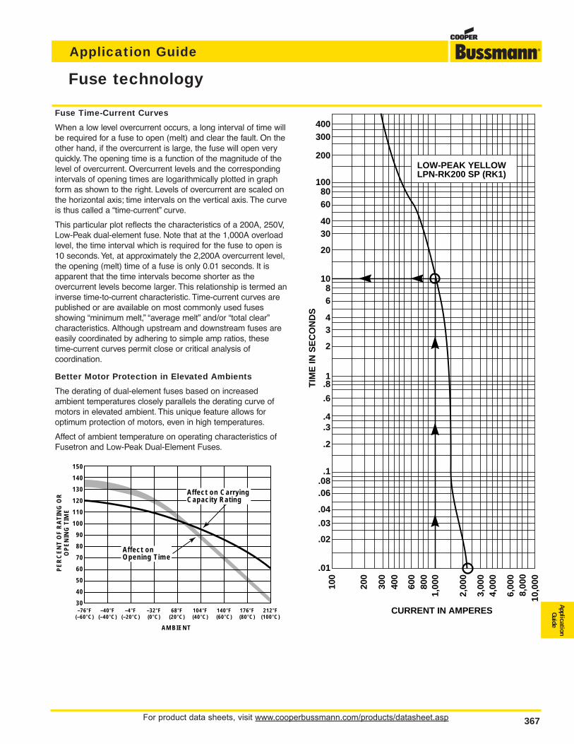
For product data sheets, visit www.cooperbussmann.com/products/datasheet.asp 367
Application Guide
ApplicationGuide
Fuse technology
Fuse Time-Current Curves
When a low level overcurrent occurs, a long interval of time willbe required for a fuse to open (melt) and clear the fault. On theother hand, if the overcurrent is large, the fuse will open veryquickly. The opening time is a function of the magnitude of thelevel of overcurrent. Overcurrent levels and the correspondingintervals of opening times are logarithmically plotted in graphform as shown to the right. Levels of overcurrent are scaled onthe horizontal axis; time intervals on the vertical axis. The curveis thus called a “time-current” curve.
This particular plot reflects the characteristics of a 200A, 250V,Low-Peak dual-element fuse. Note that at the 1,000A overloadlevel, the time interval which is required for the fuse to open is10 seconds.Yet, at approximately the 2,200A overcurrent level,the opening (melt) time of a fuse is only 0.01 seconds. It isapparent that the time intervals become shorter as the overcurrent levels become larger. This relationship is termed aninverse time-to-current characteristic. Time-current curves arepublished or are available on most commonly used fusesshowing “minimum melt,” “average melt” and/or “total clear”characteristics. Although upstream and downstream fuses areeasily coordinated by adhering to simple amp ratios, thesetime-current curves permit close or critical analysis of coordination.
Better Motor Protection in Elevated Ambients
The derating of dual-element fuses based on increased ambient temperatures closely parallels the derating curve ofmotors in elevated ambient. This unique feature allows for optimum protection of motors, even in high temperatures.
Affect of ambient temperature on operating characteristics ofFusetron and Low-Peak Dual-Element Fuses.
400300
200
1008060
4030
20
1086
43
2
1.8
.6
.4
.3
.2
.1.08.06
.04
.03
.02
.01
100
200
300
400
600
800
1,00
0
2,00
0
3,00
04,
000
6,00
08,
000
10,0
00
TIM
E IN
SE
CO
ND
S
CURRENT IN AMPERES
LOW-PEAK YELLOWLPN-RK200 SP (RK1)
150
140
130
120
110
100
90
80
70
60
50
40
30
AMBIENT
PE
RC
EN
T O
F R
AT
ING
OR
OP
EN
ING
TIM
E
Affect on CarryingCapacity Rating
Affect onOpening Time
–76°F(–60°C)
–40°F(–40°C)
–4°F(–20°C)
–32°F(0°C)
68°F(20°C)
104°F(40°C)
140°F(60°C)
176°F(80°C)
212°F(100°C)
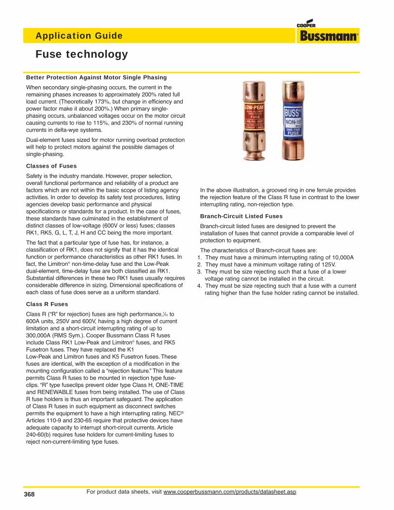
For product data sheets, visit www.cooperbussmann.com/products/datasheet.asp368
Application Guide
In the above illustration, a grooved ring in one ferrule providesthe rejection feature of the Class R fuse in contrast to the lowerinterrupting rating, non-rejection type.
Branch-Circuit Listed Fuses
Branch-circuit listed fuses are designed to prevent the installation of fuses that cannot provide a comparable level ofprotection to equipment.
The characteristics of Branch-circuit fuses are:1. They must have a minimum interrupting rating of 10,000A2. They must have a minimum voltage rating of 125V.3. They must be size rejecting such that a fuse of a lower
voltage rating cannot be installed in the circuit.4. They must be size rejecting such that a fuse with a current
rating higher than the fuse holder rating cannot be installed.
Better Protection Against Motor Single Phasing
When secondary single-phasing occurs, the current in theremaining phases increases to approximately 200% rated fullload current. (Theoretically 173%, but change in efficiency andpower factor make it about 200%.) When primary single-phasing occurs, unbalanced voltages occur on the motor circuitcausing currents to rise to 115%, and 230% of normal runningcurrents in delta-wye systems.
Dual-element fuses sized for motor running overload protectionwill help to protect motors against the possible damages of single-phasing.
Classes of Fuses
Safety is the industry mandate. However, proper selection,overall functional performance and reliability of a product arefactors which are not within the basic scope of listing agencyactivities. In order to develop its safety test procedures, listingagencies develop basic performance and physical specifications or standards for a product. In the case of fuses,these standards have culminated in the establishment of distinct classes of low-voltage (600V or less) fuses; classesRK1, RK5, G, L, T, J, H and CC being the more important.
The fact that a particular type of fuse has, for instance, a classification of RK1, does not signify that it has the identicalfunction or performance characteristics as other RK1 fuses. Infact, the Limitron® non-time-delay fuse and the Low-Peak dual-element, time-delay fuse are both classified as RK1.Substantial differences in these two RK1 fuses usually requiresconsiderable difference in sizing. Dimensional specifications ofeach class of fuse does serve as a uniform standard.
Class R Fuses
Class R (“R” for rejection) fuses are high performance,1⁄10 to600A units, 250V and 600V, having a high degree of currentlimitation and a short-circuit interrupting rating of up to300,000A (RMS Sym.). Cooper Bussmann Class R fusesinclude Class RK1 Low-Peak and Limitron® fuses, and RK5Fusetron fuses. They have replaced the K1 Low-Peak and Limitron fuses and K5 Fusetron fuses. Thesefuses are identical, with the exception of a modification in themounting configuration called a “rejection feature.” This featurepermits Class R fuses to be mounted in rejection type fuse-clips. “R” type fuseclips prevent older type Class H, ONE-TIMEand RENEWABLE fuses from being installed. The use of ClassR fuse holders is thus an important safeguard. The applicationof Class R fuses in such equipment as disconnect switches permits the equipment to have a high interrupting rating. NEC®
Articles 110-9 and 230-65 require that protective devices haveadequate capacity to interrupt short-circuit currents. Article240-60(b) requires fuse holders for current-limiting fuses toreject non-current-limiting type fuses.
Fuse technology
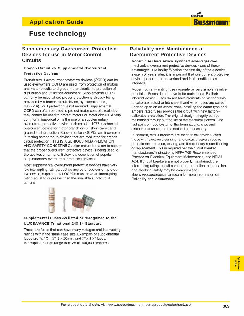
For product data sheets, visit www.cooperbussmann.com/products/datasheet.asp 369
Application Guide
ApplicationGuide
Fuse technology
Reliability and Maintenance ofOvercurrent Protective DevicesModern fuses have several significant advantages overmechanical overcurrent protective devices - one of thoseadvantages is reliability. Whether the first day of the electricalsystem or years later, it is important that overcurrent protectivedevices perform under overload and fault conditions as intended.
Modern current-limiting fuses operate by very simple, reliableprinciples. Fuses do not have to be maintained. By their inherent design, fuses do not have elements or mechanismsto calibrate, adjust or lubricate. If and when fuses are calledupon to open on an overcurrent, installing the same type andampere rated fuses provides the circuit with new factory-calibrated protection. The original design integrity can be maintained throughout the life of the electrical system. Onelast point on fuse systems; the terminations, clips anddisconnects should be maintained as necessary.
In contrast, circuit breakers are mechanical devices, eventhose with electronic sensing, and circuit breakers require periodic maintenance, testing, and if necessary reconditioningor replacement. This is required per the circuit breaker manufacturers' instructions, NFPA 70B RecommendedPractice for Electrical Equipment Maintenance, and NEMAAB4. If circuit breakers are not properly maintained, the interrupting rating, circuit component protection, coordination,and electrical safety may be compromised.See www.cooperbussmann.com for more information onReliability and Maintenance.
Supplementary Overcurrent ProtectiveDevices for use in Motor ControlCircuits
Branch Circuit vs. Supplemental Overcurrent
Protective Devices
Branch circuit overcurrent protective devices (OCPD) can beused everywhere OCPD are used, from protection of motorsand motor circuits and group motor circuits, to protection ofdistribution and utilization equipment. Supplemental OCPDcan only be used where proper protection is already beingprovided by a branch circuit device, by exception [i.e.,430.72(A)], or if protection is not required. SupplementalOCPD can often be used to protect motor control circuits butthey cannot be used to protect motors or motor circuits. A verycommon misapplication is the use of a supplementary overcurrent protective device such as a UL 1077 mechanicalovercurrent device for motor branch circuit short-circuit andground fault protection. Supplementary OCPDs are incompletein testing compared to devices that are evaluated for branchcircuit protection. THIS IS A SERIOUS MISAPPLICATIONAND SAFETY CONCERN!! Caution should be taken to assurethat the proper overcurrent protective device is being used forthe application at hand. Below is a description of popular supplementary overcurrent protective devices.
Most supplemental overcurrent protective devices have verylow interrupting ratings. Just as any other overcurrent protec-tive device, supplemental OCPDs must have an interruptingrating equal to or greater than the available short-circuit current.
Supplemental Fuses As listed or recognized to the
UL/CSA/ANCE Trinational 248-14 Standard
These are fuses that can have many voltages and interruptingratings within the same case size. Examples of supplementalfuses are 13⁄32'' X 1 1⁄2'', 5 x 20mm, and 1⁄4'' x 1 1⁄4'' fuses.Interrupting ratings range from 35 to 100,000 amperes.
For product data sheets, visit www.cooperbussmann.com/products/datasheet.asp370
Application Guide
Motor circuit branch circuit protection
Motor Circuits – Choice of Overcurrent Protection
Motor circuits have unique characteristics and several func-tions, such as short-circuit protection, overload protection andautomatic/ remote start/stop, that may be required. Sometimesthe comment is made that users prefer circuit breakersbecause they can be reset. Let’s examine the choice of eithercircuit breakers or current- limiting fuses for motor branch cir-cuit protection.
In the case to be examined, fuses and circuit breakers(includes magnetic only circuit breakers which are calledMCPs or motor circuit protectors) are sized with the intent toprovide only short-circuit and ground fault protection for themotor branch circuit protection per 430.52. Other means, suchas overload relays, provide the motor overload protection.Typical thermal magnetic circuit breakers can only be sized formotor branch circuit protection (typically 200% - 250% ofmotor current) because if they are sized closer, the motorstarting current trips the circuit breaker’s instantaneous mechanism. Magnetic only circuit breakers (MCPs) are intentionally not provided with overload capability; they onlyoperate on short-circuit currents. There are some fuses suchas the FRS-R and LPS-RK fuses that can be sized closeenough for motor running overload protection or backup motorrunning protection. But for the discussion in this section,assume current-limiting fuses are sized only for motor short-circuit and ground fault protection.
It is important to note that in this protection level being discussed, a circuit breaker or fuses should only open if thereis a fault on the motor circuit. A separate overload protectivedevice, such as an overload relays, provides motor overloadprotection per 430.32. Here are some important considerations:
1. OSHA regulation 1910.334(b)(2) Use of Equipment states:
Reclosing circuits after protective device operation. After a circuit isdeenergized by a circuit protective device, the circuit may not be manually reenergized until it has been determined that the equipmentand circuit can be safely energized. The repetitive manual reclosing ofcircuit breakers or reenergizing circuits through replaced fuses is prohibited. NOTE: When it can be determined from the design of the circuit and the over-current devices involved that the automatic operationof a device was caused by an overload rather than a fault condition, noexamination of the circuit or connected equipment is needed before thecircuit is reenergized.
So the speed of reclosing a circuit breaker after a fault is not an advantage. The law requires that if the condition is a fault (that is theonly reason the circuit breaker or fuses should open on a motor circuit),then the fault must be corrected prior to replacing fuses or resetting thecircuit breaker.
2. The typical level of short-circuit protection for the motor starter providedby circuit breakers and MCPs is referred to as Type 1. This is becausemost circuit breakers are not current-limiting. So, for a loadside fault,the starter may sustain significant damage such as severe welding ofcontacts and rupturing of the heater elements. Or the heater/overloadrelay system may lose calibration. This is an acceptable level of performance per UL508, which is the product standard for motorstarters. Current-limiting fuses can be selected that can provide Type 2“no damage” short-circuit protection for motor starters.
Consequently, with circuit breaker protection, after a fault condition,
significant downtime and cost may be incurred in repairing or replacingthe starter. With properly selected fuses for Type 2 protection, after thefault is repaired, only new fuses need to be inserted in the circuit; thestarter does not have to be repaired or replaced.
3. Circuit breakers must be periodically tested to verify they mechanicaloperate and electrically tested to verify they still are properly calibratedwithin specification. The circuit breaker manufacturers recommend this.Typically circuit breakers should be mechanically operated at least everyyear and electrically tested every 1 to 5 years, depending on the serviceconditions. Modern current-limiting fuses do not have to be maintainedor electrically tested to verify they still will operate as intended. The terminations of both circuit breakers and fusible devices need to be peri-odically checked and maintained to prevent thermal damage. Plus fuseclips should be periodically inspected and if necessary maintained.
4. After a circuit breaker interrupts a fault, it may not be suitable for furtherservice. UL489, the product standard for molded case circuit breakers,only requires a circuit breaker to interrupt two short-circuit currents atits interrupting rating. Circuit breakers that are rated 100 amps or lessdo not have to operate after only one short-circuit operation under “busbar” short-circuit conditions. If the fault current is high, circuit breakermanufacturers recommend that a circuit breaker should receive a thorough inspection with replacement, if necessary. How does one knowa circuit breaker’s service history or what level of fault current that a circuit breaker interrupts? With modern current-limiting fuses, if the fuseinterrupts a fault, new factory calibrated fuses are installed in the circuit.The original level of superior short-circuit protection can be there for thelife of the motor circuit.
5. After a fault, the electrician has to walk back to the storeroom to get newfuses; that is if spare fuses are not stored adjacent to the equipment.This does require some additional down time. However, if fuses openedunder fault conditions, there is a fault condition that must be remedied.The electrician probably will be going back to the storeroom anyway forparts to repair the fault. If properly selected current-limiting fuses areused in the original circuit, the starter will not sustain any significantdamage or loss of overload calibration.
With circuit breaker protection on motor circuits, after a faultcondition, it may be necessary to repair or replace the starter,so a trip to the storeroom may be necessary. And if the starteris not significantly damaged, it may still need to be tested toinsure the let-through energy by the circuit breaker has notcaused the loss of starter overload calibration. Also, the circuitbreaker needs to be evaluated for suitability before placing itback into service. Who is qualified for that evaluation? Howmuch time will that take?
In summary, resettability is not an important feature for motorbranch circuit (short-circuit) protection and resettability of thebranch circuit protective device is not a benefit for motor circuits. As a matter of fact, resettability of the motor branchcircuit overcurrent protective device may encourage an unsafepractice. The function of motor branch circuit protection is faultprotection: short-circuit and ground fault protection. Faults donot occur on a regular basis. But when a fault does occur, it isimportant to have the very best protection. The best motorbranch circuit protection can be judged by (1) reliability - itsability to retain its calibration and speed of operation over itslifetime, (2) current-limiting protection -its ability to provideType 2 “no damage” protection to the motor starter, and (3)safety - its ability to meet a facility’s safety needs. Modern current-limiting fuses are superior to circuit breakers for motorbranch circuit protection.
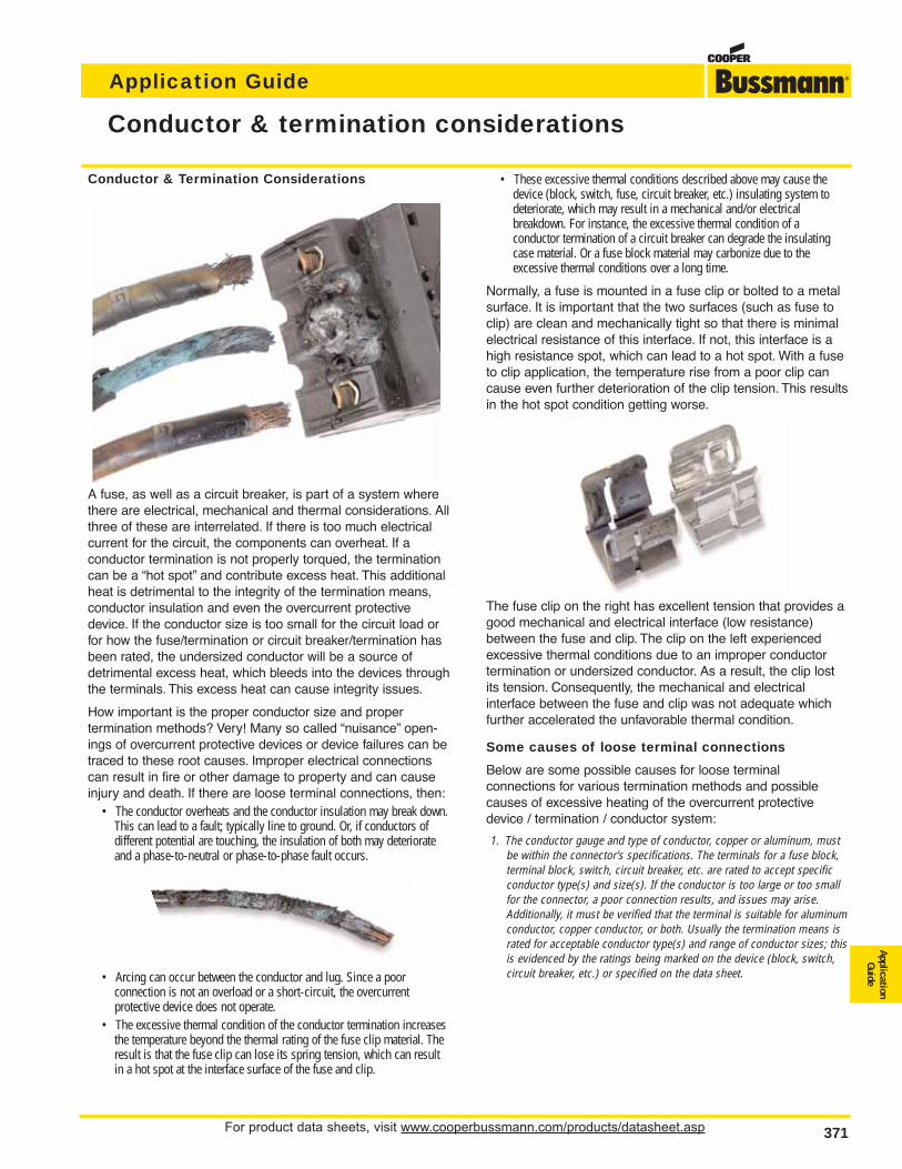
For product data sheets, visit www.cooperbussmann.com/products/datasheet.asp 371
Application Guide
ApplicationGuide
Conductor & termination considerations
Conductor & Termination Considerations
A fuse, as well as a circuit breaker, is part of a system wherethere are electrical, mechanical and thermal considerations. Allthree of these are interrelated. If there is too much electricalcurrent for the circuit, the components can overheat. If a conductor termination is not properly torqued, the terminationcan be a “hot spot” and contribute excess heat. This additionalheat is detrimental to the integrity of the termination means,conductor insulation and even the overcurrent protectivedevice. If the conductor size is too small for the circuit load orfor how the fuse/termination or circuit breaker/termination hasbeen rated, the undersized conductor will be a source of detrimental excess heat, which bleeds into the devices throughthe terminals. This excess heat can cause integrity issues.
How important is the proper conductor size and proper termination methods? Very! Many so called “nuisance” open-ings of overcurrent protective devices or device failures can betraced to these root causes. Improper electrical connectionscan result in fire or other damage to property and can causeinjury and death. If there are loose terminal connections, then:
• The conductor overheats and the conductor insulation may break down.This can lead to a fault; typically line to ground. Or, if conductors of different potential are touching, the insulation of both may deteriorateand a phase-to-neutral or phase-to-phase fault occurs.
• Arcing can occur between the conductor and lug. Since a poor connection is not an overload or a short-circuit, the overcurrent protective device does not operate.
• The excessive thermal condition of the conductor termination increasesthe temperature beyond the thermal rating of the fuse clip material. Theresult is that the fuse clip can lose its spring tension, which can resultin a hot spot at the interface surface of the fuse and clip.
• These excessive thermal conditions described above may cause thedevice (block, switch, fuse, circuit breaker, etc.) insulating system todeteriorate, which may result in a mechanical and/or electrical breakdown. For instance, the excessive thermal condition of a conductor termination of a circuit breaker can degrade the insulatingcase material. Or a fuse block material may carbonize due to the excessive thermal conditions over a long time.
Normally, a fuse is mounted in a fuse clip or bolted to a metalsurface. It is important that the two surfaces (such as fuse toclip) are clean and mechanically tight so that there is minimalelectrical resistance of this interface. If not, this interface is ahigh resistance spot, which can lead to a hot spot. With a fuseto clip application, the temperature rise from a poor clip cancause even further deterioration of the clip tension. This resultsin the hot spot condition getting worse.
The fuse clip on the right has excellent tension that provides agood mechanical and electrical interface (low resistance)between the fuse and clip. The clip on the left experiencedexcessive thermal conditions due to an improper conductortermination or undersized conductor. As a result, the clip lostits tension. Consequently, the mechanical and electrical interface between the fuse and clip was not adequate whichfurther accelerated the unfavorable thermal condition.
Some causes of loose terminal connections
Below are some possible causes for loose terminal connections for various termination methods and possiblecauses of excessive heating of the overcurrent protectivedevice / termination / conductor system:
1. The conductor gauge and type of conductor, copper or aluminum, mustbe within the connector’s specifications. The terminals for a fuse block,terminal block, switch, circuit breaker, etc. are rated to accept specificconductor type(s) and size(s). If the conductor is too large or too smallfor the connector, a poor connection results, and issues may arise.Additionally, it must be verified that the terminal is suitable for aluminumconductor, copper conductor, or both. Usually the termination means israted for acceptable conductor type(s) and range of conductor sizes; thisis evidenced by the ratings being marked on the device (block, switch,circuit breaker, etc.) or specified on the data sheet.
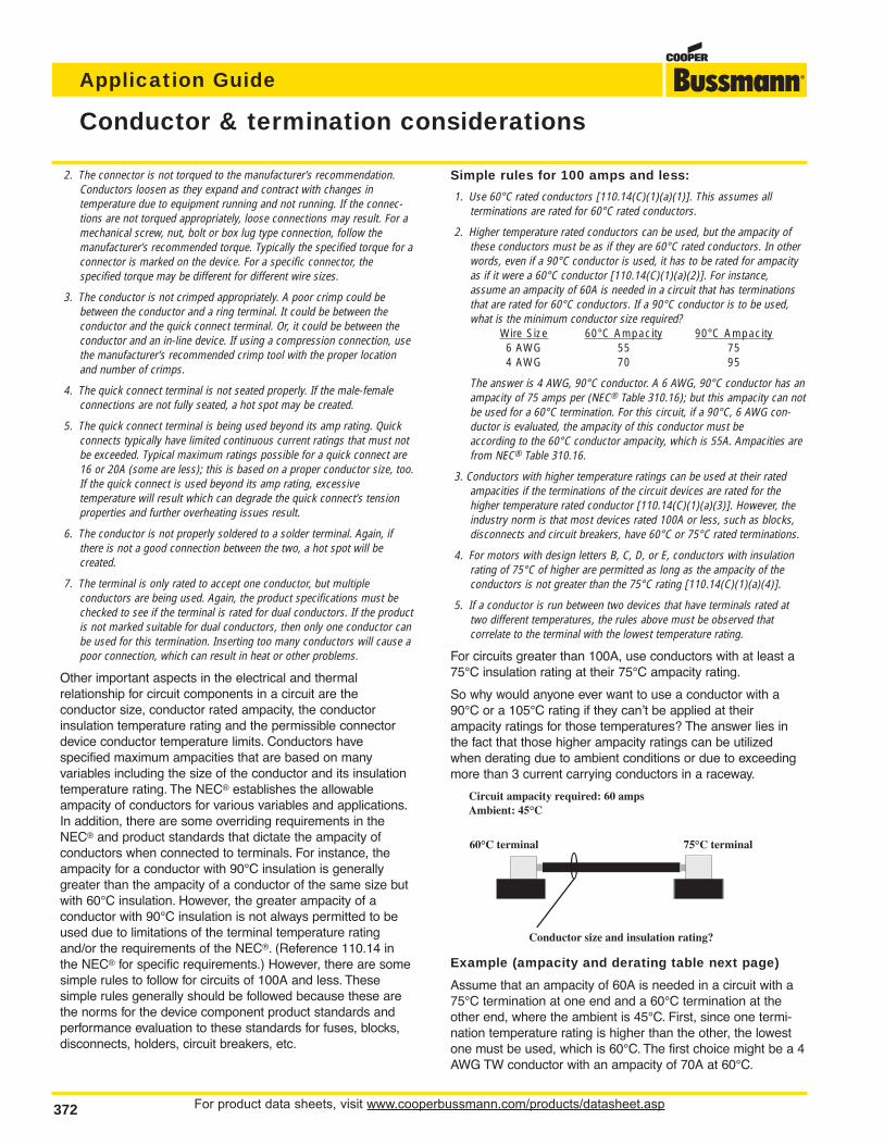
For product data sheets, visit www.cooperbussmann.com/products/datasheet.asp372
Application Guide
2. The connector is not torqued to the manufacturer’s recommendation.Conductors loosen as they expand and contract with changes in temperature due to equipment running and not running. If the connec-tions are not torqued appropriately, loose connections may result. For amechanical screw, nut, bolt or box lug type connection, follow the manufacturer’s recommended torque. Typically the specified torque for aconnector is marked on the device. For a specific connector, the specified torque may be different for different wire sizes.
3. The conductor is not crimped appropriately. A poor crimp could bebetween the conductor and a ring terminal. It could be between the conductor and the quick connect terminal. Or, it could be between theconductor and an in-line device. If using a compression connection, usethe manufacturer’s recommended crimp tool with the proper locationand number of crimps.
4. The quick connect terminal is not seated properly. If the male-femaleconnections are not fully seated, a hot spot may be created.
5. The quick connect terminal is being used beyond its amp rating. Quickconnects typically have limited continuous current ratings that must notbe exceeded. Typical maximum ratings possible for a quick connect are16 or 20A (some are less); this is based on a proper conductor size, too.If the quick connect is used beyond its amp rating, excessive temperature will result which can degrade the quick connect’s tensionproperties and further overheating issues result.
6. The conductor is not properly soldered to a solder terminal. Again, ifthere is not a good connection between the two, a hot spot will be created.
7. The terminal is only rated to accept one conductor, but multiple conductors are being used. Again, the product specifications must bechecked to see if the terminal is rated for dual conductors. If the productis not marked suitable for dual conductors, then only one conductor canbe used for this termination. Inserting too many conductors will cause apoor connection, which can result in heat or other problems.
Other important aspects in the electrical and thermal relationship for circuit components in a circuit are the conductor size, conductor rated ampacity, the conductor insulation temperature rating and the permissible connectordevice conductor temperature limits. Conductors have specified maximum ampacities that are based on many variables including the size of the conductor and its insulationtemperature rating. The NEC® establishes the allowableampacity of conductors for various variables and applications.In addition, there are some overriding requirements in theNEC® and product standards that dictate the ampacity of conductors when connected to terminals. For instance, theampacity for a conductor with 90°C insulation is generallygreater than the ampacity of a conductor of the same size butwith 60°C insulation. However, the greater ampacity of a conductor with 90°C insulation is not always permitted to beused due to limitations of the terminal temperature ratingand/or the requirements of the NEC®. (Reference 110.14 inthe NEC® for specific requirements.) However, there are somesimple rules to follow for circuits of 100A and less. These simple rules generally should be followed because these arethe norms for the device component product standards andperformance evaluation to these standards for fuses, blocks,disconnects, holders, circuit breakers, etc.
Simple rules for 100 amps and less:
1. Use 60°C rated conductors [110.14(C)(1)(a)(1)]. This assumes all terminations are rated for 60°C rated conductors.
2. Higher temperature rated conductors can be used, but the ampacity ofthese conductors must be as if they are 60°C rated conductors. In otherwords, even if a 90°C conductor is used, it has to be rated for ampacityas if it were a 60°C conductor [110.14(C)(1)(a)(2)]. For instance,assume an ampacity of 60A is needed in a circuit that has terminationsthat are rated for 60°C conductors. If a 90°C conductor is to be used,what is the minimum conductor size required?
Wire Size 60°C Ampacity 90°C Ampacity6 AWG 55 754 AWG 70 95
The answer is 4 AWG, 90°C conductor. A 6 AWG, 90°C conductor has anampacity of 75 amps per (NEC® Table 310.16); but this ampacity can notbe used for a 60°C termination. For this circuit, if a 90°C, 6 AWG con-ductor is evaluated, the ampacity of this conductor must be according to the 60°C conductor ampacity, which is 55A. Ampacities arefrom NEC® Table 310.16.
3. Conductors with higher temperature ratings can be used at their ratedampacities if the terminations of the circuit devices are rated for thehigher temperature rated conductor [110.14(C)(1)(a)(3)]. However, theindustry norm is that most devices rated 100A or less, such as blocks,disconnects and circuit breakers, have 60°C or 75°C rated terminations.
4. For motors with design letters B, C, D, or E, conductors with insulationrating of 75°C of higher are permitted as long as the ampacity of theconductors is not greater than the 75°C rating [110.14(C)(1)(a)(4)].
5. If a conductor is run between two devices that have terminals rated attwo different temperatures, the rules above must be observed that correlate to the terminal with the lowest temperature rating.
For circuits greater than 100A, use conductors with at least a75°C insulation rating at their 75°C ampacity rating.
So why would anyone ever want to use a conductor with a90°C or a 105°C rating if they can’t be applied at their ampacity ratings for those temperatures? The answer lies inthe fact that those higher ampacity ratings can be utilizedwhen derating due to ambient conditions or due to exceedingmore than 3 current carrying conductors in a raceway.
Example (ampacity and derating table next page)
Assume that an ampacity of 60A is needed in a circuit with a75°C termination at one end and a 60°C termination at theother end, where the ambient is 45°C. First, since one termi-nation temperature rating is higher than the other, the lowestone must be used, which is 60°C. The first choice might be a 4AWG TW conductor with an ampacity of 70A at 60°C.
Conductor & termination considerations
Circuit ampacity required: 60 ampsAmbient: 45°C
75°C terminal60°C terminal
Conductor size and insulation rating?
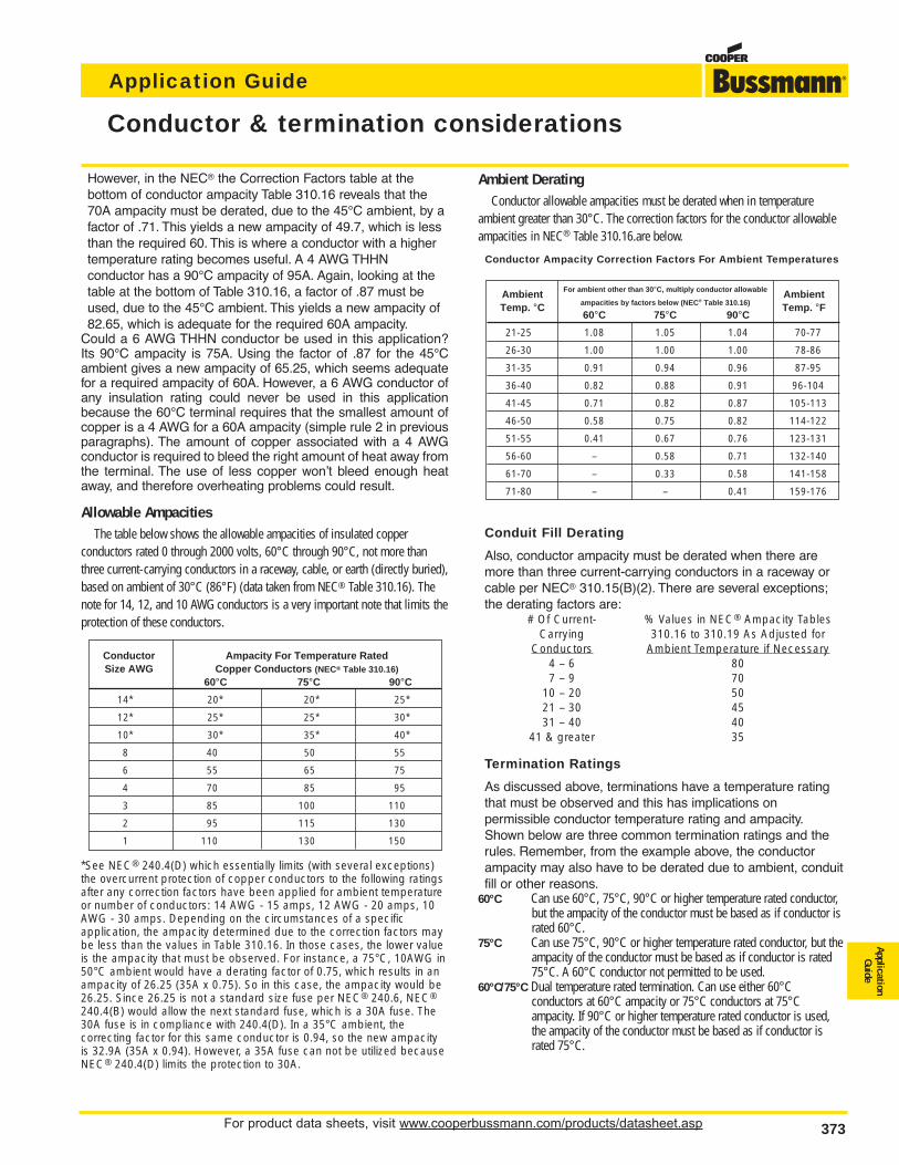
For product data sheets, visit www.cooperbussmann.com/products/datasheet.asp 373
Application Guide
ApplicationGuide
However, in the NEC® the Correction Factors table at the bottom of conductor ampacity Table 310.16 reveals that the70A ampacity must be derated, due to the 45°C ambient, by afactor of .71. This yields a new ampacity of 49.7, which is lessthan the required 60. This is where a conductor with a highertemperature rating becomes useful. A 4 AWG THHN conductor has a 90°C ampacity of 95A. Again, looking at thetable at the bottom of Table 310.16, a factor of .87 must beused, due to the 45°C ambient. This yields a new ampacity of82.65, which is adequate for the required 60A ampacity.
Could a 6 AWG THHN conductor be used in this application?Its 90°C ampacity is 75A. Using the factor of .87 for the 45°Cambient gives a new ampacity of 65.25, which seems adequatefor a required ampacity of 60A. However, a 6 AWG conductor ofany insulation rating could never be used in this applicationbecause the 60°C terminal requires that the smallest amount ofcopper is a 4 AWG for a 60A ampacity (simple rule 2 in previous paragraphs). The amount of copper associated with a 4 AWGconductor is required to bleed the right amount of heat away fromthe terminal. The use of less copper won’t bleed enough heataway, and therefore overheating problems could result.
Allowable AmpacitiesThe table below shows the allowable ampacities of insulated copper
conductors rated 0 through 2000 volts, 60°C through 90°C, not more thanthree current-carrying conductors in a raceway, cable, or earth (directly buried),based on ambient of 30°C (86°F) (data taken from NEC® Table 310.16). Thenote for 14, 12, and 10 AWG conductors is a very important note that limits theprotection of these conductors.
*See NEC® 240.4(D) which essentially limits (with several exceptions)the overcurrent protection of copper conductors to the following ratingsafter any correction factors have been applied for ambient temperatureor number of conductors: 14 AWG - 15 amps, 12 AWG - 20 amps, 10AWG - 30 amps. Depending on the circumstances of a specific application, the ampacity determined due to the correction factors maybe less than the values in Table 310.16. In those cases, the lower valueis the ampacity that must be observed. For instance, a 75°C, 10AWG in50°C ambient would have a derating factor of 0.75, which results in anampacity of 26.25 (35A x 0.75). So in this case, the ampacity would be26.25. Since 26.25 is not a standard size fuse per NEC® 240.6, NEC®
240.4(B) would allow the next standard fuse, which is a 30A fuse. The30A fuse is in compliance with 240.4(D). In a 35°C ambient, the correcting factor for this same conductor is 0.94, so the new ampacityis 32.9A (35A x 0.94). However, a 35A fuse can not be utilized becauseNEC® 240.4(D) limits the protection to 30A.
Ambient DeratingConductor allowable ampacities must be derated when in temperature
ambient greater than 30°C. The correction factors for the conductor allowableampacities in NEC® Table 310.16.are below.
Conductor Ampacity Correction Factors For Ambient Temperatures
Conduit Fill Derating
Also, conductor ampacity must be derated when there aremore than three current-carrying conductors in a raceway orcable per NEC® 310.15(B)(2). There are several exceptions;the derating factors are:
# Of Current- % Values in NEC® Ampacity TablesCarrying 310.16 to 310.19 As Adjusted for
Conductors Ambient Temperature if Necessary4 – 6 807 – 9 70
10 – 20 5021 – 30 4531 – 40 40
41 & greater 35
Termination Ratings
As discussed above, terminations have a temperature ratingthat must be observed and this has implications on permissible conductor temperature rating and ampacity.Shown below are three common termination ratings and therules. Remember, from the example above, the conductorampacity may also have to be derated due to ambient, conduitfill or other reasons.
60°C Can use 60°C, 75°C, 90°C or higher temperature rated conductor,but the ampacity of the conductor must be based as if conductor israted 60°C.
75°C Can use 75°C, 90°C or higher temperature rated conductor, but theampacity of the conductor must be based as if conductor is rated75°C. A 60°C conductor not permitted to be used.
60°C/75°C Dual temperature rated termination. Can use either 60°C conductors at 60°C ampacity or 75°C conductors at 75°C ampacity. If 90°C or higher temperature rated conductor is used,the ampacity of the conductor must be based as if conductor israted 75°C.
Conductor & termination considerations
Conductor Ampacity For Temperature RatedSize AWG Copper Conductors (NEC® Table 310.16)
60°C 75°C 90°C
14* 20* 20* 25*
12* 25* 25* 30*
10* 30* 35* 40*
8 40 50 55
6 55 65 75
4 70 85 95
3 85 100 110
2 95 115 130
1 110 130 150
Ambient For ambient other than 30°C, multiply conductor allowable AmbientTemp. °C ampacities by factors below (NEC® Table 310.16) Temp. °F
60°C 75°C 90°C
21-25 1.08 1.05 1.04 70-77
26-30 1.00 1.00 1.00 78-86
31-35 0.91 0.94 0.96 87-95
36-40 0.82 0.88 0.91 96-104
41-45 0.71 0.82 0.87 105-113
46-50 0.58 0.75 0.82 114-122
51-55 0.41 0.67 0.76 123-131
56-60 – 0.58 0.71 132-140
61-70 – 0.33 0.58 141-158
71-80 – – 0.41 159-176
For product data sheets, visit www.cooperbussmann.com/products/datasheet.asp374
Application Guide
374
Glossary
Ampere (Amp)
The measurement of intensity of rate offlow of electrons in an electric circuit. Anampere (amp) is the amount of currentthat will flow through a resistance of oneohm under a pressure of one volt.
Amp Rating
The current-carrying capacity of a fuse.When a fuse is subjected to a currentabove its amp rating, it will open the circuit after a predetermined period oftime.
Amp Squared Seconds, l2t
The measure of heat energy developedwithin a circuit during the fuse’s clear-ing. It can be expressed as “melting l2t”,“arcing l2t” or the sum of them as“Clearing l2t”. “l” stands for effective let-through current (RMS), which issquared, and “t” stands for time of opening, in seconds.
Arcing I2t
Value of the I2t during the arcing timeunder specified conditions.
Arcing Time
The amount of time from the instant thefuse link has melted until the overcur-rent is interrupted, or cleared.
Breaking Capacity
(See Interrupting Rating)
Cartridge Fuse
A fuse consisting of a current responsive element inside a fuse tubewith terminals on both ends.
Class CC Fuses
600V, 200,000A interrupting rating,branch circuit fuses with overall dimensions of 13⁄32” x 11⁄2”. Their designincorporates a rejection feature thatallows them to be inserted into rejectionfuse holders and fuse blocks that rejectall lower voltage, lower interrupting rating 13⁄32” x 11⁄2” fuses. They are available from 1⁄10A through 30A.
Class G Fuses
480V, 100,000A interrupting ratingbranch circuit fuses that are size reject-ing to eliminate overfusing. The fusediameter is 13⁄32” while the length variesfrom 15⁄16” to 21⁄4”. These are available inratings from 1A through 60A.
Class H Fuses
250V and 600V, 10,000A interruptingrating branch circuit fuses that may berenewable or non-renewable. These areavailable in ampere ratings of 1 ampthrough 600A.
Class J Fuses
These fuses are rated to interrupt a minimum of 200,000A ac. They arelabeled as “Current-Limiting”, are ratedfor 600Vac, and are not interchangeablewith other classes.
Class K Fuses
These are fuses listed as K-1, K-5, or K-9 fuses. Each subclass has designated I2t and lp maximums. Theseare dimensionally the same as Class Hfuses, and they can have interruptingratings of 50,000, 100,000, or 200,000A. These fuses are current-limiting.However, they are not marked “current-limiting” on their label since theydo not have a rejection feature.
Class L Fuses
These fuses are rated for 601 through6000A, and are rated to interrupt a minimum of 200,000A ac. They arelabeled “Current-Limiting” and are ratedfor 600Vac. They are intended to bebolted into their mountings and are notnormally used in clips. Some Class Lfuses have designed in time-delay features for all purpose use.
Class R Fuses
These are high performance fuses rated1⁄10-600A in 250V and 600V ratings. Allare marked “Current Limiting” on theirlabel and all have a minimum of200,000A interrupting rating. They haveidentical outline dimensions with theClass H fuses but have a rejection feature which prevents the user frommounting a fuse of lesser capabilities(lower interrupting capacity) when usedwith special Class R Clips. Class Rfuses will fit into either rejection or non-rejection clips.
Class T Fuses
An industry class of fuses in 300V and600V ratings from 1 amp through1200A. They are physically very smalland can be applied where space is at apremium. They are fast acting fuses withan interrupting rating of 200,000A RMS.
Classes of Fuses
The industry has developed basic physical specifications and electricalperformance requirements for fuses withvoltage ratings of 600V or less. Theseare known as standards. If a type offuse meets the requirements of a standard, it can fall into that class.Typical classes are K, RK1, RK5, G, L,H, T, CC, and J.
Clearing Time
The total time between the beginning ofthe overcurrent and the final opening ofthe circuit at rated voltage by an overcurrent protective device. Clearingtime is the total of the melting time andthe arcing time.
Current Limitation
A fuse operation relating to short circuitsonly. When a fuse operates in its current-limiting range, it will clear a shortcircuit in less than 1⁄2 cycle. Also, it willlimit the instantaneous peak let-throughcurrent to a value substantially less thanthat obtainable in the same circuit if thatfuse were replaced with a solid conductor of equal impedance.
For product data sheets, visit www.cooperbussmann.com/products/datasheet.asp 375
Application Guide
ApplicationGuide
375
Dual Element Fuse
Fuse with a special design that utilizestwo individual elements in series insidethe fuse tube. One element, the springactuated trigger assembly, operates onoverloads up to 5-6 times the fuse current rating. The other element, theshort circuit section, operates on shortcircuits up to their interrupting rating.
Electrical Load
That part of the electrical system whichactually uses the energy or does thework required.
Fast Acting Fuse
A fuse which opens on overload andshort circuits very quickly. This type offuse is not designed to withstand temporary overload currents associatedwith some electrical loads.
Fuse
An overcurrent protective device with afusible link that operates and opens thecircuit on an overcurrent condition.
High Speed Fuses
Fuses with no intentional time-delay inthe overload range and designed toopen as quickly as possible in the short-circuit range. These fuses areoften used to protect solid-state devices.
Inductive Load
An electrical load which pulls a largeamount of current—an inrush current—when first energized. After a few cyclesor seconds the current “settles down” tothe full-load running current.
Interrupting Capacity
(See Interrupting Rating)
Interrupting Rating — IR
(Breaking Capacity)
The rating which defines a fuse’s abilityto safely interrupt and clear short circuits. This rating is much greater thanthe ampere rating of a fuse. The NEC®
defines Interrupting Rating as “The highest current at rated voltage that anovercurrent protective device is intendedto interrupt under standard test conditions.”
Melting I2t
Value of the I2t during the melting timeof the fuse link under specified conditions.
Melting Time
The amount of time required to melt thefuse link during a specified overcurrent.(See Arcing Time and Clearing Time.)
“NEC®” Dimensions
These are dimensions once referencedin the National Electrical Code. They arecommon to Class H and K fuses andprovide interchangeability between manufacturers for fuses and fusibleequipment of given ampere and voltage ratings.
Ohm
The unit of measure for electric resistance. An ohm is the amount ofresistance that will allow one ampere toflow under a pressure of one volt.
Ohm’s Law
The relationship between voltage, current, and resistance, expressed bythe equation E = IR, where E is the voltage in volts, I is the current in amps,and R is the resistance in ohms.
One Time Fuses
Generic term used to describe a ClassH non-renewable cartridge fuse, with asingle element.
Overcurrent
A condition which exists on an electricalcircuit when the normal load current isexceeded. Overcurrents take on twoseparate characteristics—overloads andshort circuits.
Overload
Can be classified as an overcurrentwhich exceeds the normal full load current of a circuit. Also characteristic ofthis type of overcurrent is that it doesnot leave the normal current carryingpath of the circuit—that is, it flows fromthe source, through the conductors,through the load, back through the conductors, to the source again.
Peak Let-Through Current, lp
The instantaneous value of peak currentlet-through by a current-limiting fuse,when it operates in its current-limitingrange.
Renewable Fuse (600V & below)
A fuse in which the element, typically azinc link, may be replaced after the fusehas opened, and then reused.Renewable fuses are made to Class Hstandards.
Resistive Load
An electrical load which is characteristicof not having any significant inrush current. When a resistive load is energized, the current rises instantly toits steady-state value, without first risingto a higher value.
RMS Current
The RMS (root-mean-square) value ofany periodic current is equal to thevalue of the direct current which, flowingthrough a resistance, produces thesame heating effect in the resistance asthe periodic current does.
Semiconductor Fuses
Fuses used to protect solid-statedevices. See “High Speed Fuses.”
Short Circuit
Can be classified as an overcurrentwhich exceeds the normal full load current of a circuit by a factor manytimes (tens, hundreds or thousandsgreater). Also characteristic of this typeof overcurrent is that it leaves the normal current carrying path of the circuit—it takes a “short cut” around theload and back to the source.
Short-Circuit Current Rating
The maximum short-circuit current anelectrical component can sustain without the occurrence of excessivedamage when protected with an overcurrent protective device.
Short-Circuit Withstand Rating
Same definition as short-circuit rating.
Glossary
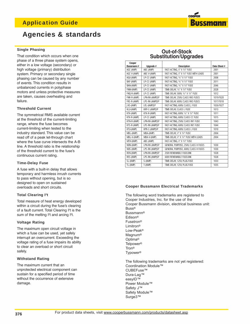
For product data sheets, visit www.cooperbussmann.com/products/datasheet.asp376
Application Guide
Agencies & standards
Single Phasing
That condition which occurs when onephase of a three phase system opens,either in a low voltage (secondary) orhigh voltage (primary) distribution system. Primary or secondary singlephasing can be caused by any numberof events. This condition results inunbalanced currents in polyphasemotors and unless protective measuresare taken, causes overheating and failure.
Threshold Current
The symmetrical RMS available currentat the threshold of the current-limitingrange, where the fuse becomes current-limiting when tested to theindustry standard. This value can beread off of a peak let-through chartwhere the fuse curve intersects the A-Bline. A threshold ratio is the relationshipof the threshold current to the fuse’scontinuous current rating.
Time-Delay Fuse
A fuse with a built-in delay that allowstemporary and harmless inrush currentsto pass without opening, but is sodesigned to open on sustained overloads and short circuits.
Total Clearing I2t
Total measure of heat energy developedwithin a circuit during the fuse’s clearingof a fault current. Total Clearing I2t is thesum of the melting I2t and arcing I2t.
Voltage Rating
The maximum open circuit voltage inwhich a fuse can be used, yet safelyinterrupt an overcurrent. Exceeding thevoltage rating of a fuse impairs its abilityto clear an overload or short circuit safely.
Withstand Rating
The maximum current that an unprotected electrical component cansustain for a specified period of timewithout the occurrence of extensivedamage.
CooperBussmann # Upgrade # Description Data Sheet #AGC-(AMP) ABC-(AMP) FAST-ACTING, 1⁄4” X 11⁄4” FUSE 2001
AGC-V-(AMP) ABC-V-(AMP) FAST-ACTING, 1⁄4” X 11⁄4” FUSE WITH LEADS 2001
AGU-(AMP) LP-CC-(AMP) FAST-ACTING, 13⁄32” X 11⁄2” FUSE 2008
BAF-(AMP) LP-CC-(AMP) FAST-ACTING, 13⁄32” X 11⁄2” FUSE 2011
BAN-(AMP) LP-CC-(AMP) FAST-ACTING, 13⁄32” X 11⁄2” FUSE 2046
FNM-(AMP) LP-CC-(AMP) TIME-DELAY, 13⁄32” X 11⁄2” FUSE 2028
FNQ-R-(AMP) LP-CC-(AMP) TIME-DELAY, 500V, 13⁄32” X 11⁄2” FUSE 1012
FNR-R-(AMP) LPN-RK-(AMP)SP TIME-DELAY, 250V, CLASS RK5 FUSES 1019/1020
FRS-R-(AMP) LPS-RK-(AMP)SP TIME-DELAY, 600V, CLASS RK5 FUSES 1017/1018
JKS-(AMP) LPJ-(AMP)SP FAST-ACTING, 600V, CLASS J FUSE 1026/1027
KLU-(AMP) KRP-C-(AMP)SP TIME-DELAY, CLASS L FUSE 1013
KTK-(AMP) KTK-R-(AMP) FAST-ACTING, 600V, 13⁄32” X 11⁄2” FUSE 1011
KTK-R-(AMP) LP-CC-(AMP) FAST-ACTING, 600V, CLASS CC FUSE 1015
KTN-R-(AMP) LPN-RK-(AMP)SP FAST-ACTING, 250V, CLASS RK1 FUSE 1043
KTS-R-(AMP) LPS-RK-(AMP)SP FAST-ACTING, 600V, CLASS RK1 FUSE 1044
KTU-(AMP) KPR-C-(AMP)SP FAST-ACTING, 600V, CLASS L FUSE 1010
MDL-(AMP) MDA-(AMP) TIME-DELAY, 1⁄4” X 11⁄4” FUSE 2004
MDL-V-(AMP) MDA-V-(AMP) TIME-DELAY, 1⁄4” X 11⁄4” FUSE WITH LEADS 2004
MTH-(AMP) ABC-(AMP) FAST-ACTING, 1⁄4” X 11⁄4” FUSE
NON-(AMP) LPN-RK-(AMP)SP GENERAL PURPOSE, 250V, CLASS H FUSES 1030
NOS-(AMP) LPS-RK-(AMP)SP GENERAL PURPOSE, 600V, CLASS H FUSES 1030
REN-(AMP) LPN-RK-(AMP)SP 250V RENEWABLE FUSELINK 1028
RES-(AMP) LPS-RK-(AMP)SP 600V RENEWABLE FUSELINK 1028
SL-(AMP) S-(AMP) TIME-DELAY, 125V, PLUG FUSE 1033
TL-(AMP) T-(AMP) TIME-DELAY, 125V, PLUG FUSE 1035
Out-of-StockSubstitution/Upgrades
Cooper Bussmann Electrical Trademarks
The following word trademarks are registered to
Cooper Industries, Inc. for the use of the
Cooper Bussmann division, electrical business unit:
Buss®
Bussmann®
Edison®
Fusetron®
Limitron®
Low-Peak®
Magnum®
Optima®
Telpower®
Tron®
Typower®
The following trademarks are not yet registered:
Coordination Module™
CUBEFuse™
Dura-Lag™
easyID™
Power Module™
Safety J™
Safety Module™
Surge3™
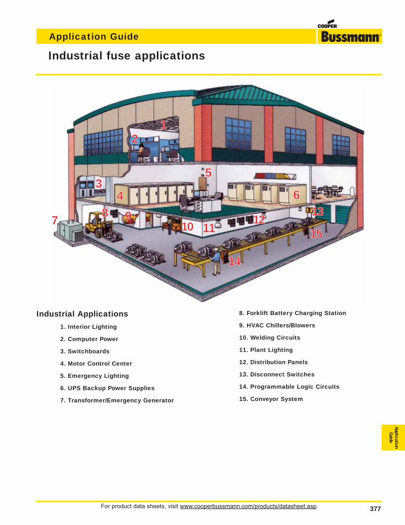
For product data sheets, visit www.cooperbussmann.com/products/datasheet.asp 377
Application Guide
ApplicationGuide
Industrial fuse applications
12
34
5
6
7 8 910 11
1213
15
14
Industrial Applications
1. Interior Lighting
2. Computer Power
3. Switchboards
4. Motor Control Center
5. Emergency Lighting
6. UPS Backup Power Supplies
7. Transformer/Emergency Generator
8. Forklift Battery Charging Station
9. HVAC Chillers/Blowers
10. Welding Circuits
11. Plant Lighting
12. Distribution Panels
13. Disconnect Switches
14. Programmable Logic Circuits
15. Conveyor System
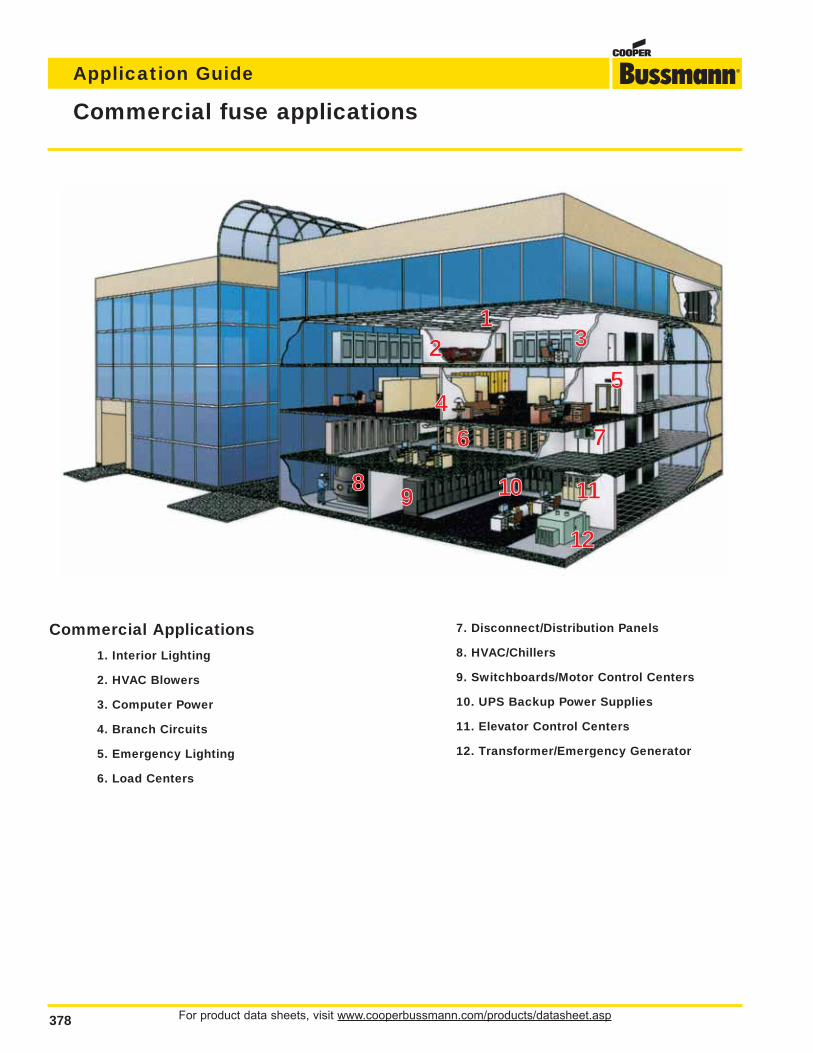
For product data sheets, visit www.cooperbussmann.com/products/datasheet.asp378
Application Guide
Commercial fuse applications
13
45
6 7
8 9 10 11
12
2
Commercial Applications
1. Interior Lighting
2. HVAC Blowers
3. Computer Power
4. Branch Circuits
5. Emergency Lighting
6. Load Centers
7. Disconnect/Distribution Panels
8. HVAC/Chillers
9. Switchboards/Motor Control Centers
10. UPS Backup Power Supplies
11. Elevator Control Centers
12. Transformer/Emergency Generator
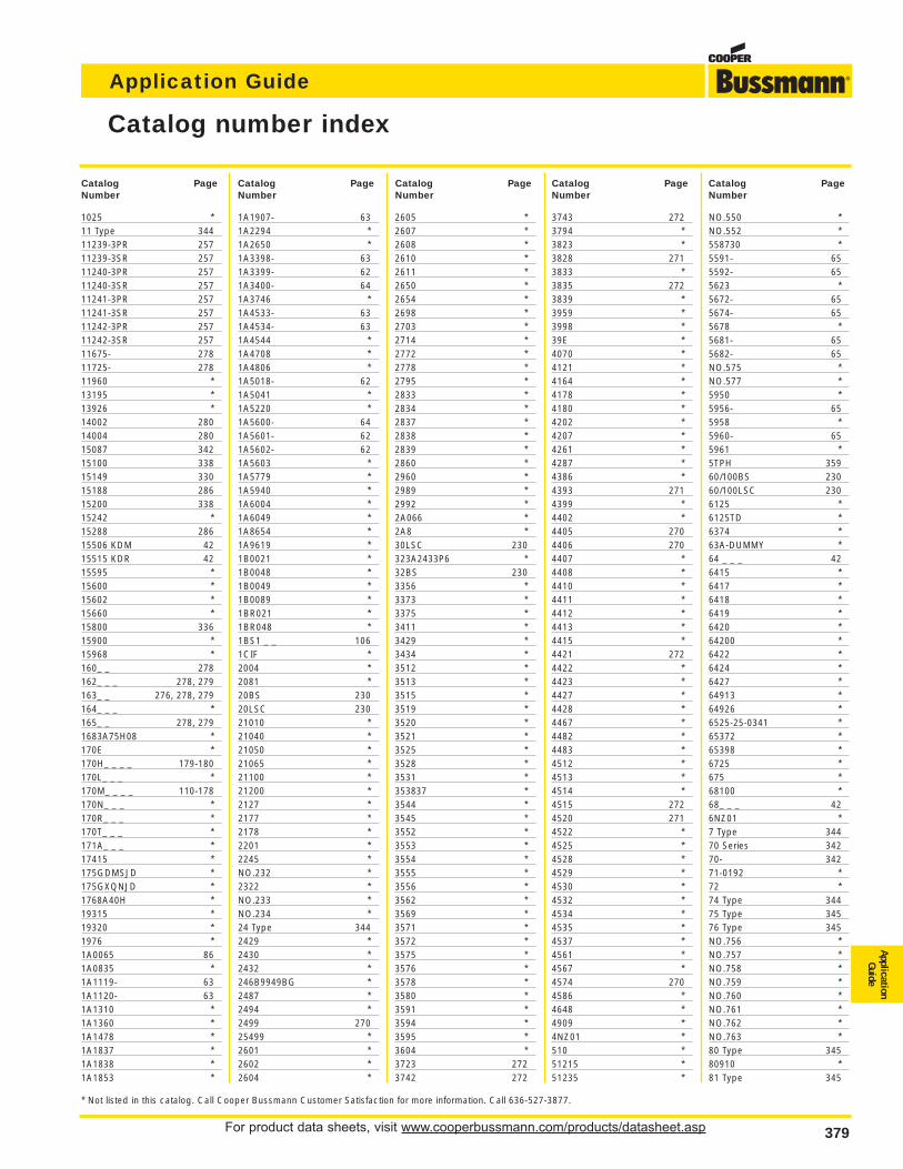
For product data sheets, visit www.cooperbussmann.com/products/datasheet.asp 379
Application Guide
ApplicationGuide
379
Catalog number index
1025 *11 Type 34411239-3PR 25711239-3SR 25711240-3PR 25711240-3SR 25711241-3PR 25711241-3SR 25711242-3PR 25711242-3SR 25711675- 27811725- 27811960 *13195 *13926 *14002 28014004 28015087 34215100 33815149 33015188 28615200 33815242 *15288 28615506 KDM 4215515 KDR 4215595 *15600 *15602 *15660 *15800 33615900 *15968 *160_ _ 278162_ _ _ 278, 279163_ _ 276, 278, 279164_ _ _ *165_ _ 278, 2791683A75H08 *170E *170H_ _ _ _ 179-180170L_ _ _ *170M_ _ _ _ 110-178170N_ _ _ *170R_ _ _ *170T_ _ _ *171A_ _ _ *17415 *175GDMSJD *175GXQNJD *1768A40H *19315 *19320 *1976 *1A0065 861A0835 *1A1119- 631A1120- 631A1310 *1A1360 *1A1478 *1A1837 *1A1838 *1A1853 *
1A1907- 631A2294 *1A2650 *1A3398- 631A3399- 621A3400- 641A3746 *1A4533- 631A4534- 631A4544 *1A4708 *1A4806 *1A5018- 621A5041 *1A5220 *1A5600- 641A5601- 621A5602- 621A5603 *1A5779 *1A5940 *1A6004 *1A6049 *1A8654 *1A9619 *1B0021 *1B0048 *1B0049 *1B0089 *1BR021 *1BR048 *1BS1 _ _ 1061CIF *2004 *2081 *20BS 23020LSC 23021010 *21040 *21050 *21065 *21100 *21200 *2127 *2177 *2178 *2201 *2245 *NO.232 *2322 *NO.233 *NO.234 *24 Type 3442429 *2430 *2432 *246B9949BG *2487 *2494 *2499 27025499 *2601 *2602 *2604 *
2605 *2607 *2608 *2610 *2611 *2650 *2654 *2698 *2703 *2714 *2772 *2778 *2795 *2833 *2834 *2837 *2838 *2839 *2860 *2960 *2989 *2992 *2A066 *2A8 *30LSC 230323A2433P6 *32BS 2303356 *3373 *3375 *3411 *3429 *3434 *3512 *3513 *3515 *3519 *3520 *3521 *3525 *3528 *3531 *353837 *3544 *3545 *3552 *3553 *3554 *3555 *3556 *3562 *3569 *3571 *3572 *3575 *3576 *3578 *3580 *3591 *3594 *3595 *3604 *3723 2723742 272
3743 2723794 *3823 *3828 2713833 *3835 2723839 *3959 *3998 *39E *4070 *4121 *4164 *4178 *4180 *4202 *4207 *4261 *4287 *4386 *4393 2714399 *4402 *4405 2704406 2704407 *4408 *4410 *4411 *4412 *4413 *4415 *4421 2724422 *4423 *4427 *4428 *4467 *4482 *4483 *4512 *4513 *4514 *4515 2724520 2714522 *4525 *4528 *4529 *4530 *4532 *4534 *4535 *4537 *4561 *4567 *4574 2704586 *4648 *4909 *4NZ01 *510 *51215 *51235 *
NO.550 *NO.552 *558730 *5591- 655592- 655623 *5672- 655674- 655678 *5681- 655682- 65NO.575 *NO.577 *5950 *5956- 655958 *5960- 655961 *5TPH 35960/100BS 23060/100LSC 2306125 *6125TD *6374 *63A-DUMMY *64 _ _ _ 426415 *6417 *6418 *6419 *6420 *64200 *6422 *6424 *6427 *64913 *64926 *6525-25-0341 *65372 *65398 *6725 *675 *68100 *68_ _ _ 426NZ01 *7 Type 34470 Series 34270- 34271-0192 *72 *74 Type 34475 Type 34576 Type 345NO.756 *NO.757 *NO.758 *NO.759 *NO.760 *NO.761 *NO.762 *NO.763 *80 Type 34580910 *81 Type 345
Catalog PageNumber
Catalog PageNumber
Catalog PageNumber
Catalog PageNumber
Catalog PageNumber
* Not listed in this catalog. Call Cooper Bussmann Customer Satisfaction for more information. Call 636-527-3877.
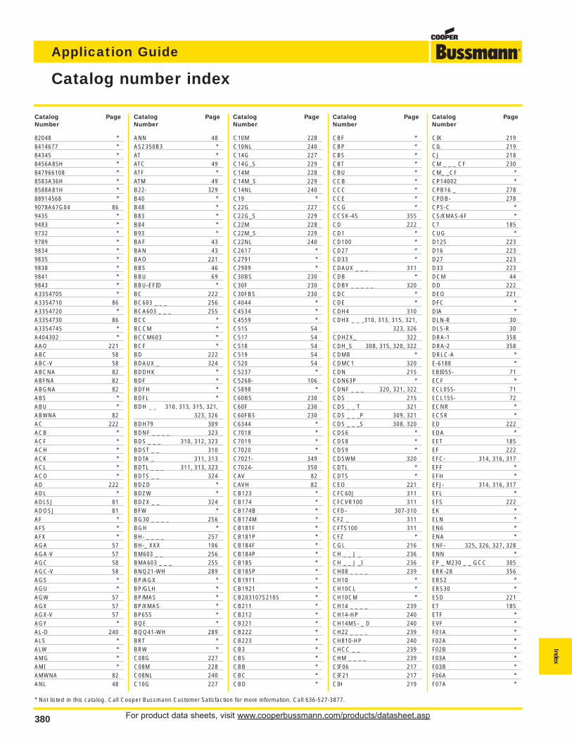
For product data sheets, visit www.cooperbussmann.com/products/datasheet.asp380
Application Guide
380
Catalog number index
82048 *8414677 *84345 *8456A85H *847966108 *8583A36H *8588A81H *88914568 *9078A67G04 869435 *9483 *9732 *9789 *9834 *9835 *9838 *9841 *9843 *A3354705 *A3354710 86A3354720 *A3354730 86A3354745 *A404302 *AAO 221ABC 58ABC-V 58ABCNA 82ABFNA 82ABGNA 82ABS *ABU *ABWNA 82AC 222ACB *ACF *ACH *ACK *ACL *ACO *AD 222ADL *ADLSJ 81ADOSJ 81AF *AFS *AFX *AGA 57AGA-V 57AGC 58AGC-V 58AGS *AGU *AGW 57AGX 57AGX-V 57AGY *AL-D 240ALS *ALW *AMG *AMI *AMWNA 82ANL 48
ANN 48ASZ350B3 *AT *ATC 49ATF *ATM 49B22- 329B40 *B48 *B83 *B84 *B93 *BAF 43BAN 43BAO 221BBS 46BBU 69BBU-EFID *BC 222BC603 _ _ _ 256BCA603 _ _ _ 255BCC *BCCM *BCCM603 *BCF *BD 222BDAUX _ 324BDDHK *BDF *BDFH *BDFL *BDH _ _ 310, 313, 315, 321,
323, 326BDH79 309BDNF _ _ _ _ 323BDS _ _ _ 310, 312, 323BDST _ _ 310BDTA _ 311, 313BDTL _ _ _ 311, 313, 323BDTS _ _ 324BDZD *BDZW *BDZX _ _ 324BFW *BG30 _ _ _ _ 256BGH *BH- _ _ _ _ 257BH-_ XXX 106BM603 _ _ 256BMA603 _ _ _ 255BNQ21-WH 289BP/AGX *BP/GLH *BP/MAS *BP/XMAS *BP655 *BQE *BQQ41-WH 289BRT *BRW *C08G 227C08M 228C08NL 240C10G 227
C10M 228C10NL 240C14G 227C14G_S 229C14M 228C14M_S 229C14NL 240C19 *C22G 227C22G_S 229C22M 228C22M_S 229C22NL 240C2617 *C2791 *C2909 *C30BS 230C30F 230C30FBS 230C4044 *C4534 *C4559 *C515 54C517 54C518 54C519 54C520 54C5237 *C5268- 106C5898 *C60BS 230C60F 230C60FBS 230C6344 *C7018 *C7019 *C7020 *C7021- 349C7024- 350CAV 82CAVH 82CB123 *CB174 *CB174B *CB174M *CB181F *CB181P *CB184F *CB184P *CB185 *CB185P *CB1911 *CB1921 *CB203107S2105 *CB211 *CB212 *CB221 *CB222 *CB223 *CB3 *CB5 *CBB *CBC *CBD *
CBF *CBP *CBS *CBT *CBU *CCB *CCC *CCE *CCG *CCSK-45 355CD 222CD1 *CD100 *CD27 *CD33 *CDAUX _ _ _ 311CDB *CDBY _ _ _ _ _ 320CDC *CDE *CDH4 310CDHX _ _ _310, 313, 315, 321,
323, 326CDHZX_ 322CDH_S 308, 315, 320, 322CDMB *CDMC1 320CDN 215CDN63P *CDNF _ _ _ 320, 321, 322CDS 215CDS _ _ T 321CDS _ _ _P 309, 321CDS _ _ _S 308, 320CDS6 *CDS8 *CDS9 *CDSWM 320CDTL *CDTS *CEO 221CFC60J 311CFCVR100 311CFD- 307-310CFZ _ 311CFTS100 311CFZ *CGL 216CH _ _ J _ 236CH _ _ J _I 236CH08 _ _ _ _ 239CH10 *CH10CL *CH10CM *CH14 _ _ _ _ 239CH14-HP 240CH14MS- _ D 240CH22 _ _ _ _ 239CH810-HP 240CHCC _ _ 239CHM _ _ _ _ 239CIF06 217CIF21 217CIH 219
CIK 219CIL 219CJ 218CM _ _ _ CF 230CM_ _CF *CP14002 *CPB16 _ 278CPDB- 278CPS-C *CS/XMAS-6F *CT 185CUG *D125 223D16 223D27 223D33 223DCM 44DD 222DEO 221DFC *DIA *DLN-R 30DLS-R 30DRA-1 358DRA-2 358DRLC-A *E-6188 *EBI055- 71ECF *ECL055- 71ECL155- 72ECNR *ECSR *ED 222EDA *EET 185EF 222EFC- 314, 316, 317EFF *EFH *EFJ- 314, 316, 317EFL *EFS 222EK *ELN *EN6 *ENA *ENF- 325, 326, 327, 328ENN *EP _ M230 _ _ GCC 305ERK-28 356ERS2 *ERS30 *ESD 221ET 185ETF *EVF *F01A *F02A *F02B *F03A *F03B *F06A *F07A *
Index
Catalog PageNumber
Catalog PageNumber
Catalog PageNumber
Catalog PageNumber
Catalog PageNumber
* Not listed in this catalog. Call Cooper Bussmann Customer Satisfaction for more information. Call 636-527-3877.
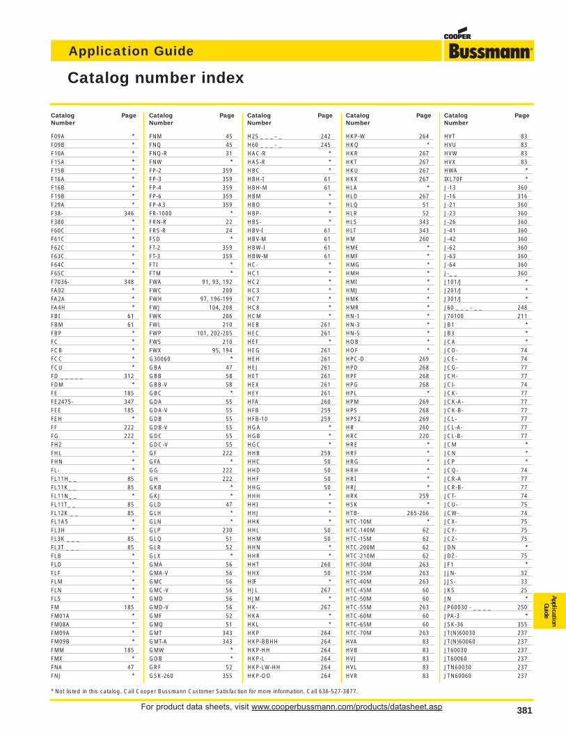
For product data sheets, visit www.cooperbussmann.com/products/datasheet.asp 381
Application Guide
ApplicationGuide
381
F09A *F09B *F10A *F15A *F15B *F16A *F16B *F19B *F29A *F38- 346F380 *F60C *F61C *F62C *F63C *F64C *F65C *F7036- 348FA02 *FA2A *FA4H *FBI 61FBM 61FBP *FC *FCB *FCC *FCU *FD _ _ _ _ _ 312FDM *FE 185FE2475- 347FEE 185FEH *FF 222FG 222FH2 *FHL *FHN *FL- *FL11H_ _ 85FL11K_ _ 85FL11N_ _ *FL11T_ _ 85FL12K _ _ 85FL1A5 *FL3H *FL3K _ _ _ 85FL3T _ _ _ 85FLB *FLD *FLF *FLM *FLN *FLS *FM 185FM01A *FM08A *FM09A *FM09B *FMM 185FMX *FNA 47FNJ *
FNM 45FNQ 45FNQ-R 31FNW *FP-2 359FP-3 359FP-4 359FP-6 359FP-A3 359FR-1000 *FRN-R 22FRS-R 24FSD *FT-2 359FT-3 359FTI *FTM *FWA 91, 93, 192FWC 200FWH 97, 196-199FWJ 104, 208FWK 206FWL 210FWP 101, 202-205FWS 210FWX 95, 194G30060 *GBA 47GBB 58GBB-V 58GBC *GDA 55GDA-V 55GDB 55GDB-V 55GDC 55GDC-V 55GF 222GFA *GG 222GH 222GKB *GKJ *GLD 47GLH *GLN *GLP 230GLQ 51GLR 52GLX *GMA 56GMA-V 56GMC 56GMC-V 56GMD 56GMD-V 56GMF 52GMQ 51GMT 343GMT-A 343GMW *GOB *GRF 52GSK-260 355
H25 _ _ _ - _ 242H60 _ _ _ - _ 245HAC-R *HAS-R *HBC *HBH-I 61HBH-M 61HBM *HBO *HBP- *HBS- *HBV-I 61HBV-M 61HBW-I 61HBW-M 61HC- *HC1 *HC2 *HC3 *HC7 *HC8 *HCM *HEB 261HEC 261HEF *HEG 261HEH 261HEJ 261HET 261HEX 261HEY 261HFA 260HFB 259HFB-10 259HGA *HGB *HGC *HHB 259HHC 50HHD 50HHF 50HHG 50HHH *HHI *HHJ *HHK *HHL 50HHM 50HHN *HHR *HHT 260HHX 50HIF *HJL 267HJM *HK- 267HKA *HKL *HKP 264HKP-BBHH 264HKP-HH 264HKP-L 264HKP-LW-HH 264HKP-OO 264
HKP-W 264HKQ *HKR 267HKT 267HKU 267HKX 267HLA *HLD 267HLQ 51HLR 52HLS 343HLT 343HM 260HME *HMF *HMG *HMH *HMI *HMJ *HMK *HMR *HN-1 *HN-3 *HN-5 *HOB *HOF *HPC-D 269HPD 268HPF 268HPG 268HPL *HPM 269HPS 268HPS2 269HR 260HRC 220HRE *HRF *HRG *HRH *HRI *HRJ *HRK 259HSK *HTB- 265-266HTC-10M *HTC-140M 62HTC-15M 62HTC-200M 62HTC-210M 62HTC-30M 263HTC-35M 263HTC-40M 263HTC-45M 60HTC-50M 60HTC-55M 263HTC-60M 60HTC-65M 60HTC-70M 263HVA 83HVB 83HVJ 83HVL 83HVR 83
HVT 83HVU 83HVW 83HVX 83HWA *IXL70F *J-13 360J-16 316J-21 360J-23 360J-26 360J-41 360J-42 360J-62 360J-63 360J-64 360J-_ _ 360J101/J *J201/J *J301/J *J60 _ _ _ - _ _ 248J70100 211JB1 *JB3 *JCA *JCD- 74JCE- 74JCG- 77JCH- 77JCI- 74JCK- 77JCK-A- 77JCK-B- 77JCL- 77JCL-A- 77JCL-B- 77JCM *JCN *JCP *JCQ- 74JCR-A 77JCR-B- 77JCT- 74JCU- 75JCW- 74JCX- 75JCY- 75JCZ- 75JDN *JDZ- 75JF1 *JJN- 32JJS- 33JKS 25JN *JP60030 - _ _ _ _ 250JPA-3 *JSK-36 355JT(N)60030 237JT(N)60060 237JT60030 237JT60060 237JTN60030 237JTN60060 237
Catalog number index
Catalog PageNumber
Catalog PageNumber
Catalog PageNumber
Catalog PageNumber
Catalog PageNumber
* Not listed in this catalog. Call Cooper Bussmann Customer Satisfaction for more information. Call 636-527-3877.
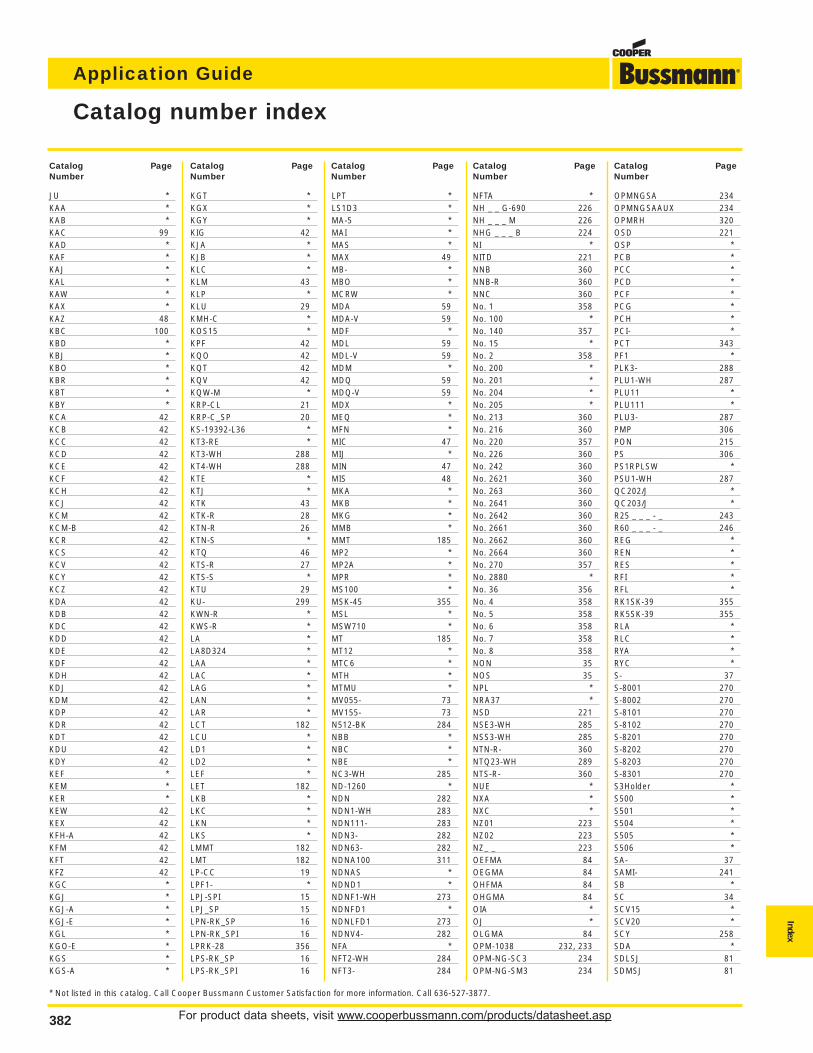
For product data sheets, visit www.cooperbussmann.com/products/datasheet.asp382
Application Guide
382
JU *KAA *KAB *KAC 99KAD *KAF *KAJ *KAL *KAW *KAX *KAZ 48KBC 100KBD *KBJ *KBO *KBR *KBT *KBY *KCA 42KCB 42KCC 42KCD 42KCE 42KCF 42KCH 42KCJ 42KCM 42KCM-B 42KCR 42KCS 42KCV 42KCY 42KCZ 42KDA 42KDB 42KDC 42KDD 42KDE 42KDF 42KDH 42KDJ 42KDM 42KDP 42KDR 42KDT 42KDU 42KDY 42KEF *KEM *KER *KEW 42KEX 42KFH-A 42KFM 42KFT 42KFZ 42KGC *KGJ *KGJ-A *KGJ-E *KGL *KGO-E *KGS *KGS-A *
KGT *KGX *KGY *KIG 42KJA *KJB *KLC *KLM 43KLP *KLU 29KMH-C *KOS15 *KPF 42KQO 42KQT 42KQV 42KQW-M *KRP-CL 21KRP-C_SP 20KS-19392-L36 *KT3-RE *KT3-WH 288KT4-WH 288KTE *KTJ *KTK 43KTK-R 28KTN-R 26KTN-S *KTQ 46KTS-R 27KTS-S *KTU 29KU- 299KWN-R *KWS-R *LA *LA8D324 *LAA *LAC *LAG *LAN *LAR *LCT 182LCU *LD1 *LD2 *LEF *LET 182LKB *LKC *LKN *LKS *LMMT 182LMT 182LP-CC 19LPF1- *LPJ-SPI 15LPJ_SP 15LPN-RK_SP 16LPN-RK_SPI 16LPRK-28 356LPS-RK_SP 16LPS-RK_SPI 16
LPT *LS1D3 *MA-5 *MAI *MAS *MAX 49MB- *MBO *MCRW *MDA 59MDA-V 59MDF *MDL 59MDL-V 59MDM *MDQ 59MDQ-V 59MDX *MEQ *MFN *MIC 47MIJ *MIN 47MIS 48MKA *MKB *MKG *MMB *MMT 185MP2 *MP2A *MPR *MS100 *MSK-45 355MSL *MSW710 *MT 185MT12 *MTC6 *MTH *MTMU *MV055- 73MV155- 73N512-BK 284NBB *NBC *NBE *NC3-WH 285ND-1260 *NDN 282NDN1-WH 283NDN111- 283NDN3- 282NDN63- 282NDNA100 311NDNAS *NDND1 *NDNF1-WH 273NDNFD1 *NDNLFD1 273NDNV4- 282NFA *NFT2-WH 284NFT3- 284
NFTA *NH _ _ G-690 226NH _ _ _ M 226NHG _ _ _ B 224NI *NITD 221NNB 360NNB-R 360NNC 360No. 1 358No. 100 *No. 140 357No. 15 *No. 2 358No. 200 *No. 201 *No. 204 *No. 205 *No. 213 360No. 216 360No. 220 357No. 226 360No. 242 360No. 2621 360No. 263 360No. 2641 360No. 2642 360No. 2661 360No. 2662 360No. 2664 360No. 270 357No. 2880 *No. 36 356No. 4 358No. 5 358No. 6 358No. 7 358No. 8 358NON 35NOS 35NPL *NRA37 *NSD 221NSE3-WH 285NSS3-WH 285NTN-R- 360NTQ23-WH 289NTS-R- 360NUE *NXA *NXC *NZ01 223NZ02 223NZ_ _ 223OEFMA 84OEGMA 84OHFMA 84OHGMA 84OIA *OJ *OLGMA 84OPM-1038 232, 233OPM-NG-SC3 234OPM-NG-SM3 234
OPMNGSA 234OPMNGSAAUX 234OPMRH 320OSD 221OSP *PCB *PCC *PCD *PCF *PCG *PCH *PCI- *PCT 343PF1 *PLK3- 288PLU1-WH 287PLU11 *PLU111 *PLU3- 287PMP 306PON 215PS 306PS1RPLSW *PSU1-WH 287QC202/J *QC203/J *R25 _ _ _ - _ 243R60 _ _ _ - _ 246REG *REN *RES *RFI *RFL *RK1SK-39 355RK5SK-39 355RLA *RLC *RYA *RYC *S- 37S-8001 270S-8002 270S-8101 270S-8102 270S-8201 270S-8202 270S-8203 270S-8301 270S3Holder *S500 *S501 *S504 *S505 *S506 *SA- 37SAMI- 241SB *SC 34SCV15 *SCV20 *SCY 258SDA *SDLSJ 81SDMSJ 81
Catalog number index
Index
Catalog PageNumber
Catalog PageNumber
Catalog PageNumber
Catalog PageNumber
Catalog PageNumber
* Not listed in this catalog. Call Cooper Bussmann Customer Satisfaction for more information. Call 636-527-3877.
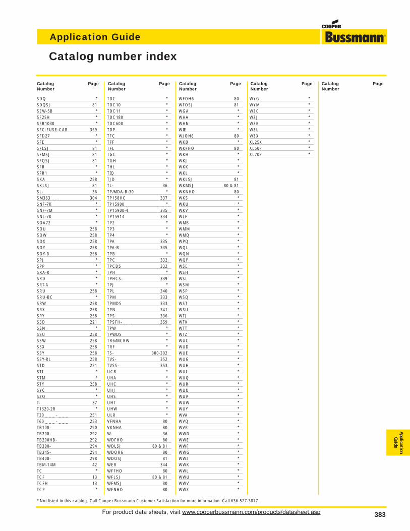
For product data sheets, visit www.cooperbussmann.com/products/datasheet.asp 383
Application Guide
ApplicationGuide
383
Catalog number index
SDQ *SDQSJ 81SEW-5B *SF25H *SFB1030 *SFC-FUSE-CAB 359SFD27 *SFE *SFLSJ 81SFMSJ 81SFQSJ 81SFR *SFR1 *SKA 258SKLSJ 81SL- 36SM363 _ _ 304SNF-7K *SNF-7M *SNL-7K *SOA72 *SOU 258SOW 258SOX 258SOY 258SOY-B 258SPJ *SPP *SRA-R *SRD *SRT-A *SRU 258SRU-BC *SRW 258SRX 258SRY 258SSD 221SSN *SSU 258SSW 258SSX 258SSY 258SSY-RL 258STD 221STI *STM *STY 258SYC *SZQ *T- 37T1320-2R *T30 _ _ _ - _ _ _ 251T60 _ _ _ - _ _ _ 253TB100- 290TB200- 292TB200HB- 292TB300- 294TB345- 294TB400- 298TBM-14M 42TC *TCF 13TCFH 13TCP *
TDC *TDC10 *TDC11 *TDC180 *TDC600 *TDP *TFC *TFF *TFL *TGC *TGH *THL *TIQ *TJD *TL- 36TP/MDA-B-30 *TP158HC 337TP15900 *TP15900-4 335TP15914 334TP2 *TP3 *TP4 *TPA 335TPA-B 335TPB *TPC 332TPCDS 332TPH *TPHCS- 339TPJ *TPL 340TPM 333TPMDS 333TPN 341TPS 336TPSFH- _ _ _ 359TPW *TPWDS *TR6/MCRW *TRF *TS- 300-302TVS- 352TVSS- 353UCB *UHA *UHC *UHJ *UHS *UHT *UHW *ULR *VFNHA 80VKNHA 80W- 36WDFHO 80WDLSJ 80 & 81WDOH6 80WDOSJ 81WER 344WFFHO 80WFLSJ 80 & 81WFMSJ 80WFNHO 80
WFOH6 80WFOSJ 81WGA *WHA *WHN *WIE *WJON6 80WKB *WKFHO 80WKH *WKJ *WKK *WKL *WKLSJ 81WKMSJ 80 & 81WKNHO 80WKS *WKU *WKV *WLF *WMB *WMM *WMQ *WPQ *WQL *WQN *WQP *WSE *WSH *WSL *WSM *WSP *WSQ *WST *WSU *WTJ *WTK *WTT *WTZ *WUC *WUD *WUE *WUG *WUH *WUI *WUQ *WUR *WUU *WUV *WUW *WUY *WVA *WVQ *WVR *WWD *WWE *WWF *WWG *WWI *WWK *WWL *WWU *WWV *WWX *
WYG *WYM *WZC *WZJ *WZK *WZL *WZX *XL25X *XL50F *XL70F *
Catalog PageNumber
Catalog PageNumber
Catalog PageNumber
Catalog PageNumber
Catalog PageNumber
* Not listed in this catalog. Call Cooper Bussmann Customer Satisfaction for more information. Call 636-527-3877.

For product data sheets, visit www.cooperbussmann.com/products/datasheet.asp384
Application Guide
World HeadquartersCooper Bussmann
P. O. Box 14460
St. Louis, Missouri 63178-4460 USA
Telephone: 636/394-2877
Fax: 800/544-2570
Email: [email protected]
Asian HeadquartersCooper Bussmann
Cooper Electric (Shanghai) Co. Ltd.
28th Floor Yu An Building
738 Dongfang Road
Pudong, Shanghai 200122 China
Telephone: 8621-5831-6805
Fax: 8621-6876-5532
European HeadquartersCooper (UK) Ltd.
Bussmann Division
Burton-on-the-Wolds
Leicestershire LE12 5th England
Telephone: 44-1509-882737
Fax: 44-1509-882786
Bussmann Asia-Pacific1 Jalan Kilang Timor
#06-01 Pacific Tech Centre
Singapore 159303
Republic of Singapore
Telephone: 65-6278-6151
Fax: 65-6278-3151
Email: [email protected]
Bussmann Australia205 – 209 Woodpark Road
P O Box 2577
Smithfield NSW 2164
Australia
Telephone: 61-2-8787-2700
Fax: 61-2-9609-2746
Bussmann BrasilBussmann do Brasil Ltda.
Rodovia Santos Dumont, km 23
13.300-000, Caixa Postal 095
Itu – Sao Paulo Brasil
Telephone: 55-11-4024-8400
Fax: 55-11-4024-8424
Bussmann Denmark5 Literbuen
DK-2740 Skovlunde
Copenhagen Denmark
Telephone: 45-4485-0900
Fax: 45-4485-0901
Bussmann India#3 EVR Street, Sedarapet
Pondicherry – 605 111
India
Telephone: 91-413-2678203
or 91-413-2678204
Fax: 91-413-267-7010
Bussmann MexicoCooper Wiring Devices
Poniente 148 No. 933
Industrial Vallejo
02300 Mexico, D.F. Mexico
Telephone: 52-55-57-47-4519, Ext 3219
Fax: 52-55-57-52-5336
Cooper Bussmann Transportation175 Hansen Court
Wood Dale, IL 60191
Telephone: 630/422-2400
Fax: 630/422-2500
Cooper Electronic Technologies3601 Quantum Blvd.
Boynton Beach, FL 33426
Telephone: 561/752-5000
Fax: 561/742-0134
Enbray ContactorsEnbray Cooper (U.K.) Limited
Salterbeck Industrial Est.
Workington, Cumbria CA14 5DT England
Telephone: 44-1946-839000
Fax: 44-1946-833000
Email: [email protected]
Sales Support & Manufacturing Facilities