a monosaccharide-based coin-cell biobattery
TRANSCRIPT

DOI: 10.1002/celc.201402162
A Monosaccharide-Based Coin-Cell BiobatteryFabien Giroud,[a] David P. Hickey,[b] David W. Schmidtke,[c] Daniel T. Glatzhofer,[b] andShelley D. Minteer*[a]
1. Introduction
Interest in biofuel cells has grown dramatically over the lastdecade.[1–3] By immobilizing oxidizing enzymes at the anodeand reducing enzymes at the cathode, a voltage can be gener-ated that, if stacked, is sufficient to operate a wide range ofuseful electronics.[4–6] However, despite a relatively large theo-retical potential, many biofuel cells are limited by the amountof current that can be generated due to limitations in diffusionof either the substrate or the electrons through the electrodematerial. By either vigorously stirring the solution or using a ro-tating disk electrode, many of the substrate diffusion limita-tions can be overcome. However, it should be noted that nei-ther of these options is an applicable solution to the problemof substrate diffusion, but rather a means of determining theo-retical limitations of various biofuel-cell materials.[7] A practicalsolution to the problem of electron diffusion is the use ofcarbon nanotubes (CNTs) and various types of mesoporousmaterials as a means of dramatically increasing the amount ofreal surface area and decreasing the diffusional distances be-tween redox species (redox mediators or active centers of en-zymes) and electrode surfaces.[8, 9] Nonetheless, these materials
do not solve the substrate diffusion issue as shown in recentpapers.[10]
Much of the early work with high current density biofuelcells has focused on the use of redox polymers to immobilizean enzyme onto the surface of an electrode. In such electrodefilms, redox mediators help shuttle electrons from the activesite of the enzyme to the electrode surface. Mediated electrontransfer is preferable for enzymes such as glucose oxidase, asthe active site resides in the interior of the enzyme, and thismakes it inaccessible for direct electron transfer to the elec-trode surface.[11–13]
Recent research has shown that redox polymers based onferrocene-modified linear poly(ethylenimine) (LPEI) form hydro-gels if crosslinked in the presence of an enzyme on the surfaceof an electrode. The ferrocene–LPEI polymers interact favorablywith enzymes such as glucose oxidase through complexationbetween positive charges along the polymer backbone andthe negatively charged enzyme surface, which allows for cur-rent densities as high as 2 mA cm�2 in the presence of glucoseon planar surfaces.[14]
Unlike glucose oxidase, laccase contains a T1 Cu electronrelay that is readily accessible from the enzyme’s surface, andit can shuttle the electrons to the active site. Work has beendone to show that anthracene-modified multiwalled CNTs (An-MWCNTs) can bind to the active site of laccase to control theorientation of the enzyme.[15, 16] The use of An-MWCNTs to im-mobilize laccase allows for a very efficient means of direct elec-tron transfer, which can result in cathodic current densities ashigh as 1.84 mA cm�2 in the presence of O2.[17]
In this report, we study the use of carbon felt (CF) electrodesas the conductive support material in place of Toray paper (TP)electrodes for the construction of enzyme-based bioelectrodes.For this purpose, we utilize a combination of ferrocene-modi-fied linear poly(ethylenimine) (Fc-C6-LPEI) and glucose oxidase(GOx) or fructose dehydrogenase (FDH) at the bioanode,whereas an ink of An-MWCNTs and laccase is used at the cath-
The utilization of carbon felt as the conductive material for theconstruction of a monosaccharide-based coin-cell biobattery isexplored. Anthracene-modified carbon nanotubes were usedat the positive electrode to preferentially orientate laccase fordirect electron transfer during O2 reduction. A ferrocene-modi-fied poly(ethylenimine) redox polymer was used to electricallycommunicate with either glucose oxidase or fructose dehydro-genase at the negative electrode. The use of carbon felt
helped in the immobilization of a larger quantity of enzyme.Cathodic and anodic currents with carbon felt electrodesshowed a three-fold and twofold increase, respectively, relativeto the currents obtained with Toray paper materials. Bioelec-trodes were assembled in a commercial coin-cell batterycasing and were tested as possible biobatteries. This workpresents the first time in which a traditional battery design isused for the performance evaluation of different biobatteries.
CHEMELECTROCHEMARTICLES
[a] Dr. F. Giroud, Prof. S. D. MinteerDepartment of Chemistry, University of Utah315 S 1400 E Rm 2020Salt Lake City, Utah 84112 (USA)Phone : 1-801-587-8325E-mail : [email protected]
[b] Dr. D. P. Hickey, Prof. D. T. GlatzhoferDepartment of Chemistry and BiochemistryUniversity of Oklahoma, 101 Stephenson ParkwayNorman, Oklahoma 73019 (USA)
[c] Prof. D. W. SchmidtkeUniversity of Oklahoma Biomedical Engineering Centerand School of Chemical, Biological, Materials EngineeringUniversity of Oklahoma, 100 East BoydNorman, Oklahoma 73019 (USA)
An invited contribution to a Special Issue on Biofuel Cells
� 2014 Wiley-VCH Verlag GmbH & Co. KGaA, Weinheim ChemElectroChem 2014, 1, 1880 – 1885 1880

ode. Finally, we investigate a new approach for the characteri-zation of biobatteries by sealing the bioanode and the bioca-thode in a commercial, self-contained coin-cell design to con-struct a monosaccharide/dioxygen biobattery. The coin-cellbattery is tested with glucose and fructose for comparison.This work presents an attractive method to help standardizethe testing done for the performance evaluation of biobatter-ies in development.
Materials and Methods
Materials
d-Glucose (anhydrous) was purchased from Macron Chemicals.d-Fructose, laccase from Trametes versicolor (EC 1.10.3.2,�10 U mg�1 solid), glucose oxidase from Aspergillus niger (EC1.1.3.4, 192 U mg�1 solid), and horseradish peroxidase (HRP) (EC1.11.1.7, 200–300 U mg�1 solid) were purchased from Sigma–Al-drich. Fructose dehydrogenase from Gluconobacter sp. (EC1.1.99.11, Grade III, 169 U mg�1 of solid) was purchased fromToyobo Enzymes. Ethylene glycol diglycidyl ether (EGDGE) was pur-chased from Polysciences, Inc. , Washington, PA. All chemicals usedin the synthesis of the redox polymer were purchased fromSigma–Aldrich and were used as received unless otherwise noted.Ferrocene-modified linear poly(ethyleneimine) (Fc-C6-LPEI) was syn-thesized as previously reported.[18] Stock solutions of glucose andfructose were allowed to mutarotate overnight at 4 8C. TP electro-des were purchased from Fuel Cell Earth (non-wet proof, Prod. No.TGP-H-060). CF was obtained from Alfa Aesar (3.18 mm thick,99.0 %). Coin-cell casings were obtained from AA Portable PowerCorp (CR2032, cases-304). The insulator layer between the anodeand cathode was made of filter paper from Whatman (diameter =70 mm. MWCNTs were purchased from cheaptubes.com (outer di-ameter = 10-20 nm, length = 10–30 mm) and were used as received.The anthracene (An)-modified MWCNTs were synthesized accord-ing to our previous work.[15] In brief, hydroxylated MWCNTs (OHgroup 1.76 wt %) were dispersed in acetonitrile for 15 min. Anthra-cene-2-carbonyl chloride (1.0 equiv. of OH group) was added tothe mixture, and the solution was vigorously stirred and heated atreflux overnight. The modified CNTs were filtered and washed withcopious amounts of acetonitrile, benzene, and dichloromethane toremove any unreacted starting materials.
Electrode Fabrication
Biocathode preparation: For 1 cm2 TP electrode modification, An-MWCNTs (7.5 mg) were dispersed in a laccase solution (75 mL,40 mg mL�1, 50 mm citrate buffer, pH 5.0) by successive sonicationand vortexing (1 min each, repeated 4 �). A tetrabutylammoniumbromide modified Nafion (TBAB-Nafion) suspension (25 mL of a 5 %by wt suspension) as previously described was used as an immobi-lizing agent and was added to the solution.[19] The mixture wasmixed by vortex and sonication (1 min each). The resulting blackink was paint coated evenly on four TP electrodes. Unless other-wise specified in the text, the same preparation was used tomodify a single electrode for 1 cm2 CF electrodes. The CF was nottreated before coating with the bioink and was used dry.
Bioanode preparation: For 1 cm2 TP electrode modification or CFelectrodes, a freshly dispersed solution of CNTs in deionized water(34.4 mL, 1 mg mL�1) was added to Fc-C6-LPEI (120 mL, 12 mg mL�1
in deionized water), and the mixture was sonicated and vortexed(1 min each, solution 1). For single enzyme bioelectrodes, oxidore-
ductase (17.2 mL, 13 mg mL�1) was added to solution 1, and the so-lution was mixed by vortexing for 1 min. Finally, a solution of 4.3 %EGDGE (6.44 mL, EGDGE/water = 2:45 v/v) was added to the previ-ous mixture. The resulting solution was mixed thoroughly. The TPand CF electrodes were modified by dropcasting from the final so-lution (25 and 50 mL, respectively), and the resulting films were al-lowed to dry in open air at room temperature overnight to ensurecrosslinking. In the case of the CF electrodes, the felt was thor-oughly soaked in deionized water to help the hydrogel to diffuseinside the pores.
Voltammetric and Amperometric Characterization of Half-Cell Biocathodes and Bioanodes
Biocathodes: Half-cell electrodes were tested by using a three-elec-trode setup. Cyclic voltammetry (CV) experiments were performedon both TP and CF 1 cm � 1 cm electrodes as the working elec-trode. The potential was scanned from 0.7 to 0.0 V versus a saturat-ed calomel electrode (SCE) by using a platinum mesh counter elec-trode at 1 mV s�1. Experiments were performed in 50 mm citratebuffer at pH 4.5 (unless otherwise stated) by using a DY2300 po-tentiostat (Digi Ivy, TX USA). Each experiment was performed intriplicate by using separate electrodes (n = 3) in dissolved O2 or inpure O2 saturated conditions. Electrodes were allowed to equili-brate for 5 min in buffer before performing CV experiments.Amperometric experiments were performed by applying 0.3 Vversus SCE for 23 h in dissolved O2 without any stirring and atroom temperature (22�2 8C). CV and amperometric testing wasperformed for 7 days to assess the stability of the biocathode.
Bioanodes: Half-cell electrodes were tested by using a three-elec-trode setup. Electrodes were allowed to equilibrate for 5 min inbuffer before performing the CV experiments to determine the oxi-dation potential for the redox hydrogel on both the TP and CF1 cm � 1 cm electrodes. The potential was scanned from �0.1 to0.6 V versus SCE by using a platinum mesh counter electrode at20 mV s�1. Experiments were performed in 50 mm citrate buffer atpH 5.0 by using a DY2300 potentiostat (Digi Ivy, TX USA). Each ex-periment was performed in triplicate by using separate electrodes(n = 3). Afterwards, amperometric studies were performed by al-lowing the films to reach a steady-state current at a potential Ethat was 50 mV above the peak oxidation potential (Epa) at 25 8C(i.e. E = Epa + 50 mV). The solutions were continuously stirred at400 rpm. After the charging current dissipated (t = 1000 s), sequen-tial injections of a 1 m substrate solution in 50 mm citrate buffer atpH 5.0 were made as the current was recorded as a function oftime.
Coin-Cell Battery Characterization
The previously described biocathodes and bioanodes were assem-bled and sealed in a coin-cell casing to form a biobattery. Filterpaper was added between the two electrodes as a separator toavoid short circuiting of the cell. For the particular case in whichGOx-based bioanodes were used in the coin cell, the filter paperwas modified with a solution of HRP [1 mg mL�1 HRP diluted ina TBAB-Nafion (50 % v/v, in water)] to prevent laccase deactivationby the build up of H2O2 coming from the reaction between GOxand its natural electron acceptor, O2.[20] Buffer solution was injectedinto the battery by holes located on the cathode side. The open-circuit voltage (OCV) was measured and allowed to reach steadystate. Slow scan polarization (1 mV s�1 from the measured open cir-cuit potential to 1 mV) was used to obtain polarization and powercurves by monitoring current as a function of potential. As the fer-
CHEMELECTROCHEMARTICLES www.chemelectrochem.org
� 2014 Wiley-VCH Verlag GmbH & Co. KGaA, Weinheim ChemElectroChem 2014, 1, 1880 – 1885 1881

rocene in the Fc-C6-LPEI is originally in its reduced state, experi-ments were recorded after a second polarization of the biobatteryfrom OCV to 5 mV to guarantee that the Fc-C6-LPEI was in its oxi-dized state before characterization in the presence of fuel. The fuelsolution was flushed through the battery to allow the solutioninside the casing to be constant between experiments (namely,100 mm substrate). The OCV was allowed to stabilize until itreached a steady state, and linear scan voltammetry (LSV) was per-formed in the presence of 100 mm fuel solution.
2. Results
2.1. Half-Cell Biocathode Characterization: Carbon MaterialStudies
Two different electrode materials were used in this study tocompare the bioelectrocatalytic currents obtained from theoxygen reduction reaction from laccase at An-MWCNTs. TP andCF electrodes were modified on a single side with the sameamount of biocathode ink. Figure 1 depicts the bioelectrocata-lytic current obtained at these electrodes immersed in 50 mm
citrate buffer, pH 4.5. The larger porosity (from 0.94 to0.98)[21, 22] and greater thickness (3.18 mm) of the CF materialrelative to the same values of the TP material (0.78 and0.19 mm, specification sheet) provided a higher capacity load-ing for incorporation of the bioink into the conductive materi-al. Current densities were higher on the CF electrodes witha twofold and 1.5-fold increase relative to those on the TPelectrodes in the presence of dissolved and saturated oxygen,respectively (TP: 115.4�10.0 and 299.6�33.5 mA cm�2 for dis-solved and saturated O2, respectively; CF: 242.1�15.1 and458.6�44.4 mA cm�2 for dissolved and saturated O2, respective-ly). To estimate the benefit of the CF material on the bioink ca-pacity loading at the electrode, the biocathode ink was depos-ited on both sides of the CF material and the volume usedwas increased by a factor of two and four on each side foreach electrode. Bioelectrocatalysis of oxygen reduction wasperformed in quiescent solution (dissolved O2) and under satu-rated oxygen conditions. All the current densities are reportedin Table 1. The resulting currents were increased two- andthreefold relative to those of the single-side-modified CFelectrodes.
Finally, both working conditions and stability experimentswere performed at pH 5.0 to assess the electrocatalytic currentthat could be obtained in the biofuel cell experiment runningunder the same conditions. Upon first testing by CV, the cur-rent recorded from An-MWCNT/laccase biocathodes at + 300 mVversus SCE was 682.3�66.3 mA cm�2. The current wasmonitored continuously by CVand amperometric studies fora period of 7 days. As shown inFigure 2, electrocatalytic currentsof the biocathodes decreasedprogressively to reach 65 % ofthe original currents after 7 daysof continuous operation.
2.2. Half-Cell Bioanode Characterization: Carbon MaterialStudies
Bioelectrocatalysis of the bioanodes was tested under differentconditions at 25 8C in 50 mm citrate buffer at pH 5.0. To in-crease the current at the electrodes, CNT dispersions wereadded to the hydrogel modification. Different CNT dispersion
Figure 1. Representative cyclic voltammograms of laccase/An-MWCNT im-mobilized on TP electrodes (top) and CF electrodes (bottom) soaked in50 mm citrate buffer at pH 4.5 in dissolved O2 (c) or under pure O2 bub-bling (a) conditions recorded at 1 mV s�1.
Table 1. Comparison of the catalytic current of different laccase/An-MWCNT-modified CF electrodes dependingon the bioink loading and oxygen concentration.[a]
Conditions Current density [mA cm�2]Single side modification Two side modification
Twofold increase in volume Fourfold increase in volume
dissolved O2 254.5�13.6 546.9�32.1 (2.3) 774.4�43.7 (3.0)saturated O2 518.8�54.7 1180.0�110.3 (2.3) 1830.0�78.5 (3.5)
[a] Cyclic voltammograms were recorded at 1 mV s�1 in 50 mm citrate buffer, pH 4.5. Current densities weretaken at 300 mV vs. SCE.
CHEMELECTROCHEMARTICLES www.chemelectrochem.org
� 2014 Wiley-VCH Verlag GmbH & Co. KGaA, Weinheim ChemElectroChem 2014, 1, 1880 – 1885 1882

concentrations were assayed (0, 1, and 2 mg mL�1 CNTs in de-ionized water). Figure 3 shows calibration curves of GOx-basedbioanodes modified with a Fc-C6-LPEI redox hydrogel on TPelectrodes. As expected, the presence of CNTs within the redoxhydrogel greatly enhanced the catalytic current at the bioe-lectrodes upon the addition of glucose into the electrolyte.[23]
With a CNTs dispersion of 1 mg mL�1, the maximum currentdensity (Jmax) reached a plateau at around 100 mm glucose(380.5�35.0 mA cm�2). No change was obtained upon replac-ing the TP electrode by a CF-based bioanode (378.1�33.5 mA cm�2 at 100 mm glucose). However, the thickness ofthe CF allowed a larger quantity of hydrogel/enzyme mixture
to be immobilized onto the electrodes. Twice the volume im-mobilized led to a twofold increase in catalytic current at theanodes (745.1�59.7 mA cm�2 at 100 mm glucose). Similar ex-periments were performed on MWCNT/FDH-based CF bioe-lectrodes made with a 1 mg mL�1 CNT dispersion. Amperomet-ric measurements in the presence of 100 mm fructose resultedin electrocatalytic currents of 40.6�7.5 mA cm�2, as shown inFigure 4.
2.3. Coin-Cell Biobattery Design
Coin-cell biobatteries were assembled with CF-based biocath-odes and CF-based bioanodes by using a 50 mm citrate buffer.Polarization was performed to fully oxidize the redox hydrogel.Upon OCV stabilization, a second polarization of the batterywas performed to assess the characteristics of the coin cell inthe absence of substrate. Finally, a solution of 100 mm fuel so-lution was flushed into the coin cell. The OCV increased gradu-ally as the amount of ferrocene was reduced by the enzymaticreaction in the presence of the substrate. Figure 5 displays thepolarization curves for glucose and fructose coin cells in thepresence of 100 mm fuel solution at pH 5.0. The maximum cur-rent densities were 31.3�3.0, 120.2�9.7, and 281.8�3.7 mA cm�2 and the power densities reached 12.7�0.1, 29.9�3.2, and 51.2�1.6 mW cm�2 in buffer, 100 mm fructose, and100 mm glucose, respectively. Whereas the OCVs for both bio-fuel cells in the presence of substrates were close due to theuse of the same mediator, currents were higher for GOx-basedbiobatteries, as expected from the amperometric experimentsshown earlier. The glucose biobattery presented a typical po-larization curve with the three limitations usually observed (ac-tivation, ohmic, and concentration losses). On the other hand,the fructose biobattery presented a current density peak thatshould correspond to a diffusion limitation due to a decreasein the local redox site concentration, as well as instability of
Figure 2. Stability over time of laccase/An-MWCNT CF biocathodes. Currentrecorded from CV experiments at E = 300 mV versus SCE (&) and from poten-tiostatic experiments after 23 h of continuous polarization at E = 300 mVversus SCE (&).
Figure 3. Calibration curves obtained for GOx/Fc-C6-LPEI immobilized on TPelectrodes without the addition of CNTs within the redox hydrogel (~), withthe addition of a dispersion of 1 mg mL�1 CNTs (&) and 2 mg mL�1 CNTs (&)upon successive additions of glucose in 50 mm citrate, pH 5.0 at 25 8C.Epoised = Epa + 50 mV.
Figure 4. Calibration curves obtained for FDH/Fc-C6-LPEI immobilized on CFelectrodes with addition of a dispersion of 1 mg mL�1 CNTs upon successiveadditions of fructose in 50 mm citrate, pH 5.0 at 25 8C. Epoised = Epa + 50 mV.
CHEMELECTROCHEMARTICLES www.chemelectrochem.org
� 2014 Wiley-VCH Verlag GmbH & Co. KGaA, Weinheim ChemElectroChem 2014, 1, 1880 – 1885 1883
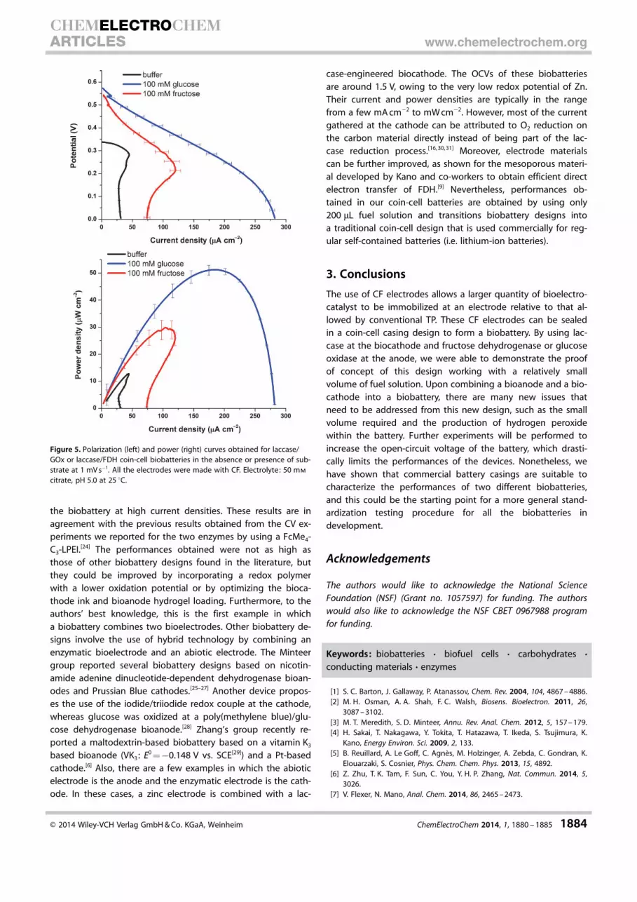
the biobattery at high current densities. These results are inagreement with the previous results obtained from the CV ex-periments we reported for the two enzymes by using a FcMe4-C3-LPEI.[24] The performances obtained were not as high asthose of other biobattery designs found in the literature, butthey could be improved by incorporating a redox polymerwith a lower oxidation potential or by optimizing the bioca-thode ink and bioanode hydrogel loading. Furthermore, to theauthors’ best knowledge, this is the first example in whicha biobattery combines two bioelectrodes. Other biobattery de-signs involve the use of hybrid technology by combining anenzymatic bioelectrode and an abiotic electrode. The Minteergroup reported several biobattery designs based on nicotin-amide adenine dinucleotide-dependent dehydrogenase bioan-odes and Prussian Blue cathodes.[25–27] Another device propos-es the use of the iodide/triiodide redox couple at the cathode,whereas glucose was oxidized at a poly(methylene blue)/glu-cose dehydrogenase bioanode.[28] Zhang’s group recently re-ported a maltodextrin-based biobattery based on a vitamin K3
based bioanode (VK3 : E0 =�0.148 V vs. SCE[29]) and a Pt-basedcathode.[6] Also, there are a few examples in which the abioticelectrode is the anode and the enzymatic electrode is the cath-ode. In these cases, a zinc electrode is combined with a lac-
case-engineered biocathode. The OCVs of these biobatteriesare around 1.5 V, owing to the very low redox potential of Zn.Their current and power densities are typically in the rangefrom a few mA cm�2 to mW cm�2. However, most of the currentgathered at the cathode can be attributed to O2 reduction onthe carbon material directly instead of being part of the lac-case reduction process.[16, 30, 31] Moreover, electrode materialscan be further improved, as shown for the mesoporous materi-al developed by Kano and co-workers to obtain efficient directelectron transfer of FDH.[9] Nevertheless, performances ob-tained in our coin-cell batteries are obtained by using only200 mL fuel solution and transitions biobattery designs intoa traditional coin-cell design that is used commercially for reg-ular self-contained batteries (i.e. lithium-ion batteries).
3. Conclusions
The use of CF electrodes allows a larger quantity of bioelectro-catalyst to be immobilized at an electrode relative to that al-lowed by conventional TP. These CF electrodes can be sealedin a coin-cell casing design to form a biobattery. By using lac-case at the biocathode and fructose dehydrogenase or glucoseoxidase at the anode, we were able to demonstrate the proofof concept of this design working with a relatively smallvolume of fuel solution. Upon combining a bioanode and a bio-cathode into a biobattery, there are many new issues thatneed to be addressed from this new design, such as the smallvolume required and the production of hydrogen peroxidewithin the battery. Further experiments will be performed toincrease the open-circuit voltage of the battery, which drasti-cally limits the performances of the devices. Nonetheless, wehave shown that commercial battery casings are suitable tocharacterize the performances of two different biobatteries,and this could be the starting point for a more general stand-ardization testing procedure for all the biobatteries indevelopment.
Acknowledgements
The authors would like to acknowledge the National ScienceFoundation (NSF) (Grant no. 1057597) for funding. The authorswould also like to acknowledge the NSF CBET 0967988 programfor funding.
Keywords: biobatteries · biofuel cells · carbohydrates ·conducting materials · enzymes
[1] S. C. Barton, J. Gallaway, P. Atanassov, Chem. Rev. 2004, 104, 4867 – 4886.[2] M. H. Osman, A. A. Shah, F. C. Walsh, Biosens. Bioelectron. 2011, 26,
3087 – 3102.[3] M. T. Meredith, S. D. Minteer, Annu. Rev. Anal. Chem. 2012, 5, 157 – 179.[4] H. Sakai, T. Nakagawa, Y. Tokita, T. Hatazawa, T. Ikeda, S. Tsujimura, K.
Kano, Energy Environ. Sci. 2009, 2, 133.[5] B. Reuillard, A. Le Goff, C. Agn�s, M. Holzinger, A. Zebda, C. Gondran, K.
Elouarzaki, S. Cosnier, Phys. Chem. Chem. Phys. 2013, 15, 4892.[6] Z. Zhu, T. K. Tam, F. Sun, C. You, Y. H. P. Zhang, Nat. Commun. 2014, 5,
3026.[7] V. Flexer, N. Mano, Anal. Chem. 2014, 86, 2465 – 2473.
Figure 5. Polarization (left) and power (right) curves obtained for laccase/GOx or laccase/FDH coin-cell biobatteries in the absence or presence of sub-strate at 1 mV s�1. All the electrodes were made with CF. Electrolyte: 50 mm
citrate, pH 5.0 at 25 8C.
CHEMELECTROCHEMARTICLES www.chemelectrochem.org
� 2014 Wiley-VCH Verlag GmbH & Co. KGaA, Weinheim ChemElectroChem 2014, 1, 1880 – 1885 1884

[8] A. de Poulpiquet, A. Ciaccafava, E. Lojou, Electrochim. Acta 2014, 126,104 – 114.
[9] K. So, S. Kawai, Y. Hamano, Y. Kitazumi, O. Shirai, M. Hibi, J. Ogawa, K.Kano, Phys. Chem. Chem. Phys. 2014, 16, 4823.
[10] A. d. Poulpiquet, H. Marques-Knopf, V. Wernert, M. T. Giudici-Orticoni, R.Gadiou, E. Lojou, Phys. Chem. Chem. Phys. 2014, 16, 1366.
[11] A. Heller, Curr. Opin. Chem. Biol. 2006, 10, 664 – 672.[12] J. Hodak, R. Etchenique, E. J. Calvo, K. Singhal, P. N. Bartlett, Langmuir
1997, 13, 2708 – 2716.[13] S. Boland, P. Jenkins, P. Kavanagh, D. Leech, J. Electroanal. Chem. 2009,
626, 111 – 115.[14] M. T. Meredith, D.-Y. Kao, D. Hickey, D. W. Schmidtke, D. T. Glatzhofer, J.
Electrochem. Soc. 2011, 158, B166.[15] M. T. Meredith, M. Minson, D. Hickey, K. Artyushkova, D. T. Glatzhofer,
S. D. Minteer, ACS Catal. 2011, 1, 1683 – 1690.[16] K. Stolarczyk, M. Sepelowska, D. Lyp, K. Zelechowska, J. F. Biernat, J. Ro-
galski, K. D. Farmer, K. N. Roberts, R. Bilewicz, Bioelectrochemistry 2012,87, 154 – 163.
[17] M. Minson, M. T. Meredith, A. Shrier, F. Giroud, D. Hickey, D. T. Glatzhofer,S. D. Minteer, J. Electrochem. Soc. 2012, 159, G166 – G170.
[18] S. A. Merchant, M. T. Meredith, T. O. Tran, D. B. Brunski, M. B. Johnson,D. T. Glatzhofer, D. W. Schmidtke, J. Phys. Chem. C 2010, 114, 11627 –11634.
[19] C. M. Moore, N. L. Akers, A. D. Hill, Z. C. Johnson, S. D. Minteer, Biomac-romolecules 2004, 5, 1241 – 1247.
[20] R. D. Milton, F. Giroud, A. E. Thumser, S. D. Minteer, R. C. T. Slade, Chem.Commun. 2014, 50, 94.
[21] R. Carta, S. Palmas, A. M. Polcaro, G. Tola, J. Appl. Electrochem. 1991, 21,793 – 798.
[22] J. Gonz�lez-Garc�a, P. Bonete, E. Exp�sito, V. Montiel, A. Aldaz, R. Torre-grosa-Maci�, J. Mater. Chem. 1999, 9, 419 – 426.
[23] T. O. Tran, E. G. Lammert, J. Chen, S. A. Merchant, D. B. Brunski, J. C.Keay, M. B. Johnson, D. T. Glatzhofer, D. W. Schmidtke, Langmuir 2011,27, 6201 – 6210.
[24] D. P. Hickey, F. Giroud, D. W. Schmidtke, D. T. Glatzhofer, S. D. Minteer,ACS Catal. 2013, 3, 2729 – 2737.
[25] P. K. Addo, R. L. Arechederra, S. D. Minteer, J. Power Sources 2011, 196,3448 – 3451.
[26] M. N. Arechederra, P. K. Addo, S. D. Minteer, Electrochim. Acta 2011, 56,1585 – 1590.
[27] Y. H. Kim, E. Campbell, J. Yu, S. D. Minteer, S. Banta, Angew. Chem. 2013,125, 1477 – 1480; Angew. Chem. Int. Ed. 2013, 52, 1437 – 1440.
[28] J.-Y. Wang, P.-C. Nien, C.-H. Chen, L.-C. Chen, K.-C. Ho, Bioresour. Technol.2012, 116, 502 – 506.
[29] M. Togo, A. Takamura, T. Asai, H. Kaji, M. Nishizawa, Electrochim. Acta2007, 52, 4669 – 4674.
[30] U. B. Jensen, M. Vagin, O. Koroleva, D. S. Sutherland, F. Besenbacher,E. E. Ferapontova, J. Electroanal. Chem. 2012, 667, 11 – 18.
[31] M. Skunik-Nuckowska, K. Grzejszczyk, K. Stolarczyk, R. Bilewicz, P. J. Ku-lesza, J. Appl. Electrochem. 2014, 44, 497 – 507.
Received: May 29, 2014Published online on August 11, 2014
CHEMELECTROCHEMARTICLES www.chemelectrochem.org
� 2014 Wiley-VCH Verlag GmbH & Co. KGaA, Weinheim ChemElectroChem 2014, 1, 1880 – 1885 1885