a layered model of a virtual human intestine for surgery simulation
TRANSCRIPT
A Layered Model of a Virtual Human
Intestine for Surgery Simulation
L. France a, J. Lenoir b, A. Angelidis c, P. Meseure b,
M.-P. Cani c, F. Faure c, C. Chaillou b
aSyscom, Universite de Savoie, Chambery, FrancebALCOVE, INRIA Futurs, IRCICA-LIFL, Universite de Lille I, Villeneuve
d’Ascq, FrancecGRAVIR, joint lab of CNRS, INRIA, INPG and Universite J. Fourier,
Montbonnot, France
Abstract
In this paper, we propose a new approach to simulate the small intestine in a contextof laparoscopic surgery. The ultimate aim of this work is to simulate the training of abasic surgical gesture in real-time: moving aside the intestine to reach hidden areasof the abdomen. The main problem posed by this kind of simulation is animatingthe intestine. The problem comes from the nature of the intestine: a very long tubewhich is not isotropically elastic, and is contained in a volume that is small whencompared to the intestine’s length. It coils extensively and collides with itself inmany places.
To do this, we use a layered model to animate the intestine. The intestine’s axisis animated as a linear mechanical component. A specific sphere-based model han-dles contacts and self-collisions. A skinning model is used to create the intestine’svolume around the axis. This paper discusses and compares three different repre-sentations for skinning the intestine: a parametric surface model and two implicitsurface models. The first implicit surface model uses point skeletons while the sec-ond uses local convolution surfaces. Using these models, we obtained good-lookingresults in real-time. Some videos of this work can be found at:
http://www-imagis.imag.fr/Publications/2004/FLAMCFC04/ .
Key words: Surgical simulation, virtual reality, physically based simulation,real-time computation, medical application.PACS: 07.05.Tp
Email addresses: [email protected] (L. France),[Julien.Lenoir|Philippe.Meseure|Christophe.Chaillou]@lifl.fr,[Alexis.Angelidis|Marie-Paule.Cani|Francois.Faure]@imag.fr (M.-P. Cani).
Preprint submitted to Elsevier Science 27 February 2004
1 Introduction
Laparoscopic surgery involves making small incisions in the body, throughwhich surgical tools and a micro video camera are inserted. This techniqueavoids large cuts typical of conventional open surgery. It places the surgeonin peculiar working conditions, requiring among other skills a flawless hand-eye coordination. Training, therefore, is necessary, and could be done on asimulator.
Different endoscopic simulators are available commercially, such as the onesmanufactured by Simbionix[35], Surgical Science[33] or Xitact[40]. These sim-ulators usually handle the interaction of surgical tools on a single organ. Cur-rently, there is no satisfying simulation solution for the viscera, which is madeof easily deformed organs in contact, that cannot be simulated as totally in-dependent components.
Being wound inside the abdominal cavity, the viscera must be pulled andfolded with surgical tools to clear the area for treatment in such a way thatthey do return to their previous position. This manipulation is difficult forsurgeons to perform correctly. Any mistake will prolong the procedure unnec-essarily[11]. Since this clearing stage is necessary in almost all laparoscopicoperations and surgeons have to train for a long time before acquiring theright technique, simulators will give them the opportunity to practice at a lowcost.
Simulating a highly deformable and smooth organ such as the intestine isa challenge: the model must handle large displacements, contacts, and self-collisions in real-time. Moreover, the smooth aspect of the intestine must beadequately rendered. The goal of this work is to propose an intestine modelwell suited to the virtual surgical environment described above. To do this,we rely on a layered model, the components of which were described in twopreviously published conference proceedings[19,18]:
• a mechanical layer, which simulates the main intestine behavior and handlescollisions with other objects as well as self-collisions,
• a smooth skin used at the rendering stage, for which three possible repre-sentations are discussed.
Obtaining a real-time simulation is a challenge with several temporal con-straints: the first component (the mechanical layer) must be simulated at ahigh frequency (100Hz) to enable future user interaction via haptic devices[25], while the second component (the geometric skinning) can be updated atonly 25Hz to display a continuous animation. Both simulations have to beperformed in parallel.
2
This paper is organized as follows: Section 2 reviews related works. Sections3 and 4 present our method of intestine simulation by describing the twocomponents of the model. Section 5 contains the conclusion and discussespossible future refinements of our method.
2 Previous Work
We want to simulate the behavioral evolution and the visual aspect of theintestine under the action of surgical tools. In this section, we therefore presentwork related to two aspects of concern: soft tissue simulation and skinning.
2.1 Soft Tissue Simulation
Most previous deformable models for surgical simulation were dedicated to thesimulation of volumetric objects (e.g. the liver). Some models rely on mass-spring nets [7,16,26] and others on finite elements [13,17,30]. Specific methods,such as condensation [6], reduction of the mesh to only surface elements [23]or adaptive simulation [15] were proposed to obtain real-time performance.
Unfortunately, volumetric models are not very well suited to represent theintestine, because the intestine is not isotropically elastic. Indeed, the intestinecan withstand tight curvatures without any noticeable resistance, and it doesnot resume its shape after deformation (contrary to other organs like the liver).Since the geometry of the intestine is similar to a linear object, it seems moreconvenient to use a linear model (1D model), which provides better controlof the strain, curvature, and twisting deformations. Therefore, to simulatethe displacement of the intestine, we focus on the displacement of its virtualskeleton 1 , represented as a curve with mechanical properties.
A good way of simulating the dynamic behavior of a linear object is presentedby Remion et al. in [32]. The authors use a Lagrangian model to animate a1D spline where the physical properties are distributed continuously along thecurve. We rely on this approach for our mechanical component of the intestine.However, the solution in [32] must be adapted to meet the real-time constraintsof our future goal to provide a simulator for haptic devices. Moreover, anadequate deformation energy must be proposed to emulate as best as possiblethe intestine’s behavior. Several works can be used to define this energy. Wehave experimented with both spring-based energy as discussed by Provot in
1 The same way as the human motion may be computed from the skeleton motion.
3
[31] and the continuous deformation energy as covered by Terzopoulos et al.in [36].
In addition, in the specific case of the intestine, we must handle multipleinteractions and collisions, by taking into account the intestine’s thickness.The interaction between those parts of the intestine in continuous contactwith themselves and with the intestine and its environment, consisting ofsurgical tools, other organs or tissues, can be decomposed into two tasks:the collision detection, and the computation of resulting interaction forces ordisplacements.
To address this problem, many approaches for collision detection are basedon hierarchies of bounding volumes or spatial decompositions. Only a few ofthem are adaptable enough to handle deformable objects. They do this bybuilding hierarchies of bounding volumes that ensure an optimum trade-offbetween the best approximation of objects and a straightforward checking ofvolume overlaps, for instance by using spheres [22], k-dops [24] or AABB trees[39].
With regard to the collision response, different approaches exist to prevent thedetected interpenetrations. Impulses methods [28] or analytical approaches [2]are however restricted to rigid bodies. Instead, penalty methods [29] do not tryto prevent overlap, but they apply forces, depending on the penetration depthor volume to decrease this overlap. This has the advantage of speed. In addi-tion, the problem of numerous sections of the intestine being in contact withone another is quite similar to the simulation of multi-body collision detection.Yet, Milenkovic et al. in [27] show that a method based on interpenetration isusually more efficient in this case.
To be able to provide interactive simulations, we prefer to use a simple andfast algorithm for both the collision detection and response, based on a set ofapproximating spheres which interpenetration generates penalty forces. Thistechnique is a good approximation and provides good results for the consideredvirtual scenes.
2.2 Skinning
Skinning is meant to provide an elaborate visualization of an object based ona simpler model than that of the object itself, namely the skeleton, which emu-lates the object’s behaviour. Skinning builds complex surfaces from a small setof skeleton model control points. Skinning is usually purely passive, attempt-ing to restore skeleton deformations, without managing any supplementarydeformations (radial deformations).
4
In [20], Haristis uses a series of circles placed regularly along a curve to displayan “inside” view of the still colon. Our approach uses the same idea, butprovides instead an animated tessellated surface for the external view of theintestine. We want to define a volume around the skeleton-axis of the intestine.Some methods are better adapted to build a tubular volume based on a linearskeleton.
A classical approach is to use parametric, generalized cylinders, based, forinstance, on spline surfaces, as in [12]. A generalized cylinder is a solid whoseaxis is a 3D space curve. At any point on the axis, a closed cross section isdefined, usually normal to the axis. The volume is then described by a boundedsurface cross-section, which is swept along the 3D curve.
An alternative is to rely on implicit surfaces [3]. Implicit surfaces particularlysuit organic shapes, since they define a volume around a skeleton, enablingrealistic curved shapes and geometric contacts between surfaces. An implicitsurface is defined by the set of points p at which a field function f has aconstant value e (called iso-value): S = {p ∈R3/f(p) = e}. Two kinds ofimplicit surfaces are of interest for this work:
• Distance surfaces [5,8]:Given a skeleton primitive, the field it generates at a point p is the field
generated by the closest point on the skeleton primitive. By summing all theindividual fields of many skeleton primitives, a blending of them is obtained.The resulting implicit surface is a smooth blending of the individual surfaces,and may create bulges near the junctions [4].
• Convolution surfaces [4]:Convolution surfaces have an advantage over distance surfaces for defining
tubular shapes. This representation avoids the bulges in regions connectingthe segments, and allows the number of segments to change on the fly with-out creating jumps of the implicit surface (as long as newly introducedvertices are smoothly translated).
For a single convolution segment-skeleton, the field value f at a point pis the sum of the fields of all the point-skeletons s along the segment S:f =
∫
s∈S f(p, S)ds.In [4], there are no analytical methods to compute this integral, and time
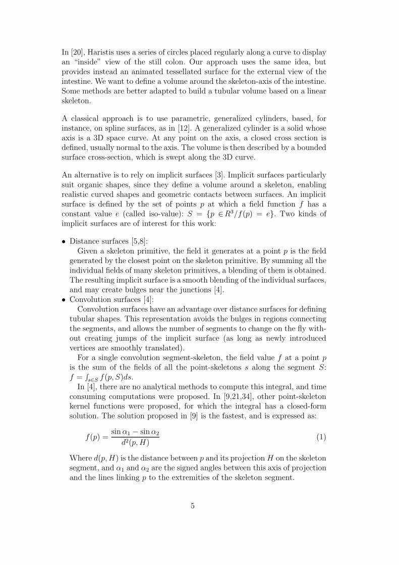
consuming computations were proposed. In [9,21,34], other point-skeletonkernel functions were proposed, for which the integral has a closed-formsolution. The solution proposed in [9] is the fastest, and is expressed as:
f(p) =sin α1 − sin α2
d2(p, H)(1)
Where d(p, H) is the distance between p and its projection H on the skeletonsegment, and α1 and α2 are the signed angles between this axis of projectionand the lines linking p to the extremities of the skeleton segment.
5
3 Mechanical Model
As shown in section 2, a dynamic spline seems to be a good approach tocompute the global dynamic motion of the intestine. This section details theway we use this model and explains how we extend it to handle the non-zerothickness of the intestine for collision processing.
3.1 Modeling
We define the intestine’s axis (skeleton) as a cubic Catmull-Rom [10] seg-mented spline. A 1D spline defines points P that are a linear combination ofn + 1 control points qk and basis functions bk:
P(s, t) =n∑
k=0
qk(t)bk(s) (2)
with t the time and s ∈ [0, 1] being the parametric abscissa along the entirecurve. The corresponding velocity can, therefore, be expressed simply as:
P(s, t) =n∑
k=0
qk(t)bk(s) (3)
This definition allows the user to control the shape of the spline by just mod-ifying the control points.
3.2 Lagrangian dynamic splines
To animate the spline, we use the Lagrangian formalism proposed by Remionet al. in [32]. This takes into account the continuity of the object and thusenables a continuous mass distribution along the curve. It allows externalactions and/or constraints to occur anywhere along the spline. We show herethat this formalism can be adapted to real-time simulations of a curve.
The Lagrangian mechanism is based on the equations:
∀i,∂ ∂K
∂qα
i
∂t+
∂K
∂qαi
= Qαi +
∂E
∂qαi
(4)
where qαi represent the degrees of freedom of the object, qα
i the velocities ofthese degrees of freedom, K the kinetic energy of the object, E the potential
6
energy (deformation energy and gravity) and Qαi the non-conservative gener-
alized forces (collisions forces). A description of equation (4) can be found in[32]. We detail, however, the left part to show an optimization that is impor-tant for real-time simulation purposes.
The expression of the velocity P of equation (3), depends only on the velocityof the control points (and not on their position). Given this, we obtain:
∀i,∂K
∂qαi
= 0 (5)
∀i,∂ ∂K
∂qα
i
∂t= m
n∑
k=0
1∫
0
bi(s)bk(s) ds
qαk (t) (6)
The left part of the Lagrangian equations (4) can be re-written as a matrixvector product of the mass matrix M and the acceleration vector A:
MA =
M 0 0
0 M 0
0 0 M
Ax
Ay
Az
with Aαi = qα
i where Aαi is an element of Aα and α ∈ {x, y, z}. The right part
of equations (4) combines the other energies, such as the gravity, deformationenergy, viscosity friction, and collision forces (details can be found in [32]). Itwill be noticed that such forces can be applied on any point of the spline, notonly on control points, thanks to the Lagrangian formalism.
3.3 Deformation Energy
To define the deformation energy E, which is aimed at structuring the model(see equation (4)), we combine two methods.
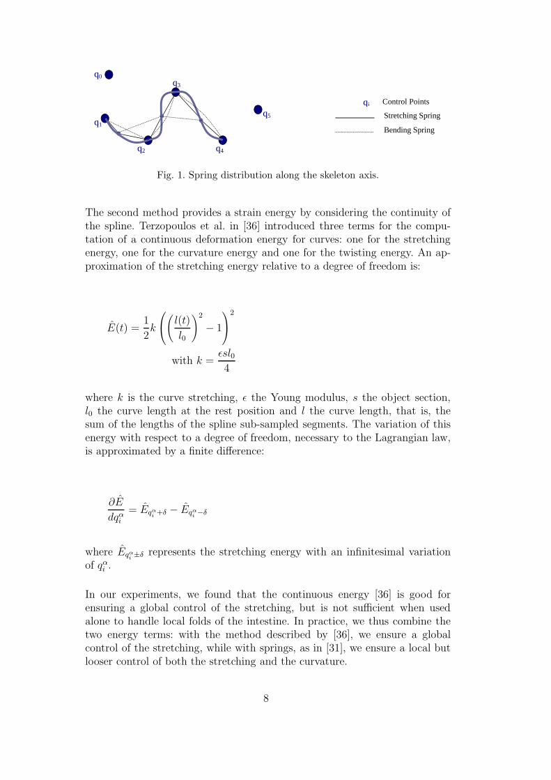
The first method is based on springs to induce an internal potential energy inthe system. We can simulate a strain energy by considering mechanical pointsof the spline that are consecutively linked. We are also able to simulate acurvature energy by joining a point to its immediate neighbors as presentedby Provot in [31] (see Figure 1). The deformation energy is expressed as E =∑N
i=11
2ki(li − l0
i)2, where N is the number of springs, k their stiffness, l theircurrent length and l0 their rest length.
7
q0 q3
q1
q2 q4
q5 Stretching Spring
Bending Spring
qi Control Points
Fig. 1. Spring distribution along the skeleton axis.
The second method provides a strain energy by considering the continuity ofthe spline. Terzopoulos et al. in [36] introduced three terms for the compu-tation of a continuous deformation energy for curves: one for the stretchingenergy, one for the curvature energy and one for the twisting energy. An ap-proximation of the stretching energy relative to a degree of freedom is:
E(t) =1
2k
(
l(t)
l0
)2
− 1
2
with k =εsl04
where k is the curve stretching, ε the Young modulus, s the object section,l0 the curve length at the rest position and l the curve length, that is, thesum of the lengths of the spline sub-sampled segments. The variation of thisenergy with respect to a degree of freedom, necessary to the Lagrangian law,is approximated by a finite difference:
∂E
dqαi
= Eqα
i+δ − Eqα
i−δ
where Eqα
i±δ represents the stretching energy with an infinitesimal variation
of qαi .
In our experiments, we found that the continuous energy [36] is good forensuring a global control of the stretching, but is not sufficient when usedalone to handle local folds of the intestine. In practice, we thus combine thetwo energy terms: with the method described by [36], we ensure a globalcontrol of the stretching, while with springs, as in [31], we ensure a local butlooser control of both the stretching and the curvature.
8
3.4 Real-time Simulation
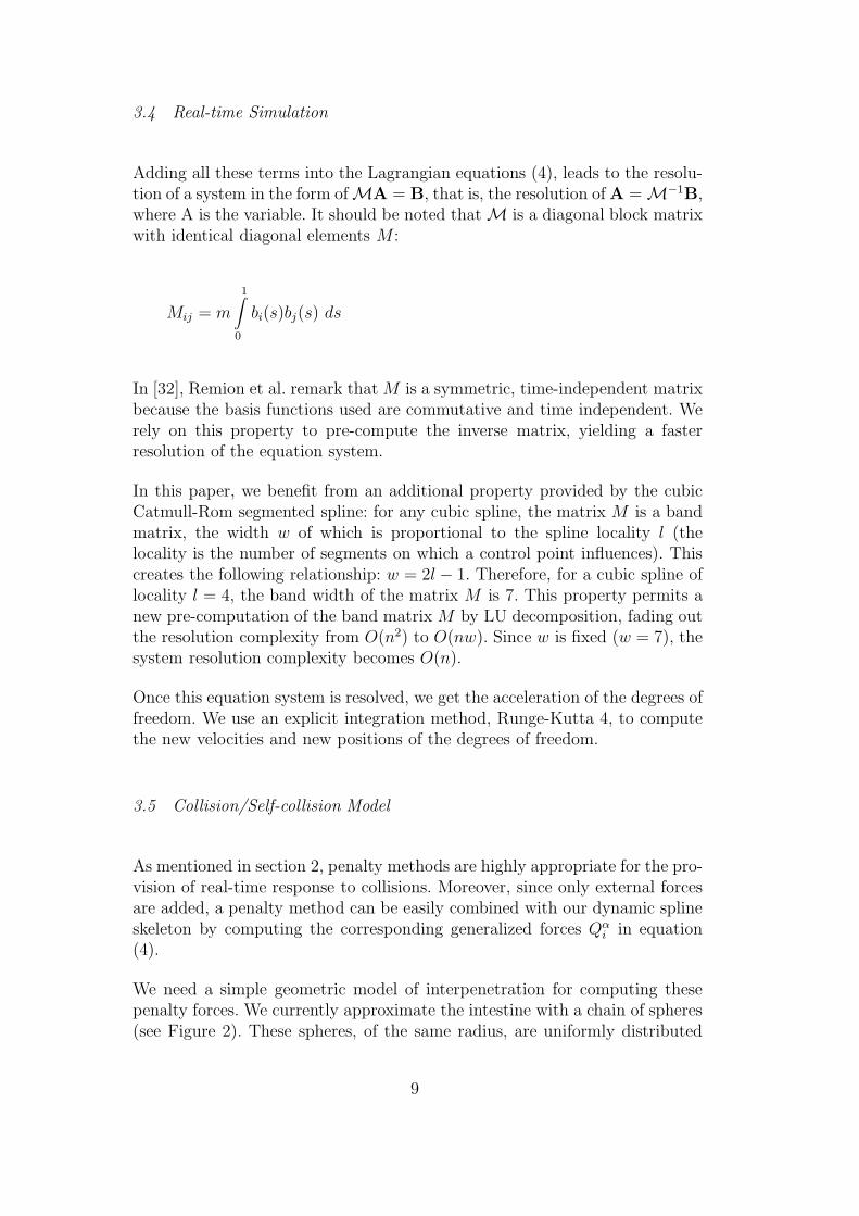
Adding all these terms into the Lagrangian equations (4), leads to the resolu-tion of a system in the form of MA = B, that is, the resolution of A = M−1B,where A is the variable. It should be noted that M is a diagonal block matrixwith identical diagonal elements M :
Mij = m
1∫
0
bi(s)bj(s) ds
In [32], Remion et al. remark that M is a symmetric, time-independent matrixbecause the basis functions used are commutative and time independent. Werely on this property to pre-compute the inverse matrix, yielding a fasterresolution of the equation system.
In this paper, we benefit from an additional property provided by the cubicCatmull-Rom segmented spline: for any cubic spline, the matrix M is a bandmatrix, the width w of which is proportional to the spline locality l (thelocality is the number of segments on which a control point influences). Thiscreates the following relationship: w = 2l − 1. Therefore, for a cubic spline oflocality l = 4, the band width of the matrix M is 7. This property permits anew pre-computation of the band matrix M by LU decomposition, fading outthe resolution complexity from O(n2) to O(nw). Since w is fixed (w = 7), thesystem resolution complexity becomes O(n).
Once this equation system is resolved, we get the acceleration of the degrees offreedom. We use an explicit integration method, Runge-Kutta 4, to computethe new velocities and new positions of the degrees of freedom.
3.5 Collision/Self-collision Model
As mentioned in section 2, penalty methods are highly appropriate for the pro-vision of real-time response to collisions. Moreover, since only external forcesare added, a penalty method can be easily combined with our dynamic splineskeleton by computing the corresponding generalized forces Qα
i in equation(4).
We need a simple geometric model of interpenetration for computing thesepenalty forces. We currently approximate the intestine with a chain of spheres(see Figure 2). These spheres, of the same radius, are uniformly distributed
9
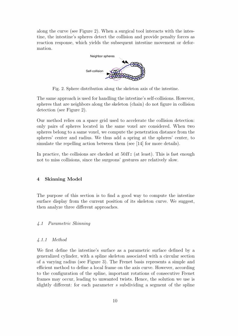
along the curve (see Figure 2). When a surgical tool interacts with the intes-tine, the intestine’s spheres detect the collision and provide penalty forces asreaction response, which yields the subsequent intestine movement or defor-mation.
Neighbor spheres
Self-collision
Fig. 2. Sphere distribution along the skeleton axis of the intestine.
The same approach is used for handling the intestine’s self-collisions. However,spheres that are neighbors along the skeleton (chain) do not figure in collisiondetection (see Figure 2).
Our method relies on a space grid used to accelerate the collision detection:only pairs of spheres located in the same voxel are considered. When twospheres belong to a same voxel, we compute the penetration distance from thespheres’ center and radius. We thus add a spring at the spheres’ center, tosimulate the repelling action between them (see [14] for more details).
In practice, the collisions are checked at 50Hz (at least). This is fast enoughnot to miss collisions, since the surgeons’ gestures are relatively slow.
4 Skinning Model
The purpose of this section is to find a good way to compute the intestinesurface display from the current position of its skeleton curve. We suggest,then analyze three different approaches.
4.1 Parametric Skinning
4.1.1 Method
We first define the intestine’s surface as a parametric surface defined by ageneralized cylinder, with a spline skeleton associated with a circular sectionof a varying radius (see Figure 3). The Frenet basis represents a simple andefficient method to define a local frame on the axis curve. However, accordingto the configuration of the spline, important rotations of consecutive Frenetframes may occur, leading to unwanted twists. Hence, the solution we use isslightly different: for each parameter s subdividing a segment of the spline
10
curve and ts the tangent vector of the curve at this point, we construct thenew coordinate frame (ts,ks,bs) based on the previous one (ts−δs,ks−δs,bs−δs)(δs being defined as the axis parameter step used for tessellation) such that:
bs = ts ∧ ks−δs
ks =bs ∧ ts
For example, the initial frame may be the Frenet frame, where for each othersegment, the frame (t0,k0,b0) is identical to the frame (t1,k1,b1) of theprevious segment. In practice, this method generates good results.
We then define a certain number of points in the plane perpendicular to thecurve, so that they discretize a circle where the curve point is the center andwhere the radius is obtained by R(s) = Rmin + cos2(πs)∆R, in order to get anapproximate shape of the intestine (see Figure 3). We use ∆R = Rmax−Rmin,and Rmin and Rmax respectively to represent the maximum and the minimumradii allowed, and s ∈ [0, 1] between two control points of the spline. Finally,we join the points between the circles to create facets. This representationallows a certain type of display of the intestine at interactive rates.
q i
q j
t s-1
t s
k s-1
b s-1
k s
b s
Fig. 3. Skinning of the intestine.
4.1.2 Results
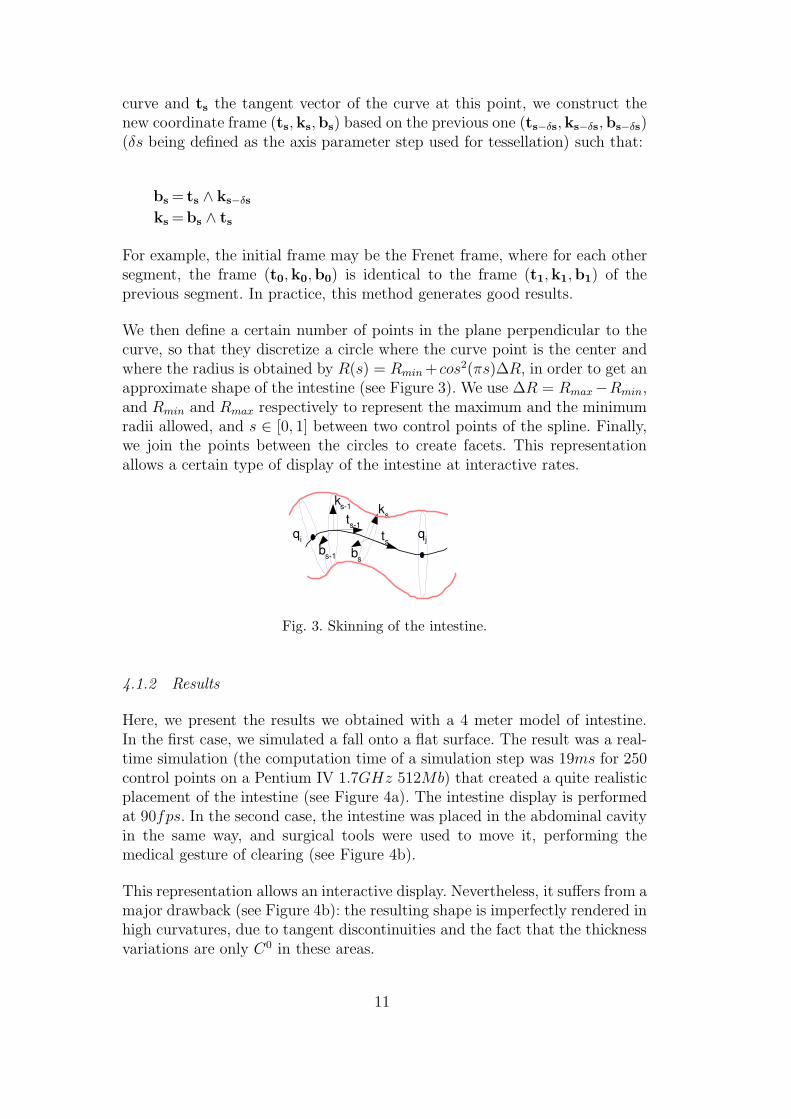
Here, we present the results we obtained with a 4 meter model of intestine.In the first case, we simulated a fall onto a flat surface. The result was a real-time simulation (the computation time of a simulation step was 19ms for 250control points on a Pentium IV 1.7GHz 512Mb) that created a quite realisticplacement of the intestine (see Figure 4a). The intestine display is performedat 90fps. In the second case, the intestine was placed in the abdominal cavityin the same way, and surgical tools were used to move it, performing themedical gesture of clearing (see Figure 4b).
This representation allows an interactive display. Nevertheless, it suffers from amajor drawback (see Figure 4b): the resulting shape is imperfectly rendered inhigh curvatures, due to tangent discontinuities and the fact that the thicknessvariations are only C0 in these areas.
11
(a) Placement. (b) In the cavity.
Fig. 4. Parametric intestine.
The remainder of this paper, therefore, presents two alternate methods basedon implicit surfaces for the display of the intestine.
4.2 Implicit Skinning using Point-Skeletons
4.2.1 Method
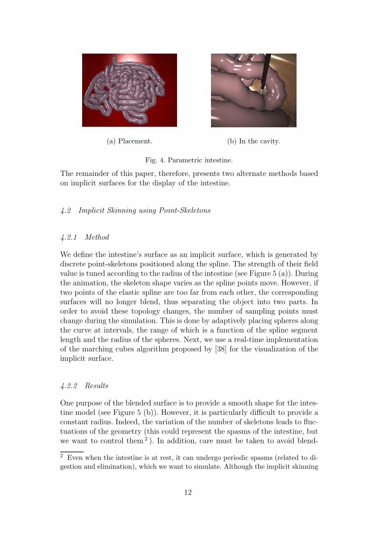
We define the intestine’s surface as an implicit surface, which is generated bydiscrete point-skeletons positioned along the spline. The strength of their fieldvalue is tuned according to the radius of the intestine (see Figure 5 (a)). Duringthe animation, the skeleton shape varies as the spline points move. However, iftwo points of the elastic spline are too far from each other, the correspondingsurfaces will no longer blend, thus separating the object into two parts. Inorder to avoid these topology changes, the number of sampling points mustchange during the simulation. This is done by adaptively placing spheres alongthe curve at intervals, the range of which is a function of the spline segmentlength and the radius of the spheres. Next, we use a real-time implementationof the marching cubes algorithm proposed by [38] for the visualization of theimplicit surface.
4.2.2 Results
One purpose of the blended surface is to provide a smooth shape for the intes-tine model (see Figure 5 (b)). However, it is particularly difficult to provide aconstant radius. Indeed, the variation of the number of skeletons leads to fluc-tuations of the geometry (this could represent the spasms of the intestine, butwe want to control them 2 ). In addition, care must be taken to avoid blend-
2 Even when the intestine is at rest, it can undergo periodic spasms (related to di-gestion and elimination), which we want to simulate. Although the implicit skinning
12
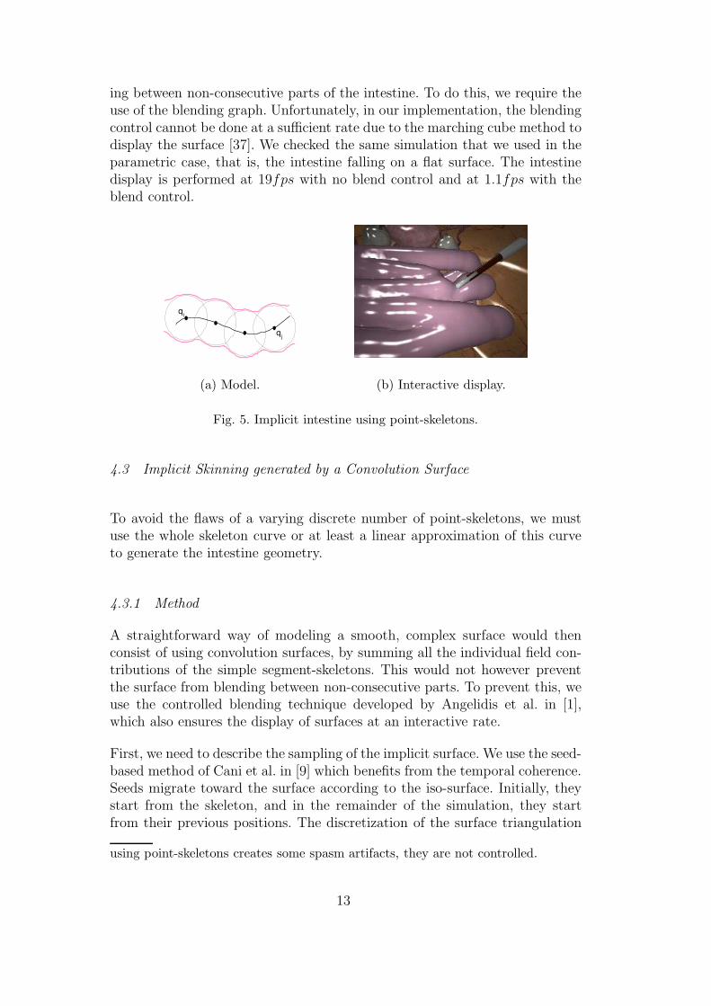
ing between non-consecutive parts of the intestine. To do this, we require theuse of the blending graph. Unfortunately, in our implementation, the blendingcontrol cannot be done at a sufficient rate due to the marching cube method todisplay the surface [37]. We checked the same simulation that we used in theparametric case, that is, the intestine falling on a flat surface. The intestinedisplay is performed at 19fps with no blend control and at 1.1fps with theblend control.
q i
q j
(a) Model. (b) Interactive display.
Fig. 5. Implicit intestine using point-skeletons.
4.3 Implicit Skinning generated by a Convolution Surface
To avoid the flaws of a varying discrete number of point-skeletons, we mustuse the whole skeleton curve or at least a linear approximation of this curveto generate the intestine geometry.
4.3.1 Method
A straightforward way of modeling a smooth, complex surface would thenconsist of using convolution surfaces, by summing all the individual field con-tributions of the simple segment-skeletons. This would not however preventthe surface from blending between non-consecutive parts. To prevent this, weuse the controlled blending technique developed by Angelidis et al. in [1],which also ensures the display of surfaces at an interactive rate.
First, we need to describe the sampling of the implicit surface. We use the seed-based method of Cani et al. in [9] which benefits from the temporal coherence.Seeds migrate toward the surface according to the iso-surface. Initially, theystart from the skeleton, and in the remainder of the simulation, they startfrom their previous positions. The discretization of the surface triangulation
using point-skeletons creates some spasm artifacts, they are not controlled.
13
is adaptive, allowing the surface to be rendered at different levels of detail. Toproduce this adaptive sampling, a rough polygonization is initially attached toa few sampling points, and then refined recursively by a uniform subdivisionuntil a certain criterion is satisfied.
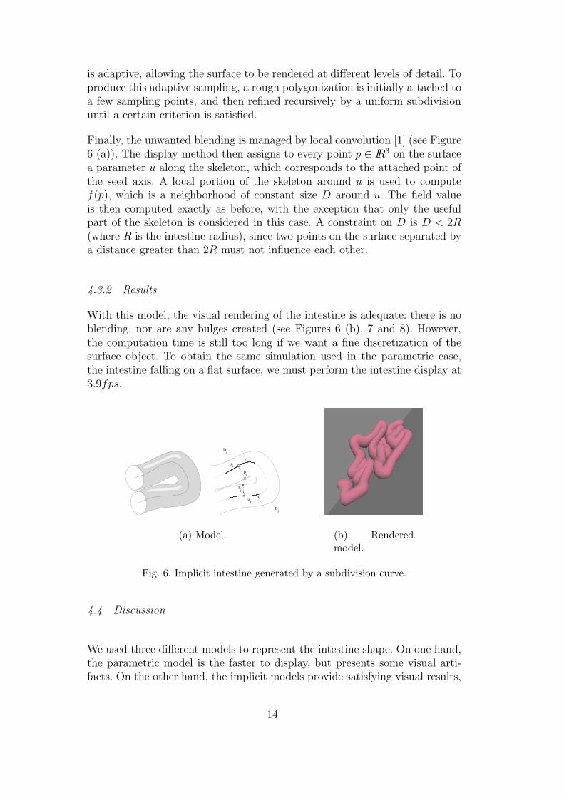
Finally, the unwanted blending is managed by local convolution [1] (see Figure6 (a)). The display method then assigns to every point p ∈ IR3 on the surfacea parameter u along the skeleton, which corresponds to the attached point ofthe seed axis. A local portion of the skeleton around u is used to computef(p), which is a neighborhood of constant size D around u. The field valueis then computed exactly as before, with the exception that only the usefulpart of the skeleton is considered in this case. A constraint on D is D < 2R(where R is the intestine radius), since two points on the surface separated bya distance greater than 2R must not influence each other.
4.3.2 Results
With this model, the visual rendering of the intestine is adequate: there is noblending, nor are any bulges created (see Figures 6 (b), 7 and 8). However,the computation time is still too long if we want a fine discretization of thesurface object. To obtain the same simulation used in the parametric case,the intestine falling on a flat surface, we must perform the intestine display at3.9fps.
j
i
j
i
j
i
D
u
u
P
P
D
(a) Model. (b) Renderedmodel.
Fig. 6. Implicit intestine generated by a subdivision curve.
4.4 Discussion
We used three different models to represent the intestine shape. On one hand,the parametric model is the faster to display, but presents some visual arti-facts. On the other hand, the implicit models provide satisfying visual results,
14
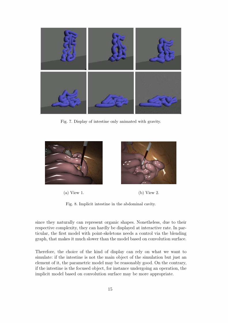
Fig. 7. Display of intestine only animated with gravity.
(a) View 1. (b) View 2.
Fig. 8. Implicit intestine in the abdominal cavity.
since they naturally can represent organic shapes. Nonetheless, due to theirrespective complexity, they can hardly be displayed at interactive rate. In par-ticular, the first model with point-skeletons needs a control via the blendinggraph, that makes it much slower than the model based on convolution surface.
Therefore, the choice of the kind of display can rely on what we want tosimulate: if the intestine is not the main object of the simulation but just anelement of it, the parametric model may be reasonably good. On the contrary,if the intestine is the focused object, for instance undergoing an operation, theimplicit model based on convolution surface may be more appropriate.
15
5 Conclusion
In this paper, we presented a method to simulate in interactive time the intes-tine in the abdominal cavity, for surgical training purposes. The intestine is avery deformable object, and during a surgery, it may undergo large displace-ments and multiple interactions. This paper focuses on two contributions.
We presented first a method based on a skeleton defined by a spline to computethe mechanical motion of the intestine, from the Lagrange formalism, whichwe optimized to obtain a fast simulation. We then used collision spheres forfast collision detection and response.
Next, we compared different methods of skinning this model. First, we createda skinning using parametric surfaces around the skeleton, but this producedrough visual effects associated with the curvatures of the intestine, however itwas obtained in real-time. We then compared two implicit solutions that offerquite good results as far as visual effects are concerned, providing good shapeand deformations of the intestine 3 , but requiring more computation time.
Finally, we obtained a reasonable basic framework to allow intestine surgerysimulations, by showing, in the context of a surgical simulator, that skinning byimplicit surfaces can provide an attractive model when the surgical procedurefocuses on the intestine; otherwise, the skinning by parametric surfaces methodmay be more appropriate. Some videos showing our results can be found athttp://www-imagis.imag.fr/Publications/2004/FLAMCFC04/ .
Nevertheless, several improvements can be envisaged. For example, it maybe desirable to let the simulation switch between the two methods, provid-ing better resolution for up close work and faster rendering for more generaloverviews. The challenge in doing this will be to create a simulation that letsus display the area of focus using the implicit technique, while simultaneouslydisplaying the non-focused areas using the parametric technique; and, whichlets us switch between the two display techniques, as the area of focus changes,seamlessly.
Moreover, only the discretization of the surface triangulation is currently adap-tive. Future work might focus on dynamically adapting the discretization ofthe skeleton according to the curvature as it varies over time. The introduc-tion of adaptive methods would be especially beneficial, since this would allow
3 We restore the skeleton deformation as much as possible. When the skeletoncurves itself, so does the surface, therefore, the surface is deformed. Nevertheless,the radial deformations of the intestine are not taken into account since they areindependent of the skeleton.
16
the animation to be displayed at different levels of detail, thereby obtaininginteractive rates on any workstation.
Self-collisions could also be detected more precisely by taking into account thecylindrical aspect of the intestine or the information provided by the implicitsurface. It may also be possible to add the contact surfaces presented byAngelidis et al. in [1] so that the contact is better handled.
We should, nevertheless, obtain real-world data as input for our model. Thiswill allow us to prove our model against real-life examples.
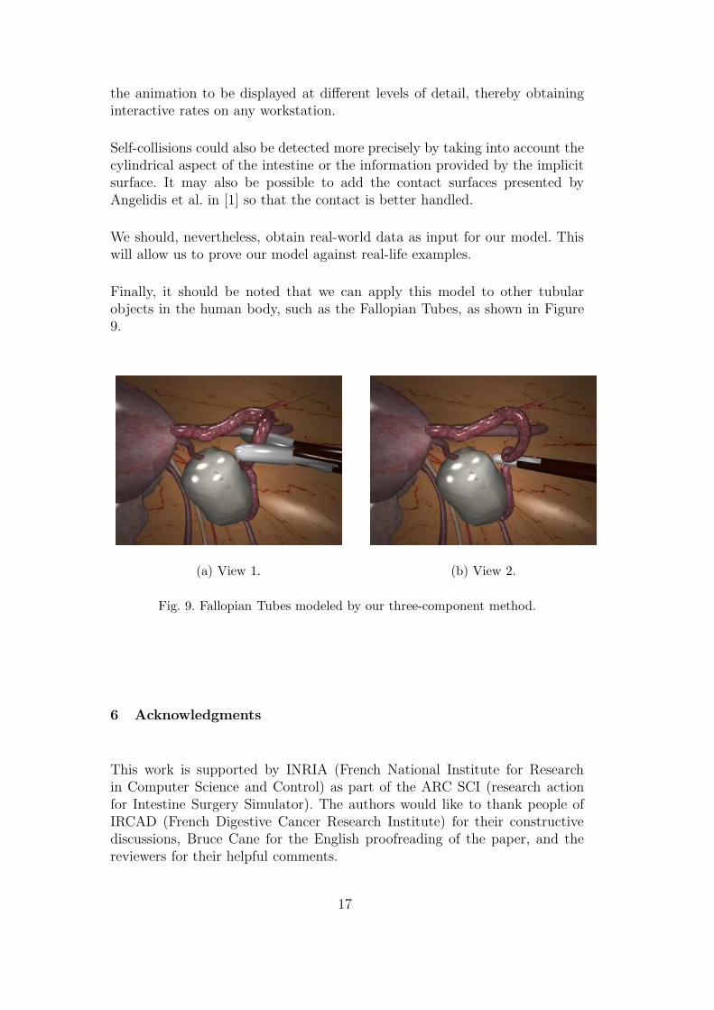
Finally, it should be noted that we can apply this model to other tubularobjects in the human body, such as the Fallopian Tubes, as shown in Figure9.
(a) View 1. (b) View 2.
Fig. 9. Fallopian Tubes modeled by our three-component method.
6 Acknowledgments
This work is supported by INRIA (French National Institute for Researchin Computer Science and Control) as part of the ARC SCI (research actionfor Intestine Surgery Simulator). The authors would like to thank people ofIRCAD (French Digestive Cancer Research Institute) for their constructivediscussions, Bruce Cane for the English proofreading of the paper, and thereviewers for their helpful comments.
17
References
[1] A. Angelidis, P. Jepp, and M.-P. Cani. Implicit modeling with skeleton curves:Controlled blending in contact situations. Shape Modeling International, 2002.
[2] D. Baraff. Analytical methods for dynamic simulation of non-penetrating rigidbodies. ACM SIGGRAPH Computer Graphics, v.23 n.3, p.223-232, July 1989.
[3] J. Bloomenthal, C. Bajaj, J. Blinn, M.-P. Cani, A. Rockwood, B. Wyvill, andG. Wyvill. Introduction to Implicit Surfaces. Morgan Kaufmann, July 1997.
[4] J. Bloomenthal and K. Shoemake. Convolution surfaces. Computer Graphics,25(2):251–256, July 1991.
[5] J. Bloomenthal and B. Wyvill. Interactive techniques for implicit modeling.Computer Graphics, 24(2):109–116, March 1990.
[6] M. Bro-Nielsen and S. Cotin. Real-time volumetric deformable models forsurgery simulation using finite elements and condensation. Computer GraphicsForum 15(3):57–66, 1996.
[7] H. Cakmak and U. Kuhnapfel. Animation and simulation techniques for vr-training systems in endoscopic surgery. Eurographics Workshop on Animationand Simulation, pp. 173-185, 2000.
[8] M.-P. Cani and M. Desbrun. Animation of deformable models using implicitsurfaces. IEEE Transactions on Visualization and Computer Graphics, 1(3),March 1997. Published under the name M.-P. Cani-Gascuel.
[9] M.-P. Cani and S. Hornus. Subdivision curve primitives: a new solution forinteractive implicit modeling. In Shape Modelling International, May 2001.
[10] R. Catmull and R. Rom. A class of local interpolating splines. Computer AidedGeometric Design, Academic Press, 1974.
[11] Personal communication of Luc Soler. Virtual-surg manager at IRCAD.http://www.virtual-surg.com/English/index en.htm, 2002.
[12] S. Coquillart. Computing offsets of b-spline curves. Computer Aided Design,Vol. 19, No. 6, p305-309, 1987.
[13] S. Cotin, H. Delingette, and N. Ayache. Real time volumetric deformable modelsfor surgery simulation. Visualization in Biomedical Computing, volume 1131.Springer Verlag, 1996.
[14] J. Davanne, P. Meseure, and C. Chaillou. Stable haptic interaction in a dynamicvirtual environment. IEEE/RSJ International Conference on Intelligent Robotsand Systems, 2002.
[15] G. Debunne, M. Desbrun, M.-P. Cani, and A.H. Barr. Dynamic real-timedeformations using space and time adaptive sampling. Computer Graphics,August 2001.
18
[16] H. Delingette, G. Subsol, S. Cotin, and J. Pignon. A craniofacial surgerysimulation testbed. Visualization in Biomedical Computing, pp 607–618, 1994.
[17] S. Fisher and M. Lin. Fast penetration depth estimation for elastic bodies usingdeformed distance fields. IROS, 2001.
[18] L. France, A. Angelidis, P. Meseure, M.-P. Cani, J. Lenoir, F. Faure, andC. Chaillou. Implicit representations of the human intestines for surgerysimulations. Conference on Modelling and Simulation for Computer-aidedMedicine and Surgery, 2002.
[19] L. France, J. Lenoir, P. Meseure, and C. Chaillou. Simulation of a minimallyinvasive surgery of intestines. Virtual Reality International Conference, pp 21-27, 2002.
[20] A. Haristis, D. Gillies, and C. Williams. Realistic generation and real timeanimation of images of the human colon. Computer Graphics Forum 1992, vol.II, 3:367–379, 1992.
[21] S. Hornus, A. Angelidis, and M.-P. Cani. Implicit modelling using subdivision-curves. The Visual Computer, 2002.
[22] P.M. Hubbard. Approximating polyhedra with spheres for time-critical collisiondetection. ACM Transactions on Graphics, 15(3):179–209, July 1996.
[23] D.L. James and D.K. Pai. ARTDEFO: Accurate real time deformable objects.Proc. ACM SIGGRAPH, pp 65–72, 1999.
[24] J.T. Klosowski, M. Held, J.S.B. Mitchell, H. Sowizral, and K. Zikan. Efficientcollision detection using bounding volume of k-dop’s. TVCG(4), pp 21–36,1998.
[25] D. Lamy and C. Chaillou. Design, implementation and evaluation of anhaptic interface for surgical gesture training. Virtual Reality and PrototypingConference, 7mes journes du Groupe de Travail Ralit Virtuelle, Laval, pages107–116, June 1999.
[26] P. Meseure and C. Chaillou. Deformable body simulation with adaptivesubdivision and cuttings. Proc. WSCG Conference, pp 361–370, 1997.
[27] V. Milenkovic and H. Schmidl. Optimization-based animation. SIGGRAPH’01Conference Proceedings, Computer Graphics annual conference series, LosAngeles, pages 37–46, August 2001.
[28] B. Mirtich and J. Canny. Impulse-based dynamic simulation. Proceedings ofWorkshop on Algorithmic Foundations of Robotics, February 1994.
[29] M. Moore and J. Wilhelms. Collision detection and response for computeranimation. SIGGRAPH’88 Conference Proceedings, Computer Graphics,Atlanta, 22(4):289–298, August 1988.
[30] G. Picinbono, H. Delingette, and N. Ayache. Non-linear and anisotropic elasticsoft tissue models for medical simulation. IEEE International ConferenceRobotics and Automation, May 2001.
19
[31] X. Provot. Deformation constraints in a mass-spring model to describe rigidcloth behavior. Graphics Interface, 1995.
[32] Y. Remion, J.M. Nourrit, and D. Gillard. Dynamic animation of spline likeobjects. WSCG, 1999.
[33] Surgical Science. http://surgical-science.com/.
[34] A. Sherstyuk. Kernel functions in convolution surfaces: a comparative analysis.The Visual Computer, 15(4), 1999.
[35] Simbionix. http://www.simbionix.com/.
[36] D. Terzopoulos, J. Platt, A. Barr, and K. Fleischer. Elastically deformablemodels. Computer Graphics, July 1987.
[37] F. Triquet, L. Grisoni, P. Meseure, and C. Chaillou. Realtime visualization ofimplicit objects with contact control. International Conference on ComputerGraphics and Interactive Techniques in Australia and South East Asia, February2003.
[38] F. Triquet, P. Meseure, and C. Chaillou. Fast polygonization of implicit surfaces.WSCG (2):283–290, February 2001.
[39] G. van den Bergen. Efficient collision detection of complex deformable modelsusing AABB trees. Journal of Graphics Tools, 2(4):1–13, 1997.
[40] Xitact. http://www.xitact.com/.
20