a hybrid static active video surveillance system
TRANSCRIPT
PLEASE SCROLL DOWN FOR ARTICLE
This article was downloaded by: [Gasteratos, Antonios]On: 9 March 2011Access details: Access Details: [subscription number 934624792]Publisher Taylor & FrancisInforma Ltd Registered in England and Wales Registered Number: 1072954 Registered office: Mortimer House, 37-41 Mortimer Street, London W1T 3JH, UK
International Journal of OptomechatronicsPublication details, including instructions for authors and subscription information:http://www.informaworld.com/smpp/title~content=t741771165
A Hybrid Static/Active Video Surveillance SystemAlexandros Iosifidisa; Spyridon G. Mouroutsosa; Antonios Gasteratosb
a Electrical and Computer Engineering Department, Democritus University of Thrace, Xanthi, Greece b
Production and Management Engineering Department, Democritus University of Thrace, Xanthi,Greece
Online publication date: 09 March 2011
To cite this Article Iosifidis, Alexandros , Mouroutsos, Spyridon G. and Gasteratos, Antonios(2011) 'A Hybrid Static/ActiveVideo Surveillance System', International Journal of Optomechatronics, 5: 1, 80 — 95To link to this Article: DOI: 10.1080/15599612.2011.553252URL: http://dx.doi.org/10.1080/15599612.2011.553252
Full terms and conditions of use: http://www.informaworld.com/terms-and-conditions-of-access.pdf
This article may be used for research, teaching and private study purposes. Any substantial orsystematic reproduction, re-distribution, re-selling, loan or sub-licensing, systematic supply ordistribution in any form to anyone is expressly forbidden.
The publisher does not give any warranty express or implied or make any representation that the contentswill be complete or accurate or up to date. The accuracy of any instructions, formulae and drug dosesshould be independently verified with primary sources. The publisher shall not be liable for any loss,actions, claims, proceedings, demand or costs or damages whatsoever or howsoever caused arising directlyor indirectly in connection with or arising out of the use of this material.
A HYBRID STATIC/ACTIVE VIDEO SURVEILLANCESYSTEM
Alexandros Iosifidis,1 Spyridon G. Mouroutsos,1 andAntonios Gasteratos21Electrical and Computer Engineering Department, Democritus University ofThrace, Xanthi, Greece2Production and Management Engineering Department, DemocritusUniversity of Thrace, Xanthi, Greece
In this article, we present an effective real–time video surveillance system for real-life out-
door surveillance scenarios. The system integrates two different camera’s behaviors: a static
and a moving one. Static camera subsystem operates multiple object tracking and classi-
fication. Abnormal behaviors are detected using information about objects’ routes. In case
of a probable collision scenario, the operation of the moving camera subsystem initiates and
a PID controller gives instructions at a pan/tilt mechanism in order to rotate the camera and
record the activity. The approaches employed address properly the challenges that might
arise in a typical outdoor scene, such as local and global lighting changes, variations in
objects’ appearance and occlusions.
Keywords: background subtraction, hybrid camera system, object tracking, video surveillance
1. INTRODUCTION
The rapid invasion of information and communication technology in oureveryday life elevated the role of automatic video surveillance due to its increasedimportance in safety and security (Hu et al. 2004; Moeslund et al. 2006). Traditionalsystems need human operators to understand the activities of objects of interest(humans, vehicles, etc.) and take decisions. On the other hand, automatic systemsare capable of detecting objects of interest, classify and track them from one frameto another. The expansion of automatic surveillance systems with the capability ofdetecting and recognizing abnormal behaviors can lead to useful autonomous sys-tems. This can be achieved by describing atypical or suspect actions with pre-learnedpatterns. Once the system detects one of them several predetermined actions can beapplied without human’s interruption. In indoor tracking scenarios, the scene is nor-mally constrained and objects’ appearance is clear due to the small camera-objectdistance. On the other hand, in outdoor tracking scenarios the scene is unconstrainedand objects appear in small sizes. This makes the later procedure more difficult andunreliable.
Address correspondence to Antonios Gasteratos, Production and Management Engineering
Department, Democritus University of Thrace, Xanthi 671 00, Greece. E-mail: [email protected]
International Journal of Optomechatronics, 5: 80–95, 2011
Copyright # Taylor & Francis Group, LLC
ISSN: 1559-9612 print=1559-9620 online
DOI: 10.1080/15599612.2011.553252
80
Downloaded By: [Gasteratos, Antonios] At: 12:09 9 March 2011
Another categorization of systems is due to the capability of the camera tomove. Most systems premise static cameras. On the other hand, many researchershave proposed several methods to track objects of interest with cameras capableto move, by means of servomechanisms, on two rotational (pan=tilt cameras) orthree degrees of freedom (combination of pan=tilt and a prismatic joint). The inte-gration of those two functionalities can lead to a hybrid system that is capable todetect, track and follow objects of interest in a wide area (Gasteratos 2008; Kuhnlenzand Buss 2008). This capability is very useful in security applications, where e.g., theentrance in a depository is the area of main interest.
Systems described in literature can be categorized in single – and multi-camerasurveillance systems. Most single-camera systems utilize static cameras (Kim andHwang 2002; Georis et al. 2007; Fonseca et al. 2008), which exhibit the advantageof a stationary background. An effective segmentation technique is capable toextract objects of interest (Stauffer and Grimson 1999; Li et al. 2003; Mahadevanand Vasconcelos 2008; Luque et al. 2008). However, an open problem with fore-ground regions is that they often include shadowed pixels. Shadow elimination isan important background treatment technique (Horprasert et al. 1999; Leone et al.2006). After the extraction of foreground regions a tracking algorithm performsinter-frame correspondences in order to keep the ID of every object of interest.An effective algorithm has to be able to handle changes in object’s appearances, par-tial and=or complete occlusions, etc. (Li et al. 2008; Francois 2004; Lei and Xu2006). Systems designed for moving cameras can be categorized in pan=tilt camerasystems and freely moving camera systems. In pan=tilt camera systems the conceptof a relatively static background model is valid. The main approach is to shift thebackground information in regard with the camera rotation (Micheloni and Foresti2006; Lalonde et al. 2007). In freely moving camera systems, the most popularmethod models the appearance of objects in the first frame and future appearancesare obtained using Bayesian filters via sampling in every frame (Xue et al. 2008;Maggio et al. 2007). Systems that integrate the functionalities of static and moving
NOMENCLATURE
BCKðx; yÞtC color background model’s value
in location (x, y) at time instance t
BCKðx; yÞtC texture background model’s value
in location (x, y) at time instance t
dI(x, y)t first spatial derivative of scene’s
luminance value in location (x, y)
at time instance t
D Bhattacharyya distnace
(histogram similarity metric)
I(x, y)t scene’s color value in location
(x, y) at time instance t
sm ROI motion factor
aC chromatic background model’s
absorbent factor
aD texture background model’s
absorbent factor
dBr(x, y)t brightness distortion value of
pixel in location (x, y) at time
instance t
dCr(x, y)t chromatic distortion value of
pixel in location (x, y) at time
instance t
ha angle of non-rigid object parts
(object rigidness metric)
r2cx
directional variance of ROI
centroid in horizontal axis
r2cy
directional variance of ROI
centroid in perpendicular axis
r2ux
velocity variance of ROI centroid
in horizontal axis
r2cy
velocity variance of ROI centroid
in perpendicular axis
HYBRID STATIC/ACTIVE VIDEO SURVEILLANCE SYSTEM 81
Downloaded By: [Gasteratos, Antonios] At: 12:09 9 March 2011
cameras have also been proposed. In (Kang et al. 2004; Bashir and Porikli 2007;Bellotto et al. 2009; Hoedl et al. 2008) a static camera performs multiple object track-ing, while one PTZ camera tracks individual subjects. Multi-camera systems oftenconsist of a number of static cameras (Jiao et al. 2004; Remagnino et al. 2004; Wuet al. 2003). The spatial relationship between regions belonging in moving objectsin every camera is exploited to determine the relative to the scene position of everyobject of interest. Systems that use combined camera configurations (Quershi andTerzopoulos 2005; Chang and Wang 2004) create a 3-D reconstruction of the sceneand perform multiple object tracking using calibrated static cameras, while PTZcameras track individual subjects for a time period. Detection of abnormal behaviorsis a very interesting and active field of cognitive research. Several approaches havebeen proposed by researchers depending on the scenario and the application field.
In this article, we present a system that integrates the functionality of astatic-camera system and a moving-camera that is geared towards outdoor scenarios.In the first case the background is modeled with a fast and effective technique.Because of the wide variety of applications due to relative angle between camera’soptical axis and scene’s plane of interest we have implemented two tracking mod-els—one that can handle partial (Partial-Occlusion Tracker—POT) and one thatcan handle total occlusion levels (Total-Occlusion Tracker—TOT). We define thatan occlusion level that exceeds the 25% of an objects area as a high occlusion level.In POT objects of interest are tracked using Bayesian filters. Single objects aretracked using high-order Kalman filters while directed Particle filters treat themerged objects. In TOT high-order Kalman filters predict the state of single objects,while they estimate the appearance of merged objects. Objects are classified using aheuristic method. In the second case, the initialization is performed automaticallywith the appearance of an ‘‘object of special interest.’’ This object is tracked andrecorded. Its position on the image plane is used by a PID controller in order tomove the pan=tilt mechanism, on which the camera is mounted. The experimentalresult shows that the proposed system is accurate and fast enough to be utilized inreal-life cases.
The proposed system can be utilized in an autonomous surveillance system.Multiple object detection and tracking can be used to detect abnormal behaviors.The appearance of such an event can put into action the moving camera subsystemin order to start tracking and recording. The proposed approach can also be embed-ded in a multi-camera surveillance network. Such networks use a setup of several sta-tic calibrated cameras and pan=tilt uncalibrated cameras (Chang and Wang 2004).The main approach is to use static cameras to generate a 3-D reconstruction ofthe scene, via triangulation, while pan=tilt cameras track and follow individual sub-jects of the scene. Automatic pan=tilt camera calibration (Wren et al. 2005; Davisand Chen 2003) can be utilized to replace static cameras with hybrid cameras, suchas the proposed one. Thus the number of cameras capable to track and follow indi-vidual subjects of the scene can vary, depending on the number of subjects appearingin the scene.
The rest of the article is organized as follows: in Section 2 we describe the func-tionality of our system; details about the procedures of every subsystem are pre-sented and discussed; in Section 3, we present some quantitative and functionalresults and, finally, concluding remarks are given in Section 4.
82 A. IOSIFIDIS ET AL.
Downloaded By: [Gasteratos, Antonios] At: 12:09 9 March 2011
2. SYSTEM DESCRIPTION
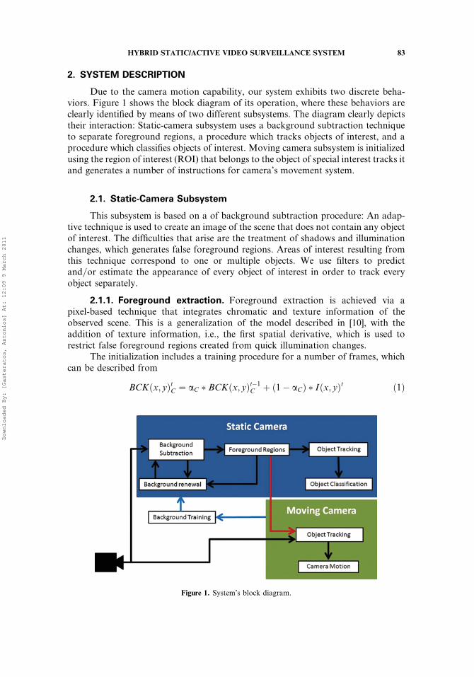
Due to the camera motion capability, our system exhibits two discrete beha-viors. Figure 1 shows the block diagram of its operation, where these behaviors areclearly identified by means of two different subsystems. The diagram clearly depictstheir interaction: Static-camera subsystem uses a background subtraction techniqueto separate foreground regions, a procedure which tracks objects of interest, and aprocedure which classifies objects of interest. Moving camera subsystem is initializedusing the region of interest (ROI) that belongs to the object of special interest tracks itand generates a number of instructions for camera’s movement system.
2.1. Static-Camera Subsystem
This subsystem is based on a of background subtraction procedure: An adap-tive technique is used to create an image of the scene that does not contain any objectof interest. The difficulties that arise are the treatment of shadows and illuminationchanges, which generates false foreground regions. Areas of interest resulting fromthis technique correspond to one or multiple objects. We use filters to predictand=or estimate the appearance of every object of interest in order to track everyobject separately.
2.1.1. Foreground extraction. Foreground extraction is achieved via apixel-based technique that integrates chromatic and texture information of theobserved scene. This is a generalization of the model described in [10], with theaddition of texture information, i.e., the first spatial derivative, which is used torestrict false foreground regions created from quick illumination changes.
The initialization includes a training procedure for a number of frames, whichcan be described from
BCKðx; yÞtC ¼ aC � BCKðx; yÞt�1C þ ð1� aCÞ � Iðx; yÞt ð1Þ
Figure 1. System’s block diagram.
HYBRID STATIC/ACTIVE VIDEO SURVEILLANCE SYSTEM 83
Downloaded By: [Gasteratos, Antonios] At: 12:09 9 March 2011
and
BCKðx; yÞtD ¼ aD � BCKðx; yÞt�1D þ ð1� aDÞ � dIðx; yÞt; ð2Þ
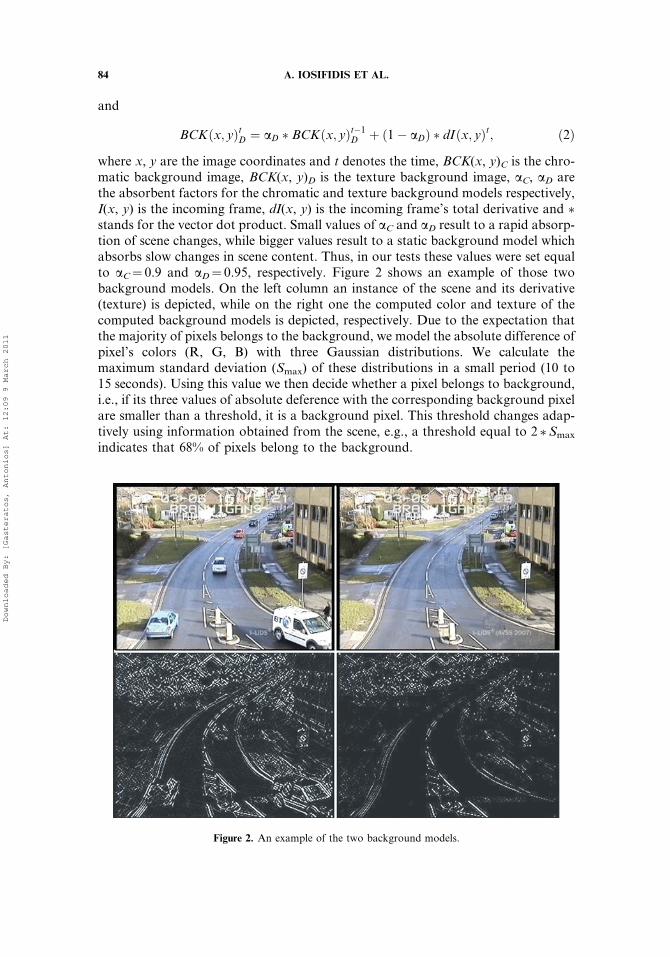
where x, y are the image coordinates and t denotes the time, BCK(x, y)C is the chro-matic background image, BCK(x, y)D is the texture background image, aC, aD arethe absorbent factors for the chromatic and texture background models respectively,I(x, y) is the incoming frame, dI(x, y) is the incoming frame’s total derivative and *stands for the vector dot product. Small values of aC and aD result to a rapid absorp-tion of scene changes, while bigger values result to a static background model whichabsorbs slow changes in scene content. Thus, in our tests these values were set equalto aC¼ 0.9 and aD¼ 0.95, respectively. Figure 2 shows an example of those twobackground models. On the left column an instance of the scene and its derivative(texture) is depicted, while on the right one the computed color and texture of thecomputed background models is depicted, respectively. Due to the expectation thatthe majority of pixels belongs to the background, we model the absolute difference ofpixel’s colors (R, G, B) with three Gaussian distributions. We calculate themaximum standard deviation (Smax) of these distributions in a small period (10 to15 seconds). Using this value we then decide whether a pixel belongs to background,i.e., if its three values of absolute deference with the corresponding background pixelare smaller than a threshold, it is a background pixel. This threshold changes adap-tively using information obtained from the scene, e.g., a threshold equal to 2 *Smax
indicates that 68% of pixels belong to the background.
Figure 2. An example of the two background models.
84 A. IOSIFIDIS ET AL.
Downloaded By: [Gasteratos, Antonios] At: 12:09 9 March 2011
For those pixels that do not belong to the background we calculate two factors:its chromatic and its brightness distortion [10], respectively:
dBrðx; yÞ ¼ kBCKðx; yÞk � I 0ðx; yÞ ¼ kBCKðx; yÞk � Iðx; yÞ � BCKðx; yÞkBCKðx; yÞk ð3Þ
and
dCrðx; yÞ ¼ cos�1 Iðx; yÞ � BCKðx; yÞkIðx; yÞkkBCKðx; yÞk
� �; ð4Þ
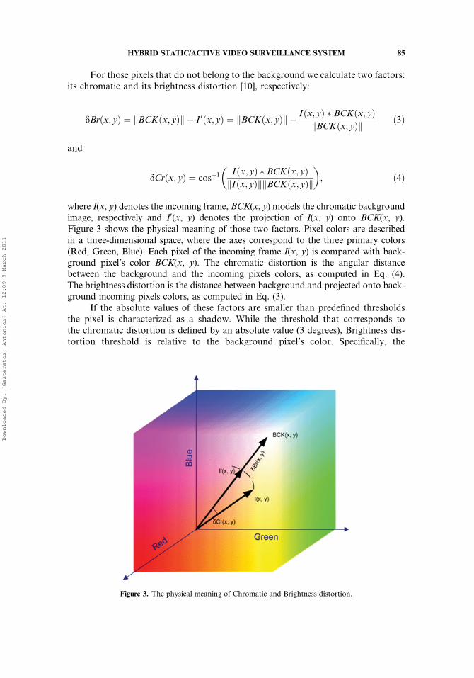
where I(x, y) denotes the incoming frame, BCK(x, y) models the chromatic backgroundimage, respectively and I0(x, y) denotes the projection of I(x, y) onto BCK(x, y).Figure 3 shows the physical meaning of those two factors. Pixel colors are describedin a three-dimensional space, where the axes correspond to the three primary colors(Red, Green, Blue). Each pixel of the incoming frame I(x, y) is compared with back-ground pixel’s color BCK(x, y). The chromatic distortion is the angular distancebetween the background and the incoming pixels colors, as computed in Eq. (4).The brightness distortion is the distance between background and projected onto back-ground incoming pixels colors, as computed in Eq. (3).
If the absolute values of these factors are smaller than predefined thresholdsthe pixel is characterized as a shadow. While the threshold that corresponds tothe chromatic distortion is defined by an absolute value (3 degrees), Brightness dis-tortion threshold is relative to the background pixel’s color. Specifically, the
Figure 3. The physical meaning of Chromatic and Brightness distortion.
HYBRID STATIC/ACTIVE VIDEO SURVEILLANCE SYSTEM 85
Downloaded By: [Gasteratos, Antonios] At: 12:09 9 March 2011
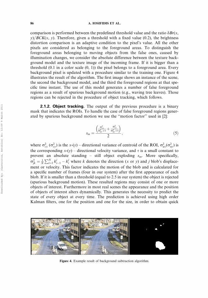
comparison is performed between the predefined threshold value and the ratio dBr(x,y)=BCK(x, y). Therefore, given a threshold with a fixed value (0.2), the brightnessdistortion comparison is an adaptive condition to the pixel’s value. All the otherpixels are considered as belonging to the foreground areas. To distinguish theforeground areas belonging to moving objects from the false ones, caused byillumination changes, we consider the absolute difference between the texture back-ground model and the texture image of the incoming frame. If it is bigger than athreshold (0.1 in a color scale (0, 1)) the pixel belongs to a foreground area. Everybackground pixel is updated with a procedure similar to the training one. Figure 4illustrates the result of the algorithm. The first image shows an instance of the scene,the second the background model, and the third the foreground regions at that spe-cific time instant. The use of this model generates a number of false foregroundregions as a result of spurious background motion (e.g., waving tree leaves). Thoseregions can be rejected in the procedure of object tracking, which follows.
2.1.2. Object tracking. The output of the previous procedure is a binarymask that indicates the ROIs. To handle the case of false foreground regions gener-ated by spurious background motion we use the ‘‘motion factor’’ used in [2]:
sm ¼r2cx
r2uxþs þ
r2cy
r2uyþs
� �2
; ð5Þ
where r2cx (r2
cy) is the x-(y) – directional variance of centroid of the ROI, r2ux(r
2uy) is
the corresponding x-(y) – directional velocity variance, and s is a small constant toprevent an absolute standing – still object exploding sm. More specifically,
r2jk ¼ 1
N
PNi¼1 k
ji�1 � kji where k denotes the direction (x or y) and j blob’s displace-
ment or velocity. This factor indicates the motion of the blob and is calculated fora specific number of frames (four in our system) after the first appearance of eachblob. If it is smaller than a threshold (equal to 2.5 in our system) the object is rejected(spurious background motion). These resulted regions may consist of one or moreobjects of interest. Furthermore in most real scenes the appearance and the positionof objects of interest alters dynamically. This generates the necessity to predict thestate of every object at every time. The prediction is achieved using high orderKalman filters, one for the position and one for the size, in order to obtain quick
Figure 4. Example result of background subtraction algorithm.
86 A. IOSIFIDIS ET AL.
Downloaded By: [Gasteratos, Antonios] At: 12:09 9 March 2011
and robust predictions. First order filters may be unreliable due to the noise that canbe observed in outdoors scenes captured by low resolution sensors. Thus the usage ofhigh order filters is used to obtain more accurate results. Furthermore the computa-tional cost of implementing such a solution is not prohibitive with modern compu-ters. Kalman filters are used to estimate the state of a vector xERm of a process thatcan be described by a stochastic process of the form: xk¼Axk�1þBuk�1þwk�1 witha measurement vector zeRn of the form: zk¼Hxkþ vk where ueRk denotes the con-trol vector, weRm and veRn process and measurement noise vectors (Gaussian distri-bution), respectively, and AeRmxm, BeRmxk and HeRnxm are matrices associate tothose vectors. In our implementation m is equal to 16 (x, y, ux and uy for te[0,3]),n is equal to 2, and B equals zero.
In our system every object of interest is described by its approximate size(width – height), its position (center of its bounding box) and its color (histogram).Histograms are equalized in order to correctly match objects that enter or exit a sha-dowed region. At those cases object’s color intensity values are transferred towardszero (entering a shadow region) or towards to one (exiting a shadow region). Histo-gram equalization spreads out the most frequent intensity values of object’s colorand reduces the dissimilarity produced from this effect. Histogram comparison is
achieved using Bhattacharyya distance: D ¼ 1�PN
i¼1 H1ðiÞ �H2ðiÞ where N denotes
the number of histogram bins and H1, H2 the compared histograms.Using the multi-state approach every object can be characterized as candi-
date, visible, invisible, or group object. At every incoming frame of Kalman filters’predictions are calculated. Every blob of the binary mask is compared with everyobject’s prediction at the current frame. The comparison of two blobs is done withrespect to their positions and sizes. Two blobs match if their centers of mass areclose enough, i.e., the distance of their centers is smaller than half the size ofone of them, and their sizes are similar (jw1�w2j< 0.05w1 and jh1� h2j< 0.05h1,where wi and hi denotes the width and height of blob i, respectively). If two blobsmatch then their histograms are compared in order to avoid incorrect objectmatching. If a blob does not match with any object, a new candidate object is initi-alized. If this object is updated for a number of consecutive frames (four in oursystem) it is indicated as visible. If the predictions of more than one object areinside a blob, a new group is initialized and every object inside this group isupdated. Objects that do not match are characterized as invisible. If an invisibleobject does not match for a number of consecutive frames (ten in our system) itis omitted. As an object is matched with its appearance in the previous frame,its histogram and prediction filters are updated.
In the cases that the camera’s optical axis is perpendicular to the scene’s mainplain, objects’ occlusion level is more probable small, while when camera’s opticalaxis is parallel this plane, objects’ occlusion level is more probable high. Our trackingsystem separates those two cases with two separated subsystems (POT – TOT). InTOT, we perform blob tracking using objects’ position and color information. LinearKalman filters (4th order) are used to predict single object position and to estimatemerged object appearance, while in order to assign the true ID of split objects weuse color information. In POT we separate single object tracking and multiple objecttracking in two different procedures. In the case of single object tracking we use two
HYBRID STATIC/ACTIVE VIDEO SURVEILLANCE SYSTEM 87
Downloaded By: [Gasteratos, Antonios] At: 12:09 9 March 2011
linear Kalman filters (4th order) to predict the position and the size for every object ofinterest. Regions that include more than one object are indicated as a ‘‘group’’ (caseof merged objects). This initializes the procedure of multiple objects tracking.
If a ‘‘group’’ is observed then every object which belongs to this group is modeledwith a directed Particle filter. Particle filters are used to assess the state of a dynamicsystem which can be represented by a stochastic process of the form (Xt)eR
nx:Xt¼Ft(Xt �1,Vt) using observations which are system representations of the stochasticprocess (Yt)eR
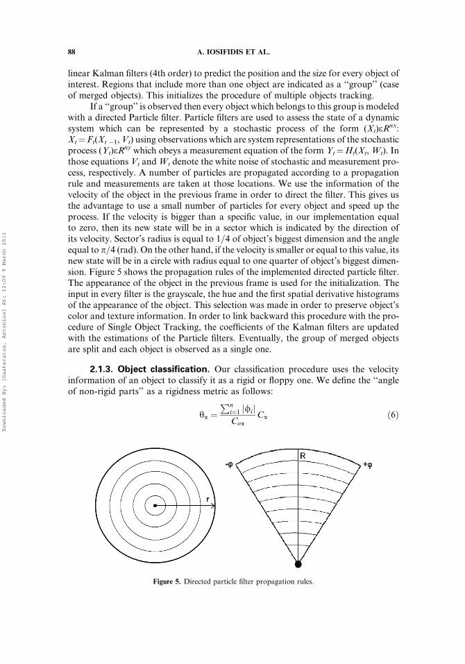
ny which obeys a measurement equation of the form Yt¼Ht(Xt,Wt). Inthose equations Vt andWt denote the white noise of stochastic and measurement pro-cess, respectively. A number of particles are propagated according to a propagationrule and measurements are taken at those locations. We use the information of thevelocity of the object in the previous frame in order to direct the filter. This gives usthe advantage to use a small number of particles for every object and speed up theprocess. If the velocity is bigger than a specific value, in our implementation equalto zero, then its new state will be in a sector which is indicated by the direction ofits velocity. Sector’s radius is equal to 1=4 of object’s biggest dimension and the angleequal to p=4 (rad). On the other hand, if the velocity is smaller or equal to this value, itsnew state will be in a circle with radius equal to one quarter of object’s biggest dimen-sion. Figure 5 shows the propagation rules of the implemented directed particle filter.The appearance of the object in the previous frame is used for the initialization. Theinput in every filter is the grayscale, the hue and the first spatial derivative histogramsof the appearance of the object. This selection was made in order to preserve object’scolor and texture information. In order to link backward this procedure with the pro-cedure of Single Object Tracking, the coefficients of the Kalman filters are updatedwith the estimations of the Particle filters. Eventually, the group of merged objectsare split and each object is observed as a single one.
2.1.3. Object classification. Our classification procedure uses the velocityinformation of an object to classify it as a rigid or floppy one. We define the ‘‘angleof non-rigid parts’’ as a rigidness metric as follows:
ha ¼Pn
i¼1 /ij jCoa
Ca ð6Þ
Figure 5. Directed particle filter propagation rules.
88 A. IOSIFIDIS ET AL.
Downloaded By: [Gasteratos, Antonios] At: 12:09 9 March 2011
where ha is the angle of non-rigid parts of object a, Ca denotes the number of object’scorners that their velocity vector creates an angle with object’s velocity vector biggerthan a threshold, / is the corresponding angle of corner i, and Coa is the total num-ber of object’s corners. The selection of the threshold is important and defines thedegree of rigidness of an object which is considered as rigid or not. The choice of thisvalue depends on the content of scene. A fairly small value (e.g., 5 to 10 degrees) canbe used in cases of noisy environments. In the above notation corners are the imagepixels where strong derivatives in two orthogonal directions are observed. Thesepoints are extracted using Sobel operators and calculating the correspondingHessian matrix of every image pixel. The corner pixels are those that their Hessianmatrix consists of two large eigenvalues (Shi and Tomasi 1994).
2.2. Moving-Camera Subsystem
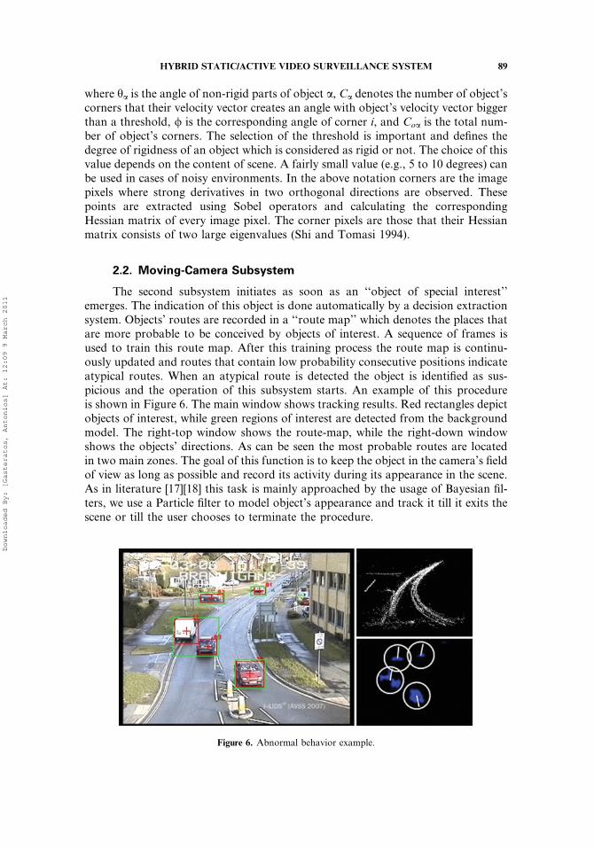
The second subsystem initiates as soon as an ‘‘object of special interest’’emerges. The indication of this object is done automatically by a decision extractionsystem. Objects’ routes are recorded in a ‘‘route map’’ which denotes the places thatare more probable to be conceived by objects of interest. A sequence of frames isused to train this route map. After this training process the route map is continu-ously updated and routes that contain low probability consecutive positions indicateatypical routes. When an atypical route is detected the object is identified as sus-picious and the operation of this subsystem starts. An example of this procedureis shown in Figure 6. The main window shows tracking results. Red rectangles depictobjects of interest, while green regions of interest are detected from the backgroundmodel. The right-top window shows the route-map, while the right-down windowshows the objects’ directions. As can be seen the most probable routes are locatedin two main zones. The goal of this function is to keep the object in the camera’s fieldof view as long as possible and record its activity during its appearance in the scene.As in literature [17][18] this task is mainly approached by the usage of Bayesian fil-ters, we use a Particle filter to model object’s appearance and track it till it exits thescene or till the user chooses to terminate the procedure.
Figure 6. Abnormal behavior example.
HYBRID STATIC/ACTIVE VIDEO SURVEILLANCE SYSTEM 89
Downloaded By: [Gasteratos, Antonios] At: 12:09 9 March 2011
2.2.1. Object tracking. The initialization of this function is made in theselection frame. Using the object’s foreground region created by the static cameraobject tracking procedure, we use the object’s position and size, and calculate histo-grams of objects intensity, hue and first spatial derivative images, respectively, todescribe its appearance. By retaining these three images the object’s dominant color,a linear combination of object’s colors and object’s texture information are pre-served. These are the inputs of a particle filter which uses second-order autoregres-sive dynamics for its propagation:
xt ¼ A1ðxt�1 � x0Þ þ A2ðxt�2 � x0Þ þ B0Rx þ x0 ð7Þ
yt ¼ A1ðyt�1 � y0Þ þ A2ðtt�2 � y0Þ þ B0Ry þ y0 ð8Þ
st ¼ A1ðst�1 � 1Þ þ A2ðst�2 � 1Þ þ B0Rs þ 1 ð9Þ
where (xt, yt) and st denote the object’s position and scale in the current frame; (x0,y0) is the object’s position in initialization frame; Ai, Bi are the models coefficientsand Ri denotes random numbers (Gaussian distribution). These equations show thatthe update rules for every particle take into consideration the two previous states.The model coefficients indicate the extent to which each state is taken into account.In our implementation values equal to A1¼ 2, A2¼�1 and B0¼ 1 have beenconsidered.
2.2.2. Camera motion. In every frame the object’s position is compared withthe frame’s center and a number of instructions are generated in order to keep theobject in the camera’s field of view. In other words, the vector denoting the object’stranslation on the 2-D image plane is transformed into motors commands into theactuators’ space. A PID controller is utilized to control the camera’s rotation speed.In more detail, the center of gravity of the computed blob corresponding to thetracking object is computed and the error is then calculated. This is the vector fromthe image center to the blob’s center of gravity on the image plane. The horizontaland the vertical components of this vector are fed into two identical standard PIDcontroller (Gc¼KpþKi=sþKds) controlling the pan and tilt degrees of freedom,respectively. The proportional, integral, and differential gains of the controllersare respectively: Kp¼ 61.5, Ki¼ 2000, and Kd¼ 357.2. While in our implementationwe employed a pan=tilt mechanism, a similar procedure as the one used by ourmoving-camera subsystem can be utilized by any visual-servoing mechatronic mech-anism, e.g., a camera rotation-translation one.
When the function of this procedure ends, the system returns to the static cam-era procedure. This enables the initialization of a new background model at the newscene, which resulted from the movement of the camera. This model is initialized atthe first incoming frame of the new scene and a number of frames (250 that corre-spond to 10 seconds) are used to train this background model. After this procedurethe static-camera subsystem operates in the same manner described in section 2.1.
90 A. IOSIFIDIS ET AL.
Downloaded By: [Gasteratos, Antonios] At: 12:09 9 March 2011
3. EXPERIMENTAL RESULTS
Our software system operates in a video frame size of 320� 240 on a 2.5GHzPC without any optimization. In the case of the static camera, TOT subsystem runsat about 32 frames per second, while POT subsystem’s single object tracking runs atabout 31 frames per second and merged objects tracking runs at about 20 frames persecond. The process of classification slows down the process at 6 frames per secondand is optional. In the case of a moving camera the procedure runs at about 30frames per second.
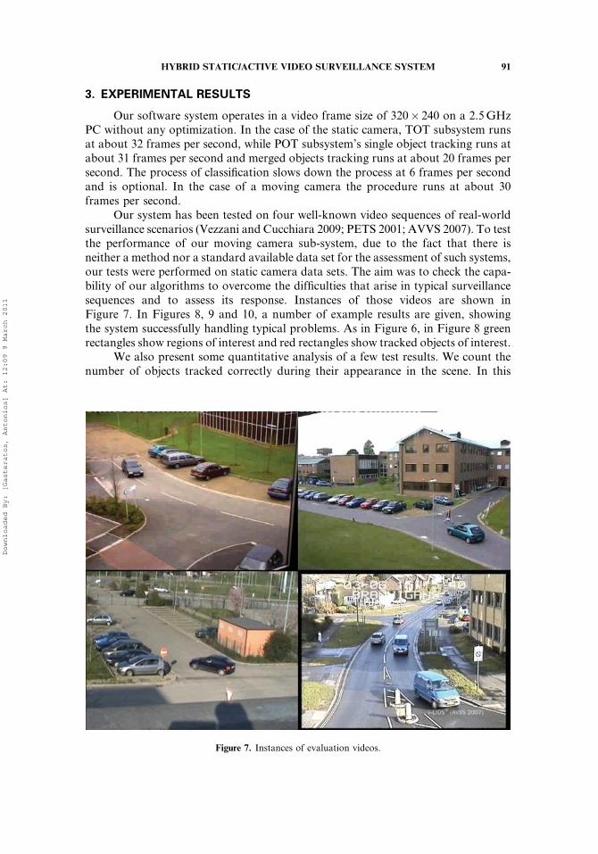
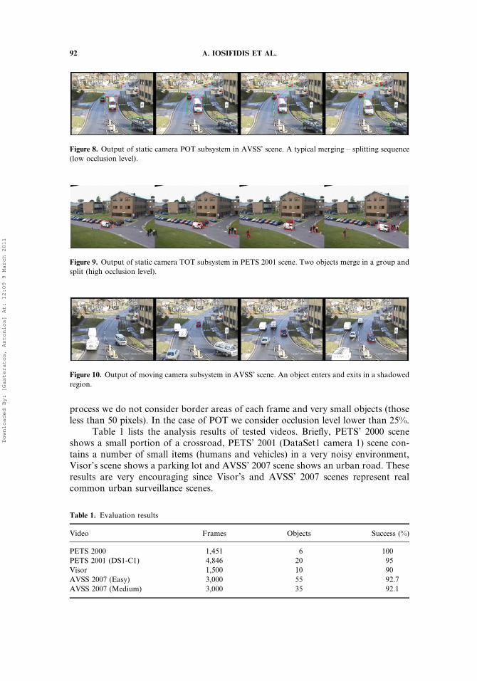
Our system has been tested on four well-known video sequences of real-worldsurveillance scenarios (Vezzani and Cucchiara 2009; PETS 2001; AVVS 2007). To testthe performance of our moving camera sub-system, due to the fact that there isneither a method nor a standard available data set for the assessment of such systems,our tests were performed on static camera data sets. The aim was to check the capa-bility of our algorithms to overcome the difficulties that arise in typical surveillancesequences and to assess its response. Instances of those videos are shown inFigure 7. In Figures 8, 9 and 10, a number of example results are given, showingthe system successfully handling typical problems. As in Figure 6, in Figure 8 greenrectangles show regions of interest and red rectangles show tracked objects of interest.
We also present some quantitative analysis of a few test results. We count thenumber of objects tracked correctly during their appearance in the scene. In this
Figure 7. Instances of evaluation videos.
HYBRID STATIC/ACTIVE VIDEO SURVEILLANCE SYSTEM 91
Downloaded By: [Gasteratos, Antonios] At: 12:09 9 March 2011
process we do not consider border areas of each frame and very small objects (thoseless than 50 pixels). In the case of POT we consider occlusion level lower than 25%.
Table 1 lists the analysis results of tested videos. Briefly, PETS’ 2000 sceneshows a small portion of a crossroad, PETS’ 2001 (DataSet1 camera 1) scene con-tains a number of small items (humans and vehicles) in a very noisy environment,Visor’s scene shows a parking lot and AVSS’ 2007 scene shows an urban road. Theseresults are very encouraging since Visor’s and AVSS’ 2007 scenes represent realcommon urban surveillance scenes.
Figure 8. Output of static camera POT subsystem in AVSS’ scene. A typical merging – splitting sequence
(low occlusion level).
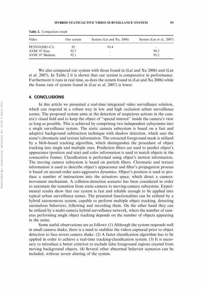
Figure 9. Output of static camera TOT subsystem in PETS 2001 scene. Two objects merge in a group and
split (high occlusion level).
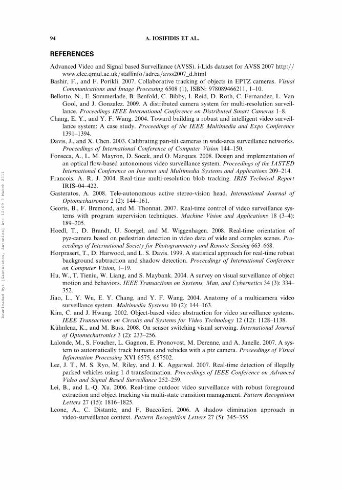
Figure 10. Output of moving camera subsystem in AVSS’ scene. An object enters and exits in a shadowed
region.
Table 1. Evaluation results
Video Frames Objects Success (%)
PETS 2000 1,451 6 100
PETS 2001 (DS1-C1) 4,846 20 95
Visor 1,500 10 90
AVSS 2007 (Easy) 3,000 55 92.7
AVSS 2007 (Medium) 3,000 35 92.1
92 A. IOSIFIDIS ET AL.
Downloaded By: [Gasteratos, Antonios] At: 12:09 9 March 2011
We also compared our system with those found in (Lei and Xu 2006) and (Leeet al. 2007). In Table 2 it is shown that our system is comparative in performance.Furthermore it runs in real time, as does the system found in (Lei and Xu 2006) whilethe frame rate of system found in (Lee et al. 2007) is lower.
4. CONCLUSIONS
In this article we presented a real-time integrated video surveillance solution,which can respond in a robust way in low and high occlusion urban surveillancescenes. The proposed system aims at the detection of suspicious actions in the cam-era’s visual field and to keep the object of ‘‘special interest’’ inside the camera’s viewas long as possible. This is achieved by comprising two independent subsystems intoa single surveillance system. The static camera subsystem is based on a fast andadaptive background subtraction technique with shadow detection, which uses thescene’s chromatic and texture information. The extracted foreground mask is utilizedby a blob-based tracking algorithm, which distinguishes the procedure of objecttracking into single and multiple ones. Prediction filters are used to predict object’sappearance (position and size) and color information is used to match objects in theconsecutive frames. Classification is performed using object’s motion information.The moving camera subsystem is based on particle filters. Chromatic and textureinformation is used to describe object’s appearance and filter’s propagation processis based on second-order auto-aggressive dynamics. Object’s position is used to pro-duce a number of instructions into the actuators space, which direct a camera-movement mechanism. A collision-detection scenario has been considered in orderto automate the transition from static-camera to moving-camera subsystem. Experi-mental results show that our system is fast and reliable enough to be applied intotypical urban surveillance scenes. The presented functionalities can be utilized by ahybrid autonomous system, capable to perform multiple object tracking, detectinganomalous behaviors, following and recording them. On the other hand they canbe utilized by a multi-camera hybrid surveillance network, where the number of cam-eras performing single object tracking depends on the number of objects appearingin the scene.
Some useful observations are as follows: (1) Although the system responds wellin small camera shake, there is a need to stabilize the videos captured prior to objectdetection to face severe camera shake. (2) A faster classification algorithm has to beapplied in order to achieve a real-time tracking-classification system. (3) It is neces-sary to introduce a better criterion to exclude false foreground regions created frommoving background objects. (4) Several other abnormal behavior scenarios can beincluded, without severe altering of the system.
Table 2. Comparison result
Video Our system System (Lei and Xu, 2006) System (Lee et al., 2007)
PETS’01(DS1-C1) 95 93.4 –
AVSS’ 07 Easy 92.7 – 98.3
AVSS’ 07 Medium 92.1 – 95.2
HYBRID STATIC/ACTIVE VIDEO SURVEILLANCE SYSTEM 93
Downloaded By: [Gasteratos, Antonios] At: 12:09 9 March 2011
REFERENCES
Advanced Video and Signal based Surveillance (AVSS). i-Lids dataset for AVSS 2007 http://www.elec.qmul.ac.uk/staffinfo/adrea/avss2007_d.html
Bashir, F., and F. Porikli. 2007. Collaborative tracking of objects in EPTZ cameras. VisualCommunications and Image Processing 6508 (1), ISBN: 978089466211, 1–10.
Bellotto, N., E. Sommerlade, B. Benfold, C. Bibby, I. Reid, D. Roth, C. Fernandez, L. VanGool, and J. Gonzalez. 2009. A distributed camera system for multi-resolution surveil-lance. Proceedings IEEE International Conference on Distributed Smart Cameras 1–8.
Chang, E. Y., and Y. F. Wang. 2004. Toward building a robust and intelligent video surveil-lance system: A case study. Proceedings of the IEEE Multimedia and Expo Conference1391–1394.
Davis, J., and X. Chen. 2003. Calibrating pan-tilt cameras in wide-area surveillance networks.Proceedings of International Conference of Computer Vision 144–150.
Fonseca, A., L. M. Mayron, D. Socek, and O. Marques. 2008. Design and implementation ofan optical flow-based autonomous video surveillance system. Proceedings of the IASTEDInternational Conference on Internet and Multimedia Systems and Applications 209–214.
Francois, A. R. J. 2004. Real-time multi-resolution blob tracking. IRIS Technical ReportIRIS–04–422.
Gasteratos, A. 2008. Tele-autonomous active stereo-vision head. International Journal ofOptomechatronics 2 (2): 144–161.
Georis, B., F. Bremond, and M. Thonnat. 2007. Real-time control of video surveillance sys-tems with program supervision techniques. Machine Vision and Applications 18 (3–4):189–205.
Hoedl, T., D. Brandt, U. Soergel, and M. Wiggenhagen. 2008. Real-time orientation ofpyz-camera based on pedestrian detection in video data of wide and complex scenes. Pro-ceedings of International Society for Photogrammetry and Remote Sensing 663–668.
Horprasert, T., D. Harwood, and L. S. Davis. 1999. A statistical approach for real-time robustbackground subtraction and shadow detection. Proceedings of International Conferenceon Computer Vision, 1–19.
Hu, W., T. Tieniu, W. Liang, and S. Maybank. 2004. A survey on visual surveillance of objectmotion and behaviors. IEEE Transactions on Systems, Man, and Cybernetics 34 (3): 334–352.
Jiao, L., Y. Wu, E. Y. Chang, and Y. F. Wang. 2004. Anatomy of a multicamera videosurveillance system. Multimedia Systems 10 (2): 144–163.
Kim, C. and J. Hwang. 2002. Object-based video abstraction for video surveillance systems.IEEE Transactions on Circuits and Systems for Video Technology 12 (12): 1128–1138.
Kuhnlenz, K., and M. Buss. 2008. On sensor switching visual servoing. International Journalof Optomechatronics 3 (2): 233–256.
Lalonde, M., S. Foucher, L. Gagnon, E. Pronovost, M. Derenne, and A. Janelle. 2007. A sys-tem to automatically track humans and vehicles with a ptz camera. Proceedings of VisualInformation Processing XVI 6575, 657502.
Lee, J. T., M. S. Ryo, M. Riley, and J. K. Aggarwal. 2007. Real-time detection of illegallyparked vehicles using 1-d transformation. Proceedings of IEEE Conference on AdvancedVideo and Signal Based Surveillance 252–259.
Lei, B., and L.-Q. Xu. 2006. Real-time outdoor video surveillance with robust foregroundextraction and object tracking via multi-state transition management. Pattern RecognitionLetters 27 (15): 1816–1825.
Leone, A., C. Distante, and F. Buccolieri. 2006. A shadow elimination approach invideo-surveillance context. Pattern Recognition Letters 27 (5): 345–355.
94 A. IOSIFIDIS ET AL.
Downloaded By: [Gasteratos, Antonios] At: 12:09 9 March 2011
Li, L., W. Huang, I. Y. H. Gu, and Q. Tian. 2003. Foreground object detection from videoscontaining complex background. Proceedings of the Eleventh ACM International Confer-ence on Multimedia 2–8.
Li, L., W. Huang, I. Y. H. Gu, R. Luo, and Q. Tian. 2008. An efficient sequential approach totracking multiple objects through crowds for real-time intelligent cctv systems. IEEETransactions On Systems, Man and Cybernetics 38 (5): 1254–1269.
Luque, R. M., E. Domınguez, E. J. Palomo, and J. Munoz. 2008. A neural network approachfor video object segmentation in traffic surveillance. Proceedings of International Confer-ence on Image Analysis and Recognition 151–158.
Maggio, E., F. Smeraldi, and A. Cavallaro. 2007. Adaptive multi-feature tracking in a particlefiltering framework. IEEE Transactions on Circuits and Systems for Video Technology 17(10): 1348–1359.
Mahadevan, V., and N. Vasconcelos. 2008. Background subtraction in highly dynamic scenes.Proceedings of Computer Vision and Pattern Recognition 1–6.
Micheloni, C., and G. L. Foresti. 2006. Real time image processing for active monitoring ofwide areas. Journal of Visual Communication and Image Representation 17 (3): 589–604.
Moeslund, T. B., A. Hilton, and V. Kruger. 2006. A survey of advances in vision-based humanmotion capture and analysis. Computer Vision and Image Understanding 103 (2–3):90–126.
Performance Evaluation of Tracking and Surveillance (PETS). PETS 2001 Benchmark Datahttp://www.cvg.rdg.ac.uk/slides/pets.html
Quereshi, F. Z., and D. Terzopoulos. 2005. Surveillance camera scheduling: A virtual visionapproach. Proceedings of 3rd ACM Workshop on Video Surveillance and Sensor Networks131–139.
Remagnino, P., A. I. Shihab and G. Jones. 2004. Distributed intelligence for multi-cameravisual surveillance. Pattern Recognition 37 (4): 675–689.
Sangkyu, K., K. Andrea, A. R. Besma, and A. A. Mongi. 2004. Video surveillance of highsecurity facility. Proceedings of 10th International Conference on Robotics and RemoteSystems for Hazardous Environments 530–536.
Shi, J., and C. Tomasi. 1994. Good features to track. Proceedings of the IEEE Conference onComputer Vision and Pattern Recognition 593–600.
Stauffer, C., and W. E. L. Grimson. 1999. Adaptive background mixture models for real-timetracking. Proceedings of Computer Vision and Pattern Recognition 246–252.
Vezzani, R., and R. Cucchiara. 2009. Video surveillance online repository (VISOR): An inte-grated framework. Multimedia Tools and Applications (MTAP) 50 (2): 359–380.
Wren, C. R., M. U. Erdem, and A. J. Azarbayejani. 2005. Automatic pan-tilt_zoomcalibration in the presence of hybrid sensor networks. Proceedings of the Third ACMWorkshop on Video Surveillance and Sensor Networks 113–120.
Wu, G., Y. Wu, L. Jiao, Y.-F. Wang, and E. Y. Chang. 2003. Multi-camera spatio-temporalfusion and biased sequence-data learning for security surveillance. Proceedings of 11thAssociation for Computing Machinery International Conference on Multimedia 528–538.
Xue, J., N. Zheng, and X. Zhong. 2008. Tracking multiple visual targets via particle-basedbelief propagation. IEEE Transactions on Systems, Man, and Cybernetics 38 (1): 196–209.
HYBRID STATIC/ACTIVE VIDEO SURVEILLANCE SYSTEM 95
Downloaded By: [Gasteratos, Antonios] At: 12:09 9 March 2011