a hybrid pv-battery system for on-grid and off-grid
TRANSCRIPT
energies
Article
A Hybrid PV-Battery System for ON-Grid andOFF-Grid Applications—Controller-In-LoopSimulation Validation
Umashankar Subramaniam 1, Sridhar Vavilapalli 2, Sanjeevikumar Padmanaban 3,* ,Frede Blaabjerg 4 , Jens Bo Holm-Nielsen 3 and Dhafer Almakhles 1
1 Renewable Energy Lab, College of Engineering, Prince Sultan University, Riyadh 12435, Saudi Arabia;[email protected] (U.S.); [email protected] (D.A.)
2 Department of Power Electronics, Bharat Heavy Electricals Limited (BHEL), Bengaluru 560026, India;[email protected]
3 Center for Bioenergy and Green Engineering, Department of Energy Technology, Aalborg University,6700 Esbjerg, Denmark; [email protected]
4 Center of Reliable Power Electronics (CORPE), Department of Energy Technology, Aalborg University,9220 Aalborg, Denmark; [email protected]
* Correspondence: [email protected]
Received: 24 December 2019; Accepted: 7 February 2020; Published: 9 February 2020�����������������
Abstract: In remote locations such as villages, islands and hilly areas, there is a possibility of frequentpower failures, voltage drops or power fluctuations due to grid-side faults. Grid-connected renewableenergy systems or micro-grid systems are preferable for such remote locations to meet the local criticalload requirements during grid-side failures. In renewable energy systems, solar photovoltaic (PV)power systems are accessible and hybrid PV-battery systems or energy storage systems (ESS) aremore capable of providing uninterruptible power to the local critical loads during grid-side faults.This energy storage system also improves the system dynamics during power fluctuations. In presentwork, a PV-battery hybrid system with DC-side coupling is considered, and a power balancing control(PBC) is proposed to transfer the power to grid/load and the battery. In this system, a solar powerconditioning system (PCS) acts as an interface across PV source, battery and the load/central grid.With the proposed PBC technique, the system can operate in following operational modes: (a) PCScan be able to work in grid-connected mode during regular operation; (b) PCS can be able to chargethe batteries and (c) PCS can be able to operate in standalone mode during grid side faults and deliverpower to the local loads. The proposed controls are explained, and the system response duringtransient and steady-state conditions is described. With the help of controller-in-loop simulationresults, the proposed power balancing controls are validated, for both off-grid and on-grid conditions.
Keywords: battery; cascaded H-Bridge; chopper; energy storage; multi-level; PV inverter
1. Introduction
A low voltage (LV)-rated solar PCS containing a conventional inverter with two-level topologies ispreferable for PV systems rated for lower power. For higher power solar power stations, it is better toopt for the system with medium voltage (MV) rating. Multi-level inverters (MLI) are more suitable forMV applications. The cascaded H-bridge (CHB) inverter is a popular MLI configuration which requiresisolated DC sources/DC links. Hence CHB configuration is highly suitable for static compensator(STATCOM) and solar applications due to the availability of isolated DC links [1]. CHB inverter needsmultiple H-bridge modules, and to control the multiple H-bridge modules, the required input-outputchannels in the processor are more when compared to other MLI configurations, but in MV high power
Energies 2020, 13, 755; doi:10.3390/en13030755 www.mdpi.com/journal/energies
Energies 2020, 13, 755 2 of 19
systems, the CHB inverter enables the independent maximum power point (MPP) controls to attainenhanced efficiency [2]. In high power applications, the number of H-bridge modules to be used inCHB is more which results in better power quality [3,4]. The transformer on the AC side can also beeliminated with this configuration.
Solar PV stations can reduce carbon emissions and provide clean energy but may not be ableto supply the load requirements due to sudden changes in weather conditions and when the solarirradiation is weak. The system remains in an idle state during nighttime, which affects the utilizationfactor of the system drastically. Hence there is much attention to battery energy storage systems alongwith PV to reduce power disturbances in the system, to improve the stability, for providing continuouspower to the load and for improving utilization factor of the system. In such hybrid PV-battery stations,power is transferred from PV array to battery and load during daytime and batteries transfer power tothe load during night time. The battery storage system also improves the system dynamics for suddenweather changes [5,6]. Importance of hybrid PV-battery stations and operation strategy is discussedin [7]. A review of energy storage for large-scale PV systems, grid integration issues, stability concernsand the selection of batteries is available in [8]. With the battery storage system in PV applications,the utilization factor of the PCS can also be improved since the system can be made operational for allthe time. To keep the grid power non-negative always, an approach called ‘Solar Plus’s which is thecombination of energy storage, PV and load controls are presented in [9].
Cost of the battery storage systems is also decreasing over time due to the advancements in the areasof different battery technologies, battery charging and discharging methods. In [10], various batterytypes such as lithium-ion, lead-acid, aluminium–ion, sodium-sulphur (NaS), flow batteries, etc.suitable for large-scale PV ESS systems are explained and compared. Various discharge strategiesare presented for grid-connected hybrid PV-battery applications in [11] and different battery storagetechnologies suitable for residential applications are also elaborated.
In a conventional grid-connected PV power conditioning system, the anti-islanding feature willbe incorporated as a feature of protection. But as mentioned earlier, it may be required to operate thePCS in stand-alone mode also when there are frequent disconnections from the grid. In such scenarios,a power management system at a higher level of control architecture needs to isolate the grid from thecritical loads.
Hybrid PV-battery stations can also be operated in standalone mode; hence it is possible toprovide power to local critical loads during grid-side faults or during maintenance on the grid side.Such systems help in catering continuous power supply in remote locations which are not connectedto the central grid or which are facing problems of regular power supply failures from the grid.Optimal design for a PV + Diesel + Battery storage hybrid system is presented in [12].
From the above, the following research gaps are identified:√
In a conventional PV power station, the system remains in an idle state when irradiation is weak;hence the utilization factor (UF) of the system is very small. By incorporating ESS in the solarpower system, the overall utilization factor of the system can be improved significantly.
√Commercially available PV inverter configurations are based on two-level or three-level inverterswith low voltage ratings. These configurations are not suitable for large scale applications,but the medium voltage systems are more suitable for high power applications. The use ofconventional two-level inverter for high power applications results in poor power quality,large filter requirement and higher dv/dt across power switches.
√A CHB-based PV inverter can nullify the disadvantages of conventional low voltage inverterconfigurations. An investigation on energy storage systems suitable for CHB inverters is required.
√In previous works, controls for PV-battery hybrid system either in grid-connected mode or instandalone modes of operations are discussed but the system controls for operating in both modesare not covered.
Energies 2020, 13, 755 3 of 19
Present work mainly focuses on medium voltage CHB-based power condition system to meetthe large-scale PV system requirements. For the uninterrupted power supply and to improve theutilization factor of the system, battery energy storage is incorporated in to the PV power system.The following are the contributions of present work to address the research gaps in earlier systems:√
A literature review is carried out to investigate various ESS configurations suitable for CHBbased inverters. A power conditioning system based on a CHB MLI and battery charger basedon a chopper with multiple battery banks is studied thoroughly due to the advantages ofchopper-based systems.
√A novel power balancing control (PBC) is proposed in this work which enables the system tooperate both in standalone mode and in grid-connected mode, unlike earlier works where thecontrols proposed were for either grid-connected systems or for standalone systems only.
√The controls proposed in this work also enable the smooth transition in changing modesof operation.
√Controller-In-Loop simulations are carried out with the help of real-time simulator to validate theproposed power balancing controls.
This paper is organized, as explained below: In Section 2, ESS configurations suitable forCHB inverter and advantages of chopper-based ESS are explained. Operation of buck chopper andbi-directional chopper are also elaborated in this section. Section 3 covers the procedure for selection ofcomponents such as PV array, batteries, filter components and other accessories. Controls adapted forinverter and battery charger are discussed thoroughly in Sections 4 and 5, respectively. The setup for thecontroller-in-loop simulation validation is explained in Section 6 and results are presented in Section 7.Contributions and the conclusions of the present work are presented in Sections 8 and 9, respectively.
2. Chopper-Based ESS for CHB Inverter
An AC coupled ESS configuration suitable for CHB inverters based on a voltage regulator ispresented in [13], but AC-side coupled configurations are not suitable for higher rated energy storagesystems as the power quality may get affected due to the multiple interfaces connected on the gridside. DC-coupled systems are more suitable for large-scale energy storage systems and for obtainingbetter power quality. A dual active bridge (DAB)-based ESS configuration is presented in [14], it is ithas been observed that independent power control through PCS and battery charger is possible withthis configuration but the control is complex due to a greater number of power modules. Since eachDAB needs eight gate pulses, the controller hardware requirements are more. To reduce the cost,controller hardware requirements and the control complexity, it is preferable to select chopper-basedsystems. In this work, two types of choppers namely buck-chopper and bi-directional choppers,are discussed to operate as a battery charger.
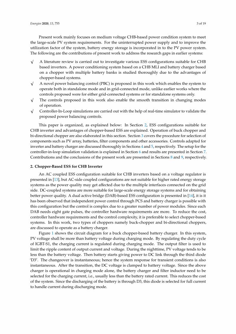
Figure 1 shows the circuit diagram for a buck chopper-based battery charger. In this system,PV voltage shall be more than battery voltage during charging mode. By regulating the duty cycleof IGBT-S1, the charging current is regulated during charging mode. The output filter is used tolimit the ripple content of output current and voltage. During the nighttime, PV voltage tends to beless than the battery voltage. Then battery starts giving power to DC link through the third diode‘D3′. The changeover is instantaneous; hence the system response for transient conditions is alsoinstantaneous. After the transition, the DC voltage is clamped to battery voltage. Since the abovecharger is operational in charging mode alone, the battery charger and filter inductor need to beselected for the charging current, i.e., usually less than the battery rated current. This reduces the costof the system. Since the discharging of the battery is through D3, this diode is selected for full currentto handle current during discharging mode.
Energies 2020, 13, 755 4 of 19Energies 2020, 13, x FOR PEER REVIEW 4 of 19
Figure 1. Battery charger based on a buck-chopper.
The main drawback with this type of charger is that the battery starts discharging only when the irradiation is weak. In grid-connected mode, the battery cannot transfer power to DC link even when the local load demand is higher than the power available at PV array since the PV array is operating at its MPP voltage which is more than the battery voltage. In this case, the power required for the local load needs to be taken from the grid. In standalone mode, the battery needs to provide power along with the PV source for the local critical load requirement due to the absence of the grid. In this case, the PV array cannot be operated at its MPP voltage but operates at battery voltage which reduces the efficiency of PV [15]. So, this charger is more suitable for grid applications. For standalone PV systems, it is required to have control during the discharging mode of operation also which is possible through bi-directional chopper based ESS.
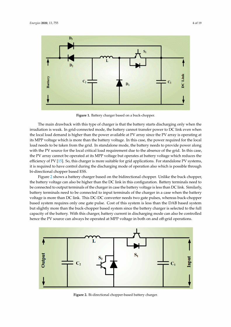
Figure 2 shows a battery charger based on the bidirectional chopper. Unlike the buck chopper, the battery voltage can also be higher than the DC link in this configuration. Battery terminals need to be connected to output terminals of the charger in case the battery voltage is less than DC link. Similarly, battery terminals need to be connected to input terminals of the charger in a case when the battery voltage is more than DC link. This DC-DC converter needs two gate pulses, whereas buck-chopper based system requires only one gate pulse. Cost of this system is less than the DAB based system but slightly more than the buck-chopper based system since the battery charger is selected to the full capacity of the battery. With this charger, battery current in discharging mode can also be controlled hence the PV source can always be operated at MPP voltage in both on and off-grid operations.
Figure 2. Bi-directional chopper-based battery charger.
3. Design Calculations for the System
In present work, a high-power PV system with a solar inverter based on a CHB MLI and a bi-directional chopper-based battery charger is studied. To discuss the controls proposed at various operating points and in different modes such as grid-connected and standalone modes, a single-phase system with ratings given in Figure 3 is chosen. In this work, a single-phase system is
Figure 1. Battery charger based on a buck-chopper.
The main drawback with this type of charger is that the battery starts discharging only when theirradiation is weak. In grid-connected mode, the battery cannot transfer power to DC link even whenthe local load demand is higher than the power available at PV array since the PV array is operating atits MPP voltage which is more than the battery voltage. In this case, the power required for the localload needs to be taken from the grid. In standalone mode, the battery needs to provide power alongwith the PV source for the local critical load requirement due to the absence of the grid. In this case,the PV array cannot be operated at its MPP voltage but operates at battery voltage which reduces theefficiency of PV [15]. So, this charger is more suitable for grid applications. For standalone PV systems,it is required to have control during the discharging mode of operation also which is possible throughbi-directional chopper based ESS.
Figure 2 shows a battery charger based on the bidirectional chopper. Unlike the buck chopper,the battery voltage can also be higher than the DC link in this configuration. Battery terminals need tobe connected to output terminals of the charger in case the battery voltage is less than DC link. Similarly,battery terminals need to be connected to input terminals of the charger in a case when the batteryvoltage is more than DC link. This DC-DC converter needs two gate pulses, whereas buck-chopperbased system requires only one gate pulse. Cost of this system is less than the DAB based systembut slightly more than the buck-chopper based system since the battery charger is selected to the fullcapacity of the battery. With this charger, battery current in discharging mode can also be controlledhence the PV source can always be operated at MPP voltage in both on and off-grid operations.
Energies 2020, 13, x FOR PEER REVIEW 4 of 19
Figure 1. Battery charger based on a buck-chopper.
The main drawback with this type of charger is that the battery starts discharging only when the irradiation is weak. In grid-connected mode, the battery cannot transfer power to DC link even when the local load demand is higher than the power available at PV array since the PV array is operating at its MPP voltage which is more than the battery voltage. In this case, the power required for the local load needs to be taken from the grid. In standalone mode, the battery needs to provide power along with the PV source for the local critical load requirement due to the absence of the grid. In this case, the PV array cannot be operated at its MPP voltage but operates at battery voltage which reduces the efficiency of PV [15]. So, this charger is more suitable for grid applications. For standalone PV systems, it is required to have control during the discharging mode of operation also which is possible through bi-directional chopper based ESS.
Figure 2 shows a battery charger based on the bidirectional chopper. Unlike the buck chopper, the battery voltage can also be higher than the DC link in this configuration. Battery terminals need to be connected to output terminals of the charger in case the battery voltage is less than DC link. Similarly, battery terminals need to be connected to input terminals of the charger in a case when the battery voltage is more than DC link. This DC-DC converter needs two gate pulses, whereas buck-chopper based system requires only one gate pulse. Cost of this system is less than the DAB based system but slightly more than the buck-chopper based system since the battery charger is selected to the full capacity of the battery. With this charger, battery current in discharging mode can also be controlled hence the PV source can always be operated at MPP voltage in both on and off-grid operations.
Figure 2. Bi-directional chopper-based battery charger.
3. Design Calculations for the System
In present work, a high-power PV system with a solar inverter based on a CHB MLI and a bi-directional chopper-based battery charger is studied. To discuss the controls proposed at various operating points and in different modes such as grid-connected and standalone modes, a single-phase system with ratings given in Figure 3 is chosen. In this work, a single-phase system is
Figure 2. Bi-directional chopper-based battery charger.

Energies 2020, 13, 755 5 of 19
3. Design Calculations for the System
In present work, a high-power PV system with a solar inverter based on a CHB MLI and abi-directional chopper-based battery charger is studied. To discuss the controls proposed at variousoperating points and in different modes such as grid-connected and standalone modes, a single-phasesystem with ratings given in Figure 3 is chosen. In this work, a single-phase system is consideredas a case study due to limitations in the controller hardware. However, the system controls can beupgraded to the three-phase system, which is suitable for high power applications.
Energies 2020, 13, x FOR PEER REVIEW 5 of 19
considered as a case study due to limitations in the controller hardware. However, the system controls can be upgraded to the three-phase system, which is suitable for high power applications.
Figure 3. DC-coupled ESS for CHB-based PCS.
Design calculations for CHB inverters, selection of devices, device loss calculations etc. are discussed in [16,17]. The procedure for the selection of CHB inverter and AC side filter components is shown in Table 1.
Table 1. Design calculations for CHB Inverter and L-C-L Filter.
Electrical Parameter Value Remarks CHB power rating 350 kW PCHB = Grid + Load
Inverter voltage 1250 V Vac No. of H-bridges 4 No’s NH H-bridge power 87.5 kW CHB Rating/NH H-bridge voltage 312.5 V VH = Vac/NH
Output current (Iac) 280 A PCHB/Vac Minimum DC voltage 422 V Vdcmin = 1.35 × VH
Carrier frequency 1 kHz Fcr Switching frequency 8 kHz Fsw = 2 × NHX Fcr
Corner frequency (Fc) 2 kHz Fc selected = Fsw/4 L-C-L Filter Component Selection
Maximum % reactive power allowed 5 % Max reactive power through Filter Capacitor Maximum filter voltage drops 3 % Max voltage drop across filter Inductors Maximum reactive power (Qc) 17.5 kW 5% of 350kW
Current rating of the capacitor (Ic) 14 A Qc/Grid Voltage Maximum capacitance of filter capacitor 35.67 uF Ic/(2 × pi × F × Grid Voltage) Capacitance of filter capacitor selected 30 uF
Inductance of filter inductor L1 211 uH Fc = 1/[2 × pi × √(LC)] % Voltage drop in L1 1.49 % (Iac × 2 × pi × F × L1)/Grid Voltage
Maximum drop allowed in L2 1.51 % Max % voltage drop–% drop across L1 Filter inductance L2 215 uH
To cater to the power needed for local load and power to be transferred to the grid, the required power rating of CHB inverter is 350 kW. In this system, 4 H-bridges are selected hence the levels achieved on the output PWM voltage is nine. The voltage and the power ratings of each H-bridge are 1/4th of CHB ratings and the current rating is equal to the rated inverter output current i.e., 280 amperes. Minimum DC input required for each H-bridge is calculated based on the AC output. In
Figure 3. DC-coupled ESS for CHB-based PCS.
Design calculations for CHB inverters, selection of devices, device loss calculations etc.are discussed in [16,17]. The procedure for the selection of CHB inverter and AC side filter componentsis shown in Table 1.
Table 1. Design calculations for CHB Inverter and L-C-L Filter.
Electrical Parameter Value Remarks
CHB power rating 350 kW PCHB = Grid + LoadInverter voltage 1250 V Vac
No. of H-bridges 4 No’s NHH-bridge power 87.5 kW CHB Rating/NHH-bridge voltage 312.5 V VH = Vac/NH
Output current (Iac) 280 A PCHB/VacMinimum DC voltage 422 V Vdcmin = 1.35 × VH
Carrier frequency 1 kHz FcrSwitching frequency 8 kHz Fsw = 2 × NHX Fcr
Corner frequency (Fc) 2 kHz Fc selected = Fsw/4
L-C-L Filter Component Selection
Maximum % reactive power allowed 5 % Max reactive power through Filter CapacitorMaximum filter voltage drops 3 % Max voltage drop across filter InductorsMaximum reactive power (Qc) 17.5 kW 5% of 350 kW
Current rating of the capacitor (Ic) 14 A Qc/Grid VoltageMaximum capacitance of filter capacitor 35.67 uF Ic/(2 × pi × F × Grid Voltage)Capacitance of filter capacitor selected 30 uF
Inductance of filter inductor L1 211 uH Fc = 1/[2 × pi ×√
(LC)]% Voltage drop in L1 1.49 % (Iac × 2 × pi × F × L1)/Grid Voltage
Maximum drop allowed in L2 1.51 % Max % voltage drop–% drop across L1Filter inductance L2 215 uH
Energies 2020, 13, 755 6 of 19
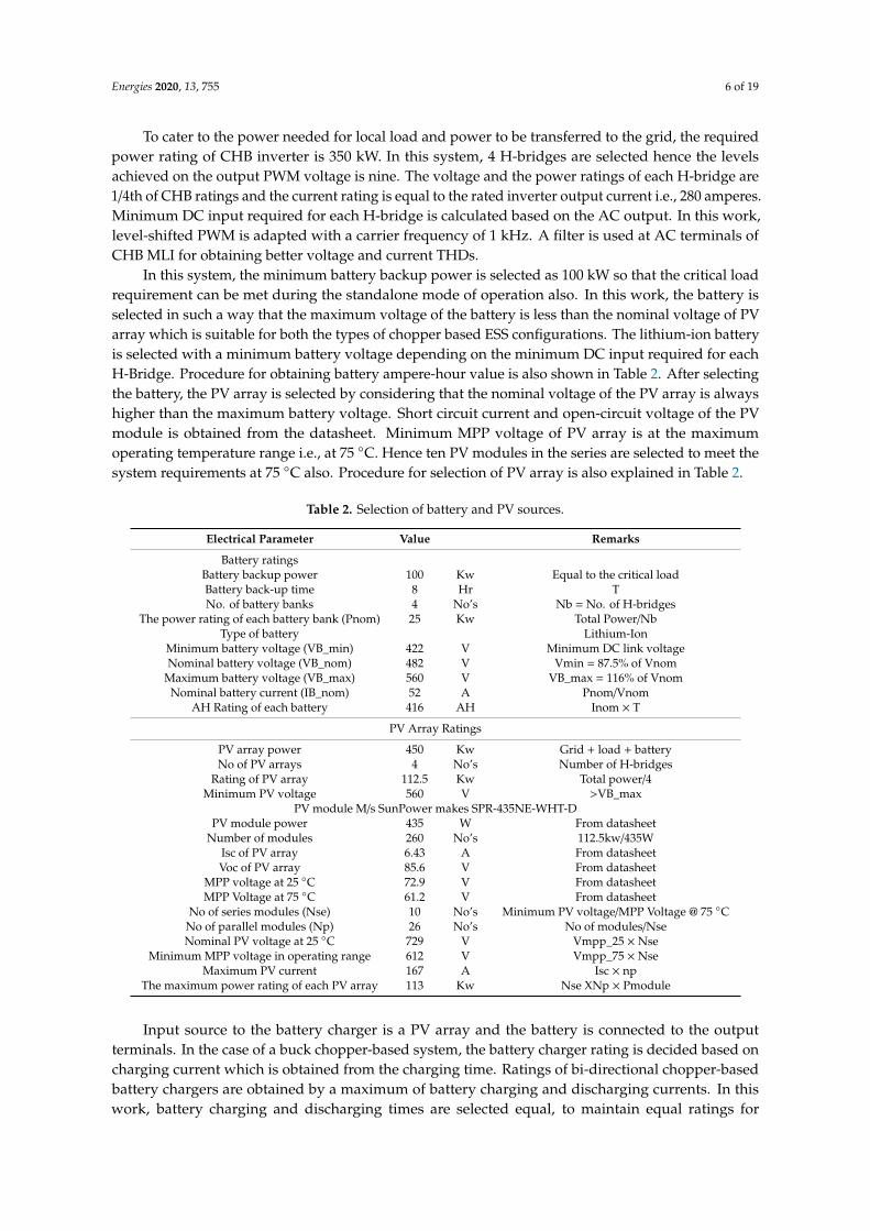
To cater to the power needed for local load and power to be transferred to the grid, the requiredpower rating of CHB inverter is 350 kW. In this system, 4 H-bridges are selected hence the levelsachieved on the output PWM voltage is nine. The voltage and the power ratings of each H-bridge are1/4th of CHB ratings and the current rating is equal to the rated inverter output current i.e., 280 amperes.Minimum DC input required for each H-bridge is calculated based on the AC output. In this work,level-shifted PWM is adapted with a carrier frequency of 1 kHz. A filter is used at AC terminals ofCHB MLI for obtaining better voltage and current THDs.
In this system, the minimum battery backup power is selected as 100 kW so that the critical loadrequirement can be met during the standalone mode of operation also. In this work, the battery isselected in such a way that the maximum voltage of the battery is less than the nominal voltage of PVarray which is suitable for both the types of chopper based ESS configurations. The lithium-ion batteryis selected with a minimum battery voltage depending on the minimum DC input required for eachH-Bridge. Procedure for obtaining battery ampere-hour value is also shown in Table 2. After selectingthe battery, the PV array is selected by considering that the nominal voltage of the PV array is alwayshigher than the maximum battery voltage. Short circuit current and open-circuit voltage of the PVmodule is obtained from the datasheet. Minimum MPP voltage of PV array is at the maximumoperating temperature range i.e., at 75 ◦C. Hence ten PV modules in the series are selected to meet thesystem requirements at 75 ◦C also. Procedure for selection of PV array is also explained in Table 2.
Table 2. Selection of battery and PV sources.
Electrical Parameter Value Remarks
Battery ratingsBattery backup power 100 Kw Equal to the critical loadBattery back-up time 8 Hr TNo. of battery banks 4 No’s Nb = No. of H-bridges
The power rating of each battery bank (Pnom) 25 Kw Total Power/NbType of battery Lithium-Ion
Minimum battery voltage (VB_min) 422 V Minimum DC link voltageNominal battery voltage (VB_nom) 482 V Vmin = 87.5% of Vnom
Maximum battery voltage (VB_max) 560 V VB_max = 116% of VnomNominal battery current (IB_nom) 52 A Pnom/Vnom
AH Rating of each battery 416 AH Inom × T
PV Array Ratings
PV array power 450 Kw Grid + load + batteryNo of PV arrays 4 No’s Number of H-bridges
Rating of PV array 112.5 Kw Total power/4Minimum PV voltage 560 V >VB_max
PV module M/s SunPower makes SPR-435NE-WHT-DPV module power 435 W From datasheet
Number of modules 260 No’s 112.5kw/435WIsc of PV array 6.43 A From datasheetVoc of PV array 85.6 V From datasheet
MPP voltage at 25 ◦C 72.9 V From datasheetMPP Voltage at 75 ◦C 61.2 V From datasheet
No of series modules (Nse) 10 No’s Minimum PV voltage/MPP Voltage @ 75 ◦CNo of parallel modules (Np) 26 No’s No of modules/NseNominal PV voltage at 25 ◦C 729 V Vmpp_25 × Nse
Minimum MPP voltage in operating range 612 V Vmpp_75 × NseMaximum PV current 167 A Isc × np
The maximum power rating of each PV array 113 Kw Nse XNp × Pmodule
Input source to the battery charger is a PV array and the battery is connected to the outputterminals. In the case of a buck chopper-based system, the battery charger rating is decided based oncharging current which is obtained from the charging time. Ratings of bi-directional chopper-basedbattery chargers are obtained by a maximum of battery charging and discharging currents. In thiswork, battery charging and discharging times are selected equal, to maintain equal ratings for
Energies 2020, 13, 755 7 of 19
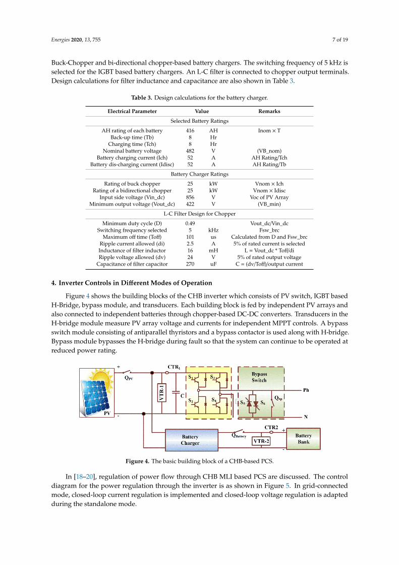
Buck-Chopper and bi-directional chopper-based battery chargers. The switching frequency of 5 kHz isselected for the IGBT based battery chargers. An L-C filter is connected to chopper output terminals.Design calculations for filter inductance and capacitance are also shown in Table 3.
Table 3. Design calculations for the battery charger.
Electrical Parameter Value Remarks
Selected Battery Ratings
AH rating of each battery 416 AH Inom × TBack-up time (Tb) 8 Hr
Charging time (Tch) 8 HrNominal battery voltage 482 V (VB_nom)
Battery charging current (Ich) 52 A AH Rating/TchBattery dis-charging current (Idisc) 52 A AH Rating/Tb
Battery Charger Ratings
Rating of buck chopper 25 kW Vnom × IchRating of a bidirectional chopper 25 kW Vnom × Idisc
Input side voltage (Vin_dc) 856 V Voc of PV ArrayMinimum output voltage (Vout_dc) 422 V (VB_min)
L-C Filter Design for Chopper
Minimum duty cycle (D) 0.49 Vout_dc/Vin_dcSwitching frequency selected 5 kHz Fsw_brc
Maximum off time (Toff) 101 us Calculated from D and Fsw_brcRipple current allowed (di) 2.5 A 5% of rated current is selectedInductance of filter inductor 16 mH L = Vout_dc * Toff/diRipple voltage allowed (dv) 24 V 5% of rated output voltage
Capacitance of filter capacitor 270 uF C = (dv/Toff)/output current
4. Inverter Controls in Different Modes of Operation
Figure 4 shows the building blocks of the CHB inverter which consists of PV switch, IGBT basedH-Bridge, bypass module, and transducers. Each building block is fed by independent PV arrays andalso connected to independent batteries through chopper-based DC-DC converters. Transducers in theH-bridge module measure PV array voltage and currents for independent MPPT controls. A bypassswitch module consisting of antiparallel thyristors and a bypass contactor is used along with H-bridge.Bypass module bypasses the H-bridge during fault so that the system can continue to be operated atreduced power rating.
Energies 2020, 13, x FOR PEER REVIEW 7 of 19
selected for the IGBT based battery chargers. An L-C filter is connected to chopper output terminals. Design calculations for filter inductance and capacitance are also shown in Table 3.
Table 3. Design calculations for the battery charger.
Electrical Parameter Value Remarks Selected Battery Ratings
AH rating of each battery 416 AH Inom × T Back-up time (Tb) 8 Hr
Charging time (Tch) 8 Hr Nominal battery voltage 482 V (VB_nom)
Battery charging current (Ich) 52 A AH Rating/Tch Battery dis-charging current (Idisc) 52 A AH Rating/Tb
Battery Charger Ratings Rating of buck chopper 25 kW Vnom × Ich
Rating of a bidirectional chopper 25 kW Vnom × Idisc Input side voltage (Vin_dc) 856 V Voc of PV Array
Minimum output voltage (Vout_dc) 422 V (VB_min) L-C Filter Design for Chopper
Minimum duty cycle (D) 0.49 Vout_dc/Vin_dc Switching frequency selected 5 kHz Fsw_brc
Maximum off time (Toff) 101 us Calculated from D and Fsw_brc Ripple current allowed (di) 2.5 A 5% of rated current is selected Inductance of filter inductor 16 mH L = Vout_dc * Toff/di Ripple voltage allowed (dv) 24 V 5% of rated output voltage
Capacitance of filter capacitor 270 uF C = (dv/Toff)/output current
4. Inverter Controls in Different Modes of Operation
Figure 4 shows the building blocks of the CHB inverter which consists of PV switch, IGBT based H-Bridge, bypass module, and transducers. Each building block is fed by independent PV arrays and also connected to independent batteries through chopper-based DC-DC converters. Transducers in the H-bridge module measure PV array voltage and currents for independent MPPT controls. A bypass switch module consisting of antiparallel thyristors and a bypass contactor is used along with H-bridge. Bypass module bypasses the H-bridge during fault so that the system can continue to be operated at reduced power rating.
Figure 4. The basic building block of a CHB-based PCS.
In [18–20], regulation of power flow through CHB MLI based PCS are discussed. The control diagram for the power regulation through the inverter is as shown in Figure 5. In grid-connected mode, closed-loop current regulation is implemented and closed-loop voltage regulation is adapted during the standalone mode.
Figure 4. The basic building block of a CHB-based PCS.
In [18–20], regulation of power flow through CHB MLI based PCS are discussed. The controldiagram for the power regulation through the inverter is as shown in Figure 5. In grid-connectedmode, closed-loop current regulation is implemented and closed-loop voltage regulation is adaptedduring the standalone mode.
Energies 2020, 13, 755 8 of 19Energies 2020, 13, x FOR PEER REVIEW 8 of 19
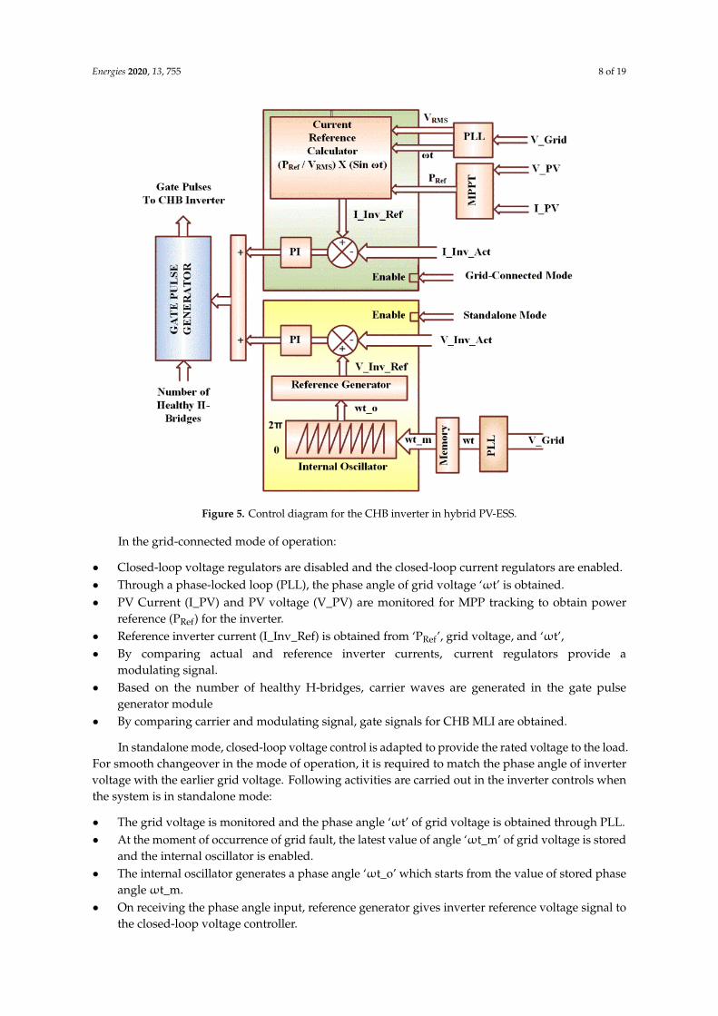
Figure 5. Control diagram for the CHB inverter in hybrid PV-ESS.
In the grid-connected mode of operation:
• Closed-loop voltage regulators are disabled and the closed-loop current regulators are enabled. • Through a phase-locked loop (PLL), the phase angle of grid voltage ‘ωt’ is obtained. • PV Current (I_PV) and PV voltage (V_PV) are monitored for MPP tracking to obtain power
reference (PRef) for the inverter. • Reference inverter current (I_Inv_Ref) is obtained from ‘PRef’, grid voltage, and ‘ωt’, • By comparing actual and reference inverter currents, current regulators provide a modulating
signal. • Based on the number of healthy H-bridges, carrier waves are generated in the gate pulse
generator module • By comparing carrier and modulating signal, gate signals for CHB MLI are obtained.
In standalone mode, closed-loop voltage control is adapted to provide the rated voltage to the load. For smooth changeover in the mode of operation, it is required to match the phase angle of inverter voltage with the earlier grid voltage. Following activities are carried out in the inverter controls when the system is in standalone mode:
• The grid voltage is monitored and the phase angle ‘ωt’ of grid voltage is obtained through PLL. • At the moment of occurrence of grid fault, the latest value of angle ‘ωt_m’ of grid voltage is
stored and the internal oscillator is enabled. • The internal oscillator generates a phase angle ‘ωt_o’ which starts from the value of stored phase
angle ωt_m. • On receiving the phase angle input, reference generator gives inverter reference voltage signal
to the closed-loop voltage controller. • By comparing actual and reference inverter voltages, the voltage regulators provide a
modulating signal. • Based on the number of healthy H-bridges, carrier waves are generated in the gate pulse
generator module • By comparing carrier and modulating signal, gate signals for CHB MLI are obtained.
Figure 5. Control diagram for the CHB inverter in hybrid PV-ESS.
In the grid-connected mode of operation:
• Closed-loop voltage regulators are disabled and the closed-loop current regulators are enabled.• Through a phase-locked loop (PLL), the phase angle of grid voltage ‘ωt’ is obtained.• PV Current (I_PV) and PV voltage (V_PV) are monitored for MPP tracking to obtain power
reference (PRef) for the inverter.• Reference inverter current (I_Inv_Ref) is obtained from ‘PRef’, grid voltage, and ‘ωt’,• By comparing actual and reference inverter currents, current regulators provide a
modulating signal.• Based on the number of healthy H-bridges, carrier waves are generated in the gate pulse
generator module• By comparing carrier and modulating signal, gate signals for CHB MLI are obtained.
In standalone mode, closed-loop voltage control is adapted to provide the rated voltage to the load.For smooth changeover in the mode of operation, it is required to match the phase angle of invertervoltage with the earlier grid voltage. Following activities are carried out in the inverter controls whenthe system is in standalone mode:
• The grid voltage is monitored and the phase angle ‘ωt’ of grid voltage is obtained through PLL.• At the moment of occurrence of grid fault, the latest value of angle ‘ωt_m’ of grid voltage is stored
and the internal oscillator is enabled.• The internal oscillator generates a phase angle ‘ωt_o’ which starts from the value of stored phase
angle ωt_m.• On receiving the phase angle input, reference generator gives inverter reference voltage signal to
the closed-loop voltage controller.
Energies 2020, 13, 755 9 of 19
• By comparing actual and reference inverter voltages, the voltage regulators provide amodulating signal.
• Based on the number of healthy H-bridges, carrier waves are generated in the gate pulsegenerator module
• By comparing carrier and modulating signal, gate signals for CHB MLI are obtained.
5. Battery Charger Controls in Different Modes of Operation
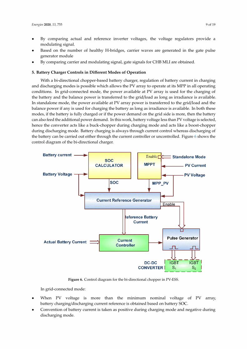
With a bi-directional chopper-based battery charger, regulation of battery current in chargingand discharging modes is possible which allows the PV array to operate at its MPP in all operatingconditions. In grid-connected mode, the power available at PV array is used for the charging ofthe battery and the balance power is transferred to the grid/load as long as irradiance is available.In standalone mode, the power available at PV array power is transferred to the grid/load and thebalance power if any is used for charging the battery as long as irradiance is available. In both thesemodes, if the battery is fully charged or if the power demand on the grid side is more, then the batterycan also feed the additional power demand. In this work, battery voltage less than PV voltage is selected,hence the converter acts like a buck-chopper during charging mode and acts like a boost-chopperduring discharging mode. Battery charging is always through current control whereas discharging ofthe battery can be carried out either through the current controller or uncontrolled. Figure 6 shows thecontrol diagram of the bi-directional charger.
Energies 2020, 13, x FOR PEER REVIEW 9 of 19
5. Battery Charger Controls in Different Modes of Operation
With a bi-directional chopper-based battery charger, regulation of battery current in charging and discharging modes is possible which allows the PV array to operate at its MPP in all operating conditions. In grid-connected mode, the power available at PV array is used for the charging of the battery and the balance power is transferred to the grid/load as long as irradiance is available. In standalone mode, the power available at PV array power is transferred to the grid/load and the balance power if any is used for charging the battery as long as irradiance is available. In both these modes, if the battery is fully charged or if the power demand on the grid side is more, then the battery can also feed the additional power demand. In this work, battery voltage less than PV voltage is selected, hence the converter acts like a buck-chopper during charging mode and acts like a boost-chopper during discharging mode. Battery charging is always through current control whereas discharging of the battery can be carried out either through the current controller or uncontrolled. Figure 6 shows the control diagram of the bi-directional charger.
In grid-connected mode:
• When PV voltage is more than the minimum nominal voltage of PV array, battery charging/discharging current reference is obtained based on battery SOC.
• Convention of battery current is taken as positive during charging mode and negative during discharging mode.
• During charging mode, the current controller compares the actual battery current with reference battery current and generates gate pulse so that the chopper operates as a Buck-Chopper.
• When the reference battery current is negative and the PV voltage is more than the minimum nominal voltage of PV array, then the battery discharging current is controlled through the current controller.
• When the reference battery current is negative, and if the PV voltage is less than the minimum nominal voltage of the PV array, then the pulse generator is disabled. No gate pulse is given to IGBTs and the battery discharges through the inductor (L) and the diode across IGBT-S1. In this mode, the current through the battery charger varies based on the reference inverter power.
Figure 6. Control diagram for the bi-directional chopper in PV-ESS.
In the standalone mode of operation:
• If PV voltage is more than the minimum nominal voltage of PV array, battery charging current reference is obtained based on battery SOC and represented as Ibatt_SOC.
Figure 6. Control diagram for the bi-directional chopper in PV-ESS.
In grid-connected mode:
• When PV voltage is more than the minimum nominal voltage of PV array,battery charging/discharging current reference is obtained based on battery SOC.
• Convention of battery current is taken as positive during charging mode and negative duringdischarging mode.
Energies 2020, 13, 755 10 of 19
• During charging mode, the current controller compares the actual battery current with referencebattery current and generates gate pulse so that the chopper operates as a Buck-Chopper.
• When the reference battery current is negative and the PV voltage is more than the minimumnominal voltage of PV array, then the battery discharging current is controlled through thecurrent controller.
• When the reference battery current is negative, and if the PV voltage is less than the minimumnominal voltage of the PV array, then the pulse generator is disabled. No gate pulse is given toIGBTs and the battery discharges through the inductor (L) and the diode across IGBT-S1. In thismode, the current through the battery charger varies based on the reference inverter power.
In the standalone mode of operation:
• If PV voltage is more than the minimum nominal voltage of PV array, battery charging currentreference is obtained based on battery SOC and represented as Ibatt_SOC.
• Another battery current reference is generated through MPPT controls and represented asIbatt_MPP.
• The minimum value in Ibatt_SOC and Ibatt_MPP is selected as a current reference for the charger.• While charging the battery, MPPT controls are carried out in the battery charger and adjust the
battery reference current to maintain the MPP of the PV array.• Current reference may also become negative to supply power from the battery when the irradiance
on PV array is poor. In this case, also, PV array operates at its MPP voltage.• When the irradiance becomes zero, then the PV voltage becomes less than the minimum nominal
voltage of the PV array and the pulse generator module is disabled. Then battery dischargesthrough inductor L and the diode across IGBT-S1. Based on the load on the AC side, batterycurrent varies.
In this work, a bi-directional chopper-based battery charger is considered for ease of understandingand due to limitations in the controller hardware. For high power applications interleaved buck-boostconverters presented in [21] may be adapted with minor modifications in the control logic.
6. Validation of Control Algorithm for Chopper Based ESS Configurations
To validate the system, controller-in-loop simulation validation is adapted. With thecontroller-in-loop simulations, the control software can be tested prior to the site trials and canbe tested at various operating points which are difficult to test with a real plant [22]. The followingactivities are carried out as part of controller-in-loop simulation validation:√
The power circuit also is known as the plant which consists of a grid, input breaker, local load,CHB inverter, PV array, batteries, and battery chargers are simulated as shown in Figure 7 withthe help of real-time simulator library
√The simulated model is compiled and loaded in the high-speed processors of thereal-time simulator
√Input-output channels of the real-time simulator are interfaced with the processor cards and otheruser interfaces. The real-time simulator enables the simulated plant to operate as a real plant
√The user interface consists of pushbuttons to provide start/stop commands and for mode selection.Potentiometers on the user interface are used for varying irradiance value on PV arrays
√Due to the limitations in the analogue inputs in the used processor, two processor cards of thesame type are used in this work
√Control algorithm in processor cards is programmed through MatLab-embedded coder
√In controller card-1, the controls for inverter are programmed. It receives start command andmode selection from the user and receives module faulty signals from the plant as digital inputs.Analogue inputs such as grid voltage, inverter voltage, and currents are received from thesimulated plant
Energies 2020, 13, 755 11 of 19
√From the simulated plant, controller-2 receives analogue inputs such as battery current,battery voltage, PV current, and PV. Based on the mode of operation, MPPT is carried out.Battery charger controls are programmed in this controller card
√When the start command is given from the user interface, the controllers process the proposedcontrol algorithm to control battery chargers and the CHB inverter
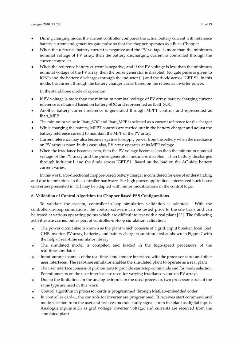
√When the system is in grid-connected mode, based on MPPT of PV arrays, the reference powersignal is communicated to controller card-1 through a serial communication interface (SCI).Transmission of data is by RS232 protocol
Energies 2020, 13, x FOR PEER REVIEW 11 of 19
Figure 7. Block diagram of the controller-in-loop simulation setup.
Controller-in-loop simulation setup is shown in Figure 8, Table 4 lists the particulars of the real-time simulator hardware.
Figure 7. Block diagram of the controller-in-loop simulation setup.
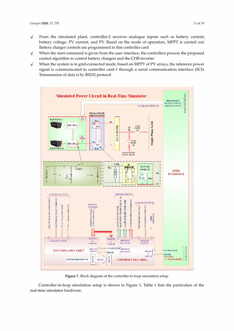
Controller-in-loop simulation setup is shown in Figure 8, Table 4 lists the particulars of thereal-time simulator hardware.
Energies 2020, 13, 755 12 of 19
Energies 2020, 13, x FOR PEER REVIEW 12 of 19
Figure 8. Controller-in-loop simulation setup.
Table 4. Hardware details of real-time simulator setup.
Electrical Parameter Value Real-time simulator Manufacturer name Opal-RT
Processor Intel Xeon Quad core, 2.5 GHz Modelling platform Matlab-Simulink
Analog channels −10 to +10 V Digital channels 0 V: Logic Low, +15V: Logic High
Controller Cards 1 & 2 DSP processor TI Make TMS320F2812 Analog input −7.5 V to +7.5 V
Digital input channels 0 V: Logic Low, +15V: Logic High Digital output channels 0 V: Logic Low, +15V: Logic High
No. of analog inputs 16 No’s No. of digital inputs 8 No’s
No. of digital outputs 22 (Including PWM outputs) User interface
Potentiometers To provide variable voltage to AI Pushbuttons To provide Digital inputs
7. Results and Discussion
In grid-connected mode, the advantage with the bi-directional chopper-based system is the possibility of discharging even when the PV array is active. The response of the inverter current is observed by operating the battery in charging mode and discharging modes intermittently. Irradiance is continuously maintained at 1000 watt per square meter hence the PV array current is constant. The battery reference current is varied from +50 Ampere to −50 Ampere and vice versa with an equal interval time of 1 s. When the battery current is negative, additional current is flowing through the inverter as shown in Figure 9. The dynamic response of the system in this condition is also found to be satisfactory.
Figure 8. Controller-in-loop simulation setup.
Table 4. Hardware details of real-time simulator setup.
Electrical Parameter Value
Real-time simulatorManufacturer name Opal-RT
Processor Intel Xeon Quad core, 2.5 GHzModelling platform Matlab-Simulink
Analog channels −10 to +10 VDigital channels 0 V: Logic Low, +15V: Logic High
Controller Cards 1 & 2
DSP processor TI Make TMS320F2812Analog input −7.5 V to +7.5 V
Digital input channels 0 V: Logic Low, +15V: Logic HighDigital output channels 0 V: Logic Low, +15V: Logic High
No. of analog inputs 16 No’sNo. of digital inputs 8 No’s
No. of digital outputs 22 (Including PWM outputs)User interface
Potentiometers To provide variable voltage to AIPushbuttons To provide Digital inputs
7. Results and Discussion
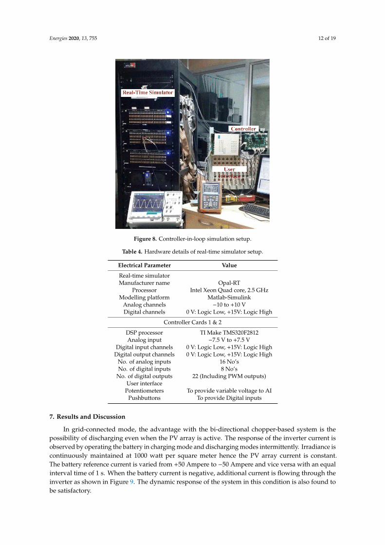
In grid-connected mode, the advantage with the bi-directional chopper-based system is thepossibility of discharging even when the PV array is active. The response of the inverter current isobserved by operating the battery in charging mode and discharging modes intermittently. Irradiance iscontinuously maintained at 1000 watt per square meter hence the PV array current is constant.The battery reference current is varied from +50 Ampere to −50 Ampere and vice versa with an equalinterval time of 1 s. When the battery current is negative, additional current is flowing through theinverter as shown in Figure 9. The dynamic response of the system in this condition is also found tobe satisfactory.
Energies 2020, 13, 755 13 of 19
Energies 2020, 13, x FOR PEER REVIEW 13 of 19
Figure 9. Change in the battery, PV array and actual inverter currents with a change in reference battery current at constant irradiance of 1000 watt per square meter in a bi-directional chopper-based ESS in grid-connected mode.
Irradiance on the PV arrays is varied from zero watts per square meter to 1000 watt per square meter in steps of 200 watts per square meter and the currents of inverter output, battery and PV array are observed.
Irradiance
Inverter Current
Battery Current
PV Current
1000 W/sq.m
800 600 400 200 ZeroW/sq.m
Figure 10. Inverter, battery and PV currents with varying irradiance value in grid-connected mode.
Figure 9. Change in the battery, PV array and actual inverter currents with a change in reference batterycurrent at constant irradiance of 1000 watt per square meter in a bi-directional chopper-based ESS ingrid-connected mode.
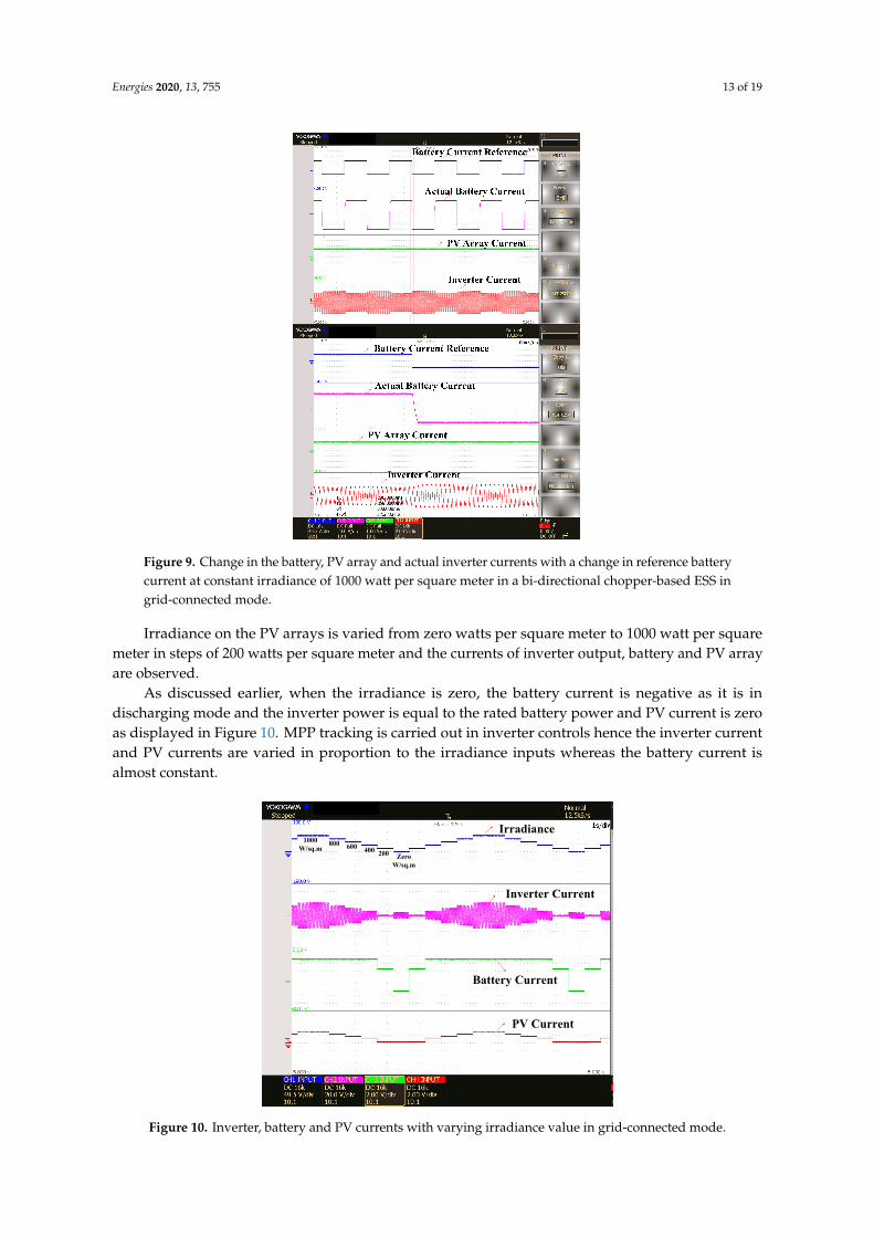
Irradiance on the PV arrays is varied from zero watts per square meter to 1000 watt per squaremeter in steps of 200 watts per square meter and the currents of inverter output, battery and PV arrayare observed.
As discussed earlier, when the irradiance is zero, the battery current is negative as it is indischarging mode and the inverter power is equal to the rated battery power and PV current is zeroas displayed in Figure 10. MPP tracking is carried out in inverter controls hence the inverter currentand PV currents are varied in proportion to the irradiance inputs whereas the battery current isalmost constant.
Energies 2020, 13, x FOR PEER REVIEW 13 of 19
Figure 9. Change in the battery, PV array and actual inverter currents with a change in reference battery current at constant irradiance of 1000 watt per square meter in a bi-directional chopper-based ESS in grid-connected mode.
Irradiance on the PV arrays is varied from zero watts per square meter to 1000 watt per square meter in steps of 200 watts per square meter and the currents of inverter output, battery and PV array are observed.
Irradiance
Inverter Current
Battery Current
PV Current
1000 W/sq.m
800 600 400 200 ZeroW/sq.m
Figure 10. Inverter, battery and PV currents with varying irradiance value in grid-connected mode. Figure 10. Inverter, battery and PV currents with varying irradiance value in grid-connected mode.
Energies 2020, 13, 755 14 of 19
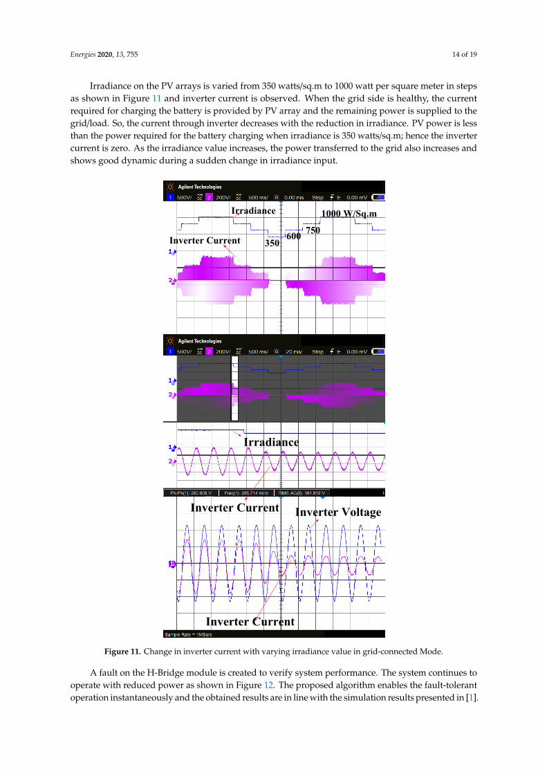
Irradiance on the PV arrays is varied from 350 watts/sq.m to 1000 watt per square meter in stepsas shown in Figure 11 and inverter current is observed. When the grid side is healthy, the currentrequired for charging the battery is provided by PV array and the remaining power is supplied to thegrid/load. So, the current through inverter decreases with the reduction in irradiance. PV power is lessthan the power required for the battery charging when irradiance is 350 watts/sq.m; hence the invertercurrent is zero. As the irradiance value increases, the power transferred to the grid also increases andshows good dynamic during a sudden change in irradiance input.
Energies 2020, 13, x FOR PEER REVIEW 14 of 19
As discussed earlier, when the irradiance is zero, the battery current is negative as it is in discharging mode and the inverter power is equal to the rated battery power and PV current is zero as displayed in Figure 10. MPP tracking is carried out in inverter controls hence the inverter current and PV currents are varied in proportion to the irradiance inputs whereas the battery current is almost constant.
Irradiance on the PV arrays is varied from 350 watts/sq.m to 1000 watt per square meter in steps as shown in Figure 11 and inverter current is observed. When the grid side is healthy, the current required for charging the battery is provided by PV array and the remaining power is supplied to the grid/load. So, the current through inverter decreases with the reduction in irradiance. PV power is less than the power required for the battery charging when irradiance is 350 watts/sq.m; hence the inverter current is zero. As the irradiance value increases, the power transferred to the grid also increases and shows good dynamic during a sudden change in irradiance input.
Irradiance
Inverter Current
Irradiance
Inverter Current
1000 W/Sq.m750 600
350
Inverter Current
Inverter Voltage
Figure 11. Change in inverter current with varying irradiance value in grid-connected Mode. Figure 11. Change in inverter current with varying irradiance value in grid-connected Mode.
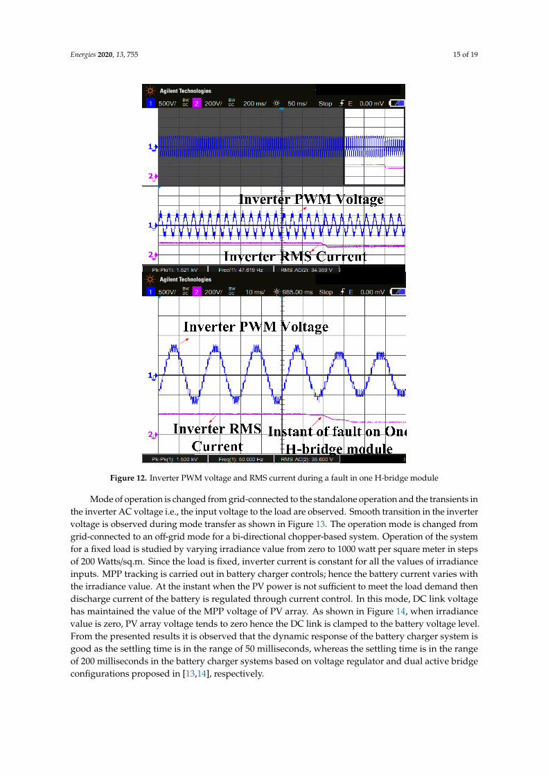
A fault on the H-Bridge module is created to verify system performance. The system continues tooperate with reduced power as shown in Figure 12. The proposed algorithm enables the fault-tolerantoperation instantaneously and the obtained results are in line with the simulation results presented in [1].
Energies 2020, 13, 755 15 of 19
Energies 2020, 13, x FOR PEER REVIEW 15 of 19
A fault on the H-Bridge module is created to verify system performance. The system continues to operate with reduced power as shown in Figure 12. The proposed algorithm enables the fault-tolerant operation instantaneously and the obtained results are in line with the simulation results presented in [1].
Figure 12. Inverter PWM voltage and RMS current during a fault in one H-bridge module
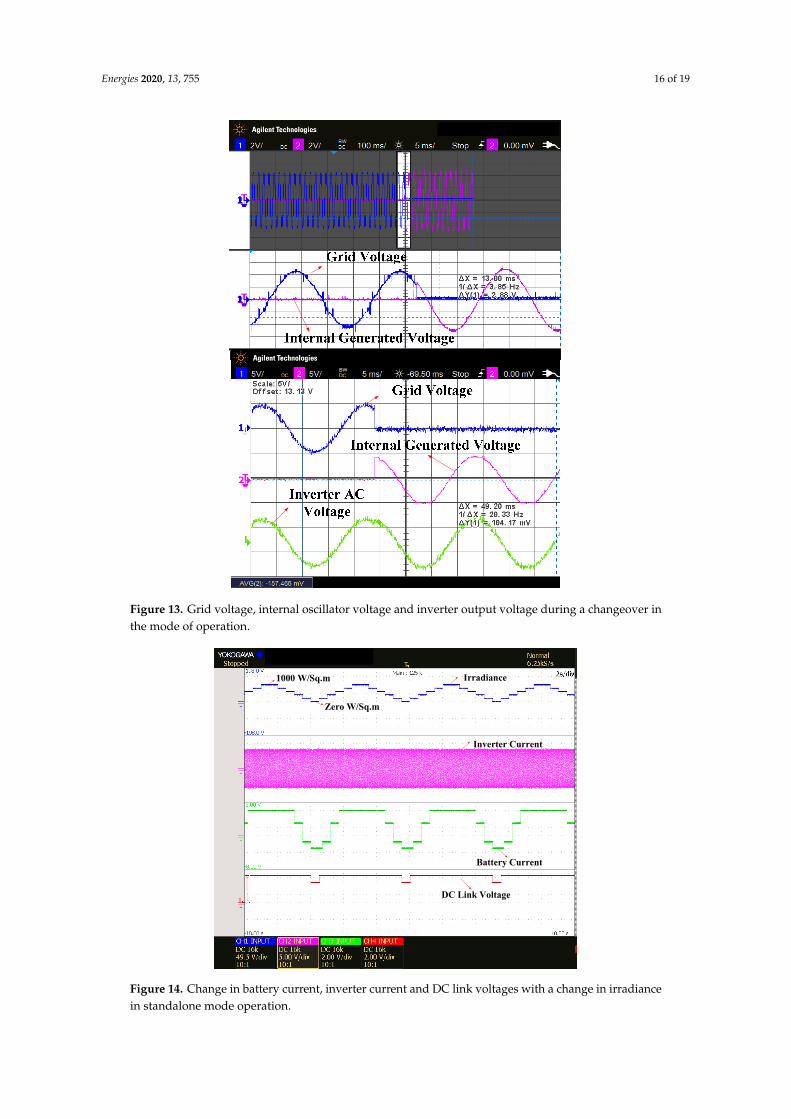
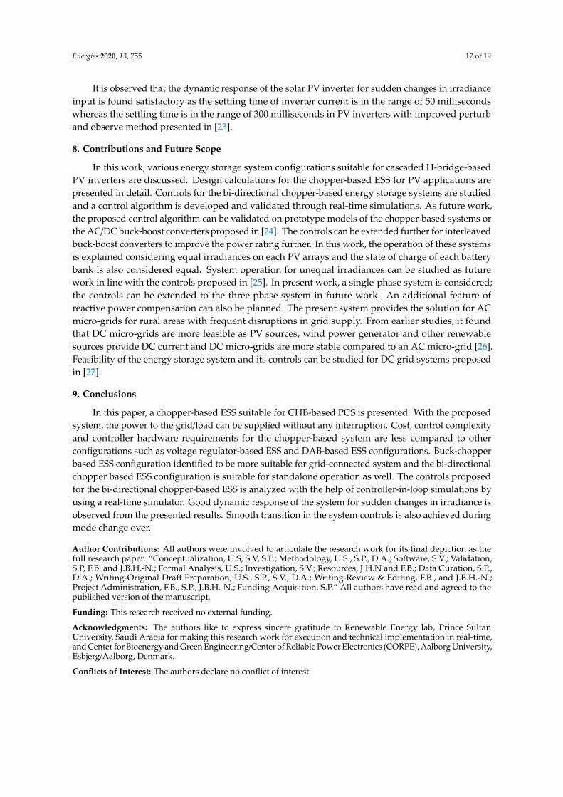
Mode of operation is changed from grid-connected to the standalone operation and the transients in the inverter AC voltage i.e., the input voltage to the load are observed. Smooth transition in the inverter voltage is observed during mode transfer as shown in Figure 13. The operation mode is changed from grid-connected to an off-grid mode for a bi-directional chopper-based system. Operation of the system for a fixed load is studied by varying irradiance value from zero to 1000 watt per square meter in steps of 200 Watts/sq.m. Since the load is fixed, inverter current is constant for all the values of irradiance inputs. MPP tracking is carried out in battery charger controls; hence the battery current varies with the irradiance value. At the instant when the PV power is not sufficient to meet the load demand then discharge current of the battery is regulated through current control. In this mode, DC link voltage has maintained the value of the MPP voltage of PV array. As shown in Figure 14, when irradiance value is zero, PV array voltage tends to zero hence the DC link is clamped to the battery voltage level. From the presented results it is observed that the dynamic response of the battery charger system is good as the settling time is in the range of 50 milliseconds, whereas the settling time is in the range of 200 milliseconds in the battery charger systems based on voltage regulator and dual active bridge configurations proposed in [13,14], respectively.
Figure 12. Inverter PWM voltage and RMS current during a fault in one H-bridge module
Mode of operation is changed from grid-connected to the standalone operation and the transients inthe inverter AC voltage i.e., the input voltage to the load are observed. Smooth transition in the invertervoltage is observed during mode transfer as shown in Figure 13. The operation mode is changed fromgrid-connected to an off-grid mode for a bi-directional chopper-based system. Operation of the systemfor a fixed load is studied by varying irradiance value from zero to 1000 watt per square meter in stepsof 200 Watts/sq.m. Since the load is fixed, inverter current is constant for all the values of irradianceinputs. MPP tracking is carried out in battery charger controls; hence the battery current varies withthe irradiance value. At the instant when the PV power is not sufficient to meet the load demand thendischarge current of the battery is regulated through current control. In this mode, DC link voltagehas maintained the value of the MPP voltage of PV array. As shown in Figure 14, when irradiancevalue is zero, PV array voltage tends to zero hence the DC link is clamped to the battery voltage level.From the presented results it is observed that the dynamic response of the battery charger system isgood as the settling time is in the range of 50 milliseconds, whereas the settling time is in the rangeof 200 milliseconds in the battery charger systems based on voltage regulator and dual active bridgeconfigurations proposed in [13,14], respectively.
Energies 2020, 13, 755 16 of 19
Energies 2020, 13, x FOR PEER REVIEW 16 of 19
Figure 13. Grid voltage, internal oscillator voltage and inverter output voltage during a changeover in the mode of operation.
Irradiance
Inverter Current
Battery Current
DC Link Voltage
1000 W/Sq.m
Zero W/Sq.m
Figure 14. Change in battery current, inverter current and DC link voltages with a change in irradiance in standalone mode operation.
Figure 13. Grid voltage, internal oscillator voltage and inverter output voltage during a changeover inthe mode of operation.
Energies 2020, 13, x FOR PEER REVIEW 16 of 19
Figure 13. Grid voltage, internal oscillator voltage and inverter output voltage during a changeover in the mode of operation.
Irradiance
Inverter Current
Battery Current
DC Link Voltage
1000 W/Sq.m
Zero W/Sq.m
Figure 14. Change in battery current, inverter current and DC link voltages with a change in irradiance in standalone mode operation.
Figure 14. Change in battery current, inverter current and DC link voltages with a change in irradiancein standalone mode operation.
Energies 2020, 13, 755 17 of 19
It is observed that the dynamic response of the solar PV inverter for sudden changes in irradianceinput is found satisfactory as the settling time of inverter current is in the range of 50 millisecondswhereas the settling time is in the range of 300 milliseconds in PV inverters with improved perturband observe method presented in [23].
8. Contributions and Future Scope
In this work, various energy storage system configurations suitable for cascaded H-bridge-basedPV inverters are discussed. Design calculations for the chopper-based ESS for PV applications arepresented in detail. Controls for the bi-directional chopper-based energy storage systems are studiedand a control algorithm is developed and validated through real-time simulations. As future work,the proposed control algorithm can be validated on prototype models of the chopper-based systems orthe AC/DC buck-boost converters proposed in [24]. The controls can be extended further for interleavedbuck-boost converters to improve the power rating further. In this work, the operation of these systemsis explained considering equal irradiances on each PV arrays and the state of charge of each batterybank is also considered equal. System operation for unequal irradiances can be studied as futurework in line with the controls proposed in [25]. In present work, a single-phase system is considered;the controls can be extended to the three-phase system in future work. An additional feature ofreactive power compensation can also be planned. The present system provides the solution for ACmicro-grids for rural areas with frequent disruptions in grid supply. From earlier studies, it foundthat DC micro-grids are more feasible as PV sources, wind power generator and other renewablesources provide DC current and DC micro-grids are more stable compared to an AC micro-grid [26].Feasibility of the energy storage system and its controls can be studied for DC grid systems proposedin [27].
9. Conclusions
In this paper, a chopper-based ESS suitable for CHB-based PCS is presented. With the proposedsystem, the power to the grid/load can be supplied without any interruption. Cost, control complexityand controller hardware requirements for the chopper-based system are less compared to otherconfigurations such as voltage regulator-based ESS and DAB-based ESS configurations. Buck-chopperbased ESS configuration identified to be more suitable for grid-connected system and the bi-directionalchopper based ESS configuration is suitable for standalone operation as well. The controls proposedfor the bi-directional chopper-based ESS is analyzed with the help of controller-in-loop simulations byusing a real-time simulator. Good dynamic response of the system for sudden changes in irradiance isobserved from the presented results. Smooth transition in the system controls is also achieved duringmode change over.
Author Contributions: All authors were involved to articulate the research work for its final depiction as thefull research paper. “Conceptualization, U.S, S.V, S.P.; Methodology, U.S., S.P., D.A.; Software, S.V.; Validation,S.P, F.B. and J.B.H.-N.; Formal Analysis, U.S.; Investigation, S.V.; Resources, J.H.N and F.B.; Data Curation, S.P.,D.A.; Writing-Original Draft Preparation, U.S., S.P., S.V., D.A.; Writing-Review & Editing, F.B., and J.B.H.-N.;Project Administration, F.B., S.P., J.B.H.-N.; Funding Acquisition, S.P.” All authors have read and agreed to thepublished version of the manuscript.
Funding: This research received no external funding.
Acknowledgments: The authors like to express sincere gratitude to Renewable Energy lab, Prince SultanUniversity, Saudi Arabia for making this research work for execution and technical implementation in real-time,and Center for Bioenergy and Green Engineering/Center of Reliable Power Electronics (CORPE), Aalborg University,Esbjerg/Aalborg, Denmark.
Conflicts of Interest: The authors declare no conflict of interest.
Energies 2020, 13, 755 18 of 19
References
1. Sridhar, V.; Umashankar, S. A comprehensive review on CHB MLI based PV inverter and feasibility study ofCHB MLI based PV-STATCOM. Renew. Sustain. Energy Rev. 2017, 78, 138–156. [CrossRef]
2. Yu, Y.; Konstantinou, G.; Hredzak, B.; Agelidis, V.G. Operation of Cascaded H-Bridge Multilevel Convertersfor Large-Scale Photovoltaic Power Plants under Bridge Failures. IEEE Trans. Ind. Electron. 2015,62, 7228–7236. [CrossRef]
3. Dragonas, F.A.; Neretti, G.; Sanjeevikumar, P.; Grandi, G. High-Voltage High-Frequency Arbitrary WaveformMultilevel Generator for DBD Plasma Actuators. IEEE Trans. Ind. Appl. 2015, 51, 3334–3342. [CrossRef]
4. Sridhar, V.; Umashankar, S.; Sanjeevikumar, P.; Ramachandaramurthy, V.K.; Mihet-Popa, L.; Fedák, V. ControlArchitecture for Cascaded H-Bridge Inverters in Large-Scale PV Systems. Energy Procedia 2018, 145, 549–557.[CrossRef]
5. Chen, L.; Chen, H.; Li, Y.; Li, G.; Yang, J.; Liu, X.; Xu, Y.; Ren, L.; Tang, Y. SMES-Battery Energy StorageSystem for the Stabilization of a Photovoltaic-Based Microgrid. IEEE Trans. Appl. Supercond. 2018, 28, 1–7.[CrossRef]
6. Rallabandi, V.; Akeyo, O.M.; Jewell, N.; Ionel, D.M. Incorporating Battery Energy Storage Systems IntoMulti-MW Grid Connected PV Systems. IEEE Trans. Ind. Appl. 2018, 55, 638–647. [CrossRef]
7. Yang, Y.; Ye, Q.; Tung, L.J.; Greenleaf, M.; Li, H. Integrated Size and Energy Management Design of BatteryStorage to Enhance Grid Integration of Large-Scale PV Power Plants. IEEE Trans. Ind. Electron. 2018,65, 394–402. [CrossRef]
8. Lai, C.S.; Jia, Y.; Lai, L.L.; Xu, Z.; McCulloch, M.D.; Wong, K.P. A comprehensive review on large-scalephotovoltaic system with applications of electrical energy storage. Renew. Sustain. Energy Rev. 2017,78, 439–451. [CrossRef]
9. O’Shaughnessy, E.; Cutler, D.; Ardani, K.; Margolis, R. Solar plus: Optimization of distributed solar PVthrough battery storage and dispatchable load in residential buildings. Appl. Energy 2018, 213, 11–21.[CrossRef]
10. Zhang, C.; Wei, Y.-L.; Cao, P.-F.; Lin, M.-C. Energy storage system: Current studies on batteries and powercondition system. Renew. Sustain. Energy Rev. 2018, 82, 3091–3106. [CrossRef]
11. Olaszi, B.D.; Ladanyi, J. Comparison of different discharge strategies of grid-connected residential PVsystems with energy storage in perspective of optimal battery energy storage system sizing. Renew. Sustain.Energy Rev. 2017, 75, 710–718. [CrossRef]
12. Rodríguez-Gallegos, C.D.; Gandhi, O.; Yang, D.; Alvarez-Alvarado, M.S.; Zhang, W.; Reindl, T.; Panda, S.K.A siting and sizing optimization approach for PV–battery–diesel hybrid systems. IEEE Trans. Ind. Appl.2017, 54, 2637–2645. [CrossRef]
13. Vavilapalli, S.; Subramaniam, U.; Padmanaban, S.; Ramachandaramurthy, V.K. Design and Real-TimeSimulation of an AC Voltage Regulator Based Battery Charger for Large-Scale PV-Grid Energy StorageSystems. IEEE Access 2017, 5, 25158–25170. [CrossRef]
14. Vavilapalli, S.; Padmanaban, S.; Subramaniam, U.; Mihet-Popa, L. Power Balancing Control for Grid EnergyStorage System in Photovoltaic Applications—Real Time Digital Simulation Implementation. Energies 2017,10, 928. [CrossRef]
15. Vavilapalli, S.; Umashankar, S.; Sanjeevikumar, P.; Fedák, V.; Mihet-Popa, L.; Ramachandaramurthy, V.K.A Buck-Chopper Based Energy Storage System for the Cascaded H-Bridge Inverters in PV Applications.Energy Procedia 2018, 145, 534–541. [CrossRef]
16. Sastry, J.; Bakas, P.; Kim, H.; Wang, L.; Marinopoulos, A. Evaluation of cascaded H-bridge inverter forutility-scale photovoltaic systems. Renew. Energy 2014, 69, 208–218. [CrossRef]
17. Wang, Z.; Fan, S.; Zheng, Y.; Cheng, M. Design and Analysis of a CHB Converter Based PV-Battery HybridSystem for Better Electromagnetic Compatibility. IEEE Trans. Magn. 2012, 48, 4530–4533. [CrossRef]
18. Kumar, N.; Saha, T.K.; Dey, J.; Barman, J.C. Modelling, control, and performance study of cascaded inverterbased grid connected PV system. In Proceedings of the IREC2015 the Sixth International Renewable EnergyCongress, Sousse, Tunisia, 24–26 March 2015; pp. 1–6.
19. Xiao, B.; Hang, L.; Mei, J.; Riley, C.; Tolbert, L.M.; Ozpineci, B. Modular Cascaded H-Bridge Multilevel PVInverter With Distributed MPPT for Grid-Connected Applications. IEEE Trans. Ind. Appl. 2014, 51, 1722–1731.[CrossRef]
Energies 2020, 13, 755 19 of 19
20. Iman-Eini, H.; Bacha, S.; Frey, D. Improved control algorithm for grid-connected cascaded H-bridgephotovoltaic inverters under asymmetric operating conditions. IET Power Electron. 2017, 11, 407–415.[CrossRef]
21. Samavatian, V.; Radan, A. A novel low-ripple interleaved buck–boost converter with high efficiency and lowoscillation for fuel-cell applications. Int. J. Electr. Power Energy Syst. 2014, 63, 446–454. [CrossRef]
22. Vavilapalli, S.; Subramaniam, U.; Padmanaban, S.; Blaabjerg, F. Design and Controller-In-Loop Simulationsof a Low Cost Two-Stage PV-Simulator. Energies 2018, 11, 2774. [CrossRef]
23. Kamran, M.; Mudassar, M.; Fazal, M.R.; Asghar, M.U.; Bilal, M.; Asghar, R. Implementation of improvedPerturb & Observe MPPT technique with confined search space for standalone photovoltaic system. J. KingSaud Univ. Eng. Sci. 2018, 30. [CrossRef]
24. Li, X.; Wu, W.; Wang, H.; Gao, N.; Chung, H.S.-H.; Blaabjerg, F. A New Buck-Boost AC/DC Converter withTwo-Terminal Output Voltage for DC Nano-Grid. Energies 2019, 12, 3808. [CrossRef]
25. Vavilapalli, S.; Umashankar, S.; Sanjeevikumar, P.; Ramachandaramurthy, V.K.; Mihet-Popa, L.; Fedák, V.Three-stage control architecture for cascaded H-Bridge inverters in large-scale PV systems—Real timesimulation validation. Appl. Energy 2018, 229, 1111–1127. [CrossRef]
26. Marcon, P.; Szabo, Z.; Vesely, I.; Zezulka, F.; Sajdl, O.; Roubal, Z.; Dohnal, P. A Real Model of a Micro-Grid toImprove Network Stability. Appl. Sci. 2017, 7, 757. [CrossRef]
27. Arunkumar, G.; Elangovan, D.; Sanjeevikumar, P.; Nielsen, J.B.H.; Leonowicz, Z.; Joseph, P.K. DC Grid forDomestic Electrification. Energies 2019, 12, 2157. [CrossRef]
© 2020 by the authors. Licensee MDPI, Basel, Switzerland. This article is an open accessarticle distributed under the terms and conditions of the Creative Commons Attribution(CC BY) license (http://creativecommons.org/licenses/by/4.0/).