a football kicking high speed actuator for a mobile robotic application
TRANSCRIPT
A Football Kicking High Speed Actuator for aMobile Robotic Application
K. J. Meessen, J. J. H. Paulides, E. A. LomonovaEindhoven University of Technology5612AZ Eindhoven, the Netherlands
Email: [email protected]
Abstract—This paper presents the design and validation of ahigh speed reluctance actuator for a soccer robot. The actuatoris used to shoot a regular sized soccer ball by applying differentforce levels directly to the ball. As the application requires force inonly one direction, a plunger type reluctance actuator is selected.A capacitor is used to buffer energy from the battery of therobot. Through an IGBT, the energy is transferred from thecapacitor to the actuator. Consequently, by applying pulse widthmodulation, the force applied by the actuator can be adjusted toenable a variable shooting power. The reluctance type actuatoris designed using finite element analysis. The actuator is buildand implemented in the robot providing the capability to shoota ball from standstill over 12 meters with a starting speed of 11m/s.
I. INTRODUCTION
RoboCup [1] is an international joint project to stimulate re-search in the field of artificial intelligence, robotics and relatedfields. A robot soccer game is used as the central topic wherea wide range of technologies can be developed and integrated.To establish intelligent motion for autonomous robots, sensing,signal processing, decision making and actuation have to workproperly. The large number of essential tasks that have to beintegrated results in a complex system where obtaining robustperformance is one of the main challenges.
The robots play soccer autonomously according to the FIFArules with a list of modifications such that it is suited forstate-of-the-art robotics. Several leagues exist where this paperconcerns a robot for the mid-size league, i.e., a wheeled robotwith a height of maximum 80 cm playing in a team of fiveon a field of 12 × 18 m.
This paper focusses on the shooting mechanism for a mobilefootball robot to shoot the ball with variable speed and overa variable distance. To define the system requirements veryaccurately, an extensive ball model should be taken intoaccount which includes e.g. pressure, stiffness, mass and theball material. Additionally, the exact position on the ballsurface where the robot hits the ball affects the ball behavior.Therefore, experience from previous shooting devices as wellas results from experiments (e.g. football games at europeanand world level, www.techunited.nl) are used to define therequirements. This has lead to the initial design requirementthat the ball has to be shot with an initial speed of at least10 m/s. Since the stroke of the actuator is limited due tothe volumetric constraints of the complete robot, a very highacceleration level up to 1000 ms−2 is required dependent on
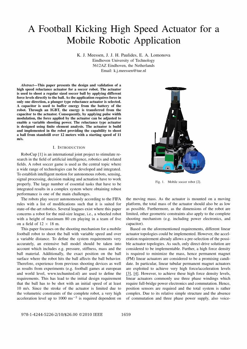
Fig. 1. Mobile soccer robot [2].
the moving mass. As the actuator is mounted on a movingplatform, the total mass of the actuator should also be as lowas possible. Furthermore, as the dimensions of the robot arelimited, other geometric constraints also apply to the completeshooting mechanism (e.g. including power electronics, andcapacitor).
Based on the aforementioned requirements, different linearactuator topologies could be implemented. However, the accel-eration requirement already allows a pre-selection of the possi-ble actuator topologies. As such, only direct-drive solution areconsidered to be implementable. Further, a high force densityis required to minimize the mass, hence permanent magnet(PM) linear actuators are considered to be a promising candi-date. In particular, linear tubular permanent magnet actuatorsare exploited to achieve very high force/acceleration levels[3], [4]. However, to achieve these high force density levels,linear actuators commonly use three phase windings whichrequire full-bridge power electronics and commutation. Hence,position sensors are required and the total system is rathercomplex. Due to its relative simple structure and the absenceof commutation and three phase power supply, also voice-
978-1-4244-5226-2/10/$26.00 ©2010 IEEE 1659
coil actuators are considered to be a promising candidate.However, these actuators typically have a short stroke withlimited force capability which is not considered to be sufficientfor this application. An alternative is the reluctance actuator(solenoid), which combines ”short-stroke” with a relative highforce density and a very simple structure. Therefore, a plungertype reluctance actuator has been selected and designed for thisapplication [5], [6].
In this paper, the design of the solenoid is presented aswell as the driving circuit of the actuator. In Section II therequirements of the actuator are treated and in Section IIIthe driving circuit is described. In Section IVb a magneto-static finite element analysis (FEA) is provided to investigatethe initial sizes. Section IVc presents the transient analysiswhich deals with the transient magnetic and electric behavior.Furthermore, this transient model is used to investigated theinfluence of the eddy currents on the performance of the sys-tem. The last section deals with the experimental verificationof the actuator integrated in the robot.
II. REQUIREMENTS
From measurements on previous shooting mechanisms andsimulations, the requirements of the solenoid are determinedas stated in Table I.
TABLE IREQUIREMENTS AND CONSTRAINTS
Property Value DescriptionS (mm) 80 Minimum strokeLax (mm) 220 Maximum actuator lengthDmax (mm) 95 Maximum actuator diametervf (m/s) 10 Final velocity at end of strokeUpeak (V) 450 Maximum allowable voltageIpeak (A) 100 Maximum allowable current
Besides the requirements concerning the force and sizes,the force produced by the actuator has to be repeatable andcontrollable. As the actuator is used to shoot a ball in a soccergame, it should be able to produce a high force when shootingat the goal and produce a lower force during a pass. To enablethe use of standard electric components, electric constraints aslisted in Table I have to be obeyed.
III. DRIVING CIRCUIT
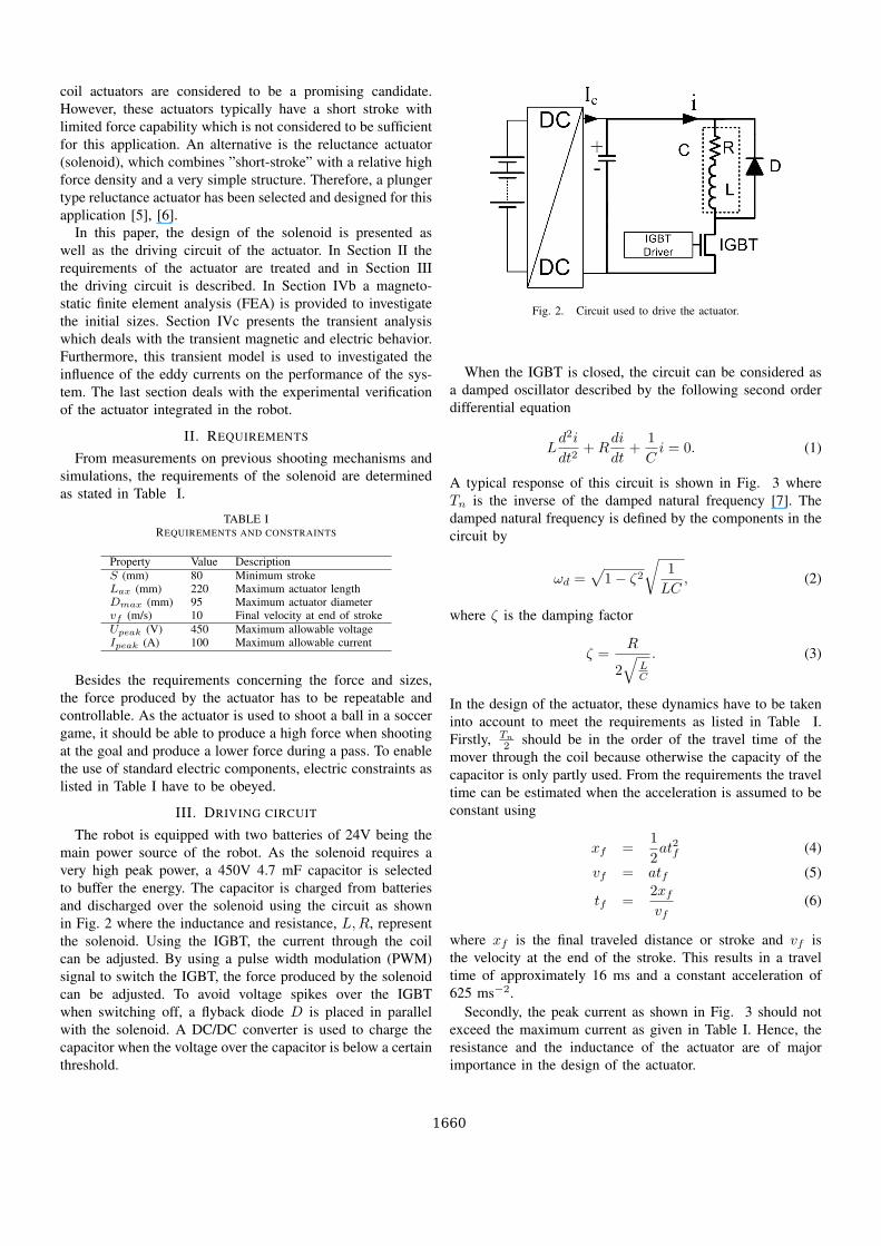
The robot is equipped with two batteries of 24V being themain power source of the robot. As the solenoid requires avery high peak power, a 450V 4.7 mF capacitor is selectedto buffer the energy. The capacitor is charged from batteriesand discharged over the solenoid using the circuit as shownin Fig. 2 where the inductance and resistance, L,R, representthe solenoid. Using the IGBT, the current through the coilcan be adjusted. By using a pulse width modulation (PWM)signal to switch the IGBT, the force produced by the solenoidcan be adjusted. To avoid voltage spikes over the IGBTwhen switching off, a flyback diode D is placed in parallelwith the solenoid. A DC/DC converter is used to charge thecapacitor when the voltage over the capacitor is below a certainthreshold.
Fig. 2. Circuit used to drive the actuator.
When the IGBT is closed, the circuit can be considered asa damped oscillator described by the following second orderdifferential equation
Ld2i
dt2+R
di
dt+
1Ci = 0. (1)
A typical response of this circuit is shown in Fig. 3 whereTn is the inverse of the damped natural frequency [7]. Thedamped natural frequency is defined by the components in thecircuit by
ωd =√
1− ζ2
√1LC
, (2)
where ζ is the damping factor
ζ =R
2√
LC
. (3)
In the design of the actuator, these dynamics have to be takeninto account to meet the requirements as listed in Table I.Firstly, Tn
2 should be in the order of the travel time of themover through the coil because otherwise the capacity of thecapacitor is only partly used. From the requirements the traveltime can be estimated when the acceleration is assumed to beconstant using
xf =12at2f (4)
vf = atf (5)
tf =2xfvf
(6)
where xf is the final traveled distance or stroke and vf isthe velocity at the end of the stroke. This results in a traveltime of approximately 16 ms and a constant acceleration of625 ms−2.
Secondly, the peak current as shown in Fig. 3 should notexceed the maximum current as given in Table I. Hence, theresistance and the inductance of the actuator are of majorimportance in the design of the actuator.
1660
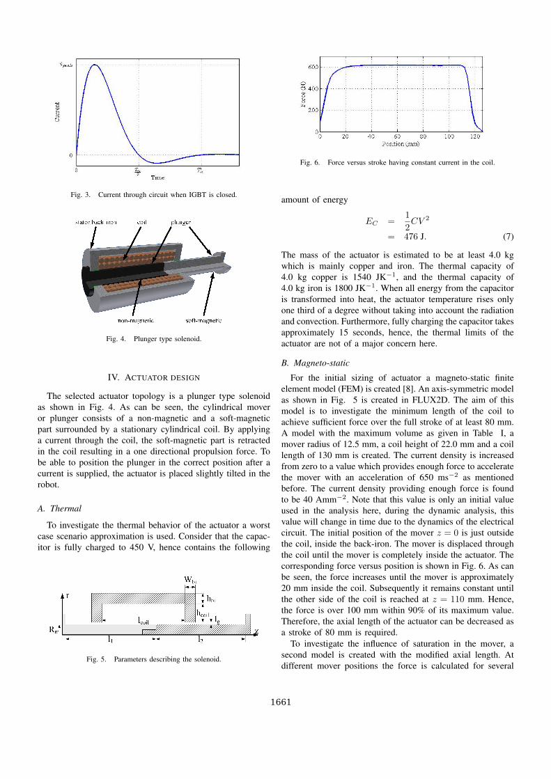
Fig. 3. Current through circuit when IGBT is closed.
Fig. 4. Plunger type solenoid.
IV. ACTUATOR DESIGN
The selected actuator topology is a plunger type solenoidas shown in Fig. 4. As can be seen, the cylindrical moveror plunger consists of a non-magnetic and a soft-magneticpart surrounded by a stationary cylindrical coil. By applyinga current through the coil, the soft-magnetic part is retractedin the coil resulting in a one directional propulsion force. Tobe able to position the plunger in the correct position after acurrent is supplied, the actuator is placed slightly tilted in therobot.
A. Thermal
To investigate the thermal behavior of the actuator a worstcase scenario approximation is used. Consider that the capac-itor is fully charged to 450 V, hence contains the following
Fig. 5. Parameters describing the solenoid.
Fig. 6. Force versus stroke having constant current in the coil.
amount of energy
EC =12CV 2
= 476 J. (7)
The mass of the actuator is estimated to be at least 4.0 kgwhich is mainly copper and iron. The thermal capacity of4.0 kg copper is 1540 JK−1, and the thermal capacity of4.0 kg iron is 1800 JK−1. When all energy from the capacitoris transformed into heat, the actuator temperature rises onlyone third of a degree without taking into account the radiationand convection. Furthermore, fully charging the capacitor takesapproximately 15 seconds, hence, the thermal limits of theactuator are not of a major concern here.
B. Magneto-static
For the initial sizing of actuator a magneto-static finiteelement model (FEM) is created [8]. An axis-symmetric modelas shown in Fig. 5 is created in FLUX2D. The aim of thismodel is to investigate the minimum length of the coil toachieve sufficient force over the full stroke of at least 80 mm.A model with the maximum volume as given in Table I, amover radius of 12.5 mm, a coil height of 22.0 mm and a coillength of 130 mm is created. The current density is increasedfrom zero to a value which provides enough force to acceleratethe mover with an acceleration of 650 ms−2 as mentionedbefore. The current density providing enough force is foundto be 40 Amm−2. Note that this value is only an initial valueused in the analysis here, during the dynamic analysis, thisvalue will change in time due to the dynamics of the electricalcircuit. The initial position of the mover z = 0 is just outsidethe coil, inside the back-iron. The mover is displaced throughthe coil until the mover is completely inside the actuator. Thecorresponding force versus position is shown in Fig. 6. As canbe seen, the force increases until the mover is approximately20 mm inside the coil. Subsequently it remains constant untilthe other side of the coil is reached at z = 110 mm. Hence,the force is over 100 mm within 90% of its maximum value.Therefore, the axial length of the actuator can be decreased asa stroke of 80 mm is required.
To investigate the influence of saturation in the mover, asecond model is created with the modified axial length. Atdifferent mover positions the force is calculated for several
1661
values of the current density in the range between 10 and60 Amm−2 resulting in flux density levels up to 3 Teslain the mover. The produced force is divided by the appliedcurrent resulting in a linear function for all positions exceptthe positions when the mover is almost completely inside thecoil. Hence, when the effective airgap is larger than 10 mm,the effect of mover saturation is negligible. Furthermore, thesizes of the back-iron are minimized to reduce the mass whileavoiding too high saturation levels.
A third FE model is created with the adapted sizes fromthe aforementioned analysis results, e.g. a coil length, lcoil of110 mm. In this model, the current density is again fixed at40 Amm−2. A parametric analysis is performed to investigatethe influence of the parameter hcoil on the inductance of thecoil. For all values of hcoil, the inductance is calculated atmultiple mover positions. Although the inductance of this typeof actuator is heavily dependent on position and current dueto saturation, a mean value of the inductance as function ofhcoil is calculated from the FEM model. This inductance valuerepresents the inductance for a coil having a single turn, L1
for a certain value of hcoil. The total inductance of the coilcan subsequently be calculated using
LN = L1N2, (8)
where N is the total number of turns. The resistance of thecoil is calculated using
RN = ρCul
AkfN2, (9)
where ρCu is the resistivity of copper, l is the mean length ofa single wire of the coil, A is the total coil area lcoil · hcoil,and kf is the filling factor of the coil which is assumed to be0.55 for an orthocyclic coil. By varying the number of turns,N , and the height of the coil, hcoil, the natural frequency (2)can be adjusted such that Tn
2 is approximately 16 ms withoutviolating the constraint on the maximum current. At the sametime the force needs to be maximized which is for this typeof actuator given by
F = −∆W ′f (z, i)
∆z
∣∣∣λ=constant
,
=i2(t)
2∂L(z)∂z
, (10)
where W ′f is the co-energy and i is the current through thecoil which should not exceed the maximum current as given inTable I. On the other hand, the height of the coil hcoil shouldbe minimized to reduce the total actuator mass.
Using this information, an initial value for hcoil and thenumber of turns are selected for the transient analysis.
C. Transient
Using the results from the magneto-static model, a fulltransient FE model is created to investigate the dynamicbehavior of the actuator. The circuit as shown in Fig. 2 isimplemented where a (stranded) coil conductor representsthe actuator coil in the circuit. This provides the ability to
TABLE IILOSSES IN THE ACTUATOR
Loss component EnergyCopper loss 231.4 JEddy current back-iron (FEM) 2.7 JEddy current soft-magnetic mover (FEM) 5.7 JEddy current non-magnetic mover (FEM) 13.9 J
include the dynamic behavior of the circuit in the FEA. Theinitial sizes and number of turns selected using the results ofthe magneto-static analysis are adapted such that the criteriaas mentioned in the previous section are met including alldynamic effects.
A final FE model is created which includes the calculationof eddy current losses in three different parts of the actuatornamely, the back-iron, the soft-magnetic part of the mover andthe non-magnetic part of the mover. The back-iron encountersa time varying magnetic field solely due to the current whilethe mover experiences a time-varying field due to the currentas well as the movement. The back-iron and the soft-magneticpart of the mover are made of (solid) iron (st 37.3, 1.0114).To withstand the mechanical stress when the mover collideswith the ball, or with other objects, the non-magnetic part ismade of aluminum instead of an electrically non-conductingmaterial. The results from the FEA are shown in Table II. Ascan be seen the losses in the aluminum part of the moverare the most significant however, the losses are still muchlower than the copper losses, the other loss component. Tominimize the losses in the soft-magnetic parts of the actuator,normally laminated structures are used. However, laminationfor these type of cylindrical actuators with an axial flux flowshould have a wedge shape. To create a robust mechanicalstructure from these type of wedge shaped parts will bedifficult. Therefore, the final design contains solely solid steelparts. Having these type of materials, the requirements are stillmet.
D. Final design
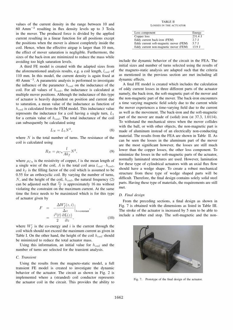
From the preceding sections, a final design as shown inFig. 7 is obtained with the dimensions as listed in Table III.The stroke of the actuator is increased by 5 mm to be able toinclude a rubber end stop. The soft-magnetic and the non-
Fig. 7. Prototype of the final design of the actuator.
1662
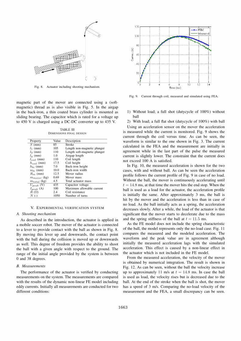
Fig. 8. Actuator including shooting mechanism.
magnetic part of the mover are connected using a (soft-magnetic) thread as is also visible in Fig. 5. In the airgapin the back-iron, a thin coated brass cylinder is mounted assliding bearing. The capacitor which is rated for a voltage upto 450 V is charged using a DC-DC converter up to 435 V.
TABLE IIIDIMENSIONS FINAL DESIGN
Property Value DescriptionS (mm) 85 Strokel1 (mm) 105 Length non-magnetic plungerl2 (mm) 110 Length soft-magnetic plungerlg (mm) 1.0 Airgap lengthlcoil (mm) 110 Coil lengthhcoil (mm) 17.5 Coil heighthbi (mm) 7.0 Back-iron heightwbi (mm) 10.0 Back-iron widthRm (mm) 12.5 Mover radiusmmover (kg) 0.69 Mover massmtotal (kg) 4.5 Total actuator massUpeak (V) 435 Capacitor voltageIpeak (A) 100 Maximum allowable currentR (Ω) 2.4 Coil resistanceN (-) 1050 Number of turns
V. EXPERIMENTAL VERIFICATION SYSTEM
A. Shooting mechanism
As described in the introduction, the actuator is applied ina mobile soccer robot. The mover of the actuator is connectedto a lever to provide contact with the ball as shown in Fig. 8.By moving this lever up and downwards, the contact pointwith the ball during the collision is moved up or downwardsas well. This degree of freedom provides the ability to shootthe ball with a given angle with respect to the ground. Therange of the initial angle provided by the system is between0 and 38 degrees.
B. Measurements
The performance of the actuator is verified by conductingmeasurements on the system. The measurements are comparedwith the results of the dynamic non-linear FE model includingeddy currents. Initially all measurements are conducted for twodifferent conditions:
Fig. 9. Current through coil, measured and simulated using FEA.
1) Without load; a full shot (dutycycle of 100%) withoutball
2) With load; a full flat shot (dutycycle of 100%) with ballUsing an acceleration sensor on the mover the acceleration
is measured while the current is monitored. Fig. 9 shows thecurrent through the coil versus time. As can be seen, thewaveform is similar to the one shown in Fig. 3. The currentcalculated in the FEA and the measurement are initially inagreement while in the last part of the pulse the measuredcurrent is slightly lower. The constraint that the current doesnot exceed 100 A is satisfied.
In Fig. 10, the measured acceleration is shown for the twocases, with and without ball. As can be seen the accelerationprofile follows the current profile of Fig. 9 in case of no load.Without the ball, the mover is continuously accelerating untilt = 14.8 ms, at that time the mover hits the end stop. When theball is used as a load for the actuator, the acceleration profileis initially the same. After approximately 3 ms, the ball ishit by the mover and the acceleration is less than in case ofno load. As the ball initially acts as a spring, the accelerationdecreases slowly. After a while, the load of the actuator is thatsignificant that the mover starts to decelerate due to the massand the spring stiffness of the ball at t = 11.5 ms.
As the FE model does not include the spring characteristicof the ball, the model represents only the no-load case. Fig. 11compares the measured and the modeled acceleration. Thewaveform and the peak value are in agreement althoughinitially the measured acceleration lags with the simulatedacceleration. This effect is caused by a non-linear effect inthe actuator which is not included in the FE model.
From the measured acceleration, the velocity of the moveris obtained by numerical integration. The result is shown inFig. 12. As can be seen, without the ball the velocity increaseup to approximately 11 m/s at t = 14.8 ms. In case the ballis used as load, the velocity rises but is decreased due to theball. At the end of the stroke when the ball is shot, the moverhas a speed of 3 m/s. Comparing the no-load velocity of themeasurement and the FEA, a small discrepancy can be seen.
1663
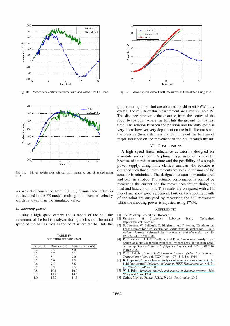
Fig. 10. Mover acceleration measured with and without ball as load.
Fig. 11. Mover acceleration without ball, measured and simulated usingFEA.
As was also concluded from Fig. 11, a non-linear effect isnot included in the FE model resulting in a measured velocitywhich is lower than the simulated value.
C. Shooting power
Using a high speed camera and a model of the ball, themovement of the ball is analyzed during a lob shot. The initialspeed of the ball as well as the point where the ball hits the
TABLE IVSHOOTING PERFORMANCE
Dutycycle Distance (m) Initial speed (m/s)0.2 2.5 5.00.3 3.7 6.10.4 5.1 7.00.5 6.0 7.90.6 7.5 8.60.7 8.9 9.30.8 10.1 10.00.9 11.2 10.51.0 12.2 11.2
Fig. 12. Mover speed without ball, measured and simulated using FEA.
ground during a lob shot are obtained for different PWM dutycycles. The results of this measurement are listed in Table IV.The distance represents the distance from the center of therobot to the point where the ball hits the ground for the firsttime. The relation between the position and the duty cycle isvery linear however very dependent on the ball. The mass andthe pressure (hence stiffness and damping) of the ball are ofmajor influence on the movement of the ball through the air.
VI. CONCLUSIONS
A high speed linear reluctance actuator is designed fora mobile soccer robot. A plunger type actuator is selectedbecause of its robust structure and the possibility of a simplepower supply. Using finite element analysis, the actuator isdesigned such that all requirements are met and the mass of theactuator is minimized. The designed actuator is manufacturedand built in a robot. The actuator performance is verified bymeasuring the current and the mover acceleration during noload and load conditions. The results are compared with a FEmodel and show good agreement. Further, the shooting resultsof the robot are analyzed by measuring the ball movementwhile the shooting power is adjusted using PWM.
REFERENCES
[1] The RoboCup Federation, “Robocup.”[2] University of Eindhoven Robocup Team, “Techunited,
http://www.techunited.nl.”[3] N. Jakeman, W. Bullough, C. Binghama, and P. Mellor, “Brushless pm
linear actuator for high acceleration textile winding applications,” Inter-national Journal of Applied Electromagnetics and Mechanics, vol. 19,pp. 237–242, April 2004.
[4] K. J. Meessen, J. J. H. Paulides, and E. A. Lomonova, “Analysis anddesign of a slotless tubular permanent magnet actuator for high accel-eration applications,” Journal of Applied Physics, vol. 105, p. 07F110,March 2009.
[5] C. R. Underhill, “Solenoids,” American Institute of Electrical Engineers,Transactions of the, vol. XXXIII, pp. 477 –517, jan. 1914.
[6] B. Lequesne, “Finite-element analysis of a constant-force solenoid forfluid flow control,” Industry Applications, IEEE Transactions on, vol. 24,pp. 574 –581, jul/aug 1988.
[7] W. J. Palm, Modeling analysis and control of dynamic systems. JohnWiley and Sons, 1994.
[8] Cedrat, Meylan, France, FLUX2D 10.3 User’s guide, 2010.
1664