robonet startup/maintenance - intelligent actuator
TRANSCRIPT
Operation Manual First Edition
ROBONET Startup/Maintenance


Introduction Thank you for purchasing IAI’s ROBONET. “ROBONET” is a general term for dedicated single-axis controllers used in a field network environment characterized by super-compact size, wire-saving design, and easy installation. This manual describes the information you need to know to use your ROBONET. Before using your ROBONET, be sure to read this manual and fully understand the items described herein.
• Unauthorized reproduction of this manual, whether in part or in whole, is strictly prohibited. • The content of this manual is subject to change without notice for the sake of improvement. • We have made every effort to ensure accuracy of the information provided in this manual. Should
you find an error, however, or have any comment, please contact IAI.
Safety Precautions (Please read before using the product.) Before installing, operating, maintaining or inspecting this product, please peruse this operating manual as well as the operating manuals and other related documentations for all equipment and peripheral devices connected to this product in order to ensure the correct use of this product and connected equipment/devices. Those performing installation, operation, maintenance and inspection of the product must have sufficient knowledge of the relevant equipment and their safety. The precautions provided below are designed to help you use the product safely and avoid bodily injury and/or property damage.
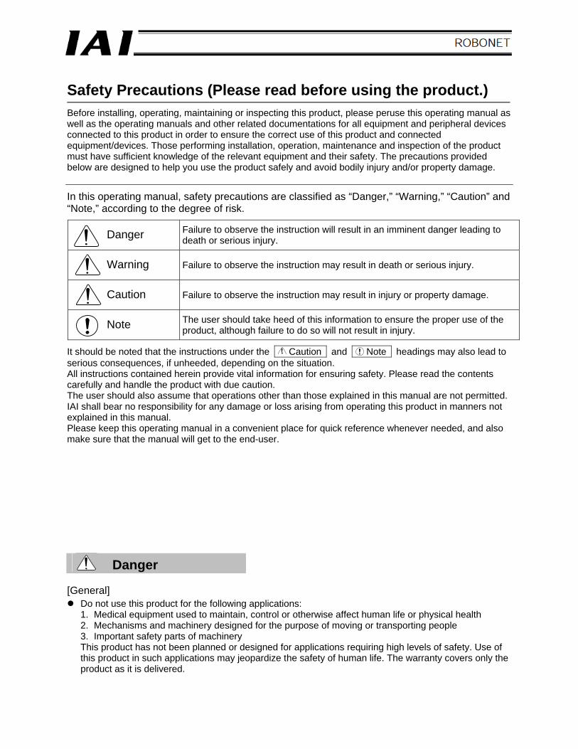
In this operating manual, safety precautions are classified as “Danger,” “Warning,” “Caution” and “Note,” according to the degree of risk.
Danger Failure to observe the instruction will result in an imminent danger leading to death or serious injury.
Warning Failure to observe the instruction may result in death or serious injury.
Caution Failure to observe the instruction may result in injury or property damage.
Note The user should take heed of this information to ensure the proper use of the product, although failure to do so will not result in injury.
It should be noted that the instructions under the Caution and Note headings may also lead to serious consequences, if unheeded, depending on the situation. All instructions contained herein provide vital information for ensuring safety. Please read the contents carefully and handle the product with due caution. The user should also assume that operations other than those explained in this manual are not permitted. IAI shall bear no responsibility for any damage or loss arising from operating this product in manners not explained in this manual. Please keep this operating manual in a convenient place for quick reference whenever needed, and also make sure that the manual will get to the end-user.
Danger [General]
Do not use this product for the following applications: 1. Medical equipment used to maintain, control or otherwise affect human life or physical health 2. Mechanisms and machinery designed for the purpose of moving or transporting people 3. Important safety parts of machinery This product has not been planned or designed for applications requiring high levels of safety. Use of this product in such applications may jeopardize the safety of human life. The warranty covers only the product as it is delivered.
[Installation]
Do not use this product in a place exposed to ignitable, inflammable or explosive substances. The product may ignite, burn or explode.
Avoid using the product in a place where the product may come in contact with water or oil droplets. Never cut and/or reconnect the cables supplied with the product for the purpose of extending or
shortening the cable length. Doing so may result in fire. [Operation]
Do not allow the product to come in contact with water. If the product contacts water or is washed with water, it may operate abnormally and cause injury, electric shock, fire, etc.
[Maintenance, Inspection, Repair]
Never modify the product. Unauthorized modification may cause the product to malfunction, resulting in injury, electric shock, fire, etc.
Do not disassemble and reassemble the product. Doing so may result in injury, electric shock, fire, etc.
Warning [General]
Do not use the product outside the specifications. Using the product outside the specifications may cause it to fail, stop functioning or sustain damage. It may also significantly reduce the service life of the product. In particular, observe the maximum loading capacity, acceleration/deceleration speed and speed.
[Installation]
If the machine will stop in the case of system problem such as emergency stop or power failure, design a safety circuit or other device that will prevent equipment damage or injury. Also take safety measures so that the product will not be started only by canceling an emergency stop or upon restoration of power after a power outage.
Be sure to provide Class D grounding for the controller and actuator (formerly Class 3 grounding: Grounding resistance at 100 Ω or less). Leakage current may cause electric shock or malfunction.
Before supplying power to and operating the product, always check the operation area of the equipment to ensure safety. Supplying power to the product carelessly may cause electric shock or injury due to contact with the moving parts.
Wire the product correctly by referring to the operation manual. Securely connect the cables and connectors so that they will not be disconnected or come loose. Failure to do so may cause the product to malfunction or cause fire.
[Operation]
Do not touch the terminal block or various switches while the power is supplied to the product. Failure to observe this instruction may result in electric shock or malfunction.
Before operating the moving parts of the product by hand (for the purpose of manual positioning, etc.), confirm that the servo is turned off (using the teaching pendant and PC software). Failure to observe this instruction may result in injury.
Do not scratch the cables. Scratching, forcibly bending, pulling, winding, crushing with heavy object or pinching a cable may cause it to leak current or lose continuity, resulting in fire, electric shock, malfunction, etc.
If you find the product exhibiting any abnormal symptom, such as generation of heat, smoke, fire or
smell, turn off the power immediately. Continuing to use the product may damage the product or cause it to ignite, or even lead to bodily injury.
If any of the internal protective devices (alarms) of the product has actuated, turn off the power immediately. Continuing to use the product may result in product damage or injury due to malfunction. Once the power supply is cut off, investigate and remove the cause and then turn on the power again.
[Maintenance, Inspection, Repair]
Before conducting maintenance/inspection, parts replacement or other operations on the product, completely shut down the power supply. At this time, take the following measures: 1. Display a sign that reads, “WORK IN PROGRESS. DO NOT TURN ON POWER” at a conspicuous
place, in order to prevent a person other than the operator from accidentally turning on the power. 2. When two or more operators are to perform maintenance/inspection together, always call out every
time the power is turned on/off or an axis is moved in order to ensure safety. [Disposal]
Do not throw the product into fire. The product may burst or generate toxic gases.
Caution [Installation]
Do not use the product under direct sunlight (UV ray), in a place exposed to dust, salt or iron powder, in a humid place, or in an atmosphere of organic solvent, phosphate-ester machine oil, etc. The product may lose its function over a short period of time, or exhibit a sudden drop in performance or its service life may be significantly reduced. The product may also malfunction.
Do not use the product in an atmosphere of corrosive gases (sulfuric acid or hydrochloric acid), etc. Rust may form and reduce the structural strength.
When using the product in any of the places specified below, provide a sufficient shield. Failure to do so may result in malfunction: 1. Place where large current or high magnetic field is present 2. Place where welding or other operations are performed that cause arc discharge 3. Place subject to electrostatic noise 4. Place with potential exposure to radiation
Do not install the product in a place subject to large vibration or impact (4.9m/S2 or more). Doing so may result in the malfunctioning of the product.
Provide an emergency-stop device in a readily accessible position so the device can be actuated immediately upon occurrence of a dangerous situation during operation. Lack of such device in an appropriate position may result in injury.
Provide sufficient maintenance space when installing the product. Routine inspection and maintenance cannot be performed without sufficient space, which will eventually cause the equipment to stop or the product to sustain damage.
Always use IAI’s genuine cables for connection between the controller and the actuator. Also use IAI’s genuine products for the key component units such as the actuator, controller and teaching pendant.
Before installing or adjusting the product or performing other operations on the product, display a sign that reads, “WORK IN PROGRESS. DO NOT TURN ON POWER.” If the power is turned on inadvertently, injury may result due to electric shock or sudden activation of an actuator.
[Operation]
Take safety measures so that the product will not be started only by turning on the power. Failure to do so may cause the product to start suddenly, resulting in injury or product damage.
Do not insert a finger or object in the openings in the product. It may cause fire, electric shock or injury. [Maintenance, Inspection, Repair]
Do not touch the terminals when performing an insulation resistance test. Electric shock may result. (Do not perform any withstand voltage test, since the product uses DC voltage.)
Note [Installation]
Do not place objects around the controller that will block airflows. Insufficient ventilation may damage the controller.
Configure a control circuit to prevent the work, etc., from dropping when the power to the mechanical equipment is cut off or an emergency stop is actuated.
[Installation, Operation, Maintenance]
When installing the actuator or carrying out other tasks, wear safety gloves, goggles and shoes and/or other safety gears as necessary to ensure safety.
[Disposal]
When the product becomes no longer usable or necessary, dispose of it properly as an industrial waste.
Others
IAI shall not be liable whatsoever for any loss or damage arising from a failure to observe the items specified in “Safety Precautions.”
The company names and product names mentioned in this manual may be the trademarks or registered trademarks of their respective owners and are hereby acknowledged.
Warranty
The ROBONET you have purchased passed IAI’s shipping inspection implemented under the strictest standards. Your ROBONET is covered by the following warranty:
(1) Warranty period
The warranty period shall be one of the following periods, whichever ends first: • 18 months after shipment from our factory • 12 months after delivery to a specified location
(2) Scope of warranty
If an obvious manufacturing defect is found during the above period under an appropriate condition of use, IAI will provide a replacement unit or repair the defective product free of charge. Note, however, that the following items are excluded from the scope of warranty: [1] Defect caused by handling or use in a condition or environment not explained in the catalog or
operation manual, etc. [2] Defect attributable to a product not manufactured by IAI [3] Defect caused by an alteration or repair not carried out by IAI or its agent [4] Defect not predictable when the product was shipped from IAI based on the science and
technology available at the time [5] Defect caused by an act of God, accident or other event beyond the control of IAI [6] Aging such as natural discoloration of coating [7] Wear of a consumable part due to use [8] Noise or other sensory deviation that doesn’t affect the function of the facility The warranty covers only the product as it has been delivered by IAI and shall not cover any losses arising from a failure of the delivered product. The defective product must be brought to our factory for repair.
(3) Limited liability
IAI shall bear no responsibility for any special, indirect or passive losses attributable to IAI’s product.
Related manuals
• ROBONET Operation Manual – Specification • PC Software RCM-101-** Operation Manual • RCM-* Teaching Pendant Operation Manual • Serial Communication Protocol [Modbus] Operation Manual • Touch Panel Display RCM-PM-01 Operation Manual
Revision history of the manual
[1] April 20, 2007 Draft [2] 2007 First Edition
Table of Contents
Chapter 1 Overview....................................................................................................... 1
1.1 Introduction ..................................................................................................................... 1 1.2 Required Tools................................................................................................................ 1 1.3 Startup Procedure........................................................................................................... 2
Chapter 2 Mounting and Installation.............................................................................. 3
2.1 Installation....................................................................................................................... 3 2.1.1 Important Information and Items to Note.............................................................. 3 2.1.2 Mounting on a DIN Rail ........................................................................................ 7 2.1.3 Interconnecting Multiple Units .............................................................................. 9 2.1.4 Installing in a Control Panel.................................................................................11
2.2 Wiring............................................................................................................................ 12 2.2.1 Wiring the Power Supply .................................................................................... 12 2.2.2 Grounding Wire .................................................................................................. 13 2.2.3 EMG Connector.................................................................................................. 13 2.2.4 Motor Cable and Encoder Cable ........................................................................ 14 2.2.5 Network Wiring ................................................................................................... 16
(1) CC-Link....................................................................................................... 16 (2) DeviceNet ................................................................................................... 17 (3) RS485SIO................................................................................................... 19
Chapter 3 Controller Address Setting .......................................................................... 20
Chapter 4 Absolute Reset ........................................................................................... 21
4.1 Overview of Simple Absolute System........................................................................... 21 4.2 Setting the Configuration Switches............................................................................... 22 4.3 Connecting the Backup Battery .................................................................................... 24 4.4 Setting the Parameters ................................................................................................. 24 4.5 Performing an Absolute Reset...................................................................................... 24
4.5.1 Performing an Absolute Reset in the PC Software ............................................ 24 4.5.2 Performing an Absolute Reset from the Host..................................................... 26
Chapter 5 Network Setup ............................................................................................ 27
5.1 How to Use the ROBONET Gateway Parameter Setting Tool ..................................... 27 5.1.1 Operating Environment ...................................................................................... 27 5.1.2 Launching the Setting Tool ................................................................................. 27 5.1.3 Explanation of the Main Screen ......................................................................... 28 5.1.4 Operating Procedures ........................................................................................ 32
5.2 Setting Up the ROBONET ............................................................................................ 37
5.2.1 Launching the “ROBONET Gateway Parameter Setting Tool”........................... 38 5.2.2 Setting the Gateway Parameters in the Main Screen ........................................ 39 5.2.3 Transferring the Gateway Parameters ............................................................... 42 5.2.4 Restarting the Gateway R Unit........................................................................... 43
5.3 Setting Up the Master ................................................................................................... 45 5.3.1 CC-Link............................................................................................................... 45 5.3.2 DeviceNet ........................................................................................................... 51 5.3.3 ProfiBus .............................................................................................................. 64 5.3.4 RS485SIO .......................................................................................................... 69
5.4 Creating a Controller Position Table ............................................................................. 83 5.5 Address Correlation Diagram ....................................................................................... 85
5.5.1 Address Correlation Diagram for CC-Link System............................................. 86 5.5.2 Address Correlation Diagram for DeviceNet System......................................... 88 5.5.3 Address Correlation Diagram for RS485SIO System ........................................ 89
Chapter 6 Troubleshooting .......................................................................................... 90
6.1 Actions to Be Taken upon Problems............................................................................. 90 6.2 Alarms of the Gateway R Unit ...................................................................................... 91
6.2.1 Common Alarms................................................................................................. 92 6.2.2 Alarms by Field Network Type............................................................................ 93 6.2.3 Examples of Indicator Statuses Corresponding to Representative Alarms........ 96
6.3 Alarms of the Controller Unit and Simple Absolute R Unit ........................................... 97 6.3.1 Overview of Alarms............................................................................................. 97 6.3.2 Alarms, Causes and Actions ............................................................................ 100 6.3.3 Messages Displayed during Operation Using the Teaching Pendant
or PC Software ................................................................................................. 108
Chapter 7 Maintenance/Inspection.............................................................................110
7.1 Periodic Inspection Items.............................................................................................111 7.2 Important Information on Unit Replacement................................................................112 7.3 Replacing the Backup Battery .....................................................................................113

1
Chapter 1 Overview 1.1 Introduction This operation manual (ROBONET Operation Manual – Startup/Maintenance) describes the procedure to start the ROBONET system, troubleshooting tips, and maintenance/inspection. Before starting your ROBONET system based on this operation manual, peruse the separate volume “ROBONET Operation Manual – Specification.” 1.2 Required Tools The tools needed to configure a ROBONET system and start the system include the PC software, teaching pendant, and ROBONET gateway parameter setting tool, as specified below.
[1] PC software RCM-101-** Version 6.0.4.0 or later [2] Teaching pendant
• RCM-T/TD Version 2.06 or later • RCM-E/P Version 2.08 or later • CON-T/TD Version 1.00 or later
[3] ROBONET gateway parameter setting tool Version 1.0.0.2 or later * This tool is provided in the CD-ROM containing PC software (Control No. CDCON00006 or
later). You can also download the tool from our website.
2
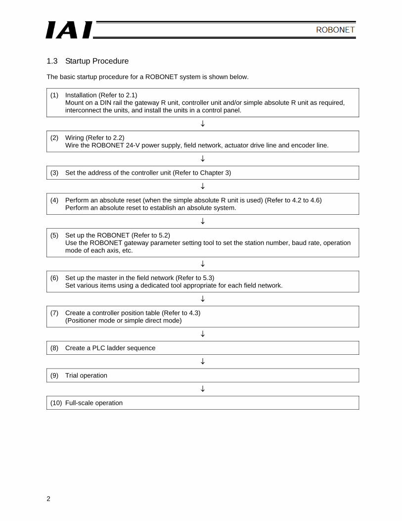
1.3 Startup Procedure The basic startup procedure for a ROBONET system is shown below.
(1) Installation (Refer to 2.1) Mount on a DIN rail the gateway R unit, controller unit and/or simple absolute R unit as required, interconnect the units, and install the units in a control panel.
↓
(2) Wiring (Refer to 2.2) Wire the ROBONET 24-V power supply, field network, actuator drive line and encoder line.
↓
(3) Set the address of the controller unit (Refer to Chapter 3)
↓
(4) Perform an absolute reset (when the simple absolute R unit is used) (Refer to 4.2 to 4.6) Perform an absolute reset to establish an absolute system.
↓
(5) Set up the ROBONET (Refer to 5.2) Use the ROBONET gateway parameter setting tool to set the station number, baud rate, operation mode of each axis, etc.
↓
(6) Set up the master in the field network (Refer to 5.3) Set various items using a dedicated tool appropriate for each field network.
↓
(7) Create a controller position table (Refer to 4.3) (Positioner mode or simple direct mode)
↓
(8) Create a PLC ladder sequence
↓
(9) Trial operation
↓
(10) Full-scale operation
3
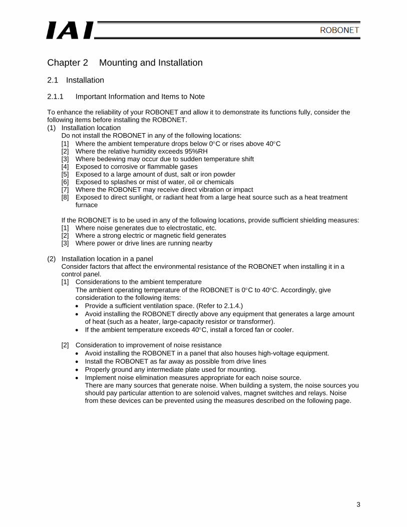
Chapter 2 Mounting and Installation 2.1 Installation 2.1.1 Important Information and Items to Note To enhance the reliability of your ROBONET and allow it to demonstrate its functions fully, consider the following items before installing the ROBONET. (1) Installation location
Do not install the ROBONET in any of the following locations: [1] Where the ambient temperature drops below 0°C or rises above 40°C [2] Where the relative humidity exceeds 95%RH [3] Where bedewing may occur due to sudden temperature shift [4] Exposed to corrosive or flammable gases [5] Exposed to a large amount of dust, salt or iron powder [6] Exposed to splashes or mist of water, oil or chemicals [7] Where the ROBONET may receive direct vibration or impact [8] Exposed to direct sunlight, or radiant heat from a large heat source such as a heat treatment
furnace If the ROBONET is to be used in any of the following locations, provide sufficient shielding measures: [1] Where noise generates due to electrostatic, etc. [2] Where a strong electric or magnetic field generates [3] Where power or drive lines are running nearby
(2) Installation location in a panel
Consider factors that affect the environmental resistance of the ROBONET when installing it in a control panel. [1] Considerations to the ambient temperature
The ambient operating temperature of the ROBONET is 0°C to 40°C. Accordingly, give consideration to the following items: • Provide a sufficient ventilation space. (Refer to 2.1.4.) • Avoid installing the ROBONET directly above any equipment that generates a large amount
of heat (such as a heater, large-capacity resistor or transformer). • If the ambient temperature exceeds 40°C, install a forced fan or cooler.
[2] Consideration to improvement of noise resistance
• Avoid installing the ROBONET in a panel that also houses high-voltage equipment. • Install the ROBONET as far away as possible from drive lines • Properly ground any intermediate plate used for mounting. • Implement noise elimination measures appropriate for each noise source.
There are many sources that generate noise. When building a system, the noise sources you should pay particular attention to are solenoid valves, magnet switches and relays. Noise from these devices can be prevented using the measures described on the following page.
4
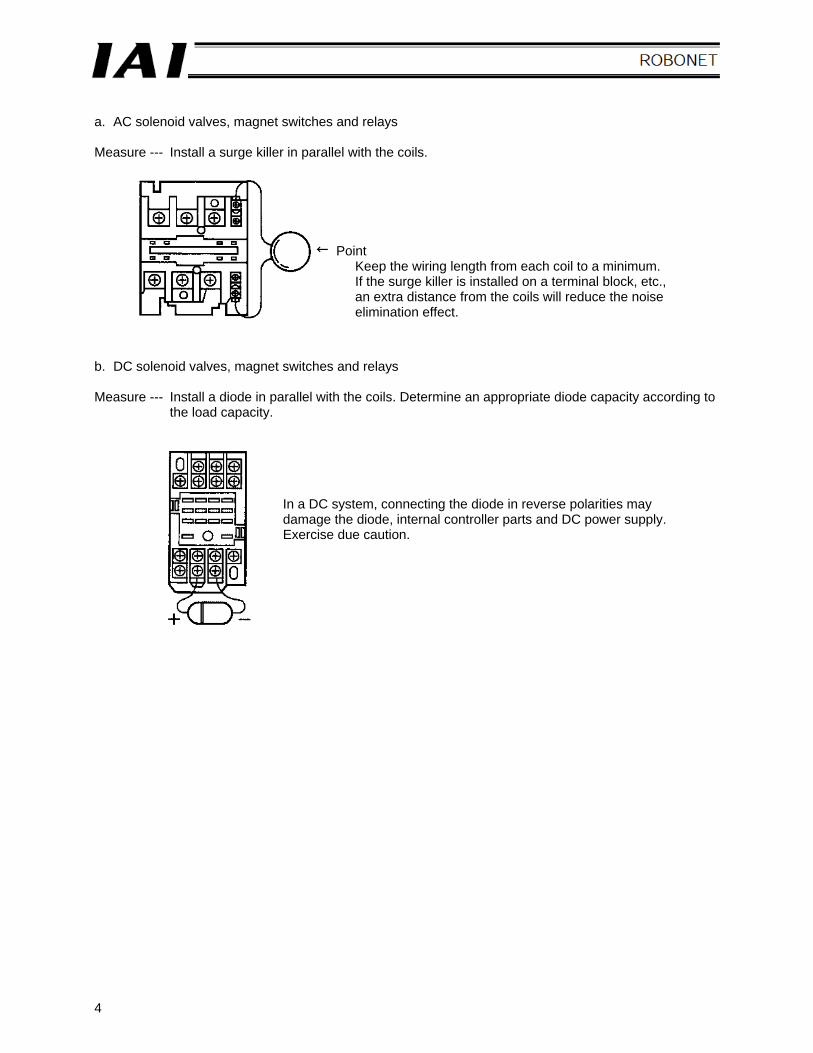
a. AC solenoid valves, magnet switches and relays Measure --- Install a surge killer in parallel with the coils. b. DC solenoid valves, magnet switches and relays Measure --- Install a diode in parallel with the coils. Determine an appropriate diode capacity according to
the load capacity.
In a DC system, connecting the diode in reverse polarities may damage the diode, internal controller parts and DC power supply. Exercise due caution.
Point Keep the wiring length from each coil to a minimum. If the surge killer is installed on a terminal block, etc., an extra distance from the coils will reduce the noise elimination effect.
5
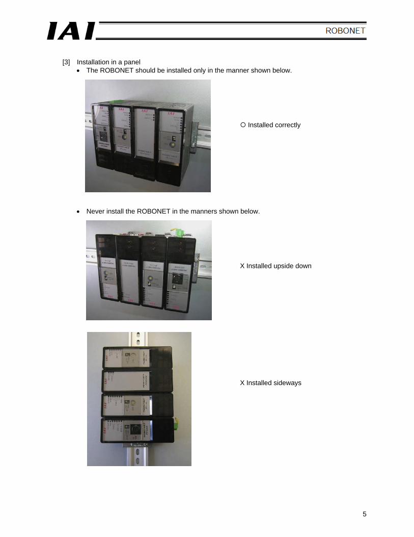
[3] Installation in a panel
• The ROBONET should be installed only in the manner shown below.
Installed correctly
• Never install the ROBONET in the manners shown below.
X Installed upside down
X Installed sideways
6
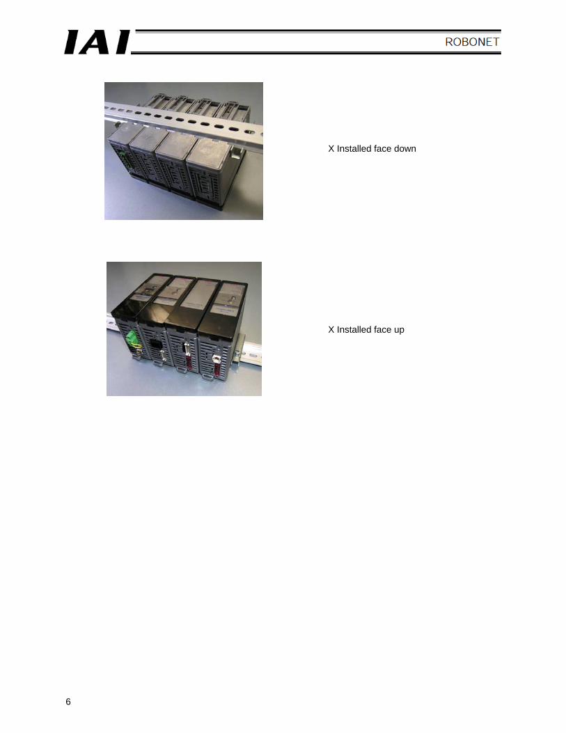
X Installed face down
X Installed face up
7
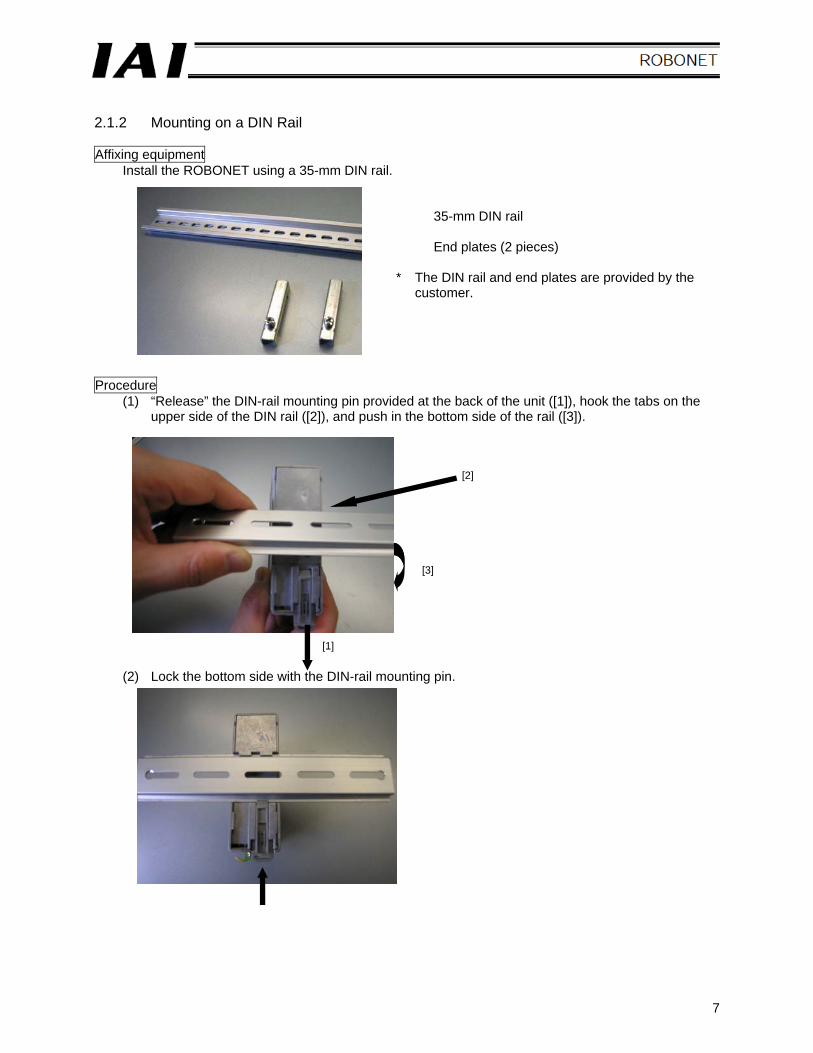
2.1.2 Mounting on a DIN Rail Affixing equipment
Install the ROBONET using a 35-mm DIN rail.
35-mm DIN rail End plates (2 pieces)
* The DIN rail and end plates are provided by the
customer. Procedure
(1) “Release” the DIN-rail mounting pin provided at the back of the unit ([1]), hook the tabs on the upper side of the DIN rail ([2]), and push in the bottom side of the rail ([3]).
(2) Lock the bottom side with the DIN-rail mounting pin.
[2]
[3]
[1]
8
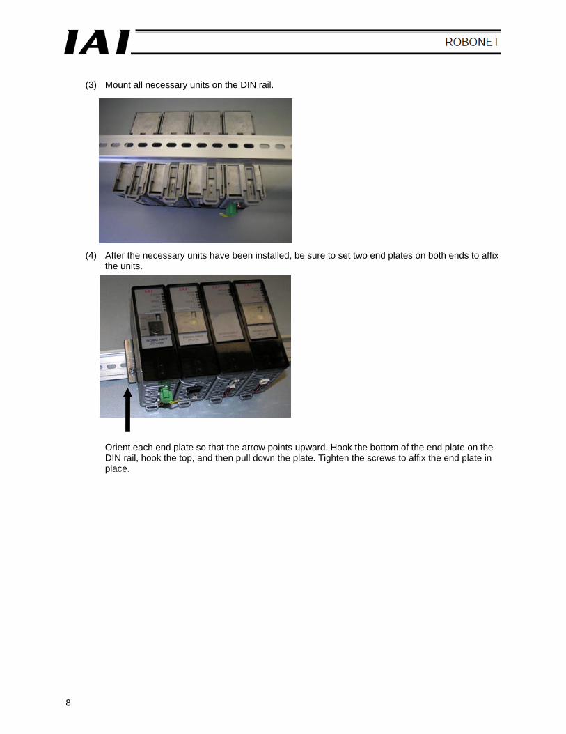
(3) Mount all necessary units on the DIN rail.
(4) After the necessary units have been installed, be sure to set two end plates on both ends to affix the units.
Orient each end plate so that the arrow points upward. Hook the bottom of the end plate on the DIN rail, hook the top, and then pull down the plate. Tighten the screws to affix the end plate in place.
9
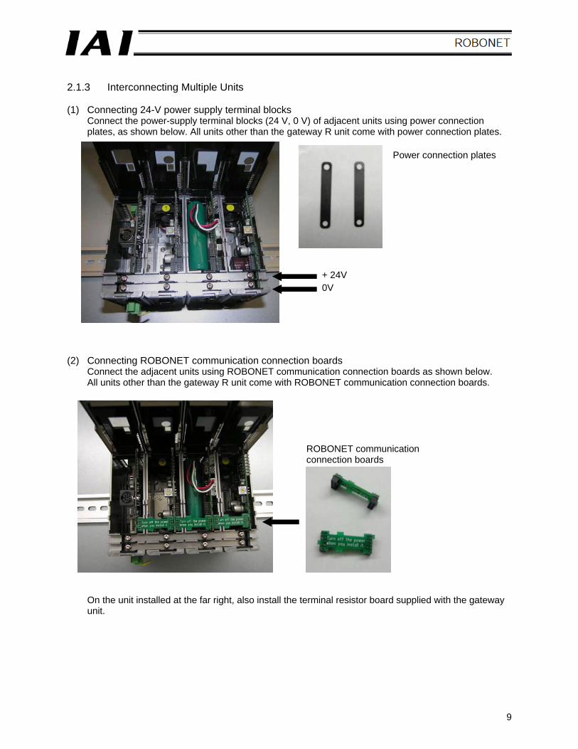
2.1.3 Interconnecting Multiple Units (1) Connecting 24-V power supply terminal blocks
Connect the power-supply terminal blocks (24 V, 0 V) of adjacent units using power connection plates, as shown below. All units other than the gateway R unit come with power connection plates.
(2) Connecting ROBONET communication connection boards
Connect the adjacent units using ROBONET communication connection boards as shown below. All units other than the gateway R unit come with ROBONET communication connection boards.
On the unit installed at the far right, also install the terminal resistor board supplied with the gateway unit.
Power connection plates
ROBONET communication connection boards
+ 24V 0V
10
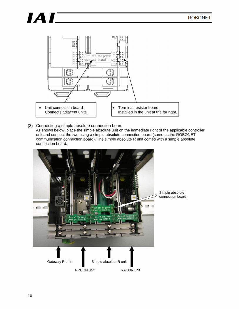
(3) Connecting a simple absolute connection board
As shown below, place the simple absolute unit on the immediate right of the applicable controller unit and connect the two using a simple absolute connection board (same as the ROBONET communication connection board). The simple absolute R unit comes with a simple absolute connection board.
• Unit connection board Connects adjacent units.
• Terminal resistor board Installed in the unit at the far right.
Simple absolute connection board
Gateway R unit
RPCON unit RACON unit
Simple absolute R unit
11
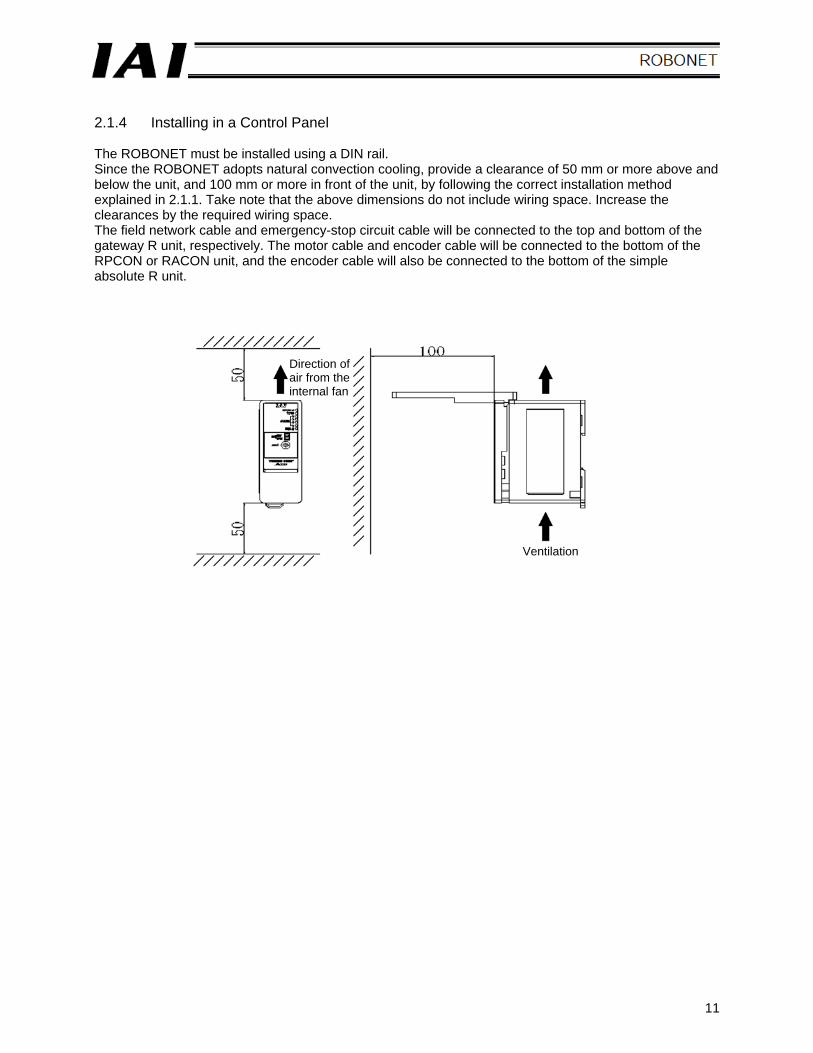
2.1.4 Installing in a Control Panel The ROBONET must be installed using a DIN rail. Since the ROBONET adopts natural convection cooling, provide a clearance of 50 mm or more above and below the unit, and 100 mm or more in front of the unit, by following the correct installation method explained in 2.1.1. Take note that the above dimensions do not include wiring space. Increase the clearances by the required wiring space. The field network cable and emergency-stop circuit cable will be connected to the top and bottom of the gateway R unit, respectively. The motor cable and encoder cable will be connected to the bottom of the RPCON or RACON unit, and the encoder cable will also be connected to the bottom of the simple absolute R unit.
Direction of air from the internal fan
Ventilation
12
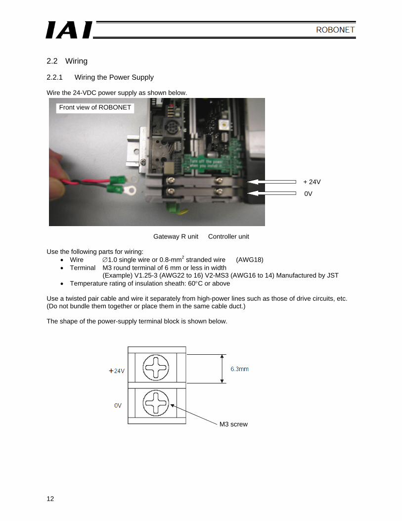
2.2 Wiring 2.2.1 Wiring the Power Supply Wire the 24-VDC power supply as shown below.
Gateway R unit Controller unit Use the following parts for wiring:
• Wire ∅1.0 single wire or 0.8-mm2 stranded wire (AWG18) • Terminal M3 round terminal of 6 mm or less in width
(Example) V1.25-3 (AWG22 to 16) V2-MS3 (AWG16 to 14) Manufactured by JST • Temperature rating of insulation sheath: 60°C or above
Use a twisted pair cable and wire it separately from high-power lines such as those of drive circuits, etc. (Do not bundle them together or place them in the same cable duct.) The shape of the power-supply terminal block is shown below.
M3 screw
+ 24V
0V
Front view of ROBONET
13
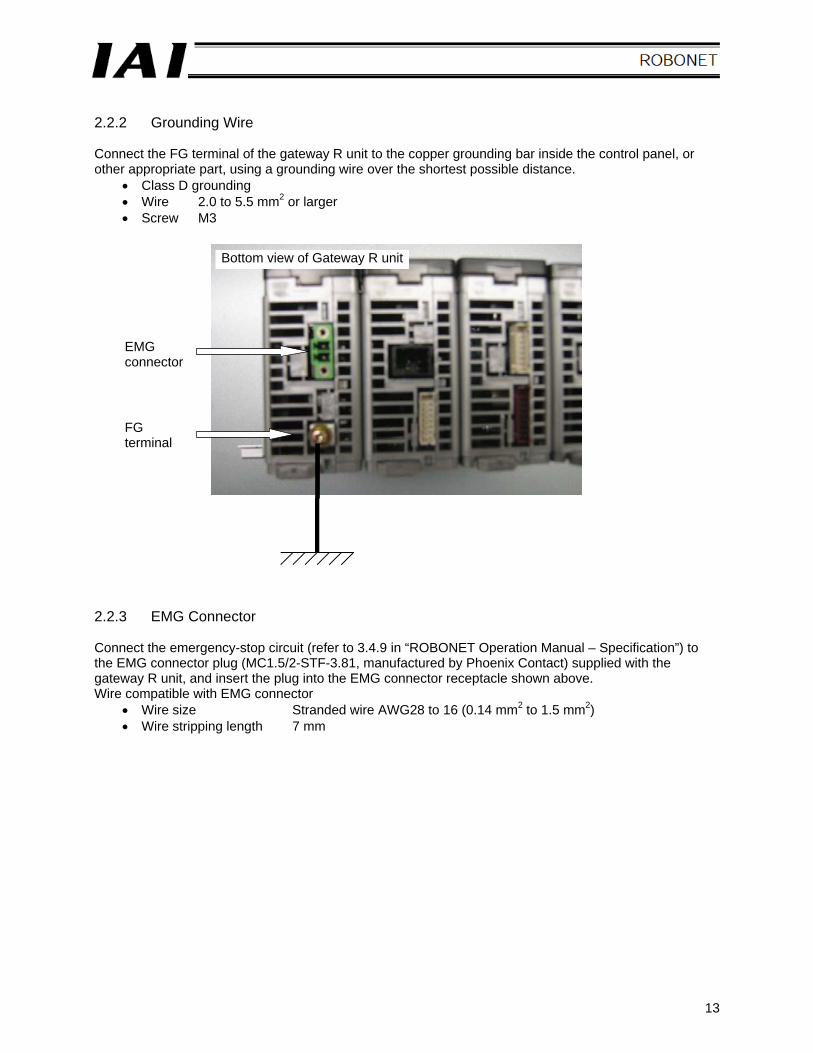
2.2.2 Grounding Wire Connect the FG terminal of the gateway R unit to the copper grounding bar inside the control panel, or other appropriate part, using a grounding wire over the shortest possible distance.
• Class D grounding • Wire 2.0 to 5.5 mm2 or larger • Screw M3
2.2.3 EMG Connector Connect the emergency-stop circuit (refer to 3.4.9 in “ROBONET Operation Manual – Specification”) to the EMG connector plug (MC1.5/2-STF-3.81, manufactured by Phoenix Contact) supplied with the gateway R unit, and insert the plug into the EMG connector receptacle shown above. Wire compatible with EMG connector
• Wire size Stranded wire AWG28 to 16 (0.14 mm2 to 1.5 mm2) • Wire stripping length 7 mm
Bottom view of Gateway R unit
EMG connector
FG terminal
14
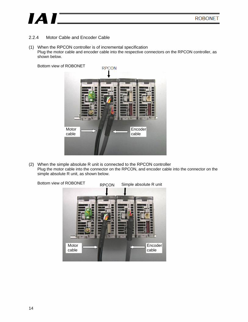
2.2.4 Motor Cable and Encoder Cable (1) When the RPCON controller is of incremental specification
Plug the motor cable and encoder cable into the respective connectors on the RPCON controller, as shown below. Bottom view of ROBONET
(2) When the simple absolute R unit is connected to the RPCON controller
Plug the motor cable into the connector on the RPCON, and encoder cable into the connector on the simple absolute R unit, as shown below. Bottom view of ROBONET
Motor cable
Encoder cable
Simple absolute R unit
Motor cable
Encoder cable
RPCON
15
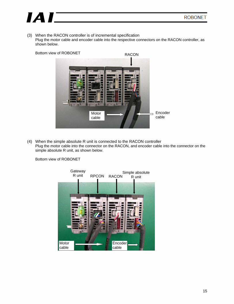
(3) When the RACON controller is of incremental specification
Plug the motor cable and encoder cable into the respective connectors on the RACON controller, as shown below. Bottom view of ROBONET
(4) When the simple absolute R unit is connected to the RACON controller
Plug the motor cable into the connector on the RACON, and encoder cable into the connector on the simple absolute R unit, as shown below. Bottom view of ROBONET
Motor cable
Encoder cable
RACON
Simple absolute R unit
Motor cable
Encoder cable
Gateway R unit RPCON RACON
16
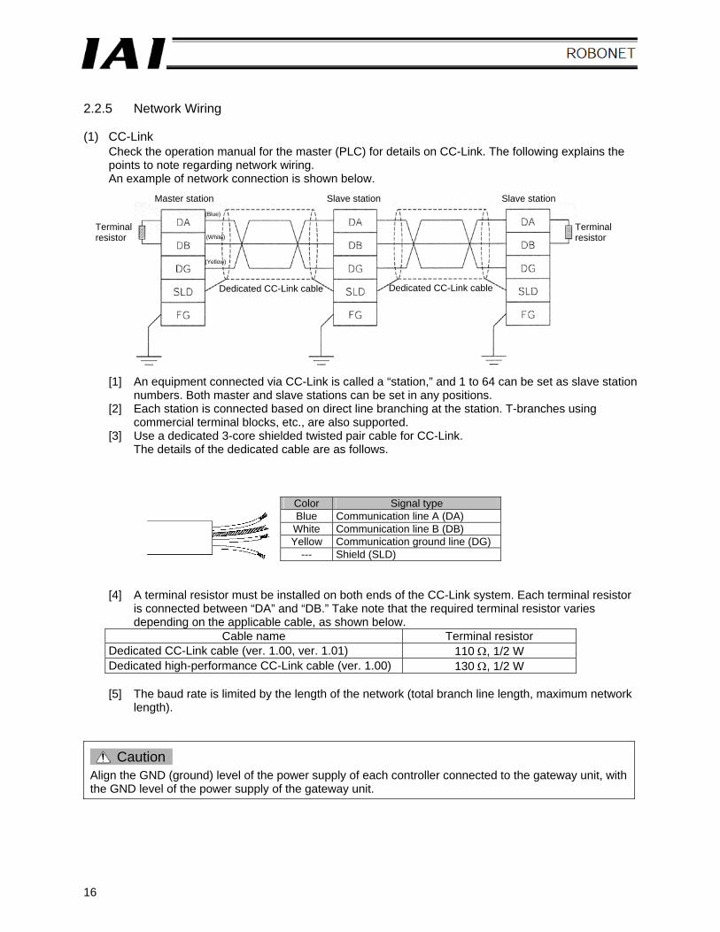
2.2.5 Network Wiring (1) CC-Link
Check the operation manual for the master (PLC) for details on CC-Link. The following explains the points to note regarding network wiring. An example of network connection is shown below.
[1] An equipment connected via CC-Link is called a “station,” and 1 to 64 can be set as slave station numbers. Both master and slave stations can be set in any positions.
[2] Each station is connected based on direct line branching at the station. T-branches using commercial terminal blocks, etc., are also supported.
[3] Use a dedicated 3-core shielded twisted pair cable for CC-Link. The details of the dedicated cable are as follows.
Color Signal type Blue Communication line A (DA)
White Communication line B (DB) Yellow Communication ground line (DG)
--- Shield (SLD)
[4] A terminal resistor must be installed on both ends of the CC-Link system. Each terminal resistor is connected between “DA” and “DB.” Take note that the required terminal resistor varies depending on the applicable cable, as shown below.
Cable name Terminal resistor Dedicated CC-Link cable (ver. 1.00, ver. 1.01) 110 Ω, 1/2 W Dedicated high-performance CC-Link cable (ver. 1.00) 130 Ω, 1/2 W
[5] The baud rate is limited by the length of the network (total branch line length, maximum network
length).
Caution Align the GND (ground) level of the power supply of each controller connected to the gateway unit, with the GND level of the power supply of the gateway unit.
Terminal resistor
Master station Slave station Slave station
Terminal resistor
Dedicated CC-Link cable
(Blue)
(White)
(Yellow)
Dedicated CC-Link cable
17
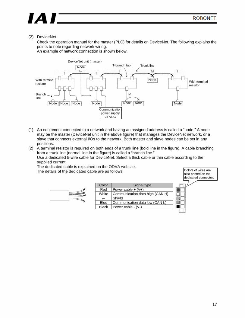
(2) DeviceNet
Check the operation manual for the master (PLC) for details on DeviceNet. The following explains the points to note regarding network wiring. An example of network connection is shown below.
(1) An equipment connected to a network and having an assigned address is called a “node.” A node
may be the master (DeviceNet unit in the above figure) that manages the DeviceNet network, or a slave that connects external I/Os to the network. Both master and slave nodes can be set in any positions.
(2) A terminal resistor is required on both ends of a trunk line (bold line in the figure). A cable branching from a trunk line (normal line in the figure) is called a “branch line.” Use a dedicated 5-wire cable for DeviceNet. Select a thick cable or thin cable according to the supplied current. The dedicated cable is explained on the ODVA website. The details of the dedicated cable are as follows.
Color Signal type Red Power cable + (V+)
White Communication data high (CAN H) --- Shield
Blue Communication data low (CAN L) Black Power cable - (V-)
DeviceNet unit (master)
Node T-branch tap Trunk line
Node
Node Node NodeNode Node Node Node
Communication power supply
24 VDC
With terminal resistor
Branch line
With terminal resistor
Colors of wires are also printed on the dedicated connector.
18
(3) Nodes can be connected in one of the following two ways. Both methods can be used together in a
single network. [1] T-branch method Use a T-branch tap, etc. [2] Multi-drop method Use a multi-drop connector to branch the line directly at the node.
(4) Communication power (24 VDC) must be supplied to each node via a 5-wire cable. (5) A terminal resistor must be installed on both ends of a trunk line.
The gateway R unit (RGW-DV) does not come with a terminal resistor. Connect Omron’s terminal-block terminal resistor (121 Ω ± 1 %, 1/4 W) or T-branch tap with terminal resistor (121 Ω ± 1%, 1/4 W), or other resistor of the same specification, directly between the white and blue wires at the communication connector.
(6) The baud rate is limited by the length of the network (total branch line length, maximum network length).
Caution Align the GND (ground) level of the power supply of each controller connected to the gateway unit, with the GND level of the power supply of the gateway unit.
19
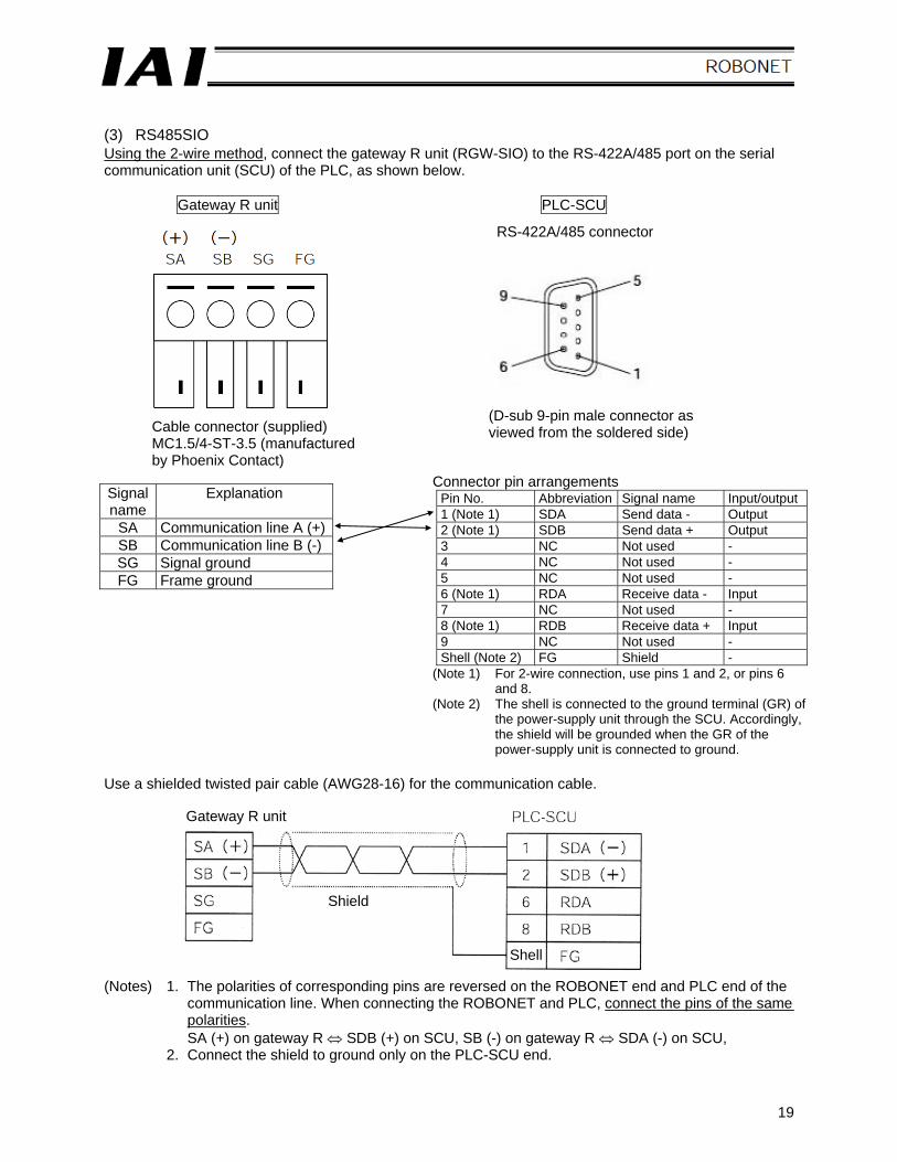
(3) RS485SIO Using the 2-wire method, connect the gateway R unit (RGW-SIO) to the RS-422A/485 port on the serial communication unit (SCU) of the PLC, as shown below.
Gateway R unit PLC-SCU Signal name
Explanation
SA Communication line A (+) SB Communication line B (-) SG Signal ground FG Frame ground
Use a shielded twisted pair cable (AWG28-16) for the communication cable. (Notes) 1. The polarities of corresponding pins are reversed on the ROBONET end and PLC end of the
communication line. When connecting the ROBONET and PLC, connect the pins of the same polarities. SA (+) on gateway R ⇔ SDB (+) on SCU, SB (-) on gateway R ⇔ SDA (-) on SCU,
2. Connect the shield to ground only on the PLC-SCU end.
RS-422A/485 connector
Cable connector (supplied) MC1.5/4-ST-3.5 (manufactured by Phoenix Contact)
(D-sub 9-pin male connector as viewed from the soldered side)
Connector pin arrangements Pin No. Abbreviation Signal name Input/output 1 (Note 1) SDA Send data - Output 2 (Note 1) SDB Send data + Output 3 NC Not used - 4 NC Not used - 5 NC Not used - 6 (Note 1) RDA Receive data - Input 7 NC Not used - 8 (Note 1) RDB Receive data + Input 9 NC Not used - Shell (Note 2) FG Shield -
(Note 1) For 2-wire connection, use pins 1 and 2, or pins 6 and 8.
(Note 2) The shell is connected to the ground terminal (GR) of the power-supply unit through the SCU. Accordingly, the shield will be grounded when the GR of the power-supply unit is connected to ground.
Gateway R unit
Shield
Shell
20
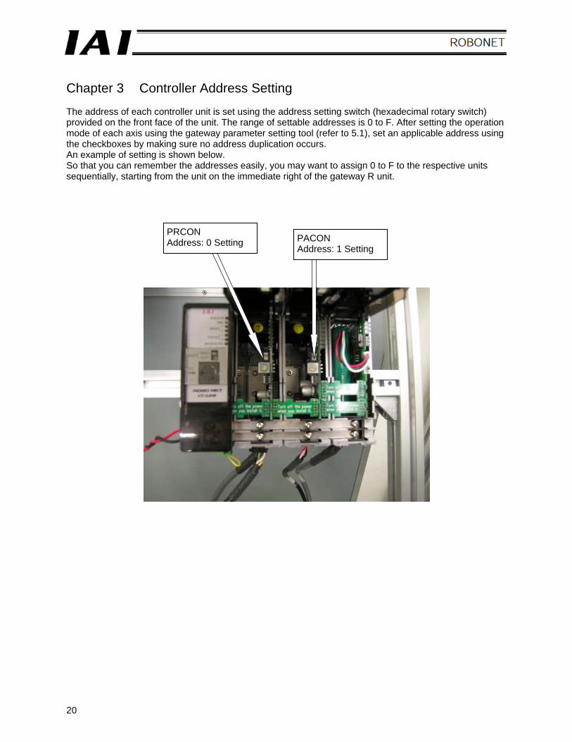
Chapter 3 Controller Address Setting The address of each controller unit is set using the address setting switch (hexadecimal rotary switch) provided on the front face of the unit. The range of settable addresses is 0 to F. After setting the operation mode of each axis using the gateway parameter setting tool (refer to 5.1), set an applicable address using the checkboxes by making sure no address duplication occurs. An example of setting is shown below. So that you can remember the addresses easily, you may want to assign 0 to F to the respective units sequentially, starting from the unit on the immediate right of the gateway R unit.
PRCON Address: 0 Setting PACON
Address: 1 Setting
21
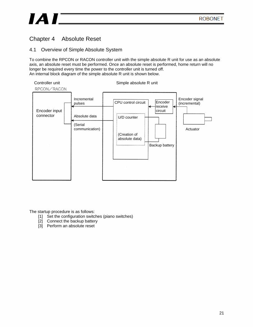
Chapter 4 Absolute Reset 4.1 Overview of Simple Absolute System To combine the RPCON or RACON controller unit with the simple absolute R unit for use as an absolute axis, an absolute reset must be performed. Once an absolute reset is performed, home return will no longer be required every time the power to the controller unit is turned off. An internal block diagram of the simple absolute R unit is shown below. The startup procedure is as follows:
[1] Set the configuration switches (piano switches) [2] Connect the backup battery [3] Perform an absolute reset
Controller unit Simple absolute R unit
Encoder input connector
Incremental pulses Absolute data (Serial communication)
CPU control circuit
U/D counter (Creation of absolute data)
Encoder receive circuit
Backup battery
Encoder signal (incremental)
Actuator
22
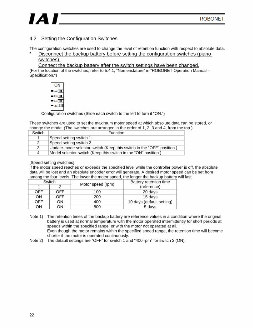
4.2 Setting the Configuration Switches The configuration switches are used to change the level of retention function with respect to absolute data. * Disconnect the backup battery before setting the configuration switches (piano
switches). Connect the backup battery after the switch settings have been changed.
(For the location of the switches, refer to 5.4.1, “Nomenclature” in “ROBONET Operation Manual – Specification.”)
Configuration switches (Slide each switch to the left to turn it “ON.”) These switches are used to set the maximum motor speed at which absolute data can be stored, or change the mode. (The switches are arranged in the order of 1, 2, 3 and 4, from the top.)
Switch Function 1 Speed setting switch 1 2 Speed setting switch 2 3 Update-mode selector switch (Keep this switch in the “OFF” position.) 4 Model selector switch (Keep this switch in the “ON” position.)
[Speed setting switches] If the motor speed reaches or exceeds the specified level while the controller power is off, the absolute data will be lost and an absolute encoder error will generate. A desired motor speed can be set from among the four levels. The lower the motor speed, the longer the backup battery will last.
Switch 1 2 Motor speed (rpm) Battery retention time
(reference) OFF OFF 100 20 days ON OFF 200 15 days OFF ON 400 10 days (default setting) ON ON 800 5 days
Note 1) The retention times of the backup battery are reference values in a condition where the original
battery is used at normal temperature with the motor operated intermittently for short periods at speeds within the specified range, or with the motor not operated at all. Even though the motor remains within the specified speed range, the retention time will become shorter if the motor is operated continuously.
Note 2) The default settings are “OFF” for switch 1 and “400 rpm” for switch 2 (ON).
23
[Update-mode selector switch]
Switch 3 Function
ON Update mode OFF Normal mode
This switch need not be used in a normal condition of use, and should therefore remain in the “OFF” position. (Do not set the switch to the “ON” position.) In the update mode, the RDY/ALM LED blinks in green and red alternately. [Model selector switch]
Switch 4 Function
ON Keep this switch in the “ON” position (default setting). OFF ---
24
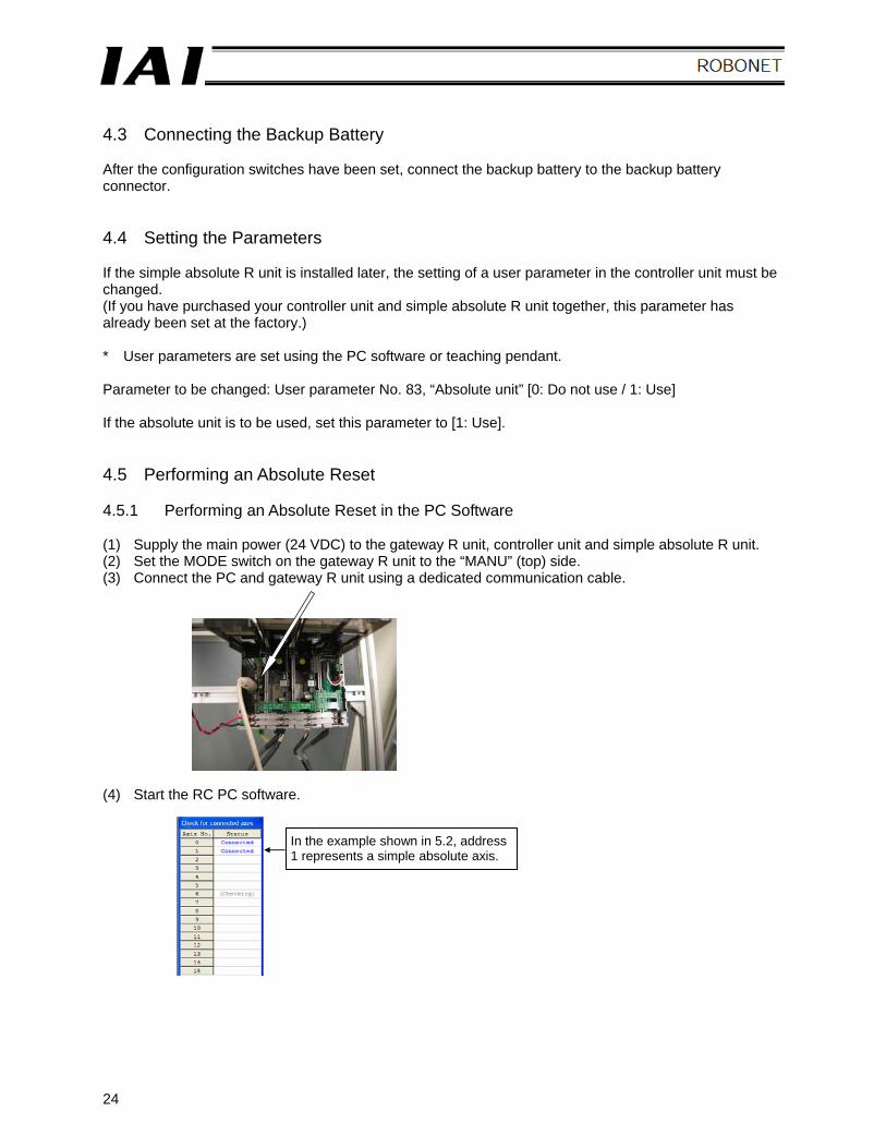
4.3 Connecting the Backup Battery After the configuration switches have been set, connect the backup battery to the backup battery connector. 4.4 Setting the Parameters If the simple absolute R unit is installed later, the setting of a user parameter in the controller unit must be changed. (If you have purchased your controller unit and simple absolute R unit together, this parameter has already been set at the factory.) * User parameters are set using the PC software or teaching pendant. Parameter to be changed: User parameter No. 83, “Absolute unit” [0: Do not use / 1: Use] If the absolute unit is to be used, set this parameter to [1: Use]. 4.5 Performing an Absolute Reset 4.5.1 Performing an Absolute Reset in the PC Software (1) Supply the main power (24 VDC) to the gateway R unit, controller unit and simple absolute R unit. (2) Set the MODE switch on the gateway R unit to the “MANU” (top) side. (3) Connect the PC and gateway R unit using a dedicated communication cable. (4) Start the RC PC software.
In the example shown in 5.2, address 1 represents a simple absolute axis.
25
[3]
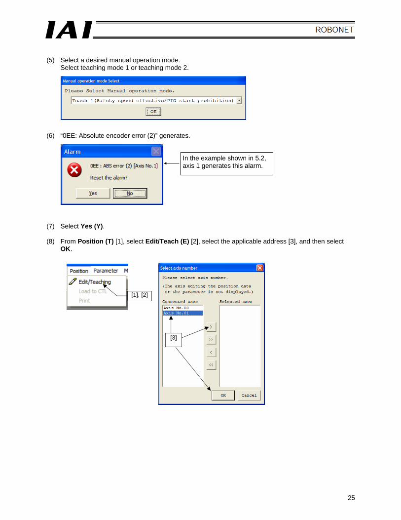
(5) Select a desired manual operation mode.
Select teaching mode 1 or teaching mode 2. (6) “0EE: Absolute encoder error (2)” generates. (7) Select Yes (Y). (8) From Position (T) [1], select Edit/Teach (E) [2], select the applicable address [3], and then select
OK.
In the example shown in 5.2, axis 1 generates this alarm.
[1], [2]
26
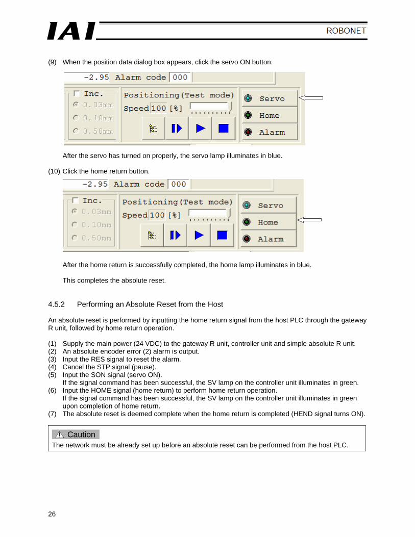
(9) When the position data dialog box appears, click the servo ON button.
After the servo has turned on properly, the servo lamp illuminates in blue. (10) Click the home return button.
After the home return is successfully completed, the home lamp illuminates in blue. This completes the absolute reset.
4.5.2 Performing an Absolute Reset from the Host An absolute reset is performed by inputting the home return signal from the host PLC through the gateway R unit, followed by home return operation. (1) Supply the main power (24 VDC) to the gateway R unit, controller unit and simple absolute R unit. (2) An absolute encoder error (2) alarm is output. (3) Input the RES signal to reset the alarm. (4) Cancel the STP signal (pause). (5) Input the SON signal (servo ON).
If the signal command has been successful, the SV lamp on the controller unit illuminates in green. (6) Input the HOME signal (home return) to perform home return operation.
If the signal command has been successful, the SV lamp on the controller unit illuminates in green upon completion of home return.
(7) The absolute reset is deemed complete when the home return is completed (HEND signal turns ON).
Caution The network must be already set up before an absolute reset can be performed from the host PLC.
27
Chapter 5 Network Setup 5.1 How to Use the ROBONET Gateway Parameter Setting Tool To set up the network, use this tool to set the following items on the ROBONET side: [1] Station number [2] Baud rate over the field network [3] Operation mode of each axis Before setting the above items, install the “gateway parameter setting tool” software in the PC. 5.1.1 Operating Environment (1) This tool can be used on a PC running any of the following operating systems:
• Windows98SE • WindowsMe • Windows2000 • WindowsXP (2) Serial port
RS-232C serial port (3) Connection cable
Communication cable for RC PC software 5.1.2 Launching the Setting Tool (1) Connect the gateway R unit with the PC using the communication cable that came with the PC
software, and set the operation mode of the gateway R unit to “MANU.” (2) From the Start menu, click Programs (P), click IAI, click ROBONET, and select ROBONET
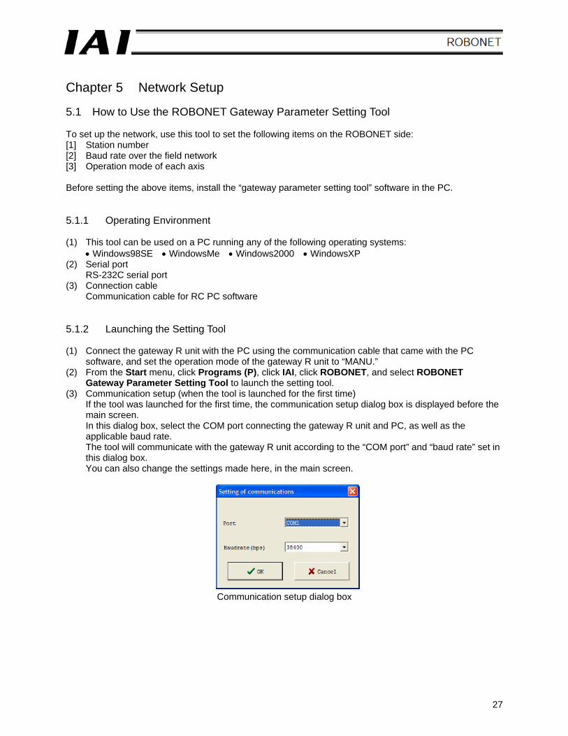
Gateway Parameter Setting Tool to launch the setting tool. (3) Communication setup (when the tool is launched for the first time)
If the tool was launched for the first time, the communication setup dialog box is displayed before the main screen. In this dialog box, select the COM port connecting the gateway R unit and PC, as well as the applicable baud rate. The tool will communicate with the gateway R unit according to the “COM port” and “baud rate” set in this dialog box. You can also change the settings made here, in the main screen.
Communication setup dialog box
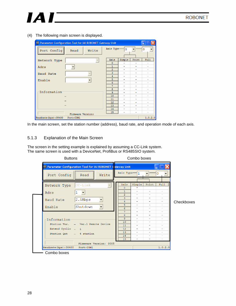
28
(4) The following main screen is displayed. In the main screen, set the station number (address), baud rate, and operation mode of each axis. 5.1.3 Explanation of the Main Screen The screen in the setting example is explained by assuming a CC-Link system. The same screen is used with a DeviceNet, ProfiBus or RS485SIO system.
Checkboxes
Buttons Combo boxes
Combo boxes
29
(1) Button operations
[1] Tool Communication Setup Clicking this button opens the communication setup dialog box.
[2] Load Clicking this button loads the parameters from the gateway R unit.
[3] Transfer Clicking this button transfers to the gateway R unit the parameters set with the checkboxes.
(2) Combo box operations
[1] Network Type The network type of the gateway R unit is automatically recognized and shown here.
[2] Address Select and set the address (station number) of the gateway R unit to be used by the host.
[3] Baud Rate Select and set a desired baud rate only when the network type is “CC-Link.” The baud rate is set automatically for all other network types. (The tool shows “Auto.”)
[4] Enable Operation Select and set the control action to be performed by the controller when the enable function is enabled. • Shutdown control --- Turn off the servo, and then cut off the drive source. • Servo control --- Turn off the servo.
[5] Address Setting The address set here determines the number of occupied stations or I/O Size.
30
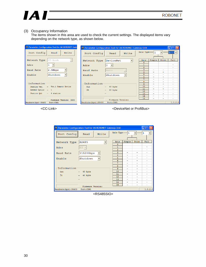
(3) Occupancy Information
The items shown in this area are used to check the current settings. The displayed items vary depending on the network type, as shown below.
<CC-Link> <DeviceNet or ProfiBus>
<RS485SIO>
31
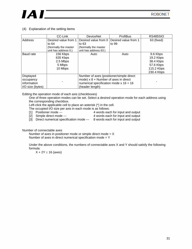
(4) Explanation of the setting items
CC-Link DeviceNet ProfiBus RS485SIO Address Desired value from 1
to 64 (Normally the master unit has address 0.)
Desired value from 0 to 63 (Normally the master unit has address 63.)
Desired value from 1 to 99
63 (fixed)
Baud rate 156 Kbps 635 Kbps 2.5 Mbps 5 Mbps 10 Mbps
Auto Auto 9.6 Kbps 19.2 Kbps 38.4 Kbps 57.6 Kbps 115.2 Kbps 230.4 Kbps
Displayed occupancy information I/O size (bytes)
-
Number of axes (positioner/simple direct mode) x 8 + Number of axes in direct numerical specification mode x 16 + 16 (header length)
-
Editing the operation mode of each axis (checkboxes)
One of three operation modes can be set. Select a desired operation mode for each address using the corresponding checkbox. Left-click the applicable cell to place an asterisk (*) in the cell. The occupied I/O size per axis in each mode is as follows: [1] Positioner mode --- 4 words each for input and output [2] Simple direct mode --- 4 words each for input and output [3] Direct numerical specification mode --- 8 words each for input and output
Number of connectable axes
Number of axes in positioner mode or simple direct mode = X Number of axes in direct numerical specification mode = Y Under the above conditions, the numbers of connectable axes X and Y should satisfy the following formula:
X + 2Y ≤ 16 (axes)
32
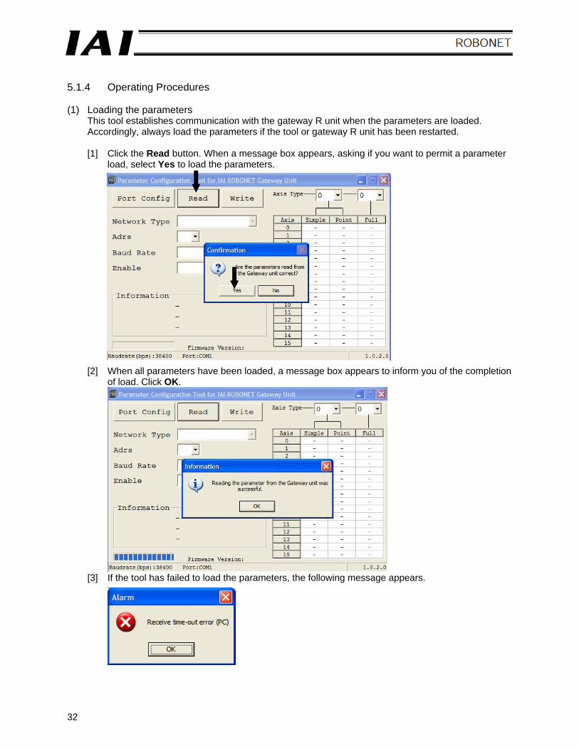
5.1.4 Operating Procedures (1) Loading the parameters
This tool establishes communication with the gateway R unit when the parameters are loaded. Accordingly, always load the parameters if the tool or gateway R unit has been restarted. [1] Click the Read button. When a message box appears, asking if you want to permit a parameter
load, select Yes to load the parameters.
[2] When all parameters have been loaded, a message box appears to inform you of the completion of load. Click OK.
[3] If the tool has failed to load the parameters, the following message appears.
33
(2) Editing (setting) the parameters
Edit the address, baud rate and enable operation according to the explanations given in 5.1.3.
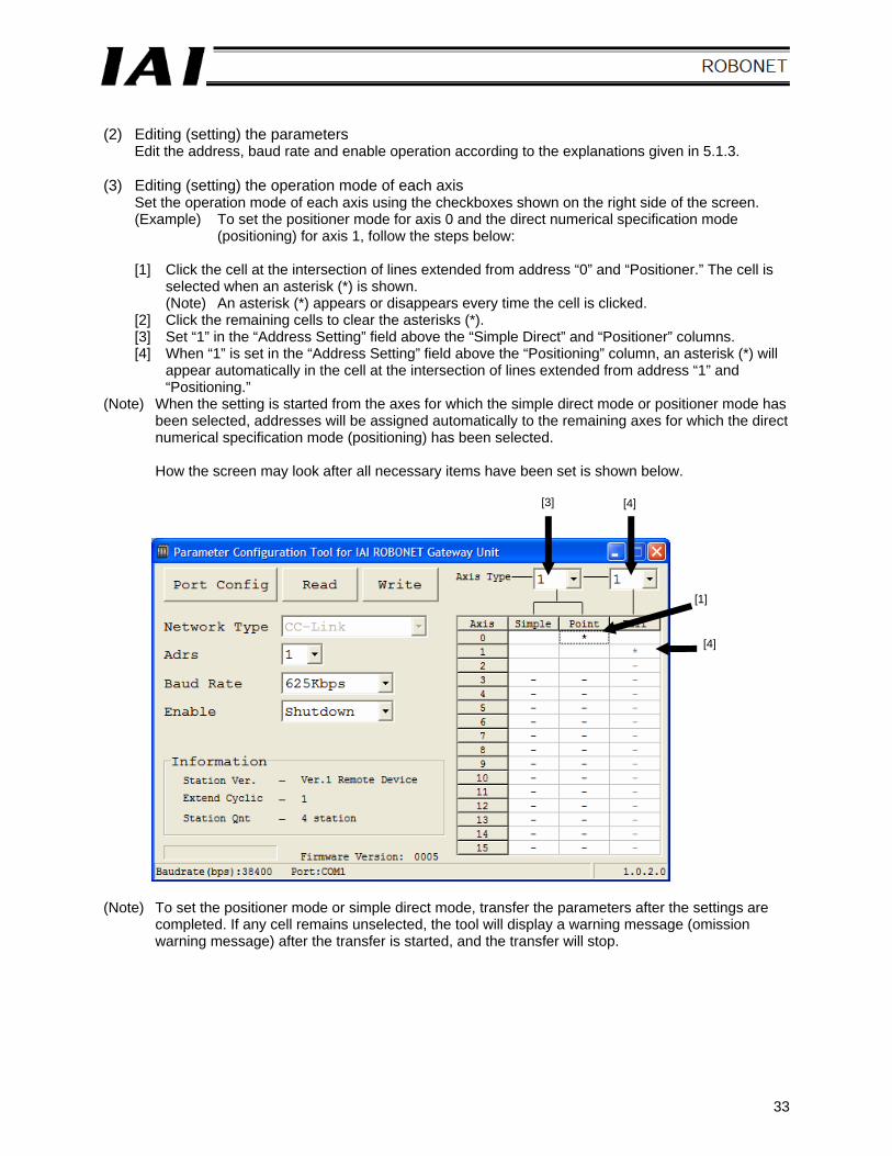
(3) Editing (setting) the operation mode of each axis Set the operation mode of each axis using the checkboxes shown on the right side of the screen. (Example) To set the positioner mode for axis 0 and the direct numerical specification mode
(positioning) for axis 1, follow the steps below: [1] Click the cell at the intersection of lines extended from address “0” and “Positioner.” The cell is
selected when an asterisk (*) is shown. (Note) An asterisk (*) appears or disappears every time the cell is clicked.
[2] Click the remaining cells to clear the asterisks (*). [3] Set “1” in the “Address Setting” field above the “Simple Direct” and “Positioner” columns. [4] When “1” is set in the “Address Setting” field above the “Positioning” column, an asterisk (*) will
appear automatically in the cell at the intersection of lines extended from address “1” and “Positioning.”
(Note) When the setting is started from the axes for which the simple direct mode or positioner mode has been selected, addresses will be assigned automatically to the remaining axes for which the direct numerical specification mode (positioning) has been selected. How the screen may look after all necessary items have been set is shown below.
(Note) To set the positioner mode or simple direct mode, transfer the parameters after the settings are
completed. If any cell remains unselected, the tool will display a warning message (omission warning message) after the transfer is started, and the transfer will stop.
[3] [4]
[1]
[4]
34
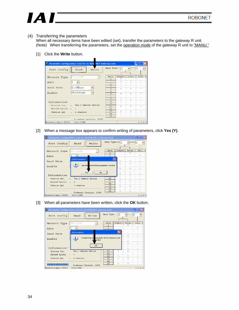
(4) Transferring the parameters
When all necessary items have been edited (set), transfer the parameters to the gateway R unit. (Note) When transferring the parameters, set the operation mode of the gateway R unit to “MANU.”
[1] Click the Write button.
[2] When a message box appears to confirm writing of parameters, click Yes (Y).
[3] When all parameters have been written, click the OK button.
35
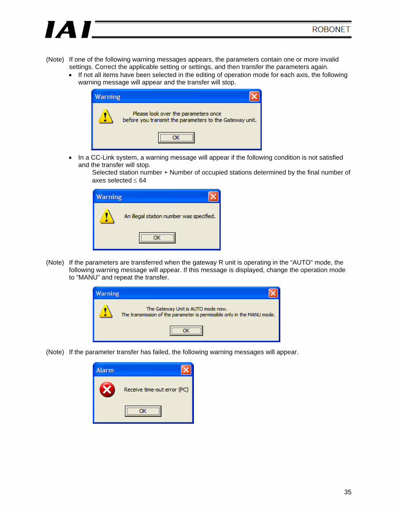
(Note) If one of the following warning messages appears, the parameters contain one or more invalid
settings. Correct the applicable setting or settings, and then transfer the parameters again. • If not all items have been selected in the editing of operation mode for each axis, the following
warning message will appear and the transfer will stop.
• In a CC-Link system, a warning message will appear if the following condition is not satisfied and the transfer will stop.
Selected station number + Number of occupied stations determined by the final number of axes selected ≤ 64
(Note) If the parameters are transferred when the gateway R unit is operating in the “AUTO” mode, the
following warning message will appear. If this message is displayed, change the operation mode to “MANU” and repeat the transfer.
(Note) If the parameter transfer has failed, the following warning messages will appear.
36
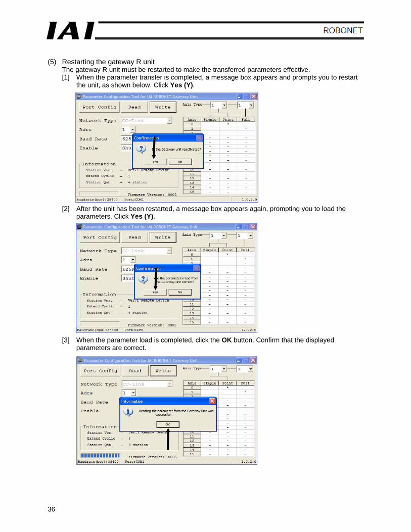
(5) Restarting the gateway R unit
The gateway R unit must be restarted to make the transferred parameters effective. [1] When the parameter transfer is completed, a message box appears and prompts you to restart
the unit, as shown below. Click Yes (Y). [2] After the unit has been restarted, a message box appears again, prompting you to load the
parameters. Click Yes (Y). [3] When the parameter load is completed, click the OK button. Confirm that the displayed
parameters are correct.
37
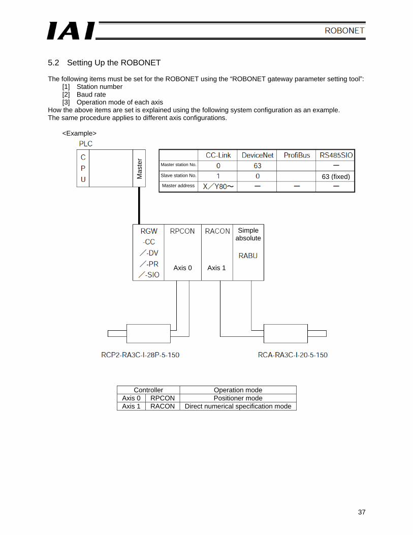
5.2 Setting Up the ROBONET The following items must be set for the ROBONET using the “ROBONET gateway parameter setting tool”:
[1] Station number [2] Baud rate [3] Operation mode of each axis
How the above items are set is explained using the following system configuration as an example. The same procedure applies to different axis configurations.
<Example>
Controller Operation mode Axis 0 RPCON Positioner mode Axis 1 RACON Direct numerical specification mode
Mas
ter
Master station No.
Slave station No.
Master address
63 (fixed)
Axis 0 Axis 1
Simple absolute
38
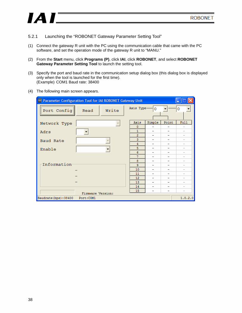
5.2.1 Launching the “ROBONET Gateway Parameter Setting Tool” (1) Connect the gateway R unit with the PC using the communication cable that came with the PC
software, and set the operation mode of the gateway R unit to “MANU.” (2) From the Start menu, click Programs (P), click IAI, click ROBONET, and select ROBONET
Gateway Parameter Setting Tool to launch the setting tool. (3) Specify the port and baud rate in the communication setup dialog box (this dialog box is displayed
only when the tool is launched for the first time). (Example) COM1 Baud rate: 38400
(4) The following main screen appears.
39
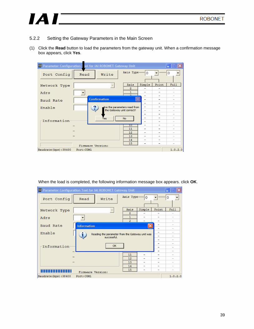
5.2.2 Setting the Gateway Parameters in the Main Screen (1) Click the Read button to load the parameters from the gateway unit. When a confirmation message
box appears, click Yes.
When the load is completed, the following information message box appears. click OK.
40
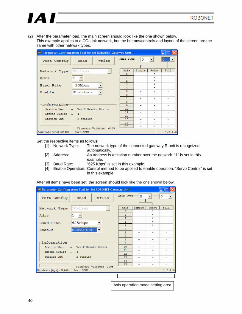
(2) After the parameter load, the main screen should look like the one shown below.
This example applies to a CC-Link network, but the buttons/controls and layout of the screen are the same with other network types.
Set the respective items as follows: [1] Network Type: The network type of the connected gateway R unit is recognized
automatically. [2] Address: An address is a station number over the network. “1” is set in this
example. [3] Baud Rate: “625 Kbps” is set in this example. [4] Enable Operation: Control method to be applied to enable operation. “Servo Control” is set
in this example. After all items have been set, the screen should look like the one shown below.
Axis operation mode setting area
41
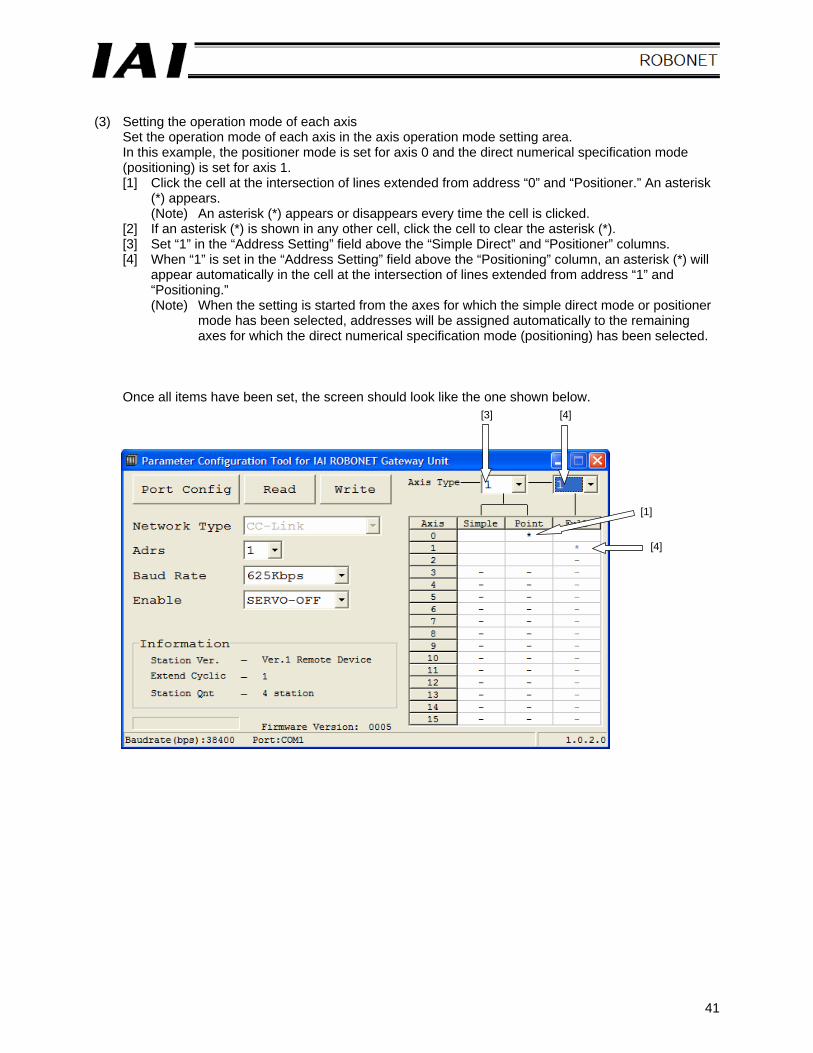
(3) Setting the operation mode of each axis
Set the operation mode of each axis in the axis operation mode setting area. In this example, the positioner mode is set for axis 0 and the direct numerical specification mode (positioning) is set for axis 1. [1] Click the cell at the intersection of lines extended from address “0” and “Positioner.” An asterisk
(*) appears. (Note) An asterisk (*) appears or disappears every time the cell is clicked.
[2] If an asterisk (*) is shown in any other cell, click the cell to clear the asterisk (*). [3] Set “1” in the “Address Setting” field above the “Simple Direct” and “Positioner” columns. [4] When “1” is set in the “Address Setting” field above the “Positioning” column, an asterisk (*) will
appear automatically in the cell at the intersection of lines extended from address “1” and “Positioning.” (Note) When the setting is started from the axes for which the simple direct mode or positioner
mode has been selected, addresses will be assigned automatically to the remaining axes for which the direct numerical specification mode (positioning) has been selected.
Once all items have been set, the screen should look like the one shown below.
[4]
[1]
[4] [3]
42
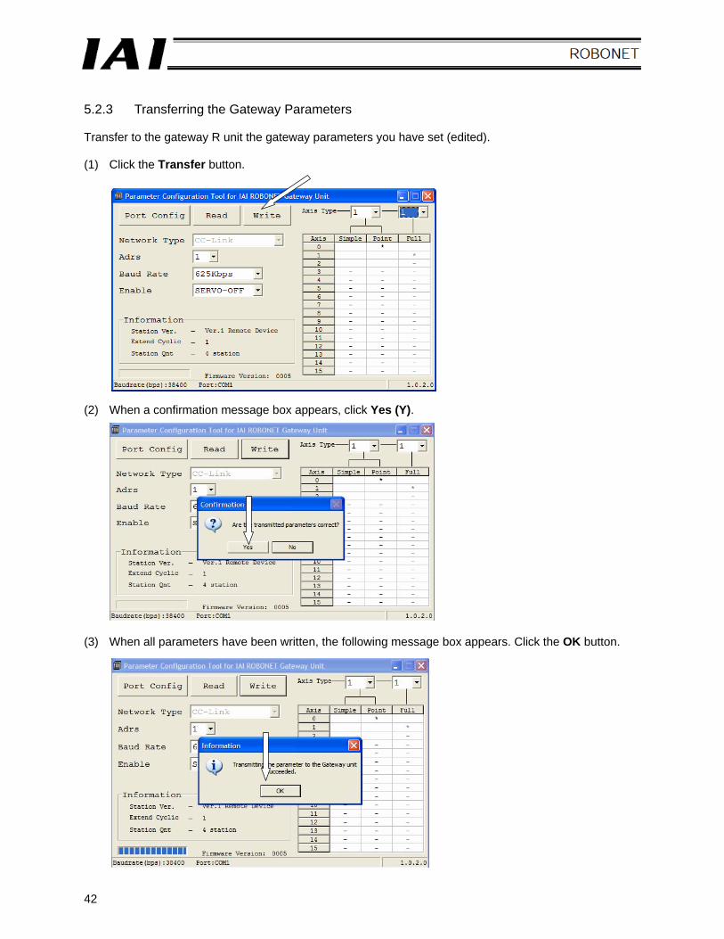
5.2.3 Transferring the Gateway Parameters Transfer to the gateway R unit the gateway parameters you have set (edited). (1) Click the Transfer button. (2) When a confirmation message box appears, click Yes (Y). (3) When all parameters have been written, the following message box appears. Click the OK button.
43
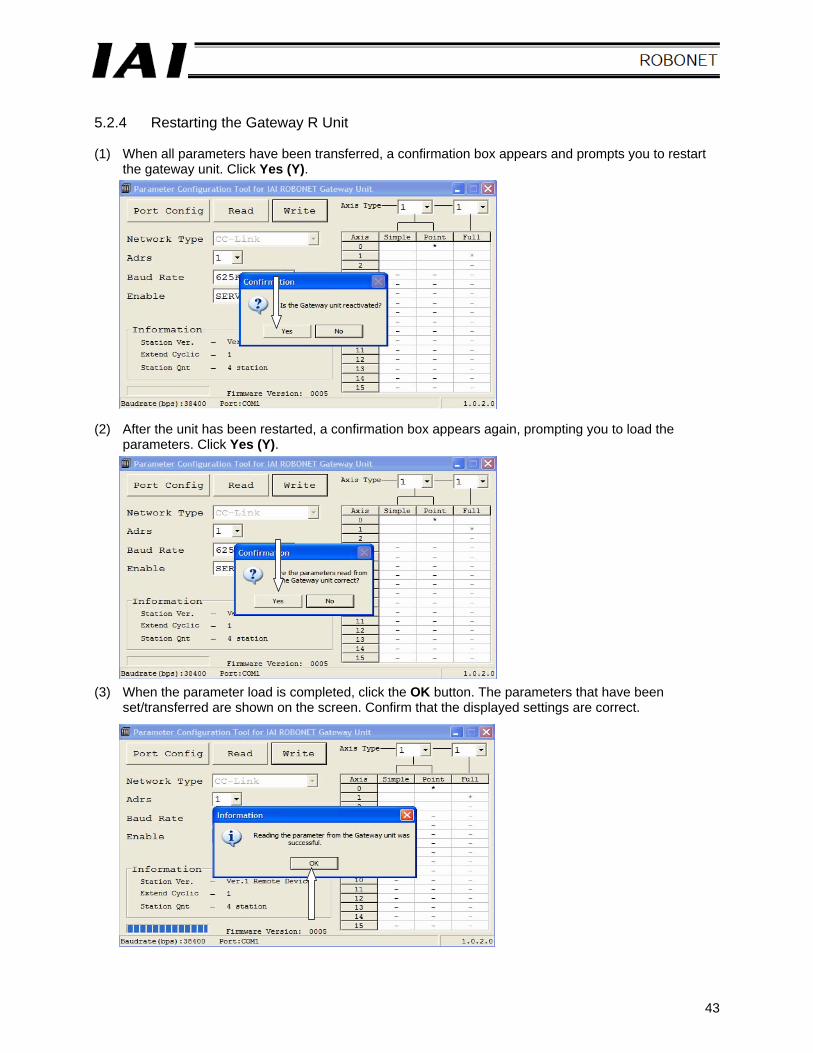
5.2.4 Restarting the Gateway R Unit (1) When all parameters have been transferred, a confirmation box appears and prompts you to restart
the gateway unit. Click Yes (Y). (2) After the unit has been restarted, a confirmation box appears again, prompting you to load the
parameters. Click Yes (Y). (3) When the parameter load is completed, click the OK button. The parameters that have been
set/transferred are shown on the screen. Confirm that the displayed settings are correct.
44
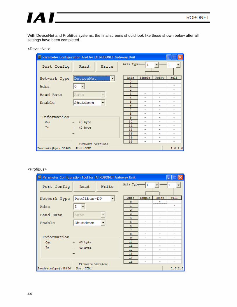
With DeviceNet and ProfiBus systems, the final screens should look like those shown below after all settings have been completed. <DeviceNet> <ProfiBus>
45
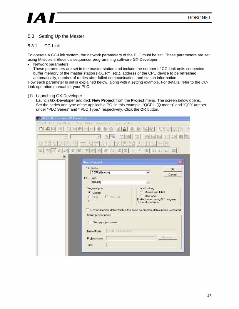
5.3 Setting Up the Master 5.3.1 CC-Link To operate a CC-Link system, the network parameters of the PLC must be set. These parameters are set using Mitsubishi Electric’s sequencer programming software GX-Developer. • Network parameters
These parameters are set in the master station and include the number of CC-Link units connected, buffer memory of the master station (RX, RY, etc.), address of the CPU device to be refreshed automatically, number of retries after failed communication, and station information.
How each parameter is set is explained below, along with a setting example. For details, refer to the CC-Link operation manual for your PLC. (1) Launching GX-Developer
Launch GX-Developer and click New Project from the Project menu. The screen below opens. Set the series and type of the applicable PC. In this example, “QCPU (Q mode)” and “Q00” are set under “PLC Series” and “ PLC Type,” respectively. Click the OK button.
46
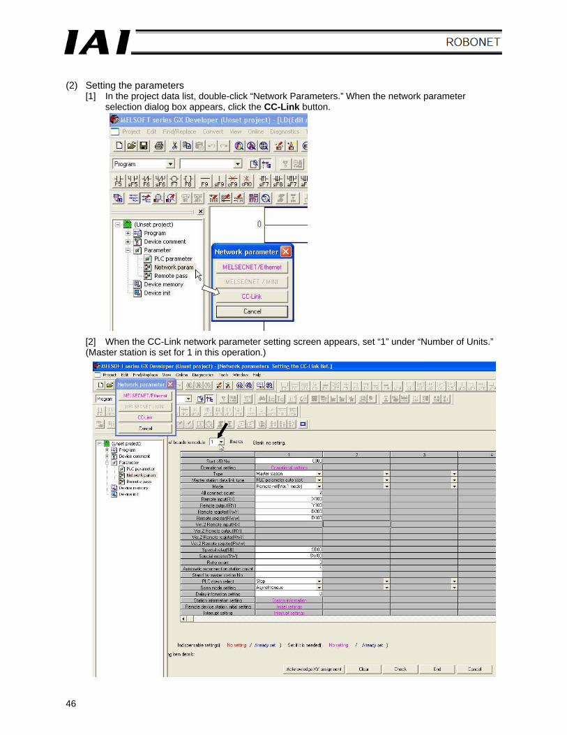
(2) Setting the parameters
[1] In the project data list, double-click “Network Parameters.” When the network parameter selection dialog box appears, click the CC-Link button.
[2] When the CC-Link network parameter setting screen appears, set “1” under “Number of Units.” (Master station is set for 1 in this operation.)
47
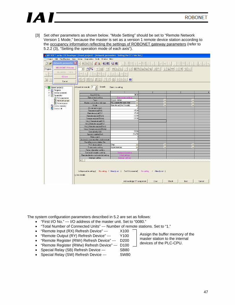
[3] Set other parameters as shown below. “Mode Setting” should be set to “Remote Network
Version 1 Mode,” because the master is set as a version 1 remote device station according to the occupancy information reflecting the settings of ROBONET gateway parameters (refer to 5.2.2 (3), “Setting the operation mode of each axis”).
The system configuration parameters described in 5.2 are set as follows:
• “First I/O No.” --- I/O address of the master unit. Set to “0080.” • “Total Number of Connected Units” --- Number of remote stations. Set to “1.” • “Remote Input (RX) Refresh Device” --- X100 • “Remote Output (RY) Refresh Device” --- Y100 • “Remote Register (RWr) Refresh Device” --- D200 • “Remote Register (RWw) Refresh Device” --- D100 • Special Relay (SB) Refresh Device --- SB80 • Special Relay (SW) Refresh Device --- SW80
Assign the buffer memory of the master station to the internal devices of the PLC-CPU.
48
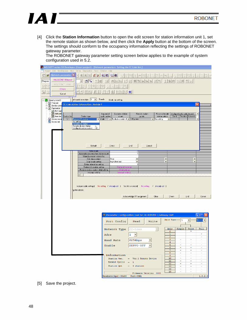
[4] Click the Station Information button to open the edit screen for station information unit 1, set
the remote station as shown below, and then click the Apply button at the bottom of the screen. The settings should conform to the occupancy information reflecting the settings of ROBONET gateway parameter. The ROBONET gateway parameter setting screen below applies to the example of system configuration used in 5.2.
[5] Save the project.
49
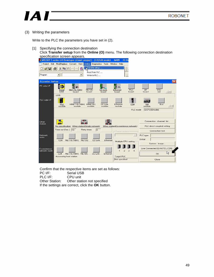
(3) Writing the parameters
Write to the PLC the parameters you have set in (2). [1] Specifying the connection destination
Click Transfer setup from the Online (O) menu. The following connection destination specification screen appears.
Confirm that the respective items are set as follows: PC I/F: Serial USB PLC I/F: CPU unit Other Station: Other station not specified If the settings are correct, click the OK button.
50
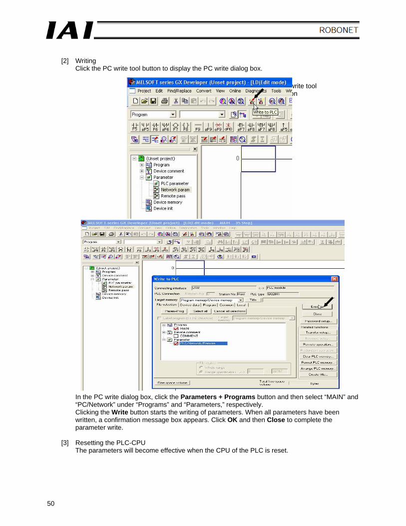
[2] Writing
Click the PC write tool button to display the PC write dialog box.
In the PC write dialog box, click the Parameters + Programs button and then select “MAIN” and “PC/Network” under “Programs” and “Parameters,” respectively. Clicking the Write button starts the writing of parameters. When all parameters have been written, a confirmation message box appears. Click OK and then Close to complete the parameter write.
[3] Resetting the PLC-CPU
The parameters will become effective when the CPU of the PLC is reset.
PC write tool button
51
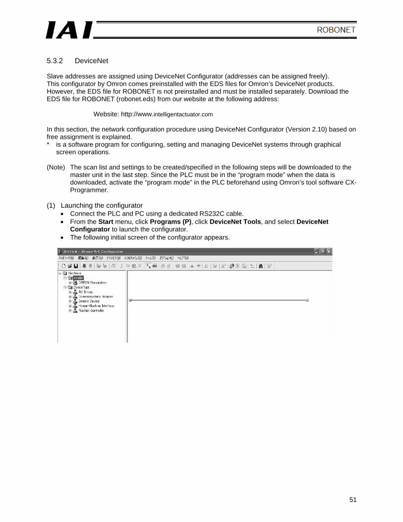
5.3.2 DeviceNet Slave addresses are assigned using DeviceNet Configurator (addresses can be assigned freely). This configurator by Omron comes preinstalled with the EDS files for Omron’s DeviceNet products. However, the EDS file for ROBONET is not preinstalled and must be installed separately. Download the EDS file for ROBONET (robonet.eds) from our website at the following address:
Website: http://www.intelligentactuator.com In this section, the network configuration procedure using DeviceNet Configurator (Version 2.10) based on free assignment is explained. * is a software program for configuring, setting and managing DeviceNet systems through graphical
screen operations. (Note) The scan list and settings to be created/specified in the following steps will be downloaded to the
master unit in the last step. Since the PLC must be in the “program mode” when the data is downloaded, activate the “program mode” in the PLC beforehand using Omron’s tool software CX-Programmer.
(1) Launching the configurator
• Connect the PLC and PC using a dedicated RS232C cable. • From the Start menu, click Programs (P), click DeviceNet Tools, and select DeviceNet
Configurator to launch the configurator. • The following initial screen of the configurator appears.
52
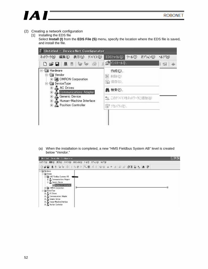
(2) Creating a network configuration
[1] Installing the EDS file Select Install (I) from the EDS File (S) menu, specify the location where the EDS file is saved, and install the file.
(a) When the installation is completed, a new “HMS Fieldbus System AB” level is created below “Vendor.”
53
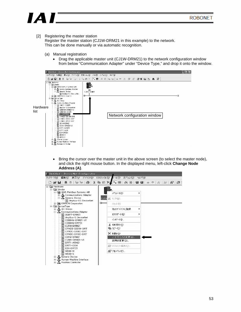
[2] Registering the master station
Register the master station (CJ1W-DRM21 in this example) to the network. This can be done manually or via automatic recognition.
(a) Manual registration
• Drag the applicable master unit (CJ1W-DRM21) to the network configuration window from below “Communication Adapter” under “Device Type,” and drop it onto the window.
• Bring the cursor over the master unit in the above screen (to select the master node), and click the right mouse button. In the displayed menu, left-click Change Node Address (A).
Hardware list
Network configuration window
54
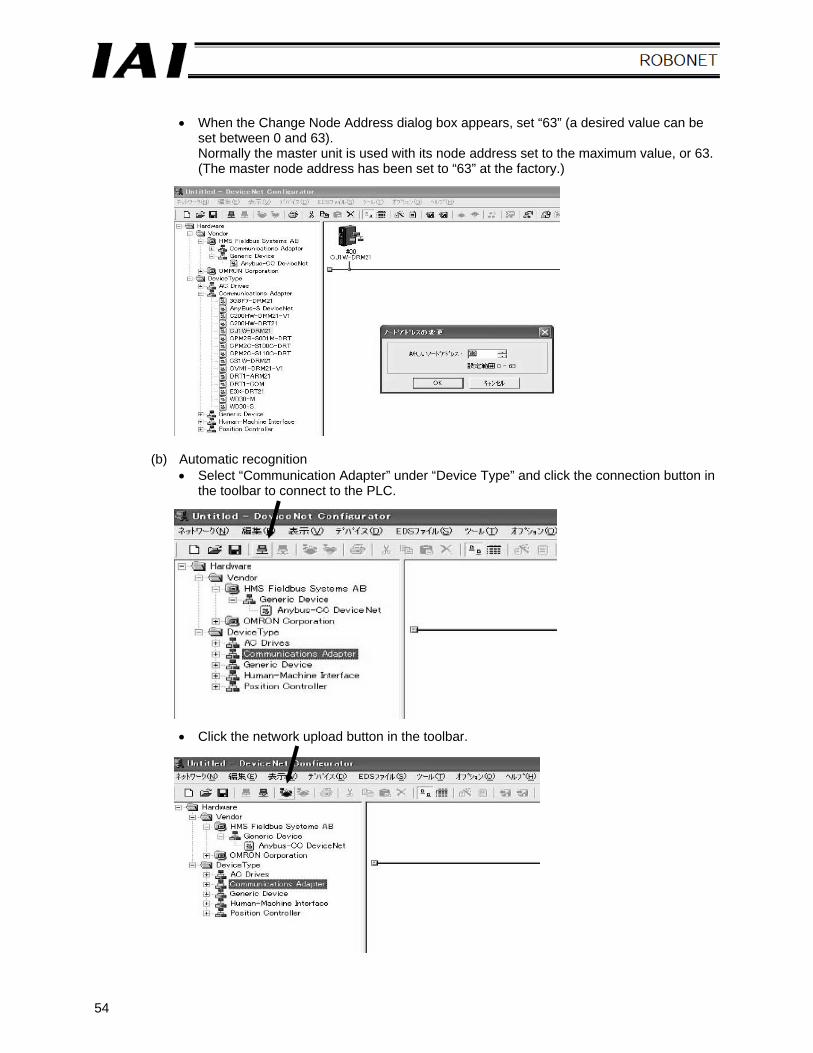
• When the Change Node Address dialog box appears, set “63” (a desired value can be
set between 0 and 63). Normally the master unit is used with its node address set to the maximum value, or 63. (The master node address has been set to “63” at the factory.)
(b) Automatic recognition • Select “Communication Adapter” under “Device Type” and click the connection button in
the toolbar to connect to the PLC.
• Click the network upload button in the toolbar.
55
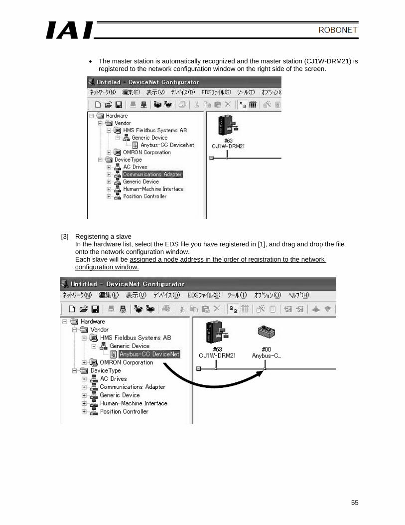
• The master station is automatically recognized and the master station (CJ1W-DRM21) is
registered to the network configuration window on the right side of the screen.
[3] Registering a slave In the hardware list, select the EDS file you have registered in [1], and drag and drop the file onto the network configuration window. Each slave will be assigned a node address in the order of registration to the network configuration window.
56
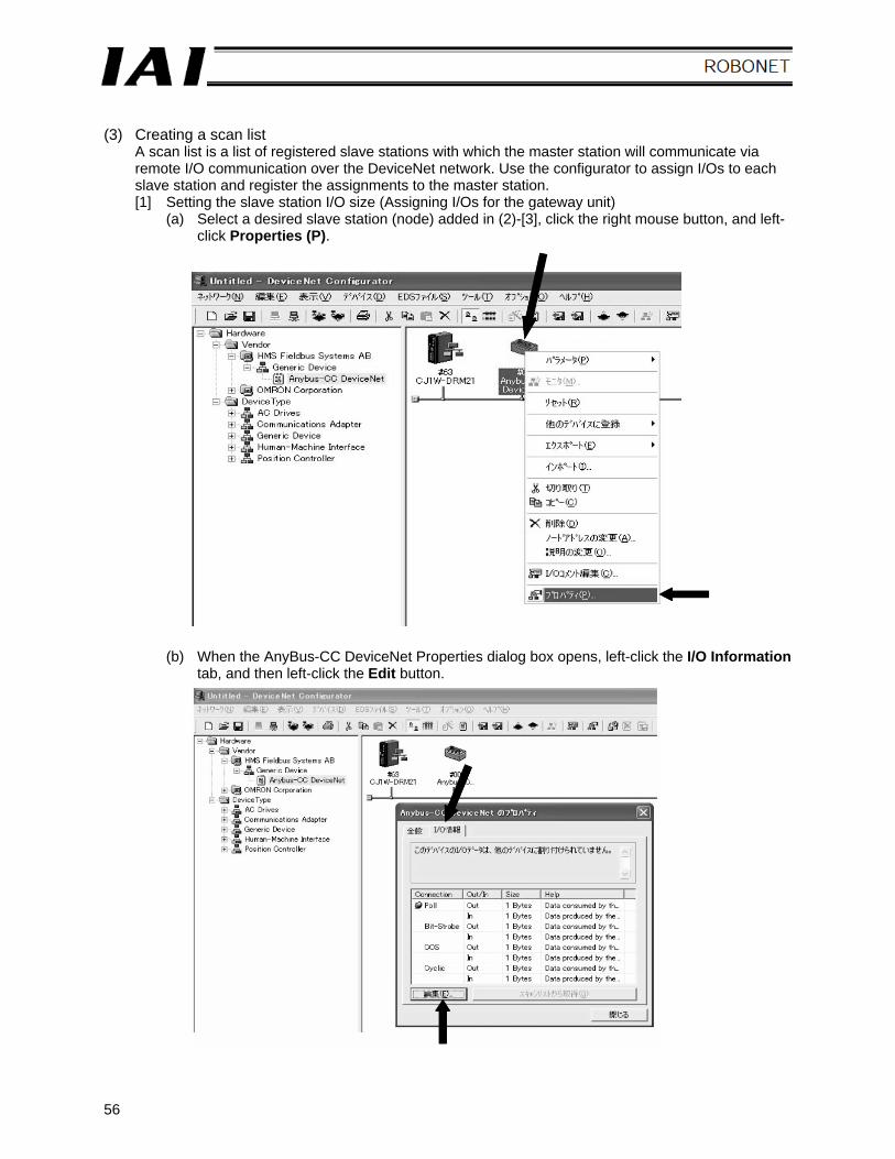
(3) Creating a scan list
A scan list is a list of registered slave stations with which the master station will communicate via remote I/O communication over the DeviceNet network. Use the configurator to assign I/Os to each slave station and register the assignments to the master station. [1] Setting the slave station I/O size (Assigning I/Os for the gateway unit)
(a) Select a desired slave station (node) added in (2)-[3], click the right mouse button, and left-click Properties (P).
(b) When the AnyBus-CC DeviceNet Properties dialog box opens, left-click the I/O Information tab, and then left-click the Edit button.
57
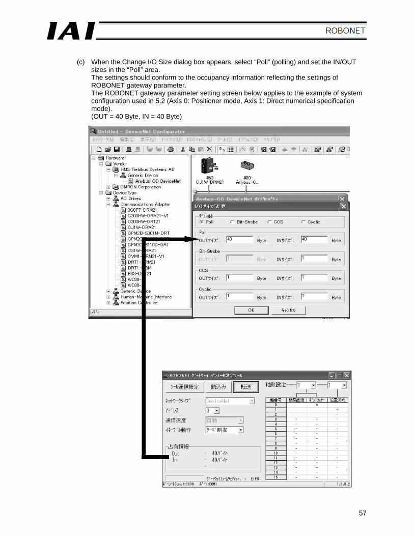
(c) When the Change I/O Size dialog box appears, select “Poll” (polling) and set the IN/OUT
sizes in the “Poll” area. The settings should conform to the occupancy information reflecting the settings of ROBONET gateway parameter. The ROBONET gateway parameter setting screen below applies to the example of system configuration used in 5.2 (Axis 0: Positioner mode, Axis 1: Direct numerical specification mode). (OUT = 40 Byte, IN = 40 Byte)
58
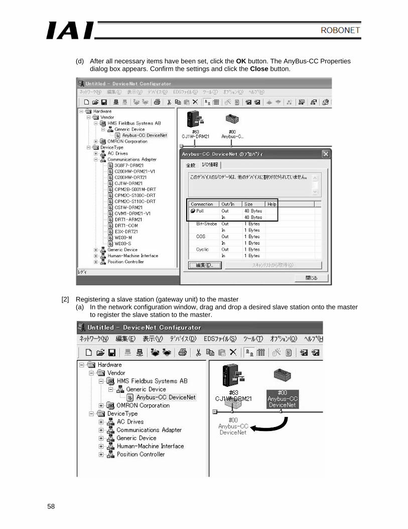
(d) After all necessary items have been set, click the OK button. The AnyBus-CC Properties
dialog box appears. Confirm the settings and click the Close button.
[2] Registering a slave station (gateway unit) to the master (a) In the network configuration window, drag and drop a desired slave station onto the master
to register the slave station to the master.
59
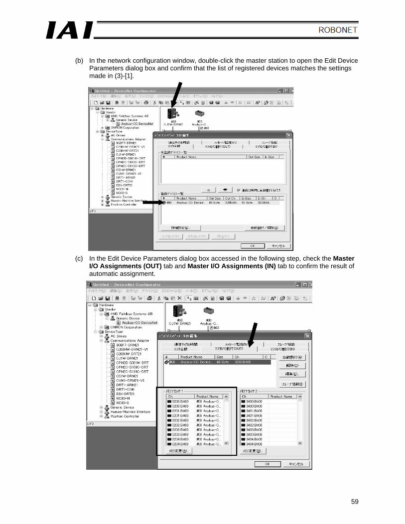
(b) In the network configuration window, double-click the master station to open the Edit Device
Parameters dialog box and confirm that the list of registered devices matches the settings made in (3)-[1].
(c) In the Edit Device Parameters dialog box accessed in the following step, check the Master I/O Assignments (OUT) tab and Master I/O Assignments (IN) tab to confirm the result of automatic assignment.
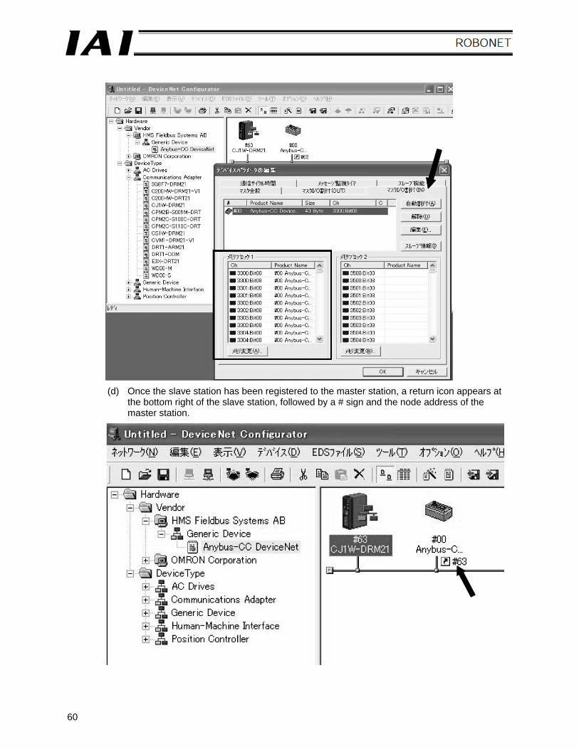
60
(d) Once the slave station has been registered to the master station, a return icon appears at the bottom right of the slave station, followed by a # sign and the node address of the master station.
61
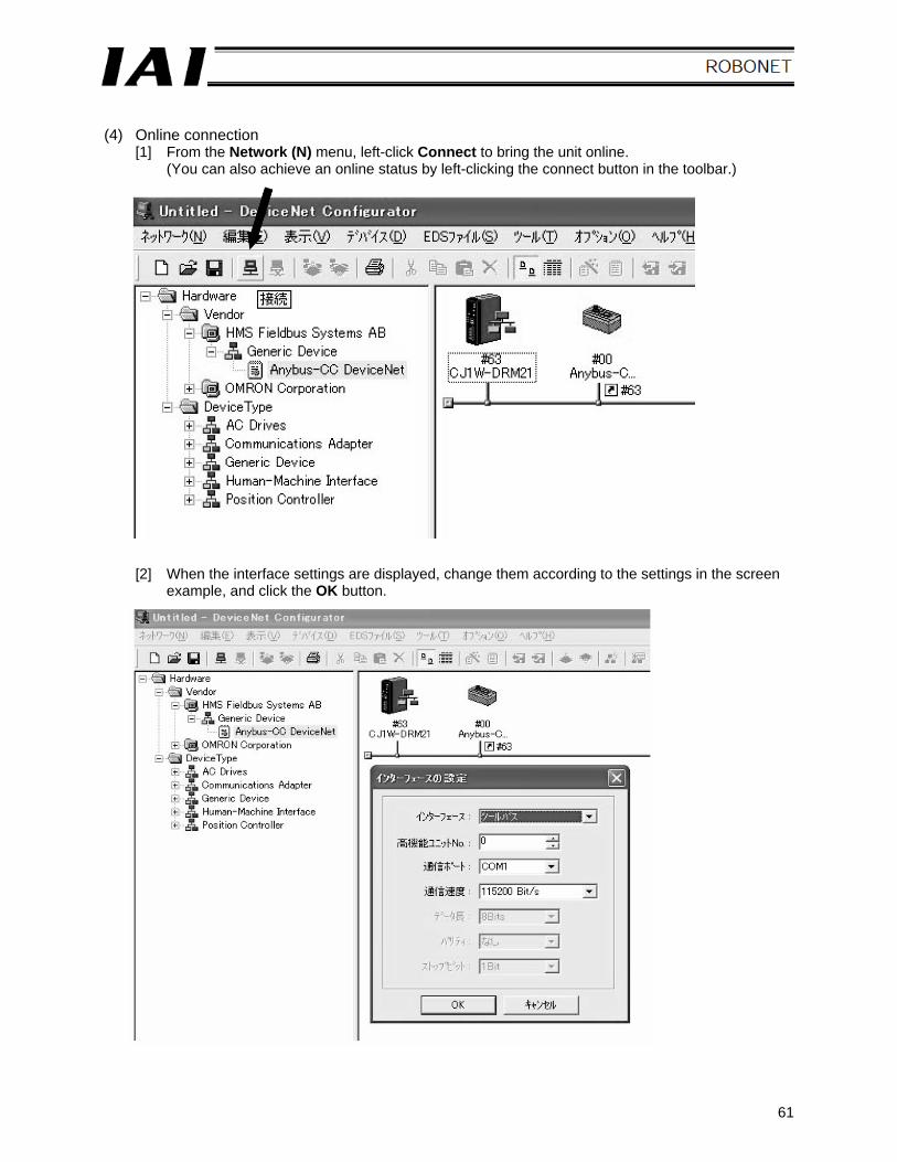
(4) Online connection
[1] From the Network (N) menu, left-click Connect to bring the unit online. (You can also achieve an online status by left-clicking the connect button in the toolbar.)
[2] When the interface settings are displayed, change them according to the settings in the screen example, and click the OK button.
62
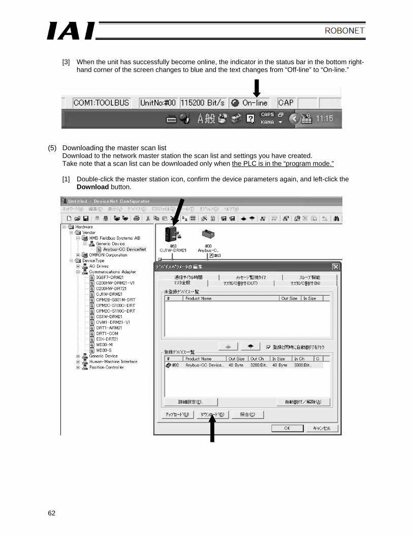
[3] When the unit has successfully become online, the indicator in the status bar in the bottom right-
hand corner of the screen changes to blue and the text changes from “Off-line” to “On-line.” (5) Downloading the master scan list
Download to the network master station the scan list and settings you have created. Take note that a scan list can be downloaded only when the PLC is in the “program mode.” [1] Double-click the master station icon, confirm the device parameters again, and left-click the
Download button.
63
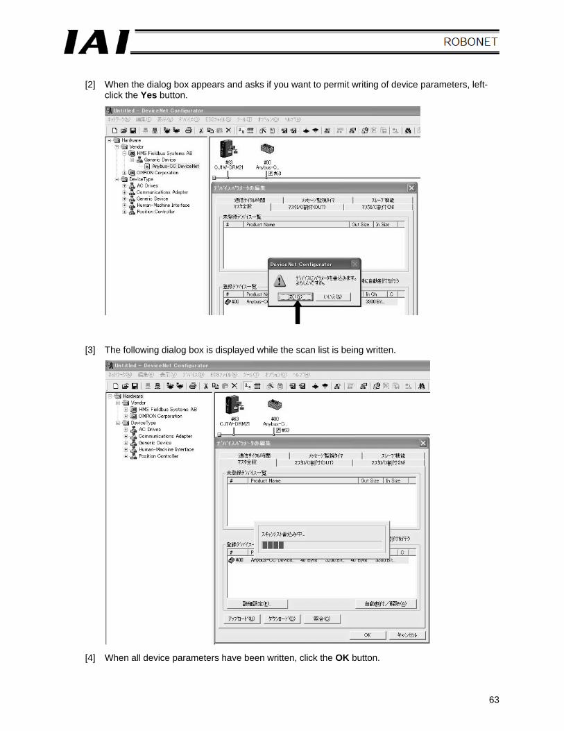
[2] When the dialog box appears and asks if you want to permit writing of device parameters, left-
click the Yes button.
[3] The following dialog box is displayed while the scan list is being written.
[4] When all device parameters have been written, click the OK button.
64
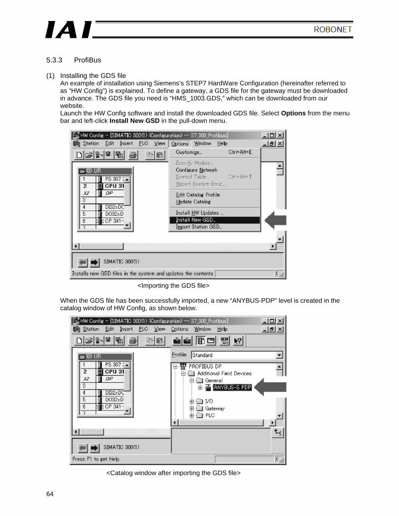
5.3.3 ProfiBus (1) Installing the GDS file
An example of installation using Siemens’s STEP7 HardWare Configuration (hereinafter referred to as “HW Config”) is explained. To define a gateway, a GDS file for the gateway must be downloaded in advance. The GDS file you need is “HMS_1003.GDS,” which can be downloaded from our website. Launch the HW Config software and install the downloaded GDS file. Select Options from the menu bar and left-click Install New GSD in the pull-down menu.
<Importing the GDS file>
When the GDS file has been successfully imported, a new “ANYBUS-PDP” level is created in the catalog window of HW Config, as shown below.
<Catalog window after importing the GDS file>
65
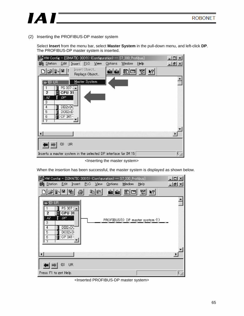
(2) Inserting the PROFIBUS-DP master system
Select Insert from the menu bar, select Master System in the pull-down menu, and left-click DP. The PROFIBUS-DP master system is inserted.
<Inserting the master system>
When the insertion has been successful, the master system is displayed as shown below.
<Inserted PROFIBUS-DP master system>
66
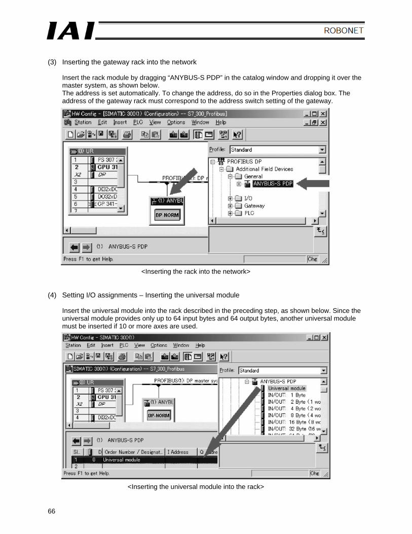
(3) Inserting the gateway rack into the network
Insert the rack module by dragging “ANYBUS-S PDP” in the catalog window and dropping it over the master system, as shown below. The address is set automatically. To change the address, do so in the Properties dialog box. The address of the gateway rack must correspond to the address switch setting of the gateway.
<Inserting the rack into the network> (4) Setting I/O assignments – Inserting the universal module
Insert the universal module into the rack described in the preceding step, as shown below. Since the universal module provides only up to 64 input bytes and 64 output bytes, another universal module must be inserted if 10 or more axes are used.
<Inserting the universal module into the rack>
67
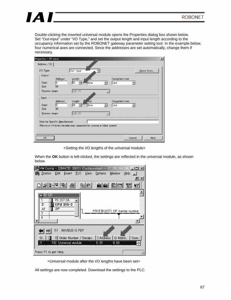
Double-clicking the inserted universal module opens the Properties dialog box shown below. Set “Out-input” under “I/O Type,” and set the output length and input length according to the occupancy information set by the ROBONET gateway parameter setting tool. In the example below, four numerical axes are connected. Since the addresses are set automatically, change them if necessary.
<Setting the I/O lengths of the universal module>
When the OK button is left-clicked, the settings are reflected in the universal module, as shown below.
<Universal module after the I/O lengths have been set>
All settings are now completed. Download the settings to the PLC.
68
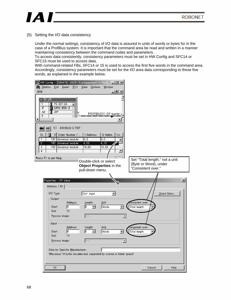
(5) Setting the I/O data consistency
Under the normal settings, consistency of I/O data is assured in units of words or bytes for in the case of a ProfiBus system. It is important that the command area be read and written in a manner maintaining consistency between the command codes and parameters. To access data consistently, consistency parameters must be set in HW Config and SFC14 or SFC15 must be used to access data. With command-related FBs, SFC14 or 15 is used to access the first five words in the command area. Accordingly, consistency parameters must be set for the I/O area data corresponding to these five words, as explained in the example below.
Double-click or select Object Properties in the pull-down menu.
Set “Total length,” not a unit (Byte or Word), under “Consistent over.”
69
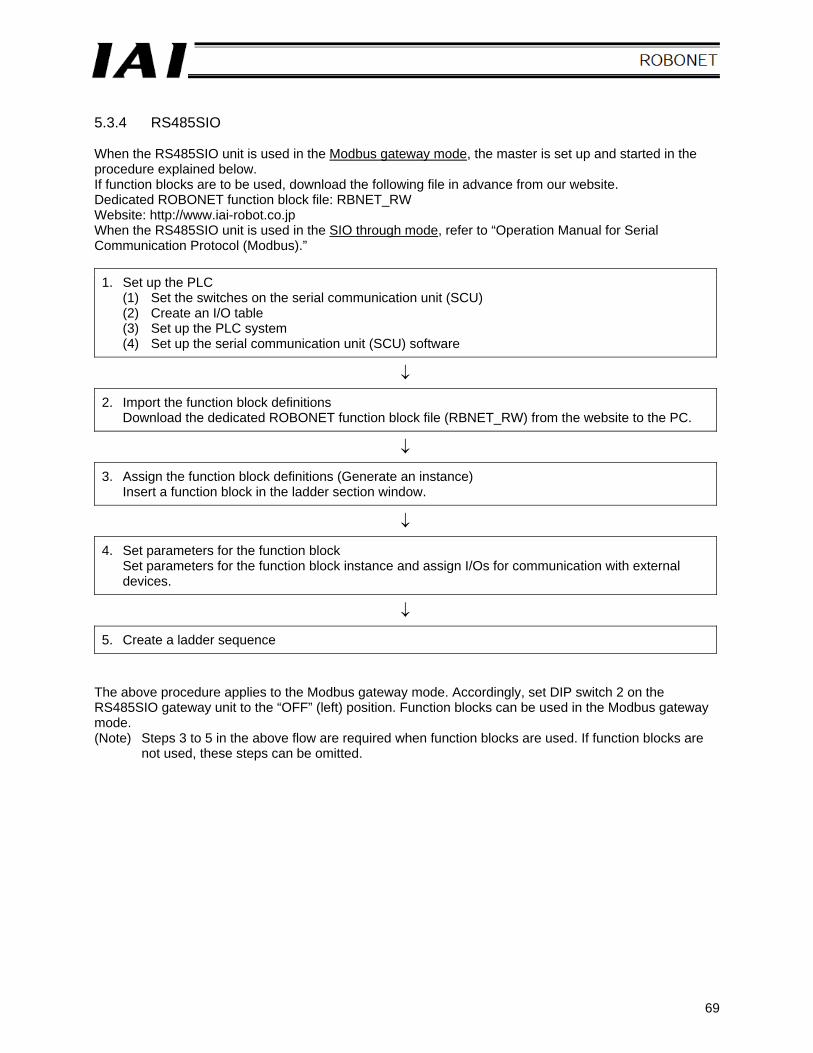
5.3.4 RS485SIO When the RS485SIO unit is used in the Modbus gateway mode, the master is set up and started in the procedure explained below. If function blocks are to be used, download the following file in advance from our website. Dedicated ROBONET function block file: RBNET_RW Website: http://www.iai-robot.co.jp When the RS485SIO unit is used in the SIO through mode, refer to “Operation Manual for Serial Communication Protocol (Modbus).”
1. Set up the PLC (1) Set the switches on the serial communication unit (SCU) (2) Create an I/O table (3) Set up the PLC system (4) Set up the serial communication unit (SCU) software
↓
2. Import the function block definitions Download the dedicated ROBONET function block file (RBNET_RW) from the website to the PC.
↓
3. Assign the function block definitions (Generate an instance) Insert a function block in the ladder section window.
↓
4. Set parameters for the function block Set parameters for the function block instance and assign I/Os for communication with external devices.
↓
5. Create a ladder sequence The above procedure applies to the Modbus gateway mode. Accordingly, set DIP switch 2 on the RS485SIO gateway unit to the “OFF” (left) position. Function blocks can be used in the Modbus gateway mode. (Note) Steps 3 to 5 in the above flow are required when function blocks are used. If function blocks are
not used, these steps can be omitted.
70
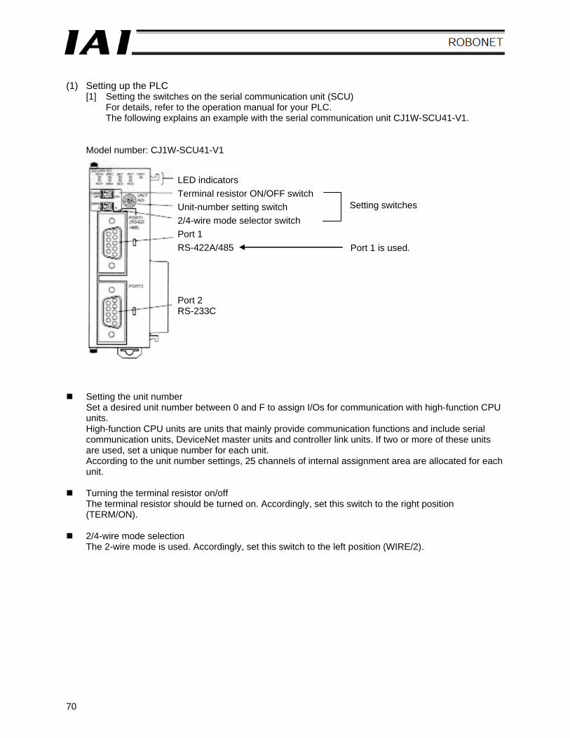
(1) Setting up the PLC
[1] Setting the switches on the serial communication unit (SCU) For details, refer to the operation manual for your PLC. The following explains an example with the serial communication unit CJ1W-SCU41-V1.
Model number: CJ1W-SCU41-V1
Setting the unit number Set a desired unit number between 0 and F to assign I/Os for communication with high-function CPU units. High-function CPU units are units that mainly provide communication functions and include serial communication units, DeviceNet master units and controller link units. If two or more of these units are used, set a unique number for each unit. According to the unit number settings, 25 channels of internal assignment area are allocated for each unit.
Turning the terminal resistor on/off The terminal resistor should be turned on. Accordingly, set this switch to the right position (TERM/ON).
2/4-wire mode selection The 2-wire mode is used. Accordingly, set this switch to the left position (WIRE/2).
LED indicators Terminal resistor ON/OFF switch Unit-number setting switch 2/4-wire mode selector switch Port 1 RS-422A/485
Setting switches
Port 1 is used.
Port 2 RS-233C
71
[2] Creating an I/O table
[a] Launch CX-Programmer (Version 7.0). [b] Connect CX-Programmer to the PLC.
You can connect CX-Programmer to the PLC by setting the network type, baud rate and other necessary items in an offline state, or by selecting a connection port to automatically bring the connection online.
[c] Set the PLC operation mode to “Program.” [d] Double-clicking “I/O Table/Unit Settings” in the workspace window opens the I/O table
dialog box. From the Options (O) menu, select Create I/O Table (R) and manually create an I/O table.
The CJ series PLC has been shipped with the “Automatic generation upon power ON” setting
enabled. Accordingly, channel numbers (I/Os) are assigned automatically to the basic I/O units that are mounted when the power is turned on, even when an I/O table is not yet registered. Take note that unit numbers must be set in advance for high-function CPU units and high-function units such as serial communication units.
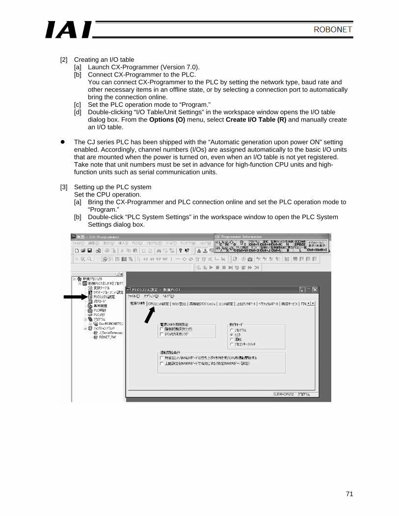
[3] Setting up the PLC system
Set the CPU operation. [a] Bring the CX-Programmer and PLC connection online and set the PLC operation mode to
“Program.” [b] Double-click “PLC System Settings” in the workspace window to open the PLC System
Settings dialog box.
72
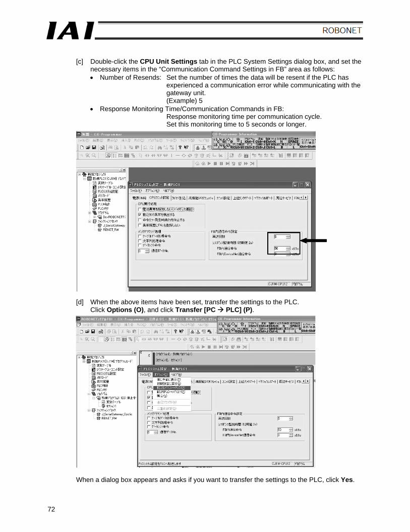
[c] Double-click the CPU Unit Settings tab in the PLC System Settings dialog box, and set the
necessary items in the “Communication Command Settings in FB” area as follows: • Number of Resends: Set the number of times the data will be resent if the PLC has
experienced a communication error while communicating with the gateway unit. (Example) 5
• Response Monitoring Time/Communication Commands in FB: Response monitoring time per communication cycle. Set this monitoring time to 5 seconds or longer.
[d] When the above items have been set, transfer the settings to the PLC. Click Options (O), and click Transfer [PC PLC] (P).
When a dialog box appears and asks if you want to transfer the settings to the PLC, click Yes.
73
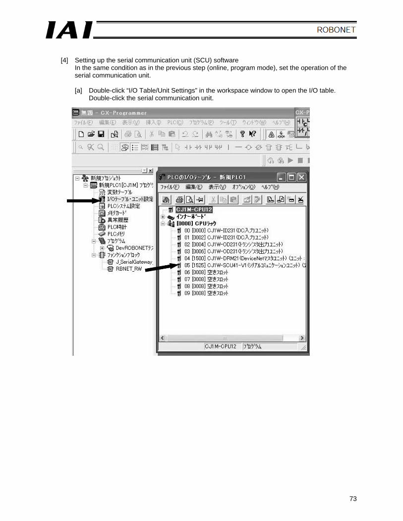
[4] Setting up the serial communication unit (SCU) software
In the same condition as in the previous step (online, program mode), set the operation of the serial communication unit.
[a] Double-click “I/O Table/Unit Settings” in the workspace window to open the I/O table.
Double-click the serial communication unit.
74
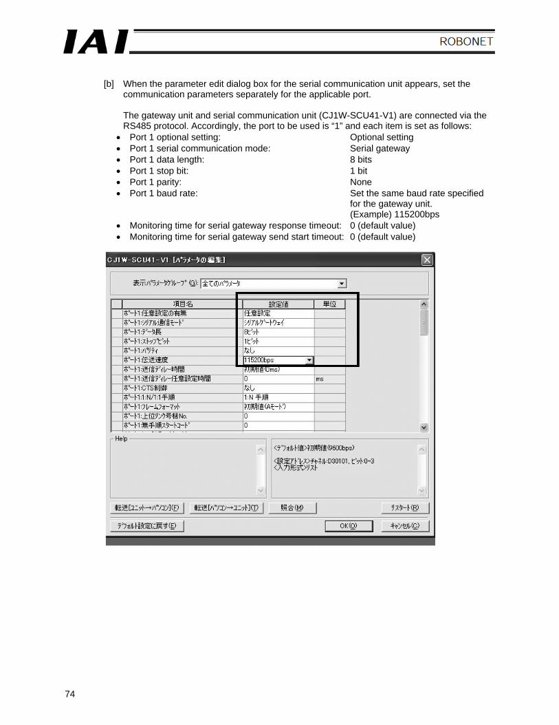
[b] When the parameter edit dialog box for the serial communication unit appears, set the
communication parameters separately for the applicable port.
The gateway unit and serial communication unit (CJ1W-SCU41-V1) are connected via the RS485 protocol. Accordingly, the port to be used is “1” and each item is set as follows:
• Port 1 optional setting: Optional setting • Port 1 serial communication mode: Serial gateway • Port 1 data length: 8 bits • Port 1 stop bit: 1 bit • Port 1 parity: None • Port 1 baud rate: Set the same baud rate specified
for the gateway unit. (Example) 115200bps
• Monitoring time for serial gateway response timeout: 0 (default value) • Monitoring time for serial gateway send start timeout: 0 (default value)
75
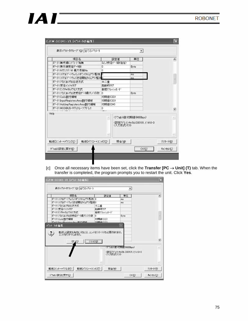
[c] Once all necessary items have been set, click the Transfer [PC → Unit] (T) tab. When the transfer is completed, the program prompts you to restart the unit. Click Yes.
76
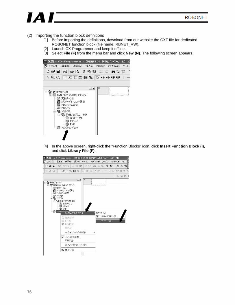
(2) Importing the function block definitions
[1] Before importing the definitions, download from our website the CXF file for dedicated ROBONET function block (file name: RBNET_RW).
[2] Launch CX-Programmer and keep it offline. [3] Select File (F) from the menu bar and click New (N). The following screen appears.
[4] In the above screen, right-click the “Function Blocks” icon, click Insert Function Block (I), and click Library File (F).
77
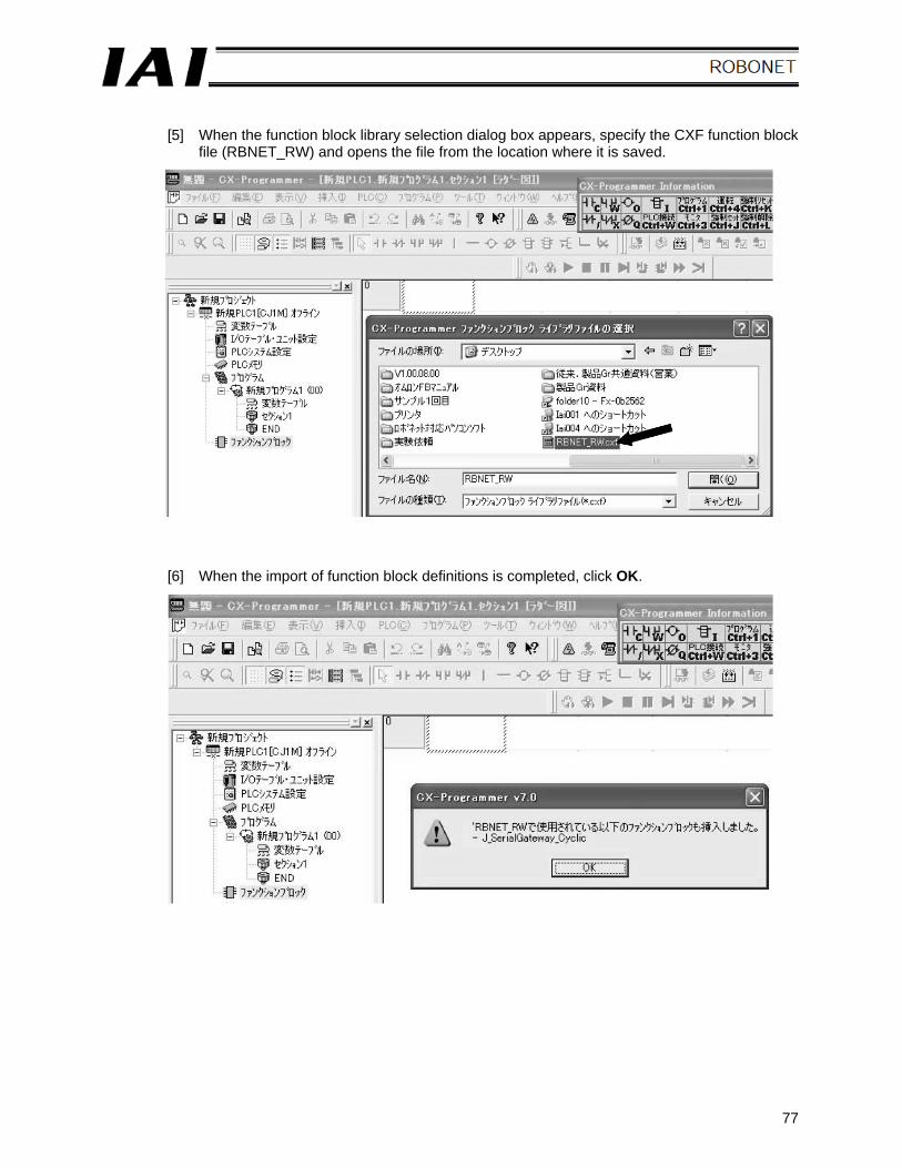
[5] When the function block library selection dialog box appears, specify the CXF function block
file (RBNET_RW) and opens the file from the location where it is saved.
[6] When the import of function block definitions is completed, click OK.
78
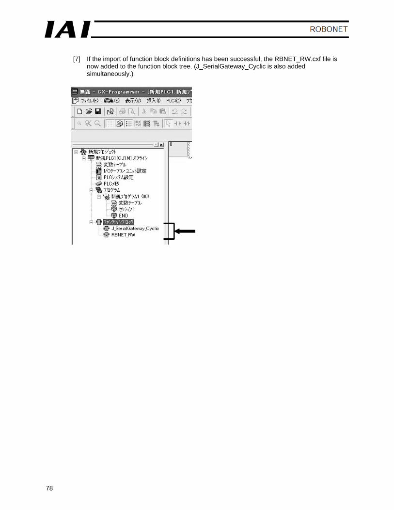
[7] If the import of function block definitions has been successful, the RBNET_RW.cxf file is
now added to the function block tree. (J_SerialGateway_Cyclic is also added simultaneously.)
79
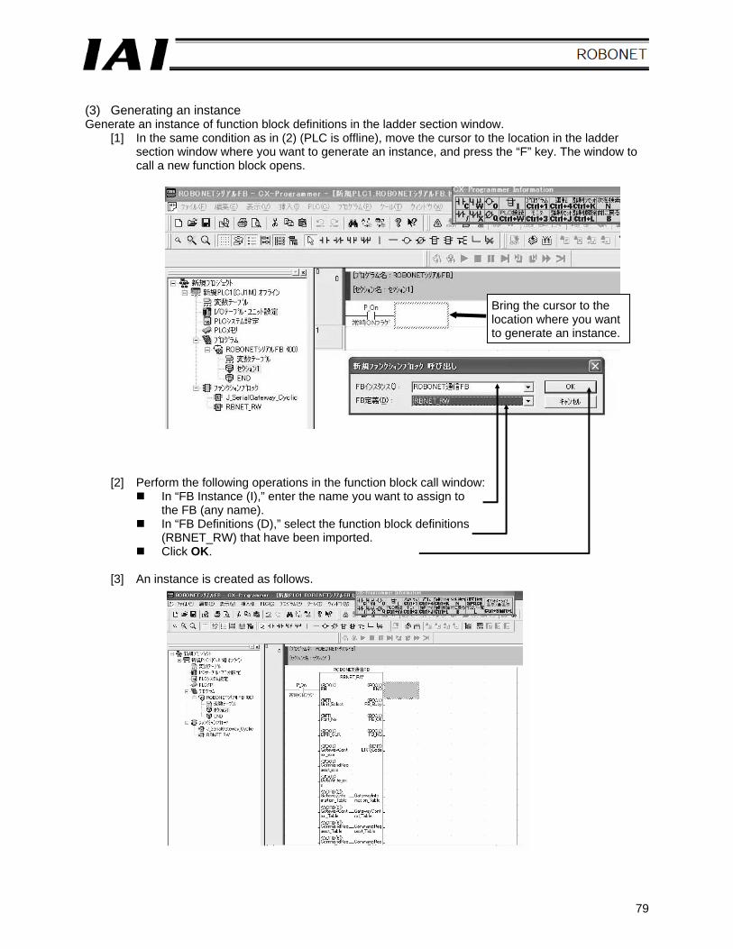
(3) Generating an instance Generate an instance of function block definitions in the ladder section window.
[1] In the same condition as in (2) (PLC is offline), move the cursor to the location in the ladder section window where you want to generate an instance, and press the “F” key. The window to call a new function block opens.
[2] Perform the following operations in the function block call window: In “FB Instance (I),” enter the name you want to assign to
the FB (any name). In “FB Definitions (D),” select the function block definitions
(RBNET_RW) that have been imported. Click OK.
[3] An instance is created as follows.
Bring the cursor to the location where you want to generate an instance.
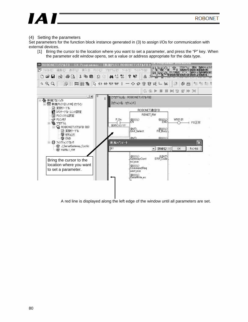
80
(4) Setting the parameters Set parameters for the function block instance generated in (3) to assign I/Os for communication with external devices.
[1] Bring the cursor to the location where you want to set a parameter, and press the “P” key. When the parameter edit window opens, set a value or address appropriate for the data type.
Bring the cursor to the location where you want to set a parameter.
A red line is displayed along the left edge of the window until all parameters are set.
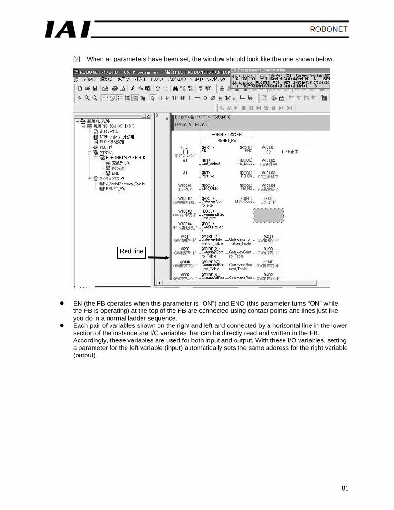
81
[2] When all parameters have been set, the window should look like the one shown below.
EN (the FB operates when this parameter is “ON”) and ENO (this parameter turns “ON” while the FB is operating) at the top of the FB are connected using contact points and lines just like you do in a normal ladder sequence.
Each pair of variables shown on the right and left and connected by a horizontal line in the lower section of the instance are I/O variables that can be directly read and written in the FB. Accordingly, these variables are used for both input and output. With these I/O variables, setting a parameter for the left variable (input) automatically sets the same address for the right variable (output).
Red line
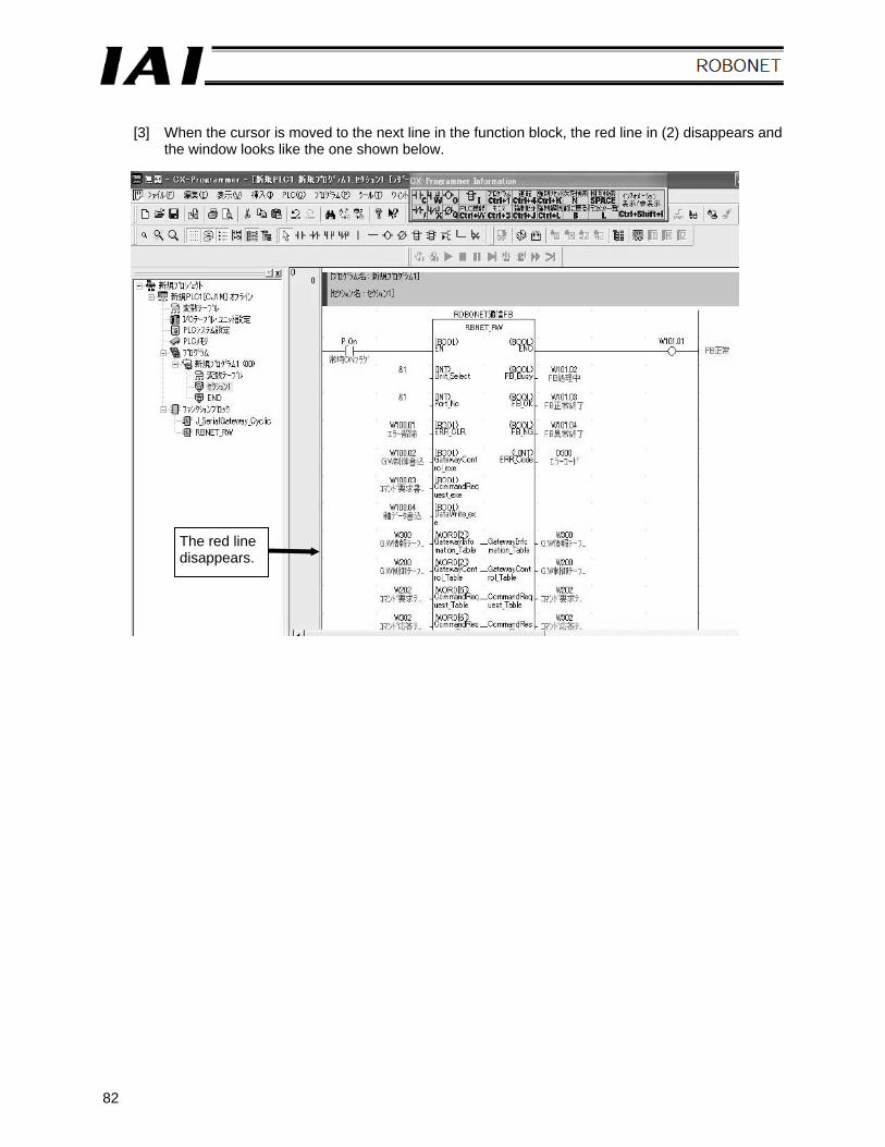
82
[3] When the cursor is moved to the next line in the function block, the red line in (2) disappears and
the window looks like the one shown below.
The red line disappears.
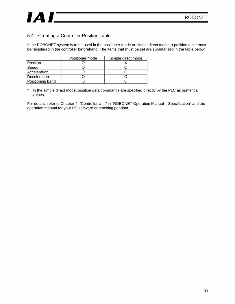
83
5.4 Creating a Controller Position Table If the ROBONET system is to be used in the positioner mode or simple direct mode, a position table must be registered in the controller beforehand. The items that must be set are summarized in the table below.
Positioner mode Simple direct mode Position X Speed Acceleration Deceleration Positioning band * In the simple direct mode, position data commands are specified directly by the PLC as numerical
values. For details, refer to Chapter 4, “Controller Unit” in “ROBONET Operation Manual – Specification” and the operation manual for your PC software or teaching pendant.

84

85
5.5 Address Correlation Diagram The correlation between the PLC’s I/O addresses (internal addresses) and the ROBONET addresses (gateway addresses) over the network that has been set up is explained for CC-Link, DeviceNet and RS485SIO systems. 5.2 and 5.3 explained an example of network configuration and the configuration procedure. The descriptions in this section assume the settings used in this example. A PLC sequence for ROBONET operation can be created based on the applicable settings.
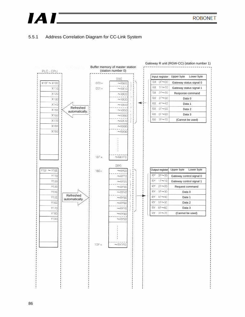
86
5.5.1 Address Correlation Diagram for CC-Link System
Refreshed automatically.
Buffer memory of master station(station number 0)
Gateway R unit (RGW-CC) (station number 1)
Refreshed automatically.
Input register Upper byte Lower byte
Gateway status signal 0
Gateway status signal 1
Response command
Data 0
Data 1
Data 2
Data 3
(Cannot be used)
Output register Upper byte Lower byte
Gateway control signal 0
Gateway control signal 1
Request command
Data 0
Data 1
Data 2
Data 3
(Cannot be used)
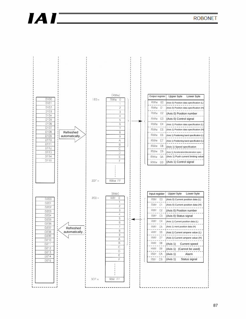
87
Refreshed automatically.
Refreshed automatically.
Output register Upper byte Lower byte
Input register Upper byte Lower byte
(Axis 0) Position data specification (L) (Axis 0) Position data specification (H) (Axis 0) Position number
(Axis 0) Control signal (Axis 1) Position data specification (L) (Axis 1) Position data specification (H) (Axis 1) Positioning band specification (L) (Axis 1) Positioning band specification (L) (Axis 1) Speed specification (Axis 1) Acceleration/deceleration spec. (Axis 1) Push current limiting value (Axis 1) Control signal
(Axis 0) Current position data (L) (Axis 0) Current position data (H) (Axis 0) Position number
(Axis 0) Status signal (Axis 1) Current position data (L) (Axis 1) rrent position data (H) (Axis 1) Current ampere value (L) (Axis 1) Current ampere value (H) (Axis 1) Current speed
(Axis 1) (Cannot be used)
(Axis 1) Alarm
(Axis 1) Status signal
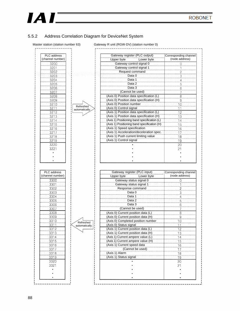
88
5.5.2 Address Correlation Diagram for DeviceNet System
Master station (station number 63) Gateway R unit (RGW-DV) (station number 0)
PLC address (channel number)
Gateway register (PLC output) Upper byte Lower byte
Corresponding channel (node address)
Refreshed automatically.
Refreshed automatically.
Gateway control signal 0 Gateway control signal 1
Request command Data 0 Data 1 Data 2 Data 3
(Cannot be used) (Axis 0) Position data specification (L) (Axis 0) Position data specification (H) (Axis 0) Position number (Axis 0) Control signal (Axis 1) Position data specification (L) (Axis 1) Position data specification (H) (Axis 1) Positioning band specification (L) (Axis 1) Positioning band specification (H) (Axis 1) Speed specification (Axis 1) Acceleration/deceleration spec. (Axis 1) Push current limiting value (Axis 1) Control signal
(Axis 0) Current position data (L) (Axis 0) Current position data (H) (Axis 0) Completed position number (Axis 0) Status signal (Axis 1) Current position data (L) (Axis 1) Current position data (H) (Axis 1) Current ampere value (L) (Axis 1) Current ampere value (H) (Axis 1) Current speed data
(Cannot be used) (Axis 1) Alarm (Axis 1) Status signal
PLC address (channel number)
Gateway register (PLC input) Upper byte Lower byte
Corresponding channel (node address)
Gateway status signal 0 Gateway status signal 1
Response command Data 0 Data 1 Data 2 Data 3
(Cannot be used)
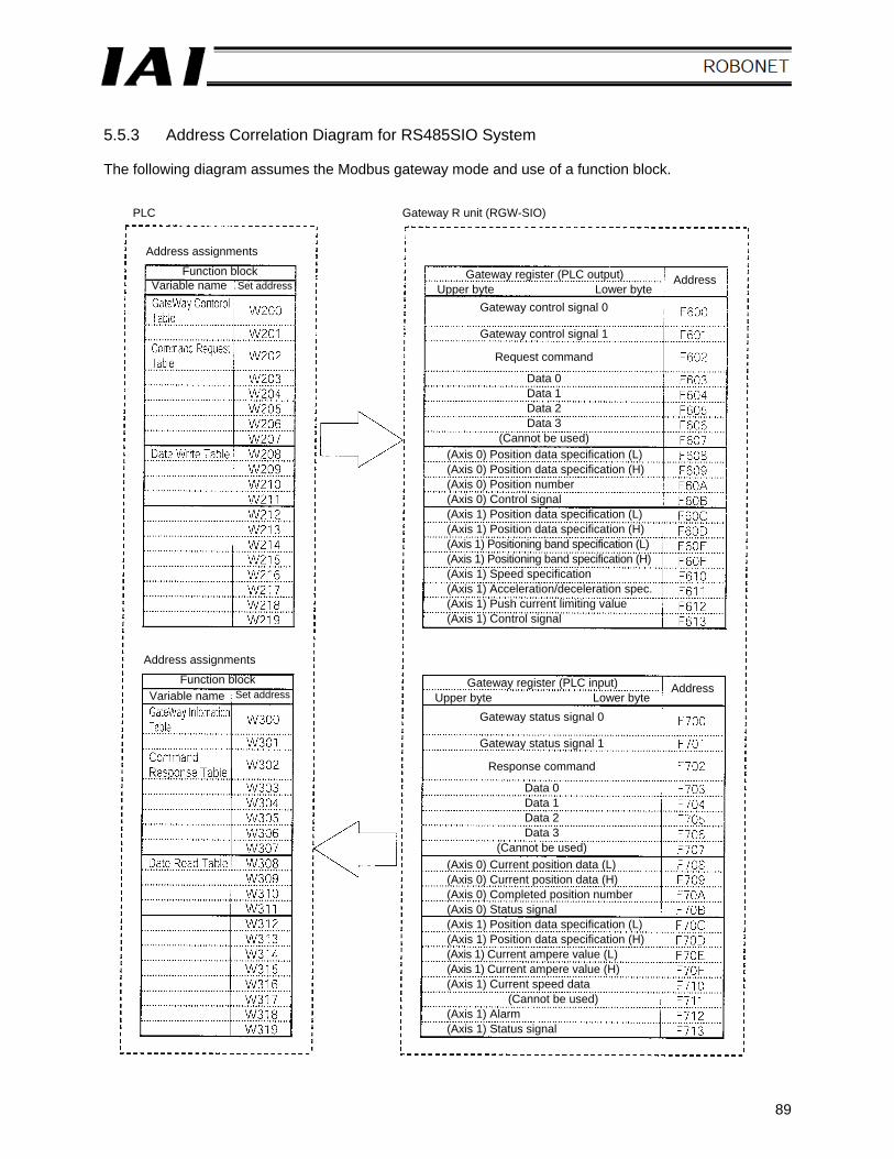
89
5.5.3 Address Correlation Diagram for RS485SIO System The following diagram assumes the Modbus gateway mode and use of a function block.
PLC Gateway R unit (RGW-SIO)
Gateway register (PLC output) Upper byte Lower byte
(Axis 0) Position data specification (L) (Axis 0) Position data specification (H) (Axis 0) Position number (Axis 0) Control signal (Axis 1) Position data specification (L) (Axis 1) Position data specification (H) (Axis 1) Positioning band specification (L) (Axis 1) Positioning band specification (H) (Axis 1) Speed specification (Axis 1) Acceleration/deceleration spec. (Axis 1) Push current limiting value (Axis 1) Control signal
(Axis 0) Current position data (L) (Axis 0) Current position data (H) (Axis 0) Completed position number (Axis 0) Status signal (Axis 1) Position data specification (L) (Axis 1) Position data specification (H) (Axis 1) Current ampere value (L) (Axis 1) Current ampere value (H) (Axis 1) Current speed data
(Cannot be used) (Axis 1) Alarm (Axis 1) Status signal
Gateway status signal 0
Gateway status signal 1
Response command
Data 0 Data 1 Data 2 Data 3
(Cannot be used)
Address assignments Function block
Variable name Set address Address
Address assignments Function block
Variable name Set address Gateway register (PLC input)
Upper byte Lower byte Address
Gateway control signal 0
Gateway control signal 1
Request command
Data 0 Data 1 Data 2 Data 3
(Cannot be used)
90
Chapter 6 Troubleshooting 6.1 Actions to Be Taken upon Problems If you encountered a problem, follow the procedure below for speedy recovery and to prevent the same problem from occurring again:
a. Check the LED indicators on the gateway R unit RUN/ALM, ERROR-T, ERROR-C, STATUS-0, STATUS-1, EMG
b. Check the host controller (PLC master station) for abnormality c. Check the LED indicators on the controller unit
SV/ALM, TX/RX, STATUS0 to STATUS3 (If the ALM LED is illuminating in red, the STATUS0 to STATUS3 LEDs indicate an applicable simple alarm code.)
d. Check the LED indicators on the simple absolute R unit RDY/ALM, STATUS0 to STATUS1
e. Check if the power-supply voltage is within a range of 24 V ± 10% With a DeviceNet system, check the communication power supply (24 V).
f. Check the wiring of the ROBONET communication connection board, simple absolute connection board, motor cable and encoder cable
g. Check the network cable connection (In particular, pay attention to the connection points on the terminal block and connector.)
h. Check the installation condition of network terminal resistor and their resistance values i. Conduct operation check using the teaching pendant or PC software
Connect the teaching pendant or PC software to the gateway R unit and set the MODE switch to “MANU.” In this condition, operate each axis and check if an alarm generates.
j. Check the I/O signals transmitted between the PLC and controller unit [1] On the PLC side, check the I/O signals using the monitor function of a dedicated tool
(Mitsubishi GX Developer, Omron CX Programmer, etc.) [2] On the control unit side, check the I/O signals using the status monitor function of the
teaching pendant or PC software. [3] Confirm that the I/O signals checked in steps [1] and [2] above are consistent.
k. Identify the background leading to the problem as well as the operating condition when the problem occurred
l. Analyze the cause of problem m. Take appropriate actions
If the problem cannot be resolved, contact IAI after conducting the checks in a to k.
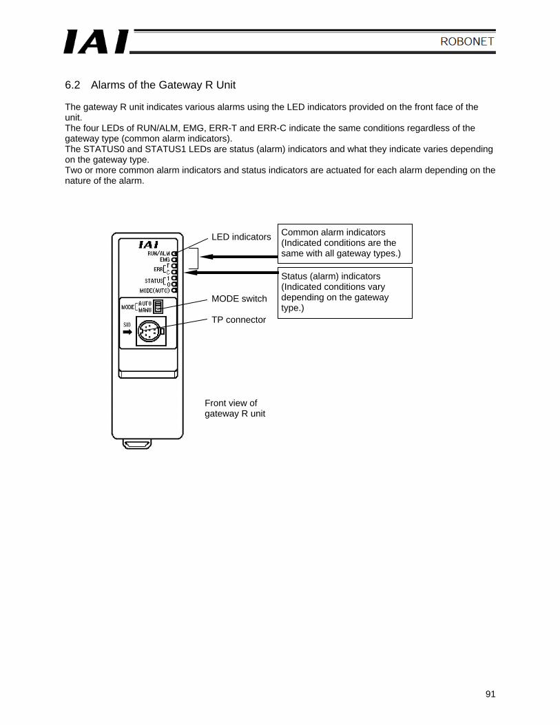
91
6.2 Alarms of the Gateway R Unit The gateway R unit indicates various alarms using the LED indicators provided on the front face of the unit. The four LEDs of RUN/ALM, EMG, ERR-T and ERR-C indicate the same conditions regardless of the gateway type (common alarm indicators). The STATUS0 and STATUS1 LEDs are status (alarm) indicators and what they indicate varies depending on the gateway type. Two or more common alarm indicators and status indicators are actuated for each alarm depending on the nature of the alarm.
LED indicators
MODE switch TP connector
Common alarm indicators (Indicated conditions are the same with all gateway types.)
Status (alarm) indicators (Indicated conditions vary depending on the gateway type.)
Front view of gateway R unit
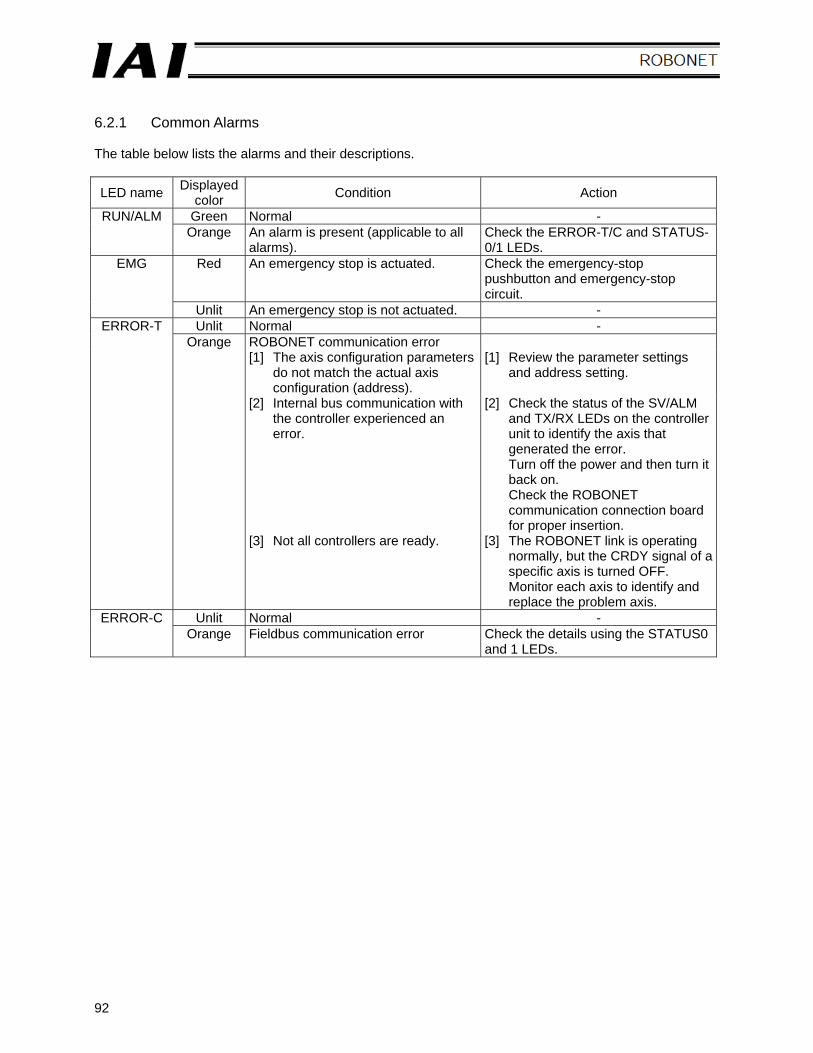
92
6.2.1 Common Alarms The table below lists the alarms and their descriptions.
LED name Displayed color Condition Action
Green Normal - RUN/ALM Orange An alarm is present (applicable to all
alarms). Check the ERROR-T/C and STATUS-0/1 LEDs.
Red An emergency stop is actuated. Check the emergency-stop pushbutton and emergency-stop circuit.
EMG
Unlit An emergency stop is not actuated. - Unlit Normal - ERROR-T
Orange ROBONET communication error [1] The axis configuration parameters
do not match the actual axis configuration (address).
[1] Review the parameter settings and address setting.
[2] Internal bus communication with the controller experienced an error.
[2] Check the status of the SV/ALM and TX/RX LEDs on the controller unit to identify the axis that generated the error. Turn off the power and then turn it back on. Check the ROBONET communication connection board for proper insertion.
[3] Not all controllers are ready. [3] The ROBONET link is operating normally, but the CRDY signal of a specific axis is turned OFF. Monitor each axis to identify and replace the problem axis.
Unlit Normal - ERROR-C Orange Fieldbus communication error Check the details using the STATUS0
and 1 LEDs.
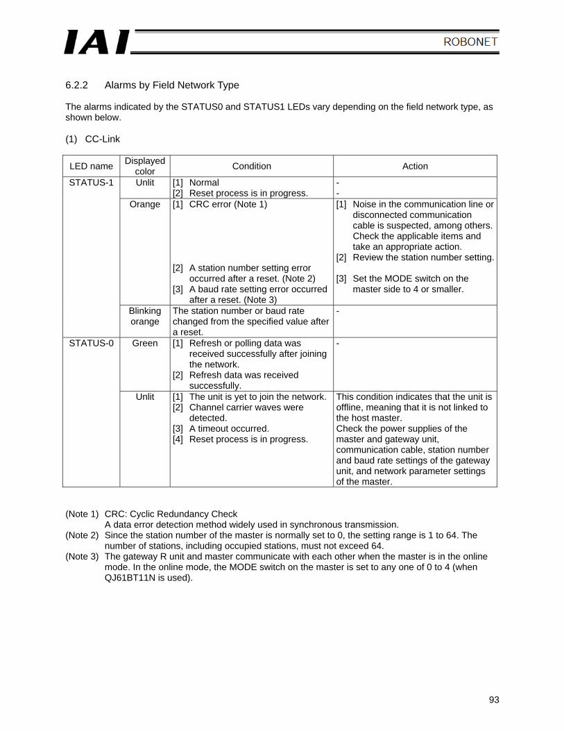
93
6.2.2 Alarms by Field Network Type The alarms indicated by the STATUS0 and STATUS1 LEDs vary depending on the field network type, as shown below. (1) CC-Link
LED name Displayed color Condition Action
Unlit [1] Normal [2] Reset process is in progress.
- -
Orange [1] CRC error (Note 1) [2] A station number setting error
occurred after a reset. (Note 2) [3] A baud rate setting error occurred
after a reset. (Note 3)
[1] Noise in the communication line or disconnected communication cable is suspected, among others. Check the applicable items and take an appropriate action.
[2] Review the station number setting. [3] Set the MODE switch on the
master side to 4 or smaller.
STATUS-1
Blinking orange
The station number or baud rate changed from the specified value after a reset.
-
Green [1] Refresh or polling data was received successfully after joining the network.
[2] Refresh data was received successfully.
- STATUS-0
Unlit [1] The unit is yet to join the network. [2] Channel carrier waves were
detected. [3] A timeout occurred. [4] Reset process is in progress.
This condition indicates that the unit is offline, meaning that it is not linked to the host master. Check the power supplies of the master and gateway unit, communication cable, station number and baud rate settings of the gateway unit, and network parameter settings of the master.
(Note 1) CRC: Cyclic Redundancy Check
A data error detection method widely used in synchronous transmission. (Note 2) Since the station number of the master is normally set to 0, the setting range is 1 to 64. The
number of stations, including occupied stations, must not exceed 64. (Note 3) The gateway R unit and master communicate with each other when the master is in the online
mode. In the online mode, the MODE switch on the master is set to any one of 0 to 4 (when QJ61BT11N is used).
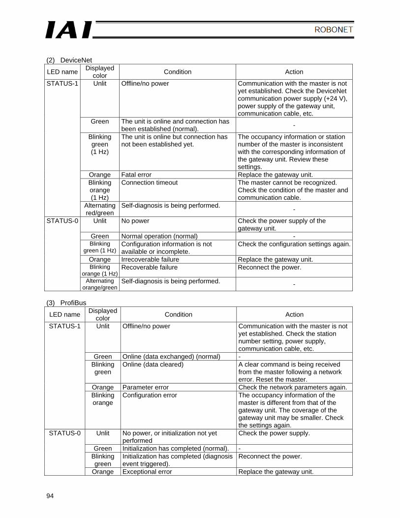
94
(2) DeviceNet
LED name Displayed color Condition Action
Unlit Offline/no power Communication with the master is not yet established. Check the DeviceNet communication power supply (+24 V), power supply of the gateway unit, communication cable, etc.
Green The unit is online and connection has been established (normal). -
Blinking green (1 Hz)
The unit is online but connection has not been established yet.
The occupancy information or station number of the master is inconsistent with the corresponding information of the gateway unit. Review these settings.
Orange Fatal error Replace the gateway unit. Blinking orange (1 Hz)
Connection timeout The master cannot be recognized. Check the condition of the master and communication cable.
STATUS-1
Alternating red/green
Self-diagnosis is being performed. -
Unlit No power Check the power supply of the gateway unit.
Green Normal operation (normal) - Blinking
green (1 Hz) Configuration information is not available or incomplete.
Check the configuration settings again.
Orange Irrecoverable failure Replace the gateway unit. Blinking
orange (1 Hz) Recoverable failure Reconnect the power.
STATUS-0
Alternating orange/green
Self-diagnosis is being performed. -
(3) ProfiBus
LED name Displayed color Condition Action
Unlit Offline/no power Communication with the master is not yet established. Check the station number setting, power supply, communication cable, etc.
Green Online (data exchanged) (normal) - Blinking green
Online (data cleared) A clear command is being received from the master following a network error. Reset the master.
Orange Parameter error Check the network parameters again.
STATUS-1
Blinking orange
Configuration error The occupancy information of the master is different from that of the gateway unit. The coverage of the gateway unit may be smaller. Check the settings again.
Unlit No power, or initialization not yet performed
Check the power supply.
Green Initialization has completed (normal). - Blinking green
Initialization has completed (diagnosis event triggered).
Reconnect the power.
STATUS-0
Orange Exceptional error Replace the gateway unit.

95
(4) RS485SIO
LED name Displayed color Condition Action
STATUS-1 Unlit Data send stopped - Green Sending data -
STATUS-0 Unlit Data receive stopped - Green Receiving data -
* These are not alarm signals.
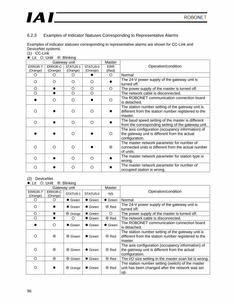
96
6.2.3 Examples of Indicator Statuses Corresponding to Representative Alarms Examples of indicator statuses corresponding to representative alarms are shown for CC-Link and DeviceNet systems. (1) CC-Link
: Lit : Unlit : Blinking Gateway unit Master
ERROR-T (Orange)
ERROR-C (Orange)
STATUS-1 (Orange)
STATUS-0 (Orange)
ERR (Red)
Operation/condition
Normal
The 24-V power supply of the gateway unit is turned off.
The power supply of the master is turned off. The network cable is disconnected.
The ROBONET communication connection board is detached.
The station number setting of the gateway unit is different from the station number registered to the master.
The baud speed setting of the master is different from the corresponding setting of the gateway unit.
The axis configuration (occupancy information) of the gateway unit is different from the actual configuration.
The master network parameter for number of connected units is different from the actual number of units.
The master network parameter for station type is wrong.
The master network parameter for number of occupied station is wrong.
(2) DeviceNet
: Lit : Unlit : Blinking Gateway unit Master
ERROR-T (Orange)
ERROR-C (Orange) STATUS-1 STATUS-0 NS Operation/condition
Green Green Green Normal
Green Green Red The 24-V power supply of the gateway unit is turned off.
Orange Green The power supply of the master is turned off. Green Red The network cable is disconnected.
Green Green Green The ROBONET communication connection board is detached.
Green Green Red The station number setting of the gateway unit is different from the station number registered to the master.
Green Green Red The axis configuration (occupancy information) of the gateway unit is different from the actual configuration.
Green Green Red The I/O size setting in the master scan list is wrong.
Orange Green Red The station number setting (switch) of the master unit has been changed after the network was set up.
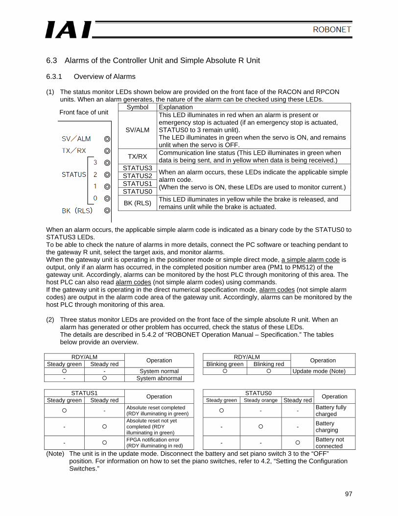
97
6.3 Alarms of the Controller Unit and Simple Absolute R Unit 6.3.1 Overview of Alarms (1) The status monitor LEDs shown below are provided on the front face of the RACON and RPCON
units. When an alarm generates, the nature of the alarm can be checked using these LEDs. Symbol Explanation
SV/ALM
This LED illuminates in red when an alarm is present or emergency stop is actuated (if an emergency stop is actuated, STATUS0 to 3 remain unlit). The LED illuminates in green when the servo is ON, and remains unlit when the servo is OFF.
TX/RX Communication line status (This LED illuminates in green when data is being sent, and in yellow when data is being received.)
STATUS3 STATUS2 STATUS1 STATUS0
When an alarm occurs, these LEDs indicate the applicable simple alarm code. (When the servo is ON, these LEDs are used to monitor current.)
BK (RLS) This LED illuminates in yellow while the brake is released, and remains unlit while the brake is actuated.
When an alarm occurs, the applicable simple alarm code is indicated as a binary code by the STATUS0 to STATUS3 LEDs. To be able to check the nature of alarms in more details, connect the PC software or teaching pendant to the gateway R unit, select the target axis, and monitor alarms. When the gateway unit is operating in the positioner mode or simple direct mode, a simple alarm code is output, only if an alarm has occurred, in the completed position number area (PM1 to PM512) of the gateway unit. Accordingly, alarms can be monitored by the host PLC through monitoring of this area. The host PLC can also read alarm codes (not simple alarm codes) using commands. If the gateway unit is operating in the direct numerical specification mode, alarm codes (not simple alarm codes) are output in the alarm code area of the gateway unit. Accordingly, alarms can be monitored by the host PLC through monitoring of this area. (2) Three status monitor LEDs are provided on the front face of the simple absolute R unit. When an
alarm has generated or other problem has occurred, check the status of these LEDs. The details are described in 5.4.2 of “ROBONET Operation Manual – Specification.” The tables below provide an overview.
RDY/ALM RDY/ALM
Steady green Steady red Operation Blinking green Blinking red Operation
- System normal Update mode (Note) - System abnormal
STATUS1 STATUS0
Steady green Steady red Operation Steady green Steady orange Steady red Operation
- Absolute reset completed (RDY illuminating in green) - - Battery fully
charged
- Absolute reset not yet completed (RDY illuminating in green)
- - Battery charging
- FPGA notification error (RDY illuminating in red) - - Battery not
connected (Note) The unit is in the update mode. Disconnect the battery and set piano switch 3 to the “OFF”
position. For information on how to set the piano switches, refer to 4.2, “Setting the Configuration Switches.”
Front face of unit
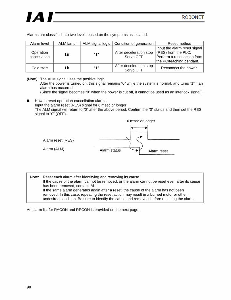
98
Alarms are classified into two levels based on the symptoms associated.
Alarm level ALM lamp ALM signal logic Condition of generation Reset method
Operation cancellation Lit “1” After deceleration stop
Servo OFF
Input the alarm reset signal (RES) from the PLC. Perform a reset action from the PC/teaching pendant.
Cold start Lit “1” After deceleration stop Servo OFF Reconnect the power.
(Note) The ALM signal uses the positive logic.
After the power is turned on, this signal remains “0” while the system is normal, and turns “1” if an alarm has occurred. (Since the signal becomes “0” when the power is cut off, it cannot be used as an interlock signal.)
How to reset operation-cancellation alarms
Input the alarm reset (RES) signal for 6 msec or longer. The ALM signal will return to “0” after the above period. Confirm the “0” status and then set the RES signal to “0” (OFF).
Note: Reset each alarm after identifying and removing its cause. If the cause of the alarm cannot be removed, or the alarm cannot be reset even after its cause has been removed, contact IAI. If the same alarm generates again after a reset, the cause of the alarm has not been removed. In this case, repeating the reset action may result in a burned motor or other undesired condition. Be sure to identify the cause and remove it before resetting the alarm.
An alarm list for RACON and RPCON is provided on the next page.
Alarm reset (RES) Alarm (ALM) Alarm status
6 msec or longer
Alarm reset
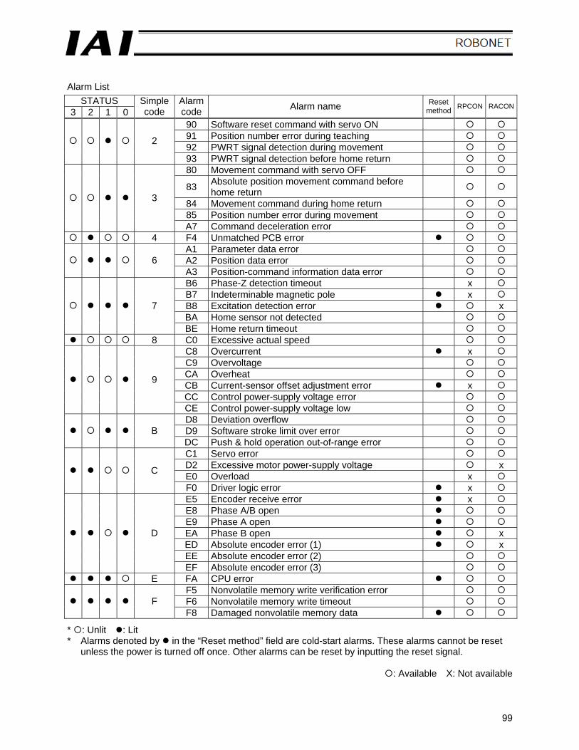
99
Alarm List
STATUS 3 2 1 0
Simple code
Alarm code Alarm name Reset
method RPCON RACON
90 Software reset command with servo ON 91 Position number error during teaching 92 PWRT signal detection during movement
2
93 PWRT signal detection before home return 80 Movement command with servo OFF
83 Absolute position movement command before home return
84 Movement command during home return 85 Position number error during movement
3
A7 Command deceleration error 4 F4 Unmatched PCB error
A1 Parameter data error A2 Position data error 6 A3 Position-command information data error B6 Phase-Z detection timeout x B7 Indeterminable magnetic pole x B8 Excitation detection error x BA Home sensor not detected
7
BE Home return timeout 8 C0 Excessive actual speed
C8 Overcurrent x C9 Overvoltage CA Overheat CB Current-sensor offset adjustment error x CC Control power-supply voltage error
9
CE Control power-supply voltage low D8 Deviation overflow D9 Software stroke limit over error B DC Push & hold operation out-of-range error C1 Servo error D2 Excessive motor power-supply voltage x E0 Overload x C
F0 Driver logic error x E5 Encoder receive error x E8 Phase A/B open E9 Phase A open EA Phase B open x ED Absolute encoder error (1) x EE Absolute encoder error (2)
D
EF Absolute encoder error (3) E FA CPU error
F5 Nonvolatile memory write verification error F6 Nonvolatile memory write timeout F F8 Damaged nonvolatile memory data
* : Unlit : Lit * Alarms denoted by in the “Reset method” field are cold-start alarms. These alarms cannot be reset
unless the power is turned off once. Other alarms can be reset by inputting the reset signal.
: Available X: Not available
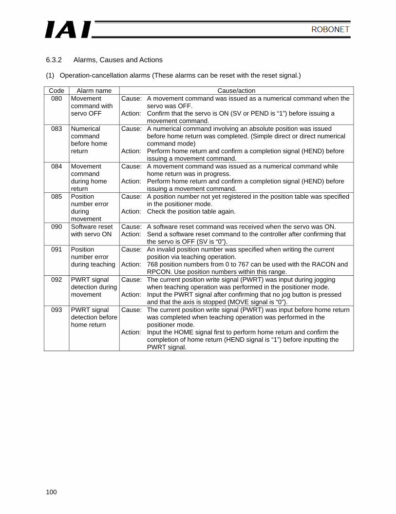
100
6.3.2 Alarms, Causes and Actions (1) Operation-cancellation alarms (These alarms can be reset with the reset signal.) Code Alarm name Cause/action 080 Movement
command with servo OFF
Cause: A movement command was issued as a numerical command when the servo was OFF.
Action: Confirm that the servo is ON (SV or PEND is “1”) before issuing a movement command.
083 Numerical command before home return
Cause: A numerical command involving an absolute position was issued before home return was completed. (Simple direct or direct numerical command mode)
Action: Perform home return and confirm a completion signal (HEND) before issuing a movement command.
084 Movement command during home return
Cause: A movement command was issued as a numerical command while home return was in progress.
Action: Perform home return and confirm a completion signal (HEND) before issuing a movement command.
085 Position number error during movement
Cause: A position number not yet registered in the position table was specified in the positioner mode.
Action: Check the position table again.
090 Software reset with servo ON
Cause: A software reset command was received when the servo was ON. Action: Send a software reset command to the controller after confirming that
the servo is OFF (SV is “0”). 091 Position
number error during teaching
Cause: An invalid position number was specified when writing the current position via teaching operation.
Action: 768 position numbers from 0 to 767 can be used with the RACON and RPCON. Use position numbers within this range.
092 PWRT signal detection during movement
Cause: The current position write signal (PWRT) was input during jogging when teaching operation was performed in the positioner mode.
Action: Input the PWRT signal after confirming that no jog button is pressed and that the axis is stopped (MOVE signal is “0”).
093 PWRT signal detection before home return
Cause: The current position write signal (PWRT) was input before home return was completed when teaching operation was performed in the positioner mode.
Action: Input the HOME signal first to perform home return and confirm the completion of home return (HEND signal is “1”) before inputting the PWRT signal.
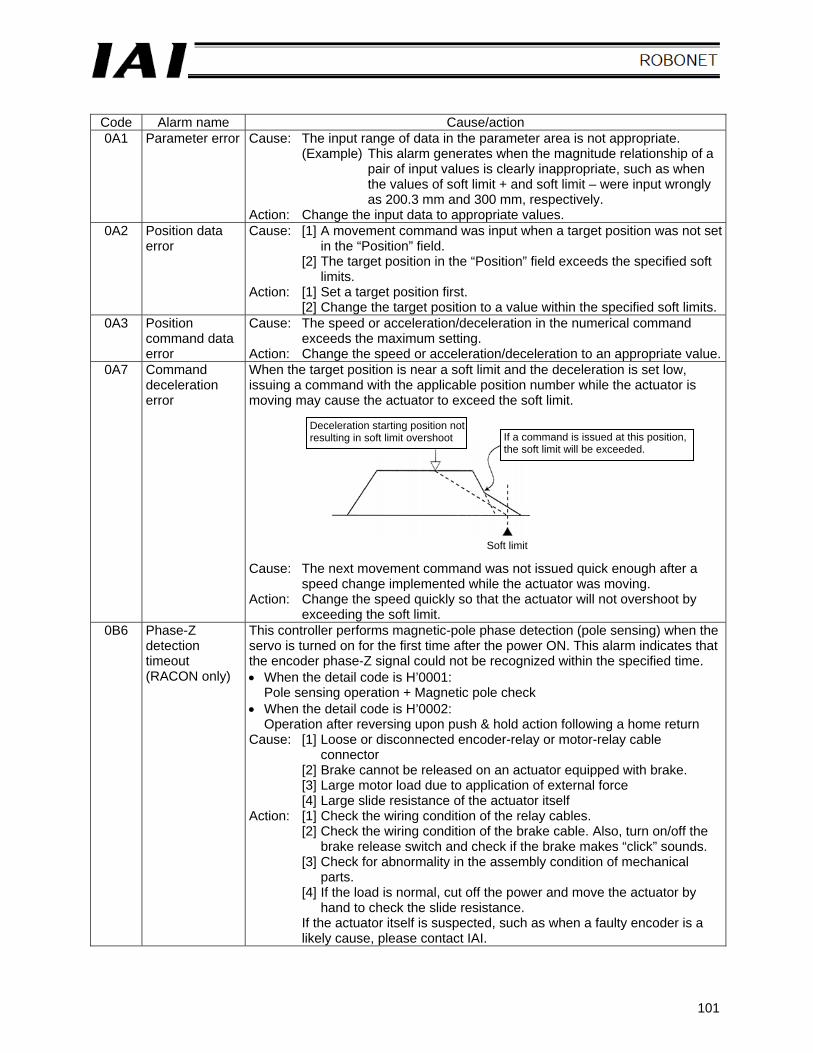
101
Code Alarm name Cause/action 0A1 Parameter error Cause: The input range of data in the parameter area is not appropriate.
(Example) This alarm generates when the magnitude relationship of a pair of input values is clearly inappropriate, such as when the values of soft limit + and soft limit – were input wrongly as 200.3 mm and 300 mm, respectively.
Action: Change the input data to appropriate values. 0A2 Position data
error Cause: [1] A movement command was input when a target position was not set
in the “Position” field. [2] The target position in the “Position” field exceeds the specified soft
limits. Action: [1] Set a target position first.
[2] Change the target position to a value within the specified soft limits. 0A3 Position
command data error
Cause: The speed or acceleration/deceleration in the numerical command exceeds the maximum setting.
Action: Change the speed or acceleration/deceleration to an appropriate value. 0A7 Command
deceleration error
When the target position is near a soft limit and the deceleration is set low, issuing a command with the applicable position number while the actuator is moving may cause the actuator to exceed the soft limit. Cause: The next movement command was not issued quick enough after a
speed change implemented while the actuator was moving. Action: Change the speed quickly so that the actuator will not overshoot by
exceeding the soft limit. 0B6 Phase-Z
detection timeout (RACON only)
This controller performs magnetic-pole phase detection (pole sensing) when the servo is turned on for the first time after the power ON. This alarm indicates that the encoder phase-Z signal could not be recognized within the specified time. • When the detail code is H’0001:
Pole sensing operation + Magnetic pole check • When the detail code is H’0002:
Operation after reversing upon push & hold action following a home return Cause: [1] Loose or disconnected encoder-relay or motor-relay cable
connector [2] Brake cannot be released on an actuator equipped with brake. [3] Large motor load due to application of external force [4] Large slide resistance of the actuator itself
Action: [1] Check the wiring condition of the relay cables. [2] Check the wiring condition of the brake cable. Also, turn on/off the
brake release switch and check if the brake makes “click” sounds. [3] Check for abnormality in the assembly condition of mechanical
parts. [4] If the load is normal, cut off the power and move the actuator by
hand to check the slide resistance. If the actuator itself is suspected, such as when a faulty encoder is a likely cause, please contact IAI.
Deceleration starting position not resulting in soft limit overshoot If a command is issued at this position,
the soft limit will be exceeded.
Soft limit
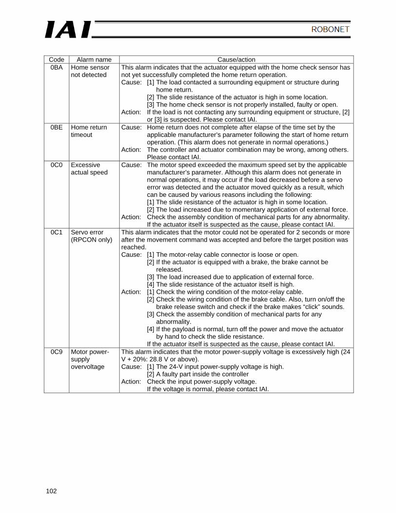
102
Code Alarm name Cause/action 0BA Home sensor
not detected This alarm indicates that the actuator equipped with the home check sensor has not yet successfully completed the home return operation. Cause: [1] The load contacted a surrounding equipment or structure during
home return. [2] The slide resistance of the actuator is high in some location. [3] The home check sensor is not properly installed, faulty or open.
Action: If the load is not contacting any surrounding equipment or structure, [2] or [3] is suspected. Please contact IAI.
0BE Home return timeout
Cause: Home return does not complete after elapse of the time set by the applicable manufacturer’s parameter following the start of home return operation. (This alarm does not generate in normal operations.)
Action: The controller and actuator combination may be wrong, among others.Please contact IAI.
0C0 Excessive actual speed
Cause: The motor speed exceeded the maximum speed set by the applicable manufacturer’s parameter. Although this alarm does not generate in normal operations, it may occur if the load decreased before a servo error was detected and the actuator moved quickly as a result, which can be caused by various reasons including the following: [1] The slide resistance of the actuator is high in some location. [2] The load increased due to momentary application of external force.
Action: Check the assembly condition of mechanical parts for any abnormality.If the actuator itself is suspected as the cause, please contact IAI.
0C1 Servo error (RPCON only)
This alarm indicates that the motor could not be operated for 2 seconds or more after the movement command was accepted and before the target position was reached. Cause: [1] The motor-relay cable connector is loose or open.
[2] If the actuator is equipped with a brake, the brake cannot be released.
[3] The load increased due to application of external force. [4] The slide resistance of the actuator itself is high.
Action: [1] Check the wiring condition of the motor-relay cable. [2] Check the wiring condition of the brake cable. Also, turn on/off the
brake release switch and check if the brake makes “click” sounds. [3] Check the assembly condition of mechanical parts for any
abnormality. [4] If the payload is normal, turn off the power and move the actuator
by hand to check the slide resistance. If the actuator itself is suspected as the cause, please contact IAI.
0C9 Motor power-supply overvoltage
This alarm indicates that the motor power-supply voltage is excessively high (24 V + 20%: 28.8 V or above). Cause: [1] The 24-V input power-supply voltage is high.
[2] A faulty part inside the controller Action: Check the input power-supply voltage.
If the voltage is normal, please contact IAI.
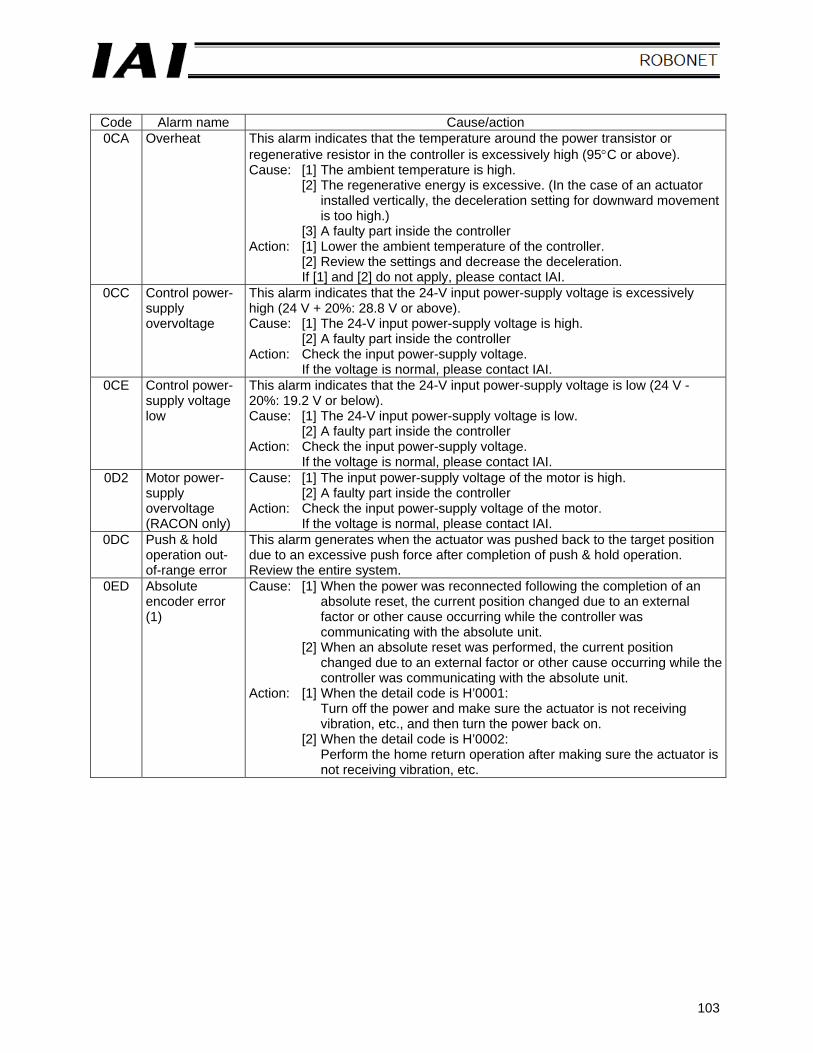
103
Code Alarm name Cause/action 0CA Overheat This alarm indicates that the temperature around the power transistor or
regenerative resistor in the controller is excessively high (95°C or above). Cause: [1] The ambient temperature is high.
[2] The regenerative energy is excessive. (In the case of an actuator installed vertically, the deceleration setting for downward movement is too high.)
[3] A faulty part inside the controller Action: [1] Lower the ambient temperature of the controller.
[2] Review the settings and decrease the deceleration. If [1] and [2] do not apply, please contact IAI.
0CC Control power-supply overvoltage
This alarm indicates that the 24-V input power-supply voltage is excessively high (24 V + 20%: 28.8 V or above). Cause: [1] The 24-V input power-supply voltage is high.
[2] A faulty part inside the controller Action: Check the input power-supply voltage.
If the voltage is normal, please contact IAI. 0CE Control power-
supply voltage low
This alarm indicates that the 24-V input power-supply voltage is low (24 V - 20%: 19.2 V or below). Cause: [1] The 24-V input power-supply voltage is low.
[2] A faulty part inside the controller Action: Check the input power-supply voltage.
If the voltage is normal, please contact IAI. 0D2 Motor power-
supply overvoltage (RACON only)
Cause: [1] The input power-supply voltage of the motor is high. [2] A faulty part inside the controller
Action: Check the input power-supply voltage of the motor. If the voltage is normal, please contact IAI.
0DC Push & hold operation out-of-range error
This alarm generates when the actuator was pushed back to the target position due to an excessive push force after completion of push & hold operation. Review the entire system.
0ED Absolute encoder error (1)
Cause: [1] When the power was reconnected following the completion of an absolute reset, the current position changed due to an external factor or other cause occurring while the controller was communicating with the absolute unit.
[2] When an absolute reset was performed, the current position changed due to an external factor or other cause occurring while the controller was communicating with the absolute unit.
Action: [1] When the detail code is H’0001: Turn off the power and make sure the actuator is not receiving vibration, etc., and then turn the power back on.
[2] When the detail code is H’0002: Perform the home return operation after making sure the actuator is not receiving vibration, etc.
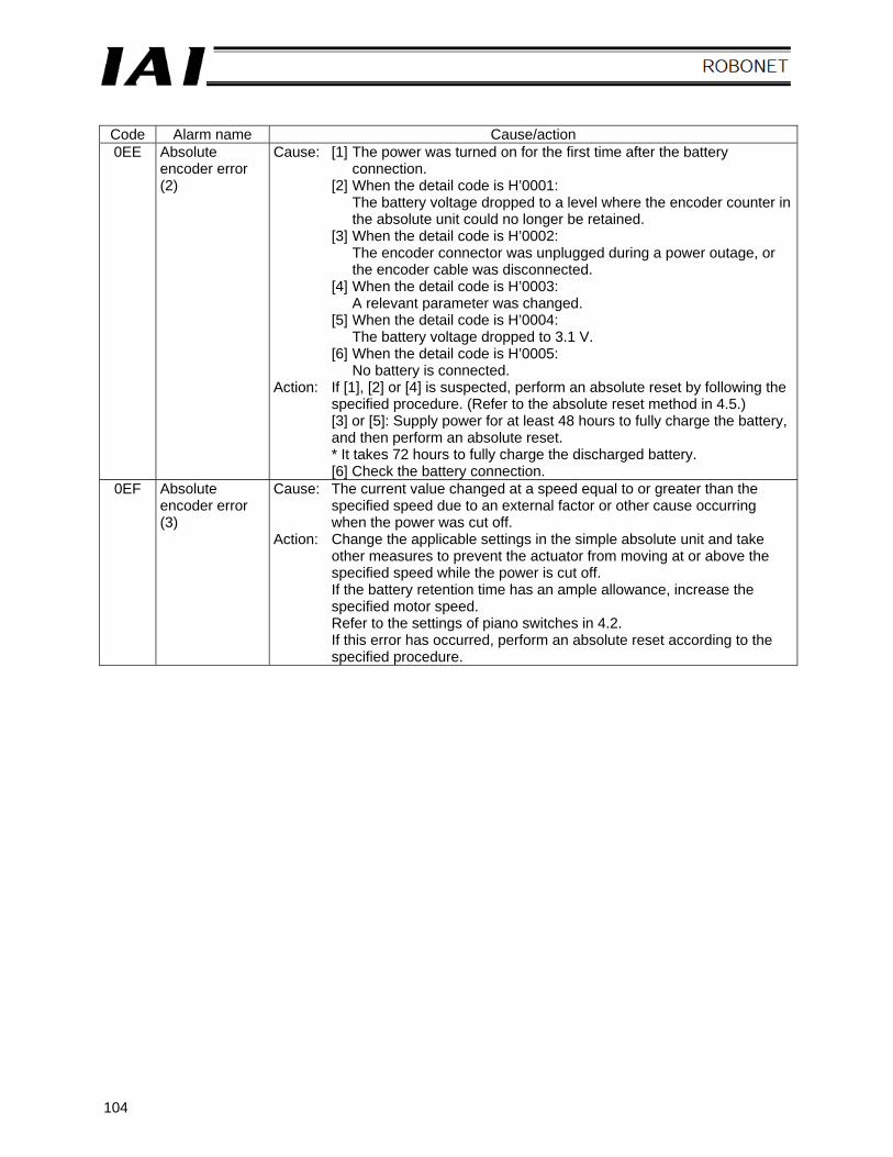
104
Code Alarm name Cause/action 0EE Absolute
encoder error (2)
Cause: [1] The power was turned on for the first time after the battery connection.
[2] When the detail code is H’0001: The battery voltage dropped to a level where the encoder counter in the absolute unit could no longer be retained.
[3] When the detail code is H’0002: The encoder connector was unplugged during a power outage, or the encoder cable was disconnected.
[4] When the detail code is H’0003: A relevant parameter was changed.
[5] When the detail code is H’0004: The battery voltage dropped to 3.1 V.
[6] When the detail code is H’0005: No battery is connected.
Action: If [1], [2] or [4] is suspected, perform an absolute reset by following the specified procedure. (Refer to the absolute reset method in 4.5.) [3] or [5]: Supply power for at least 48 hours to fully charge the battery, and then perform an absolute reset. * It takes 72 hours to fully charge the discharged battery. [6] Check the battery connection.
0EF Absolute encoder error (3)
Cause: The current value changed at a speed equal to or greater than the specified speed due to an external factor or other cause occurring when the power was cut off.
Action: Change the applicable settings in the simple absolute unit and take other measures to prevent the actuator from moving at or above the specified speed while the power is cut off. If the battery retention time has an ample allowance, increase the specified motor speed. Refer to the settings of piano switches in 4.2. If this error has occurred, perform an absolute reset according to the specified procedure.
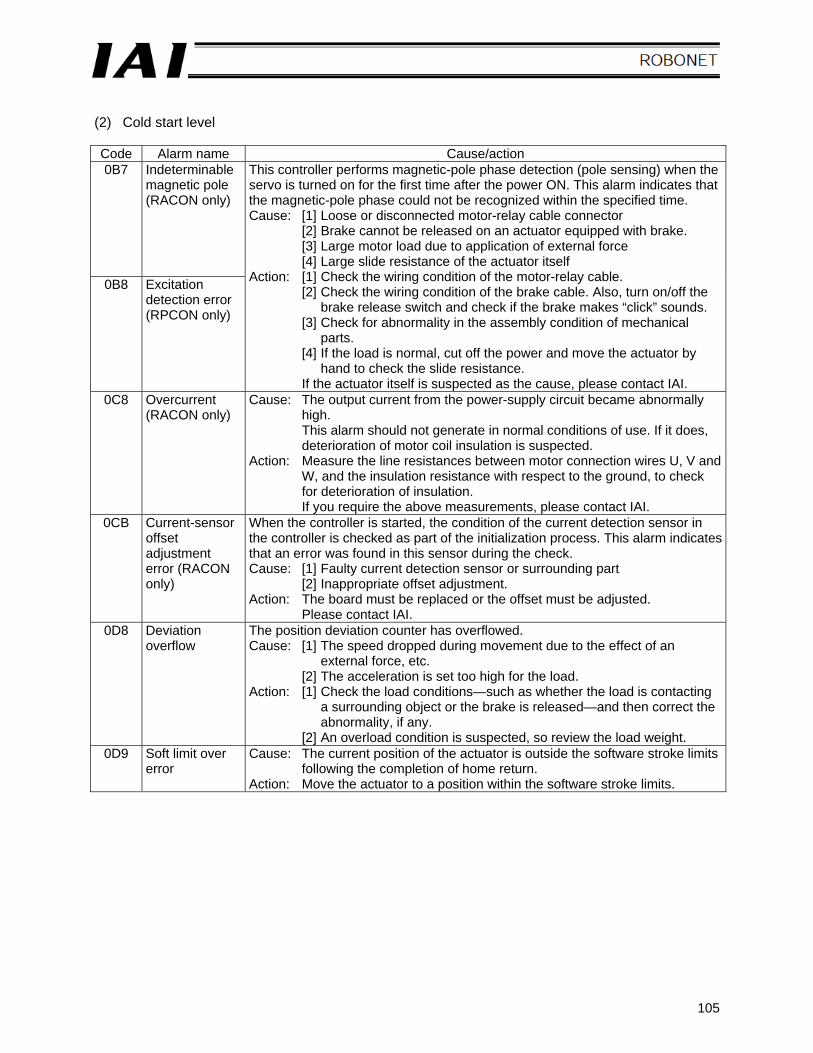
105
(2) Cold start level Code Alarm name Cause/action 0B7 Indeterminable
magnetic pole (RACON only)
0B8 Excitation detection error (RPCON only)
This controller performs magnetic-pole phase detection (pole sensing) when the servo is turned on for the first time after the power ON. This alarm indicates that the magnetic-pole phase could not be recognized within the specified time. Cause: [1] Loose or disconnected motor-relay cable connector
[2] Brake cannot be released on an actuator equipped with brake. [3] Large motor load due to application of external force [4] Large slide resistance of the actuator itself
Action: [1] Check the wiring condition of the motor-relay cable. [2] Check the wiring condition of the brake cable. Also, turn on/off the
brake release switch and check if the brake makes “click” sounds. [3] Check for abnormality in the assembly condition of mechanical
parts. [4] If the load is normal, cut off the power and move the actuator by
hand to check the slide resistance. If the actuator itself is suspected as the cause, please contact IAI.
0C8 Overcurrent (RACON only)
Cause: The output current from the power-supply circuit became abnormally high. This alarm should not generate in normal conditions of use. If it does, deterioration of motor coil insulation is suspected.
Action: Measure the line resistances between motor connection wires U, V and W, and the insulation resistance with respect to the ground, to check for deterioration of insulation. If you require the above measurements, please contact IAI.
0CB Current-sensor offset adjustment error (RACON only)
When the controller is started, the condition of the current detection sensor in the controller is checked as part of the initialization process. This alarm indicates that an error was found in this sensor during the check. Cause: [1] Faulty current detection sensor or surrounding part
[2] Inappropriate offset adjustment. Action: The board must be replaced or the offset must be adjusted.
Please contact IAI. 0D8 Deviation
overflow The position deviation counter has overflowed. Cause: [1] The speed dropped during movement due to the effect of an
external force, etc. [2] The acceleration is set too high for the load.
Action: [1] Check the load conditions—such as whether the load is contacting a surrounding object or the brake is released—and then correct the abnormality, if any.
[2] An overload condition is suspected, so review the load weight. 0D9 Soft limit over
error Cause: The current position of the actuator is outside the software stroke limits
following the completion of home return. Action: Move the actuator to a position within the software stroke limits.
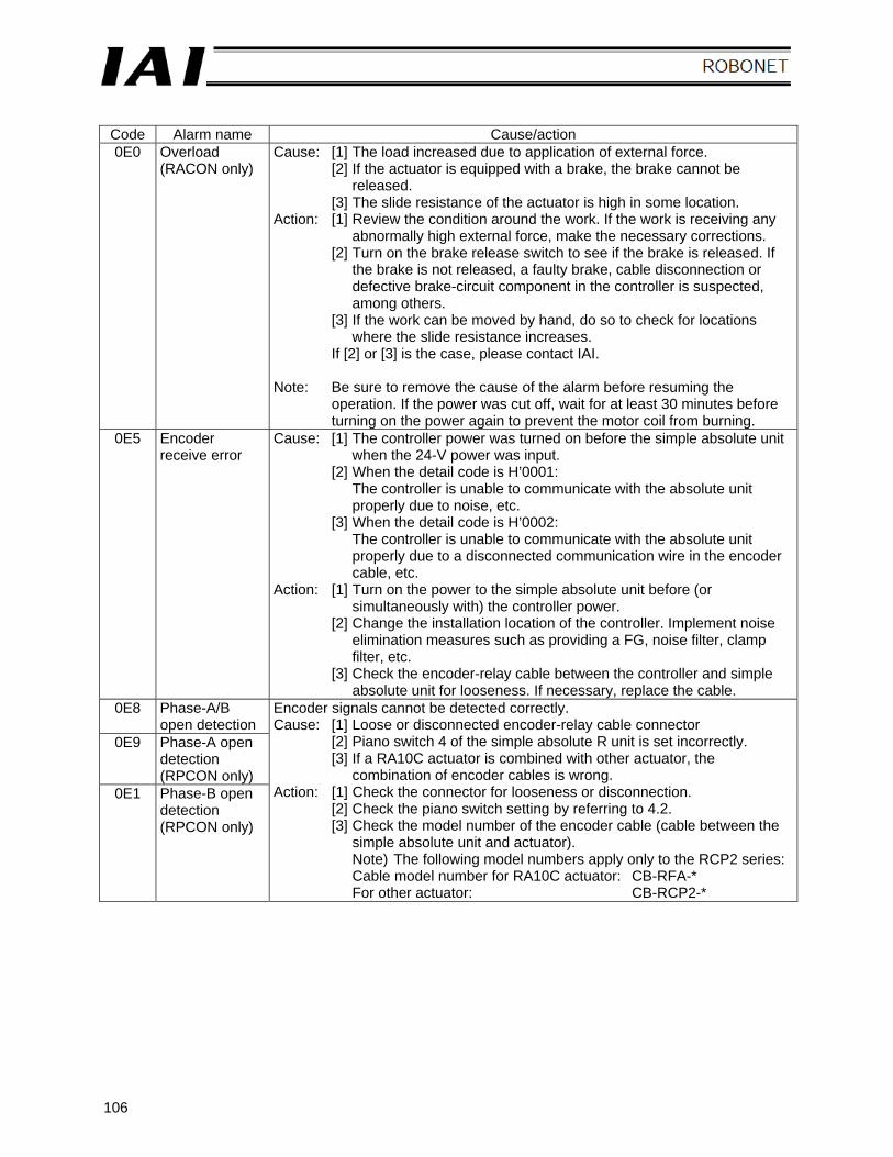
106
Code Alarm name Cause/action 0E0 Overload
(RACON only) Cause: [1] The load increased due to application of external force.
[2] If the actuator is equipped with a brake, the brake cannot be released.
[3] The slide resistance of the actuator is high in some location. Action: [1] Review the condition around the work. If the work is receiving any
abnormally high external force, make the necessary corrections. [2] Turn on the brake release switch to see if the brake is released. If
the brake is not released, a faulty brake, cable disconnection or defective brake-circuit component in the controller is suspected, among others.
[3] If the work can be moved by hand, do so to check for locations where the slide resistance increases.
If [2] or [3] is the case, please contact IAI.
Note: Be sure to remove the cause of the alarm before resuming the operation. If the power was cut off, wait for at least 30 minutes before turning on the power again to prevent the motor coil from burning.
0E5 Encoder receive error
Cause: [1] The controller power was turned on before the simple absolute unit when the 24-V power was input.
[2] When the detail code is H’0001: The controller is unable to communicate with the absolute unit properly due to noise, etc.
[3] When the detail code is H’0002: The controller is unable to communicate with the absolute unit properly due to a disconnected communication wire in the encoder cable, etc.
Action: [1] Turn on the power to the simple absolute unit before (or simultaneously with) the controller power.
[2] Change the installation location of the controller. Implement noise elimination measures such as providing a FG, noise filter, clamp filter, etc.
[3] Check the encoder-relay cable between the controller and simple absolute unit for looseness. If necessary, replace the cable.
0E8 Phase-A/B open detection
0E9 Phase-A open detection (RPCON only)
0E1 Phase-B open detection (RPCON only)
Encoder signals cannot be detected correctly. Cause: [1] Loose or disconnected encoder-relay cable connector
[2] Piano switch 4 of the simple absolute R unit is set incorrectly. [3] If a RA10C actuator is combined with other actuator, the
combination of encoder cables is wrong. Action: [1] Check the connector for looseness or disconnection.
[2] Check the piano switch setting by referring to 4.2. [3] Check the model number of the encoder cable (cable between the
simple absolute unit and actuator). Note) The following model numbers apply only to the RCP2 series: Cable model number for RA10C actuator: CB-RFA-* For other actuator: CB-RCP2-*
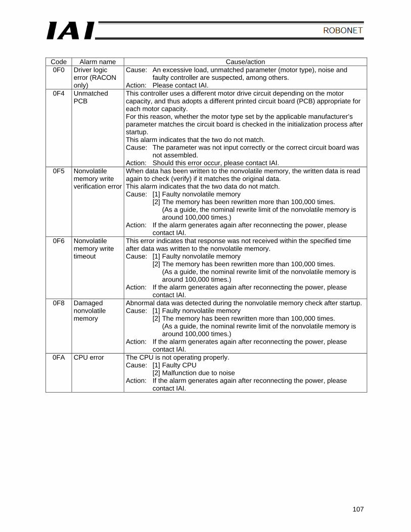
107
Code Alarm name Cause/action 0F0 Driver logic
error (RACON only)
Cause: An excessive load, unmatched parameter (motor type), noise and faulty controller are suspected, among others.
Action: Please contact IAI. 0F4 Unmatched
PCB This controller uses a different motor drive circuit depending on the motor capacity, and thus adopts a different printed circuit board (PCB) appropriate for each motor capacity. For this reason, whether the motor type set by the applicable manufacturer’s parameter matches the circuit board is checked in the initialization process after startup. This alarm indicates that the two do not match. Cause: The parameter was not input correctly or the correct circuit board was
not assembled. Action: Should this error occur, please contact IAI.
0F5 Nonvolatile memory write verification error
When data has been written to the nonvolatile memory, the written data is read again to check (verify) if it matches the original data. This alarm indicates that the two data do not match. Cause: [1] Faulty nonvolatile memory
[2] The memory has been rewritten more than 100,000 times. (As a guide, the nominal rewrite limit of the nonvolatile memory is around 100,000 times.)
Action: If the alarm generates again after reconnecting the power, please contact IAI.
0F6 Nonvolatile memory write timeout
This error indicates that response was not received within the specified time after data was written to the nonvolatile memory. Cause: [1] Faulty nonvolatile memory
[2] The memory has been rewritten more than 100,000 times. (As a guide, the nominal rewrite limit of the nonvolatile memory is around 100,000 times.)
Action: If the alarm generates again after reconnecting the power, please contact IAI.
0F8 Damaged nonvolatile memory
Abnormal data was detected during the nonvolatile memory check after startup. Cause: [1] Faulty nonvolatile memory
[2] The memory has been rewritten more than 100,000 times. (As a guide, the nominal rewrite limit of the nonvolatile memory is around 100,000 times.)
Action: If the alarm generates again after reconnecting the power, please contact IAI.
0FA CPU error The CPU is not operating properly. Cause: [1] Faulty CPU
[2] Malfunction due to noise Action: If the alarm generates again after reconnecting the power, please
contact IAI.
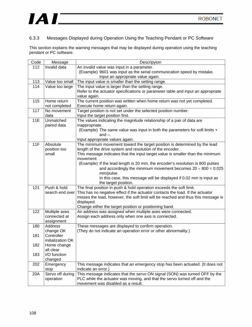
108
6.3.3 Messages Displayed during Operation Using the Teaching Pendant or PC Software This section explains the warning messages that may be displayed during operation using the teaching pendant or PC software. Code Message Descripyion 112 Invalid data An invalid value was input in a parameter.
(Example) 9601 was input as the serial communication speed by mistake. Input an appropriate value again.
113 Value too small The input value is smaller than the setting range. 114 Value too large The input value is larger than the setting range.
Refer to the actuator specifications or parameter table and input an appropriate value again.
115 Home return not completed
The current position was written when home return was not yet completed. Execute home return again.
117 No movement data
Target position is not set under the selected position number. Input the target position first.
11E Unmatched paired data
The values indicating the magnitude relationship of a pair of data are inappropriate. (Example) The same value was input in both the parameters for soft limits +
and –. Input appropriate values again.
11F Absolute position too small
The minimum movement toward the target position is determined by the lead length of the drive system and resolution of the encoder. This message indicates that the input target value is smaller than the minimum movement. (Example) If the lead length is 20 mm, the encoder’s resolution is 800 pulses
and accordingly the minimum movement becomes 20 ÷ 800 = 0.025 mm/pulse. In this case, this message will be displayed if 0.02 mm is input as the target position.
121 Push & hold search end over
The final position in push & hold operation exceeds the soft limit. This has no negative effect if the actuator contacts the load. If the actuator misses the load, however, the soft limit will be reached and thus this message is displayed. Change either the target position or positioning band.
122 Multiple axes connected at assignment
An address was assigned when multiple axes were connected. Assign each address only when one axis is connected.
180 Address change OK
181 Controller initialization OK
182 Home change all clear
183 I/O function changed
These messages are displayed to confirm operation. (They do not indicate an operation error or other abnormality.)
202 Emergency stop
This message indicates that an emergency stop has been actuated. (It does not indicate an error.)
20A Servo off during operation
This message indicates that the servo ON signal (SON) was turned OFF by the PLC while the actuator was moving, and that the servo turned off and the movement was disabled as a result.
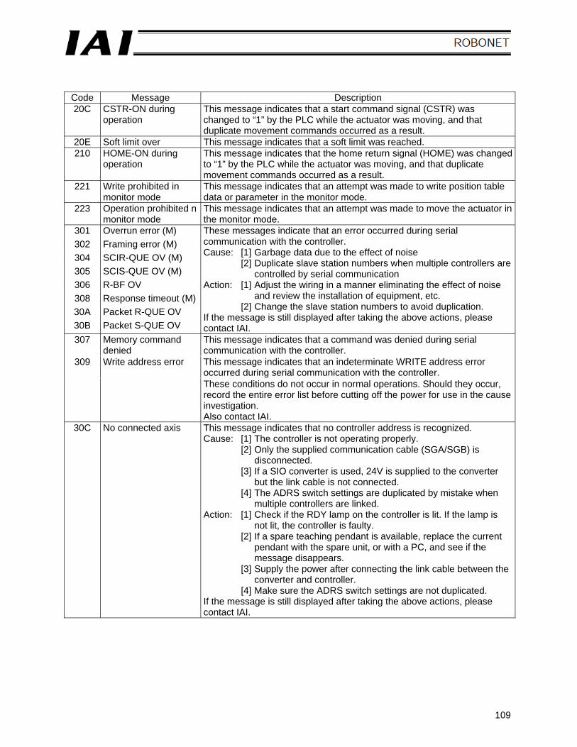
109
Code Message Description 20C CSTR-ON during
operation This message indicates that a start command signal (CSTR) was changed to “1” by the PLC while the actuator was moving, and that duplicate movement commands occurred as a result.
20E Soft limit over This message indicates that a soft limit was reached. 210 HOME-ON during
operation This message indicates that the home return signal (HOME) was changed to “1” by the PLC while the actuator was moving, and that duplicate movement commands occurred as a result.
221 Write prohibited in monitor mode
This message indicates that an attempt was made to write position table data or parameter in the monitor mode.
223 Operation prohibited n monitor mode
This message indicates that an attempt was made to move the actuator in the monitor mode.
301 Overrun error (M) 302 Framing error (M) 304 SCIR-QUE OV (M) 305 SCIS-QUE OV (M) 306 R-BF OV 308 Response timeout (M) 30A Packet R-QUE OV 30B Packet S-QUE OV
These messages indicate that an error occurred during serial communication with the controller. Cause: [1] Garbage data due to the effect of noise
[2] Duplicate slave station numbers when multiple controllers are controlled by serial communication
Action: [1] Adjust the wiring in a manner eliminating the effect of noise and review the installation of equipment, etc.
[2] Change the slave station numbers to avoid duplication. If the message is still displayed after taking the above actions, please contact IAI.
307 Memory command denied
This message indicates that a command was denied during serial communication with the controller.
309 Write address error This message indicates that an indeterminate WRITE address error occurred during serial communication with the controller.
These conditions do not occur in normal operations. Should they occur, record the entire error list before cutting off the power for use in the cause investigation. Also contact IAI.
30C No connected axis This message indicates that no controller address is recognized. Cause: [1] The controller is not operating properly.
[2] Only the supplied communication cable (SGA/SGB) is disconnected.
[3] If a SIO converter is used, 24V is supplied to the converter but the link cable is not connected.
[4] The ADRS switch settings are duplicated by mistake when multiple controllers are linked.
Action: [1] Check if the RDY lamp on the controller is lit. If the lamp is not lit, the controller is faulty.
[2] If a spare teaching pendant is available, replace the current pendant with the spare unit, or with a PC, and see if the message disappears.
[3] Supply the power after connecting the link cable between the converter and controller.
[4] Make sure the ADRS switch settings are not duplicated. If the message is still displayed after taking the above actions, please contact IAI.
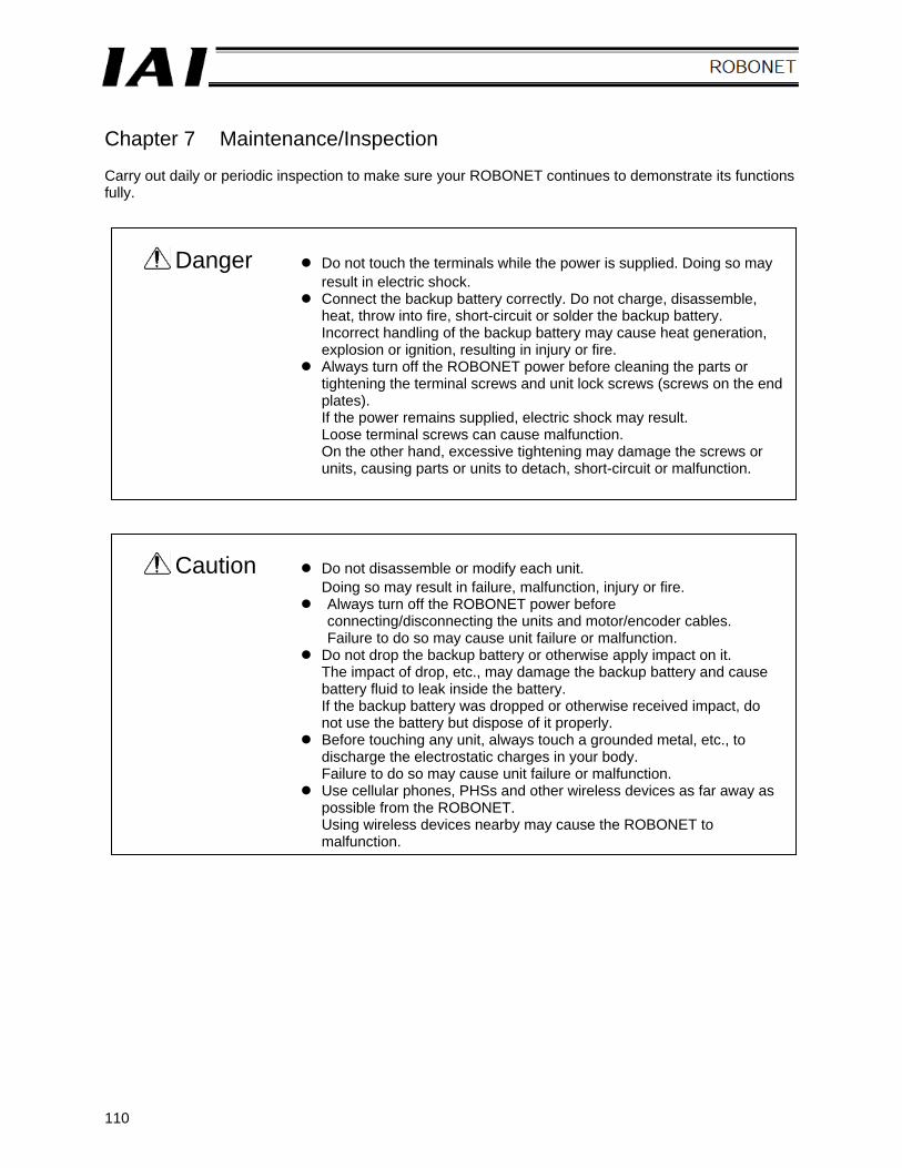
110
Chapter 7 Maintenance/Inspection Carry out daily or periodic inspection to make sure your ROBONET continues to demonstrate its functions fully.
Danger Do not touch the terminals while the power is supplied. Doing so may result in electric shock.
Connect the backup battery correctly. Do not charge, disassemble, heat, throw into fire, short-circuit or solder the backup battery. Incorrect handling of the backup battery may cause heat generation, explosion or ignition, resulting in injury or fire.
Always turn off the ROBONET power before cleaning the parts or tightening the terminal screws and unit lock screws (screws on the end plates). If the power remains supplied, electric shock may result. Loose terminal screws can cause malfunction. On the other hand, excessive tightening may damage the screws or units, causing parts or units to detach, short-circuit or malfunction.
Caution Do not disassemble or modify each unit. Doing so may result in failure, malfunction, injury or fire.
Always turn off the ROBONET power before connecting/disconnecting the units and motor/encoder cables. Failure to do so may cause unit failure or malfunction.
Do not drop the backup battery or otherwise apply impact on it. The impact of drop, etc., may damage the backup battery and cause battery fluid to leak inside the battery. If the backup battery was dropped or otherwise received impact, do not use the battery but dispose of it properly.
Before touching any unit, always touch a grounded metal, etc., to discharge the electrostatic charges in your body. Failure to do so may cause unit failure or malfunction.
Use cellular phones, PHSs and other wireless devices as far away as possible from the ROBONET. Using wireless devices nearby may cause the ROBONET to malfunction.
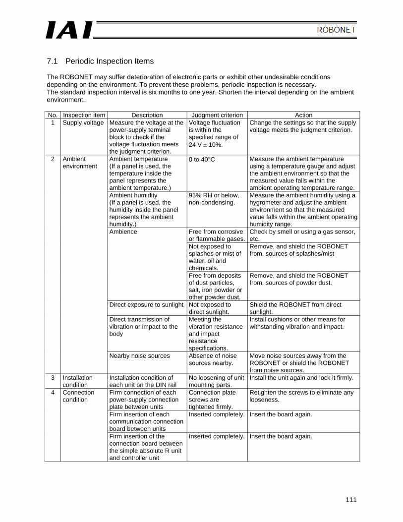
111
7.1 Periodic Inspection Items The ROBONET may suffer deterioration of electronic parts or exhibit other undesirable conditions depending on the environment. To prevent these problems, periodic inspection is necessary. The standard inspection interval is six months to one year. Shorten the interval depending on the ambient environment. No. Inspection item Description Judgment criterion Action 1 Supply voltage Measure the voltage at the
power-supply terminal block to check if the voltage fluctuation meets the judgment criterion.
Voltage fluctuation is within the specified range of 24 V ± 10%.
Change the settings so that the supply voltage meets the judgment criterion.
2 Ambient environment
Ambient temperature (If a panel is used, the temperature inside the panel represents the ambient temperature.)
0 to 40°C Measure the ambient temperature using a temperature gauge and adjust the ambient environment so that the measured value falls within the ambient operating temperature range.
Ambient humidity (If a panel is used, the humidity inside the panel represents the ambient humidity.)
95% RH or below, non-condensing.
Measure the ambient humidity using a hygrometer and adjust the ambient environment so that the measured value falls within the ambient operating humidity range.
Free from corrosive or flammable gases.
Check by smell or using a gas sensor, etc.
Not exposed to splashes or mist of water, oil and chemicals.
Remove, and shield the ROBONET from, sources of splashes/mist
Ambience
Free from deposits of dust particles, salt, iron powder or other powder dust.
Remove, and shield the ROBONET from, sources of powder dust.
Direct exposure to sunlight Not exposed to direct sunlight.
Shield the ROBONET from direct sunlight.
Direct transmission of vibration or impact to the body
Meeting the vibration resistance and impact resistance specifications.
Install cushions or other means for withstanding vibration and impact.
Nearby noise sources Absence of noise sources nearby.
Move noise sources away from the ROBONET or shield the ROBONET from noise sources.
3 Installation condition
Installation condition of each unit on the DIN rail
No loosening of unit mounting parts.
Install the unit again and lock it firmly.
4 Connection condition
Firm connection of each power-supply connection plate between units
Connection plate screws are tightened firmly.
Retighten the screws to eliminate any looseness.
Firm insertion of each communication connection board between units
Inserted completely. Insert the board again.
Firm insertion of the connection board between the simple absolute R unit and controller unit
Inserted completely. Insert the board again.
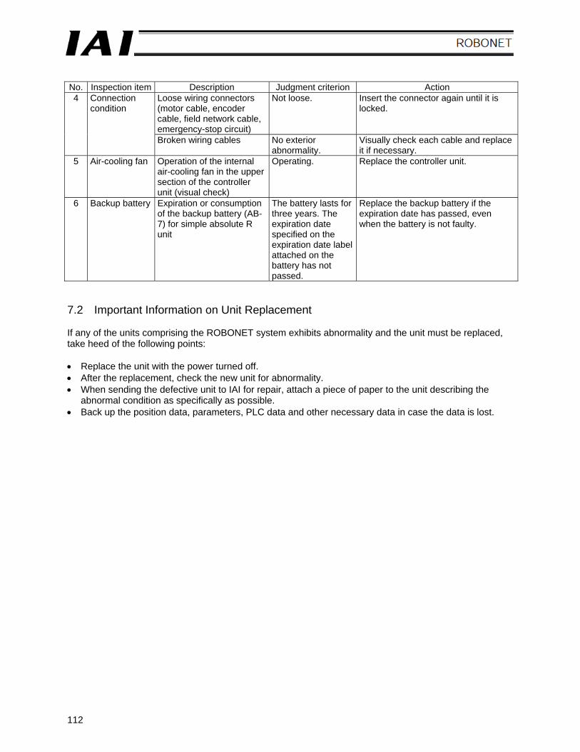
112
No. Inspection item Description Judgment criterion Action 4 Connection
condition Loose wiring connectors (motor cable, encoder cable, field network cable, emergency-stop circuit)
Not loose. Insert the connector again until it is locked.
Broken wiring cables No exterior abnormality.
Visually check each cable and replace it if necessary.
5 Air-cooling fan
Operation of the internal air-cooling fan in the upper section of the controller unit (visual check)
Operating. Replace the controller unit.
6 Backup battery Expiration or consumption of the backup battery (AB-7) for simple absolute R unit
The battery lasts for three years. The expiration date specified on the expiration date label attached on the battery has not passed.
Replace the backup battery if the expiration date has passed, even when the battery is not faulty.
7.2 Important Information on Unit Replacement If any of the units comprising the ROBONET system exhibits abnormality and the unit must be replaced, take heed of the following points: • Replace the unit with the power turned off. • After the replacement, check the new unit for abnormality. • When sending the defective unit to IAI for repair, attach a piece of paper to the unit describing the
abnormal condition as specifically as possible. • Back up the position data, parameters, PLC data and other necessary data in case the data is lost.
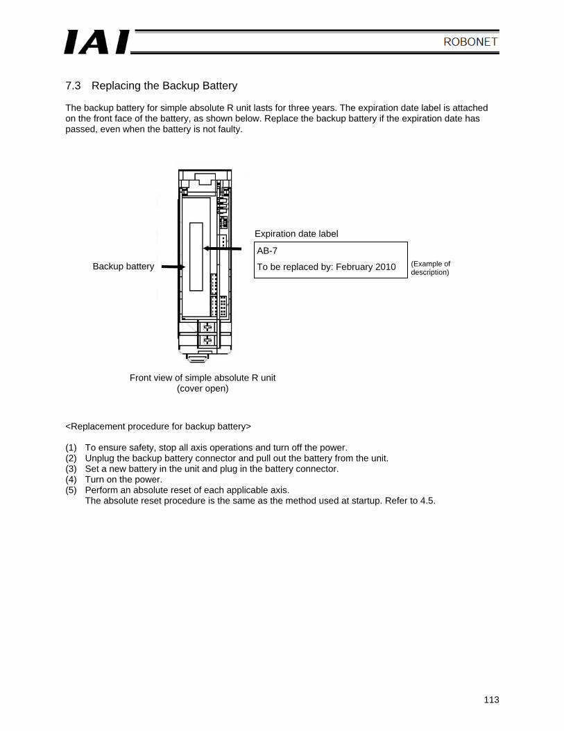
113
7.3 Replacing the Backup Battery The backup battery for simple absolute R unit lasts for three years. The expiration date label is attached on the front face of the battery, as shown below. Replace the backup battery if the expiration date has passed, even when the battery is not faulty. <Replacement procedure for backup battery> (1) To ensure safety, stop all axis operations and turn off the power. (2) Unplug the backup battery connector and pull out the battery from the unit. (3) Set a new battery in the unit and plug in the battery connector. (4) Turn on the power. (5) Perform an absolute reset of each applicable axis.
The absolute reset procedure is the same as the method used at startup. Refer to 4.5.
Backup battery
Expiration date label
AB-7
To be replaced by: February 2010 (Example of description)
Front view of simple absolute R unit (cover open)

114

Catalog No.: MJ0181-1A
Head Office: 2690 W. 237th Street, Torrance, CA 90505 TEL (310) 891-6015 FAX (310) 891-0815
Chicago Office: 1261 Hamilton Parkway, Itasca, IL 60143 TEL (630) 467-9900 FAX (630) 467-9912
Atlanta Office: 1220 E. Kennestone Circle Marrietta, GA 30066 TEL (678) 354-9470 FAX (678) 354-9471
Website: www.intelligentactuator.com
Ober der Röth 4, D-65824 Schwalbach am Taunus, Germany TEL 06196-88950 FAX 06196-889524
The information contained in this document is subject to change without notice for the purpose of product improvement. Copyright © 2007.Jul. IAI Corporation. All rights reserved.