a complete aeroservoelastic model: incorporation of oscillation-reduction- control into a high-order...
TRANSCRIPT

American Institute of Aeronautics and Astronautics
1
A Complete Aeroservoelastic Model: Incorporation of Oscillation-Reduction-Control into a High-Order CFD/FEM
Fighter Aircraft Model
Brian P. Danowsky,* Peter M. Thompson, Ph.D.,† Systems Technology, Incorporated, Hawthorne, CA, 90250
Charbel Farhat, Ph.D.,‡ Thuan Lieu, Ph.D.,§ CMSoft, Inc., Palo Alto, CA 94306
Chuck Harris, Ph.D.** and Jason Lechniak†† U.S. Air Force Flight Test Center, Edwards Air Force Base, CA, 93523
Flight testing for aeroservoelastic clearance is an expensive and time consuming process. Large degree-of-freedom nonlinear aircraft models using Computational Fluid Dynamics coupled with Finite Element Models (CFD/FEM) can be used for accurately predicting inviscid aeroelastic phenomena in all flight regimes including subsonic, supersonic and transonic. With the incorporation of an active feedback control system (FCS), these models can be utilized to reduce the flight test time needed for aeroservoelastic clearance. A complete CFD/FEM/FCS model can be used for full simulations including the dynamics of the fluid, the airframe, the actuators, and the FCS. Accurate CFD/FEM models are computationally complex, rendering their runtime ill suited for adequate FCS design. In this work, a complex, large-degree-of-freedom, transonic, inviscid CFD/FEM model of a fighter aircraft is fitted with a FCS for oscillation reduction. A linear reduced order model (ROM) of the complete aeroelastic aircraft dynamic system is produced directly from the high-order non-linear CFD/FEM model. This rapid runtime ROM is utilized for the design of the FCS, which includes models of the actuators and common nonlinearities in the form of rate limiting and saturation. An oscillation reduction controller is successfully demonstrated via a simulated flight test utilizing the high-order non-linear CFD/FEM/FCS model.
I. Introduction eroservoelastic (ASE) clearance for new and existing aircraft is a necessary, yet very time consuming and expensive process. Aircraft envelope definition contains aeroelastic and aeroservoelastic boundaries that
account for such phenomena as flutter, buffet, buzz, lightly damped response and limit cycle oscillations (LCO), among others. Due to the complexity of the aerodynamic fluid regime and the structure, Computational Fluid Dynamic (CFD) and Finite Element (FE) models that correctly characterize the behavior can become very high order (millions of degrees of freedom) and are computationally intensive. Model complexity becomes increasingly more intense when it is required to correctly characterize non-linear regions, such as highly viscous flows (e.g., insect flight and micro aerial vehicles) and the transonic regime (e.g., high performance fighter aircraft and large transport aircraft). Model complexity of very high order, such as this, greatly inhibits its use for flight control system (FCS) design.
Aeroservoelasticity comprises the interaction between four dynamic disciplines: aerodynamics, structural dynamics, actuator dynamics and an active flight control system (Figure 1). A complete dynamic model of the * Senior Research Engineer, AIAA Senior Member. † Chief Scientist, AIAA Member. ‡ President, AIAA Fellow. § Research Scientist. ** Aerospace Engineer, 412th Test Wing, AIAA Member. †† Aerospace Engineer, 412th Test Wing.
A
AIAA Atmospheric Flight Mechanics Conference10 - 13 August 2009, Chicago, Illinois
AIAA 2009-5708
Copyright © 2009 by Systems Technology, Inc. Published by the American Institute of Aeronautics and Astronautics, Inc., with permission.
Dow
nloa
ded
by S
TA
NFO
RD
UN
IVE
RSI
TY
on
Mar
ch 2
2, 2
016
| http
://ar
c.ai
aa.o
rg |
DO
I: 1
0.25
14/6
.200
9-57
08

American Institute of Aeronautics and Astronautics
2
system must include the influence of each discipline, especially when the dominant frequencies of each system are within close proximity to each other. Traditional aeroelasticity, which includes aerodynamics, inertial, and elastic dynamics, neglects the actuator dynamics. It has been shown that in many cases the actuator dynamics cannot be neglected; higher order1 and even non-linear2 actuator models may be required to characterize the complete ASE system.
The conventional approach to ASE testing3,4,5 is analysis, followed by extensive ground tests, leading to flight tests. This approach is a requirement and will continue to be followed, even as better and more reliable computational methods evolve. More accurate analysis, in the form of improved computational models, will aid the experimental aspect of ASE certification. More reliable methods will predict more accurate ASE phenomena (e.g., flutter, LCO), making flight tests safer. Also, more accurate methods will most likely decrease the amount of flight testing needed for validation, bringing the cost down.
In addition to envelope clearance, ASE certification can require validating FCS designs, especially when these systems are tailored to avoid or take advantage of ASE phenomena (i.e. oscillation reduction control systems6 and active aeroelastic wings7,8,9). A complex nonlinear ASE system model is ideal for describing the complete behavior of the aircraft. FCS design requires models of relatively low order and low complexity that can be simulated in near real-time or faster. Unfortunately, the complexity and computational requirements of accurate CFD/FEM ASE models greatly inhibit their use for FCS design. Fortunately, modern model reduction techniques exist and are being further evolved to greatly reduce the order of the complex ASE models.10 These reduced order models (ROMs) retain the significant dynamic aspects of the full order models and can be used for accurate FCS design. ROMs can be constructed from high order models that are either linear or non-linear.
A linear aeroelastic ROM contains a wealth of information in a very compact form. Not only can it be used as a means for much more rapid simulation but the linear ROM itself can be exploited in other ways. One use of the linear model is the rapid prediction of stability (flutter) boundaries. The flutter boundary at a specific Mach number, for instance, can be found quite easily by observing the poles (or eigenvalues) of the ROM as the atmospheric conditions (dictated by altitude) vary. If input and output effectiveness derivatives are included with the ROM, classical flight control law design can be achieved with ease. The ROM itself contains many important parameters pertaining to the flexible aircraft that can be extracted.
The objective of this study is to incorporate an active FCS into a complex high-order CFD/FE ASE model of a high speed fighter aircraft operating in the transonic flight regime. Simulations with a model of this caliber, including an active FCS, will produce results that are of the highest fidelity and will be representative of a system that is as close to reality as the complex model dictates. The objective is not limited to only simulating high order ASE models with an active FCS but also to utilize the high order models for FCS design. This includes producing a ROM directly from the high order model that is capable of this task. The FCS is designed using this ROM rather than the full model. Subsequent simulated flight testing of the designed FCS with the high order model is the final step, providing full validation of the capabilities. The capability presented herein will greatly aid subsequent flight testing, most likely reducing the amount of testing required, and thus making the flight testing process safer and cheaper.
II. The Non-linear Full Order Model (NFOM) of the Aeroelastic High Speed Fighter The CFD/FE model (NFOM) of the high speed fighter is described in detail in Ref. 11 and is summarized here.
The aerodynamic and elastic modeling is performed with the validated aeroelastic simulation code, AERO.12,13 The aeroelastic computational model has two main components: 1) a FE structural model that includes a representation of eight control surfaces: two flaps, two ailerons, two vertical rudders, and two stabilators and, 2) a dynamic CFD grid for inviscid, Euler flow computations.
Aerodynamic
ElasticInertial
FlightControlSystem
ActuatorDynamics
Figure 1: Multidisciplinary ASE system.
Dow
nloa
ded
by S
TA
NFO
RD
UN
IVE
RSI
TY
on
Mar
ch 2
2, 2
016
| http
://ar
c.ai
aa.o
rg |
DO
I: 1
0.25
14/6
.200
9-57
08

American Institute of Aeronautics and Astronautics
3
A. Finite Element Base Structural Model The FE “base” structural model constructed for aeroservoelastic applications is based on a previously verified FE
model14 that is comprised of masses, springs, rigid beams and flexible beams. The fuselage and wing structures of the fighter airframe are represented by several mass, beam and spring elements that accurately represent the dynamic behavior. Various stores are also modeled by mass and beam elements and connected to the modeled wings by various stiff and flexible attachments.
B. Rigid Support Structure The base structural model does not contain detail of the aerodynamic surface needed for accurate CFD
calculations. To effectively communicate forces between the fluid and the structure, a rigid structure is implemented for the purpose of supporting a fictitious structural skin model that can communicate with the CFD surface mesh. The FE model of this support structure, which extends to the stores and missiles, consists of mass-less rigid beam elements. Due to the absence of mass and stiffness, the incorporation of the FE model of this support structure into the base FE model does not affect its dynamic properties (e.g. natural frequencies and mode shapes).
C. Phantom Structural Skin Model The structural skin model designed for enabling the exchange of aerodynamic and elastodynamic data between
the fluid and structural computational models consists of several “phantom” triangular elements. Phantom elements are elements with zero stiffness and mass properties. They are used to establish a data structure for communicating information between the CFD surface mesh and the structural surface model. A phantom element does not introduce any new nodes; it is specified using the nodes from the rigid support structure. Despite being mass-less with zero stiffness, a phantom element does not introduce singularities in the FE computational solutions since it does not increase the model order.
D. Control Surface Models Mechanisms for deploying the flaps, ailerons, and rudders are included in the FE model. This slightly affects the
stiffness properties of the base structural model as nodal splitting and torsional springs are introduced in the global FE model to deploy the flaps, ailerons, rudders and stabilators along their hinge lines. Surface deflections are initiated by the application of equal and opposite moments at specific node points on the base structure and control surface that act along the control surface hinge lines.
E. CFD Euler Grid The CFD grid is unstructured and suitable for inviscid (Euler) computations. It contains millions of tetrahedra
and several hundred thousand grid points, many of which lie on the surface of the considered fighter configuration. The resolution of the CFD surface mesh far exceeds that of the structural phantom skin model since the fluid computations demand small control volumes for transonic calculations.
III. The Linear Reduced Order Model (ROM) of the Aeroelastic High Speed Fighter The large degree-of-freedom, nonlinear aerodynamic and linear structural system can take on the order of several
days to run simulations on parallel computing clusters, prohibiting routine use for system analysis and control design. Fortunately, an established process has been evolved to produce a ROM that is several orders of magnitude smaller and still captures the vital dynamic characteristics of the full system. Simulations using the ROM can be performed faster than real time on a standard desktop PC.
A number of ROM construction approaches have been under investigation for more than a decade. One method seeks to use aerodynamic mode shapes of some linearized CFD solutions as a set of base vectors for order reduction. Other methods apply various system identification methods adopted from systems theory to identify a low-order model of the CFD-based aerodynamic system. Beran has compiled a summary of modern ROM techniques.15 Reduced-order model creation in all of these methods is computationally intensive,10 even in cases involving only a small number of full-order fluid response analyses to a small number of well designed inputs. Yet, once such reduced-order models are created for a given configuration, dynamic simulation of many cases (corresponding to many inputs, dynamic pressures, and initial conditions) is fast and cheap computationally. It is expected that reduced-order aerodynamic methods will see increasing use in industry as part of the effort to create systems capable of analyzing large numbers of load cases and flight conditions using CFD-based aerodynamics.
The CFD/FE code (AERO) utilized for the high speed fighter configuration employs ROM building capabilities that compute linearized flow perturbations around an equilibrium solution, predict linearized aeroelastic responses
Dow
nloa
ded
by S
TA
NFO
RD
UN
IVE
RSI
TY
on
Mar
ch 2
2, 2
016
| http
://ar
c.ai
aa.o
rg |
DO
I: 1
0.25
14/6
.200
9-57
08

American Institute of Aeronautics and Astronautics
4
assuming a modalized structure, generate snapshots for constructing a Proper Orthogonal Decomposition (POD) basis, generate an aeroelastic ROM in the frequency domain, and compute aeroelastic ROM solutions in the time-domain.
A. Governing Equations for the Aeroelastic System The three-field Arbitrary Lagrangian-Eulerian (ALE) can be used to represent the nonlinear aeroelastic system.16
Semi-discretization by a finite volume method produces three coupled ordinary differential systems of equations (Eq. (1)).
( ) int,( ) ( , , ) 0, ( , ) ( , ), ext
ctA x w F w x x Mu f u u f u w Kx K u+ = + = = (1)
In the above equations: A denotes the diagonal matrix composed of the fluid cell volumes, F is the nonlinear numerical flux function, w is the state vector of the fluid system, M is the FE mass matrix, fint is the vector of internal forces, fext is the vector of external forces and u is the vector of structural degrees of freedom (displacements). The fluid mesh deforms as the fluid-structure system interacts and its motion is described by the 3rd equation above; the vector x represents mesh motion states where K represents a fictitious stiffness matrix for describing the mesh motion and cK is a transfer matrix mapping mesh motion to structural displacements. The notation ,t denotes the derivative with respect to time.
In short, a ROM is constructed by first linearizing these equations around an equilibrium point17,18 non-dimensionally.19 The order is then reduced by defining a lower dimensional subspace via POD.20,15 The POD method can be conducted in either the time domain or the frequency domain. For the purposes of this work, the ROM was constructed using POD in the frequency domain. The resulting aeroelastic ROM describes the equations of motion of the reduced fluid state vector (w) and the reduced structural state vector (um) outlined in the following sections. For a more comprehensive overview of the ROM construction process the reader is referred to Lieu.21
B. Fluid ROM The fluid ROM consists of an nw order, POD-based, real, non-dimensional, full matrix ( H ) which governs the
perturbed equations of equilibrium. H is a non-dimensional square matrix that describes the behavior of the fluid states when dimensionalized by atmospheric properties. Eq. (2) displays the linearized equations of motion with a dimensionalized ROM.
w Hw= − (2)
In Eq. (2), w denotes the perturbation of the reduced order fluid state vector about a steady state operating point; it is the perturbed, linearized and reduced approximation of w displayed in Eq. (1) above. The ROM matrix H has dimensions nw × nw and is dimensionalized as follows:
( , ) /H p pHρ ρ∞ ∞ ∞ ∞= (3)
where p∞ and ρ∞ denote the free-stream pressure and density of interest, respectively. The ROM matrix can be exploited in at least the following ways: 1) This matrix can be used for a time-domain simulation assuming an appropriate initial condition is specified, and 2) H can be used to investigate the stability of the fluid system. If all real parts of the eigenvalues of –H are negative, the fluid system is stable for all free-stream densities and pressures.
C. Aeroelastic ROM In this case the ROM consists of the fluid ROM combined with linearized structural dynamics. The coupled and
scaled equations of motion are:
20m m
m m m
w Hw Bu CuI u u Pw+ + + =
+ Ω = (4)
The new terms are as follows: um is an nm length vector of structural modal displacements, Ω2 is an nm × nm diagonal matrix composed of the squares of the natural structural frequencies, P is an nm × nw aerodynamic load transfer matrix, B and C are nw × nm fluid/structural coupling matrices, and Im is the identity matrix of size m.
The coupled equations can be converted to a standard first order state space form. The matrices, as shown, can be used for stability and initial condition response analysis. Not shown are the input and output coefficients needed for
Dow
nloa
ded
by S
TA
NFO
RD
UN
IVE
RSI
TY
on
Mar
ch 2
2, 2
016
| http
://ar
c.ai
aa.o
rg |
DO
I: 1
0.25
14/6
.200
9-57
08

American Institute of Aeronautics and Astronautics
5
simulation and control analysis (these are described in the following section). The number of fluid and structural states can be changed as needed to improve validation. For a complete aircraft, typical numbers of structural modes needed to retain accuracy in frequency ranges of interest are five to fifty. Alternatively, the structural equations can be left in their nonlinear form as would be needed (i.e., in case of large structural deflections).
D. Inclusion of Input and Output Effectiveness with the ROM The ROM represented by Eq. (4) does not contain any information defining the input/output relationship. The
input and output effectiveness is needed for FCS design as well as open loop simulations that include control surface deflections and sensor outputs. Inputs to the system are control surface deflections (in the form of equal and opposite moments that act along the hinge lines) and outputs are “sensor states” (i.e., accelerations and rotational rates) at specific locations on the aircraft.
A generic aeroelastic system in terms of its inputs and outputs can be represented by Figure 2. For the purposes presented here, the inputs are forces acting at specific node points on the structural model and the outputs are states of the structure (sensors) at specific node points on the structural model. The system in the figure is general and can represent a linear or non-linear system.
Fi represents a vector of the input forces at the specific structural node points and ys represents a vector of the “sensed” outputs, which are states of specific structural node points. The node points of the sensors are not necessarily the same as the input forces.
The linearized reduced order aerodynamic states and the structural modal states are represented by Eq. (4), which can also be represented by Eq. (5) below.
2ˆˆ 0 ˆˆ: m m
Ts m m
w Hw BXu CXu where B BX and C CXI u u X F
+ + + = = =+ Ω =
(5)
The matrix of retained structural mode shapes (X), which is used to map the structural degrees of freedom to the modal domain, is introduced in this alternate representation. The forces acting on the structure have also been generalized to include any forces and moments acting on the structure (F). This vector is a combination of forces from aerodynamics and other external forces.
The vector F, which represents the forces and moments acting on all structural degrees of freedom can be separated into the aerodynamic forces (governed by the top of Eq. (5)) and a general vector of external forces and moments (f) acting on all nodes of the structure (Eq. (6)).
ˆ ˆ , : T T TF Pw f then X F Pw X f where P X P= + = + = (6)
The desired input vector (Fi) is composed of the moments that act at specific nodes on the structure to deploy control surfaces. These moments can be mapped to f linearly (Eq. (7)).
Ti if T F= (7)
The linear mapping matrix (Ti) is not square and will be mainly zero valued. Applying Eq. (7) to (6), and ultimately Eq. (5) will result in the coupled system with the states defined as [ ]Tm mq w u u= and the inputs defined as Fi.
2
2
0
0 , 0 0 0
w w w m
w m m w
m m m i
n n n n
n n n nT Ti m m i i
n n n nT Tm m i
H BH B Cw wq Nq GF u P u X T F where C P
u I u X T
× ×
× ×
× ×
∈ ∈− − −⎡ ⎤ ⎡ ⎤⎡ ⎤ ⎡ ⎤⎢ ⎥ ⎢ ⎥⎢ ⎥ ⎢ ⎥= + = = −Ω + ∈ ∈⎢ ⎥ ⎢ ⎥⎢ ⎥ ⎢ ⎥⎢ ⎥ ⎢ ⎥⎢ ⎥ ⎢ ⎥⎣ ⎦ ⎣ ⎦ Ω ∈ ∈⎣ ⎦ ⎣ ⎦
(8)
This concludes the application of input effectiveness where inputs are defined as equal and opposite moments that act along the hinge lines of the control surfaces.
The sensors, in general, can be any structural node displacement, velocity or acceleration. A linear mapping can be determined that extracts the sensor nodes from the complete full degree of freedom structural displacement vector u. If the desired nodes are defined as ud, the mapping matrix can be defined as Ts (Eq. (9)).
( , , )ASE M p ρ∞ ∞ ∞iF sy
Figure 2: Generic ASE Input-Output System.
Dow
nloa
ded
by S
TA
NFO
RD
UN
IVE
RSI
TY
on
Mar
ch 2
2, 2
016
| http
://ar
c.ai
aa.o
rg |
DO
I: 1
0.25
14/6
.200
9-57
08
American Institute of Aeronautics and Astronautics
6
d su T u= (9)
The matrix Ts is not square and sparse comprised of mainly zeros. By this definition the sensors, which are the displacement, velocity and acceleration (both translational and rotational), can be described below.
0 0 0 0
0 0 0 00 0 0 0
d s s m
s d s s m
d s s m
u T u T X uy u T u T X u
u T u T X u
⎡ ⎤ ⎡ ⎤ ⎡ ⎤ ⎡ ⎤⎡ ⎤⎢ ⎥ ⎢ ⎥ ⎢ ⎥ ⎢ ⎥⎢ ⎥= = =⎢ ⎥ ⎢ ⎥ ⎢ ⎥ ⎢ ⎥⎢ ⎥⎢ ⎥ ⎢ ⎥ ⎢ ⎥ ⎢ ⎥⎢ ⎥⎣ ⎦⎣ ⎦ ⎣ ⎦ ⎣ ⎦ ⎣ ⎦
(10)
Expressing the sensors in the modal domain yields the third equality. The output vector ys can further be described as a linear function of the entire augmented state vector q and the
input vector Fi (see Eq. (8) for mu ).
2
0 0 00 0 0 ,
0
sn ns m
s i s m i sT Tms s s i
T X wy Zq DF T X u F where T X
uT XP T X T XX T
×
⎡ ⎤ ⎡ ⎤⎡ ⎤⎢ ⎥ ⎢ ⎥⎢ ⎥= + = + ∈⎢ ⎥ ⎢ ⎥⎢ ⎥⎢ ⎥ ⎢ ⎥⎢ ⎥⎣ ⎦− Ω⎣ ⎦ ⎣ ⎦
(11)
With the input and the output defined, the complete state space linear system (Eq. (12)) is described by Eqs. (8) and (11).
i
s i
q Nq GFy Zq DF
= +
= + (12)
The above system describes, in entirety, the input/output aeroelastic system displayed in Figure 2 in a linearized form and is well tailored for FCS design.
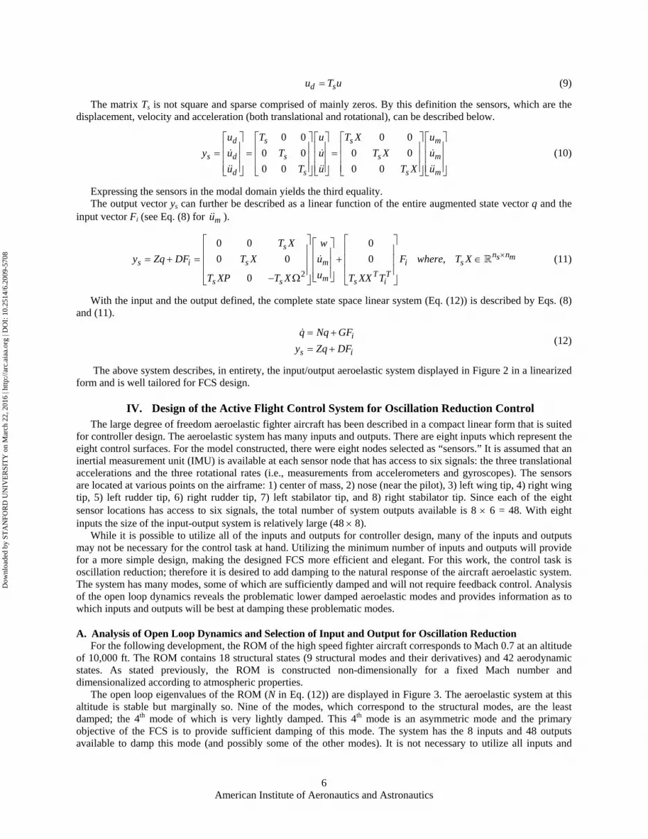
IV. Design of the Active Flight Control System for Oscillation Reduction Control The large degree of freedom aeroelastic fighter aircraft has been described in a compact linear form that is suited
for controller design. The aeroelastic system has many inputs and outputs. There are eight inputs which represent the eight control surfaces. For the model constructed, there were eight nodes selected as “sensors.” It is assumed that an inertial measurement unit (IMU) is available at each sensor node that has access to six signals: the three translational accelerations and the three rotational rates (i.e., measurements from accelerometers and gyroscopes). The sensors are located at various points on the airframe: 1) center of mass, 2) nose (near the pilot), 3) left wing tip, 4) right wing tip, 5) left rudder tip, 6) right rudder tip, 7) left stabilator tip, and 8) right stabilator tip. Since each of the eight sensor locations has access to six signals, the total number of system outputs available is 8 × 6 = 48. With eight inputs the size of the input-output system is relatively large (48 × 8).
While it is possible to utilize all of the inputs and outputs for controller design, many of the inputs and outputs may not be necessary for the control task at hand. Utilizing the minimum number of inputs and outputs will provide for a more simple design, making the designed FCS more efficient and elegant. For this work, the control task is oscillation reduction; therefore it is desired to add damping to the natural response of the aircraft aeroelastic system. The system has many modes, some of which are sufficiently damped and will not require feedback control. Analysis of the open loop dynamics reveals the problematic lower damped aeroelastic modes and provides information as to which inputs and outputs will be best at damping these problematic modes.
A. Analysis of Open Loop Dynamics and Selection of Input and Output for Oscillation Reduction For the following development, the ROM of the high speed fighter aircraft corresponds to Mach 0.7 at an altitude
of 10,000 ft. The ROM contains 18 structural states (9 structural modes and their derivatives) and 42 aerodynamic states. As stated previously, the ROM is constructed non-dimensionally for a fixed Mach number and dimensionalized according to atmospheric properties.
The open loop eigenvalues of the ROM (N in Eq. (12)) are displayed in Figure 3. The aeroelastic system at this altitude is stable but marginally so. Nine of the modes, which correspond to the structural modes, are the least damped; the 4th mode of which is very lightly damped. This 4th mode is an asymmetric mode and the primary objective of the FCS is to provide sufficient damping of this mode. The system has the 8 inputs and 48 outputs available to damp this mode (and possibly some of the other modes). It is not necessary to utilize all inputs and
Dow
nloa
ded
by S
TA
NFO
RD
UN
IVE
RSI
TY
on
Mar
ch 2
2, 2
016
| http
://ar
c.ai
aa.o
rg |
DO
I: 1
0.25
14/6
.200
9-57
08

American Institute of Aeronautics and Astronautics
7
outputs and it is desired to utilize as few inputs and outputs as possible. For robustness and efficiency, a single-input-single-output (SISO) design is the most desired.
-7 -6 -5 -4 -3 -2 -1 0
x 104
0
1000
2000
3000
4000
5000
6000
7000
8000
9000
10000
6e+004 5e+004 4e+004 3e+004 2e+004 1e+004
0.999
0.995
0.986 0.972 0.945 0.89 0.78 0.5
Real
Imag
inar
y
a) All eigenvalues.
0
70
60
50
40
30
20
100.07
0.034
0.021
0.015
0.0105 0.007 0.0044 0.002
Real
Imag
inar
y
9 structural modes
b) Detail around origin. Figure 3: Aeroelastic airframe open loop eigenvalues.
To determine which inputs and outputs will best damp this critical mode the time response residuals were compared. Time response residuals are the coefficients of the explicitly solved time domain response of the system (ys(t)) due to an impulsive input (Fi = F0δ(τ)). The ROM system is linear; therefore the output time response (ys(t)), due to an input time series (Fi(t)) and an initial state vector (q0), can be solved explicitly. If the initial state vector is assumed to be zero, the output time response due to an impulsive input (impulse at t = 0) is:
0( ) Ntisy t Ze GF= (13)
The system state dynamic matrix can be expressed in terms of the modal domain (Eq. (14)). In this form, the matrix N is expressed as a product of three square matrices: XN is a matrix of the eigenvectors of N, Λ = diag( λ1, λ2, …, λn) is a diagonal matrix of the eigenvalues of N and YN is the inverse of XN.
1N N NNN X X X Y−= Λ = Λ (14)
This form of N allows Eq. (13) to be expressed as a sum where each element in the sum is the sinusoidal response at each modal frequency.
0 0 01
( ) X YN Ns N N
n tt t ji i Nj Nj i
jGF GF Zy t Ze ZX e x y Ge FY λ
=
Λ Λ == = ∑ (15)
In the above equation, xNj is the jth column of XN and yNj is the jth row of YN. The jth residual (Eq. (16)) is the relative amplitude of the time response corresponding to the jth mode at the jth frequency (eigenvalue).
N Njj jZxA y GMP = (16) Dow
nloa
ded
by S
TA
NFO
RD
UN
IVE
RSI
TY
on
Mar
ch 2
2, 2
016
| http
://ar
c.ai
aa.o
rg |
DO
I: 1
0.25
14/6
.200
9-57
08

American Institute of Aeronautics and Astronautics
8
The jth residual is a matrix which is the same size as the system (number of outputs x number of inputs). It is complex valued containing magnitude and phase information. There is a matrix AMPj for each mode contained in XN and these individual matrices display the relative effect of each input-output pair on that specific mode. The element with the highest norm (sqrt(Re(AMP(i,j))2 + Im(AMP(i,j))2)) demonstrates that input j is the best at exciting the mode and output i is the best at measuring the mode.
Figure 4 displays the relative amplitudes of the elements of AMP4, which corresponds to the least damped 4th mode. The eight control surface inputs are on the x-axis, the 48 sensor signals are along the y-axis and the norm of the elements of AMP4 is displayed as individual bars with height along the z-axis. The largest two elements of AMP4 are clearly evident. These correspond to the nose lateral acceleration output due to aileron inputs. The conclusion gathered from this analysis is that the 4th mode will be best controlled utilizing the ailerons as inputs with feedback from the nose lateral acceleration sensor.
For further simplification, a differential aileron can be defined that maps the two inputs to one input (Eq. (17)).
, ,ail ail left ail rightδ δ δ= − (17)
The ailerons are each defined with positive deflection down; therefore this differential aileron input will command the left aileron down and the right aileron up, providing the traditional roll right aileron input. With the differential aileron defined this way, the controlled element aeroelastic system is SISO. The bare airframe root locus (detail around origin) is displayed in Figure 5. The dynamics include a linear 7th order actuator taken from Ref. 1.
B. Controller Design With the SISO system defined as differential aileron “in”
and nose lateral acceleration “out,” compensation to damp the 4th mode can be applied with traditional negative feedback (Figure 6). Simple gain compensation will not be adequate as it will drive the 4th mode less stable. A 5th order compensator was designed to supply the sufficient damping. This compensator adds damping to the 4th mode as well as the 2nd, 6th and 8th modes, which are all asymmetric.
A system survey of the designed controller is displayed in Figure 7. It is immediately evident that the compensator effectively damps the 4th mode by both the closed loop root locus (Figure 7a) and the initial condition response comparison (Figure 7b) in the survey. The input to system sensitivity (Figure 7c) displays the output of the compensator due to external inputs. The natural structural frequencies are also displayed in this plot and it is shown that input frequencies near the 2nd, 4th, 6th and 8th modes show a drop in gain. The compensator frequency response is displayed in Figure 7d and the loop transfer function frequency response is displayed in Figure 7e. The loop transfer function frequency response displays the relative input effectiveness. It is the goal to keep this low as a means to
Figure 4: Time response residual of the lightly damped 4th mode.
0
80
70
60
50
40
30
20
100.2
0.11
0.065
0.046
0.032
0.022 0.014 0.007
Real
Imag
inar
y
-0.007 -0
Figure 5: Root locus for the bare flexible airframe
( nose ailv δ ) including aileron actuator.
Fighter flex model
nose
ail
vδ
Compensator( )( )
num sCden s
=ailδ nosev
Figure 6: Controller Structure.
Dow
nloa
ded
by S
TA
NFO
RD
UN
IVE
RSI
TY
on
Mar
ch 2
2, 2
016
| http
://ar
c.ai
aa.o
rg |
DO
I: 1
0.25
14/6
.200
9-57
08

American Institute of Aeronautics and Astronautics
9
avoid actuator position and rate limits and to retain control authority for maneuvering. The designed compensator achieves the goal of providing sufficient damping to the natural response and keeping control authority low.
Comp(s) Fighter
1
r e δail nose:ud(-vd)
0 5 10 15 20 25 30 35 40 45 50-1
-0.5
0
0.5
1Initial Condition Responses: Mode 4 excited
Time, s
nose
:ud(
-vd)
Res
pons
e
Open LoopClosed Loop
0
70
60
50
40
30
20
100.8
0.56
0.4
0.28
0.2
0.14
0.09 0.04
Map of Poles and Zeros
Real
Imag
inar
y
-0.04 -0.09
-0.14
-0.2
-0.28
-0.4
-0.56
-0.8
Roots at gain = 1
30
40
50
60
70
80
90
Frequency, rad/sM
agni
tude
, dB
Input to System Sensitivity
magnitude (δail/r)
natural frequencies
0
50
100From: e To: dif ferential aileron
Mag
nitu
de (d
B)
101.3
101.4
101.5
101.6
101.7
101.8
101.9
-360
-180
0
180
Phas
e (d
eg)
Compensator Frequency Response
Frequency (rad/sec)
-50
0
50From: e To: nose:ud(-vd)
Mag
nitu
de (d
B)
-540
-360
-180
0
Phas
e (d
eg)
Loop Transfer Function Frequency ResponseMaximum magnitude of Loop Transfer Function (at 51.3228 rad/s) = 9.4422 (19.5015 dB)
Frequency (rad/sec)
Figure 7: System Survey of the 5th order oscillation reduction controller applied to the flexible fighter model.
C. Demonstration of Controller Performance with the ROM Utilizing the ROM, the controller executes with good performance. Nonlinearities arise due to the transonic
nature of the flow regime which will not be represented by the linear ROM. Nonlinearities are also prevalent in other areas, namely the actuators. The actuators have position and rate limits that can, in some cases, cause instabilities with designed controllers. In order to verify the performance of the controller subject to these non-linearities, simulations that include saturation and rate limits were run to verify the controller robustness. It was assumed that the aileron actuators are limited to 100 deg/s rates and saturate when deflected ±25o. The compensator was designed to keep control authority low with these rate limit and saturation non-linearities in mind.
Simulations were conducted using the ROM with applied rate limits and surface position limits to verify the robustness with these non-linearities using SimulinkTM. Rate and saturation limits were applied prior to being fed to the actuator to represent software rate limiting. Initially, the airframe is deflected in its 4th mode shape. The simulation was run in open loop for the first 15 seconds, at which point the oscillation reduction controller is activated and continues to be active throughout the rest of the simulation. Figure 8 displays the nose sensor lateral acceleration and it is evident that the controller is supplying damping, even when the surface rate limits and saturation are present. Figure 9 displays the aileron position, which is maintained below 3o for the duration of the simulation. Figure 10 displays the aileron position rate. The rate limit is active from 15 to ~23 seconds. The acceleration response displays no instabilities and adequate damping despite the presence of the active rate limit.
(a)
(b)
(c)
(d)
(e)
Dow
nloa
ded
by S
TA
NFO
RD
UN
IVE
RSI
TY
on
Mar
ch 2
2, 2
016
| http
://ar
c.ai
aa.o
rg |
DO
I: 1
0.25
14/6
.200
9-57
08

American Institute of Aeronautics and Astronautics
10
0 5 10 15 20 25 30 35 40-1
-0.5
0
0.5
1
Time, s
Nos
e la
tera
lac
cele
ratio
n, g
's
Figure 8: Simulated nose lateral acceleration response using the ROM with controller activated at 15s
simulation time.
0 5 10 15 20 25 30 35 40-4
-2
0
2
4
Time, s
Aile
ron
posi
tion,
deg
Figure 9: Simulated aileron position using the ROM with controller activated at 15s simulation time.
0 5 10 15 20 25 30 35 40
-100
-50
0
50
100
Time, s
Aile
ron
rate
, deg
/s
Figure 10: Simulated aileron position rate using the ROM with controller activated at 15s simulation time.
Utilizing the linear ROM, the controller has been designed and performs as expected, even when subject to rate limit and saturation non-linearities. The final validation step is a simulated flight test with the controller and the full order nonlinear flexible airframe model.
V. Validation of the Active FCS using the NFOM of the Aeroelastic High Speed Fighter The NFOM has been utilized to construct a linear ROM, which was then used to successfully design and
implement an active oscillation controller. As a final validation step, the controller has been employed and implemented to be utilized with the CFD/FEM model to form the complete CFD/FEM/FCS model. The high speed fighter is operating in the transonic flight regime, therefore complexities and nonlinearities associated with this fluid regime will be modeled and simulated.
A. General Controller Structure for Implementation with the NFOM The AERO CFD/FEM model is equipped with the capability to internally output any structural nodal state (e.g.,
acceleration or rotational rate) for use with an internal function to produce outputs in the form of forces and moments that will act on any structural node at the next time step. The function that maps the nodal states to nodal forces is completely general and has been utilized to apply the FCS. The FCS, as designed using the ROM, outputs moments directly. This is well tailored for use with the full order model. There is an inherent delay in the full order model of exactly one time step, which is unavoidable with the current implementation. Although this introduces another potential source of error, it represents real-world computational and data transfer delays that exist in flight control systems on operational aircraft.
The implementation of modern flight control systems in real-world aircraft is done almost exclusively digitally. Therefore, the implementation of the FCS utilized for validation with the NFOM was done in discrete time to represent that behavior of a digital FCS.
Dow
nloa
ded
by S
TA
NFO
RD
UN
IVE
RSI
TY
on
Mar
ch 2
2, 2
016
| http
://ar
c.ai
aa.o
rg |
DO
I: 1
0.25
14/6
.200
9-57
08

American Institute of Aeronautics and Astronautics
11
Significant generality was applied to the implementation of the FCS with the NFOM so that future FCS designs with completely different objectives could be applied with ease. As part of this generality, a standard control structure was defined (Figure 11). The inputs and outputs to the NFOM (u and y) with this structure can be multidimensional and the blocks that define the control system can be linear or non-linear, allowing for control systems of low and high complexity. An external input r can also be supplied which can be used to test stability augmentation schemes with inputs and pilot in the loop simulations (i.e., to validate flying qualities). The NFOM is blind to the makeup of the FCS so the controller structure can be represented alternatively as a single function with y and r as inputs and u as the output (Figure 12).
Fighter flexible airframe
ActuatorsController
Sensors
Filteru yr
Figure 11: General control system structure for use with the NFOM.
Fighter flexible airframe
C
u y
r
Figure 12: Alternative representation of the control
system.
The NFOM views the actuator dynamics as part of the FCS so they must be incorporated in the FCS if they are to be considered. It was decided to supply the actuator dynamics in this fashion in anticipation of future developments. Implementation in this manner allows for different actuator models to be supplied more easily without affecting that CFD/FEM NFOM model.
The FCS was designed using tools built in the MatlabTM/SimulinkTM platform with this general control structure implemented. The tools take the components of the control system in Figure 11 and auto generate the source code needed for the AERO CFD/FEM model (C in Figure 12). A testing platform has also been constructed in Simulink that uses the exact source code the NFOM uses. The exact FCS can then be tested with the ROM prior to a full order system test for error checking. The full order system tests can take on the order of several days to run so validated error free FCS code is of significant value.
B. Validation of FCS Performance via NFOM Simulation The FCS was implemented within the full order model as described above to form the complete CFD/FEM/FCS
model. The NFOM simulation solves at each time-step the Arbitrary Langrangian-Eulerian (ALE) form of the Euler equations (Eq. (1)) which includes an algebraic system for the flow solution and an algebraic system for solving the pseudo-structural mesh motion solver. The airframe was initialized with a structure deflected in the 4th mode shape. For this demonstration the FCS is active throughout the duration of the simulation. Figure 13 through Figure 15 display the nose lateral acceleration, the aileron position, and the aileron rate time histories respectively. Figure 16 displays the comparison of two NFOM simulations: 1) with an active FCS and 2) without an active FCS. It is well evident that the FCS properly supplies the predicted damping to the response.
0 5 10 15 20 25
-0.05
0
0.05
Time, s
Nos
e la
tera
lac
cele
ratio
n, g
's
Figure 13: Simulated nose lateral acceleration response using the NFOM.
Dow
nloa
ded
by S
TA
NFO
RD
UN
IVE
RSI
TY
on
Mar
ch 2
2, 2
016
| http
://ar
c.ai
aa.o
rg |
DO
I: 1
0.25
14/6
.200
9-57
08

American Institute of Aeronautics and Astronautics
12
0 5 10 15 20 25-0.5
0
0.5
Time, s
Aile
ron
posi
tion,
deg
Figure 14: Simulated aileron position using the NFOM.
0 5 10 15 20 25-30
-20
-10
0
10
20
Time, s
Aile
ron
rate
, deg
/s
Figure 15: Simulated aileron position rate using the NFOM.
0 5 10 15 20 25
-0.05
0
0.05
Time, s
Nos
e la
tera
lac
cele
ratio
n, g
's
No Active FCSWith Active FCS
Figure 16: Comparison of the nose lateral acceleration with and without an active FCS using the NFOM.
From the above figures it is apparent that the FCS is providing the adequate damping to the full order nonlinear aeroelastic system. Figure 16 shows the comparison to the uncontrolled case. This plot displays that the amplitude of the oscillations at the nose acceleration sensor are being damped as expected. The simulation to generate this data with the nonlinear full order model took approximately seven days and four hours to complete.‡‡
VI. Summary and Conclusions A very high order, complex CFD/FEM aeroservoelastic model has been utilized for flight control system (FCS)
design and implementation and a model that contains all aspects (CFD/FEM/FCS) has been successfully demonstrated. The considered high performance fighter model utilized for this demonstration is operating in the transonic regime, displaying the efficacy of the methods for models of high complexity with inherent nonlinear behavior. The complex, non-linear full order model (NFOM) has been utilized directly to produce a linear reduced order model (ROM). This ROM has been successfully utilized for traditional system analysis and subsequent FCS design. Nonlinearities have been introduced in the actuators in the form of rate limiters and position saturations to test the robustness of the FCS in the presence of these real-world limits. The designed FCS has been implemented into a form that is interactive with the full-order model to produce the complete CFD/FEM/FCS model of the high speed fighter. This full order model has been utilized to complete simulated flight tests, demonstrating the powerful capabilities and verifying the effectiveness of the designed FCS. The technology demonstrated will serve to help bridge the gap between 1) complex structural/aerodynamic modeling and 2) flight control system design and implementation.
The demonstrated capabilities have been performed with an aeroelastic model of a high speed fighter aircraft that contains only flexible structural dynamics. This model is complex; however, no rigid body dynamics were included in the model. Inclusion of rigid body dynamics into the full order model is trivial but introduces much greater difficulty in producing a ROM since unstable modes are introduced. A model that contains rigid body modes will ‡‡ Performed on a Dell PowerEdge cluster utilizing 15 2.66GHz cores.
Dow
nloa
ded
by S
TA
NFO
RD
UN
IVE
RSI
TY
on
Mar
ch 2
2, 2
016
| http
://ar
c.ai
aa.o
rg |
DO
I: 1
0.25
14/6
.200
9-57
08

American Institute of Aeronautics and Astronautics
13
have vast capabilities. ROMs produced from such a model will contain the traditional rigid body stability derivatives, as well as the inherent structural dynamics. These models can be utilized to model the entire aircraft in any flight regime and configuration. Residualization can also be done to models such as this to extract an equivalent rigid body aircraft system that contains static structural flexibility.22 This equivalent rigid body model will contain the traditional stability derivatives as well as input and output effectiveness derivatives. Work is currently being performed to satisfy this capability.
The capabilities demonstrated open up many new potential capacities. The degree of model fidelity that can be utilized with the developed technology is virtually limitless. The ROM is produced directly from the full-order model, regardless of its inherent complexity, and will represent the dynamics of the system linearized around a defined operating point. The ROM has many capabilities beyond a model suitable for FCS design. This includes a model representation that is capable of faster than real-time simulation, making it a logical choice for interactive flight simulation. Aeroservoelastic behavior, which is built into the model, will be available for pilot in the loop simulations to test performance and flying qualities of either open loop aircraft or aircraft with active stability augmentation, as well as other flight control systems. A highly functional testing platform can be produced directly from a complex CFD/FEM/FCS aeroservoelastic model.
VII. Acknowledgement This work was conducted as part of a Phase II Small Business Innovation Research contract sponsored by the
United States Air Force. The authors would like to thank the Air Force Flight Test Center at Edwards Air Force Base for valuable resources and funding to make this work possible.
AFFTC-PA-09316: Approved for public release; distribution is unlimited. This document is for information
only. No US Government commitment to sell, loan, lease, co-develop or co-produce defense articles or provide defense services is implied or intended.
References 1. Brenner, M. J., Aeroservoelastic Modeling and Validation of a Thrust-Vectoring F/A-18 Aircraft, NASA TP-
3647, Sept. 1996. 2. Click, G. E., A. P. Henry, R. L. Rishel, J. W. Hager, D. T. McRuer, and D. Benun, The Hydraulics System, BU
AER Report AE-61-4 IV, Bureau of Aeronautics, Department of the Navy, March, 1953. 3. Kehoe, M. W., AFTI/F-16 Aeroservoelastic and Flutter Flight Test Program- Phase-I, NASA TM 86027, 1985. 4. Kehoe, M. W., Aircraft Flight Flutter Testing at the NASA Ames-Dryden Flight Research Facility, NASA TM
100417, May 1988. 5. Paduano, J. D., E. Feron, and M. Brenner, Methods for In-Flight Robustness Evaluation, NASA CR-201886,
Sep. 1995. 6. Trame, L. W., L. E. Williams, and R. N. Yurkovich, Active Oscillation Control on the F/A-18 Aircraft, AIAA-
85-1858, AIAA Guidance, Navigation and Control Conference, Snowmass, CO, August 19-21, 1985. 7. Voracek, D., E. Pendleton, E. Reichenbach, K. Griffin, and L. Welch, The Active Aeroelastic Wing Phase I
Flight Research Through January 2003, NASA/TM-2003-210741, 2003. 8. Cumming, S. B. and C. G. Diebler, Active Aeroelastic Wing Aerodynamic Model Development and Validation
for a Modified F/A-18A, AIAA-2005-6312, AIAA Atmospherics Flight Mechanics Conference, San Francisco, CA, August 15-18, 2005.
9. Clarke, R., M. J. Allen, R. P. Dibley, J. Gera and J. Hodgkinson, Flight Test of the F/A-18 Active Aeroelastic Wing Airplane, AIAA-2005-6316, AIAA Atmospherics Flight Mechanics Conference, San Francisco, CA, August 15-18, 2005.
10. Lieu, T., C. Farhat and M. Lesoinne, Reduced-Order Fluid/Structure Modeling of a Complete Aircraft Configuration, Computer Methods in Applied Mechanics and Engineering, Vol. 195, pp. 5730-5742, 2006.
11. Thompson, P. M., D. H. Klyde, C. Farhat and C. Harris, Aeroservoelastic Predictive Analysis Capability, AIAA-2007-6716, AIAA Atmospheric Flight Mechanics Conference, Hilton Head, South Carolina, Aug. 20-23, 2007.
12. Farhat, C., P. Geuzaine and G. Brown, Application of a Three-Field Nonlinear Fluid-Structure Formulation to the Prediction of the Aeroelastic Parameters of an F-16 Fighter, Computers and Fluids, Vol. 32, pp. 3-29, 2003.
Dow
nloa
ded
by S
TA
NFO
RD
UN
IVE
RSI
TY
on
Mar
ch 2
2, 2
016
| http
://ar
c.ai
aa.o
rg |
DO
I: 1
0.25
14/6
.200
9-57
08

American Institute of Aeronautics and Astronautics
14
13. Geuzaine, P., G. Brown, C. Harris and C. Farhat, Aeroelastic Dynamic Analysis of a Full F-16 Configuration
for Various Flight Conditions, AIAA Journal, Vol. 41, pp. 363-371, 2003. 14. Goodman, C., M. Hood, E. Reichenbach, and R. Yurkovich, An Analysis of the F/A-18C/D Limit Cycle
Oscillation Solution, AIAA Paper No. 2003-1424 presented at the 44th Structures, Structural Dynamics and Materials Conference, Norfolk, VA, 7-10 April 2003.
15. Beran, P., Reduced-order modeling: new approaches for computational physics, AIAA Paper No. 2001-0853. 16. Farhat, C., M. Lesoinne, and N. Maman, Mixed explicit/implicit time integration of coupled aeroelastic
problems: three-field formulation, geometric conservation and distributed solution, International Journal for Numerical Methods in Fluids, 21 (1995) 807–835.
17. Lesoinne, M. and C. Farhat, CFD-based aeroelastic eigensolver for the subsonic, transonic, and supersonic regimes, Journal of Aircraft, No. 38 (4) (2001) 628–635.
18. Lesoinne, M., M. Sarkis, U. Hetmaniuk and C. Farhat, A linearized method for the frequency analysis of three-dimensional fluid/structure interaction problems in all flow regimes, Computer Methods in Applied Mechanics and Engineering, No. 190 (2001) 3121–3146.
19. Lieu, T., Adaptation of reduced order models for applications in aeroelasticity, Ph.D. thesis, University of Colorado at Boulder (2004).
20. Thomas, J. P., E. H. Dowell and K. C. Hall, Three-dimensional transonic aeroelasticity using proper orthogonal decomposition-based reduced order models, Journal of Aircraft, No. 40 (3) (2003) 544–551.
21. Lieu, T., C. Farhat, and M. Lesoinne, Modeling of a complete aircraft configuration, Computer Methods in Applied Mechanics and Engineering, Vol 195 Nos. 41-43. 2006. pp 5730-5742.
22. Danowsky, B. P., P. M. Thompson, C. Farhat and C. Harris, Residualization of an Aircraft Linear Aeroelastic Reduced Order Model to Obtain Static Stability Derivatives, AIAA 2008-6370, AIAA Atmospheric Flight Mechanics Conference, Honolulu, HI, Aug. 18-21, 2008.
Dow
nloa
ded
by S
TA
NFO
RD
UN
IVE
RSI
TY
on
Mar
ch 2
2, 2
016
| http
://ar
c.ai
aa.o
rg |
DO
I: 1
0.25
14/6
.200
9-57
08