a body joint improves vertical to horizontal transitions of a
TRANSCRIPT
Abstract— Several recent robots are able to scale steep
surfaces using animal-inspired strategies for foot attachment
and leg kinematics. These designs could be valuable for
reaching high vantage points or for overcoming large obstacles.
However, most of these robots cannot transition between
intersecting surfaces. For example, our previous robot
Climbing Mini-Whegs™ cannot make a 90° transition from a
vertical wall up onto a flat horizontal surface. This ability will
be important for practical applications. Cockroaches bend
their body to accomplish such transitions. This concept has
been simplified to a single-axis body joint which allows ground-
walking robots to cross uneven terrain. In this work, we
examine the effect of a body joint on wall-climbing vehicles
using both a kinematic simulation and two prototype Climbing
Mini-Whegs™ robots. The simulation accurately predicts that
the better design has the body joint axle closer to the center of
the robot than to the front wheel-legs for orthogonal exterior
transitions for a wide range of initial conditions. In the future,
the methods and principles demonstrated here could be used to
improve the design of the robot for other environments.
I. INTRODUCTION
OBOT mobility is being improved through the intelligent
application of mechanical and control principles found
in biological systems. Animals such as insects and geckos
are able to move up vertical walls and over high obstacles. A
robot able to climb such steep surfaces could reach locations
previously difficult to access by robotic systems. The ability
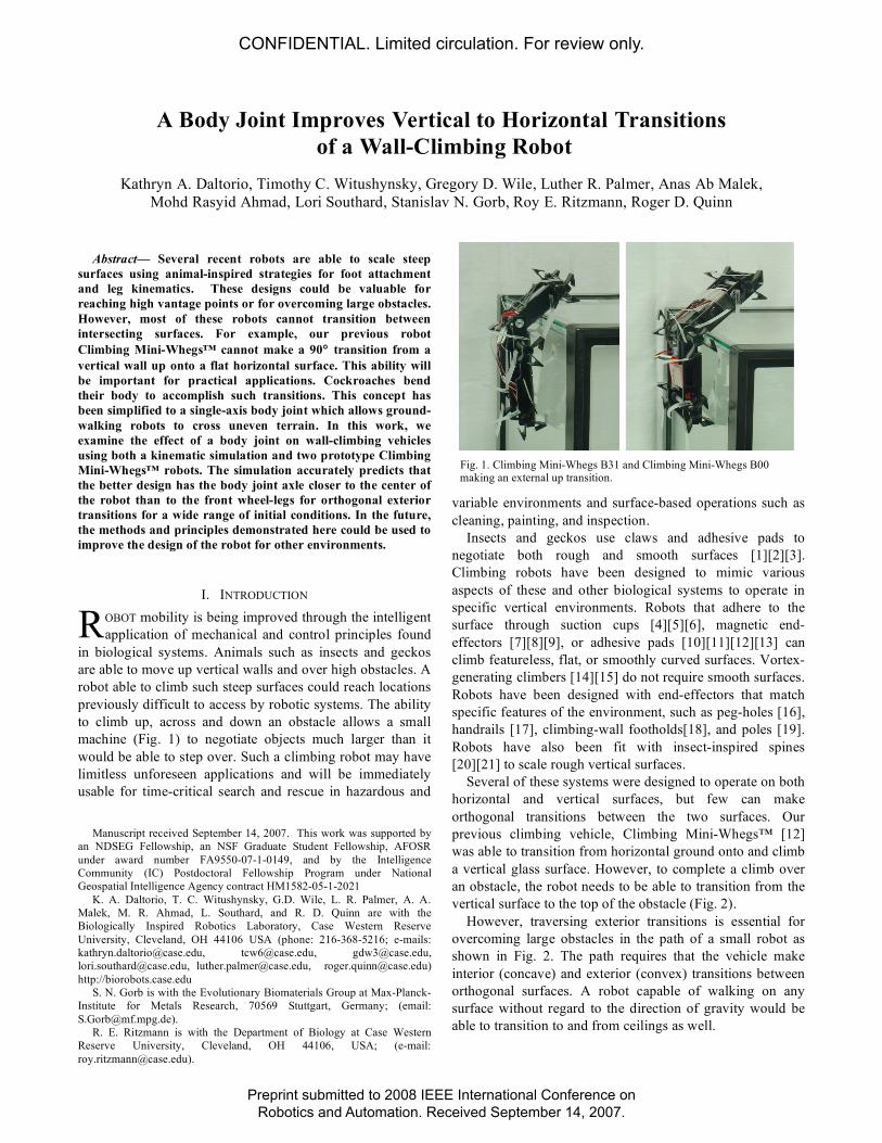
to climb up, across and down an obstacle allows a small
machine (Fig. 1) to negotiate objects much larger than it
would be able to step over. Such a climbing robot may have
limitless unforeseen applications and will be immediately
usable for time-critical search and rescue in hazardous and
Manuscript received September 14, 2007. This work was supported by
an NDSEG Fellowship, an NSF Graduate Student Fellowship, AFOSR
under award number FA9550-07-1-0149, and by the Intelligence
Community (IC) Postdoctoral Fellowship Program under National
Geospatial Intelligence Agency contract HM1582-05-1-2021
K. A. Daltorio, T. C. Witushynsky, G.D. Wile, L. R. Palmer, A. A.
Malek, M. R. Ahmad, L. Southard, and R. D. Quinn are with the
Biologically Inspired Robotics Laboratory, Case Western Reserve
University, Cleveland, OH 44106 USA (phone: 216-368-5216; e-mails:
[email protected], [email protected], [email protected],
[email protected], [email protected], [email protected])
http://biorobots.case.edu
S. N. Gorb is with the Evolutionary Biomaterials Group at Max-Planck-
Institute for Metals Research, 70569 Stuttgart, Germany; (email:
R. E. Ritzmann is with the Department of Biology at Case Western
Reserve University, Cleveland, OH 44106, USA; (e-mail:
variable environments and surface-based operations such as
cleaning, painting, and inspection.
Insects and geckos use claws and adhesive pads to
negotiate both rough and smooth surfaces [1][2][3].
Climbing robots have been designed to mimic various
aspects of these and other biological systems to operate in
specific vertical environments. Robots that adhere to the
surface through suction cups [4][5][6], magnetic end-
effectors [7][8][9], or adhesive pads [10][11][12][13] can
climb featureless, flat, or smoothly curved surfaces. Vortex-
generating climbers [14][15] do not require smooth surfaces.
Robots have been designed with end-effectors that match
specific features of the environment, such as peg-holes [16],
handrails [17], climbing-wall footholds[18], and poles [19].
Robots have also been fit with insect-inspired spines
[20][21] to scale rough vertical surfaces.
Several of these systems were designed to operate on both
horizontal and vertical surfaces, but few can make
orthogonal transitions between the two surfaces. Our
previous climbing vehicle, Climbing Mini-Whegs™ [12]
was able to transition from horizontal ground onto and climb
a vertical glass surface. However, to complete a climb over
an obstacle, the robot needs to be able to transition from the
vertical surface to the top of the obstacle (Fig. 2).
However, traversing exterior transitions is essential for
overcoming large obstacles in the path of a small robot as
shown in Fig. 2. The path requires that the vehicle make
interior (concave) and exterior (convex) transitions between
orthogonal surfaces. A robot capable of walking on any
surface without regard to the direction of gravity would be
able to transition to and from ceilings as well.
A Body Joint Improves Vertical to Horizontal Transitions
of a Wall-Climbing Robot
Kathryn A. Daltorio, Timothy C. Witushynsky, Gregory D. Wile, Luther R. Palmer, Anas Ab Malek,
Mohd Rasyid Ahmad, Lori Southard, Stanislav N. Gorb, Roy E. Ritzmann, Roger D. Quinn
R
Fig. 1. Climbing Mini-Whegs B31 and Climbing Mini-Whegs B00 making an external up transition.
CONFIDENTIAL. Limited circulation. For review only.
Preprint submitted to 2008 IEEE International Conference onRobotics and Automation. Received September 14, 2007.
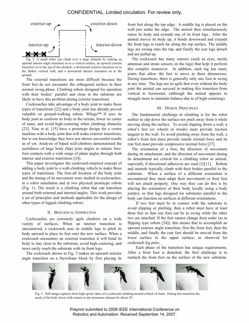
Fig. 2. A small robot can climb over a large obstacle by making an
upward interior angle transition on to a vertical surface, an upward exterior
transition on to the top of the obstacle, a downward exterior transition on to
the farther vertical wall, and a downward interior transition on to the
ground.
The external transitions are more difficult because the
front feet do not encounter the orthogonal surface in their
normal swing phase. Climbing robots designed for operation
with their bodies’ parallel and close to the substrate are
likely to have this problem during exterior transitions.
Cockroaches take advantage of a body joint to make these
types of transitions [22] and a body joint has already proved
valuable on ground-walking robots. Whegs™ II uses its
body joint to conform its body to the terrain, lower its center
of mass, and avoid high-centering when climbing obstacles
[23]. Xiao et al. [15] have a prototype design for a vortex
machine with a body joint that will make exterior transitions,
but to our knowledge they have not shown successful results
as of yet. Analysis of biped wall-climbers demonstrated the
usefulness of large body (hip) joint angles to initiate fore-
foot contacts with a wide range of plane angles through both
interior and exterior transitions [24].
This paper investigates the cockroach-inspired concept of
adding a body joint to a wall-climbing vehicle to make these
types of transitions. The fore-aft location of the body joint
and the timing of its movement were studied in cockroaches,
in a robot simulation and in two physical prototype robots
(Fig. 1). The result is a climbing robot that can transition
around both external and internal angles. This work provides
a set of principles and methods applicable for the design of
other types of legged climbing robots.
II. BIOLOGICAL INSPIRATION
Cockroaches are extremely agile climbers on a wide
variety of surfaces. When an interior transition is
encountered, a cockroach uses its middle legs to pitch its
body upward to place its feet onto the new surface. When a
cockroach encounters an external transition it will bend its
body to stay close to the substrate, avoid high centering, and
more easily reach the substrate with its front legs.
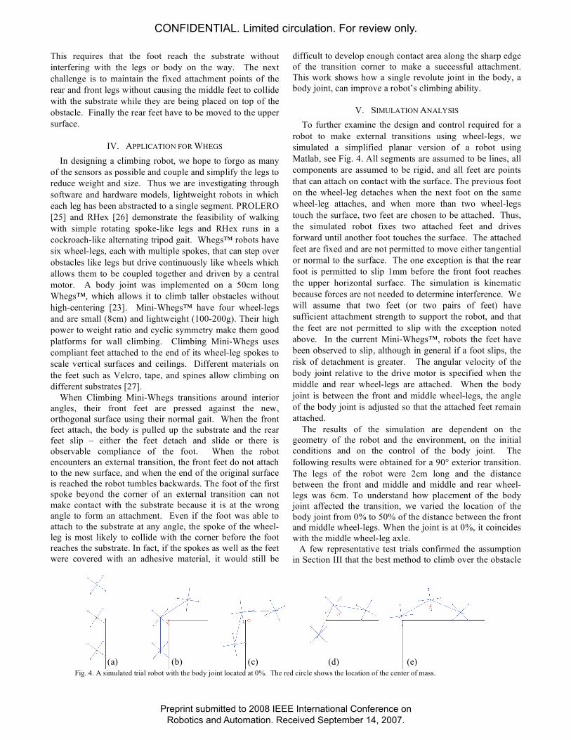
The cockroach shown in Fig. 3 makes an upward exterior
angle transition on a Styrofoam block by first placing its
front feet along the top edge. A middle leg is placed on the
wall just under the edge. The animal then simultaneously
raises its body and extends one of its front legs. After the
animal moves its body up, it bends downward and extends
the front legs to reach far along the top surface. The middle
legs are swung onto the top, and finally the rear legs detach
and are pulled up.
The cockroach has many sensors (such as eyes, tactile
antennae and strain sensors on the legs) that help it perform
this complex maneuver. In addition, each leg has many
joints that allow the feet to move in three dimensions.
During transitions, there is generally only one foot in swing
at any time. The legs are so agile that even without the body
joint the animal can succeed in making this transition from
vertical to horizontal, (although the animal appears to
struggle more to maintain balance due to of high-centering).
III. DESIGN PRINCIPLES
The fundamental challenge in climbing is for the robot
neither to slip down the surface nor pitch away from it while
moving along the surface. To avoid slipping down a wall, a
robot’s feet (or wheels or treads) must provide traction
tangent to the wall. To avoid pitching away from the wall, a
robot’s front feet must provide tensile normal force and its
rear feet must provide compressive normal force [27].
The orientation of a foot, the direction of movement
during its attachment, and the direction of movement during
its detachment are critical for a climbing robot or animal,
especially if directional adhesives are used [3][11]. Robots
and animals typically climb with their bodies parallel to the
substrate. When a surface of a different orientation is
encountered they must adapt their movements or their feet
will not attach properly. One way they can do this is by
altering the orientation of their body locally using a body
joint(s), so that legs designed for substrates parallel to the
body can function on surfaces at different orientations.
If two feet must be in contact with the substrate to
avoid slipping or pitching, then a robot must have at least
three feet so that one foot can be in swing while the other
two are attached. If the feet cannot change their order (as in
flipping type robots [24]), this means that to accomplish an
upward exterior angle transition, first the front feet, then the
middle, and finally the rear feet should be moved from the
lower surface to the upper surface, as observed for
cockroach leg pairs.
Each phase of the transition has unique requirements.
After a front foot is detached, the first challenge is to
reattach the front foot on the surface of the new substrate.
Fig. 3. Still image captures from high speed video of a cockroach climbing around a block of foam. During this transition the
angle of the body lower with respect to the pronotum changes by about 35°.
CONFIDENTIAL. Limited circulation. For review only.
Preprint submitted to 2008 IEEE International Conference onRobotics and Automation. Received September 14, 2007.
This requires that the foot reach the substrate without
interfering with the legs or body on the way. The next
challenge is to maintain the fixed attachment points of the
rear and front legs without causing the middle feet to collide
with the substrate while they are being placed on top of the
obstacle. Finally the rear feet have to be moved to the upper
surface.
IV. APPLICATION FOR WHEGS
In designing a climbing robot, we hope to forgo as many
of the sensors as possible and couple and simplify the legs to
reduce weight and size. Thus we are investigating through
software and hardware models, lightweight robots in which
each leg has been abstracted to a single segment. PROLERO
[25] and RHex [26] demonstrate the feasibility of walking
with simple rotating spoke-like legs and RHex runs in a
cockroach-like alternating tripod gait. Whegs™ robots have
six wheel-legs, each with multiple spokes, that can step over
obstacles like legs but drive continuously like wheels which
allows them to be coupled together and driven by a central
motor. A body joint was implemented on a 50cm long
Whegs™, which allows it to climb taller obstacles without
high-centering [23]. Mini-Whegs™ have four wheel-legs
and are small (8cm) and lightweight (100-200g). Their high
power to weight ratio and cyclic symmetry make them good
platforms for wall climbing. Climbing Mini-Whegs uses
compliant feet attached to the end of its wheel-leg spokes to
scale vertical surfaces and ceilings. Different materials on
the feet such as Velcro, tape, and spines allow climbing on
different substrates [27].
When Climbing Mini-Whegs transitions around interior
angles, their front feet are pressed against the new,
orthogonal surface using their normal gait. When the front
feet attach, the body is pulled up the substrate and the rear
feet slip – either the feet detach and slide or there is
observable compliance of the foot. When the robot
encounters an external transition, the front feet do not attach
to the new surface, and when the end of the original surface
is reached the robot tumbles backwards. The foot of the first
spoke beyond the corner of an external transition can not
make contact with the substrate because it is at the wrong
angle to form an attachment. Even if the foot was able to
attach to the substrate at any angle, the spoke of the wheel-
leg is most likely to collide with the corner before the foot
reaches the substrate. In fact, if the spokes as well as the feet
were covered with an adhesive material, it would still be
difficult to develop enough contact area along the sharp edge
of the transition corner to make a successful attachment.
This work shows how a single revolute joint in the body, a
body joint, can improve a robot’s climbing ability.
V. SIMULATION ANALYSIS
To further examine the design and control required for a
robot to make external transitions using wheel-legs, we
simulated a simplified planar version of a robot using
Matlab, see Fig. 4. All segments are assumed to be lines, all
components are assumed to be rigid, and all feet are points
that can attach on contact with the surface. The previous foot
on the wheel-leg detaches when the next foot on the same
wheel-leg attaches, and when more than two wheel-legs
touch the surface, two feet are chosen to be attached. Thus,
the simulated robot fixes two attached feet and drives
forward until another foot touches the surface. The attached
feet are fixed and are not permitted to move either tangential
or normal to the surface. The one exception is that the rear
foot is permitted to slip 1mm before the front foot reaches
the upper horizontal surface. The simulation is kinematic
because forces are not needed to determine interference. We
will assume that two feet (or two pairs of feet) have
sufficient attachment strength to support the robot, and that
the feet are not permitted to slip with the exception noted
above. In the current Mini-Whegs™, robots the feet have
been observed to slip, although in general if a foot slips, the
risk of detachment is greater. The angular velocity of the
body joint relative to the drive motor is specified when the
middle and rear wheel-legs are attached. When the body
joint is between the front and middle wheel-legs, the angle
of the body joint is adjusted so that the attached feet remain
attached.
The results of the simulation are dependent on the
geometry of the robot and the environment, on the initial
conditions and on the control of the body joint. The
following results were obtained for a 90° exterior transition.
The legs of the robot were 2cm long and the distance
between the front and middle and middle and rear wheel-
legs was 6cm. To understand how placement of the body
joint affected the transition, we varied the location of the
body joint from 0% to 50% of the distance between the front
and middle wheel-legs. When the joint is at 0%, it coincides
with the middle wheel-leg axle.
A few representative test trials confirmed the assumption
in Section III that the best method to climb over the obstacle
Fig. 4. A simulated trial robot with the body joint located at 0%. The red circle shows the location of the center of mass.
(a) (b) (c) (d) (e)
CONFIDENTIAL. Limited circulation. For review only.
Preprint submitted to 2008 IEEE International Conference onRobotics and Automation. Received September 14, 2007.
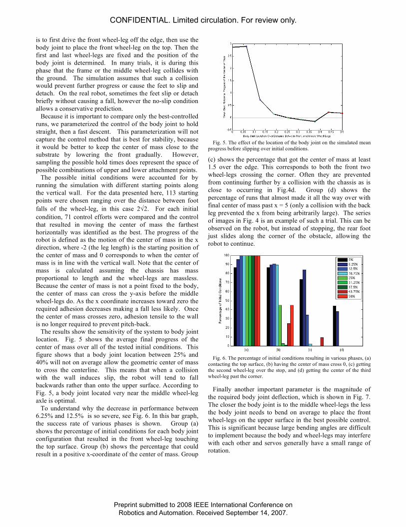
is to first drive the front wheel-leg off the edge, then use the
body joint to place the front wheel-leg on the top. Then the
first and last wheel-legs are fixed and the position of the
body joint is determined. In many trials, it is during this
phase that the frame or the middle wheel-leg collides with
the ground. The simulation assumes that such a collision
would prevent further progress or cause the feet to slip and
detach. On the real robot, sometimes the feet slip or detach
briefly without causing a fall, however the no-slip condition
allows a conservative prediction.
Because it is important to compare only the best-controlled
runs, we parameterized the control of the body joint to hold
straight, then a fast descent. This parameterization will not
capture the control method that is best for stability, because
it would be better to keep the center of mass close to the
substrate by lowering the front gradually. However,
sampling the possible hold times does represent the space of
possible combinations of upper and lower attachment points.
The possible initial conditions were accounted for by
running the simulation with different starting points along
the vertical wall. For the data presented here, 113 starting
points were chosen ranging over the distance between foot
falls of the wheel-leg, in this case 2 2. For each initial
condition, 71 control efforts were compared and the control
that resulted in moving the center of mass the farthest
horizontally was identified as the best. The progress of the
robot is defined as the motion of the center of mass in the x
direction, where -2 (the leg length) is the starting position of
the center of mass and 0 corresponds to when the center of
mass is in line with the vertical wall. Note that the center of
mass is calculated assuming the chassis has mass
proportional to length and the wheel-legs are massless.
Because the center of mass is not a point fixed to the body,
the center of mass can cross the y-axis before the middle
wheel-legs do. As the x coordinate increases toward zero the
required adhesion decreases making a fall less likely. Once
the center of mass crosses zero, adhesion tensile to the wall
is no longer required to prevent pitch-back.
The results show the sensitivity of the system to body joint
location. Fig. 5 shows the average final progress of the
center of mass over all of the tested initial conditions. This
figure shows that a body joint location between 25% and
40% will not on average allow the geometric center of mass
to cross the centerline. This means that when a collision
with the wall induces slip, the robot will tend to fall
backwards rather than onto the upper surface. According to
Fig. 5, a body joint located very near the middle wheel-leg
axle is optimal.
To understand why the decrease in performance between
6.25% and 12.5% is so severe, see Fig. 6. In this bar graph,
the success rate of various phases is shown. Group (a)
shows the percentage of initial conditions for each body joint
configuration that resulted in the front wheel-leg touching
the top surface. Group (b) shows the percentage that could
result in a positive x-coordinate of the center of mass. Group
Fig. 5. The effect of the location of the body joint on the simulated mean
progress before slipping over initial conditions.
(c) shows the percentage that got the center of mass at least
1.5 over the edge. This corresponds to both the front two
wheel-legs crossing the corner. Often they are prevented
from continuing further by a collision with the chassis as is
close to occurring in Fig.4d. Group (d) shows the
percentage of runs that almost made it all the way over with
final center of mass past x = 5 (only a collision with the back
leg prevented the x from being arbitrarily large). The series
of images in Fig. 4 is an example of such a trial. This can be
observed on the robot, but instead of stopping, the rear foot
just slides along the corner of the obstacle, allowing the
robot to continue.
Fig. 6. The percentage of initial conditions resulting in various phases, (a)
contacting the top surface, (b) having the center of mass cross 0, (c) getting
the second wheel-leg over the stop, and (d) getting the center of the third
wheel-leg past the corner.
Finally another important parameter is the magnitude of
the required body joint deflection, which is shown in Fig. 7.
The closer the body joint is to the middle wheel-legs the less
the body joint needs to bend on average to place the front
wheel-legs on the upper surface in the best possible control.
This is significant because large bending angles are difficult
to implement because the body and wheel-legs may interfere
with each other and servos generally have a small range of
rotation.
CONFIDENTIAL. Limited circulation. For review only.
Preprint submitted to 2008 IEEE International Conference onRobotics and Automation. Received September 14, 2007.

Fig. 7. The effect of body joint location on body joint angle required on
average to bring the first wheel-leg down into contact with the top surface.
VI. CLIMBING MINI-WHEGS™ WITH BODY JOINT
Two prototype robots were built and tested with body
joints, see Table I. The first robot, Climbing Mini-Whegs
B31 (CMWB31), see Fig. 1 (left), has a body joint located
between the front and middle wheel-legs, located such that
the distance between the body joint axis and middle wheel-
leg axis is 31% of the distance from the middle wheel-legs to
the front wheel-legs. The robot was built before we did the
simulation so the ratio was chosen because it appeared to
mimic that of the cockroach when bending around external
angles (see Fig. 3) and because it was convenient for
mechanical design. The second robot, Climbing Mini-
Whegs B00 (CMWB00), has a body joint that is co-axial
with the middle wheel-legs, see Fig. 1(right).
A. Climbing Mini-Whegs™ B31
CMWB31 is the first iteration of a small wheel-legged
robot with a body joint for steep-surface climbing. Like
previous Whegs™ and Mini-Whegs™, all the wheel-legs are
driven by a single central drive motor. While CMW has
only 4 wheel-legs, CMWB31 has 6, three on each side of the
chassis. The front wheel-legs are mounted on one segment
of the body and the middle and rear wheel-legs are mounted
on a second segment. A servo-motor adjusts the relative
angle between the two segments, which is called the body
joint angle. For simplicity, this robot was not designed to
steer, although our previous work with CMW suggest that
steering on a vertical surface is possible[27]. The center of
mass is in the rear of the vehicle so that when the robot is on
the ground the body joint can raise the front segment before
approaching an obstacle or wall.
Several sets of wheel-legs can be used on the robot.
Three-spoke non-adhesive wheel-legs can be used for
stepping onto obstacles twice as high as the leg length on the
ground. Wheel-legs with passive-ankles and metal spines
allow climbing on steep (50°) foam. The tests on the
transition environment were performed with four-spoke
wheel-legs with flexible feet made of office tape as
described in [12]. These feet stick reliably to glass without
slipping and can support the weight of the robot, so they are
helpful for testing robot designs.
CMWB31 was able to make upward interior transition
climbs from a horizontal surface to vertical on glass. On
both Styrofoam and glass the vehicle was able to make
transitions up to ±45°. Interior angles could be traversed, but
for exterior angles, the limitations of the body joint
prevented the front wheel-legs from contacting the top
surface in exterior angle transitions. The body joint flexed
about 45°, and continued the vertical climb, but then the
middle wheel-legs lost contact on the vertical surface.
CMWB31 subsequently fell backwards instead of forwards.
External-down transitions often resulted in a fall, but in one
trial the transition was accomplished.
B. Climbing Mini-Whegs™ B00
The next robot was built to incorporate two design
changes. First a body joint-servo, a Hitec HS-85MG, with a
larger range of motion was chosen. Secondly the location of
the body joint was moved to coincide with the middle
wheel-leg axle. These changes increased the weight of the
robot as shown in Table I and increased the width of the
chassis from 5.1cm to 7.6cm. Both CMWB31 and CMWB00
have both drive and body joint motors in the front and the
batteries in the back, with center of mass very close to the
middle axis when the body joint is straight.
CMWB00 is able to make upward internal transitions
from horizontal glass to vertical glass and upward external
transitions from vertical glass to horizontal. This external
transition was impossible even after many tries with CMW
and CMWB31. To accomplish this, the operator drives the
vehicle up the glass slowly, keeping the body joint straight
until the upper wheel-legs are free of the wall. Then the
body joint is adjusted gradually so that the front wheel-legs
reach down and contact the upper horizontal surface. In
some cases, the robot slipped before the front feet made
contact, falling unto the surface. According to Fig. 6a this
happens about 15% of the time even with the best control,
however because the center of mass will usually be over the
obstacle, the robot will fall in the right direction. The
middle feet then are attached onto the horizontal surface,
followed by the rear wheel-legs. Like in the simulation
results, the body is initially bent at the top, but because the
TABLE I
COMPARISON OF CLIMBING MINI-WHEGS™
Climbing
Mini-
Whegs
Climbing
Mini-Whegs
B31
Climbing
Mini-Whegs
B00
Mass of chassis 90g 104.6g 166.4g
From front to
middle wheel-legs
7.0 cm 6.5 cm 6.5 cm
From middle to rear
wheel-legs
No rear
wheel-legs
6.5 cm 6.5 cm
Middle wheel-legs
to body joint
No body
joint
2 cm forward 0 cm
Leg length 2 cm 2 cm 2 cm
Body Joint Range
of motion*
No body
joint –45° to +45° –180° to +45°
90° Transition
Types (Fig. 2)
Internal Internal and
external-down
All four types
*Where (+) is bending the front up and (–) is bending the front down
CONFIDENTIAL. Limited circulation. For review only.
Preprint submitted to 2008 IEEE International Conference onRobotics and Automation. Received September 14, 2007.

wheel-legs slip, the body joint flattens with applied torque
from the servo.
The robot could make an exterior-down transition without
falling if the feet on the middle wheel-leg were adjusted to
be collinear with the spoke rather than nearly parallel to the
substrate. Feet in this orientation act like compliant
extensions to the legs. See ICRA 2008 video proceedings
submission: Making Orthogonal Transitions with Climbing
Mini-Whegs™ for video of Climbing Mini-Whegs™.
VII. CONCLUSIONS
The simulation predicted an improved location of the
body joint axle. The cockroach has the advantage that it can
reach with its front legs to grasp the substrate, so it is not
surprising that the optimal location of a body joint on Mini-
Whegs™ is not the same as on the cockroach. The resulting
vehicle progressed farther than predicted. The no-slip
assumption is conservative and useful, but the real robot
works better because there is compliance in the attached
feet. These methods could be used to optimize other design
parameters of climbing robots for various environments.
ACKNOWLEDGMENT
The authors would like to thank the members of the Bio-
Robotics Team Research Spring 2006 Class.
REFERENCES
[1] S. F. Frazier, G. S. Larsen, D. Neff. “Elasticity and movements of the
cockroach tarsus in walking,” J. of Comp. Physiol. A, vol. 185, pp.
157–172, 1999.
[2] K. Autumn, Y.A. Liang, S.T. Hsieh, et al. “Adhesive force of a single
gecko foot-hair,” Nature, vol. 405, pp. 681–685. 2000.
[3] S. N. Gorb, Attachment devices of insect cuticle, Dordrecht, Boston,
London: Kluwer Academic Publishers, pp. 1–305, 2001.
[4] A. Nagakubo and S. Hirose, “Walking and running of the quadruped
wall-climbing robot,” ICRA ‘94, vol. 2, pp. 1005-1012, May, 1994.
[5] S. W. Ryu, J. J. Park, S. M. Ryew, and H. R. Choi, “Self-contained
wall-climbing robot with closed link mechanism,” IROS ‘01, Maui,
2001.
[6] W. Yan, L. Shuliang, X. Dianguo, Z. Yanzheng, S. Hao, and G.
Xuesban, “Development and application of wall-climbing robots,”
ICRA ‘99, Detroit, 1999.
[7] J. C. Grieco, M. Prieto, M. Armada, and P. G. deSantos, “A six-legged
climbing robot for high payloads,” IEEE Int. Conf. on Control
Applications, Trieste, Italy, 1998.
[8] S. Hirose and K. Kawabe, “Ceiling walk of quadruped wall climbing
robot NINJA-II,” CLAWAR ‘98, Brussels, Belgium, 1998.
[9] L. Guo, K. Rogers, and R. Kirkham, “A climbing robot with
continuous motion,” IEEE/RSJ Int. Conf. on Robotics and Automation
(ICRA), 1994.
[10] R. J. Full, “Using biological inspiration to build artificial life that
locomotes,” in Proc. of Evolutionary Robotics from Intelligent
Robotics to Artificial Life: International Symposium, ER 2001, Tokyo,
Japan, October, 2001.
[11] S. Kim, M. Spenko, S. Trujillo, B. Heyneman, V. Mattoli, M. R.
Cutkosky, “Whole body adhesion: hierarchical, directional and
distributed control of adhesive forces for a climbing robot,” ICRA ’07,
pp. 1268-1273, Roma, Italy, April, 2007.
[12] K. A. Daltorio, A. D. Horchler, S. Gorb, R. E. Ritzmann, and R. D.
Quinn, “A small wall-walking robot with compliant, adhesive feet,” in
IROS ’05, pp. 3648-3653, August, 2005.
[13] C. Menon and M. Sitti, “Biologically-inspired adhesion based surface
climbing robots,” in ICRA ’05, pp. 2715-2720, 2005.
[14] L. Illingworth and D. Reinfeld, “Vortex attractor for planar and non-
planar surfaces,” U.S. Patent 6,619,922, Sep. 16, 2003.
[15] J. Xiao, W. Morris, N. Chakravarthy, A. Calle, “City climber: a new
generation of mobile robot with wall-climbing capability,” SPIE. vol.
6230, pp. 62301d, 2006.
[16] Y. Xu, H. Brown, M. Friendman, and T. Kanade, “Control system of
the self-mobile space manipulator,” IEEE Trans. On Control System
Technology, vol. 2, num. 3, pp. 207-219, 1994.
[17] H. Amano, K. Osuka, and T. J. Tarn, “Development of vertically
moving robot with gripping handrails for firefighting,” IROS ‘01,
Maui, HI, 2001.
[18] T. Bretl, S. Rock, J. C. Latombe, B. Kennedy, and H. Aghazarian,
“Free-climbing with a multi-use robot,” in Proc. of Inter. Symp. on
Experimental Robotics (ISER), Singapore, June, 2004.
[19] Z. Ripin, T. B. Soon, A. Abdullah, and Z. Samad, “Development of a
low-cost modular pole climbing robot,” in Proc. of TENCON, vol. 1,
pp. 196-200, Kuala Lumpur, Malaysia, 2000.
[20] K. Autumn, M. Buehler, M. Cutkosky, R. Fearing, R.J. Full, D.
Goldman, R. Groff, W. Provancher, A. A. Rizzi, U. Saranli, A.
Saunders, and D. E. Koditschek, “Robots in scansorial environments,”
in Proc. of SPIE, vol. 5804, pp. 291–302, 2005.
[21] S. Kim, A. T. Asbeck, M. R. Cutkosky, and W. R. Provancher,
“SpinybotII: climbing hard walls with compliant microspines,” in
IEEE Int. Conf. on Advanced Robotics (ICAR ‘05), Seattle, 2005.
[22] Ritzmann, R.E., Quinn, R.D. and Fischer, M.S. (2004) Convergent
evolution and locomotion through complex terrain by insects,
vertebrates and robots. Arth. Struct. Dev. 33:361-379.
[23] T. J. Allen, R. D. Quinn, R. J. Bachmann, and R. E. Ritzmann,
“Abstracted biological principles applied with reduced actuation
improve mobility of legged vehicles,” in Proc. of Int. Conf. on
Intelligent Robots and Systems (IROS), Las Vegas, Nevada, 2003.
[24] R. Lal Tummala, R. Mukherjee, N. Xi, et al., “Climbing The Walls,”
IEEE Robotics and Automation Magazine, vol. 9, no. 4, pp. 10–19,
2002.
[25] A. Martin-Alvarz, W. de Peuter, J. Hellebrand, P. Putz, A.
Matthyssen, and J. R. de Weerd, “Walking Robots for Planetary
Exploration Missions,” in Proc. of 2nd World Automation Congress,
Montpellier, France, May, 1996.
[26] U. Saranli, M. Buehler, and D. Koditschek, “RHex: a simple and
highly mobile hexapod robot,” International Journal of Robotics
Research, vol. 20, no. 7, pp. 616-631, 2001.
[27] K. Daltorio, T. Wei, A.D. Horchler, L. Southard, G. Wile, S. Gorb, R.
Ritzmann, R. Quinn. “Mini-Whegs™ Climbs Steep Surfaces Using
Insect-Inspired Attachment Mechanisms” International Journal of
Robotics Research. Submitted: 3/2007
Fig. 8. Shows Climbing Mini-Whegs™ B00 making an exterior upward transition.
(a) (b) (c) (d) (e)
CONFIDENTIAL. Limited circulation. For review only.
Preprint submitted to 2008 IEEE International Conference onRobotics and Automation. Received September 14, 2007.